Make: AVR Programming - Keybase.pub
472
-
Upload
khangminh22 -
Category
Documents
-
view
0 -
download
0
Transcript of Make: AVR Programming - Keybase.pub


Elliot Williams
Make: AVRProgramming

Make: AVR Programmingby Elliot Williams
Copyright © 2014 Elliot Williams. All rights reserved.
Printed in the United States of America.
Published by Maker Media, Inc., 1160 Battery Street East, Suite 125, San Francisco, CA 94111.
Maker Media books may be purchased for educational, business, or sales promotional use. Online editionsare also available for most titles (http://my.safaribooksonline.com). For more information, contact O’ReillyMedia’s corporate/institutional sales department: 800-998-9938 or [email protected].
Editor: Patrick Di JustoProduction Editor: Kara EbrahimCopyeditor: Kim CoferProofreader: Amanda Kersey
Indexer: Judy McConvilleCover Designer: Shawn WallaceInterior Designer: Monica KamsvaagIllustrator: Rebecca Demarest
February 2014: First Edition
Revision History for the First Edition:
2014-01-24: First release
2014-02-14: Second release
2015-03-03: Third release
See http://oreilly.com/catalog/errata.csp?isbn=9781449355784 for release details.
The Make logo and Maker Media logo are registered trademarks of Maker Media, Inc. Make: AVR Program-ming and related trade dress are trademarks of Maker Media, Inc.
Many of the designations used by manufacturers and sellers to distinguish their products are claimed astrademarks. Where those designations appear in this book, and Maker Media, Inc., was aware of a trademarkclaim, the designations have been printed in caps or initial caps.
While every precaution has been taken in the preparation of this book, the publisher and authors assumeno responsibility for errors or omissions, or for damages resulting from the use of the information containedherein.
ISBN: 978-1-449-35578-4
[LSI]

Preface . . . . . . . . . . . . . . . . . . . . . . . . . . . . . . . . . . . . . . . . . . . xi
Part I. The Basics
1. Introduction . . . . . . . . . . . . . . . . . . . . . . . . . . . . . . . . . . . 3What Is a Microcontroller? The Big Picture . . . . . . . . . . . . . . . . . . . . . . . . 3
A Computer on a Chip… . . . . . . . . . . . . . . . . . . . . . . . . . . . . . . . . . . . . . . . 3…But a Very Small Computer . . . . . . . . . . . . . . . . . . . . . . . . . . . . . . . . . . . 4What Can Microcontrollers Do? . . . . . . . . . . . . . . . . . . . . . . . . . . . . . . . . . 5
Hardware: The Big Picture . . . . . . . . . . . . . . . . . . . . . . . . . . . . . . . . . . . . . . . . 5The Core: Processor, Memory, and I/O . . . . . . . . . . . . . . . . . . . . . . . . . . . 8Peripherals: Making Your Life Easier . . . . . . . . . . . . . . . . . . . . . . . . . . . . . 9
2. Programming AVRs . . . . . . . . . . . . . . . . . . . . . . . . . . . 13Programming the AVR . . . . . . . . . . . . . . . . . . . . . . . . . . . . . . . . . . . . . . . . . . 13
Toolchain . . . . . . . . . . . . . . . . . . . . . . . . . . . . . . . . . . . . . . . . . . . . . . . . . . . . . 14The Software Toolchain . . . . . . . . . . . . . . . . . . . . . . . . . . . . . . . . . . . . . . . . . 16
Linux Setup . . . . . . . . . . . . . . . . . . . . . . . . . . . . . . . . . . . . . . . . . . . . . . . . . . 18Windows Setup . . . . . . . . . . . . . . . . . . . . . . . . . . . . . . . . . . . . . . . . . . . . . . . 18Mac Setup . . . . . . . . . . . . . . . . . . . . . . . . . . . . . . . . . . . . . . . . . . . . . . . . . . . . 20Arduino Setup . . . . . . . . . . . . . . . . . . . . . . . . . . . . . . . . . . . . . . . . . . . . . . . . 20Make and Makefiles . . . . . . . . . . . . . . . . . . . . . . . . . . . . . . . . . . . . . . . . . . . 20
AVR and the Arduino . . . . . . . . . . . . . . . . . . . . . . . . . . . . . . . . . . . . . . . . . . . . 21Arduino Pros . . . . . . . . . . . . . . . . . . . . . . . . . . . . . . . . . . . . . . . . . . . . . . . . . 21Arduino Cons . . . . . . . . . . . . . . . . . . . . . . . . . . . . . . . . . . . . . . . . . . . . . . . . . 22
iii
Table of Contents

The Arduino: Hardware or Software? Both! . . . . . . . . . . . . . . . . . . . . . 24The Arduino Is an AVR . . . . . . . . . . . . . . . . . . . . . . . . . . . . . . . . . . . . . . . . . 24The Arduino Is an AVR Programmer . . . . . . . . . . . . . . . . . . . . . . . . . . . . 26
Other Hardware Programmers . . . . . . . . . . . . . . . . . . . . . . . . . . . . . . . . . . . 29Flash Programmers I Have Known and Loved . . . . . . . . . . . . . . . . . . . 29
Getting Started: Blinking LEDs . . . . . . . . . . . . . . . . . . . . . . . . . . . . . . . . . . . 30Hookup . . . . . . . . . . . . . . . . . . . . . . . . . . . . . . . . . . . . . . . . . . . . . . . . . . . . . . . 31ISP Headers . . . . . . . . . . . . . . . . . . . . . . . . . . . . . . . . . . . . . . . . . . . . . . . . . . . 34AVRDUDE . . . . . . . . . . . . . . . . . . . . . . . . . . . . . . . . . . . . . . . . . . . . . . . . . . . . . 36Configuring Your Makefile . . . . . . . . . . . . . . . . . . . . . . . . . . . . . . . . . . . . . 39Flash . . . . . . . . . . . . . . . . . . . . . . . . . . . . . . . . . . . . . . . . . . . . . . . . . . . . . . . . . . 41Troubleshooting . . . . . . . . . . . . . . . . . . . . . . . . . . . . . . . . . . . . . . . . . . . . . . . 41
3. Digital Output . . . . . . . . . . . . . . . . . . . . . . . . . . . . . . . . . 43blinkLED Redux . . . . . . . . . . . . . . . . . . . . . . . . . . . . . . . . . . . . . . . . . . . . . . . . . . 44
The Structure of AVR C Code . . . . . . . . . . . . . . . . . . . . . . . . . . . . . . . . . . . 45Hardware Registers . . . . . . . . . . . . . . . . . . . . . . . . . . . . . . . . . . . . . . . . . . . . 46blinkLED Summary . . . . . . . . . . . . . . . . . . . . . . . . . . . . . . . . . . . . . . . . . . . . 49
POV Toy . . . . . . . . . . . . . . . . . . . . . . . . . . . . . . . . . . . . . . . . . . . . . . . . . . . . . . . . . 49Building the Circuit . . . . . . . . . . . . . . . . . . . . . . . . . . . . . . . . . . . . . . . . . . . . 50Pretty Patterns: The POV Toy Code . . . . . . . . . . . . . . . . . . . . . . . . . . . . . 54Experiment! . . . . . . . . . . . . . . . . . . . . . . . . . . . . . . . . . . . . . . . . . . . . . . . . . . . 56
4. Bit Twiddling . . . . . . . . . . . . . . . . . . . . . . . . . . . . . . . . . . 59Working Through the Code: Cylon Eyes . . . . . . . . . . . . . . . . . . . . . . . . . . . 60Bit Twiddling and Cylon Eyes . . . . . . . . . . . . . . . . . . . . . . . . . . . . . . . . . . . . . 61
Bit Shifting . . . . . . . . . . . . . . . . . . . . . . . . . . . . . . . . . . . . . . . . . . . . . . . . . . . . 62Advanced Bit Twiddling: Above and Beyond Cylon Eyes . . . . . . . . . . . 64
Setting Bits with OR . . . . . . . . . . . . . . . . . . . . . . . . . . . . . . . . . . . . . . . . . . . 68Toggling Bits with XOR . . . . . . . . . . . . . . . . . . . . . . . . . . . . . . . . . . . . . . . . . 69Clearing a Bit with AND and NOT . . . . . . . . . . . . . . . . . . . . . . . . . . . . . . . 70
Showing Off . . . . . . . . . . . . . . . . . . . . . . . . . . . . . . . . . . . . . . . . . . . . . . . . . . . . . 72Summary . . . . . . . . . . . . . . . . . . . . . . . . . . . . . . . . . . . . . . . . . . . . . . . . . . . . . . . . 76
5. Serial I/O . . . . . . . . . . . . . . . . . . . . . . . . . . . . . . . . . . . . . . 77Serial Communication . . . . . . . . . . . . . . . . . . . . . . . . . . . . . . . . . . . . . . . . . . . 77Implementing Serial Communication on the AVR: Loopback Project 81
Setup: Configuring the AVR . . . . . . . . . . . . . . . . . . . . . . . . . . . . . . . . . . . . 81Setup: Your Computer . . . . . . . . . . . . . . . . . . . . . . . . . . . . . . . . . . . . . . . . . 83Setup: USB-Serial Adapter . . . . . . . . . . . . . . . . . . . . . . . . . . . . . . . . . . . . . 83Putting It All Together: Test Out Your Loopback . . . . . . . . . . . . . . . . . 86Troubleshooting Serial Connections . . . . . . . . . . . . . . . . . . . . . . . . . . . . 87
Configuring USART: The Nitty-Gritty Details . . . . . . . . . . . . . . . . . . . . . . 88AVR Square-Wave Organ . . . . . . . . . . . . . . . . . . . . . . . . . . . . . . . . . . . . . . . . . 95
Making Music with Your Micro . . . . . . . . . . . . . . . . . . . . . . . . . . . . . . . . . 96
iv Make: AVR Programming

The Organ Library . . . . . . . . . . . . . . . . . . . . . . . . . . . . . . . . . . . . . . . . . . . . . 98The Code . . . . . . . . . . . . . . . . . . . . . . . . . . . . . . . . . . . . . . . . . . . . . . . . . . . . . . 99Extra Goodies . . . . . . . . . . . . . . . . . . . . . . . . . . . . . . . . . . . . . . . . . . . . . . . . 102
Summary . . . . . . . . . . . . . . . . . . . . . . . . . . . . . . . . . . . . . . . . . . . . . . . . . . . . . . 103
6. Digital Input . . . . . . . . . . . . . . . . . . . . . . . . . . . . . . . . . . 105Pushbuttons, Switches, Etc. . . . . . . . . . . . . . . . . . . . . . . . . . . . . . . . . . . . . . 105
Configuring Input: DDRs, PORTs, and PINs . . . . . . . . . . . . . . . . . . . . . 108Interpreting Button Presses . . . . . . . . . . . . . . . . . . . . . . . . . . . . . . . . . . . 109
Changing State . . . . . . . . . . . . . . . . . . . . . . . . . . . . . . . . . . . . . . . . . . . . . . . . . 112Debouncing . . . . . . . . . . . . . . . . . . . . . . . . . . . . . . . . . . . . . . . . . . . . . . . . . . . 113
Debounce Example . . . . . . . . . . . . . . . . . . . . . . . . . . . . . . . . . . . . . . . . . . 115AVR Music Box . . . . . . . . . . . . . . . . . . . . . . . . . . . . . . . . . . . . . . . . . . . . . . . . . 117
The Code . . . . . . . . . . . . . . . . . . . . . . . . . . . . . . . . . . . . . . . . . . . . . . . . . . . . 117Boss Button . . . . . . . . . . . . . . . . . . . . . . . . . . . . . . . . . . . . . . . . . . . . . . . . . . . . 119
Desktop-side Scripting . . . . . . . . . . . . . . . . . . . . . . . . . . . . . . . . . . . . . . . 120Extensions . . . . . . . . . . . . . . . . . . . . . . . . . . . . . . . . . . . . . . . . . . . . . . . . . . . 124
7. Analog-to-Digital Conversion I . . . . . . . . . . . . . . . 125ADC Hardware Overview . . . . . . . . . . . . . . . . . . . . . . . . . . . . . . . . . . . . . . . 126Light Meter . . . . . . . . . . . . . . . . . . . . . . . . . . . . . . . . . . . . . . . . . . . . . . . . . . . . 129
The Circuit . . . . . . . . . . . . . . . . . . . . . . . . . . . . . . . . . . . . . . . . . . . . . . . . . . . 129The Code . . . . . . . . . . . . . . . . . . . . . . . . . . . . . . . . . . . . . . . . . . . . . . . . . . . . 135ADC Initialization . . . . . . . . . . . . . . . . . . . . . . . . . . . . . . . . . . . . . . . . . . . . . 137Extensions . . . . . . . . . . . . . . . . . . . . . . . . . . . . . . . . . . . . . . . . . . . . . . . . . . . 139
Slowscope . . . . . . . . . . . . . . . . . . . . . . . . . . . . . . . . . . . . . . . . . . . . . . . . . . . . . 140The AVR Code . . . . . . . . . . . . . . . . . . . . . . . . . . . . . . . . . . . . . . . . . . . . . . . . 141The Desktop Code . . . . . . . . . . . . . . . . . . . . . . . . . . . . . . . . . . . . . . . . . . . . 143Synergies . . . . . . . . . . . . . . . . . . . . . . . . . . . . . . . . . . . . . . . . . . . . . . . . . . . . 145
AVR Night Light and the Multiplexer . . . . . . . . . . . . . . . . . . . . . . . . . . . . 145Multiplexing . . . . . . . . . . . . . . . . . . . . . . . . . . . . . . . . . . . . . . . . . . . . . . . . . 145Setting the Mux Bits . . . . . . . . . . . . . . . . . . . . . . . . . . . . . . . . . . . . . . . . . . 146The Circuit . . . . . . . . . . . . . . . . . . . . . . . . . . . . . . . . . . . . . . . . . . . . . . . . . . . 148The Code . . . . . . . . . . . . . . . . . . . . . . . . . . . . . . . . . . . . . . . . . . . . . . . . . . . . 148
Summary . . . . . . . . . . . . . . . . . . . . . . . . . . . . . . . . . . . . . . . . . . . . . . . . . . . . . . 150
Part II. Intermediate AVR
8. Hardware Interrupts . . . . . . . . . . . . . . . . . . . . . . . . . 153External Interrupts 101: Real-time Button Pressing Examples . . . . . 155
External Interrupt 0 Example . . . . . . . . . . . . . . . . . . . . . . . . . . . . . . . . . . 156Pin-Change Interrupt Example . . . . . . . . . . . . . . . . . . . . . . . . . . . . . . . . 161
Capacitive Sensor . . . . . . . . . . . . . . . . . . . . . . . . . . . . . . . . . . . . . . . . . . . . . . 164The Sensor . . . . . . . . . . . . . . . . . . . . . . . . . . . . . . . . . . . . . . . . . . . . . . . . . . . 165
vTable of Contents

The Code . . . . . . . . . . . . . . . . . . . . . . . . . . . . . . . . . . . . . . . . . . . . . . . . . . . . 168Global, Volatile Variables . . . . . . . . . . . . . . . . . . . . . . . . . . . . . . . . . . . . . . 170Debugging the Circuit . . . . . . . . . . . . . . . . . . . . . . . . . . . . . . . . . . . . . . . . 173
9. Introduction to the Timer/Counter Hardware 175Timer/Counters: Why and How? . . . . . . . . . . . . . . . . . . . . . . . . . . . . . . . . . 175Test Your Reaction Time . . . . . . . . . . . . . . . . . . . . . . . . . . . . . . . . . . . . . . . . 178Using Timer 0 for a Better 8-Bit Organ . . . . . . . . . . . . . . . . . . . . . . . . . . . 182AM Radio . . . . . . . . . . . . . . . . . . . . . . . . . . . . . . . . . . . . . . . . . . . . . . . . . . . . . . 186
The Circuit . . . . . . . . . . . . . . . . . . . . . . . . . . . . . . . . . . . . . . . . . . . . . . . . . . . 188CPU Speed . . . . . . . . . . . . . . . . . . . . . . . . . . . . . . . . . . . . . . . . . . . . . . . . . . . 189AM Radio: The Code . . . . . . . . . . . . . . . . . . . . . . . . . . . . . . . . . . . . . . . . . . 190
Summary . . . . . . . . . . . . . . . . . . . . . . . . . . . . . . . . . . . . . . . . . . . . . . . . . . . . . . 196
10. Pulse-Width Modulation . . . . . . . . . . . . . . . . . . . . . 199Bright and Dim LEDs: PWM . . . . . . . . . . . . . . . . . . . . . . . . . . . . . . . . . . . . . 200Brute-Force PWM Demo . . . . . . . . . . . . . . . . . . . . . . . . . . . . . . . . . . . . . . . . 202Timers PWM Demo . . . . . . . . . . . . . . . . . . . . . . . . . . . . . . . . . . . . . . . . . . . . . 204
Initializing Timers for PWM Mode . . . . . . . . . . . . . . . . . . . . . . . . . . . . . 206PWM on Any Pin . . . . . . . . . . . . . . . . . . . . . . . . . . . . . . . . . . . . . . . . . . . . . . . . 208
PWM on Any Pin Demo . . . . . . . . . . . . . . . . . . . . . . . . . . . . . . . . . . . . . . . 209Closing: Alternatives to PWM and a Timer Checklist . . . . . . . . . . . . . . 211
11. Driving Servo Motors . . . . . . . . . . . . . . . . . . . . . . . . 215Servos . . . . . . . . . . . . . . . . . . . . . . . . . . . . . . . . . . . . . . . . . . . . . . . . . . . . . . . . . 216
The Secret Life of Servos . . . . . . . . . . . . . . . . . . . . . . . . . . . . . . . . . . . . . . 217The Circuit . . . . . . . . . . . . . . . . . . . . . . . . . . . . . . . . . . . . . . . . . . . . . . . . . . . 218The Code . . . . . . . . . . . . . . . . . . . . . . . . . . . . . . . . . . . . . . . . . . . . . . . . . . . . 219
Servo Sundial . . . . . . . . . . . . . . . . . . . . . . . . . . . . . . . . . . . . . . . . . . . . . . . . . . 223The Build . . . . . . . . . . . . . . . . . . . . . . . . . . . . . . . . . . . . . . . . . . . . . . . . . . . . . 224Ready the Lasers! . . . . . . . . . . . . . . . . . . . . . . . . . . . . . . . . . . . . . . . . . . . . . 227The Code . . . . . . . . . . . . . . . . . . . . . . . . . . . . . . . . . . . . . . . . . . . . . . . . . . . . 229Servo Sundial Calibration . . . . . . . . . . . . . . . . . . . . . . . . . . . . . . . . . . . . . 236
12. Analog-to-Digital Conversion II . . . . . . . . . . . . . . 243Voltage Meter . . . . . . . . . . . . . . . . . . . . . . . . . . . . . . . . . . . . . . . . . . . . . . . . . . 244
The Circuit . . . . . . . . . . . . . . . . . . . . . . . . . . . . . . . . . . . . . . . . . . . . . . . . . . . 245The Code . . . . . . . . . . . . . . . . . . . . . . . . . . . . . . . . . . . . . . . . . . . . . . . . . . . . 248
The Footstep Detector . . . . . . . . . . . . . . . . . . . . . . . . . . . . . . . . . . . . . . . . . . 252The Circuit . . . . . . . . . . . . . . . . . . . . . . . . . . . . . . . . . . . . . . . . . . . . . . . . . . . 253The Theory . . . . . . . . . . . . . . . . . . . . . . . . . . . . . . . . . . . . . . . . . . . . . . . . . . . 258Exponentially Weighted Moving Averages . . . . . . . . . . . . . . . . . . . . 259The Code . . . . . . . . . . . . . . . . . . . . . . . . . . . . . . . . . . . . . . . . . . . . . . . . . . . . 262
Summary . . . . . . . . . . . . . . . . . . . . . . . . . . . . . . . . . . . . . . . . . . . . . . . . . . . . . . 266
vi Make: AVR Programming

Part III. Advanced AVR Topics
13. Advanced PWM Tricks . . . . . . . . . . . . . . . . . . . . . . . . 269Direct-Digital Synthesis . . . . . . . . . . . . . . . . . . . . . . . . . . . . . . . . . . . . . . . . . 270Making a Sine Wave . . . . . . . . . . . . . . . . . . . . . . . . . . . . . . . . . . . . . . . . . . . . 274Next Steps: Mixing and Volume . . . . . . . . . . . . . . . . . . . . . . . . . . . . . . . . . 277
Mixing . . . . . . . . . . . . . . . . . . . . . . . . . . . . . . . . . . . . . . . . . . . . . . . . . . . . . . . 277Dynamic Volume Control . . . . . . . . . . . . . . . . . . . . . . . . . . . . . . . . . . . . . 280
Polling USART . . . . . . . . . . . . . . . . . . . . . . . . . . . . . . . . . . . . . . . . . . . . . . . . . . 283ADSR Envelope . . . . . . . . . . . . . . . . . . . . . . . . . . . . . . . . . . . . . . . . . . . . . . . . . 283Auxiliary Files . . . . . . . . . . . . . . . . . . . . . . . . . . . . . . . . . . . . . . . . . . . . . . . . . . 284
14. Switches . . . . . . . . . . . . . . . . . . . . . . . . . . . . . . . . . . . . . 287Controlling Big Loads: Switches . . . . . . . . . . . . . . . . . . . . . . . . . . . . . . . . . 288
Bipolar-Junction Transistors . . . . . . . . . . . . . . . . . . . . . . . . . . . . . . . . . . 290MOSFETs . . . . . . . . . . . . . . . . . . . . . . . . . . . . . . . . . . . . . . . . . . . . . . . . . . . . . 291Power MOSFETs . . . . . . . . . . . . . . . . . . . . . . . . . . . . . . . . . . . . . . . . . . . . . . 293Relays . . . . . . . . . . . . . . . . . . . . . . . . . . . . . . . . . . . . . . . . . . . . . . . . . . . . . . . . 294Triacs and SSRs . . . . . . . . . . . . . . . . . . . . . . . . . . . . . . . . . . . . . . . . . . . . . . . 295Switches: Summary . . . . . . . . . . . . . . . . . . . . . . . . . . . . . . . . . . . . . . . . . . 296
DC Motors . . . . . . . . . . . . . . . . . . . . . . . . . . . . . . . . . . . . . . . . . . . . . . . . . . . . . 297
15. Advanced Motors . . . . . . . . . . . . . . . . . . . . . . . . . . . . 305Going in Reverse: H-Bridges . . . . . . . . . . . . . . . . . . . . . . . . . . . . . . . . . . . . 306Code: Taking Your H-Bridge Out for a Spin . . . . . . . . . . . . . . . . . . . . . . . 309
Experts-Only H-Bridge . . . . . . . . . . . . . . . . . . . . . . . . . . . . . . . . . . . . . . . . 312PWM and the H-Bridge . . . . . . . . . . . . . . . . . . . . . . . . . . . . . . . . . . . . . . . . . 313
Drive Modes: Sign-Magnitude . . . . . . . . . . . . . . . . . . . . . . . . . . . . . . . . 314Drive Modes: Locked Anti-phase . . . . . . . . . . . . . . . . . . . . . . . . . . . . . . 314Drive Modes: Comparison . . . . . . . . . . . . . . . . . . . . . . . . . . . . . . . . . . . . 315
Stepper Motors . . . . . . . . . . . . . . . . . . . . . . . . . . . . . . . . . . . . . . . . . . . . . . . . 318Kinds of Stepper Motors . . . . . . . . . . . . . . . . . . . . . . . . . . . . . . . . . . . . . . . . 319Full Stepping and Half Stepping . . . . . . . . . . . . . . . . . . . . . . . . . . . . . . . . 320Identification of Stepper Motor Wires . . . . . . . . . . . . . . . . . . . . . . . . . . . 323
Too Many Wires! . . . . . . . . . . . . . . . . . . . . . . . . . . . . . . . . . . . . . . . . . . . . . . 323Dual H-Bridge Chips: The SN754410 . . . . . . . . . . . . . . . . . . . . . . . . . . . . . 325The Code . . . . . . . . . . . . . . . . . . . . . . . . . . . . . . . . . . . . . . . . . . . . . . . . . . . . . . 327Acceleration Control . . . . . . . . . . . . . . . . . . . . . . . . . . . . . . . . . . . . . . . . . . . . 331Microstepping . . . . . . . . . . . . . . . . . . . . . . . . . . . . . . . . . . . . . . . . . . . . . . . . . 334
16. SPI . . . . . . . . . . . . . . . . . . . . . . . . . . . . . . . . . . . . . . . . . . . 337How SPI Works . . . . . . . . . . . . . . . . . . . . . . . . . . . . . . . . . . . . . . . . . . . . . . . . . 338
Bit Trading Example . . . . . . . . . . . . . . . . . . . . . . . . . . . . . . . . . . . . . . . . . . 340Shift Registers . . . . . . . . . . . . . . . . . . . . . . . . . . . . . . . . . . . . . . . . . . . . . . . . 340
viiTable of Contents

EEPROM External Memory . . . . . . . . . . . . . . . . . . . . . . . . . . . . . . . . . . . . . . 343External Memory . . . . . . . . . . . . . . . . . . . . . . . . . . . . . . . . . . . . . . . . . . . . . 344
SPI Demo Hookup . . . . . . . . . . . . . . . . . . . . . . . . . . . . . . . . . . . . . . . . . . . . . . 347SPI Demo Code . . . . . . . . . . . . . . . . . . . . . . . . . . . . . . . . . . . . . . . . . . . . . . . . . 348
SPI EEPROM Library Header . . . . . . . . . . . . . . . . . . . . . . . . . . . . . . . . . . . 350SPI EEPROM Library C Code . . . . . . . . . . . . . . . . . . . . . . . . . . . . . . . . . . . 352initSPI . . . . . . . . . . . . . . . . . . . . . . . . . . . . . . . . . . . . . . . . . . . . . . . . . . . . . . . . 354SPI_tradeByte . . . . . . . . . . . . . . . . . . . . . . . . . . . . . . . . . . . . . . . . . . . . . . . . 355Convenience Functions . . . . . . . . . . . . . . . . . . . . . . . . . . . . . . . . . . . . . . . 356
Summary . . . . . . . . . . . . . . . . . . . . . . . . . . . . . . . . . . . . . . . . . . . . . . . . . . . . . . 357
17. I2C . . . . . . . . . . . . . . . . . . . . . . . . . . . . . . . . . . . . . . . . . . . 359How I2C Works . . . . . . . . . . . . . . . . . . . . . . . . . . . . . . . . . . . . . . . . . . . . . . . . . 361I2C Demo Hookup . . . . . . . . . . . . . . . . . . . . . . . . . . . . . . . . . . . . . . . . . . . . . . 365I2C Demo Library . . . . . . . . . . . . . . . . . . . . . . . . . . . . . . . . . . . . . . . . . . . . . . . 366I2C Thermometer Demo . . . . . . . . . . . . . . . . . . . . . . . . . . . . . . . . . . . . . . . . 370SPI and I2C Data Logger . . . . . . . . . . . . . . . . . . . . . . . . . . . . . . . . . . . . . . . . 372
Pointers in EEPROM . . . . . . . . . . . . . . . . . . . . . . . . . . . . . . . . . . . . . . . . . . 376The UART Serial Menu . . . . . . . . . . . . . . . . . . . . . . . . . . . . . . . . . . . . . . . . 377The Logger’s Event Loop . . . . . . . . . . . . . . . . . . . . . . . . . . . . . . . . . . . . . . 378
18. Using Flash Program Memory . . . . . . . . . . . . . . . . 379Using Flash Program Memory . . . . . . . . . . . . . . . . . . . . . . . . . . . . . . . . . . . 379
Memory Addresses . . . . . . . . . . . . . . . . . . . . . . . . . . . . . . . . . . . . . . . . . . . 381The Address-Of Operator: & . . . . . . . . . . . . . . . . . . . . . . . . . . . . . . . . . . . 382
Pointers . . . . . . . . . . . . . . . . . . . . . . . . . . . . . . . . . . . . . . . . . . . . . . . . . . . . . . . . 385Pointers in Brief . . . . . . . . . . . . . . . . . . . . . . . . . . . . . . . . . . . . . . . . . . . . . . 385Pointers as Arguments to Functions . . . . . . . . . . . . . . . . . . . . . . . . . . . 388Summary . . . . . . . . . . . . . . . . . . . . . . . . . . . . . . . . . . . . . . . . . . . . . . . . . . . . 392Optional: Dereferencing Pointers . . . . . . . . . . . . . . . . . . . . . . . . . . . . . 393
Talking Voltmeter . . . . . . . . . . . . . . . . . . . . . . . . . . . . . . . . . . . . . . . . . . . . . . 394PROGMEM Data Structures and the Header File . . . . . . . . . . . . . . . 395Sound Playback and Voltage Reading: The .c File . . . . . . . . . . . . . . 400
Generating the Audio Data . . . . . . . . . . . . . . . . . . . . . . . . . . . . . . . . . . . . . 404Differential Pulse-Code Modulation . . . . . . . . . . . . . . . . . . . . . . . . . . . 404Encoding Two-bit DPCM . . . . . . . . . . . . . . . . . . . . . . . . . . . . . . . . . . . . . . 405Encoding DPCM: wave2DPCM.py . . . . . . . . . . . . . . . . . . . . . . . . . . . . . 408
19. EEPROM . . . . . . . . . . . . . . . . . . . . . . . . . . . . . . . . . . . . . 413Using EEPROM . . . . . . . . . . . . . . . . . . . . . . . . . . . . . . . . . . . . . . . . . . . . . . . . . 414
Storing in Memory . . . . . . . . . . . . . . . . . . . . . . . . . . . . . . . . . . . . . . . . . . . 414Reading from Memory . . . . . . . . . . . . . . . . . . . . . . . . . . . . . . . . . . . . . . . 419Saving and Loading EEPROM . . . . . . . . . . . . . . . . . . . . . . . . . . . . . . . . . 422Organizing Data in EEPROM . . . . . . . . . . . . . . . . . . . . . . . . . . . . . . . . . . 423
Project: Vigenère Cipher Encoder/Decoder . . . . . . . . . . . . . . . . . . . . . . 426
viii Make: AVR Programming

20. Conclusion, Parting Words, and Encouragement. . . . . . . . . . . . . . . . . . . . . . . . . . . . . . . . . . . . . . . . . . . . . . . 437Learning AVR: The Missing Chapters . . . . . . . . . . . . . . . . . . . . . . . . . . . . 437
The Watchdog Timer . . . . . . . . . . . . . . . . . . . . . . . . . . . . . . . . . . . . . . . . . 437Power Savings . . . . . . . . . . . . . . . . . . . . . . . . . . . . . . . . . . . . . . . . . . . . . . . 438Crystals and Alternate Clock Sources . . . . . . . . . . . . . . . . . . . . . . . . . . 438Bootloaders . . . . . . . . . . . . . . . . . . . . . . . . . . . . . . . . . . . . . . . . . . . . . . . . . . 438Analog Comparator . . . . . . . . . . . . . . . . . . . . . . . . . . . . . . . . . . . . . . . . . . 439
Debugging . . . . . . . . . . . . . . . . . . . . . . . . . . . . . . . . . . . . . . . . . . . . . . . . . . . . . 439Put This Book Down and Build! . . . . . . . . . . . . . . . . . . . . . . . . . . . . . . . . . . 440
Index . . . . . . . . . . . . . . . . . . . . . . . . . . . . . . . . . . . . . . . . . . . . 441
ixTable of Contents

Microcontroller projects are ubiquitous in the hobbyist/hacker/Maker world, andwith good reason. Microcontrollers stand directly in the middle ground betweenthe hardware world of buttons, motors, and lights and the software world of al-gorithms, connectivity, and infinite possibility. Microcontrollers are part computerand part electrical component. They can also be the metaphorical glue betweenthe real world and the virtual world.
Why This Book?
Are you sending a balloon with a small payload to near space? Need a small bit ofcomputing power to read your temperature sensors and accelerometer and logthe data to an SD card without using too much power? A microcontroller is justwhat you need. Would you like to build your own small robot or a cute interactivetoy for your niece? There’s a microcontroller application there, too. I’m sure thatyou’ve seen a million interesting projects online, wondered, “How’d they do that?”and gotten the answer: a microcontroller. Without their capable microcontrollerbrains, the homegrown 3D printing scene would be nowhere. Microcontrollers areat the center of an emerging culture of people building the previously impossible.
The goal of this book is to get you building projects with microcontrollers andwriting your own firmware (or using libraries from other people) in C. I’ve chosenthe Atmel AVR series microcontrollers to focus on because they have a fantasticfree and open toolchain, easily available programming hardware, and many of youprobably have one or two already on hand in the form of Arduinos. A large part ofthe collaborative hacker community uses these chips, so it’s as good a startingpoint as any. The ATmega168 chip family that we’ll be using is right now the sweetspot in price-per-functionality, but it is not hard to port your code to smaller andcheaper if you want to or move over to other AVR chips if you need to.
xi
Preface

I picked the C language because it’s pretty much the standard for programmingmicrocontrollers. It’s just at the right point, for my taste, in terms of being abstractenough to read but low-level enough that turning an individual bit on or off doesn’trequire subclassing or overriding anything. Your C code will compile down tosomething that is nearly as efficient as the best-written assembler, but it’s a heckof a lot easier to maintain. There’s also a ton of code examples out there on the Webfor you to look at and learn from. (That said, if you really want a good feel for howthe hardware works, teach yourself AVR assembler when you’re done with thisbook.)
On the other hand, this book is really a book about programming and using mi-crocontrollers in general. Though the particular naming conventions and some ofthe implementation details are different across different brands of microcontrol-lers, the basic principles will be the same. More on this in just a minute.
Software Type or Hardware Type?In a class on programming microcontrollers that I taught at my local hackerspace,I discovered that the students would identify largely as either hardware types orsoftware types. Some people coded JavaScript for web applications all day, whileothers worked in electrical and machine shops. One guy had never seen a for loop,and another didn’t know that the red wire is the positive side of a battery pack.Everyone had something to learn, but it was almost never the same thing foreveryone.
In building your microcontroller projects, you’re going to need to think both like asoftware type and a hardware type, even if only one of these initially comes natu-rally to you. At times you’re going to need to debug code algorithms, and at othertimes you’re going to need to figure out exactly what’s going on electrically whenthat button is pushed or that motor is energized. This need to put on two differenthats, sometimes even at the same time, characterizes microcontroller and embed-ded applications.
Throughout this book, there’ll be some concepts that are too obvious to you, butwhich may be entirely perplexing to others. I’ll be swapping my software-type andhardware-type hats accordingly. In the end, you’ll become familiar enough withboth worlds that you’ll be able to navigate the middle ground. You’ll know you’vereached embedded-design nirvana when you begin coding with the hardware.Then you’ll have become a microcontroller type!
Manifesto!And so we come to my sincerest goal in writing this book instead of simply anotherblinky-LEDs-on-an-Arduino manual—to turn you into a true microcontrollertype. Although the Arduino environment is good for getting people hooked onmicrocontrollers, it’s a cheap high. Arduino/Wiring goes to great lengths to abstractaway from the microcontroller’s hardware. Here, I want to teach you about the
xii Make: AVR Programming

hardware—because it’s useful—so getting further away from it won’t help. (Myfriend Ash once described working with the Arduino environment as being “likeknitting in boxing gloves.”)
I don’t think that the built-in hardware timer modules are something to be ab-stracted away from. I believe the timers should be understood thoroughly enoughto be abused to create a small AM radio transmitter that can play the Mario themesong within a room using nothing more than a wire or your finger as an antenna(in Chapter 9). And I believe that this code should fit in under 500 bytes of programmemory.
More seriously, many of the hardware peripherals inside the AVR are common tomost microcontrollers, from the “prehistoric” 8051 or the tiniest PIC or ATtiny chips,through the MSP430s and the ATmegas, to the mighty XMega and ARM chips.These hardware peripherals have been developed and honed over 40 years ofmicrocontroller design development, and they’re not going away any time soonbecause they have been designed to be helpful to getting your project realized.The microcontroller hardware has been designed by very clever engineers to solveyour problems. My goal in writing this book is to show you how common problemsare solved. You need to learn the hardware, and apply the hardware, to love thehardware.
Although every microcontroller design implements things a little bit differently,once you’ve seen it here, it will make sense there. Every microcontroller that I’veever come across is programmable in C. Almost all of what you learn workingthrough this book is transferable to other chips and other architectures, becausewhat you’re learning here is the way things work rather than an abstraction wrap-ped around the way things work, designed to protect you from the way thingswork. Some of what you learn (for instance bitwise binary manipulations in Chap-ter 4) might seem boring, but in the end it will give you simple and direct accessto the common hardware bits that are put there to help you, and the techniqueswill work with any brand of microcontroller that you choose to use.
In short, almost none of the time you spend learning about how to create projectson the AVR in C will be wasted. Yeah, it’s a bit harder than just reusing someone’sshields and code. Yeah, you might need to stop sometimes and leaf through a Cprogramming book or an electronics text (or just look it up on the Net). But whenyou find out that you need more processing power, or a different set of peripherals,you can just buy yourself a $8 chip in place of the $4 one you were using and bringmost of your code, and more importantly your knowledge, along with you.
This book is meant to be the red pill, and I sincerely hope that you find it worthyour time once you’ve seen how deep the rabbit hole goes.
xiiiPreface

You Will Need…
Before we get too much into detail about the AVR chips and what they can do foryou, let me provide you with a shopping list. Order this stuff now so that you canbe ready to start programming chips in a few days when the delivery truck showsup.
The Basic KitHere is a basic kit of parts that you’ll need throughout the rest of your AVR life. Alot of this gear is multipurpose, and you’ll have some of these parts on hand if you’replaying around with electronics. The following is the basic kit that you’ll use forprogramming AVRs throughout the book:
• A solderless breadboard or two or three. I like the 800-contact type becauseof the extra working space, but a few smaller breadboards can be nice forbuilding subcircuits on. You can never have too much workspace.
• A number of wire jumpers to plug in to the breadboard. I really like the prebuiltones with rubber grips and pins on the end. You can often find these sold incombination with breadboards for cheap at online auction websites.
• You should probably have a small resistor assortment on hand. You’ll need abunch in the 200–500 ohm range for LEDs, a few around 1k ohm, and at leastfive in the 10k ohm range.
• An ISP programmer (see “Flash Programmers I Have Known and Loved” onpage 29 for recommendations) or Arduino (see “AVR and the Arduino” on page21).
• An ATmega168, 168A, 168P, or 168PA. Make sure you get one in the DIP packageif you want to plug it into the breadboard. The parts I’m using at the momentare called ATMEGA 168A-PU, where the “PU” denotes a DIP part. See “The AVRFamily of Microcontrollers” on page 11 for more on chip selection.
• A USB-to-serial adapter. I’m a big fan of the FTDI USB-Serial cable. Get the 3.3V-compatible one for maximum flexibility. It works painlessly with all operatingsystems, and at all speeds. A variety of online geekery stores have slightlycheaper options as well.
• At least 10 LEDs (any color) and 10 appropriately sized resistors: 200–500 ohms.You can never have enough LEDs.
• A source of 5 V DC power (optional). Many of the ISP programmers providepower to the breadboard. If yours doesn’t, cutting up a 5 V wall-wart powersupply or using a 4xAA battery pack will work. Rechargeable batteries are evenbetter.
xiv Make: AVR Programming

For the Basic Projects
• A small 8 ohm (normal) speaker and roughly 10–100 uF capacitor. I got myspeaker from an old keyboard toy.
• Two or more pushbuttons. Normally open. Cheap tactile switches are great.
• At least 5x 2N7000 MOSFETs.
• Two light-dependent resistors (LDRs), but you might as well buy an assortedpack.
• Two potentiometers. 10k ohms is ideal. Anything above 1k ohms will work.
For the Intermediate Projects
• A piezo disk, preferably with wires attached.
• A servo. Any old hobby servo will do. I get my cheap ones from Tower Hobbies.
• A laser pointer that you’re willing to take apart.
• An I2C device to talk to—my example uses the very common LM75 tempera-ture sensor.
• An SPI device to talk to. Here, I’m using a 25LC256 32K SPI EEPROM chip.
For the Motors and H-Bridge Chapters
• A small DC motor (3–12 V is good). I got mine from a racecar toy.
• MOSFETs for building an H-Bridge. I use two IRF9530s and two IRF530s.
• SN754410 or L293D motor driver chip instead of or in addition to the MOSFETs.
• A stepper motor and a power supply to drive it.
• Random switch-like devices: relays, SSRs, Darlington transistors (TIP120, etc.).
• Random DC-powered devices like LED lamps or pumps or fans or solenoids orkids’ toys or…
• A 5 V relay.
Deluxe and Frills
• A standalone voltmeter.
• An amplified speaker—computer speakers are ideal.
• A soldering iron and some solder.
• A prototype board for soldering up your circuits permanently.
xvPreface

• Extras of everything in the first list so that you can create permanent versionsof each chapter’s project that you like. Nothing beats having a bunch of sou-venirs around to show off what you’ve learned and to go back to and modifylater on.
Conventions Used in This Book
The following typographical conventions are used in this book:
ItalicIndicates new terms, URLs, email addresses, filenames, and file extensions.
Constant width
Used for program listings, as well as within paragraphs to refer to programelements such as variable or function names, databases, data types, environ-ment variables, statements, and keywords.
Constant width bold
Shows commands or other text that should be typed literally by the user.
Constant width italic
Shows text that should be replaced with user-supplied values or by valuesdetermined by context.
This icon signifies a tip, suggestion, or general note.
This icon indicates a warning or caution.
Using Code Examples
Supplemental material (code examples, exercises, etc.) is available for downloadat https://github.com/hexagon5un/AVR-Programming.
This book is here to help you get your job done. In general, you may use the codein this book in your programs and documentation. You do not need to contact usfor permission unless you’re reproducing a significant portion of the code. For ex-ample, writing a program that uses several chunks of code from this book does notrequire permission. Selling or distributing a CD-ROM of examples from MAKE booksdoes require permission. Answering a question by citing this book and quotingexample code does not require permission. Incorporating a significant amount of
xvi Make: AVR Programming

example code from this book into your product’s documentation does requirepermission.
We appreciate, but do not require, attribution. An attribution usually includes thetitle, author, publisher, and ISBN. For example: “Make: AVR Programming by ElliotWilliams (MAKE). Copyright 2014 Elliot Williams, 978-1-4493-5578-4.”
If you feel your use of code examples falls outside fair use or the permission givenhere, feel free to contact us at [email protected].
Safari® Books Online
Safari Books Online is an on-demand digital library that deliversexpert content in both book and video form from the world’sleading authors in technology and business.
Technology professionals, software developers, web designers, and business andcreative professionals use Safari Books Online as their primary resource for re-search, problem solving, learning, and certification training.
Safari Books Online offers a range of product mixes and pricing programs for or-ganizations, government agencies, and individuals. Subscribers have access tothousands of books, training videos, and prepublication manuscripts in one fullysearchable database from publishers like Maker Media, O’Reilly Media, PrenticeHall Professional, Addison-Wesley Professional, Microsoft Press, Sams, Que, Peach-pit Press, Focal Press, Cisco Press, John Wiley & Sons, Syngress, Morgan Kaufmann,IBM Redbooks, Packt, Adobe Press, FT Press, Apress, Manning, New Riders, McGraw-Hill, Jones & Bartlett, Course Technology, and dozens more. For more informationabout Safari Books Online, please visit us online.
How to Contact Us
Please address comments and questions concerning this book to the publisher:
Maker Media, Inc.1160 Battery Street East, Suite 125San Francisco, CA 94111
MAKE unites, inspires, informs, and entertains a growing community of resourcefulpeople who undertake amazing projects in their backyards, basements, and ga-rages. MAKE celebrates your right to tweak, hack, and bend any technology to yourwill. The MAKE audience continues to be a growing culture and community thatbelieves in bettering ourselves, our environment, our educational system—ourentire world. This is much more than an audience, it’s a worldwide movement thatMake is leading—we call it the Maker Movement.
For more information about MAKE, visit us online:
xviiPreface

MAKE magazine: http://makezine.com/magazine/Maker Faire: http://makerfaire.comMakezine.com: http://makezine.comMaker Shed: http://makershed.com/
We have a web page for this book, where we list errata, examples, and any addi-tional information. You can access this page at:
http://oreil.ly/avr-programming
To comment or ask technical questions about this book, send email to:
Acknowledgments
I would like to thank the members of HacDC, and especially those who were sub-jected to my first couple of classes teaching microcontroller programming. I’velearned as much from you all as you have from me. And you’re all the inspirationfor this book in the first place!
Special thanks go out to Gareth Branwyn and Alberto Gaitan for pushing me intowriting this crazy thing. You are truly overlords and enablers. Respect!
To anyone who has contributed to the greater hive-mind that is the global hacker/Maker community: if you’ve put anything microcontroller-related out there, you’veprobably contributed to this book in a six-degrees-of-separation sort of way. I hopeyou enjoy it.
This book couldn’t have been made without the help of the tremendous folks atO’Reilly and Maker Media. Patrick DiJusto edited the text with a fine-tooth comband provided much helpful feedback. Brian Jepson, Shawn Wallace, and DaleDougherty provided high-level direction. Kara Ebrahim helped pull it all together.Also, much thanks to Eric Weddington for his technical review. Writing a book is ateam effort, and I thank you all.
Finally, my wife Christina has my endless gratitude for letting me see this longproject through. Hab dich lieb, Schatz.
xviii Make: AVR Programming

PART I
The Basics
This first section of the book covers the material you’ll need to know for most AVR projects.These chapters build directly on one another, and you’re probably going to want to workthrough them in order. Chapter 1 starts out with an overview of the chip and what it can do foryou, then we move on to doing it.
The first task is to learn how to write and compile code for the AVR, and then get that codewritten into the chip’s flash program memory. By the end of Chapter 2, you’ll have an LEDblinking back at you from your breadboard. Chapter 3 introduces the topic of digital output ingeneral, and we’ll build a POV illusion gadget that you can program yourself. Chapter 4 is anintroduction to bit-level manipulations using bitwise logic functions. Though not a particularlysexy chapter, it’s fundamentally important.
Chapter 5 connects your AVR to the outside world: in particular, your desktop computer. Bridg-ing the computer world and the real world is where microcontrollers excel, and the serial portis the easiest way to do so. To show off a little, we’ll make an organ that you can play from yourdesktop’s keyboard.
Chapter 6 introduces you to the world of button pressing. We’ll make a standalone AVR musicbox where you control the tempo and length of the notes that are preprogrammed into thechip and leverage the serial connection from the previous chapter to make a dedicated webpage–launching button.
Chapter 7 brings the outside world of analog voltages into your AVR, by introducing the built-in analog-to-digital converter (ADC) hardware. Knowing how to use the ADC opens up the worldof sensors. We’ll build a light meter, expand on this to build a knob-controllable night light, andfinally combine the ADC with serial output and your desktop to implement a simple and slow,but still incredibly useful, oscilloscope.


The first question to ponder is what, exactly, is a microcontroller? Clearly it’s a chunkof silicon, but what’s inside of it?
What Is a Microcontroller? The Big Picture
Rhetorical questions aside, it’s well worth getting the big-picture overview beforewe dive headfirst into flipping bits, flashing program memory, and beyond.
A Computer on a Chip…Microcontrollers are often defined as being complete computers on a single chip,and this is certainly true.
At their core, microcontrollers have a processor that is similar to the CPU on yourcomputer. The processor reads instructions from a memory space (in flash memoryrather than on a hard drive), sends math off to an arithmetic logic unit (instead ofa math coprocessor), and stores variables in RAM while your program is running.
Many of the chips have dedicated serial hardware that enables them to commu-nicate to the outside world. For instance, you’ll be able to send and receive datafrom your desktop computer in Chapter 5. OK, it’s not gigabit Ethernet, but yourmicrocontroller won’t have to live in isolation.
Like any computer, you have the option of programming the microcontroller usinga variety of languages. Here we use C, and if you’re a software type, the code ex-amples you see in this book will be an easy read. It’ll contain things like for loopsand assigning variables. If you’re used to the design-code-compile-run-debug cy-cle, or you’ve got your favorite IDE, you’ll feel at home with the software side ofthings.
So on one hand, microcontrollers are just tiny little computers on a chip.
3
Introduction 1

…But a Very Small ComputerOn the other hand, the AVR microcontrollers are tiny little computers on a chip, andtheir small scale makes development for microcontrollers substantially differentfrom development for “normal” computers.
One thing to notice is that the chips in the AVR product line, from ATtiny15 toATmega328, include the flash program memory space in kilobytes in the chip’sname. Yeah, you read that right: we’re talking about 1 KB to 32 KB of room for yourcode. Because of this limited program memory space, the scope of your programrunning on a single chip is necessarily smaller than, for example, that Java enter-prise banking system you work on in your day job.
Microcontrollers have limited RAM as well. The ATmega168 chips that we’ll be fo-cusing on here have a nice, round 1 KB. Although it’s entirely possible to interfacewith external RAM to get around this limitation, most of the time, the limitedworking memory is just something you’ll have to live with. On the other hand, 1,024bytes isn’t that limiting most of the time. (How many things do you need 1,024 of?)The typical microcontroller application takes an input data stream, processes itrelatively quickly, and shuttles it along as soon as possible with comparatively littlebuffering.
And while we’re talking specs, the CPU core clocks of the AVR microprocessors runfrom 1 to 20 megahertz (when used with an external crystal), rather than thehandful of gigahertz you’re probably used to. Even with the AVR’s RISC design,which gets close to one instruction per cycle, the raw processing speed of a mi-crocontroller doesn’t hold a candle to a modern PC. (On the other hand, you’ll besurprised how much you can do with a few million operations per second.)
Finally, the AVR family of microcontrollers have 8-bit CPUs without a floating-pointmath coprocessor inside. This means that most of the math and computation youdo will involve 8-bit or 16-bit numbers. You can use 32-bit integers, but higherprecision comes with a slight speed penalty. There is a floating-point math libraryfor the AVRs, but it eats up a large chunk of program memory, so you’ll often endup redesigning your software to use integers cleverly. (On the other hand, whenyou have memory sitting unused, go for it if it helps make your life easier.)
Because the computer that’s inside the microcontrollers is truly micro, some moreof the niceties that you’re probably used to on your PC aren’t present. For instance,you’ll find no built-in video, sound, keyboard, mouse, or hard drives. There’s nooperating system, which means that there’s no built-in provision for multitasking.In Part II, I’ll show you how the built-in hardware interrupt, clock, and timer pe-ripherals help you get around this limitation.
On the other hand, microcontrollers have a range of hardware peripherals built inthat make many of the common jobs much easier. For instance, the built-in hard-ware serial interface means you don’t have to write serial drivers, but merely put
4 Make: AVR Programming
What Is a Microcontroller? The Big Picture
your byte in the right place and wait for it to get transmitted. Built-in pulse-widthmodulation hardware allows you to just write a byte in memory and then the AVRwill toggle a voltage output accordingly with fractional microsecond precision.
What Can Microcontrollers Do?Consumer examples of microcontrollers include the brains behind your microwaveoven that detect your fingers pressing on the digit buttons, turn that input into aseries of programmed on-times, and display it all on a screen for you to read. Themicrocontroller in your universal remote control translates your key presses into aprecise series of pulses for an infrared LED that tells the microcontroller inside yourtelevision to change the channel or increase the volume.
On the other end of the cost spectrum, microcontrollers also run braking and ac-celeration code in streetcars in Norway and provide part of the brains for satellites.
Hacker projects that use microcontrollers basically span everything that’s coolthese days, from the RepRap motor-control and planning electronics, to quadcop-ter inertial management units, to high-altitude balloon data-loggers; Twitteringtoilets and small-scale robotics; controls for MAME cabinets and disk-drive emu-lators for C64s. If you’re reading this book, you’ve probably got a couple applica-tions in mind already; and if you don’t, it’ll only take one look at Hack-a-day or theMake blog to get your creative juices flowing.
(If you want to know why you’d ever want to get your toilet to tweet each time youflush, I’m afraid I can’t help you. I’m just hear to show you how.)
Hardware: The Big Picture
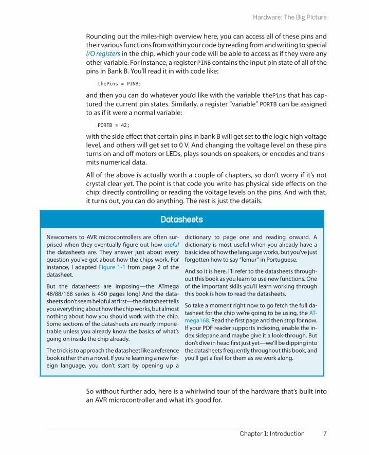
So a microcontroller is a self-contained, but very limited computer—halfway be-tween a computer and a component. I’ve been talking a lot about the computerside. What about the AVR chips as components? Where can you hook stuff up? Andhow exactly do they do all that they do? Figure 1-1 lays out all of the chip’s pinsalong with the mnemonics that describe their main functions.
If you’re coming at this from no background, you’re probably wondering how amicrocontroller does all this marvellous stuff. The short answer is by reading vol-tages applied to its various pins or by setting up output voltages to these very samepins. Blinking an LED is an obvious example—when the output voltage is high, theLED lights up, and when the voltage is low, it doesn’t. More complicated examplesinclude the serial ports that communicate numbers by encoding them in binary,with high voltage standing in for a 1 and low voltage standing in for a 0, andchanging the voltage on the pins over time to convey arbitrary messages.
5Chapter 1: Introduction
Hardware: The Big Picture

Figure 1-1. ATMega168 pins and their functions
Each pin on the AVR has a name, and you’ll see later on how you can refer to themall in code. So if I hook an LED up to pin number 14, I can then write a high voltageor low voltage out to that pin by referring to it as PB0. Most of the pins on the AVRalso have secondary functions, and these are listed as mnemonics in parentheses.For instance, RXD and TXD are the receive and transmit functions for the serial portfunctionality and live on pins PD0 and PD1, respectively. By the end of this book,you’ll know what all of the terms in parentheses mean and will have played aroundwith almost all of their special functionalities.
Internally, and somewhat according to function, the pins are arranged into banksof eight pins. I’ve color-coded the pins according to their banks. (I wish they wereall located in consecutive blocks, but there’s nothing you can do about that withoutbuilding your own circuit board.) Because each bank, for instance, “bank B,” has amaximum of eight pins in it, you can refer to them by an eight-bit binary numberto turn on or off their voltage source. You’ll see a lot more of this in Chapter 3 andonward.
6 Make: AVR Programming
Hardware: The Big Picture
Datasheets
Newcomers to AVR microcontrollers are often sur-prised when they eventually figure out how usefulthe datasheets are. They answer just about everyquestion you’ve got about how the chips work. Forinstance, I adapted Figure 1-1 from page 2 of thedatasheet.
But the datasheets are imposing—the ATmega48/88/168 series is 450 pages long! And the data-sheets don’t seem helpful at first—the datasheet tellsyou everything about how the chip works, but almostnothing about how you should work with the chip.Some sections of the datasheets are nearly impene-trable unless you already know the basics of what’sgoing on inside the chip already.
The trick is to approach the datasheet like a referencebook rather than a novel. If you’re learning a new for-eign language, you don’t start by opening up a
dictionary to page one and reading onward. Adictionary is most useful when you already have abasic idea of how the language works, but you’ve justforgotten how to say “lemur” in Portuguese.
And so it is here. I’ll refer to the datasheets through-out this book as you learn to use new functions. Oneof the important skills you’ll learn working throughthis book is how to read the datasheets.
So take a moment right now to go fetch the full da-tasheet for the chip we’re going to be using, the AT-mega168. Read the first page and then stop for now.If your PDF reader supports indexing, enable the in-dex sidepane and maybe give it a look-through. Butdon’t dive in head first just yet—we’ll be dipping intothe datasheets frequently throughout this book, andyou’ll get a feel for them as we work along.
Rounding out the miles-high overview here, you can access all of these pins andtheir various functions from within your code by reading from and writing to specialI/O registers in the chip, which your code will be able to access as if they were anyother variable. For instance, a register PINB contains the input pin state of all of thepins in Bank B. You’ll read it in with code like:
thePins = PINB;
and then you can do whatever you’d like with the variable thePins that has cap-tured the current pin states. Similarly, a register “variable” PORTB can be assignedto as if it were a normal variable:
PORTB = 42;
with the side effect that certain pins in bank B will get set to the logic high voltagelevel, and others will get set to 0 V. And changing the voltage level on these pinsturns on and off motors or LEDs, plays sounds on speakers, or encodes and trans-mits numerical data.
All of the above is actually worth a couple of chapters, so don’t worry if it’s notcrystal clear yet. The point is that code you write has physical side effects on thechip: directly controlling or reading the voltage levels on the pins. And with that,it turns out, you can do anything. The rest is just the details.
So without further ado, here is a whirlwind tour of the hardware that’s built intoan AVR microcontroller and what it’s good for.
7Chapter 1: Introduction
Hardware: The Big Picture

The Core: Processor, Memory, and I/OCPU
The central processing unit (CPU) of the AVR is basically very similar to that inyour laptop or desktop computer. It is a bit of electronic circuitry that has abunch of predefined logical and mathematical operations built in, and knowswhere to find a list of these operations to follow (your program) and where toget the data it needs to execute them.
MemoryAVR microcontrollers have no fewer than three different memory types, eachwith different uses.
1. Flash. Your compiled program code gets stored in nonvolatile flash mem-ory. It doesn’t disappear when the chip loses power. In fact, it’s guaranteedto only lose 1 bit per million after 100 years at room temperature. We’lldiscuss uploading your code to flash memory in Chapter 2.
2. RAM. Naturally, there is some memory for storing temporary variableswhile doing calculations and so forth.
3. EEPROM. EEPROM is slow to write to, and there’s not much of it, but likeflash program memory, it stays around when the power goes out. We’lltalk about using EEPROM in Chapter 19.
ClocksAll computers need a sense of time. In the AVR chips, there are multiple clocksthat are all derived from the same common timebase but often divided downthrough their own individual prescalers. We’ll use the internal RC oscillator asthe master clock source. It runs at around 8 MHz. The CPU clock is then divideddown from the master clock, and runs at 1 MHz by default, but sometimeswhen we need the extra speed, we’ll bump it up to the full 8 MHz.
Following the CPU clock come all the other peripheral clocks, most of whichhave their own prescalers relative to the CPU. There are clocks for the I/O sub-system, the analog-to-digital converter, RAM, and Flash and EEPROM. Whenyou’re using any of the peripheral subsystems, remember the clock prescalers—you’ll often have to set their values. These multiple clocks derived from thesame source keep everything running on schedule together.
OutputsAlmost all of the pins on the AVR chips can be configured so that they’re usableas digital outputs, meaning that the pin can be commanded in software tooutput either the supply voltage level or the ground voltage level. (Call thesevoltage levels VCC and GND, or ground.) Any way you slice it, digital output isthe heart and soul of microcontroller programming. It’s how you “speak” tothe outside world. We’ll go into digital output in great depth in Chapter 3.
8 Make: AVR Programming
Hardware: The Big Picture

“Analog” Outputs
If you’ve used the Arduino platform, you might think of some of the outputs as “analog”outputs, but there aren’t really any truly analog outputs on the AVR series micros. What theArduino code is doing behind the scenes is switching the pin state very rapidly between thehigh and low voltages so that the average voltage is somewhere in the middle. This is calledpulse-width modulation, and we’ll cover it in detail in Chapter 10.
InputsJust as almost all the pins can be set up as outputs, they can also be configuredas digital inputs, where they detect if the voltage applied to the pin externallyis high or low. Specifically, if the voltage on the pin is greater than half of thesupply voltage, the chip sets a bit in an internal variable to one. If the voltageis lower than the threshold, that same bit reads as zero.
Hook up a button to the supply voltage through a resistor on one side, andconnect this junction to one of the AVR’s pins that’s configured for input. Con-nect the other side of the button to ground. When the button isn’t pressed,the AVR will read the VCC voltage, but when you do press the button the AVR’sinput pin will be grounded. Thus, by reading in the voltage on the pin, the AVRis able to detect whether or not you’ve pressed the button.
Physical states are turned into voltage levels, which are in turn converted tologic values inside the chip.
You’ll see a lot more about digital inputs and pushbuttons in Chapter 6.
So far, I’ve described a tiny computer that can run programs that read and writevalues out to pins in the form of digital logic voltages. That’s essentially all there isto it—with this framework you can implement nearly anything. And a broad rangeof very useful microcontroller applications can be built with just this ability.
The rest of the microcontroller’s hardware is dedicated to making your life as aprogrammer easier and to making many common tasks more reliable.
Peripherals: Making Your Life EasierSerial communications
One of my favorite uses of microcontrollers is as the connector between a realcomputer and interesting hardware. Say you want to strap accelerometers toyour body, dance around like it’s 1999, and pass this data off to your laptop,which renders a 3D figure of you in real time. The job of the microcontrollerhere is simple: talk to the accelerometers, do a little math and light up someLEDs perhaps, and send all of the data to your laptop. But what language dothe accelerometers speak? How about your desktop?
9Chapter 1: Introduction
Hardware: The Big Picture

The AVR has three serial communications peripherals built in. Plain-vanillaUSART serial described in Chapter 5 is useful for communicating with yourdesktop computer, radio modems, and GPS units. SPI (Chapter 16) is good forultra-fast communication over very short distances with peripherals like mem-ories, ADCs, and DACs. I2C (Chapter 17) is like a small network, allowing you toconnect up to 127 different sensors to the same couple of wires. Devices thatmove around a moderate amount of data tend to use I2C. That’s a good choicefor the network of accelerometers.
Because each of these serial hardware peripherals is separate inside the AVR,you can use each of these at the same time. Your AVR can communicate withvirtually anything.
Analog to digital converterA number of the useful sensors that you’d like to connect to your projects don’tspeak the microcontroller’s native digital language; rather, they speak in termsof continuous analog voltages. To read in these values and manipulate themlike you’ll manipulate any other digital data, you’ll need to run them throughan analog to digital converter (ADC). In Chapter 7, you’ll make good use of theADCs in building a light sensor and variable-threshold night light. In Chap-ter 12 I’ll go over some more advanced ADC applications, including buildinga vibration sensor that can detect footsteps indoors, and introduce you tooversampling and exponential smoothing—two techniques that can get youmore precision or remove noise from your ADC readings.
InterruptsYou’d like your program to be able to react to the outside world: you press abutton, you’d like something to happen. Heck, that’s half of the fun of writingcode for a microcontroller. Or maybe you’d like your program to do somethingevery so often, as the examples using timers/counters make clear. Hardware-level interrupts are just the ticket.
An interrupt service routine is a software function that you can write that auto-matically executes whenever an interrupt condition is met. They’re called in-terrupt routines because the processor stops whatever it was doing in the mainflow of your program and runs the appropriate function. After it’s done withthe interrupt routine, the processor picks up your program’s normal operationwhere it left off.
There are many ways to trigger interrupts in the AVR microcontroller. Theseinterrupt conditions include a press on the reset button, a changing inputvalue, an internal clock tick, a counter value being reached, data coming in onthe serial port, an analog-to-digital conversion finishing, or many others. Thepoint here is that there are loads of interrupt conditions and they each cantrigger their own function calls.
10 Make: AVR Programming
Hardware: The Big Picture

Interrupts and interrupt service routines are fundamental to advanced AVRprogramming, and along with timers form most of the content of Part II.
Timers/countersThe AVR microprocessors have built-in hardware counters. The counters arebasically what they sound like—they keep a running count of how many timesa pin or internal source has changed its voltage level.
The simplest counter application is hooking up the internal counter to a but-ton. Now whenever your program wants, you can tell how many times thatbutton’s been pushed by just reading the counter’s register. (You can write tothe counter as well, so you can reset it to zero at the beginning of any day, forinstance.)
Counters really come into their own when paired up with clocks, and this iswhy they’re often referred to as timer/counters. With a clock and a timer, youcan measure either how long some event takes, or figure out the event’s fre-quency. You’ll even be able to output to certain AVR pins (OCRxn in the pinoutdiagram) and fire off special subroutines periodically. The timer/counter pe-ripherals are tremendously configurable and turn out to provide more func-tionality than you would have thought. Which is great, because there are threeof them.
You’ll see a lot more applications of the timer/counters throughout Part II.
11Chapter 1: Introduction
Hardware: The Big Picture

The AVR Family of Microcontrollers
Although we’ve settled on the AVR ATmega168 forthe purposes of this book, you might want to tailorthe chip to your specific project later on. There aremany, many AVR microcontroller chips to choosefrom, each with different capabilities at differentprice points. Finding the one that’s right for yourproject can be intimidating. You can spend hourschoosing the chip that has the peripherals you needand enough memory to fit your code, and then lo-cating the least expensive part.
If you’re just working on a prototype and you want toget something working as fast as you can, you prob-ably shouldn’t worry about spending an extra 50cents per chip. You’re better served by having a fewchip types on hand, and just picking the best fit fromwhat you’ve got. Here’s my current working set:
Small: ATtiny45The x5 series chips are small and cheap, great forwhen you only need five I/O pins. They also havea high-speed peripheral clock that can run up to66 MHz, which makes them uniquely great forPWM applications, and for use in conjunctionwith the V-USB firmware USB library to buildyour own USB peripheral devices.
The only differences between the 25, 45, and 85are the amount of program memory (2 kB, 4 kB,and 8 kB) and the price, so there’s a trade-off. Forme, 4 kB of memory is the sweet spot.
ATtiny45s cost around $1 singly or $0.65 in bulkas of this writing.
Medium: ATtiny 44An attractive step up from the 45 when you don’tneed the high-speed PWM of the Tiny45. For justa few cents more, you get 11 I/O pins and a 16-bit timer. Even though they’re relatively new onthe market, these chips are becoming my go-tofor small projects as well.
ATtiny44s cost around $1.15 singly or $0.75 inbulk as of this writing.
Large: ATmega xx8 FamilyNow we’re talking—the Mega xx8 chips are de-luxe! If you’re going to focus on one chip series,this is the one. At this level, you get 20 I/O pins,
hardware USART, three timers, and a whopping16 kB of program memory. There’s a reason thewildly popular Arduino platform is based onMega 168s and 328s.
And because the Mega 48, 88, 168, and 328 allhave the same features outside of programmemory, it’s often possible to just swap out achip and save a few dollars on a project. TheMega48s give you the same functionality for halfthe price of the mega168s that we’re using whenyou don’t need the extra memory.
ATmega168s cost around $2.25 singly or $1.50in bulk as of this writing.
Now, there are lots of other options besides the chipfamily and member. Searching for “mega168” at anelectronics house yields over 50 results:ATmega168PA-10PU, ATmega168-AU, and so on.
The letters after the part number (168P or 168PA or168A) represent different versions of the chips. The“V” variants are guaranteed to run at lower voltages,but are only guaranteed to run at reduced speed. The“P” and “V” series are an older design. The “A” and “PA”variants represent newer designs that use less power(P) or run full-range across speed and voltages (A) orboth.
The extensions represent the package size and willoften be described in words. PU (PDIP) is the largest,and is the through-hole standard part. AU (TQFP) is1.0 mm spacing surface-mount and is entirely doableif you’re comfortable with SMT. The MU packages arevery difficult to solder by hand.
The number in the extension is a speed grade, andchips that end in 10, for instance, are only guaranteedto run up to 10 MHz. When there is no numeric ex-tension (as with the modern chips), the chip runs atfull rated speed, which is usually 20 MHz at 5 V.
So which variant, in which package? P, A, or PA aresafe bets, and I’m basically indifferent among them.The P variants seem to be cheapest at the moment.For packages, pick PU (PDIP) if you’ve got little or noexperience soldering, and AU (TQFP) if you enjoysurface-mount work.

Hello World!
In this chapter, you’ll get set up with everything you need for coding, compiling,and flashing your programs into the bare silicon of the AVR chips that are sittingon your desk right now. To do so, you’re going to need some hardware (a flashprogrammer) and some software (a code editor, C compiler, and the program that’llcommunicate with the hardware flash programmer). Finally, you’ll need to hookup some wires from the programmer to the AVR chip and get set up with a powersupply.
In this process, there are a lot of different approaches that will get you to the topof the same mountain. Ultimately, the different approaches are all basically thesame at some abstract level, but we’ll step through some details of a few of themost popular options to make things clearer.
On the hardware side, most of the flash programmers work about the same, andthe differences there won’t amount to much more than a few tweaks to a file thatyou’ll use over and over again. Flash programmers, after all, are just USB devicesthat send bytes of your code across to the AVR chip. On the software side, differentdevelopment packages will have different looks and feels, but in the end it all comesdown to editing code, compiling it, and then sending it off to the hardwareprogrammer.
Programming the AVR
The words “program,” “programmer,” and “programming” are overloaded in themicrocontroller world. We (as programmers) write programs, compile them, andthen use a flash programmer to program the AVRs, which then runs our program.Pshwew! Let’s step through the actual procedure and see what’s actually going on.
13
Programming AVRs 2

What You Need
For this chapter, you’ll just need the basic kit as de-scribed in “The Basic Kit” on page xiv. For conve-nience, I’ve summarized that here:
• A solderless breadboard.
• Wire jumpers to plug in to the breadboard.
• An ISP programmer.
• An ATmega168, 168A, 168P, or 168PA.
• An LED (any color) and an appropriately sizedresistor: 200–500 ohms.
• A source of 5 V DC power (if not supplied byyour ISP); a 4xAA battery pack is nice anyway.
• One 100 nF (0.1 μF) capacitor to smooth outthe AVR’s power supply.
ToolchainIt’s a long and winding road from the code you type into your editor to a chip onyour desk that turns a light on and off. Getting from typed letters on a computerscreen to a working piece of electronic machinery requires a chain of tools called,predictably, a toolchain!
Toolchain overview
1. Write your source code in an editor.
2. Turn your source code into machine code with a compiler (and associated soft-ware tools).
3. Using uploader software on your big computer and a hardware flash program-mer, send the machine code to your target AVR chip, which stores the instruc-tions in its nonvolatile flash memory.
4. As soon as the flash programmer is done, the AVR chip resets and starts runningyour code.
Figure 2-1 sketches out the main steps in AVR firmware development along withwhich tools you’ll use for each step.
The first step in your toolchain is going to be a text editor, or whatever you’re mostcomfortable writing code in. For the Linux folks out there, gedit is quite nice. OnWindows platforms, you’ll probably find the editor that comes with WinAVR, Pro-grammer’s Notepad, will work pretty well, but I prefer the freeware Notepad++.Many Mac coders swear by TextMate. If you’ve already got a favorite code editor,by all means feel free to use it. Nice features to look for include syntax highlighting,automatic formatting and indenting, parenthesis matching, and maybe even codefolding. (Put your copy of Microsoft Word away—that’s not what we’re looking forhere.)
14 Make: AVR Programming
Programming the AVR

Aside on Windows Editors
Both Programmer’s Notepad and Notepad++ let youcompile and flash code directly from the editor witha single button push, which is handy because theWindows command line isn’t very familiar to mostfolks.
In Programmer’s Notepad, there are options for callingyour makefile in the Tools pull-down menu, and you’llsee the results of your compilation and uploading inthe “Output” panel at the bottom of the screen.
In Notepad++, use the Run pull-down menu, and typein cmd /K cd /d $(CURRENT_DIRECTORY) &&
make flash to open up a command window in thecurrent directory, compile your code, and flash it tothe AVR. The /K leaves the window open after it’sdone, so you can read any errors in compiling or up-loading that may have occurred. You can also run itwith /C if you don’t want to see the output.
With both of these editors, you can also bind theseactions to a key combination so that compiling anduploading your code is as easy as it would be in anIDE. Pretty slick.
Figure 2-1. AVR programming toolchain
Anyway, once you can write and edit code, you need to compile it for the AVR,turning your human-readable C code into machine code for the AVR. The compilerwe’re using, avr-gcc, is the AVR-specific version of the popular open source com-piler GCC. (In fact, I would argue that the support from Atmel for avr-gcc and anopen source toolchain is the main reason for the chip’s amazing success in thehacker community.)
In addition to the compiler, you’ll need a few more software tools from the avr-gcc suite to go from source code to machine code that’s ready for uploading. Ascript called a makefile is commonly used to automate all of the repetitive, inter-mediate bits of the process. See “Make and Makefiles” on page 20 if you want tolearn a little more about what’s going on with the makefiles, but don’t sweat it if
15Chapter 2: Programming AVRs
Programming the AVR

it’s too much info—you can do everything you need to by simply editing a fewlines, and I’ll walk you through that.
Once you’ve compiled your C code into machine code in the right format, it’s timeto send the machine code over to the chip and write it into nonvolatile flash mem-ory. The flash programmer is a piece of hardware that sits in between your computerand the target AVR microcontroller. The AVR microcontrollers, when put into pro-gramming mode, listen over their serial peripheral interface (SPI) bus for incomingdata to flash into program memory. The flash programmer’s job is to relay thecompiled machine code to the target AVR over the SPI bus. There are tons of flashprogrammers available, and I’ve listed some of my favorites in “Flash ProgrammersI Have Known and Loved” on page 29.
A lot of you will have an Arduino sitting around. If so, it turns out to be fantasticallyeasy to turn that Arduino (temporarily) into an AVR programmer. I’ll walk youthrough the steps to do so, and how to wire it up, in “AVR and the Arduino” on page21. So if you don’t have a dedicated hardware SPI programmer just yet, I’ll get youup and running with an Arduino.
Now, stepping back to your main computer, you’ll need to run software that feedsthe compiled machine code to the flash programmer. Far and away the most pop-ular software uploader is AVRDUDE, which is available for all platforms and sup-ports a wide variety of programmers. How wide? So wide that almost any way thatyou can think of communicating in SPI with the target AVR will work with AVRDUDE,from a few wires hooked up to your parallel port to dedicated USB programmerswith their own AVR microcontroller brains.
The Software Toolchain
The main feature of the style of software development that we’ll use in this bookis cross-platform compatibility. That is, if you’re used to the whole workflow ofwriting code and compiling it on a Mac, you’ll have the same tools available for youon Windows or Linux, and you can be sure that you’ll always know what you’redoing wherever you go. After all, the target of all our work here is a little 8-bitmicrocontroller that doesn’t know anything about what operating system you use.
16 Make: AVR Programming
The Software Toolchain

To Recap:
1. Plan. This stage just requires your brain, somepaper and a pencil, and maybe the AVR data-sheet so you can figure out which parts theonboard hardware can help you with. Thinkthrough what you need the chip to do, andbreak it up into functions for each logical step.
2. Code. Write your program using whatevertext/code editor makes you happy. Hereyou’re just translating the ideas behind thefunctions into valid C code.
3. Compile. Turn your C code into AVR machinecode with avr-gcc and its associated tools,most likely run from a makefile. Type make andread through the compiler errors, then goback and fix them.
4. Flash. Hook up a flash programmer to yourtarget AVR and then run AVRDUDE to send themachine code through the programmer to
the AVR chip, which saves it in flash memory.(Or just type make flash and watch it go.)Did flashing work?
5. Test. Once you’ve uploaded your code to theAVR, does it do what you want it to? Test itunder many differing conditions beforeyou’re sure. You’ll find all sorts of interestingreal-world situations where your sensorsaren’t reporting data as you thought theywould. Now’s a good time to find that out, soyou can recode around it.
6. Debug. There are many tricks for figuring outwhat’s going wrong with your code—fromlighting up status LEDs, to transferring vari-able data information over the serial line toyour desktop computer, to stepping throughthe code with a debugger.
Programming the AVR—What’s Really Going On?
AVR microcontrollers are able to write into their ownflash program memory space. All of the ATmega ser-ies microcontrollers are set up so that when you resetthem, they start listening for data on the SPI lines, andwith the right instructions can program themselves.
A flash programmer works by grounding the RESETline, which halts the CPU and signals the AVR to startlistening on the SPI bus. The programmer then trans-mits programming instructions over the SPI bus. Af-ter each instruction or section of code, the AVR writesthe received data to flash memory. Some of the tinyAVR chips flash the data to program memory afterevery few bytes, which can be slow. Larger and newer
chips store the incoming data in a temporary pagememory and then write it all at once, which is much,much faster.
After the programming is complete, you can read thedata back out of the AVR’s flash program memory toverify again that its correct. The -v flag for AVRDUDEdoes this for you.
For a deep read on programming the AVR chips, forinstance, if you want to implement your own flashprogrammer or write your own bootloader onceyou’re done working through this book, see Atmel’s“Application Note AVR910”.
17Chapter 2: Programming AVRs
Programming the AVR

Linux SetupSetting up the toolchain for programming AVRs on Linux is tremendously simple.If you’re using a Debian-based distribution (like Ubuntu or Mint or, heck, Debian)you can simply type (all on one line):
sudo apt-get install avrdude avrdude-doc binutils-avr avr-libc gcc-avr
gdb-avr
Red Hat and Fedora users type:
sudo yum install avrdude avr-gcc avr-binutils avr-libc avr-gdb
All other Linux users will find that it’s easy enough to find source packages for allof the above. See http://www.nongnu.org/avr-libc/user-manual/install_tools.htmlor http://avr-eclipse.sourceforge.net/wiki/index.php/The_AVR_GCC_Toolchain fordetails.
Windows SetupWindows users have three options for the software toolchain, and each has itsquirks. The first is to download Atmel’s official Atmel Studio. The downside is thatit’s absolutely huge and requires its own learning curve just to get familiar with theIDE. On the other hand, it’s the de facto standard for programming Atmel’s line ofchips, and there’s plenty of documentation out there to help you learn to use it.
If you use Atmel Studio you’ll need to set a couple of “symbols” in the project prop-erties to make up for macro variables otherwise defined in the project’s makefile.In particular, you need to define the AVR’s processor speed and baud rate (for serial
communications) in two symbols F_CPU and BAUD. This will make sense once you’re used tothe Studio environment. Similarly, if you use someone else’s software, you’ll need to add asymbol for every macro variable defined in their project’s makefile.
Support for non-Atmel hardware programmers has also been variable, and the utility that’sincluded in Studio isn’t nearly as flexible as the open-source AVRDUDE program that I rec-ommend. (For instance, if you’d like to program an Arduino using the Arduino bootloader,you’ll need AVRDUDE.) To use AVRDUDE with Studio, you can create an “External Tool” com-mand that calls AVRDUDE with the correct options for your programmer and chip. See http://waihung.net/programming-arduino-using-atmel-studio-6/ for an example setup.
Another option for the software toolchain in Windows is to download WinAVR. Theproject was frozen in 2010, but it’s still available and works well, for the most part.You can download WinAVR from SourceForge. The good news is that WinAVRcomes with everything you’d need to get going, including a decent code editorand AVRDUDE.
18 Make: AVR Programming
The Software Toolchain

The gotcha with WinAVR is that it’s old and this causes trouble when you’re pro-gramming a chip that didn’t exist when WinAVR was last updated. The solution isto copy a recent configuration file for AVRDUDE (avrdude.conf) into your installa-
tion. I’ve included one in the software bundle for the book, so all you need to do is copy thefile into C:\WinAVR-20100110\bin and you should be set.
During the installation, WinAVR will offer to change your PATH variable so that allof the binary files (importantly make, avrdude, and avr-gcc) are available withouttyping the full pathnames in. Be sure that you allow this.
The third option is the one that I’d recommend most these days. Even though it’sa little bit of hassle, it’s the most powerful and flexible.
In addition to the full-blown IDE, Atmel also makes the AVR cross-compiler availableseparately here: AVR Toolchain for Windows. It’s compact, up-to-date, and prettymuch bulletproof. The caveat here is that you’ll need to flesh out the rest of thetoolchain yourself, notably AVRDUDE and the make program that tells the compilerhow to put all the pieces together. But to make your life easy, I’ve included themin the book’s software bundle in a folder called avrdude_utilities.
If you download Atmel’s compiler and the additional tools, you’ll need to put thefolders somewhere and then make sure that your OS knows where to find theprograms. Easiest is to move both folders into your Program Files directory and
then hand-edit your PATH environment variable to point to them. To set an environmentvariable, open the Control Panel, search for “Environment”, and choose “Edit environmentvariables for your account”. Edit the PATH variable, and taking care to not modify any existingvalues, append a ; to the end of the path, followed by the full path to the bin and avrdude-utilities directories (separated by a ;), which should be something like C:\Program Files\avr-8-gnu-toolchain\bin` and `C:\Program Files\avrdude-utilities.
If you go either of the two non-IDE ways, you’ll need an external editor (“Aside onWindows Editors” on page 15), and you might be interested in the following short-cut. Assuming you’ve downloaded the project code from the website, open upyour code editor and save something like the following to a file called somethinglike blinkLED.bat (you’ll need to change C:\Users\elliot\ to wherever you’ve extrac-ted the sample code directory).
cd C:\Users\elliot\AVR-Programming-master\Chapter02_Programming-AVRs\blinkLEDmake flashcmd
When you double-click on this batch file, it will open up a command window,change to the appropriate directory, compile and flash the code to your target AVR,
19Chapter 2: Programming AVRs
The Software Toolchain

and then leave the command window open so that you can look out for errors inthe process or issue other make commands quickly and easily. You can edit it topoint to whatever code you’re working on and then compiling and flashing AVRcode is just a click away.
Mac SetupAVR CrossPack is the way to go for Mac. It includes all the compile tools, AVRDUDE,and more. It’s kept up to date and should just work.
Arduino SetupAs a fourth option, the Arduino IDE is available for all three OS platforms. Heck,most of you will have it installed already. If you’ve got Arduino up and running,there are some modifications you can make to turn your Arduino IDE into a workinggeneric AVR C-language environment. See “AVR and the Arduino” on page 21 and,in particular, “Writing C in the Arduino IDE” on page 25 for details.
If you’d like to use your Arduino as a hardware flash programmer, but don’t plan touse the Arduino IDE, you can do that too. In addition to the Arduino install, installthe software toolchain for your OS.
Make and MakefilesThe C programming language lets you split up one big program or task into a bunchof individual functions, and lets you keep collections of functions together in theirown files for easier maintenance and portability. That way, if you want to frequentlyreuse some serial-port input/output functions, for instance, all you have to do isinclude the serial library code files (by name) in your main code, and then tell thecompiler where to find these files. Separating your code into functionally differentfiles is good software design, but it means that you need to remember all of thedependencies among the different files in your codebase and type out potentiallymany filenames each time you compile.
Keeping track of all of these dependencies manually can quickly become unrea-sonable, and it was only a few years after C was invented that the make utility wasdesigned to help. Instead of compiling your files together manually, a file called amakefile contains a bunch of dependency rules and instructions for processingthem, and then you just run the make command and everything compiles. (That’sthe idea, anyway.)
So, for instance, you can explicitly compile all of your source files together like this:
gcc main.c another_file.c serialLibrary.c -o main
which makes an executable file, main, from all of the listed .c files. Or, you can writea makefile that maps out these dependencies:
main: main.c another_file.c serialLibrary.c
20 Make: AVR Programming
The Software Toolchain

and then simply type make main or even simpler, make. The make program knowsthat names on the left side of the “:” are targets, and on the right, their dependen-cies. If you need to run special commands to make the targets from their depen-dencies, these commands are listed on the next line, indented with a tab.
Dependencies can, in turn, have other dependencies, and make will keep diggingdeeper until it can resolve them. Things get complicated with makefiles when youadd in variables and wildcards that match any filenames. You can start to writegeneric rules that compile any .c files together, for example, and then you only haveto change the variable definitions when you move a makefile from project toproject.
I’m including a preconfigured makefile for each project in this book’s code repos-itory. You may be able to use them as is, but we also might have different AVRprogrammers and different serial ports, so you’ll eventually want to at least modifysome of the definitions. We’ll step through configuring the makefile to fit yoursetup in “Configuring Your Makefile” on page 39.
Now that you’ve got the software set up, all you need is to connect up a flashprogrammer to the chip and test it out. Here, you’ll have two choices. If you don’thave a dedicated AVR flash programmer yet, but you have an Arduino lying around,the next chapter is for you. If you’d like to buy a dedicated AVR flash programmer,I have some advice in “Other Hardware Programmers” on page 29. Otherwise, ifyou’ve already got a flash programmer, you may proceed straight to “Getting Start-ed: Blinking LEDs” on page 30 and get started.
AVR and the Arduino
A bunch of you are going to be used to the Arduino programming environment.That’s great! In this book, I’ll be teaching you all of the powerful nitty-gritty thatArduino hides from you in the name of easy accessibility. But that doesn’t meanthat there’s any reason to let your Arduino gather dust—in fact, the Arduino plat-form can be a great generic AVR playground, once you know how to (ab)use it.
Arduino ProsOne very real advantage of the Arduino hardware setup is that the chip comes pre-flashed with a bootloader, which is code that enables the chip to communicatewith your computer over the serial line in order to flash program itself. This meansthat you can do away with the requirement for an external bit of hardware to flashthe chip—there’s a tiny bit of bootloader code already running in your Arduinothat’ll flash the chip for you!
The second highlight of the Arduino package is that it comes with a built-in USB-to-serial converter, so you don’t have to buy a separate one just yet. I personallyget a lot of mileage out of my USB-Serial cable, and you will too if you want to playaround with freestanding microcontrollers, GPS units, old terminals, hacked WiFi
21Chapter 2: Programming AVRs
AVR and the Arduino
routers, and other devices. If you’re going to get serious about embedded elec-tronics hacking, you’re going to want a standalone USB-Serial adapter eventually,but it’s sweet that the Arduino lets you get away without buying one for the timebeing.
And finally, although it’s not such a big deal, the Arduino is powered by your com-puter’s USB power supply. This is handy if you’re developing code on your laptopin a park or on a plane. You don’t need to find a wall plug for your power adapteror remember to bring batteries along with you—all you need for flashing, com-munications, and power is a USB cable.
Arduino ConsAs good as the Arduino hardware is as a generic AVR development platform, it’snot perfect. For use with this book and our examples, there are a number of dis-advantages to using an Arduino instead of just plugging an AVR chip into abreadboard.
Probably the first among these disadvantages is the lack of the breadboard itself.Shields are great for finished products, but when I’m building up a hardware sectionfor the first time, it’s nice to test it out on something more flexible like a breadboard.I find that the more complicated my external circuitry gets, the less suitable work-ing on the Arduino becomes. The Arduino is great for plugging a few LEDs or acouple of sensors into. But when things get interesting, I end up having to jumperthe Arduino into the breadboard with 10 or more wires like some demented spider,and then my dog knocks something loose, and it takes a long while to debug theproblem, and that’s when I wish I’d just stuck a chip into the breadboard in the firstplace. (True story.)
Another downside to using an Arduino as an AVR development platform is that afew ports and pins are already irreversibly wired up and unavailable for use. Forinstance, when we make an eight-LED POV toy in Chapter 3, you’ll discover thattwo of the pins that I’d like to use for LEDs are already hard-wired up to the crystaloscillator. It’s a design trade-off—because it’s clocked with a 16 MHz crystal oscil-lator, the Arduino is able to run twice as fast as an AVR using only its internaltimebase.
But because the Arduino ties up two of the pins in PORTB, you’ll only be able tomake a six-LED cylon without having to do some elaborate coding as a workaround.If you want to display a byte’s worth of data on PORTB, you’ll be missing the mostsignificant two bits.
Arduino boards aren’t cheap either; just compare an Arduino Uno with the AVRATmega328p chip that powers it. You can buy 8 or 10 AVRs (or 20 ATtiny 45s) forthe price of one Arduino. This is because the Arduino has extra hardware—powerregulation, USB-to-serial, and other circuitry onboard—which makes them over-qualified for many trivial applications. This also makes an Arduino too expensive
22 Make: AVR Programming
AVR and the Arduino

to commit to a one-off quickie project, and that’s a real shame because nothing inthe world is better than giving your young niece a goofy microcontroller-basedtoy that you made for around $5 in parts. (That said, if you can prototype the toyfaster because everything’s wired up for you on the Arduino, go for it. A goal of thisbook is that you’ll be able to move fluently between the “Real AVR” world andArduino.)
More trivially, it’s a minor pain to be always going back and forth between the pinnames in the datasheet (”PB5" and similar) and the Arduino’s pin names (“Digital13” and so on). Figure 2-2, which is similar to the sweet ASCII art in arduino-1.0.4/hardware/arduino/variants/standard/pins_arduino.h, should help.
Figure 2-2. AVR pinout and Arduino labels
So if you’re working along with code from this book, and you need an LED con-nected to pin PB0, for instance, you’ll want to hook up the same LED to your Ardu-ino’s Digital 8 pin. (And see how the Arduino doesn’t use pins PB6 and PB7?)
23Chapter 2: Programming AVRs
AVR and the Arduino

Choices, Choices!
From my perspective as an experienced coder andmicrocontroller user, I like to use my own favorite de-velopment tools rather than the Arduino IDE. It’s alsoa lot easier and faster to prototype circuits with a bareAVR on a breadboard than using the Arduinohardware.
However, using the Arduino as a hardware program-mer is tremendously comfortable, even if you’re usedto more advanced tools. With just six wires betweenthe Arduino and your breadboard, you’ve got a
source of power and a flash programmer that’s justas good as any other.
If you’re willing to learn a bit more about the non-Arduino toolchain—programming in standard C, us-ing makefiles, and all that—you’ll be learning sometransferrable skills that will work on other hardwareplatforms and microprocessor architectures. Andthen if you eventually swap out the Arduino-as-programmer for dedicated hardware, you won’t evennotice.
But don’t let these gripes overshadow the main point—an Arduino can also beturned into a fine C-language AVR-programming platform. And besides, if you’vegot one sitting on your desk, you might as well use it.
The Arduino: Hardware or Software? Both!In the next two sections, I’ll show you how to use the Arduino—both the softwareIDE and the physical hardware—as an AVR learning platform. The first section cov-ers programming the AVR chip that’s inside the Arduino (as you normally would)but using standard C instead of the strange Arduino dialect. This way, if you’vealready got an Arduino in hand, but AVR chips and a breadboard in the mail, youcan get started working through this book by programming the Arduino boarddirectly.
The second section treats the case where you’ve already got your AVR chip on abreadboard, and you want to use your Arduino as a hardware flash programmerto transfer the code to the target AVR. Following some simple steps, you can (tem-porarily and reversibly) use the Arduino as a hardware programmer to flash yourcode into the bare AVR. And then you can decide to continue using the ArduinoIDE to compile and send your code, or you can use any other code editor and thestandard AVR development toolchain. The choice is yours.
The Arduino Is an AVRIf you’re shy about leaving the comfortable Arduino IDE, you don’t have to. With afew tweaks, the Arduino compiler can be fooled into compiling standard C code,which you can then flash directly to the AVR that lives inside the Arduino hardware.So if you’re coming from the Arduino world and you’d like to get started with thisbook right away—you can!
The reason that this all works is that the Arduino environment is really just a thinGUI layer that ties together the standard AVR toolchain—GCC as a compiler and
24 Make: AVR Programming
AVR and the Arduino
AVRDUDE to talk to the flash programmer. In short, you can start off with the fullArduino IDE and slowly migrate over to doing everything manually, or vice versa.
Writing C in the Arduino IDEIf you’re used to the Arduino IDE and don’t want to try out another code editor, forinstance, the following steps will enable you to compile and flash valid C code withminimal changes to your old workflow. Follow these steps whether you’re pro-gramming for the Arduino’s onboard AVR chip or for an external AVR target on abreadboard—anytime you want to write straight AVR C code within the Arduinoenvironment.
To get running in C with the Arduino IDE, there are two things that you’ll have todo only once, before you even start the IDE:
• Copy over whatever libraries you need to go with your code. In writing thecode for this book, I ended up using a few bits of common code in almost everyproject. It makes more sense to put all of these common files in one place. Touse this “library” of common code, create a directory in your libraries folder(~/sketchbook/libraries on Linux and Documents/Arduino/libraries on Win-dows) and copy your common code here. Now you’ll be able to use it withinany other program by simply by importing the library. So copy the AVR-Programming-Library folder out of the code directory and into your sketcheslibrary right now.
• If you’re going to be coding for an ATmega 328P, either in an Arduino (the Uno,for instance) or as a standalone chip, fix up your portpins.h file. See “portpins.hand the Arduino IDE” on page 26. If you’re going to use an ATmega168 or otherchips, you don’t have to follow this step, but it won’t hurt.
Now that your Arduino IDE is set up, it’s time to get coding. In this example, I’llassume that you’d like to copy some code out of one of the book’s projects, butthe same basic steps apply for when you’re writing it yourself:
1. Start the Arduino IDE.
2. Import the header files into the project using the Sketch → Import Librarypulldown, where you should find the AVR-Programming-Library folder at thebottom of the list. Notice that the Arduino IDE adds include lines for eachheader file in your directory.
3. Save this (mostly blank) sketch with a descriptive name. This will create a di-rectory for you to put your code in.
4. Outside of Arduino, copy the C code file that you’d like to use into the sketchesdirectory. If you press Open and reopen the sketch, you should see this newlyadded code in a new tab.
25Chapter 2: Programming AVRs
AVR and the Arduino

portpins.h and the Arduino IDE
The code compiler that the Arduino IDE uses is thesame GCC as you’d use if you were compiling man-ually. As such, it doesn’t care if you pass it code writtenin C for the AVR, or in C++, using the Arduino libraries.Along the way, though, I found a gotcha.
For whatever reason, the portpins.h include file thatcomes with Arduino 1.0.4 and previous is old (2006!)and doesn’t conform to modern usage. The end resultis that standard pin-name macros like PB1 don’t endup getting defined for the mega328 chip, while theold-style PORTB1 macros are.
If you want to compile for an ATmega 328P chip (asis found on the Arduino Uno, for instance), you’ll wantto replace the portpins.h file with a more recent ver-sion. On my system, I found the file in arduino-1.0.4/hardware/tools/avr/lib/avr/include/avr/portpins.h.Replace this file with the version that I’ve includedwith the book’s code library, and you should be ableto just write C.
If you see errors like PB1 undeclared (first usein this function), that’s the portpins.h bug.
5. Alternatively, you can write new C code in the sketch by opening up a new tab(Ctrl-Shift-N, or from the arrow menu in the top-right corner) and then enteringthe code directly.
6. To make sure that all works, click on the Verify button. If it does, then you’reready to flash the code.
Flashing the Arduino as targetThis is super simple from within the Arduino IDE, because programming the Ar-duino is what it’s meant to do. The only difference here is that you’re writing yourcode in real, portable C rather than Arduinoese:
1. Verify that your board type is selected in Tools → Board.
2. Make sure you’ve included your library using Sketch → Import Libraries, andthat the #include lines appear in the first sketch tab.
3. Click Upload (or type Ctrl-U) to flash your code into the AVR inside the Arduinohardware. Easy.
The Arduino Is an AVR ProgrammerOr at least it can be. In this section, you’re not going to be writing your code intothe Arduino as a target, but rather using it as the middleman. You’ve got an AVRchip that you’ve stuck into a breadboard, and you’re going to use the Arduino asthe hardware programmer, thanks to example code that converts the Arduino intoan Arduino In-System Programmer (ISP). You can do this either from within theArduino software IDE, or you can use an editor and the avr-gcc toolchainindependently.
26 Make: AVR Programming
AVR and the Arduino

Wiring your Arduino as a flash programmerThe first step toward using your Arduino as a flash programmer is hooking it up toyour breadboard. The essential six connections are power, ground, RESET/PC6, SCK/PB5, MISO/PB4, and MOSI/PB3. (You’ll find these pin names in Figure 2-5 on page 2of the AVR datasheet, or you can also just refer to Figure 2-3.)
Figure 2-3. Arduino as flash programmer
The single red LED hooked up to pin PB0 on the target AVR is the LED in questionif you’re uploading this chapter’s blinkLED code.
The three (optional, colored) LEDs hooked up to the Arduino are status lights. Greenwill pulse while the ArduinoISP is waiting for input, yellow will light when it’s trans-ferring code to the AVR, and red will light if there’s an error. You can leave theseout, but they make everything look so professional, no?
Resistor values for the LEDs aren’t too critical, but something over 200 ohms is agood idea for normal LEDs, which commonly have around a 1.7 V threshold voltage,and are rated for around 20 milliamps: (5 V – 1.7 V) / 220 ohms = 15 milliamps.
Flashing AVR chips using the Arduino as a programmerNow that the hardware is wired up, let’s use it to program the AVR chip! Followingthese instructions will turn your Arduino into a flash programmer. (When you wantyour Arduino back as an Arduino, you can just reprogram it as usual.)
27Chapter 2: Programming AVRs
AVR and the Arduino

1. Verify that your Arduino board type is set up correctly (Tools → Board → Unoin my case).
2. Flash the example code “ArduinoISP” into the Arduino hardware the usual Ar-duino way.
3. If you don’t have a sketch ready to upload yet, go back to “Writing C in theArduino IDE” on page 25 and set up blinkLED.c.
4. Select Tools → Programmer → Arduino as ISP to program through the Arduinohardware instead of programming the Arduino itself.
5. Select Tools → Board → Arduino Pro Mini (8 MHz) w/ ATmega168, because we’retargeting an ATmega168 running at 8 MHz. (Nobody will know it’s not insidean Arduino Pro.)
6. Shift-click on the Upload button (Shift-Ctrl-U) to flash your code into the AVRtarget. If you’re too accustomed to just clicking the Upload button and forgetto press Shift here, you’ll get an error like avrdude: stk500_disable(): protocol error, expect=0x14, resp=0x10.
7. If you want to see what’s going on in the background, click File → Preferences→ Show verbose output.
8. Otherwise, sit back and watch your AVR target get programmed. Does it blink?Sweet!
Using Arduino as hardware programmer without the Arduino IDEBecause it’s possible to use your Arduino as a flash programmer from within theArduino IDE, you’re probably wondering if it’s possible to flash arbitrary AVR chipswithout using the Arduino IDE as well. Of course it is!
First, make sure that your Arduino is wired up as in Figure 2-3 and that you’veuploaded the ArduinoISP sketch to the Arduino. Once you’ve done that, you won’tneed to touch the Arduino IDE again if you don’t want to.
Open up the blinkLED directory from the software that accompanies this book.Because you’re using makefiles to configure and compile your code, you’re goingto need to edit Makefile by hand so that it knows how to use the Arduino pro-grammer. In short, you want to use programmer type “avrisp” at 19,200 baud onthe correct serial port.
For Linux, try:
PROGRAMMER_TYPE = avrispPROGRAMMER_ARGS = -b 19200 -P /dev/ttyACM0
For Windows, try:
PROGRAMMER_TYPE = avrispPROGRAMMER_ARGS = -b 19200 -P com5
28 Make: AVR Programming
AVR and the Arduino

For Macintosh using the Uno or Mega 2560, try:
PROGRAMMER_TYPE = avrispPROGRAMMER_ARGS = -b 19200 -P /dev/tty.usbmodemXXXXXXX
For Macintosh using any other Arduino, try:
PROGRAMMER_TYPE = avrispPROGRAMMER_ARGS = -b 19200 -P /dev/tty.usbserialXXXXXXX
You can figure out which port name the Arduino connects to from within the Ar-duino environment, under Tools → Serial Port. On Windows systems it will be a COMport, and on Linux or OSX systems it will be /dev/tty-something.
Once your makefile is configured for the Arduino-as-programmer, you’re all set toflash the code over to your chip. If you’ve got a terminal window open, and you’rein the blinkLED directory, typing make flash should do it.
Other Hardware Programmers
If you don’t have an Arduino handy, or if you’d like the convenience of a dedicatedhardware flash programmer, you’ve got a lot of good choices. If you’ve got thesoftware already set up, a flash programmer is your missing link. (If you already gotyour firmware flashed by following the previous Arduino instructions, you can skipthis section, or read on for curiosity’s sake.)
Flash Programmers I Have Known and LovedYou have a large number of choices for hardware flash programmers. A program-mer can be as simple as a handful of wires, but most of them actually use an AVRor other microcontroller to interface between your computer and the AVR thatyou’d like to program. Here is a shortened list of some of the good choices you haveavailable:
Parallel portThe first programmer I ever used was not really any programmer at all, butinstead just a cable with five wires soldered to a parallel port D-sub connector.This works because AVRDUDE knows how to toggle the lines of a parallel portto program your AVR chips directly. Unfortunately this programming methodrequires a parallel port on your computer, which is a luxury that fewer andfewer of us have. On the other hand, if you’d like to go this route, search theWeb for a DAPA (Direct AVR Parallel Access) cable. Many of the schematics willinclude “safety” resistors—feel free to ignore them unless you’re hooking upyour AVR to voltages higher than 15 V. If you’ve got an unused parallel printercable lying around, you’ve got your first programmer.
Atmel AVRISP mkIIAtmel’s current official USB in-system programmer, the AVRISP mkII is a verynice programmer that’s capable of programming the whole AVR line, including
29Chapter 2: Programming AVRs
Other Hardware Programmers

the newest XMega devices. It’s a bit more expensive than other programmers,but it’s rock solid and is quite a bargain all in all.
USBTiny and USBaspThese two USB-based AVR programmers have super simple hardware designswith open source firmware. You can make one yourself, although you will iron-ically have to find a way to flash the firmware into the AVR in the programmer(an Arduino ISP is perfect for this). You can also find these designs for sale allover—I’ve got a USBasp-based programmer that I bought for $5 online, andit’s just fine. Both of these designs have a jumper that allows you to power yourbreadboard off of your computer’s USB port, which is handy for most applica-tions in this book.
LadyAda’s USBTinyISPThis is an improved version of the USBTiny, with input and output buffering.I’ve used one of these for a few years. They come in kits, don’t cost too muchmoney, and have very good build instructions and support. Like the USBTinyproject that it’s based on, LadyAda’s programmer can power your project offthe USB bus. If you’d like an easy kit to solder together that builds a useful tool,this is a good way to go.
A family portrait of some of my programmers can be found in Figure 2-4, fromcenter-top and going clockwise:
1. An Arduino and six wires makes a totally workable flash programmer.
2. USBTinyISP
3. USBasp, from BaiTe in China
4. USBTiny, tiny version from ehajo.de
5. A homemade programming spider, which plugs into a breadboard around theAVR chip and connects up the programming, power, and reset pins the rightway every time. If you’re at all handy with a soldering iron and perfboard, youshould make one of these.
Getting Started: Blinking LEDs
OK, let’s get down to business and compile, flash, and test our first AVR microcon-troller project. This is not the coolest, most interesting project in this book. Thepoint is to verify that all parts of the programming toolchain are working for youbefore we start to get a little fancy. In order to minimize the possible ways to messup, we’ll build up the simplest possible project that puts the software toolchaintogether with the flash programmer, an AVR chip, and the most minimal possiblefeedback—a single LED.
30 Make: AVR Programming
Getting Started: Blinking LEDs

To download the code for this project—and for the rest of the book—visit https://github.com/hexagon5un/AVR-Programming and click the “Download ZIP” button.The blinking LED example is in this chapter’s folder.
Please double-check that you’ve installed an appropriate software toolchain foryour OS, or modified the Arduino environment to work with C language code. Ifyou’re using an Arduino as a hardware programmer, make sure that you’ve flashedArduinoISP. Fasten your seatbelts—here we go!
Figure 2-4. Some programmer options
HookupThe overview of wiring for this chapter is that we’re going to be hooking up theprogrammer (including its power-supply pins) to the AVR chip. Each of these pinshas a specific function, and they’re labelled in Figure 2-5. The whole point is tomake sure that the programmer’s MOSI pin is connected to the AVR’s MOSI pin (PB3)and so on. We’ll also wire up an LED for display purposes, and optionally wire upanother as a power-on indicator.
If you’re using an Arduino as your programmer, your wiring will end up looking likeFigure 2-3, but you can also assemble the circuit piecewise as we’re doing here.First hook up the power and verify that it’s working, and then move on to the MOSI,MISO, SCK, and RESET wires. The principle is exactly the same.
For the first step, let’s set up the power rails of your breadboard to double-checkthat we’ve got the pinout from the programmer’s connector right. You’re going to
31Chapter 2: Programming AVRs
Getting Started: Blinking LEDs

need some red wire for 5 V and some black wire for GND. If you’re using an Arduinoas programmer, the 5 V and GND connections are nicely labelled on the board. Usered and black wires to hook them up to the breadboard’s power rails.
Figure 2-5. AVR ISP programming pins
If you’re using a programmer that ends in a standard 6-pin or 10-pin two-row IDCconnector, getting the pinout correct can be a little bit tricky. For orientation, setthe connector on the table so that you’re looking down into the holes, and noticethe location of the plastic tab. The cable should also have a red stripe on the sameside that has the VCC pin, which is a very helpful mnemonic. Hook up the powerpins so that they look like Figure 2-6.
If you’re going to use a power-on LED, now’s the time to plug it into the board toverify that you’ve got power. Wire it up as in Figure 2-7. Note polarity matters withLED, and you’ll need to make sure that the positive side is connected to VCC andthe negative to ground. You can recognize the negative side of an LED by its shorterpin (think of it as the “minus” side having something subtracted from its length), orby the slight flat spot on the flange of round LEDs, or by the larger structure insidethe LED itself. Connect the resistor up to the negative pin.
Plug your USB programmer into your computer. If the LED glows, the power supplyis ready to go. If not, and you’re using a programmer like the USBTiny, you may haveto install a jumper across two pins to enable the power-supply passthrough. (Seethe instructions that came with your programmer for how to make the programmersupply power to the AVR.) If this still isn’t working, double-check your 6-pin con-nector again. Or maybe your programmer doesn’t supply power over the VCC and
32 Make: AVR Programming
Getting Started: Blinking LEDs
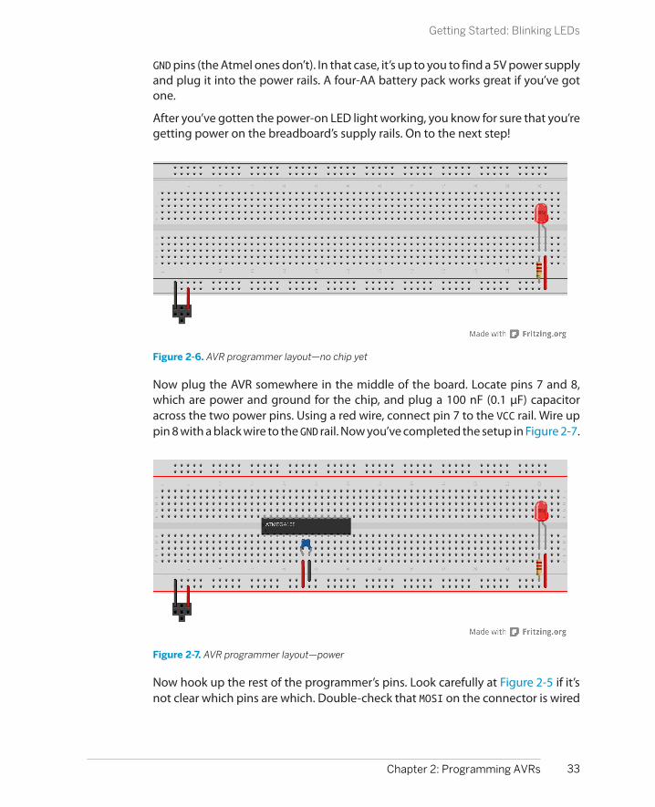
GND pins (the Atmel ones don’t). In that case, it’s up to you to find a 5V power supplyand plug it into the power rails. A four-AA battery pack works great if you’ve gotone.
After you’ve gotten the power-on LED light working, you know for sure that you’regetting power on the breadboard’s supply rails. On to the next step!
Figure 2-6. AVR programmer layout—no chip yet
Now plug the AVR somewhere in the middle of the board. Locate pins 7 and 8,which are power and ground for the chip, and plug a 100 nF (0.1 µF) capacitoracross the two power pins. Using a red wire, connect pin 7 to the VCC rail. Wire uppin 8 with a black wire to the GND rail. Now you’ve completed the setup in Figure 2-7.
Figure 2-7. AVR programmer layout—power
Now hook up the rest of the programmer’s pins. Look carefully at Figure 2-5 if it’snot clear which pins are which. Double-check that MOSI on the connector is wired
33Chapter 2: Programming AVRs
Getting Started: Blinking LEDs

Full Power Connections
The astute datasheet readers out there will noticethat there are more pins on the AVR devoted to pow-ering the chip than we’re connecting here. On theright side of the chip, pins 20 and 22 are labelled AVCCand GND respectively. AVCC provides power to theanalog to digital converter (ADC), which you’ll firstlearn how to use in Chapter 7.
The extra GND line exists to provide a low resistancereturn line to the digital pins on the right side of thechip. Inside the integrated circuit package, there’s atiny wire connecting the two GND pins, but it’s thin
enough that it actually has measurable resistance. (Iget around 2 Ohms with my multimeter.) In most cir-cumstances, this won’t matter.
We’re skipping the not-entirely-essential power lineshere in the name of simplicity — too many wires onthe breadboard when you’re starting out providesmore points of failure. On the other hand, if you’redesigning a PCB that’s going to use an AVR along withother integrated circuits, it’s certainly good practiceto connect up both of the GND pins.
to MOSI on the AVR, etc. Finally, connect up the demo output LED and its resistoras shown in Figure 2-8. When you’re done with this, we’re ready to test it out.
Figure 2-8. BlinkLED full setup
ISP HeadersThe Atmel-standard 6-pin and 10-pin headers are nice for manufactured boardsbecause they’re compact, but they’re not at all breadboard-friendly, and that’s whywe end up with all these wires all over. Sparkfun (and probably others) sell adaptersthat convert the 5 × 2 and 3 × 2 layouts into a 6 × 1 inline layout that plugs nicelyinto the breadboard and labels the signal lines as well. If you’re ever placing anorder with them, these little tools are well worth a dollar.
34 Make: AVR Programming
Getting Started: Blinking LEDs

Alternatively, you can take some perfboard and wire up a similar breakout yourself.You’ll need a bunch of breakaway header pins, a bit of wire, and some patience.Make sure you test and label the outputs when you’re done.
For the long run, I’d recommend making yourself a programming adapter of somekind. The idea is to hardwire up a connector that either plugs into a breadboard orsits on top of the chip that you can use to replace the multiple wires that connectthe programmer to the chip. Figure 2-9 demonstrates a variety of ways to simplifyconnections between your AVR and programmer.
Figure 2-9. Programming adapters for ISP 6-pin headers
From the top, going clockwise:
1. A USBTiny programmer with the standard 6-pin ISP header.
2. A zero insertion force (ZIF) socket that I wired up to connect to the 6-pin ISPheader and the ATmegax8 series chips. For fun, I also added a power-on LEDand an external power connection so that it can work with non-self-poweredflash programmers. You can find ZIF sockets cheap at online auction sites. Theunderlying perfboard came from Radio Shack.
3. Next is a (deluxe!) custom board that I had made as a precursor to a board Iused in teaching an AVR class. This one breaks out all the ports into banks, hasa 6-pin SPI header, an external power connector, on-board capacitors andpower lights, and a 6-pin inline header that’s compatible with the FTDI USB-Serial cable pinouts.
35Chapter 2: Programming AVRs
Getting Started: Blinking LEDs

4. On the bottom is an experimental 6-pin ISP adaptor that just barely squeezeson top of an AVR chip, holding itself in place by bending the pins a little bit. Igot the idea from http://elm-chan.org/works/avrx/report_e.html, but I addedon a serial interface as well. It’s hard to maintain contact with all the pins atonce, and I only use this connector in emergencies.
5. Last, on the far left, is the homemade programming spider that I use almostall the time. It plugs into a breadboard just around the AVR and connects upeverything you need to flash the chip. It’s the bee’s knees, and if you’re handywith a soldering iron or looking for an excuse to learn, making a connector likethis is well worth your time.
AVRDUDEAfter you’ve gotten the circuit breadboarded and the AVR connected up to theprogrammer, you’re ready to start talking to the AVR to test the connection. And,believe it or not, the easiest way to do this is to type a little bit.
Open up a command-line window. If you’re in Linux or Mac OS, open up Terminal.For Windows, open up a Run dialog from the Start menu, type in cmd, and hit Enter.You can then type avrdude to double-check your installation. You should see ahelpful listing of all the command-line flags and arguments that you can use. Youcan read up on the most useful ones in “AVRDUDE Options” on page 36.
If you don’t get AVRDUDE running from the command line, you’re going to needto make sure that it’s installed and that your OS knows the correct path to find it.If you’re on Windows, the easiest way is probably to uninstall WinAVR and reinstall,allowing it to set up the PATH variable for you this time. Linux and Mac peopleshould not have this issue.
Drivers and Windows
If you’re running Windows, you may not automatically have the correct drivers for your pro-grammer installed. This is notably the case with Windows Vista and Windows 7 and theUSBTiny and USBasp type programmers. If you get a warning message like “usbtiny devicenot found,” it’s very likely that your drivers aren’t set up right.
You should probably follow whatever instructions your programmer comes with. For me, Ihad to download a newer libusb from LadyAda’s website, install it, and then do a manualinstall of the USBTiny drivers through the Device Manager. This step is no fun, but you onlyhave to do it once.
Now let’s try to talk to the programmer directly. Type something like avrdude -pm168p -c usbtiny to interrogate the chip (only substitute your programmer in
36 Make: AVR Programming
Getting Started: Blinking LEDs

AVRDUDE Options
Whoa! That’s a lot of choices. Let’s look at a few of theones that we’ll use:
-c <programmer>Here you specify the type of flash programmerthat you’re using. Many serial programmers, in-cluding the ArduinoISP, use the generic avrisp type (not the arduino type, which pro-grams the Arduino itself ). There are also config-urations for both usbasp and usbtiny pro-grammers. If you’d like to see the full list, typeavrdude -c ?.
-p <partno>Here you specify the type of AVR chip that you’reprogramming for. In our case “m168” is an AT-mega168 chip or “m168p” if you’ve got thatversion.
-P <port>If you’re not using a native USB programmer (forinstance, if you’re using an ArduinoISP), you’llneed to know which serial port the programmeris connected to. See “Common AVRDUDE Con-figurations” on page 39 for details. On Windows,it’s usually something like COM3; on Linux andMac OS, it’s in the /dev/tty* lineup.
-b <baud>This sets the baud rate if you’re using a serialprogrammer. You’ll have to know what speedyour programmer wants, or use trial and error.
-nWrite-nothing mode. This one lets you test outcommands without worrying that you’ll acci-dently mess up the chip.
-tTerminal mode. This mode lets you talk to theAVR chip directly. After the programmer hasconnected, type sig to read the AVR’s devicesignature, which makes a quick test of basiccommunication between the programmer andchip. Type help to see all the options.
-C <config-file>This lets you use a nonstandard configurationfile. If the version of AVRDUDE that you’ve gotdoesn’t support a particular chip or program-mer, you can often fix it by getting a more recentconfiguration file. I’ve included mine in thebook’s software bundle.
-UThis the command that reads or writes to mem-ory. You’ll almost always be calling this from amakefile, but if you’d like to dump the memoryof an AVR chip to a file, or flash in a .hex file thatsomeone has already compiled for you, this ishow you’d do it.
place of the “usbtiny”) and optionally add a serial port and baud rate. If all is hookedup well, it will respond with something about the chip’s signature and fuses andsay OK. Success looks something like this:
avrdude: AVR device initialized and ready to accept instructionsReading | ################################################## | 100% 0.01savrdude: Device signature = 0x1e9406avrdude: safemode: Fuses OKavrdude done. Thank you.
AVRDUDE errorsOn the other hand, you might get an error. There are basically four possible errorsyou’ll get, depending on whether you’ve messed up the wiring, specified the wrong
37Chapter 2: Programming AVRs
Getting Started: Blinking LEDs

chip or programmer type, or don’t have adequate permissions to use the interface.Let’s break them down into cases.
You get an an error that reads:
avrdude: initialization failed, rc=-1 Double check connections and try again, or use -F to override this check.
The dreaded rc=-1 error message means that your wiring is messed up. Despitewhat it suggests, using -F won’t help you—99.9% of the time when you see thiserror, your problem is that the six wires connecting your programmer to the AVRchip aren’t hooked up right. This error can occur when you don’t have power tothe chip, when any of the RESET, MISO, MOSI, or SCK lines aren’t connected properly,or even if you’ve got something else plugged into any of these pins that’s inter-fering with your setup. Double-check everything until the problem is fixed; maybeeven unplug and replug your USB programmer.
You get an an error that reads:
avrdude: Device signature = 0x1e9406avrdude: Expected signature for ATmega168P is 1E 94 0B Double check chip, or use -F to override this check.
This probably means that you’ve got the AVR chip type wrong. In the previousexample, I used a mega168 but told it I had a mega168P. In this case, you just needto change the chip type that you’re passing as an argument to AVRDUDE. If AVR-DUDE doesn’t have a configuration for the chip you’re using, you should try usinga newer (or custom) configuration file with the -C flag (see “AVRDUDE Options” onpage 36).
The other source of the Expected signature error is that there’s something wrongwith the communication channel. If the programmer sees a signature like 0xffffffor 0x000000 or the signature changes from one trial to the next, you’ve most likelygot something wired up to your ISP lines that’s blocking the communications, oryou’ve got a loose wire. Fix these problems and try again.
You get an an error that reads:
avrdude: stk500_recv(): programmer is not respondingavrdude done. Thank you.
or:
avrdude: error: could not find USB device with vid=0x16c0 pid=0x5dcvendor='www.fischl.de' product='USBasp'
or:
avrdude: Error: Could not find USBtiny device (0x1781/0xc9f)
This means AVRDUDE is having trouble finding your programmer. In the case of aserial programmer like when you’re using the Arduino, double-check the serial port
38 Make: AVR Programming
Getting Started: Blinking LEDs

Common AVRDUDE Configurations
AVRDUDE supports more than 70 programmers and100 chip types, and runs on three different operatingsystems, so the number of possible configurations isridiculous. Here are some examples of the types ofconfigurations that you’ll encounter to get youstarted:
Windows, Linux, or Mac OS with USBTiny,ATmega168P
avrdude -p m168p -c usbtiny
(Because USBTiny and USBasp programmers don’tneed any additional options, the command is thesame across all three operating systems.)
For the following, you need to type the commandsall on one line:
Windows with ArduinoISP, ATmega168pavrdude -p m168p -c avrisp -P com5-b 19200
Linux with ArduinoISP, ATmega168pavrdude -p m168p -c avrisp -P/dev/ttyACM0 -b 19200
Mac OS with ArduinoISP, ATmega168pavrdude -p m168p -c avrisp -P/dev/tty.usbserial-A5307bQf -b 19200
ArduinoISP needs the -P flag for the serial port. Tofind out which serial port you need, open up the Ar-duino IDE and look under Tools → Serial Ports withthe Arduino plugged in. (The Arduino plugs into USB,but it’s got an onboard serial emulator that makes itshow up as a serial port device.)
Windows with parallel port programming ca-ble, ATmega88
avrdude -p m88 -c dapa -P lpt1
Linux with parallel port programming cable,ATmega168p
avrdude -p m88 -c dapa -P /dev/parport0
I hope these examples get you squared away, or atleast put you on the right path. If not, an Internetsearch will probably yield results. In most all situa-tions, just a couple of tweaks to the same basic com-mand options will work.
and baud-rate flags that you’re passing to AVRDUDE. If you’re using a USB pro-grammer, make sure that it’s recognized by the system. On Linux you can typelsusb and look for the programmer in the list. On Windows, check for it in the DeviceManager.
Finally, if you’re on Linux and you receive a permissions error, you can fix it by typingsudo avrdude instead of avrdude. When you get tired of the extra typing, you cangive yourself permission to write to USB serial ports. In Ubuntu-like distributions,this means adding yourself to the dialout group. For all flavors of Linux you couldalternatively write a udev script for the specific programmer. You’ll find specificdirections online if you search “avrdude udev” and your programmer type.
Configuring Your MakefilePlaying around with AVRDUDE by itself is good for debugging and making sureeverything works, but you’d hate to have to remember all this, much less type thisall out every time. And that’s where the makefile comes in.
As mentioned in “Make and Makefiles” on page 20, most of the makefile is genericinfo for the compiler about how to compile and link program files for the AVR, andyou’ll never need to modify these generic bits. On the other hand, the top few lines
39Chapter 2: Programming AVRs
Getting Started: Blinking LEDs

include some definitions that are specific to the project at hand and to your com-pilation and flash programming setup. We’re going to need to edit some of theseby hand. Copy the blinkLED folder from the book’s source code library and openup Makefile with your programming editor. Let’s step through the bits you’ll needto change:
MCU
This is the type of AVR chip you’re using. In our case, we’re using an ATmega168,so it reads atmega168. For a complete list of supported chips, type avr-gcc --target-help and about halfway down you’ll find a list of “Known MCU names.”
F_CPU
This definition tells the compiler what clock speed your chip is running at. Ifyou don’t have an external clock source, like a crystal, this is either 1000000 or8000000 for the ATmega chips—one megahertz or eight megahertz. Gettingthis right will matter for the timing of serial communication, and anything elsewhere timing is key.
BAUD
This is the baud rate that you’re going to use for computer-to-AVR serial com-munications, and 9,600 baud is a good conservative default.
LIBDIR
The code for this book reuses a common base for many projects. Instead ofcopying these files into each project’s folder, the common files are stored in adirectory that I’ve called AVR-Programming-Library. By default, it’s located twodirectories above each project. If you move things around, you’ll need tochange this variable to point at the new location of the AVR-Programming-Library. Later on, if your code doesn’t rely on this library, you can leave thevariable blank or change it to fit.
PROGRAMMER_TYPE
The two “programmer” options are for AVRDUDE, along with informationabout what chip we’re programming from MCU. Here, you enter the type of flashprogrammer that you’re using, and the makefile passes it to AVRDUDE usingthe -c option. If you’re using a USBTiny or USBasp, for instance, you enter thathere. If you’re using the Arduino as a flash programmer, enter avrisp.
PROGRAMMER_ARGS
The other “programmer” option is for any of the other necessary AVRDUDEoptions. If you’re using a USBTiny or USBasp, you won’t have to enter anythinghere; just leave the line blank. If you are using a serial-based programmer, you’llneed to specify the serial port and baud rate using the -P and -b options,respectively.
See “Common AVRDUDE Configurations” on page 39 for hints, or scroll downto the very bottom of the makefile to see some examples for common pro-
40 Make: AVR Programming
Getting Started: Blinking LEDs

grammers and configurations. And remember, this is just passing these optionson to AVRDUDE, so whatever it took to get AVRDUDE working on the commandline (except for processor and programmer type), you’ll need to add in here.
FlashOK, by now you’re dying to see some blinking lights. I can’t blame you. If you’vealready got a command-line window open, change directory to the blinkLEDproject and type make flash. If all of the preparations up to now went well, con-gratulations! Your sweet reward is a slowly blinking LED on the breadboard!
You want more? Open up the blinkLED.c file in your editor, and read through. Trychanging the delay times to change the blink rate of the LED—for instance, makeit blink on for just a very short time between long periods of being off. Each timeyou edit the code, save it and then type make flash again. Or if you’re using aneditor that lets you compile and flash from within it, it’s even simpler.
Take the time now to get used to the “edit-compile-flash” cycle, while the toolchainis unfamiliar but the code is simple. Once the code and/or the circuits start to getcomplicated, you’ll be glad to have faith in the toolchain.
TroubleshootingWe did most of the troubleshooting for this project as we went along. Is the powerworking? It should be, as long as the power LED is lit. Does the AVR receive thispower? A quick way to double-check is to put an LED with a series resistor acrossthe AVR power pins, where you’ve got a capacitor.
The next things to check are the connections, because it’s easy to get these wrong.But because we tested them using AVRDUDE, we know that the programmer isable to communicate with the AVR chip, so all should be well.
So with the hardware all debugged, that only leaves the software, and in this case,it’s about as simple as can be. What’s more, I’ve double-checked it about a billiontimes, so it should compile just fine. (Barring the pindefs.h problem if you’re usingan Arduino IDE for compiling, in which case see “portpins.h and the Arduino IDE”on page 26.)
Because everything’s working just fine, a good exercise at this point is to break thecode and see what happens. C compilers are great when it comes to complainingthat something’s wrong, but not as helpful as you’d like when it comes to pin-pointing the cause of the error. For instance, pick a line of code that ends with a “;”and delete the semicolon. Save the bad code and type make to see what happens.All sorts of errors, no? But none of them tell you “you deleted a semicolon.” Learningto deal with the error messages is an important part of coding.
If you deleted a semicolon as suggested, you’ll probably see an error like:
41Chapter 2: Programming AVRs
Getting Started: Blinking LEDs

blinkLED.c: In function ‘main’:blinkLED.c:22:5: error: called object ‘_delay_ms(1.0e+3)’ is not a function
The compiler is telling you that something went wrong around line 22 in the code,specifically something that starts at line 22, column 5. It doesn’t know there’s amissing semicolon, but it gets you in the right neighborhood. This is where youhave to do a little detective work. (The meaning of the error is that lines that looklike something() without a semicolon at the end are supposed to be function def-initions, but in this case it’s not. The compiler can’t know that you meant use afunction rather than define one if you don’t add that semicolon on the end.)
It could be worse. Sometimes there will be a string of many errors all in a row. Don’tgive up! It’s not necessarily the case that you made many errors, but maybe thefirst one caused a bunch of follow-on problems to arise. If the compiler gives youmultiple errors, it’s often a good idea to start fixing the first one (by line number)and then see if that resolves the rest.
Anyway, fix up that semicolon and reflash your valid code with a make flash. Noticewhat a successful flashing looks like. Heck, if you’re feeling nerdy, scroll back up tosee the exact string of commands the makefile ran on your behalf and revisit “Makeand Makefiles” on page 20. If you just want to get on with more programming, andeverything worked, we’re done here.
42 Make: AVR Programming
Getting Started: Blinking LEDs
What You Need
In this chapter, in addition to the programming setupfrom Chapter 2, you will need:
• Eight LEDs and current-limiting resistors.
• One 2N7000 MOSFET. This is not strictly es-sential, but highly recommended. The MOS-FET acts as a switch to allow you to share someof the AVR pins between duty as LED outputs
and flash-programming inputs. (See “MOS-FET trickery” on page 52 for details.)
• (Optionally) a soldering iron to solder the re-sistors permanently to the LEDs.
• (Optionally) a 4xAA battery pack so that youcan swing the POV toy around.
POV Toy
If you got the project from Chapter 2 running, you’ve gotten yourself a little bitfamiliar with the AVR toolchain. You’ve hooked up a simple circuit on the bread-board, and you’ve seen the first sweet blinkies of success! Now you’re ready to takethe next step: even more blinkies blinking even faster, and looking at what’s goingon under the hood.
The project for this chapter is a persistence-of-vision (POV) pattern generator. Byturning eight LEDs on and off really quickly, the POV toy exploits your eye’s slowresponse to light in order to draw patterns that seem to float in midair when youscan your eyes across the LEDs. For an example of how this looks, see Figure 3-1.POV toys are fun, and you’ll have something neat to show for your efforts at theend of the chapter. You could spend an entire rainy Saturday making up neat pat-terns to display on the POV toy. (Don’t ask me how I know!)
43
Digital Output 3

Figure 3-1. POV invasion
Digital output is both the simplest and most common way that your microcon-troller programs are going to control other devices in the outside world. By settingthe voltage on an AVR pin, you can light an LED or activate a circuit that turns amotor on or off. So as we’re going through these exercises, if you’d like to think ofeach LED as standing in for a motor you’d like to turn on, or a switch you’d like toflip somewhere, I won’t stop you from daydreaming.
Along the way, you’ll learn how to configure the AVR’s pins to output a digital logicvoltage, a bit about how the AVR represents numbers as eight-bit binary bytes, andsome of the basics of writing code in C. That’s a lot to cover, so lets get to it!
blinkLED Redux
Before we take on anything truly new, let’s have a look at the code that’s hopefullystill blinking away inside the chip on your desktop, because we’ll be expanding onthat program in this chapter. See Example 3-1 to refresh your memory.
Example 3-1. blinkLED.c listing /* Blinker Demo */
// ------- Preamble -------- //#include <avr/io.h> /* Defines pins, ports, etc */#include <util/delay.h> /* Functions to waste time */
44 Make: AVR Programming
blinkLED Redux
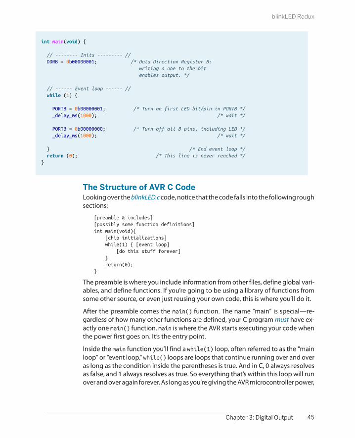
int main(void) {
// -------- Inits --------- // DDRB = 0b00000001; /* Data Direction Register B: writing a one to the bit enables output. */
// ------ Event loop ------ // while (1) {
PORTB = 0b00000001; /* Turn on first LED bit/pin in PORTB */ _delay_ms(1000); /* wait */
PORTB = 0b00000000; /* Turn off all B pins, including LED */ _delay_ms(1000); /* wait */
} /* End event loop */ return (0); /* This line is never reached */}
The Structure of AVR C CodeLooking over the blinkLED.c code, notice that the code falls into the following roughsections:
[preamble & includes][possibly some function definitions]int main(void){ [chip initializations] while(1) { [event loop] [do this stuff forever] } return(0);}
The preamble is where you include information from other files, define global vari-ables, and define functions. If you’re going to be using a library of functions fromsome other source, or even just reusing your own code, this is where you’ll do it.
After the preamble comes the main() function. The name “main” is special—re-gardless of how many other functions are defined, your C program must have ex-actly one main() function. main is where the AVR starts executing your code whenthe power first goes on. It’s the entry point.
Inside the main function you’ll find a while(1) loop, often referred to as the “mainloop” or “event loop.” while() loops are loops that continue running over and overas long as the condition inside the parentheses is true. And in C, 0 always resolvesas false, and 1 always resolves as true. So everything that’s within this loop will runover and over again forever. As long as you’re giving the AVR microcontroller power,
45Chapter 3: Digital Output
blinkLED Redux

Why the return(0)?
I just said that the event loop is an infinite while()loop, and thus never finishes. So why is there a return(0) following it?
For programs that run on your desktop computer, it’simportant for the operating system to know whetherthey ran correctly or not. For that reason, GCC, ourcompiler, wants every main() to end with a returncode. Return codes are totally superfluous for AVRcode, which runs freestanding without any support-ing operating system; nevertheless, the compilerraises a warning if you don’t end main with return(). And I’d rather that you take compiler
warnings seriously, because the warnings often helpyou debug bigger issues.
There is another way around the whole issue, andthat’s to prototype the main function like so beforeyou define it: void main(void) __attribute__((noreturn));, but almost nobodydoes this, even though it would be strictly correct.Instead, almost everyone gives the compiler the return(0); it expects, just to keep it quiet. Or they ig-nore the compiler warnings entirely—but there’s aspecial level in Hades allocated for those folks.
it’s going to keep going round and round the main event loop, turning your oneLED on and off until it burns out.
Hardware RegistersNow we get down to actually doing something in the code. The lines that are mostlyin all caps (DDRB = 0b00000001;) need some explaining. Let’s tackle the left sidefirst. DDRB and PORTB are definitions that point to the AVR’s internal hardwareregisters.
As mentioned in Chapter 1, almost all of the pins on the AVR chips are configurableas either input or output pins. That is, they can be internally hooked up as eithervoltage-sensing components or as transistor switches that will connect the pinthrough to the VCC or GND voltage levels. The way we’re going to configure thepins as either input or output is deceptively simple in code—assigning a variablea certain value—but what goes on inside the dark wiring heart of the chip isinteresting.
When you save a value in a “normal” variable, for instance with code that lookssomething like a = 7, the compiler picks a free slot from the chip’s available RAM,calls that slot “a”, and stores the value 7 there. Later on, when you add one to yourvariable a = a + 1; the compiler looks up “a” to see in which slot in memory itstored the value, pulls the value out of the memory slot, adds one to it, and puts itback in its slot. (For much more detail about the AVR’s use of memory, see Chap-ter 19.)
Each slot in the AVR’s memory is a byte, and each byte has eight bits. For a “normal”RAM location, these bits are used to encode (in binary) the number you’d like tostore. Inside the chip, each bit in RAM is hooked up to a network of transistors that
46 Make: AVR Programming
blinkLED Redux
keep whatever electrical state was last imposed on them. The ATmega168, for in-stance, has 8,192 of these single-bit memory networks, or 1,024 bytes of RAM.
When you want to configure a microcontroller pin, it looks the same in code assaving a value into a variable. And that’s because the same thing is going on insidethe chip. The chip’s hardware registers are just like the RAM storage slots that youuse for variables, only they each have side effects. So when you write DDRB =0b00000001;, you’re not just storing the number one in a memory location; you’realso flipping the transistor switches that are directly wired to each of the eightmemory cells.
Inside the AVR chip, the data-direction register (DDR) memory locations are phys-ically wired up to the transistor switches that determine whether a given pin is ininput or output mode. When you write the numeric value one to that register, it’sremembered. But it doesn’t end there—the register’s output is additionally con-nected to two switches. When a one is stored in that register bit, the output switchis closed, the input switch is open, and the pin is configured as output. When a zerois stored in that bit in your code, the output switch is open, the input switch isclosed, and the pin is configured as input.
Because hardware registers are special memory locations, the compiler can’t treatthem exactly the same as variables. When you create a normal variable, the com-piler can pick any convenient place in memory for it. Because the hardware registersare physically connected to the input/output circuitry, the location can’t change.These register locations are spelled out in the io.h header file so that we don’t haveto remember their numerical value, but rather mnemonic names like DDRB, for“data-direction register B.” Anyway, the upshot is that, once you’ve included theio.h file in your code, you can treat the hardware registers like normal variables andwrite code like DDRB = 0b00000001;, DDRB = 23;, or DDRB = DDRB + 7;.
Hardware registers: the bottom lineWhether or not you care about what’s going on deep under the hood inside thechip, you need to take away two things from all this: hardware registers can beaccessed just like “normal” variables from your code, but inside the chip they haveextra connections that let them influence the way the rest of the chip behaves.
Consequently, when you need to tell the chip to put out a high voltage level on agiven pin, it ends up being a matter of figuring out which number corresponds tothe bits that correspond to the pins you’d like activated, and then writing thatnumber into memory. Try to think of each register as being a row of eight switches,and writing a number into that register is the equivalent of flipping some of theswitches. In particular, if you know how your number is represented in binary, eachof the bits that has a 1 in it is a switch turned on, and each 0 is a switch turned off.
47Chapter 3: Digital Output
blinkLED Redux

The three most important hardware registersEach bank of pins (B, C, and D on the Mega series AVRs) has three hardware registermemory locations associated with it. Let x stand for each bank’s letter: so DDRx willbe DDRB, DDRC, or DDRD depending on which bank of pins you mean:
DDRx data-direction registers (port x)These registers control whether each pin is configured for input or output—the data direction. After a reset or power-up, the default state is all zeros, cor-responding to the pins being configured for input. To enable a pin as output,you write a one to its slot in the DDR.
PORTx port x data registersWhen the DDRx bits are set to one (output) for a given pin, the PORT registercontrols whether that pin is set to logic high or low (i.e., the VCC voltage orground). Switching between these voltage levels could, for instance, turn onand off attached LEDs.
With the DDR configured for input, setting the PORT bits on a pin will controlwhether it has an internal pull-up resistor attached or whether it’s in a “hi-Z”(high-impedance) state, effectively electrically disconnected from the circuit,but still able to sense voltage. We’ll talk more about this in Chapter 6.
PINx port x input pins addressThe PIN register addresses are where you read the digital voltage values foreach pin that’s configured as input. Each PINx memory location is hooked upto a comparator circuit that detects whether the external voltage on that pinis high or low. You can’t write to them, so they’re not really memory, but youcan read from the PINx registers like a normal variable in your code to see whichpins have high and low voltages on them.
All of these hardware registers are readable, so you can always query the input/output direction or state of any pin at any time. The PINx addresses aren’t writable,because they just reflect the voltage values (high or low) on the correspondingpins.
Configuring output: DDRs, PORTsLet’s quickly step through what you need to do in order to light up some LEDs.When an AVR chip first gets power, it starts off in a default state with all its pins ininput mode, with the pins essentially electrically disconnected from the circuit. Tooutput a voltage on a given pin, you’ll need to:
1. Configure the relevant pin for output mode by writing to the data-directionregister (DDR).
2. Assign a high or low value to the individual pin by writing to the PORT hardwareregister.
48 Make: AVR Programming
blinkLED Redux
Get Your DDRs, PINs, and PORTs Straight!
A common beginner mistake, and one I even make from time to time, is trying to write to thePORT register and expecting a voltage out when the DDR hasn’t been set to output yet. So whenyou’re debugging your code, and can’t figure out why the LEDs aren’t lighting up, the firstthing you should do is make sure that you’ve enabled the pins in question for output.
The other related gotcha is forgetting which register you’re writing to—writing to the DDR orthe PIN registers when you want to be writing to the PORT register, for instance. Try to thinkof the PIN registers as "Port INput,” and the PORT registers as "Port Output Register Thing.”
When things aren’t working as expected, double-check the logic of your DDRs, PINs, and PORTs!
blinkLED SummaryLook back at the blinkLED.c code, and make sure you know what’s going on. Thefirst two lines include files that are part of the AVR standard C library. avr/io.h is thefile that defines all the PORTs and DDRs. util/delay.h provides us with the _delay_ms() function that we use to delay between blinks. You’ll end up including afew more of these AVR library files as we move through the book.
int main(void) starts the main function—when the microcontroller starts up, it’llstart here. Unlike big-computer programs, the microcontroller main() functionusually never returns. We’ll initialize our variables, configure the chip, and thenenter a neverending event loop.
Our initialization here consists of writing a 1 in one bit of the DDRB register, whichis enough to set up that pin as output. And then, in the event loop, we go back andforth between turning on and off the first LED by writing a 1 to the bit in the PORTregister that’s connected to our LED, with a delay to make it visible. That’s the one-two combo for setting up digital output.
POV Toy
That should be more than enough detail about how to blink a single LED on andoff slowly! Now let’s take some time to solidify all that information and makesomething cool with it. Specifically, a programmable POV toy.
With all this newfound bit-twiddling power, it’s time to show off a little. POV toysare pretty neat, and take our LED-blinking skills up to the next level. POV standsfor persistence of vision, the phenomenon in which an afterimage persists on theretina for approximately 1/25 of a second. The point with a POV toy is that you turnLEDs on and off so quickly that the eye can’t react to them. If you swing the devicearound, the afterimage patterns that they make seem to float in the air. They’re
49Chapter 3: Digital Output
POV Toy

POV Toys: How Do They Work?
The human eye doesn’t react instantly. Rather, if alight blinks on and off quickly enough, it’s perceivedas being constantly on. This is, of course, how movieswork—they flash images at you 24 to 32 times persecond, and your brain interprets them as being afluid stream.
Persistence-of-vision toys exploit this slow responseto make animations “magically” float in midair. If youswing a single LED quickly, persistence of visionwould make it look like a streak. By turning the LEDon and off rapidly, you can make a dashed line or aseries of dots instead of a solid streak. Now by doingthe same with multiple LEDs, you can make a low-resolution image just like with old dot-matrixprinters.
It’s also fun (and sometimes frustrating) to take pho-tos of your POV toy in action. Getting the timing ofthe camera shutter just right takes a bit of practice.
If you think that persistence of vision is just for toys,it might surprise you to know that almost all LEDs aredriven in pulses these days, either for a dimming ef-fect (known as pulse-width modulation, or PWM, andthe subject of Chapter 10) or for energy efficiency. Tosee for yourself, scan your eyes across any LED taillights on a car, or stoplight at an intersection (do thiswhile you’re standing on the sidewalk, or while you’renot behind the wheel of a car, please). See the blink-ing? Wouldn’t the world be a cooler place if they em-bedded patterns in them?
pretty cool, and the only thing cooler is one that’s loaded up with patterns youmade yourself.
Building the CircuitIn building the blinkLED circuit from the previous chapter, you’ve already hookedup an LED and resistor to PB0 on the AVR. For the POV toy, you’re going to need todo that seven more times. At some point, it becomes convenient to solder the LEDand the resistor together directly, because they’re always used together anyway.If you’d like to take a 10-minute soldering break, make yourself some blinkenlights.
BlinkenlightsYou’re going to want to test voltages all of the time to make sure that everythingis working as you expect, and for digital circuits the easiest way is to light (or not!)an LED. But LEDs can burn out if you run too much current through them, so wealmost always add on a current-limiting resistor. So warm up your soldering iron,and take a few minutes to make yourself some tools—LEDs with integrated resis-tors used for diagnostic purposes: blinkenlights. (Look up “blinkenlights” on Wiki-pedia if this doesn’t ring a bell.)
To make a blinkenlight, all you’ll need to do is clip the negative/cathode side of theLED short and solder on an appropriate resistor. If you’re only going to be using 5V, a 220 ohm resistor will work fine. But for maximum utility, use something like a1,000 ohm resistor, and you’ll be able to light the LED off sources up to 15 V withoutfear of burning out your LED. Figure 3-2 shows you the three simple steps.
50 Make: AVR Programming
POV Toy

Figure 3-2. Constructing blinkenlights
If you’re going to be working through this book with a breadboard, you’ll need 8LEDs for the POV toy project alone, so go ahead and make 10 or 12. Everywhere inour circuit diagrams that you see an LED and a resistor, you can substitute a blin-kenlight. Having the resistors prewired can save you a bunch of extra connectionson your breadboard.
When you’re done with this book and you start up a new project, attach a blin-kenlight to the power lines of your breadboard to use as a power indicator. Thenyou’ll never have to worry about whether the breadboard is “on” or not. Scatterthem liberally around your breadboard wherever you want to test a logic value(and the current draw of 20 mA isn’t too excessive). Making 10 or 12 may seem likea lot at once, but trust me; you’ll find a use for them all someday. If you’ve got LEDsof different colors, make a few of each. Go nuts!
Simplest POV ToyThe simplest version of the POV circuit is just eight LEDs, each with its own current-limiting resistor, all hooked up to the pins PB0 through PB7 on the AVR. This way,you can write a one to selected bits of the eight-bit byte in PORTB, and the corre-sponding LEDs will light up. Hook up the circuit shown in Figure 3-3.
51Chapter 3: Digital Output
POV Toy
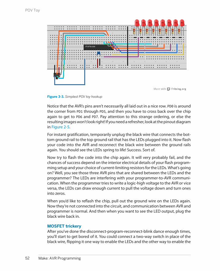
Figure 3-3. Simplest POV toy hookup
Notice that the AVR’s pins aren’t necessarily all laid out in a nice row. PD0 is aroundthe corner from PD1 through PD5, and then you have to cross back over the chipagain to get to PD6 and PD7. Pay attention to this strange ordering, or else theresulting images won’t look right! If you need a refresher, look at the pinout diagramin Figure 2-5.
For instant gratification, temporarily unplug the black wire that connects the bot-tom ground rail to the top ground rail that has the LEDs plugged into it. Now flashyour code into the AVR and reconnect the black wire between the ground railsagain. You should see the LEDs spring to life! Success. Sort of.
Now try to flash the code into the chip again. It will very probably fail, and thechances of success depend on the interior electrical details of your flash program-ming setup and your choice of current-limiting resistors for the LEDs. What’s goingon? Well, you see those three AVR pins that are shared between the LEDs and theprogrammer? The LEDs are interfering with your programmer-to-AVR communi-cation. When the programmer tries to write a logic-high voltage to the AVR or viceversa, the LEDs can draw enough current to pull the voltage down and turn onesinto zeros.
When you’d like to reflash the chip, pull out the ground wire on the LEDs again.Now they’re not connected into the circuit, and communication between AVR andprogrammer is normal. And then when you want to see the LED output, plug theblack wire back in.
MOSFET trickeryAfter you’ve done the disconnect-program-reconnect-blink dance enough times,you’ll start to get bored of it. You could connect a two-way switch in place of theblack wire, flipping it one way to enable the LEDs and the other way to enable the
52 Make: AVR Programming
POV Toy

programmer. A nice twist on this idea is to use an electrical switch to automaticallyconnect and disconnect the LEDs for you. In our case, the electrical switch that we’lluse is a 2N7000 MOSFET.
(If you got “lucky,” and you’re able to program the AVR’s flash with the LEDs stillconnected, you might be tempted to skip the MOSFET. You can do that at yourown risk—just remember later on when you have random trouble flashing the AVRthat I told you so. You can always test out if this is the case by temporarily pullingthe ground wire that supplies the LEDs.)
What Is a MOSFET?
A MOSFET is a transistor. We’ll be using it in full-on and full-off modes, so for now you canthink of it as an electrically controlled switch. All MOSFETs have three pins, and we’ll almostalways connect one (the source pin) to ground and another (the drain) to the part of thecircuit that we’d like to turn on and off. This switching action is accomplished by putting avoltage on the remaining pin, the gate.
Inside the MOSFET is a channel that connects the source to the drain. The gate lies physicallybetween them and is a metal plate that’s insulated from the drain-source channel. Voltagesapplied to the gate actually attract or repel electrons in the channel, making it more or lessconductive. At the extremes, it’s like an open circuit (disconnected) when there is no voltageon the gate, and very conductive with five volts on the gate.
We’ll cover FETs in much more detail in Chapter 14.
Back to our wiring-up problem. We’d like our MOSFET switch to automatically dis-connect the LED’s ground rail when we’re programming the AVR, and reconnectthe ground rail so that the chip can blink LEDs when we’re done programming. Theclever bit in this next circuit uses the fact that the AVR uses its RESET pin to enterprogramming mode. And we have the good luck that the RESET pin (PC6, blue wirefrom the programmer) is held at 5 V by the AVR when the chip is running, and pulledlow to 0 V by the programmer to signal the AVR to enter programming mode.
We can thus connect the MOSFET to the AVR’s RESET pin and use the RESET actionto connect and disconnect the LED’s ground rail. When the AVR is running normally,the RESET pin is pulled up to 5 V and the gate on the MOSFET is pulled up alongwith it. This closes the MOSFET switch, which connects the ground rail from theLEDs to the circuit ground and the LED’s blink. When the programmer pulls theRESET line low, it simultaneously sets the AVR into programming mode and alsodraws the gate of the MOSFET to ground, opening the MOSFET switch and dis-connecting the LEDs. See Figure 3-4 for a breadboard wiring diagram.
53Chapter 3: Digital Output
POV Toy
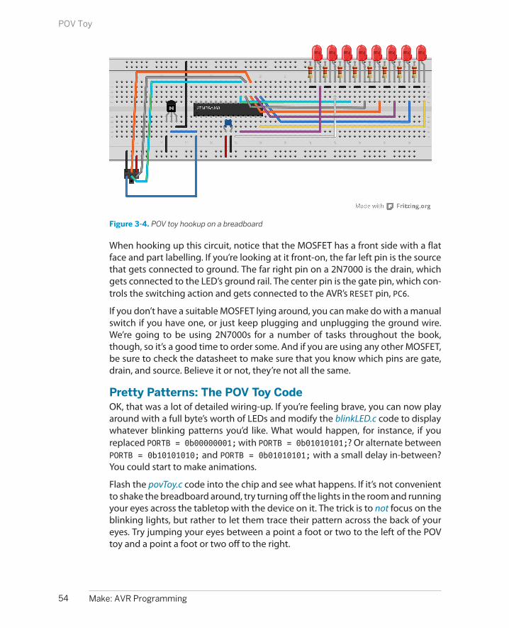
Figure 3-4. POV toy hookup on a breadboard
When hooking up this circuit, notice that the MOSFET has a front side with a flatface and part labelling. If you’re looking at it front-on, the far left pin is the sourcethat gets connected to ground. The far right pin on a 2N7000 is the drain, whichgets connected to the LED’s ground rail. The center pin is the gate pin, which con-trols the switching action and gets connected to the AVR’s RESET pin, PC6.
If you don’t have a suitable MOSFET lying around, you can make do with a manualswitch if you have one, or just keep plugging and unplugging the ground wire.We’re going to be using 2N7000s for a number of tasks throughout the book,though, so it’s a good time to order some. And if you are using any other MOSFET,be sure to check the datasheet to make sure that you know which pins are gate,drain, and source. Believe it or not, they’re not all the same.
Pretty Patterns: The POV Toy CodeOK, that was a lot of detailed wiring-up. If you’re feeling brave, you can now playaround with a full byte’s worth of LEDs and modify the blinkLED.c code to displaywhatever blinking patterns you’d like. What would happen, for instance, if youreplaced PORTB = 0b00000001; with PORTB = 0b01010101;? Or alternate betweenPORTB = 0b10101010; and PORTB = 0b01010101; with a small delay in-between?You could start to make animations.
Flash the povToy.c code into the chip and see what happens. If it’s not convenientto shake the breadboard around, try turning off the lights in the room and runningyour eyes across the tabletop with the device on it. The trick is to not focus on theblinking lights, but rather to let them trace their pattern across the back of youreyes. Try jumping your eyes between a point a foot or two to the left of the POVtoy and a point a foot or two off to the right.
54 Make: AVR Programming
POV Toy

Once you get tired of my preprogrammed pattern, it’s time to work through thecode in Example 3-2 so that you can create your own!
Example 3-2. povToy.c listing// POV toy demo framework //
// ------- Preamble -------- //#include <avr/io.h>#include <util/delay.h>
// -------- Functions --------- //void POVDisplay(uint8_t oneByte) { PORTB = oneByte; _delay_ms(2);}
int main(void) { // -------- Inits --------- // DDRB = 0xff; /* Set up all of LED pins for output */ // ------ Event loop ------ // while (1) { /* mainloop */ POVDisplay(0b00001110); POVDisplay(0b00011000); POVDisplay(0b10111101); POVDisplay(0b01110110); POVDisplay(0b00111100); POVDisplay(0b00111100); POVDisplay(0b00111100); POVDisplay(0b01110110); POVDisplay(0b10111101); POVDisplay(0b00011000); POVDisplay(0b00001110);
PORTB = 0; _delay_ms(10); } /* end mainloop */ return (0);}
At the base of the POV toy routine is a really simple function, POVDisplay(), but ifit’s the first function declaration in C you’ve ever seen, it’s worth a short explanation.
Let’s look at what the POVDisplay function does. It takes in a single byte and thenturns around and writes it straight back out to the PORTB. This is just like what goeson in blinkLED. Every bit that’s set to a one in the number we pass to POVDisplayhas a corresponding illuminated LED. Here, we also delay for a few milliseconds todisplay the pattern for just a tiny bit.
55Chapter 3: Digital Output
POV Toy

Now look down at the main() functions. The first step to using the AVR’s digitaloutputs is to configure the data-direction register (DDRB) so that any subsequentvalues written to the PORTB register will appear as either high or low voltage valueson the corresponding pins.
Functions in C
When your code gets to the point that it’s doing many, many different things, it can reallyhelp both the readability and the logical flow to encapsulate whatever parts of it you caninto functions. In C, a function takes variables as arguments (or inputs) and returns eithernothing or a single value as a result. Each time you call the function from any other place inthe code, the code inside the function is run.
Variables that are defined within the function stay in the function (this is called their scope)and aren’t accessible outside the function’s context, so you don’t have to worry about one ioverwriting another. Variables that are defined outside the function can be changed by codewithin the function.
C insists on knowing the type of each of these arguments and return values. In this example,POVDisplay() is a function that takes in an unsigned integer (uint8_t) variable as its input,uses the input to set the LEDs, and then waits. It doesn’t return any values, hence the void init’s definition.
If you’re new to C, you’ll see a lot more function definitions throughout the rest of the book,and you’ll pick it up as we go along.
The event loop is where the action happens. The POVDisplay() function is calledrepeatedly with a binary value. I could have written this part of the code using thedecimal representation of these numbers, but if you squint your eyes just right andtilt your head, you can almost see the pattern that’s displayed in the ones and zeros.(How readable would it be if I wrote POVDisplay(189);? Quick, which LEDs are onand which are off?)
After displaying the desired pattern, all of the LEDs are turned off with PORTB=0;and a relatively long delay time separates one run of the pattern from the next.Then the infinite while() loop starts up again at the top.
Experiment!Now I’d like you to start messing around with the code. Increase the delay insidethe POVDisplay() function so that it’s long enough that you can see the individualsteps. Compare them to the binary values getting written to the PORTB register. Seehow numbers being written around in your code is making electrical things happenin the real world. Experience the zen of hardware registers.
56 Make: AVR Programming
POV Toy

Battery Power!
To make the POV toy swingable, it’s nice to unplug itfrom the wall or your USB tether. The easiest way todo this is by battery-powering your circuit, and you’vegot a couple of ways to do this.
My favorite power supply for AVR projects is a set offour AA-cell rechargeable batteries. Rechargeableshave two advantages: they’re cheaper in the longrun, and they have a lower voltage than normal bat-teries. While four fresh standard AA cells start off at 6V (4 × 1.5 V), most single-cell rechargeables runaround 1.2 V, making four of them together just right
at 4.8 V—meaning you won’t have to modify most ofyour 5 V circuits.
On the other hand, the AVR chips run reliably as lowas 3 V, so you can get by with two or three regular AAbatteries or even three rechargeables. (My version ofthe circuit keeps on blinking until around 2 V, but isa little dim on two rechargeables.) If you’ve designedyour LED circuit with 5 V in mind, you’ll find that theLEDs run a little bit dim on three or four volts. Oh well.You’re probably swinging your POV toy around in adark room anyway.
How short can you make the delay before you can no longer swing your arm (ormove your eyes) fast enough to see the pattern anymore? If you need to decreasethe delay down below one millisecond, there is a _delay_us() function that delaysin increments of microseconds, or thousandths of a millisecond.
Finally, and here’s the part where I lost a Saturday afternoon, try coding up someof your own patterns using this simple function. I found that it helps to draw outthe patterns horizontally across eight rows of graph paper first, and then read thebinary numbers out down the vertical columns.
In the povToy directory, I’ve included some more examples and even an examplePOV font so that you can easily spell words. The code for running all of these is alittle advanced for the first serious chapter of this book but was written with easyextensibility in mind, so feel free to flash them in or modify them and see whathappens.
The easiest way to program in another bit of code from within the same directoryis to edit the makefile and change the target from MAIN = povToy.c to somethinglike MAIN = 1up.c or whatever. Alternatively, if you’re running make from the com-mand line, you can just type make MAIN=1up.c flash and it will compile the newcode and flash it into your microcontroller without having to touch the makefile.
If you’ve made some patterns that you’re really proud of, you’ll want to show themoff to other people. You may want to make this whole setup a little bit moreportable, and the easiest way to do that is to unplug the flash programmer andsupply power using batteries.
Once you’ve exhausted all of the eight-LED POV possibilities, pick up again withthe next chapter where you’ll learn a much more flexible method of controllingthe AVR’s output from code.
57Chapter 3: Digital Output
POV Toy


Cylon Eyes and More
In this chapter we’ll make a cylon-eye-type LED back-and-forth scanner. Everyoneneeds one. Scanning lights were the only thing, besides maybe menace, that gavethe cylons their personality. Would KITT have been half as useful to David Has-selhoff without his scrolling red lights? I think not. And now you can build yourvery own.
But I won’t lie to you. We’re building cylon eyes in order to learn a fundamentalconcept in microcontroller-specific programming: how to flip individual bits onand off inside a hardware register. And while that may not sound sexy, you’ll beusing the ideas from this chapter in every AVR or microcontroller project you evermake from here on out. Flipping bits is just that important in embedded devices.
If you don’t believe me yet, think back on how we turned on LED3. We wrotesomething like:
PORTB = 0b00001000;
And that worked, as long as we knew for sure that we wanted all of the other LEDsturned off. But what if you need to turn on or off a particular LED without disturbingany of the others? Bitwise logical operations—“bit twiddling”—lets us modify anyone bit out of the register byte without having to think explicitly about the others.Because we’ll be setting bits in registers to configure nearly every aspect of theAVR hardware, we’ll get a lot of mileage out of this investment.
Because this chapter is mostly theory, let’s get the project up and running so youhave something pretty to look at. Assuming that you still have all the LEDs hookedup as in Chapter 3, all you have to do is enter the cylonEyes directory, open upcylonEyes.c in your editor, and run make to compile the firmware and upload it tothe chip.
59
Bit Twiddling 4

What You Need
In this chapter, in addition to the basic kit, you willneed:
• The eight LEDs and their resistors that youhooked up in Chapter 3.
• That’s it. Well, it wouldn’t hurt to have yourthinking cap on, because we’re going to beusing a bunch of bitwise binary logic.
If you have trouble uploading the program to the chip, please double-check theISP connectors according to Figure 3-4 and make sure you’ve got the MOSFET setup right. If in doubt about the MOSFET part of the circuit, go back to the wirebetween the top ground rail to the bottom ground rail to double-check that’s theproblem.
Working Through the Code: Cylon Eyes
You got it running? Great! Now let’s look at the code in Example 4-1 and see whatmakes it tick. Essentially, it’s the same as with the one-LED blinker code, only insteadof switching on and off only one of the bits in the PORTB register, we can toggleeight of them.
Example 4-1. cylonEyes.c listing /* Cylon Eyes */
// ------- Preamble -------- //#include <avr/io.h> /* Defines pins, ports, etc */#include <util/delay.h> /* Functions to waste time */
#define DELAYTIME 85 /* milliseconds */#define LED_PORT PORTB#define LED_PIN PINB#define LED_DDR DDRB
int main(void) {
// -------- Inits --------- // uint8_t i = 0; LED_DDR = 0xff; /* Data Direction Register B: all set up for output */
// ------ Event loop ------ // while (1) {
while (i < 7) { LED_PORT = (1 << i); /* illuminate only i'th pin */ _delay_ms(DELAYTIME); /* wait */
60 Make: AVR Programming
Working Through the Code: Cylon Eyes

i = i + 1; /* move to the next LED */ }
while (i > 0) { LED_PORT = (1 << i); /* illuminate only i'th pin */ _delay_ms(DELAYTIME); /* wait */ i = i - 1; /* move to the previous LED */ }
} /* End event loop */ return (0);}
You should recognize the general form of the code from blinkLED.c. In fact, the onlybig differences are that we have loops inside our event loop, and we have thecryptic PORTB = (1 << i); statement—our first introduction to bit twiddling!Before we get on to the main course, though, I’ll introduce our first #define state-ment (“C Asides: #defines” on page 61). Feel free to skim through if you’re alreadycomfortable with C.
Bit Twiddling and Cylon Eyes
Looking back briefly at how we implemented blinkLED.c and even povToy.c, you’llsee that the code turns on and off the bit that controls our LED quite directly: PORTB= 0b0000001;. We could make a cylon eyes animate in the same way. To make thetraditional back-and-forth scanner, we hook up eight LEDs to the same port, andlight them up one at a time, moving from right to left and left to right. Our naivecode might look something like this:
DDRB = 0b11111111; // enable all pins for output
while(1){ PORTB = 0b00000001; // set the 0th pin in PORT B high _delay_ms(100); PORTB = 0b00000010; // set the 1st pin in PORT B high _delay_ms(100); PORTB = 0b00000100; // set the 2nd pin in PORT B high (etc.) ...}
As you can see, that’s going to involve a lot of typing, and in the end the code isgoing to be difficult to maintain, tweak, and extend. So we’re going to need a betterway. Enter bit twiddling! The C programming language allows the user to accessbits individually, and the AVR libc (the microcontroller-specific library routines)helps even more, but it’s going to take a little getting used to.
61Chapter 4: Bit Twiddling
Bit Twiddling and Cylon Eyes

C Asides: #defines
#define statements improve code readability andportability by defining human-friendly synonyms forconstants or code fragments. For instance, in a setupwith only one LED like our blinkLED.c, I’ll usually de-fine LED as a synonym for a particular pin on the AVR(PB0) partly to remind myself how to hook up thecircuit, but also partly to make it easy to change later.
For instance, if you were reproducing the blinkLED.ccode, but you’d like to physically wire the LED to pinPB5, you could go through the code and changeevery occurrence of PB0 to PB5. If instead, as here,you define the LED pin at the top of the code, some-thing like #define LED PB0 and then consistentlyonly use LED in the main body, you’ll only have tochange PB0 to PB5 in the one place where it’s defined,right up at the top of your code or in a suitably namedinclude file. Defining your hardware layout makes iteasier to modify later, and makes your code easier toread. (What was hooked up to PB0 again?)
This is handled by the preprocessor, which goesthrough your code and does a search-and-replace forall your #defines before handing the result off to thecompiler. Because #define statements are simplesubstitutions made by the preprocessor, they’re notvariables, take up no memory in the AVR, and can’tbe changed from within your code.
To keep from forgetting their special nature, thenames of #defines are usually written in
ALL_CAPS_SEPARATED_WITH_UNDERSCORES. Thismakes #defines stand out in your code, and remindsyou that they’re not normal variables.
In addition to user-defined #defines, if you look inthe avr/io.h file that we include in all our examplecodes, you’ll find that there’s a #define for everyhardware register that’s listed in the datasheet. (In-clude files are also handled by the preprocessor, be-fore the code is compiled.) These definitions point inturn to the correct memory locations of the AVR’shardware registers.
This is a more general pattern in AVR C: a lot of thelow-level details of the layout and configuration ofthe chip (like what locations in memory are hardwareregisters) are provided for you in #define state-ments, and the names are a vaguely helpfulmnemonic for something that’s written in thedatasheet.
For now, think of #defines as handy shortcuts forkeeping track of values that you might later like tochange or would like to make more clear. Using #defines for pin-layouts also makes your code flexibleacross different hardware setups, and helps remindyou later which pin your accelerometer was hookedup to. Good use of #defines is good practice.
Bit ShiftingWouldn’t it be nice, instead of having to write out 0b00001000, if we could just say“give me a number with a 1 in bit number three”? (If you thought that one was inbit number four, see “Bits, Numbering, and Significance” on page 62.) That way wecould code our cylon eyes by incrementing or decrementing a variable and thenputting a 1 in the corresponding bit’s place.
It turns out that the technique known as bit shifting will do exactly that for us.You’re going to be surprised at how often we use bit shifting in microprocessor-style C code.
Bit shifts have the effect of rolling all of the bit positions to the left or right, de-pending on your command. Bits that fall off either end just disappear, and any new
62 Make: AVR Programming
Working Through the Code: Cylon Eyes
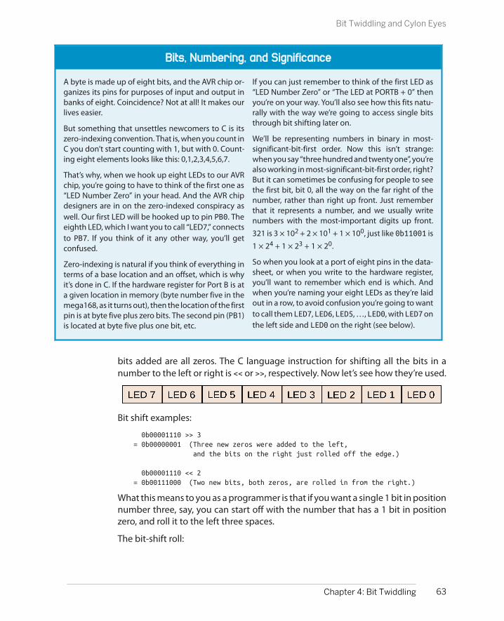
Bits, Numbering, and Significance
A byte is made up of eight bits, and the AVR chip or-ganizes its pins for purposes of input and output inbanks of eight. Coincidence? Not at all! It makes ourlives easier.
But something that unsettles newcomers to C is itszero-indexing convention. That is, when you count inC you don’t start counting with 1, but with 0. Count-ing eight elements looks like this: 0,1,2,3,4,5,6,7.
That’s why, when we hook up eight LEDs to our AVRchip, you’re going to have to think of the first one as“LED Number Zero” in your head. And the AVR chipdesigners are in on the zero-indexed conspiracy aswell. Our first LED will be hooked up to pin PB0. Theeighth LED, which I want you to call “LED7,” connectsto PB7. If you think of it any other way, you’ll getconfused.
Zero-indexing is natural if you think of everything interms of a base location and an offset, which is whyit’s done in C. If the hardware register for Port B is ata given location in memory (byte number five in themega168, as it turns out), then the location of the firstpin is at byte five plus zero bits. The second pin (PB1)is located at byte five plus one bit, etc.
If you can just remember to think of the first LED as“LED Number Zero” or “The LED at PORTB + 0” thenyou’re on your way. You’ll also see how this fits natu-rally with the way we’re going to access single bitsthrough bit shifting later on.
We’ll be representing numbers in binary in most-significant-bit-first order. Now this isn’t strange:when you say “three hundred and twenty one”, you’realso working in most-significant-bit-first order, right?But it can sometimes be confusing for people to seethe first bit, bit 0, all the way on the far right of thenumber, rather than right up front. Just rememberthat it represents a number, and we usually writenumbers with the most-important digits up front.
321 is 3 × 10² + 2 × 101 + 1 × 100, just like 0b11001 is
1 × 24 + 1 × 23 + 1 × 20.
So when you look at a port of eight pins in the data-sheet, or when you write to the hardware register,you’ll want to remember which end is which. Andwhen you’re naming your eight LEDs as they’re laidout in a row, to avoid confusion you’re going to wantto call them LED7, LED6, LED5, …, LED0, with LED7 onthe left side and LED0 on the right (see below).
bits added are all zeros. The C language instruction for shifting all the bits in anumber to the left or right is << or >>, respectively. Now let’s see how they’re used.
Bit shift examples:
0b00001110 >> 3= 0b00000001 (Three new zeros were added to the left, and the bits on the right just rolled off the edge.)
0b00001110 << 2= 0b00111000 (Two new bits, both zeros, are rolled in from the right.)
What this means to you as a programmer is that if you want a single 1 bit in positionnumber three, say, you can start off with the number that has a 1 bit in positionzero, and roll it to the left three spaces.
The bit-shift roll:
63Chapter 4: Bit Twiddling
Bit Twiddling and Cylon Eyes
1 = 0b00000001(1 << 0) = 0b00000001(1 << 1) = 0b00000010...(1 << 3) = 0b00001000...(1 << 7) = 0b10000000
Take a minute to make sure you’ve got the logic of the bit-shift roll down. It’s astandard idiom in microcontroller coding, and you’ll be using it in nearly everyprogram you write. Any time you want to set the nth bit to a 1, you’ll shift the value1 over to the left n times.
Now you’re starting to see how the cylon eyes work: start off with the number 1,roll the bit one position, and then write that to an output hardware register, rinse,and repeat. Shift bits left until you end up at LED7, then switch to shifting bits rightuntil you hit LED0.
So before we leave this section, let’s recap the meat of the cylon eyes code. Makesure that it makes sense to you, because we’ll be using the bit-shift roll extensivelyfrom here on out:
while(i < 7){ LED_PORT = (1 << i); /* illuminate only i'th pin */ _delay_ms(DELAYTIME); /* wait */ i = i + 1; /* increase shift amount */}while(i > 0){ LED_PORT = (1 << i); /* illuminate only i'th pin */ _delay_ms(DELAYTIME); /* wait */ i = i - 1; /* decrease shift amount */}
There are two while loops, driving the variable i up to seven and back down tozero. Inside each loop there is a delay, which is fairly self-explanatory. All the actionthat matters is in the LED_PORT = (1 << i); command. We want a binary numberwith a 1 in the ith place, which will turn on only the ith LED in our series. Weimplement it by starting with a 1 in the zeroth position and rolling it over i timesto the left.
Advanced Bit Twiddling: Above and BeyondCylon Eyes
So that’s all there is to making cylon eyes: just shifting a bit to the left or right asappropriate, and waiting. But what if we wanted to make an even more interestingpattern? Multiple lights on at once? Or random toggling? Or maybe we just needto control one bit out of a byte, without changing any of the others.
64 Make: AVR Programming
Advanced Bit Twiddling: Above and Beyond Cylon Eyes
The serious limitation in the preceding code is that each time through the while()loop, we’re writing a whole byte to the LED port. This works in cylon eyes becausewe know that we’d only like one LED on at a time. But what about the case wherewe’ve already got a few LEDs lit up, and we’d like to add another? Say just LED1? Ifwe wrote LED_PORT = (1<<1);, we’d turn on LED1 all right, but in the process, we’llhave turned off all the rest.
In this section, we’re going to learn some essential bit-twiddling techniques thatwill allow us to manipulate single bits easily without clobbering the rest of thecontents of the register. Think of each byte in the AVR’s hardware registers as beinga row of eight little switches; in this section, we’re going to use bitwise logic func-tions to set or toggle each switch individually without modifying the rest.
Even if you’ve programmed C since you were seven years old, it’s quite possiblethat you haven’t spent much time on bit-level manipulations. If you’ve ever learneda little bit about logic, digital or otherwise, the bitwise operators will seem familiarto you, but the context may be brand new. For some of you, this is all going to bebrand new. Hold on to your hats.
Bitwise logical operators take full bytes as their input. They do logical operations onthose bytes one bit at a time, hence the name. This makes the bitwise operatorsan absolutely perfect match for manipulating the individual bits inside a registerbyte.
To give you a bit of the flavor, the bitwise operator NOT takes each bit in the byteand toggles, or flips, it. A 1 becomes a 0, and a 0 becomes a 1: 10001110 turns into01110001. The operation happens all at once inside the AVR chip, but you can thinkof it as reading bit 0 and then writing the logical opposite to bit 0 of the result byte.This same operation repeats seven more times, bitwise, for each bit in the byte.
There are four bitwise logical operators in total, so let’s work through each with anexample. I find it helpful to think of the two input bytes stacked on top of eachother so that the bits being compared are aligned vertically. Work through thefollowing sidebar and make sure that you see how the logical operation is beingapplied, bitwise down the columns, to get the final result.
Bitwise logic definitions are all well and good, and you may have seen all this al-ready. It’s how bitwise logic is used in microcontroller coding that’s interesting,especially when combined with the side effects of setting, clearing, and testingbits in hardware registers. In short, we care about twiddling bits inside bytes a lotmore in AVR programming than in most other computer programming, becausebitwise logic allows us to configure the AVR’s internal hardware, and read from andwrite to individual pins.
65Chapter 4: Bit Twiddling
Advanced Bit Twiddling: Above and Beyond Cylon Eyes

The _BV() Macro
Bit shifting is so common in AVR programming thatthere’s even a macro defined that gets included withio.h: it’s called _BV() and stands for “bit value.”
Before 2006, this macro used to be called BV(), andit used to be used quite commonly. Sometimearound 2007, it got renamed to _BV(), where theunderscore indicates that it’s intended for internaluse within the avr-libc libraries, because it isn’tpart of official Standard C.
The _BV() macro is just our bit-shift roll in disguise.In fact, it’s even defined as:
`#define _BV(bit) (1 << (bit))`
So should you use _BV(2) or (1 << 2)? Well, theyend up being exactly the same thing once the pre-processor has done its text replacing, so it’s just amatter of style. You’ll definitely see code written bothways, so I want you to be able to read both.
There are a couple of arguments for the use of_BV(). If you saw (1 << 2) and were new to micro-controller programming, you might have to think fora while about what the purpose of the “1” was—is ita numerical value to be treated like a number, or is itjust the simplest way of representing a 1 in a singlebit? So the first argument for _BV() is that it does reada little more clearly in code. On the other hand, thebit-shift roll is so common in microcontroller C andassembly code that the _BV() doesn’t really gainmuch in readability after you’ve been at it a fewmonths.
Secondly, many old AVR programmers are used tohaving the macro around, and they wrote a bunch ofcode with BV() in it, and it’s trivial to find-replace alltheir code to read _BV()—people also use _BV()because they’re used to it.
The arguments against _BV() basically boil down toit not being Standard C. If you want to compile yourcode on some other platform to test it out, for in-stance, it probably won’t have the _BV() macro al-ready defined.
So what if you like the clarity of BV() as a macro, butalso want to keep your code maximally portable?Define BV() yourself! It’s easy and hardly costs any-thing. If you define it yourself in your code, you won’thave to worry about your code being portable, be-cause it’ll be right there. In the sidebar “Bit Twiddlingfor the Impatient” on page 74, I’ve listed an examplewith a bunch of bit-shifting macros that I routinelyinclude in my own code.
In the interest of teaching you standardmicrocontroller-style C I’ll use (1 << 3) in the codemost of the time. If you can read code written thisway, you can read anything; this idiom is used acrossmicrocontroller families and compilers. But in yourown code, feel free to use the built-in _BV() macro,or better still, define your own.
66 Make: AVR Programming
Advanced Bit Twiddling: Above and Beyond Cylon Eyes

Bitwise Logical Operators
OR (|)For each bit position, a bitwise OR returns 1 ifeither bit in the comparison is 1. OR returns a 1if this bit is 1 or that bit is 1. OR returns 0 onlywhen both bits are 0:
1010| 1100= 1110
AND (&)Bitwise AND compares two bits and returns 1 on-ly if both of the bits are 1. If either of the bits are0, AND returns 0:
1010& 1100= 1000
XOR (^)XOR (or “exclusive or”) returns 1 if only one of thetwo bits compared is a 1. If both bits are 1 or ifboth bits are 0, XOR returns 0:
1010^ 1100= 0110
NOT (~)NOT takes all the bits and flips their logical sense—each 1 becomes a 0 and each 0 becomes a 1.It’s also the only logical operator that takes onlyone input:
~ 1100= 0011
Stupid Bitwise Tricks
As a quick demo of the utility of bitwise logical operators, you can convert the Cylon Eyesdemo into Inverse-Video Cylon Eyes with the NOT operator. Just replace each:
LED_PORT = (1 << i);
with:
LED_PORT = ~(1 << i);
Every LED that was previously on will be off, and vice versa.
For a different display that uses tools you’ll learn in the remainder of this section, change thefirst LED_PORT line into LED_PORT |= (1 << i); and the second into LED_PORT &= ~(1 <<i); See what you get!
So let’s get down to the business at hand: manipulating individual bits within abyte. For concreteness, take the eight LEDs and suppose that we already have afew LEDs lit: LEDs zero, one, six, and seven. If we looked at the value currently storedin PORTB, it would read 0b11000011. Now say we want to turn on and off LED2 withoutchanging the states of any of the other LEDs. Or maybe we want to turn on or offLEDs two and four at the same time. How can we do this?
67Chapter 4: Bit Twiddling
Advanced Bit Twiddling: Above and Beyond Cylon Eyes

Setting Bits with ORFor our first trick, let’s learn how to set an individual bit in a register, leaving all theother bits as they were. Thinking back on the bitwise logical operators, let’s revisitthe way the OR operator works. In particular, let’s think about ORing some bit witheither a fixed 0 or a fixed 1.
Consider ORing a bit with zero. If you OR a 1 with a 0, the result is 1. If you OR a 0 witha 0, the result is 0. That is, ORing a bit with 0 doesn’t change the initial logical bit atall. But ORing with a 1 always yields a 1. This behavior lays the groundwork for usingOR to turn bits on using bitmasks:
OR with 0: 0 | 0 -> 0 1 | 0 -> 1
OR with 1: 0 | 1 -> 1 1 | 1 -> 1
A bitmask is just a normal old byte, but we’re thinking of it as being made up ofones and zeros in particular places that we specify rather than representing anumerical value. We use a bitmask, along with a bitwise logical operator, to changesome bits in a target byte.
I like to think of bitmasks almost like stencils used for spray painting. You cut awayparts of the stencil where you want to change (paint) the underlying surface, andyou leave the stencil intact where you don’t want paint to go.
In particular, if we want to turn on some bits in PORTB while leaving the othersuntouched, we’ll create a bitmask with ones in the bit locations we’d like turnedon. This works because a one ORed with anything will return a one. So we read inPORTB and OR it with the bitmask. The result should be the unaltered contents ofPORTB everywhere that we had a zero, and ones everywhere our bitmask had a one.If we write this back out to PORTB, we’re set—PORTB has all its old bits intact, exceptthose where there was a 1 in the bitmask have been turned on. I’ve worked this allthrough in detail in Example 4-2.
Example 4-2. Using OR to set bitsIf LED2 is initially off:
PORTB : 0b11000011 // the current LED state(1 << 2) = 0b00000100 // the LED we want to turn on | = 0b11000111 // hooray!
LED2 is turned on, and none of the others are changed.
If LED2 is initially on:
68 Make: AVR Programming
Advanced Bit Twiddling: Above and Beyond Cylon Eyes

PORTB : 0b11000111 // the current LED state(1 << 2) = 0b00000100 // the LED we want to turn on | = 0b11000111 // hooray!
LED2 is still on, and none of the others are changed.
We can also set multiple bits at once. All we have to do is create a bitmask with the two bits(say LED2 and LED4) that we’d like to turn on. Since:
0b00010100 // the desired bitmask = (0b00000100 | 0b00010000) = ( (1 << 2) | (1 << 4) )
then:
PORTB = 0b11000011 // the current LED state((1 << 2) | (1 << 4)) = 0b00010100 // bits two and four | = 0b11010111 // turned both on!
We’ve just seen how to get a copy of the byte currently in PORTB, and how to turnon LED2 and LED4 using OR and a bitmask. That gives us a new byte, which we justwrite out to PORTB, and we’re done:
PORTB = PORTB | (1 << 2);
This type of operation is so common that there’s a shorthand for it in C:
PORTB |= (1 << 2);
Either way you write it, the code ends up the same after compilation, so pick a stylethat makes you happy. Both of them have the effect of turning on LED2 and leavingthe other bits as they were.
Toggling Bits with XORNow imagine that you want to flip a bit or two. You don’t really care if it’s on or offright now, you just want it in the other state, whatever that is. Imagine that youwant to blink LED2 while leaving the rest of the LEDs unchanged. To do this, you’dtoggle the bit that corresponds to LED2, delay a while, and then toggle it again, etc.To toggle a bit, you’ll use a bitmask and the XOR operator.
Let’s look at XOR again. If you XOR any bit with a fixed 0, you get a 1 if that bit is a 1and a 0 if that bit is 0. (Remember, this is the “exclusive” or and is only true if oneor the other is true, but not both.) So XORing with a zero gives you the input backagain.
If you XOR with a 1, what happens? Starting with a 0 and XORing 1 returns a 1, andstarting with a 1 and XORing 1 yields 0. XORing with a 1 seems a good way to togglebits!
XOR with 0: 0 ^ 0 -> 0
69Chapter 4: Bit Twiddling
Advanced Bit Twiddling: Above and Beyond Cylon Eyes
1 ^ 0 -> 1
XOR with 1: 0 ^ 1 -> 1 1 ^ 1 -> 0
As we did with OR for setting bits, we’ll make a bitmask with a 1 where we want totoggle a bit and zeros everywhere else. To toggle a bit in a register, we XOR thecurrent register value with the bitmask, and write it back into the register. Boom.For more detail, see Example 4-3.
Example 4-3. Using XOR to toggle a bitIf LED2 is initially off:
PORTB : 0b11000011 // the current LED state(1 << 2) = 0b00000100 // bitmask LED2 ^ = 0b11000111 // LED2 bit flipped on
After the XOR, LED2 is turned on, and none of the others are changed.
And if LED2 is initially on:
PORTB : 0b11000111 // the current LED state(1 << 2) = 0b00000100 // bitmask LED2 ^ = 0b11000011 // LED2 bit flipped off
After the XOR, LED2 is turned off, and none of the others are changed.
So to toggle a bit, we create a bitmask for the bit we’d like to toggle, XOR it with the contentsof our register, and write the result back out to the register. In one line:
PORTB = PORTB ^ (1 << 2);
or:
PORTB ^= (1 << 2);
for short. You can, of course, toggle more than one bit at once with something like:
PORTB ^= ((1 << 2) | (1 << 4));
Clearing a Bit with AND and NOTClearing a bit (setting it to zero) is just inconvenient, but you’ll have to do it so oftenthat you’ll eventually find it second nature. So far, we’ve used OR to set bits and XORto toggle them. You may not be entirely surprised that we’re going to use AND toclear bits. Let’s run through the usual analysis.
If we AND any bit with 0, the result is guaranteed to be 0. There’s no way they canboth be 1 if one of them was a 0 to start with. This is how we’ll turn bits off:
70 Make: AVR Programming
Advanced Bit Twiddling: Above and Beyond Cylon Eyes

AND with 0: 0 & 0 -> 0 1 & 0 -> 0
AND with 1: 0 & 1 -> 0 1 & 1 -> 1
This suggests using a bitmask with AND to turn bits off. The bitmask we’ll have touse should have a 1 where we want to keep the old data and a 0 where we wantto clear a bit. That is, to turn off LED2, we’ll use an AND bitmask that looks like0b11111011.
But wait a minute! That bitmask is the exact opposite of the bitmasks we’ve usedbefore—it has ones where the others had zeros and vice versa. There’s a millionstupid ways to create such a mask, but the easy way is to first create the mask witha 1 where we want it, and then use NOT to flip all the bits.
So to make a bitmask to turn off LED2, we’ll first shift a 1 over into the right spotand then NOT the whole mask:
(1 << 2) -> 0b00000100~(1 << 2) -> 0b11111011
Now we AND that with the original value and we’re home free. I work through all ofthe steps for you in Example 4-4.
Example 4-4. Using AND and NOT to clear a bitIf LED2 is initially off:
PORTB = 0b11000011~(1 << 2) = 0b11111011 & = 0b11000011
LED2 stays off, and none of the others are changed.
And if LED2 is initially on:
PORTB = 0b11000111~(1 << 2) = 0b11111011 & = 0b11000011
LED2 is turned off, and none of the others are changed.
Reassigning to PORTB and writing these as one-liners, we get:
PORTB = PORTB & ~(1 << 2);
or:
PORTB &= ~(1 <<2);
And as with the other examples, you can of course turn off multiple bits in one statement:
71Chapter 4: Bit Twiddling
Advanced Bit Twiddling: Above and Beyond Cylon Eyes

PORTB &= ~((1 << 2) | (1 << 4));
being careful with the NOT outside the parentheses, because you want to have two zeros inyour bitmask.
Showing Off
Now that we’ve got all this bit-level manipulation under our belts, let’s make somedemo code to show off a little bit. Being able to set, clear, and toggle individualbits allows a little more flexibility than cylon eyes code had, and it should give youenough basis to start experimenting. Let’s work through Example 4-5.
Example 4-5. showingOffBits.c listing /* Showing off some patterns to practice our bit-twiddling */
// ------- Preamble -------- //#include <avr/io.h>#include <util/delay.h>
#define DELAYTIME 85 /* milliseconds */#define LED_PORT PORTB#define LED_DDR DDRB
int main(void) {
uint8_t i; uint8_t repetitions; uint8_t whichLED; uint16_t randomNumber = 0x1234;
// -------- Inits --------- // LED_DDR = 0xff; /* all LEDs configured for output */ // ------ Event loop ------ // while (1) { /* Go Left */ for (i = 0; i < 8; i++) { LED_PORT |= (1 << i); /* turn on the i'th pin */ _delay_ms(DELAYTIME); /* wait */ } for (i = 0; i < 8; i++) { LED_PORT &= ~(1 << i); /* turn off the i'th pin */ _delay_ms(DELAYTIME); /* wait */ } _delay_ms(5 * DELAYTIME); /* pause */
/* Go Right */ for (i = 7; i < 255; i--) { LED_PORT |= (1 << i); /* turn on the i'th pin */ _delay_ms(DELAYTIME); /* wait */
72 Make: AVR Programming
Showing Off

} for (i = 7; i < 255; i--) { LED_PORT &= ~(1 << i); /* turn off the i'th pin */ _delay_ms(DELAYTIME); /* wait */ } _delay_ms(5 * DELAYTIME); /* pause */
/* Toggle "random" bits for a while */ for (repetitions = 0; repetitions < 75; repetitions++) { /* "random" number generator */ randomNumber = 2053 * randomNumber + 13849; /* low three bits from high byte */ whichLED = (randomNumber >> 8) & 0b00000111; LED_PORT ^= (1 << whichLED); /* toggle our LED */ _delay_ms(DELAYTIME); } LED_PORT = 0; /* all LEDs off */ _delay_ms(5 * DELAYTIME); /* pause */
} /* End event loop */ return (0); /* This line is never reached */}
Reading down from the top, I include the standard avr/io.h file, which includes allthe DDR and PORT macros and AVR part definitions, and then the delay utilities. Next,a delay time and the pinouts are defined in case you want to play around with themlater on.
Down in the main() routine, there’s not much to do for initialization. A few variablesthat we’ll be needing are defined, and then the DDRB is configured for output onall of the pins. (0xff is 255 in hexadecimal, and is equivalent to 0b11111111.)
The event loop (while(1){...) is divided into three different “animations”: one thatturns on all the LEDs starting from LED0, and then turns them all off starting fromLED0; one that does the same thing in reverse; and one that “randomly” togglesindividual LEDs on and off.
The “go left” routine is a lot like cylon eyes, except that it doesn’t turn off any LEDsuntil they’re all on, and it uses a for() loop. Turning on each LED one at a time,without turning them back off, ends up with all eight LEDs on. The next for() loopin the “go left” section turns off the LEDs one at a time, from right to left. This makesit look like a block of LEDs, eight wide, passes through our viewing range.
73Chapter 4: Bit Twiddling
Showing Off
For Loops
You’ll be seeing a lot more for() loops in this book, but this one’s the first one. So make sureyou know what’s going on inside the loop’s parentheses.
First, a loop variable is initialized (i=0). Then a test is done on that variable (i<8). If the testis true, the rest of the code in curly brackets is run. If not, the loop is over and the code moveson. Finally, each time it’s done with a loop, the third argument in the for() parentheses isrun. In our case, we’re adding one (i++) to the variable.
The “go right” code is a little bit more interesting, and here’s a potential trap whencoding for microcontrollers. Conceptually, it’s easiest to think of starting with i=7and subtracting one until it’s reached zero. The problem with this is how we testfor the end condition. We want to run the for loop when i=0 and turn off LED0.
If you set up the loop like this:
for (i=7; i>0; i--){}
it will stop as soon as i is zero, so it will never set or unset LED0. You might try to fixthis by comparing with a greater-than-or-equal-to:
for (i=7; i>=0; i--){}
then you end up with a surprising infinite loop! The reason for this gotcha is thati is defined as an unsigned integer, which counts from 0 to 255—it’s only definedfor positive numbers. When you subtract one from zero, it rolls back around to themaximum value, which is 255 in the 8-bit case. This means the condition i>=0; isalways true.
Because we want the for loop to run when i is 0, and then stop afterwards wheni equals 255, we can test for i < 255, which is exactly what the code, as written,does.
Finally, have a brief look at the “random toggling” section of the code. The “randomnumber” isn’t really random at all, but it looks pretty close, so it is good enough.You can see how I used bit-masking to take a 16-bit random number and turn itinto a number in the range zero to seven, to match up with our LED numbers. You’llend up seeing these tricks again, so I’ll at least introduce them here.
First, we convert the 16-bit randomNumber variable into an 8-bit number by bitshifting the randomNumber over eight times: whichLED = (randomNumber >> 8);.This keeps the most significant eight bits, which are the most “random” using thisquick-and-dirty algorithm.
74 Make: AVR Programming
Showing Off

Bit Twiddling for the Impatient
In summary, here’s a recap of the three important bit-twiddling operations. Let’s say you’re trying to writebit i in byte BYTE:
Set a bitBYTE |= (1 << i);
Clear a bitBYTE &= ~(1 << i);
Toggle a bitBYTE ^= (1 << i);
Of course, you can substitute more complicated bit shifts in for the parentheses. For instance, if you want toset bits i and j, use BYTE |= ((1<<i)|(1<<j));.
It’s “hardcore” to do the bit shifting and negation stuff by hand, and this book’s code is also written in thatstyle because I think it’s good for you, like doing situps or drinking wheatgrass juice. In the end, you will haveto read other people’s code, and they will do bitwise operations this way. You can’t escape it, so you mightas well get used to it—it’s part of the language idiom.
But on days when you’re not feeling hardcore, you can also define some macros to do the same thing, andthis can make your code more easily readable. If you’d like to take this path, these will do the trick:
#define BV(bit) (1 << (bit))#define setBit(byte, bit) (byte |= BV(bit))#define clearBit(byte, bit) (byte &= ~BV(bit))#define toggleBit(byte, bit) (byte ^= BV(bit))
The main limitation of the macros is that they can only change one bit at a time, while the standard methodcan accept any kind of bitmask, but this rarely makes any practical difference except to how it reads in yourcode. In the rare cases that you need to flip four bits or more really quickly or really frequently, you’ll get itdone faster the hardcore way. Anyway, in my opinion, it’s good to have options.
Next, we need to limit the random number to the range zero through seven. Andwhat’s the largest number you can count to with three bits? Seven. So the trick isto keep only the lowest three bits, zeroing out the upper five. And the quickest andeasiest way to do this is using AND and a bitmask: whichLED = whichLED &0b00000111;. Now our variable whichLED will be in the range of the number of LEDswe actually have.
Finally, if whichLED contains a number like zero or three or seven, all that’s left forus to do is use XOR and a bit-shift roll to toggle the randomly selected bit. Voila! Arandom blinker, powered by bit twiddling.
75Chapter 4: Bit Twiddling
Showing Off

Summary
You learned a lot about bit twiddling in this chapter, so let’s recap. In the last chapteryou saw how to set up the data-direction registers to enable any given pin foroutput, and then how writing a logical one or zero to the same bit number inanother register set the output voltage on that pin to 5 V or 0 V, respectively.
And because digital output is all about controlling individual bits, you dove head-first into more advanced bit twiddling. First, using the bit-shift roll, you saw howto get a one bit in any given position. Then you saw how to use the various bitwiselogical operations (OR, XOR, AND, and NOT) to set, toggle, or clear bits in a byte indi-vidually or in groups. Here, I also introduced the idea of a bitmask that’s used withthe logical operations to tweak specific bits individually or together:
Set a bitBYTE |= (1 << i);
Clear a bitBYTE &= ~(1 << i);
Toggle a bitBYTE ^= (1 << i);
And that’s a lot of bit twiddling for one chapter, but the groundwork we’ve laidhere will serve you throughout the rest of the book and for the rest of your life withmicrocontrollers.
76 Make: AVR Programming
Summary

What You Need
In addition to the basic kit, you will need:
• A speaker with a DC-blocking capacitoraround 10 uF.
• A USB-Serial adapter.
• (Optionally) an amplifier if you want to play itloud.
Square-Wave Organ
This chapter gives you a lot of bang for the buck. Before it’s all over, you’re goingto have learned how to communicate between the AVR and your desktop or laptopcomputer and constructed a cheesy computer-controlled musical instrument.
Along the way, you’re going to learn a little about serial communications protocols,and how you can generate quick-and-dirty audio with the AVRs. Serial communi-cation is the simplest possible way to interface your microcontroller with yourdesktop or laptop computer, your first step toward bridging the world of the phys-ical and the virtual.
Serial Communication
How do computers or integrated circuit components actually talk to each other?The (too-short) answer is that it’s almost exactly like what we were doing in Chap-ter 3. One side sends a signal by outputting high and low voltage pulses on a wirethat connects it to the other device. The other side, in input mode, listens to thevoltages on the wire.
The rules for encoding data into voltage pulses and decoding the voltage pulsesback into data is called a serial protocol. We’ll get into a lot more of the nitty-gritty
77
Serial I/O 5

of other serial protocols in Chapter 16 and Chapter 17. For now, we’ll limit ourselvesto the most common serial mode—universal asynchronous receive and transmit(UART) serial.
To understand what’s going on with UART serial, start by thinking of two peoplewho want to talk to each other by sending voltage signals over a few wires. Let’ssay Alice wants to send the number 10 to her friend Bob over a wire. For concrete-ness, let’s say that the wire’s got a pull-up resistor on it so that it’s constantly at fivevolts. On Alice’s side of the wire, there’s a switch connected to ground, and on Bob’sside, there’s also an LED so that he can see what the voltage on the wire is bywhether or not the LED lights up.
Alice is going to send the number 10 to Bob by pressing her button, grounding thewire, and turning off Bob’s LED on the other side. Now, she could send the numberby just blinking the LED off 10 times, but that system’s going to break down whenshe wants to send the number 253, or worse, 64,123. So instead she writes out 10in binary, 0b00001010, and sends a corresponding pattern of flashes.
Bob and Alice have to agree on a bunch of things beforehand for this to work—the serial protocol. First they need to decide on an encoding: they agree before-hand that a button press (a zero-volt signal on the wire) indicates a zero, and no-press (five volts) indicates a one, and that they’ll send the numbers least-significant-bit first.
Next, they need to agree how often Alice presses or doesn’t press the button. Let’ssay they choose to signal once per second. This is the baud rate—how often thevoltage is allowed to change on the line, and conversely how often the receiverneeds to read in a new voltage.
How does Bob tell when the transmission begins and ends? They’ve agreed to wrapthe eight bits with two extra bits: a start bit, which will always be a zero so that youcan tell when the transmission starts, and a stop bit, which is a one.
Bob is sitting at his end, staring at the LED, when he sees the LED blink. It blinks offfor a second—the start bit! Now once every second after the start bit, he notesdown whether the LED is on or off. After the first blink, he sees off, on, off, on, off,off, off, off, and then the LED stays on for a while. He writes down his eight bits,01010000. He then flips the bit-ordering around, and sees that Alice has sent thenumber 10!
The oscilloscope trace in Figure 5-1 is a real example of an AVR transmitting thedigit 10 to my computer. Instead of one bit per second I used 9,600 bits per second(baud), so each bit takes about 104 microseconds. But you can make out the pat-tern: 1111100101000011111. Remember that the first low bit is the start bit, thencount out eight bits, check that the ninth is high, flip the order, and read it out inbinary.
78 Make: AVR Programming
Serial Communication

Figure 5-1. Sending 10 in Serial
Now if Bob wants to reply, the simplest solution is just to repeat the same physicalsetup and protocol, but in reverse—that is, give Bob a button and Alice an LED.That way, Bob and Alice can signal each other at any time, sending numbers backand forth. It takes two signal wires to make this work, but the advantages of dedi-cated lines are simplicity and data throughput.
Figure 5-2 is the trace when two bytes in a row are sent: 9 and then 10. Notice inthe center that the stop bit that lies between the two digits is slightly longer—theAVR was doing work and not sending data for an extra few microseconds. Thisdoesn’t bother the receiving computer, which starts timing again only when itreceives the next start bit.
79Chapter 5: Serial I/O
Serial Communication

Figure 5-2. Sending 9 and 10 in Serial
See Figure 5-3 for the logic interpretation of the signals, and try to read out the bitsfrom the scope trace if you’re so inclined.
Figure 5-3. Sending 9 and 10
Encoding and decoding this data seems like a lot of work, and getting the timingexactly right to send and receive data at baud rates in the tens of thousands of bitsper second is no picnic either. That’s why all of the AVR Mega microcontrollers haveat least one dedicated hardware peripheral, called a Universal Synchronous andAsyncronous Receiver and Transmitter (USART) device built in. In the rest of thischapter, we’ll look into how to configure and use the USART hardware, as well ashow to set up your desktop computer to talk to the AVR.
80 Make: AVR Programming
Serial Communication

UART and USART
In the introduction, I said we’d be using UART (universal asynchronous receive and transmit)serial, but the AVR’s peripheral is called a USART. What’s the difference? Why the extra “S”?
The AVR’s serial hardware is capable of running both in a synchronous mode—using a clockthat helps with data timing—and in asynchronous mode without a clock, hence “USART”(universal synchronous and asynchronous receiver and transmitter). But until Chapter 16,we’ll be exclusively concerned with asynchronous serial communications, so you can feel freeto ignore the “S” in the AVR’s USART for now.
Implementing Serial Communication on the AVR:Loopback Project
The first thing you’re going to want to do is make sure that your serial link betweencomputer and microcontroller is up and running, and get used to using it. Time toget your chips talking to your desktop computer.
Our setup here is going to involve three different stages:
1. Configuring the AVR
2. Installing serial terminal software on your computer
3. Connecting them together
Setup: Configuring the AVRBecause the AVR microprocessors have dedicated USART circuitry inside, all wehave to do to communicate is configure the interface, and then dump our bytesinto the special hardware registers designated for sending and receiving. Thehardware peripheral will take care of the rest. That’s fantastically handy.
First, just to make sure everything is working, we’ll flash in a quick demo program.If you’ve got the LEDs still plugged in from the last few chapters, that’s great! If not,you’ll miss on out seeing the ASCII numeric representation of each character’s valueas you type it out. Before we dive into the nitty-gritty of configuring the USARThardware, let’s see how we can use it by working through Example 5-1.
Example 5-1. serialLoopback.c listing/*A simple test of serial-port functionality.Takes in a character at a time and sends it right back out, displaying the ASCII value on the LEDs.*/
81Chapter 5: Serial I/O
Implementing Serial Communication on the AVR: Loopback Project

// ------- Preamble -------- //#include <avr/io.h>#include <util/delay.h>#include "pinDefines.h"#include "USART.h"
int main(void) { char serialCharacter;
// -------- Inits --------- // LED_DDR = 0xff; /* set up LEDs for output */ initUSART(); printString("Hello World!\r\n"); /* to test */
// ------ Event loop ------ // while (1) {
serialCharacter = receiveByte(); transmitByte(serialCharacter); LED_PORT = serialCharacter; /* display ascii/numeric value of character */
} /* End event loop */ return (0);}
Skip straight down to the event loop, and you can see that there’s only three thingsour program is doing. It receives a byte from the serial line using the functionreceiveByte(). Then it transmits that same byte back out using transmitByte().Finally, the LED displays the byte that it just sent across in ASCII.
In the initialization section, you shouldn’t be surprised to find that we’re initializingthe LEDs for output just as we did in the previous chapter. What’s new are thefunctions initUSART() and printString(). They must be defined somewhere, butwhere? Scrolling up to the preamble, you’ll see that I’ve included a new file,USART.h. If you open that file up, you’ll find their prototypes, and we’ll go into detailabout the configuration routine in “Configuring USART: The Nitty-Gritty Details”on page 88 and including modules in “Modules in C” on page 94. For now, we’ll focuson making sure everything is up and running.
82 Make: AVR Programming
Implementing Serial Communication on the AVR: Loopback Project
Functions as Verbs
It’s a style question, but I find that if I name all of my functions with verbs that describe whatthey do, and all the variables as descriptive nouns, C code can start to read like a sentence.
Sure, you may have to type a little more the first time, but consider yourself coming back tolook at this code six months from now. Will you be able to browse through the code and findthe section that you’d like to modify? You will, if your functions and variables have descriptivenames.
That’s the overview. If you haven’t already, now’s a good time to flash the serialLoopback project code into your AVR.
Setup: Your ComputerOn your computer, it’s just a matter of installing the right software. In particular,you need to connect to a terminal application that’ll let you type to the AVR andread what it types back. If you’ve got a favorite terminal application, by all meansfeel free to use it. Otherwise, I’ve got a few suggestions.
Setup: USB-Serial AdapterSo your AVR is flashed with the serialLoopback code, and your computer’s gotbrand-new serial terminal software loaded and running. Time to hook them uptogether.
If you’ve got one of the ubiquitous FTDI cables, it’s got a pinout, as summarized inTable 5-1.
Table 5-1. FTDI cable pinout
Color Signal
Black GND
Brown CTS#
Red VCC
Orange TXD
Yellow RXD
Green RTS#
If you don’t have an FTDI cable, the lines you’re looking for are going to be labeledsomething like RX, TX, GND, and optionally VCC. You can choose between power-ing the project from an external source of 5V, which is the right way to do it, orpowering the whole circuit from the USB cable, which is convenient but will prob-ably be drawing more current through the FTDI cable than its specifications allow.
83Chapter 5: Serial I/O
Implementing Serial Communication on the AVR: Loopback Project

Terminal Emulator Software
Linuxgtkterm is nice and easy to configure andshould work on most Linuxes. Another option isscreen, which is available on both Mac OS andLinux, but which you may not realize is a serialterminal in disguise. Invoking screen withscreen [portName] 9600 should get you talk-ing to your AVR directly. Ctrl-A followed by Ctrl-?will get you help. Ctrl-A then Ctrl-K will kill yourcurrent session. Linux users can find out whichUSB serial port is connected by typing ls /dev/tty*.
Mac OSCoolTerm and ZTerm are nice serial terminalapplications for Macs. If they don’t detect yourserial port automatically, you can find it by open-ing up a regular terminal and typing ls /dev/*usbserial*. You’re looking for somethinglike /dev/cu.usbserial-XXXX.
WindowsThere are a bazillion terminal programs for Win-dows systems. In the olden days, Hyperterminalwas the default and came under Accessories. Inrecent times, I’ve used Bray’s Terminal, which isminimalistic and gets the job done. If you’re not
sure which port the USB serial is connected to,check in Device Manager under Ports → USB Se-rial Port.
Cross-platform, PythonIf you’ve already got Python and the serial libraryinstalled, you can run the included serial termi-nal emulator. Typing python -m serial.tools.miniterm --cr [portName]9600 should get you talking. Note that you typeCtrl-] to quit and Ctrl-T then Ctrl-H for help. (Andmake a shortcut for this if you know how.)
Cross-platform, ArduinoIf you’ve got the Arduino IDE set up on yourcomputer, you’ll find its serial terminal programunder Tools → Serial Monitor. This “terminal”program works well enough to listen to the AVR,but it requires you to hit Enter after every char-acter you type in order to send it. For text, youcan send a line at a time this way, but for any-thing interactive, it’s inconvenient. In short, Ican’t recommend the Arduino Serial Monitor as a general-purpose terminal program,even though it works fine if you only need toreceive data from the AVR.
Double-check that you’ve hooked up the computer/FTDI cable’s RX pin to the AVR’sTX pin, and vice versa. On the breadboard, with an FTDI cable represented by therainbow-colored, six-pin header strip, it’ll look like Figure 5-4.
84 Make: AVR Programming
Implementing Serial Communication on the AVR: Loopback Project
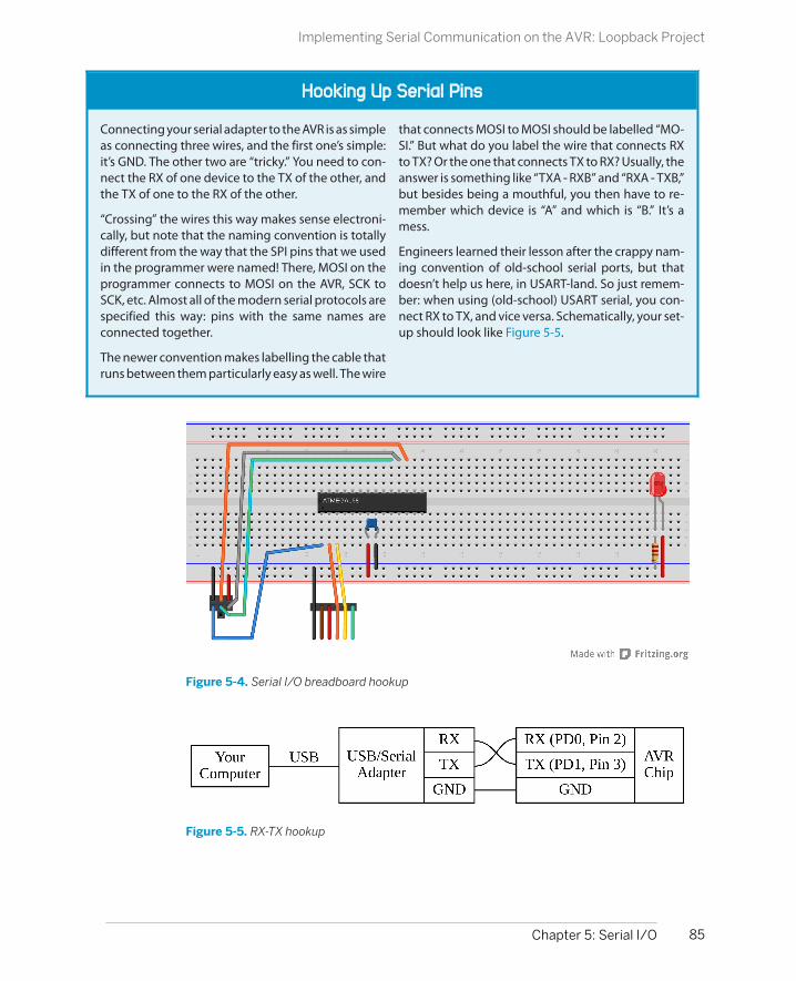
Hooking Up Serial Pins
Connecting your serial adapter to the AVR is as simpleas connecting three wires, and the first one’s simple:it’s GND. The other two are “tricky.” You need to con-nect the RX of one device to the TX of the other, andthe TX of one to the RX of the other.
“Crossing” the wires this way makes sense electroni-cally, but note that the naming convention is totallydifferent from the way that the SPI pins that we usedin the programmer were named! There, MOSI on theprogrammer connects to MOSI on the AVR, SCK toSCK, etc. Almost all of the modern serial protocols arespecified this way: pins with the same names areconnected together.
The newer convention makes labelling the cable thatruns between them particularly easy as well. The wire
that connects MOSI to MOSI should be labelled “MO-SI.” But what do you label the wire that connects RXto TX? Or the one that connects TX to RX? Usually, theanswer is something like “TXA - RXB” and “RXA - TXB,”but besides being a mouthful, you then have to re-member which device is “A” and which is “B.” It’s amess.
Engineers learned their lesson after the crappy nam-ing convention of old-school serial ports, but thatdoesn’t help us here, in USART-land. So just remem-ber: when using (old-school) USART serial, you con-nect RX to TX, and vice versa. Schematically, your set-up should look like Figure 5-5.
Figure 5-4. Serial I/O breadboard hookup
Figure 5-5. RX-TX hookup
85Chapter 5: Serial I/O
Implementing Serial Communication on the AVR: Loopback Project

ASCII
When sending 8-bit bytes across the serial line, it’snatural to think of them as numbers. But if you wantto send letters, we’ll have to work out a mapping fromthe numbers into letters. Enter the American Stan-dard Code for Information Interchange (ASCII).
Have a look at an ASCII table on the Web, or type manascii in Linux or OS X. Otherwise, you’ll be well-oriented just by knowing that 'A' is at 0x41, 'B' isat 0x42, 'a' is at 0x61, and '0' is at 0x30. What comesin between should be self-explanatory.
C and ASCII work very well together. You can transi-tion seamlessly between letters and numbers, andbecause the characters are defined in correspondingalphabetical and numerical order, there’s all sorts oftricks you can play with ASCII. 'A' + 2 = 'C' forinstance, and '0' + 3 = '3'. This means that if you
have the variable a=3; and you’d like to send singledigits represented as their ASCII characters, then youcan send '0' + a. The printByte() function frommy USART library exploits this fact to send a byte asits text representation:
void printByte(uint8_t number){ /* Hundreds */ transmitByte('0'+ (number/100)); /* Tens */ transmitByte('0'+ ((number/10) % 10)); /* Ones */ transmitByte('0'+ (number % 10));}
With all this in mind, load up the serialLoopback.cdemo, type some letters on your keyboard, andwatch the blinking (ASCII binary numeric) lights.You’re watching the ghost in the machine!
Again, notice that we’ve hooked up the RX and TX wires, and connected the groundfrom the FTDI cable to the ground that’s shared between our AVR chip and theprogrammer. (And if you’ve still got the LEDs hooked up from last chapter, that’s abonus.)
Putting It All Together: Test Out Your LoopbackSo if you’ve flashed the serialLoopback code to your chip, hooked up the RX/TXpins (and GND) to the USB-Serial converter, and plugged it into your computer, it’stime to test this baby out.
Open up the terminal program, make sure it’s configured for the right port (theUSB converter) and with the right baud rate (9600). If it’s got an option for “localecho,” set it to no—we’re going to be echoing back from the AVR chip. If you’ve gotlocal echo on, you’ll see everything you type twice, “lliikkee tthhiiss”.
Now type something. The LED’s should display the binary values that correspondto the letter you typed in ASCII. Success! And if you unplug and replug power tothe AVR (or momentarily ground the RESET pin), you should be greeted with afriendly “Hello World!” If you’re at this point, you’ve got it all working.
86 Make: AVR Programming
Implementing Serial Communication on the AVR: Loopback Project

printBinaryByte in Lieu of LEDs
If you don’t have the LEDs connected but would still like to see how individual characters lookas binary ASCII bits, you can replace the line:
transmitByte(serialCharacter);
in serialLoopback.c with:
printBinaryByte(serialCharacter);
printString("\r\n");
and then, instead of a simple echo, you’ll get the ASCII value of the character you just typedsent back to you. A character-to-ASCII converter!
Troubleshooting Serial ConnectionsSomething’s not working? Let’s step through it:
1. You’ve installed terminal software, right?
2. When you plug in the USB-Serial cable, does your computer recognize it? OnLinux, type lsusb and look for “FT232 USB-Serial” (get a Mac version at https://github.com/jlhonora/lsusb.) On Windows, check Device Manager→Ports.
3. On Windows, did you install the correct driver? If not, try unplugging and re-plugging the FTDI cable. If the driver is not installed, it should walk youthrough it.
4. Do you have the right port name? In Linux and Mac, it’ll be something like /dev/ttyUSB0 or /dev/XXX.usbserial-XXXXXXXX. In Windows, click on the FTDI devicein the Device Manager and select the Hardware tab. It should show you whichport it’s connected to.
5. Do you have permissions? On Linux and Mac, if you’re getting hassled, tryrunning your terminal with sudo. (sudo is a command that lets you temporarilyrun one command at a time as super user—the user with maximum permis-sions. When something won’t run because of permissions issues, you can side-step it quickly by using sudo.) In the long term, you may need to add yourselfto a group with read/write permissions to the USB-Serial adapter. Search “serialport permissions” plus your operating system name if you don’t already knowhow to do this.
6. Do you have the TX and RX lines mixed up? It’s a quick experiment to switchthem and see if that fixes things.
7. Finally, you can remove the AVR from the picture and make sure that yourcomputer isn’t to blame by using a hardware loopback. Take a wire and connect
87Chapter 5: Serial I/O
Implementing Serial Communication on the AVR: Loopback Project

it between the TX and RX lines of your USB-Serial adapter. Now open up yourterminal program and type something. The signal should go out the TX, backinto the RX, and be typed back out on your screen. If this works, it’s possiblethat the wires connecting to your AVR aren’t appropriately crossed, or you’veset the baud rates wrong somewhere. Double-check.
8. Once you’ve got it all working, take a picture of the circuit. You can refer backto this later when you’re hooking things up again.
If you have the serialLoopback program up and running, then all is well with yourcomputer, the AVR chip, and the connection between them. Now you are ready tostart using the serial port for something. If you want to move straight on down tothe AVR Organ project in “AVR Square-Wave Organ” on page 95, feel free. If you’dlike a little more detail on just exactly how the USART library that we’re includingworks, keep on reading.
Configuring USART: The Nitty-Gritty Details
In this section, I’m going to go into a bit of detail on how the initUSART() codedoes its work. You’ll see similar examples of hardware configuration and initializa-tion routines in almost every chapter of this book. It can be a little bit intimidatingon the first pass, but after working through it a couple of times, either in this chapteror any of the later chapters in this book, you’ll get it.
The essential outline of the hardware configuration is that there are a handful ofregisters for each of the AVR’s built-in peripherals. Each bit in a register byte is aswitch that enables or disables some functions of the peripheral. Setting up thehardware to do its job, then, is just a matter of figuring out which switches youneed to set and bit twiddling them into the right states.
To dig in, let’s look at the USART.h and USART.c files. The .h file is pretty standard—it defines a default BAUD rate if you haven’t already specified one, and then intro-duces the functions with descriptive comments. Any macro defines you may needin USART.c are also found here.
So on to the source file, USART.c where the functions are actually defined. I’ve par-tially excerpted the file in Example 5-2.
To read along with the USART.c file, you’ll want to get the datasheet for the mega168chip, and open up to the chapter labeled "USART0.” Feel free to read the overviewsection of the datasheet, and then jump on down to the section on “USARTInitialization.”
Example 5-2. USART.c partial listing/* Quick and dirty functions that make serial communications work.
88 Make: AVR Programming
Configuring USART: The Nitty-Gritty Details

*/
#include <avr/io.h>#include "USART.h"#include <util/setbaud.h>
void initUSART(void) { /* requires BAUD */ UBRR0H = UBRRH_VALUE; /* defined in setbaud.h */ UBRR0L = UBRRL_VALUE;#if USE_2X UCSR0A |= (1 << U2X0);#else UCSR0A &= ~(1 << U2X0);#endif /* Enable USART transmitter/receiver */ UCSR0B = (1 << TXEN0) | (1 << RXEN0); UCSR0C = (1 << UCSZ01) | (1 << UCSZ00); /* 8 data bits, 1 stop bit */
}
void transmitByte(uint8_t data) { /* Wait for empty transmit buffer */ loop_until_bit_is_set(UCSR0A, UDRE0); UDR0 = data; /* send data */}
uint8_t receiveByte(void) { loop_until_bit_is_set(UCSR0A, RXC0); /* Wait for incoming data */ return UDR0; /* return register value */}
// Example of a useful printing commandvoid printString(const char myString[]) { uint8_t i = 0; while (myString[i]) { transmitByte(myString[i]); i++; }}
Because this is your first time configuring an AVR hardware peripheral, I’ll take youthrough the configuration steps in some detail. Have a look at the general structureof the initUSART() function. What’s going on? Well, we’re writing some numbersinto registers UBRR0H and UBRR0L at the top of the code. At the bottom, we’re settinga couple of bits in the UCSR0B and UCSR0C registers using a bit-shift roll. In particular,for instance, I’ll claim that UCSR0B = (1 << TXEN0) | (1 << RXEN0) sets the “trans-mit enable” bit and the “receive enable” bit for USART0. But how do I know whatany of these uppercase macro definitions stand for? Where are they defined?
89Chapter 5: Serial I/O
Configuring USART: The Nitty-Gritty Details
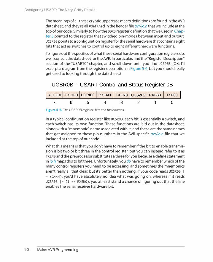
The meanings of all these cryptic uppercase macro definitions are found in the AVRdatasheet, and they’re all #defined in the header file avr/io.h that we include at thetop of our code. Similarly to how the DDRB register definition that we used in Chap-ter 3 pointed to the register that switched pin-modes between input and output,UCSR0B points to a configuration register for the serial hardware that contains eightbits that act as switches to control up to eight different hardware functions.
To figure out the specifics of what these serial hardware configuration registers do,we’ll consult the datasheet for the AVR. In particular, find the “Register Description”section of the “USART0” chapter, and scroll down until you find UCSR0B. (OK, I’llexcerpt a diagram from the register description in Figure 5-6, but you should reallyget used to looking through the datasheet.)
Figure 5-6. The UCSR0B register: bits and their names
In a typical configuration register like UCSR0B, each bit is essentially a switch, andeach switch has its own function. These functions are laid out in the datasheet,along with a “mnemonic” name associated with it, and these are the same namesthat get assigned to these pin numbers in the AVR-specific avr/io.h file that weincluded at the top of our code.
What this means is that you don’t have to remember if the bit to enable transmis-sion is bit two or bit three in the control register, but you can instead refer to it asTXEN0 and the preprocessor substitutes a three for you because a define statementin io.h maps this to bit three. Unfortunately, you do have to remember which of themany control registers you need to be accessing, and sometimes the mnemonicsaren’t really all that clear, but it’s better than nothing. If your code reads UCSR0B |= (1<<4), you’d have absolutely no idea what was going on, whereas if it readsUCSR0B |= (1 << RXEN0), you at least stand a chance of figuring out that the lineenables the serial receiver hardware bit.
90 Make: AVR Programming
Configuring USART: The Nitty-Gritty Details

avr/io.h
Actually, the avr/io.h file in turn includes a different subfile depending on which chip you arewriting for so that you don’t have to change much of your code when you change chips. Forinstance, using an ATmega168P, the file that actually gets included is called iom168p.h.Looking through this file, you can see all the special register definitions for each register byteand its bits.
Scrolling down to the USART section, we find that:
#define UCSR0B _SFR_MEM8(0xC1)
#define TXB80 0
#define RXB80 1
#define UCSZ02 2
#define TXEN0 3
#define RXEN0 4
#define UDRIE0 5
#define TXCIE0 6
#define RXCIE0 7
But bear in mind that the macro definition doesn’t do everything for you—all itdoes is substitute a four everywhere it finds RXEN0, for instance. The real meaningof that bit number is only realized when you flip that bit in the right register,UCSR0B. Which is to say, when you have to configure some AVR peripheral by hand,there’s no substitute for the “Register Description” sections of the AVR datasheet.
The “Register Description” Section
When I’m approaching an AVR peripheral configuration problem, I almost always start offby rereading the “Features” and “Overview” sections, and then jump straight across to the“Register Description.” After the first two sections, I have a good idea of what the hardwareis supposed to do. The “Register Description” section then describes how to do it.
The first hunk of code in initUSART() makes use of some macro definitions fromthe util/setbaud.h include file to set up the USART configuration registers. UBRR0Land UBRR0H contain, respectively, the low byte and high byte of a 16-bit numberthat determines what baud rate the AVR will use for serial communications. Tosample the serial line at just the right times, the AVR divides the system CPU clock,which usually runs between 1 MHz to 20 MHz, down to a baud-rate clock runningbetween 9,600 Hz and 115,200 Hz. The divisor for this clock is stored in UBRR0.
91Chapter 5: Serial I/O
Configuring USART: The Nitty-Gritty Details

Because there’s such a wide range of possible system clocks and desired baud rates,the AVR also has a double-speed mode to handle the higher speeds. A USE_2Xmacro is defined in setbaud.h that figures out whether we should use the regularor double-speed modes. The #if, #else, and #endif commands are like #definestatements; they’re intended for the preprocessor. This is the only time I’ll use pre-processor #if statements, so don’t sweat this if you don’t want to.
Next, the code enables the USART hardware by writing the enable bits for bothtransmit and receive. When we do this, the AVR takes over the normal operationof these ports for the USART, setting the data direction registers and pull-up resis-tors and everything else appropriately for serial communication. Finally, we set afew extra configuration bits that set the USART for 8-bit bytes and one stop bit.
Feel free to skim through the “Register Description” section in the datasheet to seewhat all the special register configuration bits can do. We’ll only use a very smallsubset of the options here, because we’re doing the default—speaking “normal”hardware serial to the computer. In particular, if you’d like to change the numberof bits per frame, or include a parity bit or extra stop bits, you’ll see which bits youneed to set here in the register description.
Once the USART is configured, using it is a piece of cake. Look at the functionstransmitByte() and receiveByte(). They both check bits in the UCSR0A (USARTControl and Status Register 0 A) register to make sure that the hardware is ready,then read or write their target byte to a special hardware register, UDR0 (USART DataRegister), that you use for reading and writing data to and from the USARThardware.
To transmit, you simply wait until the UDRE0 (USART Data Register Empty) bit in thestatus register is set and then load your byte to transmit into UDR0. The USARThardware logic then shuttles that data along to another memory where it writes itout bit by bit over the serial line as described in the Bob and Alice example.
Similarly, there is a receive-complete bit (RXC0) in the status register UCSR0A thatlets you know when a byte has been received. When that bit is set, you can readout the data that just came in. Indeed, if you didn’t want to loop around until datacame in over the USART—say you wanted the AVR to process other events in themeantime—instead of using a loop_until_bit_is_set(UCSR0A, RXC0); con-struct, you could simply test if the RXC0 bit is set from within your main event loopand act on the new data when it comes in. You’ll see examples of this style of codelater on.
92 Make: AVR Programming
Configuring USART: The Nitty-Gritty Details

The Registers: Using USART
SendingWait until the USART data register is clear, indicated by the UDRE0 bit in UCSR0A being set,then write your data to UDR0.
ReceivingWhen data comes in, the RXC0 bit in UCSR0A will be set, and you can read the incomingdata out of UDR0.
The function printString() just loops through all the characters in a string untilthe end, transmitting them one at a time. How does it know when it’s come to theend? C strings end in the NULL character, a character with the special value of zero,which you can test easily enough for in an if() or while() statement.
Two more functions, printByte() and printBinaryByte(), are mostly for yourconvenience and to help make pretty output for your computer. printByte() takesthe numeric value of an 8-bit byte and turns it into the three ASCII digits it repre-sents and sends them out. So if a=56, printByte(a) sends “0” and then “5” and then“6” across the serial line:
void printByte(uint8_t byte){ /* Converts a byte to a string of decimal text, sends it */ transmitByte('0'+ (byte/100)); /* Hundreds */ transmitByte('0'+ ((byte/10) % 10)); /* Tens */ transmitByte('0'+ (byte % 10)); /* Ones */ }
printBinaryByte() does a similar thing, but in binary; printBinaryByte(56) printsout “00111000” to your terminal:
void printBinaryByte(uint8_t byte){ /* Prints out a byte as a series of 1's and 0's */ uint8_t bit; for (bit=7; bit < 255; bit--){ if ( bit_is_set(byte, bit) ) transmitByte('1'); else transmitByte('0'); }}
Because we’re used to reading binary in most-significant-bit order, the for() loopin printBinaryByte() runs the variable bit from seven to zero. The if() statementtests each bit and sends a 1 or 0 character accordingly.
93Chapter 5: Serial I/O
Configuring USART: The Nitty-Gritty Details

Modules in C
All of this USART code, wrapped up in the USART.h andUSART.c files, is written in a way so that it’s maximallyeasy to import it into your own code. When yourprojects get complex enough, you’re going to wantto do this, too. So let’s take a minute to look at theways people bundle up their code into reusable mod-ules in C.
Generally speaking, the .c file is where your codegoes, and the .h, or header file is reserved for#defines that the user is likely to want to change andfor descriptions of the functions that are included inthe .c file. This makes the header file the first place tolook when looking at someone else’s code—theheader file should provide an overview.
Additionally, in strict C, every function should beprototyped before it is defined or used, and the tra-ditional way to make sure this happens is to put func-tion prototypes in the header files. A function proto-type is very similar to a function definition, justwithout the code. The important part is that you mustdeclare what type of variables each function takes asarguments, and what value it will return. But whileyou’re at it, you might as well write some nice ex-planations of what everything does. This makes theheader files very valuable.
To use functions from a given module, say module.c,into your code, you’ve got to first include all the func-tion prototypes by including the module.h file at thetop of your main file. (See how I do that with#include "USART.h" at the top of the code in thischapter?) Next, you’ve got to tell the compiler whereto find the module.c file in which the actual code forthe functions are stored. Much of the project-specificdetail, like locations of module files and so on, is in-corporated into the project’s makefile.
Makefiles automate a bunch of the repetitive andotherwise boring parts of software compilation by
defining which parts of the project depend on whichother parts. So when you’re adding a new module toyour code, you’ll need to tell the makefile where it canfind the module.c file, so that it can compile it alongwith your main program’s .c file.
If you are only using a given module for this oneproject, it makes sense to keep its header and codefiles in the same folder as your main code. If, on theother hand, you are reusing the same code acrossmultiple projects, you may want to store the modulein some other “library” directory and include it fromthere.
In my makefiles, I provide options for both of thesepossibilities. If you’d like to include .c files that are inthe same directory as the rest of your project, you canadd the filenames to the LOCAL_SOURCE variable. Ifyou’d like to include library functions that you’vestored somewhere else, you can pass the directoryname to EXTRA_SOURCE_DIR and the filenames toEXTRA_SOURCE_FILES. Other makefiles will havesimilar definitions.
So, in short, if you want to include a module module into your main code, you need to:
1. Copy the module.h and module.c files intoyour project directory or include the directorywhere you’ve stored the files in your makefile.
2. #include module.h at the top of your codebefore you use any of the functions.
3. Add the .c file to your makefile as extra sourceto be compiled.
If you look into the full version of the USART.h and USART.c files, you’ll find a fewmore useful functions that we’ll employ at various points in the rest of the book.But feel free to hold off on that for later. It’s time to start using this stuff.
94 Make: AVR Programming
Configuring USART: The Nitty-Gritty Details

Other Uses for USART
Besides communicating with your computer, hereare some other uses of the USART:
• Debugging. The ability to send out info aboutthe AVR’s state over the serial line can bepriceless. The functions printByte(), printWord(), and printBinaryByte() make itpainless.
• Using LCD and VFD displays that take serialinput.
• Making your own GPS datalogger is fairlyeasy, because GPS modules usually send outtheir location data using a USART-style serialprotocol.
• Integrating card-readers, both magnetic-stripe and RFID, into your designs, becausethey often send their data to you in USARTserial.
• Sending data via radio protocols, becausemost use USART encoded in various ways.
• Building other examples in this book: we’ll setup a low-speed “oscilloscope” using the ADCin Chapter 7.
Now you know what makes it all work. Again, because the USART code is all bundledup in the .h and .c files, all you need to do to use serial in your code is includethe .h file in your preamble and add the .c file into your makefile. Then you can haveyour AVR talk freely to your computer, and tremendous power becomes yours.
AVR Square-Wave Organ
It’s time to make some noise, and put our serial-port to good use. I love soundprojects, and thought an AVR organ would be a nice demonstration. But then, ifyou’re going to play an organ, you certainly need a keyboard. Rather than buildone out of ebony, ivory, and 88 keyswitches, we’ll hijack your computer’s keyboardand use the serial port to connect the computer with the AVR. Let’s get started.
Hearing is frankly amazing. In case you don’t share my sense of wonder, think aboutthis: periodic pressure waves in the air around you press on a thin skin membranethat wiggles some tiny bones that are configured like a lever, amplifying the move-ments and pressing on a fluid-filled sac that contains hairs that are connected tonerves that sense vibrations. When the longer hairs are vibrated by the fluid, youhear bass tones. When the shorter ones are vibrated, you hear treble.
Right. So the hearing part is already sorted out by Mother Nature. All that’s left forus to do is make the corresponding periodic pressure waves in the air. And for that,we’ll use a paper cone that we’ve strapped an electromagnet onto, and use elec-tricity to wiggle the electromagnet and cone back and forth in the field of a per-manent magnet. And we’ll call this device a speaker. Now all we have to do is sendtime-varying voltages to the speaker coil, and we’ll hear tones. Glorious!
95Chapter 5: Serial I/O
AVR Square-Wave Organ

Making Music with Your MicroMicrocontrollers are not meant to drive speakers. Speakers have a very low resist-ance to direct current (DC), around 8 ohms. For instance, if we run our AVR at 5 voltsand we connect it directly to an 8-ohm speaker, a current of 625 milliamps (5 voltsdivided by 8 ohms) will be drawn, which is significantly more than the 20 to 50milliamps that an AVR pin is good for. The solution is to add a blocking capacitor tothe circuit, as shown in Figure 5-7.
Figure 5-7. Speaker with a blocking capacitor
When a capacitor is subject to a DC voltage, it lets a little current through until it is“charged up” to that voltage, then it blocks further current. This means that ca-pacitors pass current only for changes in voltage. This is perfect for our speaker!The changing signal that makes up the audio is passed through, while the speakerdoesn’t overload the AVR’s output current when the voltage is held high.
But do note that if you’re using an electrolytic capacitor (one that comes in a metaltube-shaped can), they often have a positive and negative sides to them. We’re notrunning enough current through the capacitor to damage it anyway, but you mightas well hook it up with the stripe (negative terminal) to ground. On the breadboard,it will look like Figure 5-8.
96 Make: AVR Programming
AVR Square-Wave Organ

Figure 5-8. Speaker with a blocking capacitor on the breadboard
Just how large a capacitor to use depends on your desired bass response, theparticulars of the speaker, and how willing you are to overdrive the AVR’s outputs.In my experience, anything between 10 and 100 microfarads works well, and I tendto use 47 microfarads. Experiment with whatever values you can get your handson; it’s unlikely that you can break anything.
AmplificationIt’s equally unlikely that the AVR will be driving your speaker to deafening levels,so to truly annoy your neighbors, you may need to redirect the audio signal towhatever amplification you’ve got handy: amplified computer speakers, your ster-eo, a mixing board, etc. But first, you’ll have to attenuate the signal. The 5 V signalthat the AVR puts out is not enough to drive your speaker very loudly, but it’s tooloud for direct input into an amplifier.
Most amplified devices expect a “line level” signal; that is, something from one totwo volts peak to peak. Assuming the AVR is running on 5 V, you’ll want to cut thesignal at least in half before sending it on. The easiest way to do this is to place avoltage-divider in the circuit before the capacitor to limit the output. Any poten-tiometer with a resistance in the 10 kΩ to 100 kΩ range makes a good voltagedivider, and a volume-adjust knob to boot. See Figure 5-9 for the circuit diagram.
97Chapter 5: Serial I/O
AVR Square-Wave Organ
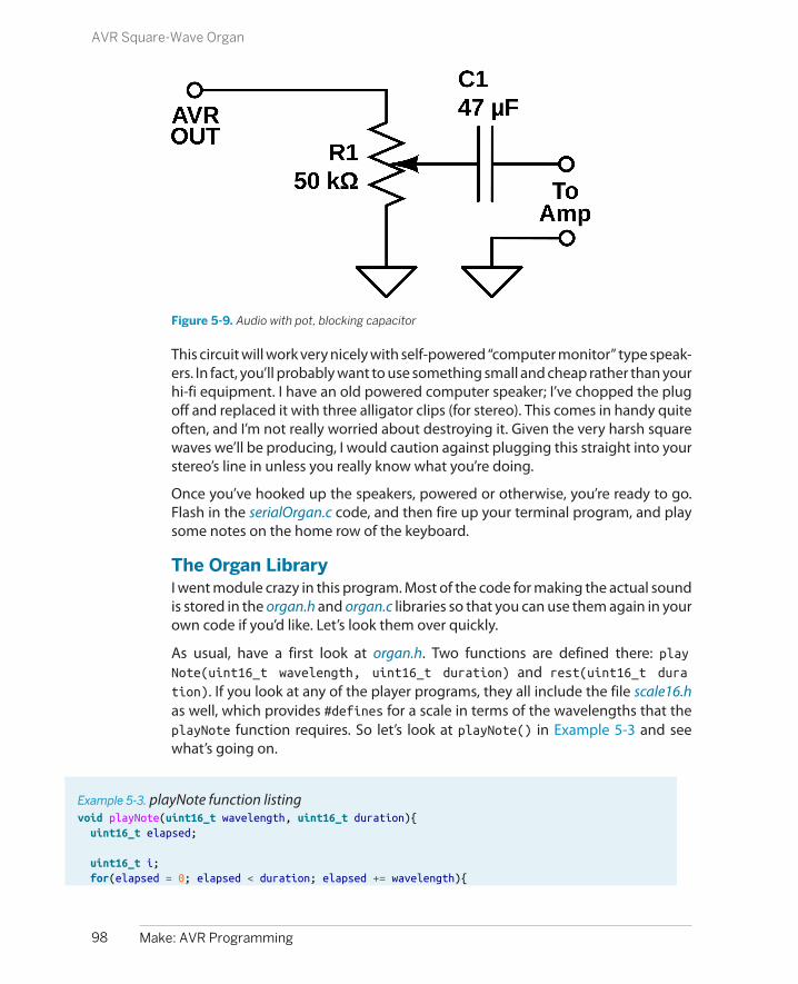
Figure 5-9. Audio with pot, blocking capacitor
This circuit will work very nicely with self-powered “computer monitor” type speak-ers. In fact, you’ll probably want to use something small and cheap rather than yourhi-fi equipment. I have an old powered computer speaker; I’ve chopped the plugoff and replaced it with three alligator clips (for stereo). This comes in handy quiteoften, and I’m not really worried about destroying it. Given the very harsh squarewaves we’ll be producing, I would caution against plugging this straight into yourstereo’s line in unless you really know what you’re doing.
Once you’ve hooked up the speakers, powered or otherwise, you’re ready to go.Flash in the serialOrgan.c code, and then fire up your terminal program, and playsome notes on the home row of the keyboard.
The Organ LibraryI went module crazy in this program. Most of the code for making the actual soundis stored in the organ.h and organ.c libraries so that you can use them again in yourown code if you’d like. Let’s look them over quickly.
As usual, have a first look at organ.h. Two functions are defined there: playNote(uint16_t wavelength, uint16_t duration) and rest(uint16_t dura
tion). If you look at any of the player programs, they all include the file scale16.has well, which provides #defines for a scale in terms of the wavelengths that theplayNote function requires. So let’s look at playNote() in Example 5-3 and seewhat’s going on.
Example 5-3. playNote function listingvoid playNote(uint16_t wavelength, uint16_t duration){ uint16_t elapsed;
uint16_t i; for(elapsed = 0; elapsed < duration; elapsed += wavelength){
98 Make: AVR Programming
AVR Square-Wave Organ
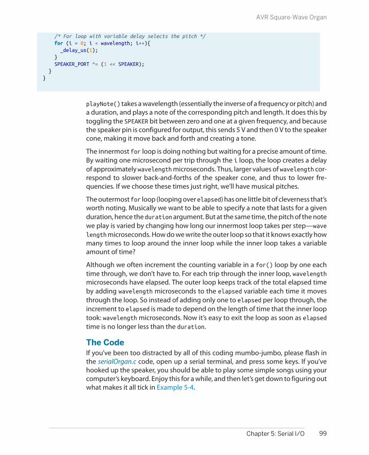
/* For loop with variable delay selects the pitch */ for (i = 0; i < wavelength; i++){ _delay_us(1); } SPEAKER_PORT ^= (1 << SPEAKER); }}
playNote() takes a wavelength (essentially the inverse of a frequency or pitch) anda duration, and plays a note of the corresponding pitch and length. It does this bytoggling the SPEAKER bit between zero and one at a given frequency, and becausethe speaker pin is configured for output, this sends 5 V and then 0 V to the speakercone, making it move back and forth and creating a tone.
The innermost for loop is doing nothing but waiting for a precise amount of time.By waiting one microsecond per trip through the i loop, the loop creates a delayof approximately wavelength microseconds. Thus, larger values of wavelength cor-respond to slower back-and-forths of the speaker cone, and thus to lower fre-quencies. If we choose these times just right, we’ll have musical pitches.
The outermost for loop (looping over elapsed) has one little bit of cleverness that’sworth noting. Musically we want to be able to specify a note that lasts for a givenduration, hence the duration argument. But at the same time, the pitch of the notewe play is varied by changing how long our innermost loop takes per step—wave
length microseconds. How do we write the outer loop so that it knows exactly howmany times to loop around the inner loop while the inner loop takes a variableamount of time?
Although we often increment the counting variable in a for() loop by one eachtime through, we don’t have to. For each trip through the inner loop, wavelengthmicroseconds have elapsed. The outer loop keeps track of the total elapsed timeby adding wavelength microseconds to the elapsed variable each time it movesthrough the loop. So instead of adding only one to elapsed per loop through, theincrement to elapsed is made to depend on the length of time that the inner looptook: wavelength microseconds. Now it’s easy to exit the loop as soon as elapsedtime is no longer less than the duration.
The CodeIf you’ve been too distracted by all of this coding mumbo-jumbo, please flash inthe serialOrgan.c code, open up a serial terminal, and press some keys. If you’vehooked up the speaker, you should be able to play some simple songs using yourcomputer’s keyboard. Enjoy this for a while, and then let’s get down to figuring outwhat makes it all tick in Example 5-4.
99Chapter 5: Serial I/O
AVR Square-Wave Organ

Example 5-4. serialOrgan.c listing/*
serialOrgan.c
Reads a character in serial from the keyboard, plays a note.
See organ.h for pin defines and other macrosSee organ.c (and include it in the Makefile) for playNote() and rest()
*/
// ------- Preamble -------- //#include <avr/io.h>#include <util/delay.h>#include "organ.h"#include "scale16.h"#include "pinDefines.h"#include "USART.h"
#define NOTE_DURATION 0xF000 /* determines long note length */
int main(void) {
// -------- Inits --------- // SPEAKER_DDR |= (1 << SPEAKER); /* speaker for output */ initUSART(); printString("----- Serial Organ ------\r\n");
char fromCompy; /* used to store serial input */ uint16_t currentNoteLength = NOTE_DURATION / 2; const uint8_t keys[] = { 'a', 'w', 's', 'e', 'd', 'f', 't', 'g', 'y', 'h', 'j', 'i', 'k', 'o', 'l', 'p', ';', '\'' }; const uint16_t notes[] = { G4, Gx4, A4, Ax4, B4, C5, Cx5, D5, Dx5, E5, F5, Fx5, G5, Gx5, A5, Ax5, B5, C6 }; uint8_t isNote; uint8_t i;
// ------ Event loop ------ // while (1) {
/* Get Key */ fromCompy = receiveByte(); /* waits here until there is input */ transmitByte('N'); /* alert computer we're ready for next note */
/* Play Notes */ isNote = 0; for (i = 0; i < sizeof(keys); i++) {
100 Make: AVR Programming
AVR Square-Wave Organ

if (fromCompy == keys[i]) { /* found match in lookup table */ playNote(notes[i], currentNoteLength); isNote = 1; /* record that we've found a note */ break; /* drop out of for() loop */ } }
/* Handle non-note keys: tempo changes and rests */ if (!isNote) { if (fromCompy == '[') { /* code for short note */ currentNoteLength = NOTE_DURATION / 2; } else if (fromCompy == ']') { /* code for long note */ currentNoteLength = NOTE_DURATION; } else { /* unrecognized, just rest */ rest(currentNoteLength); } }
} /* End event loop */ return (0);}
First and foremost, look at the laundry list of include files. We want to use theplayNote() function from the organ.c and organ.h files, so I’ve included that here.I’ll also use the predefined scale data from the scale16.h file. (“16” because the scalemakes use of 16-bit numbers for greater pitch accuracy.) And finally, I include theUSART.h file that includes the utility serial functions that we’ve already seen.
And speaking of the USART library, look down to the main() function. Notice thatbefore entering the event loop, in the initializations section, I call the initUSART() function and print out something friendly to the serial port. As you sawearlier, initUSART() selects the baud rate and configures the USART hardware ap-propriately. The print command gives us something to look for in the serial ter-minal window to verify that all’s well with the serial connection. And before weleave the initialization section, notice that we’ve set up the speaker pin for outputby setting the correct bit in the DDR.
Finally, inside the event loop, the program starts off by waiting for a serial byte fromyour computer. Once it gets a byte, it acknowledges it back to your computer, whichwill let you play around with scripting the serial organ later, and then the routineplays an appropriate note depending on which key you’ve sent. The way the codemaps these keys to notes is a tiny bit advanced, so feel free to skip the followingsidebar if you’d like.
101Chapter 5: Serial I/O
AVR Square-Wave Organ

Converting Keypresses to Notes
The organ code needs to take input from your serialterminal program and map those keys to notes in away that’s intuitive for you. To code this lookup in aflexible and maintainable manner, I use two constantarrays, one with the list of keypresses and the otherwith a list of the pitches. This is actually a pretty com-mon case for dealing with user input, so I thought I’dmention it here.
The “trick” to the lookup is the for(i=0; i < sizeof(keys); i++){} loop. The code looks throughall of the possible keys that correspond to notes. If itmatches one of them, it plays the i‘th note immedi-ately and drops out of the for() loop. Slick, no?
There’s one nuance in the for loop that I’d like topoint out. Notice that i is only incremented as longas i < sizeof(keys). Because the code indexes thekeys[] array with i, this seems natural. But weshould double-check that i never gets bigger thanthe size of the array. Because each key[] entry is a
byte and the array is 18 bytes long, the sizeof(keys) command will return 18, and the max-imum value i will ever take on is 17. That is, we onlywant to run the for() loop as long as i < sizeof(keys).
The error that new C programmers make here is towrite something like i <= sizeof(keys), becausewe have 18 bytes and we’d like to loop over all ofthem, right? Right, but wrong! Because C indexes itsarrays starting at position 0, the last element iskeys[17] and not keys[18]. That is, the less-than-or-equal-to construction ends up indexing one pastthe end of the array, which is no good.
If you’re still new at C, you’ll probably want to double-check the variables you use to index arrays each timeyou see one. Just remember that the maximum indexfor an array is one less than its length because westarted counting at zero rather than one.
If the program hasn’t received a valid note command, it checks to see if you’vechanged the note length, and sets the appropriate value if you have. If none ofthese have happened, it defaults to resting (not playing a note) for the duration.
And that’s it. You can now play your AVR from your laptop’s keyboard, and that’spretty cool. But this is just the beginning of a long and fruitful friendship; yourcomputer and your AVR are a match made in hacker heaven.
Extra GoodiesI’ve also included two more files that might be interesting in the software bundlefor the serialOrgan project. Both of them are written in Python, rather than beingwritten in C. Python is an interpreted language, and includes modules that let youdo basically anything, easily. I’ll use it throughout the book for projects that requirecomputer/AVR interaction, or for doing any sort of computations that are too de-manding for the AVR.
Creating the scale16.h header file that contains the note pitch data is an exampleof something that you’ll really want to do with a simple routine on your big com-puter, rather than reimplementing on the fly in the AVR. I’ve included the genera-teScale.py file that created the header file in the software distribution for thisproject.
102 Make: AVR Programming
AVR Square-Wave Organ

I’ve also included a simple script (autoPlay.py) that demonstrates one way to in-terface your desktop computer with the AVR. The code relies on Python and thepyserial library. This script sends a character to the organ to play a note, and thenwaits for the AVR’s response before sending the next note—you’ll recall the AVRacknowledges when it’s ready to continue.
Though it’s a little bit difficult to get the timing right, and even to remember whichkeys are which while playing the AVR organ live, it’s a lot easier to type in stringsof characters and let a Python routine shuttle them out to the AVR for you. And forpure frivolity, I have the demonstration program fetch text from a web page thatcontains “song” data, and play it across on the organ.
Neither of these programs are necessary to your understanding of the AVR serialperipheral, so I’m going to leave digging into the code up to you—they’re just hereto whet your appetite. If you’ve already got Python installed on your computer, feelfree to run them both. If you don’t have Python or pyserial installed yet and youjust can’t wait, flip ahead to “Installing Python and the Serial Library” on page 121and install them both. If you’d like to get on to more and better AVR programming,don’t sweat it; I’ll catch you up on the whole Python thing later.
Summary
After digging deep into a complex application like this, you may have forgottenthe reason we came here—to learn something about the AVR’s serial peripheral.
Using the USART:
1. Choose a baud rate, here by defining BAUD, and write the appropriate valuesto the baud rate registers UBRRL and UBRRH. (The setbaud.h library will help youwith this.)
2. Enable the serial receive and transmit register bits.
3. If you’re transmitting, wait until the hardware is ready (loop_until_bit_is_set(UCSR0A, UDRE0)) and then load your byte data into UDR0. TheAVR’s hardware handles everything else automatically.
4. If you’re waiting for data, check the data-received bit (bit_is_set(UCSR0A,RXC0)) and then read the data out of UDR0. Reading UDR0 automatically clearsthe data-received bit, and the AVR gets ready for the next received byte.
Additionally, I’ve wrapped up these simple statements into a few functions that Ifind convenient. I use initUSART(), transmitByte(), and receiveByte() in mycode all the time. If you feel adventurous, you can look through the USART.c fileand see how I’ve implemented other useful serial functions, like printing out a byteas its binary or hexadecimal equivalent, and printing whole strings at a time.
103Chapter 5: Serial I/O
Summary

Connecting your big desktop computer to the little computer that lives inside theAVR provides you with many creative possibilities. Your computer can fetch andparse websites, check up on stock prices, and do incredible amounts of math. TheAVR can move motors, blink LEDs, sense light levels, respond to pushbuttons inreal time, and generally interface with the world of DIY electronics. Putting thesetwo together is a recipe for winning, and the serial port is your link.
104 Make: AVR Programming
Summary

What You Need
In this chapter, in addition to the basic kit, you willneed:
• A pushbutton or two.
• A speaker and blocking capacitor, around10µF.
• A USB-Serial adapter.
AVR Music Box and a Boss Button
If you want to build a standalone AVR device, there’s no substitute for the tried-and-true pushbutton. Look around the room you’re now in. How many electronicdevices with pushbuttons are you surrounded by? (Feel free to stop counting afterfive or ten.) Pushbuttons are cheap, ubiquitous, and the natural choice for quickand mostly painless human/AVR interaction.
In this chapter, we’ll take the humble pushbutton as a stand-in for all types of digitalinput, but there are also a few quirks in using pushbuttons that you will need toknow about. Most importantly, they often bounce very rapidly between the on andoff states when pressed or released. Additionally, you’re often interested in runningsome action when the button is first pressed rather than continuously while it’spressed.
Pushbuttons, Switches, Etc.
As soon as you start having plans for more interesting AVR devices, you’re goingto want some degree of user interaction. And what’s simpler than the humble
105
Digital Input 6

pushbutton? Still, there are a couple of things you’re going to need to know beforeyou can start using switches and buttons as inputs to the AVR.
The AVR inputs are good at sensing voltages. In particular, they’re very good atsensing whether an applied voltage on a particular pin is higher or lower than halfof the supply voltage. Your first task, then, is to figure out how to apply logic highand low voltages to an AVR pin by way of a pushbutton.
The naïve circuit shown in Figure 6-1 connects one end of the pushbutton toground and the other end to the AVR. That way, whenever you press the buttonthe AVR end is connected to ground, too, so it’s pretty much guaranteed to be at0 V.
Figure 6-1. Naive button circuit
But when you let go of the button (or open the switch), what is the voltage at theAVR end of the switch? Short answer: nobody knows. A wire that’s just dangling inthe air, on the unconnected side of a switch, can act as an antenna. The voltage onthat wire will wiggle around between high and low logic states at whatever fre-quency the strongest local radio stations (or even “noisy” electrical appliances)broadcast. The only thing you do know about this voltage is that it’s unreliable.
Instead of some random value, you want the side of the button that you connectto the AVR to have a nice, defined high voltage level when the button isn’t pressed.But you can’t hook the AVR-side of the button directly to VCC, because if you did,you’d be shorting out the power supply when you pressed the button—hookingVCC up directly to GND is a recipe for disaster. Enter the pull-up resistor, shown inFigure 6-2.
106 Make: AVR Programming
Pushbuttons, Switches, Etc.
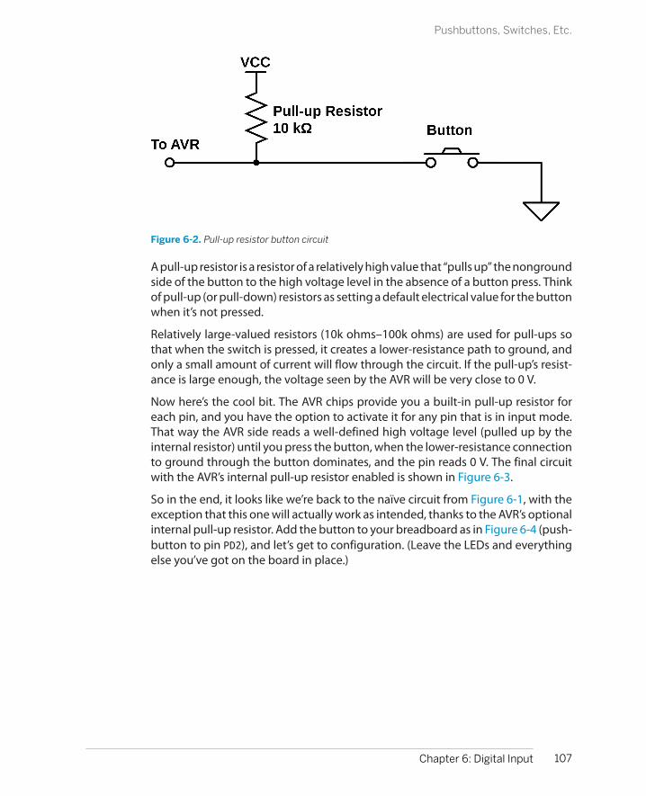
Figure 6-2. Pull-up resistor button circuit
A pull-up resistor is a resistor of a relatively high value that “pulls up” the nongroundside of the button to the high voltage level in the absence of a button press. Thinkof pull-up (or pull-down) resistors as setting a default electrical value for the buttonwhen it’s not pressed.
Relatively large-valued resistors (10k ohms–100k ohms) are used for pull-ups sothat when the switch is pressed, it creates a lower-resistance path to ground, andonly a small amount of current will flow through the circuit. If the pull-up’s resist-ance is large enough, the voltage seen by the AVR will be very close to 0 V.
Now here’s the cool bit. The AVR chips provide you a built-in pull-up resistor foreach pin, and you have the option to activate it for any pin that is in input mode.That way the AVR side reads a well-defined high voltage level (pulled up by theinternal resistor) until you press the button, when the lower-resistance connectionto ground through the button dominates, and the pin reads 0 V. The final circuitwith the AVR’s internal pull-up resistor enabled is shown in Figure 6-3.
So in the end, it looks like we’re back to the naïve circuit from Figure 6-1, with theexception that this one will actually work as intended, thanks to the AVR’s optionalinternal pull-up resistor. Add the button to your breadboard as in Figure 6-4 (push-button to pin PD2), and let’s get to configuration. (Leave the LEDs and everythingelse you’ve got on the board in place.)
107Chapter 6: Digital Input
Pushbuttons, Switches, Etc.
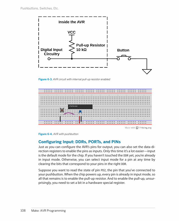
Figure 6-3. AVR circuit with internal pull-up resistor enabled
Figure 6-4. AVR with pushbutton
Configuring Input: DDRs, PORTs, and PINsJust as you can configure the AVR’s pins for output, you can also set the data di-rection registers to enable the pins as inputs. Only this time it’s a lot easier—inputis the default mode for the chip. If you haven’t touched the DDR yet, you’re alreadyin input mode. Otherwise, you can select input mode for a pin at any time byclearing the bits that correspond to your pins in the right DDR.
Suppose you want to read the state of pin PD2, the pin that you’ve connected toyour pushbutton. When the chip powers up, every pin is already in input mode, soall that remains is to enable the pull-up resistor. And to enable the pull-up, unsur-prisingly, you need to set a bit in a hardware special register.
108 Make: AVR Programming
Pushbuttons, Switches, Etc.
But the surprise is which hardware register you need to set a bit in: the output pinhardware register. That is, if you’d like to enable the pull-up on PD2, you need to setPORTD’s corresponding bit high:
DDRD &= ~(1 << PD2); // makes double-sure we're in input modePORTD |= (1 << PD2); // enables pull-up resistor
The way I remember this is that writing a bit to the PORTD register when it’s con-figured for output would pull the pin high, so doing the same when it’s configuredfor input also pulls it high, but only weakly—that is, through the pull-up resistor.
You might be wondering why the Atmel engineers would reuse the same hardwareregister for both setting the output value in output mode and for enabling ordisabling the pull-up resistor in input mode. Well, me too. My only guess is that itcosts them more space in the IC’s internal circuitry to set up another dedicatedeight bits of memory for (yet another) register. Because you’re never going to havea given pin both in output and input mode, they can use the PORT registers to dodouble duty. The point is, though, that you’re going to have to remember thisdouble role of the PORT registers in input mode.
Great. So you’re configured. Now how do you access the bits? Very similarly to howyou wrote to them: reading out a byte from a hardware register and doing somebit twiddling. Only this time you’re twiddling the input hardware register address:PIND. (Think "Pin INput D.”)
Let’s say that you haven’t attached anything to any of the other pins in bank Dexcept for your pushbutton on PD2. Further, you’ve just reset the chip, so all of thepins are in input mode. One more thing: let’s write a 1 to all the bits in PORTD,enabling all of the pull-ups:
DDRD = 0x00; // all pins in input mode, just to be surePORTD = 0xff; // all pins pull-ups enabled
If you look at the eight bits in PIND, you’ll see:
PIND: 11111111
Why? Because nothing is grounded, and the pull-ups guarantee that everything isin logic-high state. Now let’s say you push your button, grounding pin PD2. Whathappens? All the other bits in PIND stay the same, but because the button has muchlower resistance than the internal pull-up resistor, the ground voltage wins out, thevoltage on PD2 drops near zero, and PIND reads:
PIND: 11111011
Now you’ve got something you can work with!
Interpreting Button PressesSo you’ve configured the pin with your button for input, you’ve set the pull-upresistor, and you’re ready to go! How do you read the value of a single bit in the
109Chapter 6: Digital Input
Pushbuttons, Switches, Etc.

register without reading all the others? If your instincts tell you that it’s somethingto do with bitwise logical operators, you are on your way to microcontrollermastery.
Testing bit states is done with the AND operator. You know that an AND will onlyreturn 1 if both bits are 1. If you perform an AND operation in which you comparean unknown bit value against a known 1, you’ll get the state of the mystery bits asthe result. So you’ll bit-shift a 1 into the bit location you’re interested in, then ANDthe two bytes together. The result will either be all zeros if the target bit was zero,or it will be a byte with a 1 in the target location if it was 1.
Testing bits with ANDSay we’re interested in testing if bit two is set. The first step is to create a bitmaskwith a 1 in bit two:
(1 << 2) : 00000100
Then we AND that byte with whatever is in the input register, PIND:
PIND : xxxxxxxx(1 << 2) : 00000100& : 00000x00
If the value we were interested in knowing is a zero, the result is eight zeros. If theresult isn’t zero, then we know the pin in the input register must have been set.Voilà!
So we can test this:
if (PIND & (1<<2)){ doStuff();}
using the C language convention that only a value of zero returns false, and any-thing else is true.
GCC convenience macrosBecause all of this shifting and ANDing can get tiresome, you won’t be surprisedthat there are some convenience macros defined to help you out. Now I’ve almostnever seen other people’s code using these macros, so you’re going to have toremain used to reading the bitmask-and-AND method. These macros are probablynot defined by any compiler other than GCC, for all I know.
On the other hand, these macros are in avr-libc for your use, and I do find theylead to nicely readable code. I’ll use them in my code sometimes, but then also usethe standard C bitmask method sometimes too just to keep you on your toes.
Helpful input macros (included with avr/io.h):
#define _BV(bit) (1 << (bit))
110 Make: AVR Programming
Pushbuttons, Switches, Etc.

#define bit_is_set(sfr, bit) (_SFR_BYTE(sfr) & _BV(bit))#define bit_is_clear(sfr, bit) (!(_SFR_BYTE(sfr) & _BV(bit)))
#define loop_until_bit_is_set(sfr, bit) do { } while (bit_is_clear(sfr, bit))#define loop_until_bit_is_clear(sfr, bit) do { } while (bit_is_set(sfr, bit))
simpleButton demo codeAs a quick example of reading button input, flash the simplePushbutton.c test pro-gram into your chip now and then have a look at the code listed in Example 6-1.
Example 6-1. simpleButton.c listing/* Demo of the simplest on/off button code Button connected to PD2 LEDs connected to PB0..PB7*/
// ------- Preamble -------- //#include <avr/io.h>#include <util/delay.h>
int main(void) { // -------- Inits --------- // PORTD |= (1 << PD2); /* initialize pullup resistor on our input pin */ DDRB = 0xff; /* set up all LEDs for output */
// ------ Event loop ------ // while (1) { if (bit_is_clear(PIND, PD2)) { /* look for button press */ /* equivalent to if ((PIND & (1 << PD2)) == 0 ){ */ PORTB = 0b00111100; /* pressed */ } else { /* not pressed */ PORTB = 0b11000011; } } /* End event loop */ return (0);}
It’s not all that complicated, so I’m not going to explain it in excruciating detail, butthere are two points worth mentioning. First, notice that the code enables the pull-up resistor for the button pin (PD2) by writing to PORTD. In Cylon Eyes, we used PORTBfor controlling output state. In input mode, PORTD controls the pull-up resistor.
The second detail is that our logic is reversed. Because a high voltage on the AVR’spin results in a logical 1 inside the AVR, and the switch voltage is high when thebutton is not pressed, PIND has a 1 in bit PD2 when the button is not pressed. Con-trariwise, when the button is pressed, the bit will read 0. So if you’re testing for a
111Chapter 6: Digital Input
Pushbuttons, Switches, Etc.

press in an if() statement, you’ll want to use bit_is_clear(PIND, PD2) or equiv-alently (PIND & (1<< PD2)) == 0 as the test.
Careful with Those Parentheses
Note that I used (PIND & (1 << PD2)) == 0 and not PIND & (1 << PD2) == 0 in thepreceding test. This is because the == is evaluated before the & otherwise. If you forget theparentheses, (1 << PD2) == 0 returns zero, and PIND & 0 is also going to be zero, no matterwhether the button is pressed or not. The parentheses make it evaluate the & before the ==.
Of course, you can avoid all this thinking and use bit_is_clear() instead, which I find muchmore readable anyway. (And note that the macro is defined with the outer parentheses foryou.)
Changing State
Depending on what your device does, you may be interested in whether the buttonis currently pressed, or whether the button just got pressed. That is, you may wantto know what state the button is in (pressed or not), or you may alternatively wantto know that the button has changed state (just got pressed or just released).
Because the English language is a little imprecise on these matters, but the AVR isbrutally literal, you’ll need to think like a computer here. When you say “do some-thing if the button is pressed,” you’ll have to think about whether you mean “whilethe button is pressed” or “when the button enters the pressed state.”
The difference? Imagine that you want to turn on or off an LED with a button press.If you write naïve code:
while(1) { if (buttonIsPressed){ toggleLED(); }}
the LED is going to be toggling around 100,000 times per second while you’reholding the button down, and whichever state it ends up in when you let go of thebutton is pretty much random. This is probably not what you want.
Instead, if you save the current state of the button in a variable, you’ll be able tosee when the button changes state easily. The code shown in Example 6-2 togglesthe LED every time you press a button.
112 Make: AVR Programming
Changing State

Example 6-2. toggleButton.c listing/* Demonstrates using state to detect button presses*/
// ------- Preamble -------- //#include <avr/io.h>#include "pinDefines.h"
int main(void) { // -------- Inits --------- // uint8_t buttonWasPressed; /* state */ BUTTON_PORT |= (1 << BUTTON); /* enable the pullup on the button */ LED_DDR = (1 << LED0); /* set up LED for output */
// ------ Event loop ------ // while (1) { if (bit_is_clear(BUTTON_PIN, BUTTON)) { /* button is pressed now */ if (buttonWasPressed == 0) { /* but wasn't last time through */ LED_PORT ^= (1 << LED0); /* do whatever */ buttonWasPressed = 1; /* update the state */ } } else { /* button is not pressed now */ buttonWasPressed = 0; /* update the state */ } } /* End event loop */ return (0); /* This line is never reached */}
In this code, the state of the button after the last pass through the event loop isstored in the variable buttonWasPressed. If the button is pressed right now, but itwasn’t pressed the last time we looked, then we know that there’s been a changeof state—the button has just been pressed. In this code, we toggle an LED, but youcan imagine doing something fancy.
Debouncing
If you play around with the toggleButton.c code for long enough, it will glitch. Thatis, you’ll press the button, and instead of turning the LED on, it will turn on andthen off again so quickly that you might not even see it. But the end effect will bethat you thought you were turning the LED on, and it didn’t go on.
Or sometimes it’ll happen that you’ve just turned the LED on with a press, and thenwhen you release the button, it turns back off again. Is there a bug in the code?Nope. You’re just suffering from button bounce.
113Chapter 6: Digital Input
Debouncing

When you press a switch closed, two surfaces are brought into contact with eachother. Often they don’t fit together quite perfectly, and electrical contact will getmade and unmade a few times before you’ve smooshed the two plates togetherfirmly enough that a good reliable connection is made. The same is true when yourelease a button, but in reverse. You let go, the plates start to separate, but onegets a little sideways and just taps the other before they’re far enough apart thatthey never touch.
This physical open-close-open-close nature of switches makes the voltage on thecircuit bounce between high and low logic voltages over a timescale from a fewmicroseconds to a few milliseconds. The really annoying thing about buttonbounce is that most of the time it doesn’t happen. You can test your button 10times and declare it working, only to have it bounce on the thirteenth press.
Figure 6-5 displays two oscilloscope traces from the pushbutton on my bread-board. Because the button is normally held high by the AVR’s internal pull-up re-sistor, the first frame represents a button press while the second is a button release.I’ve cherry-picked two of the worst examples just for you.
Figure 6-5. Pushbutton bounce example
So that’s what’s going on with our toggling code! When we release the button, forinstance, it can momentarily go high and then low again before finally taking thecorrect high voltage value. If the AVR is checking the button state frequentlyenough, it can see this high-low transition that occurs during the release bounceand interpret it as a button press, even though no human could ever release andthen repress a button that quickly.
The easiest solution is to have the AVR wait a few milliseconds and then check tosee if the button is still pressed or not before making any decisions. Because thebuttons bounce only for a “short” time, waiting for a little bit longer and thendouble-checking will ensure that we’re not mistaking bounce for a true change.
The trick with debouncing-by-waiting is getting the timing right. The characteristictime that a switch bounces varies from switch to switch, but all that I’ve ever seensettle down within a couple milliseconds. We can therefore very conservatively
114 Make: AVR Programming
Debouncing

wait around 5 ms and test the button again. Bearing in mind that human responsetime is on the order of tens of milliseconds, this won’t result in a noticeable delayto the user, either. Of course, I recommend varying the wait time and trying it outin your particular setup.
(More than) All You Ever Wanted to Know About Debouncing…
You can find a nice writeup of debouncing at http://www.ganssle.com/debouncing.htm, anda compilation of software debouncing routines on http://hackaday.com/2010/11/09/debounce-code-one-post-to-rule-them-all/. Both are good reads.
Debounce ExampleSo let’s add a debouncing routine to our toggleLED code. The result is shown inExample 6-3.
Example 6-3. debouncer.c listing// ------- Preamble -------- //#include <avr/io.h>#include "pinDefines.h"
#include <util/delay.h>#define DEBOUNCE_TIME 1000 /* microseconds */
uint8_t debounce(void) { if (bit_is_clear(BUTTON_PIN, BUTTON)) { /* button is pressed now */ _delay_us(DEBOUNCE_TIME); if (bit_is_clear(BUTTON_PIN, BUTTON)) { /* still pressed */ return (1); } } return (0);}
int main(void) { // -------- Inits --------- // uint8_t buttonWasPressed; /* state */ BUTTON_PORT |= (1 << BUTTON); /* enable the pullup on the button */ LED_DDR = (1 << LED0); /* set up LED for output */
// ------ Event loop ------ // while (1) { if (debounce()) { /* debounced button press */ if (buttonWasPressed == 0) { /* but wasn't last time through */ LED_PORT ^= (1 << LED0); /* do whatever */ buttonWasPressed = 1; /* update the state */ }
115Chapter 6: Digital Input
Debouncing

To Debounce, or Not to Debounce?
As much as I love debouncing routines (and I lovethem a lot!) there’s a time and a place for everything.
To debounceFundamentally, you need to debounce when-ever you’re counting button press events. Thisgoes equally for on/off toggling, scrollingthrough elements of a menu, or switchingamong modes.
You’ll also want to debounce if you’re timing anevent. How long was the button pressed? Well,that will depend on when you define the buttonpress as beginning. If you accidentally time oneof the early spikes, you might erroneously con-clude that the user pressed and released thebutton within microseconds, when it was just abounce.
Not to debounceIf you don’t care about counting button pressesor events, there’s no need to spend the code ondebouncing. For instance, if you’d like a circuitto light up when you press a button, a simplelogic test will suffice. If your LED blinks a couple
times during the first few microseconds, but it’sfaster than a human’s flicker-fusion rate, nobodywill notice.
Similarly, if you’ve got a built-in delay, thebounce may not matter as much. If your code isdoing a lot, and only makes it through the mainevent loop once in a few milliseconds, then youdon’t really have to worry about debouncing—the delay you would have written into your de-bounce code is already built in to your (slow)main event loop.
Hardware debouncingThere’s also a third option, and this is the waybuttons were debounced in the old days beforemicrocontrollers reduced the issue to just a fewextra lines of code. Putting a capacitor across thetwo contacts of a switch forces the voltage torise slowly, and can ensure that it will not jumpup and down along the way. In industry, almosteveryone debounces in code, saving a few centsper capacitor.
} else { /* button is not pressed now */ buttonWasPressed = 0; /* update the state */ }
} /* End event loop */ return (0); /* This line is never reached */}
The debouncer.c code here is almost exactly the same as that in the bouncy tog-gleButton.c earlier. The debounce() function is new, I added a definition for thedebounce delay, and I changed the line:
if (bit_is_clear(BUTTON_PIN, BUTTON)){
to:
if (debounce()){
but that’s it. All of the rest of the logic of the code (in particular, keeping track ofthe button state) is just the same, so you don’t have to rethink that through.
116 Make: AVR Programming
Debouncing
The debounce() function handles debouncing in the simplest way possible—checking if the button is pressed twice with a delay in between. The function re-turns a one only if the button was pressed both times. If the button wasn’t pressedfor either of the two checks, debounce() returns a zero, and the if(debounce())statement is false. This, for a long-enough value of the defined DEBOUNCE_TIME,guarantees debounce-free toggling.
Try it out and see. I’ve defined the debounce timeout in microseconds (millionthsof a second), which will enable you to experiment. You can set the delay shortenough that your button still bounces, and then you can adjust it so it doesn’t. Iencourage you to play around with it. For instance, my button still bounces some-times at 200 microseconds, but doesn’t seem to at 700 microseconds. Even 1,000microseconds, or one millisecond, is very, very fast on human timescales. Yourmileage will vary. Play around.
Just to reiterate, debouncing can be as simple as waiting a fixed time and retestingthe button. It’s a good thing to know about debouncing, and to understand thatit’s no big deal. If you didn’t know, and you were trying to debug an infrequentglitch like switch bounce in your system, you’d be pulling your hair out.
AVR Music Box
Here is a simple musical application of everything that you’ve learned so far. We’veall seen music boxes, right? The ones with the small crank on the outside that turnsa drum that plucks little tines to play a song? When you turn the crank faster orslower, you can influence the tempo of the song, but the notes are “hardcoded” into the pins on the turning drum.
You can easily do the same with the AVR: you already know how to play notes soall that’s left is using the pushbutton to allow you to control the tempo. If you’vegot the speaker and blocking capacitor and the pushbutton set up, there’s nothingmore for you to do other than flash in this simple code.
The CodeThis code is basically just a small tweak on the serial organ in Chapter 5. It calls thesame playNote() that we used in the organ routine repeatedly, each time with adifferent note. The notes themselves are stored in an array called song[]. Each timeyou press the button (that is, the button state changes to pressed), a variable isincremented that points to the next note in the song. While the button is helddown, the same note continues to play. This gives you total control over both thetempo and duration of each note.
Flash it in, play around, and see if you can figure out what the tune is! Once you do,feel free to extend the song[] array to play anything you want. The code for theexample is found in Example 6-4.
117Chapter 6: Digital Input
AVR Music Box

Example 6-4. avrMusicBox.c listing// Music Box Input Demo
// ------- Preamble -------- //#include <avr/io.h>#include <util/delay.h>#include "organ.h"#include "scale16.h"#include "pinDefines.h"
#define SONG_LENGTH (sizeof(song) / sizeof(uint16_t))
int main(void) { const uint16_t song[] = { E6, E6, E6, C6, E6, G6, G5, C6, G5, E5, A5, B5, Ax5, A5, G5, E6, G6, A6, F6, G6, E6, C6, D6, B5, C6, G5, E5, A5, B5, Ax5, A5, G5, E6, G6, A6, F6, G6, E6, C6, D6, B5, /* etc */ }; /* starting at end b/c routine starts by incrementing and then playing this makes the song start at the beginning after reboot */ uint8_t whichNote = SONG_LENGTH - 1; uint8_t wasButtonPressed = 0;
// -------- Inits --------- // SPEAKER_DDR |= (1 << SPEAKER); /* speaker for output */ BUTTON_PORT |= (1 << BUTTON); /* pullup on button */
// ------ Event loop ------ // while (1) { if (bit_is_clear(BUTTON_PIN, BUTTON)) { if (!wasButtonPressed) { /* if it's a new press ... */ whichNote++; /* advance to next note */ /* but don't run over the end */ if (whichNote == SONG_LENGTH) { whichNote = 0; } wasButtonPressed = 1; } playNote(song[whichNote], 1600); } else { wasButtonPressed = 0; } } /* End event loop */ return (0);}
118 Make: AVR Programming
AVR Music Box

The bulk of the main() routine looks just like the toggleButton code, and that’s nosurprise. First, the button is tested for input. If it’s pressed, but it wasn’t pressed lasttime, we advance to the next note. If that takes us past the last note in the song,we loop back to the beginning. Outside of the first-press logic, the code updatesthe button-press state and plays our note. If the button is not pressed this timethrough the loop, wasButtonPressed is naturally set to zero.
If you’re new to C, the way the code moves through the song[] array is worthlooking at. The number of notes in the song is computed by the #define macroSONG_LENGTH. Why can’t we just use the sizeof() command directly? Because thenote values happen to all be 16-bit numbers, and sizeof() returns the number ofbytes. So for a 10-note song, sizeof() will return 20. But because I know that I’vegot an array of uint16_t numbers, I can get the number of entries either by dividingby two or dividing by sizeof(uint16_t), which I think makes it clearer why we’redoing the division in the first place.
Also notice that we test for running over the end of the song with:
if (whichNote == SONG_LENGTH) { ...
Remember that arrays start at zero in C. Because of this, if you’ve got a 10-elementarray, the first element is number 0 and the last is 9. On the one hand, this is hardto remember and is the cause of many off-by-one errors. On the other hand, itmakes it super easy to test for whether you’ve gone too far with just a simple testof equality, as we do here.
Finally, the last strange bit about this code is that we start off with the note indexingvariable whichNote set to SONG_LENGTH -1. What gives? If you followed the discus-sion about zero-indexing, you’ll recognize that whichNote is set to the last validnote in the song. I ended up having to do this because of the button-press logic,which updates the song position first, then plays the note afterward. (I suppose Icould have changed the logic to update the note when the button is released, butI wanted it to be a mirror of the toggleButton code.) Anyway, because I wantedthe song to start with the first note on reboot, but it advances a note with everypress, the solution is to start on the last note so that when you press the buttonthe first time it will wrap around back to the beginning.
And that’s it. The simple button-pressing routine we developed here turns into amusic box with very little extra effort. I hope you enjoy the quick demo. Now whatcan you do with a pushbutton and some quick programming logic?
Boss Button
While we’re on the topic of pushbuttons and the AVR, I can’t resist but throw in aproject that uses the AVR as a frontend for code that runs on your desktop. Why?Because I think it’s awesome to have a pushbutton that opens a web page. So let’smake a quick-and-dirty Boss Button.
119Chapter 6: Digital Input
Boss Button
Pushbutton Checklist
1. Set DDR for input. It’s the default pin state, butif you’re not sure, it doesn’t hurt to set it ex-plicitly with something like DDRD &= ~(1 <<PD2).
2. Set the internal pull-up if you don’t have aphysical pull-up resistor in the circuit: PORTD|= (1 << PD2).
3. Read the button voltage in your code. If you’dlike to test that the button is pressed, you cando so two ways: with something like if(!(PIND & (1 << PD2))) or using the macro
bit_is_clear(PIND, PD2), which I findmore readable, and less error-prone.
4. Think about whether you want something tohappen while the button is pressed, or whenit becomes pressed. Store the previous stateand test for changes if you’re interested in thelatter.
5. If you’re trying to detect a single button-pressevent, consider debouncing. The simplestway to debounce is to simply wait a few mil-liseconds and test if the button is still pressed.
What’s a Boss Button? You know, when you’re surfing the Web, or generally goofingoff and your boss comes by? You’re going to need to hide the evidence on yourcomputer screen quickly. But how are you going to do this without mousing allaround and generally looking klutzy and suspicious? The answer is the Boss Button.One click on your trusty (and totally work-related) AVR microcontroller project thatjust happens to be sitting on your desk, and your browser is loaded with all sortsof businessy looking stuff.
OK, so that’s the pitch. But once you’re done with this project, you can simply adda few more buttons and modify the desktop code to launch whatever web pagesyou’d like with each press. You’ll have your own dedicated physical favorite-website-launcher machine.
To open the browser window to a website, we’ll need to do some scripting on thecomputer side. And for that, we’ll use Python. So if you don’t have Python andpyserial installed on your computer yet, now’s the time. After you’ve got that setup and understood, the rest is child’s play.
If you’re more focused on simply learning the AVR chip than playing around withdesktop computer programming, at least take the few minutes to install Pythonand the serial module (see “Installing Python and the Serial Library” on page 121)because we’ll be using them throughout the rest of the book. But don’t fret—youwon’t have to learn Python on top of C unless you’d like to.
Desktop-side ScriptingI do most of my computer-side scripting in Python, mostly because it’s very easyto extend your work from one domain to another. Most of the stuff that’s almostimpossible to implement on a microcontroller is trivial in Python (and vice versa).
120 Make: AVR Programming
AVR Music Box

Installing Python and the Serial Library
First off, if you don’t have Python installed already,let’s do that. And even if you do, we’ll need to makesure you’ve got the serial library (confusingly con-tained in a package called pyserial) installed.
On Linux and Mac OS XOn any modern distribution, you’ll very likelyhave Python installed, which means that youcan simply open up a terminal window and typeeasy_install pyserial to get the serial portlibraries. If your system can’t find easy_install and you’re on a Debian system, try sudoapt-get install python-setuptools. If allthat fails, a web search for how to install setuptools on your system should set you straight.
On WindowsThe easiest way to go is with ActiveState’sPython distribution. Click on downloads and
save the Python 2.7 installer for your system. Ifin doubt, get the 32-bit version. Run the installerand install in the default directories (Python27).Now you’ll need to get pyserial (the serial portlibrary). Run cmd.exe to get a terminal windowand type in pypm install pyserial and youshould be all set.
To verify that all’s well, open IDLE, the included GUIeditor and shell, and type import serial. If there’sno error, you’re all set.
And if you’re new to Python development, ThePython Tutorial is the traditional place to start. Butbecause we’ve got some demo code coming right up,I’d start there for now.
For instance, if you’d like to write a website hit counter that moves a physical arm,it couldn’t be easier—fetching and parsing a web page is easy with Python. Nowall that remains is turning the data into a byte or two, and taking care of the physicalinterfacing with the AVR, which is where it excels.
In this project, we’ll be working through two fairly straightforward bits of code. Thefirst is in Python (but you don’t have to worry too much about the details unlessyou’d like to), and the other is AVR C. Let’s start off with the Python file listed inExample 6-5.
Example 6-5. bossButton.py listing## Simple demo## Sits forever listening to serial port## When you press button, opens website of your choosing.## Extend this to many buttons and you'll have a physical## web-launcher.
BOSS_SITE = "http://www.cartalk.com/content/boss-redirect"## or perhaps more topical...XKCD = "http://xkcd.com/353/"
SERIAL_PORT = "/dev/ttyUSB0"BAUD_RATE = 9600
import serial
121Chapter 6: Digital Input
Boss Button

import webbrowser
sp = serial.Serial(SERIAL_PORT, BAUD_RATE, timeout = 5)sp.flush()
while(1): # Sit and wait forever response = sp.read(1) # get one byte if response == "O": print "Got OK Byte. Waiting for button press." elif response == "X": print "Got Boss Byte! Alarm!" webbrowser.open(BOSS_SITE) else: print "Got nothing. Still waiting."
The first few lines are simple defines. If you’d like your button to open up a differentweb page, this is where you modify things. If you’re not using Linux, you’ll definitelyneed to change the SERIAL_PORT line to point to your USB-Serial port. In Windows,it’s going to be something like COM4 or similar. Leave the baud rate as is for now.
One thing that’s marvelous about Python for this type of quick, yet awesome, hackis that most everything is built-in. (Yes, yes, we had to install the serial library, andthat was kind of a pain. But from here on, it’s smooth sailing.) For instance, openinga page in a browser requires you to import the webbrowser library and then callwebbrowser.open(), and then you’re done. So all you need to do is wait until youget the signal from your microcontroller over the serial port.
And using the serial port in Python is almost just as easy. First, import the seriallibrary. Then, create a serial port object with the location of your USB-Serial adapter,the baud rate, and an optional timeout. When you later ask for a byte over the serialline, this timeout value tells you how long, in seconds, your program will wait untilit gives up and returns nothing. I set it to a relatively low five seconds, but you canset it to whatever you’d like. Longer values will just mean fewer messages indicatingthat the program is still waiting.
The sp.flush() command clears out the serial input and output buffers. Your bigcomputer collects all of the values that it’s seen in a serial buffer and waits for someprogram to read from it. You don’t want the serial buffer clogged up with otherdata before you start your program, so you flush it. This step may or may not benecessary on your system, but it won’t hurt.
Then you enter an infinite loop, where you continually read a byte from the serialport and then print messages or open a browser window, depending on the valuereceived from the AVR. You can see how to generalize this to multiple buttons here—for each button, simply send out a different character over the serial line andassign it a different action. Simplicity itself.
122 Make: AVR Programming
Boss Button

Try resetting your AVR by either unplugging its power or temporarily groundingthe RESET line, and verify that your Python-side program says that it’s received theOK byte. Now press the Boss Button and smile with glee as it opens up a browser.The power!!!
What’s fun about the AVR code in bossButton.c is that it’s even more trimmed-downthan our “simple” loopback routine. Aside from the usual configurations and in-cluding the USART files, Example 6-6 lists the AVR-side code.
Example 6-6. bossButton.c listing/*bossButton.c
As long as we've got a button wired up to the AVR,might as well have some fun.
Upload this code to your AVR, run bossButton.py.Press button.
*/
// ------- Preamble -------- //#include <avr/io.h>#include <util/delay.h>#include "pinDefines.h"#include "USART.h"
static inline void blinkLED(void) { LED_PORT = (1 << LED0); _delay_ms(1000); LED_PORT &= ~(1 << LED0);}
int main(void) {
// -------- Inits --------- // BUTTON_PORT |= (1 << BUTTON); /* input mode, turn on pullup */
LED_DDR = (1 << LED0); blinkLED();
initUSART(); transmitByte('O');
// ------ Event loop ------ // while (1) {
if (bit_is_clear(BUTTON_PIN, BUTTON)) { transmitByte('X'); blinkLED();
123Chapter 6: Digital Input
Boss Button

}
} /* End event loop */ return (0);}
Yup. All the AVR does is sit in the event loop, looking for the button press. When itsees a button press, it sends your secret code character “X” and blinks an LED. ThePython code on your big computer takes care of the rest. You don’t have to worryabout debouncing and sending multiple “X"s per button press either, becauseyou’re delaying for one second per button press, so the AVR is basically unbur-dened.
ExtensionsAlthough the Boss Button application is probably a little bit trivial, it demonstratessome of the real power of connecting your AVR to your computer. If you can serveweb pages, you can have them display real-time status from anything you can hookyour AVR up to. Any of the further projects we undertake in this book can be triviallywebified. Need a remote light sensor? Send the data out from our project in Chap-ter 7 to a web server. Or tweet it. Or whatever. Your imagination is the limit.
If you’d like to get even fancier, and have the AVR take some of the load, see theexample in the pyserial Python module documentation of a serial-to-TCP/IPbridge. Now you can connect to your AVR remotely by accessing the relevant net-work port. Using this, you can serve web pages directly from your AVR. (That’soverkill in my opinion—it’s better to send the data to your desktop, and have thedesktop generate the web page. But you may have your reasons.)
124 Make: AVR Programming
Boss Button

Light Sensors and Slowscope
If there’s one thing I like about microcontrollers, it’s connecting the real world withthe code world. And a lot of the real world is analog: voltages, currents, light levels,forces, etc., all take on continuously variable values. Deep inside the AVR, on theother hand, everything is binary: on or off. Going from the analog world to thedigital is the job of the analog-to-digital converter (ADC) hardware. Using the built-in ADC, we’ll see how to use the AVR to take (voltage) readings from analog sensorsand turn them into numbers that we can use inside our code.
Imagine that you’re building a robot or an interactive art piece. You might be in-terested in measuring temperature, distance to the nearest object, force and ac-celeration, sound pressure level, brightness, magnetic force, or other physicalcharacteristics. The first step is to convert all of these physical quantities into avoltage using a specifically designed sensor of some sort. Then, you might have tomodify this voltage input so that it’s in a range that’s usable by the AVR. Finally, thevoltage is connected up to an AVR pin, and the internal ADC hardware convertsthe continuous voltage value into a number that you can use in your code like anyother.
In this chapter, we’ll use the ADC and a serial connection to make a slow “oscillo-scope.” We’ll interface with a light sensor, making a simple LED-display light meter.Finally, we’ll add in a potentiometer to create an adjustable-threshold night-lightthat turns a bunch of LEDs on when it gets dark enough. How dark? You get todecide by turning a knob!
Analog sensors and electronics are by themselves huge topics, so I won’t be ableto cover everything, but I’ll try to point out further interesting opportunities inpassing. In this chapter, I’ll focus on simply using the AVR’s ADC hardware—takingcontinuous readings through clever use of interrupt service routines, and usingthe multiplexer so that you can read analog voltages from more than one source.
125
Analog-to-DigitalConversion I 7

What You Need
In this chapter, in addition to the basic kit, you willneed:
• Two light-dependent resistors (LDR) and a fewresistors in the 10k ohm range to create a volt-age divider.
• A potentiometer—anything above 1k ohmwill work.
• LEDs hooked up to PORTB as always.
• A USB-Serial adapter.
Sensors
With the exception of a battery-charge monitor orsomething similar, you’re almost never interested inmeasuring a voltage directly. But because measuringvoltages is so darn easy, you’ll find that many, manyanalog sensors convert whichever physical quanti-ties they’re designed to measure (light, noise, or tem-perature) into a voltage. And once you’ve got a prop-erly scaled voltage, you’re all set to read the value inthrough the ADC.
Designing sensors to put out carefully calibrated vol-tages in response to the physical world is both a sci-
ence and an art in itself. When you don’t needabsolute accuracy, though, there are a lot of interest-ing physical effects that end up in a voltage signal.For you as the microcontroller designer, browsingaround through the world of different sensing pos-sibilities can be inspirational.
One good source of cheap-and-easy ideas for sensorsis Forrest Mims’ Electronic Sensor Circuits & Projectsfrom the “Engineer’s Mini Notebook” series (MasterPublishing, Inc., 2004).
Topics like input voltage scaling and oversampling and noise smoothing will haveto wait for Chapter 12.
ADC Hardware Overview
The onboard ADC peripheral is an incredibly complex system. Have a look at theblock diagram in the datasheet to see for yourself. You might be tempted to justtreat it all as a black-box, and I’m sure a lot of people do. But a quick look behindthe curtain will help make sense of all the configuration options and the few trickybits that it pays to be aware of. Figure 7-1 lays out all the major components of theADC peripheral.
126 Make: AVR Programming
ADC Hardware Overview

Figure 7-1. ADC hardware
At the heart of the ADC is actually a DAC—a digital-to-analog converter—and acomparator. The DAC generates a voltage that corresponds to a digital value thatit takes as input. The comparator is a digital device that outputs a binary high orlow value if the input signal coming from one of the ADC pins is higher or lowerthan the output of the DAC. Like playing a game of “20 Questions,” the conversionlogic sets a voltage level on the DAC and then reads the value off the comparatorto figure out if the input voltage is higher or lower than this DAC voltage. The ADCrepeats this until it has located the input voltage between two of the 10-bit voltagelevels that it can produce with the DAC.
The ADC has a number of options for the reference voltage it applies to the internalDAC, which enable you to tailor the voltage range over which the 10 bits are spreadso that you get maximum resolution in end use. The ADC also has a number oftriggering options. You can start an ADC conversion from your code, or any of theinternal timer compare or overflow conditions, the external INT0 pin, or even theADC itself—resulting in the so-called free-running mode where it’s continuallysampling.
The ADC module can’t run at the full CPU clock speed, though, so it needs its ownclock source. The good news is that it’s equipped with a clock prescaler (like thetimers are) that can subdivide the CPU clock down to a usable speed. The bad newsis that because you can change the CPU clock speed, it’s also your responsibility tofigure out an appropriate prescaler for the ADC clock.
127Chapter 7: Analog-to-Digital Conversion I
ADC Hardware Overview

How the ADC Works: Successive Approximation
The AVR is a fundamentally digital chip, so how canit figure out the analog voltage on the input pin? Well,it can’t figure it out exactly, but it can figure out arange in which the analog value lies by asking abunch of clever yes/no questions. The method theAVR’s ADC uses is called successive approximation.
Successive approximation works by taking a refer-ence voltage (on the AREF pin) and dividing it in halfusing an internal 10-bit digital-to-analog converter.Then the input voltage is compared with this DACvoltage. If the input is higher, the ADC writes down a1 and then sets the internal DAC at half the differencebetween AREF and AREF/2. If the input is lower, theADC writes down a 0 and sets the DAC halfway be-tween GND and AREF/2.
The ADC repeats these tests 10 times for a 10-bit re-sult, changing the DAC level each time to cut thepossible voltage range in half. If the most significantbit is a 1, then you know that input voltage is greaterthan AREF/2. If the most significant bits are (1,0), thenyou know that the voltage is greater than 1/2 AREF,but less than 3/4 AREF, etc. For each bit, the possiblevoltage range that the input can be in is cut in half,so that by the end of 10 bits, the ADC knows whichof 1,024 bins the voltage is in, and the resulting 10-bit binary number points exactly at it.
As the AVR goes through this process of successiveapproximation, it needs to have a constant version ofthe input voltage. To do this, there’s a sample andhold circuit just on the frontend of the ADC that con-nects a capacitor to your voltage source and lets itcharge up to the input voltage level. Then it discon-nects the capacitor and the (now nearly constant)voltage on the capacitor is used in the successive ap-proximation procedure. So even if the external volt-age is changing rapidly, the ADC will have a snapshotof that voltage taken at the time that samplingstarted.
What does this mean for you, as chip-user and pro-grammer? Using the ADC is going to boil down to firstconfiguring an ADC clock speed (more on this later),and then instructing the ADC to start taking a sampleby setting the “start conversion” bit in an ADC regis-ter. When the ADC is done, it writes this same bit backto zero. Between starting the ADC conversion and itsfinish, your code can either sit around and test for thisflag, or set up an interrupt service routine to triggerwhen the ADC is done. Because the ADC is reasonablyfast, I’ll often just use the (simpler) blocking-waitmethod. On the other hand, when you’re trying tosqueeze out maximum speed from the CPU and ADC,the ISR method is the way to go. You’ll see examplesof both here.
Because of all this complexity, the ADC module is a large chunk of silicon. It wouldbe a shame to have only one ADC on board, though, and only be able to sampleone sensor. As a compromise, the AVR (and most other microprocessors) sharesthe ADC module out over a number of pins. In our case, pins PC0 to PC5 are allavailable for use as ADC inputs (plus a couple more if you’re using the surface-mount version of the chips), with the catch that you can only take readings fromone at a time, and you must switch between them. A multiway switch like this iscalled a multiplexer, or “mux” for short.
Finally, the ADC has to communicate with the rest of the chip through a bunch ofhardware registers, both for configuration and for returning the digitized voltagevalue. So in summary, the ADC hardware is a beast. Heck, the ADC even drawspower from its own separate power supply pin, AVCC!
128 Make: AVR Programming
ADC Hardware Overview

We’ll start with a minimum configuration and work our way up example by exampleto something more complex. To make full use of the ADC you can or must set:
• The ADC clock prescaler (default: disabled, which means no conversions)
• The voltage reference that defines the full scale (default: an externally suppliedvoltage)
• The analog channel to sample from (default: external pin PC0)
• An ADC trigger source (default: free-running if specified)
• Interrupts to call when an ADC conversion is complete (default: none)
• Other miscellaneous options including an 8-bit mode, turning off the digitalinput circuitry to save power, and more
Light Meter
Creating a simple light meter is a classic first ADC project. The sensor is cheap andsimple to make, and there are a many different directions to extend the basic pro-gram just in software. Here, we’ll use the LEDs to display the amount of light hittingthe sensor. If you calibrated this sensor, you could use it as an exposure meter fora camera. If you shine a light on the circuit from across the room with a laserbounced off a bunch of mirrors, you could make a beam-break detector suitablefor securing your diamonds.
The CircuitThe sensor portion of this project is basically a voltage divider. A voltage divider isreally just two resistors (or similar) in series between one voltage level and ground.Because the bottom end of the lower resistor is at ground, and the top end of theupper resistor at, say VCC, the middle point where they join together must be atsome voltage in the middle. If the two resistances are equal, the voltage in themiddle will be 1/2 VCC. If the top resistance is less than the bottom, the outputvoltage will be higher than 1/2, and vice versa.
To make our light sensor, we’re using an LDR for the top resistor and hooking upthe middle-point output voltage to our ADC. So when the LDR is less resistive, we’llread more voltage. The LDR gets less resistive when more light shines on it, so we’llsee a direct relationship between the light level and the voltage sent to the AVR—a simple light meter!
129Chapter 7: Analog-to-Digital Conversion I
Light Meter

Cadmium-Sulfide Light Sensor
One of my favorite electronic components is the cadmium-sulfide, light-dependent resistor(LDR), also known simply as “photocells” or “photoresistors.” They’re cheap, relatively sturdy,and do just exactly what they are supposed to—provide a resistance that decreases as moreand more light falls on them. Coupled with a fixed-value resistor, you get a voltage dividerwhose output depends on its illumination: a light-to-voltage converter.
LDRs are used everywhere: old-school camera light meters, streetlamp on/off circuits, auto-matic headlight sensors, beam-break detectors, and even sensors in telescopes. On the otherhand, LDRs can be a little touchy to work with unless you know a few things:
• LDRs vary a lot from one to the next in terms of their maximum resistance in the dark,so don’t expect any two to have exactly the same resistance in the same conditions. Ifyou’ve got an ohmmeter, measure a few in the dark to see what I mean.
• Lesser-known fact: LDRs also exhibit a temperature-dependent resistance.• You can burn an LDR out if you run too much current through it. And because the resist-
ance drops as the light hitting it gets brighter, the fixed resistor can’t be too small: keepit above 200 ohms at 5 V.
• If your sensor saturates in bright light, try decreasing the fixed resistor in the voltagedivider. If you need more dark sensitivity, increase the fixed resistor.
• LDRs are slow relative to microcontrollers, but faster than the human eye: they takebetween tens and hundreds of milliseconds to react to changes in light. My example LDRcircuit is fast enough to detect the flicker in incandescent light bulbs that results fromalternating current.
• LDRs are most sensitive to light in the red-green wavelength range, so they pair up beau-tifully with red LEDs or lasers. Some even see into the infrared. They’re a little weaker inthe blue-purple range. Their response curve is actually a lot like the human eye’s.
So connect one end of the LDR to VCC and the other to the fixed resistor to ground,as shown in Figure 7-2. The joint between the LDR and fixed resistor is our voltageoutput—connect this to pin PC0 on the AVR.
130 Make: AVR Programming
Light Meter

Figure 7-2. LDR voltage divider
A good rule of thumb for getting the maximum variability out of your LDR-basedvoltage divider is to use a fixed resistor that’s approximately the square root of theLDR’s resistance at the brightest light level, multiplied by the resistance at the low-est light level:
R = LDRbright × LDRdark
For instance, if the LDR measures 16k ohm in the light and 100k ohm when it’s dark,you’ll want roughly a 40k ohm resistor. For a sample of LDRs on my bench andindoor lighting conditions, the ideal resistor ended up in the 10k ohm to 100k ohmrange, so measure and experiment in this range. (The value is also going to dependon how brightly lit your room is.) If you’ve got a 100k ohm potentiometer lyingaround, you can use that in place of the fixed resistor and you’ll have control overthe sensitivity.
131Chapter 7: Analog-to-Digital Conversion I
Light Meter

Voltage Dividers
You’ll start seeing voltage dividers everywhere onceyou know what to look for. Almost any time you havetwo passive components hooked together in seriesbetween two different voltage levels, and you’rereading out the value from the middle—you’ve gota voltage divider.
The basic voltage divider is just two resistors hookedend-to-end between the VCC and GND rails. We’reinterested in the voltage in-between the two resis-tors, and this voltage is determined by the values ofthe two resistors. If both have the same resistance,the voltage taken from the midpoint is half of theinput voltage. In general, you can get any voltageyou’d like between GND and Vin by using the formulaVout = Vin × R2 / (R1 + R2).
By analogy to water pressure in a piping system,where water pressure is like voltage, higher resist-ance corresponds to skinnier tubes. Smaller diameterpiping restricts the flow of water, like higher resist-ance impedes the flow of electrons. If you pinch on ahose (increase the resistance), you’ll see more pres-sure upstream of the pinch and less downstream. Inthe same way, if you use a large resistor for R2, moreof the original Vin voltage (pressure) is present at themidpoint. If you decrease the resistance in R2, thecurrent flows through it relatively unimpeded, andthe voltage/pressure at the junction is much lower.
To remember whether it’s R1 or R2 in the numerator,think about which resistor the voltage is measured
across. One end of the pair of resistors is at 5 V, andthe other end is at GND, 0 V. The total 5 V voltagedifference from top to bottom must be split up be-tween the two resistors. Because it takes more volt-age to push a given current through a larger resist-ance, more of the voltage is dropped across the largerof the two resistors. If more voltage is dropped beforewe sample it, our Vout will be lower than half. If thelarger resistor is on the bottom, most of the voltagedrop occurs after we measure the voltage, so Vout willbe greater than half.
Besides resistor-resistor voltage dividers, the resistor-capacitor lowpass filter we will use in Chapter 10 isanother example of a voltage divider. Look at it again.We’re taking our output signal from between a resis-tor and capacitor that are connected in series to GND.Capacitors have a resistance to passing current that’ssimilar to resistors, except that it’s frequency-dependent. Capacitors block direct current (DC) en-tirely, but let higher and higher frequency alternatingcurrent (AC) through with less and less resistance.(This resistance to AC is called reactance, but you canthink of reactance as a frequency-dependent resist-ance.) So if you look at the filter this way, you’ll seethat the capacitor at the bottom of the circuit is moreand more resistive as the frequency lowers, passingthrough more of the voltage at lower frequencies,and making a low-pass filter.
132 Make: AVR Programming
Light Meter

This circuit’s great on a breadboard, because it’s just two parts and a wire, or youcan “sensorize” it by soldering the LDR and fixed resistor together and adding somewires. You can also increase the directionality of your sensor by wrapping the LDRin a bit of black electrical tape to make a snoot so that it is only sensitive to lightfalling on it from one direction. If you’re making a beam-break detector, this’ll alsohelp protect the sensor from ambient light in the room, and make it more reliable.Figure 7-3 demonstrates the basic ideas.
Figure 7-3. LDR sensors
ADC power pinsAside from the sensor, there’s one tweak we’ll have to the AVR setup—poweringup the ADC. There are two “special” pins connected to the ADC that are importantfor powering the hardware and for stabilizing the reference voltage. Good analogcircuit design practice dictates that we use a separate source of 5 V for the chip(which has all sorts of quick switching and power spikes) and for the ADC, whichneeds a stable value to be accurate.
Ideally, you’d run a second wire directly from your 5 V source to the AVCC pin, ratherthan sharing the line that supplies the AVR with power. You should probably usethis second, analog-only, 5 V rail to provide power to the light sensor as well. Ifyou’re measuring very small voltage differences or high-frequency signals, this allbecomes much more important, and you may need to use even more tricks tostabilize the AVCC.
133Chapter 7: Analog-to-Digital Conversion I
Light Meter

Here, we’re not looking for millivolt accuracy, and we’re only sampling a few timesper second. Feel free to get power to AVCC and the sensor however you’d like—justmake sure you get 5 V to AVCC somehow. Without power, the ADC won’t run. I’vemade this mistake a bunch of times, and end up scratching my head about what’swrong in my ADC init code for far longer than is productive.
If you’ve hooked up the AVCC and the LDR with a resistor, you should have some-thing that looks like Figure 7-4. Of course, you’ll still have the programmer con-nections as well. You should also have the eight LEDs still hooked up to the B pins.
Figure 7-4. LDR voltage divider on the breadboard
LDR alternative: potentiometerIf you don’t happen to have an LDR handy, you really owe it to yourself to go outand get a few. Trust me on this. However, you can also “simulate” one so that youcan experiment with the code and the setup here. The LDR and it’s resistor aresimply making a variable voltage divider, so anything else along those lines willwork as well. The obvious candidate is a potentiometer (pot). Any value of pot willdo, as long as it’s greater than 1k ohm resistance.
Potentiometers are three-terminal devices. Essentially there’s a resistive track con-necting the two outermost pins—that’s the rated (maximum) resistance. The mid-dle pin is connected to a wiper that scans across the surface of the resistor as youturn the knob. The result is that when you turn the potentiometer knob one way,the resistance between the wiper and one outside pin increases while the resist-ance between the wiper and the other decreases.
Imagine that you’ve got a 10k ohm linear potentiometer with the knob turnedexactly to the middle. The resistance from the wiper to either side will read 5k ohms,and if you put a voltage across the two outside pins, you’d find exactly half of thatvoltage on the wiper. Turn the knob one way, and the 10k ohms is split up, perhaps,7k and 3k. If you apply 5 V across the outside pins, and the 3k resistance is on theGND side, the voltage at the wiper will be 5 V × 3 / (3 + 7) = 1.5 V.
134 Make: AVR Programming
Light Meter

To make a long story short, a potentiometer tied to the voltage rails makes a niceadjustable voltage for experimenting around with ADCs, and also a tremendouslyuseful input device if you need a user to select from more than a couple of choices—just mark them out on a dial and read the ADC values in. Even if you do have anLDR lying around to play with, it’s probably worth your while to experiment somewith potentiometers. An example circuit is shown in Figure 7-5.
Figure 7-5. Potentiometer voltage divider on the breadboard
The CodeBecause this is our first project with the ADC, we’ll necessarily have to talk a littlebit of hardware initialization. First, let’s work through the event loop, as listed inExample 7-1, and then we’ll come back and clean up the details.
Example 7-1. lightSensor.c Listing// Quick Demo of light sensor
// ------- Preamble -------- //#include <avr/io.h>#include <util/delay.h>#include "pinDefines.h"
// -------- Functions --------- //static inline void initADC0(void) { ADMUX |= (1 << REFS0); /* reference voltage on AVCC */ ADCSRA |= (1 << ADPS1) | (1 << ADPS0); /* ADC clock prescaler /8 */ ADCSRA |= (1 << ADEN); /* enable ADC */}
int main(void) {
// -------- Inits --------- // uint8_t ledValue; uint16_t adcValue; uint8_t i;
135Chapter 7: Analog-to-Digital Conversion I
Light Meter

initADC0(); LED_DDR = 0xff;
// ------ Event loop ------ // while (1) {
ADCSRA |= (1 << ADSC); /* start ADC conversion */ loop_until_bit_is_clear(ADCSRA, ADSC); /* wait until done */ adcValue = ADC; /* read ADC in */ /* Have 10 bits, want 3 (eight LEDs after all) */ ledValue = (adcValue >> 7); /* Light up all LEDs up to ledValue */ LED_PORT = 0; for (i = 0; i <= ledValue; i++) { LED_PORT |= (1 << i); } _delay_ms(50); } /* End event loop */ return (0); /* This line is never reached */}
The event loop starts off by directly triggering the start of a read from the ADC.Here, we first set the “ADC start conversion” (ADSC) bit in the “ADC Status RegisterA” to tell the ADC to sample voltage and convert it into binary for us. Because anADC conversion doesn’t take place instantaneously, we’ll need to wait around forthe result to become ready to use. In this example, I’m using a blocking-wait forthe ADC; the loop_until_bit_is_clear() just spins the CPU’s wheels until the ADCsignals that it’s done by resetting the ADSC bit.
If you’re reading up on the ADC in the datasheet, this mode of triggering is called“single-conversion mode” because our code initiates the conversion, and when it’sdone, the ADC waits for further instructions. This is in contrast to “free-runningmode,” in which the ADC retriggers itself as soon as it’s completed a conversion, orother triggering modes where you can assign the INT0 pin or even timer events tostart an ADC conversion.
After a conversion is complete, the virtual register ADC contains a number from zeroto 1,023 that represents the voltage (scaled by AREF) on the selected pin. I say“virtual” because the 10-bit ADC result is too large to fit in a normal 8-bit register,so it’s spread out over two registers: ADCL contains the least significant eight bitsand ADCH contains the most significant two bits, and is padded with zeros. Thecompiler, GCC, lets us access these two registers as if they were a single 16-bitnumber.
136 Make: AVR Programming
Light Meter

Finally, as eye-candy, the code displays the voltage/light level on our eight LEDs.Here’s a trick I end up using a lot when displaying data on a small number of LEDs.We have eight LEDs, or three-bits worth of them. We can use yet another bit shiftto reduce our current eight-bit value down to three. (Or you can think if it as dividinga number between 0 and 255 by 32 so that it’s always between zero and eight.)Then to create a bargraph-like display, the code lights up each i‘th LED in a forloop up to the one that represents the scaled ADC value.
Besides the visualization on the LEDs, you can display the values on your computer.The Python routine serialScope.py provides rather nice feedback when debuggingsomething like this, and it’s fun to watch the graph change as you wave your handover the light sensor. When you’re done playing around with that, let’s look intothe initialization.
ADC InitializationNow let’s look in-depth at the ADC initialization in the initADC0() function. Thereare three principle registers that configure the ADC: ADMUX controls the multiplexerand voltage source; ADCSRA (status register A) controls the prescaler, enables theADC, and starts conversions; and ADCSRB controls the triggering. And because we’llbe running in the so-called single conversion mode, we don’t need to worry abouttrigger sources. So have a look at the datasheet for the ADMUX and ADCSRA registersand follow along.
First, we set up the voltage reference for the chip. Because we’re using a light sensorthat’s set up to output voltage in the same 0–5 V range as the chip is operating,we’ll set the reference voltage to AVCC. Because the AVR is internally connectingthe AREF and AVCC pins together, we can add a decoupling capacitor between AREFand ground to further stabilize the analog reference voltage. It’s not necessary here,but it’s quick and easy if you’d like.
Next, we set up the ADC clock prescaler. Because we’re running the chip at 1 MHzoff of the internal oscillator, and the ADC wants to run between 50 kHz and 200kHz, we’ll pick a prescaler of 1/8, resulting in a 125 kHz sampling frequency. If you’refeeling brave, you can change this to 250 kHz, but the results aren’t guaranteed towork.
Providing the ADC with its own prescaled clock source is a pain if you’re runningthe AVR’s CPU clock at other frequencies, but at the end of the day, it’s just math.The ADC prescaler gives you the choice of dividing the CPU clock by 2, 4, 8, 16, 32,64, or 128. Your goal is to pick one of these divisors that sets the ADC clock between50 kHz and 200 kHz. Rather than go through this calculation every time, Table 7-1provides a cheat sheet.
137Chapter 7: Analog-to-Digital Conversion I
Light Meter

Table 7-1. ADC prescaler options
CPU clock Prescale ADC frequency ADCSRA bits set
1 MHz 4 250 kHz ADPS1
8 125 kHz ADPS1 and ADPS0
16 62.5 kHz ADPS2
32 31.25 kHz ADPS2 and ADPS0
8 MHz 16 250 kHz ADPS2
32 125 kHz ADPS2 and ADPS0
64 62.5 kHz ADPS2 and ADPS1
128 31.25 kHz ADPS2 and ADPS1 and ADPS0
12 MHz 64 187.5 kHz ADPS2 and ADPS1
128 93.75 kHz ADPS2 and ADPS1 and ADPS0
16 MHz 64 250 kHz ADPS2 and ADPS1
128 125 kHz ADPS2 and ADPS1 and ADPS0
Note that I’ve included a couple of ADC clock frequencies that are just outside ofthe official 50–200 kHz range. Although I can’t figure why you’d want to run theADC clock any slower than you have to, they seem to work. Maybe you save a littlepower?
On the fast end of things, the datasheet notes that running the ADC clock at speedshigher than 200 kHz is possible, with reduced resolution. I’ve included the clocksettings for 250 kHz because I’ve found that it’s worked for me. You’re on your ownhere: Atmel only guarantees the ADC to run at 10-bits resolution up to 200 kHz,but I’ve never had trouble or noticed the lack of accuracy at 250 kHz.
Wrapping up the ADC initialization section, we’ll enable the ADC circuitry. This finalstep, enabling the ADC, is one of those small gotchas—do not forget to enable theADC by setting the ADEN bit when you’re using the ADC!
So to recap the initialization: we’ve set the voltage reference. We’ve set the ADCclock prescaler. And finally, we’ve enabled the ADC. This is the simplest initializationroutine that will work. What’s missing? We didn’t configure the multiplexer—butthe default state is to sample from pin PC0, so we don’t need to. And we didn’t setup any triggering modes because we’re going to trigger the ADC conversions our-selves from code. So we’re set.
138 Make: AVR Programming
Light Meter

ADC Gotchas
So you’re not getting output from the ADC or it’s not changing? Here’s a quick troubleshootingchecklist:
1. Did you hook up AVCC? The ADC needs power, and it needs to be within 0.3 V of the AVR’sVCC.
2. Did you set a voltage reference with the REFSx bits in ADMUX? By default the AVR is lookingfor an external voltage reference on the AREF pin. If you’d like to use the AVCC as AREF,you have to set REFS0 in ADMUX.
3. Did you set the ADC prescaler? The ADC needs a clock source.4. Did you set the ADEN bit to enable the ADC?5. Do you have the correct channel selected in the multiplexer? Remember that they’re
referenced by binary value rather than bit value.6. Finally, if you’re reading the ADC values out independently, make sure that you read the
low byte, ADCL, before you read the high byte, ADCH. For whatever reason, the ADCH bytesaren’t updated until ADCL is read in 10-bit mode. (I just avoid this snafu by reading ADC,and letting the compiler take care of the ordering for me.)
And if none of this is working, are you sure that your sensor is working? Try outputting theADC data over the serial port and connecting the ADC pin to AREF and GND, respectively, tomake sure that the problem lies in your code and not in a broken sensor. Or if you can, hookthe sensor up to a voltmeter or oscilloscope. Is it behaving as you expect?
ExtensionsOK, so now you’ve got a simple light meter. What can you do with it? First off, youcould make a beam-break sensor. Aim a laser pointer or light of any kind at thelight sensor and then walk through it. In your code, you can test if the value isgreater or less than some threshold, and then light up LEDs or sound an alarm orsomething. Since you’re sending the data across to your computer, you could eventweet when someone breaks the beam.
Or you can send data (slowly!) from one AVR to another using light. Just rememberthat the LDR has about a 10–20 ms reaction time, which means bitrates like 50–100 baud. (You can get a lot faster with a photodiode, but that’s a different electricalsetup.)
Or combine the AVR with some additional memory, and you can make a light-levellogger. Put it out in your garden and record how many hours of what intensitysunlight your plants receive. Measure their growth along with it, and you’ve gotthe makings of some real plant science.
139Chapter 7: Analog-to-Digital Conversion I
Light Meter

Vactrols
A fantastic application for LDRs (totally unrelated tothe one in this chapter, but I can’t resist) is providingmicrocontroller-controlled resistance for all sorts ofcircuits. Imagine that you had a circuit that relies onturning a potentiometer to create a variable resist-ance. (A perfect example is a guitar effect pedal, thekind that makes an electric guitar go waka-waka-wow-wow.) Wouldn’t it be nice if you could have yourmicrocontroller turn the knob for you?
The trick is to tape an LDR face-to-face with an LEDusing black electrical tape so that the only light hit-ting the LDR comes from the LED. Now you’ve effec-tively got an LED-controlled resistor. The idea here isold—going back to the early 1900s—but a popularimplementation of the circuit was trademarked in the1960s as the “Vactrol” and the name stuck. In theanalog-circuits days, Vactrols were used to turn vary-ing currents into varying resistances, by brighteningor dimming a light and thus lowering or raising theresistance of the LDR.
Now let’s digitize the Vactrol. In Chapter 10 you willsee how you could pulse an LED quickly, using the
duty cycle to make it appear to dim and brighten ina nearly continuous fashion. Taking advantage of theLDR’s relatively slow response time, you can PWM theLED, and thus digitally control the LDR’s resistance.Now you’ve got an 8-bit PWM-controlled resistorwith a very wide range of resistances. Solder this intoyour guitar effects box, and your AVR chip can takecare of the knob-twiddling for you.
The only limit to the PWM-Vactrol is that the LDR can’thandle much power, so if you’re substituting out apot that moves significant current, you might wantto consider hooking the LDR up to the base of a(power) transistor to supply the current. How to hookthis up is application dependent, so if you’re going todo this, you’ll need to learn a thing or two about driv-ing loads with transistors. I’ll cover this a little bit inChapter 15, but otherwise I recommend a good bookon introductory electronics. Practical Electronics forInventors by Paul Scherz (McGraw-Hill) is a good one.The Art of Electronics by Horowitz and Hall (Cam-bridge University Press) is a little tougher read, but isan absolute classic.
Slowscope
In the light sensor example, we triggered an ADC conversion and then displayedthe light reading on eight LEDs. You could also kind of visualize the light levels bywatching the LEDs light up and turn off. But if you wanted to look at simple voltageswith more resolution, or see some trace of them over time, you’ll want an oscillo-scope. Old-school analog oscilloscopes would trace out a changing voltage overtime by sweeping a light beam across a phosphorescent screen at a fixed speed,while the voltage applied to an input would deflect the beam up or down so thatthe end result was a display of the changing voltage levels over time. They’re tre-mendously useful if, like me, you like to visualize signals to “see” what’s going on.
When you’re debugging an ADC circuit, for instance, an oscilloscope can be par-ticularly useful. But what if you don’t have one handy? Well, in this section you’llset up the AVR’s ADC in free-running mode and transmit the digitized values backto your desktop computer. From there, you can either store it or plot it. To get aquick-and-dirty impression of what’s going on with the ADC voltage, you can sim-ply plot the values out on the screen, making a sort of serial-port-speed limited,zero-to-five-volt oscilloscope—the “slowscope.” (Rhymes with “o-scope.”)
140 Make: AVR Programming
Slowscope

Because you’re already set up for measuring light levels as voltage using the LDRvoltage divider, let’s use that for the demo. Plus, it’s nice to see what happens onyour desktop computer’s screen as you wave your hands around over the lightsensor.
For the circuit, all that’s left is to connect your USB-Serial converter to the AVR asyou did in Chapter 5. In fact, all you’ll need is to connect the TX line from the AVRto the RX line on your USB-Serial converter.
The AVR CodeThe AVR code in Example 7-2 is a quick exercise in configuring the ADC to work infree-running mode where it’s continually taking samples. Because there’s alwaysa fresh ADC value ready to be read out, you can simply write it out to the serial portwhenever you feel like it—in this case after a fixed time delay that determines thesweep speed of your scope.
Example 7-2. slowScope.c listing// Slow-scope. A free-running AVR / ADC "oscilloscope"
// ------- Preamble -------- //#include <avr/io.h>#include <util/delay.h>#include "pinDefines.h"#include "USART.h"
#define SAMPLE_DELAY 20 /* ms, controls the scroll-speed of the scope */
// -------- Functions --------- //static inline void initFreerunningADC(void) { ADMUX |= (1 << REFS0); /* reference voltage on AVCC */ ADCSRA |= (1 << ADPS1) | (1 << ADPS0); /* ADC clock prescaler /8 */
ADMUX |= (1 << ADLAR); /* left-adjust result, return only 8 bits */
ADCSRA |= (1 << ADEN); /* enable ADC */ ADCSRA |= (1 << ADATE); /* auto-trigger enable */ ADCSRA |= (1 << ADSC); /* start first conversion */}
int main(void) { // -------- Inits --------- // initUSART(); initFreerunningADC(); // ------ Event loop ------ // while (1) { transmitByte(ADCH); /* transmit the high byte, left-adjusted */ _delay_ms(SAMPLE_DELAY); } /* End event loop */
141Chapter 7: Analog-to-Digital Conversion I
Slowscope
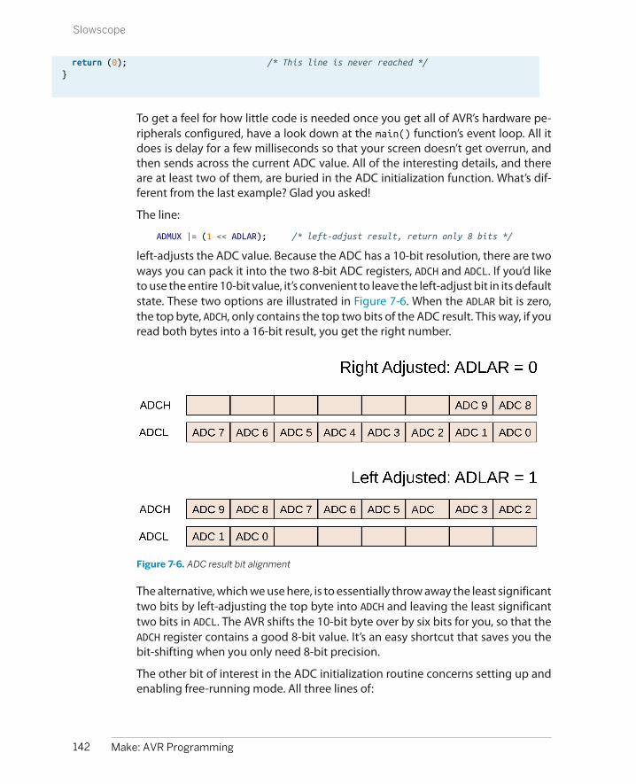
return (0); /* This line is never reached */}
To get a feel for how little code is needed once you get all of AVR’s hardware pe-ripherals configured, have a look down at the main() function’s event loop. All itdoes is delay for a few milliseconds so that your screen doesn’t get overrun, andthen sends across the current ADC value. All of the interesting details, and thereare at least two of them, are buried in the ADC initialization function. What’s dif-ferent from the last example? Glad you asked!
The line:
ADMUX |= (1 << ADLAR); /* left-adjust result, return only 8 bits */
left-adjusts the ADC value. Because the ADC has a 10-bit resolution, there are twoways you can pack it into the two 8-bit ADC registers, ADCH and ADCL. If you’d liketo use the entire 10-bit value, it’s convenient to leave the left-adjust bit in its defaultstate. These two options are illustrated in Figure 7-6. When the ADLAR bit is zero,the top byte, ADCH, only contains the top two bits of the ADC result. This way, if youread both bytes into a 16-bit result, you get the right number.
Figure 7-6. ADC result bit alignment
The alternative, which we use here, is to essentially throw away the least significanttwo bits by left-adjusting the top byte into ADCH and leaving the least significanttwo bits in ADCL. The AVR shifts the 10-bit byte over by six bits for you, so that theADCH register contains a good 8-bit value. It’s an easy shortcut that saves you thebit-shifting when you only need 8-bit precision.
The other bit of interest in the ADC initialization routine concerns setting up andenabling free-running mode. All three lines of:
142 Make: AVR Programming
Slowscope

ADCSRA |= (1 << ADEN); /* enable ADC */ADCSRA |= (1 << ADATE); /* auto-trigger enable */ADCSRA |= (1 << ADSC); /* start first conversion */
are needed to make free-running mode work. The first sets the ADC auto-triggerenable bit, which turns on free-running mode. This sets up the ADC to start anothersample as soon as the current sample is finished. You still have to start up the initialconversion, so I set the ADSC bit as I did in normal, one-shot mode to start up thefirst conversion. Then, because ADATE is set, the next conversion follows alongautomatically.
If you read the datasheet section on the ADC auto-trigger source, you’ll find thatyou can actually trigger conversions automatically a whole bunch of ways—whenexternal pins changing logic state or from the AVRs internal timer/counter mod-ules. But the default is to use the signal from the ADC’s own conversion-completebit to trigger the next conversion, and that’s what we’re doing here. This meansthat as soon as the ADC finishes one reading, it will start up the next without anyuser intervention: “free-running.”
But you have to remember to kick it off initially at least that one time, hence theADSC.
The Desktop CodeThe AVR is sending data across the serial line to your desktop computer. All that’sleft to do is plot it. I find this short bit of Python code in Example 7-3 so useful thatI had to throw it in here. There’s all sorts of cosmetic and performance improve-ments you could make, but there’s a lot to be said for just printing the numbersout on the screen.
Example 7-3. serialScope.py listingimport serial
def readValue(serialPort): return(ord(serialPort.read(1)))
def plotValue(value): """ Displays the value on a scaled scrolling bargraph""" leadingSpaces = " " * (value*(SCREEN_WIDTH-3) / 255) print "%s%3i" % (leadingSpaces, value)
def cheapoScope(serialPort): while(1): newValue = readValue(serialPort) plotValue(newValue)
if __name__ == "__main__":
143Chapter 7: Analog-to-Digital Conversion I
Slowscope

PORT = '/dev/ttyUSB0' BAUDRATE = 9600 TIMEOUT = None SCREEN_WIDTH = 80
## Take command-line arguments to override defaults above import sys if len(sys.argv) == 3: port = sys.argv[1] baudrate = int(sys.argv[2]) else: # nothing passed, use defaults print ("Optional arguments port, baudrate set to defaults.") port, baudrate = (PORT, BAUDRATE)
serialPort = serial.Serial(port, baudrate, timeout=TIMEOUT) serialPort.flush() cheapoScope(serialPort)
The code makes heavy use of the Python pyserial library. If you don’t already havethis installed, go do so now! See “Installing Python and the Serial Library” on page121 for installation instructions.
The three functions that make the scope work include readValue() that gets asingle byte from the serial stream and converts it into an ordinal number. This waywhen the AVR sends 123, the code interprets it as the number 123 rather than {,which is ASCII character number 123.
Next plotValue() takes the value and prints an appropriate number of leadingspaces, and then the number, padding to three digits with empty space. Finally,cheapoScope() just wraps an infinite loop around these two other functions. A newvalue is read in, then plotted. This goes on forever or until you close the windowor press Ctrl-C to stop it.
If you call serialScope.py from the command line, it allows you to override the de-fault serial port and baud rate configurations. On the other hand, once you knowhow your serial port is configured, you might as well hardcode it in here by editingthe PORT and BAUDRATE definitions.
While looking through the defaults, if you’d like the program to quit after a fewseconds with no incoming data, you can reset TIMEOUT to a number (in seconds).If you have a particularly wide or skinny terminal window, you can also changeSCREEN_WIDTH.
The only little trick here is that before running the scope, the code flushes the serialport input buffer. Depending on your operating system, it may be collecting abunch of past values from the serial port for you. This is normally a good idea, buthere we’d like to start off with a clean slate so that we instantly read in the new
144 Make: AVR Programming
Slowscope

values from the AVR. Hence, we flush out the serial buffer before calling cheapoScope() and looping forever.
SynergiesThis sort of simple desktop computer scripting can greatly expand on the capa-bilities and debugging friendliness of the AVR environment. You saw in Chap-ter 5 how you can expand the AVR’s capabilities dramatically by taking in informa-tion from your desktop computer. Here, we’re doing the opposite.
If you’re adept with Python, I encourage you to make a fancier scope display if you’dlike. The Python code could also easily be expanded out to a general-purpose datalogger application if you’d like. Just open a file on your hard disk and start writingthe values to it. Import the datetime module and timestamp them. Heck, importthe csv module and you can import the data straight into a spreadsheet or statisticspackage. Even with such simple tools, if you combine them right, the world is youroyster.
Debugging the ADC is sometimes tricky. You won’t always know a priori what typesof values to expect. Writing code to detect a shadow is much easier when you knowjust exactly how dark the shadow is, or how light it is in the room the rest of thetime. Seeing how your signal data looks in real time helps your intuition a lot.
I hope you get as much use out of these simple “oscilloscope” routines as I do. Orat least that you have a good time waving your hand over the light sensor for alittle bit. I’m pretty sure I can tell which direction I’m moving my hand—the thumband pinkie fingers cast different shadows. Who knew? I wonder if I can teach theAVR to detect that?
AVR Night Light and the Multiplexer
We just saw how to use single ADC conversions, and then ADC conversions in free-running mode. What’s next? Learning how to use more than one of the ADC chan-nels “at once”! We’ll stick with our light sensor on ADC0 / PC0 and add in a poten-tiometer on ADC3 / PC3. Switching between the two rapidly and comparing theirvoltage values in software will give us an easily adjustable night light that turns onat precisely the level of darkness that we desire.
OK, I’ll admit it’s not that cool a project, but it gives us a good excuse to learn aboutthe ADC multiplexer and play around with reading values from potentiometers,both of which are fundamental uses of the ADC hardware.
MultiplexingBecause the internal ADC is a fairly complex bit of circuitry, it’s not too surprisingthat there’s only one of them per microcontroller. But what to do if you’d like tomonitor several analog sensors or voltages? The approach that the AVR, and most
145Chapter 7: Analog-to-Digital Conversion I
AVR Night Light and the Multiplexer

other microcontrollers, take is to multiplex the ADC out to multiple pins; the singleinput to the ADC on the inside of the chip is connected through a six-way switchto external pins, enabling you to sample analog voltages on any one of the six PCnpins at a time.
If you’d like to sample from two or three different analog sources, you’ll need toswitch between the pins, sampling each one at a time and then moving on to thenext. And as always with the AVR’s hardware peripherals, this is done by telling aninternal hardware register which channel you’d like to sample from.
This sounds obvious, but you also have to take care to be sure that you switchchannels in the multiplexer before the start of an ADC sampling cycle. This is onlyreally a problem in “free-running” mode, in which the ADC samples continually. Infree-running mode, when you change the multiplexer, the AVR doesn’t restart thesampling automatically. This means that the first sample after you’ve changed themultiplexer will still be from the old analog source—you need to wait at least onecomplete ADC cycle before getting a value from the new channel. In my experience,it’s a lot easier to trigger each sample yourself (through mainloop or interrupt),because it’s easier to verify that you’ve set up the multiplexer correctly without anycomplex bookkeeping.
Setting the Mux BitsThe multiplexer is a tiny bit tricky to program, so I hope you haven’t forgotten allyou learned about bit twiddling from Chapter 4. The problem is the following: thelow four bits control which ADC pin is used for input, but the upper three controlthe voltage reference and switch between 8-bit mode and 10-bit mode as we sawin the slowScope code. When you change the multiplexer channel in ADMUX, youwant to change the bottom four bits without modifying the upper four. To see whatI mean, look at Figure 7-7.
Figure 7-7. ADMUX register bits
To sample from ADC3, you set both the MUX0 and MUX1 bits and make sure that MUX2and MUX3 are zeroed, because three in binary is 0011, right? But it’s lousy to have tothink about setting each bit individually. Wouldn’t it be nicer to just write a threeto the register? Sure, but then you’d end up clobbering the high bits. What if youjust AND a three into the register? It doesn’t clear out the other low bits, if any wereset. For instance, if you were sampling on channel five before with MUX2 and MUX1set, you’d need to make sure that the MUX2 bit was cleared to get back to channelthree.
146 Make: AVR Programming
AVR Night Light and the Multiplexer

The easiest solution is to first clear out the bottom four bits, and then OR in yourdesired channel number. This takes two conceptual steps. To change to ADC3 forinstance, you first clear all the low bits and then write the number three back in:
ADMUX = ADMUX & 0b11110000; // clear all 4 mux bitsADMUX = ADMUX | PC3; // set the bits we want
Notice that the top four bits aren’t changed by either of these instructions. You’lloften see this written with the clear and set steps combined into one line like this:
ADMUX = (0b11110000 & ADMUX) | PC3;/* or, the ADC macro synonyms */ADMUX = (0b11110000 & ADMUX) | ADC3;/* or, in hex for the lazy typer */ADMUX = (0xf0 & ADMUX) | ADC3;/* or with numbers instead of macros */ADMUX = (0xf0 & ADMUX) | 3;
This bitmask-style code is easily extensible when you need to loop over all the ADCpins, sampling from each one. If you’d like to read which channel is being sampled,you can logically invert the bitmask, keeping the low four bits of the ADMUX register.For instance, here’s an example code snippet that reads from each of the ADCs ina row and stores its value in an array:
uint16_t adcValues[6];uint8_t channel;
for (channel = 0; channel < 6; channel++) { ADMUX = (0xf0 & ADMUX) | channel; // set channel ADCSRA |= (1 << ADSC); // start next conversion loop_until_bit_is_clear(ADCSRA, ADSC); // wait for conversion adcValues[channel] = ADC; // store the value in array}
With code like this, running with the ADC clocked at 125 kHz, you can get over1,500 cycles of all six channels in a second. You’ll see in Chapter 8 how to useinterrupts to avoid the blocking loop_until_bit_is_clear() step and use the ex-tra CPU time for processing.
Another application of bit-masking and the MUX register is in reading out whichchannel has just been read from:
channelNumber = (0x0f & ADMUX);
To figure out which channel was just read from, you can create a bitmask for thelowest four bits and then AND that with the ADMUX register. That way, your channelNumber variable will only contain the value of the ADC sampling channel, andnone of the upper bits.
147Chapter 7: Analog-to-Digital Conversion I
AVR Night Light and the Multiplexer
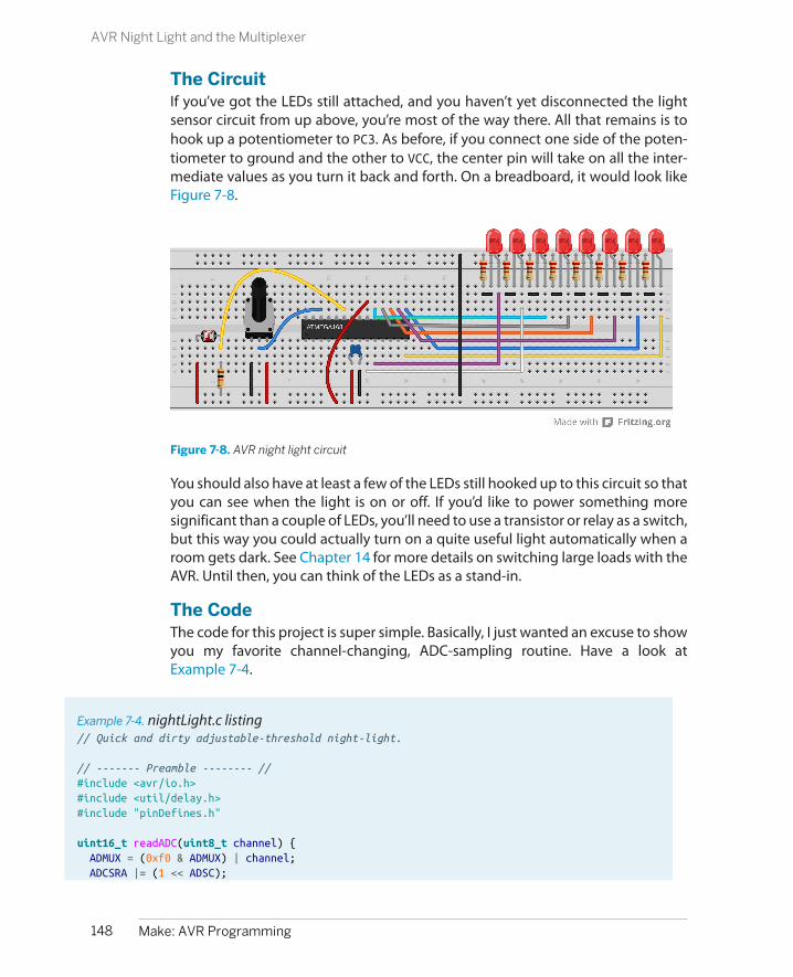
The CircuitIf you’ve got the LEDs still attached, and you haven’t yet disconnected the lightsensor circuit from up above, you’re most of the way there. All that remains is tohook up a potentiometer to PC3. As before, if you connect one side of the poten-tiometer to ground and the other to VCC, the center pin will take on all the inter-mediate values as you turn it back and forth. On a breadboard, it would look likeFigure 7-8.
Figure 7-8. AVR night light circuit
You should also have at least a few of the LEDs still hooked up to this circuit so thatyou can see when the light is on or off. If you’d like to power something moresignificant than a couple of LEDs, you’ll need to use a transistor or relay as a switch,but this way you could actually turn on a quite useful light automatically when aroom gets dark. See Chapter 14 for more details on switching large loads with theAVR. Until then, you can think of the LEDs as a stand-in.
The CodeThe code for this project is super simple. Basically, I just wanted an excuse to showyou my favorite channel-changing, ADC-sampling routine. Have a look atExample 7-4.
Example 7-4. nightLight.c listing// Quick and dirty adjustable-threshold night-light.
// ------- Preamble -------- //#include <avr/io.h>#include <util/delay.h>#include "pinDefines.h"
uint16_t readADC(uint8_t channel) { ADMUX = (0xf0 & ADMUX) | channel; ADCSRA |= (1 << ADSC);
148 Make: AVR Programming
AVR Night Light and the Multiplexer

loop_until_bit_is_clear(ADCSRA, ADSC); return (ADC);}
int main(void) { // -------- Inits --------- // uint16_t lightThreshold; uint16_t sensorValue; // Set up ADC ADMUX |= (1 << REFS0); /* reference voltage on AVCC */ ADCSRA |= (1 << ADPS1) | (1 << ADPS0); /* ADC clock prescaler /8 */ ADCSRA |= (1 << ADEN); /* enable ADC */
LED_DDR = 0xff; // ------ Event loop ------ // while (1) {
lightThreshold = readADC(POT); sensorValue = readADC(LIGHT_SENSOR);
if (sensorValue < lightThreshold) { LED_PORT = 0xff; } else { LED_PORT = 0x00; } } /* End event loop */ return (0); /* This line is never reached */}
In this example, I initialize the ADC inside the main() routine. By now, you’re notsurprised by any of these lines, I hope. I also turn on all the LEDs for output. (Witheight yellow LEDs on my desktop right now, this night light would actually workpretty well!)
The event loop simply consists of reading the ADC value on the potentiometer andthen the light sensor. If the value from the light sensor is lower, it turns the LEDson, otherwise it turns them off. That’s it! Too simple.
The reason for this night-light demo, however, is the function readADC(). I probablyreuse this function, or something similar enough, for tens of simple ADC applica-tions. Taking a channel number as an input, it applies the bitmask to change theADC channel, starts a conversion, waits for a result, and then returns it. Simple,effective, and it makes simple ADC sampling from multiple channels relativelypainless.
149Chapter 7: Analog-to-Digital Conversion I
AVR Night Light and the Multiplexer
Summary
You now know enough about using the ADC to do some pretty complicated sam-pling. Free-running mode is great when you’re only interested in one channel andyou’d like to always have a contemporaneous value available. Single-shot mode isgreat when you don’t need to sample that often, or if you’re switching channels alot as we just did here. You know how to use all 10-bits of the ADCs sample or howto set the ADLAR bit to left-adjust down to an easy-to-read 8-bit value in ADCH. That’sgoing to cover you for most simple sensor sampling situations.
We’re not quite done with the ADC yet, though. In Chapter 12, I’ll demonstratesome more advanced signal-processing methods (oversampling and smoothing)that are useful for getting more resolution from the sensor for stable signals andfor getting smoother outputs from noisy signals. We’ll also experiment around alittle with signal conditioning—namely creating a frontend voltage divider to ex-pand the voltage range over which you can read with the ADC, and adding in aDC-blocking capacitor and biasing circuit for use with input voltages that other-wise would go negative, like microphones and piezo sensors.
150 Make: AVR Programming
Summary

PART II
Intermediate AVR
This section makes you a more efficient programmer of the chip and expands the universe ofwhat you’ll think an AVR can do. You’ll start doing cool things with the internal hardware pe-ripherals and some more sophisticated tricks in firmware using what you already know. Thissection provides the big payoff—the tools to do things with a bare AVR chip that you just can’tdo without knowing a little about how the hardware works.
Mastery of microcontrollers starts with good use of the interrupt system. Chapter 8 shows youhow to allow events in the outside world to directly and instantaneously call portions of yourcode. You’ll use this speed to build a noncontact capacitive touch sensor out of aluminum foiland tape that will detect your finger as far as a few centimeters away.
Chapter 9 introduces you to the three internal timers that the ATmega microcontroller comeswith. Offloading timing from your code to the timer/counter hardware lets you do things witha precision and speed that you couldn’t before, or even just do two things at once. Timers areshockingly versatile, and you’ll use them to make a reaction timer, an improved square-waveorgan, and even a tiny AM radio transmitter. What do these have in common? Time.
In Chapter 10, you finally get to output something other than ones and zeros from the AVR.(Sort of ). Pulse-width modulation (PWM) is the most convenient way to dim LEDs and slowdown motors. Between the timer and interrupt hardware, the AVR provides you with a fewoptions for producing PWM, and we’ll go through three.
Servo motors are the perfect match for microcontrollers. For so little circuitry, you get so muchmovement. In Chapter 11, you’ll use the 16-bit timer to directly control a servo motor withalmost no CPU overhead. The project for this chapter is a “sundial” in reverse—instead of thesun creating a moving shadow, you’ll track a laser across the ceiling to show the time. As abonus, you also get to make a real-time clock out of the AVR.

Rounding out the intermediate section, in Chapter 12 I’ll show you two of my favorite mathe-matical techniques that help you get more out of the ADC: oversampling and exponentialsmoothing. These techniques let you build a 12-bit accurate voltmeter and a super-sensitivefootstep detector built from a $2 piezo element.

What You Need
In this chapter, in addition to the basic kit, you willneed:
• An LED or a few. You may still have thesehooked up.
• A pushbutton. You may still have this hookedup, too.
• A capacitive touch sensor: we’ll make ours outof two pieces of aluminum foil, some tape, apiece of paper, two alligator clips, and a 100kohm resistor.
• A USB-Serial adapter.
Real-time Response, and a Capacitive Sensor
This chapter introduces perhaps the most useful of the AVR’s hardware peripherals—the interrupt system. Up to now, our programs have been very much linear, goingfrom one command to the next command to the next command. However, youoften have to deal with input from the real world that arrives asynchronously, al-most at random—you want the AVR to respond when you press the button, notwhen it’s ready to have you press the button.
In this chapter, we’ll take our first steps into interrupt programming. The first twoexamples will demonstrate how interrupts can run code for you any time an inputpin changes state. And while it’s pretty cool to have the interrupt hardware directlyrun a bit of your code when a button is pressed, it’s a bit trivial. So we’ll expand onthat and build a capacitive touch sensor. (In fact, if you build a large sensor andtweak the code, it’ll even detect your hand a centimeter or so away from the touchplace.)
Elegant and skillful use of the interrupt system separates good programmers fromgood microcontroller programmers. When you’re writing code that runs on a
153
Hardware Interrupts 8

multitasking operating system, you don’t have to worry nearly as much about whathappens when, or how long it takes. The OS takes care of the nitty-gritty detailslike making sure that the video card is constantly fed with video data and that themouse and keyboard are being constantly listened to. (You don’t have to worryabout it, because your OS is doing all this for you with its own system of hardwareinterrupts.)
Here in the land of microcontrollers, we don’t often have the luxury of running anOS. Instead, if we’d like to have two things going on seemingly at once, we eithercycle between them very quickly or set up a system where one can preemptivelyinterrupt the other. The first strategy, called “polling” in the comp sci jargon, cansuffice for a lot of applications. The event loop in a polling-style program is essen-tially a list of things that we’d like to check up on. (Is a button pressed? If it is, lightan LED.) The AVR then runs through that list repeatedly as fast as it can. If we keepour event loop short enough that any given part comes around frequently enough,it’s hard to tell that we’re polling—when a button is pressed, the LED seems to lightup instantly even if we caught the program in another part of the event loop.
Polling code frequently looks something like this:
int main(void){ // Event Loop while(1){
if (checkLightSensor()){ set_bit(LED_PORT, LED); }
switchesState = checkSwitches(); if (switchesState == DANGER_VALUE){ turnOffKillerLaser(); }
doWhateverElse(); }}
One problem with polling in event loops is that there’s no concept of priority. Eventhough we care more about the limit switches that control our laser than the lightsensors, each separate check happens at the same frequency, once per trip throughthe event loop. That may work fine as long as the event loop is short enough. Butif the doWhateverElse() routine takes a while, maybe because it uses a lot of CPUpower, too much time can elapse between checks of the switches, and our death-laser-on-a-motor might end up cutting something that it shouldn’t.
Handling multiple jobs at once is where interrupts excel. Interrupts do just whatthey sound like—they interrupt the normal flow of the program. When an interruptis triggered, all of the variables that you’re using are stashed in memory and thena special function, called an interrupt service routine (ISRs), is run. After the ISR is
154 Make: AVR Programming
Hardware Interrupts
done, your program picks up again where it left off. Switching from one context toanother like this takes an AVR chip four cycles (half a microsecond at 8 MHz) bothgoing and returning, but otherwise the ISR happens just about instantly when theinterrupt is flagged.
What are interrupts good for? There are internally triggered interrupts that respondto the internal AVR hardware peripherals. For instance, there are interrupts that canrun ISR code when the analog-to-digital converter or USART has got new data orwhen the timer/counter peripheral has reached a certain value. Instead of waitingin a blocking loop until the peripheral is ready, we can write our ISR to handle thatperipheral directly, and it will execute only when required. We’ll be using internallytriggered interrupts throughout the rest of the book, and when I introduce a newperipheral subsystem, I’ll show you how it can trigger ISRs for you.
There are also externally triggered interrupts that can react to to a voltage changeon any of the AVRs pins, and these external interrupts will be the focus of thischapter. Without interrupts, you have to check each button in the system to see ifit’s pressed, which wastes some processor cycles and can result in serious delay ifparts of the event loop take a long time. By using interrupts for each AVR pin, youcan dispatch code that executes within a microsecond of the button press.
From a coder’s perspective, using interrupts judiciously can vastly streamline yourwork. For instance, when we wanted to test if a button had just been pressed, wehad to store the old button state in a variable and check each time around theevent loop to see if the current state is different from the old state. Then we had toreplace the old state with the current one. By using interrupts, we can configurethe interrupt routines to only fire when a pin changes state. (We still have to testwhether it changed into a pressed or released state, but it’s a lot simpler.)
I find that interrupts often match the way I’m thinking about a coding problem. Iwant the AVR to be doing one or two main things, but be ready to drop them andexecute a third task for a while if it needs to react to a change coming in from theoutside world. Interrupts make it much easier for my code to mirror the way I thinkabout the problem.
Interrupts are a deep and rich topic, and we’ll just be scratching the surface. Thatsaid, we’ve got a lot of surface area to scratch. In this chapter, we’ll walk through afew exercises with external interrupts, we’ll use internal interrupts paired with thetimer/counter modules to create a system clocks, and then we’ll combine bothtypes to implement a capacitive touch sensor.
External Interrupts 101: Real-time Button PressingExamples
The first use case for external hardware interrupts is to handle a button press asyn-chronously. That is, you write your event loop so that when an interrupt comes in
155Chapter 8: Hardware Interrupts
External Interrupts 101: Real-time Button Pressing Examples
from outside, the CPU drops whatever it was doing and executes your interruptroutine before getting back to the event loop.
There are two flavors of external interrupts: the fancy interrupts, INT0 and INT1,and the pin-change interrupts. We’ve wired our button up to pin PD2, which is thededicated pin for the INT0 interrupt, but which also works with the pin-changeinterrupt mechanism like all the other I/O pins on the AVR chips.
The INT0 interrupt mechanism has more versatile triggering possibilities, allowingyou trigger the interrupt on a rising voltage, a falling voltage, any change, or con-tinuously for a low-voltage level, which is useful for interaction with other pro-cessors or peripherals. Due to their hardware complexity, there are only two ofthese type interrupts: INT0 and INT1, on pins PD2 and PD3.
The PCINT system, on the other hand, allows you to treat every I/O pin on the AVRas an interrupt source if you so desire, but only detects changes (not their direction)and thus requires a little more processing to interpret. The pin-change interruptsare grouped together in banks, so it’s more accurate to say that there’s a pin-changeinterrupt for the “B” pins, one for the “C” pins, and one for the “D” pins. We use pin-mask registers to select which of the pins from within the bank we want to triggerthe interrupt. I’ll discuss this more in the following code example.
External Interrupt 0 ExampleFirst off, let’s consider the INT0 and INT1 external interrupts. These are the twohighest-priority interrupts in the chip, so in general, you’ll want to reserve themfor some signal that you really care about. (If you get a bunch of interrupts at thesame time, the INT0 routine will run before any of the others.)
As an example, I built a logging accelerometer with GPS, which was mainly anexercise in coordinating among three devices—the GPS over the USART, the ac-celerometer using I2C serial, and external flash memory using SPI serial. (I’ll coverthe two advanced serial protocols in Chapter 16 and Chapter 17.)
The accelerometer (an LIS302D) updated at 100 Hz, so every 10 milliseconds, theAVR had to request new data from it or else it would miss the current value. For-tunately, the accelerometer provided a falling-voltage signal when it had new dataready. The simplest solution was to connect the data-ready signal from the accel-erometer directly to pin PD2 on the AVR, and trigger an interrupt for a falling volt-age. When the accelerometer had new data, it grounded the wire, the AVR detectedthe falling edge, triggered the interrupt, read the new data in, and saved it tomemory. Easy peasy.
Many external peripherals will signal data-ready or otherwise demand your atten-tion by either raising or lowering a voltage signal on a dedicated line, and that’sexactly the situation that INT0 and INT1 are designed to handle. For the moment,we’re simulating this all with a button press, so let’s look at some code.
156 Make: AVR Programming
External Interrupts 101: Real-time Button Pressing Examples
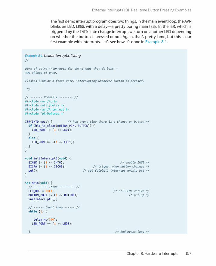
The first demo interrupt program does two things. In the main event loop, the AVRblinks an LED, LED0, with a delay—a pretty boring main task. In the ISR, which istriggered by the INT0 state change interrupt, we turn on another LED dependingon whether the button is pressed or not. Again, that’s pretty lame, but this is ourfirst example with interrupts. Let’s see how it’s done in Example 8-1.
Example 8-1. helloInterrupt.c listing/*
Demo of using interrupts for doing what they do best --two things at once.
Flashes LED0 at a fixed rate, interrupting whenever button is pressed.
*/
// ------- Preamble -------- //#include <avr/io.h>#include <util/delay.h>#include <avr/interrupt.h>#include "pinDefines.h"
ISR(INT0_vect) { /* Run every time there is a change on button */ if (bit_is_clear(BUTTON_PIN, BUTTON)) { LED_PORT |= (1 << LED1); } else { LED_PORT &= ~(1 << LED1); }}
void initInterrupt0(void) { EIMSK |= (1 << INT0); /* enable INT0 */ EICRA |= (1 << ISC00); /* trigger when button changes */ sei(); /* set (global) interrupt enable bit */}
int main(void) { // -------- Inits --------- // LED_DDR = 0xff; /* all LEDs active */ BUTTON_PORT |= (1 << BUTTON); /* pullup */ initInterrupt0();
// ------ Event loop ------ // while (1) {
_delay_ms(200); LED_PORT ^= (1 << LED0);
} /* End event loop */
157Chapter 8: Hardware Interrupts
External Interrupts 101: Real-time Button Pressing Examples

return (0); /* This line is never reached */}
As usual, let’s first skip down to the event loop and see what the main() routinedoes. At first glance, it looks like all it does is blink LED0 on and off again. There’snothing in the event loop concerning the button or LED1 at all!
Before we leave the event loop, think about how you’d program something similarwithout interrupts. If you took the easy way and tested the button once per triparound the event loop, just before or after the _delay_ms() statement, you’d noticea delay between the time when you press the button and the time that LED1 lightsup, right? For extra credit, try to code up this functionality as a polled event-looptype program—just comment out the initInterrupt0() function and testbit_is_set() to toggle LED1 from within the event loop. You’ll find that the buttonpressing action will start to feel horribly sluggish if it takes significant time to cyclethrough the event loop.
Let’s see what’s going on with the interrupts and LED1. First, there’s the ISR() callitself. If you’ve been following along, you’ll guess (correctly) that ISR being writtenin all-caps denotes a macro. (In this case, it’s a fairly complicated macro that definesa function, defined in the interrupt.h header file that we included at the top of theprogram.)
ISRs are special routines that run when their interrupt flag is set, and their interruptvector is called. For the nitty-gritty on interrupts, see “Interrupts: Under theHood” on page 158. Otherwise, feel free to think of the ISR as being a function thatgets called whenever its interrupt flag is set.
The ISR() Is a Special Function
ISRs are different from normal functions in two important ways, however. ISR() “functions”don’t have a return value, and they take only their interrupt vector as an argument. Thismeans you can’t pass arguments to the ISR directly and have to use variables with globalscope to get data in and out of the ISR. For now, just remember that an ISR is a special typeof macro/function hybrid that has neither arguments nor return values.
In this example, we’re setting the ISR for the INT0 interrupt, and so we use thespecial (macro) name INT0_vect. The interrupt macro names are defined in thenormal io.h header file that’s specific for the chip. In our case, that’d be iomx8.h,which covers the entire series of Mega chips in the “x8” series like the ATmega48,ATmega88P, etc.
158 Make: AVR Programming
External Interrupts 101: Real-time Button Pressing Examples

Interrupts: Under the Hood
The interrupt system is a little bit involved at thehardware level, but it’s not magic, and knowing howit works may someday help you track down interrupt-related bugs.
Like everything else in the AVR, it’s all done with bitsin registers. For each type of possible interrupt, thereis a flag bit inside the AVR that can be set. When youpress the button, the INT0 interrupt flag is set. Thereis also a global interrupt-enable bit that determineswhether or not any interrupts are checked.
When this global flag is set, the AVR continuallychecks all of the interrupt flags to see if any of themare set. If one or more of the individual interrupt flagsis set, the global interrupt-enable flag is first cleared,preventing any further interrupts, and then the sys-tem runs the ISR corresponding to the first individualflag it finds. When the first ISR is done, the system setsthe global interrupt-enable flag again, and controleither goes to the next ISR with a set flag or back toyour main program where it left off. The ordering ofthe individual interrupt flags thus provides a priorityscheme for executing the ISRs. (For the complete list,see Table 8-1, which is derived from a table from thedatasheet.)
How does the interrupt mechanism know which sec-tion of code to run? At the very beginning of themachine-language version of your code lies the in-terrupt vector space. Each entry in this space cancontain a command to jump to the memory locationwhere the corresponding ISR code will be stored.When the CPU gets a USART_RX interrupt, for in-stance, signaling that some data has come in over theUSART, the USART_RX interrupt flag is set. Becausethis flag is the 18th flag in the interrupt table, the 18thentry in the interrupt vector table is read out. The
18th slot of this table contains a command that tellsthe AVR to execute code at the location where the ISRroutine’s function starts.
In short, when an interrupt flag is thrown, the CPUdrops what it’s doing, disables further interrupts byturning off the global interrupt bit, looks up the cor-responding memory address in the interrupt vectortable, and then starts running whatever code it findsat that memory address—which is set to be the be-ginning of your ISR. Each ISR then ends with the RETI (“return from interrupt”) command, which tells theCPU to turn the global interrupt flag back on, to re-check the interrupt flags register, and if none are set,to return to your code where it left off. If, while it washandling your first interrupt request, another inter-rupt flag has been set, the CPU handles the new in-terrupt before getting back to your main() routine.
What does all this mean for you as a programmer?Because the individual interrupt flags are prioritized,they’ll reliably be run in the same order. Think aboutthis when designing your hardware layout, and phys-ically connect the most important signals to the mostimportant interrupt pins. Additionally, the individualinterrupt flags can be set even when the global in-terrupt flag isn’t. Later on, when the global interrupt-enable flag is set, they’ll all get processed in the nor-mal priority order. Because interrupts are handledone after the other, if your interrupt routines take along time to run, or the interrupt flags keep gettingset very frequently, execution may take a while be-fore it can get back to your main routine. And finally,because the individual interrupt flags are just like anyother flag in a hardware register, you can trigger themfrom within your own code if you ever need to sim-ulate a button press or whatever.
Table 8-1. Interrupt vector
Name in datasheet Vector name for ISRs Interrupt definition
RESET External Pin Reset, Power-on Reset, Brown-out Reset, and WatchdogSystem Reset
INT0 INT0_vect External Interrupt Request 0
INT1 INT1_vect External Interrupt Request 1
159Chapter 8: Hardware Interrupts
External Interrupts 101: Real-time Button Pressing Examples
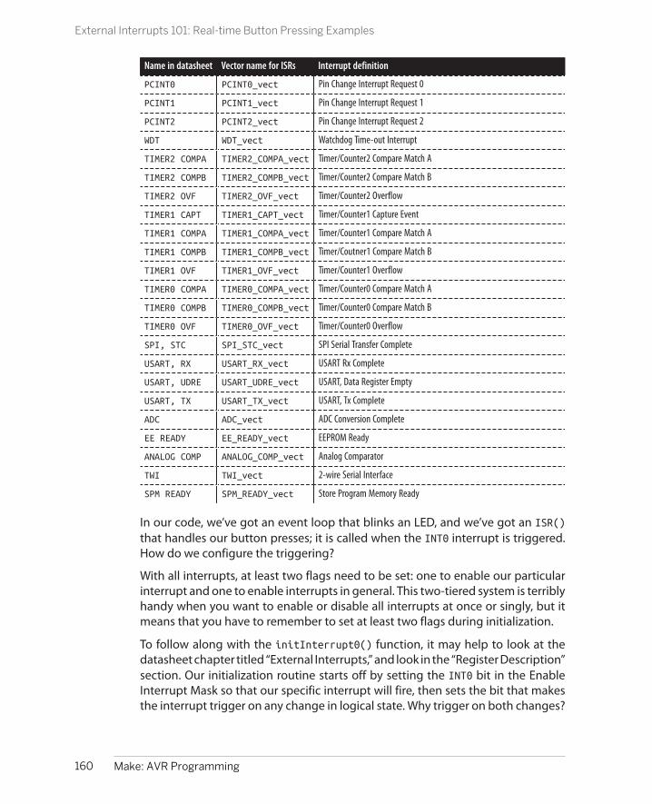
Name in datasheet Vector name for ISRs Interrupt definition
PCINT0 PCINT0_vect Pin Change Interrupt Request 0
PCINT1 PCINT1_vect Pin Change Interrupt Request 1
PCINT2 PCINT2_vect Pin Change Interrupt Request 2
WDT WDT_vect Watchdog Time-out Interrupt
TIMER2 COMPA TIMER2_COMPA_vect Timer/Counter2 Compare Match A
TIMER2 COMPB TIMER2_COMPB_vect Timer/Counter2 Compare Match B
TIMER2 OVF TIMER2_OVF_vect Timer/Counter2 Overflow
TIMER1 CAPT TIMER1_CAPT_vect Timer/Counter1 Capture Event
TIMER1 COMPA TIMER1_COMPA_vect Timer/Counter1 Compare Match A
TIMER1 COMPB TIMER1_COMPB_vect Timer/Coutner1 Compare Match B
TIMER1 OVF TIMER1_OVF_vect Timer/Counter1 Overflow
TIMER0 COMPA TIMER0_COMPA_vect Timer/Counter0 Compare Match A
TIMER0 COMPB TIMER0_COMPB_vect Timer/Counter0 Compare Match B
TIMER0 OVF TIMER0_OVF_vect Timer/Counter0 Overflow
SPI, STC SPI_STC_vect SPI Serial Transfer Complete
USART, RX USART_RX_vect USART Rx Complete
USART, UDRE USART_UDRE_vect USART, Data Register Empty
USART, TX USART_TX_vect USART, Tx Complete
ADC ADC_vect ADC Conversion Complete
EE READY EE_READY_vect EEPROM Ready
ANALOG COMP ANALOG_COMP_vect Analog Comparator
TWI TWI_vect 2-wire Serial Interface
SPM READY SPM_READY_vect Store Program Memory Ready
In our code, we’ve got an event loop that blinks an LED, and we’ve got an ISR()that handles our button presses; it is called when the INT0 interrupt is triggered.How do we configure the triggering?
With all interrupts, at least two flags need to be set: one to enable our particularinterrupt and one to enable interrupts in general. This two-tiered system is terriblyhandy when you want to enable or disable all interrupts at once or singly, but itmeans that you have to remember to set at least two flags during initialization.
To follow along with the initInterrupt0() function, it may help to look at thedatasheet chapter titled “External Interrupts,” and look in the “Register Description”section. Our initialization routine starts off by setting the INT0 bit in the EnableInterrupt Mask so that our specific interrupt will fire, then sets the bit that makesthe interrupt trigger on any change in logical state. Why trigger on both changes?
160 Make: AVR Programming
External Interrupts 101: Real-time Button Pressing Examples
Because we’re using the ISR to turn the LED on and off, we need to trigger on boththe rising and falling voltage edges. Finally, the initialization routine ends with acommand that sets the global interrupt-enable bit, turning on all interrupts thatwe’ve configured so far: sei();.
Sometimes you’ll find that you need to turn on or off all interrupts at once. The AVRdesigners have anticipated this and added a global interrupt bit and two com-mands to control it. sei() turns all interrupts on, and cli() turns them all off. Forsome timing-sensitive sections of code, especially if you have long-running inter-rupt service routines, you may want to disable interrupts before you call criticalfunctions and reenable interrupts after you return.
Both sei() and cli() compile into machine-language instructions of the samename, so we’re stuck with those names even though I don’t find them particularlydescriptive. In case you’re wondering, “sei” is “Set Enable Interrupt” bit and “cli” is“CLear enable Interrupt” bit. (Hooray for inconsistent mnemonics!)
Also note that interrupts are automatically turned off when entering an ISR andturned back on again when finishing. This prevents a situation where an interruptgets called from inside another interrupt, which itself had been called from insideanother interrupt, and so on. Of course, if you’d like to have interruptable ISRs, youcan specify that either manually by calling sei() in the ISR itself or by using a specialISR_NOBLOCK argument to the ISR() definition. Use this only if you know whatyou’re doing!
And don’t forget that interrupts are disabled by default, and that you need to ex-plicitly enable them with an sei() somewhere in your code if you expect them torun. (Have I hammered that home enough? You’ll still forget to do it sometimes.)
I can’t count the number of times that I’ve written a brand-new ISR, compiled,flashed, and run the code only to find that my interrupt isn’t working because Iforgot to enable interrupts globally. Always remember that enabling interrupts isa two-step process; enable your specific interrupt vector, then enable the overallinterrupt system with sei().
Pin-Change Interrupt ExampleAs mentioned previously, the INT0 and INT1 interrupts are special. If you’d like touse any of the other pins to generate an interrupt, you’ll have to use a pin-changeinterrupt. Initialization of pin-change interrupts is a tiny bit different, but the maindifference is that there are only three pin-change interrupt flags, and each onestands for up to eight physical pins on the AVR. In order to select which of the eightpins in each bank you’d like to trigger the interrupt, you’ll also need to set up a pinmask:
ISR(PCINT2_vect){ ....}
161Chapter 8: Hardware Interrupts
External Interrupts 101: Real-time Button Pressing Examples

void initPinChangeInterrupt18(void){ PCICR |= (1 << PCIE2); /* set pin-change interrupt for D pins */ PCMSK2 |= (1 << PCINT18); /* set mask to look for PCINT18 / PD2 */ // PCMSK2 |= (1 << PD2); /* this will also work for the pin mask */ sei(); /* set (global) interrupt enable bit */}
First, you’ll notice that we’re using a different interrupt vector. There’s not muchmore to say about that—see Table 8-1 for the possible interrupts that can triggerISRs. Inside the interrupt, we’ll still test to see whether the button is pressed or not,just as before.
Setting up a pin-change interrupt is only a tiny bit more conceptually involved thanusing INT0. Remember that the pin-change interrupt system can respond to achange on any of the AVR’s pins (except the power supply pins, naturally). To ac-commodate that many pins, they’re broken up into interrupt bytes by bank.
Which Pin-Change Interrupt?
For some reason, the AVR designers decided to label the pin-change interrupts by numberinstead of the letter-number pairs that they labeled the pins with. Don’t let this confuse you!All of the pins PB0 through PB7 can potentially trigger the PCINT0 interrupt, PC0 through PC6trigger PCINT1, and PD0 through PD7 trigger PCINT2. Because we attached the button to pinPD2, we’ll need to enable PCINT2. (I would have called it PCINTD, but they didn’t ask me—seeTable 8-2 for the full list.)
Table 8-2. Pin-change interrupts
Name in datasheet Vector name for ISRs Which pins are covered
PCINT0 PCINT0_vect PB0 .. PB7
PCINT1 PCINT1_vect PC0 .. PC6
PCINT2 PCINT2_vect PD0 .. PD7
Because the pin-change interrupt can in principle trigger if any of the pins in therelevant bank change state, we’ll need to tell the AVR which pins we’d like for it towatch specifically. This is done through the pin mask, which is just a normal 8-bitbyte where the corresponding bit is set for each pin we’d like to be able to triggerthe interrupt. See Figure 8-1, which is similar to the pinout diagram in the AVRdatasheet, for the correspondence between physical pins and their pin-changeinterrupt numbering.
162 Make: AVR Programming
External Interrupts 101: Real-time Button Pressing Examples

Figure 8-1. AVR pinouts—PCINT names
So if we want to trigger on PD2 and PD4, we can set the pin mask one of two ways.We can either use the pins’ PCINTxx aliases, or the normal PD2 type pin refer-ences. For instance:
PCMSK2 |= ( (1 << PCINT18) | (1 << PCINT20) );
and:
PCMSK2 |= ( (1 << PD2) | (1 << PD4) );
both do the same thing: configure the pin-change interrupt to trigger if either PD2or PD4 changes state.
If you have an interrupt that is triggered by multiple pins, you’ll need to test whichpin actually changed state in the ISR itself. For instance, continuing the precedingtwo-button example:
if (bit_is_clear(PIND, PD2)){ // Do one thing...}if (bit_is_clear(PIND, PD4)){ // Do another}
163Chapter 8: Hardware Interrupts
External Interrupts 101: Real-time Button Pressing Examples

Pin-Change Interrupts Made Easy
Using pin-change interrupts allows your code to re-spond instantaneously to a voltage change on any orall(!) AVR pins. Just remember the three-tiered systemfor configuring pin-change interrupts and you’ll beall set:
1. Enable your specific interrupt in the controlregister: PCICR |= (1 << PCIEx)
2. Set which pins you’d like to react to in the ap-propriate pin-mask register: PCMSKx |= (1<< PCINTyy) or PCMSK0 |= (1 << PB2)
3. Enable interrupts globally with sei() whenyou’re ready.
Now write the code that you’d like to run using theISR(PCINTx_vect) macro:
1. If you’re triggering off of multiple pins in thesame bank, you will want to test which pin justcaused the interrupt in your ISR with some-thing like bit_is_clear(BUTTON_IN, BUTTON).
2. Even if you’re triggering on only one pin in thebank, remember that pin-change interruptstrigger on any pin change. If you care whetherthe change is a press or release, you will needto test for that.
Now you’ll be able to respond nearly instantly to input on any or all of the AVR’spins.
Capacitive Sensor
Capacitive sensors are pretty cool. I mean, who doesn’t like a button that can bepressed through a piece of paper or even just by waving your hand near a metalplate? Regular pushbuttons are old-tech, reliable, and despite their debouncingrequirements, quite easy to use. When you want something that’s just a bit fancier,a little temperamental, and just a tad futuristic, you’ll want a capacitive touch sen-sor. Touching metal plates is what they do in the “future.”
The basic principle behind capacitive touch sensors is the same: timing how longit takes for a capacitor to charge or discharge. When nobody is nearby, the sensorplate itself will have some roughly fixed capacitance of its own, and it will take agiven amount of time to charge and discharge at a given voltage. When you comealong, your body capacitance couples with the circuit. The resulting capacitor—made up of you and the sensor—has more capacitance than the sensor’s capacitoralone, and so takes longer to charge and discharge. Measuring the change incharge time, allowing for environmental variation and more, lets you determinewhen the “button” is pressed.
Timing the capacitor’s discharge time directly involves detecting the differencebetween times that are on the order of two or more microseconds different fromeach other, and that’s a little bit unreliable and hard to do with great sensitivity.Instead if you fire off a pin-change interrupt service routine that recharges thecapacitor and adds one to a count variable, and then time how many of these cycles
164 Make: AVR Programming
Capacitive Sensor
Capacitive Sensor Timing Methods
All capacitive sensor applications work by measuringthe time it takes to charge or discharge a baselinecapacitor, and then comparing that with the extratime it takes to charge or discharge the same capac-itor when the capacitance changes due to the prox-imity of a human. The approaches differ in how thetiming of an individual charge/discharge cycle isdone, and how these times are averaged together.
The most intuitive method is to directly time the ca-pacitor discharging with nobody touching it, thenwith someone touching it, and compute the differ-ence in time. If a human body adds around 20–30 pFof extra capacitance, and the capacitor is drainedthrough a 100k ohm resistor as we do here, the timedifference is one or two microseconds. With the AVR’sprocessor running at eight instructions per micro-second at best, we just don’t have much resolutionwith times that are that short.
Instead, we indirectly time how long it takes the ca-pacitor to discharge by discharging it to a fixed level(where the digital pin reads a logic change), fullycharging it back up, and then repeating. Becausewe’re always charging and discharging the capacitor,we can then count how many cycles take place in afixed amount of time. This has the added advantageof averaging a bunch of cycles together—as many fitin our fixed time frame—so that if one cycle is a littletoo short due to some random fluctuation, and an-other cycle is too long, they cancel out.
In the end, the direct and indirect methods are verysimilar, and either is workable. I encourage you tomake a direct-timing capacitive sensor if you’d like toexperiment.
you get in 50 milliseconds, you’ll get a number that ranges between 2,000 withyour hand on the sensor plate, 8,000 with a thumb, 10,000 with a finger, 12,000with your hand 1 cm above the plate, and 15,000 counts when you’re nowhere nearthe sensor.
As demonstration code, a capacitive sensor lets me show you how interrupts letyou do two things “at once.” We’ll use the plain-vanilla _delay_ms() function toimplement the waiting time. Now normally, your code doesn’t do anything whilea delay is running. But here we’ll be charging up the capacitor and keeping trackof how many cycles we’ve seen in an interrupt that’s fired automatically every timethe capacitor is discharged. So every time the ISR is called, the chip stops delaying,recharges the capacitor, increments a counter, and then goes back to the delayfunction where it left off. Cool, no? But first, we’ll need to build ourselves a sensor.
The SensorA capacitive sensor is basically just a capacitor. But unlike normal capacitors wherethe goal is to minimize the size and prevent it from interacting with electric fieldsin the environment, here you’ll be building your own capacitor as large as you’dlike and trying to integrate your hand into the electric field.
Consequently, you can make a fairly low-tech capacitor. In fact, a very nice sensorfor this project can be made by taking two pieces of aluminum foil with a sheet ofpaper between them. For starters, cut one piece of foil approximately 10 × 10 cm
165Chapter 8: Hardware Interrupts
Capacitive Sensor
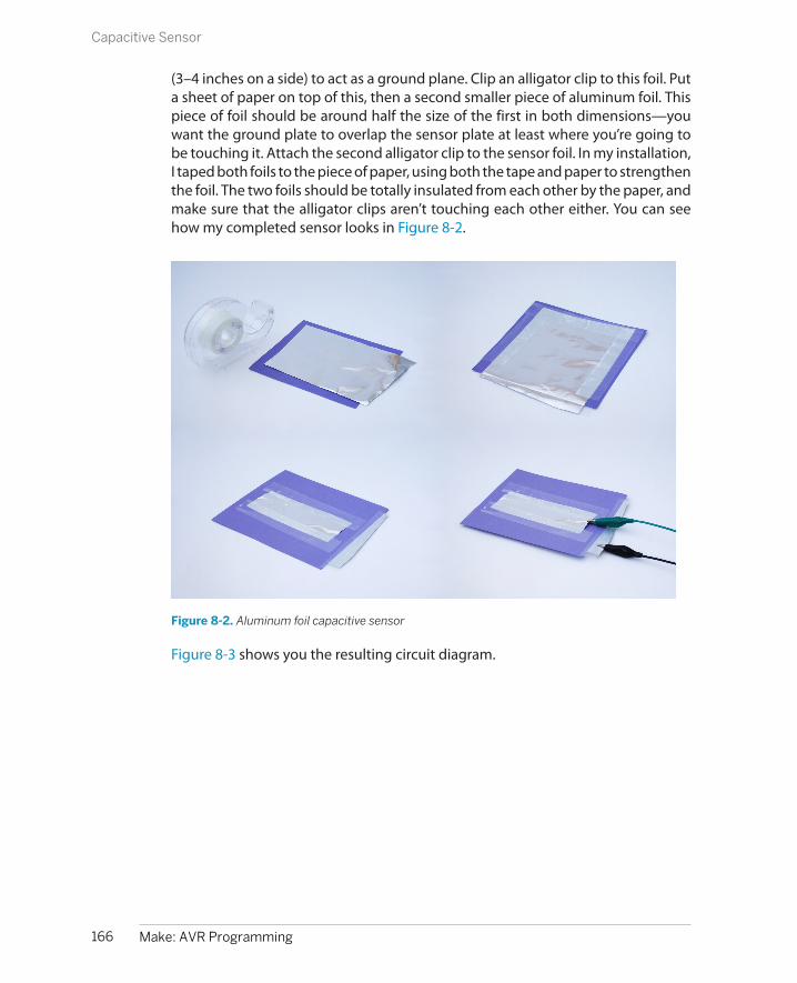
(3–4 inches on a side) to act as a ground plane. Clip an alligator clip to this foil. Puta sheet of paper on top of this, then a second smaller piece of aluminum foil. Thispiece of foil should be around half the size of the first in both dimensions—youwant the ground plate to overlap the sensor plate at least where you’re going tobe touching it. Attach the second alligator clip to the sensor foil. In my installation,I taped both foils to the piece of paper, using both the tape and paper to strengthenthe foil. The two foils should be totally insulated from each other by the paper, andmake sure that the alligator clips aren’t touching each other either. You can seehow my completed sensor looks in Figure 8-2.
Figure 8-2. Aluminum foil capacitive sensor
Figure 8-3 shows you the resulting circuit diagram.
166 Make: AVR Programming
Capacitive Sensor
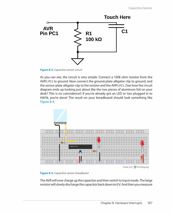
Figure 8-3. Capacitive sensor circuit
As you can see, the circuit is very simple. Connect a 100k ohm resistor from theAVR’s PC1 to ground. Now connect the ground-plate alligator clip to ground, andthe sensor-plate alligator clip to the resistor and the AVR’s PC1. (See how the circuitdiagram ends up looking just about like the two pieces of aluminum foil on yourdesk? This is no coincidence!) If you’ve already got an LED or two plugged in toPORTB, you’re done! The result on your breadboard should look something likeFigure 8-4.
Figure 8-4. Capacitive sensor breadboard
The AVR will now charge up the capacitor and then switch to input mode. The largeresistor will slowly discharge the capacitor back down to 0 V. And then you measure
167Chapter 8: Hardware Interrupts
Capacitive Sensor

(indirectly) the time it takes for the capacitor to discharge and see if you’re touchingthe plate or not.
Once you’ve gotten it working the “right” way, feel free to experiment around withother capacitor geometries. Any conductive surface held insulated over a groundplane should work, in principle. By reading the number of counts per sensing pe-riod over the serial port, you’ll be able to figure out a suitable sensing time andthreshold value for almost any capacitor. For instance, I dunked my alligator clip ina cup of tea that was sitting on top of grounded aluminum foil, and it could sensewhen I put my hand on the mug. You could also try taping the aluminum foil andpaper sensor underneath a thin-seated chair to detect when a person sits down.You have a lot of room to experiment here.
The CodeOK, so down to business. To recap, we’ll be repeatedly charging up the sense ca-pacitor and letting it discharge through the resistor, counting up the number ofcycles. A delay function keeps track of the time. Once the delay is over, the numberof charge-discharge cycles can be used to detect a nearby hand. Example 8-2implements these ideas in code.
Example 8-2. capSense.c listing/* Capacitive touch sensor demo*/
#include <avr/io.h>#include <util/delay.h>#include <avr/interrupt.h>#include <avr/power.h>#include "pinDefines.h"#include "USART.h"
#define SENSE_TIME 50#define THRESHOLD 12000
// ------- Global Variables ---------- //volatile uint16_t chargeCycleCount;
// ------- Functions -------- //
void initPinChangeInterrupt(void) { PCICR |= (1 << PCIE1); /* enable Pin-change interrupts 1 (bank C) */ PCMSK1 |= (1 << PC1); /* enable specific interrupt for our pin PC1 */}
ISR(PCINT1_vect) { chargeCycleCount++; /* count this change */
168 Make: AVR Programming
Capacitive Sensor

CAP_SENSOR_DDR |= (1 << CAP_SENSOR); /* output mode */ _delay_us(1); /* charging delay */
CAP_SENSOR_DDR &= ~(1 << CAP_SENSOR); /* set as input */ PCIFR |= (1 << PCIF1); /* clear the pin-change interrupt */}
int main(void) { // -------- Inits --------- // clock_prescale_set(clock_div_1); /* full speed */ initUSART(); printString("==[ Cap Sensor ]==\r\n\r\n");
LED_DDR = 0xff; MCUCR |= (1 << PUD); /* disable all pullups */ CAP_SENSOR_PORT |= (1 << CAP_SENSOR); /* we can leave output high */
initPinChangeInterrupt();
// ------ Event loop ------ // while (1) {
chargeCycleCount = 0; /* reset counter */ CAP_SENSOR_DDR |= (1 << CAP_SENSOR); /* start with cap charged */ sei(); /* start up interrupts, counting */ _delay_ms(SENSE_TIME); cli(); /* done */ if (chargeCycleCount < THRESHOLD) { LED_PORT = 0xff; } else { LED_PORT = 0; } printWord(chargeCycleCount); /* for fine tuning */ printString("\r\n");
} /* End event loop */ return (0); /* This line is never reached */}
The pin-change interrupt initialization is the minimal setup—we set the pin-change interrupt for the bank of pins that we’d like to trigger and then the pin-mask for the particular pin we’re interested in. The only thing this initializationdoesn’t do is enable the global interrupt vector. We’ll do that from within main().
The interrupt service routine does three things. First it increments our cycle vari-able. Then it changes the DDR to output and delays a tiny bit to charge up thecapacitor. (The delay may or may not be necessary depending on your setup. Tryit without.) Then, the DDR is set back to input for the pin, and the pin-change
169Chapter 8: Hardware Interrupts
Capacitive Sensor

interrupt flag is cleared by writing PCIF1 into the pin-change interrupt flag register,PCIFR.
Resetting the pin-change interrupt flag is described in the datasheet, in the pin-change interrupts “Register Description” section if you’d like to read more. Why didwe do this? Because, during the pin-change ISR, we change the voltage on the pinby charging up the capacitor, which sets the interrupt flag. If we didn’t reset theflag, program execution would jump right back to the pin-change ISR as soon asthe ISR is done.
Moving down to the main() routine, we set the chip to run at maximum speed andcall the initialization routines. (I go into more depth on setting the CPU speed in“CPU Speed” on page 189, so sit tight until then. I’ve been trying to explain everythingin place, but this code just works so much better with the AVR in high-speed modethat I had to do it.)
Because the ISR will be swapping between charging the capacitor and passivelyreading its voltage, we can leave the PORT register high for charging, but we don’twant it to enable the internal pull-up resistor when we’re sensing the voltage. Itturns out that we can disable all of the internal pull-up resistors with a single bit:setting MCUCR |= (1 << PUD);, the pull-up disable bit in the MCU control register.
The event loop then resets the charge cycle counter, initially charges up the ca-pacitor, and then enables interrupts. As soon as the voltage on the capacitor dropsback down, the ISR will be called, which will add one to the counter and then chargethe capacitor back up. This cycle loops around until the delay is up and the codeagain disables interrupts. Now we can test how many cycles happened during thedelay time and decide whether a press happened or not.
Global, Volatile VariablesThere’s one more important detail in the capacitive sensor code that I brushed overin the preceding treatment, and that’s the use of global variables with our interruptservice routine. Have a look back at where the variable chargeCycleCount is de-fined, way up at the top of the file. Being defined outside of any function like thismakes the variable global, meaning that any of the other functions defined in thisfile can access it without explicitly passing it as an argument to that function. Thismakes the variable chargeCycleCount available to both our main() routine and theISR.
Remember back in “The ISR() Is a Special Function” on page 158 where I said thatISRs were not entirely equivalent to functions? Here’s where the difference reallymatters. We need to increment a variable in the ISR and then use it to make adecision in the main() function. How can we do that without passing argumentsand return values between the ISR and main()? The answer is to define a globalvariable that’s defined outside of both functions, and so its value isn’t contained
170 Make: AVR Programming
Capacitive Sensor

within the scope of either. The ISR can add to chargeCycleCount and main() canread it.
But chargeCycleCount also must be marked volatile because the compiler needsto be warned that it can change without notice in any given context. In fact, thisdistinction is so important that not declaring the variable as volatile will breakthe code. I’ll explain why in a bit, but it’s a little arcane.
If your eyes glaze over while reading the next section, just remember to alwaysdefine your global variables using the special volatile keyword for the AVR, other-wise the compiler will optimize them away and your ISR won’t work.
The volatile keywordvolatile warns the compiler that the declared variable can change at any timewithout warning, and that the compiler shouldn’t optimize it away no matter howstatic it seems.
For a glimpse into the mind of the optimizing compiler, imagine you write codewith a segment like this:
int main(void){ char a; a = 'H'; while(1){ transmitByte(a); }}
The compiler is going to notice that nothing in your main() function changes thevalue of the variable a, and the optimizer will get rid of it entirely. The optimizerwill instead compile the equivalent of this code for you:
int main(void){ while(1){ transmitByte('H'); }}
which does the same thing, but is much shorter and doesn’t involve allocatingscarce memory for a variable that never varies. A win, right?
The optimizer is pretty good about finding shortcuts through our code, and if wewrite code that uses a variable that doesn’t change, the optimizer is going to re-place it with a constant. This is where we run afoul of interrupts. Because the ISRsare never explicitly called from within the main() function, the optimizer doesn’tknow that the ISR is changing a variable relevant for main(), and it replaces it witha constant value.
In the capacitive sensor code, it looks like the variable chargeCycleCount is set tozero and then it’s never changed with the main() routine. An optimizing compiler
171Chapter 8: Hardware Interrupts
Capacitive Sensor

will notice this and replace chargeCycleCount with 0 everywhere within main(). Ifthe cycle count is always 0, the code thinks that the sensor is always being pressed,even when it’s not, and the sensor routine won’t work.
To tell the compiler that we expect our global variables to change without warning,we mark it volatile. Now the compiler won’t make assumptions that it knows whatthe variable’s value is.
What about the AVR’s special memory registers like PINB that change all the timedue to external input? If you dig deep enough into the include files (into sfr_defs.hto be precise), you’ll find that the macros that define the hardware register vari-ables, PORTB and PINB and so on, are already defined as volatile so that the compilercan’t just ignore them, even if nothing in code changes them explicitly.
Forgetting to mark global shared variables as volatile is probably pitfall #1 inadvanced AVR programming. If your ISR seems not to be working, and you’re sureyou’ve run sei(), double-check your volatiles.
Aside: volatile in for loopsAnother place you’ll want to define a variable as volatile is when you’re using aloop to do nothing but delay. Because it’s doing nothing, the compiler will optimizeit away. The compiler loves to help your code run faster!
So when you write something like:
uint8_t i;/* I'd really like to delay here */for (i = 0; i < 200; i++){ ;}
hoping to slow the program down for something like 200 CPU cycles, the compilernotices the empty for loop and optimizes it to:
uint8_t i;/* Compiler: I found a shortcut! */
Instead, if you declare the variable i to be volatile, the compiler doesn’t know thatit can’t be changed by external subroutines during any step in the for loop, so itexecutes them all just to be sure:
volatile uint8_t i;for (i = 0; i < 200; i++){ ; }
works just fine as a 200-CPU-tick (plus a couple more for setting up the for loop)delay.
On the other hand, if you write:
uint8_t i;for (i = 0; i < 200; i++){
172 Make: AVR Programming
Capacitive Sensor

_delay_ms(100);}
it will work fine because the compiler thinks it needs to call that _delay_ms()function 200 times.
Volatile and ISRs: The Bottom Line
If you share a global variable between a function (including main()) and an ISR, you mustdeclare that variable as volatile.
If you don’t, the compiler will not realize that the variable can change within the scope of thefunction because it never sees the ISR being called directly, and it will likely substitute aconstant for your variable. Your code will compile just fine, but your ISR won’t do anythingand you’ll scratch your head for 10 minutes until you remember reading this warning. I hope.
Debugging the CircuitIf you haven’t already, flash the program in, connect the serial port to your com-puter, and run the Python serialScope.py program. (You may have to tweak the PORTdefinition to match your serial port.) Now touch the sensor and you’ll see the cur-rent cycle count. You’ll want to play around with the defined SENSE_TIME andTHRESHOLD. If you aren’t getting at least 5,000 counts when you are not touchingthe sensor plate, try increasing the SENSE_TIME until you do. Now touch the platea few times. You want to set the THRESHOLD somewhere in between the untouchedreading and what it reads when you put your finger on the plate.
Setting the THRESHOLD too close to the no-press value can make the circuit sensitiveto small changes in the intrinsic capacitance of the circuit with weather or peoplewalking by. On the other hand, if you set the THRESHOLD too low, you might needto press down with two fingers or more. You just have to explore a bit until you getit working like you’d like, but that’s half the fun.
Capacitive touch sensors are tricky beasts to troubleshoot. One reason is that theextra capacitance you’re trying to detect is around the same magnitude as what’snormally called “stray capacitance”; that is, the capacitance from having wires nextto each other, or running your alligator clips too close to a grounded metal surface.
The other reason these sensors can be finicky is that the capacitance of the sensoritself depends on what you make it out of, what kind of environment it’s in, thehumidity, and other factors. We’ve got a lot of parameters that are variable in thissystem: sensor geometry and capacitance, sampling time (controlled by the delay),and the count threshold to detect a touch.
173Chapter 8: Hardware Interrupts
Capacitive Sensor

So where to begin? If you’ve built the sensor as described, with a 100k ohm resistor,you should be already in the right ballpark. You can substitute a variable resistoror potentiometer in for the 100k resistor, and sweep the value around, which willvary the discharge rate. If you find that you have to use very long sampling timesjust to get a reasonable number of cycles counted, you might try changing theresistor value.
On the other hand, if you’re getting too many counts per period, you might evenbe running into overflow problems. Remember that a 16-bit counting variable canonly get up to 65,535 before it loops back around to zero. Try running a shorterSENSE_TIME at first, and increase it until you get into a reasonable ballpark, espe-cially if you see the sensor value decrease down to, and through, zero when youmove your finger slowly onto the sensor.
Once you get the sensor working reliably, experiment with different materials andconfigurations. Plants? That’s been done. What’s the strangest capacitive sensoryou can come up with?
174 Make: AVR Programming
Capacitive Sensor

What You Need
In addition to the basic kit, you will need:
• A speaker and DC-blocking capacitor.
• A pushbutton to test your reaction time.
• A long length of wire for an AM antenna.
• A USB-Serial adapter to display your times.
AM Radio Transmitter and Reaction Timer
In this chapter, we’ll test our reaction time, refine our old organ routines, and trans-mit AM radio directly from the AVR. What do these projects have in common?They’re all made possible by the internal timer-counter hardware. Previously, we’vemarked the passing of time by holding up the CPU in counting delay loops. Nomore! The AVRs have dedicated hardware that’ll do that for us.
In all of these cases, you’ll find that using the hardware timers costs a little bit ininitial setup, but makes your resulting code significantly simpler, the timing sig-nificantly more accurate, and frees up the CPU for useful work.
Timer/Counters: Why and How?
Looking back at the serial-port organ code, the function that made the music (suchas it was) was called playNote(). It worked by turning the speaker pin on andwaiting, and then turning the speaker pin off and waiting. To refresh your memory,see Example 9-1.
175
Introduction to the Timer/Counter Hardware 9

Example 9-1. Old playNote() listingvoid playNote(uint16_t wavelength, uint16_t duration) { uint16_t elapsed;
uint16_t i; for (elapsed = 0; elapsed < duration; elapsed += wavelength) { /* For loop with variable delay selects the pitch */ for (i = 0; i < wavelength; i++) { _delay_us(1); } SPEAKER_PORT ^= (1 << SPEAKER); }}
This code works just fine, but if you’d like the CPU to do anything else at the sametime, you’re out of luck—it’s all tied up doing the important task of waiting for aprecise amount of time. We run into a similar situation with our LED blinking codewhere we invoke the _delay_ms() function. All of our processor power is momen-tarily tied up just spinning around in a fruitless loop that simply counts up until it’sdone.
What we need instead is a clock that we can use as a timebase and a counter that’llcount up a certain number of clock ticks for us before it acts. This is, of course, whatthe internal timer/counter hardware peripheral does. Before we get down to ap-plications, let’s take a quick tour of the hardware to see how it works. It’ll give youa better feel for the possibilities.
Essentially, the timer/counter hardware works as summarized in Figure 9-1. Inputarrives from either the system clock or an external source connected up to an inputpin (T0 for counter 0). In this way, the same hardware can be used as a timer (count-ing ticks of the system clock) or a generic counter (counting voltage change eventson the dedicated input pin). The current count is stored in an internal timer/counterregister (TCNTn).
Figure 9-1. Timer/counter hardware
176 Make: AVR Programming
Timer/Counters: Why and How?

Your code can read the count from TCNT registers at any time, yielding the currentcount value. You can also write to it, and you’ll often do so in order to reset thecount to zero. With just reading and writing to the timer register, you can make theequivalent of a stopwatch—set the timer value to zero, do something, and thencheck the value again to see how much time has elapsed.
If instead of a stopwatch, you’d like an alarm clock, you can put the Timer CompareUnit to work for you. Its job is to let you know when a certain count value is reached.You store this compare value in the Output Compare Register (OCRn). This way, youcan store the value you’d like for an elapsed time, a frequency or a duty cycle in theOCRn, and then forget about it—the timer hardware will do the rest for you, freeingup the CPU to do more interesting things.
So the counter is counting, and the compare unit is comparing the count value toa value that you set. What happens when the compare value is reached? A compareevent triggers the Waveform Generator, and what it does depends on a pair ofimportant configuration options: the waveform mode and output mode. In brief,the Waveform Generator unit can be configured to generate three main types ofoutput depending on the waveform mode: counter, timer, or (in Chapter 10) PWM.Whether you want pins set, cleared, or toggled is determined by the output modes.The timer/counters can also trigger interrupts, which is useful when you want toperiodically update variables or run code; you’ve seen a bunch of interrupt exam-ples in Chapter 8. In this chapter, we’ll be focusing on counter and timer waveformmodes, and direct-to-pin output.
And if one timer/counter weren’t enough, the ATmega series of AVR chips havethree timers, two with 8-bit (256 step) resolution and one with 16-bit (65,356 step)resolution. That way, you can have one timer/counter generating a frequency foryou, another keeping track of wall-clock time, and the third timing short-durationevents. They’re very useful once you’ve learned how to use them.
As you can see, there’s a lot of flexibility and utility built into the timer/counterhardware. If you want to count button presses, you can simply hook up your(hardware-debounced) switch directly to the appropriate counter input pin. Orimagine that you want to get the time in between button presses. Then you canset your code to zero the TCNT register at the beginning, connect the counter upto the system clock, and then when the button is pressed, simply read out the valuein TCNT. The count will be the number of system clock ticks that have elapsed, whichyou can then manipulate any way you want. And because all of this is taken careof by the timer/counter hardware, the CPU is free to listen to serial ports or crunchnumbers at the same time.
177Chapter 9: Introduction to the Timer/Counter Hardware
Timer/Counters: Why and How?
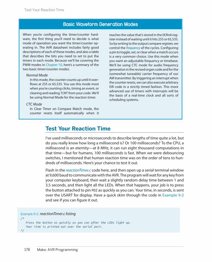
Basic Waveform Generation Modes
When you’re configuring the timer/counter hard-ware, the first thing you’ll need to decide is whatmode of operation you want the timer/counter op-erating in. The AVR datasheet includes fairly gooddescriptions of each of these modes, and also a tablethat describes the bits you need to set to put thetimers in each mode. Because we’ll be covering thePWM modes in Chapter 10, here’s a summary of thetwo basic timer/counter modes:
Normal ModeIn this mode, the counter counts up until it over-flows at 255 or 65,535. You use this mode mostwhen you’re counting clicks, timing an event, orclearing and reading TCNT from your code. We’llbe using Normal Mode for the reaction timer.
CTC ModeIn Clear Timer on Compare Match mode, thecounter resets itself automatically when it
reaches the value that’s stored in the OCRnA reg-ister instead of waiting until it hits 255 or 65,535.So by writing to the output compare register, wecontrol the frequency of the cycles. Configuringa pin to toggle, set, or clear when a match occursis a very common choice. Use this mode whenyou want an adjustable frequency or timebase.We’ll be using CTC mode for audio frequencygeneration in the revised organ code and for the(somewhat tuneable) carrier frequency of ourAM transmitter. By triggering an interrupt whenthe counter resets, we can also execute arbitraryISR code in a strictly timed fashion. This moreadvanced use of timers with interrupts will bethe basis of a real-time clock and all sorts ofscheduling systems.
Test Your Reaction Time
I’ve used milliseconds or microseconds to describe lengths of time quite a lot, butdo you really know how long a millisecond is? Or 100 milliseconds? To the CPU, amillisecond is an eternity—at 8 MHz, it can run eight thousand computations inthat time—but for humans, 100 milliseconds is fast. When we were debouncingswitches, I mentioned that human reaction time was on the order of tens to hun-dreds of milliseconds. Here’s your chance to test it out.
Flash in the reactionTimer.c code here, and then open up a serial terminal windowat 9,600 baud to communicate with the AVR. The program will wait for any key fromyour computer keyboard, then wait a slightly random delay time between 1 and3.5 seconds, and then light all the LEDs. When that happens, your job is to pressthe button attached to pin PD2 as quickly as you can. Your time, in seconds, is sentover the USART for display. Have a quick skim through the code in Example 9-2and see if you can figure it out.
Example 9-2. reactionTimer.c listing/* Press the button as quickly as you can after the LEDs light up. Your time is printed out over the serial port.*/
178 Make: AVR Programming
Test Your Reaction Time
// ------- Preamble -------- //#include <avr/io.h>#include <util/delay.h>#include <avr/interrupt.h>#include "pinDefines.h"#include "USART.h"
#include "support.h"
static inline void initTimer1(void) { /* Normal mode (default), just counting */ TCCR1B |= (1 << CS11) | (1 << CS10); /* Clock speed: 1 MHz / 64, each tick is 64 microseconds ~= 15.6 per ms */ /* No special output modes */}
int main(void) { char byte; uint16_t timerValue;
// -------- Inits --------- //
initUSART(); initTimer1(); LED_DDR = 0xff; /* all LEDs for output */ BUTTON_PORT |= (1 << BUTTON); /* enable internal pull-up */
printString("\r\nReaction Timer:\r\n"); printString("---------------\r\n"); printString("Press any key to start.\r\n");
// ------ Event loop ------ // while (1) {
byte = receiveByte(); /* press any key */ printString("\r\nGet ready..."); randomDelay();
printString("\r\nGo!\r\n"); LED_PORT = 0xff; /* light LEDs */ TCNT1 = 0; /* reset counter */
if (bit_is_clear(BUTTON_PIN, BUTTON)) { /* Button pressed _exactly_ as LEDs light up. Suspicious. */ printString("You're only cheating yourself.\r\n"); } else { // Wait until button pressed, save timer value. loop_until_bit_is_clear(BUTTON_PIN, BUTTON); timerValue = TCNT1 >> 4; /* each tick is approx 1/16 milliseconds, so we bit-shift divide */
179Chapter 9: Introduction to the Timer/Counter Hardware
Test Your Reaction Time

printMilliseconds(timerValue); printComments(timerValue); }
// Clear LEDs and start again. LED_PORT = 0x00; printString("Press any key to try again.\r\n");
} /* End event loop */ return (0); /* This line is never reached */}
I’ve shifted the pretty-printing functions off to another pair of support.c and sup-port.h files. If you look at the makefile, you’ll see that it includes them in additionto the USART files. All of this is to keep the main reactionTimer.c code tight and keepyou focused on the timers. So for now, just assume that randomDelay(), printMilliseconds(), and printComments() do what their names imply.
The initialization section is pretty standard for our applications, and we’ll get toinitTimer1() soon, so skip on down to the event loop, which starts off by waitingfor a byte (any byte) across the USART. After a random delay, all the LEDs light up,“Go!” is transmitted on the USART, and we have the first timer-specific bit of code.
As described in the timer/counter overview, the current timer count value is keptin a hardware register called TCNT1 for Timer 1. (Not surprisingly, the counter registerfor Timer 0 is called TCNT0, and TCNT2 for Timer 2.) In this example, we’re using thetimer/counter to simply count up at a fixed rate, starting out from zero. Later, whenwe read the TCNT1 register, we’ll know how many timer ticks have elapsed. Andbecause people can have widely varying reaction times, I’ve chosen to use the 16-bit Timer 1 to allow us to easily count values from one sixteenth of a millisecondup to just over four seconds
So after the random delay, the LEDs are turned on, and the counter hardware reg-ister is reset to zero. The next thing the code does is to check if you’re alreadypressing the button and issues an admonishment. (Not that I don’t trust you oranything, but you know how the temptation is…) If you weren’t found to be cheat-ing, the code continues on.
Next, the code goes into an endless loop until you press the button by using theloop_until_bit_is_clear macro function. But wait, if the CPU is looping aroundwaiting, who’s doing the timing in the meantime? That’s right, the timer/countermodule. When the button is finally pressed (after an eternity in CPU time), all that’sleft to do is read the TCNT1 value out of the register and convert it to (approximate)milliseconds, print it out, and rate your time.
How do we know how long a timer tick lasts? That’s a function of the CPU clockspeed and CPU prescaler, so let’s have a look at the initialization routine. In fact,
180 Make: AVR Programming
Test Your Reaction Time

Alternative Representations for Setting Bits
You do remember your bit-shifting logic from Chap-ter 4, right? You’ll frequently need it when readingother people’s code, and may want to use it in yourown sometimes.
For instance, the initialization code for setting thetimer’s clock-speed prescaler that we wrote as:
TCCR1B |= (1 << CS10) | (1 << CS11);
could be written, using the built-in _BV() macros, as:
TCCR1B |= _BV(CS10) | _BV(CS11);
or using a set_bit style macro as:
#define set_bit(register, bit) \ (register |= (1<<bit))
set_bit(TCCR1B, CS10);set_bit(TCCR1B, CS12);
or (yuck!) as:
TCCR1B |= 5;
if they’re total jerks.
There’s no reason to ever write nonreadable code likethat last example. To figure out if “5” is setting the
waveform generation bits or the clock speed, you’llhave to open up the datasheet and do a decimal-to-binary conversion. And all the one-liners compile tothe same machine code anyway, so there’s nothingat all gained by using the difficult-to-read notation.
The two-line, set_bit macro version ends up takingtwice as many instructions in machine code asTCCR1B |= (1 << CS10) | (1 << CS12);, andafter you’re used to the explicit bit shifts, they’re justabout as readable. If you’re writing timing-sensitivecode, or setting multiple bits in a single register overand over again, the one-liner versions are better.
How did I figure out these timings? I typed make disasm and then read the resulting .lst file to see how thecode converts into the machine language that getsflashed into the chip. You can disassemble the ma-chine code by hand with the avr-objdump com-mand. Looking over the quasi-assembler can helpdemystify compilation process and is informativeeven if you don’t know a word of assembler yet.
when you get there, you’ll see that all the init routine does is set the clock speed.Looking at Table 15-5 in the “Register Description” section for Timer 1 in the data-sheet, you’ll see the list of possible clock speeds and the necessary bits to set toget each of them. Some prescaler modes can be set with just one bit, while othersrequire two or three, like “CPU/64,” which we use here.
The rest of the reaction timer code is just pretty-printing the results to the serialoutput and the nice trick used to make a “random” delay. (Using the least significantbits of a fast-updating counter isn’t random by any means, but it’s good enoughto make an unpredictable delay, as long as the counter value depends on humaninput.) These miscellaneous functions are listed in support.h and support.c, andshould be fairly readable.
So let’s quickly recap the timer-relevant details of this project before we move onto something more complex. First, once the timer/counter is initialized, it just runson its own, counting up until it reaches its maximum value and starts again fromzero. In this example, I wanted more than 255 possible values for the reaction times,so I used the 16-bit Timer 1, which can count up to 65,535 before rolling over. The
181Chapter 9: Introduction to the Timer/Counter Hardware
Test Your Reaction Time

speed at which the timer/counter counts depends on the system CPU speed andthe CPU prescaler that we pick when we’re initializing the timer. In this case, usingan 1 MHz CPU clock and a divide-by-64 prescaler value, each timer tick takes 64microseconds, which is close enough to 1/16th of a millisecond that we can cal-culate the timing with a bit-shift divide for convenience.
The initialization of the timer/counter was particularly simple here because wewere already using Normal Mode, which is the default, so we didn’t need to set anyof the waveform generation mode bits. Additionally, we weren’t using the outputof the timer in any way except to read it straight out of the count hardware register,so we didn’t need to set up any of the output-mode bits. All we had to do was setup the clock source/prescaler and off it went.
The rest of this chapter introduces more nuanced ways to use the timer/counterhardware, with just-slightly more complicated initialization routines. Banzai!
Using Timer 0 for a Better 8-Bit Organ
Before we get on to something complicated and slightly hackish like making anAVR into an AM radio transmitter, let’s refine our playNote() code from the serialOrgan project by using the timer/counter in CTC mode. Remember in “BasicWaveform Generation Modes” on page 178, I mentioned that CTC mode is mostoften used when we want to set the timer/counter to repeat at a given frequency?Well, it turns out that’s exactly what we need to set the pitches on our 8-bit Organ.
To get zero-CPU-use audio out of the AVR, we’re going to use one of the timer/counter’s output modes to toggle our speaker out pin for us each time it goesaround a cycle, and then we’ll use the CTC mode’s adjustable compare value tovary the pitch. We want all of this to run within the audio range, so we’ll need todivide down the 1 MHz CPU clock frequency into something more manageable.We’ll use Timer 0 here for simplicity and variety, but there’s no reason we couldn’tuse Timer 1 if we wanted higher pitch accuracy or a wider frequency range.
Flash in timerAudio into your AVR and let’s dissect the code listing inExample 9-3. As usual, the initialization section calls initialization functions andthen the event loop calls our playNote() function and waits. playNote() is fairlystraightforward as well. The speaker output is enabled in its data-direction register,and then the values that correspond to our musical pitches are loaded into theoutput compare register.
Example 9-3. timerAudio.c listing/*
Quick audio demo using Timer 0 to generate audio frequencies directly.
*/
182 Make: AVR Programming
Using Timer 0 for a Better 8-Bit Organ

// ------- Preamble -------- //#include <avr/io.h> /* Defines pins, ports, etc */#include <util/delay.h> /* Functions to waste time */#include "pinDefines.h"#include "scale8.h" /* 8-bit scale */
static inline void initTimer(void) { TCCR0A |= (1 << WGM01); /* CTC mode */ TCCR0A |= (1 << COM0A0); /* Toggles pin each cycle through */ TCCR0B |= (1 << CS00) | (1 << CS01); /* CPU clock / 64 */}
static inline void playNote(uint8_t wavelength, uint16_t duration) {
OCR0A = wavelength; /* set pitch */ SPEAKER_DDR |= (1 << SPEAKER); /* enable output on speaker */
while (duration) { /* Variable delay */ _delay_ms(1); duration--; } SPEAKER_DDR &= ~(1 << SPEAKER); /* turn speaker off */}
int main(void) { // -------- Inits --------- // initTimer(); // ------ Event loop ------ // while (1) { /* Play some notes */ playNote(C2, 200); playNote(E2, 200); playNote(G2, 200); playNote(C3, 400);
_delay_ms(1000); _delay_ms(1000); _delay_ms(1000);
} /* End event loop */ return (0); /* This line is never reached */}
For making a sound, that’s all there is to it—the timer unit takes care of the timingand pin toggling for us. The rest of the function just waits for the specified duration,while the speaker is being driven by the timer, and then turns the speaker off bydisabling output on the SPEAKER pin.
Notice what’s different here. In Chapter 5, when we wanted to make sound, wetoggled the speaker output bit on and off ourselves, and the timing of this toggling
183Chapter 9: Introduction to the Timer/Counter Hardware
Using Timer 0 for a Better 8-Bit Organ

was pretty critical. We had to lock up our CPU in cycles of exactly the right lengthto keep the frequency consistent. Using the hardware timer to do the bit toggling,we only have to worry about waiting for the duration of the note, and that’s con-siderably less critical. Humans hear differences between pitches very well, but youmight have trouble discriminating between durations that differ as much as a fewtens of milliseconds.
So let’s look at the initialization code in initTimer() in the context of our timerhardware flowchart in Figure 9-1, working backward from the desired output. Firstwe can see that we need to configure the waveform generation unit, and it needsto know the desired waveform mode and output mode. Here’s a good place to readalong with the datasheet. Open up the datasheet to the section on Timer/Counter0, “Register Description,” and follow along. (If you’re using a PDF reader that sup-ports indexes, it’s a snap to jump to this section.)
For waveform mode, as previously mentioned, you need to think about what you’redoing with the timer. In this case, you’ll be making a variable frequency output,and CTC mode is perfect. Remember, CTC mode simply counts upward for everytick of its input clock, and then when the value in the counter reaches the value inthe compare register (OCR0A), the count is cleared and starts again at zero. In CTCmode, the timer is reset every OCR0A+1 clock ticks (+1 because it starts counting atzero), and so with a fixed-frequency input clock, you can change the output fre-quency by changing the value in OCR0A.
Unlike the timer example, which used the default Normal Mode, we’ll need to setsome configuration bits to enable CTC mode. So looking at the table for configuringthe Waveform Generation Mode for Timer 0 in the datasheet, Table 14-8 in my copy,we see that we need to set Waveform Generation Mode bit 1 in TCCR0A. TCCR0A |= (1<<WGM01) sets the timer/counter to CTC waveform mode.
Next, we want to set the output mode, so we scroll up a couple pages in the data-sheet to Table 14-2, Compare Output Mode, non-PWM. There we find that if we setthe COM0A0 bit in TCCR0A, the hardware timer will toggle our OC0A pin for us whenthe counter reaches our compare match value. Note also that we have to set theDDR as usual to enable the pin for output—this is useful for turning the pin toggling(and our sound) on and off without stopping and starting the counter.
We’ve set the output mode and the waveform mode. All that’s left is to set up theclock prescaler for the counter as we did in “Test Your Reaction Time” on page178. (Do not forget this step! If you don’t set a clock prescaler, the default is for thetimer to be stopped.) Because we want audio frequencies in the range of 100–800Hz, and the CPU clock starts out at one million Hz, we’re clearly going to have todivide it down before use.
In Table 9-1, I’ve worked out some examples of frequencies generated from theinternal CPU clock, assuming that your output is a square wave toggled by the
184 Make: AVR Programming
Using Timer 0 for a Better 8-Bit Organ

timer in CTC mode. (Note that because we’re toggling the speaker pin, each audiocycle is actually two trips through the counter, and the highest frequency is 1/2 ofwhat you might expect.)
Table 9-1. Clock prescaler calculations: CTC mode
CPU clock Prescale CSx2,CSx1,CSx0bits
Clock tick time Highestfrequency
Lowest frequency (8-bit timer)
Lowest frequency(16-bit timer)
1 MHz 1 0,0,1 1 microsecond 500 kHz 1.95 kHz (0.5 millisec) 7.6 Hz (0.13 sec)
1 MHz 8 0,1,0 8 microseconds 62.5 kHz 244 Hz (4.1 millisec) 0.96 Hz (1.05 sec)
1 MHz 64 0,1,1 64 microseconds 7.8 kHz 30.5 Hz (32 millisec) 0.12 Hz (8.4 sec)
1 MHz 256 1,0,0 2.56 milliseconds 1.95 kHz 7.6 Hz (130 millisec) 0.03 Hz (33.5 sec)
1 MHz 1024 1,0,1 1.024 milliseconds 488 Hz 1.9 Hz (0.5 sec) 0.007 Hz (134 sec)
8 MHz 1 0,0,1 1/8 microsecond 4 MHz 15.6 kHz (64 microsec) 61 Hz (16 millisec)
8 MHz 8 0,1,0 1 microsecond 500 kHz 1.95 kHz (0.5 millisec) 7.6 Hz (0.13 sec)
8 MHz 64 0,1,1 8 microseconds 62.5 kHz 244 Hz (4.1 millisec) 0.96 Hz (1.05 sec)
8 MHz 256 1,0,0 32 microseconds 15.6 kHz 61 Hz (16 millisec) 0.24 Hz (4.2 sec)
8 MHz 1024 1,0,1 128 microseconds 3.91 kHz 15 Hz (65 millisec) 0.06 Hz (16.8 sec)
Looking over Table 9-1, and sticking to our 1 MHz default clock speed for the mo-ment, we can see that prescale values of 64 or 256 will work for generating ourdesired 100–800 Hz range. Picking the faster of these two, prescale by 64, gives usa little bit more accuracy in the pitches at the higher-frequency end of the scale,so that’s my choice. If we didn’t want notes lower than 244 Hz, we would be evenbetter off using the prescale-by-eight option. (And if you really care about pitchaccuracy, you’re better off using 8 MHz, no prescaling, and Timer 1, which has 16-bit resolution. That’ll give you most of the range of human hearing with very decentaccuracy, although if the music you’re playing is bass centric, the divide-by-eightprescaler may be a better choice.)
Before we leave this example, let’s recap what’s new in this section. When we usedthe default timer mode, all we needed to set was the clock prescaler. Because wewant an adjustable frequency, here we set the timer/counter module for CTCwaveform generation mode so that it counts from zero to the value that we’vestored in the related Output Compare Register, in our case OCR0A. We generatedifferent audio frequencies by toggling a pin connected to a speaker every timethe counter reaches OCR0A and clears back to zero.
To sum up, the new AVR organ works like this:
1. Set the Waveform Generation Mode bits to CTC mode.
185Chapter 9: Introduction to the Timer/Counter Hardware
Using Timer 0 for a Better 8-Bit Organ
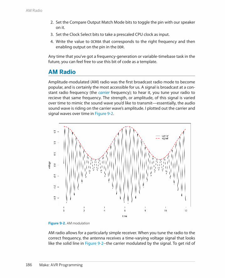
2. Set the Compare Output Match Mode bits to toggle the pin with our speakeron it.
3. Set the Clock Select bits to take a prescaled CPU clock as input.
4. Write the value to OCR0A that corresponds to the right frequency and thenenabling output on the pin in the DDR.
Any time that you’ve got a frequency-generation or variable-timebase task in thefuture, you can feel free to use this bit of code as a template.
AM Radio
Amplitude-modulated (AM) radio was the first broadcast radio mode to becomepopular, and is certainly the most accessible for us. A signal is broadcast at a con-stant radio frequency (the carrier frequency); to hear it, you tune your radio torecieve that same frequency. The strength, or amplitude, of this signal is variedover time to mimic the sound wave you’d like to transmit—essentially, the audiosound wave is riding on the carrier wave’s amplitude. I plotted out the carrier andsignal waves over time in Figure 9-2.
Figure 9-2. AM modulation
AM radio allows for a particularly simple receiver. When you tune the radio to thecorrect frequency, the antenna receives a time-varying voltage signal that lookslike the solid line in Figure 9-2--the carrier modulated by the signal. To get rid of
186 Make: AVR Programming
AM Radio

the carrier, you simply run the received voltage through a diode, so that you getonly the positive voltages. Now you’ve got a signal that varies from roughly zeroto 1.6 V, which you can output directly to a speaker with a capacitor, just as we didin the audio demos.
Indeed, the simplest versions of AM radio receivers are crystal radios, which reallyonly have four parts: an inductor and tuning capacitor to select the right carrierfrequency, a diode to separate the signal from the carrier, and a high-impedanceearpiece that doesn’t require amplification (and has the blocking capacitor builtin). If you’re interested, you can find crystal radio kits that’ll allow you to build anunpowered receiver for less than the cost of a nice dinner out. Or, for even lessmoney, you can pick up any cheap powered radio receiver and some batteries.
OK, so you’ve got an AM radio receiver ready. How do you make the AVR into anAM radio transmitter? The first step is to create the carrier frequency, and for thiswe’re going to use the built-in timer/counter hardware to generate a square waveat just under 1 MHz, right in the middle of the AM radio frequencies.
1 MHz?
Try as you might, you are not going to find 1 MHz on your AM radio dial. That’s because themedium-wave band where AM radio normally lives is usually measured in kiloHertz and runsfrom around 500 kHz to around 1600 kHz.
Set your radio to 1000 kHz to listen to this AVR project.
Once we’ve got that set up, we’ll modulate the amplitude of the carrier wave byturning on and off the output to the “antenna” pin at our audio frequency—this isthe same thing as modulating the carrier with another square wave (at audio fre-quency). Because both our carrier wave and modulation waves are both squarewaves, the resulting radio signal will look something like Figure 9-3.
Note that this signal is what’s called 100% modulated. When the audio signal is atits maximum, the carrier is fully on, and when it’s at its minimum, the carrier is fullyoff. (Compare with the sine wave in Figure 9-2, which was sketched with 75% mod-ulation.) We’ll output this signal directly to an antenna, and send it across the room.
187Chapter 9: Introduction to the Timer/Counter Hardware
AM Radio

Figure 9-3. AM modulation: square-wave version
The CircuitHow much of a radio you’d like to construct is up to you. Because this project ismostly for fun (and to amaze your nongeek friends), I recommend going all-outminimalist. You can broadcast this signal within a room with just a wire hooked upto pin PD5 / OC0B. A longer wire will broadcast farther and louder, so if you have 10feet or more of any type of wire just sitting around, that’ll do. If you have a wirethat’s long enough to make a loop around the room you’re in, you’ll get phenom-enal reception when you’re inside the loop.
Another super-simplistic broadcast antenna option is just to touch pin PD5 withyour finger. You’d be surprised how good an AM antenna your body will make! Justas in with adding more wire, you can increase the signal by holding hands with afriend while you touch the antenna pin.
188 Make: AVR Programming
AM Radio

On the Legality of Broadcasting Low-Power AM Radio
You might be wondering if broadcasting your own bleepy-bloopy AM radio signal is legal.The answer depends on where you live, and what kind of power you’re transmitting. In theUSA, for instance, it’s legal to broadcast on the AM bands if you use less than 100 milliwatts.It’s very unlikely that you’ll be putting anywhere near that much power with an AVR unlessyou’ve got a very long wire, so don’t worry about it.
Power limits aside, we’re making such a lousy AM transmitter that it’s almost surely the casethat you won’t interfere with anyone else’s reception. When I did this experiment, I could onlyreceive the signal within the room I was broadcasting in. And because I was only running the“station” for a few minutes, I didn’t worry about it, but I wouldn’t leave this circuit poweredand running for too long out of consideration for others. If you’d like to be broadcasting fora long period of time, you should probably get yourself an amateur radio license and moveover to a frequency that’s reserved for radio experimentation—then you can use (almost) allthe power you need.
CPU SpeedThus far, we’ve been running code that we needed to slow down to a human time-scale, so we were never all that concerned with how fast the AVR was able to run.Generating a radio signal at 1 MHz provides us the opposite problem—we needthe chip running as fast as it can—without resorting to an external crystal.
The internal CPU clock in all of the ATmegaxx8 chips (like our 168s) run at 8 MHz,so we should have no real problem making our 1 MHz signal. But all of the ATme-gaxx8 chips come from the factory with a 1/8th prescaler between the CPU clockand the CPU. That’s right—your chip comes fresh out of the box running at 1/8thof its possible speed. The reason is that, as we’ve seen here, most of the time theextra CPU speed isn’t necessary and just wastes power. But when you need speed,as here, it’s nice to be able to put the chip into overdrive.
There are two ways to turn off the prescaler on the ATmega 168 series chips. Thefirst is permanent, and involves changing a so-called fuse in the AVR. The “fuses”are actually a bunch of programmable flash memory locations, just like we storeour program in, only they directly control the behavior of the chip and are keptseparate from the main program space so that we don’t mess anything up.
The advantage to setting the CPU speed by setting a fuse is that once you’ve setthe chip up to run at full speed, you won’t have to remember to do it again. Whenyou flash in another program, the AVR’s CPU clock will still run at 8 MHz as long asyou haven’t reset the fuse in the meantime. The disadvantage is that sometimes,for power-reduction reasons, you might like to control the CPU speed on the fly
189Chapter 9: Introduction to the Timer/Counter Hardware
AM Radio
from within your code. And this leads us to the second method of modifying theCPU clock prescaler—through software using the avr/power.h library functions.
The newer ATmega chips, including all of the xx8 series that we’re using here (andmost of the new generation of ATtiny chips as well) have the ability to change theCPU prescaler from within software, and to many more possible values than simply1 MHz or 8 MHz. I’ll go over switching the CPU speed both ways, fuses and fromsoftware, because you’ll still see a lot of code out there where people tell you toset the “fast fuse.” But note that you can just as easily add a couple lines to yourcode and control the speed in firmware.
Setting fuse bitsIf you look up in the datasheet, or online, the fuse we’re interested in resetting iscalled the DIV8 clock fuse bit. If you’re interested in the nitty-gritty details of settingfuses, and you may need to set some of the AVR’s other fuses someday, read “Burn-ing Fuses: Enabling the High-Speed CPU Clock” on page 190. If you’d just like to getthe fuse set, and you’re using my makefiles, you can simply type make set_fast_fuse.
And I should mention that you don’t really need to do any of this for the purposesof the code in this book. I’ll be setting the clock to fast-mode in software as needed.
Setting CPU speed in codeThe modern way to change CPU speed is through code. Note that this won’t workif your chip doesn’t support it, and the compiler should throw an error. In that case,you’ll need to use the fuse-bit method to enable the chip’s full potential. But forthe entire ATmegaxx8 line of chips, you’ll be able to control the speed dynamicallythrough code. Here’s how.
Finally, before we leave the section where I introduced the avr/power.h library, Ishould mention that there are all sorts of other macros available that allow you toshut down parts of the AVR hardware in order to minimize power usage. For in-stance, if you’re not using the analog-to-digital converter (ADC) hardware, youmight as well turn it off to save a little power:
power_adc_disable();
See the avr-libc homepage for the complete listing of all the parts of the chipthat you can turn off to save power.
AM Radio: The CodeThis code section really gets to show off what timers can do, and we even get tocombine a timer with interrupts. Hold on tight!
In the radio code, we’ll be using Timer 0 in CTC mode as we did earlier to generateaudio in the improved organ code. That is, we have the counter count up to a valuethat determines its frequency, and then clear the counter and start over at zero.
190 Make: AVR Programming
AM Radio

Burning Fuses: Enabling the High-Speed CPU Clock
Believe it or not, most of the AVR chips come from thefactory set to divide the system CPU clock by eight.That’s right, they’re running slowed down 8x by de-fault. Why would Atmel do this to you? Well, for a largemajority of projects, the speed just isn’t necessary,and you save a lot on power drain by under-clocking.But here, we’re pushing the limits of what’s reason-able—using the hardware clock to directly producea radio-frequency signal. We’re going to need all thespeed we can get.
Changing up the clock speed turns out to be a matterof burning fuses. The AVR chips have two or threebytes of special memory locations that they call fusebits. Because they fundamentally alter the way thechip behaves, the fuse bits are kept separate from themain program flash memory, but otherwise theyfunction similarly. You can read and write them witha flash programmer and AVRDUDE just like program-ming any other flash memory in the chip.
Because the fuse bits alter the way the chips interactwith the world, it pays to be a little cautious with theflash memory because there are a two main dangers.
The worst thing you can do is change the SPI-programming bit, which disables your ability to fur-ther program the chip using your flash programmer.Why would you want to do this? Because you mightwant to use the RESET pin for something other thana dedicated reset line, I guess. But if you do so, theprogrammer can’t signal to the chip that it shouldenter programming mode without extreme meas-ures. Of course, you can unlock the chip again, usinga high-voltage parallel programmer circuit, but thisis more work than you’re going to want to get intojust for an extra pin of digital I/O. So until you knowbetter, and are prepared for a high-voltage rescue,don’t change the SPIEN-enable fuse bit!
The next worst thing that you can do with fuses is toselect the CPU clock to be connected to an externalcrystal clock source when you haven’t got one in-stalled. The CPU will just sit there waiting for an ex-ternal clock pulse that never comes. Your code won’trun, and you won’t be able to reprogram the chip (orthe fuses) until you provide an external clock source.
This situation really isn’t so bad, though. If you’ve gota crystal lying around, you can just plug in and then
reset the fuses to the internal CPU clock as before.And even if you don’t have an oscillator crystal onhand, you can set up another AVR chip to create a(say) 1 MHz signal and hook that up to the “dead”AVR’s clock input. Then you can reflash the fuse bit toenable the internal clock and you’re back in business.
These two warnings aside, what can you do with thefuse bits that’s useful? In this chapter, we’ll be clearingthe default CLKDIV8 fuse that divides the internalCPU clock by eight. Configuring the CPU clock to bedriven by an external crystal is also quite common.There are fuse bits that set up how a bootloader (pro-gram in the chip itself that will flash the chip—oftenusing a serial connection to replace your flash pro-grammer) will operate.
The most convenient way I know to calculate whatthe AVR fuse bits should be is using an online fuse bitcalculator program that has all the chip data pre-entered. This fuse calculator even goes so far as toprovide you the AVRDUDE flags that you’d need toenter on the command line.
For the ATmega48, 88, 168, and 328 series, the defaultfuse values are:
• lfuse = 0x62
• hfuse = 0xDF
• efuse = 0x01
and you only need to change the lfuse to 0xE2 toenable high-speed mode. The AVRDUDE flag to setthe full-speed clock looks like -U lfuse:w:0xE2:m,which tells AVRDUDE to do a flash memory operation,on lfuse, writing the byte 0xE2 immediately (m, asopposed to reading the data from a file). On a Linuxor Mac system, type man avrdude or search the In-ternet for “avrdude man page” to see what all of thecommand-line arguments do in detail.
Or, using my included makefile, you can simply typemake set_fast_fuse or make set_default_fuses to switch back and forth between full-speed (8 MHz) and low-speed (1 MHz) mode.
191Chapter 9: Introduction to the Timer/Counter Hardware
AM Radio
Software CPU Clock Speed Control
If you look through the AVR datasheet, in the sectionon the System Clock and the Register Description,you’ll find the “Clock Prescale Register,” CLKPR. Thelowest four bits of this register (CLKPS3..CLKPS0)allow you to control the clock division by all powersof two from 1 to 256. So even if the main system clockis running at 8 MHz by default, you can run the CPUclock from 8 MHz all the way down to 8/256 MHz, or31.25 kHz if you’d really like to save power and don’tneed the extra speed.
Because monkeying around with the CPU speed isnot something you’d want to do by accident, there isadditionally a “Clock Prescaler Change Enable” bitthat has to be set no more than four CPU clock cyclesbefore the prescaler bits are able to be written. Be-cause all of this timing is tight, the avr-libc libraryprovides functions that make it trivial to change thespeed. The CPU prescaler macro functions are in-cluded in the avr/power.h library. The advantage ofsetting them through the prebuilt libraries is that youdon’t have to worry about any of the timing detailsand that nicely named convenience macros are de-fined for all of the speed grades.
So to set the chip to run at 8 MHz, full speed, you onlyneed to add the following two lines to your code:
#include <avr/power.h>/* and then in the main() function... */clock_prescale_set(clock_div_1);
Or if you’d like to run the chip at 1/2 MHz to savepower:
clock_prescale_set(clock_div_16);
Notice here that setting the clock speed in softwareessentially ignores the fuse setting. That is, if you havethe fuse set to run the chip at 1 MHz (the default), youcan either speed it up or slow it down from software.
You can think of the fuse setting as a default speedthat the software setting is able to override.
If you set the CPU speed too slow, you should bewarned that your flash programmer may be trying totalk too fast for your chip. If this is the case—you’veslowed the chip way down and you find that yourprogrammer no longer works—you’ll need to slowthe programmer down to match. In AVRDUDE, youuse the -B flag to reset the bit-clock to a larger (slow-er) value. If you’re running the chip particularly slow-ly, you may need to add as much as -B 200 to pro-gram the chip if you’ve got it set to clock_div_256.
Also note that everything runs slower (or faster) ifyou’re changing the CPU speed on the fly from withinyour code. Functions like _delay_ms(100) may nottake as much time as you’d expect, and none of theserial communication routines will work either. Thesefunctions use the #define F_CPU macro to figureout how fast they have to run. If you’re changing theCPU speed in your code on the fly, delays and serialroutines won’t work unless the currently set speedmatches the F_CPU definition in the makefile (or inyour code, if you’ve decided to define it there in-stead).
But for everything we’ll do in this book, we set theCPU speed once in the init section and leave italone. The corresponding makefile should have thematching F_CPU definition as well, so you won’t needto worry about that. It’s only if you’re mixing andmatching that you’ll need to think about the CPUspeed. If you need to use the serial port, for instance,at a CPU speed other than that defined in F_CPU,you’ll need to redo the device initialization stuff tomatch the new CPU speed. (Or just avoid switchingCPU speeds on the fly entirely.)
Every time it resets, it will toggle a pin. Only this time, it’s toggling the pin at roughly1 MHz and emitting radio waves rather than audio. This is the carrier frequency.
To modulate the carrier, we’re going to use another timer, Timer 1. Timer 1 is alsorun in CTC mode to generate variable frequencies. Only instead of toggling a pindirectly, it calls an interrupt service routine every time it resets. Inside the ISR, we
192 Make: AVR Programming
AM Radio

simply turn on and off the carrier signal to modulate it, generating the audio ontop.
All that’s left to do is set the pitch in Timer 1’s OCR1A, and let it run for a given amountof time to sound the note. Let’s see how it goes in detail in Example 9-4.
Example 9-4. amRadio.c listing/*Plays a simple tune, broadcasts it in the AM radio band.*/
// ------- Preamble -------- //#include <avr/io.h> /* Defines pins, ports, etc */#include <util/delay.h> /* Functions to waste time */#include <avr/power.h>#include <avr/interrupt.h>#include "pinDefines.h"#include "scale16.h"
#define COUNTER_VALUE 3 /* determines carrier frequency */
// From f = f_cpu / ( 2* N* (1 + OCRnx) )// Good values for the AM band from 2 to 6: pick one that's clear// Divide by two b/c we're toggling on or off each loop;// a full cycle of the carrier takes two loops.// 8Mhz / (2 * 1 * (1+2)) = 1333 kHz// 8Mhz / (2 * 1 * (1+3)) = 1000 kHz// 8Mhz / (2 * 1 * (1+4)) = 800 kHz// 8Mhz / (2 * 1 * (1+5)) = 670 kHz// 8Mhz / (2 * 1 * (1+6)) = 570 kHz// 8Mhz / (2 * 1 * (1+7)) = 500 kHz
static inline void initTimer0(void) { TCCR0A |= (1 << WGM01); /* CTC mode */ TCCR0A |= (1 << COM0B0); /* Toggles pin each time through */ TCCR0B |= (1 << CS00); /* Clock at CPU frequency, ~8MHz */ OCR0A = COUNTER_VALUE; /* carrier frequency */}
static inline void initTimer1(void) { TCCR1B |= (1 << WGM12); /* CTC mode */ TCCR1B |= (1 << CS11); /* Clock at CPU/8 frequency, ~1MHz */ TIMSK1 |= (1 << OCIE1A); /* enable output compare interrupt */}
ISR(TIMER1_COMPA_vect) { /* ISR for audio-rate Timer 1 */ ANTENNA_DDR ^= (1 << ANTENNA); /* toggle carrier on and off */}
static inline void transmitBeep(uint16_t pitch, uint16_t duration) { OCR1A = pitch; /* set pitch for timer1 */ sei(); /* turn on interrupts */
193Chapter 9: Introduction to the Timer/Counter Hardware
AM Radio
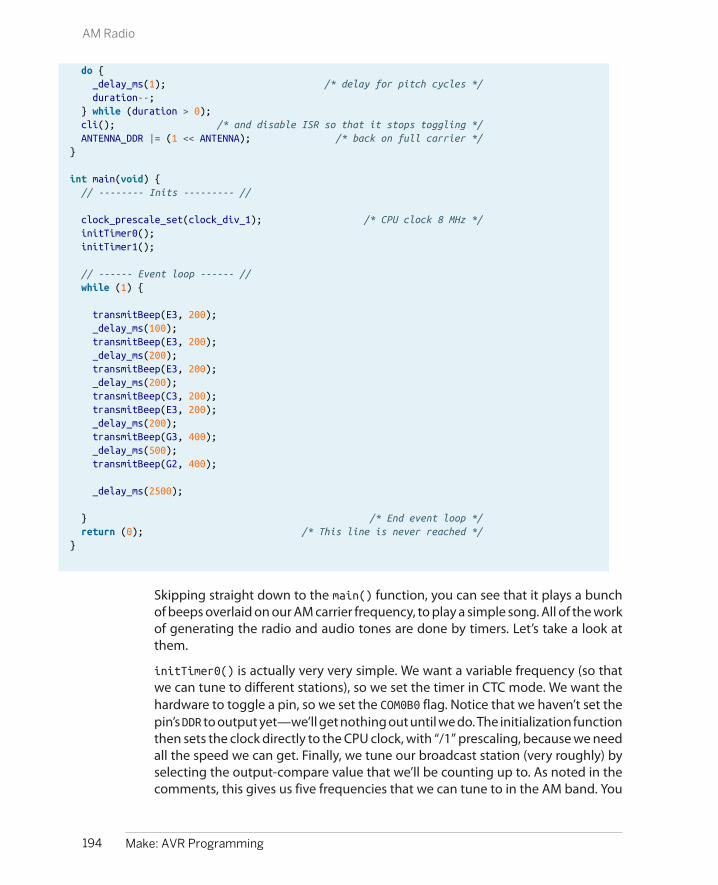
do { _delay_ms(1); /* delay for pitch cycles */ duration--; } while (duration > 0); cli(); /* and disable ISR so that it stops toggling */ ANTENNA_DDR |= (1 << ANTENNA); /* back on full carrier */}
int main(void) { // -------- Inits --------- //
clock_prescale_set(clock_div_1); /* CPU clock 8 MHz */ initTimer0(); initTimer1();
// ------ Event loop ------ // while (1) {
transmitBeep(E3, 200); _delay_ms(100); transmitBeep(E3, 200); _delay_ms(200); transmitBeep(E3, 200); _delay_ms(200); transmitBeep(C3, 200); transmitBeep(E3, 200); _delay_ms(200); transmitBeep(G3, 400); _delay_ms(500); transmitBeep(G2, 400);
_delay_ms(2500);
} /* End event loop */ return (0); /* This line is never reached */}
Skipping straight down to the main() function, you can see that it plays a bunchof beeps overlaid on our AM carrier frequency, to play a simple song. All of the workof generating the radio and audio tones are done by timers. Let’s take a look atthem.
initTimer0() is actually very very simple. We want a variable frequency (so thatwe can tune to different stations), so we set the timer in CTC mode. We want thehardware to toggle a pin, so we set the COM0B0 flag. Notice that we haven’t set thepin’s DDR to output yet—we’ll get nothing out until we do. The initialization functionthen sets the clock directly to the CPU clock, with “/1” prescaling, because we needall the speed we can get. Finally, we tune our broadcast station (very roughly) byselecting the output-compare value that we’ll be counting up to. As noted in thecomments, this gives us five frequencies that we can tune to in the AM band. You
194 Make: AVR Programming
AM Radio

can transmit on other frequencies of course, but your radio may not be designedto pick them up.
initTimer1() has a little more detail to it. Again, we select CTC mode. But noticethat the Waveform Generation Mode bits we need to set are different. Timer 1, a16-bit timer, has many more options than the 8-bit equivalents, and it has four WGMbits that you can set instead of only three. Table 16-4 in the datasheet goes throughall of them. I just looked down until I found the CTC mode with a variable TOP valueand used that. In order to get the audio pitches in the right range for the values I’dcomputed, I ended up dividing the CPU clock by eight for Timer 1 and setting theCS11 bit to do it.
Finally, there is one new bit in configuring this timer that we haven’t seen before.The Timer Interrupt Mask (TIMSK) registers allow us to configure all of the differentways to trigger interrupts from the timer/counter. The three options include trig-gering when the counter hits compare values A or B, or alternatively when thecounter overflows.
Because we’re running the timer in CTC mode, it will essentially never overflow.Remember that when the timer hits a compare value, it is reset, right? So unlessthat compare value is equal to the maximum value (65,535 for the 16-bit timer), itwill never overflow. Instead, the overflow interrupts are more useful when the timeris used in PWM mode, which we’ll discuss in Chapter 10.
Anyway, because we wanted to be able to control the pitch of the audio by mod-ifying the compare-and-reset value OCR1A, we enable the interrupt by setting thebit for Output Compare Interrupt Enable 1A (OCIE1A).
The ISR for Timer 1’s compare interrupt A, called TIMER1_COMPA_vect, does our 100%modulation of the carrier for us. That is to say, it toggles the antenna output onand off. And that’s it. A short and sweet interrupt service routine!
Now the two timers are configured and doing their things, right? Timer 0 is loopingthrough very quickly from zero to three, toggling a pin every time it resets. Timer1 is looping through at audio rates, triggering an ISR every time it resets, right? Wellnot quite yet. We haven’t enabled the global interrupt bit yet.
That’s where the function transmitBeep() comes in. This function sets the pitch inthe OCR1A register and then enables interrupts. Now the ISR toggles the antennaon and off, creating the audio signal over our carrier. There’s a simple _delay_ms() loop to allow for the duration of the note, and then interrupts are turnedoff again and the carrier is returned to being full on.
If you’re not familiar with radio broadcasting, it might seem strange to leave thecarrier on full and claim that it’s not making any noise. But look back at the diagramsof how amplitude modulation works. It’s the change in the carrier wave—the mod-ulation—that carries the pitch. If you just leave the carrier on full, without
195Chapter 9: Introduction to the Timer/Counter Hardware
AM Radio

modulating its volume, that corresponds to a flat line in its outer volume envelope,and a flat line makes no noise. It’s only when we start wiggling the volume envelopeat a particular frequency (by reenabling the ISR) that we get a pitch back out.
And that’s it, really. Our AM radio is a tiny bit of a hardware hack (if you considerhooking up a long wire to an AVR pin as a hardware hack) and the rest is done insoftware. For the audio, we reuse the concept for generating audio from our im-proved organ program, only instead we turn on and off the transmitter throughan ISR instead of directly driving a speaker. The transmitter is just another CTC-timer generating a really high-frequency square wave toggling our antenna pin.It’s not the cleanest radio station in the world, and certainly not professional, butyou can play yourself bleepy music across the room.
Summary
In this chapter, we started in on our first of a two-part series on the timer/counterhardware. We used Normal mode to time short-duration events in the reactiontimer. Then, we revisited our original organ program, offloading the job of togglingthe speaker pin to a variable-frequency CTC-mode timer/counter with the outputpins enabled.
Then finally, we shifted the timer into high gear, enabling the AVR’s full-speed modethrough the power.h libraries, and used two timers to make a fully modulated AMradio signal. One timer ran at radio frequencies to create the carrier that you tuneyour radio to, and the other employed an ISR to turn this carrier on and off at givenfrequencies to make music.
When configuring timer/counters, so far, the important points to remember are:
• Set the waveform mode to either Normal mode (the default) or to CTC modeby setting the appropriate waveform mode bits.
• Select the clock prescaler speed. You must set these bits, because the defaultvalue leaves the timer/counter prescaler unconnected, and thus not running.
• Optionally select an output mode if you’d like to set, clear, or toggle outputpins from your timer/counter. (And don’t forget to set the corresponding DDRbits.)
• If, instead of toggling pins directly, you’d like to have some code executed, youcan enable an interrupt to trigger on compare match. (And don’t forget toenable interrupts globally with sei().)
In Chapter 10 we’ll see how to create “analog” voltage output by using pulse-widthmodulation. The PWM mode of timer/counter modules will come in handy there.We’ll also use timers to control motors in Chapter 11, Chapter 14, and Chapter 15.We’ll use timers plus interrupts again and again, both for making real-time clocks
196 Make: AVR Programming
Summary

and in conjunction with PWM to make a direct-digital audio synthesizer and even(in Chapter 18) to play back your own voice samples.
In short, this chapter on timers and the preceding chapter on interrupts are thefoundation for all of the advanced techniques in the rest of this book. So if it feelslike a lot to take in all at once, don’t worry. You’ll get more examples of using bothcoming right up!
197Chapter 9: Introduction to the Timer/Counter Hardware
Summary


Fading LEDs and “Analog” Output
So far, everything’s been either on or off in our AVR world—strictly digital. LEDshave been either on or off. Speaker cones have been either pulled fully back orpushed fully forward. Electrons have been pushed this way or that through an-tennas without particular finesse. On and off is fun, but sometimes you want anLED to fade instead of blink, or a motor to run at half speed instead of being alwayson or off. Or you’d like to make some audio waveforms other than just the squarewave, and you’d like them to have volume control.
To do that, we’ll need to figure out a way to make intermediate voltages from theAVR’s logical high and low, and one of the most common ways of doing so is pulse-width modulation (PWM). In brief, PWM toggles the logic output on and off veryfast, so quickly that whatever is attached to the output can’t react fully. The resultis that the output sees a voltage that is proportional to the average percent of thetime that the AVR spends with its output on. (If that sounds strange right now, it’llseem perfectly normal by the end of this chapter.)
In Chapter 13, we’ll use PWM to play back audio synthesizer waveforms. In Chap-ter 14 and Chapter 15, we’ll use PWM to drive motors at different speeds and evenbackward. Finally, in Chapter 18, timer/counter PWM will help us build a talkingvoltmeter that reads out voltages to you in your own voice. In sum, we’ll be usingPWM in a lot of the upcoming projects, so please excuse me for this chapter if wesimply pulse some LEDs.
PWM is such a common method of creating analog voltages from digital devicesthat almost all microcontrollers, including the AVR, have dedicated internal pe-ripheral hardware that takes care of this high-speed bit toggling for you, and Irecommend using this feature whenever you can. In this chapter, we’ll also stepthrough a completely manual PWM routine that’s useful for helping build up yourintuition about what’s going on, and I’ve added in another method of using the
199
Pulse-Width Modulation 10

What You Need
In addition to the basic kit, you will need:
• LEDs and current-limiting resistors hooked upas in previous chapters.
• A USB-Serial adapter.
timer/counter peripheral and its interrupts to output PWM waveforms on any pinthat’s capable of output. So let’s get down to the business at hand—flipping bits,fast.
Bright and Dim LEDs: PWM
PWM is perhaps the easiest technique for us to implement that’ll give us a partly-on, analog effect. As mentioned earlier, we’ll need to switch a digital output highand low fast enough that whatever device we’re driving can’t react to the individualon-off pulses, but instead only to the average value. We then regularly repeat thesepulses and control the average value by varying the percentage of the time in acycle that the output is held high. The resulting voltages are plotted in Figure 10-1.
Figure 10-1. PWM oscilloscope traces
In Figure 10-1, the top line is the direct-from-the-AVR PWM trace. You can see howthe percentage of time that the AVR output is high changes from low to high, and
200 Make: AVR Programming
Bright and Dim LEDs: PWM
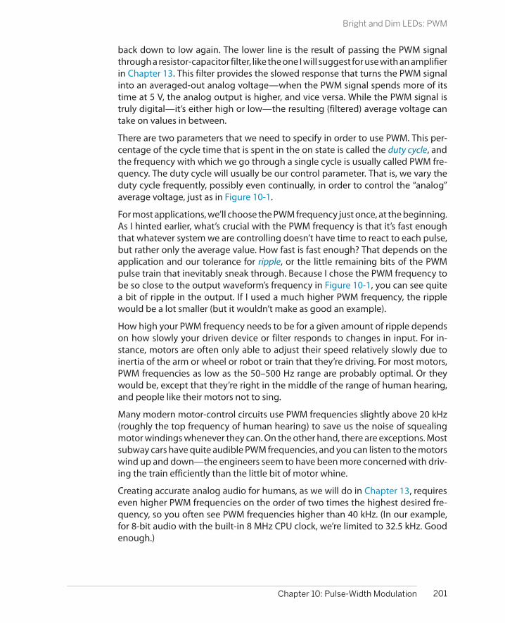
back down to low again. The lower line is the result of passing the PWM signalthrough a resistor-capacitor filter, like the one I will suggest for use with an amplifierin Chapter 13. This filter provides the slowed response that turns the PWM signalinto an averaged-out analog voltage—when the PWM signal spends more of itstime at 5 V, the analog output is higher, and vice versa. While the PWM signal istruly digital—it’s either high or low—the resulting (filtered) average voltage cantake on values in between.
There are two parameters that we need to specify in order to use PWM. This per-centage of the cycle time that is spent in the on state is called the duty cycle, andthe frequency with which we go through a single cycle is usually called PWM fre-quency. The duty cycle will usually be our control parameter. That is, we vary theduty cycle frequently, possibly even continually, in order to control the “analog”average voltage, just as in Figure 10-1.
For most applications, we’ll choose the PWM frequency just once, at the beginning.As I hinted earlier, what’s crucial with the PWM frequency is that it’s fast enoughthat whatever system we are controlling doesn’t have time to react to each pulse,but rather only the average value. How fast is fast enough? That depends on theapplication and our tolerance for ripple, or the little remaining bits of the PWMpulse train that inevitably sneak through. Because I chose the PWM frequency tobe so close to the output waveform’s frequency in Figure 10-1, you can see quitea bit of ripple in the output. If I used a much higher PWM frequency, the ripplewould be a lot smaller (but it wouldn’t make as good an example).
How high your PWM frequency needs to be for a given amount of ripple dependson how slowly your driven device or filter responds to changes in input. For in-stance, motors are often only able to adjust their speed relatively slowly due toinertia of the arm or wheel or robot or train that they’re driving. For most motors,PWM frequencies as low as the 50–500 Hz range are probably optimal. Or theywould be, except that they’re right in the middle of the range of human hearing,and people like their motors not to sing.
Many modern motor-control circuits use PWM frequencies slightly above 20 kHz(roughly the top frequency of human hearing) to save us the noise of squealingmotor windings whenever they can. On the other hand, there are exceptions. Mostsubway cars have quite audible PWM frequencies, and you can listen to the motorswind up and down—the engineers seem to have been more concerned with driv-ing the train efficiently than the little bit of motor whine.
Creating accurate analog audio for humans, as we will do in Chapter 13, requireseven higher PWM frequencies on the order of two times the highest desired fre-quency, so you often see PWM frequencies higher than 40 kHz. (In our example,for 8-bit audio with the built-in 8 MHz CPU clock, we’re limited to 32.5 kHz. Goodenough.)
201Chapter 10: Pulse-Width Modulation
Bright and Dim LEDs: PWM

The human eye, unlike the ear, falls in the slow response category. We saw this inthe POV toy example, where we used pulses on the order of 2 milliseconds (500Hz). It turns out that we don’t need a frequency anywhere near this high to avoidflickering—for me a period of around 18 milliseconds (just under 60 Hz) doesn’tseem to flicker. Remember that here I’m talking about the response time of thehuman eye, not the LEDs—those can pulse on and off in the megahertz range butwe wouldn’t notice it. Here, the human optical system is the slowly adjustingmechanism that we’re using to average out the pulses.
Brute-Force PWM Demo
But don’t take my word for it. Example 10-1 is a fully adjustable, manual PWMroutine to play around with. Flash in the program pwm.c and experiment withwhere your own flicker-fusion frequency lies by changing the delay time definedat the top. Then, let’s look at the event loop and see how it works.
Example 10-1. pwm.c listing /* Quick and dirty PWM Demo */
// ------- Preamble -------- //#include <avr/io.h> /* Defines pins, ports, etc */#include <util/delay.h> /* Functions to waste time */#include "pinDefines.h"
#define LED_DELAY 20 /* microseconds */
void pwmAllPins(uint8_t brightness) { uint8_t i; LED_PORT = 0xff; /* turn on */ for (i = 0; i < 255; i++) { if (i >= brightness) { /* once it's been on long enough */ LED_PORT = 0; /* turn off */ } _delay_us(LED_DELAY); }}
int main(void) {
uint8_t brightness = 0; int8_t direction = 1;
// -------- Inits --------- //
// Init all LEDs LED_DDR = 0xff; // ------ Event loop ------ // while (1) { // Brighten and dim
202 Make: AVR Programming
Brute-Force PWM Demo

if (brightness == 0) { direction = 1; } if (brightness == 255) { direction = -1; } brightness += direction; pwmAllPins(brightness);
} /* End event loop */ return (0); /* This line is never reached */}
This code is split up into two distinct parts. The function pwmAllPins() takes careof implementing PWM. The remaining code in the event loop increases and de-creases a brightness variable. Calling pwmAllPins() with the increasing and de-creasing brightness makes the LEDs pulse in and out.
In pwmAllPins(), we have a loop over i, which takes exactly 255 steps each time.Inside the i loop, we compare a variable brightness to i and turn on the LEDs if iis smaller. This has the effect of turning on the LEDs at the beginning of each setof 256 and then turning them off as soon as i reaches the value brightness, so forhigher values of brightness the LEDs stay on for a greater percentage of the 256steps. PWM! (But notice that we’ve locked up the entire CPU just brightening anddimming.)
Now, you can modify the per-step delay time and figure out where you just startto notice the flickering. (Or better still, hook up a potentiometer and adjust thedelay time by turning the knob.) You’ll soon find your personal flicker-fusion rate.Notice when you move your head that you’ll see the persistence-of-vision trailereffects as well.
When you’re playing around with the delay, remember that you’re taking 256 stepsper cycle, so if you delay 20 microseconds per step, that’s 5,120 microseconds, or5.12 milliseconds per cycle. Because there are 1,000 milliseconds in a second, thisgives a PWM frequency of 1,000 / 5.12, or around around 195 Hz.
The main() portion of the code sets up a direction variable (as a signed integer)that lets us add to or subtract from the current brightness. Finally, when the bright-ness hits either limit, direction reverses sign. The result is a brighter-and-dimmerpulsing fade.
When you’re playing with the LED demo, you may also notice that the human eyedoesn’t respond to equal changes in brightness equally. In our simple fade, it lookslike the LEDs go through the dark portion of their fade-in and fade-out faster than
203Chapter 10: Pulse-Width Modulation
Brute-Force PWM Demo
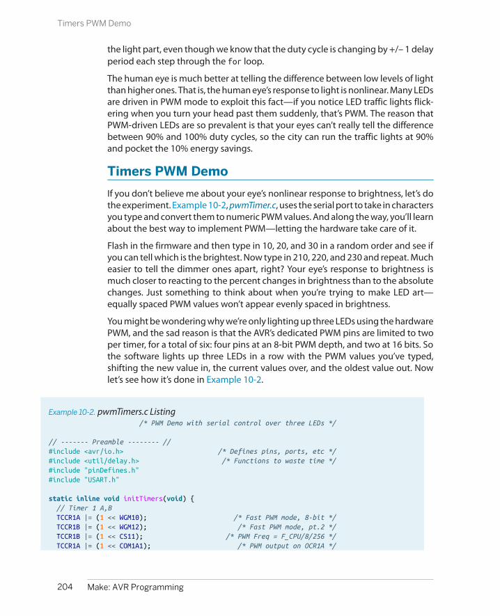
the light part, even though we know that the duty cycle is changing by +/– 1 delayperiod each step through the for loop.
The human eye is much better at telling the difference between low levels of lightthan higher ones. That is, the human eye’s response to light is nonlinear. Many LEDsare driven in PWM mode to exploit this fact—if you notice LED traffic lights flick-ering when you turn your head past them suddenly, that’s PWM. The reason thatPWM-driven LEDs are so prevalent is that your eyes can’t really tell the differencebetween 90% and 100% duty cycles, so the city can run the traffic lights at 90%and pocket the 10% energy savings.
Timers PWM Demo
If you don’t believe me about your eye’s nonlinear response to brightness, let’s dothe experiment. Example 10-2, pwmTimer.c, uses the serial port to take in charactersyou type and convert them to numeric PWM values. And along the way, you’ll learnabout the best way to implement PWM—letting the hardware take care of it.
Flash in the firmware and then type in 10, 20, and 30 in a random order and see ifyou can tell which is the brightest. Now type in 210, 220, and 230 and repeat. Mucheasier to tell the dimmer ones apart, right? Your eye’s response to brightness ismuch closer to reacting to the percent changes in brightness than to the absolutechanges. Just something to think about when you’re trying to make LED art—equally spaced PWM values won’t appear evenly spaced in brightness.
You might be wondering why we’re only lighting up three LEDs using the hardwarePWM, and the sad reason is that the AVR’s dedicated PWM pins are limited to twoper timer, for a total of six: four pins at an 8-bit PWM depth, and two at 16 bits. Sothe software lights up three LEDs in a row with the PWM values you’ve typed,shifting the new value in, the current values over, and the oldest value out. Nowlet’s see how it’s done in Example 10-2.
Example 10-2. pwmTimers.c Listing /* PWM Demo with serial control over three LEDs */
// ------- Preamble -------- //#include <avr/io.h> /* Defines pins, ports, etc */#include <util/delay.h> /* Functions to waste time */#include "pinDefines.h"#include "USART.h"
static inline void initTimers(void) { // Timer 1 A,B TCCR1A |= (1 << WGM10); /* Fast PWM mode, 8-bit */ TCCR1B |= (1 << WGM12); /* Fast PWM mode, pt.2 */ TCCR1B |= (1 << CS11); /* PWM Freq = F_CPU/8/256 */ TCCR1A |= (1 << COM1A1); /* PWM output on OCR1A */
204 Make: AVR Programming
Timers PWM Demo

TCCR1A |= (1 << COM1B1); /* PWM output on OCR1B */
// Timer 2 TCCR2A |= (1 << WGM20); /* Fast PWM mode */ TCCR2A |= (1 << WGM21); /* Fast PWM mode, pt.2 */ TCCR2B |= (1 << CS21); /* PWM Freq = F_CPU/8/256 */ TCCR2A |= (1 << COM2A1); /* PWM output on OCR2A */}
int main(void) {
uint8_t brightness;
// -------- Inits --------- //
initTimers(); initUSART(); printString("-- LED PWM Demo --\r\n");
/* enable output on LED pins, triggered by PWM hardware */ LED_DDR |= (1 << LED1); LED_DDR |= (1 << LED2); LED_DDR |= (1 << LED3);
// ------ Event loop ------ // while (1) {
printString("\r\nEnter (0-255) for PWM duty cycle: "); brightness = getNumber(); OCR2A = OCR1B; OCR1B = OCR1A; OCR1A = brightness;
} /* End event loop */ return (0); /* This line is never reached */}
As with the rest of the timer/counter-based code demos so far, the event loop isquite sparse. It gets a value from the serial port and then shifts the values up achain, corresponding to the output compare registers of LED1, LED2, and LED3. Notehow we don’t need to use any more variables to store the “previous” values thatwe received over the serial line—they’re stored in the OCRnx registers just as if theywere normal variables.
Writing those three variables takes just a couple microseconds even at 1 MHz. Therest of the CPU time is spent waiting for and processing our serial input. Note howwe couldn’t do this at all with the software-based PWM approach in pwm.c; if wewaited for serial input, the LEDs would stop blinking. Even if we just checked if theserial port had new data, it would throw off our PWM timings. Here, all our codehas to do to keep the LEDs blinking at their appropriate duty cycle is write values
205Chapter 10: Pulse-Width Modulation
Timers PWM Demo

to the appropriate OCRnx registers. The hardware takes care of the rest—counting,comparing, turning on and off pins. In this example, that leaves us free to use theCPU to talk to us over the serial port.
Initializing Timers for PWM ModeConfiguring PWM by timer is a lot like using the hardware timer/counter in Chap-ter 9 except that we’re selecting a PWM waveform generation mode instead ofNormal or CTC modes.
Turn your attention to the initTimers() function, and you’ll see something similarto what we did in Chapter 9. We set up the timers’ waveform modes, set the clockinput prescaler, and then set the compare output bits to enable direct output onthe OCR1A, OCR1B, and OCR2A pins. Voila.
Fast PWM Mode
Fast PWM mode is probably the most-used PWM mode, as well as the most straightforward.The counter loops around from zero to its maximum value (255 or 65,535 or another valuestored in the OCRxA register, depending on the particular timer and mode) continuously atthe speed defined by the prescaler. Along the way, the counter is compared with the contentsof the Output Compare (OCRnx) registers. When a match happens, the PWM output pins canbe set or cleared and interrupts can be fired.
Fast PWM mode is fundamentally a hardware version of the pwm.c demo code, which con-tinuously looped around from 0 to 255 and compared the counter value to a duty cyclevariable. But using the hardware PWM mode can be much faster than doing the same thingin code and uses no CPU cycles.
Calculating the PWM frequency for fast PWM mode is easy. Take the CPU clock frequency,divide it by a prescaler value if applicable, and then divide by the number of steps per cycle.For example, I’ve set the prescaler at 8, using an 8-bit timer with 256 steps, and a 1 MHz CPUclock; therefore, the fast PWM frequency is 1,000,000 Hz / 8 / 256 = 488 Hz.
Have a look through the datasheet and make sure you understand at least whereto find the bits that are being set in the initialization routine. You’ll notice that Timer1 is more complicated because it’s a 16-bit timer—the AVR gives us modes to op-erate it in 8-bit, 10-bit, or full-resolution modes. We’ll use its full resolution later onto drive servo motors in Chapter 11, but for now, notice that we have it set up inan 8-bit PWM mode that uses 255 as its maximum value so that it’s consistent withthe other LED on Timer 2.
Setting the compare output mode with the COM bits is also a little bit different herethan in the CTC case. For one thing, there are different tables for what the bits mean
206 Make: AVR Programming
Timers PWM Demo

in the CTC, fast PWM and phase-correct PWM cases, so make sure you’re lookingat the right COM tables. In our case, setting COM1A1, COM1B1, and COM2A1 correspondto the “noninverting” mode—that is, the PWM turns the pin on when it overflowsfrom 255 to 0, and turns it off when it reaches the compare value. This is just whatwe did in the brute-force PWM example that lead this chapter, and results in higherPWM values corresponding to higher duty cycles and thus brighter LEDs.
Setting up the clock speed prescaler is just the same as it was in the CTC examples,so there’s not much that’s interesting here. When we configured the prescaler inCTC mode, we were interested in the frequency for its own sake, but here it’s notsuper critical. With the PWM frequency, it’s only important that the PWM cycles arefast enough that our system responds to the average value. Play around with thedifferent prescaler settings to get a feel for what range of frequencies are good fordriving PWM’ed LEDs. Or take an engineering approach and see “Fast PWMMode” on page 206 on how to calculate the PWM frequency.
Before we leave the initialization section, note that we enable output for the threeLEDs using the DDR registers. By now you might have noticed that even if you hitReturn or type “0,” the dimmest the LEDs go is still not off. Why is that? When youset the OCR to zero, it doesn’t actually turn the pins off. Instead, the pins get turnedon as soon as the hardware counter flips over from 255 to zero, and then turnedoff after the compare match unit compares a zero. That is, each pin is on for 1/256th(0.4%) of the time and this produces visible brightness on the LED.
So what can you do if you want the LED off, like really off-off? The easiest way is todisconnect the pin by putting it in input mode by clearing its corresponding bit inthe bank’s DDR register. In some cases, you’ll want to send an actual ground-voltage,low signal; for instance, if you want to turn off a FET that’s attached to the pin. Toget a constant logic low voltage, you need to clear the COM bit in the timer’s con-figuration register to decouple the pin from the timer, and make sure the DDR is setfor output and the PORT bit is clear as you normally would.
The good news here is that there’s no such precaution necessary for the case whenyou want the LED always on. Setting the OCR to 255 does result in output that’salways high. It’s only when you want the pin entirely off that you need to overridethe hardware PWM.
And with this example under your belt, you should be able to set up and use hard-ware PWM anywhere in your code. Notice how little your main code actually needsto do to set or change the PWM average-value output once it’s configured. All that’sleft for your code is to write a value to the output-compare register, and the hard-ware takes care of the rest. This makes using PWM conceptually very simple: if youwant to output a voltage halfway between 5 V and 0 V, write OCR1A = 127 andyou’re done. It’s like you were setting the output’s “analog” voltage directly fromyour code.
207Chapter 10: Pulse-Width Modulation
Timers PWM Demo

“Analog” Output on the Arduino
If you’ve used the Arduino platform, you’re probablywondering why we don’t just use the Analog Outpins. Here’s the deal—there are no Analog Out pins.By opening this book, you’ve taken the Red Pill, andyou’re going to find out how deep this rabbit holegoes, right? The Arduino folks have been lying to you!It’s all a giant conspiracy to keep you from learningabout PWM. Now you know the truth!
OK, more seriously, the Arduino platform aims to ab-stract away a lot of the nitty-gritty details, and so theydon’t bother you with the difference between “ana-log” and PWM output, or require you to know whichpins are connected to which timers. Have a look atthe analogWrite() function in the Arduino sourcecode file wiring_analog.c in the arduino-1.0/hard-ware/arduino/cores/arduino directory. (Change tomatch your version number.) You’ll see that we’re alldoing the same thing after all.
analogWrite() first checks to see if the value you’rewriting is 0 or 255, always off or always on. Then itfigures out which timer (digitalPinToTimer(pin)) you need to configure for the pin youspecified, and then sets the relevant COM bits and fi-nally the OCR register value. Just like we’ve been
doing here! (The Arduino library version sets the COMbits every time you change the duty cycle, which isredundant but makes sure that it’s set.)
The price paid for the Arduino pin/timer abstractionis that what we do in one or two lines of code, andtwo or three cycles of CPU time, the Arduino does in50+ clock cycles. It tests if you want the pin fully onor off, and it uses a whole switch() expression andmemory lookup to figure out which timer registersto write to—and all of this just so that you don’t haveto look up the pin in the datasheet.
If you’re calling analogWrite() infrequently in yourcode, this will probably work OK, and you’ll never no-tice the speed penalty. If you’re setting the OCR bitsfrequently, as we will be in Chapter 13, this extra codeoverhead means the difference between the possibleand impossible. If you’re coming from the Arduinoworld, you’ll probably be annoyed by how much de-tail about the chip you’re required to learn, but onceyou learn how to actually use the hardware periph-erals as they’re intended, you’ll be surprised by howmuch more is possible. And once you know how theinternal peripherals work, it’s not much harder toconfigure them yourself.
PWM on Any Pin
So far we’ve seen two ways to implement PWM in our AVR code. One methodimplements PWM entirely in code by looping and directly setting the pins on andoff using the CPU. The “normal” hardware PWM method works significantly faster,but only on six designated pins, two for each timer.
If we want to implement PWM on an arbitrary pin, there is a trick, but it’s a little bitof hack. Instead of using the built-in pin-toggling function of the timer/counter,we’ll instead use the interrupts to trigger our own code, and turn on and off pinsfrom within ISRs. We don’t have to tie up the CPU with counting and waiting, as wedid in the brute-force PWM example. Rather, we can use a timer/counter in Normalmode to do the counting for us.
Then we trigger interrupts at the beginning of the cycle to turn the PWM pins onand use the output-compare values to trigger another interrupt to turn the pinsback off. So this method is a little bit like a hybrid of the brute force and fully
208 Make: AVR Programming
PWM on Any Pin
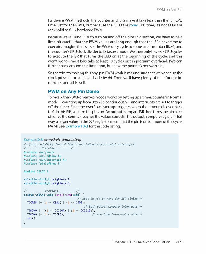
hardware PWM methods: the counter and ISRs make it take less than the full CPUtime just for the PWM, but because the ISRs take some CPU time, it’s not as fast orrock solid as fully hardware PWM.
Because we’re using ISRs to turn on and off the pins in question, we have to be alittle bit careful that the PWM values are long enough that the ISRs have time toexecute. Imagine that we set the PWM duty cycle to some small number like 6, andthe counter’s CPU clock divider to its fastest mode. We then only have six CPU cyclesto execute the ISR that turns the LED on at the beginning of the cycle, and thiswon’t work—most ISRs take at least 10 cycles just in program overhead. (We canfurther hack around this limitation, but at some point it’s not worth it.)
So the trick to making this any-pin PWM work is making sure that we’ve set up theclock prescaler to at least divide by 64. Then we’ll have plenty of time for our in-terrupts, and all is well.
PWM on Any Pin DemoTo recap, the PWM-on-any-pin code works by setting up a timer/counter in Normalmode—counting up from 0 to 255 continuously—and interrupts are set to triggeroff the timer. First, the overflow interrupt triggers when the timer rolls over backto 0. In this ISR, we turn the pins on. An output-compare ISR then turns the pin backoff once the counter reaches the values stored in the output-compare register. Thatway, a larger value in the OCR registers mean that the pin is on for more of the cycle.PWM! See Example 10-3 for the code listing.
Example 10-3. pwmOnAnyPin.c listing// Quick and dirty demo of how to get PWM on any pin with interrupts// ------- Preamble -------- //#include <avr/io.h>#include <util/delay.h>#include <avr/interrupt.h>#include "pinDefines.h"
#define DELAY 3
volatile uint8_t brightnessA;volatile uint8_t brightnessB;
// -------- Functions --------- //static inline void initTimer0(void) { /* must be /64 or more for ISR timing */ TCCR0B |= (1 << CS01) | (1 << CS00); /* both output compare interrupts */ TIMSK0 |= ((1 << OCIE0A) | (1 << OCIE1B)); TIMSK0 |= (1 << TOIE0); /* overflow interrupt enable */ sei();}
209Chapter 10: Pulse-Width Modulation
PWM on Any Pin

ISR(TIMER0_OVF_vect) { LED_PORT = 0xff; OCR0A = brightnessA; OCR0B = brightnessB;}ISR(TIMER0_COMPA_vect) { LED_PORT &= 0b11110000; /* turn off low four LEDs */}ISR(TIMER0_COMPB_vect) { LED_PORT &= 0b00001111; /* turn off high four LEDs */}
int main(void) { // -------- Inits --------- //
uint8_t i; LED_DDR = 0xff; initTimer0();
// ------ Event loop ------ // while (1) {
for (i = 0; i < 255; i++) { _delay_ms(DELAY); brightnessA = i; brightnessB = 255 - i; }
for (i = 254; i > 0; i--) { _delay_ms(DELAY); brightnessA = i; brightnessB = 255 - i; }
} /* End event loop */ return (0); /* This line is never reached */}
There are also a couple of details to clean up. First, notice that there are two globalvariables defined, brightnessA and brightnessB, that will be used to load up theoutput-compare registers at the beginning of every cycle. Why not write to OCR0Aand OCR0B directly? Depending on the timing of exactly when the variable is writtenand its value, the PWM can glitch for one cycle. A way around that is to always setthe output-compare registers at a predictable point in the cycle—inside the over-flow ISR. These two global variables can be set by our code in main() whenever,but they’re only loaded into the OCR0 registers from inside the overflow ISR. It’s asimple buffer.
Triggering three different interrupts from one timing source is surprisingly easy. Inthe initTimer0 code, we can see that it basically amounts to setting three different
210 Make: AVR Programming
PWM on Any Pin

bits in the TIMSK (timer interrupt mask) register. As mentioned previously, the clocksource for the timer has to be significantly slower than the CPU clock to allow theISRs time to run, so I’ve use a divide-by-64 clock setting. Finally, as with all situationswhen you’re using an interrupt, don’t forget to enable the global interrupt bit usingthe sei() function.
The rest of the code is straightforward. The ISRs should be kept as short as possiblebecause they’re being called quite frequently. Here, the compare interrupts haveonly one task. Finally, the main() function demonstrates how to use the any-pinPWM functionality. We simply set the global variable to the desired level wheneverit suits us, and the timer and interrupts take care of the rest.
Closing: Alternatives to PWM and a TimerChecklist
In this chapter, I’ve introduced you to three different methods of producing “ana-log” output by toggling a digital pin quickly. First, we coded everything up fromscratch, using the full CPU time just to create PWM output. Next, we handed all ofthe duties off to the timer/counter PWM. This is by far the most common andpowerful method of creating PWM output, but it’s limited to two designatedhardware-PWM pins per timer. Bear these restrictions in mind when you’re layingout your own circuits, and the hardware PWM facilities will serve you well.
Finally, as a bit of a hack, I demonstrated a method to get PWM output on any pinby using a timer/counter and its automatically triggered interrupts to toggle anypin or pins for you. The costs here are a little more CPU overhead than the directhardware method, reduced maximum speed due to the time needed to run theISRs, and the need to use a couple of global variables to avoid glitches when settingup the output compare registers. On the other hand, when you really need PWMon a nonstandard pin or pins and you’ve got a free timer, using the timer in Normalmode coupled to fire off interrupts is a totally valid option.
So with three options in this chapter, we’ve pretty much exhausted PWM. In closing,though, I’d like to mention a few other options for getting analog output from theAVRs. If you’re in need of higher performance, either in terms of reduced digitalnoise or higher frequency output, there are other options you should know about.
Digital-to-analog converters (DACs):
Simple voltage dividerIf you only need to produce four discrete voltage levels, you can connect boththe high end and low end of a resistive voltage divider to two AVR output pins.When both are driven high, the output will be VCC. When both are driven low,the output will read 0 V. When only one of the two outputs is driven high, theoutput of the voltage divider will be between the two extremes.
211Chapter 10: Pulse-Width Modulation
Closing: Alternatives to PWM and a Timer Checklist

Imagine creating a voltage divider with twice as much resistance in one leg asin the other—creating a 1/3 voltage divider. Driving one pin high will output1/3 × 5 V and driving the other pin high will output 2/3 × 5 V.
If you only need one intermediate analog value but you need it to be accurate,you can hand-pick the voltage divider resistors to get exactly the voltage youneed. You could even use a potentiometer to make it tunable.
DIY R-2R DACExpanding on the logic of the simple voltage divider, you can make a multi-input nested voltage divider using a lot more resistors that’ll let you write outa binary value to the voltage-divider ladder and get the corresponding voltageout. The trick is to pick the resistance values to generate the right intermediatevoltages.
For instance, to make an 8-bit R-2R DAC, you hook up all eight pins of PORTB toresistors of value 2R, and connect these together with resistors of value R, withanother of 2R to ground at the least-significant bit. (Look up a schematic onthe Web if you’d like to make one.) The end result is that each pin on the AVRcontributes to the output voltage in a binary-weighted fashion so that you cansimply write out the voltage you’d like to the AVR’s port. Writing 63 to PORTBproduces 5 V/4 with a 5 V VCC, for instance.
Building an R-2R DAC is easy enough, and you can get enough accuracy foreight bits using 1% tolerance resistors for all the values. You can do even betterby using the same resistors all around, but using two in parallel to make the Rvalues. If you look up plans on the Web, don’t forget that almost all of themrequire an amplifier following the output, or else you risk loading down theoutput of the R-2R network with your speakers, for instance.
In addition to simplicity, the advantage of an R-2R-style DAC is that the bits areloaded, and the voltage generated, in parallel—you can change the outputvoltage almost as fast as you can write a new value to the port that’s drivingit, which enables you to create signals with frequencies up into the megahertzrange. There is also no ripple at a fixed output level, and the transitions betweenoutput voltage levels is usually well behaved. The disadvantage, of course, isthat the DAC takes up eight pins that you might want to use for somethingelse.
External DAC chipsAlthough the DIY R-2R DAC might work for 8-bit output, you have to matchresistors carefully to get 10-bit resolution, and much more than 12-bit is nearlyimpossible. So for high-quality audio output, you’ll want to use a ready-madechip DAC. Some of these are just factory-trimmed R-2R DACs on the inside,whereas others have some digital logic that do high-frequency digital con-version for you.
212 Make: AVR Programming
Closing: Alternatives to PWM and a Timer Checklist

Because they’re quite frequently used in consumer audio products, you’ll findDACs that are well-suited to generating stereo audio signals (16-bit to 24-bit,44.1 to 96 kHz) for just a few dollars. These modern audio DACs mostly taketheir input data through SPI or I2C serial data lines, and you’ll learn about theseprotocols in Chapter 16 and Chapter 17.
When shopping for a DAC chip, it’s important to consider your desired con-version speed and need for DC accuracy in addition to the resolution in numberof bits, because if you try to have everything, you’ll end up with a very expen-sive chip! That said, DACs for audio use aren’t very sensitive to absolute accu-racy, and the maximum frequency is not difficult to attain, so they’re nice andcheap. It’s only when you need a DAC that’s microvolt accurate or operatinginto the megahertz range that you’ll need to compromise.
Finally, to round out the last couple chapters, which have centered around differentuses of the timer/counter hardware, here’s a checklist of all the configuration de-mands to make use of them. This is not meant to substitute for the “Register De-scription” pages in the datasheet, but should help to guide you through them.
Timer configuration checklist:
1. First, decide on which timer to use. This will mostly depend on how many bitsof resolution you need. If the answer is “8-bit is fine,” then use Timers 0 or 2. Ifyou need 16-bit resolution, or just aren’t using it for anything else anyway, takeTimer 1.
2. Next, decide which mode you need: set WGMn0 and WGMn1 bits in TCCRnA andWGMn2 in TCCRnB. See the table “Waveform Generation Mode Bit Description”in the datasheet.
a. Counting or timing events? You’ll want Normal mode. (No configurationbits necessary.)
b. Are you using the timer as a timebase or frequency generator? That’s easiestin CTC mode. Set the WGMn1 bit in TCCRnA.
c. Are you using the timer for PWM? Usually I use fast PWM mode. Set theWGMn0 and WGMn1 bits in TCCRnA if you don’t need adjustable PWM frequency,and additionally set WGMn2 in TCCRnB if you do.
3. Want direct output to the pins? Set COMxA and COMxB bits in TCCRnA accordingly.
4. Determine which clock speed divisor you need and set it with the CSnx bits inTCCRnB.
5. If you’re using a compare value, it’s nice to set a default value in OCRnA and/orOCRnB. Don’t forget to set the corresponding DDR to output mode when youwant the pins to output the PWM signal.
6. Using interrupts with your timers?
213Chapter 10: Pulse-Width Modulation
Closing: Alternatives to PWM and a Timer Checklist

a. Enable counter overflow interrupt if using Normal mode with bit TOIEn inTIMSKn.
b. Enable output compare interrupts if using PWM or CTC modes with bitsOCIEnA and OCIEnB in TIMSKn.
c. Don’t forget to enable global interrupts via sei(); and write your interruptservice routines.
214 Make: AVR Programming
Closing: Alternatives to PWM and a Timer Checklist

Real-Time Clocks and a Laser “Sundial”
Servos are an essential part of any small robot, and they’re literally tailor-made forrunning with logic-level signals. They’re so easy to drive with the AVR that theymake the perfect introduction to microcontroller-driven movement. Figure 11-1 isa family portrait of a few servo motors that I had lying around.
Figure 11-1. Some servo motors
In this chapter, we’ll use the servo’s reasonably accurate positioning to make a lasersundial—a laser dot that moves around your room that you can use to tell the time.
215
Driving Servo Motors 11

What You Need
In addition to the basic kit, you will need:
• A servo. Any old hobby servo will do.
• (Optionally, but a good idea) a separate powersupply for the servo. I used 4xAA batteries.This helps keep the AVR’s power supply cleanof motor-generated voltage noise.
• A laser pointer that you’re willing to takeapart. Use a cheapie. I used a cat toy that wasgiven to me.
• A 2N7000 MOSFET to turn the laser on and off.
• A USB-Serial adapter to set and calibrate yourclock in combination with your desktop orlaptop computer.
Along the way, we’ll work on calibrating the AVR’s internal CPU clock well enoughthat you can use it as a standalone real-time clock that will keep time to withinabout a second per day. And that’s pretty useful even if you already have a decentclock in your office.
Servos
Servos are positioning motors with a built-in feedback circuit, and it’s this internalcircuitry that makes them so simple to use. As positioning motors, they don’t spinaround and around like traditional motors. Instead, they only rotate through 180degrees or so, and they can move to the desired position to roughly the nearestdegree on command. This makes them ideal for pulling up the landing gear on amodel airplane, or for moving robot arms. (Your elbow doesn’t spin continuously;why should your robot’s?)
You send position controls to a servo with a signal pulse that ranges nominallyfrom 1 ms to 2 ms. When you send a 1 ms pulse, the motor turns to its most-counterclockwise position, and when you send a 2 ms pulse, it turns the shaft toits most clockwise. If you send a pulse of 1.5 ms, the motor turns the shaft to thecenter, and so on. These are “nominal” values—you’ll find that they vary a little bitfrom servo to servo, but assuming that 1.5 milliseconds is somewhere in the middleis a good starting point.
The circuitry inside the servo is expecting a pulse like this every 10–20 ms, and aslong as it receives a pulse, it tries to turn the motor shaft to the right position. Whenno pulse is seen for a while, the servo disengages and can be turned more or lessfreely. From our perspective, this means that we need to be able to send a shortvoltage pulse signal of fairly precise duration that controls the position of the servo,and to send these pulses every 20 milliseconds or so.
216 Make: AVR Programming
Servos
Why do I say that servos are a perfect match for microcontrollers? First, becauseoutputting this kind of simple control pulse is a job that’s basically tailor-made forthe hardware timer circuitry. But most importantly, the AVR doesn’t need to supplyany of the driving power for the servo, just the control signal. The servo’s internalcircuitry takes care of driving the motor for us. This is in contrast to DC and steppermotors that we’ll see in Chapter 15, where we need all sorts of intermediary circuitryto get a motor to turn. With a servo, we plug it in to power, connect one signal lineup to the AVR, and we’re running.
The Secret Life of ServosIf you’re wondering how servos convert the periodic pulses into motor positions,you’ll have to crack open the casing and peek inside. The feedback circuit inside aservo is based on comparing two voltages: one that’s proportional to the controlsignal that you’ve sent, and one that’s proportional to the motor shaft’s pointingdirection. Every time the servo circuit receives a pulse, it turns its motor for a littlewhile in the right direction to make the two voltages more equal.
The shaft-position voltage is simple enough to generate. A potentiometer is con-nected to the output shaft of the motor inside the servo’s black box. Just like wedid in Chapter 7, the potentiometer is wired up as a voltage divider, and the voltageread off the middle terminal is controlled by turning the potentiometer, which isconnected to the motor.
(For completeness, I should mention that the drivetrain inside the servo has a setof gears that connects the quick-but-weak motion of a tiny little motor into thestronger-but-slower turning of the output shaft. The geared-down output shaft,not the motor, is connected to the position-sensing potentiometer. The small mo-tor actually turns many times for one half turn of the output shaft. But don’t let thatconfuse the issue; the practical effect is that the stepper motor’s shaft is connectedto a potentiometer.)
Now let’s look at the control signal. When we send a control pulse, the integratorcircuit starts to charge a capacitor with a fixed current. As soon as the control pulsedrops low, the integrator circuit turns off the current. The result is that the voltagein the capacitor depends on how long it has been charged.
The motor potentiometer voltage and the integrated control pulse voltage arethen fed into a comparator, which is just about what it sounds like: a circuit thatoutputs a high voltage level if the first input voltage is higher than the second, anda low voltage level otherwise. This high or low digital signal then controls the motordirection.
The other thing that happens at the end of a control pulse is that the motor isturned on, but it’s kept on a timer. For instance, for the servo on my desk, the motorruns for 23 ms per signal pulse. This timer is the reason for the 20 ms update rate
217Chapter 11: Driving Servo Motors
Servos
—if we keep the control pulses coming in faster than this timer, the motor willalways be moving in the right direction. And that’s the essence of servo control.
But if this were the end of the story, the motor would be continually running backand forth, oscillating around the control set point. If the position voltage is a tinybit low, the motor turns clockwise until the position voltage is a tiny bit high andthen the motor turns counterclockwise, and so on. It’s a noisy waste of batterypower to have the motor continually “seeking” like this. The solution is to imple-ment a dead band where the internal circuitry decides that it’s close enough andturns the motor off.
Because of this dead band, the positioning accuracy of a servo motor isn’t infinite—it won’t bother to reposition itself for tiny changes in the control pulse width.The width of the dead band will vary from motor to motor, but I’ve found that tryingto get much more than a few hundred distinct positions from a cheap servo is alosing battle. You can test it out yourself with your motor using the code in thissection.
And that explains all the mysteries of the servo-motor! The pulse length is criticalbecause it determines the position. The inter-pulse timing is not nearly so critical,but if you’d like the motor to be always holding its position, the pulses need toarrive every 20ms or so. And finally, the dead band limits how finely you can controlthe position, but also reduces power consumption by preventing the motor fromendlessly seeking.
So servos need a pulse between 1 ms and 2 ms long, and they need this pulserepeated regularly roughly every 20 ms. How are we going to do this? With timers!By far the easiest and most accurate way to drive a servo is simply to hook it up tothe output from Timer 1, the 16-bit timer, set the timer’s period to be 20 ms, andthen use the PWM output pins and register to send the pulses. You can do thiseasily with up to two servo motors, because the timer has two dedicated outputcompare pins. Let’s see how.
The CircuitServos have three pins: voltage supply, ground, and signal. We can connect thefirst two pins directly up to any 4–6 V power supply. The third pin, signal, we’llconnect directly to the AVR. On a breadboard, you’ll end up with something likewhat’s show in Figure 11-2.
218 Make: AVR Programming
Servos

Figure 11-2. Simple servo hookup
To take advantage of Timer 1, which has its output compare channels on PB1/OC1A and PB2/OC1B, you may need to disconnect LED1, and connect it to the servo’scontrol pin. Or you might get lucky and they’ll work together. It all depends onhow much current you’re drawing for the LED, which in turn depends on the LEDcurrent-limiting resistors you’ve chosen.
As mentioned earlier, you should also hook the servo up to a supply of 4–6 V. Thiscan be the same power supply that you’re using for the AVR, but it’s sometimesnice to run your robot’s logic and motors on separate circuits so that if your motorstalls out and pulls hard on the battery, it won’t subject the AVR to a brownout. Ifyou are trying to get by with the same power supply for both the servo and theAVR, note that it’ll need to be able to supply at least 500 mA, because a servo caneasily draw that much current.
The best practice, though, is to use a separate power supply for the servo. Four AAcells will do the trick nicely. When using a separate power supply for the servo, besure that the ground for the motor and battery are connected to the ground forthe AVR so that they share a common reference voltage level. Otherwise, the AVRand the servo won’t be able to agree on what constitutes a voltage pulse on thesignal line.
The CodePhysically connecting a servo to the AVR is simplicity itself. Now all we have to doto make it work is set up the AVR’s internal timer to create the control pulses. Let’shave a look at the code in Example 11-1.
219Chapter 11: Driving Servo Motors
Servos

Example 11-1. servoWorkout.c listing /* Quick interactive demo running servo with Timer 1 */
// ------- Preamble -------- //#include <avr/io.h>#include <util/delay.h>#include <avr/interrupt.h>
#include "pinDefines.h"#include "USART.h"
#define PULSE_MIN 1000 /* experiment with these values */#define PULSE_MAX 2000 /* to match your own servo */#define PULSE_MID 1500
static inline uint16_t getNumber16(void);
static inline void initTimer1Servo(void) { /* Set up Timer1 (16bit) to give a pulse every 20ms */ /* Use Fast PWM mode, counter max in ICR1 */ TCCR1A |= (1 << WGM11); TCCR1B |= (1 << WGM12) | (1 << WGM13); TCCR1B |= (1 << CS10); /* /1 prescaling -- counting in microseconds */ ICR1 = 20000; /* TOP value = 20ms */ TCCR1A |= (1 << COM1A1); /* Direct output on PB1 / OC1A */ DDRB |= (1 << PB1); /* set pin for output */}
static inline void showOff(void) { printString("Center\r\n"); OCR1A = PULSE_MID; _delay_ms(1500); printString("Clockwise Max\r\n"); OCR1A = PULSE_MIN; _delay_ms(1500); printString("Counterclockwise Max\r\n"); OCR1A = PULSE_MAX; _delay_ms(1500); printString("Center\r\n"); OCR1A = PULSE_MID; _delay_ms(1500);}
int main(void) {
// -------- Inits --------- // uint16_t servoPulseLength; OCR1A = PULSE_MID; /* set it to middle position initially */ initTimer1Servo(); initUSART(); printString("\r\nWelcome to the Servo Demo\r\n");
220 Make: AVR Programming
Servos
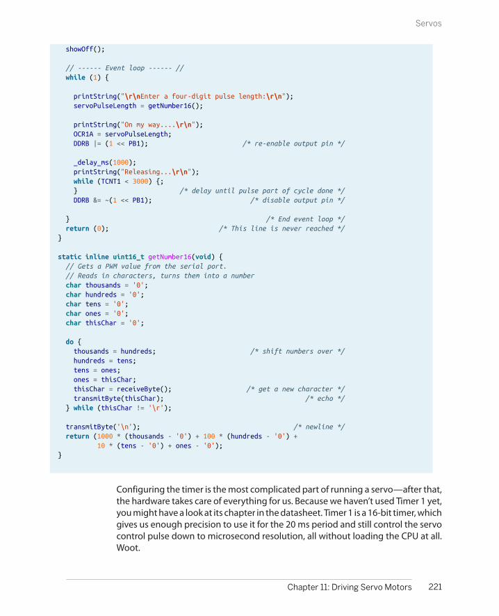
showOff();
// ------ Event loop ------ // while (1) {
printString("\r\nEnter a four-digit pulse length:\r\n"); servoPulseLength = getNumber16();
printString("On my way....\r\n"); OCR1A = servoPulseLength; DDRB |= (1 << PB1); /* re-enable output pin */
_delay_ms(1000); printString("Releasing...\r\n"); while (TCNT1 < 3000) {; } /* delay until pulse part of cycle done */ DDRB &= ~(1 << PB1); /* disable output pin */
} /* End event loop */ return (0); /* This line is never reached */}
static inline uint16_t getNumber16(void) { // Gets a PWM value from the serial port. // Reads in characters, turns them into a number char thousands = '0'; char hundreds = '0'; char tens = '0'; char ones = '0'; char thisChar = '0';
do { thousands = hundreds; /* shift numbers over */ hundreds = tens; tens = ones; ones = thisChar; thisChar = receiveByte(); /* get a new character */ transmitByte(thisChar); /* echo */ } while (thisChar != '\r');
transmitByte('\n'); /* newline */ return (1000 * (thousands - '0') + 100 * (hundreds - '0') + 10 * (tens - '0') + ones - '0');}
Configuring the timer is the most complicated part of running a servo—after that,the hardware takes care of everything for us. Because we haven’t used Timer 1 yet,you might have a look at its chapter in the datasheet. Timer 1 is a 16-bit timer, whichgives us enough precision to use it for the 20 ms period and still control the servocontrol pulse down to microsecond resolution, all without loading the CPU at all.Woot.
221Chapter 11: Driving Servo Motors
Servos
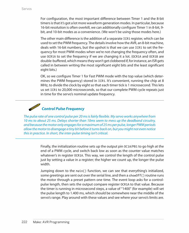
For configuration, the most important difference between Timer 1 and the 8-bittimers is that it’s got a lot more waveform generation modes. In particular, because16-bit resolution is often overkill, we can additionally configure Timer 1 in 8-bit, 9-bit, and 10-bit modes as a convenience. (We won’t be using those modes here.)
The other main difference is the addition of a separate ICR1 register, which can beused to set the PWM frequency. The details involve how the AVR, an 8-bit machine,deals with 16-bit numbers, but the upshot is that we can use ICR1 to set the fre-quency for most PWM modes when we’re not changing the frequency often, anduse OCR1A to set the frequency if we are changing it a lot. (OCR1A and OCR1B aredouble-buffered, which means they won’t get clobbered if, for instance, an ISR getscalled in between writing the most significant eight bits and the least significanteight bits.)
OK, so we configure Timer 1 for Fast PWM mode with the top value (which deter-mines the PWM frequency) stored in ICR1. It’s convenient, running the chip at 8MHz, to divide the clock by eight so that each timer tick is 1 microsecond. This letsus set ICR1 to 20,000 microseconds, so that our complete PWM cycle repeats justin time for the servo’s nominal update frequency.
Control Pulse Frequency
The pulse rate of one control pulse per 20 ms is fairly flexible. My servo works anywhere from10 ms to about 25 ms. Delays shorter than 10ms seem to mess up the deadband circuitry,and because the motor only engages for a maximum of 25 ms per pulse, longer PWM periodsallow the motor to disengage a tiny bit before it turns back on, but you might not even noticethis in practice. In short, the inter-pulse timing isn’t critical.
Finally, the initialization routine sets up the output pin OC1A/PB1 to go high at theend of a PWM cycle, and switch back low as soon as the counter value matcheswhatever’s in register OCR1A. This way, we control the length of the control pulsejust by setting a value in a register; the higher we count up, the longer the pulsewidth.
Jumping down to the main() function, we can see that everything’s initialized,some greetings are sent out over the serial line, and then a showOff() routine runsthe motor through a preset pattern one time. The event loop asks for a control-pulse length, then sets the output compare register OCR1A to that value. Becausethe timer is running in microsecond steps, a value of “1400” (for example) will setthe pulse length to 1.400 ms, which should be somewhere near the middle of theservo’s range. Play around with these values and see where your servo’s limits are.
222 Make: AVR Programming
Servos
After a couple of seconds, the program stops sending control pulses by setting thedata-direction register on PB1 to input, which blocks the timer’s automatic output.Now you should be able to turn the servo by hand, though you’ll feel some resist-ance due to the motor’s internal gearing. Type in a set value in the serial terminaland compare the resistance when the servo is receiving a command and when it’snot. Notice that the servo “fights” you to hold its place as long as it’s being sentcontrol pulses. Cool, isn’t it? (Alternatively, if you’re interested in conserving yourbatteries, you should note that holding position requires power. If you don’t needto hold the motor’s position, don’t send position pulses.)
As a final experiment with servos for this section, try to figure out your servo’sminimum resolution (alternatively, the width of the dead band). Type in “1400” toset it near the middle of its range. Now try “1401” and see if it moves. If not, try“1402” and so on. Mine just twitched noticeably at “1403” or “1404.” My servo alsohas a working range of about 180 degrees from 400 to 2,250, which isn’t bad at all.So to control this servo at maximum resolution over the maximum range, we’llneed (2,250 – 400) / 3 = 616 steps, which is somewhere between nine and ten bitsof information. (Which lines up nicely with the ADC’s input range, which makes methink about what I can do with a light-controlled servo. Play around if you’ve stillgot the LDR hooked up.)
The final bit of code is a simple modification of the getNumber() routine from theUSART.h library that we’ve been using. It takes in a four-digit number via the serialport and converts it into a 16-bit number for use as the servo control pulse length.Notice that we don’t check to see whether or not this number is in range. If it’s toolow, the servo will just seek against its mechanical endstop until the code stopssending pulses. In a real application, once you know how far you want the servoto rotate, you should probably encode limits into your servo routines using #define statements as I do here, so that they’re easy to change when you adjust hard-ware or switch to a different motor.
This little program, in addition to providing a fun way to show off a servo-controltechnique, can also help you characterize a new servo, especially once it’s installedin the final device. With it, you can figure out where the endpoints are, how manydegrees it turns per microsecond pulse, how wide the deadband is, etc. So takegood notes—we’ll use this data later on when we tie all this code together with aclock and a laser driver to make a “sundial.”
Servo Sundial
In the days of old, before people worked in offices, the average person could tellthe time of day by the position of the sun in the sky. If you put a stake in the ground,it casts shadows. If you then mark out the location of these shadows at knowntimes, you’ve got something you can use as a clock later on. Real sundials are a bitfinicky, changing with the seasons and requiring pointing in a particular direction
223Chapter 11: Driving Servo Motors
Servo Sundial

and all. Plus they need the sunshine as input, which means you’d better have anoffice with windows. Wouldn’t it be a lot easier and more practical to pan a laseraround the room with a servo, controlled by a microcontroller, and mark out thetime on the wall? Well, there’s only one way to find out.
This project could be dead simple—it doesn’t require much more than a servomotor and a cheapo laser pointer. I’ve had one of these up and running in my officefor a while now, and it’s pretty fun, although there have been complaints aboutthe sticky notes on the ceiling that I use to mark the hours. And once you get itcalibrated, it keeps decent time, although it’s no atomic clock.
The BuildThis is one of the few times where you’ve got some slight physical construction todo. The first task is to decide how you’re going to steer the laser beam with theservo. I’ve used two different ways to aim the laser using the servo, and you’rewelcome to choose whichever seems easiest.
The first is to mount the laser directly to one of the plastic “servo horns” that turnwith the motor. Hot glue is fantastic for this application, and you’re up and runningin like 30 seconds. If you’re using a lightweight and cheap laser diode from a two-dollar laser pointer cat toy, I wouldn’t hesitate to just stick it all directly together.The problem with the direct-mounting method is that the laser (and its wires) endup moving around. Laser diodes can be sensitive to physical vibration, especiallywhen they’re active, so the continual jerking around may shorten the life of yourlaser diode. On the other hand, my cheap laser-pointer laser has worked for a fewmonths now, so it’s maybe not a big concern. My version of the direct-glue sundialis show in Figure 11-3.
The other option is to mount a small mirror on the servo horn and bounce the laseroff of it. This setup allows you to keep both the motor and the laser fixed, steeringthe beam around with the mirror. If your laser doesn’t like to be shaken around, oris worth more than a few dollars, you should probably at least consider the mirroroption. It’s the professional way to go. The other advantage is that by adjusting theangle of the mirror, you can adjust the way the beam arcs around the room. Again,I used hot-glue to affix the mirror to the servo horn. The result (with some fog tomake the laser beam visible) is demonstrated in Figure 11-4.
224 Make: AVR Programming
Servo Sundial
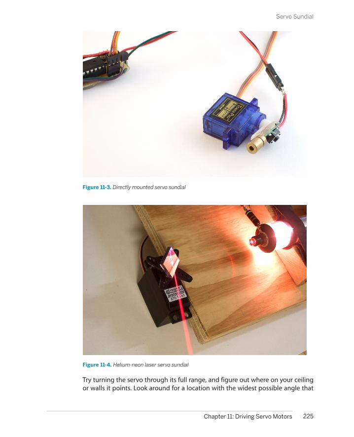
Figure 11-3. Directly mounted servo sundial
Figure 11-4. Helium-neon laser servo sundial
Try turning the servo through its full range, and figure out where on your ceilingor walls it points. Look around for a location with the widest possible angle that
225Chapter 11: Driving Servo Motors
Servo Sundial
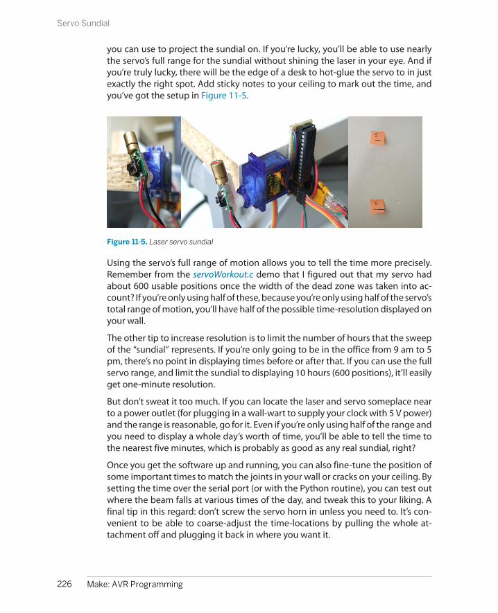
you can use to project the sundial on. If you’re lucky, you’ll be able to use nearlythe servo’s full range for the sundial without shining the laser in your eye. And ifyou’re truly lucky, there will be the edge of a desk to hot-glue the servo to in justexactly the right spot. Add sticky notes to your ceiling to mark out the time, andyou’ve got the setup in Figure 11-5.
Figure 11-5. Laser servo sundial
Using the servo’s full range of motion allows you to tell the time more precisely.Remember from the servoWorkout.c demo that I figured out that my servo hadabout 600 usable positions once the width of the dead zone was taken into ac-count? If you’re only using half of these, because you’re only using half of the servo’stotal range of motion, you’ll have half of the possible time-resolution displayed onyour wall.
The other tip to increase resolution is to limit the number of hours that the sweepof the “sundial” represents. If you’re only going to be in the office from 9 am to 5pm, there’s no point in displaying times before or after that. If you can use the fullservo range, and limit the sundial to displaying 10 hours (600 positions), it’ll easilyget one-minute resolution.
But don’t sweat it too much. If you can locate the laser and servo someplace nearto a power outlet (for plugging in a wall-wart to supply your clock with 5 V power)and the range is reasonable, go for it. Even if you’re only using half of the range andyou need to display a whole day’s worth of time, you’ll be able to tell the time tothe nearest five minutes, which is probably as good as any real sundial, right?
Once you get the software up and running, you can also fine-tune the position ofsome important times to match the joints in your wall or cracks on your ceiling. Bysetting the time over the serial port (or with the Python routine), you can test outwhere the beam falls at various times of the day, and tweak this to your liking. Afinal tip in this regard: don’t screw the servo horn in unless you need to. It’s con-venient to be able to coarse-adjust the time-locations by pulling the whole at-tachment off and plugging it back in where you want it.
226 Make: AVR Programming
Servo Sundial

Or you can do what I did initially, and what our sun-using predecessors did, too,which is to take the position of the beam as granted and just mark off where thebeam hits at different times of the day using sticky notes. With a laser sundial, youdon’t have to correct for the seasons. And you don’t have to wait for a full day either;I’ve included a Python routine that steps the clock through the hours and thatmakes setting up your sticky notes a piece of cake.
My fantasy is to someday make light-sensitive alarm units (perhaps using the ADCand LDR setup of Chapter 7) and set alarms for myself by physically sticking themon the wall so that the light sensor is in the beam of the laser. When the time comesfor the 10 am meeting, the laser hits the sensor, and an alarm is sounded, or a tweetis sent, or an email is dispatched. Rube Goldberg would be proud.
Ready the Lasers!For this project, you’re not going to need a gigantic, multiwatt laser. In fact, the lessbright it is, the better from both a power-usage and eye-hazard standpoint. And ifyou’re constantly wiggling the laser diode on the end of a motor, you’re not goingto want to use anything valuable.
The standard red diode laser that comes in cat toys is perfect and only costs a fewdollars, if you’re not lucky enough to have one around to scrounge. Most of thesediodes come with circuitry that lets them run on three battery cells, or 4.5 V, whichis close enough to just plug it straight into a 5 V power supply and hope for thebest.
Whether or not you want to leave the laser in its decorative case is up to you.Originally, mine was in a mouse-shaped plastic case. Now I regret having extractedthe laser unit, because who doesn’t want a servo-controlled laser mouse tellingthem the time? If you do want to pull out the laser unit, it’s as easy as shown inFigure 11-6.
The small “bullet” laser pointers that come in a thin metal casing can be removedonly with brutality. I’ve gotten them loose using a pair of tin-snips and simplycutting through the case. (Do not use regular scissors.) Another option would beto simply buy a bare laser module. Online discount stores like DealExtreme havebare laser modules and cheap servos.
Many cheap laser pointers come with a switch that you’re supposed to press toturn the laser on. We’re going to need to take care of that. The easiest way to removethe switch from the circuit is just to solder across it. With a normal pushbuttonswitch, the two pairs of pins that are on the same side of the button connect toeach other when pressed. Soldering a small wire across either pair will completelybypass the switch. You can see where I did this in the first frame of Figure 11-5.
227Chapter 11: Driving Servo Motors
Servo Sundial

Figure 11-6. Getting the laser out
Now all you have to do is figure out how the AVR can turn the laser on and off. InChapter 15, we’ll go over the use of transistor switches in great detail, so you caneither look ahead at the description of using low-side MOSFET switches to controlsmall loads, or you can just hook up the circuit in Figure 11-7.
Figure 11-7. Breadboarding the laser sundial
228 Make: AVR Programming
Servo Sundial
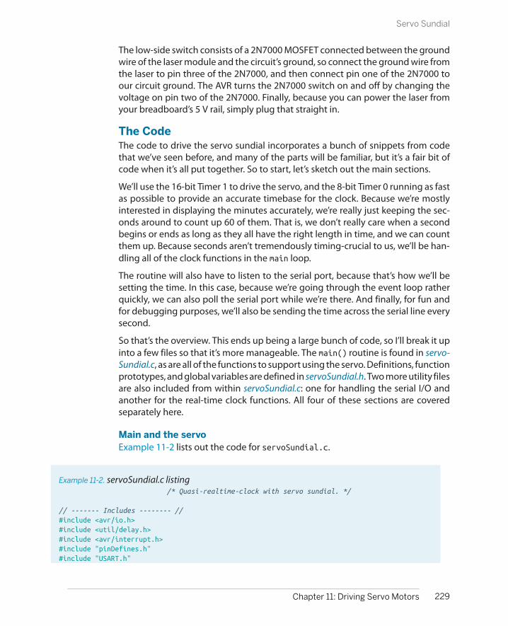
The low-side switch consists of a 2N7000 MOSFET connected between the groundwire of the laser module and the circuit’s ground, so connect the ground wire fromthe laser to pin three of the 2N7000, and then connect pin one of the 2N7000 toour circuit ground. The AVR turns the 2N7000 switch on and off by changing thevoltage on pin two of the 2N7000. Finally, because you can power the laser fromyour breadboard’s 5 V rail, simply plug that straight in.
The CodeThe code to drive the servo sundial incorporates a bunch of snippets from codethat we’ve seen before, and many of the parts will be familiar, but it’s a fair bit ofcode when it’s all put together. So to start, let’s sketch out the main sections.
We’ll use the 16-bit Timer 1 to drive the servo, and the 8-bit Timer 0 running as fastas possible to provide an accurate timebase for the clock. Because we’re mostlyinterested in displaying the minutes accurately, we’re really just keeping the sec-onds around to count up 60 of them. That is, we don’t really care when a secondbegins or ends as long as they all have the right length in time, and we can countthem up. Because seconds aren’t tremendously timing-crucial to us, we’ll be han-dling all of the clock functions in the main loop.
The routine will also have to listen to the serial port, because that’s how we’ll besetting the time. In this case, because we’re going through the event loop ratherquickly, we can also poll the serial port while we’re there. And finally, for fun andfor debugging purposes, we’ll also be sending the time across the serial line everysecond.
So that’s the overview. This ends up being a large bunch of code, so I’ll break it upinto a few files so that it’s more manageable. The main() routine is found in servo-Sundial.c, as are all of the functions to support using the servo. Definitions, functionprototypes, and global variables are defined in servoSundial.h. Two more utility filesare also included from within servoSundial.c: one for handling the serial I/O andanother for the real-time clock functions. All four of these sections are coveredseparately here.
Main and the servoExample 11-2 lists out the code for servoSundial.c.
Example 11-2. servoSundial.c listing /* Quasi-realtime-clock with servo sundial. */
// ------- Includes -------- //#include <avr/io.h>#include <util/delay.h>#include <avr/interrupt.h>#include "pinDefines.h"#include "USART.h"
229Chapter 11: Driving Servo Motors
Servo Sundial
#include "servoSundial.h"#include "_servoSerialHelpers.c"#include "_servoClockFunctions.c"
// -------- Functions --------- //// Servo setup and utility functionsvoid initTimer1_Servo(void) { /* Set up Timer1 (16bit) to give a pulse every 20ms */ TCCR1A |= (1 << WGM11); /* Using Fast PWM mode */ TCCR1B |= (1 << WGM12); /* counter max in ICR1 */ TCCR1B |= (1 << WGM13); TCCR1B |= (1 << CS11); /* /8 prescaling -- microsecond steps */ TCCR1A |= (1 << COM1A1); /* set output on PB1 / OC1A for servo */ ICR1 = 20000; /* TOP value = 20ms */}
void enableServo(void) { while (TCNT1 < PULSE_OVER) {; } /* delay until pulse part of cycle done */ SERVO_DDR |= (1 << SERVO); /* enable servo pulses */}
void disableServo(void) { while (TCNT1 < PULSE_OVER) {; } /* delay until pulse part of cycle done */ SERVO_DDR &= ~(1 << SERVO); /* disable servo pulses */}
void setServoPosition(void) { uint32_t elapsedMinutes; /* using 32 bits because elapsedMinutes * PULSE_RANGE will overflow 16 bits */
elapsedMinutes = (hours - START_TIME) * 60 + minutes; OCR1A = PULSE_MIN + elapsedMinutes * PULSE_RANGE / (HOURS_RANGE * 60); enableServo();}
int main(void) {
// -------- Inits --------- // initUSART(); printString("\r\nWelcome to the Servo Sundial.\r\n"); printString("Type S to set time.\r\n");
initTimer0_Clock(); initTimer1_Servo(); sei(); /* set enable interrupt bit */ LED_DDR |= (1 << LED0); /* blinky output */ LASER_DDR |= (1 << LASER); /* enable laser output */
// ------ Event loop ------ // while (1) {
230 Make: AVR Programming
Servo Sundial
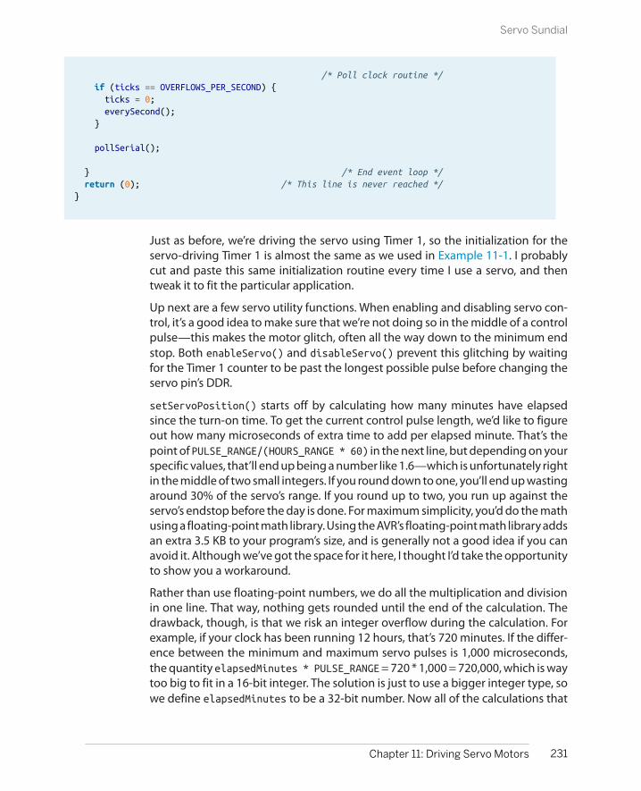
/* Poll clock routine */ if (ticks == OVERFLOWS_PER_SECOND) { ticks = 0; everySecond(); }
pollSerial();
} /* End event loop */ return (0); /* This line is never reached */}
Just as before, we’re driving the servo using Timer 1, so the initialization for theservo-driving Timer 1 is almost the same as we used in Example 11-1. I probablycut and paste this same initialization routine every time I use a servo, and thentweak it to fit the particular application.
Up next are a few servo utility functions. When enabling and disabling servo con-trol, it’s a good idea to make sure that we’re not doing so in the middle of a controlpulse—this makes the motor glitch, often all the way down to the minimum endstop. Both enableServo() and disableServo() prevent this glitching by waitingfor the Timer 1 counter to be past the longest possible pulse before changing theservo pin’s DDR.
setServoPosition() starts off by calculating how many minutes have elapsedsince the turn-on time. To get the current control pulse length, we’d like to figureout how many microseconds of extra time to add per elapsed minute. That’s thepoint of PULSE_RANGE/(HOURS_RANGE * 60) in the next line, but depending on yourspecific values, that’ll end up being a number like 1.6—which is unfortunately rightin the middle of two small integers. If you round down to one, you’ll end up wastingaround 30% of the servo’s range. If you round up to two, you run up against theservo’s endstop before the day is done. For maximum simplicity, you’d do the mathusing a floating-point math library. Using the AVR’s floating-point math library addsan extra 3.5 KB to your program’s size, and is generally not a good idea if you canavoid it. Although we’ve got the space for it here, I thought I’d take the opportunityto show you a workaround.
Rather than use floating-point numbers, we do all the multiplication and divisionin one line. That way, nothing gets rounded until the end of the calculation. Thedrawback, though, is that we risk an integer overflow during the calculation. Forexample, if your clock has been running 12 hours, that’s 720 minutes. If the differ-ence between the minimum and maximum servo pulses is 1,000 microseconds,the quantity elapsedMinutes * PULSE_RANGE = 720 * 1,000 = 720,000, which is waytoo big to fit in a 16-bit integer. The solution is just to use a bigger integer type, sowe define elapsedMinutes to be a 32-bit number. Now all of the calculations that
231Chapter 11: Driving Servo Motors
Servo Sundial

involve elapsedMinutes, particularly the risky multiplication, will be done using32-bit numbers, and we’ll get the right answer out. The code here takes less CPUtime and less program memory than it would if we had used floating-point num-bers, and we get the same answer!
Finally, moving down to main(), we call all the initialization functions, set up out-puts, and enable interrupts. The event loop is a super-quick polling loop. If a secondhas passed, the clock-time handling functions are called via the everySecond()routine. Otherwise, the USART is checked to see if any data came in by calling thefunction pollSerial() that’s defined in the serial helper file.
Before we look into the real-time clock application section, let’s quickly get theheader file out of the way.
The headerThe header file’s contents are shown in Example 11-3.
Example 11-3. servoSundial.h listing /* Quasi-realtime-clock with servo sundial. */
// ------- Includes -------- //#include <avr/io.h>
// ------- Defines -------- //#define PULSE_MIN 1000 /* experiment with these values */#define PULSE_MAX 2000 /* to match your own servo */#define PULSE_RANGE (PULSE_MAX - PULSE_MIN)#define PULSE_OVER (PULSE_MAX + 10) /* Must be larger than PULSE_MAX */
#define START_TIME 10 /* 10 am */#define STOP_TIME 22 /* 10 pm */#define HOURS_RANGE (STOP_TIME - START_TIME - 1)
#define LASER PB2#define LASER_PORT PORTB#define LASER_DDR DDRB
#define SERVO PB1#define SERVO_PORT PORTB#define SERVO_DDR DDRB
#define OVERFLOWS_PER_SECOND 31250 /* nominal, should calibrate */
// -------- Global Variables --------- //volatile uint16_t ticks;volatile uint8_t hours = 15; /* arbitrary default time */volatile uint8_t minutes = 42;volatile uint8_t seconds = 57;
// Serial input and output functions
232 Make: AVR Programming
Servo Sundial
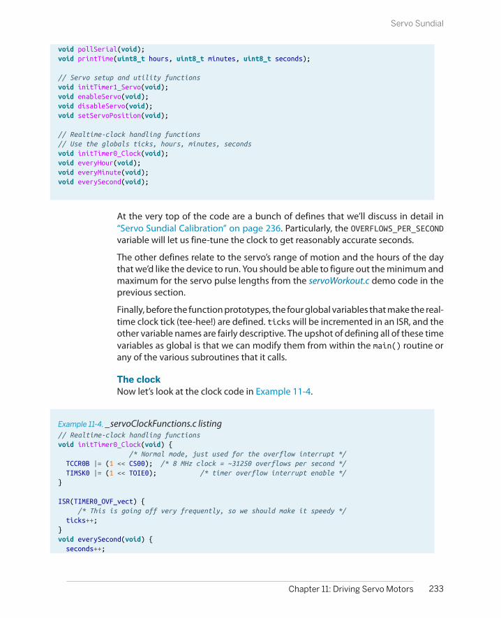
void pollSerial(void);void printTime(uint8_t hours, uint8_t minutes, uint8_t seconds);
// Servo setup and utility functionsvoid initTimer1_Servo(void);void enableServo(void);void disableServo(void);void setServoPosition(void);
// Realtime-clock handling functions// Use the globals ticks, hours, minutes, secondsvoid initTimer0_Clock(void);void everyHour(void);void everyMinute(void);void everySecond(void);
At the very top of the code are a bunch of defines that we’ll discuss in detail in“Servo Sundial Calibration” on page 236. Particularly, the OVERFLOWS_PER_SECONDvariable will let us fine-tune the clock to get reasonably accurate seconds.
The other defines relate to the servo’s range of motion and the hours of the daythat we’d like the device to run. You should be able to figure out the minimum andmaximum for the servo pulse lengths from the servoWorkout.c demo code in theprevious section.
Finally, before the function prototypes, the four global variables that make the real-time clock tick (tee-hee!) are defined. ticks will be incremented in an ISR, and theother variable names are fairly descriptive. The upshot of defining all of these timevariables as global is that we can modify them from within the main() routine orany of the various subroutines that it calls.
The clockNow let’s look at the clock code in Example 11-4.
Example 11-4. _servoClockFunctions.c listing// Realtime-clock handling functionsvoid initTimer0_Clock(void) { /* Normal mode, just used for the overflow interrupt */ TCCR0B |= (1 << CS00); /* 8 MHz clock = ~31250 overflows per second */ TIMSK0 |= (1 << TOIE0); /* timer overflow interrupt enable */}
ISR(TIMER0_OVF_vect) { /* This is going off very frequently, so we should make it speedy */ ticks++;}void everySecond(void) { seconds++;
233Chapter 11: Driving Servo Motors
Servo Sundial

if (seconds > 59) { seconds = 0; everyMinute(); } LED_PORT ^= (1 << LED0); /* blink */ printTime(hours, minutes, seconds); /* serial output */ /* Turn off servo motor after three seconds into new minute */ if (seconds == 3) { disableServo(); }}void everyMinute(void) { minutes++; if (minutes > 59) { minutes = 0; everyHour(); } // If during business hours, set servo to new minute // Otherwise, don't need to move motor when laser is off if ((hours >= START_TIME) && (hours < STOP_TIME)) { setServoPosition(); enableServo(); LASER_PORT |= (1 << LASER); /* make sure laser is on */ } else { /* make sure laser is off */ LASER_PORT &= ~(1 << LASER); }}void everyHour(void) { hours++; if (hours > 23) { /* loop around at end of day */ hours = 0; }}
Between the timer initialization and the servo utility functions in servoSundial.c,we’ve got the servo sorted out. Global defines in servoSundial.h lay out the dataskeleton for the clock. Now it’s time to get the clock up and running. Timer 0 andthe associated ISR are the simplest possible clock timebase routine. The combi-nation of the timer running at full speed, and overflowing every 256 steps yields atick every 31,250th of a second (if the CPU clock runs exactly at 8 MHz).
If you look back at the event loop in main(), it continually checks the ticks variableto see when it hits our defined (and calibrated) OVERFLOWS_PER_SECOND value. Whenit does, it resets ticks and calls the routine everySecond(). This starts a cascadethrough the rest of the clock functions—just like the gears in a real mechanicalclock.
The basic structure of each of the time-handling functions is the same. For instance,every second, the function increments the seconds variable and then checks to see
234 Make: AVR Programming
Servo Sundial
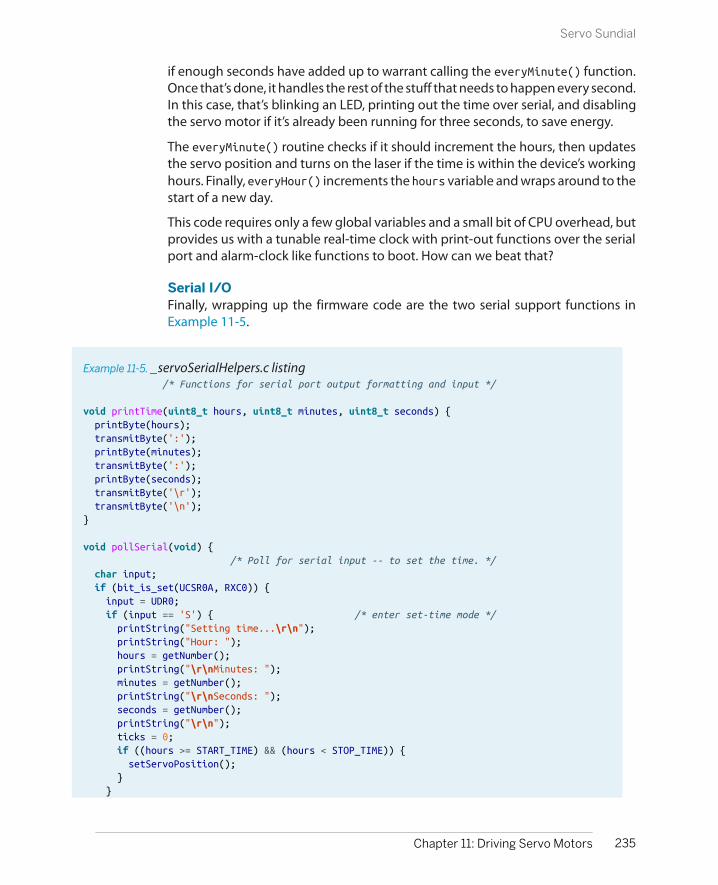
if enough seconds have added up to warrant calling the everyMinute() function.Once that’s done, it handles the rest of the stuff that needs to happen every second.In this case, that’s blinking an LED, printing out the time over serial, and disablingthe servo motor if it’s already been running for three seconds, to save energy.
The everyMinute() routine checks if it should increment the hours, then updatesthe servo position and turns on the laser if the time is within the device’s workinghours. Finally, everyHour() increments the hours variable and wraps around to thestart of a new day.
This code requires only a few global variables and a small bit of CPU overhead, butprovides us with a tunable real-time clock with print-out functions over the serialport and alarm-clock like functions to boot. How can we beat that?
Serial I/OFinally, wrapping up the firmware code are the two serial support functions inExample 11-5.
Example 11-5. _servoSerialHelpers.c listing /* Functions for serial port output formatting and input */
void printTime(uint8_t hours, uint8_t minutes, uint8_t seconds) { printByte(hours); transmitByte(':'); printByte(minutes); transmitByte(':'); printByte(seconds); transmitByte('\r'); transmitByte('\n');}
void pollSerial(void) { /* Poll for serial input -- to set the time. */ char input; if (bit_is_set(UCSR0A, RXC0)) { input = UDR0; if (input == 'S') { /* enter set-time mode */ printString("Setting time...\r\n"); printString("Hour: "); hours = getNumber(); printString("\r\nMinutes: "); minutes = getNumber(); printString("\r\nSeconds: "); seconds = getNumber(); printString("\r\n"); ticks = 0; if ((hours >= START_TIME) && (hours < STOP_TIME)) { setServoPosition(); } }
235Chapter 11: Driving Servo Motors
Servo Sundial

}}
The printTime function is straightforward enough. As long as we don’t mind seeingleading zeros and reading the clock in 24-hour time, all we need to do is reuse ourold favorite number-printing function from USART.c and spice it up with colons forpunctuation.
If you recall the main event loop, it doesn’t really do much. It first checks to see ifa second has elapsed and triggers the real-time clock functions if it has. Otherwise,it polls the serial line to see if anything has come in. If there has been data on theserial line, it enters the time-setting routine triggers if the character received is “S”,and otherwise just ignores anything that comes across the serial line.
The rest of the time-setting routine is implemented as prompt-input pairs untilhours, minutes, and seconds have been entered. This interface isn’t very sexy, butit allows us (with good timing pressing Return) to get times into the sundial thatare accurate down to the second. More importantly, for the calibration routinesbelow, it’s very simple to script this time-setting procedure from a Python routine.
But for now, open up a serial terminal, type S and enter the current time in 24-hourtime format, sit back, and relax. Maybe make marks, put up sticky notes, or evenuse some removable masking tape to plot out the time on the ceiling. If you’reimpatient, you can short-circuit this procedure by typing in a time just before theone that you’re interested in setting, for instance 10:59:56. Now wait four secondsfor 11 o’clock, and the servo will swing into place. Put your sticky note in placewithin the next minute, and repeat.
While you’re setting up the room to match the clock, you’ll probably notice thatthe servo isn’t exactly precise. The dead band is a lot easier to see when it’s mag-nified and projected on your ceiling. (In fact, if you’d like to reflash the servo workoutroutine, you can learn a lot more about the characteristics of your servo this way.)
In my office, the sundial only advances roughly every two or three minutes, andthe direction that you approach the current time matters, too. To help with this, Iwrote a small Python program, stepHours.py (included in the demo program’s di-rectory), that slowly approaches each hour, and then stops for you to put up a stickynote and press Return before moving slowly on to the next one.
Servo Sundial CalibrationAt this point, I do hope that you’ve got a little red dot creeping around your ceiling(or walls). It should provide you at least a few hours of accurate time-keeping as-is. But a few hours of accuracy is not enough! You want more. After all, you’ve putall this effort into hot-gluing a servo to the side of your desk, and taping sticky
236 Make: AVR Programming
Servo Sundial

notes all over your ceiling. It’s probably worth a little bit of effort to see how accurateyou can make the clock.
The reason behind the lousy accuracy is that the AVR’s internal CPU clock isn’t reallymeant for time-keeping. It’s meant to give you a quick-and-dirty clock pulse so thatthe chip can run without any external parts. The AVR datasheet suggests that thisclock will be in the range of 7.3 to 8.1 MHz, which is nowhere near accurate enough.(If your chip is running at 7.3 MHz when you’re expecting 8 MHz, it will keep accuratetime for about 12 minutes!) This is not to say that the AVR’s CPU clock will swingaround across this wide frequency range—an individual chip’s CPU clock is prettystable—but that if you pick a random chip out of a bucket, it could have a clockthat runs fast or slow. Clearly, we’re going to have to fix this if our sundial clock isgoing to keep time.
The engineering (brute-force? proper?) solution to the problem is to use an externalcrystal instead of the internal clock source. After all, it’s easy enough to get a crystalthat’s accurate to 20 parts per million, giving us a drift of around two seconds perday straight from the factory. Plug in a crystal, toss in a couple of capacitors, andthen flash the AVR’s fuse bits to use the new clock source, and presto.
The hacker’s way is to take whatever we’ve got coming out of the chip and adjustour timebase to it. In particular, we’re counting up 31,250 overflows of the Timer 0and calling that a second. But if your AVR’s internal clock is running fast, it may get33,234 counts per true second. If we can figure out what this number should be,we’ll have a clock that’s accurate to roughly one part in 32,000, or 30 parts permillion, which is almost as good as the crystal solution, and on the order of a fewseconds per day.
As we saw earlier, the interface to the AVR’s clock routine was designed to beworked by humans. We type an “S” to enter time-setting mode, and then the hours,minutes, and seconds over the serial port to set it, and it echos the time back overserial every second. To calibrate your sundial, you could set the clock yourself, writedown what time it is, and then come back in a while and see how much it hasdrifted. Then you’ll know how fast the clock is running, and you can just scale yourcounts-per-second define to match.
But doing that yourself is boring. Let’s whip up a quick Python routine that we canrun on the computer to do the typing and dividing for us. Example 11-6 containsthe code that I wrote up to do just that.
Example 11-6. calibrateTime.py listingimport timeimport serial
def readTime(serialPort): '''Reads the time from the AVR over the serial port'''
237Chapter 11: Driving Servo Motors
Servo Sundial

serialPort.flushInput() character = "" while(not character == "\n"): # loop until see end of line character = serialPort.read(1) ## The time string looks something like '011:045:023\r\n' timeString = serialPort.read(13) hms = timeString.split(":") hms = [int(x) for x in hms] # make hour, minute, second numeric return(hms)
def setTime(serialPort, hours, minutes, seconds): '''Sends the time over the serial port''' serialPort.flushOutput() serialPort.write("S") time.sleep(0.1) # delay while AVR sends serialPort.write(str(hours) + "\r") time.sleep(0.2) # delay while AVR sends serialPort.write(str(minutes) + "\r") time.sleep(0.2) # delay while AVR sends serialPort.write(str(seconds) + "\r")
def setTimeNow(serialPort): '''Sets the AVR clock to the current time''' hours, minutes, seconds = time.localtime()[3:6] setTime(serialPort, hours, minutes, seconds) return(time.time())
def calculateTimeDelay(serialPort): '''Gets AVR time and subtracts off actual (computer) time''' avrHMS = readTime(serialPort) hms = time.localtime()[3:6] hmsDifference = [x - y for x,y in zip(avrHMS, hms)] out = "AVR is fast by: {x[0]} hours, {x[1]} minutes, and {x[2]} seconds" print out.format(x=hmsDifference) return(hmsDifference)
def calculateTimeDrift(serialPort, startTime): '''Calculates the ratio to multiply OVERFLOWS_PER_SECOND given a start time and current error''' h, m, s = calculateTimeDelay(serialPort) driftSeconds = 60*60*h + 60*m + s elapsed = time.time() - startTime print "After {:.0f} seconds, ".format(elapsed) return (driftSeconds / elapsed + 1)
if __name__ == "__main__":
## Set time automatically, recording start time, ## then periodically calculate multiplication factor OVERFLOWS_PER_SECOND = 31250 # set this to equal the value in your code
SLEEP_TIME = 10 ratioLog = []
238 Make: AVR Programming
Servo Sundial
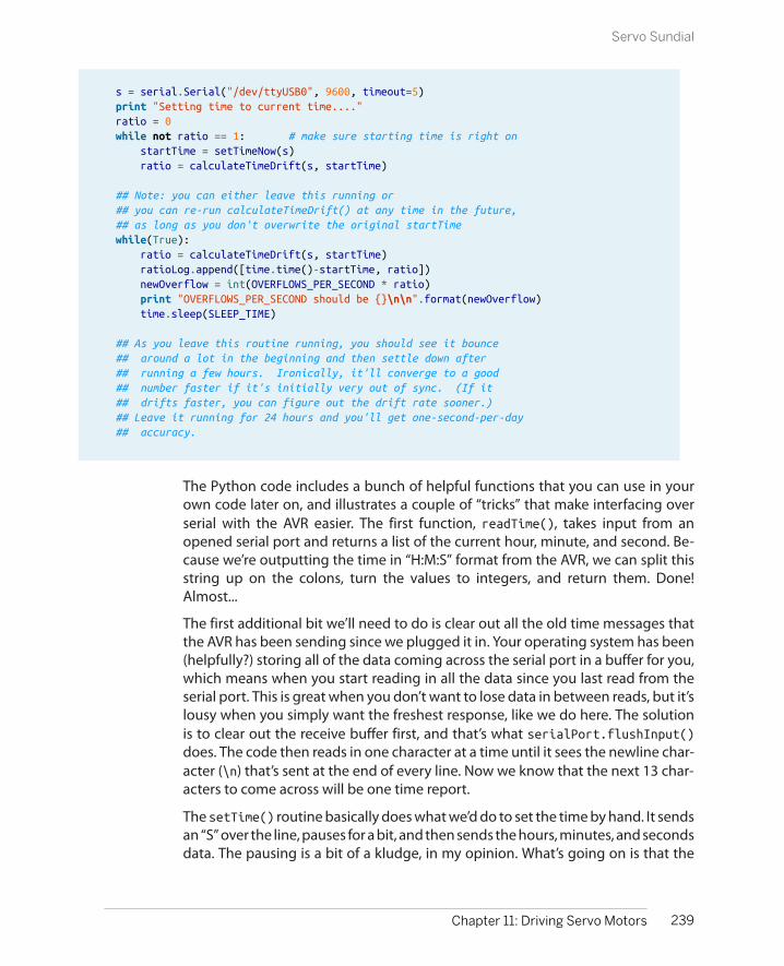
s = serial.Serial("/dev/ttyUSB0", 9600, timeout=5) print "Setting time to current time...." ratio = 0 while not ratio == 1: # make sure starting time is right on startTime = setTimeNow(s) ratio = calculateTimeDrift(s, startTime)
## Note: you can either leave this running or ## you can re-run calculateTimeDrift() at any time in the future, ## as long as you don't overwrite the original startTime while(True): ratio = calculateTimeDrift(s, startTime) ratioLog.append([time.time()-startTime, ratio]) newOverflow = int(OVERFLOWS_PER_SECOND * ratio) print "OVERFLOWS_PER_SECOND should be {}\n\n".format(newOverflow) time.sleep(SLEEP_TIME)
## As you leave this routine running, you should see it bounce ## around a lot in the beginning and then settle down after ## running a few hours. Ironically, it'll converge to a good ## number faster if it's initially very out of sync. (If it ## drifts faster, you can figure out the drift rate sooner.) ## Leave it running for 24 hours and you'll get one-second-per-day ## accuracy.
The Python code includes a bunch of helpful functions that you can use in yourown code later on, and illustrates a couple of “tricks” that make interfacing overserial with the AVR easier. The first function, readTime(), takes input from anopened serial port and returns a list of the current hour, minute, and second. Be-cause we’re outputting the time in “H:M:S” format from the AVR, we can split thisstring up on the colons, turn the values to integers, and return them. Done!Almost...
The first additional bit we’ll need to do is clear out all the old time messages thatthe AVR has been sending since we plugged it in. Your operating system has been(helpfully?) storing all of the data coming across the serial port in a buffer for you,which means when you start reading in all the data since you last read from theserial port. This is great when you don’t want to lose data in between reads, but it’slousy when you simply want the freshest response, like we do here. The solutionis to clear out the receive buffer first, and that’s what serialPort.flushInput()does. The code then reads in one character at a time until it sees the newline char-acter (\n) that’s sent at the end of every line. Now we know that the next 13 char-acters to come across will be one time report.
The setTime() routine basically does what we’d do to set the time by hand. It sendsan “S” over the line, pauses for a bit, and then sends the hours, minutes, and secondsdata. The pausing is a bit of a kludge, in my opinion. What’s going on is that the
239Chapter 11: Driving Servo Motors
Servo Sundial
Python Modules
If you write code in Python that’s generally useful, youcan include it in any of your other programs by simplyincluding (“importing”) that module at the top ofyour code. Then all the functions defined in the im-ported module will be available under the name ofthat module.
This makes code reuse super easy. To create a soft-ware module, you can just save a bunch of functionsin the same file, and import it later to use them. Whenyou write another bit of code that needs one of thefunctions, just include the module file again. So if youdefine a function doStuff() in a file called myMod-ule.py, you can later use it like this:
import myModule
## And use itresult = myModule.doStuff()
And this brings us to the code at the bottom of themodule: if __name__ == "__main__":. This is aPython trick to make a file both able to run directlyand be importable as a module. Basically, the codethat follows the if __name__ == "__main__":statement will only be run if it’s the main programbeing run. If the file is imported from another file, theif statement is false, and the code at the bottom getsskipped. This way you can include code that you’dlike to test out your module’s functionality when it’scalled directly, but that you don’t have to load andrun when it’s imported as a module. Neat, huh?
AVR code echoes what we type back to us as we type it, and it uses the blockingtransmitByte() routine for simplicity. Unfortunately, that causes the AVR’s serialport response to be a little slow, so the Python code compensates for that. It’s ugly.We could remove the echoing from the AVR’s code, and we wouldn’t need thedelays in Python, but then we’d be typing blind. These delays are a compromise.
If we let this calibration routine run until it’s stationary, and use that result, weshould get a clock that accurate to within a few seconds per day. Is this acceptable?Well, that’s a little more than a minute per month, and it’s probably better than thegrandfather clock your parents had in the hallway. That should be good enough,right? I mean, the laser only moves perceptibly every couple minutes or so. But still,what if we want more? How accurate can we make this?
Suppose that, even though you’ve calibrated the seconds as precisely as you can,your sundial still runs fast by one second per day. As long as the clock is consistentlyfast by one second, you can fix this tiny drift up by adding in a leap second intoyour code, sometime while you’re sleeping. Just test the time with an if() state-ment in your code, and add a seconds++; whenever needed to keep the clock inline.
Adding leap seconds like this should make your clock accurate within a handful ofseconds per week, and you should really stop here. The limits to how far you canpush this exercise are most likely your patience and how stable you can keep thetemperature in the room with the AVR—the AVR’s internal clock circuitry will runslightly faster as it gets warmer and slower when it gets colder. The AVR’s clock alsospeeds up a little bit as the supply voltage increases, so you’ll need to keep that
240 Make: AVR Programming
Servo Sundial

precisely regulated as well. In the end, keeping super-accurate time is best left togovernment physics labs with large budgets.
And this realization leads us to the absolute best way to get a super-accurate AVRclock: get it from the Internet! If you’re able to connect to the Net, you’ll be able tosync your computer to a national standard clock to within one second. Now justwrite a Python script that sends the time to your AVR sundial once per day, andyou’ll never be off by more than a few seconds. Even if you only resync once permonth, your clock will be easily as accurate as its displayed resolution. Beats usingthe sun and shadows!
241Chapter 11: Driving Servo Motors
Servo Sundial


Accurate Voltage Meter and the Footstep Detector
In Chapter 7, you learned the basics of using the ADC to convert continuous analogvoltages into digital numbers that you can use in your AVR code. In this chapter,I’ll go over some of the extra details that you’ll need to work with many real-worlddevices.
In particular, you’ll find that not everything works on the same 0 V to 5 V range thatyour AVR’s ADC wants to use, so we’ll have to talk a little bit about input voltagescaling. You may also find that sometimes you want a little bit more accuracy thanthe AVR’s 10-bit ADC can deliver. When this is the case, you can either buy a separateADC chip or use a software technique known as oversampling to get a couple morebits of effective resolution. We’ll combine these two ideas to make a surprisinglyaccurate voltmeter that can read from 0 V to 15 V in hundredths of a volt.
We’ll also build up a project that I use in my own home to detect footsteps andturn on a light for the stairs. It detects footsteps using a sensor that’s tremendouslyversatile for detecting sound and vibration—the piezo-electric disk. Because thepiezo (for short) produces both positive and negative voltages, we’ll look into bias-ing it so that the voltage always lies in the middle of the range that the AVR likesto see—a technique you’ll also want to use for microphones, for instance.
The software tricks in making a very sensitive footstep detector involve ADC datasmoothing. In any real-world circuit, there’s always some background noise, andthe true value that we’d really like to measure often lies buried somewhere withinit. When making a very sensitive device, like our piezo vibration sensor, figuringout the difference between this background noise and our desired signal is veryimportant. In this project, we know that the “volume” from the vibrations of afootstep is a fairly short signal, while the background noise is basically constant.We’ll use a moving average to get a good idea of the sensor’s natural bias point as
243
Analog-to-DigitalConversion II 12

What You Need
In this chapter, in addition to the basic kit, you willneed:
• A battery whose charge you’d like to measure.
• A USB-Serial adapter for voltage display.
• Three resistors of the same value for an inputvoltage divider.
• A standalone voltmeter to calibrate the AVRvoltmeter.
• A piezo disk, preferably with wires attached,for the footstep sensor.
• Two 1M ohm resistors to provide bias voltagefor the piezo.
well as the average magnitude of the background noise. Then, when we see asensor reading that’s outside this range, we’ll know that it’s a footstep.
So without further ado, let’s get down to it. It’s time to learn some pre- and post-ADC signal conditioning.
Voltage Meter
The story of this voltmeter project is that I was building a battery charger that knewwhen to stop charging a 9 V rechargeable battery. When charging nickel-basedrechargeable batteries, the voltage across the battery increases until the batteryis full, at which point it levels off and even drops just a little bit. To use this slightvoltage drop as a clue that the battery was 100% charged, I needed to read out avoltage into the AVR that was outside of the 0–5 V range and needed enoughresolution that I could detect the tiny little dip in charging voltage and not over-charge the battery.
So the design specs are to make a voltmeter that measures a voltage in the range0–15 V with resolution down to two decimal places—10 mV. “Wait just a minute!”I hear you saying, “The ADC only measures 10-bits or 1,024 steps, which are justabout 15 mV each over a 15 V range. How are you going to get more resolutionthan that? And how are you measuring up to 15 V with just a 5 V power supply?”
Measuring higher voltages is actually easy enough. We simply predivide the volt-age down to our 5 V range using a voltage divider. To measure up to 15 V, we onlyneed to divide the input voltage down by a factor of three, which we can do fairlyaccurately with just three similar resistors. That’s the easy part.
To get extra resolution in the measurement, we’ll use oversampling, which is atremendously useful technique to have in your repertoire. The idea behind over-sampling is that we take repeated measurements from our ADC and combine them.This almost sounds like averaging, but it’s not the same. When we average fournumbers, for instance, we add up the four numbers together and divide by four.
244 Make: AVR Programming
Voltage Meter
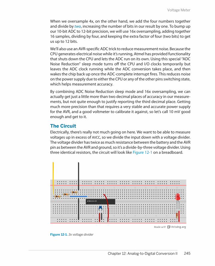
When we oversample 4x, on the other hand, we add the four numbers togetherand divide by two, increasing the number of bits in our result by one. To bump upour 10-bit ADC to 12-bit precision, we will use 16x oversampling, adding together16 samples, dividing by four, and keeping the extra factor of four (two bits) to getus up to 12 bits.
We’ll also use an AVR-specific ADC trick to reduce measurement noise. Because theCPU generates electrical noise while it’s running, Atmel has provided functionalitythat shuts down the CPU and lets the ADC run on its own. Using this special “ADCNoise Reduction” sleep mode turns off the CPU and I/O clocks temporarily butleaves the ADC clock running while the ADC conversion takes place, and thenwakes the chip back up once the ADC-complete interrupt fires. This reduces noiseon the power supply due to either the CPU or any of the other pins switching state,which helps measurement accuracy.
By combining ADC Noise Reduction sleep mode and 16x oversampling, we canactually get just a little more than two decimal places of accuracy in our measure-ments, but not quite enough to justify reporting the third decimal place. Gettingmuch more precision than that requires a very stable and accurate power supplyfor the AVR, and a good voltmeter to calibrate it against, so let’s call 10 mV goodenough and get to it.
The CircuitElectrically, there’s really not much going on here. We want to be able to measurevoltages up in excess of AVCC, so we divide the input down with a voltage divider.The voltage divider has twice as much resistance between the battery and the AVRpin as between the AVR and ground, so it’s a divide-by-three voltage divider. Usingthree identical resistors, the circuit will look like Figure 12-1 on a breadboard.
Figure 12-1. 3x voltage divider
245Chapter 12: Analog-to-Digital Conversion II
Voltage Meter

Oversampling
Oversampling seems like magic. You take a 10-bitsensor, add up 16 observations, and then dividedown by four and declare that the result is good to12 bits. What’s going on?
When you take a normal average of a few samples, ithas the effect of reducing the variability of the meas-urement. Intuitively, if one ADC reading happens tobe a bit high, the next one might just be a bit low.There are some statistics that I’m sweeping under thecarpet (a central limit theorem), but the end result isthat the variability of an average drops as the squareroot of the number of measurements in the averageincreases. Qualitatively, taking averages of measure-ments tends to smooth out noise, so if you’ve got ameasurement that’s jumping all over the place dueto sensor noise, you can take bigger and bigger aver-ages until it’s smooth enough for you. When we tookmoving averages before, we were doing just that.
Adding numbers together (and not averaging) re-sults in a larger number of bits in the sum. If you addtwo 10-bit numbers, the result can be as large as an11-bit number. Add up four 10-bit numbers, and theresult requires 12 bits. But the last bit isn’t any lessnoisy than the samples that went into the sum. You’vegot a bigger number for sure, but not a more preciseone.
When oversampling, you take many samples to getmore bits and then take a (partial) average to smooththe result out so that it’s precise enough to justify the
extra bits. In our example, we add up 16 samples,enough to end up with a 14-bit number, and then wedivide by four (equivalently, drop the least-significanttwo bits). Now we’ve got 12 bits that we’re pretty sureof.
Anyway, this has all been hand-waving around somefairly serious mathematics. I hope that it gives you alittle bit of faith in oversampling—it’s a great techni-que that you should know. To use oversampling, allyou have to know is that if you want n more bits ofresolution, you take a sum of 22n
samples and bit shift
the result n times to the right (dividing by 2n).
The main limitation is that you have to take these 22n
samples before the true input value changes by morethan one least significant bit, so oversampling ismainly a technique for slowly varying signals relativeto the sampling speed. You can almost always useoversampling for anything that happens on a humantime scale, but it’s going to slow you down too muchfor audio. There’s a three-way trade-off betweenspeed, precision, and cost. 16x oversampling is 16times slower than sampling directly, but two-bitsmore precise and free. If you need faster and moreprecise, you can always pay money for a better ADC!
For more on oversampling and the AVR’s ADC con-verter, see the Atmel application note “AVR121: En-hancing ADC resolution by oversampling.”
For our voltage divider, we want this to be as close to a true 3x division as possible,which means having twice as much resistance in the “top” half of the voltage divideras in the “bottom.” Unfortunately, the standard resistor value series jumps from 10kto 22k ohms, so there’s no good 2x ratio available without special ordering. Longstory short, the easiest thing to do is buy yourself three resistors and make yourvoltage divider with them, using two in series for the “top” resistor to drop 2/3 ofthe voltage.
246 Make: AVR Programming
Voltage Meter
Resistor Tolerance
In the real world, 10k ohm resistors don’t really measure exactly 10k ohm, but are ratherspecified with a tolerance. Common tolerance grades are 1%, 5%, and 10%. One of the cruelrealities of economics is that 1% tolerance resistors cost more than 5% resistors, which costmore than 10% resistors, and this means that you’ll almost never find a 10% tolerance resistorthat’s closer to the nominal value than 5%—the manufacturer could sell it as a 5% toleranceresistor for more money.
On the other hand, due to improved manufacturing techniques, 1% resistors are pretty cheapthese days, almost to the point that it’s not worth it to check. So if you’re lucky, you might findthat a 5% resistor is accidentally within 1% of the target value, but I wouldn’t count on it. Tenyears ago, you’d almost never find one.
Voltage scaling in generalHere, were using a voltage divider to predivide down a 0–15 V range to fit the AVR’s5 V maximum. This is a special case of a more general problem: the sensor’s rangedoesn’t always match up with the voltage range that works well for themicrocontroller.
If your sensor outputs between two and three volts, and you’re measuring with anADC that reads between zero and five volts, you’re wasting a lot of the ADC’s pre-cision. Using a five-volt ADC reference voltage, and ten bits resolution, we get5/1024 volts per step, or just under 5 mV per step. Between two and three volts,there are only around 200 of these steps, so in that situation, you’ve only got aroundone-fifth of the possible resolution—the sensor will never output high or lowenough to make use of 80% of the ADC’s range. The point is that you make bestuse of the ADC’s resolution when the voltage range of the ADC matches the voltagerange of the sensor.
Basically, we want to rescale and recenter the sensor’s signal to match the voltage-measurement range of the AVR. Rather than rescaling the sensor’s output, it’s ofteneasier to change the ADC’s voltage reference. There are two easy things we can doto match the sensor’s output voltage range with the ADC’s measurement range,and make best use of the 10 bits that we’ve got.
The AVR chips give us choices in voltage reference, which is extremely handy, oftenmeaning that we don’t have to use any frontend prescaling circuitry. In our exam-ples, we’re using VCC as our voltage reference, which is the simplest solution if yoursensors are able to output in that range. If you can easily design your voltage-divider type sensors so that they’re between VCC and GND, and use most of theavailable voltage range, you’re done.
247Chapter 12: Analog-to-Digital Conversion II
Voltage Meter

Another possibility when the range of the sensor is less than VCC, but the lowestsignal is still at ground, is to use a voltage divider on the AREF pin (with a capacitorto stabilize it). This can work very well, with the caveats that cheap resistors areoften only accurate to 10% or so, and the values can change with temperature,leaving you with higher or lower absolute voltage measurements depending onthe weather. On the other hand, two matched 1% quality resistors in a voltagedivider can give you a 2.5 V reference that’s just about as accurate as your VCC value—if the resistors have the same resistance, the effects of changing temperaturewill cancel out.
The AVR chips also have an internal voltage reference, which is nominally 1.1 V, butcan range from 1.0 V to 1.2 V across chips. This isn’t as bad as it sounds—the voltagelevel for your particular chip will stay nearly constant over time, temperature, andVCC fluctuations, which is especially handy if you’re running a circuit on batteries.If your sensor’s output range is between ground and something less than 1 V, theinternal reference voltage is the way to go. If the input signal range is higher than1 V, but you’re worried about a changing VCC affecting your measurements, it’soften worth it to divide down your input signal and use the internal voltage refer-ence. This is a good trick to use with battery-powered circuits, where VCC changesas the battery drains.
With all these options for the ADC’s reference voltage, the hard part of matchingthe sensor to the AVR is making sure that the minimum voltage stays above ground.
For many sensors, like microphones and the piezo transducer that we use here, thevoltage swing is naturally symmetric around ground, guaranteeing that we’ll losehalf of the signal unless we recenter it to capture the otherwise negative half ofthe signal. The good news is that with these sources, we don’t need the DC levelfrom the sensor. We only care about changes in voltage, say from our voice reachingthe microphone or ground tremors reaching our seismograph. In those cases, thesimplest circuit to implement is to use a capacitor to block the DC voltage and avoltage-divider circuit to bias the center voltage. We’ll use this approach in “TheFootstep Detector” on page 252.
When you have a sensor with an extreme range, or if you require biasing, and if theDC level matters, then things are more complicated. With an operational amplifier(op-amp) it’s fairly straightforward to build a signal conditioning circuit that’ll getyour sensor signal just where you want it in terms of bias voltage and range, butthat’s adding a level of complexity to the circuit that’s beyond this book.
The CodeBecause we want the voltmeter to be accurate and we’re using AVCC as the voltagereference, we’re going to have to very accurately measure the AVCC to get the scal-ing right. This means at least two or three decimal places, which means using adecent voltmeter. And we’ve got the divide-by-not-exactly-three voltage divider
248 Make: AVR Programming
Voltage Meter

in the circuit, which we’ll also have to measure and calculate around. While I usuallyavoid doing much floating-point math—math with noninteger numbers—on theAVR, I’ll make an exception here because the code is simpler that way. The trade-off is that the floating-point math libraries take up more program space and aremuch slower to execute than integer math, but for this example, none of the timingis critical, and we have memory to spare. Let’s start looking into the code inExample 12-1.
Example 12-1. voltmeter.c listing/* ADC Voltmeter * Continuously outputs voltage over the serial line. */
// ------- Preamble -------- //#include <avr/io.h>#include <util/delay.h>#include <avr/interrupt.h>#include <avr/sleep.h> /* for ADC sleep mode */#include <math.h> /* for round() and floor() */
#include "pinDefines.h"#include "USART.h"
/* Note: This voltmeter is only as accurate as your reference voltage. * If you want four digits of accuracy, need to measure your AVCC well. * Measure either AVCC of the voltage on AREF and enter it here.*/#define REF_VCC 5.053 /* measured division by voltage divider */#define VOLTAGE_DIV_FACTOR 3.114
// -------- Functions --------- //void initADC(void) { ADMUX |= (0b00001111 & PC5); /* set mux to ADC5 */ ADMUX |= (1 << REFS0); /* reference voltage on AVCC */ ADCSRA |= (1 << ADPS1) | (1 << ADPS2); /* ADC clock prescaler /64 */ ADCSRA |= (1 << ADEN); /* enable ADC */}
void setupADCSleepmode(void) { set_sleep_mode(SLEEP_MODE_ADC); /* defined in avr/sleep.h */ ADCSRA |= (1 << ADIE); /* enable ADC interrupt */ sei(); /* enable global interrupts */}
EMPTY_INTERRUPT(ADC_vect);
uint16_t oversample16x(void) { uint16_t oversampledValue = 0; uint8_t i;
249Chapter 12: Analog-to-Digital Conversion II
Voltage Meter

for (i = 0; i < 16; i++) { sleep_mode(); /* chip to sleep, takes ADC sample */ oversampledValue += ADC; /* add them up 16x */ } return (oversampledValue >> 2); /* divide back down by four */}
void printFloat(float number) { number = round(number * 100) / 100; /* round off to 2 decimal places */ transmitByte('0' + number / 10); /* tens place */ transmitByte('0' + number - 10 * floor(number / 10)); /* ones */ transmitByte('.'); transmitByte('0' + (number * 10) - floor(number) * 10); /* tenths */ /* hundredths place */ transmitByte('0' + (number * 100) - floor(number * 10) * 10); printString("\r\n");}
int main(void) {
float voltage;
// -------- Inits --------- // initUSART(); printString("\r\nDigital Voltmeter\r\n\r\n"); initADC(); setupADCSleepmode();
// ------ Event loop ------ //
while (1) {
voltage = oversample16x() * VOLTAGE_DIV_FACTOR * REF_VCC / 4096; printFloat(voltage); /* alternatively, just print it out: * printWord(voltage*100); * but then you have to remember the decimal place */ _delay_ms(500);
} /* End event loop */ return (0); /* This line is never reached */}
The event loop is straightforward; sample the voltage by calling the oversample16x() function, scale it up, and then print it out over the serial port. But in orderto run the ADC while the chip is sleeping and incorporate these values in with theoversampling routine, a few things need to be taken care of.
250 Make: AVR Programming
Voltage Meter
Sleep modeMaking use of the ADC sleep mode is not too hard, once you know how. First, noticethat we included avr/sleep.h up at the top. This isn’t strictly necessary—it definesa few macros that save us from having to look up which bits to set in the datasheet.But then again, as long as it’s there, why not use it?
Next, turn to the initialization function setupADCSleepmode(). The first line,set_sleep_mode(SLEEP_MODE_ADC);, actually just runs SMCR |= (1<<SM0); underthe hood, but isn’t it easier to read with the defines? Whichever way you spell it, abit is set in the hardware sleep mode register. That bit tells the AVR to enter ADCsleep mode (halt CPU and I/O clocks and start an ADC conversion). When the ADC-complete interrupt fires off, the chip wakes back up and the ISR is called and han-dled.
Wait a minute—what ISR? We don’t really need an ISR because we’re sampling oncommand from a function and sleeping until the ADC is done. But because we’veenabled the ADC-complete interrupt to wake up out of sleep mode, the code hasto go somewhere. The next line, EMPTY_INTERRUPT(ADC_vect);, is specific to theGCC compiler and tells it to set up a fake interrupt that just returns to wherever itwas in the code. EMPTY_INTERRUPT() basically exists just for this purpose—creatinga quick, fake ISR that we can trigger when we need to wake the processor up fromsleep modes.
OversamplingAll of the work in oversampling is done in the function oversample16x(). There’snot much to say here, because it’s such a straightforward application. One gotchais that there is a practical limit on how much we can oversample, set by the size ofthe variable that we collect up the sum of the samples in. Here, I used uint16_toversampledValue to keep track of our 16 10-bit samples, and that works out fine.In fact, it’s big enough to contain the sum of 64 10-bit values, so if we needed tooversample even more, we could.
The other thing to note while we’re here is that we could change the bit-shift di-vision in the last line of oversample16x() to divide by 16, and the result would bea regular average of 16 values. This is useful when we’d like to smooth out noise inthe sample, and the result will be a 10-bit number that’s more stable than anyindividual ADC reading by itself.
So to sum up the meat of this project, we can get extra resolution by oversampling,and we can reduce noise to the ADC by using the ADC-specific sleep mode to shutdown the CPU while sampling. And we can handle higher-than-5 V voltages bysimply using a voltage divider before the ADC. Putting all this together with a stable5 V voltage reference and some careful calibration, we can easily get 12 bits of datafrom the 10-bit ADC—enough to detect a 10 mV drop on a charging battery.
251Chapter 12: Analog-to-Digital Conversion II
Voltage Meter
Sleep Modes
The AVRs have a bunch of different sleep modes thatput some of the internal clocks to sleep until someinterrupt condition wakes the chip back up. The basicidea is that you can save power by shutting down thehardware that you’re not using at any given time, andwaking the chip up when an interrupt or timer comesin that it needs to handle.
For instance, you’ve already seen how you can set upa timer as a system tick that takes care of handlingtime for you instead of using _delay_ms() routines.If you don’t have much else to do with the CPU at thetime, you might as well let the CPU doze off a bit tosave power. Using the idle mode, the lightest sleepmode, is perfect in this case. In idle mode, the CPUclock is shut down, and any interrupt will wake thechip back up. The timer clock, ADC clock, and I/Oclocks will all keep running in the background, so youcan use idle mode instead of a wait loop and the CPUwill wake up with each timer overflow that calls anISR (like our system ticks). You can even use idle modeif you’re transmitting or expecting serial I/O, as longas you’re handling your serial input from an interruptservice routine and remember to enable theinterrupt.
ADC noise reduction mode is the mode we’re usinghere. It not only shuts down the CPU and I/O clocks,but it also triggers an ADC conversion after the CPUhas stopped, and wakes everything back up once theADC is done, which is exactly what you’d want. Howcool is that? (But note that if you’re expecting I/Oduring the ADC sampling time, you’ll miss it.)
Power down mode is the other sleep mode that I usea lot. It’s the most aggressive of them all—shuttingdown all of the internally generated clocks and pe-ripherals. From a power-usage perspective, you’rebasically turning the chip off. The AVR will still wakeup if it receives any external interrupt like a buttonbeing pressed, which is handy if you’d like to imple-ment an on/off button. If you’re not using the resetpin for anything else, it makes a nice power-on buttonto wake the chip back up from power down mode.
You can read up on all of the other sleep modes inthe datasheet under the section called “Power Man-agement and Sleep Modes,” where it has a very nicetable showing you which peripherals get turned offin which modes and what interrupts will wake thechip back up.
The Footstep Detector
In this project, we’ll be using the ADC and a sensor to make essentially a DIY ac-celerometer, but one that’s specifically tuned to detect very small vibrations liketaps on a tabletop, tiny earthquakes, or in my case, a person walking up the stairs.I’ll show you a couple of ways to make the system more or less responsive. I lovethis project.
The sensor that we’ll use to do this can be found for a few bucks or less, and canbe scavenged from a whole ton of cheap commercial products: things like musicalgreeting cards and tiny buzzers. The piezoelectric disk, or piezo for short, is a crystalthat deforms (slightly) when you apply a voltage to it, or conversely develops anelectric voltage when you deform it. The first direction, voltage to deformation,gives you a tinny-sounding speaker, super-precise control over laser deflectionmirrors, or inkjet printer heads. The reverse direction, deformation to voltage, letsyou build force sensors, high-end acoustic guitar pickups, electronic drum pads,and the vibration-sensor in this chapter, not to mention barbecue grill lighters,where the piezo voltage is high enough to make a spark.
252 Make: AVR Programming
The Footstep Detector
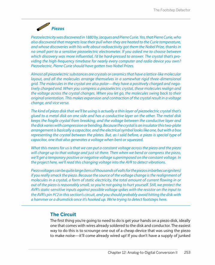
Piezos
Piezoelectricity was discovered in 1880 by Jacques and Pierre Curie. Yes, that Pierre Curie, whoalso discovered that magnets lose their pull when they are heated to the Curie temperature,and whose discoveries with his wife about radioactivity got them the Nobel Prize, thanks inno small part to a sensitive piezoelectric electrometer. If you asked me to choose betweenwhich discovery was more influential, I’d be hard-pressed to answer. The crystal that’s pro-viding the high-frequency timebase for nearly every computer and radio device you own?Piezoelectric. Pierre Curie should have gotten two Nobel Prizes.
Almost all piezoelectric substances are crystals or ceramics that have a lattice-like molecularlayout, and all the molecules arrange themselves in a somewhat rigid three-dimensionalgrid. The molecules in the crystal are also polar—they have a positively charged and nega-tively charged end. When you compress a piezoelectric crystal, these molecules realign andthe voltage across the crystal changes. When you let go, the molecules swing back to theiroriginal orientation. This makes expansion and contraction of the crystal result in a voltagechange, and vice versa.
The kind of piezo disk that we’ll be using is actually a thin layer of piezoelectric crystal that’sglued to a metal disk on one side and has a conductive layer on the other. The metal diskkeeps the fragile crystal from breaking, and the voltage between the conductive layer andthe disk varies with compression or bending. Because the crystal is an insulator this two-platearrangement is basically a capacitor, and the electrical symbol looks like one, but with a boxrepresenting the crystal between the plates. But, as I said before, a piezo is special type ofcapacitor, one that also generates a voltage when bent or squeezed.
What this means for us is that we can put a constant voltage across the piezo and the piezowill charge up to that voltage and just sit there. Then when we bend or compress the piezo,we’ll get a temporary positive or negative voltage superimposed on the constant voltage. Inthe project here, we’ll read this changing voltage into the AVR to detect vibrations.
Piezo voltages can be quite large (tens of thousands of volts for the piezos in barbecue igniters)if you really smack the piezo. Because the source of the voltage change is the realignment ofmolecules in a crystal, a form of static electricity, the total amount of current flowing in orout of the piezo is reasonably small, so you’re not going to hurt yourself. Still, we protect theAVR’s static-sensitive inputs against possible voltage spikes with the resistor on the input tothe AVR’s pin PC2 in this section’s circuit, and you should probably avoid hitting the disk witha hammer or a drumstick once it’s hooked up. We’re trying to detect footsteps here.
The CircuitThe first thing you’re going to need to do is get your hands on a piezo disk, ideallyone that comes with wires already soldered to the disk and conductor. The easiestway to do this is to scrounge one out of a cheap device that was using the piezoto make noise—it’ll come already wired up! If you don’t have a supply of junked
253Chapter 12: Analog-to-Digital Conversion II
The Footstep Detector
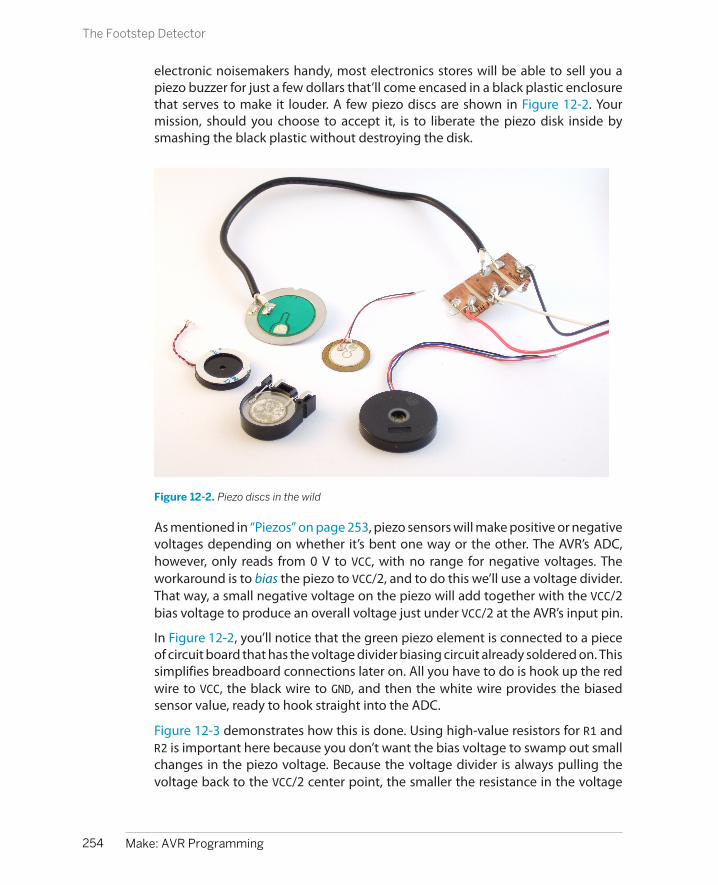
electronic noisemakers handy, most electronics stores will be able to sell you apiezo buzzer for just a few dollars that’ll come encased in a black plastic enclosurethat serves to make it louder. A few piezo discs are shown in Figure 12-2. Yourmission, should you choose to accept it, is to liberate the piezo disk inside bysmashing the black plastic without destroying the disk.
Figure 12-2. Piezo discs in the wild
As mentioned in “Piezos” on page 253, piezo sensors will make positive or negativevoltages depending on whether it’s bent one way or the other. The AVR’s ADC,however, only reads from 0 V to VCC, with no range for negative voltages. Theworkaround is to bias the piezo to VCC/2, and to do this we’ll use a voltage divider.That way, a small negative voltage on the piezo will add together with the VCC/2bias voltage to produce an overall voltage just under VCC/2 at the AVR’s input pin.
In Figure 12-2, you’ll notice that the green piezo element is connected to a pieceof circuit board that has the voltage divider biasing circuit already soldered on. Thissimplifies breadboard connections later on. All you have to do is hook up the redwire to VCC, the black wire to GND, and then the white wire provides the biasedsensor value, ready to hook straight into the ADC.
Figure 12-3 demonstrates how this is done. Using high-value resistors for R1 andR2 is important here because you don’t want the bias voltage to swamp out smallchanges in the piezo voltage. Because the voltage divider is always pulling thevoltage back to the VCC/2 center point, the smaller the resistance in the voltage
254 Make: AVR Programming
The Footstep Detector
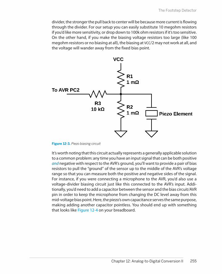
divider, the stronger the pull back to center will be because more current is flowingthrough the divider. For our setup you can easily substitute 10 megohm resistorsif you’d like more sensitivity, or drop down to 100k ohm resistors if it’s too sensitive.On the other hand, if you make the biasing voltage resistors too large (like 100megohm resistors or no biasing at all), the biasing at VCC/2 may not work at all, andthe voltage will wander away from the fixed bias point.
Figure 12-3. Piezo biasing circuit
It’s worth noting that this circuit actually represents a generally applicable solutionto a common problem: any time you have an input signal that can be both positiveand negative with respect to the AVR’s ground, you’ll want to provide a pair of biasresistors to pull the “ground” of the sensor up to the middle of the AVR’s voltagerange so that you can measure both the positive and negative sides of the signal.For instance, if you were connecting a microphone to the AVR, you’d also use avoltage-divider biasing circuit just like this connected to the AVR’s input. Addi-tionally, you’d need to add a capacitor between the sensor and the bias circuit/AVRpin in order to keep the microphone from changing the DC level away from thismid-voltage bias point. Here, the piezo’s own capacitance serves the same purpose,making adding another capacitor pointless. You should end up with somethingthat looks like Figure 12-4 on your breadboard.
255Chapter 12: Analog-to-Digital Conversion II
The Footstep Detector

Figure 12-4. Piezo footstepDetector breadboard
Finally, the input resistor R3 in Figure 12-3 protects the AVR from the case that wegenerate a too-high or too-low voltage by really whacking the piezo sensor. Theinput resistor works like this: inside the AVR, the pins have diodes that prevent toohigh or low voltages from frying the circuitry, but these diodes can only handle alimited amount of current before the AVR gets burnt out. The input resistor givesus a little bit more assurance that if the external voltage goes too high or too low,not much current will flow. You can increase sensitivity by leaving this resistor out,but you’d better be careful not to hit the piezo sensor hard.
So that’s the electronic circuit: three resistors and a piezo disk. The rest of the sensordesign is mechanical engineering. For a table-based seismometer with maximumsensitivity, you’ll want to do what they do inside commercial accelerometers—puta weight on the end of a beam to magnify the effect of the force and wedge thepiezo and the beam together in something solid.
For the beam, anything from a ruler to a piece of scrap two-by-four will do. Tapesome coins or something moderately heavy to the far end of the beam, and clampthe near end of the beam to your table, wedging the piezo sensor between thetable and beam so that any force applied to the table relative to the weight ismagnified by the leverage. (You may need to take precautions against your beamshorting out the conductor and disk sides of the piezo. A piece of electrical tapeshould work.) With this setup I can detect someone walking up the stairs that leadto my office while the piezo is sitting on my office desk.
I’ve also gotten pretty good performance just by resting something heavy on thepiezo. At the moment, I have the piezo sitting on my desk with a pint glass holdingit down as shown in Figure 12-5. As the table is vibrated up and down, the inertia
256 Make: AVR Programming
The Footstep Detector

of the pint glass provides the squeezing force that creates a voltage in the piezo.This setup is much simpler and can still detect my footsteps anywhere within theroom. It’s blinking along with each keystroke even as I type this.
Figure 12-5. Piezo footstep detector setup
Once you’ve got the piezo set up with either a weight or a weight on a beam, youcan reduce the sensitivity of the detector in firmware. How loud a signal on thepiezo must be in order to count as a footstep is stored in a variable called padding. You can optionally hook up a potentiometer to pin PC5, which is also ADCchannel 5 to control this parameter directly. We’ll read the voltage off the pot, bitshift the value to scale it, and use the result to create a dead band in the center ofthe ADC’s range where the software doesn’t react. This is useful if you’d like theaccelerometer to detect a hard tap on your desk, but not react to each and everykeystroke as you type.
And as long as we’re at it, it’s nice to have some LEDs for feedback. If you haven’tpulled the LEDs off of the PB0-PB7 bank, you’ve got nothing more to hook up. If youhave, attach LEDs to PB0, PB1, and PB7. Your breadboard should now look likeFigure 12-6.
257Chapter 12: Analog-to-Digital Conversion II
The Footstep Detector

Figure 12-6. Piezo breadboard with optional potentiometer
The TheoryMy real-life application for the piezo vibration detector is actually a footstep-activated light for the stairs in my house. The AVR continually reads the ADC andthe piezo, and when it finds a vibration that is large enough, it turns on a LED lightstrip that lights up the stairs. In the final version, I actually combine an LDR circuitwith the vibration sensor here so that it doesn’t turn on the lights in the daytime,but let’s focus on the vibration sensing part. We’ll discuss how to turn on and offlight strips (and motors and other electrically large loads) in Chapter 14.
My device turns the light strip on for a few seconds when vibration due to a footstepon the stairs is detected, and goes off automatically after the stairs are still again.In the code, I implement the timeout by restarting a countdown timer every timevibration is sensed.
Because I don’t know how hard my footsteps will be, or how much backgroundvibration there is in the house, or how much background electrical noise the sensorsees, I want the sensor to be somewhat auto-calibrating. And because the sensor’srest voltage is determined by a two-resistor voltage divider, I don’t want to haveto recalibrate the firmware between one version of the device and another in orderto account for the variation among resistors. So let’s see how we can handle all ofthese issues in our firmware.
First off, let’s tackle the problem of finding the bias voltage of the piezo. While idealbias resistors provide a midpoint voltage of 2.5000 V, you may have slightly differentreal-world values for two nominally 1 megohm resistors, and end up with a biasvoltage of 2.47 V or so. Deviations from a perfect VCC/2 biasing voltage will manifestas both the minimum and maximum observed ADC values being higher or lower
258 Make: AVR Programming
The Footstep Detector

than 511—the midpoint in the ADC’s 10-bit range. To make the sensor maximallysensitive, that is, to measure the smallest differences between the ADC value andits midpoint, we need to get this midpoint value measured accurately.
Unfortunately, any time we try to measure the bias voltage, it will have some elec-trical or physical background noise added on top of it. That is, if we make two ADCreadings, they’ll probably have different results. On the other hand, the additionalnoise voltage will be high sometimes and low other times, and if we take an aver-age, the noise will sum up to zero. The strategy is then to take a good long-runaverage and use that as a measure of the bias value. In order to make the AVR sensormaximally sensitive, it’s important to get this average spot on, and this’ll give mea chance to show you some important details for implementing exponentiallyweighted moving averages (EWMA) with integer math. (Hold on to your hats!)
Even with a perfect measure of the central value, there is still a limit to how sensitivewe can make the footstep detector. We want to pick a value on either side of thecentral value and and say that when the ADC reads outside these values, a footstephas been detected. If it weren’t for noise in the system, we could pick values juston either side of the middle, bias value. In the real world, we’ve got some range of(possibly even large) ADC values that we shouldn’t treat as footsteps, becausethey’re just the background noise.
The next moving average trick is to track the noise volume so that we can pick ourfootstep-detection thresholds outside of it. We do this by taking an average of justthe positive values (those greater than the midpoint) and a separate average ofjust the negative values. When there is no external signal present, the differencebetween these two averages should give a good idea of the average noise volume.This will increase the sensitivity when this noise is relatively quiet, and we can hopeto hear fainter footsteps, and to decrease the sensitivity if there’s a lot of back-ground noise to avoid “detecting” footsteps when none were present.
Exponentially Weighted Moving AveragesThis section is going to go into a little bit of math. It’s just a little algebra, but ifyou’re more into programming the dang AVR than thinking about what it all means,feel free to skip on down to “The Code” on page 262. On the other hand, exponentiallyweighted moving averages (EWMA) are a tremendously flexible and simple-to-usetool once you get used to them, so it’s probably worth a bit of your time hereunderstanding what’s going on.
Imagine that we have a sensor reading every second. We’ll call the raw values xt
where the t labels which second the reading is from. A time series of our data is thewhole list of x0, x1, x2, ... etc. That is, it’s the whole measured history of our sensorvalue. We’ll call our average series yt . Every time we get in a new sensor value (xt),we’ll update our average value (yt), so it ends up being another time series.
259Chapter 12: Analog-to-Digital Conversion II
The Footstep Detector
A regular moving average of our x’s just takes, for instance, the last five readingsand averages them together. If there’s some noise in the readings, it’ll hopefully behigh in a few of the five readings and low in the others, so that the average valueis close to the “true” underlying sensor reading that we’re looking for. Every secondthat we get a new sensor reading, we drop the oldest entry out of the average andadd in the new one. That’s the “moving” average part—the values that are beingaveraged together move along with our growing dataset so that we only take anaverage of, say, five values at a time.
The more terms you choose to average together in your moving average, the betteryou’ll average out the noise signal. If you average 10 values together, for instance,you’ll have a better chance at seeing both high and low noise values. On the otherhand, you’ll be including sensor information from 10 seconds ago into your averagevalue this period. There is always this trade-off between smoothing the values outbetter and having the average be up to date.
For the AVR to calculate a five-value moving average, we’ll need to store five pre-vious values from our sensor. To store 10, we’ll need to dedicate even more RAMto the averaging. It’s usually not a big deal, but it is possible to use up a lot ofmemory if you’re tracking a few variables with very long moving windows.
My preferred average, the EWMA, only needs two values to work: the current sensorreading and the current average value. Instead of averaging a bunch of valuestogether, in the EWMA, we only need to average two values: the current value andthe average value from the last observation. The only complication here is that wedon’t take an equal average between the two, but a weighted average where weput more weight on the past value (usually) than on the present. For instance, inthis chapter’s code, we’ll average 1/16th of the current value with 15/16ths of theaverage from last period.
And finally, because what we’re after is an accurate value for the bias voltage, we’llwant to take some care making sure we calculate everything right. This meansavoiding doing division whenever we can, and taking extra care to get the roundingright when we do have to divide. Even if we make sure to always divide by a powerof two, so that we can use a bit shift, we still lose some information every time wedivide. As an example, 7/2 = 3.5, but if we’re only using integers, we round up to 4.But 8/2 is also 4, so if we’ve only got the divided-by-two version, we can’t be surewhether it came from a seven or an eight.
Anyway, to the EWMA. In what follows, I’m going to be assuming an EWMA with a1/16, 15/16 split between the new value and the average. It should be obvious howto generalize this to any other fraction:
yt =1
16 xt +1516 yt -1
260 Make: AVR Programming
The Footstep Detector
That is, we calculate this period’s EWMA by taking a weighted average of one partthis period’s sensor value xt and many parts of the previous EWMA value.
The secret to keeping the EWMA accurate is to put off the dividing-by-m part untilwe absolutely have to. Multiply both sides by m and we have:
16yt = xt + 15yt -1
and we’re almost there. Now we have m times the EWMA on the left side, and nodividing at all. But when we come to next period, we’ll need (m - 1) × yt on theright side instead of the m × yt that we have. Easy enough, we could subtract offone yt if we knew it. Because we’ve got m × yt , we can subtract off m × yt / m.
But, as I mentioned earlier, when C divides, it just throws away the remainder.There’s a trick to making C “round” for us, and it involves adding or subtracting halfof the denominator into the numerator before dividing.
Rounding and Integer Division
C does integer division differently than you or I would. If you were dividing two numbers andwanted an integer result, you’d first figure out what the decimal value was (with integer valueand remainder) and then round up or down accordingly. C, on the other hand, figures outthe integer part and throws away the remainder. For example, 16/8 = 2, 17/8 = 2, and even23/8 = 2. (24/8, at least, is 3).
It turns out that we can fool C into rounding by preadding half of the denominator beforewe divide. In our example of dividing by eight, we need to add four to the number up frontbefore the division: (16 + 4) / 8 = 2, (19 + 4) / 8 = 2, but (20 + 4) / 8 = 3, etc. If you want yourinteger divisions to be “rounded” to the nearest integer, remember to add or subtract thiscorrection factor of half of the denominator before dividing.
The final equation, minimizing the effects of division and adding in a roundingfactor looks like Equation 12-1.
Equation 12-1. Optimized EWMA equation
16yt = xt + 16yt -1 -(16yt -1 - 16 / 2)
16
Everything is kept undivided as long as possible, and the average tracks the actualvalue very well, although we need to remember to divide it back down by 16 beforeusing it.
261Chapter 12: Analog-to-Digital Conversion II
The Footstep Detector

The only thing that’s a little odd about this expression is that the correction factorenters in with a negative sign, but that’s because we’re subtracting off the wholefractional part. The two negatives cancel out to make a positive and the value thatwe’re using for 15yt is rounded (correctly) up.
The CodeIf you’ve hooked everything up right, you’ll have a vibration sensor hooked up topin PC2 on the AVR. Now let’s flash in the code listed in Example 12-2 and use it.
Example 12-2. footstepDetector.c listing/* * Sensitive footstep-detector and EWMA demo */
// ------- Preamble -------- //#include <avr/io.h>#include <util/delay.h>#include <avr/sleep.h>#include "pinDefines.h"#include "USART.h"
#define ON_TIME 2000 /* milliseconds */#define CYCLE_DELAY 10 /* milliseconds */#define INITIAL_PADDING 16 /* higher is less sensitive */
#define SWITCH PB7 /* Attach LED or switch relay here */
#define USE_POT 0 /* define to 1 if using potentiometer */#if USE_POT#define POT PC5 /* optional padding pot */#endif
// -------- Functions --------- //void initADC(void) { ADMUX |= (1 << REFS0); /* reference voltage to AVCC */ ADCSRA |= (1 << ADPS1) | (1 << ADPS2); /* ADC clock prescaler /64 */ ADCSRA |= (1 << ADEN); /* enable ADC */}
uint16_t readADC(uint8_t channel) { ADMUX = (0b11110000 & ADMUX) | channel; ADCSRA |= (1 << ADSC); loop_until_bit_is_clear(ADCSRA, ADSC); return (ADC);}
int main(void) { // -------- Inits --------- // uint16_t lightsOutTimer = 0; /* timer for the switch */ uint16_t adcValue;
262 Make: AVR Programming
The Footstep Detector

uint16_t middleValue = 511; uint16_t highValue = 520; uint16_t lowValue = 500; uint16_t noiseVolume = 0; uint8_t padding = INITIAL_PADDING;
LED_DDR = ((1 << LED0) | (1 << LED1) | (1 << SWITCH)); initADC(); initUSART();
// ------ Event loop ------ // while (1) { adcValue = readADC(PIEZO);
/* moving average -- tracks sensor's bias voltage */ middleValue = adcValue + middleValue - ((middleValue - 8) >> 4); /* moving averages for positive and negative parts of signal */ if (adcValue > (middleValue >> 4)) { highValue = adcValue + highValue - ((highValue - 8) >> 4); } if (adcValue < (middleValue >> 4)) { lowValue = adcValue + lowValue - ((lowValue - 8) >> 4); } /* "padding" provides a minimum value for the noise volume */ noiseVolume = highValue - lowValue + padding;
/* Now check to see if ADC value above or below thresholds */ /* Comparison with >> 4 b/c EWMA is on different scale */ if (adcValue < ((middleValue - noiseVolume) >> 4)) { LED_PORT = (1 << LED0) | (1 << SWITCH); /* one LED, switch */ lightsOutTimer = ON_TIME / CYCLE_DELAY; /* reset timer */ } else if (adcValue > ((middleValue + noiseVolume) >> 4)) { LED_PORT = (1 << LED1) | (1 << SWITCH); /* other LED, switch */ lightsOutTimer = ON_TIME / CYCLE_DELAY; /* reset timer */ } else { /* Nothing seen, turn off lights */ LED_PORT &= ~(1 << LED0); LED_PORT &= ~(1 << LED1); /* Both off */ if (lightsOutTimer > 0) { /* time left on timer */ lightsOutTimer--; } else { /* time's up */ LED_PORT &= ~(1 << SWITCH); /* turn switch off */ } }#if USE_POT /* optional padding potentiometer */ padding = readADC(POT) >> 4; /* scale down to useful range */#endif /* Serial output and delay */ /* ADC is 10-bits, recenter around 127 for display purposes */ transmitByte(adcValue - 512 + 127); transmitByte((lowValue >> 4) - 512 + 127); transmitByte((highValue >> 4) - 512 + 127);
263Chapter 12: Analog-to-Digital Conversion II
The Footstep Detector

_delay_ms(CYCLE_DELAY); } /* End event loop */ return (0); /* This line is never reached */}
Let’s start off with a look through the functions. initADC() and readADC() are gen-eral purpose functions that you can quite easily reuse in your code with a simplecut and paste. initADC() sets up the voltage reference, starts the ADC clock, andenables ADC. readADC() takes a channel value as an input, configures the multi-plexer register to read from that channel, and then starts a conversion, waits, andreturns the result. As you’ll see in the main loop, this makes calling multiple chan-nels with the ADC as easy as result = readADC(PIEZO); or result = readADC(ADC5);.
Rolling down to the main() function, we have the usual declarations for variables,and call the initialization functions, and then run the event loop.
Each cycle through the loop begins with an ADC read from the piezo channel, andthen the code updates the middle value, and the high and low averages, respec-tively. To avoid round-off error, as is done in Equation 12-1, we’re not storing themoving-average values, but rather 16 times the moving-average value. Everywherein the rest of the code where we use both the ADC reading directly and thesesmoothed versions, we have to remember to finish making the average by dividingby 16.
Notice that we only update the “moving average” for highValue when the meas-ured ADC value is greater than the center value, and only update lowValue whenit’s below. This way, highValue gives us the average value that’s above the middle,and lowValue gives us the average below it. The difference between these two issome measure of how wide the sampled waveform is on average. The value of thisdifference will track the average volume of background noise when there’s no ac-tive footsteps. As soon as we tap on the sensor, or step nearby it, the current valueof the ADC will go very high or very low, but the average value will track this onlyslowly, and this is how we tell a real footstep from noise.
On top of this average measure of the background noise, I’ll add in an additionalbit called padding. If you find that the sensor is triggering too often, or you’d justlike it to only trigger on heavy-footed footsteps, you can use this value to add insome extra range in which the sensor won’t respond.
I’ve also left a define in the code (USE_POT) that you can enable if you’d like to hookup a potentiometer to PC5 and control the padding in real time. This makes thecircuit easily tunable, and gives you an example of how easy it is to change valueswithin your code via the ADC. When you define USE_POT to 1, the following twoextra lines are inserted into the code:
264 Make: AVR Programming
The Footstep Detector

#define POT PC5 /* optional padding pot */padding = readADC(POT) >> 4; /* scale down to useful range */
and that’s enough to enable you to set the value of the variable padding by turninga knob. Neat, huh? Think back to every bit of code where we’ve defined a fixedvalue that you then had to edit, compile, flash, and test out. Why not add in apotentiometer and use an ADC channel to make the parameters adjustable in realtime? When you’ve got the extra ADC channels and the extra processing time,nothing is stopping you.
The rest of the code just takes care of some display LEDs and the timing turningon and off the switch that controls the lights. Each time through the event loop,there’s a fixed delay at the very end. The switch only stays on for lightsOutTimer= ON_TIME / CYCLE_DELAY of these cycles after the last detected movement. Butthe sensor is looking for a new footstep with each cycle through the event loop,so as long as the vibrations continue, the switch’s timer variable will continue beingreset to its maximum. The switch will turn off only after ON_TIME milliseconds of noactivity.
I left these as defines because it’s interesting to play with them. If you sample theADC too slowly (setting CYCLE_DELAY too large), you may miss the loud part of afootstep. If you sample too frequently, the sensitivity to background noise canincrease. So you can play around with these values. The CYCLE_DELAY also implicitlysets the maximum time that the switch is on between footsteps; because lightsOutTimer is a 16-bit value, you’re “limited” to a maximum on-time of 655.36 sec-onds (about 11 minutes) with a 10 ms CYCLE_DELAY.
The code also takes advantage of the two thresholds, one low and one high, toblink two separate LEDs, providing nice feedback as to how sensitive the circuit is.If only one of the LEDs blinks, your footstep was just above the noise threshold. Ifboth blink and keep blinking back and forth for a second or so, you know thatyou’re detecting the footstep loud and clear.
By increasing the padding variable and making the sensor only react to larger valueson the ADC, you could turn this circuit into a knock-detector suitable for detectingsecret-knock patterns on a tabletop. For instance, if you want the AVR to do some-thing only when you rap out the classic “shave-and-a-haircut” knock, you couldkeep track of the timing between detected knocks and only respond if they’re inthe right approximate ratios.
If you increase the physical sensitivity of the sensor either mechanically by usinga long lever arm and heavy weight or electronically by increasing the value of thebias resistors, this application will make a good seismometer. You might, forinstance, store the values on a computer and look at them later. Or if you do a littlepreprocessing in the AVR and only record the values that are extreme, most likelyin combination with some external storage, you can make yourself a capable log-ging seismometer.
265Chapter 12: Analog-to-Digital Conversion II
The Footstep Detector

Summary
In this chapter, you’ve learned two important techniques for getting either moreaccuracy (oversampling) or more stability (moving averaging) out of a digitizedanalog signal. Along the way, you learned two things about input conditioning:how to divide down a voltage to a manageable level for the AVR’s ADC using voltagedividers and how to handle an AC signal that doesn’t have a well-defined zerovoltage reference.
In all of this, getting as much feedback from your measured system as possible isimportant. In the case of reasonably slow signals, you can send real-time data toyour desktop computer over the serial port for simple diagnostics. For applicationswith very fast signals, nothing beats being able to hook up an oscilloscope to thecircuit in question so that you can simply see how the voltages that you’re tryingto measure are behaving.
The specifics of using any given analog sensor are usually very much application-dependent, so I hope that this chapter gives you enough of a basis to take the nextsteps yourself. And in the analog world, there’s really no substitute for building upyour system and testing it out. This includes testing your circuit out in the envi-ronment that it’ll eventually be used in. No matter how well you think you’vespecified your sensors and your circuits, you’ll occasionally be surprised when theypick up on something in the environment that you hadn’t anticipated.
I built a noisemaker with light-dependent resistor light sensors once, wrote all ofthe firmware, and tested it out thoroughly, I thought. But I had tested it out in aroom with strong daylight. As soon as I tried it out in a room with overhead fluo-rescent lights, there was a warbling noise overlaid on the pitch that I thought itshould be playing. It turns out that the light sensors were reacting quickly enoughto pick up the relatively quick light pulses that result from driving lights on 60 HzAC house wiring. This took even longer to debug because it wasn’t simply a 60 Hzor 120 Hz pitch overlaid on top, but an interaction of the AVR’s sample rate withthe 120 Hz bright-dark cycle from the lights. The solution was to take a movingaverage ADC value that smoothed out the fluorescent bulb’s light cycle, and allwas well.
Grab yourself a sensor and hook it up to the AVR. See how it behaves, and thenstart coding up some neat interactions. But don’t get caught up in the idea thatyou can design everything from the specifications. With sensors, sometimes you’regoing to be surprised by what they pick up, or don’t. So you’ve got to build it first,and then you can get down to puzzling out what’s really going on. And in myopinion, that’s more than half of the fun. Enjoy!
266 Make: AVR Programming
Summary

PART III
Advanced AVR Topics
Once you’ve mastered the AVR itself, this last section of the book is dedicated to using moderncommunications protocols to interface with other devices, building the circuitry you need todrive motors and other electrical devices, and covering a few more of the features of the AVRthat you may or may not need every day. The projects here are more involved, and you can readthese chapters largely in whatever order you’d like. When you’re done with this chapter, you’llbe ready to tackle almost any project that you can dream up that needs a microcontroller.
Chapter 13 covers a software and firmware technique that makes good use of what you’velearned about PWM. This enables playback of sampled speech, volume control, and mixing oflow-fi digital audio signals. You’ll end up with a clean sine wave, a nice-sounding abstract droneynoisebox, and an improved, serial-port playable “piano.”
In Chapter 14 and Chapter 15, I’ll show you some simple (and not-so-simple) circuits that youcan use to control almost anything that runs on electricity. DC motors, stepper motors, sole-noids, and even household appliances can be put under microcontroller control with someadditional circuitry. Although the projects in these chapters are basically just about turningmotors, I’m hoping that you’ve got an idea why you’d like motors to turn.
In Chapter 16 and Chapter 17, I cover the two most commonly used modern serial peripheralprotocols. This opens up the world of sophisticated digital sensors, high-resolution digital-to-analog converters, and external storage. The demos culminate in integrating a 25LC256 externalSPI EEPROM and an LM75 I2C temperature sensor into a long-running temperature logger, butsimilar techniques let you work with anything that speaks either I2C or SPI.
Chapter 18 and Chapter 19 are all about making the most of the AVR’s scarce memory resources,which enables you to do more cool stuff. Thanks to some clever encoding, you can store 10seconds of sampled low-fi speech data in the read-only flash program memory, enough to makea talking voltmeter that reads out the current voltage to you using your own voice. And though

the chip’s onboard EEPROM isn’t all that fast or abundant, it doesn’t disappear when the powergoes out and it’s writable from within your code. I show off by making an AVR secret encoder/decoder that stores the passwords in EEPROM. If you have two with the same key phrases storedin them, you can pass encrypted messages.

Direct-Digital Synthesis
To create audio that’s more interesting than square waves, we’re going to use PWMto create rapidly changing intermediate voltages that’ll trace out arbitrary wave-forms. For now, we’ll content ourselves with a few of the traditional synthesizer-type waveforms (sine, sawtooth, and triangle waves), but this project also lays thegroundwork for playing back sampled speech. (When we have enough memoryat our disposal, in Chapter 18, we’ll use the same techniques to make a talkingvoltmeter.) We’ll also be able to change the volume of the sounds and mix multiplesounds together. If you like making spacey, droney sounds or just something moremusical than the square wave sounds we’ve been making so far, this is the chapterfor you!
Along the way, we’ll really give the PWM hardware a workout. We’ll be running thetimer/counter with no prescaling (at 8 MHz) and, frankly, we can use all the speedwe can get. Generating fancy waveforms in real-time at 31.25 kHz involves enoughmath that it’s tough on the CPU as well, and we’ll find that there are just some thingswe can’t do all that easily. But in my opinion, some of the fun of working with smalldevices like microcontrollers is seeing how much you can do with how little. I hopeyou’ll be pleasantly surprised by what is possible.
For starters, we’ll make a simple DDS sine wave generator. Unmodulated sine wavesare kinda boring, so the next project demonstrates how to mix different DDS os-cillators by taking a few (2, 4, 8, or 16) sawtooth waves and mixing them together.To animate the sound, each waveform is slowly shifted a little bit over in time bydifferent amounts, creating a phasing effect that makes a nice drone sound, andis the basis for a lot of 1990’s basslines when played rhythmically. Finally, the lastproject adds dynamic volume control, making your nice AVR into a fairly cheesysounding “piano.” Ah well, beats square waves, right?
269
Advanced PWM Tricks 13

What You Need
In this chapter, in addition to the basic kit, you willneed:
• A speaker and capacitor hooked up to the AVRto make sound.
• (Optionally) a resistor and capacitor pair tomake a lowpass filter if you’re going to con-nect the output to an external amplifier.
• A USB-Serial cable to play the piano from yourdesktop’s keyboard.
Frequencies Within Frequencies
As we work through Direct-digital Synthesis, it’s probably a good idea to think of the PWMvalue you write to OCR0A as being directly translated into a voltage level, because we’ll bevarying this voltage level over time to make up the desired audio waveform. So when I say“frequency of the waveform,” I’m referring to how many times the audio voltage-wave cyclesper second.
But of course, we know that deep down, the PWM “voltage level” is itself just another, muchfaster, train of on-off pulses that repeat at the PWM frequency. These pulses are smoothedout so that they appear to be a nearly constant average voltage at the audio-frequencytimescale, and you won’t need to worry about them most of the time, as long as your PWMfrequency is high enough that your filter does enough smoothing to average them out.
On the other hand, if you’ve switched output from something slow like a speaker to somethingthat responds a lot faster, like a good amplifier or pair of headphones, you may notice somehigh-frequency noise that you didn’t before. The remedy is to increase the value of the resistorand/or capacitor in your lowpass filter, slowing down its voltage response, so that it dampsout the much-higher PWM frequency.
Direct-Digital Synthesis
At the heart of this application is a technique known as direct-digital synthesis(DDS). If you’d like to reproduce, for instance, a sine wave, you start by samplingthe voltages along that waveform at regularly spaced intervals in time. Then toplay it back, you just output those different voltage levels back over time. You’llstore all of the different sample values (voltage levels) for one complete cycle ofyour waveform in an array in memory, and then play through this sample lookuptable at different speeds to create different pitches.
270 Make: AVR Programming
Direct-Digital Synthesis

It’s easy enough to imagine how to play the fundamental note; you would just stepthrough the lookup table at a fixed speed, storing one value at a time in the PWMcompare register to generate that voltage. Now to change the pitch, you’ll needto change how quickly you go through the waveform lookup table. The obviousway to do that would be to speed up the playback rate, but there’s no good wayto do that with the hardware we’ve got—the system CPU clock runs at a fixedfrequency, and to speed up the PWM part, we’d need to also drop down the reso-lution. There must be a better way.
Instead of changing the clock frequency—how quickly you take each step throughthe cycle—you change how many steps you take for each clock tick. In order toplay a lower note, with a longer wavelength, you play some of the steps for morethan a single sample period. To play a higher note, you skip some steps in thewaveform table. Either way, the idea is that it takes more or less time to get throughone complete trip through the waveform table, resulting in a lower or higher pitch.
There’s still a couple more implementation details left, but for starters, imagine thatyou went through the lookup table, playing each sample for one PWM cycle each.I’ve written this routine out in pseudocode:
uint8_t waveStep;while(1){ waveStep++; OCR0A = lookupTable[waveStep]; // (and wait for next PWM cycle)}
Now if you want to play a note that was an octave up, you can go through the samelookup table but skip an entry each time, and the output will cycle through thetable twice as fast. In the pseudocode example, that would correspond to incre-menting waveStep by two each sample (see Figure 13-1). Here, the basic wavetablehas 40 samples. Skipping every other step gives you effectively 20 samples to getthrough the full wavetable. Alternatively, in the same time it took to play one fullsample, you’ll get through the wavetable two times by skipping steps. Either wayyou look at it, the pitch of the output waveform is doubled by skipping steps.
If you wanted to play a note that was an octave down, you’d just need to figure outa way to increment waveStep by 1/2 each time through the loop. This is going tobe the secret to DDS. Instead of changing the playback speed of the samples, youchange the number of steps you take per PWM cycle.
271Chapter 13: Advanced PWM Tricks
Direct-Digital Synthesis
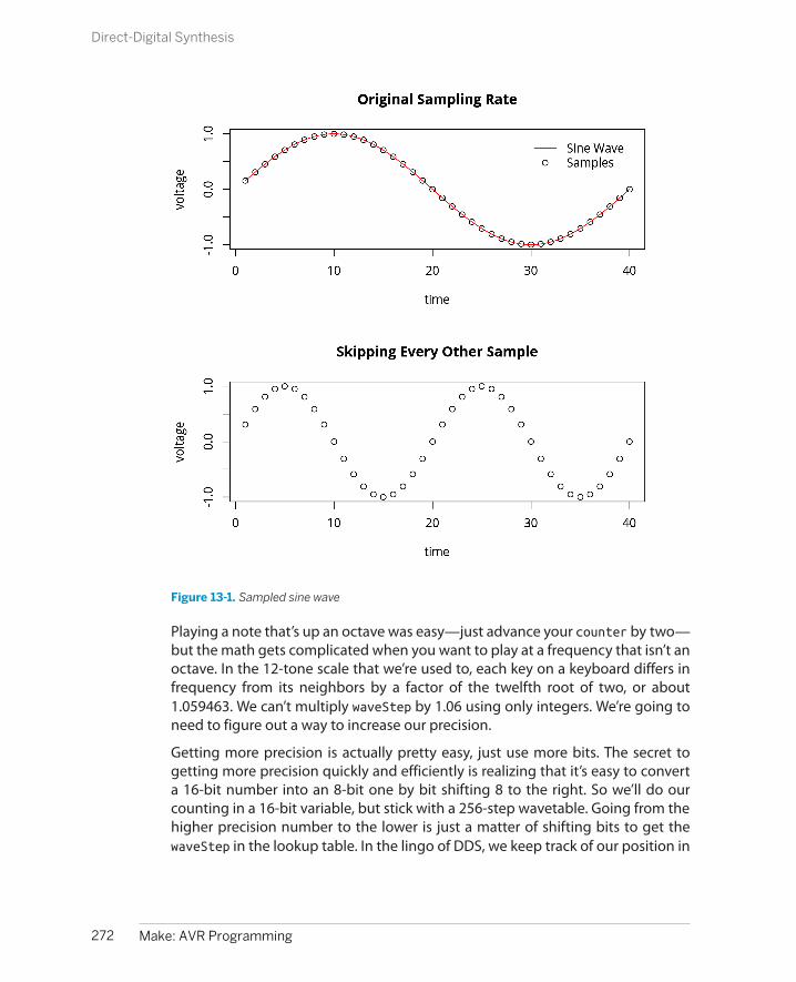
Figure 13-1. Sampled sine wave
Playing a note that’s up an octave was easy—just advance your counter by two—but the math gets complicated when you want to play at a frequency that isn’t anoctave. In the 12-tone scale that we’re used to, each key on a keyboard differs infrequency from its neighbors by a factor of the twelfth root of two, or about1.059463. We can’t multiply waveStep by 1.06 using only integers. We’re going toneed to figure out a way to increase our precision.
Getting more precision is actually pretty easy, just use more bits. The secret togetting more precision quickly and efficiently is realizing that it’s easy to converta 16-bit number into an 8-bit one by bit shifting 8 to the right. So we’ll do ourcounting in a 16-bit variable, but stick with a 256-step wavetable. Going from thehigher precision number to the lower is just a matter of shifting bits to get thewaveStep in the lookup table. In the lingo of DDS, we keep track of our position in
272 Make: AVR Programming
Direct-Digital Synthesis
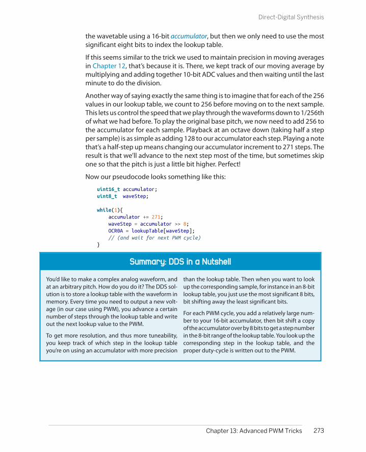
Summary: DDS in a Nutshell
You’d like to make a complex analog waveform, andat an arbitrary pitch. How do you do it? The DDS sol-ution is to store a lookup table with the waveform inmemory. Every time you need to output a new volt-age (in our case using PWM), you advance a certainnumber of steps through the lookup table and writeout the next lookup value to the PWM.
To get more resolution, and thus more tuneability,you keep track of which step in the lookup tableyou’re on using an accumulator with more precision
than the lookup table. Then when you want to lookup the corresponding sample, for instance in an 8-bitlookup table, you just use the most significant 8 bits,bit shifting away the least significant bits.
For each PWM cycle, you add a relatively large num-ber to your 16-bit accumulator, then bit shift a copyof the accumulator over by 8 bits to get a step numberin the 8-bit range of the lookup table. You look up thecorresponding step in the lookup table, and theproper duty-cycle is written out to the PWM.
the wavetable using a 16-bit accumulator, but then we only need to use the mostsignificant eight bits to index the lookup table.
If this seems similar to the trick we used to maintain precision in moving averagesin Chapter 12, that’s because it is. There, we kept track of our moving average bymultiplying and adding together 10-bit ADC values and then waiting until the lastminute to do the division.
Another way of saying exactly the same thing is to imagine that for each of the 256values in our lookup table, we count to 256 before moving on to the next sample.This lets us control the speed that we play through the waveforms down to 1/256thof what we had before. To play the original base pitch, we now need to add 256 tothe accumulator for each sample. Playback at an octave down (taking half a stepper sample) is as simple as adding 128 to our accumulator each step. Playing a notethat’s a half-step up means changing our accumulator increment to 271 steps. Theresult is that we’ll advance to the next step most of the time, but sometimes skipone so that the pitch is just a little bit higher. Perfect!
Now our pseudocode looks something like this:
uint16_t accumulator;uint8_t waveStep;
while(1){ accumulator += 271; waveStep = accumulator >> 8; OCR0A = lookupTable[waveStep]; // (and wait for next PWM cycle)}
273Chapter 13: Advanced PWM Tricks
Direct-Digital Synthesis

Making a Sine Wave
So let’s flash in our first DDS example, dds.c. It won’t do anything at first, but if you’veconnected a button and speaker, pressing the button will emit a nice sine wavearound 440 Hz. Time to break down the code in Example 13-1.
Example 13-1. dds.c listing /* Direct-digital synthesis */
// ------- Preamble -------- //#include <avr/io.h> /* Defines pins, ports, etc */#include <util/delay.h> /* Functions to waste time */
#include "pinDefines.h"#include "macros.h"#include "fullSine.h"
static inline void initTimer0(void) { TCCR0A |= (1 << COM0A1); /* PWM output on OCR0A */ SPEAKER_DDR |= (1 << SPEAKER); /* enable output on pin */
TCCR0A |= (1 << WGM00); /* Fast PWM mode */ TCCR0A |= (1 << WGM01); /* Fast PWM mode, pt.2 */
TCCR0B |= (1 << CS00); /* Clock with /1 prescaler */}
int main(void) {
uint16_t accumulator; uint16_t accumulatorSteps = 880; /* approx 440 Hz */ uint8_t waveStep; int8_t pwmValue;
// -------- Inits --------- //
initTimer0(); BUTTON_PORT |= (1 << BUTTON); /* pullup on button */
// ------ Event loop ------ // while (1) {
if (bit_is_clear(BUTTON_PIN, BUTTON)) {
SPEAKER_DDR |= (1 << SPEAKER); /* enable speaker */ accumulator += accumulatorSteps; /* advance accumulator */ waveStep = accumulator >> 8; /* which entry in lookup? */ pwmValue = fullSine[waveStep]; /* lookup voltage */
loop_until_bit_is_set(TIFR0, TOV0); /* wait for PWM cycle */ OCR0A = 128 + pwmValue; /* set new PWM value */
274 Make: AVR Programming
Making a Sine Wave

TIFR0 |= (1 << TOV0); /* reset PWM overflow bit */ } else { /* button not pressed */ SPEAKER_DDR &= ~(1 << SPEAKER); /* disable speaker */ } } /* End event loop */ return (0); /* This line is never reached */}
Timer 0 is configured in Fast PWM mode, so for our purposes, think of the valuewritten to the compare register, OCR0A, as representing the average voltage wewant to output during that PWM cycle. Note that we’re setting the clock inputprescaler to a value of 1, that is to say, no prescaling. For sampled audio, we needall the speed we can get.
In the event loop, we check to see if the button is pressed. When it is, the speakeris enabled for output, and the DDS routine inside the if() statement runs. Just asin our earlier pseudocode example, the accumulator is advanced by a number ofsteps that determine the pitch, then the 16-bit accumulator is divided by 256 (usingbit-shift division) yielding the step of the waveform table that we’re on. Then thelookup takes place, yielding the (signed) integer pwmValue. I keep this variablesigned because it’s easier later on when we mix multiple signals together or scalethem by volume multipliers, because it’s centered on zero.
Signed Integers
Note here that our wavetables are made up of signed integers. Why? It makes volume controland mixing a lot easier. If the waveforms can vary between –128 and 127 and we divide themin half, we’ll get a waveform between –64 and 63, which is still nicely centered, and we canadd it together with other waveforms. Only at the last minute, before writing it out to thePWM register, do we convert it to the 0–255 range that we need to fit in the OCR0A register.
Then we load the PWM register, but first we have to wait for the current PWM cycleto finish. This guarantees that we only load up the PWM register with a new valueonce per cycle, which keeps the sample rate nice and consistent. The OCR is thenwritten to with our signed pwmValue + 128. The number 128 is chosen because therange of signed 8-bit integers goes from –128 to 127, and adding 128 to it maps itnicely into our PWM counter’s 0 to 255 range. Finally, the PWM overflow flag bit isreset by writing a one to it, as described in the datasheet, so that we will be ableto detect when we’ve yet again completed a full PWM cycle.
275Chapter 13: Advanced PWM Tricks
Making a Sine Wave

Sample Rate
In this demo, we’re using 8-bit PWM to generate anew average-voltage once per PWM cycle. But ex-actly how frequently are we playing back eachvoltage-level sample? We’ll have to do some math.
Because we’re running the AVR off of its internal CPUclock at maximum speed, the CPU clock is 8 MHz.We’re using no prescaling, so the effective PWM clockalso ticks eight million times per second. Using an 8-
bit PWM, we complete one PWM cycle every 256clocks, so our resulting PWM frequency is 31,250 Hz.
One of the central theorems of digital signal process-ing states that you have to sample a sine wave at leasttwice per period to reproduce it. That is, our currentsystem can reproduce a maximum frequency of15,625 Hz, which is fairly respectable.
Lowpass Filter
If you’re thinking of amplifying the signal from the AVR synth that we’ve just made, you mightwant to put a lowpass filter between your AVR’s audio out and your amplifier’s audio in.Remember what I said about PWM working to create average voltages when the responseof the driven system is slow enough? If you’re running the audio out directly into a speaker,the tiny AVR is not going to be able to push the speaker cone back and forth at anywherenear the PWM frequency, and you’ll be OK.
On the other hand, if you’re plugging the AVR output into an amplifier, the amp may be fastenough to react to the PWM-frequency signals or higher, creating extra noise or even amplifierinstability. So let’s cut out the higher-frequency components with a lowpass filter.
The simplest lowpass filter is a resistor in series with the AVR out, followed by a capacitor toground. See Figure 13-2 for an example. The basis of a lowpass filter is the resistor and ca-pacitor, and their product determines the cutoff frequency of the filter—the frequency abovewhich tones get quieter and quieter. With the values here, all frequencies above 1,600 Hzbegin to be attenuated, which assures that our 31.25 kHz PWM frequency is nice and quiet.
276 Make: AVR Programming
Making a Sine Wave

Figure 13-2. Simplest lowpass filter
Next Steps: Mixing and Volume
The nice thing about DDS synthesis is that it’s incredibly easy to mix two or morewaveforms together (add the waveform values), or to make sounds louder or qui-eter (multiply or divide them). Combining different waveforms with dynamic vol-ume envelopes puts us on the road toward real sound synthesis, and being ableto mix a few of these sounds together puts real music within reach.
Toward these ends, I’ve included two demonstrations. The first mixes two, four,eight, or sixteen sawtooth waves together and then varies their relative phases. Itcreates a neat, slowly evolving soundscape, and also introduces us to what happensif our event loop is too slow for our sample update frequency—we end up with alower pitch. The second example demonstrates a simple way to add a dynamicvolume envelope to our sounds. Before when we were playing square waves, thespeaker was either on or off. There was no idea of volume. But here, with DDS, ifwe put out a series of voltages that are 1/2 of the PWM value of another series, theresulting sound will be quieter.
MixingFirst off, load up and flash the fatSaw.c code and give it a listen. The code is a lotlike our DDS sine wave code in Example 13-1, but with the waveform lookup tablechanged, and multiple sound sources playing at once and mixed together. Thenstart having a look through the code in Example 13-2.
277Chapter 13: Advanced PWM Tricks
Next Steps: Mixing and Volume

Example 13-2. fatSaw.c listing/* Direct-digital synthesis Phasing saw waves demo
*/
#include "fatSaw.h"
int main(void) {
uint16_t accumulators[NUMBER_OSCILLATORS]; uint8_t waveStep; int16_t mixer; uint8_t i;
// -------- Inits --------- //
initTimer0(); SPEAKER_DDR |= (1<<SPEAKER); /* speaker output */ LED_DDR |= (1<<LED0);
// Init all to same phase for (i = 0; i < NUMBER_OSCILLATORS; i++) { accumulators[i] = 0; }
// ------ Event loop ------ // while (1) {
/* Load in the PWM value when ready */ loop_until_bit_is_set(TIFR0, TOV0); /* wait until overflow bit set */ OCR0A = 128 + mixer; /* signed-integers need shifting up */ TIFR0 |= (1<<TOV0); /* re-set the overflow bit */
/* Update all accumulators, mix together */ mixer = 0; for (i = 0; i < NUMBER_OSCILLATORS; i++) { accumulators[i] += BASEPITCH; waveStep = accumulators[i] >> 8;
// Add extra phase increment. // Makes shifting overtones when // different frequency components add, subtract if (waveStep == 0) { /* roughly once per cycle */ accumulators[i] += PHASE_RATE * i; /* add extra phase */ }
mixer += fullSaw15[waveStep]; } mixer = mixer >> OSCILLATOR_SHIFT;
278 Make: AVR Programming
Next Steps: Mixing and Volume

/* Dividing by bitshift is very fast. */
} /* End event loop */ return (0); /* This line is never reached */}
The first thing you’ll notice is that I’ve moved the standard preamble, with includefiles and defines, off to its own fatSaw.h file. Many people like to do this to reduceclutter in the main loop. I’m doing it here mainly to save space. In the fatSaw.h fileare some definitions relating to the number of voices we’d like to produce and eventhe same initTimer0() function that we used in our first DDS program. (C pro-grammers will argue that putting significant code in an .h file is bad practice, be-cause other people aren’t expecting it there. I agree, but in the same sense thatmacro functions are tolerated in .h files, I beg your indulgence with a couple bit-twiddling initialization routines.)
Just inside the main() routine, notice that we’re defining an array of accumulatorsbecause we have to keep track of not just one note’s location in the wavetable, butup to 16. Moving on to the event loop, the first chunk should look familiar. Theroutine waits for the current PWM counter loop to complete, then loads the OCRand resets the overflow flag bit.
The mixer chunk is where the interesting action lies. Notice that we’ve defined a16-bit signed integer called mixer, in which we’ll add up all of the waveform valuesfrom the individual digital oscillators. So for each oscillator, we advance its accu-mulator (here, all by the same amount) and then use a bit shift divide to find outwhich step in the waveform table we’re on. At the end of the mixer code loop, welook up our value from the table and add it to the mixer.
The fun stuff lies in the middle. Here, we advance the accumulator by a few stepsin the accumulator’s phase each time around the cycle. Each oscillator gets movedforward in its accumulator by a different amount, however, which results in thedifferent versions of the exact same note slipping against each other in time,sometimes peaking all at the same time (when the note sounds lowest) and othertimes offset from each other (producing overtones). The effect is a slowly changingdrone which I find a little hypnotic if it’s just left running.
Finally, after we’ve looped through all of the oscillators and added their valuestogether, the mixer is rescaled to be in the 8-bit range again. But remember thatit’s a signed 8-bit integer, so we’ll have to convert it to an unsigned integer againand add 128 to go from the range –128..127 to 0..255. Here again we use a bit-shiftdivide. You can try the code out with a regular division, and you’ll be able to hearthe difference—the pitch will shift down because the AVR isn’t able to make itssample updates every 32 microseconds.
279Chapter 13: Advanced PWM Tricks
Next Steps: Mixing and Volume
Debugging for Speed
There are limits to how much math you can do percycle at this sampling rate. If you run the PWM as fastas you can, at 31,250 Hz, then there are less than 256available CPU clock cycles per sample update. This isplenty of time to do some complex operations on asingle voice, or simple operations on a few voices, butif you try the fatSaw demo with eight or sixteen voi-ces, you’ll end up missing the 31.25 kHz update fre-quency. The result is that you miss PWM updates andthe effective sampling frequency drops to 15,625 Hzand a lower pitch results.
There are two good ways to diagnose these types ofhigh-speed issues in code—look at the generatedassembly code or set a pin to toggle at differentpoints in the code, enabling you to look at the timingof individual sections on an oscilloscope.
The avr-gcc suite that we’re using includes areverse-assembler (avr-objdump) that will turn yourcompiled code into quasi-readable assembly code.With your makefile you can type make disasm and
then have a look at the resulting fatSaw.lst list file.Though working through AVR assembly is beyondthe scope of this book, you can get a rough idea oftimings by seeing where your C code translates intolong blocks of assembly.
The other useful high-speed debugging method is toblink LEDs and read them on an oscilloscope. For in-stance, if you’re interested in how long the fatSawroutine waits for the PWM overflow flag to clear, youcould turn an LED on just before the loop_until_bit_is_set(TIFR0, TOV0); and turn it offright after. The time spent looping here is equal tothe free time you have for code in the event loop, andthe period of the waveform will be the 256 cycles *1/8 microsecond = 32 microseconds that you’ve gotto update the PWM register. If the waveform looksjittery or takes longer than 32 microseconds, it’s awarning sign that you’re not making your desiredsample rate.
So if you really want to do something elaborate with a whole lot of virtual oscilla-tors, you’re going to need more processing power. If a factor of two or three inspeed will let you do what you’d like, you can clock the AVR’s CPU up to 20 MHz bysyncing it to an external crystal or oscillator. If you really need much more thanthat, as one often does for high-quality audio synthesis, the AVR may not be ableto keep up, and you may need a dedicated digital signal processing (DSP) chip orto offload the sound generation to a real computer and save the AVR for controllingthe interaction and interfacing. But before we give up on the good old AVR, let’ssee if we can’t make some interesting musical sounds.
Dynamic Volume ControlOur next step toward getting something that sounds more natural is to put a vol-ume envelope on the sound. When you hit a piano key, a string gets hit by a hammerand goes rather quickly from being still and quiet to vibrating and making sound.This phase is called the attack. Then the string settles into its main vibratory modes,with the settling speeds referred to as the decay rate and sustain level. Then whenyou let go of the key, the sound dampens out fairly quickly at a speed called therelease rate. If you wanted to model a piano sound, you’d need to get at least thesevolume dynamics right. Let’s see what we can do.
280 Make: AVR Programming
Next Steps: Mixing and Volume
ADSR Envelopes
This attack-decay-sustain-release volume envelope that we’ll be using for our “piano” is prettymuch the standard across all sorts of real synthesizers from the 1970s to the present.
Load up the code adsr.c and let’s get started. If you’ve never played around withan old synthesizer that has an ADSR volume envelope before, you may want totweak the defined envelope values in adsr.h for a while. Try a long attack, maybe220, to see how that smooths out the initial sound by more slowly ramping in theinitial volume. Try setting the sustain level higher or lower and the sustain timeand release rates to play with the default note length.
Once you’re done with that, let’s dive into the code in Example 13-3.
Example 13-3. adsr.c listing/* Direct-digital synthesis ADSR Dynamic Volume Envelope Demo*/
// ------- Preamble -------- //#include "adsr.h" /* Defines, includes, and init functions */
int main(void) {
// -------- Inits --------- //
uint16_t accumulator = 0; uint8_t volume = 0; uint16_t noteClock = 0; uint16_t tuningWord = C1;
uint8_t waveStep; int16_t mixer; uint8_t i; char serialInput;
initTimer0(); initUSART(); printString(" Serial Synth\r\n"); printString("Notes: asdfghjkl;'\r\n");
SPEAKER_DDR |= (1<<SPEAKER); /* speaker output */
// ------ Event loop ------ // while (1) {
281Chapter 13: Advanced PWM Tricks
Next Steps: Mixing and Volume

// Set PWM output loop_until_bit_is_set(TIFR0, TOV0); /* wait for timer0 overflow */ OCR0A = 128 + (uint8_t) mixer; TIFR0 |= (1<<TOV0); /* reset the overflow bit */
// Update the DDS accumulator += tuningWord; waveStep = accumulator >> 8; mixer = fullTriangle[waveStep] * volume; mixer = mixer >> 5;
/* Input processed here: check USART */ if (bit_is_set(UCSR0A, RXC0)) { serialInput = UDR0; /* read in from USART */ tuningWord = lookupPitch(serialInput); noteClock = 1; }
/* Dynamic Volume stuff here */ if (noteClock) { /* if noteClock already running */ noteClock++; if (noteClock < ATTACK_TIME) { /* attack */ /* wait until time to increase next step */ if (noteClock > ATTACK_RATE * volume) { if (volume < 31) { volume++; } } } else if (noteClock < DECAY_TIME) { /* decay */ if ((noteClock - ATTACK_TIME) > (FULL_VOLUME - volume) * DECAY_RATE) { if (volume > SUSTAIN_LEVEL) { volume--; } } } else if (noteClock > RELEASE_TIME) { /* release */ if ((noteClock - RELEASE_TIME) > (SUSTAIN_LEVEL - volume) * RELEASE_RATE) { if (volume > 0) { volume--; } else { noteClock = 0; } } } }
} /* End event loop */
282 Make: AVR Programming
Next Steps: Mixing and Volume

return (0); /* This line is never reached */}
Because this code is a little bit complex, let’s start with an overview. The first chunkof code is just the usual DDS routine, waiting for the PWM timer to overflow to setthe next value. Then a variable tuningWord gets added to the accumulator, whichwill result in the desired pitch. Finally, the 16-bit mixer stores the wavetable valuescaled up by volume and down by the maximum volume (as a bit-shift division).
Polling USART
Next, the code polls the USART for new data, and sets the tuningWord dependingon which key has been pressed. It also sets a noteClock variable, which is incre-mented to keep track of time for the volume envelope. Finally, a lot of code space(relatively speaking) is spent changing the volume of the note as it evolves overtime and the noteClock advances.
The section where we check up on the USART is not particularly difficult to under-stand, but because it’s such a useful technique, I’ll expand on it a little bit. In contrastto the last few times we’ve used the serial port where we wait in an infinite loopfor serial data to arrive, in this example, we implement a nonblocking, polled USARTinput. “Polled” in this sense means that we check to see if new data has come inonce every time we go around the event loop. If yes, we process it. If not, we justkeep on looping.
Polling for serial data works because the USART raises a “receive complete” (RXC0)flag in the status register (UCSR0A) when it gets a new byte of data in. This flag isautomatically cleared whenever the USART data register (UDR0) is read, so we don’thave to tell the USART that we’re ready for the next byte; it knows automatically.
And because the event loop is running really frequently in this example, at 31.25kHz, the delay between a received character and playing the note is so short thata human will never know. On the other hand, when you really need instant responseto incoming serial data, you can always feel free to use an interrupt! You have lotsof options.
ADSR Envelope
The other section of the code that still needs explanation is the dynamic ADSRvolume envelope calculation bit. An idealized (continuous-volume) version of anADSR envelope is shown in Figure 13-3. In our implementation, because we can’ttell how long the key was pressed, we set a sustain time instead of waiting untilthe key is released. Otherwise, it’s standard.
283Chapter 13: Advanced PWM Tricks
Polling USART
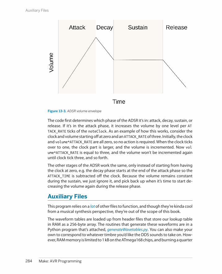
Figure 13-3. ADSR volume envelope
The code first determines which phase of the ADSR it’s in: attack, decay, sustain, orrelease. If it’s in the attack phase, it increases the volume by one level per ATTACK_RATE ticks of the noteClock. As an example of how this works, consider theclock and volume starting off at zero and an ATTACK_RATE of three. Initially, the clockand volume*ATTACK_RATE are all zero, so no action is required. When the clock ticksover to one, the clock part is larger, and the volume is incremented. Now volume*ATTACK_RATE is equal to three, and the volume won’t be incremented againuntil clock tick three, and so forth.
The other stages of the ADSR work the same, only instead of starting from havingthe clock at zero, e.g. the decay phase starts at the end of the attack phase so theATTACK_TIME is subtracted off the clock. Because the volume remains constantduring the sustain, we just ignore it, and pick back up when it’s time to start de-creasing the volume again during the release phase.
Auxiliary Files
This program relies on a lot of other files to function, and though they’re kinda coolfrom a musical synthesis perspective, they’re out of the scope of this book.
The waveform tables are loaded up from header files that store our lookup tablein RAM as a 256-byte array. The routines that generate these waveforms are in aPython program that’s attached, generateWavetables.py. You can also make yourown to correspond to whatever timbre you’d like the DDS sounds to take on. How-ever, RAM memory is limited to 1 kB on the ATmega168 chips, and burning a quarter
284 Make: AVR Programming
Auxiliary Files

Arrays in Memory
The way that we’re storing the waveform tables inmemory isn’t particularly efficient—we’re storingthem in the chip’s scarce dynamic memory (of whichthe chip has only 1 kB) even though the values don’tchange. A much better approach is to store the wave-forms in the flash program memory space, wherewe’ve got 16 kB of space, and we know for sure thatsome of it is sitting empty. I’ll cover the use of pro-gram memory in Chapter 18, so if you need to builda synthesizer with a whole bunch more wavetables,feel free to skip ahead.
Or you can use your head—I’m not exploiting any ofthe symmetry in the sine waves. Because the second
half of the cycle is just the same as the first half butwith a negative sign, you could easily cut memorystorage in half. You could also cut the storage in halfagain if you observe that for each sample in the firstquarter, the same sample in the second quarter is just255 minus the first.
I thought the DDS code was complicated enoughwithout this extra optimization, so I left it as simpleas possible. This means you can’t really use more thanthree waveforms in the same program without run-ning into trouble.
of that memory up for each waveform you’d like to play is dangerous. You’ll be fineloading two waveforms into memory, but three is dangerous and loading four willcertainly end up with different sections of memory overwriting each other andimpossible to debug glitches. You’ve been warned.
The scales that are loaded up in scale.h are generated by the Python file genera-teScale.py. These accumulator increment values are dependent on the processorspeed we choose as well as on using 8-bit PWM. If you’re interested in other pitches,or nontraditional pitches, feel free to play around with the scales.
Anyway, DDS synthesis is a great tool. If you’re content with a lower bit-depth or aslower sample rate, creating music this way is entirely within the power of an AVRchip, even for multiple voices simultaneously. Indeed, you’ll see in Chapter 18 thatit’s fairly easy to make reasonable-sounding human sampled speech, for instance.And although we’re aiming at audio here, bear in mind that similar techniques canbe used (with proper buffering for current-handling capability) to smoothly accel-erate and decelerate motors, or any other situation where you need time-varyingvoltage waveforms.
285Chapter 13: Advanced PWM Tricks
Auxiliary Files


Driving Simple Loads with Transistors, Relays, and DC Motors
Microcontrollers are great for many things where you need a little bit of computersmarts in a physical system.
One thing they’re not suited for is driving big electrical loads. The pins on the AVRare great for driving small things like our LEDs or even a speaker (decoupled witha capacitor so that it doesn’t draw too much current). But they just don’t put outenough juice to turn a motor—at least not a motor big enough to do anythingmeaningful!
This is a problem, because everybody needs a robot or two, and robots need mo-tors. The AVR chips (especially the larger ones) make a great small-robot brain. Sure,you can make it flash LEDs and sing through a speaker, but without legs or wheels,your robot is more like a brain in a jar. Your mechanized killer droid is not going toget very far without the ability to turn a motor.
We made a start on this problem in Chapter 11, where you saw how to control servomotors. Servos are designed especially to accept logic-level signals so that the AVRdoesn’t have to do any heavy lifting. In this chapter, I’ll cover a number of circuitsthat you can use to allow the AVR to run motors that don’t have internal interfacingcircuitry.
The secret to driving large loads is using transistors between the AVR and a motor.You’ll see that’s it’s easy enough to run a motor forward with just a single transistorused as a switch. You can then add speed control using PWM. If you’re not intomotors, the same circuits and techniques can control any large DC load. You coulddrive serious room-lighting LEDs, or power solenoids to latch and unlatch doors.
For the project in this chapter, we’ll just be making a motor turn at different speeds.I added a wheel with a white stripe painted on it to make the turning more visible.
287
Switches 14

What You Need
In addition to the basic kit, you will need:
• A DC motor and a power supply. I used a smallmodel-car motor that worked nicely with a 9Vbattery. Whatever motor you use, make sureyou have the right batteries to drive it. (If thetoy runs on 4xAA, don’t use much more than6 V.)
• Some transistors for driving the load. I usedour old standby 2N7000 because I only need-ed to drive a small motor. For larger loads, agood choice is something larger like anIRF530 or similar power MOSFET.
• A flyback diode and a smoothing capacitor forthe motor. I used a random 1N4007 rectifierdiode because I had one on hand. For bigloads and high speeds, there are specifically
designed motor flyback diodes. A ceramic ca-pacitor or two in the 10 nF to 1 uF range willwork—the value is not critical. Both of theseare “optional” in the sense that your motor willprobably turn, but you put the transistor atrisk of reverse-voltage breakdown when youturn the motor off.
• (Optionally) any other switch-like devicesyou’ve got on hand. Relays, SSRs, or Darling-ton Transistors (TIP120, etc.).
• (Optionally) other DC-powered devices likeLED lamps or pumps or fans or solenoids orkids toys or….
• A USB-Serial adapter.
But this chapter is much more about enabling you to build something of your ownthan it is following a particular project.
Controlling Big Loads: Switches
As you learned back in Chapter 3, each of the AVR’s digital outputs has two tran-sistors—one connected to the VCC supply and one connected to GND. It outputsdigital logic by turning one of these two transistors on, making it conduct. Thelimiting factor for the AVR driving “big” loads is these internal transistors and thefact that they’re only tied to VCC. So before we dive into the specifics of motors, let’stake a quick overview of our options for circuits that require a higher voltage thanthe AVR can run at, a higher current than its transistors can handle, or both of theabove.
If we can’t drive our hypothetical load directly from the AVR like we have beendoing with our LEDs or speakers, we’ll need to connect the AVR’s digital I/O pinsup to something else that can act as a switch to drive our motor in its place. All ofthese switches can be modelled as three-terminal devices that allow some currentor voltage to pass through two of their pins depending on the voltage or currentat or through the third terminal. We hook up this control terminal to the output ofthe AVR, and we’re set.
288 Make: AVR Programming
Controlling Big Loads: Switches

High-side Versus Low-side Switches
Even in the simplest case, turning a motor on or off with a switch, there are two choices:putting the switch on the high side (higher voltage, “above” or “upstream” of the motor inthe circuit) or putting it on the low side (lower voltage, or “below” the motor). These two casesare illustrated in Figure 14-1.
Figure 14-1. High-side and low-side switches
If we’re talking about a switch that you open and close by pressing a button, the choice isirrelevant—either configuration will stop the flow of electricity when the circuit is opened,so the motor won’t run. Notice that “Motor 1” and “Motor 2” both run when their switchesare pushed closed, but the high-side circuit works by the switch closing at VCC and the low-side circuit works by the switch closing at GND.
This distinction between high-side and low-side switching will matter a lot when we useelectronically operated switches like transistors, which need a voltage difference to turn on.In the low-side switching configuration, the transistor is connected to ground, and the voltagethat you use to switch it on or off is thus relative to ground. When you use a high-side switch,the “ground” voltage level that the transistor sees is whatever voltage is present at the high-side of the motor, which is variable and can be tricky to deal with.
The upshot is that it’s often a lot easier to use a low-side switch if you’ve got the choice.
289Chapter 14: Switches
Controlling Big Loads: Switches
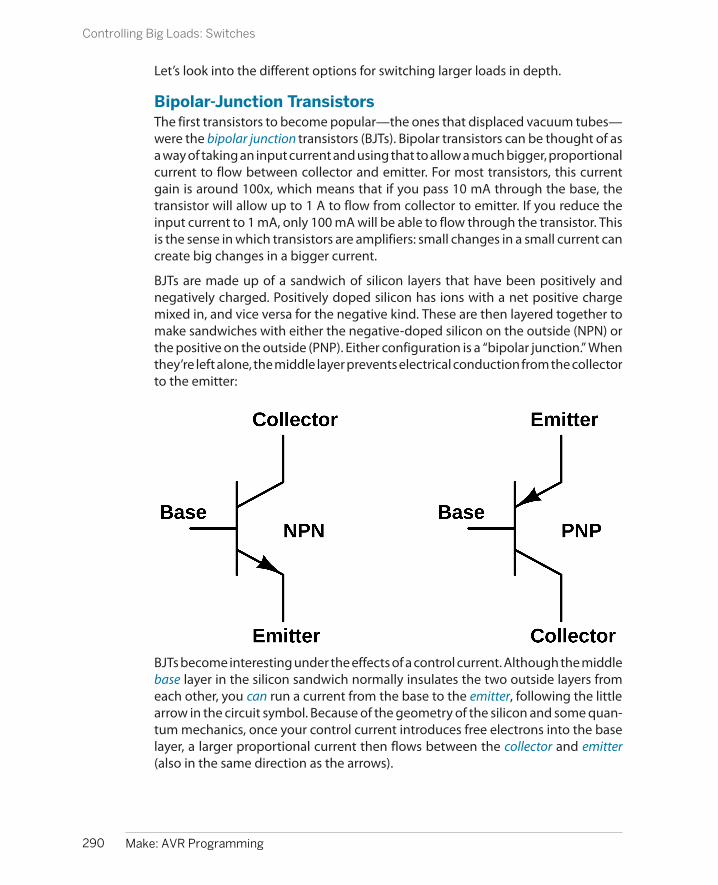
Let’s look into the different options for switching larger loads in depth.
Bipolar-Junction TransistorsThe first transistors to become popular—the ones that displaced vacuum tubes—were the bipolar junction transistors (BJTs). Bipolar transistors can be thought of asa way of taking an input current and using that to allow a much bigger, proportionalcurrent to flow between collector and emitter. For most transistors, this currentgain is around 100x, which means that if you pass 10 mA through the base, thetransistor will allow up to 1 A to flow from collector to emitter. If you reduce theinput current to 1 mA, only 100 mA will be able to flow through the transistor. Thisis the sense in which transistors are amplifiers: small changes in a small current cancreate big changes in a bigger current.
BJTs are made up of a sandwich of silicon layers that have been positively andnegatively charged. Positively doped silicon has ions with a net positive chargemixed in, and vice versa for the negative kind. These are then layered together tomake sandwiches with either the negative-doped silicon on the outside (NPN) orthe positive on the outside (PNP). Either configuration is a “bipolar junction.” Whenthey’re left alone, the middle layer prevents electrical conduction from the collectorto the emitter:
BJTs become interesting under the effects of a control current. Although the middlebase layer in the silicon sandwich normally insulates the two outside layers fromeach other, you can run a current from the base to the emitter, following the littlearrow in the circuit symbol. Because of the geometry of the silicon and some quan-tum mechanics, once your control current introduces free electrons into the baselayer, a larger proportional current then flows between the collector and emitter(also in the same direction as the arrows).
290 Make: AVR Programming
Controlling Big Loads: Switches

For the NPN transistor, you provide the control current by raising the base voltageup above that at the emitter. For the PNP transistor, the control current is createdby having the base voltage lower than the emitter. Either way, the effect is the same:a small current between base and emitter allows a much larger current to flowbetween the collector and emitter.
One disadvantage of using BJTs, from the AVR perspective, is that they’re current-driven. The AVR’s digital outputs are only rated for a few tens of milliamps, so if youare using a transistor with a current gain of 100, the maximum current you can runthrough the transistor is on the order of one amp. If you need to control morecurrent than that, you either need to buy a transistor with higher current gain orfigure out another way to get more drive current. One way to do this is to driveyour transistor with another transistor. This is not as crazy as it sounds.
Darlington transistors are just a pair of transistors built together into the same chunkof silicon so that the first one supplies drive current to the second. Because the firsttransistor amplifies the current that is again amplified by the second transistor,instead of having a gain of around 35–100, Darlingtons have a current gain around1,000 to 10,000. Now the puny 10 mA that the AVR will put out is able to switch10–100 A on and off. Hooray!
The other downside of BJTs, and this one is unavoidable, is that they have a voltagedrop across the collector/emitter pair—that’s wasted from the perspective of yourmotor, and it heats up the transistor to boot. If you look at the datasheet for aTIP102, one of my favorite power Darlington transistors, you’ll see that it has acollector/emitter saturation voltage of around 2 V. This means that if you’re drivinga motor that’s designed for 12 V and 1 A, you’ll need a power supply of 14 V, andyou’ll generate 2 V × 1 A = 2 watts of heat in the transistor. It’s gonna get hot andprobably need a heatsink.
Finally, in order to control BJT transistors from the AVR, you’ll have to convert thedigital I/O voltage level into a current for the transistor input. And to do that, you’lluse a resistor and Ohm’s law.
MOSFETsThe metal oxide silicon field-effect transistor (MOSFET for short) is a more recentlywidespread type of transistor. We’re already using a small-signal MOSFET (the2N7000) in our basic LED-driving setup, and now we’ll take a second to talk moreabout its inner workings.
MOSFETs work by passing current through a channel of silicon that’s been posi-tively or negatively doped, just like in the BJT. The difference is that the amount ofcurrent that is allowed to pass through the channel depends on an electric fieldthat’s imposed on the slice of silicon by putting a voltage on a metal gate plate.The gate doesn’t actually touch the silicon channel layer. Instead, it’s insulated from
291Chapter 14: Switches
Controlling Big Loads: Switches

Selecting the Base Resistor
If you’re using a digital I/O pin from the AVR, you’relimited to outputting either 0 V or 5 V (for instance).That’s usually too much for a transistor; you’ll need todo something to limit the current going into the base.You can calculate the value you need using Ohm’slaw, with one minor detail: because the negativelyand positively doped layers inside the transistor al-ready have a voltage on them, there’s a certain min-imum voltage between base and emitter (calledsomething like VBE, measuring around 0.7 V for reg-ular transistors, and 1.4 V for Darlingtons) that youhave to overcome before any current starts flowing.But after that, it’s just V = I × R.
As an example, imagine that you’ve got a 12 V batteryand you’d like a current of 500 mA to flow through amotor. Imagine as well that you’ve got an NPN tran-sistor with a current gain of 100, and you’re buildingthe circuit in the low-side drive configuration of “Mo-tor 2” in Figure 14-1. Because you gain is 100, you
want 500 mA/100 = 5 mA to flow from base to emitter.The low-side switch configuration means the emitteris at ground, so you need to add a resistor before thebase to make 5 mA from (5 V – 0.7 V), which is theAVR’s VCC minus the voltage drop across the insideof the transistor. You have 4.3 V/5 mA = 860 ohms.Putting a resistor around that value between the AVRpin and the base will allow up to 500 mA to flowthrough the transistor.
If you want to be really sure that the transistor is fullyon, in what’s known as the saturation region, you’llwant to give it a bit more current than it needs, maybeby a factor of two. So pick a base resistor that’s smallerby 50% or so. Instead of an 860 ohm resistor, 330ohms is a standard value that should work. You mayneed to experiment with this resistance, though, be-cause the transistor’s gain is a particularly variableparameter.
the silicon by a thin layer of metal oxide, which explains the mouthful of a name.The electrical symbols for MOSFETs are shown in Figure 14-2.
Figure 14-2. MOSFET Symbols
Applying a voltage to the gate creates an electric field that extends through theinsulator and into the channel, which makes a thin “inversion layer” in the channel,which is able to conduct electricity. Here comes the bit you need to remember.With an N-channel MOSFET, a positive voltage from gate to source allows a currentto pass from drain to source. With a P-channel MOSFET, a negative voltage fromgate to source allows current through, from source to drain. In this sense, the N-channel MOSFET is a bit like the NPN BJT, and vice versa.
292 Make: AVR Programming
Controlling Big Loads: Switches

Double Up for Double Current
Another nice feature with MOSFETs, although it’skind of a hack, is that because they only require a littlecurrent when turning on, you can easily run a few inparallel off of one AVR pin, especially at low frequen-cies. So take our 2N7000, for instance, which can han-dle 200 mA constant or 500 mA pulsed current. If youneed to drive 400 mA or up to 1 A peak for a project,you can either go out to the MOSFET store and buy abigger transistor or you can just use two 2N7000s inparallel, as long as they share the current equally.
And therein lies the secret. Because the on-resistanceof a MOSFET increases as it gets hotter, if one of thetransistors starts off taking too much of the currentthrough itself, it’ll heat up and become more resistive,which will then divert more of the current to the oth-er, cooler MOSFET. In this sense, they’re self-balancing.
I say this is a bit of a hack because the 2N7000s werecertainly not designed for parallel load-sharing. Butthe process will definitely work because of the posi-tive temperature/resistance relationship betweenthe transistors (see the datasheet). In fact, many high-power MOSFETs are specifically designed to be op-erated in parallel; if you look at an industrial forklift,you’ll find 20 or so power MOSFETs all in parallelscrewed into the same big heatsink.
Anyway, though you’re not going to be pushing alocomotive with a handful of 2N7000’s, the ability torun a few of them in parallel to batter manage yourcurrent load is a handy trick to have up your sleeve.
Unlike BJTs, MOSFETs are voltage-controlled devices, which means that you don’thave to include a base resistor when hooking them up to an AVR I/O pin—just wireup the AVR pin directly to the gate. Even better, small MOSFETs draw very littlecurrent when they’re switching on or off, and almost none when they’re in a steadystate, so you don’t have to worry about the AVR’s current sourcing capabilities. (Thisis because the gate is insulated from the channel.) Finally, MOSFETs have almostno voltage-drop when they’re on: even a small-signal switching MOSFET like our2N7000 has only a couple of ohms of resistance when switched fully on. This meansthat less power is wasted heating up the transistor and that the load sees the fulldriving voltage.
Switching MOSFETs are designed to turn on and off quickly, with gate voltages thatare between two and four volts. As such, they’re the perfect “switch” to drive inPWM mode with a microcontroller’s pin. Being small and fast, they can’t pass awhole lot of current or withstand very high voltages, but our 2N7000 is good for acouple hundred milliamps at 5 V or 100 ms bursts of 50 mA at 60 V—both situationsthat the AVR alone couldn’t handle. In short, switching MOSFETs make the idealnext step when your power or voltage demands are just out of reach of the AVR’sdigital output drivers.
Power MOSFETsIf you want to power something really beefy, say an electric bike or a heavy robot,you’ll want a specifically designed power MOSFET (or several). Modern powerMOSFETs are just like their smaller switching MOSFET cousins, only larger and with
293Chapter 14: Switches
Controlling Big Loads: Switches

a geometry that’s adapted to deliver more current with less resistance, and thusless wasted heat. The trade-off is that power MOSFETs usually require a higher gatevoltage to turn fully on and a little more current as well if you’d like to turn themon and off quickly.
As the MOSFETs get bigger and bigger, the area between the gate and the channelgets bigger. To make the same electric field strength inside the channel of thetransistor, more charge is needed. In fact, viewed from the gate and source pins,all MOSFETs behave like a capacitor—a certain charge needs to be pushed ontothe gate to create a given electric field between the gate and source, just like acapacitor stores charge in the form of an electric field between its two plates.
With power MOSFETs, this gate capacitance limits how quickly the switch can beturned off and on, which puts limits on how quickly you can PWM the MOSFETswitch. Small switching FETs have a small gate capacitance and are easy enoughto charge up using just an AVR I/O pin’s internal current source, with a gate capac-itance in the tens of picofarads, and switching speeds up to 1 MHz. Larger powerMOSFETs can have gate capacitances on the order of thousands of picofarads,which means that you’ve got to charge up effectively a 100 times larger capacitorto get the switch open. This means you’ll need more current sourcing capabilityand probably more voltage to push it through if you want the power FET to switchon at the same speed. The trade-off for the increased gate size is that you get aMOSFET with only 20 milliohms of resistance capable of switching 12 amps at 80volts.
If you’re truly pushing the high-voltage, high-current, high-frequency PWM fron-tier, you’ll want a gate driver chip that’s tailor-made to supply the fast charging thatthe biggest power MOSFETs need. If you just want to drive a fairly beefy (5 A at 12V) small-robot motor at moderate switching speeds (<20 kHz), you can probablydrive it directly from the AVR, or at worst through a switching MOSFET as a firststage.
RelaysA lot of people would start out all this discussion of switches with the relay. Afterall, a relay is just a switch that’s opened and closed by electromagnet, so they’reeasiest to understand. Put a current through a coil of wire, and it pulls a piece ofmetal into contact with another piece of metal and your switch closes. Done.
The reason relays are near the end of my discussion is that they’re fairly special-purpose these days. They switch on and off comparatively slowly, going click-clackas they physically open and close. This means that PWM is out of the question asa method of control—you can turn a normal relay on and off a couple of times persecond, but not much more. And the coils that make the magnetic field take a lotof current. With the exception of precision (costly and sensitive) relays, most require
294 Make: AVR Programming
Controlling Big Loads: Switches
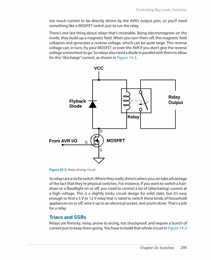
too much current to be directly driven by the AVR’s output pins, so you’ll needsomething like a MOSFET switch just to run the relay.
There’s one last thing about relays that’s miserable. Being electromagnets on theinside, they build up a magnetic field. When you turn them off, this magnetic fieldcollapses and generates a reverse voltage, which can be quite large. This reversevoltage can, in turn, fry your MOSFET or even the AVR if you don’t give the reversevoltage somewhere to go. So relays also need a diode in parallel with them to allowfor this “discharge” current, as shown in Figure 14-3.
Figure 14-3. Relay driving circuit
So relays are a niche switch. Where they really shine is when you can take advantageof the fact that they’re physical switches. For instance, if you want to switch a hair-dryer or a floodlight on or off, you need to control a lot of (alternating) current ata high voltage. This is a slightly tricky circuit design for solid state, but it’s easyenough to find a 5 V or 12 V relay that is rated to switch these kinds of householdappliances on or off, wire it up to an electrical socket, and you’re done. That’s a jobfor a relay.
Triacs and SSRsRelays are finnicky, noisy, prone to arcing, not shockproof, and require a bunch ofcurrent just to keep them going. You have to build that whole circuit in Figure 14-3
295Chapter 14: Switches
Controlling Big Loads: Switches

just to drive them. If you really want to get fancy, or if you need to PWM yourhousehold appliance, you’re going to want something solid state.
The main contenders here are triacs and solid state relays (SSRs). Triacs are liketransistors but used for AC instead of DC. SSRs are basically triacs with some extracircuitry to help isolate the control side from the AC line voltage. Many (most?) SSRshave an LED on the control side and a light-sensitive triac on the AC side, so thatturning on or off a washing machine looks to your AVR like blinking an LED; butbecause there’s no direct electrical connection between the AVR side and the wall-voltage side, there is no corresponding electrocution hazard, and that’s a darn goodthing.
We won’t be using either of these in our projects here, but if you ever need tocontrol a wall-voltage device from the AVR, you should look into an SSR. I used oneonce, along with a temperature sensor, to regulate the heater in an electric coffeeroaster.
Switches: SummaryIf you want to control real power with the AVR, there’s a number of switch-likedevices out there that will help you do it. What you need to use will depend on thespecifics of the motor or laser or home appliance you want to run.
For providing power to small-robot DC motors, BJTs—particularly Darlington BJTcircuits—can work just fine. If you need more current, the advantages of a (morecomplicated) power MOSFET circuit become more apparent. Keep both of themin mind.
Small switching MOSFETs, like the 2N7000 that we’re using, are great for drivingsmall-to-medium loads, even if you have to use a few in parallel. We’ll be using a2N7000 to drive the laser in the laser-sundial application, and for driving powerMOSFETs.
Finally, when you need to control house-voltage AC, you’ve got two main choices.If you’re doing low-frequency switching, it’s hard to beat the simplicity of a relaydriven with a switching FET. If you need to turn the device on and off a lot, you’llwant an SSR.
A summary of all of the possible switch choices can be found in Table 14-1.
Table 14-1. Switching: transistors, relays, etc.
Type Activation Voltage gain Current gain Voltage type Main use
Bipolar Current High Lower DC Amplifying voltage signal
Darlington Current Very high Can be high DC Amplifying, sourcing current
FETs Voltage Lower High DC Sourcing current
Relay Current - - AC or DC Literal switching
SSR Voltage - - AC Medium-speed PWM
296 Make: AVR Programming
Controlling Big Loads: Switches
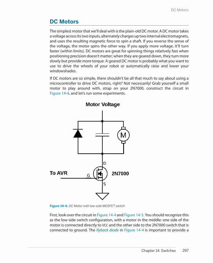
DC Motors
The simplest motor that we’ll deal with is the plain-old DC motor. A DC motor takesa voltage across its two inputs, alternately charges up two internal electromagnets,and uses the resulting magnetic force to spin a shaft. If you reverse the sense ofthe voltage, the motor spins the other way. If you apply more voltage, it’ll turnfaster (within limits). DC motors are great for spinning things relatively fast whenpositioning precision doesn’t matter; when they are geared down, they turn moreslowly but provide more torque. A geared DC motor is probably what you want touse to drive the wheels of your robot or automatically raise and lower yourwindowshades.
If DC motors are so simple, there shouldn’t be all that much to say about using amicrocontroller to drive DC motors, right? Not necessarily! Grab yourself a smallmotor to play around with, strap on your 2N7000, construct the circuit inFigure 14-4, and let’s run some experiments.
Figure 14-4. DC Motor with low-side MOSFET switch
First, look over the circuit in Figure 14-4 and Figure 14-5. You should recognize thisas the low-side switch configuration, with a motor in the middle: one side of themotor is connected directly to VCC and the other side to the 2N7000 switch that isconnected to ground. The flyback diode in Figure 14-4 is important to provide a
297Chapter 14: Switches
DC Motors

Motor as Generator
Why is a DC motor’s speed controlled by the voltagewe apply across the terminals?
Just as our piezo disk could be viewed as convertingvibration to voltage or voltage to vibration, most mo-tors are actually also electrical generators. Genera-tors (intentionally designed ones) work by spinninga permanent magnet inside a series of coils, and thechanging magnetic field induces electrical currentsin the wires. Motors work in exactly the opposite way:changing electrical currents in the wires createchanging magnetic fields inside a series of coils,which spin the magnet and spindle.
For just about any DC motor, if you put voltage intoits terminals, you’ll create motion in its shaft. If youspin the shaft, you’ll find that a voltage developsacross the terminals. The faster you spin the motor,the higher the generator voltage.
In a motor, this generator voltage is called back volt-age or back EMF (electro-motive force, which is an-other word for voltage) and is what limits a motorspeed. When a motor starts up because you’ve ap-plied 5 V to it, the forward voltage is 5 V, and becausethe motor isn’t spinning yet, no back voltage is gen-erated. As the motor speeds up, its effective genera-tor puts out more and more voltage, but in the op-posite sense to the applied voltage. When the backvoltage just equals the forward voltage, the motorstops speeding up, and it’s reached maximum speed.If you increase the applied voltage, the motor speedsup until the generated back voltage just equals thenew applied voltage.
You’ll see the same thing with the current, too. Whenyou first turn the motor on, and the voltage differenceis maximized, current goes rushing through the mo-tor. As the motor comes up to speed, the differencebetween the applied voltage and the back voltageshrinks, and less and less current is fed through. Anideal motor, driving no load, with no friction and nowire resistance, would stop drawing current once itgets up to speed. In the real world, some current isneeded to drive the load and overcome friction, butat cruising speed, the current draw will be minimizedif not minimal.
Normal brushed DC motors make kinda crappy gen-erators. The one on my desk measures about half avolt with no load put on it when I spin it as fast as Ican. Brushless DC motors or stepper motors, on theother hand, are pretty darn effective. You can demon-strate this by taking a stepper motor and putting anLED across two of the paired coil wires and giving ita spin.
In fact, each pair of pole wires of a stepper motor putout AC when used as a generator, so you can connecttwo LEDs back to back across the pole wires. Whenthe coil puts out a positive voltage, one LED will light,and when it puts out a negative voltage, the otherLED will light. And now do the same thing with theother pole of the motor—add two more LEDs. If youcould see fast enough, you’d see that the LEDs lightup one at a time in exactly the sequence that we’llend up using to drive the motor.
path for the current that’s flowing through the motor to continue on after we’veswitched the motor off. Finally, the optional capacitor smooths out noise that theDC motor itself makes as the brushes inside switch from one polarity to the other.
If you’re using a separate voltage source for the motor, like a battery, be sure toconnect the negative pole of the battery to your circuit ground, and the positiveend directly to the motor as shown in Figure 14-5. Notice that the battery groundand the MOSFET’s ground are both connected to the AVR’s circuit ground. Thisgives the AVR, its power supply, the 2N7000, and the battery the same referencevoltage.
298 Make: AVR Programming
DC Motors

Figure 14-5. DC Motor on a breadboard with a battery
As a first experiment, hook up the transisor, motor, diode, and capacitor as inFigure 14-4. If you don’t have a battery handy, and your DC motor will run on thebreadboard’s 5 V, feel free to connect the high side of the motor directly into thepower rail. This circuit is temporary anyway, so feel free to use alligator clips to hookit all together wherever you need to.
Now, without any code in the AVR, you can verify that you can control the motorby applying 5 V and 0 V to the gate of the transistor through a wire. Pull out theAVR side of the wire that connects the gate of the MOSFET to the AVR. Tap it alter-natively to the 5 V and ground power supply. You should see the motor start tospin when you connect the wire to 5 V, and stop spinning when you connect it toground. This is exactly what we’ll have the AVR doing in a few minutes.
What happens if you just hold the wire in your fingers? MOSFET gates take verylittle current to turn on and off, and you may be coupling enough voltage frompower line radiation to turn it on. If not, try alternately touching your 5 V powersupply and then ground with your free hand. You’ll find that your body chargesand discharges enough to flip the switch.
Now let’s put the motor under the AVR’s control. Reconnect the gate of the 2N7000transistor to pin PD5 as in Figure 14-5, and we’ll use Timer 0 and the output compare
299Chapter 14: Switches
DC Motors

Flyback
What happens when you turn off a running motor?For a little while, the motor’s still spinning, so it’s stillgenerating its back voltage. But the motor’s genera-tor voltage turns out to be a relatively small effectwhen if you suddenly turn off the power.
While the motor was running, the motor windingshave been passing current through them and havebuilt up these powerful magnetic fields that in turnspin the motor. All of a sudden you shut this currentsupply off, and the magnetic fields collapse, and asthey do so create a voltage in the same direction asthe applied voltage was (and opposite the back volt-age). The faster the current is shut off, the higher thisvoltage is. That is, the motor windings act like aninductor.
You can think of inductors as being like flywheels forthe current—when you try to stop a current sudden-ly, inductors try to keep the current flowing in thesame direction, and this can show up as a high volt-age developing across them. With my little motorson my desk, I get roughly 30 V peaks, even though
I’m driving them with a 5 V power supply—it’s all inhow quickly you shut the driving current off. Withbigger motors and higher currents and voltages, thevoltage spikes can get into the hundreds of volts.
This is where the flyback diode comes in. It providesa path for the current generated by the “inductivekick” to go, namely through the motor, back up thediode, and through the motor again in a loop. Thisshort-circuit loop continues until the magnetic fieldsare discharged.
So the energy built up in the coils creates a high volt-age across the motor’s coils. Where does this energygo? Some of it is cancelled out by the motor’s gen-erator voltage, some of it is dissipated in the windingresistance of the motor (heating up the motor), andsome of it heats up the flyback diode.
In conclusion, if you’d like to keep high flyback vol-tages from frying your transistor switches, please re-member to add in a flyback diode.
pin functionality to experiment with simple DC motor driving. If you’ve still gotthat circuit set up, the transistor is already hooked up in the right place.
Flash in the code and then you can start playing around with your motor. Drivinga motor with signal-switching FETs is a little bit sketchy, so you might want to keepa finger on the MOSFET and see if it warms up excessively. It shouldn’t get hotunless you’re putting the motor under a load, though. Let’s look at the code inExample 14-1.
Example 14-1. dcMotorWorkout.c listing /* Demos PWM control of a DC motor */
// ------- Preamble -------- //#include <avr/io.h>#include <util/delay.h>#include <avr/interrupt.h>#include "pinDefines.h"#include "USART.h"
#define SPEED_STEP_DELAY 2 /* milliseconds */
300 Make: AVR Programming
DC Motors
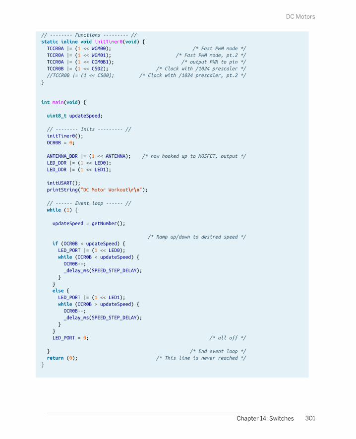
// -------- Functions --------- //static inline void initTimer0(void) { TCCR0A |= (1 << WGM00); /* Fast PWM mode */ TCCR0A |= (1 << WGM01); /* Fast PWM mode, pt.2 */ TCCR0A |= (1 << COM0B1); /* output PWM to pin */ TCCR0B |= (1 << CS02); /* Clock with /1024 prescaler */ //TCCR0B |= (1 << CS00); /* Clock with /1024 prescaler, pt.2 */}
int main(void) {
uint8_t updateSpeed;
// -------- Inits --------- // initTimer0(); OCR0B = 0;
ANTENNA_DDR |= (1 << ANTENNA); /* now hooked up to MOSFET, output */ LED_DDR |= (1 << LED0); LED_DDR |= (1 << LED1);
initUSART(); printString("DC Motor Workout\r\n");
// ------ Event loop ------ // while (1) {
updateSpeed = getNumber();
/* Ramp up/down to desired speed */ if (OCR0B < updateSpeed) { LED_PORT |= (1 << LED0); while (OCR0B < updateSpeed) { OCR0B++; _delay_ms(SPEED_STEP_DELAY); } } else { LED_PORT |= (1 << LED1); while (OCR0B > updateSpeed) { OCR0B--; _delay_ms(SPEED_STEP_DELAY); } } LED_PORT = 0; /* all off */
} /* End event loop */ return (0); /* This line is never reached */}
301Chapter 14: Switches
DC Motors

There’s nothing particularly new in the code, and I copied a large part of it straightfrom other examples. I just wanted to write something that you can get a feel fordriving motors with. (Once you’ve gotten a library of working examples for yourself,you’ll find that this kind of code reuse is phenomenally handy.) The Timer 0 initi-alization routine is taken straight from our PWM examples; it sets up the timer tooutput the PWM waveform on pin PD5. The getNumber() routine takes in a number(as ASCII characters) that’s sent over the serial line.
The main event loop waits for you to type in a PWM value over the serial line andthen adjusts the OCR0B register smoothly up or down to that value, lighting up LEDsfor acceleration or deceleration, respectively. As befits a simple demo program,almost all of the time is spent sitting and waiting for you to type something in.
The real point of the program, though, is to get you familiar with driving small DCmotors by PWM, so flash this in and start typing PWM duty-cycle values. Hit Returnafter each one, and it’ll ramp up the motor.
The first thing to notice is that, although the PWM duty cycle will vary the per-centage of the time that the motor is powered, that is not the same as controllingthe speed. With my different motors, they would start turning only in the 20–60(out of 255) range, even at their proper working voltages. Motors, and especiallygearmotors, have different internal frictions and coil inductances that make themunique.
Next, change the clock prescaler in initTimer0. First, just try commenting out theTCCR0B |= (1<<CS02); line to change from prescaling by 1,024 to 256. At 1,024,the PWM frequency is a fairly low 31.25 Hz. At low duty cycles, you may be able tohear the individual pulses. At a prescaling of 256, you should be able to hear a lowhum coming from the motor windings—the PWM frequency is around 125 Hz.Look at the datasheet where it describes the possible clock settings and experimentwith them all. As you increase the PWM frequency, you’ll notice that the range ofduty cycles over which the motor runs will change. How different motors respondto different PWM drive frequencies depends a lot on the winding resistance andinductance, which varies from motor to motor, as well as the driving voltage.
Finally, you can experiment with how quickly your motor changes speed whendriven at different duty cycles. The macro definition #define SPEED_STEP_DELAY10 sets the rate at which the PWM duty cycle changes. If you set this to zero, thePWM will change as soon as you hit Enter and transmit the new value. If you set ithigher, the motor will ramp up more slowly. Try to imagine what would happen ifyou had this motor and a wheel on a robot or vehicle. Think about what kinds ofaccelerations it can handle. Load the wheel down with your hand. (Or if you’ve builta bot already, playing around with code like this will let you discover your tractionlimits.)
302 Make: AVR Programming
DC Motors

Gearmotors
The good thing about DC motors is that they spinvery fast. The disadvantage, though, is that they don’thave much turning force, or torque, at lower speeds.As you noticed with the PWM speed control demo,it’s easier to stall the motor out when it’s turningslowly than when it’s at full speed, and if your motorsare anything like mine, it wasn’t hard to stop even atfull speed.
Suppose you’ve got a motor that turns at 6,000 rpm,and is only able to drive a 10 gram robot. Perhapsyou’d rather have the wheels turn 60 times per mi-nute, but push a 1 kg robot. Using gears with your
motor will let you make this trade-off. Gears are likea lever—you can push a heavier weight, but it travelsless (rotational) distance per unit time.
These days, there are scores of small gearmotorsavailable for small to medium robots, RC cars, etc.Depending on the size of the wheels and the weightof the robot, something in the 100:1 gear reductionratio tends to be about right. If you want to buildsomething lightweight to play around with code andscoot around the room, it’s hard to beat the Tamiyadouble gearbox kit, which you can find for under $10and has a nice assortment of matching tires.
Motor Specs
If you’re buying a motor, there are a couple of specifications that you should know about.The first spec is the rated voltage. Most DC motors will run +/– 50% of their rated voltage, butyou want one that matches your power source, or vice versa. For small bots, look for somethingin the 3 V to 12 V range to match your batteries.
The other spec is stall current, which is just the rated voltage divided by the coil windingresistance. Stall current is the maximum current that the motor will draw when it’s just startingup (or when it’s stalled out) and the back voltage is at 0 V. The transistor that you’re runningthe motor with should be able to deliver at least this much current, if not a little more as asafety margin.
303Chapter 14: Switches
DC Motors


H-Bridges and Stepper Motors
In Chapter 14 we discussed how to use the AVR to drive big loads in the simplest,on-off case. Adding in PWM to the mix allows you to, for instance, vary the speedof a motor. That’s great, right? Now your little robot is going forward fast and for-ward slow. But what do you do when you want to put it in reverse?
In this chapter, I’ll introduce you to some useful concepts for more advanced motor-driving. The first step in all this is to build (or buy) a circuit that can reverse a DCmotor by applying voltage to it in either polarity. Such a circuit is called an H-bridge, and I’ll go into detail about how you can build your own if you need to.
If you are only driving small motors, there is very probably a premade solution outthere that is cheaper, easier, and more reliable than building your own. For instance,the SN754410 chip provides two full H-bridges in one package.
Finally, we’ll dip our toes into driving stepper motors. Steppers are great for fairlyaccurate positioning coupled with decent speed. Driving one stepper motor isroughly equivalent to driving two DC motors, but we’ll see that some coordination(in code) is necessary.
For fun and inspiration, a bunch of motors that I’ve driven with the AVR code andSN754410 H-bridge chip are shown in Figure 15-1. These include stepper motorson the left, gear motors in the middle, and two small plain DC motors on the bottomright.
305
Advanced Motors 15
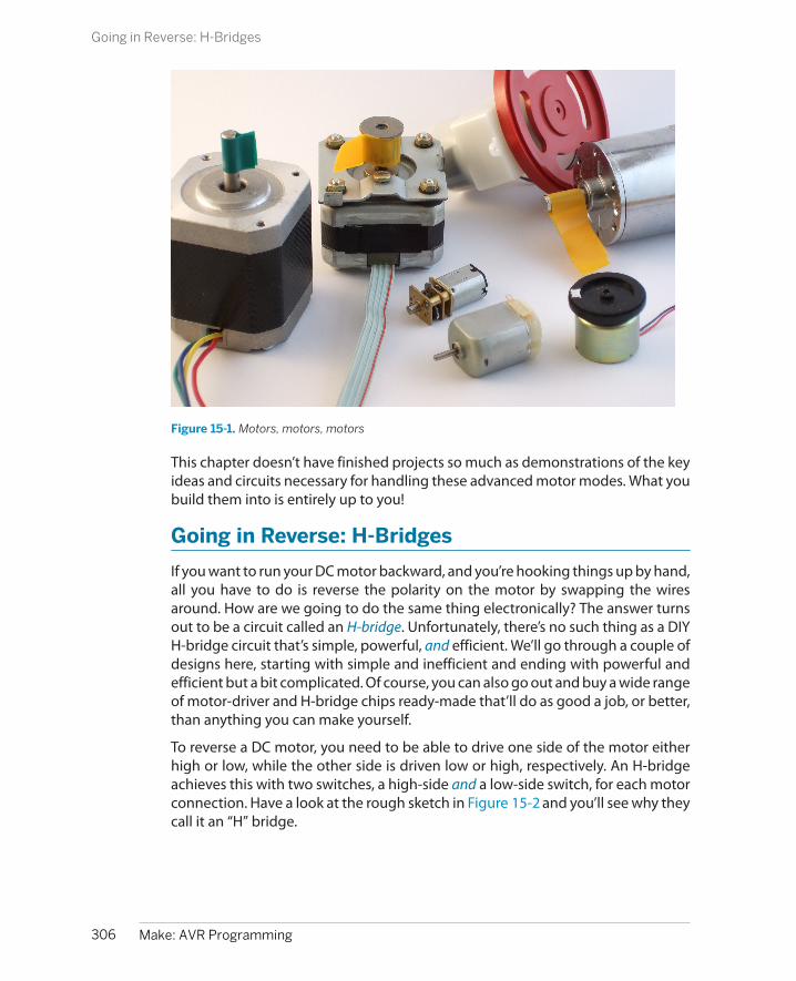
Figure 15-1. Motors, motors, motors
This chapter doesn’t have finished projects so much as demonstrations of the keyideas and circuits necessary for handling these advanced motor modes. What youbuild them into is entirely up to you!
Going in Reverse: H-Bridges
If you want to run your DC motor backward, and you’re hooking things up by hand,all you have to do is reverse the polarity on the motor by swapping the wiresaround. How are we going to do the same thing electronically? The answer turnsout to be a circuit called an H-bridge. Unfortunately, there’s no such thing as a DIYH-bridge circuit that’s simple, powerful, and efficient. We’ll go through a couple ofdesigns here, starting with simple and inefficient and ending with powerful andefficient but a bit complicated. Of course, you can also go out and buy a wide rangeof motor-driver and H-bridge chips ready-made that’ll do as good a job, or better,than anything you can make yourself.
To reverse a DC motor, you need to be able to drive one side of the motor eitherhigh or low, while the other side is driven low or high, respectively. An H-bridgeachieves this with two switches, a high-side and a low-side switch, for each motorconnection. Have a look at the rough sketch in Figure 15-2 and you’ll see why theycall it an “H” bridge.
306 Make: AVR Programming
Going in Reverse: H-Bridges
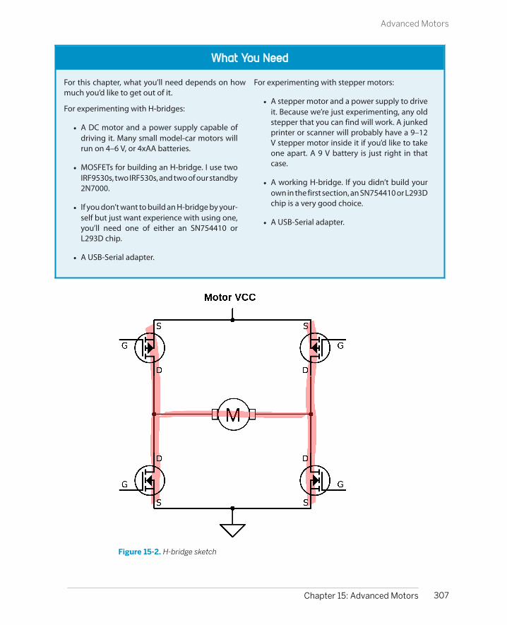
What You Need
For this chapter, what you’ll need depends on howmuch you’d like to get out of it.
For experimenting with H-bridges:
• A DC motor and a power supply capable ofdriving it. Many small model-car motors willrun on 4–6 V, or 4xAA batteries.
• MOSFETs for building an H-bridge. I use twoIRF9530s, two IRF530s, and two of our standby2N7000.
• If you don’t want to build an H-bridge by your-self but just want experience with using one,you’ll need one of either an SN754410 orL293D chip.
• A USB-Serial adapter.
For experimenting with stepper motors:
• A stepper motor and a power supply to driveit. Because we’re just experimenting, any oldstepper that you can find will work. A junkedprinter or scanner will probably have a 9–12V stepper motor inside it if you’d like to takeone apart. A 9 V battery is just right in thatcase.
• A working H-bridge. If you didn’t build yourown in the first section, an SN754410 or L293Dchip is a very good choice.
• A USB-Serial adapter.
Figure 15-2. H-bridge sketch
307Chapter 15: Advanced Motors
Advanced Motors

Each side of the H-bridge is just a push-pull MOSFET driver, in exactly the sameconfiguration as the circuitry inside the digital I/O pins on the AVR but using higher-wattage components. To understand how it works, first look at one side of the H.When the top P-channel FET is turned on and the lower N-channel FET is off, theside is pulled to the motor-high supply voltage. Turn off the top switch, and turnon the low-side switch, and the voltage is pulled down to ground. This way, youcan set either side of the H to high or low voltage. Now if you drive one side to thehigh voltage while the other is low, current flows and the motor spins. Switchingthe roles of the two sides reverses the motor. Success!
There are a couple of complications to this circuit, though. The first is how to in-terface this circuit with the AVR. The low-side FET is easy enough, and it will sinkas much as 5 A with a 5 V AVR output with the parts specified. The high-side FET istrouble, though. To turn it on, you just have to pull the line low, which is easyenough. To turn it fully off, though, you need to raise the gate voltage to the sameas the source of the FET, which is at the motor supply voltage. If you’re runningmotors that want 9 V or 12 V or even more, you can’t close the high-side switchwithout some intermediate circuitry.
The other danger with this circuit sketch is shoot-through. What would happen ifyou opened both the upper and lower switches on the same side? If each MOSFEThas an on resistance of about half an ohm, the total resistance is only 1 ohm, or justabout as much as you’d get if you put a screwdriver across the battery terminals:not good! The battery will put out as much current as it can, and something willburn: either the battery, your wiring, or the MOSFETs.
Finally, note that I picked a pair of MOSFETs with similar part numbers. These aredesigned to be used as a complementary pair and have similar characteristics. Thismatters a lot for controlling shoot-through and can be a gotcha when you’re de-signing your own circuits. Because the high-side and low-side FETs we use arematched and have similar switch-on times, we can get away with a single signal toopen one and close the other. (With random MOSFETs, you’ll want some circuitryto control shoot-through.)
So with matched MOSFETs on the high and low side, we can drive them both atthe same time. Because they’re complementary, one will turn off just about as theother turns on. Now you might be tempted to drive these as is with the AVR’s outputpins, and that’s not a horrible idea for low-voltage applications where the motorvoltage is up to 5 V.
Things get more complicated when you want to drive a motor with more voltagethan the AVR’s VCC. The low-side switch is no problem—many FETs (and ourIRF530s) will push a fair amount of current when the gate is held at 5 V with respectto ground. The problem is that you can’t shut off the high-side switch completelywithout a source of 9–12 V, and the AVR’s output pins aren’t going to cut it any
308 Make: AVR Programming
Going in Reverse: H-Bridges

more. So what we’re going to do is use transistor switches to drive our transistorswitches as shown in Figure 15-3.
Figure 15-3. Working H-bridge
This H-bridge is stable and “smokeproof” (meaning, it’s not possible to send it intoa short-circuit mode through software). If the bridge is not hooked up to the AVRor if the AVR is sending a logic low, the gate of the 2N7000 is low and the 2N7000is not conducting. If the 2N7000 is not conducting, the voltage on the power MOS-FETs is pulled up by the 1k ohm resistor to the motor power supply level, whichshuts off the high-side MOSFET and fully opens the low side, which essentiallygrounds this side of the bridge.
When the left side 2N7000 gets a logic high voltage, it conducts and pulls bothpower MOSFETs’ gates to ground. The low-side power MOSFET turns off whengrounded, and the high-side MOSFET turns fully on, so the whole side is pulledstrongly high. So a high signal to the half-bridge driver sets the output high, andvice versa.
Code: Taking Your H-Bridge Out for a Spin
The drive modes for this bridge are really simple. Because the state of the half-bridges mimics their input, you can just pretend that the AVR digital output isdriving the motor, and the bridge will take care of the heavy lifting. This means
309Chapter 15: Advanced Motors
Code: Taking Your H-Bridge Out for a Spin

that if you want the motor to rotate one way, simply set one AVR output pin highand the other low. To reverse, switch the high and low values. Easy!
But what happens when both sides of the bridge are held high or both held low?The motor doesn’t know anything about high or low voltages. It only sees thevoltage difference across its terminals. So if the motor wasn’t moving to begin with,the modes (high, high) and (low, low) don’t do anything. Both of these modesare just like connecting a wire across the two terminals of the motor. On the otherhand, if the motor was already turning and then you switch to (high, high) thesituation gets more interesting—you’ve just shorted out the terminals of a movingmotor.
Look back at Figure 15-3, and think back to the motor-as-generator discussion in“Motor as Generator” on page 297. For concreteness, let’s imagine that the motorwas being powered (high, low) just before getting turned off to (high, high).Because the motor windings are inductors, they want to keep the current flowingin the same direction as their magnetic fields wind down. So the current will wantto flow in a loop from the motor, up the open high-side FET, over to the other high-side FET, and back down into the motor. But because the motor is a generator, aslong as it’s turning, it’s making a voltage that opposes this current. When you short-circuit a running motor, these two opposing voltages act like an electronic brakefor the motor and stop it faster than it would if you just disconnected it.
So before we get to controlling both speed and direction by applying PWM to thecircuit, let’s play around with digital logic control of the bridge to get a good feelfor how it works in Example 15-1. In the following H-bridge examples, the PD5 andPD6 pins (that we’ve used for the speaker and antenna previously) are connectedto the bridge. If these are still hooked up, it might be time to pull them out or evento start up a new breadboard with another AVR chip.
Example 15-1. hBridgeWorkout.c listing// Simple demo of an h-bridge
// ------- Preamble -------- //#include <avr/io.h>#include <util/delay.h>#include <avr/interrupt.h>#include "pinDefines.h"
static inline void setBridgeState(uint8_t bridgeA, uint8_t bridgeB) { /* Utility function that lights LEDs when it energizes a bridge side */ if (bridgeA) { PORTD |= (1 << PD6); LED_PORT |= (1 << LED0); } else { PORTD &= ~(1 << PD6);
310 Make: AVR Programming
Code: Taking Your H-Bridge Out for a Spin
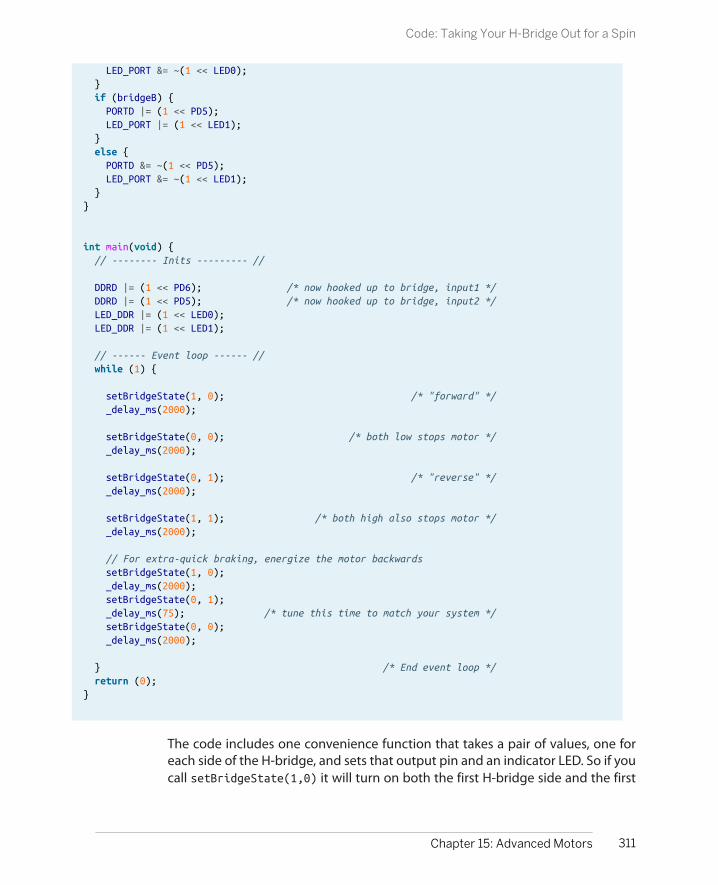
LED_PORT &= ~(1 << LED0); } if (bridgeB) { PORTD |= (1 << PD5); LED_PORT |= (1 << LED1); } else { PORTD &= ~(1 << PD5); LED_PORT &= ~(1 << LED1); }}
int main(void) { // -------- Inits --------- //
DDRD |= (1 << PD6); /* now hooked up to bridge, input1 */ DDRD |= (1 << PD5); /* now hooked up to bridge, input2 */ LED_DDR |= (1 << LED0); LED_DDR |= (1 << LED1);
// ------ Event loop ------ // while (1) {
setBridgeState(1, 0); /* "forward" */ _delay_ms(2000);
setBridgeState(0, 0); /* both low stops motor */ _delay_ms(2000);
setBridgeState(0, 1); /* "reverse" */ _delay_ms(2000);
setBridgeState(1, 1); /* both high also stops motor */ _delay_ms(2000);
// For extra-quick braking, energize the motor backwards setBridgeState(1, 0); _delay_ms(2000); setBridgeState(0, 1); _delay_ms(75); /* tune this time to match your system */ setBridgeState(0, 0); _delay_ms(2000);
} /* End event loop */ return (0);}
The code includes one convenience function that takes a pair of values, one foreach side of the H-bridge, and sets that output pin and an indicator LED. So if youcall setBridgeState(1,0) it will turn on both the first H-bridge side and the first
311Chapter 15: Advanced Motors
Code: Taking Your H-Bridge Out for a Spin

LED, and turn off the second H-bridge side and second LED. Then the rest of thecode enables output by setting the DDR for each and starts demoing the four pos-sible H-bridge drive states.
At the very end, I tried an experiment with reversing the motor while it’s still runningin an attempt to get it to brake faster. Especially if your motor has a heavy wheelon it, you may be able to notice that using reverse as a brake stops the motor evenfaster than the two “normal” braking modes. Anyway, it’s a handy technique if youfind your robot coasting down to a stop too slowly.
Experts-Only H-BridgeIf you’re using unmatched P-channel and N-channel FETs, or you’re looking formore control, you can also drive the high side and low side separately as shown inFigure 15-4. This comes with the benefit that you can fine-tune the opening andclosing times of the upper and lower FETs so that they’re as fast as possible withoutshoot-through even with unmatched parts by tweaking the relative timing of sig-nals in software.
Figure 15-4. Four-wire H-bridge
If you hook up an H-bridge as in Figure 15-4, think super hard about the polarityof the control signals. In particular, when the “A High” signal is written high, the2N7000 conducts, pulling the MOSFET gate low, which makes it conduct. When
312 Make: AVR Programming
Code: Taking Your H-Bridge Out for a Spin

the “A Low” signal is written logic high, it also conducts. So what you’re never goingto want to do is have the AVR drive the two pins on the same side high at once.
On the other hand, driving both pins on the same side low at once opens both theupper and lower MOSFET switches, which leaves the motor to spin mostly freely.This mode is often called “coasting.” If all four switches are open, it’s like the motorisn’t connected to anything at all and is free to turn.
There are also four other modes where only one transistor conducts, which end upbeing like coasting except that one leg of the current passes through a flywheeldiode and one through a transistor. These modes are interesting for high-speedPWM, because you can alternate between driving and not driving by simply tog-gling one switch.
But let me repeat my warning that you should be extra careful with this circuit.Never close both the top and bottom MOSFETs on either side at the same time.Nobody likes burnt MOSFETs.
PWM and the H-Bridge
Being able to move a motor forward and backward is great, but for a real-worldrobot, you’re going to want to have forward and backward with speed control. Andthe way to do this with digital outputs from your microcontroller is, of course, ourold friend PWM. Because we’re dealing with more current and external switches,not to mention a motor with inductance, things get a tiny bit more complicated.Here, I’ll step you through what you need to know. We’ll be using both our home-made H-bridge and an SN754410 (or the similar, but lower current, L293D) H-bridgechip to demonstrate the two main PWM modes that are commonly used to controlmotor speed. Table 15-1 summarizes the four drive states available to us with astandard H-bridge circuit.
Table 15-1. Our H-bridge’s drive states
Left input Right input Current path Result
0 0 Motor shorted, low side Braking
0 1 Right to left “Forward”
1 0 Left to right “Backward”
1 1 Motor shorted, high side Braking
With our H-bridge, we have three choices for driving the motor: forward, backward,and brake. This gives us basically two choices for PWM—alternating between for-ward and braking or between forward and backward. The first choice is called “sign-magnitude” drive, and the second is “locked-antiphase.” Each PWM drive mode hasits advantages and disadvantages, both for our code and for the driving circuit, solet’s look at them briefly.
313Chapter 15: Advanced Motors
PWM and the H-Bridge

Drive Modes: Sign-MagnitudeSign-magnitude drive is usually implemented in hardware motor drivers with twowires: one controls the direction of rotation (the “sign”) and the other is PWM-edto control how fast it goes (the “magnitude”), as summarized in Table 15-2.
Table 15-2. Sign-magnitude drive
Sign Magnitude duty cycle Result
1 100% “Forward” full speed ahead
1 50% “Forward” half speed
1 0% Dynamic braking
0 0% Dynamic braking
0 50% “Backward” half speed
0 100% “Backward” full speed
Sign-magnitude drive modes are usually implemented in a motor driver’s discreteIC logic circuitry, but we can do the same in code. When we’re going forward, we’llleave one side permanently on high and assign the other side to PWM control sothat it toggles between high and low to alternate between driving and dynamicbraking with both high. Going backward just means switching which side stayspermanently high (and reinterpreting the PWM).
Note that we’re using all three possibilities here—forward, reverse, and dynamicbraking—although we’re not using all four possible bridge states. We never usethe (low, low) braking state, but that’s OK because it’s the same as the (high,high) state for all intents and purposes.
Drive Modes: Locked Anti-phaseIn locked anti-phase mode, you only use two of the H-bridge’s possible drives,forward and backward. The halves are “locked” to be out of phase with each other:when one is high, the other is always low. This simplification means that you couldpotentially control the bridge with just one wire, with both direction and speedcontrolled by the PWM duty cycle as summarized in Table 15-3.
Table 15-3. Locked anti-phase drive
PWM duty cycle Result
100% “Forward” full speed ahead
75% “Forward” half speed
50% Stopped
25% “Backward” half speed
0% Backward"” full speed
314 Make: AVR Programming
PWM and the H-Bridge

If you’d like to modify the H-bridge circuit for explicit locked anti-phase drive, youcan add (yet another) 2N7000 and a pull-up resistor to invert the AVR’s signal asshown in Figure 15-5.
Figure 15-5. Locked anti-phase circuit
This circuit is a simple digital inverter—when the AVR’s output is low, the directsignal passed to the H-bridge’s right side is low. The voltage on the 2N7000 is alsolow, so it doesn’t conduct, so the wire leading to the H-bridge’s left side is pulledhigh. When the AVR pin is high, the 2N7000 conducts, pulling the left side low whilethe right side gets the direct high voltage.
The simplest way to control a locked anti-phase driver PWM bridge in code is tohook it up to a hardware-togglable pin and let the timer/counter module handlethe rest for you. Your main code merely has to write the PWM value to the correctoutput-compare register.
Drive Modes: ComparisonWhich of the possible drive modes is better? Well, as with everything, there arepluses and minuses to each. Locked anti-phase is simpler in that it only requiresone wire between AVR and H-bridge, and that one timer/counter hardware PWMcan handle everything for you.
The main problem with locked anti-phase drive is that, on startup, the motor isrunning at full speed in one direction or another until the AVR has gotten its PWMroutine up and running to slow it down. This startup glitch is usually trivially short,but if your initialization routines take a long time to run, you might consider moving
315Chapter 15: Advanced Motors
PWM and the H-Bridge

the motor-driver initializations to the top of your code. Similarly, if you accidentlydisable the timers, or you zap the AVR, or if the control signal wire comes unplug-ged, the motors run full speed ahead, which is definitely not what you want whensomething goes wrong. (Big robots must have kill switches attached to their powersupplies.)
Secondarily, locked anti-phase mode keeps the H-bridge active and switching evenwhile stopped, so it uses a little more power than sign-magnitude. It turns out notto be nearly as much as you might think, though. If you run the PWM at a highenough frequency, the motor windings end up building and collapsing magneticfields and very little actual current flows; the motor doesn’t turn, and little poweris lost. (A little bit of power is lost to the flyback diodes and FETs because of theunequal and not-exactly-instantaneous switching speeds of the FETs.)
One thing in sign-magnitude’s favor is that sometimes it’s conceptually natural tothink of “shifting” into forward or backward first and then controlling the speed. Ifsomething goes wrong, the sign-magnitude drive style will usually end up withthe motors stopped, which is a bonus. Finally, if your motors spend a lot of timestopped, sign-magnitude is a slightly better choice for power use.
Coasting
Our H-bridge in Figure 15-3 is a compromise design. In order to avoid the situation whereboth switches in a side are closed at the same time (which causes long-run shoot-throughand catastrophic failure), we tied the P-channel and N-channel FET controls together. As aresult, one (and only one) of the FETs on a side is conducting at any given time.
Though we need the one-FET-closed states, and it’s mandatory to avoid the both-FETs-closedstate, the fourth state, both-FETs-open, is actually useful. When both of the switches on a sideare open and not conducting, the motor can spin freely and coast. Access to a coasting modeallows another type of PWM, similar to our sign-magnitude drive, that alternates betweendrive and coast.
Because of this, most of the IC bridge chips offer an “enable” or “brake” line that will allowyou to use both the braking mode we use here and the coasting mode where none of the FETswitches are closed and you’re relatively free to push the motor around.
You can modify this circuit to enable coasting, but at the cost of another transistor or two, orother complexities. For a neat idea of how to do this with a quad opto-isolator instead of our2N7000, see BJT H-Bridge.
316 Make: AVR Programming
PWM and the H-Bridge
H-Bridge Chips I Have Known and Loved
One problem I have with recommending motor driv-er parts is that they’re in very active technologicaldevelopment at the moment. What was the best H-bridge driver three years ago isn’t the best H-bridgedriver today, although some classics remain popular.Here’s a quick rundown of some available H-bridgesilicon.
In the old days, for small loads up to 1 A, I would haverecommended either the SN754410 or the L293Dparts. I still have a soft spot in my heart for theSN754410, which builds four half-H bridges into oneDIP part and has built-in flyback diodes. If you’renearing the 1 A current limit, I recommended youtake some of the heat load off the chip by providingyour own diodes externally and/or paying attentionto heat-sinking. The big drawback with the SN754410and L293D is that they use Darlington transistors in-ternally, so you have to count on losing 1–2 V on thehigh side and the low side at higher currents. Becauseof this voltage drop, you’ll want to run your applica-tion with a higher-voltage motor and battery for ef-ficiency’s sake. With that one drawback, theSN754410 is a complete two-motor solution foraround a US dollar in a handy chip format. You shouldhave a couple of these in your parts drawer. I’ll usethis chip to drive stepper motors in “Stepper Mo-tors” on page 318.
Competing with the SN754410 on the low-voltage,lower-amperage side of the market are a bunch ofMOSFET-based surface-mount devices that are in-tended for driving toys or other small motors. TheDRV883x family from TI and the A3959 and A495xseries from Allegro Micro all offer 1–2 A MOSFET de-signs in tiny, tiny little packages. Because of theirsmall size, these are not necessarily easy to solder to-gether, but you can do it with practice. Or you canbuy motor-driver breakout boards from hobbyist-friendly shops like Sparkfun or Pololu.
For medium-sized motor loads, the next step up oncurrent-handling is another old classic—the L298driver. The L298 is good for a max of 3 A, at a cost of
around $5. This is one of the most popular motordrivers of all time, and is also a Darlington-based de-sign, with all the accordant drawbacks. They have astrange pinout but are very easy to mount to a heat-sink, which you’ll need if you’re going to use themabove 2 A. The L298 is such a classic that I can’t fail tomention it, but I would rather spend a little moremoney on a modern chip.
Above 5 A or so, you’re going to want a MOSFET de-sign. Because DC motors are used in cars to adjustseats and drive fans and so on, there’s a variety ofmotor drivers that drive tens of amps at 12 V. TheVNH2SP30 from ST is surface-mount, but not tiny,and includes all the bells and whistles you could wantfrom a motor driver. The BTN7960 from Infineon is asimilar half-bridge, so you’ll need to buy one chip foreach side of the H-bridge, but they come in largerpackages and may be easier for you to work with. Ifyou’re pushing either of these drivers anywhere neartheir limit of 30 A, you will need a small fan for coolingin addition to a heatsink. You’ll probably also want touse thick wire.
At really high current levels, you’ll want to build yourown H-bridge. Because N-channel FETs switch fasterand have lower losses than their P-channel cousins,high-current bridges are almost exclusively builtfrom N-channel MOSFETs, even on the high side. Thismeans generating a control voltage for the high-sideFETs that is higher than the battery supply by 5 to 10volts. Because this quickly becomes a design hassle,there are dedicated MOSFET driver chips that providevoltage-doubled, high-side switch drivers and pre-vent shoot-through and limit maximum current, allin one IC. With one of these chips plus two N-channelMOSFETs, you’ve got one half of a bridge. Duplicatethe circuit again, and you’ve built a full bridge withall the bells and whistles of an integrated solution,but without any of the power limitations. Now youcan build that autonomous electronic forklift you’vebeen thinking about.
317Chapter 15: Advanced Motors
PWM and the H-Bridge

Stepper Motors
Stepper motors can provide high positioning accuracy like a servo, while beingable to rotate continuously like a normal DC motor. Stepper motors are found insidethings like printers and scanners, where it’s important to be able to repeatedlymove a very precise distance (say, 1,200 dots per inch). Stepper motors have twodistinct sets of coils inside them and get the name “steppers” because they rotatea fixed number of degrees each time the magnetic fields reverse in the coils.
Brushed (regular) DC motors have a pair of flexible conductive brushes that makeand break connections for the two coil windings inside as they turn, constantlyreversing the polarity of the magnetic field induced in the coils. The connectionsare precisely aligned; just as the electromagnets have pulled themselves close tothe permanent magnets in the shell, the electromagnets’ polarity is switched andthey repel themselves away from the same permanent magnet. Getting this tim-ing/positioning just right makes the motor spin on its own even with DC appliedto the motor’s two terminals. You apply DC voltage, but the brushes periodicallyreverse the direction that this current flows through the internal electromagnets,making the motor turn.
Stepper motors have no brushes. You’re expected to know when to switch thecurrent one way or the other through the coils. The great advantage of steppermotors is that you can control when it takes a step, and how many it takes, bycontrolling these coil currents. This means that your microcontroller can count uphow many steps the motor has taken and know exactly where the motor shaft iscurrently pointed.
But if you thought it was a pain to have to use an H-bridge in the previous section,you’re not going to like the fact that most steppers require two H-bridges to drive:one for each coil winding. If you’re building a system with a bunch of stepper motorsin it, each with two H-bridges to drive it, you’ll get tired of hand-tuning H-bridgespretty quickly. In this chapter, I’ll use a common dual H-bridge driver chip, theSN754410.
Even using a dual H-bridge chip is taking a fairly low-level approach these days.There are a few dedicated stepper-motor driver chips out there that do all sorts ofuseful and complicated things for you, not the least of which is enabling you totake even smaller, smoother steps than we’ll be able to here. These chips take aload off of your microprocessor by incorporating some of the driving logic and thetwo H-bridges in one. On the other hand, you can do a lot with a simple dual-Hdriver chip, and you’ll get a better feel for what’s really going on.
318 Make: AVR Programming
Stepper Motors
Kinds of Stepper Motors
There’s quite a variety of different stepper motors out there, but I’ll be focusing onthe most common type that you’re most likely to see and use: a hybrid stepperwith 200 steps per revolution, driven in bipolar mode.
Hybrid stepper motors have both permanent magnets and electromagnets on therotating core. This gives the stepper motor a bit of a pull toward fixed detent po-sitions when no current is applied, but with enough current, the motor can rotateitself out of one detent state into the next. These detents make it much more likelythat the motor will take one and only one step when driven in full-stepping mode;plus they give the motors some holding torque when all electrical power is turnedoff.
Bipolar stepper motors rely on you driving the poles of the electromagnets oneway and the other via something like an H-bridge. We’re going to drive currentback and forth through the whole coil—bipolar style.
Finally, most steppers have 200 steps per revolution, though you’ll find that espe-cially cheaper and smaller ones sometimes have fewer steps per revolution. Youcan also buy 400-step steppers if you want to. If you need more resolution orsmoother rotation, you can use microstepping, a PWM-like technique, to drive themotor between steps. We’ll discuss microstepping in detail in “Microstepping” onpage 334.
Figure 15-6 is a diagram of a four-step-per-rotation stepper motor’s insides. Thecentral core is a permanent magnet attached to the shaft, with its north polepointing in the direction of the arrow. Around the outside are four coils, arrangedin two pairs. When current flows from 2A to 2B, for instance, the two coils becomeelectromagnets with their north poles pointing to the left, in the direction of thearrows. Because the north pole of the magnet on the shaft is attracted to the southpoles and repelled by the north poles of the surrounding electromagnets, it willturn until the shaft’s north pole is halfway between the two south coil poles.
In a stepper motor with 200 steps per rotation, the permanent magnet attachedto the rotating shaft and the coil magnets on the outside of the case both havemany teeth that are slightly offset from one another. Instead of the motor shaftturning 90 degrees to align up between the nearest coil magnets, it only turns 1.8degrees. The principle is the same, however, and I find the simpler four-step analogymore useful.
319Chapter 15: Advanced Motors
Kinds of Stepper Motors

Figure 15-6. Stepper motor inside
Full Stepping and Half Stepping
Now that we know how a stepper motor is built and what makes it rotate, let’s lookin detail at how we can drive it.
The simplest way to drive a stepper motor is in full steps. In full stepping, both ofthe coils are energized all the time, so both electromagnetic fields are pulling allthe time on the permanent magnets attached to the motor shaft. If you changethe coil-driving voltages around in the right way, you can get the motor to spin.See Figure 15-7.
Looking at the diagram, starting from the upper left and going clockwise, you cansee the pattern of coil voltages required to spin the motor shaft clockwise. Goingfrom the top-left state to the top-right state requires reversing the voltage on thehorizontal coil pair. Then to take the next step, you reverse the voltages on thevertical pair. Following this cycle, changing the polarity of one coil first, then theother, will make the stepper motor rotate.
Also note that if you start off by changing the voltages on the vertical pair first, youmove down to the lower-left motor state. Turning the stepper motor counter-clockwise is simply a matter of moving through the same pattern of driving vol-tages the other way around.
320 Make: AVR Programming
Full Stepping and Half Stepping
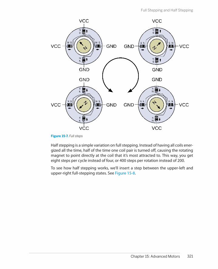
Figure 15-7. Full steps
Half stepping is a simple variation on full stepping. Instead of having all coils ener-gized all the time, half of the time one coil pair is turned off, causing the rotatingmagnet to point directly at the coil that it’s most attracted to. This way, you geteight steps per cycle instead of four, or 400 steps per rotation instead of 200.
To see how half stepping works, we’ll insert a step between the upper-left andupper-right full-stepping states. See Figure 15-8.
321Chapter 15: Advanced Motors
Full Stepping and Half Stepping

Figure 15-8. Half steps
If we were full stepping, the first step to turn the motor clockwise would be toreverse the polarity on the horizontal coil pair. To take a half step, we first simplyturn off the horizontal coil pair, either by driving both ends of the coil at the VCC orGND voltages. The north pole of the rotating magnet then points straight up, at thesouth pole of the still-energized vertical pair, and the motor’s shaft has turned 45degrees counterclockwise. The next half step, then, is to reenergize the horizontalcoil pair, but in the opposite polarity of the initial state.
In summary, to go from full steps to half steps, instead of simply reversing eachcoil’s current, you take an intermediate step where you turn off that coil first. SeeTable 15-4 if you’d like to see that written out in a table. (And notice that you canget the full-stepping pattern simply by skipping the odd-numbered phases.)
Table 15-4. Half-stepping coil currents
Phases Coil 1 Coil 2 Degrees rotation, 4-step motor Degrees rotation, 200-step motor
0 + + 0 0.0
1 + 45 0.9
2 - + 90 1.8
3 - 135 2.7
4 - - 180 3.6
5 - 225 4.5
6 + - 270 5.4
7 + 315 6.3
0 + + 360 7.2
322 Make: AVR Programming
Full Stepping and Half Stepping

Identification of Stepper Motor Wires
The stepper essentially has two electromagnet coils inside it, and if you’ve got abipolar stepper motor, you’re probably looking at four wires sticking out. Two ofthese wires are the ends of one coil, and two are the ends of the other. Now youneed to figure out which is which. I’ll show you three ways, and there are probablymore.
The first is to simply hook up an ohmmeter to two wires arbitrarily. If you get wire-ends from two different coils, they should be not connected. When you get a pairfrom the same coil, you will be able to read off the coil resistance in ohms. Writethis down somewhere. And while you’re at it, write down which colors are commonto a coil.
If you already know the coil resistance, one neat way to figure out the pairingscheme is to connect an LED across two wires, spin the motor shaft, and see if theLED lights up. If it does, you’ve found a coil pair and demonstrated that a steppermotor can be used as a generator. The spinning magnets inside the stepper makean alternating current in the coil as the north and south poles on the rotor swingpast.
The final way to figure out the coil pairing is to connect the wires together pair-wise. For instance, connect wire one with wire two, and separately connect wirethree to wire four. If it is hard to turn the motor, you’ve got the pairings right. If youswitch the connections (one to three, two to four) you should be able to turn themotor freely. What’s happening is that when you short out the coils, the generatedelectricity creates a magentic field inside the motor that opposes your turning it.Remember with DC motors how the speed was limited by the generator voltageequalling the driving voltage? When you try to turn a shorted stepper motor, you’refighting this generator voltage.
Anyway, if you’ve done any or all of the three experiments, you’ll have a good feelingfor some of the internal physics of stepper motors and you’ll know which wiresform the two coil pairs.
Too Many Wires!If you’ve got a motor with five, six, or eight wires coming out of it, don’t fret. ConsultFigure 15-9 to see what’s going on inside the motor.
If your motor has five or six wires, you can use an ohmmeter to find the pair ends.Looking at Figure 15-9, you’ll notice that the coil resistance between a center tapand any of the coil ends will be half of the resistance across two coil ends. Forinstance, a six-wire motor on my desk has roughly 5 ohms of resistance per coil, sothe end-to-end resistance between the end wires is 10 ohms. Once you’ve foundthe two pairs with 10 ohms resistance between them, you’re done. You can ignorethe extra two center taps.
323Chapter 15: Advanced Motors
Identification of Stepper Motor Wires

Figure 15-9. Possible stepper motor wiring patterns
Most five-wire steppers are essentially the same as six-wire motors, except the twocenter tap wires are connected together inside the motor body. Just as with six-wire motors, the center tap will show half of the resistance to other wires on anohmmeter. Ignore it and you’re done.
Center Taps, Unipolar Motors
In the case of five- or six-wire steppers, the extra wires tapped off between the coil pairs enableyou to drive the motor without using an H-bridge by supplying a high voltage to the centertap and alternately grounding either end of the coil pair to activate it. This style of motor anddrive are both referred to as unipolar, because each individual coil is only ever being drivenwith one polarity: high voltage in the center and ground on the coil end.
Because you can choose to ignore the center taps, a unipolar stepper can always be drivenas if it were a bipolar motor. The reverse isn’t true, of course.
If you’ve got a stepper with eight wires, a bifilar stepper motor, you’ve got yourwork cut out for you! It’s fairly easy to figure out which four pairs of wires areconnected together with an ohmmeter, and in principle you can just connect upthe four wire ends together in pairs to mimic the wiring of the four-wire, bipolar,stepper motor. But now you face two problems: you don’t know which coils are onopposite sides of the motor, and then you don’t know which wires to connect toget the two opposite coils in the same polarity. If you’re really determined to drivea bifilar stepper motor, there are 12 ways to connect the wires up, and two of themwill work. Grab a cup of patience and take good notes.
324 Make: AVR Programming
Identification of Stepper Motor Wires

Dual H-Bridge Chips: The SN754410
So you’ve just figured out which two pairs of wires correspond to the inner coilsthat spin your stepper motor. Now we need to hook each coil up to an H-bridgecircuit so that we can charge up the coils in either polarity; applying a positivedriving voltage on one side and then on the other, just like we did with the DCmotor earlier.
The chip we’re using for this project actually consists of four half-H-bridges. Thatmeans that each side of the “H” can be driven to the high or low voltage inde-pendently, just like our demo H-bridge could. We’ll control the four half-H sideswith four wires from the AVR. Each one sets an “H” side to high or low drive voltage,respectively. Once we’ve hooked up the stepper motor’s two coils to the four H-halves, we’ll be able to run current one way through the coil by setting one AVRpin high and the other low, and then reverse the current flow (and the sense of theelectromagnetic field) by setting the first pin low and then the other high.
Each half-H is “smokeless” in the sense that when it sees a logic high voltage, itconnects only its high-side switch internally, and vice versa for logic low. If we setboth sides of the same coil (and the same “H”) high or low, no current flows throughthe coil unless the motor is being turned externally. It’s like the previous examplewhere we shorted the two coil ends together.
Let’s have a look at the SN754410 chip’s pinout in Figure 15-10 and make sure thatwe understand how everything works. If you’d like to read along in the chip’s da-tasheet, go right ahead.
The pins labelled “1 Out” and “2 Out” are the left and right halves of a complete H-bridge. The corresponding “In"s control the voltage on the “Out"s. There’s addi-tionally a “1,2 Enable” line which, when held at the logic high voltage, enables thedriving transistors on the “1,2” side. Disabling the H-bridge means that all of thedriving switches are open, and it’s as if the motor were entirely unconnected.Whenever the H-bridge is enabled, the two outputs are pulled either high or lowthrough the bridge’s transistors.
You’ll notice that there are also two VCC voltage supply pins. One is for the logic-level voltage that you connect to the AVR, and the other is for the high voltagelevel that you’d like to use to drive your motor. In the case of the SN754410 you canuse up to 36 V, depending on your stepper motor.
325Chapter 15: Advanced Motors
Dual H-Bridge Chips: The SN754410
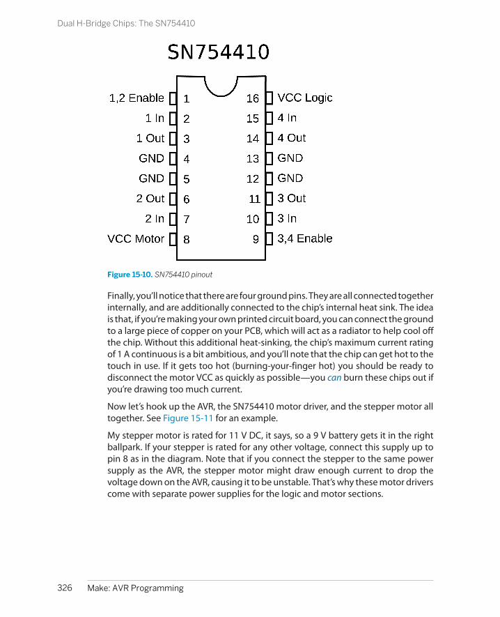
Figure 15-10. SN754410 pinout
Finally, you’ll notice that there are four ground pins. They are all connected togetherinternally, and are additionally connected to the chip’s internal heat sink. The ideais that, if you’re making your own printed circuit board, you can connect the groundto a large piece of copper on your PCB, which will act as a radiator to help cool offthe chip. Without this additional heat-sinking, the chip’s maximum current ratingof 1 A continuous is a bit ambitious, and you’ll note that the chip can get hot to thetouch in use. If it gets too hot (burning-your-finger hot) you should be ready todisconnect the motor VCC as quickly as possible—you can burn these chips out ifyou’re drawing too much current.
Now let’s hook up the AVR, the SN754410 motor driver, and the stepper motor alltogether. See Figure 15-11 for an example.
My stepper motor is rated for 11 V DC, it says, so a 9 V battery gets it in the rightballpark. If your stepper is rated for any other voltage, connect this supply up topin 8 as in the diagram. Note that if you connect the stepper to the same powersupply as the AVR, the stepper motor might draw enough current to drop thevoltage down on the AVR, causing it to be unstable. That’s why these motor driverscome with separate power supplies for the logic and motor sections.
326 Make: AVR Programming
Dual H-Bridge Chips: The SN754410

Figure 15-11. Stepper motor and H-bridge
Hook up the two wires that are common to one coil to one side of the SN754410so that they’re connected to the same H-bridge. In my example, the blue and yellowwires form one coil and the orange and green wires form the other. Which one ofthe two wires you designate as “1” or “2” is irrelevant. You can swap them aroundonce you get the software running, and getting it “wrong” just means the motorwill rotate counterclockwise where you think it should be clockwise. Now connectthe other pair to the other side—outputs “3” and “4.”
Connect the logic power and the two enable lines to the AVR’s breadboard VCC rail(and notice that I jumpered it across to make the wiring simpler). Connect up thegrounds to ground. At least one of these must be connected. The others areoptional.
Now run wires to the AVR’s pins PB0, PB1, PB2, and PB3. If you’ve still got your LEDshooked up to these pins, feel free to leave them in. They won’t interfere with thelogic levels for the motor driver chip, and they’ll give you some nice visual feedbackabout which coil phases are currently energized.
Make sure that PB0 and PB1 go to one side of the chip (the same H-bridge) and thatPB2 and PB3 go to the other side. If you swap PB0 for PB1, the motor will run theother direction, but if you swap PB0 with PB2, the motor won’t run.
Once you’ve got the stepper motor and driver connected, you’re ready to run somecode.
The Code
To drive the stepper motor forward, say, we’ll need to energize and deenergize thecoils in the motor in a given pattern at a given rate. This suggests that we store thestepping pattern in an array and then just step through it with an indexing variable.To take steps at a regular speed, we can use a timer/counter set in compare-matchmode to handle the variable timing and an interrupt to do the work of setting up
327Chapter 15: Advanced Motors
The Code
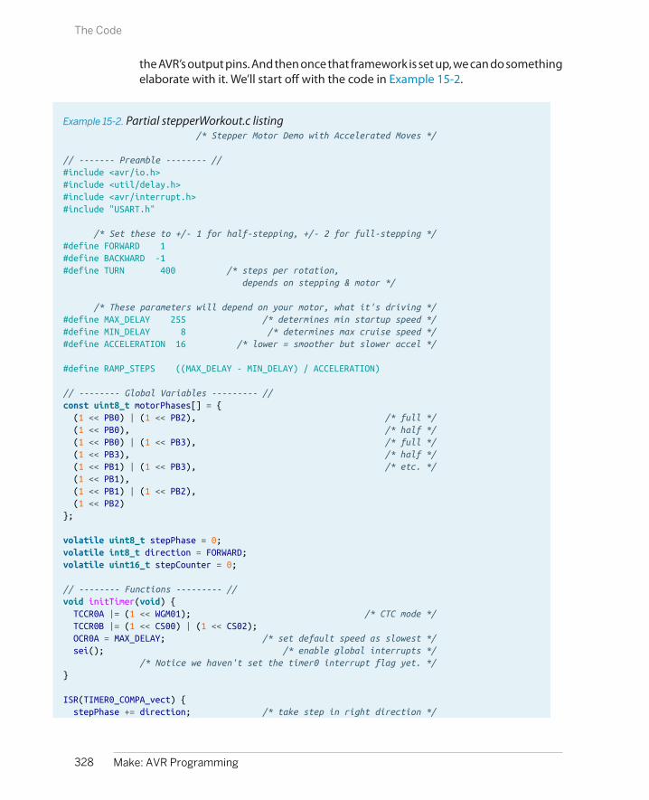
the AVR’s output pins. And then once that framework is set up, we can do somethingelaborate with it. We’ll start off with the code in Example 15-2.
Example 15-2. Partial stepperWorkout.c listing /* Stepper Motor Demo with Accelerated Moves */
// ------- Preamble -------- //#include <avr/io.h>#include <util/delay.h>#include <avr/interrupt.h>#include "USART.h"
/* Set these to +/- 1 for half-stepping, +/- 2 for full-stepping */#define FORWARD 1#define BACKWARD -1#define TURN 400 /* steps per rotation, depends on stepping & motor */
/* These parameters will depend on your motor, what it's driving */#define MAX_DELAY 255 /* determines min startup speed */#define MIN_DELAY 8 /* determines max cruise speed */#define ACCELERATION 16 /* lower = smoother but slower accel */
#define RAMP_STEPS ((MAX_DELAY - MIN_DELAY) / ACCELERATION)
// -------- Global Variables --------- //const uint8_t motorPhases[] = { (1 << PB0) | (1 << PB2), /* full */ (1 << PB0), /* half */ (1 << PB0) | (1 << PB3), /* full */ (1 << PB3), /* half */ (1 << PB1) | (1 << PB3), /* etc. */ (1 << PB1), (1 << PB1) | (1 << PB2), (1 << PB2)};
volatile uint8_t stepPhase = 0;volatile int8_t direction = FORWARD;volatile uint16_t stepCounter = 0;
// -------- Functions --------- //void initTimer(void) { TCCR0A |= (1 << WGM01); /* CTC mode */ TCCR0B |= (1 << CS00) | (1 << CS02); OCR0A = MAX_DELAY; /* set default speed as slowest */ sei(); /* enable global interrupts */ /* Notice we haven't set the timer0 interrupt flag yet. */}
ISR(TIMER0_COMPA_vect) { stepPhase += direction; /* take step in right direction */
328 Make: AVR Programming
The Code

stepPhase &= 0b00000111; /* keep phase in range 0-7 */ PORTB = motorPhases[stepPhase]; /* write phase out to motor */ stepCounter++; /* count step taken */}
void takeSteps(uint16_t howManySteps, uint8_t delay) { UDR0 = delay; /* send speed/delay over serial, non-blocking */ OCR0A = delay; /* delay in counter compare register */ stepCounter = 0; /* initialize to zero steps taken so far */ TIMSK0 |= (1 << OCIE0A); /* turn on interrupts, stepping */ while (!(stepCounter == howManySteps)) {; } /* wait */ TIMSK0 &= ~(1 << OCIE0A); /* turn back off */}
int main(void) { // -------- Inits --------- // initUSART(); _delay_ms(1000); initTimer(); DDRB = (1 << PB0) | (1 << PB1) | (1 << PB2) | (1 << PB3);
// ------ Event loop ------ // while (1) {
direction = FORWARD; takeSteps(TURN / 2, MIN_DELAY * 2); _delay_ms(1000);
direction = BACKWARD; takeSteps(TURN, MIN_DELAY); _delay_ms(1000);
direction = FORWARD; takeSteps(TURN / 16, MAX_DELAY); direction = BACKWARD; takeSteps(TURN / 8, MAX_DELAY / 2); direction = FORWARD; takeSteps(TURN / 16, MAX_DELAY); _delay_ms(1000);
} /* End event loop */ return (0); /* This line is never reached */}
As I suggested earlier, most of the heavy lifting in this example is done with a timer/counter and some global variables, so that’s a good place to start our analysis. Theconstant array motorPhases[] contains the bit values that we need to energize themotor coil windings and is arranged in the right order to make the motor turn onedirection. For concreteness, let’s say that the horizontal coil in the motor is con-nected through the H-bridge to the AVR pins PB0 and PB1. When you set PB0 high
329Chapter 15: Advanced Motors
The Code

and PB1 low, the coil is energized with one polarity, and when PB1 is high and PB0is low, the other polarity.
The current position in the motor phase table is stored in the global stepPhase.There is code inside the ISR to keep stepPhase within the range of the motorPhases[] table. The direction that the motor should turn is stored in direction andan overall counter of how many steps have been taken is stored in stepCounter.
The ISR that uses these global variables is short and sweet. First the stepPhase isincremented or decremented depending on the value of direction. stepPhase &=0b00000111; makes sure that we’re keeping the steps in the range zero to sevenso that it never overflows the motorPhases[] lookup table. Finally, the ISR sets upthe output on PORTB according to the current stepping phase and increments thestep counter. If we let the counter and ISR free-run, the motor would turn at a speeddetermined by the frequency of compare-match interrupts coming from the timer.
And speaking of timer initialization, it’s is a totally standard “clear timer on comparematch” (CTC) setup, where the delay between steps is set using the OCR0A registerthat the timer counts up to. The only thing noteworthy here is that, although weset up the global interrupt enable bit, the code doesn’t enable the specific compare-match interrupt just yet. As soon as the interrupt is enabled, the ISR code will runand the motor will start spinning. We’re not ready for that yet.
Next, let’s look at the takeSteps() function that’ll actually do something for us.Basically, it simply uses this timer/counter and ISR framework that we’ve just setup. We specify how many steps we’d like the motor to take and the delay betweensteps that determines the rotation speed, and the routine makes it happen.
For fun, and for your intuition about what’s going on, the takeSteps() functionstarts off by sending the current delay value out over the serial line. Later, whenwe implement complex movements that speed up and slow down, you can watchthis output change on your computer using something like our serialScope.pyapplication.
The rest of the code does the real work. The delay value is written to the output-compare register for Timer 0, the stepCounter is reset, and then the output compareinterrupt enable bit (OCIE0A) is set. At this point, the ISR will start firing and themotor will start turning at the specified speed. Because the ISR increments thestepCounter with every step, all that remains is for us to wait until it reaches thedesired value, and then turn off the compare interrupt to shut the motor off.
That’s all you need for simple stepper motor control. If you’re interested in seeingwhat you can do with just the basics, flash in the code example with the shortenedversion in Example 15-2. (make flash MAIN=stepperWorkout_short.c shouldwork.)
330 Make: AVR Programming
The Code

Acceleration Control
The problem with our naïve demo based simply on the takeSteps() routine is thatwe’re telling the motor to start up at full speed, take a bunch of steps, and thenstop instantaneously. If the stepper motor is strong enough and your load lightenough, you can get away with these jerky, start-stop movements. But it’s equiv-alent to driving by flooring either the gas or brake pedal. This style may be OK forFormula One races, but it’s tough on the car, the environment, and the passengers.And with stepper motors, this can lead to missing steps.
To see how steps get missed, it’s worthwhile to think of the stepper motor shaftand motor coils as two distinct parts of your motor system. Under light loads andat low speeds, the motor shaft catches up almost instantly when you advance thephase of the driver and the coils. As you speed up the driver or increase the inertiaof the motor’s load, the motor shaft phase can start to lag behind the coil phase.If you try to spin the motor faster and faster, eventually you’ll get to the point wherethe shaft phase gets more than one step behind the driver and coils. (Try it! AddtakeSteps(TURN, 2); to the code and see what happens.)
Look again at the single-stepping diagram in Figure 15-7. If the motor’s shaft lagsmore than one step behind the driver when you are full-stepping, the coil ends uppulling it in the direction that’s exactly opposite of the direction you’d like it to beturning. This can cause missed steps, a nasty grinding noise, and all of a suddenyour AVR chip doesn’t know where the motor is pointing any more because it thinksit has taken steps but the motor didn’t turn.
A better idea is to ramp up the speed, from slowly moving to full speed ahead.Taking a little more time per step at the beginning gives the motor shaft more timeto catch up to the driver’s phase, and helps to prevent missed steps. Once yourheavy load has started to turn, you can speed the motor up. And of course you’llwant to ramp the speed back down again in anticipation of stopping. Ramping thespeed up and down like this allows you to run the motor at a higher cruising speedthan you would otherwise be able to start the motor off with, and it makes forsmoother motion control and less stress on moving parts. It’s a win all around.
In the demo code, I implement an acceleration profile that’s particularly easy tocode up and understand, yet performs pretty well in the real world. Motion controlturns out to be a deep subject, and if you know a lot about the geometry andmasses of your particular setup, you can probably optimize this code for your sit-uation. This is particularly true if you’re planning a complicated path where youdon’t necessarily want to stop the motor fully between movements. Still, try thiscode snippet first for generic situations.
We assume that the motor is initially stopped and that we’d like it to be stoppedagain but having rotated through a given number of steps as fast as possible. We’llmodel the movement in three stages: an acceleration stage, a cruising stage where
331Chapter 15: Advanced Motors
Acceleration Control
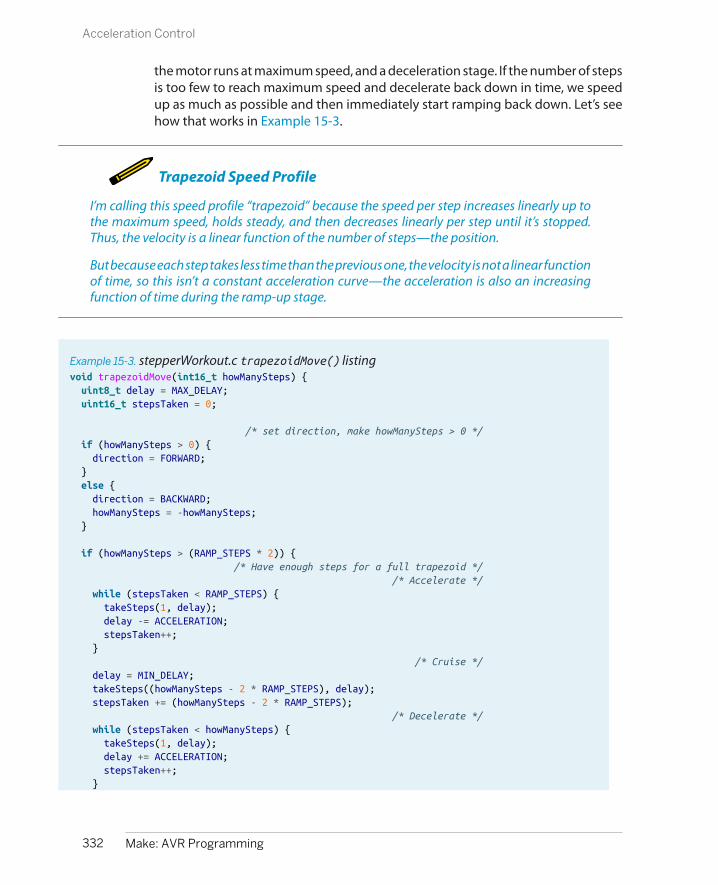
the motor runs at maximum speed, and a deceleration stage. If the number of stepsis too few to reach maximum speed and decelerate back down in time, we speedup as much as possible and then immediately start ramping back down. Let’s seehow that works in Example 15-3.
Trapezoid Speed Profile
I’m calling this speed profile “trapezoid” because the speed per step increases linearly up tothe maximum speed, holds steady, and then decreases linearly per step until it’s stopped.Thus, the velocity is a linear function of the number of steps—the position.
But because each step takes less time than the previous one, the velocity is not a linear functionof time, so this isn’t a constant acceleration curve—the acceleration is also an increasingfunction of time during the ramp-up stage.
Example 15-3. stepperWorkout.c trapezoidMove() listingvoid trapezoidMove(int16_t howManySteps) { uint8_t delay = MAX_DELAY; uint16_t stepsTaken = 0;
/* set direction, make howManySteps > 0 */ if (howManySteps > 0) { direction = FORWARD; } else { direction = BACKWARD; howManySteps = -howManySteps; }
if (howManySteps > (RAMP_STEPS * 2)) { /* Have enough steps for a full trapezoid */ /* Accelerate */ while (stepsTaken < RAMP_STEPS) { takeSteps(1, delay); delay -= ACCELERATION; stepsTaken++; } /* Cruise */ delay = MIN_DELAY; takeSteps((howManySteps - 2 * RAMP_STEPS), delay); stepsTaken += (howManySteps - 2 * RAMP_STEPS); /* Decelerate */ while (stepsTaken < howManySteps) { takeSteps(1, delay); delay += ACCELERATION; stepsTaken++; }
332 Make: AVR Programming
Acceleration Control

} else { /* Partial ramp up/down */ while (stepsTaken <= howManySteps / 2) { takeSteps(1, delay); delay -= ACCELERATION; stepsTaken++; } delay += ACCELERATION; while (stepsTaken < howManySteps) { takeSteps(1, delay); delay += ACCELERATION; stepsTaken++; } }}
Because we want the motion profile to be the same whether we’re spinning themotor clockwise or counterclockwise, we can set the direction global variable atthe beginning of the routine and convert the number of steps into a positivenumber.
The minimum and maximum delays, which are the inverse of the speed, are set indefine statements at the top of the program, as is the acceleration, how much toreduce the delay per step. This means that the number of steps needed to completean acceleration or deceleration ramp is fixed and can also be computed in a define(RAMP_STEPS).
Because everything is precomputed, the trapezoidMove() routine just has to figureout if it has enough steps to spend some time cruising at the maximum speed—if the number of steps to take is longer than two ramps—or whether it should gostraight from acceleration to deceleration. In the first case, the routine loopsthrough a series of single steps at increasingly small delays and counts the stepstaken as it goes along. The cruising stage is implemented with a single call totakeSteps() at the maximum speed: setting the delay to the defined MIN_DELAY.Finally, the deceleration phase is a single-step loop that’s the mirror image of theacceleration stage.
When there are not enough steps desired to reach maximum speed, and thuscruise, the routine is even simpler. The acceleration stage lasts for half of the steps,and takes single steps more and more quickly. At the halfway point, it’s time to startdecelerating again, and the deceleration routine just adds to the delay with eachstep until it’s done.
333Chapter 15: Advanced Motors
Acceleration Control
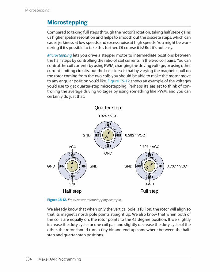
Microstepping
Compared to taking full steps through the motor’s rotation, taking half steps gainsus higher spatial resolution and helps to smooth out the discrete steps, which cancause jerkiness at low speeds and excess noise at high speeds. You might be won-dering if it’s possible to take this further. Of course it is! But it’s not easy.
Microstepping lets you drive a stepper motor to intermediate positions betweenthe half steps by controlling the ratio of coil currents in the two coil pairs. You cancontrol the coil currents by using PWM, changing the driving voltage, or using othercurrent-limiting circuits, but the basic idea is that by varying the magnetic pull onthe rotor coming from the two coils you should be able to make the motor moveto any angular position you’d like. Figure 15-12 shows an example of the voltagesyou’d use to get quarter-step microstepping. Perhaps it’s easiest to think of con-trolling the average driving voltages by using something like PWM, and you cancertainly do just that.
Figure 15-12. Equal power microstepping example
We already know that when only the vertical pole is full on, the rotor will align sothat its magnet’s north pole points straight up. We also know that when both ofthe coils are equally on, the rotor points to the 45 degree position. If we slightlyincrease the duty cycle for one coil pair and slightly decrease the duty cycle of theother, the rotor should turn a tiny bit and end up somewhere between the half-step and quarter-step positions.
334 Make: AVR Programming
Microstepping

Equal Power Microstepping
The mathematics isn’t pretty, but it’s not really morethan a little physics and some trigonometry. We wantto figure out how much power we need from eachcoil pair for a given angle, holding the total powerconstant around the circle.
Power is a function of voltage (or duty cycle) squared,so adding up the duty cycles from the two coils is likeadding up lengths of legs of triangles. That meansthe duty cycles that we’d need to use are sine andcosine functions of the desired rotation angle. Easy,right?
In contrast, when we implemented half stepping wewere not keeping the power constant as we rotatedthe motor around the circle. In fact, the motor pulled1.414 times stronger when both coils were on than it
did with just one on. We’d need to throttle the twophases back by a factor of sin(pi/4) or 0.707 whenthey’re both on to maintain equal power around thecycle.
Whether or not this is a good thing depends on yourapplication. The slightly uneven power cycle of reg-ular half stepping makes it a little bit noisier than itwould be under equal-power half stepping, butwhen both coils are fully engaged, the motor hasroughly 40% more torque. Most microstepping chipswill aim for equal power, so you’ll be losing some ofyour possible motor torque. The way we implement-ed half stepping is both the easiest and gets the max-imum performance out of a given voltage source, atthe expense of being a little “jerkier.”
Now, it would be possible to calculate all of the sines and cosines ahead of time,store them in a table in memory, and then use the built-in PWM hardware (con-veniently, there are two compare values per timer!) to implement microsteppingon your own with our SN754410 H-bridge. If you’d like a challenge after this chapter,I recommend it as a good learning experience.
On the other hand, if you’d like to simply use microstepping and stepper motorsrather than learning something, I honestly have to recommend buying an inte-grated indexer and driver chip. Chips like the Allegro A4988 or TI’s DRV8825 takecare of a bunch of current-limiting and power-handling details that you can’t rea-sonably mimic yourself.
Most importantly, the dedicated driver chips allow you to use a higher supplyvoltage with your motor than you would otherwise. The extra voltage can give themotor an extra kick as it transitions between steps, but would burn the motor outif you applied this higher voltage constantly. The chips take care of the currentlimiting for you, while providing the motor with extra power bursts. Because chipslike the Allegro or TI drivers implement this current control in a way that actuallyimproves the performance of your stepper motor, I recommend buying a slightlylower voltage stepper than your power supply, maybe by a factor of two, to givethe IC the headroom it needs. (For details, the datasheets from Allegro go into gooddepth.)
With a dedicated stepper-driver IC, all you have to do is provide a high or low signalon a direction pin to set which way it’s going to rotate, and a rising-edge on a steppin to make it move. The controller chip takes care of the rest. Your AVR code then
335Chapter 15: Advanced Motors
Microstepping

just has to supply a positive-going pulse every time that you’d like the motor toturn one step. Whether you do this purely in code or make use of the timer/counterhardware is up to you. Using a stepper-driver IC is a lot like driving a simple DCmotor in sign-magnitude mode, only you have some assurance that with eachtoggling of the PWM pin, the motor has turned a precise, known amount.
In fact, the dedicated indexer/driver chips make life so simple, that there’s almostnothing I can say about them here! You buy one, follow the circuit diagrams to setthe maximum currents to match your motor, and then pulse it from the AVR. If that’stoo much work for you, you can even buy them already preintegrated into a circuitboard from many hobbyist supply shops including Sparkfun, Adafruit, and Pololu,to name a few. The bare chips only cost a few dollars, and the preassembled boardsaren’t too bad. You’ve got no excuse not to go out and buy a couple. When youwant the motor to turn five steps, you just pulse a control line five times.
The Limits of Microstepping
As you try to subdivide the motor’s phase circle into finer and finer pie slices, you end uphaving to vary the voltage applied to the coils by smaller and smaller amounts. This placesreal demands on your current-control circuitry, or in our case the PWM accuracy. Frictioninside the motor and the presence of the permanent magnet in hybrid stepper motors furthercomplicate issues. When you’re relying on tiny differences in applied current to turn the motora tiny fraction of a degree, you can’t expect to get much torque between the two steps.
Because of these factors, there’s a real limit to how many microsteps you can expect per cycle,even with the best-designed dedicated chip drivers. Exactly how many microsteps are prac-tical is a topic of hot industry debate and depends on why you’re using microstepping in thefirst place, but the value almost certainly lies between 8x and 16x. Reconfiguring a driver chipbetween 4x, 8x, and 16x is usually quite simple, though, so test them all out!
336 Make: AVR Programming
Microstepping

Interfacing with External Memory
So far, when we’ve been talking serial, we’ve really meant the kind of old-schoolasynchronous serial protocol that’s based on RS-232, which is how computers usedto talk to printers in the 1970s. But there are other serial data transfer modes outthere, more or less appropriate in different situations.
In this chapter and the next, we’ll look at two modern serial protocols. This chapterdeals with the serial peripheral interface (SPI), which is blindingly fast and bettersuited for a small number of devices. The other protocol, I2C (“inter integratedcircuit”), has an addressing scheme and is easily extended to a network of up to128 devices using only two wires (and ground), but is a lot slower than SPI.
From a user’s perspective, however, most of the time you’ve got a cool new deviceand you just want to talk to it. The peripheral devices that need speed will speakSPI and those that play well with others will speak the I2C protocols, so you’re goingto need to learn to use both of them. Fortunately, because these protocols are sowidespread, our AVR microcontrollers have internal hardware that makes codingfor them a breeze once you know how. That’s what this chapter and the next areall about.
This chapter gets your AVR chip talking SPI serial with an external EEPROM chip.We’re building up toward a standalone data logger application by the end ofChapter 17, and we’re going to need a bunch of nonvolatile memory to store thedata in. External EEPROMs and other flash-memory devices provide a cheap andeasy way to keep lots of data around even when the power goes out, so they’reworth knowing about in their own right. But if you’re not so interested in the par-ticular application, just think of the EEPROM as a generic SPI device and you’ll stilllearn something useful.
337
SPI 16

What You Need
In addition to the basic kit, you will need:
• An SPI device to talk to. Here, I’m using a25LC256 32K SPI EEPROM chip becausethey’re cheap and similar to many other off-board memory devices.
• A USB-Serial adapter.
How SPI Works
I love the SPI (serial peripheral interface) bus protocol. It’s like a shark, brutallyefficient at what it does, and essentially stripped of all frills. When you want to movea lot of data really fast between a few devices, it’s hard to beat SPI.
One reason that SPI is so fast is that, unlike our old friend UART, it’s a clocked, orsynchronous, protocol. With UART, we were always worried about a baud rate, therate at which to transmit and expect data. The transmitting and receiving deviceshave to be precisely in sync, agreeing on when to set and read the voltage levelson the transmit and receive lines. And this means that UART serial can only transmitdata as quickly as the two devices can agree on the timing, which limits the speedto a few hundred thousand bits per second at best. (We’ve been running at 9,600baud, which is a little conservative; it’s about 1/10th of the fastest UART speed.)
With SPI, in addition to the transmitting and receiving lines, there’s a third wirethat’s used as a clock line that synchronizes the two communicating devices. Thisway, both can agree that they’ll read and write data on the positive voltage tran-sition, for instance. This means that the bit rate can be as fast as the two devicescan agree on a rising voltage edge. SPI speeds usually start at 1 megahertz, and 10megahertz is pretty much standard. That’s a hundred times faster than the fastestasynchronous serial setups, and a thousand times faster than what we’re using forUART. And these days it’s not uncommon to have SPI buses in consumer electronicsdevices running as fast as 50–100 MHz. That’s really, really fast.
The other reason that SPI can be so fast is that there’s almost no overhead, and thusno extra work for the CPU to do to make use of the data as it comes across. Our oldserial protocol relied on a start bit and a stop bit to keep synchronized and to delimitthe bytes one from the next. This means that for every 8 bits of data, 10 signalsneed to be sent, which further slows it down. This data framing--knowing whereone byte starts and the previous one ends—is handled by yet another wire in SPI.
So if you’ve been following along so far, you’ve got the picture that SPI is fast, butyou’ve probably also counted at least four wires necessary for SPI: a clock line, twodata lines (one for each direction), and a fourth line that’s used to signal the start
338 Make: AVR Programming
How SPI Works
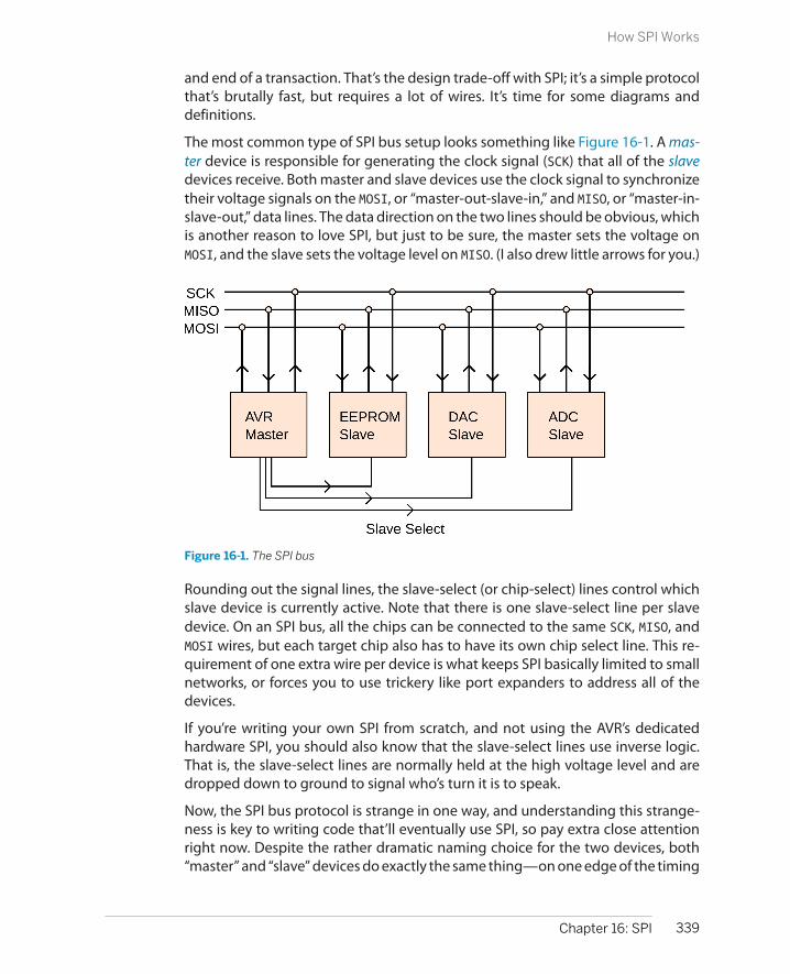
and end of a transaction. That’s the design trade-off with SPI; it’s a simple protocolthat’s brutally fast, but requires a lot of wires. It’s time for some diagrams anddefinitions.
The most common type of SPI bus setup looks something like Figure 16-1. A mas-ter device is responsible for generating the clock signal (SCK) that all of the slavedevices receive. Both master and slave devices use the clock signal to synchronizetheir voltage signals on the MOSI, or “master-out-slave-in,” and MISO, or “master-in-slave-out,” data lines. The data direction on the two lines should be obvious, whichis another reason to love SPI, but just to be sure, the master sets the voltage onMOSI, and the slave sets the voltage level on MISO. (I also drew little arrows for you.)
Figure 16-1. The SPI bus
Rounding out the signal lines, the slave-select (or chip-select) lines control whichslave device is currently active. Note that there is one slave-select line per slavedevice. On an SPI bus, all the chips can be connected to the same SCK, MISO, andMOSI wires, but each target chip also has to have its own chip select line. This re-quirement of one extra wire per device is what keeps SPI basically limited to smallnetworks, or forces you to use trickery like port expanders to address all of thedevices.
If you’re writing your own SPI from scratch, and not using the AVR’s dedicatedhardware SPI, you should also know that the slave-select lines use inverse logic.That is, the slave-select lines are normally held at the high voltage level and aredropped down to ground to signal who’s turn it is to speak.
Now, the SPI bus protocol is strange in one way, and understanding this strange-ness is key to writing code that’ll eventually use SPI, so pay extra close attentionright now. Despite the rather dramatic naming choice for the two devices, both“master” and “slave” devices do exactly the same thing—on one edge of the timing
339Chapter 16: SPI
How SPI Works
clock, they set up one bit for output, and on the next edge of the timing clock, theyread one bit in as input. It’s just that the master, as noted previously, is responsiblefor generating the clock signal and deciding which slave to speak to.
Let me say that again, because it’s the key to understanding SPI. With every clocktick, both the master and the slave transmit and receive a bit of data on their re-spective lines. Consequently, there’s no real concept of separate “send” and “re-ceive” actions in SPI—both are sending and receiving all the time. I like to think ofit as “bit trading.”
Bit Trading ExampleAs an example, imagine that you’re communicating with a device that that takesin an 8-bit command and returns 16 bits of response data. If the AVR is the masterdevice, it needs to set up its data line and clock out 8 bits of data in a row. At thesame time, it’s just received an 8-bit byte from the slave device, but because theslave hadn’t received the command yet, the byte probably isn’t meaningful. TheAVR can probably throw it away.
After clocking out the 8-bit command string, the AVR needs to clock out 16 morebits of data to the slave, during which time the slave will send its 16-bit responseback to the AVR. For these 16 bits, the slave probably doesn’t care what the AVR issending, but it needs to receive the clock signal so that it can transmit its bits. Thisis bit trading; the AVR needs to send out 16 bits to get 16 bits back. It probablydoesn’t matter what bits the AVR sends, though it’s customary to send all zeroswhen you’re just waiting for a response.
I say “probably” because there are some slave devices that are smart enough toreceive the next command while still sending the response to the previous one,effectively doubling the data throughput. When this is the case, it can be tricky tokeep the timing of command and response straight. This is why it can help to bearin mind the simultaneous bit-for-bit trading nature of SPI.
The other time that the SPI bus can seem strange is when you’re dealing withsensors. Some devices, like temperature sensors, for instance, don’t really take anyinput and are designed as slave devices. Because of the way SPI works, the AVRmaster has to send data—any data—to the sensor in order to get data back. Thesensor ignores this data and is just using it for the clock source; but from the per-spective of the AVR, it may seem odd to send data to your sensor. Keep in mind theway SPI works under the hood, that you’re really bit trading, and this won’t seemso strange.
Shift RegistersIf you’d like to take a deeper look into the SPI bus, you’ll need to understand shiftregisters, because shift registers are what let the devices on an SPI bus convert databetween serial data (one bit at a time) and parallel data (all eight bits at once).
340 Make: AVR Programming
How SPI Works

The AVR’s CPU—and whatever the CPU is connected to—wants to work with bytes.Rather than connecting them together with eight wires (which we’d probably calla “parallel data cable”) and simultaneously transmitting a bit on each wire, it’sphysically simpler to send the bytes one bit at a time (in serial) over just one or twowires, and then reassemble the received bits into our 8-bit byte after they’ve allarrived. The circuit that does this serial-to-parallel and parallel-to-serial conversionis a shift register, which is basically eight clocked one-bit memories arranged in arow. When the clock ticks, each memory cell takes on logic value that the cell tothe left of it had. How does this work?
Imagine eight people standing in a line, and a ninth person who’s handing themred or blue rocks. When a clock ticks, everyone passes their rock to the right downthe line. After eight clock ticks, each of the eight people will have rocks whose colordepends on the sequence of rocks that were fed in one at a time. Now you can readout the data that came in one bit at a time, but all together as an 8-bit byte—aserial-to-parallel conversion.
In Figure 16-2, the serial sequence “1,0,1,0,0,0,0,0” was clocked in one bit at a time.After eight clock ticks, you can read the parallel value out (in mirror-image).
Figure 16-2. A shift register
Some shift registers also operate the other way around: parallel in, and serial out.You can load up all eight memory cells at once and then read out the value of therightmost memory cell as you advance the clock. The output is then a serializedversion of the same pattern of bits that you loaded in. “Universal” shift registers letyou both read and write to the register in parallel, making them serial-to-parallelor parallel-to-serial converters.
And this is why I love the SPI protocol: it’s just two of these universal shift registerslinked together in a loop. Both the master and slave have a shift register, and theinput of each is connected to the output of the other through the MOSI and MISOlines so that they form a ring. See Figure 16-3.
341Chapter 16: SPI
How SPI Works

Figure 16-3. SPI is shift registers
Both devices’ shift registers start out parallel-loaded with the data that they’regoing to transmit. In this example, the slave is loaded with all zeros, and the masterall ones. After one clock tick, the master is left with seven of its original bits and thefirst one that’s come in from the slave, and vice versa, because it’s completelysymmetric.
After a total of eight clock ticks, all eight bits of each byte have traded places.Because the two shift registers are universal, the respective processors can readthem out as a single byte, in parallel. Once that byte is processed, the registers arereloaded, and the next bytes are ready to move around the circle.
Shift Registers Driving Shift Registers
Here’s where it gets meta! Remember that we had an issue with a proliferation of slave-selectlines in a big SPI network? You can solve this by using a shift register connected to the slave-select lines, and addressing the shift register with the AVR SPI hardware. This is not for thefaint of heart, but it’s an elegant solution to a common problem.
To select a slave device, you first slave-select the shift register and send it the right byte todrop the desired device’s slave-select line. When you latch in this address byte and deselectthe shift register, the SPI bus is set up to talk to your slave device. This trick lets you easilyaddress eight devices on your SPI bus with nothing more than the normal four AVR SPI pinsand a shift register.
342 Make: AVR Programming
How SPI Works

Other Uses of Shift Registers
Shift registers are good for more than SPI and serial-izing data streams. In fact, given that input and out-put pins on AVR microcontrollers are often scarce inmy designs, shift registers are an essential part of myelectronics-design toolkit.
First, let’s think about how a shift register could beused as an output-pin multiplier. With two pins, youcan shift eight bits of data into a shift register one ata time. If it’s important that none of the outputschange until they have the full data, there are shiftregisters that have additional enable lines that onlylatch the data into an output register once all eight(or however many) bits have been clocked in.
So say you need to light up 16 LEDs in particular pat-terns. One way to do this is with one AVR output pinper LED, but that uses up almost all of the pins on theAVR. Using shift registers, you can be a lot more clever.If you use one 8-bit shift register, you only need twopins, data and clock, to control all eight bits of outputfrom the register. Naively, you could just hook up an-other two pins to another shift register, and you’vegot all 16 LEDs under control with only four AVR pins.
But you can do better. If you can shift the bits in fastenough that the blinking isn’t noticeable on the out-put, you can chain the two shift registers together,wiring up the output of the eigth bit of the first reg-ister to the input of the second. This way you’re driv-ing all 16 outputs with just the same two pins. And ifyou need simultaneous change on all 16 outputs, youcan use shift registers with an output register, for thecost of only one more AVR pin to toggle their enablepins.
Now if that’s not good enough, remember that theAVR’s hardware SPI peripheral is built to take in eight
bits and clock them out to a shift register in the re-ceiving peripheral. Usually, we’re thinking of a mem-ory chip, sensor, DAC, or other “real” peripherals. Butwe can also use the SPI to talk to plain-old shift reg-isters, for pin-multiplying purposes.
When you want to load up a particular pattern ofeight bits on a generic shift register using the SPIhardware, all you have to do is connect the MOSI tothe shift register’s input, write the byte to the SPDRdata register, and watch it go. And remember, thehardware SPI is very fast—transmitting the bits atmegahertz rather than mere kilohertz.
The 74HC595 is a very common 8-bit serial-in,parallel-out shift register with built-in a storage reg-ister. They sell for 15–20 US cents each, and half ofthat in bulk. You can cascade as many of these as youneed to multiply your AVR pins’ output capabilities.In many applications, you’ll find that the AVR’s outputpins are scarce. When this is the case, combined withthe AVR’s dedicated SPI hardware, a shift register canbe your very best friend.
And of course, there’s a parallel-to-serial equivalentshift register, the 74HC165 chip, that you can use toeffectively multiply the number of digital inputs theAVR can have. As previously, you can use the SPIhardware to read in bytes from the shift registers,taking in parallel data when latched, shifting it intothe AVR’s SPI register one bit at a time, and then read-ing the full byte out in your code. It’s essentially thesame trick, just in reverse. If you find yourself needinga parallel-to-serial input expander, the 74HC165 chipis a good bet.
EEPROM External Memory
Because the SPI bus is fast, you’ll find that it’s mostly used by devices that needspeed: ADCs and DACs for audio or much faster signals, output expanders, andmemory. In this section, we’ll work on a demonstration of the AVR’s SPI capabilitiesusing an offboard SPI EEPROM memory chip that’ll let us store 32 KB of data. (OK,
343Chapter 16: SPI
EEPROM External Memory

that’s not a lot, but similar principles take you up into the gigabytes becauseSD/MMC flash memory cards have an SPI interface.)
External MemoryWhen you need to store more data than you’ve got space for inside the AVR chip,it’s time to look to external memory. There are two main types of external memory:volatile types that rely on constant power to remember their data, and nonvolatilememory that is slower and more expensive but retains its data even when the lightsgo out.
Volatile memory (SRAM, DRAM, etc.)There are all sorts of electronic tricks for storing bits of information as voltages.Static random access memory (SRAM) and dynamic random access memory(DRAM) take two different approaches to storing your bits. SRAM uses a net-work of transistors that hold the last voltage level that was imposed on them—as long as the power stays connected.
DRAM, on the other hand, charges or discharges one tiny capacitor per bit tostore the logical one or zero. This means that dynamic RAM’s many capacitorsneed periodic reading and recharging, a cycle called a “memory refresh,” whichstatic RAM doesn’t.
Both rely on power to retain data—cut the power, and poof! The data storedin memory is gone. These two types of memory can be quite cheap per meg-abyte, and read and write quickly—SRAM has a slight speed advantage.
Dynamic RAM is a lot cheaper for large memories, but the necessary refreshcircuitry makes it impractical for small microcontroller designs. For use with amicrocontroller, static RAM is the easiest way to go when you need a lot of faststorage but don’t mind losing it when the power is off. In particular, Microchipmakes a range of 23Kxxx SPI serial SRAM chips that can be used just like theEEPROM in this chapter, but they run on lower voltage, which complicates thepower supply.
EEPROMEEPROM (electrically erasable programmable read-only memory) is probablythe most flexible type of external memory, although it’s not particularly cheapor fast. The advantage that it does have, though, it that EEPROM is nonvolatile(doesn’t go away when the power is turned off ) and there are plenty of chipsavailable that run on 5 V supplies without level conversion. EEPROM, like theone we’re using in this chapter, can hold its memory for a very long time withno power—Microchip’s datasheets specify longer than 200 years!
FlashFlash memory is a newer type of EEPROM that is significantly cheaper andoffers faster write times, but at the expense of only being able to write a pageof memory at a time. While with generic EEPROM, you can change one byte
344 Make: AVR Programming
EEPROM External Memory
without modifying its neighbors, with flash memory, the bytes are arrangedin pages of multiple (often 512) bytes that must all be written together. So tochange one byte, you read all 512 into your microcontroller’s memory, changeone byte, and then send them all back out to flash storage.
Because this procedure is power consuming, time consuming, and no fun,there are also flash memory chips that have a small embedded controller insidethat takes care of all this for you. When you need more memory that you’reable to get from a plain-vanilla EEPROM, something like Atmel’s AT45 series offlash memories are fantastic. They have onboard SRAM buffers so that you canaccess one while the other is writing to flash. You can get them with a 66 MHzSPI bus and 2 MB of memory for under $1.50, though you’ll have to supplythem with 3.6 V instead of 5 V.
SD cardsFinally, you should know about SD/MMC cards. Under the hood, they’ve got asmall processor and a bunch of flash memory. Most SD cards also allow you toread/write to them with SPI. One catch is that, as with the higher-storage Atmelchips, they also need to be run at a lower voltage, usually between 3.0 and 3.6volts. The other disadvantage is that, being flash chips inside, you have to readand write in 512-byte pages.
On the plus side, the SPI protocol for running SD cards is well documented,and it’s hard to beat 2 GB of storage for only a few bucks. You’ll find tutorialson the Web for how to use SD cards with an AVR, and even how to incorporatea FAT filesystem so that you can easily transfer files to and from your desktopcomputer.
The memory chip I’ve chosen is one of a family of very common EEPROM chips, the25LC256 from Microchip. Why? Because it has a decent amount of nonvolatilememory for making a logger, it works on a wide 3.5–5.5 volt range, it’s available asa DIP part for breadboarding, and it’s basically cheap. It’s also part of a family of SPIEEPROMs with memory ranging from 512 bytes to 128 kB. Small(ish) EEPROMS likethis are usually used for storing configuration data, but even with just 32 KB, sam-pling the temperature once every five minutes, we’ll get over three month’s ofruntime. Or if we sample temperature every 10 seconds, it’ll run for three and a halfdays. Thirty-two thousand samples is more than you’d think.
If you look at the datasheet for the 25LC256 chip, it supports exactly six commands:read, write, write-enable, write-disable, read status, and write status. When you’dlike to read from the chip’s memory, you first pass it the read command, then thememory start address, and then just keep clocking in/out bytes until you’ve hadenough. To write, you first have to send a write-enable command. Then, send thewrite command, the start address, and then up to 64 bytes of data. When you’redone writing, the AVR raises the voltage of the slave-select line, and the EEPROMflashes the bytes into memory.
345Chapter 16: SPI
EEPROM External Memory

There are a couple of complications, which are common to about every memorytype out there, so I’ll go into some detail for you. First, writing the received datainto memory takes a bit of time. With the 25LC256, it’s guaranteed that a write won’ttake more than 5 ms, but that’s quite a long time in microprocessor-land. This iswhy the EEPROM chip also has a status register and a bit in that register that tellsyou that it’s busy writing. After you (or the AVR) write a block of data to memory,it’s customary to check up on the status register until the “write-in-process” bit isclear if you need to use the EEPROM again within a short period of time, as isfrequently the case when you’re saving a bunch of data.
The other complication is that the memory inside the EEPROM is internally ar-ranged in “pages” of 64 bytes each. Other memory devices, like flash cards or SDcards, will have a similar layout but with different numbers of bytes per page. Be-cause writing to memory is relatively slow, it makes sense to do as much of it atonce as possible, but this means that you have to have some internal temporarystorage inside the EEPROM device, and that the places it’s going to store the dataare simultaneously accessible. Hence, memory pages.
The gotcha with paged memories is that you have to send less than one page ofdata, or else it wraps around. For example, say we’re going to save eight bytes ofdata starting at memory location 60. The first four bytes will fit within the pageeasily, going into locations 60, 61, 62, and 63. The next four bytes, however, willwrap around and get written into memory locations 0, 1, 2, and 3, rather than 64,65, 66, and 67, because memory locations 64, 65, 66 and 67 don’t exist on that page.Yoiks!
There are a few ways to work with paged memory. The first, and by far the slowest,is to always write one byte at a time. If you can live with (in our case) 5 ms per byte,this is just fine. If you find that you need speed, the fastest method is to accumulate64 bytes of data together in an array in the AVR and then send them all directly tothe same page in EEPROM, only incurring the 5 ms write delay at the end. You cansee that this about 64 times faster. All you have to do is make absolutely sure thatyou start each block at an even multiple of 64 in the EEPROM’s memory addressspace.
I once built an accelerometer logger that had to write into a memory that had a512-byte page structure. But I didn’t want to keep all 512 bytes in the AVR’s RAMat once, because it would use up half of what I had available. As a compromise, Ialways used multiple-of-512 start addresses and sent the bytes over to the flashmemory chip as they came, but kept count of how many I’d sent. Once I’d gotten512 bytes across, the AVR closed the connection with the memory chip, and theflash memory flashed. While the flash wrote the block of 512 bytes into its memory,the AVR had to buffer up a few more data inputs until the flash signalled that it wasready again.
346 Make: AVR Programming
EEPROM External Memory

I mention this more complicated example because it’s a common problem withinterfacing between integrated circuits (or any kind of production line, or evencooking with friends). If some processes run at different speeds, you often need tohave some ability to buffer up data, test when the downstream chips are ready,and then send it as soon as possible.
SPI Demo Hookup
Figure 16-4 demonstrates how to hook up an SPI EEPROM chip on your breadboard.
Figure 16-4. SPI EEPROM demo hookup
In order to hook up the 25LC256 EEPROM, you’re going to need to connect powerto the chip, naturally. VCC and GND are pins 8 and 4, respectively. There are also twodifferent ways to prevent the chip from working, a write-protect line and a holdline, both of which are active low. So we’ll tie both of these pins (3 and 7) to VCC.Notice that I snuck the VCC rail around to the other side of the chip to make thiseasier.
Finally, we’ll connect the SPI interface. Pin 1 is the slave select pin (labelled “chipselect” in the 25LC256 datasheet), and we’ll connect that to the AVR’s PB2, usingthe yellow wire in the diagram. SCK is pin 6 on the 25LC256, and goes to AVR PB5,the green wire. MISO (labelled “SO” on the 25LC256 datasheet) is pin 2 and connectsto AVR PB4, which is the gray wire. Finally, pin 5 is MOSI (“SI”) and connects to AVRpin PB3 using the orange wire.
You’ve doubtless noticed that we’ve reused the AVR’s programming lines. This isno mistake. The AVR’s self-flashing routines use the SPI bus just as the EEPROMdoes, only the AVR’s equivalent of a slave-select line is its reset line. And of course,we don’t have to worry about the 25LC256 interfering with the AVR during pro-gramming, because its slave-select line will not be pulled low by the AVR.
347Chapter 16: SPI
SPI Demo Hookup
Pull-up Resistors on RESET
If you’re having trouble programming the AVR after installing the chip, double-check yourconnections, and then consider adding a 10k or 100k ohm pull-up resistor between the25LC256’s pin 1 (slave select) and VCC. This will make sure that the memory chip’s slave selectpin doesn’t accidentally get dragged low by the AVR when you’re loading a new program.
Adding a pull-up resistor on a reset or slave-select line is often cheap insurance against startupglitches and other transients. In fact, the Atmel Application Note AVR042 recommends usingan external pull-up resistor of greater than 10k ohms on the reset pin in addition to the built-in one. I’ve never had problems related to spurious resets, but if you’re designing a high-reliability application, it’s probably a good idea.
SPI Demo Code
Because I’d like to reuse almost all of the EEPROM memory code in this chapter’sfinal temperature-logger project, when I worked on the demo project I tried tokeep much of the EEPROM-specific code separate from the demo code. What I didwas to open up the main spiEEPROMDemo.c file in one window, and the 25LC256.cand 25LC256.h files in another. I had thought about halfway through what functionsI’d need—writing, reading bytes to and from the EEPROM, plus whatever was nec-essary to get that done. By the end, I realized that I wanted a bulk-erase and two-byte read and write facilities. Although I don’t use all of the functions in the democode, you’ll see how they could be useful later on.
Let’s first take a look at the demo code in Example 16-1. When you’re readingthrough, notice that almost none of the nitty-gritty of handling the EEPROM mem-ory is present—it’s all handled in the library functions.
Example 16-1. spiEEPROMDemo.c listing /* SPI EEPROM 25LC256 Demo */
// ------- Preamble -------- //#include <avr/io.h>#include <util/delay.h>
#include "pinDefines.h"#include "macros.h"#include "USART.h"#include "25LC256.h"
int main(void) { uint8_t i; uint8_t address;
348 Make: AVR Programming
SPI Demo Code

// -------- Inits --------- // initSPI(); initUSART();
// ------ Event loop ------ // while (1) { printString("\r\n==== EEPROM Memory Playground ====\r\n"); printString("Address Value\r\n");
for (i = 0; i < 10; i++) { /* print out first ten bytes of memory */ printString(" "); printByte(i); printString(" "); printByte(EEPROM_readByte(i)); printString("\r\n"); } printString(" [e] to erase all memory\r\n"); printString(" [w] to write byte to memory\r\n\r\n");
switch (receiveByte()) { /* take input */ case 'e': printString("Clearing EEPROM, this could take a few seconds.\r\n"); EEPROM_clearAll(); break; case 'w': printString("Which memory slot would you like to write to?\r\n"); address = getNumber(); printString("\r\nWhat number would you like to store there?\r\n"); i = getNumber(); EEPROM_writeByte(address, i); printString("\r\n"); break; default: printString("What??\r\n"); }
} /* End event loop */ return (0); /* This line is never reached */}
First off, you’ll note that we include the 25LC256.h header in the includes section.Just as with the USART.h library that we usually include, we also have to have the25LC256 code linked in by adding it to the EXTRA_SOURCES list in the makefile.
The first half of the event loop is just printing out over UART. In addition to printingout a menu, a for loop prints out the first 10 memory locations for you to playaround with. The remainder of the demo is a switch statement that handles key-board input, clearing memory, or storing an input into memory. The only EEPROM-specific commands here are EEPROM_readByte and EEPROM_writeByte, and
349Chapter 16: SPI
SPI Demo Code

EEPROM_clearAll from the library. And that’s just as it should be: after all, the wholepoint of writing an EEPROM library is so that I’ll never have to open up the datasheetagain!
SPI EEPROM Library HeaderSo let’s turn to the EEPROM library code. After all, this is where all of the fun SPIstuff happens. Let’s start out with the 25LC256.h file in Example 16-2.
Example 16-2. 25LC256.h Listing /* SPI EEPROM 25LC256 Library */#include <avr/io.h>#include "pinDefines.h"
/* Which pin selects EEPROM as slave? */#define SLAVE_SELECT SPI_SS_PORT &= ~(1<<SPI_SS);#define SLAVE_DESELECT SPI_SS_PORT |= (1<<SPI_SS)
// Instruction Set -- from data sheet#define EEPROM_READ 0b00000011 /* read memory */#define EEPROM_WRITE 0b00000010 /* write to memory */
#define EEPROM_WRDI 0b00000100 /* write disable */#define EEPROM_WREN 0b00000110 /* write enable */
#define EEPROM_RDSR 0b00000101 /* read status register */#define EEPROM_WRSR 0b00000001 /* write status register */
// EEPROM Status Register Bits -- from data sheet// Use these to parse status register#define EEPROM_WRITE_IN_PROGRESS 0#define EEPROM_WRITE_ENABLE_LATCH 1#define EEPROM_BLOCK_PROTECT_0 2#define EEPROM_BLOCK_PROTECT_1 3
#define EEPROM_BYTES_PER_PAGE 64#define EEPROM_BYTES_MAX 0x7FFF
// Functions
void initSPI(void); /* Init SPI to run EEPROM with phase, polarity = 0,0 */
void SPI_tradeByte(uint8_t byte); /* Generic. Just loads up HW SPI register and waits */
void EEPROM_send16BitAddress(uint16_t address); /* splits 16-bit address into 2 bytes, sends both */
uint8_t EEPROM_readStatus(void); /* reads the EEPROM status register */
350 Make: AVR Programming
SPI Demo Code

void EEPROM_writeEnable(void); /* helper: sets EEPROM write enable */
uint8_t EEPROM_readByte(uint16_t address); /* gets a byte from a given memory location */
uint16_t EEPROM_readWord(uint16_t address); /* gets two bytes from a given memory location */
void EEPROM_writeByte(uint16_t address, uint8_t byte); /* writes a byte to a given memory location */
void EEPROM_writeWord(uint16_t address, uint16_t word); /* gets two bytes to a given memory location */
void EEPROM_clearAll(void); /* sets every byte in memory to zero */
Remember, the idea in C is to store definitions in the header files and keep yourcode in .c files. In 25LC256.h, I define all of the macros that we’ll be needing to workwith the chips.
First, I define SLAVE_SELECT and SLAVE_DESELECT macros. The point here is that ifyou wanted to hook up your memory chips to use a different chip-select pin in theAVR, you could do so just by changing these two lines, and the rest of the codewould work as planned. Next, I make nice mnemonic names for the commandsthat the SPI memory chip understands. I took these straight out of the memory’sdatasheet. I did the same thing with the bit names from the memory’s status reg-ister so that I didn’t have to remember which bit is flipped when there’s a write inprogress, or the chip is write-protected. Finally, because we’ll be doing page-by-page writes and complete chip erases, I needed to note down the number of bytesper page and the maximum size of the memory.
As you can see, writing a header file like this for new hardware is mainly an exercisein going through the hardware’s datasheet, understanding what it needs, and thenmaking a bunch of definitions that’ll make your life easier when doing the actualprogramming. And after you’ve done that, you can start to think about what kindsof functions you need to talk to the thing.
Finally, the include file gets to the function prototypes—essentially predefiningwhat all the functions do, what arguments they take, and what type of data theyreturn. Having all the function prototypes in the header file like this is a little bitredundant, but writing them all out is a good exercise for thinking your problemcompletely through, and having them all written down (and well-commented) isa good resource for later. In principle, you only have to read through the .h file toknow how to use the library. (In practice, you’ll almost always have to or want todive into the code.)
351Chapter 16: SPI
SPI Demo Code

SPI EEPROM Library C CodeFinally, we get to the meat of the code—the C source code that actually talks SPIto the EEPROM. Without further ado, let’s learn some SPI! Follow along withExample 16-3.
Example 16-3. 25LC256.c listing#include "25LC256.h"
void initSPI(void) { SPI_SS_DDR |= (1 << SPI_SS); /* set SS output */ SPI_SS_PORT |= (1 << SLAVE_DESELECT); /* start not selected (high) */
SPI_MOSI_DDR |= (1 << SPI_MOSI); /* output on MOSI */ SPI_MISO_PORT |= (1 << SPI_MISO); /* pullup on MISO */ SPI_SCK_DDR |= (1 << SPI_SCK); /* output on SCK */
/* Don't have to set phase, polarity b/c * default works with 25LCxxx chips */ SPCR |= (1 << SPR1); /* div 64, safer for breadboards */ SPCR |= (1 << MSTR); /* clockmaster */ SPCR |= (1 << SPE); /* enable */}
void SPI_tradeByte(uint8_t byte) { SPDR = byte; /* SPI starts sending immediately */ loop_until_bit_is_set(SPSR, SPIF); /* wait until done */ /* SPDR now contains the received byte */}
void EEPROM_send16BitAddress(uint16_t address) { SPI_tradeByte((uint8_t) (address >> 8)); /* most significant byte */ SPI_tradeByte((uint8_t) address); /* least significant byte */}
uint8_t EEPROM_readStatus(void) { SLAVE_SELECT; SPI_tradeByte(EEPROM_RDSR); SPI_tradeByte(0); /* clock out eight bits */ SLAVE_DESELECT; return (SPDR); /* return the result */}
void EEPROM_writeEnable(void) { SLAVE_SELECT; SPI_tradeByte(EEPROM_WREN); SLAVE_DESELECT;}
uint8_t EEPROM_readByte(uint16_t address) { SLAVE_SELECT; SPI_tradeByte(EEPROM_READ);
352 Make: AVR Programming
SPI Demo Code
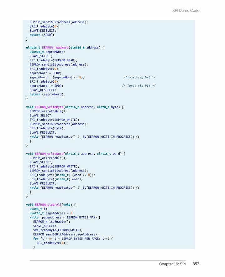
EEPROM_send16BitAddress(address); SPI_tradeByte(0); SLAVE_DESELECT; return (SPDR);}
uint16_t EEPROM_readWord(uint16_t address) { uint16_t eepromWord; SLAVE_SELECT; SPI_tradeByte(EEPROM_READ); EEPROM_send16BitAddress(address); SPI_tradeByte(0); eepromWord = SPDR; eepromWord = (eepromWord << 8); /* most-sig bit */ SPI_tradeByte(0); eepromWord += SPDR; /* least-sig bit */ SLAVE_DESELECT; return (eepromWord);}
void EEPROM_writeByte(uint16_t address, uint8_t byte) { EEPROM_writeEnable(); SLAVE_SELECT; SPI_tradeByte(EEPROM_WRITE); EEPROM_send16BitAddress(address); SPI_tradeByte(byte); SLAVE_DESELECT; while (EEPROM_readStatus() & _BV(EEPROM_WRITE_IN_PROGRESS)) {; }}
void EEPROM_writeWord(uint16_t address, uint16_t word) { EEPROM_writeEnable(); SLAVE_SELECT; SPI_tradeByte(EEPROM_WRITE); EEPROM_send16BitAddress(address); SPI_tradeByte((uint8_t) (word >> 8)); SPI_tradeByte((uint8_t) word); SLAVE_DESELECT; while (EEPROM_readStatus() & _BV(EEPROM_WRITE_IN_PROGRESS)) {; }}
void EEPROM_clearAll(void) { uint8_t i; uint16_t pageAddress = 0; while (pageAddress < EEPROM_BYTES_MAX) { EEPROM_writeEnable(); SLAVE_SELECT; SPI_tradeByte(EEPROM_WRITE); EEPROM_send16BitAddress(pageAddress); for (i = 0; i < EEPROM_BYTES_PER_PAGE; i++) { SPI_tradeByte(0); }
353Chapter 16: SPI
SPI Demo Code

SLAVE_DESELECT; pageAddress += EEPROM_BYTES_PER_PAGE; while (EEPROM_readStatus() & _BV(EEPROM_WRITE_IN_PROGRESS)) {; } }}
initSPIThe first function is initSPI, which initializes the SPI mode. In this case, it’s terriblysimple. We configure all of the pins we’re using for input and output, and then setthe clock, master or slave mode, and SPI enable bits in the SPI Control Register, SPCR.
SPI and Output Pins
Notice in this code that we first set up the data-direction registers for the pins that we’re usingfor SPI, and then enable the SPI-specific hardware. This ordering turns out to be crucial, andthe source of a very subtle bug that’s caught me twice now.
When the SPI is in master mode, it’s got a provision for deferring to other SPI masters in amultimaster setup. If the AVR has its slave-select pin configured as input (which is the boot-up default) and the pin is toggled low, it goes into a passive SPI mode in order to not interferewith the other masters on the bus. So as long as the slave-select pin is low in master mode,it won’t send out a clock signal.
Because of this, you should enable the pullup on the slave-select pin, even if you’re not usingthe pin as an output, before you enable SPI mode. Otherwise, you risk random electricalfluctuations shutting down your SPI. In our case, I’m using the SS pin as an output, so I set itas output and set it high before enabling SPI.
One possible complication with other devices is that you’ll have to set up the phaseand polarity of the SPI bus lines. In our case, the EEPROM is already configured foroperation in the so-called Mode 0, which is the boot-up default for the AVR. Other-wise, you’d have to set up the polarity using the CPOL and CPHA bits. If you findyourself needing to change the SPI data mode, there’s a handy table in the AVRdatasheet, Table 18-2, SPI Modes that summarizes it all, along with nice timingdiagrams in Tables 18-3 and 18-4. Or read “Phases and Polarities” on page 355.
Setting the clock division bits (SPR1 in our example) is largely unnecessary. Afterall, we’re running the AVR at 1 MHz, and most SPI devices handle 10 MHz or higherdata rates. On the other hand, at higher and higher frequencies, wires becomeeffectively antennas and circuits that should work if designed with short connec-tions on a printed circuit board can fail entirely when you’re using long wires andassembling stuff on a breadboard. So in this example, I’m running the SPI bus at a
354 Make: AVR Programming
SPI Demo Code
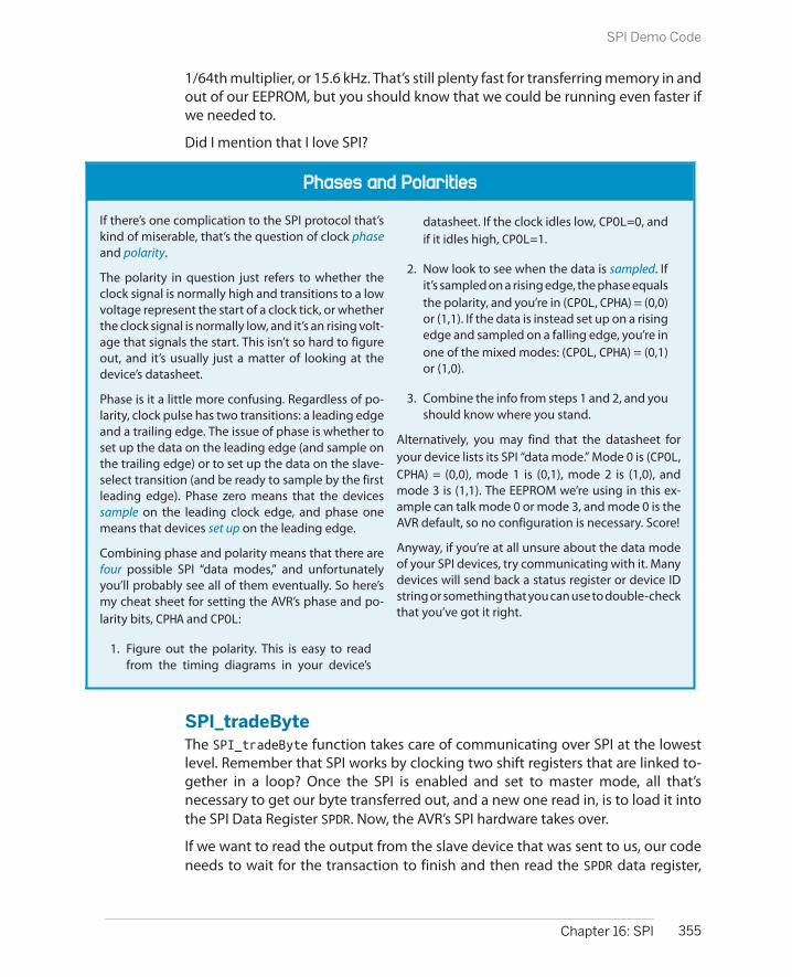
Phases and Polarities
If there’s one complication to the SPI protocol that’skind of miserable, that’s the question of clock phaseand polarity.
The polarity in question just refers to whether theclock signal is normally high and transitions to a lowvoltage represent the start of a clock tick, or whetherthe clock signal is normally low, and it’s an rising volt-age that signals the start. This isn’t so hard to figureout, and it’s usually just a matter of looking at thedevice’s datasheet.
Phase is it a little more confusing. Regardless of po-larity, clock pulse has two transitions: a leading edgeand a trailing edge. The issue of phase is whether toset up the data on the leading edge (and sample onthe trailing edge) or to set up the data on the slave-select transition (and be ready to sample by the firstleading edge). Phase zero means that the devicessample on the leading clock edge, and phase onemeans that devices set up on the leading edge.
Combining phase and polarity means that there arefour possible SPI “data modes,” and unfortunatelyyou’ll probably see all of them eventually. So here’smy cheat sheet for setting the AVR’s phase and po-larity bits, CPHA and CPOL:
1. Figure out the polarity. This is easy to readfrom the timing diagrams in your device’s
datasheet. If the clock idles low, CPOL=0, andif it idles high, CPOL=1.
2. Now look to see when the data is sampled. Ifit’s sampled on a rising edge, the phase equalsthe polarity, and you’re in (CPOL, CPHA) = (0,0)or (1,1). If the data is instead set up on a risingedge and sampled on a falling edge, you’re inone of the mixed modes: (CPOL, CPHA) = (0,1)or (1,0).
3. Combine the info from steps 1 and 2, and youshould know where you stand.
Alternatively, you may find that the datasheet foryour device lists its SPI “data mode.” Mode 0 is (CPOL,CPHA) = (0,0), mode 1 is (0,1), mode 2 is (1,0), andmode 3 is (1,1). The EEPROM we’re using in this ex-ample can talk mode 0 or mode 3, and mode 0 is theAVR default, so no configuration is necessary. Score!
Anyway, if you’re at all unsure about the data modeof your SPI devices, try communicating with it. Manydevices will send back a status register or device IDstring or something that you can use to double-checkthat you’ve got it right.
1/64th multiplier, or 15.6 kHz. That’s still plenty fast for transferring memory in andout of our EEPROM, but you should know that we could be running even faster ifwe needed to.
Did I mention that I love SPI?
SPI_tradeByteThe SPI_tradeByte function takes care of communicating over SPI at the lowestlevel. Remember that SPI works by clocking two shift registers that are linked to-gether in a loop? Once the SPI is enabled and set to master mode, all that’snecessary to get our byte transferred out, and a new one read in, is to load it intothe SPI Data Register SPDR. Now, the AVR’s SPI hardware takes over.
If we want to read the output from the slave device that was sent to us, our codeneeds to wait for the transaction to finish and then read the SPDR data register,
355Chapter 16: SPI
SPI Demo Code

where the outgoing data used to be and the incoming data now resides. All theSPI_tradeByte code does is wait for the transmission to be complete. Reading outthe new byte (if you want to) is left for the calling code.
Convenience FunctionsThe rest of the 25LC256.c file defines a bunch of convenience functions. All of thesebasically just code up what the EEPROM’s datasheet said to do to talk to it, so I won’tgo into all of them in too much detail. However, the basic flavor of an SPI transactionruns through all of them, so it’s worth taking a quick peek.
Look at the function EEPROM_readByte, for example. As with all SPI devices, theEEPROM needs to know when it’s being spoken to, and this is done by sending adigital low voltage over it’s slave-select (or chip-select, depending on the data-sheet) line. Then the AVR sends the command to read out memory from the EE-PROM, which is defined in the .h file. (Remember, at the same time, the EEPROM isloading up the SPDR with a byte, but we don’t really care what it is.) Next the AVRsends the 16-bit address of where to start reading memory from. Because we dothis so often, I wrote a convenience function that breaks up a 16-bit number intotwo 8-bit bytes and sends them separately.
Having sent the read command and the address, all that remains is to read outsome bytes. In this case, the function reads just one and then returns. Note againthat the AVR is sending a byte worth of zeros—it had to have something to tradefor the EEPROM’s byte. If we wanted to read more bytes, the AVR could keep tradingbytes with the EEPROM, and because the EEPROM is in read mode, it would sendthe next byte out of its memory. In this case, though, we’re happy with one byte,so the function deselects the slave-select line (raising it to a logic high voltagelevel), and returns the value of SPDR, which has the last value read out from thememory.
The EEPROM_writeByte command is only a bit more complicated. In order to pre-vent EEPROM memory corruption, you have to first send a write-enable commandbefore issuing the write command. This is done in the usual way—drop the slave-select line, load a byte across to the EEPROM with the write-enable command, andthen reraise slave select. Now the EEPROM is ready for writing, and the procedureis similar to reading.
Finally, because writing to an EEPROM can take a few milliseconds, the last line inthe write command continually reads the EEPROM’s status byte: dropping the slaveline, sending the “read status” command, sending a byte to receive the response,and then reraising slave line at the end. Each time through this cycle, the codechecks to see if the write-in-progress bit is set and keeps looping until it isn’t.
Because the EEPROM is structured in 8-bit bytes, like the AVR, it takes a little bitmore work to read and write 16-bit numbers, so I wrote convenience functions forthese. If you look at EEPROM_readWord for instance, you’ll notice that it’s just about
356 Make: AVR Programming
SPI Demo Code
the same as EEPROM_readByte except that there are two calls to SPI_tradeByte(0) after the address is sent, and the return value is a 16-bit data word that’sbeen reconstituted from the two bytes that get read in.
Finally, there’s a function that erases the entire EEPROM. The fastest way to do thisis to start on a page boundary (multiple of 64 in the address space) and load up 64bytes of zeros, and then write it permanently to memory. Repeating this for everypage of 64 bytes in the EEPROM blanks the whole device in minimum time. Thisfunction is a good example of the page-by-page style of writing that gets the fastestspeed out of EEPROMs.
Summary
Using the AVR’s built-in SPI hardware is easy and is definitely the fastest way to getdata in and out of the microcontroller. In terms of configuration, it’s not hard at all;in terms of use it is even easier—just write your byte to a register. Here’s a summary:
1. Set up the SCK and MOSI pins (PB5 and PB3, respectively) for output.
2. Set up the MISO pin (PB4) for input, with pullup enabled.
3. If the AVR is the clock master, set the pullup on SS (PB2) if you’re not using thepin as output.
4. Make sure the SPI clock speed is low enough to work with your intended device,and set a speed divider if it’s not, or even if you just don’t need the extra speed.
5. Set the AVR into clock master mode and enable SPI.
6. When you start communicating with a given slave device, begin by flipping itsslave-select line low.
7. Now when you want to send a byte to that slave, write it to SPDR, wait for thetransaction to end, and read the response back again from SPDR.
8. Finish up a transaction by setting the slave’s slave-select line high again. Whenyou want to talk to another device on the SPI line, simply drop its slave-selectline low to start, and away you go.
9. The rest of the details are application-specific. Most devices have their owncommand sets, address spaces, etc. All of them will be based around sendinga series of 8-bit bytes, and all of these should be laid out in their datasheets.
Still, communication between devices can be tricky. When you’re looking at a newperipheral chip, be prepared to sit down with the datasheet for an hour or so. Thefirst step is to turn all of the useful chip-specific commands into nice, readabledefinitions, and store them in a header file. Then write down all of the transactiontypes you’ll need, look them up in the datasheet, and start coding and testing.
357Chapter 16: SPI
Summary


Logging Digital Thermometer
I2C is a tremendously popular protocol for interfacing microcontrollers with smallsensors and these days even with devices that require more speed. Its main ad-vantage is that you can talk to a large number of devices with just a couple of wires,which makes it much more like a network than the SPI bus. When you find yourselfwanting to talk with I2C devices, this chapter will get you a head start!
We’ll be continuing on from Chapter 16 toward building a logging I2C thermom-eter. If you use the SPI EEPROM chip from last chapter, the logger will be capableof recording the temperature at a variable frequency for at least a few days on AAbatteries. Then, when you want to read the data back out, the AVR code will dumpit over the USB-Serial port back to your desktop computer for graphing andanalysis.
And even if you don’t need a logging thermometer, you should be able to modifythis code reasonably easily to work with other I2C devices. Indeed, I wrote most ofthe code in this chapter for a logging accelerometer that our hackerspace sent upinto near-space with a helium balloon. There are I2C sensors available for almostany quantity you’d like to measure, all you have to do is look around.
In the previous chapter, I extolled the main virtues of the SPI bus: it’s fast and simple.At least as long as you’re only communicating with a few devices. When you’redealing with more than a few peripherals, the requirement to have one slave-selectline per device on the network can get out of hand. (Imagine if the Internet workedlike SPI! Each computer would need a physical wire to every other computer in theworld just to tell the other that you’re ready to talk to it.)
Instead, we can give each device an address and require the master to send thisaddress as a data prefix that the slave devices will listen for. That would drop SPI’srequirement of four wires (plus one more for each additional device) down to three.
359
I2C 17

What You Need
In addition to the basic kit, you will need:
• An I2C device to talk to—my example uses thevery common LM75 temperature sensor.
• For the LM75 temperature sensor, you’ll alsoneed a surface-mount to DIP adapter.
• Two 10k ohm resistors to use as pull-ups forthe I2C data line.
• SPI EEPROM Memory chip from the previouschapter for logging data.
• A USB-Serial adapter.
What’s in a Name? (TWI, I2C, and I2C)
“I2C” was once a trademark of Philips Electronics andis now owned by the spin-off IC company, NXP. Whilethere’s absolutely no licensing issues surrounding
using the “I2C” protocol, you’ll have to pay NXP mon-
ey if you’d like to use the name “I2C” with yourhardware.
Because of this, Atmel uses what they call a “Two-wireinterface” (TWI) protocol that happens to be 100%
compatible with “I2C,” but by calling it something
else, they sidestep the trademark issue. So whenyou’re reading through Atmel documentation, feel
free to read “I2C” anywhere you see “TWI.”
There are also a handful of “I2C"-like protocols, mostof which are tiny variations (SMBus, PMBbus, etc.) orwhich are largely interoperable. So when I write “I2C,”
I don’t mean “I2C,” but instead the whole family of
“I2C"-like protocols that all work together. (And be-sides, typing superscripts all the time gets old.)
And because most of the time we’re only sending meaningful data one way or theother, maybe we don’t need truly bidirectional, full-duplex communications likeSPI provides. Maybe we could run everything half duplex, drop yet one more wire,and use only two? And if we could, we’d call the two wires by the more genericnames “serial clock” and “serial data.” Hmmm….
Welcome to the beginnings of the I2C protocol. In contrast to SPI, it’s designed touse a minimum number of wires (two, plus ground) and yet handle a large networkof devices (up to 128 with “standard” I2C). The trade-off is that I2C is a bit morecomplex from a user’s standpoint, and not capable of the same extreme speeds.However, when you need to connect your AVR to an LCD screen, a few buttons,some sensors, and a dozen networked multicolor blinky lights, I2C is the way togo. (Of course, nothing stops you from using both SPI and I2C peripherals at thesame time—the AVR’s hardware peripherals are independent of each other.)
360 Make: AVR Programming
I2C
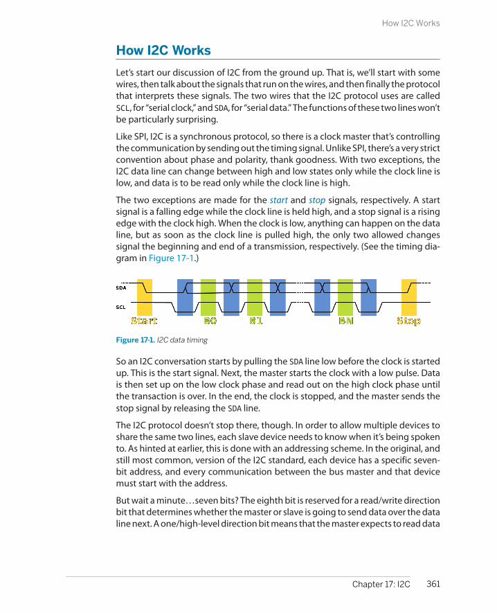
How I2C Works
Let’s start our discussion of I2C from the ground up. That is, we’ll start with somewires, then talk about the signals that run on the wires, and then finally the protocolthat interprets these signals. The two wires that the I2C protocol uses are calledSCL, for “serial clock,” and SDA, for “serial data.” The functions of these two lines won’tbe particularly surprising.
Like SPI, I2C is a synchronous protocol, so there is a clock master that’s controllingthe communication by sending out the timing signal. Unlike SPI, there’s a very strictconvention about phase and polarity, thank goodness. With two exceptions, theI2C data line can change between high and low states only while the clock line islow, and data is to be read only while the clock line is high.
The two exceptions are made for the start and stop signals, respectively. A startsignal is a falling edge while the clock line is held high, and a stop signal is a risingedge with the clock high. When the clock is low, anything can happen on the dataline, but as soon as the clock line is pulled high, the only two allowed changessignal the beginning and end of a transmission, respectively. (See the timing dia-gram in Figure 17-1.)
Figure 17-1. I2C data timing
So an I2C conversation starts by pulling the SDA line low before the clock is startedup. This is the start signal. Next, the master starts the clock with a low pulse. Datais then set up on the low clock phase and read out on the high clock phase untilthe transaction is over. In the end, the clock is stopped, and the master sends thestop signal by releasing the SDA line.
The I2C protocol doesn’t stop there, though. In order to allow multiple devices toshare the same two lines, each slave device needs to know when it’s being spokento. As hinted at earlier, this is done with an addressing scheme. In the original, andstill most common, version of the I2C standard, each device has a specific seven-bit address, and every communication between the bus master and that devicemust start with the address.
But wait a minute…seven bits? The eighth bit is reserved for a read/write directionbit that determines whether the master or slave is going to send data over the dataline next. A one/high-level direction bit means that the master expects to read data
361Chapter 17: I2C
How I2C Works

off the line, and a zero/low-level direction bit means that the master is going towrite data to the SDA line.
So if the AVR sends a start, then the address of a slave device, and then a zero, theslave device knows that it’s going to receive a byte from the AVR (that is, the masteris going to write a byte) immediately afterward. If the last bit after the address is aone, then the slave is responsible for sending data; the master reads data off thebus.
There’s one final complication that you need to know about. The device that’sreceiving the data, whether it’s the master or slave, is responsible for acknowledg-ing that it has received the byte. To do this, a ninth bit is sent after every 8-bit byte.A zero or low (“ACK”) indicates that the byte is acknowledged and signals that thesender should continue sending. A high bit (“NACK”) indicates that there was anerror or that the transmitter should stop sending or that the whole communicationis about to end, depending on the circumstances.
Note that the “ACK” or “NACK” bit is sent by the receiver rather than the transmitter.This makes it possible to detect if there’s been an error in the transmission, whichcan be handy if you’re operating in an electrically noisy environment. (And this isin contrast to SPI, where everything’s just assumed to work.)
Later on in this chapter, you’ll implement this exact conversation in code, but fornow, to give you the flavor of a “complicated” I2C transaction between the AVR andan LM75 temperature sensor, let’s set the LM75 up for a temperature reading andget two bytes from it. To do this, the AVR will first need to send a byte to the LM75,to put it in temperature-reading mode, and then the AVR will need to receive twobytes (the temperature) from the LM75. The oscilloscope trace from this conver-sation can be seen in Figure 17-2.
362 Make: AVR Programming
How I2C Works
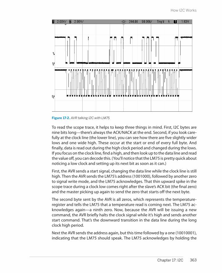
Figure 17-2. AVR talking I2C with LM75
To read the scope trace, it helps to keep three things in mind. First, I2C bytes arenine bits long—there’s always the ACK/NACK at the end. Second, if you look care-fully at the clock line (the lower line), you can see how there are five slightly widerlows and one wide high. These occur at the start or end of every full byte. Andfinally, data is read out during the high clock period and changed during the lows.If you focus on the clock line, find a high, and then look up to the data line and readthe value off, you can decode this. (You’ll notice that the LM75 is pretty quick aboutnoticing a low clock and setting up its next bit as soon as it can.)
First, the AVR sends a start signal, changing the data line while the clock line is stillhigh. Then the AVR sends the LM75’s address (1001000), followed by another zeroto signal write mode, and the LM75 acknowledges. That thin upward spike in thescope trace during a clock low comes right after the slave’s ACK bit (the final zero)and the master picking up again to send the zero that starts off the next byte.
The second byte sent by the AVR is all zeros, which represents the temperature-register and tells the LM75 that a temperature read is coming next. The LM75 ac-knowledges again—a ninth zero. Now, because the AVR will be issuing a newcommand, the AVR briefly halts the clock signal while it’s high and sends anotherstart command. That’s the downward transition in the data line during the longclock high period.
Next the AVR sends the address again, but this time followed by a one (10010001),indicating that the LM75 should speak. The LM75 acknowledges by holding the
363Chapter 17: I2C
How I2C Works

I2C Protocol Summary
So to recap:
1. The SDA data line and SCL clock lines are bothheld normally high by pull-up resistors. Datais signalled as a zero by pulling the line low, oras a one by allowing the line to float back uphigh.
2. Communication starts with a start signal: pull-ing the data line low before the clock hasstarted up.
3. Data is then set up during the clock low peri-ods, and read out when the clock is high.
4. The first byte after a start is always the seven-bit address of the slave, followed by a
direction bit indicating whether master orslave will be sending data on the SDA line next.
5. After each byte sent, the receiving devicesends either an ACK bit (a low voltage, or zero)or a NACK bit (high, or one) depending onwhether the communication is to continue.
6. If the master needs to change the direction ofcommunication in the middle, it can send an-other start signal, followed by the address andnew direction bit.
7. Finally, after the last transmitted byte, themaster stops the clock and then releases thedata line, sending a stop signal.
data line low, and then sends the most significant byte of data. In my office, it wasapparently 21 degrees (00010101).
The AVR now acknowledges this byte with a zero, and the LM75 sends the least-significant byte, which in the case of the LM75 is the decimal place. For the cheapLM75s only the first bit counts, and it stands for half a degree. Here, the LM75 sent10000000, so the full temperature reading is 21.5 degrees. Fancier LM75s can readdown to the eighth of a Celsius degree, so there may be meaningful data in thefirst three of these bits.
And then finally, because it’s the end of the communication, the AVR sends a NACK(a one) and the stop signal by holding the clock line high and raising the data line.
364 Make: AVR Programming
How I2C Works

I2C Wiring
Both of these lines are normally held high when nobody is transmitting. In fact, electrically,the two I2C lines are held high by a pull-up resistor, and to send a zero on the data line, thedevices connected to them pull the lines low with low-side transistor switches and just let thelines “float” back up to their high state.
A practical speed limit on how fast the I2C bus can run is how quickly this pull-up resistor candrag the whole wire back up to the high voltage level. For long I2C connections, the capaci-tance between the signal wires and ground can slow this transition down even further. Ifyou’re having trouble with noise on a long (many inches) I2C line, that’s a good first place tostart looking; try slowing down the data rate and see if that fixes the problem.
If you need the line to run faster, you can try to fine-tune the pull-up resistors on the line, butyou may need to reroute the I2C lines to reduce inter-wire capacitance.
I2C Demo Hookup
It’s time to hook up the I2C thermometer to your breadboard. Don’t unplug the SPIEEPROM when adding in the LM75 temperature sensor, because we’re going to beusing both together to make the temperature logger by the end of the chapter.
The LM75 is only available these days as a surface-mount component, so we’regoing to have to do a little bit of adapting to get it to fit into the breadboard. Theeasiest way to go is to purchase a pre-made SOIC-to-DIP 8 pin adapter. The usualsuspects for hobbyist electronics prototyping supplies will have these for a coupleof dollars, but you may be able to get them cheaper from online auction sites.
Solder the LM75 into the adapter and then plug the adapter into the breadboardand you’re all set. If the adapter were in fact a DIP chip, you would have somethinglike Figure 17-3.
365Chapter 17: I2C
I2C Demo Hookup
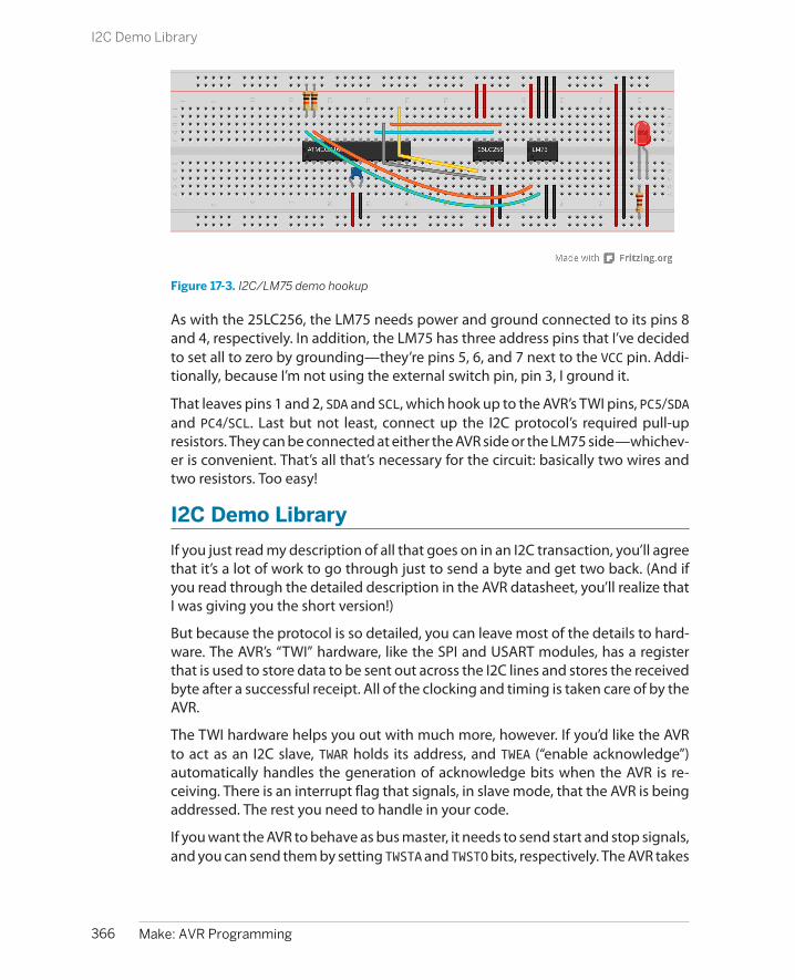
Figure 17-3. I2C/LM75 demo hookup
As with the 25LC256, the LM75 needs power and ground connected to its pins 8and 4, respectively. In addition, the LM75 has three address pins that I’ve decidedto set all to zero by grounding—they’re pins 5, 6, and 7 next to the VCC pin. Addi-tionally, because I’m not using the external switch pin, pin 3, I ground it.
That leaves pins 1 and 2, SDA and SCL, which hook up to the AVR’s TWI pins, PC5/SDAand PC4/SCL. Last but not least, connect up the I2C protocol’s required pull-upresistors. They can be connected at either the AVR side or the LM75 side—whichev-er is convenient. That’s all that’s necessary for the circuit: basically two wires andtwo resistors. Too easy!
I2C Demo Library
If you just read my description of all that goes on in an I2C transaction, you’ll agreethat it’s a lot of work to go through just to send a byte and get two back. (And ifyou read through the detailed description in the AVR datasheet, you’ll realize thatI was giving you the short version!)
But because the protocol is so detailed, you can leave most of the details to hard-ware. The AVR’s “TWI” hardware, like the SPI and USART modules, has a registerthat is used to store data to be sent out across the I2C lines and stores the receivedbyte after a successful receipt. All of the clocking and timing is taken care of by theAVR.
The TWI hardware helps you out with much more, however. If you’d like the AVRto act as an I2C slave, TWAR holds its address, and TWEA (“enable acknowledge”)automatically handles the generation of acknowledge bits when the AVR is re-ceiving. There is an interrupt flag that signals, in slave mode, that the AVR is beingaddressed. The rest you need to handle in your code.
If you want the AVR to behave as bus master, it needs to send start and stop signals,and you can send them by setting TWSTA and TWSTO bits, respectively. The AVR takes
366 Make: AVR Programming
I2C Demo Library

care of the timing, not sending its own start signal until after the line is clear. Thenyou send the address of the device you’re talking to, and then data, with or withoutacknowledge bits as configured.
If you thought I was a genius for being able to transmit the signal in Figure 17-2,you’ll be surprised how easy the AVR hardware makes it all. And for this demo, Ibasically just reused an old I2C library of mine that I had lying around, and franklyI encourage you to do the same whenever possible.
Because the AVR hardware takes care of so much of the low-level detail, the indi-vidual functions that read and write to the I2C bus are fairly straightforward andquite short. First, have a read through the header file in Example 17-1, and thenwe’ll dig into the code.
Example 17-1. i2c.h listing// Functions for i2c communication#include <avr/io.h>#include "pinDefines.h"
void initI2C(void); /* Sets pullups and initializes bus speed to 100kHz (at FCPU=8MHz) */
void i2cWaitForComplete(void); /* Waits until the hardware sets the TWINT flag */
void i2cStart(void); /* Sends a start condition (sets TWSTA) */void i2cStop(void); /* Sends a stop condition (sets TWSTO) */
void i2cSend(uint8_t data); /* Loads data, sends it out, waiting for completion */
uint8_t i2cReadAck(void); /* Read in from slave, sending ACK when done (sets TWEA) */uint8_t i2cReadNoAck(void); /* Read in from slave, sending NOACK when done (no TWEA) */
By now, you’re not surprised to see an initI2C function that sets up the necessariesfor using hardware TWI. Because I’m not using interrupt-driven code, i2cWaitForComplete sits in a loop until an already-in-progress I2C byte is sent.
If you look back on the description of I2C in “How I2C Works” on page 361, you’llsee that we’re basically doing three things: sending data (and waiting for it to beacknowledged) or reading in data either with or without an acknowledge at theend. Of course, as the master, the AVR is also responsible for bracketing the con-versation with start and stop conditions.
367Chapter 17: I2C
I2C Demo Library

Let’s turn now to the i2c.c listing in Example 17-2. The actual code itself is notmuch longer than the words typed to describe it!
Example 17-2. i2c.c listing#include "i2c.h"
void initI2C(void) { TWBR = 32; /* set bit rate, see p. 242 */ /* 8MHz / (16+2*TWBR*1) ~= 100kHz */ TWCR |= (1 << TWEN); /* enable */}
void i2cWaitForComplete(void) { loop_until_bit_is_set(TWCR, TWINT);}
void i2cStart(void) { TWCR = (_BV(TWINT) | _BV(TWEN) | _BV(TWSTA)); i2cWaitForComplete();}
void i2cStop(void) { TWCR = (_BV(TWINT) | _BV(TWEN) | _BV(TWSTO));}
uint8_t i2cReadAck(void) { TWCR = (_BV(TWINT) | _BV(TWEN) | _BV(TWEA)); i2cWaitForComplete(); return (TWDR);}
uint8_t i2cReadNoAck(void) { TWCR = (_BV(TWINT) | _BV(TWEN)); i2cWaitForComplete(); return (TWDR);}
void i2cSend(uint8_t data) { TWDR = data; TWCR = (_BV(TWINT) | _BV(TWEN)); /* init and enable */ i2cWaitForComplete();}
Initialization is just a matter of configuring the SDA and SCL pins for output, selectingthe bit rate, and hitting the enable button in the TWI configuration register, TWCR.If you want to run the I2C bus very slowly, that’s also fine, and there are also twoprescaler bits in the TWI status register, TWSR, that you can use to divide the baserate by 1 (default), 4, 16, or 64.
368 Make: AVR Programming
I2C Demo Library
I2C Bus Speeds
A word or two on the bit rate, while we’re here. Theoldest I2C standard specified 100 kHz for the maxi-mum bit-rate, and then came 400 kHz “Fast-mode”and 1 MHz “Fast-mode Plus” and recently 3.4 MHz“High-speed mode” and 5 MHz “Ultra Fast-mode.” Myguess is that before the English language runs out ofsuperlatives to go with “fast,” there will be a few moreI2C speed grades as well.
In practical situations, the speed over the bus line islimited by how quickly the pull-up resistors can
reraise the line’s voltage, and this in turn is limited bythe intrinsic capacitance in the line. As you get up intohigher and higher frequencies, the lines behave morelike transmission lines than instantaneous signals,and you have to start worrying about terminationand internal reflections and stuff like that.
If none of the above makes any sense, or it does andyou just don’t feel like working these design issuesinto your circuit board, stick with the lower-speed 100kHz or 400 kHz modes.
The function i2cWaitForComplete is the equivalent of the blocking-wait that wedid in the UART code. When the byte in progress has been transferred across theI2C line, the TWINT flag is set. Here, we just loop until the transfer’s done. Unlike theUART code, where it can take a long time to get a byte in, especially if we’re waitingfor a human to type it, here the wait is usually short enough that the cost of ablocking wait is not a problem.
The rest of the code simply gives readable names to the process of setting the bitswe need to set in the TWI control register in order to send or receive data andincludes the i2cWaitForComplete command where necessary. In particular, eachof the other commands set the TWINT and TWEN bits, which has the effect of re-setting the interrupt flag and making sure that the TWI interface stays enabled.The additional bits in the TWCR that are either set or not determine the type oftransaction: a start or stop signal; sending or receiving data; and with or withoutan ACK.
I2C Error Codes
If you wanted to be very careful about things, you could check up on the codes returned inthe TWI status register after every transmission and make sure that there’s nothing strangegoing on. The AVR datasheet has five or six brutal pages going through all of the error codesand their causes. The util/twi.h standard library includes mnemonic macros for each ofthe I2C transaction status codes for your convenience.
Honestly, I’ve only had use for them once, and that was when I was trying to troubleshoot aproblem that turned out to be of my own making—not sending a NACK at the end of a finalbyte caused the I2C data flash chip I was using to lock up every other conversation. You mayget more out of the result codes than I did, however, so feel free to read through that sectionof the AVR datasheet when the time arises.
369Chapter 17: I2C
I2C Demo Library

I2C Thermometer Demo
With I2C, just as with SPI, getting the AVR’s hardware to speak the protocol andshuttle data across is only half of the battle. The rest is in the specifics of commu-nicating with a specific target chip. In the case here, it’s a cheap digital thermometerthat sends the temperature over I2C. If you’d like to follow along as I work throughthe code in Example 17-3, go download the datasheet for your version of the LM75.(It’s a mostly standardized chip produced by multiple manufacturers, but with littledifference across them. The datasheets should all be similar, too. For what it’s worth,I’ve looked at the ones from NXP and from National Semiconductor.)
Example 17-3. i2cThermometer.c listing /* Reads LM75 Thermometer and Prints Value over Serial */
// ------- Preamble -------- //#include <avr/io.h>#include <util/delay.h>#include <avr/power.h>
#include "pinDefines.h"#include "USART.h"#include "i2c.h"
// -------- Defines -------- //
#define LM75_ADDRESS_W 0b10010000#define LM75_ADDRESS_R 0b10010001#define LM75_TEMP_REGISTER 0b00000000#define LM75_CONFIG_REGISTER 0b00000001#define LM75_THYST_REGISTER 0b00000010#define LM75_TOS_REGISTER 0b00000011// -------- Functions --------- //
int main(void) {
uint8_t tempHighByte, tempLowByte;
// -------- Inits --------- // clock_prescale_set(clock_div_1); /* 8MHz */ initUSART(); printString("\r\n==== i2c Thermometer ====\r\n"); initI2C();
// ------ Event loop ------ // while (1) { /* To set register, address LM75 in write mode */ i2cStart(); i2cSend(LM75_ADDRESS_W); i2cSend(LM75_TEMP_REGISTER); i2cStart(); /* restart, just send start again */
370 Make: AVR Programming
I2C Thermometer Demo
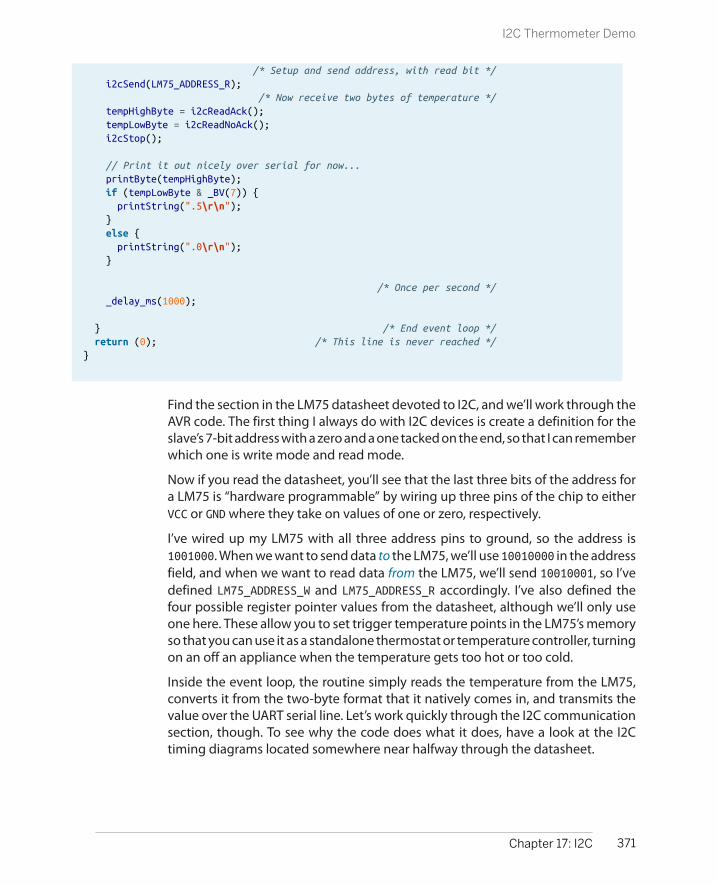
/* Setup and send address, with read bit */ i2cSend(LM75_ADDRESS_R); /* Now receive two bytes of temperature */ tempHighByte = i2cReadAck(); tempLowByte = i2cReadNoAck(); i2cStop();
// Print it out nicely over serial for now... printByte(tempHighByte); if (tempLowByte & _BV(7)) { printString(".5\r\n"); } else { printString(".0\r\n"); }
/* Once per second */ _delay_ms(1000);
} /* End event loop */ return (0); /* This line is never reached */}
Find the section in the LM75 datasheet devoted to I2C, and we’ll work through theAVR code. The first thing I always do with I2C devices is create a definition for theslave’s 7-bit address with a zero and a one tacked on the end, so that I can rememberwhich one is write mode and read mode.
Now if you read the datasheet, you’ll see that the last three bits of the address fora LM75 is “hardware programmable” by wiring up three pins of the chip to eitherVCC or GND where they take on values of one or zero, respectively.
I’ve wired up my LM75 with all three address pins to ground, so the address is1001000. When we want to send data to the LM75, we’ll use 10010000 in the addressfield, and when we want to read data from the LM75, we’ll send 10010001, so I’vedefined LM75_ADDRESS_W and LM75_ADDRESS_R accordingly. I’ve also defined thefour possible register pointer values from the datasheet, although we’ll only useone here. These allow you to set trigger temperature points in the LM75’s memoryso that you can use it as a standalone thermostat or temperature controller, turningon an off an appliance when the temperature gets too hot or too cold.
Inside the event loop, the routine simply reads the temperature from the LM75,converts it from the two-byte format that it natively comes in, and transmits thevalue over the UART serial line. Let’s work quickly through the I2C communicationsection, though. To see why the code does what it does, have a look at the I2Ctiming diagrams located somewhere near halfway through the datasheet.
371Chapter 17: I2C
I2C Thermometer Demo

The LM75 comes in power-up default ready to read out its temperature data, butjust so that we’re sure it’s giving us a temperature reading (and to demonstratesending a restart signal), let’s set the temperature pointer just to be sure. Find thesection in the LM75 datasheet where it describes something like “Read Tempera-ture register including pointer byte (2-byte data)” or similar. Because the AVR hard-ware will take care of a bunch of the low-level detail for you, what you’re lookingfor in these diagrams are things like start and stop conditions, what bytes need tobe sent in what order, and where ACK and NACKs are expected of the AVR whenreceiving data.
Communication with the thermometer starts off, naturally, with a start command.To set the pointer byte, we need to write to the LM75, so the AVR will send theLM75’s address plus the write flag and expect an ACK to be sure everything is OK.After the ACK, the AVR sends the temperature register command, which happensto be all zeros, and expects another ACK.
Now the AVR wants to read from the LM75, so it has to change the data direction.To do this, the AVR sends a restart and then the LM75’s address byte plus the readflag this time, and expects an ACK. Next, the LM75 should transmit a single byte,followed by an ACK, and then another byte, this time followed with a NACK to markthe end of the transmission. Finally, the AVR sends a stop signal to free up the I2Cbus line for other communication. See how that translates fairly cleanly into code?
SPI and I2C Data Logger
Now let’s put all that we know about SPI and I2C together with a USART serial userinterface. That’s right, three serial communication modes in one little project!
Combine an AVR, the EEPROM memory, and the LM75 thermometer and four AAbatteries, and you’ve got a portable temperature logger that will run for days. Andbecause the data is stored in the EEPROM, you can unplug the device at any timeand pick up from wherever you left off. And when you connect it to your desktopcomputer’s serial port, you can dump all of the data and do whatever you’d likewith it.
You should also note that, although this is a thermometer application, it could beanything. Data loggers are all very similar, and not particularly difficult to writeonce you’ve figured out how to communicate with the devices in question. Forinstance, if you wanted to build a GPS location-logger, you’ll be stoked to knowthat GPS modules almost all speak UART serial, and that parsing their report stringsisn’t all that hard at all. Or maybe you’re interested in building a logging acceler-ometer. For instance, most accelerometers speak I2C and are even easier to inte-grate into a data logger. Heck, I don’t know what it is that you’re interested inlogging, but here’s a simple framework to do it.
372 Make: AVR Programming
SPI and I2C Data Logger

You’ve already seen the basics of how to work with both the SPI EEPROM and theI2C data from the LM75 temperature sensor. And because I wrote these functionsinto standalone libraries, reusing the functions is as easy as including the headerfiles in the code and linking to their code in the makefile.
The main new bit in this project is a simple UART-serial based menu system thatonly activates if you type “m” within a few seconds of resetting the AVR chip. Thegoal was to build a device that’s both free-standing and can be controlled whenplugged into your desktop computer. Implementing the menu is actually quitesimple—you simply configure the serial port, wait for a few seconds, and then testif the desired character came across in the meantime. If yes, enter a menu loop thatrepeats until you type “s” to start logging. If “m” wasn’t received over the serial portduring the delay time, jump straight into the event loop.
Let’s see how it all comes together in Example 17-4.
Example 17-4. loggingThermometer.c listing// ------- Preamble -------- //#include <avr/io.h>#include <util/delay.h>#include <avr/interrupt.h>#include <avr/power.h>
#include "pinDefines.h"#include "USART.h"
#include "i2c.h" /* for i2c functions */#include "25LC256.h" /* for EEPROM specific */
// -------- Defines --------- //
#define LM75_ADDRESS_W 0b10010000#define LM75_ADDRESS_R 0b10010001#define LM75_TEMP_REGISTER 0b00000000#define LM75_CONFIG_REGISTER 0b00000001#define LM75_THYST_REGISTER 0b00000010#define LM75_TOS_REGISTER 0b00000011
#define CURRENT_LOCATION_POINTER 0 /* where to store a pointer to the current reading in EEPROM */#define SECONDS_POINTER 2 /* store seconds-delay value here */#define MEMORY_START 4 /* where to start logging temperature values */#define MENU_DELAY 5 /* seconds to wait before bypassing main menu */
// -------- Functions --------- //
static inline void printTemperature(uint8_t tempReading) {
373Chapter 17: I2C
SPI and I2C Data Logger

/* temperature stored as 2x Celcius */ printByte((tempReading >> 1)); if (tempReading & 1) { printString(".5\r\n"); } else { printString(".0\r\n"); }}
int main(void) { uint16_t secondsDelay; /* how long to wait between readings */ uint16_t currentMemoryLocation; /* where are we in EEPROM? */ uint16_t i; /* used to count memory locations */ uint8_t tempHighByte, tempLowByte, temperatureByte; /* from LM75 */ uint8_t enterMenu; /* logical flag */
// -------- Inits --------- // clock_prescale_set(clock_div_1); /* 8 MHz */ initSPI(); initI2C(); initUSART(); LED_DDR |= (1 << LED0);
/* Load up last values from EEPROM */ secondsDelay = EEPROM_readWord(SECONDS_POINTER);
/* Delay to allow input to enter main menu */ printString("*** Press [m] within "); printByte(MENU_DELAY); printString(" seconds to enter menu. ***\r\n ");
for (i = 0; i < MENU_DELAY; i++) { _delay_ms(1000); }
if (bit_is_set(UCSR0A, RXC0) && (UDR0 == 'm')) { enterMenu = 1; } else { enterMenu = 0; }
while (enterMenu) { printString("\r\n====[ Logging Thermometer ]====\r\n "); currentMemoryLocation = EEPROM_readWord(CURRENT_LOCATION_POINTER); printWord(currentMemoryLocation - MEMORY_START); printString(" readings in log.\r\n "); printWord(secondsDelay); printString(" seconds between readings.\r\n"); printString(" [<] to shorten sample delay time\r\n"); printString(" [>] to increase sample delay time\r\n"); printString(" [?] to reset delay time to 60 sec\r\n"); printString(" [d] to print out log over serial\r\n");
374 Make: AVR Programming
SPI and I2C Data Logger

printString(" [e] to erase memory\r\n"); printString(" [s] to start logging\r\n\r\n");
switch (receiveByte()) { case 'd': SLAVE_SELECT; SPI_tradeByte(EEPROM_READ); EEPROM_send16BitAddress(MEMORY_START); for (i = MEMORY_START; i < currentMemoryLocation; i++) { SPI_tradeByte(0); printTemperature(SPDR); } SLAVE_DESELECT; break; case '<': if (secondsDelay >= 10) { secondsDelay -= 5; EEPROM_writeWord(SECONDS_POINTER, secondsDelay); } break; case '>': if (secondsDelay < 65000) { secondsDelay += 5; EEPROM_writeWord(SECONDS_POINTER, secondsDelay); } break; case '?': secondsDelay = 60; EEPROM_writeWord(SECONDS_POINTER, secondsDelay); break; case 'e': printString("Clearing EEPROM, this could take a few seconds.\r\n"); EEPROM_clearAll(); EEPROM_writeWord(CURRENT_LOCATION_POINTER, MEMORY_START); EEPROM_writeWord(SECONDS_POINTER, secondsDelay); break; case 's': printString("OK, logging...\r\n"); enterMenu = 0; break; default: printString("Sorry, didn't understand that.\r\n"); } }
// ------ Event loop ------ // while (1) {
currentMemoryLocation = EEPROM_readWord(CURRENT_LOCATION_POINTER);
/* Make sure in temperature mode */ i2cStart(); i2cSend(LM75_ADDRESS_W); i2cSend(LM75_TEMP_REGISTER);
375Chapter 17: I2C
SPI and I2C Data Logger

/* Get Temp from thermometer */ i2cStart(); /* Setup and send address, with read bit */ i2cSend(LM75_ADDRESS_R); tempHighByte = i2cReadAck(); /* two bytes of temperature */ tempLowByte = i2cReadNoAck(); i2cStop(); temperatureByte = (tempHighByte << 1) | (tempLowByte >> 7); /* temperatureByte now contains 2x the temperature in Celcius */ printTemperature(temperatureByte); /* serial output */
/* Save the new temperature value */ EEPROM_writeByte(currentMemoryLocation, temperatureByte);
/* move on to next location and record new position if not already at the end of memory */ if (currentMemoryLocation < EEPROM_BYTES_MAX) { currentMemoryLocation++; EEPROM_writeWord(CURRENT_LOCATION_POINTER, currentMemoryLocation); }
/* delay */ for (i = 0; i < secondsDelay; i++) { _delay_ms(1000); LED_PORT ^= (1 << LED0); /* blink to show working */ }
} /* End event loop */ return (0); /* This line is never reached */}
Pointers in EEPROMFirst off, I just copied the definitions for the LM75’s I2C address into the top of thecode to make reading and writing just as easy as it was in the demo program. Whatfollows next, though, is a little bit interesting. I define three EEPROM memorylocations.
The first defined memory location is the one in which I plan to store the memorylocation where the current temperature reading should go. (If you’ve never beenthrough pointers in C, reread that sentence until it makes sense.) The idea is thatif the AVR is reset, we don’t want to start writing again at the beginning of memory,because then we’d overwrite whatever data we have in memory. So instead, wekeep track of where we should be writing next. But we can’t keep track of it in RAM,because we lose that when the battery goes dead, so we write the current EEPROMmemory location itself into EEPROM. CURRENT_LOCATION_POINTER is the memorylocation where the current memory location value is stored.
Next, I wanted the device to be menu-configurable in terms of how many secondsto sleep between data readings, rather than have the value hardcoded into a#define or something. But this also means that whatever value is last decided on
376 Make: AVR Programming
SPI and I2C Data Logger

needs to be stored somewhere nonvolatile—on our SPI EEPROM. SECONDS_LOCATION is the location in EEPROM where the number of seconds per update is stored.
Jumping briefly down to the main() body, you can see that just after the variousserial initialization functions are called, the code initializes a variable secondsDelay from the EEPROM location defined earlier. Because the code uses this valuefrequently, it’s probably worthwhile to keep it in RAM like this. If RAM is tight,though, you could simply reread the value from EEPROM every time youneeded it.
Configuration Parameters and Internal EEPROM
Storing nonvolatile configuration parameters like this is very common in small embedddeddevices, and to help with that, the AVRs actually have a very small amount of built-in EEPROMso that you can do the same trick as here, but without needing external memory.
Unfortunately, internal EEPROM is measured in bytes rather than kilobytes, so it’s not verygood for data-logging purposes, but we’ll see in Chapter 18 how to use internal EEPROM tostore configuration parameters and other user data.
Both of the memory pointer and the delay value are 16-bit numbers, so note thatI’m allocating two bytes for each in choosing the locations. Finally, MEMORY_STARTis a useful definition to have around. This way, we’ll know where to start recordingagain after a complete memory erase.
The UART Serial MenuWe saw a simple UART-serial menu system in a few examples so far. This one’s themost elaborate. In this menu, there are options for setting the delay, printing outall the data from the EEPROM over the serial line, erasing the SPI EEPROM, andsimply leaving the menu and entering logging mode. First, let’s talk about how toget into menu mode, and then we’ll look at the menu code itself.
When the chip first wakes up from a reset, it prompts over the UART serial line toto press “m” within a few seconds to enter the menu. This is followed by a com-pletely normal delay, and then the serial receive flag is checked. If anything camethrough, it’s checked to be equal to “m” or not. If it is, a flag variable, enterMenu, isset, and otherwise, not.
Now the menu loop can easily be constructed as a while(enterMenu) loop arounda switch() statement that reads from the serial input, so that any of the commandsin the menu can be run, and as long as they don’t change the value of enterMenu,we loop around for the next command. Then, if the serial input “s” is received, the
377Chapter 17: I2C
SPI and I2C Data Logger

enterMenu variable is set to zero and the while() is no longer true, and executionmoves on to the event loop.
This pattern of a while() loop with a switch() inside, where one or more of theoptions invalidate the while(), is a common pattern for things like menus andmultiple-choice routines.
From the perspective of this chapter, the other interesting detail in the menu sec-tion is the way that dumping all of the logged memory is handled. Here, we usethe feature of the EEPROM that it will continue spitting out its memory contentsone at a time as long as it receives an SPI clock. Because the last-stored memorylocation is in the variable currentMemoryLocation, we can run through all of thelogged memory by starting at the defined MEMORY_START and reading outcurrentMemoryLocation-MEMORY_START values and printing them out over theUART serial port.
Accessing all of the logged EEPROM memory in one SPI transaction like this is byfar the fastest way to dump all of the EEPROM, but it won’t actually have any realeffect on overall speed, because the SPI bus is so much faster than the UART print-out. Oh well.
The Logger’s Event LoopFinally, whether the user has hit “s” to escape from the menu loop or never enteredthe menu to begin with, we enter the event loop, and the next chunk of code setsthe LM75 temperature pointer and reads out the temperature just as we did in thetemperature sensor demo.
The nine-bit temperature value is trimmed down to eight bits so that it fits moreeasily in memory, the memory location is updated if it’s still within the range of theEEPROM’s maximum number of bytes, and the data is stored. The memory addresspointer in EEPROM is then updated and the AVR delays.
In my personal version of this code, I also added in a slow timer to provide a systemtick so that you can put the AVR and LM75 to sleep, using the timer and an interruptto wake everything back up. Dig into the LM75’s sleep mode in its datasheet ifyou’re interested. With both the AVR and the LM75 asleep (and the EEPROM draw-ing no power), the power drain is less than a battery’s self-discharge rate. If youonly take a temperature reading once every fifteen minutes, you could leave itrunning for a year! Not bad for around $5 in parts.
378 Make: AVR Programming
SPI and I2C Data Logger

What You Need
In addition to the basic kit, you will need:
• A speaker and blocking capacitor for audiooutput.
• A USB-Serial adapter for debugging.
• Some voltage in the 0–5 V range that you’dlike to test (or a potentiometer hooked up asa voltage divider).
Talking Voltmeter Project
The project for this chapter pulls off something pretty cool: storing enough sam-pled sound data in your limited 16 KB of memory so that you can build a voltmeterthat talks to you using your own voice. It’s not easy or even particularly sensible,but it gives me a good excuse to demonstrate how to use data stored in programmemory.
Storing nonprogram data in flash program memory space is also very useful forany kind of constant data that you’d like to use in your programs—waveforms,menu strings, lists of birthdays, or any other sort of data that doesn’t need tochange.
Using Flash Program Memory
If we had tried to use more than one or two waveforms in “Direct-Digital Synthe-sis” on page 270, we would have run out of memory. Not flash program memory—the ATmega168 has 16 K of that, and we were only using 1 or 2 K—but RAM. Theirony of this is that we were storing entirely static data (a lookup table for a sinewave) in our scarce dynamic memory while the difficult-to-change flash memorysection was largely empty.
379
Using Flash ProgramMemory 18

We’re doing the same thing when we print out a fixed string over the USART. Everytime we write something like printString("hello world!");, the compiler ac-tually sticks the string "hello world!" into RAM somewhere just so that it can printthe string back out later. But there was no reason for that string to be in RAM otherthan that our printString function requires it. We don’t change the string data atall, so it’s just sitting there and taking up RAM. In this chapter, you’ll learn how torewrite a printString routine so that it can use strings stored in program memoryand save up on RAM when necessary.
This becomes more important if you want to implement a menu system, whereyou’ll want a large number of strings to serve as prompts for the user. For everycharacter you include in your menu, that’s one byte taken away from your programlogic. Indeed, if you want to make an application menu that uses more than 1,000characters or so, you’re forced to start putting some of them into flash programmemory, or else you won’t have any RAM for your program to use.
And that’s doubly the case in this chapter; we’re going to be building a low-fi talkingvoltmeter. Reproducing audio, unless you’re synthesizing it yourself in real time,requires a lot of data just to get only moderate quality. Even with clever encoding,this project will end up storing 14 kB of data in flash program memory to use forvoice playback. That’s 14 times the amount of RAM we have.
If you want high-fidelity speech out of an AVR, there are actually a bunch of waysto go about it, but all involve an external DAC chip and a store of megabytes ofexternal memory. (If you’re into that sort of thing, you’ll also need to brush up onyour SPI protocol, because most of the parts use SPI to communicate. See Chap-ter 16.)
Instead, with a little ingenuity, and by taking full advantage of the 16 kB of memoryin program space, we can whip up a decent speech-playback routine. As we did inChapter 10, we’ll be using a PWM output pin to drive a speaker with a fast enoughsignal to make decent audio output. Getting a few seconds of voice-quality audiointo approximately 14 kB is quite a feat, but we’ll manage by using a two-bit dif-ferential pulse-code modulation (DPCM) encoding and playback scheme.
But before we get too much into the speech-playback side of things, you’ll needto learn some fundamentals of AVR memory use, more C language facilities, andabout using the avr/pgmspace.h library.
The avr/pgmspace.h library allows you to write (constant) data into flash memoryand access it from your code. The overview is that using the pgmspace library’sPROGMEM macro stores your data in program flash memory, and then pgm_read_bytewill read a byte out of program memory for you, if you tell it where to look. Modi-fying our existing code to take advantage of data stored in flash memory isn’tentirely straightforward, but by the end of this chapter, you’ll have learned mostof the tricks.
380 Make: AVR Programming
Using Flash Program Memory

Memory AddressesC has been hiding some of the cruel realities of the world from you. When youwrote myNumber=7; the chip stored away the number seven somewhere in memory,in a location that it was calling “myNumber” as a mnemonic shorthand. At thesilicon-and-transistors level, that “somewhere in memory” corresponds to a phys-ical location inside the chip, and that’s what the AVR needs to know when it retrievesor modifies data. The number of the physical memory location where your datasits is called its address; an analogy with the address of your house on your street.
Think of 1600 Pennsylvania Avenue NW, Washington, DC. We call this address “TheWhite House” because it’s easier to remember than the full address, so it’s like thevariable name. But if you want to see who’s inside the White House, you’ve inevi-tably got to walk down Pennsylvania Avenue until you hit #1600, and look inside.And just like a number stored in a variable’s memory address, the inhabitant of theWhite House changes from time to time as well.
When you first declare a variable, the compiler figures out which RAM slots it stillhas open, allocates an appropriate number of slots for the type of variable you’vechosen, and associates that address with the variable name. Then when your codeuses that variable, the compiler looks up the corresponding address and writesthat number into the AVR machine code. So when you write uint8_t myNumber;the compiler picks a memory address for you, say RAM slot #1452, and associates“myNumber” with #1452. The compiler also notes the variable type—that is, thatyou’re storing a single-byte, unsigned integer in that location. Later, when you readand write to the variable myNumber, the compiler again looks up the name, findsthe corresponding address, and reads or writes the correct number of bytes to orfrom that memory location.
When you declare a variable, the compiler associates that variable with a locationin RAM. But what if you want to associate a “variable” name with a location inprogram memory where you’d like to store some nonchanging data? This is whatthe PROGMEM macro does for you—it stores your constant data in program memoryand then associates the name and variable type that you give it with a variablename for your convenience.
Just as uint8_t myNumber; creates a reference to a memory address for when youtype “myNumber” in your code, const uint8_t myFlashNum PROGMEM = 17; createsa reference from “myFlashNum” to the location in program memory space whereit’s just written the data “17.” In short, adding the PROGMEM macro allocates thevariable in question in program flash memory instead of in RAM.
Now when you want to access the data stored in flash, you call the pgm_read_byte()command and pass it the memory address in flash where your data has been stored.The only thing that’s missing is a way to go from the name of a variable
381Chapter 18: Using Flash Program Memory
Using Flash Program Memory
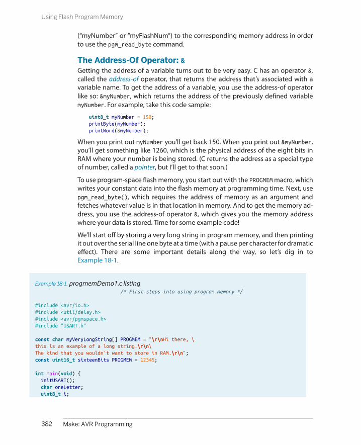
(“myNumber” or “myFlashNum”) to the corresponding memory address in orderto use the pgm_read_byte command.
The Address-Of Operator: &Getting the address of a variable turns out to be very easy. C has an operator &,called the address-of operator, that returns the address that’s associated with avariable name. To get the address of a variable, you use the address-of operatorlike so: &myNumber, which returns the address of the previously defined variablemyNumber. For example, take this code sample:
uint8_t myNumber = 150;printByte(myNumber);printWord(&myNumber);
When you print out myNumber you’ll get back 150. When you print out &myNumber,you’ll get something like 1260, which is the physical address of the eight bits inRAM where your number is being stored. (C returns the address as a special typeof number, called a pointer, but I’ll get to that soon.)
To use program-space flash memory, you start out with the PROGMEM macro, whichwrites your constant data into the flash memory at programming time. Next, usepgm_read_byte(), which requires the address of memory as an argument andfetches whatever value is in that location in memory. And to get the memory ad-dress, you use the address-of operator &, which gives you the memory addresswhere your data is stored. Time for some example code!
We’ll start off by storing a very long string in program memory, and then printingit out over the serial line one byte at a time (with a pause per character for dramaticeffect). There are some important details along the way, so let’s dig in toExample 18-1.
Example 18-1. progmemDemo1.c listing /* First steps into using program memory */
#include <avr/io.h>#include <util/delay.h>#include <avr/pgmspace.h>#include "USART.h"
const char myVeryLongString[] PROGMEM = "\r\nHi there, \this is an example of a long string.\r\n\The kind that you wouldn't want to store in RAM.\r\n";const uint16_t sixteenBits PROGMEM = 12345;
int main(void) { initUSART(); char oneLetter; uint8_t i;
382 Make: AVR Programming
Using Flash Program Memory
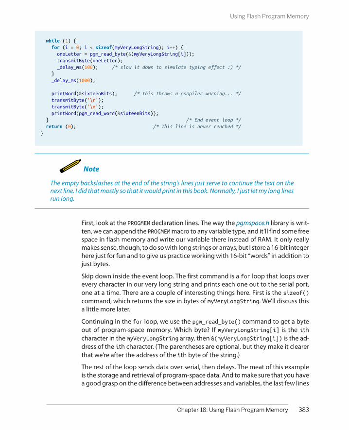
while (1) { for (i = 0; i < sizeof(myVeryLongString); i++) { oneLetter = pgm_read_byte(&(myVeryLongString[i])); transmitByte(oneLetter); _delay_ms(100); /* slow it down to simulate typing effect :) */ } _delay_ms(1000);
printWord(&sixteenBits); /* this throws a compiler warning... */ transmitByte('\r'); transmitByte('\n'); printWord(pgm_read_word(&sixteenBits)); } /* End event loop */ return (0); /* This line is never reached */}
Note
The empty backslashes at the end of the string’s lines just serve to continue the text on thenext line. I did that mostly so that it would print in this book. Normally, I just let my long linesrun long.
First, look at the PROGMEM declaration lines. The way the pgmspace.h library is writ-ten, we can append the PROGMEM macro to any variable type, and it’ll find some freespace in flash memory and write our variable there instead of RAM. It only reallymakes sense, though, to do so with long strings or arrays, but I store a 16-bit integerhere just for fun and to give us practice working with 16-bit “words” in addition tojust bytes.
Skip down inside the event loop. The first command is a for loop that loops overevery character in our very long string and prints each one out to the serial port,one at a time. There are a couple of interesting things here. First is the sizeof()command, which returns the size in bytes of myVeryLongString. We’ll discuss thisa little more later.
Continuing in the for loop, we use the pgm_read_byte() command to get a byteout of program-space memory. Which byte? If myVeryLongString[i] is the ithcharacter in the myVeryLongString array, then &(myVeryLongString[i]) is the ad-dress of the ith character. (The parentheses are optional, but they make it clearerthat we’re after the address of the ith byte of the string.)
The rest of the loop sends data over serial, then delays. The meat of this exampleis the storage and retrieval of program-space data. And to make sure that you havea good grasp on the difference between addresses and variables, the last few lines
383Chapter 18: Using Flash Program Memory
Using Flash Program Memory

PROGMEM Variables: Constant and Global
Because PROGMEM data is burned into flash memoryalong with the program itself, the PROGMEM data is notvariable and is available from any subroutine in theprogram. This has two important consequences fordeclaring program-space “variables” in C.
First off, because you can’t ever change a PROGMEM“variable,” you should probably preface the declara-tion with the keyword const, which tells the com-piler to throw an error if you try to change the con-tents of this memory location later on. The most re-cent version of avr-gcc actually requires you to de-clare your PROGMEM as const, whereas prior versionsonly recommended it. It’s probably a good idea eitherway.
Secondly, because your PROGMEM is nonvolatile andsitting there in program memory, it is available fromwithin any subroutine. It is thus a global variable andshould be declared in the global namespace. That is,PROGMEM variables should be declared outside of anyfunction definitions so that C knows that it’s not limi-ted in scope to any specific function, and that anyfunction can access the data stored there.
For myself, I find it easiest to define all of my PROGMEM data in a separate header file. That way, the datais defined as global by being included at the top ofthe main .c file, and it’s easy to open the file and makesure that each entry is declared const by just lookingdown the first row of text.
play around with the address of the 16-bit number that’s also stored in programspace.
What should printWord(&sixteenBits); print out? And what should printWord(pgm_read_word(&sixteenBits)); print? Answer these questions yourselfbefore you read on.
The first print statement takes the address in memory of sixteenBits and justprints it out. When I run it on my AVR, I get flash-memory address 205, but you mayget something else around there depending on your compiler version and options.Then the code calls pgm_read_word(&sixteenBits) and actually fetches the dataout of the memory address in question. Lo and behold, it’s our 12345!
OK, let’s quickly recap before we dive off the deep end. You can store data in pro-gram memory with the PROGMEM macro and read it back with pgm_read_byte() andpgm_read_word(), respectively, as long as you know the address. You can get theaddress with &, and if you’re interested in the address of a byte within a string orarray, you can get its address by using the address-of operator around the indi-vidual character element in the string that you’re interested in: &myString[4]. Thesesimple operations will get you halfway to mastery of using PROGMEM and addresses;you can now use PROGMEM from the main loop. But if you’d like to use PROGMEM stringsin functions or ISRs, you’ll have to learn how to store addresses in variables andpass them off to functions. And this requires pointers.
384 Make: AVR Programming
Using Flash Program Memory

Make Size (and avr-size)
When you’re interested in knowing how large yourcode is or how much RAM it’s using, there’s a utilityprogram for that, and it’s called avr-size. (The stan-dard GCC size routine is called, shockingly, size.) Tosave you from typing filenames, I’ve included a “size”target in the makefile that comes with the book’scode.
Take a minute now to type in make size. You’ll seetwo lines, one for “Program” memory and one for“Data” memory. The former is program-space dataflash memory usage. This is where your code (andnow PROGMEM data) is stored. With an ATmega168,you’ve got 16 kB of program memory.
The “Data” line is how much of the available RAM yourprogram uses. Because there’s no operating system,you have no real way of knowing when your AVRprogram runs out of memory except to check the
value here. If you ever find the chip behaving super-strangely, and you suspect that you may have run theAVR out of RAM, this is the easiest way to diagnosethe problem for sure.
I also ran make size on progmemDemo1 just to makesure that all of the data that should be stored in pro-gram space is actually stored in program space. If yourun make size after compiling progmemDemo1, youshould see all your variables in program memory, andzero bytes of data memory (RAM) used.
The other time I use make size is in the next chapter,when tweaking audio samples in the talking voltme-ter example. Naturally, I wanted to get as much speak-ing time crammed into the chip as possible. Checkingmake size after adding a sample into memory letsme know how close I am to the 16 kB limit.
Pointers
Have a close look at the compiler output when you ran make on the precedingexample. (Or run make clean then make again to force it to recompile.) You’ll noticethat you got some warnings back from the compiler. In particular, I get somethinglike:
warning: assignment makes integer from pointer without a castwarning: passing argument 1 of ‘printWord’ makes integer from pointer without a castnote: expected ‘uint16_t’ but argument is of type ‘uint8_t *’
What’s going on? The code works, right? Yes, the code does work. But it’s missinga subtlety of the C language, one that will help keep you out of a lot of trouble inthe future. It’s what the compiler is warning you about with its “making an integerfrom a pointer” business. So let’s take a diversion to talk a little bit about pointers.
Pointers in BriefThe pointer is a special variable type that should be used specifically for storingmemory addresses. For the AVR, as I mentioned earlier, a pointer is a 16-bit number.But it’s a special 16-bit number. In addition to being big enough to store a memoryaddress, pointers additionally keep track of the type of the variable they point at.
Pointers are declared with a “*” between the type definition and the declared vari-able name: uint8_t* myPointer;. (I’ll clarify the type declaration part shortly.)
385Chapter 18: Using Flash Program Memory
Pointers

Remember, an address is the location of a byte in memory. If I just give you the rawaddress as a 16-bit number, you have no way of knowing what type of data thestored byte represents. Is the byte at our address the first letter in a string? Is it asingle byte number or letter (uint8_t or char)? Is it the most significant byte of atwo-byte number (uint16_t)? You don’t really know unless you keep tracksomehow, and that’s the extra magic that’s in a pointer. A pointer is an address witha type: it contains the numerical address of the memory referred to and also informsthe compiler what type of data it will find there.
The pointer keeps track of the type of variable it points to by being declared to bea pointer to a type. When you initialize a pointer as uint8_t* myPointer, you’vedeclared that the pointer will be used only to point to 8-bit unsigned integers.char* myString[] is a pointer to a character array (or a string). You use uint16_t*muchData[] to point to an array in memory where each entry is a 16-bit unsignedtype. The typing helps make sure that you’re interpreting the stored data correctly.
When the compiler warns you that you’re mismatching types, especially withpointers, pay attention! If you end up pointing your pointer to the wrong type ofdata in memory, you stand a good chance of interpreting that data incorrectly.
Now that we’ve got a variable type to store memory addresses in, let’s see how towork with them in Example 18-2.
Example 18-2. progmemDemo2.c listing /* Second steps into using program memory */ /* Storing the addresses in pointers */
#include <avr/io.h>#include <util/delay.h>#include <avr/pgmspace.h>#include "USART.h"
const char myVeryLongString[] PROGMEM = "\r\nHi there, \this is an example of a long string.\r\n\The kind that you wouldn't want to store in RAM.\r\n";const uint16_t sixteenBits PROGMEM = 12345;
int main(void) { initUSART();
const char *stringPointer; const uint16_t *wordPointer; uint8_t i; char oneLetter;
stringPointer = &myVeryLongString[0]; /* address of first char */ // stringPointer = myVeryLongString; /* same as above */ wordPointer = &sixteenBits; /* address of first byte */
386 Make: AVR Programming
Pointers

while (1) { for (i = 0; i < sizeof(myVeryLongString); i++) { oneLetter = pgm_read_byte(stringPointer + i); transmitByte(oneLetter); _delay_ms(100); /* slow it down to simulate typing effect :) */ } _delay_ms(1000);
printWord(pgm_read_word(wordPointer)); } /* End event loop */ return (0); /* This line is never reached */}
The essential difference between this code and progmemDemo1.c is that we’rereading the bytes with pgm_read_byte( stringPointer+i ) instead ofpgm_read_byte( &(myVeryLongString[i]) ). That is, we store the address of ourPROGMEM data in a pointer, stringPointer, and then simply add i to that addressto reach successive letters in the string. Note that there’s no address-of operatorhere, because pointers are already addresses.
Let’s look at how we assign the addresses to our pointers. First, you’ll see that thepointers are declared as const char* stringPointer and const uint16_t* wordPointer, in order to match the string and uint16_t word, respectively. Now lookdown to where we assign the addresses to the pointers. There’s no secret aboutthe line wordPointer = &sixteenBits—it stores the address of the variable sixteenBits in the pointer wordPointer. (The compiler verifies that the types matchfor us.)
When you want to define the address of an array, you’ve got a little bit of a problem.Imagine an array of 10 bytes in memory. You’ve got 10 addresses! Which one doyou pick to be the “address of the array”? In C, you always pick the address of thefirst (zeroth) element. So we can assign the address of our PROGMEM string to thepointer like so: stringPointer = &myVeryLongString[0].
Some time long ago, someone invented a “clever” shorthand for referencing theaddress of the first element of a string or array in memory: stringPointer = myVeryLongString. What’s confusing about this is that it doesn’t look like an addressassignment, but it is. This statement is in every way identical to the one earlier,which explicitly gets the address of the array’s first element. Whichever you’d liketo use in your code is fine by me, and seasoned C programmers have it drilled intotheir heads that “arrays used on the right side of an equation decompose to apointer to their first element.” (Get that tattooed on your forearm!) You’ll see thisagain when we pass arrays to functions.
387Chapter 18: Using Flash Program Memory
Pointers

Arrays and Pointers
In C, arrays are special, in an awkward way. When you use an array on the right side of anassignment, or pass it as an argument to a function, what you actually get is a pointer to thearray’s first element.
Because of this, you can either get the address of the first element explicitly:
char* stringP = &myString[0];
or you can take advantage of the decomposition rule:
char* stringP = myString;
The latter doesn’t look like it’s setting the address of a pointer, but that’s exactly what it does.
As a result of the decomposing-to-pointer rule (“arrays used on the right side of an equationdecompose to a pointer to their first element”), the one way that you shouldn’t assign theaddress of an array is the one that might at first glance look most reasonable:
char* brokenP = &myString; (Don't do this!)
This results in a warning: assignment from incompatible pointer type warning. (It maywork anyway, or it may not, depending on your compiler. Do you feel lucky?) This is a warningbecause myString on the right side is already a pointer to the first element of myString, andso &myString is the address of the pointer, and not the address of a char as required.
I’ll keep saying this over and over, because it’s important: pointers store addresses.We need addresses to use the pgm_read_byte() and pgm_read_word() commandsto get our fixed data out of flash memory. As demonstrated in Example 18-2, apointer is a convenient way to store the address because we can add to it just likea normal number. Because it’s an address, adding to it allows us to move on to thenext entry in memory. And because the pointer tells the compiler the size of ourdata type, the compiler knows how many more bytes it needs to increment inmemory to get to the next entry.
Pointers as Arguments to FunctionsThe last piece of the pointer puzzle that we’ll need for working with program-spacememory is how to work with arrays and pointers to arrays when they’re passed asarguments to functions. It’s very common to call a function that runs on static datathat’s stored in program memory, and to do this, we need to pass the address ofthe data to the function.
As a practical example, let’s write a function that prints out strings from flash pro-gram memory that we can use to replace our old printString() function. Because
388 Make: AVR Programming
Pointers
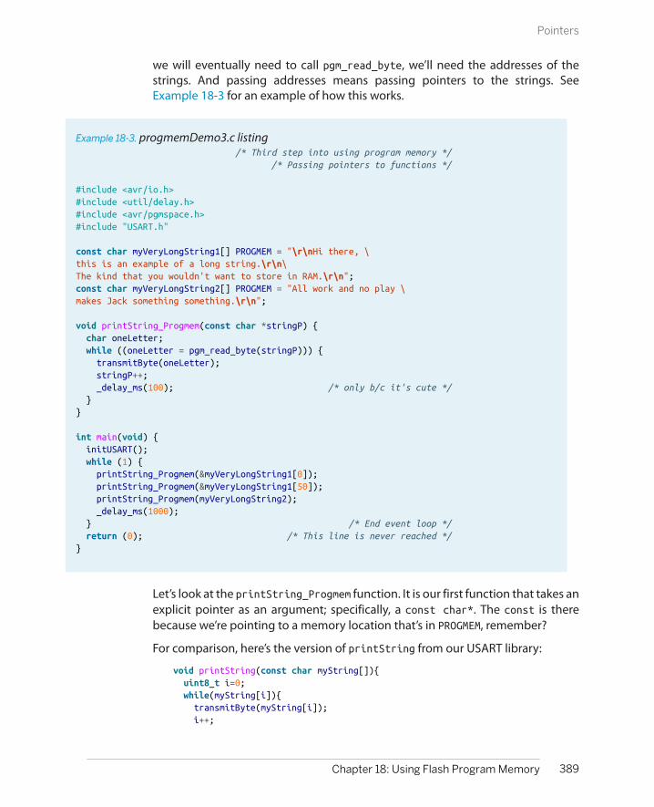
we will eventually need to call pgm_read_byte, we’ll need the addresses of thestrings. And passing addresses means passing pointers to the strings. SeeExample 18-3 for an example of how this works.
Example 18-3. progmemDemo3.c listing /* Third step into using program memory */ /* Passing pointers to functions */
#include <avr/io.h>#include <util/delay.h>#include <avr/pgmspace.h>#include "USART.h"
const char myVeryLongString1[] PROGMEM = "\r\nHi there, \this is an example of a long string.\r\n\The kind that you wouldn't want to store in RAM.\r\n";const char myVeryLongString2[] PROGMEM = "All work and no play \makes Jack something something.\r\n";
void printString_Progmem(const char *stringP) { char oneLetter; while ((oneLetter = pgm_read_byte(stringP))) { transmitByte(oneLetter); stringP++; _delay_ms(100); /* only b/c it's cute */ }}
int main(void) { initUSART(); while (1) { printString_Progmem(&myVeryLongString1[0]); printString_Progmem(&myVeryLongString1[50]); printString_Progmem(myVeryLongString2); _delay_ms(1000); } /* End event loop */ return (0); /* This line is never reached */}
Let’s look at the printString_Progmem function. It is our first function that takes anexplicit pointer as an argument; specifically, a const char*. The const is therebecause we’re pointing to a memory location that’s in PROGMEM, remember?
For comparison, here’s the version of printString from our USART library:
void printString(const char myString[]){ uint8_t i=0; while(myString[i]){ transmitByte(myString[i]); i++;
389Chapter 18: Using Flash Program Memory
Pointers

}}
If you compare the two versions, you’ll find that they have a few important differ-ences. The RAM version of printString passes the array of characters as an array.The PROGMEM version passes the array as a pointer to the memory location of thearray in PROGMEM. In the PROGMEM version, the function stores each letter temporarilyin a variable in RAM (oneLetter) in order to avoid making two calls topgm_read_byte, which is slower than reading the data straight out of RAM. (This isprobably a bit of overoptimization for a printing routine where the USART routineis the slowest part, but the principle is sound.)
And now that we understand the PROGMEM version of the printString function,have a look down in the while(1) loop where we’ve been calling it. Just as whenwe were assigning addresses to pointers in Example 18-2, we pass a pointer as anargument to a function by getting the address of the variable we’d like to pass. Inthat sense, our function printString_Progmem works exactly like pgm_read_worddoes—it expects an address, stored as a pointer, as an argument. So you have yourchoice of calling it with the two different ways of getting the address of an array:&myVeryLongString1[0] or myVeryLongString1. Both pass the address of the firstelement of the array.
Finally, if you have a data array that’s not a string, you can’t count on a zero beinga signal for the end of the array (for example, what if you needed to store a bunchof zeros?) In this case, you have to use some other mechanism for signalling theend of the array. By far the most common method is to pass the pointer to thebeginning of the array, and the number of entries in the array. If your numbers arecorrect, the function will not run over the end of the array data. Example 18-4presents an example of a typical data-array function call with pointers.
390 Make: AVR Programming
Pointers

Example 18-4. progmemDemo4.c listing /* Fourth step into using program memory */ /* Passing data array pointers to functions */#include <avr/io.h>#include <util/delay.h>#include <avr/pgmspace.h>#include "USART.h"
const uint16_t myData[] PROGMEM = { 1111, 2222, 3333, 4444, 5555, 6666, 7777, 8888, 9999, 10000 };const uint16_t myData2[] PROGMEM = { 123, 456, 789, 012, 345, 678, 999 };
void printData_Progmem(const uint16_t * dataPointer, uint8_t length) { while (length) { printWord((uint16_t) dataPointer); /* print out address */ printString(": "); printWord(pgm_read_word(dataPointer)); /* print out data */ printString("\r\n"); dataPointer++; /* move to next uint16_t */ length--; /* one less element to go */ _delay_ms(100); }}
int main(void) { initUSART(); while (1) { printData_Progmem(myData, sizeof(myData) / 2); printString("\r\n"); _delay_ms(1000); printData_Progmem(myData2, sizeof(myData2) / sizeof(myData2[0])); printString("\r\n"); _delay_ms(1000); } /* End event loop */ return (0); /* This line is never reached */}
As advertised, the printData_Progmem() function takes the array pointer and itslength as explicit arguments. It loops through the data by incrementing dataPointer, adding two bytes to the address every time dataPointer increases by one. Wait,two bytes? Yup. Run the code and check out the memory addresses it’s readingfrom, if you don’t believe me.
Because the pointer is declared as a pointer to uint16_t types, it changes the ad-dress it points to by two bytes’ worth for every time it’s incremented. This makesiterating over different types of data with pointers very easy—just make sure thatyou’ve got the pointer’s type declaration right and you can iterate through memoryby address just as you would with an array by index.
391Chapter 18: Using Flash Program Memory
Pointers

sizeof
sizeof() returns the size in bytes in the array (orother variable) in question. When you pass an arrayto a function, you need to know the number of entriesin the array. For instance, when you store an array of16-bit integers, sizeof() returns the length in bytes,which is twice as big as the number of 16-bit wordsthat you’ve stored.
The easiest way to deal with this is just to pass sizeof(mySixteenBitArray)/2 to the function, andthis works fine as long as you always remember to doit and always get the size of the array variable typeright.
On the other hand, because this problem arises sooften there’s a common idiom for dealing with thebytes-to-entries conversion problem. Because eachentry in an array has to be of the same type, you candivide the total length of the array by the length ofone element, say the first one, to get the total numberof elements. The example code I provided does this.Some people even go so far as to define this into amacro when they end up using it a lot (a cute trick,no?):
#define \SIZE_OF_ARRAY(a) (sizeof(a) / sizeof(a[0]))
But it also imposes a little extra burden on how you call the function. Namely, youhave to know how many entries you’ve got in the data array and pass that numberto the function when you call it. Unfortunately, C’s built-in sizeof() commandreturns the length in bytes of the array. So if you’ve got an array of 16-bit integers,you’ll have to divide the result of sizeof() by two somehow.
SummaryThis section started out as a simple exercise in storing data in flash program mem-ory and then reading it back out again. How could it all get so complicated?
To store data in program memory, we use the PROGMEM macro when defining ourconstant data. What otherwise looks like a normal global variable assignmentwinds up as a variable whose address points off into nonvolatile flash programmemory instead of RAM. Reading the values out of this memory isn’t so compli-cated, but the two functions we’ve got, pgm_read_byte and pgm_read_word, bothrequire the address in memory where the data is stored.
Addresses are easily obtainable with the “address-of” operator, &, and using thisyou can call pgm_read_byte to get your data back out. If all you ever do is usePROGMEM from within the main() function, this is all you’ll ever need.
But in order to use PROGMEM data from within your own functions, you’ll need to beable to pass the address as a variable. The specific type of variable that storesaddresses is called a pointer. This stores the memory location (a 16-bit number forthe AVRs) of your variable and is declared in a way that indicates the type of thedata that it points to so the compiler at least knows what kind of data you’re point-ing at and can fetch it easily. Using a pointer also allows you to increment memorylocations by the appropriate number of bytes and use the type-checking systemto make sure that you’re not making any gross mistakes.
392 Make: AVR Programming
Pointers

Finally, if the data in question is a string, an array of characters that finishes with azero, your function can use the final zero to find the end of the data. On the otherhand, if your data is an array, you’ll need to pass its number of elements to thecalled function as well because you can’t tell how large the array is from the pointer.
If you’ve never seen pointers before, that was probably quite a whirlwind tour. Andif you’re a hard-boiled pointer fan, you’ll probably notice that I haven’t mentioneda few of your favorite applications, like pointers to functions. With what we’vecovered here, you’ve got everything you need to use GCC’s PROGMEM facilities. Fora quick introduction to the last class of Pointers 101, feel free to read up on deref-erencing pointers in the next section. Otherwise, it’s time to get down to businessof programming AVRs.
Optional: Dereferencing PointersPointers store memory addresses where you’ve got data stored. We’ve been usingpointers coupled with the pgm_read_byte() function to get data out of programflash memory locations. What if you’d like to store references to RAM memorylocations? After all, that’s what the rest of the world does with pointers. When thedata is in RAM, you can read and write that data as if the pointer were a normalvariable by dereferencing the pointer like so: *myPointer = 7;.
In C, the dereferencing operator * skips over the reference to the memory addressthat the pointer actually stores and goes straight to the memory location that’saddressed. Among other things, this lets you treat the pointer exactly as you wouldany other variable, except that by changing the address stored in the pointer, youcan change which variable the pointer is behaving like.
In fact, to keep this from getting too metaphysical, I find that the best way to getyour head around dereferenced pointers is to think of them as being the variablewho’s address they currently point to. In the following comments, I’ve noted theeffect of the command, and in parentheses how you can think about what’s goingon as a shortcut:
uint8_t a = 7;uint8_t b = 2;uint8_t myArray[] = {10,11,12};uint8_t c;uint8_t* p;
p = &a; /* p stores address of a */c = *p; /* c = 7 (c = a) */
*p = 5; /* 5 into memory at p (a = 5) */c = a; /* c = 5 */
p = &b; /* p stores address of b */*p = 12; /* 12 into memory at p (b = 12) */c = b; /* c = 12 */
393Chapter 18: Using Flash Program Memory
Pointers
p = &myArray[0]; /* p stores address myArray */c = *(p+2); /* c = 12 (c = myArray[2]) */*(p+1) = 25; /* 25 into memory at p+1 (myArray[1] = 25) */
The last example shows how you can use pointers to read from and write to arrays,and this is how one usually deals with arrays in RAM. In fact, the only real differencein writing code for dealing with RAM-based arrays and those written into nonvo-latile program memory space is that you use *(pointer+i) to access the memorystored at the RAM location and pgm_read_byte(pointer+i) or pgm_read_word(pointer+i) to get the values out of flash. The important disctinction is thatwith RAM-based arrays, you can also write to the dereferenced pointer, whereasflash memory is nonvolatile.
Even if you only ever use PROGMEM variables in your AVR programming, I hope thatthis discussion of dereferenced pointers helps reinforce the way pointers work—they are addresses with a type—and if you want to access values stored therein,you have to dereference it one way or the other, * or pgm_read_byte().
Talking Voltmeter
If you’re at all like most people, getting your head around pointers is serious work.If that’s the case, you might want to take a break from reading code for a minute.Hook up a speaker to your AVR, flash in the talking voltmeter code, and think abouthow sweet it would be to have your own talking voltmeter programmed with yourown voice. If that doesn’t give you the motivation to carry on, you’re not half asgeeky as I am.
The main project for this chapter is certainly the most ambitious out of the wholebook, and it combines a lot of aspects from previous projects into one, as well asmaking use of 14 kB of program-space flash memory. We’ll take the bird’s-eye viewfirst and then dive in to the details one by one.
In order to create the audio output, we use the fast PWM output of Timer 0, directto the output-compare pin, as we did in Chapter 10. PWM using Timer 0 is set at afixed frequency of around 31.25 kHz, as before, so what we hear is the changes inaverage voltage due to the duty cycle changing over time.
Timer 2 is configured in CTC mode and counts up until a fixed value and thentriggers and interrupt. I’ve set the frequency of Timer 2’s cycle to be around 8 kHzto match the sample rate of the audio input files. (You can play with this to speedup or slow down sample playback.) Each time Timer 2’s ISR is called, it loads a newsample value into Timer 0’s output compare register.
The Timer 2 ISR is a busy place. Because the data is packed into PROGMEM in 8-bitbytes but we only use two bits per sample, once every four times the ISR is called,
394 Make: AVR Programming
Talking Voltmeter

it reads a new byte and unpacks it into four values. Then the ISR undoes the DPCMencoding, which involves reading the two-bit number, picking the correspondingvalue from a table, and then adding that value to last period’s sample value. (See“Generating the Audio Data” on page 404 for details on the DPCM encoding anddecoding.)
The Timer 2 ISR also tests to see if the end of the sample data table has been reached,and if so it turns itself off and sends no new samples to the Timer 1’s PWM registeruntil it’s restarted from the event loop. Because the ISR loads in new values to Timer1, when Timer 2 isn’t running, the output PWM is constant and no signal isproduced.
The code is split among three files: talkingVoltmeter.h, talkingVoltmeter.c, and all-Digits.h. The first header file lays out all of the data structures and initializations fortalkingVoltmeter.c, which does all the work. The other header file, allDigits.h, con-tains the DPCM data for the speech samples. I’ll hold of on discussing this data fileuntil “Generating the Audio Data” on page 404.
PROGMEM Data Structures and the Header FileLet’s start our discussion of the speech-generation part of the code with the dataand the functions that use it, in Example 18-5.
Example 18-5. talkingVoltmeter.h listing /* Include file with DPCM data in it */#include "allDigits.h"#include <avr/pgmspace.h>
// Now define sample-table names used in digits file// From here on, no matter what you call the samples,// you can refer to them as "ONE_TABLE", etc.#define ONE_TABLE DPCM_one_8000#define TWO_TABLE DPCM_two_8000#define THREE_TABLE DPCM_three_8000#define FOUR_TABLE DPCM_four_8000#define FIVE_TABLE DPCM_five_8000#define SIX_TABLE DPCM_six_8000#define SEVEN_TABLE DPCM_seven_8000#define EIGHT_TABLE DPCM_eight_8000#define NINE_TABLE DPCM_nine_8000#define ZERO_TABLE DPCM_zero_8000#define POINT_TABLE DPCM_point_8000#define VOLTS_TABLE DPCM_volts_8000#define INTRO_TABLE DPCM_talkingvoltmeter_8000
#define SPEECH_DELAY 2000 /* milliseconds */
/* --------------- Globals used by the ISR -------------- */volatile uint8_t *thisTableP; /* points at the current speech table */volatile uint16_t thisTableLength; /* length of current speech table */
395Chapter 18: Using Flash Program Memory
Talking Voltmeter
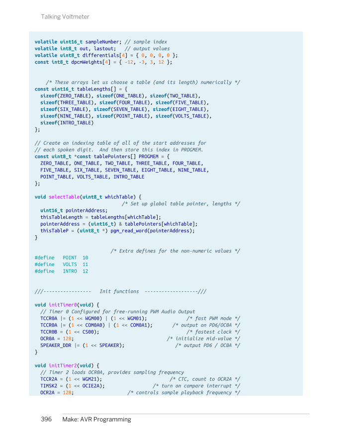
volatile uint16_t sampleNumber; // sample indexvolatile int8_t out, lastout; // output valuesvolatile uint8_t differentials[4] = { 0, 0, 0, 0 };const int8_t dpcmWeights[4] = { -12, -3, 3, 12 };
/* These arrays let us choose a table (and its length) numerically */const uint16_t tableLengths[] = { sizeof(ZERO_TABLE), sizeof(ONE_TABLE), sizeof(TWO_TABLE), sizeof(THREE_TABLE), sizeof(FOUR_TABLE), sizeof(FIVE_TABLE), sizeof(SIX_TABLE), sizeof(SEVEN_TABLE), sizeof(EIGHT_TABLE), sizeof(NINE_TABLE), sizeof(POINT_TABLE), sizeof(VOLTS_TABLE), sizeof(INTRO_TABLE)};
// Create an indexing table of all of the start addresses for// each spoken digit. And then store this index in PROGMEM.const uint8_t *const tablePointers[] PROGMEM = { ZERO_TABLE, ONE_TABLE, TWO_TABLE, THREE_TABLE, FOUR_TABLE, FIVE_TABLE, SIX_TABLE, SEVEN_TABLE, EIGHT_TABLE, NINE_TABLE, POINT_TABLE, VOLTS_TABLE, INTRO_TABLE};
void selectTable(uint8_t whichTable) { /* Set up global table pointer, lengths */ uint16_t pointerAddress; thisTableLength = tableLengths[whichTable]; pointerAddress = (uint16_t) & tablePointers[whichTable]; thisTableP = (uint8_t *) pgm_read_word(pointerAddress);}
/* Extra defines for the non-numeric values */#define POINT 10#define VOLTS 11#define INTRO 12
///----------------- Init functions -------------------///
void initTimer0(void) { // Timer 0 Configured for free-running PWM Audio Output TCCR0A |= (1 << WGM00) | (1 << WGM01); /* fast PWM mode */ TCCR0A |= (1 << COM0A0) | (1 << COM0A1); /* output on PD6/OC0A */ TCCR0B = (1 << CS00); /* fastest clock */ OCR0A = 128; /* initialize mid-value */ SPEAKER_DDR |= (1 << SPEAKER); /* output PD6 / OC0A */}
void initTimer2(void) { // Timer 2 loads OCR0A, provides sampling frequency TCCR2A = (1 << WGM21); /* CTC, count to OCR2A */ TIMSK2 = (1 << OCIE2A); /* turn on compare interrupt */ OCR2A = 128; /* controls sample playback frequency */
396 Make: AVR Programming
Talking Voltmeter

/* note: no clock source selected yet, so won't start up */}
void initADC(void) { // ADC for Voltmeter function ADMUX |= (0b00001111 & PC5); /* set mux to ADC5 */ DIDR0 |= _BV(ADC5D); /* turn off digital circuitry on PC5 */ ADMUX |= (1 << REFS0); /* reference voltage is AVCC, 5V */ ADCSRA |= (1 << ADPS1) | (1 << ADPS2); /* ADC clock prescaler /64 */ ADCSRA |= (1 << ADEN); /* enable ADC */}
The very first line of talkingVoltmeter.h includes a single data header file that in-cludes the DPCM-encoded sample values for all of the spoken-out digits. If youlook at allDigits.h, you’ll see that it looks like this:
const uint8_t DPCM_one_8000[] PROGMEM = { 153, 90, 106, 150, ...}const uint8_t DPCM_two_8000[] PROGMEM = { 250, ...}
Next, a series of twelve #define statements take the names of the samples in theallDigits.h datafile and maps them to defined names and numbers that are used inthe rest of this code. I did this so that you could easily add your own audio data,and would only have to change these 12 top-level definitions. So if your datafilehas tables called “one” and “two” instead of “DPCM_one_8000” and“DPCM_two_8000,” modify these defines and everything else should work fine.
Next, I define some global variables. The first two are used to select which sampleshould be playing. The pointer, uint8_t* thisTableP, is used to point to an addressof the uint8_t speech data arrays that we just included. When it points toDPCM_one_8000[], for instance, the chip will speak the word “one”; when it pointsto DPCM_two_8000[], the chip says “two,” and so on. The other variable contains thelength of the selected data array, so that the playback function knows when tostop.
The next three global variables keep track of exactly which sample is playing andwhat the previous and current PWM output values are.
397Chapter 18: Using Flash Program Memory
Talking Voltmeter

Then there are two arrays defined in RAM that will hold the four two-bit differentials(differentials), and the vector of the step sizes that the decoder will take whenreconstructing the audio.
Indexing arrays: arrays of pointers in PROGMEMTo use the speech data that’s stored in PROGMEM, we’re going to need both it’s start-ing address and the length of each array of spoken samples. And we’ll do it in away that makes accessing the data easy, storing the sound for “one” in positionone of the arrays.
Getting the lengths and storing them in tableLengths[] is a breeze—we simplystore the lengths of the indexed speech-sample arrays in RAM using sizeof()because we know that we’re using single-byte integers to do the encoding. Whenthe time comes to select which table we’re using, the function selectTable() setsa global length variable equal to the selected size: thisTableLength = tableLengths[whichTable]. When we call selectTable(1), it looks up the length fromthis table that’s in slot one and stores it in the global variable thisTableLength thatthe ISR can access.
The next array is an array of pointers to the speech data. That is, each entry intablePointers is a pointer that contains the starting address of one spoken digit.As with the lengths table, the pointers are arranged in numerical order so thattablePointers[1] contains the pointer that points to the data array that speaksout the number “one.” (That’s the convenient part.)
In this sense, tablePointers is like an index. If you want to know where the speechdata for the number “four” is stored, you can look it up in tablePointers[4]. If youwant the number i, you just fetch the data from the location stored in tablePointers[i]. This is much simpler than the alternative, which is to write a bunch of ifstatements like this:
if (i == 4){ address = FOUR_TABLE;}else if (i == 5){ address = FIVE_TABLE;}// ... etc for each digit
(Don’t forget that when we reference an array of data like like FIVE_TABLE, C actuallyreturns a pointer to the first entry of the array.)
But there’s one twist here: I stored the tablePointers indexing array itself in PROGMEM! And why not? It’s an array of pointers that contains addresses of data that’sstored in flash memory. Those addresses surely aren’t going to change, so thislookup table that contains those addresses won’t change either. This pattern issurprisingly useful, and when you have many arrays to index (more than just the
398 Make: AVR Programming
Talking Voltmeter
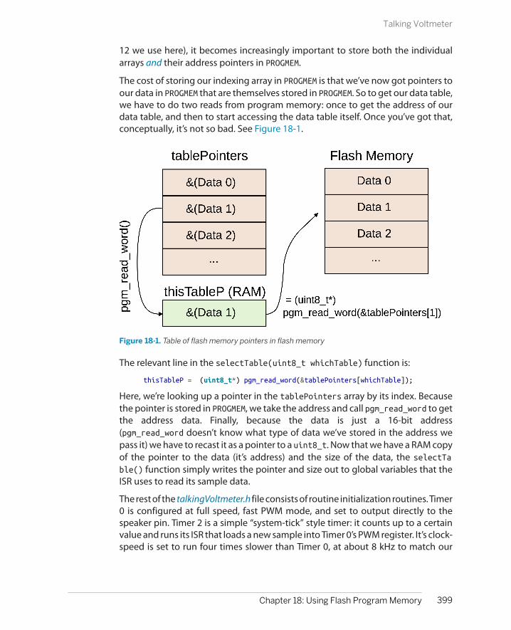
12 we use here), it becomes increasingly important to store both the individualarrays and their address pointers in PROGMEM.
The cost of storing our indexing array in PROGMEM is that we’ve now got pointers toour data in PROGMEM that are themselves stored in PROGMEM. So to get our data table,we have to do two reads from program memory: once to get the address of ourdata table, and then to start accessing the data table itself. Once you’ve got that,conceptually, it’s not so bad. See Figure 18-1.
Figure 18-1. Table of flash memory pointers in flash memory
The relevant line in the selectTable(uint8_t whichTable) function is:
thisTableP = (uint8_t*) pgm_read_word(&tablePointers[whichTable]);
Here, we’re looking up a pointer in the tablePointers array by its index. Becausethe pointer is stored in PROGMEM, we take the address and call pgm_read_word to getthe address data. Finally, because the data is just a 16-bit address(pgm_read_word doesn’t know what type of data we’ve stored in the address wepass it) we have to recast it as a pointer to a uint8_t. Now that we have a RAM copyof the pointer to the data (it’s address) and the size of the data, the selectTable() function simply writes the pointer and size out to global variables that theISR uses to read its sample data.
The rest of the talkingVoltmeter.h file consists of routine initialization routines. Timer0 is configured at full speed, fast PWM mode, and set to output directly to thespeaker pin. Timer 2 is a simple “system-tick” style timer: it counts up to a certainvalue and runs its ISR that loads a new sample into Timer 0’s PWM register. It’s clock-speed is set to run four times slower than Timer 0, at about 8 kHz to match our
399Chapter 18: Using Flash Program Memory
Talking Voltmeter

sampled audio data. Finally, the ADC is initialized for full-range 5 V measurementson PC5, but you can change this easily enough.
Yo Dawg. I Heard You Like PROGMEM
This general pattern, storing pointers to other memory locations in an index, is very useful.You’d do the same thing if you were storing text for menu items, for example. If you stored amenu prompt in menuString0[] and another in menuString1[] in PROGMEM, you can createa second array of pointers to each one that lets you reference them by merely selecting theindex of the pointer array. If you don’t choose to store the pointer array in PROGMEM, you canget a pointer to your string data like this: char* p = stringPointers[i]. If you do decideto store the pointers in PROGMEM as well, you can retrieve the pointers you want like this: char*p = (char*) pgm_get_word(&stringPointers[i]), which really isn’t all that much morecomplicated and can free up a lot of RAM if you have many entries in your menu.
Sound Playback and Voltage Reading: The .c FileOnce we’ve set up the data and the hardware peripherals are configured, it’s timeto sample voltages on the ADC and generate some audio. This means workingthrough the code in Example 18-6.
Example 18-6. talkingVoltmeter.c listing// Talking Voltmeter Example
#include <inttypes.h>#include <avr/io.h>#include <avr/interrupt.h>#include <util/delay.h>#include <avr/pgmspace.h>#include <avr/power.h>#include "pinDefines.h"#include "USART.h"
#include "talkingVoltmeter.h"
void startSampleTimer(void) { sampleNumber = 0; /* back to start of sample table */ TCCR2B = (1 << CS21); /* turn on timer clock */ /* Two clock options above end up ~8kHz on 8MHz system */}void stopSampleTimer(void) { TCCR2B = 0; /* disable sample-playback clock */ OCR0A = 128; /* idle PWM at mid-voltage */ lastout = 0; /* start at 0 next time */}void speak(void) {
400 Make: AVR Programming
Talking Voltmeter

startSampleTimer(); loop_until_bit_is_clear(TCCR2B, CS21); /* Wait until done */}
void updatePWMAudio(void) { OCR0A = out + 128; /* re-center for 0-255 PWM */ lastout = out; /* update last value */ sampleNumber++; /* on to next sample */}void unpackByte(uint8_t dataByte) { /* Select pairs of bits from byte, save out */ differentials[0] = (dataByte >> 6) & 0b00000011; differentials[1] = (dataByte >> 4) & 0b00000011; differentials[2] = (dataByte >> 2) & 0b00000011; differentials[3] = (dataByte & 0b00000011);}
/* Timer 2 controls sampling speed. ISR reads new data, loads PWM values into OCR0A */ISR(TIMER2_COMPA_vect) { /* Since we can decode 4 2-bit values at once, need to know where we are in the 4-step mini-cycle. */ uint8_t cycle = sampleNumber & 0b00000011; /* keep last 2 bits */ uint16_t tableEntry; uint8_t packedData;
if (cycle == 0) { /* at first sample, re-load */ tableEntry = sampleNumber >> 2; /* where we are in table */ if (tableEntry < thisTableLength) { /* read the next byte from the selected table */ packedData = pgm_read_byte(&thisTableP[tableEntry]); unpackByte(packedData); /* split up byte into differentials[] */ } else { /* at end of table, done. */ stopSampleTimer(); } } /* Decode the differences: current value = last + difference */ out = lastout + dpcmWeights[differentials[cycle]] - (lastout >> 4); updatePWMAudio();} // end ISR (TIMER2_COMPA_vect)
void printString_Progmem(const char *stringP) { char oneLetter; while ((oneLetter = pgm_read_byte(stringP))) { transmitByte(oneLetter); stringP++; }}
int main(void) { uint16_t voltage; uint8_t volts;
401Chapter 18: Using Flash Program Memory
Talking Voltmeter

uint8_t tenths; uint8_t vcc = 51; /* 10x VCC, in volts */
clock_prescale_set(clock_div_1); /* 8 MHz */ initTimer0(); initTimer2(); sei(); /* for timer2 ISR */ initADC(); initUSART();
printString_Progmem(PSTR("\r\n--=( Talking Voltmeter )=--\r\n"));
selectTable(INTRO); speak();
while (1) {
ADCSRA |= (1 << ADSC); /* start ADC */ loop_until_bit_is_clear(ADCSRA, ADSC);
voltage = ADC * vcc + vcc / 2; /* vcc/2 to make rounding work */ voltage = voltage >> 10; /* divide by 10-bits for ADC */ /* "voltage" is now actually 10x real-world voltage */ volts = voltage / 10; tenths = voltage % 10;
transmitByte('0' + volts); /* serial output as well */ selectTable(volts); /* 0 points to ZERO_TABLE, etc */ speak();
transmitByte('.'); selectTable(POINT); speak();
transmitByte('0' + tenths); selectTable(tenths); speak();
printString_Progmem(PSTR(" volts\r\n")); selectTable(VOLTS); speak();
_delay_ms(SPEECH_DELAY);
} /* end while */ return (0);}
The ISRBecause the bulk of the work of decoding and playing the speech samples takesplace in Timer 2’s ISR, let’s start there first. The general overview is that, because
402 Make: AVR Programming
Talking Voltmeter
our two-bit samples are stored four to a byte, for every fourth sample, we need toload up another byte and break it up into the four parts.
The first line defines a local variable, cycle, that takes on a value of zero, one, two,or three depending on which sample is currently running. The fastest way to dothis is just to mask off the lowest two bits, and interpret them as an integer. Next,if we’re at the first sample of a cycle, we need to figure out which byte of the speechdata array to unpack next, or if we’re at the end, to stop. To do this, we divide thesample number by four using a bit-shift by two, which gives us the current bytenumber, tableEntry. Because we’re at the first position in a byte, the routine callsunpackByte to unpack an 8-bit number into four two-bit parts.
Look up at unpackByte() for a second. It sets all four values of the differentialsarray by shifting the passed data sample byte over by six bits, four bits, two bits,and zero bits (i.e., not shifting at all), and then masking that byte so that only thelowest two bits remain. Shifting to the right by six leaves only the top two bits, sothose are obvious. Shifting to the right by four leaves the top four bits, and themasking selects out only the lower two of those, and so on. At the end of thisprocess of shifting and masking, each element of differentials[] contains a two-bit number from zero to three.
Jumping back down to the ISR, if the cycle is anywhere but the first position, noth-ing happens and we go on to decompress the data and update the PWM output.Because this is “differential” PCM, the data stored is the (quantized) differencesbetween the last sample value and the next one. The decoding step consists ofadding this difference value to the old output.
We also subtract a sixteenth of the previous value to make the decoding stable.The reason that we need to do this is that there’s a slight chance that approximationerrors in our sampling routine add up in a row long enough to max out the volumeon playback. Subtracting off a small fraction each time shrinks the sample value alittle bit toward zero and prevents these random errors from accumulating. If youdon’t believe me, try flashing the code without this term, and you’ll probably hearthat it distorts.
Finally, the ISR calls updatePWMAudio(), which adds 128 to the signed integer valueto center it between zero and 255, and then writes the new volume level to Timer0’s output-compare register and controls the PWM duty cycle, outputting an aver-age voltage level to the speaker.
main()The main function starts off with some variable definitions. Of them, the mostinteresting is setting the calibrated vcc variable. Remember, the ADC’s absoluteaccuracy is only as good as the VCC level, and the vcc variable should contain thecalibrated voltage of your VCC times 10. On my system, for instance, I get 5.08 V,which is 50.8, so I round up to 51 and that’s the vcc.
403Chapter 18: Using Flash Program Memory
Talking Voltmeter

Just after all the usual initialization routines, the code prints out a long string that’sstored in flash memory, partly to verify our serial connections, but mostly as ademonstration of how simple it can be to use PROGMEM strings directly in your code.
The last part of the initialization section speaks out a prerecorded introduction tothe talking voltmeter. If you can’t hear this, something’s wrong. This demo alsoshows you how the speech playback system works. Remember that to pass thedesired data to the ISR, we saved its start location and length in two separate globalvariables. The function selectTable() uses the PROGMEM index of pointers to thedata to get the starting position from memory. selectTable() also looks up thelength of the chosen speech data from the length array tableLengths.
Once the data is pointed to, all that remains is to call the speak() function, whichresets the sample counter to zero and starts up Timer 2, then waits for the sampletable to reach the end, and shut down Timer 2 again. Note that I’m implicitly usingthe Timer 2 clock-select bit as a status flag for whether or not there is currently asample playing.
Finally, now that you understand how the system plays back a spoken digit bysetting up pointers to the current sample and letting the timer hardware take careof the rest, the event loop should be an easy read. An ADC sample is taken, thevalue scaled up by the VCC value times 10 and then back down by 1,024, to yieldan eventual value that should be 10 times the actual measured voltage. The re-mainder of the event loop simply prints out the values on the serial line and si-multaneously speaks them out through the speaker.
Now, if you’re interested in the nitty-gritty of how I got my seven seconds of mysampled voice into 14 kB of data talking to you, or to make your own samples, readon to the next section.
Generating the Audio Data
Eight-bit audio, even at a minimum data rate for speech, requires a lot of data.Human speech has a highest frequency of around 4 kHz, which means we’d needan 8 kHz sample rate to reproduce it. (Read up on “Nyquist Frequency” online ifyou’d like to know more.) That’s around 8 kB per second, and if it takes about 1/2a second to read out a digit, we’ll need 48 kB just to sample 10 digits plus “point”and “volts.” That’s not going to work for us at all. We’ll need to figure out a way todivide that by four and still retain intelligibility. We’ll use Differential Pulse-CodeModulation (DPCM), which is an audio compression method developed for com-pressing speech over phone lines in the 1950s.
Differential Pulse-Code ModulationFirst off, pulse-code modulation is actually just the fancy name for what we’ve beenusing to play “analog” audio all along. Basically, the “pulse codes” are what
404 Make: AVR Programming
Generating the Audio Data
Cornell University Microcontroller Class Webpages
If you’re at all interested in video, speech, or audiogeneration, the final projects and lab exercises fromCornell University’s ECE 4760: Designing with Micro-controllers class is a great resource. Professor Landhas even posted his lectures to YouTube. It’s a greatresource both for ideas and even working codesnippets.
Indeed, I got the basis for the talking voltmeter codefrom Cornell University’s ECE 4760 Speech Genera-tion page. In the end, I rewrote some sections, fixed(IMO) a bug, and adapted the code to function withmultiple speech tables, but the basic framework is
theirs. While I rewrote the encoder in Python, it’s ba-sically a copy of similar code from that website that’swritten for Matlab.
If you’re using the Cornell code, note that the ATme-ga644 that they use has a different pinout from theATmegaxx8 series, so you may have to move somepins around for everything to work. For instance, thedirect-PWM-output (OCR0A) pins are in different lo-cations across the two chip series; PB3 on the 644 isequivalent to PD6 on our series of chips. But once Ichanged those around, the code worked just fine.
old-timey engineers called our digital samples. Pulse-code modulation is just pro-ducing audio by changing the binary data that you feed into a digital-to-analogconverter over time—just exactly what we were doing in Chapter 10, using filteredPWM output to do the digital-to-analog conversion.
The “differential” in DPCM means that instead of using the voltage level values, westore the changes the voltage levels. For smooth signals, like audio signals tend tobe, the difference between two samples is drastically smaller than the maximumrange from quietest to loudest. If you’re using eight bits for output, you can oftenencode the same data with just two or three bits per sample. That’s a dramaticreduction in the amount of data required.
As mentioned, for the talking voltmeter, we’d need roughly 48 kB of raw uncom-pressed PCM output. But if we use two-bit DPCM, we can shrink our data require-ments to 12 kB, which will fit in the ATmega168’s flash memory with room to spare.The sound quality will be reduced somewhat, but you’ll be surprised how intelli-gible it is.
Encoding Two-bit DPCMTo start our discussion of DPCM, imagine that we have a series of sample valueslike [..., 200, 201, 204, 208, 206, 203, 200, 198, ...]. (From the way thevalues rise and fall, they could be the top of a sine wave, or something similar.) Thefirst step in DPCM is to take the differences between successive sample values:[..., 1, 3, 4, -2, -3, -3, -2, ...]. Notice how nice and small these differencevalues are? Heck, we could represent those precisely with three bits, as opposedto the eight bits in our original sample, and we’d be done.
One-bit DPCM consists of deciding whether the samples change upward or down-ward—we’ve only got two choices with one bit. If we encode an positive difference
405Chapter 18: Using Flash Program Memory
Generating the Audio Data

as a one, and a negative difference as a zero, the preceding differences string lookslike [..., 1, 1, 1, 0, 0, 0, 0, ... ]. Now to reconstruct the data back intoeight bits, all we know is that it went up for three periods and down for four. We’llhave to decide on how big each step up or down is going to be.
Picking that step size is actually a little tricky, because we’re trading off how quicklythe DPCM can respond to big changes against how smooth our output can be forsmall changes. Just from looking at our data, we’d pick something like plus or minustwo, because the increases and decreases are about two-ish on average.
Let’s assume that we start off with the correct sample value of 200. The decodedversion of our one-bit DCPM with step size of two would give us the followingsequence: [..., 200, 202, 204, 206, 204, 202, 200, 198, ...], which reallyisn’t that bad an approximation of our original data. The peak at 208 isn’t as high,and the slope of the change is always constant, but it could work.
Two-bit DPCM improves on the one-bit version by allowing for two different ratesof increase and two different rates of decrease. That is, instead of just choosing upor down in the encoding stage, we get to choose between a large step up and asmall step up, a large step down and a small step down. For our example, we mightdecide that any change smaller than 2.5 is a small step, and larger than 2.5 is a bigstep:
STEP TABLE UP DOWN
BIG 3 0
LITTLE 2 1
Using two-bit numbers, we map these steps (big down step, small down step,small up step, big up step) to (0,1,2,3). Encoding like this, we get [...,2,3,3,1,0,0,1,...] for the difference sequence.
In the one-bit scenario, we had to pick a step size in order to reconstruct the data.To play back our two-bit DPCM series, we need to choose twice as many values—a size for our small steps and a size for the big steps. Let’s use 1 for the small stepsand 3 for the big steps, giving us the mapping (0,1,2,3) to (-3, -1, 1, 3). Nowour reconstructed series would look like [..., 200, 201, 204, 207, 206, 203,200, 197]. Because we could pick two levels for the differences, the encoding canaccommodate both slow changes and faster changes. We don’t lose as much onthe peak at 208 as we did with the one-bit version, and the slow-changing partsare more accurately represented as well.
See Figure 18-2 where I’ve plotted them. The two-bit DPCM line overlaps the actualvalues most of the time, while the one-bit DPCM misses a lot, but is right much ofthe time. The one-bit DPCM, having only the choice of two slopes, up or down,makes waveforms that look like triangles, while the two-bit DPCM starts to look alittle more rounded and natural.
406 Make: AVR Programming
Generating the Audio Data

Figure 18-2. Graph of one- and two-bit DPCM example
To do the encoding into two-bit DPCM, we needed to pick a positive-going andnegative-going threshold to distinguish between big and small steps, and whenwe reconstructed the original signal, we needed to pick two more values—the sizesof the big and small steps in either direction. Picking these values is a compromisebetween speed of response and smoothness, and the choices are interdependent.If you chose the threshold to be large in the encoding step, you should probablyhave a fairly large difference for the big step when you’re decoding.
For any given signal, there is a best choice for each of these values, but that’s gettingway beyond our needs. In fact, the next level of cleverness in sample encoding,Adaptive DPCM, is simply an encoding method where the different step sizes arechanged on the fly to best match the audio sample. So when the audio is slowlychanging, the thresholds and reconstruction differentials are smaller, and whenthere’s a lot of movement in the waveform, both thresholds and differentials areincreased to match. The algorithms for doing ADPCM are yet more complicated,but the general idea is simple once you’ve got the DPCM concept.
Anyway, do feel free to play around with both the thresholds and the reconstructiondifferential values. When encoding, the thresholds are stored in the wave2DPCM.pyfile as TWO_BIT_THRESHOLDS = [-0.05, 0, 0.05]. In the encoder, I’ve normalizedthe samples to a maximum and minimum values of 1 and –1, respectively, so thethresholds are effectively in percentages. Any change that’s bigger than 5% of the
407Chapter 18: Using Flash Program Memory
Generating the Audio Data

maximum value is a big change. The reconstruction differentials are stored intalkingVoltmeter.h in reconstruction_differentials. These are on our usual 8-bitscale of –128 to 127, so the big step is scaled to be bigger than 5% of 128—at 12,it’s around 10%—and the small step is about 2.5%, or 3. Within reasonable ranges,you may find that you get better or worse reproduction. If you change the numbersaround drastically, you’ll get horrible digital-sounding squawky noises. Enjoy!
Encoding DPCM: wave2DPCM.pyEverything you need to load up your own .wav files into the AVR is included in thisPython file. The short version of the procedure is that you record files of yourself(or you can use an online speech synthesizer like AT&T Natural Voices Text-to-Speech Demo) saying the words “zero” through “nine,” “point,” “volts,” and anythingelse you want the voltmeter to repeat for you. Then save these files as 8,000 Hz,mono .wav files with names like one.wav, etc. (See the bottom of Example 18-7 fora list of the digits used.)
Running the wave2DPCM.py program in a directory with all the correctly namedfiles gives you a header file that’ll plug right in to the talkingVoltmeter project.(Or you can download some of my extra sample voices from links on this book’swebsite.) If you make your own samples, you’ll need to keep them short to fit intomemory. If you need more room, feel free to remove the introductory talkingvoltmeter prompt from the project to make more space. To do so, you’ll need toremove it from the Python file, the talkingVoltmeter.h file that includes it, and inthe initialization part of the main() function in talkingVoltmeter.c where the func-tion to play the file is called.
In case you’d like to customize the code, let’s get at least a good overview under-standing of what’s going on in wave2DPCM.py, listed in Example 18-7.
Example 18-7. wave2DPCM.py listing## Functions to convert mono, 8kHz .wav files to differential PCM
## If you've got 'sox' installed on your computer, this code calls## 'sox' and re-codes the files for you. If not, you've got to do it.
## Finally, given a bunch of wav files with names like one.wav, two.wav## this writes the DPCM data out to a header file for including in AVR C
from struct import unpackimport waveimport osimport sys
def unpackMono(waveFile): w = wave.Wave_read(waveFile) data = [] for i in range(w.getnframes()):
408 Make: AVR Programming
Generating the Audio Data

data.append(unpack("h", w.readframes(1))[0]) return(data)
def scaleData(data): scale = max(max(data), abs(min(data))) * 1.0 return([x/scale for x in data])
def getDifferences(data): differences = [] for i in range(len(data)-1): differences.append(data[i+1]-data[i]) return(differences)
def quantize(data, thresholds): quantized = [] n = len(thresholds) thresholdRange = range(n) for d in data: categorized = False for i in thresholdRange: if d <= thresholds[i]: quantized.append(i) categorized = True break if not categorized: quantized.append(n) return(quantized)
def pack4(data): # for 2-bit data packedData = [] for i in range(len(data) / 4): thisByte = 0 thisByte += 2**6 * data[4*i] thisByte += 2**4 * data[4*i+1] thisByte += 2**2 * data[4*i+2] thisByte += data[4*i+3] packedData.append(thisByte) return(packedData)
def packTwoBitDPCM(filename): data = unpackMono(filename) data = scaleData(data) differences = getDifferences(data) quantized = quantize(differences, TWO_BIT_THRESHOLDS) packed = pack4(quantized) return(packed)
def createHeader(filename, packedData): baseFilename = filename[:-4] outfile = open("DPCM_" + baseFilename + ".h", "w") outfile.write('uint8_t DPCM_{}[] PROGMEM = {{\n'.format(baseFilename)) for byte in packedData: outfile.write(' {:d},\n'.format(byte)) outfile.write('};\n')
409Chapter 18: Using Flash Program Memory
Generating the Audio Data

outfile.close()
def fixWaveFile(filename): w = wave.Wave_read(filename) bitrate = w.getframerate() channels = w.getnchannels() bits = w.getsampwidth()*8 if not bitrate==8000 or not channels==1 or not bits==16: newFilename = filename[:-4] + "_8000.wav" returnValue = os.system(SOXCOMMAND.format(filename, newFilename)) if returnValue: raise(SOX_Exception("""Something went wrong calling sox:SOXCOMMAND.format(filename, newFilenameIs sox installed? If not, just make sure that you've saved 8kHz mono wav files.""")) filename = newFilename return(filename)
class SOX_Exception(Exception): pass
if __name__ == "__main__":
## Default is to convert all wav files in the current directory.
TWO_BIT_THRESHOLDS = [-0.05, 0, 0.05]
SOXCOMMAND = "sox {} -r 8000 -c 1 -b 16 {}" # for converting wave file ## install sox, or use itunes or audacity to convert ## wavefile to 8kHz, 16-bit, one-channel
wavefiles = [x for x in os.walk(".").next()[2] if x.endswith(".wav")] for filename in wavefiles: filename = fixWaveFile(filename) # converts if needed, returns new filename packedData = packTwoBitDPCM(filename) createHeader(filename, packedData)
## And create a digits sample set for talkingVoltmeter.h: digits = ["one", "two", "three", "four", "five", "six", "seven", "eight", "nine", "zero", "point", "volts", "talkingvoltmeter"] allDigits = open("allDigits.h", "w") for digit in digits: filename = "DPCM_" + digit + "_8000.h" print filename allDigits.write(open(filename).read()) allDigits.close()
Let’s start at the top. unpackMono(waveFile) converts the specified 16-bitmono .wav audio file into it’s corresponding numeric data. The result is a list ofnumbers ranging from –32,768 to 32,767. scaleData(data) changes the range to
410 Make: AVR Programming
Generating the Audio Data
(-1,1), and then getDifferences(data) subtracts each sample from the one beforeit. This is the first step in DPCM encoding.
The function quantize(data, thresholds) does the DPCM encoding. For eachdifference value, it figures out where it falls relative to the thresholds and gives ita corresponding numeric value. The last stage of the algorithm part is to then packthese two-bit values into eight-bit numbers to load into the AVR. pack4(data) doesthe packing.
The next function, packTwoBitDPCM(filename) just wraps up all of the precedingsteps into one function for convenience. The input is a filename, and the output ispacked two-bit DPCM data. Now all that’s left is to write the data out into an .h fileto include with your AVR code, which is handled by createHeader(). Finally, I’veincluded a convenience function that double-checks your .wav file’s bitrate, num-ber of channels, and bit-depth, and runs the command-line utility sox to convertthe file if it’s not right. If you don’t have sox installed on your system, go get it! It’san awesome audio tool—the rightly nicknamed Swiss army knife of audio files. Ifyou don’t want to install sox, just make sure that you’re saving your audio samplesas 16-bit, 8,000 Hz, mono .wav files, and you’ll be OK.
After if __name__ == "__main__", we get to actually calling these functions anddoing the work. The bit thresholds are defined here, as is the command-line call tosox if you need it. After that, the code loops through all the .wav files in the directory,encodes them in DPCM, and writes out an individual header file for each. The lastloop just combines all of the listed names into a single header file, allDigits.h, thatyou can include in the talkingVoltmeter.h project without any further modification.
411Chapter 18: Using Flash Program Memory
Generating the Audio Data


What You Need
In this chapter, in addition to the basic kit, you willneed:
• A USB-Serial adapter.
AVR Secret Decoder Ring
In Chapter 16 we used external EEPROM (electrically erasable and programmableROM) for nonvolatile external data storage. For making a data logger it was justright: EEPROM provides low-power, long-term storage of fairly large amounts ofdata. But if all you want is a little bit of data to survive a chip reset, adding an extrachip and tying up the SPI or I2C lines just for a few bytes of configuration dataseems overkill. That’s why the Atmel chip designers put a small amount of EEPROMon each of the ATmega chips for you to use.
In this chapter, we’ll turn the AVR into a Vigenère Cipher encoder and decoder,storing the encryption key strings in nonvolatile EEPROM memory so that you don’thave to remember them yourself. Because the keys are stored on the AVR, you canmake them fairly long and fairly complicated, making even a trivial example en-cryption scheme like this unbreakable for short enough messages. And becauseyou can also preload key strings into the EEPROM, you can set up two AVR SecretDecoder Rings with the identical memory contents. Give one to a friend, and you’llhave a marvellous high-tech/low-tech encryption system.
Of course, if you encrypt important information using the AVR Secret Decoder Ring,you’ll want you be sure that you never reflash the chip or let it out of yourpossession.
The AVR’s internal EEPROM is full of trade-offs. There’s not a whole lot of it and it’sa little bit slow to erase or write to—taking 1.8 ms for a write or 3.4 ms for an erase
413
EEPROM 19

and write combo. In practice, if you’re writing an application that runs on a humantimescale or only needs to save configuration information periodically, the speedisn’t an issue. You’ve still only got 512 bytes, but whether that’s a lot or a littledepends on your application.
The final limitation of EEPROM is that each memory cell has a given number oferase and write cycles that it can go through before it becomes unreliable. On theother hand, reads are unlimited, your data won’t be forgotten when the powergoes off, and the EEPROM is specified for 100,000 writes.
In short, unlike the timer/counter modules, the ADCs, any of the serial communi-cations hardware, or the interrupt system, the AVR’s internal EEPROM is a nicheutility. It’s not fast enough to use as buffer memory or large enough to store tonsof data, and you don’t want to write to it all the time. But when you do need a smallamount of nonvolatile memory to save the AVR’s state when the power goes off,the built-in EEPROM is terribly convenient. Working with the EEPROM is also a greatexcuse for us to use all that we’ve just learned about pointers and memory ad-dresses, so let’s get to it.
Using EEPROM
The AVR’s hardware-level EEPROM functions are fairly straightforward but a littlebit cumbersome to use. For instance, to write a byte to a memory location, youneed to first check that the EEPROM is ready to use, then write the data to oneregister, write the address where you’d like to save the data to another register,then set an enable bit, and then within four cycles set the write bit and optionallywait for it to finish. Pshwew!
If you have multiple bytes to read and write, all of this can get annoying, so it shouldbe no surprise that the avr/eeprom.h library has a bunch of utility functions thatstreamline using EEPROM. Using these functions, combined with what we nowknow about pointers, makes working with the EEPROM easy.
Storing in MemoryFirst off, there are two types of functions in the avr/eeprom.h library that store avariable: eeprom_write_byte() and eeprom_update_byte(). The difference is thatthe “write” commands just write to EEPROM, whereas the “update” commands firstverify that the data has actually changed before performing a write operation. Theextra read from EEPROM only adds a few microseconds, as opposed to millisecondsfor the write command, and it can possibly save you time if the EEPROM valuehasn’t changed. But more importantly, using eeprom_update_byte() avoids un-necessary writes to EEPROM, which is a good idea because EEPROM, althoughrewriteable, isn’t rewriteable indefinitely. We’ll be using the “update” family offunctions exclusively. Forget about “write.”
414 Make: AVR Programming
Using EEPROM

EEPROM Life Span
Rewriting EEPROM causes electrical wear-and-tear on the insulating semiconductor layerthat is responsible for retaining the data. The AVR datasheet says that the internal EEPROMis good for around 100,000 write and erase cycles. That’s quite a few, right? Well, maybe. Ifyou write to the EEPROM once per hour, then you have an expected 11 years of useful EEPROMlife. At one write per minute, 100,000 writes is only 69.5 days. If you write to EEPROM once persecond, you’re looking at just under 28 hours of expected lifetime before data may startgetting lost.
There are small improvements possible around the margins, like writing to different memoryaddresses instead of reusing the same memory cells every time—called wear leveling. But inthe end, if you need to save your data very frequently, maybe EEPROM isn’t the right choice.
In the avr/eeprom.h library, EEPROM read and update commands come in a fewdifferent types, tailored for reading and writing different types of data. If you readthrough the include file avr/eeprom.h, you’ll find that the EEPROM update functionsare specified as follows:
void eeprom_update_byte (uint8_t *__p, uint8_t __value)void eeprom_update_word (uint16_t *__p, uint16_t __value)void eeprom_update_dword (uint32_t *__p, uint32_t __value)void eeprom_update_float (float *__p, float __value)void eeprom_update_block (const void *__src, void *__dst, size_t __n)
With the exception of the block update command, the functions take two argu-ments: an address to store the data (passed as a pointer of the correct type) andthe value to store in memory. These avr-libc functions take care all the low-leveldetails: checking that the EEPROM is ready for a write, enabling the EEPROM writebits, loading up the necessary registers, and so on.
Floats
I’ve been avoiding using float type variables. Floats are 32-bit floating-point representationsthat let you represent numbers with decimal places. The floating-point–compatible mathlibraries end up taking up a bunch of memory and are slow. In my experience, there’s almostalways a way to rephrase your problem that can avoid using floating-point numbers; forinstance the way we dealt with fractional frequency steps in the direct-digital synthesismethod in Chapter 13. But just in case you’ve been secretly using floats all along, now youknow how to store them in EEPROM.
415Chapter 19: EEPROM
Using EEPROM

The eeprom_update_block command is a little bit more complicated, but it makesnice use of pointers and memory addresses. The three arguments, in order, are: theaddress of the first element of a source array of data, the address in EEPROM whereyou want to start writing, and the size of the array in bytes. Internally, the functionstarts at the first byte of the RAM array and the specified location in EEPROM, andtakes one step at a time, writing one byte to EEPROM before moving on to the next.
Let me walk you through some quick example usages of all the different updatecommands in Example 19-1.
Example 19-1. quickDemo.c listing#include <avr/io.h>#include <avr/eeprom.h>
int main(void) {
// Store the 8-bit value 5 in EEPROM slot 0 uint8_t *address = (uint8_t *) 0; eeprom_update_byte(address, 5);
// Store the 16-bit value 12345 in EEPROM slots 5 and 6: eeprom_update_word((uint16_t *) 5, 12345);
// Store a character array (string) in EEPROM slots 16-28: char *stringPointer = (char *) 16; char myString[] = "hello world."; eeprom_update_block(myString, stringPointer, sizeof(myString));
return (0);}
The first example is the most straightforward: we create a pointer to the EEPROM’smemory address 0 with the type uint8_t* so that we’re set up for storing a uint8_tvariable. Then, using eeprom_update_byte(), we write the number five into EE-PROM. If you wanted to store another byte of data in the next memory slot inEEPROM, you could simply add one to the pointer and go on: eeprom_update_byte(address+1, 17);.
In the next example, we store the 16-bit value 12345 into EEPROM memory loca-tions five and six. Instead of creating a uint16_t* pointer variable just to encodethe number five as an address, we convert the type of the Memory Address 1 to apointer on the fly. You could just write a simple numeric “5” here and it will workbecause this is a trivial demo example, but the compiler would complain thateeprom_update_word expects a pointer to an unsigned 16-bit integer. If we wereusing a pointer, and you wanted to store another 16-bit integer, you’d be able tosimply add one to the pointer and it would know to skip forward to memory slot
416 Make: AVR Programming
Using EEPROM
seven because the pointer is declared to be 16-bits wide. That’s one reason thatusing pointers, which join an address with a type, is handy.
The third example writes a string into EEPROM using the eeprom_block_update() function. The first thing to remember about strings is that they’re reallyarrays of characters that are terminated with a numeric zero. Thus the length of mystring is the 12 characters that you probably counted out, plus the trailing zero.That’s how I figured out that I’d be writing from address 16 to address 28 (inclusive).But I didn’t have to figure out the length of the string myself; using sizeof(myString) takes care of the counting for me.
Just about now, if you’ve got a whole lot of different variable types that you’d liketo store into EEPROM, you’re probably starting to worry about how you’re goingto keep their starting and ending locations straight. If you make a mental mistakeon any of the addresses, you can overwrite data or read from the wrong bits. Thegood news is that you can let the compiler handle all of that for you, and you’ll seehow in “Organizing Data in EEPROM” on page 423. Before I show you how to read outEEPROM values in code, though, let’s take a peek at the chip’s memory usingAVRDUDE.
AVRDUDE and EEPROMNot only can AVRDUDE read and write to the flash program memory in the AVRchips, but it can also read and write to EEPROM if your programmer supports it. Afun way to have a look at the EEPROM in your chip is to use AVRDUDE’s terminalmode.
If you’ve been using the makefile that I’ve included with the AVR-Programming-Library library included with the book, all you have to do is type make avrdude_terminal and you’re in. All that does is add the -nt flags to your usual AVRDUDE com-mand line (“t” is for terminal mode) but it’s easier to run from the makefile, no?
Once you’re in terminal mode, you’re talking directly with the AVR chip itself. Youcan type help and get a list of options. In our case, to see what’s stored in EEPROM,type dump eeprom.
If you haven’t flashed any code that uses the EEPROM into your chip yet, you’ll findthat each byte in memory is set to 255, or 0xff, which is what EEPROMs (includingflash memory and similar) default to when they’re reset. If you’d flashed and runthe little quickDemo.c code snippet, this is what you’d get after it has run once andwritten to EEPROM:
avrdude -c usbasp -p atmega168 -nt
Reading | ################################################## | 100% 0.00s
avrdude: Device signature = 0x1e9406avrdude> dump eeprom>>> dump eeprom
417Chapter 19: EEPROM
Using EEPROM
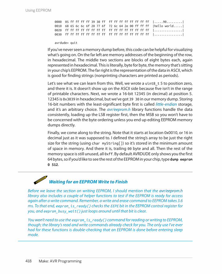
0000 05 ff ff ff ff 39 30 ff ff ff ff ff ff ff ff ff |.....90.........|0010 68 65 6c 6c 6f 20 77 6f 72 6c 64 2e 00 ff ff ff |hello world.....|0020 ff ff ff ff ff ff ff ff ff ff ff ff ff ff ff ff |................|0030 ff ff ff ff ff ff ff ff ff ff ff ff ff ff ff ff |................|
avrdude> quit
If you’ve never seen a memory dump before, this code can be helpful for visualizingwhat’s going on. On the far left are memory addresses of the beginning of the row,in hexadecimal. The middle two sections are blocks of eight bytes each, againrepresented in hexadecimal. This is literally, byte for byte, the memory that’s sittingin your chip’s EEPROM. The far right is the representation of the data in ASCII, whichis good for finding strings (nonprinting characters are printed as periods).
Let’s see what we can learn from this. Well, we wrote a uint8_t 5 to position zero,and there it is. It doesn’t show up on the ASCII side because five isn’t in the rangeof printable characters. Next, we wrote a 16-bit 12345 (in decimal) at position 5.12345 is 0x3039 in hexadecimal, but we’ve got 39 30 in our memory dump. Storing16-bit numbers with the least-significant byte first is called little-endian storage,and it’s an arbitrary choice. The avr/eeprom.h library functions handle the dataconsistently, loading up the LSB register first, then the MSB so you won’t have tobe concerned with the byte ordering unless you end up editing EEPROM memorydumps directly.
Finally, we come along to the string. Note that it starts at location 0x0010, or 16 indecimal just as it was supposed to. I defined the string’s array to be just the rightsize for the string (using char myString[]) so it’s stored in the minimum amountof space in memory. And there it is, trailing 00 byte and all. Then the rest of thememory space is still unused, all 0xff. By default AVRDUDE only shows you the first64 bytes, so if you’d like to see the rest of the EEPROM in your chip, type dump eeprom0 512.
Waiting for an EEPROM Write to Finish
Before we leave the section on writing EEPROM, I should mention that the avr/eeprom.hlibrary also includes a couple of helper functions to test if the EEPROM is ready for accessagain after a write command. Remember, a write and erase command to EEPROM takes 3.6ms. To that end, eeprom_is_ready() checks the EEPE bit in the EEPROM control register foryou, and eeprom_busy_wait() just loops around until that bit is clear.
You won’t need to use the eeprom_is_ready() command for reading or writing to EEPROM,though; the library’s read and write commands already check for you. The only use I’ve everhad for these functions is double-checking that an EEPROM is done before entering sleepmode.
418 Make: AVR Programming
Using EEPROM

Data Types
Numbers represented in binary have a necessarilylimited number of distinct values they can take on.For instance, if you’ve only got one bit, all you canrepresent are the numbers zero and one. Two bitsgets you zero, one, two, and three. Three bits coversthe range zero to seven inclusive, and so on. Eachadditional bit doubles the number of possible valuesthat binary digit can have.
If you want to represent negative numbers as well aspositive numbers, you can use one bit as a positive/negative sign. This cuts the maximum value that’srepresentable in half, but then adds an equal numberof possible negative values (plus one). The numbersare stored internally in two’s-complement order, butthis is an implementation detail that you can ignoreor look up on Wikipedia if you’re interested.
I strongly prefer the fixed-width variable type namesthat got introduced with ISO standard C99 for micro-controller work, because you know at a glance howmany bits you’re dealing with. With a big computer,where resources aren’t critically allocated, I’m entirelyhappy to use 64 bits to represent the number five,but on our AVRs, large data types take up an unnec-essary amount of memory and usually take signifi-cantly more CPU time to process. It’s a good idea touse the smallest data type you can.
Before C99, there were a few integer types, but thesize of each wasn’t guaranteed at all and could varyacross computer architectures:
charMeant to represent ASCII character data, thechar type is almost always an unsigned 8-bit
integer. On the AVR, it’s identical to uint8_t, butI tend to use char when I mean to represent AS-CII data and uint8_t when I’m thinking aboutthe numerical value.
int“Integers” in standard C are at least 16 bits. Onthe AVR, an int is usually 16 bits. There’s an avr-gcc compiler flag to redefine int as 8 bits, butyou’re asking for trouble if you enable it. (Seewhy I like uint16_t now?)
long“Long integers” are 32 bits on the AVR.
long longDouble long integers are 64 bits on the AVR.
word“Word” isn’t really a defined C type, but peoplecommonly use it as they would int. Here, whatwe call a “word” is a 16-bit integer.
The AVR ATmega chips have an 8-bit architecture,meaning that they’re built to work with data thatcomes in 8-bit bytes. A byte gets you a range of inte-gers, for instance, between zero and 255. When youneed more numbers, the next step up is to string twobytes together, giving you a 16-bit word that canrange, for unsigned integers, from 0 to 65,535, or from–32,768 to 32,767. Early Macintoshes and PC-ATsused 24-bit addressing, but that seems to have diedout. The next commonly used integer is the 32-bit“long” integer, which covers the range from 0 to4,294,967,295 when you need it.
Reading from MemoryOnce you’ve got data stored in EEPROM, it’s simple enough to read it back out. Justlike the update commands that we used for writing, there are corresponding readcommands: uint8_t eeprom_read_byte(), uint16_t eeprom_read_word(), anduint32_t eeprom_read_dword(). Using these functions is straightforward: Passthem a memory address, and you get the data out. For reading stored strings orother array data, we’ll want to use the block read mode, eeprom_read_block(),which is worth a demonstration. See Example 19-2.
419Chapter 19: EEPROM
Using EEPROM

Example 19-2. favoriteColor.c listing#include <avr/io.h>#include <avr/eeprom.h>#include <USART.h>
#define STRING_MAXLEN 0x20 /* 32 characters */#define STRING_ADDRESS 0x20#define COUNTER_ADDRESS 0x10
int main(void) {
char myString[STRING_MAXLEN]; char *eepromAddress = (char *) STRING_ADDRESS; uint16_t counter;
initUSART();
while (1) { // Read from EEPROM and print out eeprom_read_block(myString, eepromAddress, STRING_MAXLEN); counter = eeprom_read_word((uint16_t *) COUNTER_ADDRESS); printString("\r\nYour old favorite color is: "); printString(myString);
// Take input, store in EEPROM printString("\r\n\r\n Type your new favorite color. "); readString(myString, sizeof(myString)); /* pass by address, function will change its values */ eeprom_update_block(myString, eepromAddress, STRING_MAXLEN); counter++; printString("Thanks! \r\nYou've answered the same question "); printWord(counter); printString(" times. \r\n"); eeprom_update_word((uint16_t *) COUNTER_ADDRESS, counter); }
return (0);}
This demonstration code reads a string out of EEPROM, prints it out for you, andthen asks you for a new string and stores it in the same place. Run it once and putin your favorite color. Then use AVRDUDE in terminal mode and dump the EEPROMto see the contents. Quit AVRDUDE and reopen a terminal to change the coloragain. See how it goes?
And now that we’ve had an introduction to pointers, we can discuss a little bit ofthe magic that’s going on here when we’re passing the variable myString from onefunction to another. Let’s start with the first eeprom_read_block() statement. If you
420 Make: AVR Programming
Using EEPROM

look up the function in the AVR libc function reference, you’ll find the functionprototype reads void eeprom_read_block (void *__dst, const void *__src,size_t __n). Phswew! Taking that apart, you’ll see that the function returns noth-ing. So how is it reading the data? Where does it go?
The answer lies in the arguments. The first argument is the pointer to a destinationstring where we want the data stored after it’s read out. The benefit of passing ourfunction a pointer to a string is that the function doesn’t have to worry aboutassigning any variables in memory because we’ve already done that in the main()routine. We’ve defined the array myString[32], and then passed the address ofmyString to eeprom_read_block(), which fills it up.
Remember that when an array is passed to a function, what’s really passed is justa pointer to its first element. When we pass myString as an argument, it is the sameas passing &myString[0]: the memory address where it should start storing thedata it gets out of EEPROM. When the eeprom_read_block() function reads its firstbyte in, it stores it in the memory address that is pointed to by myString. Then itincrements the pointer and stores the next byte, and so on, until it’s done.
How does the function know when it’s done? The third argument of the functionis the length that we’d like read. We need to be careful here! If the compiler onlyallocated space in memory for 32 bytes, for instance, but we pass the eeprom_read_block() function a length that’s greater than 32, it’ll just keep writingas if nothing had happened. There’s no telling what is stored in the next region ofmemory, and we might end up corrupting other variables. (Writing over the endof an array, and its close cousin the buffer overflow, are the classic sources of crashesand exploitable bugs in C code. If you pass a string or array to another function,make sure that you know how long it is.)
All that remains now is the second argument, a pointer to the starting EEPROMaddress. If you’re going to read from EEPROM memory, of course you have to tellit where to start and how many bytes to read at a time. The type of pointer youpass to the read functions should also reflect the size of the data you’re going toread out. So if you are reading a byte, you pass a uint8_t*, and if you’re reading aword, you pass a uint16_t*.
But what kind of pointer should you pass if you’d like to read out a block of somenumber of bytes? eeprom_read_block() expects a memory address in the form ofa void*, a void pointer. A void pointer should probably actually be called a “generic”pointer—it’s a pointer without a type. It’s what you define when you just don’t carewhat type of data you’re pointing at. On the AVR platform, if you increment a voidpointer, it increases by a byte, so it’s essentially a basic bytewise pointer.
The one virtue that a void* has is that it matches anything. So if you, the program-mer, know that the data you’ve got stored in EEPROM is character data, you canpass the eeprom_read_block() a character pointer and you won’t have to convert
421Chapter 19: EEPROM
Using EEPROM

the type of the pointer just to match the type of the function argument. Or saidanother way, if you write your function with a void pointer as an argument, you’resimply saying that all you care about is the address and not the type at all. Theeeprom_read_block() function can get away with that because in the third argu-ment, you have to tell it how many bytes of data you want to read.
I’ve also included a counter that shows how many times you’ve suffered throughthe favorite color routine. It’s a simple (and probably optimistic) uint16_t counter,stored at a fixed location in EEPROM, that gets updated and resaved each time yourun the program. If you want to test the 100,000 write cycles for the EEPROM, justkeep typing in colors! (Are there 100,000 words for colors?)
Saving and Loading EEPROMThe most valuable (and fun) thing about EEPROM is that it’s nonvolatile. You canpower down your chip completely, and the data in EEPROM will still be there whenyou turn the chip back on, even thirty years later. (Can you say the same for yourhard drive?) But what if you want to send that data to a printer? Or save the EEPROMvalues to your desktop computer so that you can upload them again later? Or pre-load the EEPROM with data from some other source entirely?
Naturally, we’ll use AVRDUDE. We already saw how we could dump the EEPROMdata to the screen from within terminal mode. If you’d like a more permanentrecord, you can save all of the EEPROM to a quasi-readable file using a commandlike avrdude -c usbasp -p atmega168 -U eeprom:r:myEEPROM.hex:i (where you’llneed to substitute your own programmer’s options).
The myEEPROM.hex file is stored in Intel hex dump format. This format uses the firsteight digits for the memory address, followed by the data, and the last two digitsas a checksum. Because of the checksum, editing the .hex files directly is a little bitawkward, but having the checksums around guards against data corruption. Usethis if you just want to store, copy, and reupload EEPROM data.
If you’d like to edit the data, the easiest way is to dump the data in raw binary mode.With my setup, avrdude -c usbasp -p atmega168 -U eeprom:r:myEE
PROM.raw:r creates a binary file with the data in it. You’ll want to use a hex editorto edit this file. There are about a thousand freeware hex editors out there, so youcan just pick one.
Alternatively, you can open up the file in a Python interactive session, edit the data,and write it back out:
>> eeprom = file("myEEPROM.raw").read() ## Reads in as a string>> eeprom[15:28]'hello world.\x00'>>> eepromList = list(eeprom) ## Converts to list so can edit elements>>> eepromList[15] = "j">>> eeprom = "".join(eepromList) ## Back to string>>> eeprom[15:28]
422 Make: AVR Programming
Using EEPROM

'jello world.\x00'>>> file("newEEPROM.raw", "w").write(eeprom)
Now if you want to reupload either the hex or raw format EEPROM memories tothe AVR, you issue a command like avrdude -c usbasp -p atmega168 -U eeprom:w:myEEPROM.raw:r, where the only thing I changed was eeprom:r: for readto eeprom:w: for write. Using this strategy, you can load whatever values into theEEPROM that you’d want to, even programmatically. This is handy if you’re flashinga bunch of devices but would like each one to have a unique serial number, forinstance. A single Python routine can take care of flashing the program memoryby calling AVRDUDE, creating an EEPROM image with the serial number in it, andthen flashing that across as well.
The dumpEEPROM-edit-and-reflash procedure is good for a quick, one-time edit,and although you can write routines to generate EEPROM data that are separatefrom your C code, it turns out that you don’t have to. What do you do if you wantto preload EEPROM value into the AVR but don’t want to have to keep track of allthe memory locations yourself? The answer is the EEMEM macro—the topic of thenext section.
Organizing Data in EEPROMBy now, you should be able to do anything you want to with EEPROM using justthe read and write commands, if you conscientiously keep track of what data is inwhich memory locations. Heck, you can even preload values into EEPROM by sav-ing them to a file and uploading them with AVRDUDE as you just saw. On the otherhand, keeping track of memory locations is a drag, and hand-editing EEPROMdump files isn’t much fun either.
When you’re saving variables in “normal” RAM, you don’t have to worry aboutkeeping track of the addresses by yourself—you leave that to the compiler. Youjust type in a=7; and the compiler figures out where to stash the number, and goeslooking in the right place when you ask it to print out the value a again.
In this section, you’ll see how to use C’s built-in variable handling and (pointer)addressing scheme to handle the EEPROM memory management chores for youautomatically, and additionally how to initialize data in EEPROM the easy way.Along the way, you will learn a bit more about how you actually use pointers forstoring and recalling memory addresses. All of this is made possible by the EEMEMmacro. I’ll demonstrate how this works in Example 19-3.
Example 19-3. eememDemo.c listing#include <avr/io.h>#include <avr/eeprom.h>#include <USART.h>
#define STRING_LEN 80
423Chapter 19: EEPROM
Using EEPROM
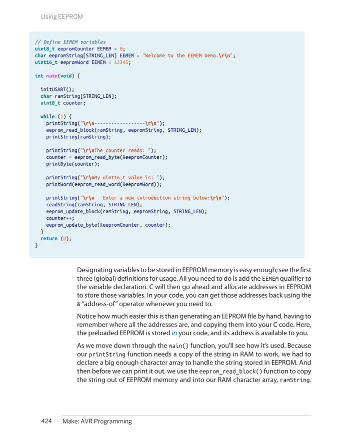
// Define EEMEM variablesuint8_t eepromCounter EEMEM = 0;char eepromString[STRING_LEN] EEMEM = "Welcome to the EEMEM Demo.\r\n";uint16_t eepromWord EEMEM = 12345;
int main(void) {
initUSART(); char ramString[STRING_LEN]; uint8_t counter;
while (1) { printString("\r\n------------------\r\n"); eeprom_read_block(ramString, eepromString, STRING_LEN); printString(ramString);
printString("\r\nThe counter reads: "); counter = eeprom_read_byte(&eepromCounter); printByte(counter);
printString("\r\nMy uint16_t value is: "); printWord(eeprom_read_word(&eepromWord));
printString("\r\n Enter a new introduction string below:\r\n"); readString(ramString, STRING_LEN); eeprom_update_block(ramString, eepromString, STRING_LEN); counter++; eeprom_update_byte(&eepromCounter, counter); } return (0);}
Designating variables to be stored in EEPROM memory is easy enough; see the firstthree (global) definitions for usage. All you need to do is add the EEMEM qualifier tothe variable declaration. C will then go ahead and allocate addresses in EEPROMto store those variables. In your code, you can get those addresses back using the& “address-of” operator whenever you need to.
Notice how much easier this is than generating an EEPROM file by hand, having toremember where all the addresses are, and copying them into your C code. Here,the preloaded EEPROM is stored in your code, and its address is available to you.
As we move down through the main() function, you’ll see how it’s used. Becauseour printString function needs a copy of the string in RAM to work, we had todeclare a big enough character array to handle the string stored in EEPROM. Andthen before we can print it out, we use the eeprom_read_block() function to copythe string out of EEPROM memory and into our RAM character array, ramString.
424 Make: AVR Programming
Using EEPROM

Don’t forget that eepromString is an array, so that passing it as an argument to afunction is really passing the address of the first element.
The next few lines demonstrate how to read byte (8-bit) and word (16-bit) valuesout of EEPROM. It’s easy when the EEMEM macro keeps track of the variable addressesfor us. To get the data stored as eepromCounter, we need to pass its address toeeprom_read_byte(). If we allocated this memory manually, we’d have to remem-ber that the counter data was stored at EEPROM memory slot whatever. But here,we simply use the “address-of” operator on the EEMEM-defined variable, and we’reall set. Compare read_byte with read_block—we have to explicitly use the & op-erator here because we wanted the address of an integer. We didn’t need to usethe & operator in the earlier example because in that case we wanted the addressof an array.
If you dump the EEPROM using the AVRDUDE terminal, you’ll find that the 16-bitnumber is stored at memory location 81. You could have figured that out yourself(one byte for the counter plus 80 bytes for the welcome string), but it’s a lot easierto let gcc take care of it all for you. Much more importantly, if you change yourcode, adding a variable or two stored in EEPROM, or changing a string’s length, allthe addresses get updated automatically when you recompile.
The last half of the demo takes input from you, stores it as the next welcome string,increments the counter, and stores that away in EEPROM, too.
Initializing EEPROMBut if we just flash this program into our chip, the program will just print out abunch of garbage because although we’ve changed the program, we haven’t up-dated the EEPROM yet. (Try it!) Where did our predefined EEPROM data go?
When the EEMEM statement allocates the variables in EEPROM, it writes them intoour compiled .elf file, so in principle the variables are usable by the rest of the code.But AVRDUDE doesn’t flash the EEPROM without our permission. This means thatwe can reflash the program memory or the EEPROM memory or both, which is veryhandy if we’ve got some values in EEPROM that we’d like to keep. The upshot ofthis is that in order to preload the EEPROM data, we need to split it out into anEEPROM file and burn that into the AVR in a separate step, just as we were doingin “Saving and Loading EEPROM” on page 422.
Where you normally type make flash to compile and load the program into theAVR, you can type make flash_eeprom to generate the EEPROM file and flash it intoEEPROM. And if you type just make eeprom, you’ll end up with a copy of the Intelhex file that it uses. Feel free to open it up in a hex editor and have a look. This time,though, you won’t need to edit the EEPROM memory dump file, because it’s gen-erated from your C code.
425Chapter 19: EEPROM
Using EEPROM
The EESAVE Fuse Bit
Naturally, there’s a catch. ATmega168 chips comefrom the factory with a fuse setting that automati-cally invokes an EEPROM erase every time you pro-gram the chip. This can be handy if you want all ofthe chip’s memory to be in a known state and don’twant data from previous incarnations lying aroundin EEPROM. Just remember that your EEPROM will beblank unless you reload it each time after a program-ming cycle.
On the other hand, sometimes you want to flash oneprogram over another without losing the EEPROMvalues—if, for instance, you’ve found a bug in thecode that doesn’t impact the addresses or content ofEEPROM. Or maybe you’ve got user data stored inEEPROM that you don’t want to forget. (Though ac-tually, the safest thing to do in that case is to save theEEPROM to a file.)
If you’d like the EEPROM to not be erased automati-cally when you flash in a new program, you’ll have toset the EESAVE bit in the high fuse byte. Starting froma stock mega168 chip, you’d pass AVRDUDE an argu-ment like -U hfuse:w:0xd7:m. Or if you’re using mmakefile, just type make set_eeprom_save_fuse.You can reset the EESAVE fuse by writing a 0xd9 tohfuse or by invoking make clear_eeprom_save_fuse.
If you haven’t set the EESAVE fuse bit, make sure thatyou’re flashing the EEPROM initialization values af-ter you’ve flashed in your program. The order is im-portant because each time you reprogram the chip,it will reinitialize the EEPROM.
If you haven’t already, set the EESAVE fuse bit and play around with this two-stageprogram and EEPROM cycle. Change some of the ‘EEMEM` variables’ initial valuesin your code, and type make flash to reprogram the chip. You’ll notice that thevalues stored in EEPROM didn’t change. Now make flash_eeprom and they will beupdated. If you edit the code and reflash that in and none of the memory addresseshave changed, you’ll find the variables preserved in whatever state you last leftthem.
The one thing to be careful of is moving or adding new EEMEM definitions. EEMEM isallocated in the same order it’s defined in your file. If you switch the order of thevariables around, between the string and the uint16_t variable for instance, thevariables will get assigned different addresses in EEPROM, and things will getscrambled up. If you do change the ordering of EEMEM variables, or even just wantto be on the safe side, reflash both the program memory and the EEPROM. To beon the super safe side, you can first run run make clean, which will remove all ofthe compiled files—machine code and EEPROM. Then use make flash flash_eeprom to remake your entire project from scratch and flash both program and EE-PROM memories.
Project: Vigenère Cipher Encoder/Decoder
I’ve already walked you through a bunch of the good uses for EEPROM and howyou’d implement it. In my projects, I’ve never used more than a few bytes of EEPROM—for serial numbers or for storing a couple configuration parameters. Nonvolatile
426 Make: AVR Programming
Project: Vigenère Cipher Encoder/Decoder

storage in small amounts like this is invaluable when you need it, but you neverreally need all that much.
For instance, in a logging accelerometer I made, I used five bytes of EEPROM—onefor a sensitivity setting (2 g / 8 g) and four for the location of the last page write onthe SD card that was used for storing the data. This enabled it to restart in the rightplace in case it lost power or had a brownout. That’s not an ideal use of EEPROMbecause the logger ended up saving its state every three minutes or so, but it onlyhad to run for four hours anyway, and it was only four bytes, so if it burned themout, I’d just switch to another location.
In this project, however, I’m going hog-wild. The program itself is a menu-drivenVigenère cipher encoder and decoder that stores its code phrases in EEPROM. I’malso storing the strings that are used as menu prompts in EEPROM, just because Ican. (Flash program memory is a better place for storing static data, but that’s thetopic of Chapter 18.)
A Vigenère cipher is an old encryption method, based on the Caesar cipher. In theCaesar cipher, every letter of the message is replaced with a letter that’s been shif-ted by the same number of letters in the alphabet. If the shifted result runs off theend of the alphabet, you start over at “a” again. So if the message is “hello” and theshift is one, the encrypted message is “ifmmp.” Julius Caesar is reported to haveused the secret key “c,” which shifts all characters over by three and isn’t really allthat clever: “C” for Caesar. It might have worked in Emperor Caesar’s time, but it’seasily crackable these days.
On the other hand, two changes can make the encryption unbreakable. The firstis to shift each letter by a different amount, depending on their position in themessage. The most common way to do this, called a Vigenère cipher, is to have akey phrase that’s easy to remember and then shift each letter in the message by anumber of letters that corresponds to the key phrase. So if your key phrase is “abdc”and the message is “hello,” you’d encrypt as follows: “h” is shifted over by onebecause of the “a,” to become “i.” “e” is shifted over two letters because of “b,” andbecomes a “g.” The AVR version here updates the Vigenère cipher to use the fullrange of printable ASCII characters, but the operation is the same. To decrypt, youjust apply the same idea in reverse—subtracting the letter value of each letter inthe key phrase.
For short key phrases, the Vigenère cipher is good enough to challenge a novicecryptanalyst. If you use a five-letter key phrase, for instance, cracking the code islike solving five simultaneous Caesar ciphers, which is hard, but possible if theplaintext message is long enough. If you want truly unbreakable encryption, youcan make the key phrase truly random and as long as the message—a “one-timepad.” Using a medium-length memorable key phrase gives you encryption that’ssomewhere between these extremes of simple to decrypt and unbreakable.
427Chapter 19: EEPROM
Project: Vigenère Cipher Encoder/Decoder

So flash the code example and play around. If everything looks like garbage afteryou’ve flashed the code in, don’t forget to reinitialize the EEPROM. make cleanflash flash_eeprom should get you set up. Enter a sample message, and eitheruse a precompiled code phrase or enter your own. What’s fun about Vigenère ci-phers is that they’re symmetric—if you encrypt twice with the same code phrase,then decrypt twice, you still get back to your original message.
Now let’s see what makes the program tick. I’ve split the code up into two sectionsto make it more manageable. Let’s have a look at the header first in Example 19-4.
Example 19-4. vigenereCipher.h listing#include <avr/io.h>#include <avr/eeprom.h>#include "USART.h"
#define MAX_TEXT_LENGTH 256#define CODE_LEN 64
// -------- Global Variables --------- //char EEMEM code0[CODE_LEN] = "ettubrute";char EEMEM code1[CODE_LEN] = "attackatdawn";char EEMEM code2[CODE_LEN] = "theraininspainfallsmainlyontheplain";char EEMEM code3[CODE_LEN] = "ablewasiereisawelba";char *codePointers[] = { code0, code1, code2, code3 };
// Menu strings. Why not store them in EEPROM?char EEMEM welcomeString[] = "\r\n--== Vigenere Cipher ==--\r\n";char EEMEM menuEncode[] = " [e] to encode text\r\n";char EEMEM menuDecode[] = " [d] to decode text\r\n\r\n";char EEMEM menuEnterText[] = " [n] to enter new text\r\n";char EEMEM menuCodeText[] = " [c] to select your code phrase\r\n";char EEMEM menuChangeCode[] = " [x] to modify code phrases\r\n";char EEMEM promptCode[] = "code: ";char EEMEM promptText[] = "\r\ntext: ";
char EEMEM promptSelectCode[] = "Select codephrase:\r\n\r\n";char EEMEM promptTypeText[] = "Type your text: ";
// Given the address of an EEPROM string, prints it out// Used for menu itemsvoid printFromEEPROM(char *eepromString);
// Takes input from serial, stores it in the text arrayvoid enterText(char text[]);
// Reads code phrases out of EEPROM and prints them.// Uses the codeBuffer for temporary storagevoid displayCodes(void);
// Changes a code phrase, both in EEPROM and the current codevoid changeCode(char codeBuffer[]);
428 Make: AVR Programming
Project: Vigenère Cipher Encoder/Decoder

// Pick a code phrase from EEPROMvoid selectCode(char code[]);
// Encodes the passed text string, in placevoid encodeVigenere(char text[], char code[]);
// Decodes the passed text string, in placevoid decodeVigenere(char text[], char code[]);
You can see that I’m going to be letting the compiler allocate the EEPROM memoryusing the EEMEM keyword—there are tons of EEMEM declarations in the global-variable section of the file. Other than those defines, I’d like to draw your attentionto the array of character pointers that’s defined to point to the four code phrasestrings: codePointers.
codePointers is really just an index. To find the address of the second key phrase,for instance, you first look up the address of the desired code string in EEPROMfrom the array codePointers[], and then you’re ready to fetch the string itself outvia printFromEEPROM() or eeprom_read_byte(), or whatever.
Almost every time I have a bunch of related strings stored in memory, EEPROM,program flash, or even RAM, I’ll create this kind of pointer-array for indexing pur-poses. It’s much easier to type code like:
char* codePointers[] = {code0, code1, code2, code3};stringAddress = codePointers[i];printFromEEPROM(stringAddress);
than it is to explicitly handle each case:
if (i==0){ printFromEEPROM(code0);}else if (i==1){ printFromEEPROM(code1);}else if (...){ // etc. for each possible code}
Next we come to a bunch of strings that we’re going to use for prompts and menuitems later on. Why am I doing this? When we print out a string using printString("hi");, for instance, the compiler allocates memory to encode the phrase“hi” both in the program memory, and as a variable in RAM, because our printString() command takes a normal RAM array as an argument. Here, we stash thestrings in EEPROM instead and read the characters out from EEPROM one by one,which saves on RAM. A better place to store nonchanging prompt strings is in
429Chapter 19: EEPROM
Project: Vigenère Cipher Encoder/Decoder

program memory, as we saw in Chapter 18, but I had the extra storage space inEEPROM, so why not?
Finally, we have the function prototypes. When we write free-standing libraries inC, we almost always have a header (.h) file and a code (.c) file. In these cases, it’smandatory to prototype your functions in the header file, so that the compilerknows what functions your main code has available to it just by including theheader file. Here it’s not strictly necessary because all of my functions are definedin the main file, but it’s still nice for style. Looking through all the function proto-types like this can give you a good overview of what the code does.
From the prototypes, we can see that there are functions for printing strings storedin EEPROM to serial output, for entering text into strings, for displaying the codephrases, for changing the code phrases, for picking an active code phrase, and forencoding and decoding. The main() routine basically ties all these together andgives us a fairly sophisticated program.
Most of these functions use a trick that’s made possible by pointers. You’ll noticethat they all have return type void, meaning they don’t return anything. But thenhow can a function like enterText(), which takes in text and “updates” a text stringvariable, actually work? The answer is that the argument, a text string (a characterarray with a zero at the end), is passed into this function by its address: the pointerto its first memory element. Everything the function does with this “array,” it’s ac-tually doing in the memory location that is passed by the pointer. So the functiondoesn’t need to return anything at all; all the changes to the variable are donewithin the function itself.
When we call enterText(char text[]) from the main() routine, we pass a stringthat’s defined in main() somewhere, let’s say that it’s called textBuffer in main().This data, the letters that make up the string, are stored somewhere in RAM. Whenwe pass the array to the enterText() function, remember that what’s being passedis actually the address of the first character in RAM. When the enterText() functionstores a letter in text[0], it’s actually storing the letter in the memory address thatwas passed to it—the same memory slot that’s pointed at by the first character oftextBuffer in main().
The upshot of passing arrays by pointers like this is that the called function canwrite directly to the same memory that’s been allocated in main(). This in turnmeans that there’s no reason for our enterText() function to pass anything backto main() as a return value—it can just edit the underlying variable memory di-rectly, and then when the function returns, main() will have the new character dataalready sitting in textBuffer.
In order to see how this all works in practice, and to play around some with readingand writing to EEPROM memory using pointers, let’s dig into the C code now. Be-
430 Make: AVR Programming
Project: Vigenère Cipher Encoder/Decoder

cause the listing is so long, I’ll break it up into an outline first in Example 19-5, andthen we’ll fill in the details as we work through it.
Example 19-5. vigenereCipher_outline.c listing/*Vigenere Cipher encoder / decoder demoAnd an excuse to play around with EEPROM memory */
#include "vigenereCipher.h"
// -------- Functions --------- //
void printFromEEPROM(char *eepromString);void enterText(char text[]);void displayCodes(void);void changeCode(char codeBuffer[]);void selectCode(char code[]);void encodeVigenere(char text[], char code[]);void decodeVigenere(char text[], char code[]);
int main(void) { // -------- Inits --------- //
char textBuffer[MAX_TEXT_LENGTH]; char codeString[CODE_LEN]; char input; initUSART();
// ------ Event loop ------ // while (1) {
// Menu printFromEEPROM(welcomeString); // .... more fany menu printing printFromEEPROM(menuDecode); input = receiveByte();
switch (input) { case 'e': // encode encodeVigenere(textBuffer, codeString); break; case 'd': // decode decodeVigenere(textBuffer, codeString); break; case 'n': // new text printFromEEPROM(promptTypeText); enterText(textBuffer); break; case 'c': // choose code selectCode(codeString); break;
431Chapter 19: EEPROM
Project: Vigenère Cipher Encoder/Decoder
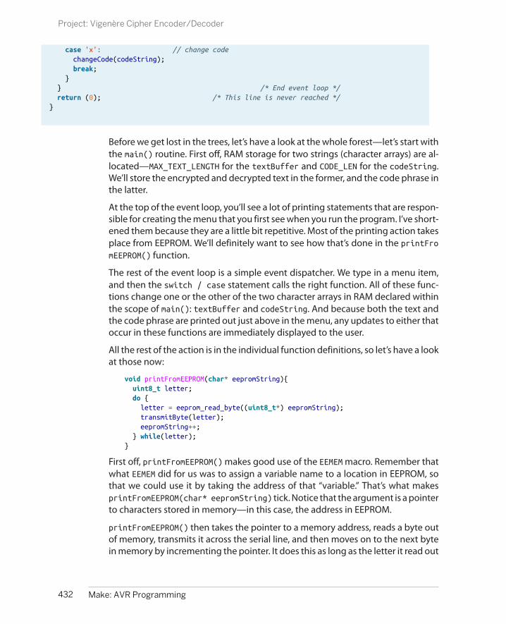
case 'x': // change code changeCode(codeString); break; } } /* End event loop */ return (0); /* This line is never reached */}
Before we get lost in the trees, let’s have a look at the whole forest—let’s start withthe main() routine. First off, RAM storage for two strings (character arrays) are al-located—MAX_TEXT_LENGTH for the textBuffer and CODE_LEN for the codeString.We’ll store the encrypted and decrypted text in the former, and the code phrase inthe latter.
At the top of the event loop, you’ll see a lot of printing statements that are respon-sible for creating the menu that you first see when you run the program. I’ve short-ened them because they are a little bit repetitive. Most of the printing action takesplace from EEPROM. We’ll definitely want to see how that’s done in the printFromEEPROM() function.
The rest of the event loop is a simple event dispatcher. We type in a menu item,and then the switch / case statement calls the right function. All of these func-tions change one or the other of the two character arrays in RAM declared withinthe scope of main(): textBuffer and codeString. And because both the text andthe code phrase are printed out just above in the menu, any updates to either thatoccur in these functions are immediately displayed to the user.
All the rest of the action is in the individual function definitions, so let’s have a lookat those now:
void printFromEEPROM(char* eepromString){ uint8_t letter; do { letter = eeprom_read_byte((uint8_t*) eepromString); transmitByte(letter); eepromString++; } while(letter);}
First off, printFromEEPROM() makes good use of the EEMEM macro. Remember thatwhat EEMEM did for us was to assign a variable name to a location in EEPROM, sothat we could use it by taking the address of that “variable.” That’s what makesprintFromEEPROM(char* eepromString) tick. Notice that the argument is a pointerto characters stored in memory—in this case, the address in EEPROM.
printFromEEPROM() then takes the pointer to a memory address, reads a byte outof memory, transmits it across the serial line, and then moves on to the next bytein memory by incrementing the pointer. It does this as long as the letter it read out
432 Make: AVR Programming
Project: Vigenère Cipher Encoder/Decoder

is anything other than a zero, which marks the end of the string. The only othercatch is the typecasting of the type char* to uint8_t*, which is essentiallymeaningless because both types refer to a byte of data, but we know we’ve storedcharacters, while the function eeprom_read_byte() expects to have stored numer-ical data. (If you omit the typecast, the compiler throws a warning about it, buteverything works just fine.)
The next function, enterText(), is basically printFromEEPROM in reverse, with theresult stored in RAM:
void enterText(char text[]){ uint8_t i=0; char letter; do{ letter = receiveByte(); transmitByte(letter); /* echo */ text[i] = letter; i++; } while(!(letter == '\r') && (i < (MAX_TEXT_LENGTH-1))); text[i-1] = 0;}
For every letter that you type in over the serial line, another character is stored inthe RAM character array text[]. This ends when you either send a carriage return(\r) or the maximum length of the text buffer is reached, and then a zero is addedto designate the end of the string. Again, when you’re looking at this function,remember that it’s all done with pointers; inside this function, the character arraytext[] is actually an address in RAM of some variable that’s defined in main(). Sowhen a letter is stored in text[] inside this function, it’s actually stored in the RAMlocations that go with whatever variable in main() was passed to the function.
Previously, we took input from the serial port and stored it in variables, so why dowe need pointers and addresses here? In the other examples, everything was tak-ing place from the context of a main() function. Here, only the variables definedinside the function enterText() and the arguments passed to it (and globals anddefines) are available inside that function. The point of passing the string variabletext[] by its address is that the function can write to memory starting at thataddress and it will be as if the function wrote directly into the RAM string variablein main() that we passed as an argument to this function:
void displayCodes(void){ uint8_t i; for (i=0; i<4; i++){ transmitByte(' '); transmitByte('0'+i); printString(": "); printFromEEPROM(codePointers[i]); printString("\r\n"); }}
433Chapter 19: EEPROM
Project: Vigenère Cipher Encoder/Decoder
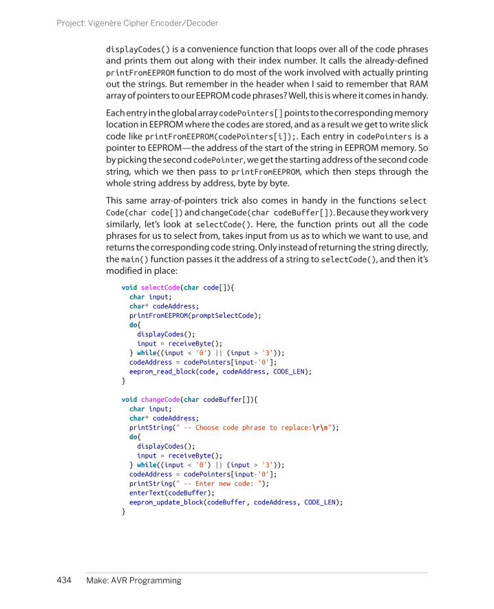
displayCodes() is a convenience function that loops over all of the code phrasesand prints them out along with their index number. It calls the already-definedprintFromEEPROM function to do most of the work involved with actually printingout the strings. But remember in the header when I said to remember that RAMarray of pointers to our EEPROM code phrases? Well, this is where it comes in handy.
Each entry in the global array codePointers[] points to the corresponding memorylocation in EEPROM where the codes are stored, and as a result we get to write slickcode like printFromEEPROM(codePointers[i]);. Each entry in codePointers is apointer to EEPROM—the address of the start of the string in EEPROM memory. Soby picking the second codePointer, we get the starting address of the second codestring, which we then pass to printFromEEPROM, which then steps through thewhole string address by address, byte by byte.
This same array-of-pointers trick also comes in handy in the functions selectCode(char code[]) and changeCode(char codeBuffer[]). Because they work verysimilarly, let’s look at selectCode(). Here, the function prints out all the codephrases for us to select from, takes input from us as to which we want to use, andreturns the corresponding code string. Only instead of returning the string directly,the main() function passes it the address of a string to selectCode(), and then it’smodified in place:
void selectCode(char code[]){ char input; char* codeAddress; printFromEEPROM(promptSelectCode); do{ displayCodes(); input = receiveByte(); } while((input < '0') || (input > '3')); codeAddress = codePointers[input-'0']; eeprom_read_block(code, codeAddress, CODE_LEN);}
void changeCode(char codeBuffer[]){ char input; char* codeAddress; printString(" -- Choose code phrase to replace:\r\n"); do{ displayCodes(); input = receiveByte(); } while((input < '0') || (input > '3')); codeAddress = codePointers[input-'0']; printString(" -- Enter new code: "); enterText(codeBuffer); eeprom_update_block(codeBuffer, codeAddress, CODE_LEN);}
434 Make: AVR Programming
Project: Vigenère Cipher Encoder/Decoder
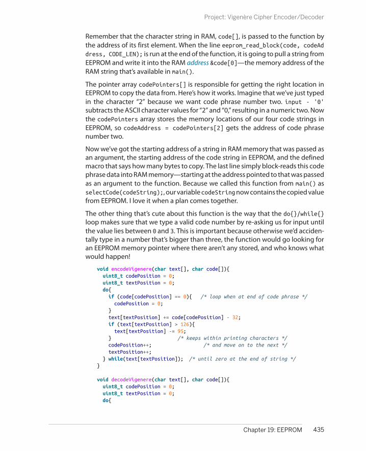
Remember that the character string in RAM, code[], is passed to the function bythe address of its first element. When the line eeprom_read_block(code, codeAddress, CODE_LEN); is run at the end of the function, it is going to pull a string fromEEPROM and write it into the RAM address &code[0]—the memory address of theRAM string that’s available in main().
The pointer array codePointers[] is responsible for getting the right location inEEPROM to copy the data from. Here’s how it works. Imagine that we’ve just typedin the character “2” because we want code phrase number two. input - '0'subtracts the ASCII character values for “2” and “0,” resulting in a numeric two. Nowthe codePointers array stores the memory locations of our four code strings inEEPROM, so codeAddress = codePointers[2] gets the address of code phrasenumber two.
Now we’ve got the starting address of a string in RAM memory that was passed asan argument, the starting address of the code string in EEPROM, and the definedmacro that says how many bytes to copy. The last line simply block-reads this codephrase data into RAM memory—starting at the address pointed to that was passedas an argument to the function. Because we called this function from main() asselectCode(codeString);, our variable codeString now contains the copied valuefrom EEPROM. I love it when a plan comes together.
The other thing that’s cute about this function is the way that the do{}/while{}loop makes sure that we type a valid code number by re-asking us for input untilthe value lies between 0 and 3. This is important because otherwise we’d acciden-tally type in a number that’s bigger than three, the function would go looking foran EEPROM memory pointer where there aren’t any stored, and who knows whatwould happen!
void encodeVigenere(char text[], char code[]){ uint8_t codePosition = 0; uint8_t textPosition = 0; do{ if (code[codePosition] == 0){ /* loop when at end of code phrase */ codePosition = 0; } text[textPosition] += code[codePosition] - 32; if (text[textPosition] > 126){ text[textPosition] -= 95; } /* keeps within printing characters */ codePosition++; /* and move on to the next */ textPosition++; } while(text[textPosition]); /* until zero at the end of string */}
void decodeVigenere(char text[], char code[]){ uint8_t codePosition = 0; uint8_t textPosition = 0; do{
435Chapter 19: EEPROM
Project: Vigenère Cipher Encoder/Decoder

if (code[codePosition] == 0){ codePosition = 0; } if (code[codePosition] > text[textPosition]){ text[textPosition] += 95; } /* keeps within printing characters */ text[textPosition] -= code[codePosition] - 32; codePosition++; textPosition++; } while(text[textPosition]);}
In comparison, the functions encodeVigenere and decodeVigenere are almost bor-ingly straightforward. As mentioned earlier, Vigenère ciphers work by adding thenumerical values of a letter in the code phrase to the plaintext to encrypt it, andsubtracting the same code phrase from the encrypted text to get the plaintextback. Doing this in C is made easy by the equivalence of numbers and letters inASCII. The first printable character is “space” at ASCII 32, and the last printablecharacter is “~” at 126—that’s 95 printable characters in all. When you add thedifference between the code phrase’s character and 32 to the text character, wrap-ping around to the beginning if the sum is too large, you’ve just Vigenère-ciphered.Decoding is the subtraction version of the same procedure, with bounds-checkingto make sure the subtracted characters stay in the printable range.
436 Make: AVR Programming
Project: Vigenère Cipher Encoder/Decoder

Learning AVR: The Missing Chapters
That was quite a lot of material! Surely there is nothing left to learn about workingwith the AVR microcontroller or any of its peripherals, right? Wrong!
By now you should have the base knowledge to read the datasheet or scour aroundthe interwebs to find what you need. In that spirit, here is a list of all the topics thatI didn’t have room for, but that I feel like you should know about anyway.
The Watchdog TimerThe watchdog system is a very slow timer that can be configured to run from 16milliseconds all the way up to 8 seconds. It is special in that when it reaches theend of its time, it can fire an interrupt or reset the chip. Why would you want toreset the chip every second?
The primary use of the watchdog timer is as a safeguard against runaway code. Ifyour event loop normally takes, say, 20 milliseconds, you can configure the watch-dog timer for 40 milliseconds. At the bottom of your event loop, you zero thewatchdog timer out again. When your code is running normally, the watchdogtimer will never fire.
But if anything goes horribly wrong and your chip freezes up—say you’re doing ablocking wait for peripheral input that never arrives—the watchdog will reset yourAVR at least once in a while. You can very cleverly structure your code to takeadvantage of this and provide nearly foolproof functionality of the first part of yourroutine.
Another use of the watchdog is as a source of sleep-mode interrupts. If you areputting the chip to sleep for long periods of time, and you configure the watchdogto use a normal interrupt rather than the system reset, it can be a handy wakeup
437
Conclusion, Parting Words,and Encouragement 20
source because it runs so slowly. You can put your chip to sleep for up to eightseconds at a time.
For more on the watchdog system, see the chapter in the datasheet on “SystemControl and Reset.”
Power SavingsI hardly scratched the surface of power saving and sleep modes. You saw how toenter sleep mode and vary the CPU prescaler, but there’s even more you can do.For instance, if you really need to minimize power use, you can turn off all of theperipherals that you don’t need. Read up on these in the “Power Management”section of the datasheet, but then go straight to the avr/power.h library for im-plementation because it’s much more readable in your code.
My first choice for lowering power consumption is just to stay in sleep mode asmuch as possible. Following that, I’ll shut down whatever peripherals I can, but thisgets tricky if you’re actually using some of them. A no-code-change method toreduce your power usage is just to use a lower voltage for VCC—all of the A serieschips run on 3.3–3.6 V just fine.
Crystals and Alternate Clock SourcesHere, we always used the internal calibrated RC oscillator as a timebase, but youcan also supply an external crystal and set some fuses to use it. This gives you theadvantage of a super-accurate timebase. I’ve only really needed a crystal for high-speed USART serial communications and USB emulation. Other people swear bythem.
Another option, if you’ve got an accurate external timebase, is to calibrate theinternal oscillator to the external source by varying the byte in the OSCCAL registerto change the speed. The problem is that the OSCCAL register is a normal, volatile,register and gets lost on reset.
A solution, once you’ve found a good value, is to write the calibration byte to a safeplace in EEPROM and then read the value back out and store it back in the OSCCAL register as part of your initialization routine at the top of main().
BootloadersWith a number of the ATmega chips, notably the mega88 and mega168, you havethe option to reserve some space at the end of the program memory for a boot-loader program that gets automatically called on reset, if the right fuses are en-abled. This bootloader code is able to write to program flash memory, so that youcan program the chip with only a serial cable. The old-school Arduinos used to dothis, for instance.
I’m not a big fan of bootloaders because the serial port depends so much on theCPU speed that it can get messed up if you play around with the CPU speed fuse
438 Make: AVR Programming
Learning AVR: The Missing Chapters

settings. That said, you can’t set the fuses from within a bootloader either, so itmakes for a nice safe playground. You should have an ISP on hand as a fallback.
Analog ComparatorThe AVR not only has an ADC, but also an analog comparator built in. In short, itcan trigger interrupts when the analog voltage on one pin (AIN0) exceeds that onanother pin (AIN1). With a fixed voltage threshold, you could just use the ADC andcompare it to a number in code. But the ADC allows you to figure out the differ-ence between two signals.
The comparator can also share the ADC multiplexer, so you can use same ADC pinsin place of AIN1. You do have to turn off the ADC to use its multiplexer for thecomparator, however.
Debugging
If there’s anything I like about microcontrollers, it’s putting together a projectquickly and having it work. Of course, it’s sometimes fun and sometimes frustratingto debug the darn thing for a few hours, but I usually learn something along theway.
Advice on debugging is usually the same old chestnuts, and I’m afraid I’m goingto dish them up as well:
• Is it powered?
• Is the reset line pulled low?
• Have you declared variables used in your ISRs as volatile?
• Have you actually called those initialization subroutines that you just defined?(How many times do I write a timer init, and then forget to call the darnfunction!)
• When all else fails, reduce or simplify to the closest known working state.
• Toss a 0.1 uF decoupling capacitor on the power pins of any or all ICs.
• Never assume anything. Or at least test or verify your assumptions.
• Put LEDs on everything. (Within reason.) Do you see the problem?
• Put oscilloscope probes on everything you can’t use an LED for. Are the voltagelevels what you expect? Why or why not?
• Buy all critical parts in pairs, and don’t hesitate to swap one out if you think itmay be buggy. Even if it’s a low probability of being the problem, it’s a quickfix.
439Chapter 20: Conclusion, Parting Words, and Encouragement
Debugging

Put This Book Down and Build!
Now get out there and build stuff! Take photos, post project writeups, and postyour code for all to see.
440 Make: AVR Programming
Put This Book Down and Build!
Symbols25LC256.h listing, 350_BV() macro, 66
Aacceleration control, 331ADC sleep mode, 251
(see also noise reduction)address-of operator, 382adsr.c listing, 281AM radio project
amRadio.c listing, 193carrier frequency, 186circuit for, 188code for, 190CPU speed and, 189power limits for, 189receiver for, 187square-wave modulation,
187
American Standard Code forInformation Interchange(ASCII), 86
analog comparator, 439analog outputs (on Arduino), 9analog sensors, 126, 266analog-to-digital converters
(ADCs)accuracy /stability in, 266basics of, 125exponentially weighted
moving averages, 259footstep detector project,
252hardware overview, 126initialization of, 137integer division in, 261internal voltage reference,
247light meter project, 129minimum configuration,
129night light project, 145
noise reduction in, 245, 251oscilloscope project, 140oversampling and, 243,
245, 251piezoelectric disks and, 252prescaler options, 137project supplies, 126, 244successive approximation
and, 128troubleshooting, 139uses for, 139voltage meter project, 244voltage pre-scaling for, 247voltage sensors, 126
analogWrite() function, 208AND operator, 70, 110Arduino
analog output in, 9, 208AVR programming with, 26benefits of, 21breadboard connections,
31diagram of flash wiring, 27
441Index
Index

drawbacks of, xii, 22flashing as a target, 26hardware programming in,
28pin diagram, 23portpins.h bug, 26programming toolchain, 20terminal emulator software,
84vs. other IDEs, 24writing C in, 25
arrays, 388Atmel AVRISP mkII flash pro-
grammer, 30attack-decay-sustain-release
(ADSR) volume envelopes,280, 284
ATtiny44/45, 12attributions, xviiaveraging vs. oversampling,
246AVR ATmega microcontrollers
benefits of, xibuilt-in pull-up resistor, 107built-in USART device, 80C code structure in, 45configuring serial commu-
nication in, 81driving large loads with,
287hardware overview, 8hardware registers in, 47interfacing over serial, 239internal clock speed, 189internal EEPROM on, 414limited memory in, 4naming conventions, 12pin overview, 5programming in Arduino,
27(see also programming)
selection of, 12timer/counters in, 177voltage reference in, 248
avr-gcc code compiler, 15, 280avr-size utility program, 385
avr/eeprom.h library, 414, 418avr/io.h file , 91AVRDUDE
common configurations, 39error messages, 38fuse-bit settings, 191, 426options for, 37programmers supported,
16reading/writing to EEPROM,
417saving/loading EEPROM,
422starting, 36
avrMusicBox.c listing, 117
Bback voltage, 298base resistance, 292battery power, 57, 248
(see also DC motors)baud rate, definition of, 78bipolar-junction transistors
(BJTs), 290bit trading in SPI, 340bit twiddling
advanced application of, 64bit shifting, 62, 181bit-shift roll, 64bitwise logical operators,
65clearing bits with AND/NOT,
70Cylon eyes project, 59, 64overview of, 75pin numbering and, 63project supplies, 60setting bits with OR, 68toggling bits with XOR, 69usefulness of, 59, 72_BV() macro, 66
bitmasks, 68, 71, 110bitwise logical operations, 59blinkenlights, 50
blocking capacitors, 96, 97Boss Button project
bossButton.c listing, 123bossButton.py listing, 121
button bounce, 113buttons, 106, 156
(see also digital input)(see also interrupt pro-
gramming)
CC language
arrays in, 388ASCII and, 86AVR code structure, 45benefits of, xiibit shifting instructions, 63code reuse with modules,
94, 240coding in Arduino IDE, 25compiler errors, 41dereferencing operator, 393functions in, 56integer division in, 261memory addresses, 381naming conventions, 83zero-indexing in, 63, 102
C99 integer types, ISO stan-dard for, 419
cadmium-sulfide light-dependent resistor (LDR),129, 140
calibrateTime.py listing, 237capacitive sensors
circuit for, 166code for, 168debugging, 173global variables and, 170principle behind, 164sensor for, 165timing of, 164
capacitors, 96capSense.c listing, 168Central Limit Theorem, 246
442 Index

central processing unit (CPU)basics of, 8CPU clock, 8, 189, 191, 237noise reduction, 245, 251setting speed in code, 190
character-to-ASCII converter,87
clearing bits, 70cli() function, 161CLKPR (Clock Prescale Regis-
ter), 192clocks
accuracy of, 237, 241alternate sources for, 438as timebase, 176double-speed mode, 92enabling high-speed, 191noise reduction and, 245,
251prescalers for, 8, 137, 185,
189types of, 8
code editors, 14code examples, permission to
use, xviicomparators, 217, 439compare events, 177compiler errors, 41, 46, 386computer-side scripting, 121configuration registers, input-
output, 48const keyword, 384constants, human-friendly
synonyms for, 62control pulse frequency, 222cross-platform compatibility,
16, 84crystal radios, 187crystals, 438CTC waveform mode, 178, 184Cylon eyes project, 59, 64
DDarlington transistors, 291
dataorganization in EEPROM,
423serial vs. parallel, 340types of, 419
data framing, 338data logging, 372, 378data smoothing, 244data-direction register (DDR),
47Data-Direction Register (DDR),
108datasheets
accessing, 7External Interrupts section,
161macro definitions, 90Power Management and
Sleep Modes, 252Power Management sec-
tion, 438Register Description sec-
tion, 92System Control and Reset
section, 438UCSR0B functions, 90
DC motorsback voltage in, 298basics of, 297dcMotorWorkout.c listing,
300diagram of beadboard, 298diagram of circuit, 297flyback diode in, 300running in reverse, 305specification for, 303torque in, 303vs. stepper motors, 318
DDRx (see data-direction reg-ister)
dead band in servo motor, 218debouncer.c listing, 115debouncing, 113debugging
ADC code, 137, 145ADC output, 139
basic steps to, 439button press interpretation,
112capacitive sensors, 173EEPROM chip installation,
348global variables, 173hardware registers, 49, 91I2C initialization, 369pin output, 49pointer initialization, 386portpins.h bug, 26programmer-to-AVR com-
munication, 52sampling frequency, 280serial port loopback testing,
86with USART, 95
decomposing-to-pointer rule,388
# define statements, 62, 377dependencies, keeping track
of, 20dereferencing operator, 393desktop-side scripting, 121differential pulse-code modu-
lation (DPCM)basics of, 405encoding two-bit data, 405wave2DPCM.py encoding,
408digital input
Boss Button project, 119button presses, 110configuration of, 108debouncing, 113music box project, 117project supplies, 105pushbutton checklist, 120pushbuttons/switches, 106state change indicators,
112digital output
AVR C code structure, 45blinking LED project, 44, 49configuration of, 48
443Index

hardware registers, 46POV pattern generator, 43POV toy, 49project supplies, 43
digital signal processing (DSP)chip, 280
digital thermometer project,361, 370(see also I2C protocol)
digital-to-analog converters(DACs), 127, 211
direct digital synthesis (DDS)accumulators, 273ADSR envelopes, 284auxiliary files for, 284basics of, 270code for, 274debugging for speed, 280digital signal processing
chip and, 280dynamic volume control,
280fatSaw.c listing, 277lowpass filter and, 276mixing, 277project overview, 269project supplies, 269pseudocode for, 271PWM frequency and, 270sample rate and, 276sine wave creation, 274summary of, 273
DRAM (dynamic random ac-cess memory), 344
drive modes, h-bridgecoasting, 316comparison of, 315locked anti-phase, 314sign-magnitude, 314states available, 313
drivers, for Windows, 36duty cycles, 201dynamic volume control, 280
EEEPROM (electrically erasable
programmable read-onlymemory)automatic erase settings,
426AVRDUDE terminal mode,
417benefits of external, 344block update command,
415convenience functions, 356data organization in, 423defining memory locations,
376detecting a write comple-
tion, 418float type variables and,
415hookup of external, 347initialization of, 425initSPI function, 354internal size limits, 377, 414lifespan of, 415quickDemo.c listing, 416reading from, 419saving and loading, 422utility functions for, 414write cycle limits, 414
electro-motive force (EMF),298
encryption/decryption projectencryption used in, 427vigenereCipher.h listing,
428vigenereCipher_outline.c
listing, 431errors
AVRDUDE errors, 38compiler errors, 41, 386I2C error codes, 369PB1 undeclared, 26programming errors, 41
(see also debugging)
event loops, 46, 56, 154, 378,437
exponentially weighted mov-ing averages (EWMA), 259
FfatSaw.c listing, 277fixed-width variable type
names, 419flash memory
basics of, 345determining file size, 385memory addresses, 381overview of, 392pointers and, 384PROGMEM variables, 384progmemDemo1.c listing,
382talking voltmeter project,
394flash programmers, 16, 26, 29floating-point math, 249, 415flyback diodes, 300footstep detector project
bias voltage in, 259circuit for, 254code for, 262components used, 252exponentially weighted
moving averages and,259
integer division in, 261overview of, 266theory behind, 258
for() loops, 74, 172free-running ADC mode, 136,
143frequency
control pulse frequency,222
cutoff frequency, 276PWM voltage level and, 270sampling frequency, 280selection of in PWM, 201
444 Index

FTDI cables, pinout summary,83
functionsin C language, 56naming conventions for, 83pointers as arguments to,
388prototyping of, 94scope of, 56
fuse bits, 190, 426
GGCC code compiler, 15, 46, 110gearmotors, 303gedit text editor, 14global variables, 170
HH-bridges
alternatives to, 324avoiding shoot-through in,
308, 316avoiding short-circuit
mode, 309, 316chip for dual, 325chip selection, 317coasting mode, 316diagrams of, 308, 309, 312digital logic control in, 310DIY vs. ready-made, 306drive state comparison, 315drive states available, 313four-wire control of, 312hBridgeWorout.c listing,
310locked anti-phase drive
mode, 314project supplies, 306sign-magnitude drive
mode, 314stepper motors and, 318
hardware flash programmersArduino, 28Atmel AVRISP mkII, 30LadyAda’s USBTinyISP, 30Parallel Port, 29USBTiny/USBasp, 30
hardware peripheralsanalog/digital converters
(ADCs), 10benefits of, xiii, 5clocks for, 8configuration of, 89interrupt service routines,
10interrupt system, 153power saving and, 438serial communication with,
9timer/counters, 11, 175
hardware registers, 46, 48, 62,63, 91
helloInterrupt.c listing, 157human-readable code, 62, 83,
181
II/O registers, 7I2C protocol
addressing scheme in, 361benefits of, 359bus speeds in, 369byte acknowledgement,
362code for, 367data logging in, 372data timing in, 361demo hookup, 365demo library, 366EEPROM configuration, 376error codes in, 369event loops in, 378function of, 361initialization of, 368overview of, 364
project supplies, 359speed limits in, 365thermometer project, 370UART serial menu and, 377vs. two-wire interface, 360
initI2C function, 367initInterrupt0() function, 158initSPI function, 354initTimers() function, 206initUSART() function, 82, 88input-output configuration
registers, 48inputs, 9
(see also digital input)INT0/INT1 external interrupts,
156integers
division in C language, 261floating-point math, 249,
415pre-C99 types, 419signed, 275unsigned, 74using 32-bit, 4
internally triggered interrupts,155
interrupt programmingAVR pinouts/PCINT names,
163capacitive sensors, 164externally triggered, 155function of, 159INT0/INT1 external inter-
rupts, 156internally triggered, 155interrupt vector names, 159ISR() function, 158, 251pin-change interrupts, 161polling-style programming,
154real-time response, 156sleep-mode interrupts, 438turning interrupts on/off,
161usefulness of, 153, 155
445Index

Interrupt Service Routines(ISRs), 10, 155, 251
interrupt vector names, 159,160
ISP headers, 34ISR() function, 158, 170, 251
LLadyAda’s USBTinyISP flash
programmer, 30LDR (see cadmium-sulfide
light-dependent resistor)LEDs
connection of, 32current-limiting resistors
for, 50dimming with PWM, 200naming with zero-indexing,
63less-than-or-equal-to con-
struction, 102light meter project
ADC initialization, 137ADC power pins, 133circuit for, 129code for, 135potentiometer, 134uses for, 129, 139
lightSensor.c listing, 135Linux
AVRDUDE errors, 39programming toolchain, 16Python installation, 121terminal emulator software,
84locked anti-phase drive mode,
314logging digital thermometer
project, 361, 370lowpass filters, 276
MMac OS
programming toolchain, 20Python installation, 121terminal emulator software,
84macros
datasheet definitions of, 90GCC convenience macros,
110power minimizing with, 190PROGMEM macro, 381_BV() macro, 66
main loop, 46main() function, 45, 56make/makefiles
configuration of, 39dependency tracking, 20determining file size, 385function of, 16
master SPI device, 339math coprocessors, 4memory
chip selection and, 12flash memory, 379interfacing with external,
337memory addresses, 381types of, 8types of external, 344waveform storage and, 285
microcontroller projectsAM radio, 186basic kit for, xivblinking LEDs, 30, 44, 49Boss Button, 119capacitive sensor, 164Cylon eyes, 59footstep detector, 252light meter, 129logging accelerometer, 156logging digital thermome-
ter, 361loopbacks, 81
music box, 117night light, 145oscilloscope project, 140permission for code use,
xviiservo sundial, 224software vs. hardware ap-
proach to, xiisquare-wave organ, 95, 182talking voltmeter, 394Vigenère cipher encoder/
decoder, 427voltage meter, 244
microcontroller-controlled re-sistance, 140
microcontroller-specific libraryroutines, 61
microcontrollersbasics of, 3built-in peripherals for, 5function of, xi, 5interfacing with desktop
computer, 77, 124limitations on, 4similarities among brands,
xii, xiiiuser interaction with, 106uses for, xi, 5
microstepping, 334mixing digital audio, 277modules, 94, 240MOSFETs (metal oxide silicon
field-effect) transistors2N7000, 53, 291gate charge, 295gate driver chips, 294
motion detector (see footstepdetector project)
motorsback voltage in, 298DC motors, 297H-bridges for, 305project supplies, 306stepper motors, 305, 318unipolar, 324
446 Index

moving averagesEWMA implementation,
259usefulness of, 244
multiplexinganalog comparator and,
439multiplexer (mux) switch,
128nightlight project and, 145setting mux bits, 146
music (see direct digital syn-thesis; music box project;square-wave organ project)
music box project, 117
Nnegative numbers, 419night light project
circuit for, 148code for, 148multiplexing and, 145
noise reduction, 245, 251, 252NOT operator, 70Notepad text editor, 14
OOCRn (Output Compare Regis-
ter), 177OR operator, 68oscilloscope project
AVR code for, 141desktop code for, 143synergies and, 145uses for, 140
outputs, 8(see also digital output)
oversamplingbasics of, 245practical limit on, 251usefulness of, 243vs. averaging, 246
PParallel Port flash programmer,
29PCINT (pin-change interrupts),
161persistence-of-vision (POV)
toybasis of, 49building the circuit, 50code for, 54creating patterns, 56POVDisplay function, 55simplest version of, 51switch for, 53
persistence-of-vision (POV),pattern generation with, 43
phase, SPI protocol, 355photocells/photoresistors, 130piezoelectric disks, 252pinout diagram, 6pins
accessing with I/O registers,7
ADC power pins, 133analog output from, 208arrangement of, 6dedicated to PWM, 204default state of, 48define statements for, 62diagram of, 5diagram of Arduino labels,
23diagram of ISP connectors,
31diagram of PCINT names,
163diagram of SN754410, 325digital inputs of, 9, 108digital outputs of, 8, 46FTD cable pinout summary,
83function of, 5naming conventions, 6, 85pin masks, 161
pin-change interrupts, 161RESET pin, 53serial pin connection, 85zero-indexing and, 63
PINx hardware register, 48playNote() function, 98, 117,
175pointers
address storage in, 388address-of operator, 382arrays and, 388as arguments to functions,
388basics of, 385dereferencing operator, 393progmemDemo2.c listing,
386polarity, SPI protocol, 355polling-style program, 154,
283port x data registers, 48port x input pins address, 48portpins.h bug, 26potentiometers (pots), 134,
140POVDisplay function, 55power down mode, 252power management, 438power supply
ADC power pins, 133battery power, 57, 248connection of, 31LED indicator for, 32minimizing use with mac-
ros, 190printBinaryByte() function, 87,
93printByte() function, 93printString() function, 82, 93PROGMEM macro
data structures, 395data variables, 384function of, 381pointer arrays, 398progmemDemo1.c listing,
382
447Index

program memory, size limita-tions on, 4(see also flash memory)
Programmer’s Notepad, 14programming
Arduino environment, 21basic steps of, 16basic supplies needed, 14checking installation with
AVRDUDE, 36flashing, 41hookup, 31ISP headers, 34overview of, 13software toolchain, 16toolchain overview, 14troubleshooting, 41
pull-up resistors, 107, 348pulse-code modulation, 405pulse-width modulation
(PWM)advanced techniques using
(see direct digital syn-thesis)
alternatives to, 211average value control, 200basics of, 199differential pulse-code
modulation, 405duty cycle specification,
201fast mode, 206frequency selection, 201H-bridges and, 313LED dimming with, 200manual routine for, 202on non-dedicated pins, 208overview of, 211project supplies, 199pwm.c listing, 202pwmOnAnyPin.c listing,
209pwmTimers.c listing, 204ripple tolerance, 201timer initialization, 206timers demo, 204
Vactrols and, 140pushbuttons, 105, 120, 156
(see also digital input)(see also interrupt pro-
gramming)Python
benefits of, 102code modules, 240debugging with serial-
Scope.py, 137, 330DPCM encoding with, 408installation of, 121pyserial library, 144readTime() function, 239terminal emulator software,
84wavetable pre-calculation
with, 285
QquickDemo.c listing, 416
RRAM
limitations on, 4single-bit memory net-
works in, 47random toggling, 74rated voltage, 303RC oscillators, 438reactance, 132reaction time, testing, 178readTime() function, 239real-time responses, 156receiveByte() function, 82Register Description section,
91relays, 294RESET pin, 53resistance, microcontroller-
controlled, 140resistor tolerance, 247
return(0), 46ripple voltage, 201RX-TX hookup, 85
Ssample and hold circuit, 128sample rate, 276scope, of variables in C lan-
guage, 56SD/MMC cards, 345sei() function, 161sensors
analog, 126capacitive touch, 164voltage, 126
serial communicationAVR configuration, 81built-in peripherals for, 9computer setup, 83implementation of, 81local echo, 86loopback testing, 86project supplies, 77servo motor I/O, 235SPI protocol for, 337square-wave organ project,
95synchronous vs. asynchro-
nous, 81, 338, 361terminal emulator software,
84troubleshooting, 87USART basics, 78USART overview, 103USB-serial adapter, 83
serial communicationsUSART polling, 283
serial library, installation of,121
serial pins, connection of, 85serial protocols, 78serial-to-TCP/IP bridge, 124serialLoopback.c listing, 82serialOrgan.c listing, 99
448 Index

serialScope.py listing, 143servo motors
code for, 219connecting to AVR, 218control pulse frequency,
222control signal in, 217function of, 217position controls in, 216project supplies, 216servoWorkout.c listing, 219sundial project, 224uses for, 216
servoClockFunctions.c listing,233
servoSerialHelpers.c listing,235
servoSundial.c listing, 229servoSundial.h listing, 232setting bits, 78shift registers, 340shoot-through, in H-bridges,
308, 316sign-magnitude H-bridge
drive mode, 314simpleButton.c listing, 111sine waves, using DDS (direct-
digital synthesis), 274single-conversion triggering,
136sizeof(), 392slave devices, in SPI protocol,
339slave-select pin, in SPI proto-
col, 354sleep mode, 251, 438
(see also noise reduction)slowscope, 140slowScope.c listing, 141SN754410 dual H-bridge chips,
325software toolchain
Arduino setup, 20Linux setup, 16Mac setup, 20make/makefiles, 20
Windows setup, 18solid state relays (SSRs), 296sound (see direct digital syn-
thesis) (see square-wave or-gan project) (see talkingvoltmeter project)
speech playback (see talkingvoltmeter project)
speeddebugging high-speed is-
sues, 280limitations on, 4setting in code, 190speed profiles, 332
SPI (serial peripheral interface)benefits of, 337bit trading in, 340bus setup, 339clock phase/polarity, 355configuration overview, 357convenience functions, 356data framing in, 338data logging in, 372EEPROM hookup, 347EEPROM library C code, 352EEPROM memory chip and,
344function of, 338initSPI function, 354output pins and, 354shift registers in, 340SPI demo code, 348SPI library header, 350SPI_tradeByte function, 355
square-wave organ projectadditional files for, 102amplification for, 97code for, 99keyboard for, 95keypress conversion, 102library for, 98speaker capacitor, 96timer/counters and, 182
SRAM (static random accessmemory), 344
stall current, 303
start bits, UART serial, 78state change, testing for, 112stepper motors
acceleration control, 331basics of, 318bifilar stepper motors, 324code for, 328diagrams of, 319, 323, 334dual H-bridge chip, 325full/half stepping, 320H-bridges for, 318half-stepping coil currents,
322kinds of, 319microstepping, 334project supplies, 306trapezoid speed profile, 332usefulness of, 305vs. brushed DC motors, 318wire identification, 323
stop bits, USART serial, 78successive approximation
DAC, 128sundial project
calibrateTime.py listing, 237calibration, 237circuit for, 228clock for, 233code for, 229laser attachment, 224laser preparation, 227positioning, 226range of motion for, 226serial I/O for, 235servoClockFunctions.c list-
ing, 233servoSerialHelpers.c listing,
235servoSundial.c listing, 229servoSundial.h listing, 232
Ttalking voltmeter project
audio data generation, 404
449Index

diagram of flash memorypointers, 399
differential pulse-codemodulation, 405
ISR() function, 403main() function, 403overview of, 394pointer arrays, 398sound playback, 400speech generation for, 395talkingVoltmeter.c listing,
400talkingVoltmeter.h listing,
395TCNTn (timer/counter regis-
ter), 176terminal emulator software,
83, 84text editors, 14TextMate, 14thermometer project, 361, 370timebases, 438timer/counters
AM radio project, 186basics of, 11block diagram, 176clock prescaler settings, 185configuration checklist, 213overview of, 196project supplies, 175PWM demo, 204PWM initialization, 206reaction time testing, 178servo motor configuration,
221square-wave organ, 182timerAudio.c listing, 182types included, 177usefulness of, 175watchdog timer, 437waveform generation
modes, 178toggleButton.c listing, 112toggling bits, 69torque, 303touch sensors, 164
transistor switchesbipolar-junction transistors,
290Darlington transistors, 291driving large loads with,
288high- vs. low-side, 289metal oxide silicon field-
effect transistors (MOS-FETs), 291
overview of, 296project supplies, 288relays, 294summary of, 296triacs/SSRs, 296
transistorsbipolar-junction transistors,
290Darlington transistors, 291driving large loads with,
287selecting base resistor, 292
transmitByte() function, 82trapezoid speed profile, 332triacs, 296troubleshooting, 41, 87
(see also debugging)(see also errors)
TWI (two-wire interface) pro-tocol, 360
two’s complement order, 419
UUART/USART serial
additional uses for, 95configuration of, 81, 88data logging with, 372difference between, 81I2C protocol, 377overview of, 103polled serial input, 283synchronous vs. asynchro-
nous communication,338
transmitting/receiving with,92
UART serial basics, 78UART.c file, 88
UCSR0B register, 90UDRE0 (USART0 Data Register
Empty), 92USB-serial adapter, setup of, 83USBTiny/USBasp flash pro-
grammers, 30
VVactrols, 140variables
definition of, 56float-type, 415global variables, 170naming conventions, 83pointers and, 385PROGMEM variables, 384variable types, 381
Vigenère cipher, 427volatile keyword, 171voltage dividers, 129, 211, 245voltage meter project
circuit for, 245code for, 249design specifications, 244oversampling in, 245overview of, 266resistor tolerance, 247sleep modes, 251supplies needed, 244voltage scaling in, 247
voltage sensors, 126voltmeter.c listing, 249volume control, 280
Wwatchdog timer, 437wave2DPCM.py program, 408
450 Index

waveform modes, PWM hard-ware, 177, 206, 285
wear leveling, 415while() loops, 46, 65Windows
drivers for, 36programming toolchain, 18
Python installation, 121terminal emulator software,
84
XXOR operator, 69
Zzero-indexing, 63, 102
451Index
About the AuthorElliot Williams is a Ph.D. in economics, a former government statistician, and a lifelong elec-tronics hacker. He was among the founding members of HacDC, Washington DC’s hackerspace,and served as president and vice president for three years. He now lives in Munich, Germany,where he works for an embedded hardware development firm that has, to date, exactly oneemployee (and CEO). This book came out of his experiences teaching AVR programming work-shops at HacDC.
ColophonThe cover and body font is BentonSans, the heading font is Serifa, and the code font is BitstreamsVera Sans Mono.