Maintenance and Service Guide HP 14 Laptop PC
91
Maintenance and Service Guide HP 14 Laptop PC IMPORTANT! This document is intended for HP authorized service providers only.
-
Upload
khangminh22 -
Category
Documents
-
view
0 -
download
0
Transcript of Maintenance and Service Guide HP 14 Laptop PC

Maintenance and Service Guide
HP 14 Laptop PC
IMPORTANT! This document is intended for HP authorized service providers only.

© Copyright 2018, 2019 HP Development Company, L.P.
AMD, Ryzen, and Radeon are trademarks of Advanced Micro Devices, Inc. Bluetooth is a trademark owned by its proprietor and used by HP Inc. under license. Intel is a trademark of Intel Corporation in the U.S. and other countries. Windows is a trademark of the Microsoft group of companies.
The information contained herein is subject to change without notice. The only warranties for HP products and services are set forth in the express warranty statements accompanying such products and services. Nothing herein should be construed as constituting an additional warranty. HP shall not be liable for technical or editorial errors or omissions contained herein.
Second Edition: February 2019
First Edition: April 2018
Document Part Number: L19037-002
Product notice
This user guide describes features that are common to most models. Some features may not be available on your computer.
Not all features are available in all editions of Windows. This computer may require upgraded and/or separately purchased hardware, drivers and/or software to take full advantage of Windows functionality. Go to http://www.microsoft.com for details.
Software terms
By installing, copying, downloading, or otherwise using any software product preinstalled on this computer, you agree to be bound by the terms of the HP End User License Agreement (EULA). If you do not accept these license terms, your sole remedy is to return the entire unused product (hardware and software) within 14 days for a full refund subject to the refund policy of your seller.
For any further information or to request a full refund of the price of the computer, please contact your seller.

Safety warning notice
CAUTION: To reduce the possibility of heat-related injuries or of overheating the device, do not place the device directly on your lap or obstruct the device air vents. Use the device only on a hard, flat surface. Do not allow another hard surface, such as an adjoining optional printer, or a soft surface, such as pillows or rugs or clothing, to block airflow. Also, do not allow the AC adapter to contact the skin or a soft surface, such as pillows or rugs or clothing, during operation. The device and the AC adapter comply with the user-accessible surface temperature limits defined by the International Standard for Safety of Information Technology Equipment (IEC 60950-1).
iii

iv Safety warning notice

Table of contents
1 Product description ....................................................................................................................................... 1
2 Getting to know your computer ...................................................................................................................... 6
Right side ............................................................................................................................................................... 6
Left side ................................................................................................................................................................. 7
Display .................................................................................................................................................................... 8
Keyboard area ........................................................................................................................................................ 9
TouchPad ............................................................................................................................................. 9
Lights ................................................................................................................................................. 10
Button, vent, and speakers ............................................................................................................... 11
Special keys ....................................................................................................................................... 12
Action keys ........................................................................................................................................ 13
Bottom ................................................................................................................................................................. 14
Labels ................................................................................................................................................................... 15
3 Illustrated parts catalog .............................................................................................................................. 16
Computer major components .............................................................................................................................. 16
Cables ................................................................................................................................................................... 19
Display assembly subcomponents ...................................................................................................................... 20
Mass storage devices ........................................................................................................................................... 23
Miscellaneous parts ............................................................................................................................................. 24
4 Removal and replacement procedures preliminary requirements .................................................................... 25
Tools required ...................................................................................................................................................... 25
Service considerations ......................................................................................................................................... 25
Plastic parts ....................................................................................................................................... 25
Cables and connectors ...................................................................................................................... 25
Drive handling ................................................................................................................................... 26
Workstation guidelines ..................................................................................................................... 26
Electrostatic discharge information .................................................................................................................... 26
Generating static electricity .............................................................................................................. 27
Preventing electrostatic damage to equipment ............................................................................... 27
Personal grounding methods and equipment .................................................................................. 28
Grounding the work area ................................................................................................................... 28
Recommended materials and equipment ........................................................................................ 28
Packaging and transporting guidelines .............................................................................................................. 29
v

5 Removal and replacement procedures for authorized service provider parts .................................................... 30
Component replacement procedures .................................................................................................................. 30
Preparation for disassembly ............................................................................................................. 30
Bottom cover ..................................................................................................................................... 31
Battery ............................................................................................................................................... 33
Memory module ................................................................................................................................ 35
Hard drive .......................................................................................................................................... 37
Solid-state drive ................................................................................................................................ 39
WLAN module .................................................................................................................................... 40
System board hook ........................................................................................................................... 41
Speakers ............................................................................................................................................ 42
TouchPad button board ..................................................................................................................... 43
Fan ..................................................................................................................................................... 44
Heat sink assembly ........................................................................................................................... 45
TouchPad module .............................................................................................................................. 49
System board .................................................................................................................................... 50
Power connector cable (DC-in) .......................................................................................................... 53
USB/card reader/power button board ............................................................................................... 54
Display assembly ............................................................................................................................... 55
Top cover with keyboard ................................................................................................................... 64
6 Using Setup Utility (BIOS) ............................................................................................................................. 65
Starting Setup Utility (BIOS) ................................................................................................................................ 65
Updating Setup Utility (BIOS) .............................................................................................................................. 65
Determining the BIOS version ........................................................................................................... 65
Downloading a BIOS update .............................................................................................................. 66
7 Using HP PC Hardware Diagnostics ................................................................................................................ 67
Using HP PC Hardware Diagnostics Windows (select products only) ................................................................. 67
Downloading HP PC Hardware Diagnostics Windows ....................................................................... 67
Downloading the latest HP PC Hardware Diagnostics Windows version ....................... 68
Downloading HP Hardware Diagnostics Windows by product name or number
(select products only) ..................................................................................................... 68
Installing HP PC Hardware Diagnostics Windows ............................................................................. 68
Using HP PC Hardware Diagnostics UEFI ............................................................................................................. 68
Starting HP PC Hardware Diagnostics UEFI ....................................................................................... 69
Downloading HP PC Hardware Diagnostics UEFI to a USB flash drive .............................................. 69
Downloading the latest HP PC Hardware Diagnostics UEFI version .............................. 69
Downloading HP PC Hardware Diagnostics UEFI by product name or number
(select products only) ..................................................................................................... 69
Using Remote HP PC Hardware Diagnostics UEFI settings (select products only) ............................................. 70
vi
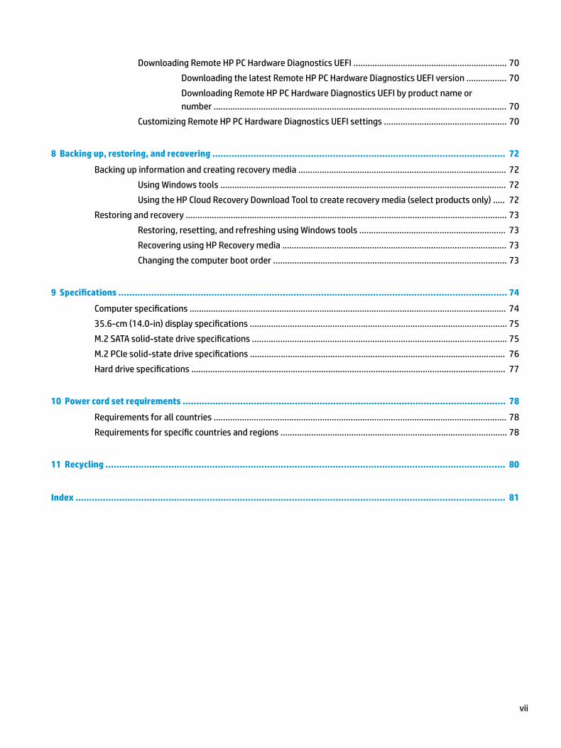
Downloading Remote HP PC Hardware Diagnostics UEFI ................................................................. 70
Downloading the latest Remote HP PC Hardware Diagnostics UEFI version ................. 70
Downloading Remote HP PC Hardware Diagnostics UEFI by product name or
number ............................................................................................................................ 70
Customizing Remote HP PC Hardware Diagnostics UEFI settings .................................................... 70
8 Backing up, restoring, and recovering ........................................................................................................... 72
Backing up information and creating recovery media ........................................................................................ 72
Using Windows tools ......................................................................................................................... 72
Using the HP Cloud Recovery Download Tool to create recovery media (select products only) ..... 72
Restoring and recovery ........................................................................................................................................ 73
Restoring, resetting, and refreshing using Windows tools .............................................................. 73
Recovering using HP Recovery media ............................................................................................... 73
Changing the computer boot order ................................................................................................... 73
9 Specifications .............................................................................................................................................. 74
Computer specifications ...................................................................................................................................... 74
35.6-cm (14.0-in) display specifications ............................................................................................................. 75
M.2 SATA solid-state drive specifications ............................................................................................................ 75
M.2 PCIe solid-state drive specifications ............................................................................................................ 76
Hard drive specifications ..................................................................................................................................... 77
10 Power cord set requirements ...................................................................................................................... 78
Requirements for all countries ............................................................................................................................ 78
Requirements for specific countries and regions ................................................................................................ 78
11 Recycling .................................................................................................................................................. 80
Index ............................................................................................................................................................. 81
vii

viii
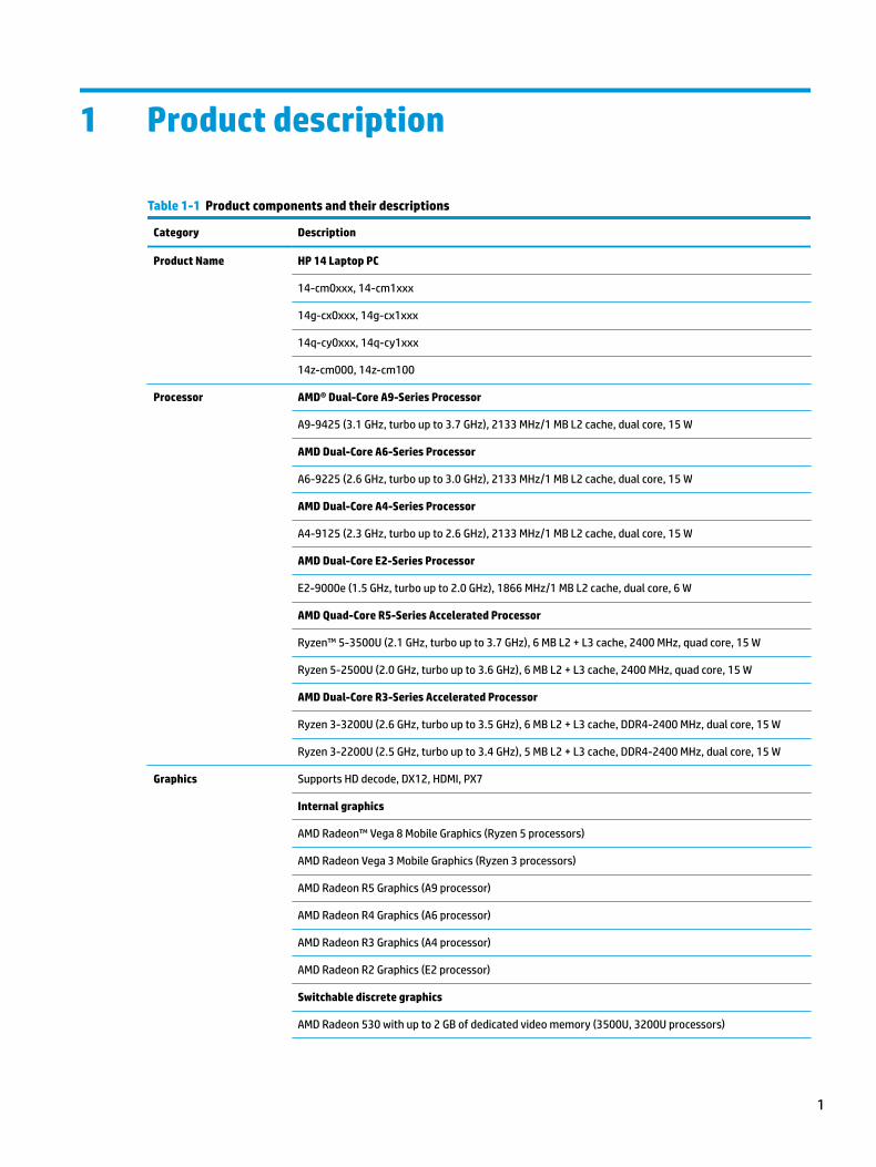
1 Product description
Table 1-1 Product components and their descriptions
Category Description
Product Name HP 14 Laptop PC
14-cm0xxx, 14-cm1xxx
14g-cx0xxx, 14g-cx1xxx
14q-cy0xxx, 14q-cy1xxx
14z-cm000, 14z-cm100
Processor AMD® Dual-Core A9-Series Processor
A9-9425 (3.1 GHz, turbo up to 3.7 GHz), 2133 MHz/1 MB L2 cache, dual core, 15 W
AMD Dual-Core A6-Series Processor
A6-9225 (2.6 GHz, turbo up to 3.0 GHz), 2133 MHz/1 MB L2 cache, dual core, 15 W
AMD Dual-Core A4-Series Processor
A4-9125 (2.3 GHz, turbo up to 2.6 GHz), 2133 MHz/1 MB L2 cache, dual core, 15 W
AMD Dual-Core E2-Series Processor
E2-9000e (1.5 GHz, turbo up to 2.0 GHz), 1866 MHz/1 MB L2 cache, dual core, 6 W
AMD Quad-Core R5-Series Accelerated Processor
Ryzen™ 5-3500U (2.1 GHz, turbo up to 3.7 GHz), 6 MB L2 + L3 cache, 2400 MHz, quad core, 15 W
Ryzen 5-2500U (2.0 GHz, turbo up to 3.6 GHz), 6 MB L2 + L3 cache, 2400 MHz, quad core, 15 W
AMD Dual-Core R3-Series Accelerated Processor
Ryzen 3-3200U (2.6 GHz, turbo up to 3.5 GHz), 6 MB L2 + L3 cache, DDR4-2400 MHz, dual core, 15 W
Ryzen 3-2200U (2.5 GHz, turbo up to 3.4 GHz), 5 MB L2 + L3 cache, DDR4-2400 MHz, dual core, 15 W
Graphics Supports HD decode, DX12, HDMI, PX7
Internal graphics
AMD Radeon™ Vega 8 Mobile Graphics (Ryzen 5 processors)
AMD Radeon Vega 3 Mobile Graphics (Ryzen 3 processors)
AMD Radeon R5 Graphics (A9 processor)
AMD Radeon R4 Graphics (A6 processor)
AMD Radeon R3 Graphics (A4 processor)
AMD Radeon R2 Graphics (E2 processor)
Switchable discrete graphics
AMD Radeon 530 with up to 2 GB of dedicated video memory (3500U, 3200U processors)
1
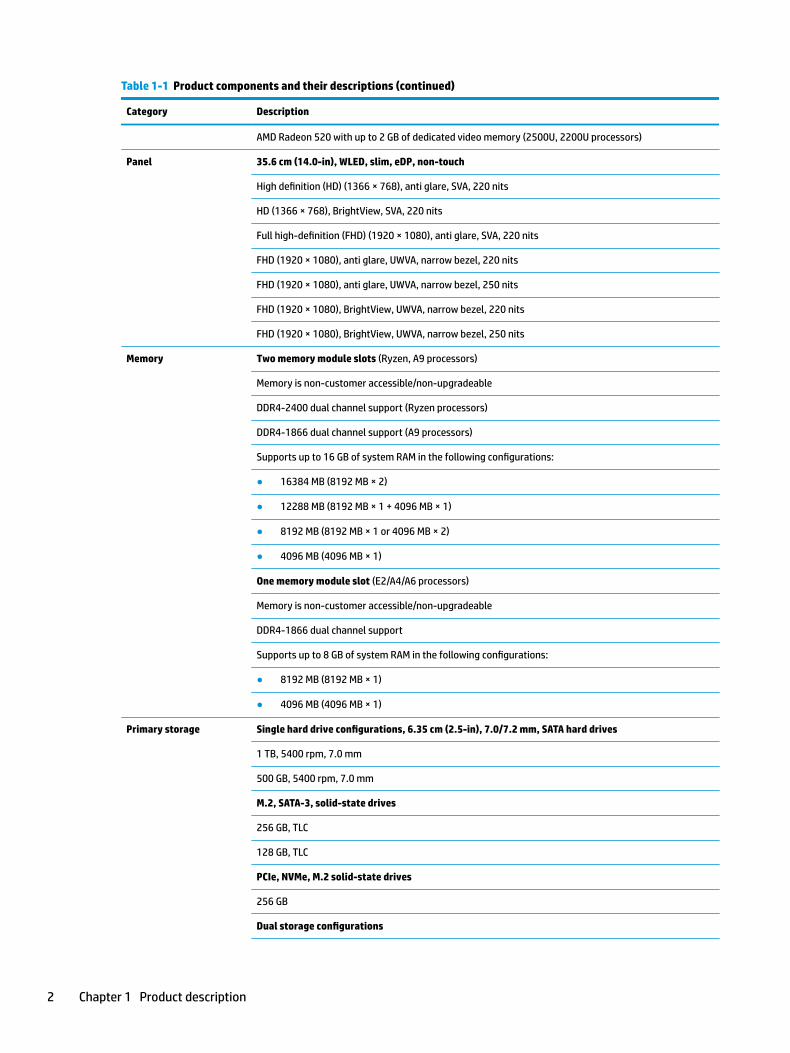
Table 1-1 Product components and their descriptions (continued)
Category Description
AMD Radeon 520 with up to 2 GB of dedicated video memory (2500U, 2200U processors)
Panel 35.6 cm (14.0-in), WLED, slim, eDP, non-touch
High definition (HD) (1366 × 768), anti glare, SVA, 220 nits
HD (1366 × 768), BrightView, SVA, 220 nits
Full high-definition (FHD) (1920 × 1080), anti glare, SVA, 220 nits
FHD (1920 × 1080), anti glare, UWVA, narrow bezel, 220 nits
FHD (1920 × 1080), anti glare, UWVA, narrow bezel, 250 nits
FHD (1920 × 1080), BrightView, UWVA, narrow bezel, 220 nits
FHD (1920 × 1080), BrightView, UWVA, narrow bezel, 250 nits
Memory Two memory module slots (Ryzen, A9 processors)
Memory is non-customer accessible/non-upgradeable
DDR4-2400 dual channel support (Ryzen processors)
DDR4-1866 dual channel support (A9 processors)
Supports up to 16 GB of system RAM in the following configurations:
● 16384 MB (8192 MB × 2)
● 12288 MB (8192 MB × 1 + 4096 MB × 1)
● 8192 MB (8192 MB × 1 or 4096 MB × 2)
● 4096 MB (4096 MB × 1)
One memory module slot (E2/A4/A6 processors)
Memory is non-customer accessible/non-upgradeable
DDR4-1866 dual channel support
Supports up to 8 GB of system RAM in the following configurations:
● 8192 MB (8192 MB × 1)
● 4096 MB (4096 MB × 1)
Primary storage Single hard drive configurations, 6.35 cm (2.5-in), 7.0/7.2 mm, SATA hard drives
1 TB, 5400 rpm, 7.0 mm
500 GB, 5400 rpm, 7.0 mm
M.2, SATA-3, solid-state drives
256 GB, TLC
128 GB, TLC
PCIe, NVMe, M.2 solid-state drives
256 GB
Dual storage configurations
2 Chapter 1 Product description
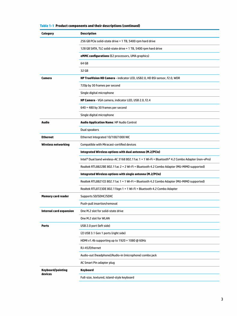
Table 1-1 Product components and their descriptions (continued)
Category Description
256 GB PCIe solid-state drive + 1 TB, 5400 rpm hard drive
128 GB SATA, TLC solid-state drive + 1 TB, 5400 rpm hard drive
eMMC configurations (E2 processors, UMA graphics)
64 GB
32 GB
Camera HP TrueVision HD Camera - indicator LED, USB2.0, HD BSI sensor, f2.0, WDR
720p by 30 frames per second
Single digital microphone
HP Camera - VGA camera, indicator LED, USB 2.0, f2.4
640 × 480 by 30 frames per second
Single digital microphone
Audio Audio Application Name: HP Audio Control
Dual speakers
Ethernet Ethernet Integrated 10/100/1000 NIC
Wireless networking Compatible with Miracast-certified devices
Integrated Wireless options with dual antennas (M.2/PCIe)
Intel® Dual band wireless-AC 3168 802.11ac 1 × 1 Wi-Fi + Bluetooth® 4.2 Combo Adapter (non-vPro)
Realtek RTL8822BE 802.11ac 2 × 2 Wi-Fi + Bluetooth 4.2 Combo Adapter (MU-MIMO supported)
Integrated Wireless options with single antenna (M.2/PCIe)
Realtek RTL8821CE 802.11ac 1 × 1 Wi-Fi + Bluetooth 4.2 Combo Adapter (MU-MIMO supported)
Realtek RTL8723DE 802.11bgn 1 × 1 Wi-Fi + Bluetooth 4.2 Combo Adapter
Memory card reader Supports SD/SDHC/SDXC
Push-pull insertion/removal
Internal card expansion One M.2 slot for solid-state drive
One M.2 slot for WLAN
Ports USB 2.0 port (left side)
(2) USB 3.1 Gen 1 ports (right side)
HDMI v1.4b supporting up to 1920 × 1080 @ 60Hz
RJ-45/Ethernet
Audio-out (headphone)/Audio-in (microphone) combo jack
AC Smart Pin adapter plug
Keyboard/pointing devices
Keyboard
Full-size, textured, island-style keyboard
3

Table 1-1 Product components and their descriptions (continued)
Category Description
Full-size, two coat paint, backlit, island-style keyboard
TouchPad
Image sensor
Power requirements Battery
3-cell Prismatic/Polymer battery, 41 Whr, long-life
Supports battery fast charge
AC adapter, barrel type
65 W Smart, nPFC, right angle, 4.5 mm (models with discrete graphics)
65 W Smart, nPFC, 4.5 mm (Argentina) (models with discrete graphics)
65 W Smart, nPFC, 4.5 mm, EM
45 W Smart, nPFC, right angle, 4.5 mm (models with UMA graphics)
45 W Smart, nPFC, 4.5 mm (Argentina) (models with UMA graphics)
Power cord (C5)
1 m, conventional
Security Kensington Mini Security Lock
Supports Firmware Trusted Platform Module (fTPM) 2.0 (Infineon, soldered down)
Operating system FreeDOS 2.0
Windows® 10 Home 64
Windows 10 Home 64 Web/Kiosk
Windows 10 Home 64 Chinese Market CPPP
Windows 10 Home 64 Entry Notebook Compact (E2/A4/A6/A9 processors and UMA graphics only)
Windows 10 Home 64 Entry Notebook Compact Web/Kiosk (E2/A4/A6/A9 processors and UMA graphics only)
Windows 10 Home 64 Entry Single Language
Windows 10 Home 64 High-End Chinese Market CPPP
Windows 10 Home 64 Plus
Windows 10 Home 64 Plus Single Language
Windows 10 Home 64 Plus Single Language Africa Market PPP
Windows 10 Home 64 Plus Single Language APAC EM PPP
Windows 10 Home 64 Plus Single Language India Market PPP
Windows 10 Home 64 Single Language Indonesia Market PPP
Windows 10 Home 64 Single Language
Windows 10 Home 64 Single Language APAC EM PPP
4 Chapter 1 Product description

Table 1-1 Product components and their descriptions (continued)
Category Description
Windows 10 Home 64 Single Language Entry India Market PPP (E2/A4/A6/A9 processors and UMA graphics only)
Windows 10 Home 64 Single Language India Market PPP
Windows 10 Home 64 Single Language Indonesia Market PPP
Windows 10 Home 64 Single Language Value Africa Market PPP (E2/A4/A6/A9 processors and UMA graphics only)
Windows 10 Home 64 Single Language Value APAC EM PPP (E2/A4/A6/A9 processors and UMA graphics only)
Windows 10 Home 64 Single Language Value India Market PPP (E2/A4/A6/A9 processors and UMA graphics only)
Windows 10 Home 64 Single Language Value Indonesia Market PPP (E2/A4/A6/A9 processors and UMA graphics only)
Windows 10 Home 64 Value Notebook (E2/A4/A6/A9 processors and UMA graphics only)
Windows 10 Home 64 Value Notebook Compact (E2/A4/A6/A9 processors and UMA graphics only)
Windows 10 Home 64 Value Notebook Compact Web/Kiosk (E2/A4/A6/A9 processors and UMA graphics only)
Windows 10 Home 64 Value Notebook Single Language (E2/A4/A6/A9 processors and UMA graphics only)
Windows 10 Home 64 Value Notebook Single Language SEAP (E2/A4/A6/A9 processors and UMA graphics only)
Windows 10 Home 64 Value Notebook Single Language select GEO (E2/A4/A6/A9 processors and UMA graphics only)
Windows 10 Home 64 Value Notebook Single Language select GEO (E2/A4/A6/A9 processors and UMA graphics only)Compact
Windows 10 Home 64 Web/Kiosk
Windows 10 Home 64
Serviceability End user replaceable parts
AC adapter
5

2 Getting to know your computer
Your computer features top-rated components. This chapter provides details about your components, where they're located, and how they work.
Right side
Table 2-1 Right-side components and their descriptions
Component Description
(1) Audio-out (headphone)/Audio-in (microphone) combo jack
Connects optional powered stereo speakers, headphones, earbuds, a headset, or a television audio cable. Also connects an optional headset microphone. This jack does not support optional standalone microphones.
WARNING! To reduce the risk of personal injury, adjust the volume before putting on headphones, earbuds, or a headset. For additional safety information, refer to the Regulatory, Safety, and Environmental Notices.
To access this guide:
▲ Select the Start button, select HP Help and Support, and then select HP Documentation.
NOTE: When a device is connected to the jack, the computer speakers are disabled.
(2) USB SuperSpeed ports (2) Connect a USB device, such as a cell phone, camera, activity tracker, or smartwatch, and provide high-speed data transfer.
(3) HDMI port Connects an optional video or audio device, such as a high-definition television, any compatible digital or audio component, or a high-speed High-Definition Multimedia Interface (HDMI) device.
(4) RJ-45 (network) jack/status lights
Connects a network cable.
● White: The network is connected.
● Amber: Activity is occurring on the network.
(5) AC adapter and battery light ● White: The AC adapter is connected and the battery is fully charged.
● Blinking white: The AC adapter is disconnected and the battery has reached a low battery level.
● Amber: The AC adapter is connected and the battery is charging.
6 Chapter 2 Getting to know your computer

Table 2-1 Right-side components and their descriptions (continued)
Component Description
● Off: The battery is not charging.
(6) Power connector Connects an AC adapter.
Left side
Table 2-2 Left-side components and their descriptions
Component Description
(1) Security cable slot Attaches an optional security cable to the computer.
NOTE: The security cable is designed to act as a deterrent, but it may not prevent the computer from being mishandled or stolen.
(2) USB port Connects a USB device, such as a cell phone, camera, activity tracker, or smartwatch, and provides data transfer.
(3) Memory card reader Reads optional memory cards that enable you to store, manage, share, or access information.
To insert a card:
1. Hold the card label-side up, with connectors facing the computer.
2. Insert the card into the memory card reader, and then press in on the card until it is firmly seated.
To remove a card:
▲ Pull the card to remove it from the memory card reader.
(4) Drive light (select products only)
● Blinking white: The hard drive is being accessed.
(5) Power light ● On: The computer is on.
● Blinking: The computer is in the Sleep state, a power-saving state. The computer shuts off power to the display and other unneeded components.
● Off: The computer is off or in Hibernation. Hibernation is a power-saving state that uses the least amount of power.
Left side 7

Display
Table 2-3 Display components and their descriptions
Component Description
(1) WLAN antennas* (1 or 2 depending on model) Send and receive wireless signals to communicate with wireless local area networks (WLANs).
(2) Camera light On: The camera is in use.
(3) Camera Allows you to video chat, record video, and record still images. Some cameras also allow a facial recognition logon to Windows, instead of a password logon.
NOTE: Camera functions vary depending on the camera hardware and software installed on your product.
(4) Internal microphone Records sound.
*The antennas are not visible from the outside of the computer. For optimal transmission, keep the areas immediately around the antennas free from obstructions.
For wireless regulatory notices, see the section of the Regulatory, Safety, and Environmental Notices that applies to your country or region.
To access this guide:
▲ Select the Start button, select HP Help and Support, and then select HP Documentation.
8 Chapter 2 Getting to know your computer

Keyboard area
TouchPad
Table 2-4 TouchPad components and their descriptions
Component Description
(1) TouchPad zone Reads your finger gestures to move the pointer or activate items on the screen.
(2) Left TouchPad button Functions like the left button on an external mouse.
(3) Right TouchPad button Functions like the right button on an external mouse.
Keyboard area 9
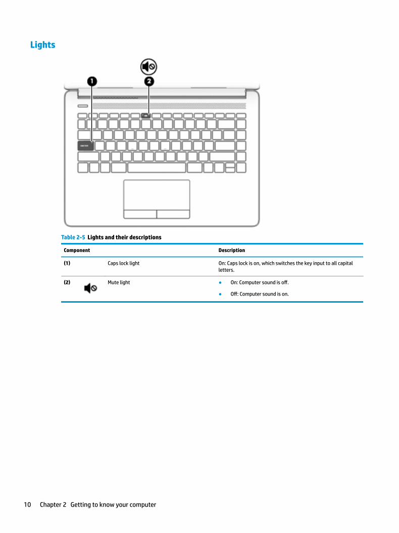
Lights
Table 2-5 Lights and their descriptions
Component Description
(1) Caps lock light On: Caps lock is on, which switches the key input to all capital letters.
(2) Mute light ● On: Computer sound is off.
● Off: Computer sound is on.
10 Chapter 2 Getting to know your computer

Button, vent, and speakers
Table 2-6 Button and speakers and their descriptions
Component Description
(1) Power button ● When the computer is off, press the button to turn on the computer.
● When the computer is on, press the button briefly to initiate Sleep.
● When the computer is in the Sleep state, press the button briefly to exit Sleep.
● When the computer is in Hibernation, press the button briefly to exit Hibernation.
CAUTION: Pressing and holding down the power button results in the loss of unsaved information.
If the computer has stopped responding and shutdown procedures are ineffective, press and hold the power button down for at least 5 seconds to turn off the computer.
To learn more about your power settings, see your power options:
▲ Right-click the Power icon , and then select Power
Options.
(2) Vent Enables airflow to cool internal components.
NOTE: The computer fan starts up automatically to cool internal components and prevent overheating. It is normal for the internal fan to cycle on and off during routine operation.
(3) Speakers (2) Produce sound.
Keyboard area 11
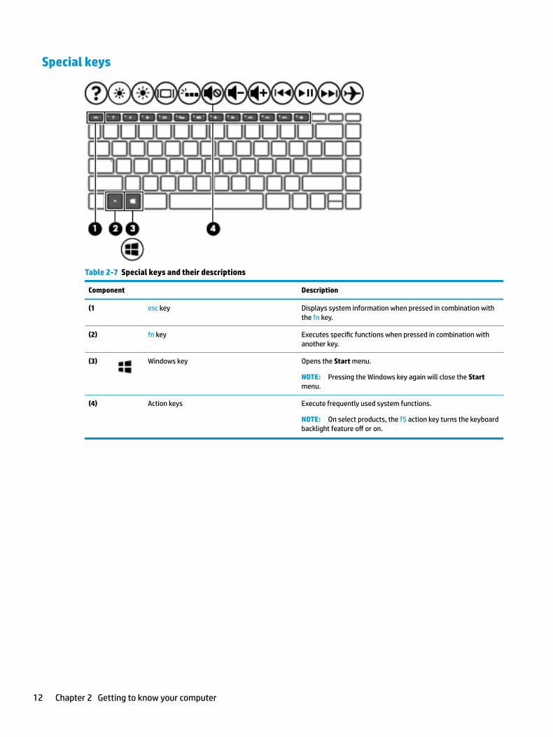
Special keys
Table 2-7 Special keys and their descriptions
Component Description
(1 esc key Displays system information when pressed in combination with the fn key.
(2) fn key Executes specific functions when pressed in combination with another key.
(3) Windows key Opens the Start menu.
NOTE: Pressing the Windows key again will close the Start menu.
(4) Action keys Execute frequently used system functions.
NOTE: On select products, the f5 action key turns the keyboard backlight feature off or on.
12 Chapter 2 Getting to know your computer

Action keys
An action key performs the function indicated by the icon on the key. To determine which keys are on your product, see Special keys on page 12.
▲ To use an action key, press and hold the key.
Table 2-8 Action keys and their descriptions
Icon Description
Opens the “How to get help in Windows 10” webpage.
Decreases the screen brightness incrementally as long as you hold down the key.
Increases the screen brightness incrementally as long as you hold down the key.
Switches the screen image between display devices connected to the system. For example, if a monitor is connected to the computer, repeatedly pressing this key alternates the screen image from the computer display to the monitor display to a simultaneous display on both the computer and the monitor.
Turns the keyboard backlight off or on.
NOTE: To conserve battery power, turn off this feature.
Mutes or restores speaker sound.
Decreases speaker volume incrementally while you hold down the key.
Increases speaker volume incrementally while you hold down the key.
Plays the previous track of an audio CD or the previous section of a DVD or a Blu-ray Disc (BD).
Starts, pauses, or resumes playback of an audio CD, a DVD, or a BD.
Plays the next track of an audio CD or the next section of a DVD or a BD.
Turns the airplane mode and wireless feature on or off.
NOTE: The airplane mode key is also referred to as the wireless button.
NOTE: A wireless network must be set up before a wireless connection is possible.
Keyboard area 13

Bottom
Table 2-9 Bottom components and their descriptions
Component Description
Vent Enables airflow to cool internal components.
NOTE: The computer fan starts up automatically to cool internal components and prevent overheating. It is normal for the internal fan to cycle on and off during routine operation.
14 Chapter 2 Getting to know your computer

LabelsThe labels affixed to the computer provide information you may need when you troubleshoot system problems or travel internationally with the computer. Labels may be in paper form or imprinted on the product.
IMPORTANT: Check the following locations for the labels described in this section: the bottom of the computer, inside the battery bay, under the service door, on the back of the display, or on the bottom of a tablet kickstand.
● Service label—Provides important information to identify your computer. When contacting support, you may be asked for the serial number, the product number, or the model number. Locate this information before you contact support.
Table 2-10 Service label components
Component
(1) HP product name
(2) Model number
(3) Product ID
(4) Serial number
(5) Warranty period
● Regulatory label(s)—Provide(s) regulatory information about the computer.
● Wireless certification label(s)—Provide(s) information about optional wireless devices and the approval markings for the countries or regions in which the devices have been approved for use.
Labels 15
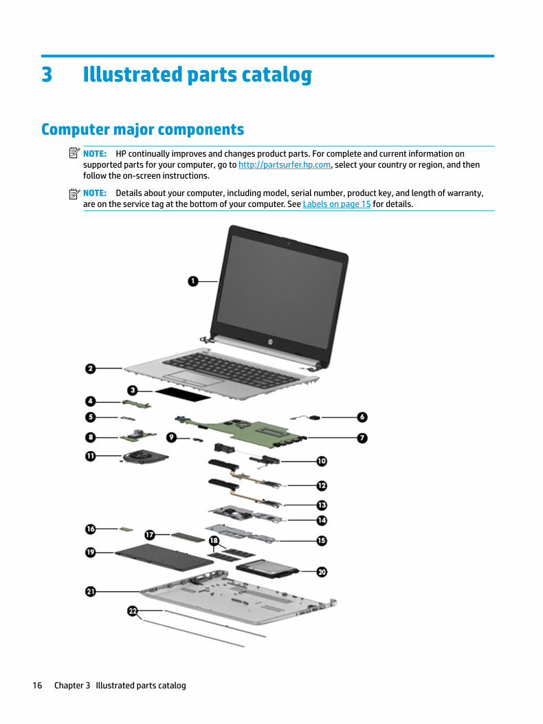
3 Illustrated parts catalog
Computer major componentsNOTE: HP continually improves and changes product parts. For complete and current information on supported parts for your computer, go to http://partsurfer.hp.com, select your country or region, and then follow the on-screen instructions.
NOTE: Details about your computer, including model, serial number, product key, and length of warranty, are on the service tag at the bottom of your computer. See Labels on page 15 for details.
16 Chapter 3 Illustrated parts catalog

Table 3-1 Computer major components and their descriptions
Item Component Spare part number
(1) Display
NOTE: Displays are not spared as whole units. Display subcomponent spare parts are available. For spare part information, see Display assembly subcomponents on page 20.
Not spared
(2) Top cover/keyboard
NOTE: For a detailed list of country codes, see Top cover with keyboard on page 64.
Keyboard, no backlight, jet black L23239-xx1
Keyboard, no backlight, snow white L23240-xx1
Keyboard, no backlight, ash silver L23241-xx1
Keyboard, backlit, ash silver L23242-xx1
Keyboard, no backlight, jet black with mesh knit pattern L48210-xx1
Keyboard, no backlight, snow white with mesh knit pattern L48211-xx1
(3) TouchPad module L22586-001
(4) TouchPad button board L23197-001
(5) TouchPad button board bracket L23193-001
(6) Power connector cable (DC-in) L23188-001
(7) System board
NOTE: All system board spare part kits include replacement thermal material.
All system boards use the following part numbers:
xxxxxx-001: Non-Windows operating systems
xxxxxx-601: Windows operating system
For use in models with discrete graphics memory:
● AMD Ryzen 3-3200U processor L46793-xx1
● AMD Ryzen 3-2200U processor L23396-xx1
● AMD A9-9425 processor L23395-xx1
For use in models with UMA graphics memory:
● AMD Ryzen 5-3500U processor L46792-xx1
● AMD Ryzen 3-3200U processor L46791-xx1
● AMD Ryzen 5-2500U processor L23394-xx1
● AMD Ryzen 3-2200U processor L23393-xx1
● AMD A9-9425 processor L23392-xx1
● AMD A6-9225 processor L23391-xx1
● AMD A4-9125 processor L23390-xx1
● AMD E2-9000e processor L23389-xx1
(8) USB/card reader/power button board L23196-001
Computer major components 17

Table 3-1 Computer major components and their descriptions (continued)
Item Component Spare part number
(9) System board hook L23206-001
(10) Speakers (includes cable) L23221-001
(11) Fan L23189-001
Heat sink
(12) For use in models with AMD Ryzen processors and discrete graphics L23192-001
For use in models with AMD A4/A6/A9 processors and discrete graphics L23386-001
(13) For use in models with AMD Ryzen processors and integrated UMA graphics L23191-001
For use in models with AMD A4/A6/A9 processors and integrated UMA graphics L23385-001
(14) For use in fanless models with AMD E2-9000e processors L23384-001
(15) Fan insert (for use in fanless models) L23198-001
(16) WLAN module
Intel Dual band wireless-AC 3168 802.11ac 1 × 1 Wi-Fi + Bluetooth 4.2 Combo Adaptor (non-vPro) 863934-855
Realtek RTL8822BE 802.11ac 2 × 2 Wi-Fi + Bluetooth 4.2 Combo Adapter (MU-MIMO supported) 924813-855
Realtek RTL8821CE 802.11ac 1 × 1 Wi-Fi + Bluetooth 4.2 Combo Adapter (MU-MIMO supported) L17365-005
Realtek RTL8723DE 802.11bgn 1 × 1 Wi-Fi + Bluetooth 4.2 Combo Adapter L21480-005
(17) Solid-state drive
NOTE: For spare part information, see Mass storage devices on page 23.
(18) Memory modules (2400 MHz DDR4)
8 GB 862398-855
4 GB 862397-855
(19) Battery (3-cell, 48 Whr, 4.212 Ahr) L11119-855
(20) Hard drive
NOTE: For spare part information, see Mass storage devices on page 23.
(21) Bottom cover
Jet black L23174-001
Natural silver L23175-001
Pale gold L23176-001
Scarlet red L23177-001
Twilight blue L23178-001
Smoke gray L23179-001
Snow white L23180-001
Jet black with mesh knit pattern L47562-001
Snow white with mesh knit pattern L47563-001
18 Chapter 3 Illustrated parts catalog
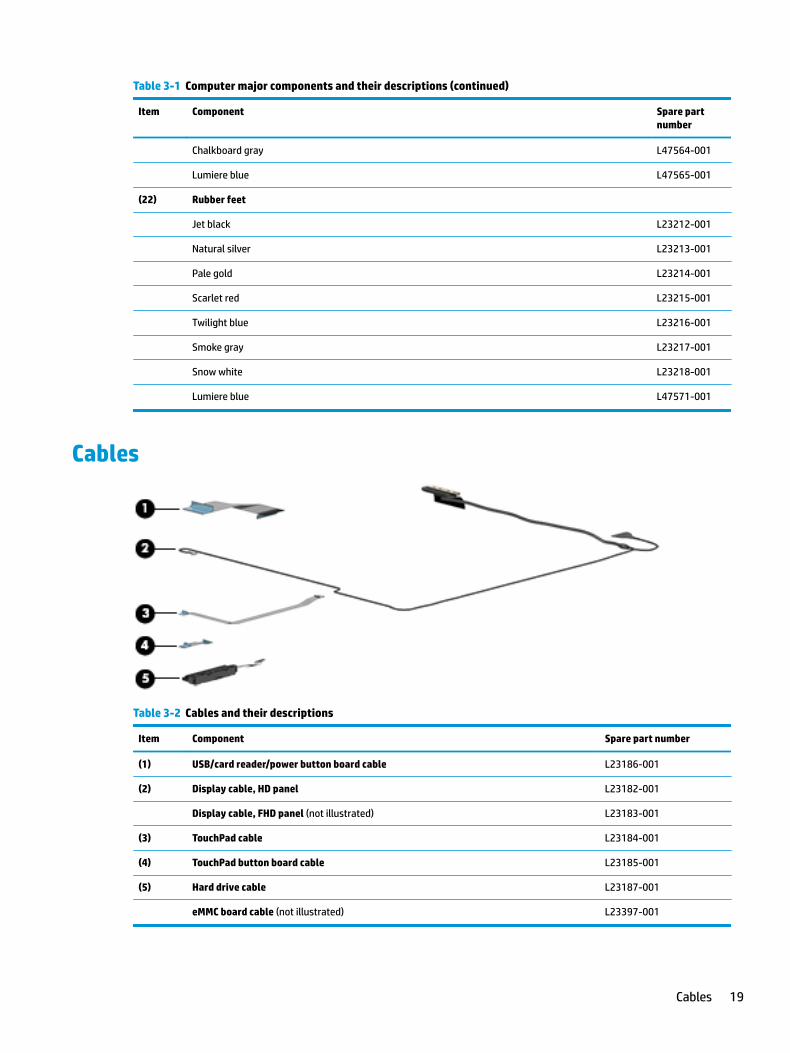
Table 3-1 Computer major components and their descriptions (continued)
Item Component Spare part number
Chalkboard gray L47564-001
Lumiere blue L47565-001
(22) Rubber feet
Jet black L23212-001
Natural silver L23213-001
Pale gold L23214-001
Scarlet red L23215-001
Twilight blue L23216-001
Smoke gray L23217-001
Snow white L23218-001
Lumiere blue L47571-001
Cables
Table 3-2 Cables and their descriptions
Item Component Spare part number
(1) USB/card reader/power button board cable L23186-001
(2) Display cable, HD panel L23182-001
Display cable, FHD panel (not illustrated) L23183-001
(3) TouchPad cable L23184-001
(4) TouchPad button board cable L23185-001
(5) Hard drive cable L23187-001
eMMC board cable (not illustrated) L23397-001
Cables 19

Display assembly subcomponents
Table 3-3 Display assembly components and their descriptions
Item Component Spare part number
(1) Hinge cover
Jet black L23199-001
Natural silver L23200-001
Pale gold L23201-001
Scarlet red L23202-001
Twilight blue L23203-001
Smoke gray L23204-001
Snow white L23205-001
Chalkboard gray L47567-001
Lumiere blue L47568-001
(2) Display bezel L23181-001
(3) Display panel
20 Chapter 3 Illustrated parts catalog
Table 3-3 Display assembly components and their descriptions (continued)
Item Component Spare part number
FHD, anti glare, for use in models with a narrow bezel L23208-001
FHD, BrightView, for use in models with a narrow bezel L23209-001
FHD, anti glare L42787-001
FHD, anti glare, UWVA, for use in models with a narrow bezel L46789-001
FHD, BrightView, UWVA, for use in models with a narrow bezel L46790-001
HD, anti glare L23210-001
HD, BrightView L23211-001
(4) Hinge Kit (includes left and right hinges)
For use in models with an HD panel L23194-001
For use in models with an FHD panel L23195-001
(5) Display panel stretchable adhesive tape (not illustrated) L23207-001
(6) WLAN antenna cable (included in Antenna Kit)
Single antenna, for use in models with an HD panel L23158-001
Dual antennas, for use in models with an HD panel L23159-001
Single antenna, for use in models with an FHD panel L24037-001
Dual antennas, for use in models with an FHD panel L24038-001
(7) Camera module
HD camera L23237-001
VGA camera L23238-001
(8) Display cable
For use with HD panels L23182-001
For use with FHD panels L23183-001
(9) Back cover
For use in models with an HD panel:
● Jet black L23160-001
● Natural silver L23161-001
● Pale gold L23162-001
● Scarlet red L23163-001
● Twilight blue L23164-001
● Smoke gray L23165-001
● Snow white L23166-001
● Jet black, mesh knit pattern L47552-001
● Snow white, mesh knit pattern L47553-001
Display assembly subcomponents 21
Table 3-3 Display assembly components and their descriptions (continued)
Item Component Spare part number
● Chalkboard gray L47554-001
● Lumiere blue L47555-001
For use in models with an FHD panel:
● Jet black L23167-001
● Natural silver L23168-001
● Pale gold L23169-001
● Scarlet red L23170-001
● Twilight blue L23171-001
● Smoke gray L23172-001
● Snow white L23173-001
● Jet black, mesh knit pattern L47557-001
● Snow white, mesh knit pattern L47558-001
● Chalkboard gray L47559-001
● Lumiere blue L47560-001
22 Chapter 3 Illustrated parts catalog
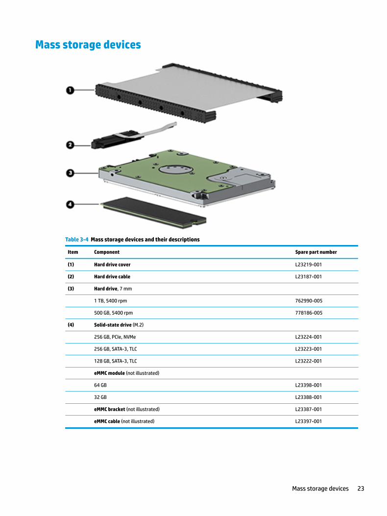
Mass storage devices
Table 3-4 Mass storage devices and their descriptions
Item Component Spare part number
(1) Hard drive cover L23219-001
(2) Hard drive cable L23187-001
(3) Hard drive, 7 mm
1 TB, 5400 rpm 762990-005
500 GB, 5400 rpm 778186-005
(4) Solid-state drive (M.2)
256 GB, PCIe, NVMe L23224-001
256 GB, SATA-3, TLC L23223-001
128 GB, SATA-3, TLC L23222-001
eMMC module (not illustrated)
64 GB L23398-001
32 GB L23388-001
eMMC bracket (not illustrated) L23387-001
eMMC cable (not illustrated) L23397-001
Mass storage devices 23

Miscellaneous partsTable 3-5 Miscellaneous parts and their descriptions
Component Spare part number
AC adapter
65 W AC adapter, nPFC, S-3P, 4.5 mm 710412-001
65 W AC adapter, nPFC, SMART, RC, 4.5 mm, EM 913691-850
65 W AC adapter, nPFC, 4.5 mm, for use in Argentina 710340-850
45 W AC adapter, nPFC, SMART, RC, 4.5 mm, non-slim 741727-001
45 W AC adapter, nPFC, for use in Argentina 741553-852
Power cord, C5, conventional, 1.0 m
For use in Argentina L19357-001
For use in Australia L19358-001
For use in Denmark L19360-001
For use in Europe L19361-001
For use in India L19363-001
For use in Israel L19362-001
For use in Italy L19364-001
For use in North America L19367-001
For use in the People’s Republic of China L19368-001
For use in South Africa L19369-001
For use in Thailand L19371-001
For use in the United Kingdom L19373-001
Screw Kit L23220-001
24 Chapter 3 Illustrated parts catalog
4 Removal and replacement procedures preliminary requirements
Tools requiredYou will need the following tools to complete the removal and replacement procedures:
● Non-conductive, non-marking plastic tool
● Magnetic Phillips P1 screwdriver
Service considerationsThe following sections include some of the considerations that you must keep in mind during disassembly and assembly procedures.
NOTE: As you remove each subassembly from the computer, place the subassembly (and all accompanying screws) away from the work area to prevent damage.
Plastic parts
IMPORTANT: Using excessive force during disassembly and reassembly can damage plastic parts.
Cables and connectors
IMPORTANT: When servicing the computer, be sure that cables are placed in their proper locations during the reassembly process. Improper cable placement can damage the computer.
Cables must be handled with extreme care to avoid damage. Apply only the tension required to unseat or seat the cables during removal and insertion. Handle cables by the connector whenever possible. In all cases, avoid bending, twisting, or tearing cables. Be sure that cables are routed in such a way that they cannot be caught or snagged by parts being removed or replaced. Handle flex cables with extreme care; these cables tear easily.
Tools required 25

Drive handling
IMPORTANT: Drives are fragile components that must be handled with care. To prevent damage to the computer, damage to a drive, or loss of information, observe these precautions:
Before removing or inserting a hard drive, shut down the computer. If you are unsure whether the computer is off or in Hibernation, turn the computer on, and then shut it down through the operating system.
Before handling a drive, be sure that you are discharged of static electricity. While handling a drive, avoid touching the connector.
Before removing an optical drive, be sure that a disc is not in the drive and be sure that the optical drive tray is closed.
Handle drives on surfaces covered with at least one inch of shock-proof foam.
Avoid dropping drives from any height onto any surface.
After removing a hard drive or an optical drive, place it in a static-proof bag.
Avoid exposing an internal hard drive to products that have magnetic fields, such as monitors or speakers.
Avoid exposing a drive to temperature extremes or liquids.
If a drive must be mailed, place the drive in a bubble pack mailer or other suitable form of protective packaging and label the package “FRAGILE.”
Workstation guidelines
Follow these grounding workstation guidelines:
● Cover the workstation with approved static-shielding material.
● Use a wrist strap connected to a properly grounded work surface and use properly grounded tools and equipment.
● Use conductive field service tools, such as cutters, screw drivers, and vacuums.
● When fixtures must directly contact dissipative surfaces, use fixtures made only of static-safe materials.
● Keep the work area free of nonconductive materials, such as ordinary plastic assembly aids and Styrofoam.
● Handle ESD-sensitive components, parts, and assemblies by the case or PCM laminate. Handle these items only at static-free workstations.
● Avoid contact with pins, leads, or circuitry.
● Turn off power and input signals before inserting or removing connectors or test equipment.
Electrostatic discharge informationA sudden discharge of static electricity from your finger or other conductor can destroy static-sensitive devices or microcircuitry. Often the spark is neither felt nor heard, but damage occurs. An electronic device exposed to electrostatic discharge (ESD) may not appear to be affected at all and can work perfectly throughout a normal cycle. The device may function normally for a while, but it has been degraded in the internal layers, reducing its life expectancy.
Networks built into many integrated circuits provide some protection, but in many cases, the discharge contains enough power to alter device parameters or melt silicon junctions.
26 Chapter 4 Removal and replacement procedures preliminary requirements

IMPORTANT: To prevent damage to the device when you are removing or installing internal components, observe these precautions:
Keep components in their electrostatic-safe containers until you are ready to install them.
Before touching an electronic component, discharge static electricity by using the guidelines described in this section.
Avoid touching pins, leads, and circuitry. Handle electronic components as little as possible.
If you remove a component, place it in an electrostatic-safe container.
Generating static electricity
Note the following:
● Different activities generate different amounts of static electricity.
● Static electricity increases as humidity decreases.
Table 4-1 Static electricity occurrence based on activity and humidity
Relative humidity
Event 55% 40% 10%
Walking across carpet
Walking across vinyl floor
Motions of bench worker
Removing DIPs from plastic tube
7,500 V
3,000 V
400 V
400 V
15,000 V
5,000 V
800 V
700 V
35,000 V
12,000 V
6,000 V
2,000 V
Removing DIPs from vinyl tray
Removing DIPs from Styrofoam
Removing bubble pack from PCB
Packing PCBs in foam-lined box
2,000 V
3,500 V
7,000 V
5,000 V
4,000 V
5,000 V
20,000 V
11,000 V
11,500 V
14,500 V
26,500 V
21,000 V
Electronic components are then multi-packaged inside plastic tubes, trays, or Styrofoam.
NOTE: As little as 700 volts can degrade a product.
Preventing electrostatic damage to equipment
Many electronic components are sensitive to ESD. Circuitry design and structure determine the degree of sensitivity. The following packaging and grounding precautions are necessary to prevent static electricity damage to electronic components.
● To avoid hand contact, transport products in static-safe containers such as tubes, bags, or boxes.
● Protect all electrostatic parts and assemblies with conductive or approved containers or packaging.
● Keep electrostatic-sensitive parts in their containers until they arrive at static-free stations.
● Place items on a grounded surface before removing them from their container.
● Always be properly grounded when touching a sensitive component or assembly.
Electrostatic discharge information 27
● Avoid contact with pins, leads, or circuitry.
● Place reusable electrostatic-sensitive parts from assemblies in protective packaging or conductive foam.
Personal grounding methods and equipment
Use the following equipment to prevent static electricity damage to electronic components:
● Wrist straps are flexible straps with a maximum of one-megohm ± 10% resistance in the ground cords. To provide proper ground, a strap must be worn snug against bare skin. The ground cord must be connected and fit snugly into the banana plug connector on the grounding mat or workstation.
● Heel straps/Toe straps/Boot straps can be used at standing workstations and are compatible with most types of shoes or boots. On conductive floors or dissipative floor mats, use them on both feet with a maximum of one-megohm ± 10% resistance between the operator and ground.
Table 4-2 Static shielding protection levels
Static shielding protection levels
Method Voltage
Antistatic plastic
Carbon-loaded plastic
Metallized laminate
1,500
7,500
15,000
Grounding the work area
To prevent static damage at the work area, use the following precautions:
● Cover the work surface with approved static-dissipative material. Provide a wrist strap connected to the work surface and properly grounded tools and equipment.
● Use static-dissipative mats, foot straps, or air ionizers to give added protection.
● Handle electrostatic sensitive components, parts, and assemblies by the case or PCB laminate. Handle them only at static-free work areas.
● Turn off power and input signals before inserting and removing connectors or test equipment.
● Use fixtures made of static-safe materials when fixtures must directly contact dissipative surfaces.
● Keep work area free of nonconductive materials such as ordinary plastic assembly aids and Styrofoam.
● Use field service tools, such as cutters, screwdrivers, and vacuums, that are conductive.
Recommended materials and equipment
Materials and equipment that are recommended for use in preventing static electricity include:
● Antistatic tape
● Antistatic smocks, aprons, or sleeve protectors
● Conductive bins and other assembly or soldering aids
● Conductive foam
● Conductive tabletop workstations with ground cord of one-megohm +/- 10% resistance
● Static-dissipative table or floor mats with hard tie to ground
28 Chapter 4 Removal and replacement procedures preliminary requirements
● Field service kits
● Static awareness labels
● Wrist straps and footwear straps providing one-megohm +/- 10% resistance
● Material handling packages
● Conductive plastic bags
● Conductive plastic tubes
● Conductive tote boxes
● Opaque shielding bags
● Transparent metallized shielding bags
● Transparent shielding tubes
Packaging and transporting guidelinesFollow these grounding guidelines when packaging and transporting equipment:
● To avoid hand contact, transport products in static-safe tubes, bags, or boxes.
● Protect ESD-sensitive parts and assemblies with conductive or approved containers or packaging.
● Keep ESD-sensitive parts in their containers until the parts arrive at static-free workstations.
● Place items on a grounded surface before removing items from their containers.
● Always be properly grounded when touching a component or assembly.
● Store reusable ESD-sensitive parts from assemblies in protective packaging or nonconductive foam.
● Use transporters and conveyors made of antistatic belts and roller bushings. Be sure that mechanized equipment used for moving materials is wired to ground and that proper materials are selected to avoid static charging. When grounding is not possible, use an ionizer to dissipate electric charges.
Packaging and transporting guidelines 29
5 Removal and replacement procedures for authorized service provider parts
This chapter provides removal and replacement procedures for Authorized Service Provider only parts.
IMPORTANT: Components described in this chapter should only be accessed by an authorized service provider. Accessing these parts can damage the computer or void the warranty.
IMPORTANT: This computer does not have user-replaceable parts. Only HP authorized service providers should perform the removal and replacement procedures described here. Accessing the internal part could damage the computer or void the warranty.
Component replacement proceduresNOTE: Details about your computer, including model, serial number, product key, and length of warranty, are on the service tag at the bottom of your computer. See Labels on page 15 for details.
NOTE: HP continually improves and changes product parts. For complete and current information on supported parts for your computer, go to http://partsurfer.hp.com, select your country or region, and then follow the on-screen instructions.
There are as many as 42 screws that must be removed, replaced, and/or loosened when servicing Authorized Service Provider only parts. Make special note of each screw size and location during removal and replacement.
Preparation for disassembly
See Removal and replacement procedures preliminary requirements on page 25 for initial safety procedures.
1. Turn off the computer. If you are unsure whether the computer is off or in Hibernation, turn the computer on, and then shut it down through the operating system.
2. Disconnect the power from the computer by unplugging the power cord from the computer.
3. Disconnect all external devices from the computer.
30 Chapter 5 Removal and replacement procedures for authorized service provider parts

Bottom cover
Table 5-1 Bottom cover, rubber feet and their descriptions and part numbers
Description Spare part number
Bottom cover, jet black L23174-001
Bottom cover, natural silver L23175-001
Bottom cover, pale gold L23176-001
Bottom cover, scarlet red L23177-001
Bottom cover, twilight blue L23178-001
Bottom cover, smoke gray L23179-001
Bottom cover, snow white L23180-001
Jet black with mesh knit pattern L47562-001
Snow white with mesh knit pattern L47563-001
Chalkboard gray L47564-001
Lumiere blue L47565-001
Rubber feet, jet black L23212-001
Rubber feet, natural silver L23213-001
Rubber feet, pale gold L23214-001
Rubber feet, scarlet red L23215-001
Rubber feet, twilight blue L23216-001
Rubber feet, smoke gray L23217-001
Rubber feet, snow white L23218-001
Rubber feet, lumiere blue L47571-001
▲ Prepare the computer for disassembly (Preparation for disassembly on page 30).
Remove the bottom cover:
1. Peel the rubber feet off the bottom of the computer (1).
Component replacement procedures 31
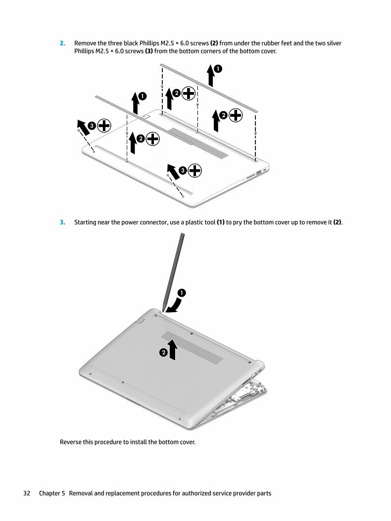
2. Remove the three black Phillips M2.5 × 6.0 screws (2) from under the rubber feet and the two silver Phillips M2.5 × 6.0 screws (3) from the bottom corners of the bottom cover.
3. Starting near the power connector, use a plastic tool (1) to pry the bottom cover up to remove it (2).
Reverse this procedure to install the bottom cover.
32 Chapter 5 Removal and replacement procedures for authorized service provider parts

Battery
Table 5-2 Battery description and part number
Description Spare part number
Battery (3-cell, 48 Whr, 4.212 Ahr) L11119-855
Before removing the battery, follow these steps:
1. Prepare the computer for disassembly (Preparation for disassembly on page 30).
2. Remove the bottom cover (see Bottom cover on page 31).
Remove the battery:
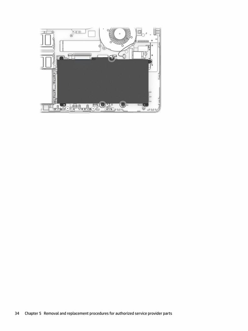
1. Remove the five Phillips M2.0 × 3.0 screws (1) that secure the battery to the computer.
2. Remove the battery from the computer (2).
Reverse this procedure to install the battery.
When installing the battery, be sure to install screws in the proper locations. The following image shows the locations around the battery that have holes but do NOT require screws.
Component replacement procedures 33
34 Chapter 5 Removal and replacement procedures for authorized service provider parts
Memory module
Table 5-3 Memory module descriptions and part numbers
Description Spare part number
Memory module, 8 GB 862398-855
Memory module, 4 GB 862397-855
Before removing the memory modules, follow these steps:
1. Prepare the computer for disassembly (Preparation for disassembly on page 30).
2. Remove the bottom cover (see Bottom cover on page 31).
3. Remove the battery (see Battery on page 33).
Remove the memory modules:
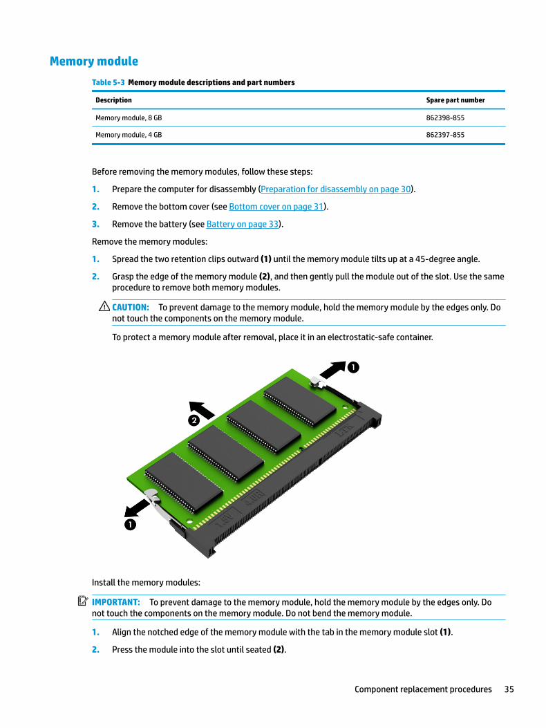
1. Spread the two retention clips outward (1) until the memory module tilts up at a 45-degree angle.
2. Grasp the edge of the memory module (2), and then gently pull the module out of the slot. Use the same procedure to remove both memory modules.
CAUTION: To prevent damage to the memory module, hold the memory module by the edges only. Do not touch the components on the memory module.
To protect a memory module after removal, place it in an electrostatic-safe container.
Install the memory modules:
IMPORTANT: To prevent damage to the memory module, hold the memory module by the edges only. Do not touch the components on the memory module. Do not bend the memory module.
1. Align the notched edge of the memory module with the tab in the memory module slot (1).
2. Press the module into the slot until seated (2).
Component replacement procedures 35

3. Gently press down on the module edges until the side retention clips snap into place (3).
36 Chapter 5 Removal and replacement procedures for authorized service provider parts
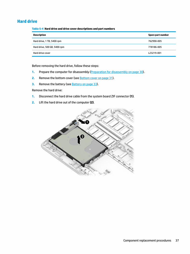
Hard drive
Table 5-4 Hard drive and drive cover descriptions and part numbers
Description Spare part number
Hard drive, 1 TB, 5400 rpm 762990-005
Hard drive, 500 GB, 5400 rpm 778186-005
Hard drive cover L23219-001
Before removing the hard drive, follow these steps:
1. Prepare the computer for disassembly (Preparation for disassembly on page 30).
2. Remove the bottom cover (see Bottom cover on page 31).
3. Remove the battery (see Battery on page 33).
Remove the hard drive:
1. Disconnect the hard drive cable from the system board ZIF connector (1).
2. Lift the hard drive out of the computer (2).
Component replacement procedures 37
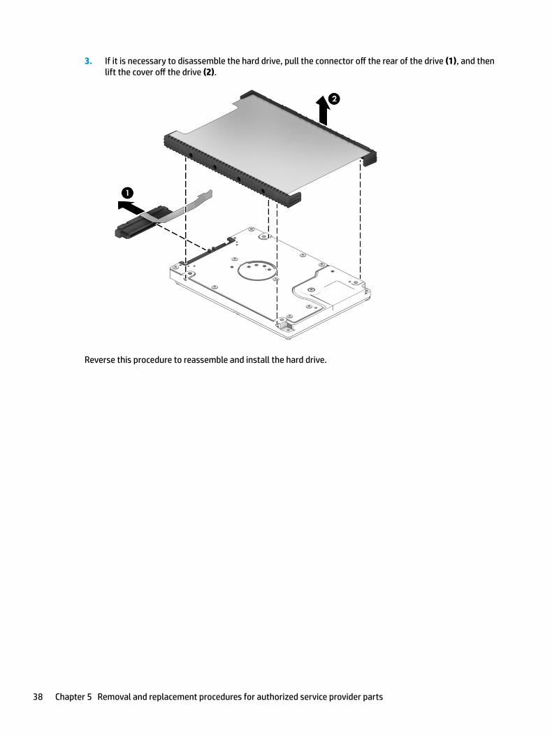
3. If it is necessary to disassemble the hard drive, pull the connector off the rear of the drive (1), and then lift the cover off the drive (2).
Reverse this procedure to reassemble and install the hard drive.
38 Chapter 5 Removal and replacement procedures for authorized service provider parts

Solid-state drive
Table 5-5 Solid-state drive descriptions and part numbers
Description Spare part number
256 GB, PCIe, NVMe L23224-001
256 GB, SATA-3, TLC L23223-001
128 GB, SATA-3, TLC L23222-001
Before removing the solid-state drive, follow these steps:
1. Prepare the computer for disassembly (Preparation for disassembly on page 30).
2. Remove the bottom cover (see Bottom cover on page 31).
3. Remove the battery (see Battery on page 33).
Remove the solid-state drive:
▲ Remove the Phillips M2.0 × 3.0 screw (1), and then pull the solid-state drive module from the socket (2).
Reverse this procedure to install the solid-state drive.
Component replacement procedures 39

WLAN module
Table 5-6 WLAN module descriptions and part numbers
Description Spare part number
Intel Dual band wireless-AC 3168 802.11ac 1 × 1 Wi-Fi + Bluetooth 4.2 Combo Adaptor (non-vPro) 863934-855
Realtek RTL8822BE 802.11ac 2 × 2 Wi-Fi + Bluetooth 4.2 Combo Adapter (MU-MIMO supported) 924813-855
Realtek RTL8821CE 802.11ac 1 × 1 Wi-Fi + Bluetooth 4.2 Combo Adapter (MU-MIMO supported) L17365-005
Realtek RTL8723DE 802.11bgn 1 × 1 Wi-Fi + Bluetooth 4.2 Combo Adapter L21480-005
Before removing the WLAN, follow these steps:
1. Prepare the computer for disassembly (Preparation for disassembly on page 30).
2. Remove the bottom cover (see Bottom cover on page 31).
3. Remove the battery (see Battery on page 33).
Remove the WLAN module:
1. Disconnect the two antenna cables from the module (1).
2. Remove the Phillips M2.0 × 3.0 screw (2), and then pull the module out of the socket (3).
Reverse this procedure to install the WLAN module.
40 Chapter 5 Removal and replacement procedures for authorized service provider parts
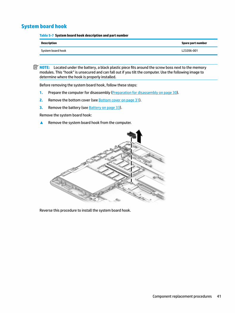
System board hook
Table 5-7 System board hook description and part number
Description Spare part number
System board hook L23206-001
NOTE: Located under the battery, a black plastic piece fits around the screw boss next to the memory modules. This “hook” is unsecured and can fall out if you tilt the computer. Use the following image to determine where the hook is properly installed.
Before removing the system board hook, follow these steps:
1. Prepare the computer for disassembly (Preparation for disassembly on page 30).
2. Remove the bottom cover (see Bottom cover on page 31).
3. Remove the battery (see Battery on page 33).
Remove the system board hook:
▲ Remove the system board hook from the computer.
Reverse this procedure to install the system board hook.
Component replacement procedures 41
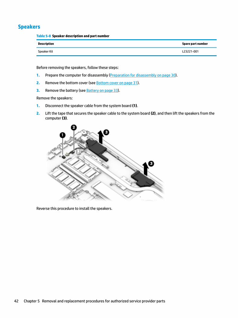
Speakers
Table 5-8 Speaker description and part number
Description Spare part number
Speaker Kit L23221-001
Before removing the speakers, follow these steps:
1. Prepare the computer for disassembly (Preparation for disassembly on page 30).
2. Remove the bottom cover (see Bottom cover on page 31).
3. Remove the battery (see Battery on page 33).
Remove the speakers:
1. Disconnect the speaker cable from the system board (1).
2. Lift the tape that secures the speaker cable to the system board (2), and then lift the speakers from the computer (3).
Reverse this procedure to install the speakers.
42 Chapter 5 Removal and replacement procedures for authorized service provider parts
TouchPad button board
Table 5-9 TouchPad button board, bracket, and cable descriptions and part numbers
Description Spare part number
TouchPad button board L23197-001
TouchPad button board bracket L23193-001
TouchPad button board cable L23185-001
Before removing the TouchPad button board, follow these steps:
1. Prepare the computer for disassembly (Preparation for disassembly on page 30).
2. Remove the bottom cover (see Bottom cover on page 31).
3. Remove the battery (see Battery on page 33).
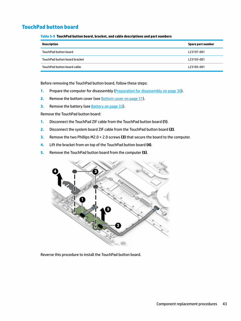
Remove the TouchPad button board:
1. Disconnect the TouchPad ZIF cable from the TouchPad button board (1).
2. Disconnect the system board ZIF cable from the TouchPad button board (2).
3. Remove the two Phillips M2.0 × 2.0 screws (3) that secure the board to the computer.
4. Lift the bracket from on top of the TouchPad button board (4).
5. Remove the TouchPad button board from the computer (5).
Reverse this procedure to install the TouchPad button board.
Component replacement procedures 43
Fan
Table 5-10 Fan descriptions and part numbers
Description Spare part number
Fan L23189-001
Before removing the fan, follow these steps:
1. Prepare the computer for disassembly (Preparation for disassembly on page 30).
2. Remove the bottom cover (see Bottom cover on page 31).
3. Remove the battery (see Battery on page 33).
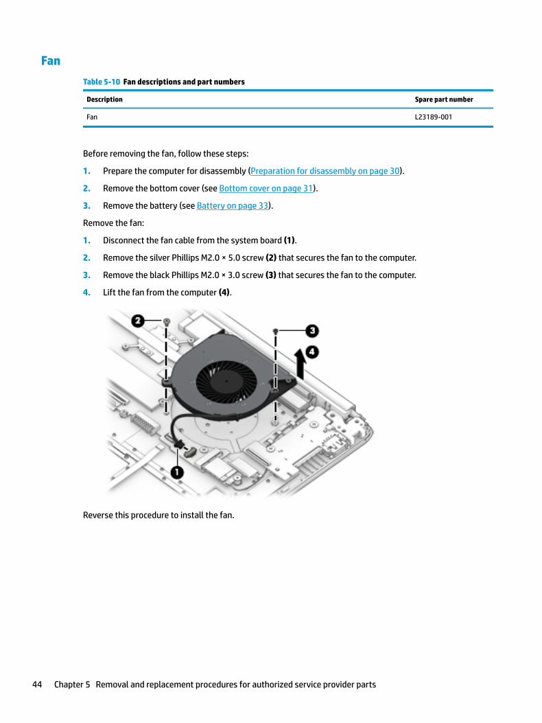
Remove the fan:
1. Disconnect the fan cable from the system board (1).
2. Remove the silver Phillips M2.0 × 5.0 screw (2) that secures the fan to the computer.
3. Remove the black Phillips M2.0 × 3.0 screw (3) that secures the fan to the computer.
4. Lift the fan from the computer (4).
Reverse this procedure to install the fan.
44 Chapter 5 Removal and replacement procedures for authorized service provider parts

Heat sink assembly
Table 5-11 Heat sink descriptions and part numbers
Description Spare part number
Heat sink for use in models with AMD Ryzen processors and discrete graphics L23192-001
Heat sink for use in models with AMD A4/A6/A9 processors and discrete graphics L23386-001
Heat sink for use in models with AMD Ryzen processors and integrated UMA graphics L23191-001
Heat sink for use in models with AMD A4/A6/A9 processors and integrated UMA graphics L23385-001
Heat plate for use in fanless models with AMD E2-9000e processors L23384-001
Before removing the heat sink, follow these steps:
1. Prepare the computer for disassembly (Preparation for disassembly on page 30).
2. Remove the bottom cover (see Bottom cover on page 31).
3. Remove the battery (see Battery on page 33).
To remove the heat sink assembly from products with integrated UMA graphics:
1. In the order indicated on the heat sink assembly, remove the four Phillips M2.0 × 3.0 screws (1) that secure the heat sink to the computer.
2. Lift the heat sink assembly from the computer (2).
Component replacement procedures 45

3. Thoroughly clean the thermal material from the surface of the heat sink (1) and associated system board component (2) each time the heat sink is removed. Replacement thermal material is included with the heat sink and system board spare part kits.
To remove the heat sink assembly from products with discrete graphics:
1. In the order indicated on the heat sink assembly, remove the six Phillips M2.0 × 3.0 screws (1) that secure the heat sink to the computer.
2. Lift the heat sink assembly from the computer (2).
46 Chapter 5 Removal and replacement procedures for authorized service provider parts

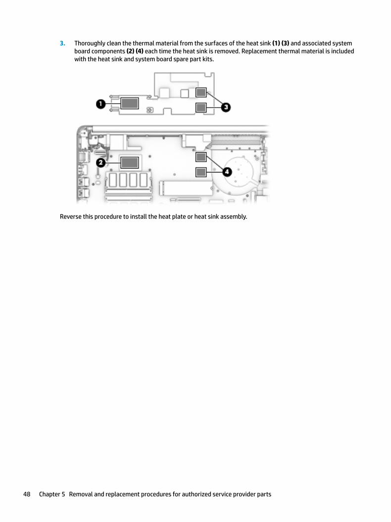
3. Thoroughly clean the thermal material from the surfaces of the heat sink (1) (3) and associated system board components (2) (4) each time the heat sink is removed. Replacement thermal material is included with the heat sink and system board spare part kits.
To remove the heat plate from fanless models:
1. In the order indicated on the heat plate, remove the four Phillips M2.0 × 3.0 screws (1) that secure the heat plate to the computer.
2. Lift the heat plate from the computer (2).
Component replacement procedures 47
3. Thoroughly clean the thermal material from the surfaces of the heat sink (1) (3) and associated system board components (2) (4) each time the heat sink is removed. Replacement thermal material is included with the heat sink and system board spare part kits.
Reverse this procedure to install the heat plate or heat sink assembly.
48 Chapter 5 Removal and replacement procedures for authorized service provider parts

TouchPad module
Table 5-12 TouchPad module and cable descriptions and part numbers
Description Spare part number
TouchPad module L22586-001
TouchPad module cable L23184-001
Before removing the TouchPad module, follow these steps:
1. Prepare the computer for disassembly (Preparation for disassembly on page 30).
2. Remove the bottom cover (see Bottom cover on page 31).
3. Remove the battery (see Battery on page 33).
To remove the TouchPad module:
1. Peel the conductive tape off the keyboard (1)
2. Starting in the corner, use a plastic, non-marking tool to pry up the TouchPad module to disengage the adhesive that secures it to the top cover (2)
3. Working around each edge, pry the TouchPad module loose, and then remove it from the computer (3).
NOTE: The TouchPad module may be very tight and difficult to remove.
Reverse this procedure to install the TouchPad module.
Component replacement procedures 49
System board
NOTE: All system board spare part kits include replacement thermal material.
All system boards use the following part numbers:
xxxxxx-001: Non-Windows operating systems
xxxxxx-601: Windows operating system
Table 5-13 System board descriptions and part numbers
Description Spare part number
System board for use in models with discrete graphics memory:
● AMD Ryzen 3-3200U processor L46793-xx1
● AMD Ryzen 3-2200U processor L23396-xx1
● AMD A9-9425 processor L23395-xx1
System board for use in models with UMA graphics memory:
● AMD Ryzen 5-3500U processor L46792-xx1
● AMD Ryzen 3-3200U processor L46791-xx1
● AMD Ryzen 5-2500U processor L23394-xx1
● AMD Ryzen 3-2200U processor L23393-xx1
● AMD A9-9425 processor L23392-xx1
● AMD A6-9225 processor L23391-xx1
● AMD A4-9125 processor L23390-xx1
● AMD E2-9000e processor L23389-xx1
Before removing the system board, follow these steps:
1. Prepare the computer for disassembly (Preparation for disassembly on page 30).
2. Remove the following components:
a. Bottom cover (see Bottom cover on page 31)
b. Battery (see Battery on page 33)
c. Hard drive (see Hard drive on page 37)
d. Solid-state drive (see Solid-state drive on page 39)
e. WLAN module (see WLAN module on page 40)
f. Memory modules (see Memory module on page 35)
Remove the system board:
IMPORTANT: Make special note of each screw size and location during removal and replacement
1. Disconnect the following cables from the system board:
(1) Hard drive cable
50 Chapter 5 Removal and replacement procedures for authorized service provider parts

(2) Display cable
(3) Power connector cable
(4) Speaker cable
(5) Keyboard backlight cable
(6) Keyboard cable
(7) TouchPad button board cable
(8) USB board cable
2. Remove the black Phillips M2.0 × 3.0 screw (1), and the four silver Phillips M2.0 × 2.0 screws (2) that secure the system board to the computer.
Component replacement procedures 51
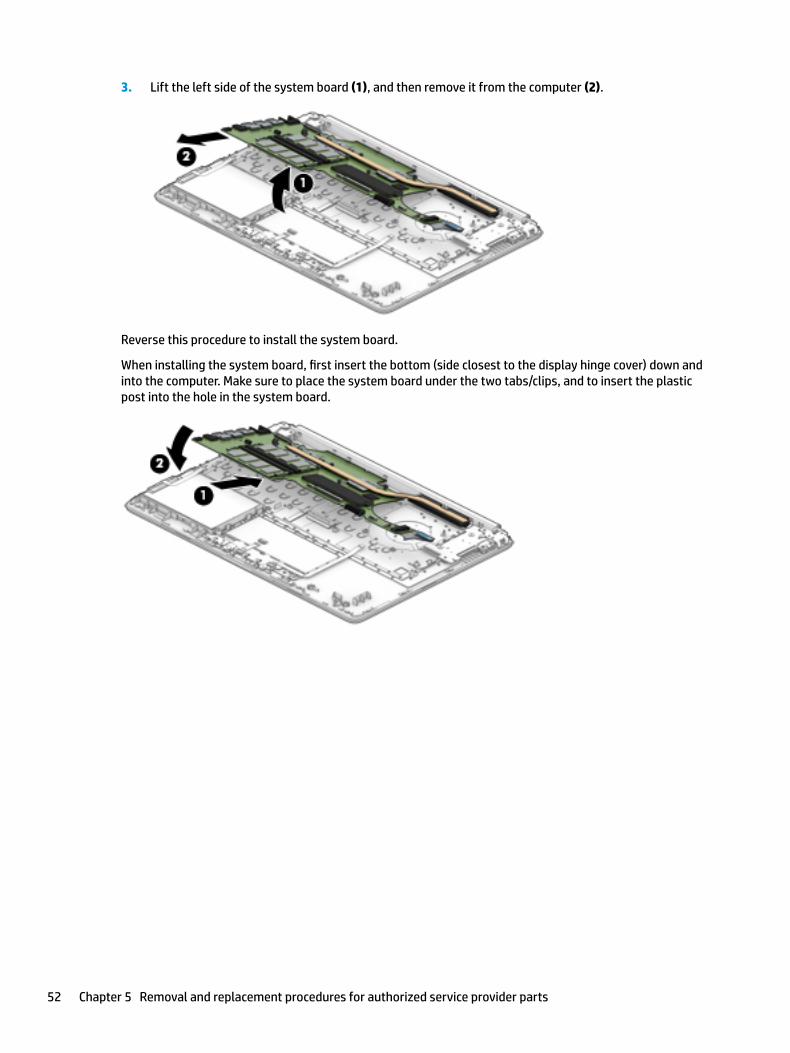
3. Lift the left side of the system board (1), and then remove it from the computer (2).
Reverse this procedure to install the system board.
When installing the system board, first insert the bottom (side closest to the display hinge cover) down and into the computer. Make sure to place the system board under the two tabs/clips, and to insert the plastic post into the hole in the system board.
52 Chapter 5 Removal and replacement procedures for authorized service provider parts

Power connector cable (DC-in)
Table 5-14 Power connector cable description and part number
Description Spare part number
Power connector cable L23188-001
Before removing the power connector cable, follow these steps:
1. Prepare the computer for disassembly (Preparation for disassembly on page 30).
2. Remove the bottom cover (see Bottom cover on page 31).
3. Remove the battery (see Battery on page 33).
4. Remove the display (see Display assembly on page 55).
Remove the power connector cable:
1. Disconnect the power connector cable from the system board (1).
2. Remove the cable from the clip (2).
3. Remove the power connector cable out of the computer (3).
Reverse this procedure to install the power connector cable.
Component replacement procedures 53

USB/card reader/power button board
Table 5-15 USB/card reader/power button board and cable descriptions and part numbers
Description Spare part number
USB/card reader/power button board L23196-001
USB/card reader/power button board cable L23186-001
Before removing the USB/card reader/power button board, follow these steps:
1. Prepare the computer for disassembly (Preparation for disassembly on page 30).
2. Remove the bottom cover (see Bottom cover on page 31).
3. Remove the battery (see Battery on page 33).
4. Remove the display (see Display assembly on page 55).
Remove the USB/card reader/power button board:
1. Disconnect the cable from the ZIF connector on the USB/card reader/power button board (1).
2. Remove the two Phillips M2.0 × 3.0 screws (2), and then remove the board from the computer (3).
Reverse this procedure to replace the USB/card reader/power button board.
54 Chapter 5 Removal and replacement procedures for authorized service provider parts
Display assembly
Full hinge-up displays are not spared. Displays are spared only at the subcomponent level.
Before removing the display panel, follow these steps:
1. Prepare the computer for disassembly (Preparation for disassembly on page 30).
2. Remove the bottom cover (see Bottom cover on page 31).
3. Remove the battery (see Battery on page 33).
Remove the display assembly:
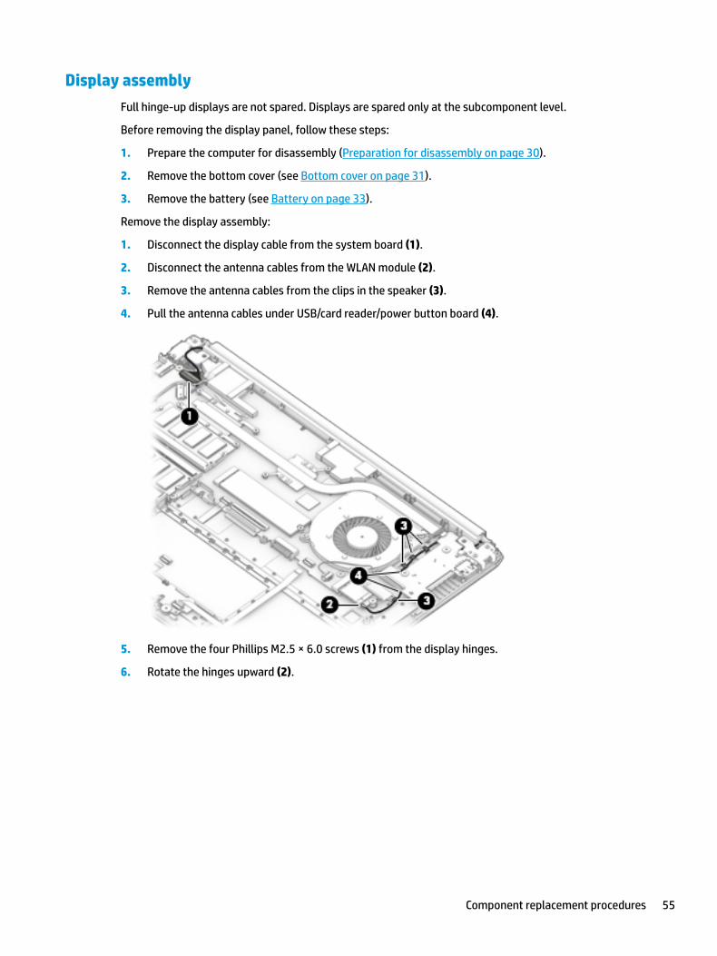
1. Disconnect the display cable from the system board (1).
2. Disconnect the antenna cables from the WLAN module (2).
3. Remove the antenna cables from the clips in the speaker (3).
4. Pull the antenna cables under USB/card reader/power button board (4).
5. Remove the four Phillips M2.5 × 6.0 screws (1) from the display hinges.
6. Rotate the hinges upward (2).
Component replacement procedures 55

7. Separate the display from the computer (3).
Remove the display assembly subcomponents:
1. If it is necessary to replace the display bezel:
a. If you need to remove the display bezel, flex the top (1) of the bezel, the inside edges of the left and right sides (2), and then the bottom (3) of the bezel until it disengages from the display enclosure.
b. Remove the bezel (4).
The display bezel is available using spare part number L23181-001.
2. If it is necessary to replace the camera module:
56 Chapter 5 Removal and replacement procedures for authorized service provider parts

a. Detach the camera module (1) from the display back cover. (The module is attached with double-sided adhesive.)
The HD camera module is available using spare part number L23237-001.
The VGA camera module is available using spare part number L23238-001.
b. Disconnect the cable (2) from the camera/microphone module.
3. If it is necessary to replace the display panel:
IMPORTANT: HD panels are secured to the display enclosure with screws. FHD panels are secured with tape.
a. HD panels:
Remove the four Phillips M2.0 × 3.0 screws that secure the panel to the display enclosure.
FHD panels:
Component replacement procedures 57
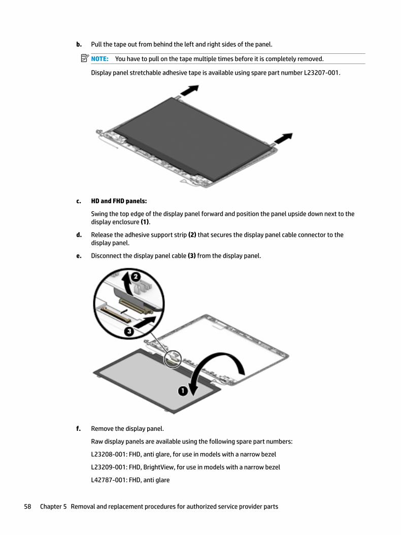
b. Pull the tape out from behind the left and right sides of the panel.
NOTE: You have to pull on the tape multiple times before it is completely removed.
Display panel stretchable adhesive tape is available using spare part number L23207-001.
c. HD and FHD panels:
Swing the top edge of the display panel forward and position the panel upside down next to the display enclosure (1).
d. Release the adhesive support strip (2) that secures the display panel cable connector to the display panel.
e. Disconnect the display panel cable (3) from the display panel.
f. Remove the display panel.
Raw display panels are available using the following spare part numbers:
L23208-001: FHD, anti glare, for use in models with a narrow bezel
L23209-001: FHD, BrightView, for use in models with a narrow bezel
L42787-001: FHD, anti glare
58 Chapter 5 Removal and replacement procedures for authorized service provider parts
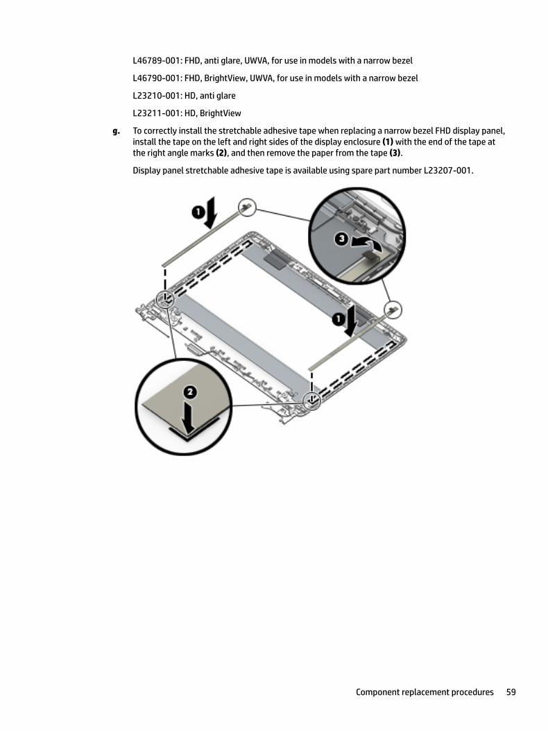
L46789-001: FHD, anti glare, UWVA, for use in models with a narrow bezel
L46790-001: FHD, BrightView, UWVA, for use in models with a narrow bezel
L23210-001: HD, anti glare
L23211-001: HD, BrightView
g. To correctly install the stretchable adhesive tape when replacing a narrow bezel FHD display panel, install the tape on the left and right sides of the display enclosure (1) with the end of the tape at the right angle marks (2), and then remove the paper from the tape (3).
Display panel stretchable adhesive tape is available using spare part number L23207-001.
Component replacement procedures 59
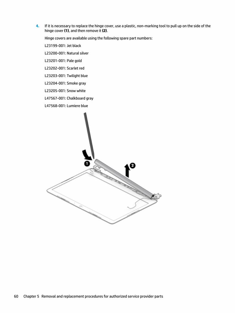
4. If it is necessary to replace the hinge cover, use a plastic, non-marking tool to pull up on the side of the hinge cover (1), and then remove it (2).
Hinge covers are available using the following spare part numbers:
L23199-001: Jet black
L23200-001: Natural silver
L23201-001: Pale gold
L23202-001: Scarlet red
L23203-001: Twilight blue
L23204-001: Smoke gray
L23205-001: Snow white
L47567-001: Chalkboard gray
L47568-001: Lumiere blue
60 Chapter 5 Removal and replacement procedures for authorized service provider parts
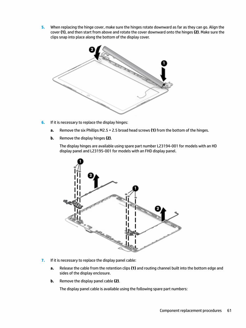
5. When replacing the hinge cover, make sure the hinges rotate downward as far as they can go. Align the cover (1), and then start from above and rotate the cover downward onto the hinges (2). Make sure the clips snap into place along the bottom of the display cover.
6. If it is necessary to replace the display hinges:
a. Remove the six Phillips M2.5 × 2.5 broad head screws (1) from the bottom of the hinges.
b. Remove the display hinges (2).
The display hinges are available using spare part number L23194-001 for models with an HD display panel and L23195-001 for models with an FHD display panel.
7. If it is necessary to replace the display panel cable:
a. Release the cable from the retention clips (1) and routing channel built into the bottom edge and sides of the display enclosure.
b. Remove the display panel cable (2).
The display panel cable is available using the following spare part numbers:
Component replacement procedures 61

● L23182-001 – HD display panel
● L23183-001 – FHD display panel
8. If it is necessary to replace the wireless antenna cables and transceivers:
a. Release the wireless antenna cables from the retention clips and routing channel built into the side of the display enclosure (1).
b. Release the antenna from the display enclosure (2).
Antennas are available using the following spare part numbers:
L23158-001: Single antenna for use in models with an HD panel
L23159-001: Dual antennas for use in models with an HD panel
L24037-001: Single antenna for use in models with an FHD panel
L24038-001: Dual antennas for use in models with an FHD panel
Use the following image to determine proper cable routing in the display of the antenna cable (1) and display cable (2).
62 Chapter 5 Removal and replacement procedures for authorized service provider parts
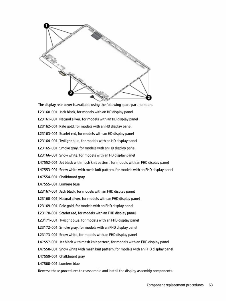
The display rear cover is available using the following spare part numbers:
L23160-001: Jack black, for models with an HD display panel
L23161-001: Natural silver, for models with an HD display panel
L23162-001: Pale gold, for models with an HD display panel
L23163-001: Scarlet red, for models with an HD display panel
L23164-001: Twilight blue, for models with an HD display panel
L23165-001: Smoke gray, for models with an HD display panel
L23166-001: Snow white, for models with an HD display panel
L47552-001: Jet black with mesh knit pattern, for models with an FHD display panel
L47553-001: Snow white with mesh knit pattern, for models with an FHD display panel
L47554-001: Chalkboard gray
L47555-001: Lumiere blue
L23167-001: Jack black, for models with an FHD display panel
L23168-001: Natural silver, for models with an FHD display panel
L23169-001: Pale gold, for models with an FHD display panel
L23170-001: Scarlet red, for models with an FHD display panel
L23171-001: Twilight blue, for models with an FHD display panel
L23172-001: Smoke gray, for models with an FHD display panel
L23173-001: Snow white, for models with an FHD display panel
L47557-001: Jet black with mesh knit pattern, for models with an FHD display panel
L47558-001: Snow white with mesh knit pattern, for models with an FHD display panel
L47559-001: Chalkboard gray
L47560-001: Lumiere blue
Reverse these procedures to reassemble and install the display assembly components.
Component replacement procedures 63

Top cover with keyboard
The top cover with keyboard remains after removing all other spared parts from the computer.
In this section, the first table provides the main spare part number for the keyboards. The second table provides the country codes.
Table 5-16 Top cover with keyboard descriptions and part numbers
Description Spare part number
Keyboard, no backlight, jet black L23239-xx1
Keyboard, no backlight, snow white L23240-xx1
Keyboard, no backlight, ash silver L23241-xx1
Keyboard, backlit, ash silver L23242-xx1
Keyboard, no backlight, jet black with mesh knit pattern L48210-xx1
Keyboard, no backlight, snow white with mesh knit pattern L48211-xx1
Table 5-17 Keyboard country codes
For use in country or region
Spare part number
For use in country or region
Spare part number
For use in country or region
Spare part number
Belgium -A41 Israel -BB1 Spain -071
Canada -DB1 Italy -061 Thailand -281
The Czech Republic and Slovakia
-FL1 Latin America -161 Turkey -141
Denmark, Finland, and Norway
-DH1 The Netherlands -B31 United Kingdom -031
France -051 Russia -251 United States -001
Germany -041 Saudi Arabia -171
64 Chapter 5 Removal and replacement procedures for authorized service provider parts
6 Using Setup Utility (BIOS)
Setup Utility, or Basic Input/Output System (BIOS), controls communication between all the input and output devices on the system (such as disk drives, display, keyboard, mouse, and printer). Setup Utility (BIOS) includes settings for the types of devices installed, the startup sequence of the computer, and the amount of system and extended memory.
NOTE: To start Setup Utility on convertible computers, your computer must be in notebook mode and you must use the keyboard attached to your notebook.
Starting Setup Utility (BIOS)CAUTION: Use extreme care when making changes in Setup Utility (BIOS). Errors can prevent the computer from operating properly.
▲ Turn on or restart the computer and quickly press f10.
– or –
Turn on or restart the computer, quickly press esc, and then press f10 when the Start menu is displayed.
Updating Setup Utility (BIOS)Updated versions of Setup Utility (BIOS) may be available on the HP website.
Most BIOS updates on the HP website are packaged in compressed files called SoftPaqs.
Some download packages contain a file named Readme.txt, which contains information regarding installing and troubleshooting the file.
Determining the BIOS version
To decide whether you need to update Setup Utility (BIOS), first determine the BIOS version on your computer.
To reveal the BIOS version information (also known as ROM date and System BIOS), use one of these options.
● HP Support Assistant
1. Type support in the taskbar search box, and then select the HP Support Assistant app.
– or –
Select the question mark icon in the taskbar.
2. Select My notebook, and then select Specifications.
● Setup Utility (BIOS)
1. Start Setup Utility (BIOS) (see Starting Setup Utility (BIOS) on page 65).
2. Select Main, and then make note of the BIOS version.
3. Select Exit, select one of the options, and then follow the on-screen instructions.
● In Windows, press CTRL+Alt+S.
Starting Setup Utility (BIOS) 65
To check for later BIOS versions, see Downloading a BIOS update on page 66.
Downloading a BIOS update
CAUTION: To reduce the risk of damage to the computer or an unsuccessful installation, download and install a BIOS update only when the computer is connected to reliable external power using the AC adapter. Do not download or install a BIOS update while the computer is running on battery power, docked in an optional docking device, or connected to an optional power source. During the download and installation, follow these instructions:
● Do not disconnect power from the computer by unplugging the power cord from the AC outlet.
● Do not shut down the computer or initiate Sleep.
● Do not insert, remove, connect, or disconnect any device, cable, or cord.
NOTE: If your computer is connected to a network, consult the network administrator before installing any software updates, especially system BIOS updates.
1. Type support in the taskbar search box, and then select the HP Support Assistant app.
– or –
Select the question mark icon in the taskbar.
2. Select Updates, and then select Check for updates and messages.
3. Follow the on-screen instructions.
4. At the download area, follow these steps:
a. Identify the most recent BIOS update and compare it to the BIOS version currently installed on your computer. If the update is more recent than your BIOS version, make a note of the date, name, or other identifier. You may need this information to locate the update later, after it has been downloaded to your hard drive.
b. Follow the on-screen instructions to download your selection to the hard drive.
Make a note of the path to the location on your hard drive where the BIOS update is downloaded. You will need to access this path when you are ready to install the update.
BIOS installation procedures vary. Follow any instructions that appear on the screen after the download is complete. If no instructions appear, follow these steps:
1. Type file in the taskbar search box, and then select File Explorer.
2. Select your hard drive designation. The hard drive designation is typically Local Disk (C:).
3. Using the hard drive path you recorded earlier, open the folder that contains the update.
4. Double-click the file that has an .exe extension (for example, filename.exe).
The BIOS installation begins.
5. Complete the installation by following the on-screen instructions.
NOTE: After a message on the screen reports a successful installation, you can delete the downloaded file from your hard drive.
66 Chapter 6 Using Setup Utility (BIOS)
7 Using HP PC Hardware Diagnostics
Using HP PC Hardware Diagnostics Windows (select products only)
HP PC Hardware Diagnostics Windows is a Windows-based utility that allows you to run diagnostic tests to determine whether the computer hardware is functioning properly. The tool runs within the Windows operating system in order to diagnose hardware failures.
If HP PC Hardware Diagnostics Windows is not installed on your computer, first you must download and install it. To download HP PC Hardware Diagnostics Windows, see Downloading HP PC Hardware Diagnostics Windows on page 67.
After HP PC Hardware Diagnostics Windows is installed, follow these steps to access it from HP Help and Support or HP Support Assistant.
1. To access HP PC Hardware Diagnostics Windows from HP Help and Support:
a. Select the Start button, and then select HP Help and Support.
b. Right-click HP PC Hardware Diagnostics Windows, select More, and then select Run as administrator.
– or –
To access HP PC Hardware Diagnostics Windows from HP Support Assistant:
a. Type support in the taskbar search box, and then select the HP Support Assistant app.
– or –
Select the question mark icon in the taskbar.
b. Select Troubleshooting and fixes.
c. Select Diagnostics, and then select HP PC Hardware Diagnostics Windows.
2. When the tool opens, select the type of diagnostic test you want to run, and then follow the on-screen instructions.
NOTE: If you need to stop a diagnostic test at any time, select Cancel.
When HP PC Hardware Diagnostics Windows detects a failure that requires hardware replacement, a 24-digit Failure ID code is generated. The screen displays one of the following options:
● A Failure ID link is displayed. Select the link and follow the on-screen instructions.
● A Quick Response (QR) code is displayed. With a mobile device, scan the code and then follow the on-screen instructions.
● Instructions for calling support are displayed. Follow those instructions.
Downloading HP PC Hardware Diagnostics Windows
● The HP PC Hardware Diagnostics Windows download instructions are provided in English only.
● You must use a Windows computer to download this tool because only .exe files are provided.
Using HP PC Hardware Diagnostics Windows (select products only) 67
Downloading the latest HP PC Hardware Diagnostics Windows version
To download HP PC Hardware Diagnostics Windows, follow these steps:
1. Go to http://www.hp.com/go/techcenter/pcdiags. The HP PC Diagnostics home page is displayed.
2. Select Download HP Diagnostics Windows, and then select a location on your computer or a USB flash drive.
The tool is downloaded to the selected location.
Downloading HP Hardware Diagnostics Windows by product name or number (select products only)
NOTE: For some products, it may be necessary to download the software to a USB flash drive by using the product name or number.
To download HP PC Hardware Diagnostics Windows by product name or number, follow these steps:
1. Go to http://www.hp.com/support.
2. Select Get software and drivers, select your type of product, and then enter the product name or number in the search box that is displayed.
3. In the Diagnostics section, select Download, and then follow the on-screen instructions to select the specific Windows diagnostics version to be downloaded to your computer or USB flash drive.
The tool is downloaded to the selected location.
Installing HP PC Hardware Diagnostics Windows
To install HP PC Hardware Diagnostics Windows, follow these steps:
▲ Navigate to the folder on your computer or the USB flash drive where the .exe file was downloaded, double-click the .exe file, and then follow the on-screen instructions.
Using HP PC Hardware Diagnostics UEFINOTE: For Windows 10 S computers, you must use a Windows computer and a USB flash drive to download and create the HP UEFI support environment because only .exe files are provided. For more information, see Downloading HP PC Hardware Diagnostics UEFI to a USB flash drive on page 69.
HP PC Hardware Diagnostics UEFI (Unified Extensible Firmware Interface) allows you to run diagnostic tests to determine whether the computer hardware is functioning properly. The tool runs outside the operating system so that it can isolate hardware failures from issues that are caused by the operating system or other software components.
If your PC will not boot into Windows, you can use HP PC Hardware Diagnostics UEFI to diagnose hardware issues.
When HP PC Hardware Diagnostics Windows detects a failure that requires hardware replacement, a 24-digit Failure ID code is generated. For assistance in solving the problem:
▲ Select Get Support, and then use a mobile device to scan the QR code that displays on the next screen. The HP Customer Support - Service Center page displays, with your Failure ID and product number automatically filled in. Follow the on-screen instructions.
– or –
Contact support, and provide the Failure ID code.
68 Chapter 7 Using HP PC Hardware Diagnostics
NOTE: To start diagnostics on a convertible computer, your computer must be in notebook mode, and you must use the attached keyboard.
NOTE: If you need to stop a diagnostic test, press esc.
Starting HP PC Hardware Diagnostics UEFI
To start HP PC Hardware Diagnostics UEFI, follow these steps:
1. Turn on or restart the computer, and quickly press esc.
2. Press f2.
The BIOS searches three places for the diagnostic tools, in the following order:
a. Connected USB flash drive
NOTE: To download the HP PC Hardware Diagnostics UEFI tool to a USB flash drive, see Downloading the latest HP PC Hardware Diagnostics UEFI version on page 69.
b. Hard drive
c. BIOS
3. When the diagnostic tool opens, select a language, select the type of diagnostic test you want to run, and then follow the on-screen instructions.
Downloading HP PC Hardware Diagnostics UEFI to a USB flash drive
Downloading HP PC Hardware Diagnostics UEFI to a USB flash drive can be useful in the following situations:
● HP PC Hardware Diagnostics UEFI is not included in the preinstall image.
● HP PC Hardware Diagnostics UEFI is not included in the HP Tool partition.
● The hard drive is damaged.
NOTE: The HP PC Hardware Diagnostics UEFI download instructions are provided in English only, and you must use a Windows computer to download and create the HP UEFI support environment because only .exe files are provided.
Downloading the latest HP PC Hardware Diagnostics UEFI version
To download the latest HP PC Hardware Diagnostics UEFI version to a USB flash drive:
1. Go to http://www.hp.com/go/techcenter/pcdiags. The HP PC Diagnostics home page is displayed.
2. Select Download HP Diagnostics UEFI, and then select Run.
Downloading HP PC Hardware Diagnostics UEFI by product name or number (select products only)
NOTE: For some products, it may be necessary to download the software to a USB flash drive by using the product name or number.
To download HP PC Hardware Diagnostics UEFI by product name or number (select products only) to a USB flash drive:
Using HP PC Hardware Diagnostics UEFI 69
1. Go to http://www.hp.com/support.
2. Enter the product name or number, select your computer, and then select your operating system.
3. In the Diagnostics section, follow the on-screen instructions to select and download the specific UEFI Diagnostics version for your computer.
Using Remote HP PC Hardware Diagnostics UEFI settings (select products only)
Remote HP PC Hardware Diagnostics UEFI is a firmware (BIOS) feature that downloads HP PC Hardware Diagnostics UEFI to your computer. It can then execute the diagnostics on your computer, and it may upload results to a preconfigured server. For more information about Remote HP PC Hardware Diagnostics UEFI, go to http://www.hp.com/go/techcenter/pcdiags, and then select Find out more.
Downloading Remote HP PC Hardware Diagnostics UEFI
NOTE: HP Remote PC Hardware Diagnostics UEFI is also available as a Softpaq that can be downloaded to a server.
Downloading the latest Remote HP PC Hardware Diagnostics UEFI version
To download the latest Remote HP PC Hardware Diagnostics UEFI version, follow these steps:
1. Go to http://www.hp.com/go/techcenter/pcdiags. The HP PC Diagnostics home page is displayed.
2. Select Download Remote Diagnostics, and then select Run.
Downloading Remote HP PC Hardware Diagnostics UEFI by product name or number
NOTE: For some products, it may be necessary to download the software by using the product name or number.
To download HP Remote PC Hardware Diagnostics UEFI by product name or number, follow these steps:
1. Go to http://www.hp.com/support.
2. Select Get software and drivers, select your type of product, enter the product name or number in the search box that is displayed, select your computer, and then select your operating system.
3. In the Diagnostics section, follow the on-screen instructions to select and download the Remote UEFI version for the product.
Customizing Remote HP PC Hardware Diagnostics UEFI settings
Using the Remote HP PC Hardware Diagnostics setting in Computer Setup (BIOS), you can perform the following customizations:
● Set a schedule for running diagnostics unattended. You can also start diagnostics immediately in interactive mode by selecting Execute Remote HP PC Hardware Diagnostics.
● Set the location for downloading the diagnostic tools. This feature provides access to the tools from the HP website or from a server that has been preconfigured for use. Your computer does not require the traditional local storage (such as a disk drive or USB flash drive) to run remote diagnostics.
70 Chapter 7 Using HP PC Hardware Diagnostics

● Set a location for storing the test results. You can also set the user name and password settings used for uploads.
● Display status information about the diagnostics run previously.
To customize Remote HP PC Hardware Diagnostics UEFI settings, follow these steps:
1. Turn on or restart the computer, and when the HP logo appears, press f10 to enter Computer Setup.
2. Select Advanced, and then select Settings.
3. Make your customization selections.
4. Select Main, and then Save Changes and Exit to save your settings.
Your changes take effect when the computer restarts.
Using Remote HP PC Hardware Diagnostics UEFI settings (select products only) 71

8 Backing up, restoring, and recovering
This chapter provides information about the following processes, which are standard procedure for most products:
● Backing up your personal information—You can use Windows tools to back up your personal information (see Using Windows tools on page 72).
● Creating a restore point—You can use Windows tools to create a restore point (see Using Windows tools on page 72).
● Creating recovery media (select products only)—You can use the HP Cloud Recovery Download Tool (select products only) to create recovery media (see Using the HP Cloud Recovery Download Tool to create recovery media (select products only) on page 72).
● Restoring and recovery—Windows offers several options for restoring from backup, refreshing the computer, and resetting the computer to its original state (see Using Windows tools on page 72).
IMPORTANT: If you will be performing recovery procedures on a tablet, the tablet battery must be at least 70% charged before you start the recovery process.
IMPORTANT: For a tablet with a detachable keyboard, connect the tablet to the keyboard base before beginning any recovery process.
Backing up information and creating recovery media
Using Windows tools
IMPORTANT: Windows is the only option that allows you to back up your personal information. Schedule regular backups to avoid information loss.
You can use Windows tools to back up personal information and create system restore points and recovery media.
NOTE: If computer storage is 32 GB or less, Microsoft System Restore is disabled by default.
For more information and steps, see the Get Help app.
1. Select the Start button, and then select the Get Help app.
2. Enter the task you want to perform.
NOTE: You must be connected to the Internet to access the Get Help app.
Using the HP Cloud Recovery Download Tool to create recovery media (select products only)
You can use the HP Cloud Recovery Download Tool to create HP Recovery media on a bootable USB flash drive.
To download the tool:
▲ Go to the Microsoft Store and search for HP Cloud Recovery.
For details, go to http://www.hp.com/support, search for HP Cloud Recovery, and then select "HP PCs – Using the Cloud Recovery Tool (Windows 10, 7)."
72 Chapter 8 Backing up, restoring, and recovering

NOTE: If you cannot create recovery media yourself, contact support to obtain recovery discs. Go to http://www.hp.com/support, select your country or region, and then follow the on-screen instructions.
Restoring and recovery
Restoring, resetting, and refreshing using Windows tools
Windows offers several options for restoring, resetting, and refreshing the computer. For details, see Using Windows tools on page 72.
Recovering using HP Recovery media
HP Recovery media is used to recover the original operating system and software programs that were installed at the factory. On select products, it can be created on a bootable USB flash drive using the HP Cloud Recovery Download Tool. For details, see Using the HP Cloud Recovery Download Tool to create recovery media (select products only) on page 72.
NOTE: If you cannot create recovery media yourself, contact support to obtain recovery discs. Go to http://www.hp.com/support, select your country or region, and then follow the on-screen instructions.
To recover your system:
▲ Insert the HP Recovery media, and then restart the computer.
Changing the computer boot order
If your computer does not restart using the HP Recovery media, you can change the computer boot order. This is the order of devices listed in BIOS where the computer looks for startup information. You can change the selection to an optical drive or a USB flash drive, depending on the location of your HP Recovery media.
To change the boot order:
IMPORTANT: For a tablet with a detachable keyboard, connect the tablet to the keyboard base before beginning these steps.
1. Insert the HP Recovery media.
2. Access the system Startup menu.
For computers or tablets with keyboards attached:
▲ Turn on or restart the computer or tablet, quickly press esc, and then press f9 for boot options.
For tablets without keyboards:
▲ Turn on or restart the tablet, quickly hold down the volume up button, and then select f9.
‒ or –
Turn on or restart the tablet, quickly hold down the volume down button, and then select f9.
3. Select the optical drive or USB flash drive from which you want to boot, and then follow the on-screen instructions.
Restoring and recovery 73

9 Specifications
Computer specificationsTable 9-1 Computer specifications
Metric U.S.
Dimensions
Length 234.0 mm 9.21 in
Width 335.0 mm 13.19 in
Height 19.9 mm 0.78 in
Weight
With solid-state drive or eMMC 1509.4 g 3.3 lbs
With hard drive 1545.7 g 3.4 lbs
With solid-state drive and hard drive 1554.0 g 3.43 lbs
Input power
Operating voltage 19.0 V dc @ 4.74 A – 90 W or 18.5 V dc @ 3.5 A - 65 W or 45 W
Operating current 4.74 A or 3.5 A
Temperature
Operating (not writing to optical disc) 0°C to 35°C 32°F to 95°F
Operating (writing to optical disc) 5°C to 35°C 41°F to 95°F
Nonoperating -20°C to 60°C -4°F to 140°F
Relative humidity
Operating 10% to 90%
Nonoperating 5% to 95%
NOTE: Applicable product safety standards specify thermal limits for plastic surfaces. The computer operates well within this range of temperatures.
74 Chapter 9 Specifications

35.6-cm (14.0-in) display specificationsTable 9-2 Display specifications
Metric U.S.
Active diagonal size 35.6-cm 14.0-in
Resolution FHD: 1920 × 1080
HD: 1366 × 768
Surface treatment Anti-glare
BrightView
Brightness 220 nits
Viewing angle SVA (HD panels)
UWVA (FHD panels)
Backlight LED
Aspect ratio 16:9
Display panel interface eDP
M.2 SATA solid-state drive specificationsTable 9-3 Solid-state drive specifications
128-GB* 256-GB* 512-GB*
Height 1.35 mm 1.35 mm 1.35 mm
Weight < 10 g < 10 g < 10 g
Form factor M.2 2280-D2-B-M M.2 2280-D2-B-M M.2 2280-D2-B-M
Transfer rate up to 540 MB/sec up to 540 MB/sec up to 540 MB/sec
Interface type SATA-3 SATA-3 SATA-3
Ready time, maximum (to not busy) 1.0 ms < 1.0 ms < 1.0 ms
Access times, logical 0.1 ms 0.1 ms 0.1 ms
Total logical sectors 234,441,648 468,883,296 937,766,592
Operating temperature 0°C to 70°C (32°F to 158°F)
*1 GB = 1 billion bytes when referring to hard drive storage capacity. Actual accessible capacity is less. Actual drive specifications may differ slightly.
NOTE: Certain restrictions and exclusions apply. Contact technical support for details.
35.6-cm (14.0-in) display specifications 75
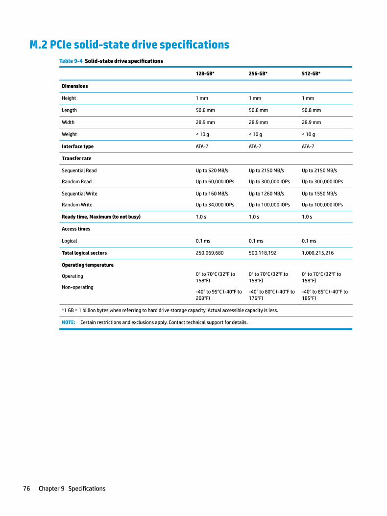
M.2 PCIe solid-state drive specificationsTable 9-4 Solid-state drive specifications
128-GB* 256-GB* 512-GB*
Dimensions
Height 1 mm 1 mm 1 mm
Length 50.8 mm 50.8 mm 50.8 mm
Width 28.9 mm 28.9 mm 28.9 mm
Weight < 10 g < 10 g < 10 g
Interface type ATA-7 ATA-7 ATA-7
Transfer rate
Sequential Read
Random Read
Up to 520 MB/s
Up to 60,000 IOPs
Up to 2150 MB/s
Up to 300,000 IOPs
Up to 2150 MB/s
Up to 300,000 IOPs
Sequential Write
Random Write
Up to 160 MB/s
Up to 34,000 IOPs
Up to 1260 MB/s
Up to 100,000 IOPs
Up to 1550 MB/s
Up to 100,000 IOPs
Ready time, Maximum (to not busy) 1.0 s 1.0 s 1.0 s
Access times
Logical 0.1 ms 0.1 ms 0.1 ms
Total logical sectors 250,069,680 500,118,192 1,000,215,216
Operating temperature
Operating
Non-operating
0° to 70°C (32°F to 158°F)
-40° to 95°C (-40°F to 203°F)
0° to 70°C (32°F to 158°F)
-40° to 80°C (-40°F to 176°F)
0° to 70°C (32°F to 158°F)
-40° to 85°C (-40°F to 185°F)
*1 GB = 1 billion bytes when referring to hard drive storage capacity. Actual accessible capacity is less.
NOTE: Certain restrictions and exclusions apply. Contact technical support for details.
76 Chapter 9 Specifications
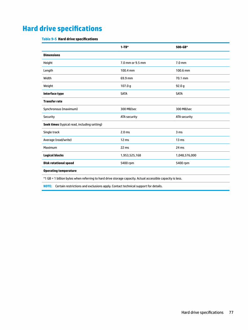
Hard drive specificationsTable 9-5 Hard drive specifications
1-TB* 500-GB*
Dimensions
Height 7.0 mm or 9.5 mm 7.0 mm
Length 100.4 mm 100.6 mm
Width 69.9 mm 70.1 mm
Weight 107.0 g 92.0 g
Interface type SATA SATA
Transfer rate
Synchronous (maximum) 300 MB/sec 300 MB/sec
Security ATA security ATA security
Seek times (typical read, including setting)
Single track 2.0 ms 3 ms
Average (read/write) 12 ms 13 ms
Maximum 22 ms 24 ms
Logical blocks 1,953,525,168 1,048,576,000
Disk rotational speed 5400 rpm 5400 rpm
Operating temperature
*1 GB = 1 billion bytes when referring to hard drive storage capacity. Actual accessible capacity is less.
NOTE: Certain restrictions and exclusions apply. Contact technical support for details.
Hard drive specifications 77
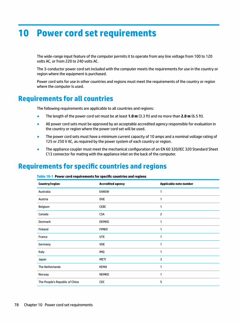
10 Power cord set requirements
The wide-range input feature of the computer permits it to operate from any line voltage from 100 to 120 volts AC, or from 220 to 240 volts AC.
The 3-conductor power cord set included with the computer meets the requirements for use in the country or region where the equipment is purchased.
Power cord sets for use in other countries and regions must meet the requirements of the country or region where the computer is used.
Requirements for all countriesThe following requirements are applicable to all countries and regions:
● The length of the power cord set must be at least 1.0 m (3.3 ft) and no more than 2.0 m (6.5 ft).
● All power cord sets must be approved by an acceptable accredited agency responsible for evaluation in the country or region where the power cord set will be used.
● The power cord sets must have a minimum current capacity of 10 amps and a nominal voltage rating of 125 or 250 V AC, as required by the power system of each country or region.
● The appliance coupler must meet the mechanical configuration of an EN 60 320/IEC 320 Standard Sheet C13 connector for mating with the appliance inlet on the back of the computer.
Requirements for specific countries and regionsTable 10-1 Power cord requirements for specific countries and regions
Country/region Accredited agency Applicable note number
Australia EANSW 1
Austria OVE 1
Belgium CEBC 1
Canada CSA 2
Denmark DEMKO 1
Finland FIMKO 1
France UTE 1
Germany VDE 1
Italy IMQ 1
Japan METI 3
The Netherlands KEMA 1
Norway NEMKO 1
The People's Republic of China COC 5
78 Chapter 10 Power cord set requirements
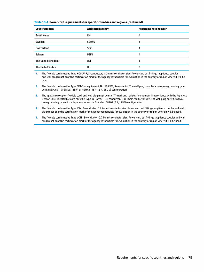
Table 10-1 Power cord requirements for specific countries and regions (continued)
Country/region Accredited agency Applicable note number
South Korea EK 4
Sweden SEMKO 1
Switzerland SEV 1
Taiwan BSMI 4
The United Kingdom BSI 1
The United States UL 2
1. The flexible cord must be Type HO5VV-F, 3-conductor, 1.0-mm² conductor size. Power cord set fittings (appliance coupler and wall plug) must bear the certification mark of the agency responsible for evaluation in the country or region where it will be used.
2. The flexible cord must be Type SPT-3 or equivalent, No. 18 AWG, 3-conductor. The wall plug must be a two-pole grounding type with a NEMA 5-15P (15 A, 125 V) or NEMA 6-15P (15 A, 250 V) configuration.
3. The appliance coupler, flexible cord, and wall plug must bear a “T” mark and registration number in accordance with the Japanese Dentori Law. The flexible cord must be Type VCT or VCTF, 3-conductor, 1.00-mm² conductor size. The wall plug must be a two-pole grounding type with a Japanese Industrial Standard C8303 (7 A, 125 V) configuration.
4. The flexible cord must be Type RVV, 3-conductor, 0.75-mm² conductor size. Power cord set fittings (appliance coupler and wall plug) must bear the certification mark of the agency responsible for evaluation in the country or region where it will be used.
5. The flexible cord must be Type VCTF, 3-conductor, 0.75-mm² conductor size. Power cord set fittings (appliance coupler and wall plug) must bear the certification mark of the agency responsible for evaluation in the country or region where it will be used.
Requirements for specific countries and regions 79
11 Recycling
When a non-rechargeable or rechargeable battery has reached the end of its useful life, do not dispose of the battery in general household waste. Follow the local laws and regulations in your area for battery disposal.
HP encourages customers to recycle used electronic hardware, HP original print cartridges, and rechargeable batteries. For more information about recycling programs, see the HP Web site at http://www.hp.com/recycle.
80 Chapter 11 Recycling

Index
AAC adapter and battery light,
identifying 6AC adapter, spare part numbers 24action keys
airplane mode 13help 13identifying 12, 13keyboard backlight 13mute 13next track 13pause 13play 13screen brightness 13speaker volume 13switch screen image 13using 13
airplane mode key 13antenna
removal 62audio
adjusting volume 13audio, product description 3audio-out (headphone)/audio-in
(microphone) combo jack, identifying 6
Bback cover
spare part number 21backup, creating 72backups 72battery
removal 33spare part number 18, 33
BIOSdetermining version 65downloading an update 66starting the Setup Utility 65updating 65
Bluetooth label 15boot order, changing 73bottom components 14
bottom coverremoval 31spare part number 18, 31
buttonsleft TouchPad 9power 11right TouchPad 9
Ccamera
identifying 8product description 3
camera light, identifying 8camera module
spare part number 21spare part numbers 57
caps lock light, identifying 10cautions
electrostatic discharge 26chipset, product description 1components
bottom 14display 8keyboard area 9left side 7right side 6
computer major components 16computer specifications 74connector, power 7
DDisplay assembly
spare part numbers 17display assembly
removal 55subcomponents 20
display assembly componentsremoval 55spare part numbers 55
display bezelremoval 56spare part numbers 20, 56
display cable, spare part number 21display components 8
display panelproduct description 2removal 57
display panel cableremoval 61spare part numbers 61
display specifications 75drive light, identifying 7
Eelectrostatic discharge (ESD) 26
preventing damage 27esc key, identifying 12ethernet
product description 3
Ffan
removal 44spare part number 18, 44
fan insertspare part number 18
fn key, identifying 12
GGet Help in Windows 10 action key
13grounding methods 28guidelines
packaging 29transporting 29workstation 26
Hhard drive
product description 2removal 37spare part number 18, 23spare part numbers 37specifications 77
hard drive cablespare part number 23
hard drive coverspare part number 23
Index 81

HDMI portidentifying 6
heat sinkspare part numbers 18
heat sink assemblyremoval 45spare part numbers 45
hingeremoval 61spare part number 61
hinge coverspare part number 20
Hinge Kitspare part number 21
HP PC Hardware Diagnostics UEFIdownloading 69starting 69using 68
HP PC Hardware Diagnostics Windowsdownloading 67installing 68using 67
HP Recovery Managercorrecting boot problems 73
HP Recovery mediarecovery 73
Iinternal microphones, identifying 8
Jjacks
audio-out (headphone)/audio-in (microphone) 6
network 6RJ-45 (network) 6
Kkeyboard
product description 3removal 64spare part number 64spare part numbers 17
keyboard backlight action key 13keys
action 12airplane mode 13esc 12fn 12Windows 12
Llabels
Bluetooth 15regulatory 15serial number 15service 15wireless certification 15WLAN 15
left side components 7lights
AC adapter and battery 6camera 8caps lock 10drive 7mute 10power 7RJ-45 (network) status 6
MM.2 solid-state drive
specifications 76memory
product description 2removal 35spare part number 18spare part numbers 35
MicroSD memory card reader, identifying 7
model name 1mute light, identifying 10mute volume action key 13
Nnetwork jack, identifying 6next track action key 13
Ooperating system, product
description 4
Ppackaging guidelines 29panel
spare part numbers 20pause action key 13play action key 13pointing device, product
description 3ports
HDMI 6product description 3
USB 7USB SuperSpeed 6
power button, identifying 11power connector
identifying 7power connector cable
removal 53spare part numbers 53
power cordset requirements 78
power lights, identifying 7power requirements, product
description 4processor 1product description
audio 3camera 3chipset 1display panel 2ethernet 3hard drive 2keyboard 3memory 2memory card reader 3operating system 4pointing device 3ports 3power requirements 4processor 1product name 1security 4serviceability 5wireless networking 3
product name 1product name and number,
computer 15
Rrecovery 72
discs 73HP Recovery partition 73media 73USB flash drive 73
recovery mediacreating using HP Cloud Recovery
Download Tool 72creating using Windows tools 72
regulatory informationregulatory label 15wireless certification labels 15
82 Index
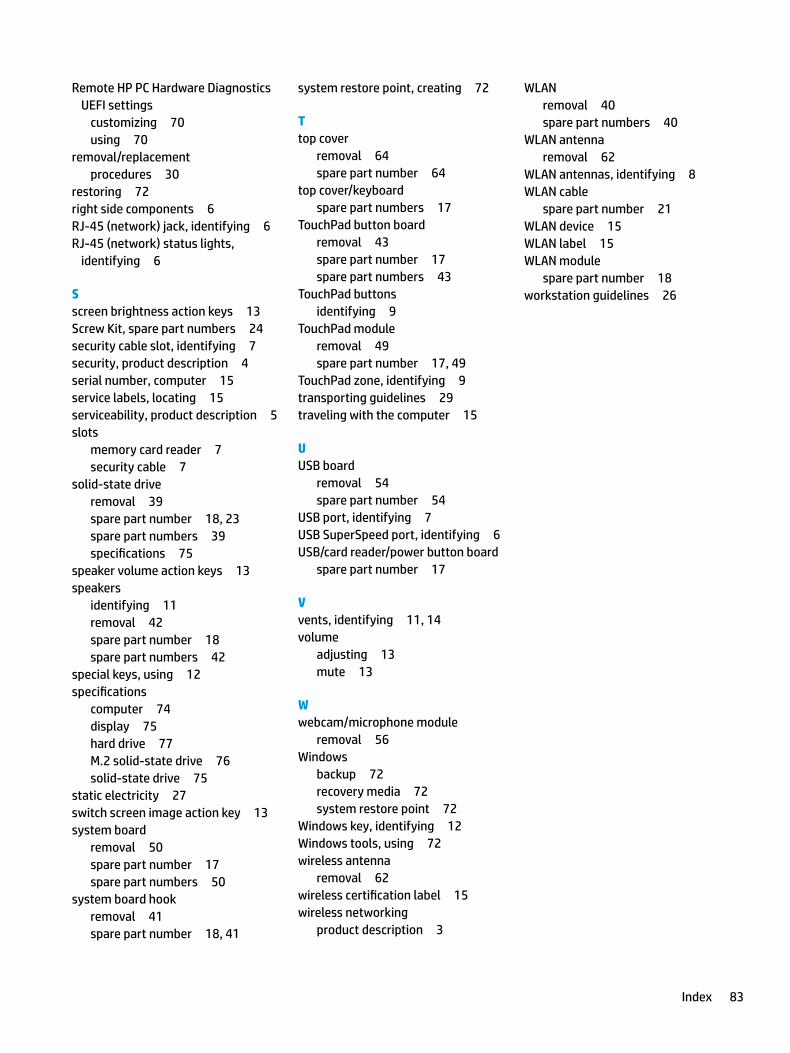
Remote HP PC Hardware Diagnostics UEFI settings
customizing 70using 70
removal/replacementprocedures 30
restoring 72right side components 6RJ-45 (network) jack, identifying 6RJ-45 (network) status lights,
identifying 6
Sscreen brightness action keys 13Screw Kit, spare part numbers 24security cable slot, identifying 7security, product description 4serial number, computer 15service labels, locating 15serviceability, product description 5slots
memory card reader 7security cable 7
solid-state driveremoval 39spare part number 18, 23spare part numbers 39specifications 75
speaker volume action keys 13speakers
identifying 11removal 42spare part number 18spare part numbers 42
special keys, using 12specifications
computer 74display 75hard drive 77M.2 solid-state drive 76solid-state drive 75
static electricity 27switch screen image action key 13system board
removal 50spare part number 17spare part numbers 50
system board hookremoval 41spare part number 18, 41
system restore point, creating 72
Ttop cover
removal 64spare part number 64
top cover/keyboardspare part numbers 17
TouchPad button boardremoval 43spare part number 17spare part numbers 43
TouchPad buttonsidentifying 9
TouchPad moduleremoval 49spare part number 17, 49
TouchPad zone, identifying 9transporting guidelines 29traveling with the computer 15
UUSB board
removal 54spare part number 54
USB port, identifying 7USB SuperSpeed port, identifying 6USB/card reader/power button board
spare part number 17
Vvents, identifying 11, 14volume
adjusting 13mute 13
Wwebcam/microphone module
removal 56Windows
backup 72recovery media 72system restore point 72
Windows key, identifying 12Windows tools, using 72wireless antenna
removal 62wireless certification label 15wireless networking
product description 3
WLANremoval 40spare part numbers 40
WLAN antennaremoval 62
WLAN antennas, identifying 8WLAN cable
spare part number 21WLAN device 15WLAN label 15WLAN module
spare part number 18workstation guidelines 26
Index 83