
Magnitude least squares optimization for parallel radio frequency excitation design demonstrated at...
15
Magnitude Least Squares Optimization for Parallel Radio Frequency Excitation Design Demonstrated at 7 Tesla With Eight Channels K. Setsompop 1 , L.L. Wald 2,3 , V. Alagappan 2 , B.A. Gagoski 1 , and E. Adalsteinsson 1,2,3 1 Department of Electrical Engineering and Computer Science, MIT, Cambridge, Massachusetts. 2 A.A. Martinos Center for Biomedical Imaging, MGH, Harvard Medical School, Charlestown, Massachusetts. 3 Harvard-MIT Health Sciences and Technology, MIT, Cambridge, Massachusetts. Abstract Spatially tailored radio frequency (RF) excitations accelerated with parallel transmit systems provide the opportunity to create shaped volume excitations or mitigate inhomogeneous B 1 excitation profiles with clinically relevant pulse lengths. While such excitations are often designed as a least-squares optimized approximation to a target magnitude and phase profile, adherence to the target phase profile is usually not important as long as the excitation phase is slowly varying compared with the voxel dimension. In this work, we demonstrate a method for a magnitude least squares optimization of the target magnetization profile for multichannel parallel excitation to improve the magnitude profile and reduce the RF power at the cost of a less uniform phase profile. The method enables the designer to trade off the allowed spatial phase variation for the improvement in magnitude profile and reduction in RF power. We validate the method with simulation studies and demonstrate its performance in fourfold accelerated two-dimensional spiral excitations, as well as for uniform in- plane slice selective parallel excitations using an eight-channel transmit array on a 7T human MRI scanner. The experimental results are in good agreement with the simulations, which show significant improvement in the magnitude profile and reductions in the required RF power while still maintaining negligible intravoxel phase variation. Keywords parallel excitation; acceleration; magnitude least squares; RF shimming Parallel excitation offers a means of designing multidimensional radio frequency (RF) pulses using accelerated gradient trajectories resulting in a short pulse duration compared with single- channel excitation. Accelerations of four- to sixfold have been shown using an eight-channel transmit system (1), potentially enabling several important applications, including flexibly shaped excitation volumes, and mitigation of RF field inhomogeneity at high field. Various methods have been proposed for the design of such RF and gradient waveforms (2–5), primarily in the low flip domain (6), and successfully implemented on multichannel hardware (1,7). © 2008 Wiley-Liss, Inc. *Correspondence to: Kawin Setsompop, 77 Massachusetts Avenue, Building 36, Room 766A, Cambridge, MA 02139. E-mail: E-mail: [email protected]. NIH Public Access Author Manuscript Magn Reson Med. Author manuscript; available in PMC 2009 July 27. Published in final edited form as: Magn Reson Med. 2008 April ; 59(4): 908–915. doi:10.1002/mrm.21513. NIH-PA Author Manuscript NIH-PA Author Manuscript NIH-PA Author Manuscript
-
Upload
hms-harvard -
Category
Documents
-
view
0 -
download
0
Transcript of Magnitude least squares optimization for parallel radio frequency excitation design demonstrated at...
Magnitude Least Squares Optimization for Parallel RadioFrequency Excitation Design Demonstrated at 7 Tesla With EightChannels
K. Setsompop1, L.L. Wald2,3, V. Alagappan2, B.A. Gagoski1, and E. Adalsteinsson1,2,31Department of Electrical Engineering and Computer Science, MIT, Cambridge, Massachusetts.2A.A. Martinos Center for Biomedical Imaging, MGH, Harvard Medical School, Charlestown,Massachusetts.3Harvard-MIT Health Sciences and Technology, MIT, Cambridge, Massachusetts.
AbstractSpatially tailored radio frequency (RF) excitations accelerated with parallel transmit systems providethe opportunity to create shaped volume excitations or mitigate inhomogeneous B1 excitation profileswith clinically relevant pulse lengths. While such excitations are often designed as a least-squaresoptimized approximation to a target magnitude and phase profile, adherence to the target phase profileis usually not important as long as the excitation phase is slowly varying compared with the voxeldimension. In this work, we demonstrate a method for a magnitude least squares optimization of thetarget magnetization profile for multichannel parallel excitation to improve the magnitude profileand reduce the RF power at the cost of a less uniform phase profile. The method enables the designerto trade off the allowed spatial phase variation for the improvement in magnitude profile andreduction in RF power. We validate the method with simulation studies and demonstrate itsperformance in fourfold accelerated two-dimensional spiral excitations, as well as for uniform in-plane slice selective parallel excitations using an eight-channel transmit array on a 7T human MRIscanner. The experimental results are in good agreement with the simulations, which show significantimprovement in the magnitude profile and reductions in the required RF power while still maintainingnegligible intravoxel phase variation.
Keywordsparallel excitation; acceleration; magnitude least squares; RF shimming
Parallel excitation offers a means of designing multidimensional radio frequency (RF) pulsesusing accelerated gradient trajectories resulting in a short pulse duration compared with single-channel excitation. Accelerations of four- to sixfold have been shown using an eight-channeltransmit system (1), potentially enabling several important applications, including flexiblyshaped excitation volumes, and mitigation of RF field inhomogeneity at high field. Variousmethods have been proposed for the design of such RF and gradient waveforms (2–5), primarilyin the low flip domain (6), and successfully implemented on multichannel hardware (1,7).
© 2008 Wiley-Liss, Inc.*Correspondence to: Kawin Setsompop, 77 Massachusetts Avenue, Building 36, Room 766A, Cambridge, MA 02139. E-mail: E-mail:[email protected].
NIH Public AccessAuthor ManuscriptMagn Reson Med. Author manuscript; available in PMC 2009 July 27.
Published in final edited form as:Magn Reson Med. 2008 April ; 59(4): 908–915. doi:10.1002/mrm.21513.
NIH
-PA Author Manuscript
NIH
-PA Author Manuscript
NIH
-PA Author Manuscript
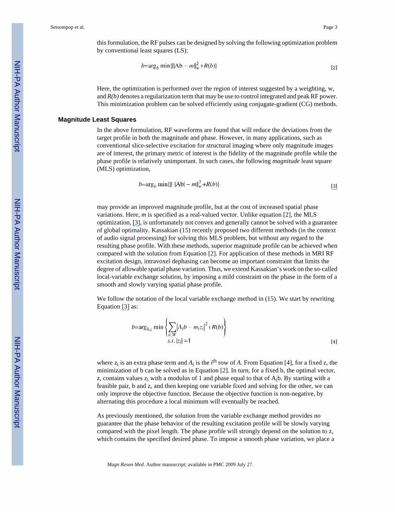
In this work, we propose an extension to the spatial domain parallel excitation pulse designmethod introduced by Grissom et al. (5), where we apply magnitude least squares optimizationto improve excitation magnitude profile and reduce the required RF power at a cost of increasedphase variations in the excitation pattern. However, for many excitation applications, such aswhen magnitude images are recorded, low-order spatial phase variations do not impose asignificant penalty. In fact, they can potentially decrease the dynamic range requirements ofthe imaging (which can be extensive for high field three-dimensional [3D] acquisitions) byreducing the amplitude at the center of k-space. We, therefore, developed a method for pulsecalculation with an adjustable regularization parameter de-emphasizing the excitation phaseprofile and study the potential benefits in magnitude profile fidelity and SAR, which canaccompany this relaxed constraint.
The idea of permitting phase variation in the excitation profile has previously been exploitedin several applications, including the design of quadratic-phase RF pulses (8,9), RF shimming(10–13), and frequency-sweep pulses (14), with benefits such as improved magnitude transitionbands for saturation pulses, homogeneity for RF shimming, and reduced RF peak power forfrequency-sweep pulses. In this work, we propose a method that allows us to take advantageof relaxed constraints on the phase profile for parallel excitation design. Our approach is basedon a variant of a local optimization method used for solving general magnitude least squareproblems (15). We demonstrate the method using a 2D spiral excitation with R = fourfoldacceleration over the Nyquist sampling and a uniform in-plane slice-selective spoke excitation(1,16) on an eight-channel excitation system at 7 Tesla (T).
Recently, at the ISMRM’07 conference, Katscher el al. (17) demonstrated the significantimprovement gained in RF shimming when a magnitude least square approach is used. Kerret al. (18) also proposed an approach for magnitude least square optimization for the design ofparallel RF excitation and demonstrate the method using a spiral trajectory. The approach inthis work differs in that it takes into account intravoxel dephasing and enables the designer tosystematically trade off the allowed spatial phase variation for the improvement in magnitudeprofile and reduction in RF power. Furthermore, the work provides an extensive simulationand experimental study on the possible benefit of the algorithm on both spiral and spoke k-space trajectory excitations at high magnetic field strength.
THEORYParallel Excitation
In this work, we based our parallel excitation formulation on the spatial-domain approach byGrissom et al. (5). Briefly, the small-tip multidimensional excitation approximation with Rcoils is written as
[1]
Here, Sr and B1,r are the spatial sensitivity profiles and the RF waveforms for coils indexed byr, x is the spatial variable, m(x) is the target transverse magnetization after excitation, and k
(t) is the excitation k-space trajectory, defined as ,where γ is thegyromagnetic ratio, and G is the gradient, and T is the duration of the gradient waveform. Afterdiscretization of space and time, this expression can be written as a matrix equation, m = Ab,where the A-matrix incorporates the B1 coil profiles modulated by the Fourier kernel due tothe k-space traversal, m is the target profile in space, and b contains the RF waveforms. With
Setsompop et al. Page 2
Magn Reson Med. Author manuscript; available in PMC 2009 July 27.
NIH
-PA Author Manuscript
NIH
-PA Author Manuscript
NIH
-PA Author Manuscript
this formulation, the RF pulses can be designed by solving the following optimization problemby conventional least squares (LS):
[2]
Here, the optimization is performed over the region of interest suggested by a weighting, w,and R(b) denotes a regularization term that may be use to control integrated and peak RF power.This minimization problem can be solved efficiently using conjugate-gradient (CG) methods.
Magnitude Least SquaresIn the above formulation, RF waveforms are found that will reduce the deviations from thetarget profile in both the magnitude and phase. However, in many applications, such asconventional slice-selective excitation for structural imaging where only magnitude imagesare of interest, the primary metric of interest is the fidelity of the magnitude profile while thephase profile is relatively unimportant. In such cases, the following magnitude least square(MLS) optimization,
[3]
may provide an improved magnitude profile, but at the cost of increased spatial phasevariations. Here, m is specified as a real-valued vector. Unlike equation [2], the MLSoptimization, [3], is unfortunately not convex and generally cannot be solved with a guaranteeof global optimality. Kassakian (15) recently proposed two different methods (in the contextof audio signal processing) for solving this MLS problem, but without any regard to theresulting phase profile. With these methods, superior magnitude profile can be achieved whencompared with the solution from Equation [2]. For application of these methods in MRI RFexcitation design, intravoxel dephasing can become an important constraint that limits thedegree of allowable spatial phase variation. Thus, we extend Kassakian’s work on the so-calledlocal-variable exchange solution, by imposing a mild constraint on the phase in the form of asmooth and slowly varying spatial phase profile.
We follow the notation of the local variable exchange method in (15). We start by rewritingEquation [3] as:
[4]
where zi is an extra phase term and Ai is the ith row of A. From Equation [4], for a fixed z, theminimization of b can be solved as in Equation [2]. In turn, for a fixed b, the optimal vector,z, contains values zi with a modulus of 1 and phase equal to that of Aib. By starting with afeasible pair, b and z, and then keeping one variable fixed and solving for the other, we canonly improve the objective function. Because the objective function is non-negative, byalternating this procedure a local minimum will eventually be reached.
As previously mentioned, the solution from the variable exchange method provides noguarantee that the phase behavior of the resulting excitation profile will be slowly varyingcompared with the pixel length. The phase profile will strongly depend on the solution to z,which contains the specified desired phase. To impose a smooth phase variation, we place a
Setsompop et al. Page 3
Magn Reson Med. Author manuscript; available in PMC 2009 July 27.
NIH
-PA Author Manuscript
NIH
-PA Author Manuscript
NIH
-PA Author Manuscript
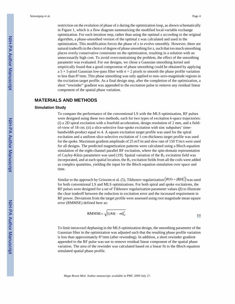
restriction on the evolution of phase of z during the optimization loop, as shown schematicallyin Figure 1, which is a flow diagram summarizing the modified local-variable exchangeoptimization. For each iteration step, rather than using the optimal z according to the originalalgorithm, a phase-smoothed version of the optimal z was calculated and used in theoptimization. This modification forces the phase of z to evolve smoothly. However, there arenatural tradeoffs in the choice of degree of phase smoothing for z, such that too much smoothingplaces overly conservative constraints on the optimization, resulting in a solution with anunnecessarily high cost. To avoid overconstraining the problem, the effect of the smoothingparameter was evaluated. For our designs, we chose a Gaussian smoothing kernel andempirically found that a good compromise of phase smoothing could be obtained by applyinga 5 × 5-pixel Gaussian low-pass filter with σ = 2 pixels to smooth the phase profile variationto less than 8°/mm. This phase smoothing was only applied to non–zero-magnitude regions inthe excitation target profile. As a final design step, after the completion of the optimization, ashort “rewinder” gradient was appended to the excitation pulse to remove any residual linearcomponent of the spatial phase variation.
MATERIALS AND METHODSSimulation Study
To compare the performance of the conventional LS with the MLS optimization, RF pulseswere designed using these two methods, each for two types of excitation k-space trajectories:(i) a 2D spiral excitation with a fourfold acceleration, design resolution of 2 mm, and a field-of-view of 18 cm; (ii) a slice-selective four-spoke excitation with sinc subpulses’ time-bandwidth-product equal to 4. A square excitation target profile was used for the spiralexcitation and a uniform slice-selective excitation of 1-cm-thickness target profile was usedfor the spoke. Maximum gradient amplitude of 25 mT/m and slew rate of 150 T/m/s were usedfor all designs. The predicted magnetization patterns were calculated using a Bloch equationsimulation of the eight-channel parallel RF excitation, where the spin-domain representationof Cayley-Klein parameters was used (19). Spatial variation of the B1 excitation field wasincorporated, and at each spatial location, the B1 excitation fields from all the coils were addedas complex quantities, yielding the input for the Bloch equation simulation over space andtime.
Similar to the approach by Grissom et al. (5), Tikhonov regularization was usedfor both conventional LS and MLS optimizations. For both spiral and spoke excitations, theRF pulses were designed for a set of Tikhonov regularization parameter values (β) to illustratethe clear tradeoff between the reduction in excitation error and the increased requirement inRF power. Deviations from the target profile were assessed using root magnitude mean squareerror (RMMSE) defined here as:
[5]
To limit intravoxel dephasing in the MLS optimization design, the smoothing parameter of theGaussian filter in the optimization was adjusted such that the resulting phase profile variationis less than approximately 8°/mm (after rewinding). In addition, a short rewinder gradientappended to the RF pulse was use to remove residual linear component of the spatial phasevariation. The area of the rewinder was calculated based on a linear fit to the Bloch equationsimulated spatial phase profile.
Setsompop et al. Page 4
Magn Reson Med. Author manuscript; available in PMC 2009 July 27.
NIH
-PA Author Manuscript
NIH
-PA Author Manuscript
NIH
-PA Author Manuscript
System HardwareFor experimental verification of the method, the RF pulses were tested on a Siemens prototype7T Magnetom scanner (Erlangen, Germany), equipped with an eight-channel transmit system,with maximum gradient amplitude of 40 mT/m and slew rate of 200 T/m/s. An eight-channelstrip-line coil array was used for transmit and receive (20). The RF array was built around a28-cm diameter acrylic tube (Fig. 2a) and was driven through a transmit-receive switch at eachof the eight rungs. The signal was received on eight receive channels from the same coils. Allmeasurements were performed in a 17-cm diameter doped water phantom, containing 1.25 g/L of nickel sulfate and 5 g/L of sodium chloride. A cylindrical loading ring (filled with dopedwater containing manganese chloride to reduce its T1 to less than 3 ms), was used to reducethe amount of B1 inhomogeneity observed in the spherical water phantom to a similar levelobserved in human in vivo imaging. The bottom right of Figure 2a shows the transmit-received(TXRX) birdcage image for in vivo and for the water phantom with loading ring. The peak-to-trough signal ratio is ~9 and ~8.5 for in vivo and water phantom respectively. Without theloading ring, the water phantom’s peak-to-trough signal ratio would have been ~13 which ismuch higher than that observed in vivo with this particular setup.
B1 MappingExcitation B1 profiles for the eight transmit coils were obtained by applying a slice-selective,low-flip-angle RF pulse to a single transmission channel at a time, and receiving through thebirdcage reception mode of the array. In this reception mode, the complex data from theindividual receive channels were phased with an incremental phase of 45 degrees and summed,to mimic reception with the traditional birdcage coil. The B1 profiles were estimated byrecording the amplitude and phase of a low flip angle 2D gradient-recalled echo sequence with128 × 128 pixels in x,y at 2 × 2 mm resolution, (TR/TE/BW = 100 ms, 5 ms, 260 pixel), andthe transmit map was inferred by a division of the estimated reception profile (Fig. 2b).
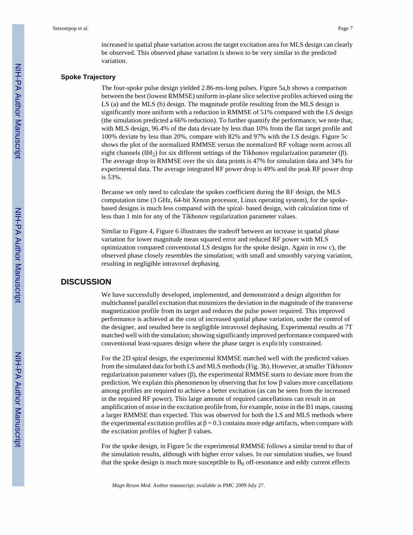
At low B0 field, an estimation of the birdcage reception profile can be obtained by taking thesquare-root of the image intensity pattern created when the birdcage mode was used for bothreception and transmission. However, because the transmit and receive patterns of a given coiluse opposite circular polarizations that can have different profiles at high B0 field (21), the useof a quantitative coil profile mapping technique was required to estimate the birdcage receptionprofile. The technique used in this work, relies on transmitting and receiving with the birdcagemode at several transmission voltages, and fitting the resulting images to the appropriate imageintensity equation (which can be derived from, e.g., Haake et al. (22), p. 454–455, noting thatthe TE decay is identical across all B1 excitation field mapping acquisitions and is ignoredhere):
[6]
Where I is the image intensity, RX is the receive coil profile, TR is the sequence repetition time,T1 is the longitudinal relaxation time constant, and θ is the flip angle. A standard nonlinearsearch algorithm in Matlab was used to perform the fitting. From the fitting, the birdcagetransmission profile (TX) can be approximated by θ̃(x,y) and the reception profile (RX) by RX(x,y). The resulting profiles are shown in Figure 2a.
Parallel ExcitationFor each of the parallel excitation designs, the eight-channel array was driven with eightindependent transmit channels modulated in magnitude and phase by the calculatedwaveforms, and the data were received using the birdcage mode of the coil array. The excitation
Setsompop et al. Page 5
Magn Reson Med. Author manuscript; available in PMC 2009 July 27.
NIH
-PA Author Manuscript
NIH
-PA Author Manuscript
NIH
-PA Author Manuscript
pattern was imaged with a 3D gradient-recalled echo sequence with matrix = 128 × 128 × 32,field of view = 256 mm × 256 mm × 160 mm, voxel resolution = 2 mm × 2 mm × 5mm, TR/TE/BW = 100 ms, 6 ms, 260 pixel. The excitation profile was inferred by dividing thereconstructed image by the estimated birdcage receive profile. The RF excitation pulses wereadjusted so that all the experimental results are of the same target flip angle.
Low-Flip-Angle ValidationIn the report by Grissom et al. (5), it was shown that, with low Tikhonov regularizationparameter value (β), that is, high RF power requirement, the excitation profile can be heavilydegraded from the low flip angle approximation even at relatively low flip angle. For the currentwork, the applied excitation voltages were established to be well within the low-flip-angleregimen, although without a full quantitative B1 map to determine the exact excitation flipangle. For example, in the spiral-based pulse design, we made our calibration by exciting thedesign that required the highest power (the LS design with β = 0.3) with a sequence of increasingvoltages and quantified the resulting profiles. For very low excitation voltages, the signal-to-noise ratio (SNR) is low, and at high excitation voltage, the low-flip-angle approximation fails.We chose the voltages for our experiments to be such that our data are acquired with ampleSNR, but at the same time are low enough to not violate the low-flip-angle approximation. Inour current setup, we found that this favorable operating range for the voltage extended from30V to 100V for this design (β = 0.3).
To make a comparison between simulation and experimental results, the RMMSE for thesimulation data is calculated assuming a target transverse magnetization value of mxy = 0.1.For the experimental results, the intensity is scaled so that the mean signal in the targetexcitation ROI matches that of the simulation, after which the RMMSE is then calculated.
RESULTSSpiral Trajectory
The fourfold accelerated (4×) spiral excitation design yielded 3.51-ms-long pulse, with anadditional 70 µs for the rewinder gradient in the MLS cases. Figure 3a) shows a comparisonbetween the LS and MLS design for Tikhonov regularization parameter value of 1.5. Visually,the MLS magnitude profile shows improved target excitation and background noisesuppression in areas outside the target square. For this particular β, the MLS optimization yieldsan improvement of 15.62% in RMMSE and 26% and 41% in integrated and peak RF powerover the LS method. Figure 3b shows the plot of the normalized RMMSE versus the normalizedRF voltage norm across all eight channels (‖b‖2) for four different settings of the Tikhonovregularization parameter (β). The dotted red and blue curves represent the simulation resultsfor conventional LS and MLS, respectively. Similarly, the solid red and blue curves show theexperimental tradeoff between mean square error and pulse energy at the differentregularization parameters. The average drop in RMMSE over the four data points is 12% forsimulation data and 10% for experimental data. The average integrated RF power drop is 5.7%,and the peak RF power drop is 9.3%.
We note that the MLS computation time (3 GHz, 64-bit Xenon processor, Linux operatingsystem), for the spiral-based designs ranged from 5–8 min for higher Tikhonov regularizationparameter values, up to approximately 35 min for lower value (β = 0.3). Figure 4 illustratesthe tradeoff between an increase in spatial phase variation for lower magnitude mean squarederror and reduced RF power with MLS optimization compared conventional LS designs. Themagnitude (left) and phase (right) profiles of the square target excitation with β = 1.5, for LSand MLS optimization are shown in row a and b, respectively. Similar to Figure 3a, themagnitude profile of the MLS design is visually better than the LS design. In Figure 4c, the
Setsompop et al. Page 6
Magn Reson Med. Author manuscript; available in PMC 2009 July 27.
NIH
-PA Author Manuscript
NIH
-PA Author Manuscript
NIH
-PA Author Manuscript
increased in spatial phase variation across the target excitation area for MLS design can clearlybe observed. This observed phase variation is shown to be very similar to the predictedvariation.
Spoke TrajectoryThe four-spoke pulse design yielded 2.86-ms-long pulses. Figure 5a,b shows a comparisonbetween the best (lowest RMMSE) uniform in-plane slice selective profiles achieved using theLS (a) and the MLS (b) design. The magnitude profile resulting from the MLS design issignificantly more uniform with a reduction in RMMSE of 51% compared with the LS design(the simulation predicted a 66% reduction). To further quantify the performance, we note that,with MLS design, 96.4% of the data deviate by less than 10% from the flat target profile and100% deviate by less than 20%, compare with 82% and 97% with the LS design. Figure 5cshows the plot of the normalized RMMSE versus the normalized RF voltage norm across alleight channels (‖b‖2) for six different settings of the Tikhonov regularization parameter (β).The average drop in RMMSE over the six data points is 47% for simulation data and 34% forexperimental data. The average integrated RF power drop is 49% and the peak RF power dropis 53%.
Because we only need to calculate the spokes coefficient during the RF design, the MLScomputation time (3 GHz, 64-bit Xenon processor, Linux operating system), for the spoke-based designs is much less compared with the spiral- based design, with calculation time ofless than 1 min for any of the Tikhonov regularization parameter values.
Similar to Figure 4, Figure 6 illustrates the tradeoff between an increase in spatial phasevariation for lower magnitude mean squared error and reduced RF power with MLSoptimization compared conventional LS designs for the spoke design. Again in row c), theobserved phase closely resembles the simulation; with small and smoothly varying variation,resulting in negligible intravoxel dephasing.
DISCUSSIONWe have successfully developed, implemented, and demonstrated a design algorithm formultichannel parallel excitation that minimizes the deviation in the magnitude of the transversemagnetization profile from its target and reduces the pulse power required. This improvedperformance is achieved at the cost of increased spatial phase variation, under the control ofthe designer, and resulted here in negligible intravoxel dephasing. Experimental results at 7Tmatched well with the simulation; showing significantly improved performance compared withconventional least-squares design where the phase target is explicitly constrained.
For the 2D spiral design, the experimental RMMSE matched well with the predicted valuesfrom the simulated data for both LS and MLS methods (Fig. 3b). However, at smaller Tikhonovregularization parameter values (β), the experimental RMMSE starts to deviate more from theprediction. We explain this phenomenon by observing that for low β values more cancellationsamong profiles are required to achieve a better excitation (as can be seen from the increasedin the required RF power). This large amount of required cancellations can result in anamplification of noise in the excitation profile from, for example, noise in the B1 maps, causinga larger RMMSE than expected. This was observed for both the LS and MLS methods wherethe experimental excitation profiles at β = 0.3 contains more edge artifacts, when compare withthe excitation profiles of higher β values.
For the spoke design, in Figure 5c the experimental RMMSE follows a similar trend to that ofthe simulation results, although with higher error values. In our simulation studies, we foundthat the spoke design is much more susceptible to B0 off-resonance and eddy current effects
Setsompop et al. Page 7
Magn Reson Med. Author manuscript; available in PMC 2009 July 27.
NIH
-PA Author Manuscript
NIH
-PA Author Manuscript
NIH
-PA Author Manuscript
when compared with the spiral design. This vulnerability is likely to be part of the cause forthe increased error. Our future work includes the exact quantification of the source of this errorand possibly the design for a correction method.
Also in Figure 5c, an increase in error at lower Tikhonov regularization parameter value (β)can be observed in the LS experimental result. In the simulation result over the same β valuesrange, a very small reduction in error for a much higher required RF power can be observed.This finding suggests that, at lower β values, a significantly larger amount of profilecancellation is required during the excitation. In the experiment, this causes large noiseamplification, which resulted in the increased error.
In comparing the spiral and the spoke excitations, the improvement gained from using the MLSdesign in the spoke case is much more prominent. This is to be expected, because the spokestrajectory, which is just a few delta points in kx-ky, allows for much less control of the in-planeexcitation profile when compared with the spiral trajectory. Therefore, the gain from relaxingthe in-plane excitation phase constrain for the spoke design should be much larger.
This work is a novel study of the possible benefits from relaxing the phase constraint in parallelexcitation design. To relax the phase constraint, the design problem was mapped to an MLSoptimization. Because of the nonconvex nature of this optimization, currently no method solvesthe problem with a guaranteed global optimality of the solution. We chose to extend the localvariable exchange method (15) to solve the problem, because it allows us to impose thesmoothly varying phase constraint. Other methods exist for solving MLS problems, includingthe relaxed semidefinite programming method (15). Future work includes an exploration ofalternate means to solve the posed MLS problem for parallel RF excitation.
This work demonstrated the benefit of MLS optimization in parallel excitation. A waterphantom with large B1 profile variation, similar to that observed in human imaging at highfield, was used in our experimental set up. Given the significant benefit achieved with the MLSoptimization, particularly for the mitigation of the inhomogeneous B1 profile through the useof the spoke trajectory excitation, we expect the MLS optimization to play an important rolein parallel excitation design for human imaging at high field.
AcknowledgmentsGrant sponsor: Siemens Medical Solutions; Grant sponsor: National Institutes of Health NCRR; Grant number:P41RR14075; Grant number: R01EB006847; Grant sponsor: R.J. Shillman Career Development Award; Grantsponsor: the MIND Institute.
REFERENCES1. Setsompop K, Wald LL, Alagappan V, Gagoski B, Hebrank F, Fontius U, Schmitt F, Adalsteinsson
E. Parallel RF transmission with eight channels at 3 Tesla. Magn Reson Med 2006;56:1163–1171.[PubMed: 17036289]
2. Katscher U, Bornert P, Leussler C, van den Brink JS. Transmit SENSE. Magn Reson Med2003;49:144–150. [PubMed: 12509830]
3. Zhu Y. Parallel excitation with an array of transmit coils. Magn Reson Med 2004;51:775–784.[PubMed: 15065251]
4. Griswold, M.; Kannengiesser, S.; Muller, M.; Jakob, P. Autocalibrated accelerated parallel excitation(transmit-GRAPPA). Proceedings of the 13th Annual Meeting of ISMRM; Miami Beach, Florida,USA. 2005. p. 2435
5. Grissom W, Yip CY, Zhang Z, Stenger VA, Fessler JA, Noll DC. Spatial domain method for the designof RF pulses in multicoil parallel excitation. Magn Reson Med 2006;56:620–629. [PubMed:16894579]
Setsompop et al. Page 8
Magn Reson Med. Author manuscript; available in PMC 2009 July 27.
NIH
-PA Author Manuscript
NIH
-PA Author Manuscript
NIH
-PA Author Manuscript
6. Pauly J, Nishimura D, Macovski A. A k-space analysis of small-tip angle excitation. J Magn Reson1989;81:43–56.
7. Ullmann P, Junge S, Wick M, Seifert F, Ruhm W, Hennig J. Experimental analysis of parallel excitationusing dedicated coil setups and simultaneous RF transmission on multiple channels. Magn Reson Med2005;54:994–1001. [PubMed: 16155886]
8. Le Roux P, Gilles RJ, McKinnon GC, Carlier PG. Optimized outer volume suppression for single-shotfast spin-echo cardiac imaging. J Magn Reson Imaging 1998;8:1022–1032. [PubMed: 9786138]
9. Schricker AA, Pauly JM, Kurhanewicz J, Swanson MG, Vigneron DB. Dualband spectral-spatial RFpulses for prostate MR spectroscopic imaging. Magn Reson Med 2001;46:1079–1087. [PubMed:11746572]
10. Mao W, Smith MB, Collins CM. Exploring the limits of RF shimming for high-field MRI of thehuman head. Magn Reson Med 2006;56:918–922. [PubMed: 16958070]
11. Collins CM, Liu W, Swift BJ, Smith MB. Combination of optimized transmit arrays and some receivearray reconstruction methods can yield homogeneous images at very high frequencies. Magn ResonMed 2005;54:1327–1332. [PubMed: 16270331]
12. Vaughan T, DelaBarre L, Snyder C, Tian J, Akgun C, Shrivastava D, Liu W, Olson C, Adriany G,Strupp J, Andersen P, Gopinath A, van de Moortele PF, Garwood M, Ugurbil K. 9.4T human MRI:preliminary results. Magn Reson Med 2006;56:1274–1282. [PubMed: 17075852]
13. Ibrahim TS, Lee R, Baertlein BA, Abduljalil AM, Zhu H, Robitaille PM. Effect of RF coil excitationon field inhomogeneity at ultra high fields: a field optimized TEM resonator. Magn Reson Imaging2001;19:1339–1347. [PubMed: 11804762]
14. Park JY, DelaBarre L, Garwood M. Improved gradient-echo 3D magnetic resonance imaging usingpseudo-echoes created by frequency-swept pulses. Magn Reson Med 2006;55:848–857. [PubMed:16506188]
15. Kassakian PW. Convex approximation and optimization with applications in magnitude filter designand radiation pattern synthesis: University of California at Berkeley. 2006
16. Saekho S, Yip CY, Noll DC, Boada FE, Stenger VA. Fast-kz three-dimensional tailoredradiofrequency pulse for reduced B1 inhomogeneity. Magn Reson Med 2006;55:719–724. [PubMed:16526012]
17. Katscher, U.; Vernickel, P.; Graesslin, I.; Boernert, P. RF shimming using a mult-element transmitsystem in phantom and in vivo studies. Proceedings of the 15th Annual Meeting of ISMRM; Berlin,Germany. 2007. p. 1693
18. Kerr, AB.; Zhu, Y.; Pauly, JM. Phase constraint relaxation in parallel excitation pulse design.Proceedings of the 15th Annual Meeting of ISMRM; Berlin, Germany. 2007. p. 1694
19. Pauly J, Le Roux P, Nishimura D, Macovski A. Parameter relations for the Shinnar-Le Roux selectiveexcitation pulse design algorithm. IEEE Trans Med Imaging 1991;10:53–65. [PubMed: 18222800]
20. Alagappan, V.; Adalsteinsson, E.; Setsompop, K.; Fontius, U.; Zelinski, AC.; Wiggins, GC.; Hebrank,F.; Schmitt, F.; Wald, LL. Comparison of three transmit arrays for parallel transmit. Proceedings ofthe 15th Annual Meeting of ISMRM; Berlin, Germany. 2007. p. 35
21. Tropp J. Reciprocity and gyrotropism in magnetic resonance transduction. Phys Rev A2006;74:062103.
22. Haacke, EM.; Brown, RW.; Thompson, MR.; Venkatesan, R. Magnetic resonance imaging: physicalprinciples and sequence design. New York: Wiley-Liss; 1999.
Setsompop et al. Page 9
Magn Reson Med. Author manuscript; available in PMC 2009 July 27.
NIH
-PA Author Manuscript
NIH
-PA Author Manuscript
NIH
-PA Author Manuscript
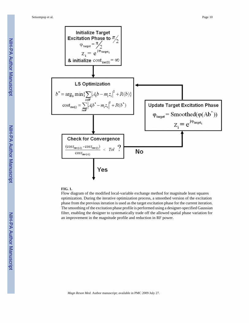
FIG. 1.Flow diagram of the modified local-variable exchange method for magnitude least squaresoptimization. During the iterative optimization process, a smoothed version of the excitationphase from the previous iteration is used as the target excitation phase for the current iteration.The smoothing of the excitation phase profile is performed using a designer-specified Gaussianfilter, enabling the designer to systematically trade off the allowed spatial phase variation foran improvement in the magnitude profile and reduction in RF power.
Setsompop et al. Page 10
Magn Reson Med. Author manuscript; available in PMC 2009 July 27.
NIH
-PA Author Manuscript
NIH
-PA Author Manuscript
NIH
-PA Author Manuscript
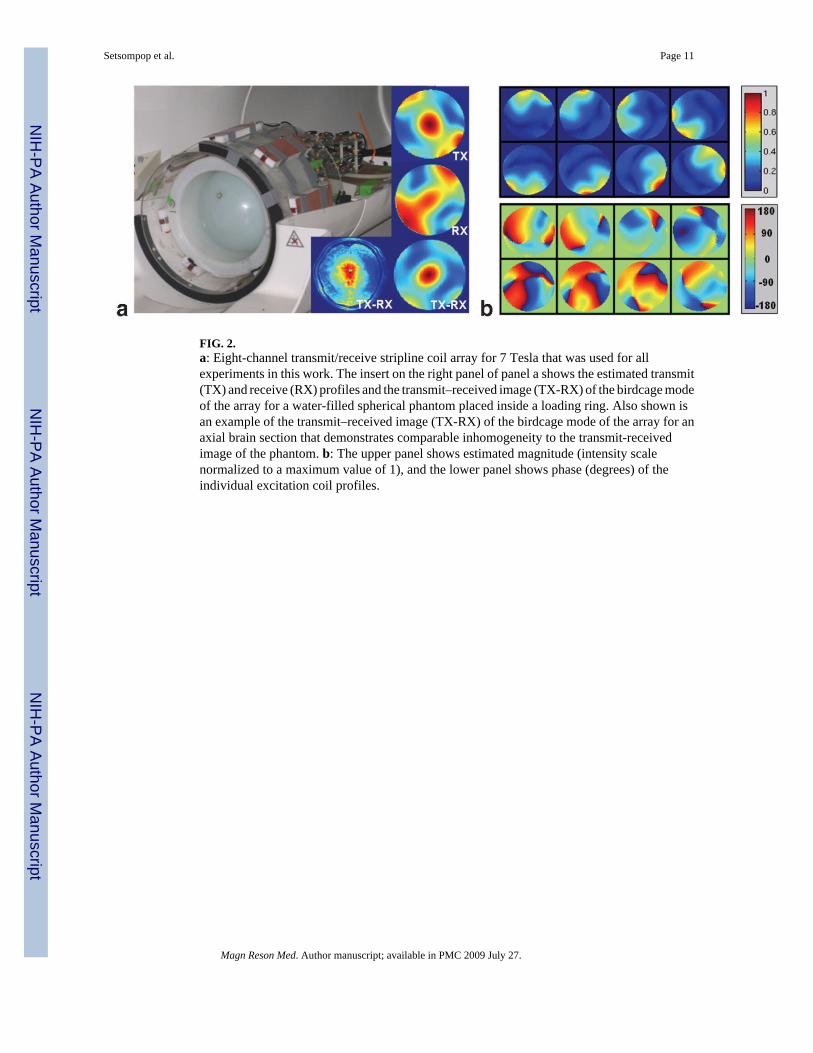
FIG. 2.a: Eight-channel transmit/receive stripline coil array for 7 Tesla that was used for allexperiments in this work. The insert on the right panel of panel a shows the estimated transmit(TX) and receive (RX) profiles and the transmit–received image (TX-RX) of the birdcage modeof the array for a water-filled spherical phantom placed inside a loading ring. Also shown isan example of the transmit–received image (TX-RX) of the birdcage mode of the array for anaxial brain section that demonstrates comparable inhomogeneity to the transmit-receivedimage of the phantom. b: The upper panel shows estimated magnitude (intensity scalenormalized to a maximum value of 1), and the lower panel shows phase (degrees) of theindividual excitation coil profiles.
Setsompop et al. Page 11
Magn Reson Med. Author manuscript; available in PMC 2009 July 27.
NIH
-PA Author Manuscript
NIH
-PA Author Manuscript
NIH
-PA Author Manuscript
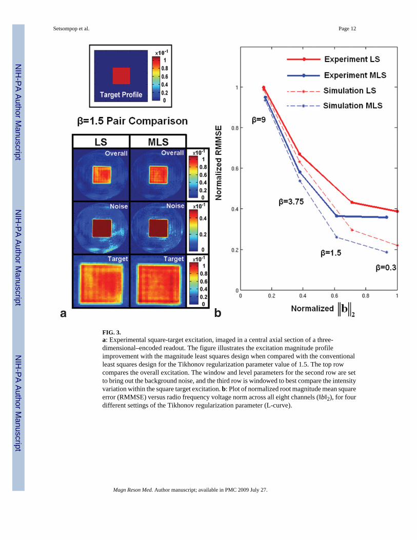
FIG. 3.a: Experimental square-target excitation, imaged in a central axial section of a three-dimensional–encoded readout. The figure illustrates the excitation magnitude profileimprovement with the magnitude least squares design when compared with the conventionalleast squares design for the Tikhonov regularization parameter value of 1.5. The top rowcompares the overall excitation. The window and level parameters for the second row are setto bring out the background noise, and the third row is windowed to best compare the intensityvariation within the square target excitation. b: Plot of normalized root magnitude mean squareerror (RMMSE) versus radio frequency voltage norm across all eight channels (‖b‖2), for fourdifferent settings of the Tikhonov regularization parameter (L-curve).
Setsompop et al. Page 12
Magn Reson Med. Author manuscript; available in PMC 2009 July 27.
NIH
-PA Author Manuscript
NIH
-PA Author Manuscript
NIH
-PA Author Manuscript
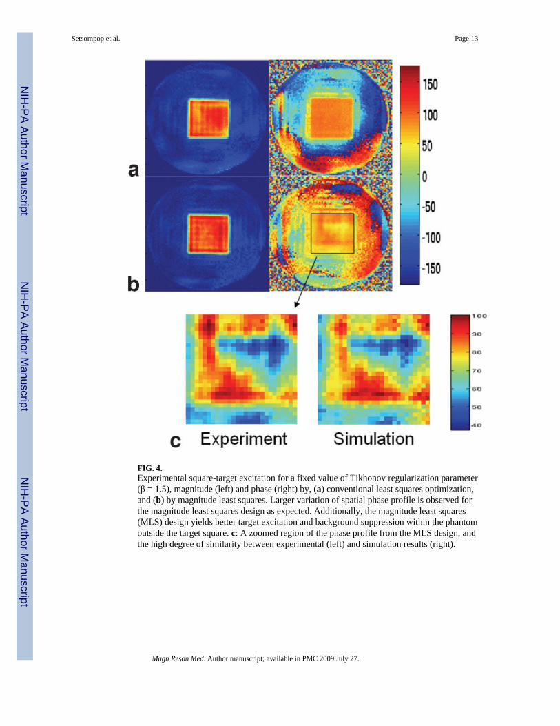
FIG. 4.Experimental square-target excitation for a fixed value of Tikhonov regularization parameter(β = 1.5), magnitude (left) and phase (right) by, (a) conventional least squares optimization,and (b) by magnitude least squares. Larger variation of spatial phase profile is observed forthe magnitude least squares design as expected. Additionally, the magnitude least squares(MLS) design yields better target excitation and background suppression within the phantomoutside the target square. c: A zoomed region of the phase profile from the MLS design, andthe high degree of similarity between experimental (left) and simulation results (right).
Setsompop et al. Page 13
Magn Reson Med. Author manuscript; available in PMC 2009 July 27.
NIH
-PA Author Manuscript
NIH
-PA Author Manuscript
NIH
-PA Author Manuscript
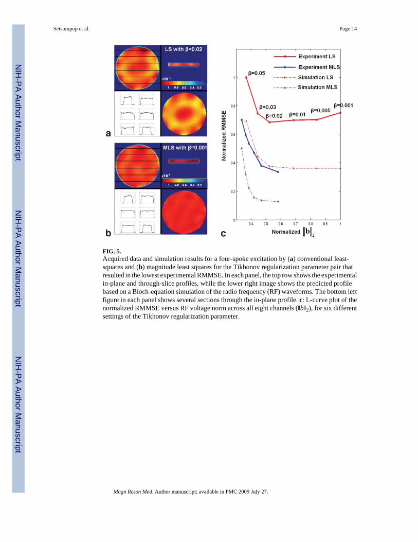
FIG. 5.Acquired data and simulation results for a four-spoke excitation by (a) conventional least-squares and (b) magnitude least squares for the Tikhonov regularization parameter pair thatresulted in the lowest experimental RMMSE. In each panel, the top row shows the experimentalin-plane and through-slice profiles, while the lower right image shows the predicted profilebased on a Bloch-equation simulation of the radio frequency (RF) waveforms. The bottom leftfigure in each panel shows several sections through the in-plane profile. c: L-curve plot of thenormalized RMMSE versus RF voltage norm across all eight channels (‖b‖2), for six differentsettings of the Tikhonov regularization parameter.
Setsompop et al. Page 14
Magn Reson Med. Author manuscript; available in PMC 2009 July 27.
NIH
-PA Author Manuscript
NIH
-PA Author Manuscript
NIH
-PA Author Manuscript
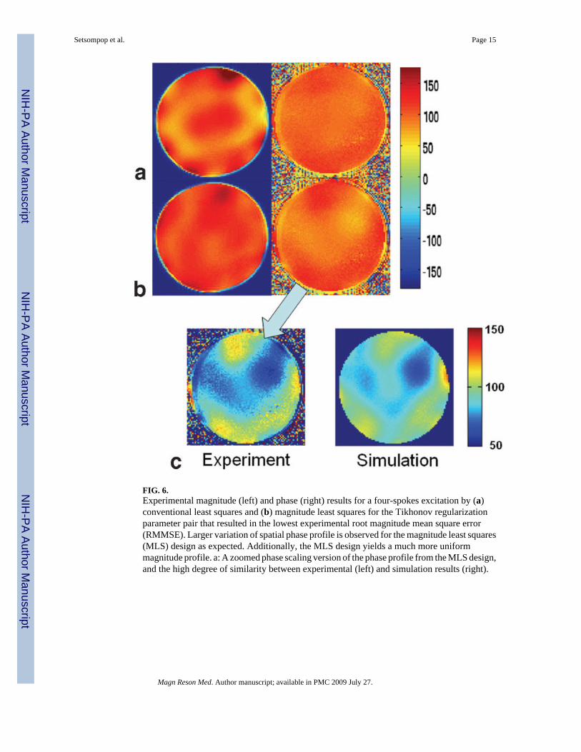
FIG. 6.Experimental magnitude (left) and phase (right) results for a four-spokes excitation by (a)conventional least squares and (b) magnitude least squares for the Tikhonov regularizationparameter pair that resulted in the lowest experimental root magnitude mean square error(RMMSE). Larger variation of spatial phase profile is observed for the magnitude least squares(MLS) design as expected. Additionally, the MLS design yields a much more uniformmagnitude profile. a: A zoomed phase scaling version of the phase profile from the MLS design,and the high degree of similarity between experimental (left) and simulation results (right).
Setsompop et al. Page 15
Magn Reson Med. Author manuscript; available in PMC 2009 July 27.
NIH
-PA Author Manuscript
NIH
-PA Author Manuscript
NIH
-PA Author Manuscript