
Made in the USA Since 1878 Product Catalog
489
Made in the USA Since 1878 Steam Traps Condensate Pumps Pressure Regulators Temperature Regulators Control Valves Relief Valves Liquid Drainers Check Valves Product Catalog Manufacturing High-Quality Steam & Fluid Specialty Products for Industry
-
Upload
khangminh22 -
Category
Documents
-
view
7 -
download
0
Transcript of Made in the USA Since 1878 Product Catalog

Made in the USA Since 1878
Steam TrapsCondensate Pumps
Pressure RegulatorsTemperature Regulators
Control ValvesRelief Valves
Liquid DrainersCheck Valves
Product Catalog
Manufacturing High-Quality Steam & Fluid Specialty Products for Industry

428 Jones Boulevard Limerick Airport Business CenterPottstown PA • 19464Tel. 610.495.5131 Fax. 610.495.5134
www.watsonmcdaniel.com
For over 135 years, Watson McDaniel has been manufacturing a wide range of steamspecialty and fluid products for the industrial marketplace. These time-tested products havemade the operation of steam, compressed air, heat transfer and fluid systems substantiallymore effective and efficient.
In 1995, Watson McDaniel received its ISO 9001 Quality Certification as industryrecognition of our continued commitment to world class manufacturing, assembly and qualitycontrol procedures. This level of quality certification assures our customers unequaleddependability of our products. Our manufacturing facilities, with over fifty computer numericalcontrolled (CNC) machining centers, is considered the most modern in the industry.
Watson McDaniel serves the global marketplace with a network of Manufacturers,Representatives, Distributors, Manufacturing Plants and Sales Offices located throughout theworld. In 1997, a Manufacturing Plant and Sales Office was opened in Shanghai, China tofulfill the growing demands of steam specialty products in the Far East. The success of thisoperation has allowed us to quickly deliver products with competitive prices to our customersthroughout this region.
The structure of our operation affords us the ability to give highly personalized attention toeach and every customer. We continually strive to provide ultimate customer service andproduct reliability while responding immediately to our customers' requests and detailedneeds. Watson McDaniel welcomes the opportunity to work with your company so that wemay help to make all of your steam system and fluid applications the best that they can be.
Manufacturing High-Quality Steam & Fluid Specialty Products for Industry
Made in the USA Since 1878
Steam TrapsCondensate PumpsPressure RegulatorsTemperature RegulatorsControl ValvesRelief ValvesLiquid DrainersCheck Valves


Pipeline Accessories• Check Valves • Safety Relief Valves • Strainers • Mixing Tees • Flash Tanks • Air Eliminators • Air Vents • Separators • Vacuum Breakers • Steam Trap Test Valves
Instantaneous Hot Water Heater (Heat Miser) 365-368Steam Humidifiers 369-373
Parts & Kits 374-403
Tabl
e of
Con
tent
sSteam Traps• Thermodynamic • Thermostatic • Float & Thermostatic • Inverted Bucket • Universal Style Steam Traps (Universal Connectors & Modules)• Clean Steam • Bi-Metallic • Manifolds
STEAM
TRA
PS
CO
ND
ENSA
TEPU
MPS
PILOT-O
PERATEDREG
ULATING
VALVESCO
NTR
OL
VA
LVES
LIQU
IDD
RA
INER
S
Condensate Return Pumps & Systems• Non-Electric Condensate Return Pumps – PMP Series• Standard & Customized Skid Mounted Systems • Receiver Tanks • Pump-Trap Combinations • Accessories & Options • Insulation Jackets• Gauge Glass • Cycle Counters • Electric Condensate Pumps
Pilot-Operated Regulating Valves• Back Pressure • Temperature • Pressure & Temperature• Solenoid On/Off • Differential Pressure • Air-Operated • Pneumatic Temperature Controller • Noise Attenuators
Liquid Drainers• Float Type • Inverted Bucket • Thermodynamic
• Guided Float Type • Installation Guidelines
Engineering Data• Formulas, Conversions & Guidelines • Steam Properties & Flow Characteristics• Fluid Flow in Piping • Pipe Fitting & Flange Specifications • Steam Trap Applications • Regulating Valve Applications• Pressure Motive Pump (PMP) Applications • Heat Exchanger Formulas
Pages 6-128
Pages 129-197
Pages 198-241
Pressure & Temperature Regulators• Pressure Regulating • Temperature Regulating• Back Pressure & Relief Valves • Piston-Actuated
Control Valves• Pneumatic Control Valves • Electropneumatic (I/P) Transducer• Electronic PID Controllers • Air Filter/Regulator • RTD & Thermocouple Temperature Sensors • Thermowells
PIP
ELINE
ACCESSO
RIES
ENG
INEER
ING
Pressure &
Temp
REG
ULA
TORS
Page 242-285
Pages 286-307
Pages 308-326
Pages 327-364
Pages 404-475
Product Cross Reference 476-483
1To download any portion of this catalog go to: www.watsonmcdaniel.com
Pilot-Operated
REG
ULA
TORS

2
Thermodynamic TD600 38
TD600S 40
TD700S 42
TD900S 44
TD3600 46
Thermostatic WT1000 51
WT2000 52
WT3000 54
WT4000 56
WT5000 Adjustable Bi-Metallic 58
TA25B & TA125, TS25B & TS125 60
WT2500 62
Float & Thermostatic WFT 66
FTT 70
FTE & FTES 74
FT600 & FT601 76
FT 82
Inverted Bucket SIB & SIBH 86
IB1031/1041 88 IB1032 /1042 88
IB1033 88IB1034/1044 88
Universal Connectors & Quick-Change Universal System 94-110Trap Modules UC450 Series Universal Connectors 96-98
450 Series Universal Trap Modules 100-110
Clean Steam Traps FDA300 113FDA400 114FDA500 116FDA600 118FDA800 119
Bi-Metallic WPN 120
Manifolds FM & FSM 126
STEAM TRAPS 6-128Steam System Introduction 8-21
Steam TrapsTable of Contents
Product Catalog
www.watsonmcdaniel.com •• Pottstown PA • USA • Tel: 610-495-5131

Inverted Bucket
3
Pressure Motive Pumps PMPC 138PMPF 139PMPSS 140PMPLS 141PMPNT 142PMPBP 143
Sump Drainer PMPSP 144
Skid-Mounted Systems PMPC • PMPF 146
Pump-Trap Combinations PMPT & WPT 153-165
Accessories for PMPs 166-168
Electric Condensate Pumps W4100, W4200, W4300 170-197
HD Regulator (Main Valve) 208Ductile Iron Body
Pilots for HD Regulators 210-230
HSP Pressure Regulator 231-235Cast Steel Body
Noise Attenuators for HD 236-239Capacity Charts: HD & HSP 240
Pressure Regulators O Series 246-249B Series 250-251455 Series 252-253403 Series 254-257
Relief & Back Pressure Regulators R & 10691 Series 258-2603040 Series 261-263
PILOT-OPERATED REGULATING VALVES 198-241Introduction 200-207
DIRECT-OPERATED PRESSURE REGULATING VALVES 242-263
CONDENSATE RETURN PUMPS 129-197Introduction 129-137
(Simplex, Duplex, Triplex)
Table of ContentsProduct Catalog
Tel: 610-495-5131 • Pottstown PA • USA •• www.watsonmcdaniel.com

4
Heating, Cooling, 3-Way W91 & W94 272-285
2-Way Valves HB Series 2883-Way Valves W910TB 292Accessories for Control Valves 298-307
Electronic PID Controllers 302TA901 I/P Transducer 304TA987 Air Filter & Regulator 305Electronic Temperature Sensors 306Thermowells for Temp Sensors 307
Float Type WLD1900 313WLD1400 316WLDE & WLDES 318WLD600 & WLD601 320
Guided-Float Type WLD1800 & WLD1800R 322Inverted Bucket Type WLD1500 324
Disc Type WLD1703S 326
TEMPERATURE REGULATING VALVES 265-285Introduction 266-271
CONTROL VALVES 286-307
LIQUID DRAINERS 308-326Introduction 308-312
Steam TrapsTable of Contents
Product Catalog
www.watsonmcdaniel.com •• Pottstown PA • USA • Tel: 610-495-5131

5
Check Valves WSSCV 334Safety Relief Valves SVB 336
SVI 338Drip Pan Elbows DPL 340Flash Tank WFLV 341Exhaust Heads EHC, EHF, EHFSS 342Vacuum Breakers WVBSS 344Air Vents AVT125 346
AV2000 347Strainers CIY 348
CSY 349SSY 349
Suction/Mixing Tees SUCT 350Syphon Pumps & Ejectors EJECT 352
EJECT-ELL & EJECT-LM 352Air Eliminators AV813 356
AE1800 357Air/Steam Moisture Separators WDS 358
WCIS 360Freeze Protection Valves WFPV 362Scald Protection Valves WSPV 363Steam Trap Test Valves WSTTV 364
Instantaneous Hot Water Heater Heat Miser 365
Steam Humidifiers WSI/WIP/WSX 369
Parts & Kits 374-403
Product Cross Reference 476-483
PIPELINE ACCESSORIES 327-364
Engineering 404-475
Inverted BucketTable of ContentsProduct Catalog
Tel: 610-495-5131 • Pottstown PA • USA •• www.watsonmcdaniel.com

What is Steam?
Steam is simply the gas that is formed when water isheated to its boiling temperature at a given pressure.
A tea kettle is the most common example of producingsteam by heating water to its boiling temperature (212˚F).In this case, the steam does not develop any pressure and is released into the atmosphere. A boiler will generatesteam under pressure by heating a large quantity of waterin a contained system. This pressurized steam will travelthroughout the pipes in the system to where it is needed. In addition to being created from water, which is readilyavailable and relatively inexpensive, steam has many other advantages that make it easy and efficient to work with.
WATER STEAM
A Steam Trap allo ws condensate tobe discharged from the rad iator andreturned back to the boiler. It will not all ow steam to pass.
The steam trap closes when steam is present (trapping the steam) andopens when condensate is present(discharging the condensate).
Steam condenses and turnsback to water
6
Steam & CondensateIntroduction
STEA
M T
RA
PS
What makes steam desirable to use for heating?
Another benefit of using steam is that steam temperature is directly related to thepressure of the system. Therefore, by increasing or reducing pressure, it is easy toincrease or reduce the temperature.
The Steam & Condensate Loop
Water is heated under press ure inside of the boiler and turned into steam
Steam travels up the pipe and fills the radiators with steam
The radiators are therefore heated by the steam and give off heat into the room
Steam transfers its heat into the room, and then it condenses back into water and collects a t the bottom of the radiator. Thi s water is referred to as condensate. The condensate must be continuallyremoved or the radiator will fill up withwater. This is the purpose of a steam trap.
Condensate Return Line
Steam
Water
Pump
SteamTrap
SteamTrap
Condensate drainsfrom the radiator
Water is heated to its boilingpoint, producing steam
Boiler
A pump may beused to returncond ensate to
the boiler
www.watsonmcdaniel.com •• Pottstown PA • USA • Tel: 610-495-5131
1
2
3
4
5

Pressure / Temperature Relationship of Steam
Steam is created when water is heated to its boiling temperature until enough heat energy is absorbed totransform the water from a liquid to a gas. The temperature at which water boils is 212˚F; however, this is theboiling point of water at 0 psig, or atmospheric pressure. A unique property of steam is that there is a directrelationship between the pressure at which it is generated and the temperature at which it boils. The boiling temperature increases as steam pressure increases. If steam is generated at a pressure higher than 0 psig, the temperature at which the water boils will be higher than 212˚F. An abbreviated version of the Saturated Steam Table is included to show the exact boiling temperature at various steam pressures. (The complete steamt able is available in E n gi ne e ring Sec tion.)
Where else is steam used?Hospitals and pharmaceutical manufacturers may use steam for the sterilization of medical instruments and production of medicines, while the petrochemical industry may use steam for processing gasoline from crude oil.Steam is essential in large scale food processing & manufacturing applications. Large cities, such as New York ,have centralized steam systems for heating large apartment complexes.
Heating Properties: The energy absorbed by water at its boiling point to transform it from a liquid to a gas isknown as Latent Heat. This Latent Heat is then released by the steam when used for heating. Steam is very efficient in transferring heat to other processes. Steam, being a gas, allows it to surround any surface it needs totransfer its heat energy into. When steam transfers its heat, it condenses back into water, which will be drainedaway and sent back to the boiler in order to be used again (referred to as Condensate Recovery).
Steam Supplies Heat at a Constant TemperatureSteam does not reduce its temperature when it releases its heat; it just simply changes from a gas back into water at the same temperature. For example, steam at 50 psig (is at 298˚F; refer to steam chart above) will condense back to water at 298˚F when it releases its heat energy. In contrast to steam, water reduces in temperature when it gives up its heat.
0 psi = 212˚ F 212˚ F1 psi = 215˚ F 215˚ F4 psi = 224˚ F 224˚ F
10 psi = 239˚ F 239˚ F50 psi = 298˚ F 298˚ F
100 psi = 338˚ F 338˚ F150 psi = 366˚ F 366˚ F200 psi = 388˚ F 388˚ F300 psi = 421˚ F 421˚ F
What is saturated steam?Steam that is generated under pressure inside the boiler, while in the presence of boiling water, is referred to as Saturated Steam. If additional heat is later added to the saturated steam to increase its temperature, it is thenreferred to as Superheated Steam. Superheated steam is used in power generation and saturated steam is used forheating. When saturated steam releases its energy, it condenses back to water. This hot water at or near boiling tem-perature is referred to
7
Steam & CondensateIntroduction
STEAM
TRA
PS
Steam Pressure (psig)Temperature (˚F)
Steam Boiling Water
Tel: 610-495-5131 • Pottstown PA • USA •• www.watsonmcdaniel.com
Steam Turbines in Power Plants Steam exhaust from power plants Steam used in cities for heat

Steam is contained in a “jacket” which surrounds theKettle and heatsthe contents indirectly throughthe metal wall
Steam Jacketed Kettle Shell & Tube Heat Exchanger(Single tube shown for clarity)
PressurizedSteam enters
Shell contains the steam which surrounds the tube section in orderto heat the liquid flowing thru it
Single Tubeshown forclarityCold liquid
enters the tube section& the heated
liquid exits
Condensatedischargesfrom below
Condensatedischargesfrom below
8
Steam TrapsSteam & Condensate
Introduction
STEA
M T
RA
PS
Typical pieces of equipment used to control, protect and optimize steam systems
Now that a basic understanding of steam has been provided, let’s introduce some components of the systemand their general purposes:
Since steam is created from water, it will condense back to water after releasing its energy during heating. This water, or condensate, must be removed to not onlyensure proper heat transfer, but system safety as well. Removing condensate withoutthe loss of live steam is the primary function of Steam Traps. Steam traps also discharge air that is present in the system prior to system start-up.
Steam is generated at the boiler at pressures sufficient to ensure travel throughout theentire piping system. Pressure Regulating Valves and Control Valves may be used fortemperature contro l or to reduce the steam pressure generated at the boiler down tomore usa ble levels.
When condensate does not have sufficient pressure to return to the boiler on its own,mechanical or electric pumps a re required to pump the condensate back to the boiler.
Steam Traps
Pressure Regulators & Control Valves
Condensate Return Pumps
Typical equipment used for process heating in steam systemsA steam jacketed kettle contains a liquid to be heated surrounded by an isolated jacket containing the steam (steam does not contact the fluid). They are typically found in commercial food processing facilities. The Shell & Tube Heat Exchanger is used for continuous processes where a liquid to be heated (such aswater), continually flows through the tubes surrounded by the steam.
Liquid to beheated
Cold WaterEnters
Hot WaterExits
www.watsonmcdaniel.com •• Pottstown PA • USA • Tel: 610-495-5131
PressurizedSteam enters

Roof
Pump
Steam Jacketed
Kettle
Vat Process
Process Steam
Trap
Process Steam
Trap
Drip TrapTD600S
Drip TrapTD600S
50 psigInlet Pressure
How does steam flow in a system?Steam coming from the boiler is distributed throughout the system by pipes referred to as steam mains or steam supply lines. Since steam is generated under pressure at the boiler, it will travel on its own throughthe system. Steam may travel in pipes at velocities exceeding 90 mph; for this reason, care should always be taken to open and close valves slowly.
System showing use of Steam for Heating in two different Process Applications:Steam Jacketed Kettle & Tank w ith Steam Coil (Vat Process)
Steam travels through piping
9
Steam & Condensate Introduction
STEAM
TRA
PS
What is condensate and why must it be removed from a system?When steam releases its heat energy, it condenses from a gas back to a liquid. This “condensed” steam is referred to as condensate ... which is nothing more than extremely hot water. As previously discussed, steam at 50 PSIG condenses back into water at 298˚F. Steam Traps were specifically designed for the removal ofunwanted Condensate and Air.
Condensate will form in steam pipelines due to radiation losses through the pipe wal ls. Drip Traps remove condensate from steam pipelines. However, the bulk of the condensate formed in the system occurs in the heat exchangers and other processes, and must be removed or the system would fill with water and impede the heat transfer process. In contrast to drip traps, Process Traps remove condensate from the actual processapplication (such as a heat exchanger).
Steam turns back intocondensate in the
Jacketed Kettle just as itdid in the radiator
illustration
Process 1 Process 2
Condensate Return Line
Condensate
Condensate
BoilerFeed
Pump
Boiler Feed Tank
Condensate Re turn Pump
Tel: 610-495-5131 • Pottstown PA • USA •• www.watsonmcdaniel.com
Condensate
Condensate
Condensate
VentedReceiver
Note the process steam traps draining condensate from the Steam Jacketed Kettle and the Vat Process, discharging into a condensatereturn line. Condensate is then drained into a vented receiver which is used to release flash steam from the hot condensate in order toneutralize the pressure in the condensate return line. Also note the drip traps used for draining condensate from the steam supply lines.Other components, such as control valves and pressure regulating valves that would be required to control steam pressures and producttemperatures, have not been included for simplification purposes.

Thermostatic Trap Thermodynamic Trap Float & Thermostatic Trap Thermostatic Air Vent
Common Types of Steam Traps
Contains a ther mos taticelement which allow s airand conde nsa te to bedischarge d, but clos es when s team is present.
Contains a di sc and s eatarrangemen t which allowscondensate to be discharged,but will close when steamtries to pass through.
Contains a float-operated valv e to dischar ge condensate,a nd a thermostatic ai r ventwhich dis charges air, but willclose when steam is present.
Air Vents are used in steam systemsfor the removal of air and other non-condensable gases. They are placedat the end of steam mains and directly on process equipment.
10
WHY ARE STEAM TRAPS REQUIRED?
The purpose of the steam trap is to allow Condensate (water that is formed from the condensed steam) and air, to be discharged from the steam system while preventing the loss of live steam. The steam trap is a special type of valve whichopens when condensate and air are present and closes when steam tries to pass.
CONDENSATE: (condensed steam or water): Any time steam releases its heat energy (latent heat), the steam condenses backto water. This water is therefore referred to as condensate. This transformation of steam back to liquid condensate will occur in a radiator heating a room, in a heat exchanger making hot water, in a pipe transferring the steam over long distances, or in any process that uses steam. If this condensate is not continuously removed, the radiators, heat exchangers and piping will fill with condensate (water). The removal of condensate from the steam system, while preventing the loss of live steam, is therefore the primary function of the steam trap.
AIR: Before the steam is turned on and the system is cold, air will exist in all the steam pipes and process equipment, such asradiators and heat exchangers. This air must be bled from the entire system to allow the steam to enter and reach its intendeddesignated process. The air is actually pushed thru the system by the incoming steam and automatically bled thru the processtraps at the end of the steam lines or special air vents at the high points in the system. This bleeding of air from the systemallows the steam to enter.
GENERAL APPLICATION CATEGORIES for STEAM TRAPS:
DRIP APPLICATIONS: Drip applications refer to removing the condensate that forms in the steam main and steam supply lines as opposed to condensate that forms at the actual process (heat exchanger, jacketed kettle, radiator, etc.). When steam losesits heat energy due to radiation losses through the pipe walls, condensate forms in the pipes. This condensate needs to be continuously removed, and it is therefore common to have steam traps placed 150–300 feet apart throughout the piping system.Traps used for this application are referred to as drip traps and have small condensate capacities as opposed to process traps.Drip traps are not normally relied upon to discharge the air from the system. Air removal is performed by the process traps andair vents located throughout the system. The most common trap choices for drip applications are the Thermodynamic style forline pressures over 30 PSIG, and Float & Thermostatic style for line pressures up to 30 PSIG. Inverted Bucket (IB) style traps are also commonly used for drip trap applications. The orifice of the IB is mounted at the top of the trap which makes themless susceptible to failure from dirt and pipe scale when compared to other trap types.
PROCESS APPLICATIONS: Process applications refer to removing condensate and air where the actual process using the steamis taking place. This process could be a heat exchanger making hot water, or a radiator heating a room, or anything else thatrequires the use of steam. Traps used for process applications require larger condensate handling capability in contrast to steamtraps that are used for drip applications. Traps used in Process applications also need to be able to discharge large amounts of air present in the system at start-up. The most common trap choice for process applications are Float & Thermostatic trapssince they do an excellent job of discharging condensate and air. Thermostatic traps make a good choice for process applications since they also do an excellent job of discharging air and condensate. In contrast, the lack of air venting capabilityof the Thermodynamic and Inverted Bucket traps, make these trap types a less desirable choice for most process applications.
Steam & CondensateIntroduction
STEA
M T
RA
PS
www.watsonmcdaniel.com •• Pottstown PA • USA • Tel: 610-495-5131
Shown below are some of the most common types of steam traps; Float and Thermostatic, Thermodynamic, Thermostatic, as well as aThermostatic Air vent. Other common steam trap types are the Inverted Bucket and the Bi-Metal. In the following diagrams, other systemcomponents such as control valves and regulating valves are often required to control steam pressure and process temperatures. (Some piping components may not be included in the diagrams for simplification purposes.)

Drip Application:Removes condensate formed in the steam main
11
Diagram of a Steam System
STEAM
TRA
PS
Process Trap
F&T Trap
steam su
pp
ly line
Drip Application:Removes condensateformed in the steam supply line
Condensate pumped back tothe boiler room to be reused
Drip Application:Removes condensate formed in the steam main
(placed every 200 feet)
steam su
pp
ly line
Drip TrapTD600S
Air VentDischarges air from the system(placed at end of steam main)
PMPC
Drip TrapTD600S
Drip TrapTD600
Drip TrapTD600
Roof
Steam Jacketed
Kettle
Process #1 Process #2
VatProcess
Drip applications refer to removing the condensate that forms in the steam pipes as opposed to condensate that forms at the actual process. It is appropriate to have steam traps (drip traps) placed 150 to 300 feet apart.
Process Applications refer to removing condensate and air from the actual process where steam is being used. This process could be a heat exchanger making hot water, or a radiator heating a room, or anything else that requires the use of steam. Traps used for process applications require larger condensate handling capability than steam traps used for drip applications and also need to be able to discharge large amounts of air.
Trap CLOSED
Trap OPEN
OPENDischarging Condensate
CLOSEDTrappingsteam in system
steam main
condensate
AIR VENT: Placed at the end of steam mains and otherhigh points in order to remove air from the system.
Air Vent OPENDischarging Airon start-up
Trap OPENDischargingCondensate
STEAM
condensate
Trap CLOSEDAir Vent CLOSEDTrappingsteam in system
steam main
condensate
stea
m
AIR
STEAM
Air Vent CLOSEDwhen steam is present
condensate
AV2000
Airsteam
Air Vent OPENDischarging Airon start-up
F&T Trap
Process Application:Removes condensate formed by the process
Process Trap
Steam Jacketed
Kettle
Steam Jacketed Kettle
Steam Jacketed Kettle
DRIP APPLICATION:
PROCESS APPLICATION:
Tel: 610-495-5131 • Pottstown PA • USA •• www.watsonmcdaniel.com
Flas
h S
team
Air
VentedReceiver

12
Steam TrapsSteam & Condensate Introduction
STEA
M T
RA
PS
Roof
Condensate Return LineCondensate flows by gravityinto the flash vessel.
Condensate Return PumpA mechanical or electricPump is used to return
the condensate.
Vented ReceiverA Vented Receiver maintains
a pressure of 0 psig inside thecondensate return lines by venting
the flash steam generated by the hot condensateto the atmosphere.
How does condensate flow through steam traps? Steam Pressure pushes the condensate through the trap.
VentedReceiver
Pump
Air Vent OpenDischarges air
during start-up
0 psig
Operation of a Steam System
Steam Jacketed
Kettle
Vat Process
Process Trap
Drip TrapTD600
Drip TrapTD600
Process Trap
Drip TrapTD600S
Drip TrapTD600S
0 psig
50 psigInlet Pressure
Outlet Pressure
Inlet Pressure(Steam)
Outlet Pressure(Condensate)– = Differential
Pressure
50 psig – 0.0 psig = 50 psi
Every steam trap has an Inlet Pressure (Steam Supply Pressure) and an Outlet Pressure. The difference between inlet & outlet pressure is referred to as the Differential Pressure. When the Inlet Steam Pressure is higher thanthe Outlet Pressure (Positive Differential Pressure), the steam will “PUSH” the condensate through the steam trap.
Differential Pressure is an important factor for sizing steam traps as well as other components, such as regulators and control valves. The higher the Inlet Pressure in relation to the Outlet Pressure, the more condensate the trap can remove from the steam system. The trap capacity is therefore a function of the differential pressureacross the trap.
Outlet PressureInlet Pressure
50
0
0 psig
Boiler
Steam pressu re pushesconden s ate through the trap
www.watsonmcdaniel.com •• Pottstown PA • USA • Tel: 610-495-5131
Steam
Flas
h S
teamProcess #1 Process #2

13
Steam & Condensate Introduction
STEAM
TRA
PS
STEAM
Steam is now atFull Pressure and all Air is discharged from the system
Air DischargingAir Vent placed at highpoint in system. Air vent isOpen when air is present.
Steam Pressure pushescondensate through
the steam trap
Incoming steam pushes air through the OPEN air vent.
Air Vent CLOSED
AIR
Thermostatic Air Vent OPEN when air is present and CLOSED when steamtries to escape.
PROCESS APPLICATION using a Float & Thermostatic (F&T) Trap: Removing condensate and air from a steam jacketed kettle
Start-Up – Air discharging from systemAir that entered the system during system shut-down must bepurged so that steam may enter. Float & Thermostatic steam trapscontain a separate thermostatic air vent for discharging air duringsystem start-up.
Note: Additional air vents may be installed on the process or other high points in the system.
Operation – Condensate discharging from systemSteam now fills the jacket at full operating pressure, heating the con t ents of kettle. Steam is condensing and the steam pressure inthe kettle is being relied upon to push the condensate through thesteam trap and into the condensate return line.
Air DischargingSteam Pressure pushes airthrough the ThermostaticAir Vent in the steam trap
Steam Pressure pushescondensate through the steam trap
Inlet Pressure
Inlet Pressure(Steam)
Outlet Pressure(Condensate)– = Differential
Pressure
50 psig – 0.0 psig = 50 psi
Inlet Pressure Outlet Pressure
Inlet Pressure
Outlet Pressure
CondensateDischarge
Steam pushes airthrough the Air Vent in the Steam Trap and also through theauxiliary air vent.
The Steam Trap discharges the Condensate& the Air Vent purges the air.
Float & Thermostatic (F&T) Steam Trap
contains separate thermostatic air vent
Thermodynamic Steam Trap(TD600S)
used in Drip Application
Float & ThermostaticSteam Trap
Steam Jacketed
Kettle
Steam Jacketed
Kettle
DRIP APPLICATION using a Thermodynamic Trap: Removing condensate from steam mains & steam supply lines
Drip applications refer to removing the condensate that forms in the steam pipes (due to heat losses) as opposed to condensate thatforms at the actual process. It is appropriate to have “Drip traps” placed 150 to 300 feet apart in the steam pipe line, and at any abruptchanges in direction or elevation. Air discharges through the separate air vent located at the end of the steam line.
Tel: 610-495-5131 • Pottstown PA • USA •• www.watsonmcdaniel.com
Air
Air
Air
DischargingCondensate
DripLeg
Operation of a Steam System

Discharging condensate to atmosphere is often done inlarger facilities when it may not be cost-effective or practicalto install long lengths of condensate return lines back to the boiler.
Inlet Pressure: The Pressure in the steam main. In our case, 50 psig
Outlet Pressure: Since we are discharging steam trap to atmosphere, 0.0 psig
Typical Ways Steam Traps are Installed ... and how this affects the differential pressure.
It is always preferable to drain condensate in the directionof gravity to a condensate return line which leads into a vented receiver for condensate collection. In most situations the vented receiver vents to atmosphere, and is therefore at a pressure of 0.0 psig.
Inlet Pressure: The Pressure in the steam main. In our case, 50 psig
Outlet Pressure: Since the steam trap is bei ng discharged to a properly sized condensate return line that leads to a vented receiver, we assume 0.0 psig
50 psig
50 psig
0 psig
50 psig
0 psig
Condensate Discharge to Atmosphere
14
Steam & Condensate IntroductionST
EAM
TRA
PS
Depending on the installation of the steam trap, the pressure at the outlet of the trap can vary significantly. It is important to understandthe trap Outlet Pressure as this will affect the differential pressure used for sizing and selecting the appropriate steam trap. Furthermore,there could be instances where steam supply pressure to the inlet of the trap is insufficient to "push" the condensate into the return line.The following diagrams show: 1) discharging condensate to atmosphere, 2) discharging condensate into gravity return line, and 3)discharging condensate into an elevated and/or pressurized return line.
Steam Pressure “pushes” the condensate through the steam trap allowing it to discharge out of the system (0 PSIG)
Steam Pressure “pushes” the condensate through the steam trap allowing it to discharge into gravity return line (0 PSIG)
Condensate returns back to boiler
condensate return line
TD600SThermodynamic
Steam Trap
50 psig
50 psig
Inlet Pressure(Steam)
Outlet Pressure(Condensate)– = Differential
Pressure
50 psig – 0.0 psig = 50 psi
Inlet Pressure(Steam)
Outlet Pressure(Condensate)– = Differential
Pressure
50 psig – 0.0 psig = 50 psi
Inlet Pressure
Outlet Pressure
Inlet Pressure
1) Discharging Condensate to Atmosphere:
2) Discharging Condensate to Gravity Return Line (Connected to Vented Receiver):
Inlet Pressure
0 psigOutlet Pressure
VentedReceiver
Condensate flowsby gravity to the
vented receiver
www.watsonmcdaniel.com •• Pottstown PA • USA • Tel: 610-495-5131
0 psig
Outlet Pressure
VentingFlash
Steam
Pump

Total Back Pressure (Outlet Pressure) is the Sum ofCondensate Return Line Pressure + Equivalent Lift Height PressureDischarging condensate upward against gravity is the least desirable scenario; however, in certain instances, it may be the only solution possible. Since condensate must be “lifted” to an elevation, it adds additional back-pressure to the discharge (outlet) side of the trap. For this example the condensate return line pressure is 5 psig. We first need to calculate Lift Height Pressure :
Height x 0.433
Inlet Pressure: Pressure in the steam main. = 50 psig
Outlet Pressure: Since we are discharging steam trap to a pressurized and elevated condensate return line, we need to add condensate return line pressure (5 psig) to lift height pressure (10 psig)
= 15 psig
23.1 ft.Equates to
10 psigPressure
23.1 Ft. Lift Height
5 psig
15
Steam & Condensate Introduction
STEAM
TRA
PS
Calculating Lift PressureA column of condensate in vertical piping results in additional pressure at the outlet of the steam trap. By knowing the height of the condensate return line, the pressure of this column can be easily calculated as follows:
Lift pressure (psig) = Lift height (ft) x 0.433 (psig/ft)
Condensate Return Linesare designed to drain by gravity at 0 psig;
however, they often contain unintentionalpressure from being undersized or from
the discharge of failed steam traps.
2.31 Ft. X 0.433 = 1 psig
1 psig 5 psig 10 psig
23.1 Ft. X 0.433 = 10 psig
23.1 Ft. X 0.433
TD600Thermodynamic
Steam Trap
Inlet Pressure(Steam)
Outlet Pressure(Condensate)– = Differential
Pressure
50 psig – 15 psig = 35 psi
50 psig 15 psig Outlet Pressure5 + 10 = 15 psig
Steam Pressure “pushes” the condensate up throughan Elevated return line (15 PSIG)
Inlet
23.1 ft.water column
11.55 ft.water column
2.31 ft.water column
3) Discharging Condensate into an Elevated and/or Pressurized Return Line:
Weight of the water columncreates pressure
50 psig
Lift Height Pressure =
= 10 psig
=
11.55 Ft. X 0.433 = 5 psig
A column of water exerts adownward pressure of 1 psi for
every 2.31 ft. of height
Tel: 610-495-5131 • Pottstown PA • USA •• www.watsonmcdaniel.com
Total BackPressure

When set temperature of the process fluid is reached, thesteam pressure inside the ja cke ted ke ttle may reduce to 0 PSIG or even go into Vacuum. To promote condensatedrainage, the steam trap is placed a ce rtai n dis t ance below the process equipm ent.
2.3 ft. will provide 1 psig of condensate head pressure. As long as the trap discharges into a gravity return line (at 0 psig), there will be 1 psi differential pressure and condensate may freely drain.
Pressure = Column Height x 0.433 psift
1 psig = 2.31 Ft. x 0.433
0 psig
2.3 ft.
Inlet1 psig
2.31 Ft. X 0.433 = 1 psig
1 psig
2.31 ft.water column
16
Steam & Condensate IntroductionST
EAM
TRA
PS
The Control Valve regulates theamount of Steam delivered to the process equipment
50 psig
0 psig
0 psig30 psig
30 psig
2.3 FT.
HotCondensate
Pump
Vented ReceiverA Vented Receiver maintains a pressure of 0 psig inside the condensate return lines by venting the flash steam generated by the hot condensateto the atmosphere
Flash Steam
Why the Steam Trap needs to be placed a minimum distance below Jacketed Kettle
Steam Pressure pushescondensate through the steam trap
Steam Trap Installed after a Control Valve ... which can cause wide variations of trap inlet pressures and condensate loads.
F&T Trap
TempSensor
TemperatureController
Inlet Pressure(Steam)
Outlet Pressure(Condensate)– = Differential
Pressure
30 psig – 0 psig = 30 psi
The flow rate and the steam pressure in the jacketed kettle is determined by the temperature control valve. When the processfluid in the jacketed kettle reaches the desired set temperature, the control valve reduces the flow of steam which, in turn,reduces steam pressure. The Steam pressure can drop down to 0 psig or below (to sub-atmospheric pressures) to maintain just the correct amount of steam flow to keep the kettle at the exact set temperature.
With the varying amount of steam that is sent to the process, the amount of condensate that is generated also varies. If thesteam demand is high for a given period, more condensate is generated after the steam is used. When there is a low steamdemand, less condensate is generated.
The appropriate steam trap selected for process applications must be able to adjust to varying condensate loads without oversizing, and have the capability to remove air from the system.
www.watsonmcdaniel.com •• Pottstown PA • USA • Tel: 610-495-5131
FlashSteam

Steam jacketed kettles are used for batch processing an d are typically found in commercial food processing facilities. A steam jacketed kettle contains a liquid to be heated surrounded by an isolated jacket containing the steam (steam does not contact the fluid). Steam enters the kettleand its heat is then transferred to the liquid through the jacket wall and the condensate is discharged out the bottom. Steam Pressure to the kettle is controlled by the Steam Supply (Control) Valve. The steam trap is placed a minimum distance below the kettle to promote condensatedrainage when low pressure or partial vacuum exists in the jacket of the kettle (14” is equivalent to 1/2 psi of head pressure).
Inverted Bucket
17
Inverted BucketInverted Bucket
Steam & Condensate Introduction
Typical Process Equipment Which Use Steam for Heating
STEAM
TRA
PSBatch Processes: Steam Jacketed Kettle
Continuous Process: Shell & Tube Heat Exchangers
PressurizedSteam entersShell of Heat
Exchanger
Single Tubeshown forclarity
Condensate dischargesfrom below
Shell & Tube Heat Exchangers are used for continuous processes such as heating a continuous flow of water or other liquid. The Shell & Tubeheat exchanger contains multiple tubes inside to optimize heat transfer to the process. In the majority of applications, the process liquid goesthrough the inside of the tubes and the steam surrounds the outside of the tubes and is contained within the shell area. The condensate thatis formed from the condensed steam is discharged out of the bottom through a steam trap. Steam Pressure to the heat exchanger is con-trolled by the Steam Supply (Control) Valve. The steam trap is placed a minimum distance below the heat exchanger to promote condensatedrainage when low pressure or partial vacuum exists in the shell of the heat exchanger (14” is equivalent to 1/2 psi of head pressure).
Steam is containedin a “Jacket” whichsurrounds the Kettle and heats thecontents.
Pressurized Steam enters
Jacket of Kettle
Condensate dischargesfrom below
Liquid to beheated
Tel: 610-495-5131 • Pottstown PA • USA •• www.watsonmcdaniel.com
Steam Trap (not shown) placed a minimum distance of 14” below kettle to promotedrainage of condensate under vacuum.
Steam Trap (not shown)placed a minimum distanceof 14” below Heat Exchangerto promote drainage of condensate under vacuum.
Shell contains the steam which surrounds the tube section in orderto heat the liquid flowing thru it
Cold liquid enters the tube section & theheated liquid exits
Tube Bundle of a Shell & TubeHeat Exchanger
Shell & Tube Heat Exchanger

Batch Process Application: Jacketed Kettle ... from Start-Up to Reaching Temperature Set Point
Let’s take a detailed look at a batch process application using a control valve to heat the contents of a Jacketed Kettle to a specific temperature. Steam will enter the jacket to indirectly heat the kettle contents through a metal wall.
The condensate load and pressure drop across the steam trap varies because the control valve will open and close in response to the temperature of the contents inside of the kettle. As the valve opens and closes, the steam pressure and steam flow in the jacket will vary, affecting the differential pressure across the steam trap and condensate load requirements. A Float & Thermostatic steam trap is the primary choice for the majority of process applications because of its ability to quickly adjust tochanging condensate loads, as well as having thecapability to discharge air from the system.
18
Steam & Condensate IntroductionST
EAM
TRA
PS
DIAGRAM 1:
Start-Up (Air Vents Open)On start-up, jacket is filled with air which must first be discharged by the Air Vents to allow steam to enter for heating. Float &Thermostatic steam traps contain a separate thermostatic vent, and can discharge large volumes of air present during system startup. Additional air vents may be installed on the kettle. The faster air isexpelled, the faster steam can enter and heating can begin.
DIAGRAM 2:Steam Enters (Trap Fully Open; Air Vents Closed)Once the air has been discharged, steam can fill the jacket. Since the kettle is cool, the control valve will open to allow as muchsteam as possible to fill the jacket and begin heating the contentsin the kettle. The steam trap must adjust to the high condensateload as the steam is entering and building pressure.
Steam
F&TTRAP
TemperatureController
Steam ControlValve
Temp Sensor
AirVent
VacuumBreaker
SteamJacketed
Kettle
AirVent
CLOSED
Steam
Air Vent OPENDischarges air during start-up
Trap Fully OPENDischarging Condensate
Air Vent CLOSEDWhen steamis present
Air Vent
OPEN
Air Vent OPENDischarges air during start-up Air Vent CLOSED
Steam Temperature Closes Air Vent
AirControl Valve FULLY OPEN
Control Valve FULLY OPEN
Air
Air Discharging from Process on Start-Up Temperature of Steam causes Air Vents to Close
SteamPressure in
Jacket ofKettle
SteamPressure in Jacketof Kettle
(low pressure)
SteamPressure in Jacketof Kettle
(high pressure)
www.watsonmcdaniel.com •• Pottstown PA • USA • Tel: 610-495-5131
Air
Air
Presence of airpreventsheating
Heatingbegins

19
Steam & Condensate Introduction
STEAM
TRA
PS
DIAGRAM 4:
Tempera ture Set Point Achieved (Steam Flow Reduced; Since O n ly Required to Maintain Temperature)Once the set temperature is achieved, a significantly less amount of steam is required to maintain the temperature of the product inside thejacketed kettle. The steam supply valve will modulate to a near shut-off condition, dropping the pressure, and the kettle may be operating invacuum. This action will impede the discharge of condensate as the pressure in the jacket will be less than atmospheric. Therefore, a vacuumbreaker is required to allow air to enter the jacket and equalize the pressure. This then allows drainage of condensate through the steam trapby gravity.
Condensate does not drain freely
Vacuum Breaker OPEN Vacuum breaker equalizes the pressure in the jacke t and allows head pressure to "push" condensate through the steam trap
DIAGRAM 3:
Nearing Set Temperature (Trap Partially Open)
As the temperature of the kettle contents nears set point, less steam will be required and the controlvalve will modulate toward a partially open position.As this happens, steam pressure decreases in the jacket and therefore the pressure differential across the steam trap will likewise decrease. The steam trap will then adjust to the lower condensate flow generated.
Trap Partially OPEN
Air Vent CLOSED
CondensateBacks Upinto Jacket of Kettle
System withoutVacuum Breaker
System withVacuum Breaker
0 psig
Control Valve PARTIALLY
OPEN
-5 psig
Control Valve PARTIALLY OPEN Control Valve
PARTIALLY OPENCondensate
2.31 Ft.
Process Liquid is nearing Set Temperature
SteamPressure in Jacketof Kettle
(low pressure)
SteamPressure in Jacketof Kettle(vacuum)
SteamPressure in Jacketof Kettle
(atmospheric)(0 psig)
Condensate does not freely d rain because of negative pressure differential(i.e. atmospheric pressure at 0 psig is higher than jacket pressure at -5 psig)
Tel: 610-495-5131 • Pottstown PA • USA •• www.watsonmcdaniel.com
0 psig
1 psig
0 psig

Let’s take a detailed look at a cont inuous processapplication using a control valve on a Heat Exchanger to heat a variable flow rate of water to a constant temperature. Cold water enters the Heat exchanger and hot water is discharged at an elevated temperature.
The condensate load and pressure drop (differential pressure) across the steam trap are not constant. Therefore, it is important to select a steam trap thatcan handle high condensate loads at very low pressure drops, without significantly oversizing the steam trap during normal operation.
A temperature control valve will modulate between an open and closed position to deliver the proper amount of steam to a heat exchanger to maintain the outlet water at a desired temperature. During this process, the steam pressure in the heat exchanger will vary depending on the flow rate of heated water produced. The higher the flow rate of water – the higher the steam pressure in the heat exchanger will be. Conversely, when water flow is reduced, steam pressure is reduced.
DIAGRAM 1:
Start-Up (Air Vents Open)On start-up, heat exchanger is filled with air which must first be discharged by the Air Vents to allow steam to enter for heating. Float & Thermostatic steam traps contain a separate thermostatic vent, and can discharge large volumes of air present during system startup. Additional air vents may be installed on the heat exchanger. The fasterair is expelled, the faster steam can enter and heating can begin.
DIAGRAM 2:Steam Enters (Trap Fully Open; Air Vents Closed)Since the water temperature is cold, the control valve is fully open to allow as much steam as possible to fill the heat exchanger. The steam trap must adjust to the high condensate load as thesteam is entering and building pressure. This steam pressure in the shell of the heat exchanger pushes the condensate through the steam trap and into the return line.
F&TTRAP
TemperatureController
SteamControl
Valve
Temp Sensor
coldwaterinlet
hot wateroutlet
AirVent
VacuumBreaker
Trap CLOSEDAir Vent OPENDischarging Airon start-up
Trap Fully OPENDischargingCondensate
condensate
condensate
AIR Air Vent CLOSEDwhen steam is present
AIR
STEAM
STEAM
STEAM
Air Vent
ClosedAir
VentOpen
Air Vent OPENReleases air
during start-up
Air Vent CLOSEDSteam Temperature
Closes Air Vent
20
Steam & Condensate IntroductionST
EAM
TRA
PS
Continuous Process Application: Shell & Tube Heat Exchanger
Inlet pressure to
ControlValve
Inlet pressure to
ControlValve
Steam
Steampressure to
HeatExchanger
www.watsonmcdaniel.com •• Pottstown PA • USA • Tel: 610-495-5131
Air
Air
Same as inletpressure tosteam trap
HeatExchanger
Same as Inlet
pressure to Steam
Trap
Steampressure to Heat
Exchanger
LowPressure
HighPressure
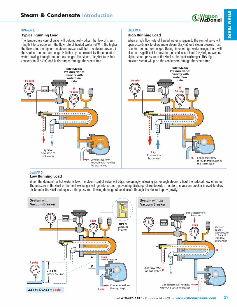
DIAGRAM 4:High Running LoadWhen a high flow rate of heated water is required, the control valve willopen accordingly to allow more steam (lbs/hr) and steam pressure (psi)to enter the heat exchanger. During times of high water usage, there will also be a significant increase in the condensate load (lbs/hr), as well as higher steam pressure in the shell of the heat exchanger. This high pressure steam will push the condensate through the steam trap.
21
Steam & Condensate Introduction
STEAM
TRA
PS
DIAGRAM 5:Low Running LoadWhen the demand for hot water is low, the steam control valve will adjust accordingly, allowing just enough steam to heat the reduced flow of water.The pressure in the shell of the heat exchanger will go into vacuum, preventing discharge of condensate. Therefore, a vacuum breaker is used to allow air to enter the shell and equalize the pressure, allowing drainage of condensate through the steam trap by gravity.
DIAGRAM 3:Typical Running LoadThe temperature control valve will automatically adjust the flow of steam(lbs/hr) to coincide with the flow rate of heated water (GPM). The higherthe flow rate, the higher the steam pressure will be. The steam pressure inthe shell of the heat exchanger is indirectly determined by the amount ofwater flowing through the heat exchanger. The steam (lbs/hr) turns intocondensate (lbs/hr) and is discharged through the steam trap.
STEAM
STEAM
Condensate flowthrough trap matchesthe steam load
VacuumcausesCondensateto Back Upinto Heat Exchanger
System withoutVacuum Breaker
OPENVacuumBreaker
0 psig
- 5 psig
System withVacuum Breaker
STEAM
30 psig
50 psig50 psig
10 psig
Condensate flowthrough trap matchesthe steam load
Typical flow rate of hot water
Highflow rate of hot water
Inlet SteamPressure varies
directly withwater flow
rate
Condensate flowsthrough trap
Condensate will not flowwithout a vacuum breaker
Sub-atmosphericPressure
Low flow rateof hot water
2.31 Ft. X 0.433 = 1 psig
1 psig
2.31 ft.water column
Inlet SteamPressure varies
directly withwater flow
rate
Tel: 610-495-5131 • Pottstown PA • USA •• www.watsonmcdaniel.com
1 psigHead Pressure
0 psig

êꧦ §¦ÎÉÉ�½�§¦ÎÉ §¦©�½�§¦©� §¦¦ ±§¦
±¦ÉÉÉ ±¦®±ÉÉ ±®ÉÉÉ ±¦ÉÉÉ ±¦°ÉÉÉ ±¦±ÉÉÉ ¦ä¦�
¦åÎÉÉ�¦åÎÉÉ ¦å¾ÉÉ� ¦åÌÉÉ� ¦å ÎÉɦ��¡ª«¹�¢�ª �Aìíð _ìíò�Añõôöñð ¬A��¤¬ \y¥ öíù ©ìïïúõöìïù ¬ñû��죦åÎÉÉ õñöïðùù� õ ð ÎÉÉ Fp¿ë�À��Dë �¬ë ͦåÎÉÉ� õñöïðùù� õ ð ÎÉÉ DpBë��Fpwë��Dë �¬ë °É¦å¾ÉÉ� �ððìò� õ ð ÎÉÉ DpBë��Fpwë��Dë �¬ë�� §��@«y °®¦åÌÉÉ� �ððìò� õ ð ÌÉÉ DpBë��Fpwë��Dë �¬ë�� §��@«y °°¦åÎÉÉ �ððìò� õ ð ÎÉÉ DpBë��Fpwë��Dë �� §��_§��@«y °Î±¦ÉÉÉ õñöïðùù�� õ ð ÉÉ DpBë��Fpwë �¬ë ±±¦®ÉÉÉ� õñöïðùù�� õ ð 뱃 DpBë��Fpwë �¬ë ±®±¦ÉÉÉ õñöïðùù�� õ ð 뱃 DpBë��Fpwë �¬ë�� §��@«y ±°±¦°ÉÉÉ õñöïðùù�� õ ð ÉÉ Fpwë��Dë �¬ë�� §��@«y ±Î±¦±ÉÉÉ õñöïðùù�� õ ð 뱃 Fp¿ë�À�Dë �¬ë�� § ±Í¦ä¦� _ôñùù ®±ä®± DpBë��Fpwë �¬ë Îɱ¦®±ÉÉ ©ñùõ�\ôìï ®±É DpBë��Fpwë �¬ë ή¦��¡ª«���� �Aìíð _ìíò�Añõôöñð ¬A��¤¬ \y¥ öíù ©ìïïúõöìïù ¬ñû��ì£
±§¦� ©ñùõ�\ôìï ®±É Fpwë�À�Bë �¬ë ÎΧ¦¦ øúõöð�\ôìï ÉÉ DpBë�À�Bë �¬ë ¾É§¦©ä§¦©� øúõöð�\ôìïp©ñùõ� õ ð ®ÉÉäÉÉ DDpBë��Bë��BDpBë �¬ë�� §��@«y ¾°§¦ÎÉÉ䧦ÎÉ ©ñô¢ìï� õ ðp õñöïðùù� õ ð °±É Fpwë�À�wë �¬ë�� §��@«y ¾Î§¦ ©ñùõ�\ôìï ¾± Fpwë�À�Bë �¬ë Í®§�«���½�¦��¡ª«���� �Aìíð _ìíò�Añõôöñð ¬A��¤¬ \y¥ öíù ©ìïïúõöìïù ¬ñû��ì£
ÇÆ�ÂÈ�Á�Â��ÁÂÃ����Ä�Å��Æ��Æ�
999:9;<=>?@AB;?CDE:A>@FFGHIIJIHKL�GM�FNOM�FPQRS�TUVWXYZWZU[U
ÇÁË�Ì�ÁÍ��Ç

Inverted Bucket
23
Steam TrapsTable of Contents
Manifolds Page 126
The FM / FSM Series Manifolds are used for steam distribution to the tracing system and for condensate collection.
CastIron
StainlessSteel
Inverted Bucket No Strainer Strainer Body Material PMO (PSIG) Sizes Connections Page No.
SIB/SIBH Stainless Steel 450 1/2”, 3/4” NPT, SW, 86-87
IB 1031 IB 1041 Cast Iron 150 1/2”, 3/4” NPT 88-93
IB 1032 IB 1042 Cast Iron 250 1/2”, 3/4”, 1” NPT 88-93
IB 1033 Cast Iron 250 1/2”, 3/4” NPT 88-93
IB 1034 IB 1044 Cast Iron 250 3/4”, 1” NPT 88-93
IB 1038S Cast Iron 250 11/4”, 11/2” NPT 88-93
Model Body Material PMO (PSIG) Sizes Connections Page No.
WPN-40 Carbon Steel 470 1/2” – 2” NPT, 150# / 300# FLG, SW, BW 120
WPN-63 Alloy Steel 823 1/2” , 3/4”, 1” NPT, 300# FLG, SW, BW 120
WPN-100 Alloy Steel 1220 1/2” , 3/4”, 1” NPT, 600# FLG, SW, BW 120
WPN-160 Alloy Steel 1620 1/2” , 3/4”, 1” NPT, 900# FLG, SW, BW 120
WPN-250 Alloy Steel 2260 1/2” , 3/4”, 1” NPT, 1500# FLG, SW, BW 120
Bi-Metallic
Model Body Material PMO (PSIG) Sizes Connections Page No.
FDA300 Stainless Steel 90 11/2” Tri-Clamp 113FDA400 Stainless Steel 90 1/2”, 3/4” Tri-Clamp 114FDA500 Stainless Steel 90 1/2”, 3/4”, 1” Tri-Clamp, NPT, TW 116FDA600 Stainless Steel 110 1/2”, 3/4”, 1” Tri-Clamp, NPT, TW 118FDA800 Stainless Steel 150 1/2” Tri-Clamp, NPT, TW 119
Clean Steam
Quick-Change Universal Style Model Type PMO (PSIG) Sizes Connection Page No.
USIB450 Inverted Bucket 450 1/2”, 3/4”, 1” Universal Connector 100
UFT450 Float & Thermostatic 225 1/2”, 3/4”, 1” Universal Connector 102
UTD450 Thermodynamic 450 1/2”, 3/4”, 1” Universal Connector 104-107
UTD600 Thermodynamic 600 1/2”, 3/4”, 1” Universal Connector 104-105
UT450 Thermostatic 450 1/2”, 3/4”, 1” Universal Connector 108
UB450 Bi-Metallic 450 1/2”, 3/4”, 1” Universal Connector 110
Tel: 610-495-5131 • Pottstown PA • USA •• www.watsonmcdaniel.com
STEAM
TRA
PS

ê¿
ÇÁË�Ì�ÁÍ��Ç ¢�¡«¹�� «¢����ª�¦¡�¬������� «¢�á ¹�� ¢��ÇÁË�Ì�ÁÍ��Ç ����ª�¦¡�¬���«¡�å¡ ¬�¬¬� ��� «¢�����å¡ ¬��¡�¬����wy�uyyzw�usw��x��t~t��s����uw�w�}�����t�xust�s|us�~��vx�w���wxs�w��sw���ywyw�}�ux�xstuv�wx�s�u�xy��st��~��v�s|t���wzt��s���|t�t�ws�wx�s���t��xt���zwvw�usw�}�s|wx�����t�xust�y��st�sx��uz�tx�u���ywyw�}�~��v��w�t��u�w�}�u����ust��|uvvt���3t�u�xt�����t�xust�z�u�x�st���s���t�z����xstuv�s�uyx��ws|�xvuzzt����w��tx�u�t�s{yw�uzz{xtzt�st��~���t�st��t��xt��w�t�zw~t���s�wx��tux��u�zt�s�����xw�t��u�xw�}zt�s�uy�s|us��u���yt�ust���t��u��w�t�y�txx��t��u�}t�w�����t��s��xwvyzw~{�xtzt�sw���u����t���t�w��t�s��{��Ûs|t��~u�s��x�s�����xw�t���|t��xtzt�sw�}���wy�s�uyx»�vust�wuzx���tyuw�u�wzws{��t~��wt��{���tzwu�wzws{��w�xsuzzusw�����wt�susw����yt�x��uz�y�t~t�t��tÜt�yt�wt��t�ux��tzz�ux�s|t�s�uyñx�u�wzws{�s��|u��zt�~�tt�w�}��zwvustx��x�yt�|tust��xstuv�����ywyt�x�uzt�u����t��wx�����ª�¦¡�¬���«¡�¦¡�� ¢¥�¬¬� ��� «¢�����¦¡�� ¢¥��¦¡�¬����u�w�}��yyzw�usw��x��t~t��s���xw�}�xstuv�s��tzt�ust�s|t�stvyt�us��t��~�u�y�����s��y���txx�����ywt�t��~�t��wyvt�s��{��xw�}�s��w�}����x�vt�s{yt��~�Åu��tsw�}��t�w�t��zzt���ws|�xstuv���|txt�uyyzw�usw��x�u�t���vv��z{�xt��s��y��v�st�ó����~�|tu�{�ó�w�x����y�t�t�s�ywytzw�tx�u���t��wyvt�s�~��v�~�tt�w�}���|t��tzusw�tz{�xvuzz�s�uyx�xt��~���s|txt�uyyzw�usw��x�u�t��t~t��t��s��ux����u�w�}�s�uyx�������ÔÃ�wsw�uz���u�w�}�uyyzw�usw���vu{��t�t�s~��v�u�s|t�v�xsusw��xstuv�s�uy��|w�|�x��Ô���zx�u����u��x��y�x�vt�����t�xust�Ô�u��u�Å�xsu�zt��wvtsuz�s�uy�~~t�x�u��wsw��uz�stvyt�us��t����s��z���|t�v��{�uvw��s�uyx�u�t�w�tuz�~���Ã�wsw�uz���u�w�}�uyyzw�usw��x��|t�t�����t�xust��u��Ô�y�wx���s�yt�vwsst������ª�¦¡�¬���«¡�¼¡«�����¬¬� ��� «¢�����¼¡«�����¦¡�¬��º���txx�uyyzw�usw��x��t~t��s����uw�w�}�����t�xust�~��v�s|t�u�s�uz�y���txx��xw�}�s|t�xstuv���|txt��t��w�t�xstuv�s�uyx��ws|��tzusw�tz{�|w}|�����t�xust��uyu�ws{�����s|t�vuÅ��ws{��~�y���txx�uyyzw�usw��x��ws�wx�wvy��su�s�s���wx�|u�}t�uw��y�txt�s�w��s|t�x{xstv����w�}�xsu�sÔ�y�x��s|t�xstuv��u����w��z{�t�st��s|t�x{xstv���zs|��}|�xtyu�ust�uw���t�sx��u���t��xt��~���s|wx�y��y�xt��ws�vu�tx�xt�xt�s��xtzt�s�u�s�uy��|w�|�|ux�uw���t�sw�}��uyu�wzws{�w��u��wsw���s���wx�|u�}w�}��u�{w�}�����t�xust�z�u�x���|t�s�uy�v�xs�|u�t�t���}|��uyu�ws{�s���wx�|u�}t�s|t�����t�xust�t�t���|t��s|t��w~~t�t�swuz�y�txx��t�u���xx�s|t�s�uy�wx�z�����|txt�z���y�txx��t�����wsw��x���vv��z{������w��y���txx�|tusw�}�uyyzw�usw��x��|t�t����s��z��uz�tx�u�t��xt��s���t}�zust�s|t�ó����~�xstuv�w�s��s|t�t��wyvt�s��µ��t�t���w~�s|t�s�uy�wx�xw}�w��u�sz{���t�xw�t��ws�vu{��u�xt�ws�s���tu����s�v��t���w��z{�u���uzz��xstuv�s��yuxx�w�s��s|t�����t�xust��ts������|t�v�xs���vv���s�uy�s{yt�~���y���txx�uyyzw�usw��x�wx�s|t��z�us�¶��|t�v�xsusw��xs{zt�ÝÞßà�áÞââÞã�äßåæº���txx��yyzw�usw��x�~��v�z���y�txx��t�µò�Ã�v��tzx�~����txw�t�swuz�|tusw�}�s������xs�wuz��uxs�xsttz�u���xsuw�ztxx�xsttzv��tzx�~���Ã|tvw�uz�u���ºts��ÔÃ|tvw�uz�yzu�sx��y�s���çƳ�ºr��r�wsu�zt�uzst��usw�t�~�����wy�uyyzw�usw��x�s���³³�yxw}�
§½¦�²§�«���½�¦��¡ª«���� �³�¦¡�¬��@ðìñõ�ï�ëøô¡ìùõñõöú� õñ¡�ëôñóù�úìïõñöï�ñ�÷ðìñõ%ìóôñõí�]ñð]�õì�úìïõöïñððò�íöùúøñôû�úìïíïùñõ�ñïí�ñ�õøô¡ìùõñõöú�ñöô�]ïõ�îøöúø�íöùúøñôûù�ñöô£��_ìíò�¡ñõôöñðù�ñ]ñöðñ¢ð�ñô�©ñùõ�\ôìï�øúõöð�\ôìï�©ñùõ� õ ð�ï� õñöïðùù� õ ð�÷ìô�óôùùôù�ó�õì�wEú�óùöû£�èéê���¡¤NP�¤¡R�¡R¢R¡¡R°����¤P�¦R©Q¤§�©¤£��¡¤NP«ë¦�¬ ����¬¬� ��� «¢��@ïëù�ñô�õø�¡ìùõ�úì¡¡ìïðò�ùí�õôñó�÷ìô�¢ìõø�¢ñõúø�õòó�óôìúùùù�ñïí�úìïõöïìù�óôìúùùñóóðöúñõöìïù�îöõø�ôñóöíðò�úøñïûöïû�óôùùôù�ñïí�ðìñíù£¹��¢��¥�����@ïëù�îöúaðò�ôùóìïí�õì�ðìñí�ñïí�óôùùôúøñïûù�íöùúøñôû�ðñôû�ñ¡ìïõù�ì÷�ñöô�óôùïõ�ñõ�ùõñôõ%óîøöúø�ñððìî�ùõñ¡�õì�îöúaðò�ïõô�õø�ùòùõ¡�úìïõöïìùðò�íöùúøñôû�úìïíïùñõ�ñù�öõ�÷ìô¡ù�ñïí�ì÷÷ô�ñ�îöí�ôñïû�ì÷úñóñúöõöù�÷ìô�ñïò�óôìúùù�ñóóðöúñõöìï£ß���¡�§���«¡���«��«¢� ¹�¡���@ïëù�ïñôôìî�ìóôñõöïû�óôùùôôñïûù�ôîöô�¡ìô�úñô�íôöïû�ùðúõöìï£� öïú�õøò�ñô�ïìõùð÷%íôñöïöïû�õøò�ñô�ù¢êúõ�õì�÷ô íöïû£�ëôñó�¢ìíò�¡ ùõ�¢öïùõñððí�]ôõöúñððò�÷ìô�óôìóô�ìóôñõöìï£
,��"��������������� �!"�#���$#��
����ª�¦¡�¬������� «¢�á ¹�� ¢��
999:9;<=>?@AB;?CDE:A>@FFGHIIJIHKL�GM�FNOM�FPQRS�TUVWXYZWZU[U

25
STEAM TRAPS Introduction
Steam Trap Selection Guidelines
STEAM
TRA
PS
Thermodynamic Traps:The Thermodynamic Trap is simple and compact with a single moving part (disc) which opens to discharge condensate and closes in the presence of steam. Body materials available areStainless and Alloy Steels for pressures up to 3,600 psig.
Typical Applications: Widely used on higher pressure drip applications and critical tracingapplications (where condensate back-up is not permitted).
Advantages: Rugged design, operation is easy to check due to distinct cyclic operation, relatively small with lower capacities, single model operates over wide pressure range in contrast to mechanical traps, excellent for superheated steam, self-draining when mounted vertically to prevent freezing.
Other Factors to Consider: Limited air venting, wet climates can increase cycle rates, sensitiveto excess back pressure, blast discharge may not be preferred in some systems
Thermostatic Traps:A Thermostatic Trap contains a heavy-duty, industrial-purpose welded stainless steel thermal element designed to control condensate discharge by sensing the temperature differencebetween steam and cooler condensate. Body materials available are Cast Iron, Stainless and Alloy Steels with thermal element designs available for pressures up to 650 psig. The WPNSeries Bi-metallic design will handle presssures up to 2,260 psig.
Typical Applications: Extremely versatile and energy efficient, these traps are suitable for a wide range of applications. Thermal element designs are suitable for applications ranging from general service drip and tracing applications to small-to-medium batch style processes. Bi-metal designs can be used in high pressure, superheated drip applications or in lower pressure tracing applications.
Advantages: Self-draining when mounted vertically to prevent freezing, single model operates over wide pressure range in contrast to mechanical traps, small and compact with similar capacities to larger mechanical traps (F&Ts & IBs), superior air venting capabilities, welded stainless steel thermal element and bimetal elements are extremely rugged, moderatedischarge due to reduced flash steam, choose between fail-open or fail-closed bellows.
Other Factors to Consider: Some condensate back-up can be expected, thermal elementdesign not recommended for superheated applications.
Inverted Bucket Traps:The Inverted Bucket Trap uses an inverted bucket as a float device to control the opening and closing of the plug and seat to discharge condensate. Body materials available are Cast Ironand Stainless Steel for pressures up to 450 psig. (IB traps are referred to as mechanical traps.)
Typical Applications: These traps have a discharge orifice positioned at the top of the trapbody which make them ideal for drip applications on systems containing excessive pipe scaleand debris. They may be considered for process applications where air venting is less of a concern or handled by a separate air vent.
Advantages: Rugged and simple design, top-mounted discharge orifice less susceptible to failure from dirt and debris, service life often exceeds other style traps.
Other Factors to Consider: Limited air venting capabilities, can lose its prime causing it tofail, narrow operating pressure ranges require more care during selection, not self-drainingtherefore subject to freezing, single position installation, fixed orifice on bucket allows smallsteam leakage, physical size can be large and require additional support.
Most Common Use:General service drip & tracingapplications above 30 psig, as well as high-pressure dripapplications with superheat.
Most Common Use:Industrial style ThermostaticTraps are extremely versatile. Their use can range from generalservice drip & tracing applicationsto small-to-medium batch process heating applications.
Most Common Use:Used on drip applications where excessive dirt and debrismay be of significant concern.They can serve as alternatives to F&T's in process applicationswhere air venting is not required bythe steam trap.
Tel: 610-495-5131 • Pottstown PA • USA •• www.watsonmcdaniel.com

STEA
M T
RA
PS
26 www.watsonmcdaniel.com •• Pottstown PA • USA • Tel: 610-495-5131
STEAM TRAPS Introduction
Steam Trap Selection Guidelines • DRIP Applications
Drip applications refer to the removal of condensate formed in steam lines due to the radiant heat loss of the hot steampipes to surrounding air and are required for the protection of the steam system. (Drip Traps remove the condensate fromthe steam lines where the process traps remove condensate being generated by the actual process.) Drip traps shouldbe placed 150 to 300 feet apart on straight runs of piping, before elevation changes, and before critical equipment such as Regulators and Control Valves. See description below of typical drip leg configurations.
Why Condensate Safety Load Factors and Warm-up Loads need to be considered: During start-up, when the piping system is cold and steam begins to flow thru the pipes, steam is condensing very quickly because of the energy required to heat all the cold surfaces. Furthermore, the steam pressure in the systemwhich is required to push the condensate through the steam trap into the return line, is low before the system comesup to full pressure. Therefore, condensate is being generated at a maximum rate and the steam pressure used to pushthe condensate out of the system is at a minimum. If the traps are sized for the normal running loads and normal system pressures, then they would be undersized for the start-up condition.
In a supervised start-up, condensate drain valves located throughout the system, are manually opened to drain excessive condensate generated by the cold piping system; relying less on the steam traps. Therefore, the steamtraps selected for a system with a supervised start-up can be more closely sized for the actual normal running load.
Steam Main
To condensatereturn
6”Min. Strainer
L
Drain Valve
Drip Leg Design Criteria:• For systems with automatic start-up,
L to be 28” minimum (= 1 PSI minimum head pressure)
• Drip leg diameter should be equal to steam main diameter (up to 4” in size)
Drip Leg in a Steam Main
Large diameter drip legs ensurethat condensate in steam mainis properly collected. Length ofdrip leg gives head pressure todrain the trap after shutdown.
DR
IP LEG
TD600LDrip Trap
Drip Legs should be installed directly ahead of regulators and control valves to minimize erosion to valve trim andflooding of valve bodies.
TD600LDrip Trap
GateValve
DrainValve
Pressure Regulating
Valve
Steam Su
pp
ly Line
Strainer recommended to prevent dirt from entering trap
Drip Leg Before Regulator or Control Valve
Steam Main
DR
IP LEG
To condensatereturnStrainer
DRIP Applications • Sizing a Trap for Draining a Steam Main
Dirt Pocketfor accumulationof pipe scale & debris
Drain Valveused to
dischargedebris
Branch lines should always be takenoff the top of the steam main pipe.
Steam moving at high velocity can engulf aslug of condensate and propel it at extremely
high speeds down the length of a pipe.
Condensate must be removed fromsteam lines to protect piping systems from
dangerous water hammer conditions.

27
STEAM
TRA
PS
Tel: 610-495-5131 • Pottstown PA • USA •• www.watsonmcdaniel.com
STEAM TRAPS Introduction
Steam Trap Selection Guidelines • DRIP Applications
Sizing Example: Size a drip trap for an 8” steam main with 100 psig steam pressure. Traps should be placedevery 200 ft. A 2x safety factor based on Warm-Up load will be used.
• Based on Warm-Up Load Chart: 100 lbs/hr of condensate is generated per 100 feet length of pipe.• Warm up load for 200 ft. length is therefore, 200 lbs/hr (2 x 100 lbs/hr)• If a 2x safety factor based on warm-up load is used, we require a trap with a capacity of 400 lbs/hr• Actual running load for 100 ft. length = 41 lbs/hr• Actual running load for 200 ft. length = 82 lbs/hr
Trap Selection: Reference the TD600S Series Capacity Chart below based on inlet steam pressure. Enter the chart under 100 psig inlet pressure to compare the capacities of different models.
The 1/2” TD600LS will be capable of discharging 375 lbs/hr of condensate at 100 psig steam pressure. The capacityis slightly less than the load calculated based on warm-up load with 2x safety factor, however, this trap selectionwould be a suitable choice since its capacity is well in excess of what is actually required. These loads are indicativeof drip applications and lend support as to why only reduced capacity 1/2" TD600L or 3/4" TD600L traps arerequired for the majority of drip applications.
SteamPressure(PSIG) 2” 21/2” 3” 4” 5” 6” 8” 10” 12” 14” 16” 18” 20” 24”
20 8.4 13.4 17.5 24.9 33.8 44 66 93 124 146 191 241 284 396 1.37 60 11.0 17.5 22.9 32.6 44 57 86 122 162 192 250 316 372 518 1.29 100 12.8 20.3 26.6 37.8 51 67 100 142 188 222 290 366 431 600 1.26 125 13.7 21.7 28.4 40 55 71 107 152 200 238 310 391 461 642 1.25
Outside Temperature at 70˚F0˚F
CorrectionFactor †
Pipe Size
Warm-Up Loads in Pounds of Condensate per hour per 100 ft. of Steam Main
Running Loads in Pounds of Condensate per hour per 100 ft. of Steam Main
2” 21/2” 3” 4” 5” 6” 8” 10” 12” 14” 16” 18” 20” 24” 20 8 9 11 14 17 20 26 32 38 42 48 51 57 68 1.50 60 10 12 14 18 24 27 33 41 49 54 62 67 74 89 1.45 100 12 15 18 22 28 33 41 51 61 67 77 83 93 111 1.41 125 13 16 20 24 30 36 45 56 66 73 84 90 101 121 1.39
† For outdoor temperatures of 0˚F, multiply load value selected from table by correction factor shown.
Outside Temperature at 70˚F 0˚F
CorrectionFactor †
Pipe SizeSteamPressure(PSIG)
100
Steam Pressurepushes condensate
through trap
Inlet Pressure(Steam)
CAPACIT IES – Condensate (lbs/hr) Steam Inlet Pressure (PSIG) Size Model Code 3.5 5 10 15 20 25 30 40 50 75 100 1/2” TD600LS-12-N
180 185 190 195 200 215 220 230 250 310 375 1” TD600LS-14-N 3/4” TD600LS-13-N 300 315 350 380 415 440 470 515 580 710 825
1/2” TD600S-12-N 300 315 350 380 415 440 470 515 580 710 825 3/4” TD600S-13-N 415 430 475 520 565 610 650 720 825 1020 1185

28
STEA
M T
RA
PS
www.watsonmcdaniel.com •• Pottstown PA • USA • Tel: 610-495-5131
STEAM TRAPS Introduction
Steam Trap Selection Guidelines • DRIP Applications
Drip Applications The trap models in the chart below are for drip applications for the protection of steam mains and steam supply lines. When traps listed below are installed every 200 feet, they will have adequate capacity to handle typical warm-up loads in properly insulated8” steam mains. See Warm-up Load Chart in Engineering Section. Several models listed will handle steam mains considerably largerthan 8”. Steam pipe size, the distance between traps, insulation quality, ambient temperatures and start-up conditions should all beconsidered. Consult factory if additional guidance is required.
Float & ThermostaticThermodynamic
Cast IronIB1032-250 PMO=250 1/2” • 3/4”
Stainless SteelSIBH-250 PMO=250 1/2” • 3/4”
Universal Quick-Change
USIB450-250 PMO=250
Model Size
Inverted BucketThermostatic
Model Size
30
to
15
0
PSI
G
Cast Iron
IB1031-150 1/2”PMO=150 3/4”
Stainless Steel
SIB150 1/2”PMO=150 3/4”
Universal Quick-Change
USIB450-150 PMO=150
0
to
15
0
PSI
G125
to
25
0
PSI
G
15
0
to 6
00
PSI
G
Model Size
125 PSIG
0
to
65
0
PSI
G
Model Size
30 PSIG
150 PSIG
225 PSIG
Non-Repairable
TD600L & TD600LS 1/2” 3/4”
Repairable
TD700HS 1/2” 3/4”
Universal Quick-Change
UTD600LSM
Parallel Pipe Connection(Cast Iron)
WFT-125 PMO=125 3/4”
In-Line Pipe Connection(Ductile Iron)
FTT-145 PMO=145 1/2” • 3/4”
Universal Quick-Change
UFT450-145 PMO=145
Non-Repairable
TD600L & TD600LS 1/2” 3/4”
Repairable
TD700S 1/2” • 3/4”
Universal Quick-Change
UTD450LSM
0
to
125
PSI
G125
to
225
PSI
G
In-Line Pipe Connection(Ductile Iron)
FTT-225 PMO=225 1/2” • 3/4”
Universal Quick-Change
UFT450-225 PMO=225
600
- 90
0
900 PSIG
Repairable
TD900S 1/2” , 3/4”TD900LS (Light Loads)
600 PSIG
650 PSIG
Repairable(Cast Iron)
WT2501 1/2” 3/4”
(Limited to 250 PSI)
Non-Repairable(Stainless Steel)
WT2001 1/2” 3/4”
Repairable(Stainless Steel)
WT3001 1/2” 3/4”
Universal Quick-Change
UT450 (Limited to 450 PSI)
250 PSIG
150 PSIG
NOTE: The WFT-125, FTT-145 and FTT-225have adequate capacity for draining steam mains and steam supply lines. For pressures below 65 PSI, the WFT-075or the FTT-065 can be used if a larger discharge orifice and increased capacityis required.
NOTE: IB Models up to a PMO of 250 shown above, have adequate capacityfor draining steam mains and steam supply lines.On lower pressure systems, models with lower PMO ratings can be used if a larger discharge orifice and increased capacity is required.

êº
ÇÁË�Ì�ÁÍ��Ç
PQRS�TUVWXYZWZU[UFGHIIJIHKL�GM�FNOM�FF999:9;<=>?@AB;?CDE:A>@
ÇÁË�Ì�ÁÍ��Ç�¢�¡«¹�� «¢����ª�¦¡�¬������� «¢�á ¹�� ¢����å�¼ ¬¬� ��� «¢�
±¦®±É���t�st��3���ts���uyx�u�t�t�s�tvtz{���}}t��u���|u�t�u��wx�|u�}t���w��t�v���st��us�s|t�s�y��~�s|t�s�uy����{��vu�w�}�s|tv�ztxx�x�x�tysw�zts��~uwz��t�~��v��w�s�u����t��wx��|t����vyu�t��s���s|t��s�uy�s{ytx����|t��3�v��tzx�xtzt�st��u�t�x�wsu�zt��|�w�t�~���v�xs��wy�uyyzw�usw��x���� ¢���� �����¡«¢�����
�|t�uzz�xsuw�ztxx�xsttz���w�t�xuz�xs{zt�xstuv�s�uyx~tus��t�u�yt�vu�t�s�w�xsuzzusw����~�s|t���w�t�xuz����t�s����ws|�u��Ô��zs�v���sw�}�u��u�}tvt�s�~���s|t���w�t�xuz�xstuv�s�uy�v���zt��uzz��w�}�s|t�xstuv�s�uy�s���t��tv��t��u����tyzu�t��w��vw��stx���|txt�Ã�w��ÔÃ|u�}t�rstuv���uyxx|��z���t����xw�t�t��~���uzz���wy�uyyzw�usw��x�#��|t�v��{�uvw�#��z�us�¶��|t�v�xsusw�#��|t�v�xsusw�#����t�st��3���ts
¦åÎÉɦ��¦åÎÉɦ ¦å¾ÉÉ� ¦åÌÉÉ�
±¦®Éɱ§¦§¦¦
�|t��|t�v��{�uvw���wx�������rstuv���uy�wx�xwvyztu�����vyu�s�u�����t��~�s|t�y�wvu�{��|�w�tx�~�����wyuyyzw�usw��x���t��:³�yxw}���|t���*³³�rt�wtx��ws|w�st}�uz���t�ywt�t����{Ôxtus��txw}���u�t�s|t�v�xst����vw�uz�u�����vv��z{��xt��~���y�txx��tx��y�s��*³³�yxw}���|t��Ü�,�¶�:Üç,���*³³¼�wzz�vtts�s|t��uyu�ws{�tt�x��~�v�xs���wy�uyyzw�usw��x��,r,�v��tzx�|u�t�w�st}�uz�xs�uw�t�x����|t���*³³�rt�wtx��u���s��t��tz�t�w�Ôzw�t���|t���+³³r�¶���dz³r�rt�wtx�u�t���s|�w�Ôzw�t�tyuw�u�zt�u����u���t��tz�t��w�s��s|t�ywytzw�t��|t�v�xsusw��rstuv���uyx�u�t�t�s�tvtz{��t�xuswzt�u����u���t��xt�����u��w�t��u�wts{��~uyyzw�usw��x�~��v�}t�t�uz�xt��w�t���wyx�s��xvuzzÔs�Ôvt�w�v��us�|�s{yt�y���txxtx��îxw�}u��tz�t��xsuw�ztxx�xsttz�s|t�vuz�tztvt�s�s�����s��z�����t�xust��wx�|u�}t��s|txt�s�uyx�uzz������t�xust�s��x�����z��vu�w�}�s|tv�t�s�tvtz{�t�t�}{�t~��wt�s���x�u��tx�zs��s|t�����t�xust�wx�|u�}t��}t�t�ustx�ztxx�óux|�xstuv��|w�|��t���tx��u���y�txx��t���wz�Ô�y�w������t�xust�ts����zw�tx����xw�}zt�v��tz��wzz��yt�ust�~��v�³�s��*Ƴ�yxw}��|w�|�xwvyzw�tx�xtzt�sw�����|tÂ��³³����ws|�xsuw�ztxx�xsttz����{�u������Ô�tyuw�u�zt��txw}���wx�s|t�v�xs���vv��z{��xt���|t�Â�:³³��u���Â��Ƴ��|u�t�s|t�xuvt�w�st��uzx�ux�s|t�Â��³³���|��t�t���s|tw��çÔ��zs����t��uzz��x�s|tv�s���t�w�Ôzw�t��tyuw�u�zt���|t�Â�:³³��|ux�u�xsuw�ztxx�xsttz����{��|wzt�s|t�Â��Ƴ��wx��uxs�w�����|t�º �rt�wtx����s�x|�������xtx�u��wÔvtsuz�tztvt�s�x�wsu�zt�~���y�txx��tx�s�����*³�yxw}��u����wzz�|u��zt�x�yt�|tust��xstuv�
�|t��z�us�¶��|t�v�xsusw����¶���rstuv���uy�wx�s|t�y�wvu�{��|�w�t�~���y���txx�uyyzw�usw��x��µ��t�t���~�����wy�uyyzw�usw��x��s|t{��u���t�t~~t�sw�tz{��xt��~���y�txx��tx��y�s����Æ�yxw}����s|t�Â���rt�wtx�¶���Æ�yxw}����s|t�����rt�wtx²�~���|w}|t��y�txx��tx��s|t�zu�}t�����{�xw�tx��t��w�t��vu�t��¶��s�uyx�u�ztxx�t����vw�uz�u����txw�tu�zt�x�z�sw���~�����wy�xt��w�t���|t�:Üç,�Â��Ô��Æ������Ü�,�¶�:Üç,����Ô��Æ��wzz�vtts�s|t��uyu�ws{��tt�x��~�v�xs���wy�uyyzw�usw��x��Ûs|t��ºÄÛ��vu�wv�v��yt�usw�}�y�txx��t���u�}tx�u�uwzu�zt��������wy�uyyzw�usw��x��xtzt�s�u�ºÄÛ�s|us�vttsx����t��tt�x�s|t�vu�wv�v�y�txx��t�w��s|t�vuw��xstuv��wxs�w��sw���ywyw�}�¦��¡ª«¹�¢�ª �
¦��¡ª«���� �§�«���½�¦��¡ª«���� �
¢��¡��¹�®�����²®³ É¢ ��¡����Ú ��Ê���¢¥�
�Ð����;Àò� À¿�Å¿�½ ѽó�¿;Àò� À¿�Æ �¿��ÀÀ¿�¾ �À ƽѽ��¿��Æ �¿��ÀÀ¿�¾ �ÀÅ¿�½ ѽó�¿ÇÈÉÊË:ÌÍÎÏÐ Ñ�ÀòÅ¿�½ ѽó�¿ÇÒËÉÓÏÔÕÊÊ:ÒËÕÕÔÐ

30
STEA
M T
RA
PS
www.watsonmcdaniel.com •• Pottstown PA • USA • Tel: 610-495-5131
STEAM TRAPS Introduction
Steam Trap Selection Guidelines • TRACING Applications
Thermostatic Trap
ThermodynamicTraps
Steam tracing refers to using steam to indirectly elevate the temperature of a product or process by using tubing or some type of jacketing device filled with steam. In a typical steam tracing application, stainless steel or copper tubing isfilled with steam and is coiled or wrapped around the outside of a pipe or tank containing material that requires heating.The steam inside the tubing transfers its heat to the material in the pipe or tank; to stop it from freezing or to lower its viscosity to allow it to flow more easily. A steam trap is required for tracing to remove the condensate and air from thesystem. The most common trap choice for tracing applications is the Thermostatic type. Depending on the particular tracing application, it is often desirable to have some amount of condensate backup in the tubing.
Tracing Applications
Heating Vertical Pipelines
Tubing can be wrapped around the piping with a steam trap installed at the low point to allow condensate to freely drain by gravity. Partial back-upof condensate using thermostatic trap.
Heating Horizontal Pipelines
Tubing should not be wrapped around horizontal pipelines or condensate will collect at low points. After shutdown, condensate retained in the system could potentially freeze.Therefore, tracing tubing should be run parallel to any pipingand sloped slightly towards the steam trap to promote condensate drainage.
WT5000
WT5000Bi-Metal
TD600WT2000
Thermostatic(5˚F - 10˚F subcool)
Bi-Metal Steam Trap with Adjustable Discharge Temperature (WT5000)
For applications where overheating of product fluidsin a pipeline may be a concern, an Adjustable Bi-MetalSteam Trap, such as the WT5000 (shown), should beconsidered. The discharge temperature of the condensate can be manually adjusted to control theamount of condensate back-up in the tracing tubing.This technique can be used to control the temperatureof the product in the pipeline.
Steam Tracing Applications: Primary Trap Choice Special Notes
Typical Service: Some condensateback-up preferable
Critical Service: No back-up of condensate permitted
• ThermostaticThermostatic traps are suitable for the majorityof steam tracing applications; for critical steamtracing applications, where no back-up of condensate can be tolerated, thermodynamictraps should be used.• Thermodynamic
By increasing subcool, hot condensate can be made to back-up into hundreds of feet into tracing lines if required.

31
STEAM
TRA
PS
Tel: 610-495-5131 • Pottstown PA • USA •• www.watsonmcdaniel.com
STEAM TRAPS Introduction
Steam Trap Selection Guidelines • PROCESS Applications
Batch Process - Steady Demand
This guide is intended to provide the user with a "starting point" for the selection of Watson McDaniel steam traps.Steam trap selection can appear to be overwhelming given the range of applications and trap choices available.Selection criteria for a specific application may include pressure & temperature ratings, capacity, physical size & weight, and materials.
Process Steam Trap Selection Guidelines
Batch type processes typically have steady demand as a batch of products is heated to a certain temperature. They tend not to experience rapid changes in steam pressure and steam flow. Common examples of such processesare: • Unit Heaters • Storage Tank Coils • Jacketed Vessels • Pipe Coils
The primary steam trap type for process equipment is a Float & Thermostatic. The WFT & FTT Series in Cast Ironand Ductile Iron are the most cost-effective solutions to most applications. The FTE Series is for higher capacity applications. The FT600/601 Series traps are available in Cast Steel or Stainless Steel which may be specified forrefineries and higher pressure applications. Since rapid pressure changes do not typically occur with batch processes,Thermostatic Bellows traps can also be selected. The WT2000, WT3000 & WT4000 Series have Stainless Steel bodiesand may be preferred for outdoor applications to Cast Iron F&T traps, particularly when a potential for freezing exists.
Continuous Process - Varying Demand • Heating Processes (high to ultra-high capacity)
These applications use steam to heat a continuous flowing product. The modulation of the control valve results in rapid change in steam pressure and flow. Common examples of such processes are:
• Heat Exchangers • Air Handling Coils • Instantaneous Water Heaters
The primary steam trap type for process equipment is a Float & Thermostatic. The WFT & FTT Series in Cast Ironand Ductile Iron are the most cost-effective solutions to most applications. The FTE Series is for higher capacityapplications. The FT600/601 Series traps are available in Cast or Stainless Steel which may be specified for refineriesand for higher pressure applications.
Safety Load Factors (SLF’s) and appropriate rules to size steam traps
The largest condensate load occurs when the maximum steam pressure is present in the Heat Exchanger (HX). However, if the steam trap is selected based on the maximum condensate load at maximum pressure, it will not be adequately sized at lower differential pressures. This is because the capacity of a steam trap depends on the differential pressure across the trap (less pressure means less capacity) and trap capacity decreases at a significantly faster rate than condensate load when the steam pressure drops. When temperature control valves are used to control steam flow to a HX, the pressure mayreduce to 0 psig or less. The pressure available to discharge condensate would then be based on head pressure of the drop leg. A drop leg length of 14" will produce a head pressure of ½ psig.
Use the following rules and safety factors for the three categories of process applications. This should assure the trap has adequate capacity at lower differential pressure and not be drastically oversized when operating at full pressure.
For applications NOT containing a Temperature Control Valve and operate at fairly constant steam pressures; select a steam trap that will handle 2X the maximum condensate load at the maximum differential pressure.For Example: if a process will generate 5,000 lbs/hr at 50 psi differential pressure, then choose a trap that can handle 10,000 lbs/hr at 50 psi.
For applications WITH a Temperature Control Valve and steam pressures OVER 30 PSI; select a steam trap that will handle 2.5X the maximum condensate load at the maximum differential pressure. For Example: if a process is expected to generate 5,000 lbs/hr at 50 psi differential pressure, then choose a trap that can handle 12,500 lbs/hr at 50 psi.
For applications WITH a Temperature Control Valve and steam pressures UNDER 30 PSI; calculate the maximum condensate load at the maximum differential pressure; select a steam trap that will handle this maximum amount of condensate at ½ psi differential pressure. For Example: if a process is expected to generate 5,000 lbs/hr at 15 psi differential pressure, then choose a trap that can handle 5,000 lbs/hr at ½ psi differential pressure. The purpose of the ½ psi differential pressure is to allow condensate to properly drain when system pressure goes into vacuum. This assumes the installation of a vacuum breaker and a drop leg of at least 14" in length (for ½ psig) below the HX to give proper condensate head pressure to the steam trap, and trap discharge to atmospheric pressure (0 psig).
I
II
III

STEAM TRAPS Introduction
Steam Trap Selection Guidelines • PROCESS Applications
PROCESS Applications • Sizing a Trap for Heat Exchanger Application
32
STEA
M T
RA
PS
www.watsonmcdaniel.com •• Pottstown PA • USA • Tel: 610-495-5131
STEAM
20 psig
40 psig
Condensate Load (lbs/hr)equals steam load (lbs/hr)
Max Flow Rateof Hot Water
18 GPM
Steam Pressure in the HX variesdirectly with water flow rate
Steam (lbs/hr) = GPM x Temp. Rise (˚F) 2
Goal: Select appropriate model and size steam trap for Process Water Heating application using a Shell & Tube HeatExchanger in which a maximum of 18 GPM of water is being heated from 45-140˚F. Steam Pressure to the control valveis 40 PSI. The trap is discharging to a condensate return line at atmospheric pressure (0 psig back pressure)
Example: Conditions of Service at Max Load
• Maximum water load to be heated = 18 GPM• Temperature Rise: (140˚F - 45˚F) = 95°F
1 Calculate Maximum Condensate LoadUsing the formula below, to approximate steam load based on water flow rate (GPM) and temperature rise, a Steam Flow of 855 lbs/hr is required; therefore, 855 lbs/hr of condensate will likewise be generated.
Steam Flow (lbs/hr) = Condensate Load (lbs/hr)
2 Determining the Differential Pressure (ΔP) Across the Trap at the Maximum Condensate LoadIn order to size the steam trap, we must first know the pressure in the HX at the Max Condensate Load. This steampressure is determined by the physical size of the HX. (note that a larger HX uses lower steam pressure while a smallerHX requires a higher steam pressure to heat the same flow of water). If the pressure of the HX is not known, assume 50% of the Pressure at the inlet of the control valve is required in the HX to heat the maximum flow of 18 GPM of water.We therefore have (40 psig x 0.5 = 20 psig) 20 psig steam pressure at 855 lbs/hr.
3 The Condensate Load at 0 psig Steam Pressure and Conditions at other Water Flow Rates The steam trap cannot be selected solely based the condensate load at the maximum steam pressure because it will be undersized at lower steam pressures (when there is much less force to push the condensate thru the trap). Lower steam pressures occur when less water is being heated. If the steam pressure and condensate load is known at the lowest pressure, the trap can be selected based on that operating point, and it would be adequately sized at higher pressures. In this particular application, we have a gravity return line at 0 psig back pressure.
Flow Steam Steam Steam Actual Trap Rate Flow Temperature Pressure Pressure Differential Condensate
Water (required) (required) (required) in the HX Pressure Flow(GPM) (lbs/hr) in HX (°F) in HX (PSIG) (PSIG) (PSI) (lbs/hr)
18 855 259 20 20 20 855steam
12.9 614 212 0 0 1/2 psi 614steam 14” drip leg
10 475 185 -6 0 1/2 psi 475vacuum 14” drip leg
At maximum Flow Rate of 18 GPM
Flow Rate of Water at 0 psig Steam Pressure
At Flow Rate of10 GPM of Water
Hot Water 140˚F
ColdWater 45˚F
0 psig back pressure
VacuumBreaker
For this size HX, when water flow rate is 12.9 GPM, the steam temperature required is 212˚F, therefore, the steam pressure is 0 psig. At flow rates below 12.9 GPM, the steam pressure would need to go intovacuum or mix with air drawn in thru the vacuum breaker in order to achieve the proper temperature.
0 psig
Load Chart Based on HX Size to Heat 18 GPM of Water using 20 psig Steam Pressure
SystemPressure
steam & air mixes together
=18 x 95˚F
= 855 lbs/hr 2
Condensate (lbs/hr) = 855 lbs/hr

CAPACIT IES – Condensate (lbs/hr)PMO Pipe Orifice Differential Pressure (PSI)
Model Code (PSIG) Size Size 1/4 1/2 1 2 5 10 15 20 30 40 50 75WFT-015-13-N 15 3/4” 0.250 390 490 620 780 1050 1320 1500
WFT-015-14-N 15 1” 0.250 390 490 620 780 1050 1320 1500
WFT-015-15-N 15 11/4” 0.312 610 770 960 1210 1630 2040 2330
WFT-015-16-N 15 11/2” 0.500 1420 1910 2570 3460 5120 6890 8190
WFT-015-17-N 15 2” 0.625 2260 2950 3860 5040 7170 9360 10930
WFT-030-13-N 30 3/4” 0.228 330 420 530 670 930 1180 1350 1500 1720
WFT-030-14-N 30 1” 0.228 330 420 530 670 930 1180 1350 1500 1720
WFT-030-15-N 30 11/4” 0.228 330 420 530 670 930 1180 1350 1500 1720
WFT-030-16-N 30 11/2” 0.390 930 1240 1650 2190 3210 4280 5060 5700 6750
WFT-030-17-N 30 2” 0.500 1420 1910 2570 3460 5120 6890 8190 9260 11020
WFT-075-13-N 75 3/4” 0.166 175 225 295 385 545 705 825 920 1075 1200 1305 1525
WFT-075-14-N 75 1” 0.166 175 225 295 385 545 705 825 920 1075 1200 1305 1525
WFT-075-15-N 75 11/4” 0.312 640 850 1130 1500 2180 2900 3420 3850 4540 5110 5600 6610
WFT-075-16-N 75 11/2” 0.312 640 850 1130 1500 2180 2900 3420 3850 4540 5110 5600 6610
WFT-075-17-N 75 2” 0.422 1020 1340 1760 2310 3330 4380 5140 5760 6770 7590 8290 9730
Up to 15 PSI
Up to 30 PSI
Up to 75 PSI
11/4” trap is able to handle the condensateload of 614 lbs/hr at 1/2 psi.
(see Load Chart to left)
The actual load is only 855 lbs/hr. However, with 2.5X SLFs applied, this larger trap was selected
since it has adequate capacity at lower pressures.
STEAM TRAPS Introduction
Steam Trap Selection Guidelines • PROCESS Applications
33
STEAM
TRA
PS
Tel: 610-495-5131 • Pottstown PA • USA •• www.watsonmcdaniel.com
The steam trap should be sized for a condensate load of 2.5 x 855 = 2,138 lbs/hr at 20 psi differential pressure.The HX is assumed to have 20 psig steam pressure at the maximum water usage of 18 GPM. However, whenselecting the PMO (maximum operating pressure) for the trap, assume the actual pressure could reach nearlythe full line pressure of 40 psig. Therefore, select a trap with a PMO of at least 40 psig.
Referring to the WFT Capacity chart below, we must select a WFT-075 model with a PMO of 75 psig. Enter the 20 psicolumn inside the WFT-075 section and scroll down until a condensate load greater than 2,138 lbs/hr is found. The capacity of 3,850 lbs/hr is the first condensate load greater than 2,138 lbs/hr.
For this application, the WFT-075-15-N will be capable of discharging the calculated condensate loads of 2,138 lbs/hr at 20 psi ΔP and 614 lbs/hr at ½ psi ΔP.
4 Using Safety Load Factors to size Steam TrapsThe largest condensate load occurs when the maximumsteam pressure is present in the HX. However, if thesteam trap is selected based on the maximum conden-sate load at maximum pressure, it will not be adequatelysized at lower differential pressures. This occursbecause the capacity of a steam trap decreases at asignificantly faster rate than condensate load when thesteam pressure drops. When temperature control valvesare used to control steam flow to a HX, the pressuremay reduce to 0 psig or less. The pressure available todischarge condensate would then be based on statichead pressure of the drip leg. A drip leg length of 14" will produce a static head pressure of 1/2 psig.
In this application, 614 lbs/hr of condensate is beinggenerated at 0 psig steam pressure. See Load Chart.
The appropriate safety load factor for this application is 2.5X the maximum condensate load of 855 lbs/hr.Therefore, select a steam trap based on: 2.5 x 855 = 2,138 lbs/hr at a differential pressure of 20 psi.
OPENVacuumBreaker
0 psig
Condensate flowsthrough trap2.31 Ft. X 0.433 = 1 psig
1 psig
2.31 ft.water column
½ psigHead Pressure
0 psig
14” = ½ psig
5 Selecting the Steam Trap
40 psig
The Vacuum Breaker opens when thesteam pressure drops below 0 psig. TheΔP across the trap is determined by the
static head of the drip leg. (1/2 psig).
This 3/4” trap can discharge
855 lbs/hr at 20 psi but is drastically
undersized at 1/2 psi

34
STEA
M T
RA
PS
STEAM TRAPS Introduction
Steam Trap Selection Guidelines • Typical Applications
www.watsonmcdaniel.com •• Pottstown PA • USA • Tel: 610-495-5131
Jacketed Kettle
As the name implies, Jacketed Kettles have a Jacket of Steam surrounding the outside of a Kettle. They are commonly used in the food and beverage industry for indirect heating of the contents in the kettle. This application demonstrates the use of the WT3003 Thermostatic Steam trap. Along with high condensate capacity handling and superior air handling capability, this trap can also operate at higher pressures. An advantage they have over F&T traps is that a single trap model operates over the entire pressure range making them easier to apply and maintain. It is typically recommended toinstall a thermostatic trap approximately 2 feet from processoutlet piping to accommodate some back-up of condensate due to sub-cooling.
Rotating Steam Dryer
Commonly found in the Paper Making industry, a rotating piece of equipment offers a unique challenge of removing the condensate. Steam inside a rotating drum cylinder is used to heatproduct such as sheets of paper over the outside surface of the drum.Since the drum is rotating, the trap must be positioned above thecondensate collection point. The steam pressure inside the drumpushes the condensate up through the pipe to the steam trap. Ifsteam enters the tubing, it will “Steam Lock” the trap by causing it to close which in turn causes the condensate to build up inside therotating drum. Since the pipe line is surrounded by steam, it may takean extended length of time for the steam in the pipe to dissipate. By using the Steam Lock Release feature, a small amount of steamis continually discharged thru the seat, allowing the condensate to continually reach the steam trap. This steam lock release featureis available on ALL F&T and Thermostatic traps and should be considered on this type of application.
Multi-Bank Air Heating Coils /Air Handling Unit (AHU)
For certain Industrial Heating and Dryingapplications, several Air Heating coils ofvarious sizes may be set up in series toaccommodate the process. The heatload of each coil should be taken intoaccount when sizing the steam traps. It’s preferable to have a separate steamtrap on each individual coil.
FTE Serieswith Steam LockRelease (SLR)
WT3003
WFT SeriesWFT Series
FTE Series
Steam Steam Steam
Steam
Steam
RotaryCoupling
RotaryCoupling
RotatingDrum
CondensateCollectionPoint
Trap PositionedAboveCondensateCollection Pointrequires SLUR
Condensate
Condensate
AIR FLOW

35
STEAM
TRA
PS
STEAM TRAPS Introduction
Steam Trap Selection Guidelines • Typical Applications
Tel: 610-495-5131 • Pottstown PA • USA •• www.watsonmcdaniel.com
Steam Separator
Separators are used on steam mains and steam supply lines to removeentrained water in the steam. Steam flows through the Separator and thecondensate falls by gravity to the bottom where it needs to be dischargedthrough a steam trap. F&T traps are recommended for this application.
Storage Tank Coil
When heating Storage tanks, the heat exchanger may be placedinside the tank. This may be simpler and less expensive than using a pump to circulate the product thru an external heat exchanger. Shown is a WT4000 Series thermostatic process trap removing thecondensate. If a small amount of sub-cooled condensate is backed up, it will not adversely affect the process.
Platens
Platens are extensively used in the molding industrywhen steam is required to heat the mold, allowingplastics and rubber to be formed into different shapesand sizes. On this particular Process application, aTD700S thermodynamic trap is being used to removethe condensate. Since Air is generally only present during system start-up, and this type of process may runnon-stop for extended periods of time, a thermodynamictrap is a potential choice for this application.
WetSteam
WFT Series
Steam
WT4003
TD700S
TD700S
Platen PressSteam
Condensate
Flexible Hose
Storage Tank
Heat Exchanger(Steam Coil)
Condensate
Condensate
DrySteam

Thermodynamic Steam TrapsIntroduction
36
Thermodynamic
Model Body Material PMO (PSIG) Sizes Connections Page No.
TD600 Stainless Steel 600 3/8” – 1” NPT 38
TD600S Stainless Steel 600 1/2”, 3/4”, 1” NPT 40
TD700S Alloy Steel 600 1/2”, 3/4”, 1” NPT, SW, FLG 42
TD900S Alloy Steel 900 1/2”, 3/4”, 1” NPT, SW, FLG 44
TD3600 Alloy Steel 3600 1/2”, 3/4”, 1” SW, BW, FLG 46
STEA
M T
RA
PS
TD600S
TD600
TD700S
TD900S
TD3600
Characteristics Material Application
420 Stainless Steel
In-line RepairableSeat & body are non-integral.Replacement capsule allows forcomplete repair without removingtrap body from piping system.
Can be welded in-line.
Alloy Steel
The one piece body-seatdesign is extremely simple,rugged and economical,however, they are not fully in-line repairable.
Trap body cannot be welded in-line.
Most widely used and economical thermodynamic trapfor Drip & Tracing Applications
30 to 600 psig
Ultra High-Pressure3600 PSIG
In-line RepairableCan be welded in-line.
Alloy SteelDrip Application
Ultra High-Pressure to3600 psig
In-line RepairableSeat & body are non-integral;allows for complete repair without removing trap body from piping system.
Can be welded in-line.
Alloy SteelDrip Application
High-Pressure to 900 psig
Strainer
NoStrainer
Drip & TracingApplications
30 to 600 psig
ReplacementCapsuleFeature
www.watsonmcdaniel.com •• Pottstown PA • USA • Tel: 610-495-5131

37
A) Valve Disc (Open) B) Valve Disc (Starting to Close)
PeripheralOutlet
Disc(Closing)
Inlet
ControlChamber
Flash Steam
Condensate
Steam
A) When condensate is present, trap remains in the openposition allowing condensate to discharge.
B) When steam enters the trap, it creates an internal pressureabove the disc that instantly forces the disc and seat toclose tightly, preventing steam from escaping.
C) Trap will remain closed, trapping steam in the system until the steam above the disc condenses, due to heatloss through the cap.
C) Valve Disc (Closed)
STEAM
TRA
PS
Thermodynamic Steam TrapsIntroduction
THERMODYNAMIC TRAPS
Thermodynamic traps use only one moving part, the valve disc, which allows condensate to be discharged when present andcloses tightly upon the arrival of steam. These traps have an inherently rugged design and are commonly used as drip traps onsteam mains and supply lines. Their solid construction and single moving part make them resistant to waterhammer and arefreeze-proof when installed vertically. Thermodynamic traps will only discharge small amounts of air and therefore are typicallynot used in process applications. Since Thermodynamic traps rely on steam velocity to operate, they are not intended forlow pressure service (below 30 PSI).
Operation:The inlet pressure to the trap pushes the disc off the seat and allows unwanted condensate to be discharged through the peripheral outlet surrounding the inlet (Figure A). As hot condensate reaches the disc chamber, flash steam is created that travels at high velocity from the inlet to the outlet creating a low pressure area under the disc and higher pressure above the disc (Figure B). This differential pressure causes the disc to close against the seat and trap the steam in the system (Figure C).The steam pressure above the disc creates a force holding the disc closed. Heat transfer takes place through the cap and thesteam pressure above the disc begins to reduce. When the downward force created by the steam pressure above the disc fallsbelow the force created by the incoming condensate, the disc is pushed off its seat and the process repeats itself (Figure A).Cycle time is dependent on steam temperature, and more importantly, ambient temperature outside the trap. Since the amount of time the valve remains closed is primarily dependent on the heat transfer from the steam above the disc to the ambient environment, frequent cycling of the valve can occur in cold or wet environments. Applying an insulating cap over the cover of the trap will reduce the cycle rate.
Tel: 610-495-5131 • Pottstown PA • USA •• www.watsonmcdaniel.com

38
TD600Steam TrapsThermodynamic Steam Trap Thermodynamic
Model TD600, TD600LSizes 3/8”, 1/2”, 3/4”, 1”Connections NPTBody Material Stainless Steel 420FOptions Insulation CapPMO Max. Operating Pressure 600 PSIGTMO Max. Operating Temperature 800ºFPMA Max. Allowable Pressure 600 PSIG up to 800ºFTMA Max. Allowable Temperature 800ºF @ 600 PSIG
Typical Applications
DRIP, TRACING: TD600 model steam traps are most commonlyused in drip applications, such as draining condensate fromsteam mains and steam supply lines. They can also be used forsteam tracing applications. These traps are suitable for outdoorapplications that are subject to freezing as well as superheatedsteam conditions. They are compact and rugged with only a single moving part. If a trap with an integral strainer is desired,the TD600S is recommended. If a fully in-line repairable designis required, the TD700S or the UTD450 with Universal Quick-Change connector is recommended.
How It Works
The disc is the only moving part inside a thermodynamic trap.When steam enters the trap, it creates an internal pressure abovethe disc that instantly forces the disc to close tightly on the seat, preventing the steam from escaping. The internal steam pressure(holding the disc and seat shut) eventually drops, and the trap re-opens. When condensate enters the trap, it pushes the discupwards, allowing the condensate to freely discharge. If steam is present, the trap instantly shuts.
Features
• High pressure applications up to 600 PSIG
• Hardened stainless steel seat and disc for extended service life even at high pressure
• Single trap will operate over the entire pressure range of3.5-600 PSIG (recommended above 30 PSIG)
• Suitable for superheated steam
• Freeze-proof when trap is piped in a vertical orientation for complete drainage of condensate
• Three-hole balanced discharge extends life of the seat area
• Trap will function in any orientation (horizontal preferred)
Sample Specification
The steam trap shall be a thermodynamic disc type with all stainless steel construction. Integral seat design and disc to behardened for long service life. Unit shall be capable of installationin any orientation and self-draining when mounted vertically.
Installation and Maintenance
The TD600 can be installed in any orientation; however, horizontalwith cap facing upward is preferred for longest service life. The one piece body-seat design is extremely simple and economical; however, this configuration is generally considered not fullyrepairable since the seat cannot be repaired if damaged or worn.Welding of trap body directly into pipeline is not recommendedsince excessive heat may cause distortion of the seat area. TheTD600 does not contain an integral strainer and separate strainershould therefore be installed to protect from dirt and pipe scale. If a fully in-line repairable design or a trap that can be welded intopipeline is desired, the TD700S, TD900S or the UTD450 withUniversal Quick-Change connector is recommended.
Helpful Selection InformationThe TD600L has reduced size discharge orifice holes which are preferable in terms of performance, longevity, and efficiency; particularly on pressures over 150 psi. For most drip applicationsthe 1/2” TD600L should have sufficient capacity. For higher loaddrip applications or if a 3/4” pipe connection is required, use 3/4” TD600L for best results. Choosing a model with a condensatehandling capacity in the range of the specific application will prolong trap life.L = Reduced Size Discharge Orifice holes which are preferable in
terms of performance, longevity, and efficiency; particularly on pressures over 150 psi.
OptionsAn insulation cap is available to reduce cycle rates and steamloss in rain, snow, or cold environments.
STEA
M T
RA
PS
www.watsonmcdaniel.com •• Pottstown PA • USA • Tel: 610-495-5131

39
TD600Thermodynamic Steam Trap Thermodynamic
Steam Traps
Notes: 1) Maximum back pressure not to exceed 80% of inlet pressure (measured in absolute pressure) or trap may not close. 2) For optimum performance, recommended for operating pressure above 30 PSIG.
How to Size / OrderSelect working pressure; follow column down to correct capacity(lbs/hr) block. Example:
Application: 500 lbs/hr at 100 PSIG working inlet pressureSize/Model: 3/4” TD600L-13-N
MATERIALSBody Stainless Steel, AISI 420FDisc Stainless Steel, AISI 420Cover Stainless Steel, AISI 416Insulation Cap Stainless Steel, AISI 304
DIMENSIONS & WEIGHTS – inches
Size Model Code Connection A B C Weight (lbs)
3/8” TD600-11-N NPT 1.37 1.69 2.00 0.75
1/2” TD600-12-N NPT 1.50 2.00 2.69 1.25
3/4” TD600-13-N NPT 1.75 2.38 2.81 2.00
1” TD600-14-N NPT 2.12 2.81 3.81 3.00
1/2” TD600L-12-N NPT 1.50 1.81 2.71 1.00
3/4” TD600L-13-N NPT 1.50 2.25 2.75 1.75
3-HoleBalancedDischarge
Disc
CAPACIT IES – Condensate (lbs/hr)Steam Inlet Pressure (PSIG)
Size Model Code 3.5 5 10 15 20 25 30 40 50 75 100 150 200 250 300 350 400 450 500 550 6001/2” TD600L-12-N 180 185 190 195 200 215 220 230 250 310 375 500 620 710 800 825 900 1070 1120 1185 1290
3/4” TD600L-13-N 300 315 350 380 415 440 470 515 580 710 825 1020 1165 1300 1440 1565 1670 1775 1880 1960 2060
3/8” TD600-11-N 180 185 190 195 200 215 220 230 250 310 375 500 620 710 800 825 900 1070 1120 1185 1290
1/2” TD600-12-N 300 315 350 380 415 440 470 515 580 710 825 1020 1165 1300 1440 1565 1670 1775 1880 1960 2060
3/4” TD600-13-N 415 430 475 520 565 610 650 720 825 1020 1185 1480 1710 1950 2110 2265 2490 2625 2780 2985 3140
1” TD600-14-N 650 680 740 815 885 940 1000 1080 1225 1500 1800 2215 2625 2935 3300 3600 3875 4120 4350 4560 4840
A
B
C
OptionalInsulationCap
Cover
STEAM
TRA
PS
FLOW
Seat
Tel: 610-495-5131 • Pottstown PA • USA •• www.watsonmcdaniel.com

40
TD600SSteam TrapsThermodynamic Steam Trap Thermodynamic
Model TD600S, TD600LSSizes 1/2”, 3/4”, 1”Connections NPTBody Material Stainless Steel 420FOptions Blowdown Valve, Insulation CapPMO Max. Operating Pressure 600 PSIGTMO Max. Operating Temperature 750ºFPMA Max. Allowable Pressure 915 PSIG up to 250ºFTMA Max. Allowable Temperature 610ºF @ 750 PSIG
Typical Applications
DRIP, TRACING: TD600S model steam traps with integralstrainer are most commonly used in drip applications, such asdraining condensate from steam mains and steam supply lines.They can also be used for steam tracing applications. These trapsare suitable for outdoor applications that are subject to freezingas well as superheated steam conditions. They are compact andrugged with only a single moving part. Integral strainer protectsagainst dirt and scale. If a fully in-line repairable design isrequired, the TD700S or the UTD450 with Universal Quick-Change Connector is recommended.
How It Works
The disc is the only moving part inside a thermodynamic trap.When steam enters the trap, it creates an internal pressure abovethe disc that instantly forces the disc to close tightly on the seat, preventing the steam from escaping. The internal steam pressure(holding the disc and seat shut) eventually drops, and the trap re-opens. When condensate enters the trap, it pushes the discupwards, allowing the condensate to freely discharge. If steam is present, the trap instantly shuts.
Features
• Integral strainer with optional blowdown valve to protect trap from contamination
• High pressure applications up to 600 PSIG
• Hardened stainless steel seat and disc for extended service life even at high pressure
• Single trap will operate over the entire pressure range of3.5-600 PSIG (recommended above 30 PSIG)
• Suitable for superheated steam
• Freeze-proof when trap is piped in a vertical orientation for complete drainage of condensate
• Three-hole balanced discharge extends life of the seat area
• Trap will function in any orientation (horizontal preferred)
TD600SStrainer
TD600SBStrainer &
Blowdown Valve
Sample Specification
The steam trap shall be all stainless steel thermodynamic type with hardened integral seat and disc with integral strainer and blowdown valve.
Installation and Maintenance
The TD600S can be installed in any orientation; however, horizontal with cap facing upward is preferred for longest servicelife. The one piece body-seat design is extremely simple and economical; however, this configuration is generally considerednot fully repairable since the seat cannot be replaced if damaged or worn. Welding of trap body directly into pipeline is not recommended since excessive heat can cause distortion of theseat area. All models of the TD600S contain an integral strainerfor protection against dirt and scale. If a fully in-line repairabledesign or a trap that can be welded into pipeline is desired, theTD700S, TD900S or the UTD450 with Universal Quick-Changeconnectors is recommended.
Helpful Selection InformationThe TD600LS has reduced size discharge orifice holes which are preferable in terms of performance, longevity, and efficiency; particularly on pressures over 150 psi. For most drip applicationsthe 1/2” TD600LS should have sufficient capacity. For higher load drip applications or if a 3/4” pipe connection is required, use 3/4” TD600LS for best results. Choosing a model with a condensate handling capacity in the range of the specific application will prolong trap life.
L = Reduced Size Discharge Orifice holes which are preferable in terms of performance, longevity, and efficiency; particularly on pressures over 150 psi.
Options
An insulation cap is available to reduce cycle rates and steamloss in rain, snow, or cold environments. Blowdown valve, usedfor flushing dirt and scale from strainer.
STEA
M T
RA
PS
www.watsonmcdaniel.com •• Pottstown PA • USA • Tel: 610-495-5131

41
TD600SThermodynamic Steam Trap Thermodynamic
Steam Traps
Note: Maximum back pressure not to exceed 80% of inlet pressure (measured in absolute pressure) or trap may not close. Note: For optimum performance, recommended for operating pressure above 30 PSIG.
MATERIALS
Body Stainless Steel, AISI 420FDisc Stainless Steel, AISI 420Cover Stainless Steel, AISI 416Insulation Cap Stainless Steel, AISI 304Strainer Screen Stainless Steel, AISI 304Blowdown Valve Stainless Steel, AISI 303
Optional InsulationCap
Cover
Disc
Body
Strainer
OptionalBlowdown Valve
StrainerPlug
B
C
A
DIMENSIONS & WEIGHTS – inches
Size Model Conn. A B C Weight (lbs)
Series TD600S (Strainer)
1/2" TD600S-12-N NPT 3.16 1.50 2.53 2
1/2" TD600LS-12-N NPT 3.16 1.44 2.53 1.5
3/4" TD600S-13-N NPT 3.56 1.62 2.53 2.5
3/4" TD600LS-13-N NPT 3.56 1.56 2.53 2.4
1" TD600LS-13-N NPT 3.75 1.44 2.53 2.5
Series TD600SB (Strainer & Blowdown Valve)
1/2" TD600SB-12-N NPT 3.16 1.50 3.5 2.31/2" TD600LSB-12-N NPT 3.16 1.44 3.5 2.0
3/4" TD600SB-13-N NPT 3.56 1.62 3.5 2.8
3/4" TD600LSB-13-N NPT 3.56 1.56 3.5 2.7
1" TD600LSB-14-N NPT 3.72 1.44 3.5 2.7
CAPACIT IES – Condensate (lbs/hr) Steam Inlet Pressure (PSIG) Size Model 3.5 5 10 15 20 25 30 40 50 75 100 150 200 250 300 400 450 500 550 600 1/2” TD600LS-12-N
180 185 190 195 200 215 220 230 250 310 375 500 620 710 800 900 1070 1120 1185 1290 1” TD600LS-14-N 3/4” TD600LS-13-N 300 315 350 380 415 440 470 515 580 710 825 1020 1165 1300 1440 1670 1775 1880 1960 2060
1/2” TD600S-12-N 300 315 350 380 415 440 470 515 580 710 825 1020 1165 1300 1440 1670 1775 1880 1960 2060 3/4” TD600S-13-N 415 430 475 520 565 610 650 720 825 1020 1185 1480 1710 1950 2110 2265 2625 2780 2985 3140
How to Size / OrderSelect working pressure; follow column down to correct capacity(lbs/hr) block. Example:
Application: 500 lbs/hr at 100 PSIG working inlet pressureSize/Model: 3/4” TD600LS-13-N
STEAM
TRA
PS
FLOW
Seat
Tel: 610-495-5131 • Pottstown PA • USA •• www.watsonmcdaniel.com

42
TD700SSteam TrapsThermodynamic Steam Trap (Repairable) Thermodynamic
Model TD700S, TD700HSSizes 1/2”, 3/4”, 1”Connections NPT, SW, FLGBody Material Chrome-Moly Alloy SteelOptions Blowdown Valve, Insulation CapPMO Max. Operating Pressure 600 PSIGTMO Max. Operating Temperature 800ºFPMA Max. Allowable Pressure 600 PSIG up to 800ºFTMA Max. Allowable Temperature 800ºF @ 600 PSIG
Typical Applications
DRIP, TRACING: TD700S model steam traps are fully in-linerepairable and most commonly used in drip applications, suchas draining condensate from steam mains and steam supplylines. They can also be used for steam tracing applications.These traps are suitable for outdoor applications that are subjectto freezing as well as superheated steam conditions. They featurea “Quick-Replace” capsule that contains the trap’s complete internal working mechanism, which is easily replaced while the trap body remains in-line. All models contain an integralstrainer for protection against dirt and scale.
How It Works
The disc is the only moving part inside a thermodynamic trap.When steam enters the trap, it creates an internal pressure abovethe disc that instantly forces the disc to close tightly on the seat, preventing the steam from escaping. The internal steam pressure(holding the disc and seat shut) eventually drops, and the trap re-opens. When condensate enters the trap, it pushes the discupwards, allowing the condensate to freely discharge. If steam is present, the trap instantly shuts.
Features
• “Quick-Replace” capsule design for easy in-line repair
• Integral strainer with optional blowdown valve to protect trap from contamination
• High pressure applications up to 600 PSIG
• Hardened stainless steel seat and disc for extended service life even at high pressure
• Single trap will operate over the entire pressure range 4-600 PSIG (recommended above 30 PSI)
• Suitable for superheated steam
• Freeze-proof when trap is piped in a vertical orientation for complete drainage of condensate
• Non-integral seat and chrome-moly body allow fortrap to be welded in-line
• Trap will function in any orientation (horizontal preferred)
Sample Specification
The steam trap shall be a thermodynamic style in a chrome-molyalloy steel body with an integral strainer and optional blowdownvalve. Unit shall have an all stainless steel in-line removable seat anddisc capsule assembly. Trap shall be capable of installation in any orientation and self-draining when mounted vertically.
Installation and Maintenance
The TD700S can be installed in any orientation; however, horizontal with cap facing upward is preferred for longest service life. For maintenance, ALL internal components are easily removed and completely changed using a replacement kit. All models of the TD700S contain an integral strainer for protection against dirt and scale. Available in NPT, Socket-Weld and Flange connections.
Helpful Selection InformationThe TD700HS is a high pressure version of the standard TD700Smodel. While both the TD700S and TD700HS will operate withpressures up to 600 PSIG, the TD700HS has a slightly smallerdischarge orifice and is recommended for system pressures over300 PSIG because of increased efficiency and performance. TheTD700S is available in NPT, socket weld, and flange connectionsfrom 1/2” through 1”. Replacement capsules are available, see Parts & Kits Section.
Options
Blowdown valve, used for flushing dirt and scale from strainer.Customized Flanged Connections:
TD700HSThe TD700HS is the high pressure version of the TD700S. The standard model TD700S will operate over the entire pressurerange, however, the TD700HS will operate more efficiently andhave a longer service life for pressures over 300 PSIG.
TD700S Standard pressure capsule 4-300 PSIGTD700HS High pressure capsule 150-600 PSIG
Option: TD700SB = Blowdown Valve
TD700SBStrainer &
Blowdown Valve
TD700SStrainer
TD700S is a Direct Replacement for Yarway Model 721
STEA
M T
RA
PS
www.watsonmcdaniel.com •• Pottstown PA • USA • Tel: 610-495-5131

43
TD700SThermodynamic Steam Trap (Repairable) Thermodynamic
Steam Traps
OptionalBlowdown Valve
Strainer Plug
Strainer
Body
Cover
Gasket
How to Size / OrderSelect working pressure; follow column down to correct capacity(lbs/hr) block. Example:
Application: 275 lbs/hr at 100 PSIG working inlet pressureSize/Model: TD700S, specify pipe size and connections
(NPT, SW, FLG)
MATERIALSBody Chrome Moly ASTM A-217, GR WC9Seat Stainless Steel, 420F Seat Gasket 316SS/GrafoilCover Stainless Steel, 416 Disc Stainless Steel, 420 Retaining Ring Stainless Steel Spring WireScreen Stainless Steel, 304 Strainer Plug, Pipe Plug Stainless Steel, 303 Blowdown Valve Stainless SteelFlanges Carbon Steel
B
A
CAPACIT IES – Condensate (lbs/hr)
Size Conn. Model Code Steam Inlet Pressure (PSIG)
4 5 6 7 8 9 10 20 30 40 50 60 80 100 150 300 400 500 600
1/2” NPT TD700S-12-N
95 105 115 120 125 130 140 180 220 250 265 280 320 350 405 550 600 650 700 SW TD700S-12-SW
3/4” NPT TD700S-13-N
95 105 115 120 125 130 140 180 220 250 265 280 320 350 405 550 600 650 700 SW TD700S-13-SW
1” NPT TD700S-14-N
95 105 115 120 125 130 140 180 220 250 265 280 320 350 405 550 600 650 700 SW TD700S-14-SW
1/2” NPT TD700HS-12-N
250 330 380 410 450 SW TD700HS-12-SW
3/4” NPT TD700HS-13-N
250 330 380 410 450 SW TD700HS-13-SW
1” NPT TD700HS-14-N
250 330 380 410 450 SW TD700HS-14-SW
Notes: 1) Maximum back pressure not to exceed 80% of inlet pressure (measured in absolute pressure) or trap may not close. 2) For optimum performance, recommended for operating pressure above 30 PSIG.
C (NPT, SW)
* Flanged face-to-face dimension 9” standard. For custom sizes consult factory (9” minimum).
D (Flanged as Req’d) *
STEAM
TRA
PS
FLOW
DIMENSIONS & WEIGHTS – inches
Size/Model Connection A B C Weight (lbs)Series TD700S & TD700HS (Strainer)
1/2" NPT, SW 2.04 2.50 3.16 2.03/4" NPT, SW 2.04 2.50 3.55 2.01” NPT, SW 2.04 2.50 6.31 2.0
Series TD700SB & TD700HSB (Strainer & Blowdown Valve)
1/2" NPT, SW 2.04 3.06 3.16 2.253/4" NPT, SW 2.04 3.06 3.55 2.251” NPT, SW 2.04 3.06 6.31 2.25
Disc
Seat
ReplacementCapsule
Tel: 610-495-5131 • Pottstown PA • USA •• www.watsonmcdaniel.com

44
TD900SSteam TrapsThermodynamic Steam Trap (Repairable) Thermodynamic
Model TD900S, TD900LSSizes 1/2”, 3/4”, 1”Connections NPT, SW, 600# FLGBody Material Low Carbon Chrome-MolyOptions Insulation CapPMO Max. Operating Pressure 900 PSIGTMO Max. Operating Temperature 842ºFPMA Max. Allowable Pressure 1500 PSIG @ 100ºFTMA Max. Allowable Temperature 842ºF @ 981 PSIG
Typical Applications
DRIP: TD900S model steam traps, capable of handlingpressures up to 900 PSIG, are used in drip applications such as draining condensate from steam mains and steam supplylines. The complete internal working mechanism can be replacedwhile the trap body remains connected in-line. All models containan integral strainer for protection against dirt and scale. Thesetraps are suitable for outdoor applications that are subject tofreezing as well as superheated steam conditions.
How It Works
The disc is the only moving part inside a thermodynamic trap.When steam enters the trap, it creates an internal pressure abovethe disc that instantly forces the disc to close tightly on the seat, preventing the steam from escaping. The internal steam pressure(holding the disc and seat shut) eventually drops, and the trap re-opens. When condensate enters the trap, it pushes the discupwards, allowing the condensate to freely discharge. If steam is present, the trap instantly shuts.
Features
• “Quick-Change” seat and disc for easy in-line repair
• High pressure applications up to 900 PSIG
• Integral strainer to protect trap from contamination
• Hardened stainless steel seat and disc for extended service life even at extremely high pressures
• Single trap model will operate over the entire pressure range (20-900 PSIG)
• Suitable for superheated steam
• Freeze-proof when trap is piped in a vertical orientation for complete drainage of condensate
• Trap will function in any orientation (horizontal preferred)
Sample Specification
The steam trap shall be a thermodynamic style with body material in chrome-moly alloy steel. Available in size 1/2”, 3/4” and 1” Class 600 socket weld ends or flanges. Unit shall have hardened stainless steel seat and disc with a removablestainless steel strainer.
Installation and Maintenance
The TD900S can be installed in any orientation; however, horizontal with cap facing upward is preferred for longest service life. For maintenance, ALL internal components are easily removed and completely changed using a replacement kit. All models contain an integral strainer for protection against dirt and scale. Available in NPT, Socket-Weld and Flange connections.
Helpful Selection InformationThe TD900LS is a reduced capacity version of the standardTD900S model. The TD900S is available in NPT, SocketWeld,and Flange connections from 1/2” thru 1”.
Options
Customized Flanged Connections: Specify size and face-to-facedimensions.
STEA
M T
RA
PS
www.watsonmcdaniel.com •• Pottstown PA • USA • Tel: 610-495-5131

45
TD900SThermodynamic Steam Trap (Repairable) Thermodynamic
Steam Traps
MATERIALSBody Alloy Steel, GR WC9Seat Stainless Steel, AISI 420Cover Alloy Steel, GR WC9Strainer Cap Alloy Steel, GR WC9Strainer Stainless Steel, AISI 300Disc Stainless Steel, AISI 420Gasket Stainless Steel, AISI 304Studs SA-193, GR B7Nuts SA-194, GR 2H
CAPACIT IES – Condensate (lbs/hr) Steam Inlet Pressure (PSIG)Size Model Code (NPT) Model Code (SW) 20 50 100 150 200 300 400 500 600 700 800 9001/2” TD900S-12-N TD900S-12-SW
3/4” TD900S-13-N TD900S-13-SW 243 411 555 641 700 781 835 874 905 930 951 968
1” TD900S-14-N TD900S-14-SW
1/2” TD900LS-12-N TD900LS-12-SW
3/4” TD900LS-13-N TD900LS-13-SW 181 210 253 290 325 360 381 405 429
1” TD900LS-14-N TD900LS-14-SW
DIMENSIONS & WEIGHTS – inches
Size Model Connection A B C D Weight (lbs)
1/2" TD900S/TD900LSNPT, SW 3.6 4.8 2.6 2.1 4.5
*600# FLG 9.0 4.8 2.6 2.1 9.0
3/4" TD900S/TD900LSNPT, SW 3.6 4.8 2.6 2.1 4.5
*600# FLG 9.0 4.8 2.6 2.1 11.0
1" TD900S/TD900LSNPT, SW 6.5 4.8 2.6 2.1 4.5
*600# FLG 9.0 4.8 2.6 2.1 11.0
* Flanged face-to-face dimension 9” standard. For custom sizes consult factory (9” minimum).
B
D
A (NPT, SW)
A (Flanged as Req’d)*
C Square
Notes: WD900S: 1) Minimum recommended working pressure: 20 PSIG. 2) Maximum back pressure not to exceed 80% of inlet pressure (measured in absolute pressure) or trap may not close.
WD900LS: 1) Minimum recommended working pressure: 150 PSIG. 2) Maximum back pressure not to exceed 50% of inlet pressure (measured in absolute pressure) or trap may not close.
Nuts
Cover
Nameplate
Disc
Gasket
Seat
Gasket
Body
Strainer
Bottom Plug
Gasket
STEAM
TRA
PS
FLOW
Complete internal working mechanism can be replacedwhile trap body remains connected in-line
Tel: 610-495-5131 • Pottstown PA • USA •• www.watsonmcdaniel.com

46
TD3600Steam TrapsHigh-Pressure Thermodynamic Steam Trap Thermodynamic
Model TD3600Sizes 1/2”, 3/4”, 1”Connections BW, SW, 600# FLG, 1500# FLGBody Material Forged Alloy SteelPMO Max. Operating Pressure 3600 PSIGTMO Max. Operating Temperature 975 ºF @ 3600 psi
1025 ºF @ 2220 psi
PMA Max. Allowable Pressure 2220 PSIG @ 1025 ºF3600 PSIG @ 975 ºF
TMA Max. Allowable Temperature 1025 ºF @ 2220 PSIG
Typical Applications
DRIP: TD3600 model steam traps are designed to handle thedrainage of condensate from extremely high pressure systems,and are commonly used as drip traps on high-pressure steammains and steam supply lines. These traps are suitable for outdoor applications that are subject to freezing as well as superheated steam conditions. The complete internal workingmechanism can be completely replaced while the trap bodyremains in line.
How it Works
The disc is the only moving part inside a thermodynamic trap.When steam enters the trap, it creates an internal pressure abovethe disc that instantly forces the disc to close tightly on the seat, preventing the steam from escaping. The internal steam pressure(holding the disc and seat shut) eventually drops, and the trap re-opens. When condensate enters the trap, it pushes the discupwards, allowing the condensate to freely discharge. If steam is present, the trap instantly shuts.
Features
• “Quick-Change” seat and disc for easy in-line repair
• High pressure applications up to 3600 PSIG
• Integral strainer to protect trap from contamination
• Hardened stainless steel seat and disc for extended service life even at extremely high pressures
• Steam trap model will operate over the entire pressure range (100-3600 PSIG)
• Suitable for superheated steam
• Freeze-proof when trap is piped in a vertical orientation for complete drainage of condensate
• Trap will function in any orientation (horizontal preferred)
Sample Specification
The steam trap shall be a thermodynamic style with body material in forged alloy steel. Available in size 1/2”, 3/4” and 1”Socket Weld, Butt Weld ends or ANSI 600# &1500# RF flanged connections. Unit shall have hardened repairable stainless steel seat and disc with a removable stainless steel sintered strainer.
Installation and Maintenance
The TD3600 can be installed in any orientation; however, with cap facing upward is preferred for longest service life. For maintenance, ALL internal components are easily removedand completely changed using a replacement kit. The TD3600contains an integral high pressure sintered strainer for protection against dirt and scale.
Helpful Selection InformationThis trap was designed for handling the drainage of condensatefrom EXTREMELY HIGH PRESSURE systems, with a maximumoperating pressure of 3600 PSIG. The TD3600 is available inSocket Weld, Butt Weld and Flange connections from 1/2” through 1”.
Options
Customized Flanged Connections:Specify size and face-to-face dimensions.
Note: Connections may limit Pressure & Temperature ratings.
STEA
M T
RA
PS
www.watsonmcdaniel.com •• Pottstown PA • USA • Tel: 610-495-5131

47
TD3600High-Pressure Thermodynamic Steam Trap Thermodynamic
Steam Traps
CAPACIT IES – Condensate (lbs/hr) Steam Inlet Pressure (PSIG)Size Conn. Model Code 100 500 1000 1250 1750 2000 2250 2500 2750 3000 3250 3500 36001/2” SW TD3600-12-SW
3/4” SW TD3600-13-SW 165 290 380 400 435 470 500 525 550 575 595 610 625
1” SW TD3600-14-SW
5.4
3.6
6.3
3.5
4.5
3.5
MATERIALS
Body Forged Alloy Steel, ASTM 182 F22Seat Stainless Steel, AISI 420Cover, top & bottom Forged Alloy Steel, ASTM 182 F22Strainer Sintered Stainless Steel, AISI 300Disc Stainless Steel, AISI 420Gasket Stainless Steel, AISI 304Studs SA-193, GR B16Nuts SA-194, GR 4
How to Size / OrderSelect working pressure; follow column down to correct capacity(lbs/hr) block. Example:
Application: 380 lbs/hr at 1000 PSIG working inlet pressureSize/Model: TD3600, Specify pipe size and connections
(BW, SW, 600# FLG, 1500# FLG )
Note: Maximum back pressure not to exceed 50% of inlet pressure (measured in absolute pressure) or trap may not close. Add note about other connections.
STEAM
TRA
PS
FLOW
DIMENSIONS – inchesWeight: 25 lbs.
Nuts
Top Cover
Nameplate
Disc Seat
Gasket
Body
Strainer
Bottom Cover
Strainer Plug
Gasket
Tel: 610-495-5131 • Pottstown PA • USA •• www.watsonmcdaniel.com
Cap
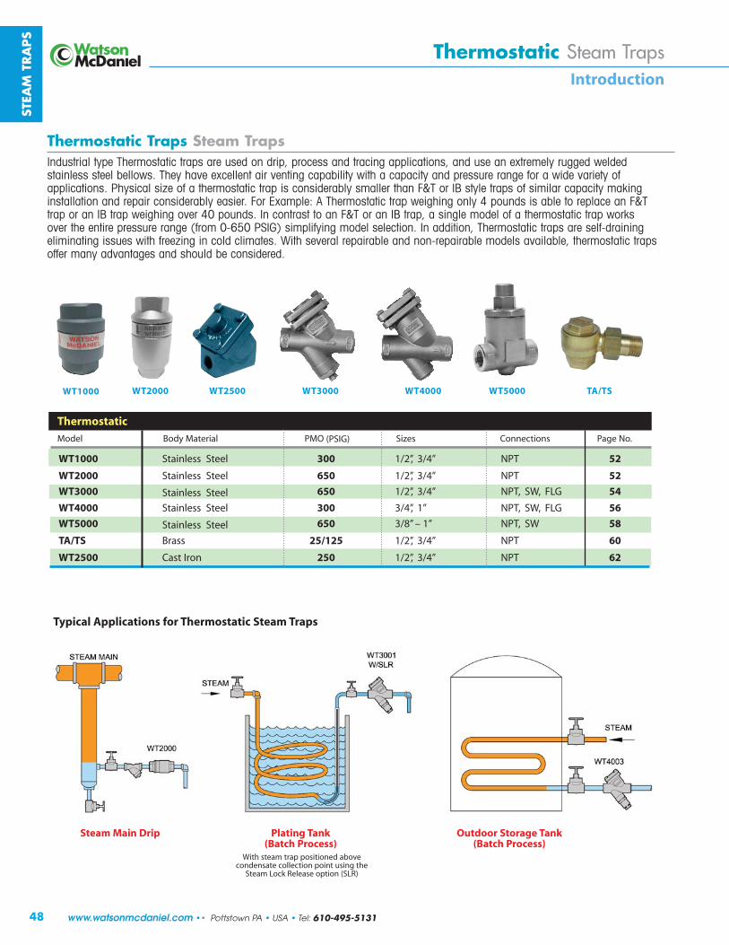
¿
ÇÁË�Ì�ÁÍ��Ç ÇÆ�ÂÈ�Á�Â�� Áß��È��ÆÂÆ��àáâãä�åæãçè¢�¡«¹�� «¢±¦ÉÉÉ õñöïðùù�� õ ð ÉÉ DpBë��Fpwë �¬ë ±®±¦®ÉÉÉ� õñöïðùù�� õ ð 뱃 DpBë��Fpwë �¬ë ±�®±¦ÉÉÉ õñöïðùù�� õ ð 뱃 DpBë��Fpwë �¬ë�� §��@«y ±°±¦°ÉÉÉ õñöïðùù�� õ ð ÉÉ Fpwë��Dë �¬ë�� §��@«y ±Î±¦±ÉÉÉ õñöïðùù�� õ ð 뱃 Fp¿ë�À�Dë �¬ë�� § ±�ͦä¦� _ôñùù ®±ä®± DpBë��Fpwë �¬ë Îɱ¦®±ÉÉ ©ñùõ�\ôìï ®±É DpBë��Fpwë �¬ë ή�¦��¡ª«���� �Aìíð _ìíò�Añõôöñð ¬A��¤¬ \y¥ öíù ©ìïïúõöìïù ¬ñû��ì£
Áß��È��ÆÂÆ���Á�Â��ÇÆ�ÂÈ�Á�Â��}�î�{|~�z�:|ï�Ã:ÁÂÃ~í�{|z|��:|~z�{:z~Ã:�{Ãî:��:î~��ð:�~��Ã{{:z�î:|~z����:z�����z|���{ð:z�î:�{Ã:z�:Ã5|~ÃíÃ�ï:~���Ãî:ñÃ�îÃî:{|z���Ã{{:{|ÃÃ�:�Ã���ñ{ó:ÁÂÃï:Âz�Ã:Ã5�Ã��Ã�|:z�~:�Ã�|���:�z�z����|ï:ñ�|Â:z:�z�z��|ï:z�î:�~Ã{{�~Ã:~z��Ã:ò�~:z:ñ�îÃ:�z~�Ã|ï:�ò:z�����z|���{ó:øÂï{��z�:{�ôÃ:�ò:z:|ÂÃ~í�{|z|��:|~z�:�{:���{�îÃ~z��ï:{íz��Ã~:|Âz�::7qÁ:�~:}r:{|ï�Ã:|~z�{:�ò:{�í��z~:�z�z��|ï:íz������{|z��z|���:z�î:~Ã�z�~:���{�îÃ~z��ï:Ãz{�Ã~ó:7�~:s5zí��Ãt:û:ÁÂÃ~í�{|z|��:|~z�:ñÃ��Â���:���ï:Q:����î{:�{:z��Ã:|�:~Ã��z�Ã:z�:7qÁ|~z�:�~:z�:}r:|~z�:ñÃ��Â���:��Ã~:Q÷:����î{ó:}�:���|~z{|:|�:z�:7qÁ:�~:z�:}r:|~z�ð:z:{����Ã:í�îÃ�:�ò:z:|ÂÃ~í�{|z|��:|~z�:ñ�~�{:��Ã~:|ÂÃ:Ã�|�~Ã:�~Ã{{�~Ã:~z��Ã:õò~�í:÷�36÷:ø�}4ù:{�í���òï���:í�îÃ�:{Ã�Ã�|���ó:}�:zîî�|���ð:ÁÂÃ~í�{|z|��:|~z�{:z~Ã:{Ã�ò�î~z�����:Ã��í��z|���:�{{�Ã{:ñ�|Â:ò~ÃÃô���:��:���î:���íz|Ã{ó:��|Â:{Ã�Ã~z�:~Ã�z�~z��Ã:z�î:����~Ã�z�~z��Ã:í�îÃ�{:z�z��z��Ãð:|ÂÃ~í�{|z|��:|~z�{�òòÃ~:íz�ï:zî�z�|z�Ã{:z�î:{Â���î:�Ã:���{�îÃ~Ãîó±¦ÉÉÉ ±¦®±Éɱ¦®ÉÉÉ ±¦ÉÉÉ ±¦°ÉÉÉ ±¦±ÉÉÉ ¦ä¦�
����ª�£� ¢�å¡ ¬ ¼��� ¢¥�¦�¢� ß�¹««¡���«¡�¥��¦�¢�²®�����¼¡«����³ ²®�����¼¡«����³¦�¬ ����¬¬� ��� «¢���«¡�¦��¡ª«���� ������ª�¦¡�¬�999:9;<=>?@AB;?CDE:A>@FFGHIIJIHKL�GM�FNOM�FPQRS�TUVWXYZWZU[U§öõø�ùõñ¡�õôñó�óìùöõöìïí�ñ¢ì]�úìïíïùñõ�úìððúõöìï�óìöïõ�ùöïû�õø� õñ¡�«ìúa�ªðñù�ìóõöìï�¤ «ª¥

49
STEAM
TRA
PS
Thermostatic Steam TrapsIntroduction
THERMOSTATIC STEAM TRAPS
Operation:The bellows type thermostatic trap contains a fluid-filled thermal element (bellows). The operation of this thermal element is governedby the volumetric thermal expansion of the fluid inside the bellows asit changes states. There is no adjustment required for this trap as thefluid inside the bellows is chosen for its quick response to the changein temperature between steam and condensate at various pressures.The operation of the bellows follows the steam saturation curve, always discharging condensate a few degrees cooler than the steam temperature.
During start-up, when the system is cold, the bellows is retracted and the valve plug is lifted off the seat allowing air and condensateto be discharged from the system. As hot steam approaches the thermal element in the trap, the fluid inside the bellows vaporizes and expands, closing the valve tightly. As long as steam is present, the valve will remain closed. Only when subcooled condensate or airis present will the valve open.
Watson McDaniel thermal element traps offer wide operating pressureranges, rugged welded stainless steel bellows, and various orificesizes, making them a great choice for a majority of applications.
Sub-cool:The sub-cooling of condensate prior to discharge can have certainbeneficial effects. In the majority of tracing applications, the sub-cooling of condensate is highly desirable because of the additionalenergy that is extracted from the Hot condensate. If the trap did notsub-cool condensate, this energy would be wasted.
In Batch style process applications such as jacketed kettles, platingtanks and heating of outdoor storage tanks, the sub-cooling of condensate is generally not a factor to consider since the amount ofcondensate back-up requires less than 1% of the heat transfer surfacearea and is therefore considered negligible. So a heat exchanger with50 square feet of surface area requires only ½ a square foot of surfacearea to sub-cool the condensate. In a Continuous process applicationthat exhibit rapid changes in steam pressures, steam traps requiring sub-cool could lead to additional condensate back up. This scenario is typical in instantaneous hot water heaters using a shell & tube heat exchanger with temperature control valves. The steam pressure in the heat exchanger can drop extremely fast when the water demandchanges. In this case, additional sub-cooling of the condensate isrequired before it will discharge. In some cases, this may be accept-able, but in general, only F&T traps are recommended for process with rapid changes in steam pressures since they always dischargecondensate immediately as it is formed. In addition, traps that sub-cool condensate have a softer discharge since less flash steam is generated in the return line.
Bellows ValveValve Seat
A) AIR When air, which is cooler than steam, is present, the bellows is retracted and the seat is open,allowing large quantities of air to be discharged.
B) CONDENSATE When condensate, which is cooler than steam, is present, the bellows retracts and the seat opens, allowing condensate to be discharged.
C) STEAM When steam reaches the trap, the bellows expands, closing off the seat and preventingthe steam from escaping.
Air
Condensate
Steam
Tel: 610-495-5131 • Pottstown PA • USA •• www.watsonmcdaniel.com

¶À
ÇÆ�ÂÈ�Á�Â�� Áß��È��ÆÂÆ��àáâãä�åæãçè¢�¡«¹�� «¢Ï��·Í��Â��ÂÃ��J½�¦· º�·�:½¬¦§·�µµ:½¬��·:Á²°L ±¦®ÉÉÉ õñöïðùù� õ ðÍ��Â��ÂÃ��J¥ Á²·¬:|²©�³L ±¦ÉÉÉ õñöïðùù� õ ð±¦ÉÉÉ õñöïðùù� õ ðëø�±¦ÉÉÉ�ï�±¦®ÉÉÉ�ëøô¡ìùõñõöú� õñ¡�ëôñóù�øñ] õñöïðùù� õ ð�ùñð%î ðíí�¢ìíöù�ñïí�ñô��ìï%ôóñöôñ¢ð£��ëø�±¦ÉÉÉöù�ùóúö÷öúñððò�öïõïíí�÷ìô�øôöó�ñïí�ëôñúöïû��óóðöúñõöìïù£�ëø�±¦®ÉÉÉöù�ù¢ùõñïõöñððò�ðñôûô�öï�úñóñúöõò�õøñï�õø�§ëDúúú£��\õ�úñï�¢�ùí�÷ìô�_ñõúø�ëòó�¬ôìúùù�óóðöúñõöìïù�ñù�îðð�ñù�÷ìô�øôöó�ñïí�ëôñúöïû£���ðùì�ùí�ñù�ñï��öô�÷ïõ?�Aìíð��÷Búúú£
±¦±ÉÉÉ_ö%A õñð
±¦°ÉÉÉ õñöïðùù� õ 𱦮±ÉÉ©ñùõ%\ôìï ¦�½�¦�_ôñùù
ëø�±¦ÉÉÉ�ï�±¦°ÉÉÉ�ëøô¡ìùõñõöú� õñ¡�ëôñóù�øñ]úñùõ� õñöïðùù� õ ð�¢ìíöù�ñïí�ñô�÷ððò%ôóñöôñ¢ð£��ëø�±¦ÉÉÉøñù�ñï�öíïõöúñð�úñóñúöõò�õì�õø�§ëBúúú?úì¡¡ìïðò�ùí�÷ìô�¬ôìúùù��óóðöúñõöìïù�¢õ�úñï�ñðùì�¢ùí�÷ìô�íôöó�ñïí�õôñúöïû�ö÷�ñ�ôóñöôñ¢ð�íùöûï�öù�íùöôí£ëø�±¦°ÉÉÉøñù�ù¢ùõñïõöñððò�øöûøô�úñóñúöõò�õøñï�õø§ëFúúú?��ùí�÷ìô�ðñôûô�¬ôìúùù��óóðöúñõöìïù£�ëø�±¦±ÉÉÉ�_ö%A õñð� õñ¡�ëôñó�øñù�ñ� õñöïðùù� õ ð¢ìíò�öù�÷ððò%ôóñöôñ¢ð�ñïí�öïõïíí�÷ìô� õñ¡�ëôñúöïû�óóðöúñõöìïù£�\õù�ïöî �÷ñõô�öù�ñ�õ¡óôñõô%ñíêùõñ¢ð�_ö%A õñð�ð¡ ïõ�îøöúø�ñððìîù�÷ìô�óôúöù�úìïõôìð�ì÷�úìïíïùñõíöùúøñôû�õ¡óôñõô�¤õ¡óôñõô�ñíêùõ¡ ïõ�úñï�¢¡ñí�öï�õø�÷öðí¥£�ëøöù�öù�ñ�íùöôñ¢ð�÷ñõô�÷ìô�õôñúöïû�ùì�õøñõ�úìïíïùñõ�íöùúøñôû�õ¡óôñõô�úñï�¢�úìïõôìððí�õì�ùöõ�ñ�óñôõöúðñô�ñóóðöúñõöìï£
ëø�±¦®±ÉÉ�îöõø�ñ�úñùõ�öôìï�¢ìíò��öù�ñï�úìïì¡öúñðñðõôïñõö]�õì�õø�§ëFúúú�ñïí�öù�öíïõöúñð�öï�úñóñúöõò?øìî ]ô�öõù�ðö¡öõí�õì�BEú�¬ \y£��\õ�öù�ðöaîöù�÷ððò%ôóñöôñ¢ð�ñïí�úñï�¢�ùí�îøô�úñùõ�öôìï�öù�ñúúóõñ¢ð£ëø�¦ä¦����¡ ���ñô�ô÷ôôí�õì�ñù�ëøô¡ìùõñõöú�ªñíöñõìôëôñóù£�ëøò�øñ]�¢ôñùù�¢ìíöù�ñïí�ñô�÷ððò%ôóñöôñ¢ð?�óôíì¡öïñïõðò�ùí�öï�õø�õ÷�©�öïíùõôò�÷ìô�ùõñ¡�õôñóùñïí�ñöô�]ïõù£
ÇÁË�Ì�ÁÍ��Ç
Á�È���ÂÆØ����×}Ø�ÆÂÃ���~�·Ì�ÆÂ�
ñð%î ðííw%_ìðõ�©ì]ô
999:9;<=>?@AB;?CDE:A>@FFGHIIJIHKL�GM�FNOM�FPQRS�TUVWXYZWZU[U

51
WT1000Thermostatic
Steam Traps
Model WT1000 (Non-Repairable)Sizes 1/2”, 3/4”Connections NPTBody Material Stainless SteelPMO Max. Operating Pressure 300 PSIGTMO Max. Operating Temperature Saturated Steam TemperaturePMA Max. Allowable Pressure 1032 PSIG @ 100ºFTMA Max. Allowable Temperature 750ºF @ 800 PSIG
Typical Applications
DRIP, TRACING: The WT1000 is a low capacity thermostatic trap ideally sized for steam tracing. Thermostatic traps are small,light weight and have excellent air discharging capabilities.Discharging air at start-up allows steam to quickly enter the system. Trap body is permanently seal welded together andtherefore non-repairable. Contains an extremely strong andrugged precision welded Stainless Steel thermal element. Its small discharge orifice, which makes it an optimal size trap forboth drip and tracing applications, is susceptible to cloggingdepending on system conditions, therefore, a separate strainershould be installed.
How It Works
This thermostatic trap contains a welded stainless steel thermal element that expands when heated and contracts when cooledto 5˚F below saturated steam temperature. When air or sub-cooledcondensate are present, the trap is in the open discharge position.When steam reaches the trap, the element expands and closes off tightly.
Features
• Excellent at discharging air which allows steam to enter system quickly; extremely important during start-up
• Welded stainless steel thermal element resists shock from water hammer
• Freeze-proof when trap is installed in a vertical orientation allowing for complete condensate drainage
• Stainless steel Barstock body
• In the unlikely event of bellows failure; trap dischargeremains open
DIMENSIONS – inches
CAPACIT IES – Condensate (lbs/hr) Steam Inlet Pressure (PSIG)Size Model Code 5 10 20 50 100 125 150 200 250 3001/2” WT1000-12-N
95 140 195 305 435 485 530 610 685 7503/4” WT1000-13-N
MATERIALS
Trap Housing Stainless Steel, AISI 304LThermal Element Stainless Steel, 300 SeriesValve Stainless Steel, AISI 440C
2.5” 1.31”
1.75”
Installation & MaintenanceTrap can be installed in any orientation. The WT1000 steam trapbody is seal-welded and therefore non-repairable. If a new trapis required, remove from line and replace. This product cannotbe welded in-line or failure of the thermal element due to excessheat may occur. Available in NPT threaded connections only.
Sample Specification
The steam trap shall be of thermostatic type with stainless steelbody and stainless steel thermal element.
STEAM
TRA
PS
FLOW
Thermostatic Steam Trap(Non-Repairable)
Tel: 610-495-5131 • Pottstown PA • USA •• www.watsonmcdaniel.com
Seal-weldedWeight: 1.25 lbs.

52
WT2000Steam TrapsThermostatic Steam Trap(Non-Repairable)
Thermostatic
Model WT2000 (Non-Repairable)Sizes 1/2”, 3/4”Connections NPTBody Material Stainless SteelPMO Max. Operating Pressure 650 PSIGTMO Max. Operating Temperature Saturated Steam Temp.PMA Max. Allowable Pressure 1032 PSIG @ 100ºFTMA Max. Allowable Temperature 750ºF @ 800 PSIG
Typical Applications
DRIP, TRACING, PROCESS: The WT2000 is a general purposemedium-capacity thermostatic trap that can be used for steamtracing, as a drip trap on steam mains and steam supply lines,as well as for process applications. They are also commonlyused as an Air Vent on heat exchangers or at the ends of steammains. Thermostatic traps are small, light weight, operate over awide pressure range, and have excellent air handling capabilities.Discharging air at start-up allows steam to quickly enter the system. All stainless steel construction and integral strainer, makethe WT2000 an excellent choice for a variety of applications.Trap body is permanently seal welded together and therefore non-repairable. Contains an extremely strong and rugged precision welded Stainless Steel thermal element which is highly resistant to waterhammer.
How It Works
This thermostatic trap contains a welded stainless steel thermal element that expands when heated and contracts when cooledto 5˚F below saturated steam temperature. When air or sub-cooledcondensate are present, the trap is in the open discharge position.When steam reaches the trap, the element expands and closes off tightly.
Features
• Thermostatic traps are excellent at discharging air, which allows steam to enter quickly; extremely important during start-up
• Integral strainer to protect trap from contamination
• Welded stainless steel thermal element resists shock from waterhammer
• Freeze-proof when trap is installed in a vertical orientation allowing for complete condensate drainage
• Body is produced from stainless steel investment casting
• Hardened stainless steel seat for extended service life
• Will operate at steam pressures up to 650 PSIG
Sample Specification
Steam trap shall be of thermostatic type with stainless steel body,thermal element, internal screen, and hardened valve and seat.
Installation and Maintenance
Trap can be installed in any position. The WT2000 steam trapbody is seal-welded and therefore non-repairable. If a new trap isrequired, remove from line and replace. Cannot be welded in-lineor failure of the thermal element may occur. Available in NPTthreaded connections only.
Helpful Selection Information
Two orifice sizes are available: The 3/16” orifice should beused on all drip and tracing applications as well as small processapplications with lower condensate loads. The 5/16” orifice isavailable to be used on process applications if additional capacityis required.
Options
• Special Bellows Option; available upon request:• Fail-closed Bellows (standard bellows fails in open position)• 43˚F Sub-cool Bellows (Note: Standard bellows are designed
for approximately 5˚F sub-cool temperature)
• SLR = Steam lock release
• Standard models contain a non-cleanable strainer screen.Also available without screen where it is desireable to flush dirt and scale thru the trap. Recommend WT2003 withlarger orifice if used without strainer.
STEA
M T
RA
PS
www.watsonmcdaniel.com •• Pottstown PA • USA • Tel: 610-495-5131

53
WT2000Thermostatic Steam Trap(Non-Repairable)
Thermostatic
Steam Traps
3.75”
1.31”
1.88”
Note: 3/16” orifice should be used on all drip and tracing applications.
CAPACIT IES – Condensate (lbs/hr) Orifice Steam Inlet Pressure (PSIG)Size Model Code Size 5 10 20 50 100 125 150 200 250 300 350 400 500 600 650
1/2” WT2001-12-N 3/16” 441 625 882 1391 1827 1969 2095 2305 2483 2636 2777 2903 3129 3323 3413
3/4” WT2001-13-N
1/2” WT2003-12-N
3/4” WT2003-13-N 5/16”
903 1271 1811 2861 3754 4043 4300 4730 5093 5413 5702 5959 6421 6820 7004
Back Pressure as Percentage of Inlet Pressure 10 20 25 30 40 50 60 70 80 90
Percentage Decrease in Trap Capacity 0 0 0 2 5 12 20 30 40 55
How to Size / OrderSelect working pressure; follow column down to correct capacity(lbs/hr) block. Example:
Application: 1827 lbs/hr at 100 PSIG working inlet pressureSize/Model: WT2001-12-N, 1/2” NPT, 3/16” orifice
MATERIALSTrap Housing Stainless Steel, ASTM A351-CF3Thermal Element Stainless SteelValve & Seat Stainless Steel, AISI 416Strainer Screen Stainless Steel
Orifice
STEAM
TRA
PS
FLOW
DIMENSIONS – inchesWeight: 1.5 lbs.
Seam-welded body (Non-Repairable)
Tel: 610-495-5131 • Pottstown PA • USA •• www.watsonmcdaniel.com
Strainer

54
WT3000Steam TrapsThermostatic Steam Trap(Repairable)
Thermostatic
Model WT3000 (Repairable)Sizes 1/2”, 3/4”Connections NPT, SW, FLGBody Material Stainless SteelOptions Strainer, Blowdown ValvePMO Max. Operating Pressure 650 PSIGTMO Max. Operating Temperature Saturated Steam Temp.PMA Max. Allowable Pressure 906 PSIG @ 100ºFTMA Max. Allowable Temperature 750ºF @ 725 PSIG
Typical Applications
DRIP, TRACING, PROCESS: The WT3000 is a general purpose medium capacity thermostatic trap that can be used forsteam tracing; as a drip trap on steam mains and steam supplylines; as well as for process applications. All internal workingcomponents can be replaced while the trap body remains in-line.Thermostatic traps are small, light weight, operate over a widepressure range, and have excellent air handling capabilities.Discharging air at start-up allows steam to quickly enter the system. All stainless steel construction and integral strainer option make the WT3000 an excellent choice for a variety ofapplications. Contains an extremely strong and rugged precisionwelded Stainless Steel thermal element which is highly resistantto waterhammer.
How It Works
This thermostatic trap contains a welded stainless steel thermal element that expands when heated and contracts when cooledto 5˚F below saturated steam temperature. When air or sub-cooledcondensate are present, the trap is in the open discharge position.When steam reaches the trap, the element expands and closes off tightly.
Features
• The thermal element and seat can be easily removed and replaced in minutes with the trap body still in-line
• Operates at steam pressures up to 650 PSIG
• Thermostatic traps are excellent at discharging air, which allows steam to enter quickly; extremely important during start-up
• Welded stainless steel thermal element resists shock from waterhammer
• Freeze-proof when trap is installed in a vertical orientation allowing for complete condensate drainage
• Body is produced from stainless steel investment casting
• Hardened stainless steel seat for extended service life
• Available with integral strainer and blowdown valve
Sample Specification
The steam trap shall be of a thermostatic type with stainless steel body, thermal element and internal strainer. Trap must bein-line repairable with a bolt-on type cover that is sealed with a spiral wound Stainless Steel AISI 316 gasket. Seat and valve to be hardened stainless steel.
Installation and Maintenance
Trap can be installed in any orientation. All internal working components are extremely easy to replace and can be performedwhile the trap body remains connected in-line. Repair kit includesALL parts to fully rebuild the steam trap including thermal element, seat and gasket. The WT3000S model comes with an optional strainer. WT3000SB comes with optional blowdownvalve for flushing dirt and scale from strainer.
Helpful Selection Information
Two orifice sizes are available: The 3/16” orifice should beused on all drip and tracing applications as well as small processapplications with lower condensate loads. The 5/16” orifice isavailable to be used on process applications if additional capacityis required.
Options
Strainer, blowdown valve, steam lock release and special bellows available. S = Strainer (WT3001S)SB = Strainer and blowdown valve (WT3001SB)SLR = Steam lock releaseSpecial Bellows Option; available upon request:
• Fail-closed Bellows (standard bellows fails in open position)• 43˚F Sub-cool Bellows (Note: Standard bellows are designed
for approximately 5˚F sub-cool temperature)
How to Size / OrderRefer to the Capacity Chart to determine which model, the WT3001 or WT3003 is required to satisfy the condensate loadbased on steam inlet pressure.
Example:
Application: 3754 lbs/hr at 100 PSIG steam inlet pressure Size/Model: WT3003S, 5/16” orifice with strainer,
Specify size & connections (NPT, SW, FLG)
Example Model Codes:
WT3003S-13-N 3/4” NPT with strainer, and 5/16” orifice.
WT3001SB-12-N 1/2” NPT with strainer and blowdown valve,3/16” orifice
STEA
M T
RA
PS
www.watsonmcdaniel.com •• Pottstown PA • USA • Tel: 610-495-5131

55
WT3000Thermostatic
Steam Traps
Back Pressure as Percentage of Inlet Pressure 10 20 25 30 40 50 60 70 80 90
Percentage Decrease in Trap Capacity 0 0 0 2 5 12 20 30 40 55
* Flanged face-to-face dimension 9” standard. For custom sizes consult factory (9” minimum).
2.62” Square
FLOW
MATERIALS
Cover & Body Stainless Steel, AISI 316LThermal Element Stainless Steel, AISI 300Valve & Seat Stainless Steel, AISI 416Cover Gasket Stainless Steel, AISI 316Seat Gasket Stainless Steel, AISI 316Cover Bolts Steel, ASTM A193 GR B7 Nickel PlatedStrainer* 0.046 Perforated Stainless Steel AISI 304Blowdown Valve* Stainless Steel AISI 303
* Strainer and blowdown valve are optional
3.13”
WT3000: 2.57”WT3000S: 2.57”
WT3000SB: 3.20”
4.50” (NPT, SW)
(Flanged as Req’d) *
Cover Bolts
Cover
Thermal Element
Strainer
Strainer Plug
Optional Blowdown Valve
STEAM
TRA
PS
Orifice
CAPACIT IES – Condensate (lbs/hr) Orifice Steam Inlet Pressure (PSIG)
Model Size 5 10 20 50 100 125 150 200 250 300 350 400 500 600 650WT3001 3/16” 441 625 882 1391 1827 1969 2095 2305 2483 2636 2777 2903 3129 3323 3413
WT3003 5/16” 903 1271 1811 2861 3754 4043 4300 4730 5093 5413 5702 5959 6421 6820 7004
Weight: 4.5 lbs.
Size/Connection* Model Code Orifice Size Description
1/2” NPT WT3001-12-N 3/16” No Strainer3/4” NPT WT3001-13-N 3/16” No Strainer1/2” NPT WT3001S-12-N 3/16” Strainer3/4” NPT WT3001S-13-N 3/16” Strainer1/2” NPT WT3001SB-12-N 3/16” Strainer & Blowdown3/4” NPT WT3001SB-13-N 3/16” Strainer & Blowdown
1/2” NPT WT3003-12-N 5/16” No Strainer3/4” NPT WT3003-13-N 5/16” No Strainer1/2” NPT WT3003S-12-N 5/16” Strainer3/4” NPT WT3003S-13-N 5/16” Strainer1/2” NPT WT3003SB-12-N 5/16” Strainer & Blowdown3/4” NPT WT3003SB-13-N 5/16” Strainer & Blowdown
* For Socket Weld Connection change N to SW
Tel: 610-495-5131 • Pottstown PA • USA •• www.watsonmcdaniel.com
Thermostatic Steam Trap(Repairable)

56
WT4000Steam TrapsThermostatic Steam Trap(Repairable)
Thermostatic
Model WT4000 (Repairable)Sizes 3/4”, 1”Connections NPT, SW, FLGBody Material Stainless SteelOptions Strainer, Blowdown ValvePMO Max. Operating Pressure 300 PSIGTMO Max. Operating Temperature Saturated Steam TemperaturePMA Max. Allowable Pressure 906 PSIG @ 100ºF TMA Max. Allowable Temperature 750ºF @ 725 PSIG
Typical Applications
PROCESS: The WT4000 is a high capacity version of theWT3000, for removing condensate and air from larger processapplications. This steam trap is fully repairable while the bodyremains in-line. Like all thermostatic traps, they are small, lightweight, operate over a wide pressure range, and have excellentair handling capabilities. Discharging air at start-up allows steamto quickly enter the system. All stainless steel construction andintegral strainer option make the WT4000 an excellent choice for most process applications. Contains an extremely strong and rugged precision welded Stainless Steel thermal elementwhich is highly resistant to waterhammer.
How It Works
This thermostatic trap contains a welded stainless steel thermal element that expands when heated and contracts when cooledto 5˚F below saturated steam temperature. When air or sub-cooledcondensate are present, the trap is in the open discharge position.When steam reaches the trap, the element expands and closes off tightly.
Features
• The thermal element and seat can be easily removed and replaced in minutes with the trap body still in-line
• Operates at steam pressures up to 300 PSIG• Thermostatic traps are excellent at discharging air, which
allows steam to enter quickly; extremely important during start-up
• Welded stainless steel thermal element resists shock from waterhammer
• Freeze-proof when the trap is installed in a vertical orientation allowing for complete condensate drainage
• Body is produced from stainless steel investment casting• Hardened stainless steel seat for extended service life• Available with integral strainer and blowdown valve
Sample Specification
The steam trap shall be of thermostatic type with stainless steelbody, thermal element, and internal strainer. Trap must be in-linerepairable with a bolt-on type cover that is sealed with a spiralwound Stainless Steel AISI 316 gasket. Seat and valve to be hardened stainless steel.
Installation and Maintenance
Trap can be installed in any orientation. All internal working components are extremely easy to replace and can be performedwhile the trap body remains connected in-line. Repair kit includesALL parts to fully rebuild the steam trap including thermal element, seat and gasket. The WT4000 does not contain astrainer. The WT4000S contains a strainer. WT4000SB containsa blowdown valve for flushing dirt and scale from strainer.
Helpful Selection Information
Two orifice sizes are available: 7/16” standard capacity and5/16” reduced capacity. Select these models for steam systemswith maximum working pressure of 300 PSIG.
Options
Strainer, blowdown valve, and steam lock release. S = Strainer (WT4001S)
SB = Strainer and blowdown valve (WT4001SB)
SLR = Steam lock release
Customized flanged connections: Specify size, face-to-facedimensions.
How to Size / OrderRefer to the Capacity Chart to determine which model, the WT4001 or WT4003 is required to satisfy the condensate loadbased on steam inlet pressure.
Example:
Application: 5610 lbs/hr at 100 PSIG steam inlet pressure
Size/Model: WT4001S, 5/16” orifice, and strainerSpecify size & connections (NPT, SW, FLG)
Example Model Codes:
WT4001S-13-N 3/4” NPT with strainer, and 5/16” orifice
WT4003SB-14-N 1” NPT with strainer and blowdown valve,7/16” orifice
STEA
M T
RA
PS
www.watsonmcdaniel.com •• Pottstown PA • USA • Tel: 610-495-5131

57
WT4000Thermostatic Steam Trap(Repairable)
Thermostatic
Steam Traps
MATERIALSBody Stainless Steel, AISI 316LCover Stainless Steel, AISI 316LCover Gasket Spiral Wound Stainless Steel, AISI 316Cover Bolts Steel, ASTM A193 GR B7 Nickel PlatedThermal Element Stainless Steel, AISI 302Valve & Seat Hardened Stainless Steel, AISI 416Seat Gasket Stainless Steel, AISI 316Strainer* 0.046 Perforated Stainless Steel AISI 304Blowdown Valve* Stainless Steel AISI 300
* Strainer and blowdown valve are optional
* Flanged face-to-face dimension 9” standard. For custom sizes consult factory (9” minimum).3” Square
STEAM
TRA
PS
Orifice
StrainerPlug
FLOW
4.81” (NPT, SW)
(Flanged as Req’d) *
4.12”
CAPACIT IES – Condensate (lbs/hr) Orifice Steam Inlet Pressure (PSIG)
Model Size 1 2 5 10 20 50 100 125 150 200 250 300WT4001 5/16” 605 855 1350 1910 2705 4275 5610 6045 6425 7070 7615 8095
WT4003 7/16” 940 1325 2095 2960 4190 6620 8695 9365 9950 10955 11800 12540
Cover Bolts
Cover
Strainer
Thermal Element
WT4000: 2.57”WT4000S: 2.57”
WT4000SB: 3.12”
Weight: 4.5 lbs.
Size/Connection* Model Code Orifice Size Description
3/4” NPT WT4001-13-N 5/16” No Strainer1” NPT WT4001-14-N 5/16” No Strainer3/4” NPT WT4001S-13-N 5/16” Strainer1” NPT WT4001S-14-N 5/16” Strainer3/4” NPT WT4001SB-13-N 5/16” Strainer & Blowdown1” NPT WT4001SB-14-N 5/16” Strainer & Blowdown
3/4” NPT WT4003-13-N 7/16” No Strainer1” NPT WT4003-14-N 7/16” No Strainer3/4” NPT WT4003S-13-N 7/16” Strainer1” NPT WT4003S-14-N 7/16” Strainer3/4” NPT WT4003SB-13-N 7/16” Strainer & Blowdown1” NPT WT4003SB-14-N 7/16” Strainer & Blowdown
* For Socket Weld Connection change N to SW
Back Pressure as Percentage of Inlet Pressure 10 20 25 30 40 50 60 70 80 90
Percentage Decrease in Trap Capacity 0 0 0 2 5 12 20 30 40 55
Tel: 610-495-5131 • Pottstown PA • USA •• www.watsonmcdaniel.com

58
WT5000Steam TrapsBi-Metal Adjustable Discharge Temperature(Repairable)
Bi-Metal
Model WT5000 (Bi-Metal)Sizes 3/8”, 1/2”, 3/4, 1”Connections NPT, SWBody Material Stainless SteelPMO Max. Operating Pressure 650 PSIGTMO Max. Operating Temperature 662˚FPMA Max. Allowable Pressure 900 PSIG TMA Max. Allowable Temperature 800ºF
Typical Applications
TRACING: The WT5000 is specifically designed for steam tracing applications where accurate and adjustable control ofcondensate discharge temperature is desired. Can be used where a temperature sensitive medium is being transferred in piping system or held in a storage vessel and standard steamtracing methods may not be adequate to maintain specific product temperatures. Having the ability to adjust the condensatedischarge temperature would allow for accurate temperature control of the product being traced. The significant feature of the WT5000 is that the condensate discharge temperature is easily field-adjustable.
How It Works
Bi-metallic plates of dissimilar metals which are connected to the valve seat assembly respond to temperature variations. At relatively cool conditions, the trap is open for the discharge ofcondensate. When the temperature of the condensate is equal toor higher than the set temperature, the metals react and expand,closing the trap. External field-adjustability of the bi-metal element allows control of the condensate discharge temperature.
The condensate temperature can be field adjusted as follows:
To INCREASE the temperature, turn the adjuster screw:COUNTERCLOCKWISE
To DECREASE the temperature, turn the adjuster screw:CLOCKWISE
Note: The lower the set temperature, the more condensate will back-up in front of the trap inlet connection. Therefore, consideration should be given to providing adequate piping to accommodate any such back-up.
Features
• Excellent for various steam tracing and small process applications using the additional energy (sensible heat)of the hot condensate
• Field-adjustable bi-metal element allows control of condensate discharge temperature
• Internal screen and seat/plug design help prevent pipe scale and debris from accumulating on seating surfaces to provide trouble-free operation
• In-line repairable
MATERIALSBody and Cover 304 Stainless SteelBimetal Element GB14Valve Seat 420 Stainless SteelValve Stem 420 Stainless Steel
STEA
M T
RA
PS
Sample Specification
The steam trap shall be a bi-metal type with stainless steel body,seat, valve plug and bimetallic element. Bi-metal element shallbe externally adjustable for control of condensate discharge temperature. Trap must be in-line repairable with a replaceablebi-metal element, valve plug and seat.
Installation and Maintenance
Trap can be installed in any orientation. The body is made fromstainless steel and is fully repairable while the steam trap remainsin-line. If the trap fails, remove the cover and replace the internalworking components. Repair kit includes bimetallic element(including valve stem and plug), seat and gasket.
Helpful Selection Information
Available in 3/8” through 1” NPT and socket weld connections.Select this model for steam systems with maximum working pressure of 650 PSIG.
Size/Connection Model Weight Cross ReferenceCode lbs TLV
3/8” NPT WT5000-11-N1/2” NPT WT5000-12-N
3.0 LEX3N-TZ3/4” NPT WT5000-13-N1” NPT WT5000-14-N3/8” SW WT5000-11-SW1/2” SW WT5000-12-SW
3.0 LEX3N-TZ3/4” SW WT5000-13-SW1” SW WT5000-14-SW
www.watsonmcdaniel.com •• Pottstown PA • USA • Tel: 610-495-5131

59
WT5000Bi-Metal Adjustable Discharge Temperature(Repairable)
Bi-Metal
Steam Traps
Notes: 1) Capacities in chart are based on discharging condensate to atmospheric pressure (0 PSIG).2) Initial Opening Temperature = T is the temperature at which the trap just begins to open.
A negligable amount of condensate flow takes place at this temperature. It is adjustablebetween 120˚F and 390˚F.
3) Initial Opening Temperature must be at least 27 degrees below the saturated steamtemperature to prevent possible steam loss.
4) When the condensate cools below the initial opening temperature, the Bi-metal mechanismopens further, increasing trap capacity. Trap capacity can be adjusted up to the max valuegiven in the chart.
5) For instructions on setting the trap discharge temperature and capacity, refer to the Watson McDaniel Installation and Maintenance Guide.
6) Example: A WT5000 trap with 125 PSIG Steam Inlet Pressure can be set to an Initial Opening Temperature between 120˚F and 326˚F. It can pass up to 413 lbs/hr when the temperatureof the condensate is 80˚F below the initial opening temperature (T–80˚F).
Trap Capacities at Various Inlet Pressures – Lbs/hr @ T, T-20˚F, T-40˚F, T-60˚F, T-80˚F Saturated Steam Temperature (˚F) (based on given steam inlet pressure)
250 274 298 338 353 366 388 406 422 436 448 460 470 489 497 Maximum Initial Opening Temperature must be at least 27 degrees below saturated steam temperature. (390˚F max) 223 247 271 311 326 339 361 379 390 390
Condensate Steam Inlet Pressure (PSIG)Discharge Temperature 15 30 50 100 125 150 200 250 300 350 400 450 500 600 650
T 0 0 0 0 0 0 0 0 0 0 0 0 0 0 0
T–20˚F 56 70 102 144 161 177 204 228 250 270 289 306 323 354 368
T–40˚F 116 164 212 300 336 368 425 475 520 562 600 637 671 735 756
T–60˚F 134 190 245 346 387 424 490 548 600 648 693 735 775 849 883
T–80˚F 143 202 261 370 413 453 523 584 640 691 739 784 826 905 942
3.25”
4.25”
3/8” – 1”NPT, SW
2.75” (3/8” & 1/2”) 3.12” (3/4” & 1”)
STEAM
TRA
PS
Units: inches
FLOW
FLOW
WT5000
Demonstrated in thistracing application, the discharge temperature of the trap is adjusted so that hot condensatebacks up into the tracingline. This allows theproduct flowing thru thepipe to be heated to a specific temperature bythe condensate.
TemperatureAdjustment
Screw
Tel: 610-495-5131 • Pottstown PA • USA •• www.watsonmcdaniel.com
T = Initial Opening Temperature of the Trap can be set from 120˚F to 390˚F
= Initial Opening Temp.
20˚below Initial OpeningTemperature
40˚below Initial OpeningTemperature60˚below Initial OpeningTemperature
80˚below Initial OpeningTemperature
T can range from 120˚F to 390˚F.
T range for Steam Inlet Pressureof 15 PSIG is 120 to 223˚F

60
TA25B, TA125TS25B, TS125
Steam TrapsThermostatic Steam Trap(Repairable)
Model TA25B, TA125, TS25B, TS125
Sizes 1/2”, 3/4”Connections NPTBody Material BrassPMO Max. Operating Pressure TA25B, TS25B 25 PSIG
TA125, TS125 125 PSIGTMO Max. Operating Temperature Saturated Steam TemperaturePMA Max. Allowable Pressure 125 PSIG up to 450ºFTMA Max. Allowable Temperature 450ºF @125 PSIG
Typical Applications
TA & TS type steam traps are predominantly used in the HVACindustry. They are referred to as radiator traps because the quick-disconnect right angle connection of the TA Type is found on most steam radiator installations. The TS Type offers astraight-through connection alternative. TA and TS Series radiatortraps were designed specifically for removing condensate and air from 2-pipe steam heating systems. Their excellent air-handlingcapabilities, compact size, and economical cost make them agreat choice for air vents on heat exchangers or for steam trapapplications on OEM equipment. Contains an extremely strongand rugged precision-welded Stainless Steel thermal elementwhich is highly resistant to waterhammer.
How It Works
This thermostatic trap contains a welded stainless steel thermalelement that expands when heated and contracts when cooled.When air and condensate are present the trap is in the open discharge position. When steam reaches the trap the elementexpands and closes off tightly.
Features
• Excellent air handling capability
• In-line repairable
• Welded stainless steel thermal element
• Stainless seat on TA125 & TS125
• High thermal efficiency
Sample Specification
The steam trap shall be of thermostatic type with brass or bronze body and stainless steel thermal element. Trap must be in-line repairable.
Installation and Maintenance
Trap can be installed in any orientation. The bodies are madefrom a high-quality brass forging and are easily repairable while the steam trap remains in-line by removing the cap andreplacing the seat and thermal element. Repair kit includes thermal element, seat and gasket.
STEA
M T
RA
PS
Inlet
Outlet
TA Type • Right-Angle Connection
TS Type • Straight-thru Connection
Inlet
Outlet
www.watsonmcdaniel.com •• Pottstown PA • USA • Tel: 610-495-5131

61
Thermostatic Steam Trap(Repairable)
Steam Traps
How to Size / OrderSelect differential pressure; follow column down to correctcapacity (lbs/hr) block. Example:
Application: 2100 lbs/hr at 40 PSI differential pressure
Size/Model: 3/4” TA125
MATERIALS
Body Forged Brass, CA 377Element Welded Stainless Steel, AISI 302Cover Forged Brass, CA 377Spring Stainless Steel, AISI 304Seat TA25B/TS25B: Brass ASTM B-21
TA125/TS125: Stainless Steel, AISI 303Gasket Brass, ASTM B-21Union Nipple Brass, ASTM B-16Union Nut Brass, ASTM B-16
Cover
Spring
Element
Seat
Body
Union Nipple
Union Nut
DIMENSIONS & WEIGHTS – inchesModel Pipe Size A Weight (lbs)
TA25B, TA125 1/2” 2.1875 1.5
TA25B, TA125 3/4” 3.062 1.5
TS25B, TS125 1/2” 4.500 1.5
TS25B, TS125 3/4” 4.625 1.5
Note: Other Union Connections and Lengths are available; consult factory.
1.0”
1.19”
A
2.12”
Gasket
STEAM
TRA
PS
1/2”
3/4”
TA Type • Right-Angle Connection
TA25B, TA125TS25B, TS125
TS Type • Straight-thru Connection
A
1.25”1.75”
2.54”
CAPACIT IES – Condensate (lbs/hr) PMO Steam Inlet Pressure (PSIG)Size Model Code (PSIG) 15 25 40 65 125 TA25B-12-N
25 825 1070 TS25B-12-N
TA125-12-N 125 825 1070 1323 1610 1950
TS125-12-N
TA25B-13-N 25 1290 1700
TS25B-13-N TA125-13-N
125 1290 1700 2100 2575 3300 TS125-13-N
Tel: 610-495-5131 • Pottstown PA • USA •• www.watsonmcdaniel.com
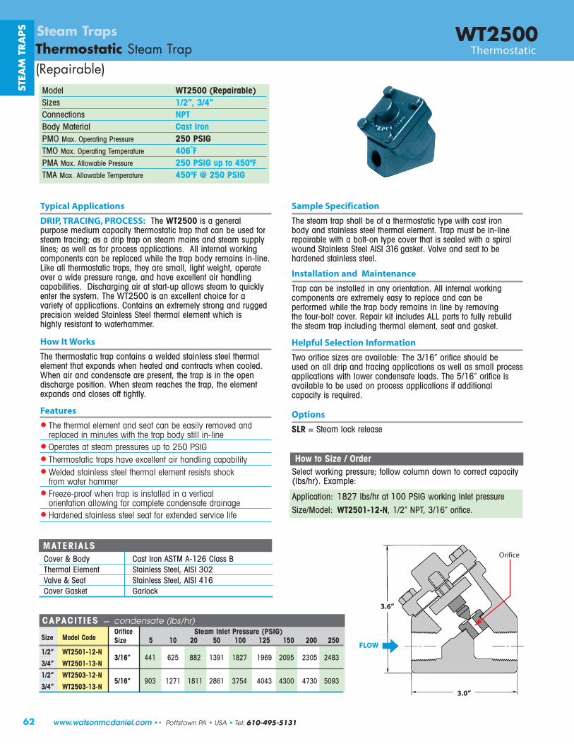
�Îr�Ér§¦ß±
�ôö÷öúµê
�Áê¶ÀÀÁß��È��ÆÂÆ���½¬�¦¶:�³¦®JK�®¦³¦¹·�L ëøô¡ìùõñõöúÇÆ�ÂÈ�Á�Â������ �S;ADD:6A/T0Q30da/9��� =>;<:?>@<���������� x2S����:������� X04.:73Y[���:���F:���������:��� ���: ;AD:2-78���:���F:���������:�����������: @DBVW���:���F:�� �!�:��� ���: ;AD:2-78:5T:.Y:@AD�W���:���F:�� �!�:�����������: @AD�W:":;AD:2-78
Xh2hX7S7i-¡�CHLlQLJmIQ�nRoJpqrs::::::::::::::::::::::::::::::::::::P3Q_QZ/:::::::::::::::::::::::: -./01:7[a/.:23/4453/:62-789-Q]/::::tYR/a:XYR/::::::-Q]/::::::::::::A::::::::=D::::::;D::::::::AD::::::=DD::::::=;A::::::=AD::::::;DD::::;AD=>;<:::�S;AD=w=;wx::::?>=B<:::::::GGH::::::NLK::::EEL::::HIMH::::HELJ::::HMNM::LOMK::::LIOK::LGEI?>@<:::�S;AD=w=?wx::::::::::::::::::::::::=>;<:::�S;AD?w=;wx::::::::::::::::::::::::?>@<:::�S;AD?w=?wx::::A>=B<::::::MOI::::HLJH::HEHH::LENH::::IJKG::::GOGI::GIOO::::GJIO::KOMI
�Yf:.Y:-Q]/:>:P3R/3����: ��.���:��� ���8:%�� :�����:�� �:��:�������:��������0! ¢$�1F:?�����@����������@HELJ:! ¢$�:��:HOO:�(>: ��.���:����:��� ������¢����@�S;AD=w=;wx#:H¢L£:E��#:I¢HN£:���%���F
��ª¬����¬�� � ��� «¢�$�: ����:����: $�:!�:�%:�:�$���� �����:����: ��$:�� �:����:!���:���: ����� : ���:�$����:������F:����:�� �:!�:��*����������!�: ��$:�:!��*��:����:��'��:�$��:� : ����: ��$:�: ���� ����:����� :���:�((:IHN�� .��F:H�'�:���: ���:��:!�:$�������: ����� : ���F¢������� «¢��¢¹��£� ¢��¢�¢������:���:!�:�� ����:��:���:�����������F:�:�������: ��.���:��������� :���:��������:�� �:��:������:���:���:!�:���%�����: $��:�$�:����:!���:������ :��:���:!�:����'���:�$�:%���*!��:��'��F:;�����:.��:������ :�RR:���� :��:%��:��!����$�: ����:����:��������:�$����:������#: ���:���:�� .��F::°��¬��������� «¢�¢�«¡ª�� «¢� �:���%���: ��� :���:�'���!�@:�$�:I¢HN£:���%���: $���:!�� ��:��:�:����:���:�������:���������� :� : �:� : ��:����� ���������� : ��$:� ��:������ ���:��� F:�$�:K¢HN£:���%���:� �'���!�:��:!�:� ��:��:����� :���������� :�%:���������:��������:� :��+�����F::߬� «¢�-vA::����:��.:���� �
ÇÁË�Ì�ÁÍ��Ǧ�¬ ����¬¬� ��� «¢�å�¼ç�¦� �Ûáç�¼�ß�©����$�:�S;ADD� :�:������:����� �:������:��������:�$���� �����:����:�$��:���:!�:� ��:%�� ����:�������8:� :�:����:����:��: ����:���� :���: ����: ������� 8:� : �:� :%��:����� :���������� F::�:�������: ��.������������ :���:!�:�������: $��:�$�:����:!���:������ :��*���FR�.�:�:�$���� �����:���� #:�$��:���: ��#:��$�: ���$�#:��������'��:�: ���:��� ���:�����#:���:$�'�:�������:���:$����������!����� F::)� �$������:���:��: ����*��:�� : ����:��:+���.������:�$�: � ���F:�$�:/�LKOO:� :��:�������:�$����:%��:�:'������:�%:���������� F:������� :��:��������: �����:���:������:����� ���: ����:����� :���:�$����:������: $��$:� :$��$�:�� � ����:��: ����$�����F°«è���±«¡����$�:�$���� �����:����:������� :�: ����: ����� : ���:�$����������:�$��:������ : $��:$�����:���:�������� : $��:�����F/$��:���:���:������ ���:���:��� ���#:�$�:����:� :��:�$�:����:�� �$����:�� �����F:/$��: ����:����$� :�$�:����#:�$�:������������ :���:�� � :�%%:���$��F§���¡��2ÁÂÃ:|ÂÃ~íz�:Ã�ÃíÃ�|:z�î:{Ãz|:�z�:�Ã:Ãz{��ï:~Ãí��Ãî:z�î:~Ã��z�Ãî:��:í���|Ã{:ñ�|Â:|ÂÃ:|~z�:��îï:{|���:������Ã2v�Ã~z|Ã{:z|:{|Ãzí:�~Ã{{�~Ã{:��:|�:a6÷:ø�}42ÁÂÃ~í�{|z|��:|~z�{:Âz�Ã:Ã5�Ã��Ã�|:z�~:Âz�î����:�z�z����|ï:2�Ã�îÃî:{|z���Ã{{:{|ÃÃ�:|ÂÃ~íz�:Ã�ÃíÃ�|:~Ã{�{|{:{Â���:ò~�í:ñz|Ã~:ÂzííÃ~27~ÃÃôÃ��~��ò:ñÂÃ�:|~z�:�{:��{|z��Ãî:��:z:�Ã~|��z�:�~�Ã�|z|���:z���ñ���:ò�~:��í��Ã|Ã:���îÃ�{z|Ã:î~z��z�Ã2�z~îÃ�Ãî:{|z���Ã{{:{|ÃÃ�:{Ãz|:ò�~:Ã5|Ã�îÃî:{Ã~���Ã:��òÃthSiA7hv-��'��:T:���� �� �:(���:���:�*HLN:�� :��$����:?����� ����� :���#:�((:IOLH�'�:T:��� ����� :���#:�((:GHN��'��:>� .�� >����.999:9;<=>?@AB;?CDE:A>@FFGHIIJIHKL�GM�FNOM�FPQRS�TUVWXYZWZU[U

63
STEAM
TRA
PS
Steam TrapsFloat & Thermostatic Steam Traps
Tel: 610-495-5131 • Pottstown PA • USA •• www.watsonmcdaniel.com

µ¿
±§¦� ©ñùõ�\ôìï ®±É Fpwë�À�Bë �¬ë ÎΧ¦¦ øúõöð�\ôìï ÉÉ DpBë�À�Bë �¬ë ¾É§¦©ä§¦©� øúõöð�\ôìïp©ñùõ� õ ð ®ÉÉäÉÉ DDpBë��Bë��BDpBë �¬ë�� §��@«y ¾°§¦ÎÉÉ䧦ÎÉ ©ñô¢ìï� õ ðp õñöïðùù� õ ð °±É Fpwë�À��wë �¬ë�� §��@«y ¾Î§¦ ©ñùõ�\ôìï ¾± Fpwë�À�Bë �¬ë Í®ÅÆÃ�Ç�ÆÄÈÎÍÇÍ�ÃÉÆÅÄÌÎÐÓ�ÅÅÆÈÈÇÅƧ�«���½�¦��¡ª«���� � ΰÊÍAìíð _ìíò�Añõôöñð ¬A��¤¬ \y¥ öíù ©ìïïúõöìïù ¬ñû��ì£ÇÁË�Ì�ÁÍ��Ç Ä��ÂÆ�Ù�Áß��È��ÆÂÆ��àáâãä�åæãçè¢�¡«¹�� «¢
§¦§¦ÎÉÉ罹Îɧ¦©�罹©�§¦¦±§¦���¡����¡ �� �� £���¡ �� ¬¬� ��� «¢
¬ñôñððð�¬öó©ìïïúõöìï¤õ%óñõõôï¥ ©ñùõ�\ôìï y ïôñð�¬ôóìù��«ìî�õì�A íö¡©ñóñúöõò�¬ôìúùù��óóðöúñõöìïù�ó�õìÞE�óùöû ¡ñððô�ùöíù�úñï�ñðùì�¢�ùí�÷ìôøôöó��óóðöúñõöìïù
\ï%«öï�¬öó©ìïïúõöìï øúõöð�\ôìï ¬ôö¡ñôò� ðúõöìï�÷ìô�«ìî�õì�A íö¡�©ñóñúöõòy ïôñð�¬ôóìù�¬ôìúùù��óóðöúñõöìïù ¡ñððô�ùöíù�úñï�ñðùì�¢�ùí�÷ìôøôöó��óóðöúñõöìïù¬ñôñððð�¬öó©ìïïúõöìï©ñùõ� õ ð�_ìíò §¦ÎÉÉ�©ñô¢ìï� õ ð§¦ÎÉ� õñöïðùù� õ ð §øô�©ñô¢ìï� õ ðìô� õñöïðùù� õ ð�¢ìíöùñô�ôîöôíôèõô¡ ðòõöûø%©ñóñúöõò §¦©�øúõöð�\ôì罹©��©ñùõ� õ ð õöûø�©ñóñúöõò�¬ôìúùù��óóðöúñõöìïù
©ñùõ�\ôìï
999:9;<=>?@AB;?CDE:A>@FFGHIIJIHKL�GM�FNOM�FPQRS�TUVWXYZWZU[U

65
FLOAT & THERMOSTATIC TRAPSF&T steam traps are the most common trap type used for process applications. They use a float-operated valve mechanism to discharge condensate as it is formed, and an air vent for discharging air at start-up; both very important requirements for process applications. The WFTand FTT-Series with Iron bodies, are suitable for most general purpose process applications up to 250 PSIG. The 3/4” WFT and FTT are oftenused for drip applications. The FTE-Series has extremely high capacity. The FT600 Series available with Cast Steel or Stainless Steel bodies; often required in Chemical and Petrochemical refineries and other industries.
F&T Traps are classified as mechanical style traps and require the buoyancy of the float, and a lever mechanism to lift the valve disc off the seat orifice. Larger seat orifices and higher steam pressures require additional buoyancy and mechanical force for the trap to open. Select a trapmodel with an equal or higher PMO rating than the steam pressure, or the trap will not open. F&T traps are not self-draining and are thereforesubject to freezing in cold climates. Freeze protection valves are available to fully drain most model F&T traps during shut down periods.
Operation:At start-up, air and condensate enter the steam trap. The air will be discharged through the open thermostatic air vent (Figure A). As the condensate level in the trap rises, it lifts the float which opens the valve to allow the discharge of condensate. When steam enters the trap, the thermostatic element expands and closes the air vent, preventing the steam from escaping (Figure B). As the condensate discharges through the seat orifice, the float lowers, and shuts the valve (Figure C). The float closes the valve with a level of condensate above the seating orifice to prevent loss of any steam. The float level rises and falls to modulate the seat opening in orderto maintain a constant equilibrium between the incoming and discharging condensate. Due to the balance of forces required between theincoming pressure and internal trap components, several orifice sizes are offered to accommodate various differential pressure ranges.These traps can be fitted with a steam lock release (SLR) to be used when the steam trap is physically positioned above the condensate collection point. For superheated steam applications, the thermostatic air vent is replaced with a live orifice air vent.
Float
Thermostatic Air Vent (Open)when Air is present
Valve (Closed)
Air
Condensate
Steam
Thermostatic Air Vent (Closed)when Steam is present Thermostatic Air Vent (Closed)
when Steam is present
ElevatedCondensateLevel
Condensate levelalways remainsabove valveseat to preventloss of steam
A) When cold air enters the trap duringstart-up, the thermostatic air vent isopen, allowing the discharge of largequantities of air from the system.
B) When condensate enters the trap,the float lifts which opens the valve, allowing condensate to discharge.
C) When steam is present, and no condensate is entering the trap, the valve and thermostatic air ventremain closed, trapping steam in the system.
A) Venting Air
Valve (Closed)Valve (Open)
Float & Thermostatic Steam TrapsIntroduction
Float
Float
Inlet
Outlet
Inlet
Outlet
Inlet
Outlet
Tel: 610-495-5131 • Pottstown PA • USA •• www.watsonmcdaniel.com
B) Discharging Condensate C) Closed (Trapping Steam )
STEAM
TRA
PS

66
WFT SeriesSteam TrapsFloat & Thermostatic Steam Trap Float & Thermostatic
Model WFTSizes 3/4”, 1”, 11/4”, 11/2”, 2”Connections NPTBody Material Cast IronPMO Max. Operating Pressure 250 PSIGTMO Max. Operating Temperature Saturated Steam TemperaturePMA Max. Allowable Pressure 250 PSIG up to 450ºFTMA Max. Allowable Temperature 450ºF @ 250 PSIG
Typical Applications
PROCESS, DRIP: WFT Series with parallel port connections werespecifically designed for removing condensate and air from HVACand industrial process applications such as unit heaters, pressingmachines, heat exchangers and coils. They contain a high-qualitywelded stainless steel thermostatic air vent and stainless steelmechanism. The WFT Series are fully repairable while the trapremains in-line and are available in 3/4” thru 2" NPT connections.For drip applications, such as draining steam mains and steamsupply lines, use model 3/4” WFT-125 (WFT-125-13-N).
How It Works
Float and thermostatic traps contain a float-operated valve andseat mechanism with a separate thermostatic element which worktogether to remove both condensate and air from the steam system. The float, which is attached to a valve, rises and opensthe valve when condensate enters the trap, allowing the conden-sate to discharge. Air is discharged through the thermostatic airvent to the outlet side of the trap. Steam entering the trap causesthe thermostatic element to expand, closing the air vent and trapping the steam.
Features
• All stainless steel internals with hardened seat and wear parts
• In-line repairability is simplified by having all internals attached to the cover
• Welded stainless steel thermostatic air vent resists shock from waterhammer. Live orifice air vent is available for superheated applications
• Excellent air handling capability allows air to be discharged rapidly so steam can enter the system quickly during start-up
• F&T traps discharge condensate immediately as it is formed (no condensate will back up into the system)
Sample Specification
The trap shall be of float and thermostatic design with cast iron body and parallel piping configuration. Thermostatic air vent to be welded stainless steel. All internals must be stainless steelwith hardened seat area. Trap must be in-line repairable.
Installation and Maintenance
The trap must be installed upright and level for the float mechanism to operate properly. All internal components can be replaced with the trap connected in-line. Repair kits includethermostatic air vent, float, valve seat and disc, and gaskets. The standard thermostatic air vent can be damaged by superheat;therefore, in applications with superheated steam, the thermostaticair vent should be replaced with a special “live orifice” air vent.
Options
• Live orifice air vent for superheated steam applications.• NPT Connection for freeze protection
MATERIALSBody & Cover Cast IronGasket GrafoilCover Screws Steel, GR5Float Stainless Steel, AISI 304Internals Stainless Steel, 300 SeriesThermostat Stainless SteelValve Seat Stainless Steel, 17-4 PHValve Disc Stainless Steel, AISI 420F
OUTLET
INLET
STEA
M T
RA
PS
Inlet
Outlet
Demonstration of Parallel piping connections:
www.watsonmcdaniel.com •• Pottstown PA • USA • Tel: 610-495-5131

67
WFT SeriesFloat & Thermostatic Steam Trap Float & Thermostatic
Steam Traps
CAPACIT IES – Condensate (lbs/hr)PMO Pipe Orifice ΔP = Differential Pressure (PSI)
Model Code (PSIG) Size Size 1/4 1/2 1 2 5 10 15 20 30 40 50 75 100 125 150 175 200 225 250WFT-015-13-N 15 3/4” 0.250 390 490 620 780 1050 1320 1500
WFT-015-14-N 15 1” 0.250 390 490 620 780 1050 1320 1500
WFT-015-15-N 15 11/4” 0.312 610 770 960 1210 1630 2040 2330
WFT-015-16-N 15 11/2” 0.500 1420 1910 2570 3460 5120 6890 8190
WFT-015-17-N 15 2” 0.625 2260 2950 3860 5040 7170 9360 10930
WFT-030-13-N 30 3/4” 0.228 330 420 530 670 930 1180 1350 1500 1720
WFT-030-14-N 30 1” 0.228 330 420 530 670 930 1180 1350 1500 1720
WFT-030-15-N 30 11/4” 0.228 330 420 530 670 930 1180 1350 1500 1720
WFT-030-16-N 30 11/2” 0.390 930 1240 1650 2190 3210 4280 5060 5700 6750
WFT-030-17-N 30 2” 0.500 1420 1910 2570 3460 5120 6890 8190 9260 11020
WFT-075-13-N 75 3/4” 0.166 175 225 295 385 545 705 825 920 1075 1200 1305 1525
WFT-075-14-N 75 1” 0.166 175 225 295 385 545 705 825 920 1075 1200 1305 1525
WFT-075-15-N 75 11/4” 0.312 640 850 1130 1500 2180 2900 3420 3850 4540 5110 5600 6610
WFT-075-16-N 75 11/2” 0.312 640 850 1130 1500 2180 2900 3420 3850 4540 5110 5600 6610
WFT-075-17-N 75 2” 0.422 1020 1340 1760 2310 3330 4380 5140 5760 6770 7590 8290 9730
WFT-125-13-N 125 3/4” 0.128 105 135 180 235 340 445 525 585 690 770 845 990 1110 1210
WFT-125-14-N 125 1” 0.128 105 135 180 235 340 445 525 585 690 770 845 990 1110 1210
WFT-125-15-N 125 11/4” 0.250 410 540 710 930 1340 1770 2070 2320 2730 3050 3340 3920 4390 4790
WFT-125-16-N 125 11/2” 0.250 410 540 710 930 1340 1770 2070 2320 2730 3050 3340 3920 4390 4790
WFT-125-17-N 125 2” 0.332 720 960 1270 1690 2460 3270 3860 4340 5130 5770 6320 7460 8390 9190
WFT-175-13-N 175 3/4” 0.166 190 250 320 420 590 770 900 1010 1180 1310 1430 1670 1870 2030 2180 2310
WFT-175-14-N 175 1” 0.166 190 250 320 420 590 770 900 1010 1180 1310 1430 1670 1870 2030 2180 2310
WFT-175-15-N 175 11/4” 0.250 410 540 710 930 1340 1770 2070 2320 2730 3050 3340 3920 4390 4790 5150 5470
WFT-175-16-N 175 11/2” 0.250 410 540 710 930 1340 1770 2070 2320 2730 3050 3340 3920 4390 4790 5150 5470
WFT-175-17-N 175 2” 0.281 520 680 900 1180 1700 2230 2620 2930 3440 3860 4210 4950 5540 6050 6510 6920
WFT-250-13-N 250 3/4” 0.128 115 145 190 245 345 450 520 580 675 755 820 955 1060 1155 1235 1310 1375 1440 1495
WFT-250-14-N 250 1” 0.128 115 145 190 245 345 450 520 580 675 755 820 955 1060 1155 1235 1310 1375 1440 1495
WFT-250-15-N 250 11/4” 0.203 270 350 450 590 820 1070 1240 1380 1600 1780 1940 2250 2500 2720 2910 3080 3240 3380 3520
WFT-250-16-N 250 11/2” 0.203 270 350 450 590 820 1070 1240 1380 1600 1780 1940 2250 2500 2720 2910 3080 3240 3380 3520
WFT-250-17-N 250 2” 0.250 410 540 710 930 1340 1760 2060 2310 2710 3040 3320 3890 4360 4760 5110 5430 5730 6000 6250
STEAM
TRA
PS
Tel: 610-495-5131 • Pottstown PA • USA •• www.watsonmcdaniel.com
How to Size / Order The PMO (maximum operating pressure) rating of model selected must meet or exceed the maximum steam pressure or the trap may not open. For example; the WFT-125 has a PMO of 125 psi. Condensate capacity (lbs/hr) of the trap is based on the differential pressure across the trap. For drip applications, a 3/4" WFT size is generally sufficient to exceed warm-up loads with a 2X safety factor. The condensate loads (lbs/hr) for process applications are normally calculated at the maximum steam pressure; then an appropriate safety margin is applied in order to select a trap with sufficient capacity when operating at lower steam pressures. Reference full explanation of Safety Load Factors in Steam Trap Introduction section. When a temperature control valve regulates the flow of steam to the process equipment (Heat Exchanger) being drained of condensate, it is recommended to select a trap with a PMO that exceeds the inlet steam pressure to the temperature control valve. This assures that under all operating conditions, the steam pressure will not exceed the PMO of the trap.
For Example: Process application has a maximum steam inlet pressure of 100 psi, a maximum condensate load of 2,500 lbs/hr and is discharging to a condensate return line with a possible back pressure of 25 PSIG. ΔP = 100-25 = 75 PSI
To select trap: If the Safety Load Factor is chosen to be 2X max capacity at max differential pressure, then Trap should be selected based on 5,000 lbs/hr (2,500 x 2 = 5,000) at 75 PSI differential pressure with a PMO in excess of 100 PSIG
Selection: WFT-125-17-N, PMO=125 PSIG, 2” NPT with a condensate capacity of 7,460 lbs/hr at 75 PSI differential pressure.

68
WFT SeriesSteam TrapsFloat & Thermostatic Steam Trap Float & Thermostatic
SPECIF ICATIONSPMO PMA Weight
Model Sizes Connection (PSIG) (PSIG) (lbs)
WFT-15 3/4”, 1”, 11/4” NPT 15 125 9
WFT-30 3/4”, 1”, 11/4” NPT 30 125 9
WFT-75 3/4”, 1” NPT 75 125 9
WFT-125 3/4”, 1” NPT 125 125 9
SPECIF ICATIONSPMO PMA Weight
Model Sizes Connection (PSIG) (PSIG) (lbs)
WFT-175 3/4”, 1” NPT 175 250 20
WFT-250 3/4”, 1” NPT 250 250 20
3.4
6.23.1
4.2
5.9
1.3
4.8
8.2
3.0
2.6
0.30.7
4.32.2
8.9
Dimensions: inches
3.3
STEA
M T
RA
PS
Steam Main Drip Application Separator Application
WFT3/4” • 1” • 11/4”
WFT3/4” & 1”
www.watsonmcdaniel.com •• Pottstown PA • USA • Tel: 610-495-5131
WFT SeriesWFT Series
Use 3/4” F&T traps for drip applications up to
125 PSIG

69
WFT SeriesFloat & Thermostatic Steam Trap Float & Thermostatic
Steam Traps
SPECIF ICATIONSPMO PMA Weight
Model Sizes Connection (PSIG) (PSIG) (lbs)
WFT-15 11/2” NPT 15 250 21
WFT-30 11/2” NPT 30 250 21
WFT-75 11/4”, 11/2” NPT 75 250 21
WFT-125 11/4”, 11/2” NPT 125 250 21
WFT-175 11/4”, 11/2” NPT 175 250 21
WFT-250 11/4”, 11/2” NPT 250 250 21
SPECIF ICATIONSPMO PMA Weight
Model Sizes Connection (PSIG) (PSIG) (lbs)
WFT-15 2” NPT 15 250 53
WFT-30 2” NPT 30 250 53
WFT-75 2” NPT 75 250 53
WFT-125 2” NPT 125 250 53
WFT-175 2” NPT 175 250 53
WFT-250 2” NPT 250 250 53
4.8
8.2
3.0
0.30.7
4.32.2
8.9
3.9
4.5
5.7
0.5 12.2
Dimensions: inches
10.9
2.6
STEAM
TRA
PS
Multi-bank Air Heating Coils / Air Handler Unit
WFT11/4” & 11/2”
WFT2”
WFT SeriesWFT Series
FTE Series
Steam Steam Steam
Tel: 610-495-5131 • Pottstown PA • USA •• www.watsonmcdaniel.com
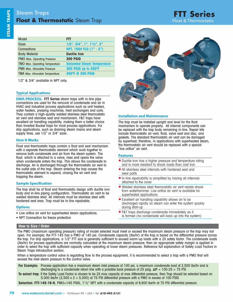
Installation and Maintenance
The trap must be installed upright and level for the float mechanism to operate properly. All internal components canbe replaced with the trap body remaining in-line. Repair kitsinclude thermostatic air vent, float, valve seat and disc, and gaskets. The standard thermostatic air vent can be damaged by superheat; therefore, in applications with superheated steam,the thermostatic air vent should be replaced with a special “live orifice” air vent.
Features
• Ductile Iron has a higher pressure and temperature rating and is more resistant to shock loads than cast Iron
• All stainless steel internals with hardened seat and wear parts
• In-line repairability is simplified by having all internals attached to the cover
• Welded stainless steel thermostatic air vent resists shock from waterhammer. Live orifice air vent is available for superheated applications
• Excellent air handling capability allows air to be discharged rapidly so steam can enter the system quickly during start-up
• F&T traps discharge condensate immediately as it is formed (no condensate will back up into the system)
70
FTT SeriesSteam TrapsFloat & Thermostatic Steam Trap Float & Thermostatic
Model FTTSizes 1/2”, 3/4”, 1”, 11/2”, 2”Connections NPT, 150# FLG (1” - 2”)Body Material Ductile IronPMO Max. Operating Pressure 300 PSIGTMO Max. Operating Temperature Saturated Steam TemperaturePMA Max. Allowable Pressure 300 PSIG up to 450ºFTMA Max. Allowable Temperature 450ºF @ 300 PSIG
Typical Applications
DRIP, PROCESS: FTT Series steam traps with in-line pipe connections are used for the removal of condensate and air inHVAC and industrial process applications such as unit heaters,water heaters, pressing machines, heat exchangers and coils.They contain a high-quality welded stainless steel thermostatic air vent and stainless seat and mechanism. F&T traps have excellent air handling capability, making them a better choicethan Inverted Bucket traps for most process applications. For drip applications, such as draining steam mains and steam supply lines, use 1/2” or 3/4” sizes.
How It Works
Float and thermostatic traps contain a float and seat mechanism with a separate thermostatic element which work together toremove both condensate and air from the steam system. The float, which is attached to a valve, rises and opens the valvewhen condensate enters the trap. This allows the condensate to discharge. Air is discharged through the thermostatic air vent tothe outlet side of the trap. Steam entering the trap causes the thermostatic element to expand, closing the air vent and trapping the steam.
Sample Specification
The trap shall be of float and thermostatic design with ductile ironbody and in-line piping configuration. Thermostatic air vent to bewelded stainless steel. All internals must be stainless steel withhardened seat area. Trap must be in-line repairable.
Options
• Live orifice air vent for superheated steam applications.• NPT Connection for freeze protection
STEA
M T
RA
PS
How to Size / Order The PMO (maximum operating pressure) rating of model selected must meet or exceed the maximum steam pressure or the trap may notopen. For example; the FTT-145 has a PMO of 145 psi. Condensate capacity (lbs/hr) of the trap is based on the differential pressure acrossthe trap. For drip applications, a 1/2" FTT size is generally sufficient to exceed warm-up loads with a 2X safety factor. The condensate loads(lbs/hr) for process applications are normally calculated at the maximum steam pressure; then an appropriate safety margin is applied inorder to select the trap with sufficient capacity when operating at lower steam pressures. Reference full explanation of Safety Load Factors inSteam Traps Introduction section. When a temperature control valve is regulating flow to the process equipment, it is recommended to select a trap with a PMO that will exceed the inlet steam pressure to the control valve.
For Example: Process application has a maximum steam inlet pressure of 100 psi, a maximum condensate load of 2,500 lbs/hr and is discharging to a condensate return line with a possible back pressure of 25 psig. ΔP = 100-25 = 75 PSI
To select trap: If the Safety Load Factor is chosen to be 2X max capacity at max differential pressure, then Trap should be selected based on 5,000 lbs/hr (2,500 x 2 = 5,000) at 75 PSI differential pressure with a PMO in excess of 100 PSIG
Selection: FTT-145-16-N, PMO=145 PSIG, 11/2” NPT with a condensate capacity of 9,600 lbs/hr at 75 PSI differential pressure.
1/2” & 3/4” available in NPT only.
www.watsonmcdaniel.com •• Pottstown PA • USA • Tel: 610-495-5131

71
FTT SeriesFloat & Thermostatic Steam Trap Float & Thermostatic
Steam TrapsSTEA
M TR
APS
CAPACIT IES – Condensate (lbs/hr)PMO Pipe ΔP = Differential Pressure (PSI)
Model Code (PSIG) Size 1/4 1/2 1 2 5 10 15 20 30 40 50 65 75 100 125 145 200 225 250 300FTT-065-12-N 65 1/2” 115 155 205 270 390 520 610 685 810 910 995 1110
FTT-065-13-N 65 3/4” 115 155 205 270 390 520 610 685 810 910 995 1110
FTT-065-14-N 65 1” 340 500 775 1100 1700 2400 2800 3250 3925 4200 5000 5825
FTT-065-16-N 65 11/2” 1150 1650 2500 3450 5300 7500 8180 10600 13100 15000 16800 18900
FTT-065-17-N 65 2” 3470 4820 8500 11950 18700 25200 26900 36000 43000 49600 55500 61300
FTT-145-12-N 145 1/2” 55 75 100 135 200 270 320 365 435 490 540 600 640 725 795 850
FTT-145-13-N 145 3/4” 55 75 100 135 200 270 320 365 435 490 540 600 640 725 795 850
FTT-145-14-N 145 1” 190 275 405 550 840 1200 1380 1600 1850 2200 2450 2750 2920 3400 3700 3900
FTT-145-16-N 145 11/2” 685 970 1275 1750 2740 3750 4490 5100 6250 7200 8000 8900 9600 11250 12000 13300
FTT-145-17-N 145 2” 1860 2680 3125 4400 6900 9250 13790 14600 16900 19400 21900 25000 26800 31000 34000 37000
FTT-225-12-N 225 1/2” 40 50 70 95 135 185 220 245 290 330 360 405 430 485 530 565 645 680
FTT-225-13-N 225 3/4” 40 50 70 95 135 185 220 245 290 330 360 405 430 485 530 565 645 680
FTT-225-14-N 225 1” 150 200 300 405 600 820 975 1130 1375 1510 1620 1875 2000 2350 2600 2750 3100 3250
FTT-250-16-N 250 11/2” 530 710 825 1130 1760 2500 2950 3375 4125 4740 5250 6000 6400 7300 8000 8650 10200 10800 11300
FTT-250-17-N 250 2” 695 985 1560 2185 3490 4800 5800 6750 8250 9500 10650 12400 13300 15000 16600 18120 21200 22300 23200
FTT-300-14-N 300 1” 100 155 220 300 460 630 750 860 1060 1240 1360 1450 1600 1820 2000 2130 2500 2650 2800 3000
Seat Area Heat-treated
for Extended Life
Welded Stainless Steel Thermostatic
Air Vent
High-StrengthStainless
Steel Float
AllStainless
Steel InternalsHeat-treatedSeat & Disc
Cover Gasket
Connection Code: N=NPT, F150 = 150# FLG1/2” & 3/4” available in NPT only. PMO = Max Operating Pressure
Tel: 610-495-5131 • Pottstown PA • USA •• www.watsonmcdaniel.com
MATERIALSBody & Cover Ductile IronGasket GrafoilCover Screws Steel, GR5Float Stainless Steel, AISI 304Internals Stainless SteelThermostat Stainless SteelValve Seat Stainless Steel, 17-4 PHValve Disc Stainless Steel, AISI 420F

Dimensions: inches
1.9
2.5
3.9
4.8
FLOW
CL PIPING
10.6NPT
4.3
12.0
9.6
1.4
8.8
3.1
7.5
4.8NPT
1.1
FTT • 1/2” & 3/4”
Weight: 6 lbs.
FTT 1”
FTT • 11/2” • Weight threaded NPT 38 lbs.
1.9
CL PIPING
FTT • 2” • Weight threaded NPT 42 lbs.
CL PIPING
11.9NPT
4.3
12.0
9.6
1.4 CL PIPING
FLOW
FLOW
FLOW
72
FTT SeriesSteam TrapsFloat & Thermostatic Steam Trap Float & Thermostatic
STEA
M T
RA
PS
Weight threaded NPT: 16 lbs.
www.watsonmcdaniel.com •• Pottstown PA • USA • Tel: 610-495-5131
6.3Flange
9.1Flange
9.1Flange

73
FTT SeriesFloat & Thermostatic Steam Trap Float & Thermostatic
Steam TrapsSTEA
M TR
APS
Instantaneous Steam to Hot Water Heater(Heat Miser)
Jacketed Kettle Application
Steam Main Drip Application
Typical Applications for Float & Thermostatic Steam Traps
Tel: 610-495-5131 • Pottstown PA • USA •• www.watsonmcdaniel.com
FTT Series
FTT Series
FTTSeries
Steam
Strainer
Strainer

74
STEA
M T
RA
PS
FTE & FTESSteam TrapsFloat & Thermostatic Steam Trap Float & Thermostatic
Model FTE FTESSizes 11/2”, 2”, 21/2” 21/2”Connections NPT NPT, SW, FLGBody Material Ductile Iron Cast SteelPMO Max. Operating Pressure 200 PSIG 300 PSIGTMO Max. Operating Temperature 450ºF 450ºFPMA Max. Allowable Pressure 300 PSIG up to 450ºF 300 PSIG up to 750ºFTMA Max. Allowable Temperature 450ºF @ 300 PSIG 750ºF @ 300 PSIG
Typical Applications
PROCESS: FTE & FTES Series are high capacity steam trapsspecifically designed to remove condensate and air from HVAC and industrial process applications with extremely high condensate load requirements. Examples include reboilers,absorption chillers, large air-handling coils, large heat exchangersand other large process equipment. They are available with a ductile iron (FTE) or steel body (FTES) and contain a high quality welded stainless steel thermostatic air vent and stainlessmechanism. F&T traps have excellent air-handling capability,making them a better choice than Inverted Bucket traps for most process applications.
Features
• Ductile Iron has a higher pressure and temperature rating and is more resistant to shock loads than Cast Iron
• Cast Steel Body will allow operating pressures and temperatures up to 300 PSIG and 450˚F
• High capacity steam trap for draining large process equipment (over 100,000 lbs/hr)
• All stainless steel internals with hardened seat and wear parts
• In-line repairability is simplified by having all internals attached to the cover
• Welded stainless steel thermostatic air vent resists shock from waterhammer. Live orifice air vent is available for superheated applications
• Excellent air handling capability allows air to be discharged rapidly so steam can enter the system quickly during start-up
• F&T traps discharge condensate immediately as it is formed (no condensate will back up into the system)
How It Works
Float and thermostatic traps contain a float and seat mechanism with a separate thermostatic element which work together toremove both condensate and air from the steam system. The float, which is attached to a valve, rises and opens the valvewhen condensate enters the trap. This allows the condensate to discharge. Air is discharged through the thermostatic air vent tothe outlet side of the trap. Steam entering the trap causes the thermostatic element to expand, closing the air vent and trapping the steam.
Sample Specification
The trap shall be of float and thermostatic design with ductile iron or cast steel body. The trap must incorporate all stainless steel internals with hardened seat and welded stainless steel thermostatic air vent. Trap must be in-line repairable.
Installation and Maintenance
The trap must be installed upright and level for the float mechanism to operate properly. All internal components can be replaced with the trap body remaining in-line. Repair kitsinclude thermostatic air vent, float, valve seat and disc, and gaskets. The FTES Series have cast steel bodies and are availablein 21/2” NPT, socket weld and flange connections. The standardthermostatic air vent can be damaged by superheat; therefore,in applications with superheated steam, the thermostatic air ventshould be replaced with a special “live orifice” air vent.
Options
Live orifice air vent for superheated steam applications.
Parallel-pipe inlet/outlet connections are standard as shown. An optional In-line inlet/outlet connection is available; contact factory.
The FTE & FTES are used for extremely high capaci ty condensa tedr ainage applications.
www.watsonmcdaniel.com •• Pottstown PA • USA • Tel: 610-495-5131

75
STEAM
TRA
PS
FTE & FTESFloat & Thermostatic Steam Trap Float & Thermostatic
Steam Traps
* Single seat orifice. All others are double seated.
DIMENSIONS & WEIGHTS – inchesSize/Model A B C D E F Weight
2“ FTE-20 12.6 5.7 4.5 0.5 11.1 3.9 54
2“ FTE-50 16.0 8.4 7.3 1.4 15.6 3.6 150
21/2” FTE-50 15.5 8.4 7.3 1.4 15.6 3.6 150
21/2” FTE-125 15.5 8.4 7.3 1.4 15.6 3.6 150
11/2” FTE-200 9.6 4.3 3.0 0.7 8.8 2.6 35
2“ FTE-200 12.6 5.7 4.5 0.5 11.1 3.9 65
21/2” FTE-200 15.5 8.4 7.3 1.4 15.6 3.6 150
21/2” FTES-300 15.5 8.4 7.3 1.4 15.6 3.6 150
MATERIALSBody & Cover (FTE) Ductile IronBody & Cover (FTES) Cast Steel, ASTM A-216Cover Screw Grade 5 Carbon SteelCover Gasket GrafoilValve Discs Stainless Steel, AISI 17-4PHMain Valve Assembly Housing Stainless Steel, AISI 17-4PHValve Assembly Gasket GarlockBall Float Stainless Steel, AISI 304Thermostatic Vent Stainless Steel, AISI 300
Optional: Live orifice air vent
CAPACIT IES – Condensate (lbs/hr)PMO Pipe Orifice ΔP = Differential Pressure (PSI)
Model Code (PSIG) Size Size 1/4 1/2 1 2 5 10 15 20 30 50 75 100 125 200 250 300FTE-20-17-N* 20 2” .937” 6100 7800 9300 11800 15900 19500 22500 26000
FTE-50-17-N 50 2” 2.125” 12800 16900 20100 25300 33000 40200 43500 46000 47800 52500
FTE-50-18-N 50 21/2” 2.125” 20400 25700 31000 37000 46300 55100 60300 65100 72000 82100
FTE-125-18-N 125 21/2” 2.125” 20400 25700 31000 37000 46300 55100 60300 65100 72000 82100 90400 97700 105000
FTE-200-16-N 200 11/2” .375” 950 1350 1900 2200 2700 3300 3900 4400 5300 6400 7600 8500 9400 11900
FTE-200-17-N 200 2” .75” 2700 4100 5700 7400 9900 11800 13400 14400 16400 19000 21500 23000 24500 29200
FTE-200-18-N 200 21/2” 1.5” 7200 12300 17400 21500 27600 32600 36000 39300 43100 49200 54700 58800 61900 74000
FTES-50-18-N 50 21/2” 2.125” 20400 25700 31000 37000 46300 55100 60300 65100 72000 82100
FTES-125-18-N 125 21/2” 2.125” 20400 25700 31000 37000 46300 55100 60300 65100 72000 82100 90400 97700 105000
FTES-300-18-N 300 21/2” 1.5” 7200 12300 17400 21500 27600 32600 36000 39300 43100 49200 54700 58800 61900 74000 86000 100550
A
F
C
D
B
E
OUTLET
Note: 21/2” FTES-50, 125 & 300 have same dimensions and wei ghts.
INLET
Tel: 610-495-5131 • Pottstown PA • USA •• www.watsonmcdaniel.com
How to Size / Order The PMO (maximum operating pressure) rating of model selected must meet or exceed the maximum steam pressure or the trap may notopen. For example; the FTE-125 has a PMO of 125 psi. Condensate capacity (lbs/hr) of the trap is based on the differential pressure acrossthe trap. The condensate loads (lbs/hr) for process applications are normally calculated at the maximum steam pressure; then an appropriatesafety margin is applied in order to select a trap with sufficient capacity when operating at lower steam pressures. Reference full explanation ofSafety Load Factors in Steam Traps Introduction section. When a temperature control valve is regulating flow to the process equipment, it is recommended to select a trap with a PMO that will exceed the inlet steam pressure to the control valve.
For Example: Process application has a maximum steam inlet pressure of 100 psi, a maximum condensate load of 10,000 lbs/hr and is discharging to a condensate return line with a possible back pressure of 25 psig. ΔP = 100-25 = 75 PSI
To select trap: If the Safety Load Factor is chosen to be 2X max capacity at max differential pressure, then Trap should be selected based on 20,000 lbs/hr (10,000 x 2 = 20,000) at 75 PSI differential pressure with a PMO in excess of 100 PSIG
Selection: FTE-200-17-N, PMO=200 PSIG, 2” NPT with a condensate capacity of 21,500 lbs/hr at 75 PSI differential pressure.

76
FT600 & FT601Steam TrapsFloat & Thermostatic Steam Trap Float & Thermostatic
Typical Applications
PROCESS: FT600 Series steam traps with Cast Steel Body were specifically designed for removing condensate and air from higher pressure steam applications or where steel bodies are specified. They are typically used in chemical plants andpetrochemical refineries on re-boilers, heat exchangers, and other critical process applications. The excellent air-handlingcapability of float and thermostatic traps make them a betterchoice than bucket traps for applications requiring quick systemstart-up. Maximum steam pressure is 450 PSIG. Note: ModelFT601 is identical to FT600 except body material is 316 SS.
How It Works
Float and thermostatic traps contain a float and seat mechanism with a separate thermostatic element which work together toremove both condensate and air from the steam system. The float, which is attached to a valve, rises and opens the valvewhen condensate enters the trap. This allows the condensate to discharge. Air is discharged through the thermostatic air vent tothe outlet side of the trap. Steam entering the trap causes the thermostatic element to expand, closing the air vent and trapping the steam.
Features
• Investment cast steel body and cover with class 400 shell rating (670 PSIG @ 750˚F)
• Hardened stainless steel seat and disc for extended service life even at extreme temperatures and pressures
• Excellent air handling capability allows air to be discharged rapidly so steam can enter the system quickly during start-up
• In-line repairability is simplified by having all internals attached to the cover. Studded cover allows for easier removal of body.
• Welded stainless steel air vent resists shock from waterhammer. Live orifice air vent is available for superheated applications
• F&T traps discharge condensate immediately as it is formed (no condensate will back up into the system)
Options
Live orifice air vent for superheated applications.
Sample Specification
The steam trap shall be of the mechanical float type having caststeel bodies, horizontal in-line connections in NPT, SW, or flanged,and all stainless steel internals. Incorporated into the trap bodyshall be an all stainless steel welded thermal element air ventwhich is water hammer resistant. The air vent is to be located at the high point of trap body to assure proper venting of non-condensables. The trap body will be in-line renewable. All bodies and covers shall be class 400 shell design, suitable for 670 PSIG @ 750ºF.
Installation and Maintenance
The trap must be installed upright and level for the float mechanism to operate properly. All internal components can be replaced while the steam trap remains connected to the piping(in-line repairable). Threaded studs are permanently installed intothe cover assembly which greatly simplifies the removal andreplacement of the body when servicing. Internal componentsinclude a high quality welded stainless steel thermostatic air ventand stainless steel seat and mechanism. The standard thermostaticair vent can be damaged by superheat; therefore, in applicationswith superheated steam, the thermostatic air vent should bereplaced with a special “live orifice” air vent.
* FT601 Body Material is 316 SS FT600 Body Material is Carbon Steel
Model FT600 & FT601*Sizes 3/4”, 1”, 11/2”, 2”, 3”, 4”Connections NPT, SW, FLGBody Material Carbon Steel or 316SS Options Live Orifice Air VentPMO Max. Operating Pressure 450 PSIGTMO Max. Operating Temperature 750ºFPMA Max. Allowable Pressure 990 PSIG @ 100ºFTMA Max. Allowable Temperature 750ºF @ 670 PSIG
STEA
M T
RA
PS
www.watsonmcdaniel.com •• Pottstown PA • USA • Tel: 610-495-5131

77
FT600 & FT601 Float & Thermostatic Steam Trap Float & Thermostatic
Steam TrapsSTEA
M TR
APS
MATERIALSFT 600: Body & Cover Cast Steel, ASTM A-216FT 601: Body & Cover 316 SSCover Studs Steel, AS 193, GR B7Cover Nuts Steel, SA 194, GR 2HCover Gasket Stainless Steel Reinforced GrafoilValve Assembly Stainless Steel, AISI 431Gasket, Valve Assembly Stainless Steel Reinforced GrafoilPivot Assembly Stainless Steel, 17-4 PHMounting Screws Stainless Steel Hex Head, 18-8Float Stainless Steel, ASTM -240, 304Air Vent Assembly Thermostatic element 304 SS
Optional: Live orifice
Studded Cover toFacilitate Disassembly
& Maintenance(Studs remain attached
to cover)
Stainless Steel Erosion
Protection Shield
Investment CastBody & Cover
available in Carbon Steelor 316 SS
Seat Area Heat-treated and Lapped
for Extended Lifeand Tight Shut-off
Welded Stainless SteelThermostatic Air VentOptional Live Orifice forSuperheat Applications.(Live Orifice is standard
on pressures above 300 PSIG.)
High-StrengthStainless
Steel Float
All Wear Points are
Heat-treated Stainless
Steel
Cover Gasket
Tel: 610-495-5131 • Pottstown PA • USA •• www.watsonmcdaniel.com

78
FT600 & FT601Steam TrapsFloat & Thermostatic Steam Trap Float & Thermostatic
STEA
M T
RA
PS
CAPACIT IES – Condensate (lbs/hr)PMO ΔP = Differential Pressure (PSI)
Model Code* (PSIG) Sizes 1 2 3 4 5 10 20 30 40 50 65 80 100 145 200 300 400 450
FT600-65-13-N 65 3/4” 225 300 363 413 463 635 960 1060 1180 1320 1460
FT600-65-14-N 65 1” 775 1094 1340 1520 1690 2370 3260 3990 4500 5000 5500
FT600-65-16-N 65 11/2” 2500 3450 4130 4750 5300 7500 10625 13125 15000 16800 18850
FT600-65-17-N 65 2” 8500 11950 14670 16800 18700 25250 35900 43000 49600 55500 61250
FT600-145-13-N 145 3/4” 137 180 218 250 275 380 520 625 725 863 895 995 1120 1315
FT600-145-14-N 145 1” 400 555 660 755 850 1237 1593 1925 2240 2490 2750 3000 3430 3935
FT600-145-16-N 145 11/2” 1275 1750 2125 2430 2740 3750 5100 6250 7200 7995 8875 9900 11250 13300
FT600-145-17-N 145 2” 3125 4400 5375 6250 6900 9250 14625 16875 19375 21875 25000 27500 31000 37000
FT600-200-13-N 200 3/4” 93 137 160 187 205 287 400 487 560 610 710 775 875 1060 1250
FT600-200-14-N 200 1” 300 410 487 560 610 925 1140 1375 1520 1687 1875 2060 2312 2750 3100
FT600-200-16-N 200 11/2” 825 1130 1400 1570 1760 25000 375 4125 4740 5250 6000 6600 7300 8650 10200
FT600-200-17-N 200 2” 1560 2187 2800 3100 3490 4800 6750 8250 9500 10625 12400 13700 15000 18120 21200
FT600-300-13-N 300 3/4” 50 68 83 95 106 155 197 240 275 300 340 375 413 490 570 710
FT600-300-14-N 300 1” 225 300 363 413 463 635 960 1060 1180 1320 1468 1640 1815 2130 2550 3000
FT600-300-16-N 300 11/2” 825 1130 1400 1570 1760 25000 375 4125 4740 5250 6000 6600 7300 8650 10200 12600
FT600-300-17-N 300 2” 1560 2187 2800 3100 3490 4800 6750 8250 9500 10625 12400 13700 15000 18120 21200 26250
FT600-450-13-N 450 3/4” 32 42 49 56 62 84 119 145 163 175 192 210 186 275 312 375 425 450
FT600-450-14-N 450 1” 137 180 218 250 275 380 520 625 725 863 895 995 1120 1315 1500 1870 2125 2250
FT600-450-16-N 450 11/2” 825 1130 1400 1570 1760 2500 3375 4125 4740 5250 6000 6600 7300 8650 10200 12600 14375 15200
FT600-450-17-N 450 2” 1560 2187 2800 3100 3490 4800 6750 8250 9500 10625 12400 13700 15000 18120 21200 26250 28700 31250
Note: For 450 Model, the Thermostatic Air Vent is replaced with a live Orifice.* Chart is applicable for both Models FT600 & FT601
www.watsonmcdaniel.com •• Pottstown PA • USA • Tel: 610-495-5131
How to Size / Order The maximum operating pressure (PMO) rating of model selected must meet or exceed the maximum steam pressure or the trap may notopen. For example; the FT600-145 has a PMO of 145 psi. Condensate capacity (lbs/hr) of the trap is based on the differential pressureacross the trap.
For drip applications, a (3/4)" FT600 size is sufficient to exceed warm-up loads with a 2X safety factor. The condensate loads (lbs/hr)for process applications are normally calculated at the maximum steam pressure; then an appropriate safety margin is applied in order to select a trap with sufficient capacity when operating at lower steam pressures. Reference full explanation of Safety Load Factors in Steam Traps Introduction section.
When a temperature control valve regulates the flow of steam to the process equipment (Heat Exchanger) being drained of condensate, it is recommended to select a trap with a PMO that exceeds the inlet steam pressure to the temperature control valve. This assures that under all operating conditions, the steam pressure will not exceed the PMO of the trap.
For Example: Process application has a maximum steam inlet pressure of 100 psi, a maximum condensate load of 2,500 lbs/hr and is discharging to a condensate return line with a possible back pressure of 20 psig. ΔP = 100-20 = 80 PSI
To select trap: If the Safety Load Factor is chosen to be 2X max capacity at max differential pressure, then Trap should be selected based on 5,000 lbs/hr (2,500 x 2 = 5,000) at 80 PSI differential pressure with a PMO in excess of 100 PSIG
Selection: FT600-145-16-N, PMO=145 PSIG, 11/2” NPT with a condensate capacity of 9,900 lbs/hr at 80 PSI differential pressure.
Connection Codes: (N=NPT, SW=Socket Weld, F150=150# FLG, F300=300# FLG, F600=600# FLG)

79
FT600 & FT601 Float & Thermostatic Steam Trap Float & Thermostatic
Steam TrapsSTEA
M TR
APS
DIMENSIONS & WEIGHTS – inchesWeight (lbs)
Model* Size A AA B C D E F NPT/SW FLG
FT600 3/4" 6.10 10.10 2.07 3.93 7.38 8.41 5.75 25 31
FT600 1" 6.50 10.40 2.50 5.50 8.44 9.50 6.25 31 36
FT600 11/2" 9.80 14.00 3.26 6.85 10.40 11.94 7.75 82 91
FT600 2" 11.80 16.00 3.60 7.40 11.59 13.27 8.00 93 107
* Chart is applicable for FT600 & FT601
AA
A
E
D
B
C
F min.(for service)
FT600 & FT601: 3/4”, 1”, 11/2”, 2”
Shell & Tube Heat Exchanger Application: Steam Main Drip Application
Typical Applications for Float & Thermostatic Steam Traps
Tel: 610-495-5131 • Pottstown PA • USA •• www.watsonmcdaniel.com
FT600 Series
Steam
Steam
ColdLiquidInlet
HotLiquidOutlet
Strainer
3/4” FT600-200
Strainer

80
FT600 & FT601Steam TrapsFloat & Thermostatic Steam Trap Float & Thermostatic
STEA
M T
RA
PS
Size Conn PMO Model(PSIG) Code
3” NPT 450 FT600-450-19-N3” SW 450 FT600-450-19-SW3” 150 # Flg 285 FT600-285-19-F1503” 300 # Flg 450 FT600-450-19-F3003” 600 # Flg 450 FT600-450-19-F6004” 150 # Flg 285 FT600-285-20-F1504” 300 # Flg 450 FT600-450-20-F3004” 600 # Flg 450 FT600-450-20-F600
* Cold Water capacities are to be used when the trap is used as a liquid drain trap. Note: For liquid drain trap applications, please specify “liquid drain trap” when ordering.
CAPACITY CORRECTION FACTORSTo obtain capacity with a liquid other than water, multiply water capacity by correction factor.
Spec. Gravity 1 .98 .96 .94 .92 .90 .88 .86 .84 .82 .80 .75 .70 .65 .60 .55 .50
Corr. Factor 1 .990 .980 .970 .959 .949 .938 .927 .917 .906 .894 .866 .837 .806 .775 .742 707
CAPACIT IES – Condensate (1000 lbs/hr)Differential Pressure (PSI)
Temp 1/2 1 2 5 10 15 20 30 40 50 75 100 125 150 175 200 250 300 350 400 450COLD* 44 59 81 122 170 205 230 280 317 350 425 480 540 580 625 670 740 800 860 910 960
HOT 44 53 64 83 100 112 121 138 149 159 177 190 201 212 222 230 247 260 270 280 290
PRESSURE-TEMPERATURE RATING - 3” & 4” ModelsPMA 650 PSIG up to 450˚F TMA 750˚F @ 375 PSIG
* FT601 Body Material is 316 SS FT600 Body Material is Carbon Steel
3” & 4” FT600 & FT601 contain an open orifice a ir vent.If a thermostatic air ve nt is required, contac t factory.
Model FT600 & FT601*Sizes 3”, 4”Connections NPT, SW, FLGBody Material Carbon Steel or 316SS PMO Max. Operating Pressure 450 PSIGTMO Max. Operating Temperature 750ºFPMA Max. Allowable Pressure 990 PSIG @ 100ºFTMA Max. Allowable Temperature 750ºF @ 670 PSIG
www.watsonmcdaniel.com •• Pottstown PA • USA • Tel: 610-495-5131

FT600 & FT601Steam TrapsFloat & Thermostatic Steam Trap Float & Thermostatic
81
STEAM
TRA
PS
A
AAFlanged
NPT & SW
25.8”
DIMENSIONS & WEIGHTS – inches
Weight (lbs)
Model* Size A AA Connection FLG
FT600 3" 27 39 587 (NPT, SW) 626
FT600 4" 27 39 587 (SW) 654
* Chart is applicable for both Models FT600 & FT601
16”
8.8
(4) 0.62” øMounting Holes
(2) JackScrews
LiftingEyes
FT600 & FT601:3” & 4”
FT600: 3” - 4” :Process: Refinery Reboiler Application
4” FT600
Tel: 610-495-5131 • Pottstown PA • USA •• www.watsonmcdaniel.com
Vapor from Reboilerflows to
Distillation Tower
Steam
Liquid fromCracking
Tower to beHeated
InletBottomProduct
Condensate

82
FT SeriesSteam TrapsFloat & Thermostatic Steam Trap Float & Thermostatic
Model FTSizes 3/4”, 1”, 11/4”, 11/2”, 2”Connections NPTBody Material Cast IronPMO Max. Operating Pressure 75 PSIGTMO Max. Operating Temperature Saturated Steam TemperaturePMA Max. Allowable Pressure 75 PSIG up to 450ºF TMA Max. Allowable Temperature 450ºF @ 75 PSIG
Typical Applications
DRIP, PROCESS: FT Series steam traps are designed foroperating pressures up to 75 PSIG. These float and thermostatictraps are used for lower pressure HVAC and light industrial processapplications. They are used on unit heaters, water heaters, pressing machines, heat exchangers and coils. For drip applications, such as draining steam mains and steam supplylines, use 3/4” FT-075 (FT73-075-13-N). F&T traps have excellent air-handling capability, which make them a better choice than Inverted Bucket traps for most process applications.FT Series traps have a dual inlet-outlet H-Pattern connectionallowing for additional flexibility in installation.
How It Works
Float and thermostatic traps contain a float and seat mechanism with a separate thermostatic element which work together toremove both condensate and air from the steam system. The float, which is attached to a valve, rises and opens the valvewhen condensate enters the trap. This allows the condensate to discharge. Air is discharged through the thermostatic air vent tothe outlet side of the trap. Steam entering the trap causes the thermostatic element to expand, closing the air vent and trapping the steam.
Sample Specification
The trap shall be of float and thermostatic design with cast iron body. Thermostatic element to be welded stainless steel. Float and seating material to be stainless steel. Trap must be in-line repairable.
Features
• H-pattern design allows piping from either side of the steam trap (there are two inlet ports at top and two outlet ports at bottom)
• F&T traps have excellent air handling capability allows air to be discharged rapidly and steam to enter the system quickly during start-up
• Welded stainless steel thermostatic air vent resists shock from waterhammer
• In-line repairable (all internals are attached to cover)
Installation and Maintenance
The trap must be installed upright and level for the float mechanism to operate properly. All internal components can be replaced with the trap body piped in-line. Repair kit includes thermostatic element, valve seat and disc, float and sealing gasket.
Helpful Selection Information
Select a model that can handle the maximum working pressureof the steam system. For example, the FT3-015 has a maximumworking pressure of 15 PSI. Consult capacity tables to properlysize unit. Available in 3/4” through 2” NPT connections. Selectthese models for steam systems with maximum working pressureof 75 PSIG.
STEA
M T
RA
PS
OutletInletInlet
Inlet
Inlet
Outlet
Outlet
Outlet
Demonstration of H-Style piping connections:
Plugged
Plugged
Plugged
Plugged
Plugged
Plugged
Plugged
Plugged
www.watsonmcdaniel.com •• Pottstown PA • USA • Tel: 610-495-5131

83
FT SeriesFloat & Thermostatic Steam Trap Float & Thermostatic
Steam Traps
CAPACIT IES – Condensate (lbs/hr)PMO Pipe Orifice ΔP = Differential Pressure (PSI)
Model Code (PSIG) Size Size 1/4 1/2 1 2 3 5 10 15 20 25 30 40 50 60 75FT3-015-13-N 15 3/4” 9/32” 340 440 600 830 990 1280 1790 2150
FT4-015-14-N 15 1” 9/32” 340 440 600 830 990 1280 1790 2150
FT6-015-15-N 15 11/4” 25/64” 850 1100 1460 2000 2350 2950 4000 4800
FT7-015-16-N 15 11/2” 1/2” 1300 1700 2050 2550 2900 3500 4400 5300
FT8-015-17-N 15 2” 21/32” 2500 3150 4000 5700 6100 6800 8300 9800
FTS8-015-17-N 15 2” 15/16” 4400 5850 7400 9200 10300 12600 15300 18100
FT33-030-13-N 30 3/4” 11/64” 220 300 405 530 650 890 1210 1485 1705 1865 2010
FT34-030-14-N 30 1” 11/64” 220 300 405 530 650 890 1210 1485 1705 1865 2010
FT35-030-14-N 30 1” 1/4” 450 600 880 1205 1420 1845 2560 3230 3715 4100 4405
FT36-030-15-N 30 11/4” 1/4” 450 600 880 1205 1420 1845 2560 3230 3715 4100 4405
FT37L-030-16-N 30 11/2” 7/16” 600 800 1200 1680 2210 2600 3500 4500 5200 5700 6100
FT38-030-17-N 30 2” 13/32” 1550 2045 2625 3560 4260 5660 7890 9440 10500 11360 12095
FT73-075-13-N 75 3/4” 9/64” 140 195 265 360 430 580 770 990 1110 1210 1290 1430 1560 1680 1830
FT74-075-14-N 75 1” 9/64” 140 195 265 360 430 580 710 990 1110 1210 1290 1430 1560 1680 1830
FT75-075-14-N 75 1” #16 270 360 485 660 780 1020 1430 1740 1980 2200 2420 2670 2910 3135 3370
FT76-075-15-N 75 11/4” #16 270 360 485 660 780 1020 1430 1740 1980 2200 2420 2670 2910 3135 3370
FT77L-075-16-N 75 11/2” 5/16” 340 460 690 900 1200 1400 1900 2350 2700 3000 3250 3750 4150 4500 4700
FT78-075-17-N 75 2” 5/16” 800 1075 1300 1700 2000 2600 3750 4350 4700 5050 5400 5960 6500 6950 7550
FTS8-075-17-N 75 2” 13/32” 1360 1800 2100 2800 3300 4300 6300 7300 8000 8500 9000 10000 11000 11600 12500
DIMENSIONS & WEIGHTS – inches/pounds
Model A B C D E WeightFT-3, FT-4, FT-33 FT-34, FT-73, FT-74 4.125 5.00 5.125 3.125 2.75 7.50
FT-6, FT-35, FT-36 5.00 6.81 6.47 4.125 3.43 13.0FT-75, FT-76
FT-7, FT-37L, FT-77L 6.375 7.68 8.218 5.25 4.41 21.0
FT-8, FT-38, FT-78 6.50 11.0 8.968 7.468 4.531 40.0FT-S8-15, FT-S8-75
MATERIALSBody & Cover Cast Iron, ASTM A-126 Class BNuts & Bolts High-Tensile SteelGasket Grafoil/GarlockFloat Stainless SteelValve & Seat Stainless SteelThermostatic Assembly Stainless Steel Bellows & Valve
A
B
D
E
C
STEAM
TRA
PS
inlet
outlet
inlet
outlet
Tel: 610-495-5131 • Pottstown PA • USA •• www.watsonmcdaniel.com
How to Size / Order The maximum operating pressure (PMO) rating of model selected must meet or exceed the maximum steam pressure or the trap may not open. Forexample; the FT-35-030 has a PMO of 30 psi. For drip applications, a 3/4” FT size is sufficient to exceed warm-up loads with a 2X safety factor.The condensate loads (lbs/hr) for process applications are normally calculated at the maximum steam pressure; then a safety margin is applied inorder to select a trap with sufficient capacity at lower pressures. Reference full explanation of Safety Load Factors in Steam Traps Introduction section.
For Example: Process application has a maximum steam inlet pressure of 50 psi, a maximum condensate load of 1,700 lbs/hr and is discharging to a condensate return line with a possible back pressure of 10 psig. ΔP = 50-10 = 40 PSI
To select trap: If the Safety Load Factor is chosen to be 2X max capacity at max differential pressure, then Trap should be selected based on 3,400 lbs/hr (1,700 x 2 = 3,400) at 40 PSI differential pressure with a PMO in excess of 50 PSIG
Selection: FT77L-075-16-N, PMO=75 PSIG, 11/2” NPT with a condensate capacity of 3,750 lbs/hr at 40 PSI differential pressure.

84
Inverted Bucket
Model Body Material PMO (PSIG) Sizes Connections Page No.
SIB/SIBH Stainless Steel 450 1/2”, 3/4” NPT, SW 86
IB Series103X/104X Cast Iron 250 1/2” – 11/2” NPT 88
1031 1032 1033 1034
1041 1042 1044 & 1038S
SIB/SIBH
PMO = Maximum Operating Pressure
STEA
M T
RA
PS
Inverted Bucket TrapsThe Inverted Bucket Trap, with its rugged design, offers features that are advantageous in certain conditions. The dischargeorifice of the IB is mounted at the top of the trap, making them less susceptible to failure from dirt and pipe scale when compared to other trap types. Although they are typically not the primary choice for process applications due to their lack of air venting capability, they are often used in drip applications. They can be used on less critical process applicationswhich do not require venting of air during system start-up or when a secondary air vent is added to the system.
Steam TrapsInverted Bucket Steam Traps
Introduction
SIB Series Stainless Steel Body IB Series Cast Iron Body (No Strainer)
IB Series Cast Iron Body (with Strainer)
www.watsonmcdaniel.com •• Pottstown PA • USA • Tel: 610-495-5131

85
STEAM
TRA
PS
INVERTED BUCKET TRAPS.
Operation:Due to its weight, the inverted bucket within the trap will rest on the bottom of the trap body keeping the valve open and allowing condensate to be discharged (Figure A). In the top of the bucket there is a small bleed hole which allows air to escape from inside thebucket and ex it through the outlet port (Figure B). When steam arrives through the inlet of the trap, it fills the inverted bucket whichmakes it buoyant and rise to the top of the trap, closing the valve (Figure C). As steam condenses and/or is bled through the small bleedhole in the top of the bucket, the bucket loses buoyancy which causes it to sink to the bottom of the trap. The valve then opens allowingcondensate to be discharged from the system (Figure A). The bucket trap must maintain a certain amount of water (prime) in order tooperate. If the trap loses its prime, the bucket will not be able to float when steam enters; keeping the valve in the open position whichallows steam to escape (Figure D). Due to the balance of forces required between the incoming pressure and internal trap components,several orifice sizes are required to accommodate various differential pressure ranges. For this reason care must be used to select a trapmodel with an equal or higher PMO rating than the steam pressure.
Valve (Open)
Valve (Open)
Inverted Bucket
Bleed Hole
Valve (Open)
Bleed HoleValve (Closed)
A) With condensate completelyfilling the trap, the bucket isin the down position with the valve open, allowing condensate to be discharged.
B) Small amounts of air willpass thru the bleed holeon top of the bucket and bedischarged. (Note: Largeamounts of air will lift thebucket and close off the trap, temporarily air locking the system.)
C) When steam enters the trap, the inverted bucket fills with steam and floats tothe surface, closing off thevalve, preventing steam from escaping.
D) Potential Failure Mode:Bucket traps must maintaina water prime to function properly. If the prime is lost,the bucket will remain in thedown position with the valveopen, and live steam will bedischarged from the system.
A) Discharging Condensate B) Discharging Air
D) Potential Failure ModeLoss of Prime
Inverted Bucket Steam TrapsIntroduction
Air
Steam
Condensate
C) Closed (Trapping Steam)
Tel: 610-495-5131 • Pottstown PA • USA •• www.watsonmcdaniel.com

MATERIALSBody Stainless Steel GR CF3Cover 304L Stainless SteelInternals 300 Series Stainless SteelValve Plug & Seat 420F Stainless Steel
86
SIB/SIBHSteam TrapsInverted Bucket Steam Trap Inverted Bucket
STEA
M T
RA
PS
Model SIB, SIBHSize 1/2”, 3/4”Connections NPT, SWBody Material Stainless SteelPMO Max. Operating Pressure 450 PSIG*TMO Max. Operating Temperature 750ºFPMA Max. Allowable Pressure 720 PSIG @ 100ºFTMA Max. Allowable Temperature 750ºF @ 400 PSIG
Typical Applications
DRIP, TRACING: The SIB & SIBH Inverted Bucket Steam traps are suitable for removing condensate from steam mainsand steam supply lines. They are also used on unit heaters,laundry equipment, and other smaller, low capacity and less critical process applications where slow start-up can be tolerated.The discharge orifice of the inverted bucket trap is mounted at the top of the trap body, which makes them less susceptible tofailure from dirt and debris when compared to other trap types.The SIBH is physically larger and has a higher press ure capabilityfor a par ticular ori fice size than the SIB.
How It Works
When the trap is filled with condensate, the inverted bucket inside the steam trap loses its buoyancy and rests on the bottomof the trap. This pulls the disc off the seat allowing condensate to be discharged through the seat orifice located at the top of the trap. When steam enters, it fills the inverted bucket causingthe bucket to float to the surface which closes the discharge valve, containing the steam in the system. Eventually, the steam is bled off through a small hole in the top of the bucket causing it to sink, which repeats the cycle.
Features
• All stainless steel body
• Acceptable for superheated steam (with check valve installed at inlet)
• Waterhammer resistant
• Valve & seat are located at the top of the trap body making them less prone to clogging from debris and pipe scale
• All stainless steel internals with hardened valve & seat
Sample Specification
Steam trap shall be an all stainless steel module design inverted bucket type with a frictionless valve lever assembly.
Option
Internal Check Valve
Installation and Maintenance
Trap must be installed in upright position to function properly. The stainless steel body is seal welded and therefore non-repairable. If a new trap is required, remove and replace. Bucket traps require an internal water seal to operate. Applications with superheated steam cancause the water seal to flash into steam and trap to fail in open position. A check valve installed at trap inlet will help prevent the loss of prime.
CAPACIT IES – Condensate (lbs/hr) Orifice PMO Differential Pressure (PSI) Model Size (PSIG) 5 10 15 20 25 30 40 50 60 70 80 100 125 150 180 200 250 350 450
SIB-20 3/16” 20 450 560 640 690
SIB-80 1/8” 80 300 350 400 440 460 500 550 580 635 660 690
SIB-150 #38 150 210 250 280 300 320 350 380 400 420 450 470 500 550 570
SIB-450 .057 450 31 50 70 84 95 105 120 133 145 152 160 174 187 198 208 215 228 248 263
SIBH-15 1/4” 15 830 950 1060
SIBH-30 3/16” 30 530 700 820 880 950 1000
SIBH-70 5/32” 70 380 500 560 620 680 710 770 840 90 950
SIBH-125 1/8” 125 285 375 440 485 530 560 620 670 720 780 800 860 950
SIBH-200 7/64” 200 205 265 315 350 385 410 465 500 580 590 620 650 700 810 840 860
SIBH-250 #38 250 155 205 240 270 295 320 360 400 500 530 550 580 630 660 690 710 760
SIBH-450 .057 450 31 50 70 84 95 105 120 133 145 152 160 174 187 198 208 215 228 248 263
SIBInverted Bucket
Steam Trap
4.55”
3.0”
SIB - 6.56”SIBH - 7.81”
FLOW
1.25”
Units: inches
www.watsonmcdaniel.com •• Pottstown PA • USA • Tel: 610-495-5131

87
SIB/SIBHInverted Bucket Steam Trap Inverted Bucket
Steam TrapsSTEA
M TR
APSHelpful Selection Information
The PMO (maximum operating pressure) rating of model selected must meet or exceed the maximum steam pressure or thetrap may not open. For example; the SIB-12-N-150 has a PMO of 150 PSI. Condensate capacity (lbs/hr) of the trap is basedon the differential pressure across the trap.
Size/ Model PMO Weight Cross ReferenceConnection Code PSI lbs Spirax Sarco Armstrong
1/2” NPT SIB-12-N-203/4” NPT SIB-13-N-20 20 5.0 SIB30 18101/2” SW SIB-12-SW-203/4” SW SIB-13-SW-201/2” NPT SIB-12-N-803/4” NPT SIB-13-N-80 80 5.0 SIB30 18101/2” SW SIB-12-SW-803/4” SW SIB-13-SW-801/2” NPT SIB-12-N-1503/4” NPT SIB-13-N-150 150 5.0 SIB30 18101/2” SW SIB-12-SW-1503/4” SW SIB-13-SW-1501/2” NPT SIB-12-N-4503/4” NPT SIB-13-N-450 450 5.0 SIB30 18101/2” SW SIB-12-SW-4503/4”SW SIB-13-SW-450
1/2” NPT SIBH-12-N-153/4” NPT SIBH-13-N-15 15 5.5 SIB30H 18111/2” SW SIBH-12-SW-153/4” SW SIBH-13-SW-151/2” NPT SIBH-12-N-303/4” NPT SIBH-13-N-30 30 5.5 SIB30H 18111/2” SW SIBH-12-SW-303/4” SW SIBH-13-SW-301/2” NPT SIBH-12-N-703/4” NPT SIBH-13-N-70 70 5.5 SIB30H 18111/2” SW SIBH-12-SW-703/4” SW SIBH-13-SW-701/2” NPT SIBH-12-N-1253/4” NPT SIBH-13-N-125 125 5.5 SIB30H 18111/2” SW SIBH-12-SW-1253/4” SW SIBH-13-SW-1251/2” NPT SIBH-12-N-2003/4” NPT SIBH-13-N-200 200 5.5 SIB30H 18111/2” SW SIBH-12-SW-2003/4” SW SIBH-13-SW-2001/2” NPT SIBH-12-N-2503/4” NPT SIBH-13-N-250 250 5.5 SIB30H 18111/2” SW SIBH-12-SW-2503/4” SW SIBH-13-SW-2501/2” NPT SIBH-12-N-4503/4” NPT SIBH-13-N-450 450 5.5 SIB30H 18111/2” SW SIBH-12-SW-4503/4” SW SIBH-13-SW-450
SIBHInverted Bucket
Steam Trap
SIBInverted Bucket
Steam Trap
Tel: 610-495-5131 • Pottstown PA • USA •• www.watsonmcdaniel.com

88
Inverted Bucket
IB SeriesSteam TrapsInverted Bucket Steam Trap Inverted Bucket
Model 1031, 1032, 1033, 1034, 1041, 1042, 1044, 1038S
Sizes 1/2”, 3/4”, 1”, 11/4”, 11/2”Connections NPTBody Material Cast IronOptions Internal check valve, Thermic ventPMO Max. Operating Pressure 250 PSIGTMO Max. Operating Temperature 450ºFPMA Max. Allowable Pressure 250 PSIG up to 450ºFTMA Max. Allowable Temperature 450ºF @ 250 PSIG
Typical Applications
DRIP, TRACING PROCESS: IB Series inverted bucket steam traps are used in drip applications to remove condensate from steam mains and steam supply lines. For drip applications, thesmaller sized units have adequate capacity. The discharge orifice of the inverted bucket trap is mounted at the top of the trap body,which makes them less susceptible to failure from dirt and debriswhen compared to other trap types. Since Inverted Bucket traps have poor air-handling capability, they are normally not recommended for most process applications. However, they can be used on certainprocess applications such as unit heaters and laundry equipment,where discharging air during system start-up is not a critical factor.F&T traps are the preferred choice for systems where air must be quickly discharged.
How It Works
When the trap is filled with condensate, the inverted bucket insidethe steam trap loses its buoyancy and rests on the bottom of the trap.This pulls the disc off the seat allowing condensate to be dischargedthrough the seat orifice located at the top of the trap. When steamenters, it fills the inverted bucket causing the bucket to float to thesurface which closes the discharge valve, containing the steam in the system. Eventually, the steam is bled off through a small hole in the top of the bucket causing it to sink, which repeats the cycle.
Features
• Waterhammer resistant
• Suitable for superheated steam (use internal check valve option to eliminate loss of prime)
• In-line repairability is simplified by having all internals attached to the cover
• Valve & seat are located at the top of the trap body making them less prone to clogging from debris and pipe scale
• All stainless steel internals with hardened valve & seat
Sample Specification
The steam trap shall be of an inverted bucket trap design.
1031/10321033/1034
(No Strainer)
1041/10421044/1038S
(with Strainer)
STEA
M T
RA
PS
Installation and Maintenance
Trap must be installed in upright position to function properly.All working components can be replaced with the trap bodyremaining in-line. With superheated steam, a check valveshould be installed at inlet or trap may lose prime. A replace-ment kit containing the lever and seat assembly is a more economical option than replacing the entire steam trap. Alsoavailable are replacement screens, gaskets and buckets. Whenordering replacement lever and seat assemblies, specify modeland operating pressure. See Replacement Parts and Kits Sectionfor exact cross-reference to Armstrong PCA (Pressure ChangeAssembly) kits.
Helpful Selection Information
Select a model with a higher maximum operating pressure(PMO) that meet or exceed the maximum steam pressure or the trap may not open. For example, the IB-1032-14-N-250has a PMO of 250 PSI. Choose a model that will handle thecapacity requirement based on the differential pressure acrossthe trap. Reference capacity charts.
Options
Strainer and Blowdown valve connection available on 1041,1042, 1044 & 1038S. Thermic vent to improve air handlingcapability. Internal check valve for superheated or condensatebackflow applications.
www.watsonmcdaniel.com •• Pottstown PA • USA • Tel: 610-495-5131

89
IB SeriesInverted Bucket Steam Trap Inverted Bucket
Steam Traps
How to Size / OrderFrom the capacity chart, select the model that can handle the workingpressure of the system (PMO). Select the appropriate trap that will meetthe capacity requirements at the differential pressure. Example:
Application: 1000 lbs/hr at 75 PSIG working pressure and 2 PSI differential pressure
Note: Specify Model, PMO and Connection Size Size/Model: IB-1034, 80 PSIG, Specify pipe size (3/4”, 1”), or
IB-1044, 80 PSIG, Specify pipe size (3/4”, 1”)
STEAM
TRA
PS
NO STRAINER STRAINERWatson Armstrong Watson Armstrong
McDaniel McDaniel1031 800 1041 8801032 811 1042 8811033 812 1044 8831034 813
1031/1031S/1032/1033/1034without Strainer (except 1031S)
MATERIALSBody & Cover Cast Iron, ASTM A-278 Class 30Nuts & Bolts High-Tensile SteelGasket GarlockBucket Stainless SteelLever & Seat Assembly Stainless SteelValve & Seat Hardened Stainless SteelIntegral Strainer* Stainless Steel
* 1031S, 1038S, 1041, 1042, 1044 models only.
1041/1042/1044/1038S with Strainer
DIMENSIONS & WEIGHTS – inchesWeight
Model A B C D (lbs)1031 3.75 5.875 5.00 2.75 51031S* 3.75 5.875 5.00 2.75 5
1032 3.75 6.875 5.00 4.25 6
1033 5.625 9.06 6.50 5.375 15
1034 7.00 11.75 7.75 7.03 271041* 3.75 6.06 5.00 3.43 51042* 3.75 7.06 5.00 4.43 6
1044* 7.00 12.375 7.125 7.375 301038S* 7.00 12.375 7.125 7.375 30
* With Integral Strainer
C
A
B
D
FLOW FLOW
C
A
B
D
How to Order Options: (reference model code chart)Check Valve (suffix CV)Built-in Inlet Check Valve is recommended when used on Superheated SteamExample: IB1032-12-N-125-CV
Thermic Vent (suffix TV)A Thermic Vent is recommended when using a Bucket Trap on any type of processapplication or where the removal of air from the system is critical.Example: IB1032-12-N-125-TV
Thermic Vent & Check Valve (suffix TCV)For both Check Valve & Thermic Vent Options use Suffix Code Example: IB1032-12-N-125-TCV
Blowdown Valve (add B to Model Code)Blowdown connection is available on Models IB1038S, 1041, 1042 and 1044 Example: IB1041B-13-N-150
(Model IB1041, 3/4” NPT, 150 PSI max operating pressure with Blowdown & Strainer)
Cross Reference Chart
Tel: 610-495-5131 • Pottstown PA • USA •• www.watsonmcdaniel.com

90
IB SeriesSteam TrapsInverted Bucket Steam Trap Inverted Bucket
STEA
M T
RA
PS
Conn. Model PMO Weight Cross Ref.NPT Code PSI lbs Armstrong
1/2” IB1031-12-N-20 20 7 8003/4” IB1031-13-N-201/2” IB1031-12-N-80 80 7 8003/4” IB1031-13-N-801/2” IB1031-12-N-125 125 7 8003/4” IB1031-13-N-1251/2” IB1031-12-N-150 150 7 8003/4” IB1031-13-N-1501/2” IB1032-12-N-153/4” IB1032-13-N-15 15 8 8111” IB1032-14-N-151/2” IB1032-12-N-303/4” IB1032-13-N-30 30 8 811 1” IB1032-14-N-301/2” IB1032-12-N-703/4” IB1032-13-N-70 70 8 811 1” IB1032-14-N-701/2” IB1032-12-N-1253/4” IB1032-13-N-125 125 8 811 1” IB1032-14-N-1251/2” IB1032-12-N-2003/4” IB1032-13-N-200 200 8 811 1” IB1032-14-N-2001/2” IB1032-12-N-2503/4” IB1032-13-N-250 250 8 811 1” IB1032-14-N-2501/2” IB1033-12-N-15 15 17 8123/4” IB1033-13-N-151/2” IB1033-12-N-30 30 17 8123/4” IB1033-13-N-301/2” IB1033-12-N-70 70 17 8123/4” IB1033-13-N-701/2” IB1033-12-N-125 125 17 8123/4” IB1033-13-N-1251/2” IB1033-12-N-200 200 17 8123/4” IB1033-13-N-2001/2” IB1033-12-N-250 250 17 8123/4” IB1033-13-N-2503/4” IB1034-13-N-15 15 30 8131” IB1034-14-N-153/4” IB1034-13-N-30 30 30 8131” IB1034-14-N-303/4” IB1034-13-N-60 60 30 8131” IB1034-14-N-603/4” IB1034-13-N-80 80 30 8131” IB1034-14-N-803/4” IB1034-13-N-125 125 30 8131” IB1034-14-N-1253/4” IB1034-13-N-180 180 30 8131” IB1034-14-N-1803/4” IB1034-13-N-250 250 30 8131” IB1034-14-N-250
NO STRAINER
Conn. Model PMO Weight Cross Ref.NPT Code PSI lbs Armstrong
1/2” IB1041-12-N-20 20 7 8803/4” IB1041-13-N-201/2” IB1041-12-N-80 80 7 8803/4” IB1041-13-N-801/2” IB1041-12-N-125 125 7 8803/4” IB1041-13-N-1251/2” IB1041-12-N-150 150 7 8803/4” IB1041-13-N-1501/2” IB1042-12-N-15 15 8 8813/4” IB1042-13-N-151/2” IB1042-12-N-30 30 8 8813/4” IB1042-13-N-301/2” IB1042-12-N-70 70 8 8813/4” IB1042-13-N-701/2” IB1042-12-N-125 125 8 8813/4” IB1042-13-N-1251/2” IB1042-12-N-200 200 8 8813/4” IB1042-13-N-2001/2” IB1042-12-N-250 250 8 8813/4” IB1042-13-N-2503/4” IB1044-13-N-15 15 37 8831” IB1044-14-N-153/4” IB1044-13-N-30 30 37 8831” IB1044-14-N-303/4” IB1044-13-N-60 60 37 8831” IB1044-14-N-603/4” IB1044-13-N-80 80 37 8831” IB1044-14-N-803/4” IB1044-13-N-125 125 37 8831” IB1044-14-N-1253/4” IB1044-13-N-180 180 37 8831” IB1044-14-N-1803/4” IB1044-13-N-250 250 37 8831” IB1044-14-N-25011/4” IB1038S-15-N-15 15 37 88311/2” IB1038S-16-N-1511/4” IB1038S-15-N-30 30 37 88311/2” IB1038S-16-N-3011/4” IB1038S-15-N-60 60 37 88311/2” IB1038S-16-N-6011/4” IB1038S-15-N-80 80 37 88311/2” IB1038S-16-N-8011/4” IB1038S-15-N-125 125 37 88311/2” IB1038S-16-N-12511/4” IB1038S-15-N-180 180 37 88311/2” IB1038S-16-N-18011/4” IB1038S-15-N-250 250 37 88311/2” IB1038S-16-N-250
WITH STRAINER
1032
1031
1033
1034
1042
1041
1044&
1038S
www.watsonmcdaniel.com •• Pottstown PA • USA • Tel: 610-495-5131

91
IB SeriesInverted Bucket Steam Trap Inverted Bucket
Steam TrapsSTEA
M TR
APS
CAPACIT IES – Condensate (lbs/hr)Pipe Orifice PMO Differential Pressure (PSI)
Model Size Size (PSIG) 1/4 1/2 1 2 5 10 15 20 30 50 60 70 80 100 125 150 180 200 250
1/2”, 3/4” 3/16” 20 139 200 270 340 450 560 640 6901031 1/2”, 3/4” 1/8” 80 75 115 150 190 300 350 400 440 500 580 635 660 6901041
1/2”, 3/4” 7/64” 125 50 80 100 145 240 280 320 350 410 490 520 560 580 640 6801031S *
1/2”, 3/4” #38 150 35 50 75 105 150 250 280 300 350 400 420 450 470 500 550 570
1/2”, 3/4”,1” 1/4” 15 191 300 450 590 830 950 1060
1/2”, 3/4”,1” 3/16” 30 150 235 325 410 530 700 820 880 1000
1/2”, 3/4”,1” 5/32” 70 85 145 220 275 380 500 560 620 710 840 900 950
1/2”, 3/4”,1” 1/8” 125 70 110 160 210 285 375 440 485 560 670 720 780 800 860 950
1/2”, 3/4”,1” 7/64” 200 45 75 110 145 205 265 315 350 410 500 550 580 620 650 700 810 840 860
1/2”, 3/4”,1” #38 250 15 40 80 105 155 205 240 270 320 400 500 530 550 580 630 660 690 710 760
1/2”, 3/4” 1/4” 15 191 300 450 590 830 950 1060
1/2”, 3/4” 3/16” 30 150 235 325 410 530 700 820 880 1000
1/2”, 3/4” 5/32” 70 85 145 220 275 380 500 560 620 710 840 900 950
1/2”, 3/4” 1/8” 125 70 110 160 210 285 375 440 485 560 670 720 780 800 860 950
1/2”, 3/4” 7/64” 200 45 75 110 145 205 265 315 350 410 500 550 580 620 650 700 810 840 860
1/2”, 3/4” #38 250 15 40 80 105 155 205 240 270 320 400 500 530 550 580 630 660 690 710 760
1/2”, 3/4” 5/16” 15 350 570 850 1140 1600 1900 2100
1/2”, 3/4” 1/4” 30 270 400 640 810 1000 1300 1600 1800 2050
1/2”, 3/4” 3/16” 70 195 300 480 610 750 950 1200 1375 1600 1900 2000 22001033
1/2”, 3/4” 5/32” 125 130 205 320 415 595 775 910 900 1100 1380 1480 1600 1650 1800 2000
1/2”, 3/4” 1/8” 200 75 120 200 255 365 490 585 630 700 900 980 1080 1120 1220 1400 1500 1560 1600
1/2”, 3/4” 7/64” 250 30 80 130 170 250 335 400 470 525 665 600 700 800 900 1000 1100 1180 1220 1300
3/4”, 1” 1/2” 15 950 1410 1880 2300 2900 3500 3900
3/4”, 1” 3/8” 30 600 960 1300 1640 2200 2800 3300 3500 4000
1034 3/4”, 1” 5/16” 60 490 800 1090 1400 1750 2200 2600 2900 3500 4100 4400
1044 3/4”, 1” 9/32” 80 330 580 720 1070 1450 1800 2100 2400 2800 3300 3600 3800 4000
3/4”, 1” 1/4” 125 260 430 620 810 1150 1650 1800 1900 2200 2600 2800 3000 3200 3600 3900
3/4”, 1” 7/32” 180 200 310 470 610 880 1170 1380 1510 1800 2100 2300 2500 2700 2900 3200 3500 3700
3/4”, 1” 3/16” 250 170 250 380 490 700 940 1100 1250 1450 1700 1800 2000 2100 2300 2700 2800 3100 3200 3500
11/4”, 11/2” 1/2” 15 1188 1763 2350 2875 3625 4375 4875
11/4”, 11/2” 3/8” 30 760 1190 1625 2050 2750 3500 4125 4375 5125
11/4”, 11/2” 5/16” 60 615 1000 1375 1750 2188 2750 3250 3625 4375 5125 5500
1038S 11/4”, 11/2” 9/32” 80 420 720 900 1340 1810 2250 2625 3000 3500 4125 4500 4750 5000
11/4”, 11/2” 1/4” 125 330 540 775 1010 1440 2063 2250 2375 2750 3250 3500 3750 4000 4500 4875
11/4”, 11/2” 7/32” 180 250 390 590 760 1100 1470 1725 1890 2063 2375 2875 3125 3375 3625 4000 4375 4625
11/4”, 11/2” 3/16” 250 210 320 470 610 875 1170 1380 1560 1800 2125 2250 2500 2625 2875 3375 3500 3875 4000 4375
* 1031S only available @ PMO = 125 PSIG.
1032
1042
Tel: 610-495-5131 • Pottstown PA • USA •• www.watsonmcdaniel.com
Helpful Selection Information
Select a model with a higher maximum operating pressure (PMO) that meet or exceed the maximum steam pressure or the trap maynot open. For example, the IB-1032-14-N-250 has a PMO of 250 PSI. Choose a model that will handle the capacity requirementbased on the differential pressure across the trap. Reference capacity charts.

Steam Trap Installed Above Condensate Collection Point
In this example, condensate must travel upwards to reach the trap. Under this condition, it is possible for condensate to flow from the condensate return line into the steam coils, thereby flooding the system. The internal check valve, inside the IB trap, prevents the backflow of condensate.
Why use a Check Valve Option ?
The optional internal check valve allows the bucket trap to retain its prime even when exposed to superheated steam. The IB Trap must retain hot condensate inside the trap body to operate. Superheated steam or a sudden drop in inlet pressure can flash off the hot condensate inside the trap body causing the trap to lose its prime. If the steam pressure falls below the discharge pressure on the outlet side of the steam trap, the internal check valve will stop the back flow of condensate into the steam system. When discharging to a condensate return line, a check valve is always recommended.
92
IB SeriesSteam TrapsInverted Bucket Steam Trap Inverted Bucket
STEA
M T
RA
PS
OptionalInternalCheck Valve
Replacement Kits
A replacement kit containing the lever and seat assembly is a more economicaloption than replacing the entire steam trap. Also available are replacementscreens, gaskets and buckets.
When ordering replacement lever and seat assemblies specify model and operating pressure. See Replacement Parts and Kits Section for exact cross-reference to Armstrong PCA (Pressure Change Assembly) Kits.
OptionalInternal Check Valve
Water Seal
CondensateReturn Line
Steam Trap Discharging into Elevated Condensate Return Line
When a steam trap discharges condensate to an elevated location,a check valve should be used to stop condensate from flowing backwards into the steam system.
ExternalCheck Valve
www.watsonmcdaniel.com •• Pottstown PA • USA • Tel: 610-495-5131
Condensate
Steam

1031S
The 1031S is equipped with a small protection screen to guard against dirt in the steam system. It is a more economical alternative than the 1041 which has a full-port strainer. Specifically designed for use in laundries. Available in 125 PSIG model only.
Why use a Thermic Vent ?
The Thermic Vent is used fordischarging air from the steam system during start-up.
93
IB SeriesInverted Bucket Steam Trap Inverted Bucket
Steam Traps
Blowdown Valve Connection
A Blowdown Valve connection is available as an option on the 1041, 1042, 1044, and 1038S models. This simplifies maintenance by allowing the strainer to be cleaned without removal. User to supply blowdown valve.
OptionalBlowdownConnection
STEAM
TRA
PS
Strainer Screen
Thermic VentOPEN
(when air ispresent)
Thermic VentCLOSED
(when steam orcondensate is
present)
BlowdownValve forcleaningstrainer
Strainer Screen
Air
Steam
Condensate
Tel: 610-495-5131 • Pottstown PA • USA •• www.watsonmcdaniel.com

94
UC450 SeriesQuick-Change Universal Style Trap-Connector System
STEA
M T
RA
PS
STEP 2: Select appropriate Universal CONNECTOR.Any Universal Connector (shown right) will work with any Universal Steam Trap Module. (Including those of other manufacturers. See product catalog for full offering of Connectors.) Trap orientation must be considered.
“QUICK-CHANGE” Universal Trap Modules
“QUICK-CHANGE” Universal Connectors
STEP 1: Select an appropriate UniversalSTEAM TRAPMODULE
UC450 UC450SR
UTD450 UTD450SM UT450 UB450 USIB450 UFT450Thermodynamic Thermodynamic Thermostatic Thermostatic Inverted Float &
“Top Mount” “Side Mount” Bellows Adjustable Bi-Metal Bucket Thermostatic
Simple 2-bolt removal for quick
replacement of steam trap modules
Universal Connector remains permanently installed
in piping system
ReplaceableSteam Trap
Module
Inlet Steam Pipe
Condensate Return Pipe
The All Stainless Steel Universal Style Steam Traps feature a permanent installation of the Universal Connector with a 2-boltmounting arrangement for the Universal Steam Trap Module, allowing the Steam Trap to be removed and replaced in minutes:
• Steam trap is replaced without having to unthread piping • By removing only 2 bolts with a socket or open-end wrench• Trap module can swivel 360º on the universal connector allowing proper orientation
UC450S
The UC450 Series QUICK-CHANGE Universal Trap-Connector System with multiple choices for trap modules and multiple choices for connectors are used in steam systems where a simplified and economical maintenance program of steam traps is desired. These Universal Style quick replacement steam traps can be used on steam supply lines as well as for tracing and smallprocess applications. They are commonly used in chemical plants, petrochemical refineries, paper mills and other industrial facilities.
www.watsonmcdaniel.com •• Pottstown PA • USA • Tel: 610-495-5131

95
UC450 SeriesSTEA
M TR
APS
Quick-Change Universal Style Trap-Connector System
Quick-Change Steam Trapsare recommended in any application –particularly those which require simpleand frequent replacement of steam traps
Why Use the UC450 Series “QUICK-CHANGE” Universal Style Trap-Connector System ?
Universal ConnectorsThese Connectors remain permanently installed in the piping system. The convenient 2-bolt mounting system allows the Trap Module to bereplaced quickly and easily using a socket or open-end wrench withouthaving to unthread piping.
Quick-Change Steam Trap Modules with Universal Connectors
Inverted Bucket Trap
USIB450 Steam Trap(shown with)
UC450S Connector
4 basic configurations of connectors are available:
UC450, UC450S & UC450R/UC450L.
Choice is based on strainer orientation or if a piping interference exists.
The UC450SR is the standard connector choice.The R & L versions are a mirrorimage of each other and are strictly a user’s preference based on piping orientation.
UC450
UC450S
UC450SR
Float & Thermostatic Trap
UFT450 Steam Trap(shown with)
UC450SBR Connector
Thermostatic Trap
UT450 Steam Trap(shown with)
UC450SB Connector
Thermodynamic “side-mount” Trap
UTD450SM Steam Trap(shown with)
UC450SBL Connector
Thermodynamic “top-mount” Trap
UTD450 Steam Trap(shown with)
UC450SB Connector
Tel: 610-495-5131 • Pottstown PA • USA •• www.watsonmcdaniel.com

96
Model UC450, UC450S, UC450SBUC450SR, UC450SBR, UC450SL, UC450SBL
Sizes 1/2”, 3/4”, 1”Connections NPT, SW, FLGBody Material Stainless SteelPMO Max. Operating Pressure (trap module dependent)TMO Max. Operating Temperature (trap module dependent)PMA Max. Allowable Pressure 750 PSIG @ 100ºFTMA Max. Allowable Temperature 800ºF @ 400 PSIG
MATERIALSBody Stainless Steel, AISI 316Strainer 40 Mesh Stainless Steel, AISI 304Blowdown Valve Stainless Steel, AISI 303
UC450no strainer
UC450Swith strainer
How to Size / OrderConnectors and Trap Modules are ordered separately. See followingpages for the Trap Modules.
Steam Trap Modules that mount to Universal Connectors are shown on the following pages. Trap modules available in: Inverted Bucket, Float & Thermostatic, Thermodynamic, Thermostatic and Bi-metallic type.
UC450SBwith strainer &
blowdown valve
Installation and Maintenance
The universal connector can be installed in vertical or horizontalpiping and available in 1/2”, 3/4” and 1” threaded NPT and socket weld (SW). In horizontal installations, orientation of connecter body may be dependent on the specific type of trapmodule used. These connectors remain permanently installed inthe piping system. The convenient 2-bolt mounting system allowsthe trap module to be easily replaced using a socket or open-endwrench without having to unthread piping.
Typical Applications
DRIP, TRACER: UC450 Series Universal Trap Connectors reduce the time and manpower to replace steam traps. Thestainless steel Connector remains permanently in-line allowingsteam trap module to be replaced in minutes. These universalconnectors can be used for drip service on steam mains andsteam supply lines, tracing, or for small process equipment.Industrial standard 2-bolt universal connectors are commonlyused in chemical plants, petrochemical refineries, paper mills,and other industrial facilities. The UC450 connectors conform to industrial standards, making them compatible with other manufacturers’ universal steam trap modules.
Used with the following Watson McDaniel Steam Trap Modules:USIB450 - Inverted BucketUTD450 - ThermodynamicUTD450SM - ThermodynamicUTD600LSM - ThermodynamicUT450 - ThermostaticUFT450 - Float & Thermostatic UB450 - Bi-Metallic
How It Works
Universal connectors remain permanently installed in the pipingsystem. The convenient 2-bolt mounting system allows the trapmodule to be removed and replaced quickly and easily using asocket or open-end wrench without disturbing the existing piping.
Features
• Universal connector with 2-bolt mounting allows for fast, easy replacement of trap module making it more cost-effective than replacing conventional type steam traps
• All stainless steel construction
• Trap module can rotate 360º on the universal connectorallowing any orientation during installation
• Compatible with other manufacturers’ trap modules
• Available with integral strainer and blowdown valve
Sample Specification
The Universal Connector shall be all stainless steel constructionwith a two-bolt 360 degree swivel mount flange design andavailable with integral strainer and blowdown valve.
UC450SLwith strainer
(Flow directionto Left)
UC450SBLwith strainer &
blowdown valve(Flow direction
to Left)
UC450SRwith strainer
(Flow directionto Right)
UC450SBRwith strainer &
blowdown valve(Flow direction
to Right)
Note: Optional Flanged units available.
STEA
M T
RA
PS
(For use with Universal Quick-Change Trap Modules)
UC450 SeriesUniversal Style
Quick-Change Connectors
www.watsonmcdaniel.com •• Pottstown PA • USA • Tel: 610-495-5131

97
UC450S Type
UC450 SeriesSTEA
M TR
APS
UC450No Strainer
UC450SStrainer
UC450SBStrainer &Blowdown Valve
UC450SRStrainer
UC450SBRStrainer &Blowdown Valve
UC450SLStrainer
UC450SBLStrainer &Blowdown Valve
UC450SR Type Flow to Right (as viewed)
UC450SL Type Flow to Left (as viewed)
Size Model Code Model Code WeightThreaded - NPT Socket Weld lbs
Connector (with Strainer) FLOW TO RIGHT
1/2” UC450SR-12-N UC450SR-12-SW 2.53/4” UC450SR-13-N UC450SR-13-SW 2.51” UC450SR-14-N UC450SR-14-SW 2.5
Connector (with Strainer & Blowdown Valve) FLOW TO RIGHT
1/2” UC450SBR-12-N UC450SBR-12-SW 2.53/4” UC450SBR-13-N UC450SBR-13-SW 2.51” UC450SBR-14-N UC450SBR-14-SW 2.5
Size Model Code Model Code WeightThreaded - NPT Socket Weld lbs
Connector (with Strainer) FLOW TO LEFT
1/2” UC450SL-12-N UC450SL-12-SW 2.53/4” UC450SL-13-N UC450SL-13-SW 2.51” UC450SL-14-N UC450SL-14-SW 2.5
Connector (with Strainer & Blowdown Valve) FLOW TO LEFT
1/2” UC450SBL-12-N UC450SBL-12-SW 2.53/4” UC450SBL-13-N UC450SBL-13-SW 2.51” UC450SBL-14-N UC450SBL-14-SW .5
Size Model Code Model Code WeightThreaded - NPT Socket Weld lbs
Connector
1/2” UC450-12-N UC450-12-SW 1.53/4” UC450-13-N UC450-13-SW 1.51” UC450-14-N UC450-14-SW 3.0
Connector (with Strainer)
1/2” UC450S-12-N UC450S-12-SW 2.53/4” UC450S-13-N UC450S-13-SW 2.51” UC450S-14-N UC450S-14-SW 3.5
Connector (with Strainer & Blowdown Valve)
1/2” UC450SB-12-N UC450SB-12-SW 2.53/4” UC450SB-13-N UC450SB-13-SW 2.51” UC450SB-14-N UC450SB-14-SW 4.5
Helpful Selection InformationChoose the desired style connector:UC450, UC450SUC450SR (flow to right)UC450SL (flow to left)
Four basic configurations of connectors are available: UC450, UC450S, and UC450SR/UC450SL. The UC450SR (with strainer, flow to right) is the most common connector choice. Choice is based upon strainer orientation or if a piping interference exists. All connector styles operate with any trap module. The R and L versions are mirror images of each other and are selected based on which side the user prefers the trap mounted on.
UC450 Type
Universal StyleQuick-Change Connectors
(For use with Universal Quick-Change Trap Modules)
Tel: 610-495-5131 • Pottstown PA • USA •• www.watsonmcdaniel.com

98
UC450SR & UC450SBR Universal Connectors Flow Direction - To RIGHT
Connectors available in 1/2”, 3/4” and 1” sizes in NPT or Socket-Weld Connections Note: Optional Flange units available.
UC450SR(Strainer)
UC450SBR(Strainer & Blowdown)
1.00
2.75
3.31 (1/2”, 3/4”)6.06 (1”)
.84
.293.31 (1/2”, 3/4”)
6.06 (1”) .81
.84
3.38
.84
2.92 (1/2”, 3/4”)5.66 (1”)
NPT orSOCKETWELD
NPT orSOCKETWELD
UC450SL & UC450SBL Universal Connectors Flow Direction - To LEFT
Connectors available in 1/2”, 3/4” and 1” sizes in NPT or Socket-Weld Connections
3.31 (1/2”, 3/4”)3.62 (1”)
3.4
3.31 (1/2”, 3/4”)3.62 (1”)
3.9
3.43.9
1.00 3.31 (1/2”, 3/4”)3.62 (1”)
3.31 (1/2”, 3/4”)3.62 (1”)
UC450SL(Strainer)
UC450SBL(Strainer & Blowdown)
STEA
M T
RA
PS
UC450 SeriesUniversal Style
Quick-Change ConnectorsDimensions
Note: Optional Flange units available.
UC450S(Strainer)
UC450SB(Strainer &Blowdown)
UC450(No Strainer)
1.97 (1/2”, 3/4”)3.35 (1”)
UC450, UC450S, UC450SB Universal ConnectorsConnectors available in 1/2”, 3/4” and 1” sizes in NPT or Socket-Weld Connections Note: Optional Flange units available.
www.watsonmcdaniel.com •• Pottstown PA • USA • Tel: 610-495-5131

99
STEAM
TRA
PS
Trap Modules with UC450-ConnectorsUniversal Style
Quick-Change System
USIB450 Trap Module
UC450SBConnector
UC450SLConnector
UB450 Trap Module
UTD450 Trap Module
UC450SBRConnector
UT450 Trap Module
UC450SBLConnector
Tel: 610-495-5131 • Pottstown PA • USA •• www.watsonmcdaniel.com

100
MATERIALS
Body Stainless Steel GR CF3Cover 304L Stainless SteelInternals 300 Series Stainless SteelValve Plug & Seat 420F Stainless SteelBolts ASTM A193 GR B7Gasket Spiral-Wound 304 Stainless Steel with Grafoil FillerSwivel Flange 303 Stainless Steel
Model USIB450, USIB450HConnections Fits UC450 Series Universal ConnectorsBody Material Stainless SteelPMO Max. Operating Pressure 450 PSIG*TMO Max. Operating Temperature 800ºFPMA Max. Allowable Pressure 720 PSIG @ 100ºFTMA Max. Allowable Temperature 800ºF @ 400 PSIG
Typical Applications
DRIP, TRACER: The USIB450 inverted bucket steam trap modules must be mounted to a universal connector. They are typically used for drip applications such as draining condensatefrom steam mains or steam supply lines as well as for steam tracing applications. USIB450H is the higher capacity model.
How It Works
The UC450 universal connector is permanently installed into the pipeline where the steam trap would normally be placed. The trapmodule, which functions like any standard inverted bucket steamtrap, is fastened to the universal connector with two bolts. When a new trap module is needed, it can be easily removed andreplaced with a standard open-end or socket wrench without disturbing the existing piping.
Sample Specification
The steam trap shall be an all stainless steel modular design,inverted bucket type with a frictionless valve lever assembly. Thetrap shall have a 360 degree swivel mount on a stainless steelUniversal Connector that is available with integral strainer andblowdown valve options.
Options
Universal Connectors are available with an integral strainer and blowdown valve. Connector is purchased separately. See the UC450 Universal Connectors section for more information.
Installation and Maintenance
Universal connector is first permanently threaded or welded into piping system. The USIB trap module is attached to the universalconnector with two bolts. When a new trap is needed, it can be easily removed and replaced with a standard open-end or socketwrench without disturbing the existing piping. Trap must be installedin upright position as shown to function properly. With superheatedsteam, a check valve must be installed at inlet of trap to prevent theloss of prime. In vertical piping installations with upward flow, use ofa blowdown valve is not recommended because discharge would bein upward and possibly unsafe direction.
Features
• Trap module can be easily removed and replaced in minutes without having to disconnect any piping
• Hardened stainless steel valves and seat
• Freeze resistant
• Connectors available with integral strainers and blowdown valves
• 360º swivel design for convenient installation
*750ºF @ operating pressures below 400 PSIG. See installation note regarding using trap in superheated applications.
CAPACIT IES – Condensate (lbs/hr)Orifice PMO Differential Pressure (PSI)
Model Size (PSIG) 5 10 15 20 25 30 40 50 60 70 80 100 125 150 180 200 250 350 450 USIB450-20 3/16” 20 450 560 640 690
USIB450-80 1/8” 80 300 350 400 440 460 500 550 580 635 660 690
USIB450-150 #38 150 210 250 280 300 320 350 380 400 420 450 470 500 550 570
USIB450-450 .057 450 31 50 70 84 95 105 120 133 145 152 160 174 187 198 208 215 228 248 263
USIB450H-15 1/4” 15 830 950 1060
USIB450H-30 3/16” 30 530 700 820 880 950 1000
USIB450H-70 5/32” 70 380 500 560 620 680 710 770 840 900 950
USIB450H-125 1/8” 125 285 375 440 485 530 560 620 670 720 780 800 860 950
USIB450H-200 7/64” 200 205 265 315 350 385 410 465 500 580 590 620 650 700 810 840 860
USIB450H-250 #38 250 155 205 240 270 295 320 360 400 500 530 550 580 630 660 690 710 760
USIB450H-450 .057 450 31 50 70 84 95 105 120 133 145 152 160 174 187 198 208 215 228 248 263
Steam trap modules can be used with other manufacturers’Universal Connectors.
STEA
M T
RA
PS
Inverted Bucket Steam Trap Module (mounts to UC450 Universal Connectors)
USIB450Universal Style
Quick-Change Trap Module
www.watsonmcdaniel.com •• Pottstown PA • USA • Tel: 610-495-5131

101
3.00 3.00
A A
2.75 3.343.34.75
360˚Swivel
USIB450 A-Dimension = 5.81” USIB450H A-Dimension = 6.81”
360˚Swivel
USIB450Trap Module
USIB450Trap Module
UC450CONNECTOR
UC450SCONNECTOR
Strainer
3.31 (1/2”, 3/4”)6.06 (1”)
2.92 (1/2”, 3/4”)5.66 (1”)
USIB450 A-Dimension = 6.12” USIB450H A-Dimension = 7.12”
3.4
A
3.503.00
USIB450Trap Module
UC450SRCONNECTOR
Strainer
Trap shown with UC450SR Connector(Use L Style if a Piping Constraint exists)
Vertical Piping(Connector with Strainer)
Horizontal Piping(Connector with Strainer)
Trap shown with UC450 Connector
Vertical or Horizontal Piping(No Strainer)
Steam Flow Downward Steam Flow Any DirectionSteam Flow to the Right (Standard)
Trap shown with UC450SR Connector
STEAM
TRA
PS
Inverted Bucket Steam Trap Module (mounts to UC450 Universal Connectors)
Connectors available in 1/2”, 3/4” and 1” sizes in NPT or Socket-Weld Connections
USIB450Universal Style
Quick-Change Trap Module
Universal Connector
Mounting Bolt
Flange Connection
Stop Ring
Gasket
Gasket
SteamTrap
Plug or Blowdown Valve
3.31 (1/2”, 3/4”)3.62 (1”)
Tel: 610-495-5131 • Pottstown PA • USA •• www.watsonmcdaniel.com

102
STEA
M T
RA
PS
Float & Thermostatic Steam Trap Module (mounts to UC450 Universal Connectors)
CAPACIT IES – Condensate (lbs/hr)PMO Differential Pressure (PSI)
Model (PSIG) 1/4 1/2 1 2 5 10 15 20 30 40 50 65 75 100 125 145 200 225
UFT450-15 15 390 490 620 780 1050 1320 1500
UFT450-65 65 115 155 205 270 390 520 610 685 810 910 995 1110
UFT450-145 145 55 75 100 135 200 270 320 365 435 490 540 600 640 725 795 850
UFT450-225 225 40 50 70 95 135 185 220 245 290 330 360 405 430 485 530 565 645 680
MATERIALSBody Stainless Steel GR CF3Cover 304L Stainless SteelInternals 300 Series Stainless SteelValve Disc 420F Stainless SteelValve Seat 17-4 PH Stainless SteelBolts ASTM A193 GR B7Gasket Spiral-Wound 304 Stainless Steel with
Grafoil FillerSwivel Flange 303 Stainless Steel
Model UFT450Connections Fits UC450 Series Universal ConnectorsBody Material Stainless SteelPMO Max. Operating Pressure 225 PSIGTMO Max. Operating Temperature 397ºFPMA Max. Allowable Pressure 720 PSIG @ 100ºFTMA Max. Allowable Temperature 800ºF @ 400 PSIG
Typical Applications
PROCESS, DRIP: The UFT450 Float & Thermostatic steam trapmodule can be used on small process equipment which generate light condensate loads. F&T traps have excellent air handling capability. These F&T trap modules can also be used in drip serviceon steam mains and steam supply lines. Mounts to any universalconnector.
How It Works
The UC450 universal connector is permanently installed into the pipeline where the steam trap would normally be placed. Thetrap module, which functions like any F&T steam trap, is fastenedto the universal connector with two bolts. When a new trap module is needed, it can be easily removed and replaced with a standard open-end or socket wrench without disturbing theexisting piping.
Sample Specification
The steam trap shall be an all stainless steel modular design, float & thermostatic unit. The thermostatic air vent to be pressurebalanced welded bellows. The trap shall have a 360 degree swivelmount on a stainless steel Universal Connector that is available withintegral strainer and blowdown valve options.
Installation and Maintenance
Universal connector is first permanently threaded or welded intopiping system. The UFT450 mounts to any 2-Bolt Quick-ChangeUniversal Connector. Trap module must be installed in orientationshown. The trap module is bolted to the universal connector withtwo bolts. When a new trap module is needed, it can be easilyremoved and replaced with a standard open-end or socketwrench without disturbing the existing piping.
UFT450Float & ThermostaticSteam Trap ModuleSteam trap modules can be used with other manufacturers’
Universal Connectors.
Features
• Trap module can be easily removed and replaced in minutes without having to disconnect any piping
• Hardened stainless steel valves and seat
• Freeze-resistant
• Connectors available with integral strainers and blowdown valves
• 360º swivel design for convenient installation
Options
Universal Connectors are available with an integral strainer and blowdown valve. Connector is purchased separately. See the Universal Connectors section for more information.
Helpful Selection InformationSelect a model with a PMO (maximum operating pressure) that meets orexceeds the steam pressure of the system. For example, the UFT450-65has a maximum operating pressure of 65 PSI. Any universal connector can be used. Recommended connector: UC450SR
UFT450Universal Style
Quick-Change Trap Module
www.watsonmcdaniel.com •• Pottstown PA • USA • Tel: 610-495-5131

Mounting Bolt
Stop Ring
Gasket
Plug or Blowdown Valve
Gasket
Flange Connection
Steam Trap
103
STEAM
TRA
PS
Float & Thermostatic Steam Trap Module (mounts to UC450 Universal Connectors)
Steam Flow to the RightUC450SBR Connector (with Blowdown Valve) shown below
Vertical Piping(Connector with Strainer)
Horizontal Piping(Connector with Strainer)
Trap shown with UC450 Connector
Vertical or Horizontal Piping(No Strainer)
Steam Flow DownwardUC450SBR Connector (with Blowdown Valve) shown below
Trap shown with UC450SBR Connector
Steam Flow Any DirectionUC450 Connector shown below
Trap shown with UC450SBR Connector(Use L Style Connector to reverse orientation as an alternative if a Piping Constraint exists)
2.92 (1/2”, 3/4”)5.66 (1”)
7.40.75
3.50
UC450CONNECTOR
3.50
7.56
UFT450Trap Module
UFT450Trap Module
Connectors available in 1/2”, 3/4” and 1” sizes in NPT or Socket-Weld Connections
UC450SBCONNECTOR
Universal Connector
UFT450Universal Style
Quick-Change Trap Module
UFT450 Trap Module must beoriented Horizontally, as shown.
Tel: 610-495-5131 • Pottstown PA • USA •• www.watsonmcdaniel.com

104
Model (Side Mount Style) UTD450LSM UTD600LSMUTD450SM
Connections Fits UC450 Series Universal Connectors
Body Material Stainless Steel Stainless SteelPMO Max. Operating Pressure 450 PSIG 600 PSIGTMO Max. Operating Temperature 750ºF 750ºF PMA Max. Allowable Pressure 720 PSIG @ 100ºF 720 PSIG @ 100ºFTMA Max. Allowable Temperature 800ºF @ 400 PSIG 800ºF @ 600 PSIG
Typical Applications
DRIP, TRACER: Designed for drip applications for thedraining of condensate from steam mains and other steam supply lines as well as for tracing applications. The UTD450 & UTD600 Steam Trap Modules can be used anywhere conventional thermodynamic steam traps are used. This trap module can be used on either vertical or horizontal pipinginstallations and can mount to any 2-bolt Quick-ChangeUniversal Connector.
How It Works
The UC450 universal connector is permanently installed into the pipeline where the steam trap would normally be placed. The trap module, which functions like any thermodynamic steam trap, is fastened to the universal connector with two bolts. When a new trap module is needed, it can be easily removedand replaced with a standard open-end or socket wrench without disturbing the existing piping.
Features
• Trap module can be easily removed and replaced in minutes without having to disconnect any piping
• Trap modules can be used with most manufacturers’ 2-bolt universal connector
• All stainless steel construction with hardened seat
Sample Specification
The steam trap module shall be designed to attach to the industry standard two-bolt universal connector. Trap module shall be of a thermodynamic design. Universal connector shall conform to the two bolt industry standard with integral strainerand blowdown options.
MATERIALSBody Stainless Steel, AISI 420Disc Stainless Steel, AISI 420Cap Stainless Steel, AISI 416Insulation Cover Stainless Steel, AISI 304Bolts Steel, ASTM A193 GR B7Gaskets (2) Spiral Wound 304 Stainless Steel
with Grafoil Filler
Installation and Maintenance
Universal connector is first permanently installed (threaded, welded, flanged) into piping system. Trap module should beinstalled in orientation shown with cap facing upwards. The trapmodule is fastened to the universal connector using two bolts. If the trap fails for any reason, replace only the trap module. Invertical piping installations with upward flow, use of a blowdownvalve is not recommended. Discharge would be in upward and unsafe direction.
Options
Universal Connectors are available with an integral strainer and blowdown valve. Connector is purchased separately. See the Universal Connectors section for more information.
CAPACIT IES – Condensate (lbs/hr) Differential Pressure (PSI) Model 4 10 15 20 25 30 40 50 75 100 150 200 250 300 400 450 600
UTD450LSM 140 215 242 270 295 320 355 390 455 510 600 670 730 790 880 925
UTD450SM 247 370 420 475 520 560 625 685 800 900 1060 1185 1300 1400 1560 1630
UTD600LSM 465 500 550 600 632 675 730
Steam trap modules can be used with other manufacturers’Universal Connectors.
STEA
M T
RA
PS
Thermodynamic Steam Trap Module (mounts to UC450 Universal Connectors)
UTD450&
UTD600Thermodynamic
Steam Trap Module
(Side Mount Style)For vertical or horizontal
piping installations.
Helpful Selection InformationConnector selection to use with the UTD450SM and UTD600LSM:UC450 (no strainer), UC450SR (strainer), UC450SBR (strainer andblowdown).
UTD450UTD600
Universal StyleQuick-Change Trap Module
www.watsonmcdaniel.com •• Pottstown PA • USA • Tel: 610-495-5131

105
Steam Flow to the Right or to the Left
Vertical Piping(Connector with Strainer)
Horizontal Piping(Connector with Strainer)
Trap shown with UC450 Connector
Vertical or Horizontal Piping(No Strainer)
Trap shown withUC450SBR Connector
Trap shown with UC450SBR Connector
Steam Flow Downward Steam Flow Vertically or Horizontally
Universal Connector
Mounting Bolt
Stop Ring
Gasket
Plug or Blowdown Valve
GasketFlange Connection
Steam Trap
Trap shown withUC450SBL
Connector
UTD450/UTD600 Trap Module should be oriented with cap facing Upwards, As shown.
STEAM
TRA
PS
3.56A A
C
1.17
B
1.17
UC450SRCONNECTOR
Strainer
UC450SBRCONNECTOR
Strainer & Blowdown
3.56
UTD450SMor
UTD600LSMSteam Trap
UC450SBLCONNECTOR
Strainer & BlowdownDIMENSIONS – inchesSize A B C1/2” 3.31 3.25 3.783/4” 3.31 3.25 3.781” 3.62 3.44 3.95
Connectors available in 1/2”, 3/4” and 1” sizes in NPT and Socket-Weld Connections
Thermodynamic Steam Trap Module (mounts to UC450 Universal Connectors)
UTD450UTD600
Universal StyleQuick-Change Trap Module
Tel: 610-495-5131 • Pottstown PA • USA •• www.watsonmcdaniel.com

106
STEA
M T
RA
PS
UTD450Thermodynamic
Steam Trap Module(Top Mount Style)
Recommended for horizontal piping installations only
so that cap can be oriented upwards as shown.
Model (Top Mount Style) UTD450 UTD450L
Connections Fits UC450 Series Universal Connectors
Body Material Stainless SteelPMO Max. Operating Pressure 450 PSIGTMO Max. Operating Temperature 750ºF PMA Max. Allowable Pressure 720 PSIG @ 100ºFTMA Max. Allowable Temperature 800ºF @ 400 PSIG
Typical Applications
DRIP, TRACER: Designed to work as a drip trap for the draining of condensate from steam mains and other steam supply lines, the UTD450 Thermodynamic Steam Trap Modulecan be used anywhere conventional thermodynamic steam trapsare used. Can also be used on tracing applications. This model isonly recommended for horizontal piping installations to allow thecap to be oriented upwards. The UTD450 mounts to any 2-bolt Quick-Change Universal Connector.
The UTD450 is recommended for horizontal piping only so that cap can be oriented upwards, as shown.
How It Works
The UC450 universal connector is permanently installed into the pipeline where the steam trap would normally be placed. The trap module, which functions like any thermodynamic steamtrap, is fastened to the universal connector with two bolts. When anew trap module is needed, it can be easily removed andreplaced with a standard open-end or socket wrench without disturbing the existing piping.
Features
• Trap module can be easily removed and replaced in minutes without having to disconnect any piping
• Trap modules can be used with most manufacturers’ 2-bolt universal connector
• All stainless steel construction with hardened seat
Sample Specification
The steam trap module shall be designed to attach to the industry standard two-bolt universal connector. Trap module shall be of a thermodynamic design. Universal connector shall conform to the two bolt industry standard with integral strainer andblowdown options.
MATERIALSBody Stainless Steel, AISI 420Disc Stainless Steel, AISI 420Cap Stainless Steel, AISI 416Insulation Cover Stainless Steel, AISI 304Bolts Steel, ASTM A193 GR B7Gaskets (2) Spiral Wound 304 Stainless Steel
with Grafoil Filler
Installation and Maintenance
The UTD450 Trap module was intended for horizontal pipinginstallations so the trap can be installed with cap facing upwards.Trap module is attached to the connector using two bolts. If thetrap fails for any reason, replace only the trap module. When a new trap module is needed, it can be easily removed andreplaced with a standard open-end or socket wrench without disturbing the existing piping.
Options
Universal Connectors are available with an integral strainer and blowdown valve. Connector is purchased separately. See the Universal Connectors section for more information.
CAPACIT IES – Condensate (lbs/hr) Differential Pressure (PSI) Model 4 10 15 20 25 30 40 50 75 100 150 200 250 300 350 400 450
UTD450L 140 215 242 270 295 320 355 390 455 510 600 670 730 790 840 880 925
UTD450 247 370 420 475 520 560 625 685 800 900 1060 1185 1300 1400 1485 1560 1630
Steam trap modules can be used with other manufacturers’Universal Connectors.
Helpful Selection InformationConnector selection to use with the UTD450: UC450 (no strainer),UC450S (strainer), UC450SB (strainer and blowdown). Select this modelfor steam systems with maximum working pressure of 450 PSIG.
Thermodynamic Steam Trap Module (mounts to UC450 Universal Connectors)
UTD450Universal Style
Quick-Change Trap Module
www.watsonmcdaniel.com •• Pottstown PA • USA • Tel: 610-495-5131

107
STEAM
TRA
PS
Steam Flow to the Right or to the LeftUC450SBR & UC450SB Connector (with Blowdown Valve) shown below
Horizontal Piping(Connector with Strainer)
Trap shown with UC450 Connector
Horizontal Piping(No Strainer)
Trap shown with UC450SBR ConnectorStrainer & Blowdown Valve is directed to the side
Trap shown with UC450SB ConnectorStrainer & Blowdown Valve is directed downwards
Universal Connector
Mounting Bolt
Stop Ring
Gasket
Plug or Blowdown Valve
Gasket
Flange Connection
UTD450 Trap Module should be oriented withcap facing Upwards. Therefore it should onlybe used with Horizontal Piping, as shown.
Steam Flow Horizontally
UC450 Connector shown below
Steam Trap
2.69
2.92 (1/2”, 3/4”)5.66 (1”)
3.31 (1/2”, 3/4”)6.06 (1”)
3.31 (1/2”, 3/4”)6.06 (1”)
.75
2.69 2.69
2.75 3.38
UTD450 Trap Modulewith UC450 Connector
UTD450 Trap Modulewith UC450S Connector
(Strainer)
UTD450 Trap Module with UC450SB Connector
(Strainer & Blowdown)
Connectors available in 1/2”, 3/4” and 1” sizes in NPT and Socket-Weld Connections
UTD450Universal Style
Quick-Change Trap ModuleThermodynamic Steam Trap Module (mounts to UC450 Universal Connectors)
Tel: 610-495-5131 • Pottstown PA • USA •• www.watsonmcdaniel.com

108
Model UT450Connections Fits UC450 Series Universal ConnectorsBody Material Stainless SteelPMO Max. Operating Pressure 450 PSIGTMO Max. Operating Temperature Saturated Steam Temp.PMA Max. Allowable Pressure 720 PSIG @ 100ºFTMA Max. Allowable Temperature 800ºF @ 400 PSIG
Typical Applications
DRIP, TRACER, PROCESS: The UT450 Thermostatic SteamTrap Module can be used anywhere conventional thermostaticsteam traps are used. Used for drip, tracing and light processapplications. Trap module mounts to any 2-bolt Quick-ChangeUniversal Connector.
How It Works
The UC450 universal connector is permanently installed into thepipeline where the steam trap would normally be placed. Thetrap module is fastened to the universal connector with two bolts.When a new trap module is needed, it can be easily removedand replaced with a standard open-end or socket wrench withoutdisturbing the existing piping.
Features
• Trap module can be easily removed and replaced in minutes without having to disconnect any piping
• Trap modules can be used with most manufacturers’ 2-bolt universal connector
• All stainless steel construction with hardened seat
Sample Specification
The steam trap module shall be designed to attach to the industry standard two-bolt universal connector. Trap module shall be of a thermostatic design. The universal connector shall conform to the two-bolt industry standard with integralstrainer and blowdown options.
MATERIALSBody Stainless Steel, AISI 420Thermal Element Stainless Steel, AISI 302Disc & Seat Stainless Steel, AISI 420Insulation Cover Stainless Steel, AISI 304Bolts Steel, ASTM A193 GR B7Gaskets (2) Spiral Wound 304 Stainless Steel
with Grafoil Filler
Installation and Maintenance
Mounts to any two-bolt quick change universal connector.Trap module is attached to the connector using two bolts and two sealing gaskets. When a new trap module is needed, it canbe easily removed and replaced with a standard open-end orsocket wrench without unthreading the existing piping. In verticalpiping installations with upward flow, use of a blowdown valve is not recommended. Discharge would be in upward and unsafedirection.
Options
Universal Connectors are available with an integral strainer and blowdown valve. Connector is purchased separately. See the Universal Connectors section for more information.
Steam trap modules can be used with other manufacturers’Universal Connectors.
CAPACIT IES – Condensate (lbs/hr) Orifice Steam Inlet Pressure (PSIG)Model Size 5 10 20 50 100 125 150 200 250 300 350 400 450
UT450 3/16” 441 625 882 1391 1827 1969 2095 2305 2483 2636 2777 2903 3019
Note: 5/64” low capacity orifice is available upon request.
UT450Thermostatic Steam Trap
Module
STEA
M T
RA
PS
Helpful Selection InformationConnector selection to use with the UT450: UC450 (no strainer),UC450SR (strainer), UC450SBR (strainer and blowdown). Select thismodel for steam systems with maximum working pressure of 450 PSIG.
Thermostatic Steam Trap Module (mounts to UC450 Universal Connectors)
UT450Universal Style
Quick-Change Trap Module
www.watsonmcdaniel.com •• Pottstown PA • USA • Tel: 610-495-5131

109
Universal Connector
Mounting Bolt
Stop Ring
Gasket
Plug or Blowdown Valve
Gasket
Flange Connection
Steam Trap
Steam Flow to the Right or to the LeftUC450SBR & UC450SB Connector shown below
Vertical Piping(Connector with Strainer)
Horizontal Piping(Connector with Strainer)
Trap shown with UC450 Connector
Vertical or Horizontal Piping(No Strainer)
Trap shown with UC450SBR Connector
Steam Flow Vertically or Horizontally
UC450 Connector shown below
Trap shown withUC450SB Connector
Trap shown with UC450SBR Connector
Trap shown withUC450SB Connector
UT450 Trap Module may bemounted in any orientation
Steam Flow DownwardUC450SBR & UC450SB Connector shown below
STEAM
TRA
PS
.75
UT450 Trap Modulewith UC450 Connector UT450 Trap Module with UC450S Connector
(Strainer)UT450 Trap Module
with UC450SB Connector(Strainer & Blowdown)
2.75
4.38 4.384.38
3.31 (1/2”, 3/4”)3.62 (1”)
3.31 (1/2”, 3/4”)3.62 (1”)
3.38
Connectors available in 1/2”, 3/4” and 1” sizes in NPT and Socket-Weld Connections
UT450Thermostatic Steam Trap
Moduleshown with
UC450SLConnectors
Thermostatic Steam Trap Module (mounts to UC450 Universal Connectors)
UT450Universal Style
Quick-Change Trap Module
2.92 (1/2”, 3/4”)5.66 (1”)
Tel: 610-495-5131 • Pottstown PA • USA •• www.watsonmcdaniel.com

110
Model UB450Connections Fits UC450 Series
Universal Connectors
Body Material Stainless SteelPMO Max. Operating Pressure 450 PSIGTMO Max. Operating Temperature 662˚FPMA Max. Allowable Pressure 720 PSIG @ 100˚FTMA Max. Allowable Temperature 800ºF @ 400 PSIG
Typical Applications
The UB450 Series Bi-Metallic Steam Trap Modules are used insteam tracing applications (for process line heating, instrumenta-tion and winterization, general steam jacketing). In tracing applications, the externally-adjustable (temperature adjustment)bi-metal element provides accurate control of condensate discharge temperature as required to maintain a specific producttemperature as well provide maximum usage of energy.
How It Works
Bi-metallic plates of dissimilar metals which are connected to the valve seat assembly respond to temperature variations. At relatively cool conditions, the trap is open for the discharge ofcondensate. When the temperature of the condensate is equal toor higher than the set temperature, the metals react and expand,closing the trap. External field-adjustability of the bi-metal ele-ment allows control of the condensate discharge temperature.Trap module is fastened to the universal connector using 2 bolts.
Features
• Excellent for various steam tracing and small process applications where maximum energy usage is desired
• Field-adjustable bimetal element allows control of ondensate discharge temperature, providing maximum use of additional energy in the condensate
• Internal screen and seat/plug design help prevent pipe scale and debris from accumulating on seating surfaces to provide trouble-free operation
Installation and MaintenanceUniversal connector is first permanently threaded or welded intopiping system. Trap module is attached to the universal connectorusing two bolts. If the trap fails for any reason, replace only thetrap module. In vertical piping installations with upward flow, useof a blowdown valve is not recommended. Discharge would be in upward and unsafe direction.
MATERIALSBody and Cover Stainless Steel, A-351, Gr. CF8Bimetal Element GB14Valve Seat 17-4 Ph Stainless SteelGaskets (2) Spiral Wound 304 Stainless Steel with Grafoil Filler
UB450Bi-MetallicSteam Trap
Module
Steam trap modules can be used with other manufacturers’Universal Connectors.
Notes: 1) Capacities in chart are based on discharging condensate to atmosphere with a condensate temperature of 200˚ F.2) Contact factory for additional information including other condensate set and discharge temperatures.3) To ensure proper operation and eliminate possible steam loss, the Set Temperature should be lower than 27 ˚F subcool
(degrees below inlet steam saturation temperature).
Maximum Trap Capacities at Various Inlet Pressures and Set Temperatures – Condensate (lbs/hr)
Steam Inlet Pressure (PSIG)Set Temperature 15 30 50 100 125 150 200 250 300 350 400 450
220˚F 56 70 102 144 161 177 204 228 250 270 289 306
240˚F 116 164 212 300 336 368 425 475 520 562 600 637
260˚F 134 190 245 346 387 424 490 548 600 648 693 735
280˚F 143 202 261 370 413 453 523 584 640 691 739 784
STEA
M T
RA
PS
2.92 (1/2”, 3/4”)5.66 (1”)
3.31 (1/2”, 3/4”)6.06 (1”)
5.34 5.34
2.75
Shown with UC450 & UC450S Connectors
UB450Bi-MetallicSteam Trap
Moduleshown withUC450SBL
connector
Bi-Metallic Steam Trap Module (mounts to UC450 Universal Connectors)
UB450Universal Style
Quick-Change Trap Module
4.50
Field-adjusta bledischarge
temperature
www.watsonmcdaniel.com •• Pottstown PA • USA • Tel: 610-495-5131

Clean Steam TrapsIntroduction
111
STEAM
TRA
PS
What is Clean Steam or Pure Steam?Clean Steam is steam that is made from deionized or distilled water in specialty boilers or steam generators. It is typicallyused in pharmaceutical applications such as sterilizers, fermenters and bioreactors as well as in the food productionindustries, distilleries and hospitals. Clean Steam should be used on any process that utilizes steam in such a way that itmay come into direct contact with the end product and cause contamination. Industrial grade steam (most common gradeof steam) is unsuitable for direct product contact because it contains contaminants from boiler additives, rust, and otherheat transfer equipment. Pure Steam is clean steam that is produced to be virtually free of pyrogens and endotoxins, andis defined as “Water For Injection” or WFI.
Materials of constructionThe Ultra-Pure water that is used to make clean steam has been depletedof all of its ions during the purificationprocess, making it very chemicallyaggressive to metals, or “ion hungry.”Therefore, only corrosion resistant metalssuch as 316 Stainless Steel can be usedin products that handle clean steam. It’s often required that the Stainless Steelin contact with Clean Steam must be passivated, a chemical process thatremoves any residual surface iron andpromotes Chrome Oxide formation, further improving corrosion resistance.
Surface FinishSmoothing the surfaces by means of polishing reduces the ridges andcrevices where micro-organisms (bacteria) may grow. While mechanicalpolishing will reduce the surface ridgessignificantly, electro-polishing is requiredto meet the standards of sanitarysystems. Electro-polishing is an electro-chemical process that smoothes the surface of a metal object by removingsurface metal ion by ion. Ra is measuredin microinches and refers to the smooth-ness of a surface. The lower the Ra number, the smoother the surface and the less chance for surface contaminationand microorganism growth.
Tel: 610-495-5131 • Pottstown PA • USA •• www.watsonmcdaniel.com

112
STEA
M T
RA
PS
Steam Traps
Clean Steam TrapsIntroduction
FDA400 FDA600 FDA800FDA500FDA300
Model Body Material PMO (PSIG) Sizes Connections Page No.
FDA300 Stainless Steel 90 11/2” Tri-Clamp 113FDA400 Stainless Steel 90 1/2”, 3/4” Tri-Clamp 114FDA500 Stainless Steel 90 1/2”, 3/4”, 1” Tri-Clamp, NPT, TW 116FDA600 Stainless Steel 110 1/2”, 3/4”, 1” Tri-Clamp, NPT, TW 118FDA800 Stainless Steel 150 1/2” Tri-Clamp, NPT, TW 119
Clean Steam 62-65
Connections
Because different facilities may identify different areas ofpotential contamination in a piping system, various endconnections are available to satisfy customer needs. Sanitary Tri-Clamp - A quick disconnect type fitting thatmeets sanitary piping standards allowing piping systemsor products to be easily dismantled. Tube Weld (TW) – a connection offered where welding ofthe steam trap is preferred for sanitary applications NPT – a standard national pipe thread taper connectionoffered for applications with less stringent requirements,often considered on main line drip applications
Manufacturing and Design Standards
ASME BPE – Provides requirements of equipment used in bioprocessing, pharmaceutical and other applicationsthat require high hygienic levels.USP 24 – Standard for Pharmaceutical Grade Waterwhich specifies the chemical composition of the allowablenumber of contaminants.FDA CFR Title 21-177.1550 – Standard for perfluoro-carbon resins that may be safely used as componentsintended to contact food. 3A Sanitary Standards – Standards provide materialspecifications, design criteria and other necessary information for equipment types to satisfy public healthconcerns where a high degree of sanitation is required.
Sanitary Steam Traps Vs. Clean Steam Traps
Steam traps to be installed in sanitary piping systemsmust adhere to stringent design standards beyond trapsmerely suitable for clean steam applications.
Sanitary Steam Traps are designed to offer free flowthrough internal passages by incorporating very smoothinternal finishes. The internal electro-polish finish on asanitary steam trap must be between 20-25 Ra while the external finish is usually between 25-32 Ra. Becausethe system must be periodically passivated to providesterilization, these traps offer a sanitary tri-clamp con-nection on the body to allow for removal of the thermalelement. Removal of the element allows unobstructedflow through the trap during passivation. The FDA300,FDA400 & FDA500 are Sanitary Steam Traps.
Clean Steam Traps are steam traps designed for thesame functionality as the sanitary traps, but do not offerthe same level of surface finish, RA. Therefore cleansteam traps cannot be used when a sanitary specifiedapplication is required.
Clean-in-place (CIP) & Sterilization-in-place (SIP)
CIP is a system which allows the automatic cleaningand disinfecting of plant equipment without dismantling,using cleaning fluids such as detergents, acids, alkalis,and water. CIP uses a high flow, highly turbulent solutionto remove soil in the system. Chemicals are used tobreak up and remove the remaining soil. Sanitizer isthen used to kill remaining microorganisms.
SIP is the process of sterilizing plant equipment withoutdismantling, usually following CIP procedures. SIP useslow pressure steam for sterilization purposes – typically30 – 35 psig. The steam trap bodies must be passivatedto remove any residual iron deposits as well as to promote a chrome oxide layer to enhance corrosionresistance of the stainless steel.
www.watsonmcdaniel.com •• Pottstown PA • USA • Tel: 610-495-5131

113
FDA300Clean Steam Thermostatic Steam Trap (Repairable)High-Capacity Sanitary
Thermostatic Clean Steam
Steam TrapsSTEA
M TR
APS
Model FDA300Sizes 11/2”Connections Tri-ClampBody Material Stainless SteelPMO Max. Operating Pressure 90 PSIGTMO Max. Operating Temperature Saturated Steam TemperaturePMA Max. Allowable Pressure 145 PSIG up to 338ºFTMA Max. Allowable Temperature 350ºF @ 132 PSIG
Typical Applications
PROCESS: FDA300 Series high-capacity thermostatic cleansteams traps are used on clean steam applications, and for condensate drainage on CIP/SIP systems and various process vessels.
How It Works
This trap contains a welded 316L stainless steel thermal elementthat expands when heated and contracts when cooled. When air and subcooled condensate are present, the trap is in an opendischarge position. When steam reaches the trap, the elementexpands, closing the trap tightly.
Features
• All wetted parts are 316L stainless steel
• Electro-polish finish of 20-25 microinches RA oninternal surfaces of body
• Electro-polish finish of 25-32 microinches RA on external surfaces of body
• Operates close to saturation curve to minimizecondensate back-up
• Completely self-draining in the vertical downward floworientation
Sample Specification
The steam Trap shall be all 316L stainless steel thermostatic type with a balanced pressure bellows that operates close to saturated steam temperatures. Internal body parts shall have an electro-polish finish of 20-25 microinches RA internally and a25-32 finish externally. The unit shall have a split-body sanitaryclamp design for easy maintenance. Trap shall be completelyself-draining when mounted vertically.
Installation and Maintenance
This trap is designed for installation in a vertical, downward flow orientation to ensure that the self-draining clean steamrequirement is satisfied.
MATERIALS
Body Stainless Steel, AISI 316LElement Plate Stainless Steel, AISI 316LThermal Element Stainless Steel, AISI 316LClamp Stainless Steel, AISI 304
CAPACIT IES – Condensate (lbs/hr)Orifice Differential Pressure (PSI)
Model (inches) 5 10 20 50 75 90FDA300 0.394 216 368 702 2214 4300 5904
Note: Capacities at 9˚F below saturated steam temperature
Size/Connection Model Orifice WeightInlet x Outlet Code Size lbs
11/2” TC x TC FDA300-16-TCTC 0.394 2.25
1.98”
2.05”
Tel: 610-495-5131 • Pottstown PA • USA •• www.watsonmcdaniel.com

114
FDA400Steam TrapsClean Steam Thermostatic Steam Trap(Repairable)
Thermostatic Clean Steam
Model FDA401, FDA402, FDA403Sizes 1/2”, 3/4”Connections Tri-clampBody Material Stainless SteelPMO Max. Operating Pressure 90 PSIGTMO Max. Operating Temperature Saturated Steam TemperaturePMA Max. Allowable Pressure 145 PSIG up to 338ºFTMA Max. Allowable Temperature 350ºF @ 132 PSIG
Typical Applications
DRIP, PROCESS: FDA400 Series thermostatic clean steamtraps are used in clean steam applications such as drainage for CIP/SIP systems and various process vessels. The universalhorizontal connection allows the trap body to swivel to anyangle. The FDA400 Series allows for a 90 degree connection on either the inlet or outlet capable of 360 degree orientation.Available with 2˚F sub-cool bellows.
How It Works
This trap contains a welded 316L stainless steel thermal elementthat expands when heated and contracts when cooled. When airand sub-cooled condensate are present, the trap is in an opendischarge position. When steam reaches the trap, the elementexpands, closing the trap tightly.
Features
• Universal horizontal connection swivels to any angle
• All wetted parts are 316L stainless steel
• Electro-polish finish of 20-25 microinches RA on internal surfaces of body
• Electro-polish finish of 25-32 microinches RA on external surfaces of body
• Operates close to saturation curve to minimize condensate back-up
• Completely self-draining in the vertical downward floworientation
MATERIALSBody Stainless Steel, AISI 316LGasket Teflon/Encapsulated VitonElement Plate Stainless Steel, AISI 316LThermal Element Stainless Steel, AISI 316LClamp Stainless Steel, AISI 304
Sample Specification
The Steam Trap shall be all 316L stainless steel thermostatic typewith a balanced pressure bellows that operates close to saturatedsteam temperatures. Inlet, outlet or both connections must contain a 90˚ swivel arrangement capable of 360˚ orientation. Internal bodyparts shall have an electro-polish finish of 20-25 microinches RA internally and a 25-32 finish externally. The unit shall have a split-body sanitary clamp design for easy maintenance. Trap shall be completely self-draining when mounted vertically.
Installation and Maintenance
Trap is designed for installation in a vertical, downward flow orientationto ensure that the self-draining clean steam requirement is satisfied.
STEA
M T
RA
PS
Size/Connection Model Port Configuration WeightInlet x Outlet Code Inlet Outlet lbs
9/64” Orifice (0.141)
1/2” TC x TC FDA401-12-TCTC 90˚ 90˚ 31/2” TC x TC FDA402-12-TCTC 90˚ Straight 31/2” TC x TC FDA403-12-TCTC Straight 90˚ 3
5/16” Orifice (0.312)3/4” TC x TC FDA411-13-TCTC 90˚ 90˚ 33/4” TC x TC FDA412-13-TCTC 90˚ Straight 33/4” TC x TC FDA413-13-TCTC Straight 90˚ 3
CAPACIT IES – Condensate (lbs/hr)Orifice Differential Pressure (PSI)
Model (inches) 5 10 20 50 75 90FDA400 9/64 140 240 400 690 850 950
FDA410 5/16 850 1200 1695 2690 3165 3400
Note: Capacities at 10˚F below saturation.
SanitaryClamp forTrap Body
www.watsonmcdaniel.com •• Pottstown PA • USA • Tel: 610-495-5131

115
FDA400Clean Steam Thermostatic Steam Trap(Repairable)
Thermostatic Clean Steam
Steam Traps
FDA400 Series
Units: inches
Connections: 1/2” & 3/4”
FDA401 9/64” Orifice (0.141)FDA411 5/16” Orifice (0.312)
FLOW
FLOW
FLOW
1.50
2.77
3.38
360˚Swivel
1.80
2.85
3.45
360˚Swivel
360˚Swivel1.80
3.00
4.20
3.30
STEAM
TRA
PS
Inlet: 90˚ AngleOutlet: 90˚ Angle
FDA403 9/64” Orifice (0.141)FDA413 5/16” Orifice (0.312)
Inlet: StraightOutlet: 90˚ Angle
FDA402 9/64” Orifice (0.141)FDA412 5/16” Orifice (0.312)
Inlet: 90˚ AngleOutlet: Straight
Tel: 610-495-5131 • Pottstown PA • USA •• www.watsonmcdaniel.com

116
FDA500Steam TrapsClean Steam Thermostatic Steam Trap(Repairable)
Thermostatic Clean Steam
Model FDA500, FDA510Sizes 1/2”, 3/4”, 1”, 11/2”Connections Tri-clamp, NPT, Tube WeldBody Material Stainless SteelPMO Max. Operating Pressure 90 PSIGTMO Max. Operating Temperature Saturated Steam TemperaturePMA Max. Allowable Pressure 145 PSIG up to 338ºFTMA Max. Allowable Temperature 350ºF @ 132 PSIG
Typical Applications
DRIP, PROCESS: FDA500 Series thermostatic clean steamtraps are used in clean steam applications as drip traps on piping runs as well as for drainage for CIP/SIP systems and various process vessels. Available with 2˚F sub-cool bellows.
How It Works
This trap contains a welded 316L stainless steel thermal element that expands when heated and contracts when cooled.When air and sub-cooled condensate are present, the trap is in an open discharge position. When steam reaches the trap, theelement expands, closing the trap tightly.
Features
• All wetted parts are 316L stainless steel
• Electro-polish finish of 20-25 microinches RA on internalsurfaces of body. Consult factory for 15RA max surface finish option.
• Electro-polish finish of 25-32 microinches RA on externalsurfaces of body
• Operates close to saturation curve to minimizecondensate back-up
• Completely self-draining in the vertical downward floworientation
Sample Specification
The steam Trap shall be all 316L stainless steel thermostatic type with a balanced pressure bellows that operates close to saturated steam temperatures. Internal body parts shall have an electro-polish finish of 20-25 microinches RA internally and a25-32 finish externally. The unit shall have a split-body sanitaryclamp design for easy maintenance. Trap shall be completelyself-draining when mounted vertically.
Installation and Maintenance
This trap is designed for installation in a vertical, downward flow orientation to ensure that the self-draining clean steamrequirement is satisfied. If purchased with tube weld connectionswith the intention of welding in-line, the thermal element andgasket must be removed during the welding process or heatdamage may occur.
MATERIALS
Body Stainless Steel, AISI 316LGasket Teflon/Encapsulated VitonElement Plate Stainless Steel, AISI 316LThermal Element Stainless Steel, AISI 316LClamp Stainless Steel, AISI 304
CAPACIT IES – Condensate (lbs/hr)Orifice Differential Pressure (PSI)
Model (inches) 5 10 20 50 75 90FDA500 9/64 140 240 400 690 850 950
FDA510 5/16 850 1200 1695 2690 3165 3400
Note: Capacities at 10˚F below saturation.
Size/Connection Model Orifice WeightInlet x Outlet Code Size lbs
1/2” TC x TC FDA500-12-TCTC 9/64” 2.003/4” TC x TC FDA500-13-TCTC 9/64” 2.001” TC x TC FDA500-14-TCTC 9/64” 2.2511/2” TC x TC FDA500-16-TCTC 9/64” 2.251/2” TC x TC FDA510-12-TCTC 5/16” 2.003/4” TC x TC FDA510-13-TCTC 5/16” 2.001” TC x TC FDA510-14-TCTC 5/16” 2.2511/2” TC x TC FDA510-16-TCTC 5/16” 2.251/2” TC x NPT FDA500-12-TCNP 9/64” 2.003/4” TC x NPT FDA500-13-TCNP 9/64” 2.001” TC x NPT FDA500-14-TCNP 9/64” 3.0011/2” TC x NPT FDA500-16-TCNP 9/64” 2.251/2” TC x NPT FDA510-12-TCNP 5/16” 2.253/4” TC x NPT FDA510-13-TCNP 5/16” 2.251” TC x NPT FDA510-14-TCNP 5/16” 2.2511/2” TC x NPT FDA510-16-TCNP 5/16” 2.251/2” TW x TW FDA500-12-TWTW 9/64” 2.251/2” TW x TW FDA510-12-TWTW 5/16” 2.25
STEA
M T
RA
PS
Sanitary Clamp for Trap Body
www.watsonmcdaniel.com •• Pottstown PA • USA • Tel: 610-495-5131
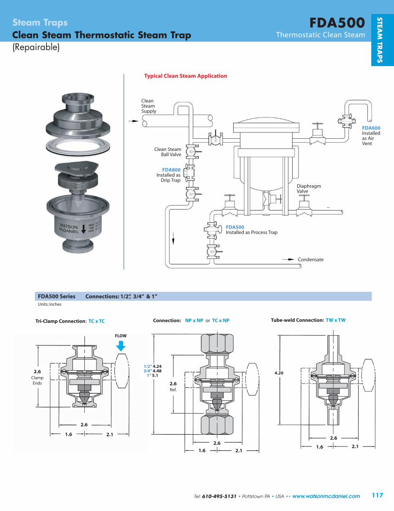
2.6ClampEnds
2.6
1.6 2.1
FLOW
2.6Ref.
2.6
1.6 2.1
1/2” 4.243/4” 4.48
1” 5.1
2.6
1.6 2.1
4.20
Tri-Clamp Connection: TC x TC Connection: NP x NP or TC x NP Tube-weld Connection: TW x TW
117
FDA500Steam TrapsClean Steam Thermostatic Steam Trap(Repairable)
Thermostatic Clean Steam
STEAM
TRA
PS
Clean SteamBall Valve
FDA500Installed as Process Trap
FDA800Installed as
Drip Trap
FDA600Installedas AirVent
Condensate
CleanSteamSupply
DiaphragmValve
Typical Clean Steam Application
FDA500 SeriesUnits: inches
Connections: 1/2”, 3/4” & 1”
Tel: 610-495-5131 • Pottstown PA • USA •• www.watsonmcdaniel.com

118
FDA600Steam TrapsClean Steam Thermostatic Steam Trap(Repairable)
Thermostatic Clean Steam
Model FDA600Sizes 1/2”, 3/4”, 1”Connections Tri-clamp, NPT, Tube WeldBody Material Stainless SteelPMO Max. Operating Pressure 110 PSIGTMO Max. Operating Temperature Saturated Steam TemperaturePMA Max. Allowable Pressure 145 PSIG up to 338ºFTMA Max. Allowable Temperature 350ºF @ 132 PSIG
Typical Applications
DRIP, PROCESS: FDA600 Series thermostatic clean steamtraps are used as drip traps on piping runs on clean steam applications and for drainage for CIP/SIP systems and variousprocess vessels.
How It Works
This trap contains a welded 316L stainless steel thermal element that expands when heated and contracts when cooled.When air and subcooled condensate are present, the trap is in an open discharge position. When steam reaches the trap, the element expands, closing the trap tightly.
Features
• All wetted parts are 316L stainless steel
• Operates close to saturation curve to minimize condensate back-up
• Completely self-draining in the vertical downward floworientation
Sample Specification
The Steam Trap shall be all 316L stainless steel thermostatic type with a balanced pressure bellows that operates close to saturated steam temperatures. The unit shall have a split-bodydesign for easy maintenance. Trap shall be completely self-draining when mounted vertically.
Installation and Maintenance
Trap is designed to be installed in a vertical, downward flow orientation to ensure that the self-draining clean steamrequirement is satisfied. If purchased with tube weld connectionswith the intention of welding in-line , the thermal element and gasket must be removed during the welding process or heatdamage may occur.
MATERIALSBody Stainless Steel, AISI 316LThermal Element Stainless Steel, AISI 316LO-Ring, FDA Grade Teflon Coated Silicone/FEPNuts & Bolts Stainless Steel, AISI 316L
CAPACIT IES – Condensate (lbs/hr)CondensateTemp Below Differential Pressure (PSI)Saturation 1 5 10 20 50 75 110
10 ˚F 32 105 175 290 615 805 1160
20 ˚F 42 115 225 440 1060 1500 1850
Cold Water 735 1070 1375 1900 3100 3500 4600
STEA
M T
RA
PS
Size/Connection Model PMO WeightInlet x Outlet Code PSI lbs
1/2” TC x TC FDA600-12-TCTC 110 1.253/4” TC x TC FDA600-13-TCTC 110 1.251” TC x TC FDA600-14-TCTC 110 1.251/2” TC x NPT FDA600-12-TCNP 110 1.253/4” TC x NPT FDA600-13-TCNP 110 1.251” TC x NPT FDA600-14-TCNP 110 1.251/2” NPT x NPTT FDA600-12-NPNP 110 1.25
3/4” NPT x NPT3/4” NPT x NPT FDA600-13-NPNP 110 1.251” NPT x NPT FDA600-14-NPNP 110 1.25
1/2” TW X TW FDA600-12-TWTW 110 1.25
4.2Tube
NPT1/2” - 3.73/4” - 3.8
1” - 5.0
1.9Sanitary
2.4 Units: Inches
FLOW
www.watsonmcdaniel.com •• Pottstown PA • USA • Tel: 610-495-5131

119
FDA800Clean Steam Thermodynamic Steam Trap Thermodynamic Clean Steam
Steam TrapsSTEA
M TR
APS
Note: Maximum back pressure not to exceed 80% of inlet pres sure.
Model FDA800Sizes 1/2”Connections Tri-Clamp, NPT, Tube WeldBody Material Stainless SteelPMO Max. Operating Pressure 150 PSIGTMO Max. Operating Temperature 500ºFPMA Max. Allowable Pressure 230 PSIG @ 850ºFTMA Max. Allowable Temperature 850ºF @ 230 PSIG
Typical Applications
DRIP: The FDA800 Series thermodynamic clean steam trapsare used as drip traps on steam mains in CIP/SIP systems and drainage for separators and filters.
How It Works
Using the thermodynamic properties of flash steam, this trapfeatures a disc that is pushed open by incoming condensate, then closes tightly when steam enters the trap. Because it normally operates in an open position, condensate is continuously discharged from the line. Steam entering the trap creates an internal pressure that forces the valve to close tightly, preventing the steam from escaping.
Features
• Small and compact
• All 316L stainless steel components
• Works in any position (horizontal preferred)
Sample Specification
The steam trap shall be a thermodynamic disc type with an all 316L stainless steel construction and integral seat design. Unit shall be capable of installation in any orientation and self-draining when mounted vertically.
Installation and Maintenance
Can be installed in any position; however, horizontal is preferred.For self-draining requirements, the trap should be installed vertically. Installation should include a strainer before the trapinlet since dirt is a common cause of premature failure.
MATERIALS
Body Stainless Steel, AISI 316LDisc Stainless Steel, AISI 316LCap Stainless Steel, AISI 316L
CAPACIT IES – Condensate (lbs/hr)Differential Pressure (PSI)
Size 3.5 5 10 15 20 25 30 40 50 75 100 1501/2” 180 185 190 195 200 215 220 230 250 310 375 500
2.6 Sanitary2.6 NPT
1.38
Units: Inches
NPT Tri-Clamp
Size/Connection Model PMO WeightInlet x Outlet Code PSI lbs
1/2” TC x TC FDA800-12-TCTC 150 1.51/2” TW x TW FDA800-12-TWTW 150 1.51/2” NPT x NPT FDA800-12-NPNP 150 1.5
Inlet Outlet
Tel: 610-495-5131 • Pottstown PA • USA •• www.watsonmcdaniel.com

120
WPN SeriesSteam TrapsBi-Metallic Steam Trap Bi-Metallic
Typical Applications
DRIP, TRACING: WPN Series Bi-metallic steam traps are used in steam tracing, steam main drips and non-critical process equipment. They are extremely robust and reliable, making them a suitable choice forhighpressure applications as well as outdoor applications that are subject to freezing. They are used in systems where a quick discharge of air, non-condensable gases and large quantities of cold water need to be dischargeat start-up.
How It Works
When the system is cold, the trap is fully open; discharging air and cold condensate. When the bi-metallic plates inside the trap heat up, they expand;pulling the seat closed and restricting flow. Prior to steam temperature beingreached, the trap shuts off tightly. Cooler temperatures cause the seat to openfurther. Therefore, trap capacity will increase when colder condensate is incontact with the Bi-metal element. Trap capacity is therefore given at differenttemperatures below saturated steam temperature.
Features
• Excellent for high-pressure and superheated steam applications
• Freeze-proof and resistant to waterhammer
• Suitable for superheated steam
• In-line repairable
• Trap can be welded into line
Sample Specification
Steam trap shall be Watson McDaniel WPN Series Bi-Metallic Steam Trap. Trap must be capable of being completely serviced while still in-line.
STEA
M T
RA
PS
Model Body Material PMO Sizes Connections Pressure Max Diff.(PSIG) Controller Pressure (PSI)
WPN-40 A105 Carbon Steel 470 1/2” – 2”NPT, 150# or 300# FLG, R22 320SW, BW R32 460
WPN-63 A182-F12CL2 Alloy Steel 823 1/2” , 3/4”, 1” NPT, 300# FLG, SW, BW R56 810
WPN-100 A182-F12CL2 Alloy Steel 1220 1/2” , 3/4”, 1” NPT, 600# FLG, SW, BW R90 1200
WPN-160 A182-F12CL2 Alloy Steel 1620 1/2” , 3/4”, 1” NPT, 900# FLG, SW, BW R130 1600
WPN-250 A182-F22CL3 Alloy Steel 2260 1/2” , 3/4”, 1” NPT, 1500# FLG, SW, BW R150 2230
Bi-Metallic Steam TrapsThe WPN Series Bi-Metallic Steam Traps are used in steam tracing, steam main drips and non-critical process equipment. They can be used on outdoor applications that are subject to freezing.The WPN Series Traps are available in multiple sizesand pressures up to 2260 PSI.
PressureController
www.watsonmcdaniel.com •• Pottstown PA • USA • Tel: 610-495-5131
Max Differential Pressurefor Pressure Controller
Pressure Max Diff. Pressure Controller PSI
R22 320R32 460R56 810R90 1200R130 1600R150 2230
Installation and Maintenance
The trap can be installed in any orientation except withthe cap facing downward. All internal componentscan be replaced while trap body remains in-line.

121
WPN SeriesBi-Metallic Steam Trap Bi-Metallic
Steam TrapsSTEA
M TR
APS
R130
1/2” 12WPN-63 3/4” 13
1” 141/2” 12
WPN-100 3/4” 131” 141/2” 123/4” 131” 141/2” 12
WPN-250 3/4” 131” 14
R56
R90
Alloy SteelA182- F12 CL2
(C)
F900, SW,BW
F1500, SW,BW
Position 1 Position 2 Position 3 Position 4 Position 5 Position 6
Body Pressure Connection Strainer Model Material Controller Connection Type Selec tion(Code) Code Size Code Code Code
1/2” 123/4” 131” 1411/2” 16
WPN-40 2” 171/2” 123/4” 131” 1411/2” 162” 17
InternalStrainer(IS)
ExternalStrainer(ES)
Carbon Stee l A105(A) F150,
F300,N, SW,
BW
F150, F300,
N, SW
WPN-160
Example Model Codes:
WPN40-A-R22-14-F150-ES(Model WPN40, 32 0 PSI Max Differential Pressure, 1” 150# Flanged with External Strainer)
WPN63-C-R56-14-F600(Model WPN63, 810 PSI Max Differential Pressure, 1” 600# Flanged with Standard Internal Strainer)
How to select a A WPN Trap:1) Select a Pressure Controller that has a max differential
pressure within the range of your application.
2) Select a Trap Body depending on System Pressure; WPN40 thru WPN250.
3) Select Connection Type & Size
4) Configure Model Code (see Examples to right)
R22 orR32
Alloy Steel A182- F12 CL2
(C)
F600, SW,BW
F300, SW,BW
Alloy Steel A182- F12 CL2
(C)
Alloy SteelA182- F22 CL3
(C)
R150
Model Configuration Chart
Tel: 610-495-5131 • Pottstown PA • USA •• www.watsonmcdaniel.com

122
WPN SeriesSteam TrapsBi-Metallic Steam Trap Bi-Metallic
STEA
M T
RA
PS
WPN-40 with R22 & R32 Controller1/2”, 3/4”, 1”
1) = 18˚F SUB-COOL2) = 54˚F SUB-COOL3) = 68˚F
WPN-40 with R22 & R32 Controller
11/2”, 2”
Model WPN-40Sizes 1/2”, 3/4”, 1”, 11/2”, 2”Connections NPT, 150# FLG, 300# FLG, SW, BWBody & Cover Material A105 (C22.8)PMA ANSI Class 150 with 150# FLG 190 PSIG up to 437˚FPMA ANSI Class 300 with 300# FLG 460 PSIG up to 772˚FTMO Max. Operating Temperature (˚F) Approx. 100˚F Superheat
Pressure Controller R22 R32PMO Max. Operating Differential Pressure
of Pressure Controller (PSI) 320 460
Note: SW = Socket WeldBW = Butt-Weld
The capacity charts show the maximum flow at factory setting.
Curve Flow of Condensate at approx. 18°F below boiling temperature.
Curve Flow of Sub-Cooled Condensate at approx. 54°F below boiling temperature.
Curve Flow of Cold Condensate at about 68°F (during start-up of a cold system).
Cooler temperatures cause the seat in the controller to open wider; therefore, trap capacity willincrease when colder condensate is in contact with the Bi-metal element. Trap capacity is given at different temperatures below saturated steam temperature
2
1
3
2
1
3
2
1
3
R22
R22
R22 R32R32
R32
R32
R32
R32
R22
R22
R22
www.watsonmcdaniel.com •• Pottstown PA • USA • Tel: 610-495-5131

123
WPN SeriesBi-Metallic Steam Trap Bi-Metallic
Steam TrapsSTEA
M TR
APS
WPN-40 with R22 or R32 Controller (screw-on cover)
1/2”, 3/4”, 1”L
H3
H
H1
H2
L L L
NPT Butt-weld SW
SW
WPN-40 with R22 or R32 Controller (bolt-on cover)
11/2”, 2”
H3
H
L
NPT Butt-weld
FLOW
DIMENSIONS & WEIGHTS – inchesModel Size Connection L H H1 H2 H3 Weight (lbs)
1/2”, 3/4” 150#/300# FLG 5.90 3.92 2.44 1.20 2.8 7.7
1” 150#/300# FLG 6.30 3.92 2.44 1.20 2.8 9.2
11/2”, 2” 150#/300# FLG 9.05 5.76 2.67 1.97 3.6 25.01/2”, 3/4” NPT, SW 3.74 3.92 2.44 1.20 2.8 3.7
WPN-40 1” NPT, SW 3.74 4.12 2.16 1.20 2.8 4.6
11/2” NPT 6.30 5.76 2.67 1.97 3.6 17.6
11/2” SW 5.12 5.76 2.67 1.97 3.6 17.6
2” NPT, SW 8.27 5.76 2.67 1.97 3.6 17.61/2”, 3/4”, 1” Butt-weld 9.84 3.92 2.44 1.20 2.8 5.0
11/2”, 2” Butt-weld 9.84 5.76 2.67 1.97 3.6 21.0
FLOW
Shown withOptional External Strainer
Shown withoutOptionalExternal Strainer
Internal Strainer
Bolt-OnCoverScrew-on
Cover
Tel: 610-495-5131 • Pottstown PA • USA •• www.watsonmcdaniel.com

124
WPN SeriesSteam TrapsBi-Metallic Steam Trap Bi-Metallic
STEA
M T
RA
PS
WPN-63 / WPN-100 / WPN-160 / WPN-250
1/2”, 3/4”, 1”
DIMENSIONS & WEIGHTS – inchesModel Size Connection L H H1 H3 Weight (lbs)
1/2”, 3/4” FLG* 8.26 4.16 1.68 2.8 17.6WPN-63, WPN-100, 1” FLG* 9.05 4.16 1.68 2.8 17.6WPN-160, WPN-250 SW 6.30 4.16 1.68 2.8 10.01/2”, 3/4”, 1”
Butt-weld 6.30 4.16 1.68 2.8 10.0
* WPN-63: 300# FLG WPN-100: 600# FLGWPN-160: 900# FLG WPN-250: 1500# FLG
Model WPN-63* WPN-100 WPN-160 WPN-250Sizes 1/2”, 3/4”, 1” 1/2”, 3/4”, 1” 1/2”, 3/4”, 1” 1/2”, 3/4”, 1”Connections 300# FLG, SW, 600# FLG, SW, 900# FLG, SW, 1500# FLG, SW,
Butt-weld Butt-weld Butt-weld Butt-weldBody & Cover Material Alloy St eel Alloy Steel Alloy Steel Alloy Steel
(A182-F12CL2) (A182-F12CL2) (A182-F12CL2) (A182-F22CL3)Body Rating ANSI 400 ANSI 600 ANSI 900 ANSI 1500PMA Max. Allowable Pressure 810 PSIG 1200 PSIG 1600 PSIG 2180 PSIG
up to 592˚F up to 610˚F up to 750˚F up to 905˚F
TMA Max. Allowable Temperature 1000˚F @ 261 PSIG 1000˚F @ 441 PSIG 1000˚F @ 595 PSIG 1000˚F @ 1305 PSIGTMO Max. Operating Temperature 572˚F 842˚F 932˚F 932˚FPressure Controller R56 R90 R130 R150PMO Max. Operating Diff. Pressure 810 PSI 1200 PSI 1600 PSI 2230 PSI
of Pressure Controller
FLGH3
H
L
SW
Butt-weld Version(shown)
H1
FLOW
www.watsonmcdaniel.com •• Pottstown PA • USA • Tel: 610-495-5131

125
WPN SeriesBi-Metallic Steam Trap Bi-Metallic
Steam TrapsSTEA
M TR
APS
54˚ F SUB-COOL
27˚ F SUB-COOL
68˚ F
54˚ F SUB-COOL
27˚ F SUB-COOL
68˚ F
Differential pressure
WPN-100 • 1/2”, 3/4”, 1”
WPN-160 • 1/2”, 3/4”, 1” WPN-250 • 1/2”, 3/4”, 1”
54˚ F SUB-COOL
18˚ F SUB-COOL
68˚ F
54˚ F SUB-COOL
18˚ F SUB-COOL
68˚ F
Differential pressure (PSI) Differential pressure (PSI)
Flow
(lbs
/hr)
Flow
(lbs
/hr)
1760011000
88006600
22001750
880
440
4400
1320
13200
8800
6600
2200
1750
880
4400
1320
WPN-63 • 1/2”, 3/4”, 1”
The capacity charts show the maximum flow at factory setting.
Curve 1 Maximum Flow quantity of Condensate at approximately 18 & 27°F below boiling temperature.
Curve Maximum Flow of Sub-Cooled condensate at approx. 54°F below boiling temperature (through back up of condensate).
Curve Maximum Flow quantity of Cold Condensate at about 68°F (during start-up of a cold system).
Cooler temperatures cause the seat in the controller to open wider; therefore, trap capacity will increase when colder condensate isin contact with the Bi-metal element. Trap capacity is given at different temperatures below saturated steam temperature.
2
1
3
2
1
3
2
1
3
2
1
3
3
2
Differential pressure
R1 30 Controller R1 50 Controller
R56 Controller R90 Controller
Tel: 610-495-5131 • Pottstown PA • USA •• www.watsonmcdaniel.com


FM SeriesSteel Manifolds
Fabricated Carbon Steel
Manifolds
Steam Traps
B
AInletConn.
Drain Connection
Pipe Cap
21/2”Tube Diameter
3/4” Siphon PipeDiameter
4” Typ.
OutletConnection
2”
16”
6”
21/2” 21/2” Typ.
3”
41/2”
6”
MATERIALS – FMBody Fabricated Carbon Steel
STEAM
TRA
PS
8” Typ.
# # BDescription Model Inlet (A) Front Side Conn. Length Wt..Vertical Mount Code Size Type Conn. Conn. Total (in) (lbs)
Condensate Collection (C) Manifolds4 side conn. FM4-12-N-C 1/2” NPT 4 0 4 24 254 side conn. FM4-13-N-C 3/4” NPT 4 0 4 24 274 side/2 front conn. FM6-12-N-C 1/2” NPT 4 2 6 24 274 side/2 front conn. FM6-13-N-C 3/4” NPT 4 2 6 24 298 side conn. FM8-12-N-C 1/2” NPT 8 0 8 40 408 side conn. FM8-13-N-C 3/4” NPT 8 0 8 40 428 side/4 front conn. FM12-12-N-C 1/2” NPT 8 4 12 40 468 side/4 front conn. FM12-13-N-C 3/4” NPT 8 4 12 40 4812 side conn. FM12A-12-N-C 1/2” NPT 12 0 12 56 5612 side conn. FM12A-13-N-C 3/4” NPT 12 0 12 56 58
Steam Distribution (D) Manifolds
4 side conn. FM4-12-N-D 1/2” NPT 4 0 4 24 254 side conn. FM4-13-N-D 3/4” NPT 4 0 4 24 274 side/2 front conn. FM6-12-N-D 1/2” NPT 4 2 6 24 274 side/2 front conn. FM6-13-N-D 3/4” NPT 4 2 6 24 298 side conn. FM8-12-N-D 1/2” NPT 8 0 8 40 408 side conn. FM8-13-N-D 3/4” NPT 8 0 8 40 428 side/4 front conn. FM12-12-N-D 1/2” NPT 8 4 12 40 468 side/4 front conn. FM12-13-N-D 3/4” NPT 8 4 12 40 4812 side conn. FM12A-12-N-D 1/2” NPT 12 0 12 56 5612 side conn. FM12A-13-N-D 3/4” NPT 12 0 12 56 58
Connection Codes: N = NPT, SW = Socket Weld For Socket Weld Connectionss: change N in Model code to SW. Example: FM4-12-SW-C
127Tel: 610-495-5131 • Pottstown PA • USA •• www.watsonmcdaniel.com

128
FSM SeriesSteam TrapsSteel ManifoldsForged Steel
Manifolds
CAPACIT IESPressure Condensate Steam(PSIG) (lbs/hr) 1 (lbs/hr) 2
25 1850 16050 1000 31075 840 460100 610 730125 660 760150 620 900200 570 1200250 535 1500300 510 1800400 470 2350500 460 3000600 440 3550
1Saturated condensate discharging into 20 PSI back pressure2Saturated Steam flow @ 5000 ft/min velocity
DIMENSIONS & WEIGHTS – inchesNo. of No. of Weight
Model L H D C O I S S1 S2 A A1 B B1 Valves Holes (lbs)
FSM-4 4.33" 1.61" 3.94" 8.97" 10.63" 6.30" 13.03" - - 2.79" 1.22" 3.23" 2.79" 4 2 (M12) 23FSM-8 4.33" 1.61" 3.94" 8.97" 10.63" 6.30" - 28.1" 2.79" 1.22" 3.23" 2.79" 8 4 (M12) 49FSM-12 4.33" 1.61" 3.94" 8.97" 10.63" 6.30" - - 36.22" 2.79" 1.22" 3.23" 2.79" 12 6 (M12) 72
11/2” SWConnection
S2(FSM-12)
S1(FSM-8)
S(FSM-4)
OC
CLOSED
A
A 1
H
L
OPEN
DTYP.
ITYP.
M12 ThreadMTG. Holes
1/2” SWConn.
B 1
B
STEA
M T
RA
PS
Model Connection # ofDescription Code Size Type Branches
Condensate Collection (C) Manifolds4 Branches/4 Valves FSM4-12-N-C 1/2” NPT 44 Branches/4 Valves FSM4-13-N-C 3/4” NPT 48 Branches/8 Valves FSM8-12-N-C 1/2” NPT 88 Branches/8 Valves FSM8-13-N-C 3/4” NPT 812 Branches/12 Valves FSM12-12-N-C 1/2” NPT 1212 Branches/12 Valves FSM12-13-N-C 3/4” NPT 12Steam Distribution (D) Manifolds
4 Branches/4 Valves FSM4-12-N-D 1/2” NPT 44 Branches/4 Valves FSM4-13-N-D 3/4” NPT 48 Branches/8 Valves FSM8-12-N-D 1/2” NPT 88 Branches/8 Valves FSM8-13-N-D 3/4” NPT 812 Branches/12 Valves FSM12-12-N-D 1/2” NPT 1212 Branches/12 Valves FSM12-13-N-D 3/4” NPT 12
Connection Codes: N = NPT, SW = Socket Weld For Socket Weld Connectionss: change N in Model code to SW.Example: FSM4-12-SW-C
MATERIALS – FSMBody Forged Steel, A105Hand Wheel Sheet MetalBonnet Forged Steel, A105Valve ring above GraphiteValve ring below Graphite/Stainless SteelPiston Stainless Steel, A304
www.watsonmcdaniel.com •• Pottstown PA • USA • Tel: 610-495-5131

129www.watsonmcdaniel.com •• 428 Jones Boulevard • Limerick Airport Business Center • Pottstown PA • 19464 •• Tel: 610-495-5131
Conden
sate
Pum
ps
Condensate Pumps

130
Condensate Return PumpsIntroduction
What is a Boiler Feed Pump? A facility will often have a separate area that contains various components required for thegeneration of steam, such as a boiler, condensate holding or deaerator (DA) tank, boiler feed pump, water treatment, etc.Regulated by the boiler control system, the boiler feed pump sends condensate from the holding tank back to the boiler.
Conden
sate
Pum
ps
Condensate Return System Shown below is a simplified view of a steam system from steam generation to condensate return. Steam generated by theboiler travels through the steam distribution lines supplying steam to various pieces of process equipment. The steam flowingto this equipment is separated from the condensate return lines by steam traps.
Relatively small steam traps, referred to as “Drip traps,” are used for optimization and protection of steam systems bydraining condensate from steam distribution lines into the condensate return line.
Process Applications refer to draining condensate from the actual process using the steam into the condensate return line.The steam traps used in these applications have relatively high condensate capacity and are referred to as “Process traps”.
A large plant may have many separate pieces of process equipment and thousands of drip traps discharging condensateinto the condensate return lines. On efficiently run steam systems, this condensate is returned back to the boiler for reuse.
In certain cases, the steam pressure of the system may be sufficient to push the condensate through the steam traps andcondensate return lines, back to the condensate holding tank in the boiler room. In most practical situations, however, one or more condensate return pumps are required to assist in overcoming gravity, pressure drops from long piping runs, andback pressures in return lines. Condensate Return Pumps are either electrically-driven centrifugal pumps or non-electricmechanical pumps that use steam pressure as the motive force to pump the condensate. Non-electric pumps are referredto as Pressure Motive Pumps (PMPs).
What are Condensate Return Pumps & when are they required?
Roof
VentedReceiver
Pump
Steam Jacketed
Kettle
Vat Process
ProcessSteam
Trap
ProcessSteam
Trap
Drip TrapTD600S
Drip TrapTD600S
Steam Distribution & Condensate Return System
Steam travels through piping
Process 1 Process 2
Condensate ReturnPump
BoilerFeedWater
BoilerFeedPump
Steam
FlashSteam
Vent
www.watsonmcdaniel.com •• Pottstown PA • USA • Tel: 610-495-5131
Condensate Return Line

Electric Pumps
Electric Condensate Return Pumps are designed to work intermittently, discharging condensateonly when the receiver tank is nearly full. This is accomplished with a float switch. A floatconnected to the switch assembly rises when condensate enters the tank. Once it rises above a set point, the switch energizes the motor on the pump, which runs until the water level dropsbelow the bottom position of the float switch. The switch then de-energizes the motor to shut off the pump. Watson McDaniel electric pumps are offered in Simplex and Duplex models.
131
Conden
sate
Pum
ps
What is the purpose of a Vented Receiver?Condensate from several different sources, at different pressures, are often discharging into the same return line. Thedischarge from one of the higher pressure sources could easily increase the pressure in the return line, which would stop the discharge from a critical process application operating at lower pressures.
By connecting the condensate return line to a vented receiver, the pressure in the return line will be effectively equalized to atmospheric pressure, allowing condensate to freely drain from all condensate sources. This is an extremely important and often overlooked aspect of any properly operating steam and condensate return system. The receiver and vent must be adequately sized to allow for the discharge of flash steam without building up excessive pressure. Higher condensatepressures or loads would require larger receiver and vent sizes. Condensate then flows by gravity from the vented receiver to the condensate return pump and is then returned back to the boiler room.
Condensate Return PumpsIntroduction
Mechanical stand-alone Pressure Motive Pumps (PMPs)
A stand-alone Pressure Motive Pump (PMP) consists of a pump tank with internal operatingmechanism, and a set of inlet and outlet check valves. Pump tanks can be made from ductile iron (PMPC), fabricated steel (PMPF) or stainless steel (PMPSS). A PMP requires some form of a separate vented receiver tank that collects the condensate prior to entering the pump. This vented receiver is required to neutralize the pressure in the condensate return line by venting the flash steam to the atmosphere.
Pumps with Receiver Tanks (Standard Skid Systems)
Simplex, Duplex, and Triplex packaged systems include stand alone pumps and check valveswith a vented receiver tank, mounted on a steel base and frame. Multiple pumping units can beused for increased capacity or for system redundancy. The stand-alone pumps are available inductile iron, carbon steel and stainless steel; options include sight glasses, insulation jackets,cycle counters, motive and vent piping, pressure regulators, steam traps, strainers and ASMEcode stamp. All components of the system are properly sized and pre-piped together; requiringonly four connections to be made in the field.
Mechanical & Electric Condensate Return Pumps
Tel: 610-495-5131 • Pottstown PA • USA •• www.watsonmcdaniel.com
VentedReceiver
PMPs
PMP(stand-alone pump)
Pressure Motive Pumps (PMPs) are non-electric pumps which return condensate back to the boiler room; usingsteam pressure as the motive force. PMPs can be supplied as stand-alone units – which include a pump tank, theinternal operating mechanism, and a set of inlet and outlet check valves, or: as a packaged system – which also includesthe vented receiver tank (to collect the condensate) mounted on a common base.
What are Pressure Motive Pumps (PMPs)?
PumpTank
InternalMechanism
CheckValve

Installation of mechanical type PMP’s vs. Electric pumps:Standard Electric Pumps are supplied with a receiver tank and are intended for lower pressure steam systems. In these instances, the vent size on the receiver tank should be adequate to vent minimal flash steam, allowing condensate tofreely enter the receiver and to adequately cool prior to being pumped. In higher pressure steam systems, the condensatetemperature is hotter, resulting in more flash steam as the condensate is discharged through steam traps and into the returnline. Additional options may be required for the electric pumps if condensate does not cool to suitable temperatures.
PMPs discharge high temperature condensate that drains from vented receivers. A stand-alone PMP pump tank cannot be used as the vented receiver since it is intermittently pressurized with steam or air to pump the condensate. PMPs require a separate vented receiver to collect the condensate and to vent the flash steam to atmosphere. The Simplex, Duplex orTriplex packaged systems include the separate vented receiver tank mounted on a common base along with the PMP(s).
Vented Receivers should generally be sized to maintain 0 psig in both the receiver and condensate return line upstream of the receiver. This helps ensure free drainage of condensate from sources that may be operating at both high and lowpressure. Sizing criteria is based on condensate pressure and the amount of the flash steam created. Undersizing the receiveror the vent will increase the pressure in the receiver and condensate return line, possibly causing issues with condensatedrainage from process equipment upstream. Undersizing of the vent will increase the velocity of flash steam in the pipe which could possibly draw condensate from the receiver and discharge it out of the vent.
132
Why choose a PMP instead of an electric (centrifugal) condensate return pump?Reliability is the primary purpose for selecting Mechanical type PMP’s instead of Electric condensate pumps.
Electric pumps require a mechanical seal to prevent the leakage of liquid around the rotating shaft that drives the impeller. The liquidbeing pumped acts as a lubricant so the seal faces of the mechanical seal may rotate freely against each other. When the liquidremains relatively cool, the mechanical seal could last for many years. However, hot condensate can flash to steam between the sealfaces leading to seal failure.
A centrifugal pump creates a low pressure zone at the eye of the impeller which draws the fluid into the pump. Hot condensate canflash into steam in the low pressure zone causing Cavitation. Cavitation happens when bubbles form in the liquid on the inlet side ofthe pump that will re-compress on the outlet side, causing erosion of the impeller and pump housing. When a pump cavitates, it oftensounds like marbles or sand is being pumped. This flashing also blocks the flow of incoming condensate; causing the pump to run drywhich decreases performance and also leads to seal failure.
1) PMP’s do not have any seals to fail.2) No cavitation can occur because the body of the pump is filled by the natural flow due to gravity from a vented receiver, and
then discharged by steam pressure. Therefore, Pressure Motive pumps are much more forgiving than centrifugal pumps when pumping hot condensate.
flash steam
condensate
condensatereturn line
motive steam
vent to atmosphere
steaminletpump
exhaustfillinghead
inletcheck valve
outletcheck valve
Condensate fromMultiple Sources
roof
Condensate Return PumpsIntroduction • Applications for using PMPs
Condensate
Conden
sate
Pum
ps
VentedReceiver
PressureMotivePump
Pump (PMP) with a Vented Receiver
A Vented Receiver (or Flash Tank) is used to collect the condensate generated fromone or several different sources (drip &process applications) in the facility.
Pressure from the Flash steam generated by the hot condensate is vented to theatmosphere to maintain atmosphericpressure (0 PSIG) in the receiver tank. This assures that condensate will freely flow by gravity to the receiver tank and then to the pump tank, avoiding potentialcondensate back-up.
www.watsonmcdaniel.com •• Pottstown PA • USA • Tel: 610-495-5131
0 PSIG

133
Conden
sate
Pum
ps
Condensate Return PumpsIntroduction • Applications for using PMPs
outlet
openclosed
inlet
FLOW
1 Condensate flows from the receiver tank through the inletcheck valve and fills the pump tank. During the filling cycle the float inside the tank rises.
2 When the pump tank has filled to the trip point, the mechanismtriggers, opening the motive gas inlet valve and simultaneouslyclosing the vent valve. This allows motive pressure to enter thepump body, which drives the condensate thru the outlet checkvalve into the condensate return line. During the discharge cycle,the liquid level and the float inside the pump tank drop.
3 At the lower trip point, the mechanism triggers and the motive gasinlet valve to the pump tank closes and simultaneously the ventvalve opens. The fill and discharge cycle then repeats.
outlet
closedopen
inlet
MOTIVEINLET
(closed)
VENTOUTLET(open)
outlet
closedopen
inlet
Open Closed
FLOW
FLOW
Operation of PMP Pressure Motive Pump
The positions of the Vent and Motive valves control the filling and discharge of the pump. The Vent valve must be open duringthe filling cycle to allow air or steam in the pump tank to bedisplaced as water enters the pump. Since water flows into thepump tank by force of gravity, the pump tank pressure must beneutralized for the pump tank to fill.
When the pump tank reaches its fill point the vent valve closesand the motive valve opens. The incoming steam pressurerapidly forces the water out of the pump tank through the outletcheck valve. When the pump tank empties, the vent valve opensand motive inlet valve closes.
Vent Outlet: Open position, allowing any pressure in the pump tank to vent out and water to freely enter pump by gravity.
Motive Inlet: Closed position
Condensate level rising
Condensate level falling
Vent Outlet: Closed
Motive Inlet: Open; steam pressure enters tank and discharges condensate
Condensate level rising
Vent Outlet: Open position, allowing any pressure in the pump tank to vent out and water to freely enter pump by gravity.
Motive Inlet: Closed Position
MOTIVEINLET(open)
VENTOUTLET(closed)
Closed Open
Check ValvesThe inlet check valve on the PMP system musthave a very low cracking pressure (openingpressure) so that the liquid will freely enter thepump tank. The proper check valve is verycritical to the proper operation of the PMPsystem. Watson McDaniel recommends usingspring-loaded stainless steel check valves with ¼ PSI cracking pressure.
Tel: 610-495-5131 • Pottstown PA • USA •• www.watsonmcdaniel.com
Pump Filling
Pump Discharging
Pump Filling


135
Condensate Return PumpsIntroduction • Pressure Motive Pump Components
Conden
sate
Pum
ps
Check ValvesThe inlet check valve on the PMP system must have a very low cracking pressure (openingpressure) so that the liquid will freely enter the pump tank. The proper check valve is verycritical to the proper operation of the PMP system. Watson McDaniel recommends usingspring-loaded stainless steel check valves with ¼ PSI cracking pressure.
Snap-Assure Pump Mechanism1) Cover & mechanism bolt to top of pump tank.2) Mechanism is field-repairable by replacing any of the functioning components such as springs and valve seats. 3) Mechanism can fit other manufacturers’ pump tanks.
Pump Tank Made in various materials & styles:Ductile Iron, Fabricated Steel, Stainless Steel
Check Valve Check Valve
Motive Steam Inlet & Vent ValvesThreaded into mechanism cover.
Outlet
Inlet
PumpMechanism
Tel: 610-495-5131 • Pottstown PA • USA •• www.watsonmcdaniel.com
Cover

136
Mechanical Condensate Return Pumps are available as:
1) PMP (Pressure Motive Pump - Stand-Alone Unit) or2) Pump System (Pumps with Vented Receiver Tanks):
Mechanical PMP Stand-Alone Pumps
Watson McDaniel’s Pressure Motive Pump (PMP stand-alone unit) consists of the pump tank, which is made from ductile iron,fabricated steel, or stainless steel, and Watson McDaniel’s patented “Snap-Assure” internal operating mechanism, along with a set ofinlet and outlet check valves. An additional vented receiver or flash tank is required to collect the condensate before it enters the pump.
Watson McDaniel offers a full line of PMP accessories, including custom tanks, insulation jackets, gauge glasses, cycle counters,pre-piped accessories, pump mechanisms, check valves and anything else you may need to maintain your system.
Stand-Alone Units - Pressure Motive Pumps
PMPC Cast Ductile Iron
PMPFFabricated Carbon Steel
PMPLSFabricated Carbon Steel(Reduced-Profile)
Ductile Iron Pump TanksDuctile Iron is far superior to cast iron in handling higher pressuresand temperatures. Ductile iron is also extremely corrosion resistant tocondensate and water and can last in excess of 50 years before tankreplacement is required. Our ductileiron tanks can be ASME coded onrequest.
Fabricated Carbon Steel Pump TanksCarbon steel tanks are required incertain industrial facilities such aschemical and petrochemical refineries.However, fabricated cast steel is muchless corrosion-resistant to condensatethan ductile iron. Our carbon steeltanks are standard ASME coded.
Fabricated Stainless Steel Pump TanksStainless steel (304L) tanks are extremely corrosion-resistant, givingincreased longevity and can serve as a substitute for fabricated carbonsteel tanks.
Low Profile Pump TanksLow-profile tanks are required whenvertical space for adequate fillinghead of the pump is limited.
Significantly morecorrosion-resistant tocondensate whencompared to carbon steel.
Carbon Steel may be requiredby code in Chemical andPetro-Chemical industries(required in certain industries).
Several choices of pump body materials, types and configurations are available to meet specific customer applications:
Condensate Return PumpsIntroduction
Conden
sate
Pum
ps
PMPSP Sump Drainer (non-electric sump pump)
Sump drainers are used to pump water from pits or sumps using steam or air pressure. They are similarto the standard PMP models except that they discharge vertically upwards. This piping configurationallows them to be lowered into a sump or pit.
Can serve as a substitute forfabricated carbon steel tanksfor extended life or whenStainless Steel is required.
For applications requiringlarge transfer rates ofcondensate or other liquids.
PMPSS304L Stainless Steel(Corrosion Resistant)
PMPBPCarbon Steel (High-Capacity)
PMPNTDuctile Iron or Stainless Steel(Low-Profile)
For lower capacityapplications.
www.watsonmcdaniel.com •• Pottstown PA • USA • Tel: 610-495-5131
Lower in height than PMPF.Required when verticalspace for adequate fillinghead of the pump is limited.

137
Pump Systems (Pumps with Receiver Tanks)
The PMPC, PMPF & PMPLS pump units are also available with a Vented Receiver mounted on a common base. The ventedreceiver is needed to collect the condensate which then drains by gravity into the pump tank. These standard Simplex, Duplexand Triplex packaged systems include stand-alone pump(s) and check valves with a vented receiver tank mounted on a steelbase and frame. Multiple pumping units can be used for increased capacity or for system redundancy. The pump units areavailable in ductile iron (PMPC) or carbon steel (PMPF). Additional options include sight glasses, insulation jackets, cyclecounters, motive and vent piping, pressure regulators, steam traps, strainers, ASME code stamps, etc.
Condensate Return PumpsIntroduction
Conden
sate
Pum
ps
Duplex Pumping System (shown)More than one pump can be used forincreased capacity or system redundancy. Vented
Receiver Tank
Check Valves
Receiver VentAdequately sized vent is important to neutralize pressure that is generatedby flashing condensate. This allowscondensate to freely flow by gravity into the receiver tank and then to pump tank.
System mounted onsteel base & frame
Pump Tanks
High pressure steamenters through
Steam Inlet Valveand is used to
pump condensate.
Condensate drains bygravity from receivertank into pump tanks
InletCheck Valves (2)Outlet
(Discharge)
Simplex Pumping System (shown)Single pump with receiver tankmounted on a common base.
Pump Tank
VentedReceiver Tank
Outlet(Discharge)
Check Valve InletCheck Valve
Receiver Vent
System mounted onsteel base & frame
Tel: 610-495-5131 • Pottstown PA • USA •• www.watsonmcdaniel.com

138
PMPC
Typical Applications
The PMPC model Ductile Iron non-electric pressure motive pump is typically used when liquids must be moved to higherelevation, higher pressure or extended distances. This stand-alonepump is capable of operating with a maximum motive pressure of 200 PSIG provided by steam, air or other gas supply. ASME “UM” code stamp is available.
Features
• Equipped with our Patented “Snap-Assure” Mechanism which extends the useful life of the pump
• Mechanism incorporates heat-treated stainless steelwear items
• All stainless steel internals for ultimate corrosion resistance
• Dual compression springs made from Inconel-X-750 for high-temperature corrosive service
• Operates using steam, air, nitrogen or other pressurized gases as the motive force
• Non-Electric – can be used in remote locations or NEMA 4, 7, 9 and hazardous areas
Sample Specification
The non-electric pressure powered pump shall be capable of operatingwith a maximum motive pressure of 200 PSIG provided by steam, airor other gas supply. The pump body shall be cast ASTM A-395 DuctileIron capable of an ASME “UM” code stamp if requested. The pumpmechanism shall be float operated with a patented “Snap-Assure”feature constructed of all stainless steel materials with all load bearingpoints hardened for extended service life. The mechanism shall featuretwo Inconel springs used in compression with motive & vent valveshardened to 40c Rockwell.
Model PMPCBody Ductile IronCover Ductile IronCheck Valves Stainless SteelPMO Max. Operating Pressure 200 PSIG TMO Max. Operating Temperature 388ºFPMA Max. Allowable Pressure 200 PSIG @ 650˚FTMA Max. Allowable Temperature 650ºF @ 200 PSIG
MATERIALSBody & Cover Ductile IronCover Gasket GrafoilCover Bolts SteelInlet Valve Hardened Stainless Steel 40 RcVent Valve Hardened Stainless Steel 40 RcMechanism Yoke 304 Stainless SteelBall Float 304 Stainless SteelCheck Valves Stainless SteelSprings Inconel-X-750Other Internal Components Stainless Steel
DIMENSIONS – inchesSize Weight
(Inlet x Outlet) Model Code A B C (lbs)
1” x 1” PMPC-1X1-N-SS 291/2 6 6 36011/2” x 1” PMPC-1.5X1-N-SS 303/4 71/2 6 365
11/2” x 11/2” PMPC-1.5X1.5-N-SS 311/4 71/2 71/2 3672” x 1” PMPC-2X1-N-SS 31 8 6 370
2” x 11/2” PMPC-2X1.5-N-SS 321/2 8 71/2 3802” x 2” PMPC-2X2-N-SS 323/4 8 8 3853” x 2” PMPC-3X2-N-SS 351/4 91/4 8 390
Snap-Assure U.S. Patent No. 6572340
Stand-Alone Pumps CAST DUCTILE IRON TANK Pressure Motive Pump
1” NPTVent
B
1/2” NPTMotive
OptionalGauge Glass
24.75”
4.20”
1.19”
C
A
LiftingEyes
OUTLETINLET
OUTLETINLET
1.19”
Conden
sate
Pum
ps
Check Valve Check Valve
The PMPC Stand Alone Pump consists of pump tank, internalmechanism, and inlet and outlet stainless steel check valves.
www.watsonmcdaniel.com •• Pottstown PA • USA • Tel: 610-495-5131

Typical Applications
The PMPF model Carbon Steel non-electric pressure motive pumpis typically used when liquids must be moved to higher elevation,higher pressure or extended distances. This stand-alone pump iscapable of operating with a maximum motive pressure of 200PSIG provided by steam, air or other gas supply. These tanks arefabricated with 1/8” corrosion allowance and receive the ASME“UM” code stamp.
Features
• Equipped with our Patented “Snap-Assure” Mechanism which extends the useful life of the pump
• Mechanism incorporates heat-treated stainless steelwear items
• All stainless steel internals for ultimate corrosion resistance
• Dual compression springs made from Inconel-X-750 for high-temperature corrosive service
• Operates using steam, air, nitrogen or other pressurized gases as the motive force
• Non-Electric – can be used in remote locations or NEMA 4, 7, 9 and hazardous areas
Sample Specification
The non-electric pressure powered pump shall be capable of operatingwith a maximum motive pressure of 200 PSIG provided by steam, air or other gas supply. The pump body shall be fabricated carbon steel and certified with the ASME “UM” code stamp. The pump mechanismshall be float operated with a patented “Snap-Assure” feature constructedof all stainless steel materials with all load bearing points hardened forextended service life. The mechanism shall feature two Inconel springsused in compression with motive & vent valves hardened to 40c Rockwell.
139
Model PMPFBody Carbon SteelCover Carbon SteelCheck Valves Stainless SteelPMO Max. Operating Pressure 200 PSIG TMO Max. Operating Temperature 388ºFPMA Max. Allowable Pressure 250 PSIG @ 650˚F
MATERIALSBody & Cover Carbon SteelCover Gasket GrafoilCover Bolts SteelInlet Valve Hardened Stainless Steel 40 Rc Vent Valve Hardened Stainless Steel 40 Rc Mechanism Yoke 304 Stainless SteelBall Float 304 Stainless SteelCheck Valves Stainless SteelSprings Inconel-X-750Other Internal Components Stainless Steel
PMPF
DIMENSIONS – inches
Size Weight(Inlet x Outlet) Model Code A B C (lbs)
1” x 1” PMPF-1X1-N-SS 301/2 6 6 21511/2” x 1” PMPF-1.5X1-N-SS 313/4 71/2 71/2 220
11/2” x 11/2” PMPF-1.5X1.5-N-SS 321/4 71/2 6 2232” x 1” PMPF-2X1-N-SS 32 8 6 225
2” x 11/2” PMPF-2X1.5-N-SS 331/2 8 71/2 2302” x 2” PMPF-2X2-N-SS 333/4 8 8 2353” x 2” PMPF-3X2-N-SS 351/4 91/4 8 240
Conden
sate
Pum
ps
FABRICATED STEEL TANK Pressure Motive Pump
Stand-Alone Pumps
1” NPTVent
B
1/2” NPTMotive
29.31”
9.31”
1.19”
C
A
LiftingEyes
1.19”
Snap-Assure U.S. Patent No. 6572340
Drain
OUTLETINLETCheck Valve Check Valve
The PMPF Stand Alone Pump consists of pump tank, internalmechanism, and inlet and outlet stainless steel check valves.
Tel: 610-495-5131 • Pottstown PA • USA •• www.watsonmcdaniel.com
OptionalGauge Glass

140
Typical Applications
The PMPSS model Stainless Steel non-electric pressure motive pump can be used in harsh and corrosive environmentsor as a substitute for fabricated carbon steel tanks for increasedlongevity. This stand-alone pump is capable of operating with a maximum motive pressure of 150 PSIG provided by steam, air or other gas supply. These pumps receive the ASME “UM”code stamp.
Features
• Equipped with our Patented “Snap-Assure” Mechanism which extends the useful life of the pump
• Mechanism incorporates heat-treated stainless steelwear items
• All stainless steel internals for ultimate corrosion resistance
• Dual compression springs made from Inconel-X-750 for high-temperature corrosive service
• Operates using steam, air, nitrogen or other pressurized gases as the motive force
• Non-Electric – can be used in remote locations or NEMA 4, 7, 9 and hazardous areas
Sample Specification
The non-electric pressure powered pump shall be capable of operatingwith a maximum motive pressure of 150 PSIG provided by steam, air or other gas supply. The pump body shall be 304L Stainless Steel andcertified with the ASME “UM” code stamp. The pump mechanism shallbe float operated with a patented “Snap-Assure” feature constructed ofall stainless steel materials with all load bearing points hardened forextended service life. The mechanism shall feature two Inconel springsused in compression with motive and vent valves hardened to 40c Rockwell.
Model PMPSSBody 304L Stainless Steel *Cover 304L Stainless Steel *Check Valves Stainless SteelPMO Max. Operating Pressure 150 PSIG TMO Max. Operating Temperature 366 ºFPMA Max. Allowable Pressure 150 PSIG @ 650˚F
MATERIALSBody & Cover 304L Stainless SteelCover Gasket GrafoilCover Bolts SteelInlet Valve Hardened Stainless Steel 40 Rc Vent Valve Hardened Stainless Steel 40 Rc Mechanism Yoke 304 Stainless SteelBall Float 304 Stainless SteelCheck Valves Stainless SteelSprings Inconel-X-750Other Internal Components Stainless Steel
DIMENSIONS – inches
Size Weight(Inlet x Outlet) Model Code A B C (lbs)
1” x 1” PMPSS-1X1-N-SS 301/2 6 6 21511/2” x 1” PMPSS-1.5X1-N-SS 313/4 71/2 71/2 220
11/2” x 11/2” PMPSS-1.5X1.5-N-SS 321/4 71/2 6 2232” x 1” PMPSS-2X1-N-SS 32 8 6 225
2” x 11/2” PMPSS-2X1.5-N-SS 331/2 8 71/2 2302” x 2” PMPSS-2X2-N-SS 333/4 8 8 2353” x 2” PMPSS-3X2-N-SS 351/4 91/4 8 240
* For special 316L SS, consult factory.
PMPSSStand-Alone Pumps STAINLESS STEEL TANK Pressure Motive Pump
1” NPTVent
B
1.19”
1/2” NPTMotive
29.31”
9.31”
1.19”
C
A
LiftingEyes
Conden
sate
Pum
ps
Snap-Assure U.S. Patent No. 6572340
Drain
OUTLETINLETCheck Valve Check Valve
The PMPSS Stand Alone Pump consists of pump tank, internalmechanism, and inlet and outlet stainless steel check valves.
www.watsonmcdaniel.com •• Pottstown PA • USA • Tel: 610-495-5131
OptionalGauge Glass
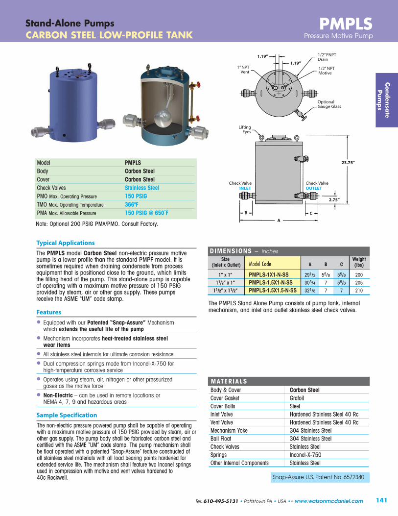
141
Typical Applications
The PMPLS model Carbon Steel non-electric pressure motivepump is a lower profile than the standard PMPF model. It issometimes required when draining condensate from processequipment that is positioned close to the ground, which limits the filling head of the pump. This stand-alone pump is capable of operating with a maximum motive pressure of 150 PSIGprovided by steam, air or other gas supply. These pumps receive the ASME “UM” code stamp.
Features
• Equipped with our Patented “Snap-Assure” Mechanism which extends the useful life of the pump
• Mechanism incorporates heat-treated stainless steelwear items
• All stainless steel internals for ultimate corrosion resistance
• Dual compression springs made from Inconel-X-750 for high-temperature corrosive service
• Operates using steam, air, nitrogen or other pressurized gases as the motive force
• Non-Electric – can be used in remote locations or NEMA 4, 7, 9 and hazardous areas
Sample Specification
The non-electric pressure powered pump shall be capable of operatingwith a maximum motive pressure of 150 PSIG provided by steam, air orother gas supply. The pump body shall be fabricated carbon steel andcertified with the ASME “UM” code stamp. The pump mechanism shallbe float operated with a patented “Snap-Assure” feature constructed ofall stainless steel materials with all load bearing points hardened forextended service life. The mechanism shall feature two Inconel springsused in compression with motive and vent valves hardened to 40c Rockwell.
Model PMPLSBody Carbon SteelCover Carbon SteelCheck Valves Stainless SteelPMO Max. Operating Pressure 150 PSIG TMO Max. Operating Temperature 366ºFPMA Max. Allowable Pressure 150 PSIG @ 650˚F
MATERIALSBody & Cover Carbon SteelCover Gasket GrafoilCover Bolts SteelInlet Valve Hardened Stainless Steel 40 Rc Vent Valve Hardened Stainless Steel 40 Rc Mechanism Yoke 304 Stainless SteelBall Float 304 Stainless SteelCheck Valves Stainless SteelSprings Inconel-X-750Other Internal Components Stainless Steel
DIMENSIONS – inches
Size Weight(Inlet x Outlet) Model Code A B C (lbs)
1” x 1” PMPLS-1X1-N-SS 291/2 55/8 55/8 20011/2” x 1” PMPLS-1.5X1-N-SS 303/4 7 55/8 205
11/2” x 11/2” PMPLS-1.5X1.5-N-SS 321/8 7 7 210
Note: Optional 200 PSIG PMA/PMO. Consult Factory.
Conden
sate
Pum
ps
PMPLSCARBON STEEL LOW-PROFILE TANK Pressure Motive Pump
Stand-Alone Pumps
1” NPTVent
1.19”
23.75”
1/2” NPTMotive
2.75”
1.19” 1/2” FNPTDrain
LiftingEyes
B C
A
Snap-Assure U.S. Patent No. 6572340
OUTLETINLETCheck Valve Check Valve
The PMPLS Stand Alone Pump consists of pump tank, internalmechanism, and inlet and outlet stainless steel check valves.
Tel: 610-495-5131 • Pottstown PA • USA •• www.watsonmcdaniel.com 141
OptionalGauge Glass

Typical Applications
The PMPNT(S) non-electric pressure motive pumps are light in weight and have an extremely low-profile. This stand-alone pumpis capable of operating with a maximum motive pressure of 125PSIG provided by steam, air or other gas supply. ASME CodeStamp available upon request.
Features
• Equipped with our proven, Patented “Snap-Assure” mechanism which extends the useful life of the pump
• Internal mechanism can be removed from the top of the pump while pump remains piped in line
• Mechanism incorporates heat-treated stainless steel wear itemsfor ultimate corrosion resistance
• Dual compression springs made from Inconel-X-750 forhigh-temperature, corrosive service
• Non-Electric – can be used in remote locations or NEMA 4, 7, 9 and hazardous areas
• Operates using steam, air, nitrogen or other pressurized gasas the motive force
InletCheck Valve
1/2” NPT Motive Inlet
1/2” NPTVent
OutletCheck Valve
1.19”
12.00” dia.
2.00”
13.19”
11.94”
25.21”
2.06” 1/2” NPTDrain
FLOW
OUTLETINLETCheck Valve Check Valve
142
CAPACIT IES – Condensate (lbs/hr) Motive Back 6” Filling Head Pressure Pressure Steam Motive Steam Motive (PSIG) (PSIG) 1” x 1” 11/2” x 11/2” 5 2 1225 2131
10 5 1204 2093 10 2 1391 2419 25 15 1171 2037 25 5 1458 2535 50 40 987 1716 50 10 1491 2593 75 60 992 1726 75 40 1262 2195 75 15 1505 2617 100 80 995 1731 100 60 1209 2102 100 15 1545 2687 125 100 997 1734 125 80 1174 2042 125 60 1316 2288 125 15 1570 2731
PMPNTStand-Alone Pumps DUCTILE IRON MINI-PUMP Pressure Motive Pump
Model PMPNT PMPNTSBody Ductile Iron Stainless SteelCover Stainless Steel Stainless SteelSizes 1”, 11/2” NPT 11/2” FLG or NPTCheck Valves Stainless Steel Stainless SteelPMO Max. Operating Pressure 125 PSIG 125 PSIGTMO Max. Operating Temperature 366ºF 366ºFPMA Max. Allowable Pressure 150 PSIG @ 450˚F 150 PSIG @ 450˚F
MATERIALSBody PMPNT Ductile Iron SA-395Body PMPNTS Stainless Steel CF3MCover Stainless Steel CF8Cover Gasket GarlockCover Bolts SteelInlet Valve Hardened Stainless Steel 40 RcVent Valve Hardened Stainless Steel 40 Rc Ball Float 300 Stainless SteelCheck Valves Stainless Steel 316SS CF3Springs Inconel-X-750Other Internal Components Stainless Steel
Conden
sate
Pum
ps
Note: Multiply Capacity by 1.16 for 12” Fill Head.Multiply Capacity by 1.28 for 18” Fill Head.
The PMPNT Stand Alone Pump consists of pump tank, internalmechanism, and inlet and outlet stainless steel check valves.
PMO Weight Size Model Code PSI lbs
Ductile Iron Pump Body (NPT)
1” x 1” PMPNT-1X1-N-SS 125 85
11/2” x 11/2” PMPNT-1.5X1.5-N-SS 125 95
Stainless Steel Pump Body (NPT or 150# FLG)
11/2” x 11/2” PMPNTS-1.5X1.5-N-SS 125 95
11/2” x 11/2” PMPNTS-1.5X1.5-F150-SS 125 98
www.watsonmcdaniel.com •• Pottstown PA • USA • Tel: 610-495-5131

143
Typical Applications
The PMPBP model non-electric Carbon Steel pressure motivepump is extremely high-capacity for applications requiring largetransfer of condensate or other liquids. This stand-alone pump iscapable of operating with a maximum motive pressure of 150PSIG provided by steam, air, nitrogen or other pressurized gasesas the motive force. ASME “U” Code Stamp available uponrequest.
Features
• All stainless steel internals for ultimate corrosion resistance
• Operates using steam, air, nitrogen or other pressurized gasas the motive force
• Non-Electric – can be used in remote locations or NEMA 4, 7, 9 and hazardous areas
Options
• Cycle counter for measuring the amount of condensate flow through the pump.
• Insulation jackets are available to stop heat losses through the pump body.
• Sight glass for monitoring liquid level inside pump body.
Model PMPBPBody Carbon SteelCover Carbon SteelCheck Valves Stainless Steel & SteelPMO Max. Operating Pressure 150 PSIGTMO Max. Operating Temperature 366ºFPMA Max. Allowable Pressure 150 PSIG @ 470˚F
Conden
sate
Pum
ps
PMPBPCARBON STEEL HIGH-CAPACITY TANK Pressure Motive Pump
Stand-Alone Pumps
3/4” FNPTGauge Glass
Conn.
17.50”
2” FNPTMotive
3/4” NPTDrain
2.75”
5.12”
2” FNPTVent
1.25”
46.56”
8.75”
37.12”
66.69”face-to- face
36” dia.
8.75”
24”
12”11/16” dia.
holes4 Pls
4” 150#Socket WeldRF Flange
16.50”
4” 150#RF Flange
FLOW
8.75”
The PMPBP Stand Alone Pump consists of pump tank, internalmechanism, and inlet and outlet check valves.
Size PMO Weight(Inlet x Outlet) Connection Model Code PSI (lbs)
4” x 4” 150#FLG PMPBP-4X4-F150-SS 150 1050
MATERIALSBody & Cover Carbon SteelCover Gasket Non-AsbestosCover Bolts SteelInlet Valve Stainless SteelVent Valve Stainless SteelMechanism Yoke 304 Stainless SteelBall Float 304 Stainless SteelCheck Valves Stainless Steel & SteelSprings Stainless SteelOther Internal Components Stainless Steel
Tel: 610-495-5131 • Pottstown PA • USA •• www.watsonmcdaniel.com

144
Typical Applications
The PMPSP Sump Drainer uses the same internal mechanism as the standard PMP models. The piping configuration is such that the liquidis discharged vertically out the top as opposed to horizontally out theside. This allows the unit to be easily positioned inside of a sump area. Condensate or water from the sump enters the tank through a stainlesssteel low resistance check valve. This unit is capable of operating with a maximum motive pressure of 150 PSIG using steam, air, nitrogen or other pressurized gas as the motive force.
Features
• Equipped with our Patented “Snap-Assure” Mechanism which extends the useful life of the pump
• Mechanism incorporates heat-treated stainless steel wear itemsfor ultimate corrosion resistance
• Dual compression springs made from Inconel-X-750 forhigh-temperature corrosive service
• Operates using steam, air, nitrogen or other pressurized gas as the motive force
• Non-Electric – can be used in remote locations or NEMA 4, 7, 9 and hazardous areas
• Built-in Strainer screen
Model PMPSP/PMPSPLBody Carbon SteelCover Ductile IronCheck Valves Stainless SteelPMO Max. Operating Pressure 150 PSIGTMO Max. Operating Temperature 366ºFPMA Max. Allowable Pressure 150 PSIG @ 650˚F Stainless Steel
Check Valve
OUTLETStainless Steel
Check Valve
PMPSPSump DrainerThe “PIT BOSS” Sump Drainer
2.56”
1” NPTVent
1/2” NPTMotive
1.19”
5.00”
16.0” ø
1.19”
25.31”
Conden
sate
Pum
ps
Snap-Assure U.S. Patent No. 6572340
PMPSPLPMPSP
30”
www.watsonmcdaniel.com •• Pottstown PA • USA • Tel: 610-495-5131
21.41”
15.6”
1.10”
1/2” NPTVent
1/2” NPTMotive
4.11”
1.19”
12.75” ø
PMPSP
PMPSPL
OUTLETStainless Steel
Check Valve
Stainless SteelCheck Valve
Water entersthru inlet
protected byscreen
Screen
Screen
Water entersthru inlet
protected byscreen

145
Discharge Line
Disc Trap
Inlet protectedby Screen
MinimumDiameter
18” PMPSP14.75” PMPSPL
Motive Steamor Air
Water enters the inlet check valve thru a screened areaat bottom of pump. After the pump fills, the internalmechanism is actuated and the pump is discharged bythe motive steam or compressed air. Other compressedgases such as nitrogen can also be used.
PMPSPSump
Drainer
Vent
Conden
sate
Pum
ps
PMPSPThe “PIT BOSS”Typical PMPSP Piping Configuration
Sump Drainer
Sump Drainer
Size/Connection PMO Weight(Outlet) NPT Model Code PSI lbs
11/2” PMPSPL 150 110
11/2” PMPSP-1 150 230
2” PMPSP-2 150 270
2” PMPSP-3 150 290
Tel: 610-495-5131 • Pottstown PA • USA •• www.watsonmcdaniel.com
PMPSP & PMPSPL
PUMP CAPACIT IES – Water (GPM)Motive Total Back PMPSPL PMPSP-1 PMPSP-2 PMPSP-3
Pressure Pressure(PSIG) (PSIG) 11/2” 11/2” 2” 2”
10 0 2.8 11.7 22.2 3520 10 3.1 9.2 17.5 2220 0 3.3 12.5 23.7 3040 20 3.2 8.7 16.5 2140 10 3.4 10.4 19.8 2540 0 3.5 13.1 25 31.470 40 3.2 7.1 12.1 1770 20 3.4 9.4 15 22.570 0 3.6 12.9 20.6 31100 70 3.2 5.4 8.6 10.8100 40 3.4 7.5 12 15100 20 3.4 9.4 15 18.8100 0 3.5 12.3 19.7 24.6150 100 - 4.5 7.2 9150 70 - 5.7 9.1 11.4150 40 - 7.2 11.5 14.4150 20 - 8.8 14 17.6150 10 - 9.5 15.2 19150 0 - 10.7 17.1 21.4
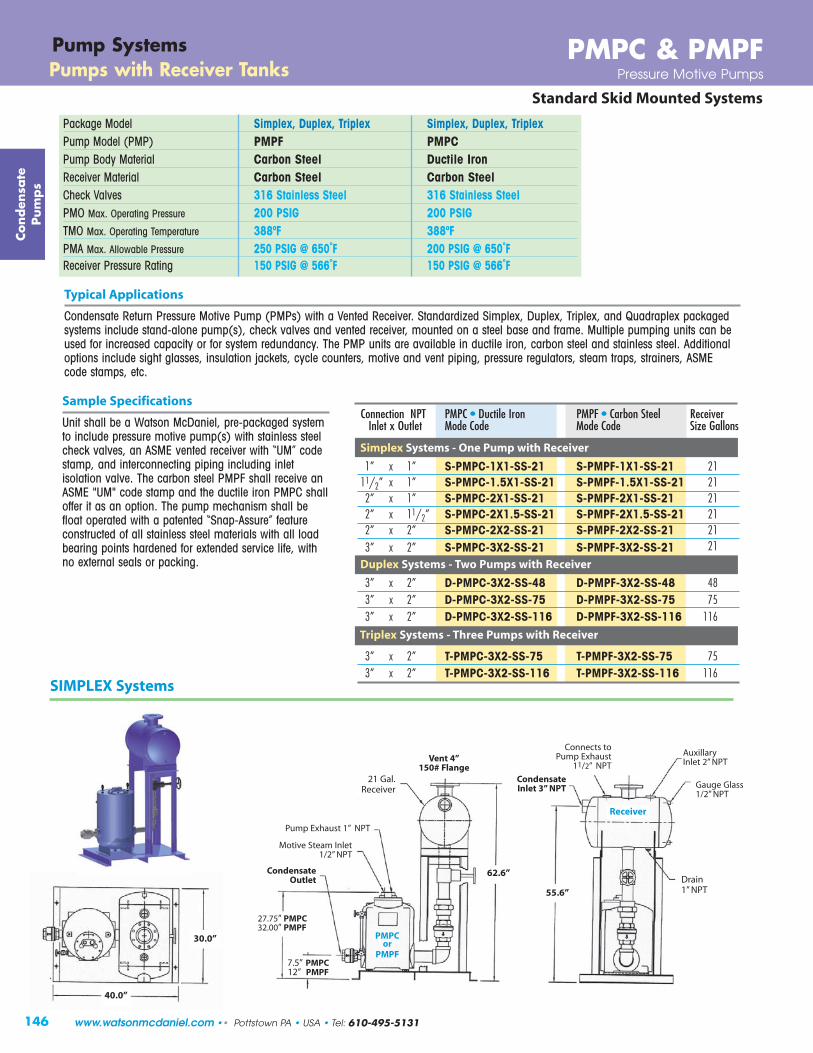
Gauge Glass1/2” NPT
55.6”
AuxillaryInlet 2” NPT
CondensateInlet 3” NPT
Connects toPump Exhaust
11/2” NPT
62.6”CondensateOutlet
PMPCor
PMPF
Motive Steam Inlet1/2” NPT
Pump Exhaust 1” NPT
21 Gal.Receiver
Drain1” NPT
7.5” PMPC12” PMPF
27.75” PMPC32.00” PMPF
Receiver
Vent 4” 150# Flange
30.0”
40.0”
146
Standard Skid Mounted Systems
SIMPLEX Systems
PMPC & PMPFPump SystemsPumps with Receiver Tanks Pressure Motive Pumps
Package Model Simplex, Duplex, Triplex Simplex, Duplex, TriplexPump Model (PMP) PMPF PMPCPump Body Material Carbon Steel Ductile IronReceiver Material Carbon Steel Carbon SteelCheck Valves 316 Stainless Steel 316 Stainless SteelPMO Max. Operating Pressure 200 PSIG 200 PSIGTMO Max. Operating Temperature 388ºF 388ºFPMA Max. Allowable Pressure 250 PSIG @ 650˚F 200 PSIG @ 650˚FReceiver Pressure Rating 150 PSIG @ 566˚F 150 PSIG @ 566˚F
Connection NPT PMPC • Ductile Iron PMPF • Carbon Steel Receiver Inlet x Outlet Mode Code Mode Code Size Gallons
Simplex Systems - One Pump with Receiver
1” x 1” S-PMPC-1X1-SS-21 S-PMPF-1X1-SS-21 2111/2” x 1” S-PMPC-1.5X1-SS-21 S-PMPF-1.5X1-SS-21 212” x 1” S-PMPC-2X1-SS-21 S-PMPF-2X1-SS-21 212” x 11/2” S-PMPC-2X1.5-SS-21 S-PMPF-2X1.5-SS-21 212” x 2” S-PMPC-2X2-SS-21 S-PMPF-2X2-SS-21 213” x 2” S-PMPC-3X2-SS-21 S-PMPF-3X2-SS-21 21
Duplex Systems - Two Pumps with Receiver
3” x 2” D-PMPC-3X2-SS-48 D-PMPF-3X2-SS-48 483” x 2” D-PMPC-3X2-SS-75 D-PMPF-3X2-SS-75 753” x 2” D-PMPC-3X2-SS-116 D-PMPF-3X2-SS-116 116
Triplex Systems - Three Pumps with Receiver
3” x 2” T-PMPC-3X2-SS-75 T-PMPF-3X2-SS-75 753” x 2” T-PMPC-3X2-SS-116 T-PMPF-3X2-SS-116 116
Typical Applications
Condensate Return Pressure Motive Pump (PMPs) with a Vented Receiver. Standardized Simplex, Duplex, Triplex, and Quadraplex packagedsystems include stand-alone pump(s), check valves and vented receiver, mounted on a steel base and frame. Multiple pumping units can beused for increased capacity or for system redundancy. The PMP units are available in ductile iron, carbon steel and stainless steel. Additionaloptions include sight glasses, insulation jackets, cycle counters, motive and vent piping, pressure regulators, steam traps, strainers, ASME code stamps, etc.
Sample Specifications
Unit shall be a Watson McDaniel, pre-packaged systemto include pressure motive pump(s) with stainless steelcheck valves, an ASME vented receiver with “UM” codestamp, and interconnecting piping including inletisolation valve. The carbon steel PMPF shall receive anASME "UM" code stamp and the ductile iron PMPC shalloffer it as an option. The pump mechanism shall befloat operated with a patented “Snap-Assure” featureconstructed of all stainless steel materials with all loadbearing points hardened for extended service life, withno external seals or packing.
Conden
sate
Pum
ps
www.watsonmcdaniel.com •• Pottstown PA • USA • Tel: 610-495-5131

147
Vent 6” 150# Flange To Pump
Exhaust11/2” NPT
CondensateInlet 3” NPT
Pump Exhaust1” NPT
Motive Steam Inlet1/2” NPT
CondensateOutlet
48 Gal.Receiver
AuxillaryInlet 3” NPT
InspectionOpening2” NPT
GaugeGlass1/2” NPT
68.0”
59.0”
40.0”
44.0”
TRIPLEX Systems
Drain1” NPT
27.75” PMPC32.00” PMPF
Gauge Glass1/2” NPT
2” NPT4” 150# Flange
CondensateInlet 3” NPT
11/2” NPT
InspectionOpening2” NPT
Connect toPump Exhaust
11/2” NPT
Pump Exhaust 1” NPT
Motive Steam Inlet1/2” NPT
75 Gal.Receiver
CondensateOutlet
27.75” PMPC32.00” PMPF
68.4”
59.0”
Vent 6” 150# Flange
PMPCor
PMPF
64.0”
40.0”
Receiver
Standard Skid Mounted Systems
PMPC & PMPFPumps with Receiver Tanks Pressure Motive Pumps
Pump Systems
7.5” PMPC12” PMPF
Drain1” NPT
7.5” PMPC12” PMPF
Receiver
PMPCor
PMPF
DUPLEX Systems
Conden
sate
Pum
ps
Features
• PMP pump systems reduce installation costs. Only 4 pipe connections are required in the field
• Watson McDaniel ensures that vented receivers and other components are properly sized for optimum system performance
• Watson McDaniel’s fully-qualified fabrication facility is ASME code certified. Our engineers can design and build complete custom systems to meet all your requirements
Options
• Gauge glass assembly• Cycle counter • Insulation covers• Motive steam drip trap• Overflow pipe connection• Pressure regulator for
motive supply line
ASMECertified
Tel: 610-495-5131 • Pottstown PA • USA •• www.watsonmcdaniel.com


149
Conden
sate
Pum
ps
PMP-Mechanical Condensate Return PumpsCapacity Charts
Capacity Correction Factors for Alternate Filling Heads
Pump Filling HeadInlet Size 6” 12” 18” 24” 36” 48” 60”
1” 1.00 1.10 1.20 1.30 1.5011/2” 0.70 1.00 1.10 1.20 1.352” 0.70 1.00 1.10 1.20 1.353” 0.84 1.00 1.04 1.08 1.204” 0.80 1.00 1.10 1.15 1.20
NOTE: When the filling head differs from the standard filling height, the capacityof the pressure power pumps are either increased or decreased. For example, a pump with a 3” inlet that has a filling head of 36” as opposed to a standard filling head of 12”, will have a capacity increase of 20%. Multiply the value found in the Capacity Table above by 1.2.
Capacity Correction Factors for Gas as Motive Pressure
Pump % Back Pressure relative to Motive PressureInlet Size 10% 20% 30% 40% 50% 60% 70% 80% 90%
1” 1.00 1.13 1.16 1.20 1.25 1.30 1.35 1.40 1.4511/2” 1.04 1.06 1.08 1.10 1.12 1.15 1.18 1.23 1.282” 1.04 1.06 1.08 1.10 1.12 1.15 1.18 1.23 1.283” 1.04 1.06 1.08 1.10 1.12 1.15 1.18 1.23 1.284” No Capacity Change
Note: For low specific gravity applications, consult factory.
CAPACIT IES – Condensate (lbs/hr) Using steam as a motive pressureMotive Total Back PMPLS PMPC, PMPF, PMPSS* (12” Fill Head) PMPBP
Pressure Pressure 6” Fill Head Duplex Triplex Quadraplex 4” x 4”(PSIG) (PSIG) 1” X 1” 11/2” X 1” 11/2” X 11/2” 2” X 1” 2” X 11/2” 2” X 2” 3” x 2” 3” x 2” 3” x 2” 3” x 2” 24” Head
5 2 1,760 1,860 1,920 2,860 3,180 3,540 5,000 10,000 15,000 20,000 16,60010 5 1,870 2,200 2,450 4,350 4,840 5,380 7,210 14,420 21,630 28,840 19,00010 2 2,200 3,030 3,370 6,880 7,650 8,500 11,110 22,220 33,330 44,440 22,60025 15 1,650 3,130 3,480 4,990 5,550 6,170 8,230 16,460 24,690 32,920 33,20025 10 1,980 3,600 3,990 6,560 7,290 8,100 10,780 21,560 32,340 43,120 40,30025 5 2,300 4,700 5,200 7,970 8,860 9,850 13,350 26,700 40,050 53,400 46,20050 40 1,650 2,280 2,530 3,370 3,750 4,170 5,670 11,340 17,010 22,680 33,30050 25 1,980 4,050 4,500 6,800 7,560 8,440 11,550 23,100 34,650 46,200 40,10050 10 2,300 4,700 5,240 7,970 8,860 9,850 13,440 26,880 40,320 53,760 47,00075 60 1,540 2,400 2,660 3,600 4,000 4,440 6,340 12,680 19,020 25,360 32,90075 40 1,980 3,780 4,190 5,920 6,580 7,320 9,870 19,740 29,610 39,480 39,40075 15 2,420 5,130 5,700 8,580 9,540 10,600 14,330 28,660 42,990 57,320 47,200
100 80 1,650 2,750 3,060 4,160 4,630 5,150 6,860 13,720 20,580 27,440 27,200100 60 1,870 3,600 4,000 5,560 6,180 6,870 9,100 18,200 27,300 36,400 35,100100 40 2,090 4,700 5,210 6,880 7,650 8,500 11,270 22,540 33,810 45,080 42,100100 15 2,420 5,400 6,010 8,740 9,720 10,800 14,330 28,660 42,990 57,320 48,000125 115 1,430 2,380 2,640 3,270 3,640 4,050 4,960 9,920 14,880 19,840 19,500125 100 1,540 2,980 3,330 4,140 4,600 5,130 6,390 12,780 19,170 25,560 25,300125 80 1,760 3,430 4,100 5,400 6,000 6,670 8,540 17,080 25,620 34,160 32,200125 60 1,980 4,170 4,850 6,600 7,340 8,160 10,530 21,060 31,590 42,120 38,500125 40 2,200 5,100 5,950 7,760 8,630 9,590 12,500 25,000 37,500 50,000 44,000125 15 2,420 5,850 6,660 9,240 10,270 11,420 15,100 30,200 45,300 60,400 49,200150 120 1,590 2,650 2,940 3,400 3,780 4,200 5,690 11,380 17,070 22,760 21,600150 100 1,640 3,150 3,490 4,320 4,800 5,350 7,000 14,000 21,000 28,000 29,000150 80 1,860 3,800 4,230 5,490 6,100 6,770 9,100 18,200 27,300 36,400 34,500150 60 2,080 4,500 5,000 6,660 7,400 8,240 11,120 22,240 33,360 44,480 40,300150 40 2,300 5,290 5,870 7,920 8,800 9,780 13,220 26,440 39,660 52,880 44,700150 15 2,520 6,100 6,820 9,450 10,500 11,680 15,500 31,000 46,500 62,000 49,500
175 140 - 2,600 2,900 3,800 4,200 4,650 6,200 12,400 18,600 24,800 -175 120 - 3,100 3,400 4,400 4,850 5,400 7,200 14,400 21,600 28,800 -175 100 - 3,600 4,000 5,100 5,700 6,300 8,400 16,800 25,200 33,600 -175 60 - 4,850 5,400 6,900 7,700 8,550 11,400 22.800 34.200 45,600 -175 40 - 6,200 6,900 8,900 9,850 10,950 14,600 29,200 43,800 58,400 -175 15 - 7,500 8,350 10,600 11,900 13,200 17,600 35,200 52,800 70,400 -200 160 - 2,400 2,700 3,500 3,800 4,300 5,700 11,400 17,100 22,800 -200 140 - 3,100 3,400 4,400 4,900 5,400 7,200 14,400 21,600 28,800 -200 100 - 4,200 4,650 5,950 6,600 7,350 9,800 19,600 29,400 39,200 -200 80 - 4,700 5,250 6,750 7,500 8,300 11,100 22,200 33,300 44,400 -200 40 - 6,800 7,550 9,700 10,800 11,950 15,950 31,900 47,850 63,800 -200 15 - 8,400 9,350 12,000 13,300 14,800 19,700 39,400 59,100 78,800 -
* PMPSS is rated to only 150 PSIG. Note: For PMPNT capacity, refer to PMPNT specification page.
Stand Alone Pumps & Systems Capacity based on 12” Fill Head except as noted
Tel: 610-495-5131 • Pottstown PA • USA •• www.watsonmcdaniel.com

150
Pump SizeThe models of a Pressure Motive Pump are designated by the size of the inlet and outlet check valves (for example,a 3” x 2” PMPC or PMPF has a 3” Inlet check valve and a 2” outlet check valve). The larger the check valves, the largerthe pump capacity.
STAND-ALONE PUMPS include pump tank, internal pumping mechanism, and check valves.
PUMP(S) WITH RECEIVER TANKS includes stand-alone pump(s), and vented receiver tank mounted together on a frame. These are available in Simplex, Duplex, Triplex and Quadraplex systems.
When sizing and selecting a Pressure Motive Pump, Four system conditions are required:(See Diagram on following page)
1 Condensate Load: If condensate from several sources of equipment is required to be pumped, sum up the maximum flow rate of condensate each could produce separately.
Motive Pressure: Normally steam is used; however, other gases can be used to pump the condensate, including Air or Nitrogen.
4 Filling Head: The Filling Head is measured between the bottom of the receiver tank and the top of the pump tank. It has a significant effect on pump capacity.
5 System Back Pressure: Pressure in condensate return line that pump will be operating against, as determined by condensate return line pressure and vertical height condensate must be lifted.
Sample System Conditions:
Condensate Load 8,000 lbs/hr
Motive Steam Pressure 100 PSIG
Filling Head 12"
System Back Pressure: 40 PSIG
(To find the pressure required to lift condensate in PSIG, multiply Vertical lift in feet by 0.433)
PMP-Mechanical Condensate Return PumpsSizing & Selection
How to specify when ordering: Example:
1) Model PMPC
2) Size of Pump(s) 2” x 2”
3) Stand-alone Pump or Pump with Receiver Tank Simplex or Duplex
(Note: Size of Receiver Tank must be specified when ordering Pump with Receiver Tank)
4) Options Gauge glass
5) When ordering a Customized Skid System, please confirm and specify Receiver size.
For PMP Selection: Consult PMP Sizing Capacity Chart using 100 PSIG inlet pressure and 40 PSIG back pressure. A 2" x 2" pump has a capacity of 8,500 lbs/hr and is an appropriate selection. Pump choices are models PMPC, PMPF and PMPSS.
1
2
3
4
1
3
2
4
Vented Receiver (Open-Loop System)
Conden
sate
Pum
ps
www.watsonmcdaniel.com •• Pottstown PA • USA • Tel: 610-495-5131

151
SystemBack
Pressure
Receiver & Vent SizingThe purpose of the vented receiver is to neutralize the pressure inside the condensate return line so condensate will properlydrain from the processes and into the pump tank. An undersized vent will increase the velocity of flash steam in the vent pipe,potentially pulling condensate from the receiver tank out the vent. It may also increase pressure in the receiver and condensatereturn line upstream of the receiver, possibly causing issues with condensate drainage from the steam traps. The table belowlists vent and corresponding receiver sizes based on the amount of flash steam. The amount of flash steam generated isdetermined by the condensate flow rate and condensate pressure entering the vented receiver.
Determine the amount of condensate in lbs/hr flowing into the vented receiver. The percentage of condensate that will flash intosteam is based on the initial condensate pressure and the pressure inside the vented receiver. Since we are trying to achieve 0 psig, reference the 0 psig flash tank pressure to determine % flash steam. Multiply the % flash by the total condensate load.
Example: 10,000 lbs/hr of condensate is generated at an estimated steam pressure of 20 psig. The percent (%) flash steam is 4.9%. Quantity of flash steam = .049 x 10,000 = 490 lbs/hr.
From the table, select a Vent and Receiver size which can handle 600 lbs/hr of flash steam. (4” vent with a 10” receiver diameter and 36” length.)
VENTED RECEIVER SIZING (inches)
Quantity of Vent Line ReceiverFlash Steam
(lbs/hr) Diameter Diameter Length
75 1” 4” 36”150 2” 6” 36”300 3” 8” 36”600 4” 10” 36”900 6” 12” 36”1200 6” 16” 36”2000 8” 20” 60”3000 8” 24” 60”4000 10” 26” 60”5000 10” 28” 60”6000 12” 30” 72”7000 12” 32” 72”8000 14” 36” 72”
PERCENT (%) FLASH STEAMProduced when condensate is discharged to atmosphere or into a flash tankcontrolled at various pressuresCondensate Flash Tank Pressure (PSIG)
Pressure(PSIG) 0 5 10 20 30 40 60 80 100
5 1.6 0.010 2.9 1.3 0.015 3.9 2.4 1.120 4.9 3.3 2.1 0.030 6.5 5.0 3.7 1.7 0.040 7.8 6.3 5.1 3.0 1.4 0.060 10.0 8.5 7.3 5.3 3.7 2.3 0.080 11.8 10.3 9.1 7.1 5.5 4.2 1.9 0.0100 13.3 11.8 10.6 8.7 7.1 5.8 3.5 1.6 0.0125 14.9 13.5 12.3 10.4 8.8 7.5 5.3 3.4 1.8150 16.3 14.9 13.7 11.8 10.3 9.0 6.8 4.9 3.3
PMP-Mechanical Condensate Return PumpsSizing & SelectionVented Receiver (Open-Loop System)
Vent
pumpexhaust
inletcheckvalve
outletcheckvalve
roof
Condensate LOAD:1
2 Motive Steam orGas PressureAvailable
Conden
sate
Pum
ps
Tel: 610-495-5131 • Pottstown PA • USA •• www.watsonmcdaniel.com
Vented Receiver
Filling Head3
PSIG
Condensate Return Line Pressure
4
PMP

152

153
Pump & Trap CombinationsPMPT & WPT
What is a Pump-Trap? A Pump-Trap is a float-operated steam trap that works in conjunction with a steam powered condensate returnpump (Pressure Motive Pump). It is used when system conditions prevent a steam trap from effectively dischargingcondensate due to excessive back-pressure, or when it is desirable to operate a heat exchanger in vacuum.
www.watsonmcdaniel.com •• 428 Jones Boulevard • Limerick Airport Business Center • Pottstown PA • 19464 •• Tel: 610-495-5131

A Pump-Trap is used in place of a Steam Trap to drain condensate from a process application when the steam pressure in theprocess is not sufficient to push the condensate thru the steam trap and into the condensate return line. When steam pressure in a Heat Exchanger is less than the back pressure on the discharge side of the steam trap, the condensate backs up, causinginconsistent heat transfer and potential waterhammer. This frequently occurs on applications where a temperature control valve isused to supply steam to a Heat Exchanger based on product temperature and flow rate. The temperature control valve increasesand decreases steam flow to the Heat Exchanger to satisfy the temperature set point. When system demand is high, the steampressure in the Heat exchanger is most likely adequate to overcome system back pressure; however, when system demanddecreases, steam pressure to the Heat Exchanger must also decrease and can fall below the back pressure. This condition is referred to as Stall, since it causes condensate to back up into the Heat Exchanger. To prevent condensate backup under stallconditions, a pump-trap must be used in place of a steam trap.
154
What is a Pump-Trap used for ?
The PMPT pressure motive pump has an internal steamtrap. The compact design makes it a suitable choice formost applications.
Pump body andSteam Trap are
one singleintegral unit.
The WPT is a stand-alone pump unit with a separate steamtrap mounted on a common base. It is used when capacityrequirements exceed that of the PMPT model.
Pump body andSteam Trap are
separate butmounted on a
common base.SteamTrap
Pump
Outlet Check Valve
Pump & Trap CombinationsPMPT & WPT
PU
MPIN
GTR
APS
FLOW(Inlet)
Steam Trap
OutletCheck Valve
Inlet Check Valve
Pump Mechanism(Includes Steam Trap)
FLOW(Discharge)
Motive Steam InletVent
Pump withInternal
Steam Trap
Pump with Internal Steam Trap (PMPT) Pump with External Steam Trap (WPT)
Outlet Check Valve
Inlet Check Valve
www.watsonmcdaniel.com •• Pottstown PA • USA • Tel: 610-495-5131

pumpexhaust
outletcheck valve
PUMPTRAP
temperaturecontroller
steamcontrolvalve
coldwaterinlet
hot wateroutlet
temp sensor
condensatereturn
condensate return line pressure
Steam
Steam Pressure
condensatedrains by
gravity intopump tank
higher pressure steamused to pump condensatecan overcome backpressure
inlet check valve
155
Pump & Trap CombinationsWhy use a Pump-Trap?
PU
MPIN
GTR
APS
condensatereturn
F&TTRAPcold
waterinlet
temp sensor
Heat Exchanger System with Steam Trap
hot wateroutlet
Steam
Condensate backs upinto heat exchanger
temperaturecontroller
steamcontrolvalve
Total Back Pressure15 PSIG
condensate return line pressure
BACK PRESSURE
Steam Pressure of 10 PSIGin heat exchanger cannot
overcome total backpressure causing
condensate to back up
Heat Exchanger System with Pumping Trap
Problem:Condensate Backs Up IntoHeat Exchanger
The diagram shows a temperaturecontrol valve delivering steam to a Heat Exchanger that is using steam toheat water. Condensate formed in theheat exchanger is being dischargedthrough the steam trap into thecondensate return line. This particularapplication demonstrates what happenswhen the return line is elevated and/orpressurized. The plant steam pressure on the inlet side of the control valve would be adequate to purge (push) thecondensate through the trap and into thereturn line. However, the steam pressurein the heat exchanger is controlled by the valve and is dependent on thedemand of the system. When the demandfor HOT water is low, the steam pressurein the Heat Exchanger falls below theback pressure and the system backs upwith condensate, creating unstabletemperature control and waterhammer.This undesirable condition, referred to asStall, occurs when the steam pressure inthe heat exchanger falls to or below thesystem back pressure due to a decreasein the demand (flow rate) of hot water.
Solution:Use a Pump-Trap to Avoid Condensate Back-up & ImproveTemperature Control
To eliminate condensatebacking up (STALL), thestandard float trap is replacedwith a PUMP-TRAP. Whensteam pressure in the HeatExchanger is greater than theback pressure, the steampressure will push thecondensate through the Pump-Trap and it functions likea standard float-operated trap.When the steam pressure tothe Heat Exchanger dropsbelow the back pressure, thecondensate backs up insidethe PUMP-TRAP, raising thefloat. When the trip point of the mechanism is reached, the high-pressure steam valve will open to drive the condensate out.
Solution: Steam Trap is Replaced withPump-Trap Combination
INLET PRESSU
RE
If Inlet Pressureis not higher than
Back Pressure, Condensatewill back up
50 PSIG
Total Back Pressure15 PSIG
Tel: 610-495-5131 • Pottstown PA • USA •• www.watsonmcdaniel.com
50 PSIG
50 PSIG
balancing line

156
Pump & Trap CombinationsHow a Pump-Trap Works
PU
MPIN
GTR
APS
1 TRAPPING Mode: Inlet steam pressure is higher than back pressure.Steam pushes condensate through Pump-Trap.
Vent Outlet: Open position, allowing pressure in the pump tank to equal pressure in the heat exchanger, allowing condensate to freely enter Pump-Trap by gravity,even under vacuum.
Motive Inlet: Closed position
Condensategets pushedthrough Trap
TRAP Mode
The system is operating with 30 PSIG inlet pressure to the heat exchanger. The Pump-Trap unit functions like a standard float-operated trap. Condensate ispushed thru the pump-trap into the return line by the steam pressure in the HX.
The steam pressure to the HX willvary depending on the flow rate ofhot water required by the system.Let’s assume the HX was sized for amaximum flow rate of 40 GPM ofHOT water at 140˚F using 30 PSIGsteam. When maximum flow rate ofwater is required, the 30 PSIG steampressure is more than adequate topush the condensate generated thruthe steam trap against the 15 PSIGback pressure. Now, if the hot waterrequirement reduces from 40 to 20GPM, the steam flow (lbs/hr) to theHeat Exchanger must drop by abouthalf. Since it is the same size HX, thesteam temperature (steam pressure)must also reduce (see table below).
Steam Pressure vs. Hot Water Required
40 1,900 30 1,90035 1,650 15 1,65032 1,530 10 1,53020 950 -6.6 (Vacuum) 950
Steam Steam Pressure CondensateUsage in Heat Exchanger Generated
Flow Rate Water
(gallons per minute) (lbs/hr) (PSIG) (same as steam used)
Operation of a PUMP-TRAP with a Heat Exchanger (HX):
Trap Mode
Pump Mode
coldwaterinlet
hot wateroutlet
Total Back Pressure15 PSIG
30 PSIG
15 PSIG
30 PSIG
SteamMotiveInlet
www.watsonmcdaniel.com •• Pottstown PA • USA • Tel: 610-495-5131
Stall Point
5 PSIG
50 PSIG
50 PSIG
10 PSIGHead
Pressure
balancing line
balancing line

157
PU
MPIN
GTR
APS
Pump & Trap CombinationsHow a Pump-Trap Works
Condensatelevel falling
Vent Outlet: ClosedMotive Inlet: Open; steam pressure (50 PSI) enters tank and
discharges condensate.
3 PUMP Mode: Pump is activated. When the pump tank has filled tothe trip point, the mechanism triggers, opening the motive gas inletvalve and simultaneously closing the vent valve. This allows motivepressure to enter the pump body, which drives the condensate thru the outlet check valve and into the condensate return line. During thedischarge cycle, the liquid level and the float inside the pump tankdrop. When the lower trip point is reached, the mechanism closes themotive inlet valve and opens the vent valve so the pump-trap can fill on the next cycle.
2 PUMP TANK FILLS: Inlet steam pressure falls below backpressure. Steam can no longer push the condensatethrough the Steam Trap.
Vent Outlet: Open position, allowing pressure in the pump tank to equal pressure in the heat exchanger, allowing condensate to freely enter Pump-Trap by gravity.
Motive Inlet: Closed position
PUMP ModeThe pressure in the HX has now dropped to 10 PSIG. This was inresponse to a fall off in demand of hot water. Based on this particularsize HX, 10 PSIG steam will heat 32 GPM of water. Since back pressureis 15 PSIG, the system is stalled and condensate is beginning to backup into the system and the float continues to rise.
Condensate rises to a level that the float triggers the inlet steam valve and closes the vent valve. Full line pressure steam (50 PSIG) enters thru the inlet valve on top of the pump body to discharge the condensate. Because of check valves, condensate will not flow back to HX and is discharged to the condensate return line.Unit will continue to operate and cycle in pump mode as long as pressure in the HX is below back pressure. Pump-Trap will also operate in vacuum conditions.
10 PSIG
15 PSIG
10 PSIG
15 PSIG
50 PSIG
50 PSIG
Condensatelevel rising
Tel: 610-495-5131 • Pottstown PA • USA •• www.watsonmcdaniel.com
50 PSIG
50 PSIG
balancing line
balancing line
Venting
Motive steampressuredischargescondensate

158
PU
MPIN
GTR
APS
Typical Applications
The PMPT low-profile pressure motive pump & trap combination has aninternal steam trap for draining heat exchangers and other equipment whosesteam pressure is modulated by a temperature regulator or a temperature controlvalve. In these applications the steam pressure in the heat exchanger may notbe sufficient to overcome the back pressure in the condensate return line. Whenthis condition occurs, the pressure powered pump takes over and uses highpressure steam supplied to the pump to discharge the condensate. Whensufficient pressure does exist, the PMPT functions like a standard steam trap.Its small compact design is perfect for applications with limited space.
Pump-Traps facilitate condensate discharge under all operating conditions, including vacuum.
Features
• Low-profile design allows for condensate drainage of equipment positioned close to the floor
• Equipped with our proven, Patented “Snap-Assure” mechanismwhich extends the useful life of the pump
• Internal mechanism can be removed from the top of the pump while pump remains piped in line
• Mechanism incorporates heat-treated stainless steel wear items
• Dual compression springs made from Inconel-X-750 forhigh-temperature, corrosive service
NOTE: Reservoir - Pump-Trap Combination may require a reservoir above the pump to collect condensate generated in the heat exchanger during the dischargecycle of the pump. Consult Reservoir Sizing Guidelines or contact factory foradditional information.
Model PMPT PMPTSBody Ductile Iron Stainless SteelCover Stainless Steel Stainless SteelSizes 1”, 11/2” NPT 11/2” FLGCheck Valves Stainless Steel Stainless SteelPMO Max. Operating Pressure 125 PSIG 125 PSIGTMO Max. Operating Temperature 366ºF 366ºFPMA Max. Allowable Pressure 150 PSIG @ 450˚F 150 PSIG @ 450˚F
Options
• Horizontal pipe reservoir (recommended)
• Motive and vent piping
• Motive piping components such as steam trap, strainer and regulator
• Packaged systems available with reservoir, base and skid
• Gauge Glass
• Insulation Jacket
• ASME Code Stamp
PMPTPump & Trap CombinationInternal Steam Trap
Steam Trap internal to pump bodywill function like a normal float trap dischargingcondensate as its formed. If condensate backs up, the pumping mechanism will use motive steampressure to discharge the condensate.
PMPT withReceiver Tank
www.watsonmcdaniel.com •• Pottstown PA • USA • Tel: 610-495-5131

159
PU
MPIN
GTR
APS
InletCheck Valve
1/2” NPT Motive Inlet
1/2” NPTVent
OutletCheck Valve
1.19”
12.00” dia.
2.00”
13.19”
11.94”
25.21”
2.06” 1/2” NPTDrain
FLOW
OutletCheck Valve
InletCheck Valve
MATERIALSBody PMPT Ductile Iron SA-395Body PMPTS Stainless Steel CF3MCover Stainless Steel CF8Cover Gasket GarlockCover Bolts SteelInlet Valve Hardened Stainless Steel 40 RcVent Valve Hardened Stainless Steel 40 Rc Ball Float 300 Stainless SteelCheck Valves Stainless Steel 316SS CF3Springs Inconel-X-750Other Internal Components Stainless Steel
U.S. Patent No. 8,858,190 BZ
PMPTInternal Steam TrapPump & Trap Combination
OutletCheck Valve
InternalSteam Trap
PumpMechanism
InletCheck Valve
PumpBody
Tel: 610-495-5131 • Pottstown PA • USA •• www.watsonmcdaniel.com
OptionalGauge Glass
The PMPT Pump-Trap consists of pump tank, internal mechanism& trap, and inlet & outlet stainless steel check valves.
PMO Weight Size Model Code PSI lbs
Ductile Iron Pump Body (NPT)
1” x 1” PMPT-1X1-N-SS 125 85
11/2” x 11/2” PMPT-1.5X1.5-N-SS 125 95
Stainless Steel Pump Body (NPT or 150# FLG)
11/2” x 11/2” PMPTS-1.5X1.5-N-SS 125 95
11/2” x 11/2” PMPTS-1.5X1.5-F150-SS 125 98
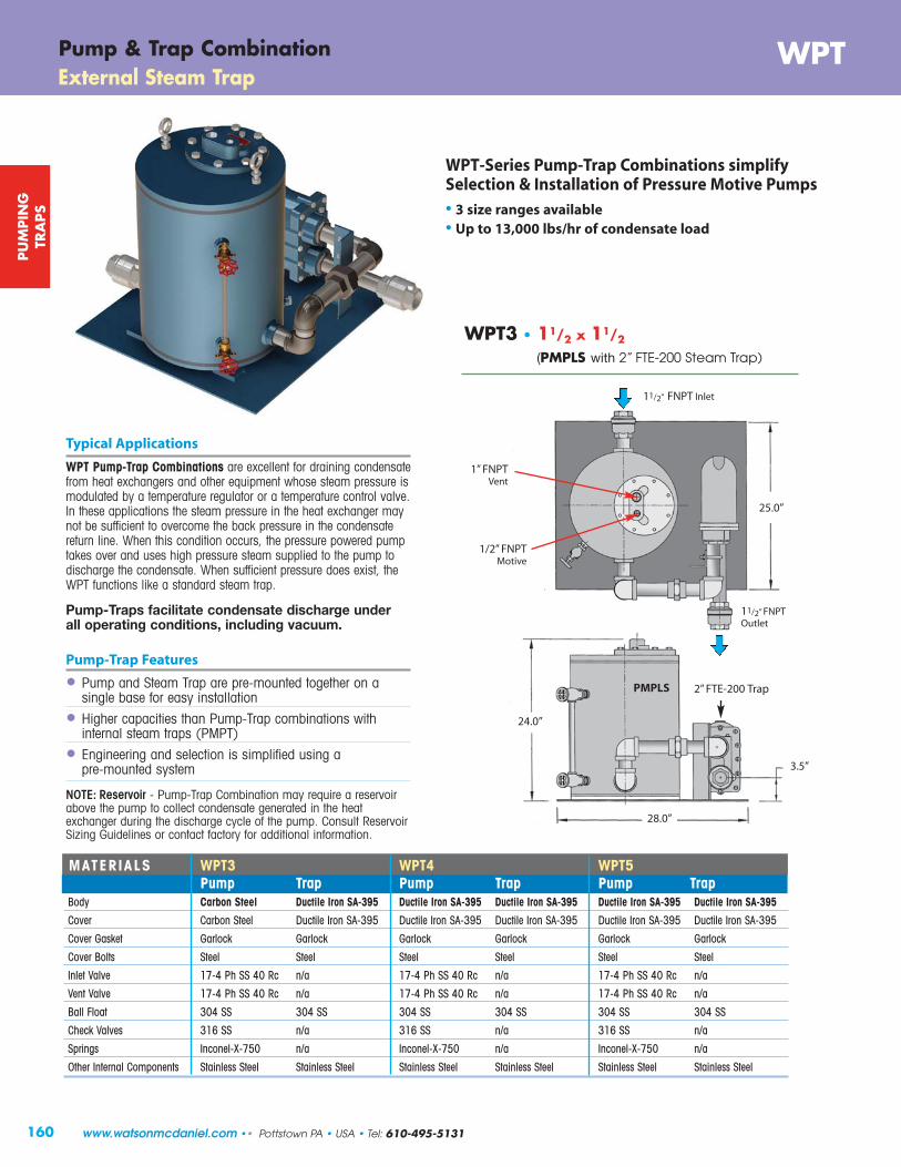
25”
PMPLS
WPT3 • 11/2 x 11/2
(PMPLS with 2” FTE-200 Steam Trap)
Typical Applications
WPT Pump-Trap Combinations are excellent for draining condensatefrom heat exchangers and other equipment whose steam pressure ismodulated by a temperature regulator or a temperature control valve.In these applications the steam pressure in the heat exchanger maynot be sufficient to overcome the back pressure in the condensatereturn line. When this condition occurs, the pressure powered pumptakes over and uses high pressure steam supplied to the pump todischarge the condensate. When sufficient pressure does exist, theWPT functions like a standard steam trap.
Pump-Traps facilitate condensate discharge under all operating conditions, including vacuum.
Pump-Trap Features
• Pump and Steam Trap are pre-mounted together on a single base for easy installation
• Higher capacities than Pump-Trap combinations withinternal steam traps (PMPT)
• Engineering and selection is simplified using apre-mounted system
NOTE: Reservoir - Pump-Trap Combination may require a reservoirabove the pump to collect condensate generated in the heatexchanger during the discharge cycle of the pump. Consult ReservoirSizing Guidelines or contact factory for additional information.
WPT-Series Pump-Trap Combinations simplify Selection & Installation of Pressure Motive Pumps
• 3 size ranges available• Up to 13,000 lbs/hr of condensate load
MATERIALS WPT3 WPT4 WPT5Pump Trap Pump Trap Pump Trap
Body Carbon Steel Ductile Iron SA-395 Ductile Iron SA-395 Ductile Iron SA-395 Ductile Iron SA-395 Ductile Iron SA-395
Cover Carbon Steel Ductile Iron SA-395 Ductile Iron SA-395 Ductile Iron SA-395 Ductile Iron SA-395 Ductile Iron SA-395
Cover Gasket Garlock Garlock Garlock Garlock Garlock Garlock
Cover Bolts Steel Steel Steel Steel Steel Steel
Inlet Valve 17-4 Ph SS 40 Rc n/a 17-4 Ph SS 40 Rc n/a 17-4 Ph SS 40 Rc n/a
Vent Valve 17-4 Ph SS 40 Rc n/a 17-4 Ph SS 40 Rc n/a 17-4 Ph SS 40 Rc n/a
Ball Float 304 SS 304 SS 304 SS 304 SS 304 SS 304 SS
Check Valves 316 SS n/a 316 SS n/a 316 SS n/a
Springs Inconel-X-750 n/a Inconel-X-750 n/a Inconel-X-750 n/a
Other Internal Components Stainless Steel Stainless Steel Stainless Steel Stainless Steel Stainless Steel Stainless Steel
WPTPump & Trap CombinationExternal Steam Trap
11/2” FNPT Inlet
25.0”
1” FNPTVent
1/2” FNPTMotive
11/2” FNPTOutlet
2” FTE-200 Trap
24.0”
28.0”
3.5”
160
PU
MPIN
GTR
APS
www.watsonmcdaniel.com •• Pottstown PA • USA • Tel: 610-495-5131

28.0”
25.0”
5.25”
28.56”
3” FNPT Inlet
WPT5 • 3” x 2”(PMPC with 21/2” FTE-200 Steam Trap)
2” FNPT Outlet
Vent1” FNPT
21/2” FTE-200
Trap
PMPC
28.0”
25.0”
8.0”
28.56”
2” FNPT Outlet
2” FNPT Inlet
WPT4 • 2” x 2”(PMPC with 2” FTE-200 Steam Trap)
2” FTE-200Trap
PMPC
WPTExternal Steam TrapPump & Trap Combination
Motive1/2” FNPT
Vent1” FNPT
Motive1/2” FNPT
161
PU
MPIN
GTR
APS
Tel: 610-495-5131 • Pottstown PA • USA •• www.watsonmcdaniel.com

162
PU
MPIN
GTR
APS
Pump-Trap CombinationsSizing & Selection • Capacity Charts
www.watsonmcdaniel.com •• Pottstown PA • USA • Tel: 610-495-5131
PMPT & WPT Pump-Trap Combinations (Operating in Pump Mode)
PUMP CAPACIT IES – Condensate (lbs/hr); using steam as a motive pressureMotive Total Back PMPT PMPT WPT3 WPT4 WPT5
Pressure Pressure 1” x 1” 11/2” x 11/2” 11/2” x 11/2” 2” x 2” 3” x 2”(PSIG) (PSIG) 6” Fill Head 6” Fill Head 12” Fill Head 12” Fill Head 12” Fill Head
5 2 1,064 1,850 1,310 2,320 4,27010 5 1,049 1,824 1,760 3,740 6,23010 2 1,200 2,087 2,350 5,640 9,45025 15 1,026 1,784 2,700 4,690 7,23025 10 1,151 2,002 3,020 5,970 9,37025 5 1,257 2,186 3,780 6,850 11,40050 40 877 1,525 2,090 3,410 5,04050 25 1,115 1,939 3,620 6,650 10,20050 10 1,286 2,237 4,080 7,140 11,50075 60 882 1,533 2,250 3,730 5,66075 40 1,102 1,916 3,470 6,010 8,77075 15 1,298 2,257 4,390 7,920 12,400100 80 884 1,538 2,620 4,390 6,140100 60 1,058 1,841 3,390 5,780 8,120100 40 1,192 2,074 4,310 6,940 10,000100 15 1,331 2,314 4,620 8,000 12,300125 115 737 1,281 2,280 3,490 4,440125 100 886 1,541 2,880 4,420 5,720125 80 1,030 1,792 3,520 5,700 7,630125 60 1,146 1,992 4,110 6,880 9,390125 40 1,243 2,161 4,910 7,800 11,100125 15 1,351 2,350 5,120 8,420 12,900150 120 - - 2,560 3,640 5,100150 100 - - 3,020 4,610 6,270150 80 - - 3,630 5,780 8,140150 60 - - 4,230 6,910 9,920150 40 - - 4,830 7,930 11,700150 15 - - 5,230 8,590 13,300
TRAP CAPACITIES – Condensate (lbs/hr)
1/4 1,511 2,770 7,2001/2 2,137 4,100 12,3001 3,020 5,700 17,4002 4,030 7,400 25,400
5 4,354 9,900 27,60010 4,841 11,800 32,60015 5,150 13,400 36,00020 5,686 14,400 39,30030 6,425 16,400 43,10040 7,711 18,000 46,60050 8,000 19,000 49,20075 9,100 21,000 54,700100 10,334 23,000 58,800125 11,451 24,500 61,900200 NA 29,200 74,000
PMPT & WPT Pump-Trap Combinations (Operating in Trap Mode)
PMPT WPT3 & WPT5WPT4
DifferentialPressure
(PSI)
RESERVOIR PIPE LENGTH in feet (ft) Condensate Reservoir Pipe Size (Diameter)
Load(lbs//hr) 3” 4” 6” 8” 10”
0-500 2’1,000 2’1,500 3’ 2’2,000 3.5’ 2’ 1’3,000 3’ 2’4,000 4’ 2’ 1’5,000 6’ 3’ 2’6,000 3’ 2’7,000 3’ 2’8,000 4’ 2’9,000 4.5’ 3’ 2’
Recommended Reservoir sizes for Pump-Trap Applications

163
PU
MPIN
GTR
APS
Pump-Trap CombinationsSizing & Selection
Pump-Trap Sizing:When the steam pressure in the heat exchanger is higher than the return line back pressure, the PUMP-TRAP functionslike a standard float-operated TRAP, allowing the steam pressure in the heat exchanger to discharge the condensate.Under these conditions, the unit is in TRAP mode. When the steam pressure in the heat exchanger falls below theback pressure, the condensate backs up into the body of the pump-trap, raising the float and opening the motive steaminlet valve, which then pumps the condensate into the return line. Under these conditions, the unit is in PUMP mode. We therefore have two separate and distinct capacities; the PUMP CAPACITY (when operating in Pump Mode) and theTRAP CAPACITY (when operating in Trap Mode).
In the example below, the system will be analyzed to determine when the Pump-Trap is in Trap Mode and when it is inPump Mode, and the specific capacity requirement of the pump. If the total back-pressure of the condensate return line isknown, the Pump-Trap should be selected with sufficient pump capacity to handle the condensate load at the system stallpoint. (i.e.; when the steam pressure is equal to the total back-pressure). Alternatively, if the total back-pressure is notknown, it is best to select a pump-trap with enough pump capacity to handle the maximum condensate load of theapplication. (i.e., at maximum steam pressure and flow). Refer to Sizing Charts.
TRAP ModeThe system is operating with 30 PSIG inlet pressure to the heatexchanger. The Pump-Trap unit functions like a standard floatoperated trap. Condensate is pushed thru into the return line bythe steam pressure in the HX. Based on this particular size HX, 30 PSIG steam will heat 53 GPM of water.
PUMP ModeIn response to a reduction in demand of hot water, the pressure in the HX hasnow dropped to 10 PSIG. Based on this particular size HX, 10 PSIG steam willheat 43 GPM of water. Since back pressure is 15 PSIG, the system is stalledand condensate backs up into the system; the float will continue to rise toactivate the pump and discharge the condensate.
ΔP Trap = 30 psig - 15 psig= 15 psi
Tel: 610-495-5131 • Pottstown PA • USA •• www.watsonmcdaniel.com
10 PSIG30 PSIG
15 PSIG15 PSIG
Reservoir Sizing: (Refer to chart on previous page)When using a Pump-Trap, a condensate holding reservoir should be installed above the pump-trap and below the heat exchanger (shown below). This will enable the condensate to collect while the pump is in the discharge cycle, thus preventing condensate backup. When back pressure against the pump outlet is less than 50% of the steam pressure to the heat exchanger, the pipe lengths given in the chart can be reduced by half.
The following example describes a Heat Exchanger (HX) using Steam to heat domestic hot water for a medium size apartmentcomplex. Note that the hot water usage varies significantly depending on the time of day. The physical size of the heatexchanger needed (sq. ft. of surface area) is based on the following criteria: (1) MAXIMUM water usage (GPM), (2) thetemperature rise of the water, and (3) what pressure steam will be used to heat the water during maximum demand. Note: The selection of the steam pressure (which determines the steam temperature), to heat the water at maximumdemand (flow rate), is the primary factor in heat exchanger sizing.
The application is requiring water to be heated from 45˚F to 140˚F in a HX using Steam. The maximum flow rate has beendetermined to be 60 GPM. The Steam Trap will be discharging into a condensate return line that may have a Total BackPressure of 15 PSIG and the flow rate of heated water could be as low as 20 GPM. The facility engineer has chosen to basethe HX size on using 50 PSIG of steam pressure. Therefore, the size of the heat exchanger was selected based on heating 60 GPM of water using 50 PSIG of steam.
Heat Exchanger (HX) using Steam to heat Hot Water
Fill HeadFill Head

164
PU
MPIN
GTR
APS
Pump-Trap CombinationsSizing & Selection
www.watsonmcdaniel.com •• Pottstown PA • USA • Tel: 610-495-5131
Summary of conditions for a Heat Exchanger (HX) using Steam to heat Water
Set of conditions used to size the Heat Exchanger:
1) Maximum Flow of Hot Water = 60 GPM
2) Water temperature required To = 140˚F
3) Steam Pressure in Heat Exchanger = 50 PSIG
4) Temperature of 50 PSIG Steam Ts = 298˚F
5) Inlet Water Temperature Ti = 45˚F
6) Temperature Rise of Water = 95˚F(140˚ F - 45˚F = 95˚ F)
What is the Heat Transfer Rate (E) to heat 60 GPM of waterfrom 45˚to 140˚F?
= 60 x 500 x [140˚- 45˚F]
= 2,850,000 Btu/hr
=E
LH
=2,850,000 Btu/hr
912 Btu/lb
= 3,125 lbs/hr
E Btu = Water Flow Rate (GPM) x 500 x Temp Rise (˚F)hr
The formula shows that the heat transfer rate (E) between the hot steam and cold water is directly proportional to the Surface contact area (A) inside the HX and the difference in temperature between the steam and water (ΔT). The more surface area (larger HX) the more heat will get transferred or the hotter the steam temperature (higherpressure) the more heat will get transferred.
E = Heat Transfer Rate in Btu/hr of the energy in the steam to the water. The flow of steam (Qs) required in lbs/hr is determined by dividing E by the Latent Heat of Steam (LH) in Btu/lb.
U = is referred to as the Overall Heat Transfer Coefficient. This depends on the HX type and the materials involved.Typical U values are 120 for Stainless Steel and 200 for Copper. We will use 120 for Stainless Steel HX.
A = The internal Surface Area (size) of the HX in Sq. Ft. The size of a HX is determined by the surface contact area between the Steam and Water.
ΔT = Average Temperature Difference between Steam & Water. Since the water temperature changes as it flows thru the HX, we need to use the average temperature difference between the steam temperature and the water temperature. See formula below:
Fundamental formula for heat transferand the basic formula for HX sizing
E = U x A x ΔT
E = U x A x ΔT
A = E U x ΔT
= 2,850,000120 x 205
A = 116 (sq ft.)
Above formula is rearranged to solve for A:ΔT = (Ts – Ti) + (TS – To) 2
= (298 – 45) + (298 – 140) 2
ΔT = 205˚F = Avg Temp. Difference
The actual size of a Heat Exchanger depends on many factors; however, based on the criteria given, 116 sq. ft of surface area is required to heat 60 GPM of water from 45˚F to 140˚F, based on a steam pressure of 50 PSIG.
Average Temperature Difference Heat Exchanger Size
How much Steam Flow is required?
(For 50 psi steam, the LH is 912 Btu/lb) Qs (steam)

165
PU
MPIN
GTR
APS
Pump-Trap CombinationsSizing & Selection
Flow Steam Steam Latent Trap Rate Steam Pressure Temp Heat Condensate Differential System
Water Usage in HX in HX of Steam Generated Pressure Condition(GPM) (lbs/hr) (PSIG) (°F) (Btu/lb) (lbs/hr) (PSI)
60 3,125 50 298 912 3,125 35
57.0 2,943 40 287 920 2,943 25
53.2 2,720 30 274 929 2,720 15
48.8 2,466 20 259 940 2,466 5
46.2 2,318 15 250 946 2,318 0
42.9 2,140 10 239 953 2,140 ---
35.0 1,715 0 212 970 1,715 ---
29.2 1,409 -5 192 983 1,409 ---
20 948 -10 161 1,002 948 ---
Trap Mode
Pump Mode
(Vacuum)
(Stall Point)
(Maximum Heat Load)
Steam Pressure = Back Pressure
(Minimum Heat Load)
Table based on a HX size of 116 ft2 and back pressure of 15 PSIGThe following table summarizes the above results and shows how the steam flow, pressure, temperature and latentheat vary as a function of the water flow rate. It can be seen that the system is operating in Trap Mode betweenwater flow rates of 60 to ~46 GPM, and in Pump Mode between ~46 to 20 GPM (based on 15 PSIG back pressure). Also, at flow rates below 35 GPM, the steam pressure inside the HX is below atmospheric pressure (0 PSIG).
To find out how much energy will be transferred to the water, we use the ΔT calculated above in our heat transfer equation.
ΔT = (TS – Ti) + (TS – To) 2
= (250 – 45) + (250 – 140) 2
ΔT = 157.5˚ F = Avg Temp. Difference
From the steam table, 15 PSIGsteam has a temp of 250˚F
E = U x A x ΔT
= 120 x 116 x 157.5
= 2,192,400 Btu/hr
(For 15 psig steam, the LH is 946 Btu/lb)lbs/hr = E
= 2,192,400
LH 946
Steam Flow = 2,318 lbs/hr
When the HX stalls, we will be using 2,318 lbs/hr of steam and will need to pump 2,318 lbs/hr of condensate. The pump-trap must be sized to handle this condensate load since it is the maximum load under stall conditions(see table below).
Stall Condition:When the steam pressure in the HX is equal to the back pressure of 15 PSIG, the condensate will no longer drain out of the HX. The Pump-Trap will now need to operate in Pump Mode to remove the condensate fromthe HX. We need to calculate how much condensate will be produced when there is 15 PSIG in the HX.
To determine how much steam is required to heat the water, we use the following formula. (LH = Latent Heat.)
Tel: 610-495-5131 • Pottstown PA • USA •• www.watsonmcdaniel.com
Qs

166
GaugeGlass
CycleCounter
Accessories & OptionsPMP-Condensate Return Pumps & Pump-Trap Combinations
Gauge GlassPumps tanks are available with gauge glass to show condensate level inside the tank(bronze or stainless steel retainer).
Watson McDaniel offers a full line of accessories for our Condensate Return Pumps and Pump Systems.If there is something you don’t see, please call our factory and we will do our best to help you.
Gauge Glass for: Model Code
Standard Bronze Gauge Glass
PMPC, PMPF, PMPLS (stand alone pumps) GAUGE GLASS-1PMPT (stand alone pump) GAUGE GLASS-PMPTPMPM (stand alone pump) GAUGE GLASS-PMPM21 Gallon Receiver Tank GAUGE GLASS-148 Gallon Receiver Tank GAUGE GLASS-175 Gallon Receiver Tank GAUGE GLASS-1116 Gallon Receiver Tank Contact Factory
Stainless Steel Gauge Glass
PMPSS (stand alone pump) GAUGE GLASS SS
PMPT & PMPNT Contact Factory
ASME CODE STAMP for Receiver Pump TanksFour standard condensate receiver sizes are available for Pressure Motive Pump Systems: 21, 48, 75 and 116 gallons.Custom receiver fabrication is available with Watson McDaniel’s ASME-certified fabrication facility. ASME Code is Standard on 21, 48, 75 and 116 gallon receiver tanks and PMPF, PMPLS, PMPSS pump tanks.
Cycle CounterThe Digital Cycle Counter option allows monitoring of pump cycles for the purpose of scheduling maintenance andrepairs, as well as calculation of condensate flow through the pump (i.e. returned condensate). There are severaloptions available depending on the PMP selected as well as the operating conditions. Therefore, proper selection isrequired to ensure proper function and operation. See below for selection, or consult factory for additional assistance.
• Pump Only (Open Loop), with pump back pressure 15 psig or above – Standard• Pump Only (Open Loop), with pump back pressure below 15 psig – Low Pressure Option• Pump-Trap (Closed Loop) – Special option required – consult factory.
Pump-traps (closed loop) can not use the pressure switch because the vent pressure will vary, so pressure differentialcan not be guaranteed.
Options for Gauge Glass
Auto Drain (self-drain) Stainless Steel Armored GAUGE GLASS-1A
Reflex Gauge for PMPC, PMPF, PMPLS, 21 Gallon Receiver GAUGE GLASS-1HP
Cycle Counter (fits all PMPs) Open Loop Systems Only Model Code
Digital Cycle Counter 1529100
Digital Cycle Counter with auxiliary contacts 1529102
Low Pressure Cycle Counter with auxiliary contacts 1529103
Low Pressure Cycle Counter w/o auxiliary contacts 1529104
Closed Loop Cycle Counter 2450300
ASME Code Stamp: Model Code
for PMPC, PMPC & PMPNT Pump Tanks Contact Factory
Conden
sate
Pum
ps
www.watsonmcdaniel.com •• Pottstown PA • USA • Tel: 610-495-5131

167
Insulation Cover
Insulation Cover for: Model Code
PMPC (Ductile Iron Pump) INSUL-CRV-PMPCPMPF (Fabricated Steel Pump) INSUL-CRV-PMPFPMPLS (Low-Profile Pump) INSUL-CRV-PMPLSPMPBP (High Capacity Pump) INSUL-CRV-PMPBPPMPT & PMPNT (Pump-Trap Combination or Pump) INSUL-CRV-PMPTPMPM (Mini Pump) INSUL-CRV-PMPM21 Gallon Receiver INSUL-CRV-2148 Gallon Receiver INSUL-CRV-4875 Gallon Receiver INSUL-CRV-75116 Gallon Receiver INSUL-CRV-116
Insulation JacketInsulation Jackets improve safety by protecting personnel from hot surfaces and conserve energy by reducing heatloss. Jackets have velcro closures for easy installation or removal and fit tightly around pump tanks and receivers.
Vertical Discharge PumpVertical Discharge Pump with “T-Bone” connection allows inlet and outletcondensate hook-ups to be made above the pump. This is an advantage whenspace is limited around the base of the pump due to equipment or pipingobstructions.
InletCheckValve
OutletCheckValve
“T-Bone”Connection
Vertical Discharge Pump Model Code
T-Bone Connections available for Stand Alone Pump PMP-TBONE
Conden
sate
Pum
ps
Accessories & OptionsPMP-Condensate Return Pumps & Pump-Trap Combinations
Check Valves - Stainless Steel
The Inlet Check Valve on PMP systems require a very low opening pressure (cracking pressure) so that the liquid will freelyenter the pump tank. The proper check valve is critical to the operation of the PMP system. Watson McDaniel uses onlyStainless Steel Check Valves with a maximum of ¼ PSI cracking pressure. (See Check Valves in Pipeline Accessories.)
Check Valves - NPT Model Code
1/2” WSSCV-12-N-0
3/4” WSSCV-13-N-0
1” WSSCV-14-N-0
11/4” WSSCV-15-N-0
11/2” WSSCV-16-N-0
11/2” (no closing spring) WSSCVQF-16-N-0
2” WSSCV-17-N-0
3” WSSCV-19-N-0
Tel: 610-495-5131 • Pottstown PA • USA •• www.watsonmcdaniel.com

168
Mechanism for Pump Tanks (with Patented “Snap-Assure” Feature)
The Patented “Snap-Assure” feature extends the useful life of the pump by assuring the internal mechanism toggles at every fill and discharge cycle. These mechanisms are simple and easy to replace, and are a cost-effective way tomake your pump as good as new. They will also fit other manufacturers’ pump tanks.
* Note for Rebuilt Mechanisms: The exchange program is for mechanisms with two years ofservice or less. The old mechanism must be returned along with the order for the rebuilt mechanism. Orders without oldmechanisms will be invoiced at the new mechanism price.
Mechanisms for: Model Code
Complete Mechanism Assembly with Cover for:
PMPF & PMPSP W-KIT-900-03PMPC & PMPLS W-KIT-910-03
PMPBP W-KIT-900-01
PMPM W-KIT-911-03
PMPT W-KIT-912-03
PMPNT W-KIT-914-03
Rebuilt Mechanism* for:
PMPF W-KIT-900-03R
PMPC & PMPLS W-KIT-910-03R
PMPT & PMPNT W-KIT-912-03R
Conden
sate
Pum
ps
Accessories & OptionsPMP-Condensate Return Pumps & Pump-Trap Combinations
Pre-Piped PRV & Drip LegA fully-assembled Pre-piped PRV, Drip Leg, or PRV and Drip Leg Assembly guarantees proper installation of your PMP System. It assures that your skid package performs to optimum levels.
Pre-Piped Accessories Model Code
Pre-piped Motive Line with Pressure Regulating Valve (PRV) for PRV1control of motive steam or air (drip trap not included – to be by others)
Pre-piped Motive Line with Drip Leg Station and Steam Trap PRV2
Pre-piped Motive Line with PRV, Drip Leg, and Steam Trap (PRV1 + PRV2) PRV3
Pre-piped Exhaust Line PRV4Overflow J-pipe Contact Factory
Pressure Gauge Contact Factory
Drain Valve Contact Factory
www.watsonmcdaniel.com •• Pottstown PA • USA • Tel: 610-495-5131

�;�
fh_ia$Òdhelk�i$Ïckk�$l¢cepplb$ ¢chkeÏelb$Ïh½edh_ea$Ïhdeke_�$i_hbi$lhb�_a$hiiei_$�ac$¡e_g$hkk$aÏ$�ac$Ïh½edh_ea$llbi�$(c$l¾elle¾$i_hÏÏ$ipldehke�li$e_gl$blie¾$aÏ$nliicl$Òa_e§l$�ablih_l$ncope¾$��i_loi$Ïa$½a_g$ebci_ehk$hbei_e_c_eahk$hppkedh_eai�$åac$dh$abl$le_gl$i_hbhb$phd×h¾liz$h§hekh½kl$Ïaoi_ad×z$a$ipldehke�lb$i�i_loi$_a$oll_$�ac$ipldeÏed$llbi�$MVRTNW¾sQP$IÖ¾P$USÆÖSÇQR MVRTNW$eST\¾ÆSTQP$OO¾TRKI�RMQ\T¾È¾QP MNOPQORSTQUVWXR
C,0D$EFGHIJKHKFLF%>*<<-<*?+$>:$%ÈÉ:$%%������������ ��!"#����

170
Automatic Make-upWater ValveConnects to water supply(supplied with Boiler Feed units)
W4100, W4200 & W4300 Condensate Pumps
Watson McDaniel’s Condensate Return and Boiler Feed Pumps are equipped with Cast Iron bodies and Bronze Impellers. The pump receiver tanks are available in either Carbon Steel (W4100), Cast Iron (W4200), or Stainless Steel (W4300) in Simplex or Duplex configurations.
Electric PumpsIntroduction
Typical Condensate Pump Features• Fabricated Steel Receivers (W4100),
Cast Iron Receivers (W4200), Stainless Steel Receivers (W4300)
• Simplex and Duplex Packages• Bronze Fitted Centrifugal Pumps• Energy Efficient 3450 RPM motors• Ceramic Pump Seal• Heavy-duty Float Switch
Float SwitchStandard on allSimplex Pumps
Control Panel(optional)
Gauge Glass(supplied on Boiler Feed units)
Condensate Return PumpsUsed for returning condensate from the facility back to the boiler room. In Condensate Return applications,the operation of the pump is controlled by a FloatSwitch located on the receiver tank. The pump turnson when the receiver tank is full and shuts off whenemptied. Duplex units contain a MechanicalAlternator float switch to alternate operation between the two pumps.
Boiler Feed PumpsFor Boiler Feed applications, the operation of the pump is controlled by the water level control system on theboiler. When the boiler requires water, the pump switcheson pumping water from the receiver into the boiler. Thereceiver tank also contains an internal make-up watervalve actuated by a stainless steel float. If the amount of condensate being returned to the receiver tank isinadequate, additional boiler feed water is automaticallyadded to the receiver tank.
Mechanical Alternatorrequired withDuplex units
(must be orderedseparately)
Gauge Glass(optional onCondensate Return units)
Control Panel(optional)
SIMPLEXFloat Switch is used to activate the pump. SIMPLEX & DUPLEX
Water Level Control System on boiler is used to activate the pump.
Automatic Make-up Water Valve is activated by a level float thatadds additional boiler feed water to the receiver tank if required.
Gauge Glass(optional onCondensate Return units)
DUPLEXMechanical Alternator (used in place of the Float Switch found on Simplex units) is used to cycleoperation between the 2 pumps.
Characteristics of Condensate Return Pumps Vs. Boiler Feed Pumps
Secondary Pump& Motor onDuplex units
DuplexSimplexReceiver
Tank
SinglePump & Motor
SecondaryPump & MotorEL
ECTR
ICPU
MPS
www.watsonmcdaniel.com •• Pottstown PA • USA • Tel: 610-495-5131
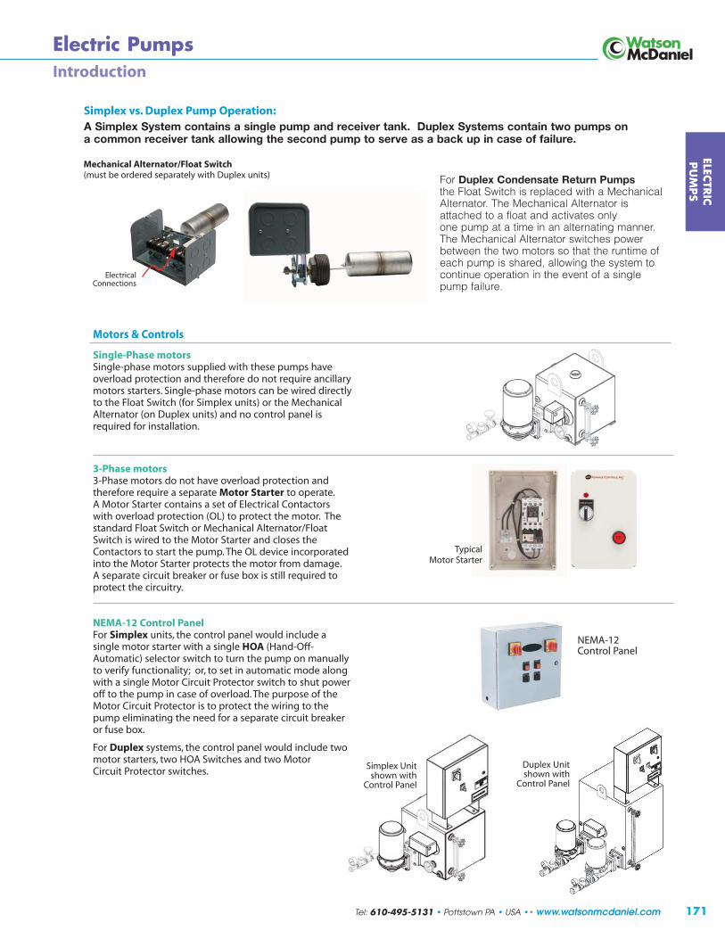
171
Motors & Controls
Single-Phase motorsSingle-phase motors supplied with these pumps haveoverload protection and therefore do not require ancillarymotors starters. Single-phase motors can be wired directlyto the Float Switch (for Simplex units) or the MechanicalAlternator (on Duplex units) and no control panel isrequired for installation.
3-Phase motors 3-Phase motors do not have overload protection andtherefore require a separate Motor Starter to operate. A Motor Starter contains a set of Electrical Contactorswith overload protection (OL) to protect the motor. Thestandard Float Switch or Mechanical Alternator/FloatSwitch is wired to the Motor Starter and closes theContactors to start the pump. The OL device incorporatedinto the Motor Starter protects the motor from damage. A separate circuit breaker or fuse box is still required toprotect the circuitry.
NEMA-12 Control Panel For Simplex units, the control panel would include asingle motor starter with a single HOA (Hand-Off-Automatic) selector switch to turn the pump on manuallyto verify functionality; or, to set in automatic mode alongwith a single Motor Circuit Protector switch to shut poweroff to the pump in case of overload. The purpose of theMotor Circuit Protector is to protect the wiring to thepump eliminating the need for a separate circuit breakeror fuse box.
For Duplex systems, the control panel would include twomotor starters, two HOA Switches and two MotorCircuit Protector switches.
ELECTR
ICPU
MPS
Electric PumpsIntroduction
NEMA-12 Control Panel
Simplex vs. Duplex Pump Operation:A Simplex System contains a single pump and receiver tank. Duplex Systems contain two pumps ona common receiver tank allowing the second pump to serve as a back up in case of failure.
Mechanical Alternator/Float Switch(must be ordered separately with Duplex units) For Duplex Condensate Return Pumps
the Float Switch is replaced with a MechanicalAlternator. The Mechanical Alternator isattached to a float and activates only one pump at a time in an alternating manner. The Mechanical Alternator switches powerbetween the two motors so that the runtime ofeach pump is shared, allowing the system tocontinue operation in the event of a singlepump failure.
ElectricalConnections
Simplex Unit shown with
Control Panel
TypicalMotor Starter
Duplex Unit shown with
Control Panel
Tel: 610-495-5131 • Pottstown PA • USA •• www.watsonmcdaniel.com

172
Electric PumpsIntroduction
Float Switch for Simplex Condensate Return Units: Wiring DiagramsThe diagrams below show typical Single-phase & 3-phase wiring diagrams for the float switch used on Simplex CondensateReturn Units. The Float Switch can be used to turn on a Single-phase motor directly or to activate a Motor Starter. A MotorStarter is required to operate 3-phase motors.
Single-PhaseMotor 3-Phase Motor
(3-wire connection)
Motor Starter
Float Switch Wired Directly to a Single-Phase Motor
Float Switch Turning on a 3-Phase Motor Using a Motor Starter
FLOAT
FLOAT SWITCH
FLOAT SWITCH
FLOAT SWITCH
MOTOR
MOTOR
MOTOR
FLOAT
FLOAT
M
Magnetic Relay
Single-PhaseMotor
110 or 220VSingle-Phase
Power Source
230 or 460VThree-Phase Power Source
NEMA 1 Control PanelMotor Starter forSimplex Pumps
ON
OFF
Float Switch for Simplex Pumps
Contacts CLOSEwhenMagnetic Relay
is Activated
When Magnetic Relay is Activatedby Float in “up” Position,
contacts of Motor Starter CLOSE to turn ON motor
Float Switch Activates MagneticRelay inside Motor Starter Closingcontacts of Motor Starter
FLOAT
Float Switch De-Activates MagneticRelay inside Motor Starter Opening contacts of Motor Starter
Magnetic Relay
M
MOTOR 3-Phase Motor(3-wire connection)
Contacts OPENwhenMagnetic Relay
is De-Activated
230 or 460VThree-Phase Power Source
Motor Starter
When Magnetic Relay is De-Activatedby Float in “down” Position,
contacts of Motor Starter OPEN to turn OFF motor
UPPosition
DownPosition
M
M
DownPosition
UPPosition
ON
OFF
ELEC
TRIC
PU
MPS
www.watsonmcdaniel.com •• Pottstown PA • USA • Tel: 610-495-5131

173
ELECTR
ICPU
MPS
Electric PumpsIntroduction
Mechanical Alternator for Duplex units: Wiring Diagrams
Single-PhaseMotor
The diagrams below show a Mechanical Alternator operating twoseparate Single-Phase Motors required to operate a Duplex PumpSystem. The Mechanical Alternator can also be used to operate two separate Motor Starters which in turn would be used tooperate two separate 3-phase motors.
MECHANICAL ALTERNATOR
MECHANICAL ALTERNATOR
1MOTOR
2MOTOR
FLOAT
FLOAT
Single-PhaseMotor
OFF110 or 220V
Single-PhasePower Source
110 or 220VSingle-Phase
Power Source
OFF
FLOAT
110 or 220VSingle-Phase
Power Source
1MOTOR
2MOTOR
1MOTOR
2MOTOR
Single-PhaseMotor
MECHANICAL ALTERNATOR
ON
OFF
OFF
ON
Explanation of Float Travel PositionOn Mechanical AlternatorNormal Operation: Switches will cut in and cut out atthe high point of distance AA + B given in the Figurebelow. Under normal conditions, as long as one pumpalone is able to handle the incoming water, the pumpswill alternate at this distance. With the water levelcontinuing to rise, the second switch will cut in and startthe second pump, when the float reaches the top ofdistance D. Both pumps will continue to run until the float returns to the lower point of distance D + C, whereone pump will cut out. The other pump will continue until the float reaches the low point of distance B.
ElectricalConnections
Single-PhaseMotorFLOAT
110 or 220VSingle-Phase
Power Source
MECHANICAL ALTERNATOR
1MOTOR
2MOTOR
ON
ON
Up
DownPosition
1st UPPosition
2nd UPPosition
Max UPPosition
Mechanical Alternator Operating Two Single-Phase Motors
FLOAT1st UPPosition
MECHANICAL ALTERNATOR
3-PhaseMotors
1MOTOR
STARTER
110 or 220VSingle-Phase
Power Source
2MOTOR
STARTER
Mechanical Alternator Operating Two 3-Phase MotorsThe Mechanical Alternator can also be used to operate two separate Motor Starters which in turn would be used to operate two separate 3-phase motors. Schematic shows Motor Starter 1 activated which will turn on the 1st motor.
A
F
DB
C
R
L1 L2 L3
L1 L2 L3
1MOTOR
2MOTOR
230 or 460VThree-Phase Power Source
230 or 460VThree-Phase Power Source
Tel: 610-495-5131 • Pottstown PA • USA •• www.watsonmcdaniel.com

174
Electric PumpsIntroduction
Condensate Return Pumps are designed to operate intermittently, discharging condensate only when the receivertank is full. This is accomplished with a float switch that energizes the pump when the float rises above a set point.Once started, the pump will continue to operate until the water level drops below the bottom set position of the floatswitch. On Duplex condensate return pumps, a Mechanical Alternator float switch is mounted to the receiver sothat both pumps are used in an alternating manner.
condensatereturn inlet
strainer
floatswitch
floor line
condensate by-pass clean out
(pipe to floor drain)
MOTOR&
PUMP
Vent: Pipe up toceiling, thenback down tofloor drain
discharge
checkvalve
gatevalve
gatevalve
Float Switch for Simplexunit or MechanicalAlternator Float Switchfor Duplex unit
Duplex UnitSimplex Unit
SinglePump & Motor
SecondaryPump & Motor
Receiver Tank
Float Switch
Receiver Tank
MechanicalAlternator
ventedreceiver
Returnscondensateback to boilerfeed reservoir
flow
Operation of CONDENSATE RETURN Pumps
Condensate Return Pump Piping Diagram
ELEC
TRIC
PU
MPS
www.watsonmcdaniel.com •• Pottstown PA • USA • Tel: 610-495-5131

For Boiler Feed applications, the operation of the pump is controlled by the water level control system on the boiler. When the boiler requires water, the pump switches on pumping water from the receiver into theboiler. The receiver tank also contains an internal make-up water valve actuated by a stainless steel float. If the amount of condensate being returned to the receiver tank is inadequate to supply the boiler, additionalmake-up water is added to the receiver tank. This condition may occur when more steam is being producedthan condensate being returned; common at system start-up.An overflow pipe is used to dump excess condensate to drain during times when less boiler feed water isrequired than the amount of condensate being returned. Larger boiler feed tanks may be advantageous tokeep systems in balance.
175
ELECTR
ICPU
MPS
Electric PumpsIntroduction
gatevalve
strainer
Check Valve:required to prevent boilerwater returning to reservoirwhen pump is off.
make-upwatervalve
vent
overflowgaugeglass
pump discharge line
condensatereturn inlet
cold watersupply
burner
boiler water level
gatevalve
SecondaryPump & Motor
Receiver Tank
GaugeGlass
Water Make-upValve
wall mountedcontrol panel
motor& pump
WATER LEVEL CONTROL SYSTEM: Controls Pump OperationWater level control system on boilermay contain a float mechanism orset of sensors to maintain properwater level in the boiler.
flow
Operation of BOILER FEED Pumps
Boiler Feed Pump Piping Diagram
BOILER
Duplex Boiler Feed Unit
Tel: 610-495-5131 • Pottstown PA • USA •• www.watsonmcdaniel.com

1) Select the model with the appropriate sized receiver and pump discharge pressure. 4100-Series Carbon Steel tank, 4200-Series – Cast Iron tank or 4300-Series – Stainless Steel tank.
Safety factors and proper operating conditions: Pumps have a 3:1 safety factor. The 3:1 safety factor for CondensateReturn pumps is based on the maximum condensate that can be produced by the EDR (Effective Direct Radiation) insquare feet. For Boiler Feed pumps, the 3:1 safety factor is based on the maximum amount of water that would berequired by the boiler (based on Boiler hp). Therefore, when the system is operating at maximum capacity, the pumpwill operate only one third of the time. Please note: these pumps as configured are not recommended for pumpingcondensate above 190˚ F.
2) Motor hp required for any given pump model is listed in the selection chart. For motor sizes below 1 hp, it is mostcommon to choose single phase motors; (1Ph either 110 or 220 Volts). Single-phase motors (available up to 2 hp)have inherent overload protection (OL) and can therefore be wired directly to the float switch or Mechanical Alternator. This is the simplest method of control and does not require any additional electrical hardware. Since 3-Phase motors do not have inherent OL protection, they require a separate Motor Starter. Motor starters can be purchased separatelyfrom an electrical supply house or ordered separately with pump unit. Reference our NEMA 1 or NEMA 12 Control Panels with Motor Starter.
3) Duplex pump units require the addition of a mechanical or electrical Alternator which activates one pump at a time in alternating fashion. CCondensate Return pumps most commonly use a Mechanical Alternator in place of the standardfloat switch and must be ordered separately. Refer to Model MECH-ALT-N1. For duplex Boiler Feed pumps, the Electric Alternator option on the NEMA-12 Control Panel (suffix code E) must be chosen. An Electric Alternator can also be used with Condensate Return pumps; however, an additional 2-level float switch is required (2-level float switch is Not required on boiler feed units).
176
Electric PumpsIntroduction
Selecting a Condensate Return Pump:
• A Condensate Return Pump contains an automaticfloat switch in the receiver tank to activate the pumpwhen the tank is filled and deactivate when empty.
• On Duplex units, the standard float switch is replacedwith a Mechanical Alternator float switch to alternateoperation between the two pumps. Must be orderedseparately. An Electric Alternator is also an option.
• The capacity of the condensate return pump in GallonsPer Minute (GPM) is based on the amount of EffectiveDirect Radiation (EDR) in sq ft. of heating surface in thefacility that the pump is expected to handle.
For Example: an EDR of 2000 sq. ft. can condense up to 500 lbs/hr of steam which translates to 1.0 GPMof condensate flow. Using a 3:1 safety factor wouldrequire a 3.0 GPM Condensate Return pump. Theproperly sized receiver tank that is adequate for thatpump capacity is shown in the model selection chart forCondensate Return units. Larger receiver sizes arealways desireable in order to cool condensate.
• Select a discharge pressure for the pump to overcomeall system back pressures including frictional pipinglosses. Pump discharge pressures of 20-50 PSI areavailable. Selecting a pump with a significantly higherdischarge pressure than required can cause pump to cavitate.
Selecting a Boiler Feed Pump:
• For a Boiler Feed Pump, the operation of the pumpis controlled by the water level control system onthe boiler. When the boiler requires water, the pumpswitches on pumping water from the receiver into theboiler. The receiver tank also contains an internalmake-up water valve actuated by a stainless steelfloat. This is used if the amount of condensate beingreturned to the receiver tank is inadequate.
• On Duplex boiler feed pumps, an Electric Alternator isrequired to cycle operation between the two pumps.
• The capacity of the boiler feed pump in Gallons PerMinute (GPM) is based on the Boiler horsepower (hp).
For Example: A 15 horsepower boiler will produce up to 500 lbs/hr of steam when running at maximumload which translates to requiring 1.0 GPM of watermake-up to the boiler. Using a 3:1 safety factor wouldrequire a 3.0 GPM Boiler Feed pump. The recommen-ded receiver sizes based on boiler horsepower areshown in selection chart.
• Select a discharge pressure for the pump to overcomeboiler pressure and all system back pressure includingfrictional piping losses. Pump discharge pressures of20-50 PSI are available.
What is required to choose and install an Electric Pump?
General Information: Applies to both Condensate Return & Boiler Feed Pumps
ELEC
TRIC
PU
MPS
www.watsonmcdaniel.com •• Pottstown PA • USA • Tel: 610-495-5131

177
W4100, W4200 & W4300Electric PumpElectric Condensate Pumps
Model W4100 W4200 W4300Connections NPT NPT NPTTank Material Carbon Steel Cast Iron Stainless SteelMax Disch. Press. 50 PSIG 50 PSIG 50 PSIG TMO/TMA 190˚F 190˚F 190˚FOptions Mechanical & electrical alternators; gauge glass; thermometer; discharge pressure
gauges; isolation valves; magnetic starters; 1750 RPM motors; control panels; oversized or stainless steel receivers; high temperature components
ELECTR
ICPU
MPS
Typical Applications
Used for general condensate return or for boiler feed applications.Available in Simplex or Duplex configurations with severaldifferent receiver sizes available.
How It Works
For Condensate Return Applications:The float, which is connected to the switch assembly, rises whencondensate enters the receiver tank. When the float rises above its set point, it energizes the motor on the pump. Once started,the pump will continue to run until the water level drops belowthe bottom position of the float switch.There it will de-energize the motor to shut off the pump. This cycle repeats as condensatebegins to fill the receiver tank. On duplex systems the float switchis replaced with a Mechanical Alternator-Switch connected to a float. The Mechanical Alternator cycles use between the twopumps, allowing only one pump to run at a time under normalconditions. If the condensate reaches a high water level, bothpumps will be activated.
For Boiler Feed Applications:For Boiler Feed units, the operation of the pump is controlled by the water level control device which is part of the boilercontrol package. When the boiler requires water, the pumpswitches on pumping water from the receiver into the boiler. On Duplex boiler feed units, an Electrical Alternator is used toactivate one pump at a time in alternating fashion. The receivertank also contains an internal make-up water valve actuated by a stainless steel float. This is used if the amount of condensatebeing returned to the receiver tank is inadequate.
Sample Specifications
Pump(s) shall be of the centrifugal type with 2-piece closedbronze impeller, cast iron housing and stainless steel motor shaft. A flat perforated brass strainer shall be provided in the inlet of the pump.
Installation
Place on an elevated, level and substantial foundation in a clean, dry and accessible area. Locate receiver tank inlet belowlowest point of the condensate return lines.
Features
• Fabricated steel receivers (W4100), Cast Iron (W4200), Stainless Steel (W4300)
• Simplex and duplex packages
• Bronze-fitted centrifugal pumps
• Energy-efficient 3450 RPM motors
• Automatic venting of mechanical seal
• Ceramic pump seal with carbon face
• Heavy-duty float switch
• All steel and iron receivers over 24 gallons includea threaded NPT overflow port
Options
• Mechanical and Electrical Alternators• Gauge Glass• Thermometers• Discharge Pressure Gauges• Isolation valves• Magnetic Starters with HOA Selector Switch• 1750 RPM Motors• Larger pumping capacities & higher discharge pressures • Wide variety of control panels• Oversized Receivers (45, 60 & 95 gallons)• Stainless Steel Receivers• High Temperature (250˚F) Components
Tel: 610-495-5131 • Pottstown PA • USA •• www.watsonmcdaniel.com

178
60 Hz Motor 50 Hz MotorMotor Phase & VoltageCode Code
115 VAC 1P115 1P115E208 VAC 1P208 1P208E230 VAC 1P230 1P230E208 VAC 3P208 3P208E230 VAC 3P230 3P230E460 VAC 3P460 3P460E575 VAC 3P575 3P575E
SinglePhase
ThreePhase
Phase & Voltage Codes for Standard 60/50 Hz Motors
Option Suffix Code
Totally Enclosed Fan Cooled (1/2 to 3 hp) TEFCExplosion Proof – 1/2, 3/4, 1 hp EP1Explosion Proof – 11/2 & 2 hp EP2Explosion Proof – 3 hp EP3
Gate Valve, Check Valve &
Pressure Gauge(optional)
GaugeGlass(optional oncondensatereturn units)
NEMA-12 Control Panel
(optional)
Thermometer(optional)
Isolation Valve(optional)
MechanicalAlternator(must be orderedseparately withDuplex units)
Float Switch(standard withSimplex units)
Codes for Specialty Motors (add as a Suffix)
W4100, W4200 & W4300Electric Condensate Pumps Electric Pump
Ordering Guidelines:
1) Decide on appropriate Receiver tank material for the application; W4100-Series with Steel Receiver tanks, W4200-Series with Cast Iron Receiver tanks or W4300 with Stainless Steel Receiver tanks.
2) Based on the particular application the model selection charts are separated on adjoining pages into either Boiler Feed orCondensate Return units. The proper pump model/size in GPM (gallons per minute) to suit the application and recommended receiversize for a Boiler Feed application is based on boiler size measured in Boiler Horsepower. The proper pump model size in GPM andrecommended receiver size for a Condensate Return application is based on the Effective Direct Radiation (EDR) in square feet of theheating surfaces throughout the facility that the pump is expected to handle.
3) Select a pump discharge pressure that will exceed system back pressure, friction loss in piping and pressure in the boiler (in the case of a boiler feed pump). Selecting a pump with a significantly higher discharge pressure than required can cause pump to cavitate.
4) Decide if a Simplex (Single pump) unit is adequate or a Duplex (two pump) unit would be more appropriate in terms of systemreliability and redundancy in the event of a pump failure.
5) Select Motor Phase and Voltage (reference chart). For smaller units under 11/2 hp Single phase motors may be desirable because of ease of installation. For units in excess of 11/2 hp, the more efficient and robust 3-phase motors are recommended.
Example Model Code: W4142JD-3P230 Duplex Condensate Return Pump, 3 GPM flow rate & 40 PSI discharge (Pump Unit) pressure & 15 gallon receiver, 1hp, 230 VAC, 60Hz, 3-Phase motor.
Example Model Code: MECH-ALT-N1 Note: Since a Duplex pump was chosen, a Mechanical Alternator must be purchased (Mechanical Alternator) separately to replace the standard Float Switch.
How to Order an Electric Condensate Return or Boiler Feed Pump
Condensate Return Boiler Feed
Water Make-UpValve
Gauge Glass(standard on
Boiler Feed Pumps)
NEMA-12 Control Panel
(optional)
ELEC
TRIC
PU
MPS
www.watsonmcdaniel.com •• Pottstown PA • USA • Tel: 610-495-5131

Allows pump and motor to be removedwithout draining condensate.
179
ELECTR
ICPU
MPS
For SIMPLEX and DUPLEX pumps Model Code
Gauge Glass for Steel Tank GAUGE-GLASS-STGauge Glass for Cast Iron Tank GAUGE-GLASS-CIIsolation Valve ISO-VALVEDial Thermometer DIAL-THERMDischarge Pressure Gauge PRESS-GAUGE-DDischarge Check Valve CHECK VALVE-DFloat Switch - NEMA 4 (for Simplex Unit) FLOAT-SWITCH-N4Float Switch - Explosion Proof (for Simplex Unit) FLOAT-SWITCH-EP
ElectricalConnections
Replaces the standard float switch on Duplex Condensate Return Units. Must be ordered separately.
On Duplex units, the standard float switch isreplaced with a Mechanical Alternator floatswitch to alternate operation between thetwo pumps. Must be ordered separately. An Electric Alternator is also an option.
For Duplex Pumps must choose either:A Mechanical Alternator or 2-Level Float Switch with the Electric Alternator Option on NEMA-12 Control Panel
Mechanical Alternator & Float Switches Model Code
Mechanical Alternator - NEMA 1 (replaces Float Switch on Duplex pumps) MECH-ALT-N1Mechanical Alternator - NEMA 4 (replaces Float Switch on Duplex) MECH-ALT-N4Mechanical Alternator - Explosion Proof (replaces Float Switch on Duplex) MECH-ALT-EP2-Level Float Switch – (required when using an Electrical Alternator - Reference NEMA-12 Control Panel)* FLOAT-SWITCH-2L(Option) High-Level Auxiliary Contacts for Mechanical Alternator CONTACTS-HLA
* 2-level float switch not required with Duplex Boiler Feed Units
Condensate Return Pumps (ordered separately)
W4100, W4200 & W4300Electric PumpElectric Condensate Pumps
Simplex Duplex Duplex Duplex Cast Iron Tank Cast Iron Tank Stainless Steel Tank Cast Iron Tank
Condensate Return Boiler Feed
For SIMPLEX and DUPLEX pumps Model Code
Isolation Valve ISO-VALVEDial Thermometer DIAL-THERMDischarge Pressure Gauge PRESS-GAUGE-DDischarge Check Valve CHECK VALVE-D
Gauge glass is standard on boiler feed pumps.
Boiler Feel Pumps (ordered separately)
Isolation Valve
How to Order an Electric Condensate Return or Boiler Feed Pump
Mechanical Alternator For Duplex Condensate Return Pump Only
Accessory Items
Tel: 610-495-5131 • Pottstown PA • USA •• www.watsonmcdaniel.com

180
NEMA 12 - Control Panel (for Duplex & Simplex Pumps)
Standard Control Panel Includes:
• Motor Circuit Protector(s)• HOA Selector Switch(s)• External Reset(s)
Standard Simplex Duplex CONTROL PANEL Model Code Model Code
1/3 thru 5 Horsepower CPN12-P1-S CPN12-P1-DOver 5 Horsepower CPN12-P2-S CPN12-P2-D
Purchasing the optional motor control panel is a convenient and simple method of hooking up your pump.
Example Model Codes: 1) CPN12-P1-S (Control Panel, NEMA 12, 1/3 thru 5 hp, Simplex, no options)2) CPN12-P1-S-UL (Control Panel, NEMA 12, 1/3 thru 5 hp, Simplex with UL Certification)3) CPN12-P2-D-E (Control Panel, NEMA 12, over 5 Hp, Duplex, with Electric Alternator)
For Simplex units, the control panel would include a single motor starter with asingle HOA (HAND-OFF-AUTOMATIC) selector switch to turn the pump onmanually to verify functionality; or, to set in automatic mode along with a singleMotor Circuit Protector switch to shut power off to the pump.
For Duplex systems, the control panel would include two motor starters with twoHOA (HAND-OFF-AUTOMATIC) selector switches to turn either of the two pumpson manually to verify functionality, or to set in automatic mode along with twoseparate Motor Circuit Protector switches to shut power off to either of the two pumps.
An Electric Alternator option can be used to replace the standard MechanicalAlternator; this option uses electronic logic as opposed to a mechanical device tocycle operation between the two pumps. If an Electrical Alternator is chosen,the Mechanical Alternator is replaced with a 2-level float switch (suffix code E).
Other Options, such as Pilot Light indicating when the pump is running or HighLevel Alarm Horn & Light indicating a flood system condition, can be added.
Control Panel OptionsPilot LightIndicates when a pump is running; Simplex - One light; Duplex - Two Lights.
Test Push ButtonUsed to test if pilot light is functional. Press to test.
Electric Alternator Uses electronic logic to alternate operation between two pumps. This option is required for Duplex Boiler Feed systems.
For Condensate Return Systems: if an Electric Alternator is choseninstead of the Mechanical Alternator, a 2-Level Float Switch is required.(See Accessories - Electric Alternator Option. Model: FLOAT-SWITCH-2L)
High-Level AlarmAlarm to indicate if maximum water level is exceeded.
W4100, W4200 & W4300Electric Condensate Pumps Electric Pump
Motor Control Panel
Options Suffix CodeUL Certification UL Pilot Light (Power On) (1 required per pump) PTest Push Button (1 required per pump) TElectric Alternator (for Duplex)* E
(2-Level Float Switch is required with Electric Alternator)
High-Level Alarm Horn & Light with Silencing Switch HAAll of the Above Options AO
Note: Standard Voltages are: 1-phase/60 Hz/115, 208, 230 VAC and 3-phase/60Hz/208, 230, 460, 575 VAC.
For non-standard voltages; consult factory.
* 2-Level Float Switch is required with Electric Alternator for Condensate Pumps Only; Not required for Boiler Feed Units.
ELEC
TRIC
PU
MPS
Control Panel Model Codes
www.watsonmcdaniel.com •• Pottstown PA • USA • Tel: 610-495-5131

181
ELECTR
ICPU
MPS
Motor Control Panel
W4100, W4200 & W4300Electric PumpElectric Condensate Pumps
Phase Power Voltage Model Code
Up to 1 HP 115 VAC MSN1-1P-1-115Up to 2 HP 230 VAC MSN1-1P-2-230Up to 2 HP 115 VAC MSN1-1P-2-115Up to 3 HP 230 VAC MSN1-1P-3-230Up to 3 HP 230 VAC MSN1-3P-3-230Up to 2 HP 460 VAC MSN1-3P-2-460Up to 7.5 HP 230 VAC MSN1-3P-7-230Up to 5 HP 460 VAC MSN1-3P-5-460
Option Pilot Light (Suffix Code) P
Example Model Codes: 1) MSN1-1P-1-115 (Motor Starter, NEMA 1, single-phase, 1 HP, 115 VAC)2) MSN1-3P-3-230-P (Motor Starter, NEMA 1, three-phase, 3 HP, 230 VAC with Pilot light)
SinglePhase
ThreePhase
NEMA 1 - Control Panel (for Simplex Pumps Only)
• Magnetic across-the-line motor starter *
• Thermal overload and Hand-Off-Automatic (HOA) selector switch
• Optional Pilot Light
* Allows for remote start-up with full line voltage across the motor terminals.
For Simplex units, the NEMA 1 Control Panel will include a single motor starter with a HOA (HAND-OFF-AUTOMATIC)selector switch to turn the pump on manually, or to set in automatic mode. A single Motor Circuit Protector switch shutsthe power off to the pump when an overload (OL) condition is detected.
NEMA 12 - Control Panel (for Duplex & Simplex Pumps)
16”6”
5”
16”
5”
Disconnect Switches
Alarm Silence Switch
High-Level Alarm Horn
Alarm Pilot Light
Pump Run Pilot Lights
HAND-OFF-AUTO Selector Switches
Elapsed Time Meters
TEST-PUSH BUTTONS
Mounting Bracket
Tel: 610-495-5131 • Pottstown PA • USA •• www.watsonmcdaniel.com

182
Boiler Feed Pumps • Model SelectionW4100
CAPACIT IESDischarge Flow Receiver Simplex Duplex
Boiler Pressure Rate Motor Capacity Model Pump Weight Model WeightHorsepower (PSIG) (GPM) Horsepower (gallons) # Series (lbs) # (lbs)
20 1/3 W4122GF G 200 W4122GDF 24015 30 3 1/2 30 W4132JF J 260 W4132JDF 300
40 1 W4142JF J 265 W4142DF 31050 2 W4152JF J 275 W4152JDF 33020 1/3 W4124GF G 200 W4124GDF 240
15 30 3 1/2 30 W4134JF J 260 W4134JDF 30040 1 W4144JF J 265 W4144DF 31050 2 W4154JF J 275 W4154JDF 33020 1/3 W4126GF G 240 W4126GDF 280
15 30 3 1/2 30 W4136JF J 300 W4136JDF 34040 1 W4146JF J 305 W4146DF 35050 2 W4156JF J 315 W4156JDF 37020 1/3 W4128GF G 275 W4128GDF 335
15 30 3 1/2 30 W4138JF J 335 W4138JDF 39540 1 W4148JF J 340 W4148DF 40550 2 W4158JF J 350 W4158JDF 425
Boiler Feed Pumps Steel Receivers (G & J Series Pumps)G (20 PSI Max Discharge Pressure ) / J (up to 50 PSI Max Discharge Pressure )
15 3 30
30 6 30
45 9 45
60 12 60
SIMPLEX & DUPLEXG Series PumpShown in Simplex configuration with
15 Gallon Receiver
SIMPLEX & DUPLEXJ Series PumpShown in Duplex configuration with
45 Gallon Receiver
Typical 4100-Series CONDENSATE RETURN Pumps
SIMPLEX & DUPLEXG Series PumpShown in Duplex configuration with
45 Gallon Receiver
Gate Valve,Check Valve
& PressureGauge
(optional)Gauge Glass(standard onboiler feed)
SIMPLEX & DUPLEXJ Series PumpShown in Duplex configuration with
30 Gallon Receiver
Gate Valve,Check Valve
& PressureGauge
(optional)
Gauge Glass(standard onboiler feed)
Typical 4100-Series BOILER FEED Pumps (available in Simplex & Duplex with 30, 45 & 60 Gallon Receivers)
Control Panel(optional)
Control Panel(optional)
Control Panel(optional)
Control Panel(optional)
Gauge Glass(optional oncondensatereturn)
Discharge3/4” NPT
Discharge11/2” NPT
ELEC
TRIC
PU
MPS
Discharge3/4” NPT Discharge
11/2” NPT
www.watsonmcdaniel.com •• Pottstown PA • USA • Tel: 610-495-5131

183
Model Selection • Condensate Return PumpsW4100
ELECTR
ICPU
MPS
CAPACIT IES
Condensate Return Pumps Steel Receivers (G & J Series Pumps)G (20 PSI Max Discharge Pressure ) / J (up to 50 PSI Max Discharge Pressure )
Tel: 610-495-5131 • Pottstown PA • USA •• www.watsonmcdaniel.com
Discharge Flow Receiver Simplex DuplexEDR Pressure Rate Motor Capacity Model Weight Model Weight
(PSIG) (GPM) HP (gallons) # (lbs) # (lbs)2000 20 3 1/3 15 W4122G 125 W4122GD 1854000 20 6 1/3 15 W4124G 125 W4124GD 1856000 20 9 1/3 15 W4126G 125 W4126GD 1858000 20 12 1/3 15 W4128G 125 W4128GD 18510000 20 15 1/2 30 W41210G 190 W41210GD 240 15000 20 22.5 1/2 30 W41215G 190 W41215GD 24020000 20 30 3/4 30 W41220G 200 W41220GD 25025000 20 37.5 3/4 45 W41225J 285 W41225JD 35030000 20 45 1 45 W41230J 285 W41230JD 35040000 20 60 11/2 60 W41240J 335 W41240JD 40550000 20 75 2 95 W41250J 385 W41250JD 460 2000 30 3 1/2 15 W4132J 180 W4132JD 2504000 30 6 1/2 15 W4134J 180 W4134JD 2506000 30 9 1/2 15 W4136J 180 W4136JD 2508000 30 12 1/2 15 W4138J 180 W4138JD 25010000 30 15 3/4 15 W41310J 185 W41310JD 25015000 30 22.5 1 30 W41315J 230 W41315JD 30020000 30 30 1 30 W41320J 230 W41320JD 30025000 30 37.5 1 45 W41325J 285 W41325JD 35030000 30 45 11/2 45 W41330J 290 W41330JD 35540000 30 60 2 60 W41340J 340 W41340JD 41050000 30 75 3 95 W41350J 395 W41350JD 4702000 40 3 1 15 W4142J 190 W4142JD 2704000 40 6 1 15 W4144J 190 W4144JD 2706000 40 9 1 15 W4146J 190 W4146JD 2708000 40 12 1 15 W4148J 190 W4148JD 27010000 40 15 1 15 W41410J 190 W41410JD 27015000 40 22.5 11/2 30 W41415J 240 W41415JD 31020000 40 30 11/2 30 W41420J 240 W41420JD 31025000 40 37.5 11/2 45 W41425J 290 W41425JD 35530000 40 45 2 45 W41430J 295 W41430JD 36040000 40 60 2 60 W41440J 240 W41440JD 41050000 40 75 3 95 W41450J 395 W41450JD 4702000 50 3 2 15 W4152J 195 W4152JD 2754000 50 6 2 15 W4154J 195 W4154JD 2756000 50 9 2 15 W4156J 195 W4156JD 2758000 50 12 2 15 W4158J 195 W4158JD 27510000 50 15 2 15 W41510J 195 W41510JD 27515000 50 22.5 2 30 W41515J 245 W41515JD 32020000 50 30 3 30 W41520J 255 W41520JD 33025000 50 37.5 3 45 W41525J 305 W41525JD 38530000 50 45 3 45 W41530J 305 W41530JD 38540000 50 60 5 60 W41540J 370 W41540JD 50050000 50 75 5 95 W41550J 430 W41550JD 500
Notes: 1) EDR = Square Feet of Equivalent Direct Radiation2) Capacity of Steam (lbs/hr) = EDR x 0.253) 2,000 EDR will produce 500 lbs/hr of condensate3) 500 lbs/hr = 1 GPM

184
W4200Boiler Feed Pumps • Model Selection
CAPACIT IESDischarge Flow Receiver Simplex Duplex
Boiler Pressure Rate Motor Capacity Model Weight Model WeightHorsepower (PSIG) (GPM) Horsepower (gallons) # (lbs) # (lbs)
20 1/3 W4222GF 465 W4222GDF 50015 30 3 1/2 30 W4232JF 505 W4232JDF 580
40 1 W4242JF 510 W4242DF 59050 2 W4252JF 520 W4252JDF 60020 1/3 W4224GF 465 W4224GDF 500
15 30 3 1/2 30 W4234JF 505 W4234JDF 58040 1 W4244JF 510 W4244DF 59050 2 W4254JF 520 W4254JDF 60020 1/3 W4226GF 575 W4226GDF 610
15 30 3 1/2 30 W4236JF 615 W4236JDF 69040 1 W4246JF 620 W4246DF 70050 2 W4256JF 625 W4256JDF 71020 1/3 W4228GF 575 W4228GDF 610
15 30 3 1/2 30 W4238JF 615 W4238JDF 69040 1 W4248JF 620 W4248DF 70050 2 W4258JF 625 W4258JDF 710
Boiler Feed Pumps Cast Iron Receivers (G & J Series Pumps)G (20 PSI Max Discharge Pressure ) / J (up to 50 PSI Max Discharge Pressure )
15 3 36
30 6 36
45 9 50
60 12 50
SIMPLEX G Series Pump6 Gallon Receiver
SIMPLEX & DUPLEXG Series Pump15 Gallon Receiver
SIMPLEX & DUPLEXJ Series Pump
Shown in Duplex configuration with
45 Gallon Receiver
Typical 4200-Series CONDENSATE RETURN Pumps
Typical 4200-Series BOILER FEED Pumps
Control Panel(optional)
Control Panel(optional)
Gauge Glass(optional oncondensatereturn)
SIMPLEX & DUPLEXJ Series Pump
Shown in Duplex configuration with
50 Gallon Receiver
Gate Valve,Check Valve
& PressureGauge
(optional)
Gauge Glass(standard onboiler feed)
Gate Valve,Check Valve
& PressureGauge
(optional)
Gauge Glass(standard onboiler feed)
Control Panel(optional)
Control Panel(optional)
ELEC
TRIC
PU
MPS
SIMPLEX & DUPLEXG Series PumpShown in Duplex configuration with
36 Gallon Receiver
Discharge3/4” NPT
Discharge11/2” NPT
Discharge3/4” NPT
Discharge11/2” NPT
Discharge3/4” NPT
www.watsonmcdaniel.com •• Pottstown PA • USA • Tel: 610-495-5131

185
ELECTR
ICPU
MPS
Model Selection • Condensate Return PumpsW4200
CAPACIT IESDischarge Flow Receiver Simplex Duplex
EDR Pressure Rate Motor Capacity Model Weight Model Weight(PSIG) (GPM) HP (gallons) # (lbs) # (lbs)
2000 20 3 1/3 6 W4222G 150 N/A N/A4000 20 6 1/3 6 W4224G 150 N/A N/A6000 20 9 1/3 15 W4226G 260 W4226GD 2958000 20 12 1/3 15 W4228G 260 W4228GD 295
10000 20 15 1/2 15 W42210G 260 W42210GD 29515000 20 22.5 1/2 24 W42215G 300 W42215GD 33520000 20 30 3/4 36 W42220G 410 W42220GD 44525000 20 37.5 3/4 36 W42225J 350 W42225JD 42030000 20 45 1 36 W42230J 355 W42230JD 43040000 20 60 11/2 50 W42240J 420 W42240JD 50050000 20 75 2 50 W42250J 425 W42250JD 5102000 30 3 1/2 6 W4232J 165 N/A N/A4000 30 6 1/2 6 W4234J 165 N/A N/A6000 30 9 1/2 15 W4236J 295 W4236JD 3608000 30 12 1/2 15 W4238J 295 W4238JD 360
10000 30 15 3/4 15 W42310J 300 W42310JD 36515000 30 22.5 1 24 W42315J 305 W42315JD 38020000 30 30 1 36 W42320J 355 W42320JD 43025000 30 37.5 1 36 W42325J 355 W42325JD 43030000 30 45 11/2 36 W42330J 360 W42330JD 44040000 30 60 2 50 W42340J 425 W42340JD 51050000 30 75 3 50 W42350J 435 W42350JD 5252000 40 3 1 6 W4242J 170 N/A N/A4000 40 6 1 6 W4244J 170 N/A N/A6000 40 9 1 15 W4246J 295 W4246JD 3608000 40 12 1 15 W4248J 295 W4248JD 360
10000 40 15 1 15 W42410J 295 W42410JD 36015000 40 22.5 11/2 24 W42415J 310 W42415JD 39020000 40 30 11/2 36 W42420J 360 W42420JD 44025000 40 37.5 11/2 36 W42425J 360 W42425JD 44030000 40 45 2 36 W42430J 365 W42430JD 45040000 40 60 2 50 W42440J 425 W42440JD 51050000 40 75 3 50 W42450J 435 W42450JD 5252000 50 3 2 6 W4252J 175 N/A N/A4000 50 6 2 6 W4254J 175 N/A N/A6000 50 9 2 15 W4256J 315 W4256JD 3958000 50 12 2 15 W4258J 315 W4258JD 395
10000 50 15 2 15 W42510J 315 W42510JD 39515000 50 22.5 2 24 W42515J 330 W42515JD 41520000 50 30 3 36 W42520J 370 W42520JD 46025000 50 37.5 3 36 W42525J 370 W42525JD 46030000 50 45 3 36 W42530J 370 W42530JD 46040000 50 60 5 50 W42540J 445 W42540JD 53550000 50 75 5 50 W42550J 445 W42550JD 535
Notes: 1) EDR = Square Feet of Equivalent Direct Radiation2) Capacity of Steam (lbs/hr) = EDR x 0.253) 2,000 EDR will produce 500 lbs/hr of condensate3) 500 lbs/hr = 1 GPM
Condensate Return Pumps Cast Iron Receivers (G & J Series Pumps)G (20 PSI Max Discharge Pressure ) / J (up to 50 PSI Max Discharge Pressure )
Tel: 610-495-5131 • Pottstown PA • USA •• www.watsonmcdaniel.com

186
Boiler Feed Pumps • Model Selection
W4300
Boiler Feed Pumps Stainless Steel Receivers (G & J Series Pumps)G (20 PSI Max Discharge Pressure ) / J (up to 50 PSI Max Discharge Pressure )
Typical 4300-Series CONDENSATE RETURN Pumps
Gate Valve,Check Valve
& PressureGauge
(optional)Gauge Glass(standard onboiler feed)
Gate Valve,Check Valve
& PressureGauge
(optional)
Gauge Glass(standard onboiler feed)
Typical 4300-Series BOILER FEED Pumps
Control Panel(optional)
Control Panel(optional)
Control Panel(optional)
ControlPanel
Gauge Glass(optional oncondensatereturn)
ELEC
TRIC
PU
MPS
SIMPLEX & DUPLEXG Series PumpShown in Duplex configuration with
45 Gallon Receiver
SIMPLEX & DUPLEXG Series Pump15 Gallon Receiver
SIMPLEX & DUPLEXJ Series Pump
45 Gallon Receiver
SIMPLEX & DUPLEXJ Series Pump
30 Gallon Receiver
Discharge11/2” NPT
Discharge3/4” NPT
Discharge3/4” NPT Discharge
11/2” NPT
www.watsonmcdaniel.com •• Pottstown PA • USA • Tel: 610-495-5131
CAPACIT IESDischarge Flow Receiver Simplex Duplex
Boiler Pressure Rate Motor Capacity Model Weight Model WeightHorsepower (PSIG) (GPM) Horsepower (gallons) # (lbs) # (lbs)
20 1/3 W4322GF 200 W4322GDF 24015 30 3 1/2 30 W4332JF 260 W4332JDF 300
40 1 W4342JF 265 W4342DF 31050 2 W4352JF 275 W4352JDF 33020 1/3 W4324GF 200 W4324GDF 240
15 30 3 1/2 30 W4334JF 260 W4334JDF 30040 1 W4344JF 265 W4344DF 31050 2 W4354JF 275 W4354JDF 33020 1/3 W4326GF 240 W4326GDF 280
15 30 3 1/2 30 W4336JF 300 W4336JDF 34040 1 W4346JF 305 W4346DF 35050 2 W4356JF 315 W4356JDF 37020 1/3 W4328GF 275 W4328GDF 335
15 30 3 1/2 30 W4338JF 335 W4338JDF 39540 1 W4348JF 340 W4348DF 40550 2 W4358JF 350 W4358JDF 425
15 3 30
30 6 30
45 9 45
60 12 60

ELECTR
ICPU
MPS
187
Model Selection • Condensate Return PumpsW4300
CAPACIT IESDischarge Flow Receiver Simplex Duplex
EDR Pressure Rate Motor Capacity Model Weight Model Weight(PSIG) (GPM) HP (gallons) # (lbs) # (lbs)
2000 20 3 1/3 15 W4322G 125 W4322GD 1854000 20 6 1/3 15 W4324G 125 W4324GD 1856000 20 9 1/3 15 W4326G 125 W4326GD 1858000 20 12 1/3 15 W4328G 125 W4328GD 185
10000 20 15 1/2 30 W43210G 190 W43210GD 240 15000 20 22.5 1/2 30 W43215G 190 W43215GD 24020000 20 30 3/4 30 W43220G 200 W43220GD 25025000 20 37.5 3/4 45 W43225J 285 W43225JD 35030000 20 45 1 45 W43230J 285 W43230JD 35040000 20 60 11/2 60 W43240J 335 W43240JD 40550000 20 75 2 95 W43250J 385 W43250JD 460 2000 30 3 1/2 15 W4332J 180 W4332JD 2504000 30 6 1/2 15 W4334J 180 W4334JD 2506000 30 9 1/2 15 W4336J 180 W4336JD 2508000 30 12 1/2 15 W4338J 180 W4338JD 250
10000 30 15 3/4 15 W43310J 185 W4310JD 25015000 30 22.5 1 30 W43315J 230 W43315JD 30020000 30 30 1 30 W43320J 230 W43320JD 30025000 30 37.5 1 45 W43325J 285 W43325JD 35030000 30 45 11/2 45 W43330J 290 W43330JD 35540000 30 60 2 60 W43340J 340 W43340JD 41050000 30 75 3 95 W43350J 395 W43350JD 4702000 40 3 1 15 W4342J 190 W4342JD 2704000 40 6 1 15 W4344J 190 W4344JD 2706000 40 9 1 15 W4346J 190 W4346JD 2708000 40 12 1 15 W4348J 190 W4348JD 270
10000 40 15 1 15 W43410J 190 W43410JD 27015000 40 22.5 11/2 30 W43415J 240 W43415JD 31020000 40 30 11/2 30 W43420J 240 W43420JD 31025000 40 37.5 11/2 45 W43425J 290 W43425JD 35530000 40 45 2 45 W43430J 295 W43430JD 36040000 40 60 2 60 W43440J 240 W43440JD 41050000 40 75 3 95 W43450J 395 W43450JD 4702000 50 3 2 15 W4352J 195 W4352JD 2754000 50 6 2 15 W4354J 195 W4354JD 2756000 50 9 2 15 W4356J 195 W4356JD 2758000 50 12 2 15 W4358J 195 W4358JD 275
10000 50 15 2 15 W43510J 195 W43510JD 27515000 50 22.5 2 30 W43515J 245 W43515JD 32020000 50 30 3 30 W43520J 255 W43520JD 33025000 50 37.5 3 45 W43525J 305 W43525JD 38530000 50 45 3 45 W43530J 305 W43530JD 38540000 50 60 5 60 W43540J 370 W43540JD 50050000 50 75 5 95 W43550J 430 W43550JD 500
Notes: 1) EDR = Square Feet of Equivalent Direct Radiation2) Capacity of Steam (lbs/hr) = EDR x 0.253) 2,000 EDR will produce 500 lbs/hr of condensate3) 500 lbs/hr = 1 GPM
Condensate Return Pumps Stainless Steel Receivers (G & J Series Pumps)G (20 PSI Max Discharge Pressure ) / J (up to 50 PSI Max Discharge Pressure )
Tel: 610-495-5131 • Pottstown PA • USA •• www.watsonmcdaniel.com

SIMPLEX • 8 Gallon Receiver4100 • Steel Receiver4300 • Stainless Steel Receiver
SIMPLEX • 15 Gallon Receiver4100 • Steel Receiver4300 • Stainless Steel Receiver
Lifting Eyes(Optional)
11/4” NPTVent
11/4” NPTVent
3/4” NPTPump Discharge
3/4” NPTPump Discharge
Gate Valve, Check Valve& Pressure Gauge
(optional)
11/4” NPTOverflow
2” NPTProcess Return
0.25 Footpad
2” NPTProcess Return
11/4” NPTOverflow
0.25 Footpad
Gate Valve, Check Valve& Pressure Gauge(optional)
188
W4100 & W4300Condensate Return Pumps Electric Pump
ELEC
TRIC
PU
MPS
G G
www.watsonmcdaniel.com •• Pottstown PA • USA • Tel: 610-495-5131

DUPLEX • 15 Gallon Receiver4100 • Steel Receiver4300 • Stainless Steel Receiver
DUPLEX • 30 Gallon Receiver4100 • Steel Receiver4300 • Stainless Steel Receiver
Gate Valve, Check Valve& Pressure Gauge
(optional)
11/2” NPTVent
3/4” NPTPump Discharge
3/4” NPTPump Discharge
Gate Valve, Check Valve& Pressure Gauge
(optional)
2” NPTProcess Return
11/2” NPTOverflow
2” NPTOverflow
0.25 Footpad
0.25 Footpad
21/2” NPTProcess Return
2” NPTVent
189
W4100 & W4300Electric PumpCondensate Return Pumps
ELECTR
ICPU
MPS
G G
Tel: 610-495-5131 • Pottstown PA • USA •• www.watsonmcdaniel.com

SIMPLEX • 15 Gallon Receiver4100 • Steel Receiver4300 • Stainless Steel Receiver
DUPLEX • 15 Gallon Receiver4100 • Steel Receiver4300 • Stainless Steel Receiver
11/4” NPTOverflow
11/4” NPTVent
11/4” NPTVent
11/4” NPTOverflow
2” NPTProcess Return
2” NPTProcess Return
11/2” NPTPump Discharge
11/2” NPTPump Discharge
Gate Valve, Check Valve& Pressure Gauge
(optional)Gate Valve, Check Valve
& Pressure Gauge(optional)
0.25 Footpad
190
W4100 & W4300Condensate Return Pumps Electric Pump
ELEC
TRIC
PU
MPS
0.25 Footpad
J J
www.watsonmcdaniel.com •• Pottstown PA • USA • Tel: 610-495-5131

SIMPLEX & DUPLEX • 45 Gallon Receiver4100 • Steel Receiver4300 • Stainless Steel Receiver
2” NPT Vent
2” NPTProcess Return2” NPT
Overflow
11/2” NPTPump Discharge
Gate Valve, Check Valve& Pressure Gauge
(optional)
0.25 Footpad
SIMPLEX & DUPLEX • 30 Gallon Receiver4100 • Steel Receiver4300 • Stainless Steel Receiver
2” NPT Vent2” NPTVent
2” NPTProcess Return
2” NPTOverflow
11/2” NPTPump Discharge
Gate Valve, Check Valve& Pressure Gauge
(optional)
0.25 Footpad
191
W4100 & W4300Electric PumpCondensate Return Pumps
ELECTR
ICPU
MPS
J J
Tel: 610-495-5131 • Pottstown PA • USA •• www.watsonmcdaniel.com

192
W4200Condensate Return Pumps Cast Iron Receiver Electric Pump
SIMPLEX • 42006 Gallon Receiver
SIMPLEX & DUPLEX • 420015 Gallon Receiver
11/4” NPTOverflow
2” NPTProcess Return
2” NPTProcess Return
1” NPTOverflow
0.13Footpad
Gate Valve,Check Valve
& PressureGauge
(optional)
Gauge Glass(optional)
1” NPTVents
3/4” NPTPump Discharge
IsolationValve(optional)
Gate Valve,Check Valve
& PressureGauge
(optional)
3/4” NPTPump Discharge DUPLEX
Pump
11/2” NPTVents
1/2” NPTDrain
0.13Footpad
Gauge Glass(optional)
Isolation Valve(optional)
ELEC
TRIC
PU
MPS
G G
www.watsonmcdaniel.com •• Pottstown PA • USA • Tel: 610-495-5131

SIMPLEX & DUPLEX • 420036 Gallon Receiver
193
W4200Electric PumpCondensate Return Pumps Cast Iron Receiver
SIMPLEX & DUPLEX • 420024 Gallon Receiver
11/2” NPT Vents
3/4” NPTPump Discharge
2” NPTProcess Return
26.24
23.40
18.43
DUPLEXPump
GaugeGlass
(optional)
Gate Valve,Check Valve
& PressureGauge
(optional)
Gate Valve,Check Valve
& PressureGauge
(optional)
2” & 1.5“ NPT Vents
3/4” NPTPump Discharge
1” NPTOverflow
3” NPTProcess Return
DUPLEXPump
ELECTR
ICPU
MPS
G G
Tel: 610-495-5131 • Pottstown PA • USA •• www.watsonmcdaniel.com

194
W4200Condensate Return Pumps Cast Iron Receiver Electric Pump
SIMPLEX • 42006 Gallon Receiver
SIMPLEX & DUPLEX • 420015 Gallon Receiver
1” NPTOverflow
2” NPTProcess Return
2” NPTProcess Return
1” NPTOverflow
Gate Valve,Check Valve
& PressureGauge
(optional)
Gauge Glass(optional)
1” NPT Vents
Isolation Valve(optional)
Gate Valve,Check Valve
& PressureGauge
(optional)
11/2” NPTPump Discharge
11/2” NPTVents
Gauge Glass(optional)
Isolation Valve(optional)
Drain
DUPLEXPump11/2” NPT
Pump Discharge
ELEC
TRIC
PU
MPS
J J
www.watsonmcdaniel.com •• Pottstown PA • USA • Tel: 610-495-5131

1” NPTOverflow
3” NPTProcess Return
195
W4200Electric PumpCondensate Return Pumps Cast Iron Receiver
SIMPLEX & DUPLEX • 420036 Gallon Receiver
SIMPLEX & DUPLEX • 420024 Gallon Receiver
Gauge Glass(optional)
Gate Valve,Check Valve
& PressureGauge
(optional)
Gate Valve,Check Valve
& PressureGauge
(optional)
3.31
29.28
DUPLEXPump
11/2” NPTPump Discharge
DUPLEXPump
11/2” NPTPump Discharge
Isolation Valve(optional)
3.13
Gauge Glass(optional)
11/2” NPTVents
11/2” NPTVents
ELECTR
ICPU
MPS
18.00
2” NPTProcess Return
Isolation Valve(optional)
J J
Tel: 610-495-5131 • Pottstown PA • USA •• www.watsonmcdaniel.com

Gate Valve,Check Valve
& PressureGauge
(optional)
Gauge Glass
Boiler Feed
JSIMPLEX & DUPLEX • 4100/430045 Gallon Receiver
2” NPTOverflow
Gate Valve,Check Valve
& PressureGauge
(optional)Gauge Glass
2” NPT Vent
11/2” NPTPump Discharge
21/2” NPTProcess Return
Lifting Eyes(optional)
Gauge Glass
W4100/4300 Boiler Feed Pumps Electric Pump
SIMPLEX & DUPLEX • 4100/430045 Gallon Receiver
2” NPTOverflow
2” NPTVent
11/2” NPTPump Discharge
21/2” NPTProcess Return
Lifting Eyes(optional)
Gauge Glass
DUPLEXPump
196
ELEC
TRIC
PU
MPS
24.00
Boiler Feed
G
www.watsonmcdaniel.com •• Pottstown PA • USA • Tel: 610-495-5131
4100 • Steel Receiver4300 • Stainless Steel Receiver

Boiler Feed
1” NPTOverflow
3” NPTProcess Return
Gate Valve,Check Valve
& PressureGauge
(optional)
Gauge Glass
2 & 1” NPTVents
DUPLEXPump11/2” NPT
Pump Discharge
Gauge GlassLifting Eyes
(optional)
W4200Electric PumpBoiler Feed Pumps
SIMPLEX & DUPLEX • 4100/4300 36 Gallon Receiver
1” NPTOverflow
3” NPTProcess Return
Gate Valve,Check Valve
& PressureGauge
(optional)
Gauge Glass
Drain
2 & 11/2” NPTVents
DUPLEX Pump
3/4” NPTPump Discharge
Gauge Glass
Lifting Eyes(optional)
197
ELECTR
ICPU
MPS
J SIMPLEX & DUPLEX • 4100/430050 Gallon Receiver
Boiler Feed
G
Tel: 610-495-5131 • Pottstown PA • USA •• www.watsonmcdaniel.com
4100 • Steel Receiver4300 • Stainless Steel Receiver

&'(
)*+,-./0123-14 56789:;/5<

199
Pilot-Operated Regulating Valves
Pilot-Operated
REG
ULA
TORS
www.watsonmcdaniel.com •• 428 Jones Boulevard • Limerick Airport Business Center • Pottstown PA • 19464 •• Tel: 610-495-5131

200
HD Main Valve is used in conjunction with the appropriatePilot(s) to control Steam Pressure or Process Temperature
Most Common HD Pilots
PP & PP5PRESSURE
Spring-Loaded
Main Valve & Pilots
HD Main ValveDuctile Iron
HD Regulator with PP-PRESSURE Pilot
(See Page 210)
HD Regulator with PP-PRESSURE Pilot & PT-TEMPERATURE Pilot
(See Page 214)
HD Regulator with PT-TEMPERATURE Pilot
(See Page 214)
HD Regulator with PA-Air Loaded PRESSURE Pilot
(See Page 218)
HD Regulator with PTRP- TEMPERATURE Pilot
(See Page 222)
PSOn/Off
(Solenoid)
PTTEMPERATURE
Liquid Filled
PAPRESSUREAir-Loaded
Pilo
t-O
pera
ted
REG
ULA
TORS
HD Regulating Valve & Pilots Table of Contents
www.watsonmcdaniel.com •• Pottstown PA • USA • Tel: 610-495-5131

201
PBPBACK PRESSURE
PDPDIFFERENTIAL
PRESSURE
PTRPTEMPERATURE
PTR & PTLTEMPERATURE
Controllers
HSP Series Pressure Regulators • Cast Steel 231
The Watson McDaniel HSP Pilot-Operated Pressure Regulating Valve is constructed of Cast Carbon Steel for higher pressure and temperature ratings when compared to ductile iron.
HD Series Pilot-Operated Regulating Valves - Introduction 202-207
Main Valve for HD Regulators • Ductile Iron 208-209
Pilots for HD Regulators 210-230
PP & PP5-Pressure Pilots Spring-loaded pressure pilots for general service steam pressure reducing. 210
PBP-Back Pressure Pilot For controlling upstream pressure of the HD Regulator. 212
PT-Temperature Pilot General purpose liquid-filled temperature pilot used when heating 214liquids to a desired temperature.
PA-Pressure Pilot Air-loaded Pressure Pilot can be used instead of spring-loaded PP pilots 218(Air-Loaded) for pressure regulation in remote installations. Also used in conjuction with
PTR & PTL temperature controllers.
PS-Solenoid Pilot Solenoid Pilot can be used in conjunction with any of the listed pilots for 222electrical on/off control of HD Regulators.
PTRP Temperature Pilot Special purpose vapor tension temperature pilot for increased sensitivity 224and reduced reaction time when controlling temperature of liquids and air.
PTR & PTL Temperature These temperature controllers have a wider temperature span than the 228Controllers PT temperature pilot. They are used in conjunction with the PA-Air Pilot to
deliver an air signal to the HD valve.
PDP-Pilot Differential Pressure Pilot with two separate sensing ports for maintaining 230differential pressure between steam and an alternate medium.
Other HD Pilots
Pilot-Operated
REG
ULA
TORS
HD Regulating Valve & PilotsTable of Contents
Noise Attenuators for HD & HSP Regulators: Reduces noise in pressure reducing applications 236
Capacity Charts for HD & HSP Regulators 240
Page No.
Tel: 610-495-5131 • Pottstown PA • USA •• www.watsonmcdaniel.com

Combination Pilots
The HD-Series Steam regulating valve can be used with up to three pilotssimultaneously to control the operation of the valve. An example is whensteam is used to heat water in a Heat Exchanger. The Temperature Pilot willmaintain precise control of outlet water temperature by controlling the amountof steam flow through the valve while a Pressure Pilot limits the maximumoutlet steam pressure of the regulator to the Heat exchanger. A third pilot(Solenoid pilot) can be added to electrically activate or de-activate the system.
202
For PressureControl• HD Main Valve with• PP Pressure Pilot
For TemperatureControl• HD Main Valve with• PT Temperature Pilot
For Combination Pressure & Temperature Control• HD Main Valve with• PT Pressure Pilot &• PP Temperature Pilot
The HD-Series Pilot-Operated Regulators are used on steam applications for pressure reduction or controllingproduct temperature (when steam is used in heating applications). The Pilot-operated regulators are more accurateand available in higher capacity than Direct-Operated regulators. The HD Series regulators use a pilot valve (severaltypes and styles including Pressure, Temperature, ON-OFF solenoid, etc) to control the operation of the Main Valve.The HD series has a Ductile Iron Body; Pilot and Main-Valve are selected separately.
The HSP Pressure Regulator has a Cast Carbon Steel body; available with pressure pilot only.
1) Select HD Main Valve 2) Select HD Pilot(s)
The HD Series Pilot-Operated RegulatingValves are used for controlling pressureand temperature in industrial and HVAC steam applications.
Model: PP
Model: PT
Model: PP
Model: PT
Typical Applications• Pressure Regulating• Temperature Regulating• Pressure-Temperature Control• Back Pressure Control• Differential Pressure Control
Pilo
t-O
pera
ted
REG
ULA
TORS
HD Pilot-Operated Regulating ValveIntroduction
www.watsonmcdaniel.com •• Pottstown PA • USA • Tel: 610-495-5131

203
HD Main Valvewith
PP-Pressure Pilot
HD Main Valvewith
PT-Temperature Pilot
Controlling TemperatureWhen steam is used on heatingapplications, several choices of pilotsare available. The PT pilot (mostcommon) is referred to as a “solidliquid fill” and contains a temperatureprobe connected by a length ofcapillary tubing to a bellows in thepilot valve. When the temperature bulbis heated the liquid inside the probeexpands the bellows and closes off thepilot valve. PTRP pilot operates in asimilar fashion except this style isreferred to as a vapor tension unit. The PTL temperature controller uses abi-metal element to sense temperatureand deliver an appropriate air signalto a PA air pilot that controls theoperation of the HD main valve.
Reducing PressureSeveral choices of pilot valves canbe used for pressure reduction onsteam applications. The opening of the pressure pilot controls theoperation of the Main Valve. The PP & PP5 are referred to as springloaded pressure pilots because anadjustable control spring is used to apply the opening force to thepilot valve. Pressure adjustmentscrew is located on top of pressurepilot. The PA pilot is referred to asan Air Loaded pressure pilot becauseAir Pressure is used to apply theopening force to the pilot valve. The PA pilot allows for convenientand remote adjustment of steampressure using a small air regulator.
HD Main Valvewith
PP-Pressure Pilotand
PT-Temperature Pilot
Controlling Temperature& Limiting Pressure to aMaximum ValueThe PT & PP Pilot combination is used when it’s required tocontrol temperature whilelimiting downstream pressureto a maximum value. When thePT & PP Pilot combination isused, the downstream pressure islimited to a maximum setting bythe pressure pilot, while thetemperature pilot maintains thecorrect temperature of the process.
steaminlet
HD MainValve
PP Pressure
Pilotreduced
outletpressureinlet
pressure
steaminlet
HD MainValve
PTTemperature
Pilot
tempprobe
heatexchanger
hot waterstorage tank
PressurePilotHD
MainValve
TemperaturePilot
tempprobe
heatexchanger
hotwateroutlet
coldwaterinlet
Pilot-Operated
REG
ULA
TORS
steaminlet
reduced outlet pressureinlet
pressure
HD Pilot-Operated Regulating ValveIntroduction • Typical Applications
Tel: 610-495-5131 • Pottstown PA • USA •• www.watsonmcdaniel.com

204
Ductile IronBody
Right or LeftPilot Mounting
Available(Non-standard
left-mounted shown)
Hardened SS (55 Rc) Seat & Disk
Main Valve Spring (protected
from steam)
Full Port Pilot Strainer with built-in
Blowdown Valve
Bronze Stem guide High Tensile
Diaphragm
OUTLET
• No external power source is required.
• Pressure & temperature pilots can be used in combination,eliminating the need for a separate pressure and temperatureregulator.
• Ductile iron body for higher pressure ranges and increasedsafety when compared to cast iron.
• Full port strainer and blowdown valve on pilot adapter forultimate protection against dirt and scale.
HD Main Valve (shown with Pressure Pilot)
Pilo
t-O
pera
ted
REG
ULA
TORS
Pressure Pilot Ductile Iron Body
• Hardened stainless steel trim (55 Rc) for extended life evenin the most demanding applications.
• The innovative design allows the pilot to be mounted oneither side of the regulator and is easily field-reversiblewithout having to rebend tubing.
• Tubing and pilot adapter is pre-mounted on main valve. Thecontrol pilot requires only four bolts to complete the installation.
Features of the HD Regulating Valve
HD Pilot-Operated Regulating ValveIntroduction
Pilot Adapter
Additional Test Portfor field diagnostics
Top & bottom Guided Stem
www.watsonmcdaniel.com •• Pottstown PA • USA • Tel: 610-495-5131

205
Pressure ControlWhen controlling pressure, there are several options you can use for a pilot. The PP-Pilot and the PP5-Pilot are both spring-adjusted pressure pilots. The PP-Pilot is used on general-purposepressure reducing applications and the PP5-Pilot is used whenhigher accuracy is required. The PA-Pilot is air controlled andallows for easi er and remote a djus tment of steam pressure.
Temperature ControlSeveral choices of pilot valves can be used for temperature controlwhen steam is used on heating applications. The PT style pilot(most common) is referred to as a “solid liquid fill” and containsa temperature probe connected by a length of capillary tubing toa bellows in the pilot valve. When the temperature bulb is heatedthe liquid inside the probe expands the bellows and closes off thepilot valve. PTRP pilot operates in a similar fashion except thisstyle is referred to as a vapor tension unit. The PTL temperature controller uses a bi-metal element to sensetemperature and deliver an appropriate air signal to a PA air pilotthat controls the operation of the HD main valve.
Temperature-Pressure ControlThe PP & PT-Pilot combination is used when it is desirable tocontrol both the pressure and temperature of a system with onlyone regulating valve. The unique features of this modular valveallow this to be accomplished quite easily. When the PP & PT-Pilotcombination is used, the downstream pressure is limited to amaximum setting by the pressure pilot, while the temperature pilotmaintains the correct temperature.
On-Off OperationElectrical On-off control of the regulator is possible by using thePS-Solenoid Pilot. The PS-Pilot allows the regulator to be shut offor turned on electrically. Normally the regulator is equipped witheither a PP-Pressure Pilot or PT-Temperature Pilot in addition to the PS-Solenoid Pilot.
Back PressureWhen controlling the back pressure in a steam system, the BP-Pilot is used in conjunction with the HD-Series Regulator. This controls the pressure on the upstream side of the regulator.
Differential Pressure The PDP-Pilot is used when trying to balance two different mediasources that are being blended.
Stainless Diaphragm OptionThe HD regulator is supplied standard with a high tensile strengthPhosphor Bronze diaphragm which has been determined thruexperience and testing to be the absolute best diaphragm materialchoice for steam applications. Stainless Steel diaphragms areoffered as an option because certain industry specifications havebeen written requiring stainless steel. Note: Stainless steel is proneto work hardening and will not last as long as phosphor bronze;only use if required by the specification to do so.
Stainless Tubing OptionCopper tubing is supplied as standard. Copper tubing offers excellent corrosion resistance and is easy to bend and manipulateand normally outlasts the life span of the valve. Stainless Steeltubing is offered as an option.
Reduced port trim Option:Regulators should be sized to meet the application not to fit the pipesize. Over sizing a regulator may cause overshoot which leads toerratic pressure or temperature control often referred to as “hunting.”A valve with reduced port trim has a reduced seat and disc size for a given pipe size, (refer to capacity charts).
Low pressure (differential and inlet) Option:Regulators require a minimum Inlet pressure as well as a minimumpressure drop across the valve to operate properly. The HDStandard Main valve requires a minimum inlet pressure of 15 PSIGand minimum differential pressure of 10 PSI. The Low PressureMain valve requires 5 PSIG minimum inlet pressure and 3 PSIminimum differential pressure. Low pressure main valve uses aEPDM diaphragm.
Typical Configurations
The HD Series Pilot-Operated Regulating Valve was designed for extremely accurate control of temperature and pressurein steam service applications. The HD-Series is made of Ductile Iron for extended pressure and temperature ratings whencompared to ca st iron. S everal different control pilots can be mounted to the valve to control pressure, temperature, or acombination of both. When two or more pilots are used tog eth er (both a pressure and a temperature pilot) an additional pilotadapter for the second pilot is required (must indicate when ordering). The most common pilots are the PP-Pilot for pressurereducing, and the PT-Pilot for temperature control. The Standard Main Valve is used for an inlet steam pressure range of 15 -300 PSI. The Low-pressure Main Valve contains a dif ferent main valve sprin g and is available for an inlet pressurerange of 5 -20 PSI. The Main Valve and Pilot are purchased separately.
PP & PP5PRESSURE
PilotSpring-Loaded
PTTEMPERATURE
PilotLiquid Filled
PAPRESSURE
PilotAir-Loaded
PBPBACK
PRESSUREPilot
PDPDIFFERENTIAL
PRESSUREPilot
PTRPTEMPERATURE
PilotVapor Tension
PSON/OFF
(Solenoid)
Pilot-Operated
REG
ULA
TORS
HD Pilot-Operated Regulating ValveIntroduction
Tel: 610-495-5131 • Pottstown PA • USA •• www.watsonmcdaniel.com

206
Pilo
t-O
pera
ted
REG
ULA
TORS
HD Main ValvewithPP-Pressure PilotSpring-Loaded
HD Main ValvewithPT-Temperature Pilot
Shown with PP Pressure control Pilot. Spring-loaded pressure pilots are the mosttypical method of controlling downstream pressure in Steam Systems. Adjustmentscrew on top of pilot controls downstream steam pressure.
Shown with Temperature control Pilot: The PT Temperature Pilot will control the flowof steam flowing through the HD valve based on the temperature of the sensing bulb.The liquid-filled sensing Bulb is available in standard 8 ft and 15 ft capillary lengths.Other lengths available.
HD Main ValvewithPA-Pressure PilotAir-Loaded
HD Main ValvewithPS On/Off ControlSolenoid Pilot
Shown with Air-loaded pressure control pilot. Air-loaded pressure pilots are used toreduce and control pressure in steam systems. They are used as an alternative to themore common spring-loaded pilot. The PA Air-loaded pressure pilot allows for remoteadjustment of the valve using a small air regulator to alter the air pressure to the topof the pilot.
Shown with PS ON-OFF(solenoid Pilot) control pilot: The PS ON-OFF (solenoid) Pilotallows for the HD valve to be opened and closed using an electrical switch to activate a small solenoid valve. The PS Pilot can be used for system automation or as a safetyshut down device. The ON-OFF pilot is most often used in conjunction with a Pressureor Temperature control pilot.
HD Pilot-Operated Regulating ValveHD Regulator & Pilot Combinations
www.watsonmcdaniel.com •• Pottstown PA • USA • Tel: 610-495-5131

207
Pilot-Operated
REG
ULA
TORS
HD Main Valvewith• PP-Pressure Pilot• PS1 On/Off Control
Solenoid Pilot
HD Main Valvewith• PT-Temperature Pilot• PS1 On/Off Control
Solenoid Pilot
HD Main Valvewith• PT-Temperature Pilot• PP-Pressure Pilot
HD Main Valvewith• PP-Pressure Pilot• PT-Temperature Pilot• PS1 On/Off Control
Solenoid Pilot
The PT Temperature Pilot will maintain the proper flow of steam through the mainvalve to keep the process it’s controlling at the proper temperature. The PP pressurePilot will LIMIT the downstream pressure to a maximum value. This combination ofPilots is very convenient when the Steam Pressure in the supply line is greater thanthe maximum pressure allowed to the process heat exchanger. This eliminates usinga separate Pressure reducing valve prior to the temperature control valve.
NOTE: When two or more pilots are used on the same valve: An additional Pilot Adapter for Second Pilot is required: Use part number: BADAPTER
The PP Pressure Pilot will maintain the desired downstream set pressure as long asthe PS ON-OFF (solenoid) Pilot is in the ON position. Available in either Normally-ONor Normally-OFF configuration; an electrical signal turns valve OFF or ON.
The PT Temperature Pilot will maintain the proper flow of steam through the main valve to keep the process it’s controlling at the proper temperature as long as the PS ON-OFF (solenoid) Pilot is in the ON position. Available in either Normally-ON or Normally-OFF configuration; an electrical signal turns valve OFF or ON.
The PT Temperature Pilot will maintain the proper flow of steam through the mainvalve to keep the process it’s controlling at the proper temperature as long as thePS ON-OFF (solenoid) Pilot is in the ON position. The PP Pressure Pilot will LIMITthe downstream pressure to a maximum value.
NOTE: When two or more pilots are used on the same valve: An additional Pilot Adapter for Second Pilot is required: Use part number: BADAPTER
HD Pilot-Operated Regulating ValveHD Regulator & Pilot Combinations
Tel: 610-495-5131 • Pottstown PA • USA •• www.watsonmcdaniel.com

xy(
)*+,-./0123-14 56789:;/5<z{�|3*?�@3+A1�¦{>}-*+1��2,? z{�<12*1B51=>+3-,2B��)*+,-./0123-14�51=>+3-*?=�@3+A1B
LQ§V©NPPVYRQNP thsª¢s¤¢� «¬®S¤£tt¤£ °VQ]MR±������������� ±������������� �²�³�µ�¶··���± �µ�·���±p¹º�uTf »¼½¾¿½À »¼½¾¿½À½Á ¹ÃÄú�uTf »¼½¾Å½À »¼½¾Å½À½Á ¹Ãpº�uTf »¼½¾Æ½À »¼½¾Æ½À½Á ÄÇpº�pqÇÈ�v�É »¼½¾Æ½Ê¾ËÌ »¼½¾Æ½Ê¾Ë̽Á Äppº�ÄÇÇÈ�v�É »¼½¾Æ½ÊÅÌÌ »¼½¾Æ½ÊÅÌ̽Á ÄÃppú�uTf »¼½¾Ë½À »¼½¾Ë½À½Á qÇpp¹º�uTf »¼½¾Í½À »¼½¾Í½À½Á qppp¹º�pqÇÈ�v�É »¼½¾Í½Ê¾ËÌ »¼½¾Í½Ê¾Ë̽Á qÃpp¹º�ÄÇÇÈ�v�É »¼½¾Í½ÊÅÌÌ »¼½¾Í½ÊÅÌ̽Á Îǹº�uTf »¼½¾Ï½À »¼½¾Ï½À½Á й¹º�pqÇÈ�v�É »¼½¾Ï½Ê¾ËÌ »¼½¾Ï½Ê¾Ë̽Á oǹº�ÄÇÇÈ�v�É »¼½¾Ï½ÊÅÌÌ »¼½¾Ï½ÊÅÌ̽Á o¹¹p¹º�pqÇÈ�v�É »¼½¾Ñ½Ê¾ËÌ »¼½¾Ñ½Ê¾Ë̽Á pÇq¹p¹º�ÄÇÇÈ�v�É »¼½¾Ñ½ÊÅÌÌ »¼½¾Ñ½ÊÅÌ̽Á pÇÒĺ�pqÇÈ�v�É »¼½¾Ó½Ê¾ËÌ »¼½¾Ó½Ê¾Ë̽Á pqÇĺ�ÄÇÇÈ�v�É »¼½¾Ó½ÊÅÌÌ »¼½¾Ó½ÊÅÌ̽Á pqoú�pqÇÈ�v�É »¼½¿Ì½Ê¾ËÌ »¼½¿Ì½Ê¾Ë̽Á ¹ÄÇú�ÄÇÇÈ�v�É »¼½¿Ì½ÊÅÌÌ »¼½¿Ì½ÊÅÌ̽Á ¹qÇκ�pqÇÈ�v�É »¼½¿¿½Ê¾ËÌ »¼½¿¿½Ê¾Ë̽Á ÃqÇκ�ÄÇÇÈ�v�É »¼½¿¿½ÊÅÌÌ »¼½¿¿½ÊÅÌ̽Á Ãй
6ÔÕ��5Ö00×5Ö�Ø��1�Ù��Ú��0#��1zÛÜ�ïêñ�îëêííùëê;�ÝÞßà�áâãäåæõ�ôïê�çðöêï�èðöê;éêÞëßÞìÞíá�������������������������������������������������������������������������������������������������������������������î�������������������������������ï� WV�\_UR�PXalVUg�w¡s¢sSh£¤xðñòóôõö�÷�øùùúûö�� �����NO�TUVWWXUV��_QP��_ZkVg�� «S�VXYV�TNUR��_ZkVWg� �¢¤LR_QPZVWW�LRVVZ�jQ_\MU_]ag� tt¢LR_QPZVWW�LRVVZ��RVUP_Z�fXlQP]g tth�VmXQUV�cNU�WVYNP_Ub�TQZNRg ¡s¢sSh£¤wuNR�UVmXQUV�cNU�LNZVPNQ�TQZNRx
�NVZ�©NVW�lVZNO�_UV�cNU�ij��_QP��_ZkV�ru��[��©NPRUNZ�TQZNR�aXWR�lV�NUVUVWV\_U_RVZb[�°MVP�RON�NU�aNUV�\QZNRW�_UV�XWV�NP�RMV�W_aV�k_ZkV��_�\QZNR�__\RVU�aXWR�lV�NUVUV�_ZWN[� WV�T_UR�uXalVU�ndjdTf�[ ôùú���ôùú��ôõ�ó��û�òóôõ����ûò������ �������������������� ����������������������������������������� �����������î������ﻼ vXZZ�TNUR ¾¿�p¹º� À uTf wp¹º�¹ºx ��¼ LL�jQ_\MU_]a»¼� �VXYV�TNUR ¾Å Äú� �� nLTf�����������wp¹º�¹ºx ���� LL��RVUP_Z�fXlQP]¾Æ pº� ʾËÌ pqÇÈ�v�É����wpº��κx Á �NO�TUVWWXUV��_QP��_ZkV�L\UQP]¾Ë ppú ÊÅÌÌ ÄÇÇÈ�v�É����wpº�κx OQRM�Tj��jQ_\MU_]a¾Í pp¹º¾Ï ¹º�¾Ñ ¹p¹º¾Ó ĺ¿Ì ú¿¿ κ
����������������������������� �����px�»¼½¾Ë½À�wij�LVUQVW��_ZkV�OQRM�ppúfMUV_V��uTf�YNPPVYRQNPWx�¹x»¼�½¾Í½Ê¾ËÌ��wij�LVUQVW��_ZkV���VXYV�TNUR�OQRM��pp¹º�pqÇÈ�vZ_P]V�YNPPVYRQNPWx�Äx�»¼½¿Ì½ÊÅÌ̽����wij�LVUQVW��_ZkV�OQRM�ú��ÄÇÇÈ�vZ_P]V�YNPPVYRQNPW�!�LL��RVUP_Z�RXlQP]x�
0!("8(58�Ø��1�Ù��Ú��0#��1zÛÜ�ïêñ�îëêííùëê;ëÝÞ#àà�áâãäåæõ�ôïê�çðöêï�èðöê;éêÞëßÞìLIQ�°LPRC �ö�·ºô·Á�GI CJ $%&'�(�)'�XQQCSKIXQJ *òù+�$%&'�ö�&',û-+�$'�ö�)'�XUY�LKCHILP �¼�¶ô�·�.º¾À_��L][��WCHLKIQN�_HCJJOHC /00�ò�.-ECJINQ�_HCJJOHC1 �_A�������2ë3�Ü456�7�8ë39�æACMWCHLKOHC�LKIQNJ�� �²�:�;®��<ë3�Ü456�7�ë889�æA\1_ \ ���:�;®��2ë3�Ü456�7�8ë39�æ_IPXK�MXOQKIQNJOHZLSC
ðûùúûóõ��=õöòû�>òóôõö�
CCCDCEFGHIJKLEIMNODKHJPPiUggXgUjV�ie�PÔÕe�PnW[o�pqrstuvsvqwq
uNRVg�vNU�aNUV�RM_P�NPV�r\RQNP��YNalQPV�WXccQ�VW[�����������?µ��@�

209
Pilot-Operated
REG
ULA
TORS
HD Valve with Temperature Pilot
Model Code for Main Valve: HD-17-F150(2” HD Series Valve with 150# Flanges)
Model Code for Pilot: PP-B(Pressure Pilot with 20-100 PSIG Range)
Model Code for Main Valve: HD-17-F150(2” HD Series Valve with 150# Flanges)
Model Code for Pilot: PTU-14-8(Temperature Pilot (100-160˚ F) with 8 Ft. Capillary)
HD Valve with Pressure Pilot
Model Code for Main Valve: HD-17-F150(2” HD Series Valve with 150# Flanges)
Model Code for Pilot: PP-B (Pressure Pilot with 20-100 PSIG Range)
Model Code for Pilot: PTU-14-8(Temperature Pilot (100-160˚ F) with 8 Ft. Capillary)
Model Code for Secondary Pilot Adapter*: BADAPTER
HD Valve with Pressure & Temperature Pilots
* If 2 Pilots are used on the same valve, a SecondaryPilot Adapter is required.
AFLG
ANPT
C
B
FLOW
D
HD SeriesRegulators Pilot-Operated Regulating Valves
Ordering Instructions: HD Series Regulator with a Pilot
Model Code for Main Valve: HD-19-F150 HD Series Valve with 3” 150# Flanges Model Code for Pilot: PP-B Pressure Pilot, 20-100 PSIG (Blue spring color)
HD Main Valve • Ductile Iron
Standard pilot mounting is on the right side of the regulator when looking into the outletport (as shown). Pilot mounting on HD regulators are field-reversible.
Option: Stainless diaphragms and external tubing - consult factory
HD-Ser ies DIMENSIONS – inches
(A) Face-To-Face Weight (lbs)Size NPT 150# 300# B C D NPT 150# 300#1/2” 43/8 51/2 33/8 61/2 183/4” 43/8 51/2 33/8 61/2 181” 53/8 51/2 6 61/4 31/2 7 23 40 45
11/4” 61/2 73/8 47/8 83/4 4311/2” 71/4 67/8 73/8 73/8 47/8 83/4 43 55 60
2” 71/2 81/2 9 81/4 53/8 107/8 65 75 8521/2” 93/8 10 9 53/4 113/4 100 105
3” 10 103/4 87/8 63/4 131/4 130 1454” 117/8 121/2 107/8 71/2 143/4 215 2356” 151/8 16 141/8 10 193/4 420 470
MATERIALSBody Ductile IronCover Ductile IronGasket Grafoil/GarlockCover Screws SteelPilot Adapter Ductile Iron/Cast SteelScreen Stainless SteelTubing CopperValve Seat Hardened SST (55Rc)Valve Disc Hardened SST (55Rc)Diaphragm Phosphor Bronze (standard)
EPDM (Low Pressure Main Valve)
OPERATING PRESSURES
Inlet Pressure Range: (for Main Valve):15 PSIG (Standard Main Valve)5 PSIG (Low-Pressure Main Valve)
Minimum Differential Pressure (for Main Valve):*10 PSI (Standard Main Valve)3 PSI (Low-Pressure Main Valve)
* Not required for Temperature Pilot applications
Tel: 610-495-5131 • Pottstown PA • USA •• www.watsonmcdaniel.com

210
Typical Applications
The PP & PP5 Pressure Pilots are used with the HD Regulator tocontrol steam pressure in steam mains or for process equipment.Pilot-operated regulators maintain constant downstream pressureeven when the inlet pressure to the valve fluctuates or steam usagevaries. The PP-Pressure Pilot is adequate for controlling pressurein most industrial applications. For increased accuracy use thePP5 Pilot.
PP-Pressure Pilot (Standard) 1.0 PSIG accuracyPP5-Pressure Pilot (Special Applications) 0.5 PSIG accuracy
Features• The PP-Pilot can maintain downstream pressure to ±1 PSIG• PP5-Pilot can maintain downstream pressure to ±0.5 PSIG• Choices of three overlapping pressure ranges• Pilot is easily installed on pilot adapter using four bolts,
no tubing connections are required• Full port strainer and blowdown valve on pilot adapter for
protection of pilot from dirt and scale• Solid floating diaphragm is more failure resistant• Watson McDaniel's pilots can be used with other
manufacturers’ regulators
MATERIALS for HD Main ValveBody Ductile IronCover Ductile IronGasket Grafoil/GarlockCover Screws SteelPilot Adapter Ductile Iron/Cast SteelScreen Stainless SteelTubing CopperValve Seat Hardened SST (55 Rc)Valve Disc Hardened SST (55 Rc)Diaphragm Phosphor Bronze
PP & PP5 PilotsRegulators Pilots for HD Regulating Valves HD Series
MATERIALS for PP Pressure Pilot
PP Pilot Body WCb 216 Cast SteelPP5 Pilot Body Cast IronHead & Seat Gasket 302 SSDiaphragm Phosphor BronzeHead & Seat Assembly Hardened SST (55 Rc)
Pressure Regulating with PP & PP5 Spring-loaded Pilot
91/2
5
Sensing Line
Connection1/4” NPT
12
8 “PP5”
“PP”
Units: inches
Reduced Pressure Range Model Spring WeightPSI Code Color lbs
PP-Pressure Pilot (for Standard Industrial Applications) 1.0 PSIG accuracy
3-25 PP-Y Yellow 1020-100 PP-B Blue 1080-200 PP-R Red 10
PP5-Pressure Pilot (Special Applications) 0.5 PSIG accuracy
1-10 PP5-Y* Yellow 2510-25 PP5-B* Blue 25
* A Spacer (model # BAP-SPACE) is required when using PP5 Pressure Pilots on a 3” & 4” HD Main Valve.
Example: PP-B Pilot at 20-100 PSIG
Pressure Pilot (Standard: 1.0 psig accuracy) PP(High-accuracy: 0.5 psig accuracy) PP5
Pilot Body Material Cast Steel Max Inlet Pressure 300 PSIGReduced Outlet Pressure Range 3-200 PSIGInlet Pressure Range(with HD Standard main valve) 15-300 PSIG(with HD Low-Pressure (LP) main valve) 5-20 PSIG
Minimum Differential Pressure(with HD Standard main valve) 10 PSI(with HD Low-Pressure (LP) main valve) 3 PSI
Model Code for Main Valve: HD-17-F150(2” HD Series Valve with 150# Flanges)
Model Code for Pilot: PP-B(Pressure Pilot with 20-100 PSIG Range)
HD Main ValvewithPP-Pressure Pilot
Pilo
t-O
pera
ted
REG
ULA
TORS
Options
• Pressure pilot can be used with temperature pilot to eliminate the need for two separate regulators
• Solenoid pilot can be added for remote on/off control of regulator
PressureAdjusting
Screw AdjustingSpring
www.watsonmcdaniel.com •• Pottstown PA • USA • Tel: 610-495-5131

211
E
B
C
D
Standard PP-Pilot = 5”PP5-Pilot = 8”
PP & PP5 PilotsRegulators Pilots for HD Regulating Valves HD Series
DIMENSIONS HD-Ser ies – inches
Face-To-Face Weight (lbs)Size NPT 150# 300# B C* D E** NPT FLG1/2” 43/8 - - 51/2 117/8 61/2 73/4 18 -3/4” 43/8 - - 51/2 117/8 61/2 73/4 18 -1” 53/8 51/2 6 61/4 117/8 7 73/4 23 35
11/4” 61/2 - - 73/8 117/8 83/4 81/4 43 -11/2” 71/4 67/8 73/8 73/8 117/8 83/4 81/4 43 60
2” 71/2 81/2 9 81/4 117/8 107/8 81/2 65 8521/2” - 93/8 10 9 117/8 113/4 81/2 - 105
3” - 10 103/4 87/8 117/8 131/4 91/2 - 1454” - 117/8 121/2 107/8 117/8 143/4 101/2 - 2356” - 151/8 16 141/8 121/2 193/4 113/4 - 470
For PP5 Pilot: * For sizes 1/2” to 11/2” add 21/2” to “C” dimension; For sizes 2” to 6” add 5” to “C” dimension.
** Add 11/2” to “E” dimension for all sizes.
Pressure Regulating with PP & PP5 Spring-loaded Pilot
Reducing PressureThe PP-Pilot and the PP5-Pilot are both spring-adjustedpressure pilots. The PP-Pilot is used on typical general-purpose pressure reducing applications. The PP5-Pilot isused when higher accuracy is required and is capable ofmaintaining a control pressure window of less than 1 PSI.
steaminlet
HD MainValve
PP Pressure
Pilot reduced outlet
pressureinletpressure
Pilot-Operated
REG
ULA
TORS
How it WorksThe Pressure Pilot controls the operation of the HD Regulator. The sensing line connects the pressure pilot to the downstream sideof the regulator. Pressure in the sensing line applies an upward force to the pilot diaphragm to compress the adjustment spring.When system pressure equals set point, the diaphragm moves upwards against the force of the adjusting spring, closing pilot valve.When the pilot valve is shut, steam cannot pass thru to the underside of the regulator diaphragm, closing the regulator. When the steam pressure falls below its set point, the pilot valve opens allowing steam to lift the main valve diaphragm which opens up the regulating valve.
Pilot Diaphragm
Downstream PressureSensing Line
HighPresssure
Diaphragm
PressureOpensMain Valve
BleedOrifice
PilotAdapter
Pilot valve opens and closesdepending on downsteam pressure
(shown open)
MainValve
Closed
MainValveOpen
Pilot ValveOpenPilot Valve
Closed
LowPressure
HighPresssure
LowPressure
High-Pressure steam pushes updiaphragm & opens valve
Pilot Valve
Pressure AdjustmentScrew
Pressure AdjustmentSpring Pilot
Diaphragm
When pilot valveopens, steam flows tounderside ofdiaphragm
Tel: 610-495-5131 • Pottstown PA • USA •• www.watsonmcdaniel.com

212
Typical Applications
The PBP-Back Pressure Pilot, used with the HD regulator,maintains upstream pressure in steam systems. These regulatorsare commonly used to supply flash steam to low pressure mains.
Features
• The PBP-Pilot can maintain upstream pressure to ±1 PSIG
• Choices of three overlapping pressure ranges
• Pilot is easily installed using four bolts. No tubingconnection required
• Full port strainer and blowdown valve on pilot adapter forprotection of pilot from dirt and scale
• Solid floating (no penetration hole) pilot diaphragm resists failure
• Watson McDaniel's pilots can be used with other manufacturers’ regulators
Option
•Can be used with solenoid pilot for on/off control
9.5”
5.0”
Steam SensingLine Connection
1/4” NPT
OPERATING PRESSURESInlet Pressure Range:
15-300 PSIG (Standard Main Valve)5-20 PSIG (Low Pressure Main Valve)
Minimum Differential Pressure:10 PSI (Standard Main Valve)
3 PSI (Low Pressure Main Valve)
PBP PilotsRegulators Pilots for HD Regulating Valves HD Series
Reduced Pressure Range Model Spring WeightPSI Code Color lbs
10-25 PBP-Y Yellow 1020--100 PBP-B Blue 1080-200 PBP-R Red 10
Back Pressure Pilot PBPPilot Body Material Ductile IronMax Inlet Pressure 300 PSIG
Reduced Outlet Pressure Range 10-200 PSIG
Inlet Pressure Range 15-300 PSIG(when used with HD Standard main valve)
Inlet Pressure Range 5-20 PSIG(when used with HD-LP Low-Pressure main valve)
Back Pressure Regulating with PBP Back-Pressure Pilot
Pilo
t-O
pera
ted
REG
ULA
TORS
PressureAdjusting
Screw
www.watsonmcdaniel.com •• Pottstown PA • USA • Tel: 610-495-5131
Minimum Differential Pressure:10 PSI (Standard Main Valve)3 PSI (Low Pressure Main Valve)

213
Back PressureThe PBP Back-Pressure Pilots are used with HD Regulators to maintainupstream pressures in steam systems. When the ups tream pressure reaches the pilot set point , the regulator opens. The HD Regulator with a PBP Back-Pressure Pilot is commonly used tosupply steam to low-pressure mains. The PBP Back-Pressure Pilot maintains a constant back-pressure on the inlet side of the regulator. Should not be used in place of a safety relief valve.
PBP PilotsRegulators Pilots for HD Regulating Valves HD Series
Back Pressure Regulating with PBP Back-Pressure Pilot
E
B
C
D
5” DIMENSIONS HD-Ser ies – inches
Face-To-Face Weight (lbs)
Size NPT 150# 300# B C* D E** NPT FLG1/2” 43/8 51/2 117/8 61/2 73/4 183/4” 43/8 51/2 117/8 61/2 73/4 181” 53/8 51/2 6 61/4 117/8 7 73/4 23 35
11/4” 61/2 73/8 117/8 83/4 81/4 4311/2” 71/4 67/8 73/8 73/8 117/8 83/4 81/4 43 60
2” 71/2 81/2 9 81/4 117/8 107/8 81/2 65 8521/2” 93/8 10 9 117/8 113/4 81/2 105
3” 10 103/4 87/8 117/8 131/4 91/2 1454” 117/8 121/2 107/8 117/8 143/4 101/2 2356” 151/8 16 141/8 121/2 193/4 113/4 470
MATERIALS for HD Main ValveBody Ductile IronCover Ductile IronGasket Grafoil/GarlockCover Screws SteelPilot Adapter Ductile Iron/Cast SteelScreen Stainless SteelTubing CopperValve Seat Hardened SST (55 Rc)Valve Disc Hardened SST (55 Rc)Diaphragm Phosphor Bronze
MATERIALS for PBP Back-Pressure PilotPilot Body & Cover Cast SteelHead & Seat Gasket 302 SSDiaphragm Phosphor BronzeHead & Seat Assembly Hardened SST (55 Rc)
Model Code for Main Valve: HD-17-F150(2” HD Series Valve with 150# Flanges)
Model Code for Pilot: PBP-B(Back-Pressure Pilot with 20-100 PSIG Range)
HD Main ValvewithPBP-Pressure Pilot
steaminlet
HD MainValve
PBP Pressure
Pilotconstantback pressure
Pilot-Operated
REG
ULA
TORS
steamoutlet
Tel: 610-495-5131 • Pottstown PA • USA •• www.watsonmcdaniel.com

214
Typical Applications
The PT-Temperature Pilots are used with the HD regulator to controltemperature in various processes and systems. Some examples are:oil heaters, ovens, process heaters, vats, dryers and jacketed kettles.Thermostatic sensing bulb comes with standard 8-ft. or 15-ft.capillary lengths. Temperature adjustment is accomplished byrotating an adjustment knob to the desired temperature setting.
The HD Regulator can be used with both the PP-Pressure Pilotand PT-Temperature Pilot simultaneously to limit pressure andcontrol temperature in process applications.
Using both the temperature and pressure pilots on the sameregulator eliminates the need for two separate regulators to controltemperature and pressure.
Features
• Temperature adjustment made simple and easy by rotating an adjustment knob to the desired temperature setting
• Thermostatic sensing bulb comes with an 8-ft. or 15-ft. length capillary
• Capillary is armor-protected to resist damage• Overheat protection bellows is incorporated into sensing
bulb; 200˚F overheat protection up to 350˚F• Full port strainer and blowdown valve on pilot adapter for
protection of pilot from dirt and scale
Options
• Temperature Pilot can be combined with Pressure and Solenoid pilots
• Capillary lengths up to 25-ft. maximum
• Thermowells* for isolating sensing bulb from process liquid are available in brass or 316 stainless steel
• Extended length wells available for increased insertion depth of sensing bulb
• 316 Stainless Steel Sensing Bulb
* Thermowells:Wells isolate sensing bulb from the process liquid and areavailable in Brass or Stainless Steel. When placed on theside of a tank or vessel, the sensing bulb can be removedwithout having to drain the process fluid.
Temperature Regulating with PT Temperature Pilot
PT PilotsRegulators Pilots for HD Regulating Valves HD Series
LOW PRESSURE PT Pilot (pressures under 15 PSIG)Use Code LP: Low pressure Temperature Pilot is required
for steam pressure under 15 PSI. (Range 5 - 20)
PILOT: Example Model Code: PTU-12-8-LP
LOW PRESSURE HD Main Valve (pressures under 15 PSIG)Use Code LP: A Low Pressure Main Valve must be used in conjuction with a
Low Pressure Temperature Pilot for steam pressure under 15 PSIG
MAIN VALVE: Example Model Code: HD-13-N-LP (Range 5 - 20)
Options & Adders:Code LP - Low Pressure Pilot
Code 20 20 ft. Capillary LengthCode 25 25 ft. Capillary Length
Example: PTU-29-8 (with standard 8 ft capillary) is changed to 20 ft of capillary. Model code becomes PTU-29-20
Code SSBBAC - *SS bulb, bushing & 8 ft. armored capillary *Note: The standard sensing bulb is copper. A 316 SS Bulb and bushing with
8 ft. armou red capillary is av ailable for corrosive applications or to meet SWDA requirements. Use code SSBBAC
Model Code Description of Thermowell
WELL-TU-BR Brass Thermowell for PTU pilotWELL-TU-SS Stainless steel Thermowell for PTU pilotWELL-T-BR-EXT Extended brass Thermowell for PT pilotWELL-T-SS-EXT Extended stainless steel Thermowell for PT pilot
Model Codels for Individual Thermowells for PT & PTU Pilots
Temperature Pilot PTPilot Body Material Ductile IronMax Inlet Pressure 300 PSIGTemperature Control Range 60-300˚F
Steam Inlet Pressure Range (Standard) 15-300 PSIG(when Standard Temperature Pilotis used with HD Standard main valve)
Steam Inlet Pressure Range (Low) 5-20 PSIG(when Low-Pressure Temperature Pilotis used with HD-LP Low-Pressure main valve)
Sensing Bulb TypePTUSW
Temperature Ranges
60 - 120°F (16 - 49°C)100 - 160°F (38 - 71°C)120 - 180°F (49 - 82°C)160 - 220°F (71 - 104°C)200 - 260°F (93 - 127°C)240 - 300°F (116 - 149°C)
For Temperature Pilot
Temperature Control Knob
Pilo
t-O
pera
ted
REG
ULA
TORS
www.watsonmcdaniel.com •• Pottstown PA • USA • Tel: 610-495-5131

Copper sensing bulb with Union connection allowing it to be screwed into the side of a tank or pipe. The sensing bulb is indirect contact with the process fluid. Sensing bulb can be removed by unscrewing union nut (union hub remains in place).
18
215
PT PilotsRegulators Pilots for HD Regulating Valves HD Series
Temperature Regulating with PT Temperature Pilot
PT Pilots with 8 Ft. Capillary & Sensing Bulbs
Bulb Temperature Pilot ModelType Range Code
60˚F-120˚F PT-12-8100˚F-160˚F PT-14-8
PT 120˚F-180˚F PT-29-8160˚F-220˚F PT-30-8200˚F-260˚F PT-31-8240˚F-300˚F PT-32-860˚F-120˚F PTU-12-8100˚F-160˚F PTU-14-8
PTU 120˚F-180˚F PTU-29-8160˚F-220˚F PTU-30-8200˚F-260˚F PTU-31-8240˚F-300˚F PTU-32-860˚F-120˚F PTUBW-12-8100˚F-160˚F PTUBW-14-8
PTUBW 120˚F-180˚F PTUBW-29-8160˚F-220˚F PTUBW-30-8200˚F-260˚F PTUBW-31-8240˚F-300˚F PTUBW-32-860˚F-120˚F PTUSW-12-8100˚F-160˚F PTUSW-14-8
PTUSW 120˚F-180˚F PTUSW-29-8160˚F-220˚F PTUSW-30-8200˚F-260˚F PTUSW-31-8240˚F-300˚F PTUSW-32-860˚F-120˚F PTBW-12-8100˚F-160˚F PTBW-14-8
PTBW 120˚F-180˚F PTBW-29-8160˚F-220˚F PTBW-30-8200˚F-260˚F PTBW-31-8240˚F-300˚F PTBW-32-860˚F-120˚F PTSW-12-8100˚F-160˚F PTSW-14-8
PTSW 120˚F-180˚F PTSW-29-8160˚F-220˚F PTSW-30-8200˚F-260˚F PTSW-31-8240˚F-300˚F PTSW-32-8
Model Code Configuration for Temperature Pilot Example Model: PTBW-31-8-LP
Bulb Type Code Temperature Range Code Capillary Length Code Options (Suffix)
PT Plain Sensing Bulb (no threaded connection) 12 60°F - 120°F 8 8 Feet LP Low Pressure (required under 15 PSI)PTU Sensing Bulb with Threaded Union Connection 14 100°F - 160°F 15 15 Feet SSBBAC SS bulb, bushing & armored capillaryPTUBW Sensing Bulb with Threaded Union Connection & Brass Well 29 120°F - 180°F 20 20 Feet PTUSW Sensing Bulb with Threaded Union Connection & 316L SS Well 30 160°F - 220°F 25 25 FeetPTBW Plain Sensing Bulb with Extended Length Brass Well 31 200°F - 260°FPTSW Plain Sensing Bulb with Extended Length 316L SS Well 32 240°F - 300°F
Plain copper sensing bulb that is directly immersed into the fluid. Normally the PT bulb type is lowered down verticallyinto the top of a tank or vat to a desired vertical insertion depth.
PT
PTU
PTUBW & PTUSW (PTU style copper sensing bulb with Thermowell)
PTBW & PTSW (PT style copper sensing bulb with Extended Length Thermowell)
51/2
5/8
All Sensing Bulbs are Copper
Example Model Codes:
PT-14-15 PT Plain Sensing Bulb (no threaded connection), 100-160 °F, 15 Ft. Capillary LengthPTUBW-30-8 PTUBW Sensing Bulb with Threaded Union Connection & Brass Well, 160-220 °F, 8 Ft. Capillary Length PTBW-31-20-LP PTBW Plain Sensing Bulb with Extended Brass Well, 200-260 °F, 20 Ft. Capillary Length with Low Pressure Option
Union Hub (3/4” NPT)
Union Nut
For deeper & variable insertion depths into tanks or vats; up to 18” deep. The extended lengthIsolation Well isolates the copper sensing bulb from the liquid and allows the copper sensing bulb insertion depth to beadjusted to a depth of up to 18”. They are available in either Brass or 316L Stainless Steel. Isolation Well remains inplace which allows the removal of the sensing bulb without having to drain the tank.
Pilot-Operated
REG
ULA
TORS
The Isolation Well, which isolates the copper sensing bulb from the process fluid, is available in either Brass or 316LStainless Steel. Sensing bulb can be removed by unscrewing union nut. Union Hub & Isolation Well remain in place whichallows the removal of the sensing bulb without having to drain the tank. Stainless Steel Isolation Wells are used to protectthe copper sensing bulb from corrosive fluids. Brass wells have better heat tr ansfer.
Dimension (inches)
PTBW: Brass WellPTSW: 316L SS
Well
5/881/2
3/4
61/8
3/4
Union Hub(3/4” NPT)
Union Nut
Hub(3/4” NPT)
Isolation Well
Isolation Well
BrassWell
BrassWell
SSWell
SSWell
PTUBW: Brass WellPTUSW: 316L SS
Well
Tel: 610-495-5131 • Pottstown PA • USA •• www.watsonmcdaniel.com

216
Temperature Regulating with PT Temperature Pilot
PT PilotsRegulators Pilots for HD Regulating Valves HD Series
63/4”
referenceSensing
Bulbchart
Union Hub3/4” NPTthreads into side of tank or pipe
Union Nutallows for removalof sensing bulb
Controlling Temperature of a large Tank of Water using PT-Temperature Pilot
Controlling Temperature
PT-pilot is used for temperature control when steam is used onheating applications. The PT style pilot is a “solid liquid fill”design made up of a temperature probe connected by a lengthof capillary tubing to a bellows in the pilot valve. When thetemperature bulb is heated the liquid inside the probe expandsthe bellows and closes off the pilot valve. The opening andclosing of the pilot controls the flow of steam thru the mainvalve; which maintains system temperature. PT-pilot controlstemperature through a range of 60-300˚F.
An overheat protection bellows is incorporated into sensing bulb.
Controlling Temperature and Limiting Pressure using PT-Temperature Pilot & PP-Pressure Pilot
steam
HD MainValve
PTTemperature
Pilot
sensingbulb
heatexchanger
hot waterstorage tank
PressurePilotHD
MainValve
TemperaturePilot
tempprobe
heatexchanger
hotwateroutlet
coldwaterinlet
PT Pilot Dimensionscapillary
HD Main Valvewith
PT-Temperature Pilot
HD Main Valvewith
• PP-Pressure Pilot• PT-Temperature Pilot
Controlling Temperature & Limiting Pressureto a Maximum ValueThe PT & PP Pilots combination is used when it’srequired to control temperature while limitingdownstream pressure to a maximum value. When the PT & PP Pilots combination is used, thedownstream pressure is limited to a maximum settingby the pressure pilot, while the temperature pilotmaintains the correct temperature of the process.This eliminates the need for a separate pressurereducing valve.
Pilo
t-O
pera
ted
REG
ULA
TORS
steam
reduced outlet pressureinlet
pressure
armour
sensing b ulb
o ve rheatprotectionbellows
bellows
pilot valve
www.watsonmcdaniel.com •• Pottstown PA • USA • Tel: 610-495-5131

Model Code for Main Valve: HD-17-F150(2” HD Series Valve with 150# Flanges)
Model Code for Pilot: PP-B (Pressure Pilot with 20-100 PSIG Range)
Model Code for Pilot: PTU-14-8(Temperature Pilot (100-160˚ F) with 8 Ft. Capillary)
Model Code for Secondary Pilot Adapter*: BADAPTER
217
DIMENSIONS HD-Ser ies – inchesFace-To-Face Weight (lbs)
Size NPT 150# 300# B C D E F G NPT FLG1/2” 43/8 – – 51/2 91/4 61/2 61/2 141/2 101/4 18 –3/4” 43/8 – – 51/2 91/4 61/2 61/2 141/2 101/4 18 –1” 53/8 51/2 6 61/4 91/4 7 81/4 141/2 101/4 23 35
11/4” 61/2 – – 73/8 91/4 83/4 71/4 141/2 103/4 43 –11/2” 71/4 67/8 73/8 73/8 91/4 83/4 71/4 141/2 103/4 43 60
2” 71/2 81/2 9 81/4 91/4 107/8 71/2 141/2 111/4 65 8521/2” – 93/8 10 9 91/4 113/4 73/4 141/2 111/4 – 105
3” – 10 103/4 87/8 91/4 131/4 81/2 141/2 12 – 1454” – 117/8 121/2 107/8 91/4 61/2 91/2 141/2 13 – 2356” – 151/8 16 141/8 93/4 193/4 103/4 15 141/4 – 470
PT PilotsRegulators Pilots for HD Regulating Valves HD Series
Temperature Regulating with PT Temperature Pilot
E
B
C
D
MATERIALS for HD Main ValveBody Ductile IronCover Ductile IronGasket Grafoil/GarlockCover Screws SteelPilot Adapter Ductile Iron/Cast SteelScreen Stainless SteelTubing CopperValve Seat Hardened SST (55 Rc)Valve Disc Hardened SST (55 Rc)Diaphragm Phosphor Bronze
MATERIALS for PT Temperature PilotPilot Body Ductile IronBellows Phosphor BronzeHead & Seat Assembly Hardened SST (55 Rc)
MATERIALS for PP Pressure PilotPilot Body & Cover Ductile Iron or Cast SteelHead & Seat Gasket 302 SSDiaphragm Phosphor BronzeHead & Seat Assembly Hardened SST (55 Rc)
G
B
F
D
HD Main ValvewithPT-Temperature Pilot
Model Code for Main Valve: HD-17-F150(2” HD Series Valve with 150# Flanges)
Model Code for Pilot: PTU-14-8(Temperature Pilot (100-160˚ F) with 8 Ft. Capillary)
* If 2 Pilots are used on the same valve, a SecondaryPilot Adapter is required.
HD Main Valvewith• PP-Pressure Pilot• PT-Temperature Pilot
Pilot-Operated
REG
ULA
TORS
Pressure ModelRanges
3-25 PSIG PP-Y20-100 PSIG PP-B80-200 PSIG PP-R
For Pressure Pilot
HD ValvewithTemperaturePilot
HD ValvewithTemperature&Pressure Pilot
Tel: 610-495-5131 • Pottstown PA • USA •• www.watsonmcdaniel.com

218
Pressure Control with PA Air-Loaded Pilot
PA Series PilotsRegulators Pilots for HD Regulating Valves HD Series
Typical Applications
The PA Air-Loaded Pressure Pilot is used with the HD Regulatorto control steam pressure on steam mains and processequipment. The principal advantage the PA-Air Pilot has overstandard spring-loaded pilots is that pressure adjustments to theregulator can be made from a remote location. A regulator that is located in a difficult to reach or inaccessible location can beadjusted by a remote control panel board. The PA-Air Pilotcan also be used in conjunction with the PTL or PTR pneumatictemperature controllers for controlling temperature in processapplications.
How it Works
When air pressure is applied to the upper chamber of the air pilot it exerts a downward force on the air pilot’s diaphragm. This force controls the outlet pressure of the steam through the regulating valve. The control process is similar to a springloaded pressure pilot except that the air pressure takes the placeof the spring. There are three separate models of air pilots thatmake up the complete range depending on the steam pressurethat needs to be controlled and the control air pressure available.See Pressure Adjusting Ranges chart.
Features
• Pressure adjustments to the regulator can be done froma remote location using an air signal
• Air-operated pilot ensures instant response and extremelyaccurate control
• Full port strainer and blowdown valve on pilot adapter forprotection of pilot from dirt and scale
• Controls pressure settings within ±1 PSIG
PRESSURE ADJUSTING RANGES
Model Pressure DescriptionRanges
PA1 3-125 PSIG 1:1 ratio of steam pressure to control air pressure
PA4 3-200 PSIG 4:1 ratio of steam pressure to control air pressure
PA6 20-200 PSIG 6:1 ratio of steam pressure to control air pressure
DIMENSIONS – inchesModel A BPA1 51/4 5
PA4 51/4 77/8PA6 51/4 91/2
B
A
Steam Sensing LineConnection
1/4” NPT
Control Air Connection1/4” NPT
The larger Diaphragm area of the PA4 & PA6 Air Pilots allow the use of lower control air pressure to regulate higherpressure steam.
MAXIMUM CONTROL AIR PRESSURE ON AIR PILOT IS 125 PSIG
Note: Temperature Range: 0-350 ˚F when used with PTL & PTR temperature controllers
Pressure Pilot (Air) PA Pilot Body Material Ductile IronMax Inlet Pressure 300 PSIGReduced Outlet Pressure Range 3-200 PSIGInlet Pressure Range 15-300 PSIG(when used with HD Standard main valve)
Inlet Pressure Range 5-20 PSIG(when used with HD-LP Low-Pressure main valve)
Pilo
t-O
pera
ted
REG
ULA
TORS
www.watsonmcdaniel.com •• Pottstown PA • USA • Tel: 610-495-5131
Minimum Differential Pressure:10 PSI (Standard Main Valve)3 PSI (Low Pressure Main Valve)

219
PA Series PilotsRegulators Pilots for HD Regulating Valves HD Series
Pressure Control with PA Air-Loaded Pressure Pilot
REMOTE CONTROL PANEL BOARDSThree different options of remote control panel boards can be used along with the Air Pilots. Supply air is fed directly through the control panel board to the air pilot. You can choose one of the three options of control panel boards when using the air piloted regulators. Minimum of 5 PSIG air supply pressure is required.
P L 1The PL1 is made up of an air pressure regulator withadjustment knob and pressure gauge that measures theamount of air pressure going to the pilot (air signal).Steam pressure of the system is controlled by adjustingthe air pressure regulator.
P L 2The PL2 is the same as the PL1 with the addition of anextra air pressure gauge for measuring the air supplypressure to the control panel board.
P L 3The PL3 is the same as the PL2 with the addition of aSteam Pressure Gauge for measuring steam pressure onthe outlet side of the regulating valve.
InletAir Supply
OutletSteam
Air Signal(control air)
inletsteam
PL1 PL3PL2
AIR SIGNAL AIR SUPPLY
AIR SIGNAL
AIR SUPPLY
STEAM PRESSURE
AIR SIGNAL
FLOW
HD Regulatorwith
PA Air Pilot
Pressure Reducing Station Using HD Regulator with an Air Pilot
PAAir Pilot
Description of Operation
The PA-Air Pilot is being used in conjunction with the PL2 Control Panel Board to regulate steam pressure. A small air regulator onthe panel board can be adjusted to control the air pressure to the pilot. One gauge on the panel board measures air line pressure tothe panel board and the other gauge shows the air pressure being sent to the pilot. Steam pressure at the outlet of the regulator iscontrolled by the air pressure signal to the pilot. Depending on the air pilot model chosen (PA1, PA4, PA6), there will be a 1:1,4:1, or 6:1 ratio of outlet steam pressure to air pressure.
Using Air-loaded Pressure PilotAdjustment of outlet steam pressurecan be done from a remote locationfrom the valve by adjusting air pressure.Convenient if the r e gula tor is no t in an ea sily a ccessa ble area.
Model PL2 Remote Control Panel Board
reducedoutlet
pressureinlet
pressure
Pilot-Operated
REG
ULA
TORS
Tel: 610-495-5131 • Pottstown PA • USA •• www.watsonmcdaniel.com

220
Pressure Control with PA Air-Loaded Pilot
PA Series PilotsRegulators Pilots for HD Regulating Valves HD Series
Pilo
t-O
pera
ted
REG
ULA
TORS
Upper & LowerPilot Diaphragms
Downstream PressureSensing Line
HighPresssure
Diaphragm
SteamPressureOpensMain Valve
BleedOrifice
MainValve
Closed
MainValveOpen
Pilot ValveOpen
Pilot ValveClosed
LowPressure
HighPresssure
LowPressure
High-Pressure steam pushes updiaphragm & opens valve
How it WorksWhen air pressure is applied to the upper chamber of the air pilot, it exerts a downward force on the air pilot’s diaphragm. The lower chamber of the air pilot is connected to the outlet side of the regulator using a sensing line. The purpose of the sensingline is to sense the pressure on the outlet side of the regulator and direct it under the lower pilot diaphragm to push it upwards.When the intended set pressure is reached, the pilot valve closes, which then closes off the flow path of steam to the underside of the diaphragm chamber in the regulator body. The regulator modulates open and closed maintaining the desired downstreampressure. To change downstream pressure, increase or decrease air pressure to pilot accordingly.
Air Pressure pushesdown on Upper PilotDiaphragm
Air Pressure determinesoutlet steam pressure
Steam Pressure pushesupward on Lower PilotDiaphragm
When pilot valve closes, steampressure in lower diaphragmchamber bleeds off allowingmain valve to close
When pilot valve opens,high pressure steam entersdiaphragm chamber
PRESSURE ADJUSTING RANGES
Model Pressure DescriptionRanges
PA1 3-125 PSIG 1:1 ratio of steam pressure to control air pressure
PA4 3-200 PSIG 4:1 ratio of steam pressure to control air pressure
PA6 20-200 PSIG 6:1 ratio of steam pressure to control air pressure
The larger Diaphragm area of the PA4 & PA6 Air Pilots allow the use of lower control air pressure to regulate higherpressure steam.
MAXIMUM CONTROL AIR PRESSURE ON AIR PILOT IS 125 PSIG
If outlet steam pressurefalls below set point, pilotvalve opens.
www.watsonmcdaniel.com •• Pottstown PA • USA • Tel: 610-495-5131

221
PA Series PilotsRegulators Pilots for HD Regulating Valves HD Series
Pressure Control with PA Air-Loaded Pilot
DIMENSIONS HD-Ser ies – inches
Face-To-Face Weight (lbs)Size NPT 150# 300# B C* D E** NPT FLG1/2” 43/8 51/2 71/2 61/2 73/4 183/4” 43/8 51/2 71/2 61/2 73/4 181” 53/8 51/2 6 61/4 71/2 7 73/4 23 35
11/4” 61/2 73/8 71/2 83/4 83/8 4311/2” 71/4 67/8 73/8 73/8 71/2 83/4 83/8 43 60
2” 71/2 81/2 9 81/4 71/2 107/8 83/4 65 8521/2” 93/8 10 9 71/2 113/4 83/4 105
3” 10 103/4 87/8 71/2 131/4 91/2 1454” 117/8 121/2 107/8 71/2 143/4 101/2 2356” 151/8 16 141/8 81/4 193/4 113/4 470
* Add 21/2” to “C” dimension for PA4 or PA6 Air Pilots on 2” thru 4” valves.** Add 11/2” to “E” dimension for PA4, and 21/4”” for PA6.
E
B
C
D
How to Size / Order
PA - AIR PILOTSpecify:• Air Pilot PA1, PA4 or PA6• Remote Control Panel Board
PL1, PL2 or PL3
REGULATOR BODYSpecify:• HD regulator body• Regulator size or capacity and pressure range
of steam required• End connections (threaded, 150/300# flanged)
OPERATING PRESSURESInlet Pressure Range:
15-300 PSIG (Standard Main Valve)5-20 PSIG (Low Pressure Main Valve)
Minimum Differential Pressure:10 PSI (Standard Main Valve)
3 PSI (Low Pressure Main Valve)
CONTROL AIR PRESSURE RANGEA-Pilot Control Pressure:
3-125 PSIG (depending on pilot selected and desired outlet pressure)
Model Code for Main Valve: HD-17-F150(2” HD Series Valve with 150# Flanges)
Model Code for Pilot: PA4 (Air Pilot, 4:1 ratio of steam pressure to control air pressure)
HD Main ValvewithPA-Pressure PilotAir-Loaded
MATERIALS for HD Main ValveBody Ductile IronCover Ductile IronGasket Grafoil/GarlockCover Screws SteelPilot Adapter Ductile Iron/Cast SteelScreen Stainless SteelTubing CopperValve Seat Hardened SST (55 Rc)Valve Disc Hardened SST (55 Rc)Diaphragm Phosphor Bronze
MATERIALS for PA Pressure PilotPilot Body & Cover Ductile IronHead & Seat Gasket 302 SSCover Screws Steel, GR5Head & Seat Assembly Hardened SST (55 Rc)
Pilot-Operated
REG
ULA
TORS
Tel: 610-495-5131 • Pottstown PA • USA •• www.watsonmcdaniel.com

222
On/Off Control using an Electric Solenoid
Typical Applications
Typically used for automatic operation, remote control,programmed cycling, sequential function interlocks with otherequipment, and emergency shut-off in case of power failure.
How it Works
The PS-Solenoid Pilot can be used in conjunction with Pressure,Temperature, or Air Pilots to electrically control on/off operation ofthe HD Regulator. When the solenoid pilot is used, the regulatorcan be turned on or off by electrically activating or de-activatingthe solenoid.Normally Closed (NC) – StandardThe normally CLOSED Solenoid Pilot remains closed in the non-activated state. The regulating valve will remain closed until an electrical signal is sent to the solenoid pilot. The signalis required to allow the regulator to operate. This is known as a fail-safe condition.Normally Open (NO) – OptionalThe normally OPENED Solenoid Pilot remains open in the non-activated state. The regulating valve will function normallyunless an electrical signal is used to shut off the solenoid pilot.
Features
• Available normally opened (NO) or normally closed (NC)• Full-port strainer and blow-down valve on pilot adapter to
eliminate failure caused by contaminated steam systems
Options
• Normally open solenoid• NEMA Ratings: NEMA 4 and NEMA 7• Voltage: 24 VAC, 120 VAC, 240 VAC
• Max Inlet Pressure: 250 PSIG
Standard Solenoid Pilots AvailableSteam Inlet Pressure 0-180 PSIG
180-250 PSIG
NEMA Ratings NEMA 4 – Waterproof (standard)NEMA 7 – Explosion-proof (optional)
Voltage 24 Volts AC110-120 Volts AC 220-240 Volts AC
Control Action Normally Closed (standard)Normally Open (special ordered)
Solenoid PilotRegulators Pilots for HD Regulating Valves HD Series
Model PMO WeightCode PSIG lbs
PS1 15-180 4.5
PS2 180-250 5.5
PS1-LP 0-20 4.5
Use PS1-LP for Low Pressure applications under 15 PSI.Model Code Configuration ChartModels Pressure PSI Code Voltage Code Action Code Rating
PS1 15-180 PSIG 24 24 VAC NC Normally Closed (Standard) N4 Standard. Meets enclosure Type 4 (water proof).PS2 180-250 PSIG 120 110 -120 VAC NO Normally Open (special ordered) N7 Meets NEMA 4 & 7 Rating (water proof & explosion proof)PS1-LP 0-20 PSIG 240 220 - 240 VAC
Example Model Codes:
1) PS1-120-NC-N4 NEMA 4 (standard)2) PS1-120-NC-N7 NEMA 4 & 7 (waterproof & explosion proof)
Pilo
t-O
pera
ted
REG
ULA
TORS
www.watsonmcdaniel.com •• Pottstown PA • USA • Tel: 610-495-5131
Solenoid Pilot (Electric) PS1 & PS2 Pilot Body Material Cast IronValve Head & Seat Stainless SteelMax Inlet Pressure 250 PSIGPressure RangePS1 0-180 PSIGPS2 180-250 PSIG

E
B
C
D
223
MATERIALS for On/Off Solenoid PilotPilot Body & Cover Ductile IronSeat Gasket 302 SSCover Screws Steel, GR5Internals Stainless Steel
OPERATING PRESSURESInlet Pressure Range:
15 PSIG (Standard Main Valve)5 PSIG (Low Pressure Main Valve)
Minimum Differential Pressure:10 PSI (Standard Main Valve)
3 PSI (Low Pressure Main Valve)
Solenoid PilotRegulators Pilots for HD Regulating Valves HD Series
DIMENSIONS HD-Ser ies – inches
Face-To-Face Weight (lbs)Size NPT 150# 300# B C* D E** NPT FLG1/2” 43/8 51/2 71/2 61/2 73/4 183/4” 43/8 51/2 71/2 61/2 73/4 181” 53/8 51/2 6 61/4 71/2 7 73/4 23 35
11/4” 61/2 73/8 71/2 83/4 83/8 4311/2” 71/4 67/8 73/8 73/8 71/2 83/4 83/8 43 60
2” 71/2 81/2 9 81/4 71/2 107/8 83/4 65 8521/2” 93/8 10 9 71/2 113/4 83/4 105
3” 10 103/4 87/8 71/2 131/4 91/2 1454” 117/8 121/2 107/8 71/2 143/4 101/2 2356” 151/8 16 141/8 81/4 193/4 113/4 470
MATERIALS for HD Main ValveBody Ductile IronCover Ductile IronGasket Grafoil/GarlockCover Screws SteelPilot Adapter Ductile Iron/Cast SteelScreen Stainless SteelTubing CopperValve Seat Hardened SST (55 Rc)Valve Disc Hardened SST (55 Rc)Diaphragm Phosphor Bronze
HD Main ValvewithPS1 On/Off ControlSolenoid Pilot
HD Main Valvewith• PT-Temperature Pilot• PS1 On/Off Control
Solenoid Pilot
HD Main Valvewith• PP-Pressure Pilot• PT-Temperature Pilot• PS1 On/Off Control
Solenoid Pilot
Pilot-Operated
REG
ULA
TORS
Tel: 610-495-5131 • Pottstown PA • USA •• www.watsonmcdaniel.com

224
Pneumatic Temperature Controllers (must be used with PA-Air Pilot)
PTL & PTR SeriesRegulators Controllers for HD Regulating Valves HD Series
Temperature Controller PTL PTR
Temperature Adjustment Range 50 - 350 ˚F 0 - 300 ˚FMaximum Air Supply Pressure 35 PSIG 35 PSIGSensing Bulb Bi-Metallic Hydraulic Fill
Max. Pressure 250 PSIG 250 PSIGMax. Temperature 400˚F 350˚FMaterial Copper CopperOptional Material Stainless Steel Stainless SteelCapillary Length N/A 4-ft.
PTL(mounts directly on
tank or vessel)
PTR(mounts remotelywith 4-ft. capillary)
Typical Applications
The PTL and PTR Pneumatic Temperature Controllersoperate over a wider temperature range and react faster thanour standard PT temperature pilot. This makes them apreferable choice for instantaneous hot water applications.
How it Works
The PTL and PTR Pneumatic Temperature Controllersare used in conjunction with a PA-Air Pilot to control theoperation of the HD Regulator. The PTL uses a bi-metallicelement to sense temperature and the PTR uses ahydraulically-filled bulb (with 4-ft. capillary) to sensetemperature. The air supply is connected to the inlet of the controller and the air output signal is fed directly to an Air Pilot, which controls the opening and closing of the steam regulating valve.
Features
• Accurate and rapid response to temperature changes
• Temperature control range of 0-350 ˚F
How to Size / OrderPTL & PTR PNEUMATIC TEMPERATURE CONTROLLERSpecify: • PTL or PTR controller model (air pilot required for operation)
AIR PILOTSpecify: • PA1, PA4 or PA6 Air Pilot model (refer to Air Pilot section)
REGULATOR BODYSpecify: • HD regulator body
• Regulator size or capacity• End connections (threaded, 150/300# flanged)
• Temperature Range: PTR: 0-300 ˚FPTL: 50-350 ˚F
OPERATING PRESSURES
Inlet Pressure Range:15-300 PSIG (Standard Main Valve)
5-20 PSIG (Low Pressure Main Valve)
Minimum Differential Pressure:10 PSI (Standard Main Valve)
3 PSI (Low Pressure Main Valve)
Model Product Description Capillary WeightCode Bulb & Capillary Length lbs
PTL-E7 Pneumatic temperature controller, direct mount N/A 5.3
PTR-E8 Pneumatic temperature controller, remote mount 4’ 3.0
for PTL & PTRPneumatic
TemperatureController,
Air Pilot is required
Pilo
t-O
pera
ted
REG
ULA
TORS
www.watsonmcdaniel.com •• Pottstown PA • USA • Tel: 610-495-5131

225
PTL & PTR Series Regulators Controllers for HD Regulating Valves HD Series
Pneumatic Temperature Controllers (must be used with PA-Air Pilot)
Model PTL (DIRECT Mounted)
Model PTR (REMOTE Mounted)
Description of Operation
The PTL Pneumatic TemperatureController senses outlet watertemperature on a semi-instant-aneous hot water heater. Whenthe outlet water temperature fallsbelow the set point, the PTLpneumatic temperature controllersends an air signal to the PA AirPilot, which opens the regulator,allowing steam to heat the tank.When the water reaches thedesired set temperature, the PTLpneumatic temperature controllershuts off the air signal to the PAAir Pilot and the regulator closes,cutting off steam to the heater.
HD Regulator with PA-Air Pilot
steaminlet
Semi-InstantaneousHeater
coldwaterinlet
PTLCONTROLLERPneumaticTemperatureComptroller
Air Regulator
hot wateroutlet
air signalline
Thermowell(included)
111/8
3/4” NPT
7/8
111/2
11/2
35/8
21/4
315/16
23/4
with Relay
3/4” NPT
61/2
Stainless Steel
51/4
1/8”NPT 21/8
13/32
Copper
27/8
1/8”NPT
111/8
Temperature Set Point Adjustment Knob
Units: inches
vacuumbreaker
Air Inlet
steamtrap
air vent
Temperature Set Point Adjustment Knob
hot wateroutlet
Pilot-Operated
REG
ULA
TORS
Tel: 610-495-5131 • Pottstown PA • USA •• www.watsonmcdaniel.com
Thermowell(included)

226
Temperature Control with PTRP Temperature Pilot
PTRP Series PilotsRegulators Pilots for HD Regulating Valves HD Series
Typical Applications
The PTRP-Temperature Pilot is used with the HD Regulator to control temperature in various processes and systems. The PTRPuses a vapor tension system to actuate the bellows in the temper turepilot giving it a faste r reaction time and better temperature sensitivitythan the standard PT pilot. They can be used on: oil heaters, ovens,process heaters, vats, dryers, jacketed kettles, and semi-Instantaneouswater h eaters.
Features
• Stainless steel valve and seat• Standard bulb & capillary is copper, which has the best heat
tran sfer prope r ties . • Standard c apillary length is 8 ft. with 316 stainless steel
armour- protection
Options
• Capillary Lengths: Available in 8, 12, 16, 20 & 24-ft.• Special Materials: Sensing bulb, thermowells, and capillary are
available in special corrosion resistant materials.- 316 stainless steel capillary, bulb & bushing- 316 stainless steel armor with standard capillary
• Thermowell (Separable Socket): Available in stainless steel or copper• Temperature Sensing Dial: Indicates temperature of process
being controlled• SDWA Compliance (Safe Drinking Water Act); Consult factory
Model PTRP-94 contains
TemperatureIndicating Dial
Model PTRP-91
is Non-Indicating
TemperatureAdjustment Screw
Teflon V-RingPacking
Seat
Specifications
Dial Thermometer: 4" dial, stainless steel case, swivel and angle adjustment (Model PTRP-94 only)
Housing: Die cast aluminum, epoxy powder coated grey finish
Bellows: High pressure brass, corrosion resistant, tin plated finish (not shown)
Over-Temperature Upper range limit +100° F Protection:
Model PTRPPilot Body Material Cast SteelMax Inlet Pressure 300 PSIGTemperature Control Range 20-440˚ FSteam Inlet Pressure Range 15-300 PSIG(when Standard Temperature Pilotis used with HD Standard main valve)
Steam Inlet Pressure Range 5-20 PSIG(when Low-Pressure Temperature Pilotis used with HD-LP Low-Pressure main valve)
11.6”
Over-TemperatureProtectionSpring
Pilo
t-O
pera
ted
REG
ULA
TORS
www.watsonmcdaniel.com •• Pottstown PA • USA • Tel: 610-495-5131
LOW PRESSURE PTRP-LP Pilot (pressures under 15 PSIG)Use Code LP: Low pressure Temperature Pilot is required
for steam pressure under 15 PSI. (Range 5 - 20)
PILOT: Example Model Code: PTRP-LP-06-08-S15
LOW PRESSURE HD Main Valve (pressures under 15 PSIG)Use Code LP: A Low Pressure Main Valve must be used in conjuction with a
Low Pressure Temperature Pilot for steam pressure under 15 PSIG
MAIN VALVE: Example Model Code: HD-13-N-LP (Range 5 - 20)
(Bellows not shown)

227
PTRP Series Pilots Regulators Pilots for HD Regulating Valves HD Series
DIMENSIONS HD-Series – inches
Face-To-Face Weight (lbs)
Size NPT 150# 300# B C D E NPT FLG1/2” 43/8 51/2 14 61/2 73/4 183/4” 43/8 51/2 14 61/2 73/4 181” 53/8 51/2 6 61/4 14 7 73/4 23 35
11/4” 61/2 73/8 14 83/4 81/4 4311/2” 71/4 67/8 73/8 73/8 14 83/4 81/4 43 60
2” 71/2 81/2 9 81/4 14 107/8 81/2 65 8521/2” 93/8 10 9 14 113/4 81/2 105
3” 10 103/4 87/8 14 131/4 91/2 1454” 117/8 121/2 107/8 14 143/4 101/2 2356” 151/8 16 141/8 141/2 193/4 113/4 470
HD Valve with PTRP-Temperature Pilot ApplicationA semi-instantaneous steam-to-water heater is a common application where the simplebenefits of a self-contained, pilot-operatedregulator with temperature sensing pilot maybe favored over more complex and expensivecontrol valves. The thermally sensitive bulb ofthe PTRP pilot contains a fluid that creates avapor which increases or decreases in pressureas the sensing bulb – sensing the heated water– temperature increases or decreases. Thisvapor pressure is transmitted hydraulically tothe bellows, which actuates the pilot and HDregulator to control the flow of steam into theheater. At start-up, the pilot is manually-adjusted to raise the temperature set point and allow steam to flow through the pilot and valve. As the heated water nears thetemperature set point, the vapor pressure in the sensing bulb increases and expands thebellows, closing the pilot and regulator toproportionally limit the steam supply.
MATERIALS for PTRP PilotPilot Body Cast SteelValve and Seat Stainless steel
Support Bracket AluminumBulb & Capillary Copper
(optional stainless steel)All Other Parts Brass
E
B
C
D
4.0”
Steam Trap
3” NPTCold waterinlet
1/2” NPTSolenoid-operateddischarge valve(pipe to drain)
2” NPTHot water
outlet
condensate return
MATERIALS for HD Main ValveBody Ductile IronCover Ductile IronGasket Grafoil/GarlockCover Screws SteelPilot Adapter Ductile Iron/Cast SteelScreen Stainless SteelTubing CopperValve Seat Hardened SST (55 Rc)Valve Disc Hardened SST (55 Rc)Diaphragm Phosphor Bronze
Pilot-Operated
REG
ULA
TORS
PTRPTemperature
Pilot
Steam
Tel: 610-495-5131 • Pottstown PA • USA •• www.watsonmcdaniel.com

228
Temperature Control
PTRP Series PilotsRegulators Pilots for HD Regulating Valves HD Series
Thermowell Option (ordered separately)Thermowells isolate and protect the sensing bulb from the process fluid; available in either brass (better heat transferproperties) or Stainless Steel for corrosion resistance. They allow for sensing bulb removal and replacement withouthaving to drain liquid from the system. For corrosive applications, a Stainless Steel thermowell (with a copper sensingbulb) can be used. For best temperature control use a copper sensing bulb with a brass thermowell. Thermowells arealso recommended for applications with excessive system pressures or extremely turbulent flow to protect the sensingbulb from damage.
Sensing Bulb Selection & Installation: The sensing bulb and capillary is available in either Copper (standard) or Stainless Steel (for corrosive applications). Copper has the best heattransfer properties and should always be chosen unless used in corrosive service. Sensing bulb length is dependent upon the capillary lengthrequired; longer capillary lengths require a longer bulb to hold the additional actuating fluid. When installing the sensing bulb, the Union Hub is first threaded into a tank or piping system. The bulb slides thru the Union Hub and held in place by threading in the Union Nut. The angledseating surface of the bulb forms a metal-to-metal seal to the Union Hub, preventing the leakage of process fluid.
STAINLESS STEEL ARMOR PROTECTED CAPILLARY
“U” Sensing Bulb Length
UNION NUTUnscrews to allow
for Sensing Bulb Removal
UNION HUB - 1“ NPT Threaded into side of vessel & is not permanently fastened to bulb.
Sensing Bulb
“A” Insertion Length
“D”
Tank Wall
HUB - 11/4“ NPT (Attached to thermowell and threaded into side of vessel)
Sensi ngThermowellremains in place
Sensing Bulb
Bulb beingremoved fromside of tank
THERMOWELL LENGTH
Sensing Bulb & Capillary
ORDER Sensing Bulb Capillary Tubing Capillary Length in Feet “D”CODE Material Material 8, 12, 16 20 24 Bulb Dia.
S15 Copper Copper with A 13” 16” 20”1”(Brass Union Hub) Stainless Steel
U 12.25” 15.25” 19.25”Spiral Armor
S16 Stainless Steel Stainless Steel A 13” 16” 20”1”(Stainless Steel Union Hub) with Stainless Steel
U 12.25” 15.25” 19.25”Spiral Armor
SB15* Copper Copper with A 9” 9” 9”3/4”(special 9”) (Brass Union Hub) Stainless Steel
U 8.25” 8.25” 8.25”(9” bulb) Spiral Armor
SB16* Stainless Steel Stainless Steel A 9” 9” 9”`3/4”(special 9”) (Stainless Steel Union Hub) with Stainless Steel
U 8.25” 8.25” 8.25”(9” bulb) Spiral Armor
3/4“ NPT For special 9” Bulb.
1“ NPT For special 9” Bulb.
*Note for 9” Bulb:Care should be taken when using9” bulbs, and they should only beused in applications where spaceconsiderations exist. They shouldnot be used when the temperatureof the actuator housing is higherthan the sensing bulb temperature,as this condition may create erratic temperature control. Thetemperature of the actuatorhousing is affected by thesurrounding ambient temperatureas well as the steam temperatureflowing through the valve and mayreach 140˚F.
Notes: 1) Other connections and lengths may be available, consult factory.2) External pressure rating on Brass is 500 PSI max.3) External pressure rating on 316 SS is 1000 PSI max.
Brass Stainless Steel Nominal “A” INSERTION LENGTH (in.) Capillary LengthModel No. Model No. Length BULB THERMOWELL in Feet
536-S2 536-S6 13" 12.25 13.00 8, 12 or 16536-SE2 536-SE6 16" 15.25 16.00 20536-WE2 536-WE6 20" 19.25 20.00 24535-M2* 535-M6* 9" 8.25 9.00 8, 12 or 16
THERMOWELLS - Model Numbers & Lengths
Note: to ensure minimum responsetime, Heat TransferPaste should be appliedto the sensing bulbbefore installation intothe thermowell.
Pilo
t-O
pera
ted
REG
ULA
TORS
(Included with Bulb; discard when using Thermowell)
“A” Insertion Length
www.watsonmcdaniel.com •• Pottstown PA • USA • Tel: 610-495-5131

229
PTRP Series Pilots Regulators Pilots for HD Regulating Valves HD Series
Model Code Chart with Temperature Ranges (8 ft. Capillary Lengths)
Range Nominal Recommended Model Code Model Code WeightCode Range (˚F) Working Span (˚F) NON-Indicating Indicating lbs01 20 - 70 40 to 65 °F PTRP-91-01-08 PTRP-94-01-08 802* 40 - 90 65 to 85 °F PTRP-91-02-08 PTRP-94-03-08 803 30 - 115 85 to 110 °F PTRP-91-03-08 PTRP-94-03-08 804 50 - 140 110 to 135 °F PTRP-91-04-08 PTRP-94-04-08 805 75 - 165 135 to 160 °F PTRP-91-05-08 PTRP-94-05-08 806 105 - 195 160 to 190 °F PTRP-91-06-08 PTRP-94-06-08 807 125- 215 190 to 210 °F PTRP-91-07-08 PTRP-94-07-08 809 155- 250 210 to 245 °F PTRP-91-09-08 PTRP-94-09-08 810 200 - 280 245 to 275 °F PTRP-91-10-08 PTRP-94-10-08 811 225 - 315 275 to 310 °F PTRP-91-11-08 PTRP-94-11-08 812 255 - 370 305 to 365 °F PTRP-91-12-08 PTRP-94-12-08 813 295 - 420 365 to 415 °F PTRP-91-13-08 PTRP-94-13-08 814 310 - 440 415 to 435 °F PTRP-91-14-08 PTRP-94-14-08 8
* The recommended working span typically falls within the upper third of the nominal temperature range.
Model Code Configuration ChartModels Temperature Range Capillary Length Bulb
PTRP-91 Non-Indicating 01 – 14 Refer to 08 8 Feet (std) S15 (copper bulb)PTRP-94 Indicating Dial Temperature 12 12 Feet (standard)
PTRP-LP-91 Non-Indicating Range Chart 16 16 Feet S16 (SS bulb)
PTRP-LP-94 Indicating Dial 20 20 Feet SB15 (9” copper bulb)
24 24 Feet SB16 (9” SS bulb)
Note: Thermowells are ordered separately. LP = Low Pressure Models.
Explanation of PTRP-91 06 08 S15Model Number: Model Temp. Cap. Bulb
Range Length Type
Model Number: PTRP-91-06-08-S15
How to write proper model number:
CROSS REFERENCE: PTRP = Spence T-14
HD Main ValvewithPTRPTemperature Pilot
Example Model Codes:
1) PTRP-91-06-08-S15 (105°F - 195°F Temp Range, 8 ft. Capillary, 12“ Copper Bulb)2) PTRP-94-06-08-S15 (105°F - 195°F Temp Range, with Dial Thermometer, 8 ft. Capillary, 12” Copper Bulb)
Model Code for Main Valve:HD-17-F150
(2” HD Series Valve with 150# Flanged)
Model Code for Pilot: PTRP-94-06-08-S15(Temperature Pilot with Indicating Dial(105-195˚F) with 8 Ft. Capillary, Copper Bulb)
Pilot-Operated
REG
ULA
TORS
Model PTRP-94 contains Temperature Indicating DialModel PTRP-91 is Non-Indicating
Tel: 610-495-5131 • Pottstown PA • USA •• www.watsonmcdaniel.com

230
Differential Pressure
PDP PilotsRegulators Pilots for HD Regulating Valves HD Series
MATERIALS for PDP Differential Pressure PilotPilot Body & Cover Ductile Iron & Cast SteelSeat Gasket 302 SSDiaphragm Phosphor BronzeHead & Seat Assembly Hardened SST (55 Rc)
Typical Applications
The PDP-Differential Pressure Pilot is used with the HDRegulator to maintain steam pressure at a set differential pressureabove another media source. This is typical on an oil burnerwhere steam used for atomization is injected into the oil burner at a set pressure above the incoming oil supply pressure. When oil pressure fluctuates (based on demand), the steam pressure willmaintain a constant differential pressure above the oil pressure.
Features
• The PDP-Differential Pressure Pilot is used to maintain downstream steam pressure to a set differential pressureabove loading pressure
• Accuracy to within ±2 PSI• 3 overlapping spring ranges to choose from• Pilot is installed using only four bolts• Full port strainer and blowdown valve on pilot adapter for
ultimate protection from dirt and scale• Solid floating diaphragm• Watson McDaniel's pilots can be used with other
manufacturers’ regulators
Options
• Solenoid pilot can be added for remote on/off controlof regulator
How to Size / OrderPDP - DIFFERENTIAL PRESSURE PILOTSpecify: • Reduced pressure range – Example: PDP-Y: PDP Pilot with 3-25 PSIG spring
REGULATOR BODYSpecify: • HD regulator body
• Regulator size or capacity• End connections (threaded, 150/300# flanged)
9.27
5.00
OPERATING PRESSURESInlet Pressure Range:
15-300 PSIG (Standard Main Valve)5-20 PSIG (Low Pressure Main Valve)
Minimum Differential Pressure:10 PSI (Standard Main Valve)
3 PSI (Low Pressure Main Valve)Units: inches
Pressure Range Model Spring WeightPSI Code Color lbs
3-25 PDP-Y Yellow 1620-100 PDP-B Blue 1680-200 PDP-R Red 16
Pilo
t-O
pera
ted
REG
ULA
TORS
Differential Pressure Pilot PDP Body Material Ductile Iron Max Inlet Pressure 300 PSIGReduced Outlet Pressure Range 3-200 PSIGInlet Pressure Range(with HD Standard main valve) 15-300 PSIG(with HD-LP Low-Pressure main valve) 5-20 PSIGMinimum Differential Pressure(with HD Standard main valve) 10 PSI(with HD-LP Low-Pressure main valve) 3 PSI
PressureAdjustingScrew
www.watsonmcdaniel.com •• Pottstown PA • USA • Tel: 610-495-5131

231
Pilot-Operated
REG
ULA
TORS
HSP Pressure Regulating ValveCast Steel
Tel: 610-495-5131 • Pottstown PA • USA •• www.watsonmcdaniel.com

232
Cast Steel Pressure Regulating Valve
HSP SeriesRegulators Pilot-Operated Regulating Valves Pilot-Operated
Typical Applications
The HSP Series Main Valve with integral Pressure Pilot reduces steam pressure in steam system piping mains andprocess applications. This pilot-operated regulator is specificallyused in applications where the properties and benefits of CastSteel are desired and/or specified. Using steel as the material of construction for the main valve body extends the pressure-temperature rating of the regulator. A unique two-bolt pilotadapter design and field-reversible tubing offer even greaterversatility to this type of regulator, further reducing maintenancedowntime. These valves share the same design and provenreliability of the Watson McDaniel HD-Series Regulators,providing extremely accurate control of downstream systempressure even when inlet pressure to the regulator fluctuates or steam usage varies.
Features• Cast Steel body for higher pressure and temperature ratings• New, convenient bolt-on pilot design simplifies installation• New diaphragm design improves performance and
extends life• Hardened stainless steel trim for extended life• Optional Stellite trim available• Full port strainer and blowdown valve on pilot adapter
for ultimate protection from dirt and scale• Maintains downstream pressure to ±1.0 PSIG• Choice of three overlapping spring ranges• Pre-mounted pilot & tubing simplifies installation
Control Pilots
Model HSP SeriesSizes 1”, 11/2”, 2”, 3”, 4”Connections 150#/300# FlangeBody Material Cast SteelPMO Max. Operating Pressure 450 PSIGTMO Max. Operating Temperature 650˚FPMA Max. Allowable Pressure 550 PSIG @ 650˚FTMA Max. Allowable Temperature 650˚F @ 550 PSIG
Pilot MountingStandard pilot mounting is on the right side of the regulatorwhen looking into the outlet port. For opposite-mounting, specify when ordering. Pilot mounting on HSP regulators are field-reversible.
Pressure PilotThe spring-adjusted Pilot is used for general purpose pressurereducing applications.
MATERIALS for HSP RegulatorBody ASTM A-216 GR WCBCover ASTM A-216 GR WCBDiaphragm Cover ASTM A-216 GR WCBPilot ASTM A-216 GR WCBGaskets Garlock 3400/grafoil SLSSeat 420F SS
(optional Stellite seat, consult factory)Disc 420F SSDiaphragm Bronze Diaphragm for LP Model EPDMMfg. Bolts SA-193 GR B7Spring 302 SSStem 416 SS
PRESSURE-ADJUSTING SPRING RANGES Pressure Ranges Identifying Colors 10-40 PSIG yellow 25-100 PSIG blue 75-300 PSIG red
OPERATING PRESSURESInlet Pressure Range:
15-450 PSIG (standard Main Valve)5-20 PSIG (low-pressure Main Valve)
Minimum Differential Pressure:10 PSIG (standard Main Valve)3 PSIG (low-pressure Main Valve)
Pilo
t-O
pera
ted
REG
ULA
TORS
Inlet
Pilot shown Left-mounted(opposite-mounted)
www.watsonmcdaniel.com •• Pottstown PA • USA • Tel: 610-495-5131

Cast Steel Body
Pressure Pilot(quick-change)
Hardened SS (55 Rc)
Seat & Disk
Spring protected from steam
Full-Port Pilot Strainer with built-inBlowdown ValveBronze
Stem Guide
High Tensile Diaphragm
INLET
PressureAdjustmentScrew
Pilot shown Left-mounted(opposite-mounted)
233
HSP SeriesRegulators Pilot-Operated Regulating Valves Pilot-Operated
Cast Steel Pressure Regulating Valve
Pilot-Operated
REG
ULA
TORS
Pressure Regulator shown with Left-mounted Pilot(right-mounted is standard)
Top & Bottom GuidedStem Assembly
Tel: 610-495-5131 • Pottstown PA • USA •• www.watsonmcdaniel.com

234
Cast Steel Pressure Regulating Valve
HSP SeriesRegulators Pilot-Operated Regulating Valves Pilot-Operated
Size/Connection Model Pressure Pilot WeightCode Range (PSI) lbs
HSP-14-F150-Y 10-40
150# FLG HSP-14-F150-B 25-100 36
HSP-14-F150-R 75-300
HSP-14-F300-Y 10-40
300# FLG HSP-14-F300-B 25-100 38
HSP-14-F300-R 75-300
HSP-16-F150-Y 10-40
150# FLG HSP-16-F150-B 25-100 60
HSP-16-F150-R 75-300
HSP-16-F300-Y 10-40
300# FLG HSP-16-F300-B 25-100 64
HSP-16-F300-R 75-300
HSP-17-F150-Y 10-40
150# FLG HSP-17-F150-B 25-100 87
HSP-17-F150-R 75-300
HSP-17-F300-Y 10-40
300# FLG HSP-17-F300-B 25-100 90
HSP-17-F300-R 75-300
HSP-19-F150-Y 10-40
150# FLG HSP-19-F150-B 25-100 170
HSP-19-F150-R 75-300
HSP-19-F300-Y 10-40
300# FLG HSP-19-F300-B 25-100 175
HSP-19-F300-R 75-300
HSP-20-F150-Y 10-40
150# FLG HSP-20-F150-B 25-100 255
HSP-20-F150-R 75-300
HSP-20-F300-Y 10-40
300# FLG HSP-20-F300-B 25-100 265
HSP-20-F300-R 75-300
1“
11/2“
2“
3“
4“
Model includes HSP Main Valve with Pressure Pilot
Pilot Ranges
Code Color PSIG
Y Yellow 10-40B Blue 25-100R Red 75-300
Example Model Codes:
1) HSP-17-F150-Y (HSP Full port valve, 2” 150# Flg, 10-40 PSIG, with no options)2) HSPR-17-F300-B-ST (HSP Reduced port valve, 2” 300# Flg, 25-100 PSIG, with Stellite Trim)
Model Configuration ChartModels Code Size Code Connection Code Pressure Range (PSIG) Code Options (Suffix)
HSP Full Port 14 1” F150 150# Flanged Y 10-40 (yellow) SSXT Stainless Steel External TubingHSPR Reduced Port 16 11/2” F300 300# Flanged B 25-100 (blue) ST Stellite Trim
17 2” R 75-300 (red) LP Low Pressure Main Valve Spring19 3” SSD SS Diaphragm20 4”
Pilo
t-O
pera
ted
REG
ULA
TORS
www.watsonmcdaniel.com •• Pottstown PA • USA • Tel: 610-495-5131

DIMENSIONS HSP Series – inches
(A) Face-To-Face Weight (lbs)Size 150# 300# B C D E 150# 300#1” 51/2 6 61/4 31/2 7 63/8 40 45
11/2” 67/8 73/8 73/8 47/8 83/4 71/16 55 602” 81/2 9 81/4 53/8 107/8 73/16 75 853” 10 103/4 87/8 63/4 131/4 83/16 130 1454” 117/8 121/2 107/8 71/2 143/4 95/16 215 235
A
C
B
FLOWStandard pilot mounting is on the right side of theregulator when looking into the outlet port (asshown). Pilot mounting on HSP regulators are field-reversible.
D
E
235
HSP SeriesRegulators Pilot-Operated Regulating Valves Pilot-Operated
Cast Steel Pressure Regulating Valve
Pressure Reducing Station for Steam Application
HSP Regulator
GateValve
PressureSensing Line
ReducedOutlet
Pressure
SteamInlet
Pilot-Operated
REG
ULA
TORS
Y-Strainer
FTTSteam Trap
SteamOutlet
CondensateReturn Line
Tel: 610-495-5131 • Pottstown PA • USA •• www.watsonmcdaniel.com

236
Noise Reduction
Series ARegulators - Noise AttenuatorsOrifice Plate for Pressure Regulating Valves
Noise Attenuation Equipment is used to reduce unwanted or excessive noise that commonly occurs in pressure reducing stations.
Series-A DIMENSION (A) – inches Pipe Size 125# Flange 250# Flange 2” 6 43/16 21/2” 7 415/16 3” 71/2 511/16 4” 9 615/16 6” 11 911/16
Note: Other sizes available. Consult factory.
PressureReducing
Valve
Series-A Typical Hook-up
Noise Reduction Capability: 5-10 dBA
Description
Selection: Series A orifice plates are custom engineered tomaximize noise attenuation and reduce dbA to the lowestachievable value. The number and diameter of holes will bedetermined based on application conditions, and the platediameter will typically be equal to the recommended downstreampipe size. Therefore, the following information is required forselection:
• Inlet (Supply) Pressure to the HD/HSP Regulator• Outlet (Downstream) Pressure of the HD/HSP Regulator• Steam Flow Rate (lb/hr)
How it Works
The Series-A Orifice Plate with its drilled orifice pattern is installedafter the pressure regulating valve to smooth out turbulencecaused by the pressure drop across the regulator. Noise reductionlevels of 5-10 dBA can typically be achieved.
Installation
The Series-A Orifice Plate is installed between ANSI flangesimmediately after the regulator. If the regulator is a flanged unit,the orifice plate is placed at the flange outlet connection.
Series-AOrifice Plate
FLOWA DIa.
.75
Orifice Plate installed between flanges
FLOWFLOW
Series-AOrifice Plate
Full Model Code Size Pressure PSI
WSA-12-250 1/2” 5-250WSA-13-250 3/4” 5-250WSA-14-250 1” 5-250WSA-15-7 11/4” 5-7WSA-15-250 11/4” 10-250WSA-16-250 11/2” 5-250WSA-17-20 2” 5-20WSA-17-250 2” 25-250WSA-18-5 21/2” 5WSA-18-40 21/2” 7-40WSA-18-250 21/2” 50-250WSA-19-5 3” 5WSA-19-30 3” 7-30WSA-19-250 3” 40-250WSA-20-5 4” 5WSA-20-30 4” 7-30WSA-20-250 4” 40-250WSA-22-5 6” 5WSA-22-10 6” 7-10WSA-22-250 6” 12-250
Notes: 1) 300# Flange plates available. Consult Factory. (WSB)2) Must specify Inlet Pressure to the regulating valve
when ordering
Pilo
t-O
pera
ted
REG
ULA
TORS
www.watsonmcdaniel.com •• Pottstown PA • USA • Tel: 610-495-5131

237
Series HRegulators - Noise AttenuatorsAcoustic Silencer for Pressure Regulating Valves
Noise Reduction
How it Works
The Series-H Acoustic Silencer incorporates a Dual Diffusertube design. The inner tube has a drilled orifice pattern andthe outer tube contains an integral layer of sound absorbinginsulation. Noise reduction levels of 20-30 dBA can typicallybe achieved.
Installation
The Series-H Diffuser Tube should be installed immediatelydownstream of the regulator, as shown below.
Series-HAcoustic Silencer
Series-H Typical Hook-up
Separator
PRV
Series-HAcoustic Silencer
PressureSensing Line
Series-H DIMENSIONS – inches Model A1 A B C Weight (lbs) LCV-8 4 8 14 57 145 LCV-10 6 10 16 71 210 LCV-12 6 12 18 81 295
Note: Other sizes available. Consult factory.
Noise Attenuation Equipment is used to reduce unwanted or excessive noise that commonly occurs in pressure reducing stations.
C
BA1 A
Inlet
Gate Valve
Gate Valve
Strainer
To Trap
FLOW
Noise Reduction Capability: 20-30 dBA
Pilot-Operated
REG
ULA
TORS
Tel: 610-495-5131 • Pottstown PA • USA •• www.watsonmcdaniel.com

238
Noise Reduction
Series SRegulators - Noise AttenuatorsAcoustic Diffuser for Pressure Regulating Valves
Model Selection Chart for Series-S Diffuser
Valve Inlet Pressure (PSIG)15 20 25 30 40 50 60 75 90 100 125 150 175 200 225 250
1000 S-3 S-3 S-3 S-3 S-3 S-3 S-3 S-3 S-3 S-3 S-3 S-3 S-3 S-3 S-3 S-31500 S-3 S-3 S-3 S-3 S-3 S-3 S-3 S-3 S-3 S-3 S-3 S-3 S-3 S-3 S-3 S-32000 S-4 S-4 S-4 S-4 S-4 S-4 S-4 S-4 S-4 S-4 S-4 S-4 S-4 S-4 S-4 S-43000 S-4 S-4 S-4 S-4 S-4 S-5 S-5 S-5 S-5 S-5 S-5 S-5 S-5 S-5 S-5 S-5 4000 S-5 S-5 S-5 S-5 S-5 S-5 S-5 S-5 S-5 S-5 S-5 S-5 S-5 S-5 S-5 S-5 6000 S-6 S-6 S-6 S-6 S-6 S-6 S-6 S-6 S-6 S-6 S-6 S-6 S-6 S-6 S-6 S-6 8000 S-8 S-8 S-8 S-8 S-8 S-8 S-8 S-8 S-8 S-8 S-8 S-8 S-8 S-8 S-8 S-810000 S-8 S-8 S-8 S-8 S-8 S-8 S-8 S-8 S-8 S-8 S-8 S-8 S-8 S-8 S-8 S-8
Note: For higher capacity models, S-10 & S-12, consult factory.
SteamCapacity(lbs/hr)
Series-SAcoustic Diffuser
How it Works
The Series-S Acoustic Diffuser incorporates a single tube with a drilled orifice pattern which reduces downstream turbulence.Noise reduction levels of 10-15 dBA can typically be achieved.
Installation
The Series-S Diffuser Tube should be installed immediatelydownstream of the regulator, as shown below.
Series-S Typical Hook-up
Separator
PRV
GateValve
GateValve
Strainer
To Trap
FLOW
Noise Reduction Capability: 10-15 dBA
Series-SAcoustic Diffuser
PressureSensing Line
Pilo
t-O
pera
ted
REG
ULA
TORS
www.watsonmcdaniel.com •• Pottstown PA • USA • Tel: 610-495-5131

239
Series SRegulators - Noise AttenuatorsAcoustic Diffuser for Pressure Regulating Valves
Noise Reduction
Series-S DIMENSIONS – inches
Inlet (A) Outlet NPT x Weld Dimensions
NPT FLG FLG/BW B C D
S-33/4 2 51/2 131/2 23/81 2 51/2 131/2 23/8
3/4 4 61/2 131/2 41/21 4 61/2 131/2 41/2
S-4 11/4 4 61/2 131/2 41/211/2 4 61/2 131/2 41/2
2 4 61/2 131/2 41/23/4 4 61/2 161/2 41/21 4 61/2 161/2 41/2
S-5 11/4 4 61/2 161/2 41/211/2 4 61/2 161/2 41/2
2 4 61/2 161/2 41/221/2 21/2 4 61/2 161/2 41/211/4 6 8 14 55/811/2 6 8 14 55/8
S-6 2 6 8 14 55/821/2 21/2 6 8 14 55/8
3 3 6 8 14 55/811/2 8 10 17 85/8
2 8 10 17 85/8S-8 21/2 21/2 8 10 17 85/8
3 3 8 10 17 85/84 4 8 10 17 85/82 12 12 14 123/4
21/2 21/2 12 12 14 123/4S-10 3 3 12 12 14 123/4
4 4 12 12 14 123/46 6 12 12 14 123/4
21/2 21/2 12 12 21 123/4
S-12 3 3 12 12 21 123/44 4 12 12 21 123/46 6 12 12 21 123/4
Notes: 1)150# & 300# flanged available.2) Other sizes available; consult factory.
Model
NPT x Butt-Weld
Flanged x Butt-Weld
NPT x Flanged
Flanged x Flanged
D
BC
(A)InletNPT
Pilot-Operated
REG
ULA
TORS
BW = Butt-weld
Tel: 610-495-5131 • Pottstown PA • USA •• www.watsonmcdaniel.com
OutetBW
(A)Inlet
Flanged
OutetBW
(A)InletNPT
OutetFlanged
(A)Inlet
FlangedOutetFlanged
FLOW

240
InletPressure(PSIG)
OutletPressure(PSIG)
Cv Factors
1/2" 3/4" 1" 11/4" 11/2" 2" 21/2" 3" 4" 6"
3.8 6.7 11 15 21 37 55 71 113 241
CAPACIT IES – Steam (lbs/hr) FULL PORT
5 0 85 150 250 350 500 800 1200 1600 2600 5500 2 80 140 230 310 440 770 1100 1500 2400 5100 0 115 200 325 450 600 1100 1650 2100 3600 7800 7 2 105 180 300 400 575 1000 1500 2000 3100 6700 3 90 160 275 375 525 900 1300 1800 2800 6000 0 150 260 425 575 850 1500 2200 2800 4600 9900 10 2 140 240 400 550 800 1400 2100 2700 4300 9100
5 100 175 300 400 600 1000 1600 2000 3200 6900 0 160 280 475 600 900 1600 2400 3100 4900 10300 12 4 140 240 400 550 800 1400 2100 2700 4300 9100
7 125 200 375 500 700 1200 1900 2400 3800 8200 0-3 190 325 550 750 1000 1800 2700 3500 5600 12000 15 5 175 300 500 700 900 1700 2500 3200 5200 11100 8 140 250 400 500 800 1300 2000 2600 4200 8900 0-5 210 375 625 850 1200 2100 3100 4000 6400 13700 20 10 190 325 550 750 1000 1800 2700 3500 5600 12000 12 170 300 500 675 950 1600 2500 3200 5100 10800 0-7 250 450 775 1050 1500 2600 3800 5000 7900 16900 25 10 225 425 700 975 1300 2400 3600 4600 7300 15600 15 200 350 600 800 1100 2000 3000 3900 6200 13200 0-12 275 500 800 1100 1500 2700 4100 5200 8300 17800 30 15 250 450 750 1000 1400 2500 3800 4900 7800 16600 20 225 375 650 850 1200 2100 3200 4100 6500 14000 0-18 350 600 1000 1350 1900 3300 5000 6400 10300 21900 40 25 300 500 850 1150 1600 2800 4200 5400 8700 18500 30 250 425 700 1000 1400 2500 3700 4700 7600 16100 0-20 400 700 1200 1650 2300 4100 6000 7800 12400 26500 50 30 350 650 1100 1500 2000 3600 5400 6900 11000 23600 40 275 500 800 1100 1500 2700 4100 5200 8300 17800 0-30 475 850 1350 1900 2600 4600 6900 8900 14200 30300 60 35 425 775 1250 1700 2400 4300 6400 8200 13100 27900 50 300 525 850 1200 1600 2900 4300 5600 8900 19000 0-35 575 1000 1650 2300 3200 5600 8300 10800 17200 36600 75 50 475 825 1350 1900 2600 4600 6900 8900 14100 30100 60 400 700 1150 1600 2200 3900 5800 7400 11800 25200 0-45 675 1200 1950 2700 3700 6600 9800 12700 20200 43100 90 60 575 1000 1700 2300 3200 5700 8500 10900 17400 37100 75 425 750 1200 1700 2300 4100 6100 7900 12600 27000 0-50 750 1300 2100 3000 4100 7300 10800 14000 22200 47500 100 60 700 1200 2000 2700 3800 6700 10000 12900 20500 43800 80 500 875 1400 1900 2700 4800 7100 9200 14700 31300 0-60 925 1650 2700 3700 5200 9100 14000 17500 28000 59500 125 75 825 1475 2400 3300 4600 8200 12200 15700 25000 53500 100 625 1100 1800 2500 3500 6200 9200 11900 19000 40400 0-75 1100 1900 3100 4300 6000 10600 15800 20400 32400 69100 150 100 925 1600 2700 3600 5100 9000 13400 17400 27700 59000 125 650 1150 1900 2600 3600 6400 9500 12300 19600 41900 0-85 1275 2250 3700 5000 7100 12500 18600 24000 38200 81400 175 125 1000 1800 2900 4000 5600 9900 14700 18900 30100 64300 150 750 1300 2100 2900 4100 7300 10800 14000 22200 47500 0-100 1450 2500 4200 5700 8000 14100 21000 27100 43100 92000 200 125 1300 2300 3700 5100 7100 12600 18700 24100 38400 81900 150 1075 1900 3100 4300 6000 10600 15700 20300 32300 68900 0-120 1575 2800 4600 6200 8700 15400 22900 29500 47000 100200 225 150 1450 2500 4200 5700 8000 14100 21000 27200 43300 92300 175 1350 2400 3900 5300 7400 13100 19500 25200 40100 85500 0-130 1750 3100 5100 6900 9700 17100 25500 32900 53400 111800 250 150 1650 2900 4700 6500 9100 16000 23800 30800 49000 104600 200 1200 2100 3500 4800 6700 11900 17600 22800 36200 77300 0-160 2045 3605 5920 8075 11310 19220 29610 38230 60840 129750
300 175 1945 3425 5625 7670 10740 18925 28130 36320 57800 123270 200 1780 3140 5155 7030 9840 17340 25780 33275 52960 112950 0-200 7980 1480 22000 48800 78000 400 250 7550 13800 23800 46200 73950 300 6700 12100 21200 41000 65200 0-225 8970 16000 22000 55000 87600
450 300 8500 15000 26900 52100 83200 350 7540 13300 23900 46200 73900
Note: For inlet pressures in green shaded area, use low pressure main valve and low pressure temperature pilot. For 400 & 450 PSIG inlet pressures, use HSP regulator only.
HD & HSP SeriesRegulators Capacity Charts
Pilo
t-O
pera
ted
REG
ULA
TORS
Full Port
www.watsonmcdaniel.com •• Pottstown PA • USA • Tel: 610-495-5131

241
Note: For inlet pressures in green shaded area, use low pressure main valve and low pressure temperature pilot. For 400 & 450 PSIG inlet pressures, use HSP regulator only.
InletPressure(PSIG)
OutletPressure(PSIG)
Cv Factors
1/2" 3/4" 1" 11/4" 11/2" 2" 21/2" 3" 4" 6"
1.4 3.3 5.6 7.8 13.3 18.8 25.9 41.7 74 163
CAPACIT IES – Steam (lbs/hr) REDUCED PORT
5 0 15 35 59 82 140 197 272 438 777 1712 2 13 32 53 75 128 181 249 401 712 1569 0 21 48 82 115 195 276 381 613 1088 2396 7 2 20 46 79 110 187 265 365 587 1042 2296 3 19 44 74 104 177 250 344 554 983 2165 0 29 70 117 164 279 395 544 876 1554 3423 10 2 28 68 115 160 274 387 533 858 1523 3354 5 25 60 102 142 242 342 471 758 1346 2964 0 35 83 141 197 335 473 653 1051 1865 4108 12 4 33 78 133 185 316 446 615 990 1758 3873 7 29 68 115 160 272 385 530 854 1515 3336 0-3 43 102 173 241 410 580 800 1287 2284 5031 15 5 41 98 166 232 395 558 769 1238 2198 4841 8 37 88 149 208 354 500 690 1111 1972 4343 0-5 57 134 227 317 541 764 1053 1696 3009 6629 20 10 51 120 204 284 483 684 942 1517 2692 5929 12 47 111 188 262 447 632 870 1401 2486 5477 0-7 70 166 282 393 670 948 1305 2102 3730 8215 25 10 67 158 269 375 640 905 1246 2006 3561 7843 15 59 139 235 328 559 790 1088 1751 3108 6846 0-12 81 190 323 450 768 1085 1495 2408 4273 9411 30 15 76 180 305 426 726 1025 1413 2275 4037 8892 20 66 155 263 366 625 883 1216 1958 3475 7654 0-18 105 248 420 585 998 1410 1943 3128 5551 12227 40 25 99 199 367 511 872 1232 1698 2734 4852 10688 30 78 183 311 433 739 1044 1439 2317 4111 9056 0-20 135 318 539 751 1280 1809 2492 4013 7121 15686 50 30 118 277 470 655 1117 1579 2175 3502 6216 13692 40 88 208 353 491 838 1184 1632 2627 4662 10269 0-30 153 360 611 851 1451 2051 2826 4550 8074 17786 60 35 143 338 573 798 1361 1924 2651 4268 7573 16682 50 98 230 390 543 926 1309 1804 2904 5154 11353 0-35 195 460 780 1086 1853 2619 3608 5809 10308 22706 75 50 164 387 657 916 1561 2207 3040 4895 8687 19135 60 132 312 529 737 1257 1777 2448 3941 6993 15404 0-45 229 540 916 1277 2177 3077 4239 6825 12112 26680 90 60 197 465 789 1100 1874 2648 3649 5874 10425 22962 75 146 345 585 815 1389 1964 2705 4357 7731 17029 0-50 255 600 1018 1419 2419 3419 4710 7584 13458 29644 100 60 235 554 940 1310 2234 3158 4351 7006 12432 27384 80 176 416 706 983 1676 2367 3263 5254 9324 20538 0-60 322 760 1290 1796 3063 4329 5964 9603 17041 37536 125 75 294 693 1176 1638 2793 3948 5439 8757 15540 34230 100 221 518 882 1229 2095 2961 4079 6568 11655 25672 0-75 381 900 1527 2128 3628 5128 7065 11376 20187 44467 150 100 329 775 1315 1831 3123 4414 6081 9791 17374 38270 125 243 575 975 1385 2316 3274 4510 7261 12885 28382 0-85 449 1060 1800 2505 4272 6939 8320 13396 23771 52362 175 125 360 849 1440 2006 3421 4835 6661 10725 19032 41923 150 265 625 1060 1476 2518 3558 5606 7893 14008 30855 0-100 509 1200 2037 2837 4838 6838 9420 15168 26916 59288 200 125 459 1082 1836 2557 4360 6164 8492 13672 24262 53442 150 389 917 1556 2167 3695 5223 7195 11584 20557 45232 0-120 560 1319 2238 3117 5360 7514 10351 16667 29577 65150 225 150 493 1162 1972 2747 4684 6621 9121 14686 26061 57405 175 416 980 1663 2316 3950 5583 7692 12384 21976 48409 0-130 628 1480 2511 3498 5964 8431 11614 18700 33184 73095 250 150 588 1386 2352 3276 5586 7896 10878 17514 31080 68460 200 441 1040 1764 2457 4190 5922 8159 13136 23310 51345 0-160 755 1775 3015 4200 7160 10120 13945 22450 39840 87760
300 175 715 1690 2865 3990 6800 9615 13250 21330 37850 83370 200 655 1550 2625 3655 6235 8810 12140 19545 34680 76400 0-200 4070 9460 24500 29980 51450 400 250 3860 8970 12380 27460 48750 300 3430 7970 11010 24410 43330 0-225 4580 10650 24500 32600 57890
450 300 4340 10090 13930 30890 54840 350 3860 8970 12380 27460 48750
HD & HSP SeriesRegulators Capacity Charts
Pilot-Operated
REG
ULA
TORS
Reduced Port
Tel: 610-495-5131 • Pottstown PA • USA •• www.watsonmcdaniel.com

242
Direct-Operated Regulators are used for controlling pressure or temperature in a variety of applications.
Pres
sure
& T
emp
REG
ULA
TORS
Direct-Operated Pressure & Temperature Regulating Valves
Page No.
Page No.
O Series 246-249
Pressure Regulating Valve: Steam, Water, Oil, Air, other Liquids & Gases
The O-Series, with Cast Iron body and Hardened Stainless internals, is our most popular and economical solution for reducing pressure in STEAM systems. It is also suitable for Water, Oil, Air as well as other Liquids & Gases.
B Series 250-251
Pressure Regulating Valve: Water, Air, Oil, other Liquids & Gases,
The B-Series is primarily used for reducing pressure in WATER systems. It is also suitable for Air, Oil, as well as other Liquids and Gases. The B-Series offers higher capacity than the O-Series.
455 Series 252-253Pressure Regulating Valve: Steam, Air, Other Gases
The 455 is ideally suited for reducing pressure in STEAM applicationsand requires only 5 PSIG minimum inlet pressure. Excellent for use in steam systems that contain large amounts of scale that may cause failure in pilot-operated regulators.
403 Series 254-257
Pressure Regulating Valve: Steam, AirThe 403 are pilot-operated, piston-actuated, pressure regulators primarily used for reducing pressure in STEAM systems. This regulator is availablewith an optional internal sensing line which simplifies installation.
Pressure Regulating Valves
Cast Iron3/8” – 2”
Bronze,Cast Iron1/2” – 4”
Bronze,Cast Iron1/2” – 4”
Ductile Iron1/2” – 4”
www.watsonmcdaniel.com •• 428 Jones Boulevard • Limerick Airport Business Center • Pottstown PA • 19464 •• Tel: 610-495-5131

Page No.
R-Series & 10691-Series 258-260
Relief & Back Pressure Valves: Water, Liquids, AirThe R-Series & 10691 Series are economically-priced Back Pressure Relief Valvesfor Liquid service. Relief Valves (Back Pressure Valves) are used to maintain a specific back pressure or to protect systems from an over-pressure condition. 10691-Series is similar to the R-Series with the exception of a soft-elastomeric seat for bubble-tight shut-off.
3040-Series 261-263
Relief & Back Pressure Valves: Water, Liquids, AirThe 3040 Back Pressure Relief Valve offers a much higher capacity than the R-Series. Used for Liquid service. Relief Valves protect systems from over-pressurized conditions.
W91 & W94 Series 265-285Self-Operating Temperature Regulating Valves: Heating, Cooling, Mixing & Diverting
The W91/W94 Series Temperature Regulating Valves are used for controllingprocess temperature in industrial and HVAC applications.
Typical applications are: Heating different processes & devices with steam,Cooling equipment with chilled water, or Mixing & Diverting hot & cold liquids using 3-Way Valves.
Temperature Regulating Valves
Back-Pressure Relief Valves
Bronze,Cast Iron1/2” – 2”
Pressure & Tem
pREG
ULA
TORS
Direct-Operated Pressure & Temperature Regulating Valves
243
Bronze1/2” – 3”
Tel: 610-495-5131 •• 428 Jones Boulevard • Limerick Airport Business Center • Pottstown PA • 19464 • • www.watsonmcdaniel.com

244
Pressure RegulatorsIntroduction
Steam, liquids and other gases are typically transported through piping systems at relatively higher pressure than ultimatelyneeded and therefore need to be reduced to a lower pressure at the final point of use. The purpose of the Pressure Regulating Valve (PRV) is to reduce the pressure of steam, liquid or gas to a lower pressure appropriate for its final application. All pressureregulating valves are self-operated, which means they do not require any outside source of power such as air pressure or electricactuators to operate. In contrast, Control valves do require an outide source of power to actuate the valve. All pressure regulatingvalves are Self-Operated; however, they are categorized as either Direct-Operated or Pilot-Operated. The Pilot-OperatedRegulators are either Piston-Actuated or Diaphragm-Actuated.
Direct-operated pressure regulating valves are the simplest in design and the mosteconomical to purchase and therefore should be used whenever suitable. The downstreampressure of the steam or liquid being regulated is used to position the diaphragm and valvedisc to control the amount of flow through the valve. Downstream pressure adjustment is easilymade by turning the adjustment screw to increase or decrease compression on the controlspring. The limitation of the direct-operated type regulator is a variation of up to 10% of initialset pressure depending on changes in flow through the valve. As flow requirements throughthe valve increase, the outlet set pressure will tend to decrease.
For example; Inlet pressure is 100 PSIG and downstream pressure is adjusted to maintain 50 PSIG while 250 lbs/hr of steam flows through the valve. If the steam flow rate happens toincrease to 500 lbs/hr, then the outlet pressure would drop to 45 PSIG.
Direct-operated regulators are suitable for many less critical uses in the low-to-moderate flow range including small heaters, humidifiers, hospital equipment, tire molds, typicalapplications in food processing, as well as many other general uses.
What are Pressure Regulating Valves (PRVs) used for?
PRES
SURE
Reg
ula
tors
O-SeriesPRV
Steam Inlet
Flow
InletPressure
ReducedOutlet
Pressure
O-Series B-Series 455-Series
Direct-OperatedO-Series for Steam, Air & Water455-Series for SteamB-Series for Water & Liquids.
www.watsonmcdaniel.com •• Pottstown PA • USA • Tel: 610-495-5131

External Sensing Line
245
Pressure RegulatorsIntroduction
PRESSU
RE
Reg
ula
tors
Pilot-Operated Piston-Actuated403-Series for Steam, Air & Gas Applications
Pilot-operated piston-actuated pressure regulating valves contain a separate pilot valve which ismounted on top of the main valve. The valve senses the downstream pressure (low pressure side)and precisely modulates a small amount of steam from the upstream side (high pressure side) to thetop of the piston chamber, which in turn controls the opening of the main valve. When steam demandincreases and downstream pressure starts to drop, the valve is opened further, allowing for additionalflow. Pilot-operated piston-actuated regulators have increased accuracy and consistency of setpressure when compared to the Direct-operated type. Set pressure is more stable and will only vary a few percent over the full flow range. Downstream pressure sensing is either done internally(internally sensed) or by using an external pressure sensing line (externally sensed).
The piston-actuated valves are more compact than diaphragm-actuated valves; however, since the piston has more friction than a freely flexing diaphragm, they are not quite as accurate. Thesevalves can be used for low-to-high flow applications or when larger flow rates or more accuratepressure control is required than can be achieved with direct-operated pressure regulators.
Pilot-Operated Diaphragm-Actuated Pilot-Operated Diaphragm-Actuated PRVs contain a separate pilot valve mounted externally to the main valve. The pilot valve senses the downstream pressure (low pressure side) through anexternal sensing line which in turn controls the opening of the main valve. The sensitivity andfrictionless motion of the diaphragm, in combination with using a control pilot, make this style ofregulators the most accurate. Downstream pressure can often be controlled within 1-2 % of initialset-pressure. Refer to Watson HD-Series Regulators for steam applications.
FLOW
403 SeriesPressure
Regulator
InletPressure
ReducedOutlet
Pressure
Internal Sensing Option(Specially drilledinternal sensing patheliminates the need for an external sensing line)
403 SeriesPressure
Regulator
External Sensing(standard)(requires sensing line)
Steam Inlet
InternalSensing Path
Connection Point forExternal Sensing Line
Steam Inlet
InletPressure
ReducedOutlet
Pressure
Tel: 610-495-5131 • Pottstown PA • USA •• www.watsonmcdaniel.com

246
PRES
SURE
Reg
ula
tors
Model O-SeriesService Steam, Air, Water & Other LiquidsSizes 3/8”, 1/2”, 3/4”, 1”, 11/4”, 11/2”, 2”Connections NPTBody Material Cast IronSeat & Disc Hardened 420 Stainless SteelDiaphragm (for Steam) Phosphor Bronze - Steam
Diaphragm (for Liquid or Air) Viton - Water, Air & Oil (300˚F max)Max Inlet Pressure 250 PSIGMin Inlet Pressure 15 PSIGMax Differential Pressure 125 PSIMin Differential Pressure 15 PSI
Features & Options
• Hardened stainless steel seat and disc for extended service life (55 Rc)
• Phosphor Bronze diaphragm for Steam Service
• Viton diaphragm for up to 300ºF for Water, Oil & Air Service
• Double spring available for extended outlet pressure range
• Integral stainless steel strainer on 3/4” HC, 1”, 11/4”, 11/2” & 2”
Typical Applications
The O-Series direct-operated pressure regulators with heavy duty cast iron bodies and internal strainer are suitable for a wide range of applications in the low-to-moderate flow range.Applications include small heaters, humidifiers, various hospitalequipment, tire molds, as well as many other general uses. This style of regulator does not require an external sensing line.Set pressure is controlled by turning an adjustment screw withlock nut that increases or decreases spring force above thediaphragm. Several spring ranges are available, dependingupon the downstream pressure that needs to be maintained. O-Series contains hardened stainless steel seat and disc forextended service life. Phosphor Bronze Diaphragm specificallydesigned for Steam service is considered a preferred choice overStainless Steel diaphragms which are prone to work-hardeningand potential cracking. Viton diaphragms are specificallydesigned for water, air, gases and other liquid service andhave a working temperature range up to 300˚F.
Design Pressure/Temperature Rating – PMA/TMANPT 250 PSIG @ 450˚F
O-SeriesRegulatorsPressure Regulating Valve Direct-Operated
Double-SpringOption allows for awider range ofpressure reduction
O-SeriesPRV
Steam Inlet
InletPressure
ReducedOutlet
Pressure
PressureAdjustmentScrew
www.watsonmcdaniel.com •• Pottstown PA • USA • Tel: 610-495-5131

247
DIMENSIONS & WEIGHTS – inches
Size A B C C Weight Single Spring Double Spring (lbs)
3/8" 41/4 61/2 8 - 8 1/2" 35/8 61/2 8 - 8 3/4" 35/8 61/2 8 - 8 3/4" HC 35/8 8 10 121/2 15 1" 41/2 81/2 101/2 13 18 11/4" 41/2 81/2 101/2 13 18 11/2" 61/2 83/4 12 141/2 40 2" 61/2 83/4 12 141/2 40
A
B
C
PRESSU
RE
Reg
ula
tors
O-SeriesPressure Regulating Valve Direct-Operated
Regulators
Hardened Stainless Steel Trimfor Extended Service Life
Pressure Control Spring(s)
High-performance Diaphragm:• Phosphor Bronze for Steam Service• Viton for Liquid or Air Service
Internal Strainerto protect against dirt & scaleOn 3/4” HC & 1” - 2” Models
Guided Stem
DoubleSpringOutline
Flow
PressureAdjustment Screw
Lock Nut
Tel: 610-495-5131 • Pottstown PA • USA •• www.watsonmcdaniel.com

248
PRES
SURE
Reg
ula
torsO-SeriesRegulators
Pressure Regulating Valve Direct-Operated
* Air and water capacities are based on using elastomeric diaphragms.** 3/4” HC is high-capacity version of standard 3/4” valve.Note: For capacities of other gases multiply the air capacities by the following factors: Argon–0.85 CO2 –0.81 Helium–2.69 Nitrogen–1.02
How to Size/Order
From the Capacity chart, find the inlet pressure and required regulator outletpressure. Follow across chart to nearest capacity (steam, air, water) that meetsor slightly exceeds demand requirements. Follow vertically up to determineappropriate size. When exact application values are not shown, interpolate between values. Select a model with the spring range that accommodates the required outlet set pressure.
Example:
Application: 200 lbs/hr of 100 PSIG Steam reduced to 30 PSIGModel Code: O-12-N-14-B (1/2” O-Series, 10-50 PSIG spring range,
NPT with Bronze Diaphragm for Steam)
SINGLE Spring Only Available with either SINGLE or DOUBLE Pressure Adjustment Spring(s)
CAPACIT IES – Steam (lbs/hr); *Air (SCFM); *Water (GPM) Inlet/Outlet Pressures (PSIG)
Inlet Outlet 3/8”, 1/2”, 3/4” 3/4” HC ** 1” 11/4” 11/2” 2”Press. Press. Steam Air Water Steam Air Water Steam Air Water Steam Air Water Steam Air Water Steam Air Water
152 46 26 6 92 51 11 130 73 16 145 81 18 180 100 22 199 111 255 38 21 4 75 42 9 106 59 13 119 66 14 147 82 18 163 91 195 65 36 8 130 72 15 184 102 22 205 114 25 254 141 30 281 156 34
20 10 61 34 6 123 69 13 174 97 18 194 109 20 241 134 25 266 149 2715 45 25 4 90 51 9 128 72 13 143 80 14 177 99 18 196 109 195 83 46 10 167 93 20 236 131 28 264 147 32 327 181 39 362 201 43
30 10 83 46 10 167 93 18 236 131 25 264 147 28 327 181 35 362 201 3920 71 40 6 142 79 13 201 112 18 225 126 20 278 155 25 308 172 275 121 67 13 242 134 27 342 190 38 382 212 42 473 263 53 523 291 58
50 25 121 67 10 242 134 20 342 190 28 382 212 32 473 263 39 523 291 4340 87 49 6 174 97 13 247 138 18 276 154 20 341 191 25 377 211 2730 214 119 17 428 238 33 607 337 47 678 376 53 839 466 66 928 515 73
100 50 214 119 14 428 238 28 607 337 40 678 376 45 839 466 55 928 515 6170 195 109 11 275 154 18 390 218 25 436 244 28 540 301 35 597 333 3930 261 145 19 522 290 39 739 410 55 826 458 62 1021 567 76 1130 627 84
12550 261 145 17 522 290 35 739 410 49 826 458 55 1021 567 68 1130 627 7570 261 145 15 522 290 30 739 410 42 826 458 47 1021 567 58 1130 627 64100 201 112 10 402 225 20 569 318 28 636 355 32 787 440 39 871 486 4330 307 171 22 615 341 44 871 484 62 974 540 69 1204 668 86 1332 740 9550 307 171 20 615 341 40 871 484 57 974 540 63 1204 668 78 1332 740 87
150 70 307 171 18 615 341 36 871 484 51 974 540 57 1204 668 70 1332 740 78100 298 166 14 596 333 28 844 471 40 943 527 45 1167 652 55 1291 721 61120 239 133 11 478 267 22 677 378 31 756 422 35 935 523 43 1035 578 4730 401 222 26 802 445 52 1135 630 74 1269 705 83 1570 871 102 1737 964 113
20050 401 222 24 802 445 49 1135 630 69 1269 705 78 1570 871 96 1737 964 10670 401 222 23 802 445 46 1135 630 65 1269 705 72 1570 871 89 1737 964 99100 401 222 20 802 445 40 1135 630 57 1269 705 63 1570 871 78 1737 964 8750 494 274 28 988 549 57 1400 777 80 1565 869 90 1935 1074 111 2141 1189 123
250 70 494 274 27 988 549 54 1400 777 76 1565 869 85 1935 1074 105 2141 1189 116125 494 274 22 988 549 45 1400 777 63 1565 869 71 1935 1074 88 2141 1189 97
www.watsonmcdaniel.com •• Pottstown PA • USA • Tel: 610-495-5131

249
Important Application Note: • Use Phosphor Bronze Diaphragms for Steam.• Use Viton diaphragms for
Water, Air and Oil Applications.
Phosphor Bronze Diaphragms may fracture ifused on Liquid Service. Use for Steam Only.
PRESSU
RE
Reg
ula
tors
O-SeriesPressure Regulating Valve Direct-Operated
Regulators
Diaphragm Code:
B - Phosphor Bronze for Steam ServiceV - Viton (300 ˚F Max) for Air & Other Liquids
DOUBLE SPRING
SINGLE SPRING
Example Model Codes:
1) O-13-N-14-B(O-Series, 3/4” NPT, 10-50 PSI, Single Spring,Phosphor Bronze Diaphragm)
2) O-13-N-14-V(O-Series, 3/4” NPT, 10-50 PSI, Single Spring, Viton Diaphragm)
The O-Series with Cast Iron body and Hardened Stainless internals, is our most popular and economical solutionfor reducing pressure in STEAM systems. It is also suitable forAir, Water, Oil as well as other Liquids and Gases. When used on STEAM Applications, the valve must be specified with a Phosphor Bronze Diaphragm (Suffix Code B). When used on Air, Water & Oil or other Liquid Applications, the valve must be specified with a Viton Diaphragm (Suffix Code V).
Pressure Regulating Valves for
Steam: Phosphor Bronze Diaphragm
Water, Oil, Air: Viton Diaphragm STEAM Water • Oil • Air
SINGLE SPRING
Size/ Reduced Connection Pressure WeightNPT Range (PSI) Model Code Model Code lbs
0-10 O-11-N-13-B O-11-N-13-V 10
3/8”10-50 O-11-N-14-B O-11-N-14-V 1040-100 O-11-N-09-B O-11-N-09-V 10100-200 O-11-N-10-B O-11-N-10-V 10
0-10 O-12-N-13-B O-12-N-13-V 10
1/2”10-50 O-12-N-14-B O-12-N-14-V 1040-100 O-12-N-09-B O-12-N-09-V 10100-200 O-12-N-10-B O-12-N-10-V 10
0-10 O-13-N-13-B O-13-N-13-V 10
3/4”10-50 O-13-N-14-B O-13-N-14-V 1040-100 O-13-N-09-B O-13-N-09-V 10100-200 O-13-N-10-B O-13-N-10-V 10
0-10 OHC-13-N-0003-B OHC-13-N-0003-V 15
3/4” HC10-30 OHC-13-N-0004-B OHC-13-N-0004-V 1530-50 OHC-13-N-0005-B OHC-13-N-0005-V 1540-85 OHC-13-N-0006-B OHC-13-N-0006-V 15
0-10 O-14-N-0007-B O-14-N-0007-V 19
1” 10-30 O-14-N-0008-B O-14-N-0008-V 1930-50 O-14-N-0009-B O-14-N-0009-V 1940-85 O-14-N-0010-B O-14-N-0010-V 19
0-10 O-15-N-0007-B O-15-N-0007-V 18
11/4” 10-30 O-15-N-0008-B O-15-N-0008-V 1830-50 O-15-N-0009-B O-15-N-0009-V 1840-85 O-15-N-0010-B O-15-N-0010-V 18
0-10 O-16-N-0008-B O-16-N-0008-V 47
11/2” 10-30 O-16-N-0009-B O-16-N-0009-V 4730-50 O-16-N-0010-B O-16-N-0010-V 4740-85 O-16-N-0011-B O-16-N-0011-V 47
0-10 O-17-N-0008-B O-17-N-0008-V 48
2” 10-30 O-17-N-0009-B O-17-N-0009-V 4830-50 O-17-N-0010-B O-17-N-0010-V 4840-85 O-17-N-0011-B O-17-N-0011-V 48
3/4” HC0-75 OHC-13-N-0708-B OHC-13-N-0708-V 1930-130 OHC-13-N-0809-B OHC-13-N-0809-V 19
1”0-75 O-14-N-0809-B O-14-N-0809-V 2230-130 O-14-N-0910-B O-14-N-0910-V 22
11/4”0-75 O-15-N-0809-B O-15-N-0809-V 2230-130 O-15-N-0910-B O-15-N-0910-V 22
11/2”0-75 O-16-N-0809-B O-16-N-0809-V 4830-130 O-16-N-0910-B O-16-N-0910-V 48
2”0-75 O-17-N-0809-B O-17-N-0809-V 4830-130 O-17-N-0910-B O-17-N-0910-V 48
STEAM Water • Oil • Air
STEAM Water • Oil • Air
STEAM Water • Oil • Air
Tel: 610-495-5131 • Pottstown PA • USA •• www.watsonmcdaniel.com

250
Typical Applications
The B-Series direct-operated pressure regulators with balancedvalve trim are used for reducing pressure in air and watersystems. These regulators are commonly found in industrialplants, apartment buildings, water supply systems, schools and underground water distribution systems. The soft-seatedelastomeric Viton disc has an operating temperature up to 300˚F and will produce a Class V shutoff. No external sensingline is required with this style of regulator.
Model B-SeriesService Water, Air, Oil, Other Gases & LiquidsSizes 1/2”, 3/4”, 1”, 11/4”, 11/2”, 2”,
21/2”, 3”, 4”Connections NPT, 125# FLG, 250# FLGBody Material 1/2”– 21/2” Bronze
3”& 4” Cast Iron Disc & Diaphragm Viton - 300˚F maxMax Inlet Pressure 250 PSIGMin Inlet Pressure 10 PSIGMax Differential Pressure 125 PSIMin Differential Pressure 20% of Inlet Pressure
PRES
SURE
Reg
ula
tors
B-SeriesRegulatorsPressure Regulating Valve Direct-Operated
Note: Flange selection may reduce pressure/temperature ratings.
Size/Connection Model Body WeightCode * Material lbs
1/2” NPT B-12-N-X-V Bronze 8
3/4” NPT B-13-N-X-V Bronze 8
1” NPT B-14-N-X-V Bronze 9
11/4” NPT B-15-N-X-V Bronze 13
11/2” NPT B-16-N-X-V Bronze 15
2” NPT B-17-N-X-V Bronze 21
21/2” NPT B-18-N-X-V Bronze 27
3”125# FLG B-19-F125-X-V Cast Iron 150
250# FLG B-19-F250-X-V Cast Iron 160
4”125# FLG B-20-F125-X-V Cast Iron 200
250# FLG B-20-F250-X-V Cast Iron 210
X=Spring Code (reference Spring Selection Table).
VITON Diaphragm & Disc (300˚F Max)
Note: Reduced Outlet Pressure 1–12 PSI (Code 4) available in 1/2”, 3/4”, and 1” sizes only.
B Series Spring Selection Table
Reduced Outlet Spring CodePressure (PSI) # = X
1 - 12 #4 45 - 35 #3 320 - 70 #2 240 - 125 #1 1
Features & Options
• Diaphragm, disc and cup packing in Viton for 300ºF service
• Balanced pressure regulator allows accurate control even when incoming pressure fluctuates
• Valve has a Class V shut-off rating due to the “soft-seated”Viton disc
Example Model Code:
B-13-N-2-V (B-Series, 3/4” NPT, 20-70 PSI Spring Range)
InletPressure
ReducedOutlet
Pressure
Design Pressure/Temperature Rating – PMA/TMANPT 250 PSIG @ 400˚F125# FLG 125 PSIG @ 450˚F250# FLG 250 PSIG @ 450˚F
www.watsonmcdaniel.com •• Pottstown PA • USA • Tel: 610-495-5131

251
C
B
A
Flow
CAPACIT IES – Water (GPM); Air (SCFM) Inlet/Outlet Pressures (PSIG)
Inlet Outlet 1/2” 3/4” 1” 11/4” 11/2” 2” 21/2” 3” 4”Press. Press. Water Air Water Air Water Air Water Air Water Air Water Air Water Air Water Air Water Air
10 5 5.5 25 10 45 13 60 22 100 33 150 55 250 88 400 132 600 176 8005 9.8 48 18 86 23 114 39 190 59 285 98 475 156 760 234 1140 312 1520
20 10 8.0 43 14 77 19 102 32 170 48 255 80 425 128 680 192 1020 256 136015 5.5 30 10 54 13 72 22 120 33 180 55 300 88 480 132 720 176 9605 12.5 68 23 122 30 162 50 270 75 405 125 675 200 1080 300 1620 400 2160
30 10 11.3 63 20 113 27 150 45 250 68 375 113 625 180 1000 270 1500 360 200020 8.0 48 14 86 19 114 32 190 48 285 80 475 128 760 192 1140 256 15205 16.8 98 30 176 40 234 67 390 101 585 168 975 268 1560 402 2340 536 3120
50 25 12.5 88 23 158 30 210 50 350 75 525 125 875 200 1400 300 2100 400 280040 8.0 63 14 113 19 150 32 250 48 375 80 625 128 1000 192 1500 256 200010 19.3 128 35 230 46 306 77 510 116 765 193 1275 308 2040 462 3060 616 4080
70 30 15.8 125 28 225 38 300 63 500 95 750 158 1250 252 2000 378 3000 504 400050 11.3 95 20 171 27 228 45 380 68 570 113 950 180 1520 270 2280 360 304030 21.0 175 38 315 50 420 84 700 126 1050 210 1750 336 2800 504 4200 672 5600
100 50 17.5 165 32 297 42 396 70 660 105 990 175 1650 280 2640 420 3960 560 528070 13.8 135 25 243 33 324 55 540 83 810 138 1350 220 2160 330 3240 440 432030 24.3 213 44 383 58 510 97 850 146 1275 243 2125 388 3400 582 5100 776 6800
125 50 21.5 213 39 383 52 510 86 850 129 1275 215 2125 344 3400 516 5100 688 6800100 12.5 140 23 252 30 336 50 560 75 840 125 1400 200 2240 300 3360 400 448030 27.5 250 50 450 66 600 110 1000 165 1500 275 2500 440 4000 660 6000 880 8000
15050 25.0 250 45 450 60 600 100 1000 150 1500 250 2500 400 4000 600 6000 800 8000100 17.5 205 32 369 42 492 70 820 105 1230 175 2050 280 3280 420 4920 560 6560125 12.5 153 23 275 30 366 50 610 75 915 125 1525 200 2440 3000 3660 400 488070 28.5 325 51 585 68 780 114 1300 171 1950 285 3250 456 5200 684 7800 912 10400
200 100 25.0 263 45 473 60 630 100 1050 150 1575 250 2625 400 4200 600 6300 800 8400125 21.5 223 39 401 52 534 86 890 129 1335 215 2225 344 3560 516 5340 688 7120
250100 30.8 403 55 725 74 966 123 1610 185 2415 308 4025 492 6440 738 9660 984 12880125 28.0 393 50 707 67 942 101 1570 168 2355 280 3925 448 6280 672 9420 896 12560
DIMENSIONS – inches
Face-to-FaceA B C DSize
NPT 125# 250# Spring CaseThreaded Flanged Flanged Dia. (in.)
1/2", 3/4” 33/8 17/8 9 51" 35/8 21/4 91/2 5
11/4" 41/4 23/8 101/2 63/411/2" 43/4 21/2 103/4 63/42" 57/8 33/8 115/8 63/4
21/2" 61/2 41/4 123/4 63/43" 101/4 11 41/2 211/2 91/44" 13 135/8 53/4 23 91/4
Note: For capacities of other gases multiply the air capacities by the following factors: Argon–0.85 CO2 –0.81 Helium–2.69 Nitrogen–1.0
How to Size/Order
From the Capacity chart, find the inlet pressure and required regulatoroutlet pressure. Follow across chart to nearest capacity (water, air) thatmeets or slightly exceeds demand requirements. Follow vertically up todetermine appropriate size. When exact application values are notshown, interpolate between values. From the spring range chart, selectthe spring range that accommodates the required outlet set pressure.
Example:Application: 35 GPM of 70 PSIG Water reduced to 20 PSIG Model Code: B-14-N-3-V (B-Series,1” NPT, 5-35 PSIG spring range)
PRESSU
RE
Reg
ula
tors
B-SeriesPressure Regulating Valve Direct-Operated
Regulators
DSpringCaseDia.
PressureAdjustmentScrew
Tel: 610-495-5131 • Pottstown PA • USA •• www.watsonmcdaniel.com

252
Model 455 SeriesService Steam, Air & Other GasesSizes 1/2”, 3/4”, 1”, 11/4”, 11/2”, 2”, 21/2”, 3”, 4”Connections NPT, 125# FLG, 250# FLGBody Material 1/2”– 11/2” SS Body/Brass Stuffing Box
2”– 4” Cast Iron Seat & Disc Stainless SteelDiaphragm Neoprene/NylonMax Inlet Pressure 250 PSIGMin Inlet Pressure 5 PSIGMax Differential Pressure 125 PSIMin Differential Pressure 20% of Inlet Pressure
Features
• Operates with minimum inlet pressure of 5 PSIG
• Stainless steel internals
• Excellent for use in steam systems that contain excessive amounts of pipe scale and other contaminants
• Pressure balanced valve & seat for more precise control of downstream pressure
PRES
SURE
Reg
ula
tors
455 SeriesRegulatorsPressure Regulating Valve Direct-Operated
Size/Connection Model Body WeightCode * Material lbs
STEAM Applications - 455
1/2” NPT 455-12-N-X Bronze 15
3/4” NPT 455-13-N-X Bronze 15
1” NPT 455-14-N-X Bronze 15
11/4” NPT 455-15-N-X Bronze 18
11/2” NPT 455-16-N-X Bronze 18
NPT 455-17-N-X Cast Iron 75
2” 125# FLG 455-17-F125-X Cast Iron 75
250# FLG 455-17-F250-X Cast Iron 75
21/2” 125# FLG 455-18-F125-X Cast Iron 105
250# FLG 455-18-F250-X Cast Iron 105
3”125# FLG 455-19-F125-X Cast Iron 125
250# FLG 455-19-F250-X Cast Iron 125
4”125# FLG 455-20-F125-X Cast Iron 175
250# FLG 455-20-F250-X Cast Iron 175
X=Spring Code (reference Spring Selection Table).
Note: Flange selection may reduce pressure/temperature ratings.
455 Spring Selection Table
Reduced SpringOutlet Case
Size Pressure Dia. Spring Code(PSI) (in.) # = X1 - 6 6 #5 655 - 20 6 #3 63
1/2” – 11/2” 15 - 45 6 #2 6240 - 70 6 #1 6160 - 125 5 #1 511 - 6 13 #4 1345 - 20 9 #4 94
2” – 4” 15 - 45 9 #3 9340 - 70 7 #3 7360 - 125 7 #2 72
Options & Notes: Must Specify Spring Code when Ordering:
Use the 455 Spring Selection Table to specify the proper spring(s) based on valve size and reduced pressure range by Replacing the “X” with Spring Code from chart.
Typical Applications
The 455 Series direct-operated pressure regulatoring valves areused for pressure reduction applications on steam, air and othergases. Balanced seat and disc design allows these valves to beused in applications with low inlet pressure; down to 5 PSIG.Unlike pilot-operated valves, the 455 does not contain any smallpilot orifices and are therefore less susceptible to issues caused bydirt and pipe scale. The 455-Series is installed using an externalsensing line which is connected several feet downstream of thevalve. Placing the pressure sensing location out of range of valvedischarge turbulence makes it more accurate in controllingdownstream pressure.
Example Model Codes:
1) 455-15-N-65(455 Series, 11/4” NPT, 1-6 PSIG outlet pressure)
2) 455-18-F125-73(455 Series, 21/2” 125# Flanged, 40-70 PSIG outlet pressure)
Design Pressure/Temperature Rating – PMA/TMANPT 250 PSIG @ 400˚F125# FLG 125 PSIG @ 450˚F250# FLG 250 PSIG @ 450˚F
www.watsonmcdaniel.com •• Pottstown PA • USA • Tel: 610-495-5131

253
CAPACIT IES – Steam (lbs/hr); Water (GPM) Inlet/Outlet Pressures (PSIG)
Inlet Outlet 1/2” 3/4” 1” 11/4” 11/2” 2” 21/2” 3” 4”Press. Press. Steam Water Steam Water Steam Water Steam Water Steam Water Steam Water Steam Water Steam Water Steam Water
5 2 53 4.3 95 7.8 191 15.6 276 22.5 403 33.0 572 47.0 890 73.0 1166 95.0 1484 121
10 2 95 7.1 171 12.7 342 25.0 494 37.0 722 54.0 1026 76.0 1596 119 2090 156 2660 1985 73 5.6 131 10.1 263 20.0 380 29.0 555 42.0 788 60.0 1226 94.0 1606 123 2044 157
20 0-5 157 9.7 283 17.4 565 35.0 816 50.0 1193 75.0 1696 105 2638 163 3454 213 4396 27110 125 7.9 225 14.2 450 28.0 650 41.0 950 60.0 1350 85.0 2100 133 2750 174 3500 221
0-10 200 11.2 360 20.1 720 40.0 1040 58.0 1520 85.0 2160 121 3360 188 4400 246 5600 31330 20 145 7.9 261 14.2 522 28.0 754 41.0 1102 60.0 1566 85.0 2436 133 3190 174 4060 221
25 107 5.6 193 10.1 385 20.0 556 29.0 813 42.0 1156 60.0 1798 94.0 2354 123 2996 1570-20 295 13.7 531 24.6 1062 49.0 1534 71.0 2242 104 3186 148 4956 230 6490 301 8260 383
50 30 245 11.2 441 20.1 882 40.0 1274 58.0 1862 85.0 2646 121 4116 188 5390 247 6860 31340 185 7.9 333 14.2 666 28.0 962 41.0 1406 60.0 1998 85.0 3108 133 4070 174 5180 221
0-30 402 16.8 724 30.2 1447 60.0 2090 87.0 3055 127 4342 181 6754 282 8844 369 11256 47075 50 327 12.5 589 22.5 1177 45.0 1700 65.0 2485 95.0 3532 135 5494 210 7194 275 9156 350
60 255 9.7 459 17.4 918 35.0 1326 50.0 1938 74.0 2754 105 4284 163 5610 213 7140 2710-50 522 17.7 940 31.8 1879 64.0 2714 92.0 3967 134 5638 191 8770 297 11484 389 14616 495
100 60 455 15.8 819 28.5 1638 57.0 2366 82.0 3458 120 4914 171 7644 266 10010 348 12740 44380 325 11.2 585 20.1 1170 40.0 1690 58.0 2470 85.0 3510 121 5460 188 7150 246 9100 313
0-60 635 20.2 1143 36.3 2286 73.0 3302 105 4826 153 6858 218 10668 339 13970 443 17780 564125 70 575 18.5 1035 33.4 2070 67.0 2990 96.0 4370 141 6210 200 9660 311 12650 408 16100 519
100 420 12.5 756 22.5 1512 45.0 2184 65.0 3192 95.0 4536 135 7056 210 9240 275 11760 3500-70 750 22.4 1350 40.2 2700 80.0 3900 116 5700 170 8100 241 12600 376 16500 492 21000 626
150 100 612 17.7 1102 31.8 2203 64.0 3182 92.0 4651 134 6610 191 10282 297 13464 389 17136 495125 435 12.5 783 22.5 1566 45.0 2262 65.0 3306 95 4698 135 7308 210 9570 275 12180 350
2000-100 977 25.0 1759 45.0 3517 90.0 5080 130 7425 190 10552 270 16414 420 21494 550 27356 700125 850 21.7 1530 39.0 3060 78.0 4420 113 6460 165 9180 234 14280 364 18700 476 23800 606
250 0-125 1180 28.0 2124 50.3 4248 101 6136 145 8968 212 12744 302 19824 470 25960 615 33040 783
Note: Air in SCFM (Standard Cubic Feet per Minute) = Steam (lbs/hr) x 0.36
C
B
A
DIMENSIONS – inchesFace-to-Face Sensing
AB C
LineSizeNPT 125# 250# Connection
Threaded Flanged Flanged NPT
1/2" 41/4 23/8 101/4 1/4” 3/4" 41/4 23/8 101/4 1/4” 1" 41/8 23/8 101/4 1/4”
11/4" 5 31/8 103/4 1/4”11/2" 51/4 33/8 11 1/4”2" 91/2 103/8 107/8 53/4 181/2 3/8”
21/2" 105/8 111/4 61/4 183/4 3/8”3" 107/8 115/8 71/8 191/4 3/8”4" 121/2 131/8 81/4 20 3/8”
Sensing LineConnection
Flow PRESSU
RE
Reg
ula
tors
455 SeriesPressure Regulating Valve Direct-Operated
Regulators
How to Size/Order
From the Capacity chart, find the inlet pressure and required regulator outlet pressure.Follow across chart to nearest capacity (steam) that meets or slightly exceedsdemand requirements. Follow vertically up to determine appropriate size. When exactapplication values are not shown, interpolate between values. From the spring rangechart, select the spring range that accommodates the required outlet set pressure.
Example:Application: 1000 lbs/hr of 20 PSIG Steam reduced to 5 PSIG Model Code: 455-16-N-65 (455-Series, 11/2” NPT, 1-6 PSIG spring range)
PressureAdjustmentKnob
Tel: 610-495-5131 • Pottstown PA • USA •• www.watsonmcdaniel.com

254
403 SeriesRegulatorsPressure Regulating Valve Pilot-Operated
Typical Applications
The 403 Series pilot-operated (piston-actuated) pressureregulating valves are used for pressure reduction on steammains and other process equipment. Pilot-operated regulators will maintain a constant and accurate downstream pressureregardless of fluctuations in supply pressure or usage. Theseregulators can be supplied with an optional internal sensing linewhich simplifies installation. Piston-actuated regulators are morecompact than Diaphragm-actuated regulators. The 403 Seriescontains all stainless steel internals for high-pressure applicationsup to 450 PSIG. The Double-Spring option is available for awider range of reduced pressures.
Model 403 SeriesService Steam & AirSizes 1/2” – 4”Connections NPT, 150# FLG, 300# FLGBody Material Ductile IronSeat & Disc Hardened 420 Stainless Steel (55 Rc)Max Inlet Pressure 450 PSIGMin Inlet Pressure 20 PSIGMax Differential Pressure 250 PSIMin Differential Pressure 15% of Inlet Pressure (10 PSI min)
PRES
SURE
Reg
ula
tors
Features & Options
• Pilot-operated regulators minimize outlet pressure fluctuationseven when load varies
• Internal Sensing option (If requested, the regulator can be modified to internally sense pressure, eliminating theneed for an external sensing line)
• Ductile Iron body to handle increased pressure and temperature
• Hardened stainless steel seat and disc (55 Rc)
Pressure Reducing Station with External Sensing Line Pressure Reducing Station with Internal Sensing Line
External Sensing Line
403 SeriesPressure
Regulator
InletPressure
ReducedOutlet
Pressure
Internal Sensing Option(Specially drilled internal sensing path eliminatesthe need for an external sensing line)
403 SeriesPressure
Regulator
External Sensing (standard)(requires sensing line)
Steam InletSteam Inlet
InletPressure
ReducedOutlet
Pressure
Design Pressure/Temperature Rating – PMA/TMANPT 450 PSIG @ 650˚F150# FLG 150 PSIG @ 566˚F300# FLG 450 PSIG @ 650˚F
www.watsonmcdaniel.com •• Pottstown PA • USA • Tel: 610-495-5131

255
C
A
B
Flow
403 SeriesPressure Regulating Valve Pilot-Operated
Regulators
DIMENSIONS – inchesFace-to-Face Centerline to Top Overall Height
A B CSize
NPT 150# 300# Single Double Single DoubleThreaded Flanged Flanged Spring Spring Spring Spring
1/2" 41/2 12 143/8 143/8 163/43/4" 41/2 12 143/8 143/8 163/41" 41/2 12 143/8 143/8 163/4
11/4" 83/16 123/4 151/8 161/8 181/211/2" 83/16 123/4 151/8 161/8 181/2
2" 83/4 81/4 83/4 13 153/8 171/8 191/221/2" 91/8 93/4 133/4 161/8 181/4 205/8
3" 93/4 101/2 143/4 161/8 193/4 221/84" 131/2 14 16 183/8 24 263/8
PRESSU
RE
Reg
ula
tors
Hardened Stainless Steel Trim for Extended Service Life
Pilot Spring
Pilot Diaphragm
Lower Stem Guidefor greater stability
Pilot StrainerPrevents dirt and scale
from entering pilot
Actuator PistonHigh-performance piston rings minimizefriction for increased accuracy
PressureAdjustmentScrew
Pilot Seat & Disc
Tel: 610-495-5131 • Pottstown PA • USA •• www.watsonmcdaniel.com

256
403 SeriesRegulatorsPressure Regulating Valve Pilot-Operated
PRES
SURE
Reg
ula
tors
Reduced Outlet Spring CodePressure PSI # = X Color
SINGLE Spring Ranges
0 to 10 #13 0013 Blue & yellow
10 to 50 #14 0014 Black & yellow
40 to 100 #9 0009 Red & yellow
100 to 200 #10 0010 Green & blue
DOUBLE Spring Ranges
30 to 125 #14 & #9 1409 Red & yellowBlack & yellow
50 to 200 #9 & #10 0910 Red & yellowGreen & blue
Note: For 200 - 280 PSI use Bellville washers (Code = 0015)
Notes: Must Specify Spring Code when Ordering:
Use the 403 Spring Selection Table to specify the proper spring(s)based on reduced pressure range by Replacing the “X” with Spring Code from chart.
Internal Sensing (not available with 0-10 PSI range)
Pressure Sensing Codes:Code R - Remote Pressure SensingCode I - Internal Pressure Sensing
Note: Flange selection may reduce pressure/temperature ratings.
403 Spring Selection Table
INTERNAL Pressure Sensing - No Sensing Line Required
REMOTE Pressure Sensing - Requires External Sensing Line
Size/Connection Model WeightCode * lbs
1/2” NPT 403-12-N-X-R 20
3/4” NPT 403-13-N-X-R 20
1” NPT 403-14-N-X-R 20
11/4” NPT 403-15-N-X-R 37
11/2” NPT 403-16-N-X-R 38
NPT 403-17-N-X-R 54
2” 150# FLG 403-17-F150-X-R 54
300# FLG 403-17-F300-X-R 56
21/2” 150# FLG 403-18-F150-X-R 66
300# FLG 403-18-F300-X-R 69
3”150# FLG 403-19-F150-X-R 88
300# FLG 403-19-F300-X-R 96
4”150# FLG 403-20-F150-X-R 174
300# FLG 403-20-F300-X-R 182
1/2” NPT 403-12-N-X-I 20
3/4” NPT 403-13-N-X-I 20
1” NPT 403-14-N-X-I 20
11/4” NPT 403-15-N-X-I 37
11/2” NPT 403-16-N-X-I 38
NPT 403-17-N-X-I 54
2” 150# FLG 403-17-F150-X-I 54
300# FLG 403-17-F300-X-I 56
21/2” 150# FLG 403-18-F150-X-I 66
300# FLG 403-18-F300-X-I 69
3”150# FLG 403-19-F150-X-I 88
300# FLG 403-19-F300-X-I 96
4”150# FLG 403-20-F150-X-I 174
300# FLG 403-20-F300-X-I 182
X = Spring Code (reference Spring Selection Table).
How to Size/Order
From the Capacity chart, find the inlet pressure and required regulator outletpressure. Follow across chart to nearest capacity (steam, air) that meets or slightly exceeds demand requirements. Follow vertically up to determineappropriate size. When exact application values are not shown, interpolatebetween values. From the spring range chart, select the spring range thataccommodates the required outlet set pressure. Specify Internal or External(remote) Pressure sensing.
Example:Application: 12,500 lbs/hr of 300 PSIG Steam reduced to 125 PSIGModel Code: 403-17-N-0010-R (2” 403 Series Valve, 100-200 PSIG
spring range, with external sensing
Example Model Code:
1) 403-15-N-0014-R(403 Series, 11/4” NPT, 10-50 PSI, Remote Pressure Sensing)
www.watsonmcdaniel.com •• Pottstown PA • USA • Tel: 610-495-5131

257
403 SeriesPressure Regulating Valve Pilot-Operated
RegulatorsPRESSU
RE
Reg
ula
tors
CAPACIT IES – Steam (lbs/hr); Air (SCFM) Inlet/Outlet Pressures (PSIG)
Inlet Outlet 1/2”, 3/4” 1” 11/4” 11/2” 2” 21/2” 3” 4”Press. Press. Steam Air Steam Air Steam Air Steam Air Steam Air Steam Air Steam Air Steam Air
20 0-10 175 60 425 145 600 204 850 289 1300 442 2750 935 3850 1309 4900 1666
30 0-10 270 88 655 213 924 300 1309 425 2002 650 4235 1375 5929 1925 7546 245020 203 67 493 162 696 228 986 323 1508 494 3190 1045 4466 1463 5684 1862
50 0-20 385 130 935 315 1320 444 1870 629 2860 962 6050 2035 8470 2849 10780 362630 343 116 833 281 1176 396 1666 561 2548 858 5390 1815 7546 2541 9604 3234
0-50 690 231 1675 561 2364 792 3349 1122 5122 1716 10835 3630 15169 5082 19306 6468100 60 637 214 1547 519 2184 732 3094 1037 4732 1586 10010 3355 14014 4697 17836 5978
80 455 151 1105 366 1560 516 2210 731 3380 1118 7150 2365 10010 3311 12740 42140-60 865 287 2100 697 2964 984 4199 1394 6422 2132 13585 4510 19019 6314 24206 8036
125 70 805 270 1955 655 2760 924 3910 1309 5980 2002 12650 4235 17710 5929 22540 7546100 588 196 1428 476 2016 672 2856 952 4368 1456 9240 3080 12936 4312 16464 54880-70 1019 343 2474 833 3492 1176 4947 1666 7566 2548 16005 5390 22407 7546 28518 9604
150 100 858 287 2083 697 2940 984 4165 1394 6370 2132 13475 4510 18865 6314 24010 8036125 609 214 1479 519 2088 732 2958 1037 4524 1586 9570 3355 13398 4697 17052 5978
0-100 1337 445 3247 1080 4584 1524 6494 2159 9932 3302 21010 6985 29414 9779 37436 12446200 150 1001 333 2431 808 3432 1140 4862 1615 7436 2470 15730 5225 22022 7315 28028 9310
175 739 245 1794 595 2532 840 3587 1190 5486 1820 11605 3850 16247 5390 20678 68600-125 1652 550 4012 1335 5664 1884 8024 2669 12272 4082 25960 8635 36344 12089 46256 15386
250 175 1358 452 3298 1097 4656 1548 6596 2193 10088 3354 21340 7095 29876 9933 38024 12642200 1138 378 2763 918 3900 1296 5525 1836 8450 2808 17875 5940 25025 8316 31850 10584
0-150 2016 665 4896 1615 6912 2280 9792 3230 14976 4940 31680 10450 44352 14630 56448 18620300 200 2016 665 4896 1615 6912 2280 9792 3230 14976 4940 31680 10450 44352 14630 56448 18620
250 1250 417 3035 1012 4284 1428 6069 2023 9282 3094 19635 6545 27489 9163 34986 11662
4000-200 2657 875 6452 2125 9108 3000 12903 4250 19734 6500 41745 13750 58443 19250 74382 24500280 2146 711 5211 1726 7356 2436 10421 3451 15938 5278 33715 11165 47201 15631 60074 19894
450 0-225 2975 984 7225 2389 10200 3372 14450 4777 22100 7306 46750 15455 65450 21637 83300 27538280 2975 984 7225 2389 10200 3372 14450 4777 22100 7306 46750 15455 65450 21637 83300 27538
Note: For capacities of other gases multiply the air capacities by the following factors: Argon–0.85 CO2 –0.81 Helium–2.69 Nitrogen–1.02
Tel: 610-495-5131 • Pottstown PA • USA •• www.watsonmcdaniel.com

258
R & 10691 Series RegulatorsRelief & Back Pressure Valves
Model R Series 10691 Series*Service Liquids LiquidsSizes 1/2” – 3” 1/2”, 3/4”, 1”Connections NPT NPTBody Bronze Bronze Seat Material Bronze Bronze Disc Material Stainless Steel (1/2” – 11/2”) EPDM*
Bronze (2” – 3”) Optional Viton or TeflonMax Inlet Pressure 300 PSIG 300 PSIG
Description
The R-Series & the 10691-Series Back Pressure & ReliefValves relieve upstream pres sure in a variety of pro cess es. R-Series has a stainless steel disc and the 10691-Serieshas a soft elastomeric disc for tight shut-off. These valvesautomatically maintain desired max i mum pressure in a vessel or system by re liev ing excess pressure into lower pres sure re turn line or to atmosphere. Ideally suited for use as pump bypass con trol valve by maintaining constant pumpdis charge pressures. Used as a continuously operating valveor for protection against intermittent overpressure conditions.
NOT TO BE USED ON STEAM.
Typical Applications
The R-Series & 10691 Series Back Pressure Relief Valves areused in the following applications:• Water pump bypass for irrigation, sprinkler systems on
golf courses, fountains and fire protection systems• Fuel oil pump bypass on commercial sys tems or large
residential systems
Note: Not to be used as a safe ty relief valve on steam systems.
Features & Options
• Four Springs – easily interchanged to cover pressures from 1 to 300 PSIG
• Heavy-duty bronze valve body
• 10691 Series has EPDM Seat for tight shut-off (1/2” - 1”)
* 10691-Series Relief Valves use a soft elastomeric disc for tight shut-off.Available in 1/2”, 3/4” & 1” sizes only.
PRES
SURE
Reg
ula
tors
Model 10691has a Soft Disc
which allows for Class VI bubble
tight shut-off
Cap
PressureAdjustment screw
Lock nut
Spring
Outlet
Gasket
Inlet
Seat
Design Pressure/Temperature Rating – PMA/TMANPT 300 PSIG @ 180˚F
1/2” – 1”10691-Series
Pressure Adjustments
To adjust set pressure of valve, remove top cap, loosen lock nut and adjust pressure by rotating adjustment screw. Rotatingthe screw clockwise increases the compression on the springthereby in creas ing the set pressure. Rotating the screw counter-clockwise low ers the set pres sure. Tighten the lock nut and re place top cap and gasket.
www.watsonmcdaniel.com •• Pottstown PA • USA • Tel: 610-495-5131

259
R & 10691 Series Relief & Back Pressure ValvesRegulators
How it Works
The Relief Valve is actuated by the sys tem pres sure on the inlet side of the valve. Valve loading is provided by a spring. The ad just ment is done by re mov ing the cap and rotating the screw clockwise or counter-clockwise. Spring load balances against the opening force ofthe up stream (or re lief) pressure. Valve will open at the slightest increase in pres sure above the spring set point, and will close when theexcess pressure has been re lieved. The higher the system pressure is above the relief set point pressure, the more flow the valve will pass.It is therefore typical to specify the maximum capacity of a back pressure relief valve at 10% and 20% over set pressure.
D
C
B
DIMENSIONS & WEIGHTS – inches
Size B C D Weight (lbs)1/2" 11/8 11/2 35/8 1.53/4" 13/8 13/4 51/2 21" 15/8 21/4 6 3
11/4" 17/8 21/2 59/16 611/2" 23/16 23/4 65/8 82" 21/2 35/16 73/8 103" 31/2 43/4 97/8 25
Note: Model 10691 available only in sizes 1/2” thru 1”.
PressurizedSystem(liquid)
Relief orBypass Flow
R-Seriesor
10691To Tank or Suction Side
of Pump(Relief or bypass flow)
Pump
A Relief Valve allows water to recirculate throughthe pump even when the discharge valve on thepump is completely closed. As a rule, a minimumof 20% of the pump capacity must recirculate toprevent overheating of the pumped liquid.
D
C
B
1/2” – 11/2”R-Series
2” & 3”R-Series
PRESSU
RE
Reg
ula
tors
Outlet
Outlet
Inlet
R-Seriesor
10691
Flow Flow
Inlet DischargePressure
DischargePressure
* 1/2” – 11/2” R-Series type only.Not available on 2” & 3” models.
Spring Selection Table
Relief Pressure Spring Spring(PSI) # Color
1 - 6 #4* yellow
5 - 35 #3 silver
25 - 100 #2 blue
75 - 300 #1 red
SystemFlow
SystemFlow
Pump Inlet
Protection Against Over-pressure Condition
Bypass flow occurswhen the dischargepressure exceedsthe relief valve setpoint pressure
Tel: 610-495-5131 • Pottstown PA • USA •• www.watsonmcdaniel.com

260
R & 10691 Series RegulatorsRelief & Back Pressure Valves
PRES
SURE
Reg
ula
tors
Options & Notes: Factory Setting of Relief Pressure Option:Specify Set-Pressure when ordering. Add desired factory set pressure to the end of the model code. See Example below:
R-Series Example Model Code with Set-Pressure Option:R-12-N-2, Set at 50 PSI(R Series, 1/2” NPT, 25-100 PSIG Spring Range, with a Factory Set Relief Pressure of 50 PSIG)
10691 Example Model Code with Set-Pressure Option:10691-14-N-2-E, Set at 75 PSI(10691 Series, 1” NPT, 25-100 PSIG Spring Range, EPDM disc,with a Factory Set Relief Pressure of 75 PSIG)
10691-SeriesDisc Material: standard in EPDM (Sufffix Code E)Also available in: Teflon (Sufffix Code T)
& Viton (Sufffix Code V)
Size/ Model Code Model Code ReliefConnection R-Series 10691 Series Pressure WeightNPT EPDM Disc Range (PSI) lbs
R-12-N-4 NA 1-6 1.5
1/2”R-12-N-3 10691-12-N-3-E 5-35 1.5R-12-N-2 10691-12-N-2-E 25-100 1.5R-12-N-1 10691-12-N-1-E 75-300 1.5
R-13-N-4 NA 1-6 2.5
3/4” R-13-N-3 10691-13-N-3-E 5-35 2.5R-13-N-2 10691-13-N-2-E 25-100 2.5R-13-N-1 10691-13-N-1-E 75-300 2.5
R-14-N-4 NA 1-6 3.3
1”R-14-N-3 10691-14-N-3-E 5-35 3.3R-14-N-2 10691-14-N-2-E 25-100 3.3R-14-N-1 10691-14-N-1-E 75-300 3.3
R-15-N-4 1-6 4.5
11/4” R-15-N-3 5-35 4.5R-15-N-2 25-100 4.5R-15-N-1 75-300 4.5
R-16-N-4 1-6 6.3
11/2” R-16-N-3 5-35 6.3R-16-N-2 25-100 6.3R-16-N-1 75-300 6.3
R-17-N-3 5-35 10.32” R-17-N-2 25-100 10.3
R-17-N-1 75-300 10.3
R-19-N-3 5-35 25.03” R-19-N-2 25-100 25.0
R-19-N-1 75-300 25.0
Water, Oil & Other Liquids
The R Series & 10691 Relief Valve water capacities at inlet pressures of 10% and 20% over Set-Pressure:
CAPACITIES – Water (GPM)
At 10% Over Set PressureSpring Range Set Pressure 1/2” 3/4” 1” 11/4” 11/2” 2” 3”
(PSIG) (PSIG)1-6 3 1.2 2.2 3.2 4.3 5.4 - -5-35 10 0.3 0.4 0.4 0.5 0.5 0.6 0.75-35 20 0.6 0.7 0.8 1.0 1.1 1.3 1.6
25-100 50 1.0 1.3 1.6 1.8 2.2 2.6 3.225-100 75 1.4 1.9 2.3 2.8 3.4 4.0 5.075-300 100 1.9 2.5 3.2 3.8 4.6 5.4 6.975-300 200 3.4 4.4 5.8 6.9 8.2 9.7 12.3
At 20% Over Set Pressure1-6 3 2.2 3.4 4.6 5.8 7.1 - -5-35 10 0.6 0.8 1.1 1.3 1.4 1.8 2.25-35 20 1.4 1.9 2.4 3.0 3.4 4.1 4.8
25-100 50 1.8 2.0 3.1 3.8 4.4 5.4 6.425-100 75 2.3 3.2 4.0 4.8 5.6 6.9 8.175-300 100 3.6 4.2 5.0 6.3 7.0 7.3 8.975-300 200 6.5 7.6 9.0 11.2 12.4 13.1 16.0
The Relief Valve remains closed until the Set-Pressure is reached. When the Set-Pressue is met or exceeded, thespring will compress, allowing the valve to open and flow to occur. It is standard practice to publish flow values at10% and 20% over the Set-Pressure.
Example: A 1” valve set at 50 PSIG will pass 3.1 GPM if the system pressure exceeds the set point by 20%.
www.watsonmcdaniel.com •• Pottstown PA • USA • Tel: 610-495-5131

261
3040 Series Relief & Back Pressure ValvesRegulators
PRESSU
RE
Reg
ula
tors
Water, Air, Oil & Other Liquids
Typical Applications
The 3040 Series Back Pressure Valves relieve upstream pres sure in avariety of pro cess es. Automatically maintains desired max i mum pressure ina vessel or system by re liev ing excess pressure into lower pres sure re turn lineor to atmosphere. Ideally suited for use as pump bypass con trol valve bymaintaining constant pump dis charge pressures. Used as a continuouslyoperating valve or for intermittent protection against over-pressure conditions.
Features & Options
• Fast response
• Viton Trim for 300˚F service
• Soft “Seat” for tight shut-off
Pressure Adjustments
Rotating the adjustment screw clockwise increases the compression on the spring, thereby in creas ing the set-pressure. Rotating theadjustment screw counter-clockwise low ers the set-pres sure. Tighten the locknut after adjustment.
Model 3040 SeriesService Water, Oil, other Liquids, AirSizes 1/2”, 3/4”, 1”, 11/4”, 11/2”, 2”Connections NPT, 125# FLG, 250# FLGBody Material • 1/2”– 11/2” NPT, SS Body,
Bronze Diaphragm Chamber• 2” NPT, Cast Iron Body• 2” FLG, Cast Iron Body
Seat Material Stainless SteelDisc Material Viton - 300ºF maxDiaphragm Viton - 300ºF max
Max Inlet Pressure 250 PSIG
Design Pressure/Temperature Rating – PMA/TMANPT 300 PSIG @ 200˚F125# FLG 125 PSIG @ 200˚F250# FLG 250 PSIG @ 200˚F
Diaphragm
PressureAdjustmentscrew
Lock nut
Spring
OutletInlet
Seat
Disc
Tel: 610-495-5131 • Pottstown PA • USA •• www.watsonmcdaniel.com

262
DIMENSIONS – inchesFace-to-Face
A B CSize NPT 125# 250#
Threaded Flanged Flanged
1/2" 41/8 – – 25/16 93/4" 41/8 – – 25/16 91" 41/8 – – 25/16 9
11/4" 413/16 – – 31/4 123/411/2" 53/16 – – 31/2 131/42" 91/2 103/8 107/8 51/2 163/4
How it Works
The 3040 Series Back Pressure Valve senses upstream pressure acting on the un der side of the diaphragm through a port in the bot tomdiaphragm case. An in crease in the up stream pressure above the set point will compress the spring and al low the valve to open. Thespring will close the valve as the upstream pres sure de creas es to the set-point.
The higher the system pressurizes above the relief set-point pressure, the more flow the valve will pass. It is therefore typical to specify the maximum capacity of a back pressure relief valve at 10% & 20% over set-pressure.
A
C
BFlow
3040Series
Relief or BypassFlow
Pump
3040Series
A Relief Valve allows water to recirculate throughthe pump even when the discharge valve on thepump is completely closed. As a rule, a minimumof 20% of the pump capacity must recirculate toprevent overheating of the pumped liquid.
PRES
SURE
Reg
ula
tors
Outlet Inlet
3040 Series RegulatorsRelief & Back Pressure Regulating ValveWater, Air, Oil & Other Liquids
SystemFlow
SystemFlow
Pump InletPressurized
System(air or liquid)
Protection Against Over-Pressure Condition
To Tank or Suction Side of Pump
(Relief or bypass flow)
DischargePressure
DischargePressure
Bypass flow occurs when thedischarge pressure exceeds therelief valve set point pressure
www.watsonmcdaniel.com •• Pottstown PA • USA • Tel: 610-495-5131

263
PRESSU
RE
Reg
ula
tors
3040 Series Relief & Back Pressure Regulating ValveRegulators
Water, Air, Oil & Other Liquids
CAPACITIES – Water (GPM)
At 10% Over Set PressureSet Pressure
(PSIG) 1/2” 3/4” 1” 11/4” 11/2” 2”
1-12 5 4.0 8.0 10.0 – – –5-35 10 5.7 11.4 14.3 29 43 715-35 20 8.1 16.2 20.3 41 61 10120-70 50 12.7 25.4 31.8 64 95 15940-125 75 15.6 31.2 39.0 78 117 19540-125 100 18.0 36.0 45.0 90 135 22540-125 125 20 40 50 100 150 250
At 20% Over Set Pressure
1-12 5 4.4 8.8 11.2 – – –5-35 10 6.3 12.5 16.0 32 47 795-35 20 8.9 17.8 22.7 45 67 11320-70 50 14.0 27.0 35.6 71 105 17740-125 75 17.2 34.3 43.7 87 129 21740-125 100 19.8 39.6 50.4 101 149 25040-125 125 22 44 56 112 166 278
CAPACITIES – Air (SCFM)
At 10% Over Set Pressure
1/2” 3/4” 1” 11/4” 11/2” 2”
31 55 111 – – –39 70 141 203 297 42256 100 201 290 424 603106 191 381 551 805 1144148 266 532 768 1123 1596190 341 682 986 1441 2047231 416 833 1203 1758 2499
At 20% Over Set Pressure32 57 113 – – –
41 73 146 211 308 43859 106 212 306 447 635114 204 409 591 863 1226159 287 573 828 1210 1719205 369 737 1065 1556 2212250 451 901 1302 1903 2704
SpringRange(PSIG)
Example Model Code:
1) 3040-15-N-3-V(3040 Series, 11/4” NPT, 5-35 PSIG Relief Pressure)
Size/Connection Model Body WeightCode * Material lbs
Viton Diaphragm & Disc (300˚F Max)
1/2” NPT 3040-12-N-X-V Bronze 8
3/4” NPT 3040-13-N-X-V Bronze 8
1” NPT 3040-14-N-X-V Bronze 9
11/4” NPT 3040-15-N-X-V Bronze 15
11/2” NPT 3040-16-N-X-V Bronze 16
NPT 3040-17-N-X-V Cast Iron 48
2” 125# FLG 3040-17-F125-X-V Cast Iron 53
250# FLG 3040-17-F250-X-V Cast Iron 56
X=Spring Code. (reference Spring Selection Table)
3040 Series Spring Selection Table
Relief Pressure Spring Code(PSI) # = X
1 - 12 #4 45 - 35 #3 320 - 70 #2 240 - 125 #1 1
Note: Relief Pressure 1-12 PSI (Code 4) available in 1/2”, 3/4”, and 1” sizes only.
Note: The Relief Valve remains closed until the Set-Pressure is reached. When the Set-Pressure is met or exceeded, thespring will compress, allowing the valve to open and flow to occur. It is standard practice to publish flow values at 10% and 20% over the Set-Pressure.
Example: A 1” valve set at 50 PSIG will pass 35.6 GPM of water or 409 SCFM of air if the system pressure exceeds the set-point by 20%.
The 3040 Series Relief Valve water and air capacities at inlet pressures of 10% and 20% over Set-Pressure:
Tel: 610-495-5131 • Pottstown PA • USA •• www.watsonmcdaniel.com

264
TEM
PER
ATU
RE
Reg
ula
tors

265
Temperature Regulators
TEMPER
ATU
RE
Reg
ula
tors
Direct-Operated Regulators
www.watsonmcdaniel.com •• 428 Jones Boulevard • Limerick Airport Business Center • Pottstown PA • 19464 •• Tel: 610-495-5131

W91 • Non-IndicatingW94 • Indicating - Dial Thermometer
TEM
PER
ATU
RE
Reg
ula
tors
Temperature Regulators
IndicatingDial
Actuator
ValveBody
W94(with Indicating Dial)
Sensing Bulb
Capillary
For Heating with Steamfor Cooling with Water
Mixing/Diverting for LiquidsDescription & Selection
The W91/W94 Self-Operating Temperature Regulator is amechanically operated device designed to regulate systemtemperature by modulating the flow of a heating or coolingfluid in response to temperature changes; requires no external power source. They are recommended for controllingtemperature on relatively stable systems, where small valvestroke modulations will correct temperature drift. Where sudden or large load changes, or rapid temperature changesoccur, a pneumatically-actuated Control Valve should be considered. Please consult the Control Valve Section of this catalog.
Principle of Operation
The W91/W94 Temperature Regulator is a fully self-containedunit requiring no external power source (i.e., compressed air or electricity). Regulation takes place when the sensing element (bulb) of the thermal system is exposed to changes in temperature. The thermal system is charged with a predetermined amount of vapor fill, which, when heated, will cause the bellows within the unit’s actuator housing to expand.
The valve action is either In-To-Close for Heating orIn-To-Open for Cooling.
FLOW
HEATINGNormally Open
(in-to-close)
COOLING Normally Closed(in-to-open)
Normally Open Valves are used for HEATING, so the valve stemcloses (in-to-close) as the control signal (temperature) increases.
FLOW
MIXING & DIVERTING 3-Way Valves
Normally Closed Valves are used for COOLING, so the valve stemopens (in-to-open) as the control signal (temperature) increases.
LOWERPORT(B)
UPPERPORT
(C)
COMMONPORT(A)
Double-Seated Balanced Valves are used for Cooling Applications wherelarger flow rates of water are frequently required, and a small leakage ratethrough the valve is normally acceptable. Leakage rate can be up to 0.5% ofthe maximum valve capacity (Class II shut-off).
Single-Seated Balanced Valves are used for Heating Applications (normally steam) where tighter shut-off is required. Leakage rate isapproximately 0.01% of the maximum capacity (Class IV shut-off).
3-Way Valves are used for mixing two flows together, or for diverting a flowto or around a device (bypass). In order to produce consistent flow quantityfor stable operation, the pressure drop across both flow paths (inlet to outlet)must be nearly equal. The Sleeve-Type (common port on the bottom) is mostcommonly used for diverting applications; however, due to its design, it canalso be used for mixing applications (NOT for steam use). It is also suitablefor water or glycol type service, up to a maximum temperature of 300˚F. A higher temperature O-ring for use with other fluids, such as oil, or for temperatures up to 410˚F, is available. Consult factory.
ThermalSystem
266
Direct-Operated TEMPERATURE REGULATORSIntroduction
www.watsonmcdaniel.com •• Pottstown PA • USA • Tel: 610-495-5131

Components of a Self-Operated Temperature Regulator
The Sensing Bulb and Capillary are available in either Copper (for best heat transfer) or Stainless Steel (for corrosive applications). The capillary tubing is protected by stainless steel flexible armor to resist damage during handling and installation. The sensing bulb is also available with an optional Teflon or Kynar coating; used for special corrosive applicationssuch as plating tanks where stainless steel may not be acceptable.
Capillary lengths up to 24 feet are considered standard; non -standard lengths up to 52 feet are available. Longer capillary lengths require longer bulb length to contain the additional actuating fluid required (see selection chart).
Valve BodySingle-seated balanced valves are used on heating applications (most commonly steam) where tight shut-off is required. Double-seated valves are used on cooling applications because of the high flow rates often required. The balanced double-seated design also allows the temperature actuator to operate with higher differential pressures than would be possible using single-seated non-balanced valves. 3-way valves are used for mixing and diverting applications.
TEMPER
ATU
RE
Reg
ula
tors
Temperature Regulators
Model W91Actuatoris Non-indicating (without temperature indicating dial).
Steam Supply
W94
F&TTrap
Engine that requires Cooling
W94
CoolingWater Inlet
Water Outlet
Temperature Sensing Bulb
COOLINGUsing Water to Cool Engine
Valve Body determines the action of the RegulatorFor Cooling: use Normally Closed Valve Body (in-to-open)
HEATINGRegulating Temperature of a Plating or Finishing Tank
Valve Body determines the action of the RegulatorFor Heating: use Normally Open Valve Body (in-to-close)
TemperatureSensing Bulb
267
Model W94 Actuator is equipped with an integral dial thermometer to indicate sensing bulb temperature. The W94 displays thetemperature at the sensing bulb. This allows for easy adjustment of the temperature set-point, as well as continuous monitoring of the application, without the installation of an additional thermometer.
The thermometer has a 31/2" diameter dial face and can be rotated and tilted formaximum readability.
Inverted BucketDirect-Operated TEMPERATURE REGULATORSIntroduction
Tel: 610-495-5131 • Pottstown PA • USA •• www.watsonmcdaniel.com

268
Actuator Housing Assembly
The housing consists of a cap and yoke constructed from precision die cast aluminum. This assembly ensures permanent alignment with the valve body, while protecting the bellows assembly. The yoke includes a set-point scale used to reference the setting of the temperature adjustment screw. The entire housing is finished in a corrosionresistant, baked grey epoxy.
Actuator Bellows & Spring Return Assembly
The accordion type bellows is corrosion resistant to provide accurate response for the life of the regulator. An adjusting bar is provided to turn the brass temperature adjustment screw, which compresses or expands the range adjustmentspring, thereby setting the control-point of the unit.
Valve Body & Connection Type
W91/W94 Temperature Regulators available with NPT connection, Integral Union (with NPT connection) and Flanged.
Valve Trim
Valve Trim is composed of the plug and seat(s). Single and double-seated valves employ a stainless steel, tapered plugfor enhanced modulation. The valve plug is both top and bottom guided to ensure positive seating alignment. 3-Wayvalves use a stainless steel sleeve and brass seating surface to change flow direction within the body.
Packing
Valves feature a self-energizing (spring-loaded) Teflon V-Ring packing, which reduces leakage around the valve stem. V-Ring packing is spring loaded to maintain proper compression and does not require manual adjustment.
Temperature Regulators
Direct-Operated TEMPERATURE REGULATORSIntroduction • Design & Operation
Bellows
Housing Assembly(Die-Cast Aluminum)
Valve TrimBrazed-In Stainless Steel
Seats eliminate potential leakpath between seat & body
Double-seated valve shownused for Cooling applications
PackingSpring-loaded Teflon V-Ring Packing
(requires no adjustment)
Valve Body Types• Single-Seated - for Heating• Double-Seated - for Cooling• 3-Way - for Mixing & Diverting
Return Spring
TemperatureAdjustmentScrew
OverheatProtection
Spring
(Valve body shown with)
Integral Union - NPT ConnectionSimplifies Installation & Removal
TEM
PER
ATU
RE
Reg
ula
tors
InletNPT
OutletNPT
Seat
StainlessSteel ValvePlug Packing Rin g
Compression Spring
www.watsonmcdaniel.com •• Pottstown PA • USA • Tel: 610-495-5131
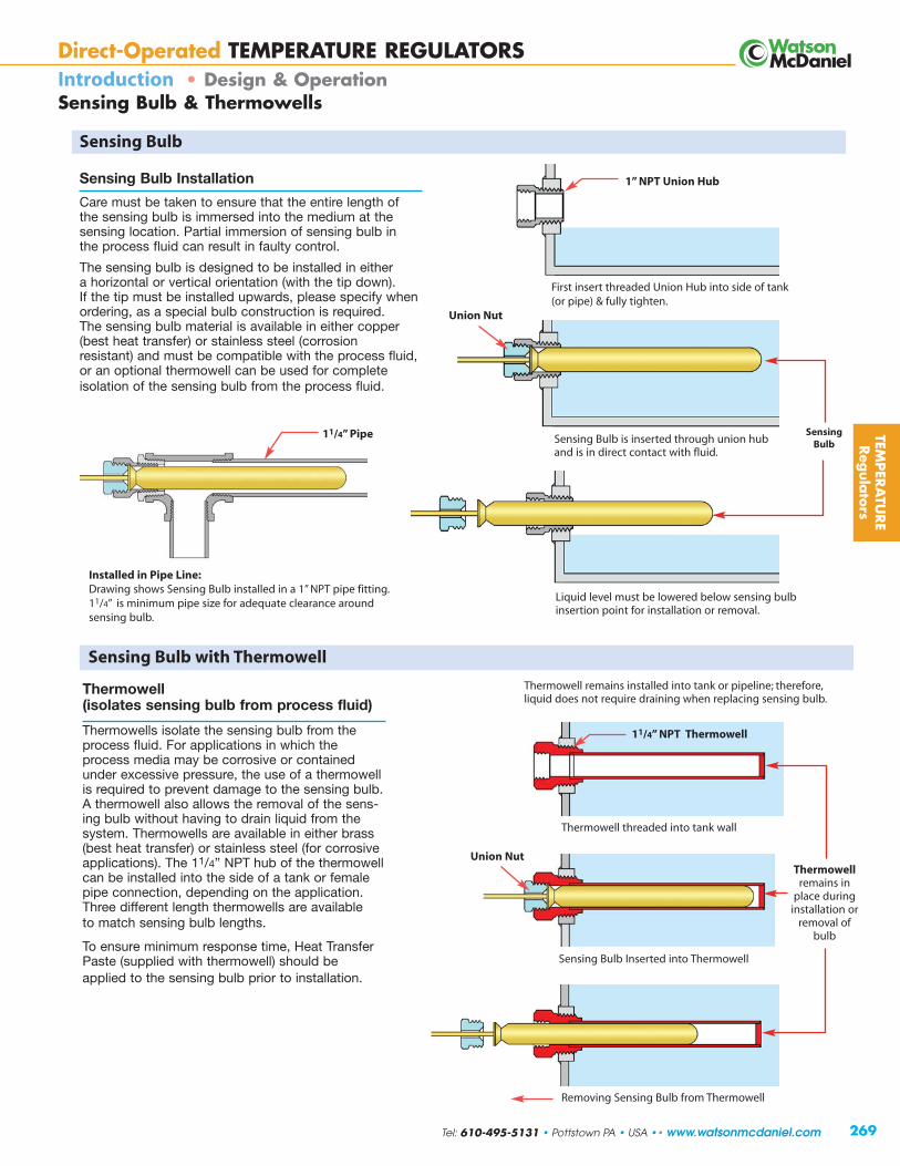
269
Sensing Bulb Installation
Care must be taken to ensure that the entire length ofthe sensing bulb is immersed into the medium at thesensing location. Partial immersion of sensing bulb inthe process fluid can result in faulty control.
The sensing bulb is designed to be installed in either a horizontal or vertical or ientation (with the tip down).If the tip must be installed upwards, please specify whenordering, as a special bulb construction is required. The sensing bulb material is available in either copper(best heat transfer) or stainless steel (corrosion resistant) and must be compatible with the process fluid,or an optional thermowell can be used for complete isolation of the sensing bulb from the process fluid.
TEMPER
ATU
RE
Reg
ula
tors
Temperature Regulators
Thermowellremains in
place duringinstallation or
removal ofbulb
SensingBulb
Sensing Bulb Inserted into Thermowell
Temperature RegulatorsInverted Bucket
Direct-Operated TEMPERATURE REGULATORSIntroduction • Design & Operation Sensing Bulb & Thermowells
Sensing Bulb
Liquid level must be lowered below sensing bulbinsertion point for installation or removal.
Removing Sensing Bulb from Thermowell
Sensing Bulb with Thermowell
Thermowell(isolates sensing bulb from process fluid)
Thermowells isolate the sensing bulb from theprocess fluid. For applications in which theprocess media may be corrosive or containedunder excessive pressure, the use of a thermowellis required to prevent damage to the sensing bulb.A thermowell also allows the removal of the sens-ing bulb without having to drain liquid from thesystem. Thermowells are available in either brass(best heat transfer) or stainless steel (for corrosiveapplications). The 11/4” NPT hub of the thermowellcan be installed into the side of a tank or femalepipe connection, depending on the application.Three different length thermowells are availableto match sensing bulb lengths.
To ensure minimum response time, Heat TransferPaste (supplied with thermowell) should beapplied to the sensing bulb prior to installation.
Thermowell remains installed into tank or pipeline; therefore,liquid does not require draining when replacing sensing bulb.
Sensing Bulb is inserted through union huband is in direct contact with fluid.
First insert threaded Union Hub into side of tank (or pipe) & fully tighten.
Installed in Pipe Line: Drawing shows Sensing Bulb installed in a 1” NPT pipe fitting.11/4” is minimum pipe size for adequate clearance around sensing bulb.
1” NPT Union Hub
11/4” NPT Thermowell
11/4” Pipe
Union Nut
Union Nut
Thermowell threaded int o tank wall
Tel: 610-495-5131 • Pottstown PA • USA •• www.watsonmcdaniel.com

W94
SteamSupply
BypassHeat
Exchanger
Fuel OilStorage Tank
PumpF&TTrap
W94 Heating Fuel Oil to Proper Temperature W94 Elevating Temperature of a Plating or Finishing Tank
TemperatureSensing Bulb
270
W94
F&TTrap
TemperatureSensing Bulb
Temperature Regulators
Direct-Operated TEMPERATURE REGULATORSIntroduction
Typical Applications for Temperature Regulators for Heating & Cooling
Temperature Range
Nominal ranges from 20°F (-10°C) through 440°F (225°C) are available. The nominal range defines the entire temperature rangeof the unit. The service conditions and choice of valve style and action will determine the actual operating range (recommendedworking span) of the unit. Using the valve in the recommended working span improves temperature response time of the system. The nominal range should be selected so that the set-point falls within the recommended working span for the specified valve style and action. They include an over-range protection spring, which allows the sensing bulb to be heated 100°F above theupper limit of the unit’s nominal range for system cleaning or temporary situations.
Accuracy
The W91/W94 Temperature Regulator is a “set-and-forget” regulating device. Once the proper control-point setting has been achieved, the unit requires virtually no adjustments and very little maintenance. Control-point accuracy is dependent upon the sensing bulb location, load change size and speed, and valve size. The sensing bulb must be installed in an area within the process that is most representative of overall process conditions. Care should be taken not to locate the bulb in close proximity to the valve, as the regulator might respond to temperature changes before the process has had time to reach the control-point. Where sudden or large load changes occur, a pneumatically or electrically-powered Control Valve should be specified. Consult the Control Valves section of this catalog.
Valve sizing also plays a major part in regulator performance. A valve that is too small will not be able to provide the desired capacityduring peak load conditions, while a valve that is too large may overshoot the control-point and operate with the valve plug too closeto the seat, resulting in undue wear of the plug and seat. As part of a well-designed system, a properly sized valve (operating in the 60-90% open position) can control to within 2 to 5 °F.
Size
The proper sizing of a regulating valve is one of the most important factors in its selection. A valve that is too small will not be able to provide the desired capacity during peak load conditions, while a valve that is too large may overshoot the control-point and operate with the valve plug too close to the seat, resulting in premature wear of the plug and seat. The valve coefficient (Cv) is used to determine the maximum capacity of a valve. From this value, a valve body with the appropriate port size can be selected. Port sizesfrom 1/8" through 4" and connection sizes from 1/2" through 4" are available. Consult the Valve Selection section of this catalog.
Close-Off
Temperature Regulators are not considered shut-off valves. A pressure surge may force a single-seated valve plug open. The W91/W94 Temperature Regulator is a balanced equilibrium system and may not provide the force necessary to tightly seat the valve plug. A separate power-driven or hand-actuated valve is required to ensure tight shut-off when necessary.
SteamSupply
When the Sensing Bulb is mounted remotely from the actualpoint of heating (as shown) the Circulation Pump MUST continue to run so that the sensing bulb can sample theproduct temperature in the heat exchanger. Without product circulation, the temperature control valve will never shut off and the oil will b e o verhe a te d
Sensing bulb should be properly placed inside tank for besttemperature consistency. An optional Thermowell (StainlessSteel or Brass) may slightly reduce temperature sensitivity.However, it will isolate sensing bulb and allow for its removalwithout draining the tank.
TEM
PER
ATU
RE
Reg
ula
tors
www.watsonmcdaniel.com •• Pottstown PA • USA • Tel: 610-495-5131
Oil Flow

W94 Used in a Drying Oven Application
W91 Used to Control Water Flow to Air Compressor for Cooling Purposes
Sensing Bulb
W94
Conveyor
Exhaust Air
Steam
Drying Oven
Fan
ColdOutside
Air
W91ColdWaterInlet
Hot OilInlet
Heat ExchangerOil Cooler
W91
CoolingWaterInlet
Oil Outlet(Reducedtemperature)
TemperatureSensing BulbWater
Outlet(Increased
temperature)
WaterFlow
TemperatureSensing Bulb
Water Outlet(Increasedtemperature)
Air Flow(heated)
HeatingCoil
W91 Used to Reduce Oil Temperature In a Heat Exchanger
TEMPER
ATU
RE
Reg
ula
tors
271
Temperature RegulatorsTemperature RegulatorsInverted Bucket
Direct-Operated TEMPERATURE REGULATORSIntroductionTypical Applications for Temperature Regulators for Heating & Cooling
W94 Valve used to regulate the temperature of the airflow through an air heating duc t. The sensing bulb is inst alled toward the end of the heating duct and willsense the temperature of the air flowing past the heating coils. When air temperature is below the setpoint, the valve will open to allow more steam through to the coils to heat the air passing through the duct. Once the desired air temperature is achieved, the valve will begin to modulate closed to maintain the air temperature.
W91 Cooling valve controlling the flow of water through aheat exchanger to maintain the temperature of oil that is gaining heat by some process. The valve automatically shutsoff when not required, greatly reducing cooling water usage.The source of the cooling water may be a well or city watersupply and it can be circulated or dumped to drain. A 3-wayvalve may be used on cold water chiller systems so flow canbe diverted from going through the heat exchanger whennot required.
When the Sensing Bulb is mounted remotely from the actual point of Cooling (as shown), the water MUST continue to flow so that the sensing bulb can sample theproduct temperature of the unit being cooled. Without continuous water flow, the temperature control valve willnever turn on, causing the unit to overheat. The bypass lineprovides a minimum continuous flow when temperature set point is achieved and the valve is closed.
Continuous bypass line
Tel: 610-495-5131 • Pottstown PA • USA •• www.watsonmcdaniel.com

Model W91 (No Indicating Dial)W94 (Temperature Indicating Dial)
Service Water, Steam, Other LiquidsSizes 1/2”– 4”Connections Threaded, Union Ends, 125# FLG
250# FLG (optional)Body Material 1/2” – 11/2” Bronze/Stainless Steel
2” Cast Iron (Direct-acting)2” Bronze (Reverse-acting)21/2” – 4” Cast Iron
Seat Material Stainless SteelMax Inlet Pressure 250 PSIG
Model Code Configuration
Models Temperature Range Capillary Length Sensing Bulb Valve Body Selection
W91 Non-Indicating 01 – 14 Refer to 08 8 Feet (standard) S15 Brass bulb Refer to Valve Body SectionW94 Indicating Dial Temperature 12 12 Feet (standard)
Range Chart 16 16 Feet (Omit this selection20 20 Feet S16 Stainless bulb if purchasing Actuator only)24 24 Feet
Note: Thermowells are ordered separately. See Thermowell & Bulb Connections page.
Explanation of W91 06 08 S15 H13NModel Number: Model Temp. Cap. Bulb Valve
Range Length Type Body
Model Number: W91-06-08-S15-H13N
How to write proper model number:
W91/W94 SeriesDirect-Operated RegulatorsTemperature Regulators
Typical Applications
The W91 & W94 Self-Operating Temperature Regulators are the preferred choice of original equipment manufacturers, mechanical contractors and specifying engineers. They requireno external power source and are ideal for regulating the temperature of tanks, process streams and various types of industrial equipment. The Actuator is noted for its rugged die-cast aluminum housing, fully-enclosed bellows assembly and internal over-temperature range protection.
Model W91Non-Indicating (without indicating dial) features a lower profileand should be specified where space constraints may be an issue.
Model W94Temperature Indicating (with indicating dial) will allow the operator to verify the process temperature and to aid in temperature adjustment.
Features
• Self-Operating (no external power source required)
• Temperature Indicating & Non-Indicating models available
• Heavy Duty Die-Cast Aluminum Housing
• 1/2" thru 4" Valve Sizes
• Fully Enclosed Bellows
• Temperature Over-range protection spring to protect thermal system
Specifications
Dial Thermometer: 31/2" dial, stainless steel case, swivel and angle adjustment (Model W94 only)
Housing: Die-cast aluminum, epoxy powder coated grey finish
Bellows: High-pressure brass, corrosion resistant, tin plated finish
Temperature Protects Thermal System from damageOver-range up to 100˚F over high limit of range Protection:
272
Temperature Regulator Valve Action
Application Stem Action Normal (Fail) Position
Heating In-To-Close Normally Open
Cooling In-To-Open Normally Closed
For Heating & Cooling
W91(no Indicating
Dial)
W94
TEM
PER
ATU
RE
Reg
ula
tors
www.watsonmcdaniel.com •• Pottstown PA • USA • Tel: 610-495-5131

TEMPER
ATU
RE
Reg
ula
tors
W91/W94 SeriesTemperature RegulatorsDirect-Operated Regulators
273
For Heating & Cooling
Dimensions: inches [mm]Actuator Weight: 6 lbs.
Ø 3.67[93]
W94 Temperature Indicating ActuatorW91 Non-Indicating Actuator
Temperature Range Chart
W91 & W94 Actuators
Range Nominal Recommended Code Range Working Span *
01 20 to 70 °F -10 to 20 °C 40 to 65 °F 5 to 20 °C
02 40 to 90 °F 5 to 30 °C 65 to 85 °F 20 to 30 °C
03 30 to 115 °F 0 to 45 °C 85 to 110 °F 30 to 45 °C
04 50 to 140 °F 10 to 60 °C 110 to 135 °F 45 to 60 °C
05 75 to 165 °F 25 to 70 °C 135 to 160 °F 60 to 70 °C
06 105 to 195 °F 40 to 90 °C 160 to 190 °F 70 to 90 °C
07 125 to 215 °F 55 to 100 °C 190 to 210 °F 90 to 100 °C
09 155 to 250 °F 70 to 120 °C 210 to 245 °F 100 to 120 °C
10 200 to 280 °F 95 to 135 °C 245 to 275 °F 120 to 135 °C
11 225 to 315 °F 110 to 155 °C 275 to 310 °F 135 to 155 °C
12 255 to 370 °F 125 to 185 °C 305 to 365 °F 155 to 185 °C
13 295 to 420 °F 145 to 215 °C 365 to 415 °F 185 to 215 °C
14 310 to 440 °F 155 to 225 °C 415 to 435 °F 215 to 225 °C
*Note: The recommended working span typically falls within the upper third of the nominal range.
4.92[125]
9.00[228]
Ø 3.63[92]
Description of Working SpanThe recommended working span typically falls within the upper third of the nominal range. Single-Seat In-To-Close,all Double-Seat, and all 3-Way valves have a recommended working span in this part of the nominal range. Usingthe valve in the recommended working span improves temperature response time of the system.
9.00[228]
Temperature Range Selection
Tel: 610-495-5131 • Pottstown PA • USA •• www.watsonmcdaniel.com

Thermowell Option (ordered separately)A thermowell isolates the sensing bulb from the process fluid. It can be used to remove the sensing bulb while the system is filled withfluid or to protect the sensing bulb from corrosive liquids or excessive system pressures (see following page).
Sensing Bulb Selection & Installation: The sensing bulb and capillary are available in Copper (best heat transfer properties) or Stainless Steel (for corrosive applications). Copperhas better heat transfer properties than stainless steel and should always be chosen for better temperature control unless used in corrosiveservice. The length of the sensing bulb is dependent upon the capillary length required (see chart). Longer capillary lengths require a longerlength sensing bulb to operate the regulator. For installation, the Union Hub is threaded into a tank or piping system. The bulb slides throughthe Union Hub and is held in place by the Union Nut which spins freely around the armored capillary and threads into the Union Hub. Theangled surface of the sensing bulb forms a metal-to-metal seal on the inner edge of the Union Hub to prevent leakage of the process fluid.
W91/W94 SeriesDirect-Operated RegulatorsTemperature RegulatorsBulb & Thermowell Selection
Temperature Regulators
For Heating & Cooling
274
STAINLESS STEEL ARMOUR PROTECTED CAPILLARY
“U” Sensing Bulb Length
UNION NUTUnscrews for Sensing Bulb Removal
UNION HUB - 1“ NPT The union hub is threaded into side of vessel & is not permanently fastened to bulb.
Sensing Bulb
Sensing Bulb
Bulb being removed from thermowell
“A” Insertion Length
1.00
(union hub is included with sensing bulb & not need e d when using a Thermowell)
Tank Wall
SENSING BULB & CAPILLARY Selection
TEM
PER
ATU
RE
Reg
ula
tors Sensing Bulb & Capillary
ORDER Sensing Bulb Capillary Tubing Capillary Length in Ft.CODE Material Material 8, 12, 16 20 24
S15Copper Copper A 13” 16” 20”
(Brass Union Hub) with Stainless SteelU 12.25” 15.25” 19.25”Spiral Armour
S16Stainless Steel Stainless Steel A 13” 16” 20”
(Stainless Steel Union Hub) with Stainless SteelU 12.25” 15.25” 19.25”Spiral Armour
Other Options available. Consult Factory.
www.watsonmcdaniel.com •• Pottstown PA • USA • Tel: 610-495-5131

Notes: 1) Other connections and lengths may be available, consult factory.2) External pressure rating on Copper is 500 PSI max.3) External pressure rating on 316 SS is 1000 PSI max.
Brass Stainless Steel Nominal “A” INSERTION LENGTH (in.) Capillary LengthModel Code Model Code Length BULB THERMOWELL (Ft.)
536-S2 536-S6 13" 12.25 13.00 8, 12 or 16536-SE2 536-SE6 16" 15.25 16.00 20536-WE2 536-WE6 20" 19.25 20.00 24
1.13”
W91/W94 SeriesTemperature RegulatorsBulb & Thermowell Selection
Direct-Operated Regulators
For Heating & Cooling
275
SENSING BULB inside OPTIONAL THERMOWELL
THERMOWELL LENGTH
HUB - 11/4“ NPT (Attached to thermowell and threaded into side of vessel)
Thermowell
The Thermowell isolates the sensing bulb from the process liquid and allows for easy and safe removal of the sensing bulb. For applications in which the process media may be corrosive or contained under pressure, the use of a thermowell is required to prevent damage to the sensing bulb. For corrosive applications, use a stainless steelthermowell & copper sensing bulb. To ensure minimum response time, Heat Transfer Paste should be applied to thesensing bulb prior to installation into the thermowell.
HUB - 11/4“ NPT (Attached to thermowell and threaded into side of vessel)
Sensi ng
Sensing Bulb
Sensing BulbBulb being removed from thermow ell
Tank Wall
“A” Insertion Length
“A” Insertion Length
TEMPER
ATU
RE
Reg
ula
tors
Thermowell Option (ordered separately)Thermowells isolate and protect the sensing bulb from the process fluid, and are available in either Brass (best heat transfer) orStainless Steel (for corrosive applications). Thermowells allow for sensing bulb removal and replacement without having to drain liquid from the system. To maintain the best temperature control, always use a Copper Sensing bulb as opposed to a Stainless Steelsensing bulb. For corrosive applications, Stainless Steel thermowells (with a copper sensing bulb) can be used. Thermowells are alsorecommended for applications with excessive system pressures or extremely turbulent flow to protect the sensing bulb from damage.
THERMOWELLS - Model Numbers & Lengths
THERMOWELL LENGTH
UNION NUTUnscrews for Sensing Bulb
Removal
Tank Wall
Thermowell Length must be selected based on the length of the sensing bulb. The sensing bulb length is based on the length of theCapillary used in the Thermal System. Longer capillary lengths require a longer sensing bulb to hold the additional actuator fluid insidethe sensing bulb. Reference Sensing Bulb Chart for sensing bulb length.
Thermowellremains inplace duringinstallation orremoval ofbulb
Tel: 610-495-5131 • Pottstown PA • USA •• www.watsonmcdaniel.com

276
Range Nominal Temperature Range *Code01 20 - 70˚F 10 - 20˚C02 40 - 90˚F 5 - 30˚C03 30 - 115˚F 0 - 45˚C04 50 - 140˚F 10 - 60˚C05 75 - 165˚F 25 - 70˚C06 105 - 195˚F 40 - 90˚C07 125 - 215˚F 55 - 100˚C09 155 - 250˚F 70 - 120˚C10 200 - 280˚F 95 - 135˚C11 225 - 315˚F 110 - 155˚C12 255 - 370˚F 125 - 185˚C13 295 - 420˚F 145 - 215˚C14 310 - 440˚F 155 - 225˚C
* The recommended working span falls within the upper third of the nominal range.
Normally Open (IN-TO-CLOSE)Single-seatedBalanced Valve withClass IV shut-off
Model Configuration Chart
Models Temperature Range = X Capillary Length Sensing Bulb Valve Body Selection
W91 Non-Indicating 01 – 14 08 8 Feet (std) S15 Copper Bulb (std) Included in Model CodeW94 Indicating Dial (Refer to Temperature 12 12 Feet (with Brass Union Hub) in above chart.W91H High-Force Range Chart) 16 16 Feet
20 20 Feet S16 Stainless Steel Bulb24 24 Feet (with SS Union Hub)
Note: Thermowells for Models W91/W94 are ordered separately.
Model Codes in Chart are for complete Temperature Regulators.This includes the Valve Body and Thermal Actuator with standard copper bulb and 8 ft. capillary.
Non-Indicating Type Actuator Indicating Type Actuatorwith valve body with valve body
X = Temperature Range X = Temperature Range08 = Capillary Length 8ft. PMO 08 = Capillary Length 8ft. PMO Weight
Connection S15 = Copper Bulb (PSI) S15 = Copper Bulb (PSI) (lbs)
1/2” NPTStandard Body W91-X-08S15-H12N 250 W94-X-08S15-H12N 250 21
with Integral Union W91-X-08S15-H12U 250 W94-X-08S15-H12U 250 21
3/4” NPTStandard Body W91-X-08S15-H13N 250 W94-X-08S15-H13N 250 21
with Integral Union W91-X-08S15-H13U 250 W94-X-08S15-H13U 250 21
1” NPTStandard Body W91-X-08S15-H14N 200 W94-X-08S15-H14N 200 21
with Integral Union W91-X-08S15-H14U 200 W94-X-08S15-H14U 200 21
11/4” NPTStandard Body W91-X-08S15-H15N 200 W94-X-08S15-H15N 200 24
with Integral Union W91-X-08S15-H15U 200 W94-X-08S15-H15U 200 24
11/2” NPTStandard Body W91-X-08S15-H16N 200 W94-X-08S15-H16N 200 25
with Integral Union W91-X-08S15-H16U 200 W94-X-08S15-H16U 200 25
2” NPT Standard Body W91-X-08S15-H17N 150 W94-X-08S15-H17N 150 57
2” W91-X-08S15-H17F125 150 W94-X-08S15-H17F125 150 57
21/2” W91-X-08S15-H18F125 65 W94-X-08S15-H18F125 65 65
3” W91-X-08S15-H19F125 50 W94-X-08S15-H19F125 50 80
4” W91-X-08S15-H20F125 40 W94-X-08S15-H20F125 40 105
21/2” W91H-X-08S15-H18F125 150 N/A - 96
3” W91H-X-08S15-H19F125 150 N/A - 118
4” W91H-X-08S15-H20F125 150 N/A - 60
* 250# Flange available. Consult Factory. The Special High-Force Actuator will allow the valve to be operated at a higher operating pressure.
W91 05 (75 - 165˚F) 12 S15 H15N (11/4” NPT)
Example Model Code configured: W91-05-12-S15-H15N (W91, 75-165 ˚F Temp. Range, 12 ft. capillary, Std. Copper Sensing Bulb, 11/4” NPT Valve Body)
*Flangedwith
StandardActuator
*Flangedwith
High-ForceActuator
W91 W94
HEATING
Valve bodies used for HEATING have designation H(Example: H15N)
W91/W94 SeriesDirect-Operated RegulatorsTemperature Regulators
HEATING
TEM
PER
ATU
RE
Reg
ula
tors
FLOW
www.watsonmcdaniel.com •• Pottstown PA • USA • Tel: 610-495-5131

277
W91/W94 SeriesDirect-Operated RegulatorsTEM
PER
ATU
RE
Reg
ula
tors
Single-Seated Valve Bodies
A(UNION)
B
A
Stem In-To-Closefor HEATING
Single Seat • 1/2” – 4”
HEATING
Dimensions in inches
THREADED & UNION FLANGED
Union
B
A(NPT)
C C
Valve Body SpecificationsBody Material Trim Material Connection Pressure & Temperature Rating1/2”- 11/2” Stainless/Bronze Stainless Steel Threaded or Malleable Iron Union Ends 250 PSI @ 410°F 2” Cast Iron Stainless Steel Threaded 250 PSI @ 450°F
2” - 4” Cast Iron Stainless Steel125# Flanged 125 PSI @ 450°F
250# Flanged 250 PSI @ 450°F
Valve Body SelectionValve Body Number Size Maximum Dimensions Approx.
(In-To-Close Heating) Connection Capacity Close-Off Pressure A A A A B C Ship. Wt.NPT Union NPT Cv (PSI�P) Threaded 125# FLG 250# FLG Union (lbs) [kg]H12N H12U 1/2" 3.2 250 4.125 x x 6.50 2.375 2.12 14 [6.35]H13N H13U 3/4" 6.3 250 4.125 x x 6.50 2.375 2.12 14 [6.35]
H14N H14U 1" 10.8 200 4.125 x x 7.00 2.375 2.12 14 [6.35]H15N H15U 11/4" 15.9 200 4.810 x x 7.50 3.250 2.50 17 [7.7]H16N H16U 11/2" 22.4 200 5.190 x x 8.00 3.500 2.69 18 [8.2]
H17N – 2" 33.1 150 9.500 x x x 5.750 4.75 50 [22.7]
H17F125 H17F250 2" 33.1 150 – x 10.375 10.875 x 5.75 4.75 80 [36.3]
H18F125 H18F250 21/2" 47.5 65 150 x 10.625 11.250 x 7.00 5.00 96 [43.6]
H19F125 H19F250 3" 68.2 50 150 x 10.875 11.625 x 8.00 5.75 110 [49.9]H20F125 H20F250 4" 109.5 40 150 x 10.500 13.125 x 8.75 6.50 160 [72.6]
Notes: For 21/2” - 4” sizes, consult factory for proper actuators.* With High-Force Actuator, which allows the valve to operate at a higher differential pressure.
FLANGED125# 250#
FLOW
Standard Special*Valve Type
for Temperature Regulators
FLOW
ActuatorMounting Surface
ActuatorMounting Surface
NORMALLY OPEN
Tel: 610-495-5131 • Pottstown PA • USA •• www.watsonmcdaniel.com

W91/W94 SeriesDirect-Operated RegulatorsCapacity Charts • Single-Seated Valve Bodies
CAPACITIES – Steam (lbs/hr) SINGLE-SEATED VALVESSize & Valve Body Number
1/2" 3/4" 1" 11/4" 11/2" 2" 21/2" 3" 4"
H12 H13 H14 H15 H16 H17 H18 H19 H20
1 91 180 309 454 640 946 1357 1949 3129
3 103 203 348 512 722 1066 1530 2197 3527
5 115 226 387 570 803 1187 1703 2445 3926
10 144 283 486 715 1007 1488 2135 3066 4922
15 173 341 584 859 1211 1789 2568 3686 5919
20 202 398 682 1004 1415 2090 3000 4307 6915
25 231 455 780 1149 1618 2392 3432 4928 7912
30 260 513 879 1294 1822 2693 3864 5548 8908
40 319 627 1075 1583 2230 3295 4729 6790 10,901
50 377 742 1272 1872 2638 3898 5593 8031 12,894
60 435 857 1468 2162 3045 4500 6458 9272 14,887
70 493 971 1665 2451 3453 5102 7322 10,513 16,880
80 552 1086 1861 2740 3861 5705 8187 11,755 18,873
90 610 1200 2058 3030 4268 6307 9051 12,996 20,866
100 668 1315 2255 3319 4676 6910 9916 14,237 22,859
125 814 1602 2746 4043 5695 8416 12,077 17,340 27,841
150 959 1888 3237 4766 6714 9922 14,238 20,443 32,823
175 1105 2175 3729 5490 7734
200 1250 2462 4220 6213 8753
250 1542 3035
Notes: 1) For reduced-port 1/2” valves, consult factory. 2) All steam capacities based on Critical Drop (Choked Flow).
CAPACITIES – Water (GPM) SINGLE-SEATED VALVESSize & Valve Body Number
1/2” 3/4” 1” 11/4” 11/2” 2” 21/2” 3” 4”HW12 HW13 HW14 HW15 HW16 HW17 HW18 HW19 HW20
1 3.2 6.3 11 16 22 33 48 68 1103 5.5 11 19 28 39 57 82 118 1905 7.2 14 24 36 50 74 106 152 245
10 10 20 34 50 71 105 150 216 34615 12 24 42 62 87 128 184 264 42420 14 28 48 71 100 148 212 305 49025 16 32 54 80 112 166 238 341 54830 18 35 59 87 123 181 260 374 60040 20 40 68 101 142 209 300 431 69350 23 45 76 112 158 234 336 482 77460 25 49 84 123 174 256 368 528 84870 27 53 90 133 187 277 397 571 91680 29 56 97 142 200 296 425 610 97990 30 60 102 151 213 314 451 647 1039100 32 63 108 159 224 331 475 682 1095125 36 70 121 178 250 370 531 762 1224150 39 77 132 195 274 405 582 835 1341175 42 83 143 210 296200 45 89 153 225 317250 51 100
Note: When used with water,add W to the Valve Body Number.
Example: H17N becomes HW17N
InletPressure(PSIG)
Pressure(PSI�P)
Note: Verify that Maximum Close-Off Pressure for 2” - 4” models does not exceed max rating for selected Valve BodyNumber and Type (refer toValve Body Number charton previous page)
Note:
Verify that MaximumClose-Off Pressure for 2” - 4” models does notexceed max rating forselected Valve BodyNumber and Type (refer to Valve BodyNumber in chart).
for Temperature Regulators
278
TEM
PER
ATU
RE
Reg
ula
tors
HEATING
www.watsonmcdaniel.com •• Pottstown PA • USA • Tel: 610-495-5131

279
W91/W94 SeriesDirect-Operated RegulatorsTEM
PER
ATU
RE
Reg
ula
tors
Steam Required for Heating Water
Capacity Formulas for Steam LoadsWhen Heat Load or Heat Transfer Capacity of E Rate (E) is Known steam required = 1000
(lbs/hr)When Square Feet Equivalent Capacity of Direct Radiation (EDR) is Known steam required = Sq. ft. of EDR
(lbs/hr) 4
When Heating Water with Steam Capacity of steam required = GPM x Temp Rise (°F)
(lbs/hr) 2
When Heating Fuel Oil with Steam Capacity of steam required = GPM x Temp Rise (°F)
(lbs/hr) 4
When Heating Air with Steam Coils Capacity of steam required = CFM x Temp Rise (°F)
(lbs/hr) 900
Steam flow required through a temperature regulator (lbs/hr) to heat a specified number of gallons of water per hour (gal/hr)
TABLE 1- Steam Flow Required in Pounds Per Hour (lbs/hr)Temp ` Temp
Increase Increase(˚F) 25 50 100 200 300 500 700 1000 2000 4000 10,000 20,000 (˚F)
5° 1 2 4 8 12 21 29 41 83 166 415 830 5° 10° 2 4 8 16 25 41 58 83 166 332 830 1660 10° 15° 3 6 12 25 37 62 87 124 249 498 1245 2490 15° 20° 4 8 17 33 50 83 116 166 332 664 1660 3320 20° 25° 5 10 20 42 62 104 145 207 415 830 2075 4150 25° 30° 6 12 25 50 75 124 174 249 498 996 2490 4980 30° 40° 8 16 33 66 100 166 232 332 664 1328 3320 6640 40° 50° 10 21 42 83 124 207 290 415 830 1660 4150 8300 50° 60° 12 25 50 100 149 249 348 498 996 1992 4980 9960 60° 70° 15 29 58 116 174 290 407 581 1162 2324 5810 11,620 70° 80° 17 33 67 133 199 332 465 664 1328 2656 6640 13,280 80° 90° 19 38 75 149 224 373 523 747 1494 2988 7470 14,940 90° 100° 21 42 83 166 249 415 581 830 1660 3320 8300 16,600 100° 115° 24 48 95 191 286 477 668 955 1909 3818 9544 19,088 115° 130° 27 54 108 216 324 539 755 1079 2158 4316 10,790 21,580 130° 145° 30 60 120 241 361 601 842 1200 2400 4812 12,030 24,060 145° 160° 33 66 133 266 398 664 929 1328 2656 5312 13,280 26,560 160° 175° 36 72 145 290 436 726 1017 1452 2900 5810 14,524 29,048 175° 200° 41 83 166 332 498 830 1162 1660 3320 6640 16,600 33,200 200° 225° 47 94 187 374 560 934 1307 1867 3735 7470 18,680 37,360 225° 250° 52 104 207 415 622 1037 1452 2075 4150 8300 20,750 41,500 250°
Gallons of Water per Hour To Be Heated
HEATING WATER: The amount of steam required to heat water can be found using chart above.Example: To heat 1000 gallons per hour of water from 40˚F to 140˚F (Temp. increase 100˚F) requires 830 lbs/hr of steam.
HEATING FUEL OIL: The amount of steam required to heat fuel oil is half of that to heat water. Use half the value found in chart above.Example: To heat 1000 gallons per hour of fuel oil from 40˚F to 140˚F (Temp. increase 100˚F) requires 415 lbs/hr of steam.
Capacity Charts • Single-Seated Valve Bodies
HEATINGfor Temperature Regulators
Note: Above formulas based on steam co ntaining approximate ly 1000 Btu’s of Latent Heat per pound.
(Btu/hr)
Tel: 610-495-5131 • Pottstown PA • USA •• www.watsonmcdaniel.com

280
W91/W94 SeriesDirect-Operated RegulatorsTemperature Regulators
TEM
PER
ATU
RE
Reg
ula
tors
Model Codes in Chart are for complete Temperature Regulators. This includes the Valve Body and Thermal Actuator with standard copper bulb and 8 ft. capillary.
W91 05 (75 - 165˚F) 12 S15 C15U (11/4” NPT)
Example Model Code configured: W91-05-12-S15-C15U (W91, 75-165 ˚F Temp. Range, 12 ft. Capillary, Copper Sensing Bulb, 11/4” NPT Valve Body)
3/4” - 2” NPTwith Integral Unionfor Easy Removal from the piping system
Normally Closed (IN-TO-OPEN)Double-seatedBalanced Valve withClass II shut-off
Valve bodies used for COOLING have designation C(Example: C15U)
COOLING
Range Nominal Temperature Range *Code01 20 - 70˚F 10 - 20˚C02 40 - 90˚F 5 - 30˚C03 30 - 115˚F 0 - 45˚C04 50 - 140˚F 10 - 60˚C05 75 - 165˚F 25 - 70˚C06 105 - 195˚F 40 - 90˚C07 125 - 215˚F 55 - 100˚C09 155 - 250˚F 70 - 120˚C10 200 - 280˚F 95 - 135˚C11 225 - 315˚F 110 - 155˚C12 255 - 370˚F 125 - 185˚C13 295 - 420˚F 145 - 215˚C14 310 - 440˚F 155 - 225˚C
* The recommended working span typically falls within the upper third of the nominal range.
Non-Indicating Type Actuator Indicating Type Actuatorwith valve body with valve body
X = Temperature Range X = Temperature Range08 = Capillary Length 8 ft. PMO 08 = Capillary Length 8 ft. PMO
Connection S15 = Copper Bulb (PSI) S15 = Copper Bulb (PSI) Weight
3/4” NPT with Integral Union W91-X-08S15-C13U 250 W94-X-08S15-C13U 250 12
1” NPT with Integral Union W91-X-08S15-C14U 250 W94-X-08S15-C14U 250 13
11/4” NPT with Integral Union W91-X-08S15-C15U 250 W94-X-08S15-C15U 250 17
11/2” NPT with Integral Union W91-X-08S15-C16U 250 W94-X-08S15-C16U 250 18
2” NPT with Integral Union W91-X-08S15-C17U 250 W94-X-08S15-C17U 250 24
21/2” 125# FLG W91-X-08S15-C18F125 65 W94-X-08S15-C18F125 65 55
3” 125# FLG W91-X-08S15-C19F125 50 W94-X-08S15-C19F125 50 80
4” 125# FLG W91-X-08S15-C20F125 40 W94-X-08S15-C20F125 40 105
W91 W94
Model Configuration Chart
Models Temperature Range = X Capillary Length Sensing Bulb Valve Body Selection
W91 Non-Indicating 01 – 14 08 8 Feet (std) S15 Copper Bulb (std) Included in Model CodeW94 Indicating Dial (Refer to Temperature 12 12 Feet (with Brass Union Hub) in above chart.
Range Chart) 16 16 Feet20 20 Feet S16 Stainless Steel Bulb24 24 Feet (with SS Union Hub)
Note: Thermowells for Models W91/W94 are ordered separately.
COOLING
FLOW
www.watsonmcdaniel.com •• Pottstown PA • USA • Tel: 610-495-5131

281
W91/W94 SeriesDirect-Operated Regulators
TEMPER
ATU
RE
Reg
ula
tors
for Temperature Regulators
C
B
A
FLOW
Dimensions in inches [mm]
Double Seat • 3/4” – 4”
A
C
B
FLOW
C
B
A21/2” – 4”Flanged
Stem In-To-Openfor Cooling
C
B
Valve Body Specifications
Body Material Trim Material Connection Pressure & Temperature Rating
3/4” - 2” Bronze Stainless Steel Threaded with Malleable Iron Union Ends 250 PSI @ 410°F (210°C)
21/2” - 4” Cast Iron Stainless Steel 125# Flanged 125 PSI @ 350°F (149°C)
Valve Body Selection – Threaded
Valve Body Number Size Maximum ApproximateClose-Off Pressure Dimensions Shipping Wt.
(In-To-Open Cooling) Connection (NPT) Nominal Port Cv (PSI�P) A B C (lbs) [kg]
C13U 3/4 3/4" 8 250 5.6 [142] 2.3 [58] 2.3 [58] 5.0 lbs [2.25 kg]
C14U 1 1" 12 250 6.0 [152] 2.3 [58] 2.3 [58] 6.1 lbs [2.75 kg]
C15U 11/4 11/4" 21 250 7.2 [183] 2.6 [66] 2.6 [66] 10.1 lbs [4.55 kg]
C16U 11/2 11/2" 30 250 7.7 [196] 2.6 [66] 2.6 [66] 11.1 lbs [5.00 kg]
C17U 2 2" 47 250 8.6 [218] 3.1 [79] 3.1 [79] 17.0 lbs [7.65 kg]
Capacity
Valve Body Selection – Flanged
Valve Body Number Size Maximum ApproximateClose-Off Pressure Dimensions Shipping Wt.
(In-To-Open Cooling) Connection Nominal Port Cv (PSI�P) A B C (lbs) [kg]
C18F125 21/2" 21/2" 69 65 7.8 [198] 4.8 [122] 5.4 [137] 45 lbs [20 kg]
C19F125 3" 3" 90 50 9.0 [229] 5.0 [127] 5.6 [142] 70 lbs [32 kg]
C20F125 4" 4" 196 40 11.4 [290] 6.3 [160] 6.5 [165] 100 lbs [45 kg]
Capacity
ActuatorMounting Surface
ActuatorMounting Surface
Double-Seated Valve Bodies
COOLING
FLOWFLOW
A3/4” – 2”
NPT
NORMALLY CLOSED
Tel: 610-495-5131 • Pottstown PA • USA •• www.watsonmcdaniel.com

282
TEM
PER
ATU
RE
Reg
ula
tors
W91/W94 SeriesDirect-Operated Regulators
Model Configuration Chart
Models Temperature Range = X Capillary Length Bulb Valve Body Selection
W91 Non-Indicating 01 – 14 08 8 Feet (standard) S15 Copper Bulb Included in Model CodeW94 Indicating Dial (Refer to Temperature 12 12 Feet (with Brass Union Hub) in above chart.
Range Chart 16 16 Feeton next page) 20 20 Feet S16 Stainless Steel Bulb
24 24 Feet (with SS Union Hub)
Note: Thermowells for Models W91/W94 are ordered separately.
Model Codes in Chart are for complete Temperature Regulators. This includes the Valve Body and Thermal Actuator with standard copper bulb and 8 ft. capillary.
W91 05 (75 - 165˚F) 12 S15 A45 (11/4” NPT)
Example Model Code configured: W91-05-12-S15-A45 (W91, 75-165 ˚F Temp. Range, 12 ft. Capillary, Copper Sensing Bulb, 11/4” NPT Valve Body)
W91
Valve Body for MIXING & DIVERTING
MIXING & DIVERTING
LOWERPORTB
UPPERPORT
C
COMMONPORT
A
Mixing FlowDiagram
Diverting FlowDiagram
CAUTION: 3-Way Valves are not designed for use in steam applications.To properly control the mixing of two flows, inlet pressures at ports B and C should be as equal as possible.
Range Nominal Temperature Range *Code01 20 - 70˚F 10 - 20˚C02 40 - 90˚F 5 - 30˚C03 30 - 115˚F 0 - 45˚C04 50 - 140˚F 10 - 60˚C05 75 - 165˚F 25 - 70˚C06 105 - 195˚F 40 - 90˚C07 125 - 215˚F 55 - 100˚C09 155 - 250˚F 70 - 120˚C10 200 - 280˚F 95 - 135˚C11 225 - 315˚F 110 - 155˚C12 255 - 370˚F 125 - 185˚C13 295 - 420˚F 145 - 215˚C14 310 - 440˚F 155 - 225˚C
* The recommended working span typically falls within the upper third of the nominal range.
Non-Indicating Type Actuator Indicating Type Actuatorwith valve body with valve body
X = Temperature Range X = Temperature Range08 = Capillary Length 8 ft. PMO 08 = Capillary Length 8 ft. PMO Weight
Connection S15 = Copper Bulb (PSI) S15 = Copper Bulb (PSI)
1/2” NPT with Integral Union W91-X-08-S15-A18 250 W94-X-08-S15-A18 250 10
3/4” NPT with Integral Union W91-X-08-S15-A25 250 W94-X-08-S15-A25 250 12
1” NPT with Integral Union W91-X-08-S15-A34 250 W94-X-08-S15-A34 250 13
11/4” NPT with Integral Union W91-X-08-S15-A45 250 W94-X-08-S15-A45 250 17
11/2” NPT with Integral Union W91-X-08-S15-A56 250 W94-X-08-S15-A56 250 18
2” NPT with Integral Union W91-X-08-S15-A67 250 W94-X-08-S15-A67 250 24
21/2” 125# FLG W91-X-08-S15-B75 125 W94-X-08-S15-B75 125 55
3” 125# FLG W91-X-08-S15-B80 125 W94-X-08-S15-B80 125 80
4” 125# FLG W91-X-08-S15-B85 125 W94-X-08-S15-B85 125 105
W94
Temperature Regulators
Air Signal@ 50%
BC
A
Air Signal@ 50%
BC
A
www.watsonmcdaniel.com •• Pottstown PA • USA • Tel: 610-495-5131

283
TEMPER
ATU
RE
Reg
ula
tors
W91/W94 Series3-Way Valve BodiesDirect-Operated Regulators
for Temperature Regulators
Dimensions in inches [mm]
Valve Body SpecificationsBody Material Trim Material Connection Pressure & Temperature Rating
1/2” - 2” Bronze Bronze Threaded with Malleable Iron Union Ends 250 PSI @ 300°F (149°C)
21/2” - 4” Cast Iron Bronze 125# Flanged 125 PSI @ 300°F (149°C)
Valve Body SelectionMaximum
Valve Body NumberSize
Close-Off Pressure Dimensions ApproximateConnection (NPT) Nominal Port Cv (PSI�P) E F G Shipping Wt.
A18 1/2" 1/2" 2.8 250 4.8 [122] 1.8 [46] 1.8 [46] 2.9 lbs [1.31 kg]
A25 3/4" 3/4" 5.6 250 5.6 [142] 2.3 [58] 2.3 [58] 4.7 lbs [2.12 kg]
A34 1" 1" 8.4 250 6.0 [152] 2.3 [58] 2.3 [58] 5.7 lbs [2.57 kg]
A45 11/4" 11/4" 15 250 7.2 [183] 2.8 [71] 2.6 [66] 9.5 lbs [4.28 kg]
A56 11/2" 11/2" 21 250 7.7 [196] 3.5 [89] 2.6 [66] 11.1 lbs [5.00 kg]
A67 2" 2" 33 250 8.6 [218] 4.1 [104] 3.1 [79] 16.7 lbs [7.55 kg]
G
F
E
LOWERPORT
(B)
COMMON PORT (A)
UPPERPORT
(C)
for Mixing or Diverting
G
F
1/2” – 2” NPT
Capacity
ActuatorMounting Surface
3-Way • 1/2” – 4”
G
F
E
LOWERPORT
(B)
COMMON PORT (A)
G
F
ActuatorMounting Surface
CAUTION: Watson McDaniel 3-Way Valves are not designed for use in steam applications.To properly control the mixing of two flows, inlet pressures at ports B and C should be as equal as possible.
Valve Body SelectionSize Maximum
Close-Off Pressure Dimensions ApproximateValve Body NumberConnection Nominal Port
Cv (PSI�P) E F G Shipping Wt.
B75 21/2" 21/2" 58 125 9.0 [229] 7.1 [180] 5.2 [132] 62 lbs [28 kg]
B80 3" 3" 72 125 10.0 [254] 8.0 [203] 6.0 [152] 80 lbs [36 kg]
B85 4" 4" 102 125 13.0 [330] 10.0 [254] 6.9 [175] 140 lbs [64 kg]
Capacity
lowerport
B
lowerport
Bupper
port
C
upperport
C
common port A
common port A
E
21/2” – 4”Flanged
E
Tel: 610-495-5131 • Pottstown PA • USA •• www.watsonmcdaniel.com
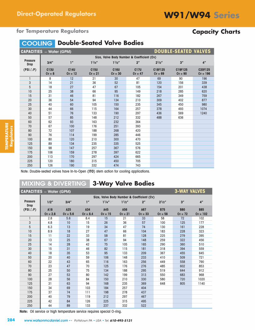
284
W91/W94 SeriesDirect-Operated Regulators
Double-Seated Valve Bodies
3-Way Valve Bodies
for Temperature Regulators
TEM
PER
ATU
RE
Reg
ula
tors
CAPACITIES – Water (GPM) DOUBLE-SEATED VALVESSize, Valve Body Number & Coefficient (Cv)
Pressure3/4” 1” 11/4” 11/2” 2” 21/2” 3” 4”Drop
(PSI�P) C13U C14U C15U C16U C17U C18F125 C19F125 C20F125Cv = 8 Cv = 12 Cv = 21 Cv = 30 Cv = 47 Cv = 69 Cv = 90 Cv = 196
1 8 12 21 30 47 69 90 1963 14 21 36 52 81 120 156 3395 18 27 47 67 105 154 201 43810 25 38 66 95 149 218 285 62015 31 46 81 116 182 267 349 75920 36 54 94 134 210 309 402 87725 40 60 105 150 235 345 450 98030 44 66 115 164 257 378 493 107440 51 76 133 190 297 436 569 124050 57 85 148 212 332 488 63660 62 93 163 232 36470 67 100 176 251 39380 72 107 188 268 42090 76 114 199 285 446100 80 120 210 300 470125 89 134 235 335 525150 98 147 257 367 576175 106 159 278 397 622200 113 170 297 424 665225 120 180 315 450 705250 126 190 332 474 743
Note: Double-seated valves have In-to-Open (ITO) stem action for cooling applications.
Capacity Charts
CAPACITIES – Water (GPM) 3-WAY VALVESSize, Valve Body Number & Coefficient (Cv)
Pressure 1/2” 3/4” 1” 11/4” 11/2” 2” 21/2” 3” 4”Drop
(PSI�P) A18 A25 A34 A45 A56 A67 B75 B80 B85Cv = 2.8 Cv = 5.6 Cv = 8.4 Cv = 15 Cv = 21 Cv = 33 Cv = 58 Cv = 72 Cv = 102
1 2.8 5.6 8.4 15 21 33 58 72 1023 4.8 10 15 26 36 57 100 125 1775 6.3 13 19 34 47 74 130 161 22810 8.9 18 27 47 66 104 183 228 32315 11 22 33 58 81 128 225 279 39520 13 25 38 67 94 148 259 322 45625 14 28 42 75 105 165 290 360 51030 15 31 46 82 115 181 318 394 55940 18 35 53 95 133 209 367 455 64550 20 40 59 106 148 233 410 509 72160 22 43 65 116 163 256 449 558 79070 23 47 70 125 176 276 485 602 85380 25 50 75 134 188 295 519 644 91290 27 53 80 142 199 313 550 683 968100 28 56 84 150 210 330 580 720 1020125 31 63 94 168 235 369 648 805 1140150 34 69 103 184 257 404175 37 74 111 198 278 437200 40 79 119 212 297 467225 42 84 126 225 315 495250 44 89 133 237 332 522
Note: Oil service or high temperature service requires special O-ring.
COOLING
MIXING & DIVERTING
www.watsonmcdaniel.com •• Pottstown PA • USA • Tel: 610-495-5131

285
W91/W94 SeriesDirect-Operated Regulators
for Temperature Regulators
TEMPER
ATU
RE
Reg
ula
tors
W94Indicating
Replacement Actuator
W91Non-indicating
Replacement Actuator
Replacement Actuator Model Configuration
Models Temperature Range = X Capillary Length Bulb
W91 01 – 14 08 8 Feet (std) S15 Copper BulbW94 (Refer to Temperature 12 12 Feet (with Brass Union Hub)
Range Chart) 16 16 Feet20 20 Feet S16 Stainless Steel Bulb24 24 Feet (with SS Union Hub)
Note: Thermowells for Models W91/W94 are ordered separately.
Example Model Code configured: W91-05-12-S15
Capillary Bulb Length Thermowell Connection Brass Stainless Steel Length (ft.) Required Length (in.) Size NPT Model # Model #
8’, 12’ or 16’ 12.25” 13.0” 11/4” 536S2 536S620’ 15.25” 16.0” 11/4” 536SE2 536SE624’ 19.25” 20.0” 11/4” 536WE2 536WE6
Thermowells for W91 & W94 Series Self-Operated Temperature Regulators
Note: Thermowell Length chosen is based on the Length of the Capillary used in the Thermal System. (See chart above)
W91 05 (75 - 165˚F) 12 S15
Replacement Actuators
Tel: 610-495-5131 • Pottstown PA • USA •• www.watsonmcdaniel.com

HB SeriesControl Valve
(with Pneumatic Actuator)
Control Valves
CO
NTR
OL
VA
LVES
286 www.watsonmcdaniel.com •• 428 Jones Boulevard • Limerick Airport Business Center • Pottstown PA • 19464 •• Tel: 610-495-5131
HB Series Control Valve(with Electric Actuator)
The HB Control Valve with ElectricActuator is a robust user-friendly alternative to pneumatic actuators.Actuator is ideal for installations where pneumatic lines are not present.
Fail-safe Mode: Super capacitors areused to drive the valve fully-closed oropen in the event of power loss to theactuator. This replaces common back-ups such as springs with limited thrust orbatteries with a limited life span.
Fast Response Time: Fully-open or closein approximately 6 seconds makingthem ideal for instantaneous and semi-instantaneous water heaters.
Integral Positioner: accepts 4-20 mA or 0-10 VDC control signal.
HEAT MISERWatson McDaniel’s
Instantaneous Hot WaterHeating Systems
(shown with HB Control Valve)

Control Valves Page No.
HB-Series 2-Way & W910TB 3-Way Control Valves 288-297
HB-Series 2-Way Valves 288W910TB 3-Way Valves 293 HB-Series & W910TB: Capacity Charts 296
Controllers & Sensors
Introduction: Control Loop Operation & Componen ts 298
TR890 Series Electronic PID Controller 302
TA901 Series Electropneumatic I/P Transducer 304
TA987 Air Filter/ Regulator (for TA901 Pneumatic Control Device) 305
Electronic Temperature Sensors (RTD or Thermocouple) 306
Thermowells (for Temperature Sensors) 307
Control Valves
TA901I/P Transducer
CO
NTR
OL
VA
LVES
287
ElectronicTemperature
Sensor
TA987Air Filter/Regulator
TR890Electronic
PID Controller
CA2000Valve Positioner
Control Valves & Control Loop Components
A Control Valve is one component of a control loop and relies upon other components for proper functionof operation (i.e. controller, sensor, transducer, etc.).
The failure mode of the valve should be considered if the air signal controlling the actuator becomes interrupted. For example: For heating applications with steam, a Normally-Closed/Air-To Open (ATO) Valve should be selected.If the air signal to the actuator is interrupted, the valve will close in a fail-safe position. For cooling applications with water, a Normally-Open/Air-To Close (ATC) should be selected.
Ensure the maximum Close-off Pressure of the valve exceeds the inlet pressure. This is necessary to guarantee the valve assembly will overcome the forces generated in the valve body from the fluid pressure, allowing the valve to open and close properly and completely.
The Pneumatic Actuator accepts an industry-standard air pressure range of 3–15 PSIG, which allows the valve to fully open and fully close and modulate in between.
The Electric Actuator features a 6-8 second actuator time (fully-open to fully-closed), super capacitors which allow Fail-Safeoperation in the event of a power loss, and an integral positioner which accepts 4-20 mA or 0-10 VDC control signal. Ideal forinstantaneous water heaters.
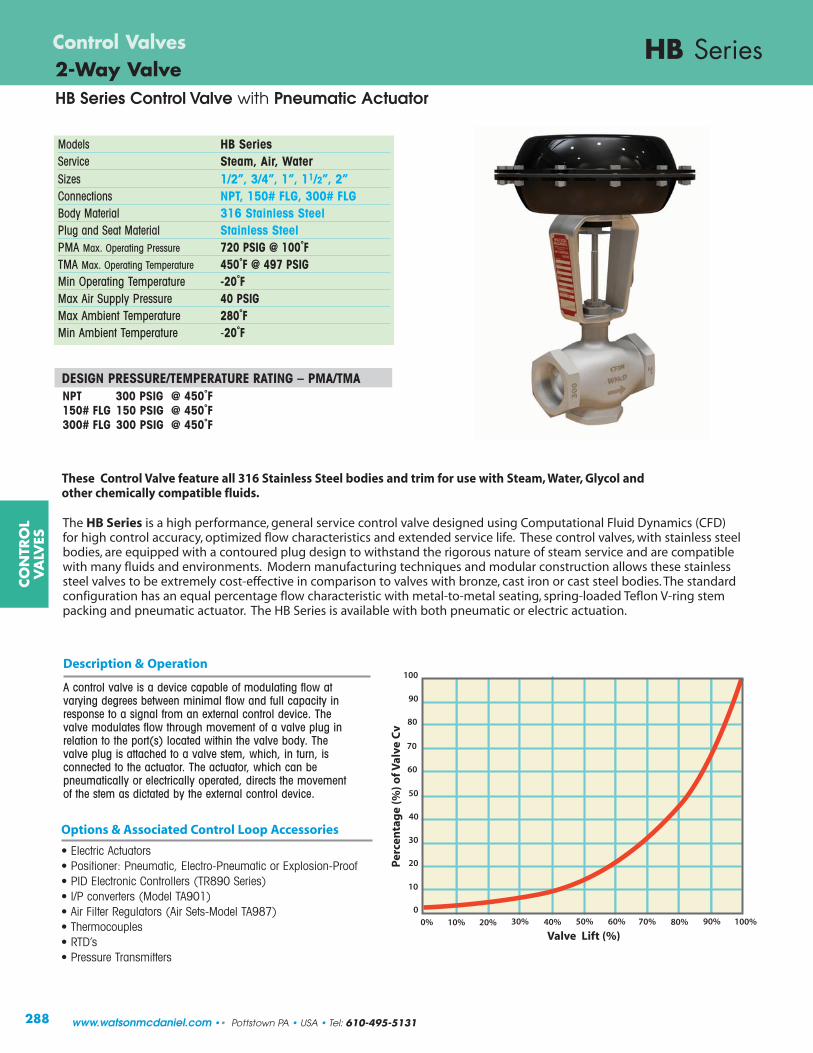
Models HB SeriesService Steam, Air, Water Sizes 1/2”, 3/4”, 1”, 11/2”, 2”Connections NPT, 150# FLG, 300# FLG Body Material 316 Stainless SteelPlug and Seat Material Stainless SteelPMA Max. Operating Pressure 720 PSIG @ 100˚FTMA Max. Operating Temperature 450˚F @ 497 PSIGMin Operating Temperature -20˚FMax Air Supply Pressure 40 PSIGMax Ambient Temperature 280˚FMin Ambient Temperature -20˚F
DESIGN PRESSURE/TEMPERATURE RATING – PMA/TMANPT 300 PSIG @ 450˚F150# FLG 150 PSIG @ 450˚F300# FLG 300 PSIG @ 450˚F
CO
NTR
OL
VA
LVES
HB SeriesControl Valves2-Way Valve
The HB Series is a high performance, general service control valve designed using Computational Fluid Dynamics (CFD)for high control accuracy, optimized flow characteristics and extended service life. These control valves, with stainless steelbodies, are equipped with a contoured plug design to withstand the rigorous nature of steam service and are compatiblewith many fluids and environments. Modern manufacturing techniques and modular construction allows these stainlesssteel valves to be extremely cost-effective in comparison to valves with bronze, cast iron or cast steel bodies. The standardconfiguration has an equal percentage flow characteristic with metal-to-metal seating, spring-loaded Teflon V-ring stempacking and pneumatic actuator. The HB Series is available with both pneumatic or electric actuation.
These Control Valve feature all 316 Stainless Steel bodies and trim for use with Steam, Water, Glycol and other chemically compatible fluids.
288
Description & Operation
A control valve is a device capable of modulating flow atvarying degrees between minimal flow and full capacity inresponse to a signal from an external control device. Thevalve modulates flow through movement of a valve plug inrelation to the port(s) located within the valve body. Thevalve plug is attached to a valve stem, which, in turn, isconnected to the actuator. The actuator, which can be pneumatically or electrically operated, directs the movementof the stem as dictated by the external control device.
Options & Associated Control Loop Accessories
• Electric Actuators • Positioner: Pneumatic, Electro-Pneumatic or Explosion-Proof • PID Electronic Controllers (TR890 Series)• I/P converters (Model TA901)• Air Filter Regulators (Air Sets-Model TA987)• Thermocouples• RTD’s• Pressure Transmitters
0% 10% 20% 30% 40% 50% 60% 70% 80% 90% 100%
Valve Lift
90
80
70
60
50
40
30
20
10
0
100
Per
cen
tag
e (%
) of V
alve
Cv
%
www.watsonmcdaniel.com •• Pottstown PA • USA • Tel: 610-495-5131
Valve Lift (%)
HB Series Control Valve with Pneumatic Actuator

CO
NTR
OL
VA
LVES
HB Series2-Way ValveControl Valves
MATERIALS • Valve Body1 Stem & Plug Assembly* Stem: 316 SS, Plug: 303 SS2 Lower Seal Bushing 303 Stainless Steel3 Gland Nut 303 Stainless Steel4 Stem Seal Spring* 302 Stainless Steel5 Guide Bushing* Rulon 6416 Washer 303 Stainless Steel7 V-ring Stem Seals* PTFE8 Body 316 Stainless Steel10 Body Plug 316 Stainless Steel11 Body Gasket* 303 Stainless Steel13 Packing O-Ring PTFE
* Available as part of a spares kit.
MATERIALS • Pneumatic Actuator14 Yoke Stainless steel15 Lower actuator stem Stainless steel16 Upper diaphragm case Epoxy painted steel17 Diaphragm plate Nickel plated steel18 Diaphragm* Nylon reinforced Neoprene19 Lower diaphragm case Epoxy painted steel20 Upper guide bush SS/Bronze Impregnated21 Upper actuator stem Stainless steel22 Nameplate Stainless steel23 Hex nut Stainless steel24 Stem O-ring* Viton25 Yoke O-ring* Viton26 Upper guide O-ring* Viton27 Ring nut* Stainless steel28 Diaphragm washer Stainless steel29 Springs† Stainless steel30 Position indicator disc Stainless steel33/34 Hex bolt & nut Grade 5 steel zinc plated
† Air-To-Open Actuator: 6 Actuator Springs† Air-To-Close Actuator: 3 Actuator Springs
289
150# FLG or 300# FLGAvailable
Technical InformationPlug Design ContouredFlow Characteristics Equal PercentageLeakage Rating ANSI/FCI 70-2 Class IVRangeability 50:1Travel 3/4”Actuator Area 47 sq. in.Body Design Rating Class 300Primary Stem Seals PTFE Live-Loaded V-RingDiaphragm Design Semi-RollingDesign Multi-Spring DiaphragmAction (field-reversible) Air-to-Open
Air-to-ClosePositioner Mounting IEC 60534-6-1 (NAMUR)Stem Wiper O-Ring
Diaphragm Area = 47 in2
Tel: 610-495-5131 • Pottstown PA • USA •• www.watsonmcdaniel.com
HB Series Control Valve with Pneumatic Actuator

12.2”
B
10”
HB SeriesControl Valves2-Way Valve
Model Code Configuration Chart
Models Code Size Code Connection Type Actuator
HB Full Port 12 1/2” N NPT ATC Air-to-CloseHBR Reduced Port 13 3/4” F150 150# FLG ATO Air-to-Open
14 1” F300 300# FLG 16 11/2”17 2”
290
Air-to-Open(Normally Closed)
Air-to-Close(Normally Open)
ActuatorHeight9.25”
A
2.95”
HB Control Valve SelectionAir-To-CLOSE (Normally OPEN)
Model Size Cv Close-Off Pressure FLG FLG ApproximateHB Connection Full Reduced (PSI�P) NPT #150 #300 Weight
(NPT) Port Port No Positioner / Positioner A B B BHB-12-N-ATC 1/2" 5.0 3.5 300 300 1.76 4.5 7.25 7.75 22 lbs [10 kg]HB-13-N-ATC 3/4" 6.5 3.5 300 300 1.76 4.5 7.25 7.75 22 lbs [10 kg]HB-14-N-ATC 1" 10 7 300 300 1.74 4.5 7.25 7.75 24 lbs [11 kg]
HB-16-N-ATC 11/2" 22 17.5 230 300 2.15 5.0 8.75 9.25 26 lbs [12 kg]HB-17-N-ATC 2" 42 32 120 300 2.31 6.0 10 10.5 29 lbs [13 kg]
Air-To-OPEN (Normally CLOSED)
HB-12-N-ATO 1/2" 5.0 3.5 300 300 1.76 4.5 7.25 7.75 22 lbs [10 kg]HB-13-N-ATO 3/4" 6.5 3.5 300 300 1.76 4.5 7.25 7.75 22 lbs [10 kg]HB-14-N-ATO 1" 10 7 300 300 1.74 4.5 7.25 7.75 24 lbs [11 kg]HB-16-N-ATO 11/2" 22 17.5 170 225 2.15 5.0 8.75 9.25 26 lbs [12 kg]
HB-17-N-ATO 2" 42 32 85 135 2.31 6.0 10 10.5 29 lbs [13 kg]
Diaphragm Area = 47 in2
Actuator weight = 16.5 lbs
CO
NTR
OL
VA
LVES
www.watsonmcdaniel.com •• Pottstown PA • USA • Tel: 610-495-5131
Air Signal Inlet
Air Signal
Air Signal
Air Signal (Inlet not shown)
HB Series Control Valve with Pneumatic Actuator

Type 2000 Valve Positioner(Pneumatic or Electro-Pneumatic)
HB Series2-Way ValveControl Valves
291
Type-2000 Pneumatic Electro-Pneumatic Input Signal 3-15 PSI 4-20 mASupply Pressure 145 PSI maximum 21.8 - 145 PSILinearity Error 0.7 % full span <1.0% of full spanHysteresis 0.4 % full span <0.6% of full spanRepeatability 0.3 % full span <0.5% of full spanPressure Gain 750 P-out/P-in 750 P-out/P-inFlow Capacity SCFM SCFM
@20 PSI 9.5 9.5@87 PSI 28.3 28.3@145 PSI 47.1 47.1
Air Consumption SCFM SCFM@20 PSI 0.18 0.2@87 PSI 0.53 0.6@145 PSI 0.88 1.0
Impedance 260 Ohms at 70˚ FLoop Load 5.2 Volts at 70˚ FPort Size 1/4” NPT; 1/2” NPT
Gauge Ports 1/8” NPTTemperature Range -40˚ F – 185˚ FMedia Oil-free Instrument Air Filtered to 40 micronEnclosure NEMA 4X
Valve Positioner Model Code Configuration
Model Postioner Type Indicator Code
CA2000L1C3 Pneumatic None (Standard Linear) NCA2010L1C3 Electro-Pneumatic Dome (Option) DCA2020L1C3 Explosion-Proof
Type 2000 Valve Positioner(Pneumatic or Electro-Pneumatic)Type 2000 Valve Positioners (Pneumatic and Electro-Pneumatic) are mechanicaldevices designed to provide enhanced control, stability, and shut-off capability inextreme flow applications. The positioner, which is mounted to the valve’s yoke assembly and linked to the valve stem, receives a signal from an external control source, compares the control signal to the actual position of the valve plug, and then sends a corrected signal to the valve’s actuator, thereby positioning the valve plug for optimum flow modulation.
Example Model : CA2000L1C3N
CO
NTR
OL
VA
LVES
Tel: 610-495-5131 • Pottstown PA • USA •• www.watsonmcdaniel.com
HB Series Control Valve with Pneumatic Actuator

HB SeriesControl Valves2-Way ValveHB Series Control Valve with Electric Actuator
CO
NTR
OL
VA
LVES
292 www.watsonmcdaniel.com •• Pottstown PA • USA • Tel: 610-495-5131
Power Supply 115VAC 24VAC 24VDC
Nominal Current (A) 0.66 3.15 2
Max Current (A) 0.86 4.1 2.6
Max Power Consumption (W) 57 53 48
Force 1,100 lbs
Stem Velocity 0.088 - 0.177 in/sec
Nominal 3/4" Travel Time 6 - 8 sec
Duty Cycle, IEC 60034-1,8 S2 30min S4 50% ED @ 77°F
Ambient Temperature -4 to 140°F
Shut-off Pressure 300 psig(1/2” to 2” HB)
Actuator Weight 17.6 lbs
WMEA Electric Actuator Specifications
Features and Benefits
• Fast Response: These actuators are respond extremely fast and will fully open or close the HB Control Valve in approximately 6 seconds making them ideal for instantaneous and semi-instantaneous water heaters. Typical signal response time is 2-3 seconds.
• Fail-Safe Mode: Super capacitors are used to drive the valve fully-closed or open in the event of power loss to the actuator. This replaces common back-ups such as springs with limited thrust or batteries with a limited life span.
• High Stem Thrust: Allows close-off of all HB valves sizes againstthe full rating of 300 psig.
• Integral Positioner: Accepts 4/0-20mA or 2/0-10 VDC controlsignals, eliminating the need for a separate I/P transducer.
• Field-Configurable: Using a PC, the actuator can be field-configuredfor minimum closing position, maximum opening position, fail-open,fail-close or stay-put failure mode in the event of power loss.
Options & Associated Control Loop Accessories
• USB Kit for parameter customization• PID Electronic Controllers (TR890 Series)• Thermocouples• RTD’s• Pressure Transmitters
The HB Series Control Valve with Electric Actuator is a robust,user-friendly alternative to the standard pneumatic actuator onthe HB Series Control Valve. With fast and precise movement, thisactuator is designed to handle a broad range of applicationsincluding instantaneous and semi-instantaneous water heaters.Ideal for installations where pneumatic lines are not present orare prohibitive.
HB Series Control Valve
(with Electric Actuator)
Model Code Configuration Chart
Models Code Size Code Connection Type Actuator Power
HB Full Port 12 1/2” N NPT EFC Fail-Closed 24V 24VAC/DCHBR Reduced Port 13 3/4” F150 150# FLG EFO Fail-Open 115V 115VAC
14 1” F300 300# FLG 16 11/2”17 2”
Additional Technical InformationMotor Protection Electric motor current monitoring with
safety cut-offSet Value Feedback 4/0-20mA or 2/0-10 VDC selectable,
split range operationValve Positioner Function Integrated positioner, deadband adjustable
from 0.5 to 5%, shutoff minAutomatic Start-up Recognizing the end position(s) and
auto-scaling set and feedback valuesInternal Fault Monitoring Torque, set value, temperature, power supply,
positioning deviation, etcDiagnostic Function Stores accumulated operation data (motor &
total run time, number of starts) and data sets of current values (set value, feedback value, torque, temp, and error messages
Communication Interface USB interface with Software - enables parameter adjustments
Cable Glands 2x M20x1.5 & 1x M16x1.5
22.43”
2.95”
B
A
6.97”
(For valve dimensions referto HB Selection Chart )

9.3 [236]
Air Inlet1/8” NPT
Units: inches [mm]Weight: 9.6 lbs
[4.32 kg]
9.8 [249]
W910TB3-Way ValveControl Valves
CO
NTR
OL
VA
LVES
Actuator Housing Die cast aluminum, epoxy powdercoated blue finish.
Setting Scale Integral to housing
Adjustment Screw BrassSpring Cadmium plated
Pressure Plate Aluminum
Diaphragm Nylon reinforced EPDM
Air Pressure to 30 PSIG maximumDiaphragm
Air Connection 1/8 “ NPT Female
Operating Ambient:-40°F (-40°C) to 180°F (82°C)Temperature Process Flow:-40°F (-40°C) to 410°F (210°C)
W910TB Actuator Specifications
Models W910TBService Water, Other LiquidsSizes 1/2”, 3/4”, 1”, 11/4”, 11/2”, 2”,
21/2”, 3”, 4”Connections Union Ends, 125# Flanged
250# Flanged (optional)Body Material 1/2” – 2” Bronze
21/2” – 4” Cast Iron Seat Material Stainless SteelMax Inlet Pressure 250 PSIG
DESIGN PRESSURE/TEMPERATURE RATING – PMA/TMAUnion Ends 250 PSIG @ 450˚F125# FLG 125 PSIG @ 450˚F
for MIXING & DIVERTING • Water & Other Liquids
293
Typical Applications
W910TB 3-way Pneumatically-Actuated control valve can be used for mixing or diverting and are actuated by a 3-15 PSIG instrument airsignal placed to the top of the actuator housing that will modulate theposition of the valve.
3-way valves are used for mixing two flows together, or for diverting aflow to or around a device (bypass). In order to produce a consistent flow quantity for stable operation, the pressure drop across both flowpaths (inlet to outlet) must be nearly equal. The sleeve type design is constructed with an O-ring around the sleeve. The O-ring is suitable for water or glycol type service, up to a maximum of 300˚F. A higher temperature O-ring for use with other fluids, such as oil or for temperatures up to 410˚F, is available. Consult factory.
Principle of Operation
A control valve is comprised of an actuator mounted to a valve.The valve modulates flow through movement of a valve plug inrelation to the port(s) located within the valve body. The valveplug is attached to a valve stem, which, in turn, is connected tothe actuator. The pneumatic actuator directs the movement of thestem as dictated by the external control device.
NOT FOR USE WITH STEAM
3-WAY VALVE • Bronze - NPT
Valve Body is shownto demonstrate action of valve.
lowerport
B
upperport
C
common port
A
Tel: 610-495-5131 • Pottstown PA • USA •• www.watsonmcdaniel.com

Air Signal@ 50%
BC
A
Air Signal@ 0%
BC
A
Air Signal@ 100%
BC
A
Closed
Closed
MIXINGFLOW DIAGRAM
DIVERTINGFLOW DIAGRAM
CAUTION: 3-Way Valves are not designed for use in steam applications.
To properly control the mixing of two flows, inlet pressures at ports B and C should be as equal as possible.
Valve Body SelectionMixing or Diverting
Valve Body Actuator & Size Maximum Close-Off Pressure Dimensions ApproximateNumber Valve Model # (NPT) Cv (PSI�P) E F G Shipping Wt.
A18 W910TB-A18 1/2" 2.8 250 4.8 [122] 1.8 [46] 1.8 [46] 13 lbs [5.9 kg]
A25 W910TB-A25 3/4" 5.6 250 5.6 [142] 2.3 [58] 2.3 [58] 15 lbs [6.8 kg]
A34 W910TB-A34 1" 8.4 250 6.0 [152] 2.3 [58] 2.3 [58] 16 lbs [7.2 kg]
A45 W910TB-A45 11/4" 15 250 7.2 [183] 2.8 [71] 2.6 [66] 19 lbs [8.6 kg]
A56 W910TB-A56 11/2" 21 250 7.7 [196] 3.5 [89] 2.6 [66] 21 lbs [9.5 kg]
A67 W910TB-A67 2" 33 250 8.6 [218] 4.1 [104] 3.1 [79] 26 lbs [11.8 kg]
All dimensions are inches [mm].
SpecificationsBody Material Trim Material Trim Style Connection Pressure & Temperature Rating
Bronze Bronze Modified Linear NPT with Malleable Iron Union Ends 250 PSIG @ 300°F (149°C)
G
F
E
for Mixing or Diverting
3-Way • 1/2” – 2”
CO
NTR
OL
VA
LVES
W910TBControl Valves3-Way Valve Bodies • BRONZEfor MIXING & DIVERTING • Water & Other Liquids
294
Air Signal@ 50%
BC
A
Air Signal@ 0%
BC
A
Air Signal@ 100%
BC
A
Closed
Closed
common port A
upperport
C
lowerport
B
ActuatorMounting Surface
1/2” - 2”NPT/Union
www.watsonmcdaniel.com •• Pottstown PA • USA • Tel: 610-495-5131

3-Way • 21/2” – 4”
SpecificationsBody Material Trim Material Trim Style Connection Pressure & Temperature Rating
Cast Iron Bronze Modified Linear 125# Flanged 125 PSIG @ 300°F (149°C)
G
F
E
LOWERPORT
(B)
COMMON PORT (A)
G
F
E
for Mixing or Diverting
MIXINGFLOW DIAGRAM
DIVERTINGFLOW DIAGRAM
CO
NTR
OL
VA
LVES
W910TB3-Way Valve Bodies - CAST IRONControl Valves
for MIXING & DIVERTING • Water & Other Liquids
295
lowerport
B
upperport
C
Air Signal@ 50%
BC
A
Air Signal@ 0%
BC
A
Air Signal@ 100%
BC
A
Closed
Closed
Air Signal@ 50%
BC
A
Air Signal@ 0%
BC
A
Air Signal@ 100%
BC
A
Closed
Closed
CAUTION: 3-Way Valves are not designed for use in steam applications.
To properly control the mixing of two flows, inlet pressures at ports B and C should be as equal as possible.
common port
A
ActuatorMounting Surface
21/2” - 4”Flanged
Tel: 610-495-5131 • Pottstown PA • USA •• www.watsonmcdaniel.com
Valve Body SelectionMixing or Diverting
Valve Body Actuator & Size Maximum Close-Off Pressure Dimensions ApproximateNumber Valve Model # (FLG) Cv (PSI�P) E F G Shipping Wt.
B75 W910TB-B75 21/2" 58 125 9.0 [229] 7.1 [180] 5.2 [132] 62 lbs [28 kg]
B80 W910TB-B80 3" 72 125 10.0 [254] 8.0 [203] 6.0 [152] 80 lbs [36 kg]
B85 W910TB-B85 4" 102 125 13.0 [330] 10.0 [254] 6.9 [175] 140 lbs [64 kg]
All dimensions are inches [mm].

296
Note: The Steam Capacity Chart is based on ISA Standard 75.01.01-2007 (60534-2-1 Mod). It assumes pipe sizes equal to the size of the valve ports, with no attached fittings.
CO
NTR
OL
VA
LVES
2-Way Valve Body • HB SeriesCapacity Charts
InletPressure(PSIG)
OutletPressure(PSIG)
CAPACITIES – Steam (lbs/hr)
4 1 48 68 89 136 300 573 5 0 5 96 137 178 274 602 1149
-4 9 114 162 211 325 714 1363 -8 13 119 170 220 339 746 1424 9 1 53 76 99 153 336 641 10 5 5 110 156 203 313 689 1315 0 10 138 197 255 393 865 1651
-7 17 148 211 274 422 929 1773 10 5 122 174 226 348 765 1460 15 5 10 156 223 290 447 983 1876 0 15 172 246 320 492 1082 2066
-5 20 177 252 328 505 1110 2119 15 5 133 189 246 379 833 1591 20 10 10 173 247 321 494 1088 2076 5 15 194 277 361 555 1221 2330
-3 23 205 293 381 587 1291 2464 25 5 152 217 282 434 955 1822 30 15 15 232 331 431 663 1459 2785 5 25 260 371 482 742 1631 3115 0 30 262 375 487 750 1649 3149 40 10 250 357 464 714 1570 2997 50 30 20 324 463 601 925 2035 3886 15 35 370 529 687 1057 2326 4440 7 43 376 537 697 1073 2361 4507 70 10 307 438 570 877 1929 3682 80 50 30 472 675 877 1350 2970 5670 30 50 534 763 992 1525 3356 6407 17 63 544 777 1010 1554 3418 6526 85 15 406 580 754 1160 2552 4872 100 60 40 586 837 1089 1675 3684 7034 40 60 643 918 1193 1836 4039 7710 23 77 655 936 1217 1872 4119 7864 110 15 452 645 839 1290 2838 5418 125 85 40 668 954 1240 1908 4199 8015 50 75 782 1117 1452 2233 4913 9380 31 94 794 1135 1475 2270 4993 9532 130 20 560 800 1040 1600 3519 6718 150 100 50 800 1143 1485 2285 5027 9598 70 80 904 1291 1678 2582 5680 10844 40 110 933 1333 1733 2666 5865 11196 150 25 666 952 1237 1903 4187 7994 175 115 60 931 1329 1728 2659 5850 11167 75 100 1052 1503 1953 3005 6612 12622 48 127 1072 1531 1990 3062 6736 12859 175 25 713 1018 1324 2037 4481 8554 200 130 70 1061 1515 1970 3031 6668 12730 90 110 1183 1690 2196 3379 7434 14192 56 144 1210 1729 2247 3457 7606 14521 225 25 798 1140 1482 2281 5017 9578 250 170 80 1273 1819 2364 3637 8002 15276 120 130 1443 2062 2680 4124 9072 17319 73 177 1487 2125 2762 4249 9348 17846 270 30 951 1359 1766 2718 5979 11414 300 200 100 1535 2193 2850 4385 9648 18418 140 160 1723 2461 3199 4922 10828 20672 89 211 1765 2521 3277 5042 11093 21177
Cv Factors
Orifice Size (in)
1/2" 1/2" 3/4" 1" 11/2" 2" 3.5 5.0 6.5 10 22 42
0.88 0.88 0.88 0.88 1.25 1.75
ReducedPort
CAPACITIES – Water (GPM)
5 4 1 3.5 5.0 6.5 10 22 42 0 5 7.8 11 15 22 49 94 7 3 6.1 8.7 11 17 38 73 10 5 5 7.8 11 15 22 49 94 0 10 11 16 21 32 70 133 10 5 7.8 11 15 22 49 94 15 5 10 11 16 21 32 70 133 0 15 14 20 26 39 86 165 25 5 7.8 11 15 22 49 94 30 15 15 14 19 25 39 85 163 7 23 17 24 31 48 106 203 40 10 11 16 21 32 70 133 50 30 20 16 22 29 45 98 188 16 34 20 29 38 58 128 244 70 10 11 16 21 32 70 133 80 50 30 19 27 36 55 120 230 30 50 25 35 46 70 155 296 85 15 14 19 25 39 85 163 100 65 35 21 30 38 59 130 248 40 60 27 39 50 78 171 326 110 15 14 19 25 39 85 163 125 85 40 22 32 41 63 139 266 52 73 30 43 56 86 188 360 130 20 16 22 29 45 98 188 150 100 50 25 35 46 71 156 297 63 87 33 47 60 93 205 391 175 25 18 25 33 50 110 210 200 130 70 29 42 54 84 184 351 87 113 37 53 69 106 234 446 225 25 18 25 33 50 110 210 250 170 80 31 45 58 89 197 376 111 139 41 59 77 118 260 495 270 30 19 27 36 55 120 230 300 200 100 35 50 65 100 220 420 134 166 45 64 84 129 283 540
Cv Factors
Orifice Size (in)
1/2" 1/2" 3/4" 1" 11/2" 2" 3.5 5.0 6.5 10 22 42
0.88 0.88 0.88 0.88 1.25 1.75
ReducedPort
www.watsonmcdaniel.com •• Pottstown PA • USA • Tel: 610-495-5131
ΔPPSI
InletPressure(PSIG)
OutletPressure(PSIG)
ΔPPSI
Note: 1) Capacities based on 70°F water (SG = 1.00).2) Capacities based on 100% of Cv.

297
CO
NTR
OL
VA
LVES
CAPACITIES – Water (GPM) 3-WAY VALVESInlet pressures should be within 5% of each other. Specify if service is for other than water.
Size, Body Number & Coefficient (Cv) 1/2” 3/4” 1” 11/4” 11/2” 2” 21/2” 3” 4”
PressureDrop A18 A25 A34 A45 A56 A67 B75 B80 B85
(PSI�P) Cv = 2.8 Cv = 5.6 Cv = 8.4 Cv = 15 Cv = 21 Cv = 33 Cv = 58 Cv = 72 Cv = 102
1 2.8 5.6 8.4 15 21 33 58 72 1023 4.8 10 15 26 36 57 100 125 1775 6.3 13 19 34 47 74 130 161 22810 8.9 18 27 47 66 104 183 228 32315 11 22 33 58 81 128 225 279 39520 13 25 38 67 94 148 259 322 45625 14 28 42 75 105 165 290 360 51030 15 31 46 82 115 181 318 394 55940 18 35 53 95 133 209 367 455 64550 20 40 59 106 148 233 410 509 72160 22 43 65 116 163 256 449 558 79070 23 47 70 125 176 276 485 602 85380 25 50 75 134 188 295 519 644 91290 27 53 80 142 199 313 550 683 968100 28 56 84 150 210 330 580 720 1020125 31 63 94 168 235 369 648 805 1140150 34 69 103 184 257 404175 37 74 111 198 278 437200 40 79 119 212 297 467225 42 84 126 225 315 495250 44 89 133 237 332 522
Note: Oil service or high temperature service requires special O-ring.
Capacity Chartfor MIXING & DIVERTING • Water & Other Liquids
W910TB • 3-Way Valve Body
W910TB Mixing & Diverting (3-Way Valves)
Tel: 610-495-5131 • Pottstown PA • USA •• www.watsonmcdaniel.com

Stem (Sheath)All Thermocouples and RTDs are furnished with a 316 stainless steel stem, with the internal wiring packed in powderedceramic. The screw head cover style is available in two stem types: welded and spring loaded. The welded stem issuitable for use in liquid applications. The spring-loaded stem is designed to bottom out inside a thermowell, providingmaximum heat sensitivity. Spring-loaded stems are not pressure tight and may allow process media to escape; therefore, they must always be installed in a thermowell.
The insertion length (U) of a thermocouple or RTD represents its depth into the process vessel or thermowell.Thermocouples and RTDs are available in standard U-lengths from 2" to 24". Other lengths are available upon specialorder; consult factory.
298
CO
NTR
OL
VA
LVES
Control LoopIntroduction
Understanding a Control Loop
TR890Series Controller
The user-interface which allows adjustment of the set point and controlsthe electrical signals received from the sensor and outputted to the I/PTransducer. The TR893 is the mostcommon controller model due to itslarger, more user-friendly size.
TA901Electropneumatic (I/P) Transducer
An electro-pneumatic transducer thatconverts an electrical signal (4-20 mA)from the Controller to an air signal (3-15 PSI) for supply to the top of theactuator of the control valve.
TA987 Air Filter/Regulator
This device is recommended for filtering and regulating the pressure of plant compressed air to the inlet ofthe I/P Transducer, which ensures thedelivery of clean, dry air at the properpressure to the pneumatic actuator.
TERMINALBLOCK
SENSOR
CONDUIT CONNECTION
FITTING
STEM
PROCESSCONNECTION
SCREWCOVER
Stem Length
1/2 NPT
Sensor for Temperature Control (Thermocouple or RTD)Electronic Temperature Sensors are available with both Type J and Type K Thermocouples, as well as RTD sensors. A thermocouple (T/C) is made from two dissimilar metals that generate electrical voltage directly with changes in temperature.An RTD (Resistance Temperature Detector) is a variable resistor that will change its electrical resistance in direct proportion to changes in temperature in a precise, repeatable and nearly linear manner. The weatherproof head provides a conduit connection and can be used to house a transmitter (optional). The stem is either welded directly to the 1/2” NPT threadedconnection, or is spring-loaded.
SEAL-WELDED orSPRING-LOADED
Spring-loadedstems mustalways beinstalled in athermowell. 0.25” Dia.
www.watsonmcdaniel.com •• Pottstown PA • USA • Tel: 610-495-5131

Understanding a Control Loop
Control Loop
A control loop is a process management systemdesigned to maintain a process variable at a desiredset point. Each step in the loop works in conjunctionwith the others to manage the system. Once the setpoint has been established, the control loop operatesusing a four-step process.
SenseMeasure the current condition of the process using a sensor, which can be a thermocoupleor RTD transmitter.
CompareEvaluate the measurement of the current condition against the set point using an electronic PID controller.
RespondReacts to any error that may exist between the measuredtemperature value and the temperature set point by generating a corrective pneumatic signal.
AffectActuate the control valve that will produce a change in the process variable.
The loop continually cycles through the steps, affecting theprocess variable (water temperature) in order to maintainthe desired temperature set point.
1
2
3
4
299
Air Signal Line
ColdWater
Inlet
Heat Exchanger(Water Heater)
SteamInlet
Heat Exchanger (Instantaneous Water Heater)
SteamTrap
Control LoopIntroduction
2 Compare
3 Respond
1 Sense
TA901 I/P TransducerConverts 4-20 mA (current) electrical signal to a 3-15 PSI (pressure) air signal
Compares output of temperature sensor to the temperature Set Point and outputs an appropriate 4-20 mA response to the I/P Transducer
TR890 Controller
Temperature Sensor(RTD or Thermocouple)Outputs a varying resistance(RTD) or voltage (T/C) toController Input
Hot WaterOutlet
CO
NTR
OL
VA
LVES
4 AffectControl Valve
TA987Air Filter/Regulator
Air Inlet
HB Series PneumaticControl Valve
ControlledSteamFlow
sensor output signal
4-20 mA
4-20 mA
3-15 PSIAir
3-15 PSIAir
Tel: 610-495-5131 • Pottstown PA • USA •• www.watsonmcdaniel.com

Description
A controller is a comparative device that receives an input signal from a measured processvariable, compares this value with that of a predetermined control point value (set point),and determines the appropriate amount of output signal required by the final control element to provide corrective action within a control loop.
Principle of Operation (Electronic PID Controller)
An electronic sensor (thermocouple, RTD or transmitter) installed at the measurement location continuously sendsan input signal to the controller. At set intervals, the controller compares this signal to a predefined set point. If the input signal deviates from the set point, the controller sends a corrective electric output signal to the controlelement. This electric signal must be converted to a pneumatic signal when used with an air operated valve, suchas a Watson McDaniel HB Series Control Valve. The conversion can be made using a Watson McDaniel TA901 I/P Transducer, which converts a 4 to 20 mA electric signal to a 3 to 15 PSI air signal. As an option, a ValvePositioner such as the Watson McDaniel CA2000 may be used to send an air signal to the Control Valve. ThesePositioners can be controlled with a 3-15 psi air signal from a Pneumatic Controller or a 4-20 mA signal from a PID Controller.
Features (Electronic PID Controller)
Watson McDaniel Electronic Controllers have full auto-tuning and PID capabilities, and offer a host of available options, including user selectable inputs, outputs and ranges.
PID Control is a feature of Watson McDaniel TR890 Electronic Controllers. PID combines the proportional, integral and derivative functions into a single unit.
• Proportional (P) — Proportional control reacts to the size of the deviation from set point when sending a corrective signal. The size of the corrective signal can be adjusted in relation to the size of the error by changing the width of the proportional band. A narrow proportional band will cause alarge corrective action in relation to a given amount of error, while a wider proportional band will a cause smaller corrective action in relation to the same amount of error.
• Integral (I) — Integral control reacts to the length of time that the deviation from set point exists when sending a corrective signal. The longer the error exists, the greater the corrective signal.
• Derivative (D) — Derivative control reacts to the speed in which the deviation is changing. The corrective signal will be proportional to the rate of change within the process.
Auto-Tuning will automatically select the optimum values for P, I and D, thus eliminating the need for the user tocalculate and program these values at system startup. This feature can be overridden when so desired. On somemodels, the control element can be manually operated.
CO
NTR
OL
VA
LVES
ControllersIntroduction
300
Design and Operation of an Electronic PID Controller
www.watsonmcdaniel.com •• Pottstown PA • USA • Tel: 610-495-5131

Selecting an Electronic PID Controller
When selecting a PID controller, the following parameters must be specified. (Refer to the TR890 SeriesElectronic PID Controller Specifications and Model Coding chart on the following two pages.)
1) Model (Case Size)
The Case Size selection is determined by both available and designed space, and controller features.Watson McDaniel Electronic Controllers are available in the following panel sizes:
TR891: 48 x 48 mm (1/16 DIN) TR893: 96 x 96 mm (1/4 DIN)TR892: 72 x 72 mm TR894: 96 (H) x 48 (W) mm (1/8 DIN)
2) Input
The Input is the measurement signal received by the controller from the sensor. One of the following three input typescan be specified for the controller: 8: Universal, 4: Current or 6: Voltage. The Universal input type is switchablebetween Thermocouple, RTD and mV input signals. If temperature will be measured with a thermocouple or RTD sensor, the Universal input type must be selected for thecontroller (Model Code Position 2 = 8). If another process variable such as PRESSURE is being measured, verify thetype of output signal from that sensor. If it’s 4-20 mA or 0-10 Volts then the Current or Voltage input option would bechosen, respectively.
3) Control Output
The Control Output is the corrective signal transmitted from the controller to the control device. One of the following four control output types can be specified for the controller: I: 4-20 mA DC, Y: On/Off Contact, P: Solid State Relay (SSR) Driver or V: 0-10 VDC. The most common control devices are the TA901 Electro-pneumatic (I/P) Transducer and CA2000-Series ValvePositioner with built-in I/P transducer, both of which accept a 4-20 mA signal. For these devices, the 4-20 mA control output type must be selected for the controller (Model Code Position 3 = I). The TA901 or CA2000-Series output an air signal to the actuator of the Control Valve, which is the final control element of the feedback loop. The On/Off Contact and SSR Driver control output types are typically used to switch on AC power to a load. If the SSR Driver control output is selected, an external solid state relay (SSR) is required and can be used for activating electrical equipment with larger current requirements.
4) Power Supply
The power supply requirement for the electronic controller must be specified. The available choices are: 100-240 VAC, 50/60 Hz or 24 V AC/DC, 50/60Hz.
5) Event Output (Option)
The Event Output is used to signal an external device when an alarm condition is detected. Various alarm types canbe detected by the controller. These include deviation of the measured value from the set value, the measured valueexceeding absolute limits (i.e., high and low level alarm) and heater break/loop alarm (i.e., heater current outside ofnormal limits). If selected as an option, the controller will have two Event Outputs. In the case of a high/low alarm,one output is used for the high level alarm and the other for the low level alarm.
6) Options: Analog Output & Digital Input
The Analog Output is an optional secondary signal that transmits either the measured process value (PV), the targetset value (SV) or the Control Output value from the controller to a remote data acquisition device, such as a recorder,personal computer or display unit. One of the following three analog output types can be specified for the controller:0-10 mV DC, 4-20 mA DC or 0-10 V DC. The analog output type is independent of the measured input type or thecontrol output type. However, the analog output type selection must be compatible with the data acquisition deviceinput.
The Digital Input is an optional input that can be specified for the controller. The digital input functions as an On/Offswitch and can be programmed to activate the Set Value Bias or Standby mode, or switch the Control Action type(i.e., to Reverse Acting or Direct Acting).
Note: The Analog Output and Digital Input combination is not available for Model TR891. Only one of these options can be selected for this model.
CO
NTR
OL
VA
LVES
ControllersIntroduction
301
Design and Operation of an Electronic PID Controller
Tel: 610-495-5131 • Pottstown PA • USA •• www.watsonmcdaniel.com

Features PID & Auto-tuning
Use of a Watson McDaniel No. TA987 Air Filter/Regulator is recommended for filtering and regulating the pressure ofplant compressed air, and fordelivering clean, dry air at the proper pressure to pneumatic control devices.
S p e c i f i c a t i o n s
Multiple Sizes
+ 0.3% Accuracy
Keyboard Programmable
Reverse or Direct Acting
Manual Output Override
Models TR891: 48 x 48 mm (1/16 DIN)TR892: 72 x 72 mmTR893: 96 x 96 mm (1/4 DIN)TR894: 96 x 48 mm (1/8 DIN)
Control Control Mode: Auto-Tuning PIDAction: Reverse acting (field switchable to direct acting)
Proportional Off, 0.1-999.9% Full ScaleBand Integral Time: Off, 1-6000 sec.
Derivative Time: Off, 1-3600 sec.
Accuracy + 0.3%
Display Process Value: 4 Digit, 20 mm red LEDSet Value: 4 digit, 10.2 mm green LEDSampling Cycle: 0.25 seconds
Inputs Universal: (switchable between)Thermocouple: B, R, S, K, E, J, T, N, PL II, WRe5-26 (U,L (DIN 43710)RTD: Platinum 100 Ω, 3-Wire mV: (scalable) -10–10, 0-10, 0-20, 0-50, 10-50, 0-100 mV DC
Current: (scalable) 4-20, 0-20 mAVoltage: -1–1, 0-1, 0-2, 0-5, 1-5, 0-10 VDC
Current: 4-20 mA (load resistance: 600 Ω maximum)Contact: Proportional cycle, 1-120 sec. (capacity: 240 VAC 2 A resistive / 1.2 A inductive)
SSR Drive Voltage: Proportional cycle 1-120 sec.(output rating: 12 ± 1.5 VDC / 30 mA maximum)
Voltage: 0-10 VDCLoad Current 2 mA max
Power Supply Voltage: 100-240 VAC, 50/60 Hz or 24 VAC/VDC 50/60 Hz Requirements
Data Storage Nonvolatile EEPROM memory
Case Material Polyphenylene Oxide (PPO)
Ambient Temp. 14°F (-10°C) to 122°F (50°C)
Humidity Maximum: 90% RH, non-condensing
The TR890 Series ElectronicPID Controller is designed foruse on applications wherelarge load changes are expected, or extreme accuracyand fast response times areneeded. With full auto-tunecapabilities and a large selection of available inputs,the TR890 Series is ideally suited for use with a WatsonMcDaniel Control Valve.
Event Outputs(Contact Capacity: 240 VAC, 1 A/resistive load)
Dual Event Outputs (High and/or Low Alarms)Single Event Output + Heater Break Alarm (includes CT30A sensor)Single Event Output + Heater Break Alarm (includes CT50A sensor)
Options:Analog Output: 0-10 mV DC (output resistance 10 Ω )Analog Output: 4-20 mA DC (load resistance 300 Ω max )Analog Output: 0-10 VDC (load current 2 mA max )
Digital Input (switch) including:Set Value Bias setting range of -1999 - 5000, standby or DA/RA SelectionOperated by either non-voltage contact or open collector input rated at approx. 5V DC/1mA max.
Consumption: 100-240 VAC, 15VA 24 VDC, 8W24 VAC, 9VA
Approximate Shipping Weights:TR891: 0.4 lbs [0.17 kg]TR892: 0.6 lbs [0.28 kg]TR893: 0.7 lbs [0.33 kg]TR894: 0.5 lbs [0.24 kg]
Control Output
CO
NTR
OL
VA
LVES
TR890 SeriesControl ValvesElectronic PID Controllers
302 www.watsonmcdaniel.com •• Pottstown PA • USA • Tel: 610-495-5131

Model Input Control Output Power Supply Event Output Options
TR891 8 Universal I 4-20 mA 90 100-240 VAC, 50/60 Hz 0 None 00 NoneTR892 4 mA Y On/Off Contact 08 24 VAC/VDC, 50/60 Hz 1 Dual Event 30 Analog Output (0-10 mVDC)TR893 6 VDC P SSR Driver (high and/or low) 40 Analog Output (4-20 mA)TR894 V 0-10 VDC 2 Single Event 60 Analog Output (0-10 VDC)
(high or low) and 08 Digital Input (switch)heater break CT30A 38 Digital Input (switch) with
3 Single Event 0-10 mVDC* Analog Output(high or low) and 48 Digital Input (switch) heater break CT50A with 4-20 mA* Analog Output
68 Digital Input (switch) with 0-10 VDC* Analog Output
HOW TO ORDER (Model Coding) Sample Order Number: TR893 8 I 90 1 00
Event Outputs2 or 3 requireControl OutputsY or P
*Not available with Model TR891
W
H
DC
A
B
PANEL CUTOUT DIMENSIONS
Model A B C D H WTR891 1.77 [45] 1.77 [45] 0.43 [11] 3.94 [100] 1.89 [48] 1.89 [48]TR892 2.68 [68] 2.68 [68] 0.43 [11] 3.94 [100] 2.83 [72] 2.83 [72]TR893 3.63 [92] 3.63 [92] 0.43 [11] 3.94 [100] 3.78 [96] 3.78 [96]TR894 1.77 [45] 3.63 [92] 0.43 [11] 3.94 [100] 3.78 [96] 1.89 [48]
Programmable RangesThermocouple Inputs RTD Inputs Current & Voltage InputsT/C Range Fahrenheit Range Celsius Range Fahrenheit Range Celsius Range RangeType Code Range Code Range Code Range Code Range Code (User-scalable Readout)
B* 15 0° to 3300°F 01 0° to 1800°C 47 -300° to 1100°F 31 -200° to 600°C 71 -10–10 mV
E 21 0° to 1300°F 07 0° to 700°C 48 -150.0° to 200.0°F 32 -100.0° to 100.0°C 72 0-10 mV
J 22 0° to 1100°F 08 0° to 600°C 49 -150° to 600°F 33 -100.0° to 300.0°C 73 0-20 mV
K 18 -150° to 750°F 04 -100.0° to 400.0°C 50 -50.0° to 120.0°F 34 -50.0° to 50.0°C 74 0-50 mV
K 19 0° to 1500°F 05 0° to 800°C 51 0.0° to 120.0°F 35 0.0° to 50.0°C 75 10-50 mV
K 20 0° to 2200°F 06 0° to 1200°C 52 0.0° to 200.0°F 36 0.0° to 100.0°C 76 0-100 mV
L 28 0° to 1100°F 14 0° to 600°C 53 0.0° to 400.0°F 37 0.0° to 200.0°C 81 -1–1 V
N 24 0° to 2300°F 10 0° to 1300°C 54 0° to 1000°F 38 0.0° to 500.0°C 82 0-1 V
PL II 25 0° to 2300°F 11 0° to 1300°C 83 0-2 V
R 16 0° to 3100°F 02 0° to 1700°C 84 0-5 V
S 17 0° to 3100°F 03 0° to 1700°C 85 1-5 V
T 23 -300° to 400°F 09 -199.9° to 200.0°C 86 0-10 V
U 24 -300° to 400°F 13 -199.9° to 200°C 94 0-20 mA
WRe5-26 26 0° to 4200°F 12 0° to 2300°C 95 4-20 mA
Range Codes are not required for ordering, but are used for field programming.*750°F (400°C) falls below the accuracy range
Electronic PID Controller Dimensions – units: inches [mm]
CO
NTR
OL
VA
LVES
TR890 SeriesElectronic PID ControllersControl Valves
Features PID & Auto-tuning
303
1 2 3 4 5 6
Tel: 610-495-5131 • Pottstown PA • USA •• www.watsonmcdaniel.com

Electropneumatic
TA901Control ValvesI/P Transducer
Specifications
The TA901 I/P Transducer is tested and approved by Factory Mutual asIntrinsically Safe Class I, II and III, Division I, Groups C, D, E, F and G wheninstalled in accordance with the Installation, Operation and MaintenanceInstructions. It should be installed in a vertical position in a vibration-free area.
The Watson McDaniel TA987 Air Filter/Regulator is recommended for filteringand regulating the pressure of plant compressed air, and for delivering clean, dry air at the proper pressure to pneumatic control devices.
The TA901 Electropneumatic (I/P) Transducer converts a milliampcurrent signal to a linearly proportional pneumatic output pressure. Thistransducer is designed for control applications that require a high degreeof reliability and repeatability. The TA901 is used in the control operationof valve actuators and pneumatic valve positioners in the petrochemical,HVAC, energy management, textile, paper, and food & drug industries.
ModelTA901
Input4-20 mA
Output1-17 PSIG Per ANSI/FCI 87-2(can be calibrated to provide 1-9 PSIG or 9-17 PSIG)
Volume Booster Built-in volume booster allows flow capacity up to 20 SCFM
ConnectionsPneumatic: 1/4” NPT
Electric: 1/2” NPT
Air RequirementsClean, oil-free, dry air filtered to 40 microns
Minimum Supply Pressure: 3 PSIG
Maximum Supply Pressure:100 PSIG
Sensitivity: < ±0.1% of spanper PSIG
Air Consumption: 0.03 SCFHtypical
Flow Rate: 4.5 SCFM at25 PSIG supply
Relief Capacity: 2.0 SCFM at5 PSIG above 20 PSIG setpoint
MountingPipe, panel or bracket in avibration-free area. Field adjustment will be required ifmounted in a nonvertical position.
AdjustmentAdjustable zero and span
AccuracyTerminal Based Linearity:< ±0.75% of span
Repeatability: < 0.5% of span
Hysteresis: < 1.0% of span
Response Time: < 0.25 sec. @3-15 PSIG
Intrinsic SafetyTested and approved byFactory Mutual as IntrinsicallySafe Class I, II and III, DivisionI, Groups C, D, E, F and Gwhen installed in accordancewith Installation, Operation andMaintenance Instructions
Ambient Temperature-20°F (-30°C) to 140°F (60°C)
Approximate ShippingWeight2.1 lbs [0.94 kg]
10-32 UNF-2A X .38 DEEPMOUNTING HOLES
18 GA. WIRE LEADS18" LONG
BLACK-POSITIVE / WHITE-NEGATIVE
MOUNTING BRACKET
1/4 NPT
1.10[27.9]
1.09[27.7]
2.18 [55.4]MAX. SQUARE
4.24[107.7]
1/2NPT
1.50[38.1]
1.50[38.1]
Ø1.13[28.7]
.55 [14.0]
.55[14.0]
.55 [14.0]
2.88[73.1]
Ø.21 [5.4]
1.25 [31.8]
1.43[36.2]
Unit: inches [mm].
How to Order
Order using Item Number: TA901
4 to 20 mAInput
3 to 15 PSI Output
Intrinsically Safe
Zero and SpanAdjustments
CO
NTR
OL
VA
LVES
304 www.watsonmcdaniel.com •• Pottstown PA • USA • Tel: 610-495-5131

The maximum allowable supply pressure to TA987 Air Filter/Regulatoris 250 PSIG. Improper application may cause failure of the regulator,resulting in possible personal injury or property damage.
TA987Air Filter/RegulatorControl Valves
Specifications
Model TA987
Air RequirementsMaximum Supply Pressure:250 PSIG
Output Range:0 to 30 PSIG, adjustable
Sensitivity: 0.036 PSIG
Air Consumption: < 6 SCFH
Air Requirements (con’t.)Flow Rate: 20 SCFM at 100PSIG supply/20 PSIG output
Relief Capacity: 0.1 SCFM at5 PSIG above setpoint
Effect of Supply PressureVariation: < 0.2 PSIG for 25 PSIG
FilterRemoves particles 40 micronsor greater
Port Size1/4” NPT
HousingCast aluminum
MountingSide, pipe, panel or through body
Ambient Temperature-20°F (-30°C) to 160°F (71°C)
Approximate ShippingWeight1.9 lbs [0.86 kg]
Cast Aluminum Housing
Removable Nylon Mesh Filter
Low Air Consumption
Drip Well
GAUGEPORT
.05 [1.2]TO CLOF
GAUGEPORT
VENT
1.44[36.6]
2.06[52.3]
2.14[54.4]
.75[19.1]
OUT
1.25[31.8]
2.25[57.2]
Ø.36 [9.1]THRU 2 HOLES
1/4-20 UNC.44 [11.1] DEEP
2 HOLES
7.25[184.2]
10-24 UNC2 HOLES
2.10[53.3]
2.75[69.9]
3.19[81.0]
Ø.44[11.2]
.31 [7.9] SQUARE
Units: inches [mm].
The TA987 Air Filter/Regulator is recommended for filtering and regulating the pressure of plant compressed air, and for deliveringclean, dry air at the proper pressure to pneumatic control devices. Supply airenters the inlet port, passes through the filtering element, and exits throughthe reducing valve to the outlet port. The filtering element removes particlesas small as 40 microns. A drip well is provided for the accumulation of oil and water and a drain cock is included to allow purging of the unit. The filtering element is readily accessible for cleaning by removal ofthe drip well bowl.
3.19[81.0]
CO
NTR
OL
VA
LVES
305
How to Order
Order using Item Number: TA987
Tel: 610-495-5131 • Pottstown PA • USA •• www.watsonmcdaniel.com

1/2 NPT
STEMLENGTH
3.40[86.2]
3.91[99.4]
Ø3.30[83.8]
Ø.25[6.4]
Thermocoupleor RTD
Cast AluminumPolypropyleneor Stainless Steel Head
Weather-Proof
Welded orSpring LoadedStem
The Watson McDanielConnection Head is available with both Type J and Type K Thermocouples, as well as RTD sensors. Theweatherproof head provides a conduit connection and is available in cast aluminum (screw cover), polypropylene (flip cover) and stainless steel(screw cover). The stem is eitherwelded directly to the 1/2” NPTthreaded connection, or is spring-loaded to provide maximum sensitivity. The spring-loaded stem must alwaysbe installed in a thermowell.
S p e c i f i c a t i o n s
Sensors Description
TJD Type J (Thermocouple)
TKD Type K (Thermocouple)
TDD 100 Ω RTDTMD 1000 Ω RTD
Hot JunctionT/C: UngroundedRTD: Platinum, 3-Wire
Stem 316 stainless steel1/4" diameter
Insulation Ceramic
Head Cast aluminum, polypropylene orstainless steel
Process Connection1/2” NPT welded or spring-loaded
Conduit Connection3/4” NPT Female
Approximate Shipping Weight1.1 lbs [0.50 kg]
Extension wire and transmitteraccessories are also available.Please consult factory.
For applications wherethe process media maybe corrosive or containedunder pressure, the use ofa thermowell is required toprevent damage to the sensorand facilitate its removal fromthe process. To prevent leakageof the process media, springloaded sensors must alwaysbe installed in a thermowell.
How to Order Temperature Sensors Example Model Code: TJD Z 04 U W A
Sensor Type Stem Style Stem Length Hot Junction Connection Head Material
TJD Type J (T/C) Z 316SS, 1/4” O.D. 02 21/2" Stem U Ungrounded (T/C) S Spring Loaded, A AluminumTKD Type K (T/C) 04 4" Stem D 3-Wire (RTD) 1/2” NPT P PolypropyleneTDD 100 Ω RTD 06 6" Stem W Welded, S Stainless SteelTMD1000 Ω RTD 09 9" Stem 1/2” NPT
12 12" Stem
Other sensor styles available. Other Lengths: Specify in inches (24" maximum)T/C = Thermocouple
ThermocoupleType Color Code Positive Lead Negative Lead Temperature Range
J Black Iron* (Fe) Constantan (Cu-Ni) 32° to 1382°F [white] [red] (0° to 750°C)
K Yellow Nickel-Chromium (Ni-Cr) Nickel-Aluminum* (Ni-Al) 32° to 2282°F [yellow] [red] (0° to 1250°C)
*magnetic lead
RTDType Material Resistance @ 0°C Temperature Coefficient Temperature Range
D Platinum (Pt) 100 Ω a = 0.00385 Ω/Ω /°C -50° to 700°F (-45° to 400°C)
M Platinum (Pt) 1000 Ω a = 0.00385 Ω/Ω /°C -50° to 700°F (-45° to 400°C)
Units: inches [mm]
Specifications
CO
NTR
OL
VA
LVES
Electronic Temperature SensorsControl Valves
Connection Head Type
306
RTD or Thermocouple
www.watsonmcdaniel.com •• Pottstown PA • USA • Tel: 610-495-5131
SEAL-WELDED orSPRING-LOADED

Standard (9” - 24”)
Pressure Ratings (PSI)Operating Temperature
Material 70°F 200°F 400°F 600°F 800°F 1000°FCarbon steel 5000 5000 4800 4600 3500 -304 stainless steel 6550 6000 4860 4140 3510 3130
316 stainless steel 6540 6400 6000 5270 5180 4660
Standard Lagging(A) U (T) U
Stem Length Length Lagging Extension Length
21/2" 1.75 [44] — —
4” 2.50 [64] 1.00 [25] 1.50 [38]
6” 4.50 [114] 2.00 [51] 2.50 [64]
9” 7.50 [191] 3.00 [76] 4.50 [114]
12” 10.50 [267] 3.00 [76] 7.50 [191]
15” 13.50 [343] 3.00 [76] 10.50 [267]
18” 16.50 [419] 3.00 [76] 13.50 [343]
24” 22.50 [572] 3.00 [76] 19.50 [495]
How to Order 76-Series Thermowells Example Model Code: 76-4JN6
Thermowell Model (P) External Thread (A) Stem Length (T) Lagging Extension Material
76 Thermowell 3 1/2 NPT* D 21/2" Stem A 1" Extension (4" Stem only) 2 Brass4 3/4 NPT G 4" Stem C 2" Extension (6" Stem only) 5 304SS5 1 NPT* J 6" Stem E 3" Extension (9" thru 24” Stem only) 6 316SS
M 9" Stem N No ExtensionR 12" StemV 15" StemWa 18" StemWk 24" Stem
*Not available with 21/2" Stem Length
Standard (2 1/2" - 6") (A)
STEM LENGTH(A)STEM LENGTH
(P)EXTERNALTHREAD
ULENGTH
ULENGTH
1/2 NPSM
1/2 NPSM
1.00[25]
.75 [19]
.40 [10]
.61 [15]
Ø.260 [7]Ø.260 [7]
Ø.50 [13]
Ø.44 [11]
Lengths
Units inches: [mm]
Other thermowell styles available. Please consult factory.
(A)STEM LENGTH
(T)LAGGING
EXTENSION
(P)EXTERNAL THREAD
ULENGTH
1/2 NPSM
1.00[25]
.75 [19]
Ø.260 [7]
Ø.50 [13]
(P)EXTERNALTHREAD
with Lagging Extension (4” - 24”)
CO
NTR
OL
VA
LVES
Thermowellsfor RTD & Thermocouple Temperature Sensors
Control Valves
307
A Thermowell is a pressure tight receptacle designed to accept a temperature sensing element and provide a means to insert that element into a vessel or pipe. It acts as a barrier between a process medium and the sensing element ofa temperature measuring device and protects against corrosive process media. A thermowell also allows the sensing element to be removed from the application while maintaining a closed system. The material chosen must be compatiblewith the process medium to which it is exposed.
The U-length (insertion length) of a thermowell indicates its insertion depth into a process vessel or piping system and ismeasured from the tip of the thermowell to the underside of the threads. Lagging extension thermowells are used onapplications where insulation covers the vessel or piping system. The extension length (T-length) is the measurementbetween the instrument connection and process connection of the thermowell.
Tel: 610-495-5131 • Pottstown PA • USA •• www.watsonmcdaniel.com

��
!"#$"%&'()"*+(, -./0123425678-9:;; <=5>4&?@3.&ABCD&EFGFHHIH&EBJIKLMMINCBLM O>4.12>=KFPC&QGLM78-9R;;78-ST33=20>4256
<=5>4&?@3.&ABCD&QMUVBMI&EBJIKLMMINCBLM WXNCBHI&QGLM Y.6.1>=&Z[135/.&<=5>4&[email protected]\[2]&-1>26.1&24_&>/4&51&-[042=.&a156&b5]@VLA&CL&cLdIGFCIHe&DBfDgLHXcIP&Lh&HBiXBd&dGFBMFfIj&<=5>4&?@3.&ABCD&EFGFHHIH&EBJIKLMMINCBLM 78-SkWXNCBHI&QGLM78-SlkKFPC&mCIIH Sn41.o.=@&p2q_&>3>024@78-r;; <=5>4&?@3.&ABCD&QMUVBMI&EBJIKLMMINCBLM 78-r;;kKFPC&mCIIH78-r;9kmCFBMHIPP&mCIIH >/4&l4..=&LG&l4>26=.//&l4..=&b5]@78-9s;; Y[2].]&<=5>4&?@3.&tIGCBNFH&KLMMINCBLM mCFBMHIPP&mCIIH 5115/2u.FJJHBNFCBLMPj&EGIPPXGIP&XJ&CL&vwx&EmQyjzIJFBGF{HI&FMd&|LMUzIJFBGF{HIgIGPBLMP&FgFBHF{HIj78-9};; a6u.14.]b[0~.4&l4@=. KFPC&QGLM VLA&CL&cIdBXc&NFJFNBCej-2/0&?@3. mCFBMHIPP&mCIIH tIGe&NLcJFNC&PB�Ij78-9�;�l

309
Model Type Body Material PMO Sizes Connection Page No.(PSIG)
WLD1900 Float Cast Iron 250 3/4” – 2” NPT 313
WLD1400 Float Ductile Iron 300 1/2” – 2” NPT 316
WLDE Float Ductile Iron 200 11/2” - 21/2” NPT 318WLDES Float Cast Steel 300 21/2” NPT, SW, FLG
WLD600 Float Carbon Steel 450 3/4” – 4” NPT, SW, FLG 320WLD601 Float 316 Stainless Steel
WLD1800/1800R Guided Float Stainless Steel 400 1/2” - 3/4” NPT 322
WLD1500 Inverted Bucket Cast Iron 200 3/4” - 1” NPT 324
WLD1703S Disc Stainless Steel 250 1/2” NPT 326
Table of Contents
Float Type Liquid Drainer
www.watsonmcdaniel.com •• 428 Jones Boulevard • Limerick Airport Business Center • Pottstown PA • 19464 •• Tel: 610-495-5131

310
Why use Liquid Drainers?
Liquid Drain Traps are primarily used to remove condensation from tanks or pipes containing air or other pressurizedgases. The proper liquid drain trap should be selected based on pressure limitation, volume of liquid to be drained and material compatibility.
When are Balancing Lines required?
If a Float Type Liquid Drain Trap is selected, it may be required to add a balancing (or equalizing) line to allow any air orgases trapped in the drainer to escape. If the balancing line is not installed, these gases can prevent proper operation byair-binding the trap. Inverted Bucket Type and Disc Type Drain Traps will self-vent, eliminating the risk of air-binding and therefore do not require balancing lines.
With a Balancing LineIf a Float Type Liquid Drainer is used on a receiver or tank, a balancing line is normally required. The balancing line mustbe installed above the highest liquid level point to ensurethat condensate does not block the balancing line.
LIQ
UID
DRA
INER
S
ToDrain
Balancing Line:Air Receiver Tank
Water
Liquid Drainer
PressurizedAir
ToDrain
Air Receiver Tank
Water
PressurizedAir
Without a Balancing LineIn applications where the volume of liquid beingdrained is large enough to fill the complete diameterof the pipe, the potential for air binding exists. This isoccurs because Float type drain traps are normallyclosed, with the weight of the float keeping the valve inthe closed position. Liquid must first enter the body ofthe trap to lift the float and open the valve. When theliquid tries to flow down the pipe, the air pressure insidethe trap will continue to build and stop the flow of liquid causing the trap to air bind. A balancing line will equalize the pressure allowing the liquid to freelyenter the trap and lift the float, allowing proper discharge to take place.
Air blocksflow of liquid
Liquid DrainersIntroduction
Pressure in pipeline blocksthe flow of liquid to the trap.(Liquid drainer is air-locked)
Liquid is required to lift the float and opendischarge valve.
DischargeValve
Allows pressure between receiver tank and liquid drainerto equalize.
Liquid Drainer
Liquid flows freelyfrom receiver toliquid drainer
www.watsonmcdaniel.com •• Pottstown PA • USA • Tel: 610-495-5131

311
LIQU
IDD
RA
INER
S
Figure 1 Draining Condensate from Air Line with a Float Type Liquid Drainer
Figure 2 Draining Condensate from a Separator on a Large Air Main
Typically, most air line applications have a low levelof condensate to discharge, and the piping does notbecome flooded with condensate. In this type ofapplication a Float Type Liquid Drainer can be usedwithout the need of a balancing line. Due to the low level of liquid being drained, an air space existsabove the liquid in the pipe which balances thepressure allowing liquid to flow freely.
When large loads of condensate are required to bedischarged, make sure a properly sized liquid draintrap is used. On large load applications, a balancingline is required, because non-condensable gases canbe easily trapped in the drain trap due to fluctuatingcondensate levels.
Liquid DrainersIntroduction
Float Type
Drainer
Float Type
Drainer
BalancingLine
Separator
Due to low levels ofcondensate, a balancing
line is not required
With high levels ofcondensate, pipe can be
completely filled with liquid; therefore, a
balancing line is required
Air space aboveliquid allowspressure to
balance
Some Examples of Liquid Drainer Applications
Tel: 610-495-5131 • Pottstown PA • USA •• www.watsonmcdaniel.com

312
LIQ
UID
DRA
INER
S
Figure 4 Draining Condensate from Drip Leg with a Guided Float Type Liquid DrainerAll Stainless Steel
In an application where an Inverted BucketLiquid Drainer is used, a balancing line maynot be required. This style of drainer has asmall internal bleed hole on the bucket floatwhich allows a small amount of air to bevented. For the Inverted Bucket Liquid Drain Trap to operate, it must be primed with liquid prior to operation.
Figure 3 Draining Condensate from a Receiver with an Inverted Bucket Style Liquid Drainer
Liquid DrainersIntroduction
Guided Float Type Liquid Drainers
The Guided Float Type Liquid Drainers are available in either repairable or non-repairable configurations. All Stainless Steel body and internal components are suitable for corrosive applications. In low-flow dripapplications, a balancing line is normally not required.
WLD1800StainlessSteel FloatType LiquidDrainer
Inverted BucketLiquid Drainer
PrimingPlug
Air Receiver Tank
Water
PressurizedAir
WLD1800StainlessSteel FloatType LiquidDrainer
Air space above liquid allows pressure to balance
Raised floatopens
dischargevalve
Loweredfloat closes
dischargevalve
www.watsonmcdaniel.com •• Pottstown PA • USA • Tel: 610-495-5131

313
LIQU
IDD
RA
INER
S
Model WLD1900Sizes 3/4”, 1”, 11/4”, 11/2”, 2”Connections NPTBody Material Cast IronPMO Max. Operating Pressure 250 PSIGTMO Max. Operating Temperature 450ºFPMA Max. Allowable Pressure 250 PSIG up to 450ºFTMA Max. Allowable Temperature 450ºF @ 250 PSIG
Typical Applications
The WLD1900 Series is used in applications where immediate andcontinuous discharge of liquid is required. Typically used in processapplications for draining condensate from air or other gases.
How It Works
The WLD1900 Series liquid drainers contain a float-operatedvalve. When liquid enters the drainer, the float rises opening thevalve which allows liquid to be drained.
Features
• All stainless steel internals
• Hardened valve seat for longer service life
• Cast Iron body
• In-line repairable
Sample Specification
The liquid drain trap shall be float operated with a cast iron body, all stainless steel internals and a hardened valve seat. The unit shall be in-line repairable and equipped with a FNPTthreaded connection for the use of a balance line.
Installation
The installation should include isolation valves to facilitatemaintenance and an in-line strainer. The trap must be leveland upright for the float mechanism to operate. Trap must beadequately sized and properly located in the system. Installationmay require an equalizing or balancing line connected from topof drainer body to the above piping, for proper drainage.
Maintenance
All working components can be replaced with the drain trapremaining in the pipeline. Repair kits include float, valve seat & disc, and gaskets. For full maintenance details see Installationand Maintenance Manual.
MATERIALS
Body Cast IronCover Cast IronGasket Garlock 3400Cover Screws Stainless Steel, Gr 5Float Stainless Steel, AISI 304Internals Stainless Steel, 300 SeriesValve Seat Stainless Steel, 17-4 PHValve Disc Stainless Steel, AISI 420F
WLD19003/4” & 1”
WLD19002”
WLD1900 SeriesFloat Type Liquid Drainer Float Type
Liquid Drainers
Balance Line1/2” NPT
Tel: 610-495-5131 • Pottstown PA • USA •• www.watsonmcdaniel.com

314
37/8”
107/8”
41/2”
53/4”
1/2” 121/4”
33/8”
61/4”
33/8”
31/8”
41/4”
57/8”
11/4”
43/4”
81/4”
3”
25/8”
3/8”3/4”
43/8”21/4”
87/8”
43/4”
3”
25/8”
3/8”3/4”
43/8”21/4”
87/8”
DIMENSIONS – inches/poundsPMO Weight
Drawing Model Size (PSIG) (lbs)
A WLD1913-015 3/4” 15 9
A WLD1914-015 1” 15 9
A WLD1915-015 11/4” 15 9
C WLD1916-015 11/2” 15 21
D WLD1917-015 2” 15 53
A WLD1913-030 3/4” 30 9
A WLD1914-030 1” 30 9
A WLD1915-030 11/4” 30 9
C WLD1916-030 11/2” 30 21
D WLD1917-030 2” 30 53
A WLD1913-090 3/4” 90 9
A WLD1914-090 1” 90 9
C WLD1915-090 11/4” 90 21
C WLD1916-090 11/2” 90 21
D WLD1917-090 2” 90 53
A WLD1913-150 3/4” 150 9
A WLD1914-150 1” 150 9
C WLD1915-150 11/4” 150 21
C WLD1916-150 11/2” 150 21
D WLD1917-150 2” 150 53
B WLD1913-200 3/4” 200 20
B WLD1914-200 1” 200 20
C WLD1915-200 11/4” 200 21
C WLD1916-200 11/2” 200 21
D WLD1917-200 2” 200 53
B WLD1913-250 3/4” 250 20
B WLD1914-250 1” 250 20
C WLD1915-250 11/4” 250 21
C WLD1916-250 11/2” 250 21
D WLD1917-250 2” 250 53
81/4”
Drawing - B
Drawing - C
Drawing - DDrawing - A
WLD1900 SeriesLiquid DrainersFloat Type Liquid Drainer Float Type
LIQ
UID
DRA
INER
S
www.watsonmcdaniel.com •• Pottstown PA • USA • Tel: 610-495-5131
Balance Line1/2” NPT
Balance Line1/2” NPT
Balance Line1/2” NPT
Balance Line1/2” NPT

315
CAPACIT IES – Cold Water (lbs/hr)PMO Orifice Differential Pressure (PSI)
Model Size (PSIG) Size 1 2 5 10 15 20 30 40 60 90 100 125 150 175 200 225 250WLD1913-015 3/4” 15 .250” 910 1260 1940 2690 3260
WLD1914-015 1” 15 .250” 910 1260 1940 2690 3260
WLD1915-015 11/4” 15 .312” 1130 1570 2420 3360 4070
WLD1916-015 11/2” 15 .500” 2400 3330 5140 7140 8650
WLD1917-015 2” 15 .625” 3000 4170 6430 8920 10810
WLD1913-030 3/4” 30 .228” 830 1150 1770 2450 2970 3410 4130
WLD1914-030 1” 30 .228” 830 1150 1770 2450 2970 3410 4130
WLD1915-030 11/4” 30 .228” 830 1150 1770 2450 2970 3410 4130
WLD1916-030 11/2” 30 .390” 2200 3060 4710 6540 7930 9080 11000
WLD1917-030 2” 30 .500” 2400 3330 5140 7140 8650 9910 12000
WLD1913-090 3/4” 90 .166” 260 360 550 770 930 1060 1290 1480 1790 2170
WLD1914-090 1” 90 .166” 260 360 550 770 930 1060 1290 1480 1790 2170
WLD1915-090 11/4” 90 .312” 1130 1570 2420 3360 4070 4660 5650 6470 7830 9500
WLD1916-090 11/2” 90 .312” 1130 1570 2420 3360 4070 4660 5650 6470 7830 9500
WLD1917-090 2” 90 .422” 1350 1870 2890 4010 4860 5570 6740 7730 9360 11350
WLD1913-150 3/4” 150 .128” 150 210 330 450 550 630 760 870 1050 1280 1340 1490 1590
WLD1914-150 1” 150 .128” 150 210 330 450 550 630 760 870 1050 1280 1340 1490 1590
WLD1915-150 11/4” 150 .250” 910 1260 1940 2690 3260 3740 4530 5190 6280 7620 8000 8890 9800
WLD1916-150 11/2” 150 .250” 910 1260 1940 2690 3260 3740 4530 5190 6280 7620 8000 8890 9800
WLD1917-150 2” 150 .332” 1200 1670 2580 3580 4330 4960 6010 6890 8340 10100 10620 11810 12500
WLD1913-200 3/4” 200 .166” 260 360 550 770 930 1060 1290 1480 1790 2170 2280 2530 2760 2970 3150
WLD1914-200 1” 200 .166” 260 360 550 770 930 1060 1290 1480 1790 2170 2280 2530 2760 2970 3150
WLD1915-200 11/4” 200 .250” 910 1260 1940 2690 3260 3740 4530 5190 6280 7620 8000 8890 9690 10420 11100
WLD1916-200 11/2” 200 .250” 910 1260 1940 2690 3260 3740 4530 5190 6280 7620 8000 8890 9690 10420 11100
WLD1917-200 2” 200 .281” 1960 2720 4200 5830 7060 8090 9800 11230 13600 16500 17320 19250 20980 22570 23800
WLD1913-250 3/4” 250 .128” 150 210 330 450 550 630 760 870 1050 1280 1340 1490 1630 1750 1860 1970 2070
WLD1914-250 1” 250 .128” 150 210 330 450 550 630 760 870 1050 1280 1340 1490 1630 1750 1860 1970 2070
WLD1915-250 11/4” 250 .203” 600 830 1280 1770 2150 2460 2980 3420 4140 5020 5270 5860 6390 6870 7320 7740 8140
WLD1916-250 11/2” 250 .203” 600 830 1280 1770 2150 2460 2980 3420 4140 5020 5270 5860 6390 6870 7320 7740 8140
WLD1917-250 2” 250 .250” 910 1260 1940 2690 3260 3740 4530 5190 6280 7620 8000 8890 9690 10420 11100 11740 12340
How to Size / OrderDetermine the capacity (lbs/hr) required at the specified differential pressure. Locate differential pressure on capacity chart; move down column to capacity required. Make sure to select the correct model based on the maximum inlet pressure.
Example:Required to drain 3,000 lbs/hr at a differential pressure of5 PSI. The maximum inlet pressure is 30 PSIG.
Select Model: WLD1916-030, 11/2”, capacity up to 4,710 lbs/hrbased on 5 PSI differential pressure.
WLD1900 SeriesFloat Type Liquid Drainer Float Type
Liquid DrainersLIQ
UID
DRA
INER
S
Tel: 610-495-5131 • Pottstown PA • USA •• www.watsonmcdaniel.com
Capacity in lbs/hr is based on differential pressure across the drainer. Select a model with an equal or higher PMO (max. operatingpressure) than the maximum inlet pressure to the drainer. If the pressure to the drainer exceeds the PMO, the drainer may not open.If discharging to atmosphere, the differential pressure is equal to the inlet pressure.

316
LIQ
UID
DRA
INER
S
Model WLD1400Sizes 1/2”, 3/4”, 1”, 11/2”, 2”Connections NPTBody Material Ductile IronPMO Max. Operating Pressure 300 PSIGTMO Max. Operating Temperature 450ºFPMA Max. Allowable Pressure 300 PSIG up to 450ºFTMA Max. Allowable Temperature 450ºF @ 300 PSIG
Typical Applications
The WLD1400 Series is used on air and gas applications as drip traps on piping runs as well as drainage for systems andvarious process vessels that have moderate condensate loads.
How It Works
The WLD1400 Series liquid drainers contain a float-operatedvalve. When liquid enters the drainer, the float rises opening thevalve which allows liquid to be drained.
Features
• All stainless steel internals
• Hardened valve seat for longer service life
• Ductile Iron body
• In-line repairable
Sample Specification
The liquid drain trap shall be float operated with a ductile ironbody, all stainless steel internals and a hardened valve seat. The unit shall be in-line repairable and equipped with a FNPTthreaded connection for the use of a balance line.
Installation
The installation should include isolation valves to facilitatemaintenance and an in-line strainer. The trap must be leveland upright for the float mechanism to operate. Trap must be adequately sized and properly located in the system. Installationmay require an equalizing or balancing line connected from topof drainer body to the above piping, for proper drainage.
Maintenance
All working components can be replaced with the drain trapremaining in the pipeline. Repair kits include float, valve seat & disc, and gaskets. For full maintenance details see Installationand Maintenance Manual.
MATERIALSBody & Cover Ductile IronGasket Garlock 3400Cover Screws Stainless Steel, Gr 5Float Stainless Steel, AISI 304Internals Stainless Steel, 300 SeriesValve Seat Stainless Steel, 17-4 PHValve Disc Stainless Steel, AISI 420F
WLD1400 SeriesLiquid DrainersFloat Type Liquid Drainer Float Type
www.watsonmcdaniel.com •• Pottstown PA • USA • Tel: 610-495-5131

317
LIQU
IDD
RA
INER
S
E
DA
C
B
CL NPT
FLOW
WLD1400 1/2” & 3/4” WLD1400 1”
DIMENSIONS & WEIGHTS – inches/pounds
Size A B C D E Weight
1/2”, 3/4” 4.8 1.9 3.9 2.5 5.5 6
1” 4.8 3.1 7.5 1.1 8.8 16
11/2” 10.6 4.3 9.6 1.4 12 40
2” 11.9 4.3 9.6 1.4 12 40
WLD1400 11/2” & 2”
C
B
ED
A
FLOW
ED
C
B
A
FLOW
WLD1400 SeriesFloat Type Liquid Drainer Float Type
Liquid Drainers
CAPACIT IES – Cold Water (lbs/hr)PMO Orifice Differential Pressure (PSI)
Model Code Size (PSIG) Size 1 2 5 10 15 20 30 50 65 75 100 125 145 200 225 300WLD1412-N-065 1/2” 65 .157” 250 340 530 730 880 1010 1230 1560 1770
WLD1413-N-065 3/4” 65 .157” 250 340 530 730 880 1010 1230 1560 1770
WLD1414-N-065 1” 65 .273” 980 1360 2090 2910 3520 4040 4890 6220 7050
WLD1416-N-065 11/2” 65 .157” 3125 4300 6600 9350 11225 13250 16350 20950 23500
WLD1417-N-065 2” 65 .273” 10600 14900 23300 31500 38150 44750 53600 69200 76375
WLD1412-N-145 1/2” 145 .100” 110 150 230 320 380 440 530 680 770 940 1050 1130 1200
WLD1413-N-145 3/4” 145 .100” 110 150 230 320 380 440 530 680 770 940 1050 1130 1200
WLD1414-N-145 1” 145 .202” 490 670 1040 1440 1750 2000 2430 3090 3500 4290 4760 5110 5350
WLD1416-N-145 11/2” 145 .100” 1575 2175 3400 4650 5525 6325 7750 9925 11000 12300 13975 15300 16500
WLD1417-N-145 2” 145 .202” 3875 5450 8575 11500 12350 13200 20950 27175 31050 34150 38500 42225 45950
WLD1412-N-225 1/2” 225 .079” 60 80 130 180 220 250 300 380 430 530 590 630 690 740 780
WLD1413-N-225 3/4” 225 .079” 60 80 130 180 220 250 300 380 430 530 590 630 690 740 780
WLD1414-N-225 1” 225 .184” 320 450 690 960 1160 1330 1610 2050 2330 2850 3170 3400 3710 3960 4100
WLD1416-N-250 11/2” 250 .079” 1000 1375 2150 3050 3600 4100 5025 6400 7300 8050 8900 9750 10550 12450 13150
WLD1417-N-250 2” 250 .184” 1900 2675 4250 5850 7000 8225 10050 12950 15125 16700 18300 20200 22100 25850 27100
WLD1414-N-300 1” 300 .153” 230 320 500 690 840 960 1170 1480 1680 2060 2290 2460 2680 2860 3020 3460
Tel: 610-495-5131 • Pottstown PA • USA •• www.watsonmcdaniel.com
How to Size / OrderDetermine the capacity (lbs/hr) required at the specified differential pressure. Locate differential pressure on capacity chart;move down column to capacity required. Make sure to select the correct model based on the maximum inlet pressure.
Example:Required to drain 3,500 lbs/hr at a differential pressure of 2 PSI. The maximum inlet pressure is 15 PSIG. Select Model: WLD1416-N-065, 11/2”, capacity up to 4,300 lbs/hr based on 2 PSI differential pressure. PMO = 65 PSI
Capacity in lbs/hr is based on differential pressure across the drainer. Select a model with an equal or higher PMO (max. operatingpressure) than the maximum inlet pressure to the drainer. If the pressure to the drainer exceeds the PMO, the drainer may not open.If discharging to atmosphere, the differential pressure is equal to the inlet pressure.
Balance Line1/2” NPT
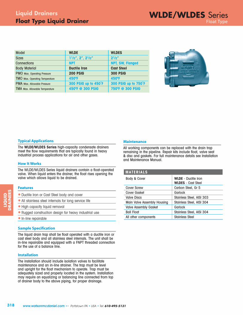
318
LIQ
UID
DRA
INER
S
WLDE/WLDES SeriesLiquid DrainersFloat Type Liquid Drainer Float Type
Model WLDE WLDESSizes 11/2”, 2”, 21/2” 21/2”Connections NPT NPT, SW, FlangedBody Material Ductile Iron Cast SteelPMO Max. Operating Pressure 200 PSIG 300 PSIGTMO Max. Operating Temperature 450ºF 450ºFPMA Max. Allowable Pressure 300 PSIG up to 450˚F 300 PSIG up to 750˚FTMA Max. Allowable Temperature 450ºF @ 300 PSIG 750ºF @ 300 PSIG
Typical Applications
The WLDE/WLDES Series high-capacity condensate drainersmeet the flow requirements that are typically found in heavyindustrial process applications for air and other gases.
How It Works
The WLDE/WLDES Series liquid drainers contain a float-operatedvalve. When liquid enters the drainer, the float rises opening thevalve which allows liquid to be drained.
Features
• Ductile Iron or Cast Steel body and cover
• All stainless steel internals for long service life
• High capacity liquid removal
• Rugged construction design for heavy industrial use
• In-line repairable
Sample Specification
The liquid drain trap shall be float operated with a ductile iron orcast steel body and all stainless steel internals. The unit shall bein-line repairable and equipped with a FNPT threaded connectionfor the use of a balance line.
Installation
The installation should include isolation valves to facilitatemaintenance and an in-line strainer. The trap must be leveland upright for the float mechanism to operate. Trap must beadequately sized and properly located in the system. Installationmay require an equalizing or balancing line connected from topof drainer body to the above piping, for proper drainage.
MATERIALS
Body & Cover WLDE - Ductile IronWLDES - Cast Steel
Cover Screw Carbon Steel, Gr 5Cover Gasket GarlockValve Discs Stainless Steel, AISI 303Main Valve Assembly Housing Stainless Steel, AISI 304Valve Assembly Gasket GarlockBall Float Stainless Steel, AISI 304All other components Stainless Steel
Maintenance
All working components can be replaced with the drain trapremaining in the pipeline. Repair kits include float, valve seat & disc and gaskets. For full maintenance details see Installationand Maintenance Manual.
www.watsonmcdaniel.com •• Pottstown PA • USA • Tel: 610-495-5131
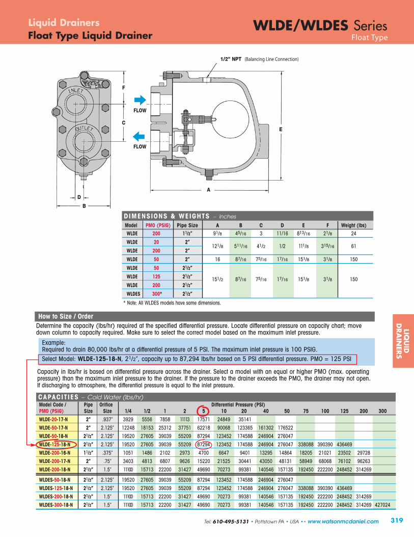
CAPACIT IES – Cold Water (lbs/hr)Model Code / Pipe Orifice Differential Pressure (PSI)PMO (PSIG) Size Size 1/4 1/2 1 2 5 10 20 40 50 75 100 125 200 300
WLDE-20-17-N 2” .937” 3929 5556 7858 11113 17571 24849 35141
WLDE-50-17-N 2” 2.125” 12248 18153 25312 37751 62218 90068 123365 161302 176522
WLDE-50-18-N 21/2” 2.125” 19520 27605 39039 55209 87294 123452 174588 246904 276047
WLDE-125-18-N 21/2” 2.125” 19520 27605 39039 55209 87294 123452 174588 246904 276047 338088 390390 436469
WLDE-200-16-N 11/2” .375” 1051 1486 2102 2973 4700 6647 9401 13295 14864 18205 21021 23502 29728
WLDE-200-17-N 2” .75” 3403 4813 6807 9626 15220 21525 30441 43050 48131 58949 68068 76102 96263
WLDE-200-18-N 21/2” 1.5” 11100 15713 22200 31427 49690 70273 99381 140546 157135 192450 222200 248452 314269
WLDES-50-18-N 21/2” 2.125” 19520 27605 39039 55209 87294 123452 174588 246904 276047
WLDES-125-18-N 21/2” 2.125” 19520 27605 39039 55209 87294 123452 174588 246904 276047 338088 390390 436469
WLDES-200-18-N 21/2” 1.5” 11100 15713 22200 31427 49690 70273 99381 140546 157135 192450 222200 248452 314269
WLDES-300-18-N 21/2” 1.5” 11100 15713 22200 31427 49690 70273 99381 140546 157135 192450 222200 248452 314269 427024
319
LIQU
IDD
RA
INER
S
WLDE/WLDES SeriesFloat Type Liquid Drainer Float Type
Liquid Drainers
How to Size / OrderDetermine the capacity (lbs/hr) required at the specified differential pressure. Locate differential pressure on capacity chart; movedown column to capacity required. Make sure to select the correct model based on the maximum inlet pressure.
Example:Required to drain 80,000 lbs/hr at a differential pressure of 5 PSI. The maximum inlet pressure is 100 PSIG. Select Model: WLDE-125-18-N, 21/2”, capacity up to 87,294 lbs/hr based on 5 PSI differential pressure. PMO = 125 PSI
F
C
B
DA
E
1/2” NPT (Balancing Line Connection)
FLOW
FLOW
Tel: 610-495-5131 • Pottstown PA • USA •• www.watsonmcdaniel.com
Capacity in lbs/hr is based on differential pressure across the drainer. Select a model with an equal or higher PMO (max. operatingpressure) than the maximum inlet pressure to the drainer. If the pressure to the drainer exceeds the PMO, the drainer may not open.If discharging to atmosphere, the differential pressure is equal to the inlet pressure.
DIMENSIONS & WEIGHTS – inches
Model PMO (PSIG) Pipe Size A B C D E F Weight (lbs)WLDE 200 11/2” 91/8 45/16 3 11/16 813/16 21/8 24
WLDE 20 2”121/8 511/16 41/2 1/2 111/8 315/16 61
WLDE 200 2”
WLDE 50 2” 16 87/16 75/16 17/16 151/8 31/8 150
WLDE 50 21/2”
WLDE 125 21/2” 151/2 87/16 75/16 17/16 151/8 31/8 150WLDE 200 21/2”
WLDES 300* 21/2”
* Note: All WLDES models have same dimensions.

320
Model WLD600 & WLD601Sizes 3/4”, 1”, 11/2”, 2”, 3”, 4”Connections NPT, SW, FlangedBody Material WLD600 Carbon SteelBody Material WLD601 316 Stainless SteelPMO Max. Operating Pressure 450 PSIGTMO Max. Operating Temperature 750ºFPMA Max. Allowable Pressure * 990 PSIG @ 100˚FTMA Max. Allowable Temperature * 750ºF @ 670 PSIG
Typical Applications
The WLD600/WLD601 Series are used in applications where immediate and continuous discharge of large amounts of liquid is required. Typically used in heavy industrial process applications for draining condensate from air or other gases.
How It Works
The WLD600/WLD601 Series liquid drainers contain a float-operated valve. When liquid enters the drainer, the float rises opening the valve which allows liquid to be drained.
Features
• All stainless steel internals for long service life
• Body & cover available in Carbon Steel or 316 SS
• Rugged construction designed for heavy industrial applications
• In-line repairable
Sample Specification
The liquid drain trap shall be float operated with a cast steel body (or stainless steel body for WLD601) and all stainless steelinternals. The unit shall be in-line repairable and equipped with a FNPT threaded connection for the use of a balance line.
Installation
The installation should include isolation valves to facilitatemaintenance and an in-line strainer. The trap must be leveland upright for the float mechanism to operate. Trap must beadequately sized and properly located in the system. Installationmay require an equalizing or balancing line connected from topof drainer body to the above piping, for proper drainage.
Maintenance
All working components can be replaced with the drain trapremaining in the pipeline. Repair kits include float, valve seat & disc and gaskets. For full maintenance details see Installationand Maintenance Manual.
MATERIALS
Body & Cover WLD600 Cast Steel, ASTM A-216 WCBBody & Cover WLD601 Cast 316 SSCover Studs Steel, SA 193, Gr B7Cover Nuts Steel, SA 194, Gr 2HCover Gasket Stainless Steel Reinforced GrafoilValve Assembly Stainless Steel, AISI 431Gasket, Valve Assembly Stainless Steel Reinforced GrafoilPivot Assembly Stainless Steel, 17-4 PHMounting Screws Stainless Steel Hex Head, 18-8Float Stainless Steel, ASTM 240 TY 304
Options
316 SS Body & Cover: use Model WLD601.
* 3/4”- 2” only.Note: For dimensions and capacities of 3” & 4” liquid drain traps,
refer to model FT600 in the Steam Trap section.
How to Size / OrderDetermine the capacity (lbs/hr) required at the specified differential pressure. Locate differential pressure on capacity chart;move down column to capacity required. Make sure to select thecorrect model based on the maximum inlet pressure.
Example:Required to drain 2,000 lbs/hr at a differential pressure of300 PSI. The maximum inlet pressure is 325 PSIG.
Select Model: WLD600-450-14-N, 1” NPT, capacity up to 2,250 lbs/hr based on 300 PSI differential pressure
Connections: (N=NPT, SW=Socket Weld, F150=150# FLG, F300=300# FLG, F600=600# FLG)
Example Models: WLD600-450-14-SW = 1” Socket WeldWLD600-450-14-F600 = 1” 600# FLG
WLD600 • Carbon SteelWLD601 • 316 SS
Liquid DrainersFloat Type Liquid Drainer
LIQ
UID
DRA
INER
S
www.watsonmcdaniel.com •• Pottstown PA • USA • Tel: 610-495-5131

321
CAPACIT IES – Cold Water (lbs/hr)Model Code Pipe Orifice Differential Pressure (PSI)PMO (PSIG) Size Size 2 5 10 20 30 40 65 70 80 100 145 200 300 350 450
WLD600-65-13-N 3/4” .156 340 520 730 1010 1220 1440 1770WLD600-65-14-N 1” .276 1390 2140 2970 4130 5000 5730 7210WLD600-65-16-N 11/2" .689 4160 6430 8920 12380 15000 17190 21630WLD600-65-17-N 2” 1.122 14730 22720 31540 43790 53060 60790 76500WLD600-145-13-N 3/4” .126 210 320 450 620 760 870 1090 1130 1200 1340 1590WLD600-145-14-N 1” .205 690 1070 1490 2060 2500 2870 3610 3740 3980 4420 5270WLD600-145-16-N 11/2" .591 2360 3630 5050 7010 8490 9730 12240 12670 13500 15000 17890WLD600-145-17-N 2” .807 5840 9010 12510 17370 21040 24110 30340 31420 33470 37200 44360WLD600-200-13-N 3/4” .106 170 260 360 500 600 690 870 900 960 1060 1270 1480WLD600-200-14-N 1” .185 450 690 960 1330 1620 1850 2330 2410 2570 2860 3410 3970WLD600-200-16-N 11/2” .531 1650 2550 3540 4910 5950 6820 8580 8890 9470 10520 12540 14610WLD600-200-17-N 2” .657 2890 4460 6190 8590 10410 11930 15010 15540 16560 18400 21940 25540WLD600-300-13-N 3/4” .079 80 130 180 250 300 340 430 450 480 530 630 730 890WLD600-300-14-N 1” .156 340 520 730 1010 1220 1400 1770 1830 1950 2160 2580 3010 3640WLD600-300-16-N 11/2” .531 1650 2550 3540 4910 5950 6820 8580 8890 9470 10520 12540 14610 17700WLD600-300-17-N 2” .657 2890 4460 6190 8590 10410 11930 15010 15540 16560 18400 21940 25540 30950WLD600-450-13-N 3/4” .063 50 70 100 140 160 190 240 250 260 290 350 400 490 530 590WLD600-450-14-N 1” .126 210 320 450 620 760 870 1090 1130 1200 1340 1590 1860 2250 2420 2720WLD600-450-16-N 11/2” .531 1650 2550 3540 4910 5950 6820 8580 8890 9470 10520 12540 14610 17700 19040 21440WLD600-450-17-N 2” .657 2890 4460 6190 8590 10410 11930 15010 15540 16560 18400 21940 25540 30950 33290 37490
DIMENSIONS & WEIGHTS – inches / pounds
Weight (lbs)Size A AA B C D E F G * NPT/SW FLG3/4" 61/8 101/8 21/8 37/16 77/16 87/16 513/16 3/8 25 31
1" 61/2 107/16 21/2 51/2 87/16 91/2 65/16 3/8 31 36
11/2" 913/16 14 37/16 9 107/16 1115/16 713/16 1/2 82 91
2" 1113/16 16 31/8 77/16 111/8 135/16 613/16 1/2 93 107
* Balancing Port available with 1/2” flanged connection. Specify on order.
AA (Flanged)
C
B
DA(NPT/SW)
E
FLOW
G (Balancing Line)NPT
F min.(for service)
WLD600/WLD601 SeriesFloat Type Liquid Drainer Float Type
Liquid Drainers
LIQU
IDD
RA
INER
S
Tel: 610-495-5131 • Pottstown PA • USA •• www.watsonmcdaniel.com
For WLD600 & WLD601
Capacity in lbs/hr is based on differential pressure across the drainer. Select a model with an equal or higher PMO (max. operatingpressure) than the maximum inlet pressure to the drainer. If the pressure to the drainer exceeds the PMO, the drainer may not open.If discharging to atmosphere, the differential pressure is equal to the inlet pressure.

322
LIQ
UID
DRA
INER
S
WLD1800/1800R SeriesLiquid DrainersGuided Float Type Liquid Drainer Guided Float Type
Model WLD1800 Non-repairableWLD1800R Repairable
Sizes 1/2”, 3/4”Connections NPTBody Material Stainless SteelPMO Max. Operating Pressure 400 PSIGTMO Max. Operating Temperature 500˚FPMA Max. Allowable Pressure 400 PSIG @ 500˚FTMA Max. Allowable Temperature 500˚F @ 400 PSIG
Typical Applications
The WLD1800/1800R Series are used on industrial air and gas applications for drainage of liquid from systems.
How It Works
The WLD1800 Series liquid drainers contain a float-operatedvalve. When liquid enters the drainer, the float rises opening thevalve which allows liquid to be drained.
Features
• Stainless steel body
• All stainless steel internals for longer service life
• Guided float ensures proper valve seating on every cycle
• Repairable unit available (WLD1800R)
Sample Specification
The liquid drain trap shall have a guided-float operation with a tamper-proof seal-welded stainless steel body and all stainless steel internals. The unit shall be available with an in-line repairable version. All units to be equipped with FNPT threaded end connections.
WLD1800(Non-Repairable)
WLD1800R(Repairable)
Installation
The installation should include an in-line strainer. The trap mustbe level and upright for the float mechanism to operate. Trapmust be adequately sized and properly located in the system.
Maintenance
The WLD1800 is non-repairable. The WLD1800R is fullyrepairable and all working components can be replaced. Repairkits include float, lever & seat assembly, and gaskets. For fullmaintenance details see Installation and Maintenance Manual.
MATERIALSBody Stainless Steel, AISI 304Inlet & Outlet Fittings Stainless Steel, AISI 304Float Assembly Stainless Steel, AISI 304Valve & Lever Assembly Stainless Steel, AISI 303Seat Hardened Stainless Steel*Gasket (Repairable only) GrafoilWasher, Seat 302 Stainless Steel*Bolt, Hex, HD Stainless Steel, AISI 316*Nut, Jam Stainless Steel, 18-8
* WLD1800R repairable models only.
ValveClosed
ValveOpen
www.watsonmcdaniel.com •• Pottstown PA • USA • Tel: 610-495-5131

323
LIQU
IDD
RA
INER
S
WLD1800/1800R SeriesGuided Float Type Liquid Drainer Guided Float Type
Liquid Drainers
WLD1800(Non-Repairable)
WLD1800R(Repairable)
7.5
2 5/8”
CAPACIT IES – Cold Water (lbs/hr)PMO* Orifice Differential Pressure (PSI)
Series (PSIG) Size 1 2 5 10 15 20 30 50 100 150 175 200 250 275 300 350 400WLD1810 400 .078” 60 80 120 130 180 260 315 400 570 700 750 800 900 940 1050 1050 1120
WLD1820 255 .101” 90 120 175 195 275 385 470 610 860 1050 1125 1200 1350 1425
WLD1830 175 .125” 160 230 325 365 510 730 790 1150 1630 2000 2150
* PMO based on a liquid with a specific gravity of 1.0. Consult factory for the PMO of a liquid with specific gravity less than 1.0.
7.9
CAPACITY CORRECTION FACTORSSpecific Gravity 1 .98 .96 .94 .92 .90 .88 .86 .84 .82 .80 .75 .70 .65 .60 .55 .50
Correction Factor 1 .99 .98 .97 .959 .949 .938 .927 .917 .906 .894 .866 .837 .806 .775 .742 .707
Note: To obtain capacity with a liquid other than water, multiply water capacity by correction factor.
How to Size / OrderDetermine the capacity (lbs/hr) required at the specified differential pressure. Locate differential pressure on capacity chart; move downcolumn to capacity required. Make sure to select the correct model based on the maximum inlet pressure.
Example: Required to drain 1,000 lbs/hr at a differential pressure of 200 PSI. The maximum inlet pressure is 250 PSIG.
Select Model: WLD1822-N 3/4” x 3/4” (non-repairable) or WLD1822R-N 3/4” x 3/4” (repairable); capacity up to 1,200 lbs/hrbased on 200 PSI differential pressure.
4.0”
FLOW
INLET
INLET
Connection Model PMO OrificeInlet x Outlet Code PSI Size3/4” x 1/2” WLD1811-N 400 .078”
3/4” x 3/4” WLD1812-N 400 .078”
1/2” x 1/2” WLD1813-N 400 .078”
3/4” x 1/2” WLD1821-N 255 .101”
3/4” x 3/4” WLD1822-N 255 .101”
1/2” x 1/2” WLD1823-N 255 .101”
3/4” x 1/2” WLD1831-N 175 .125”
3/4” x 3/4” WLD1832-N 175 .125”
1/2” x 1/2” WLD1833-N 175 .125”
Connection Full Model PMO OrificeInlet x Outlet Code PSI Size
3/4” x 1/2” WLD1811R-N 400 .078”
3/4” x 3/4” WLD1812R-N 400 .078”
1/2” x 1/2” WLD1813R-N 400 .078”
3/4” x 1/2” WLD1821R-N 255 .101”
3/4” x 3/4” WLD1822R-N 255 .101”
1/2” x 1/2” WLD1823R-N 255 .101”
3/4” x 1/2” WLD1831R-N 175 .125”
3/4” x 3/4” WLD1832R-N 175 .125”
1/2” x 1/2” WLD1833R-N 175 .125”
WLD1800 - Non-Repairable
WLD1800R - Repairable
Weight: 4 lbs
Weight: 5 lbs
Tel: 610-495-5131 • Pottstown PA • USA •• www.watsonmcdaniel.com
FLOW

324
LIQ
UID
DRA
INER
S
Model WLD1501, WLD1502, WLD1504,WLD1521, WLD1522, WLD1524
Sizes 3/4”, 1”Connections NPTBody Material Cast IronPMO Max. Operating Pressure 200 PSIGTMO Max. Operating Temperature 450ºFPMA Max. Allowable Pressure 250 PSIG up to 450ºFTMA Max. Allowable Temperature 450ºF @ 250 PSIG
Typical Applications
The WLD1500 Series Inverted Bucket Liquid Drain Traps are recommended for the removal of liquids from compressed air systems. A scrubber wire is used to keep bleed hole on topof inverted bucket from clogging due to oil that may be present in the water being drained. Oil mixed with water is typicallyfound on compressed air systems.
How It Works
When there is condensate in the system, the inverted bucketinside the liquid drain trap rests on the bottom due to its weight;with the valve in the open position. This allows liquid entering the trap to be discharged through the seat orifice located at thetop. When air enters the trap, the bucket floats to the surface andcloses off the discharge valve, containing the air in the system.Eventually, air is bled off through a small hole in the top of thebucket and the bucket sinks; repeating the cycle.
Features
• Hardened stainless steel valves and seat
• Only two moving parts
• Scrubber wire in air vent of bucket
• Discharge orifice at top of trap reduces potential for clogging
• In-line repairable
Sample Specification
Drain trap shall be an inverted bucket trap design with cast ironbody, all stainless steel internals, hardened valve & seat, plus ascrubber wire. The unit shall be in-line repairable.
MATERIALS
Body & Cover Cast Iron, ASTM A-278 Class 30Nuts & Bolts High-Tensile SteelGasket Non-Asbestos FiberBucket Stainless SteelScrubber Stainless SteelLever & Seat Assembly Stainless SteelValve & Seat Hardened Stainless SteelIntegral Strainer* Stainless Steel
* WLD1521, WLD1522 & WLD1524 models only.
Installation
Installation should include isolation valves for maintenance purposes. Trap must be installed in upright position to functionproperly. It may be necessary to prime the bucket trap by fillingit with water through the priming port prior to startup.
Maintenance
Close isolation valves prior to any maintenance. All workingcomponents can be replaced with the drain trap remaining inthe pipeline. Repair kits include lever & seat assembly, strainerscreen and gaskets. For full maintenance details see Installationand Maintenance Manual.
WLD1521/1522/1524with Strainer
WLD1500 SeriesLiquid DrainersInverted Bucket Type Liquid Drainer Inverted Bucket Type
www.watsonmcdaniel.com •• Pottstown PA • USA • Tel: 610-495-5131

325
LIQU
IDD
RA
INER
S
DIMENSIONS & WEIGHTS – inches / pounds
Model Size A B C D Weight
WLD1501-13-N 3/4” 313/16 57/16 5 213/16 5
WLD1502-13-N 3/4” 313/16 615/16 5 45/16 6
WLD1504-14-N 1” 7 1113/16 713/16 7 27
WLD1521-13-N 3/4” 313/16 61/8 5 37/16 5.5
WLD1522-13-N 3/4” 313/16 71/8 5 47/16 6
WLD1524-14-N 1” 7 127/16 713/16 77/16 30
WLD1501/1502/1504 WLD1521/1522/1524with Strainer
FLOW FLOW
C
A
D
C
A
B
D
Priming Port Priming Port
How to Size / OrderDetermine the capacity (lbs/hr) required at the specified differential pressure. Locate differential pressure on capacity chart;move down column to capacity required. Make sure to select the correct model based on the maximum inlet pressure.
Example: Required to drain 200 lbs/hr at a differential pressure of 5 PSI. The maximum inlet pressure is 30 PSIG.
Select Model: WLD1521-13-N, 3/4” NPT, with strainer, capacity up to 220 lbs/hr based on 5 PSI differential pressure.
WLD1500 SeriesInverted Bucket Type Liquid Drainer Inverted Bucket Type
Liquid Drainers
B
Tel: 610-495-5131 • Pottstown PA • USA •• www.watsonmcdaniel.com
Capacity in lbs/hr is based on differential pressure across the drainer. Select a model with an equal or higher PMO(max. operating pressure) than the maximum inlet pressure to the drainer. If the pressure to the drainer exceeds thePMO, the drainer may not open. If discharging to atmosphere, the differential pressure is equal to the inlet pressure.
CAPACIT IES – Cold Water (lbs/hr)PMO Differential Pressure (PSI)
Model Code (PSIG) Size 2 5 10 25 50 80 100 125 150 180 200
WLD1501-13-N 150 3/4” 145 220 325 510 720 900 1010 1130 1215WLD1521-13-N
WLD1502-13-N 200 3/4” 170 260 380 595 835 1045 1175 1315 1410 1550 1645WLD1522-13-N
WLD1504-14-N 200 1” 500 760 1105 1740 2460 3065 3450 3865 4140 4555 4835WLD1524-14-N

326
LIQ
UID
DRA
INER
S
WLD1703S SeriesLiquid DrainersDisc Type Liquid Drainer Disc Type
217/32
31/2 with blowdown
35/32
Model WLD1703SSizes 1/2”Connections NPTBody Material Stainless SteelOptions Blowdown ValvePMO Max. Operating Pressure 250 PSIGTMO Max. Operating Temperature 750ºFPMA Max. Allowable Pressure 915 PSIG up to 250ºFTMA Max. Allowable Temperature 610ºF @ 750 PSIG
Typical Applications
The WLD1703S is used on air and gas applications as drip trapson system mains and other piping runs. These drain traps are idealfor outdoor applications where units are subject to freezing.
How It Works
The disc type liquid drain trap has a cyclic on/off operation with a disc that is pushed open when condensate is present and pulled closed when air or gas tries to escape.
Features
• Rugged, stainless steel body and hardened seat
• Handles a wide range of pressures up to 250 PSIG
• Works in any position (horizontal preferable)
• Integral strainer with blowdown option
• Three-holed balanced discharge
• Freeze-proof in vertical flow-down position
Sample Specification
Drain Trap shall be a Disc Type with an all stainless steel construction. Body shall have a built-in strainer with optionalblowdown valve. Integral seat design and disc to be hardened for long service life. Unit shall be capable of installation in anyorientation and self-draining when mounted vertically with flowdirection downwards.
Installation
Drain Trap can be installed in any position; however, horizontalis preferred. Installation should include isolation valves for maintenance purposes.
MATERIALS
Body Stainless Steel, AISI 420FDisc Stainless Steel, AISI 420Cap Stainless Steel, AISI 416Strainer Screen Stainless Steel, AISI 304Blowdown Valve* Stainless Steel, AISI 303
* WLD1703SB model only.
Maintenance
Dirt is the most common cause of premature failure. The strainermay require periodic cleaning. For full maintenance details seeInstallation and Maintenance Manual.
OptionsBlowdown valve allows strainer to be cleaned without removal.
CAPACIT IES – Cold Water (lbs/hr)Pipe Inlet Pressure (PSIG)
Model Code Description Size 2 5 10 25 50 80 100 125 150 180 200 250 WLD1703S-12-N Strainer
1/2” 90 130 190 300 425 530 600 670 715 790 835 955 WLD1703SB-12-N Strainer & Blowdown
Note: 1) Maximum back pressure not to exceed 80% of inlet pres sure.2) To determine gallons per minute of flow, divide values in chart by 500. Example: 600 lbs/hr = 600 –: 500 = 1.2 GPM
WLD1703SBwith Strainer &
BlowdownValve
WLD1703Swith Strainer
WLD1703SBwith Strainer &
BlowdownValve
FLOW
17/16
Units: inches
www.watsonmcdaniel.com •• Pottstown PA • USA • Tel: 610-495-5131

327
Model/Series Product Body Material PMO Size Connection Page No.(PSIG)
WSSCV Check Valve Stainless Steel 500 1/2” - 3” NPT, SW 334
SVB Safety Relief Valve Bronze 250 1/2” - 21/2” NPT 336
SVI Safety Relief Valve Cast Iron 250 11/2” - 6” NPT, FLG 338
DPL Drip Pan Elbow Cast Iron 250 3/4” - 8” NPT, FLG 340
WFLV Flash Tank Carbon Steel 150 6”, 8”, 12”, 16” FLG 341
EHC/EHF/EHFSS Exhaust Head C.I., Carbon Steel, SS NA 1” - 10” NPT, FLG 342
WVBSS Vacuum Breaker Stainless Steel 300 1/2” NPT 345
AVT125 Air Vent Brass 125 1/2”, 3/4” NPT 346
AV2000 Air Vent Stainless Steel 650 1/2”, 3/4” NPT 347
CIY Strainer Cast Iron 125-500 1/2” - 4” NPT, FLG 348
CSY Strainer Carbon Steel 600 1/2” - 2” NPT, SW 349
SSY Strainer Stainless Steel 600 1/2” - 2” NPT, SW 349
SUCT Suction/Mixing Tee Cast Iron, Bronze, SS 250-450 1/2”- 3” NPT 350
EJECT/ELL/LM Ejector Cast Iron, Bronze 100 1/2” - 2” NPT 352
AV813 Air Eliminator Cast Iron 150 3/4” NPT 356
AE1800/1800R Air Eliminator Stainless Steel 400 1/2”, 3/4” NPT 357
WDS Separator C.I., Carbon Steel 250/300 3/4” - 12” NPT, SW, FLG 358
WCIS Separator Cast Iron 145/200 3/4” - 4” NPT, FLG 360
WFPV Freeze Protection Valve Stainless Steel 200 1/2” NPT 362
WSPV Scald Protection Valve Stainless Steel 200 1/2”, 3/4” NPT 363
WSTTV Steam Trap Test Valve Stainless Steel 150 1/2” - 1” NPT 364
Heat MiserInstantaneous Steam
Stainless Steel 60 – – 365to Water Heater
WSI, WIP, WSX Steam Humidifiers Stainless Steel 60 – – 369
Pipeline AccessoriesAncillary Products to support your Steam and Hydronic Systems.
PIP
ELINE
ACCESSO
RIES
www.watsonmcdaniel.com •• 428 Jones Boulevard • Limerick Airport Business Center • Pottstown PA • 19464 •• Tel: 610-495-5131
Table of Contents

PQ��ÌÅÏ��ÅÍ�Ï ÅÊÑ�ËÌÊ�ÊÍÅ�ÐÑÏ
Ï�Î�ÊÐÍ��Ê�ÊÍ���ËËÏ��Ï�ÑÅÊÍËÑÏÏ�ÅÊÍÌËÏÏ�Ï�ËËÌ�Î�ËÎ���ÅÌ�ËÏ
Ë�ËÎ�ÐÑÏ�ÑÊ¿�¿ÅÍ�ËÌ�Ð Ï
¿ÀÁÂÃÀÄÂ�ÅÆÆÂÇÇÈÉÀÂÇ!"#$%&'#()#'*+,')-%#")$&-).%.')(/$0')1#+*)("'$*)(2("'*()"+).#+"'/")/#%"%/$0)/+*.+&'&"()(3/4)$(5'630$"+#(7)83*.()$&-)!"'$*)9#$.()1#+*)-$*$6':);,$%0$<0')%&)=$(")>#+&7)=$#<+&)!"''0)$&-)!"$%&0'((!"''0)3.)"+)?@)%&)(%A':
B$"(+&)C/D$&%'0)=4'/E)F$0,'()$#')$,$%0$<0')%&)$00)GHI)!!)/+&("#3/"%+&)%&)HJK@)"4#3)G@)(%A'()$&-)$#')(.'/%1%/$002)-'(%6&'-)"+)4$&-0')"4')-%11%/30")'&,%#+&*'&"()$((+/%$"'-L%"4)("'$*)$&-)4+")/+&-'&($"')('#,%/':)=4'/E),$0,'()/$&)<')%&("$00'-)+&)"4')-%(/4$#6')(%-')+1)("'$*)"#$.()"+)'0%*%&$"')<$/E10+L)%&"+)"4')"#$.:)B%"4)"4')(.'/%$002)-'(%6&'-HJ?)8!>)0+L)/#$/E%&6).#'((3#')(.#%&67)"4'(')/4'/E),$0,'()/+*')("$&-$#-)+&)$00)B$"(+&)C/D$&%'0)8#'((3#')C+"%,')83*.(:)94%()%()$)3&%M3')$&-)(.'/%$0%A'-).#+-3/")3('-)1+#<0'&-%&67)*%N%&67)$'#$"%+&)+#)4'$"%&6)<2)*%N%&6)("'$*)$&-)L$"'#)"+6'"4'#:);,$%0$<0')%&)=$(")>#+&7O#+&A')$&-)!"$%&0'(()!"''0:
PQ'/"+#()$#')3('-)1+#)&+&R'0'/"#%/).3*.%&6+1)103%-()+#)',$/3$"%&6)$)"$&E)+#),'(('0)+1$%#)+#)+"4'#)6$('(:)S('-)+&)("'#%0%A%&6'M3%.*'&")1+#).#')$&-).+("R',$/3$"%+&)+1"4')/4$*<'#:) ;%#)P0%*%&$"+#()$#')3('-)+&)"$&E()+#).%.%&6)(2("'*()"+),'&")$%#)L%"4+3")$00+L%&6)"4')0%M3%-)%&(%-')"4')"$&E)+#).%.%&6"+)'(/$.':);,$%0$<0')%&)=$(")>#+&)$&-)!"$%&0'(()!"''0:)
D#%.)8$&)P0<+L()$#')3('-)"+)/+00'/")$&-)#'*+,')/+&-'&($"':)92.%/$002)3('-)L%"4)("'$*)($1'"2)#'0%'1),$0,'(:
¿Ê¿ËÌÊÍË ÅÎÎËÏÏÐÑÊËÏ T0$(4)"$&E()$#')%&("$00'-%&)/+&-'&($"')#'"3#&(2("'*()"+),'&")10$(4("'$*)$&-)&'3"#$0%A'.#'((3#')%&)/+&-'&($"'#'"3#&)0%&'(:)94')10$(4("'$*)*$2)<')3('-)1+#0+L).#'((3#')4'$"%&6$..0%/$"%+&()+#),'&"'-)"+$"*+(.4'#':

STEAM TRAP TEST VALVES
AIR/STEAM MOISTURESEPARATORS
FREEZE & SCALD PROTECTION VALVESVACUUM BREAKERS
SAFETY RELIEF VALVES
THERMOSTATIC AIR VENTS
EXHAUST HEADS
STEAM HUMIDIFIERS
Watson McDaniel Safety Relief Valves are ASME qualified for steam service and are available in Bronze and Cast Iron in 1/2” thru 6” sizes.
Test Valves can be installed downstream of any steam trap to visuallyinspect the discharge of condensate from the traps. Available in StainlessSteel up to 1” in size.
Exhaust Heads are used to separate entrained water from steam that is being vented directly into the atmosphere, preventing damage to rooftops and other equipment from hot water.
Vacuum Breakers “break the vacuum” causedby the condensing of steam or draining of liquid. These are primarily installed on the topof heat exchangers, allowing condensate toproperly drain from the system.
Freeze Protection Valves automatically open anddischarge liquid to protect equipment from freezedamage. Scald Protection Valves automatically openand discharge overheated liquid from a system to protect personnel from possible injury due to scalding.
Steam Humidifiers control humidity in commercialoffices, hospitals, warehouses and various types of industrial facilities.
Air Vents purge unwanted air from steam systemswhich can inhibit the steam from entering processequipment, vessels and piping. Air vents shouldbe placed at all high points in the piping systemand on heat transfer equipment.
Separators are used for the removal of entrainedmoisture in steam and compressed air lines.Separators should be placed before all regulatingvalves to eliminate problems caused by water logging and wire drawing of the valve seats.
PIP
ELINE
ACCESSO
RIES
329

SAFETY RELIEF VALVESSafety Relief Valves are used for over-pressureprotection on steam systems.
330
PIP
ELIN
EA
CCES
SORIE
S
Flash Tank
condensate return
Strainer
AirVent
VacuumBreaker
Strainer
Separator
Exhaust Head
SafetyRelief Valve
Drip Pan Elbow
DRIP PAN ELBOWDrip Pan Elbows are used to collect and removecondensate. Typically used on steam boilers andsafety valves.
STRAINERSStrainers are used to remove dirt particles from fluid or steam and provide inexpensive protection for critical equipment such aspumps, meters, valves, traps and turbines.
AIR/STEAM MOISTURESEPARATORSSeparators are used for theremoval of entrained waterfrom steam or air.
Steam TrapTest Valve
AirVent
CHECK VALVESThe WSSCV is an all stainless steel in-line check valve forsteam, gas or liquid service. Used in the petrochemical, pulp& paper, textile and food & beverage industries.
Pipeline AccessoriesApplication & Usages
Steam Flow
www.watsonmcdaniel.com •• Pottstown PA • USA • Tel: 610-495-5131

AIR VENTS (AV2000)Air vents are used in steam systems for theremoval of air and other non-condensablegases from process equipment, vessels and piping. Place at end of steam main and directly on process equipment.
331
PIP
ELINE
ACCESSO
RIES
EXHAUST HEADSExhaust Heads separate entrained water from steam prior to being discharged directly to the atmosphere.Eliminates damage to rooftops and other equipment caused by hot condensate.
FLASH TANKS Flash tanks are installed in condensate return systems to vent flash steam and neutralize pressure in condensate return lines. The flash steam may bevented to atmosphere or used for low pressure heating applications.
VACUUM BREAKER (WVBSS)Vacuum breakers allow air to enter a system in order to “break the vacuum.”
In a heat exchanger, the vacuum is caused bycondensing steam which inhibits condensatedrainage.
Drainage of liquids from storage tanks willalso cause an undesirable vacuum whichinhibits flow or can possibly collapse tank or vessel.
Drain Pipe(for collected condensate & rain water)
roof
FlashTank
flashsteam
hotcondensate
condensateinlet
return toboiler
EXHAUSTHEAD
Pipeline AccessoriesApplication & Usages
Air Vent
VacuumBreaker
Air Vents & Vacuum Breakers
Flash Tanks & Exhaust Heads
AV2000
WVBSS
Condensate will not drain fromheat exchangerunder vacuum.
Tel: 610-495-5131 • Pottstown PA • USA •• www.watsonmcdaniel.com

PPQ
YVct�¬Zcu�¬V\�pcWxVt�}§s}~w{s��s{¥�}Ï�ËÅ���ÑÅ¿��ËÏ���ÅÌ�Ë��)�����)[_\o)�g\l)�f_)d\be)j]]gf)fcolb�)cooic\_)\niecfc~b)ic\�njfcf)j])\n)f_\o)_g\lp)�hgncn�)_�)�\nib)� ¡)_j)_���f_�)ljfc_cjn)�cbb)icgm_)]bj�)j])f_\o)_g\l)jh_)_�)_f_)ljg_)]jg)ecfh\b)e\bh\_cjn)j])icfm�\g�p)��cf)cf)_�)ojf_)]]m_ce)o_�ji_j)cnflm_)_�)]hnm_cjn)j])\)f_\o)_g\lp
z{swª��w��YVct�¬Zcu�¬V\�pcWxV
ÅÊÑ�ËÌÊ�ÊÍÅ�ÐÑÏ��)¢�£¤¥)\ni)_�)¢¦¤£§§)�©ª«�cg)}bcocn\_jgf)\g)hfi)]jg)_�)goje\b)j])\cg)\ni)j_�g)�\ff)]gjo)effbf)jg)lclcn�ff_of)�c_�jh_)\bbj�cn�)_�)mjn_\cnibc�hci)_j)fm\lp)�cg)}bcocn\_jgf)\g)hfijnb)]jg)bc�hci)ff_ofp
iTZtcW�duVg¬�x� �|~�~{�w|¶r{�{r��¥¶r lg�¬V\�]T\[[Tg¬�x� �§|~trw�¶s~{r��¥¶r�{s~{����{¬V\�]TZ���s}�¬V\�]TZ��x�tus§� ��x� ��x�tus§� �~�xw{|�}vwxys
][uVW[gV�«__V\\TZ[V\ÅÁÁÃÀÆ �ÀÈÄ�V��Ç �ÂÇ¿Ê¿ËÌÊÍË ÅÎÎËÏÏÐÑÊËÏ
«[Z�¢W[t[gcTZ\�w{s� ©|� �w{s�
«[Z�¢W[t[gcTZ
¬V\�]TZ
fWT\VU duVg
ÒÒÒÓÒÔÕÖ×ØÙÚÛÔØÜÝÞÓÚ×Ùßßøäööçöäùå�øô�ß��ô�ß�æê�����������©|�

333
Suction & Mixing Tees
Controlling temperature of large open tank by steam injectionSuction Tees promote the mixing of steam and water. When steam flowsthrough the suction tee, a slight vacuum is created which pulls waterthrough the secondary inlet.
Aeration or AgitationLiquid pumped through the SuctionTee produces suction, which pulls inair through the secondary inlet.
Open Tank
Suction Tee
Thermometer
SteamSupply
TemperatureRegulator
Temp. Probe
Air or Gas Supply
Liquid
Suction Tee
EJECTORSWatson McDaniel Ejectors perform a variety of functions depending upon the application and motive fluid (steam or water) used. See performance charts on the followingpages. Applications include: exhausting, agitating, aerating, circulating, pumping and mixing.
SUCTION OR MIXING TEEThe Watson McDaniel Cast Iron, Bronze or StainlessSteel Suction Tee is a specialized type of pipe fittingused for blending, agitation, recirculation, mixing,aeration and heating.
When liquid or steam flows thru the primary inlet, a vacuum is created which causes water to be pulled through the secondary inlet.The maximum height that water or any liquid with a specific gravityof 1 can be lifted is 25 feet. Increases in the temperature of the liquidbeing lifted will cause this maximum height to decrease.
EjectorInlet Water
or Steam
25 Ft.Maximum
Lift
Pipeline AccessoriesApplication & Usages
PIP
ELINE
ACCESSO
RIES
Ejector (Pumping Liquid)
Primary Inlet
Secondary Inlet
Outlet
Primary Inlet Outlet
Secondary Inlet
SecondaryInlet
Tel: 610-495-5131 • Pottstown PA • USA •• www.watsonmcdaniel.com

334
PIP
ELIN
EA
CCES
SORIE
SWSSCV
Check Valve Stainless Steel
Pipeline Accessories
Stainless Steel
Model WSSCVSizes 1/2”, 3/4”, 1”, 11/4”, 11/2”, 2”, 3”Connections NPT, SWBody Material 316 Stainless SteelPMO Max. Operating Pressure 500 PSIGPMA Max. Allowable Pressure 750˚F PSIG @ 100ºFTMA Max. Allowable Temperature 850˚F @ 420 PSIG
Features & Options
• 316 Stainless Steel Body and Internals
• Low cracking pressure on spring (1/4 PSI) to minimize resistance and maximize flow.
• Available with optional 5 PSI cracking pressure (must specify at time of order)
• Available with NPT, SW, or optional Flanged connections
• Spring made from Inconel-X-750 to handle extreme temperature as well as corrosive applications
• Body is seam-welded to eliminate O-rings or gasket seals which can be affected by high temperature steam or hot condensate
• Spring assisted closing of check valve to minimize noise and wear
Sample Specification
Check valve shall have a 316 stainless steel body and disc.Spring shall be made from Inconel-X-750. Check valve body tobe seam welded together to eliminate need for O-ring or gasket.
MATERIALSBody 316 Stainless SteelDisc 316 Stainless SteelSpring Inconel-X-750
Note: WSSCV with 1/4 PSI cracking pressure is required for all mechanical pump applications. The 5 PSIG cracking pressure version is also available. See model code chart.
Typical Applications
The Model WSSCV is an all stainless steel in-line check valve forsteam, gas, or liquid service. It provides tight shut-off, minimizeswater hammer and also stops recycling of pumps by preventing backflow of liquid. Used in the petrochemical, pulp & paper, textile andfood & beverage industries. The WSSCV all stainless steel checkvalves will operate much longer and are less problematic than bronze or cast iron check valves.
Size/Connection Model Cracking Pressure* WeightNPT Code PSI lbs
1/2” WSSCV-12-N-0 0.25 1.0
3/4” WSSCV-13-N-0 0.25 1.5
1” WSSCV-14-N-0 0.25 2.3
11/4” WSSCV-15-N-0 0.25 3.5
11/2” WSSCV-16-N-0 0.25 5.3
11/2” WSSCVQF-16-N-0† 0.00 5.3
2” WSSCV-17-N-0 0.25 8.5
3” WSSCV-19-N-0 0.25 21
1/2” WSSCV-12-N-5 5.0 1.0
3/4” WSSCV-13-N-5 5.0 1.5
1” WSSCV-14-N-5 5.0 2.3
11/4” WSSCV-15-N-5 5.0 3.5
11/2” WSSCV-16-N-5 5.0 5.3
2” WSSCV-17-N-5 5.0 8.5
3” WSSCV-19-N-5 5.0 21
Size/Connection Model Cracking Pressure* WeightSW Code PSI lbs
1/2” WSSCV-12-SW-0 0.25 1.0
3/4” WSSCV-13-SW-0 0.25 1.5
1” WSSCV-14-SW-0 0.25 2.3
11/4” WSSCV-15-SW-0 0.25 3.5
11/2” WSSCV-16-SW-0 0.25 5.3
2” WSSCV-17-SW-0 0.25 8.5
3” WSSCV-19-SW-0 0.25 21
1/2” WSSCV-12-SW-5 5.0 1.0
3/4” WSSCV-13-SW-5 5.0 1.5
1” WSSCV-14-SW-5 5.0 2.3
11/4” WSSCV-15-SW-5 5.0 3.5
11/2” WSSCV-16-SW-5 5.0 5.3
2” WSSCV-17-SW-5 5.0 8.5
3” WSSCV-19-SW-5 5.0 21
* Differential Pressure at which valve opens and flow occurs.† WSSCVQF is a special design check valve for use on the inlet side of
the PMPT & PMPNT Pumps. It is center-guided and contains no spring . Used for increasing fill rate of pump.
NPT
Socket Weld
www.watsonmcdaniel.com •• Pottstown PA • USA • Tel: 610-495-5131

335
PIP
ELINE
ACCESSO
RIES
DIMENSIONS & SPECIF ICATIONS – inches
Size 1/2” 3/4” 1” 11/4” 11/2” 2” 3”MODEL CODE WSSCV-12 WSSCV-13 WSSCV-14 WSSCV-15 WSSCV-16 WSSCV-17 WSSCV-19
A 2.69 3.00 3.32 3.81 4.75 5.03 6.87B 1.62 2.12 2.56 3.06 3.44 4.38 6.19
Weight (lbs) 1.1 1.5 1.9 3.8 4.7 7.7 18.8Standard Cracking Pressure* 0.25 0.25 0.25 0.25 0.25 0.25 0.25Optional Cracking Pressure* 5.0 5.0 5.0 5.0 5.0 5.0 5.0
Cv 7 13 22 39 54 93 180
* Note: Differential Pressure at which valve opens and flow occurs (PSI).
INLET
NPT orSocketWeld
A
B
Seam Welded
WSSCVCheck Valve Stainless Steel
Pipeline Accessories
Stainless Steel
Seam Welded Body(316 SS)
Spring(Inconel-X-750)
Outlet
Inlet
Disc(316 SS)
WSSCV Check Valve Construction
Tel: 610-495-5131 • Pottstown PA • USA •• www.watsonmcdaniel.com

336
PIP
ELIN
EA
CCES
SORIE
S
“UV” Steam-ASME Section VIII Pressure Vessels
Model SVBSizes 1/2”, 3/4”, 1”, 11/4”, 11/2”, 2”, 21/2”Connections NPTBody Material BronzePMO Max. Operating Pressure 250 PSIG (steam)TMO Max. Operating Temperature 406 ºF
Typical Applications
The SVB Safety Valves are used for over-pressure protection onunfired pressure vessels in saturated steam systems. Valves are100% factory tested and made in the USA.
How It Works
In the event steam pressure increases to the set point, the safetyvalve will “pop open” discharging steam faster than it can beproduced; allowing system pressure to return to safe levels atwhich point the valve will close.
Features
• Stainless Steel springs
• Teflon®-PFA seat resists corrosive boiler chemicals
• Two control rings for maximum performance and adjustability
• Tapped body drain allows piping of condensate away from valve to protect the internals from fouling
Sample Specification
Safety valves shall be cast bronze construction with stainlesssteel springs, Teflon-PFA seats and stainless steel stems. Unitsshall be qualified to the ASME Boiler Code, Section VIII and suitable for steam service.
MATERIALSBody BronzeGuide Ring BrassDisc BrassSeat Insert Teflon®-PFAStem Stainless Steel
DIMENSIONS & WEIGHTS – inches
Model Orifice Inlet x Outlet WeightCode Size MNPT x FNPT A B C D (lbs)
SVB-12M-13S-D D 1/2” x 3/4” 2.21 6.52 1.37 0.84 1.6SVB-13M-13S-D D 3/4” x 3/4” 2.21 6.52 1.37 0.84 1.6SVB-13M-14S-E E 3/4” x 1” 2.50 7.16 1.75 1.06 2.0SVB-14M-14S-E E 1” x 1” 2.64 7.30 1.75 1.06 2.2SVB-14M-15S-F F 1” x 11/4”” 2.95 9.34 2.00 1.44 4.1SVB-15M-15S-F F 11/4” x 11/4” 2.95 9.34 2.00 1.44 4.3SVB-15M-16S-G G 11/4” x 11/2” 3.38 11.01 2.37 1.69 7.4SVB-16M-16S-G G 11/2” x 11/2” 3.38 11.01 2.37 1.69 7.6SVB-16M-17S-H H 11/2” x 2” 3.63 11.96 2.75 2.06 11.5SVB-17M-17S-H H 2” x 2” 3.63 11.96 2.75 2.06 11.6SVB-16S-18S-J J 11/2” FNPT x 21/2” FNPT 3.80 14.00 3.50 2.06 20.0SVB-17M-18S-J J 2” x 21/2” 4.06 14.25 3.50 2.06 19.9SVB-18M-18S-J J 21/2” x 21/2” 4.50 14.68 3.50 2.06 20.8
A
B
D C
SVB SeriesPipeline AccessoriesSafety Valves
www.watsonmcdaniel.com •• Pottstown PA • USA • Tel: 610-495-5131

337
PIP
ELINE
ACCESSO
RIES
CAPACIT IES – Pounds of saturated steam per hour (lbs/hr)
Set Orifice “D” Orifice “E” Orifice “F” Orifice “G” Orifice “H” Orifice “J” Pressure .129” .230” .359” .586” .919” 1.509”(PSIG) Diameter Diameter Diameter Diameter Diameter Diameter
15 179 320 499 820 1279 2100
20 207 369 576 945 1474 2421
25 234 418 652 1070 1670 2742
30 262 467 729 1195 1865 3063
35 292 521 813 1333 2080 3416
40 322 574 897 1471 2295 3769
45 352 628 981 1609 2510 4122
50 383 682 1065 1747 2725 4475
55 413 736 1149 1885 2941 4828
60 443 790 1233 2022 3156 5181
65 473 844 1317 2160 3371 5535
70 503 897 1401 2298 3586 5888
75 534 951 1485 2436 3801 6241
80 564 1005 1569 2574 4016 6594
85 594 1059 1653 2712 4231 6947
90 624 1113 1737 2849 4446 7300
95 654 1167 1821 2987 4661 7653
100 684 1220 1905 3125 4876 8007
105 715 1274 1989 3263 5091 8360
110 745 1328 2073 3401 5306 8713
115 775 1382 2157 3539 5521 9066
120 805 1436 2241 3677 5736 9419
125 835 1489 2325 3814 5951 9772
130 866 1543 2409 3952 6167 10125
135 896 1597 2493 4090 6382 10479
140 926 1651 2577 4228 6597 10832
145 956 1705 2661 4366 6812 11185
150 986 1759 2745 4504 7027 11538
155 1017 1812 2829 4641 7242 11891
160 1047 1866 2913 4779 7457 12244
165 1077 1920 2997 4917 7672 12597
170 1107 1973 3081 5055 7887 12951
180 1167 2081 3249 5331 8317 13657
190 1228 2189 3417 5606 8747 14363
200 1288 2296 3585 5882 9177 15069
210 1349 2404 3753 6158 9608 15776
220 1409 2512 3921 6433 10038 16482
230 1469 2619 4089 6709 10468 17188
240 1530 2727 4257 6985 10898 17894
250 1590 2834 4425 7260 11328 18601
Approx. 6.0 10.8 16.8 27.6 43.0 70.61 PSI Incr.
Notes: 1) Ratings are 90% of actual capacity. 2) For Set Pressures over 250 PSIG, consult factory. 3) For other sizes, consult factory.
SVB SeriesSafety ValvesPipeline Accessories
“UV” Steam-ASME Section VIII Pressure Vessels
Tel: 610-495-5131 • Pottstown PA • USA •• www.watsonmcdaniel.com

338
PIP
ELIN
EA
CCES
SORIE
SSVI SeriesPipeline Accessories
Safety Valves
“UV” Steam-ASME Section VIII Pressure Vessels
Model SVISizes 11/2”, 2”, 21/2”, 3”, 4”, 6”Connections NPT, FLGBody Material Cast IronPMO Max. Operating Pressure 250 PSIG (Steam)TMO Max. Operating Temperature 422º F
Typical Applications
The SVI Safety Valves are used for over-pressure protection onunfired pressure vessels in saturated steam systems. Valves are100% factory tested and made in the USA.
How It Works
In the event steam pressure increases to the set point, the safetyvalve will “pop open” discharging steam faster than it can beproduced; allowing system pressure to return to safe levels atwhich point the valve will close.
Features
• Stainless Steel wetted trim nozzle & disc
• Metal to metal seating, lapped to optimum flatness
• Tapped body drain allows piping of condensate awayfrom valve to protect the internals from fouling
• Two control rings assure maximum performance and adjustability
Sample Specification
Safety valves shall be high capacity design with cast iron construction featuring rust-proof stainless steel stems, springs,washers and metal-to-metal lapped seats. Units shall be qualified to the ASME Boiler Code Section VIII and suitable for steam service.
DIMENSIONS & WEIGHTS – inches
Model Valve Size Orifice Hex Flat WeightCode Inlet x Outlet Size A B C D (lbs)
SVI-16F-18S-J 11/2” 250#FLG x 21/2” FNPT J 15 4 4.31 35SVI-17F-19S-K 2” 250#FLG x 3” FNPT K 16 4 4.63 36SVI-17S-19S-K 2” FNPT x 3” FNPT K 16 4 4.63 3.75 37SVI-18F-19S-K 21/2” 250#FLG x 3” FNPT K 16 4 4.63 41SVI-19F-19S-K 3” 250#FLG x 3” FNPT K 16 4 4.63 45SVI-18F-20S-L 21/2” 250#FLG x 4” FNPT L 22 5.13 5.63 84SVI-18S-20S-L 21/2” FNPT x 4” FNPT L 22 5.13 5.63 5.38 81SVI-19F-20S-L 3” 250#FLG x 4” FNPT L 22 5.13 5.63 85SVI-20F-20S-L 4” 250#FLG x 4” FNPT L 22 5.13 5.63 90SVI-19S-20S-M 3” FNPT x 4” FNPT M 22 5.13 5.63 5.38 80SVI-19F-20S-M 3” 250#FLG x 4” FNPT M 22 5.13 5.63 87SVI-20F-20S-M 4” 250#FLG x 4” FNPT M 22 5.13 5.63 95SVI-20F-22F-N 4” 250#FLG x 6” 125#FLG N 28 7.25 6.75 210SVI-20F-22F-P 4” 250#FLG x 6” 125#FLG P 28 7.25 6.75 215SVI-22F-23F-Q 6” 250#FLG x 8” 125#FLG Q 42 10 9.25 530SVI-22F-23F-R 6” 250#FLG x 8” 125#FLG R 42 10 9.25 530
C
A
D
B
MATERIALSBody Cast IronGuide Ring BrassDisc Stainless SteelStem Stainless Steel
www.watsonmcdaniel.com •• Pottstown PA • USA • Tel: 610-495-5131

339
PIP
ELINE
ACCESSO
RIES
SVI SeriesSafety ValvesPipeline Accessories
CAPACIT IES – Pounds of saturated steam per hour (lbs/hr)
Set Pressure Orifice Letter / Area in Square Inches(PSIG) “J”= 1.358 “K” = 1.926 “L” = 2.990 “M” = 3.774 “N” = 4.550 “P” =6.692 “Q” = 11.593 “R” = 16.798
15 2008 2848 4421 5580 6728 9895 17141 2482020 2315 3283 5097 6433 7756 11408 19762 2861525 2622 3719 5773 7287 8785 12921 22383 3241030 2929 4154 6449 8140 9814 14434 25004 3620535 3267 4633 7193 9079 10945 16098 27887 4037940 3604 5112 7936 10017 12077 17762 30771 4455445 3942 5591 8680 10956 13208 19426 33654 4872950 4280 6070 9423 11894 14340 21091 36537 5290355 4618 6549 10167 12833 15471 22755 39420 5707860 4955 7028 10911 13771 16603 24419 42303 6125265 5293 7507 11654 14710 17735 26083 45186 6542770 5631 7986 12398 15649 18866 27748 48069 6960175 5969 8465 13141 16587 19998 29412 50952 7377680 6306 8944 13885 17526 21129 31076 53835 7795185 6644 9423 14629 18464 22261 32740 56719 8212590 6982 9902 15372 19403 23392 34405 59602 8630095 7319 10381 16116 20341 24524 36069 62485 90474
100 7657 10860 16859 21280 25655 37733 65368 94649105 7995 11339 17603 22218 26787 39397 68251 98823110 8333 11818 18346 23157 27919 41062 71134 102998115 8670 12297 19090 24096 29050 42726 74017 107173120 9008 12776 19834 25034 30182 44390 76900 111347125 9346 13255 20577 25973 31313 46055 79783 115522130 9684 13734 21321 26911 32445 47719 82666 119696135 10021 14213 22064 27850 33576 49383 85550 123871140 10359 14692 22808 28788 34708 51047 88433 128045145 10697 15171 23552 29727 35839 52712 91316 132220150 11034 15650 24295 30666 36971 54376 94199 136395155 11372 16129 25039 31604 38103 56040 97082 140569160 11710 16608 25782 32543 39234 57704 99965 144744165 12048 17087 26526 33481 40366 59369 102848 148918170 12385 17566 27270 34420 41497 61033 105731 153093175 12723 18045 28013 35358 42629 62697 108614 157267180 13061 18524 28757 36297 43760 64361 111497 161442185 13399 19003 29500 37236 44892 66026 114381 165617190 13736 19482 30244 38174 46023 67690 117264 169791195 14074 19961 30988 39113 47155 69354 120147 173966200 14412 20440 31731 40051 48287 71018 123030 178140205 14749 20919 32475 40990 49418 72683 125913 182315210 15087 21398 33218 41928 50550 74347 128796 186489215 15425 21876 33962 42867 51681 76011 131679 190664220 15763 22355 34706 43806 52813 77675 134562 194839225 16100 22834 35449 44744 53944 79340 137445 199013230 16438 23313 36193 45683 55076 81004 140329 203188235 16776 23792 36936 46621 56207 82668 143212 207362240 17113 24271 37680 47560 57339 84332 146095 211537245 17451 24750 38424 48498 58471 85997 148978 215711250 17789 25229 39167 49437 59602 87661 151861 219886
Approx. 1 PSI incr. 68 96 149 188 226 333 577 835
Notes: 1) Ratings are 90% of actual capacity. 2) For Set Pressures over 250 PSIG, consult factory. 3) For other sizes, consult factory. 4) ASME Section I – Steam Boilers – pounds of saturated steam per hour @ 3% or 2 PSIG accumulation (whichever is greater). 5) ASME Section VIII – Pressure Vessels – pounds of saturated steam per hour @ 10 % or 3 PSIG accumulation (whichever is greater).
“UV” Steam-ASME Section VIII Pressure Vessels
Tel: 610-495-5131 • Pottstown PA • USA •• www.watsonmcdaniel.com

340
PIP
ELIN
EA
CCES
SORIE
S
HOW TO ORDERSpecify pipe size needed for application.
Model DPL
Sizes 3/4” through 8”
Connections NPT, FLG
Body Material Cast Iron
PMO Max. Operating Pressure 250 PSIG
Typical Applications
The DPL Drip Pan Elbow is used to collect and remove condensate. Typically used with steam boilers, pressure reliefvalves, safety valves and steam pressure vessels and lines.
Features
• Collects discharge condensate from steam systems
• Returns condensate to safe areas
• Increases life of safety valves
• Reduces discharge piping strain
• Female NPT or Flanged connections available
Sample Specification
Drip Pan Elbow shall be made of cast iron and conform to thePower Piping Code. It shall have a pan to collect condensate inthe steam riser pipe and a drain to pipe away the condensate.
MATERIALSBody Cast Iron
DIMENSIONS & WEIGHTS – inches
Model WeightSize Connection Code A B C D E F G (lbs)
3/4” NPT DPL-13-N 11/2 33/4 13/4 23/4 11/32 1/4 11/2 2
1” NPT DPL-14-N 11/2 33/4 13/4 23/4 11/32 1/4 11/2 2
11/4” NPT DPL-15-N 2 51/2 215/32 41/8 17/16 3/8 21/8 8
11/2” NPT DPL-16-N 2 51/2 215/32 41/8 17/16 3/8 21/8 8
2” NPT DPL-17-N 3 61/4 23/8 35/8 15/8 1/2 21/4 9
21/2” NPT DPL-18-N 4 73/8 3 45/16 115/16 3/4 211/16 13
3” NPT DPL-19-N 4 8 31/2 47/8 25/16 3/4 31/8 19
4” NPT DPL-20-N 6 95/8 41/2 53/4 27/8 3/4 33/4 28
6” 125# FLG DPL-22-F125 8 123/4 65/8 79/16 43/16 3/4 8 105
8” 125# FLG DPL-23-F125 10 161/2 71/2 89/16 53/8 1 103/4 202
Note: DPL is sized to outlet connection of SRV (safety relief valve).
APipe Size
Riser
B
C
D
FDrainNPT
Inlet
1/2” Min.
E
GFLG
GNPT
DPLFlanged
DPL SeriesPipeline AccessoriesDrip Pan Elbow
Cast Iron
www.watsonmcdaniel.com •• Pottstown PA • USA • Tel: 610-495-5131

341
PIP
ELINE
ACCESSO
RIES
Model WFLVSizes 6”, 8”, 12”, 16”Connections 150# RFBody Material Carbon SteelPMO Max. Operating Pressure 150 PSIGTMO Max. Operating Temperature 366ºFPMA Max. Allowable Pressure 150 PSIG @ 562˚F
Typical Applications
The WFLV Flash tanks are installed in condensate return systems to separate off flash steam from hot condensate and neutralize pressure in condensate returnlines. The flash steam may be used for low pressureheating applications or vented to atmosphere.
How to Size / Order
Use Table 1 to determine amount of Flash Steam that willbe generated by the hot pressurized condensate. The percentage of Flash Steam formed is found whereCondensate Pressure and Flash Tank Pressure intersect.Multiply your Condensate Load by the decimal equivalentof the Flash Steam Percent to determine the amount ofFlash Steam in lbs/hr. Then, use Figure 1 to determineFlash Tank Size required:Example: Condensate Pressure: 100 PSIG
Flash Tank Pressure: 20 PSIGCondensate Load: 8,000 lbs/hr% Flash Steam: 8.7% from chartDecimal Equivalent % Flash Steam = .087.087 x 8000 = 696 lbs/hr of flash steam
Therefore Choose: 12” FLASH TANK
DIMENSIONS & WEIGHTS – inches
Tank Model Side In/Top Out Weight Diameter Code 150#FLG (H) A B C D E F G J L (lbs)
6” WFLV-6-18-F150 21/2” 65/8 47 381/2 12 8 9 251/2 3/4 11/2 1058” WFLV-8-20-F150 4” 85/8 48 393/4 13 81/2 91/2 255/8 3/4 2 17212” WFLV-12-21-F150 5” 123/4 491/2 411/4 21 113/4 111/2 26 11/2 3 21016” WFLV-16-22-F150 6” 16 58 50 24 133/8 121/2 32 2 3 300
20,000
10,000
5,000
2,000
0
Size 16”
Size 12”
Size 8”
Size 6”
Con
dens
ate
(lbs/
hr)
Figure 1 – Recovery Vessel Capacities
500 1000 2000 3000
Flash Steam (lbs/hr)
B
C
E
G
A
F
D
H150#
Flange
H150#Flange
1/2”(NPT)
J(NPT)
Table 1 – PERCENT (%) FLASH STEAMProduced when condensate is discharged to atmosphere (0 PSIG) or into a flash tank controlled at various pressuresCondensate Flash Tank Pressure (PSIG)
Pressure(PSIG) 0 5 10 20 30 40 60 80 100
5 1.6 0.010 2.9 1.3 0.015 3.9 2.4 1.120 4.9 3.3 2.1 0.030 6.5 5.0 3.7 1.7 0.040 7.8 6.3 5.1 3.0 1.4 0.060 10.0 8.5 7.3 5.3 3.7 2.3 0.080 11.8 10.3 9.1 7.1 5.5 4.2 1.9 0.0100 13.3 11.8 10.6 8.7 7.1 5.8 3.5 1.6 0.0125 14.9 13.5 12.3 10.4 8.8 7.5 5.3 3.4 1.8150 16.3 14.9 13.7 11.8 10.3 9.0 6.8 4.9 3.3200 18.7 17.3 16.2 14.3 12.8 11.5 9.4 7.6 6.0250 20.8 19.4 18.2 16.4 14.9 13.7 11.5 9.8 8.2300 22.5 21.2 20.0 18.2 16.8 15.5 13.4 11.7 10.2350 24.1 22.8 21.7 19.9 18.4 17.2 15.1 13.4 11.9400 25.6 24.2 23.1 21.4 19.9 18.7 16.7 15.0 13.5
Note: 250 PSIG unit available. Consult factory.
Note: All Watson McDaniel flash steam recovery vessels are supplied with ASME Section VIII Code Stamp.
Inlet
Outlet
WFLV SeriesFlash Steam Recovery VesselPipeline Accessories
Carbon Steel
L(NPT)
Tel: 610-495-5131 • Pottstown PA • USA •• www.watsonmcdaniel.com

342
PIP
ELIN
EA
CCES
SORIE
S
Model EHC EHF EHFSSSizes 1”, 11/2”, 2”,
21/2”, 3”, 4”, 2, 21/2”, 3”, 4”, 5”, 6”, 8”, 10”5”, 6”, 8”, 10”
Connections NPT, 125# FLGBody Material Cast Iron Carbon Steel Stainless Steel
Typical Applications
Exhaust Heads are used to separate entrained waterfrom flash steam prior to being discharged or ventedto the atmosphere. Typically used to eliminate waterdamage to rooftops and other equipment.
How It Works
Exhaust heads use the cyclonic effect where the velocity of the steam is used to generate centrifugalmotion that whirls the steam and throws the entrainedwater to the wall of the unit where it is released to adrain below. Correct sizing of exhaust heads for steamservice is important in order to assure the highest possible desiccation of the steam.
Sample Specification
Exhaust Head shall be a cyclone design for verticalventing to atmosphere. Unit shall have a vortex containment plate feature to prevent re-entrainment of liquid. Exhaust Head to be constructed in cast iron,carbon steel or stainless steel and available in FNPTand flanged connections.
Installation
Exhaust Head must be installed at the top of a verticalvent pipe. Exercise standard piping and structuralpractices when installing this unit. Proper drainage of the exhaust head is essential for proper operation.Pipe the drain Connection of the exhaust head to aroof gutter or down spout.
150# FLG
EHC, EHF & EHFSSPipeline AccessoriesExhaust Head
Cast Iron, Carbon Steel & Stainless Steel
Exhaust Head Use:The EHC Series Exhaust Heads are used to separateentrained water from flash steam prior to being vented to the atmosphere. Typically used to eliminate water damage to rooftops and other equipment.
Drain Pipe(for collected condensate & rain water)
roof
FlashTank
flashsteam
hotcondensate
condensateinlet
return toboiler
EXHAUSTHEAD
www.watsonmcdaniel.com •• Pottstown PA • USA • Tel: 610-495-5131

FLOWDrainNPT
B
A
Flange
Outlet
343
PIP
ELINE
ACCESSO
RIES
* Capacity in pounds of exhaust steam per hour at atmospheric pressure of 14.7 PSIA.
* Capacity in pounds of exhaust steam per hour at atmospheric pressure of 14.7 PSIA.Note: For Stainless Steel versions replace EHF with EHFSS in model code. Example: EHFSS17-150
EHF (Carbon Steel) & EHFSS (Stainless Steel)
EHC DIMENSIONS (inches), CAPACITIES (lbs/hr)
Inlet Inlet Model Code Drain WeightSize Connection (Cast Iron) A B NPT (lbs) Capacity*
1” NPT EHC14-N 51/4 61/8 1/2 12 160
11/2” NPT EHC16-N 51/4 61/8 1/2 12 370
2” NPT EHC17-N 71/2 87/8 3/4 32 1,000
21/2” NPT EHC18-N 71/2 87/8 3/4 32 1,000
3” NPT EHC19-N 83/4 111/4 3/4 50 2,100
4” NPT EHC20-N 10 117/8 1 50 2,700
3” 125# FLG EHC19-F125 83/4 15 3/4 60 2,700
4” 125# FLG EHC20-F125 10 15 1 82 2,700
5” 125# FLG EHC21-F125 13 14 11/2 90 4,000
6” 125# FLG EHC22-F125 143/4 183/4 11/2 137 6,000
8” 125# FLG EHC23-F125 18 20 2 170 10,500
10” 125# FLG EHC24-F125 23 24 2 335 16,000
EHF & EHFSS DIMENSIONS (Inches) & CAPACITIES (lbs/hr)
Inlet Inlet Model Code Drain WeightSize Connection (Carbon Steel) A B NPT (lbs) Capacity*
2” 150# FLG EHF17-F150 85/8 16 1 95 1,000
21/2” 150# FLG EHF18-F150 85/8 16 1 110 1,000
3” 150# FLG EHF19-F150 103/4 19 11/2 115 1,600
4” 150# FLG EHF20-F150 14 24 11/2 125 2,700
5” 150# FLG EHF21-F150 16 26 11/2 145 4,000
6” 150# FLG EHF22-F150 18 30 11/2 177 6,000
8” 150# FLG EHF23-F150 20 36 2 320 10,500
10” 150# FLG EHF24-F150 24 42 2 340 16,000
DrainNPT
A
B
FLOW
NPT
DrainNPT
A
B
FLOWFlange
EHC, EHF & EHFSSExhaust HeadPipeline Accessories
Cast Iron, Carbon Steel & Stainless Steel
EHC (Cast Iron)
Outlet
Outlet
Tel: 610-495-5131 • Pottstown PA • USA •• www.watsonmcdaniel.com

344
PIP
ELIN
EA
CCES
SORIE
S
Why Are Air Vents & Vacuum Breakers Needed?
Air Vents & Vacuum BreakersPipeline Accessories
Air Discharging on Start-Up
(Air Vent Open)
On start-up, the steam jacketed kettle is filled with air which must first be discharged by the Air Vents to allow steam to enter for heating. Float & Thermostatic steam traps contain a separatethermostatic vent; however, additional air vents should be installed on the kettle or air will betrapped. The faster air is expelled, the faster steam can enter and heating can begin.
Steam
Air Vent Discharges air during start-up
Air Vent OpenDischarges air
during start-up
Air
Air
Vacuum breaker equalizes jacket pressure to atmospheric pressure (0 psig) and allows head pressure to "push" condensatethrough the steam trap
VacuumBreakerOPEN
0 psig
Control Valve PARTIALLY OPEN
2.31 Ft.
STEAM SUPPLY LINE
Incoming steam pushes air through the OPEN air vent.
AIR
SteamJacketed
Kettle
Steam Flow is significantly Reduced afterthe Temperature Set Point is reached
Once the set temperature is achieved, only a small amount of steam is required to maintain the temperature of the product inside thejacketed kettle. The steam supply valve will modulate to a near shut-off condition, dropping the pressure, and the kettle will then be operatingin vacuum. This action will impede the discharge of condensate as the pressure in the jacket will be less than atmospheric. Therefore, a vacuum breakeris required to allow air to enter the jacket and equalize the pressure. This then allows drainage of condensate through the steam trap by gravity.If the vertical discharge leg from the jacket is 2.3 ft., this will provide 1 psi head pressure to assist with condensate drainage.
Air Vents are installed at the end of steam mains as well as other highpoints in the system. Temperature sensitive Air Vent is OPEN when cooler air is present and CLOSED when hot steam enters the system.
AV2000
AV2000
WVBSS
www.watsonmcdaniel.com •• Pottstown PA • USA • Tel: 610-495-5131
Temperature Set Point is Reached
System withVacuum Breaker

345
PIP
ELINE
ACCESSO
RIES
DIMENSIONS – inches
Model Code WVBSS-12-NSizes 1/2”Connections NPTBody Material Stainless SteelPMO Max. Operating Pressure 300 PSIGTMO Max. Operating Temperature 752ºFPMA Max. Allowable Pressure 300 PSIG up to 752ºFTMA Max. Allowable Temperature 752ºF @ 300 PSIG
Typical Applications
The WVBSS Vacuum Breaker is used on heat exchangers, aircoils, jacketed kettles, pressing machines, boiler feed water tanks,sparge systems, water lines, or anywhere else an unwanted vacuum may occur. The WVBSS allows air to enter the steam or liquid system in order to “break the vacuum” caused by thecondensing of steam or draining of liquid from a system. Theelimination of vacuum is necessary to allow proper drainage of liquid from process systems.
How It Works
The Vacuum Breaker functions like a simple check valve. Outside air is allowed to enter the system through the air inlet. However, when steam or water try to escape, the vacuum breaker closes off tightly.
Features
• All stainless steel construction
• Small and compact
Sample Specification
Vacuum Breaker shall be all stainless steel construction.
Installation
Unit must be installed in a vertical position and should be placedat the highest point in the system.
MATERIALSBody Stainless Steel, Series 300Ball Hardened Stainless Steel Nameplate Stainless Steel, Series 300
CAPACIT IES – Air (SCFM)Size inches Hg VacuumNPT 2 4 6 8 10 12
1/2” 2.4 3.4 4.0 4.3 4.7 4.9
FLOW
17/8
1/2” NPT13/8 Hex
1/8” NPT
13/8
AirInlet
SystemConnection
WVBSSPipeline AccessoriesVacuum Breaker
Stainless Steel
Tel: 610-495-5131 • Pottstown PA • USA •• www.watsonmcdaniel.com
FLOW

346
PIP
ELIN
EA
CCES
SORIE
S
1”
13/16”
1/2": – 213/16”3/4" – 31/16”
21/8”
FLOW
Outlet
AVT125Air VentPipeline Accessories
Model AVT125Sizes 1/2”, 3/4”Connections NPTBody Material Forged BrassPMO Max. Operating Pressure 125 PSIGTMO Max. Operating Temperature 353ºFPMA Max. Allowable Pressure 125 PSIG up to 450ºF TMA Max. Allowable Temperature 450ºF @ 125 PSIG
Typical Applications
The AVT125 is used on steam applications up to 125 PSIG for removal of air and non-condensable gases from processequipment, vessels and piping. The air vent should be located at a high point in the system or vessel and can be installed inany orientation.
How It Works
The thermostatic air vent contains a welded stainless steel thermal element that expands when heated and contracts whencooled. When air and non-condensable gases are present, thevalve is in the open discharge position. When steam reaches theair vent, the element expands and closes the valve off tightly.
Features
• Simple design for easy maintenance
• All Stainless Steel Internals
• Thermal element is the only moving part
Sample Specification
Air vent shall have a stainless steel thermal element with forgedbrass construction, featuring a union nipple inlet connection. The valve and seat shall be stainless steel.
Installation & Maintenance
Air vents should be located at a high point in the system or vessel. The air vent can be installed in any orientation. An isolation valve should be installed to facilitate repair without system shut-down. Unit is in-line repairable. Repair kits areavailable.
MATERIALSBody & Cover Forged Brass, CA 377Element Welded Stainless Steel, AISI 302Spring Stainless Steel, AISI 304Seat Stainless Steel, AISI 303Gasket Brass, ASTM B-21Union Nipple Brass, ASTM B-16Union Nut Brass, ASTM B-16
CAPACIT IES – Air (SCFM)Inlet Pressure (PSIG)
Size Size 5 10 25 50 100 1251/2” 1/4” 9 13 22 37 65 80
3/4” 5/16” 12 16 27 46 82 100
Orifice
Thermostatic Air Vent
Air Vents are usedfor Removing Airfrom Steam Systems
Size/Connection Model Orifice PMO WeightNPT Code Size PSI lbs1/2” AVT125-12-N 1/4” 125 1.5 3/4” AVT125-13-N 5/16” 125 1.5
www.watsonmcdaniel.com •• Pottstown PA • USA • Tel: 610-495-5131

347
PIP
ELINE
ACCESSO
RIES
AV2000Pipeline AccessoriesAir Vent Stainless Steel
DIMENSIONS – inches
Model AV2000 SeriesSizes 1/2”, 3/4”Connections NPTBody Material Stainless SteelPMO Max. Operating Pressure 650 PSIGTMO Max. Operating Temperature Saturated Steam Temp.PMA Max. Allowable Pressure 1032 PSIG @ 100˚FTMA Max. Allowable Temperature 750ºF @ 800 PSIG
Typical Applications
The AV2000 air vent is used on industrial steam applications upto 650 PSIG for the removal of air and non-condensable gasesfrom process equipment, vessels and piping. The air vent shouldbe located at a high point in the system or vessel and can beinstalled in any orientation.
How It Works
The thermostatic air vent contains a welded stainless steel thermal element that expands when heated and contracts whencooled. When air and non-condensable gases are present, thevalve is in the open discharge position. When steam reaches theair vent, the element expands and closes the valve off tightly.
Features
• Welded stainless steel thermal element
• Hardened stainless steel seat and valve plugs for extended service life
• Integral strainer to protect from contamination
• Steam pressures up to 650 PSIG
• Special Subcool Options Available
Sample Specification
Air vent shall have a thermal element with a seal-welded tamper-proof stainless steel construction. All internals shall be stainless steel,featuring an integral strainer and hardened seat and disc.
Installation
The air vent should be located at a high point in the system or vessel and can be installed in any orientation. An isolation valve should be installed to facilitate removal and replacement without system shut-down. Unit is seal-welded and non-repairable.
MATERIALSHousing Stainless Steel, ASTM A351-CF3Thermal Element Stainless SteelValve & Seat Hardened Stainless Steel, 40 RcStrainer Screen .033” perf. Stainless Steel
CAPACIT IES – Air (SCFM)PMO Inlet Pressure (PSIG)
Model Size (PSIG) 2 5 10 25 50 100 125 150 200 250 300 350 400 450 500 550 600 650
AV2001 3/16” 650 5.2 6.2 7.7 12.4 20.2 35.9 43.9 51.5 67.2 82.8 98.5 114 130 145 161 177 192 208
AV2003 5/16” 650 10.7 12.6 15.8 25.4 41.4 73.3 89.4 105 137 169 201 233 265 297 329 361 393 425
FLOW
15/1617/8
37/8
Orifice
Outlet
Thermostatic Air Vent
Size/Connection Model Orifice PMO WeightNPT Code Size PSI lbs1/2” AV2001-12-N 3/16” 650 1.25 1/2” AV2003-12-N 5/16” 650 1.25 3/4” AV2001-13-N 3/16” 650 1.25 3/4” AV2003-13-N 5/16” 650 1.25
Air Vents are usedfor Removing Airfrom Steam Systems
Seam Weld
Strainer
Tel: 610-495-5131 • Pottstown PA • USA •• www.watsonmcdaniel.com
Orifice
Thermal Element

348
PIP
ELIN
EA
CCES
SORIE
SCIY SeriesPipeline Accessories
Strainers Y-Type Strainers
DIMENSIONS & WEIGHTS – inches
Size/ Model Blowdown Weight ScreenConnection Code A B NPT (lbs) Mesh
1/2" NPT CIY-12-N-020 33/16 21/16 1/4 1.5 20
3/4” NPT CIY-13-N-020 33/4 27/16 3/8 2.5 20
1” NPT CIY-14-N-020 4 27/16 3/8 3.5 20
11/4” NPT CIY-15-N-020 5 33/8 3/4 6 20
11/2” NPT CIY-16-N-020 53/4 37/8 3/4 9 20
2” NPT CIY-17-N-020 7 43/4 1 14 20
2” 125# FLG CIY-17-F125-045 77/8 6 1/2 20 45
2” 250# FLG CIY-17-F250-045 95/8 61/2 1/2 26 45
21/2” NPT CIY-18-N-045 91/4 57/8 11/2 26 45
21/2” 125# FLG CIY-18-F125-045 10 8 1 33 45
21/2” 250# FLG CIY-18-F250-045 105/8 7 1 45 45
3” NPT CIY-19-N-045 10 6 11/2 32 45
3” 125# FLG CIY-19-F125-045 101/4 83/4 1 37 45
3” 250# FLG CIY-19-F250-045 12 8 1 60 45
4” 125# FLG CIY-20-F125-045 121/8 91/2 11/2 70 45
4” 250# FLG CIY-20-F250-045 141/2 103/4 11/2 94 45
Y-Type Strainers • Cast Iron
Model CIYSizes 1/2”, 3/4”, 1”, 11/4”, 11/2”,
2”, 21/2”, 3”, 4”Connections NPT, FLGBody Material Cast Iron
Typical Applications
The CIY Y-Strainer is used to strain dirt particles from fluid in pipelines and provideinexpensive protection for costly pumps, meters,valves, traps, turbines and compressors.
Features
• Machined seat assures perfect fit for screen
• Blowdown connection and easily removable stainless steel cylindrical screens for easy maintenance
• Durable cast iron body
Installation
The strainer should be installed in the flowdirection as indicated on the body in either avertical down or horizontal pipeline. The strainermust be accessible for periodic cleaning.
MATERIALSBody Cast Iron, A126 CLASS BPlug Cast Iron, A126 CLASS BCover Cast Iron, A126 CLASS B*Screen Stainless Steel*Gasket Grafoil*Gasket (Flg Cover) Garlock 3000
PRESSURE/TEMPERATURE RATINGSNPT 250 PSIG @ 406˚F - SteamNPT 400 PSIG @ 150˚F - WOG125# FLG 125 PSIG @ 450˚F - Steam125# FLG 200 PSIG @ 150˚F - WOG250# FLG 250 PSIG @ 450˚F - Steam250# FLG 500 PSIG @ 150˚F - WOG
Note: WOG = Water, Oil or Gas.
AA
B
B
FLOW
www.watsonmcdaniel.com •• Pottstown PA • USA • Tel: 610-495-5131

349
PIP
ELINE
ACCESSO
RIES
CSY & SSY SeriesStrainers Y-Type Strainers
Pipeline Accessories
Y-Type Strainers • Carbon Steel / Stainless Steel
Model CSY, SSYSizes 1/2”, 3/4”, 1”, 11/2”, 2”Connections NPT, SWBody Material Carbon Steel (CSY)
Stainless Steel (SSY)
Typical Applications
The CSY/SSY Y-Strainers are used to strain dirt particles fromfluid in pipelines and provide inexpensive protection for costlypumps, meters, valves, traps, turbines and compressors.
Features
• Machined seat assures perfect fit for screen
• Blowdown connection and easily removable stainless steelcylindrical screens for easy maintenance
• Choice of carbon steel or stainless steel bodies
Installation
The strainer should be installed in the flow direction as indicated on the body in either a vertical down or horizontalpipeline. The strainer must be accessible for periodic cleaning.
MATERIALSCSY Carbon Steel SSY Stainless Steel
Body Steel, A216 GR WCB SS, A351 GR CF8MPlug Steel, A216 GR WCB SS, A351 GR CF8MCover Steel, A216 GR WCB SS, A351 GR CF8MScreen Stainless StainlessGasket SS Spiral Wound SS Spiral Wound
A
B
PRESSURE/TEMPERATURE RATINGSCarbon Steel NPT 600 PSIG @ 489˚FStainless Steel NPT 600 PSIG @ 489˚F
FLOW
Size Connection Model Code Model Code Screen Blowdown WeightCarbon Steel Stainless Steel Mesh Size A B NPT lbs
1/2” NPT CSY-12-N-020 SSY-12-N-020 20 3 27/16 1/4 1.5SW CSY-12-SW-020 SSY-12-SW-020
3/4” NPT CSY-13-N-020 SSY-13-N-020 20 33/4 215/16 3/8 2.5SW CSY-13-SW-020 SSY-13-SW-020
1” NPT CSY-14-N-020 SSY-14-N-020 20 45/8 33/4 3/8 5SW CSY-14-SW-020 SSY-14-SW-020
11/2” NPT CSY-16-N-020 SSY-16-N-020 20 55/8 413/16 3/4 9SW CSY-16-SW-020 SSY-16-SW-020
2” NPT CSY-17-N-020 SSY-17-N-020 20 7 61/8 1 13SW CSY-17-SW-020 SSY-17-SW-020
For special mesh screens; Consult factory.CS not recommended for prolonged use above 800˚F. SS not recommended for prolonged use above 1000˚F.
HOW TO ORDERSpecify connection size and connection configuration (NPT or SW) that will meet application requirements.
DIMENSIONS & WEIGHTS – inches
Tel: 610-495-5131 • Pottstown PA • USA •• www.watsonmcdaniel.com
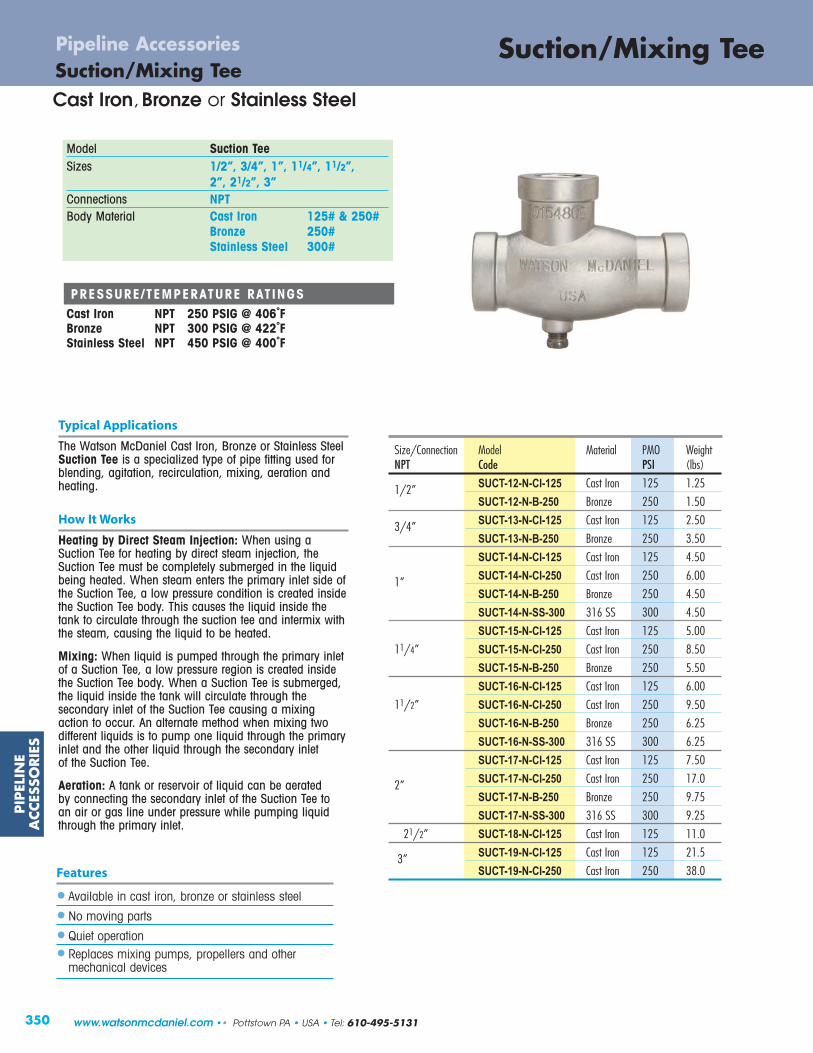
350
PIP
ELIN
EA
CCES
SORIE
SSuction/Mixing TeePipeline Accessories
Features
• Available in cast iron, bronze or stainless steel
• No moving parts
• Quiet operation
• Replaces mixing pumps, propellers and other mechanical devices
Model Suction TeeSizes 1/2”, 3/4”, 1”, 11/4”, 11/2”,
2”, 21/2”, 3”Connections NPTBody Material Cast Iron 125# & 250#
Bronze 250#Stainless Steel 300#
Typical Applications
The Watson McDaniel Cast Iron, Bronze or Stainless SteelSuction Tee is a specialized type of pipe fitting used for blending, agitation, recirculation, mixing, aeration andheating.
How It Works
Heating by Direct Steam Injection: When using aSuction Tee for heating by direct steam injection, theSuction Tee must be completely submerged in the liquidbeing heated. When steam enters the primary inlet side ofthe Suction Tee, a low pressure condition is created insidethe Suction Tee body. This causes the liquid inside thetank to circulate through the suction tee and intermix withthe steam, causing the liquid to be heated.
Mixing: When liquid is pumped through the primary inletof a Suction Tee, a low pressure region is created insidethe Suction Tee body. When a Suction Tee is submerged,the liquid inside the tank will circulate through the secondary inlet of the Suction Tee causing a mixingaction to occur. An alternate method when mixing two different liquids is to pump one liquid through the primaryinlet and the other liquid through the secondary inlet of the Suction Tee.
Aeration: A tank or reservoir of liquid can be aerated by connecting the secondary inlet of the Suction Tee to an air or gas line under pressure while pumping liquidthrough the primary inlet.
PRESSURE/TEMPERATURE RATINGSCast Iron NPT 250 PSIG @ 406˚FBronze NPT 300 PSIG @ 422˚FStainless Steel NPT 450 PSIG @ 400˚F
Cast Iron, Bronze or Stainless SteelSuction/Mixing Tee
Size/Connection Model Material PMO WeightNPT Code PSI (lbs)
1/2” SUCT-12-N-CI-125 Cast Iron 125 1.25
SUCT-12-N-B-250 Bronze 250 1.50
3/4” SUCT-13-N-CI-125 Cast Iron 125 2.50
SUCT-13-N-B-250 Bronze 250 3.50
SUCT-14-N-CI-125 Cast Iron 125 4.50
1” SUCT-14-N-CI-250 Cast Iron 250 6.00
SUCT-14-N-B-250 Bronze 250 4.50
SUCT-14-N-SS-300 316 SS 300 4.50
SUCT-15-N-CI-125 Cast Iron 125 5.00
11/4” SUCT-15-N-CI-250 Cast Iron 250 8.50
SUCT-15-N-B-250 Bronze 250 5.50
SUCT-16-N-CI-125 Cast Iron 125 6.00
11/2” SUCT-16-N-CI-250 Cast Iron 250 9.50
SUCT-16-N-B-250 Bronze 250 6.25
SUCT-16-N-SS-300 316 SS 300 6.25
SUCT-17-N-CI-125 Cast Iron 125 7.50
2” SUCT-17-N-CI-250 Cast Iron 250 17.0
SUCT-17-N-B-250 Bronze 250 9.75
SUCT-17-N-SS-300 316 SS 300 9.25
21/2” SUCT-18-N-CI-125 Cast Iron 125 11.0
3” SUCT-19-N-CI-125 Cast Iron 125 21.5
SUCT-19-N-CI-250 Cast Iron 250 38.0
www.watsonmcdaniel.com •• Pottstown PA • USA • Tel: 610-495-5131

351
PIP
ELINE
ACCESSO
RIES
Suction/Mixing TeePipeline Accessories
Cast Iron, Bronze or Stainless Steel
DIMENSIONS & WEIGHTS – inches
Pipe WeightSize A B C D E (lbs)
125# Cast Iron Body & Bronze 250#
1/2” 33/4 11/2 21/4 13/4 1/4 1.5
3/4” 5 17/8 31/8 31/8 3/8 3.25
1” 55/8 23/16 37/16 21/2 5/8 4
11/4” 53/4 21/4 31/2 21/2 11/16 4.75
11/2” 61/16 27/16 35/8 27/8 7/8 5.50
2” 7 27/8 41/8 3 15/16 7
21/2” 83/8 31/2 47/8 35/16 1 11.75
3” 91/2 41/8 53/8 37/8 15/16 20.50
250# Cast Iron Body & Stainless Steel 300#
1” 61/16 25/16 33/4 211/16 11/16 6.75
11/4” 63/16 23/8 313/16 213/16 11/16 8
11/2” 61/2 213/16 311/16 27/8 7/8 10.50
2” 73/8 31/16 45/16 31/4 15/16 16.50
MATERIALSCast IronBody Cast Iron, A126 CLASS 30Plug Cast Iron, A126 CLASS 30BronzeBody Bronze, ASTM B-62Plug BrassStainless SteelBody Stainless Steel, A351 GR CF8MPlug Stainless Steel, A351 GR 316
Applications
Controlling temperature of large open tank by steam injection
A
E
B C
D
SteamSupply
PrimaryInlet
Secondary Inlet
Outlet
CAPACIT IES – Steam (lbs/hr)Supply Pressure (PSIG)
Size 5 10 15 20 25 30 35 40 45 50 55 60 65 75 85 100 125 1501/2” 66 96 114 135 156 165 174 207 240 258 276 294 312 354 396 456 552 630
3/4” 108 138 168 198 228 255 282 309 336 363 390 402 414 504 564 648 792 936
1” 312 390 468 549 630 711 792 882 972 1026 1080 1170 1260 1428 1584 1800 2232 2556
11/4” 444 558 672 783 894 1005 1116 1230 1344 1461 1578 1689 1800 2010 2232 2592 3168 3708
11/2” 612 756 900 1026 1152 1332 1512 1674 1836 1980 2124 2286 2448 2772 3060 3528 4320 5040
2” 798 1008 1206 1410 1614 1815 2016 2214 2412 2610 2808 3024 3240 3636 3996 4680 5652 6696
21/2” 912 1152 1368 1584 1800 2052 2304 2538 2772 2997 3222 3447 3672 4140 4608 5292 6480 7560
3” 1332 1656 1980 2304 2628 2970 3312 3636 3960 4302 4644 4986 5328 5976 6600 7620 9300 10800
Suction/Mixing Tee
Tel: 610-495-5131 • Pottstown PA • USA •• www.watsonmcdaniel.com
Open Tank
Suction Tee
Thermometer
SteamSupply
TemperatureRegulator
Temp. Probe
Air or Gas Supply
Liquid
Suction Tee
SecondaryInlet
Aeration or Agitation

PIP
ELIN
EA
CCES
SORIE
S
352
EJECT, EJECT-ELL & EJECT-LMPipeline AccessoriesEjectors
Note: ELECT-ELL & ELECT-LM for liquid motive service only.
Syphons, Eductors, Exhausters & Injectors
Model EJECTEJECT-ELLEJECT-LM
Sizes 1/2” – 2”Connections NPTBody Material Bronze (1/2” - 11/2”)
Cast Iron (2”)PMO Max. Operating Pressure 100 PSIGTMO Max. Operating Temperature 130ºFPMA Max. Allowable Pressure 250 PSIG up to 450ºFTMA Max. Allowable Temperature 450ºF @ 250 PSIG
Typical Applications
Watson McDaniel Ejectors perform a variety of functions depending upon the application and motive fluid (steamor water) used. See performance charts on the following pages. Applications include: exhausting, agitating, aerating, circulating, pumping and mixing.
How It Works
Using water, steam or air pressure as the motive force, ejectors operate on the principle that a high velocity flow through a nozzle will create a pressure drop in the area around the nozzle discharge. The resulting vacuum will induce flow into the secondary inlet of the ejector.
Features
• No moving parts
• Can be used with water or steam pressure
• Submersible
• Available in cast iron or bronze
Sample Specification
Ejectors shall be constructed from bronze or cast iron. Units shall be capable of using steam, water or air as a motive force.
Installation
See installation examples on following page.
MATERIALS
Body (1/2” - 11/2”) BronzeBody (2”) Cast IronNozzles (all sizes) Bronze
Note: Minimum Operating Pressure for EJECT-ELL & EJECT-LM is 20 PSIG.
Size/Connection Model Motive Fluid Suction WeightNPT Code Used Fluid lbs
1/2” EJECT-12-N-S Steam Water 0.75EJECT-12-N-W Water Water 0.75
/4” EJECT-13-N-S Steam Water 0.75EJECT-13-N-W Water Water 0.75
1” EJECT-14-N-S Steam Water 1.50 EJECT-14-N-W Water Water 1.50
11/4” EJECT-15-N-S Steam Water 3.75EJECT-15-N-W Water Water 3.75
11/2” EJECT-16-N-S Steam Water 4.75EJECT-16-N-W Water Water 4.75
2” EJECT-17-N-S Steam Water 7.50EJECT-17-N-W Water Water 7.50
EJECT
Size/Connection Model Motive Fluid Suction WeightNPT Code Used Fluid lbs3/4” EJECT-ELL-13-N Water Gases 4.00 1” EJECT-ELL-14-N Water Gases 7.00 11/4” EJECT-ELL-15-N Water Gases 8.00
Size/Connection Model Motive Fluid Suction WeightNPT Code Used Fluid lbs3/4” EJECT-LM-13-N Water Water 1.00 1” EJECT-LM-14-N Water Water 2.2511/4” EJECT-LM-15-N Water Water 3.50
EJECT-ELL
EJECT-LM
Model EJECT can be usedwith Steam or Wateras the Motive Inlet
Motive Fluid is LIQUID
Motive Fluid is LIQUID
www.watsonmcdaniel.com •• Pottstown PA • USA • Tel: 610-495-5131

PIP
ELINE
ACCESSO
RIES
353
EJECT, EJECT-ELL & EJECT-LMEjectorsPipeline Accessories
DIMENSIONS – inches
Connection Sizes ** Dimensions
Size S. Inlet Discharge P. Inlet A B D
3/4” 3/4 3/4 1/2 513/16 2 13/8
1” 1 1 3/4 71/8 25/16 13/4
11/4” 11/4 11/4 1 9 27/16 21/8
** Connections are male NPT.
EJECT
EJECT-ELL / EJECT-LM
Bronze Body & Nozzles
It is always desirable to keep the Ejector as close to the actual liquidbeing pumped as possible. The maximum height the liquid can be pumped depends upon the pressure of the “motive” liquid orsteam available. Please refer to the capacity graphs for maximumflow rates and maximum achievable heads.
The maximum height that water or any liquid with a specific gravityof 1 can be lifted is 25 feet. Increases in the temperature of the liquidbeing lifted will cause this maximum height to decrease. Pumpingliquids in excess of 130°F is not recommended. Please consult factory with any specific application.
FLOW
A
Primary(P) Inlet
CB
D
Discharge
NPT
NPTD
B
A
Secondary(S) Inlet (suction)
Ejector
DIMENSIONS – inches
Connection Sizes * DimensionsSize S. Inlet Discharge P. Inlet A B C D
Bronze Body & Nozzles
1/2” 1/2 1/2 1/4 31/4 17/16 113/16 11/8
3/4” 3/4 3/4 3/8 4 11/2 21/2 13/8
1” 1 1 1/2 51/8 21/4 27/8 15/8
11/4” 11/4 11/4 3/4 57/8 27/16 37/16 113/16
11/2” 11/2 11/2 3/4 61/4 211/16 39/16 115/16
Cast Iron Body with Bronze Nozzles
2” 2 2 1 71/4 31/8 41/8 23/8
* Connections are female NPT.Secondary
(S) Inlet (suction)
Ejectors shown Pumping Liquid
Primary(P) Inlet
Discharge
Syphons, Eductors, Exhausters & Injectors
Inlet Wateror Steam
Inlet Wateror Steam
EjectorTotalHead
Lift
DischargeHead
25 Ft.Maximum
Lift
NPT
Tel: 610-495-5131 • Pottstown PA • USA •• www.watsonmcdaniel.com
FLOW

354
PIP
ELIN
EA
CCES
SORIE
S
500
400
300
200
100
00 20 40 60 80
Total Head (Ft - H2O)
Flow
(gal
/hr)
1750
1400
1050
700
350
00 20 40 60 80
Total Head (Ft - H2O)
Flow
(gal
/hr)
3/4" Water Ejector
1/2" Water Ejector
0 20 40 60 80 100 120Total Head (Ft - H2O)
Flow
(gal
/hr)
1/2" Steam Ejector
0 20 40 60 80 100 120Total Head (Ft - H2O)
Flow
(gal
/hr)
3/4" Steam Ejector
400
300
0
150
100
50
0
Example 2A #14 1” Ejector using 60 lbs. of steam pressure as amotive force will pump water to a maximum height of60 ft. When pumping water to a height of 53 ft. using 60 lbs. of steam pressure, the amount of water beingpumped is 650 gal/hr.
2500
2000
1500
1000
500
00 20 40 60 80
Total Head (Ft - H2O)
Flow
(gal
/hr)
0 20 40 60 80 100 120Total Head (Ft - H2O)
Flow
(gal
/hr)
700
600
0
Example 1A #14 1” Ejector using 60 lbs. of water pressure as amotive force will pump water to a maximum height of40 ft. When pumping water to a height of 20 ft. using 60 lbs. of water pressure, the amount of water beingpumped is 700 gal/hr.
Pipeline Accessories
Ejector Sizing • EJECT Model
for Model EJECT Only (Water) for Model EJECT Only (Steam)
1" Water Ejector 1" Steam Ejector
www.watsonmcdaniel.com •• Pottstown PA • USA • Tel: 610-495-5131

355
PIP
ELINE
ACCESSO
RIES
0 20 40 60 80 0 20 40 60 80 100 120
4000
3200
2400
1600
800
0
Total Head (Ft - H2O)
Flow
(gal
/hr)
11/4" Water Ejector
Total Head (Ft - H2O)
Flow
(gal
/hr)
11/4" Steam Ejector
1100
1000
0
5000
4000
3000
2000
1000
00 20 40 60 80
Total Head (Ft - H2O)
Flow
(gal
/hr)
11/2" Water Ejector
10000
8000
6000
4000
2000
00 20 40 60 80
Total Head (Ft - H2O)
Flow
(gal
/hr)
2" Water Ejector
0 20 40 60 80 100 120Total Head (Ft - H2O)
Flow
(gal
/hr)
11/2" Steam Ejector
2000
1000
0
0 20 40 60 80 100 120Total Head (Ft - H2O)
Flow
(gal
/hr)
2" Steam Ejector
3000
2000
0
Pipeline Accessories
Ejector Sizing • EJECT Model
for Model EJECT Only (Water) for Model EJECT Only (Steam)
Tel: 610-495-5131 • Pottstown PA • USA •• www.watsonmcdaniel.com

PTs
¿Ê¿ËÌÊÍË ÅÎÎËÏÏÐÑÊËÏÅ���P¿ÀÁÂÃÀÄÂ�ÅÆÆÂÇÇÈÉÀÂÇÅÀÉ�ËÃÀ�ÀÄ �ÈÉ qw~{����}
X� ºX¹�i]¬ºX��i]¬
�j° �X®
±jib)¹ji ¢�£¤¥[¤¥[Ò)f[c�f ¥ÍÑϹjnnm_cjnf ÒÓ�ºji)±\_gc\b �Õ«)Ù©µ¼|±×)±\�p)×lg\_cn�)|gffhg ¤Ø§)Ó�ÙÚ�±×)±\�p)×lg\_cn�)�olg\_hg ¥§§ßÝ|±�)±\�p)�bbj�\~b)|gffhg ¤Ø§)Ó�ÙÚ)»h)µ)¥Ø§ÜÝ�±�)±\�p)�bbj�\~b)�olg\_hg ¥Ø¥ßÝ)Þ)¤Ø§)Ó�ÙÚ¬bu[_cW�«uuW[_c[Tg\��)¢�£¤¥)�cg)}bcocn\_jg)cf)hfi)]jg)_�)goje\b)j])\cg)\nij_�g)�\ff)]gjo)effbf)jg)lclcn�)ff_of)�c_�jh_)\bbj�cn�)_�)mjn_\cni)bc�hci)_j)fm\lp£Tz�l�oTZs\���)e\be)\ni)f\_)\ffo~b)cnfci)_�)\cg)bcocn\_jg)cf)mjnnm_i)_j)\)f_\cnbff)f_b)]bj\_p)°�n)_�g)cf)nj)bc�hci)cn)_�)~ji)j])_�)\cg)bcocn\_jg�)_�)]bj\_)�cbb)~)cn)_�)ij�nljfc_cjn�)\bbj�cn�)\cg)jg)j_�g)�\ff)cn)_�)effb)jg)lclcn�)ff_o)_j)fm\lp)°�n)bc�hci)n_gf)_�)~ji�)c_)�cbb)bc]_)_�)]bj\_\ni)_�)e\be)�cbb)~)mbjfi)j]])~]jg)\n)bc�hci)m\n)fm\lp)¡Vc ZV\à5366'-)/$(")%#+&)4+3(%&6à!%*.0')-'(%6&)1+#)'$(2)*$%&"'&$&/'à!"$%&0'(()("''0)%&"'#&$0(àé."%+&$0)F%"+&)F$0,')X'$-)1+#)4%64)"'*.'#$"3#'()$&-)"%64")(43"R+11YctuWV�YuV_[w[_c[Tg�cg)}bcocn\_jg)f�\bb)~)j])m\f_)cgjn)mjnf_ghm_cjn)�c_�)f_\cnbff)f_b)cn_gn\bf)\ni)fj]_)}|{±)f\_)]jg)_c��_)f�h_kj]]p)×l_cjn\b)dc_jnf\_)cf)\e\cb\~b)]jg)be\_i)_olg\_hgf)\ni)_c��_)f�h_kj]]plg\cWWc[Tg���Sc[gVgcg_V��)�d]½ê)f�jhbi)~)bjm\_i)\_)\)�c��)ljcn_)cn)_�)ff_o)jg)effbp)��)hnc_)ohf_)~)cnf_\bbi)beb)\ni)hlgc��_)�c_�)]bj�hl�\gi)]jg)_�)]bj\_)om�\ncfo)_j)jlg\_)lgjlgbp)�fjb\_cjne\bef)f�jhbi)~)cnf_\bbi)]jg)\f)j])o\cn_n\nmp))
î¢�¦ïÙ¢ð�¹jeg ¹\f_)�gjn�)�[�±)�k½¾ë�)¹b\ff)ººji) ¹\f_)�gjn�)�[�±)�k½¾ë�)¹b\ff)ºô\f�_) ôg\]jcb[\_)Dj�) [_\cnbff)[_b�)�l)ê ód\be)[\_ [_\cnbff)[_b�)�l)ê ó|cej_)|cn) [_\cnbff)[_b�)�l)ê ód\be)�\i) }|{±)¶dc_jn)jl_cjn\b·�eg) [_\cnbff)[_b�)�l)ê ó�bj\_) [_\cnbff)[_b�)�l)ê ó°\f�g) [_\cnbff)[_b�)�l)ê ó[mg�)�)°\f�g [_\cnbff)[_b�)�l)ê óUÙî¦Ò�ÙVÒ��ðåòYæç
®m��§))))))))))))))))))ÎØ))))))))))))))))))ا))))))))))))))))))ÛØ))))))))))))))))¤§§))))))))))))))))¤ÎØ))))))))))))))¤Ø§Ôg\Øg£Ñg£¥gÛÎgÛ¤gÔ§g§��Ýî Ó©««»©)aÓ�ÙÚc�Å�Å��È��Æ�Å��Ã� ¡¢£¤��¥££¦�¥§
j)°c_�)dc_jn)f\_�)hf)±jib)¹ji)¢�£¤¥�[¤¥[Ò +,-lR,5,/1PL-01-O20OS3L-4O5L6,/7+,-3-L5,©2,SK80PO50
ÒÒÒÓÒÔÕÖ×ØÙÚÛÔØÜÝÞÓÚ×Ùßßøäööçöäùå�øô�ß��ô�ß�æê�����������

357
PIP
ELINE
ACCESSO
RIES
AE1800 & AE1800R SeriesAir Eliminator Stainless Steel
Pipeline Accessories
Repairable & Non-Repairable
CAPACIT IES – Air (SCFM)Inlet Pressure (PSIG)
Series Size (PSIG) 5 7 9 12 15 20 25 30 40 50 60 70 80 90 100 110 120 125 150 180 265 300 400
AE1810 .078” 400 1.0 1.1 1.3 1.5 1.7 1.9 2.2 2.5 3.1 3.4 3.7 4.2 5.4 6.0 6.8 7.2 7.5 7.9 9.4 11.2 16.3 18.4 24.4
AE1820 .101” 265 1.7 1.9 2.1 2.4 2.6 3.1 3.5 4.0 4.8 5.3 5.7 6.6 8.4 9.3 10.2 11.1 12 12.4 14.5 17.3 24.8 - -
AE1830 .125” 180 2.5 3.0 3.4 3.9 4.3 5.1 5.8 6.5 8.0 8.7 9.5 10.9 13.9 15.4 16.9 18.4 19.9 20.5 24.4 29.6 - - -
Note: Specify Model Number when ordering. Example: AE1812R-N (.078” Orifice, 3/4” x 3/4” NPT, 400 PSIG max, Repairable unit)
* PMO based on liquids with specific gravity of 1. Consult factory for PMO for liquids of other specific gravity values.
Model AE1800, AE1800RSizes 1/2”, 3/4”Connections NPTBody Material Stainless SteelPMO Max. Operating Pressure 400 PSIGTMO Max. Operating Temperature 500ºFPMA Max. Allowable Pressure 400 PSIG up to 500ºFTMA Max. Allowable Temperature 500ºF @ 400 PSIG
Typical Applications
The AE1800 Air Eliminator is used for the removal of air and other gases from vessels or piping systems without allowing the contained liquid to escape.
How It Works
The valve and seat assembly inside the air eliminator is connected to a stainless steel float. When there is no liquid in the body of the air eliminator, the float will be in the downposition, allowing air or other gases in the vessel or piping sys-tem to escape. When liquid enters the body, it will lift the floatand the valve will be closed off before any liquid can escape.
Features
• All stainless steel body and internals
• Hardened SS seat (55 Rc) for longer service life
• Repairable units available (AE1800R Series)
Installation & Maintenance
The AE1800 should be located at a high point in the system or vessel. The unit must be installed level and upright with flowupward for the float mechanism to operate properly. Isolationvalves should be installed for ease of maintenance.
MATERIALS
Body & Shell Stainless Steel, AISI 304Float Assembly Stainless Steel, AISI 304Valve & Lever Assembly Hardened Stainless Steel, 55 RcSeat Stainless Steel, AISI 420Washer, Seat 302 SS*Gasket Grafoil*Bolt, Hex, HD Stainless Steel, AISI 316*Nut Stainless Steel, 18-8
* AE1800R Repairable models only.
AE1800(Non-Repairable)
FLOWFLOW
AE1800(Non-Repairable)
A
25/8
DIMENSIONS – inches / pounds
Model Code & Orifice Size Size NPT Height Weight.078” .101” .125” (Inlet x Outlet) A (lbs)
AE1811-N AE1821-N AE1831-N 7.5 4
AE1811R-N AE1821R-N AE1831R-N 7.9 5
AE1812-N AE1822-N AE1832-N 7.5 4
AE1812R-N AE1822R-N AE1832R-N 7.9 5
AE1813-N AE1823-N AE1833-N 7.5 4
AE1813R-N AE1823R-N AE1833R-N 7.9 5
4.0
A
AE1800R(Repairable)
AE1800R(Repairable)
Orifice PMO*
3/4” x 1/2”
3/4” x 3/4”
1/2” x 1/2”
Air Eliminators areused for RemovingAir from LiquidSystems
Tel: 610-495-5131 • Pottstown PA • USA •• www.watsonmcdaniel.com

358
PIP
ELIN
EA
CCES
SORIE
SWDS SeriesPipeline Accessories
Air/Steam Moisture Separator
Typical Applications
The WDS Series Separators are used for the removal of entrained liquid or solids from steam or air. Effective in applications where the system has an entrained liquid flow rate of up to 40% by weight of the unit’s flow capacity.
How It Works
Wet steam enters the inlet of the separator where it is deflected in a centrifugal downward motion. The entrained moisture is separated out by reduction in velocity. Separated liquid then falls below the Vortex Containment Plate where it cannot be re-entrained. Dry steam or air then flows upward and exitsthrough the outlet of the separator.
Features
• Removes 99% of all particles > 10 microns in size
• Minimum pressure drop
• Gauge ports on 3” & 4” cast iron units
• Standard gauge ports on 21/2”–12” carbon steel units
• ASME Code constructed
Model WDSBody Material Cast Iron Carbon SteelSizes 3/4” thru 4” 1” thru 12”Connections NPT, 125# Flanged NPT, SW, 150# &
300# FlangedPMO Max. Operating Pressure 250 PSIG 300 PSIG (NPT & SW)Pressure/ NPT: 250 PSIG @ 450˚F NPT, SW: 1000 PSIG @ 650˚FTemperature Rating 125# FLG: 150 PSIG @ 450˚F 150# FLG:150 PSIG @ 450˚F
300# FLG: 500 PSIG @ 650˚F
CAPACIT IES – Steam (lbs/hr)Operating Pressure (PSIG)
Size 5 10 25 50 100 150 200 250 300 400* 450* 500*
3/4”, 1" 192 219 289 384 536 661 772 872 964 1132 1210 1284 11⁄4" 305 348 459 609 851 1050 1225 1384 1531 1797 1921 2038 11⁄2" 434 495 653 868 1211 1495 1744 1970 2179 2559 2734 2902 2" 769 877 1156 1536 2143 2646 3087 3487 3857 4529 4839 5136
21⁄2" 1220 1391 1834 2437 3401 4199 4900 5535 6121 7188 7680 8151 3" 1912 2181 2876 3821 5333 6583 7682 8677 9597 11269 12041 127794" 3183 3632 4787 6362 8878 10959 12788 14446 15977 18760 20046 212745" 4823 5501 7252 9637 13449 16603 19373 21884 24203 28420 30367 32229 6" 7465 8516 11226 14917 20818 25699 29988 33874 37464 43992 47006 498878" 12444 14196 18713 24867 34704 42840 49989 56468 62452 73334 78359 8316110" 19376 22104 29137 38720 54036 66705 77836 87924 97241 114186 122009 129487 12" 28560 32580 42947 57071 79648 98320 114728 129597 143331 168306 179836 190859
* Not to be used for steam service at these pressures. For air service only.
Sample Specification
Steam Moisture Separator shall be “T” style for horizontal piping installations. Separator to be code constructed in cast ironor carbon steel and available in FNPT and flanged connections.
Installation
The WDS Air/Steam Moisture Separator must be installed in a horizontal run of pipe. Exercise standard piping and structuralpractices when installing this unit. Proper drainage of the separator utilizing a float & thermostatic steam trap or liquiddrainer (for air applications) is essential for proper operation.
MATERIALSWDS Cast Iron Model Cast IronWDS Carbon Steel Model Fabricated Carbon Steel
WDSCast Iron
(NPT)
WDSCarbon Steel
(Flanged)
Cast Iron or Carbon Steel
www.watsonmcdaniel.com •• Pottstown PA • USA • Tel: 610-495-5131

A(NPT,SW)
A(Flanged) Vent
Connection1/4” NPT
1/2” NPTWater GaugeConnection
DrainD
B
C
G
359
PIP
ELINE
ACCESSO
RIES
WDS SeriesAir/Steam Moisture SeparatorPipeline Accessories
WDS CAST IRON NPT DIMENSIONS – inches
Size Vent Drain Gauge Centers Weight(NPT) A B C NPT NPT G (lbs)3/4” 51/2 101/8 53/4 1/4 3/4 N/A 23
1” 6 101/8 63/4 1/4 1 N/A 26
11/4” 6 103/8 7 1/4 1 N/A 30
11/2” 71/4 131/8 81/8 1/4 1 N/A 45
2” 81/8 155/8 81/2 1/4 1 N/A 50
21/2” 12 181/4 113/8 1/4 11/4 N/A 95
3” 11 181/4 113/8 1/4 11/4 31/2 90
WDS CARBON STEEL DIMENSIONS – inches
NPT & 150# & Gauge Weight (lbs)Size SW 300# FLG Centers NPT & 150# 300#
A A B C D G Std. Opt. SW FLG FLG
1” 63/8 101/2 101/2 12 59/16 Opt. 1 11/2 29 33 35
11/4” 63/8 101/2 101/2 12 59/16 Opt. 1 11/2 30 35 37
11/2” 75/8 111/2 121/2 14 65/8 Opt. 1 2 55 50 56
2” 77/8 111/2 121/2 14 65/8 Opt. 1 2 57 55 59
21/2” – 16 15 22 85/8 53/4 1 2 – 100 110
3” – 18 18 26 103/4 53/4 11/2 21/2 – 140 150
4” – 20 22 31 123/4 53/4 11/2 21/2 – 195 220
5” – 22 26 36 14 77/8 11/2 21/2 – 230 290
*6” – *24 30 41 16 77/8 11/2 21/2 – 350 380
*8” – *28 37 50 18 77/8 2 3 – 475 610
*10” – *34 55 70 24 77/8 2 3 – 780 1180
*12” – *38 58 75 28 77/8 21/2 4 – 940 1510
Note: 1” - 2” units are Cast Steel; 21/2” and up are Fabricated Steel.
* Contact Factory for certified drawings on 6” through 12” models.
NPT Drain
WDS CAST IRON FLANGED DIMENSIONS – inches
Size Vent Drain Gauge Centers Weight(Flanged) A B C NPT NPT G (lbs)
2” 101/2 133/4 81/2 1/4 1 N/A 50
3” 14 16 113/8 1/4 11/4 43/4 95
4” 157/8 193/8 14 1/4 11/4 53/4 195
A(Flanged)
A(NPT)
VentConnection1/4” NPT
1/2” NPTWater GaugeConnectionDrain
C
G
B
WDS (Cast Iron)
WDS (Carbon Steel)
Cast Iron or Carbon Steel
Tel: 610-495-5131 • Pottstown PA • USA •• www.watsonmcdaniel.com
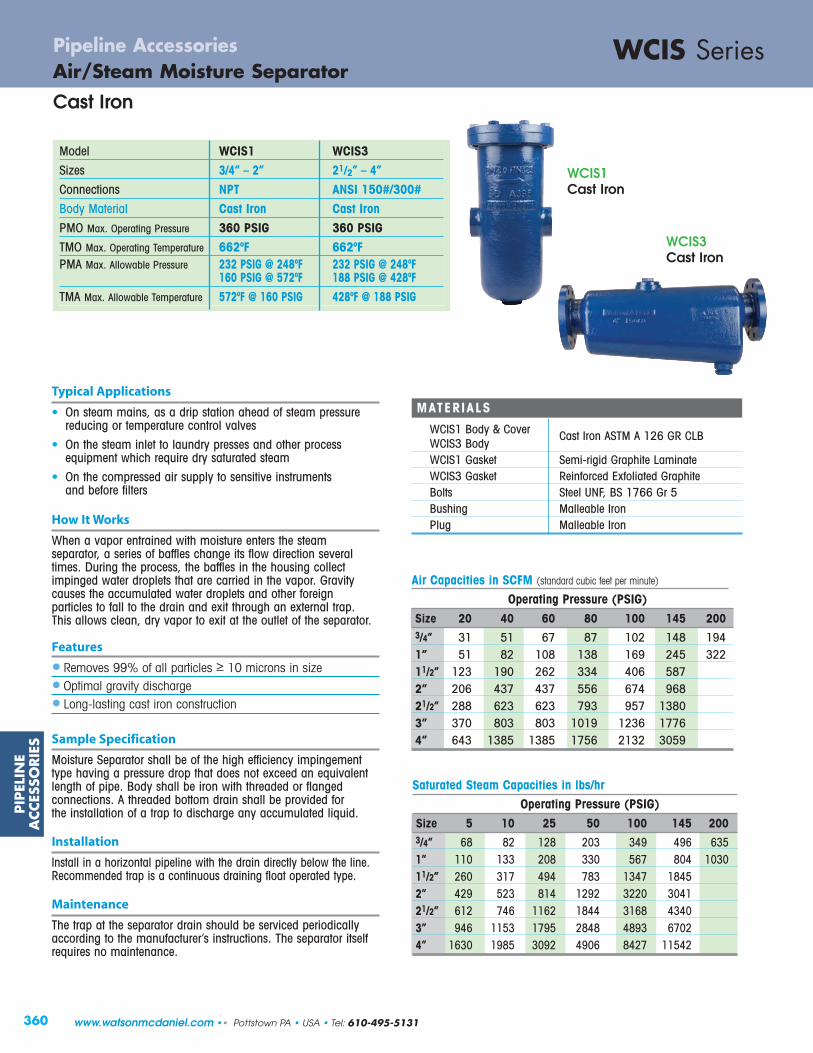
Operating Pressure (PSIG)Size 20 40 60 80 100 145 2003/4” 31 51 67 87 102 148 1941” 51 82 108 138 169 245 32211/2” 123 190 262 334 406 5872” 206 437 437 556 674 96821/2” 288 623 623 793 957 13803” 370 803 803 1019 1236 17764” 643 1385 1385 1756 2132 3059
Air Capacities in SCFM (standard cubic feet per minute)
PIP
ELIN
EA
CCES
SORIE
S
360
WCIS SeriesPipeline AccessoriesAir/Steam Moisture Separator
Cast Iron
Model WCIS1 WCIS3Sizes 3/4” – 2” 21/2” – 4”Connections NPT ANSI 150#/300#Body Material Cast Iron Cast IronPMO Max. Operating Pressure 360 PSIG 360 PSIGTMO Max. Operating Temperature 662ºF 662ºFPMA Max. Allowable Pressure 232 PSIG @ 248ºF 232 PSIG @ 248ºF
160 PSIG @ 572ºF 188 PSIG @ 428ºFTMA Max. Allowable Temperature 572ºF @ 160 PSIG 428ºF @ 188 PSIG
Typical Applications
• On steam mains, as a drip station ahead of steam pressure reducing or temperature control valves
• On the steam inlet to laundry presses and other process equipment which require dry saturated steam
• On the compressed air supply to sensitive instruments and before filters
How It Works
When a vapor entrained with moisture enters the steam separator, a series of baffles change its flow direction severaltimes. During the process, the baffles in the housing collectimpinged water droplets that are carried in the vapor. Gravitycauses the accumulated water droplets and other foreign particles to fall to the drain and exit through an external trap.This allows clean, dry vapor to exit at the outlet of the separator.
Features
• Removes 99% of all particles > 10 microns in size
• Optimal gravity discharge
• Long-lasting cast iron construction
Sample Specification
Moisture Separator shall be of the high efficiency impingementtype having a pressure drop that does not exceed an equivalentlength of pipe. Body shall be iron with threaded or flanged connections. A threaded bottom drain shall be provided for the installation of a trap to discharge any accumulated liquid.
Installation
Install in a horizontal pipeline with the drain directly below the line.Recommended trap is a continuous draining float operated type.
Maintenance
The trap at the separator drain should be serviced periodicallyaccording to the manufacturer’s instructions. The separator itselfrequires no maintenance.
MATERIALS
WCIS1 Body & Cover Cast Iron ASTM A 126 GR CLBWCIS3 BodyWCIS1 Gasket Semi-rigid Graphite LaminateWCIS3 Gasket Reinforced Exfoliated GraphiteBolts Steel UNF, BS 1766 Gr 5Bushing Malleable IronPlug Malleable Iron
Saturated Steam Capacities in lbs/hrOperating Pressure (PSIG)
Size 5 10 25 50 100 145 2003/4” 68 82 128 203 349 496 6351” 110 133 208 330 567 804 103011/2” 260 317 494 783 1347 18452” 429 523 814 1292 3220 304121/2” 612 746 1162 1844 3168 43403” 946 1153 1795 2848 4893 67024” 1630 1985 3092 4906 8427 11542
WCIS3Cast Iron
WCIS1Cast Iron
www.watsonmcdaniel.com •• Pottstown PA • USA • Tel: 610-495-5131
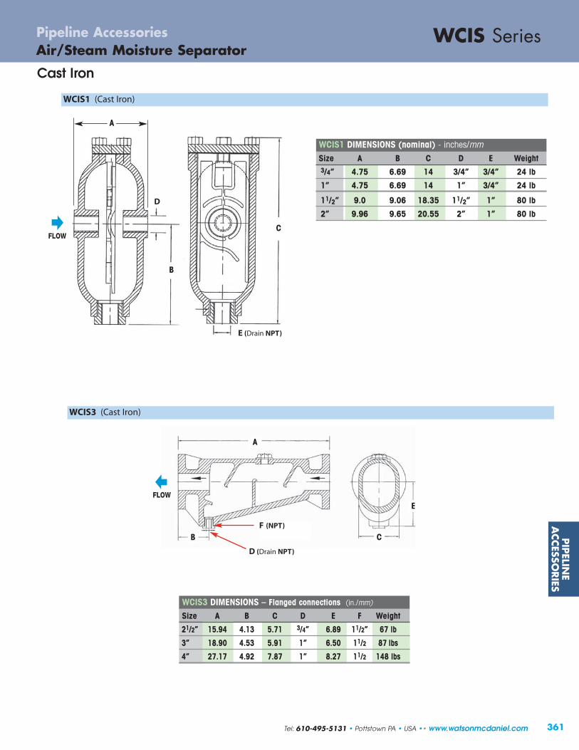
PIP
ELINE
ACCESSO
RIES
361
WCIS SeriesAir/Steam Moisture SeparatorPipeline Accessories
Cast Iron
WCIS1 DIMENSIONS (nominal) - inches/mmSize A B C D E Weight3/4” 4.75 6.69 14 3/4” 3/4” 24 lb
1” 4.75 6.69 14 1” 3/4” 24 lb
11/2” 9.0 9.06 18.35 11/2” 1” 80 lb
2” 9.96 9.65 20.55 2” 1” 80 lb
C
E (Drain NPT)
B C
WCIS3 DIMENSIONS – Flanged connections (in./mm)
Size A B C D E F Weight
21/2” 15.94 4.13 5.71 3/4” 6.89 11/2” 67 lb
3” 18.90 4.53 5.91 1” 6.50 11/2 87 lbs
4” 27.17 4.92 7.87 1” 8.27 11/2 148 lbs
WCIS1 (Cast Iron)
WCIS3 (Cast Iron)
D (Drain NPT)
E
F (NPT)
A
B
D
A
FLOW
FLOW
Tel: 610-495-5131 • Pottstown PA • USA •• www.watsonmcdaniel.com

362
PIP
ELIN
EA
CCES
SORIE
S
Model Code WFPV-12-NSizes 1/2”Connections NPTBody Material Stainless SteelPMO Max. Operating Pressure 200 PSIGTMO Max. Operating Temperature 300ºF
Typical Applications
The WFPV is used for freeze protection on pipes, valves, fittings, pumps, condensate systems, safety showers, fire lines,spray nozzles, freeze sensitive equipment or as backup protectionon steam tracing lines.
How It Works
A thermostatic element senses water temperature in the valve. If the temperature falls below 35ºF, the valve will modulate openallowing water to drain from the system. The valve will remainopen as long as the water flowing by the sensing element is lessthan 40ºF. When the water temperature rises above 40ºF, thevalve will close.
Features
• Corrosion resistant stainless steel body
• Long service life
• Narrow temperature band
• System pressures will not affect opening temperature
Sample Specification
The freeze protection valve shall have a stainless steel body and be actuated by a thermostatic element that senses water temperature. The unit shall feature a ram-type plug for a tight and reliable shut-off.
Installation
Unit should be installed in a vertical orientation with flow direction downward. For full details, see Installation andMaintenance Manual.
MATERIALSBody Stainless Steel, 303O-Ring EPDMPlug Stainless SteelSpring Stainless Steel, 302Thermal Actuator Stainless Steel
1/2 NPT
FLOW
11/4
41/2
CAPACIT IES – Water (lbs/hr)Inlet Pressure Capacity
(PSIG) (lbs/hr)
50 2475
75 3031
100 3500
125 3913
150 4287
175 4630
200 4950
WFPVPipeline AccessoriesFreeze Protection Valve
Stainless Steel
ValveOPEN
(<40˚F)
ValveCLOSED(>40˚F)
WFPVFreezeProtectionValve
Cold WaterDischarge
Sensing ElementWeight: 0.9 lbs.
www.watsonmcdaniel.com •• Pottstown PA • USA • Tel: 610-495-5131

363
PIP
ELINE
ACCESSO
RIES
Model Code 1/2” WSPV-12-N3/4” WSPV-13-N
Sizes 1/2”, 3/4”Connections NPTBody Material Stainless SteelPMO Max. Operating Pressure 200 PSIGTMO Max. Operating Temperature 300ºF
Typical Applications
The WSPV is used to protect personnel from accidental scalding by over-heated water or other liquids. Installations such as eye-wash stations and safety showers can become over-heated by piping exposed to solar radiation or a heatexchanger malfunction.
How It Works
When water temperature rises above 95ºF, the thermal actuatormodulates the valve open. If the water exceeds 105ºF, the valvewill go to full open position in order to discharge the over-heatedwater. When the water temperature returns to 95ºF, the thermalactuator modulates the valve to close.
Features
• Corrosion resistant stainless steel body
• Long service life
• Narrow temperature band
• System pressures will not affect opening temperature
Sample Specification
The scald protection valve shall have a stainless steel body and be actuated by a thermal element that senses water temperature. The unit shall feature a ram-type plug forreliable and tight shut-off.
Installation
Unit should be installed in a vertical orientation with flow direction downward. For full details, see Installation andMaintenance Manual.
MATERIALSBody Stainless Steel, 303Seat Seal PTFEPlug Stainless SteelSpring Stainless Steel, 302Thermal Actuator Stainless Steel
DIMENSIONS & WEIGHTS – inches / pounds
Size NPT A B Weight (lbs)
1/2" 11/4 41/2 0.9
3/4" 11/2 51/2 1.4
FLOW
A
B
CAPACIT IES – Water (lbs/hr)
Inlet Pressure Capacity (lbs/hr)(PSIG) 1/2” 3/4”
50 5,300 7,070
75 6,495 8,660
100 7,500 10,000
125 8,385 11,180
150 9,180 12,240
200 10,600 14,140
WSPV SeriesScald Protection ValvePipeline Accessories
Stainless Steel
ValveOPEN
(>95˚F)
ValveCLOSED(<95˚F)
WSPVScaldProtectionValve
Hot WaterDischarge
Sensing Element
Tel: 610-495-5131 • Pottstown PA • USA •• www.watsonmcdaniel.com

364
PIP
ELIN
EA
CCES
SORIE
S
Model WSTTV Stainless Steel
Sizes & Model Code 1/2” WSTTV-12-N-SS3/4” WSTTV-13-N-SS1” WSTTV-14-N-SS
Connections NPT
Body Material Stainless SteelPressure Ratings 150 PSIG WSP
Application & How It Works
The WSTTV Steam Trap Test Valve offers simple, immediate, and visible diagnosis of any steam trap. Turning the handle 90˚ to the“Test” position will direct flow of steam trap out the test port for visual evaluation of discharge.
With the WSTTV Steam Trap Test Valve installed downstream of the trap and in the open position, the steam trap discharges normally. A quarter-turn of the handle repositions the speciallydesigned ball and diverts the trap discharge through a port on the bottom of the valve. Discharge can then be observed andassessments made regarding the operation of the steam trap.
Features
• Seal welded construction
• Full stainless steel construction
• Fully compliant with ASME B16.34 & API 608
• NACE MR-01-75 compliant
• Standard locking stainless steel handles
• Single reduced bore/full porting (depending on size)MATERIALS (Stainless Steel)
Description 150 PSI RatingBody CF8MBall ASTM A276 Gr. 316 SSStem ASTM A276 Gr. 316 SSSeats (2) R-TFM (Hostaflon)Stem Packing GraphiteHandle Assembly 300 Series SS
WSP = Working Steam Pressure
WSTTV SeriesPipeline AccessoriesSteam Trap Test Valves
Stainless Steel
Installation
Test Valve to be mounted on the outlet side of the steam trap. Care should be taken to ensure that the discharge port will bepositioned in such a manner so as to avoid danger to personnel. NOT AN ISOLATION OR STOP VALVE.
Normal Open:Flow is straight through
In Test Position:Flow dischargesthrough test port
Test Port(open)
Test Port(blocked)
(flowblocked)
Steam Trap Test Valve
condensate return
IsolationValve
SteamTrap
IsolationValve
Test Port(discharge)
www.watsonmcdaniel.com •• Pottstown PA • USA • Tel: 610-495-5131

365
Steam to
Water H
eater
Heat MiserInstantaneous Steam to Water Heatersfor Domestic and Process Water Heating Applications
Heat Miser
www.watsonmcdaniel.com •• 428 Jones Boulevard • Limerick Airport Business Center • Pottstown PA • 19464 •• Tel: 610-495-5131

366
Stea
m t
oW
ater
Hea
ter
Heat MiserInstantaneous Steam to Water Heater
The Heat Miser is an Instantaneous Steam to Water Heater which produces hot water from steam. The Watson McDaniel fully-assembled Heat Miser eliminates the need for large hot water storage tanks and saves significant energy which is required for large standing tanks of hot water.
Common Applications: Hospitals, Schools & Universities, Hotels, Process Washdown Stations, Residential Apartment Buildingsor any other facility with an existing steam boiler.
System Benefits
• Meets the rigorous demands of domestic water heating
• Accommodates extreme load fluctuations without the need or storage tanks
• Accurate control of outlet water temperature for many systems to +/- 2ºF, and +/- 8ºF for wide and sudden load fluctuations
• High-efficiency Plate & Frame Heat Exchanger optimized for usewith low pressure steam and offers typical flow rates up to 300 GPM, with higher flow rate designs available
• Integral Control Panel included for ease of operationand system feedback
• Electric and Pneumatic Control Valves available for precise steam control
• Excellent for washdown stations
The Watson McDaniel Difference
• ASME qualified welders and certifications
• ASME U and UM Stamp availability on appropriate components
• Complete assembly and pressure testing prior to shipment
• Better control of design, cost and quality by avoiding 3rd party fabricators
• Unparalleled turn-around and deliveries with many units available for shipment within days
Standard Auxiliary Items
• Steam and Condensate Inlet Y-Strainers
• Stainless Steel Recirculation Pump
• Over-temperature Protection – Solenoid-actuated Cold Water Injection
• Steam Inlet Pressure Gauge
• Stainless Steel RTD Electronic Temperature Sensor
• Stainless Steel Waterside Piping with Safety Valve
Old Hot Water System Negatives
• Takes up excessive floor space• Stagnating hot water• Danger of Legionella Growth• Corrosion of tanks• Significant radiant heat loss
New Heat Miser System
• Small footprint (typical floor space of 14ft2)• Efficient plate & frame heat exchanger maximizes turbulent
flow for instantaneous hot water on demand• Stainless Steel waterside components• Simple maintenance and reduced overall costs
www.watsonmcdaniel.com •• Pottstown PA • USA • Tel: 610-495-5131
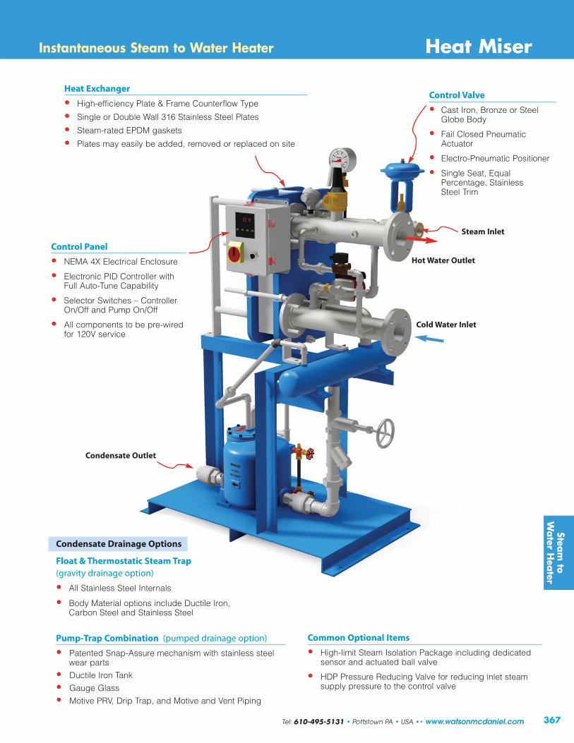
367
Steam to
Water H
eater
Heat MiserInstantaneous Steam to Water Heater
Condensate Drainage Options
Float & Thermostatic Steam Trap (gravity drainage option)
• All Stainless Steel Internals
• Body Material options include Ductile Iron, Carbon Steel and Stainless Steel
Pump-Trap Combination (pumped drainage option)
• Patented Snap-Assure mechanism with stainless steel wear parts
• Ductile Iron Tank
• Gauge Glass
• Motive PRV, Drip Trap, and Motive and Vent Piping
Control Panel
• NEMA 4X Electrical Enclosure
• Electronic PID Controller with Full Auto-Tune Capability
• Selector Switches – Controller On/Off and Pump On/Off
• All components to be pre-wired for 120V service
Control Valve
• Cast Iron, Bronze or Steel Globe Body
• Fail Closed Pneumatic Actuator
• Electro-Pneumatic Positioner
• Single Seat, Equal Percentage, Stainless Steel Trim
Heat Exchanger
• High-efficiency Plate & Frame Counterflow Type
• Single or Double Wall 316 Stainless Steel Plates
• Steam-rated EPDM gaskets
• Plates may easily be added, removed or replaced on site
Common Optional Items
• High-limit Steam Isolation Package including dedicated sensor and actuated ball valve
• HDP Pressure Reducing Valve for reducing inlet steam supply pressure to the control valve
Cold Water Inlet
Steam Inlet
Hot Water Outlet
Condensate Outlet
Tel: 610-495-5131 • Pottstown PA • USA •• www.watsonmcdaniel.com

368
Stea
m t
oW
ater
Hea
ter
Watson McDaniel offers five standard packages, or you can customize your own Heat Miser.
WATER Footprint Dimensions (in)Model Inlet &
GPMSteam Condensate Steam Load (lbs/hr)
Length Width HeightOutlet Inlet Outlet @ 100˚F Temp Rise
1P10 3” 20 11/2” 11/2” 1,030 46 30 67
1P20 3” 40 2” 11/2” 2,061 46 30 67
2P28 3” 60 21/2” 2” 3,091 46 30 73
3P20 3” 80 3” 2” 4,122 54 34 92
3P28 3” 100 3” 2” 5,152 54 34 92
3 Standard Frame Sizes
1P 2P 3P
Heat MiserInstantaneous Steam to Water Heater
STEAM
www.watsonmcdaniel.com •• Pottstown PA • USA • Tel: 610-495-5131

369
SteamH
umidifiers
Single Tube Humidifier
Steam Trap
Separator
Strainer
Steam SupplyConnection
Mounting Bracket
Injection Tube
Steam Emission Ports
Steam Control Valve& Actuator
Duct
3/4” NPT Condensate Connection
• For direct injection of steam humidification into air stream
• Many tube length options to accommodate various duct widths
• Recommended for relatively small duct heights where dissipation distance is not critical
Single Tube (WSI)
• Used for improved dissipation distances in duct heights above 20”
• Number of tubes can be selected to optimize performance• Many tube length options to accommodate various
duct widths
Multiple Tube (WSI)
• Custom-engineered manifold design for job-specific requirements
• Used when dissipation distances are critical for optimum air stream humidification
• Number of tubes properly selected to achieve design requirements
Insty-Pac (WIP)
Multiple Tube HumidifierStrainer
Separator
Trap
Trap
Valve
“B”
“B”
“A”
“A”
Injection Tubes
“C”
Insty-Pac Manifold-Style Humidifier
Steam HumidifiersOverview
Tel: 610-495-5131 • Pottstown PA • USA •• www.watsonmcdaniel.com

370
Stea
mH
umid
ifier
s
• Designed for applications that require smallhumidification loads in a small duct size
• Ideal for any high humidity job where fast steamdissipation in cool air in a short-run duct is essential
• Number of tubes can be specified per duct size andjob requirements
Mini-Mult
• Designed for applications that require humidificationwithout the use of duct work
• Ideal for area humidity control in paper, textile or woodmanufacturing applications as well as printing plantsand storage areas
Area Type
Mini-Mult Front View
BTube Insertion Length
A(ref. note #1)3” (7.6)
Typ. Centers
7.5”(19.1)
3/4” NPT Condensate Connection(see Side View)
Electric Fan115 VAC single phase9 watt / 3 amp.
Steam ControlValve & Actuator
AirFlow
Separator
3/4” NPT Condensate Connection
BTube Diameter
D
C
ADia
• Provides humidification for today’s stringent indoorair quality requirements
• Utilizes boiler steam to heat tap water providinginjection steam free from chemical or mineral carry-over
• Ideal for use where electric humidifiers would becost-prohibitive
Steam Heat Exchanger (WSX)
WSX, Mini-Mult & Area TypeSteam Humidifiers Steam Injection
Humidification Overview
www.watsonmcdaniel.com •• Pottstown PA • USA • Tel: 610-495-5131

371
SteamH
umidifiers
Typical Applications
A Steam Injection Humidifier supplies precise humidity control from the facility steam boiler into the air stream.Typically used in manufacturing plants, printing plants, commercial offices, hospitals and any other facilities which require a critical balance between temperature and humidity control.
How It Works
The Steam Injection Humidifier receives steam directly fromthe boiler (live steam), removes the condensate and injectsthe dry steam into the duct work or an air stream. Livesteam enters a steam jacket to preheat the injection tube.Steam then flows into the separator where condensate isremoved. Dry steam is then discharged through the injectiontube for circulation into the air stream.
Features
• Provides accurate humidity control
• Simple and cost efficient system to meet highhumidity requirements
• Available for regular or purified boiler steam
• Available for single or multiple tube applications
• Capacities up to 2900 lbs/hr
• Pressure ranges from 2-60 PSIG
• Available for pneumatic or electric controls
• All stainless steel distributors and nozzles ensurepermanent bond
• Separator and Steam Jacket included to provide highest quality steam
Installation
Distributor must be mounted level in a straight section of duct,with steam outlets facing into the air stream. A steam trap should be installed on the separator outlet, allowing for propercondensate removal. Also include a strainer upstream of humidifier inlet.
Maintenance
The strainer should be cleaned periodically. The valve, actuator,steam trap and temperature switch should be inspected annuallyto confirm proper operation. For full maintenance details, seeinstallation and maintenance manual.
MATERIALSSeparator 304 SSDispersion Tube 304 SST
HOW TO ORDERConsult factory for sizing and selection. Provide required humidification load, steam pressure at humidifier inlet, ductdimensions, actuator type and any accessories.
Series “WIP”INSTY-PAC
Steam Injection Humidifiers
Dry SteamSteam/Condensate
Series “WSI”Steam Injection
Humidifiers
Injection Tube
LiveSteamIn
CondensateRemoval
Separator
Valve
Dry Steam Out
WSI & WIPSteam Humidifiers Steam Injection
Trap
Strainer
Tel: 610-495-5131 • Pottstown PA • USA •• www.watsonmcdaniel.com

372
Stea
mH
umid
ifier
s
To prevent condensation on in-duct objects, such as dampeners, coils, filters or turning vanes, it is very important that the dissipation distancebe shorter than the distance from the humidifier to the in-duct object. The following recommendations should be used when designing a multiple injection tube system:
Duct Height Recommended Qty. of Tubes †Up to 36” 237” – 48” 349” – 72” 473” – 96” 5Above 96” 6
† Final duct relative humidity, air velocity and available dissipation distance will affect the quantity of tubes required.
Insty Single Multi Steam Pressure to Humidifier Supply Connection (PSIG)Pac Tube Tube 2 3 4 5 6 7 8 9 10 11 12 13 14 15 20 25 30 35 40 45 50 55 60
.10 (1/2”) 1.6 1.9 2.3 2.6 2.8 3.0 3.2 3.4 3.6 3.8 4.0 4.2 4.3 4.4 5.1 5.7 6.3 6.8 7.3 7.7 8.1 8.5 8.9
.22 (1/2”) 3.5 4.2 5.0 5.6 6.5 6.6 7.1 7.6 8 8 9 9 10 10 11 13 14 15 16 17 18 19 20
.40 (1/2”) 6.4 7.6 9.1 10 11 12 13 14 15 15 16 16 17 18 20 23 25 27 29 31 33 34 36
.75 (1/2”) 12 14 17 19 21 23 24 26 27 28 30 31 32 33 38 43 47 50 54 57 60 63 66
.95 (1/2”) 15 18 21 24 27 29 31 33 34 36 38 39 40 42 48 54 59 64 68 72 76 80 84BP-1 50-10 50 1.30 (1/2”) 21 24 29 33 36 39 42 44 47 49 51 53 55 57 66 74 80 87 93 99 104 109 114
1.75 (1/2”) 28 33 40 44 49 52 55 60 63 66 69 72 74 76 88 99 107 116 124 132 139 146 1532.20 (1/2”) 35 41 50 55 61 66 71 75 79 82 86 90 93 95 111 123 134 146 156 165 174 183 1922.80 (1/2”) 45 53 64 70 78 84 90 96 100 104 109 114 118 121 141 157 171 186 199 210 221 233 2443.25 (1/2”) 52 61 73 82 90 96 104 110 116 121 127 132 137 140 163 181 198 214 229 244 257 270 2824.40 (1/2”) 70 83 98 110 121 130 141 149 157 163 172 178 185 190 221 244 256 290 310 328 345 363 3815.50 (3/4”) 85 104 123 138 150 161 176 186 196 204 213 222 231 235 275 305 333 360 385 408 430 451 471
BP-2 60-20 60 6.20 (3/4”) 96 117 138 155 169 182 198 210 220 230 240 250 259 265 310 343 372 403 434 459 485 508 5297.50 (3/4”) 116 142 166 186 204 220 238 253 265 277 289 302 312 320 373 412 450 487 525 555 585 614 6408.20 (1”) 123 155 180 204 223 240 261 275 290 303 313 328 341 349 407 443 488 529 570 603 635 668 703
BP-3 70-20 70 10.0 (1”) 150 189 220 248 272 293 317 335 354 370 380 400 414 423 497 540 595 645 695 735 770 810 85012.0 (1”) 180 228 264 296 326 351 378 402 422 441 456 465 492 505 595 648 714 774 828 876 - - -
BP-4 80-30 80 20.0 (1-1/4”) 300 375 440 494 540 582 630 666 702 736 750 772 814 834 990 1060 1180 1280 1376 1460 - - -28.0 (1-1/4”) 420 511 612 686 756 812 873 927 980 1024 1044 1075 1128 1165 1383 1484 1638 1778 1912 2044 - - -
BP-5 N/A 90 40.0 (2”) 300 375 440 494 540 582 630 666 702 736 750 772 814 834 990 1060 1180 1280 1376 1460 - - -
Single Tube (WSI)
Multiple Tube (WSI)
Insty-Pac Tube (WIP)
Trap
Separator
Strainer
Separator
Trap
Trap
Injection Tube
Strainer
Valve
Valve
Trap
Trap
Strainer
Strainer
Control Valve
Injection Tubes
Dry SteamSteam/Condensate
ValveCv
SizeNPT
MODEL NUMBERS
WSI & WIPSteam Humidifiers Steam Injection
www.watsonmcdaniel.com •• Pottstown PA • USA • Tel: 610-495-5131

373
Typical Applications
Steam Heat Exchanger Humidifiers can be used for humidificationapplications where steam injection is to be used, but chemicallytreated boiler steam is not allowable. They provide humidification to meet stringent indoor air quality requirements and are ideal for use where electric humidifiers would be cost-prohibitive.
How It Works
The WSX Steam Heat Exchanger Humidifier works by utilizing existing boiler steam to heat tap water, providing injection steam free from chemical or mineral carry-over. Several steam injectiondispersion methods are available to suit the application requirements.
Features
• Single unit capacity up to 2,035 lbs/hr
• 304 Stainless Steel reservoir construction
• Stainless Steel heat exchanger
• Unique side-entry heat exchanger provides a large clean out access section without disturbing the cover or injection tube system’s steam supply piping
• Pneumatic modulating steam control valve
• Tri-Probe level controller
• Adjustable surface water flusher
• Motorized drain valve with brass body
• User-adjustable automatic drain system
• Float & Thermostatic steam trap(s)
• Inlet “Y” strainer(s)
Humidifier Capacity – lbs/hr (kg/hr) †
Model Steam Pressure in at the control valve – PSIG (kPa)
5 (34.5) 10 (69.0) 13 (89.6) 15 (103.4)
SX-1R 32 (14.5) 76 (34.5) 100 (45.3) 122 (55.3)
SX-2R 52 (23.6) 108 (48.9) 140 (63.5) 169 (76.7)SX-3R 102 (46.3) 228 (103.4) 292 (132.5) 348 (157.8)SX-4R 192 (87.1) 484 (219.5) 655 (297.1) 753 (341.7)
SX-8R 370 (167.8) 840 (381.0) 1200 (544.3) 1350 (612.4)
SX-12R 560 (254.0) 1265 (573.8) 1810 (821.0) 2035 (923.1)
† Actual humidifier capacity may vary due to the heat loss from the humidifierreservoir. The ambient air temperature, air velocity and injection tube systemwill affect the rate of the heat loss from the reservoir.The capacities shown are based on a non-insulated humidifier reservoir tested in a 70˚F environment.
Options
• INTAC microprocessor controller• Electric modulating actuator• Factory-mounted control panel• NEMA 4 weather-tight control panel• Control panel door lock• Seasonal End-of-Use drain system• Door interlock safety switch• Factory-insulated reservoir• Support legs• Wall brackets• Freeze protection• Stand-by water temperature sensing• Blower Pack for area humidification• Variable air volume control• Outdoor air temperature sensing• Drain tempering kit• Remote INTAC microprocessor controller• Outdoor enclosure
WSXSteam Humidifiers Steam Injection
SteamH
umidifiers
Tel: 610-495-5131 • Pottstown PA • USA •• www.watsonmcdaniel.com


375
Watson McDaniel Products Catalog
Replacement Parts & Repair Kits
Table of Contents
PRESSURE &TEMPERATUREREGULATORS
Page No.
STEAM TRAPS Thermodynamic TD600 376TD600S 376TD700S 377TD900S 377TD3600 377
Float & Thermostatic WFT 378FTT 380FTE/FTES 381FT 382FT600/FT601 384
Inverted Bucket IB 386Thermostatic WT2500 388
WT3000 & WT4000 388WT5000 388
Radiator Thermostatic TA25B & TA125 389TS25B & TS125 389
Clean Steam Traps FDA300, FDA400 & FDA500 389FDA600 389FDA800 389
PUMPS Rebuilt Mechanism Assemblies PMPC, PMPF, PMPLS, PMPT 390New Assemblies & Parts PMPM, PMPF, PMPC, 391
PMPLS, PMPBP
Parts & Kits PMPT & PMPNT 392
Pilot-Operated Valves HD Regulator 393
Pilots for HD Regulators PP, PP5, PBP, PDP 394PA, PT, PTU 395
Pilot-Operated Valves HSP Regulator & Pilots 396
Direct-Operated Regulating Valves O-Series, B-Series 397455 Series, 402 & 403 Series 398
Relief & Back Pressure Valves 10691 & 3040 Series 399Control Valve HB Series 399
LIQUID Liquid Drainers WLD1500 400DRAINERS WLD1600 400& AIR WLDE, WLDES 401ELIMINATORS WLD1400, WLD1900 401
WLD600, WLD601 402WLD1800R 403
Air Eliminators AV813/AE1800R 403
www.watsonmcdaniel.com •• 428 Jones Boulevard • Limerick Airport Business Center • Pottstown PA • 19464 •• Tel: 610-495-5131

376
Steam TrapsReplacement Parts & Kits for Thermodynamic Steam Traps
Size For Models Item Order #
Disc 1495500 Cover 1495600 Insul-cap W-INSUL-CAP-11 Disc 1495800 Cover 1495900 Insul-cap W-INSUL-CAP-12 Disc 1496100 Cover 1496200 Insul-cap W-INSUL-CAP-13 Disc 1496400 Cover 1496500 Insul-cap W-INSUL-CAP-14
TD600 Series Thermodynamic Steam Trap Parts & Kits
3/8” TD600 1/2” TD600L
1/2” TD600 3/4” TD600L
Size For Models Item Order #
Disc 1495500 Cover 1495600 Insul-cap W-INSUL-CAP-11 Disc 1495800 Cover 1495900 Insul-cap W-INSUL-CAP-12 Disc 1496100 Cover 1496200 Insul-cap W-INSUL-CAP-13All TD600S Series Screen 1532002All TD600SB/LSB Blowdown Valve Assembly WBLDNVLV-TRAPS
1/2” TD600LS/LSB1” TD600LS/LSB
1/2” TD600S/SB3/4” TD600LS/LSB
TD600S Series Thermodynamic Steam Trap Parts & Kits
3/4” TD600
1” TD600
3/4” TD600S/SB
DISC
INSULATION CAP
COVER
INSULATION CAP
COVER
DISC
Body
STRAINEROPTIONALBLOWDOWN
VALVE
StrainerPlug
www.watsonmcdaniel.com •• Pottstown PA • USA • Tel: 610-495-5131

377
Nuts
Cover
Nameplate
DISC
GASKET
SEAT
GASKET
GASKET
Body
Strainer
Gap
GASKET
OPTIONALBLOWDOWNVALVE
StrainerPlug
STRAINER
Body
REPLACEMENTCAPSULE
Steam TrapsReplacement Parts & Kits for Thermodynamic Steam Traps
Size For Models Items Order #
1/2”, 3/4”,1” TD700S/SB Repair Kit: (1) trap capsule W-KIT-WD700 (1) capsule gasket 1/2”, 3/4”, 1” TD700HS/HSB Repair Kit: (1) trap capsule W-KIT-WD700H (1) capsule gasket
1/2”, 3/4”, 1” TD700S Series (1) Strainer Screen 1532002 TD700SB/HSB (1) Blowdown Valve Assembly WBLDNVLV-TRAPS
Cross Reference: Yarway Replacement Capsule 721/721H
TD700S Series Thermodynamic Steam Trap Parts & Kits
Size For Models Items Order #
Insulation Cap W-INSUL-WD900S Seat & Disc Assembly Kit W-KIT-900-SDA
Insulation Cap W-INSUL-WD900S Seat & Disc Assembly Kit W-KIT-900L-SDA
TD900S Series Thermodynamic Steam Trap Parts & Kits
TD3600 Series High-pressure Thermodynamic Steam Trap Parts & Kits
1/2”, 3/4”,1” TD900S
1/2”, 3/4”,1” TD900LS
Size For Model Repair Kit Kit Order #
1/2”, 3/4”,1” TD3600 Seat, Disc, Screen, Gaskets W-KIT-3600
GASKET
Seat & Disc Assembly Kit consists of: (1) disc(1) seat(4) gaskets
Tel: 610-495-5131 • Pottstown PA • USA •• www.watsonmcdaniel.com

Cover Assembly Kit: (consists of all internal components below, assembled to trap cover) (1) mechanism kit(1) thermostat kit(1) cover gasket
378
WFT Series Float & Thermostatic Steam Trap Parts & Kits
Thermostat Kit:(1) welded stainless steel thermostat(1) thermostat gasket.
Model Size Order Item #
3/4” W-KIT-3-32 Cover Gasket W-KIT-4-12 Thermostat Kit W-KIT-6-57 Mechanism Kit W-KIT-7-30 Cover Assembly Kit 1” W-KIT-3-32 Cover Gasket Kit W-KIT-4-12 Thermostat Kit W-KIT-6-57 Mechanism Kit W-KIT-7-30 Cover Assembly Kit 11/4” W-KIT-3-32 Cover Gasket
W-KIT-4-12 Thermostat Kit W-KIT-6-58 Mechanism Kit W-KIT-7-30-15 Cover Assembly Kit 11/2” W-KIT-3-22 Cover Gasket W-KIT-4-12 Thermostat Kit W-KIT-6-59 Mechanism Kit W-KIT-7-31 Cover Assembly Kit 2” W-KIT-3-18 Cover Gasket W-KIT-4-12 Thermostat Kit W-KIT-6-60 Mechanism Kit W-KIT-7-32 Cover Assembly Kit
3/4” W-KIT-3-32 Cover Gasket W-KIT-4-12 Thermostat Kit W-KIT-6-61 Mechanism Kit W-KIT-7-33 Cover Assembly Kit 1” W-KIT-3-32 Cover Gasket W-KIT-4-12 Thermostat Kit W-KIT-6-61 Mechanism Kit W-KIT-7-33 Cover Assembly Kit 11/4” W-KIT-3-32 Cover Gasket W-KIT-4-12 Thermostat Kit W-KIT-6-61 Mechanism Kit W-KIT-7-33 Cover Assembly Kit 11/2” W-KIT-3-22 Cover Gasket W-KIT-4-12 Thermostat Kit W-KIT-6-62 Mechanism Kit W-KIT-7-34 Cover Assembly Kit 2” W-KIT-3-18 Cover Gasket W-KIT-4-12 Thermostat Kit W-KIT-6-63 Mechanism Kit W-KIT-7-35 Cover Assembly Kit
WFT-
030
• 3
0 P
SI
WFT-
015
• 1
5 P
SI
Mechanism Kit: (does not include thermostat & cover gasket)(1) seat & float arm assembly
COVER GASKET
TRAP COVER
MECHANISM KIT(Seat & Float Arm Assembly)
THERMOSTAT &GASKET
COVER ASSEMBLYIncludes All Highlighted
Items
COVER GASKET
TRAP COVER
MECHANISM KIT(Seat & Float Arm Assembly)
THERMOSTAT &GASKET
COVER ASSEMBLYIncludes All Highlighted
Items
* Repair Parts for WLD1900 Liquid Drainer – 15 PSIG (PMO)
*The repair parts for the WFT Series F&T Trapsare also used in the WLD1900 Liquid Drainer.Note: No thermostat required in the WLD1900.
* Repair Parts for WLD1900 Liquid Drainer – 30 PSIG (PMO)
Steam TrapsReplacement Parts & Kits for Float & Thermostatic Steam Traps
www.watsonmcdaniel.com •• Pottstown PA • USA • Tel: 610-495-5131

379
Model Size Order Item #
3/4” W-KIT-3-32 Cover Gasket W-KIT-4-12 Thermostat Kit W-KIT-6-64 Mechanism Kit W-KIT-7-36 Cover Assembly Kit 1” W-KIT-3-32 Cover Gasket W-KIT-4-12 Thermostat Kit W-KIT-6-64 Mechanism Kit W-KIT-7-36 Cover Assembly Kit 11/4” W-KIT-3-22 Cover Gasket
W-KIT-4-12 Thermostat Kit W-KIT-6-65 Mechanism Kit W-KIT-7-37-15 Cover Assembly Kit 11/2” W-KIT-3-22 Cover Gasket W-KIT-4-12 Thermostat Kit W-KIT-6-65 Mechanism Kit W-KIT-7-37 Cover Assembly Kit 2” W-KIT-3-18 Cover Gasket W-KIT-4-12 Thermostat Kit W-KIT-6-66 Mechanism Kit W-KIT-7-38 Cover Assembly Kit
Model Size Order Item #
3/4” W-KIT-3-22-1 Cover Gasket W-KIT-4-18 Thermostat Kit W-KIT-6-70 Mechanism Kit W-KIT-7-42 Cover Assembly Kit 1” W-KIT-3-22-1 Cover Gasket W-KIT-4-18 Thermostat Kit W-KIT-6-70 Mechanism Kit W-KIT-7-43 Cover Assembly Kit 11/4” W-KIT-3-22-1 Cover Gasket
W-KIT-4-18 Thermostat Kit W-KIT-6-71 Mechanism Kit W-KIT-7-44 Cover Assembly Kit 11/2” W-KIT-3-22-1 Cover Gasket W-KIT-4-18 Thermostat Kit W-KIT-6-71 Mechanism Kit W-KIT-7-45 Cover Assembly Kit 2” W-KIT-3-18 Cover Gasket
W-KIT-4-18 Thermostat Kit W-KIT-6-72 Mechanism Kit W-KIT-7-46 Cover Assembly Kit
WFT Series (continued)
3/4” W-KIT-3-32 Cover Gasket W-KIT-4-12-125 Thermostat Kit W-KIT-6-67 Mechanism Kit W-KIT-7-39 Cover Assembly Kit 1” W-KIT-3-32 Cover Gasket
W-KIT-4-12-125 Thermostat Kit W-KIT-6-67 Mechanism Kit W-KIT-7-39 Cover Assembly Kit 11/4” W-KIT-3-22 Cover Gasket
W-KIT-4-12-125 Thermostat Kit W-KIT-6-68 Mechanism Kit W-KIT-7-40-15 Cover Assembly Kit 11/2” W-KIT-3-22 Cover Gasket
W-KIT-4-12-125 Thermostat Kit W-KIT-6-68 Mechanism Kit W-KIT-7-40 Cover Assembly Kit 2” W-KIT-3-18 Cover Gasket
W-KIT-4-18 Thermostat Kit W-KIT-6-69 Mechanism Kit W-KIT-7-41 Cover Assembly Kit
WFT-
125
• 1
25 P
SI
3/4” W-KIT-3-22-1 Cover Gasket W-KIT-4-18 Thermostat Kit W-KIT-6-73 Mechanism Kit W-KIT-7-47 Cover Assembly Kit 1” W-KIT-3-22-1 Cover Gasket W-KIT-4-18 Thermostat Kit W-KIT-6-73 Mechanism Kit W-KIT-7-48 Cover Assembly Kit 11/4” W-KIT-3-22-1 Cover Gasket
W-KIT-4-18 Thermostat Kit W-KIT-6-74 Mechanism Kit W-KIT-7-49 Cover Assembly Kit 11/2” W-KIT-3-22-1 Cover Gasket W-KIT-4-18 Thermostat Kit W-KIT-6-75 Mechanism Kit W-KIT-7-50 Cover Assembly Kit 2“ W-KIT-3-18 Cover Gasket W-KIT-4-18 Thermostat Kit W-KIT-6-76 Mechanism Kit W-KIT-7-51 Cover Assembly Kit
* Repair Parts for WLD1900 Liquid Drainer – 90 PSIG (PMO)
* Repair Parts for WLD1900 Liquid Drainer – 150 PSIG (PMO)
* Repair Parts for WLD1900 Liquid Drainer – 200 PSIG (PMO)
* Repair Parts for WLD1900 Liquid Drainer – 250 PSIG (PMO)
Steam TrapsReplacement Parts & Kits for Float & Thermostatic Steam Traps
WFT-
250
• 2
50 P
SI
WFT-
175
• 1
75 P
SI
WFT-
075
• 7
5 P
SI
Tel: 610-495-5131 • Pottstown PA • USA •• www.watsonmcdaniel.com

380
Model Size Order # Description
W-KIT-3-33 Cover Gasket W-KIT-4-12 Thermostat Kit W-KIT-6-55-065 Mechanism Kit W-KIT-7-21-065 Cover Assembly Kit
W-KIT-3-31 Cover Gasket W-KIT-4-12 Thermostat Kit W-KIT-6-56-065 Mechanism Kit W-KIT-7-22-065 Cover Assembly Kit
W-KIT-3-34 Cover Gasket W-KIT-4-12 Thermostat Kit W-KIT-6-57-065 Mechanism Kit W-KIT-7-52-065 Cover Assembly Kit
W-KIT-3-34 Cover Gasket W-KIT-4-12 Thermostat Kit W-KIT-6-58-065 Mechanism Kit W-KIT-7-53-065 Cover Assembly Kit
W-KIT-3-33 Cover Gasket
W-KIT-4-18 Thermostat Kit
W-KIT-6-55-145 Mechanism Kit W-KIT-7-21-145 Cover Assembly Kit
W-KIT-3-31 Cover Gasket W-KIT-4-18 Thermostat Kit W-KIT-6-56-145 Mechanism Kit W-KIT-7-22-145 Cover Assembly Kit W-KIT-3-34 Cover Gasket
W-KIT-4-18 Thermostat Kit W-KIT-6-57-145 Mechanism Kit W-KIT-7-52-145 Cover Assembly Kit
W-KIT-3-34 Cover Gasket W-KIT-4-18 Thermostat Kit W-KIT-6-58-145 Mechanism Kit W-KIT-7-53-145 Cover Assembly Kit
W-KIT-3-33 Cover Gasket W-KIT-4-18 Thermostat Kit
W-KIT-6-55-225 Mechanism Kit W-KIT-7-21-225 Cover Assembly Kit
W-KIT-3-31 Cover Gasket W-KIT-4-18 Thermostat Kit W-KIT-6-56-225 Mechanism Kit W-KIT-7-22-225 Cover Assembly Kit
W-KIT-3-34 Cover Gasket W-KIT-4-18 Thermostat Kit W-KIT-6-57-250 Mechanism Kit W-KIT-7-52-250 Cover Assembly Kit W-KIT-3-34 Cover Gasket W-KIT-4-18 Thermostat Kit W-KIT-6-58-250 Mechanism Kit W-KIT-7-53-250 Cover Assembly Kit
W-KIT-3-31 Cover Gasket W-KIT-4-18 Thermostat Kit W-KIT-6-56-300 Mechanism Kit W-KIT-7-22-300 Cover Assembly Kit
FTT Series Float & Thermostatic Steam Trap Parts & Kits
1/2”3/4”
1”
11/2”
2”
1/2”3/4”
1”
11/2”
2”
1/2”3/4”
1”
11/2”
2”
1”
FT
T-065
• 6
5 P
SI
FT
T-145
• 1
45 P
SI
FTT-
225
• 2
25 P
SIFT
T-25
0•
250
PSI
FTT-
300
COVER GASKET
THERMOSTAT& GASKET
COVER ASSEMBLYIncludes All Highlighted
Items
COVER GASKETTHERMOSTAT& GASKET
MECHANISM KIT(Seat & Float Arm Assembly)COVER ASSEMBLY
Includes All HighlightedItems
MECHANISM KIT(Seat & Float Arm Assembly)
Thermostat Kit:(1) welded stainless steel thermostat(1) thermostat gasket
Cover Assembly Kit:(consists of All internal components below, assembled to trap cover)(1) mechanism kit(1) thermostat kit(1) cover gasket
Mechanism Kit: (does not include thermostat & cover gasket)(1) seat & float arm assembly
TRAP COVER
TRAP COVER
*The repair parts for the FTT Series F&T Trapsare also used in the WLD1400 Liquid Drainer.Note: No thermostat required in the WLD1400.
Steam TrapsReplacement Parts & Kits for Float & Thermostatic Steam Traps
www.watsonmcdaniel.com •• Pottstown PA • USA • Tel: 610-495-5131

381
Size Model Order # Description
FTE-20 W-KIT-3-18 Cover Gasket W-KIT-4-18 Thermostat Kit W-KIT-5-18 Float W-KIT-6-28 Mechanism Kit W-KIT-7-24 Cover Assembly Kit FTE-50 W-KIT-3-19 Cover Gasket
W-KIT-4-18 Thermostat Kit W-KIT-5-19 Float W-KIT-6-29 Mechanism Kit W-KIT-7-25 Cover Assembly Kit
FTE-50 W-KIT-3-19 Cover Gasket FTES-50* W-KIT-4-18 Thermostat Kit W-KIT-5-20 Float W-KIT-6-30 Mechanism Kit W-KIT-7-26 Cover Assembly Kit FTE-125 W-KIT-3-19 Cover Gasket
FTES-125* W-KIT-4-18 Thermostat Kit W-KIT-5-21 Float W-KIT-6-24 Mechanism Kit W-KIT-7-27 Cover Assembly Kit
FTE-200 W-KIT-3-22-1 Cover Gasket
W-KIT-4-18 Thermostat Kit W-KIT-5-22 Float W-KIT-6-26 Mechanism Kit W-KIT-7-28 Cover Assembly Kit
FTE-200 W-KIT-3-18 Cover Gasket W-KIT-4-18 Thermostat Kit W-KIT-5-23 Float W-KIT-6-27 Mechanism Kit W-KIT-7-29 Cover Assembly Kit FTE-200 W-KIT-3-19 Cover Gasket
FTES-200 W-KIT-4-18 Thermostat Kit FTES-300* W-KIT-5-24 Float W-KIT-6-25 Mechanism Kit W-KIT-7-23 Cover Assembly Kit
FTE/FTES Series Float & Thermostatic Steam Trap Parts & Kits
2”
21/2”
2”
11/2”
21/2”
THERMOSTAT& GASKET
MECHANISM KIT(Seat & Float Arm Assembly)
COVERASSEMBLY FLOAT
COVER GASKET
THERMOSTAT& GASKET
MECHANISM KIT(Seat & Float Arm Assembly)
FLOATCOVERASSEMBLY
MECHANISM KIT(Seat & Float Arm Assembly)
FLOATCOVER
ASSEMBLY
THERMOSTAT& GASKET
COVER GASKET
COVER GASKET
Thermostat Kit:(1) welded stainless steel thermostat(1) thermostat gasket
Cover Assembly Kit: (consists of all internal components below, assembled to trap cover)(1) mechanism kit(1) thermostat kit(1) cover gasket
* Contact Factory for any FTES Cover Assembly.
Mechanism Kit: (does not include float, thermostat & cover gasket)(1) seat & float arm assembly
Steam TrapsReplacement Parts & Kits for Float & Thermostatic Steam Traps
Tel: 610-495-5131 • Pottstown PA • USA •• www.watsonmcdaniel.com

382
FT Series Float & Thermostatic Steam Trap Parts & Kits
Model Order Item #
FT33-030-13-N W-KIT-3-01 Cover Gasket(3/4” FT-30) W-KIT-4-12 Thermostat KitFT34-030-14-N W-KIT-5-02 Float & Screw(1” FT-30) W-KIT-6-06 Lever & Seat Assembly
W-KIT-7-06 Cover Assembly KitFT35-030-14-N W-KIT-3-02 Cover Gasket(1” FT-30) W-KIT-4-12 Thermostat Kit
W-KIT-5-03 Float & ScrewW-KIT-6-07 Lever & Seat AssemblyW-KIT-7-07 Cover Assembly Kit
FT36-030-15-N W-KIT-3-02 Cover Gasket(11/4” FT-30) W-KIT-4-12 Thermostat Kit
W-KIT-5-03 Float & ScrewW-KIT-6-07 Lever & Seat AssemblyW-KIT-7-07 Cover Assembly Kit
FT37L-030-16-N W-KIT-3-03 Cover Gasket(11/2” FT-30) W-KIT-4-12 Thermostat Kit
W-KIT-5-04 Float & ScrewW-KIT-6-15 Lever & Seat AssemblyW-KIT-7-15 Cover Assembly Kit
FT37-030-16-N W-KIT-3-04 Cover Gasket(11/2” FT-30) W-KIT-4-12 Thermostat KitFT38-030-17-N W-KIT-5-05 Float & Screw(2” FT-30) W-KIT-6-08 Lever & Seat Assembly
W-KIT-7-08 Cover Assembly Kit
Model Order Item #
FT3-015-13-N W-KIT-3-01 Cover Gasket(3/4” FT-15) W-KIT-4-12 Thermostat Kit W-KIT-5-02 Float & Screw W-KIT-6-02 Lever & Seat Assembly W-KIT-7-02 Cover Assembly KitFT4-015-14-N W-KIT-3-01 Cover Gasket(1” FT-15) W-KIT-4-12 Thermostat Kit W-KIT-5-02 Float & Screw W-KIT-6-02 Lever & Seat Assembly W-KIT-7-02 Cover Assembly KitFT6-015-15-N W-KIT-3-02 Cover Gasket(11/4” FT-15) W-KIT-4-12 Thermostat Kit W-KIT-5-03 Float & Screw W-KIT-6-03 Lever & Seat Assembly W-KIT-7-03 Cover Assembly KitFT7-015-16-N W-KIT-3-03 Cover Gasket(11/2” FT-15) W-KIT-4-12 Thermostat Kit W-KIT-5-04 Float & Screw W-KIT-6-04 Lever & Seat Assembly W-KIT-7-04 Cover Assembly KitFT8-015-17-N W-KIT-3-04 Cover Gasket(2” FT-15) W-KIT-4-12 Thermostat Kit W-KIT-5-05 Float & Screw W-KIT-6-05 Lever & Seat Assembly W-KIT-7-05 Cover Assembly KitFTS8-015-17-N W-KIT-3-04 Cover Gasket(2” FTS-15) W-KIT-4-12 Thermostat Kit W-KIT-5-17 Float & Screw W-KIT-6-21 Lever & Seat Assembly W-KIT-7-18 Cover Assembly Kit
15 PSI 30 PSI
LEVER & SEATASSEMBLY
FLOATCOVER ASSEMBLYIncludes All Highlighted Items
THERMOSTAT& GASKET
COVER GASKETThermostat Kit:(1) welded stainless steel thermostat(1) thermostat gasket.
Cover Assembly Kit:(consists of all items below assembled to trap cover)(1) trap cover(1) lever & seat assembly(1) float & screw (1) thermostat kit(1) cover gasket
Lever & Seat Assembly: (does not include float)(1) lever(1) seat(1) disc(1) seat gasket
Steam TrapsReplacement Parts & Kits for Float & Thermostatic Steam Traps
www.watsonmcdaniel.com •• Pottstown PA • USA • Tel: 610-495-5131

383
Model Order Item #
FT123 W-KIT-3-01 Cover Gasket W-KIT-4-12-125 Thermostat KitFT124 W-KIT-5-02 Float & Screw W-KIT-6-12 Lever & Seat Assembly W-KIT-7-12 Cover Assembly KitFT125 W-KIT-3-02 Cover Gasket W-KIT-4-12-125 Thermostat Kit W-KIT-5-03 Float & Screw W-KIT-6-13 Lever & Seat Assembly W-KIT-7-13 Cover Assembly KitFT126 W-KIT-3-03 Cover Gasket
W-KIT-4-12-125 Thermostat Kit W-KIT-5-04 Float & Screw W-KIT-6-13 Lever & Seat Assembly W-KIT-7-13 Cover Assembly KitFT127L W-KIT-3-03 Cover Gasket W-KIT-4-12-125 Thermostat Kit W-KIT-5-04 Float & Screw W-KIT-6-17 Lever & Seat Assembly W-KIT-7-17 Cover Assembly KitFT127 W-KIT-3-04 Cover Gasket
W-KIT-4-12-125 Thermostat KitFT128 W-KIT-5-05 Float & Screw
W-KIT-6-14 Lever & Seat Assembly W-KIT-7-14 Cover Assembly Kit
FTS8-125 W-KIT-3-04 Cover Gasket W-KIT-4-12-125 Thermostat Kit W-KIT-5-05 Float & Screw W-KIT-6-23 Lever & Seat Assembly W-KIT-7-20 Cover Assembly Kit
FT Series (continued)
Model Order Item #
FT73-075-13-N W-KIT-3-01 Cover Gasket(3/4” FT-75) W-KIT-4-12 Thermostat KitFT74-075-14-N W-KIT-5-02 Float & Screw(1” FT-75) W-KIT-6-09 Lever & Seat Assembly W-KIT-7-09 Cover Assembly KitFT75-075-14-N W-KIT-3-02 Cover Gasket(1” FT-75) W-KIT-4-12 Thermostat Kit W-KIT-5-03 Float & Screw W-KIT-6-10 Lever & Seat Assembly W-KIT-7-10 Cover Assembly KitFT76-075-15-N W-KIT-3-02 Cover Gasket(11/4” FT-75) W-KIT-4-12 Thermostat Kit W-KIT-5-03 Float & Screw W-KIT-6-10 Lever & Seat Assembly W-KIT-7-10 Cover Assembly KitFT77L-075-16-N W-KIT-3-03 Cover Gasket(11/2” FT-75) W-KIT-4-12 Thermostat Kit W-KIT-5-04 Float & Screw W-KIT-6-16 Lever & Seat Assembly W-KIT-7-16 Cover Assembly KitFT77-075-16-N W-KIT-3-04 Cover Gasket(11/2” FT-75) W-KIT-4-12 Thermostat KitFT78-075-17-N W-KIT-5-05 Float & Screw(2” FT-75) W-KIT-6-11 Lever & Seat Assembly W-KIT-7-11 Cover Assembly KitFTS8-075-17-N W-KIT-3-04 Cover Gasket(2” FTS-75) W-KIT-4-12 Thermostat Kit W-KIT-5-17 Float & Screw W-KIT-6-22 Lever & Seat Assembly W-KIT-7-19 Cover Assembly Kit
75 PSI 125 PSI
Steam TrapsReplacement Parts & Kits for Float & Thermostatic Steam Traps
Tel: 610-495-5131 • Pottstown PA • USA •• www.watsonmcdaniel.com

384
FT600/FT601 Series Float & Thermostatic Steam Trap Parts & Kits
Size Model Order Item #
FT600-65 W-KIT-3-23 Cover GasketFT601-65 W-KIT-4-18 Thermostat Kit
W-KIT-5-25 Float & Screw W-KIT-6-31 Lever & Seat Assembly
FT600-145 W-KIT-3-23 Cover GasketFT601-145 W-KIT-4-18 Thermostat Kit
W-KIT-5-25 Float & Screw W-KIT-6-32 Lever & Seat Assembly
FT600-200 W-KIT-3-23 Cover GasketFT601-200 W-KIT-4-18 Thermostat Kit
W-KIT-5-25 Float & Screw W-KIT-6-33 Lever & Seat Assembly
FT600-300 W-KIT-3-23 Cover GasketFT601-300 W-KIT-4-15 Thermostat Kit
W-KIT-5-25 Float & Screw W-KIT-6-34 Lever & Seat Assembly
FT600-450 W-KIT-3-23 Cover GasketFT601-450 W-KIT-4-16 Thermostat Kit
W-KIT-5-25 Float & Screw W-KIT-6-35 Lever & Seat Assembly
3/4
”
FT600-65 W-KIT-3-24 Cover GasketFT601-65 W-KIT-4-15 Thermostat Kit
W-KIT-5-26 Float & Screw W-KIT-6-36 Lever & Seat Assembly
FT600-145 W-KIT-3-24 Cover GasketFT601-145 W-KIT-4-15 Thermostat Kit
W-KIT-5-26 Float & Screw W-KIT-6-37 Lever & Seat Assembly
FT600-200 W-KIT-3-24 Cover GasketFT601-200 W-KIT-4-15 Thermostat Kit
W-KIT-5-26 Float & Screw W-KIT-6-38 Lever & Seat Assembly
FT600-300 W-KIT-3-24 Cover GasketFT601-300 W-KIT-4-15 Thermostat Kit
W-KIT-5-26 Float & Screw W-KIT-6-39 Lever & Seat Assembly
FT600-450 W-KIT-3-24 Cover GasketFT601-450 W-KIT-4-16 Thermostat Kit
W-KIT-5-26 Float & Screw W-KIT-6-40 Lever & Seat Assembly
1”
LEVER & SEATASSEMBLY FLOAT
LEVER & SEATASSEMBLY
THERMOSTAT& GASKET COVER GASKET
FLOAT
THERMOSTAT& GASKET
COVER GASKET
Thermostat Kit:(1) welded stainless steel thermostat(1) thermostat gasket.
Lever & Seat Assembly: (does not include float)(1) lever(1) seat(1) disc(1) seat gasket
3/4” & 1” FT600
11/2” & 2” FT600
Steam TrapsReplacement Parts & Kits for Float & Thermostatic Steam Traps
www.watsonmcdaniel.com •• Pottstown PA • USA • Tel: 610-495-5131

385
Size Model Order Item #
FT600-65 W-KIT-3-25 Cover GasketFT601-65 W-KIT-4-15 Thermostat Kit
W-KIT-5-27-1 Float & Screw W-KIT-6-41 Lever & Seat Assembly
FT600-145 W-KIT-3-25 Cover GasketFT601-145 W-KIT-4-15 Thermostat Kit
W-KIT-5-27-1 Float & Screw W-KIT-6-42 Lever & Seat Assembly
FT600-200 W-KIT-3-25 Cover GasketFT601-200 W-KIT-4-15 Thermostat Kit
W-KIT-5-27-2 Float & Screw W-KIT-6-43 Lever & Seat Assembly
FT600-300 W-KIT-3-25 Cover GasketFT601-300 W-KIT-4-15 Thermostat Kit
W-KIT-5-27-2 Float & Screw W-KIT-6-44 Lever & Seat Assembly
FT600-450 W-KIT-3-25 Cover GasketFT601-450 W-KIT-4-16 Thermostat Kit
W-KIT-5-27-2 Float & Screw W-KIT-6-45 Lever & Seat Assembly
11/2
”
Size Model Order Item #
FT600-450 W-KIT-3-27 Cover GasketFT601-450 W-KIT-4-16 Thermostat Kit
W-KIT-5-29 Float & Screw W-KIT-6-51 Lever & Seat Assembly
3”
& 4
”
FT600/FT601 Series (continued)
2”
Size Model Order Item #
FT600-65 W-KIT-3-26 Cover GasketFT601-65 W-KIT-4-15 Thermostat Kit W-KIT-5-28-1 Float & Screw W-KIT-6-52 Lever & Seat Assembly
FT600-145 W-KIT-3-26 Cover GasketFT601-145 W-KIT-4-15 Thermostat Kit W-KIT-5-28-1 Float & Screw W-KIT-6-53 Lever & Seat Assembly
FT600-200 W-KIT-3-26 Cover GasketFT601-200 W-KIT-4-15 Thermostat Kit W-KIT-5-28-2 Float & Screw W-KIT-6-54 Lever & Seat Assembly
FT600-300 W-KIT-3-26 Cover GasketFT601-300 W-KIT-4-15 Thermostat Kit W-KIT-5-28-2 Float & Screw W-KIT-6-49 Lever & Seat Assembly
FT600-450 W-KIT-3-26 Cover GasketFT601-450 W-KIT-4-16 Thermostat Kit W-KIT-5-28-2 Float & Screw W-KIT-6-50 Lever & Seat Assembly
LEVER & SEATASSEMBLY
FLOAT
THERMOSTAT
COVERGASKET
3” & 4” FT600
Steam TrapsReplacement Parts & Kits for Float & Thermostatic Steam Traps
Tel: 610-495-5131 • Pottstown PA • USA •• www.watsonmcdaniel.com

386
IB Series Inverted Bucket Steam Trap Parts & Kits
BUCKETwith CLIP
COVER GASKET
Includedin PCA Kit
SCREEN
LEVER & SEATASSEMBLY
Included in PCA Kit
Inverted Bucket Trap1031, 1032, 1033, 1034
Inverted Bucket Trap1041, 1042, 1044, 1038S
BUCKETwith CLIP
COVER GASKET
Includedin PCA Kit
LEVER & SEATASSEMBLY
LEVER & SEATASSEMBLY
BUCKETwith CLIP
COVER GASKET
Includedin PCA Kit
*PCA Kit-Pressure Change AssemblyThe PCA Kit consists of all items to rebuild the Bucket Trap except the bucket & clip. This includesthe lever & seat assembly with cover gasket.
Optional InternalCheck Valve
Inverted Bucket Trap1032 shown with Check Valve
Steam TrapsReplacement Parts & Kits for Inverted Bucket Steam Traps
www.watsonmcdaniel.com •• Pottstown PA • USA • Tel: 610-495-5131

387
Connection For Model Max Orifice PCA Kit* Screen Cover Bucket Pressure Size # # Gasket # with clip #
IB1031-20 20 3/16 W-KIT-5-09-020 IB1041-20 IB1031-80 80 1/8 W-KIT-5-09-080 IB1041-80 9-01 3-07 4-06 IB1031-125 IB1041-125 125 7/64 W-KIT-5-09-125
IB1031S-125 IB1031-150 150 #38 W-KIT-5-09-150 IB1041-150 IB1032-15 15 1/4 W-KIT-5-10-015 IB1042-15 IB1032-30 30 3/16 W-KIT-5-10-030 IB1042-30 IB1032-70 70 5/32 W-KIT-5-10-070 IB1042-70 9-02 3-07 4-07 IB1032-125 125 1/8 W-KIT-5-10-125 IB1042-125 IB1032-200 200 7/64 W-KIT-5-10-200 IB1042-200 IB1032-250 250 #38 W-KIT-5-10-250 IB1042-250 IB1033-15 15 5/16 W-KIT-5-15-015 IB1033-30 30 1/4 W-KIT-5-15-030 IB1033-70 70 3/16 W-KIT-5-15-070 No Screen 3-12 4-14 IB1033-125 125 5/32 W-KIT-5-15-125 required
IB1033-200 200 1/8 W-KIT-5-15-200 IB1033-250 250 7/64 W-KIT-5-15-250 IB1034-15 15 1/2 W-KIT-5-11-015 IB1044-15 IB1034-30 30 3/8 W-KIT-5-11-030 IB1044-30 IB1034-60 60 5/16 W-KIT-5-11-060 IB1044-60 9-03 3-08 4-08 IB1034-80 80 9/32 W-KIT-5-11-080 IB1044-80 IB1034-125 125 1/4 W-KIT-5-11-125 IB1044-125 IB1034-180 180 7/32 W-KIT-5-11-180 IB1044-180 IB1034-250 250 3/16 W-KIT-5-11-250 IB1044-250 IB1038S-15 15 1/2 W-KIT-5-12S-015 IB1038S-30 30 3/8 W-KIT-5-12S-030 IB1038S-60 60 5/16 W-KIT-5-12S-060 9-03S 3-09S 4-09S IB1038S-80 80 9/32 W-KIT-5-12S-080 IB1038S-125 125 1/4 W-KIT-5-12S-125 IB1038S-180 180 7/32 W-KIT-5-12S-180 IB1038S-250 250 3/16 W-KIT-5-12S-250
1/2”
3/4”
PCA Kit: (Lever & Seat Assemblywith Cover Gasket)
PCA Kit # is dependent upon orifice size or maximumworking pressure of the steam trap.Consult factory for other parts if required.
1/2”
3/4”
1”
1/2”
3/4”
3/4”
1”
11/4”
11/2”
(For ModelIB1041 Only)
(For ModelIB1042 Only)
(For ModelIB1044 Only)
Steam TrapsReplacement Parts & Kits for Inverted Bucket Steam Traps
Tel: 610-495-5131 • Pottstown PA • USA •• www.watsonmcdaniel.com
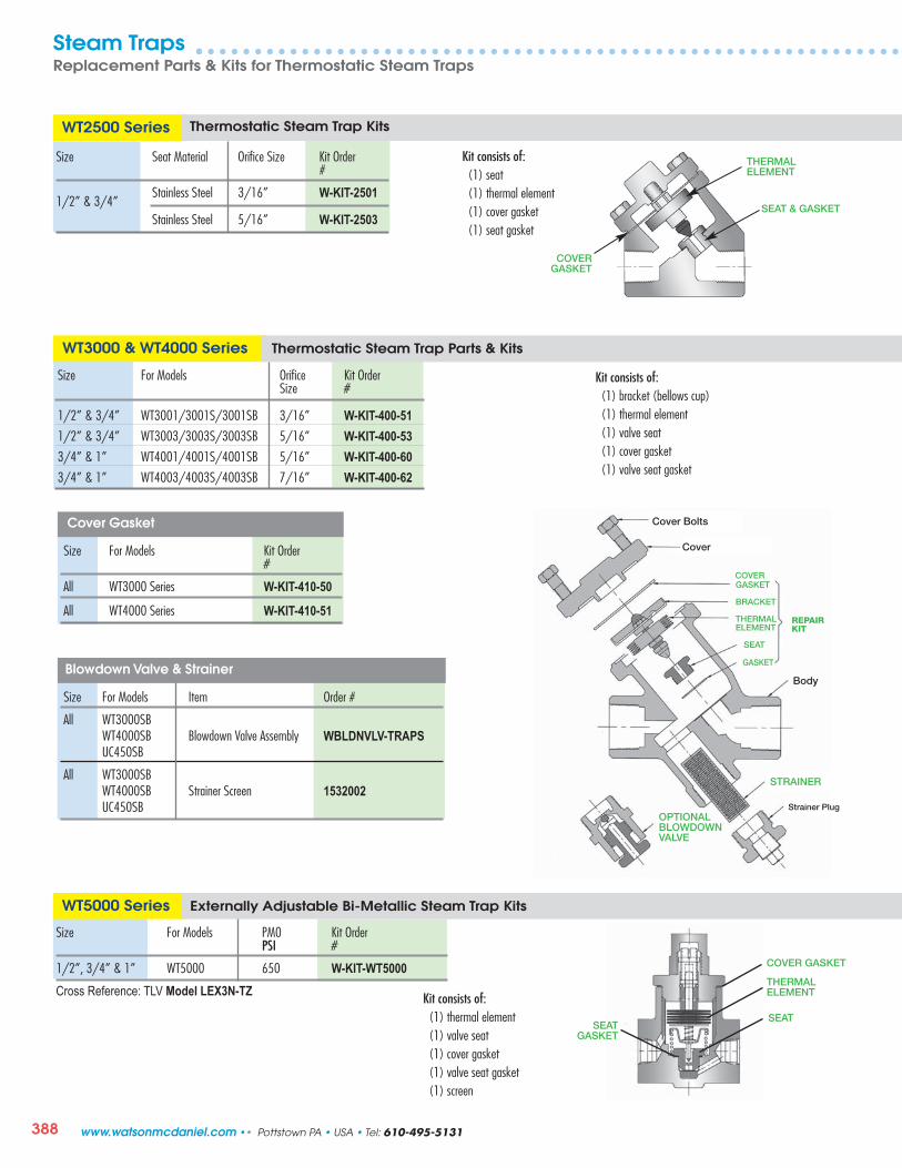
388
SEAT & GASKET
THERMALELEMENT
Size For Models Kit Order #
All WT3000 Series W-KIT-410-50
All WT4000 Series W-KIT-410-51
Size For Models Orifice Kit Order Size #
1/2” & 3/4” WT3001/3001S/3001SB 3/16” W-KIT-400-511/2” & 3/4” WT3003/3003S/3003SB 5/16” W-KIT-400-533/4” & 1” WT4001/4001S/4001SB 5/16” W-KIT-400-603/4” & 1” WT4003/4003S/4003SB 7/16” W-KIT-400-62
WT3000 & WT4000 Series Thermostatic Steam Trap Parts & Kits
Kit consists of: (1) bracket (bellows cup)(1) thermal element(1) valve seat(1) cover gasket(1) valve seat gasket
Cover Gasket
Blowdown Valve & Strainer
Size For Models Item Order #
All WT3000SB WT4000SB Blowdown Valve Assembly WBLDNVLV-TRAPS UC450SB
All WT3000SB WT4000SB Strainer Screen 1532002 UC450SB
Size Seat Material Orifice Size Kit Order #
1/2” & 3/4”Stainless Steel 3/16” W-KIT-2501
Stainless Steel 5/16” W-KIT-2503
WT2500 Series Thermostatic Steam Trap Kits
Kit consists of: (1) seat(1) thermal element(1) cover gasket(1) seat gasket
Cover Bolts
Cover
GASKET
BRACKET
THERMALELEMENT
SEAT
STRAINER
Strainer Plug
GASKET
Body
OPTIONALBLOWDOWNVALVE
REPAIRKIT
COVER
Size For Models PM0 Kit Order PSI #
1/2”, 3/4” & 1” WT5000 650 W-KIT-WT5000
Cross Reference: TLV Model LEX3N-TZ
WT5000 Series Externally Adjustable Bi-Metallic Steam Trap Kits
SEAT
THERMALELEMENT
COVER GASKET
SEATGASKET
Kit consists of: (1) thermal element(1) valve seat(1) cover gasket(1) valve seat gasket(1) screen
COVERGASKET
Steam TrapsReplacement Parts & Kits for Thermostatic Steam Traps
www.watsonmcdaniel.com •• Pottstown PA • USA • Tel: 610-495-5131

389
Cover
Spring
THERMALELEMENT
VALVE SEAT
Body
VALVE SEATWASHER
Size For Models Seat Material PMO Kit Order PSI #
1/2 TA25B-12-N Brass 25 W-KIT-TT-12-025 TA125-12-N Stainless steel 125 W-KIT-TT-12-125
3/4” TA25B-13-N Brass 25 W-KIT-TT-13-025
TA125-13-N Stainless steel 125 W-KIT-TT-13-125
TA25B & TA125 Series Radiator Thermostatic Steam Trap Kits
Kit consists of: (1) thermal element(1) valve seat(1) valve seat washer(1) cover gasket
Size For Models Seat Material PMO Kit Order PSI #
1/2 TS25B-12-N Brass 25 W-KIT-TT-12-025
TS125-12-N Stainless steel 125 W-KIT-TT-12-125
3/4” TS25B-13-N Brass 25 W-KIT-TT-13-025 TS125-13-N Stainless steel 125 W-KIT-TT-13-125
TS25B & TS125 Series Radiator Thermostatic Steam Trap Kits
FDA300, FDA400 & FDA500 Series Clean Steam Trap Parts
For Models Kit Order Product Description #
FDA300 W-KIT-300-01 Gasket FDA300 W-KIT-300-02 Thermal Assembly FDA400/410 & W-KIT-500-01 Gasket FDA500/510
FDA400/410 & W-KIT-500-02 Thermal Assembly FDA500/510
FDA600 Series Clean Steam Trap Parts
For Model Kit Order Product Description #
FDA600 W-KIT-600-01 Gasket
FDA600 W-KIT-600-02 Thermal Assembly
FDA800 Series Clean Steam Trap Parts
For Model Kit Order Product Description # $
FDA800 W-KIT-800-01 Disc
FDA800 W-KIT-800-02 Cap
GASKET
THERMALASSEMBLY GASKET
THERMALASSEMBLY
DISC
CAP
Steam TrapsReplacement Parts & Kits for Thermostatic Traps & Clean Steam Traps
Tel: 610-495-5131 • Pottstown PA • USA •• www.watsonmcdaniel.com

390
Pressure Motive Pump Mechanism Assembly
For Model (All Sizes) Kit Order # Description Weight lbs
PMPF W-KIT-900-03R Rebuilt mechanism assembly for PMPF 30
PMPC & PMPLS W-KIT-910-03R Rebuilt mechanism assembly for PMPC & PMPLS 30
PMPT & PMPNT W-KIT-912-03R Rebuilt mechanism assembly for PMPT & PMPNT 15
Note: The exchange program is for mechanisms within two years of service or less. The old mechanism must be returned along with the orderfor the rebuilt mechanism. Orders without old mechanisms will be invoiced at the new mechanism price. One time rebuild of each mechanism only.
PMP Series Pressure Motive Pump Mechanism Assembly Parts & Kits
Rebuilt Mechanism Assemblies
1” NPTOUTLET VENT
COVER
1/2” NPTINLET
SUPPORTBRACKET
FLOAT
PINS AND WEAR POINTSPivot pins and wear pointsare made from heat-treatedstainless steel with a heavylayer of hard chrome plating.
SPRING ASSEMBLY(INCONEL-X-750 DUAL COMPRESSION SPRINGS)
Includes springs, spring retainers, cotter pins & washers
INLET &VENT VALVES
MOTIVEINLET
VENTOUTLET
VENTVALVE
INLETVALVE
Inlet & Vent Valve Assembly
PumpsReplacement Parts & Kits for Pressure Motive Pumps
www.watsonmcdaniel.com •• Pottstown PA • USA • Tel: 610-495-5131

391
For Model (All Sizes) Kit Order # Description Weight lbs
W-KIT-901-04 Cover gasket for PMPM 3
W-KIT-901-06 Float & cover gasket for PMPM 3
W-KIT-901-05 Inlet & vent valve assembly for PMPM 5
W-KIT-901-08 Spring assembly for PMPM 5
W-KIT-916-03 Complete mechanism assembly for PMPM less cover 5
W-KIT-911-03 Complete mechanism assembly for PMPM 95
W-KIT-900-03 New mechanism assembly for PMPF & PMPSP 30
W-KIT-910-03 New mechanism assembly for PMPC & PMPLS 30
W-KIT-900-04 Cover gasket for PMPF, PMPC & PMPLS 3
W-KIT-900-05 Inlet & vent valve assembly for PMPF, PMPC & PMPLS 5
W-KIT-900-06 Float & cover gasket for PMPF, PMPC & PMPLS 10
W-KIT-900-08 Spring assembly for PMPF, PMPC & PMPLS 5
W-KIT-904-03 PMP Head Assembly, Johnson LMV Complete 28
W-KIT-900-01 New mechanism assembly for PMPBP & SSI 110
W-KIT-910-14 Cover gasket for PMPBP 7
W-KIT-900-15 Inlet & vent valve assembly for PMPBP 12
W-KIT-900-16 Float & cover gasket for PMPBP 20
W-KIT-900-18 Spring set for PMPBP 10
W-KIT-900-02 New mechanism assembly for PMPBP, 150# FLG. 110
W-KIT-900-07 New mechanism assembly for PMPBP, 300# FLG. 110
Note: For purchasing Stainless Steel Check Valves 1/2” - 3” NPT – See Check Valves Model WSSCV, in Pipeline Accessories Section.
New Assemblies & Parts for Pressure Motive Pumps
PMPM
PMPF,
PMPC & PMPLS
All Sizes
PMPBP
4” x 4”
Cross Reference Kit Order # Spirax Sarco Johnson Armstrong Gestra Hoffman Spence
W-KIT-900-03 PTF LMV PT-400 FPS Series PCC P3W-KIT-910-03 PTC LMV N/A FPS Series PCS P3W-KIT-900-01 PPF-P N/A PT-516 FPS33L N/A N/A
PumpsReplacement Parts & Kits for Pressure Motive Pumps
Tel: 610-495-5131 • Pottstown PA • USA •• www.watsonmcdaniel.com

392
For Model (All Sizes) Kit Order # Description Weight lbs
W-KIT-902-04 Cover Gasket 0.5
W-KIT-902-05 Inlet & Vent Valve Assembly 4.0
W-KIT-902-06 Float & Cover Gasket 0.5
W-KIT-902-08 Spring Assembly 0.8
W-KIT-912-03 Complete Pump Mechanism Assembly & Gasket PMPT 15.0
W-KIT-912-03-SS Complete Pump Mechanism Assembly & Gasket PMPTSS 15.0
W-KIT-914-03 Complete Pump Mechanism Assembly & Gasket PMPNT 0.8
W-KIT-914-03-SS Complete Pump Mechanism Assembly & Gasket PMPNTSS 0.8
W-KIT-917-03 Internal Trap Assembly Mechanism & Gasket for PMPT only 10.0
Notes: 1) For purchasing Stainless Steel Check Valves 1/2” - 3” NPT – See Check Valves Model WSSCV, in Pipeline Accessories Section.
PMPT&
PMPNT
PMPT & PMPNT Pressure Motive Pump & Trap Combination Parts & Kits
912-03Complete Pump Mechanism for
PMPT
917-03Internal Trap
Assembly Mechanismfor PMPT
VALVE
VALVE
902-08 SPRING ASSEMBLY KIT
Includes Two Spring Assemblies,Washers & Cotter Pins
902-05 INLET & VENT
VALVE ASSEMBLY
902-04COVER GASKET
902-06FLOAT
GASKET
PumpsReplacement Parts & Kits for Pressure Motive Pumps
914-03Complete Pump Mechanism for
PMPNT
www.watsonmcdaniel.com •• Pottstown PA • USA • Tel: 610-495-5131

393
HD Series Pilot-Operated Regulator Kits & Parts
1 HD Maintenance Kit (800 Series) Consists of :(1) bottom cover gasket(2) diaphragm gaskets (2) diaphragms (1) pilot adapter gasket (1) strainer screen
2 Complete Rebuild Kit (801 Series) Consists of: (1) HD Maintenance Kit (800 Series; above)(1) seat(1) disc & stem assembly
Additional Options:a) Blowdown Valve Assembly:
Order #: KIT-800-11b) Gasket for Pilot Adapter:
Order #: 1762900c) Reduced Port Kits; Contact Factory
d) Replacement Pilot Adapter: Order #: ZBHD-18-19-20
Size Maintenance Kit1 Complete Rebuild Kit 2 Order # Order #
1/2” & 3/4 ” W-KIT-800-13 W-KIT-801-13 1” W-KIT-800-14 W-KIT-801-14 11/4” W-KIT-800-15 W-KIT-801-15 11/2” W-KIT-800-16 W-KIT-801-16 2” W-KIT-800-17 W-KIT-801-17 21/2” W-KIT-800-18 W-KIT-801-18 3” W-KIT-800-19 W-KIT-801-19 4” W-KIT-800-20 W-KIT-801-20 6” W-KIT-800-22 W-KIT-801-22
DIAPHRAGMS
Set Screw
PILOT ADAPTERGASKET
DISC & STEMASSEMBLY
HDRegulator Repair Parts
DIAPHRAGMGASKETS
BOTTOM COVERGASKET
SEAT
STRAINER
BLOWDOWN VALVEASSEMBLY
PILOT ADAPTER
Ductile Iron Regulator
HD RegulatorReplacement Parts & Kits for HD Pilot-Operated Regulator
Note: For Low Pressure Main Valve (LP) Add LP to the end of the above part number to include Peroxide cured EPDM Diaphragm. Example: W-KIT-800-13-LP
Tel: 610-495-5131 • Pottstown PA • USA •• www.watsonmcdaniel.com

394
DIAPHRAGMS
PILOT ADAPTER GASKET
SEAT GASKET
CAP GASKET
Pilots – HD RegulatorReplacement Parts & Kits for Pilots used with HD Regulator
PP & PP5 Pressure Pilots Repair Kits
Kit Order # Description
W-KIT-802-01 Series PP Pressure Pilot Kit W-KIT-802-02 Series PP - 2 Diaphragms & bottom spring button only
W-KIT-854-04 Series PP5 Pressure Pilot Kit
PP & PP5 Pressure Pilot Kit Consists of: (2) diaphragms (1) head & seat assembly (1) seat gasket
(1) pilot adapter gasket (1) diaphragm gasket (PP5 only)
PBP Back Pressure Pilot Repair Kits
Kit Order # Description
W-KIT-803-01 PBP Back Pressure Pilot Kit PBP Back Pressure Pilot Kit Consists of: (2) diaphragms (1) seat gasket (1) head & seat assembly (1) pilot adapter gasket
GASKET(PP5 ONLY)
DIAPHRAGMSDIAPHRAGMS
BOTTOM SPRING BUTTON
HEAD & SEAT ASSEMBLYIncludes highlighted items
PILOT ADAPTER GASKET
SEAT GASKET
PP & PP5Pressure Pilot Repair Kit
PBP Back Pressure Pilot Repair Kit
SEAT GASKET
PILOT ADAPTER GASKET
STEMBUTTON
PDPDifferential
PilotRepair Kit
PDP Differential Pilot Repair Kits Kit Order # Description
W-KIT-806-01 PDP Differential Pressure Pilot Kit PDP Differential Pilot Kit Consists of: (2) diaphragms (1) seat gasket (1) head & seat assembly (1) pilot adapter gasket
(1) cap gasket
HEAD & SEAT ASSEMBLYIncludes highlighted items
HEAD & SEAT ASSEMBLYIncludes highlighted items
www.watsonmcdaniel.com •• Pottstown PA • USA • Tel: 610-495-5131

395
PA Series Air Pilots Repair Kits
Kit Order # Description
W-KIT-804-01 PA1 (1:1) Air Pilot Kit W-KIT-804-04 PA4 (4:1) Air Pilot Kit W-KIT-804-06 PA6 (6:1) Air Pilot Kit
Kit Consists of: (2) upper diaphragms (1) seat gasket(2) pilot diaphragms (1) pilot adapter gasket(1) head & seat assembly
PT & PTU Temperature Pilots Repair Kits
Kit Order # Description
W-KIT-805-01 PT & PTU Pilot Kit W-KIT-805-02 PT & PTU Low Pressure Pilot Kit
Pilots – HD RegulatorReplacement Parts & Kits for Pilots used with HD Regulator
Kit Consists of: (1) head & guide assembly(1) seat & seat gasket(1) pilot adapter gasket(1) guide gasket
PILOTDIAPHRAGMS
UPPERDIAPHRAGMS
SEAT GASKET
PILOT ADAPTER GASKET
HEAD & SEAT ASSEMBLYIncludes highlighted items
UPPER DIAPHRAGM
PLATE
SEATGASKET
GUIDEGASKET
HEAD & GUIDEASSEMBLY
SEAT
SEATGASKET
SEAT
HEAD & GUIDEASSEMBLY
PILOT ADAPTERGASKET
PA Air PilotRepair Kit
PT & PTUTemperature Pilot
Repair Kit
Low Pressure Pilot
Tel: 610-495-5131 • Pottstown PA • USA •• www.watsonmcdaniel.com

396
DIAPHRAGMSet Screw
PILOT ADAPTERGASKET
DISC & STEMASSEMBLY
BOTTOM COVERGASKET
SEAT RING
STRAINER
BLOWDOWN VALVEASSEMBLY
SPRING
DISCSEATDIAPHRAGM
HSP Pilot-Operated RegulatorReplacement Parts & Kits for HSP Regulators
Size Maintenance Kit 1 Complete Rebuild Kit 2
Order # Order #
1” W-KIT-810-14 W-KIT-811-14 11/2” W-KIT-810-16 W-KIT-811-16 2” W-KIT-810-17 W-KIT-811-17 3” W-KIT-810-19 W-KIT-811-19 4” W-KIT-810-20 W-KIT-811-20
1 HSP Maintenance Kit (810 Series) Consists of: (1) bottom cover gasket (1) diaphragm (1) pilot adapter gasket (1) strainer screen
2 Complete Rebuild Kit for HSP Consists of: (1) 810 Series Maintenance Kit(1) seat(1) disc & stem assembly
Additional Options:a) Blowdown Valve Assembly for HSP:
Order #: Kit-800-11-HSPb) Reduced Port Kits - Contact Factory
HSP Series Pilot-Operated Pressure Regulator Repair Parts & Kits
PHSP Series Pilots Replacement Pressure Pilots & Repair Kit
Kit Order # Description
PHSP-Y HSP Pressure Pilot, 10-40 PSI (Yellow) PHSP-B HSP Pressure Pilot, 25-100 PSI (Blue) PHSP-R HSP Pressure Pilot, 75-300 PSI (Red)
W-KIT-812-01 HSP Pressure Pilot Kit
PHSP Pressure Pilot Kit Consists of: (1) diaphragm (1) disc (1) seat (1) spring (1) stem & cup
HSP Regulator Repair Parts
Cast Steel Regulator
STRAINER
SPRING
DISC
SEAT
www.watsonmcdaniel.com •• Pottstown PA • USA • Tel: 610-495-5131

397
SPRING
“O” Series Pressure Regulator Kits
Size Kit Order # Diaphragm Material Kit Order # Diaphragm Material 3/8”, 1/2”, 3/4” W-KIT-80-11 Bronze W-KIT-81-11V Viton
3/4” HC W-KIT-82-12 Bronze W-KIT-83-12V Viton
1”, 11/4” W-KIT-82-14 Bronze W-KIT-83-14V Viton
11/2”, 2” W-KIT-82-15 Bronze W-KIT-83-15V Viton
Kits for 3/8”, 1/2” & 3/4” Sizes Consist of: (1) cover gasket(2) bronze or (1) Viton diaphragm(1) set of diaphragm cover fasteners(1) main spring
“B” Series Pressure Regulator Kits
Size Viton Kit Order #
1/2”, 3/4” W-KIT-200-01V 1” W-KIT-200-03V 11/4” W-KIT-200-04V 11/2” W-KIT-200-05V 2” W-KIT-200-06V 21/2” W-KIT-200-07V 3” W-KIT-200-08V 4” W-KIT-200-09V
Direct-Operated RegulatorsReplacement Parts & Kits for Direct-Operated Pressure Regulators
FASTENERS
DIAPHRAGM(S)
SCREEN
CUP
DIAPHRAGM
VALVEDISC
FASTENERS
Kits Consist of:(1) cup packing(1) valve disc(1) cup (1) set of gaskets(1) set of fasteners(1) diaphragm
CUP PACKING
MAIN SPRING
DIAPHRAGM(S)
FASTENERS
COVERGASKET
COVERGASKET
Kits for 3/4” HC Thru 2” Sizes also include: (1) screen
3/4” HC &1” – 2” Sizes
3/8”, 1/2” & 3/4”Sizes
MAIN SPRING
Tel: 610-495-5131 • Pottstown PA • USA •• www.watsonmcdaniel.com

398
Direct-Operated RegulatorsReplacement Parts & Kits for Direct-Operated Pressure Regulators
455 Series Pressure Regulator Kits & Parts
Size Case Kit Order Size #
1/2”, 3/4” 5” W-KIT-402-01 6” W-KIT-406-01 1 ” 5” W-KIT-402-03 6” W-KIT-406-03 11/4” 5” W-KIT-402-04 6” W-KIT-406-04 11/2” 5” W-KIT-402-05 6” W-KIT-406-05 7” W-KIT-414-06 2” 9” W-KIT-417-06 13” W-KIT-427-06 21/2” 7” W-KIT-414-07 9” W-KIT-417-07 13” W-KIT-427-07 3” 7” W-KIT-414-08 9” W-KIT-417-08 13” W-KIT-427-08 4” 7” W-KIT-414-09 9” W-KIT-417-09 13” W-KIT-427-09
Kits consist of: (1) stainless steel main valve (1) stainless steel seat ring(1) set of stem packing (1) pilot stem(1) locknut (1) gasket(1) set of diaphragm case fasteners (1) diaphragm
402 & 403 Series Pressure Regulator Kits
Size Kit Order # 402 or 403 eries
1/2”, 3/4”, 1” W-KIT-450-01 11/4”, 11/2” W-KIT-450-04 2” W-KIT-450-06 21/2” W-KIT-450-07 3” W-KIT-450-08 4” W-KIT-450-09
VALVESTEM
DIAPHRAGM
STEM PACKING
STAINLESS STEEL MAIN VALVE
SCREW & NUTFASTENERS
PILOT DISC
PILOT SEAT
DIAPHRAGMS
DIAPHRAGM SPRING
STRAINERSCREEN DIAPHRAGM GASKET
PILOTBODY GASKET
Kits consist of:(1) pilot seat(1) pilot disc(2) diaphragms(1) diaphragm gasket(1) diaphragm spring(1) strainer screen(1) pilot body gasket
GASKET
STAINLESS STEEL SEAT RING
LOCKNUT
www.watsonmcdaniel.com •• Pottstown PA • USA • Tel: 610-495-5131

DIAPHRAGM
VALVE DISC
FASTENERS
SPRING
GASKET
DISCHOLDER
DISC
DISCFOLLOWER
399
Direct-Operated RegulatorsReplacement Parts & Kits for Pressure Relief Valves
10691 Series Back Pressure / Relief Valve Kits
Size Pressure Range Kit Order PSI #
75-300 W-KIT-40-11/2” 25-100 W-KIT-40-2
5-35 W-KIT-40-375-300 W-KIT-41-1
3/4” 25-100 W-KIT-41-25-35 W-KIT-41-375-300 W-KIT-42-1
1” 25-100 W-KIT-42-25-35 W-KIT-42-3
3040 Series Back Pressure / Relief Valve Kits
Size Standard TrimKit Order #
1/2”, 3/4”, 1” W-KIT-3040-1411/4” W-KIT-3040-1511/2” W-KIT-3040-162” W-KIT-3040-17
Kits consist of:(1) valve disc (Viton)(1) diaphragm (Viton)(1) set of fasteners
2” size also includes: (1) top gasket
Kits consist of:(1) disc(1) disc follower(1) disc holder(1) spring(1) gasket
For Viton or Teflon Disc, Add V or T to part number.Example for Viton: W-KIT-42-3-V
Tel: 610-495-5131 • Pottstown PA • USA •• www.watsonmcdaniel.com
HB Series 2-Way Control Valve
MATERIALS • Valve Body1 Stem 316 Stainless Steel1 Plug 302 Stainless Steel4 Stem Seal Spring 302 Stainless Steel5 Guide Bushing Rulon 6417 V-ring Stem Seals PTFE11 Body Gasket 303 Stainless Steel
Stem & Plug is a single piece unit.
MATERIALS • Actuator18 Diaphragm Nylon reinforced Neoprene24 Stem O-ring Viton25 Yoke O-ring Viton26 Upper guide O-ring Viton

400
STRAINER SCREEN For Models
1521, 1522, 1524
LEVER & SEAT ASSEMBLY
Liquid DrainersReplacement Parts & Kits for Liquid Drainers
WLD1600 Series Liquid Drainer Kits
Size For Model Item Description Kit Order #
3/4” WLD1601 Cover Assembly W-KIT-7-12-LD Lever, Seat Assembly, Gasket W-KIT-6-12 Float & Screw W-KIT-5-02
Gasket W-KIT-3-01 1” WLD1602 Cover Assembly W-KIT-7-13-LD Lever, Seat Assembly, Gasket W-KIT-6-13 Float & Screw W-KIT-5-03 Gasket W-KIT-3-02 11/2” WLD1603 Cover Assembly W-KIT-7-17-LD Lever, Seat Assembly, Gasket W-KIT-6-17 Float & Screw W-KIT-5-04 Gasket W-KIT-3-03 2” WLD1604 Cover Assembly W-KIT-7-20-LD Lever, Seat Assembly, Gasket W-KIT-6-23 Float & Screw W-KIT-5-05 Gasket W-KIT-3-04
WLD1500 Series Liquid Drainer Kits
Size For Model Description Kit Order #
3/4” WLD1501 Lever & Seat Assembly, Gasket W-KIT-5-09-150 WLD1521 (with strainer) Strainer Screen W-KIT-9-01 Gasket W-KIT-3-07
3/4” WLD1502 Lever & Seat Assembly, Gasket W-KIT-5-10-200 WLD1522 (with strainer) Strainer Screen W-KIT-9-02 Gasket W-KIT-3-07
1” WLD1504 Lever & Seat Assembly, Gasket W-KIT-5-11-200 WLD1524 (with strainer) Strainer Screen W-KIT-9-03 Gasket W-KIT-3-08
Lever Seat Assembly with Cover Gasket
www.watsonmcdaniel.com •• Pottstown PA • USA • Tel: 610-495-5131

401
Liquid DrainersReplacement Parts & Kits for Liquid Drainers
WLDE/WLDES Series Float Type Liquid Drainer Kits
Size For Model Kit Order Description # W-KIT-3-18 Cover Gasket
2” W-KIT-5-18 Float
W-KIT-6-28 Float, Lever & Seat Assembly
W-KIT-3-19 Cover Gasket
2” W-KIT-5-19 Float
W-KIT-6-29 Float, Lever & Seat Assembly
W-KIT-3-19 Cover Gasket
21/2” W-KIT-5-20 Float
W-KIT-6-30 Float, Lever & Seat Assembly
W-KIT-3-19 Cover Gasket
21/2” W-KIT-5-21 Float
W-KIT-6-24 Float, Lever & Seat Assembly
W-KIT-3-22 Cover Gasket
11/2” W-KIT-5-22 Float
W-KIT-6-26 Float, Lever & Seat Assembly
W-KIT-3-18 Cover Gasket
2” W-KIT-5-23 Float
W-KIT-6-27 Float, Lever & Seat Assembly
W-KIT-3-19 Cover Gasket
21/2” W-KIT-5-24 Float
W-KIT-6-25 Float, Lever & Seat Assembly
WLDE-200WLDES-300
WLDE-50WLDES-50
WLDE-50
WLDE-125WLDES-125
WLDE-20
WLDE-200
WLDE-200MECHANISM& FLOAT ASSEMBLY
COVERASSEMBLY FLOAT
COVER GASKET
WLD1400 Series Float Type Liquid Drainer Kits
WLD1900 Series Float Type Liquid Drainer Kits
All internal components are identical to FTT-Series Steam Traps, less the thermostat. See Page 380.
All internal components are identical to WFT-Series Steam Traps, less the thermostat. See Page 378 & 379.
Tel: 610-495-5131 • Pottstown PA • USA •• www.watsonmcdaniel.com

402
WLD600/601 Series Liquid Drainer Kits
Size Model Order Item #
W-KIT-3-23 Cover Gasket W-KIT-5-25 Float & Screw W-KIT-6-31 Lever & seat Assembly
W-KIT-3-23 Cover Gasket W-KIT-5-25 Float & Screw W-KIT-6-32 Lever & seat Assembly
W-KIT-3-23 Cover Gasket W-KIT-5-25 Float & Screw W-KIT-6-33 Lever & seat Assembly
W-KIT-3-23 Cover Gasket W-KIT-5-25 Float & Screw W-KIT-6-34 Lever & Seat Assembly
W-KIT-3-23 Cover Gasket W-KIT-5-25 Float & Screw W-KIT-6-35 Lever & Seat Assembly
3/4
”
WLD600-65WLD601-65
WLD600-145WLD601-145
WLD600-300WLD601-300
WLD600-450WLD601-300
WLD600-200WLD601-200
W-KIT-3-25 Cover Gasket W-KIT-5-27-1 Float & Screw W-KIT-6-41 Lever & Seat Assembly
W-KIT-3-25 Cover Gasket W-KIT-5-27-1 Float & Screw W-KIT-6-42 Lever & Seat Assembly
W-KIT-3-25 Cover Gasket W-KIT-5-27-2 Float & Screw W-KIT-6-43 Lever & Seat Assembly
W-KIT-3-25 Cover Gasket W-KIT-5-27-2 Float & Screw W-KIT-6-44 Lever & Seat Assembly
W-KIT-3-25 Cover Gasket W-KIT-5-27-2 Float & Screw W-KIT-6-45 Lever & Seat Assembly
11/2
”
W-KIT-3-24 Cover Gasket W-KIT-5-26 Float & Screw W-KIT-6-36 Lever & Seat Assembly W-KIT-3-24 Cover Gasket W-KIT-5-26 Float & Screw W-KIT-6-37 Lever & Seat Assembl W-KIT-3-24 Cover Gasket W-KIT-5-26 Float & Screw W-KIT-6-38 Lever & Seat assembly W-KIT-3-24 Cover Gasket W-KIT-5-26 Float & Screw W-KIT-6-39 Lever & Seat assembly W-KIT-3-24 Cover Gasket W-KIT-5-26 Float & Screw W-KIT-6-40 Lever & Seat assembly
1”
WLD600-65WLD601-65
WLD600-145WLD601-145
WLD600-300WLD601-300
WLD600-450WLD601-300
WLD600-200WLD601-200
W-KIT-3-27 Cover Gasket
W-KIT-5-29 Float & Screw
W-KIT-6-51 Lever & Seat Assembly3”
&4
”2”
Size Model Order Item #
W-KIT-3-26 Cover Gasket W-KIT-5-28-1 Float & Screw W-KIT-6-52 Lever & seat Assembly
W-KIT-3-26 Cover Gasket W-KIT-5-28-1 Float & Screw W-KIT-6-53 Lever & Seat Assembly
W-KIT-3-26 Cover Gasket W-KIT-5-28-2 Float & Screw W-KIT-6-54 Lever & Seat Assembly
W-KIT-3-26 Cover Gasket W-KIT-5-28-2 Float & Screw W-KIT-6-49 Lever & Seat Assembly
W-KIT-3-26 Cover Gasket W-KIT-5-28-2 Float & Screw W-KIT-6-50 Lever & Seat Assembly
WLD600-65WLD601-65
WLD600-145WLD601-145
WLD600-300WLD601-300
WLD600-450WLD601-450
WLD600-200WLD601-200
WLD600-65WLD601-65
WLD600-145WLD601-145
WLD600-300WLD601-300
WLD600-450WLD601-300
WLD600-200WLD601-200
WLD600-450WLD601-450
LEVER & SEATASSEMBLY
FLOAT
COVER GASKET
Note:Reference FT600 Parts Section for additional detailed drawings.All internal parts of WLD600 are identical to FT600, except WLD600 Liquid Drainers do not include a thermostat.
Liquid DrainersReplacement Parts & Kits for Liquid Drainers
SCREW
www.watsonmcdaniel.com •• Pottstown PA • USA • Tel: 610-495-5131
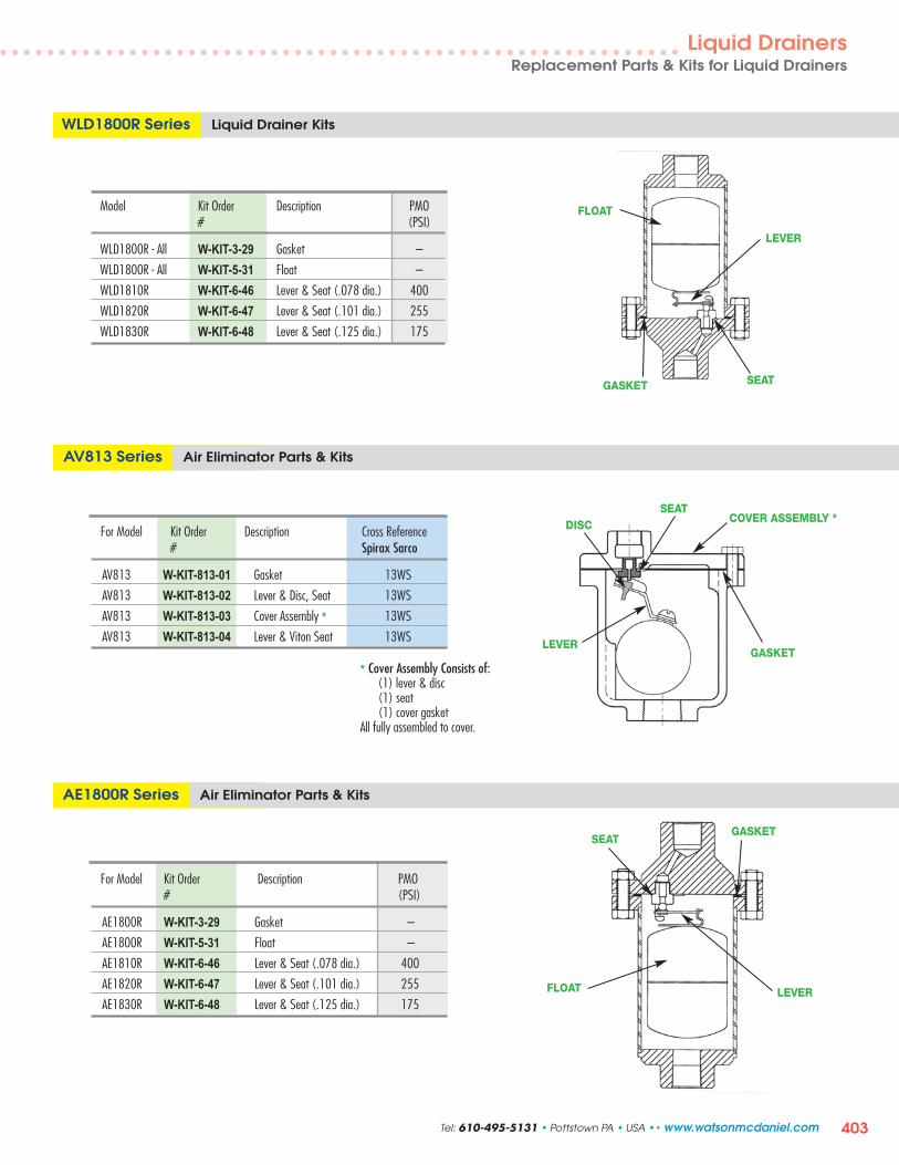
403
WLD1800R Series Liquid Drainer Kits
Model Kit Order Description PMO # (PSI)
WLD1800R - All W-KIT-3-29 Gasket –
WLD1800R - All W-KIT-5-31 Float –
WLD1810R W-KIT-6-46 Lever & Seat (.078 dia.) 400
WLD1820R W-KIT-6-47 Lever & Seat (.101 dia.) 255
WLD1830R W-KIT-6-48 Lever & Seat (.125 dia.) 175
FLOAT
SEAT
LEVER
AV813 Series Air Eliminator Parts & Kits
For Model Kit Order Description Cross Reference # Spirax Sarco
AV813 W-KIT-813-01 Gasket 13WS
AV813 W-KIT-813-02 Lever & Disc, Seat 13WS
AV813 W-KIT-813-03 Cover Assembly * 13WS
AV813 W-KIT-813-04 Lever & Viton Seat 13WS
DISCCOVER ASSEMBLY *
SEAT
* Cover Assembly Consists of:(1) lever & disc(1) seat(1) cover gasket
All fully assembled to cover.
LEVER
AE1800R Series Air Eliminator Parts & Kits
For Model Kit Order Description PMO # (PSI)
AE1800R W-KIT-3-29 Gasket –
AE1800R W-KIT-5-31 Float –
AE1810R W-KIT-6-46 Lever & Seat (.078 dia.) 400
AE1820R W-KIT-6-47 Lever & Seat (.101 dia.) 255
AE1830R W-KIT-6-48 Lever & Seat (.125 dia.) 175FLOAT
SEAT
LEVER
Liquid DrainersReplacement Parts & Kits for Liquid Drainers
GASKET
GASKET
GASKET
Tel: 610-495-5131 • Pottstown PA • USA •• www.watsonmcdaniel.com

404
Table of Contents Page No.
Formulas, Conversions & Guidelines
• Equivalents & Conversion Factors 406
• Capacity Formulas for Steam Loads 407
• Formulas for Control Valve Sizing 408-409
Steam Properties & Flow Characteristics
• Properties of Saturated Steam 410
• Draining Condensate from Steam Mains or Steam Supply Lines 411
• Steam Capacity Tables 412
• Steam Flow thru Various Orifice Diameters 412
• Sizing Steam Pipes 413
• Sizing of Condensate Return Line, Vent Line & Flash Tank 414
• Percent Flash Steam Table 414
• Pressure Drop in Schedule 40 Pipe 416
Fluid Flow in Piping
• Flow of Water thru Schedule 40 Steel Pipe – Flow Rates, Velocities & Pressure Drops 417
Pipe, Fitting & Flange Specifications
• Pipe Data Table (for 1/8” thru 30” sizes) 418
• Maximum Allowable Working Pressures for Seamless Carbon Steel Pipe 421
• Flange Standards – Dimensional Data 422
• Fitting Standards & Specifications 424
• Standard Class Pressure-Temperature Ratings 425
Engineering Data
I
II
III
IV
www.watsonmcdaniel.com •• Pottstown PA • USA • Tel: 610-495-5131

VIII
405
Table of Contents Page No.
Steam Trap Applications
• Introduction to Steam Traps 428
• Drip Leg Design 430
• Process Trap Guidelines – Gravity Drainage 432
• Process Trap Guidelines – Syphon Drainage 434
Regulating Valve Applications
• General Regulator Application & Installation Notes 436
• Pressure Reducing Station using Spring-Loaded Pilot 438
• Pressure Reducing Station using Air-Loaded Pilot for Remote Installations 440
• Pressure Reducing Station – Two-Stage (Series) for High-Pressure Turndown 442
• Pressure Reducing Station – Parallel for High-Flow Turndown 444
• Pressure Reducing Station – Two-Stage Parallel for High-Pressure & High-Flow Turndown 446
• Temperature Control of a Heat Exchanger with Pressure Limiting Pilot 448
• Temperature Control of a Batch Process with Electrical Time Sequence Programmer (Solenoid Pilot) 450
• Temperature Control of a Semi-Instantaneous Heater using a Self-Contained 452Temperature Regulating Valve
Pressure Motive Pump (PMP) & Pump-Trap Applications
• Drainage of a Single Source of Condensate using Pump-Trap 454
• Drainage of Condensate from Below Grade using Pump-Trap 456
• Drainage of Condensate from Heat Exchanger Posi tione d Close to the Ground 458
• Flash Steam Recovery 460
• Removal of Water or Condensate from a Pit 462
Heat Exchanger Formulas & Example
• Formulas for Heat Exchanger System using a Modulating Control Valve 464
• Heat Exchanger Example: Heating Water with Steam using a Modulating Control Valve 466
Engineering DataEN
GIN
EERIN
G
V
VI
VII
Tel: 610-495-5131 • Pottstown PA • USA •• www.watsonmcdaniel.com

406
FORMULAS, CONVERSIONS & GUIDELINESEN
GIN
EERIN
G
www.watsonmcdaniel.com •• Pottstown PA • USA • Tel: 610-495-5131
A B CMULTIPLY BY TO OBTAINInches of mercury 1.133 Feet of water
Inches of mercury 0.4912 Pounds per sq. in.
Inches of mercury 0.0345 Kilograms per sq. cm
Inches of water 0.03613 Pounds per sq. in.
Inches of water 0.07355 Inches of mercury
Kilograms 2.205 Pounds
Kilograms 0.001102 Short tons (2000 lbs.)
Kilograms per minute 132.3 Pounds per hour
Kilograms per sq. cm 14.22 Pounds per sq. in.
Kilograms per sq. cm 0.9678 Atmospheres
Kilograms per sq. cm 28.96 Inches of mercury
Kilopascals 0.145 Pounds per sq. in.
Liters 1000 Cubic centimeters
Liters 0.2642 Gallons
Liters per hour 0.0044 Gallons per minute
Meters 3.281 Feet
Meters 1.0936 Yards
Meters 100 Centimeters
Meters 39.37 Inches
Megapascals 145.0 Pounds per sq. in.
Pounds 0.0005 Short tons (2000 lbs.)
Pounds 0.4536 Kilograms
Pounds 0.000454 Metric Tons
Pounds 16 Ounces
Pounds per hour 6.32/M.W. Cubic feet per minute
Pounds per hour liquid 0.002/Sp. Gr. Gallons per minute liquid (at 70°F)
Pounds per sq. in. 27.684 Inches of water
Pounds per sq. in. 2.307 Feet of water
Pounds per sq. in. 2.036 Inches of mercury
Pounds per sq. in. 0.0703 Kilograms per sq. cm
Pounds per sq. in. 51.71 Millimeters of mercury
Pounds per sq. in. 0.7037 Meters of water
Specific Gravity 28.97 Molecular Wt. (of gas or vapors) (of gas or vapors)
Square centimeters 0.1550 Square inches
Square inches 6.452 Square centimeters
Tons (short ton 2000 lbs.) 907.2 Kilograms
Tons (short ton 2000 lbs.) 0.9072 Metric Tons
Tons (metric) per day 91.8 Pounds per hour
Water (cubic feet) 62.3 Pounds (at 70°F)
Yards 0.9144 Meters
Yards 91.44 Centimeters
A B CMULTIPLY BY TO OBTAINAtmospheres 14.697 Pounds per sq. in.
Atmospheres 1.033 Kilograms per sq. cm
Atmospheres 29.92 Inches of mercury
Atmospheres 760 Millimeters of mercury
Atmospheres 407 Inches of water
Atmospheres 33.90 Feet of water
Barrels (petroleum) 42 Gallons
Barrels per day 0.0292 Gallons per minute
Bars-G 14.5 Pounds per sq. in.
Centimeters 0.3937 Inches
Centimeters 0.03281 Feet
Centimeters 0.01 Meters
Centimeters 0.01094 Yards
Cubic centimeters 0.06102 Cubic inches
Cubic feet 7.48055 Gallons
Cubic feet 0.17812 Barrels
Cubic feet per second 448.833 Gallons per minute
Cubic inches 16.39 Cubic centimeters
Cubic inches 0.004329 Gallons
Cubic meters 264.17 Gallons
Cubic meters per hour 4.40 Gallons per minute
Feet 0.3048 Meters
Feet 0.3333 Yards
Feet 30.48 Centimeters
Feet of water 0.882 Inches of mercury
Feet of water 0.433 Pounds per sq. in.
Gallons (U.S.) 3785 Cubic centimeters
Gallons (U.S.) 0.13368 Cubic feet
Gallons (U.S.) 231 Cubic inches
Gallons (Imperial) 277.4 Cubic inches
Gallons (U.S.) 0.833 Gallons (Imperial)
Gallons (U.S.) 3.785 Liters
Gallons of water 8.328 Pounds (at 70°F)
Gallons of liquid 500 x Sp. Gr. Pounds per hrper minute liquid (at 70°F)
Gallons per minute 0.002228 Cubic feet per second
Horsepower (boiler) 34.5 Pounds waterper hr. evaporation
Horsepower (boiler) 33479 Btu per hour
Inches 2.54 Centimeters
Inches 0.0833 Feet
Inches 0.0254 Meters
Inches 0.02778 Yards
This table may be used in two ways:(1) Multiply the unit under column A by the figure under column B; the result is the unit under column C.(2) Divide the unit under column C by the figure under column B; the result is the unit under column A.
EQUIVALENTS & CONVERSION FACTORS

CAPACITY FORMULAS FOR STEAM LOADS
407
FORMULAS, CONVERSIONS & GUIDELINESEN
GIN
EERIN
G
Tel: 610-495-5131 • Pottstown PA • USA •• www.watsonmcdaniel.com

NOTE: Since a minimum CV of 18 was calculated, we could choose a 1-1/2" HB globe style control valve which has a CV = 22.
Cavitation can occur when the pressure inside the control valve drops below the vapor pressure ( PV ) of the liquid. Cavitation should be avoided because ������������������� �������������������������������������������������������������������������������C ( P1 - PV ), the Standard Flow Equation ��������������������������������� ���C ( P1 - PV ), cavitation may occur and ����������������������������!����������#����������
FL =
KC = 0.65 FL2
PV = Vapor Pressure of the Liquid (psia). (see chart for water at various temperatures.)
Based on when a 2% reduction ���������������occurs. (0.65 proportionality conconstant is used for conservative determination of cavitation)
The Valve Pressure Recovery Factor. For Globe Style Control Valve. FL = 0.9
Potential for Cavitation
�������������� �������� ����� ����������������������� ����������������������������� ����������������� ������ ����������������������������������������� �������������������!�����#
CV $��'��*��7���;�<�����Q = Volumetric Flow Rate of Liquid (US GPM)P1 = Absolute Inlet Pressure (psia)P2 = Absolute Outlet Pressure (psia)�P = Pressure Drop (psi) = P1 - P2
G $��>����?��@��*����������J�!���PV = Vapor Pressure of the Liquid
For Normal Flow:
����K��� ���C (P1 - PV ):
Q = CV Q
CV = Q Q
�P = [ ] G QCV
²
�P G
G�P
Flow Rate based on CV��������
CV���!������#�������7���X�����������
Pressure drop across valve based on Flow Rate and CV .
Water Physical PropertiesTemp.
(ºF)G
(Ref. to 60ºF)PV
(psia)
32 1.001 0.09
40 1.001 0.1250 1.001 0.1860 1.000 0.2670 0.999 0.3680 0.998 0.5190 0.996 0.70
100 0.994 0.95120 0.990 1.69140 0.985 2.89160 0.979 4.74180 0.972 7.51200 0.964 11.5212 0.959 14.7
Valve Sizing Example: Z�������*��*������������������������������������������������\^^�@�_���������`�\j^{��>���������������������������������������*���� ���*�������#����������������|��������������������������������������������������*��*��#�������*������������������}�����������������������������drop, determine the required minimum CV value of the control valve.
Conditions of Service:
Q = 100 GPM
T = \j^{�������
P1 = 50 psig = 64.7 psia
1 ~�|��������������������������*��*���������*��������������������������� �������������� � ���������C�$��C (P1 - Pv ).
2 Determine the minimum CV�������������*��*�����������������ΔP of 30 psi.
CV = QQ
= 100 Q
= 18
G�P
0.97230
G = ^�����`�\j^{���������(see chart)
�PC = KC (P1��������V )
= 0.53 (64.7-7.51)
= 30 psi
KC = 0.65 FL2 = 0.65 (0.9)2 = 0.53
(for globe value)
PV =����\�`�\j^{���������� (see chart)
408
FORMULAS, CONVERSIONS & GUIDELINESEN
GIN
EERIN
G
www.watsonmcdaniel.com •• Pottstown PA • USA • Tel: 610-495-5131
FORMULAS FOR CONTROL VALVE SIZING FOR LIQUIDS

409
FORMULAS, CONVERSIONS & GUIDELINES
Control Valve Sizing for Saturated Steam
The following formulas for Valve Sizing are based on ISA Standard 75.01.01-2007 (60534-2-1 Mod). The formulas assume pipe sizes equal to the size of the valve ports, with no attached fittings.
Cv = Valve Flow Coefficient � = Heat Capacity Ratio for Steam = 1.3 (0-300 psig)
�P = Pressure Drop = P1 - P2 F� = Heat Capacity Ratio Factor for Steam = ��1.4 = 1.3/1.4=0.93P1 = Absolute Inlet Pressure (psia) xx = Pressure Drop Ratio = �P/P1P2 = Absolute Outlet Pressure (psia) �Pcr = Critical Pressure Drop W = Saturated Steam Flow (lbs/hr) xT = Critical Pressure Drop Ratio for AirT1 = Steam Inlet Temperature (˚R) (see table) xcr = Critical Pressure Drop Ratio for SteamZ1 = Steam Compressibility Factor (see table) = �Pcr / P1 = F� xT = 0.93xT
82 P1 (1 – x/3xcr ) 54.6 P1
When �P/P1 < xcr : x = �P/P1 When �P/P1 > xcr
x /(T1 Z1)
FORMULAS FOR VALVE SIZING
ENG
INEER
ING
For Sub-critical Flow
Tel: 610-495-5131 • Pottstown PA • USA •• www.watsonmcdaniel.com
Cv = W
xcr /(T1 Z1)Cv =
For Critical FlowW
For single-ported globe valve with flow-to-open seating arrangement:
xT = 0.72 xcr = 0.93xT = 0.67
82 P1 (1 – x/2) 54.6 P1
When �P/P1 < 0.67 When �P/P1 > 0.67
x /(T1 Z1)Cv = W
0.67/(T1 Z1)
WCv =
Example: Determine the Cv Value for a Control Valve with 60 psig Inlet Steam Pressure, and 30 psig Outlet Pressure with a Flow Rate of 4,000 lbs/hr.
W = 4,000 lbs/hrP1 = 60 psig = 74.7 psiaP2 = 30 psig = 44.7 psia�P = 30 psix = �P/P1 = 30/74.4 = 0.40xcr = 0.93xT = 0.93 x 0.72 = 0.67Since x < xcr flow is sub-criticalT1 = 767 (from table)
Z1 = 0.955 (from table)
82 P1 (1 – x/2)
When �P/P1 < 0.67
x /(T1 Z1)Cv =
W
82 (74.7)(1 – 0.4/2)
= 4,000 = 35114.6
0.4/ (767 x 0.955)Cv = 4,000
P1 psig P1 psia T1 (˚R) Z10 14.7 672 0.985
10 24.7 699 0.97820 34.7 718 0.97330 44.7 734 0.96840 54.7 746 0.96350 64.7 757 0.95960 74.7 767 0.95570 84.7 776 0.95180 94.7 784 0.94790 104.7 791 0.943
100 114.7 798 0.940110 124.7 804 0.936120 134.7 810 0.933130 144.7 815 0.930140 154.7 821 0.927150 164.7 826 0.923160 174.7 830 0.920170 184.7 835 0.917180 194.7 839 0.915190 204.7 843 0.912200 214.7 848 0.909210 224.7 851 0.906220 234.7 855 0.903230 244.7 859 0.901240 254.7 862 0.898250 264.7 866 0.895260 274.7 869 0.893270 284.7 872 0.890280 294.7 875 0.888290 304.7 879 0.885300 314.7 882 0.883
Saturated Steam Table

410
STEAM PROPERTIES & FLOW CHARACTERISTICS
Pressure Temp. Heat (BTU/lb) Volume (ft3/lb)(°F) Sensible Latent Total Condensate Steam
in Hg vac25 133 101 1018 1119 0.01626 143.320 161 129 1002 1131 0.01640 75.4115 179 147 991 1138 0.01650 51.4110 192 160 983 1143 0.01659 39.225 203 171 976 1147 0.01666 31.82
(PSIG)0 212 180 970 1151 0.01672 26.801 215 184 968 1152 0.01674 25.212 219 187 966 1153 0.01676 23.793 222 190 964 1154 0.01679 22.534 224 193 962 1155 0.01681 21.405 227 195 961 1156 0.01683 20.386 230 198 959 1157 0.01685 19.467 232 201 957 1158 0.01687 18.628 235 203 956 1159 0.01689 17.859 237 206 954 1160 0.01690 17.1410 239 208 953 1160 0.01692 16.4912 244 212 950 1162 0.01696 15.3314 248 216 947 1163 0.01699 14.3316 252 220 944 1165 0.01702 13.4518 255 224 942 1166 0.01705 12.6820 259 228 940 1167 0.01708 11.9922 262 231 937 1168 0.01711 11.3824 265 234 935 1169 0.01713 10.8325 267 236 934 1170 0.01715 10.5726 268 237 933 1170 0.01716 10.3328 271 240 931 1171 0.01719 9.87430 274 243 929 1172 0.01721 9.45932 277 246 927 1173 0.01723 9.07834 279 249 925 1174 0.01726 8.72835 281 250 924 1174 0.01727 8.56336 282 251 923 1174 0.01728 8.40438 284 254 922 1175 0.01730 8.10440 287 256 920 1176 0.01733 7.82642 289 258 918 1177 0.01735 7.56644 291 261 916 1177 0.01737 7.32345 292 262 916 1178 0.01738 7.20846 294 263 915 1178 0.01739 7.09648 296 265 913 1178 0.01741 6.88350 298 267 912 1179 0.01743 6.68355 303 272 908 1180 0.01748 6.23060 307 277 905 1182 0.01753 5.83765 312 282 901 1183 0.01757 5.49170 316 286 898 1184 0.01761 5.18475 320 291 895 1185 0.01766 4.91180 324 295 892 1186 0.01770 4.66585 328 298 889 1187 0.01774 4.44490 331 302 886 1188 0.01778 4.24295 335 306 883 1189 0.01782 4.059100 338 309 881 1190 0.01785 3.891105 341 312 878 1190 0.01789 3.736110 344 316 876 1191 0.01792 3.594115 347 319 873 1192 0.01796 3.462120 350 322 871 1192 0.01799 3.340125 353 325 868 1193 0.01803 3.226130 356 328 866 1194 0.01806 3.119135 358 331 864 1194 0.01809 3.020140 361 333 861 1195 0.01812 2.927145 363 336 859 1195 0.01815 2.839
Properties of Saturated Steam
Pressure Temp. Heat (BTU/lb) Volume (ft3/lb)(PSIG) (°F) Sensible Latent Total Condensate Steam150 366 339 857 1196 0.01818 2.756155 368 341 855 1196 0.01821 2.678160 371 344 853 1196 0.01824 2.605165 373 346 851 1197 0.01827 2.535170 375 349 849 1197 0.01830 2.469175 377 351 847 1198 0.01833 2.407180 380 353 845 1198 0.01835 2.347185 382 355 843 1198 0.01839 2.291190 384 358 841 1199 0.01841 2.237195 386 360 839 1199 0.01844 2.185200 388 362 837 1199 0.01847 2.136205 390 364 836 1200 0.01850 2.089210 392 366 834 1200 0.01852 2.044215 394 368 832 1200 0.01855 2.001220 395 370 830 1200 0.01857 1.960225 397 372 829 1201 0.01860 1.920230 399 374 827 1201 0.01863 1.882235 401 376 825 1201 0.01865 1.845240 403 378 823 1201 0.01868 1.810245 404 380 822 1202 0.01870 1.776250 406 382 820 1202 0.01873 1.744255 408 384 818 1202 0.01875 1.712260 409 385 817 1202 0.01878 1.682265 411 387 815 1202 0.01880 1.652270 413 389 814 1203 0.01882 1.624275 414 391 812 1203 0.01885 1.596280 416 392 811 1203 0.01887 1.570285 417 394 809 1203 0.01889 1.544290 419 396 808 1203 0.01891 1.520295 420 397 806 1203 0.01894 1.497300 422 399 805 1203 0.01896 1.473310 425 402 802 1204 0.01901 1.428320 428 405 799 1204 0.01906 1.386330 430 408 796 1204 0.01910 1.346340 433 411 793 1204 0.01915 1.309350 436 414 790 1204 0.01919 1.273360 438 417 787 1204 0.01923 1.240370 441 420 785 1204 0.01927 1.207380 443 423 782 1205 0.01932 1.177390 446 426 779 1205 0.01936 1.148400 448 428 777 1205 0.01940 1.120450 460 441 764 1205 0.01961 0.9992500 470 453 752 1205 0.01980 0.9010550 480 464 740 1204 0.02000 0.8195600 489 475 729 1203 0.02019 0.7509650 497 485 718 1203 0.02038 0.6922700 505 494 707 1202 0.02056 0.6415750 513 504 697 1200 0.02074 0.5971800 520 512 687 1199 0.02092 0.5580900 534 529 667 1196 0.02128 0.4922
1000 546 545 648 1192 0.02164 0.43901250 574 581 601 1182 0.02256 0.34101500 598 614 556 1169 0.02352 0.27401750 618 644 510 1155 0.02456 0.22482000 637 674 463 1137 0.02572 0.18642250 654 703 413 1116 0.02707 0.15542500 669 734 358 1092 0.02871 0.12932750 683 766 295 1061 0.03097 0.10623000 696 805 211 1016 0.03465 0.0835
ENG
INEE
RIN
G
(continued)
www.watsonmcdaniel.com •• Pottstown PA • USA • Tel: 610-495-5131

411
STEAM PROPERTIES & FLOW CHARACTERISTICS
DRAINING CONDENSATE FROM STEAM MAINS OR STEAM SUPPLY LINESCharts Assume All Pipes are Insulated (with 80% efficiency)
SteamPressure(PSIG) 2” 21/2” 3” 4” 5” 6” 8” 10” 12” 14” 16” 18” 20” 24”
0 6.2 9.7 12.8 18.2 24.6 31.9 48 68 90 107 140 176 207 308 1.50 5 6.9 11.0 14.4 20.4 27.7 35.9 48 77 101 120 157 198 233 324 1.44 10 7.5 11.8 15.5 22.0 29.9 38.8 58 83 109 130 169 213 251 350 1.41 20 8.4 13.4 17.5 24.9 33.8 44 66 93 124 146 191 241 284 396 1.37 40 9.9 15.8 20.6 90.3 39.7 52 78 110 145 172 225 284 334 465 1.32 60 11.0 17.5 22.9 32.6 44 57 86 122 162 192 250 316 372 518 1.29 80 12.0 19.0 24.9 35.3 48 62 93 132 175 208 271 342 403 561 1.27 100 12.8 20.3 26.6 37.8 51 67 100 142 188 222 290 366 431 600 1.26 125 13.7 21.7 28.4 40 55 71 107 152 200 238 310 391 461 642 1.25 150 14.5 23.0 30.0 43 58 75 113 160 212 251 328 414 487 679 1.24 175 15.3 24.2 31.7 45 61 79 119 169 224 265 347 437 514 716 1.23 200 16.0 25.3 33.1 47 64 83 125 177 234 277 362 456 537 748 1.22 250 17.2 27.3 35.8 51 69 89 134 191 252 299 390 492 579 807 1.21 300 25.0 38.3 51 75 104 143 217 322 443 531 682 854 1045 1182 1.20 400 27.8 43 57 83 116 159 241 358 493 590 759 971 1163 1650 1.18 500 30.2 46 62 91 126 173 262 389 535 642 825 1033 1263 1793 1.17 600 32.7 50 67 98 136 187 284 421 579 694 893 1118 1367 1939 1.16 800 38 58 77 113 203 274 455 670 943 1132 1445 1835 2227 3227 1.16
1000 45 64 86 126 227 305 508 748 1052 1263 1612 2047 2485 3601 1.15 1200 52 72 96 140 253 340 566 833 1172 1407 1796 2280 2767 4010 1.14 1400 62 79 106 155 280 376 626 922 1297 1558 1988 2524 3064 4440 1.13 1600 71 87 117 171 309 415 692 1018 1432 1720 2194 2786 3382 4901 1.13 1750 78 94 126 184 333 448 746 1098 1544 1855 2367 3006 3648 5285 1.13 1800 80 97 129 189 341 459 764 1125 1584 1902 2427 3082 3741 5420 1.13
Outside Temperature at 70˚F. Based on Sch. 40 Pipe up to 250 PSI; Sch. 80 above 250 PSI; Sch. 120, 5” & Larger, above 800 PSI.0˚F
CorrectionFactor †
Running Loads in Pounds of Condensate per hour per 100 ft. of Steam Main
2” 21/2” 3” 4” 5” 6” 8” 10” 12” 14” 16” 18” 20” 24” 10 6 7 9 11 13 16 20 24 29 32 36 39 44 53 1.58 30 8 9 11 14 17 20 26 32 38 42 48 51 57 68 1.50 60 10 12 14 18 24 27 33 41 49 54 62 67 74 89 1.45 100 12 15 18 22 28 33 41 51 61 67 77 83 93 111 1.41 125 13 16 20 24 30 36 45 56 66 73 84 90 101 121 1.39 175 16 19 23 26 33 43 53 66 78 86 98 107 119 141 1.38 250 18 22 27 34 42 50 62 77 92 101 116 126 140 168 1.36 300 20 25 30 37 46 54 68 85 101 111 126 138 154 184 1.35 400 23 28 34 43 53 63 80 99 118 130 148 162 180 216 1.33 500 27 33 39 49 61 73 91 114 135 148 170 185 206 246 1.32 600 30 37 44 55 68 82 103 128 152 167 191 208 232 277 1.31 800 36 44 53 69 85 101 131 164 194 214 244 274 305 365 1.30
1000 43 52 63 82 101 120 156 195 231 254 290 326 363 435 1.27 1200 51 62 75 97 119 142 185 230 274 301 343 386 430 515 1.26 1400 60 73 89 114 141 168 219 273 324 356 407 457 509 610 1.25 1600 69 85 103 132 163 195 253 31 375 412 470 528 588 704 1.22 1750 76 93 113 145 179 213 278 347 411 452 516 580 645 773 1.22 1800 79 96 117 150 185 221 288 358 425 467 534 600 667 800 1.21
† For outdoor temperatures of 0˚F, multiply load value selected from table by correction factor shown.
Outside Temperature at 70˚F. 0˚F
CorrectionFactor †
Pipe Size
Pipe Size
SteamPressure(PSIG)
Warm Up Loads in Pounds of Condensate per hour per 100 ft. of Steam Main
ENG
INEER
ING
Warm Up Loads are basedon a 1 hour warm up time
Tel: 610-495-5131 • Pottstown PA • USA •• www.watsonmcdaniel.com

412
STEAM PROPERTIES & FLOW CHARACTERISTICS
This chart provides a simple method for sizing steam pipes with velocities in the range of 7,000 to 10,000 ft/min.(Example: a 1” pipe with 100 PSIG steam pressure has a flow rate of 672 lbs/hr at a velocity of 7250 ft/min.)
Pressure(PSIG)
Temp.(˚F)(sat.)
This table represents steam loss thru an orifice on a failed open steam trap, assuming that 25% of the flow consists of condensate.
STEAM CAPACITY TABLES
STEAM CAPACITY – Flow in lbs/hrFULL-PORT VALVE or PIPE SIZE
1/4 3/8 1/2 3/4 1 11/4 11/2 2 21/2 3 31/2 4 5 6 8 10 12VELOCITY (FPM)
7062 7094 7125 7187 7250 7312 7375 7500 7625 7750 7875 8000 8250 8500 9000 9500 10000250 406 176 324 518 916 1498 2615 3591 6018 8731 13700 18620 24360 39470 58730 107700 179200 267700
200 388 143 264 423 748 1223 2135 2932 4913 7128 11190 15200 19880 32230 47950 87910 146300 218500
175 378 127 235 375 664 1086 1895 2603 4361 6328 9931 13490 17650 28610 42560 78040 129800 194000
150 366 111 205 328 580 948 1655 2273 3810 5528 8675 11790 15420 24990 37180 68170 113400 169500
125 353 95 175 280 496 811 1415 1943 3256 4724 7414 10070 13180 21360 31780 58260 96940 144800
100 338 79 145 232 411 672 1173 1612 2701 3919 6150 8356 10930 17720 26360 48330 80410 120100
90 331 72 133 213 377 617 1076 1478 2477 3594 5641 7665 10030 16250 24180 44330 73760 110200
80 324 66 121 194 343 561 979 1345 2254 3270 5132 6973 9122 14780 22000 40330 67100 100300
70 316 59 109 175 309 505 881 1211 2029 2943 4619 6277 8211 13310 19800 36300 60400 90240
60 308 53 97 155 274 449 783 1076 1803 2616 4105 5577 7296 11820 17590 32260 53670 80190
50 298 46 85 136 240 392 684 940 1575 2286 3587 4874 6376 10330 15380 28190 46900 70080
40 287 39 72 116 205 335 585 803 1346 1953 3066 4166 5449 8831 13140 24090 40080 59890
30 274 33 60 96 170 278 485 666 1115 1618 2539 3451 4514 7315 10880 19960 33200 49610
25 267 29 54 86 152 249 434 596 999 1449 2274 3090 4042 6551 9747 17870 29730 44430
20 259 26 47 76 134 219 383 526 881 1279 2006 2726 3566 5780 8600 15770 26230 39200
15 250 22 41 66 116 190 331 455 763 1107 1737 2360 3087 5003 7444 13650 22710 33930
10 240 19 35 55 98 160 279 384 643 933 1464 1990 2603 4218 6276 11510 19150 28610
5 228 15 28 45 79 130 227 311 522 757 1188 1615 2112 3423 5093 9339 15540 23220
0 212 11 21 34 60 97 170 233 391 568 891 1210 1583 2566 3818 7000 11650 17400
STEAM FLOW – thru various or ifice diameters discharging to atmosphere (0 PSIG) in lbs/hrOrifice Diameter Inlet Pressure (PSIG)
(Inches) 2 5 10 15 25 50 75 100 125 150 200 250 300 1/32 0.31 0.47 0.58 0.70 0.94 1.53 2.12 2.70 3.30 3.90 5.10 6.30 7.40
1/16 1.25 1.86 2.30 2.80 3.80 6.10 8.50 10.80 13.20 15.60 20.30 25.10 29.80
3/32 2.81 4.20 5.30 6.30 8.45 13.80 19.10 24.40 29.70 35.10 45.70 56.40 67.00
1/8 4.50 7.50 7.40 11.20 15.00 24.50 34.00 43.40 52.90 62.40 81.30 100.00 119.00
5/32 7.80 11.70 14.60 17.60 23.50 38.30 53.10 67.90 82.70 97.40 127.00 156.00 186.00
3/16 11.20 16.70 21.00 25.30 33.80 55.10 76.40 97.70 119.00 140.00 183.00 226.00 268.00
7/32 15.30 22.90 28.70 34.40 46.00 75.00 104.00 133.00 162.00 191.00 249.00 307.00 365.00
1/4 20.00 29.80 37.40 45.00 60.10 98.00 136.00 173.00 212.00 250.00 325.00 401.00 477.00
9/32 25.20 37.80 47.40 56.90 76.10 124.00 172.00 220.00 268.00 316.00 412.00 507.00 603.00
5/16 31.20 46.60 58.50 70.30 94.00 153.00 212.00 272.00 331.00 390.00 508.00 627.00 745.00
11/32 37.70 56.40 70.70 85.10 114.00 185.00 257.00 329.00 400.00 472.00 615.00 758.00 901.00
3/8 44.90 67.10 84.20 101.00 135.00 221.00 306.00 391.00 478.00 561.00 732.00 902.00 1073.00
13/32 52.70 78.80 98.80 119.00 159.00 259.00 359.00 459.00 559.00 659.00 859.00 1059.00 1259.00
7/16 61.10 91.40 115.00 138.00 184.00 300.00 416.00 532.00 648.00 764.00 996.00 1228.00 1460.00
15/32 70.20 105.00 131.00 158.00 211.00 344.00 478.00 611.00 744.00 877.00 1144.00 1410.00 1676.00
1/2 79.80 119.00 150.00 180.00 241.00 392.00 544.00 695.00 847.00 998.00 1301.00 1604.00 1907.00
ENG
INEE
RIN
G
www.watsonmcdaniel.com •• Pottstown PA • USA • Tel: 610-495-5131

413
STEAM PROPERTIES & FLOW CHARACTERISTICSEN
GIN
EERIN
G
100
200
300
400500600800
1,000
2,000
3,0004,0005,0006,0008,000
10,000
20,000
30,00040,00050,000
Flash Vent Lines3,000 FPM
Heating Systems4,000-6,000 FPM
Process Steam8,000-12,000 FPM
4,0005,0006,000
8,000
12,000
20,000
10,000
3,000
2,000
1,000
Stea
m F
low
• lb
s/hr
Steam Pressure PSIG (Saturated Steam)
05
10
25
5075
100125
150
200250
1”1 1/4 ”1 1/2 "
2”2 1/2 "3”
4”5”
6”
8”10”12”14”16”
1/2”3/4”
Multiply Chart Velocity by Factor below to get Velocity in Schedule
80 Pipe Pipe Size
1/2" 3/4" & 1"
11/4" & 11/2" 2" to 16"
Factor1.301.23"1.171.12
Factor 1.30 1.23 1.17 1.12
05
10
25
5075
100125
150
200250
RecommendedSteam Velocities
Note: Condensate Line & Vent Line Size based on using Schedule 40 Pipe
(PSIG)
(PSIG)
E
DC
B
A
FG
Pipe Size
Pipe Size
Steam Velocity • ft/m
inSIZING STEAM PIPES • Steam Velocity Chart (Schedule 40 pipe)Saturated steam lines should be sized for a steam velocity of 4800 to 7200 ft/min.Piping on pressure reducing stations should be sized for the same steam velocity on both sides of the regulator. This usuallyresults in having a regulator smaller than the piping and having larger piping on the downstream side of the regulator.
Example using Steam Velocity Chart:100 PSIG Inlet Pressure to control valve; 25 PSIG Outlet Pressure; 1,000 lbs/hr flow rate; Determine pipe size required.
Upstream Piping: Enter Velocity Chart at A 1000 lbs/hr. Follow line to B 100 PSIG Inlet Pressure. Follow line vertically upwards to C 11/2” Pipe Diameter. Steam Velocity at D shows 4800 ft/min.
Downstream Piping:Enter Velocity Chart at A 1000 lbs/hr. Follow line to E 25 PSIG Outlet Pressure. Follow line vertically upwards to F 21/2” Pipe Diameter. Steam Velocity at G shows 5500 ft/min.
Tel: 610-495-5131 • Pottstown PA • USA •• www.watsonmcdaniel.com

414
STEAM PROPERTIES & FLOW CHARACTERISTICS
SIZING OF CONDENSATE RETURN LINE, FLASH TANK DIAMETER & VENT LINE• Velocity of Flash Steam in Condensate Return Lines should be between 4000 and 6000 ft/min. • Velocity in Flash Tank should be less than 600 ft/min. • Velocity in a Vent Pipe should be less than 4000 ft/min.
Example: A steam trap with a 150 PSIG steam inlet pressure is being discharged into a flash tank operating at 20 PSIG.The condensate load on the trap is 3200 lbs/hr.
Problem: (1) Determine the size of the condensate return line from the trap to the flash tank based on
velocities of 4,000 - 6,000 ft/min.(2) Determine the diameter of the flash tank based on velocities less than 600 ft/min.(3) Determine the size of the vent line on the flash tank based on velocities less than 4000 ft/min.
Solution: The accepted practice of determining condensate return pipe sizing is to base the size of the return pipe on the amount of flashsteam in the return line. This is due to the fact that the volume of flash steam is over 1,000 times greater than the equivalentvolume of liquid condensate. Therefore, the flash steam is the dominant factor affecting flow in the return line. We must firstcalculate the amount of flash steam produced.
From the Percent Flash Steam Table we find that 11.8% of the condensate will flash into steam. Therefore .118 X 3200 = 377 lbs/hr of flash steam will be produced in the condensate return line and flash tank.
Enter Condensate Line, Flash Tank & Vent Line Sizing chart at A 377 lbs/hr.
Move horizontally to point B 20 PSIG Flash Tank Pressure.Move vertically upwards to point D to determine a 5” Flash Tank Diameter is needed to keep velocities less than 600 ft/min.Continue to move vertically to point E to determine that the Vent Line on the Flash Tank should be 2” Diameter in order to keep velocities less than 4,000 ft/min.
PERCENT (%) FLASH STEAM TABLEPercent Flash Steam produced when condensate is discharged to atmosphere (0 PSIG) or into a flash tank controlled at various pressuresCondensate Flash Tank Pressure (PSIG)
Pressure(PSIG) 0 5 10 20 30 40 60 80 100
5 1.6 0.010 2.9 1.3 0.015 3.9 2.4 1.120 4.9 3.3 2.1 0.030 6.5 5.0 3.7 1.7 0.040 7.8 6.3 5.1 3.0 1.4 0.060 10.0 8.5 7.3 5.3 3.7 2.3 0.080 11.8 10.3 9.1 7.1 5.5 4.2 1.9 0.0100 13.3 11.8 10.6 8.7 7.1 5.8 3.5 1.6 0.0125 14.9 13.5 12.3 10.4 8.8 7.5 5.3 3.4 1.8150 16.3 14.9 13.7 11.8 10.3 9.0 6.8 4.9 3.3200 18.7 17.3 16.2 14.3 12.8 11.5 9.4 7.6 6.0250 20.8 19.4 18.2 16.4 14.9 13.7 11.5 9.8 8.2300 22.5 21.2 20.0 18.2 16.8 15.5 13.4 11.7 10.2350 24.1 22.8 21.7 19.9 18.4 17.2 15.1 13.4 11.9400 25.6 24.2 23.1 21.4 19.9 18.7 16.7 15.0 13.5
Continue to move vertically to point C to determine that the Condensate Line should be 11/2” Diameter in order to maintaincondensate return line velocities between 4000 and 6000 ft/min.
ENG
INEE
RIN
G
www.watsonmcdaniel.com •• Pottstown PA • USA • Tel: 610-495-5131
FlashTank
VentLine
Diameter
CondensateReturn Line
Flash Steam

20,000
Sizing Chart for:Condensate Line • Flash Tank Diameter • Vent Line
Flas
h St
eam
Flo
w R
ate
(lbs
/hr)
2"2 1/2 "
Multiply Chart Velocity by Factor below to get Velocity in Schedule
80 Pipe Pipe Size
1/2" 3/4" & 1"
11/4" & 11/2" 2" & 3"
4" to 24" 26" to 30"
Factor 1.30 1.23 1.15 1.12 1.1 1.0
100
200
300
500
8001,000
2,000
3,000
80
5,000
8,00010,000
30,000
50,000
60504030
20
10
100
6650
33
17
10
6" 5" 4"10"10"12"14"16"
18"20"26"26"
28"30" 3/4"
1 1/2 "1 1/4 " 1"3"
1/2"
6000
40003000
2000
1000
600
Condensate Return Line
Vent Line
Flash Tank
(ft/sec)
(PSIG)
05
1020
3040
6080
100
05
1020
3040
6080
100
05
1020
3040
6080
100
(PSIG)
(PSIG)
E
D
C
BA
Pressure in Condensate Return Line
or Flash Tank (PSIG)
Flash Steam Velocity (ft/min)
Flash Steam Velocity
415
STEAM PROPERTIES & FLOW CHARACTERISTICSEN
GIN
EERIN
G
Tel: 610-495-5131 • Pottstown PA • USA •• www.watsonmcdaniel.com
SIZING OF CONDENSATE RETURN LINE, FLASH TANK DIAMETER & VENT LINE• Velocity of Flash Steam in Condensate Return Lines should be between 4000 and 6000 ft/min. • Velocity in Flash Tank should be less than 600 ft/min. • Velocity in a Vent Pipe should be less than 4000 ft/min.

416
STEAM PROPERTIES & FLOW CHARACTERISTICSEN
GIN
EERIN
G
06.9
100 PSIG Saturated SteamFor other pressures use correction factors
06.0
55.2
104.3
153.6
203.1
302.4
402.0
601.5
751.3
901.1
1001.0
1100.92
1250.83
1500.70
1750.62
2000.55
2250.49
2500.45
3000.38
15.0
10.09.08.07.06.04.0
3.0
2.0
1.0.9.8.7.6.5.4
.3
.2
.1
100
200
300
400
500
1,00
0
Steam Flow lbs/hr
Pre
ssure
Dro
p p
si/1
00 f
t.
psifactor
3/4" 1" 1-1/4" 1-1/2" 2-1/2"2" 3" 4" 5" 6" 8" 10" 12" 14" 16" 18" 20"
24"
3500.33
4000.29
5000.23
6000.19
PRESSURE DROP IN SCHEDULE 40 PIPE
2,00
0
3,00
0
4,00
05,
000
10,0
00
20,0
00
30,0
0040
,000
50,0
0060
,000
70,0
0080
,000
100,
000
200,
000
300,
000
400,
000
500,
000
1,00
0,00
0
2,00
0,00
0
www.watsonmcdaniel.com •• Pottstown PA • USA • Tel: 610-495-5131

417
FLUID FLOW IN PIPING
20”
6”
8”
10”
12”
14”
16”
18”
24”
11/4”11/2”
2”
21/2”
3”31/2”
4”
5”
1”
ENG
INEER
ING
Flow of Water thru Schedule 40 Steel PipePressure Drop per 1,000 Feet of Schedule 40 Steel Pipe
Flow Velocity Pressure Velocity Pressure Velocity Pressure Velocity Pressure Velocity Pressure Velocity Pressure Velocity Pressure Velocity Pressure Velocity PressureRate Drop Drop Drop Drop Drop Drop Drop Drop Drop
(GPM) (ft/s) (PSI) (ft/s) (PSI) (ft/s) (PSI) (ft/s) (PSI) (ft/s) (PSI) (ft/s) (PSI) (ft/s) (PSI) (ft/s) (PSI) (ft/s) (PSI)
1 0.37 0.492 0.74 1.70 0.43 0.453 1.12 3.53 0.64 0.94 0.47 0.444 1.49 5.94 0.86 1.55 0.63 0.745 1.86 9.02 1.07 2.36 0.79 1.126 2.24 12.25 1.28 3.30 0.95 1.53 0.57 0.468 2.98 21.1 1.72 5.52 1.26 2.63 0.76 0.75
10 3.72 30.8 2.14 8.34 1.57 3.86 0.96 1.14 0.67 0.48 15 5.60 64.6 3.21 17.6 2.36 8.13 1.43 2.33 1.00 0.9920 7.44 110.5 4.29 29.1 3.15 13.5 1.91 3.86 1.34 1.64 0.87 0.5925 5.36 43.7 3.94 20.2 2.39 5.81 1.68 2.48 1.08 0.67 0.81 0.4230 6.43 62.9 4.72 29.1 2.87 8.04 2.01 3.43 1.30 1.21 0.97 0.6035 7.51 82.5 5.51 38.2 3.35 10.95 2.35 4.49 1.52 1.58 1.14 0.79 0.88 0.4240 6.30 47.8 3.82 13.7 2.68 5.88 1.74 2.06 1.30 1.00 1.01 0.5345 7.08 60.6 4.30 17.4 3.00 7.14 1.95 2.51 1.46 1.21 1.13 0.6750 7.87 74.7 4.78 20.6 3.35 8.82 2.17 3.10 1.62 1.44 1.26 0.8060 5.74 29.6 4.02 12.2 2.60 4.29 1.95 2.07 1.51 1.1070 6.69 38.6 4.69 15.3 3.04 5.84 2.27 2.71 1.76 1.50 1.12 0.4880 7.65 50.3 5.37 21.7 3.48 7.62 2.59 3.53 2.01 1.87 1.28 0.6390 8.60 63.6 6.04 26.1 3.91 9.22 2.92 4.46 2.26 2.37 1.44 0.80
100 1.11 0.39 9.56 75.1 6.71 32.3 4.34 11.4 3.24 5.27 2.52 2.81 1.60 0.95125 1.39 0.56 8.38 48.2 5.42 17.1 4.05 7.86 3.15 4.38 2.00 1.48150 1.67 0.78 10.06 60.4 6.51 23.5 4.86 11.3 3.78 6.02 2.41 2.04175 1.94 1.06 11.73 90.0 7.59 32.0 5.67 14.7 4.41 8.20 2.81 2.78200 2.22 1.32 8.68 39.7 6.48 19.2 5.04 10.2 3.21 3.46225 2.50 1.66 1.44 0.44 9.77 50.2 7.29 23.1 5.67 12.9 3.61 4.37250 2.78 2.05 1.60 0.55 10.85 61.9 8.10 28.5 6.30 15.9 4.01 5.14275 3.06 2.36 1.76 0.63 11.94 75.0 8.91 34.4 6.93 18.3 4.41 6.22300 3.33 2.80 1.92 0.75 13.02 84.7 9.72 40.9 7.56 21.8 4.81 7.41325 3.61 3.29 2.08 0.88 10.53 45.5 8.18 25.5 5.21 8.25350 3.89 3.62 2.24 0.97 11.35 52.7 8.82 29.7 5.61 9.57375 4.16 4.16 2.40 1.11 12.17 60.7 9.45 32.3 6.01 11.0400 4.44 4.72 2.56 1.27 12.97 68.9 10.08 36.7 6.41 12.5425 4.72 5.34 2.72 1.43 13.78 77.8 10.70 41.5 6.82 14.1450 5.00 5.96 2.88 1.60 14.59 87.3 11.33 46.5 7.22 15.0475 5.27 6.66 3.04 1.69 1.93 0.30 11.96 51.7 7.62 16.7500 5.55 7.39 3.20 1.87 2.04 0.63 12.59 57.3 8.02 18.5550 6.11 8.94 3.53 2.26 2.24 0.70 13.84 69.3 8.82 22.4600 6.66 10.6 3.85 2.70 2.44 0.86 15.10 82.5 9.62 26.7650 7.21 11.8 4.17 3.16 2.65 1.01 10.42 31.3700 7.77 13.7 4.49 3.69 2.85 1.18 2.01 0.48 11.22 36.3750 8.32 15.7 4.81 4.21 3.05 1.35 2.15 0.55 12.02 41.6800 8.88 17.8 5.13 4.79 3.26 1.54 2.29 0.62 12.82 44.7850 9.44 20.2 5.45 5.11 3.46 1.74 2.44 0.70 2.02 0.43 13.62 50.5900 10.00 22.6 5.77 5.73 3.66 1.94 2.58 0.79 2.14 0.48 14.42 56.6950 10.55 23.7 6.09 6.38 3.87 2.23 2.72 0.88 2.25 0.53 15.22 63.1
1,000 11.10 26.3 6.41 7.08 4.07 2.40 2.87 0.98 2.38 0.59 16.02 70.01,100 12.22 31.8 7.05 8.56 4.48 2.74 3.16 1.18 2.61 0.68 17.63 84.61,200 13.32 37.8 7.69 10.2 4.88 3.27 3.45 1.40 2.85 0.81 2.18 0.401,300 14.43 44.4 8.33 11.3 5.29 3.86 3.73 1.56 3.09 0.95 2.36 0.471,400 15.54 51.5 8.97 13.0 5.70 4.44 4.02 1.80 3.32 1.10 2.54 0.541,500 16.65 55.5 9.62 15.0 6.10 5.11 4.30 2.07 3.55 1.19 2.73 0.621,600 17.76 63.1 10.26 17.0 6.51 5.46 4.59 2.36 3.80 1.35 2.91 0.711,800 19.98 79.8 11.54 21.6 7.32 6.91 5.16 2.98 4.27 1.71 3.27 0.85 2.58 0.482,000 22.20 98.5 12.83 25.0 8.13 8.54 5.73 3.47 4.74 2.11 3.63 1.05 2.88 0.562,500 16.03 39.0 10.18 12.5 7.17 5.41 5.92 3.09 4.54 1.63 3.59 0.883,000 19.24 52.4 12.21 18.0 8.60 7.31 7.12 4.45 5.45 2.21 4.31 1.27 3.45 0.733,500 22.43 71.4 14.25 22.9 10.03 9.95 8.32 6.18 6.35 3.00 5.03 1.52 4.03 0.944,000 25.65 93.3 16.28 29.9 11.48 13.0 9.49 7.92 7.25 3.92 5.74 2.12 4.61 1.22 3.19 0.514,500 18.31 37.8 12.90 15.4 10.67 9.36 8.17 4.97 6.47 2.50 5.19 1.55 3.59 0.605,000 20.35 46.7 14.34 18.9 11.84 11.6 9.08 5.72 7.17 3.08 5.76 1.78 3.99 0.746,000 24.42 67.2 17.21 27.3 14.32 15.4 10.88 8.24 8.62 4.45 6.92 2.57 4.80 1.007,000 28.50 85.1 20.08 37.2 16.60 21.0 12.69 12.2 10.04 6.06 8.06 3.50 5.68 1.368,000 22.95 45.1 18.98 27.4 14.52 13.6 11.48 7.34 9.23 4.57 6.38 1.789,000 25.80 57.0 21.35 34.7 16.32 17.2 12.92 9.20 10.37 5.36 7.19 2.25
10,000 28.63 70.4 23.75 42.9 18.16 21.2 14.37 11.5 11.53 6.63 7.96 2.7812,000 34.38 93.6 28.50 61.8 21.80 30.9 17.23 16.5 13.83 9.54 9.57 3.7114,000 33.20 84.0 25.42 41.6 20.10 20.7 16.14 12.0 11.18 5.0516,000 29.05 54.4 22.96 27.1 18.43 15.7 12.77 6.60
Tel: 610-495-5131 • Pottstown PA • USA •• www.watsonmcdaniel.com

418
PIPE, FITTING & FLANGE SPECIFICATIONSPIPE DATA TABLE
Pipe Outside Carbon Stainless Wall Inside Circum. Circum. Flow Weight Weight Gallons PipeSize Diameter Weight Steel Steel Thickness Diameter (Ext.) (Int.) Area of Pipe of Water of Water Section Size(in.) (in.) Class Schedule Schedule (in.) (in.) (in.) (in.) (sq. in. ) (lbs/Ft.) (lbs/Ft.) per Ft. Modulus (in.)
– – 10S .049 .307 .96 .074 .19 .032 .004 .004371/8 0.405 STD 40 40S .068 .269 1.27 .85 .057 .24 .025 .003 .00523 1/8
XS 80 80S .095 .215 .68 .036 .31 .016 .002 .00602– – 10S .065 .410 1.29 .132 .33 .057 .007 .01032
1/4 0.540 STD 40 40S .088 .364 1.70 1.14 .104 .42 .045 .005 .01227 1/4XS 80 80S .119 .302 .95 .072 .54 .031 .004 .01395– – 10S .065 .545 1.71 .233 .42 .101 .012 .01736
3/8 0.675 STD 40 40S .091 .493 2.12 1.55 .191 .57 .083 .010 .0216 3/8XS 80 80S .126 .423 1.33 .141 .74 .061 .007 .0255– – 5S .065 .710 2.23 .396 .54 .172 .021 .0285– – 10S .083 .674 2.12 .357 .67 .155 .019 .0341
1/2 0.840 STD 40 40S .109 .622 2.64 1.95 .304 .85 .132 .016 .0407 1/2XS 80 80S .147 .546 1.72 .234 1.09 .102 .012 .0478– 160 – .187 .466 1.46 .171 1.31 .074 .009 .0527
XXS – – .294 .252 .79 .050 1.71 .022 .003 .0577– – 5S .065 .920 2.89 .665 .69 .288 .035 .0467– – 10S .083 .884 2.78 .614 .86 .266 .032 .0566
3/4 1.050 STD 40 40S .113 .824 3.30 2.59 .533 1.13 .231 .028 .0706 3/4XS 80 80S .154 .742 2.33 .433 1.47 .188 .022 .0853– 160 – .219 .612 1.92 .296 1.94 .128 .015 .1004
XXS – – .308 .434 1.36 .148 2.44 .064 .008 .1103– – 5S .065 1.185 3.72 1.103 .87 .478 .057 .0760– – 10S .109 1.097 3.45 .945 1.40 .409 .049 .1151
1 1.315 STD 40 40S .133 1.049 4.13 3.30 .864 1.68 .375 .045 .1328 1XS 80 80S .179 .957 3.01 .719 2.17 .312 .037 .1606– 160 – .250 .815 2.56 .522 2.84 .230 .027 .1903
XXS – – .358 .599 1.88 .282 3.66 .122 .015 .2136– – 5S .065 1.530 4.81 1.839 1.11 .797 .096 .1250– – 10S .109 1.442 4.53 1.633 1.81 .708 .085 .1934
11/4 1.660 STD 40 40S .140 1.380 5.22 4.34 1.495 2.27 .649 .078 .2346 11/4XS 80 80S .191 1.278 4.02 1.283 3.00 .555 .067 .2913– 160 – .250 1.160 3.64 1.057 3.76 .458 .055 .3421
XXS – – .382 .896 2.81 .630 5.21 .273 .033 .4110– – 5S .065 1.770 5.56 2.461 1.28 1.066 .128 .1662– – 10S .109 1.682 5.28 2.222 2.09 .963 .115 .2598
11/2 1.900 STD 40 40S .145 1.610 5.97 5.06 2.036 2.72 .882 .106 .3262 11/2XS 80 80S .200 1.500 4.71 1.767 3.63 .765 .092 .4118– 160 – .281 1.338 4.20 1.406 4.86 .608 .073 .5078
XXS – – .400 1.100 3.46 .950 6.41 .420 .049 .5977– – 5S .065 2.245 7.05 3.958 1.61 1.72 .206 .2652– – 10S .109 2.157 6.78 3.654 2.64 1.58 .190 .4204
2 2.375 STD 40 40S .154 2.067 7.46 6.49 3.355 3.65 1.45 .174 .5606 2XS 80 80S .218 1.939 6.09 2.953 5.02 1.28 .153 .7309– 160 – .344 1.687 5.30 2.241 7.46 .97 .116 .9790
XXS – – .436 1.503 4.72 1.774 9.03 .77 .092 1.1040– – 5S .083 2.709 8.51 5.764 2.48 2.50 .299 .4939– – 10S .120 2.635 8.28 5.453 3.53 2.36 .283 .6868
21/2 2.875 STD 40 40S .203 2.469 9.03 7.76 4.788 5.79 2.07 .249 1.064 21/2XS 80 80S .276 2.323 7.30 4.238 7.66 1.87 .220 1.339– 160 – .375 2.125 6.68 3.546 10.01 1.54 .184 1.638
XXS – – .552 1.771 5.56 2.464 13.69 1.07 .128 1.997– – 5S .083 3.334 10.47 8.730 3.03 3.78 .454 .744– – 10S .120 3.260 10.24 8.347 4.33 3.62 .434 1.041
3 3.500 STD 40 40S .216 3.068 11.00 9.64 7.393 7.58 3.20 .384 1.724 3XS 80 80S .300 2.900 9.11 6.605 10.25 2.86 .343 2.225– 160 – .438 2.624 8.24 5.408 14.32 2.35 .281 2.876
XXS – – .600 2.300 7.23 4.155 18.58 1.80 .216 3.424– – 5S .083 4.334 13.62 14.75 3.92 6.39 .766 1.249– – 10S .120 4.260 13.38 14.25 5.61 6.18 .740 1.761
STD 40 40S .237 4.026 12.65 12.73 10.79 5.50 .661 3.2144 4.500 XS 80 80S .337 3.826 14.14 12.02 11.50 14.98 4.98 .597 4.271 4
– 120 – .438 3.624 11.39 10.31 19.00 4.47 .536 5.178– 160 – .531 3.438 10.80 9.28 22.51 4.02 .482 5.898
XXS – – .674 3.152 9.90 7.80 27.54 3.38 .405 6.791– – 5S .109 5.345 16.79 22.44 6.36 9.72 1.17 2.498– – 10S .134 5.295 16.63 22.02 7.77 9.54 1.14 3.029
STD 40 40S .258 5.047 15.86 20.01 14.62 8.67 1.04 5.4515 5.563 XS 80 80S .375 4.813 17.48 15.12 18.19 20.78 7.88 .945 7.431 5
– 120 – .500 4.563 14.34 16.35 27.04 7.09 .849 9.250– 160 – .625 4.313 13.55 14.61 32.96 6.33 .759 10.796
XXS – – .750 4.063 12.76 12.97 38.55 5.61 .674 12.090
ENG
INEE
RIN
G
www.watsonmcdaniel.com •• Pottstown PA • USA • Tel: 610-495-5131

419
PIPE, FITTING & FLANGE SPECIFICATIONSPIPE DATA TABLE (continued)
Pipe Outside Carbon Stainless Wall Inside Circum. Circum. Flow Weight Weight Gallons PipeSize Diameter Weight Steel Steel Thickness Diameter (Ext.) (Ext.) Area of Pipe of Water of Water Section Size(in.) (in.) Class Schedule Schedule (in.) (in.) (in.) (in.) (sq. in.) (lbs/Ft.) (lbs/Ft.) per Ft. Modulus (in.)
– – 5S .109 6.407 20.13 32.24 7.60 13.97 1.68 3.576– – 10S .134 6.357 19.97 31.74 9.29 13.75 1.65 4.346
STD 40 40S .280 6.065 19.05 28.89 18.97 12.51 1.50 8.4966 6.625 XS 80 80S .432 5.761 20.81 18.10 26.07 28.57 11.29 1.35 12.22 6
– 120 – .562 5.501 17.28 23.77 36.39 10.30 1.24 14.98– 160 – .719 5.187 16.30 21.15 45.35 9.16 1.10 17.81
XXS – – .864 4.897 15.38 18.84 53.16 8.16 .978 20.02
– – 5S .109 8.407 26.41 55.51 9.93 24.06 2.88 6.131– – 10S .148 8.329 26.17 54.48 13.40 23.61 2.83 8.212– 20 – .250 8.125 25.53 51.85 22.36 22.47 2.69 13.39– 30 – .277 8.071 25.36 51.16 24.70 22.17 2.66 14.69
STD 40 40S .322 7.981 25.07 50.03 28.55 21.70 2.60 16.818 8.625 – 60 – .406 7.813 27.10 24.55 47.94 35.64 20.77 2.49 20.58 8
XS 80 80S .500 7.625 23.95 45.66 43.39 19.78 2.37 24.51– 100 – .594 7.437 23.36 43.46 50.95 18.83 2.26 28.14– 120 – .719 7.187 22.58 40.59 60.71 17.59 2.11 32.58– 140 – .812 7.001 21.99 38.50 67.76 16.68 2.00 35.65
XXS – – .875 6.875 21.60 37.12 72.42 16.10 1.93 37.56– 160 – .906 6.813 21.40 36.46 74.69 15.80 1.89 38.48
– – 5S .134 10.482 32.93 86.29 15.19 37.39 4.48 11.71– – 10S .165 10.420 32.74 85.28 18.65 36.95 4.43 14.30– 20 – .250 10.250 32.20 82.52 28.04 35.76 4.29 21.15– 30 – .307 10.136 31.84 80.69 34.24 34.96 4.19 25.57
STD 40 40S .365 10.020 31.48 78.86 40.48 34.20 4.10 29.9010 10.750 XS 60 80S .500 9.750 33.77 30.63 74.66 54.74 32.35 3.88 39.43 10
– 80 – .594 9.562 30.04 71.84 64.43 31.13 3.73 45.54– 100 – .719 9.312 29.25 68.13 77.03 29.53 3.54 53.22– 120 – .844 9.062 28.47 64.53 89.29 27.96 3.35 60.32
XXS 140 – 1.000 8.750 27.49 60.13 104.13 26.06 3.12 68.43– 160 – 1.125 8.500 26.70 56.75 115.64 24.59 2.95 74.29
– – 5S .156 12.438 39.08 121.50 20.98 52.65 6.31 19.2– – 10S .180 12.390 38.92 120.57 24.17 52.25 6.26 22.0– 20 – .250 12.250 38.48 117.86 33.38 51.07 6.12 30.2– 30 – .330 12.090 37.98 114.80 43.77 49.74 5.96 39.0
STD – 40S .375 12.000 37.70 113.10 49.56 49.00 5.88 43.8– 40 – .406 11.938 37.50 111.93 53.52 48.50 5.81 47.1
12 12.750 XS – 80S .500 11.750 40.06 36.91 108.43 65.42 46.92 5.63 56.7 12– 60 – .562 11.626 36.52 106.16 73.15 46.00 5.51 62.8– 80 – .688 11.374 35.73 101.64 88.63 44.04 5.28 74.6– 100 – .844 11.062 34.75 96.14 107.32 41.66 4.99 88.1
XXS 120 – 1.000 10.750 33.77 90.76 125.49 39.33 4.71 100.7– 140 – 1.125 10.500 32.99 86.59 139.67 37.52 4.50 109.9– 160 – 1.312 10.126 31.81 80.53 160.27 34.89 4.18 122.6
– – 5S .156 13.688 43.00 147.15 23.07 63.77 7.64 23.2– – 10S .188 13.624 42.80 145.78 27.73 63.17 7.57 27.8– 10 – .250 13.500 42.41 143.14 36.71 62.03 7.44 36.6– 20 – .312 13.376 42.02 140.52 45.61 60.89 7.30 45.0
STD 30 – .375 13.250 41.63 137.88 54.57 59.75 7.16 53.2– 40 – .438 13.124 41.23 135.28 63.44 58.64 7.03 61.3
14 14.000 XS – – .500 13.000 43.98 40.84 132.73 72.09 57.46 6.90 69.1 14– 60 – .594 12.812 40.25 128.96 85.05 55.86 6.70 80.3– 80 – .750 12.500 39.27 122.72 106.13 53.18 6.37 98.2– 100 – .938 12.124 38.09 115.49 130.85 50.04 6.00 117.8– 120 – 1.094 11.812 37.11 109.62 150.79 47.45 5.69 132.8– 140 – 1.250 11.500 36.13 103.87 170.28 45.01 5.40 146.8– 160 – 1.406 11.188 35.15 98.31 189.11 42.60 5.11 159.6
– – 5S .165 15.670 49.23 192.85 27.90 83.57 10.02 32.2– – 10S .188 15.624 49.08 191.72 31.75 83.08 9.96 36.5– 10 – .250 15.500 48.69 188.69 42.05 81.74 9.80 48.0– 20 – .312 15.376 48.31 185.69 52.27 80.50 9.65 59.2
STD 30 – .375 15.250 47.91 182.65 82.58 79.12 9.49 70.316 16.00 XS 40 – .500 15.000 50.27 47.12 176.72 82.77 76.58 9.18 91.5 16
– 60 – .656 14.688 46.14 169.44 107.50 73.42 8.80 116.6– 80 – .844 14.312 44.96 160.92 136.61 69.73 8.36 144.5– 100 – 1.031 13.938 43.79 152.58 164.82 66.12 7.93 170.5– 120 – 1.219 13.562 42.61 144.50 192.43 62.62 7.50 194.5– 140 – 1.438 13.124 41.23 135.28 233.64 58.64 7.03 220.0– 160 – 1.594 12.812 40.26 128.96 245.25 55.83 6.70 236.7
ENG
INEER
ING
Tel: 610-495-5131 • Pottstown PA • USA •• www.watsonmcdaniel.com

420
PIPE, FITTING & FLANGE SPECIFICATIONS
PIPE DATA TABLE (continued)Pipe Outside Carbon Stainless Wall Inside Circum. Circum. Flow Weight Weight Gallons PipeSize Diameter Weight Steel Steel Thickness Diameter (Ext.) (Ext.) Area of Pipe of Water of Water Section Size(in.) (in.) Class Schedule Schedule (in.) (in.) (in.) (in.) (sq. in.) (lbs/Ft.) (lbs/Ft.) per Ft. Modulus (in.)
– – 5S .165 17.67 55.51 245.22 31.43 106.26 12.74 40.8– – 10S .188 17.62 55.37 243.95 35.76 105.71 12.67 46.4– 10 – .250 17.50 54.98 240.53 47.39 104.21 12.49 61.1– 20 – .312 17.38 54.59 237.13 58.94 102.77 12.32 75.5
STD – – .375 17.25 54.19 233.71 70.59 101.18 12.14 89.6– 30 – .438 17.12 53.80 230.30 82.15 99.84 11.96 103.4
18 18.00 XS – – .500 17.00 56.55 53.41 226.98 93.45 98.27 11.79 117.0 18– 40 – .562 16.88 53.02 223.68 104.87 96.93 11.62 130.1– 60 – .750 16.50 51.84 213.83 138.17 92.57 11.11 168.3– 80 – .938 16.12 50.66 204.24 170.92 88.50 10.61 203.8– 100 – 1.156 15.69 49.29 193.30 207.96 83.76 10.04 242.3– 120 – 1.375 15.25 47.91 182.66 244.14 79.07 9.49 277.6– 140 – 1.562 14.88 46.73 173.80 274.22 75.32 9.03 305.5– 160 – 1.781 14.44 45.36 163.72 308.50 70.88 8.50 335.6
– – 5S .188 19.62 61.65 302.46 39.78 131.06 15.71 57.4– – 10S .218 19.56 61.46 300.61 46.06 130.27 15.62 66.3– 10 – .250 19.50 61.26 298.65 52.73 129.42 15.51 75.6– 20 – .375 19.25 60.48 290.04 78.60 125.67 15.12 111.3
STD 30 – .500 19.00 59.69 283.53 104.13 122.87 14.73 145.720 20.00 XS 40 – .594 18.81 62.83 59.10 278.00 123.11 120.46 14.44 170.4 20
– 60 – .812 18.38 57.73 265.21 166.40 114.92 13.78 225.7– 80 – 1.031 17.94 56.35 252.72 208.87 109.51 13.13 277.1– 100 – 1.281 17.44 54.78 238.83 256.10 103.39 12.41 331.5– 120 – 1.500 17.00 53.41 226.98 296.37 98.35 11.79 375.5– 140 – 1.750 16.50 51.84 213.82 341.09 92.66 11.11 421.7– 160 – 1.969 16.06 50.46 202.67 379.17 87.74 10.53 458.5
– – 5S .188 21.62 67.93 367.25 43.80 159.14 19.08 69.7– – 10S .218 21.56 67.75 365.21 50.71 158.26 18.97 80.4– 10 – .250 21.50 67.54 363.05 58.07 157.32 18.86 91.8
STD 20 – .375 21.25 66.76 354.66 86.61 153.68 18.42 135.4XS 30 – .500 21.00 65.97 346.36 114.81 150.09 17.99 177.5
22 22.00 – 60 – .875 20.25 69.12 63.62 322.06 197.41 139.56 16.73 295.0 22– 80 – 1.125 19.75 62.05 306.35 250.81 132.76 15.91 366.4– 100 – 1.375 19.25 60.48 291.04 302.88 126.12 15.12 432.6– 120 – 1.625 18.75 58.90 276.12 353.61 119.65 14.34 493.8– 140 – 1.875 18.25 57.33 261.59 403.00 113.36 13.59 550.3– 160 – 2.125 17.75 55.76 247.45 451.06 107.23 12.85 602.4
– – 5S .218 23.56 74.03 436.10 55 188.98 22.65 96.0– 10 10S .250 23.50 73.83 433.74 63 187.95 22.53 109.6
STD 20 – .375 23.25 73.04 424.56 95 183.95 22.05 161.9XS – – .500 23.00 72.26 415.48 125 179.87 21.58 212.5– 30 – .562 22.88 71.86 411.00 141 178.09 21.35 237.0
24 24.00 – 40 – .688 22.62 75.40 71.08 402.07 171 174.23 20.88 285.1 24– 60 – .969 22.06 69.31 382.35 238 165.52 19.86 387.7– 80 – 1.219 21.56 67.74 365.22 297 158.26 18.97 472.8– 100 – 1.531 20.94 65.78 344.32 367 149.06 17.89 570.8– 120 – 1.812 20.38 64.01 326.08 430 141.17 16.94 652.1– 140 – 2.062 19.88 62.44 310.28 483 134.45 16.12 718.9– 160 – 2.344 19.31 60.67 292.98 542 126.84 15.22 787.9
– – 5S .250 29.50 92.68 683.49 79 296.18 35.51 172.3– 10 10S .312 29.38 92.29 677.71 99 293.70 35.21 213.8
30 30.00 STD – – .375 29.25 94.25 91.89 671.96 119 291.18 34.91 255.3 30XS 20 – .500 29.00 91.11 660.52 158 286.22 34.31 336.1– 30 – .625 28.75 90.32 649.18 196 281.31 33.72 414.9
ENG
INEE
RIN
G
www.watsonmcdaniel.com •• Pottstown PA • USA • Tel: 610-495-5131

421
PIPE, FITTING & FLANGE SPECIFICATIONS
MAXIMUM ALLOWABLE WORKING PRESSURES (PSIG) FOR SEAMLESS CARBON STEEL PIPE Nominal Maximum allowable working pressure at -20 to 650 ˚F Pipe Size (in.) SCH 10 SCH 20 SCH 30 STD WALL SCH 40 SCH 60 XH SCH 80 SCH 100 SCH 120 SCH 140 SCH 160 XXH 1/2 - - - 1694 1694 - 3036 3036 - - - 4551 9223
3/4 659 - - 1450 1450 - 2589 2589 - - - 4505 7531
1 1065 - - 1578 1578 - 2601 2601 - - - 4290 7150
11/4 556 - - 1069 1069 - 1941 1941 - - - 3001 5593
11/2 486 - - 1004 1004 - 1821 1821 - - - 3091 5114
2 388 - - 903 903 - 1659 1659 - - - 3225 4475
21/2 431 - - 1214 1214 - 1936 1936 - - - 2963 4936
3 346 - - 1094 1094 - 1773 1773 - - - 2933 4405
31/2 303 - - 1023 1023 - 1671 1671 - - - - -
4 269 - - 974 974 - 1598 1598 - 2243 - 2868 3858
5 284 - - 888 888 - 1475 1475 - 2123 - 2791 3485
6 239 - - 833 833 - 1473 1473 - 2038 - 2738 3414
8 225 543 628 770 1038 1343 1343 1649 2068 2388 2715 2605 -
10 224 434 578 723 723 1070 1070 1311 1641 1975 2406 2754 -
12 219 366 534 630 696 1033 898 1305 1653 2009 2295 2735 -
14 333 451 573 573 693 999 816 1311 1690 2013 2341 2675 -
16 291 395 500 500 711 980 711 1305 1638 1975 2378 2669 -
18 258 350 538 444 725 1013 631 1303 1648 1998 2303 2665 -
20 233 399 568 399 693 995 568 1299 1653 1970 2338 2663 -
22 211 - - 363 - - 515 - - - - - -
24 194 331 541 331 683 1004 471 1295 1664 2003 2309 2656 -
26 - - - 306 - - 435 - - - - - -
30 209 376 488 265 - - 376 - - - - - -
36 - - - 220 - - 314 - - - - - -
42 - - - 189 - - 269 - - - - - -
Grade ATemperature 700 ˚F 750 ˚F 800 ˚F 850 ˚F 900 ˚F
Multiply by 0.971 0.892 0.750 0.708 0.417
Grade BTemperature 700 ˚F 750 ˚F 800 ˚F 850 ˚F 900 ˚F
Multiply by 0.956 0.853 0.720 0.620 0.333
For allowable working pressures at higher temperatures, multiply values listed above by the following factors:
ENG
INEER
ING
Tel: 610-495-5131 • Pottstown PA • USA •• www.watsonmcdaniel.com

422
PIPE, FITTING & FLANGE SPECIFICATIONS
250 lb. CAST IRON ANSI STANDARD B16.1
PIPE SIZE 1/ 23/ 4 1 11/ 4 11/ 2 2 21/ 2 3 31/ 2 4 5 6 8 10 12
Diameter of Flange – – 47/8 51/4 61/8 61/2 71/2 81/4 9 10 11 121/2 15 171/2 201/2
Thickness of Flange (min)b – – 11/163/4 13/16
7/8 1 11/8 13/16 11/4 13/8 17/16 15/8 17/8 2
Diameter of Raised Face – – 211/16 31/16 39/16 43/16 415/16 511/16 65/16 615/16 85/16 911/16 1115/16 141/16 167/16
Diameter of Bolt Circle – – 31/2 37/8 41/2 5 57/8 65/8 71/4 77/8 91/4 105/8 13 151/4 173/4Number of Bolts – – 4 4 4 8 8 8 8 8 8 12 12 16 16
Diameter of Bolts – – 5/8 5/8 3/4 5/8 3/4 3/4 3/4 3/4 3/4 3/4 7/8 1 11/8
150 lb. BRONZE ANSI STANDARD B16.24
PIPE SIZE 1/ 23/ 4 1 11/ 4 11/ 2 2 21/ 2 3 31/ 2 4 5 6 8 10 12
Diameter of Flange 31/2 37/8 41/4 45/8 5 6 7 71/2 81/2 9 10 11 131/2 16 19Thickness of Flange (min)c 5/16
11/323/8 13/32
7/161/2 9/16
5/8 11/1611/16
3/4 13/1615/16 1 11/16
Diameter of Bolt Circle 23/8 23/4 31/8 31/2 37/8 43/4 51/2 6 7 71/2 81/2 91/2 113/4 141/4 17
Number of Bolts 4 4 4 4 4 4 4 4 8 8 8 8 8 12 12
Diameter of Bolts 1/21/2
1/21/2
1/25/8
5/85/8
5/85/8
3/43/4
3/47/8
7/8
300 lb. BRONZE ANSI STANDARD B16.24PIPE SIZE 1/ 2
3/ 4 1 11/ 4 11/ 2 2 21/ 2 3 31/ 2 4 5 6 8 10 12
Diameter of Flange 33/4 45/8 47/8 51/4 61/2 61/2 71/2 81/4 9 10 11 121/2 15 – –
Thickness of Flange (min)d 1/2 17/3219/32
5/8 11/163/4 13/16
29/3231/32 11/16 11/8 13/16 13/8 – –
Diameter of Bolt Circle 25/8 31/4 31/2 37/8 41/2 5 57/8 65/8 71/4 77/8 91/4 105/8 13 – –
Number of Bolts 4 4 4 4 4 8 8 8 8 8 8 12 12 – –
Diameter of Bolts 1/2 5/8 5/8 5/8 3/4 5/8 3/4 3/4 3/4 3/4 3/4 3/4 7/8 – –
125 lb. CAST IRON ANSI STANDARD B16.1
PIPE SIZE 1/ 23/ 4 1 11/ 4 11/ 2 2 21/ 2 3 31/ 2 4 5 6 8 10 12
Diameter of Flange – – 41/4 45/8 5 6 7 71/2 81/2 9 10 11 131/2 16 19
Thickness of Flange (min)a – – 7/161/2 9/16
5/8 11/163/4 13/16
15/1615/16 1 11/8 13/16 11/4
Diameter of Bolt Circle – – 31/8 31/2 37/8 43/4 51/2 6 7 71/2 81/2 91/2 113/4 141/4 17
Number of Bolts – – 4 4 4 4 4 4 8 8 8 8 8 12 12
Diameter of Bolts – – 1/2 1/2 1/2 5/8 5/8 5/8 5/8 5/8 3/4 3/4 3/4 7/8 7/8
a 125 lb. Cast Iron Flanges have plain faces (i.e. not raised faces).
b 250 lb. Cast Iron Flanges have a 1/16” raised face which is included in the flange thickness dimensions.
c 150 lb. Bronze Flanges have plain faces (i.e. not raised faces) with two concentric gasket-retaining grooves between the port and the bolt holes.
d 300 lb. Bronze Flanges have plain faces (i.e. not raised faces) with two concentric gasket-retaining grooves between the port and the bolt holes.
FLANGE STANDARDS – Dimensional Data in inches
ENG
INEE
RIN
G
www.watsonmcdaniel.com •• Pottstown PA • USA • Tel: 610-495-5131

423
300 lb. STEEL ANSI STANDARD B16.5
PIPE SIZE 1/ 23/ 4 1 11/ 4 11/ 2 2 21/ 2 3 31/ 2 4 5 6 8 10 12
Diameter of Flange – – 47/8 51/4 61/8 61/2 71/2 81/4 9 10 11 121/2 15 171/2 201/2Thickness of Flange (min)f – – 11/16
3/4 13/167/8 1 11/8 13/16 11/4 13/8 17/16 15/8 17/8 2
Diameter of Raised Face – – 2 21/2 27/8 35/8 41/8 5 51/2 63/16 75/16 81/2 105/8 123/4 15
Diameter of Bolt Circle – – 31/2 37/8 41/2 5 57/8 65/8 71/4 77/8 91/4 105/8 13 151/4 173/4Number of Bolts – – 4 4 4 8 8 8 8 8 8 12 12 16 16
Diameter of Bolts – – 5/8 3/4 5/8 3/4 3/4 3/4 3/4 3/4 3/4 3/4 7/8 1 11/8
400 lb. STEEL ANSI STANDARD B16.5
PIPE SIZE 1/ 23/ 4 1 11/ 4 11/ 2 2 21/ 2 3 31/ 2 4 5 6 8 10 12
Diameter of Flange 33/4 45/8 47/8 51/4 61/8 61/2 71/2 81/4 9 10 11 121/2 15 171/2 201/2Thickness of Flange (min)g 9/16
5/8 11/1613/16
7/8 1 11/8 11/4 13/8 13/8 11/2 15/8 17/8 21/8 21/4Diameter of Raised Face 13/8 111/16 2 21/2 27/8 35/8 41/8 5 51/2 63/16 75/16 81/2 105/8 123/4 15
Diameter of Bolt Circle 25/8 31/4 31/2 37/8 41/2 5 57/8 65/8 71/4 77/8 91/4 105/8 13 151/4 173/4Number of Bolts 4 4 4 4 4 8 8 8 8 8 8 12 12 16 16
Diameter of Bolts 1/2 5/8 5/8 5/8 3/4 5/8 3/4 3/4 7/8 7/8 7/8 7/8 1 11/8 11/4
150 lb. STEEL ANSI STANDARD B16.5
PIPE SIZE 1/ 23/ 4 1 11/ 4 11/ 2 2 21/ 2 3 31/ 2 4 5 6 8 10 12
Diameter of Flange – – 4 45/8 5 6 7 71/2 81/2 9 10 11 131/2 16 19
Thickness of Flange (min)e – – 7/161/2
9/165/8
11/163/4
13/1615/16
15/16 1 11/8 13/16 11/4
Diameter of Raised Face – – 2 21/2 27/8 35/8 41/8 5 51/2 63/16 75/16 81/2 105/8 123/4 15
Diameter of Bolt Circle – – 31/8 31/2 37/8 43/4 51/2 6 7 71/2 81/2 91/2 113/4 141/4 17
Number of Bolts – – 4 4 4 4 4 4 8 8 8 8 8 12 12
Diameter of Bolts – – 1/21/2
1/25/8
5/85/8
5/85/8
3/43/4
3/47/8
7/8
e 150 lb. Steel Flanges have a 1/16” raised face which is included in the flange thickness dimensions.
f 300 lb. Steel Flanges have a 1/16” raised face which is included in the flange thickness dimensions.
g 400 lb. Steel Flanges have a 1/4” raised face which is included in the flange thickness dimensions.
h 600 lb. Steel Flanges have a 1/4” raised face which is included in the flange thickness dimensions.
FLANGE STANDARDS – Dimensional Data in inches (continued)
PIPE, FITTING & FLANGE SPECIFICATIONS
600 lb. STEEL ANSI STANDARD B16.5
PIPE SIZE 1/ 23/ 4 1 11/ 4 11/ 2 2 21/ 2 3 31/ 2 4 5 6 8 10 12
Diameter of Flange 33/4 45/8 47/8 51/4 61/8 61/2 71/2 81/4 9 103/4 13 14 161/2 20 22
Thickness of Flange (min)h 9/165/8 11/16
13/167/8 1 11/8 11/4 13/8 11/2 13/4 17/8 23/16 21/2 25/8
Diameter of Raised Face 13/8 111/16 2 21/2 27/8 35/8 41/8 5 51/2 63/16 75/16 81/2 105/8 123/4 15
Diameter of Bolt Circle 25/8 31/4 31/2 37/8 41/2 5 57/8 65/8 71/4 81/2 101/2 111/2 133/4 17 191/4Number of Bolts 4 4 4 4 4 8 8 8 8 8 8 12 12 16 20
Diameter of Bolts 1/2 5/8 5/8 5/8 3/4 5/8 3/4 3/4 7/8 7/8 1 1 11/8 11/4 11/4
ENG
INEER
ING
Tel: 610-495-5131 • Pottstown PA • USA •• www.watsonmcdaniel.com

424
PIPE FITTING & FLANGE SPECIFICATIONS
FITTING STANDARDS & SPECIFICATIONS
Class or Material Dimensions Material Spec. Galvanizing Thread Pressure Rating Federal/OtherMalleable Iron Fittings
Class 150/PN 20 ASME B16.3• ASTM A-197 ASTM A-153 ASME B120.1+ ASME B16.3• ASME B16.3**
Class 300/PN 50 ASME B16.3• ASTM A-197 ASTM A-153 ASME B120.1+ ASME B16.3•
Malleable Iron UnionsClass 150/PN 20 ASME B16.39• ASTM A-197 ASTM A-153 ASME B120.1+ ASME B16.39• ASME B16.39***
Class 250 ASME B16.39• ASTM A-197 ASTM A-153 ASME B120.1+ ASME B16.39•
Class 300/PN 50 ASME B16.39• ASTM A-197 ASTM A-153 ASME B120.1+ ASME B16.39•
Cast Iron Threaded FittingsClass 125 ASME B16.4• ASTM A-126 (A) ASTM A-153 ASME B120.1+ ASME B16.4• ASME B16.4u
Class 250 ASME B16.4• ASTM A-126 (A) ASTM A-153 ASME B120.1+ ASME B16.4• ASME B16.4u
Cast Iron Plugs & BushingsASME B16.14• ASTM A-126 (A) ASTM A-153 ASME B120.1+ ASME B16.14• WW-P-471
Cast Iron Drainage Threaded FittingsASME B16.12• ASTM A-126 (A) ASTM A-153 ASME B120.1+ ASME B16.12•
Cast Iron Flanges & Flanged FittingsClass 125 (1”-12”) ASME B16.1• ASTM A-126 (A) or (B) ASTM A-153 ASME B120.1+ ASME B16.1• ASME B16.1•
Class 125 (14” & up) ASME B16.1• ASTM A-126 (B) ASTM A-153 ASME B120.1+ ASME B16.1• ASME B16.1•
Class 250 (1”-12”) ASME B16.1• ASTM A-126 (A) or (B) ASTM A-153 ASME B120.1+ ASME B16.1• ASME B16.1•
Class 250 (14” & up) ASME B16.1• ASTM A-126 (B) ASTM A-153 ASME B120.1+ ASME B16.1• ASME B16.1•
Forged Steel Threaded FittingsClass 2000, 3000, ASME B16.11• ASTM A105, ASME B120.1+ ASME B16.11•6000 ASTM A182, ASTM A350
Pipe NipplesSteel Pipe - welded
ASTM A733ASTM A53 Type F ASME B120.1+ WWN 351or Type E
Steel Pipe - seamless ASTM A733 ASTM A106 Gr.B ASME B120.1+ WWN 351(High Temperature)
Brass ASTM B43 ASME B120.1+ WWN 351
• an American National standard (ANSI)+ ASME B120.1 was ANSI B2.1u Formerly WW-P-501** Formerly WW-P-521*** Formerly WW-U-531
ENG
INEE
RIN
G
www.watsonmcdaniel.com •• Pottstown PA • USA • Tel: 610-495-5131

425
PIPE, FITTING & FLANGE SPECIFICATIONS
Working A 216 WCC (a) A 217 A 217 A 351 A 351Pressure Temperature A 216 A 352 A 352 LC2 (d) WC1 (b) WC4 (h) A 217 A 217 A 217 A 217 CF3 (f) CF3M (g) A 351 A 351
by (˚F) WCB (a) LCB (d) A 352 LC3 (d) A 352 A 217 WC6 (j) WC9 (j) C5 C12 A 351 A 351 CF8C CN7M (l)Classes A 352 LCC (e) LC1 (d) WC5 (i) CF8 CF8M
Pressure Drop per 1,000 Feet of Schedule 40 Steel Pipe, in pounds per square inch Pressure Drop per 1,000 Feet of Schedule 40
-20 to 100 285 265 290 265 290 290 290 290 290 275 275 275 230200 260 250 260 260 260 260 260 260 260 235 240 245 215300 230 230 230 230 230 230 230 230 230 205 215 225 200400 200 200 200 200 200 200 200 200 200 180 195 200 185500 170 170 170 170 170 170 170 170 170 170 170 170 170
600 140 140 140 140 140 140 140 140 140 140 140 140 140650 125 125 125 125 125 125 125 125 125 125 125 125 125700 110 110 110 110 110 110 110 110 110 110 110 110 110750 95 95 95 95 95 95 95 95 95 95 95 95 95800 80 80 80 80 80 80 80 80 80 80 80 80 80
850 65 65 65 65 65 65 65 65 65 65 65 65 –900 50 50 50 50 50 50 50 50 50 50 50 50 –950 35 35 35 35 35 35 35 35 35 35 35 35 –
1000 20 20 20 20 20 20 20 20 20 20 20 20 –1050 – – – – 20(1) 20(1) 20(1) 20(1) 20(1) 20(1) 20(1) 20(1) –
1100 – – – – – 20(1) 20(1) 20(1) 20(1) 20(1) 20(1) 20(1) –1150 – – – – – 20(1) 20(1) 20(1) 20(1) 20(1) 20(1) 20(1) –1200 – – – – – 15(1) 20(1) 20(1) 20(1) 20(1) 20(1) 20(1) –1250 – – – – – – – – – 20(1) 20(1) 20(1) –1300 – – – – – – – – – 20(1) 20(1) 20(1) –
1350 – – – – – – – – – 20(1) 20(1) 20(1) –1400 – – – – – – – – – 20(1) 20(1) 20(1) –1450 – – – – – – – – – 15(1) 20(1) 20(1) –1500 – – – – – – – – – 10(1) 15(1) 15(1) –
-20 to 100 740 695 750 695 750 750 750 750 750 720 720 720 600200 675 655 750 680 750 710 715 750 750 600 620 635 555300 655 640 730 655 730 675 675 730 730 530 560 590 525400 635 620 705 640 705 660 650 705 705 470 515 555 480500 600 585 665 620 665 640 640 665 665 435 480 520 470
600 550 535 605 605 605 605 605 605 605 415 450 490 455650 535 525 590 590 590 590 590 590 590 410 445 480 450700 535 520 570 570 570 570 570 570 570 405 430 470 445750 505 475 505 530 530 530 530 530 530 400 425 460 440800 410 390 410 510 510 510 510 510 510 395 415 455 430
850 270 270 270 485 485 485 485 440 485 390 405 445 –900 170 170 170 450 450 450 450 355 450 385 395 430 –950 105 105 105 280 345 380 380 260 370 375 385 385 –
1000 50 50 50 165 215 225 270 190 290 325 365 365 –1050 – – – – 190 140 200 140 190 310 360 360 –
1100 – – – – – 95 115 105 115 260 325 325 –1150 – – – – – 50 105 70 75 195 275 275 –1200 – – – – – 35 55 45 50 155 205 170 –1250 – – – – – – – – – 110 180 125 –1300 – – – – – – – – – 85 140 95 –
1350 – – – – – – – – – 60 105 70 –1400 – – – – – – – – – 50 75 50 –1450 – – – – – – – – – 35 60 40 –1500 – – – – – – – – – 25 40 35 –
Working Pressure in PSI
150
LB.
300
LB.
STANDARD CLASS PRESSURE-TEMPERATURE RATINGS ANSI/ASME B16.34
ENG
INEER
ING
Tel: 610-495-5131 • Pottstown PA • USA •• www.watsonmcdaniel.com

426
PIPE, FITTING & FLANGE SPECIFICATIONS
Working A 216 WCC (a) A 217 A 217 A 351 A 351Pressure Temperature A 216 A 352 A 352 LC2 (d) WC1 (b) WC4 (h) A 217 A 217 A 217 A 217 CF3 (f) CF3M (g) A 351 A 351
by (˚F) WCB (a) LCB (d) A 352 LC3 (d) A 352 A 217 WC6 (j) WC9 (j) C5 C12 A 351 A 351 CF8C CN7M (l)Classes A 352 LCC (e) LC1 (d) WC5 (i) CF8 CF8M
Pressure Drop per 1,000 Feet of Schedule 40 Ste Pipe, in pounds per square inch Pressure Drop per 1,000 Feet of Schedule 40
-20 to 100 990 925 1000 925 1000 1000 1000 1000 1000 960 960 960 800200 900 875 1000 905 1000 950 955 1000 1000 800 825 850 740300 875 850 970 870 970 895 905 970 970 705 745 785 700400 845 825 940 855 940 880 865 940 940 630 685 740 640500 800 775 885 830 885 855 855 885 885 585 635 690 625
600 730 710 805 805 805 805 805 805 805 555 600 655 605650 715 695 785 785 785 785 785 785 785 545 590 640 600700 710 690 755 755 755 755 755 755 755 540 575 625 595750 670 630 670 710 710 710 710 710 710 530 565 615 585800 550 520 550 675 675 675 675 675 675 525 555 610 575
850 355 355 355 650 650 650 650 585 650 520 540 590 –900 230 230 230 600 600 600 600 470 600 510 525 575 –950 140 140 140 375 460 505 505 350 495 500 515 515 –
1000 70 70 70 220 285 300 355 255 390 430 485 485 –1050 – – – – 250 185 265 190 250 410 480 480 –
1100 – – – – – 130 150 140 150 345 430 430 –1150 – – – – – 70 140 90 100 260 365 365 –1200 – – – – – 45 75 60 70 205 275 230 –1250 – – – – – – – – – 145 245 165 –1300 – – – – – – – – – 110 185 125 –
1350 – – – – – – – – – 85 140 90 –1400 – – – – – – – – – 65 100 70 –1450 – – – – – – – – – 45 80 55 –1500 – – – – – – – – – 30 55 45 –
-20 to 100 1480 1390 1500 1390 1500 1500 1500 1500 1500 1440 1440 1440 1200200 1350 1315 1500 1360 1500 1425 1430 1500 1500 1200 1240 1270 1115300 1315 1275 1455 1305 1455 1345 1355 1455 1455 1055 1120 1175 1045400 1270 1235 1410 1280 1410 1315 1295 1410 1410 940 1030 1110 960500 1200 1165 1330 1245 1330 1285 1280 1330 1330 875 955 1035 935
600 1095 1065 1210 1210 1210 1210 1210 1210 1210 830 905 985 910650 1075 1045 1175 1175 1175 1175 1175 1175 1175 815 890 960 900700 1065 1035 1135 1135 1135 1135 1135 1135 1135 805 865 935 890750 1010 945 1010 1065 1065 1065 1065 1065 1065 795 845 920 880800 825 780 825 1015 1015 1015 1015 1015 1015 790 830 910 865
850 535 535 535 975 975 975 975 880 975 780 810 890 –900 345 345 345 900 900 900 900 705 900 770 790 865 –950 205 205 205 560 685 755 755 520 740 750 775 775 –
1000 105 105 105 330 425 445 535 385 585 645 725 725 –1050 – – – – 380 275 400 280 380 620 720 720 –
1100 – – – – – 190 225 205 225 515 645 645 –1150 – – – – – 105 205 140 150 390 550 550 –1200 – – – – – 70 110 90 105 310 410 345 –1250 – – – – – – – – – 220 365 245 –1300 – – – – – – – – – 165 275 185 –
1350 – – – – – – – – – 125 205 135 –1400 – – – – – – – – – 95 150 105 –1450 – – – – – – – – – 70 115 80 –1500 – – – – – – – – – 50 85 70 –
Working Pressure in PSI
400
LB.
600
LB.
STANDARD CLASS PRESSURE-TEMPERATURE RATINGS ANSI/ASME B16.34 (continued)
ENG
INEE
RIN
G
www.watsonmcdaniel.com •• Pottstown PA • USA • Tel: 610-495-5131

427
PIPE, FITTING & FLANGE SPECIFICATIONSSTANDARD CLASS PRESSURE-TEMPERATURE RATINGS ANSI/ASME B16.34 (continued)
Working A 216 WCC (a) A 217 A 217 A 351 A 351Pressure Temperature A 216 A 352 A 352 LC2 (d) WC1 (b) WC4 (h) A 217 A 217 A 217 A 217 CF3 (f) CF3M (g) A 351 A 351
by (˚F) WCB (a) LCB (d) A 352 LC3 (d) A 352 A 217 WC6 (j) WC9 (j) C5 C12 A 351 A 351 CF8C CN7M (l)Classes A 352 LCC (e) LC1 (d) WC5 (i) CF8 CF8M
Pressure Drop per 1,000 Feet of Schedule 40 Steel Pipe, in pounds per square inch Pressure Drop per 1,000 Feet of Schedule 40
-20 to 100 2220 2085 2250 2085 2250 2250 2250 2250 2250 2160 2160 2160 1800200 2025 1970 2250 2035 2250 2135 2150 2250 2250 1800 1860 1910 1670300 1970 1915 2185 1955 2185 2020 2030 2185 2185 1585 1680 1765 1570400 1900 1850 2115 1920 2115 1975 1945 2115 2115 1410 1540 1665 1445500 1795 1745 1995 1865 1995 1925 1920 1995 1995 1310 1435 1555 1405
600 1640 1600 1815 1815 1815 1815 1815 1815 1815 1245 1355 1475 1365650 1610 1570 1765 1765 1765 1765 1765 1765 1765 1225 1330 1440 1350700 1600 1555 1705 1705 1705 1705 1705 1705 1705 1210 1295 1405 1335750 1510 1420 1510 1595 1595 1595 1595 1595 1595 1195 1270 1385 1320800 1235 1175 1235 1525 1525 1525 1525 1490 1525 1180 1245 1370 1295
850 805 805 805 1460 1460 1460 1460 1315 1460 1165 1215 1330 –900 515 515 515 1350 1350 1350 1350 1060 1350 1150 1180 1295 –950 310 310 310 845 1030 1130 1130 780 1110 1125 1160 1160 –
1000 155 155 155 495 640 670 805 575 875 965 1090 1090 –1050 – – – – 565 410 595 420 565 925 1080 1080 –
1100 – – – – – 290 340 310 340 770 965 965 –1150 – – – – – 155 310 205 225 585 825 825 –1200 – – – – – 105 165 135 155 465 620 515 –1250 – – – – – – – – – 330 545 370 –1300 – – – – – – – – – 245 410 280 –1350 – – – – – – – – – 185 310 205 –1400 – – – – – – – – – 145 225 155 –1450 – – – – – – – – – 105 175 125 –1500 – – – – – – – – – 70 125 105 –
-20 to 100 3705 3470 3750 3470 3750 3750 3750 3750 3750 3600 3600 3600 3000200 3375 3280 3750 3395 3750 3560 3580 3750 3750 3000 3095 3180 2785300 3280 3190 3640 3260 3640 3365 3385 3640 3640 2640 2795 2940 2615400 3170 3085 3530 3200 3530 3290 3240 3530 3530 2350 2570 2770 2405500 2995 2910 3325 3105 3325 3210 3200 3325 3325 2185 2390 2590 2340
600 2735 2665 3025 3025 3025 3025 3025 3025 3025 2075 2255 2460 2275650 2685 2615 2940 2940 2940 2940 2940 2940 2940 2040 2220 2400 2250700 2665 2590 2840 2840 2840 2840 2840 2840 2840 2015 2160 2340 2225750 2520 2365 2520 2660 2660 2660 2660 2660 2660 1990 2110 2305 2200800 2060 1955 2060 2540 2540 2540 2540 2485 2540 1970 2075 2280 2160
850 1340 1340 1340 2435 2435 2435 2435 2195 2435 1945 2030 2220 –900 860 860 860 2245 2245 2245 2245 1765 2245 1920 1970 2160 –950 515 515 515 1405 1715 1885 1885 1305 1850 1870 1930 1930 –
1000 260 260 260 825 1065 1115 1340 960 1460 1610 1820 1820 –1050 – – – – 945 684 995 705 945 1545 1800 1800 –
1100 – – – – – 480 565 515 565 1285 1610 1610 –1150 – – – – – 260 515 345 380 980 1370 1370 –1200 – – – – – 170 275 225 260 770 1030 855 –1250 – – – – – – – – – 550 910 615 –1300 – – – – – – – – – 410 685 465 –
1350 – – – – – – – – – 310 515 345 –1400 – – – – – – – – – 240 380 255 –1450 – – – – – – – – – 170 290 205 –1500 – – – – – – – – – 120 205 170 –
Working Pressure in PSI
900
LB.
1500
LB.
Footnotes: a) Permissible, but not recommended for prolonged usage above about 800˚F. b) Permissible, but not recommended for prolonged usage above about 850˚F. d) Not to be used over 650˚F. e) Not to be used over 700˚F. f) Not to be used over 800˚F. g) Not to be used over 850˚F. h) Not to be used over 1000˚F. i) Not to be used over 1050˚F. j) Not to be used over 1100˚F.
Note: For welding end valves only. (1) Flanged end ratings terminate at 1000˚F.
ENG
INEER
ING
Tel: 610-495-5131 • Pottstown PA • USA •• www.watsonmcdaniel.com

428
STEAM TRAP APPLICATIONS INTRODUCTION TO STEAM TRAPS
WHAT IS A STEAM TRAP AND WHAT DOES IT DO?A steam trap is an automatic valve that allows condensate, air and other non-condensable gases to be discharged from the steam system while holding or trapping the steam in the system. Several different types of steam trap technologiesexist to accomplish this extremely critical and necessary task.
WHY ARE STEAM TRAPS REQUIRED?For any steam system to operate properly the condensate, air and other non-condensable gases such as carbon dioxidemust be removed from the steam system. This is the purpose of the steam trap.
CONDENSATE: When steam releases its heat energy, the steam reverts back to water. This occurs in a heat exchanger making hot water,in a radiator heating a room, or in a steam pipe transferring steam. This water, technically referred to as condensate, mustbe removed from the system or the system would back up with water. The removal of condensate from the steam systemis considered the primary function of the steam trap.
AIR:Air exists in all steam pipes prior to system start-up when the system is cold. This air must be bled out of the piping systemso that the steam can enter and eventually reach the designated process applications. If the air is not removed, the steamwill effectively be blocked from entering the steam pipes by the residual air. In addition to blocking the steam, air acts as an insulator to heat transfer. Even after the system is filled with steam, small amounts of air can re-enter the system thruvarious paths such as boiler water make-up systems, vacuum breakers and air vents.
NON-CONDENSABLE GASES:Gases other than air such as carbon dioxide exist inside steam systems. These non-condensable gases must also beseparated from the steam and removed from the system for all processes to operate properly. In addition to inhibiting steam flow and proper heat transfer, carbon dioxide can be very corrosive to components in the system.
STEAM TRAP GENERAL APPLICATION CATEGORIES:
DRIP APPLICATIONS:Drip applications are by far the most common application for steam traps. This application refers to removing thecondensate that forms in steam lines when steam loses its heat energy due to radiation losses. Traps used in theseapplications are referred to as drip traps. Generally speaking, traps used for these applications require relatively small condensate capacities and donʼt normally need to discharge large amounts of air. (Air removal is the primaryfunction of air vents and process traps located throughout the system.) The most common trap choices for drip applications are thermodynamic for steam pressures over 30 PSIG, and float & thermostatic for pressures upto 30 PSIG. Inverted bucket traps are also commonly used for drip trap applications due to their ability to handle large amounts of dirt and scale often found in this type of application.
PROCESS APPLICATIONS:Process trap applications refer to removing condensate and air directly from a specific heat transfer process such as a heatexchanger that could be making hot water or a radiator heating a room. Traps used in these applications are referred to asprocess traps. Generally speaking, traps used for process applications require larger condensate handling capability andalso need to be able to discharge large amounts of air. The most common trap choices for process applications are float & thermostatic traps and thermostatic traps. Both are known for their excellent condensate and air handling capabilities. In contrast, thermodynamic traps and inverted bucket traps, which have poor air handling ability, would normally make apoor choice for process applications.
TRACING APPLICATIONS: Steam tracing refers to using steam to indirectly elevate the temperature of a product using jacketed pipes or tubing filled with steam. A typical application would be wrapping a pipeline containing high viscosity oil with tracing tubing. Thesteam inside the tubing heats the oil to lower its viscosity, allowing it to flow easily thru the pipeline. Similar to any steamapplications, a steam trap must be used on the end of the steam tubing to discharge unwanted condensate. Steam trapsused in these applications are referred to as tracing traps. The most common trap choice for tracing applications is thethermostatic type.
ENG
INEE
RIN
G
www.watsonmcdaniel.com •• Pottstown PA • USA • Tel: 610-495-5131

429
STEAM TRAP APPLICATIONS INTRODUCTION TO STEAM TRAPS
ENG
INEER
ING
Tel: 610-495-5131 • Pottstown PA • USA •• www.watsonmcdaniel.com
The Thermodynamic Disc Trap is simpleand compact and an excellent choice fora wide variety of drip applications. Theyexcel in drip applications of pressuresranging from 30 psig to high pressureapplications exceeding 3,000 psig,including superheated steam. The ½”TD600L is suitable for most dripapplications, and offers reduced sizedischarge orifice holes which arepreferable in terms of performance,longevity, and efficiency.
The design of modern ThermostaticBellows Traps allows these traps to beused on a wide variety of applications,from general service drips to small-to-medium process heating applications with relatively constant loads. The weldedstainless steel bellows is extremely ruggedwhich prevents failure from waterhammerand corrosion, making these traps suitablefor demanding industrial service. Also,because thermostatic traps subcoolcondensate, the condensate dischargedgenerates less flash steam which may beadvantageous in certain installations. Forthese reasons, Thermostatic Bellows Trapscan be considered as a primary selectionor as an alternative to other styles.
The Float & Thermostatic Trap is the primary choice ofsteam trap for process applications. They are excellent at discharging air from the system during start-up andoffer a wide range of capacities to accommodate the vast majority of process heating applications. Their design allows them to immediately respond to changingcondensate loads and pressures, which is a typicalrequirement of continuous heating process applicationswhere control valves are used to modulate steam flow.Available F&T models range from designs for low pressure
heating to high-pressure and capacity industrialapplications requiring cast steel or stainless steel.

430
STEAM TRAP APPLICATIONS DRIP LEG DESIGN
PURPOSE: Drip Legs are used for removing condensate from steam transmission and distribution lines. This helps ensure high quality steam for use in various plant applications and also will preventdamaging and dangerous waterhammer.
OPERATION: As steam travels at high velocity through piping, condensate forms as the result of piping heatlosses and/or improper boiler control resulting in condensate carryover. Drip legs are therefore located at points where condensate may accumulate to allow for drainage by gravity down to a steam trap for proper discharge from the system. Since condensate drains by gravity, drip legs must be located on the bottom of piping and designed with diameters large enough to promote collection.
INSTALLATION GUIDELINES: (see Figure 1)
• For drainage of steam transmission and distribution lines, drip legs should be located at bends in piping(direction changes), low points, end of line, and in straight run of piping every 200 feet.
• For protection of equipment such as regulators and control valves, drip legs should be installed directly ahead of the regulating or control valve line.
• Proper steam trap selection for drip applications is dependent upon application requirements, such as pressure, number of and distance between installed steam traps, ambient conditions, start-up requirements, etc. A commonly accepted practice is to use float & thermostatic (F&T) steam traps for low pressure steam systems up to 30 PSIG, and thermodynamic steam traps for steam pressures over 30 PSIG.
• Because condensate drainage from steam systems is dependent upon gravity, drip leg diameter is critical for optimum removal – larger is better. Collection leg diameter (DL) is recommended to be the same size asthe steam main (D), up to 4”. For steam mains above 4”, the collection leg diameter may be half the diameterof the main, but not less than 4”. The length (L) of the drip leg for systems with automatic start-up should be aminimum of 28” to provide approximately 1 PSI head pressure. The length (L) of the drip leg for systems withsupervised start-up should be 1.5 x DL, but not less than 8”.
• Consider low-cracking pressure (1/4 PSI opening pressure) check valves after steam traps when discharging into condensate return lines. Check valves eliminate the possibility of condensate backing up through the steam trap into the system.
• A drain valve is included at the bottom of the collection leg for manual discharge of condensate duringsupervised start-up. The drain valve should be located at least 6” below the steam trap line.
• An isolation valve and strainer should be installed before the steam trap. The isolation valve simplifiesmaintenance of the trap and the strainer protects the trap from any dirt, debris or scale in the line.
ENG
INEE
RIN
G
www.watsonmcdaniel.com •• Pottstown PA • USA • Tel: 610-495-5131

431
STEAM TRAP APPLICATIONS DRIP LEG DESIGN
DRIP LEG DESIGN CRITERIA:1) Locate prior to valves, bends in pipe (direction changes), low
points, end of line and straight piping runs (max. 200 ft. apart).
2) Diameter:• Drip leg diameter (DL ) to be equal to steam main diameter (D)
for steam main sizes up to 4”
• Drip leg diameter (DL ) may be half the steam main diameter (D)for steam main sizes over 4”, but not less than 4”
3) Length (L):• For systems with automatic start-up, L to be 28” minimum
(= 1 PSI minimum head pressure)
• For systems with supervised start-up, L to be 1.5 x DL, butnot less than 8”
DrainValve
Proper DRIP LEG DesignsFigure 1:
ENG
INEER
ING
FTTTrap
To condensatereturn line Drain
Valve
WFTTrap
TD600LDrip Trap
GateValve
DrainValve
Pressure Regulating
Valve
Steam Su
pp
ly Line
Strainer recommended to prevent dirt from entering trap
Steam Main
DR
IP LEG
To condensatereturn
Strainer
Strainer
IsolationValve
GateValve
Strainer
DRIP LEGDraining Steam Main
DRIP LEGBefore Regulator or Control Valve
Tel: 610-495-5131 • Pottstown PA • USA •• www.watsonmcdaniel.com
Branch lines should always be taken offthe top of the Steam Main pipe.
Dirt Pocketfor accumulation
of pipe scale &debris

432
STEAM TRAP APPLICATIONS PROCESS TRAP GUIDELINES – Gravity Drainag e
PURPOSE: For removing condensate from below steam heat transfer equipment to ensure optimum heating under various load conditions.
OPERATION: Steam used to heat product such as water in a heat exchanger condenses to liquid after passing though the heat exchanger and releasing its heating energy. To ensure optimum heating, this condensate is removed through an adequately sized drip leg and steam trap properly selected for the application and installed below the equipment. A Float and Thermostatic (F&T) steam trap is often an appropriate choice due to its modulating discharge and air venting capability.
INSTALLATION GUIDELINES: (see Figure 2)
• Selection and sizing of the process steam trap is critical to proper operation. A safety load factor (SLF) is applied to accommodate load variations, as well as high start-up requirements. Consult appropriate sections of this catalog or the factory for guidelines regarding proper process steam trap selection and sizing.
• The collecting leg to the process trap should be no smaller than the designed condensate outlet of the heat transfer equipment. Note that some steam trap technologies such as thermostatic require extended distance between the heat exchanger and steam trap to allow for back-up of subcooled condensate.
• The process trap should be located 2.3 feet (28”) below the condensate outlet of the heat exchangerto provide a minimum of 1 PSI head pressure.
• The drip leg and steam trap prior to the regulating valve protect the valve from condensate, as well as ensure the best quality steam for heat transfer. Note the take-off from the top of the steam main to avoid condensate that would collect on the bottom of the main piping.
• The vacuum breaker and auxiliary air vent located at the top of the heat exchanger vessel promotes proper drainage and optimum heat transfer. The vacuum breaker allows system equalization with atmospheric air to allow gravity condensate drainage when vacuum is formed from condensing steam. The air vent improves heat-up times and overall heat transfer by expelling accumulated air on start-up.
• Consider low-cracking pressure (1/4 PSI opening pressure) check valves after steam traps when discharging into condensate return lines. Check valves eliminate the possibility of condensate backing up through the steam trap into the system.
• An isolation valve and strainer should be installed before any steam trap. The isolation valve simplifiesmaintenance of the trap and the strainer protects the trap from any dirt, debris or scale in the line.
ENG
INEE
RIN
G
www.watsonmcdaniel.com •• Pottstown PA • USA • Tel: 610-495-5131

433
STEAM TRAP APPLICATIONS PROCESS TRAP GUIDELINES – Gravity Drainag e
She
ll &
Tub
e H
eat
Exc
hang
er w
ith
Gra
vity
Dra
inag
e o
f C
ond
ensa
te
Ho
tW
ater
Out
let
Co
ldW
ater
Inle
t
Hea
t E
xcha
nger
WV
BS
SVa
cuum
Bre
aker
Figure 2:
HD
Reg
ulat
ing
Valv
ew
ithTe
mpera
ture
Pilo
t &
Pre
ssure
Pilo
t
Dra
inVa
lve
Iso
lati
on
Valv
e
Y-S
trai
ner
Tem
per
atur
eS
ensi
ng B
ulb
ENG
INEER
ING
TD
600
Trap
AV
2000
Air
Vent
Saf
ety
Valv
e
Dri
p P
anE
lbo
w
Pre
ssur
eS
ensi
ng L
ine
Cap
illar
y
Tel: 610-495-5131 • Pottstown PA • USA •• www.watsonmcdaniel.com
WFT
Trap

To Atmosphere orCondensateReturn Line
WT3001Thermostatic Trap
with Steam Lock Release
Water SealLift Fitting
STEAM
IsolationValve
PURPOSE: For removing condensate from steam heat transfer equipment when the steam trap is to be installed above the point where condensate will collect.
OPERATION: When steam is used to heat liquid in a tank with a submerged coil or a rotary drum dryer, gravity drainage to the steam trap is not possible. For these applications, it is necessary to install the steam trap above the drain point of the equipment by creating a syphon lift to allow for proper condensate drainage.
INSTALLATION GUIDELINES: (see Figure 3)
• There are two critical requirements to ensure proper operation of syphon lift process drainage systems: A water seal lift fitting and a steam trap with a function to prevent steam lock (often referred to as Steam Lock Release or SLR).
• The lift fitting on a submerged coil provides a water seal to stop steam from pushing past the condensate and reaching the steam trap, preventing a vapor-lock condition of the trap.
• Steam Lock Release (SLR) is provided on the steam trap to ensure the syphon lift remains continuous by preventing steam from becoming trapped – or locked – between the cavity of the steam trap and incoming condensate. The SLR function allows any small portion of trapped steam to be automatically removed from the system, allowing continuous drainage.
• Consider low-cracking pressure (1/4 PSI opening pressure) check valves after steam traps when discharging into condensate return lines. Check valves eliminate the possibility of condensate backing up through the steam trap into the system.
• An isolation valve and strainer should be installed before any steam trap. The isolation valve simplifiesmaintenance of the trap and the strainer protects the trap from any dirt, debris or scale in the line.
434
STEAM TRAP APPLICATIONS PROCESS TRAP GUIDELINES – Syphon Drainag e
SUBMERGED COIL FOR HEATING LIQUIDFigure 3:
ENG
INEE
RIN
G
www.watsonmcdaniel.com •• Pottstown PA • USA • Tel: 610-495-5131
Steam Lock Relea s e Mechanismmus t be used when trap is positionedabove con densate level.

435
STEAM TRAP APPLICATIONS PROCESS TRAP GUIDELINES – Syphon Drainag e
ENG
INEER
ING
Condensate leveldrops, steam entersand closes steam trap
Condensate rises and steam is trappe d,preventing dischargeof condensate
ROTATING STEAM DRYERCommonly found in the Paper Making industry, a rotating piece of equipment offers a unique challenge ofremoving the condensate. Steam inside a rotating drum cylinder is used to heat product such as sheets ofpaper over the outside surface of the drum. The steam pressure pushes the condensate up through the pipeto the steam trap. Since the pipe that the condensate is traveling through is surrounded by steam, an issuecan develop that will “Steam Lock” the trap causing the trap to stay closed, allowing the condensate to buildup inside the rotating drum (Figure 4 ). By placing a Steam Lock Rele ase feature on the Steam Trap, a smallamount of steam will be constantly discharged through the trap. This all ows condensate to reach the stea mtrap which causes it to open and function properl y. This steam lock release feature is available on ALL F&Tand Thermostatic traps and should be considered on this type of application.
Figure 4:
Ro tary Couplin g (allow s drum to freely ro tat e )
Steam Lock Relea s e Optionmus t be used when trap is positioned above con densate level.
Ro tating Drum
Tel: 610-495-5131 • Pottstown PA • USA •• www.watsonmcdaniel.com
Rotating Steam Dryer Illustrating “Steam Lock”

436
Regulator Application & Installation Notes
The following are considerations for all steam regulator installations, as system operation is dependent uponproper design, installation, start-up and maintenance procedures:
REGULATING VALVE APPLICATIONSGeneral Ins tallation Guidelines
Inlet & Outlet Pipe Sizing Improperly sized piping can contribute toexcessive noise in a steam system. Make certain inlet and outlet piping to the regulatoris adequately sized for the flow, velocity and pressure requirements.
Inlet piping can be 1-2 sizes larger and outlet piping 2-3 sizes larger than the connection ports of a properly sized regulator.
Straight Run of Pipe Before and After the ValvePipe fittings, bends and other accessories contribute to fluid turbulence in a system which can result in erratic control. To limit this and ensure optimum system operation, follow recommended guidelines for minimum straight run lengths of pipe before and after a regulator.
Note: Any isolation valves or pipeline accessories should be full-ported.
Reducer Selection Concentric pipe reducers should be avoided on the inlet side of regulators as they can allow entrained condensate to collect, potentially leading to damaging and dangerous waterhammer. Therefore, when reducers are required in the steam piping to accommodate properly sized valves and pipes, use eccentric reducers on regulator inletsand concentric or eccentric reducers on regulatoroutlets.
10 PipeDiametersMinimum
10 PipeDiametersMinimum
1-2 sizeslarger than regulator
inlet port
2-3 sizeslarger than regulator
outlet port
Concentric Reducer
Eccentric Reducer
STEAM
STEAM
Condensateaccumulated atlow point
Regulator
ENG
INEE
RIN
G
www.watsonmcdaniel.com •• Pottstown PA • USA • Tel: 610-495-5131

437
REGULATING VALVE APPLICATIONSGeneral Ins tallation Guidelines
Strainers with Blowdown Valves Regardless of any filters provided on a regulator,a strainer with blowdown valve is recommended before (upstream of) all regulator installations. Pipeline debris and scale can damage internal valve components, potentially leading to poor operation and/or failure.
Note: Consider strainer orientation to avoid collection of condensate (see diagram).
Drip Legs & Steam Traps To prevent condensate accumulated during shutdown from possibly damaging the regulatoror piping at start-up, an adequately sized drip leg with steam trap should be installed prior to all regulators. This will also help protect the regulator during normal operation.
Note: Separators may be necessary when boiler carryover or “wet” steam is a concern.
Proper Start-up & Maintenance Procedures It is important to follow good start-up practices to avoid operational complications and potential system damage. Starting a steam system too quickly or using an improper sequence may lead to a potentially hazardous working environment. Lack of system maintenance over time can also contribute to this situation.
It is imperative to develop proper start-up and maintenance procedures and train personnel on the importance of following them at all times.
Consult equipment manufacturers for specific guidelines, if necessary.
Blowdown valve oriented at sameelevation as strainer ports toavoid condensate collection
Blowdown valve below strainer ports
InletPort
OutletPort
ENG
INEER
ING
TD600LDrip Trap
GateValve
DrainValve
Pressure Regulating
Valve
Steam Su
pp
ly Line
Steam Main
DR
IP LEG
To condensatereturn
Strainer
Strainer
Tel: 610-495-5131 • Pottstown PA • USA •• www.watsonmcdaniel.com

438
REGULATING VALVE APPLICATIONSPRESSURE REDUCING STATION • Using Spring-Loaded Pilot
PURPOSE: For reducing system inlet pressure to a constant outlet pressure.
OPERATION: The pressure reducing valve (PRV) can be easily adjusted to set the desired outlet pressure and modulates to maintain that pressure setting. The PRV requires no external power source.
INSTALLATION GUIDELINES: (see Figure 5 )
• This example depicts a pilot-operated steam PRV, whereby an external sensing line is required to sensedownstream pressure. The end of the sensing line is placed away from the turbulent flow of the valve outlet. This helps to improve accuracy of the set pressure. Set pressure is adjusted by turning a screw on the pilot to increase or decrease compression on a balancing spring.
• For optimum operation and service life, maintain recommended minimum piping straight runs before and after the PRV. Inlet pipe diameters could be 1-2 sizes larger and outlet pipe diameters 2-3 sizes larger than the end connections of an appropriately sized PRV. The purpose of increasing the pipe size downstream of the regulator is to keep the steam velocity constant on both sides of the regulator.
• The pressure sensing line should slope downwards, away from the regulator, to prevent condensate from entering the pilot.
• Eccentric reducers, if required, are used on valve inlets to prevent accumulation of condensate which could become entrained with high-velocity steam, possibly resulting in dangerous waterhammer.
• While the separator shown upstream is appropriate for protection of the PRV, it is not always required as a properly sized drip leg with steam trap may sufficient. It is recommended for systems where steam is known to be “wet” and the entrained moisture could affect valve performance and/or result in component damage.
• Consider installing a properly sized bypass line with globe valve to provide continuous operation should regulator maintenance be required.
• Consider low-cracking pressure (1/4 PSI opening pressure) check valves after steam traps when discharging into condensate return lines. Check valves eliminate the possibility of condensate backing up through the steam trap into the system.
• A safety relief valve (SRV) is appropriate where applicable codes dictate their requirement, or anywhere protection of downstream piping and equipment from over-pressurization is desired. The SRV needs to handle the complete volume of steam from the regulator and bypass loop. Consult the factory for appropriate SRV sizing guidelines.
ENG
INEE
RIN
G
www.watsonmcdaniel.com •• Pottstown PA • USA • Tel: 610-495-5131
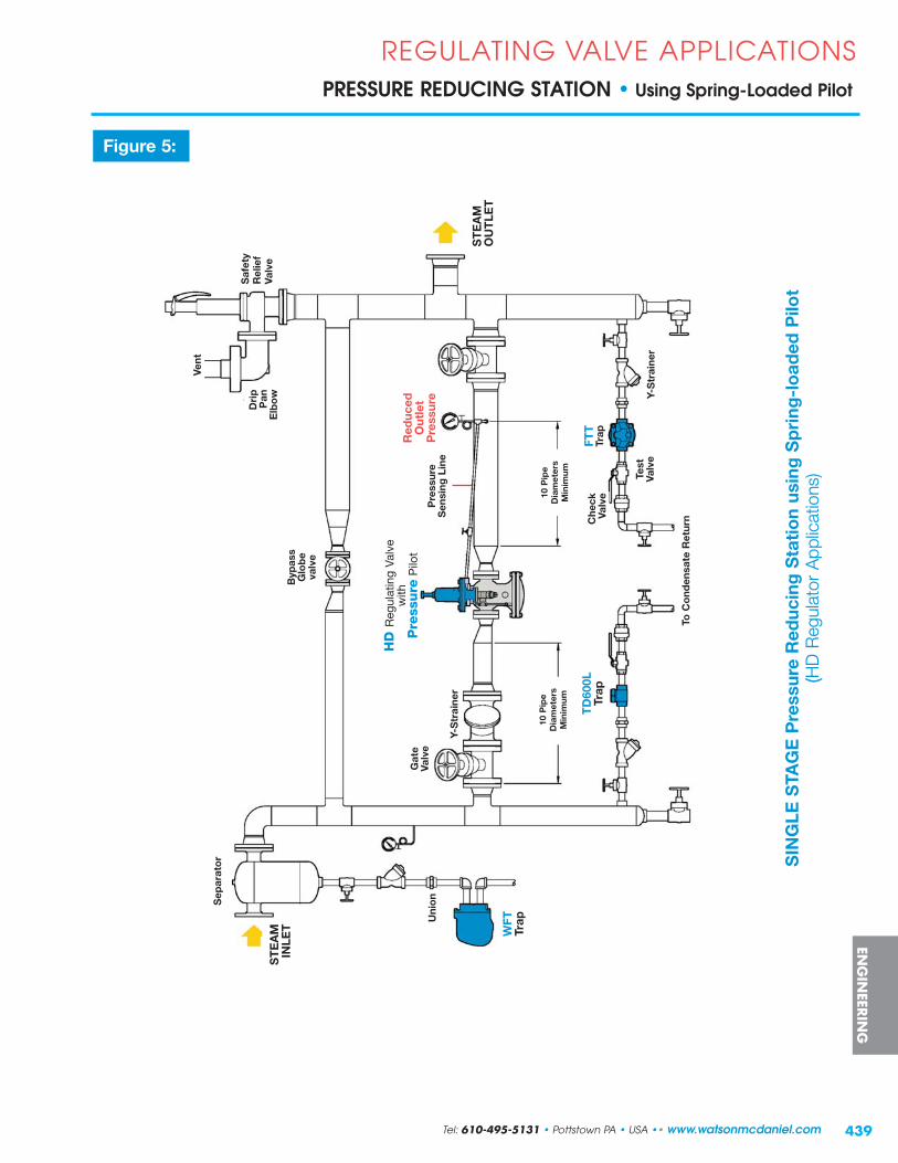
439
SIN
GLE
STA
GE
Pre
ssur
e R
educ
ing
Sta
tio
n us
ing
Sp
ring
-lo
aded
Pilo
t( (H
D R
egul
ator
App
licat
ions
)
Dri
pP
anE
lbo
w
Vent
ST
EA
MIN
LET
Sep
arat
or
10 P
ipe
Dia
met
ers
Min
imum
Byp
ass
Glo
be
valv
e
To C
ond
ensa
te R
etur
n
REGULATING VALVE APPLICATIONSPRESSURE REDUCING STATION • Using Spring-Loaded Pilot
Figure 5:
ENG
INEER
ING
WFT
Trap
HD
Reg
ulat
ing
Valv
ew
ithP
ress
ure
Pilo
t
FTT
Tr
apT
D60
0LTr
ap
Gat
eVa
lve
Y-S
trai
ner
Che
ckVa
lve
10 P
ipe
Dia
met
ers
Min
imum
Uni
on
Saf
ety
Rel
ief
Valv
e
ST
EA
MO
UT
LET
Test
Valv
e
Pre
ssur
eS
ensi
ng L
ine
Re d
uced
Ou t
let
Pre
ssur
e
Tel: 610-495-5131 • Pottstown PA • USA •• www.watsonmcdaniel.com
Y-S
trai
ner

440
REGULATING VALVE APPLICATIONSPRESSURE REDUCING STATION • Using Air-Loaded Pilot
PURPOSE: For reducing system inlet pressure to a constant outlet pressure when valve is located in a remote location and/or using air pressure for control is desired.
OPERATION: This combination of HD regulating valve and PA-pilot allows air to be used to control outlet pressure in lieu of the spring of a standard PP-pilot. Using air allows for simple adjustment of control pressure when valve is installed in a remote and/or difficult to access location.
INSTALLATION GUIDELINES: (see Figure 6)
• The desired set outlet pressure will determine the specific PA-Pilot required as well as the air supply pressure to attain the set pressure. Consult the appropriate section of this catalog or the factory for selection guidelines.
• For optimum operation and service life, maintain recommended minimum piping straight runs before and after the PRV. Inlet pipe diameters could be 1-2 sizes larger and outlet pipe diameters 2-3 sizes larger than the end connections of an appropriately sized PRV. The purpose of increasing the pipe size downstream of the regulator is to keep the steam velocity constant on both sides of the regulator.
• The pressure sensing line should slope downwards, away from the regulator, to prevent condensate from entering the pilot.
• Eccentric reducers, if required, are used on valve inlets to prevent accumulation of condensate which could become entrained with high-velocity steam, possibly resulting in dangerous waterhammer.
• While the separator shown upstream is appropriate for protection of the PRV, it is not always required, as a properly sized drip leg with steam trap may be sufficient. It is recommended for systems where steam is known to be “wet” and the entrained moisture could affect valve performance and/or result in component damage.
• Consider installing a properly sized bypass line with globe valve to provide continuous operation should regulator maintenance be required.
• Consider low-cracking pressure (1/4 PSI opening pressure) check valves after steam traps when discharging into condensate return lines. Check valves eliminate the possibility of condensate backing up through the steam trap into the system.
• A safety relief valve (SRV) is appropriate where applicable codes dictate their requirement, or anywhere protection of downstream piping and equipment from over-pressurization is desired. The SRV needs to handle the complete volume of steam from the regulator and bypass loop. Consult the factory for appropriate SRV sizing guidelines.
ENG
INEE
RIN
G
www.watsonmcdaniel.com •• Pottstown PA • USA • Tel: 610-495-5131

441
Pre
ssur
e R
educ
ing
Sta
tio
n w
ith
Air-
Load
ed P
ilot
for
Rem
ote
Ins
talla
tio
ns( (H
D R
egul
ator
App
licat
ions
)
REGULATING VALVE APPLICATIONSPRESSURE REDUCING STATION • Using Air-Loaded Pilot
Figure 6:
ENG
INEER
ING
Dri
pP
anE
lbo
w
Vent
ST
EA
MIN
LET
Sep
arat
or
Pre
ssur
eS
ensi
ng L
ine
10 P
ipe
Dia
met
ers
Min
imum
Byp
ass
Glo
be
Valv
e
To C
ond
ensa
te R
etur
n
WFT
Trap
HD
Reg
ulat
ing
Valv
e w
ithA
irP
ilot
FTT
Trap
TD
600L
Trap
Gat
eVa
lve
Y-S
trai
ner
Che
ckVa
lve
10 P
ipe
Dia
met
ers
Min
imum
Uni
on
ST
EA
MO
UT
LET
Test
Valv
e
PL2
AIR
SU
PP
LY
Saf
ety
Rel
ief
Valv
e
Re d
uced
Ou t
let
Pre
ssur
e
Tel: 610-495-5131 • Pottstown PA • USA •• www.watsonmcdaniel.com
Y-S
trai
ner

442
REGULATING VALVE APPLICATIONSPRESSURE REDUCING STATION • 2-Stage (Series) for High Pressure Turndown
PURPOSE: For reducing steam system inlet pressure to a constant outlet pressure when the pressure drop exceeds the recommended operation of a single-stage pressure regulating valve (PRV). This will help reduce overall velocity, resulting in less noise and improved equipment service life.
OPERATION: The 1st stage PRV is selected to reduce the initial steam pressure to a reasonable pressure betweenthe initial inlet and desired outlet delivery pressure. This intermediate pressure is typically selected toensure that each PRV is within recommended turndown guidelines. However, it is also possible therewill be a use for steam at a specific intermediate pressure, which must be considered when evaluatingturndown and sizing guidelines. The 2nd stage PRV, installed in series with the 1st stage, then reduces pressure to the final outlet delivery pressure. Individual valve setting and operation is the same as for single-stage applications.
INSTALLATION GUIDELINES: (see Figure 7 )
• This example depicts a two-stage (series) pilot-operated steam PRV pressure reducing station using HD Regulators with Pressure Pilot. An external sensing line is required to sense downstream pressure from each regulator. The end of each sensing line is placed away from the turbulent flow at the valve outlet. This helps to improve accuracy of the set pressures. Set pressure for each PRV is adjusted by turning a screw on the pilot to increase or decrease compression on a balancing spring.
• For optimum operation and service life, maintain recommended minimum piping straight runs before and after the PRV. Inlet pipe diameters could be 1-2 sizes larger and outlet pipe diameters 2-3 sizes larger than the end connections of an appropriately sized PRV. The purpose of increasing the pipe size downstream of the regulator is to keep the steam velocity constant on both sides of the regulator.
• Each pressure sensing line should slope downwards, away from the regulator, to prevent condensate from entering the pilot.
• Eccentric reducers, if required, are used on valve inlets to prevent accumulation of condensate which couldbecome entrained with high-velocity steam, possibly resulting in dangerous waterhammer.
• While the separator shown upstream is appropriate for protection of the PRVs, it is not always required, as a properly sized drip leg with steam trap may be sufficient. It is recommended for systems where steam is known to be “wet” and the entrained moisture could affect valve performance and/or result in component damage.
• Consider installing a properly sized bypass line with globe valve on each stage, to provide continuous operation should regulator maintenance be required.
• Consider low-cracking pressure (1/4 PSI opening pressure) check valves after steam traps when discharging into condensate return lines. Check valves eliminate the possibility of condensate backing up through the steam trap into the system.
• A safety relief valve (SRV) is appropriate where applicable codes dictate their requirement, or anywhere protection of downstream piping and equipment from over-pressurization is desired. The SRV needs to handle the complete volume of steam from the regulator and bypass loop. Consult the factory for appropriate SRV sizing guidelines.
ENG
INEE
RIN
G
www.watsonmcdaniel.com •• Pottstown PA • USA • Tel: 610-495-5131

443
REGULATING VALVE APPLICATIONSPRESSURE REDUCING STATION • 2-Stage (Series) for High Pressure Turndown
Figure 7 :
ENG
INEER
ING
Dri
pP
anE
lbo
w
Vent
ST
EA
MIN
LET
Sep
arat
or
10 P
ipe
Dia
met
ers
Min
imum
Byp
ass
Glo
be
Valv
e
To C
ond
ensa
te R
etur
n
WFT
Trap
TD
600L
Trap
Uni
on
Saf
ety
Rel
ief
Valv
e ST
EA
MO
UT
LET
Y-S
trai
ner
10 P
ipe
Dia
met
ers
Min
imum
TD
600L
Trap
10 P
ipe
Dia
met
ers
Min
imum
Byp
ass
Glo
be
Valv
e
10 P
ipe
Dia
met
ers
Min
imum
Gat
eVa
lve
TD
600L
Trap
To C
ond
ensa
te R
etur
n
20 P
IPE
D
iam
eter
s M
inim
um
HD
Reg
ulat
ing
Valv
ew
ithP
ress
ure
Pilo
t P
ress
ure
Sen
sing
Line
Pre
ssur
eS
ensi
ngLi
ne
Re d
uced
Ou t
let
Pre
ssur
eIn
t erm
edia
teP
ress
ure
Tel: 610-495-5131 • Pottstown PA • USA •• www.watsonmcdaniel.com
1st
stag
eP
re ss
ure
Red
ucti
on
2nd
s ta
ge
P re
ssur
eR
educ
tio
n
Two
-Sta
ge
(Ser
ies)
Pre
ssur
e R
educ
ing
Sta
tio
n (H
D R
egul
ator
App
licat
ions
)
HD
Reg
ulat
ing
Valv
ew
ithP
ress
ure
Pilo
t
21
Y-S
trai
ner

444
REGULATING VALVE APPLICATIONSPRESSURE REDUCING STATION • Parallel for High Flow Turndown
PURPOSE: For reducing steam system inlet pressure to a constant outlet pressure when steam flow ratesvary widely. This will help improve system rangeability resulting in more accurate control.
OPERATION: Because regulators are simple, self-powered devices which do not rely on an external control signal to determine valve steam position, they may not have the flow rangeability of control valves. Therefore, if a system has large flow variations (such as summer and winter loads), multiple regulators should be considered. Typically referred to as a 1/3 - 2/3 system, one valve may besized for approximately 1/3 of the total maximum load demand and a larger valve for the remaining 2/3. When full load is required, both valves will be open and regulating. The small regulator is typically the primary valve and is set at a pressure 2 psi higher than the larger secondary valve. This allows the small regulator to be the only one flowing when demand is low. When flow increases and the small valve cannot keep up with the demand, the downstream pressure will begin to drop which will allow the larger secondary valve to open in order to help satisfy the demand. Although the smaller regulator is commonly selected as the primary valve, either the smaller or larger regulator may be set as the primary valve based on anticipated load demand requirements. The primary valve should always be set a minimum of 2 psi above the secondary valve.
INSTALLATION GUIDELINES: (see Figure 8)
• This example depicts a parallel pilot-operated steam PRV pressure reducing station using HD Regulators withPressure Pilot. An external sensing line is required to sense downstream pressure from each regulator. The end of each sensing line is placed away from the turbulent flow at the valve outlet. This helps to improve accuracy of the set pressures. Set pressure for each PRV is adjusted by turning a screw on the pilot to increase or decrease compression on a balancing spring.
• Proper setting of the valves is key to proper operation. The chosen primary valve should be set at a pressure approximately 2 PSI higher than that of the secondary valve.
• For optimum operation and service life, maintain recommended minimum piping straight runs before and after the PRV. Inlet pipe diameters could be 1-2 sizes larger and outlet pipe diameters 2-3 sizes larger than the end connections of an appropriately sized PRV. The purpose of increasing the pipe size downstream of the regulator is to keep the steam velocity constant on both sides of the regulator.
• Each pressure sensing line should slope downwards, away from the regulator, to prevent condensate from entering the pilot.
• Eccentric reducers, if required, are used on valve inlets to prevent accumulation of condensate which couldbecome entrained with high-velocity steam, possibly resulting in dangerous waterhammer.
• While the separator shown upstream is appropriate for protection of the PRV, it is not always required, as a properly sized drip leg with steam trap may be sufficient. It is recommended for systems where steam is known to be “wet” and the entrained moisture could affect valve performance and/or result in component damage.
• Consider installing a properly sized bypass line with globe valve to provide continuous operation shouldregulator maintenance be required.
• Consider low-cracking pressure (1/4 PSI opening pressure) check valves after steam traps when discharging into condensate return lines. Check valves eliminate the possibility of condensate backing up through the steam trap into the system.
• A safety relief valve (SRV) is appropriate where applicable codes dictate their requirement, or anywhere protection of downstream piping and equipment from over-pressurization is desired. The SRV needs to handle the complete volume of steam from the regulator and bypass loop. Consult the factory for appropriate SRV sizing guidelines.
ENG
INEE
RIN
G
www.watsonmcdaniel.com •• Pottstown PA • USA • Tel: 610-495-5131

445
REGULATING VALVE APPLICATIONSPRESSURE REDUCING STATION • Parallel for High Flow Turndown
Figure 8:
PAR
ALL
EL
Pre
ssur
e R
educ
ing
Sta
tio
n
(HD
Reg
ulat
or A
pplic
atio
ns)
ENG
INEER
ING
Dri
pP
anE
lbo
w
Vent
ST
EA
MIN
LET
SE
PAR
ATO
R
Byp
ass
Glo
be
Valv
e
To C
ond
ensa
te R
etur
n
WFT
Trap
HD
Reg
ulat
ing
Valv
ew
ithP
ress
ure
Pilo
t
Y-S
trai
ner
Uni
on
ST
EA
MO
UT
LET
10 P
ipe
Dia
met
ers
Min
imum
FTT
Trap
10 P
ipe
Dia
met
ers
Min
imum 10
Pip
e D
iam
eter
s M
inim
um
Gat
eVa
lve
TD
600L
Trap
10 P
ipe
Dia
met
ers
Min
imum
HD
Reg
ulat
ing
Valv
e w
ithP
ress
ure
Pilo
t
Y-S
trai
ner
Che
ckVa
lve
Test
Valv
e
Pre
ssur
eS
ensi
ng L
ine
Pre
ssur
e S
ensi
ng L
ine
Saf
ety
Rel
ief
Valv
e
Re d
uced
Ou t
let
Pre
ssur
e
Tel: 610-495-5131 • Pottstown PA • USA •• www.watsonmcdaniel.com
2
1
Sec
onda
ry
Pri
mar
y

446
REGULATING VALVE APPLICATIONSPRESSURE REDUCING STATION • for Combination High Pressure & High Flow Turndown
PURPOSE: For reducing steam system inlet pressure to a constant outlet pressure when flow conditions vary widely combined with a high pressure drop (i.e. higher than the recommended range of a single-stage regulator).
OPERATION: This system is a combination of Two-Stage (Series) and Parallel pressure reducing stations and operates based on the individual principles of each system. Each series of valves will be sized to handle a portion of the total maximum load demand, typically 1/3 and 2/3 of the total anticipated flow. If the smaller series of valves is determined to operate as the primary, then the 2nd stage valve will be set 2 psi higher than the 2nd stage valve in the secondary series. This allows the primary seriesto be the only one flowing when demand is low. When flow increases and the primary series cannot keep up with demand, the downstream pressure will being to drop which will allow the larger secondary series of valves to open in order to help satisfy the demand.
INSTALLATION GUIDELINES: (see Figure 9)
• This example depicts a two-stage parallel pilot-operated steam PRV pressure reducing station using HD Regulators with Pressure Pilot. An external sensing line is required to sense downstream pressure from each regulator. The end of each sensing line is placed away from the turbulent flow at the valve outlet. This helps to improve accuracy of the set pressures. Set pressure for each PRV is adjusted by turning a screw on the pilot to increase or decrease compression on a balancing spring.
• Proper setting of the valves is key to proper operation. The chosen 1st stage primary valve should be set at a pressure approximately 2 PSI higher than that of the 1st stage secondary valve.
• For optimum operation and service life, maintain recommended minimum piping straight runs before and after the PRV. Inlet pipe diameters could be 1-2 sizes larger and outlet pipe diameters 2-3 sizes larger than the end connections of an appropriately sized PRV. The purpose of increasing the pipe size downstream of the regulator is to keep the steam velocity constant on both sides of the regulator.
• Each pressure sensing line should slope downwards, away from the regulator, to prevent condensate from entering the pilot.
• Eccentric reducers, if required, are used on valve inlets to prevent accumulation of condensate which couldbecome entrained with high-velocity steam, possibly resulting in dangerous waterhammer.
• While the separator shown upstream is appropriate for protection of the PRVs, it is not always required, as a properly sized drip leg with steam trap may be sufficient. It is recommended for systems where steam is known to be “wet” and the entrained moisture could affect valve performance and/or result in component damage.
• Consider installing a properly sized bypass line with globe valve on each stage, to provide continuous operation should regulator maintenance be required.
• Consider low-cracking pressure (1/4 PSI opening pressure) check valves after steam traps when discharging into condensate return lines. Check valves eliminate the possibility of condensate backing up through the steam trap into the system.
• A safety relief valve (SRV) is appropriate where applicable codes dictate their requirement, or anywhere protection of downstream piping and equipment from over-pressurization is desired. The SRV needs to handle the complete volume of steam from the regulator and bypass loops. Consult the factory for appropriate SRV sizing guidelines.
ENG
INEE
RIN
G
www.watsonmcdaniel.com •• Pottstown PA • USA • Tel: 610-495-5131

Saf
ety
Rel
ief
Valv
e
447
REGULATING VALVE APPLICATIONSPRESSURE REDUCING STATION • for Combination High Pressure & High Flow Turndown
Figure 9:
Sec
onda
ry
ENG
INEER
ING
Dri
pP
anE
lbo
w
Vent
ST
EA
MIN
LET
Sep
arat
or
Byp
ass
Glo
be
Valv
e
To C
ond
ensa
te R
etur
n
WFT
TrapU
nio
n
ST
EA
MO
UT
LET
10 P
ipe
Dia
met
ers
Min
imum
10 P
ipe
Dia
met
ers
Min
imum
Gat
eVa
lve
TD
600L
Trap
10 P
ipe
Dia
met
ers
Min
imum
10 P
ipe
Dia
met
ers
Min
imum
10 P
IPE
D
iam
eter
sM
inim
um
10 P
ipe
Dia
met
ers
Min
imum
To C
ond
ensa
te R
etur
n
Y-S
trai
ner
10 P
ipe
Dia
met
ers
Min
imum10
Pip
eD
iam
eter
sM
inim
um
TD
600L
Trap
TD
600L
Trap
HD
Reg
ulat
ing
Valv
ew
ithP
ress
ure
Pilo
t P
ress
ure
Sen
sing
Lin
e
TW
O-S
TAG
E P
AR
ALL
EL
Pre
ssur
e R
educ
ing
Sta
tio
n
(HD
Reg
ulat
or A
pplic
atio
ns)
1st
stag
eP
re ss
ure
Red
ucti
on
2nd
s ta
ge
P re
ssur
eR
educ
tio
n
Red
uced
Ou t
let
Pre
ssur
e
Inte
rmed
iate
Pre
ssur
eG
ate
Valv
e
Byp
ass
Glo
be
Valv
e
Tel: 610-495-5131 • Pottstown PA • USA •• www.watsonmcdaniel.com
Pri
mar
y2
1
43
Y-S
trai
ner
Y-S
trai
ner
Red
uced
Ou t
let
Pre
ssur
e
Gat
eVa
lve
Inte
rmed
iate
Pre
ssur
e
448
REGULATING VALVE APPLICATIONSTEMPERATURE CONTROL • of Heat Exchanger with Pressure Limiting Pilot
PURPOSE: For accurately controlling both temperature of a product being heated in heat transfer equipment as wellas limiting the pressure of the incoming steam, providing optimum heat transfer characteristics.
OPERATION: When a pilot-operated HD valve is selected, a single valve can be used for both pressure andtemperature control when equipped with a PP-Pilot and PT-Pilot. As temperature at the sensingbulb falls below set point, the valve begins to modulate open to supply steam for heating. Supply pressure to the heat exchanger is them limited by adjusting the pressure pilot to the recommendedvalue for optimum heat transfer and/or a limiting pressure of the heat transfer equipment. The HD Regulator with combination PT & PP Pilots requires no external power source.
INSTALLATION GUIDELINES: (see Figure 10)
• The temperature and pressure pilots should be set individually, starting slowly and gradually with the PT-pilot.
•l Care should be given to the installation of the temperature sensing bulb to ensure full immersion in the liquid.The sensing bulb should be placed as close as possible to the heat exchanger vessel to ensure accuratetemperature control of the process fluid.
• For optimum operation and service life, maintain recommended minimum piping straight runs before and after the Regulator. Inlet pipe diameters could be 1-2 sizes larger and outlet pipe diameters 2-3 sizes larger than the end connections of an appropriately sized Regulator. The purpose of increasing the pipe size downstream of the regulator is to keep the steam velocity constant on both sides of the regulator.
• The pressure sensing line should slope downwards, away from the regulator, to prevent condensate from entering the pilot.
• Eccentric reducers, if required, are used on valve inlets to prevent accumulation of condensate which couldbecome entrained with high-velocity steam, possibly resulting in dangerous waterhammer.
• While a separator is appropriate for protection of the Regulator, it is not always required, as a properly sized drip leg with steam trap may be sufficient. It is recommended for systems where steam is known to be “wet” and the entrained moisture could affect valve performance and/or result in component damage.
• Consider low-cracking pressure (1/4 PSI opening pressure) check valves after steam traps when discharging into condensate return lines. Check valves eliminate the possibility of condensate backing up through the steam trap into the system.
• The vacuum breaker and auxiliary air vent located at the top of the heat exchanger vessel promotes proper drainage and optimum heat transfer. The vacuum breaker allows system equalization with atmospheric air to allow gravity condensate drainage when vacuum is formed from condensing steam. The air vent improves heat-up times and overall heat transfer by expelling accumulated air on start-up.
• A safety relief valve (SRV) is appropriate where applicable codes dictate their requirement, or anywhere protection of downstream piping and equipment from over-pressurization is desired. Consult the factory for appropriate SRV sizing guidelines.
ENG
INEE
RIN
G
www.watsonmcdaniel.com •• Pottstown PA • USA • Tel: 610-495-5131

449
REGULATING VALVE APPLICATIONSTEMPERATURE CONTROL • of Heat Exchanger with Pressure Limiting Pilot
Tem
per
atur
e C
ont
rol o
f a
Hea
t E
xcha
nger
wit
h P
ress
ure
Lim
itin
g( (H
D R
egul
ator
App
licat
ions
)
Figure 10:
Pre
ssur
eS
ensi
ng L
ine
Cap
illar
y
ENG
INEER
ING
Ho
tW
ater
Out
let
Co
ldW
ater
Inle
t
Hea
t E
xcha
nger
WV
BS
SVa
cuum
Bre
aker
HD
Reg
ulat
ing
Valv
ew
ithTe
mpera
ture
Pilo
t&
Pre
ssure
Pilo
t
TD
600L
Trap
AV
2000
Air
Vent
WFT
Trap
Saf
ety
Valv
e
Tem
per
atur
eS
ensi
ng B
ulb
Dra
inVa
lve
Iso
lati
on
Valv
e
Y-S
trai
ner
Red
uced
Ou t
let
Pre
ssur
eD
rip
Pan
Elb
ow
Inle
tP
ress
ure
Tel: 610-495-5131 • Pottstown PA • USA •• www.watsonmcdaniel.com

450
REGULATING VALVE APPLICATIONSTEMPERATURE CONTROL of a BATCH PROCESS with Electrical Time Sequence Programmer (Solenoid Pilot)
PURPOSE: For accurately controlling temperature of a batch process where on-off operation is to be electronically controlled.
OPERATION: Operation is similar to that of the pressure and temperature combination pilot-operated regulator whereby the temperature (PT) pilot senses the temperature of the heated product (e.g. water) and appropriately modulates the flow of steam. Pressure is limited by the pressure (PP) pilot. The solenoid valve (PS-pilot) is electronically activated to control on-off operation of the batch process.
INSTALLATION GUIDELINES: (see Figure 11)
• The temperature and pressure pilots should be set individually, starting slowly and gradually with the PT-pilot.
• For optimum operation and service life, maintain recommended minimum piping straight runs before and after the PRV. Inlet pipe diameters could be 1-2 sizes larger and outlet pipe diameters 2-3 sizes larger than the end connections of an appropriately sized Regulator. The purpose of increasing the pipe size downstream of the regulator is to keep the steam velocity constant on both sides of the regulator.
• The pressure sensing line should slope downwards, away from the regulator, to prevent condensate from entering the pilot.
• Eccentric reducers, if required, are used on valve inlets to prevent accumulation of condensate which couldbecome entrained with high-velocity steam, possibly resulting in dangerous waterhammer.
• While a separator is appropriate for protection of the Regulator, it is not always required, as a properly sized drip leg with steam trap may be sufficient. It is recommended for systems where steam is known to be “wet” and the entrained moisture could affect valve performance and/or result in component damage.
• Consider low-cracking pressure (1/4 PSI opening pressure) check valves after steam traps when discharging into condensate return lines. Check valves eliminate the possibility of condensate backing up through the steam trap into the system.
• The vacuum breaker and auxiliary air vent located at the top of the jacketed kettle vessel promotes proper drainage and optimum heat transfer. The vacuum breaker allows system equalization with atmospheric air to allow gravity condensate drainage when vacuum is formed from condensing steam. The air vent improves heat-up times and overall heat transfer by expelling accumulated air on start-up.
• A safety relief valve (SRV) is appropriate where applicable codes dictate their requirement, or anywhere protection of downstream piping and equipment from over-pressurization is desired. Consult the factory for appropriate SRV sizing guidelines.
ENG
INEE
RIN
G
www.watsonmcdaniel.com •• Pottstown PA • USA • Tel: 610-495-5131

451
REGULATING VALVE APPLICATIONSTEMPERATURE CONTROL
of a BATCH PROCESS with Electrical Time Sequence Programmer (Solenoid Pilot)
AU
TOM
ATIC
TE
MP
ER
ATU
RE
CO
NTR
OL
of a
BAT
CH
PR
OC
ES
S w
ith E
lect
rica
l Tim
e S
eque
nce
Pro
gram
mer
(Sol
enoi
d P
ilot)
((HD
Reg
ulat
or A
pplic
atio
ns)
Figure 11:
ENG
INEER
ING
Pre
ssur
eS
ensi
ng L
ine
Jack
eted
Ket
tle
WV
BS
SVa
cuum
Bre
aker
HD
Reg
ulat
ing
Valv
ew
ithTe
mpera
ture
Pilo
t,P
ress
ure
Pilo
t&
Sole
noid
Pilo
t
TD
600L
Trap
AV
2000
Air
Vent
WFT
Trap
Tem
per
atur
eS
ensi
ng B
ulb
ELE
CT
RIC
OP
ER
ATO
RP
OW
ER
Saf
ety
Rel
ief
Valv
eD
rip
Pan
Elb
ow
Y-S
trai
ner
Cap
illar
y
Red
uced
Ou t
let
Pre
ssur
eIn
let
Pre
ssur
e
Tel: 610-495-5131 • Pottstown PA • USA •• www.watsonmcdaniel.com

452
REGULATING VALVE APPLICATIONSTEMPERATURE CONTROL of a SEMI-INSTANTANEOUS HEATERusing a Self-Contained Temperature Regulating Valve
PURPOSE: For accurate control of the temperature of a product being heated when the benefits of a self-contained regulator are required.
OPERATION: A self-contained temperature regulating valve (TRV) such as the W94, offers response times and characteristics suitable for semi-instantaneous heating applications. The temperature sensing bulb senses the temperature of the liquid being heated and allows modulation of the valve for appropriate supply of steam.
INSTALLATION GUIDELINES: (see Figure 12)
• Care should be given to the installation of the temperature sensing bulb to ensure full immersion in the liquid.The sensing bulb should be placed as close as possible to the heater tank to ensure accurate temperature control of the process fluid.
• All pressure sensing lines should slope downwards, away from the regulator, to prevent condensate from entering the pilot.
• Eccentric reducers, if required, are used on valve inlets to prevent accumulation of condensate which couldbecome entrained with high-velocity steam, possibly resulting in dangerous waterhammer.
• While a separator is appropriate for protection of the Regulator, it is not always required, as a properly sized drip leg with steam trap may be sufficient. It is recommended for systems where steam is known to be“wet” and the entrained moisture could affect valve performance and/or result in component damage.
• Consider low-cracking pressure (1/4 PSI opening pressure) check valves after steam traps when discharging into condensate return lines. Check valves eliminate the possibility of condensate backing up through the steam trap into the system.
• The vacuum breaker and auxiliary air vent located at the top of the heater tank promotes proper drainage and optimum heat transfer. The vacuum breaker allows system equalization with atmospheric air to allow gravity condensate drainage when vacuum is formed from condensing steam. The air vent improves heat-up times and overall heat transfer by expelling accumulated air on start-up.
• A safety relief valve (SRV) is appropriate where applicable codes dictate their requirement, or anywhere protection of downstream piping and equipment from over-pressurization is desired. The SRV needs to handle the complete volume of steam from the regulator and bypass loop. Consult the factory for appropriate SRV sizing guidelines.
ENG
INEE
RIN
G
www.watsonmcdaniel.com •• Pottstown PA • USA • Tel: 610-495-5131

453
Sem
i-In
stan
tane
ous
Ho
t W
ater
Hea
ter
wit
h W
94 T
emp
erat
ure
Reg
ulat
or
( (Tem
pera
ture
Reg
ulat
or A
pplic
atio
ns)
REGULATING VALVE APPLICATIONSTEMPERATURE CONTROL of a SEMI-INSTANTANEOUS HEATER
using a Self-Contained Temperature Regulating Valve
Figure 12:
ENG
INEER
ING
WV
BS
SVa
cuum
B
reak
er
W94
TE
MP
ER
ATU
RE
Reg
ulat
ing
Val
ve
TD
600L
Trap
AV
2000
Air
Vent
WFT
Trap
Tem
per
atur
eS
ensi
ngB
ulb
Dra
inVa
lve
Y-S
trai
ner
Iso
lati
on
Valv
e
Cap
illar
y
Tel: 610-495-5131 • Pottstown PA • USA •• www.watsonmcdaniel.com
Hea
t E
xcha
nger
Ho
tW
ater
Out
let
Co
ldW
ater
Inle
t

454
PMP & PUMP-TRAP APPLICATIONS
PURPOSE: For removing condensate from below steam heat transfer equipment when a modulating valve is used for control, and condensate discharge is elevated and/or pressurized, resulting in Stall condition.
OPERATION: The Pressure Motive Pump (PMP) is used to overcome the stall condition that exists when steam feeding a single piece of heat transfer equipment is controlled by a modulating steam valve and steam pressure falls below system back pressure as the valve closes. A steam trap is required after the PMP to prevent the loss of live steam when the system is under positive pressure. Operating as a closed loop provides an energy-efficient system by eliminating the need to vent flash steam.
INSTALLATION GUIDELINES: (see Figure13)
• Proper installation and piping of the pump vent line is critical to ensure the system operates correctly.Follow guidelines or consult factory for additional information.
• Maintain proper fill head above the top of the pump to ensure proper function of the pump and system. A suitably sized reservoir or oversized piping should be installed ahead of the pump for accumulation of condensate during the pumpʼs discharge cycle (i.e. when not filling).
• The steam trap after the pump must be sized in conjunction with the pump to ensure proper function as a system. Improper sizing may result in reduced capacity leading to condensate back-up, poor heat transfer and potentially dangerous waterhammer. Consult appropriate sections of this catalog or the factory for guidelines regarding proper sizing of the pump-trap combination.
• While a separator is appropriate for protection of the Regulator, it is not always required, as a properly sized drip leg with steam trap may be sufficient. It is recommended for systems where steam is known to be “wet” and the entrained moisture could affect valve performance and/or result in component damage.
• Low-cracking pressure (1/4 PSI opening pressure) check valves should be installed after steam traps when discharging into condensate return lines. Check valves eliminate the possibility of condensate backing upthrough the steam trap into the system.
• The thermostatic air vent installed on the heat exchanger promotes optimum heat transfer. The air vent improves heat-up times and overall heat transfer by expelling accumulated air on start-up. When properlysized and installed, the pump-trap combination can operate in sub-atmospheric (i.e. vacuum) conditions;therefore, a vacuum breaker should not be used.
CONDENSATE DRAINAGE • using Pump-Trap
ENG
INEE
RIN
G
www.watsonmcdaniel.com •• Pottstown PA • USA • Tel: 610-495-5131

455
PMP & PUMP-TRAP APPLICATIONSCONDENSATE DRAINAGE • using Pump-Trap
Figure 13:
Dra
inag
e o
f a
Sin
gle
So
urce
of
Co
nden
sate
fo
r a
Clo
sed
Lo
op
Sys
tem
(Pum
p-Tr
ap A
pplic
atio
ns)
ENG
INEER
ING
ST
EA
MIN
LET
Cap
illar
y
Tem
per
atur
eS
ensi
ng B
ulb
MO
TIV
EIN
LET
F&
TTr
ap
Hea
t E
xcha
nger
PR
ES
SU
RE
MO
TIV
EP
UM
P
Inle
tC
heck
Valv
e
Filli
ng H
ead
Vent
Res
ervo
ir
The
rmo
stat
icA
ir V
ent
Che
ck V
alve
MO
DU
LAT
ING
RE
GU
LAT
OR
or
CO
NT
RO
L VA
LVE
Out
let
Che
ckVa
lveTo
Co
nden
sate
Ret
urn
LIFT
HE
IGH
T
To C
ond
ensa
te R
etur
n
Ho
tW
ater
Out
let
Co
ldW
ater
Inle
t
Tel: 610-495-5131 • Pottstown PA • USA •• www.watsonmcdaniel.com

456
PMP & PUMP-TRAP APPLICATIONSCONDENSATE DRAINAGE from Below Grade • using Pump-Trap
PURPOSE: For drainage of condensate from below process equipment where fill head is limited due to height restrictions and the pump must be installed below grade.
OPERATION: When fill head is restricted and it is more suitable to create a pit below grade than reposition process equipment, the Pressure Motive Pump (PMP) may be modified so both condensate inlet and outlet connections are on top to limit the necessary pit size. When stall exists, condensate will accumulate between the inlet and outlet check valves and eventually drain into and fill the PMPtank. Once the PMP fills and its mechanism trips, high pressure motive steam will enter the pump tank and force condensate back out the same connection. The check valves will direct the flow of pumped condensate into the return piping.
INSTALLATION GUIDELINES: (see Figure 1 4)
• The positioning of the check valves and PMP fill/discharge line are the key elements which allow the system to function properly. The check valves dictate the proper direction of condensate flow for both fill and discharge cycles of the PMP. The PMP fill/discharge line should be taken off the top, as shown, so condensate only accumulates and fills the pump during stall.
• Proper installation and piping of the pump vent line is critical to ensure the system operates correctly.Follow guidelines or consult factory for additional information.
• Maintain proper fill head above the top of the pump to ensure proper function of the pump and system. A suitably sized reservoir or oversized piping should be installed ahead of the pump for accumulation of condensate during the pumpʼs discharge cycle (i.e. when not filling).
• The steam trap after the pump must be sized in conjunction with the pump to ensure proper function as a system. Improper sizing may result in reduced capacity leading to condensate back-up, poor heat transfer and potentially dangerous waterhammer. Consult appropriate sections of this catalog or the factory for guidelines regarding proper sizing of the pump-trap combination.
• Low-cracking pressure (1/4 PSI opening pressure) check valves should be installed after steam traps when discharging into condensate return lines. Check valves eliminate the possibility of condensate backing up through the steam trap into the system.
ENG
INEE
RIN
G
www.watsonmcdaniel.com •• Pottstown PA • USA • Tel: 610-495-5131

457
PMP & PUMP-TRAP APPLICATIONSCONDENSATE DRAINAGE from Below Grade • using Pump-Trap
Figure 1 4:
Dra
inag
e o
f C
ond
ensa
te f
rom
BE
LOW
GR
AD
E f
or
a C
lose
d L
oo
p S
yste
min
Sit
uati
ons
wit
h M
inim
al F
ill H
ead
(Pum
p-Tr
ap A
pplic
atio
ns)
ENG
INEER
ING
Mo
tive
Ste
amIn
let
F&
TTr
ap
PR
ES
SU
RE
MO
TIV
EP
UM
P
To D
rain
Res
ervo
ir
Che
ckVa
lve
Co
nden
sate
fro
m
Pro
cess
Eq
uip
men
t
To C
ond
ensa
teR
etur
n
UT
D450
The
rmo
dyn
amic
Ste
am T
rap
To D
rain
Inle
tC
heck
Valv
e
Out
let
Che
ckVa
lve
Mo
tive
Inle
t
Vent
Line
Fill
& D
isch
arg
eLi
ne
Fill
Hea
d
Tel: 610-495-5131 • Pottstown PA • USA •• www.watsonmcdaniel.com

458
PMP & PUMP-TRAP APPLICATIONSCONDENSATE DRAINAGE using Vertical Reservoir and Pump-Trap
PURPOSE: For drainage of condensate from below process equipment where fill head is limited due to height restrictions and a horizontal reservoir cannot be installed.
OPERATION: This system f unctions similarly to the system shown on pag e 455. However, when fill head is restricted due to heat exchanger height above ground, consider a vertical reservoir in lieu of a horizontal reservoir. This would accommodate condensate back-up as well as provide sufficientvapor space for the adequate venting of the pump while providing sufficient fill head to ensureproper operation of the pump.
INSTALLATION GUIDELINES: (see Figure 15 )
• The vertical reservoir must be properly designed and installed to allow adequate condensate back-upduring the pumpʼs discharge cycle (i.e. when not filling), unobstructed venting of the pump, as well assufficient fill head to ensure proper pump and system operation. Consult factory for additional assistance.
• Proper installation and piping of the pump vent line is critical to ensure the system operates correctly.Follow guidelines or consult factory for additional information.
• The steam trap after the pump must be sized in conjunction with the pump to ensure proper function as a system. Improper sizing may result in reduced capacity leading to condensate back-up, poor heat transfer and potentially dangerous waterhammer. Consult appropriate sections of this catalog or the factory for guidelines regarding proper sizing of the pump-trap combination.
• Low-cracking pressure (1/4 PSI opening pressure) check valves should be installed after steam traps when discharging into condensate return lines. Check valves eliminate the possibility of condensate backing up through the steam trap into the system. .
• The thermostatic air vent located on the heat exchanger promotes optimum heat transfer. The air vent improves heat-up times and overall heat transfer by expelling accumulated air on start-up. When properlysized and installed, the pump-trap combination can operate in sub-atmospheric (i.e. vacuum) conditions; therefore, a vacuum breaker should not be used.
ENG
INEE
RIN
G
www.watsonmcdaniel.com •• Pottstown PA • USA • Tel: 610-495-5131

459
PMP & PUMP-TRAP APPLICATIONSCONDENSATE DRAINAGE using Vertical Reservoir and Pump-Trap
Figure 1 5 :
Dra
inag
e o
f C
ond
ensa
tefr
om
HE
AT E
XC
HA
NG
ER
po
siti
one
d C
lose
to
the
Gro
und
(Pum
p-Tr
ap A
pplic
atio
ns)
ST
EA
MIN
LET
Cap
illar
y
F&
TTr
ap
Hea
t E
xcha
nger
PR
ES
SU
RE
MO
TIV
EP
UM
P
Vent
MO
DU
LAT
ING
RE
GU
LAT
OR
or
CO
NT
RO
L VA
LVE
To C
ond
ensa
te R
etur
n
Lift
Hei
ght
To C
ond
ensa
te R
etur
n
ENG
INEER
ING
Vert
ical
Res
ervo
ir
Inle
tC
heck
Valv
eO
utle
tC
heck
Valv
e
Mo
tive
Inle
t
Fill
Hea
d
Tem
per
atur
eS
ensi
ngB
ulb
The
rmo
stat
icA
ir V
ent
Che
ck V
alve
Tel: 610-495-5131 • Pottstown PA • USA •• www.watsonmcdaniel.com
Ho
tW
ater
Out
let
Co
ldW
ater
Inle
t

460
PMP & PUMP-TRAP APPLICATIONSFLASH STEAM RECOVERY
PURPOSE: For recovering flash steam from multiple condensate sources and drainage of the condensate when the total system back pressure is greater than the total of the individual source pressures.
OPERATION: Condensate at various pressures collects in a receiver (flash tank), equalizing the pressures to that of the flash tank. This allows drainage by gravity into the Pressure Motive Pump (PMP), filling the PMP until the internal mechanism reaches its upper trip point and activates the motive steam used for pumping. The flash steam generated from the high pressure condensate maybe used to supplement other applications for optimum energy efficiency. The pressure in the receiver tank is maintained by a back pressure regulator and protected by a safety relief valve.
INSTALLATION GUIDELINES: (see Figure 16 )
• The key element for proper system operation is the sizing of the receiver tank and receiver vent connection, which must accommodate the flash steam. Consult appropriate sections of this catalog or the factory for guidelines regarding proper sizing of the receiver tank and receiver vent connection.
• Proper installation and piping of the pump vent line is critical to ensure the system operates correctly.Follow guidelines or consult factory for additional information.
• Careful consideration should be given to sizing of the auxiliary components such as the back pressure regulator and safety relief valve.
• Maintain proper fill head above the top of the pump to ensure proper function of the pump and system. A suitably sized receiver or oversized piping should be installed ahead of the pump for accumulation of condensate during the pumpʼs discharge cycle (i.e. when not filling).
• The steam trap after the pump must be sized in conjunction with the pump to ensure proper function as a system. Improper sizing may result in reduced capacity leading to condensate back-up, poor heat transfer and potentially dangerous waterhammer. Consult appropriate sections of this catalog or the factory for guidelines regarding proper sizing of the pump-trap combination.
• While the separator shown upstream is appropriate for protection of the PRV, it is not always required, as a properly sized drip leg with steam trap may be sufficient. It is recommended for systems where steam is known to be “wet” and the entrained moisture could affect valve performance and/or result in component damage.
• Low-cracking pressure (1/4 PSI opening pressure) check valves should be installed after steam traps when discharging into condensate return lines. Check valves eliminate the possibility of condensate backing up through the steam trap into the system.
• A safety relief valve (SRV) is appropriate where applicable codes dictate their requirement, or anywhere protection of downstream piping and equipment from over-pressurization is desired. Consult the factory for appropriate SRV sizing guidelines.
ENG
INEE
RIN
G
www.watsonmcdaniel.com •• Pottstown PA • USA • Tel: 610-495-5131

461
PMP & PUMP-TRAP APPLICATIONSFLASH STEAM RECOVERY
Figure 1 6:
FLA
SH
ST
EA
M R
EC
OV
ER
Y(P
ump-
Trap
App
licat
ions
)
ENG
INEER
ING
F&
TTr
ap
PR
ES
SU
RE
MO
TIV
EP
UM
P
Dri
p P
anE
lbo
wVe
nt T
oA
tmo
sphe
re
To C
ond
ensa
te R
etur
n
RE
CE
IVE
R(F
lash
Tan
k)
Saf
ety
Valv
e
Low
Pre
ssur
e S
team
Sup
ply
pro
duc
ed f
rom
Fla
sh S
team
Pum
pVe
ntLi
ne
Mo
tive
Ste
amS
upp
ly
Ove
flow
To
Dra
in
Ste
amTr
ap
Hig
h P
ress
ure
Co
nden
sate
(f
rom
Tra
ps)
Hig
h P
ress
ure
Ste
am
Sup
ply
Wat
erS
eal
Out
let
Che
ckVa
lve
Inle
tC
heck
Valv
e
Tel: 610-495-5131 • Pottstown PA • USA •• www.watsonmcdaniel.com
HD
Reg
ulat
ing
Valv
ew
ithP
ress
ure
Pilo
t (fo
r M
akeu
p S
team
)
HD
Reg
ulat
ing
Valv
e w
ithB
ack-P
ress
ure
Pilo
t
Ste
amTr
ap

462
PMP & PUMP-TRAP APPLICATIONSREMOVAL OF WATER OR CONDENSATE FROM A PIT
PURPOSE: For drainage of water and condensate from collection pits – especially with minimal horizontal space.
OPERATION: Water enters the inlet check valve through a screened area at the bottom of the PMPSP Sump Drainer. After the pump fills, the internal mechanism is actuated and the water is discharged fromthe pump by motive steam or compressed air or other gas.
INSTALLATION GUIDELINES: (see Figure 17)
• Make certain vent line is unobstructed and allowed to discharge directly to atmosphere.
• Other compressed gases, such as nitrogen, may be used as a motive source.
• Pit diameter should be at least 18” to ensure proper installation and operation.
• Proper installation and piping of the pump vent line is critical to ensure the system operates correctly.Follow guidelines or consult factory for additional information.
• Note that liquid level in the pit must rise above the pump to allow proper function.
ENG
INEE
RIN
G
www.watsonmcdaniel.com •• Pottstown PA • USA • Tel: 610-495-5131

463
Discharge Line
Disc Trap
Screened Inlet
Vent
PMPSP Sump Drainer (“The Pit Boss”)
REMOVAL OF WATER OR CONDENSATE FROM A PIT
Figure 17:
PMP & PUMP-TRAP APPLICATIONS
Sump Drainer: “The Pit Boss”
ENG
INEER
ING
InletCheckValve
SteamSupply
PMPSPSump
Drainer
OutletCheckValve
18”Minimum Diameter
MotiveInlet
Tel: 610-495-5131 • Pottstown PA • USA •• www.watsonmcdaniel.com

464
HEAT EXCHANGER FORMULAS & EXAMPLEFormulas for Heat Exchanger System using a Modulating Control Valve
Definition of Terms and Units:
E = Mean Heat Transfer Rate or Heat Load (Btu/hr)
ED = Design Heat Load (Btu/hr)
U = Overall Heat Transfer Coefficient (Btu/(hr-ft2-°F))
A = Heat Transfer Surface Area of Heat Exchanger (ft2)
ΔTM = Mean Temperature Difference betweenSteam and Water (°F)
QW = Volumetric Flow Rate of Water (GPM)
QS = Steam Load or Steam Capacity (lbs/hr)
Cp = Specific Heat Capacity of Water (Btu/(lb-°F))
TS = Saturated Steam Temperature (°F)
TB = Back pressure Equivalent SaturatedSteam Temperature (°F)
Formula 1: Mean Heat Transfer Rate (E) of Heat Exchanger
E = U A ΔTM
The Heat Transfer Rate E (in Btu/hr) that takes place in a Heat Exchanger (HX) is a function of the Surface Area A (ft2),the average temperature difference ΔTM (°F) between the steam and water, and the overall heat transfer coefficient U. The above formula can be used to calculate the heat loads for a HX based on the steam temperature inside the HX shell.This formula, when solved for A, can be used to size the HX (see Formula 2). Typical U values used for a steam to waterHX range from 120 for stainless steel to over 200 for copper.
Formula 2: Heat Transfer Surface Area (A) of Heat Exchanger
A = ED U ΔTM
This formula is used to calculate the surface area (size) of the heat exchangerʼs internal tube or plates based on thedesign (maximum) heat load (ED) and average temperature difference (ΔTM) between the steam and water. Since ΔTMis directly proportional to the steam pressure inside the HX shell, the specific steam pressure used to heat the water at ED will determine the HX size. From the above formula, it can be seen that ΔTM is inversely proportional to A (the surfacearea). Therefore, the higher the steam pressure, the smaller the HX size, and vice versa.
Formula 3: Mean Temperature Difference ( ΔTM) between Steam and Water
ΔTM = ( TS - To) + (TS - Ti ) 2This formula gives the average of the temperature differences between the steam and water at the outlet of the HX (Ts – To) and at the inlet of the HX (Ts – Ti).
Formula 4: Saturated Steam Temperature (TS) as function of Mean Temperature Difference
Ts = ΔTM + T WM Where, T WM = (To + Ti )/2
This formula is derived by solving Formula 3 for TS. It is useful for determining the steam temperature when the meantemperature difference (ΔTM) is known. For example, the steam temperature at minimum load can be determined bysolving Formula 1 for ΔTM when E = Emin, and then substituting ΔTM into the above formula. Once TS is known, thepressure inside the HX shell can be determined from the Saturated Steam Table.
Formula 5: Heat Load (E)
E = Qw x 500 x C p x ΔTw = Qw x 500 x (T o – Ti ) [ C p = 1.0 Btu/(lb-°F)]
The above formula shows that the heat load for the HX depends on the water flow rate (Qw) and the water temperaturerise (ΔTw = To – Ti).
www.watsonmcdaniel.com •• Pottstown PA • USA • Tel: 610-495-5131
To = Outlet Water Temperature (°F)
Ti = Inlet Water Temperature (°F)
ΔTW = Temperature Rise of Water (°F) = To – Ti
TWM = Mean Water Temperature (°F) = (To + Ti)/2
LH = Latent Heat of Saturated Steam (Btu/lb)
P1 = Control Valve Inlet Pressure (PSIA)
P2 = Control Valve Outlet Pressure (PSIA)
ΔP = Control Valve Differential Pressure (PSI) = P1 – P2
Cv = Control Valve Flow Coefficient
ENG
INEE
RIN
G

Formulas for Heat Exchanger System using a Modulating Control Valve
HEAT EXCHANGER FORMULAS & EXAMPLE
Formula 6: Steam Load (QS) as function of Heat Load
QS = E LH
The steam load or capacity (QS in lbs/hr) is dependent on the heat load (E in Btu/hr) and the latent heat (LH in Btu/lb) thesteam contains. The Latent Heat of saturated steam is dependent on the steam pressure. Consult the Saturated SteamTable in Engineering Section. LH is typically approximated to 1,000 Btu/lb.
Formula 7: Steam Load (QS) as function of Water Flow Rate
QS = QW x 500 x ( To – Ti ) QS = QW x ΔTW LH 2
This formula is derived by substituting the right side of Formula 5 for E in Formula 6. It can be used for calculatingthe steam load directly from the flow rate of water to be heated.
Formula 8: Water Flow Rate (Qw) as function of Heat Load
QW = E 500 x ( T o – Ti )
This formula is derived by solving Formula 5 for Qw. It is useful for determining the water flow rate thru the HX at the stall point (Qw-stall). This is explained in the following HX example (see part M).
Formula 9: Percent Stall Load
% S tall Loa d = TB – TWM x 100 Where TWM = To + Ti
TS – TWM 2
This formula is used to calculate the percentage of Full Heat Load (ED) at which heat exchanger stall will occur. Since water flow rate is proportional to heat load (see Formula 8), the % Stall Load can be used to calculate the water flow rate at stall (see Formula 10).
Formula 10: Water Flow Rate at Stall (Qw-stall)
Qw-stall = Qw-full load x (% Stall Load)/100
Where, Qw-full load = Water flow rate at design (maximum) heat load (ED) = Maximum water flow rate
This formula is used in conjunction with Formula 9 to calculate the water flow rate at which heat exchanger stall will occur without having to know the size of the HX.
Formula 11: Control Valve Steam Capacity (QS) at Sub-Critical Flow
For ΔP < 0.42 P1: 11a: QS = 2.1 Cv 11b: Cv = QS
2.1
These formulas are applied when the pressure drop across the control valve (ΔP) is less than the critical pressure drop (0.42 P1).
Formula 12: Control Valve Steam Capacity (QS) at Critical Flow
For ΔP > 0.42 P1: 12a: QS = 1.71 Cv P1 12b: Cv = QS 1.71 P1
When the pressure drop across the valve (ΔP) is greater than or equal to the critical pressure drop (0.42 P1), the steamcapacity (QS) depends only on the valve inlet pressure (P1). The flow rate at this condition is called the critical flow. For a constant inlet pressure, the critical flow is the maximum capacity of the valve. The above formulas are derived from Formula 11a by using the critical pressure drop (ΔP = 0.42 P1) and differential pressure (ΔP = P1 – P2) formulas toeliminate ΔP and P2 from the equation.
Note: Formulas 11 and 12 are simplified versions of the steam flow equation.
Tel: 610-495-5131 • Pottstown PA • USA •• www.watsonmcdaniel.com
ΔP (P1 + P2)ΔP (P1 + P2)
(approximation for LH = 1,000 Btu/lb)
ENG
INEER
ING
465
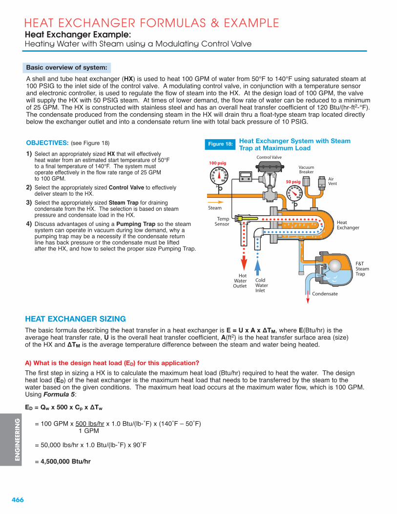
466
HEAT EXCHANGER FORMULAS & EXAMPLEHeat Exchanger Example: Heating Water with Steam using a Modulating Control Valve
ENG
INEE
RIN
G
Basic overview of system:
A shell and tube heat exchanger (HX) is used to heat 100 GPM of water from 50°F to 140°F using saturated steam at 100 PSIG to the inlet side of the control valve. A modulating control valve, in conjunction with a temperature sensorand electronic controller, is used to regulate the flow of steam into the HX. At the design load of 100 GPM, the valvewill supply the HX with 50 PSIG steam. At times of lower demand, the flow rate of water can be reduced to a minimumof 25 GPM. The HX is constructed with stainless steel and has an overall heat transfer coefficient of 120 Btu/(hr-ft2-°F).The condensate produced from the condensing steam in the HX will drain thru a float-type steam trap located directlybelow the exchanger outlet and into a condensate return line with total back pressure of 10 PSIG.
OBJECTIVES: (see Figure 18)
1) Select an appropriately sized HX that will effectively heat water from an estimated start temperature of 50°F to a final temperature of 140°F. The system must operate effectively in the flow rate range of 25 GPM to 100 GPM.
2) Select the appropriately sized Control Valve to effectively deliver steam to the HX.
3) Select the appropriately sized Steam Trap for draining condensate from the HX. The selection is based on steam pressure and condensate load in the HX.
4) Discuss advantages of using a Pumping Trap so the steam system can operate in vacuum during low demand, why a pumping trap may be a necessity if the condensate return line has back pressure or the condensate must be lifted after the HX, and how to select the proper size Pumping Trap.
STEAM
50 psig
100 psig
Hot WaterOutlet
ColdWaterInlet
HEAT EXCHANGER SIZINGThe basic formula describing the heat transfer in a heat exchanger is E = U x A x ΔTM, where E(Btu/hr) is theaverage heat transfer rate, U is the overall heat transfer coefficient, A(ft2) is the heat transfer surface area (size) of the HX and ΔTM is the average temperature difference between the steam and water being heated.
A) What is the design heat load (ED) for this application?
The first step in sizing a HX is to calculate the maximum heat load (Btu/hr) required to heat the water. The design heat load (ED) of the heat exchanger is the maximum heat load that needs to be transferred by the steam to the water based on the given conditions. The maximum heat load occurs at the maximum water flow, which is 100 GPM. Using Formula 5:
ED = Qw x 500 x Cp x ΔTw
= 100 GPM x 500 lbs/hr x 1.0 Btu/(lb-˚F) x (140˚F – 50˚F)1 GPM
= 50,000 lbs/hr x 1.0 Btu/(lb-˚F) x 90˚F
= 4,500,000 Btu/hr
Steam
Heat Exchanger System with SteamTrap at Maximum Load
Figure 18:
HeatExchanger
Control Valve
Air Vent
VacuumBreaker
F&TSteamTrap
TempSensor
Condensate

467
Heat Exchanger Example: Heating Water with Steam using a Modulating Control Valve
HEAT EXCHANGER FORMULAS & EXAMPLE
B) What is the mean temperature difference (ΔTM) between the steam and the water being heated?
From the HX formula we can see that in order to determine the size of the HX required to heat the water, we must first know the steam temperature (which is directly related to steam pressure) in the HX during the period of maximum demand. The steam pressure in the HX is dependent on the pressure drop across the control valve. For optimal control in heating applications, it is typical to target a 50% pressure drop across the valve at themaximum steam load. Therefore, at full load, the pressure drop across the control valve is 50 PSIG and the steampressure supplied to the heat exchanger is also 50 PSIG.
As the steam (primary fluid) passes thru the heat exchanger, it transfers its latent heat energy to the water (secondaryfluid) and condenses without a change in temperature. Therefore, the condensate leaving the heat exchanger is at the same temperature as the steam entering. From the saturated steam table, the steam temperature (TS) of 50 PSIGsaturated steam is 298°F. The water inlet temperature (Ti) is 50°F and the water outlet temperature (To) is 140°F.
We now have enough information to calculate the mean temperature difference between the steam (primary fluid) and water (secondary fluid). Formula 3 is used to calculate the mean temperature difference (ΔTM) which is theaverage of the temperature differences at both ends of the HX:
ΔTM = (TS - To) + (TS - Ti) = (298 - 140) + (298 - 50) = 158 + 248 = 406 = 203°F2 2 2 2
C) What is the Overall heat transfer coefficient (U) of the heat exchanger?
The U value of the HX depends on several factors, including type of HX, the quality of the steam used, if any fouling is expected, if the flow of water is turbulent or laminar, and the material of construction. The higher the U value, thebetter the heat transfer, and the smaller the HX needs to be. Typical U values range from 120 for a stainless steel HX to over 200 for copper. For this example, a Stainless Steel HX was selected for longevity purposes and so a U value of 120 will be used to determine the HX size.
D) What is the minimum heat transfer surface area (A) of the heat exchanger that can meet the design heat load?
The size of a HX is dependent on the steam pressure inside its shell. The higher the steam pressure, the smaller the HX for a given heat load. 50 PSIG was chosen because the supply pressure is 100 PSIG and this gives a 50%pressure drop across the control valve, as previously discussed. If a lower steam pressure is used, this would require a larger HX, and vice versa.
In a heat exchanger, the mean heat transfer rate is proportional to the mean temperature difference between the two fluids, as given by Formula 1. Rearranging this equation gives Formula 2, where E has been replaced by ED, the design heat load. Using Formula 2 and the mean temperature difference determined above, gives the heat transfer surface area:
A = ED = 4,500,000 Btu/hr = 185 ft2U ΔTM 120 Btu/(hr-ft2-°F) x 203°F
Therefore, for a perfectly sized heat exchanger, the heat transfer area of the tube is 185 square feet. In practice, the heat exchanger is usually oversized by at least 15% to account for fouling of the heating surfaces over time or to allow for an increase in the maximum heat load.
ENG
INEER
ING

468
HEAT EXCHANGER FORMULAS & EXAMPLEHeat Exchanger Example: Heating Water with Steam using a Modulating Control Valve
ENG
INEE
RIN
G
CONTROL VALVE SIZING
E) What is the flow of steam (steam capacity) thru the control valve at the design heat load?Formula 6 gives the mass flow rate of steam based on the heat load and the latent heat of saturated steam (LH).From the saturated steam table, the latent heat of 50 PSIG steam is 912 Btu/lb. Therefore, the steam capacity is:
QS = ED / LH = 4,500,000 Btu/hr / 912 Btu/lb = 4,934 lbs/hr
F) How must the control valve be sized?
The valve must be sized for the maximum steam capacity of the application, which occurs at the maximum (design)heat load of the heat exchanger. We first need to determine if the pressure drop across the valve at the maximumflow rate is above or below the critical pressure drop, so that we can apply the correct formula:
Valve Inlet Pressure (P1) = Steam Supply Pressure = 100 PSIG + 14.7 = 114.7 PSIA
Valve Outlet Pressure (P2) = Heat Exchanger Pressure = 50 PSIG + 14.7 = 64.7 PSIA
Differential Pressure (ΔP) = P1 – P2 = 114.7 – 64.7 = 50 PSI
Critical Pressure Drop (ΔPcritical) = 0.42 P1 = 0.42 (114.7) = 48.2 PSI
Since the pressure drop across the valve (50 PSI) is greater than the critical pressure drop (48.2 PSI), the steamflow thru the valve is critical. Therefore, we apply Formula 12b to calculate the valve coefficient:
Cv = QS / (1.71 x P1) = 4,934 / (1.71 x 114.7) = 4,934 / 196.1 = 25.2
Therefore, the control valve must have a flow coefficient of at least 26.
G) What Watson-McDaniel Control Valve should be selected for this application?
Refer to the Control Valves section of this catalog. The Watson McDaniel HB-Series 2-Way Pneumatic ControlValve is used for heating and cooling applications. Since this is a heating application with steam, a Normally-Closed,Air-To-Open (ATO) valve should be selected. (This is a fail-safe feature in case the air signal to the valve actuatorbecomes interrupted. If the air signal is lost, the valve will automatically close and block the flow of steam.)
Referring to the HB Control Valve Selection chart, a full-port valve with Cv value of 42 should be selected. TheModel Number for this valve with NPT ports is HB-17-N-ATO. This valve has a 2” NPT connection size, stainlesssteel body and trim, and a pressure-temperature rating of 300 PSIG @ 450°F.
www.watsonmcdaniel.com •• Pottstown PA • USA • Tel: 610-495-5131

469
Heat Exchanger Example: Heating Water with Steam using a Modulating Control Valve
HEAT EXCHANGER FORMULAS & EXAMPLEEN
GIN
EERIN
G
Tel: 610-495-5131 • Pottstown PA • USA •• www.watsonmcdaniel.com
H) What is the maximum close-off pressure of the control valve selected in Part G?
From the HB Control Valve Selection chart, the maximum close-off pressure for the selected valve is 85 PSI ΔP if no positioner is used, and 135 PSI ΔP if a positioner is used.
I) For the selected control valve, is a positioner required to completely shut off the flow of steam to the heat exchanger?
When the control valve is completely closed, the pressure drop across the valve is at its maximum value:
ΔPMAX = Steam Supply Pressure – Heat Exchanger Pressure= 100 PSIG – 0 PSIG= 100 PSI
Thus, the control valve must have a close-off pressure capability of at least 100 PSI. Without a positioner, themaximum close-off pressure of the valve is 85 PSI. Therefore, a valve positioner is necessary to provide therequired closing force to the actuator diaphragm.
In a normally-closed valve, the valve is held closed by a spring force. The spring pressure is set so that the valve will stay closed against an inlet pressure of 85 PSIG. The opening action is performed by the 3-15 PSIG air signal to the actuator diaphragm. When the air signal is 15 PSIG, the valve will completely open against thespring pressure. When the air signal is 3 PSIG, the valve will stay closed provided that the inlet pressure does not exceed 85 PSIG. If the inlet pressure exceeds 85 PSIG, the valve will open and a positioner will then berequired to decrease the air signal pressure below 3 PSIG to allow the valve to fully close.

470
HEAT EXCHANGER FORMULAS & EXAMPLEHeat Exchanger Example: Heating Water with Steam using a Modulating Control Valve
www.watsonmcdaniel.com •• Pottstown PA • USA • Tel: 610-495-5131
STEAM TRAP SIZING
J) What type and size of steam trap should be chosen for this application?
Initially we will assume that the condensate from the HX is being discharged to a condensate return line atatmospheric pressure (0 PSIG). At full-load, the steam pressure at the inlet of the trap is 50 PSIG. We havealready calculated the maximum condensate load that would be generated at this pressure to be around 5,000 lbs/hr(see Part E). If this was the only set of conditions, selection of the steam trap would be fairly simple. We simply lookat the capacity chart and choose a steam trap that will pass at least 5,000 lbs/hr at 50 PSI differential pressure. (See the capacity chart below for the FTE Series Float & Thermostatic steam traps.)
However, at different flow rates of water, the HX will have very different pressures. At a flow rate of ~58 GPM, the pressure in the HX drops to 0 PSIG and the HX is still producing condensate at the rate of ~2,700 lbs/hr. This condensate still needs to be drained from the HX but how can this happen with NO differential pressure? The purpose of having an extended drip leg under the HX is to give the trap a certain amount of head pressure. If the trap is mounted 14 inches below the HX, this will correspond to ½ PSI of head pressure. The trap must then be able to pass at least 2,700 lbs/hr of condensate at ½ PSI ΔP.
* Single seat orifice. All others are double seated.
CAPACIT IES – Condensate (lbs/hr)PMO Pipe Orifice Differential Pressure (PSI)
Model Code (PSIG) Size Size 1/4 1/2 1 2 5 10 15 20 30 50 75 100 125 200 250 300FTE-20-17-N* 20 2” .937” 6100 7800 9300 11800 15900 19500 22500 26000
FTE-50-17-N 50 2” 2.125” 12800 16900 20100 25300 33000 40200 43500 46000 47800 52500
FTE-50-18-N 50 21/2” 2.125” 20400 25700 31000 37000 46300 55100 60300 65100 72000 82100
FTE-125-18-N 125 21/2” 2.125” 20400 25700 31000 37000 46300 55100 60300 65100 72000 82100 90400 97700 105000
FTE-200-16-N 200 11/2” .375” 950 1350 1900 2200 2700 3300 3900 4400 5300 6400 7600 8500 9400 11900
FTE-200-17-N 200 2” .75” 2700 4100 5700 7400 9900 11800 13400 14400 16400 19000 21500 23000 24500 29200
FTE-200-18-N 200 21/2” 1.5” 7200 12300 17400 21500 27600 32600 36000 39300 43100 49200 54700 58800 61900 74000
FTES-50-18-N 50 21/2” 2.125” 20400 25700 31000 37000 46300 55100 60300 65100 72000 82100
FTES-125-18-N 125 21/2” 2.125” 20400 25700 31000 37000 46300 55100 60300 65100 72000 82100 90400 97700 105000
FTES-300-18-N 300 21/2” 1.5” 7200 12300 17400 21500 27600 32600 36000 39300 43100 49200 54700 58800 61900 74000 86000 100550
As a general rule, for HX applications using steam pressures over 30 PSIG, the steam trap should be sizedfor 2.5X maximum condensate load at full differential pressure. Therefore, to provide an appropriate safetymargin, we must select a trap that can pass 2.5 x 5,000 = 12,500 lbs/hr of condensate at 50 PSI ΔP. In addition,the steam trap must be able to handle the maximum possible inlet pressure which is 100 PSIG (the steam supplypressure). Referring to the FTE capacity chart above; the best trap to select is the FTE-200-17-N. This trap can pass 19,000 lbs/hr at 50 PSI ΔP and 4,100 lbs/hr at ½ PSI ΔP, which meets the above criteria.
ENG
INEE
RIN
G

471
Heat Exchanger Example: Heating Water with Steam using a Modulating Control Valve
HEAT EXCHANGER FORMULAS & EXAMPLE
Tel: 610-495-5131 • Pottstown PA • USA •• www.watsonmcdaniel.com
The HX can be properly drained using a steam trap as long as there is no BACK PRESSURE in the condensate return line. If there is back pressure in the condensate return line, a Pumping Trap must be used.
CondensateBacks Upinto Heat Exchanger
System without Vacuum Breaker
OPENVacuumBreaker
0 psig
- 5 psig
System with Vacuum Breaker
Condensate flowsthrough trap
Condensate will not flowwithout a vacuum breaker
Sub-atmosphericpressure
2.31 Ft. X 0.433 = 1 psig
1 psig
2.31 ft.water coulmn
100 psig
100 psig
Figure 19: Heat Exchanger System with Steam Trap shown with and without Vacuum Breaker
Now, what happens when the water flow rate thru the HX reduces to the point that the steam pressure goes intovacuum? This occurs at water flow rates below about 58 GPM down to the minimum of 25 GPM. Since the HX willbe operating in vacuum, the condensate would not effectively drain regardless of the steam trap size chosen. This is why a vacuum breaker must be added to the top of the HX. The vacuum breaker draws in air to neutralize thepressure in the HX which allows the condensate to drain (see Figure 19).
ENG
INEER
ING

472
HEAT EXCHANGER FORMULAS & EXAMPLEHeat Exchanger Example: Heating Water with Steam using a Modulating Control Valve
ENG
INEE
RIN
G
PUMP-TRAP SIZINGK) If the condensate return line has a total back pressure of 10 PSIG, can a steam trap be used to drain
the heat exchanger?
At full-load conditions, the steam pressure is 50 PSIG and the condensate load is ~5,000 lbs/hr. Since the total back pressure of the return line is 10 PSIG, the differential pressure across the steam trap is 40 PSI.An appropriately sized steam trap can handle this situation. However, when the steam pressure is reduced to 10 PSIG or lower, due to lower heat demand, the differential pressure across the steam trap will be 0 PSIG or less. Without positive differential pressure across the trap, the condensate cannot drain from the HX. During thissituation, the condensate will back up into the HX shell. Therefore, a steam trap will not be effective in dischargingcondensate from the HX under all conditions.
L) If the water flow rate is reduced, less heat energy per unit of time is needed to heat the water and therefore the heat load will also reduce. This will cause a reduction in steam flow and pressure in the heat exchanger. If the steam pressure falls to or below the system back pressure, the condensate will begin to back up into the heat exchanger, causing the system to stall. Why is it important to prevent stall from occurring?
Condensate flooding the heat exchanger space will cause poor temperature control, accelerated corrosion andpotentially damaging waterhammer. These factors can cause rapid or premature failure of the unit, leading to costly repairs and downtime.
M) For the heat exchanger size (surface area) calculated in Part D, what is the flow rate of water at which stall will occur?
We will use two methods to calculate the water flow rate at stall and then compare the two methods.
Method 1: Based on Heat Exchanger Size
Stall occurs at the point where the steam pressure equals the back pressure. The steam pressure at stall istherefore 10 PSIG. From the saturated steam table, this is equivalent to a steam temperature (Ts) of 239°F.Formula 3 can now be used to calculate the mean temperature difference between the steam and water:
ΔTM = (TS - To) + (TS - Ti) = (239 - 140) + (239 - 50) = 99 + 189 = 288 = 144°F2 2 2 2
The heat load at stall is then calculated from Formula 1:
Estall = U A ΔTM = 120 Btu/(hr-ft2-°F) x 185 ft2 x 144°F = 3,196,800 Btu/hr
Finally, the volumetric flow rate of water at stall is calculated from Formula 8:
Qw-stall = Estall / [500 x (To - Ti)]
= 3,196,800 = 3,196,800 = 3,196,800[500 x (140 – 50)] (500 x 90) 45,000
= 71 GPM
Method 2: Based on % Stall Load Formula
TS = Steam temperature at full-load = 298°F (50 PSIG steam)TB = Back pressure equivalent saturated steam temperature = 239°F (10 PSIG steam)
TWM = Mean water temperature = To - Ti = 140 + 50 = 95°F2 2
Using Formula 9:
% Stall Load = TB – TWM x 100 = 239 – 95 x 100 = .71 x 100 = 71%TS – TWM 298 – 95
The water flow rate at stall is then calculated using Formula 10:
Qstall = Qw-full load x (% Stall Load)/100 = 100 GPM x 71/100 = 71 GPM
www.watsonmcdaniel.com •• Pottstown PA • USA • Tel: 610-495-5131

10 PSIG
10 PSIG
50 PSIG
100 PSIG
Pressure Regulatorused to reduceMotive SteamPressure
Elevated Condensate Return Line
MotiveSteamPressure
Vent Line
Check Valve Check Valve
Comparison of Methods:Both methods gave the same result for the water flow rate at which stall will occur: 71 GPM. This means that at flows at or below 71 GPM, the steam pressure in the system is insufficient to push the condensate thru the steam trap and into the return line. The condensate will therefore back up into the heat exchanger unless something is done to prevent it.
The main difference between the two methods is that the heat exchanger size was needed to calculate the stall flow rate using Method 1, but not needed using Method 2.
N) How can stall (condensate back-up) be prevented?
Stall can be prevented by replacing the steam trap with a pump-trap (i.e., a pressure motive pump and steam trapcombination). Pump-traps are available with either internal or external steam traps, depending on capacity requirements.
When there is sufficient steam pressure to push the condensate thru the trap, the pump is not used and the pump-trap is operating in trap mode. The condensate will pass thru the pump body and thru the trap. The trap must besized to handle the condensate at full-load conditions as well as when the trap differential pressure is slightly above0 PSI (i.e., just above the stall point). In addition, the orifice size of the trap should be optimized to handle the highinstantaneous discharge flow rate when the pump is operating. This will reduce the discharge time of the pump andits overall fill/discharge cycle. Watson McDaniel pump-traps have the trap size optimized for all conditions.
When the steam pressure drops to or below the back pressure, the condensate will start to fill the pump tank.When the float in the tank reaches the upper trip point, the mechanism will open the steam valve whilesimultaneously closing the vent valve. High pressure steam will then force the condensate thru the trap and into the condensate return line. Check valves are used with the pump to prevent the backflow of condensate.When the pump is emptied, the float mechanism will then simultaneously close the steam valve and open the vent valve so the pump can fill on the next cycle. When the pump is being used, the pump-trap is operating in pump mode. The pump must be sized to handle the condensate load at the stall point. That is, when thesteam pressure is equal to the back pressure.
When sizing Pressure Motive Pumps in closed-loop return systems, a condensate reservoir should be installed onthe inlet side of the pump and below the HX, as shown in Figure 20. This will enable the condensate to collect whilethe pump is in the discharge cycle, thus preventing liquid backup into the HX. The reservoir should be located 12”above the top of the pump tank to provide adequate filling head. The reservoir must have sufficient size (volume) toprovide adequate vapor space for the condensate to collect during the pumpʼs discharge cycle and for the pump tovent during its filling cycle. The vent line also acts as a balancing line to allow condensate to drain into the pumptank while the HX is operating in vacuum.
Heat Exchanger System with Pump-Trap at Stall Load
473
Heat Exchanger Example: Heating Water with Steam using a Modulating Control Valve
HEAT EXCHANGER FORMULAS & EXAMPLEEN
GIN
EERIN
G
Tel: 610-495-5131 • Pottstown PA • USA •• www.watsonmcdaniel.com
Total Back Pressure fromCondensate Return Line
Figure 20:
HotWaterOutlet
ColdWaterInlet
AirVent

474
HEAT EXCHANGER FORMULAS & EXAMPLEHeat Exchanger Example: Heating Water with Steam using a Modulating Control Valve
ENG
INEE
RIN
G
O) If a pump-trap is used to prevent stall, what capacity must the pump have?
The maximum condensate load that the pump must discharge occurs at the stall point (i.e., when the steampressure is equal to the total back pressure of the condensate return line). This can be determined from the steamload at the stall point, using Formula 6. The heat load at stall was determined in Part M to be 3,196,800 Btu/hr.The steam temperature at stall was also determined in Part M to be 239˚F. From the steam table, the latent heatof steam at 239˚F is 953 Btu/lb. The steam capacity is:
QS = Estall /LH = 3,196,800 Btu/hr / 953 Btu/lb = 3,354 lbs/hr
The maximum condensate load at stall conditions is therefore 3,354 lbs/hr and the pump must be sized to remove condensate at this rate.
P) What Watson-McDaniel Pump-Trap should be selected for this application?
Referring to the pump-trap capacity chart when operating in Pump Mode, it can be seen that model WPT3(pump with external trap mounted on common base) can meet the condensate load at stall (3,354 lbs/hr) when the motive steam pressure is 50 PSIG and the total back pressure is 10 PSIG. Under these conditions, this modelhas a maximum capacity of 4,080 lbs/hr. Since the steam supply pressure is 100 PSIG, a pressure regulator canbe used to reduce the pressure to 50 PSIG for the motive steam line.
MINIMUM LOAD & OPERATION IN VACUUM
Q) What is the minimum heat load of the application?
The minimum heat load occurs at the minimum water flow of 25 GPM. Using Formula 5:
Emin = Qw x 500 x Cp x ΔTw
= 25 GPM x 500 lbs/hr x 1.0 Btu/(lb-°F) x (140°F – 50°F)1 GPM
= 12,500 lbs/hr x 1.0 Btu/(lb-°F) x 90°F
= 1,125,000 Btu/hr
R) What is the steam temperature in the heat exchanger at the minimum load?
Use Formula 1 to calculate the mean temperature difference between the steam and water:
ΔTM = Emin /(U A) = 1,125,000 Btu/hr / (120 Btu/(hr-ft2-°F) x 185 ft2) = 50.7°F
The steam temperature is then given by Formula 4:
TS = ΔTM + TWM = ΔTM + To + Ti = 50.7 + 140 + 50 = 50.7 + 190 = 50.7 + 95 = 146°F2 2 2
S) What is the steam pressure in the heat exchanger at the minimum load?
From the steam table (using extrapolation), the steam pressure corresponding to 146°F saturated steam is 22.7 in Hg Vacuum which is equivalent to -11.1 PSIG. Therefore, the steam pressure inside the heat exchanger is below atmospheric pressure.
This is another advantage in the use of a pump-trap. If a steam trap is used to drain condensate, the system could not operate in vacuum since the condensate would never drain out. Therefore, a vacuum breaker is usedwhich essentially mixes the steam with air to achieve the proper temperature differential for a particular size HX.This added air facilitates corrosion by forming carbonic acids. Some of this air is eventually discharged thru the air vent on top of the HX but some mixes with the condensate. A pump-trap can discharge condensate when theHX is operating in vacuum, which precludes the use of a vacuum breaker and thus air is prevented from enteringthe system.
www.watsonmcdaniel.com •• Pottstown PA • USA • Tel: 610-495-5131

475
Heat Exchanger Example: Heating Water with Steam using a Modulating Control Valve
HEAT EXCHANGER FORMULAS & EXAMPLEEN
GIN
EERIN
G
T) What is the flow of steam (steam capacity) thru the control valve at the minimum load?
From the steam table (using extrapolation), the latent heat of steam (LH) corresponding to 146°F saturatedsteam is 1,011 Btu/lb. Using Formula 6, the steam capacity is:
QS = Emin /LH = 1,125,000 Btu/hr / 1,011 Btu/lb = 1,113 lbs/hr
Heat Exchanger System with Pump-Trap at Minimum Load
Flow Steam Steam Latent Trap Rate Heat Steam Pressure Temp Heat Condensate Differential System
Water Load Usage in HX in HX of Steam Generated Pressure Condition(GPM) (Btu/hr) (lbs/hr) (PSIG) (°F) (Btu/lb) (lbs/hr) (PSI)
100 4,500,000 4,934 50 298 912 4,934 40
94.7 4,262,400 4,633 40 287 920 4,633 30
88.3 3,973,800 4,278 30 274 929 4,278 20
80.9 3,640,800 3,873 20 259 940 3,873 10
71.0 3,196,800 3,354 10 239 953 3,354 0
57.7 2,597,400 2,678 0 212 970 2,678 ---
47.9 2,153,400 2,191 -5 192 983 2,191 ---
25 1,125,000 1,113 -11 146 1,011 1,113 ---
Trap Mode
Pump Mode
(Vacuum)
(Stall Point)
(Maximum Heat Load)
Steam Pressure= Back Pressure
(Minimum Heat Load)
SUMMARY of HEAT EXCHANGER SYSTEMThe following table summarizes the above results and shows how the heat load and the pressure, temperature,latent heat and flow of steam vary as a function of the water flow rate. It can be seen that the system is operating in Trap Mode between water flow rates of 100 and 71 GPM, and in Pump Mode between 71 and 25 GPM. Also, at flow rates below ~58 GPM, the steam pressure inside the HX is below atmospheric pressure (0 PSIG).
-11 PSIG
10 PSIG
50 PSIG
100 PSIG
Tel: 610-495-5131 • Pottstown PA • USA •• www.watsonmcdaniel.com
Pressure Regulatorused to reduceMotive SteamPressure
Elevated Condensate Return Line
Figure 21:
MotiveSteamPressure
Vent Line
Total Back Pressure fromCondensate Return Line
HotWaterOutlet
ColdWaterInlet

476
Product Cross Reference
THERMODYNAMIC TRAPSManufacturer Watson McDaniel Armstrong Spence Nicholson Hoffman Spirax Sarco Yarway TLV
Desc. Size Product F/F Dim Product F/F Dim Product F/F Dim Product F/F Dim Product F/F Dim Product F/F Dim Product F/F Dim
3/8” 2” 2” TD6523 2” 2” 2”Disc 1/2” 2.7” 3.31” 2.68” TD6524 2.75” 2.7” 2.25”Trap 3/4” 2.8” 3.31” 2.81” TD6526 2.75” 2.8” 2.87”
1” 3.3” 3.31” 3.31” TD6528 3.25” 3.3” 3.37”
1/2” 2.7” 3.31” 3.25” 2.7”3/4” 2.8” 3.31” 3.25” 2.8”
1/2” 3.1” 3.31” 3.1”3/4” 3.5” 3.31” 3.5”
1” 3.7” 3.31” 3.7”
TD600 NTD600CD-33TD-52 29
TD600L CD-33L S610L TD-52LLow
CapacityDisc Trap
LowCapacityDisc Trap
w/ StrainerTD-42LTD600LS CD-33SL
Disc Trapwith
StrainerTD600S
1/2”
3/4”
3.1”
3.5”
3.5”
3.5”NTD600S
2”
2.68”
TD6424 3.06”TD6426 3.06”TD6428 3.25”
A3N 3.87”P46SS 2.75”A3N 4.06”P46SS 2.75”
TD-42H3.1”
3.5”129Y
2.76”
2.95”CD-33S
Disc Trapwith
Strainer&
Blowdown
TD600SB CD-33SB NTD600SB3.5”
3.7”TD-42HB
3.1”
3.7”129YB
A3N 3.87”P46SS 2.75”
A3N 4.06”P46SS 2.75”
2.76”
2.95”
3.5”
3.5”
2”
2.68”
Low Cap.Disc Trap
w/ Strainer&
Blowdown
1/2”
3/4”
1”
1/2”
3/4”
3.1”
3.7”CD-33SBL TD-42LB
3.1”
3.7”
Disc Trapwith
Strainer TD700S
A46SA50S 3.12”P46SRNA46SA50S 3.12”P46SRNA46SA50S 3.43”P46SRN
1/2”
3/4”
1”
721
S610 3.25” 3.15”
3.54”
3.93”
A46SA50S 3.12”P46SRNA46SA50S 3.12”P46SRNA46SA50S 3.43”P46SRN
Disc Trapwith
Strainer&
Blowdown
TD700SB
1/2”
3/4”
1”
721
3.16”
3.55”
6.31”
3.15”
3.54”
3.93”
Disc Trapwith
Strainer
1/2” 3.15” 3.15”3/4” 3.54” 3.54”1” 6.31” 3.93”
1/2” 3.15” 3.15”3/4” 3.54” 3.54”1” 6.31” 3.93”
1/2” 3.6” 3.6” 4.81” 3.12”
3/4” 3.6” 3.6” 4.81” 3.12”
1” 6.5” 3.9” 4.81” 3.43”1/2” 6.2” 6.2”3/4” 6.2” 6.2”1” 6.2” 6.2”
721HP
TD700HS
TD700HSB
Disc Trapw/ Strainer
&Blowdown
Disc Trapwith
Strainer
Disc Trap
TD900S
TD3600
460D3
TD120
TD62 A65SS
Ultra High-Pressure Repairable In-line – 3600 PSI
Standard 600 PSI
Repairable In-line
High-Pressure Repairable In-line
High-Pressure Repairable In-line – 900 PSI
3.16”
3.55”
6.31”
TD600LSB
Steam Traps
3.5”3.5” 3.5”
www.watsonmcdaniel.com •• Pottstown PA • USA • Tel: 610-495-5131

477
THERMOSTATIC TRAPSManufacturer Watson McDaniel Armstrong Spence Nicholson Spirax Sarco Hoffman TLV
Desc. Size Product F/F Dim Product F/F Dim Product F/F Dim Product F/F Dim Product F/F Dim Product F/F Dim
1/2” 2.5” 2.5” 2.18”3/4” 2.5” 2.5” 2.18”1/2” 3.75” 4.5” 3.75” 2.5”3/4” 3.75” 3.75” 4.69” 3.93” 2.5”
1/2” 3” 3”3/4” 3” 3”1/2” 4.5” 5”3/4” 4.5” 5”
1/2” 4.5” 5” 5.25”
3/4” 4.5” 5” 5.25”
WT1000
TAWT-1TTF-1
LV21
WT3000S
Thermostatic650 PSI
withStrainer
WT2000C
Thermostatic300 PSI
Thermostatic650 PSI
TSS300
DTS300
Thermostatic250 PSI
Thermostatic650 PSI
WT2500
WT3000
N450
N650
TM600N
L21SL32SL21SL32S
3.12”
3.12”Thermostatic
650 PSIwith
Strainer &Blowdown
1/2”
3/4”
WT3000SB4.5”
4.5”N650Y
5”
5”
Thermostatic300 PSI
3/4”1”
4.5” 3”4.5” 3”
N450WT4000
Thermostatic300 PSI
withStrainer
3/4”
1”
4.5” 3”
4.5” 3”WT4000S
Thermostatic300 PSI
w/ Strainer&
Blowdown
3/4”
1”WT4000SB
4.5” 3”
4.5” 3”
1/2” 2.81”TS-3
3.12”N125
2.75”RTA-125
2.8” 17C 3.24”RT3A
3.12”3/4” 3.06” 3.5” 3.18” 3” 8C 3.12” 3.06”
Thermostatic125 PSI,Angle*
LEX3N-TZLEXW3N-TZ 2.75”LEXF3N-TZLEX3N-TZLEXW3N-TZ 3.12”LEXF3N-TZLEX3N-TZLEXW3N-TZ 3.12”LEXF3N-TZ
1/2”
3/4”
1”
WT5000
2.75”
3.12”
3.12”
Steam Traps (continued)
TA125
* Right Angle (90˚) Ports
N650Y
N450Y
N450Y
Adjustable Bi-Metallic
Repairable
Non-Repairable
PRODUCT CROSS REFERENCE (CONTINUED)
Tel: 610-495-5131 • Pottstown PA • USA •• www.watsonmcdaniel.com

478
PRODUCT CROSS REFERENCE (CONTINUED)
FLOAT & THERMOSTATIC TRAPSManufacturer Watson McDaniel Armstrong Hoffman Spence Nicholson Spirax Sarco TLV
Desc. Size Product F/F Dim Product F/F Dim Product F/F Dim Product F/F Dim Product F/F Dim Product F/F Dim
1/2” 4.8” BI2 2.75” 5.5” 5.06” 4.8” 4.75”3/4” 4.8” BI3 2.75” 5.5” 5.06” 4.8” 4.75”
In-Line 1” 4.8” BI4 3” 5.5” 5.06” 4.7” 4.75”1.5” 10.6” BI6 4.18” 11.12” 10.6” 11”2” 11.9” BI8 6” 12.12” 11.9” 21.31”
1.5” 3” 3” 3”2” 4.5” J&L 6.62” 6.3” 6.3” 6.62” 4.5”
2.5” 7.25” K&M 11.31” 9.5” 9.5” 9.5” 7.25”
3/4” 3.3” 15-B3 2.75” FT015H-3 3.93” 3.31” 3.3” SJ3-1 3.31”
15 PSI1” 3.3” 15-B4 3” FT015H-4 3.93” 3.31” 3.3” SJ3-1 5.12”
1.25” 3” 15-B5 3” FT015H-5 3” 3” 3” SJ5-1 3”1.5” 3” 15-B6 4.18” FT015H-6 3” 3” 4.25” SJ6-1 4.93”2” 4.9” 15-B8 6” FT015H-8 4.94” 4.94” 4.9” SJ6-1 4.93”
3/4” 3.3” 30-B3 2.75” FT030H-3 3.31” 3.31” 3.3” SJ3-2 5.12”1” 3.3” 30-B4 3” FT030H-4 3.31” 3.31” 3.3” SJ3-2 5.12”
1.25” 3” 30-B5 3” FT030H-5 3” 3” 3” SJ5-2 3”
1.5” 3” 30-B6 4.18” FT030C-6 3” 3” 4.25”SJ6-2
4.06”SJ7-2
2” 4.9” 30-B8 6” FT030C-8 4.94” 4.94” 4.9”SJ6-2
4.93”SJ7-23/4” 3.3” 75-A3 2.75” FT075H-3 3.31” 3.31” 3.3” SJ3-5 5.12”1” 3.3” 75-A4 3” FT075H-4 3.31” 3.31” 3.3” SJ3-5 5.12”
1.25” 3” 75-A5 3” FT075C-5 3” 3” 4.25” SJ5-5 3”
1.5” 3” 75-A6 4.18” FT075C-6 3” 3” 4.25”SJ6-10
4.93”SJ7-10
2” 4.9” 75-A8 6” FT075C-8 4.94” 4.94” 4.9”SJ6-10
4.93”SJ7-103/4” 3.3” 125-A3 2.75” FT125H-3 3.31” 3.31” 3.3” SJ3-10 5.12”1” 3.3” 125-A4 3” FT125H-4 3.31” 3.31” 3.3” SJ3-10 5.12”
1.25” 3” 125-A5 3” FT125C-5 3” 3” 4.25” SJ5-10 3”
1.5” 3” 125-A6 4.18” FT125C-6 3” 3” 4.25”SJ6-10
4.93”SJ7-10
2” 4.9” 125-A8 6” FT125C-8 4.94” 4.94” 4.9”SJ6-10
4.93”SJ7-103/4” 3” 175-A3 2.75” FT175H-3 3.31” 3.3” SJ3-14 5.12”1” 3” 175-A4 3” FT175H-4 3.31” 3.3” SJ3-14 5.12”
1.25” 3” 175-A5 3” FT175C-5 3” 4.25” SJ5-14 3”
1.5” 3” 175-A6 4.18” FT175C-6 3” 4.25”SJ6-14
4.93”SJ7-14
2” 4.5” 175-A8 6” FT175C-8 4.94” 4.9”SJ6-14
4.93”SJ7-143/4” 3” 3.3” SJ3-14 5.12”1” 3” 3.3” SJ3-14 5.12”
1.25” 3” 4.25” SJ5-14 3”
1.5” 3” 4.25”SJ6-14
4.93”SJ7-14
2” 4.5” 4.9”SJ6-14
4.93”SJ7-143/4” FT3 4.12” FT015H-3 3.31”1” FT4 4.12” FT015H-4 3.31”
1.25” FT6 5” FT015H-5 3” 1.5” FT7 6.37” FT015H-6 5.25” 2” FT8 6.5” FT015H-8 7.46”
3/4” FT33 4.12” FT030H-3 3.31”1” FT34 4.12” FT030H-4 3.31”1” FT35 5”
1.25” FT36 5” FT030H-5 3”1.5” FT37L 6.37” FT030H-6 5.25” 2” FT38 6.5”
3/4” FT73 4.12” FT075H-3 3.31”1” FT74 4.12” FT075H-4 3.31”1” FT75 5”
1.25” FT76 5”1.5” FT77L 6.37”2” FT78 6.5”
FTT FTI FT14
HighCapacity
30 PSI
WFT-015
FTE10J3X
JS7XJ87
FTE HC FTB
FTN FT-15
WFT-030
75 PSI WFT-075
125 PSI WFT-125
175 PSI WFT-175
FT-30
FT-75
FT-125
FT-200
250 PSI WFT-250FT-200
H Pattern15 PSI
H Pattern30 PSI
H Pattern75 PSI
Steam Traps (continued)
FT-X-8FT-C-10
FTN
FTN
FTN
Ductile Iron – Repairable In-Line
Cast Iron – Repairable In-Line
www.watsonmcdaniel.com •• Pottstown PA • USA • Tel: 610-495-5131

479
PRODUCT CROSS REFERENCE (CONTINUED)
FLOAT & THERMOSTATIC TRAPS (continued)Manufacturer Watson McDaniel Armstrong Hoffman Spence Nicholson Spirax Sarco TLV
Desc. Size Product F/F Dim Product F/F Dim Product F/F Dim Product F/F Dim Product F/F Dim Product F/F Dim
3/4” 6.1” CS 6.75”5.12”
FT450 6.1” JH3X 5.12”5.5”
1” 6.5” CS 8.37”5.12”
FT450 6.5” JH3X 5.25”11”
1.5” 9.8” CS 11”11.12”
FT450 9.8” JH7.2X 16”13.75”
2” 11.8” CS 11”12.12”
FT450 11.8” JH8RX 23.25”13.75”
3”27.55”
FT45027.55” JL10
10.32”39” 39” JL16
4” 39” FT450 39” J1023.43”24.06”
Offset 2.5” FTES 8.4” LS 11.31” FTB 9.25”
3/4” 6.1” 5.8”1” 6.5” 6.2”
1.5” 9.8” 9”2” 11.8” 9”
3”27.55”
39”4” 39”
FT600In-Line
FTE44NFT650
FTE44NFT650
FTE44NFT650
FTE44NFT650
FT601
FT46
In-Line
INVERTED BUCKET (IB) TRAPS Manufacturer Watson McDaniel Armstrong Hoffman Spence Nicholson Spirax Sarco
Desc. Size Product F/F Dim Product F/F Dim Product F/F Dim Product F/F Dim Product F/F Dim
1/2” 5” 5” 5” 5”3/4” 5” 5” 5” 5”1/2” 5” 5” B1-2 6.93”3/4” 5” 5” B1-3 6.93” B2 6.6”1” 5” 5”
1/2” 6.5” 6.5” B2-2 6.93”3/4” 6.5” 6.5” B2-3 6.93” B2 6.6”3/4” 7.75” 7.75” B3-3 9.44” B2 6.6”1” 7.75” 7.75” B3-4 9.44” B3 7.9”
1/2” 5” 5” 5.06” 5”3/4” 5” 5” 5.06” 5”1/2” 5” B1S-2 5” B1S-2 6.93” 5.06”3/4” 5” B1S-3 5” B1S-3 6.93” 5.06” B2S 6.6”3/4” 7.12” 7.87” B3-3 9.44” 82S 7.00” B2S 6.6”1” 7.12” 7.87” B3-4 9.44” 83S 8.12” B3S 7.9”
1.25” 7.12” B4S 9.3”1.5” 7.12”
IBTrap
IB1031
IB1032
800
811
B1H
IB1033
IB1034
812
813
IB1041
IB1042
IB1044
IB1038S
IB Trap with
Strainer
880
881
883
80S
81S
Cast Iron
Steam Traps (continued)
STAINLESS STEEL INVERTED BUCKET (SS IB) TRAPS Manufacturer Watson McDaniel Armstrong Spence Nicholson Spirax Sarco
Desc. Size Product F/F Dim Product F/F Dim Product F/F Dim Product F/F Dim1/2” 4.55” 4.31” 4.31” 4.3”3/4” 4.55” 4.31” 4.31” 4.3”1/2” 4.55” 4.31” 4.31” 4.3”3/4” 4.55” 4.31” 4.31” 4.3”
SS IBTrap SIB
SIBH
SIB30
SIB30H
TSBT-LS/MSSS IB Trap
Hi Cap.
1810
1811
Stainless Steel
Carbon Steel
Tel: 610-495-5131 • Pottstown PA • USA •• www.watsonmcdaniel.com

480
PRODUCT CROSS REFERENCE (CONTINUED)
UNIVERSAL CONNECTORSManufacturer Watson McDaniel Armstrong Spence Nicholson Spirax Sarco TLV
Desc. Size Product F/F Dim Product F/F Dim Product F/F Dim Product F/F Dim Product F/F Dim1/2” 2.92” 3.5” 3.5” 2.4”3/4” 2.92” 3.5” 3.5” 2.9”1” 5.66” 3.5” 3.5” 3.6”
1/2” 3.31” 3.5” 3.12”3/4” 3.31” 3.5” 3.12”1” 6.06” 3.5” 3.75”
1/2” 3.31” 3.12”3/4” 3.31” 3.12”1” 6.06” 3.75”
1/2” 3.31” 3.5” 3.2”3/4” 3.31” 3.5” 3.5”1” 3.62” 3.5” 3.9”
1/2” 3.31” 3.2”3/4” 3.31” 3.5”1” 3.62” 3.9”
Str = Strainer; BD = Blowdown Valve
UniversalConnector UC450
UC450S FS
UC450SB
UC450S-LRUC450S-RL
UC450SB-LRUC450SB-RL
USC
USCB
UniversalConnector
w/ Str
UniversalConnectorw/ Str/BD
UniversalConnector
w/ Str
UniversalConnectorw/ Str/BD
FS
UMTC
UMTCY
IS-2
SANITARY / CLEAN STEAM TRAPS
Description Watson Armstrong
Spence SpiraxTLVMcDaniel Nicholson Sarco
Thermostatic Repairable, Angle* FDA400 CDHThermostatic Repairable FDA500 TC-C CDS BT6 SS5PThermostatic FDA600 TC-R DS100 BTM7Thermodynamic FDA800 NTD230L BTD52L P10
* Right Angle (90˚) Ports
UNIVERSAL STEAM TRAP MODULES
Description Watson Armstrong
Spence SpiraxTLVMcDaniel Nicholson Sarco
Standard Thermodynamic TD450 UMT-TD10Standard Thermodynamic LC TD450L UMT-TD10LSM Thermodynamic TD450SM CD-3300 UTD52H FP32SM Thermodynamic LC TD450LSM UTD52LSM Thermodynamic LC/HP TD600LSM-HP UTD52L-HP
Thermostatic UT450WT-2000
UMT450T UBP32FL21
TT-2000 FL32
Float & Thermostatic UFT450 FT-4000 UFT14FS3FS5
Inverted Bucket USIB450 2010 USBT UIB30Inverted Bucket HP USIB450H 2011 USBT UIB30HBi-Metallic UB450 AB-2000 USM21 FX-1
SM = Side Mount; LC = Low Capacity; HP = High Pressure
Steam Traps (continued)
IS-2 UPC
www.watsonmcdaniel.com •• Pottstown PA • USA • Tel: 610-495-5131

481
PRODUCT CROSS REFERENCE (CONTINUED)
SKID MOUNTED PUMP SYSTEMS
Watson McDaniel ArmstrongSpirax Sarco Spence Nicholson
Pivitrol Condensate CommanderPMPM Simplex, 6” x 36” Receiver SPT-104LBRP-6 (4 Gallon)
PMPM Simplex, 8” x 36” Receiver SPT-104LBRP-8 (7 Gallon) PMPLS
PMPM Simplex, 10” x 36” Receiver SPT-104LBRP-10 (10 Gallon) PPEC SImplex, 12 Gallon
PMPM Duplex, 21-Gallon Receiver DPT-104LBRP-12 (22 Gallon) PPEC Duplex
PMPC Simplex, 6” x 36” Receiver SPT-200LBRP-6
PMPC Simplex, 8” x 36” Receiver SPT-200LBRP-8
PMPC Simplex, 10” x 36” Receiver SPT-200LBRP-10
PMPC Simplex, 21-Gallon Receiver SPT-200LBRP-16 (30 Gallon) PTC Simplex, 31 Gallon
PMPC Duplex, 21-Gallon Receiver DPT-200LBRP-12 PTC Duplex, 31 Gallon
PMPC Duplex, 75-Gallon Receiver DPT-200LBRP-24 (85 Gallon) PTC Duplex, 65 Gallon
PMPF Simplex, 10” x 36” Receiver SPT-400LBRP-10 PTF Simplex, 12 Gallon
PMPF Simplex, 21-Gallon Receiver SPT-400LBRP-16 PTF Simplex, 31 Gallon Classic Vertical Simplex, 25 Gallon
PMPF Duplex, 21-Gallon Receiver DPT-400LBRP-12 PTF Duplex, 31 Gallon Classic Vertical Duplex, 25 Gallon
PMPF Duplex, 75-Gallon Receiver DPT-400LBRP-24 PTF Duplex, 65 Gallon Classic Vertical Duplex, 65 Gallon
PMPF Triplex, 116-Gallon Receiver TPT-400LBRP (24” x 72”) PTF Triplex, 135 Gallon Classic Vertical Triplex, 115 Gallon
PMPF Quadraplex, 116-Gallon Receiver QPT-400LBRP (24” x 72”) PTF Quadraplex, 185 Gallon Classic Vertical Quadraplex, 250 Gallon
PMPC Simplex, 10” x 36” Receiver SPT-3500LBRP-10 PTC Simplex
PMPC Simplex, 21-Gallon Receiver SPT-3500LBRP-16 PTC Simplex, 31 Gallon
PMPC Duplex, 21-Gallon Receiver DPT-3500LBRP-12 PTC Duplex, 31 Gallon
PMPC Duplex, 75-Gallon Receiver DPT-3500LBRP-24 PTC Duplex, 65 Gallon
PMPC Triplex TPT-3500LBRP PTC Triplex
PMPC Quadraplex QPT-3500LBRP PTC Quadraplex
PMPF Simplex, 10” x 36” Receiver SPT-300LBRP-10 PTF Simplex
PMPF Simplex, 21-Gallon Receiver SPT-300LBRP-16 PTF Simplex, 31 Gallon Classic Vertical Simplex, 25 Gallon
PMPF Duplex, 21-Gallon Receiver DPT-300LBRP-12 PTF Duplex, 31 Gallon Classic Vertical Duplex, 25 Gallon
PMPF Duplex, 75-Gallon Receiver DPT-300LBRP-24 PTF Duplex, 65 Gallon Classic Vertical Duplex, 65 Gallon
PMPF Triplex TPT-300LBRP PTF Triplex Classic Vertical Triplex
PMPF Quadraplex QPT-300LBRP PTF Quadraplex Classic Vertical Quadraplex
PMPBP Simplex, 116-Gallon Receiver SPT-516RP (24” x 72”) PTF4 Simplex Big Boy Simplex
PMPBP Duplex, 280-Gallon Receiver DPT-516RP (30” x 84”) PTF4 Duplex Big Boy Duplex
PPEC Simplex
PTC Simplex
Pressure Motive Pumps
PRESSURE MOTIVE PUMPS
Description Watson Armstrong
Spence SpiraxHoffman TLVMcDaniel Nicholson Sarco
Ductile Iron PMPNT PT104 PPEC GP10L
Upright Ductile Iron PMPC PT3500 P3PPC
PCCGP10
PTC GP14
Upright Carbon Steel PMPF PT400 P3 Classic PPFPCS
GP10FVertical PTF GP14F
Low Profile Carbon Steel PMPLS PT200 P3 Little Boy PPEC GP10LHi-Cap 4”x4” Carbon Steel PMPBP PT516 Big Boy PTF4
1”x1” PMPM & FTE-200 WPT1 Double Duty 4 APT-10 GT10L-111/4”x11/4” PMPM & FTE-200 WPT2 11/2”x11/2” PMPLS & FTE-200 WPT3 Double Duty 6 APT-14 GT10L-1-1/22”x2” PMPC & FTE-200 WPT4 APT-14HC3”x2” PMPC & FTE-200 WPT5 1”, 11/2” PMP w/ Internal Trap PMPT Double Duty 4 APT-14 GL10L-1
Pump-Trap Combination
Tel: 610-495-5131 • Pottstown PA • USA •• www.watsonmcdaniel.com

482
PILOT-OPERATED REGULATING VALVES
DescriptionWatson
ArmstrongSpence Spirax
HoffmanFisher
McDaniel Nicholson Sarco Controls
External Pilot-OperatedHD GP E 25 2100 92Main Valve, Ductile Iron
Pressure Pilot PP GP-2000 D P SPS 92B
Temperature Pilot PT/PTU OB-2000T124
T STPAT14
Temperature Pilot w/ Dial PTRP T14
Air Pilot PA GP-2000K A A APBack Pressure Pilot BP GP-2000R Q BPSolenoid Pilot SP GP-2000 M EPneumatic Temperature Controller PTL/PTR OBK-2000 T61/62/63/64Differential Pressure Pilot PDP Type N
Pressure & Temperature Regulators
BACK PRESSURE / RELIEF VALVES
Description Watson FisherMcDaniel Controls
Bronze & Cast Iron 3040 98HWater, Air & Oil Service
Bronze R-Series &Water Service 10691
TEMPERATURE REGULATING VALVES
Description Watson Trerice Powers
SpenceHoffmanMcDaniel Nicholson
Direct Acting, Heating H175* 91000 11 2000 1140
w/ Dial H175T** 91400 Reverse Acting, Cooling C153* 91000
11 2000 1140Rw/ Dial C153T** 91400
Heating or Cooling, W91 91000 11 2000 1140
w/o Dial 1140R
Heating or Cooling, W94 91400 11 20001140
w/ Dial 1140R
* Watson McDaniel Models 175 & 153 were upgraded to Model W91.** Watson McDaniel Models 175T & 153T were upgraded to Model W94.
SELF-CONTAINED PRESSURE REDUCING VALVES
Description Watson Armstrong Spence Spirax Hoffman Watts TLVMcDaniel Nicholson Sarco
Cast Iron, O-Series
GD30D-50 BRV 754 152
Steam, Water & Air Service GD6(N)
Ductile Iron, Piston Actuated GP-1000 COSRHigh-Capacity 402/403 GP-18/28Steam & Air Service GP-1 ACOSR
Bronze & Cast IronWater, Air & Oil Service B-Series GD-200 D-34 740 223
PRODUCT CROSS REFERENCE (CONTINUED)
www.watsonmcdaniel.com •• Pottstown PA • USA • Tel: 610-495-5131

483
Liquid Drainers
Stainless Steel
Air Eliminators, Air Vents & Vacuum Breakers
AIR ELIMINATORS & AIR VENTS
Description Watson Armstrong Spirax Hoffman SpenceMcDaniel Sarco Nicholson
Cast Iron AV813W 21AR 13WS 792
AE180011AV
Stainless Steel 22AV
AE1800R 32AV
VS204Stainless Steel AV2000C TTF-1 VS206 TAV
(Cast Iron)
Brass AVT125TS-2
T20217C
SV-12A 8C
VACUUM BREAKERS
Description Watson Spirax HoffmanMcDaniel Sarco Stainless Steel WVBSS VB21 62Brass VB14
1.5”2”
2.5”
1/2” - 2”
2.5”
3/4” - 4”
3/4” - 4”
1/2”, 3/4”
Thermostatic Air Vents
Float-Type Air Eliminators
PRODUCT CROSS REFERENCE (CONTINUED)
LIQUID DRAINERSDescription Size Watson Armstrong Spirax HoffmanMcDaniel Sarco
Ductile Iron WLDE JD & L FABKD & L
CA14 Ductile Iron WLD1400 FAI
CA10SCast Iron 3/4” - 2” WLD1900 21 FA 793
WLDES-300 LS FABCarbon Steel
WLD600LS
FA450MS
WLD601CA46SCAS14
WLD1800 11-LD WLD1800R 32-LD
Stainless Steel 1/2” WLD1703S TDA52 656A
Cast Iron 3/4”, 1” WLD1500 1-LD
Float Type
Inverted Bucket Type
Thermodynamic Type
High Capacity Float Type
Tel: 610-495-5131 • Pottstown PA • USA •• www.watsonmcdaniel.com

484
Notes

Watson McDaniel reserves the right to change the designs and/or materials of its products without notice.The contents of this publication are the property of Watson McDaniel and cannot be reproduced by any other party without
written permission. All rights reserved. Copyright © 2016 Watson McDaniel Incorporated.
428 Jones Boulevard • Limerick Airport Business Center • Pottstown PA • 19464Tel. 610.495.5131 • • • Fax. 610.495.5134www.watsonmcdaniel.com