ST SERIES - Sherco USA
51
ST SERIES
-
Upload
khangminh22 -
Category
Documents
-
view
1 -
download
0
Transcript of ST SERIES - Sherco USA

ST SERIES

1

1
TABLE OF CONTENTS
FOREWORD .................. Erreur ! Signet non défini.
ST SERIES TOOLS LIST .. Erreur ! Signet non défini.
TECHNICAL SHEETS ...... Erreur ! Signet non défini. ENGINE ............................................................... 4 CYCLE PARTS .................................................. 5
ORIGINAL SETTINGS ...... Erreur ! Signet non défini. CARBURETOR ..................................................... 6 FRONT FORK....................................................... 7
REAR SHOCK ................ Erreur ! Signet non défini.
CYCLE PARTS ..................................................... 8 FRONT ................................................................ 8 1.1 Wheel bearing replacement ............................................ 8
1.2 Disc replacement ......................................................... 8 1.3 Fork disassembly ......................................................... 9 1.4 Fork maintenance ...................................................... 10
REAR ................................................................ 13
2.1 Wheel bearing replacement ......................................... 13 2.2 Disc replacement ....................................................... 13 2.3 Swingarm bearing control ............................................ 14 2.4 Control of links ........................................................... 15
OPERATIONS REQUIRING REMOVAL OR NOT OF THE ENGINE ............................................................. 16
ENGINE REMOVAL / ASSEMBLY .................. 17
ENGINE REMOVAL ......................................... 17 ENGINE ASSEMBLY ....................................... 17
DISASSEMBLY OF THE ENGINE ................... 18
❱❘ Oil draining ............................................................. 18
❱❘ Removal of pinion and selector .............................. 18
❱❘ Removing the cylinder head, cylinder and piston .. 19
❱❘ Removing the clutch cover ..................................... 20
❱❘ Clutch and primary gear removal ........................... 21
❱❘ Kick removal ........................................................... 21
❱❘ Removal of the selection ........................................ 22
❱❘ Removing the ignition ............................................. 23
❱❘ Intake pipe and reed box ........................................ 23
❱❘ Removal stator ....................................................... 24
❱❘ Separate the crankcase ......................................... 24
❱❘ Removing the gear box .......................................... 25
❱❘ Removing the connecting rod assembly ................ 26
ENGINE ELEMENT CONTROL ....................... 27
❱❘ Balance weight, external dimension control ........... 27
❱❘ Connecting rod radial clearance ............................ 27
❱❘ Connecting rod head side play ............................... 27
❱❘ Crankshaft runout control ....................................... 27
❱❘ Piston ..................................................................... 28
❱❘ End gap .................................................................. 28
❱❘ Piston pin check ..................................................... 28
❱❘ Piston / cylinder condition check ............................ 29
❱❘ Reed box, inlet pipe ............................................... 29
❱❘ Clutch ..................................................................... 30
❱❘ Clutch disc control .................................................. 30
❱❘ Gear box ................................................................. 31
REASSEMBLING THE ENGINE ...................... 32
❱❘ Assembly of crankcase .......................................... 32
❱❘ Ignition assembly ................................................... 32
❱❘ Selection mechanism ............................................. 33
❱❘ Kicker shaft mounting ............................................. 34
❱❘ Primary transmission and clutch ............................ 34
❱❘ Clutch cover ........................................................... 36
❱❘ Water pump cover .................................................. 36
❱❘ Piston / cylinder ..............Erreur ! Signet non défini.
❱❘ Squish tabke setting ............................................... 37
❱❘ head cylinder .......................................................... 37
❱❘ Reed box, inlet pipe ............................................... 38
❱❘ Front sproket .......................................................... 38
TIGHTENING TORQUES TABLE ....................39
ELECTRICAL PART ........................................40
❱❘ Electrical components ............................................ 40
❱❘ Ignition stator control .............................................. 41
❱❘ Hall sensor control ................................................. 41
❱❘ Regulator ................................................................ 41
❱❘ CDI ......................................................................... 42
❱❘ Ignition coil ............................................................. 42
❱❘ Temperature sensor ............................................... 43
❱❘ Fan ......................................................................... 43
ELECTRIC DRAWING .....................................44
❱❘ Homologated light harness .................................... 44
❱❘ Racing light harness ............................................... 46
❱❘ Principal harness ..................................................... 47
2 ST SERIES
FOREWORD
This manual is primarily intended for qualified mechanics working in a properly equipped workshop.
The execution of the various operations requires solid mechanical knowledge and SHERCO tools specific FOR the 125/250/300 ST engines. This workshop manual complements the user manual for SHERCO 125/250 and 300 ST.

3 ST SERIES
ST SERIES TOOLING LISTING
Tools References Designation
R172 Clutch lock
2080 Water pump bearing tool
2074 Starter shaft seal tool
R232 Water pump tip tool
R465 Barrel bearing tool
2073 Spring block (selection finger)
1821 Engine support
R075 Magnetic flywheel puller
R481 Servant

4 ST SERIES
TECHNICAL SHEET
ENGINE
125 250 300
Types Mono-cylinder 2 Stroke liquid cooled
Displacement 123,70cc 249,70cc 294 CC
Bore / Stroke 54X54 mm 72,8X60 mm 79C60 mm
Fuel Lead-free with an octane rating of at least 98 mixed with 2-stroke oil (2%)
Cooling Liquid with forced circulation
Ignition Hidria Digital
Spark plug W16EPR-U3021
Distance between
spark plug electrodes 0.7 mm
Piston Aluminum foundry with graphic processing
Engine oil 580 ml ATF type
Primary transmission 20X76 24X70 24X70
Gear box 5 gears
1st 13 : 33
2nd 15 : 35
3rd 18 : 33
4th 24 : 26
5th 31 : 20
Final transmission 9 X 42 9 X 44 9 X 44
Clutch Diaphragm system, hydraulic control
Starter Retractable gear and kick system

5 ST SERIES
TECHNICAL SHEET
CYCLE PARTS
Frame Tubular steel in Chrome-Molybdenum
Front fork Fork Tech 39mm Aluminum (Factory) / Steel(Racing)
Rear shock Hydraulic rear shock Reiger 2way (FACTORY)
Hydraulic rear shock R16V (RACING) Aluminium swing arm
Forward / reverse stroke FACTORY 165/175mm
RACING 165/175mm
Front brake Disc Ø 185mm
Rear brake Disc Ø 145mm
Front tire 2,75-21’’
Rear tire 4,00-18’’
Tire pressure 0.4/0.3 bar
Fuel capacity Capacity 2,4L
Wheelbase 1322mm
Weight 68 kg
6 ST SERIES
ORIGINAL SETTINGS
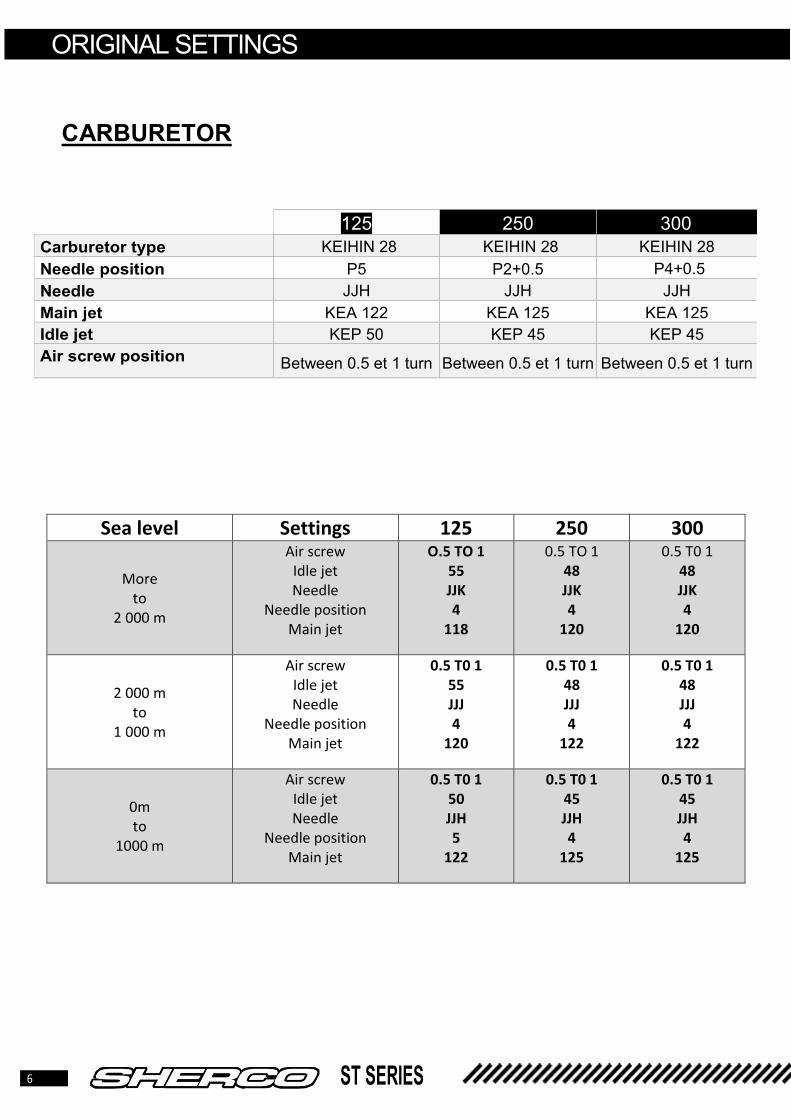
CARBURETOR
125 250 300
Carburetor type KEIHIN 28 KEIHIN 28 KEIHIN 28
Needle position P5 P2+0.5 P4+0.5
Needle JJH JJH JJH
Main jet KEA 122 KEA 125 KEA 125
Idle jet KEP 50 KEP 45 KEP 45
Air screw position Between 0.5 et 1 turn Between 0.5 et 1 turn Between 0.5 et 1 turn
Sea level Settings 125 250 300
More
to
2 000 m
Air screw
Idle jet
Needle
Needle position
Main jet
O.5 TO 1
55
JJK
4
118
0.5 TO 1
48
JJK
4
120
0.5 T0 1
48
JJK
4
120
2 000 m
to
1 000 m
Air screw
Idle jet
Needle
Needle position
Main jet
0.5 T0 1
55
JJJ
4
120
0.5 T0 1
48
JJJ
4
122
0.5 T0 1
48
JJJ
4
122
0m
to
1000 m
Air screw
Idle jet
Needle
Needle position
Main jet
0.5 T0 1
50
JJH
5
122
0.5 T0 1
45
JJH
4
125
0.5 T0 1
45
JJH
4
125
7 ST SERIES
ORIGINAL SETTING
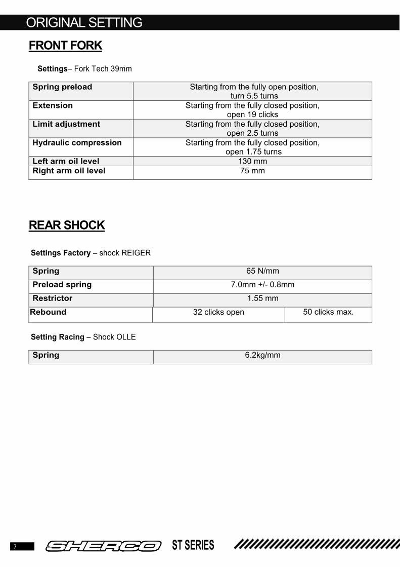
FRONT FORK
Settings– Fork Tech 39mm
Spring preload Starting from the fully open position, turn 5.5 turns
Extension Starting from the fully closed position, open 19 clicks
Limit adjustment Starting from the fully closed position, open 2.5 turns
Hydraulic compression Starting from the fully closed position, open 1.75 turns
Left arm oil level 130 mm Right arm oil level 75 mm
REAR SHOCK
Settings Factory – shock REIGER
Spring 65 N/mm
Preload spring 7.0mm +/- 0.8mm
Restrictor 1.55 mm
Rebound 32 clicks open 50 clicks max.
Setting Racing – Shock OLLE
Spring 6.2kg/mm

8 ST SERIES
CYCLE PARTS
❱❘ FRONT
1.1 Replacement of wheel bearings
• Loosen the locking screw located on the right tube.
• Loosen the axle, using a BTR key and
remove it.
• Take out the wheel.
Front wheel axle tightening : 100Nm
• Use a heat gun to heat the bearing surface on the hub.
• Remove the bearings using a flush valve and then replace them with new ones, reference 0175.
1.2 Front disc replacement
• When replacing the front brake disc, apply when reassembling the Loctite
243 and on the screws and tighten to a torque of 12Nm
• Proceed in the reverse process and
lightly grease the front axle.
WARNING
Before any operation, make sure that the motorcycle is properly fixed and that it cannot fall
WARNING
Using a caliper, check the size of the internal spacer reference 5930 on the front wheel
and replace it if necessary.
Minimum tolerance: 67.5mm

9 ST SERIES
CYCLE PARTS
1.3 Disassembly of the fork and replacement of the bearings
• Remove the two M8 screws [1] and
remove the caliper.
Caliper screws : 24 Nm
• Check the thickness of the brake pads. Tolerated limit: 1mm
• Loosen the 4 M8 screws of the
handlebar holder then remove the handlebars.
• Loosen the steering column nut [2], the M8 screws [3] of the upper triple clamp then remove it.
• Triple clamp screw : 24 Nm
• Loosen the steering column lock nut [4] and its dust cover, then separate the complete Fork of the frame
• Replace the bearings located in the upper part of the frame and on the part lower of the steering
column [5] by brand new reference C009 taking care of grease them.
• When reassembling, install the steering column lock nut and tighten it so that that the fork turns freely and without hard point. Then place the top triple clamp and tighten the upper steering column nut to 20 Nm.
2 1
2
1 3
4
5

10 ST SERIES
CYCLE PARTS
1.4 TECH fork maintenance
1.4.1 Right side oil change
• Place the fork tube in a vice with a suitable support so as not to damage it.
• Using a 17mm wrench, loosen the plug.
• Remove the plug [1] from the fork tube
so that you have access to the nut [2]
• . Hold the plug [1] and loosen the nut [2] using a 14mm wrench
• . Remove the plug from the diving tube.
• Hold the rod inside the axle [3] then empty the oil in a container by moving back and forth as shown in the photo.
• Place the suspension arm vertically and pour 250cc of new oil inside.
WARNING
Service the fork every 20 hours or every 6 months
WARNING
Use oil type SAE 5.
1
2
3

11 ST SERIES
CYCLE PARTS
• Perform an up and down movement as
shown in the photo so the hydraulic system has primed. Stop when you feel
slight resistance.
• Compress the tube and the rod to the
maximum stop.
Measure the oil level from the top of the
tube, top up until you reach the desired value.
Oil level : 75mm
• Unscrew the diving rod nut as much
as possible and install the plug.
• Tighten the plug [4] with the nut [5] to a torque of 12Nm
• Tighten the plug on the tube to a torque of 12Nm
1.4.2 Oil change on the left side
• Unscrew the cap [6] using a 17mm
wrench.
• Remove the tapered spacer [7].
4
5
6
7

12 ST SERIES
CYCLE PARTS
• Remove the spacer [8] and the
washer between it and the spring
.
• Take the spring [9] out of the fork
tube, taking care to dry it with a cloth.
• Drain the oil from the fork tube.
• Fill the arm with 250cc of new oil.
• Pump the tube several times then place it in the maximum compression position.
• Measure the volume from the top of the
tube and top up with oil until you reach the desired level.
Oil level : 130mm
• Reassemble in order, the spring, the washer, the spacer, the conical spacer then the top cap
• Place the fork in a vice using a protection for the tube and tighten the plug to 12N m.
8
9

13 ST SERIES
CYCLE PARTS
❱❘ REAR
2.1 Replacement of wheel bearings
• Hold the wheel axle on the left side and
loosen the nut on the right side
• Remove the axle from the left.
• Take out the wheel and remove the
spacers.
Rear wheel tightening : 100 Nm
• Heat the hub at the bearing seat
using a heat gun.
• Extract the bearings using a ø 20 flush.
• Replace the bearings with new ones, reference 0175.
2.2 Disc replacement
• When replacing the rear brake disc, apply when reassembling the Loctite 243 and on the screws and tighten to a torque of 12 Nm..
• Reassemble the assembly following the reverse process and lightly greasing the rear wheel axle.
WARNING
Using a caliper, check the size of the internal spacer reference 5931 on the rear wheel and replace it if necessary.
Minimum tolerance: 118.5mm

14 ST SERIES
CYCLE PARTS
2.3 Swingarm bearings control
• Loosen the nut on the lower part of the
swingarm and remove the link pin.
• Loosen the swingarm [1] axle and take
it out.
Tightening axle link : 40 Nm
Swingarm tightening: 50 Nm
• Take out the swingarm and remove
the two internal spacers [2].
• Check the needle cages on each side of the arm. In case of corrosion, replace them with new references C151, otherwise grease them before reassembly
• Reassemble the assembly following the reverse process and lightly greasing the
swingarm and connecting rod pins.
9 2
1

15 ST SERIES
CYCLE PARTS
2.4 Control of suspension links
• Loosen, respectively, the lower
suspension axle [1] and the link axle nut
[2].
• Remove the two axes and take out the delta links.
• Check the needle cages, in the event of corrosion or signs of wear, replace them with new ones. Grease during reassembly.
Shock absorber axle tightening : 40
Nm
Tightening Axle link : 40 Nm
• Remove the two axes of rear link [3].
Link axles : 40 Nm
• Remove the spacers from the links and check the friction rings [4]. If there is any wear, replace them with new ones.
• Reassemble the assembly by following the reverse process and taking care to grease all the axes and bearings.
1
2
1 3
4
16 ST SERIES
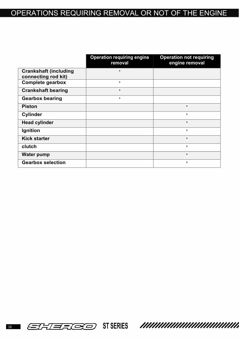
OPERATIONS REQUIRING REMOVAL OR NOT OF THE ENGINE
Operation requiring engine removal
Operation not requiring engine removal
Crankshaft (including connecting rod kit)
•
Complete gearbox •
Crankshaft bearing •
Gearbox bearing •
Piston •
Cylinder •
Head cylinder •
Ignition •
Kick starter •
clutch •
Water pump •
Gearbox selection •

17 ST SERIES
ENGINE REMOVAL / ASSEMBLY
ENGINE REMOVAL
• Drain the coolant (see user manual)Déposer la boite à air.
• Remove the air box and the tank.
• Disconnect the entire electrical harness connected to the engine (alternator, spark plug cap, CDI)
• Remove the exhaust.
• Remove the coil.
• Remove the carburetor.
• Remove the secondary transmission chain (quick coupler).
• Remove the slave cylinder
• Remove the water hoses connected to the engine.
• Loosen all the engine screws.
• Remove the swingarm.
• Remove the cylinder head mounting bracket.
• Remove the motor axles.
• Take out the engine.
REASSEMBLY OF THE ENGINE IN THE FRAME For reassembly proceed in the reverse direction to disassembly respecting the tightening torques of the screws
and nuts
Tightening torque:
Engine axles : 40Nm
Swingarm nut : 50 Nm
Slave cylinder screws: 10 Nm
Head cylinder holder screws : 23Nm
Exhaust screws: 10Nm
WARNING To remove the engine, you must remove the pivot axle of the swing arm, which allows
you to detach the rear wheel / swing arm assembly. To prevent the motorcycle from overturning, make sure that it is held by the chassis.
WARNING
When the clutch receiver is removed, the piston is no longer held. Hold the piston down with a plastic collar.

18 ST SERIES
DISASSEMBLY OF THE ENGINE
❱❘ Oil drain
• Remove the drain screw [1] and the plug [2], allow the oil to drain by tilting the motorcycle.
❱❘ Removal of front sprocket and selector
• Remove the pin [3]
• Remove the front sprocket [4].
• Remove the screw [5] and take out the selector.
• Remove the clutch push rod.
1
2
3
4
5
1

19 ST SERIES
DISASSEMBLY OF THE ENGINE
❱❘ Removing the cylinder head, cylinder and piston
• Remove the M6 screws [1] and
remove the cylinder head and the O-
rings.
• Remove the 4 cylinder nuts [2].
• Remove the cylinder.
• Hide the housing.
1
2

20 ST SERIES
DISASSEMBLY OF THE ENGINE
• Remove the piston pin clips.
• Remove the piston pin.
• Remove the piston and take out the
needle bearing from the big end.
• Remove the base gasket.
❱❘ Removing the clutch cover
• Remove the screws and the water pump cover. Remove the seal.
.
• Remove the screws and remove the clutch cover.
• Remove the gasket.

21 ST SERIES
DISASSEMBLY OF THE ENGINE
❱❘ Clutch and primary gear removal
• Loosen the Torx screws [1] of the cup and
remove it
• Successively remove the spring washer [2], the
preloading washer [3], the pressure plate [4], and the levers [5].
• Take the discs out of the boss clutch and place
the tool R172 [6] then remove the clutch nut [7] and the primary gear nut [8].
❱❘ Kick axle removal
• Remove the clip [1] then remove the idler gear [2]
• Remove the M6 screw [3] and the retaining plate
• Take out the kick axle [4] paying attention to the spring.
1
1
6
7
8
4 3
2
WARNING
At the same time, loosen the flywheel nut
while you lock the engine using tool R172.

22 ST SERIES
DISASSEMBLY OF THE ENGINE
❱❘ Disassembly selection
• Push the scorpion of the selection axle
to the left and remove the axle from its housing
• Loosen the M6 screw [1] then take out the selection finger.
• Loosen the M6 screw [2] then remove the selection star.
1
2
WARNING
Be careful not to lose the needle on the back of the selection star

23 ST SERIES
DISASSEMBLY OF THE ENGINE
❱❘ Ignition Removal
• Remove the previously loosened nut
[1].
• Fit the extractor [2] reference R075 and
tear off the magnetic flywheel [3].
❱❘ Intake pipe and reed box
• Remove the 4 screws M5 [4]
• Remove the intake pipe, reed box and gaskets.
1
3
2
4 4
4 4

24 ST SERIES
DISASSEMBLY OF THE ENGINE
❱❘ Removing the stator
• Before removing the stator, mark it in line with the mark on the crankcase
.
• Remove the three M6 screws [1] for fixing the
stator then the two M5 screws [2] for fixing the pick-up sensor and take out the assembly.
❱❘ Separate the crankcase
• Tilt the engine so that the ignition side is facing you.
• Remove the 10 fixing screws.
• Raise the left crankcase with small plastic
hammer on the gearbox output shaft to separate
from the other half.
1 1 1
2 2

25 ST SERIES
DISASSEMBLY OF THE ENGINE
• Remove the crankcase and the central gasket.
❱❘ Removal of the gearbox
• Take out the two fork axles and push the
forks sideways to free them from the
barrel.
• Take out the left fork and the central fork.
• Remove all of their bearings, the primary,
secondary shaft, barrel and right fork
simultaneously.
WARNING
Avoid as much as possible the insertion
of a screwdriver or any other tool between
the crankcases to separate it. You risk
damaging the joint planes.
WARNING Pay attention to the shims of the gearbox
shafts. They can remain stuck inside the
casings.
WARNING When removing, take care to identify the
location of the washers at the end of the shaft.

26 ST SERIES
DISASSEMBLY OF THE ENGINE
❱❘ Removing the connecting rod assembly
• Remove the crankshaft from its bearing (possibly by tapping lightly with a plastic mallet at the end of the crankshaft).
• Clean all the parts and check if they are worn, replace them if necessary.
WARNING
When the engine is completely dismantled, it is preferable to replace all gaskets,
oil seals, O-rings as well as the bearings.

27 ST SERIES
ENGINE ELEMENT CONTROL ❱❘ Balancing weight, external dimension control
• With a caliper, measure the outside distance of
the balancing weights
.
External value :
125cc � 54.85mm +0 / -0.2
250/300cc � 60.00mm +0 / -0.2
❱❘ Connecting rod radial clearance • Place the crankshaft on V and place a dial
gauge [A] against the big end.
• Push [B] the big end towards the gauge, then in the opposite direction.
• The difference between these two measurements corresponds to the radial clearance. Connecting rod radial clearance: Standard : 0.015 mm – 0.025 mm Limit : 0.06 mm If the radial clearance is greater than the tolerated limit, the crankshaft must be replaced
❱❘ Connecting rod end side clearance
• Measure the side play of the big end [A]
Connecting rod end side clearance :
Standard : 0.4 mm – 0.6 mm
Limit : 0.8 mm
If the play is above the tolerated limit, replace
the crankshaft
❱❘ Crankshaft runout control • Place the crankshaft on an alignment device or
V-shaped shims, and place a comparator as shown in the image in position [A].
• Then slowly turn the crankshaft. The maximum
difference between the measurements
corresponds to the offset of the crankshaft.
Crankshaft Offset:
Standard: 0.03 mm Limit: 0.05 mm
B A

28 ST SERIES
ENGINE ELEMENT CONTROL
❱❘ Piston • When reassembling a worn piston, check the following points:
• Look for any traces (tightening). Light traces can be removed.
• Ring emplacement: The rings must not get stuck in their emplacement. To clean it, you can use an
old segment or sand paper (400)
• The segment retainers must be securely fastened and must not be worn.
• Rings: Check the condition and end gap.
❱❘ End gap control
• Thread the segment into the cylinder and place it with the piston (approximately 10 mm from the upper edge of the cylinder).
• With a shim we measure the clearance.
End gap:
Standard 0.35-0.45mm ,
Limit 0.65mm.
❱❘ Piston pin control
Piston pin diameter for 125cc:
Standard : 14,998 mm
Limit: 14,995 mm
Piston pin hole diameter for 125cc :
Standard : 15,003mm
Limit : 15,007mm
Piston pin diameter for 250/300cc :
Standard : 17,998 mm
Limit : 17,995mm
Piston pin hole diameter for 250/300cc :
Standard : 18.002 mm
Limit : 18.006 mm
WARNING
If the clearance is greater than indicated, the condition of the cylinder and the piston must be checked. If these remain within the tolerance limits, replace only
the rings.

29 ST SERIES
ENGINE ELEMENT CONTROL
❱❘ Checking the cylinder / piston wear condition
• To detect wear on the cylinder, measure the bore with a bore gauge approximately 10 mm from the upper edge of the cylinder. Take a reading in both directions to identify a possible ovality.
125cc 250cc 300cc
A B A B A B
Ø Piston 53,96 53,97 72,75 72,76 78,95 78,96
Ø Cylinder 53,975 53,985 72,79 72,802 79 79,012
Free play 0,015 0,015 0,04 0,042 0,05 0,052
❱❘ Reed box, inlet pipe
• Over time the carbon reeds gradually lose
their elasticity, which causes a loss of power.
• Replace the worn or damaged reed. • Check the condition of the intake pipe,
especially if it is not cracked.

30 ST SERIES
ENGINE ELEMENT CONTROL
❱❘ Clutch
• Stopper [5] check for wear.
• Shaft [6] check for wear, size limit : 136,3 mm.
• Levers [17] check for wear or abnormal marks.
• Clutch holder [8] Check that there are no signs of wear on the trimmed disc guides.
• Clutch hub [9] Check the wear of the smooth disc seats
❱❘ Disc control
• On diaphragm clutches, the thickness of the discs is checked
on the complete assembly and not individually.
Minimum thickness : 9,92 mm
WARNING
When disassembling the discs, hold them with a plastic collar so as to maintain their
position and order of assembly. Worn discs which are not reassembled strictly in the same way can cause vibrations in the clutch.
31 ST SERIES
ENGINE ELEMENT CONTROL
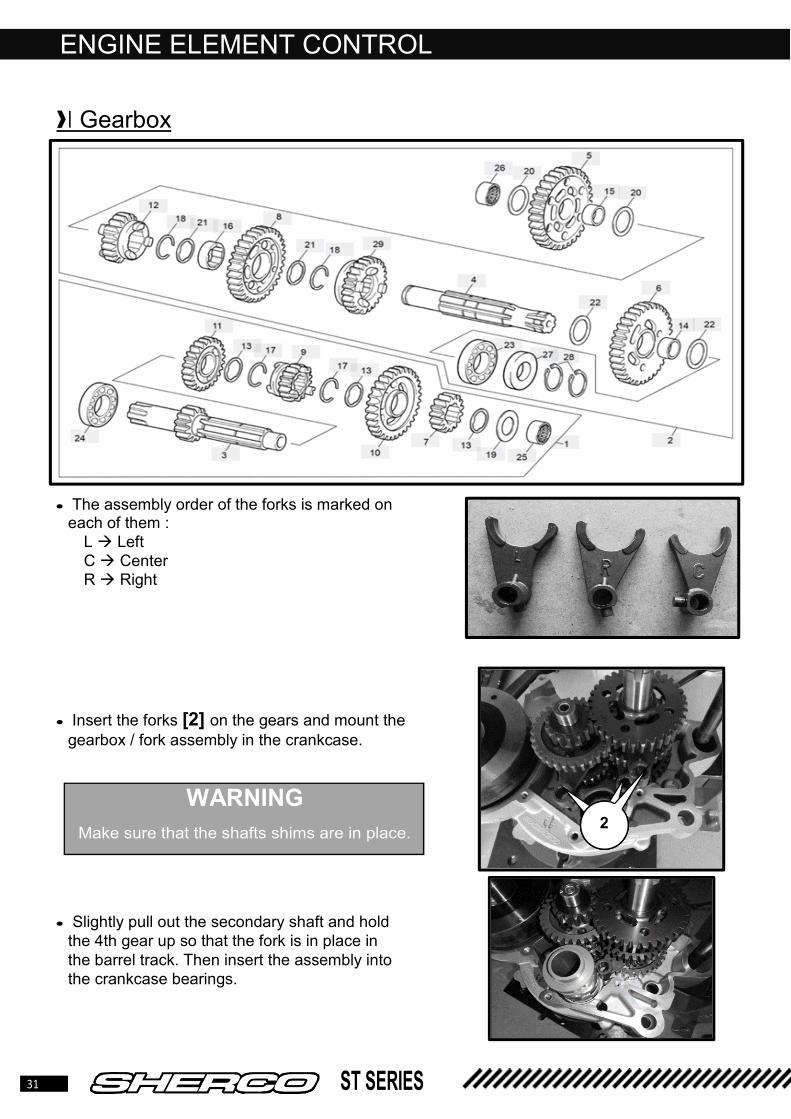
❱❘ Gearbox
• The assembly order of the forks is marked on each of them :
L � Left C � Center R � Right
• Insert the forks [2] on the gears and mount the
gearbox / fork assembly in the crankcase.
• Slightly pull out the secondary shaft and hold
the 4th gear up so that the fork is in place in
the barrel track. Then insert the assembly into
the crankcase bearings.
WARNING
Make sure that the shafts shims are in place. 2 2 2

32 ST SERIES
REASSEMBLING THE ENGINE
❱❘ Crankcases assembly
• Make sure that the centering rings are in place on
the right crankcase and that the washers of the
gearbox shafts are also in place.
• Grease the oil seals of the left crankcase and put it
in place.
• Put the screws and tighten to 10 Nm.
• Then tap lightly with a plastic mallet on the crankshaft and check that the shafts turn without any hard point.
❱❘ Ignition assembly
• Mount the stator on the crankcase and make sure that the marks are aligned. Tighten the 3 M6 screws
to 10 Nm.
• Position the hall sensor and tighten the two screws
to 8 Nm.

33 ST SERIES
REASSEMBLING THE ENGINE
❱❘ Selection mechanism
• Place the spring, the locking finger and the
spacer as in the photo.
• Coat the M6 screw with blue thread lock then tighten it to 10Nm.
• Put the indexing pin [1] of the selection star
on the drum.
• Pull the locking lever back to place the
selection star. • Coat of blue thread lock the screw and
assemble the selection star on the drum. Tighten the M6 screw to 10 Nm.
• Grease the already assembled selection shaft and thread it into the needle bearings
without forgetting the setting washer. • When the claw comes to press on the
selection star push it back so that you can lower the shaft fully.
• Check if the springs of the return spring are against the finger in the crankcase on each side.
• Fit the selector and shift all gears. (rotate the gearbox shafts to facilitate shifting).
• Remove the selector again.
1

34 ST SERIES
REASSEMBLING THE ENGINE
❱❘ Kick shaft assembly
• Fit the shaft [1] and its spring so that the slide
[2] comes against the stop of the housing [3].
• Put the retaining plate [4] and tighten the
screw [5] M6 to 10Nm.
❱❘ Primary transmission and clutch
• Place the half-moon key in its housing. Apply loctite 243 to the thread.
• Thread the gear, the washer and the nut on the
crankshaft tail.
• Thread the washer onto the primary shaft [1]
• Place the idler gear [2], making sure to put the lower and upper washers in place and then hold it with its circlip.
1
2 3
5 4
1
2

35 ST SERIES
REASSEMBLING THE ENGINE
• Fit the clutch assembly [3], making sure
that it is fully in abutment so as to be aligned with the primary transmission gear.
• Put blue thread locker on the thread [4] of the primary shaft.
• Fit tool R172 to hold the clutch and tighten
the clutch nut [5] to 40 Nm as well as that
of the primary gear [6] to 60Nm.
• Reassemble respectively :
1 The push rod of the clutch rod with the actuating cup.
2 Metal and friction discs (in the same order as when disassembled).
3 Levers (chamfer up)
4 Pressure plate
5 Preload washer
6 Spring
7 Spring cup
• Tighten the Torx screws [7] to 7Nm.
3
4
5
6
7

36 ST SERIES
REASSEMBLING THE ENGINE
❱❘ Clutch cover
• Check that the two centering sleeves are in
place and then place the clutch housing gasket.
• Present the clutch cover making sure that
the water pump assembly is in place. Rotate
the rotor so that the water pump gear can
mesh with the primary transmission gear • Put the THEP M6 screws and tighten to 10 Nm.
❱❘ Water pump cover
• Place the seal on the water pump cover and
stick it with a light layer of grease.
• Position the 4 M6 screws and tighten to 10 Nm.
WARNING Always replace the cooling bleed screw seal
[1] with a new reference M277 1

37 ST SERIES
REASSEMBLING THE ENGINE
❱❘ Piston / Cylinder
• Oil the parts well before reassembling.
• Thread the needle bearing into the big end,
position the piston (arrow on the exhaust side).
• Put the pin and the clips with the open side
down.
• Fit the base gasket.
• Position the segments correctly, (mark N)
upwards.
• thread the cylinder.
• Tighten the nuts to 22Nm.
❱❘ Squish control
• Squish control is done by measuring the distance between the flat of the piston, at top dead center, and the plane of the cylinder head. To do this, use a strand of tin that you will place on the piston. Depending on the value obtained, adjust with one or more base seals.
125cc 250cc 300cc
Squish Mini 0.9 mm 1.25 mm 1.25 mm
Squish Max 1.00 mm 1.35 mm 1.35mm
❱❘ Head cylinder
• Clean the cylinder and cylinder head gasket surfaces.
• Fit the O-rings (glue them with grease if necessary)
• Fit the head.
• Put new copper washers ref 2390 (Factory only)
• Fit the screws M6 • Tighten crosswise to 10 Nm.
WARNING Mount a 0.5mm GASKET first to check
the value of Squish.

38 ST SERIES
REASSEMBLING THE ENGINE
❱❘ Reed box and intake pipe
• Put a new reed box gasket.
• Put the complete reed box in the intake
conduct.
• Put on a new intake pipe gasket.
• Mount the intake pipe with the 4 M5 screws,
tighten them to 6Nm.
❱❘ Front sprocket
• Fit the retaining circlip on the engine side.
• Fit the front sprocket, number of teeth
outwards.
• Fit the retaining ring on the outside.

39 ST SERIES
TIGHTENING TORQUES
Cylinder head screw 10 N·m
Cylinder nuts 22 N·m
Magnetic flywheel cover screw 0,7 N·m
Stator screw 0,7 N·m
Magnetic flywheel nut 100 N·m
Clutch spring screws 0,7 N·m
Clutch nut 40 N·m (Loctite 243)
Screw intake pipe 0,7 N·m
Crankcase screw 15 N·m
Primary gear nut 60 N·m
Screws M-5 0,6 N·m
Screws M-6 12 N·m
Screws M-8 24 N·m
Screws M-10 40 N·m
Rear wheel axle nut 100 N·m
Front wheel axle 100 N·m
Lower steering nut 20 N·m
Upper steering nut 20 N·m
Swing arm 50 N·m

40 ST SERIES
ELECTRICAL PART
❱❘ Electrical components
Position Designation
1 Ventilator
2 T° Sensor
3 Ignition coil
4 Regulator
5 Ignition
6 CDI
1
2
3
4
5 6

41 ST SERIES
ELECTRICAL PART
❱❘ Ignition stator control
(Engine off)
• Resistance values of the stator windings: Measurement of the resistance between each winding.
Winding resistances :
• wire red – blue � 15.7 Ω +/- 20%%
250/300cc
• Wire Yellow – Yellow/white 0.7 a 1.5 Ω
125cc
• Wire Yellow – Yellow 0.7 à 1.5 Ω
❱❘ Hall sensor control
• Disconnect the CDI connector.
• Connect a multimeter to the hall sensor
terminals. (10/11)
• Measure with the multimeter the resistance
between the white and black wire.
Sensor resistance:
Wire black – white � 197 Ω +/- 20%%
Wire brown – white � 101 Ω +/- 20%%
❱❘ Voltage Regulator
• Voltage regulator: On regulator output (Caliber 20V continuous)
At 3500 RPM: 14.4V +/- 0.5V
Maximum output current : 15 A
Max operating temperature : 110°C
42 ST SERIES
ELECTRICAL PART
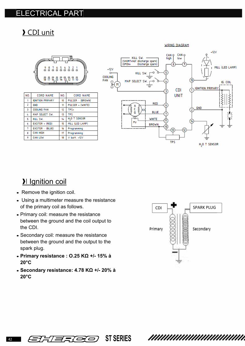
❱ CDI unit
❱❘ Ignition coil
• Remove the ignition coil.
• Using a multimeter measure the resistance
of the primary coil as follows.
• Primary coil: measure the resistance
between the ground and the coil output to
the CDI.
• Secondary coil: measure the resistance
between the ground and the output to the
spark plug.
• Primary resistance : O.25 KΩ +/- 15% à
20°C
• Secondary resistance: 4.78 KΩ +/- 20% à
20°C
SPARK PLUG CDI

43 ST SERIES
ELECTRICAL PART
❱❘ Temperature sensor
• Drain the coolant.
• Remove the radiator temperature sensor.
• Immerse the sensor [1] in a container filled
with coolant [2], making sure to leave the
terminals asleep with the liquid.
• Immerse a thermometer [3] in the liquid so
as to control its temperature.
• Heat the liquid slowly and check the
resistance of the sensor using a connected
multimeter as in the diagram according to
the temperature of the liquid, refer to the
table below.
❱❘ Ventilator
• Disconnect the fan from the harness.
• Connect a 12V battery directly to the fan as
shown in the diagram.
• Check that the fan rotates correctly without
any hard point or abnormal noise.
TEMPS (°C) RESISTANCE (Ω)
25 3000
30 2415
40 1620
50 1081
60 748
70 528
80 379
90 278
100 206

44 ST SERIES
CABLE SCHEMATICS
❱❘ Homologated light harness

45 ST SERIES
CABLE SCHEMATICS
❱❘ Homologated light harness

46 ST SERIES
CABLE SCHEMATICS
❱❘ Racing light harness

47 ST SERIES
CABLE SCHEMATICS
❱❘ Principal harness

48 ST SERIES
CABLE SCHEMATICS
❱❘ Principal harness