machine
74
Introduction to Electrical Machines 1 CHAPTER FOUR DC MACHINCES 4.1. INTRODUCTION The dc machines are versatile and extensively used in industry. A wide variety of volt-ampere or torque-speed characteristics can be obtained from various connections of the field winding. Dc machines can work as generators, motors & brakes. In the generator mode the machine is driven by a prime mover (such as a steam turbine or a diesel engine) with the mechanical power converted into electrical power. In the motor mode, the machine drives a mechanical load with the electrical power supplied converted into mechanical power. In the brake mode, the machine decelerates on account of the power supplied or dissipated by it and, therefore, produces a mechanical braking action. There is almost no modern use of dc machines as generators although in the earlier stages of electrical power generator and distribution. D.C. generators were the principle means of supplying electrical power to industrial and domestic consumers. Presently, all the land based electrical power networks are a.c systems of generation, transmission and distribution. The almost universal use of ac systems is on account of their lower generation and transmission costs, higher efficiency (large bulk of ac power can be transmitted and distributed over wide areas and long distance at much higher voltages that are impossible in dc system), greater reliability on account of interconnection and control. No doubt, application like aerocrafts, ships and road mounted vehicles which are isolated from land based ac networks employ dc sources including dc generators and secondary batteries for power supply but the modern trend is to use ac generators with the dc supply being obtained by rectification with the help of static power rectifiers. D.C. generators are still being used to produce power in small back-up and stand-by generating plants driven by windmill and mountain streams (minihydro-electric plants) to provide uninterrupted power supply. Apart from dc generators, the dc motors are finding increasing applications, especially where large magnitude and precisely controlled torque is required. Such motors are used in rolling mills, in overhead cranes and for traction purpose like in forklift trucks, electric vehicles, and electric trains. They are also used in portable machine tools supplied from batteries, in automotive vehicles as starter motors, blower motors and in many control applications as actuators and as speed and position sensing device (tachogenerators for speed sensing and servomotors for positioning and tracing). 4.2. CONSTRUCTION OF DC MACHINES The dc machines used for industrial applications have essentially three major parts: a) Field system (stator); b) Armature (Rotor) and c) commutator All the components of the dc machine are illustrated in cut-away view of Figure 4.1.
Transcript of machine
Introduction to Electrical Machines
1
CHAPTER FOUR
DC MACHINCES
4.1. INTRODUCTION
The dc machines are versatile and extensively used in industry. A wide variety of volt-ampere or torque-speed characteristics can be obtained from various connections of the field winding. Dc machines can work as generators, motors & brakes. In the generator mode the machine is driven by a prime mover (such as a steam turbine or a diesel engine) with the mechanical power converted into electrical power. In the motor mode, the machine drives a mechanical load with the electrical power supplied converted into mechanical power. In the brake mode, the machine decelerates on account of the power supplied or dissipated by it and, therefore, produces a mechanical braking action.
There is almost no modern use of dc machines as generators although in the earlier stages of electrical power generator and distribution. D.C. generators were the principle means of supplying electrical power to industrial and domestic consumers. Presently, all the land based electrical power networks are a.c systems of generation, transmission and distribution.
The almost universal use of ac systems is on account of their lower generation and transmission costs, higher efficiency (large bulk of ac power can be transmitted and distributed over wide areas and long distance at much higher voltages that are impossible in dc system), greater reliability on account of interconnection and control.
No doubt, application like aerocrafts, ships and road mounted vehicles which are isolated from land based ac networks employ dc sources including dc generators and secondary batteries for power supply but the modern trend is to use ac generators with the dc supply being obtained by rectification with the help of static power rectifiers. D.C. generators are still being used to produce power in small back-up and stand-by generating plants driven by windmill and mountain streams (minihydro-electric plants) to provide uninterrupted power supply.
Apart from dc generators, the dc motors are finding increasing applications, especially where large magnitude and precisely controlled torque is required. Such motors are used in rolling mills, in overhead cranes and for traction purpose like in forklift trucks, electric vehicles, and electric trains. They are also used in portable machine tools supplied from batteries, in automotive vehicles as starter motors, blower motors and in many control applications as actuators and as speed and position sensing device (tachogenerators for speed sensing and servomotors for positioning and tracing).
4.2. CONSTRUCTION OF DC MACHINES
The dc machines used for industrial applications have essentially three major parts:
a) Field system (stator); b) Armature (Rotor) and c) commutator
All the components of the dc machine are illustrated in cut-away view of Figure 4.1.

Introduction to Electrical Machines
Figure 4.1 cut-away view of DC machines
1.shaft; 2.end-bearings; 3. Commutator; 4. brushes; 5.armature; 6. main-pole; 7.main-pole field winding; 8.frame; 9.end-shield; 10.ventilator; 11.basement; 12.bearings
4.2.1. Field System
The field system is located on the stationary part of the machine called stator. The field system is designated for producing magnetic flux and, therefore, provides the necessary excitation for operation of machine. Figure 4.2 shows that the main flux paths which starts from a North pole, crosses the air gap and then travels down to the armature core. There, it divides into two equal (2) halves, each half enter the nearby South Pole so as to complete the flux. Each flux line crosses the air-gap twice. Some flux lines may not enter the armature; this flux, called the leakage flux, is not shown in Figure 4.2.
Figure 4.1 Flux paths in a 6-pole dc machines
Introduction to Electrical Machines
3
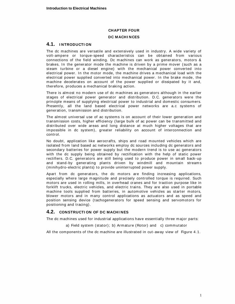
The stator of dc machines comprises of
1. Main poles: These poles are designed to produce the main magnetic flux
2. Frame: These provide support for the machine. In many machines the frame is also a part of the magnetic circuit.
3. Interpoles: These poles are designed to improve commutation conditions to ensure sparkles operation of machine.
Figure 4.3 Main-pole
Main-pole
Poles are made of sheet steel laminations of 1.0 to 1.2mm thickness (nowadays the thickness becomes 0.4-0.5mm). The pole shoes support the field coils placed on the pole body and also spread the total flux over a greater area, thereby reduce the air gap reluctance and giving the desired flux distribution to limit saturation in the teeth
of the armature. )(A
l
.The poles are secured to the yoke by means of bolts. In
small machines the pole are built of steel forgings, bolted directly to the yoke. In case of machines having compensating windings, the pole face is slotted to accommodate the windings.
Yoke (Frame)
The stator of a dc machines consists of a frame or yoke, and poles which support the field windings. The Frame or Yoke in addition to being a part of a magnetic circuit serves as mechanical support for entire assembly.
Earlier, cast iron was used for the construction of yoke but it has been replaced by cast steel. This is because cast iron has saturation density of 0.8 Wb/m2 while saturation occurs in cast steel at density of approximately 1.5 Wb/m2. Thus, the cross section of the cast steel frame or yoke is half that of iron cast and hence cast steel is used in case it is desired to reduce the weight of machine. Fabricated steel yokes are commonly used, as they are economical and have consistent magnetic & mechanical properties. For very small sized machines it may still be advantageous to use cost iron frames but for medium and large sizes rolled steel is used.
Interlopes
In addition to the main poles, modern direct current machines are also provided with interlopes with windings on them in order to improve commutation under loaded conditions. They are arranged midway between the mains poles and are bolted to the yolk. Laminated interlopes are used in machine with sever commutation problems. For small and medium size machines they could be solid.
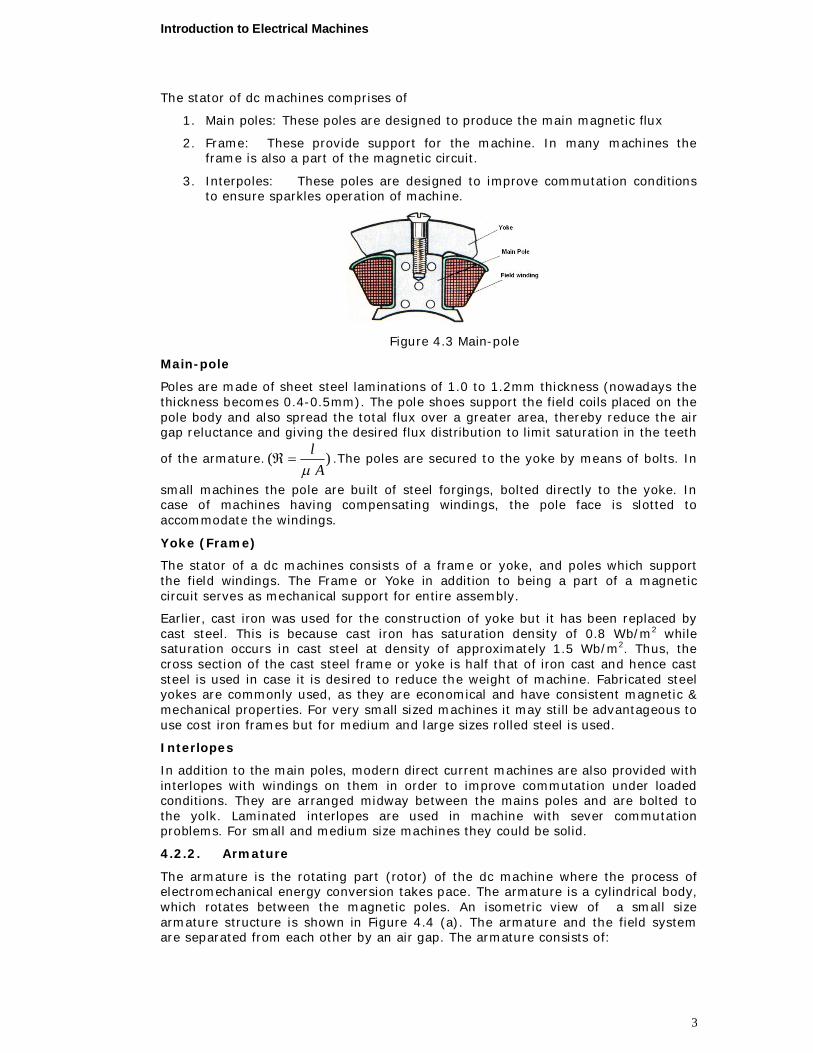
4.2.2. Armature
The armature is the rotating part (rotor) of the dc machine where the process of electromechanical energy conversion takes pace. The armature is a cylindrical body, which rotates between the magnetic poles. An isometric view of a small size armature structure is shown in Figure 4.4 (a). The armature and the field system are separated from each other by an air gap. The armature consists of:
Introduction to Electrical Machines
4
1. Armature core with slots and
2. Armature winding accommodated in slots
The purpose of the armature is to rotate the conductors in the uniform magnetic field and to induce an alternating e.m.f in its winding. The armature core is normally made from high permeability silicon-steel laminations of 0.4 to 0.5mm thickness, which are insulated from one another by varnish or ceramic insulation. The use of high grade steel is to keep hysteresis loss low, which is due to cyclic change of magnetization caused by rotation of the core in the magnetic field and to reduce the eddy current in the core which are induced by the rotation of the core in the magnetic field.
In order to dissipate the heat produced by hysteresis and eddy current losses etc, ventilating ducts are provided. By the fanning action of the armature, air is drawn in through these ducts, thus producing efficient ventilation. In the armature core of small diameters, circular holes are punched in the center of the laminations for the shaft (Figure 4.4(b)).
(a) (b)
Figure 4.4 (a) Isometric view of armature; (b) armature lamination
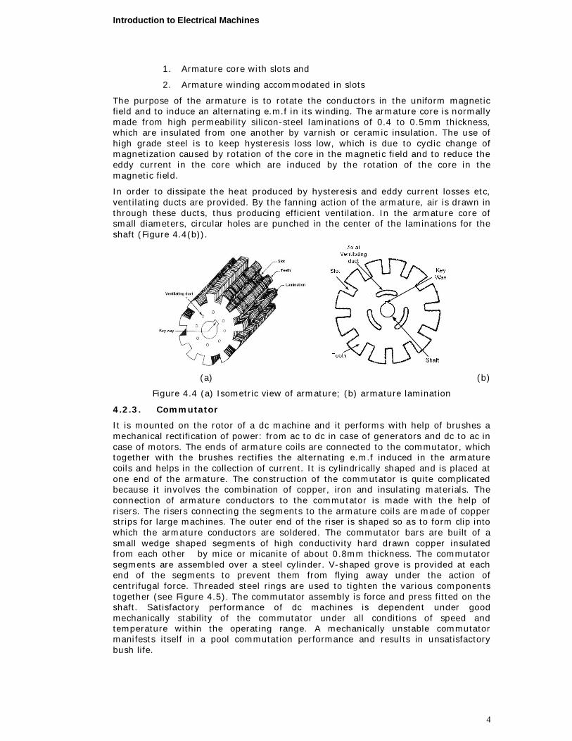
4.2.3. Commutator
It is mounted on the rotor of a dc machine and it performs with help of brushes a mechanical rectification of power: from ac to dc in case of generators and dc to ac in case of motors. The ends of armature coils are connected to the commutator, which together with the brushes rectifies the alternating e.m.f induced in the armature coils and helps in the collection of current. It is cylindrically shaped and is placed at one end of the armature. The construction of the commutator is quite complicated because it involves the combination of copper, iron and insulating materials. The connection of armature conductors to the commutator is made with the help of risers. The risers connecting the segments to the armature coils are made of copper strips for large machines. The outer end of the riser is shaped so as to form clip into which the armature conductors are soldered. The commutator bars are built of a small wedge shaped segments of high conductivity hard drawn copper insulated from each other by mice or micanite of about 0.8mm thickness. The commutator segments are assembled over a steel cylinder. V-shaped grove is provided at each end of the segments to prevent them from flying away under the action of centrifugal force. Threaded steel rings are used to tighten the various components together (see Figure 4.5). The commutator assembly is force and press fitted on the shaft. Satisfactory performance of dc machines is dependent under good mechanically stability of the commutator under all conditions of speed and temperature within the operating range. A mechanically unstable commutator manifests itself in a pool commutation performance and results in unsatisfactory bush life.
Introduction to Electrical Machines
5
(a) (b)
Figure 4.5 (a) cut-away view of commutator; (b) commutator segment
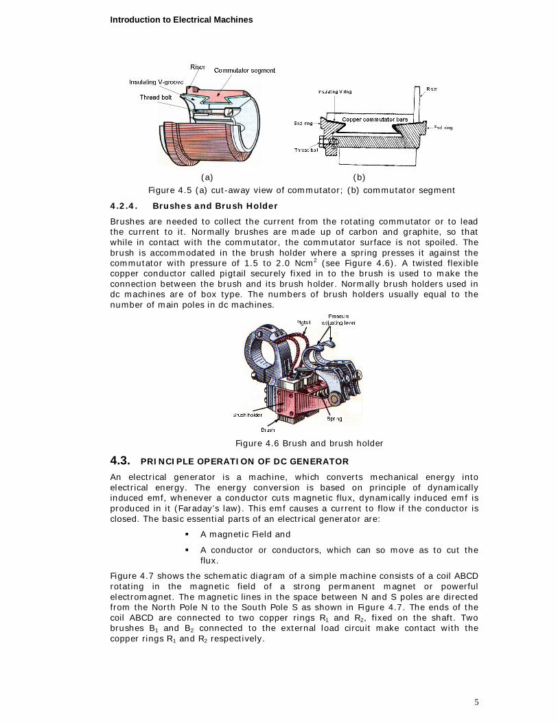
4.2.4. Brushes and Brush Holder
Brushes are needed to collect the current from the rotating commutator or to lead the current to it. Normally brushes are made up of carbon and graphite, so that while in contact with the commutator, the commutator surface is not spoiled. The brush is accommodated in the brush holder where a spring presses it against the commutator with pressure of 1.5 to 2.0 Ncm2 (see Figure 4.6). A twisted flexible copper conductor called pigtail securely fixed in to the brush is used to make the connection between the brush and its brush holder. Normally brush holders used in dc machines are of box type. The numbers of brush holders usually equal to the number of main poles in dc machines.
Figure 4.6 Brush and brush holder
4.3. PRINCIPLE OPERATION OF DC GENERATOR
An electrical generator is a machine, which converts mechanical energy into electrical energy. The energy conversion is based on principle of dynamically induced emf, whenever a conductor cuts magnetic flux, dynamically induced emf is produced in it (Faraday’s law). This emf causes a current to flow if the conductor is closed. The basic essential parts of an electrical generator are:
A magnetic Field and
A conductor or conductors, which can so move as to cut the flux.
Figure 4.7 shows the schematic diagram of a simple machine consists of a coil ABCD rotating in the magnetic field of a strong permanent magnet or powerful electromagnet. The magnetic lines in the space between N and S poles are directed from the North Pole N to the South Pole S as shown in Figure 4.7. The ends of the coil ABCD are connected to two copper rings R1 and R2, fixed on the shaft. Two brushes B1 and B2 connected to the external load circuit make contact with the copper rings R1 and R2 respectively.
Introduction to Electrical Machines
6
(a) (b)
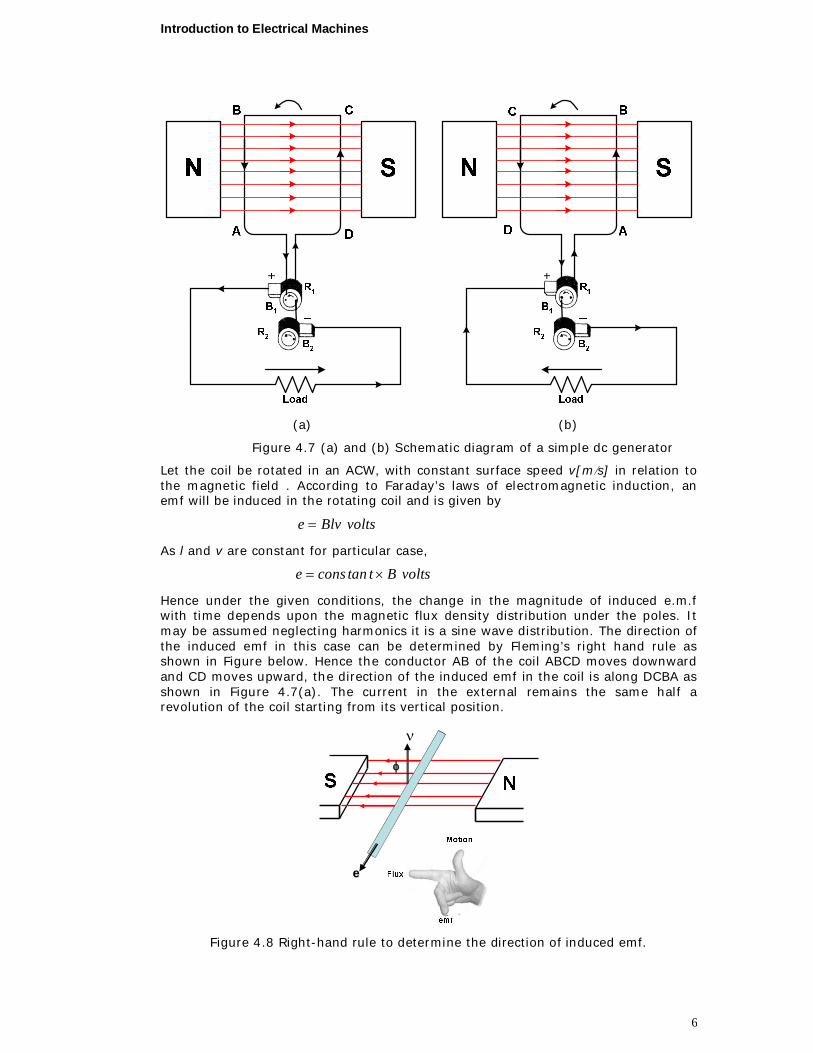
Figure 4.7 (a) and (b) Schematic diagram of a simple dc generator
Let the coil be rotated in an ACW, with constant surface speed v[ms] in relation to the magnetic field . According to Faraday’s laws of electromagnetic induction, an emf will be induced in the rotating coil and is given by
voltsBlve
As l and v are constant for particular case,
voltsBttanconse
Hence under the given conditions, the change in the magnitude of induced e.m.f with time depends upon the magnetic flux density distribution under the poles. It may be assumed neglecting harmonics it is a sine wave distribution. The direction of the induced emf in this case can be determined by Fleming’s right hand rule as shown in Figure below. Hence the conductor AB of the coil ABCD moves downward and CD moves upward, the direction of the induced emf in the coil is along DCBA as shown in Figure 4.7(a). The current in the external remains the same half a revolution of the coil starting from its vertical position.
SS NN
EMF
Flux
Motion
ee
ν
Figure 4.8 Right-hand rule to determine the direction of induced emf.

Introduction to Electrical Machines
7
Similarly, in the next half of the revolution, the direction of the induced emf is reversed and hence the current flows from brush B2 to B1 as shown in Figure 4.7(b).The magnitude of current in the external circuit also varies with time as per sine law; i.e. its magnitude is not constant with time.
If the machine has P poles and the armature rotates at N revolutions per minute, then the frequency of the induced emf in the armature is,
120PNf , Hz
The above discussion clearly indicates that the e.m.f induced in the armature of a dc generator is of alternating nature, alternating with frequency of f hertz depending upon the number of poles in the machine and the speed of the armature.
However, the output voltage or the current of dc generator must be unidirectional and that too of a constant value. Thus to compel the above alternating current to flow in one stipulated direction through the external load circuit, the dc machine is furnished with a special device called the commutator.
Figure 4.9 shows that the coil ABCD connected to a ring commutator split in two halves R1 and R2 well insulated from each other. The rings of the commutator are so arranged that during half the revolution of the coil, each half ring remain in contact with a particular brush. Figure 4.9(a) wile during the next half revolution, when the current is reversed, the same half ring is in contact with other brush as shown in Figure 4.9 (b).
(a) (b)
Figure 4.9 coil ABCD connected to a ring commutator
As a result, current in the external load circuit remains in the same direction. The nature of the variation of current in the external load current with the rotation of the coil, i.e. with time, has been shown in Figure 4.10. Such unidirectional current or emf which fluctuates between maximum and zero values is quite inconvenient for practical purposes.
Introduction to Electrical Machines
8
θ
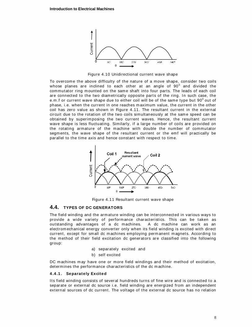
Figure 4.10 Unidirectional current wave shape
To overcome the above difficulty of the nature of a move shape, consider two coils whose planes are inclined to each other at an angle of 900 and divided the commutator ring mounted on the same shaft into four parts. The leads of each coil are connected to the two diametrically opposite parts of the ring. In such case, the e.m.f or current wave shape due to either coil will be of the same type but 900
out of phase, i.e. when the current in one reaches maximum value, the current in the other coil has zero value as shown in Figure 4.11. The resultant current in the external circuit due to the rotation of the two coils simultaneously at the same speed can be obtained by superimposing the two current waves. Hence, the resultant current wave shape is less fluctuating. Similarly, if a large number of coils are provided on the rotating armature of the machine with double the number of commutator segments, the wave shape of the resultant current or the emf will practically be parallel to the time axis and hence constant with respect to time.
θ
Figure 4.11 Resultant current wave shape
4.4. TYPES OF DC GENERATORS
The field winding and the armature winding can be interconnected in various ways to provide a wide variety of performance characteristics. This can be taken as outstanding advantages of a dc machines. A dc machine can work as an electromechanical energy converter only when its field winding is excited with direct current, except for small dc machines employing permanent magnets. According to the method of their field excitation dc generators are classified into the following group:
a) separately excited and b) self excited
DC machines may have one or more field windings and their method of excitation, determines the performance characteristics of the dc machine.
4.4.1. Separately Excited
Its field winding consists of several hundreds turns of fine wire and is connected to a separate or external dc source i.e. field winding are energized from an independent external sources of dc current. The voltage of the external dc source has no relation
Introduction to Electrical Machines
9
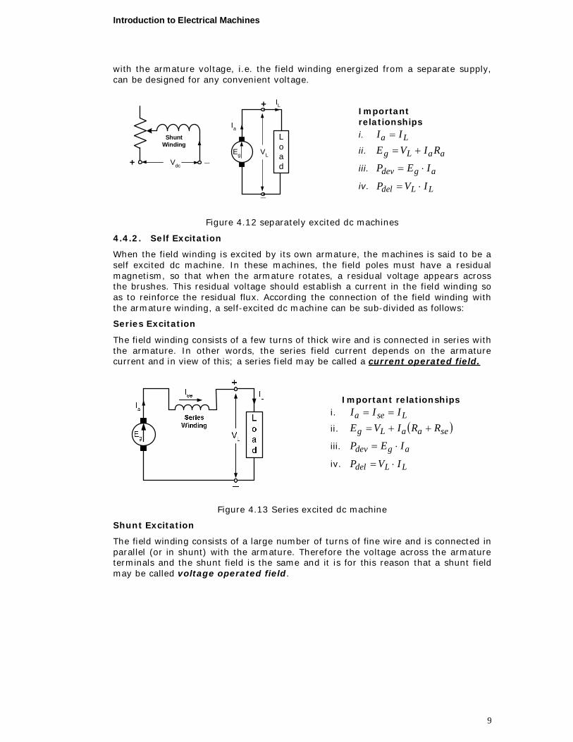
with the armature voltage, i.e. the field winding energized from a separate supply, can be designed for any convenient voltage.
+
_
ShuntWinding
_+ Vdc
VL
IL
Ia
Eg
Load
Important relationships i. La II
ii. aaLg RIVE
iii. agdev IEP
iv. LLdel IVP
Figure 4.12 separately excited dc machines
4.4.2. Self Excitation
When the field winding is excited by its own armature, the machines is said to be a self excited dc machine. In these machines, the field poles must have a residual magnetism, so that when the armature rotates, a residual voltage appears across the brushes. This residual voltage should establish a current in the field winding so as to reinforce the residual flux. According the connection of the field winding with the armature winding, a self-excited dc machine can be sub-divided as follows:
Series Excitation
The field winding consists of a few turns of thick wire and is connected in series with the armature. In other words, the series field current depends on the armature current and in view of this; a series field may be called a current operated field.
Important relationships i. Lsea III
ii. seaaLg RRIVE
iii. agdev IEP
iv. LLdel IVP
Figure 4.13 Series excited dc machine
Shunt Excitation
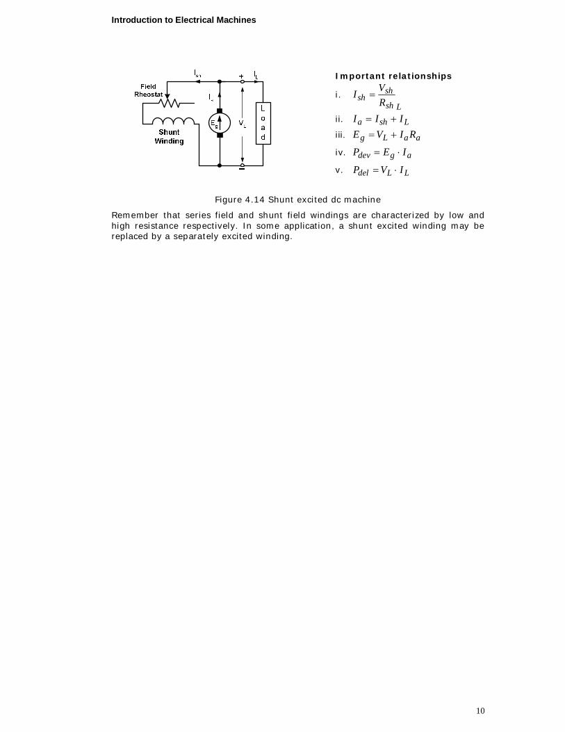
The field winding consists of a large number of turns of fine wire and is connected in parallel (or in shunt) with the armature. Therefore the voltage across the armature terminals and the shunt field is the same and it is for this reason that a shunt field may be called voltage operated field.
Introduction to Electrical Machines
10
Important relationships
i. Lsh
shsh R
VI
ii. Lsha III
iii. aaLg RIVE
iv. agdev IEP
v. LLdel IVP
Figure 4.14 Shunt excited dc machine
Remember that series field and shunt field windings are characterized by low and high resistance respectively. In some application, a shunt excited winding may be replaced by a separately excited winding.
Introduction to Electrical Machines
11
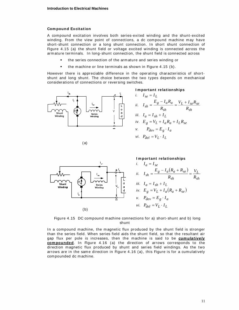
Compound Excitation
A compound excitation involves both series-exited winding and the shunt-excited winding. From the view point of connections, a dc compound machine may have short-shunt connection or a long shunt connection. In short shunt connection of Figure 4.15 (a) the shunt field or voltage excited winding is connected across the armature terminals. In long-shunt connection, the shunt field is connected across
the series connection of the armature and series winding or
the machine or line terminals as shown in Figure 4.15 (b).
However there is appreciable difference in the operating characteristics of short-shunt and long shunt. The choice between the two types depends on mechanical considerations of connections or reversing switches.
(a)
Important relationships i. Lse II
ii. sh
seseL
sh
aagsh R
RIVR
RIEI
iii. Lsha III
iv. seLaaLg RIRIVE
v. agdev IEP
vi. LLdel IVP
(b)
Important relationships i. sea II
ii.
sh
L
sh
seaagsh R
VR
RRIEI
iii. Lsha III
iv. seaaLg RRIVE
v. agdev IEP
vi. LLdel IVP
Figure 4.15 DC compound machine connections for a) short-shunt and b) long shunt
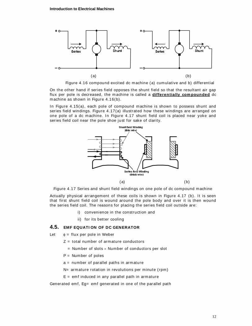
In a compound machine, the magnetic flux produced by the shunt field is stronger than the series field. When series field aids the shunt field, so that the resultant air gap flux per pole is increases, then the machine is said to be cumulatively compounded. In Figure 4.16 (a) the direction of arrows corresponds to the direction magnetic flux produced by shunt and series field windings. As the two arrows are in the same direction in Figure 4.16 (a), this Figure is for a cumulatively compounded dc machine.
Introduction to Electrical Machines
12
(a) (b)
Figure 4.16 compound excited dc machine (a) cumulative and b) differential
On the other hand if series field opposes the shunt field so that the resultant air gap flux per pole is decreased, the machine is called a differentially compounded dc machine as shown in Figure 4.16(b).
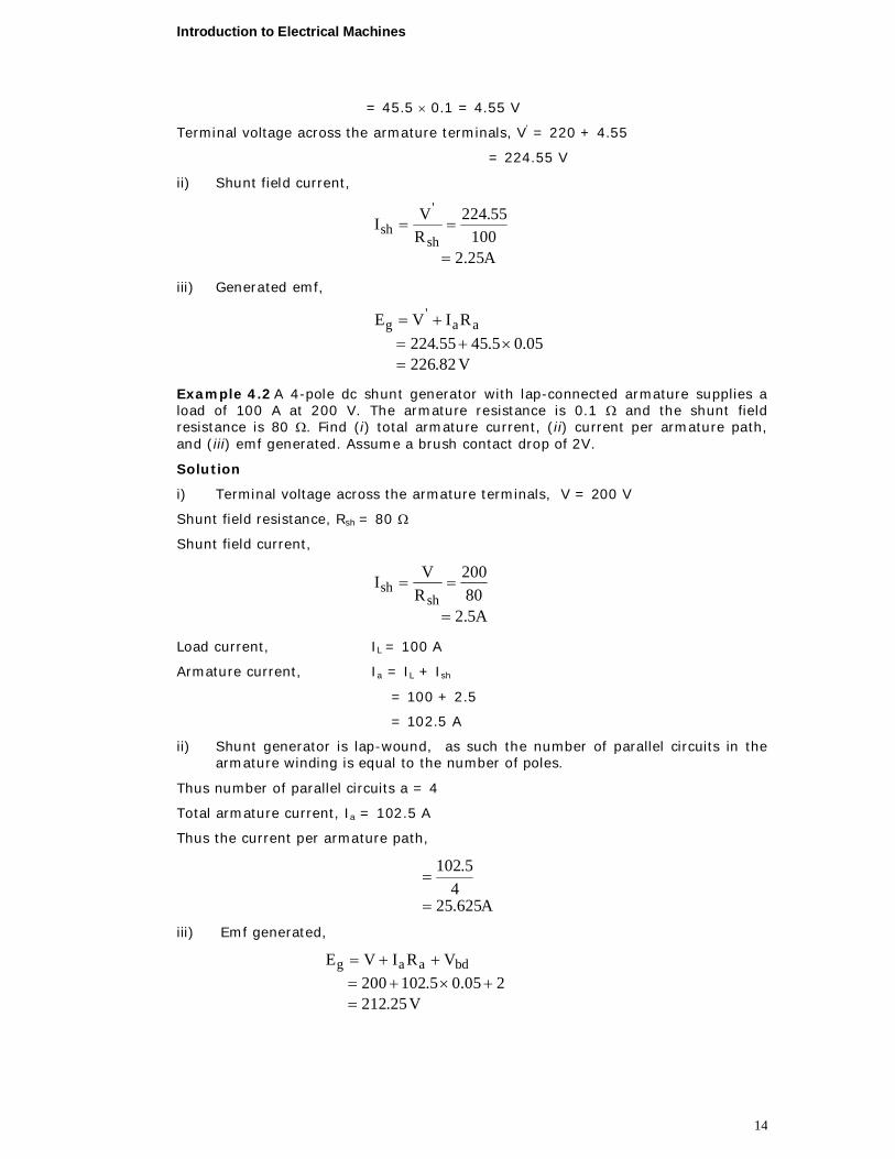
In Figure 4.15(a), each pole of compound machine is shown to possess shunt and series field windings. Figure 4.17(a) illustrated how these windings are arranged on one pole of a dc machine. In Figure 4.17 shunt field coil is placed near yoke and series field coil near the pole shoe just for sake of clarity.
(a) (b)
Figure 4.17 Series and shunt field windings on one pole of dc compound machine
Actually physical arrangement of these coils is shown in Figure 4.17 (b). It is seen that first shunt field coil is wound around the pole body and over it is then wound the series field coil. The reasons for placing the series field coil outside are:
i) convenience in the construction and
ii) for its better cooling
4.5. EMF EQUATION OF DC GENERATOR
Let = flux per pole in Weber
Z = total number of armature conductors
= Number of slots Number of conductors per slot
P = Number of poles
a = number of parallel paths in armature
N= armature rotation in revolutions per minute (rpm)
E = emf induced in any parallel path in armature
Generated emf, Eg= emf generated in one of the parallel path

Introduction to Electrical Machines
13
Average emf generated / conductor volt,dtd
Now, flux cut / conductor in one revolution, Wb,Pd
Number of revolution / second ondsec,60N
Hence according to Faraday’s law of electromagnetic induction
emf generated / conductor volt,60PN
dtd
For wave winding Number of parallel path a = 2
Number of conductors (in series) in one path 2Z
emf generated / path volt602
ZPN2Z
60PN
For lap winding Number of parallel path a = P
Number of conductors (in series) in one path PZ
emf generated / path volt60ZN
PZ
60PN
In general, the Generated emf
voltaP
60ZNEg
Where, a =2 for wave winding a = P for lap winding NKE ag
where, a60
ZPKa is machine constant.
Example 4.1 A dc shunt generator supplies a load of 10 kW at 220 V through feeders of resistance 0.1. The resistance of armature and shunt field windings is 0.05 and 100 respectively. Calculate, (i) terminal voltage, (ii) shunt field current and (iii) generated emf.
Solution
i) Load supplied , Pdel = 10 kW
= 10 103 W
Voltage at the load terminals = 220 V
Thus load current,
AVPI del
L
5.45220
1010 3
Resistance of the feeders = 0.1
Voltage drop in the feeders = IL 0.1
Introduction to Electrical Machines
14
= 45.5 0.1 = 4.55 V
Terminal voltage across the armature terminals, V = 220 + 4.55
= 224.55 V
ii) Shunt field current,
A25.2100
55.224RVI
sh
'sh
iii) Generated emf,
V82.226
05.05.4555.224RIVE aa
'g
Example 4.2 A 4-pole dc shunt generator with lap-connected armature supplies a load of 100 A at 200 V. The armature resistance is 0.1 and the shunt field resistance is 80 . Find (i) total armature current, (ii) current per armature path, and (iii) emf generated. Assume a brush contact drop of 2V.
Solution
i) Terminal voltage across the armature terminals, V = 200 V
Shunt field resistance, Rsh = 80
Shunt field current,
A5.280200
RVIsh
sh
Load current, IL = 100 A
Armature current, Ia = IL + Ish
= 100 + 2.5
= 102.5 A
ii) Shunt generator is lap-wound, as such the number of parallel circuits in the armature winding is equal to the number of poles.
Thus number of parallel circuits a = 4
Total armature current, Ia = 102.5 A
Thus the current per armature path,
A625.254
5.102
iii) Emf generated,
V25.212205.05.102200
VRIVE bdaag
Introduction to Electrical Machines
15
Example 4.3 A short shunt compound generator supplies 200 A at 100 V. The resistance of armature, series field and shunt field is respectively, 0.04, 0.03 and 60 . Find the emf generated.
Solution
Terminal voltage across the load, VL = 100 V
Load current, IL = 200 A
Resistance of series field winding Rse = 0.03
Voltage drop in series field winding = IL Rse
= 200 0.03
= 6 V
Terminal voltage across the armature, V = VL + IL Rse
= 100 + 6
= 106 V
Shunt field current,
A77.160
106RVIsh
sh
Armature current, Ia = IL + Ish
= 200 + 1.77
= 201.77 A
Generated emf,
V07.114
04.077.2016100RIRIVE aaseLLg
Example 4.4 The armature of a four pole, wave wound shunt generator has 120 slots with 4 conductors per slot. The flux per pole is 0.05 Wb. The armature resistance is 0.05 and the shunt field resistance 50 . Find the speed of the machine when supplying 450 A at a terminal voltage of 250 V.
Solution
Terminal voltage, VL = 250 V Load current, IL = 450 A Shunt field resistance, Rsh = 50
Shunt field current,
A0.550250
RVI
sh
Lsh
I
Armature current, Ia = IL + Ish
= 450 + 5 = 455 A Armature resistance, Ra = 0.05
Generated emf,
Introduction to Electrical Machines
16
V75.272
05.0455250RIVE aaLg
Generated emf,
Va60
NZPEg
Number of poles, P == 4; Flux per pole, = 0.05 Wb; Number of slots on armature = 120; Conductors per slot = 4
Thus total number of conductors on armature = 120 4 = 480
As the armature is wave wound, number of parallel paths, a=2
Substituting these in the above equation,
260
480N05.0475.272
Speed of rotation,
rpm341
48005.0426075.272N
Example 4.5 A long-shunt compound generator supplies a load at 110 V through a pair of feeders of total resistance 0.04 . The load consists of five motors, each taking 30 A and a lighting load of 150 bulbs each of 60 W. The armature resistance is 0.03 , series field resistance 0.04 and shunt field resistance, 55 . Find, (i) load current, (ii) terminal voltage, and (iii) emf generated.
Solution
i) Current drawn by each motor = 30 A Thus current drawn by five motors = 30 5
= 150 A Total lighting load = 150 60
= 9000 W
Current taken by the lighting load = A821109000
Hence, total load current = 150 + 82 = 232 A
ii) Voltage at the terminals of the load = 110 V Total resistance of the feeders = 0.04
Current through the feeders = 232 A Voltage drop in feeders = 232 0.04
= 9.28 V Terminal voltage across the generator terminals,
V = VL + drop in feeders = 110 + 9.28 = 119.28 V
Introduction to Electrical Machines
17
iii) Resistance of shunt field, Rsh = 55
Current in shunt field winding,
A2.255
28.119RVIsh
sh
Current in the armature winding, Ia = IL +Ish = 232 + 2.2 = 234.2 A Current in the series field winding, Ise = Ia = 234.2 A Total resistance of armature and series field winding = Ra + Rse = 0.03 + 0.04 = 0.07
Generated emf ,
A67.13507.02.23428.119
RRIVE seaag
4.6. ARMATURE REACTION
By armature reaction is meant the effect of magnetic field. Set up by armature current on the distribution of flux under main poles. In other words armature reaction is meant the effect of armature ampere-turns upon the value and the distribution of the magnetic flux entering and leaving the armature core. The armature magnetic field has two effects:
1. It demagnetizes or weakens the main flux &
2. It cross –magnetizes or distorts it
Let us illustrate (demonstrate) these two effects of armature reaction for 2-pole d.c generator. For better understanding let us see three cases.
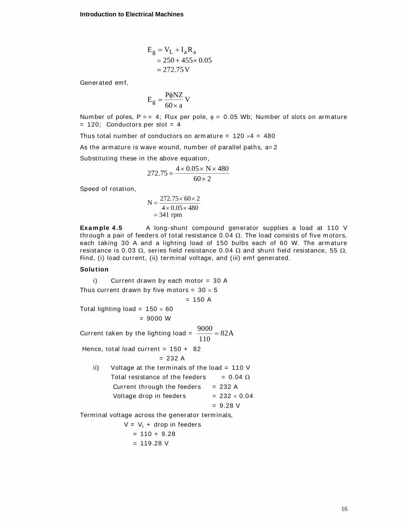
Case-I: Figure 4.18 shows the distribution of magnetic flux when there is no current (Ia=0) in the armature conductors,. For this case
a) The distribution magnetic flux symmetrical with respect to the polar axis. b) The magnetic neutral axis or place (M.N.A.) coincides with geometrical
neutral axis or plane (G.N.A)
M.N.A may be defined as the axis along which no-emf is produced in the armature conductors because they move parallel to the lines of flux
or M.N.A. is the axis which is perpendicular to the flux passing through the armature.
In this case, brushes are always placed along M.N.A and the mmf (Fm) producing the main flux is directed perpendicular to M.N.A.
Introduction to Electrical Machines
18
Figure 4.18 Magnetic flux distribution due to the main field poles only
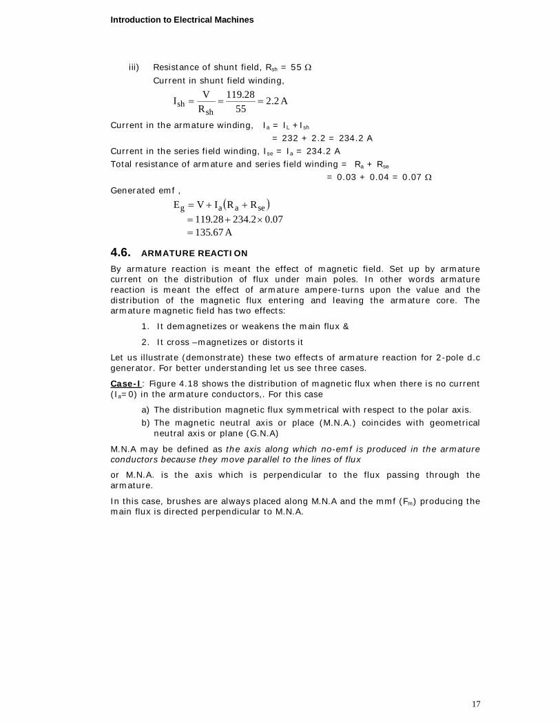
Case-II: Figure 4.19, shows the field (or flux) set up by the armature conductors alone, when current carrying the field coils being unexcited (If = 0). The direction of the armature current is the same as it would be when the generator is loaded & determined by Fleming’s Right-hand rule. Under this case, the magnetic fields, which are set up by armature conductor are symmetrical to G.N.A. and the mmf of the armature conductor (depending on the strength of Ia) is shown separately both in magnitude and direction by the Vector OFa which is parallel to G.N.A
.
Field Flux due tofield current only
Polar-axis
o
FaGenerator
rotation
Figure 4.19 Magnetic flux distribution due to the armature excitation only
In the above two cases, we considered the main mmf and armature mmf separately, as if they existed independently, which is not the case in practice under actual load conditions. The two cases exist simultaneously in generator as will be shown in case III.
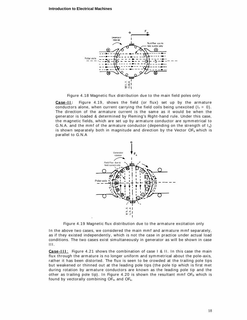
Case-III: Figure 4.21 shows the combination of case I & II. In this case the main flux through the armature is no longer uniform and symmetrical about the pole-axis, rather it has been distorted. The flux is seen to be crowded at the trailing pole tips but weakened or thinned out at the leading pole tips (the pole tip which is first met during rotation by armature conductors are known as the leading pole tip and the other as trailing pole tip). In Figure 4.20 is shown the resultant mmf OFR which is found by vectorally combining OFm and OFa.

Introduction to Electrical Machines
19
Figure 4.20 combined magnetic flux distribution due to armature and field
The new position of M.N.A which is always perpendicular to the resultant mmf vector OFR is shown in Figure 4.20. Due to the shift of M.N.A, say through an angle , brushes are also shifted so as to lie along the new positions of M.N.A. Due to this brush shift (or forward, leads), the armature conductors and hence the armature current is redistributed, i.e. some armature conductors, which were earlier under the influence of N-pole, come under the influence of S-pole and vice-versa. Let us see this condition with help of Figure 4.21.
Now the armature mmf is now represented by vector Fa that is no vertical but is inclined by angle to the left (Figure 4.21). This vector can be resolved into two rectangular components, Fd parallel to polar axis and Fc perpendicular to this axis, we find that
1. Component Fc is at right angle to the vector OFm (Figure 4.18) representing the main mmf it produces distortion in the main field and is hence called the cross-magnetizing or distorting component of the armature Reaction.
2. Component Fd is in direct opposition to OFm, which represents the main mmf. It exerts a demagnetizing influence on the main pole flux. Hence, it is called the demagnetizing or weakening component of the armature reaction.
From the above discussion we can conclude that:
1. The flux across the air gap is no longer uniform, but weakens under the leading pole tips and strengthened under the trailing pole tips. (The pole tip which is first met during rotation by armature conductors is known as the leading pole tip and the other as trailing pole tip).Due to this the resultant mmf given rise to decreases flux. So that emf in the armature under loaded conditions is somewhat less than that of under no-load conditions.
2. The brushes should be shifted in the direction of rotation to avoid a heavy short-circuit current and sparking at brushes.
3. The field distortion cause, an increase in the iron losses as compared its no-load value because of increases peak value of flux density in the tooth.
Introduction to Electrical Machines
20
θ
Figure 4.21 the demagnetizing and cross-magnetizing components of
armature mmf
4.7. COMMUTATION
The armature conductors carry current in one direction when they are under the influence of N-pole and in opposite direction when they are under S-pole. So when the conductors come under the influence of the S-pole from the influence of N-pole, the direction of flow of current in them is reversed. This reversal of current in a coil will take place when the two commutator segments to which the coil is connected are being short circuited by brush. The process of reversal of current in a coil is termed as commutation. The period during which the coil remains short-circuited is called commutation period, Tc. This commutation period is very small of the order of 0.001 to 0.003s.
If the current reversal i.e. the changes from+ I to ZERO and then to –I is completed by the end of short circuit or commutation period, the commutation is Ideal. If current reversal is not completed by that time, then sparking is produced between the brush and the commutator, which results in progressive damage to both.
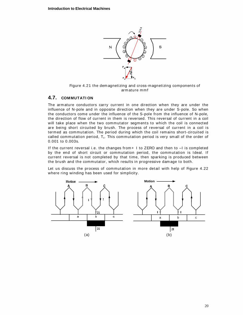
Let us discuss the process of commutation in more detail with help of Figure 4.22 where ring winding has been used for simplicity.
(a)
a b c
Motion
2I
I I
A B C
(b)
Introduction to Electrical Machines
21
(c)
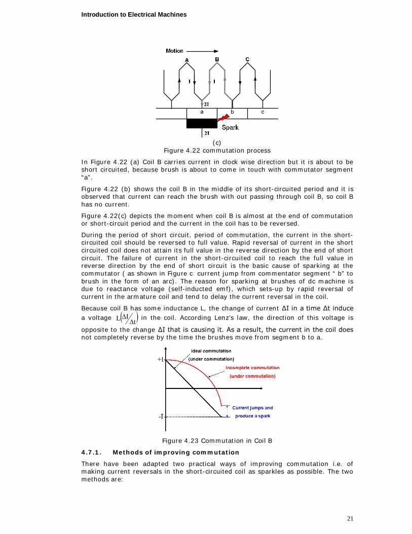
Figure 4.22 commutation process
In Figure 4.22 (a) Coil B carries current in clock wise direction but it is about to be short circuited, because brush is about to come in touch with commutator segment “a”.
Figure 4.22 (b) shows the coil B in the middle of its short-circuited period and it is observed that current can reach the brush with out passing through coil B, so coil B has no current.
Figure 4.22(c) depicts the moment when coil B is almost at the end of commutation or short-circuit period and the current in the coil has to be reversed.
During the period of short circuit, period of commutation, the current in the short-circuited coil should be reversed to full value. Rapid reversal of current in the short circuited coil does not attain its full value in the reverse direction by the end of short circuit. The failure of current in the short-circuited coil to reach the full value in reverse direction by the end of short circuit is the basic cause of sparking at the commutator ( as shown in Figure c current jump from commentator segment “ b” to brush in the form of an arc). The reason for sparking at brushes of dc machine is due to reactance voltage (self-inducted emf), which sets-up by rapid reversal of current in the armature coil and tend to delay the current reversal in the coil.
Because coil B has some inductance L, the change of current ∆I in a time ∆t induce a voltage tIL
in the coil. According Lenz’s law, the direction of this voltage is
opposite to the change ∆I that is causing it. As a result, the current in the coil does not completely reverse by the time the brushes move from segment b to a.
Figure 4.23 Commutation in Coil B
4.7.1. Methods of improving commutation
There have been adapted two practical ways of improving commutation i.e. of making current reversals in the short-circuited coil as sparkles as possible. The two methods are:
Introduction to Electrical Machines
22
(i) resistance commutation and (ii) emf commutation.
This method is achieved by
i By replacing low-resistance copper brush by comparatively high resistance carbon brush (approximately 12 times that of copper). However , it should be clearly understood that the main causes of the sparking commutation is the self induced emf ,so brushes alone do not give a sparkles commutation, though they do help in obtaining it.
ii By the help of inter poles, neutralize the self- reactance voltage by producing reversing emf. In this method, arrangement is made to neutralize the reactance voltage by producing a reversing emf in the short-circuited coil under commutation. This reversing emf, as the name shows, is an emf in opposition to the reactance voltage and if its value is made up equal to the latter, it will completely wipe it off, thereby producing quick reversal of current in short-circuited coil which will result in sparkles commutation.
4.7.2. Interpoles or Compoles
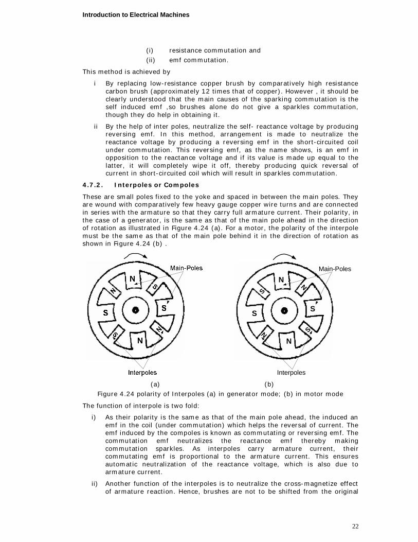
These are small poles fixed to the yoke and spaced in between the main poles. They are wound with comparatively few heavy gauge copper wire turns and are connected in series with the armature so that they carry full armature current. Their polarity, in the case of a generator, is the same as that of the main pole ahead in the direction of rotation as illustrated in Figure 4.24 (a). For a motor, the polarity of the interpole must be the same as that of the main pole behind it in the direction of rotation as shown in Figure 4.24 (b) .
N
N
S S
S
S
N
N
Interpoles
Main-Poles
(a) (b)
Figure 4.24 polarity of Interpoles (a) in generator mode; (b) in motor mode
The function of interpole is two fold:
i) As their polarity is the same as that of the main pole ahead, the induced an emf in the coil (under commutation) which helps the reversal of current. The emf induced by the compoles is known as commutating or reversing emf. The commutation emf neutralizes the reactance emf thereby making commutation sparkles. As interpoles carry armature current, their commutating emf is proportional to the armature current. This ensures automatic neutralization of the reactance voltage, which is also due to armature current.
ii) Another function of the interpoles is to neutralize the cross-magnetize effect of armature reaction. Hence, brushes are not to be shifted from the original
Introduction to Electrical Machines
23
position. Neutralization of cross- magnetization is automatic and for all loads because both are produced by the same armature current.
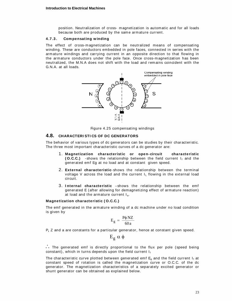
4.7.3. Compensating winding
The effect of cross-magnetization can be neutralized means of compensating winding. These are conductors embedded in pole faces, connected in series with the armature windings and carrying current in an opposite direction to that flowing in the armature conductors under the pole face. Once cross-magnetization has been neutralized, the M.N.A does not shift with the load and remains coincident with the G.N.A. at all loads.
Figure 4.25 compensating windings
4.8. CHARACTERISTICS OF DC GENERATORS
The behavior of various types of dc generators can be studies by their characteristic. The three most important characteristic curves of a dc generator are:
1. Magnetization characteristic or open-circuit characteristic (O.C.C.) -shows the relationship between the field current If and the generated emf Eg at no load and at constant given speed.
2. External characteristic-shows the relationship between the terminal voltage V across the load and the current IL flowing in the external load circuit.
3. Internal characteristic –shows the relationship between the emf generated E (after allowing for demagnetizing effect of armature reaction) at load and the armature current Ia.
Magnetization characteristic (O.C.C.)
The emf generated in the armature winding of a dc machine under no load condition is given by
a60NZPEg
P, Z and a are constants for a particular generator, hence at constant given speed.
gE
The generated emf is directly proportional to the flux per pole (speed being constant), which in turns depends upon the field current If
The characteristic curve plotted between generated emf Eg and the field current If at constant speed of rotation is called the magnetization curve or O.C.C. of the dc generator. The magnetization characteristics of a separately excited generator or shunt generator can be obtained as explained below.

Introduction to Electrical Machines
24
Figure 4.26 Circuit diagram for determination of magnetization characteristics
Figure 4.26 shows the connections of the generator and the field for determination of O.O.C. A potentiometer arrangement has been made to supply the field winding so that the field current can be varied over a wide range by moving the contact K. Ammeter indicate the field current and voltmeter indicate the generated emf. The field current is increased in steps from zero to maximum and the corresponding value of If and Eg are noted down at each step. On plotting these results, a curve of the form shown in Figure 4.27 is obtained.
Figure 4.27 Magnetization curve or O.C.C.
On analyzing the curve in Figure 4.27, it is observed that a small emf OA is generated by the generator, even when the field current is zero. The reason for this generated emf is the residual magnetism in the poles. This emf which is due to residual magnetism is normally 1 to 5% of the normal voltage of the generator. The magnetization curve of a shunt generator and a series generator can also be obtained in a similar manner. However, a shunt generator differs compared to separately excited one, in the manner that the field current in shunt generator is due to the generated emf only, where as the field current is independent of the generated emf in case of separately.
This magnetization curve is of grate importance because it represents the saturation level in the magnetic system of the dc machine for various value of the excitation mmf (current).
4.9. VOLTAGE BUILD-UP PROCESS IN SHUNT GENERATOR
In the shunt or self-excited generator the field is connected across the armature so that the armature voltage can supply the field current. Under certain conditions, to be discussed here, this generator will build up a desired terminal voltage. If the machine is to operate as a self-excited generator, some residual magnetism must exist in the magnetic circuit of the generator. Figure 4.28 shows the magnetization curve of the dc machine. Also shown in this Figure 4.28 is the field resistance line, which is a plot of Rf If versus If.
Introduction to Electrical Machines
25
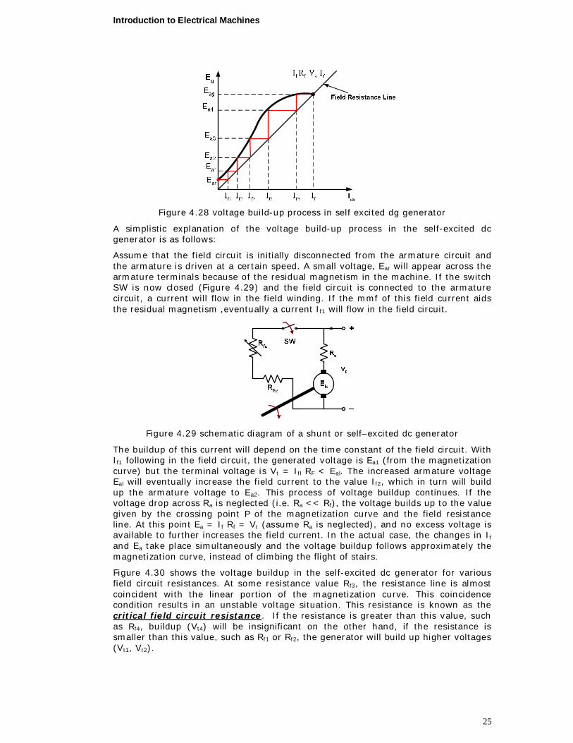
Figure 4.28 voltage build-up process in self excited dg generator
A simplistic explanation of the voltage build-up process in the self-excited dc generator is as follows:
Assume that the field circuit is initially disconnected from the armature circuit and the armature is driven at a certain speed. A small voltage, Ear will appear across the armature terminals because of the residual magnetism in the machine. If the switch SW is now closed (Figure 4.29) and the field circuit is connected to the armature circuit, a current will flow in the field winding. If the mmf of this field current aids the residual magnetism ,eventually a current If1 will flow in the field circuit.
Figure 4.29 schematic diagram of a shunt or self–excited dc generator
The buildup of this current will depend on the time constant of the field circuit. With If1 following in the field circuit, the generated voltage is Ea1 (from the magnetization curve) but the terminal voltage is Vt = Ifl RF < Eal. The increased armature voltage Eal will eventually increase the field current to the value If2, which in turn will build up the armature voltage to Ea2. This process of voltage buildup continues. If the voltage drop across Ra is neglected (i.e. Ra << Rf), the voltage builds up to the value given by the crossing point P of the magnetization curve and the field resistance line. At this point Ea = If Rf = Vt (assume Ra is neglected), and no excess voltage is available to further increases the field current. In the actual case, the changes in If and Ea take place simultaneously and the voltage buildup follows approximately the magnetization curve, instead of climbing the flight of stairs.
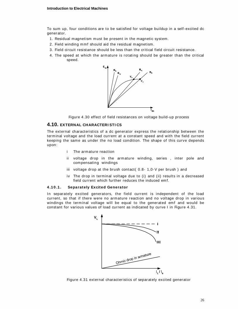
Figure 4.30 shows the voltage buildup in the self-excited dc generator for various field circuit resistances. At some resistance value Rf3, the resistance line is almost coincident with the linear portion of the magnetization curve. This coincidence condition results in an unstable voltage situation. This resistance is known as the critical field circuit resistance. If the resistance is greater than this value, such as Rf4, buildup (Vt4) will be insignificant on the other hand, if the resistance is smaller than this value, such as Rf1 or Rf2, the generator will build up higher voltages (Vt1, Vt2).
Introduction to Electrical Machines
26
To sum up, four conditions are to be satisfied for voltage buildup in a self-excited dc generator.
1. Residual magnetism must be present in the magnetic system. 2. Field winding mmf should aid the residual magnetism. 3. Field circuit resistance should be less than the critical field circuit resistance. 4. The speed at which the armature is rotating should be greater than the critical
speed.
Figure 4.30 effect of field resistances on voltage build-up process
4.10. EXTERNAL CHARACTERISTICS
The external characteristics of a dc generator express the relationship between the terminal voltage and the load current at a constant speed and with the field current keeping the same as under the no load condition. The shape of this curve depends upon:
i The armature reaction
ii voltage drop in the armature winding, series , inter pole and compensating windings
iii voltage drop at the brush contact( 0.8- 1,0-V per brush ) and
iv The drop in terminal voltage due to (i) and (ii) results in a decreased field current which further reduces the induced emf.
4.10.1. Separately Excited Generator
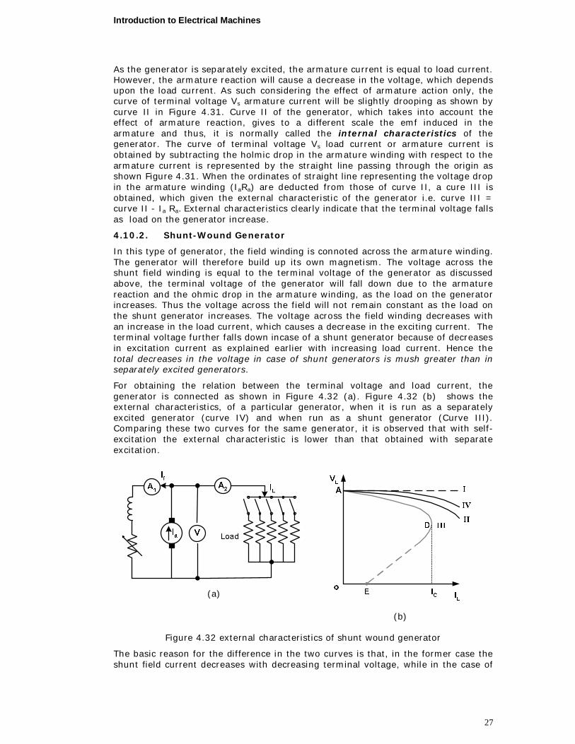
In separately excited generators, the field current is independent of the load current, so that if there were no armature reaction and no voltage drop in various windings the terminal voltage will be equal to the generated emf and would be constant for various values of load current as indicated by curve I in Figure 4.31.
Figure 4.31 external characteristics of separately excited generator
Introduction to Electrical Machines
27
As the generator is separately excited, the armature current is equal to load current. However, the armature reaction will cause a decrease in the voltage, which depends upon the load current. As such considering the effect of armature action only, the curve of terminal voltage Vs armature current will be slightly drooping as shown by curve II in Figure 4.31. Curve II of the generator, which takes into account the effect of armature reaction, gives to a different scale the emf induced in the armature and thus, it is normally called the internal characteristics of the generator. The curve of terminal voltage Vs load current or armature current is obtained by subtracting the holmic drop in the armature winding with respect to the armature current is represented by the straight line passing through the origin as shown Figure 4.31. When the ordinates of straight line representing the voltage drop in the armature winding (IaRa) are deducted from those of curve II, a cure III is obtained, which given the external characteristic of the generator i.e. curve III = curve II - Ia Ra. External characteristics clearly indicate that the terminal voltage falls as load on the generator increase.
4.10.2. Shunt-Wound Generator
In this type of generator, the field winding is connoted across the armature winding. The generator will therefore build up its own magnetism. The voltage across the shunt field winding is equal to the terminal voltage of the generator as discussed above, the terminal voltage of the generator will fall down due to the armature reaction and the ohmic drop in the armature winding, as the load on the generator increases. Thus the voltage across the field will not remain constant as the load on the shunt generator increases. The voltage across the field winding decreases with an increase in the load current, which causes a decrease in the exciting current. The terminal voltage further falls down incase of a shunt generator because of decreases in excitation current as explained earlier with increasing load current. Hence the total decreases in the voltage in case of shunt generators is mush greater than in separately excited generators.
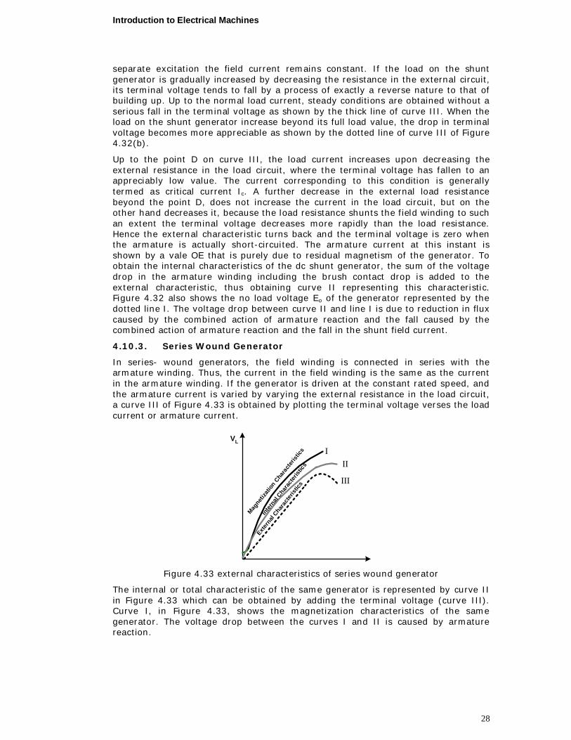
For obtaining the relation between the terminal voltage and load current, the generator is connected as shown in Figure 4.32 (a). Figure 4.32 (b) shows the external characteristics, of a particular generator, when it is run as a separately excited generator (curve IV) and when run as a shunt generator (Curve III). Comparing these two curves for the same generator, it is observed that with self-excitation the external characteristic is lower than that obtained with separate excitation.
(a)
(b)
Figure 4.32 external characteristics of shunt wound generator
The basic reason for the difference in the two curves is that, in the former case the shunt field current decreases with decreasing terminal voltage, while in the case of
Introduction to Electrical Machines
28
separate excitation the field current remains constant. If the load on the shunt generator is gradually increased by decreasing the resistance in the external circuit, its terminal voltage tends to fall by a process of exactly a reverse nature to that of building up. Up to the normal load current, steady conditions are obtained without a serious fall in the terminal voltage as shown by the thick line of curve III. When the load on the shunt generator increase beyond its full load value, the drop in terminal voltage becomes more appreciable as shown by the dotted line of curve III of Figure 4.32(b).
Up to the point D on curve III, the load current increases upon decreasing the external resistance in the load circuit, where the terminal voltage has fallen to an appreciably low value. The current corresponding to this condition is generally termed as critical current Ic. A further decrease in the external load resistance beyond the point D, does not increase the current in the load circuit, but on the other hand decreases it, because the load resistance shunts the field winding to such an extent the terminal voltage decreases more rapidly than the load resistance. Hence the external characteristic turns back and the terminal voltage is zero when the armature is actually short-circuited. The armature current at this instant is shown by a vale OE that is purely due to residual magnetism of the generator. To obtain the internal characteristics of the dc shunt generator, the sum of the voltage drop in the armature winding including the brush contact drop is added to the external characteristic, thus obtaining curve II representing this characteristic. Figure 4.32 also shows the no load voltage Eo of the generator represented by the dotted line I. The voltage drop between curve II and line I is due to reduction in flux caused by the combined action of armature reaction and the fall caused by the combined action of armature reaction and the fall in the shunt field current.
4.10.3. Series Wound Generator
In series- wound generators, the field winding is connected in series with the armature winding. Thus, the current in the field winding is the same as the current in the armature winding. If the generator is driven at the constant rated speed, and the armature current is varied by varying the external resistance in the load circuit, a curve III of Figure 4.33 is obtained by plotting the terminal voltage verses the load current or armature current.
III
III
Magneti
zatio
n Cha
racte
ristic
s
Inter
nal C
harac
terist
ics
Extern
al Char
acter
istics
VL
Figure 4.33 external characteristics of series wound generator
The internal or total characteristic of the same generator is represented by curve II in Figure 4.33 which can be obtained by adding the terminal voltage (curve III). Curve I, in Figure 4.33, shows the magnetization characteristics of the same generator. The voltage drop between the curves I and II is caused by armature reaction.
Introduction to Electrical Machines
29
4.10.4. Compound Generator
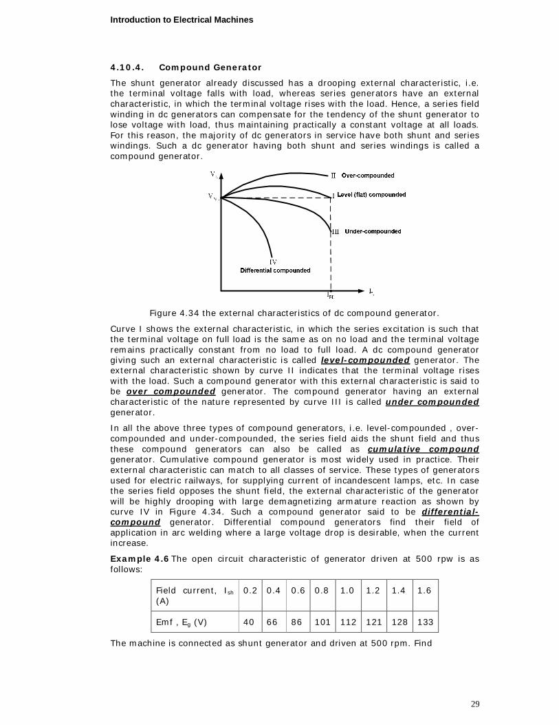
The shunt generator already discussed has a drooping external characteristic, i.e. the terminal voltage falls with load, whereas series generators have an external characteristic, in which the terminal voltage rises with the load. Hence, a series field winding in dc generators can compensate for the tendency of the shunt generator to lose voltage with load, thus maintaining practically a constant voltage at all loads. For this reason, the majority of dc generators in service have both shunt and series windings. Such a dc generator having both shunt and series windings is called a compound generator.
Figure 4.34 the external characteristics of dc compound generator.
Curve I shows the external characteristic, in which the series excitation is such that the terminal voltage on full load is the same as on no load and the terminal voltage remains practically constant from no load to full load. A dc compound generator giving such an external characteristic is called level-compounded generator. The external characteristic shown by curve II indicates that the terminal voltage rises with the load. Such a compound generator with this external characteristic is said to be over compounded generator. The compound generator having an external characteristic of the nature represented by curve III is called under compounded generator.
In all the above three types of compound generators, i.e. level-compounded , over-compounded and under-compounded, the series field aids the shunt field and thus these compound generators can also be called as cumulative compound generator. Cumulative compound generator is most widely used in practice. Their external characteristic can match to all classes of service. These types of generators used for electric railways, for supplying current of incandescent lamps, etc. In case the series field opposes the shunt field, the external characteristic of the generator will be highly drooping with large demagnetizing armature reaction as shown by curve IV in Figure 4.34. Such a compound generator said to be differential-compound generator. Differential compound generators find their field of application in arc welding where a large voltage drop is desirable, when the current increase.
Example 4.6 The open circuit characteristic of generator driven at 500 rpw is as follows:
Field current, Ish (A)
0.2 0.4 0.6 0.8 1.0 1.2 1.4 1.6
Emf , Eg (V) 40 66 86 101 112 121 128 133
The machine is connected as shunt generator and driven at 500 rpm. Find
Introduction to Electrical Machines
30
i) open circuit voltage, when the field circuit resistance is 94 ,
ii) the additional resistance required in the field circuit to reduce the emf to 110 V and
iii) critical value of shunt field resistance.
Introduction to Electrical Machines
31
Solution
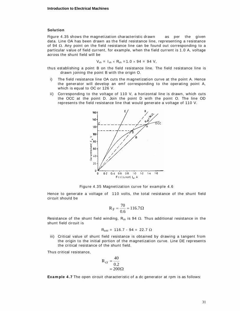
Figure 4.35 shows the magnetization characteristic drawn as per the given data. Line OA has been drawn as the field resistance line, representing a resistance of 94 . Any point on the field resistance line can be found out corresponding to a particular value of field current, for example, when the field current is 1.0 A, voltage across the shunt field will be
Vsh = Ish Rsh =1.0 94 = 94 V,
thus establishing a point B on the field resistance line. The field resistance line is drawn joining the point B with the origin O.
i) The field resistance line OA cuts the magnetization curve at the point A. Hence the generator will develop an emf corresponding to the operating point A, which is equal to OC or 126 V.
ii) Corresponding to the voltage of 110 V, a horizontal line is drawn, which cuts the OCC at the point D. Join the point D with the point O. The line OD represents the field resistance line that would generate a voltage of 110 V.
Figure 4.35 Magnetization curve for example 4.6
Hence to generate a voltage of 110 volts, the total resistance of the shunt field circuit should be
7.1166.0
70R F
Resistance of the shunt field winding, Rsh is 94 . Thus additional resistance in the shunt field circuit is
Radd = 116.7 - 94 = 22.7
iii) Critical value of shunt field resistance is obtained by drawing a tangent from the origin to the initial portion of the magnetization curve. Line DE represents the critical resistance of the shunt field.
Thus critical resistance,
2002.0
40R cr
Example 4.7 The open circuit characteristic of a dc generator at rpm is as follows:
Introduction to Electrical Machines
32
Field current, Ish (A) 0.5 1.0 1.5 2.0 2.5 3:0 3.5
open circuit voltage, VOCC(V) 60 120 138 145 149 151 152
The machine is connected as shunt generator and driven at 1000 rpm. The resistance of shunt field circuit being 60 . Calculate,
i) the open circuit voltage, ii) the critical value of the field resistance, iii) the terminal voltage when the load has resistance of 4.0 , and
iv) the load current when the terminal voltage is 100 V. Neglect armature reaction. The armature resistance is 0.1.
Solution
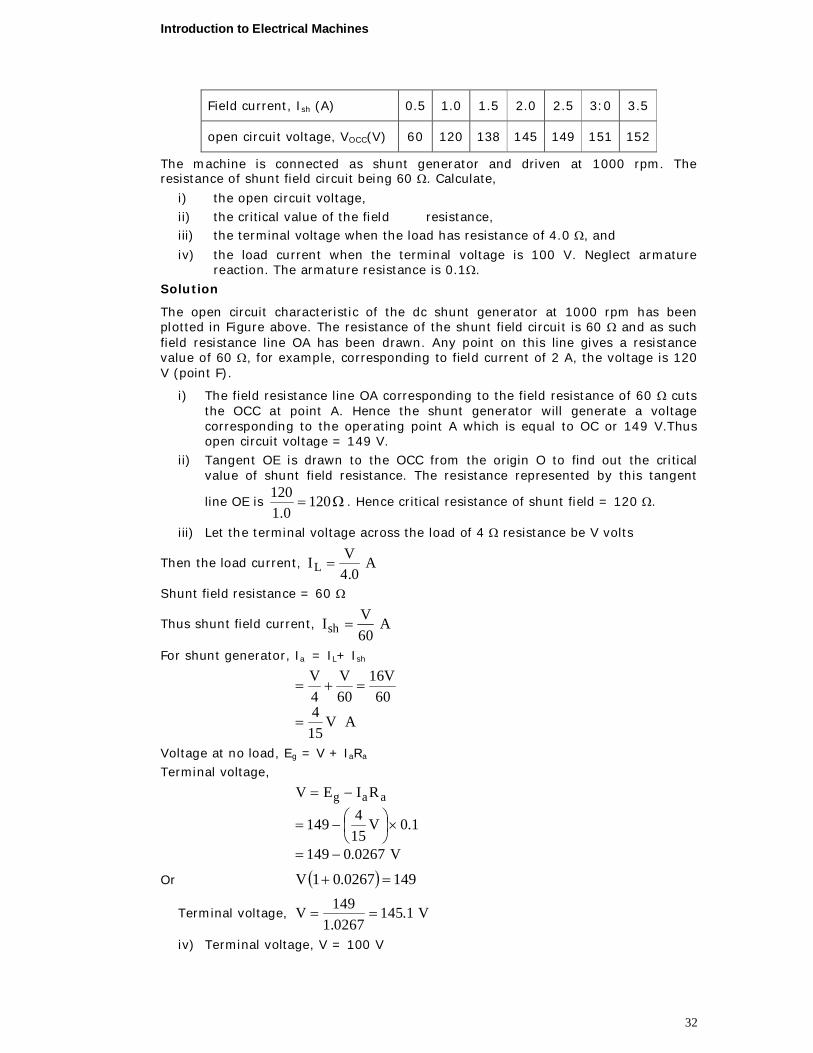
The open circuit characteristic of the dc shunt generator at 1000 rpm has been plotted in Figure above. The resistance of the shunt field circuit is 60 and as such field resistance line OA has been drawn. Any point on this line gives a resistance value of 60 , for example, corresponding to field current of 2 A, the voltage is 120 V (point F).
i) The field resistance line OA corresponding to the field resistance of 60 cuts the OCC at point A. Hence the shunt generator will generate a voltage corresponding to the operating point A which is equal to OC or 149 V.Thus open circuit voltage = 149 V.
ii) Tangent OE is drawn to the OCC from the origin O to find out the critical value of shunt field resistance. The resistance represented by this tangent
line OE is 1200.1
120. Hence critical resistance of shunt field = 120 .
iii) Let the terminal voltage across the load of 4 resistance be V volts
Then the load current, A0.4
VIL
Shunt field resistance = 60
Thus shunt field current, A60VIsh
For shunt generator, Ia = IL+ Ish
AV154
60V16
60V
4V
Voltage at no load, Eg = V + IaRa Terminal voltage,
V0267.0149
1.0V154149
RIEV aag
Or 1490267.01V
Terminal voltage, V1.1450267.1149V
iv) Terminal voltage, V = 100 V
Introduction to Electrical Machines
33
Voltage at no load, Eg = V + IaRa or IaRa = Eg V = 149 100 = 49 V
Armature current, A4901.0
49Ia
Shunt field current, A67.160
10060VIsh
Hence load current, IL = 490 1.67 = 488.33 A
60Ω
R sh
Figure 4.36 Open circuit characteristic for example 4.7
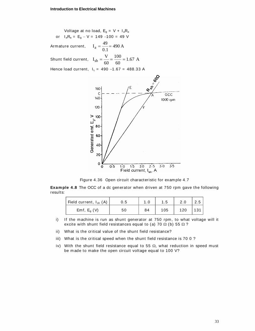
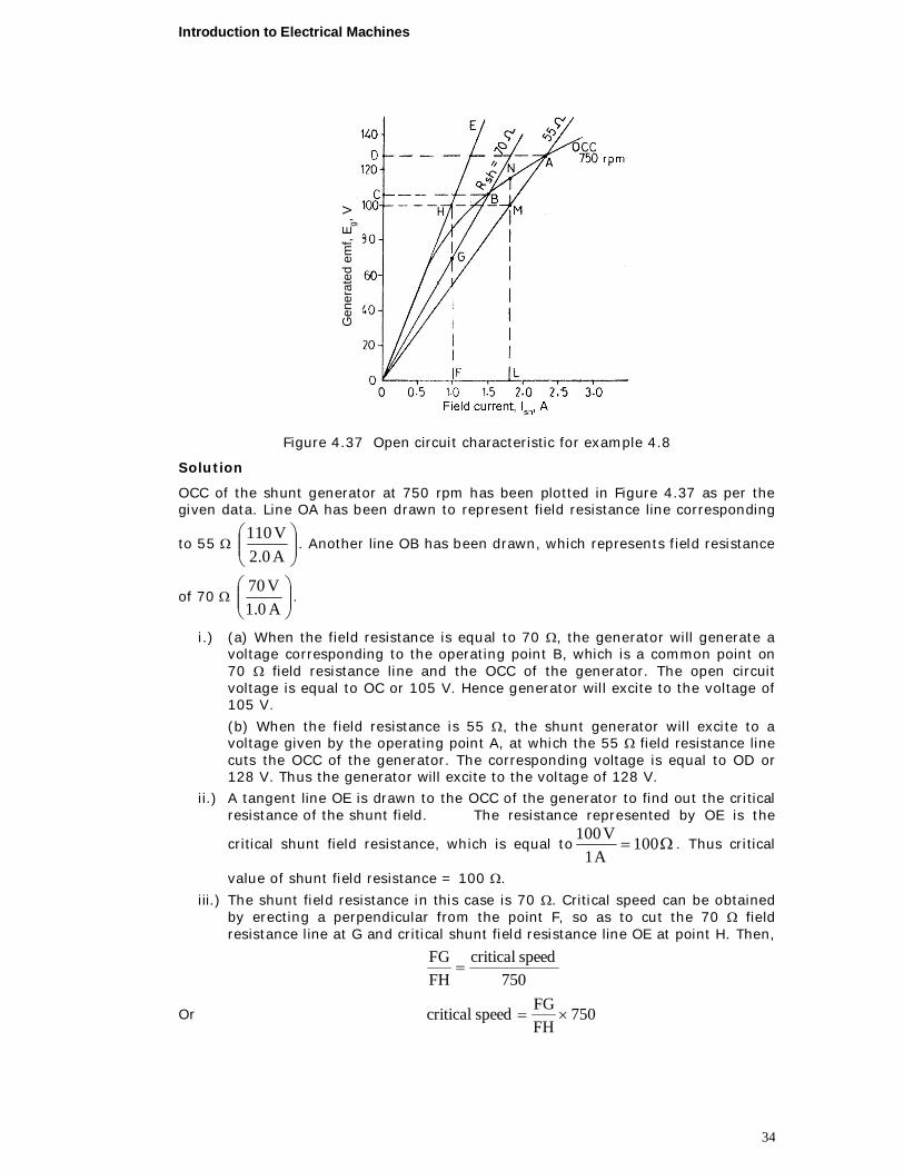
Example 4.8 The OCC of a dc generator when driven at 750 rpm gave the following results:
Field current, Ish (A) 0.5 1.0 1.5 2.0 2.5
Emf, Eg (V) 50 84 105 120 131
i) If the machine is run as shunt generator at 750 rpm, to what voltage will it excite with shunt field resistances equal to (a) 70 (b) 55 ?
ii) What is the critical value of the shunt field resistance?
iii) What is the critical speed when the shunt field resistance is 70 0 ?
iv) With the shunt field resistance equal to 55 , what reduction in speed must be made to make the open circuit voltage equal to 100 V?
Introduction to Electrical Machines
34
Gen
erat
ed e
mf,
E g, V
Figure 4.37 Open circuit characteristic for example 4.8
Solution
OCC of the shunt generator at 750 rpm has been plotted in Figure 4.37 as per the given data. Line OA has been drawn to represent field resistance line corresponding
to 55
A0.2V110
. Another line OB has been drawn, which represents field resistance
of 70
A0.1V70
.
i.) (a) When the field resistance is equal to 70 , the generator will generate a voltage corresponding to the operating point B, which is a common point on 70 field resistance line and the OCC of the generator. The open circuit voltage is equal to OC or 105 V. Hence generator will excite to the voltage of 105 V.
(b) When the field resistance is 55 , the shunt generator will excite to a voltage given by the operating point A, at which the 55 field resistance line cuts the OCC of the generator. The corresponding voltage is equal to OD or 128 V. Thus the generator will excite to the voltage of 128 V.
ii.) A tangent line OE is drawn to the OCC of the generator to find out the critical resistance of the shunt field. The resistance represented by OE is the
critical shunt field resistance, which is equal to 100A1
V100. Thus critical
value of shunt field resistance = 100 .
iii.) The shunt field resistance in this case is 70 . Critical speed can be obtained by erecting a perpendicular from the point F, so as to cut the 70 field resistance line at G and critical shunt field resistance line OE at point H. Then,
750
speedcriticalFHFG
Or 750FHFGspeedcritical
Introduction to Electrical Machines
35
But 10070
FHFG
Thus rpm525
75010070speedcritical
iv.) Open circuit voltage Eg = 100 V Shunt field resistance = 55
With shunt field resistance equal to 57 , the generator generates a voltage of 128 V at 750 rpm. To generate 100 V with the same field resistance, the operating point has to be M instead of A, for which the speed of the generator has to be reduced. The speed in such a case can be found out by drawing a perpendicular from the point M, so as to meet the OCC at point N. Then,
750
speeddesiredLNLM
Hence,
rpm652
115100750
LNLM750speeddesiredl
Reduction in speed = 750 652 = 98 rpm
Example 4.9 A dc generator has the following open circuit characteristics at 800 rpm:
Field current , Ish (A) 0 1 2 3 4 5
Generated emf, Eg (V) 10 112 198 232 252 266
Find the no load terminal voltage when the machine runs as a shunt generator at 1000 rpm. The resistance of the field circuit is 70. What additional field regulator resistance will be required to reduce the voltage to 270 V?
Solution
The open circuit characteristic of the dc generator has been given at 800 rpm. However, this generator runs as a shunt type at 1000 rpm. As the speed of the generator has increased, the emf generated corresponding to the same field current will increase and is given by
KNa60
NZPEg
for the same field current
Hence, 1
2
1g
2gNN
EE
Or 800
1000ENNEE 1g
1
21g2g
Based on this, the readings for the OCC at 1000 rpm will be:
Open Circuit Characteristics at 1000 rpm
If (A) 0 1 2 3 4 5
Eg (V) 12.5 140 247.5 290 315 332.5
Introduction to Electrical Machines
36
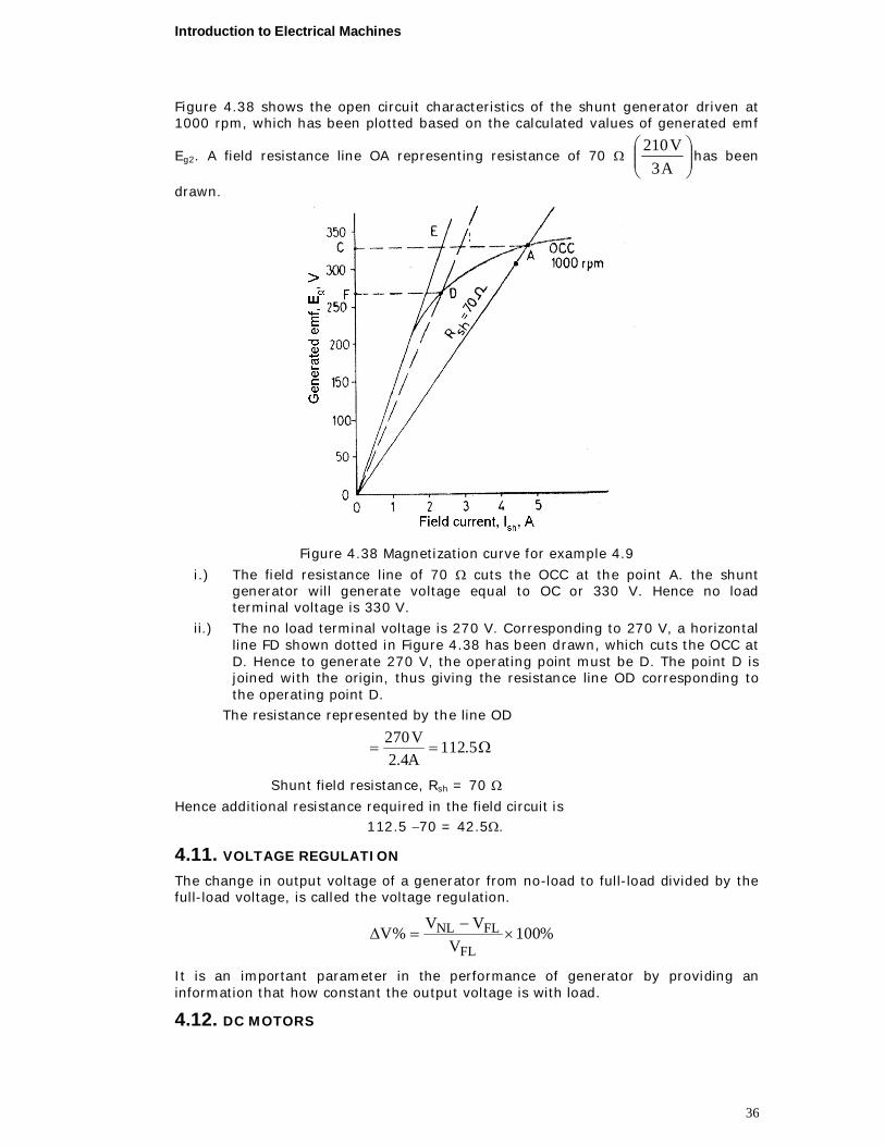
Figure 4.38 shows the open circuit characteristics of the shunt generator driven at 1000 rpm, which has been plotted based on the calculated values of generated emf
Eg2. A field resistance line OA representing resistance of 70
A3
V210has been
drawn.
Figure 4.38 Magnetization curve for example 4.9
i.) The field resistance line of 70 cuts the OCC at the point A. the shunt generator will generate voltage equal to OC or 330 V. Hence no load terminal voltage is 330 V.
ii.) The no load terminal voltage is 270 V. Corresponding to 270 V, a horizontal line FD shown dotted in Figure 4.38 has been drawn, which cuts the OCC at D. Hence to generate 270 V, the operating point must be D. The point D is joined with the origin, thus giving the resistance line OD corresponding to the operating point D.
The resistance represented by the line OD
5.112A4.2V270
Shunt field resistance, Rsh = 70
Hence additional resistance required in the field circuit is 112.5 70 = 42.5.
4.11. VOLTAGE REGULATION
The change in output voltage of a generator from no-load to full-load divided by the full-load voltage, is called the voltage regulation.
%100V
VV%VFL
FLNL
It is an important parameter in the performance of generator by providing an information that how constant the output voltage is with load.
4.12. DC MOTORS
Introduction to Electrical Machines
37
Working principle
The principle upon which a dc motor works is very simple. If a current carrying conductor is placed in a magnetic field, mechanical force is experienced on the conductor, the direction of which is given by Fleming's left hand rule (also called motor rule) and hence the conductor moves in the direction of force. The magnitude of the mechanical force experienced n the conductor is given by
F = B Ic lc, [Newtons]
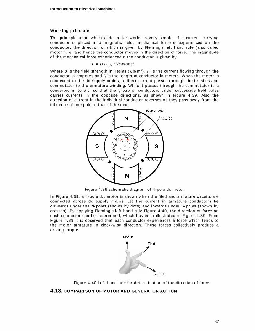
Where B is the field strength in Teslas (wb/m2), Ic is the current flowing through the conductor in amperes and lc is the length of conductor in meters. When the motor is connected to the dc Supply mains, a direct current passes through the brushes and commutator to the armature winding. While it passes through the commutator it is converted in to a.c. so that the group of conductors under successive field poles carries currents in the opposite directions, as shown in Figure 4.39. Also the direction of current in the individual conductor reverses as they pass away from the influence of one pole to that of the next.
Figure 4.39 schematic diagram of 4-pole dc motor
In Figure 4.39, a 4-pole d.c motor is shown when the filed and armature circuits are connected across dc supply mains. Let the current in armature conductors be outwards under the N-poles (shown by dots) and inwards under S-poles (shown by crosses). By applying Fleming’s left hand rule Figure 4.40, the direction of force on each conductor can be determined, which has been illustrated in Figure 4.39. From Figure 4.39 it is observed that each conductor experiences a force which tends to the motor armature in clock-wise direction. These forces collectively produce a driving torque.
Figure 4.40 Left-hand rule for determination of the direction of force
4.13. COMPARISON OF MOTOR AND GENERATOR ACTION
Introduction to Electrical Machines
38
As mentioned above, dc motor and the dc generator are the same devices, at least theoretically. The machine operating as a generator is driven by some external driving force and dc out put is obtained from it where as the machine operating as a motor is supplied by electric current and mechanical rotation is produced.
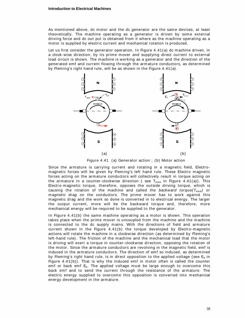
Let us first consider the generator operation. In Figure 4.41(a) dc machine driven, in a clock-wise direction, by its prime mover and supplying direct current to external load circuit is shown. The machine is working as a generator and the direction of the generated emf and current flowing through the armature conductors, as determined by Fleming's right hand rule, will be as shown in the Figure 4.41(a).
(a) (b)
Figure 4.41 (a) Generator action ; (b) Motor action
Since the armature is carrying current and rotating in a magnetic field, Electro-magnetic forces will be given by Fleming's left hand rule. These Electro magnetic forces acting on the armature conductors will collectively result in torque acting on the armature in a counter-clockwise direction ( see Tback in Figure 4.41(a)). This Electro-magnetic torque, therefore, opposes the outside driving torque, which is causing the rotation of the machine and called the backward torque(Tback) or magnetic drag on the conductors. The prime mover has to work against this magnetic drag and the work so done is converted in to electrical energy. The larger the output current, more will be the backward torque and, therefore, more mechanical energy will be required to be supplied to the generator.
In Figure 4.41(b) the same machine operating as a motor is shown. This operation takes place when the prime mover is uncoupled from the machine and the machine is connected to the dc supply mains. With the directions of field and armature current shown in the Figure 4.41(b) the torque developed by Electro-magnetic actions will rotate the machine in a clockwise direction (as determined by Fleming's left-hand rule). The friction of the machine and the mechanical load that the motor is driving will exert a torque in counter-clockwise direction, opposing the rotation of the motor. Since the armature conductors are revolving in the magnetic field, emf is induced in the armature conductors. The direction of emf so induced, as determined by Fleming's right hand rule, is in direct opposition to the applied voltage (see Eb in Figure 4.41(b)). That is why the induced emf in motor often is called the counter emf or back emf Eb. The applied voltage must be large enough to overcome this back emf and to send the current through the resistance of the armature. The electric energy supplied to overcome this opposition is converted into mechanical energy development in the armature.
Introduction to Electrical Machines
39
Thus we see that an emf is generated in both generator and motor, therefore, there is a generator action in both motor and generator operation. However, in generator operation the generated emf produces the armature current, where as, in motor operation the generated emf opposes the current direction. We also observe that Electro-magnetic torque is developed in generator as well as motor i.e. there is a motor action in both generator and motor, operation. However, in motor operation the Electro-magnetic torque developed causes the armature rotation, where as in a generator operation the Electro-magnetic torque produced opposes the rotation.
4.14. TYPES OF DC MOTORS
All dc motors must receive their excitation from an external source; therefore, they are separately excited. Their field and the armature windings are connected, however, in one of the three different ways employed for self-excited dc generators, and so according the field arrangement there are three types of dc motors namely;
i) Series wound ii) shunt wound and iii) compound wound.
4.13.1. Series wound motor
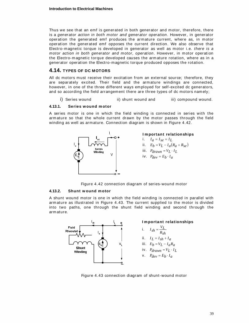
A series motor is one in which the field winding is connected in series with the armature so that the whole current drawn by the motor passes through the field winding as well as armature. Connection diagram is shown in Figure 4.42.
Important relationships i. LIseIaI ii. seRaRaILVbE iii. LILVdrawnP iv. aIbEdevP
Figure 4.42 connection diagram of series-wound motor
4.13.2. Shunt wound motor
A shunt wound motor is one in which the field winding is connected in parallel with armature as illustrated in Figure 4.43. The current supplied to the motor is divided into two paths, one through the shunt field winding and second through the armature.
Important relationships
i. shRLV
shI
ii. aIshILI iii. aRaILVbE iv. LILVdrawnP v. aIbEdevP
Figure 4.43 connection diagram of shunt-wound motor
Introduction to Electrical Machines
40
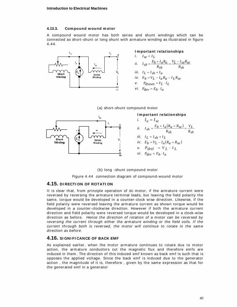
4.13.3. Compound wound motor
A compound wound motor has both series and shunt windings which can be connected as short-shunt or long shunt with armature winding as illustrated in figure 4.44.
Important relationships i. LIseI
ii. shR
seRseILV
shRaRaIbE
shI
iii. aIshILI iv. seRLIaRaILVbE v. LILVdrawnP vi. aIbEdevP
(a) short-shunt compound motor
Important relationships i. sea II
ii. shRLV
shRseRaRaIbE
shI
iii. LIshILI iv. seRaRaILVbE
v. LILVdrelP vi. aIbEdevP
(b) long -shunt compound motor
Figure 4.44 connection diagram of compound-wound motor
4.15. DIRECTION OF ROTATION
It is clear that, from principle operation of dc motor, if the armature current were reversed by reversing the armature terminal leads, but leaving the field polarity the same, torque would be developed in a counter-clock wise direction. Likewise, if the field polarity were reversed leaving the armature current as shown torque would be developed in a counter-clockwise direction. However if both the armature current direction and field polarity were reversed torque would be developed in a clock-wise direction as before. Hence the direction of rotation of a motor can be reversed by reversing the current through either the armature winding or the field coils. If the current through both is reversed, the motor will continue to rotate in the same direction as before.
4.16. SIGNIFICANCE OF BACK EMF
As explained earlier, when the motor armature continues to rotate due to motor action, the armature conductors cut the magnetic flux and therefore emfs are induced in them. The direction of this induced emf known as back emf is such that is opposes the applied voltage. Since the back emf is induced due to the generator action , the magnitude of it is, therefore , given by the same expression as that for the generated emf in a generator
Introduction to Electrical Machines
41
,voltsaP
60ZNEb
4.1
The symbols having their usual significance
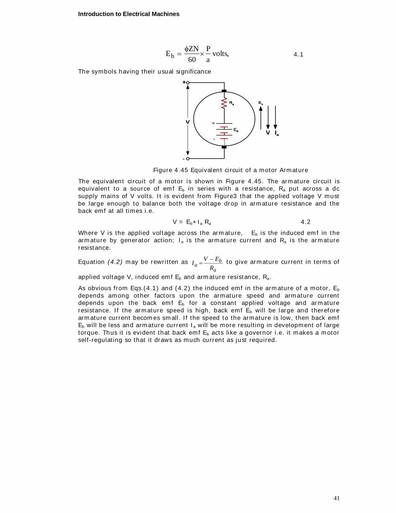
Figure 4.45 Equivalent circuit of a motor Armature
The equivalent circuit of a motor is shown in Figure 4.45. The armature circuit is equivalent to a source of emf Eb in series with a resistance, Ra put across a dc supply mains of V volts. It is evident from Figure3 that the applied voltage V must be large enough to balance both the voltage drop in armature resistance and the back emf at all times i.e.
V = Eb+Ia Ra 4.2
Where V is the applied voltage across the armature, Eb is the induced emf in the armature by generator action; Ia is the armature current and Ra is the armature resistance.
Equation (4.2) may be rewritten as a
ba R
EVI to give armature current in terms of
applied voltage V, induced emf Eb and armature resistance, Ra.
As obvious from Eqs.(4.1) and (4.2) the induced emf in the armature of a motor, Eb
depends among other factors upon the armature speed and armature current depends upon the back emf Eb for a constant applied voltage and armature resistance. If the armature speed is high, back emf Eb will be large and therefore armature current becomes small. If the speed to the armature is low, then back emf Eb will be less and armature current Ia will be more resulting in development of large torque. Thus it is evident that back emf Eb acts like a governor i.e. it makes a motor self-regulating so that it draws as much current as just required.
Introduction to Electrical Machines
42
4.17. TORQUE EQUATION
The back emf of dc motor is given by
aab RIVE 4.3
Multiplying both sides of Eq. (4.3) by Ia,
a2aaab RIVIIE 4.4
In Eq. (4.4) VIa = Total electrical power supplied to the Armature of the dc motor (armature input) and Ia
2Ra = power wasted in the armature (armature copper loss). The difference between the armature input and the armature copper loss is equal to the mechanical power developed by the armature of the motor.
Hence, mechanical power developed = EbIa, watts 4.5
If Ta is the torque in Newton meter developed by the armature of the motor, running at N revolutions per minute, then
Mechanical power developed, watts60
T.N2P amech
4.6
Equating Eqs. (4.5) and (4.6)
NIE.
2)60(Ta,Torque
60TN2
IaE
ab
ab
4.7
However back emf,
a.60
NZpEb
4.8
Substituting Equation (4.8) into equation (4.7)
].[.159.060
.260, mN
aZIP
NaNZIP
TTorque aaa
For a particular dc motor; P, Z & a are fixed. Hence,
aa IT
Therefore, the torque developed by the armature of dc motor is proportional to the product of armature current and the flux per pole. For dc shunt motor, the flux per pole is practically constant, hence the torque developed is directly proportion to the armature current, i.e.
aa IT (for dc shunt motor)
For dc series motor, the flux per pole is directly proportional to Ia hence the torque developed is directly proportion to the square of the armature current, i.e.
2aa IT (for a dc series motor)
4.18. SPEED EQUATION
The back emf for dc motor is given by
voltsa60
Z.NPEb
Introduction to Electrical Machines
43
Also, aab RIVE
Combing the above two equations,
aa RIVa60
Z.NP
Or
I.
PZa.60).RIV(N aa
For a given particular motor, P, Z and a are fixed. Hence
baa EKRIVKN
Thus the speed of dc motor is directly proportional to the voltage applied to the armature or the back emf & inversely proportional to the flux per pole. For dc shunt motor, the flux per pole is approximately constant and hence the speed of dc shunt motor is directly proportional to the back emf i.e. bEN . For dc series motor, the
flux per pole is directly proportional to the armature current and hence the load on the motor. Thus the speed of dc series motor is inversely proportional to the flux per
pole or the armature current i.e.
1N . The speed of the motor increases with the
fall in flux.
Example 4.10 The armature of a 6 pole, 6 circuit dc shunt motor takes 300 A at the speed of 400 revolutions per minute. The flux per pole is 75 10-3 Wb. The number of armature turns is 500. The torque lost in windage, friction and iron losses can be assumed as 2.5 per cent. Calculate (i) the torque developed by the armature, (ii) shaft torque and (iii) shaft power in kW.
Solution i) The torque developed by the armature of a dc motor is given by
m.NA
ZIP159.0T aa
Number of poles of shunt motor, P = 6
Armature winding has 6 circuits, thus, A = 6
Armature current, Ia = 300 A Number of armature turns = 500 Thus total conductors on the armature, Z = 2 500 = 1000
Flux per pole, = 75 10-3 Wb
Substituting these values in the above equation
Armature torque, m.N5.35776
100030010756159.0T3
a
ii) Torque lost in windage, friction and iron losses = 2.5% of Ta = 0.0255 3577.5 = 89.44 N.m
Thus, shaft torque, Tsh = 3577.589.44 = 3488.06 N m
iii) Shaft power,
Introduction to Electrical Machines
44
kW22.146100060
06.34884002
kW100060
ZNT2T shsh
Example 4.11 A 440 V dc motor takes an armature current of 60 A when its speed is 750 rpm. If the armature resistance is, 0.25, calculate the torque produced.
Solution Back emf developed, Eb = V Ia Ra = 440600.25 = 425 V
Torque produced, m.N68.32460/7502
6042560/N2
IET aba
Example 4.12 A 10 hp 230V shunt motor takes an armature current of 6A from 230 V line at no load and runs at 1,200 rpm. The armature resistance is 0.25. Determine the speed and electro-magnetic torque when the armature takes 36 A with the same flux.
Solution No-load back emf, Ebo = V Iao Ra = 23060.25 = 228.5 V
No-load speed, N0 = 1200 rpm.
When armature takes 36 A
Back emf developed Eb1 = V Ia1 Ra = 230360.25 = 221
Since NEb
0
1
0
1
2
1
0b
1bNN
NN
EE
flux is same i.e. 1= 0
Or rpm116112005.228
221NEEN 0
0b
1b1
Electro-magnetic torque developed, m.N44.6560/11612
3622160/N2
IET1
aba
Example 4.13 The armature of a 4-pole dc shunt motor has a lap winding accommodated is 60 slots, each containing 20 conductors. If the useful flux per pole be 23 mWb, calculate the total torque developed in Newton meters when the armature current is 50 A.
Solution
Flux per pole, = 23 mWb = 0.023 Wb
Total number of armature conductors, Z = 60 20 =1200
Number of poles, P=4
Armature current, Ia = 50 A Since armature has lap winding, Number of parallel paths, A=P=4 Total torque developed,
m.N6.219501200023.0159.0
AIZP159.0T a
a
4.19. DC MOTOR CHARACTERISTICS
The 3 Important characteristic curves of dc motors are:
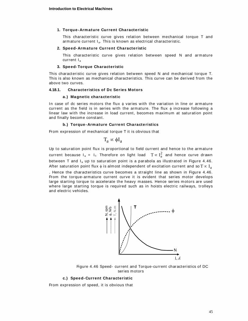
Introduction to Electrical Machines
45
1. Torque-Armature Current Characteristic
This characteristic curve gives relation between mechanical torque T and armature current Ia. This is known as electrical characteristic.
2. Speed-Armature Current Characteristic
This characteristic curve gives relation between speed N and armature current Ia
3. Speed-Torque Characteristic
This characteristic curve gives relation between speed N and mechanical torque T. This is also known as mechanical characteristics. This curve can be derived from the above two curves.
4.18.1. Characteristics of Dc Series Motors
a.) Magnetic characteristic
In case of dc series motors the flux varies with the variation in line or armature current as the field is in series with the armature. The flux increase following a linear law with the increase in load current, becomes maximum at saturation point and finally become constant.
b.) Torque-Armature Current Characteristics
From expression of mechanical torque T it is obvious that
aa IT
Up to saturation point flux is proportional to field current and hence to the armature
current because Ia = If. Therefore on light load 2aIT and hence curve drawn
between T and Ia up to saturation point is a parabola as illustrated in Figure 4.46. After saturation point flux is almost independent of excitation current and so aIT . Hence the characteristics curve becomes a straight line as shown in Figure 4.46. From the torque-armature current curve it is evident that series motor develops large starting torque to accelerate the heavy masses. Hence series motors are used where large starting torque is required such as in hoists electric railways, trolleys and electric vehicles.
N, r
pm
T, N
.m Wb
,
Figure 4.46 Speed- current and Torque-current characteristics of DC series motors
c.) Speed-Current Characteristic
From expression of speed, it is obvious that
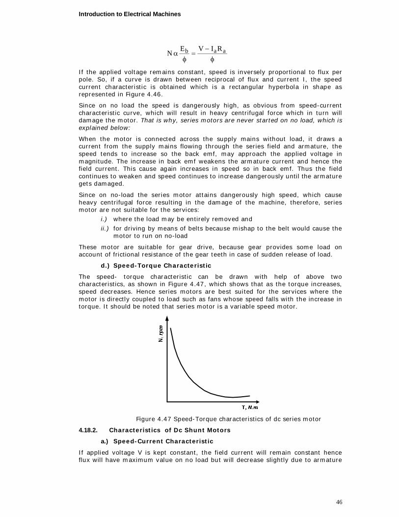
Introduction to Electrical Machines
46
aab RIVEN
If the applied voltage remains constant, speed is inversely proportional to flux per pole. So, if a curve is drawn between reciprocal of flux and current I, the speed current characteristic is obtained which is a rectangular hyperbola in shape as represented in Figure 4.46.
Since on no load the speed is dangerously high, as obvious from speed-current characteristic curve, which will result in heavy centrifugal force which in turn will damage the motor. That is why, series motors are never started on no load, which is explained below:
When the motor is connected across the supply mains without load, it draws a current from the supply mains flowing through the series field and armature, the speed tends to increase so the back emf, may approach the applied voltage in magnitude. The increase in back emf weakens the armature current and hence the field current. This cause again increases in speed so in back emf. Thus the field continues to weaken and speed continues to increase dangerously until the armature gets damaged.
Since on no-load the series motor attains dangerously high speed, which cause heavy centrifugal force resulting in the damage of the machine, therefore, series motor are not suitable for the services:
i.) where the load may be entirely removed and
ii.) for driving by means of belts because mishap to the belt would cause the motor to run on no-load
These motor are suitable for gear drive, because gear provides some load on account of frictional resistance of the gear teeth in case of sudden release of load.
d.) Speed-Torque Characteristic
The speed- torque characteristic can be drawn with help of above two characteristics, as shown in Figure 4.47, which shows that as the torque increases, speed decreases. Hence series motors are best suited for the services where the motor is directly coupled to load such as fans whose speed falls with the increase in torque. It should be noted that series motor is a variable speed motor.
Figure 4.47 Speed-Torque characteristics of dc series motor
4.18.2. Characteristics of Dc Shunt Motors
a.) Speed-Current Characteristic
If applied voltage V is kept constant, the field current will remain constant hence flux will have maximum value on no load but will decrease slightly due to armature
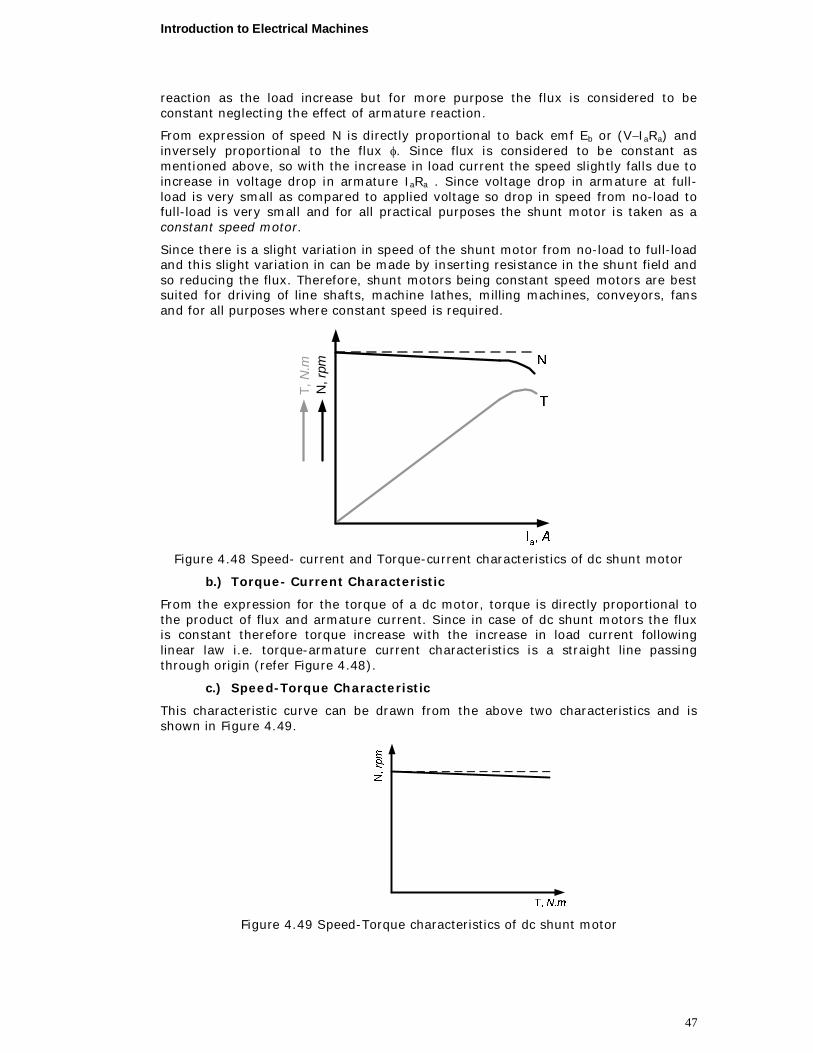
Introduction to Electrical Machines
47
reaction as the load increase but for more purpose the flux is considered to be constant neglecting the effect of armature reaction.
From expression of speed N is directly proportional to back emf Eb or (VIaRa) and inversely proportional to the flux . Since flux is considered to be constant as mentioned above, so with the increase in load current the speed slightly falls due to increase in voltage drop in armature IaRa . Since voltage drop in armature at full-load is very small as compared to applied voltage so drop in speed from no-load to full-load is very small and for all practical purposes the shunt motor is taken as a constant speed motor.
Since there is a slight variation in speed of the shunt motor from no-load to full-load and this slight variation in can be made by inserting resistance in the shunt field and so reducing the flux. Therefore, shunt motors being constant speed motors are best suited for driving of line shafts, machine lathes, milling machines, conveyors, fans and for all purposes where constant speed is required.
N, r
pmT,
N.m
Figure 4.48 Speed- current and Torque-current characteristics of dc shunt motor
b.) Torque- Current Characteristic
From the expression for the torque of a dc motor, torque is directly proportional to the product of flux and armature current. Since in case of dc shunt motors the flux is constant therefore torque increase with the increase in load current following linear law i.e. torque-armature current characteristics is a straight line passing through origin (refer Figure 4.48).
c.) Speed-Torque Characteristic
This characteristic curve can be drawn from the above two characteristics and is shown in Figure 4.49.
Figure 4.49 Speed-Torque characteristics of dc shunt motor
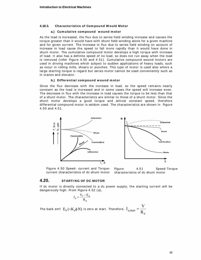
Introduction to Electrical Machines
48
4.18.3. Characteristics of Compound Would Motor
a.) Cumulative compound wound motor
As the load is increased, the flux due to series field winding increase and causes the torque greater than it would have with shunt field winding alone for a given machine and for given current. The increase in flux due to series field winding on account of increase in load cause the speed to fall more rapidly than it would have done in shunt motor. The cumulative compound motor develops a high torque with increase of load. It also has a definite speed of no load, so does not run away when the load is removed (refer Figure 4.50 and 4.51). Cumulative compound wound motors are used in driving machines which subject to sudden applications of heavy loads, such as occur in rolling mills, shears or punches. This type of motor is used also where a large starting torque is regard but series motor cannot be used conveniently such as in cranes and elevator.
b.) Differential compound wound motor
Since the flux decrease with the increase in load, so the speed remains nearly constant as the load is increased and in some cases the speed will increase even. The decrease in flux with the increase in load causes the torque to be less than that of a shunt motor. The characteristics are similar to those of a shunt motor. Since the shunt motor develops a good torque and almost constant speed, therefore differential compound motor is seldom used. The characteristics are shown in Figure 4.50 and 4.51.
Figure 4.50 Speed- current and Torque-current characteristics of dc shunt motor
Figure 4.51 Speed-Torque characteristics of dc shunt motor
4.20. STARTING OF DC MOTOR
If dc motor is directly connected to a dc power supply, the starting current will be dangerously high. From Figure 4.52 (a),
a
aia R
EVI
The back emf )NK(E ab is zero at start. Therefore, a
starta RVI
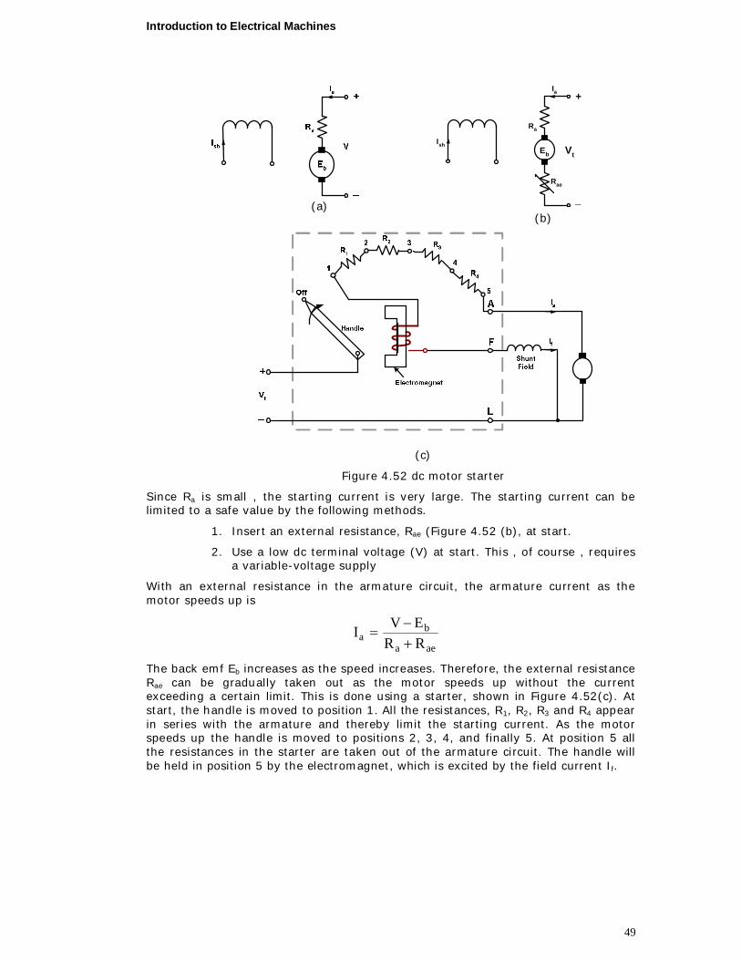
Introduction to Electrical Machines
49
(a)
+
_
Eb
Ra
Ia
Ish
Rae
Vt
(b)
(c)
Figure 4.52 dc motor starter
Since Ra is small , the starting current is very large. The starting current can be limited to a safe value by the following methods.
1. Insert an external resistance, Rae (Figure 4.52 (b), at start.
2. Use a low dc terminal voltage (V) at start. This , of course , requires a variable-voltage supply
With an external resistance in the armature circuit, the armature current as the motor speeds up is
aea
ba RR
EVI
The back emf Eb increases as the speed increases. Therefore, the external resistance Rae can be gradually taken out as the motor speeds up without the current exceeding a certain limit. This is done using a starter, shown in Figure 4.52(c). At start, the handle is moved to position 1. All the resistances, R1, R2, R3 and R4 appear in series with the armature and thereby limit the starting current. As the motor speeds up the handle is moved to positions 2, 3, 4, and finally 5. At position 5 all the resistances in the starter are taken out of the armature circuit. The handle will be held in position 5 by the electromagnet, which is excited by the field current If.
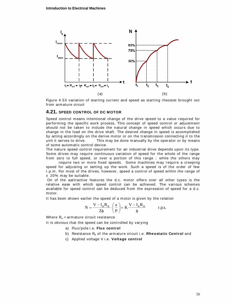
Introduction to Electrical Machines
50
(a) (b)
Figure 4.53 variation of starting current and speed as starting rheostat brought out from armature circuit
4.21. SPEED CONTROL OF DC MOTOR
Speed control means intentional change of the drive speed to a value required for performing the specific work process. This concept of speed control or adjustment should not be taken to include the natural change in speed which occurs due to change in the load on the drive shaft. The desired change in speed is accomplished by acting accordingly on the derive motor or on the transmission connecting it to the unit it serves to drive. This may be done manually by the operator or by means of some automatic control device. The nature speed control requirement for an industrial drive depends upon its type. Some drives may require continuous variation of speed for the whole of the range from zero to full speed, or over a portion of this range ; while the others may require two or more fixed speeds. Some machines may require a creeping speed for adjusting or setting up the work. Such a speed is of the order of few r.p.m. For most of the drives, however, speed a control of speed within the range of ± 20% may be suitable. On of the aattractive features the d.c. motor offers over all other types is the relative ease with which speed control can be achieved. The various schemes available for speed control can be deduced from the expression of speed for a d.c. motor. It has been shown earlier the speed of a motor is given by the relation
.s.p.rRIVKPa
ZRIVN aaaa
Where Ra =armature circuit resistance It is obvious that the speed can be controlled by varying
a) Flux/pole i.e. Flux control b) Resistance Ra of the armature circuit i.e. Rheostatic Control and c) Applied voltage V i.e. Voltage control
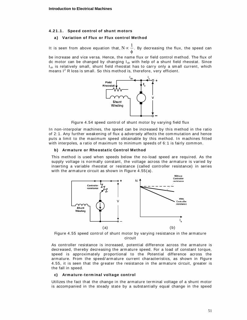
Introduction to Electrical Machines
51
4.21.1. Speed control of shunt motors
a) Variation of Flux or Flux control Method
It is seen from above equation that,
1N . By decreasing the flux, the speed can
be increase and vice versa. Hence, the name flux or field control method. The flux of dc motor can be changed by changing Ish with help of a shunt field rheostat. Since Ish is relatively small, shunt field rheostat has to carry only a small current, which means I2 R loss is small. So this method is, therefore, very efficient.
Figure 4.54 speed control of shunt motor by varying field flux
In non-interpolar machines, the speed can be increased by this method in the ratio of 2:1. Any further weakening of flux adversely affects the commutation and hence puts a limit to the maximum speed obtainable by this method. In machines fitted with interpoles, a ratio of maximum to minimum speeds of 6:1 is fairly common.
b) Armature or Rheostatic Control Method
This method is used when speeds below the no-load speed are required. As the supply voltage is normally constant, the voltage across the armature is varied by inserting a variable rheostat or resistance (called controller resistance) in series with the armature circuit as shown in Figure 4.55(a).
(a) (b)
Figure 4.55 speed control of shunt motor by varying resistance in the armature circuit
As controller resistance is increased, potential difference across the armature is decreased, thereby decreasing the armature speed. For a load of constant torque, speed is approximately proportional to the Potential difference across the armature. From the speed/armature current characteristics, as shown in Figure 4.55, it is seen that the greater the resistance in the armature circuit, greater is the fall in speed.
c) Armature-terminal voltage control
Utilizes the fact that the change in the armature terminal voltage of a shunt motor is accompanied in the steady state by a substantially equal change in the speed
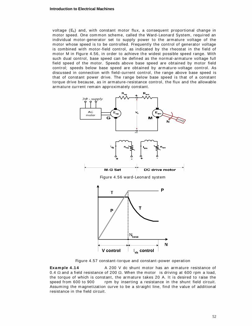
Introduction to Electrical Machines
52
voltage (Eb) and, with constant motor flux, a consequent proportional change in motor speed. One common scheme, called the Ward-Leonard System, required an individual motor-generator set to supply power to the armature voltage of the motor whose speed is to be controlled. Frequently the control of generator voltage is combined with motor-field control, as indicated by the rheostat in the field of motor M in Figure 4.56, in order to achieve the widest possible speed range. With such dual control, base speed can be defined as the normal-armature voltage full field speed of the motor. Speeds above base speed are obtained by motor field control; speeds below base speed are obtained by armature-voltage control. As discussed in connection with field-current control, the range above base speed is that of constant power drive. The range below base speed is that of a constant torque drive because, as in armature-resistance control, the flux and the allowable armature current remain approximately constant.
supply-3Φ
Figure 4.56 ward-Leonard system
Figure 4.57 constant-torque and constant-power operation
Example 4.14 A 200 V dc shunt motor has an armature resistance of 0.4 and a field resistance of 200 . When the motor is driving at 600 rpm a load, the torque of which is constant, the armature takes 20 A. It is desired to raise the speed from 600 to 900 rpm by inserting a resistance in the shunt field circuit. Assuming the magnetization curve to be a straight line, find the value of additional resistance in the field circuit.

Introduction to Electrical Machines
53
Solution
Initial speed of the motor, N1 = 600 rpm Armature current, Ia1 = 20 A Applied voltage, V = 200 V
Back emf developed by the motor at 600 rpm Eb1 = V Ia1 Ra
= 200 200.4 = 192 V
Field current under this condition, A0.1200200I 1sh
Now let the total resistance in shunt field circuit to raise the speed to 900 rpm be Rf .
Then the field current, AR200I
f1sh
The magnetization curve is to be assumed as a straight line, thus flux is directly proportional to field current, i.e. shI
Or f1sh
2sh
1
2R200
II
As per the given conditions, the torque remains constant during the change of speed. Thus T1 = T2
Torque aIT
11a'
1 IKT
22a'
2 IKT
Or 22a11a II
ff
2
11a2a R1.0
200R20II
Where, Ia2 is the current drawn by the armature, when the motor is driving the load at 900 rpm. Back emf at 900 rpm, Eb2 = V Ia2 Ra
= 200 0.1 Rf 0.4
= 200 0.04 Rf
Back emf for a particular motor, NKEb
Thus 111b NKE (i)
And 222b NKE (ii)
Dividing Eq. (ii) by Eq. (i),
1
2
1
2
1b
2bNN
EE
600900
R200
192R04.0200
f
f
Or, 057600R200R04.0 f2f
Introduction to Electrical Machines
54
8.30608.0
9216000,40200R f
Additional resistance in the shunt field circuit =Rf Rsh1 = 306.8 200 = 106.8
Example 4.15 A 250 V dc shunt motor runs at its normal speed of 500 rpm when the armature current is 100 A. Find the speed of the motor under the following cases: (i) a resistance of 1.0 is connected in series with the armature circuit, the shunt field remaining constant, (ii) the shunt field current is reduced to 60 per cent of its normal value by inserting a resistance in the field circuit.
The armature current in both the above cases is 50 A. The resistance of the armature is 0.25 and that of interpole winding, 0.05.
Solution
Total resistance of the armature circuit 0.25+0.05 = 0.3
Normal speed, N1 = 500 rpm Applied voltage, V = 250 V Armature current at normal speed, Ia1 = 100 A Back emf at 500 rpm, Eb1 = 250 100 0.3
= 220 V i) Additional resistance in the armature circuit = 1.0 Total resistance in the armature circuit = 0.3 + 1.0 = 1.3
Armature current under this condition, Ia2 = 50 A Back emf, Eb2 = 250 50 1.3
= 185 V As the field current remains unchanged, 1 = 2
Back emf for a particular motor, NKEb
or 111b NKE (i)
And 222b NKE (ii)
1
2
1
2
1b
2bNN
EE
Or 500N1
220150 2
Speed, rpm420220185500N2
ii) Total resistance in the armature circuit = 0.3
Armature current, Ia3 =50 A Back emf under this condition, Eb3 = 250 50 0.3
= 235 V Shunt field current under this condition, Ish3 = 0.6 Ish1
Assuming the magnetization curve to be linear, shI
Or 6.0II
1sh
3sh
1
3
Introduction to Electrical Machines
55
Now, 1
3
1
3
1b
3bNN
EE
Or 500N6.0
220235 3
Speed of the motor, rpm8906.0220
235500N3
Example 4.16 A 230 V shunt motor drives a load at 900 rpm drawing a current of 30A. The resistance of the armature circuit is 0.4. The torque of the load is proportional to the speed. Calculate the resistance to be connected in series with the armature to reduce the speed to 600 rpm Ignore armature reaction.,
Solution In normal conditions Armature current, Ia =30 A neglecting field current Armature circuit resistance, Ra =0.4
Back emf, Eb1 = V Ia1 Ra
= 230 300.4 =218 V
Speed, N1 = 900 rpm Let resistance R be connected in series with the armature circuit to reduce the speed to N2=600 rpm.
Since as per given data load torque, NT and also aIT
1
2
11a
22aNN
II
Assuming flux constant
A2090060030
NNII
1
21a2a
Back emf, Eb2 = V Ia2 (R +Ra)
= 230 20( R+0.4)
=22220R
NEb and flux is constant
1
2
1b
2bNN
EE
Or 900600
218R20220
Or R= 3.833
Example 4.17 A 220 V dc shunt motor draws 4.5 A on no load and runs at 1000 rpm. Resistance of the armature winding and shunt field winding is 0.3 and 157 respectively. Calculate the speed, when loaded and drawing a current of 30 A. Assume that the armature reaction weakens the field by 3 %.
Solution
Voltage applied to the motor, VL = 220 V Shunt field resistance, Rsh = 157
Introduction to Electrical Machines
56
Shunt field current, A4.1157220Ish
Current drawn by the motor at no load = 4.5 A. Thus armature current at no load, Iao = 4.5 1.4 = 3.1 A
Back emf at no load, Ebo = V Iao Ra
= 220 3.1 0.3
= 219.07 V
Under loaded conditions, current drawn by the Motor = 30 A Armature current under loaded conditions, Ia = 30 1.4 = 28.6 A
Back emf under loaded conditions, Eb = V Ia Ra
= 220 28.6 0.3
= 211.42 V Let the flux under no load condition be 0, then under the loaded condition flux = 0.97 0, because of armature reaction.
The back emf for a de motor is given by
NKa60
NZPEb
Thus oobo NKE (i)
Also, N97.0KE obo (ii)
Dividing Eq. (ii) by Eq. (i),
bo
b
o EE
N97.0N
Speed under the loaded condition,
rpm995
97.01000
07.21942.211N
4.21.2. Speed Control Of Dc Series Motors
Flux Control Method
Variation in the flux of a Series motor can be brought about in any one of the following ways.
i) Field Divertors
The series winding are shunted by a variable resistance knows as field divertor (Figure 4.54). Any desired amount of current can be passed through the divertor by adjusting its resistance. Hence the flux can be decreased, consequently, the speed of the motor increased.

Introduction to Electrical Machines
57
Figure 4.58 speed control of series motor by field divertor method
ii) Armature Divertor
A divertor across the armature can be used for giving speeds lower then the normal speed. For a given constant load torque, if Ia is reduced due to armature divertor, then must increase ( Ta Ia). This results an increase in current taken from the supply (which increases the flux) and a fall in speed (N 1/). The variations in speed can be controlled by varying the divertor resistance.
Figure 4.59 speed control of series motor by armature divertor method
iii) Tapped Field Control
This method is often used in electric traction (Show in Figure 3).The number of series field turns in the circuit can be changed at will as shown. With full field, the motor runs at its minimum speed, which can be raised in steps by cutting out some of the series turns.
Figure 4.60 speed control of series motor by tapped field control method
Variable Resistance in series with Motor
By increasing the resistance in series with armature, the voltage applied across the armature terminals can be decreased. With reduced voltage across the armature, the speed is reduced. However, it will be noted that since full motor current passes through this resistance, there is a considerable loss of power in it.
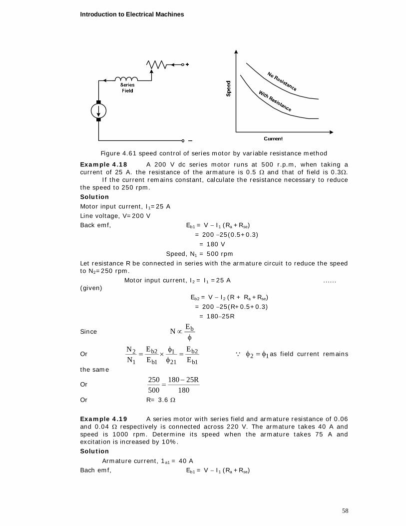
Introduction to Electrical Machines
58
Figure 4.61 speed control of series motor by variable resistance method
Example 4.18 A 200 V dc series motor runs at 500 r.p.m, when taking a current of 25 A. the resistance of the armature is 0.5 and that of field is 0.3. If the current remains constant, calculate the resistance necessary to reduce the speed to 250 rpm. Solution
Motor input current, I1=25 A Line voltage, V=200 V Back emf, Eb1 = V I1 (Ra +Rse)
= 200 25(0.5+0.3)
= 180 V
Speed, N1 = 500 rpm
Let resistance R be connected in series with the armature circuit to reduce the speed to N2=250 rpm. Motor input current, I2 = I1 =25 A ...... (given) Eb2 = V I2 (R + Ra +Rse)
= 200 25(R+0.5+0.3)
= 18025R
Since
bEN
Or 1b
2b
21
1
1b
2b
1
2EE
EE
NN
12 as field current remains
the same
Or 180
R25180500250
Or R= 3.6
Example 4.19 A series motor with series field and armature resistance of 0.06 and 0.04 respectively is connected across 220 V. The armature takes 40 A and speed is 1000 rpm. Determine its speed when the armature takes 75 A and excitation is increased by 10%. Solution
Armature current, 1a1 = 40 A Bach emf, Eb1 = V I1 (Ra +Rse)
Introduction to Electrical Machines
59
= 220 40(0.04+0.06)
= 216 V Speed, N1 = 1000 rpm Flux 1= (say)
When armature current, I2= 75 A
Bach emf, Eb2 = V I2 (Ra +Rse)
= 220 75(0.04+0.06)
= 212.5 V Flux 2= 1.11 = 1.1 ...... (given)
Since
bEN
rpm8941.1216
5.2121000
EENN
21
1
1b
2b12
Example 4.20 A series motor runs at 500 r.p.m. when taking a current of 60A at 460 V. The resistance of the armature circuit is 0.2 and that of the field winding is 0.1 . Calculate the speed when a 0.15 divertor is connected in parallel with the field winding. Assume the torque to remain unaltered and the flux to be proportional to the field current.
Solution In normal conditions Armature current, Ia1 = Series field current, Ise = Line current, IL1 = 60 A Speed, N1=500 rpm Eb1 = V Ia1 Ra I se1Rse)
= 220 60 0.2 600.1
= 442 V After connecting a divertor of resistance of 0.15 a in parallel with the field winding let the speed be N2 and line current IL2
Armature current, Ia2 = IL2
Series field current,
2L2L
divse
div2L2se
I53
15.01.015.0I
RRRII
Since torque remains unaltered T2 = T1
Or Ia22 = Ia11
Or Ia2Ise2 = Ia1Ise1 since seI
Or 6060I53I 2L2L
Or A46.773
53600I 2L
Introduction to Electrical Machines
60
A48.4646.7753I
53I 2L2se
Back emf, Eb1 = V Ia2 Ra I se2Rse)
= 220 77.46 0.2 46.48 0.1
= 440.06 V
rpm38660
48.46442
06.440500
II
EEN
EENNSpeed
2se
1se
1b
2b1
21
1
1b
2b12
4.22. LOSSES IN DC MACHINES
INTRODUCTION
The dc machines are used either for converting mechanical energy into electrical energy, i.e. generators or for converting electrical energy into mechanical energy, i.e. motors. This conversion of energy from one form to another obviously takes place at an efficiency of less than 100 percent. A part of the energy consumed by machine can not be effectively utilized in the machine proper and is dispersed in the form of heat. This part of the energy is generally termed as lost energy or simply the losses of the machine. The losses in general occur (i) in electrical circuits carrying a certain current, (ii) in magnetic circuits subjected to alternating magnetization and (iii) due to mechanical friction. Hence the losses occurring in an electrical machine constitute a source of inefficiency. In addition, these are completely converted into heat, resulting in a rise in the temperature of the machine. If reliable operation of an electrical machine is desired during its normal service life, then the temperature of the various parts of the machine should not be allowed to exceed beyond the permissible limit, decided by the type of insulating material used in the machine. The temperature rise also decides the capacity to which the machine can be loaded safely.
The losses occurring in the machine have also to be paid for and as such the running cost of a less efficient machine for the same output is more compared to an efficient machine. Hence the problem of losses in the machine is closely connected with the problems of its service life and other economic factors. The initial cost of a more efficient machine is certainly higher than that of a machine with poor efficiency. However, the higher initial cost is compensated by the saving in running energy charges; moreover a more efficient machine is highly reliable , less subject to breakdowns which is particular important when continuity of service must be maintained. Better electrical materials are being developed and with the use of these electrical machines are undergoing a continuous improvement towards reduction in losses, so as to produce more efficient machines with trouble free and continuous service even under more severe working.
4.22.1. Classification of Losses
Power losses originating in dc machines (either a motor or a generator) can be classified into the following groups
1. Copper losses, caused by the current flow and occur in (i) armature winding, (ii) series field winding , (iii) commutating pole winding , (iv) compensating winding , (v) shunt field winding and (vi) loss due to brush contact resistance.
2. Iron losses caused by varying magnetization and occur in (armature core and (ii) armature teeth , as hysteresis loss and eddy current loss.
Introduction to Electrical Machines
61
3. Mechanical losses caused by the rotation of the machine and occur as (i) bearing friction (ii) brush friction and (iii) air friction (windage). These losses are also called friction and windage losses.
4. Stray load losses include (i) increase in iron losses at load (ii) increases in copper losses due to eddy currents in armature conductors and (iii) additional losses caused by short circuit currents in the coils under commutation and occur in (a) armature teeth, (b) armature core and (c) armature winding.
For smaller machines, stray losses are quite negligible. For fairly large machines, it may be taken arbitrarily as one percent of the rating of the machine.
Of these groups of losses, copper losses vary with the load on the machine, whereas iron and mechanical losses remain substantially constant at all loads. Stray losses are more or less negligible in small and medium machines. Hence the total losses occurring in a dc machine may also be classified as
i) variable losses and
ii) Constant losses.
In case of shunt or compound dc machines, even the shunt field copper losses can be grouped with the constant losses because it remains practically constant at all loads. Thus for a shunt or compound dc machine, the constant and variable losses include:
Constant losses including (i) iron losses, (ii) mechanical losses and (iii) shunt field Cu losses.
Variable losses including (i) copper losses in armature winding (ii) copper losses in series field winding (iii) copper losses in commutating pole winding (iv) copper losses in compensating winding if any and (v) losses due to brush contact resistance.
4.22.2. Copper Losses
In general copper losses will occur in those parts of dc machines that carry electric current. These losses could be further subdivided into three groups.
1. Armature copper loss
2. Field copper loss , and 3. Loss due to brush contact resistance.
Armature copper loss
Let the current flowing in the armature winding be designated Ia amperes and its resistance Ra .
Then armature copper losses = aa RI 2 watts.
Moreover, series field winding, interpole winding and compensating windings are connected in series with the armature winding. As such the current flowing in these winding is also equal to the armature current, Ia.
Thus, the total armature copper losses
= ciseaa RRRRI 2
Where Rse, Ri and Rc are the resistance of series field winding, interpole winding and compensating winding respectively.
The armature circuit copper losses vary as the square of the armature current. As such these losses could be also called variable losses of the machine this loss is about 30 to 40% of full-load losses.
Field Copper loss
Introduction to Electrical Machines
62
If Ish is the current flowing in the shunt field winding then , Copper losses in the shunt field winding = Ish
2 Rsh where Rsh is the resistance of the shunt field winding
however the resistance of the shunt field winding sh
sh IVR
Where, V is the terminal voltage of the dc machine, i.e. voltage across the armature terminals.
Hence, shunt field copper losses = V x Ish, watts
Terminal voltage and Ish are practically constant as such this loss can be taken into the group of constant losses in the dc machine.
Losses due to Brush contact Resistance
In dc machines, brushes makes a sliding contact with the commutator and the conduction of current is through minute arcs. The contact voltage drop for a particular grade of brush is more or less constant, varying from 1 to 2 volts for normal carbon brushes. The brush contact loss is equal to the product of contact voltage drop and the armature current. Strictly speaking, it is not a copper loss; however it is normally included in the classification of copper losses.
4.22.3. Iron Losses
The reversal of magnetization of the armature core leads to iron losses in the core and the teeth of the armature structure. Iron losses can further be subdivided into: i) hysteresis loss and ii) eddy current loss
Hysteresis loss
Hysteresis loss is mainly due to the reversal of magnetization in the armature core and depends upon the area of the hysteresis loop of the magnetic material used for armature core, the volume of the core and the frequency of magnetic flux reversal. Area of the hysteresis loop again depends upon the flux density to which the material is being worked.
Dr. Charles Steinmetz suggested an empirical formula based on a series of tests for calculating the hysteresis loss, which expressed as follows,
wattsBVfP 6.1maxh .
where, is a constant, known as Steinmetz’s coefficient or hysteresis coefficient for a particular material. Its value for 4% silicon steel and sheet steel is 275 and 500 respectively. Hysteresis loss is reduced by choosing a core material with low hysteresis coefficient such as alloy steel.
Eddy current losses
As the armature core rotates relative to the magnetic field, it cuts the flux. Thus as per the lows of electromagnetic induction, a small emf is induced in the armature core body, which circulates a large current in the armature core due to its small resistance. Such a circulating current is called eddy current and the power losses due to the flow of this current are called eddy current losses. The resistance can be greatly increased by laminating the armature core of the dc machine, thereby reducing the magnitude of eddy current to an appreciable value. The eddy current losses depend upon the following factors:
i) Thickness of laminations, t ii) Frequency of flux reversal, f
iii) Maximum value of flux density, Bmax iv) Volume of armature core V and
v) Quality of iron.
Introduction to Electrical Machines
63
Hence the eddy current losses occurring in the armature core and teeth of the dc machine are given by
watts,VtfKBP 222maxc
4.22.4. Mechanical Losses
Mechanical losses are due to the rotation of the armature and can be subdivided into three categories.
1. bearing friction
2. brush friction and 3. air friction (winding)
There are also termed as friction and windage losses.
The bearing friction losses occurring in dc machine depend upon (i) the pressure on bearing, (ii) Peripheral speed of the shaft at the bearing and (iii) coefficient of friction between the bearing and the shaft.
The brush friction losses are quite appreciable in dc machines. These losses are dependent upon (i) the brush pressure, (ii) the peripheral speed of the commutator and (iii) the type of the brush.
The windage losses are mainly produced by the rotation of armature. These losses depend upon (i) peripheral speed of the armature, (ii) armature diameter, (iii) armature core length and (iv) construction of the machine
These three components added together give the total mechanical losses occurring in the machine these are practically constant provided the speed remains the same during the loading of the machine.
4.23. EFFICIENCY
The ratio of output of the machine to its input is generally called the efficiency of the machine.
inputoutputEfficiency
Input to the machine = output + total losses
Thus, lossestotalOutput
Outputefficiency
Total losses in dc machine = constant losses + variable losses
= Wc + Wv
Hence, lossesvariablelossesonstantcOutput
Outputηefficiency
Condition for maximum efficiency
Let the dc machine works as a dc shunt generator, with a terminal voltage V volts and load current IL ampere.
Then the power output of the dc generator = V IL,
Variable loss of the armature circuit = I2a Ra (assuming that the machine is not
provided with interpole and compensating windings).
Armature current, Ia = IL + ISh
Introduction to Electrical Machines
64
Shunt field current is quite small compared to the load current and Ia can be assumed equal to IL. With this assumption,
Variable losses, aLv RIW 2
Let the constant losses be = WC
Then, the efficiency of the generator,
aLCL
LRIWIV
IV2
Or
VRI
VIW aL
Lc
1
1
Efficiency will be maximum, when the denominator minimum i.e.
0
a
L
L
C
L
RVI
VIW
dId
or 02 VR
VIW a
L
c
or 2L
caVIW
VR
or caL WRI 2
i.e. copper losses in armature circuit = Constant Losses.
Hence efficiency of a dc machine will be maximum, when the variable losses are equal to the constant losses.
Load current corresponding to maximum efficiency is given by
a
cL R
WI
Example 4.21 The armature of a 6 pole, 6 circuit dc shunt motor takes 300 A at the speed of 400 rpm. The flux per pole is 75 10-3 Wb. The number of armature turns is 500. The torque lost in windage, friction and iron losses can be assumed as 2.5 per cent. Calculate
i) the torque developed by the armature, ii) shaft torque and iii) shaft power in kW.
Solution
i) The torque developed by the armature of a dc motor is given by
Nma
ZIP159.0T aa
(i)
Number of poles of shunt motor, P=6 Armature winding has 6 circuits, thus, a=6 Armature current, Ia = 300 A
Number of armature turns = 500 Thus total conductors on the armature, Z = 2 500 = 1000
Flux per pole, = 75 10-3 Wb
Introduction to Electrical Machines
65
Substituting these values in Eq. (i),
Armature torque,
Nm5.35776
100030010756159.0T3
a
ii) Torque lost in windage, friction and iron losses
= 2.5% of Ta = 0.025 3577.5 = 89.44 N m
Thus, shaft torque, Tsh = 3577.5 89.44
= 3488.06 N m
iii) Shaft power,
kW22.146100060
06.34884002
kW100060
NT2P shsh
Example 4.22 2 A 200 V dc shunt motor takes a total current of 100 A and runs at 750 rpm. The resistance of the armature winding and of shunt field winding is 0.1 and 40 respectively. Find out
i) the torque developed by the armature, and
ii) the copper losses.
If the friction and iron losses amount to 1500 W, also calculate
iii) shaft power, iv) shaft torque, and v) efficiency.
Solution
i) Voltage applied across the motor, VL = 200 V Resistance of the shunt field winding, Rsh = 40
Shunt field current, A0.540
200RVI
sh
Lsh
Total current drawn by the motor, IL = 100 A. Thus, armature current Ia = IL Ish = 100 5 = 95 A
Armature resistance, Ra = 0.1 Back emf, Eb = V IaRa
= 200 95 0.1
= 190.5 V Mechanical power developed, Pmec = Eb Ia
= 190.5 95 =
= 18097.5 W
Now, mechanical power developed, 60NT2IE a
ab
Thus, torque developed by the armature,
Introduction to Electrical Machines
66
mN3.2307502
5.1809760N2IE60T ab
a
ii) The back emf for a dc motor is given by, Eb = V IaRa
Or EbIa = VIa Ia 2Ra
Thus armature copper losses, Ia 2Ra = VIa EbIa
= 200 95 18097.5
= 902.5 W Field copper losses = Ish
2Rsh = 52 40 = 1000 W
Total copper losses = 902.5 + 1000 = 1902.5 W Copper losses could also be determined as follows: Input to the motor = VLIL = 200 100 = 20,000 kW
Mechanical power developed, Eb Ia = 18097.5 W Total copper losses = 20000 18097.5 = 1902.5 W
iii) Friction and Iron losses = 1500 W Total copper losses = 1902.5 W
Output = 20 000 (1500+1902.5)
= 16 597.5 W
or shaft power 16.6 kW
iv) Shaft power
kW100060
NT2P shsh
Shaft torque, mN24.211
75026.16100060Tsh
v) Efficiency,
%99.8220000
5.16597PP
input
output
Example 4.23 A 100 V series motor takes 45 A when running at 750 rpm. Its armature resistance is 0.22 , while the series field resistance is 0.13 . Iron and friction losses amount to 750 W. Find (i) shaft power, (ii) total torque and (iii) shaft torque.
Solution
i) Voltage applied to the series motor, = 100 V
Total resistance of the armature circuit, = Ra + Rse
= 0.22 + 0.13 = 0.35
Current in the armature circuit, Ia = 45 A
Back emf, Eb = 100 45 0.35
Introduction to Electrical Machines
67
= 84.25 V
Mechanical power developed = Eb Ia
= 84.25 45 =
= 3791.25 W
Iron and friction losses = 750 W
Output = 3791.25 750 = 3041.25 W
Thus shaft power = 3.041 kW
ii) Mechanical power developed =60NT2IE a
ab
Total torque,
mN25.48
750225.379160Ta
T°
iii) Output = 3041.25 W
Output 60NT2 sh
Or, shaft torque,
mN7.387502
25.304160Tsh
Example 4.24 A long-shunt compound motor takes a current of 24A from 240 V mains. Determine the efficiency if resistance of the armature, series field and shunt field are 0.1, 0.08 and 60 ohms respectively and stray losses are 500 watts. Solution Input line current, IL = 24 A Supply voltage, V = 240 V Total input power to the machine VIL = 24024 = 5760 W
Shunt field current, A460
240RVIsh
sh
Series field current, Ise = Ia = IL Ish
= 24 4 = 20 A
Total losses = Stray losses + armature copper loss + series field copper loss + shunt field copper loss = Ps + Ia
2Ra + Ise2Rse + V Ish
= 500 + 2020.1 + 2020.08 + 2404 = 1532 W
Useful Output = Total input Total losses = 5760 – 1532 = 4228 W
Efficiency ,
%4.7357604228
inputTotaloutputUsefull
Example 4.25 A 100 V dc series motor has an armature resistance of 0.2 and series field resistance of 0.25. When its pulley exerts a torque of 27.58
Introduction to Electrical Machines
68
N.m it runs at a speed of 600 rpm, iron and friction losses at this speed are 300 W. Determine (a) lost torque (b) copper losses and (c) efficiency. Solution Torque exerted, T =27.58 N.m Speed, N= 600 r.p.m.
Motor output = W173260
600258.2760
N2T
Stray losses, Ps =300 W Let input current be of I amperes to give a torque of 27.58 N.m.
Copper losses in series field and armature = I2(Ra + Rse) = I2 (0.2 + 0.25 )= 0.45 I2 Input to motor =Motor output + Ps + copper losses
= 1732 + 300 + 0.45 I2 = 2032 + 0.45 I2 ……..(i) Also motor input =VI = 100 I ……..(ii)
Comparing expressions (i) and (ii) we get 0.45 I2 +2032 = 100 I or I = 22.5 (b) Copper losses = I2(Ra + Rse)= 22.52 0.45 = 227.8 W
(c) Efficiency of the motor, %97.761001005.22
1732100Input
Output
(a) Torque lost = m.N4.8
606002
8.22730060/N2
wattsinLosses
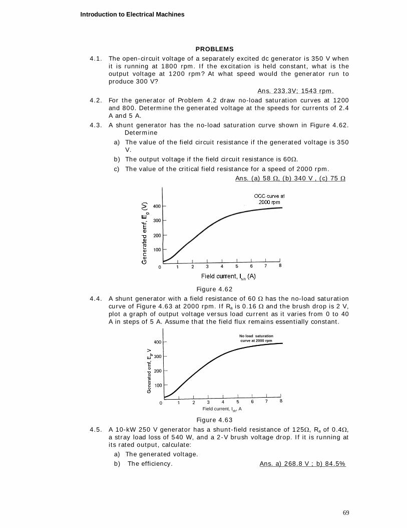
Introduction to Electrical Machines
69
PROBLEMS 4.1. The open-circuit voltage of a separately excited dc generator is 350 V when
it is running at 1800 rpm. If the excitation is held constant, what is the output voltage at 1200 rpm? At what speed would the generator run to produce 300 V?
Ans. 233.3V; 1543 rpm. 4.2. For the generator of Problem 4.2 draw no-load saturation curves at 1200
and 800. Determine the generated voltage at the speeds for currents of 2.4 A and 5 A.
4.3. A shunt generator has the no-load saturation curve shown in Figure 4.62. Determine
a) The value of the field circuit resistance if the generated voltage is 350 V.
b) The output voltage if the field circuit resistance is 60.
c) The value of the critical field resistance for a speed of 2000 rpm. Ans. (a) 58 , (b) 340 V , (c) 75
Figure 4.62
4.4. A shunt generator with a field resistance of 60 has the no-load saturation curve of Figure 4.63 at 2000 rpm. If Ra is 0.16 and the brush drop is 2 V, plot a graph of output voltage versus load current as it varies from 0 to 40 A in steps of 5 A. Assume that the field flux remains essentially constant.
Field current, Ish, A
No load saturationcurve at 2000 rpm
Figure 4.63
4.5. A 10-kW 250 V generator has a shunt-field resistance of 125, Ra of 0.4, a stray load loss of 540 W, and a 2-V brush voltage drop. If it is running at its rated output, calculate:
a) The generated voltage. b) The efficiency. Ans. a) 268.8 V ; b) 84.5%
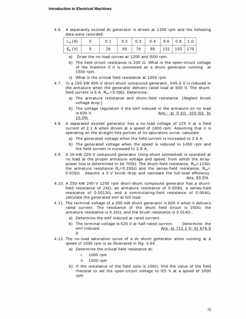
Introduction to Electrical Machines
70
4.6. A separately excited dc generator is driven at 1200 rpm and the following data were recorded:
Ish (A) 0 0.1 0.2 0.3 0.4 0.6 0.8 1.0
Eg (V) 5 26 50 76 98 131 153 170
a) Draw the no-load curves at 1200 and l500 rpm.
b) The field circuit resistance is 200 . What is the open-circuit voltage of the machine if it is connected as a shunt generator running at 1500 rpm.
c) What is the critical field resistance at 1000 rpm. 4.7. In a 150-kW 600-V short-shunt compound generator, 645.6 V is induced in
the armature when the generator delivers rated load at 600 V. The shunt-field current is 6 A. Rse =0.08. Determine:
a) The armature resistance and shunt-field resistance. (Neglect brush voltage drop.)
b) The voltage regulation if the emf induced in the armature on no load is 600 V. Ans.: a) 0.1, 103.3; b) 10.0%
4.8. A separated excited generator has a no-load voltage of 125 V at a field current of 2.1 A when driven at a speed of 1600 rpm. Assuming that it is operating on the straight-line portion of its saturation curve, calculate:
a) The generated voltage when the field current is increased to 2.6 A. b) The generated voltage when the speed is reduced to 1450 rpm and
the field current is increased to 2.8 A. 4.9. A 10-kW 220-V compound generator (long-shunt connected) is operated at
no load at the proper armature voltage and speed, from which the stray-power loss is determined to be 705. The shunt-field resistance, Rsh=110, the armature resistance Ra=0.265 and the series-field resistance, Rse= 0.035. Assume a 2-V brush drop and calculate the full-load efficiency. Ans. 83.9%
4.10. A 250-kW 240-V 1200 rpm short-shunt compound generator has a shunt-field resistance of 24, an armature resistance of 0.003, a series-field resistance of 0.0013, and a commutating-field resistance of 0.004, calculate the generated emf at full load.
4.11. The terminal voltage of a 200-kW shunt generator is 600 V when it delivers rated current. The resistance of the shunt field circuit is 250, the armature resistance is 0.32, and the brush resistance is 0.014 .
a) Determine the emf induced at rated current. b) The terminal voltage is 620 V at half-rated current. Determine the
emf induced. Ans. a) 712.1 V; b) 676.5 V
4.12. The no-load saturation curve of a dc shunt generator when running at a speed of 1000 rpm is as illustrated in Fig. 4.64.
a) Determine the critical field resistance at;
i. 1000 rpm ii. 1500 rpm
b) If the resistance of the field coils is 100, find the value of the field rheostat to set the open-circuit voltage to l25 V at a speed of 1000 rpm.
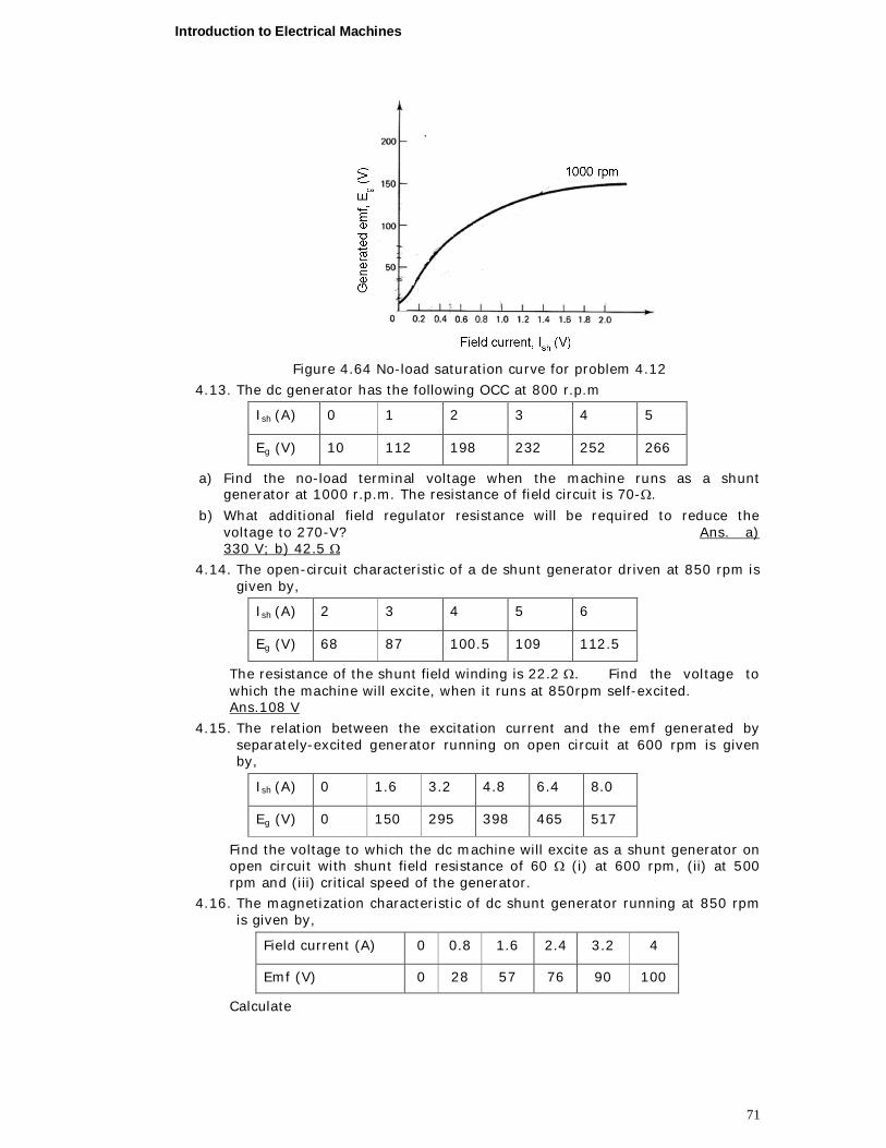
Introduction to Electrical Machines
71
Figure 4.64 No-load saturation curve for problem 4.12
4.13. The dc generator has the following OCC at 800 r.p.m
Ish (A) 0 1 2 3 4 5
Eg (V) 10 112 198 232 252 266
a) Find the no-load terminal voltage when the machine runs as a shunt generator at 1000 r.p.m. The resistance of field circuit is 70-.
b) What additional field regulator resistance will be required to reduce the voltage to 270-V? Ans. a) 330 V; b) 42.5
4.14. The open-circuit characteristic of a de shunt generator driven at 850 rpm is given by,
Ish (A) 2 3 4 5 6
Eg (V) 68 87 100.5 109 112.5
The resistance of the shunt field winding is 22.2 . Find the voltage to which the machine will excite, when it runs at 850rpm self-excited. Ans.108 V
4.15. The relation between the excitation current and the emf generated by separately-excited generator running on open circuit at 600 rpm is given by,
Ish (A) 0 1.6 3.2 4.8 6.4 8.0
Eg (V) 0 150 295 398 465 517
Find the voltage to which the dc machine will excite as a shunt generator on open circuit with shunt field resistance of 60 (i) at 600 rpm, (ii) at 500 rpm and (iii) critical speed of the generator.
4.16. The magnetization characteristic of dc shunt generator running at 850 rpm is given by,
Field current (A) 0 0.8 1.6 2.4 3.2 4
Emf (V) 0 28 57 76 90 100
Calculate
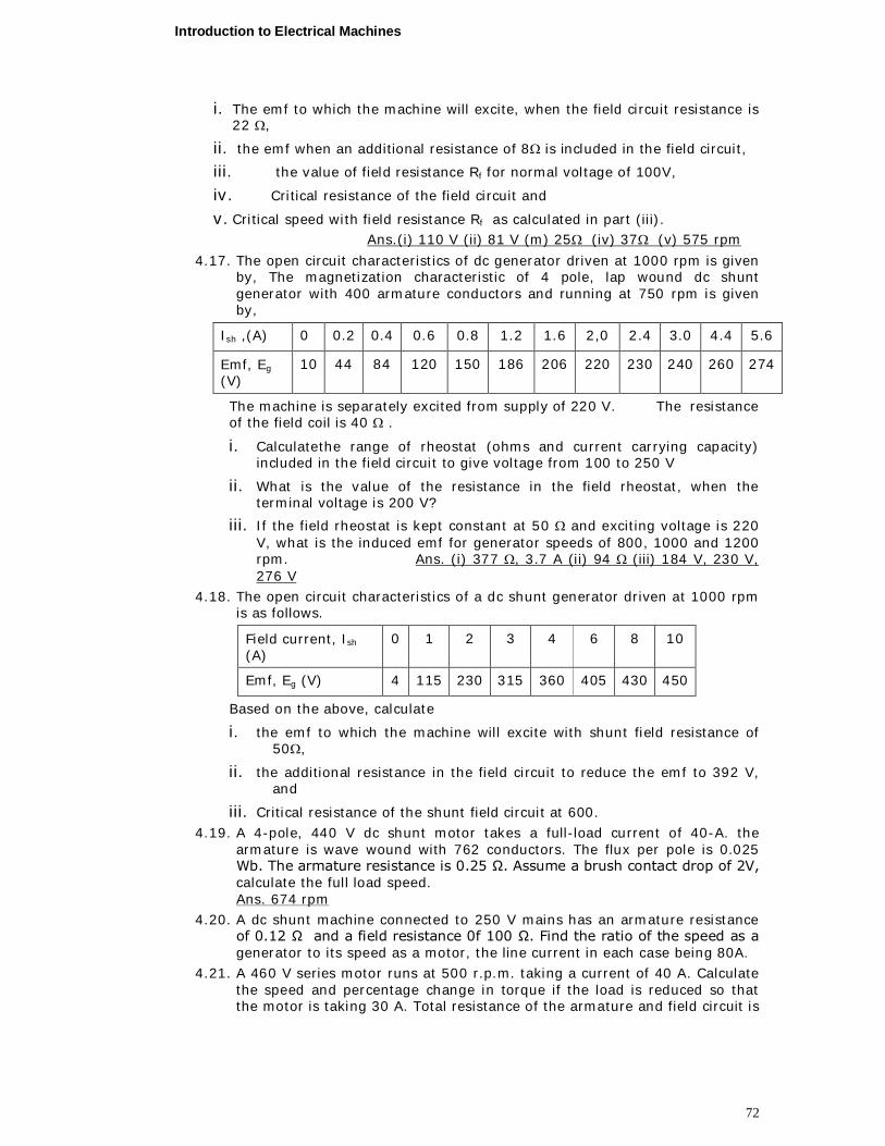
Introduction to Electrical Machines
72
i. The emf to which the machine will excite, when the field circuit resistance is 22 ,
ii. the emf when an additional resistance of 8 is included in the field circuit,
iii. the value of field resistance Rf for normal voltage of 100V,
iv. Critical resistance of the field circuit and
v. Critical speed with field resistance Rf as calculated in part (iii). Ans.(i) 110 V (ii) 81 V (m) 25 (iv) 37 (v) 575 rpm
4.17. The open circuit characteristics of dc generator driven at 1000 rpm is given by, The magnetization characteristic of 4 pole, lap wound dc shunt generator with 400 armature conductors and running at 750 rpm is given by,
Ish ,(A) 0 0.2 0.4 0.6 0.8 1.2 1.6 2,0 2.4 3.0 4.4 5.6
Emf, Eg
(V) 10 44 84 120 150 186 206 220 230 240 260 274
The machine is separately excited from supply of 220 V. The resistance of the field coil is 40 .
i. Calculate the range of rheostat (ohms and current carrying capacity) included in the field circuit to give voltage from 100 to 250 V
ii. What is the value of the resistance in the field rheostat, when the terminal voltage is 200 V?
iii. If the field rheostat is kept constant at 50 and exciting voltage is 220 V, what is the induced emf for generator speeds of 800, 1000 and 1200 rpm. Ans. (i) 377 , 3.7 A (ii) 94 (iii) 184 V, 230 V, 276 V
4.18. The open circuit characteristics of a dc shunt generator driven at 1000 rpm is as follows.
Field current, Ish (A)
0 1 2 3 4 6 8 10
Emf, Eg (V) 4 115 230 315 360 405 430 450
Based on the above, calculate
i. the emf to which the machine will excite with shunt field resistance of 50,
ii. the additional resistance in the field circuit to reduce the emf to 392 V, and
iii. Critical resistance of the shunt field circuit at 600. 4.19. A 4-pole, 440 V dc shunt motor takes a full-load current of 40-A. the
armature is wave wound with 762 conductors. The flux per pole is 0.025 Wb. The armature resistance is 0.25 Ω. Assume a brush contact drop of 2V, calculate the full load speed. Ans. 674 rpm
4.20. A dc shunt machine connected to 250 V mains has an armature resistance of 0.12 Ω and a field resistance 0f 100 Ω. Find the ratio of the speed as a generator to its speed as a motor, the line current in each case being 80A.
4.21. A 460 V series motor runs at 500 r.p.m. taking a current of 40 A. Calculate the speed and percentage change in torque if the load is reduced so that the motor is taking 30 A. Total resistance of the armature and field circuit is
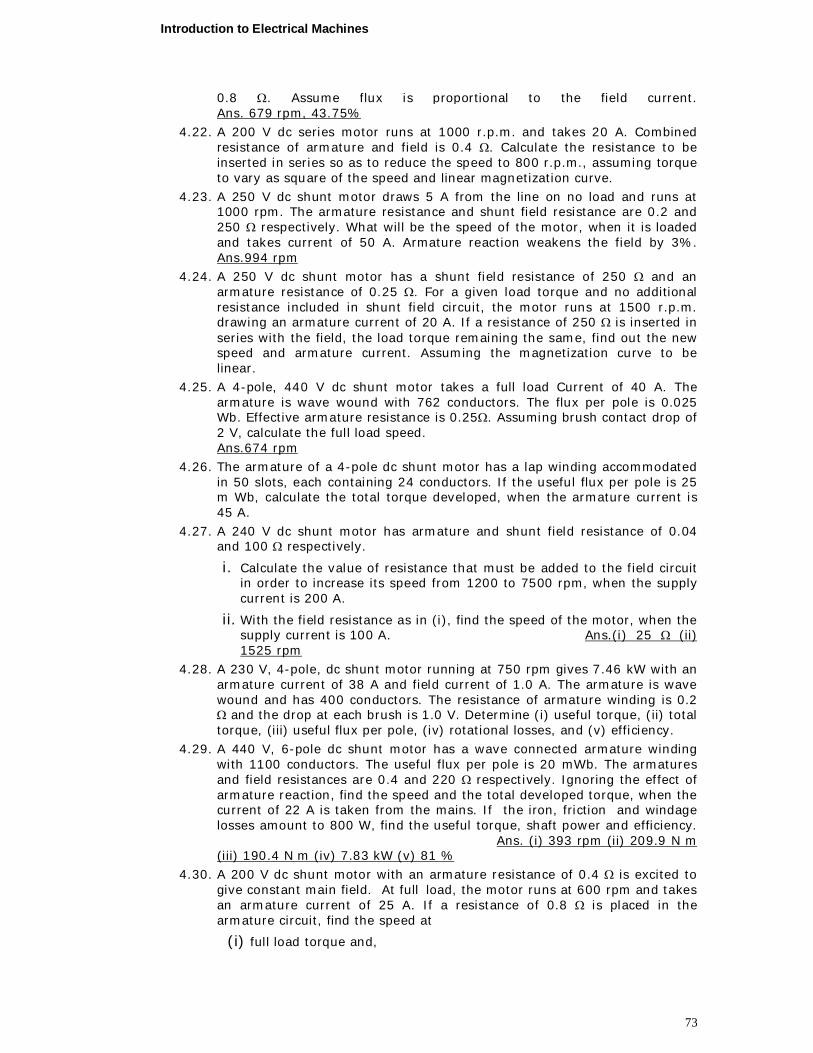
Introduction to Electrical Machines
73
0.8 . Assume flux is proportional to the field current. Ans. 679 rpm, 43.75%
4.22. A 200 V dc series motor runs at 1000 r.p.m. and takes 20 A. Combined resistance of armature and field is 0.4 . Calculate the resistance to be inserted in series so as to reduce the speed to 800 r.p.m., assuming torque to vary as square of the speed and linear magnetization curve.
4.23. A 250 V dc shunt motor draws 5 A from the line on no load and runs at 1000 rpm. The armature resistance and shunt field resistance are 0.2 and 250 respectively. What will be the speed of the motor, when it is loaded and takes current of 50 A. Armature reaction weakens the field by 3%. Ans.994 rpm
4.24. A 250 V dc shunt motor has a shunt field resistance of 250 and an armature resistance of 0.25 . For a given load torque and no additional resistance included in shunt field circuit, the motor runs at 1500 r.p.m. drawing an armature current of 20 A. If a resistance of 250 is inserted in series with the field, the load torque remaining the same, find out the new speed and armature current. Assuming the magnetization curve to be linear.
4.25. A 4-pole, 440 V dc shunt motor takes a full load Current of 40 A. The armature is wave wound with 762 conductors. The flux per pole is 0.025 Wb. Effective armature resistance is 0.25. Assuming brush contact drop of 2 V, calculate the full load speed. Ans.674 rpm
4.26. The armature of a 4-pole dc shunt motor has a lap winding accommodated in 50 slots, each containing 24 conductors. If the useful flux per pole is 25 m Wb, calculate the total torque developed, when the armature current is 45 A.
4.27. A 240 V dc shunt motor has armature and shunt field resistance of 0.04 and 100 respectively.
i. Calculate the value of resistance that must be added to the field circuit in order to increase its speed from 1200 to 7500 rpm, when the supply current is 200 A.
ii. With the field resistance as in (i), find the speed of the motor, when the supply current is 100 A. Ans.(i) 25 (ii) 1525 rpm
4.28. A 230 V, 4-pole, dc shunt motor running at 750 rpm gives 7.46 kW with an armature current of 38 A and field current of 1.0 A. The armature is wave wound and has 400 conductors. The resistance of armature winding is 0.2 and the drop at each brush is 1.0 V. Determine (i) useful torque, (ii) total torque, (iii) useful flux per pole, (iv) rotational losses, and (v) efficiency.
4.29. A 440 V, 6-pole dc shunt motor has a wave connected armature winding with 1100 conductors. The useful flux per pole is 20 mWb. The armatures and field resistances are 0.4 and 220 respectively. Ignoring the effect of armature reaction, find the speed and the total developed torque, when the current of 22 A is taken from the mains. If the iron, friction and windage losses amount to 800 W, find the useful torque, shaft power and efficiency. Ans. (i) 393 rpm (ii) 209.9 N m (iii) 190.4 N m (iv) 7.83 kW (v) 81 %
4.30. A 200 V dc shunt motor with an armature resistance of 0.4 is excited to give constant main field. At full load, the motor runs at 600 rpm and takes an armature current of 25 A. If a resistance of 0.8 is placed in the armature circuit, find the speed at
(i) full load torque and,
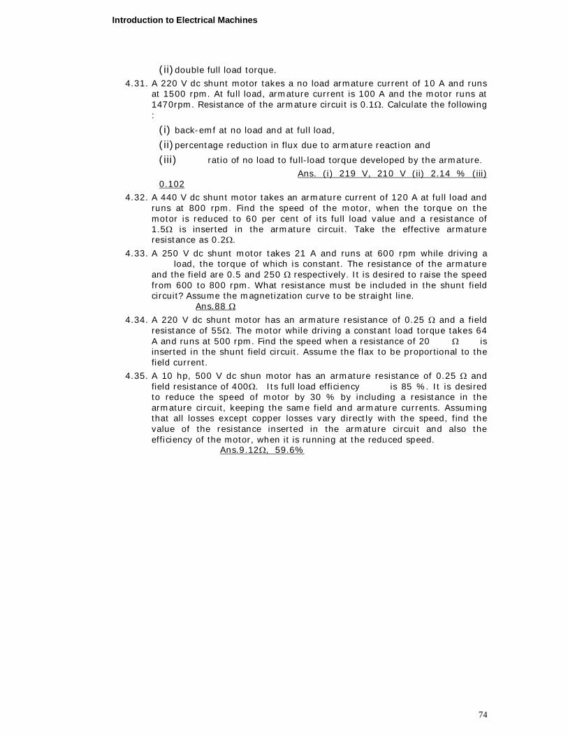
Introduction to Electrical Machines
74
(ii) double full load torque.
4.31. A 220 V dc shunt motor takes a no load armature current of 10 A and runs at 1500 rpm. At full load, armature current is 100 A and the motor runs at 1470rpm. Resistance of the armature circuit is 0.1. Calculate the following :
(i) back-emf at no load and at full load,
(ii) percentage reduction in flux due to armature reaction and
(iii) ratio of no load to full-load torque developed by the armature.
Ans. (i) 219 V, 210 V (ii) 2.14 % (iii) 0.102
4.32. A 440 V dc shunt motor takes an armature current of 120 A at full load and runs at 800 rpm. Find the speed of the motor, when the torque on the motor is reduced to 60 per cent of its full load value and a resistance of 1.5 is inserted in the armature circuit. Take the effective armature resistance as 0.2.
4.33. A 250 V dc shunt motor takes 21 A and runs at 600 rpm while driving a load, the torque of which is constant. The resistance of the armature and the field are 0.5 and 250 respectively. It is desired to raise the speed from 600 to 800 rpm. What resistance must be included in the shunt field circuit? Assume the magnetization curve to be straight line. Ans.88
4.34. A 220 V dc shunt motor has an armature resistance of 0.25 and a field resistance of 55. The motor while driving a constant load torque takes 64 A and runs at 500 rpm. Find the speed when a resistance of 20 is inserted in the shunt field circuit. Assume the flax to be proportional to the field current.
4.35. A 10 hp, 500 V dc shun motor has an armature resistance of 0.25 and field resistance of 400. Its full load efficiency is 85 %. It is desired to reduce the speed of motor by 30 % by including a resistance in the armature circuit, keeping the same field and armature currents. Assuming that all losses except copper losses vary directly with the speed, find the value of the resistance inserted in the armature circuit and also the efficiency of the motor, when it is running at the reduced speed. Ans.9.12, 59.6%