
M445 Parts Manual - Northern Lights generator
84
-
Upload
khangminh22 -
Category
Documents
-
view
3 -
download
0
Transcript of M445 Parts Manual - Northern Lights generator


INTRODUCTION
- -TABLE OF CONTENTSPlease read thoroughly before attempting to use this manual.
Table of Contents ....................... .................. ......... ..... 1 Model Designation & Serial Numbers ........................ 2 Reading a Parts Page ................................................ 3 GROUP 1 • ENGINE
Cylinder Block Assembly ............................................. 1 Flywheel Housing SAE 4 ............................................. 2 Crankshaft, Idler Gears & Main Bearings .................... 3 Cylinder Liner Assembly & Connecting Rod ............... 4 Camshaft ..................................................................... 5 Balance Shaft .............................................................. 5 Valve Train Components ............................................. 6 Front Plate.............. . ........................ 6 Timing Gear Cover ........... ......................................... 7 Oil Pan... . ................... 8 Single Oil Filter Housing .. Engine Oil Pump Oil Drain ............. . Cylinder Head ... . Rocker Cover .... .
. ............. 8 ........... 9 -10
. ... 10
. .. 11
. .. 12
GROUP 2 • INTAKE & EXHAUST SYSTEM
Air Intake Manifold & Air Filter (Marine) ...................... 1 Air Intake & Turbocharger (Mar ine) ....................... 2 -3 Air Intake & Air Filter (Industrial) ........................... 4 -5 Turbocharger & Oil Lines (Industrial) ..... 4 Exhaust Manifold & Exhaust Adapters (Marine) .......... 7 Exhaust Manifold (Industrial)........ . ........... 8 - 9 Df)I Exhaust Elbow (Marine)........ . ..... 10 Wet Exhaust Elbow (Marin e) ............................ 11 - 12 Turbocharger Assembly (Marine) ....... 13
GROUP 3 • COOLING SYSTEM
Expansion Tank Assembly (Marine) ..................... 0-1 Heat Exchanger .................................. , .. ,,, .. , ..... ,., ........ 2 Circulating Water Pump Assembly .............................. 3 Raw Water Pump Mounting .. .... .... .. .. .. .............. 4 Raw Water Pump Assembly .............. ......................... 5 Lubricating Oil Cooler (Small) ............................... 6 -7 Lubricating Oil Cooler (Large) .... .. .............. 8 - 9 Thermostat Housing ... 1 O
Radiator & Mounting ......... 11
GROUP 4 • FUEL SYSTEM Fuel Injection Pump & Fuel Lines.... . .. o - 1 Fuel Injector ... 2 Fuel Transfer Pump .................................................... 2 Fuel Filter & Lines . . .. 3 Fuel Lines, Push·on and USCG . 4
GROUP 5 • ELECTRICAL SYSTEM 12 & 24 Volt, Standard & Isolated Ground .................. 1 Stop Solenoid .............................................................. 2 Alternator and Mounting 12 Volt/78Amp ..................... 3 Alternator 12 Volt/78Amp .. . ............... 4 Optional Alternators & Mounting .................. 5 12&24VoltStarter&Mounting ..... 6 12 & 24 Volt Relay Logic Board .................. 7 S�38 Control Panel 12 & 24 Volt .... 8 Drive Belts and Belt Guard ........................ ................. 9
GROUP 6 • GASKET SETS Engine Ovemaul (Marine)......................... . ........... o Engine Overhaul (Industrial) ..................... ...... ........... 1
GROUP 7 • GEAR AND ADAPTER PARTS Consult dealer or factory.
GROUP 8 • FRAME & MOUNTING Base Frame with Centerbonded Mounts .... , .......... o - 1 Base Frame Assembly C·Series .. , .............................. 2 Base Frame with Hydrolastic Mounts .................... 3 -4
GROUP 9 • ACCESSORIES & OPTIONAL EQUIPMENT
Series 1 Control Panel ..................................... 1 Series 1 B Control Panel .............................................. 1 S·3C Flush Control Panel. .......... 2 Electric Clutch & PTO Assembly.... .. ........... 3 Crankshaft Pulley ......... . ............ 4
PROPRIETARY INFORMATION: This publication is the sole property of Northern Lights, Inc. and may not be reproduced in whole or part without the expressed written permission of Northern Lights, Inc.
P445 2/17 1

INTRODUCTION
Refer to the category designations below to find the correct parts pages for your model.M - NL 445 D - T Q
::], ___ _
Aspiration -,-
M- Northern Lights marine generator setNl- Northern Lights industrial genera
tor set
Base Model# (Deere 4045 Series
engine block) D Natural
Q 1200 RPM Generator Set
T Turbo-charged
65C-4 --,--
� <>Series kW for Commercial Application. (Deere 4045 engine block)
[ __ ill___�':'_[) __ I Northern Lights naturally aspirated 1800 rpm marine diesel generator set. John Deere 4045 T engine.
l_!ll__445 T Northern Lights turbocharged 1800 rpm marine diesel generator set. John Deere 4045 T engine. r-----------·--, _ M 445 Q
j I M 65C-4 J r·-·---.... ·--·-, I Nl445 T I
Northern Lights naturally aspirated 1200 rpm marine diesel generator set. John Deere 4045 T engine.
Northern Lights turbocharged 1800 rpm C-SERIES commercial marine diesel generator set. John Deere 4045 T engine. Northern Lights turbocharged 1800 rpm marine diesel generator set. Radiator cooling. John Deere 4045 T engine.
' When no suffix appears data will be applicable to all models
It is Alaska Diesel Electric's policy to build all 4045 series models on Deere engines intended for turbocharging. This is important when internal components are required. Check also John Deere ID plate on side of block to verify. Every effort lo note correct base engine will be made in parts text. All model
I numbers in parentheses will indicate John Deere base engine. All variations requiring serial numbers for
l_ proper identification will be noted as ADE or John Deere.
G�-1 1iiiMIW@
ordering Lugger parts, refer to this serial , numbe caled on flywheel housing. Serial numbers
!or all Luggers and Northern Lights are eight digits,e.g. i 234-5678. -��-------'
ALASKA O!ESEL EtfCllUC, Inc, «J,o, HlHW(; NW.SliAlltE,WA USA
0
0 0
When ordering Northern Lights parts, refer to !he serial number, highlighted here lrom the generator set data.
Every Northern Lights generator set has two data plates and two
serial numbers,
which may cause some confusion. One Serial number is for the generator end, and it is found on theGenerator End Data Plate. The other serial number, found with the Generator Set Data Plate, should be used
l_ :hen
-orde_r_,n_
g_p_
a_rt_s_. ---- ---
' u
Generator End
Data Plate
Mo<lojHo
"l�SIIAOltSa. &L&cm"'·'"'· '"'·"'""•""-""''(w•o,.
P445 2/17 2
or
0
World Class Marine Generators
�rato�
L==ra
PD AlaGka Oieool Electric, 4420 14th AVE., N.W.
0 Seat�e. WA 9$107 {206) 799-3880 O
� s.,s,,;,,.,---•• ,, .. ,.. -- -- :]

KEV
0 1
2
3 4
5
6 7 8
8
10
11 12 j
• !
INTRODUCTION
IMPORTANT:
Before selecting parts be sure that you are choosing parts from the correct pege. Check the model designation at the page top.
(Do not us� this illustration for parts purchasing.}
�-
Gl- ELECTRICAL SYSTEM � M'i5ia:Jffii·iif'h13M•IS11 it1Ufi1f:ill
---�---[�- 12
PART NUMBER ---+O_T_Y._,
! _____ DESCRIPTJON1.c._ _ ___ ,cS
c:E
C::Rl1ALNUMBER
185046210 185446219 185446217 185716200 185446218 040126210 020210010 027100010 026100010 185446220 015140408 015140425 199236510
! 2
Atternator Assembly Flywheel, complete Plate, complete Plate Stator, complete Bearing No1
Spring washer Washer Clamp Screw
2 i Screw 1 ! Colla1
--+--'11i
i
I
' I L__J _______ _ ____ ,,,,.J ___ _____J
REFERENCES
1 . Grouping section title.
,. . ------@]-. 114 15 1
l!!}-_ P445 09/93 ....
li.3}-- 5-2 --[lil
2. Model designation of equipment that use parts10. Part is used on units between these serial num
bers. Check your unit's serial number beforeordering parts (refer to "SERIAL NUMBERS," page2.)
listed on this page3. Title and description of assembly.4. Drawing numbers that correspond to key. 11. Assembly description and keys included.5. Denotes assembly or kit. 12. Grouping index number.6. Key column for locating parts shown on drawing.7. Part number.
13. Page number within the grouping index.14. Manual title.
8. Quantity of parts used. 15. Page publication date. Books may include pages9. Description of each component part. with different publication dates.
NOTE: • Arrows always point toward the front of the engine.
P445 2/17
3

L ___________ _
INTRODUCTION
P445 2/17
4

!
·'4:"'"""'" [m... RE50671 I 1 I
i i
1 21-10002 1 I 2 i Fl48685 4 !3 R39741 4 U13639 5 21-11003 1
6 T25701 1 T33279 2
7 T18891 2 R26493
8 R26650 2
9 R57160 6 R91708 6
rn 21-5190511 21-5190012 R54802 4 13 T27658 14 R83169 15 Fl111135 16 Fl111137 1 17 T23474 10 18 T20168 10 19 R65215 4
20 R79089 1 21 AT21535 22 R10093 23 R86819
I 24 14H826
u
ENGINE
iHW•M;l=l!•MtffJM1=1!
DESCRIPTION
Cylinder Block (marked R108755 -includes Keys 1-13 & 17-20, also requires R83169, T27658, R111135, R111137 & R112867)" Drain Cock 1/4NPT Dowel Pin Drain Plug 0-RingPlug, Socket Head 1/2NPT Stud Stud Expansion Plug 5/8" Bushing Dowel Pin Bushing, Standard Bushing .078" oversize Plug, Socket Head 1 "NPT Plug, Socket Head 1/B"NPT Orifice Spring Valve, Oil Pressure Regulating Valve, Oil Bypass Spring Capscrew Washer Main Bearing Cap #1-4 Main Bearing Cap #5 Dipstick 0-RingDipstick Tube Nut 1/2-13 ·Replaces earlier pre-Common Lube Block.**As required.
P445 2/17 1 - 1
--1
SERIAL NUMBER
Up to 362468 From 362469

!
10 -- @11----
12�113-o
14-->� / ., ) /
V
�--,"--
ENGINE
- .... �-·--,-.. --,-·--··-·�·------KEY PART NUMBER QTY.
1 R98777 1 2 RE44574 1 3 R97351 1 4 19H2351 1
5 T20089 1 6 21-00012 ..
7 12-01318 2 8 12-00314 8 9 12-01330 2
10 B3362R 1 11 B3285R 1 12 T22537 1 13 T13213 1 14 T22536 1 15 M1746T 1
DESCRIPTION ·---·-----·--
Flywheel Housing SAE #4 Seal Gasket Capscrew, Hex Head 1/2-13 x 1/2" Cover
Plug, Hex Head 1/SNPT Capscrew, Hex Head 5/8-11 x 2-1 /2" Capscrew, Hex Head 3/8-16 x 1-1/2" Capscrew, Hex Head 5/8-11 x 5-1/2" Cap (M445) Washer Fitting (M445) Washer Gear (M445) Drain Plug
P445 2/17
1 - 2
---··
SERIAL NUMBER
-
-
-
-
-
-
-
-
-
--
-
-
--
........

KEY
1 2 3 4 5 6 7 8 9
10 11 12 13 14 15 16 17 18 19 20
21
22 23 24 25 26 27 28 29 30
31 32 34
PART NUMBER
RE30341 R48685 26H72 T20094 RE44574 T26324 R89824 34H283 T20034 AR91660 T26326 T26327 T20046 AR67942 19H3183 R100105 T26321 AT24252 34H286 AT21140 AT21110 AT21112 AT21114 AT21130 AT21132 AT21134 AT21136 R89824 E69392 H35244 R81989 R85391 26H27 R109086 R84978 RE51452RE58574 R11428219H2993 T23891
QTY.
1
2
1 2
4 4
4 4
4 1
ENGINE
DESCRIPTION SERIAL NUMBER
Crankshaft (marked R54501 - includes Keys 2-4) Dowel Pin Shaft Key Gear 24 teeth Rear Main Seal Thrust Washer Shaft Spring Pin 3/16 x 1-1/8" Bushing Gear 55 teeth (marked R70182) Thrust Washer Screw
Oil Slinger Seal Capscrew. Hex Head 1 /2-13 x 2· 1 /8" Grade 8 Washer Bushing Gear 45 teeth (marked T26322) Spring Pin 3/16 x 1-1/2" Bearing: Standard Bearing: .01 O" Undersize Bearing: .020" Undersize Bearing: .030" Undersize Bearing: Standard Bearing: .01 O" Undersize Bearing: .020" Undersize Bearing: .030" Undersize Pin Nut 0-RingSleeveCrankshaft Pulley 2 GrooveKey 5/16" X 1-1 /8"Spacer (former #CD16045)Capscrew -Flywheel SAE #10 (includes Key 31) up to S/N 439998Flywheel Assembly SAE #10 from S/N 439999Ring Gear· 142 Teeth (former #T20088)Capscrew. Hex Head 1/2-13 x 1·1/2" Grade 8 Flatwasher 1/2 (special)
P445 12/93 1 - 3
1
updated 11-6-17

KEY PART NUMBER QTY.
•• RE53073 4
1 RE48818 4 2 R54114 8 3 R124230 4
4 4
5 R80500 4
6 AR65507 4
7 AR66400 4 8 R57451 4 9 R74195 8
10 AR97517 4 AR97653 4 AR97654 4
AR97655 4
ENGINE
•
DESCRIPTION
Cylinder Liner Kit (includes Keys 1 ·6) Piston Ring Kit Snap Ring Piston Pin (former #R56188)Piston (not available separate ly included in Cylinder Liner Kit) Cylinder Liner 0-Ring Seal KitConnecting Rod Assembly (marked R56187 - includes Keys 8 & 9)BushingRod BoltBearing • StandardBearing .01 O" undersizeBearing .020" undersizeBearing .030" undersize
Note: Cylinder Liner Shims .002" #CD15466 .004" #R65833 Refer to Workshop Manual CTM8 for application instructions.
P445 12/93 1 • 4
SERIAL NUMBER
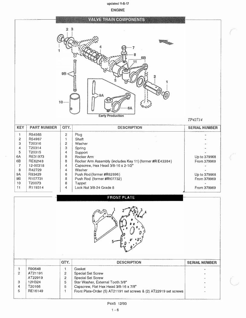
updated 11-6-17

KEY PART NUMBER QTY.
1 R54565 2
2 R54987 1 3 120316 2 4 T20314 3
5 T203·15 4 6A RE31973 8
6B RE62148 8
7 12-00318 4 8 4
9A 8
9B 8
10
R42729R83429R107731T20073 8
11 R119314 4
QTY.
R90648 1 2 AT21191 2
AT22919 2 3 12H324 5 4 T20166 5
5 RE16149 1
ENGINE
DESCRIPTION
Plug Shaft Washer
Spring Support Rocker Arm Rocker Arm Assembly (includes Key 11) (former #R E43384)Capscrew, Hex Head 3/8-16 x 2-1/2" Washer Push Rod (former #R82896)Push Rod (former #R107732)Tappet lock Nut 3/8-24 Grade 8
DESCRIPTION
Gasket Special Set Screw Special Set Screw Star Washer, External Tooth 3/8" Capscrew. Flat Hex Head 3/8-16 x 7/8" Front Plate-Order (5) AT21191 set screws & (2) AT22919 set screws
P445 12/93
1 - 6
TP42714
SERIAL NUMBER
Up to 379968 From 379969
Up to 379968 From 379969
From 379969
SERIAL NUMBER
updated 11-6-17


P4451 - 8
ENGINE
KEY PART NUMBER QTY DESCRIPTION SERIAL NUMBER
1 R 10 5 3 8 3 1 O i l P an - 2 R 9 73 4 2 1 G aske t -
3 12 H 3 0 4 2 8 L o ck W ash er 3 / 8 ” -4 19 H 3 4 11 2 0 C apscr ew 3 / 8 x1 -1/ 8 ” -5 19 H 3 0 6 5 8 C apscr ew 3 / 8 x 2 ” -6 M 174 6 T 1 D r ai n P l u g 7/ 8 - 14 -7 T 13 2 13 1 W ash er -
8 R 4 715 1 3 O -R i n g -9 R 2 74 74 3 D r ai n P l u g, 5 / 8 O -R i n g P o r t -
10 2 1-110 0 4 1 P i pe P l u g 3 / 4 ” N P T -
T P 2 8 3 9 9 co de 19 0 8
page added 11-6 -17
Oil Pan

KEY PART NUMBER QTY DESCRIPTION SERIAL NUMBER
1a R E 3 12 9 9 1 A dapt er ( n o l o n ger ava i l ab l e. R epl ace d b y R E 70 9 79 ) -( al so o r der 3 8 H 10 4 5 , R 6 3 5 4 8 & R 2 6 4 4 8 as r eq u i r ed. ) ( m ar ke d R 9 15 9 7)
1B R E 70 9 79 1 A dapt er ( M ar ke d R 13 12 3 8 ) -2 R 5 4 8 2 3 1 A dapt er F i t t i n g -3 15 H 6 6 6 * * P i pe P l u g 3 / 8 ” ( u s e w i t h R E 3 12 9 9 ) -4 15 H 2 75 * * P i pe P l u g 1/ 4 ” ( u s e w i t h R E 3 12 9 9 ) -5 T 19 0 4 4 1 O i l F i l t er -6 19 H 2 73 2 1 C apscr ew 3 / 8 ” x 2 -3 / 4 ” -7 19 H 3 75 1 1 S cr ew 3 / 8 ” x 1-3 / 8 ” -
8 R 9 8 4 8 8 1 G aske t -9 19 H 19 2 5 1 C apscr ew 3 / 8 ” x 4 -1/ 4 ” -10 2 4 M 710 6 1 W ash er 10 x 18 x 2 . 5 0 0 m m -11 R 2 6 4 4 8 1 O -R i n g ( u se w i t h R E 70 9 79 ) -12 R 2 72 18 1 F i t t i n g P l u g ( u se w i t h R E 70 9 79 ) -
* * as r eq u i r ed
TP55120 CODE 5901
ENGINE
page added 11-6 -17
P4451 - 8 A
Oil Filter & Horizo ntal Adapter
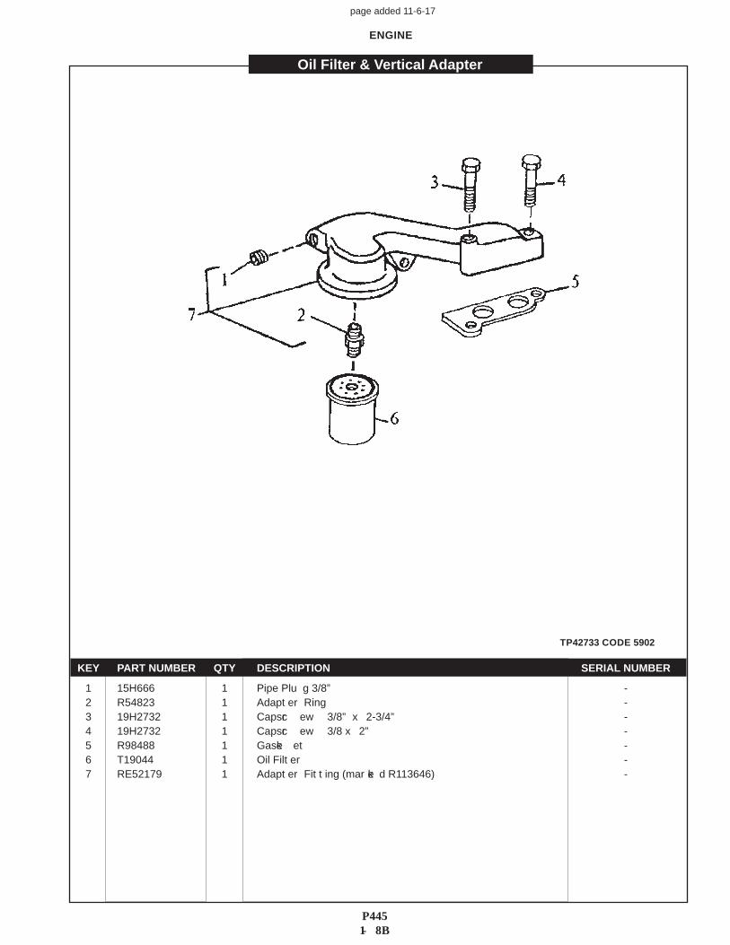
KEY PART NUMBER QTY DESCRIPTION SERIAL NUMBER
1 15 H 6 6 6 1 P i pe P l u g 3 / 8 ” -2 R 5 4 8 2 3 1 A dapt er R i n g -3 19 H 2 73 2 1 C apscr ew 3 / 8 ” x 2 -3 / 4 ” -4 19 H 2 73 2 1 C apscr ew 3 / 8 x 2 ” -
5 R 9 8 4 8 8 1 G aske et -6 T 19 0 4 4 1 O i l F i l t er -7 R E 5 2 179 1 A dapt er F i t t i n g ( m ar ke d R 113 6 4 6 ) -
TP42733 CODE 5902
ENGINE
page added 11-6 -17
P4451 - 8 B
Oil Filter & V ertical Adapter

2
1 \
1-�
KEY PART NUMBER QTY.
AR79463 1 1 R116424 2 2 R74553 2 3 RE19651 1 4 R61871 1 5 R79560 1 6 AR85788 1
R54632 1 8 T20298 9 14H826
10 R54815 R115390
11 R80632 R97185
12 R79561 R112867
13 R66177 14 R79562 15 R79363 16 R80632 17 RE15490
ENGINE
. .
El\l�II\IE l'ill12 llll9MR _
Early Production Up To Serial Number-XXXXX-427006
DESCRIPTION
Oil Pump Assembly (includes keys 1-7, 13 & 16) Capscrew Washer Oil Pickup O-RingAdapterGear and Shaft Assembly (also requires R66177)CoverGear 33 teethHex Nut 1/2-13 (Thin)FrrtingBushing (use with Cylinder Block marked R108755)O-Ring (Former# R77052)O-Ring (use with Cylinder Block marked R108755)Oil TubeOil Tube (use with Cylinder Block marked R108755)Gear (also requires AR85788)FittingSleeveO-RingHousing (includes Key 5)•• As Required
P445 12/93
1 • 9
TP21298 code 5001
SERIAL NUMBER
updated 11-6-17

KEY
�
1 2 3 4
6
8
10 11 12 13 14 15 16
KEY
1 2 3
4 5 6 7
PART NUMBER
RE55343 R57059 R74552 R74553
M3853T AR62978 T20091
R54614 R74354 R61871 14H826 R74553 RE36425 R113752 T20298
PART NUMBER
36-7100335-7100218-7103521-7104221-7104021-10005T13213
QTY.
1 2 2 2
1 1 2
QTY.
1 1 1 2
ENGINE
Late Production
From Serial Number XXXXX-427007
DESCRIPTION
Oil Pump Assembly (incudes Keys 4-12) Capscrew Capscrew
Washer 0.394 x 0.630 x 0.120" Cover (not available separately- included in Oil Pump Assembly) Groove Pin
Gear and Shaft Assembly (includes Key 5 - also requires R54614) Dowel Pin Housing (marked R54615 - not available separately- included in Oil Pump Assembly) Gear (also requires AR62978) O-RingO-RingNut 1/2-13WasherOil PickupTubeGear 33 Teeth
Drain Fitting Shut Off Valve Hose 1/2"ID x 18"
DESCRIPTION
Female Swivel, Brass 1/2 Hose Barb x 1/2-45T Male Connector, Brass 1/2NPT x 1/4-45T Plug, Hex Head Steel 1/2NPT Washer
P445 12/93
1 · 10
16
l
e TP43829 code 5001
SERIAL NUMBER
A605/B-1907
SERIAL NUMBER
updated 11-6-17

KEY PART NUMBER QTY.
" RE48615 RE48616
2 R85363 18 3 A3910R 2 4 R98063 4
R98335 4 R85687 4 R93910 4
5 R43409 2 6 1 7 1 8
21-51900 R125863 R91903 1
9 12-00512 1 10 R90692 4
R97492 4 R97493 4
11 R98062 4
R97490 4 R97491 4
12 RE31617 8
13 R26125 8 14 RE31323 8 15 R91889 18
ENGINE
0
DESCRIPTION
Cylinder Head Assembly (includes Keys 3-5 & 10-15) Cylinder Head (marked R97628 - includes Keys 5-7) Capscrew (marked E112)" Expansion Plug Valve Seat Insert - (Standard size intake valve) Valve Seat Insert - (Oversized intake valve) Valve Seat Insert - (Standard size exhaust valve) Valve Seat Insert - (Oversized exhaust valve) Expansion Plug Plug 1/BNPT Gasket (former #R92425)Lifting Bracket Capscrew, Hex Head 1 /2-13 x 1" Exhaust Valve Standard Exhaust Valve .015" Oversize Exhaust Valve .030" Oversize Intake Valve Standard Intake Valve .015" Oversize Intake Valve .030" Oversize Seal Spring Rotator Keeper • Note: Replace all capscrews marked M112 with those
marked E112.
P445 12/93
1 - 11
TP42629
SERIAL NUMBER
updated 11-6-17

KEY 1 2 3 4 5
6
78
KEV
2 3 4 567
I I I
!
ENGINE
\ '·. \ '.,·
� /, __ HUMP / HOSE
PART NUMBER QTY.
10-71009 1 R73521 1 12-00112 8 15-00121 8 R9215418-0001118-7250921-00025R56463
PART NUMBER QTY.
AT18015 AT22843 R73521 AR100124 8
T20294 T20327R92154R56463
DESCRIPTION
Rocker Arm Cover
Gasket Capscrew, Hex Head 1 /4-20 x 1" Flat Washer 1/4 SAE Elbow (former #AT25192) (order also O-ring R56463)Hose 3/4" ID x 4" (w/o Turbo) Hose 3/4" ID x 9-1/2" (w Turbo) PVC Elbow 90', 3/4 HB x 3/4 HB O-Ring (used with elbow R92154
DESCRIPTION Rocker Arm Cover (no fill - Industrial & C-Series) Rocker Arm Cover (center fill - Industrial only) Gasket Screw with Washer Cap Gasket Elbow, Breather Outlet (order also O-Ring R56463)*O-Ring (used with elbow R92154)*
* See upper parts illustration
P445 12/93 1 - 12
A3805F, A3819D/C-2220C
SERIAL NUMBER
SERIAL NUMBER
updated 11-6-17
1
11


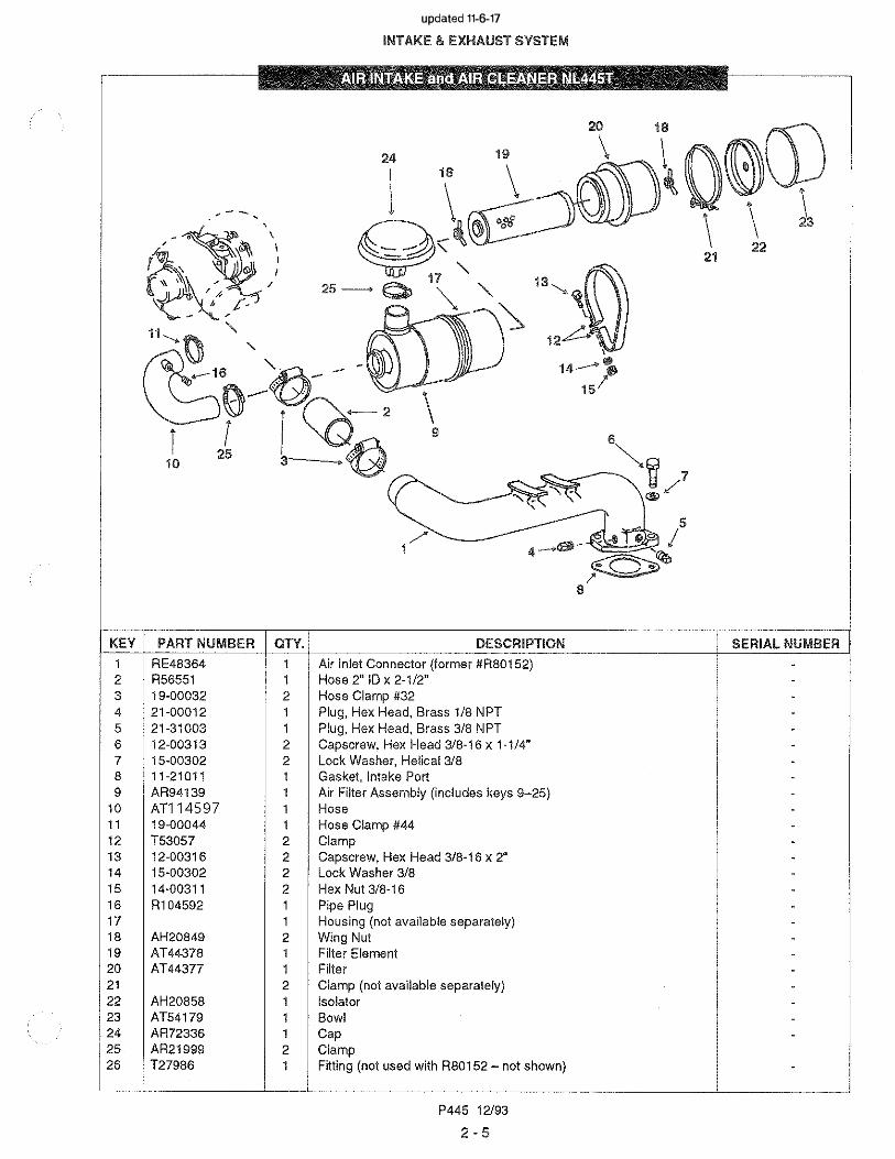
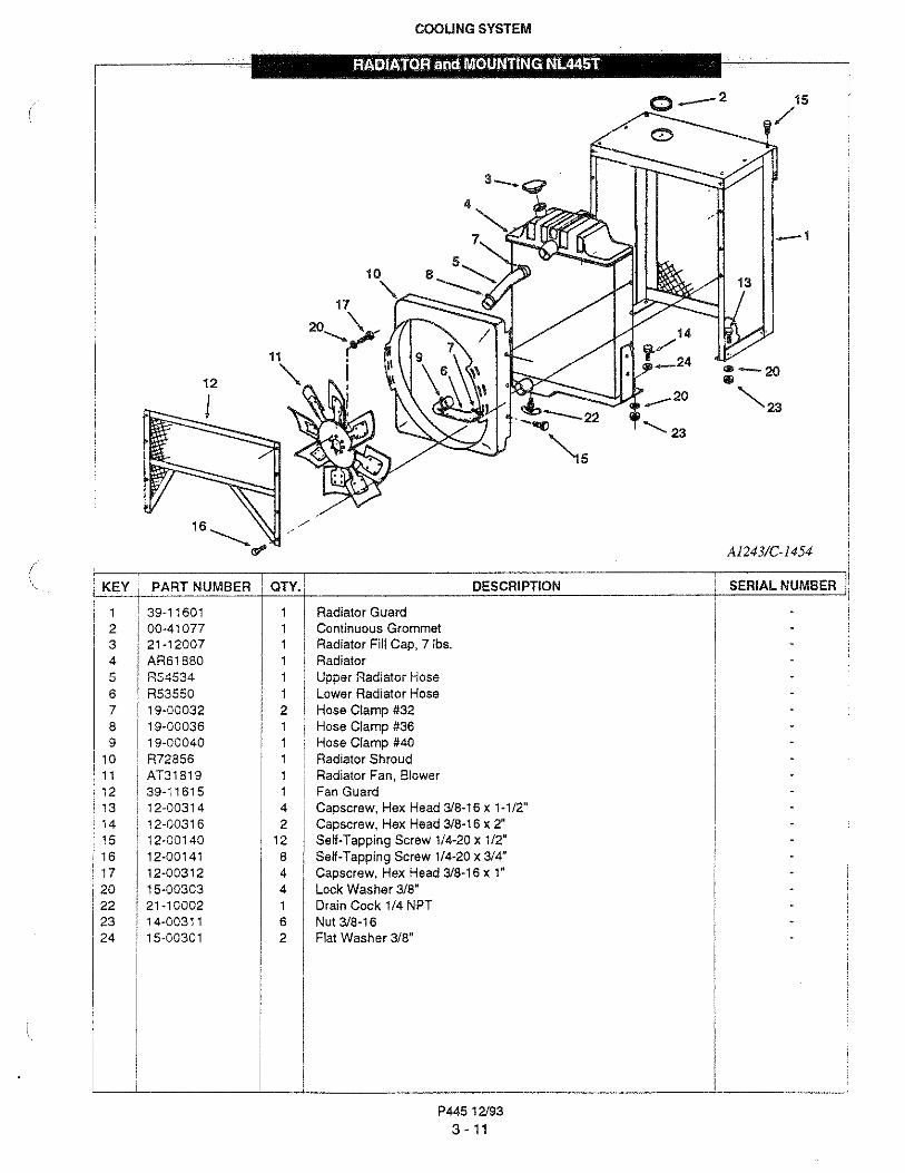
KEY PART NUMBER QTY.
1 10-21400 1 2 11-21011 1 3 12-00319 1 4 12-00300 1 5 15-00301 2 6 21-00012 1 7 23-21000 1 8 21-10003 1 9 24-21000 1
10 12-00312 2 11 18-21004 1
18-21020 1 12 19-00036 1 13 19-00032 4 14 19-00072 1 15 19-00128 1 16 30-21400 1 17 11-31401 1 18 23-21101 1 19 14-00817 4
20 15-00804 4
21 R43928 1 22 11-31012 1 23 12-00714 2 24 15-00702 4 26 21-00606
21 -5280011
27 27-3140627- 01401
11
28 27-31602 1 29 11-31031 1 30 12-00712 2 31 27-31402 1 32 18-11010 1 33 19-00012 2 34 R41285 1 35 16-01000 1 36 27-21010 1 37 18-21016 2 38 21-49999 1 39 21-10002 1 40 12-00311 2 41 15-00302 2 42 18-21014 1 43 13-00814 4
INTAKE & EXHAUST SYSTEM
DESCRIPTION
Intake Manifold Gasket Capscrew, Hex Head 3/8-16 x 2-3/4" Capscrew, Hex Head 3/8-16 x 3-1 /2" Flat Washer 3/8" Plug, 1/8 NPT Bracket Hex Plug 1/4NPT Air Filter Capscrew, Hex Head 3/8-16 x 1" Hump Hose (with vent hole M445T) Hump Hose (w/o vent hole - C-Series) Hose Clamp #36 Hose Clamp #32
Hose Clamp #72 Hose Clamp #128 Turbocharger (includes Key 43 - see parts detail) Gasket Bracket Hex Nut M1 Ox 1.5 Stainless Steel Wave Washer M1 0 Adapter, Turbo Oil Feed ( can use 31-31048)Gasket Capscrew, Hex Head M8 x 1.25 x 40mm Lock Washer M8 Male Elbow 90° Steel 3/8N PT x 3/8-37T (horizontal oil filter)Male Connector, Steel 3/8 NPT x 3/8-37 T (vertical oil filter)Tube Assembly, Turbo Oil Supply (horizontal oil filter)Tube Assy, Turbo Oil Supply (vertical oil filter)Oil Return Pipe. Upper Ha� Gasket Capscrew, Hex Head 8 x 25mm Oil Return Pipe, Lower Half Hose, 3/4" ID x 4-1/4" silicon Hose Clamp #12
Adapter, O-Ring Seal x 1/2NPT O-RingIntake Tube Assembly (former # 27-21072)Hose, 2" ID x 2"Bushing 7/8-14 x 1/4NPTFDrain Cock 1/4NPTCapscrew, Hex Head 3/8-16 x 3/4"Lock Washer 3/8
Hose, 2"ID x 2-3/8"
Stud, M10 x 1.5 x 40mm
P445 12/93
2-3
SERIAL NUMBER
-
-
-
-
"
"
"
-
-
"
-
"
-
-
"
-
-
-
"
"
-
"
-
"
-
"
"
-
"
-
"
"
-
"
"
"
-
-
"
-
-
-
updated 11-6-17
"
"

2�
9-------- 4'
/
3��
Figure "A"
KEY PART NUMBER QTY.
1 2 3 4
5
6
7 8
9
1 2 3
4 5 6 7 8
24·20001 T31948 11-2101128·2100119·0004412·0031515·0030221 ·0001221-31003
24-2000118-2100519-00044T2582921·3100311·2101112-0031315·00302
2 2 1
1 2 2
INTAKE & EXHAUST SYSTEM
----1
1--�
53
6
7
��8 4
DESCRIPTION
Figure "A" Aluminum Air Inlet
Air Filter Air Inlet Gasket Spacer Plate Hose Clamp #44 Capscrew, Hex Head 318-16 x 1 ·3/4" Lock Washer, Helical 3/8 Plug, Hex Head, Brass 1/BNPT Plug, Hex Head, Brass 3/8NPT
Figure "B" Cast Iron Air Inlet
Air Filter Hose 2·1/4"1D x 1-1/2" Hose Clamp #44 Air Inlet Plug, Hex Head Brass 3/BNPT Gasket Cap Screw, Hex Head 3/8·16 x H/4" Lock Washer, Helical 3/8
P445 12/93
2-4
i-7
----6
Figure "B"
A6511 & A5550
SERIAL NUMBER
updated 11-6-17
updated 11-6-17


4
KEY PART NUMBER
1 10·31000 10-3100110-31002
2 : 27-11101 3 16-31000
R546415 13-00337
13-003367 15-00300
14-003219 11-31011
10 12·00325 11 17-10001
I
KEY PART NUMBER 10·31504
2 10·31513 10-31506
31-310123 11-300134 12-00414
i15-004026 21-10001
INTAKE & EXHAUST SYSTEM
11
'QTY. DESCRIPTION
1 I Exhaust Manttold Assembly w/ Diy Flange •1 Exhaust Manifold Assembly w/ Wet Flange •1 Exhaust Manifold Assembly w/ Wet Elbow Adapter •1 Coolant Connector 1 O.Ring1 Gasket5 Stud 3/8-24 x 3/8-16 x 2" (special)3 Stud 3/8·24 X 3/8-16 X 2"
10 Washer 3/8 (special)8 Hex Nut 3/8-244 Gasket2 Capscrew, 12 point 3/8-16 x 1 •1 Expansion Plug
• See Exhaust Manifold & Adapter Detail for components
' <:;�\\ 1 i
.
1 ' �,#··" ' ' � • �
'@"'"' :� '_,�· \ . f1 ! .-
�) 6� h-4 ·,
QTY. I DESCRIPTION 1 Exhaust Manifold 1 Dry Exhaust Flange Adapter 1 Wet Exhaust Flange for Turbo Mounting 1 Wet Exhaust Elbow Adapter 1 Gasket 4 Capscrew, Hex Head 7/16-14 x 1·1/2" 4 Lock Washer 7/16 1 ; Drain Cock 1/SNPT
P445 12/93
2•7
I
A4656. A4657,
A4658/C26J2
SERIAL NUMBER
A4653, A4654, A4655/C-2648
SERIAL NUMBER .
.
.
.
.
.
.
updated 11-6-17

KEY PART NUMBER QTY.
1 12-00313 8
2 24H1304 8 3 T20200 1
T20249 1 4 R90658 4 5 31-31310 1
31-3100331-31008 1
6 AT63B13 2 7 12-00214 2
INTAKE & EXHAUST SYSTEM
Front and Rear Outlet
DESCRIPTION
Capscrew, Hex Head 3/8-16 x 1-1 /4" Flat Washer, Special Exhaust Manifold, Rear Outlet Exhaust Manifold, Front Outlet Gasket Exhaust Adapter 2" NPT Exhaust Adapter 3" NPT Exhaust Adapter, S/S 18" x 4" FlangeHalf Clamp with Integral Nut Capscrew, Hex Head 5/16-18 x 1-1/2"
P445 12/93
2·8
A213C, A6297,
A6295/B-1532B
SERIAL NUMBER
updated 11-6-17


KEV
2 3 4 5 6 7 8
9
10
KEY
1 2 3
4 5
6 7
PART NUMBER
27-3101111-3161521-3100212-0031514-0031115-0030212-0091615-0090214-0091111-31094
PART NUMBER
19-3140121-3100227-3141512-0091615-0090214-0091111-31094
QTY.
1 4 4 4 4 4 4
QTY.
4 4 4 1
INTAKE & EXHAUST SYSTEM
DESCRIPTION
Dry Exhaust Elbow Gasket Plug, Brass 3/8 NPT Capscrew, Hex Head 3/8-16 x 1-3/4" Hex Nut, 3/8-16 Lock Washer, 3/8 Capscrew, Hex Head 5/8-11 x 2" Lock Washer 5/8 Hex Nut 5/8-11 Gasket
-4
DESCRIPTION
V-ClampPlug, Brass 3/8 NPTDry Exhaust ElbowCapscrew, Hex Head 5/8-11 x 2" Lock Washer, 5/8Hex Nut, 5/8-11Gasket
P445 12/93
2 - 10
A457DIB-1725
SERIAL NUMBER
A912D/B-2910
SERIAL NUMBER
updated 11-6-17
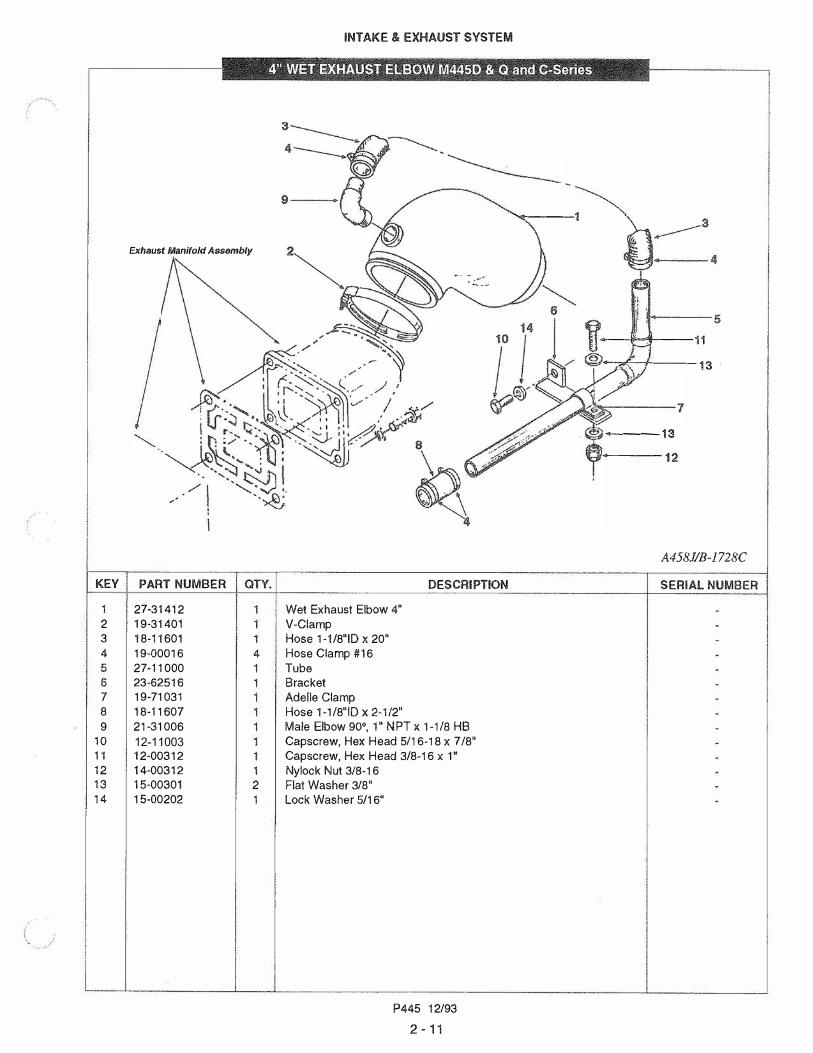
Exhaust Manifold Assembly
KEY PART NUMBER QTY.
1 27·31412 2 19-314013 18-116014 19-00016 4
5 27-110006 23-625167 19-710318 18-116079 21-31006
10 12-1100311 12-0031212 14-00312 1 13 15-00301 2
14 15-00202 1
INTAKE & EXHAUST SYSTEM
DESCRIPTION
Wet Exhaust Elbow 4" V-ClampHose 1-1/8"ID x 20"Hose Clamp #16TubeBracketAdelle ClampHose 1-1/8"ID x 2-1/2"Male Elbow 90°, 1" NPT x 1-1/8 HB Capscrew, Hex Head 5/16-18 x 7/8" Capscrew, Hex Head 3/8-16 x 1"Nylock Nut 3/8-16Flat Washer 3/8"lock Washer 5/16"
P445 12/93
2 - 11
�---1
-+4---11
,_,,.,_-1-----13
---13
·----12
A458J/B-1728C
SERIAL NUMBER

j
KEY PART NUMBER QTY.
1 27·31412 2 19·31401 3 18·11601 1 4 19-00016 4 5 27-11000 1 6 23·625167 8 9
10
19-71031 18·11607 21·31006 12·11003
11 12-0031212 14-0031213 15-0030114 15-0021115 15-00202
INTAKE & EXHAUST SYSTEM
' . ''
DESCRIPTION
Wet Exhaust Elbow 4" V-ClampHose H/8 ID x 20"Hose Clamp #16TubeBracketAdelle ClampHose 1-1/8" ID x 2·1/2"Male Elbow 90', 1" NPT x 1-1/8 HB Capscrew, Hex Head 5/16-18 x 7/8" Capscrew, Hex Head 3/8-16 x 1" Nylock Nut 3/8-16Flat Washer 3/8"Flat Washer 5/16"Lock Washer 5/16"
P445 12/93
2 · 12
5
---l-l----11
�1---:l�-13
�--7
�--12
A9l3EIB-2888
SERIAL NUMBER
updated 11-6-17

KEV PART NUMBER
- 30-21400• 30-314301 30-314292 30-314313 30-314334 30-314345 30-314356 30-314367 30-314378 30-314389 30-31439
10 30-2140111 30-3144112 30-3144213 30-3144314 30-3144415 30-3144516 30-3144617 30-3144718 30-2140219 30-3144820 30-3144921 30-3145022 14-0113123 30-3145224 30-3145325 13-0081426 30-3145427 30-3145528 30-31428
INTAKE & EXHAUST SYSTEM
. .
lEl!l�flU\l!i!fi!Alil�El!R AS'SEMBlli¥ M!fi!Sill 81 & ei,-Series . .
QTY.
1 1 2 4 1 1 1 1 1 4 1 1 1 4 1 1
1 3 6 3 6 6 4 4 1 2 1
2
7
6
DESCRIPTION
Turbocharger Assembly (ID Tag #5326 970 60 90 - includes all Keys) Repair Kit (includes Keys 4, 5, 11-17, 19-22, 24 & 28) Spacer Sleeve Turbine Housing Bearing Housing Bushing Snap Ring Heat Shield Shaft & Turbine Wheel Assembly Thrust Ring Flinger Sleeve Compressor Wheel Piston Ring Thrust Plate Oil Deflector Backing Plate Screw Nut O-RingCompressor HousingClamp PlateCapscrew, Socket Head M6 x 1.0 x 14mmClamp PlateHex Nut M6 x 1.0Stud M6 x 1.0Lock Washer M6Stud M10 x 1.5 x 30mmPlateRivetO-Ring
P445 12/93
2 • 13
SERIAL NUMBER
updated 11-6-17


KEV PART NUMBER
1 10-110222 10-110233 21-100074 11-110225 35-110006 35-110047 11-100158 10-110249 11-11013
10 11-1102311 21-0013512 21-1000213 21-1000014 21-1001015 12-2011116 12-0022317 12-0021218 12-0031319 15-0001820 15-0020221 15-0030222 00-0000623 18-1210224 21-3103125 21-0053026 21-3100827 21-1100328 21-1100431 15-0022232 15-1100033 10-1102534 10-1103135 18-0013036 12-0011137 15-0010238 31-0100239 18-1160640 19-0002041 12-0031242 23-1140143 11-1104344 10-1100645 12-0031346 17-10001
COOLING SYSTEM
..
EXR'AIIISIE!lll@r�NK}lSSEMBl12¥- l\lllHllllllE AE!F!J.;ICAllilOIII
QTY.
1 1 1 1 2 1 2 1 1 1 1 1 1 1 6 2 4 6 6 4 6 1 1 1 ..
1 1 1 2 2 1 1 1 6 6 1 1 2 2 1 1 1 2 4
DESCRIPTION
Expansion Tank Filler Neck (Hi & Low Fill) Filler Cap 7 lb. Filler Neck Gasket (Hi & Low Fill) Thermostat Thermostat Retainer Gasket Thermostat Cover Gasket Manifold to Expansion Tank Gasket Brass Bushing 1/2 NPT x 1/4 NPT Drain Cock 1 /4 NPT Plug 1/2 NPTx 7/16-14 Zinc
Capscrew, Socket Head 1 /4-20 x 3/4" Capscrew, Hex Head 5/16-18 x 3/4" (Stainless Steel) Capscrew, Hex Head 5/16-18 x 1" Capscrew, Hex Head 3/8-16 x 1-1/4" Lock Washer, High Collar 1/4 Lock Washer 5/16" Lock Washer 3/8" Nameplate "Northern Lights" Overflow Hose 3/8" x 30" Special Nipple 3/4 NPT x 1-1/2" Brass Hex Plug 1/2 NPT Hex Plug 3/8 NPT Plug, Socket Head 1/2 NPT Plug, Socket Head 3/4 NPT Lock Washer, Stainless Steel 5/16 Flat Washer, Stainless Steel 5/16 Blocking Plate (low fill) Thermostat Cover (low fill) Hose 1/4" x 30" (low fill) Capscrew, Hex Head 1/4-20 x 3/4" (low fill) Lock Washer 1/4" (low fill, remote fill) Expansion tank adapter (remote fill) Hose Hose Clamp Capscrew, Hex Head 3/8-16 x 1" Bracket Gasket Keel Cooling Connector (Keel Cooled Application Only) Capscrew, Hex Head 3/8-16 x 1-1 /4" Expansion Plug, Brass
P445 12/93
3 - 1
SERIAL NUMBER
-
-
-.
.
.
.
.
-
.
--
-
.
.
--
-
.
-
-
---
--
-
.
-
-
.
-
.
---
-
-
.
-
-
-
-
-
updated 11-6-17


1
KEY PART NUMBER QTY. .. AR77142
T20243 2 R56070 3 R56809 4 R56812 5 AR101549 1 6 JD8643 1
21-00531 1 8 12-00314 5
12-0031712-00312
9 R3498510 AR8011611 R56810 1
12 14-00311 1
13 15-00302 1 14 12-00315 1
12-00318 1 12-00310 1
15 T2570116 R5646117 R55967
COOLING SYSTEM
17 ToExpanslonTank"- / 16
�0/
4
DESCRIPTION
Circulating Pump Assembly (includes Keys 2-11 & 14) Gasket Cover Gasket Impeller Seal Kit Bearing & Shaft Assembly Plug, Square Head 1/2NPT Capscrew, Hex Head 3/8-16 x 1-1/2" Capscrew, Hex Head 3/8-16 x 2-1/4" Capscrew, Hex Head 3/8-16 x 1" line Housing (marked R90784 or R104648) Pulley Hex Nut 3/8-16 Lock Washer 3/8 Capscrew, Hex Head 3/8-16 x 1-3/4" Capscrew, Hex Head 3/8-16 x 2-1/2" Capscrew, Hex Head 3/8-16 x 3" Stud O-RingBypass Tube
P445 12/93
3-3
TP26804
SERIAi. NUMBER
updated 11-6-17
updated 11-6-17

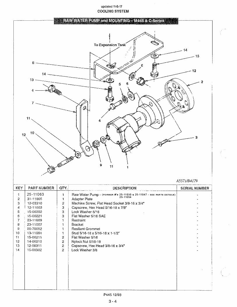
KEV PART NUMBER QTY.
25-11030
1 25-11045
2 25-11040
3 25-11037
4 25-11041
5 25-11031
6 25-11032
7 25-11024
8 25-11033
9 25-11034 2
10 25-11035 4
11 25-11036 1
12 25-11044 1
DESCRIPTION
Raw Water Pump (includes all Keys) Housing
Carrier Assembly (includes Key #9) Cam Cover
Impeller Gasket 0-RingSealBearingScrew
Screw
Washer
P445 12/93
3-5
IC
C-2016A
SERIAL NUMBER
(Johnson)
page added 11-7-17
COOLING SYSTEM

Key Part Number Qty Description Serial Number
1 1 P u m p H o u si n g * -2 2 5 -110 5 1 1 B ear i n g H o u si n g A sse m b l y F o r 2 5 -110 4 7 R aw W at er P u m p -3 2 5 -110 0 6 1 C am -4 2 5 -110 0 5 1 E n d C o ve r “ L u gger / N o r t h er n L i gh t s” ( 76 M m o d 6 -H o l e) - 5 2 5 -110 0 2 1 I m pel l er K i t W i t h C o ve r G ask et & O -R i n g -6 2 5 -110 0 3 1 G aske t -7 2 5 -110 0 7 1 S n ap R i n g, B eve l ed E xt er n al -8 2 5 -12 0 6 6 1 M ech an i ca l S eal -9 2 5 -110 5 3 1 B al l B ear i n g -10 2 5 -110 13 6 M S C R F i l l i st er H ead # 8 -3 2 x 1/ 4 ” B r ass -11 2 5 -110 4 8 1 M S C R , F i l l i st er H ead # 12 -2 4 X 5 / 16 ” B r ass -12 2 5 -110 5 2 1 S n ap R i n g, I n t er n al -13 N o t e 1 N o t e D esc ( F o r M i sc P ar t s S al es O n l y)
* N o t ava i l ab l e se par at el y
Raw Water Pump, J absco
page added 11-7-17
COOLING SYSTEM
P4453 - 5A
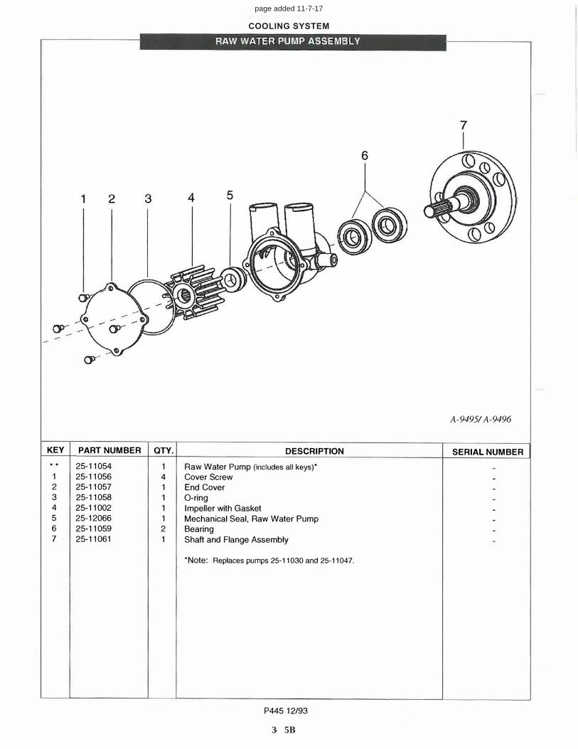
RAW WATER PUMP ASSEMBLY
A-9495/ A-9496
KEY PART NUMBER QTY. DESCRIPTION SERIAL NUMBER
25-11054 1 Raw Water Pump (includes all keys)* 1 25-11056 4 Cover Screw 2 25-11057 1 End Cover 3 25-11058 1 O-ring4 25-11002 1 Impeller with Gasket5 25-12066 1 Mechanical Seal, Raw Water Pump6 25-11059 2 Bearing7 25-11061 1 Shaft and Flange Assembly
*Note: Replaces pumps 25-11030 and 25-11047.
P445 12/93
page added 11-7-17
COOLING SYSTEM
3 - 5B

Key Part Number Qty Description Serial Number
• 2 5 -110 6 3 1 P u m p - i n cl u des al l ke ys - 1 2 5 -110 6 6 4 E n d C o ve r S cr ew s -2 2 5 -110 5 7 1 E n d C o ve r -
3 2 5 -110 5 8 1 O -R i n g - 4 2 5 -110 0 2 1 I m pel l er - 5 2 5 -110 6 4 1 C am -
6 2 5 -110 6 7 1 C am S cr ew -
Raw Water Pump Assembly, J absco
P4453 - 5C
page added 11-7-17
COOLING SYSTEM


KEY PART NUMBER QTY.
1 12-00316 2 2 15-00302 5 3 12-003124 R546395 R54638 1 6 AR48675 2 7 R54637 1 8 R56461 2 9 R55967 1
10 12-00354 2 11 R54641
.
IHERM©SIAI HOUSING
( Industrial Application)
DESCRIPTION
Capscrew, Hex Head 3/8-16 x 2" Lock Washer, Helical 3/8 Capscrew, Hex Head 3/8-16 x 1" Cover Gasket Thermostat 180'F Housing O-RingTubeCapscrew, Hex Head 3/8-16 x 3-3/4"Gasket
P445 12/93
3 · 10
A221/B-1543B
SERIAL NUMBER
updated 11-6-17
COOLING SYSTEM

COOLING SY STEM
Radiator Kit Assembly
page added 11-7-17
P4453 - 1 1 A
C-3100

Key Part Number Qty Description Serial Number
1 3 9 -110 0 2 2 S i de P an el , M o du l ar R adi at o r G u ar d -2 3 9 -110 0 5 1 T o p P an el , M o du l ar R adi at o r G u ar d -3 3 9 -110 0 6 1 R adi at o r S u ppo r t , M o du l ar R adi at o r G u ar d -4 3 9 -110 0 4 1 G r i l l e, M o du l ar R adi at o r G u ar d -5 R e5 76 9 5 1 R adi at o r A ssy W / S h r o u d & F an G u ar d -6 A t 2 4 8 3 4 1 F an 2 3 ” ( B l o w er ) -7 R 8 19 11 1 S pace r , F an M t g. -8 12 -0 0 3 0 0 4 C apscr ew , H ex H ead 3 / 8 -16 X 3 -1/ 2 ” G r ade 5 -9 15 -0 0 3 0 2 4 L o ck W ash er , H el i ca l 3 / 8 ” -10 12 -0 0 3 13 4 C apscr ew , H ex H ead 3 / 8 -16 X 1-1/ 4 ” G r ade 5 -11 12 -0 0 3 6 2 4 C apscr ew , H ex H ead 3 / 8 -16 X 1/ 2 -12 12 -0 0 3 11 14 C apscr ew , H ex H ead 3 / 8 -16 X 3 / 4 ” G r ade 5 -13 12 -0 0 3 14 2 C apscr ew , H ex H ead 3 / 8 -16 X 1-1/ 2 ” G r ade 5 -14 15 -0 0 3 0 2 10 L o ck W ash er , H el i ca l 3 / 8 ” -15 15 -0 0 3 0 1 6 F l at W ash er 3 / 8 ” U ss Z i n c P l at ed A n si T yp e A -16 14 -0 0 3 12 14 H ex N u t , N yl o ck 3 / 8 -16 -17 12 -0 13 12 2 C apscr ew , H ex H ead 5 / 8 -11 X 1” -18 15 -0 13 3 0 2 F l at W ash er 5 / 8 ” S ae Z i n c P l at ed A n si T yp e A -19 14 -0 0 9 12 2 H ex N u t , N yl o ck 5 / 8 -11 -2 0 2 1-2 10 0 4 2 S pace r , B p. 1/ 2 S ch d 4 0 X 13 / 16 ” -2 1 R 8 19 12 1 H o se , R adi at o r I n l et -2 2 R 6 14 3 3 1 H o se , R adi at o r O u t l et -2 3 19 -0 0 0 3 6 3 H o se C l am p # 3 6 S / S -2 4 19 -0 0 0 4 0 1 H o se C l am p # 4 0 S / S -2 5 0 0 -70 0 8 2 1 L ab el , ” N o r t h er n L i gh t s” 2 ” X 2 2 ” -2 6 14 -0 0 3 0 1 6 U -N u t 3 / 8 -16 -
COOLING SY STEM
Radiator Kit Assembly
page added 11-7-17
P4453 - 1 1 B


KEY PART NUMBER QTY.
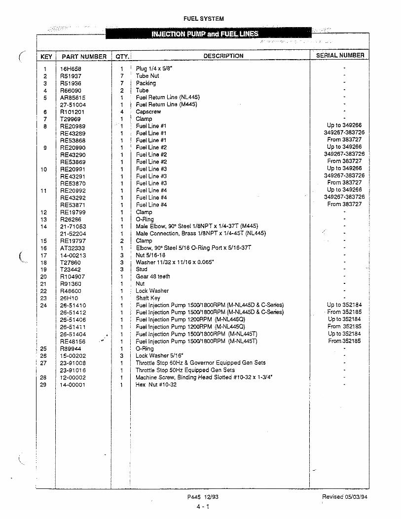
- RE51649 1 1 RE63181 1 2 N/ A separately 1 3 N/ A separately 1 4 N/ A separately 1 5 N/ A separately 1 6 N/ A separately 1 7 N/ A separately 1 8 R113562 1 9 R113563 1 10 R26286 4 11 R27094 2 12 24-51005 1 13 R113565 1 14 15-51001 1 15 21-51005 1 16 AT32333 1 17 RE54757 1 18 RE36550 1 19 21-00048 1 20 12-00312 2
12-00314 2 21 15-00302 2 22 15-00301 2 23 00-51001 1 24 RE50752 1
FUEL SYSTEM
•
I ---- - 1 3
�� 12
' -
'----"'---- j 4 0
�----- 15
�
7 - _,__
TO FUEL
PUMP
DESCRIPTION
Repair Kit (includes keys # 2,3,6,&9) Filter Head (replaces RE55762) Retainer (included in Repair Kit RE51649) Cap (included in Repair Kit RE51649) Packing (included in Seal Kit RE50752) O-Ring (included in Seal Kit RE50752)Valve (included in Repair Kit RE51649)Clamp Ring (included in Repair Kit RE51649) O-RingVent PlugO-RingPlugFilter Element (includes keys #13, 14, 15)PackingSealing WasherDrain PlugMale Elbow 90° Steel, 5/16 o-ring port x 5/16-37TTube Asembly, Filter OutletTube Assembly, Filter InletMale Elbow 90° Brass, 1/8 NPT x 5/16 - 45TCap Screw, Hex Head, 3/8-16 x 1" M445D & NL445TCap Screw, Hex Head, 3/8-16 x 1-1/2" M445T & C-SeriesLock Washer 3/8Flat Washer 318Warning LabelSeal Kit (includes keys# 4,5,8 & 13)
P445 03/95
4-5
SERIAL NUMBER
updated 11-7-17

KEY PART NUMBER QTY.
2
3 4 5 6
7
8
9
10
11 12 13 14
22-4111022-4111522-7000722-7001812-0000114-0003222-4091522-4101622-7101622-4280322-7480322-4102622-7102622-4280222-74802
22-4092522-4092321-41101RE6847022-41078RE5212022-41414
00-4101521-0002322-40402RE3169410-13422-7105122-71052
1 4 4 1
ELECTRICAL SYSTEM
11
§ I '" 8 • ff @ '
· ··� . ..,
• • •
DESCRIPTION
Wire Harness, Standard Ground
Wire Harness, Isolated Ground Dual Station Relay Board 12Volt (see parts detail) Dual Station Relay Board 24Volt (see parts detail) Machine Screw, Binding Head #10-32 x 3/4" Nylock Hex Nut #10-32 Oil Pressure Switch 15 PSI 1/8 NPTOil Pressure Sender, Standard Ground 1/8 NPTOil Pressure Sender, Dual Gauge Standard Ground 1/8 NPTOil Pressure Sender, Isolated Ground 1/8 NPTOil Pressure Sender, Dual Gauge Isolated Ground 1/8 NPTTemperature Sender, Standard Ground 1/8 NPTTemperature Sender, Dual Gauge Standard Ground 1/8 NPTTemperature Sender, Isolated Ground 1/8 NPTTemperature Sender, Dual Gauge Isolated Ground 1/8 NPTTemperature Switch 215° F 1/8 NPT(Marine)Temperature Switch 225° F (Industrial)Brass Bushing 1" NPT x 1/2 NPT Starter 12Volt Standard Ground (see mounting detail-former #RE19275)Starter 12Volt Isolated Ground (see mounting detail -former #22-41406) Starter 24Volt Standard Ground (see mounting detail -former #RE19737) *Starter 24Volt Standard or Isolated Ground (see mounting detail -former #22-41407, 22-41088 & 22-41411)BushingAdapter 1/8 NPT x 1/8 NPTGround Wire #8 AWG x 16" (not shown)Alternator 12VolV78AMP Std Ground (not shown--,;ee mounting detail)Alternator 12Vo1V72AMP lSOGround (not shown-see mounting detail)Alternator 24Volt/42AMP Std Ground (not shown--,;ee mounting detail)Alternator 24Volt/35AMP lSO Ground (not shown-see mounting detail)
• Alternate for 22-41 411 in Standard Ground application.u As Required
P445 12/93
5 • 1
A6070, A607 l, A6072
A6073/D-2132
SERIAL NUMBER
updated 11-7-17

KEY PART NUMBER QTY.
1 RE31694 2 R87764 3 T42171
34-41016 1 4 T10745 1 5 R11049 1 6 R57260 2 7 28H862 2 8 12-00310 2 9 14-00311 2
10 12-0004911 14-0081212 AR5528313 14-0480314 R10840415 12-0031616 15-00300 3
17 28H151818 12-0071219 15-0070220 21
22 23
15-00201RE51551AT24833R122848R69645
ELECTRICAL SYSTEM
1
2
DESCRIPTION
Alternator (includes Keys 4-5 & 23 - see parts detail) Fan Pulley 1800 RPM Pulley 1200 RPM Washer Hex Nut Mounting Bracket Spacer Capscrew, Hex Head 3/8-1 x 3" Hex Nut 3/8-16 Capscrew, Hex Head M1 Ox 1.5 x 80mm Nylock Nut M1 ox 1.5 Wire Harness
Nylock Nut M6 x 1.0 Tensioner
Capscrew, Hex Head 3/8-16 x 2" Flat Washer 3/8 (special) Spacer
Capscrew, Hex Head MB x 1.25 x 25mm Lock Washer Ma Stud Washer Belt Set 1800 RPM Belt Set 1200 RPM Guard Fan Spacer (not shown)
.. As Required
P445 12/93
5-3
21
SERIAL NUMBER
updated 11-7-17


KEY PART NUMBER QTY.
2 3 4 5
6 7
8
9
10 11 12 13 14 15 16 17 18
10-13422-7105122-7105234-4101931-7110112-00819R10840423-4100614-0081212-0031212-0021215-0030215-0020215-0001215-0020121-411035-14116-123-4100512-0021415-0020215-0003312-00015
1 1 2 2 3
ELECTRICAL SYSTEM
10
Supplied With Alternator
A6079, A6080, A6081/C-2968
DESCRIPTION
Alternator - 12Volt 72Amp, Isolated Ground Alternator- 24Volt 42Amp, Standard Ground Alternator - 24Volt 35Amp, Isolated Ground Pulley, 2 Groove Adapter Capscrew, Hex Head M 1 O x 1.5 x 75mm Tensioning Arm (24 Volt)Tensioning Arm (12 Volt)Hex Nut, Nylock M1 Ox 1.5mm Capscrew, Hex Head 3/8-16 x 1" (12Volt) Capscrew, Hex Head 5/16-18 x 1" (24Volt) lock Washer, Helical 3/8 (12Volt) lock Washer, Helical 5/16 (24Volt) Stud Washer 3/8 (12Volt) Stud Washer 5/16 (24Volt) Spacer 25mm OD x 10mm ID x 8.5mm D.C. Voltage Regulator•Wire Harness"
Bracket*
Capscrew, Hex Head 5/16-18 x 1-1 /2"· Lock Washer, Helical 5/15•
Lock Washer, Helical #1 o·
Machine Screw, BH Phillips #10-32 x 3/8"" Belt Set (not shown - see Belts and Guards selection chart) "For 12Volt 72Amp Alternator only.
P445 12193
5-5
SERIAL NUMBER
updated 11-7-17

KEY PARTIIIUMBER QTY.
RE1927522-41406RE5212022-4140722-4108822-41411
1
2 15-00302
3
3 14-00311
1
4 12-003125 13-003366 15-008027 14-008118 15-044009 12-04406
10 14-0000111 15-00033
RE23379 22-41409RE2224422-4140822-4140822-4141022-41421
12 14-00321
ELECTRICAL SYSTEM
12 2 5
\��-7
1--. Ol lj
24 Volt
12 Voll
DESCRIPTION
Starter 12 Volt ISO GroundStarter 24 Volt ISO GroundStarter 12Volt Standard Ground• Starter i 2Volt Isolated Ground• Starter 24Volt Standard Ground• Starter (former #RE19737)24Volt Isolated Ground• Starter 24Voit Isolated Ground' Starter 24Volt Isolated Ground' Lock Washer 3/8 Hex Nut 3/8-16 Capscrew, Hex Head 3/8-16 x 1" Stud 3/8-16 X 3/8-24 X 2" Lock Washer M10 Hex Nut M10 x 1.5 Lock Washer MS Capscrew, Hex Head M5 x 0.8 x 1 O mm Hex Nut #10-32 Lock Washer #1 O • Solenoid or Switch Assemblies for above starters:Switch Assembly for RE19275Solenoid for 22-41406Solenoid for RE19737Solenoid for 41088 & 41411Solenoid for 22-41407/22-41088/22-41411Solenoid for 22-41078Solenoid for 22-41414Hex Nut 3/8-24
Note: Starters 22-41406 & 22-41407 will be discontinued when stock depleted. Current starters which are direct replacements will then be supplied. 22-41088 NLA, Order 22-41411.
P445 12/93
5-6
I
I
I
SERIAL NUMBER
updated 11-7-17
22-4107822-41414
1
1 1

KEY
1 2
3 4 5 6 8 9
10 11 12
/
PART NUMBER
22-7000722-7001822-4106022-4204722-4008522-4103222-4019322-4001828-4000112-0008312-0008214-0000312-0008915-00001
ELECTRICAL SYSTEM
•
2
9�
2
11
/
/
8
/ 5
6
�10
A-3122 & A-2931/C-2041B
QTY. DESCRIPTION SERIAL NUMBER
12V Relay Logic Board, complete (includes all keys) 1 24V Relay Logic Board, complete (includes all keys) 2 6AMP Diode (not shown) 4 12Volt Relay SPDT 4 24Volt Relay SPDT 4 Relay Base
12 Connection Terminal Board, 600 VAC 1 10AMP Circuit Breaker 1 Relay Board Mounting Plate 2 Machine Screw, Flat Head Countersunk #8-32 x 3/4"
4 Machine Screw, Flat Head Countersunk #8-32 x 3/8" 4 Nylock Hex Nut #8 x 32 2 Machine Screw, Flat Head Countersunk #8-32 x 1" 4 Flat Washer #8
P445 12/93
5-7
updated 11-7-17

KEY
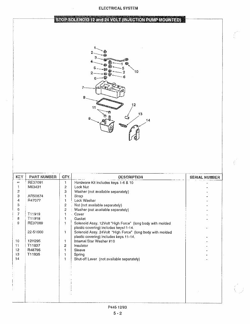
•• •• 1 2 3 4
5 6 7 8
9 10 11
12
ELECTRICAL SYSTEM
Marine and Industrial Generators Sets
6
24VDC Application Only
\ 10
:(·····.··�.\ -<: ,_:;-,c'�
""
-
PART NUMBER QTY.
22-9106522-9106639-4000837-4001037-4001137-4001237-4001437-4001300-9101822-4107722-41051 2 22-00052 1 22-40004 2
1
22-4485222-4485322-40257
DESCRIPTION
S-3B Control Panel 12 Volt (includes all Keys) S-3B Control Panel 24 Volt (includes all Keys)Enclosure
Oil Pressure Gauge Engine Temperature Gauge D.C. Volt Meter, 12VoltD.C. Volt Meter, 24VoltHour MeterDecalTerminal BoardSwitchNumber StripResistor Kit (24Volt panel only)Bulb, 12Volt (not shown)Bulb, 24Vott (not shown}Wiring Harness (not shown)
** As required
P445 12/93
5-8
7
9
A4722, A4723/C-2470
SERIAL NUMBER
updated 11-7-17


KEY PART NUMBER QTY.
•• 29-11401 1 1 RE37715 1 2 11-11013 1 3 11-11043 1 4 11-11023 1 5 11-30013 1 6 11-10015 2 7 11-31012 1 8 11-31031 1 9 11-31401 1
10 16-01000 1 11 20-11028 2 12 16-11001 1 13 25-11032 1 14 16-31000 1 15 11-31011 4
16 11-21011 2
19 11-11022 1 20 AR67942 1 21 RE44574 1
i
4
4
GASKET SETS
ENGINE 0VERHAIJIL M445 & Cl-Series
DESCRIPTION
Gasket Kit for Engine Overhaul (includes all Keys) Gasket Kit (John Deere components) Gasket, Thermostat Cover Gasket, Heat Exchanger to Expansion Tank Gasket, Exhaust Manifold to Expansion Tank Gasket, Exhaust Flange Gasket, Thermostat Seal Gasket, Oil Supply to Turbocharger Gasket, Oil Return from Turbcharger Gasket, Turbocharger Mounting O-RingGasket, Heat Exchanger End CoverO-RingGasket, Raw Water Pump CoverO-RingGasket, Exhaust PortGasket, Intake Port
Gasket, Filler Neck MountingCrankshaft Seal, FrontCrankshaft Seal, Rear
Note: Also order, as required AR65507 RE32011 R4B000
Cylinder Liner Seal Kit Injector Packing Kit Injector Tip Seal
P445 12/93
6-0
SERIAL NUMBER
--
---
-------
----
--
--
updated 11-7-17


KEY PART NUMBER QTY.
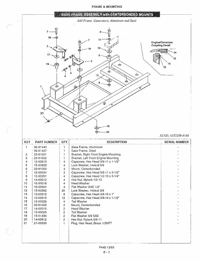
39-8143139-81430 1
2 39-81014 2 3 33-81015 2 4 23-81002 1 5 23-81001 1 6 12-00913 8 7 14-00511 8 8 15-00502 8 9 15-00901 8
10 21-00530 2. 11 15-00902 4 12 15-00302 20 13 12-00312 8 14 12-00314 12
FRAME & MOUNTING
440 Frame Generators, Aluminum and Sree!
3 Generator
DESCRIPTION
Base Frame, Aluminum
Base Frame, Steel Hydrolastic Mounts, Front Hydrolastic Mount, Rear Bracket, Left Front Engine Mount Bracket, Right Front Engine Mount Capscrew, Hex Head 5/8-11 x 1-1 /2" Hex Nut 1/2-13 Lock Washer 1/2 Flat Washer 5/8 Plug 1/2 NPT Lock Washer 5/8 Lock Washer 3/8 Capscrew, Hex Head 3/8-16 x 1" Capscrew, Hex Head 3/8-16 x 1-1 /2"
P445 12/93
8-4
Engine/Generator Coupling Detail
�1�
·�� 12
�---1\ 13
12
A3383B, A3390/C-2234A
SERIAL NUMBER

added 11-7-17
8- 5

FRAME & MOUNTING
Base Frame NL439T-445T L360-362
page added 11-7-17
P4458 - 6
D-2495A

Key Part Number Qty Description Serial Number
1 3 9 -8 10 0 2 2 S i de R ai l , M o du l ar B ase F r am e -2 3 9 -8 10 14 1 E n gi n e S u ppo r t , M o du l ar B ase F r am e -3 3 9 -8 10 0 4 1 G en er at o r S u ppo r t , M o du l ar B ase F r am e M 3 6 0 / U ci 2 2 4 -4 2 3 -8 10 3 5 1 B r acke t , F r o n t E n gi n e M t g R . h . -5 2 3 -8 10 3 6 1 B r acke t , F r o n t E n gi n e M t g L . h . -6 2 3 -8 10 3 7 1 B r acke t , E n gi n e S u ppo r t , M o du l ar B ase F r am e -7 12 -8 0 5 13 8 C apscr ew , H ex H ead S er r at ed F l an ge 1/ 2 -13 X 1-1/ 4 ”
G r ade 5 Z i n c P l at ed * ( “ W h i z- L o ck” ) -8 14 -0 0 5 0 2 12 L o ck N u t , P l ai n F l an ged 1/ 2 -13 G r ade F P l at ed -9 12 -0 0 9 13 2 C apscr ew , H ex H ead 5 / 8 -11 X 1-1/ 2 ” -10 15 -0 0 9 0 2 2 L o ck W ash er , H el i ca l 5 / 8 ” -11 12 -0 13 18 2 C apscr ew , H ex H ead 5 / 8 -11 X 2 -1/ 2 -12 15 -0 13 3 0 4 F l at W ash er 5 / 8 ” S ae Z i n c P l at ed A n si T yp e A ( N ar r o w ) -13 14 -0 0 9 12 2 H ex N u t , N y l o ck 5 / 8 -11 -14 12 -0 0 0 3 4 2 C apscr ew , H ex H ead 5 / 8 -11 X 3 -1/ 2 ” -15 15 -0 13 3 0 2 F l at W ash er 5 / 8 ” S ae Z i n c P l at ed A n si T yp e A ( N ar r o w ) -16 3 3 -8 10 0 2 2 M o u n t , C en t er b o n ded 5 0 0 L b 4 2 -4 8 D u r o m et er (
N o C o l o r C o de M ar ki n g) -17 15 -0 0 0 2 5 2 T ai l W ash er 2 . 5 0 ” X 0 . 6 4 ” X 0 . 12 5 ” -18 14 -0 0 9 12 2 H ex N u t , N y l o ck 5 / 8 -11 -19 12 -0 0 0 3 4 2 C apscr ew , H ex H ead 5 / 8 -11 X 3 -1/ 2 ” -2 0 15 -0 13 3 0 2 F l at W ash er 5 / 8 ” S ae Z i n c P l at ed A n si T yp e A ( N ar r o w ) -2 1 15 -0 0 0 15 2 H ead W ash er 2 . 75 ” X 0 . 6 4 ” X 0 . 12 5 ” -2 2 3 3 -8 10 0 8 2 M o u n t , C en t er b o n ded 6 5 0 L b s 4 7-5 3 D u r o m et er
( W h i t e O r O r an ge C o l o r C o de M ar ki n g) -2 3 15 -0 0 0 2 5 2 T ai l W ash er 2 . 5 0 ” X 0 . 6 4 ” X 0 . 12 5 ” -2 4 14 -0 0 9 12 2 H ex N u t , N y l o ck 5 / 8 -11 -2 5 12 -2 0 3 12 12 C apscr ew , S kt H d 3 / 8 -16 X 1” Z i n c P l at ed A st m A 5 74 -2 6 12 -0 0 3 11 8 C apscr ew , H ex H ead 3 / 8 -16 X 3 / 4 ” G r ade 5 -2 7 15 -0 0 3 0 2 8 L o ck W ash er , H el i ca l 3 / 8 ” -2 8 12 -8 0 5 14 4 C apscr ew , H ex H ead S er r at ed F l an ge 1/ 2 -13 X 1-1/ 2 ”
G r ade 5 Z i n c P l at ed * ( “ W h i z- L o ck” ) -
FRAME & MOUNTING
Base Frame NL439T-445T L360-362
page added 11-7-17
P4458 - 7

FRAME & MOUNTING
Base Frame NL445T/L440
page added 11-7-17
P4458 - 8
D-2500A

Key Part Number Qty Description Serial Number
1 3 9 -8 10 0 2 2 S i de R ai l , M o du l ar B ase F r am e -2 3 9 -8 10 14 1 4 4 0 -4 3 0 G en er at o r S u ppo r t , M o du l ar B ase F r am e -3 3 9 -8 10 0 3 1 G en er at o r S u ppo r t , M o du l ar B ase F r am e M 3 6 0 / U ci 2 2 4 -4 2 3 -8 10 3 5 1 B r acke t , F r o n t E n gi n e M t g R . h . -5 2 3 -8 10 3 6 1 B r acke t , F r o n t E n gi n e M t g L . h . -6 2 3 -8 10 3 7 1 B r acke t , E n gi n e S u ppo r t , M o du l ar B ase F r am e -7 12 -8 0 5 13 8 C apscr ew , H ex H ead S er r at ed F l an ge 1/ 2 -13 X 1-1/ 4 ”
G r ade 5 Z i n c P l at ed * ( “ W h i z- L o ck” ) -8 14 -0 0 5 0 2 12 L o ck N u t , P l ai n F l an ged 1/ 2 -13 G r ade F P l at ed -9 12 -0 0 9 13 2 C apscr ew , H ex H ead 5 / 8 -11 X 1-1/ 2 ” -10 15 -0 0 9 0 2 2 L o ck W ash er , H el i ca l 5 / 8 ” -11 12 -0 13 18 2 C apscr ew , H ex H ead 5 / 8 -11 X 2 -1/ 2 -12 15 -0 13 3 0 4 F l at W ash er 5 / 8 ” S ae Z i n c P l at ed A n si T yp e A ( N ar r o w ) -13 14 -0 0 9 12 2 H ex N u t , N y l o ck 5 / 8 -11 -14 12 -0 0 0 3 4 2 C apscr ew , H ex H ead 5 / 8 -11 X 3 -1/ 2 ” -15 15 -0 13 3 0 2 F l at W ash er 5 / 8 ” S ae Z i n c P l at ed A n si T yp e A ( N ar r o w ) -16 3 3 -8 10 0 2 2 M o u n t , C en t er b o n ded 5 0 0 L b 4 2 -4 8 D u r o m et er
( N o C o l o r C o de M ar ki n g) -17 15 -0 0 0 2 5 2 T ai l W ash er 2 . 5 0 ” X 0 . 6 4 ” X 0 . 12 5 ” -18 14 -0 0 9 12 2 H ex N u t , N y l o ck 5 / 8 -11 -19 12 -0 0 0 3 4 4 C apscr ew , H ex H ead 5 / 8 -11 X 3 -1/ 2 ” -2 0 15 -0 13 3 0 4 F l at W ash er 5 / 8 ” S ae Z i n c P l at ed A n si T yp e A ( N ar r o w ) -2 1 15 -0 0 0 15 4 H ead W ash er 2 . 75 ” X 0 . 6 4 ” X 0 . 12 5 ” -2 2 3 3 -8 10 0 2 4 M o u n t , C en t er b o n ded 5 0 0 L b 4 2 -4 8 D u r o m et er
( N o C o l o r C o de M ar ki n g) -2 3 15 -0 0 0 2 5 4 T ai l W ash er 2 . 5 0 ” X 0 . 6 4 ” X 0 . 12 5 ” -2 4 14 -0 0 9 12 4 H ex N u t , N y l o ck 5 / 8 -11 -2 5 12 -2 0 3 14 12 C apscr ew , H ex H ead 3 / 8 -16 X 1-1/ 2 ” G r ade 5 -2 6 12 -0 0 3 12 8 C apscr ew , H ex H ead 3 / 8 -16 X 1” G r ade 5 -2 7 15 -0 0 3 0 2 8 L o ck W ash er , H el i ca l 3 / 8 ” -2 8 12 -8 0 5 14 4 C apscr ew , H ex H ead S er r at ed F l an ge 1/ 2 -13 X 1-1/ 2 ”
G r ade 5 Z i n c P l at ed * ( “ W h i z- L o ck” ) -
FRAME & MOUNTING
Base Frame NL445T/L440
page added 11-7-17
P4458 - 9

added 11-7-17
9 - 0


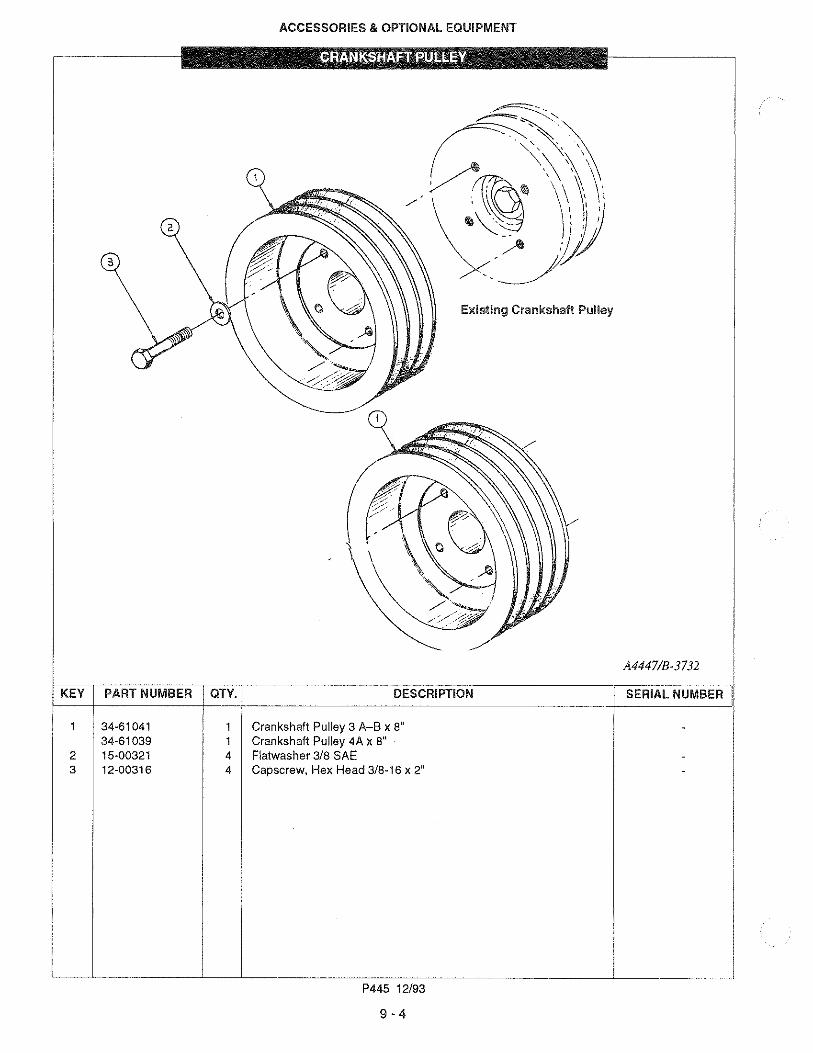
KEY PART NUMBER QTY.
10-6000410-60003
2 34-6002034-6001834-6002834-60027
3 34-614554 00-61003 1 5 12-00313 8 6 15-00321 12 7 12-00035 8 8 12-60001 4 9 00-61001 **10 34-60053
34-6005434-60056
11 34-61411 1 12 12-00312 6 13 15-00301 6 14 23-71001 1 15 12-00314 4
16 32-81001 2 17 12-00913 4 18 15-00902 4
ACCESSORIES & OPTIONAL EQUIPMENT
SAE 5/C-108
DESCRIPTION
Housing, 8-PadHousing, C-Pad Electric Clutch, H-36 8-Spline 12 Volt Electric Clutch, H-36 C-Spline 12 Volt Electric Clutch, H-36 8-Spline 24 Volt Electric Clutch, H-36 C-Spline 24 Volt Drive Assembly (includes Keys 9 & 10) Grommet
Capscrew, Hex Head 3/8-16 x 1-1/4" Flat Washer 3/8 SAE Capscrew, Socket Head 3/8-16 x 3/4" Capscrew Hex Head 7/16-20 x 1-3/4" Drive BlockDrive Ring Drive SpiderDrive HubPTO Carrier SAE #8Capscrew, Hex Head 3/8-16 x 1" Flat Washer 3/8 Bracket SAE #5Capscrew, Hex Head 3/8-16 x 1-1/2" Dowel Pin .625 x 1.5" Capscrew, Hex Head 5/8-11 x 1-1/2" Lock Washer, Helical 5/8
** As required
P445 12/93
9-3
14
17
A4066, A4067, A4068, A4069,
A4054, A4055, A3856, A3857B,
A4438/C-2235, C-2309, C-2394
SERIAL NUMBER
revised 11-7-17
1
1
Key Part Number Qty Description Serial Number
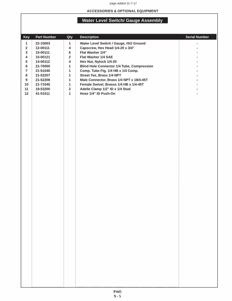
1 22-10003 1 Water Level Switch / Gauge, ISO Ground -2 12-00111 4 Capscrew, Hex Head 1/4-20 x 3/4” -3 15-00111 6 Flat Washer 1/4” -4 15-00121 2 Flat Washer 1/4 SAE -5 14-00112 4 Hex Nut, Nylock 1/4-20 -6 21-70000 1 Blind Hole Connector 1/4 Tube, Compression -7 21-51045 1 Comp. Tube Ftg. 1/4 HB x 1/4 Comp. -8 21-52207 1 Street Tee, Brass 1/4 NPT -9 21-52208 1 Male Connector, Brass 1/4 NPT x 18/4-45T -
10 21-71045 1 Female Swivel, Brasss 1/4 HB x 1/4-45T -11 19-53200 2 Adelle Clamp 1/2” ID x 1/4 Stud -12 41-01011 1 Hose 1/4” ID Push-On -
ACCESSORIES & OPTIONAL EQUIPMENT
Water Level Switch/ Gauge Assembly
page added 11-7-17
P4459 - 5

4420 14th Ave. NW., Seattle WA 98107 Tel: (206) 789-3880 • 1-800-762-0165 • www.northern-lights.comNorthern Lights and Lugger are registered trademarks of Northern Lights, Inc. © 2017 All rights reserved. Litho USA.