M-CHELP.pdf - Autodesk Forums
586
It's not the Technology which will make you successful ... but your Vision as to how to apply it! Introduction Monu-Cad Pro 2005 Monu-Cad Lite! MonuCut Flip Chart Company Info Utilities Release Date 12-16-2005
-
Upload
khangminh22 -
Category
Documents
-
view
0 -
download
0
Transcript of M-CHELP.pdf - Autodesk Forums
It's not the Technology which will make yousuccessful ... but your Vision as to how to apply it!
Introduction Monu-Cad Pro 2005 Monu-Cad Lite!
MonuCut Flip Chart Company Info
Utilities
Release Date 12-16-2005

Welcome to Monu-Cad Help
This object of this program is to take you on a tour through the Monu-Cad programs ina visual as well as written manner and to attempt to assist you whenever you havequestions about how to perform a particular operation.
Please read this first page completely and then you can skip around.
To begin, lets make sure we know how to operate this Help program.
(Sample. Do not click here.)
In the top right corner of this screen are 3 buttons as shown above. In most cases, thesize of the window you are looking at right now is about 1/2 of the full screen size.Please place your mouse arrow on the button in the center of the 3 and click the leftmouse button once.
There! The window should have expanded to full screen size. If you click on the Xbutton, this program will close and end. Clicking on the middle button a second timewill resize the window back to the original size. For those of you new to Win '95-'98,this is a standard Windows feature and most all windows function in this way. If youclick on the __button, the program will minimize. If you minimize this program, clickon the M-C Help button on the "Task Bar" located at the bottom of the screen toexpand the window again.

Clicking the Hide Icon in the top left will close and open the Table of Contents on theLeft of this form. Show will reopen it.
Clicking on the Back Icon will "Back up" to the last screen you were on. Those of youfamiliar with Internet Browsers will feel right at home with this feature. This is themost important control button in this help manual and you will use it often.
Clicking on the Print Icon will send the current "Topic" to the printer.
Clicking on the Options Icon will present you with a few more options. Try them if youlike and see what happens.
Left side of this PageContents
On the left side of this screen is a white vertical window with three folder tabs at thetop which read "Contents", "Index" and "Search". The Contents should be currentlyshowing. Below these tabs are 7 or more yellow folder icons.
These folders contain the help information. To "open" one of the folders, place yourmouse arrow on a folder and "double click" your left mouse button. A list of topics willdrop down from the folder. Once the list of topics appears, place your mouse arrow ona topic and click once. The contents of that topic will appear in the right window. Toclose the folder, double click on the icon of the folder with the pages open. (If you are notfamiliar with the term "double click" it means to place your mouse arrow on the selection and press yourleft mouse button twice quickly. Right Click means to click the right mouse button)
Index
When you click on the tab labeled Index, you will be presented with an alphabeticalindex of "key words". Double clicking on a keyword will jump directly to the pagewhich contains that keyword. Scroll through the page to locate the information you aresearching for. You may also type in a word in the little white input box at the top andthe index will jump alphabetically to that area of the index and to the specific keywordyou typed in if that word exists.
Search
Clicking on this tab will open the search window. To find a word or phrase like "Click

& Type" simply type in Click & Type and press enter. The Topic pages which containthe phrase or word you are searching for will appear in the list below. Double click onthe topic to go to that page.
Links to Other Topics
As you are reading through this manual, you will find many cases of words underlinedin blue which often begin with "Goto ...." If you place your mouse arrow on thesewords and click your left mouse button, you will "jump" or "link" immediately to thetopic which the link points to.
After you "jump" to a link, clicking on the Back button at the top of the screen willreturn you to where you started. Once you have clicked on a link, it will change colorto maroon. This means that you have visited that link once before.
That's all there is to it! We hope you will enjoy using this help manual. Please readAbout This Help Program.
Click on one of the links below to jump to your first help topic.
Goto Monu-Cad Pro 2002 Intro
Goto Monu-Cad Lite! Intro
Flip Chart Intro
Monu-Cad Utilities
Goto Monu-Cad - The Company
Goto About This Help Program
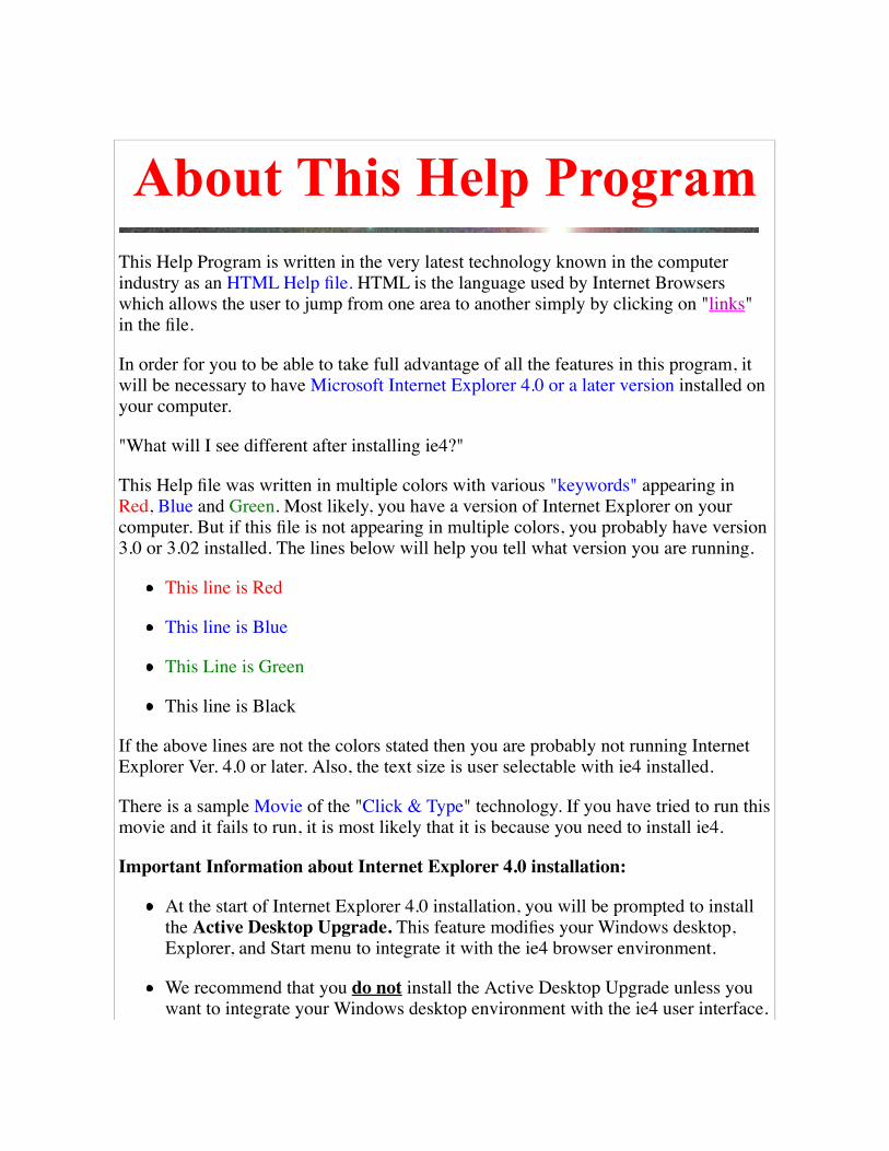
About This Help ProgramThis Help Program is written in the very latest technology known in the computerindustry as an HTML Help file. HTML is the language used by Internet Browserswhich allows the user to jump from one area to another simply by clicking on "links"in the file.
In order for you to be able to take full advantage of all the features in this program, itwill be necessary to have Microsoft Internet Explorer 4.0 or a later version installed onyour computer.
"What will I see different after installing ie4?"
This Help file was written in multiple colors with various "keywords" appearing inRed, Blue and Green. Most likely, you have a version of Internet Explorer on yourcomputer. But if this file is not appearing in multiple colors, you probably have version3.0 or 3.02 installed. The lines below will help you tell what version you are running.
This line is Red
This line is Blue
This Line is Green
This line is Black
If the above lines are not the colors stated then you are probably not running InternetExplorer Ver. 4.0 or later. Also, the text size is user selectable with ie4 installed.
There is a sample Movie of the "Click & Type" technology. If you have tried to run thismovie and it fails to run, it is most likely that it is because you need to install ie4.
Important Information about Internet Explorer 4.0 installation:
At the start of Internet Explorer 4.0 installation, you will be prompted to installthe Active Desktop Upgrade. This feature modifies your Windows desktop,Explorer, and Start menu to integrate it with the ie4 browser environment.
We recommend that you do not install the Active Desktop Upgrade unless youwant to integrate your Windows desktop environment with the ie4 user interface.

(you can always add it later if you change your mind.)
Goto 1st Introduction
Click the BACK button at the top left of the screen

Copyright NoticeMonu-Cad, Monu-Cad Pro, Monu-Cad Lite!, Click & Type™ and this M-CHelpmanual are all copyrighted (1998-2005) or Trade Marked works of MonumentalComputer Applications, Inc. All rights reserved.

Monu-Cad Pro 2005 IntroPlease note!! This manual is constantly being updated and revised. Please visit our web site atwww.monu-cad.com for the latest release.
Monu-Cad Pro 2005 is the latest "state of the art" Computer Assisted Design andDrafting program from Monu-Cad specifically created for the Designing andManufacturing of Cemetery Memorials. Monu-Cad Pro has the distinction of being theonly program available worldwide developed from the "ground up" specifically for theCemetery Memorial Industry.
Monu-Cad Pro 2005 is a fully 32 bit Windows '95/'98/NT compatible program writtenwith Visual C++ with MFC. The program code is created "in house" by Monu-Cad andis not dependent on any "commercial supplier" for improvements, updates or supply.
Goto Monu-Cad Pro Quick Help
To Start Monu-Cad Pro:
Click on the yellow Monu-Cad icon on your desktop to make the Monu-Cad programGroup window below to appear:

7
Double Click on the icon located in the Monu-Cad Program Group above to startMonu-Cad Pro. The MCPro-T icon launches a version of Monu-Cad Pro 2002 with the thumbnail file selectoroption.
Note!! If your icons have a number in them such as MCPro7 or MCPro7-T, thatsimply means that you have version 7 of Monu-Cad installed.
Goto Monu-Cad Pro Quick Help
See Demo Version Limitations


Program Operation Basics This page will provide you with links to Topics which are designedto give you general information that you will need to know toefficiently operate your Monu-Cad Program.
Click on the link of your choice below to access the subjectinformation.
Monu-Cad Commands
Monu-Cad Pro Quick Help
Description of Layers
Drawings & Components (similarities and differences)
LETTERING - Click & Type Lettering System
Cartesian Coordinate System or Where am I on the DrawScreen??
Adding New Designs to the System
Click the BACK button to return to previous page.

Monu-Cad Pro Quick HelpBelow is a sample representation of the Monu-Cad Pro Main Program Window.
Click on a button or area that you would like more information on.
After you read that information, click on the BACK arrow at the top of the page to return here. Forexample, clicking on the family name will bring up information on adding and editing lettering. Move thearrow around on the screen and when the arrow changes to a little "pointing hand" click the leftmouse button to find information on that subject.
Note: If you have received a version of MCPro later than version 5.0.0, expect to see some differences. The nature of Monu-Cad software is to improve and thus change with time.

for Monu-Cad Click & Type® Lettering System Details Click Here

MonuCut Program IntroMonuCut is a program designed to process the output data from the Monu-Cad Pro CAD program through to theStencil Cutting machinery. (Also referred to as MonuCut95)
Monu-Cut functions include: ( * indicates future features)
Selection of single and/or multiple files to cut
Selection of amount of space to leave between cuttings
Manual Control of cutter functions
Cutter knife alignment, depth setting assistance and cutter movement testing
Custom configuration of the serial port to the cutter requirements
Saving of multiple cutter configuration profiles*
Automatic Erasure of cut files after cutting*
Automatic logging and relocation of processed .MCD files after cutting*
Starting MonuCut
There are 2 ways you can start the MonuCut Program:
Method #1
Double Click on the icon in the Program Group below:

Method #2
Click on the "Launch MonuCut" button from within Monu-Cad pro:

Above is the Cutter Output Screen located within the Monu-Cad Pro Program. When you click on Cut in the File menu or enterthe command DC at the keyboard, this screen will appear. Clicking on the "Launch MonuCut" button will startMonuCut95 from inside Monu-Cad Pro.
Click here to Goto next step
Note!!
MonuCut is one of Monu-Cad's "living" programs which means that it is constantly being improved and expanded. Somefunctions may be shown on the face of the program but do not work at this time. This does not mean that something has beenleft out of your program. It just means that an improvement is being planned will be added in the future.

MonuCut OperationMonuCut95 Version 2.0.278
Start Up Screen:
When the MonuCut program starts, the screen below appears:
This Screen allows you to make selections from the menu of choices in the left panel.The choices shown in dark black letters are the currently available choices and the"grayed out" choices are future options currently being developed.
The underlined letter such as the "x" in the word Exit is a "hot key" which means thatyou can exit the program by pressing the key combination Alt-x as well as clicking onthat button with your mouse. All underlined letters which appear on the face of abutton are hot keys and perform in this way.

Select Files to Cut
The "file selection" screen allows you to select from among the files in your"FilesToCut" folder those you wish to send to the cutter for cutting.
To select a file, simply "double click" on the file name in the left most column. Afterdoing so the selected name will appear in the second column. You may do thisrepeatedly filling the second column with names. To begin the cutting operation, one ormore names must appear in the second column.
If you have made a mistake and wish to start over, you may click on the "Clear List"button which will remove all names from the second column. As an alternative, youmay click on one name and then click the "Delete File" button to remove just the onename from the second column.
Once you have finished selecting files to cut, click on the yellow CUT button and thenext CUT screen will appear.
Cut Screen:

The Files which appear in the "List of Files to Cut will be cut in the order shown whenyou press the large Yellow "Cut" button or press the key combination Alt-C. If youwish to change this order, Click on Exit and reselect the files in the desired order.
The space to be left between cuttings is shown in the space between stencils box. Thedefault value set is .25 inches. This may be set to the amount of desired space from 0 toseveral inches.
To Abort the cutting process, simple click on the Red ABORT button or enter Alt-A.
During the cutting process, the Exit Button is disabled.
The "Gas Gauge" at the top of the screen indicates the progress of each file as it isbeing output to the cutter. The little "vectors" window will count up the number oflines, arcs and circles being output. It is there just in case you may be interested andhas no bearing on the process.
Manual Control:

This screen affords you the ability to test the communication between the cutter and theprogram . When the program is configured properly, the correct cable(s) are beingused, the cutter is turned on and is on line and the buffer (if one is used) is also turnedon and connected properly clicking on the HOME button should "home" the cutter. Theother buttons should move the material in and out and the cutting head back and forth.
Note!!
If manual control does not perform the stated functions, you will not be able to send afile to the cutter for cutting. A good habit to get into is to always test thecommunication between the program and the cutter before beginning a cutting session.
The "Manual Cutter Command Entry" input box is to assist the main Monu-Cad Officepersonnel in diagnosing cutter problems. This should not be used unless you arespecifically directed to do so.
Configure Program Screen:

Note!! Only use this if you need to create a custom configuration file!
The Configuration Screen allows you to set up the output of the program to match theparameters of the cutter or pen plotter connected to the computer. In it's currentversion, it will configure the Grafityp CSR-700 and TURBO cutters in both 466 and700 mm widths, the Graphtec friction feed cutter, the Gerber HS 750 and GS750+cutters, the Newing Hall AccuTrack and most other HPGL language plotters.
The title bar displays the version number of the MonuCut program. If your screendoesn't look exactly like the image above, you probably have an earlier version. Thelatest version is always available on our web site. It is not necessary to have the latestversion. If the version you are currently running works fine for you we would suggestthat you not download the upgrade.
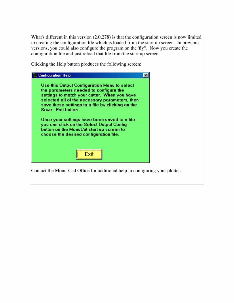
What's different in this version (2.0.278) is that the configuration screen is now limitedto creating the configuration file which is loaded from the start up screen. In previousversions, you could also configure the program on the 'fly". Now you create theconfiguration file and just reload that file from the start up screen.
Clicking the Help button produces the following screen:
Contact the Monu-Cad Office for additional help in configuring your plotter.

Frequently Asked QuestionsClick on the question below for the answer.
Why does this manual sometimes say Monu-Cad Lite! and other times Monu-Cad Pro?
What is the Right Mouse Button for?? How do I use it?
How do I get a file from Corel Draw into Monu-Cad Pro?
How do I put new lettering on a memorial?
How do I change existing lettering?
How do I put lettering on an Arc?
How do I print out a drawing?
How do I send out a job to the cutter?
How do I convert my MSDOS files to Windows format?
What are all the buttons on the Monu-Cad Pro Screen for?
What is Window Weld?
What does Command Nesting Mean?
Are there any keyboard shortcut keys?
What are Thumbnails?
What is a double click?
How do I load a base under a die?
How do I change the size of a cross?
What is a link?
What are Layers?
What are the Demo Version Limitations?
What are tool tips?

What's New in Monu-Cad Pro 2005 Version 7.09Below are links to the new features added or upgraded in Version 7.
Click on the link for more info.
Ability to set the path where fonts are stored
New Advanced Kern Dialog Features
New Justification Style Added
New Panel Style Added
Menu Bar Added
Font Selector Image Preview
Advanced User Selected Size Image File Output
Thumbnail with Database allows Search by File Name
Previous Improvements
Base Maker
Panel Maker Wizard
Die Maker Wizard
Advanced - Expanded Select Command
Auto Trim
SE command expanded
Lettering Cut and Paste Considerations and Character Map program
Auto Panel Maker Wizard
Adjust Letter Spacing Feature Improved
Lettering on Arc Multiple Lines and Panels
Additional Features on Right Click on Lettering
Thumbnail File Selector with Database Search
Window conVert Command
New MCScan Scanner Program
Drawing and Window Clean Command

True Type Font Import Command
Layers Commands
Dimensioning Commands
Right Mouse Click Rotation and Scale with Components
Object Break for Ellipse
HPGL File Import Function Import files from Any Program!
Lines to Arcs Conversion
Render Fills and Hatches
"Secret" Commands which don't appear in a Menu
Snap Parallel Improvement
File Security Options now work when saving components if desired
File Security Options now work when saving font files if desired
DTA file (spacing table) editor
Force split justify years to a specified width
PasteText into Advanced Kern Dialog
XA Explode All command
Leaders
Lettering Group Rotation without exploding group
Re Written Print Preview Screen
Improved Window Save and bug fix
Snap Perpendicular Improvement
Drawing Save bug fixed.
Change of DE command to DT
Units
Added Programmable Function Key Tab to Config Menu
Ortho Angle
A5 Tangent Arc Command
DXF Import/Export
Bitmap Image Export to clipboard, file and direct to Email messages

Fillet command
Auto Outline and Inline
Pack Data command

ASCII-ChartIn Monu-Cad Pro, when you import a True Type Font, the letters are numbered according to the ASCII chart below.In other words, a Capital Letter A is a number 65. You will normally be concerned only with characters 32 through125.

Extended ASCII Chart

ConfigClicking on this menu selection displays the configuration settings Tab dialog box shownbelow. Although the heading refers to Monu-Cad Pro, the same settings are available in Monu-Cad Lite!
Kern Tab
Exaggerated Serifs turns on or off theability to use a letter style with "fatter"serifs on certain roman alphabets likeModified and Condensed Roman. Thenormal setting is to have this box checked.
Serif Split Size determines the size of theletter at which this feature beginsfunctioning. It is normally set at 1.5 inches.Letters below this set size will haveexaggerated serifs.
Single Line Thickness sets the width ofpanel sandblast lines.
Frosted Line sets the width of frostedpanel lines
M/D/Y Attributes sets the default blockingfor Month/Day/Year Justification option
Skip Trailing Punctuation determineswhether the length of the line of lettering ismeasured excluding the width of a trailingperiod or comma or including it. With thisfeature checked, the length of the nameJohn J. will be measured and centered asif the period after the J wasn't there. Whenin doubt, turn this feature on.
Disable Save To DTA when checkeddisables dialog allowing saving changes toDTA table after Lettering Adjust
Display Tab

Construction Points when checked turnson the points
Reference Points turns on the points
Mouse Cursor sets the size and color ofthe "cross hairs"
Screen Ratio see screen ratio page
Tolerance sets the "capture area" seetolerance page
Show Simple Lettering Group turns onsimple lettering group option whenchecked. Skips the simple lettering groupdialog box when un checked. See lettering
Path/Files Tab
This Tab allows you to set the defaultpaths for the program. they are usuallypreset for you.
Drawing Path[P1} sets default .mcd path.
Alternate Drawing Path when checkedwill cause all drawings to be saved to thisone folder.
Component Path[P2] sets default path toload .mcc files from.
Alternate Component Path for

Component Saves when checked willcause all components to be saved to thisone folder.
Split Component Path allows you to set aspecial folder up to hold just those specialcomponents used in split and split2justified date configurations.
DWG Path allows you to set the defaultpath for the Import command.
Cutter Files sets the path where cutterfiles will be placed.
Font Pat: sets the path where font filesare stored
Logo File specifies the name of the .pcximage to be loaded at sign on.
Show File Security Options see FileSecurity Options
Grid Tab
Snap to Grid sets the default gridsetting...ON or OFF
Grid Size sets the default grid size

Ortho Mode sets the default Ortho Modesetting ON or OFF
Units Tab
This configuration menu allows youto set the type and accuracy of thedrawing units desired. These valuescan also be changed by using thevarious units commands duringnormal program operation.

Arc Lettering Adjust Tab
Rotate step sets the amount of rotation thatoccurs when you adjust Lettering on an Arc
Flex Distance is the step value that occurswhen you adjust the arc shape in Letteringon an Arc.
Added Space sets the amount of spaceadded when you spread out letters inLettering on an Arc.

Defaults Tab
Version 3.0 and later.
Seed Fill Tolerance is a value whichattempts to allow you to fill a drawingwhich has some gaps in it. this tells the SDcommand to ignore gaps under .0625inches wide.
Fill Layer sets the default layer that fillsare placed on.
Start Up Method determines the way inwhich MCPro starts. Use DOS methodcauses the program to begin with a file

menu appearing automatically. If youuncheck this box, MCPro will start with ablank screen "Windows Style" and thedefault drawing name will be "Untitled".
Granite Finish Method are experimentalsettings for office use only. No explanationis herein given.
Zoom Limits sets the initial size of thescreen area and is the screen areadisplayed when you enter a ZL ZoomLimits command.
Fillet Radius is the default value that theradius of a fillet is set at. This can bechanged with the RF command as well assetting it here.
Functions Key Tab
Version 3.0 and later.
This section of the Config menu allowsyou to program a command or simplecommand string to a function key. Inaddition to the keys F1 through F12, youmay also use the combination of the ShiftKey plus a Function Key, Control Key plusa Function Key or both Shift and ControlKeys plus a Function Key.
In the example shown to the left, you willsee that we have programmed thecommand combination LISA and A3SA tothe Shift F1 and Shift F2 keys. The

commands shown for the F1 through F9keys are the defaults we have preprogrammed for these keys. They may bechanged but we suggest you keep them atthe default setting and use the otheravailable spaces for your individualcustomizations.
Import/Export Paths
Version 4.0 and later.
This section of the Config menu allowsyou set the path to folders containing thedifferent file types you would like to import.
When using the IP command, justselecting the file extension willautomatically log you into the folder youhave preset in this menu.

Click BACK button to return to previous page.

Lettering Editing & AddingGoto Lettering - Advanced
Goto Panels - Adding and Editing
"Click & Type ® Technology"
In Monu-Cad Windows programs, a Very Important buttonon your Mouse is the Right Button. The Right Mousebutton controls the lettering and component functions.On the Drawing 1.mcd, we placed the mouse cursor on the Red Reference Point in the Familyname and pressed the Right Mouse Button. The following dialog box appeared. It will alwaysappear when you move the cursor over a lettering Reference Point and right mouse click.
We then moved the cursor to the word Edit... and clicked the Left Mouse Button.
The following appeared:

We then typed in SMITHJON as shown below:
and Left clicked on OK. The following appeared in 2 seconds!

This is our new "Click & Type" Technology in action!
Play Sample Movie
Goto Reference Points (PR)
To change any lettering that exists on a memorial layout:
1. Right Mouse Click on the Lettering Reference Point
2. Left Click on Edit...
3. Enter the new lettering and then
4. Left Click on OK
To add lettering to an existing memorial layout:
1. Right Mouse Click on an area where there is no lettering

2. Left Click on Add Lettering
3. Enter the new lettering and then
4. Left Click on OK. The lettering will appear where your mouse was resting when you firstclicked it to begin to add lettering.
To move any lettering group that exists on a memorial layout:
1. Right Mouse Click on the Lettering Reference Point
2. Left Click on Move
3. Move your mouse and the lettering group will follow the mouse.
4. Left Click on the new location for the lettering. It will be placed centered where thecursor rests when you click the mouse.
To Erase any lettering group that exists on a memorial layout:
1. Right Mouse Click on the Lettering Reference Point
2. Left Click on Erase. The lettering will be removed.
To Create an identical copy any lettering group that exists on a memorial layout:
1. Right Mouse Click on the Lettering Reference Point
2. Left Click on Duplicate
3. Move your mouse and the lettering group will follow the mouse.
4. Left Click on the new location for the lettering. It will be placed centered where thecursor rests when you click the mouse. You will have a second copy of the originallettering group.
To Rotate any lettering group that exists on a memorial layout:
1. Right Mouse Click on the Lettering Reference Point

Notice!!
Lettering Groups cannot be placed inside a component. Doing so will result in a component which cannot bereloaded and will be unrecoverable.
2. Left Click on Rotate.
3. Select Use Mouse function to visually rotate or enter a desired rotation value.
To Adjust Inter Letter Spacing in any lettering group that exists on a memorial layout:
1. Right Mouse Click on the Lettering Reference Point
2. Left Click on Adjust Lettering.
3. Make changes as per special instructions page goto Adjust Lettering
To make Advanced changes to lettering groups, panels, create lettering on an Arc or changeline spacing or line length,
Goto Lettering - Advanced
Goto Panels - Adding and Editing
Goto Lettering on an Arc
goto Adjust Lettering
Click your BACK button toreturn to the previous page.

Lettering - Advanced"Click & Type Technology"
When you Right Click on a lettering group in Monu-Cad and then click on Edit..., thesimple dialog box shown below appears:
The purpose of this dialog box is to provide a quick and uncomplicated way to changethe existing lettering. To change more than just the lettering and size, you must click onthe Advanced> button. Doing so will open the dialog box below:
Click on this image for more details

In this box are radio buttons and text boxes which can be altered to:
Add and insert additional lettering;
Change Alphabet Style (Primary - Secondary Font);
Change Alphabet Size (Primary - Secondary Size);
Set the desired Justification;
Force a line of lettering or a whole group of lines to a specified line length(Equate);
Select from 8 preset Auto Draw panel styles (Panel Style - Panel Type);
Set panel width parameters (Panel Width).
Set spacing above and below lines of lettering (Space Above - Top Line to Top ofPanel);

Set space value inside the panel between the beginning letter and left inside ofpanel & last letter and right inside of panel (end space).
Set the exact coordinates at which to place a lettering group (Group Anchor).
click here for more detailed information
All new lettering defaults to 1 inch height and the Press Modified Roman Alphabet. Tochange these defaults, click on the line of lettering to identify to the program the line youare working on. It will change color in response (become highlighted). Then, click in the Sizeor Font selection box and enter the desired selection.
2 sizes of letters on one lineIt is possible to enter two sizes of letters on one line. To do so, precede the size changewith a * character.
For example, the name McDonald might have a 3" capital M and a 2.5" c in the Mc.Enter as follows: M*c Donald. The size of the c is set by the value placed in theSecondary Font Size input box. This box will be "grayed out" unless there is at least one* in a line of lettering.
2 Styles of lettering on one lineTo use two different styles on one line, place a ~ (tilde) character in the line of letteringto signal to the program that the following lettering will use a different alphabet.
For example, the lettering Robert "bobby" Smith should be input as... Robert ~ "Bobby"~ Smith. The second style is selected with the Secondary Font selector.
Just trying these features once or twice will demonstrate the common sense approachused in Click & Type. The very low level learning curve is greatly appreciated by all!
Group Anchor
The group anchor box allows you to change the X and Y coordinates of the currentlettering group. In the image above, the X coordinate is 0 and the Y coordinate is 13.This means that this lettering group will be placed on the center line of the memorial and13 inches above the "joint" or 0,0 center coordinates. To lower the group by one inch,simply change the 13 to 12.
Added Space

This feature allows you to put additional space between letters to "spread out" a shortline of lettering. If you enter .25 in the edit box, you will add 1/4" more space in betweeneach letter in the currently highlighted line of lettering.
Equate
The equate button allows you to specify exactly the desired length for a particular line oflettering or for the group as a whole. For example, if the currently highlighted line oflettering is 8 inches long and you want it to be 12 inches long, click the equate button,click on the "Line" button and enter 12 in the edit box. Then click OK. The length of theline will become 12 inches.
You can also make all the lines of lettering in the group equal the same length by clickingthe "Group" button after clicking the Equate button. This is often called columnjustification similar to that used in newspaper columns. This is a handy feature for poemsand longer text passage inscriptions. When using group equation, make sure to enter avalue at least as great as the longest line of lettering. If you do not, the longest line willbe "squeezed together".
Click Here for Justification Options
Click your BACK button to return to the previous page.
Run Click & Type Movie
Run Lettering on Arc Movie
See Lettering on an Arc
Adjust Lettering
Click BACK button to return to previous page.

Lettering - Right Click On
When you place your mouse cursor on the Red insertion point in a lettering group, a "context" menu appears offeringyou choices. Below is a screen shot of the context menu:
Goto Right Mouse Button for details Click Here

Lettering on an ARCMonu-Cad Click & Type® technology makes placing lettering on an Arc quick and truly a pleasure to use.A step by step example follows:
The Easy "Use Mouse" Method
Step 1, Right Click on the place where you want the center point of the lettering to be placed. Then leftclick on the Add Lettering button. The Advanced Kern Dialog box will appear.
(Note! If you are running an earlier version and are attempting to put lettering "on top" of a component, at this pointyou may have to left click the mouse again on the spot where you want the lettering to be to make the AdvancedKern Dialog to appear)
Step 2, enter the desired lettering and press the ENTER button on the keyboard.

Step 3, click on the line of lettering to highlight it, then click on the Arc button. The menu below will pop up.
Step 4, click on the Use Mouse button. The menu below will pop up.

Step 5, click on either the Inside or Outside button to indicate the side of the arc you wish the letteringplaced on. In this case, we have selected Inside. The dialog box will close and you will be back to thedrawing screen. Now, enter three points to draw the arc right where you want it on the design.
Step 6, The arc will draw in normal Monu-Cad fashion. Immediately after you place the final end point, thelettering will appear and the lettering will be placed as shown below.
Notice the Adjust Arc Justification Tool Bar which pops up. This will allow you to make small adjustments tothe lettering after it has been placed.
Tip: If you place your mouse cursor in the tool bar top border, press and hold the left mouse button, youcan "drag" the tool bar anywhere on the screen that may be more suitable.
Clicking on the Arc Rotate buttons will rotate the text "around the clock face" either clockwise orcounter clockwise. Each click rotates a small amount. The step value of the rotation is set in the ConfigMenu.
Clicking on the Arc Bend buttons will flatten or sharpen the curvature of the arc a small amountwith each click. The step value is set in the Config menu.
The left and right arrow buttons move the cursor one character to the left or right with each

click. The up and down arrow buttons will move the cursor up or down one line of lettering if there are morethan one line in the group.
The Up and Down arrow buttons move the cursor up or down one line of lettering if the letteringgroup contains multiple lines of lettering.
buttons spread out or contract equally the lettering by increasing or decreasing the spacebetween letters a small amount with each mouse click. The <> button increases the amount of space andthe >< button decreases it. This feature is great to spread out a family name "by eye" till it "looks good".
Clicking on the + button will add more space between the letters. The - button removes space.The step value is set in the Config menu. We call these the Arc Lettering Spread buttons.
The R button will reset any changes you may have made to the original values and the Xbutton will exit and finish the command.
Step 7, Click on the X to complete the command.
As with any lettering group, you may Right Click on the insertion point once the command has beencompleted to move the lettering and thereby adjust it's location. You may also Right Click and select AdjustArc from the menu to pop the tool bar back up for more adjustments later.
Note: If you are placing lettering "on top" of a component such as you might if you are placing letteringinside wedding bands you will get the component edit dialog which has the words Add Lettering at thebottom of the list. This works the same as described in Step 1.
Two Alternate Methods
You may have noticed back in Step 3 that there are 3 methods available for locating the placement of thelettering on an Arc. In the example above, we used the easiest method which is Use Mouse. There are alsothe Radius and Coordinate Methods.
Radius Method
This method allows you to select the X and Y coordinates of a circle on which you may wish to placelettering. This is an easy way to put lettering around an emblem.
Coordinate Method
This method allows you to manually enter the coordinates of the 3 points which make up the arc on whichyou wish to place lettering. This is the same as using the Use Mouse method and typing in the coordinatesinstead of clicking their location with the mouse. We include this method here just to remain consistent withthe MSDOS Monu-Cad System.
Lettering - Advanced
Lettering - Editing - Adding

Right Mouse Button
New Features Version 5.0
Version 5.0 and later allow multiple lines of lettering on and arc with and without panels.
Click the BACK button to return to the previous page.

Adjust Lettering
This great new feature first available in Monu-Cad Pro Ver 3.0 will allow you to adjust the spacing between charactersin a lettering group without first exploding the group. We borrowed a little from the "adjust arc lettering" feature andapplied it to standard group lettering.
To access this feature, first Right Click on the Red insertion point in a lettering group just as if you were going to editor move the group. When the context menu appears left click on the Adjust Lettering option. See below.
After clicking on the Adjust Lettering label, a small "Tool Bar" as shown below will appear.

Notice that there is a RED cursor ][ in between the first 2 letter "D's". Also notice that the space between these D's inthis image are farther apart than in the first picture. This is because in preparing these images, I clicked several timeson the + button in the tool bar.
The cursor ][ button allows you to place the cursor with the mouse where you would like it.
The left and right arrow buttons move the cursor one character to the left or right with each click. The up and downarrow buttons will move the cursor up or down one line of lettering if there are more than one line in the group.
The Up and Down arrow buttons move the cursor up or down one line of lettering if the lettering group containsmultiple lines of lettering.
The buttons spread out or contract equally the lettering by increasing or decreasing the space betweenletters a small amount with each mouse click. The <> button increases the amount of space and the >< buttondecreases it. This feature is great to spread out a family name "by eye" till it "looks good".
The Plus (+) and Minus (-) buttons will allow you to increase or decrease the space between 2 letters. Each clickincreases or decreases the space by a small amount. You may also use the + and - keys on the keyboard.
The "R" (Reset) button will return the adjusted space to the initial default values. Note!! Only the line of lettering thatthe cursor is currently on will be reset.
The "X" button exits the command.
The adjusted spaces are saved in the file when you perform a drawing save. Should you edit the lettering or fontname the values will be reset to the default values.
Note!! These spacing changes are not permanently saved in the spacing table for this alphabet. These are"incidental" spacing changes. To permanently change the values in the .DTA file so that these changes always occurautomatically, you will need to turn on the "Save to DTA file" option in the config menu. This save to DTA file option isnot available in Monu-Cad Lite!


Lettering Justification Options
Left Justification
Left Justification causes the line of lettering to begin with the first character placed at the desired anchorpoint and proceed to the right or positive X direction.
Right Justification
Right Justification is the opposite of Left Justification. The right most character in the line of lettering isplaced at the desired anchor point and proceeds to the left or negative X direction.
Center Justification
Center Justification places the exact center point of the line of lettering at the desired anchor point equallyspreading the line of lettering left and right of the center point.
ArcJustification
Arc Justification allows you to draw an arc on the draw screen and then place lettering onto the path of thatarc. The arc is removed after the lettering has been placed. During the placement of the lettering, a specialtool bar pops up which allows you to adjust the rotation clockwise/counter clockwise, flatten or deepen thearc or increase/decrease the space between letters. The R button resets the arc to initial values and the Xremoves the tool bar and completes the command. see lettering on arc movie

Split Justification
Split Justification is a Monu-Cad term for a unique form of Justification. This is used when the line oflettering takes the form of lettering dash lettering. You will recognize this form as 1923-1987. When youplace a dash ( - ) between 2 words, the split option will become available. After you click on the "split"button, a dialog box appears asking you for the split distance.
This is the distance from the center point of the line of lettering to the left or right outer edge. For example,if you specify 5 for the split distance, the 1923-1987 dates will be 10 inches long. The dash will be placedexactly in the middle with the first date left justified and the second date right justified. If you select this formof justification, you must place a ( - ) after the first set of letters. You may enter 1924- without the final year.It is also possible to use this form for May 1, 1911-June 12, 1998. Do not put a space character before andafter the dash.
Notice that there is now a check box which when checked will force the width of the years to a specifiedvalue. Usage of this feature is optional.
As a bonus, we have added the ability to place a component (such as a Masonic emblem) automaticallybetween the dates. To do so, use an underline character ( _ ) in place of the dash. You will be prompted toselect the component to be used right after you select the split distance. This feature is ideal for placing anemblem, special length dash or special design between the years.
Split2 Justification is almost the same as split justification. The only difference is that the dash orcomponent is centered in the space between the dates rather than being placed on the center line in thepanel

MissouriJustification
In Missouri Justification you select the line length and the rest is automatic. As you can see from theabove example, both lines of lettering are forced to the same length. However, the space between theMONTH and the DAY and the DAY and the YEAR are equal regardless of the length of the month and year.
Left-Center-RightJustification
In Left-Center-Right Justification, enter the birth year, then the name, then the death yearseparated by a tilde (~) character. When you click on the justification radio button, a dialog willappear that will afford you the opportunity to set the parameters of the lettering line.
You can also "force" the years to be a specified maximum width.

Note: The primary font settings will apply to the years and the secondary font settings will apply tothe name.
Month - Day - YearJustification
M-D-Y Justification allows you to specify:
1. the overall length of the line of lettering2. the width to be used for the month3. the width to be used for the year
Then, based on the actual longest line of lettering, the routine spaces out the short MONTH to fit into thesame width as the longest MONTH. The DAY is placed exactly on the center line without regard to thewidth of the comma. Finally, the short YEAR numbers are placed character by character on the center linesof the numbers in the longest YEAR. The defaults for this form of justification may be set permanently inthe CONFIG menu.
Vertical Justification
Vertical justification allows you to place letters one above another. Simply type in the lettering desired,select the space between characters and click OK.


Preserve All LetteringThis is a fairly simple but very useful command. When you click on this menu item, allof the lettering groups will be saved to a buffer in the program. Then you can eraseeverything on the screen with the DX command, load another memorial drawing andclick on Restore All Lettering in the Edit menu. The lettering that you saved into thebuffer will be placed on the new memorial exactly where it was when it was saved.
Tip: if you display a 3-0 monument on the screen and the lettering is too long for thefamily name and you wish to bring up a 3-6 instead, with this command you can savethe lettering, load the 3-6 and restore the lettering. Saves re typing....
Return to MCL-Menu Commands

Restore All LetteringThis command compliments the Preserve All Lettering command. See that commandfor details.
Goto Preserve All Lettering

MCFonts lst File Specs The MCFonts.lst file is a plain text file located in the \fonts folder. It contains a list of all the fonts available toMCPro. In addition, this file contains
information which tells MCPro what spacing table (.DTA file) to use with that particular alphabet
the name prefix of the components in the alphabet
whether the alphabet contains upper and lower case letters
whether the alphabet contains a double or tripple set of letters and at which size to switch letters, theircomponent prefix and which spacing table to use with which particular size
and finally whether there is a minimum size letter for this alphabet.
A typical MCFonts.lst fill will look something like this (only first 3 entries shown):
[Modified Roman]dtafile = mr ;commentfontfile = mcalf001lowercase = noserifs = no
[Condensed Roman]dtafile = cr ;commentfontfile = mcalf002lowercase = noserifs = no
[Outline Roman]dtafile = out ;commentfontfile = mcalf003lowercase = noserifs = yes
This is the basic information needed in the file to describe one of the original 94 character Monu-Cadalphabets.
The new 256 character True Type Font import entries will look something like the following. since most TTFfiles include upper and lower cases, there in no need for the lowercase = no statement:
[ARIALBLACK]dtafile = ARBfontfile = ARB255extended = yes
[WINGDINGS1]dtafile = WDDfontfile = WDD255extended = yes

To limit the minimum size an alphabet can be used at, add the statement smallest = .75 to the definitionas shown below:
[Outline Roman]dtafile = out ;commentfontfile = mcalf003lowercase = noserifs = yessmallest = .75 the .75 can be set at the desired size.
In addition, you may create a second or even third set of letters to be used only at a designated size or smallerwithin the same alphabet. For example, in MCALF003.fnt, there are 2 sets of letters. One set is namedOUTx.mcc and the second FOUTx.mcc. The "x" is the place reserved for the specific character (A,B,C etc).Under normal operation, if serif split is turned on in the config file, the "split size" specifies at which size andsmaller to begin using the letters which begin with the prefix FOUT. The statement serifs = yes tells MCPro thatthis alphabet has more than one set of characters.
Beginning with Version 3.0 of MCPro, you now can specify up to 3 sets of letters which can be switched in andout depending on the size called for in the program.
This example shows the addition of the statement TypeFaceSubstitution =
[Press Modified Roman]dtafile = skmfontfile = mcalf010lowercase = noserifs = yesTypeFaceSubstitution = 1, skm, fTypeFaceSubstitution = 0.5, vm,smallest = .75
The rules for typeface sustitution are as follows:
Syntax:
TypeFaceSubstitution = n, dta name, [prefix]
n = Height of lettering to implement type face substitution at or below.
dta name = The name of dta spacing file to use (do not include extension .dta)
prefix = The letter used to distinguish this set of component letters from the others.
Example:
> [Press Modified Roman]
> dtafile = skm
> fontfile = mcalf010
> lowercase = no
> serifs = yes

> TypeFaceSubstitution = 1, skm, f
> TypeFaceSubstitution = 0.5, vm,
smallest =
Allways use the font file mcalf010, this contains all need components including ones use for type facesubstitutions.
When the height of the lettering is greater than 1in then use the first four lines to represent the lettering. Thisuses the skm dta file and no prefixes.
When the size of the lettering is equal to or below 1in then use the first type face substitution. Precede allcomponent names with the string "f" to use the fat characters. Use the skm dta file to space the characters.
When the size of the lettering is equal to or below .5in then use the second type face substitution. Do notprecede the component names with anything, but use the vm dta file to space the lettering.
Notice, there is the ability to use different spacing tables for different lettering heights. I hope this helps. I will sitdown tomorrow night to get you the rest of the documentation when I have some time to think.

TTTrue Type Font
Import(Version 3 only)
This very powerful command will allow you to import a Windows True Type Font (TTF) into the Monu-Cad Click &Type Lettering System. The TT command will allow you to select the True Type font to import, select the prefix to beused for the components, select which character in the font on which to base the 1" letter height, select the font namewhich will appear in the Click & Type font list and select the file name to be used for the font and spacing table files.
Once these selections have been made, the command will extract the True Type Font outline data, create 1" highindividual component letters from the data, measure the length of the letters, place the insertion points on the baseline at the center of the letter and display the resulting 256 letters on the MCPro draw screen. The function will thenautomatically add the font name to the MCFonts.lst file and save the .fnt file and .dta files to the hard disk drive in the\Fonts folder. Whatever spacing information available in the True Type Font will be carried over into the .dta file.
To begin the process, from a new blank drawing session enter the 2 letter command TT. The dialog box shownbelow will appear.
If you just wish to see the command "do it's stuff" without making any permanent changes, simply enter 3-8characters in the Prefix edit box, do not check the "Add to Font List" check box and then click the OK button.
If your system contains the Abadi MT Condensed font as depicted above, the letters will appear on the screen asshown below, 256 characters in all, 16 characters per line. Go ahead, give it a try!

Pretty amazing isn't it?
A TT font consists of 256 characters that comprise the standard computer ASCII alphabet. These characters arenumbered from 0 to 255 in standard computer form. The first 32 characters are "control" characters used mainly ininternal computer functions and there is no real character to be displayed. That is why the first 2 rows of characters inthe above example are represented by rectangles. Most True Type fonts will have some "place holder" in these first32 spaces. These characters will be ignored.
The components created by this routine will be named with the Prefix characters you entered above plus the ASCIIcharacter number. For example, the capital letter "A" is character 65. If you entered the prefix ABA in the Prefixedit box, the Capital A component will be named ABA65.mcc The Capital B would be ABA66.mcc, the small letter"a" ABA97.mcc and so on. The alphabet therefore actually begins with character #32 which is a space
To permanently add a TT font to the Monu-Cad Click & Type lettering system, in addition to specifying acomponent prefix, you must check the "Add to Font List" check box. Checking this box will allow you to enter the FontName that you wish to appear in the Click & Type font selection list. We request that you select a name of fewer than20 characters in order to fit the space available. The name you choose to enter in the File Name edit box will be the

name used for the .fnt and .dta files which are placed in the \Font folder. A short name such as the name used forprefix will help you to locate them more easily in the future.
More about 256 character fonts
The way that the IBM PC is designed, one cannot type directly on the keyboard any characters which are a characternumber greater than character 127. For example, there are no keys present for these and other characters such asê Ç ü â which have character numbers greater than 127. These characters above #127 are known as the"Extended Character Set". Keyboards used on computers in non American English speaking countries do havekeys for these extended characters and the keyboards have a different key mapping scheme. You may have seen akeyboard in England with the Pound or Euro character on it instead of the Dollar sign. Spanish and other languagekeyboards have man more. The actual character that appears when you enter an extended character depends onthe design of the particular font. You can pretty much depend on the first 127 characters to match the ASCII Chartbut characters 129-255 depend on the font designer.
If there are no keys then how do you get these characters to appear? Well, the IBM PC provides a ratherconvoluted way but I guess we should be thankful that at least there is a way. To access these characters you firsthold down the Alt key on the keyboard. Then, on the Numeric Keypad (on the right side of the keyboard) you enterthe 3 numbers of the desired character example 128, 129.....254, 255 etc preceded by a 0 (0128, 0129, 0254). Whenyou release the Alt key, the character will appear. You cannot use the keys that are on the top of the keyboard. Youmust use the numeric keypad. Fortunately, you will not have to use these characters very often. This is how you willbe able to use these characters in Monu-Cad Click & Type.
(You can also use this technique in any Windows word processor. However, remember that the character shape thatwill appear will depend on the font you have selected. )
Tip:
To remove a font name from the MCFonts list, you will have to manually edit that file with a word processor such asNotepad.
Special Note!!In the TTF Conversion Menu shown above, you will notice a small edit box which reads "Size based on [65]". Sincethe character #65 is the Capital Letter A, the size of all letters will be in proportion to the letter A measured at a heightof 1 inch. As many of you know, the letter A often extends above the average height of the rest of the letters in theAlphabet. You might consider running the TTF converter through once on a trial run for each font you desire to importjust to see if perhaps you could select another letter on which to base the height. A letter D, E or H might be a betterchoice depending on the style of the imported font. Failure to pay attention to this detail could result in letterswhich are actually shorter than you expect. For example, 1" high letters could in fact be 7/8" high or some otherfraction.
True Type fonts, while stylish, were not created with sandblasting in mind. You will find that many attractive fontswhen used in monumental work will have areas in the letters which will not be sandblastable. At best, many of thesefonts will simply provide a starting place for you to create your own font using the TTF as an example or inspiration.

LetteringCut and Paste
basic considerations
The ability to extract text from a text document and paste it into MCPro is a very convenient feature to have. It saves an incredible amount of time and insures accuracy. however, it is important to understand the rules.
The Click & Type lettering System within MCPro and MCLite! is in itself sort of a word processor...but is notcompletely the same as a word processor. Word processors like MS Word include in with the raw text, characterswhich tell the program what font to use, what size, bold or italic and formatting characters.
If these characters are pasted into Click & Type (Advanced Kern Dialog) , all kinds of strange things will happenbecause Click & Type has it's own mind to make up about what size, justification, and format is followed.
A new File and Edit Menu Bar has been added to Version 7.x x to make pasting and saving text more convenient. The paste commands have been designed to strip out unwanted characters from text files like MSWord .DOC files.
Click here for more details
MS Character Map Program
Another free program included in windows is the Character Map. It is located under Programs\Accessories\SystemTools. This cute little program allows you to easily pick out the extended characters available in True Type Fonts andcopy them to the clipboard for pasting into Click & Type. Using this program makes it very simple to select "foreign"characters such as the ones with accents. It also works great for working in a foreign language.
A screen shot of Character Map is shown Below:
By double clicking on the desired characters, they are placed into the edit box labeled "Characters to copy:"
Then, you click the Copy button and they are copied to the Windows clipboard. Now, with a Ctrl-V you can pastethem into Click & Type.


Right Mouse Button
In Monu-Cad programs, the Right Button on the Mouse performs several very important functions. (Theright mouse button is the right most button on the top of the mouse.)
When used with Components:
If you move your cursor over the Red Reference Point in acomponent and click the right mouse button, a menu willappear as shown here.
Once this menu is on the screen, you can select one of the 8properties on the menu.
Note!! The add lettering property affords you the opportunityto place lettering directly "over the top of" the component.Clicking your Left Mouse Button on Add Lettering will pop upthe lettering dialog.
Move Clicking on Move will "attach" the component to the cursor and allow you to move it around on thedraw screen. Clicking your Left Mouse Button will Place the component in the new location.
Rotate Clicking on Rotate will pop up a dialog box which will ask for the degree of rotation. A negativevalue will rotate the component to the right and a positive value will rotate to the left. (ex. -15 or 45) Therotation value entered here will affect this component only. You may also visually rotate the component byclicking on the "Use Mouse" button. In this case, the component will rotate visually as you move themouse and will anchor in place when you again click the left mouse button. Esc aborts the command.

Scale Clicking on scale will allow you to change the size of the component. A dialog box will pop upallowing you to enter a value for the X scale and Y scale. The default is 1 for each value indicating a scaleof 1:1. If you change the values to 2, the size of the component will be twice the original size. The scalevalue entered here will affect this component only. You may also visually scale the component by clickingon the "Use Mouse" button. In this case, the component will scale visually as you move the mouse andwill anchor in place at the new size when you again click the left mouse button. Pressing the Esc keyaborts the command.
Flip Is a cute and useful added feature. As soon as you click on Flip, the component will reverse itself fromleft to right. In the pictured example above, clicking on Flip will face the Praying Hands to the Left, thereverse of what is pictured.
Replace When you click on Replace, the file selector will pop up allowing you to select the name of acomponent to replace the current one with. After you select a new component name and click on OK, thenewly selected component will replace the original one. Note that the placement will be according to thereference points. In other words, the reference point of the new component will be placed where thereference point of the original one was.
Rename allows you to change the current name of the component within the drawing itself. This does notchange the name of the component saved on the hard disk drive....just the current name as used in thisdrawing. This is very helpful when changing the names of letter components when adjusting or creatingnew alphabets.
Duplicate Clicking on this option produces a second copy of the component. This is handy when you needseveral copies.
Mirror will create an exact, reversed image of the component placed on the opposite side of 0,0 centerpoint. One can use this to create for example and exact but reversed copy of a corner floral carving in theopposite corner of a die when creating a new design. This is an instant way of doing a Window Image of acomponent without all the associated work involved.
Erase Clicking on erase will simply remove the component from the drawing. This can be reversed with theOO command.
Additional Properties in version 5.0 and later, this feature will give you information about the componentas shown below:

Add Lettering will pop up the lettering dialog allowing you to place lettering "on top of" the component.
HANDS2 is simply the name of the component you have clicked on
When used on a blank area of the drawingscreen:
When you click the right mouse button onan area of the screen where there are nolettering groups present and the NP togglebutton is "out", the Add Lettering dialogbutton will appear as shown here.
Clicking on the Add Lettering dialog buttonwill pop up the lettering dialog boxes whichwill allow you to place lettering at thecurrent cursor position. See lettering
If the NP button is "pushed in", the cursorwill jump to the nearest point available. seetoggles
Right Mouse Click on Lettering GroupWhen the Right Mouse Button is clicked on the Red Reference Point in a Lettering Group:
When the Right Mouse Button is clicked on theRed Reference Point in a lettering group, themenu shown here pops up.
Adjust Lettering allows you to change thespace between characters visually.
Lettering Info... will tell you the details of the

lettering group including the number of letters,font used, size etc. See below
Edit Clicking on Edit will bring up the lettering dialog boxes. See lettering
Move Clicking on Move will "attach" the lettering group to the mouse and the lettering will move as youmove the mouse around the drawing screen. Clicking the Left Mouse Button will anchor the lettering groupwhere the mouse has been placed.
Rotate Is new to version 3.0 and will allow you to rotate a lettering group just as if it were a component.
Duplicate Is a unique feature. Clicking on duplicate will "attach" a duplicate copy of the lettering group tothe mouse allowing you to place it wherever you desire. If you are contemplating a lettering change butwant a quick way to return to the original, use this feature to make a copy which can be erased later. Thisfeature is also nice to have when you need to make several lettering group layouts with the same sizes oflettering and spacing but with different lettering. Just make one group, duplicate as many times as neededand then edit the lettering in the duplicated groups.
Erase Simply erases the lettering group. OO will reverse this action.
Adjust Lettering allows you to change the space between characters visually. Click Here to see the sheetdedicated to that function.
Lettering Info pops up a dialog which gives details about the lettering group. See image below:

Also see Mouse Operation

Render FillsOverview
(Version 3 only)
Render Fills is a term we will be using to describe Monu-Cad Pro's ability to "fill in" or "color in" areas of amemorial in order to more clearly represent to the customer or shop the areas of the memorial which arepolished, steeled, rock pitch or blued. Other finishes are also possible but we will concentrate our explanations onthese four. Click here to see example.
There are 6 commands in the Render Menu that will allow you to perform Rendering or Filling tasks. TheRender Menu is shown below.
Basic Definitions:
The Render commands are divided into two types for clarity. Four commands are tools with which toperform the fills and 2 commands are for organization and modification purposes.
Tools Commands
FF Fitted Fill is a tool which allows you to designate the area to be filled by individually selecting the drawobjects which define the border of the area to be filled with color. This command is used often when other toolswill not perform the function adequately.
F2 Group WF is a "window fill" tool which will allow you to assign a group name to a Window Fill before the fill isexecuted.
SD Seed Fill is a new type of fill tool. If you have a closed well defined area, you can use this tool to place justone point into the area to fill that area.
WF Window Fill is a tool which will allow you to fill in an enclosed area with a solid color or hatch pattern in thestyle of the MSDOS Monu-Cad Program
Organization and Modification Commands
FG Fill Change pops up a menu which allows you to change the group assignment of "Fill Points".
GF Group Fill pops up a menu which allows you to create and name "Fill Groups", assign the type of fill desiredto a group, delete previously created group names and create "child" groups under "parent groupings".

Click on one of the links above to jump to that selection
Special information on automatically filled lettering panels is available Click Here
Note!!
Fills will not display if Fills Button on the Tool Bar is not pressed in Fills by default are placed on Layer9. If Layer 9 is turned off, fills will also not display.

Fills(Render Fills)
Definition & Example
The subject of Fills or Render Fills refers to the ability to color in an area of a drawing to make it more descriptive and distinctive. Carvings,letters and components can be filled. This is available in Version 3.0 and later only. Solid colors and hatch fills are available to all users. True color granite fills, pictures and photo background fills are only available if you have purchased and are licensed for the MonuRenderoption.
The Tools used to accomplish this are available in the Render menu.
Hatches
In addition to image and solid color fills, Monu-Cad Pro offers the ability to fill areas with a line pattern known as a Hatch. Six hatch patternsare available as shown below:

The selection of a hatch pattern is made on the Group Dialog or GF command. The line color of the hatch is the current line color as shownin the Group Dialog.
Note!!
Fills will not display if Fills Button on the Tool Bar is not pressed in Fills by default are placed on Layer 9. If Layer 9 is turned off, fills will also not display.

Rendering BasicsTutorial
The first step in rendering amemorial is to begin with aplain, closed shape such asthe die and base shown tothe right.
It is a nice touch to changeall the lines to a light shadeof Gray so that when thememorial is filled in, thenatural divisions between thetablets and the background is"softer" looking.
Best results are had whenyou first color in the memorialand second add lettering andcomponents. To do it theother way around wouldrequire the fill tools to try to fitthemselves around thelettering groups andcomponents which oftenproduces mixed results.
Next, we created a Fill Groupcalled DIE-1 and assigned aGray Granite to the groupDIE-1. (Dark gray solid canbe substituted)
Then we used the Fitted Filltool (FF) to first select apolish finish for the groupDIE-1 and then to select thelines which define the dieface.

The next step is to fill in theRock Pitch around the die.
Again we selected the FittedFill (FF) tool, selected theDIE-1 group (it remainedgray granite from the lastuse), selected Rock Pitchfinish and picked the lineswhich make up the rockoutline of the die.
Again, using the FF tool, fill inthe top of the base with apolish finish. This time, whenselecting the fill group use orcreate a group called Base orBase1.
Later if you wish to changethe color of the baseindependently of the die youwill be glad that you did this.
FF tool again! Select theBase group, rock pitch finishand fill in the front of thelower stone.

At this point, I normally addthe family name. Before I doso I turn off the color with thefill button and add mylettering group on the plainwire frame drawing. Then Iturn the color back on.
Turning the color off willspeed up the processsignificantly. Whenever youneed to add items or movethem, you will find yourcomputer much moreresponsive with the colorturned off.
We do most of our buildingand editing with the color off.
Add more lettering and premade color components to
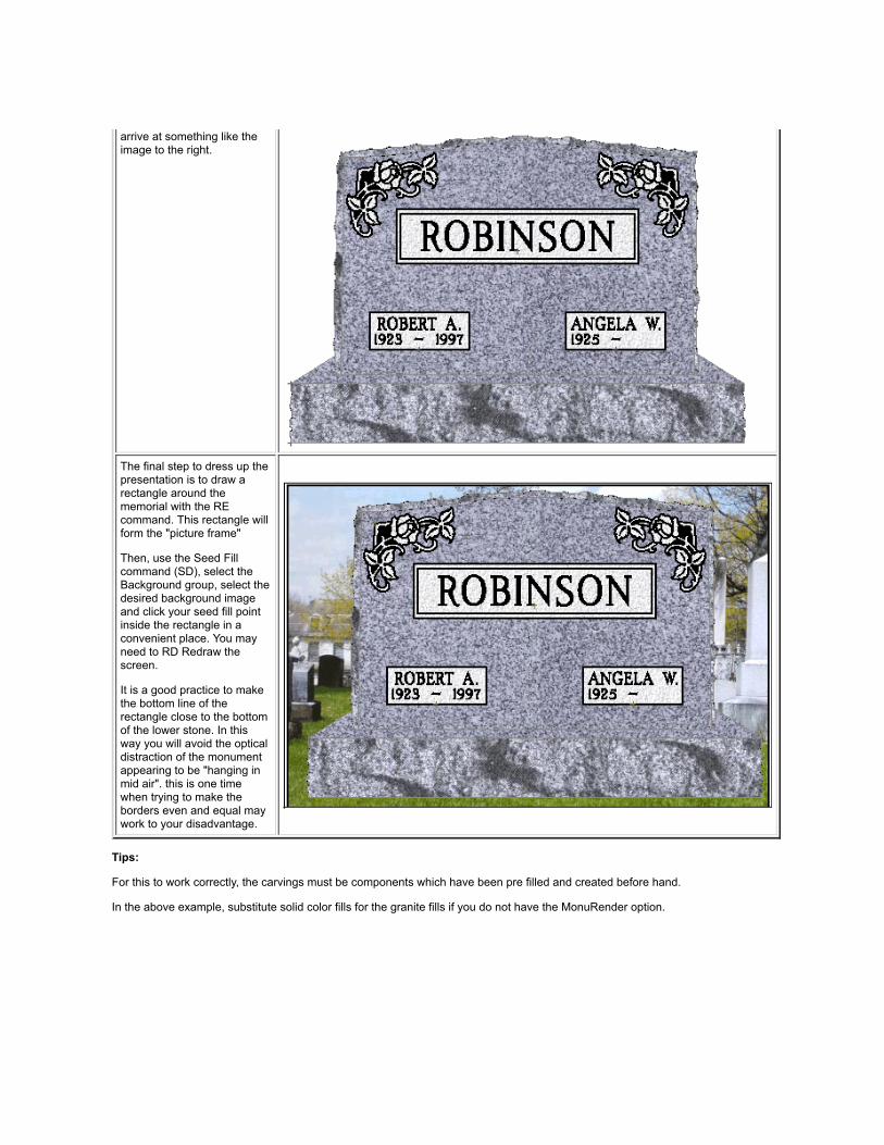
arrive at something like theimage to the right.
The final step to dress up thepresentation is to draw arectangle around thememorial with the REcommand. This rectangle willform the "picture frame"
Then, use the Seed Fillcommand (SD), select theBackground group, select thedesired background imageand click your seed fill pointinside the rectangle in aconvenient place. You mayneed to RD Redraw thescreen.
It is a good practice to makethe bottom line of therectangle close to the bottomof the lower stone. In thisway you will avoid the opticaldistraction of the monumentappearing to be "hanging inmid air". this is one timewhen trying to make theborders even and equal maywork to your disadvantage.
Tips:
For this to work correctly, the carvings must be components which have been pre filled and created before hand.
In the above example, substitute solid color fills for the granite fills if you do not have the MonuRender option.

F2Group Window Fill
(Version 3 only)
The Window Fill F2 command is a simple 4 step process:
1. Type F2 or click on the Group WF command in the Render Menu
2. When the Group Dialog menu pops up, select the Fill Group you wish to assign this fill to.
3. If you have the MonuRender option, the Finish Properties Dialog will pop up. See Below
4. Place a window around the design to be filled
5. The design sandblast lines fill from the outside in.
The color or hatch pattern of the fill is determined by the setting for the Fill Group in Group dialog.

See Fill Group for more details
Note!!

In order for the fill to occur as pictured above, all lines must be continuous with no breaks in the lines. There also must not be anysingle lines crossing the outside line border or any spaces to be filled.
Note!!
Fills will not display if Fills Button on the Tool Bar is not pressed in Fills by default are placed on Layer 9. If Layer 9 is turned off, fills will also not display.
Finish properties Dialog
After you select a Fill Group to assign the point(s) to, if you have the Monu Render option and the group you select has a granite colorassigned to it, the above dialog box will pop up. This dialog will allow you to select from the four possible granite finishes.

FFFitted Fill
(Version 3 only)
The Fitted Fill tool is used to describe the perimeter of an irregular area that you wish to fill. Examples of irregularareas are the rock pitch around the edge of a die or marker or a base which has odd shaped sides.
The SD (Seed Fill) tool is by far the easiest to use because it automatically finds the area perimeter. However,when the area is too complex for the SD tool to find the perimeter, then the Fitted Fill tool is your next logicalalternative.
To Use:
1. Enter the command FF on the keyboard or select Fitted Fill FF from the Render Menu.
2. The Group Dialog menu will appear. Select the group you wish to assign this fill to. Click on OK
3. If you have the MonuRender option, the Finish Properties Dialog will pop up. See Below
4. Next, left mouse click on the draw objects which constitute the perimeter. The draw objects thus selectedwill turn Red. Continue clicking on the objects until you have defined a closed area. When Monu-Cad Prorecognizes that the area is closed, a message box will pop up asking for your permission to accept thearea as defined.

When you click on the OK button, the area will fill as shown below.
Tip:
When selecting the perimeter objects, as you click on an object it will turn Red. If you click the same object asecond time, it will deselect the object and that object will return to the original color.
A really helpful optional feature is to hold down the Shift Key while selecting the perimeter. After the secondobject has been selected, Monu-Cad Pro will automatically select for you the next draw object in sequence andcontinue to do so until an intersection is reached or all the objects have been selected to create a closed area.
Occasionally, after the message box appears and you click OK, the area won't fill and you will see the selectedarea remain a Red outline but no filling occurs. In this event, just enter EL (Erase Last), RD (redraw) and tryagain. Select a different object to begin the selection process.
Caution!! It is best not to begin the selection process on an object which is part of the intersection of 3 or moredraw objects.
Note!!
Fills will not display if Fills Button on the Tool Bar is not pressed in Fills by default are placed on Layer 9. If Layer 9 is turned off, fills will also not display.
Finish properties Dialog

After you select a Fill Group to assign the point(s) to, if you have the Monu Render option and the group youselect has a granite color assigned to it, the above dialog box will pop up. This dialog will allow you to select fromthe four possible granite finishes.

FGChange Fill Group
(Version 3 only)
The Change Fill Group command FG has been added to the list of Render Commands to make it easy for youto change the association between the fill points you have placed into a drawing or component and the Fill GroupNames you have created or wish to create. This command is only to be used AFTER an area has been filled andyou wish to change the Group Name associated with individual or multiple fill points. If you have the MonuRenderoption, it will also allow you to change the finish of an already filled area from among the four possibilities Polish,Steeled, Blued or Rock Pitch. This command is the only way you can tell what group names have been used tofill a component without having to explode it.
To Use:
Enter the command FG or select Fill Change FG form the Render Menu.
This is a window command so you next place a window around the area containing the fills.
The Change Fill Group dialog shown below will appear on the screen.

In the Selected Fill Groups drop down edit box at the top of the Menu will appear a list of all the fill points thatwere in the selected window broken down according to the name of the fill group they are assigned to.
As shown above, the group name GRAYSOLIDPOLISH is highlighted. The number 1 (1) means there is one fillpoint in the window selection that matches this group name. If you click on a new group name in the second list,the points in the first list will be changed to the group name and color of the name in the second list. Try it! Youcan always hit the cancel button if you make a mistake.
Short Cut to Changing the Fill Group of just 1 Fill Point
If you wish to change the group name (or the granite finish for MonuRender users) on just one Fill Point, you mayRight Click on just 1 fill point. The Change Fill Group menu above will pop up and allow you to change the groupor finish for just that one specific point.
Monu Render option
Should a granite color fill be in use then by clicking on one of the options in the Change to Finish section, thegranite finish will be changed to that selected.


SDSeed Fill
(Version 3 only)
The Seed Fill SD command is the most exciting new command available in Monu-Cad Pro 3.0. This uniquecommand allows you to fill a closed area by just clicking once inside that area. This in many ways is verysimilar to filling in a paint program however, the fill is a vector based CAD object.
To Use:
1. Enter the command SD on the keyboard or select Seed Fill SD from the Render Menu.
2. The Group Dialog menu will appear. Select the group you wish to assign this fill to. Click on OK
3. If you have the MonuRender option, the Finish Properties Dialog will pop up. See Below
4. Next, click in the area you want filled. As you can see below, a SD point is placed in each closed areawhich defines a petal, leaf, stem or polished area.
Note!!After the first point has been placed, just pressing the space bar once for each point will allow you to placeadditional points without having to go through the added steps associated with the Group Dialog.

Comments:The above flower carving was created using these steps:
1. The sandblast lines were first filled in with a F2 command assigning the points to the SANDBLAST LINESgroup.
2. The SD command was used to fill in the steeled areas of the flower by clicking a point in each area.These points were assigned to the COMPONENTS STEELED group.
3. The SD command was used to fill in the one polished area assigning that point to the COMPONENTSPOLISH group.
4. Finally, the CC (Component Create) command was used to save the carving as a component . In thefuture, for those with the MonuRender option, when this component is used on a red granite die, just bychanging the granite color of the COMPONENT POLISH and STEELED groups, the component willautomatically change to match the color of the die.

Tip:
The SD (Seed Fill) tool is by far the easiest fill tool to use because it automatically finds the area perimeter.However, when the area is too complex for the SD tool to find the perimeter, then the Fitted Fill tool is your nextlogical alternative. Sometimes the SD tool works best and sometimes the FF tool. Experimentation is often thebest way to learn when to use which tool.
The key to successful filling is a very clean drawing. We have been going through the database and can't believehow many won't fill without a good amount of work.
A trick I use is to first off try a WF to see if the sandblast lines will fill. If it won't WF then it won't anything elseeither. However, if you try a SD in the sandblast lines, you will get an error message. Don't click on the button toclose the message but slide the error message out of the way and look at the red lines. You will see the red linesstop where the problem is. It is usually a break or overlap or points that don't touch.
Note!!
Fills will not display if Fills Button on the Tool Bar is not pressed in Fills by default are placed on Layer 9. If Layer 9 is turned off, fills will also not display.
Finish properties Dialog
After you select a Fill Group to assign the point(s) to, if you have the Monu Render option and the group youselect has a granite color assigned to it, the above dialog box will pop up. This dialog will allow you to select fromthe four possible granite finishes.
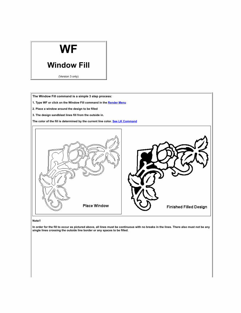
WFWindow Fill
(Version 3 only)
The Window Fill command is a simple 3 step process:
1. Type WF or click on the Window Fill command in the Render Menu
2. Place a window around the design to be filled
3. The design sandblast lines fill from the outside in.
The color of the fill is determined by the current line color. See LK Command
Note!!
In order for the fill to occur as pictured above, all lines must be continuous with no breaks in the lines. There also must not be anysingle lines crossing the outside line border or any spaces to be filled.

Note!!
Fills will not display if Fills Button on the Tool Bar is not pressed in Fills by default are placed on Layer 9. If Layer 9 is turned off, fills will also not display.
Tip:
Lettering groups cannot be filled unless you explode the group itself and then the letters inside the group. Components cannot be filledunless they are exploded.

GF
Group DialogAdvanced Concepts
(Version 3 only)
The Group Dialog shown above shows an advanced feature of the Group editor. Notice that the highlightedGroup Name DIE-1 has 2 groups below it called Components and Components Polish.
We used the Windows Drag and Drop feature to drag the Components and Components Polish group names anddrop them onto the Die-1 group. This makes those 2 Components Groups "children" of the Parent DIE-1 group.At the risk of confusing you we like to think of this as "grouping the fill groups".
(Drag and Drop means to place your mouse pointer on the group name you wish to move. Press the left mouse button andhold it down. While holding the button down, drag the child group name on top of the second name you wish to be theparent and then release or "drop" the first name onto the second. When done correctly, you will see a little + sign appear tothe left of the parent name. This means there is another group name "under" the first. If you click on the + sign, a tree viewwill open, the + sign will turn to a - sign and the child group names will appear. Clicking on the - sign will close the tree view)
What does this mean? Well, it means that whatever color or finish changes you make to the parent group ispassed onto the child groups. In this way you can control the colors of several groups at one time by justchanging the parent group. See example below.

In the monument shown behind the Group Dialog above, we can change the granite color of the die by changingthe Granite assigned to the DIE-1 group and when we do so the granite color in the floral component will changewith it.
If you have sharp eyes you might notice that the panel background also changed from pink to gray. For this tohappen automatically, the groups used in the lettering panels need to be changed manually from pink to gray orthe panel group names also should be made children of the DIE-1 group.
The RESET button will "ungroup" the parent and child groups.
This feature can be used with and without the Monu Render color option.

GFGroup Dialog
Fill Group Concept Explained(Version 3 only)
Menu Description
Understanding the workings of the Group Dialog is very important tothe inner workings of "Fill Points" and your ability to fill in letters,designs and memorial surfaces.
When you first see the Group Dialog, there will be several sample"Group Names" in the Group Names Edit Box. In this image, thecurrent highlighted group name is "SANDBLAST LINES"
With the New Group button you may enter a group name of yourchoosing. The Reset button will return group settings to a defaultsetting. The little X button allows you to erase a group name.
The Group Properties Area allows you to assign a color or hatchpattern to the Group Name Selected above. The choice you makehere will be reflected in any fills in the current drawing which havepoints assigned the the Group Name.
- - - - - - MonuRender Options - - - - - -
If your program is licensed to include Monu Render color realisticrendering, these selection buttons will be functional.
These option buttons will give you the choice of selecting either agranite color, a background picture or a photo to assign to the fillpoints.
The current selected granite, background image or picture file namewill be displayed here. (Applies only to MonuRender option.)
The Apply button will apply any changes made to the fill pointsassigned to the selected Fill Group Name. OK closes the window andCancel aborts the process.

Fill Group Concept Explained and Fill Group OperationEvery time you fill an area with the WF, FF, SD or F2 commands, a "fill" is created. It is an object itself in thesame way that a line or an arc is an object. Similar to a component, a "fill" is marked by a Red Insertion Point inthe lower left corner of the fill. We call this a "Fill Point".
Every filled area has a Fill Point. There are no exceptions. In some cases you may not see them but they arealways there.
All fill points with the exception of ones created with the WF (Window Fill) command MUST be assigned to aGroup which has a Group Name. If you look at the Group Dialog above, you will see the highlighted group nameis SANDBLAST LINES. If you look in the Group Properties section of the dialog, you will see that the GroupSANDBLAST LINES has been set to the color solid BLACK.
Why all this group business?? Imagine that you put 3 squares on the screen and with the F2 command you filleach of the squares and assign each fill to the group SANDBLAST LINES. Now, suppose you want to change all3 squares to the color green. To do so, all you have to do is enter the GF (Group Fill) command which will pop upthe dialog shown above. Then, you highlight the Group Name SANDBLAST LINES and under Group Propertiesyou click on the Color Drop down edit box and select the shade of green you desire. When you click the Applybutton, all 3 squares will change from Black to Green.
In this way, you can easily change multiple filled areas to another color, hatch or granite just by changing theproperties of the group the fill points are assigned to. See GF-Advanced
Where this especially comes in handy is with the MonuRender Granite colors. Using the above method, a graydie on a black base can easily be changed to be a rose colored die on a white base just by changing theproperties of the DIE and BASE groups! The BACKGROUND scene can be easily changed by changing theBACKGROUND group image.
Fill Points can be placed inside components and letters as well. To do this you must explode the component, fillit and then recreate the component.
Creating New Group Names
The names that appear in the Group Dialog ( GRAYSOLIDPOLISH etc) are just example names that we createdto give you a head start. The actual names that you choose to use are at your discretion. Two names will alwaysappear by default and are "hard wired" into the program. These are the names used by the program as a defaultfor lettering panes sandblast lines and the lettering panel surface. Currently these names are LETTERINGPANEL SURFACE and PANEL SANDBLAST LINES. Whenever you need to create a new group name todescribe a particular area of a memorial, just type it in.
An .mcd file which is saved with filled areas contains the group names associated with any fill points that may bein the drawing. If when you reload the file the group names are not present in the Group Dialog, Monu-Cad Prowill automatically add the names to the dialog.
See Advanced Group Dialog features Click Here
Note!!
Fills will not display if Fills Button on the Tool Bar is not pressed in Fills by default are placed on Layer 9. If Layer 9 is turned off, fills will also not display.


Panel FillsAutomatic
In Version 3.0 of Monu-Cad Pro, we have made a significant change in our Lettering System.
Any Panels automatically drawn with Click & Type contain fill points upon creation. What this means is thatyou do not necessarily have to explode the lettering group in order to place fill points to color the panel sandblastlines and surface.
The two Fill Groups Automatically created by Click & Type are named:
LETTERING PANELS SURFACE and PANEL SANDBLAST LINES
Initially, Lettering Panels Surface is assigned a solid light Gray color and Panel Sandblast Lines is assigned asolid Black color.
When you load a previously drawn .mcd file such as Demo_DD02.mcd and turn on the fills, the family nameshould look something like this:
It looks pretty good but there still is a problem....the letters are not filled in dark and the center of the letters O andD are not the panel color.
This is because the letters and their centers are Components in themselves and not part of the panel. This nextimage should look better:
How did we make that happen? Well, we created an alphabet in which the letters already contained fill points.
In detail:
1. First we created two new fill groups V-SUNK LETTERS CENTERS and V-SUNK LETTERS TYPEFACE.We assigned the solid color Black to the Typeface Group and light gray to the Centers Group. We suggestall users use these group names for all sandblast letters.

2. Next, we did a LF and loaded MCALF010.fnt (alphabet #10)
3. Then we exploded all the components, added the proper fill points and remade the components renamingthem as we created them. For example, all the letters begin with either SKM or FSKM so we renamedthem to SKMF_ of FSKMF_ the _(underline) is the letter for the character. (SKMA became SKMFA) Thebest tools to use for filling letters is the F2 fill for the letter itself and then use SD for the centers.
4. When all the letters were filled correctly and the components renamed, we saved the font with the SFcommand under the name MCALF010F.fnt ... the F for filled.
5. Next, using Windows Explorer we copied the SKM.dta file in the \fonts folder and renamed the copy toSKMF.dta.
6. Finally, we edited the MCFonts.lst file in \fonts folder to include the new font as below:
[Press Modified Roman]dtafile = skmfontfile = mcalf010lowercase = noserifs = yes [Press Modified Roman-F]dtafile = skmffontfile = mcalf010flowercase = noserifs = yes
A lot of work, yes! But the results are now automatically filled panels with automatically filled letters!
Of course, we edited the lettering group to use the Modified Roman-F font instead of Modified roman.
FYI, we also created some test alphabets consisting of Frosted and Shaded letters. The groups we created werenamed:
OUTLINE LETTERS CENTEROUTLINE LETTERS TYPEFACE

OUTLINE LETTERS SB LINE
We suggest all users use these group names for all outline letters.
MonuRender Option
If you have the MonuRender option, the panel can be made to look like this if you use a Rose Granite:
TIP:
If you are in a hurry and don't want to go through the trouble of creating a filled alphabet, you could just explodethe lettering group and the letters in it, use F2 or WF to fill the letters with a color and use SD to fill the centers.
As of 1-30-2001, all the standard Monu-Cad alphabets are now available in a pre filled version. These files havebeen included on the Version 4.01 upgrade CD but are not automatically installed. See the instructions thatcame with the CD for details as to how to use them.
Note!!
Fills will not display if Fills Button on the Tool Bar is not pressed in
Fills by default are placed on Layer 9. If Layer 9 is turned off, fills will also not display.

Monu-Cad Pro 2002 Menus
File Menu
(Click on a command in the menu for more information)
Edit Menu
(Click on a command in the menu for more information)

Draw Menu
(Click on a command in the menu for more information)
Note that Dimensions is a 2 level menu or "pop out" menu. When you clickon the word "Dimensions", the pop out will display 3 choices.
Render Menu
(Click on a command in the menu for more information)
Display Menu
(Click on a command in the menu for more information)

Object Menu
(Click on a command in the menu for more information)
Window Menu
(Click on a command in the menu for more information)
Layer Menu
(Click on a command in the menu for more information)

Drawing Menu
(Click on a command in the menu for more information)
Component Menu
(Click on a command in the menu for more information)
Controls Menu
(Click on a command in the menu for more information)

Snaps Menu
(Click on a command in the menu for more information)
Wizards Menu

A3Three Point Arc
Three point arcs can be specified with three points on the arc, much like a three point circle; however, the first pointspecified becomes the beginning of the arc, and the last point specified becomes the end of the arc. In other words,the arc goes from the first to the last points, passing through the second point.
After you select Arc from the Draw Menu or type A3 on the keyboard, specify each point in succession by clickingyour left mouse button. Construction points will appear for your reference. After clicking the first point, a "rubber band"straight line will appear connected to the first point you entered. After you click the second point, the "rubber band" willbecome an arc which extends from the first point through the second point and will "flex" as you move the mousearound. Upon entering the third (ending) point, the arc will be completely drawn.
The second point (or so-called midpoint) can be anywhere between the first two points, and does not have to be mid-way between. The arc will, in fact, pass through the second point, so it determines the radius of curvature of the arc.
If you desire to draw a number of arcs in succession connected to one another, pressing the space bar on thekeyboard after completing the first arc will automatically begin the second arc at the point where the first arc ended.Using this method, it will not be necessary to enter the first point of the second and subsequent arcs as the first pointwill be automatically placed for you. Press the Esc key to stop the chaining of Arcs feature.
Tip:After you complete an arc, the individual points may be moved with the MP command or the entire arc may be movedwith the OM command.
See A5 command for Tangent Arcs

A5Tangent Arc
The A5 Arc is a special form of the 3 point Arc. It is similar to the A3 type Arc in that it is made with 3 points: abeginning point, and ending point and a point on the perimeter of the arc.
The main difference in the A5 arc is that the second and subsequent arcs in a chain of arcs will be restricted inmovement and placement allowing only movement and placement which will allow the second arc to be Tangent tothe first arc. In other words, 2 arcs which are drawn in the form of an "S" curve will flow perfectly from the first arc tothe second one. The transition from one arc to another is perfectly smooth with out any "bumps" or flat sections at thejunction of the 2 arcs.
In addition, if one draws a straight line and then enters A5 and uses NP to begin the new A5 arc at the end of the line,the new A5 arc will be restricted to movement and placement which will make it Tangent to the straight line. again,the flow or transition from the plane of the straight line to that of the arc will be perfectly smooth with no "bumps" orirregularities.
The A5 Tangent Arc command can be executed by typing A5 on the keyboard or Clicking on the Tangent Arccommand in the Draw Menu.
See A3 Arc Command

ABArc to Bezier
This command will change arcs to Bezier Curves orQuadratic curves in the same way the BA commandchanges Bezier and Quadratic Curves to Arcs.
Simply Click on Arc to Bezier in the Edit Menu or typeAB on the keyboard. A menu will appear asking youwhich type of curve you wish to end up with and whetheryou want to convert just 1 object or a Window containingmany arcs.
Make your selections and upon completion of thecommand there will be an accept or cancel dialog. Clickon your selection and the conversion will be complete.
OO does not reverse this action.
see BA command

Adjust Lettering
This great new feature first available in Monu-Cad Pro Ver 3.0 will allow you to adjust the spacing between charactersin a lettering group without first exploding the group. We borrowed a little from the "adjust arc lettering" feature andapplied it to standard group lettering.
To access this feature, first Right Click on the Red insertion point in a lettering group just as if you were going to editor move the group. When the context menu appears left click on the Adjust Lettering option. See below.
After clicking on the Adjust Lettering label, a small "Tool Bar" as shown below will appear.

Notice that there is a RED cursor ][ in between the first 2 letter "D's". Also notice that the space between these D's inthis image are farther apart than in the first picture. This is because in preparing these images, I clicked several timeson the + button in the tool bar.
The cursor ][ button allows you to place the cursor with the mouse where you would like it.
The left and right arrow buttons move the cursor one character to the left or right with each click. The up and downarrow buttons will move the cursor up or down one line of lettering if there are more than one line in the group.
The Up and Down arrow buttons move the cursor up or down one line of lettering if the lettering group containsmultiple lines of lettering.
The buttons spread out or contract equally the lettering by increasing or decreasing the space betweenletters a small amount with each mouse click. The <> button increases the amount of space and the >< buttondecreases it. This feature is great to spread out a family name "by eye" till it "looks good".
The Plus (+) and Minus (-) buttons will allow you to increase or decrease the space between 2 letters. Each clickincreases or decreases the space by a small amount. You may also use the + and - keys on the keyboard.
The "R" (Reset) button will return the adjusted space to the initial default values. Note!! Only the line of lettering thatthe cursor is currently on will be reset.
The "X" button exits the command.
The adjusted spaces are saved in the file when you perform a drawing save. Should you edit the lettering or fontname the values will be reset to the default values.
Note!! These spacing changes are not permanently saved in the spacing table for this alphabet. These are"incidental" spacing changes. To permanently change the values in the .DTA file so that these changes always occurautomatically, you will need to turn on the "Save to DTA file" option in the config menu. This save to DTA file option isnot available in Monu-Cad Lite!


Advanced Lettering FeaturesBelow is a sample representation of the Click & Type® Advanced Edit Menu.
Click your mouse on a button or area in the image below that you would likemore information on.
After you read the information, click on the BACK arrow at the top of the page to return here.Move the cursor arrow around on the screen and when the arrow changes to a little "hand pointing"click the left mouse button to find information on that subject.
Font Style Preview
When you click on the font name list box, an image will preview the font style selected. If the fontcontains all upper case letters, all letters will be in upper case as shown in the image below.

Menu Bar Added
A new feature added to versions 3.0 and above is the ability to use the Windows "Clipboard" tocopy Text directly from a word processor into the Monu-Cad Click & Type Lettering System.
In the 7.xx upgrade, a Menu Bar has been added to the Advanced Kern Dialog containing the Fileand Edit Drop Down Menus.
FILE MENU
The first option in the File Menu, Import Text File, will allow you to import text from a text filedirectly into the Text Box. You may import a plain ASCII file or a document file such as a Word.DOCfile. If the text file contains formatting characters, they will be stripped out and only the plain text willbe placed into the Edit Box.
The second option, Save Text to File, will save the contents of the Edit Box to a file to a file nameand path of your choice.

EDIT MENU
These standard Windows Clipboard and word processing features are now available in a standarddrop down menu. for the most part, they should operate in the same way as most windows textprocessing programs.
Single Line Thickness - Frosted Line Thickness
These two edit boxes allow you to adjust the thickness of your panel sandblast lines.
Panel Width -End Space
These 2 edit boxes allow you to set either the absolute width of the desired panel or an adjustable widthdepending on the length of the lettering plus a pre defined amount of "end space:
Top Line to Top of Panel
This edit box allows you to set the "inside space" above the lettering between the top of the letters to theinside panel line.
Click the BACK button to return to previous page.
Lettering - Advanced
Lettering - Editing - Adding
Lettering on an ARC

ALAll Layers Edit
(Monu-Cad Pro Only)
The ALL LAYERS (Edit) command allows you to specify whether you wish editing commands to affect objects whichare on either ALL LAYERS or only the currently selected layer. A way to visualize this in your mind is to imaginehaving 10 pieces of transparent plastic stacked one on top of another. If there is a flower on the 9th piece of plasticand you wish to edit that flower, with the AL command turned on, you can do so without having to shuffle down to the9th layer. This feature was created for your convenience and ease of operation.
The ALL LAYERS command comes into play with the OBJECT EDIT and WINDOW EDIT commands, and will also befound on the menu under these two types of commands. With ALL LAYERS off, both the OBJECT EDIT andWINDOW EDIT commands will only be able to select objects on the currently selected layer; with ALL LAYERS on,objects can be selected from any layers that are visible. Layers that are not visible can not be edited with thesecommands even with ALL LAYERS on. (See LAYER DISPLAY and LAYER HIDE above.
ALL LAYERS is a `toggle' command, which means that it can be turned on and off even in the middle of executinganother command without having to start the command over again.
ALL LAYERS is normally toggled ON when you start Monu-Cad Pro. The All Layers toggle is always turned on inMonu-Cad Lite!


ASCII-ChartIn Monu-Cad Pro, when you import a True Type Font, the letters are numbered according to the ASCII chart below.In other words, a Capital Letter A is a number 65. You will normally be concerned only with characters 32 through125.

Extended ASCII Chart

AutoTrim(available under SE command menu)
The Auto Trim option under the Select Command menuwill automatically trim line and arcs to one another whichdo not touch or overlap a bit.
The procedure is as follows:
1. Type SE to bring up the Selection dialog
2. Use the Window button to place a window aroundthe items to be trimmed. They can also be selected oneobject at a time.
3. Click on the Auto Trim option in the menu.
4. Change the values in the dialog box as needed toadjust the amount of trim and extension desired. Try thedefault values first.
5. Click the update button to see the results. Changevalues and click update again to "play with" the result.
6. Click Ok when finished or Cancel to abort thecommand.

AXAngle Dimension
See Dimensions
Click Here

BABezier to Arcs
Before - After
The Bezier to Arc command (BA) is a recently added feature of Monu-Cad Pro. This command will allow you to convert Bezier Curves to 3point circular arcs. This command will work on both 3 point QuadraticBezier curves (BQ) and 4 point standard cubic Bezier Curves (BV).
To use the command:
1. click on BA in the Edits Menu or enter BA on the keyboard.
2. a dialog box will appear offering the choice of a single object ormultiple object selection using a window. Select one of the 2 options.
The dialog box also offers the opportunity to set the accuracy of theconversion process. 70% accuracy is sufficient for the conversion ofmost monumental drawings. Experimentation with different values willaffect the shape of the resulting conversion.
WARNING!! A setting of 100% may produce way to many arcs andmay make the resulting carving difficult to auto outline.
3. Select the curve(s) to convert. Upon completion of the conversion adialog box will appear which will give you the opportunity to accept theconversion or cancel. This operation cannot be reversed with the OO

(UNDO) command once the results have been accepted.
Why this command?This command will allow you to convert the Bezier Curves used in othergraphics programs to Monu-Cad Arcs. After importing a drawing from aGraphic program with the IP (import) command, the BA command usingthe Window select option will allow you to convert the whole file in oneoperation.

BQ3 Point Bezier Curve
The 3 point Bezier Quadratic curve is available byclicking on Quadratic BQ in the Draw Menu or typingBQ on the keyboard.
Then click 3 points with your mouse in the same way onewould make a 3 point arc.
Changing the curve is accomplished with the MP (MovePoint) command. It also can be broken with the OB(Object Break) command.
This is the same curve used in making True Type Fonts.
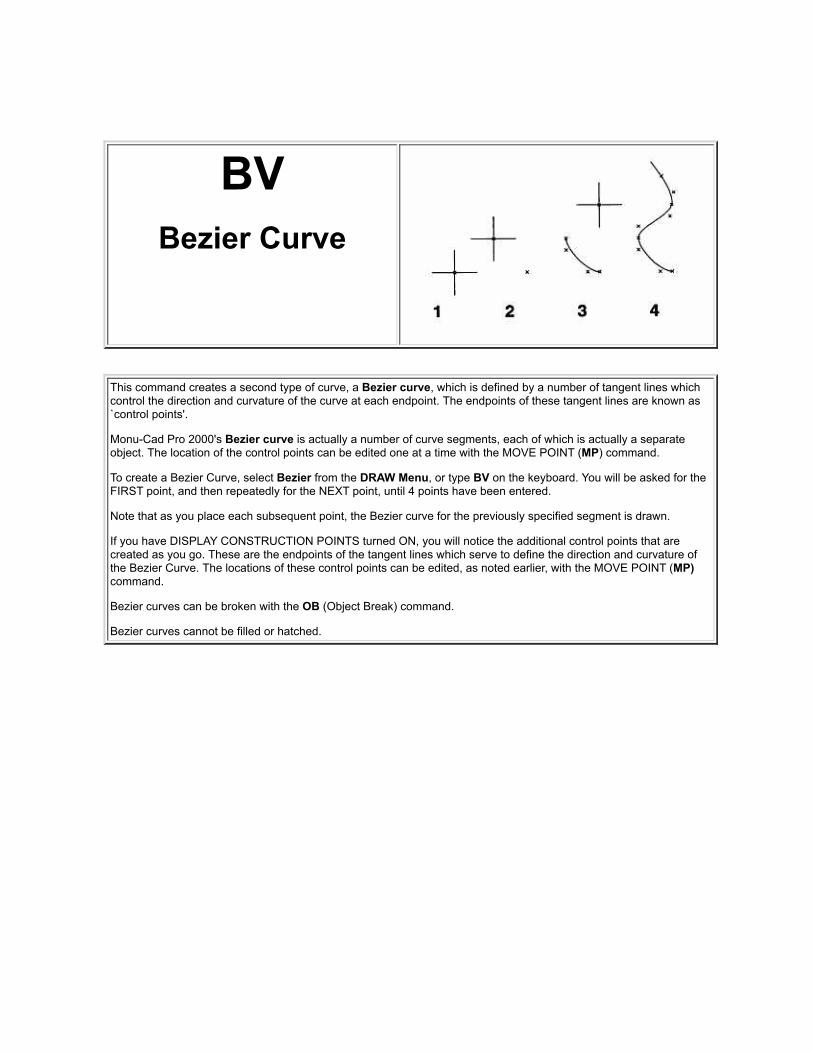
BVBezier Curve
This command creates a second type of curve, a Bezier curve, which is defined by a number of tangent lines whichcontrol the direction and curvature of the curve at each endpoint. The endpoints of these tangent lines are known as`control points'.
Monu-Cad Pro 2000's Bezier curve is actually a number of curve segments, each of which is actually a separateobject. The location of the control points can be edited one at a time with the MOVE POINT (MP) command.
To create a Bezier Curve, select Bezier from the DRAW Menu, or type BV on the keyboard. You will be asked for theFIRST point, and then repeatedly for the NEXT point, until 4 points have been entered.
Note that as you place each subsequent point, the Bezier curve for the previously specified segment is drawn.
If you have DISPLAY CONSTRUCTION POINTS turned ON, you will notice the additional control points that arecreated as you go. These are the endpoints of the tangent lines which serve to define the direction and curvature ofthe Bezier Curve. The locations of these control points can be edited, as noted earlier, with the MOVE POINT (MP)command.
Bezier curves can be broken with the OB (Object Break) command.
Bezier curves cannot be filled or hatched.

C2Two Point Circle
A two point circle is a circle which can be specified by the center and the radius (a point on the circumference of thecircle.)
After you select the Circle 2pt command from the Draw Menu or type C2 on the keyboard, you will be prompted toindicate the center of the circle. Once you have done this, as you move the mouse, the circle will form and "shrink orgrow" with the movement of the mouse. If you have the "points" turned on (PC command) a construction point willappear to remind you where you located the center, and you will be asked for a point on the circumference of thecircle. The distance between the first construction point and the second point entered will be the radius of the circle.When you select the second point, another construction point will appear, through which a circle will be drawn whosecenter is at the first point.
Note that the second point (a point on the circumference) can be at any angle from the first point; that is, it does notneed to be directly above, below, or to the left or right of the first point, because the rotation angle of a circle isirrelevant.

C3Three Point Circle
A three point circle can be specified by three points on the circumference. This can be useful to fit a circle into adrawing when the center of the circle is unknown.
After selecting the Circle 3pt command from the Draw Menu or typing C3 on the keyboard, you will be asked, insuccession, for the first, second, and third points on the circle. These points can be grouped together on one side ofthe circle, opposite each other on three sides of the circle, or anywhere on the circle. For any three points, there isonly one circle which can pass through all three.
After you select the first 2 points, the circle will appear and "shrink and grow" as you move the mouse. When youselect the third point, the circle will be completed. The center of the circle will also be located with a construction point,and a circle will be drawn through the three points you have indicated.
Note that if the three points come very close to being in a straight line, you have specified a very large circle. Thismay appear to be a straight line on your screen, but if you ZOOM ALL (ZA) you will be able to see the whole circle. Toget back where you were, select ZOOM PREVIOUS (ZP). If the three points are exactly in a straight line, you havespecified an infinitely large circle, and the results may be unpredictable.

Cartesian CoordinatesThe placement location of all drawing objects, lettering groups and components is determined using theCartesian Coordinate System. In Monu-Cad programs, the center or 0,0 location is at the bottom center ofthe draw screen. As shown in the illustration below, 0,0 is marked with a black X which cannot be erased.The comma ( , ) placed between the X and Y values is necessary to differentiate between the X andvalues.
The example above is a 3-0 x 2-0 (36" x 24") Serpentine Top Die on a base. The Cartesian CoordinateSystem is similar to using a Centering Ruler placed on the joint of the Die. The lower left corner of the Dieis 18 inches left of center or -18 inches and the lower right corner is 18 inches right of center. The plus (+)sign is assumed. Since these corners are on the same plane as the joint, the Y value is 0.
To place an object such as a family name 13 inches above the joint on the center line, you would place it atcoordinate location 0, 13 ( or zero left to right and 13" high).
To place a inscription centered in the left 1/2 of the die and 3" above the joint, you would place it atcoordinates -9, 3.
Tip:Remember that "Left and Down" are negative numbers and "Right and Up" are positive numbers.
Rulers

Click the BACK button to return to the previous page.

CCComponent Create
(Monu-Cad Pro Only)
This command is used to turn an existing portion of the drawing into a component. Component creation is useful fordrawing parts that are small and reusable like crosses, hands, emblems etc. that have to be moved, rotated andscaled easily.
The ability to create components is a very powerful feature of Monu-Cad Pro 2000. Make sure that the items that youwant to use to create the component are visible on the screen. Be sure to sort the design before making it into acomponent (see INSTRUCTIONS ON WINDOW SORT (ST)).
To Execute this Command:
Select COMPONENT CREATE from the Component Menu or type CC on the keyboard.
Place a window around the desired objects. As with any other window command, only objects which fall wholly withinthe window will be subject to the command. Follow the on screen command prompts in the lower left corner of thescreen.
After the window has been drawn, you will be asked to give the component a name.

After typing the name, press ENTER or click the Enter Reference Point button in the dialog box. What you will seewill look something like the image below:
Then you will be asked to place a reference point. This is the point that will show up on the component as a little redX which will serve as the "handle on the coffee cup" when you later wish to place it, edit it or move it.
There are 9 "little green boxes" on the green rectangle that defines the extents of the component. If you click insideone of these boxes, the cursor will "snap" to the exact center of the box. This makes it very easy to select the exactcenter of the component or any one of 8 additional "easy snap" points. Alternatively, you may click your mouse cursorany where else you may choose either inside or outside the green rectangle to define the insertion point.
Note!!
If the Save new Component to Disk check box is checked in the dialog pictured above, the component will be savedto your hard disk drive in the current component folder. You may override this path setting in the Paths/Files TAB inthe CONFIG menu.
If "Save new Component to Disk" checkbox in the dialog is not checked, then to permanently save the component todisk you will have to use the Component Save (CS) command.
If the Show File Security Options check box is checked in the Paths/Files TAB in the CONFIG file, then you will begiven the opportunity to select the Security Option desired for this component.
As a general rule, you will make into components those drawing parts which you will use later as pieces to modify orembellish a design composition. Items like emblems, crosses, flowers, special panels, letters, vehicles and religiousfigures are good candidates to be made into components.
By the way, don't name your components Fred or Joe, unless these names relate to the component, or you will soonforget which component is which. Choose a name that will help you (or even someone else) to identify the componentwithout too much guesswork. For example, the component above is called TBEAR5, the fifth teddy bear entered. Afterthe name has been entered, you will be asked for a reference point for the component. This point will be used as anorigin or basepoint for placing the component in the future, so some important place like the bottom center of a book

or the center of a flower is a good choice.
After specifying the reference point, the component is defined and may be placed elsewhere in the drawing. When acomponent is made in Monu-Cad Pro 2000, it will be automatically saved to disk. You can check to see if yourcomponent was really defined by checking the component listing. Use the COMPONENT LIST CL commanddescribed near the end of this chapter. The names of all defined components are added to the list as soon as they aredefined and your screen has been redrawn, so if your component was defined, its name should be listed.
Components, once created can be "exploded" back to their individual elements later with the CE (ComponentExplode) Command. They can also be renamed with the CN (Component Name) command. Do not renamecomponents in Windows Explorer as they will not appear when called up later.
Note that the original objects from which you created the new component are NOT the component. If you want themto be a component, erase the existing objects and use the COMPONENT PLACE command to replace them with acomponent.

CEComponent
Explode
When placed with the COMPONENT PLACE command, components are treated as single objects, no matter howmany different lines, arcs and circles they were originally created from. In most cases, this makes manipulation ofcomponents easier, but in some cases it would be better if you could identify an individual line or circle (or any otherobject) within a component.
To do this, the component must be broken up into its original parts. This is done with the COMPONENT EXPLODECE command. After you select Component Explode from the Component Menu or type CE, you will be asked tospecify the reference point of the component which you wish to explode (if you have turned off the display ofreference points, it would be a good idea to turn them back on before trying this command).
Enter the command CE, place the crosshairs at the desired reference point (red X) and press the left mouse button.The component will be redrawn (exploded) back into its original individual parts.
Note that only the individual component selected is exploded. All other similar components remain components, andmore of the same component can still be placed.

CKCursor Color
The color of the video cursor (the crosshairs that youmove with the pointing device) is set by this command.
Select the Cursor Color command from the ControlsMenu or type CK. You will be shown the current cursorcolor and given the opportunity to change that color.
To change the color, click on the down arrow next to thecurrent color.
A color selection grid will appear. Click on the new colorand then on OK. The cursor color will now be the color ofyour current selection.

CLComponent List
The Component List command is accessed from the Component Menu or by typingCL on the keyboard.
This command will pop up the list box shown here on the Draw Screen and place it tothe far right side of the screen. In the list will be the names of the Components whichare currently placed in the drawing.
If you ever need to see the names of the placed components, this is the only way youcan determine their names.
This command is also useful if you need to place the same component several times.Once the component has been placed in the drawing once, pop up this list and click ona name in the list. Then move your mouse onto the Draw Screen and click the leftmouse button to place the component. You can do this repeatedly.

CNComponent
ReName
Component files cannot be properly renamed using aMSDOS or Windows Explorer command in the way mostother files can be renamed. This is because a componentfile contains an internal name identifying it for usagewithin the Monu-Cad Program.
However, we have provided the CN command so thatcomponents can be properly be renamed. To use thecommand, simply:
1. Enter CN on the keyboard or Click on ComponentreName in the Component Drop Down Menu.
2. The file selector will appear. Navigate to the file youwish to rename, click on the name and then click OK toselect the component to be renamed. The dialog belowwill appear:
3. Enter the new name and click on OK.
The component will be renamed.
If the Show File Security Options feature is turned on the CONFIG menu, then the file security options menu willpop up before the save takes place.
In version 5.0 and later, right clicking on a component willproduce a context menu which will allow you to rename acomponent already placed in the drawing. This is a

special case and should be used carefully. Click here formore details.

Commands
To begin almost any operation, you must enter a command to tellMonu-Cad Pro 2000 to do something. Monu-Cad Lite!, anabbreviated version of Monu-Cad Pro, operates in the same way.
All Monu-Cad commands consist of two characters that are, inmost cases, logically associated with the command to beperformed. If one word is used to describe the operation, thenoften the first two letters are used for the command code, i.e.,"OR" to turn on or off ORTHO mode. If two words are used todescribe the command, then often the first letters of each wordare used for the command code, i.e., "MP" for MOVE POINT.
The user may perform any operation by typing the appropriatetwo letter command on the keyboard or by selecting theappropriate entry from the drop down menus.
When entering commands via the keyboard, it is not necessary topress ENTER after you type the two characters. When selecting acommand from the drop down menus, a single click on thecommand name will begin the command.
In either case, after you enter the command, you will be promptedon the command line for the necessary steps to complete thecommand. For example, when you execute the A3 (3 point arc)command, you will be prompted to enter the first, middle and endpoints necessary to draw the arc.
See List of Commands
Intro to Commands
Click the BACK button to return to previous page.
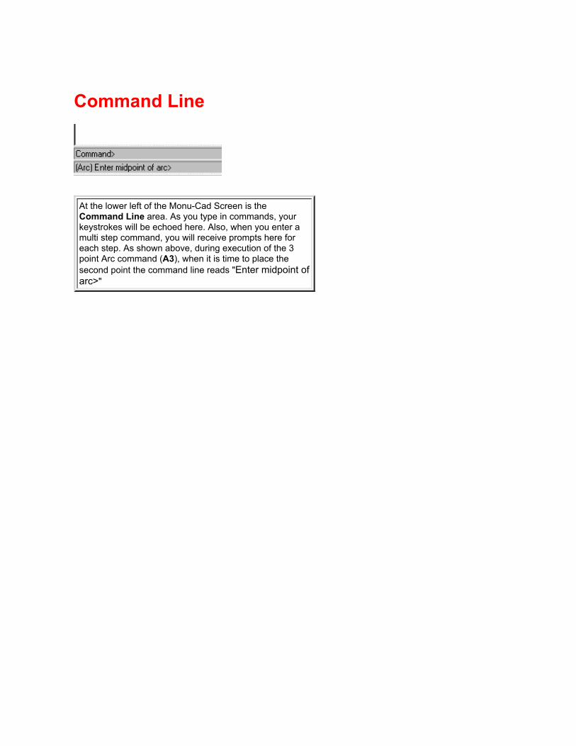
Command Line
At the lower left of the Monu-Cad Screen is theCommand Line area. As you type in commands, yourkeystrokes will be echoed here. Also, when you enter amulti step command, you will receive prompts here foreach step. As shown above, during execution of the 3point Arc command (A3), when it is time to place thesecond point the command line reads "Enter midpoint ofarc>"

Command Nesting
Command Nesting is a very powerful feature availablein Monu-Cad Pro 2000. This feature allows you toexecute one command from within the execution ofanother command.
For example, you can zoom in on the corner of amemorial, then snap the beginning of a line to a point inthe corner, zoom back out, zoom in on another part of thememorial and complete the line in that corner.
If you examine the steps in the example describedabove, you are beginning with the ZW command,followed by the LI command. Then, while the LIcommand is still executing, you perform a ZB and thenanother ZW before completing the LI command!
The ability to perform one command within another iscalled Command Nesting.
Click the BACK button to return to the previous page.

CPComponent Place
The Component Place command is used to place an existing component into the drawing at a specified location inmuch the same way that you would place text or any simple object.
When you select Component Place from the Component Menu or type CP on the keyboard, the file selector willappear and await your choice of a component name. Type the component name exactly the same way as when it wasfirst defined or click on a name and click on OK. An image of the component will appear "attached" to the cursor.Move it into the desired position and click your left mouse button to place it. You may also type in x and y coordinatesin the form x,y followed by ENTER to place it. The component will be placed so that the Reference Point in it (Red X)will be positioned at the coordinates where you clicked the mouse or the coordinates that were typed in.
Note that once you have specified the scale and rotation for components with the CZ or CR commands, allcomponents placed into the drawing will use these factors. Components already placed into the drawing are notaffected by changing these values.
Tip:Clicking on the Green Folder in the Tool Bar will be the same as typing CP.
Moving, flipping, erasing, rotating, replacing and scaling components can be easily performed by clicking your RightMouse button on the reference point. See Right Mouse Button for details

CRComponent Rotate
This command is used to rotate a component around its origin or reference point. If the specified rotation value ispositive, the component is rotated counterclockwise, while a negative value defines a clockwise rotation. The rotationvalue can be anywhere between -360 and +360 degrees. When you use this command, you must enter the rotationvalue before placing the component.
If you wish to place a component at some rotation other than the original, you use this command to specify therotation angle before typing CP. The component cannot be rotated as it is being placed.
To specify a new component rotation value, select Component Rotate from the Component Menu or type CR on thekeyboard. You will be asked for the new component rotation. Type a number, followed by ENTER.
All components placed will use this rotation value until you change it. Components already placed will not be affected.To place future components according to their original orientations, use a rotation value of zero.
If you want to change a component which has already been placed, use the WINDOW RE-SCALE WZ command toget the appropriate scale factors, or a WINDOW ROTATE WR to change the rotation angle.
Tip:
A newer and easier method of rotating components is to Right Click on the Reference Point in the component after ithas been placed and then click on rotate. You may also visually rotate the component by clicking on the "UseMouse" button. In this case, the component will rotate visually as you move the mouse and will anchor in place whenyou again click the left mouse button. see Right Mouse Button information.

also see Window Rotate
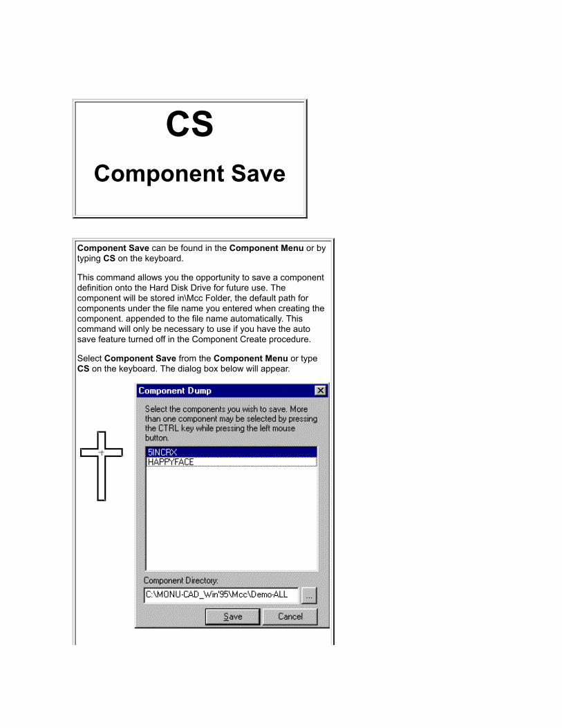
CSComponent Save
Component Save can be found in the Component Menu or bytyping CS on the keyboard.
This command allows you the opportunity to save a componentdefinition onto the Hard Disk Drive for future use. Thecomponent will be stored in\Mcc Folder, the default path forcomponents under the file name you entered when creating thecomponent. appended to the file name automatically. Thiscommand will only be necessary to use if you have the autosave feature turned off in the Component Create procedure.
Select Component Save from the Component Menu or typeCS on the keyboard. The dialog box below will appear.

Click on the component name and then click the Save button tosave. To select more than one name, hold down the control(Ctrl) key on the keyboard while clicking the selected multiple filenames, then click the Save button. This command actuallyreplaces the Component Dump (CD) command which isn'tused anymore.

CUCursor Size
The size of the video cursor is set by this command. Any positive number referring to the height and width of thecursor in pixels can be used. The actual size is determined by the graphics card in use.
Select the Cursor Size command from the Controls Menu or type CU on the keyboard. You will be shown a defaultand asked for the new value. Type a number, followed by ENTER, or just press ENTER to leave it the same. Thevideo cursor will change to the new size. The initial default is 32.

Cursor Movement
There is no command for this feature as it is turnedon at all times. In the MSDOS version of Monu-Cad, youwould have to issue the command CM.
When you choose to move the cursor on the screen withthe arrow keys, if the grid is turned on, the cursor willmove exactly the amount of the grid setting with each keypress.
This is a very powerful command for monument layoutpersons. With this feature, for example, you can set yourgrid to 1/16" and turn on the grid. Then, with the MovePoint (MP) command, you can move letters (afterexploding the lettering group) around on the screen withthe arrow keys. In this way, you can easily space out thedate 1911 to make it appear to be the same width as1924.
Click the BACK button to return to previous page.
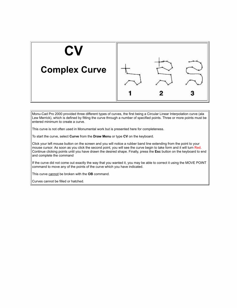
CVComplex Curve
Monu-Cad Pro 2000 provided three different types of curves, the first being a Circular Linear Interpolation curve (alaLew Merrick), which is defined by fitting the curve through a number of specified points. Three or more points must beentered minimum to create a curve.
This curve is not often used in Monumental work but is presented here for completeness.
To start the curve, select Curve from the Draw Menu or type CV on the keyboard.
Click your left mouse button on the screen and you will notice a rubber band line extending from the point to yourmouse cursor. As soon as you click the second point, you will see the curve begin to take form and it will turn Red.Continue clicking points until you have drawn the desired shape. Finally, press the Esc button on the keyboard to endand complete the command
If the curve did not come out exactly the way that you wanted it, you may be able to correct it using the MOVE POINTcommand to move any of the points of the curve which you have indicated.
This curve cannot be broken with the OB command.
Curves cannot be filled or hatched.

CXComponent
Remove
The COMPONENT REMOVE command removes the definition and all placements of the selected component fromthe drawing file.
Great care must be exercised in using this command. It is for major editing purposes only, not for erasing individualcomponents. For this purpose, use the OBJECT ERASE or WINDOW ERASE commands.
Before selecting the Component Remove command from the Component Menu or typing CX, make sure that youare never going to need this component again in this drawing. Remember that all existing placements of thiscomponent in the drawing are going to be erased.

After choosing this command, you will be shown a list of the components in the drawing. Click on the name of thedesired component and then click the Remove button. You will be warned about the severity of this command andasked if you are sure you want to remove this component. If you chicken out, press N. If you decide to forge ahead,press Y. No need to press ENTER in either case. The deed is done.
All placements of the selected component will be erased from the drawing, (except those which have been exploded), the definition removed from the drawing file, the name will be exorcised from the menu, and you can kiss thatcomponent goodbye.

CZComponent Scale
The COMPONENT SCALE command allows you to change the scale at which components are placed.
Upon selecting this command from the Component Menu or typing CZ, you will be asked for the new X and Y scalefactors. Type these as they are requested and click OK.
Any component placed with the CP command after you execute this command will be drawn on the screen at thesescale factors until you change it a second time.
If the X scale factor is larger than the Y scale factor, new component placements will be stretched horizontally. If the Yscale factor is larger, they will be stretched vertically. If both factors are larger than 1, components will be larger thantheir originally defined size, and if the factors are less than 1, components will be placed into the drawing at a scalesmaller than their original definitions. A scale factor of 1 for both X and Y will allow components to be placed at theiroriginal sizes. The scale factors are always applied to the originally defined component, and are therefore notcumulative nor calculated on the rotated component.
In Memorial work, components are usually scaled equally in both x and y directions.
Tip:
An alternate way to scale components is to click your Right Mouse Button on the Red X reference point in acomponent already placed, click on Scale and enter the scale values. You may also visually scale the component byclicking on the "Use Mouse" button. In this case, the component will "shrink and grow" visually as you move the

mouse and will anchor in place when you again click the left mouse button. This method will only affect the oneparticular component you are currently editing.
The Right Mouse Button method is the recommended way to scale for memorial work.
also see Window Scale

D2 Command - Load Drawing VariationGoto Load Drawing Variation

D3 Command - Slide ShowGoto Slide Show Command

DCDrawing CUT
Clicking on CUT in the File Menu or typing DC (Drawing Cut) on the keyboard will display the Cut Preview Screenbelow.
Place your mouse cursor over an area on the screen below and click that area for more information. Click the BACKbutton at the top of this program after you read the information to return to this image.
Cut to File Clicking on this button will pop up a file selector which will afford you theopportunity to change or accept the name of the output file. Once a file name has beendetermined, Monu-Cad Pro will automatically create an output Cutter File by that name.This file will contain the cut data which will be sent to the cutter by the MonuCut program.In normal operation, one will simply click this button and then click OK on the file selectorwithout changing anything. The cut file will be created with the name originally given to

the drawing session.
Launch MonuCut Clicking on this button will pop up the MonuCut Program so that youmay then send the file to the cutter. Goto MonuCut Program.
Exit Clicking on this button will exit the Cut Preview and return you to the Monu-Cad ProDraw Screen.
X-Y Settings This area of the screen will show you in real world coordinates the locationof the lower left corner of the stencil in relation to the drawing. You can change thesevalues manually to change the position of the red stencil outline rectangle
Rubber Size This drop down box contains pre set stencil sizes that you can select tomatch the stencil width you are using in your cutter. Simply click on the little arrow andthen click on the desired stencil size. The selected size will be retained until you againchange it.
Rotate 90 degrees Clicking this check box will rotate you output and the screenrepresentation 90 degrees.
Stencil Outline This Red Rectangle represents the position on the stencil rubber wherethe cutting will be performed. Place your mouse cursor inside the Red Rectangle, holddown the left mouse button and "drag" the rectangle over the memorial to change theposition. Release the mouse button when the desired placement has been attained. Theposition can also be changed by manually entering values in the X-Y settings edit boxesat the top of the screen.

DDDimension Settings
See Dimensions
Click Here

DGDrawing Change
The Drawing Change Command is available in the Drawing Menu or by typing DG on the keyboard.
After you have finished, the object will be erased and redrawn with all of the changes made.
This is one of the 3 Change commands all of which produce the same menus and prompts.
When you type DG, WG or OG, the dialog below pops up:
From this dialog you may elect to change the color of the objects selected, the layer that they are on and or the linewidth. At this time, line types are not supported.
Simply enter the value(s) you desire to change and enter OK. OO will UNDO this command.
If you elect to change the color of the objects the added dialog below will appear:

With the Drawing Change command, you can change the line color, line width, or layer of any object. Changes madewith this command affect the entire drawing.
Objects are drawn on specific layers, in certain line colors, using a certain line type and line width. So far, we havebeen using the defaults, drawing on layer 0, with line type 0 and line color 1. But all of these can be changed. Thesechanges can be made on any type of objects: points, lines, rectangles, regular polygons, circles, arcs, ellipses, andcurves.
Note that some care is required in the use of this command, since it is quite possible to change all of the objects in thedrawing, which may have originally been drawn on many layers with many colors, widths, and line types, to the sameline type, same color, same width, and same layer. If this is what you want, fine, but if it isn't, watch out.

DIDrag Image
The Drag Image (DI) Command turns on or off the "ghost image" that appears when you do a Window Move, WindowCopy, Object Move, Component Move, Lettering Group Move or any other command which involves "visually" moving,rotating or scaling part of the drawing.
This command is a "toggle" which means that it reverses state every time you issue the command.
In addition to the 2 letter command DI, there is also a button on the "toggle bar" labeled DI which when pressed indisplays the image and when "out" turns off the image. The last state of the button is saved when you end a MCProsession and restored when you begin the next session.
Tip:
If you need to momentarily turn off the image because it is too large and the display redraw is slowing down, simplehold down the Shift key on the keyboard
See Toggle Buttons

Die Maker WizardThis cute piece of programming, first new in Version 5.057, will create die shapes (and bases) automatically and allowadjustments to be made under user control.
To access this feature, click on Die Maker in the Wizard menu:
The following Dialog will appear:
To select a die shape, simply click on one of the 4 images shown illustrated above. To create a rectanglebase, click on the base button.
The shape and the adjustment dialog you will see is shown below:

Changing any of these parameters will change the shape of the die. The best way to understand what this does is tojust try it and play around a bit. It's pretty amazing!
Important thing to know about this wizard.
The resulting die shape is a drawing not a component.
Creating a Base
When you click on the Base button, you will see the base image below:

The Base will be drawn below the 0,0 marker and will be centered on 0,0 as shown above.
The offset value moves the base downward from 0,0 as you increase the value and upward as you decreaseit. The default value is 1/2". As with the Die maker, just playing with the buttons will make the operation ofthis Wizard obvious.
Important thing to know about this wizard.
The resulting base shape is a drawing not a component.

Dimensions(Version 3 only)
Dimensioning commands allow you to label your memorial drawings with the dimensions of thememorial such as the height and width of the whole memorial or just parts of it.
There are 3 Dimension Commands:
DD which pops up the Dimension Settings Dialog Menu shown below
LX which performs Linear dimensions (dimensions in a straight line)
AX which performs Angular Dimension functions (dimensions of angles)
There is a fourth command which is related to the Dimension commands so it is included here
LE which creates a Leader object which is useful in identifying items on the draw screen
see Draw Menu

The DD command will pop up this Dimension Settings menu shown above where all dimension and leadersettings can be made. Settings will be automatically saved from one session to another.
The first three settings are obvious: Color of dimension, layer to place the dimension on and the font to use.Default layer is Layer 8, color Black and font Arial.
Linear Direction setting determines the direction you are going to dimension. Aligned is the most popular
Text Settings:
Extension Settings:
The Offset value is only in effect when Proximity Fixed is checked.
When the Ext Stretch check box is checked, the extension will dynamically stretch from the measured point to thedimension line.
Arrow Settings

LX Command
The LX command performs linear dimensions. To execute the command simply type LX. Next, select the firstpoint and then the second point. Once the points have been selected, as you move your mouse you will see thedimension "ghost image" move with the mouse. Clicking your left mouse button will anchor the dimension in placeand the dimension text will appear.
It is important when dimensioning to be accurate when you place your points. A snap command like NearestPoint (NP) is most helpful when creating dimensions.
AX Command
This command is used when you wish to create an Angular dimension. It's operation is a little different than theLinear Dimension. To use, first enter the command AX. Next, click on the Vertex point of the angle (junction of thetwo lines). Then click on each of the two lines which create the angle. Using the snap command Nearest Line(NL) will help insure an accurate dimension. Once the vertex and 2 lines have been identified, when you moveyour mouse, the "ghost image" of the dimension will dynamically move with your mouse. Click your left mousebutton to anchor the dimension in place. You may measure either the outside or inside angle.

Erasing Dimensions
All dimensions by default will be placed on layer 8. You may simply hide layer 8 with the Layer Hide command (LH8) to shut off that layer and "turn off" the dimensions. Erase Last (EL), Object Erase (OE), Layer Erase (YX 8) andWindow Erase (WE) will permanently erase dimensions.
Special Note:
Should you stretch (SS) the drawing part that is dimensioned, the dimension value will dynamically change toreflect the correct length.
LE Command
The LE or Leader command will help in labeling parts of your drawing.
To execute the command, simply type LE. The following dialog box will pop up allowing you to input the desiredtext.
Click OK and place your cursor where you wish to point and click you left mouse button. As you move your mouseaway, a rubber band line will "follow" your mouse cursor. When you reach the area where you want the textplaced, again click your left mouse button. An outline rectangle containing the text will appear. If you move yourmouse from left to right, the rectangle will shift position. Click your left mouse button to anchor the text.
The image below is what a Leader looks like when completed. The shoulder length can be set in the DD menu asdisplayed above.

Warning!!Leaders and dimensions may be printed but they cannot be cut because they contain Windows True TypeFonts. You must erase them or turn off layer 8 before entering the Cut Preview screen.

Direct Draw
Direct Draw is a Monu-Cad Pro 2000 feature whichmakes it easy to draw lines of a specific distance, copyitems a specific distance apart and whenever you wishto move an object or window a specific distance.
For example, if you click a point to begin drawing a line,a "rubber band" line will be attached to the cursor. If youthen "stretch" the line in the direction you wish the line togo and enter 24 on the keyboard and then press Enter,the line will be drawn exactly 24 inches in the directionyou have set.

DKDrawing Clean
(Version 3 only)
The Drawing Clean command allows you to check a drawing for duplicate draw objects and components which mayexist on top of one another and are therefore invisible.
Select Clean from the Edits Menu or type DK on the keyboard. If there are duplicates present, a message box willpop up and advise you of the number present and you will be given the opportunity to erase them. If there are noduplicates you will be advises.
This command is also available in the form WK which will check and clean the whole drawing of duplicates in onepass. See Window Clean.
Tip:
This command will only remove exact duplicates. It will not remove items such as lines or arcs which overlap oneanother just a bit. It will however, also find components sitting on top of one another.

DLDrawing Load
This command allows you to load into the currentdrawing any drawing previously saved on a disk. Thisallows you to create a drawing in pieces and laterassemble them all together in one drawing.
To load a drawing, select the Load command from theFile Menu or type DL. The standard file selector dialogbox will appear. Type the desired name or navigate toand highlite the desired file and then press ENTER orclick on OK. You will be asked if you want to renameworking drawing. If you enter 'Y' you will be asked for anew drawing file name. You will also be asked for aninsertion point for the drawing that you are loading. Theorigin of the drawing will appear at that point. If you wantto load the new drawing on top of the current one, justuse 0,0. Pressing Enter will automatically select 0,0 asthe origin. All of the objects in the selected drawing filewill be loaded into the current drawing, and you cancontinue working.
Click here for more information
Tip:In Monu-Cad you can load one drawing on top ofanother. This makes it easy for example to place a diedrawing on the screen and then load a base drawing at alater time.
A quick way to load a drawing is to type DL, select the filethen press ENTER 4 times.
If you wish to start with a blank draw screen, first enterthe DX (Drawing Erase) command to eliminate theprevious drawing.
Click BACK button to return to previous page.


DODrawing Re-Origin
USE THIS COMMAND CAREFULLY--make sure that you have very carefully considered the effect! This is a verypowerful command. It seems harmless enough to change the value of the lower limit of the drawing, but in fact, theorigin is much more than that.
All points are measured from the origin. Points entered manually often use the origin as their reference. (See theMANUAL ENTRY OFFSET ORIGIN command ). Moving the origin can cause all kinds of confusion in the drawing.Some of the zoom commands use the origin as their lower left hand corner. The DRAWING PLOT command uses theorigin as a reference. Once moved, the origin is difficult to put back, because the RE-ORIGIN command uses theorigin as a reference!
If you insist, select the RE-ORIGIN command from the Drawing Menu or type DO. You will be asked for a new originpoint. Show a point, or type the X and Y coordinates, separated by a comma and followed by ENTER. If you type thecoordinates, make sure that you understand the manual entry command procedures., and know which manual entrymode you are in. It could make quite a difference whether you are specifying that the new origin be a certain distanceaway from the existing origin, the current basepoint, or the last point entered!


DPDrawing Print
For details click here to goto Printing a Memorial Design

DRDrawing Rotate
The DRAWING ROTATE command allows you to turn all of the objects in the entire drawing at one time with onecommand. It is very much like the WINDOW ROTATE command except that you don't need to select any objects orlayers, because you are rotating everything.
Select Drawing Rotate from the Drawing Menu or type DR on the keyboard. You will be asked to locate an axis pointor offset point. This is the point around which the drawing will be rotated. Click a point on the screen, or type thecoordinates. Next, you will be asked how many degrees you want to rotate around the origin. After you have given theangle of rotation in degrees, all of the objects in the entire drawing will be rotated. Counter-clockwise results from apositive value and clockwise from a negative value.
Note that it is the objects themselves which rotate; the drawing itself actually stays put. The X-axis is still horizontal,and the Y-axis is vertical. If you have the grid currently displayed, you will notice that it does not rotate either. It ispossible to rotate the drawing right off the screen. If the drawing seems to be gone after any of the rotate commands,use ZOOM ALL to see where it went.

Drawings and Components There are two main file types that you will work with in Monu-CadPrograms: Drawing Files and Component Files. (there are othersbut we will save that for later)
DrawingsA drawing file (identified by the file extension .MCD) contains theentire drawing composition. In monumental work, a drawing filecan contain a complete monument (die, carving and base), justthe die, just the base or just about any way you want to constructthe file. It all depends on what is on the drawing screen justbefore you save the drawing to a file.
We commonly refer to a drawing as a composition composed oflines, arcs, circles and other draw objects which exist asindependent objects. A drawing file is created automatically whenyou enter the command Drawing Save (DS) and give the file aname.
ComponentsComponents are a group of draw objects which have beengrouped together with the Component Create (CC) commandand the group has been given a distinct name.
Components are created from lines, arcs, circles and other drawobjects just like drawings are. The only difference is that theyhave been grouped and given a name and a reference point.Once objects have been grouped in this way, all objects within thegroup are treated as if they are just one object.
In Monu-Cad Pro, when you decide to Create a Component withthe Component Create command (CC), you are asked to givethe component a name. Once you have done so, the componentis saved to the Hard Disk Drive as a file with a .MCC fileextension.
Both Drawings and Components are really composed of thesame things but Components are given a different form to makeit easier to create new compositions.
Perhaps the following example will help to clear things up:
Lets assume that you wish to make a set of praying hands. Tostart, you draw the hands on the screen with lines, arcs andcircles. Once completed, if you enter the command DrawingSave and enter a file name such as Hands, you will end up withyour composition saved in a file called Hands.mcd. In this caseyou will have made a drawing file.
Now, if instead of doing a Drawing Save you use the Component

Create command, put a window around the hands, give it thename Hands and enter a reference point, the hands will be savedin a file called Hands.mcc. When you create your nextmonument and need a pair of praying hands in the layout, youcan place the hands you made earlier by issuing the ComponentPlace (CP) command and enter the name Hands when promptedfor the component name. The hands you made will appear on thescreen attached to your mouse cursor and will be anchored intothe new composition when you click your left mouse button.
In general, Drawing files are used to hold wholecompositions. Component files are used to contain smalldesign parts which need to be easily moved around in thecomposition and can be reused many times.
Good candidates for the component form are flowers, crosses,emblems, symbols, vehicles, animals, wedding bands etc.Components can always be returned to their original individualobject form by exploding the component with the ComponentExplode (CE) command.
Tip:If you need to determine if something is a component or part ofthe drawing, turn the Construction Points on and take anotherlook. Type PC and then RD to redraw the screen. The parts of thecomposition which are drawing elements will show the end pointsof lines and arcs. However, the component will not. also, look forthe Red X insertion point which easily identifies a component.Type PC and then RD again to turn the points back off. seeConstruction Points (PC)
See components for more information
See Component Menu
Click the Back Button to return to the previous page.

DSDrawing Save
This command allows you to save the current copy of thedrawing onto a disk without exiting the program. You canuse the current name or a different one.
It is a good idea to use the DRAWING SAVE commandfrom time to time, just to be sure that you have a recentcopy of your drawing on the disk in case anythinghappens to the drawing while you are working on it.
To save the drawing, select the Drawing Save commandfrom the File Menu, or type DS. You will be shown thecurrent name of the drawing. If this is the name you wantto use, press ENTER or Click OK. To save the drawingunder a different name, type a new name then pressENTER or click OK. The drawing will be saved on thedisk, and you can continue working.
This command can also be used to save several versionsof the same drawing under different names. Suppose thatyou want three slightly different versions. You wouldmake the drawing, and save it. Then you could edit it tomake the second version, and save it again under adifferent name. Continuing on, you could continue to editit, and save it once more under a third name. You havecreated three different drawings without quitting.
Click here for more information on saving a finisheddrawing


DTFont .DTA Spacing
Table Editor
Goto DTA-Editor

DTA File EditorDT
(Version 3.31)
Each Alphabet used in the Monu-Cad Click & Type Lettering System has an associated spacing table attached tothat alphabet. The file has a .DTA file extension and is located in the \Fonts folder. Pictured above is the SKM.DTAfile which is associated with the MCALF010.fnt alphabet.
This .DTA file contains:
The width of each letter
The "basic space factor" value used between straight sided letters
Space reduction factors between every letter combination
The width of a full and half space

This is an advanced area which normally will not be used by most Monu-Cad users. The information on the internalworkings is considered proprietary information. This information will be freely given to any Monu-Cad user who needsto create his own alphabets. Please call our office if you need the the in depth details. This command does notappear in a drop down menu.

DXDrawing Erase
The Drawing Erase command is the most powerful erasecommand of all, because you can erase everything in thedrawing at one time.
Select the Drawing Erase command from the File Menuor type DX. If you don't really want to clear out everysingle object in the drawing, type N, and you will return tothe drawing safely.
If you really want to erase everything, type Y. Don't saywe didn't warn you.
Be extra careful in using the DRAWING ERASEcommand, for obvious reasons. UNERASE or OO won'twork with this one.
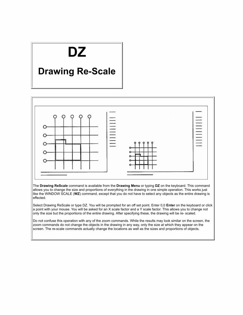
DZDrawing Re-Scale
The Drawing ReScale command is available from the Drawing Menu or typing DZ on the keyboard. This commandallows you to change the size and proportions of everything in the drawing in one simple operation. This works justlike the WINDOW SCALE (WZ) command, except that you do not have to select any objects as the entire drawing iseffected.
Select Drawing ReScale or type DZ. You will be prompted for an off set point. Enter 0,0 Enter on the keyboard or clicka point with your mouse. You will be asked for an X scale factor and a Y scale factor. This allows you to change notonly the size but the proportions of the entire drawing. After specifying these, the drawing will be re- scaled.
Do not confuse this operation with any of the zoom commands. While the results may look similar on the screen, thezoom commands do not change the objects in the drawing in any way, only the size at which they appear on thescreen. The re-scale commands actually change the locations as well as the sizes and proportions of objects.


ELErase Last
Upon selecting this command, the last object drawn (ofany type) is removed from the drawing. If youaccidentally erase something you didn't mean to, use theUNERASE (UE) command.
This command is very useful for correcting errorsimmediately after they happen, because you can easilyremember what you just drew. If you haven't drawnanything for a while, play it safe and use the OBJECTERASE command. A few extra keystrokes may save youfrom a big headache!
To erase the last object drawn, select ERASE LAST fromthe menu or type EL on the keyboard. You may alsopress the F9 key on the keyboard.

EPEllipse
An ellipse is specified by the length and location of its major axis and by the length of its minor axis. Two points areentered to determine the end points of the major axis, which in turn identifies the length, location and rotation angle ofthe ellipse. Two more points are entered to determine the height of the minor axis, but as the minor axis is assumed tobe the perpendicular bisector of the major axis, its location and rotation angles are ignored.
After selecting the Ellipse command from the Draw Menu or typing EP on the keyboard, you will be asked for oneend of the major axis. As soon as you click that end point, a straight line will "rubber band" from your mouse cursorlocation to that first point. You will then be prompted to click a second point. When you move your mouse after placingthis second point, you will see the ellipse begin to form. It will "shrink and grow" as you move the mouse. Completethe command by clicking a point indication the desired width.
The OB command will now break an ellipse into 16 arcs. Simply enter OB, click on the ellipse and answer Yes whenthe dialog pops up. A broken Ellipse can now be restored with the OOPS (OO) command in version 5.0 and later.


Exchanging Files Between Monu-CadUsersHere are some insights into file exchange between Monu-Cad users that were not issues in the MSDOSversion.
Lettering Issues
In the MSDOS version of Monu-Cad, letters were saved in the drawing file as individual components. Withthe new Click & Type® Lettering System, the letters themselves are not saved in the file. Only the"instructions" as to how to create the lettering groups is saved. When you load a file, the lettering groupsare recreated each time using the Alphabet files (.fnt files) and Spacing tables (.dta files) on the computerwhich is loading the .mcd file. This is a form of linking rather than embedding the alphabets into the files.However, if you explode the lettering groups, the alphabets will be embedded.
Why is this important to me?
If you have taken the time to respace your spacing tables or have changed your alphabets in some way,those same changes will not be on another Monu-Cad user's computer. When he brings up the file yousend to him, HIS alphabets and HIS spacing tables will be used instead of yours. If you want everything toremain just as you have laid out the job, you must Explode the lettering groups before you save the file inMasters Only or Universal Format. see file security options
Another issue that may surface concerns renaming alphabets. Some Monu-Cad users have found out howto rename the alphabets which appear in the font selection box in Monu-Cad Pro. When these users senda file to another user and the lettering groups are not exploded, an error will occur at the time the seconduser attempts to load the file. This error will state that the alphabet that the file uses doesn't exist. This maynot be true. The alphabet may exist but the creator of the file may have used a different name for that font.If this happens to you, right click on the lettering group insertion point and edit the group. Change thealphabet name to one that exists on your system.
Click the BACK button to return to previous page.
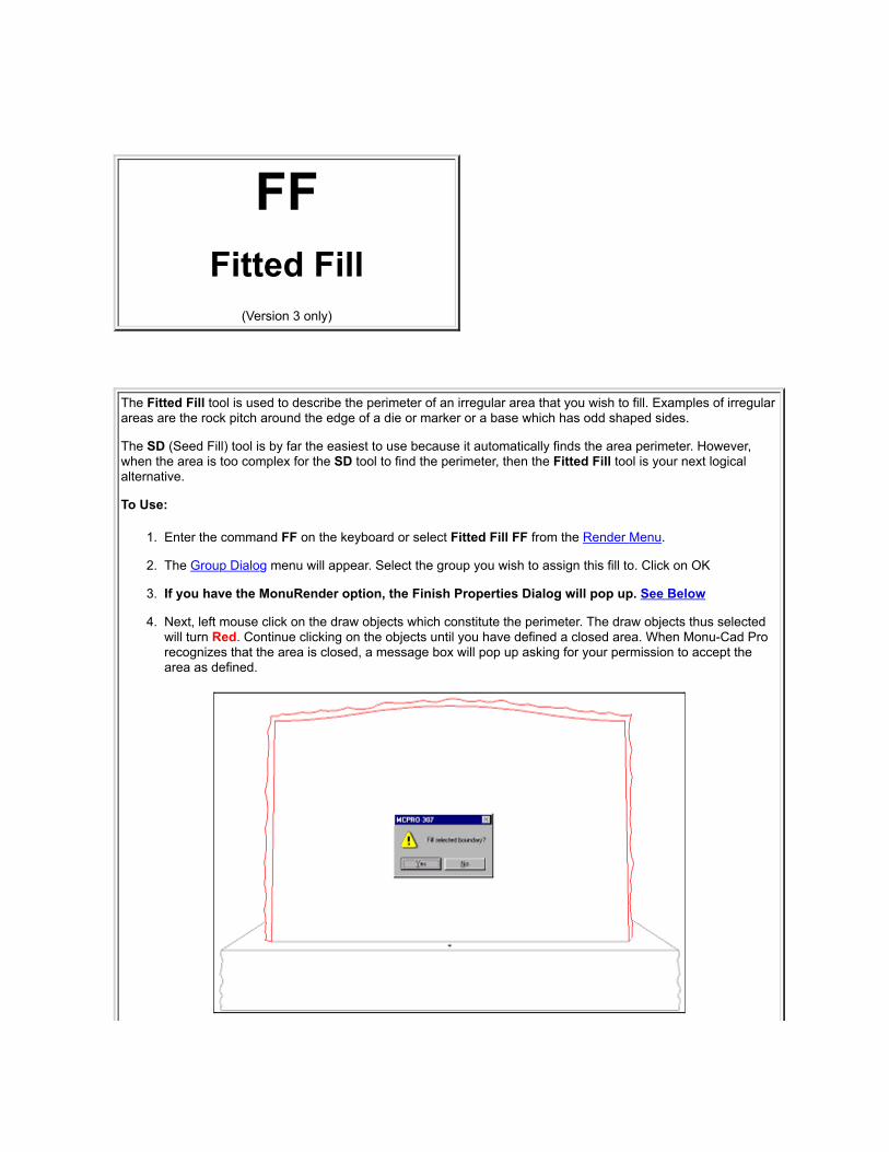
FFFitted Fill
(Version 3 only)
The Fitted Fill tool is used to describe the perimeter of an irregular area that you wish to fill. Examples of irregularareas are the rock pitch around the edge of a die or marker or a base which has odd shaped sides.
The SD (Seed Fill) tool is by far the easiest to use because it automatically finds the area perimeter. However,when the area is too complex for the SD tool to find the perimeter, then the Fitted Fill tool is your next logicalalternative.
To Use:
1. Enter the command FF on the keyboard or select Fitted Fill FF from the Render Menu.
2. The Group Dialog menu will appear. Select the group you wish to assign this fill to. Click on OK
3. If you have the MonuRender option, the Finish Properties Dialog will pop up. See Below
4. Next, left mouse click on the draw objects which constitute the perimeter. The draw objects thus selectedwill turn Red. Continue clicking on the objects until you have defined a closed area. When Monu-Cad Prorecognizes that the area is closed, a message box will pop up asking for your permission to accept thearea as defined.

When you click on the OK button, the area will fill as shown below.
Tip:
When selecting the perimeter objects, as you click on an object it will turn Red. If you click the same object asecond time, it will deselect the object and that object will return to the original color.
A really helpful optional feature is to hold down the Shift Key while selecting the perimeter. After the secondobject has been selected, Monu-Cad Pro will automatically select for you the next draw object in sequence andcontinue to do so until an intersection is reached or all the objects have been selected to create a closed area.
Occasionally, after the message box appears and you click OK, the area won't fill and you will see the selectedarea remain a Red outline but no filling occurs. In this event, just enter EL (Erase Last), RD (redraw) and tryagain. Select a different object to begin the selection process.
Caution!! It is best not to begin the selection process on an object which is part of the intersection of 3 or moredraw objects.
Note!!
Fills will not display if Fills Button on the Tool Bar is not pressed in Fills by default are placed on Layer 9. If Layer 9 is turned off, fills will also not display.
Finish properties Dialog

After you select a Fill Group to assign the point(s) to, if you have the Monu Render option and the group youselect has a granite color assigned to it, the above dialog box will pop up. This dialog will allow you to select fromthe four possible granite finishes.

FGChange Fill Group
(Version 3 only)
The Change Fill Group command FG has been added to the list of Render Commands to make it easy for youto change the association between the fill points you have placed into a drawing or component and the Fill GroupNames you have created or wish to create. This command is only to be used AFTER an area has been filled andyou wish to change the Group Name associated with individual or multiple fill points. If you have the MonuRenderoption, it will also allow you to change the finish of an already filled area from among the four possibilities Polish,Steeled, Blued or Rock Pitch. This command is the only way you can tell what group names have been used tofill a component without having to explode it.
To Use:
Enter the command FG or select Fill Change FG form the Render Menu.
This is a window command so you next place a window around the area containing the fills.
The Change Fill Group dialog shown below will appear on the screen.

In the Selected Fill Groups drop down edit box at the top of the Menu will appear a list of all the fill points thatwere in the selected window broken down according to the name of the fill group they are assigned to.
As shown above, the group name GRAYSOLIDPOLISH is highlighted. The number 1 (1) means there is one fillpoint in the window selection that matches this group name. If you click on a new group name in the second list,the points in the first list will be changed to the group name and color of the name in the second list. Try it! Youcan always hit the cancel button if you make a mistake.
Short Cut to Changing the Fill Group of just 1 Fill Point
If you wish to change the group name (or the granite finish for MonuRender users) on just one Fill Point, you mayRight Click on just 1 fill point. The Change Fill Group menu above will pop up and allow you to change the groupor finish for just that one specific point.
Monu Render option
Should a granite color fill be in use then by clicking on one of the options in the Change to Finish section, thegranite finish will be changed to that selected.


File Security OptionsNote!! This will apply only if you are a Master Monu-Cad Operator
When you save a drawing using the Drawing Save command (DS) and Component Create (CC)command, if the Show File Security option is checked in the Configuration Menu, the additional dialog willappear just before the file is saved.
All Your Satellites imprints the file with a unique code which allows youand any of your satellite Monu-Cad Lite! users to read the .MCD file.
Specific Satellite imprints the file with a unique code which allows youand only one specified satellite Monu-Cad Lite! user to read the .MCDfile.
Only You imprints the file with a unique code so that only you can readthe saved file.
Masters Only imprints the file with a unique code that permits onlyother Master Monu-Cad Users to read the file. We call this theUniversal Monu-Cad File Format. If you are going to send a file toanother Monu-Cad Master user, you will have to re-save that fileusing this format in order for him to be able to read the file.
Cancel aborts the file save operation.
Don't show next time when unchecked will stop this extra dialogfrom appearing and default to saving with the Only Youconfiguration. see config options
Exchanging Files Between Monu-Cad Users
Frequently Asked Questions
Lettering - Editing - Adding
Additional information on this topic is available to Master Monu-Cad users. Please call our office for details.

F2Group Window Fill
(Version 3 only)
The Window Fill F2 command is a simple 4 step process:
1. Type F2 or click on the Group WF command in the Render Menu
2. When the Group Dialog menu pops up, select the Fill Group you wish to assign this fill to.
3. If you have the MonuRender option, the Finish Properties Dialog will pop up. See Below
4. Place a window around the design to be filled
5. The design sandblast lines fill from the outside in.
The color or hatch pattern of the fill is determined by the setting for the Fill Group in Group dialog.

See Fill Group for more details
Note!!

In order for the fill to occur as pictured above, all lines must be continuous with no breaks in the lines. There also must not be anysingle lines crossing the outside line border or any spaces to be filled.
Note!!
Fills will not display if Fills Button on the Tool Bar is not pressed in Fills by default are placed on Layer 9. If Layer 9 is turned off, fills will also not display.
Finish properties Dialog
After you select a Fill Group to assign the point(s) to, if you have the Monu Render option and the group you select has a granite colorassigned to it, the above dialog box will pop up. This dialog will allow you to select from the four possible granite finishes.

Fills(Render Fills)
Definition & Example
The subject of Fills or Render Fills refers to the ability to color in an area of a drawing to make it more descriptive and distinctive. Carvings,letters and components can be filled. This is available in Version 3.0 and later only. Solid colors and hatch fills are available to all users. True color granite fills, pictures and photo background fills are only available if you have purchased and are licensed for the MonuRenderoption.
The Tools used to accomplish this are available in the Render menu.
Hatches
In addition to image and solid color fills, Monu-Cad Pro offers the ability to fill areas with a line pattern known as a Hatch. Six hatch patternsare available as shown below:

The selection of a hatch pattern is made on the Group Dialog or GF command. The line color of the hatch is the current line color as shownin the Group Dialog.
Note!!
Fills will not display if Fills Button on the Tool Bar is not pressed in Fills by default are placed on Layer 9. If Layer 9 is turned off, fills will also not display.

FLFillet
Note!! This command is under construction at this time. It will auto trim 2 lines but will not perform the rounding cornerfunction....yet!
This command allows an arc of specified radius to be inserted between two non-parallel lines. The radius of the arc tobe inserted is set with the FILLET RADIUS (RF) command.
To use the FILLET command, you must have at least two lines on the screen. Type FL on the keyboard or select theFILLET command from the Edit menu. You will be asked for a point on the object to fillet. Point to and select one ofthe lines. It will turn red to visually confirm the selection. You will then be asked for the second line. Point to andselect the second line.
The 2 lines will be trimmed or extended as required, and the arc inserted. Note that the default fillet radius is zero, sothat unless you change it with the FILLET RADIUS (RF)command, the FILLET command will appear to be a doubleTRIM or EXTEND, trimming and extending each of the two lines until they meet each other. This can be very useful, ifthat's what you want to do. If it's not, just set the FILLET RADIUS and FILLET them again.
See Fillet Radius Command

GF
Group DialogAdvanced Concepts
(Version 3 only)
The Group Dialog shown above shows an advanced feature of the Group editor. Notice that the highlightedGroup Name DIE-1 has 2 groups below it called Components and Components Polish.
We used the Windows Drag and Drop feature to drag the Components and Components Polish group names anddrop them onto the Die-1 group. This makes those 2 Components Groups "children" of the Parent DIE-1 group.At the risk of confusing you we like to think of this as "grouping the fill groups".
(Drag and Drop means to place your mouse pointer on the group name you wish to move. Press the left mouse button andhold it down. While holding the button down, drag the child group name on top of the second name you wish to be theparent and then release or "drop" the first name onto the second. When done correctly, you will see a little + sign appear tothe left of the parent name. This means there is another group name "under" the first. If you click on the + sign, a tree viewwill open, the + sign will turn to a - sign and the child group names will appear. Clicking on the - sign will close the tree view)
What does this mean? Well, it means that whatever color or finish changes you make to the parent group ispassed onto the child groups. In this way you can control the colors of several groups at one time by justchanging the parent group. See example below.

In the monument shown behind the Group Dialog above, we can change the granite color of the die by changingthe Granite assigned to the DIE-1 group and when we do so the granite color in the floral component will changewith it.
If you have sharp eyes you might notice that the panel background also changed from pink to gray. For this tohappen automatically, the groups used in the lettering panels need to be changed manually from pink to gray orthe panel group names also should be made children of the DIE-1 group.
The RESET button will "ungroup" the parent and child groups.
This feature can be used with and without the Monu Render color option.

GFGroup Dialog
Fill Group Concept Explained(Version 3 only)
Menu Description
Understanding the workings of the Group Dialog is very important tothe inner workings of "Fill Points" and your ability to fill in letters,designs and memorial surfaces.
When you first see the Group Dialog, there will be several sample"Group Names" in the Group Names Edit Box. In this image, thecurrent highlighted group name is "SANDBLAST LINES"
With the New Group button you may enter a group name of yourchoosing. The Reset button will return group settings to a defaultsetting. The little X button allows you to erase a group name.
The Group Properties Area allows you to assign a color or hatchpattern to the Group Name Selected above. The choice you makehere will be reflected in any fills in the current drawing which havepoints assigned the the Group Name.
- - - - - - MonuRender Options - - - - - -
If your program is licensed to include Monu Render color realisticrendering, these selection buttons will be functional.
These option buttons will give you the choice of selecting either agranite color, a background picture or a photo to assign to the fillpoints.
The current selected granite, background image or picture file namewill be displayed here. (Applies only to MonuRender option.)
The Apply button will apply any changes made to the fill pointsassigned to the selected Fill Group Name. OK closes the window andCancel aborts the process.

Fill Group Concept Explained and Fill Group OperationEvery time you fill an area with the WF, FF, SD or F2 commands, a "fill" is created. It is an object itself in thesame way that a line or an arc is an object. Similar to a component, a "fill" is marked by a Red Insertion Point inthe lower left corner of the fill. We call this a "Fill Point".
Every filled area has a Fill Point. There are no exceptions. In some cases you may not see them but they arealways there.
All fill points with the exception of ones created with the WF (Window Fill) command MUST be assigned to aGroup which has a Group Name. If you look at the Group Dialog above, you will see the highlighted group nameis SANDBLAST LINES. If you look in the Group Properties section of the dialog, you will see that the GroupSANDBLAST LINES has been set to the color solid BLACK.
Why all this group business?? Imagine that you put 3 squares on the screen and with the F2 command you filleach of the squares and assign each fill to the group SANDBLAST LINES. Now, suppose you want to change all3 squares to the color green. To do so, all you have to do is enter the GF (Group Fill) command which will pop upthe dialog shown above. Then, you highlight the Group Name SANDBLAST LINES and under Group Propertiesyou click on the Color Drop down edit box and select the shade of green you desire. When you click the Applybutton, all 3 squares will change from Black to Green.
In this way, you can easily change multiple filled areas to another color, hatch or granite just by changing theproperties of the group the fill points are assigned to. See GF-Advanced
Where this especially comes in handy is with the MonuRender Granite colors. Using the above method, a graydie on a black base can easily be changed to be a rose colored die on a white base just by changing theproperties of the DIE and BASE groups! The BACKGROUND scene can be easily changed by changing theBACKGROUND group image.
Fill Points can be placed inside components and letters as well. To do this you must explode the component, fillit and then recreate the component.
Creating New Group Names
The names that appear in the Group Dialog ( GRAYSOLIDPOLISH etc) are just example names that we createdto give you a head start. The actual names that you choose to use are at your discretion. Two names will alwaysappear by default and are "hard wired" into the program. These are the names used by the program as a defaultfor lettering panes sandblast lines and the lettering panel surface. Currently these names are LETTERINGPANEL SURFACE and PANEL SANDBLAST LINES. Whenever you need to create a new group name todescribe a particular area of a memorial, just type it in.
An .mcd file which is saved with filled areas contains the group names associated with any fill points that may bein the drawing. If when you reload the file the group names are not present in the Group Dialog, Monu-Cad Prowill automatically add the names to the dialog.
See Advanced Group Dialog features Click Here
Note!!
Fills will not display if Fills Button on the Tool Bar is not pressed in Fills by default are placed on Layer 9. If Layer 9 is turned off, fills will also not display.

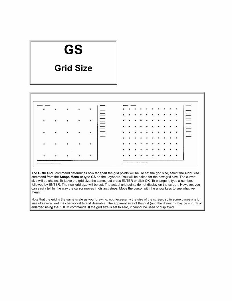
GSGrid Size
The GRID SIZE command determines how far apart the grid points will be. To set the grid size, select the Grid Sizecommand from the Snaps Menu or type GS on the keyboard. You will be asked for the new grid size. The currentsize will be shown. To leave the grid size the same, just press ENTER or click OK. To change it, type a number,followed by ENTER. The new grid size will be set. The actual grid points do not display on the screen. However, youcan easily tell by the way the cursor moves in distinct steps. Move the cursor with the arrow keys to see what wemean.
Note that the grid is the same scale as your drawing, not necessarily the size of the screen, so in some cases a gridsize of several feet may be workable and desirable. The apparent size of the grid (and the drawing) may be shrunk orenlarged using the ZOOM commands. If the grid size is set to zero, it cannot be used or displayed.

IPFile Import
The File Import (IP) command allows importing files created in selected otherCAD and Graphics programs.
This command will currently allow importing:
.DWG format (Monu-Cad 4.2)
.GCD format (CADD6)
.AI format (Adobe Illustrator)
.EPS format (Adobe Illustrator) -limited to vector only .eps file
.MCP, .PLT, .TXT, .hpg HPGL Plotter format
.WMF Windows Metafile Vector format
.DXF AutoCAD style Drawing Exchange format
Note!! The output of the older MonuSCAN program places its files in theC:\DWG folder as .DWG files. This command will allow you to import those .dwgfiles and MSDOS Monu-Cad files into MCPro.
Also note that the .eps import is not a true 100% .eps compatible format. Someprograms will save a .AI file with a .eps file extension and it is these files whichwe are able to import.
To use this command from the File Menu
1. Click on Import or enter IP on the keyboard.

2. Select the file type extension and then the file name.
3. Click OK and then press the return key 3 times. The imported file will appear.
The file then may be edited and saved as a Monu-Cad Pro .MCD file with the DS(Drawing Save) command.
Upon first usage of the IP command, the file selector will default to .DWG fileslocated in the C:\dwg folder. The format type must be changed to the format ofyour choice each time you use the command.
Comment
Most all CAD and Graphics programs are able to output to a HP plotter. InWindows, you can always save the output information to a file. Therefore, ifanother program can make a HPGL version 1 plotter file (most can) then you willbe able to import it. Couple this feature with the WV command and it is lookinglike you can import from most any program out there!
Tip:
This feature can be used to bring back into MCPro a cutter file. Of course, theimported drawing will be composed of all straight lines but if you accidentallyerase a .MCD file but still have the cutter file, this may save you hours! Shouldthis happen to you, remember the WV Window conVert command.
Special Note on WMF format
There are available many files on the Internet in Windows .WMF format. Thisformat is a graphics file format that can contain both Vector (lines and curves)information as well as Bitmapped (dots only) images. When Monu-Cad Pro

imports a WMF file, only the Vector portion (if there is one) is brought into Monu-Cad. If you attempt to import a .WMF file and nothing appears on the screenthen it is very possible that there were no vectors in the file and that the imagewas only a bitmapped image.
The WMF image below contains both Vector and Bitmap information.
When imported, the image below is what you will see.
Expect that many times the imported WMF image will consist of all short straightline segments. You might consider using the WV command to convert it to arcswhere possible.
File Selector Operation
MONUSCAN
MonuScan Programs
Click the BACK button to return to previous page.
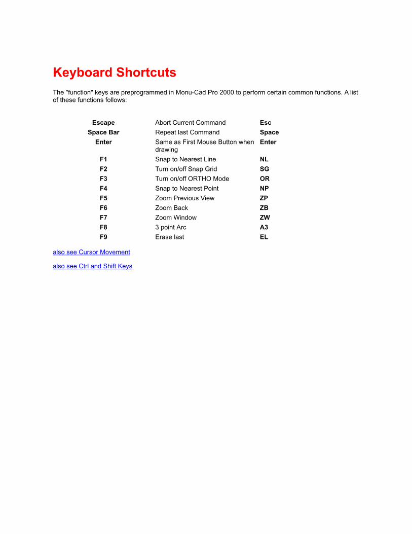
Keyboard ShortcutsThe "function" keys are preprogrammed in Monu-Cad Pro 2000 to perform certain common functions. A listof these functions follows:
Escape Abort Current Command Esc
Space Bar Repeat last Command SpaceEnter Same as First Mouse Button when
drawingEnter
F1 Snap to Nearest Line NLF2 Turn on/off Snap Grid SGF3 Turn on/off ORTHO Mode ORF4 Snap to Nearest Point NPF5 Zoom Previous View ZPF6 Zoom Back ZBF7 Zoom Window ZWF8 3 point Arc A3F9 Erase last EL
also see Cursor Movement
also see Ctrl and Shift Keys

Layers The Layers feature of Monu-Cad Pro allows the user the opportunity to place different parts of the drawing ondifferent "pages" or "sheets" which are transparent. This is the computer way to draw on separate pieces of tracingpaper or plastic transparencies. Once drawn, one can view all sheets together as one large drawing, turn on or offone or more layers, erase, save from, rotate, load to and change any one or all layers at will. (Available on versions3.0 and later)
An example of the use of layers for monument work follows:
Suppose you want to create a monument drawing which shows all parts of a flower so you can make apresentation drawing. But, when it comes time to cut the stencil, you don't want the cutter to cut out the veins in theflower. If you put just the veins on a separate layer (such as layer 5), you can then "turn off" layer 5 just beforemaking the cut file and anything that is on layer 5 will not be output to the cutter. It will also not appear on thescreen until you turn layer 5 back on again.
We think of layers in Monu-Cad Pro as a stack of transparent sheets 1024 pages high. The top most sheet iscalled layer 0 and the sheet on the bottom of the pile is sheet 1023. (computers number things beginning with 0)
The layer commands are a group of commands which perform operations on the entities which reside on anindividual layer. A list of the layer commands can be found on the Layers drop down menu.
Many of these items are similar to the WINDOW editing commands, the primary difference being in the way thatthe objects are selected, in this case by being on the same layer together.
The advantage of putting information on various layers is that some of them might contain information or lines thatyou don't always need or want to have displayed. Each layer can be thought of as a piece of transparent plasticwhich can be removed. You can put as many of them together as you want (all layers on), or just a few (manylayers off).
Typically, with the layer editing commands, you select the command, type which layer to perform the edit on, andgive some other information to complete the task required.
Other layer commands allow you to display any or all layers, send layers to and from the disk as drawing files, andselect which layer(s) you want to work on at any time.
See Layers Menu
See Toggle Bar
See Layer List Command

LBLoad Batch File
Note! This command is under construction 10-29-99
This command allows you to load a text file of commandsinto the program, executing the commands as they areloaded. The batch file can be created by using the SAVEBATCH command, by writing your own batch file with atext editor, or by some combination of the two.
To load and execute a batch file, select the LOAD BATCHFILE command or type LB. A file selector will appearallowing you to choose from among the batch filesavailable.
Loading batch files in this way can be useful for turningcertain layers on or off at the beginning of the drawingsession, setting the current layer, pre- loadingcomponents into the drawing file, and many otherfunctions.

LELeaders
See Dimensions
Click Here

LFLoad Font
The Load Font command (LF) will allow you to load onto the screen the individual components contained in aMonu-Cad .FNT file located it the \fonts folder for examination or editing. (This command is intentionally notlisted on any Drop Down Menu.)
For example, the individual letters which appear in Click & Type when using the Press Modified Roman alphabetare contained in the file named MCALF010.fnt.
If you enter LF on the keyboard and then select MCALF010.fnt and click OK, the contents of that file will bedisplayed as unique individual components. If need be, these components can then be edited as any othercomponent can.
Once components have been changed, they can be resaved to the file using the SF (Save Font) command.
How to Change a Letter in an Alphabet
1. Type LF (Load Font)
2. Select the font to load
3. Draw a trace line to the insertion point for the component to be altered (so you don't loose it's position in thenext step)
4. CE the component
5. Alter and sort the component letter
6. CC and name the component the same name as it was, overwrite the existing one. Set the insertion point atthe end of the trace line you drew in step 3 (put the insertion point back in the original place)
7. CL and select and place the new altered component on the screen (don't forget this step)
8. SF Save Font and save it under the same name (ex. MCALF010.fnt) as when you first loaded it.
9. Exit and restart MCPro
The next time you use the alphabet your changes will be there. Also, they will appear in any previously saved.MCD file. That's it!
Adding a New Alphabet to Monu-CadOverview:
1. Make a new .FNT file containing 1" high components all named with the same first 3 letters followed by the

letter contained within the component according to a set of rules to be explained later. One component will becreated for each letter.
2. Create a .DTA spacing table for the new alphabet named to link it to the alphabet (.FNT) file and the componentnames contained therein.
3. Insert into the .DTA file the widths of each character in the alphabet in decimal inch values. This step willrequire you to accurately measure the width of each new component.
4. Make an new entry in the MCFonts.lst file for the new alphabet so that you can select it in the Advanced KernDialog.
5. Check the new alphabet for correct spacing and change the spacing values accordingly.

L IStraight Line
Position the crosshairs cursor where you want to start the line, and press the first button on your mouse. A small "x"appears on the screen, called a "construction point" (more about this later). In addition, notice that as you move thecursor around the screen, you are dragging a line from the first point that you selected. This is called "rubberbanding"and allows you to see exactly what the line that you are about to draw will look like.
If your first point was not correct, press the ESCAPE Key and start over. If you decide to continue, simply position thevideo cursor at the desired placement for the end point of the line and press the first button on your mouse again. Asecond construction point will appear, and the line will be fixed between the two end points selected. You have nowcompleted your first line.
You can go on to choose any other command (note the prompt message), or continue drawing lines, using theprevious ending point for the new starting point to connect lines as long as you like. This is all done without entering asingle command! You are simply drawing with the mouse. Note that each segment between two end points isconsidered an individual line. Therefore, if you have entered three points in a row, you have drawn two lines.Remember that each segment is treated as a separate object when using various editing commands.
If you want to stop drawing lines in one area and start again somewhere else (like picking up your pen), pressESCAPE. This action will end the previous line, and there will be no "rubber band" to the new point. You can noweither draw more lines or go to another command.
The Line command can be chosen from the Draw Menu or by typing LI. However, this is the one command whichdoesn't require that a command be entered before use. Monu-Cad Pro is always ready to draw. Just click your leftmouse button and you are drawing!
see direct draw


List of Monu-Cad Pro CommandsThe Monu-Cad Pro Drop Down Menus provide a list of commands.
Click Here to View the menus
There are several commands which do not appear on the menus. These are:
LF Load Font
SF Save Font
Space Bar
Escape
Keyboard Shortcuts
TT True Type
DT DTA File Editor
XA Explode All

D2 - Load DrawingVariation
This command allows you to enter the lettering desired just once and thenautomatically transfer that lettering to another monument which has no lettering on it. This command will save you from having to type in the lettering again every time youwish to change a size or design.
To begin, you must first do a DL Drawing Load and select a folder which containsdesigns which have variations available. Then you add the desired lettering.
When you click on the Red folder on the tool bar shown above or type the D2command, Monu-Cad Lite! will search the current drawing folder on the computer forany more drawings which begin with the same name as the drawing which is currentlyon the screen. For example, if you have a drawing named CVM100.MCD on thescreen, if there are other drawings (which begin with the same name) such asCVM100_with cross.MCD or CVM100-30x18.MCD, Monu-Cad Lite! will display afile selector showing these variations and allow you to select one.
When you select a variation, Monu-Cad Lite! will automatically erase the currentdrawing and replace it with the variation you selected but retain the lettering groupsoriginally entered.. You may do this repeatedly bring up different variations.
Return to MCL-Menu Commands II

LKLine Color
Line color is represented by a number between 0 and 255. The actual color which showsup on your display is determined by the video card you are using. When you select a newline color, any objects drawn after the selection are drawn in this new color. Objects whichhave been previously drawn are not changed.
Components must be defined using the line colors that you want them to keep, becausethey are placed using the line color that was in effect when they were defined.
Select the Line Color Properties command from the Draw Menu or type LK. You will beshown the current line color and given the opportunity to select a new color from among256 choices. Note that there are 4 color blocks at the top left that are 4 different shades ofgray. These colors are meant to represent in order: steeled finish, rock pitch, blued andpolish finish. They are set aside here to make it easier to pick the same color every time.
To keep the current line color, press ENTER or click OK. To change it, type a number,

followed by ENTER, or left click on a color block.

LWLine Width
Line Width is represented by a number between 0 and10, which simply represents the number of pixels (dots)which are used to represent the line. The actual width ofthe line will be determined by the resolution of your videodisplay, and the resolution of your printer.
The currently selected line width affects any objectswhich are drawn after the width is selected. Objectswhich have been previously drawn are not changed.
Select the Line Width by executing the DG, OG, YG orWG commands from the Drawing Menu or type LW onthe keyboard. You will be shown the current line widthand asked to enter a new one. The initial default is 1. Tokeep the current line width, press ENTER. To change it,type a number,followed by ENTER.
see change commands

LLLayer List
(Version 3 only)

The Layer List command allows you visually see the current status of layers and to turn on and off different layers orchange to a layer of your choice.
Select Layer List from the Layers Menu or type LL on the keyboard. A list will appear on the right side of the drawscreen. By default, when the list first appears, only layers which have data on them will appear in the list. also, layerswhich have data on them will have a "*" before the layer number.
The layers which are "turned on" will appear in Black. The current selected layer will appear in Red. Any layers whichare "turned off" will appear in Gray.
Operation
After entering the command LL the list will appear as shown above.

To turn a layer on or off (make visible) first click on the desired layer. Second, click once on the "Light Bulb" icon. TheLight Bulb Icon will be "out" when the layer is off (invisible) and "in" when the layer is on (visible).
To change to a new layer simply double click on the desired layer number in the list. that layer number will turn Redindicating that you are now working on that layer. As an option, you may click on the layer number and then click the"pencil" Icon which will set that layer as the current working layer.
To see all 1024 layers click on the third Icon to "pop out" the list button. Doing so will display all layers regardless ofwhether they have data on them or not.
Future Functionality Place Holders
The "N" icon will allow naming layers in future versions. It is only partially functional at this time. (5-18-2000)
The "?" Icon in the future will provide additional help.
Comment
All keyboard commands and Layer Menu commands function as well as this new Layer List function. Thiscommand was provided to add visual references and to facilitate your interaction with layers.
LXLinear Dimension
See Dimensions
Click Here

MCFonts lst File Specs The MCFonts.lst file is a plain text file located in the \fonts folder. It contains a list of all the fonts available toMCPro. In addition, this file contains
information which tells MCPro what spacing table (.DTA file) to use with that particular alphabet
the name prefix of the components in the alphabet
whether the alphabet contains upper and lower case letters
whether the alphabet contains a double or tripple set of letters and at which size to switch letters, theircomponent prefix and which spacing table to use with which particular size
and finally whether there is a minimum size letter for this alphabet.
A typical MCFonts.lst fill will look something like this (only first 3 entries shown):
[Modified Roman]dtafile = mr ;commentfontfile = mcalf001lowercase = noserifs = no
[Condensed Roman]dtafile = cr ;commentfontfile = mcalf002lowercase = noserifs = no
[Outline Roman]dtafile = out ;commentfontfile = mcalf003lowercase = noserifs = yes
This is the basic information needed in the file to describe one of the original 94 character Monu-Cadalphabets.
The new 256 character True Type Font import entries will look something like the following. since most TTFfiles include upper and lower cases, there in no need for the lowercase = no statement:
[ARIALBLACK]dtafile = ARBfontfile = ARB255extended = yes
[WINGDINGS1]dtafile = WDDfontfile = WDD255extended = yes

To limit the minimum size an alphabet can be used at, add the statement smallest = .75 to the definitionas shown below:
[Outline Roman]dtafile = out ;commentfontfile = mcalf003lowercase = noserifs = yessmallest = .75 the .75 can be set at the desired size.
In addition, you may create a second or even third set of letters to be used only at a designated size or smallerwithin the same alphabet. For example, in MCALF003.fnt, there are 2 sets of letters. One set is namedOUTx.mcc and the second FOUTx.mcc. The "x" is the place reserved for the specific character (A,B,C etc).Under normal operation, if serif split is turned on in the config file, the "split size" specifies at which size andsmaller to begin using the letters which begin with the prefix FOUT. The statement serifs = yes tells MCPro thatthis alphabet has more than one set of characters.
Beginning with Version 3.0 of MCPro, you now can specify up to 3 sets of letters which can be switched in andout depending on the size called for in the program.
This example shows the addition of the statement TypeFaceSubstitution =
[Press Modified Roman]dtafile = skmfontfile = mcalf010lowercase = noserifs = yesTypeFaceSubstitution = 1, skm, fTypeFaceSubstitution = 0.5, vm,smallest = .75
The rules for typeface sustitution are as follows:
Syntax:
TypeFaceSubstitution = n, dta name, [prefix]
n = Height of lettering to implement type face substitution at or below.
dta name = The name of dta spacing file to use (do not include extension .dta)
prefix = The letter used to distinguish this set of component letters from the others.
Example:
> [Press Modified Roman]
> dtafile = skm
> fontfile = mcalf010
> lowercase = no
> serifs = yes

> TypeFaceSubstitution = 1, skm, f
> TypeFaceSubstitution = 0.5, vm,
smallest =
Allways use the font file mcalf010, this contains all need components including ones use for type facesubstitutions.
When the height of the lettering is greater than 1in then use the first four lines to represent the lettering. Thisuses the skm dta file and no prefixes.
When the size of the lettering is equal to or below 1in then use the first type face substitution. Precede allcomponent names with the string "f" to use the fat characters. Use the skm dta file to space the characters.
When the size of the lettering is equal to or below .5in then use the second type face substitution. Do notprecede the component names with anything, but use the vm dta file to space the lettering.
Notice, there is the ability to use different spacing tables for different lettering heights. I hope this helps. I will sitdown tomorrow night to get you the rest of the documentation when I have some time to think.

Monu-Cad Pro 2002 Menus
File Menu
(Click on a command in the menu for more information)
Edit Menu
(Click on a command in the menu for more information)

Draw Menu
(Click on a command in the menu for more information)
Note that Dimensions is a 2 level menu or "pop out" menu. When you clickon the word "Dimensions", the pop out will display 3 choices.
Render Menu
(Click on a command in the menu for more information)
Display Menu
(Click on a command in the menu for more information)

Object Menu
(Click on a command in the menu for more information)
Window Menu
(Click on a command in the menu for more information)
Layer Menu
(Click on a command in the menu for more information)

Drawing Menu
(Click on a command in the menu for more information)
Component Menu
(Click on a command in the menu for more information)
Controls Menu
(Click on a command in the menu for more information)
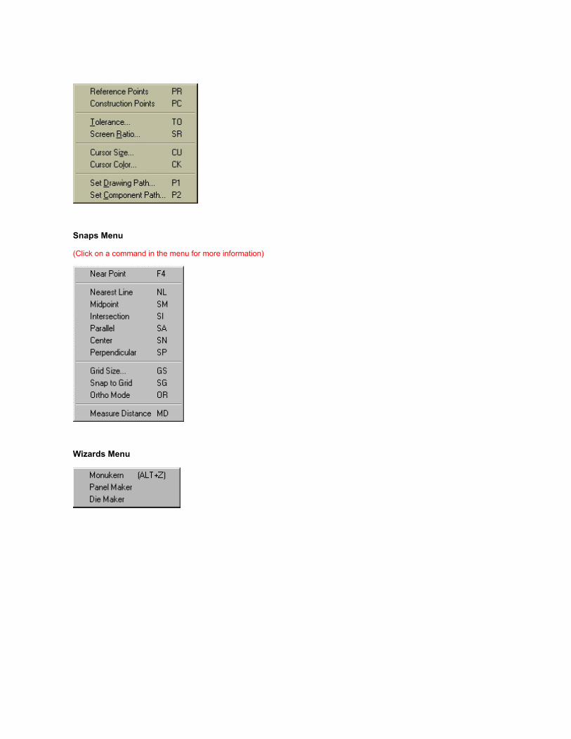
Snaps Menu
(Click on a command in the menu for more information)
Wizards Menu

MDMeasure Distance
This command can find the distance between any two points on the drawing. This is considered to be the length of animaginary line connecting the two points that you specify, not the X or Y displacements, unless the points are verticallyor horizontally aligned.
To find the distance between two points, select the Measure Distance command from the Snaps Menu or type MDon the keyboard. You will be asked to enter the first point. This can be shown on the screen using the video cursor, orentered by coordinates using one of the manual entry modes. (See the manual entry of coordinates commands ).Often it is useful to use the SNAP TO NEAREST POINT NP command to locate an existing point when you want tofind the distance between points in the drawing (which is usually the case).
Having selected the first point, you will be asked to enter the second point. As you move your mouse to the secondlocation you will see a Green Line "attached" to your mouse cursor. The second point is entered in the same fashionas the first point. After you have entered two points, the distance between them will be displayed on the command linein the lower left corner of the screen.


ConfigClicking on this menu selection displays the configuration settings Tab dialog box shownbelow. Although the heading refers to Monu-Cad Pro, the same settings are available in Monu-Cad Lite!
Kern Tab
Exaggerated Serifs turns on or off theability to use a letter style with "fatter"serifs on certain roman alphabets likeModified and Condensed Roman. Thenormal setting is to have this box checked.
Serif Split Size determines the size of theletter at which this feature beginsfunctioning. It is normally set at 1.5 inches.Letters below this set size will haveexaggerated serifs.
Single Line Thickness sets the width ofpanel sandblast lines.
Frosted Line sets the width of frostedpanel lines
M/D/Y Attributes sets the default blockingfor Month/Day/Year Justification option
Skip Trailing Punctuation determineswhether the length of the line of lettering ismeasured excluding the width of a trailingperiod or comma or including it. With thisfeature checked, the length of the nameJohn J. will be measured and centered asif the period after the J wasn't there. Whenin doubt, turn this feature on.
Disable Save To DTA when checkeddisables dialog allowing saving changes toDTA table after Lettering Adjust
Display Tab

Construction Points when checked turnson the points
Reference Points turns on the points
Mouse Cursor sets the size and color ofthe "cross hairs"
Screen Ratio see screen ratio page
Tolerance sets the "capture area" seetolerance page
Show Simple Lettering Group turns onsimple lettering group option whenchecked. Skips the simple lettering groupdialog box when un checked. See lettering
Path/Files Tab
This Tab allows you to set the defaultpaths for the program. they are usuallypreset for you.
Drawing Path[P1} sets default .mcd path.
Alternate Drawing Path when checkedwill cause all drawings to be saved to thisone folder.
Component Path[P2] sets default path toload .mcc files from.
Alternate Component Path for

Component Saves when checked willcause all components to be saved to thisone folder.
Split Component Path allows you to set aspecial folder up to hold just those specialcomponents used in split and split2justified date configurations.
DWG Path allows you to set the defaultpath for the Import command.
Cutter Files sets the path where cutterfiles will be placed.
Font Pat: sets the path where font filesare stored
Logo File specifies the name of the .pcximage to be loaded at sign on.
Show File Security Options see FileSecurity Options
Grid Tab
Snap to Grid sets the default gridsetting...ON or OFF
Grid Size sets the default grid size

Ortho Mode sets the default Ortho Modesetting ON or OFF
Units Tab
This configuration menu allows youto set the type and accuracy of thedrawing units desired. These valuescan also be changed by using thevarious units commands duringnormal program operation.

Arc Lettering Adjust Tab
Rotate step sets the amount of rotation thatoccurs when you adjust Lettering on an Arc
Flex Distance is the step value that occurswhen you adjust the arc shape in Letteringon an Arc.
Added Space sets the amount of spaceadded when you spread out letters inLettering on an Arc.
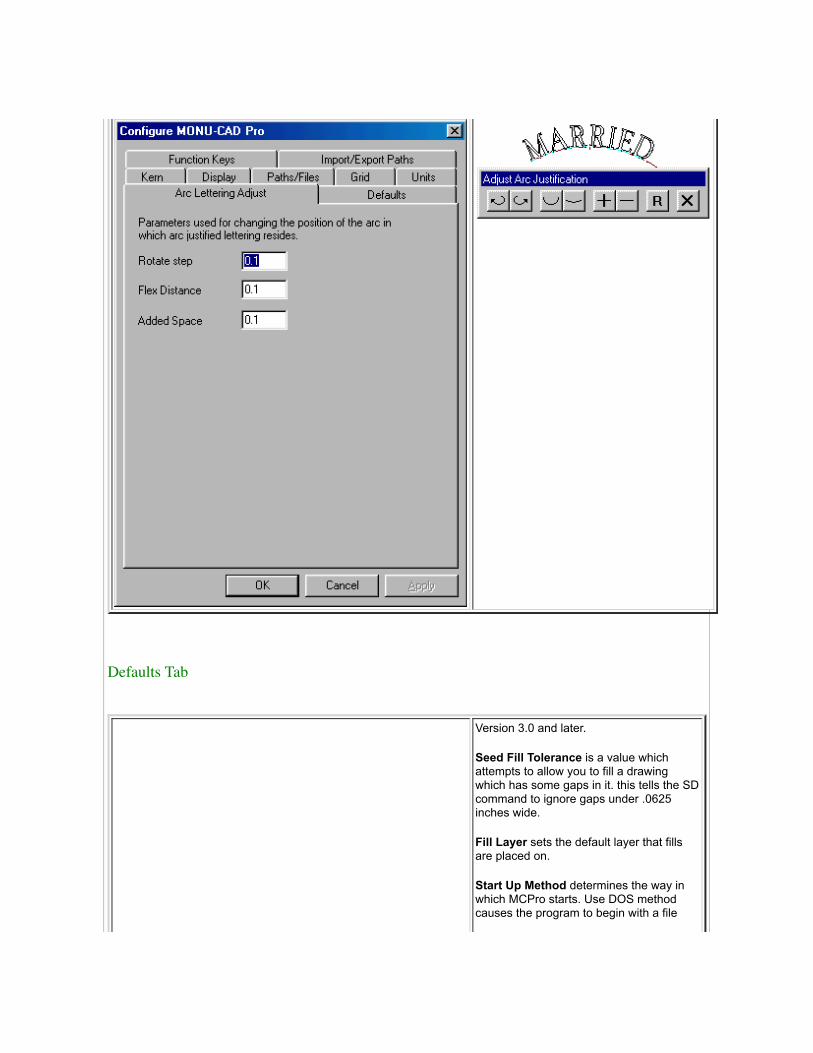
Defaults Tab
Version 3.0 and later.
Seed Fill Tolerance is a value whichattempts to allow you to fill a drawingwhich has some gaps in it. this tells the SDcommand to ignore gaps under .0625inches wide.
Fill Layer sets the default layer that fillsare placed on.
Start Up Method determines the way inwhich MCPro starts. Use DOS methodcauses the program to begin with a file

menu appearing automatically. If youuncheck this box, MCPro will start with ablank screen "Windows Style" and thedefault drawing name will be "Untitled".
Granite Finish Method are experimentalsettings for office use only. No explanationis herein given.
Zoom Limits sets the initial size of thescreen area and is the screen areadisplayed when you enter a ZL ZoomLimits command.
Fillet Radius is the default value that theradius of a fillet is set at. This can bechanged with the RF command as well assetting it here.
Functions Key Tab
Version 3.0 and later.
This section of the Config menu allowsyou to program a command or simplecommand string to a function key. Inaddition to the keys F1 through F12, youmay also use the combination of the ShiftKey plus a Function Key, Control Key plusa Function Key or both Shift and ControlKeys plus a Function Key.
In the example shown to the left, you willsee that we have programmed thecommand combination LISA and A3SA tothe Shift F1 and Shift F2 keys. The

commands shown for the F1 through F9keys are the defaults we have preprogrammed for these keys. They may bechanged but we suggest you keep them atthe default setting and use the otheravailable spaces for your individualcustomizations.
Import/Export Paths
Version 4.0 and later.
This section of the Config menu allowsyou set the path to folders containing thedifferent file types you would like to import.
When using the IP command, justselecting the file extension willautomatically log you into the folder youhave preset in this menu.

Click BACK button to return to previous page.
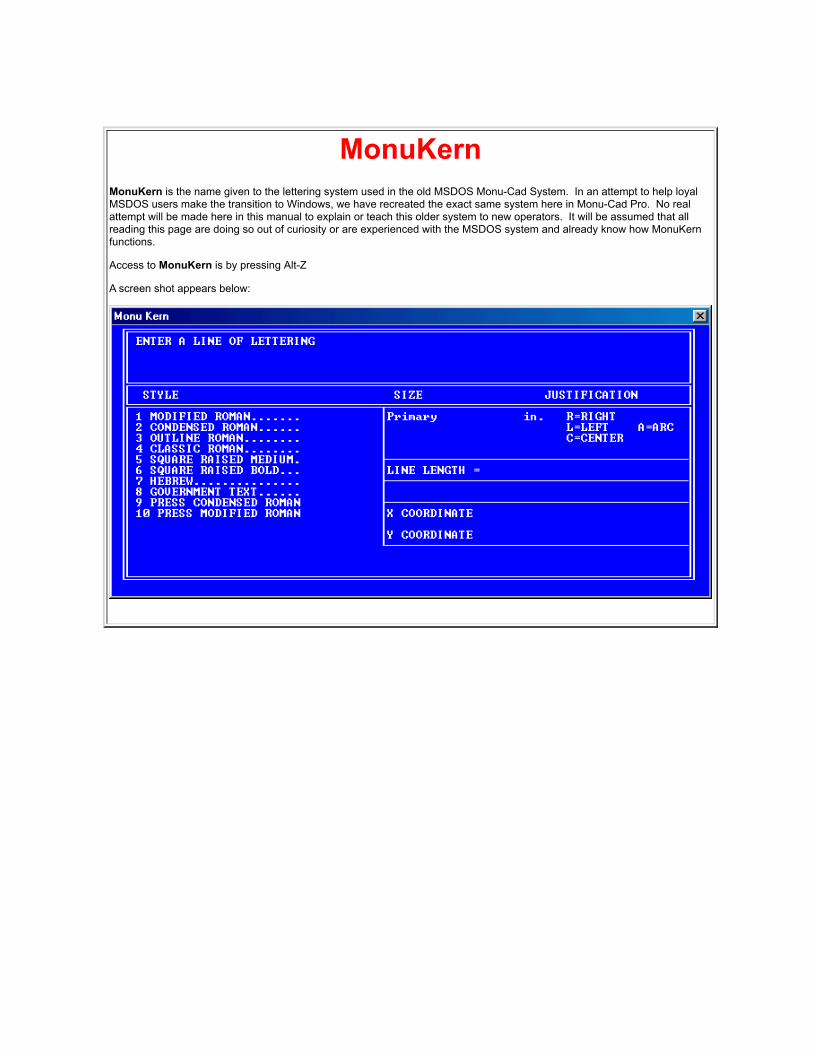
MonuKernMonuKern is the name given to the lettering system used in the old MSDOS Monu-Cad System. In an attempt to help loyalMSDOS users make the transition to Windows, we have recreated the exact same system here in Monu-Cad Pro. No realattempt will be made here in this manual to explain or teach this older system to new operators. It will be assumed that allreading this page are doing so out of curiosity or are experienced with the MSDOS system and already know how MonuKernfunctions.
Access to MonuKern is by pressing Alt-Z
A screen shot appears below:

Mouse OperationThis page is presented to help you with some terms which may not be obvious to the new computer user.
In the picture to the left, the mouse shown has 4 buttons.
Button #1 is considered the Left Mouse Button and button #3 isconsidered the Right Mouse Button.
Click This term is usually used to mean that you press your Left MouseButton once.
Double Click This term means to press your Left Mouse Button twice in rapidorder.
Right Click or Right Mouse Button Click means to press the right most button onyour mouse. Since mice can have as many as 5 buttons or more, thisusually means the right most button on the top of the mouse.
The mouse we find most reliable and easy to use is called the Mouseman Plus made by Logitech. Themodel is M-CW47. It is pictured above.
Related Topics:
right mouse button
lettering

MPMove Point
The MOVE POINT command can be used to move any point on any object. Notice that "point" may mean somethingdifferent with various types of objects. With straight lines, for instance, only the end points can be moved. With circles,the center or radius point may be moved. Each type of object is explained below.
Select the Move Point command from the Object Menu or type MP on the keyboard. You will be asked to select theobject to edit by clicking on that object (line arc etc). Select an object by clicking you left mouse button on that object.The object turn Red to indicate the selection has been made. Next, click on the point on that object that you wish tomove. Remember, this may be the end point of a line, the midpoint of an arc, or an existing point on any other type ofline. After you have selected the point to be moved, you will be asked for the new location. As you move your mouse,you will see the change taking effect. Select the new location of the point by clicking your left mouse button. Thischange will depend upon the type of object that the point was helping to describe:
STANDARD POINT (PO): The point can be moved.
STRAIGHT LINE: The end points of a straight line can be moved. The effect on the line will be that a new line will bedrawn between the newly moved end point and the other end point, which was not changed.

RECTANGLE: Since a rectangle is really just four lines that share end points, moving any of the points that form thecorners of the rectangle will change one of the two lines which share that end point, so that they will no longer form arectangle. The command asks which line you want to affect.
REGULAR POLYGON: Like a rectangle, a regular polygon is made up of individual lines, so moving a point will affectonly one line in the regular polygon.

CIRCLE: Both 2 and 3 point circles are defined by their center point and a point on the circumference. Either of thesepoints may be moved. Keep in mind that when you move one, the other one stays the same, so if you move thecenter, the circle will either get smaller or larger, because the point which locates the perimeter stays in the sameplace. If you change the perimeter point, the center stays where it was.
ARCS: Either end point or the midpoint may be moved. After you specify the arc and the point to be moved, you willbe asked for the new location. If RUBBER BANDING is ON, the new arc will be dragged. Notice that all arcs aredefined by three points on the arc.
ELLIPSE: Any of the four points used to create a TRUE ellipse can be moved. When moving these points, rememberhow an ellipse is defined. Its location and rotation are set by the points which define the major axis. The distancebetween the other two points defines the height only of the minor axis.

COMPLEX CURVE: Any of the points used to define the curve may be moved, including the end points. After movingthe point, the entire curve will be erased and redrawn, creating one continuous curving line through all of the points,just as was done when it was first created.
BEZIER CURVE: Any definition point, either on the curve, or an endpoint of one of the tangent lines, may be moved.When you select the Bezier curve, the tangent lines become visible to make editing easier. If RUBBER BANDING isON, the Bezier curve will be dragged to the new definition point.

COMPONENTS: Only the reference point of a component may be moved. When the point is moved, the entirecomponent is erased and redrawn in the new location. NEAREST POINT or SNAP CLOSEST are often helpful hereas well.
Note!!
MP was not designed to work with lettering groups. To move a lettering group, right click on the red reference point inthe group and select Move from the menu.

NLSnap to Nearest
Line
This command can also be used anytime you are asked for a point. It is used simply to insure that you are actually onan object that you want to be on. It does not look for endpoints, midpoints, intersections, or any other geometricproperties of the entity in question, it just makes sure that your point is really touching the object.
Anytime you want to place a point touching an existing entity in the drawing, type NL on the keyboard or selectNearest Line from the Snaps Menu. You will be prompted Select Object>. Point to and select the object that youwant the point to touch. The closest point on the object will be found and returned as the location of the point you arecurrently being asked for. This command is very similar to the Nearest Point (NP) command, only it can place a pointanywhere on an object, not just at the original definition points of the object. This command is also assigned to the F1key on the keyboard.

NPSnap to Nearest
Point
Suppose you want to draw a line which connects with the ends of two existing lines. Position the cursor near the endof the first line and type NP or press the F4 function key. The new line will start precisely at the end of the old line.Now position the cursor near the end of the second line and type NP or press F4. The second point of the new linewill be at the end point of the line you have just selected.
The SNAP TO NEAREST POINT command can be used with editing commands as well as with drawing commands.
The SNAP TO NEAREST POINT command will override any other snap commands which might be turned on, suchas SNAP TO GRID and SNAP ORTHO.
Right Mouse Button. Simply move the mouse cursor near the point that you want to snap to and press the rightbutton rather the first button on the mouse. This will act exactly as if you had typed NP on the keyboard. Note!! TheNP button on the toggle bar must be pushed "in" for this to work or you must be holding hold down the Shift Key. seeToggle Bar

OAOrthogonal Angle
The ORTHOGONAL MODE command allows you to specify that all lines entered into the drawing should be drawneither perfectly horizontal or perfectly vertical. Selecting the ORTHO MODE command toggles ORTHO MODE on andoff. Straight lines and certain editing commands are affected by the ORTHO MODE command.
Ortho Angle allows you to set the angle of the ORTHO Function. If you enter the command OA, you will be askedfor the angle of the Ortho Plane. For example, after entering OA you were to enter 15, the next time you turn onORTHO (OR)any object drawn or moved will then be moved at a 15 degrees angle to the horizontal.
OA and OR are separate commands but work together to make precise drawing possible.
See OR command

OBObject Break
The OBJECT BREAK command removes a part of an existing object between two specified points. You can use thiscommand on straight lines, arcs, circles, and curves.
To take out part of an object, select the Object Break command from the Objects Menu or type OB on the keyboard.Next, select the object you want to break by clicking on it. It will turn Red. Then, you will be prompted on thecommand line for the first point on the object to break.
A construction point will appear on the object at the point selected. If this is not the point you want, press ESCAPEand repeat the command. After you select the first point, you will be prompted to enter the second point. After youspecify this point, another construction point will appear, and a section between the two points will be removed. Noticethat the portion of the object to be removed can be a segment starting somewhere on the object and continuingbeyond the end of the object. Just choose the second point just beyond the end (this applies to lines, arcs, and curvesonly).
The OBJECT BREAK command not only takes out a section of an object, but now the two remaining sections areeach objects, and each can be edited independently by any other editing commands that require you to select anobject. A broken circle becomes an arc.
OB and Ellipse
The OB command will now break an Ellipse into 16 arcs. Simply enter OB, click on the ellipse and answer Yes whenthe dialog pops up. A broken Ellipse can now be restored with the OOPS command in version 5.0 and later.

OB and Circles
In Version 4.5 and later versions, a change has been made in the OB command in regard to Circles.
To break a circle follow the steps below:
1. Type OB2. Click on the part of the circle you wish to have remain after the break operation3. click the 2 break points.
This will feel odd to many users who may be used to clicking 3 points in a row. A good rule to follow is to break thecircle by clicking on the side of the circle opposite where the break will be to indicate the part of the circle youwish to keep. In the example above, in step 2, click the part of the circle outside the box to keep that section or insidethe box to keep the inside section.

OCObject Copy
The OBJECT COPY command works exactly like the OBJECT MOVE command, except that it doesn't erase theoriginal line that you pointed to, and you can make more than one copy at a time.
Choose Object Copy from the Object Menu or type OC on the keyboard. Point to the object you want to copy. It willturn Red. Next, select a point on the object you want to copy. A dialog box will appear asking you to enter the numberof copies. Enter a number and then click OK. You will now be prompted to enter a Starting Point. Click your mouse onthe coordinate of the object where you wish the copy to begin.
As soon as you move your mouse, you will see the copies visually appear and expand outward as you move yourmouse. When you click your next point, the copies will anchor.
Tip:
You might want to hold down the Ctrl key during this operation to temporarily turn on ORTHO to keep the copies in astraight line or if the object is large turn off the image with the Shift key.
Don't forget to try Cursor Movement with this command!
Also, this is a good place to use Direct Draw. Entering a number followed by Enter instead of the last point will placethe copies the exact distance apart that you have entered.

OEObject Erase
The Object Erase command can be used to erase any type of object that you have drawn. Select the Object Erasecommand from the Object Menu or type OE on the keyboard. You will be asked to enter a point on the object. Afteryou have done this, the object will be erased. If you make a mistake, use the UNERASE command.
Sometimes you can't see whether it was erased or not, or some dots are left on the screen. To clear up any confusionor to clean up the screen, select the REDRAW DISPLAY command or type RD.
Note that individual objects within components cannot be erased without first exploding the component.

OGObject Change
Select the OBJECT CHANGE command or type OG. You will be asked to specify a point on the object that you aretrying to change. After you have finished, the object will be erased and redrawn with all of the changes made.
This is one of the 3 Change commands all of which produce the same menus and prompts.
When you type DG, WG or OG, the dialog below pops up:
From this dialog you may elect to change the color of the objects selected, the layer that they are on and or the linewidth. At this time, line types are not supported.
Simply enter the value(s) you desire to change and enter OK. OO will UNDO this command.
If you elect to change the color of the objects the added dialog below will appear:

With the WINDOW CHANGE command, you can change the line color, line width, or layer of any object. When youchoose the WINDOW CHANGE command or type WG, you will get a typical window command prompt: Place awindow around the objects that you wish to change.
Objects are drawn on specific layers, in certain line colors, using a certain line type and line width. So far, we havebeen using the defaults, drawing on layer 0, with line type 0 and line color 1. But all of these can be changed. Thesechanges can be made on any type of objects: points, lines, rectangles, regular polygons, circles, arcs, ellipses, andcurves.

OMObject Move
Any object that you have drawn, including components, can be moved from its original position. To move more thanone object at a time, use the Window Move (WM) command.
The OBJECT MOVE command will ask you for two basic pieces of information:what you want to move, and whereyou want to move it to.
To move an object, select the Object Move command from the Object Menu or type OM on the keyboard. Next,select an object to move by clicking your left mouse button on the object. As soon as you click on the object, it willturn Red and become "attached" to the cursor. You then move it with your mouse to the new location and click yourleft mouse button to anchor it in place. You may also manually enter coordinates in the form (x,y ENTER) on thekeyboard if you desire.
Tip:
If you are moving a single arc and intend to attach it to the end point of another arc, use NP to select the end point ofthe arc to be moved after entering the OM command. Then you can attach it to the second arc with another NPcommand. Give it a try! It really works well!

OOUNDO
The UNDO (oops!) command will reverse aprevious action. For example, if youWindow Move (WM) a part of the drawingto another area, pressing OO will return itto the original location.
The UNDO command is located in the EditMenu but the quickest way to use it it totype OO on the keyboard. (ooh-ooh!)
Undo is only 1 level deep. In other words,you can only Undo one time. As soon asyou perform another operation,
The opposite of UNDO is REDO (UU)(uh..uh!)
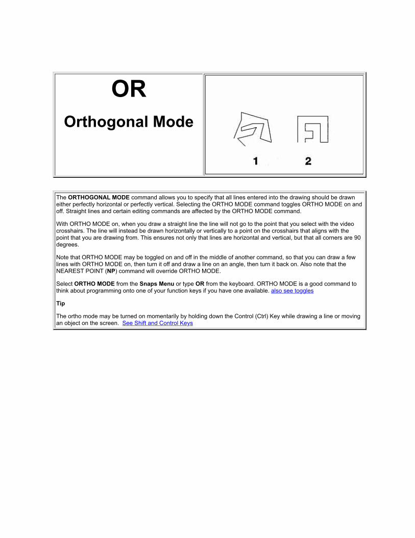
OROrthogonal Mode
The ORTHOGONAL MODE command allows you to specify that all lines entered into the drawing should be drawneither perfectly horizontal or perfectly vertical. Selecting the ORTHO MODE command toggles ORTHO MODE on andoff. Straight lines and certain editing commands are affected by the ORTHO MODE command.
With ORTHO MODE on, when you draw a straight line the line will not go to the point that you select with the videocrosshairs. The line will instead be drawn horizontally or vertically to a point on the crosshairs that aligns with thepoint that you are drawing from. This ensures not only that lines are horizontal and vertical, but that all corners are 90degrees.
Note that ORTHO MODE may be toggled on and off in the middle of another command, so that you can draw a fewlines with ORTHO MODE on, then turn it off and draw a line on an angle, then turn it back on. Also note that theNEAREST POINT (NP) command will override ORTHO MODE.
Select ORTHO MODE from the Snaps Menu or type OR from the keyboard. ORTHO MODE is a good command tothink about programming onto one of your function keys if you have one available. also see toggles
Tip
The ortho mode may be turned on momentarily by holding down the Control (Ctrl) Key while drawing a line or movingan object on the screen. See Shift and Control Keys

Auto
Outline-Inline
The Automatic Outline and Inline functions are accessible only through the Selection (SE) command.
Outlining
The outline procedure is to simply select the objects to be outlined, click on the outline command word in the menu, click the OKbutton, set the desired outline offset value, pick the outlining method (normal, clipped or rounded) and then click the updatebutton. The 4 pictures below show the process. when the desired result is obtained, click the OK button. To abort the operationclick the Cancel Button.

Note Square Corners
Note Clipped Corners!

Note Rounded Corners
Notice!! Only lines, arcs and circles may be outlined or inlined. Other curves must be converted to arcs before usingthis process. Components must be exploded before they can be outlined. See BA command
Tip
In the first example above we outlined the letter A with the Normal Method. Notice the sharp, squared corners (peaks). Onceoutlined, you may change the Offset Value or the Peaks Method and click the Update button. This will quickly and convenientlyerase the first attempt and replace it with the second results. In this way you can compare the differences visually.
The Normal/NoPeaks check box enables extra processing power in the Normal method to remove some extra sharp peakswhich may occur in some floral carvings. Usage is optional. It will increase the processing time.
Please Ignore for now the Islands option buttons. These options will be implemented in a future improved version.
Tip:
Use the SE select command to select and erase the sandblast line around a carving. Then use the Window option of the Selectcommand to automatically place a new outline around the whole carving!
InliningThe Auto Inlining process is very similar to the outline process. First select the closed area to be inlined with the SE SelectCommand. Click on the Inline Command word and then click on OK. When the menu shown below appears, set the OffsetValue and Click the Update Button. For most Inlining, the Normal, Clipped and Rounded options will have marginal effect. Usethese options as desired. Please Ignore for now the Islands option buttons.
Note that the area to be inlined must be "closed".

How to Inline a Complex Area or "island"
In the above example, we wish to inline the inside of the "chain" To identify the desired island for the process, first place a "point"in the center of the island as shown above by the red +. This is accomplished by using the PO or point command. Just type POon the keyboard and then left click your mouse in the center of the island.
Next, type the Select command SE on the keyboard. Click on the Window Button and place a window completely around thearea containing the island to select all objects. All will turn Red as shown in the second example above. The PO point must alsobe selected.

Finally, double click on the Inline option in the SE menu, set the desired offset value and click the Update button. The island willInline as shown in the third example above. Click the OK button when finished.
You will have to manually erase the PO point after the inline process has been completed.
This procedure is very helpful when the island is a complex form as the chain links are above.
Note: If you do not place the PO point in the island, very unpredictable results will occur.
Tips:
Use auto inline to draw the inside sandblast line of a panel created with a rectangle command.
Notice!! Only lines, arcs and circles may be outlined or inlined. Other curves must be converted to arcs before usingthis process. Components must be exploded before they can be outlined. See BA command
Note to Monu-Cad MSDOS Users
In the DOS version, auto outlining and inlining of letters was almost automatic. This is a different concept. You will have toindividually inline all "islands" within letters. Since it is now easy to create an outlined alphabet, we recommend that for efficiencythat you take the time to outline a whole alphabet to your specifications and save it as a new alphabet. Then it will be done onceand for all.

P1Drawing Path
This is one of three commands which allow you tochange the disk and/or directory where Monu-Cad Pro2000 looks for and places files of various types.
The initial default paths are set with the Config options inthe File Menu.
This command allows you to change the default path forDRAWING files from within Monu-Cad Pro 2000. Tochange the default path for drawings, choose SetDrawing Path from the CONTROLS menu, or type P1on the keyboard. You will be asked to specify the newdefault path. This path will be used whenever drawingsare saved or loaded.
Note that if your path includes a directory name, it shouldprobably be ended with a backslash (\), to separate thedirectory name from the filename which will be addedwhen you do the load or save.
Note also that you can override the default pathswhenever you want by simply typing a different path aspart of the filename whenever you do a load or save.

P2Component Path
This is one of three commands which allow you tochange the disk and/or directory where Monu-Cad Pro2000 looks for and places files of various types.
The initial default paths are set with the Config option inthe Files Menu.
This command allows you to change the default path forCOMPONENT files from within Monu-Cad Pro 2000. Tochange the default path for components, choose SetComponent Path from the Controls Menu, or type P2on the keyboard. You will be asked to specify the newdefault path. This path will be used whenevercomponents are saved or loaded.
Note that if your path includes a directory name, it shouldprobably be ended with a backslash (\), to separate thedirectory name from the filename which will be addedwhen you do the load or save.
Note also that you can override the default pathswhenever you want by simply typing a different path aspart of the filename whenever you do a component loador save.

PAPan
The PAN command allows you to slide the drawing around on the screen. This does not change the zoom valuefactor in any way, it just changes what part of the drawing you are looking at.
Select the Pan command from the Display Menu or type PA on the keyboard. You will next be asked to specify thenew center of the screen. Point to a location on the drawing that you want to be in the center of the screen after thePAN. All of the objects in the drawing will appear to move over on the screen.
Note that since the PAN command creates a view which is the same size as the one currently on the screen, you maywant to ZOOM BACK before panning if you have to move around by a distance that is larger than one screen. Youcan PAN repeatedly and move in increments.

Panel FillsAutomatic
In Version 3.0 of Monu-Cad Pro, we have made a significant change in our Lettering System.
Any Panels automatically drawn with Click & Type contain fill points upon creation. What this means is thatyou do not necessarily have to explode the lettering group in order to place fill points to color the panel sandblastlines and surface.
The two Fill Groups Automatically created by Click & Type are named:
LETTERING PANELS SURFACE and PANEL SANDBLAST LINES
Initially, Lettering Panels Surface is assigned a solid light Gray color and Panel Sandblast Lines is assigned asolid Black color.
When you load a previously drawn .mcd file such as Demo_DD02.mcd and turn on the fills, the family nameshould look something like this:
It looks pretty good but there still is a problem....the letters are not filled in dark and the center of the letters O andD are not the panel color.
This is because the letters and their centers are Components in themselves and not part of the panel. This nextimage should look better:
How did we make that happen? Well, we created an alphabet in which the letters already contained fill points.
In detail:
1. First we created two new fill groups V-SUNK LETTERS CENTERS and V-SUNK LETTERS TYPEFACE.We assigned the solid color Black to the Typeface Group and light gray to the Centers Group. We suggestall users use these group names for all sandblast letters.

2. Next, we did a LF and loaded MCALF010.fnt (alphabet #10)
3. Then we exploded all the components, added the proper fill points and remade the components renamingthem as we created them. For example, all the letters begin with either SKM or FSKM so we renamedthem to SKMF_ of FSKMF_ the _(underline) is the letter for the character. (SKMA became SKMFA) Thebest tools to use for filling letters is the F2 fill for the letter itself and then use SD for the centers.
4. When all the letters were filled correctly and the components renamed, we saved the font with the SFcommand under the name MCALF010F.fnt ... the F for filled.
5. Next, using Windows Explorer we copied the SKM.dta file in the \fonts folder and renamed the copy toSKMF.dta.
6. Finally, we edited the MCFonts.lst file in \fonts folder to include the new font as below:
[Press Modified Roman]dtafile = skmfontfile = mcalf010lowercase = noserifs = yes [Press Modified Roman-F]dtafile = skmffontfile = mcalf010flowercase = noserifs = yes
A lot of work, yes! But the results are now automatically filled panels with automatically filled letters!
Of course, we edited the lettering group to use the Modified Roman-F font instead of Modified roman.
FYI, we also created some test alphabets consisting of Frosted and Shaded letters. The groups we created werenamed:
OUTLINE LETTERS CENTEROUTLINE LETTERS TYPEFACE

OUTLINE LETTERS SB LINE
We suggest all users use these group names for all outline letters.
MonuRender Option
If you have the MonuRender option, the panel can be made to look like this if you use a Rose Granite:
TIP:
If you are in a hurry and don't want to go through the trouble of creating a filled alphabet, you could just explodethe lettering group and the letters in it, use F2 or WF to fill the letters with a color and use SD to fill the centers.
As of 1-30-2001, all the standard Monu-Cad alphabets are now available in a pre filled version. These files havebeen included on the Version 4.01 upgrade CD but are not automatically installed. See the instructions thatcame with the CD for details as to how to use them.
Note!!
Fills will not display if Fills Button on the Tool Bar is not pressed in
Fills by default are placed on Layer 9. If Layer 9 is turned off, fills will also not display.

Panel Styles
Click the BACK button to return to the previous page.

Panels Adding & EditingPanels are added to lettering groups by way of selection buttons in the advancedsection of the Click & Type lettering editor shown below:
Panel Style offers 3 selections or no panel at all.
Each of the three panel styles can be drawn with:
one hair line for raised letters in a panel;
a single sandblast line for normal work;
or a double sandblast line for more detailed work.
with square corners
with chipped (concave) corners
with rounded corners

click here to see the available panel styles
The width of the panel is determined by which of two input boxes has a value placed init:
Panel Width
If this input box contains a value, the panels will be forced to this with regardless of theamount of lettering in the panel. This is commonly used for inscription panels. In otherwords, the panel becomes a fixed size, the height of which is determined by the spaceabove and below lines of lettering plus the height of the letters. Common values are 10- 14 inches for inscriptions. There is no default value.
End Space
A value placed in End Space will place that amount of space automatically in front ofand following a line of lettering. The panel is automatically adjusted in widthdepending on the amount of lettering in the panel. This is used for family names.Common values are 1.5 inches or 2 inches. The default value is -0-.
Top Line to Top of Panel
This input box sets the amount of space placed between the top of the first line oflettering in a panel and the inside of the top panel line. The default is .5 inches.
Space Below
This input box sets the amount of space that immediately appears below the currentlyselected line of lettering. In a multi line inscription, a different value may be input foreach line of lettering. Click on the line of lettering you wish to set this value for beforesetting the value. The default is .5 inches.
Click your BACK button to return to the previous page.
Goto Monu-Cad Lite! Intro
Goto Monu-Cad Pro Quick Help

Panel Maker WizardThis cute piece of programming,new in Version 5.0, will create specialty panels automatically and allow adjustmentsto be made under user control.
To access this feature, click on Panel Maker in the Wizard menu:
The following Dialog will appear:
To select a panel, simply click on one of the 13 images shown illustrated above.
The next dialog you will see is shown below:

If you choose the select lettering group option, the dialog will disappear and you will be prompted to click on alettering group such as a family name. The new panel will derive it's height and width from the measurements of thelettering group.
Note!!
It is important that the lettering group you select not have a panel around it already!
The second option above, allows you to draw a rectangle manually to determine the height and width of the newpanel.
Next, a panel style will appear along with a dialog box which allows you to adjust the parameters of the panel. Theimage below illustrates what appears should you select the book Panel:

Changing any of these parameters will change the shape of the book. The best way to understand what this does isto just try it and play around a bit. It's pretty amazing!
Important things to know about this wizard.
1. The resulting panel creation is a drawing not a component or permanent part of the lettering group.
2. The Load Style/Save Style buttons allow you to save the adjustments you have made to a file so you canretrieve the same parameters at another time.
The other panel choices produce similar dialogs which allow you to make adjustments to the panel. We suggest thatyour try each one to see how it goes.

PCConstruction
Points
Construction points (the little x-shaped symbols that show up when you are drawing) can be toggled off or on. Likereference points, construction points are usually only useful while you are drawing new elements, and often you don'tneed them for certain types of editing.
If these points are distracting, you can turn them off. Select Construction Points from the Controls Menu or type PCon the keyboard. The same process turns them back on if they are currently off. Like reference points, the change willnot be evident until the next time the screen is redrawn. Also like reference points, construction points are neverplotted.
If your drawing looks very "fuzzy", your construction points are probably turned on. Remember to do a Redraw RDafter changing the state of the construction point toggle to see the results.
see construction points

PDPack Data
The Pack Data command is a form of a GeneralBackground Cleanup command.
Every time you for example draw a line and then erase itor place a component and then erase it, although it is notstill visible on the screen, it still exists in the Monu-CadDrawing Database. It sort of exists off screen in thebackground. To prove that it is still there, simply do anUE Unerase and it will re appear.
To clean up a drawing and eliminate these 'background"objects, simply type PD or click on the Pack Data item inthe Drawing Menu.
Visible objects still on the screen will not be erased. Butpreviously erased objects will be removed from thedatabase.
Why this command?
In some cases, when you have a very large drawing inwhich many objects have been erased, operations willslow down as the database grows larger. This is acommand which will help restore your session speed.

POStandard Point
This command is used to draw a Standard Point symbol, a cross, at the location specified. The standard point can beused in your drawing to mark the center of a circle, show the corners of a sheet, etc. It is drawn in the current linecolor, just like all other objects. The Standard Point is .2 units across. For more about colors, refer to the LINECOLOR command.
To draw a point, select the POINT command from the Draw Menu or enter the two-character command PO on thekeyboard. In either case, the prompt message will now indicate that the STANDARD POINT command is active, and asecond message will ask you to indicate the location of the point. To do this, move the cursor to where you want thepoint to be and press the left mouse button.
The Standard Point will appear in the location indicated, as will a construction point. Notice that when you draw,construction points show up on the screen to help you visualize what you are drawing. If you don't want constructionpoints to appear, you can turn them off using the DISPLAY CONSTRUCTION POINTS command. For moreinformation, refer to the PC Command.
If you want to draw another standard point, you can re-issue the command in a number of ways. Of course, you canselect STANDARD POINT again from the menu or type PO on the keyboard again, but there is an easier way. Most ofthe time that you want to repeat what you just did (draw another point, in this case), you can simply press the SPACEbar on the keyboard. This can save a lot of time, particularly if you plan in advance to do several of the samecommands rather than jumping from command to command indiscriminately.
Again, if you get too many standard points on the screen and want to get rid of some before moving on, use theWINDOW ERASE command. The ERASE LAST (EL) and the REDRAW DISPLAY (RD)command may also be usefulin cleaning up the screen.

PRReference Points
Reference points show up in Monu-Cad programs as Red X markers on the screen. There will be one in everycomponent and Lettering Group. Sometimes they can be distracting. To turn them off, type PR on the keyboard orselect Reference Points from the Controls Menu. see reference points
There will be many of them if you import a drawing in from CADD6 or Monu-Cad DOS.

Printing a Memorial Design(DP)
Printing is made very easy with Monu-Cad programs The quickest way to print is to click on the littleprinter Icon (shortcut) on the tool bar which will start the print function. You may also type DP or clickon Print in the file menu.
After you click on the printer icon, you will see the print preview screen below:
To begin printing, simply click on the yellow "PRINT" button. That's all there is to it!

Click on the Exit Button or Press Esc to return to the Monu-Cad program.
You may also change the output size, location, orientation and printer parameters by clicking on thecontrol buttons located on the screen.
Quick Help
Size button allows you to change the image size to one of 3 preset sizes or "zoom all"
Center button centers the image in the printable paper area
Show fills button turns on/off any filled areas that may be in the drawing
Portrait / Landscape buttons change paper orientation
Copies edit box selects the number of copies to print
Scale edit box allows you to set the desired scale ... roller buttons select integernumbers or type in decimal fractional amounts.
Update button updates the screen after the new scale amount has been entered
Output buttons set the print quality or darkness of print
Setup button allows access to printer setup options
Print button starts the printing process
Help button pops up brief help menu
Exit button exits and returns to main draw screen
Click your BACK button to return to the previous page.

Program ConfigurationGoto Program Config Menus

Program Operation Basics This page will provide you with links to Topics which are designedto give you general information that you will need to know toefficiently operate your Monu-Cad Program.
Click on the link of your choice below to access the subjectinformation.
Monu-Cad Commands
Monu-Cad Pro Quick Help
Description of Layers
Drawings & Components (similarities and differences)
LETTERING - Click & Type Lettering System
Cartesian Coordinate System or Where am I on the DrawScreen??
Adding New Designs to the System
Click the BACK button to return to previous page.

RCRadial Copy
This command creates multiple copies of objects in a radial pattern. The objects are selected with a window, an axispoint for the pattern is selected, and the angle to fill and number of items are specified.
To use this command, select Radial Copy from the Windows Menu or type RC on the keyboard.
After selecting the objects by placing a window, a dialog box will appear asking you for the number of copies and thenumber of degrees around the circle you wish to span. When you click the OK button, you will see the copiesspanning out in a circle around the current location of the mouse cursor. Select a location to place the center of thecircle and click the left mouse button. The copies will be placed in the radial pattern specified.
This command provides a quick way to make serpentine tops for memorials among many other uses. This commandwill become one of your best friends.

RDRedraw Display
This command simply redisplays the drawing using the current zoom value. This command can be useful for cleaningup the screen after erasing or moving some object that didn't go away completely.
If you suspect that some command didn't work, it is often useful to try a REDRAW DISPLAY command to make sure.Often lines drawn on top of each other or other objects which overlap look funny when they are first drawn or edited.The RD command very often clears up the confusion by showing you what the drawing is really supposed to look like.
Select the Redraw Display command from the Display Menu or type RD on the keyboard. The display will beredrawn.

RERectangle
Using the Rectangle command is much faster than drawing four lines and often more accurate, as the opposite twosides will always be parallel and the corners will always be 90 degree angles.
Select Rectangle from the Draw Menu or type RE on the keyboard. You will be asked to indicate a corner of therectangle. This can be any of the four corners of the rectangle. After you enter the point (place the video cursor andpress the first button), a construction point will indicate the corner of the rectangle that you have just chosen, and thesecond prompt message will continue to ask you for a corner of the rectangle. More importantly, a "rubber banding"rectangle will move and stretch on the screen as you move the cursor with the mouse.
When the second (opposite) corner of the rectangle is where you want it to be and the proper rubber bandingrectangle is showing on the screen, press the first mouse button again to select the location.
Once you have selected the location of both corners, all four corners will be indicated by construction points, and therectangle will be placed at the location selected. Notice that rectangles are really made of four Straight Lines, and allediting of Rectangles should take this into account.

RFFillet Radius
This command will allow you to set the radius of the arc to be inserted between the two lines. Simply enter thecommand RF on the keyboard and then enter the desired arc radius.
See Fillet Command

Render FillsOverview
(Version 3 only)
Render Fills is a term we will be using to describe Monu-Cad Pro's ability to "fill in" or "color in" areas of amemorial in order to more clearly represent to the customer or shop the areas of the memorial which arepolished, steeled, rock pitch or blued. Other finishes are also possible but we will concentrate our explanations onthese four. Click here to see example.
There are 6 commands in the Render Menu that will allow you to perform Rendering or Filling tasks. TheRender Menu is shown below.
Basic Definitions:
The Render commands are divided into two types for clarity. Four commands are tools with which toperform the fills and 2 commands are for organization and modification purposes.
Tools Commands
FF Fitted Fill is a tool which allows you to designate the area to be filled by individually selecting the drawobjects which define the border of the area to be filled with color. This command is used often when other toolswill not perform the function adequately.
F2 Group WF is a "window fill" tool which will allow you to assign a group name to a Window Fill before the fill isexecuted.
SD Seed Fill is a new type of fill tool. If you have a closed well defined area, you can use this tool to place justone point into the area to fill that area.
WF Window Fill is a tool which will allow you to fill in an enclosed area with a solid color or hatch pattern in thestyle of the MSDOS Monu-Cad Program
Organization and Modification Commands
FG Fill Change pops up a menu which allows you to change the group assignment of "Fill Points".
GF Group Fill pops up a menu which allows you to create and name "Fill Groups", assign the type of fill desiredto a group, delete previously created group names and create "child" groups under "parent groupings".

Click on one of the links above to jump to that selection
Special information on automatically filled lettering panels is available Click Here
Note!!
Fills will not display if Fills Button on the Tool Bar is not pressed in Fills by default are placed on Layer9. If Layer 9 is turned off, fills will also not display.

Rendering BasicsTutorial
The first step in rendering amemorial is to begin with aplain, closed shape such asthe die and base shown tothe right.
It is a nice touch to changeall the lines to a light shadeof Gray so that when thememorial is filled in, thenatural divisions between thetablets and the background is"softer" looking.
Best results are had whenyou first color in the memorialand second add lettering andcomponents. To do it theother way around wouldrequire the fill tools to try to fitthemselves around thelettering groups andcomponents which oftenproduces mixed results.
Next, we created a Fill Groupcalled DIE-1 and assigned aGray Granite to the groupDIE-1. (Dark gray solid canbe substituted)
Then we used the Fitted Filltool (FF) to first select apolish finish for the groupDIE-1 and then to select thelines which define the dieface.

The next step is to fill in theRock Pitch around the die.
Again we selected the FittedFill (FF) tool, selected theDIE-1 group (it remainedgray granite from the lastuse), selected Rock Pitchfinish and picked the lineswhich make up the rockoutline of the die.
Again, using the FF tool, fill inthe top of the base with apolish finish. This time, whenselecting the fill group use orcreate a group called Base orBase1.
Later if you wish to changethe color of the baseindependently of the die youwill be glad that you did this.
FF tool again! Select theBase group, rock pitch finishand fill in the front of thelower stone.

At this point, I normally addthe family name. Before I doso I turn off the color with thefill button and add mylettering group on the plainwire frame drawing. Then Iturn the color back on.
Turning the color off willspeed up the processsignificantly. Whenever youneed to add items or movethem, you will find yourcomputer much moreresponsive with the colorturned off.
We do most of our buildingand editing with the color off.
Add more lettering and premade color components to

arrive at something like theimage to the right.
The final step to dress up thepresentation is to draw arectangle around thememorial with the REcommand. This rectangle willform the "picture frame"
Then, use the Seed Fillcommand (SD), select theBackground group, select thedesired background imageand click your seed fill pointinside the rectangle in aconvenient place. You mayneed to RD Redraw thescreen.
It is a good practice to makethe bottom line of therectangle close to the bottomof the lower stone. In thisway you will avoid the opticaldistraction of the monumentappearing to be "hanging inmid air". this is one timewhen trying to make theborders even and equal maywork to your disadvantage.
Tips:
For this to work correctly, the carvings must be components which have been pre filled and created before hand.
In the above example, substitute solid color fills for the granite fills if you do not have the MonuRender option.
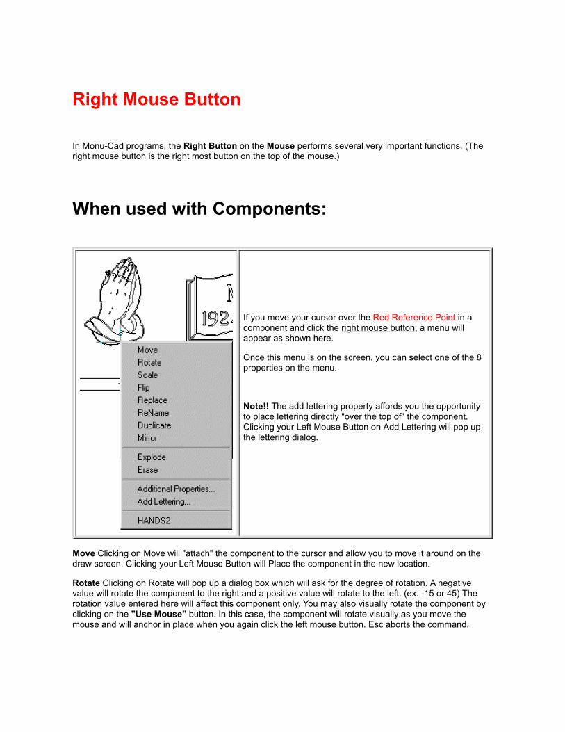
Right Mouse Button
In Monu-Cad programs, the Right Button on the Mouse performs several very important functions. (Theright mouse button is the right most button on the top of the mouse.)
When used with Components:
If you move your cursor over the Red Reference Point in acomponent and click the right mouse button, a menu willappear as shown here.
Once this menu is on the screen, you can select one of the 8properties on the menu.
Note!! The add lettering property affords you the opportunityto place lettering directly "over the top of" the component.Clicking your Left Mouse Button on Add Lettering will pop upthe lettering dialog.
Move Clicking on Move will "attach" the component to the cursor and allow you to move it around on thedraw screen. Clicking your Left Mouse Button will Place the component in the new location.
Rotate Clicking on Rotate will pop up a dialog box which will ask for the degree of rotation. A negativevalue will rotate the component to the right and a positive value will rotate to the left. (ex. -15 or 45) Therotation value entered here will affect this component only. You may also visually rotate the component byclicking on the "Use Mouse" button. In this case, the component will rotate visually as you move themouse and will anchor in place when you again click the left mouse button. Esc aborts the command.
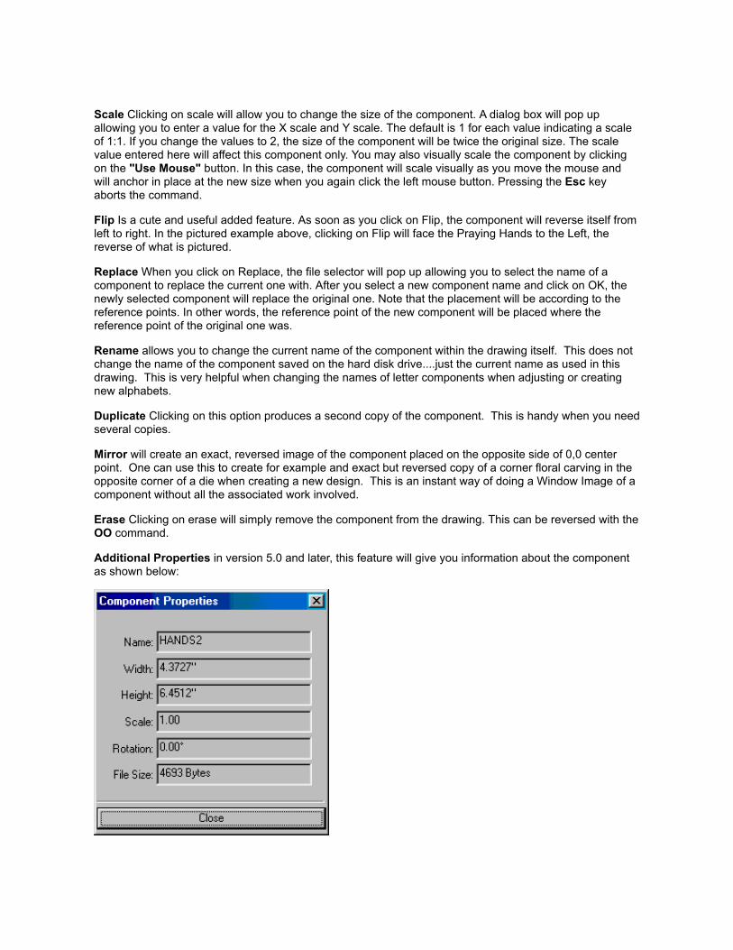
Scale Clicking on scale will allow you to change the size of the component. A dialog box will pop upallowing you to enter a value for the X scale and Y scale. The default is 1 for each value indicating a scaleof 1:1. If you change the values to 2, the size of the component will be twice the original size. The scalevalue entered here will affect this component only. You may also visually scale the component by clickingon the "Use Mouse" button. In this case, the component will scale visually as you move the mouse andwill anchor in place at the new size when you again click the left mouse button. Pressing the Esc keyaborts the command.
Flip Is a cute and useful added feature. As soon as you click on Flip, the component will reverse itself fromleft to right. In the pictured example above, clicking on Flip will face the Praying Hands to the Left, thereverse of what is pictured.
Replace When you click on Replace, the file selector will pop up allowing you to select the name of acomponent to replace the current one with. After you select a new component name and click on OK, thenewly selected component will replace the original one. Note that the placement will be according to thereference points. In other words, the reference point of the new component will be placed where thereference point of the original one was.
Rename allows you to change the current name of the component within the drawing itself. This does notchange the name of the component saved on the hard disk drive....just the current name as used in thisdrawing. This is very helpful when changing the names of letter components when adjusting or creatingnew alphabets.
Duplicate Clicking on this option produces a second copy of the component. This is handy when you needseveral copies.
Mirror will create an exact, reversed image of the component placed on the opposite side of 0,0 centerpoint. One can use this to create for example and exact but reversed copy of a corner floral carving in theopposite corner of a die when creating a new design. This is an instant way of doing a Window Image of acomponent without all the associated work involved.
Erase Clicking on erase will simply remove the component from the drawing. This can be reversed with theOO command.
Additional Properties in version 5.0 and later, this feature will give you information about the componentas shown below:

Add Lettering will pop up the lettering dialog allowing you to place lettering "on top of" the component.
HANDS2 is simply the name of the component you have clicked on
When used on a blank area of the drawingscreen:
When you click the right mouse button onan area of the screen where there are nolettering groups present and the NP togglebutton is "out", the Add Lettering dialogbutton will appear as shown here.
Clicking on the Add Lettering dialog buttonwill pop up the lettering dialog boxes whichwill allow you to place lettering at thecurrent cursor position. See lettering
If the NP button is "pushed in", the cursorwill jump to the nearest point available. seetoggles
Right Mouse Click on Lettering GroupWhen the Right Mouse Button is clicked on the Red Reference Point in a Lettering Group:
When the Right Mouse Button is clicked on theRed Reference Point in a lettering group, themenu shown here pops up.
Adjust Lettering allows you to change thespace between characters visually.
Lettering Info... will tell you the details of the

lettering group including the number of letters,font used, size etc. See below
Edit Clicking on Edit will bring up the lettering dialog boxes. See lettering
Move Clicking on Move will "attach" the lettering group to the mouse and the lettering will move as youmove the mouse around the drawing screen. Clicking the Left Mouse Button will anchor the lettering groupwhere the mouse has been placed.
Rotate Is new to version 3.0 and will allow you to rotate a lettering group just as if it were a component.
Duplicate Is a unique feature. Clicking on duplicate will "attach" a duplicate copy of the lettering group tothe mouse allowing you to place it wherever you desire. If you are contemplating a lettering change butwant a quick way to return to the original, use this feature to make a copy which can be erased later. Thisfeature is also nice to have when you need to make several lettering group layouts with the same sizes oflettering and spacing but with different lettering. Just make one group, duplicate as many times as neededand then edit the lettering in the duplicated groups.
Erase Simply erases the lettering group. OO will reverse this action.
Adjust Lettering allows you to change the space between characters visually. Click Here to see the sheetdedicated to that function.
Lettering Info pops up a dialog which gives details about the lettering group. See image below:

Also see Mouse Operation
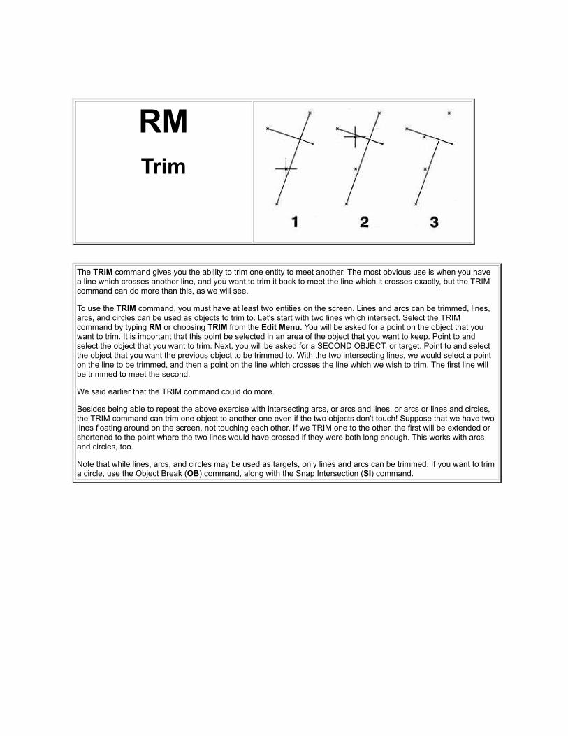
RMTrim
The TRIM command gives you the ability to trim one entity to meet another. The most obvious use is when you havea line which crosses another line, and you want to trim it back to meet the line which it crosses exactly, but the TRIMcommand can do more than this, as we will see.
To use the TRIM command, you must have at least two entities on the screen. Lines and arcs can be trimmed, lines,arcs, and circles can be used as objects to trim to. Let's start with two lines which intersect. Select the TRIMcommand by typing RM or choosing TRIM from the Edit Menu. You will be asked for a point on the object that youwant to trim. It is important that this point be selected in an area of the object that you want to keep. Point to andselect the object that you want to trim. Next, you will be asked for a SECOND OBJECT, or target. Point to and selectthe object that you want the previous object to be trimmed to. With the two intersecting lines, we would select a pointon the line to be trimmed, and then a point on the line which crosses the line which we wish to trim. The first line willbe trimmed to meet the second.
We said earlier that the TRIM command could do more.
Besides being able to repeat the above exercise with intersecting arcs, or arcs and lines, or arcs or lines and circles,the TRIM command can trim one object to another one even if the two objects don't touch! Suppose that we have twolines floating around on the screen, not touching each other. If we TRIM one to the other, the first will be extended orshortened to the point where the two lines would have crossed if they were both long enough. This works with arcsand circles, too.
Note that while lines, arcs, and circles may be used as targets, only lines and arcs can be trimmed. If you want to trima circle, use the Object Break (OB) command, along with the Snap Intersection (SI) command.

Rotate Lettering(Version 3 only)
In version 3 of MCPro, it is now possible to rotate a lettering group without exploding the group. If you rightclick on the group anchor point, the context menu now has a rotate option. Left click on rotate and you willsee the same options dialog you receive when you do a component rotate.

RPRegular Polygon
Regular polygons are geometric figures with any number of equal sides and equal angles. The Regular Polygoncommand requires entering the number of sides, the center of the polygon and a point on the polygon.
After you select the Regular Polygon command from the Draw Menu or type RP, a prompt will ask you to enter thedesired number of sides. Enter a number and click OK. You will then be prompted (on the command line) to click apoint indicating the center of the polygon. Click your left mouse button to locate the center of the polygon. Aconstruction point will appear and as you move your mouse away from the point, you will see the polygon appear and"shrink and grow" and rotate as you move the mouse around.
You will next be prompted to enter a point to indicate the perimeter of the polygon. The second prompt will ask you fora point on the polygon, which you should select carefully, as it will be one of the vertices. Select the point you wish.
The Regular Polygon will appear on the screen, and the second point will be at one of the corners of the polygon.Some experimentation may be required in locating this second point, as it determines not only the size of the polygon,but its rotation angle as well. Of course, having drawn it, you can always rotate it with the Window Rotate (WR)command.
Remember that you can always manually enter coordinates from the keyboard instead of clicking the mouse whenyou are asked to enter a point.
Note that like Rectangles, Regular Polygons are made of Straight Lines.

SASnap Parallel
This command gives you the ability to draw lines parallel to existing lines, arcs parallel to existing arcs and circlesparallel to existing circles.
Lines:
To snap a line parallel to another first enter the commands LI and SA.
Next click a point on the line you wish to parallel. It will turn Red.
Enter the offset distance followed by enter.
Next click the starting point of the new line and then the ending point. The "side" of the line you select for this point willbe the "side" that the new line will be drawn on.
The new line will be drawn parallel to the first line offset by the specified distance and the length will be the distancebetween the starting and ending points that you entered.
New 3.0 feature
Alternately, you may begin drawing a line and then enter SA while dragging the rubberband line. You will be promptedfor a line to snap the new line parallel to. Click on the line you wish to parallel and when you finally select the endpoint of the line, the new line will be parallel to the line you selected.
Arcs:
The procedure is almost the same as with lines:
First enter A3 and SA
Next, click on the arc to be paralleled. It will turn Red.
Now, enter the offset value and press the Enter key. (see tip below)
Finally, click on the "inside" or "outside" of the original arc and the new one will appear.
Circles:
The procedure is almost the same as with lines:
First enter C2 and SA

Next, click on the circle to be paralleled. It will turn Red.
Now, enter the offset value and Enter
Finally, click on the "inside" or "outside" of the original circle and the new one will appear.
Tip:
When you are prompted for the offset distance, if you wish to accept the value shown, you can skip this step andproceed to clicking the first point of the new line, arc or circle.

SDSeed Fill
(Version 3 only)
The Seed Fill SD command is the most exciting new command available in Monu-Cad Pro 3.0. This uniquecommand allows you to fill a closed area by just clicking once inside that area. This in many ways is verysimilar to filling in a paint program however, the fill is a vector based CAD object.
To Use:
1. Enter the command SD on the keyboard or select Seed Fill SD from the Render Menu.
2. The Group Dialog menu will appear. Select the group you wish to assign this fill to. Click on OK
3. If you have the MonuRender option, the Finish Properties Dialog will pop up. See Below
4. Next, click in the area you want filled. As you can see below, a SD point is placed in each closed areawhich defines a petal, leaf, stem or polished area.
Note!!After the first point has been placed, just pressing the space bar once for each point will allow you to placeadditional points without having to go through the added steps associated with the Group Dialog.
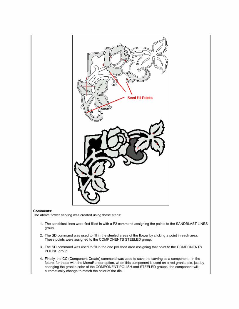
Comments:The above flower carving was created using these steps:
1. The sandblast lines were first filled in with a F2 command assigning the points to the SANDBLAST LINESgroup.
2. The SD command was used to fill in the steeled areas of the flower by clicking a point in each area.These points were assigned to the COMPONENTS STEELED group.
3. The SD command was used to fill in the one polished area assigning that point to the COMPONENTSPOLISH group.
4. Finally, the CC (Component Create) command was used to save the carving as a component . In thefuture, for those with the MonuRender option, when this component is used on a red granite die, just bychanging the granite color of the COMPONENT POLISH and STEELED groups, the component willautomatically change to match the color of the die.

Tip:
The SD (Seed Fill) tool is by far the easiest fill tool to use because it automatically finds the area perimeter.However, when the area is too complex for the SD tool to find the perimeter, then the Fitted Fill tool is your nextlogical alternative. Sometimes the SD tool works best and sometimes the FF tool. Experimentation is often thebest way to learn when to use which tool.
The key to successful filling is a very clean drawing. We have been going through the database and can't believehow many won't fill without a good amount of work.
A trick I use is to first off try a WF to see if the sandblast lines will fill. If it won't WF then it won't anything elseeither. However, if you try a SD in the sandblast lines, you will get an error message. Don't click on the button toclose the message but slide the error message out of the way and look at the red lines. You will see the red linesstop where the problem is. It is usually a break or overlap or points that don't touch.
Note!!
Fills will not display if Fills Button on the Tool Bar is not pressed in Fills by default are placed on Layer 9. If Layer 9 is turned off, fills will also not display.
Finish properties Dialog
After you select a Fill Group to assign the point(s) to, if you have the Monu Render option and the group youselect has a granite color assigned to it, the above dialog box will pop up. This dialog will allow you to select fromthe four possible granite finishes.

SESelect
The Select Command is one of the most versatile, useful and powerful editing commands available to Monu-Cad Pro operators!Prior to the development of this command, the operator could only select objects to be edited in one of two ways: individually or witha window command. For example one could OM Object Move one line, arc or circle or WM Window Move a group of objects as longas they fell wholly within the window drawn. Having only these 2 options severely limited the operator's choices and restricted theoperator's freedom and wasted time.
This new Select Command removes these restrictions and vastly increases the options available to the operator. With this command,one is able with one command to select the entire SB outline of a flower, for example, and then copy, move, change, sort, rotate,scale, save, erase, convert, outline, inline, print, cut or invert it! With SE, one could select just the vein of a leaf and scale it up ordown as needed and then move it to a new location!
A few practice runs with this command will return benefits many times over. Try it, you'll like it!

Note!! Conceptual Difference
Most Monu-Cad Commands require you to imagine the operation you are about to perform before you perform it. For example, ifyou want to move something, you must think of the command Window Move WM first, then execute the command. In the SelectCommand, you first select the objects you wish to modify and then second, decide what you are going to do with them. It is thisreverse logic that makes this command so different, powerful and wonderful.
Command Operation
As with most Monu-Cad commands, you begin by typing the 2-letter command SE or click on Select in the Edit menu. The SelectCommand Menu will appear as shown here. Three of the buttons at the top of the menu allow you to select items by Object, Windowor Drawing. The 4th Invert Button will Invert or Reverse selected items once they have been selected. More on the Invert button later.The default setting is Object meaning to select individual objects. If you click on the Window button, you will be able to select awindow full of objects. The Clear Selection button de-selects anything selected.
To select individual objects, simply left click on the objects (lines, arcs, and circles) in the drawing that you wish to highlight. Anyobject clicked on will turn Red. To de-select an object, simply click on it a second time and it will change back to the original line color.If you wish to select a whole string of objects, which are connected, hold down the shift key while left clicking. With the shift key helddown, the command will automatically select additional connected objects until a break in the path occurs. In this way, with just oneclick (holding down the shift key), you can select the entire sandblast line surrounding a carving as illustrated in the picture above.
Once the objects have been selected, the desired operation is then chosen by clicking on the name of the operation in the list ofoptions. Then click the OK button. Follow the normal command instructions for the command as prompted on the Status line. (Youcan alternately double click on the operation name to skip the apply button step)
Tool Options
When the Object button is chosen, one can left click on individual items on the draw screen. As each item is selected, it will turn Red.Clicking on the object once will select it. A second click on the same object will de select it turning it back to it's original color. If youhold down the Shift key while doing an object select, the selection process will automatically follow the path of all connected drawobjects until a natural break in the chain of draw objects occurs. This can really speed up the selection process.
The Window button allows you to select many objects at once by drawing a window around the objects to be selected. As with allwindow commands, only those objects which are wholly inside the window will be selected. This tool works in the same way WindowMove or Window Erase operates.
The Drawing button will globally select everything on the draw screen in one operation.
The Invert button will de select all currently selected objects and select all remaining objects in the drawing which were not selectedbefore. As the tool's name indicates, this tool Inverts all selections.
The Clear Selection button will de select any selected objects and allow you to begin again.
Invert Button
The Invert button will reverse or invert the selection process. In other words, if you use the SE command to select just the veins in aflower, when you click on the Invert button, the veins will be deselected and instead the entire remainder of the drawing on the screenwill be selected and turn red. This method is often used when you desire to keep certain objects but erase all the others. If this is thedesired result follow these steps:
1. Type SE
2. Left click to select the desired objects to keep
3. Click on the Invert Button. The drawing will invert.
4. Double Click the erase operation name
5. The inverted objects will be erased.
Close Button

Clicking on the Close button will terminate the SE command and close the menu.
More Examples
You can look at the SE command as an extension to other commands which already exist. For example, to erase many items atonce, follow this series of steps:
1. Type SE
2. Click on the desired objects
3. Double click on erase and all selected objects will be erased
In the same way, one can rotate a group of selected objects:
1. Type SE
2. Click on the desired objects
3. Double Click on rotate
4. Left click to place the point of rotation
5. Move your mouse to rotate the objects (similar to a window rotate)
6. Left click to end the rotation once the rotation degree has been obtained
Tip:
Some users will employ this command to select just those items that they wish the cutter to plot in ink. Once these items areselected, they will be saved to a file. Then the Invert option will be used to select the remaining items which will be sent to a secondfile to be cut with the knife.
If you hold down the Shift key while doing an object select, the selection process will automatically follow all attached drawobjects until a natural break in the chain of draw objects occurs. This can really speed up the selection process.
Comments
This command will be expanded in scope and capabilities in future versions. We will appreciate your comments and suggestions fornew uses. The Auto Inline and Outline functions are still currently under development and not fully implemented. Some operationnames may appear in the operations list that do not work at this time.
Special Command Considerations
All commands will operate as they would as if you had entered the command manually. ie Move works just like a WM or OMcommand but only the selected objects move.
Inline/Outline Options
There is no individual 2 letter command for the Auto Inline or Outline commands. The Select Command menu is the only to gainaccess to these commands. See Outline/Inline for details.
Auto Trim
There is no 2 letter command for Auto Trim. Auto Trim is only available through the Select Command menu. This command is indevelopment at this time and may not produce the desired results at times. The idea behind this command is to be able toautomatically "trim up" drawings in which lines overlap and points do not touch. We are continuing work on this command and hopeto achieve a very useful feature at some time in the future. See AutoTrim for more details.


SFSave Font
The Load Font command (LF) will allow you to loadonto the screen the individual components contained in aMonu-Cad .FNT file located it the \fonts folder forexamination or editing. (This command is intentionallynot listed on any Drop Down Menu.)
For example, the individual letters which appear in Click& Type when using the Press Modified Roman alphabetare contained in the file named MCALF010.fnt.
If you enter LF on the keyboard and then selectMCALF010.fnt and click OK, the contents of that file willbe displayed as unique individual components. If needbe, these components can then be edited as any othercomponent can.
Once components have been changed, they can beresaved to the file using the SF (Save Font) command.(This command also does not appear on any DropDown Menu)
If the Show File Security Options check box is checked inthe Paths/Files TAB in the Config file, then you will begiven the opportunity to select the File Security Optiondesired for this font file.

SGSnap to Grid
The SNAP TO GRID command causes points to be aligned automatically or "snapped" to the nearest grid point. Thisallows a certain type of control over the accuracy of the drawing.
This command is referred to as a "toggle." That means that if it is on when you select the command, it will be turnedoff; if it is off, it will be turned on. It can also be used in the middle of another command without having to start thatcommand over again. This toggle is also switched with the F2 function key and SG toggle button.
The spacing between grid points is set with the GS Grid Size command is also on the Snaps Menu. The default is .5inches.
With SNAP TO GRID turned on, all points entered will be snapped to the nearest grid point. To toggle SNAP TO GRIDon or off, select the Snap to Grid command on the Snaps Menu or type SG on the keyboard. The current status ofthe Snap to Grid command is displayed by the status of the SG toggle button. see toggles


Shift and Control Keys
On your computer keyboard are two keys which perform very useful functions. They are the Shift andthe Control (Ctrl) keys.
Shift Key
When moving a component or part of the drawing on the screen with WM, sometimes the amount ofdata being moved taxes the speed of the computer to redraw the screen and movement becomescumbersome and jerky. If this is the case, simply hold down the Shift key while moving the objects andthe image will be replaced with a plain rectangle. This also works with Window Move WM, WindowCopy WC, Radial Copy RC, and Window Stretch SS.
Control Key
When drawing a straight line, should you need to make that line perfectly straight in the horizontal orvertical direction, simply hold down the control key while drawing. This will turn on ORTHO mode for themoment. This also works with Window Move WM, Window Copy WC, Radial Copy RC, and WindowStretch SS.
In the Window Weld WW command, when selecting objects, holding down the Ctrl key will allow you toselect or deselect just one object at a time.

SISnap to
Intersection
This command can also be used anytime you are asked for a point. It is used to find and snap onto the exact pointwhere two entities cross (intersect). The crossing entities can be lines, circles, or arcs. The point where two objectstouch (such as the tangent point between a line and a circle) is also considered an intersection.
Anytime you want to select a point which is exactly at the intersection of two other entities, type SI on the keyboard orselect Intersection from the Snaps Menu. You will be prompted Select Object. Point to and select a point near theintersection you want to snap to. The intersection will be found and returned as the location of the point you arecurrently being asked for. You can draw lines from one intersection to another, create a circle at the intersection of twolines, break a circle at the intersection on a line passing through it, etc. You can even use many of these snaps, suchas MIDPOINT, CENTER, and INTERSECTION, when being asked for a displacement in an editing command such asMOVE WINDOW, or any other time a point needs to be supplied.

Load "Slide Show"Drawing (D3)
This additional "Drawing Load" option will erase the currently displayed drawing andreplace it while preserving the current lettering providing that a special criteria is met.
For this feature to work properly, the initial .MCD drawing file and the one which is toreplace it must have in common:
Both drawings must have the same number of lettering groups;
All lettering groups in each drawing must contain the same number of lines oflettering.
If the above criteria are not met, an error message will be generated.
This feature has been provided with the intent of providing a useful way to cyclethrough a series of memorial designs in which the lettering is always laid out in asimilar fashion. For example, one may have a series of 2-0 x 1-0 markers which allhave three lines of lettering. Using this feature, the operator could load the first markerin the series and edit the lettering to reflect the needs of the customer. Then, by clickingon the BLUE folder in the Tool Bar and clicking on the next design in the series, thenext design would be loaded and the lettering would be automatically replaced by thelettering used in the first marker.
Note that if the second design loaded is for example a single monument, as long as thenumber of groups of lettering are the same number and as long as the number of linesof lettering in each group is the same, the monument layout will replace the markerlayout and the lettering will be automatically changed to that of the first selectedmarker.
To cancel the effects of this feature and return to normal operation, simply erase thecurrent memorial with the DX Drawing Erase command and load another memorialusing the DL Drawing Load command.
Return to MCL-Menu Commands II

SMSnap to Midpoint
Like other snaps, this snap can be used anytime you are asked for a point. It allows you to find and snap onto theexact midpoint of an existing line in the drawing.
Any time you want to select a point which happens to be the midpoint of an existing line, type SM on the keyboard orselect Midpoint from the SNAPS Menu. You will be prompted Select Object. Point to and select the line that you wantto snap to the midpoint of. The midpoint will be found and entered as the location of the point you are currently beingasked for. You can draw lines from the midpoint of one line to the midpoint of another, create a circle at the midpoint ofa line, draw arcs or curves which pass through the midpoint of several lines, etc.

SNSnap to Center
Anytime you want to select a point which is exactly at the center of an existing arc or circle, type SN on the keyboardor select Center from the SNAPS Menu. You will be prompted Select an Arc or Circle Object. Point to and select thearc or circle that you want to snap to the center of. The center will be found and returned as the location of the pointyou are currently being asked for. You can draw lines from center of arc to center of arc, create concentric circles,draw a circle or arc using the center of an existing arc, use this snap to find the center of an arc to letter on it, etc.

SPSnap
Perpendicular
Select the Snap Perpendicular command by typing SP on the keyboard or selecting Perpendicular from the SnapsMenu. You will be prompted Select Object. Point to and left click on the line that you want the new line to beperpendicular to. A line will be constructed which starts at the first point specified and is perpendicular to the lineselected.
This command gives you the ability to draw lines perpendicular to existing lines in the drawing. SNAPPERPENDICULAR can be used whenever you are being asked for the endpoint of a STRAIGHT LINE.
The SNAP PERPENDICULAR command always leaves the first point of the line where you put it and adjusts thesecond. Let's look at two different ways of using this command.
To use SNAP PERPENDICULAR, first get a LINE command started by typing LI or electing LINE from the draw menu.You will be asked for the starting point of the line. Place a starting point anywhere on the drawing. You will then beasked for the next point. Let's snap perpendicular to something. (If you don't have any lines on the screen to snapperpendicular to, bail out now by pressing ESC and draw some!)
Tip:
You may also type the command LI SP, point to the line you wish the new one to be perpendicular to, drag away thenew line and when you click the second point on the new line, the line will snap to the perpendicular.

Lettering Justification Options
Left Justification
Left Justification causes the line of lettering to begin with the first character placed at the desired anchorpoint and proceed to the right or positive X direction.
Right Justification
Right Justification is the opposite of Left Justification. The right most character in the line of lettering isplaced at the desired anchor point and proceeds to the left or negative X direction.
Center Justification
Center Justification places the exact center point of the line of lettering at the desired anchor point equallyspreading the line of lettering left and right of the center point.
ArcJustification
Arc Justification allows you to draw an arc on the draw screen and then place lettering onto the path of thatarc. The arc is removed after the lettering has been placed. During the placement of the lettering, a specialtool bar pops up which allows you to adjust the rotation clockwise/counter clockwise, flatten or deepen thearc or increase/decrease the space between letters. The R button resets the arc to initial values and the Xremoves the tool bar and completes the command. see lettering on arc movie

Split Justification
Split Justification is a Monu-Cad term for a unique form of Justification. This is used when the line oflettering takes the form of lettering dash lettering. You will recognize this form as 1923-1987. When youplace a dash ( - ) between 2 words, the split option will become available. After you click on the "split"button, a dialog box appears asking you for the split distance.
This is the distance from the center point of the line of lettering to the left or right outer edge. For example,if you specify 5 for the split distance, the 1923-1987 dates will be 10 inches long. The dash will be placedexactly in the middle with the first date left justified and the second date right justified. If you select this formof justification, you must place a ( - ) after the first set of letters. You may enter 1924- without the final year.It is also possible to use this form for May 1, 1911-June 12, 1998. Do not put a space character before andafter the dash.
Notice that there is now a check box which when checked will force the width of the years to a specifiedvalue. Usage of this feature is optional.
As a bonus, we have added the ability to place a component (such as a Masonic emblem) automaticallybetween the dates. To do so, use an underline character ( _ ) in place of the dash. You will be prompted toselect the component to be used right after you select the split distance. This feature is ideal for placing anemblem, special length dash or special design between the years.
Split2 Justification is almost the same as split justification. The only difference is that the dash orcomponent is centered in the space between the dates rather than being placed on the center line in thepanel

MissouriJustification
In Missouri Justification you select the line length and the rest is automatic. As you can see from theabove example, both lines of lettering are forced to the same length. However, the space between theMONTH and the DAY and the DAY and the YEAR are equal regardless of the length of the month and year.
Left-Center-RightJustification
In Left-Center-Right Justification, enter the birth year, then the name, then the death yearseparated by a tilde (~) character. When you click on the justification radio button, a dialog willappear that will afford you the opportunity to set the parameters of the lettering line.
You can also "force" the years to be a specified maximum width.

Note: The primary font settings will apply to the years and the secondary font settings will apply tothe name.
Month - Day - YearJustification
M-D-Y Justification allows you to specify:
1. the overall length of the line of lettering2. the width to be used for the month3. the width to be used for the year
Then, based on the actual longest line of lettering, the routine spaces out the short MONTH to fit into thesame width as the longest MONTH. The DAY is placed exactly on the center line without regard to thewidth of the comma. Finally, the short YEAR numbers are placed character by character on the center linesof the numbers in the longest YEAR. The defaults for this form of justification may be set permanently inthe CONFIG menu.
Vertical Justification
Vertical justification allows you to place letters one above another. Simply type in the lettering desired,select the space between characters and click OK.


SRScreen Ratio
This command controls the relationship between theheight and width of the screen, which ensures that, forinstance, circles will look round. It also establishes theactual size of the screen so that a ZOOM VALUE of 1 cangive a better representation of the "real" size of thedrawing.
Select the Screen Ratio command from the ControlsMenu or type SR. You will be asked for the screendisplay width, to the nearest 100th of an inch. This shouldbe measured along the baseline of the drawing area,from the lower left corner to the lower right. There is aline around the drawing area to make this measurementsimple. Type in this number, followed by ENTER. Next,you will be asked for the display height, which can bemeasured in the same way, only vertically. Type thisvalue, followed by ENTER.
When you are done, select a ZOOM VALUE commandand give a value of 1 to check it out. Set the GRID SIZEto one, for example, and measure between the dots. Ordraw a circle and see how round it looks. Someadjustment of the screen ratio values might be needed ifthese don't look right.
With modern monitor controls, any changes made withthis command will be countered by any changes made tothe monitor height and width adjustments.
Usually one has to "play" with these settings to get it justright.

SSWindow Stretch
Window Stretch (SS) is available on the Windows Menu or by typing SS on the keyboard. This command will allow you to stretch objects as pictured above. Stretch will stretchboth lines and arcs. This is a great improvement over the Monu-Cad MSDOS version which only allowed stretching lines.
Simply enter the command, place a window around the part of the drawing to be stretched, move the mouse and finally click the left mouse button when the new position hasbeen located.
To attain a perfectly straight line, turn ORTHO on during the movement or hold down the control key while stretching.
Give it a try. It's easy!

STWindow Sort
Sort or Window Sort is a uniquecommand feature only found in Monu-CadPro 2000.
The purpose of the command is torearrange to order of the lines, arcs, circlesand curves so that when they are output toa stencil cutter, the resulting cut will besmooth, efficient and fast. A sorted drawingwill often cut in 1/2 the amount of time ofan unsorted drawing and will have a muchsmoother appearance.
Why do you need to sort?Because of the way Monu-Cad works,items which are drawn last or edited lastare output last. If for example, you put aflower in each corner of a monument andthen change one petal on each flower, thechanges will be cut last after the wholemonument has finished cutting. You willsee the cutter finish and then roll all theway back to make the corrections in oneflower and then the other making long,unnecessary moves which take time.Sorting reorders the objects in the drawingin a logical cutting sequence.
This command operates in a similar way toWindow Weld. To begin, click on WindowSort in the Window Menu or type ST onthe keyboard.
Next, place a window around the drawing

area to be sorted. Then, click on the line orarc where you want the sort to begin.Lastly, click on a point on that object toindicate the direction you desire the sort toproceed.
The sorting will take place as you watch.when complete, a dialog box will pop upasking you to accept or cancel.
When you save the drawing, it will besaved in the newly sorted order.
This command will not work oncomponents or lettering groups. It will notremove them. It will just ignore them.
Tip:
To check or prove the direction of the sort,after performing the sort, simply press theF9 key for Erase Last. If you continuepressing the F9 key, you will "walk"backwards through the sorted drawing oneobject at a time. When you have erasedthe last object, then enter UE (Unerase) onthe keyboard and then repeatedly pressyour space bar. The erased lines willappear one at a time showing the order inwhich they are sorted.
Always sort items that you intend to makeinto components just before you turn theminto components. They will never have tobe sorted again unless you again explodethem and make changes.
You do not have to explode and sortlettering groups as they should alreadysorted and optimized.

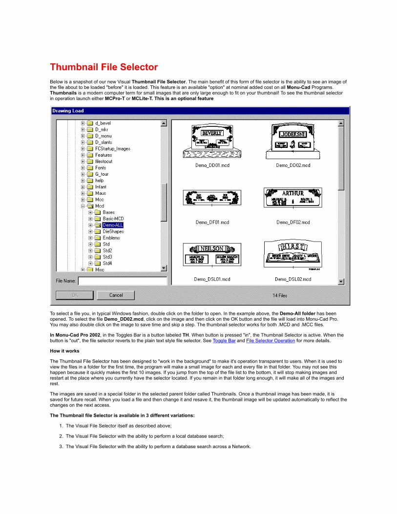
Thumbnail File SelectorBelow is a snapshot of our new Visual Thumbnail File Selector. The main benefit of this form of file selector is the ability to see an image ofthe file about to be loaded "before" it is loaded. This feature is an available "option" at nominal added cost on all Monu-Cad Programs.Thumbnails is a modern computer term for small images that are only large enough to fit on your thumbnail! To see the thumbnail selectorin operation launch either MCPro-T or MCLite-T. This is an optional feature
To select a file you, in typical Windows fashion, double click on the folder to open. In the example above, the Demo-All folder has beenopened. To select the file Demo_DD02.mcd, click on the image and then click on the OK button and the file will load into Monu-Cad Pro.You may also double click on the image to save time and skip a step. The thumbnail selector works for both .MCD and .MCC files.
In Monu-Cad Pro 2002, in the Toggles Bar is a button labeled TH. When button is pressed "in", the Thumbnail Selector is active. When thebutton is "out", the file selector reverts to the plain text style file selector. See Toggle Bar and File Selector Operation for more details.
How it works
The Thumbnail File Selector has been designed to "work in the background" to make it's operation transparent to users. When it is used toview the files in a folder for the first time, the program will make a small image for each and every file in that folder. You may not see thishappen because it quickly makes the first 10 images. If you jump from the top of the file list to the bottom, it will stop making images andrestart at the place where you currently have the selector located. If you remain in that folder long enough, it will make all of the images andrest.
The images are saved in a special folder in the selected parent folder called Thumbnails. Once a thumbnail image has been made, it issaved for future recall. When you load a file and then change it and resave it, the thumbnail image will be updated automatically to reflect thechanges on the next access.
The Thumbnail file Selector is available in 3 different variations:
1. The Visual File Selector itself as described above;
2. The Visual File Selector with the ability to perform a local database search;
3. The Visual File Selector with the ability to perform a database search across a Network.

Click Here for descriptions of the Thumbnail File Selector with Database Search Options
Click the BACK button to return to the previous page.

Thumbnail File Selector .....with Database Search This exclusive Monu-Cad feature will allow you to "ask the computer" to find for you any drawing (.mcd file) orcomponent (.mcc file) in your collection of files according to the search parameters that you enter. For example, youmay choose to ask the computer to "show you" all of the crosses in your computer which are less than 5 incheswide and 10 inches tall. In seconds, the search engine will show you thumbnail images of all the crosses that matchthis description without regard to what folder or directory these files may reside in! With this feature, every time youenter the command for a Drawing Load or Component Place, you may have the computer search for the desiredfile rather than manually hunting through all your files to find the desired one.
This feature is optional and you will only have it in your version of Monu-Cad Pro if you have ordered it.
Normal Thumbnail File Selector Screen
How it Works
In order for this technology to operate properly, a data sheet must first be filled out for each file that you desire tohave respond to search requests. On this data sheet you will enter or select the parameters that best describe thefile. If the contents is a cross, you enter the word cross as a keyword. Enter the word "hands" if the file contains aset of praying hands. When you click on the find button and enter the keyword "cross" and then click on the QueryButton (or press return), the program will find and show you thumbnail images of all the files in the database that theword "cross" has been entered as one of the keywords.
You may fill out all, some, a few or none of the data sheets. You don't have to do this all at one time. But the fewerdata sheets with data entered on them the less files will be found in a search. We suggest that you take a moderateapproach and take a moment every time you load a file to fill out the data sheet. With each data sheet filled out andadded to the database, the more productive the feature will become.

Individual File Data Sheets
If you place your mouse cursor over the thumbnail image of the contents of a .mcd or .mcc file and click your RightMouse Button, a data sheet for that particular file will appear as shown below. In this example, the data sheet for fileSTDR049.mcc is shown. (the red rectangle was added for emphasis)
In the File Properties section, the data sheet shows the file name and path, size, type and date last modified.
The Database Information section displays the Category selections and Keywords that have been entered forthis particular file, the extents (width and height) of the contents of the file and any descriptive comments that havebeen entered.
Note that the width and height is reset automatically every time you open and re-save the file. Many files arepreset to 48" x 36" as this was the default size entered when these files were converted over from the DOS version.We are adding a utility to our SatCheck program which will automatically open all your .mcd and .mcc files and resetthe size to the actual extents of the file. This utility should be available by the time you receive this documentation.
It is important to note here that you the operator will need to fill out a data sheet for every file you wish torespond to any database search queries you may make. Most records will be blank when the program isdelivered with the exception of possibly some sample or example entries.
Example Data Sheet Screen
Performing a Database Search
In the first image above you will see a button labeled "Find". Clicking on the Find button will change the screen tothat which you see below. The Database Query screen is blank because a search or query has not been made asyet.
Example "before" Database Query Screen

In our office sample database, many data sheets have been filled out for files that contain crosses and the word"cross" has been entered as a keyword in these data sheets. In the image below, you see the results of entering thekeyword "cross" in the keyword field on the Database Query screen followed by a click on the Query button. Notethat at the bottom of the window there is an entry that reads "323 files". In this particular search, the search enginefound 323 files which match the search description. This search took less than 3 seconds!
When the desired file is found, double clicking on the image will load the drawing if you were in the Drawing Loadcommand at the time you began the search. If you initiated the search while doing a Component Place command,double clicking on the image will select the component to be placed.
Example "after" Database Query Screen

Also notice that in this example, only the one keyword "cross" was used. Assuming that all the cross files have the correct size extentsrecorded, by dropping down the Width and Height combo boxes, we could have "narrowed" the search down to just crosses which weresmaller than a particular size!
Filling out the data sheets does not have to be an overly intense task. We have found that in actual practice specifying just one or twokeywords will be enough to get us the file we are looking for. The other 3 categories General, Type and Design are really optional.
Keywords
Keywords can include basic descriptive words such as car, truck, cross, and star. You are not limited as to what you type in but we have foundthat simple words will usually suffice. Dog and cat may be better choices than Greyhound, Persian or feline. As with most things, "KISS" or"keep it simple" is good advice. Pickup Truck is better than Pickuptruck.
Good keywords often include the name of a customer that uses that particular design. A search on ABC Granite will return all the filescommonly used by that customer.
Example "after" Database Query Screen "match all" search

Keyword Search Type
On the screen above, just below the keywords entry box are 2 check boxes:
Match any keyword will display any file which contains any one of the keywords entered
Match all keywords will display only those files which contain those exact specific keywords
The search type will depend on which check box is selected prior to clicking on the Query button or pressing the Enter key.
Keyword Shortcuts
You can also use global shortcuts in keywords. An example I often use the keyword "bull*" The star * character placed after the bull meansto the computer to show all files which have keywords which begin with the 4 letters "bull" and any other letters after the bull is acceptable.When we use this example in our sample database we get back images of a bull, bulldozer, bull elephant and bull dogs.
Create New folder Button
This feature will allow you to create a new folder or sub folder in which to move or create files without having to exit Monu-Cad and using aprogram like Explorer to create a new folder. There is no way to erase a folder from within the thumbnail file selector.
Moving Files
The thumbnail file selector will allow you to move files from one folder to another with the standard Windows "Drag and Drop" method. Simplyclick on the thumbnail image and drag it to the folder in the left pane of your choice.
When you use the file selector to move files, the database will automatically be updated. Without this feature, every time you move filesoutside of Monu-Cad the database would get messed up and loose track of where the files are. It is strongly recommended that you alwaysmove Monu-Cad files from within the thumbnail file selector rather than using an outside program.
Deleting Files
If you right click on the thumbnail image of a file and then press the Delete key on your keyboard you may erase files from within theThumbnail File Selector. Erasing files this way will help keep the database in synch.

Clean Up Database Button
Should you erase or move files outside of the Monu-Cad file selector, the database will not know that they have been moved or are gone.Clicking on this button will synchronize the database with the actual files present. This prevents the database from growing very large andcontaining many records for non existing files and suffering a performance penalty.
"Clean up Database" doesn't have to be used every time you move files. It should only be used to eliminate erased items from the databasewhen the database doesn't know they were erased because MCPro wasn't used to do the erasing.
Technical Considerations
The database information and data is contained in a file called MonuCad.mdb. It is located in the \MONU-CAD_Win'95 folder. This file mustbe located in this folder in order for the database feature to operate properly. An empty database file (MonuCad.mdb) is shipped with yourcopy of Monu-Cad Pro and is automatically installed in the local folder where it is designed to be placed. Note that this file is necessary to theprogram operation. If this file is not present, Monu-Cad Pro will not automatically create an empty database to use. Remember to include thisimportant file in your backup procedure.
All .mcd and .mcc files must be placed in folders which are located as sub folders to the \MONU-CAD_Win'95 parent folder. In computerspeak, all sub folders containing .mcd and .mcc files must be "children" of the \MONU-CAD_Win'95 parent folder. If you create a folder forexample C:\My_Drawings and place files into it, the database search feature will not recognize that these files exist.
Program Naming Conventions
Versions of Monu-Cad Pro 2000 which have the database search feature will have the suffix -TD or -TDn added to the program name.(MCPro-TD or MCPro-TDn). The main difference is that the "n" means that this particular version will function over a Local Area Network.
Network Use Considerations
In order for the network version to operate properly, the server computer must have a Parent Folder named \MONU-Cad_Win'95 and the.mcd and .mcc files must be placed in folders that are children of this parent folder.
A separate MonuCad.mdb file must be copied to the server parent folder to hold the data information for the .mcd and .mcc files located onthe server. When the client accesses files on the server, the .mdb file on the server will serve up the database information. When local filesare accessed, the .mdb on the local client computer will supply the information. Thus, when working in a client / server network, there will beone master .mdb file on the server and a local one on each client.
For the Network drive to appear in the Thumbnail Selector Tree, the Network drive must be mapped (mounted) to a local drive on the clientcomputer.
Note to advanced users!
Simply stated, this is the first time that this kind of a tool has been made available in a Monument CAD program. We at Monu-Cad arelearning as we go along in the same way you are. Any comments or suggestions you may have are welcome. Email all comments [email protected]

TOTolerance
The Tolerance command Located in the Controls Menudetermines the size of the search area around the cursorintersection within which a Snap may occur. Thiscommand is used to set this value for use with the SnapCommands found in the Snaps Menu.
The value of the tolerance, which determines how largean area the program should search, is measured on thevideo monitor, not in the scale of the drawing. Thatmeans that if the tolerance is set to .25 (1/4"), you alwayshave to be within a quarter of an inch on the screen ofthe point you want to snap to, no matter what the zoomvalue.
To set the tolerance value, select the Tolerancecommand or type TO. You will be shown the currenttolerance value and asked for a new one. To keep thecurrent value, press ENTER or click OK. To give a newvalue, type a number, followed by ENTER. The defaultTOLERANCE value is .25 (1/4"), and the TOLERANCEcannot be set to values greater than 1".

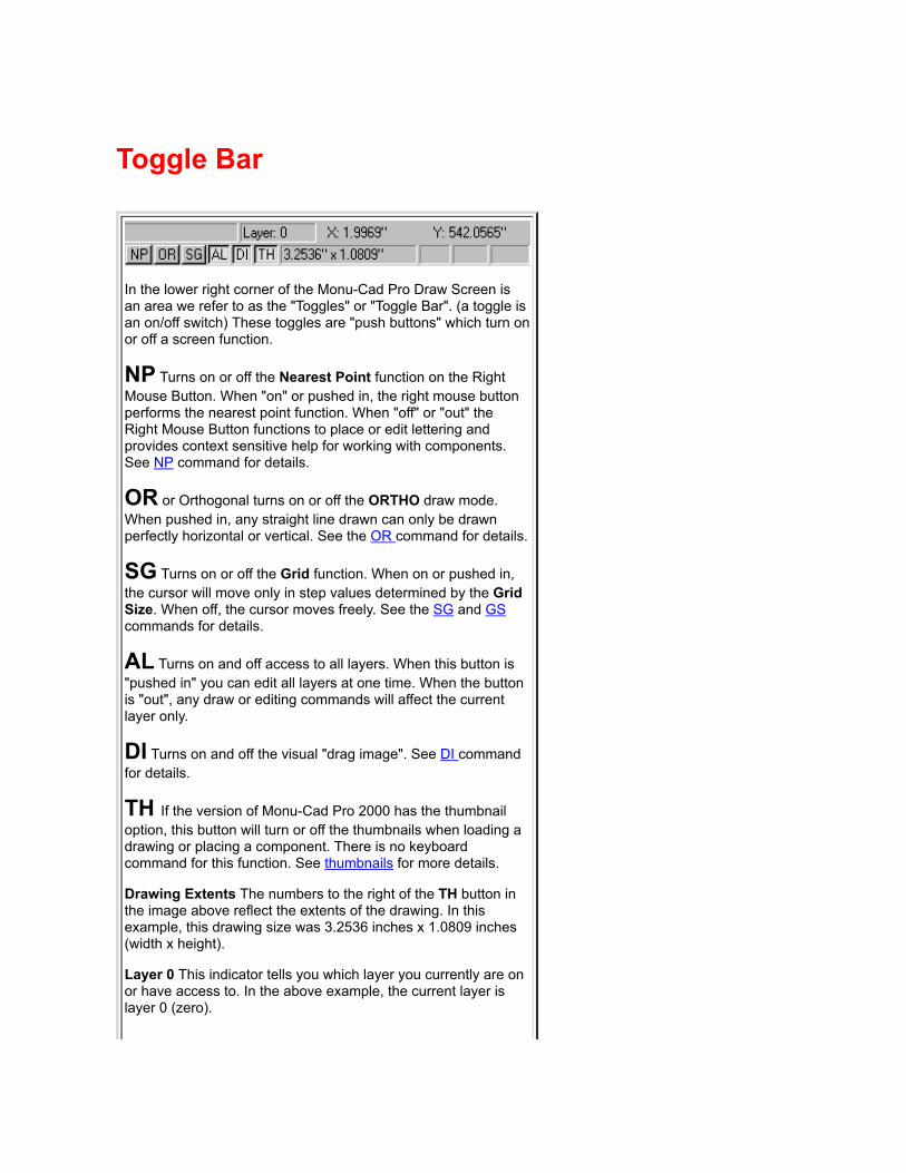
Toggle Bar
In the lower right corner of the Monu-Cad Pro Draw Screen isan area we refer to as the "Toggles" or "Toggle Bar". (a toggle isan on/off switch) These toggles are "push buttons" which turn onor off a screen function.
NP Turns on or off the Nearest Point function on the RightMouse Button. When "on" or pushed in, the right mouse buttonperforms the nearest point function. When "off" or "out" theRight Mouse Button functions to place or edit lettering andprovides context sensitive help for working with components.See NP command for details.
OR or Orthogonal turns on or off the ORTHO draw mode.When pushed in, any straight line drawn can only be drawnperfectly horizontal or vertical. See the OR command for details.
SG Turns on or off the Grid function. When on or pushed in,the cursor will move only in step values determined by the GridSize. When off, the cursor moves freely. See the SG and GScommands for details.
AL Turns on and off access to all layers. When this button is"pushed in" you can edit all layers at one time. When the buttonis "out", any draw or editing commands will affect the currentlayer only.
DI Turns on and off the visual "drag image". See DI commandfor details.
TH If the version of Monu-Cad Pro 2000 has the thumbnailoption, this button will turn or off the thumbnails when loading adrawing or placing a component. There is no keyboardcommand for this function. See thumbnails for more details.
Drawing Extents The numbers to the right of the TH button inthe image above reflect the extents of the drawing. In thisexample, this drawing size was 3.2536 inches x 1.0809 inches(width x height).
Layer 0 This indicator tells you which layer you currently are onor have access to. In the above example, the current layer islayer 0 (zero).

Cursor Position The numbers directly above the extents reflectthe X and Y coordinates of the current position of the cursor onthe screen. This changes as you move the mouse.
NUM This is a Windows thing and not really part of the Monu-Cad program. In this example it means that the Numbers Locktoggle on the keyboard is set to "on". It may also read CAPS ifyour caps lock key is on and SCRL if your scroll lock key is on.

Toolbar CommandsIn addition to the menus at the top there is also a "shortcut tool bar".Monu-Cad Lite!
Monu-Cad Pro 2000
These 14 icons provide quick ways to perform 14 common tasks. Simplyclicking on these icons (small images) will begin the command.
Drawing Erase (DX) goto
Drawing Load (DL) goto
Load Drawing Variation (D2) goto
Load Next "Slide Show" Design (D3) goto
Component Place (CP) goto
Drawing Save (DS) goto
Drawing Print (DP) goto
Zoom Window (ZW) goto
Zoom Previous (ZP) goto
Pan (PA) goto
Zoom All (ZA) goto
Redraw (RD) goto
Change (DG, OG, WG, YG) Monu-Cad Pro 2000 only
Fill Button turns on and off fills and hatches


TTTrue Type Font
Import(Version 3 only)
This very powerful command will allow you to import a Windows True Type Font (TTF) into the Monu-Cad Click &Type Lettering System. The TT command will allow you to select the True Type font to import, select the prefix to beused for the components, select which character in the font on which to base the 1" letter height, select the font namewhich will appear in the Click & Type font list and select the file name to be used for the font and spacing table files.
Once these selections have been made, the command will extract the True Type Font outline data, create 1" highindividual component letters from the data, measure the length of the letters, place the insertion points on the baseline at the center of the letter and display the resulting 256 letters on the MCPro draw screen. The function will thenautomatically add the font name to the MCFonts.lst file and save the .fnt file and .dta files to the hard disk drive in the\Fonts folder. Whatever spacing information available in the True Type Font will be carried over into the .dta file.
To begin the process, from a new blank drawing session enter the 2 letter command TT. The dialog box shownbelow will appear.
If you just wish to see the command "do it's stuff" without making any permanent changes, simply enter 3-8characters in the Prefix edit box, do not check the "Add to Font List" check box and then click the OK button.
If your system contains the Abadi MT Condensed font as depicted above, the letters will appear on the screen asshown below, 256 characters in all, 16 characters per line. Go ahead, give it a try!

Pretty amazing isn't it?
A TT font consists of 256 characters that comprise the standard computer ASCII alphabet. These characters arenumbered from 0 to 255 in standard computer form. The first 32 characters are "control" characters used mainly ininternal computer functions and there is no real character to be displayed. That is why the first 2 rows of characters inthe above example are represented by rectangles. Most True Type fonts will have some "place holder" in these first32 spaces. These characters will be ignored.
The components created by this routine will be named with the Prefix characters you entered above plus the ASCIIcharacter number. For example, the capital letter "A" is character 65. If you entered the prefix ABA in the Prefixedit box, the Capital A component will be named ABA65.mcc The Capital B would be ABA66.mcc, the small letter"a" ABA97.mcc and so on. The alphabet therefore actually begins with character #32 which is a space
To permanently add a TT font to the Monu-Cad Click & Type lettering system, in addition to specifying acomponent prefix, you must check the "Add to Font List" check box. Checking this box will allow you to enter the FontName that you wish to appear in the Click & Type font selection list. We request that you select a name of fewer than20 characters in order to fit the space available. The name you choose to enter in the File Name edit box will be the

name used for the .fnt and .dta files which are placed in the \Font folder. A short name such as the name used forprefix will help you to locate them more easily in the future.
More about 256 character fonts
The way that the IBM PC is designed, one cannot type directly on the keyboard any characters which are a characternumber greater than character 127. For example, there are no keys present for these and other characters such asê Ç ü â which have character numbers greater than 127. These characters above #127 are known as the"Extended Character Set". Keyboards used on computers in non American English speaking countries do havekeys for these extended characters and the keyboards have a different key mapping scheme. You may have seen akeyboard in England with the Pound or Euro character on it instead of the Dollar sign. Spanish and other languagekeyboards have man more. The actual character that appears when you enter an extended character depends onthe design of the particular font. You can pretty much depend on the first 127 characters to match the ASCII Chartbut characters 129-255 depend on the font designer.
If there are no keys then how do you get these characters to appear? Well, the IBM PC provides a ratherconvoluted way but I guess we should be thankful that at least there is a way. To access these characters you firsthold down the Alt key on the keyboard. Then, on the Numeric Keypad (on the right side of the keyboard) you enterthe 3 numbers of the desired character example 128, 129.....254, 255 etc preceded by a 0 (0128, 0129, 0254). Whenyou release the Alt key, the character will appear. You cannot use the keys that are on the top of the keyboard. Youmust use the numeric keypad. Fortunately, you will not have to use these characters very often. This is how you willbe able to use these characters in Monu-Cad Click & Type.
(You can also use this technique in any Windows word processor. However, remember that the character shape thatwill appear will depend on the font you have selected. )
Tip:
To remove a font name from the MCFonts list, you will have to manually edit that file with a word processor such asNotepad.
Special Note!!In the TTF Conversion Menu shown above, you will notice a small edit box which reads "Size based on [65]". Sincethe character #65 is the Capital Letter A, the size of all letters will be in proportion to the letter A measured at a heightof 1 inch. As many of you know, the letter A often extends above the average height of the rest of the letters in theAlphabet. You might consider running the TTF converter through once on a trial run for each font you desire to importjust to see if perhaps you could select another letter on which to base the height. A letter D, E or H might be a betterchoice depending on the style of the imported font. Failure to pay attention to this detail could result in letterswhich are actually shorter than you expect. For example, 1" high letters could in fact be 7/8" high or some otherfraction.
True Type fonts, while stylish, were not created with sandblasting in mind. You will find that many attractive fontswhen used in monumental work will have areas in the letters which will not be sandblastable. At best, many of thesefonts will simply provide a starting place for you to create your own font using the TTF as an example or inspiration.

UnitsOverview
(Version 3.31 only)
IN
FT
FI
MM
CM
MT
DE
DV
FR
FV
New in Version 3.31 is the ability to change the Unit Values used to display measurements and coordinates.MSDOS users will find this feature very similar to the DOS version.
The default unit value is Decimal Inches.
Unit values are changed immediately upon entering the appropriate command. For example, entering thecommand FT will change the display to show distances in decimal amounts with the largest unit being the Foot(ft). 6 inches will be displayed as .5 feet.
At any time to return to the default values, on the keyboard enter DE IN and the default values will be restored.
Note!!Upon entering the Click & Type® lettering system, all measurements will default to decimal inches. When youreturn the the draw screen the previous setting will be restored.


UtilitiesClick on one of the links below to select that Utility Program's information page.
Convert95.exe
UpgradeKL.exe
New MCScan
MonuPaint
(old)
MONUSCAN
(old)
Remote3
MonuCut95
Click your BACK button to return to the previous page.

UUREDO
The REDO (UU) command will reverse theaction of the UNDO (OO)command.
The Redo command is located in the EditsMenu. The quickest way to use it is to typeUU on the keyboard.
To try it out, draw a line on the drawscreen. Then type OO and the line willdisappear. Then type UU and the line willreappear.
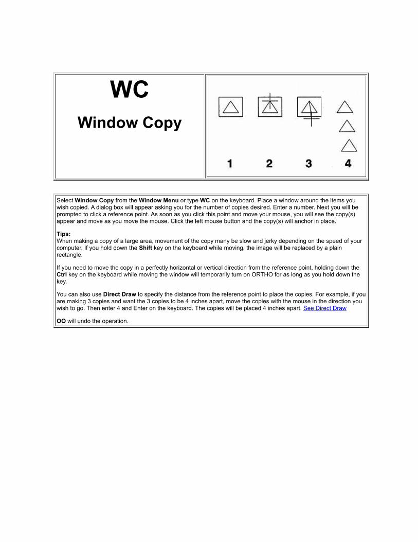
WCWindow Copy
Select Window Copy from the Window Menu or type WC on the keyboard. Place a window around the items youwish copied. A dialog box will appear asking you for the number of copies desired. Enter a number. Next you will beprompted to click a reference point. As soon as you click this point and move your mouse, you will see the copy(s)appear and move as you move the mouse. Click the left mouse button and the copy(s) will anchor in place.
Tips:When making a copy of a large area, movement of the copy many be slow and jerky depending on the speed of yourcomputer. If you hold down the Shift key on the keyboard while moving, the image will be replaced by a plainrectangle.
If you need to move the copy in a perfectly horizontal or vertical direction from the reference point, holding down theCtrl key on the keyboard while moving the window will temporarily turn on ORTHO for as long as you hold down thekey.
You can also use Direct Draw to specify the distance from the reference point to place the copies. For example, if youare making 3 copies and want the 3 copies to be 4 inches apart, move the copies with the mouse in the direction youwish to go. Then enter 4 and Enter on the keyboard. The copies will be placed 4 inches apart. See Direct Draw
OO will undo the operation.

WEWindow Erase
The WINDOW ERASE command is a more powerful version of the OBJECT ERASE command, because you canerase everything that you can place a window around.
Select the Window Erase command from the Window Menu or type WE. You will be asked to place a window, whichis done in the same way as any of the window commands; indicate a window by showing one corner, stretch it to fitaround the objects to be erased, and select the other corner.
All objects that fit entirely within the window will be erased. Any objects which hang out of the window, even slightly,will not be erased. Note that if the reference point of a component is outside of the window, no part of the componentwill be erased.
If you make a mistake, use the UNERASE UE or OO commands to restore the drawing.

WFWindow Fill
(Version 3 only)
The Window Fill command is a simple 3 step process:
1. Type WF or click on the Window Fill command in the Render Menu
2. Place a window around the design to be filled
3. The design sandblast lines fill from the outside in.
The color of the fill is determined by the current line color. See LK Command
Note!!
In order for the fill to occur as pictured above, all lines must be continuous with no breaks in the lines. There also must not be anysingle lines crossing the outside line border or any spaces to be filled.

Note!!
Fills will not display if Fills Button on the Tool Bar is not pressed in Fills by default are placed on Layer 9. If Layer 9 is turned off, fills will also not display.
Tip:
Lettering groups cannot be filled unless you explode the group itself and then the letters inside the group. Components cannot be filledunless they are exploded.

WGWindow Change
This is one of the Change commands all of which produce the same menus and prompts.
When you type DG, WG or OG, the dialog below pops up:
From this dialog you may elect to change the color of the objects selected, the layer that they are on and or the linewidth. At this time, line types are not supported.
Simply enter the value(s) you desire to change and enter OK. OO will UNDO this command.
If you elect to change the color of the objects the added dialog below will appear:

With the WINDOW CHANGE command, you can change the line color, line width, or layer of any object. When youchoose the WINDOW CHANGE command or type WG, you will get a typical window command prompt: Place awindow around the objects that you wish to change.

Why sometimes MCLite vs. MCPro?
The Monu-Cad Lite! program is actually an abbreviated version of Monu-Cad Pro 2000.
There are many commands that are shared between the two programs.
In this manual we often load the information page for Monu-Cad Lite! when you are searching for helpin Monu-Cad Pro 2000 because the information is identical.
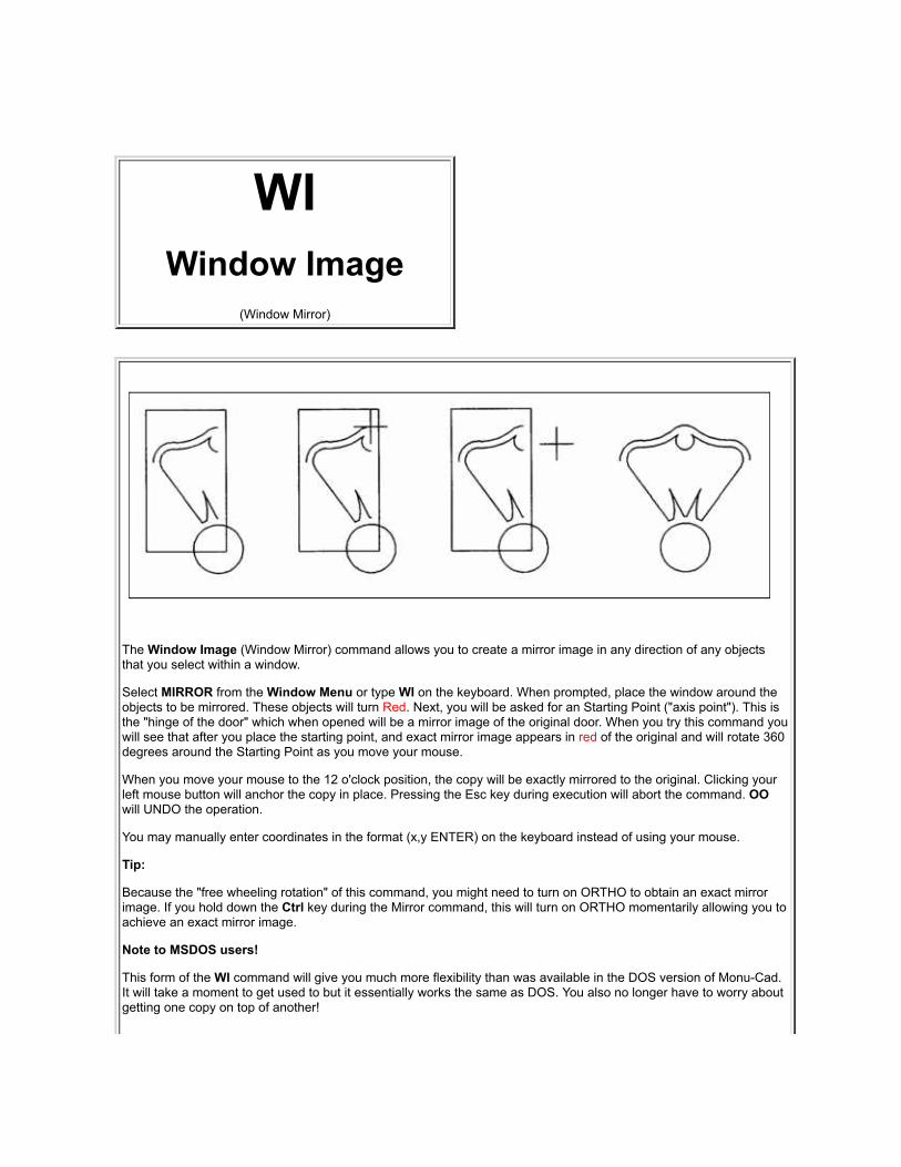
WIWindow Image
(Window Mirror)
The Window Image (Window Mirror) command allows you to create a mirror image in any direction of any objectsthat you select within a window.
Select MIRROR from the Window Menu or type WI on the keyboard. When prompted, place the window around theobjects to be mirrored. These objects will turn Red. Next, you will be asked for an Starting Point ("axis point"). This isthe "hinge of the door" which when opened will be a mirror image of the original door. When you try this command youwill see that after you place the starting point, and exact mirror image appears in red of the original and will rotate 360degrees around the Starting Point as you move your mouse.
When you move your mouse to the 12 o'clock position, the copy will be exactly mirrored to the original. Clicking yourleft mouse button will anchor the copy in place. Pressing the Esc key during execution will abort the command. OOwill UNDO the operation.
You may manually enter coordinates in the format (x,y ENTER) on the keyboard instead of using your mouse.
Tip:
Because the "free wheeling rotation" of this command, you might need to turn on ORTHO to obtain an exact mirrorimage. If you hold down the Ctrl key during the Mirror command, this will turn on ORTHO momentarily allowing you toachieve an exact mirror image.
Note to MSDOS users!
This form of the WI command will give you much more flexibility than was available in the DOS version of Monu-Cad.It will take a moment to get used to but it essentially works the same as DOS. You also no longer have to worry aboutgetting one copy on top of another!

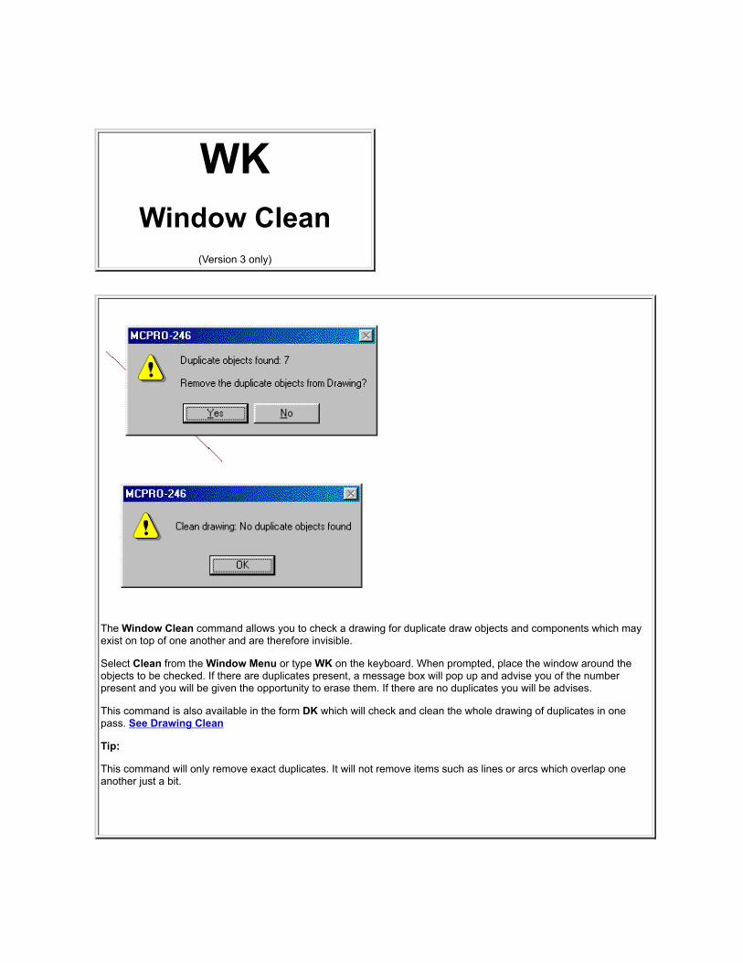
WKWindow Clean
(Version 3 only)
The Window Clean command allows you to check a drawing for duplicate draw objects and components which mayexist on top of one another and are therefore invisible.
Select Clean from the Window Menu or type WK on the keyboard. When prompted, place the window around theobjects to be checked. If there are duplicates present, a message box will pop up and advise you of the numberpresent and you will be given the opportunity to erase them. If there are no duplicates you will be advises.
This command is also available in the form DK which will check and clean the whole drawing of duplicates in onepass. See Drawing Clean
Tip:
This command will only remove exact duplicates. It will not remove items such as lines or arcs which overlap oneanother just a bit.

WMWindow Move
When you choose the Window Move command from the Window Menu or type WM on the keyboard, you are askedto place a window. Put the window around the objects that you wish to move. The objects completely within thewindow will turn Red.
You will then be asked to indicate a reference point in the window. Just click your left mouse button somewhere insidethe window. After you click this reference point, when you move your mouse, the contents of the window will movevisually with your mouse movements. When you have moved the objects to their desired location, click your leftmouse button to anchor them in place. The reference point you originally placed will be located at the coordinateswhere you click the final anchor point.
To abort the command press the Esc key on the keyboard.
You may manually enter X and Y coordinates on the keyboard (instead of using the mouse) in the format (x,y Enter) tospecify exact coordinates of the desired reference and anchor points.
After selecting these two points, all of the objects which are entirely within the window will be moved by the distancesindicated, and objects which are hanging out of the window will not be affected, with this exception:
Note to former MSDOS users!
You will notice that there is not a Straight Line Stretch option. This has been removed from this command andreplaced with the separate SS (Window Stretch) command.see SS command
Tip:
You might want to hold down the Ctrl key during this operation to temporarily turn on ORTHO to keep the movementin a straight line or if the object is large turn off the image with the Shift key.
Don't forget to try Cursor Movement with this command!
Also, this is a good place to use Direct Draw. Entering a number followed by Enter instead of the last point will placethe objects an precise distance from the original position.
OO will UNDO this command

WRWindow Rotate
The Window Rotate command allows you to rotate (turn) any objects that you can capture within a window, withoutfirst making them a component or doing anything else to them.
Select Window Rotate from the Window Menu or type WR on the keyboard. Indicate the two corners of a window.All of the objects that are completely inside the window will turn Red. Next, you will be asked for an axis point in thewindow. This is the point around which all of the objects in the window will rotate. It works as though you put a nailthrough the drawing at this point, and turned a piece of paper with only the objects in the window on it around the nail.The axis point is the nail. Click your left mouse button on the desired axis point. After specifying the axis point, as youmove your mouse around, the window will rotate visually. Once you have attained the desired rotation angle, clickyour left mouse button again and the objects will become anchored at that selected angle.
If during the command you wish to abort the process, simply press the Esc key.
Note! after you have entered the axis point, if you desire to rotate the window an exact degree value, simply enter thatvalue on the keyboard and press the ENTER key. For counter clock wise rotation, enter a positive value; Clockwiserotation a negative value (Example, 45 or -45)

WSWindow Save
This command allows you to save part of your currentdrawing onto a disk as a separate drawing (.mcd) file.
To save the contents of the window as a drawing file,select the Window Save Command from the WindowsMenu or type WS on the keyboard. Place a windowaround the part of the drawing you wish to save. Next,you will be shown the current name of the drawing. If thisis the name you want to use to save the contents of thewindow as, press ENTER or click OK. To save thecontents of the window under a different name, type anew name then press ENTER or click OK. The contentsof the window will be saved as a drawing file on the disk.This operation is almost the same as the Drawing Save(DS) command except that instead of the whole drawingonly the contents of the window is saved.
It is usually a good idea to type a new name, rather thanusing the same name as the current drawing, unless thisis really what you want to do.
Once you have saved the window, it can be called up asa separate drawing, and you can edit it independently, orload it into another drawing using the Drawing Load (DL)command.
If the Show File Security Options feature is turned on the CONFIG menu, then the file security options menu willpop up before the save takes place.


WVWindow conVert
(Version 3 and later only)
The Window conVert command allows you to change a window full of straight lines into lines and arcs automatically.Please excuse the odd spelling of the command. We are beginning to run out of 2 letter combinations.
Select Convert from the Window Menu or type WV on the keyboard. When prompted, place a window around theobjects to be converted. These objects will turn Red. The command will automatically begin changing line segmentsinto arcs where applicable and draw them on the screen in Blue over the top of the red lines. When the command isfinished, you will see to almost duplicate drawings on top of one another ... the original in Red and the converteddrawing in Blue.
Upon completion of the conversion, a message box will pop up on the screen asking you to Accept or Cancel. If youaccept the changes, the Red original lines will be erased. If you click on Cancel, the command will abort. thiscommand cannot be reversed with the OOPS command.
Tip:
As with most commands which perform a mathematical conversion from one draw object to another, there may besome slight differences between the original and end result. We accept this as normal and do not get excited orconsider this to be a bug. Expect some differences and manually change those items which may convert differently.
This command was intended primarily to be used along with the HPGL import command to allow conversion of a plotfile drawing made of all straight lines into something which can be scaled up if needed. However, use yourimagination. We are sure you will find many uses that are much different than the designers original intentions.
See HPGL Import


WWWindow Weld
Before - After
The Window Weld Command is a new feature first introduced in a Fall,1999 version ofMonu-Cad Pro 2000. The purpose of the command is to allow you to place a componentover the "top" of a section of a drawing and with one simple command, join the componentto the drawing removing the part of the drawing "under or behind" the component.
First place a component over the top of the section of the drawing you wish to "Weld" itto.
Second, left click on Weld in the Window Menu or enter WW on the keyboard. Place thewindow around the component. You will see the lines touching the component turn Blue.
Third, left click on the perimeter (outside border) of the component to select it. It will turnRed. If the border of the component is one continuous unbroken path, the entire borderwill turn red with just this one click.
Finally, enter Return on the keyboard. The welding operation will occur as you watch.Upon completion, a dialog box will appear giving you the opportunity to accept the resultsor cancel. Accepting the result is final and cannot be undone with the OO (UNDO)command.
Some fine points:

When selecting the perimeter of the component, holding down the Ctrl key while selectingwill allow selection or deselection of additional individual lines, arcs or circles. Clicking ona Red object a second time will deselect it.
Remember....component on top....drawing on bottom. If you need to weld 2 componentstogether, first explode the one on the bottom.
For this command to work properly, the outside perimeter of the component mustbe one continuous path of connected lines, arcs and circles.

WZWindow Scale
The WINDOW SCALE command changes the size and proportions of objects within a window.
Select Scale from the Windows Menu or type WZ on the keyboard. Indicate the two corners of a window around theobjects you want to re-scale. You will then be asked for a reference point in the window. This is a fixed point to whichall of the objects in the window will be referenced. This one point will stay put, while all the objects will be scaled up ordown around it.
Once you have placed this point, the objects in the window will dynamically "shrink and grow" as you move themouse. When the desired size is attained, click the left mouse button to make the change permanent.
As an alternate method, after specifying the reference point, you may type in a value for the X and Y scale on thekeyboard. Upon entering the Y value followed by a return, the objects will be scaled exactly that amount. If youspecify an X scale factor of 2, for example, the objects will all become twice as long, while if you choose a Y scalefactor of .5, all objects in the window will become half as tall. Notice that selecting different X and Y scale factorschanges not only the size of the objects but their proportions as well. After you have given the X and Y scale factors,the selected objects will be re-scaled.
It is possible to turn the objects upside down and/or inside out by selecting negative scale factors. Notice that if the Xand Y scale factors are different, Arcs and Circles may not scale the way that you want them to.

XAExplode All
(Version 3 only)
This command will Explode all lettering groups andcomponents in a drawing file.
1. The first time you enter the command, after thewarning message pops on the screen and youanswer OK, all lettering groups and componentswill be exploded. However, the letters inside thelettering groups will not be exploded.
2. The second time you issue the command, theletters themselves will be exploded.
Tip:
It may not be necessary to use the command twice. Itwill depend on what you r intentions are.
This command has been included in order to provide aquick way to explode everything to preserve the styleand spacing of the lettering when you wish to send adrawing to another Monu-Cad Master User who may nothave your lettering styles or spacing tables.

XPExport
This command has been designed to allow the operator to export the data contained within a Monu-Cad drawingin one of 2 forms: Bit Mapped and Vector formats.
Exporting Bitmap ImagesA bitmapped image is an image consisting of dots which when printed on paper or displayed on a computerscreen describe the originating drawing. This form of image creation has many important usages.
Exporting a bit mapped image may be done in one of 3 ways:
1. You may export the image to the Windows Clipboard so you can then paste it into another program
2. you can save it to a file on your Hard Disk Drive in one of 4 popular formats
3. you may directly save it as a .jpg image and have Monu-Cad Pro launch your Email program and attachthe image to a new email message!
To Use the Export Command you must type XP on the keyboard. There is no menu option for thiscommand.
After typing XP, the following image will appear:
You may click on Bitmap, Vector, eMail Drawing or Cancel buttons.
For the moment lets assume you want a bit mapped image output and you have clicked on the Bitmap button. The next dialog menu will appear:

You may select any one of 5 preset sizes or user selected size. If you click on user selected size and then Next, aspecial dialog will appear: Click here for details
In this menu you may select an output size. We have defaulted the size to 640 x 480 pixels which is a commonand popular size image. Note that you can also force any images that have colored lines in them to Black andWhite by checking the Grayscale button. Assuming you click on the Next button, the following dialog appears:
If you click on the Clipboard option, the image will be copied to the clipboard and the acknowledgment of asuccessful transfer of data will follow:
If you select the File Save Dialog option, a common file selector dialog will appear:
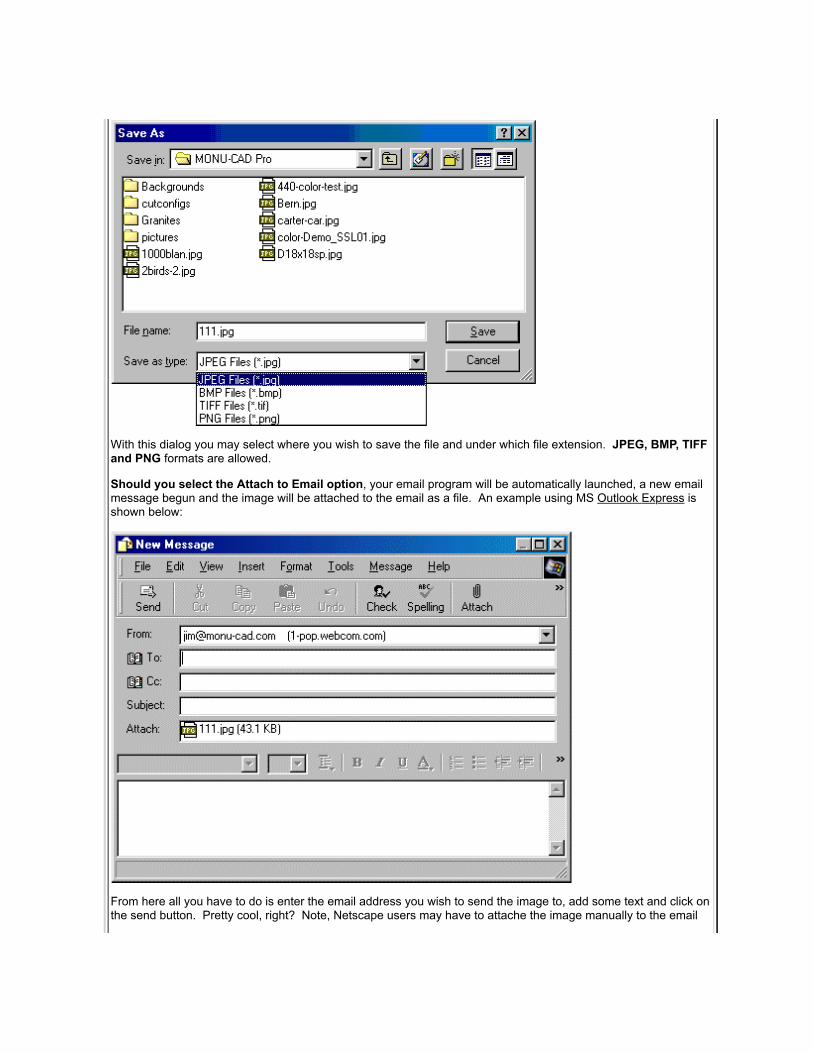
With this dialog you may select where you wish to save the file and under which file extension. JPEG, BMP, TIFFand PNG formats are allowed.
Should you select the Attach to Email option, your email program will be automatically launched, a new emailmessage begun and the image will be attached to the email as a file. An example using MS Outlook Express isshown below:
From here all you have to do is enter the email address you wish to send the image to, add some text and click onthe send button. Pretty cool, right? Note, Netscape users may have to attache the image manually to the email

message. We recommend using MS Outlook Express for this feature to work properly.
User Selected Size
This dialog will allow you to select the output size, color depth, print resolution andoutput file format. The purpose of this dialog is to allow users with Laser Etchingmachines to output a 1:1 image and save it to a file. Only file save is allowed if youselect this option.
Exporting Vector ImagesOne Vector format is supported in this version of Monu-Cad Pro ... .DXF. This stands for Drawing ExchangeFormat which is the most common CAD exchange file format.
After you type XP, the following dialog will appear:
Click on the Vector button and a common file selector dialog will appear as shown:

You now may select the drive and folder where you wish to save the .DXF file.
DXF File Export Limitations
Monu-Cad Pro as shipped will only allow the export of about 50 vectors to a .DXF file. This is enough to allowthe user to export a monument shape for use on a Contour Wire Saw. However, this is not enough to export afloral carving or full monument design. This limitation is by design.
A special license for full DXF exporting capabilities will be made available to users who request this ability andobtain a full export licensing agreement. Please contact the Monu-Cad Office for complete details.
Color Changes
All CAD programs use a different color numbering system. For example, a Blue line in Monu-Cad is color #1. However, another CAD program may have Yellow or some other color designated as color #1. When you exportor import .DXF files, expect there to be some color changes.
Lettering Groups
Lettering Groups will not export to a DXF file. To export lettering you must first explode the lettering groups usingthe OX, CE or XA commands.
eMail DrawingThis option will email the .MCD file to the person the email is addressed to. The procedure is exactly like theprocedure to email a bitmap image except that the program will save the file (like a Drawing Save DS command)before popping up the email message.
See the IP Import command for importing DXF files
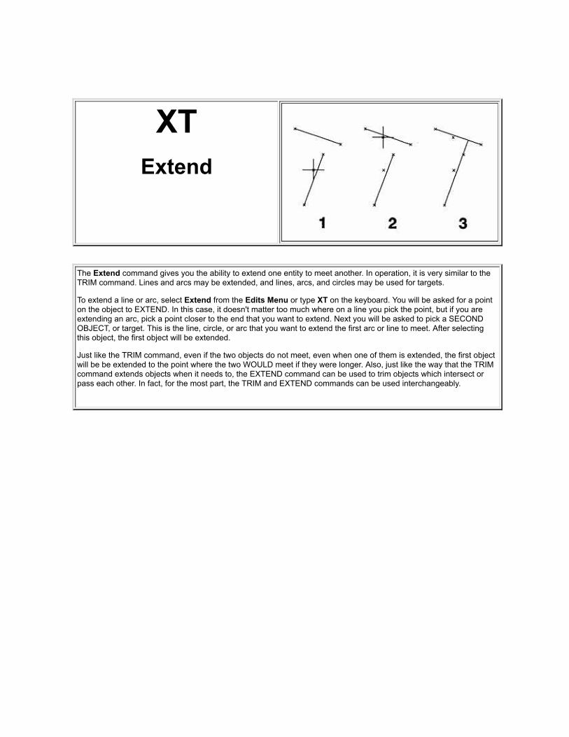
XTExtend
The Extend command gives you the ability to extend one entity to meet another. In operation, it is very similar to theTRIM command. Lines and arcs may be extended, and lines, arcs, and circles may be used for targets.
To extend a line or arc, select Extend from the Edits Menu or type XT on the keyboard. You will be asked for a pointon the object to EXTEND. In this case, it doesn't matter too much where on a line you pick the point, but if you areextending an arc, pick a point closer to the end that you want to extend. Next you will be asked to pick a SECONDOBJECT, or target. This is the line, circle, or arc that you want to extend the first arc or line to meet. After selectingthis object, the first object will be extended.
Just like the TRIM command, even if the two objects do not meet, even when one of them is extended, the first objectwill be be extended to the point where the two WOULD meet if they were longer. Also, just like the way that the TRIMcommand extends objects when it needs to, the EXTEND command can be used to trim objects which intersect orpass each other. In fact, for the most part, the TRIM and EXTEND commands can be used interchangeably.

YCLayer Current
(Version 3 only)
Anything that you draw can be considered to be onsome layer. The default layer is 0. There can be up to1024 layers, numbered 0-1023. Each layer can bedisplayed on the screen or hidden.
Whenever you draw, the layer that you are putting linesonto is called the current layer. Everything that you drawwill be drawn on this layer with these exceptions:
Lettering is placed on Layer 1
Dimensions are placed on Layer 8
Render Fills are placed on Layer 9
Objects that have been drawn on one layer can bemoved to another layer using the OBJECT CHANGE orWINDOW CHANGE commands.
To select a new current layer, choose the LAYERCURRENT command or type YC on the keyboard. Youwill be asked which layer you want to be the currentlayer. Type a number, followed by ENTER. If the layerthat you select is not currently displayed, the screen willbe redrawn to show the new current layer. Until youchange the current layer again, everything that you drawwill be placed on the layer that you have just chosen,and any editing command you use will only work onobjects on this layer, unless ALL LAYERS EDIT is on.

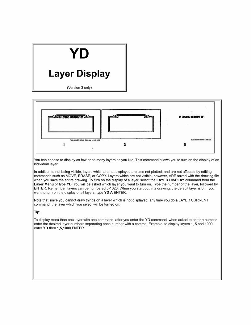
YDLayer Display
(Version 3 only)
You can choose to display as few or as many layers as you like. This command allows you to turn on the display of anindividual layer.
In addition to not being visible, layers which are not displayed are also not plotted, and are not affected by editingcommands such as MOVE, ERASE, or COPY. Layers which are not visible, however, ARE saved with the drawing filewhen you save the entire drawing. To turn on the display of a layer, select the LAYER DISPLAY command from theLayer Menu or type YD. You will be asked which layer you want to turn on. Type the number of the layer, followed byENTER. Remember, layers can be numbered 0-1023. When you start out in a drawing, the default layer is 0. If youwant to turn on the display of all layers, type YD A ENTER.
Note that since you cannot draw things on a layer which is not displayed, any time you do a LAYER CURRENTcommand, the layer which you select will be turned on.
Tip:
To display more than one layer with one command, after you enter the YD command, when asked to enter a number,enter the desired layer numbers separating each number with a comma. Example, to display layers 1, 5 and 1000enter YD then 1,5,1000 ENTER.


YGLayer Change
(Version 3 only)
The LAYER CHANGE command allows you to change certain properties of all simple objects on a particular layer.These properties include the line color,line width and the layer. You can change any or all of these with one LAYERCHANGE command.
Select the CHANGE command from the Layer Menu or type YG. You will first be asked which layer you wish tochange. All objects on the layer that you select will be affected by the changes. Then the following menu will appear:
See the change commands for details. Click Here


YHLayer Hide
(Version 3 only)
Just as you can turn on the display of individual layers with the LAYER DISPLAY command, you can turn off thedisplay of layers with the LAYER HIDE command.
Remember that layers which are not displayed are also not affected by most editing commands. The DRAWINGERASE command is an exception. This command will erase even layers which are turned off.
To turn off the display of a layer, select the HIDE command from the LAYERS menu or type YH on the keyboard. Youwill be asked which layer you want to turn off. Type a number, followed by ENTER. If you want to turn off the displayof all layers (more on that in a moment), type YH A ENTER.
Tip:
To hide more than one layer with one command, after you enter the YH command, when asked to enter a number,enter the desired layer numbers separating each number with a comma. Example, to hide layers 1, 5 and 1000 enterYH then 1,5,1000 ENTER.
From time to time, you might want to view a single layer. The easiest way to do this is to first go to the layer that youwant to see with a LAYER CURRENT command, then use the LAYER HIDE command to turn off all layers. Thecurrent layer will stay visible, because you can't hide the current layer.

YLLayer Load
(Version 3 only)
This command allows you to load onto a selected layer in the current drawing any drawing previously saved on a disk.It doesn't matter whether the drawing to be loaded was originally saved with the DRAWING SAVE, LAYER SAVE, orWINDOW SAVE command.
To load a drawing, select the LAYER LOAD command from the Layer Menu or type YL. You will be asked whichlayer you want to load the objects to, and then for the name of the drawing file that you wish to load. Type the filename, with disk drive designator and directory if required and with no file extension; then press ENTER. All of theobjects in the selected drawing file will be loaded onto the chosen layer in the current drawing, and you can continueworking.
It is important to notice that all objects in the selected drawing will be loaded onto one layer, regardless of which layerthey were drawn on in the original drawing. Also, the objects are loaded such that the origin of the selected drawing isplaced at the current origin of the current drawing. Therefore, the objects in the selected drawing will keep the samelocations that they had in the drawing where they were created, unless the origin of at least one of the drawings ischanged. See the DRAWING RE-ORIGIN command.


YRLayer Rotate
(Version 3 only)
The LAYER ROTATE command rotates all of the objects on a particular layer. It is like the WINDOW ROTATEcommand, except that objects are selected by which layer they are on rather than by placing a window.
Select ROTATE from the Layers Menu or type YR on the keyboard. You will be asked which layer you wish to rotate.ALL objects on the selected layer will be rotated. You will be asked first for an axis point, then how many degrees youwant to rotate around the origin. After you have given the angle of rotation in degrees, all of the objects on the layerwill be rotated. Only one layer can be rotated at a time. If you want to rotate the entire drawing, use DRAWINGROTATE. You can also have the angle calculated.
See WINDOW ROTATE to see how this works.
If you want to rotate most of the layers in the drawing, but leave a few unrotated, or perhaps leave a few objects thatmay be an a variety of layers unrotated, the following technique may work more quickly than rotating everything elseindividually: Use LAYER SAVE and/or WINDOW SAVE to save the layers and objects that will NOT be rotated to afile. Next, use LAYER ERASE and/or WINDOW ERASE on the same objects. Use DRAWING ROTATE on theremaining drawing, then use DRAWING LOAD to put the unrotated items back into the rotated drawing.

YSLayer Save
(Version 3 only)
This command saves a layer in the current drawing ontoa disk in its own file. You can use either the current filename or a different one.
To save the a layer, select the LAYER SAVE commandfrom the Layer Menu or type YS. You will first be askedwhich layer you wish to save, and will then be shown thefile selector just as if you were doing a Drawing Save(DS). Usually, you would want to save the layer using adifferent file name. To do this, type a name and thenpress ENTER. The layer will be saved as a new file, andyou can continue working.
The layer which has been saved is now a drawing file,like a drawing which has been saved with the DRAWINGSAVE command. You can call it up and edit itindependently, like any drawing file, and it can be loadedinto any drawing using the LAYER LOAD or DRAWINGLOAD commands.
Since components are on the layer which was currentwhen they were placed, components which were placedon this layer will be saved in the drawing file created,even though the components were created on otherlayers.
If the Show File Security Options feature is turned on the CONFIG menu, then the file security options menu willpop up before the save takes place.

YXLayer Erase
(Version 3 only)
The LAYER ERASE command is another more powerful version of the LINE ERASE command, because you canerase everything that resides on any chosen layer.
Select the LAYER ERASE command from the Layer Menu or type YX. You will be asked which layer you wish to edit.Type the layer number, followed by ENTER.
All objects on the selected layer will be erased. Note that since a component is considered to reside on the layer thatwas current when it was placed, objects that are on the chosen layer but part of a component placed on another layerwill not be affected by this command.
Be extra careful in using the LAYER ERASE command, and if you make a mistake, use UNERASE immediately to getthe erased objects back and try it again.


YZLayer Re-Scale
(Version 3 only)
The LAYER RE-SCALE command allows you to change the size and proportions of any or all objects that reside an aselected layer. This is similar to the WINDOW RE-SCALE (WZ) command, except that the objects to be scaled areselected by which layer they are on rather than by placing a window.
Select SCALE from the Layer menu or type YZ. Type the number of the layer which you want to re-scale, followed byENTER. You will be asked for an X scale factor and a Y scale factor, which can be large or small, positive or negative.After you specify these, you will be asked for a reference point. This is a point which will remain in the same placewhile all of the object in the drawing are scaled around it. After showing this point, the objects on the selected layerwill be re-scaled.
If you want to re-scale several layers, you can do each one separately, or read the note at the end of the LAYERROTATE command for a technique for editing large portions of the drawing.


ZAZoom All
This command changes the area of the display so that your entire drawing fills the screen. If your drawing is small, itwill be blown up to fit. If your drawing is larger than the screen, it will be reduced. If your drawing is very wide, ofcourse, the height may not fill the screen. The same is true with a drawing that is taller than it is wide, it will fill thescreen from top to bottom, but there will also be space left over at the sides.
The zoom commands are very simple. For most of them you just select the command. In this case, select ZOOM ALLfrom the Display Menu or type ZA on the keyboard. The display area will be recalculated, and the drawing will beredrawn on the screen at the new size. This is a command which you will use constantly.

ZBZoom Back
The ZOOM BACK command is the opposite of the ZOOM UP command. It is like getting further away from thedrawing. The objects will appear smaller on the screen. Remember, the drawing is not really getting smaller, you arejust getting further from it.
Select the ZOOM BACK command from the Display Menu or type ZB on the keyboard. You will next be asked tospecify the new center of the screen. Select a location on the drawing that you want to be in the center of the screenAFTER the zoom and click your left mouse button. All of the objects in the drawing will now appear half as large asthey were before the zoom.
Note that the ZOOM BACK command creates a zoom relative to the area currently on the screen, rather thanassuming a zoom value of 1. This means that you can ZOOM BACK repeatedly, and get further and further from thedrawing in order to see more of it.
In effect, the ZOOM BACK command is like halving the current zoom value with the ZOOM command, except that youdon't have to check and see what that value is. No matter what the current value, ZOOM BACK always makes thingsappear half as large.

ZMZoom Value
By giving a `zoom value' with the ZOOM command, you can zoom the display to see the drawing at some proportionof its actual size. For instance, if the zoom value is 2, everything will appear on the screen at half its real size (a 2"square will be 1" square), while a zoom value of .5 will make everything appear on the screen to be twice as large asit really is.
Select the ZOOM command from the Display Menu or type ZM on the keyboard. When asked for a zoom value, typea number and press ENTER.
You will next be asked to specify the new center of the screen. Select a location on the drawing that you want to be inthe center of the screen AFTER the zoom. The drawing will be regenerated at the newly specified zoom value.
Note that if the zoom value is small, you will see less of your drawing on the screen, while if the zoom value is large,you will see more. Values greater than 1 will make things look smaller than they really are, while values smaller than 1will make them larger than their actual size. If you try to use a negative value, you will get a value of 1.

ZPZoom Previous
The ZOOM PREVIOUS command remembers the scale factor and area of the screen that you were looking at justbefore the current zoom command was chosen.
You won't really be seeing an old view of the drawing, you will only be using the old scale factor. Objects that youhave drawn since zooming the current display will show up when you use the ZOOM PREVIOUS command, eventhough they weren't there the last time. The information on that display will always be current. Using ZOOMPREVIOUS several times in a row will zoom you back and forth between two views.
Select the ZOOM PREVIOUS command from the Display Menu or type ZP on the keyboard. The display is updated tothe previous view.
also see tool bars

ZUZoom Up
The ZOOM UP command is like getting closer to the drawing. The objects will appear larger on the screen.Remember, the drawing is not really getting larger, you are just getting closer to it.
Select the ZOOM UP command from the Display Menu or type ZU on the keyboard. You will next be asked to specifythe new center of the screen. Select a location on the drawing that you want to be in the center of the screen AFTERthe zoom and click your left mouse button on that spot. All of the objects in the drawing will now appear twice as largeas they were before the zoom.
Note that the ZOOM UP command creates a zoom which is relative to the area currently on the screen, rather thanassuming a zoom value of 1. This means that you can ZOOM UP repeatedly and get closer and closer to some entitythat you wish to see in great detail.
In effect, the ZOOM UP command is like doubling the current zoom value with the ZOOM command, except that youdon't have to check and see what that value is. No matter what the current value, ZOOM UP always makes thingsappear twice as large.

Lite!
Monu-Cad Lite! is a Windows '95-'98-NT-2000-XP program designed specifically toaid in the selection, layout and design of Cemetery Memorials. Several years of seriousthought and work have been devoted to making this program as easy to use as possible.The first goal in developing this program was to be able to teach it's operation tosomeone in the Monument Industry in less than an hour. Field tests have shown thatsales personnel can begin to use the program after only 15 minutes of instruction andthat after only 2 hours of use, operators become quite proficient!
This ease of use is achieved by implementing two concepts:
The first concept requires that all memorial designs in the database of designs shouldbe fully completed designs and completed memorial layouts. Anytime the operatorloads a drawing file, the lettering there on should be properly sized and placed. Allpanels, symbols and other design elements should be already in place on the memorial.The operator should not be asked to "fill out" an empty shell of a memorial with"pieces".
The second concept involves the development of Monu-Cad's "Click & Type" ™Technology. Click & Type simply requires that the operator point to the item on thescreen he wishes to modify, click, type in the change and the change is madeimmediately. As of the release of this version, the technology has become so advancedthat in many cases it has become more of a click & click technology.
Goto Click & Type
We hope that you will feel as we do that Monu-Cad Lite! may be the "greatest thingnext to sliced cheese" for the Monument Industry!
Goto MCLite Sign on
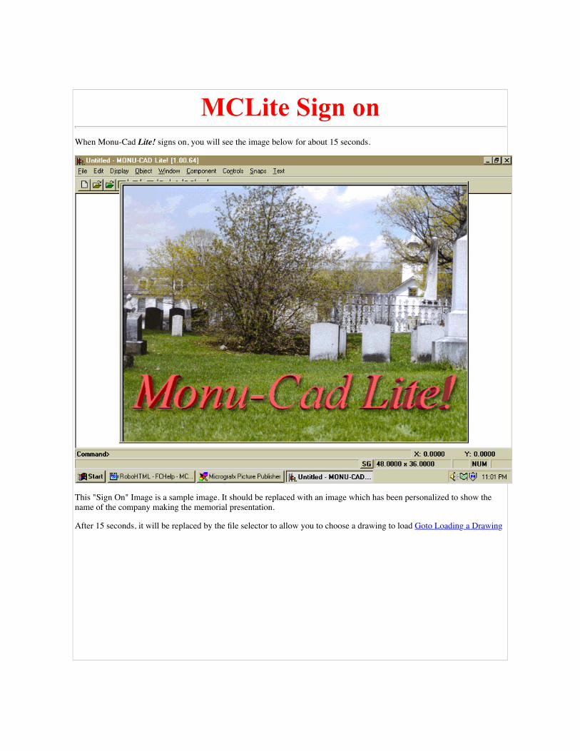
MCLite Sign onWhen Monu-Cad Lite! signs on, you will see the image below for about 15 seconds.
This "Sign On" Image is a sample image. It should be replaced with an image which has been personalized to show thename of the company making the memorial presentation.
After 15 seconds, it will be replaced by the file selector to allow you to choose a drawing to load Goto Loading a Drawing

Starting Monu-Cad Lite!After installing the Monu-Cad Full Demo Disk, a large Yellow MONU-CAD Icon willappear on your Windows '95 Desktop as pictured below:
Double click the Yellow MONU-CAD Icon.
The MONU-CAD Program group will appear as shown below:

(Note!! The image above is a typical example. The image on your computer may differ somewhat due to programimprovements and additions.)
To Run Monu-Cad Lite! from inside the Flip Chart Program then
Goto Memorial Image Display
To start the Monu-Cad Lite! Program and run it as a "Stand Alone" program without
Flip Chart, double click the Icon.
Goto MCLite Signon
For additional information about the other Icons in the program group please see

Starting Flip Chart. Goto Starting Flip Chart
Click your BACK button to return to the previous page.

Loading a DrawingWhen the sign on screen closes, the file selector shown below will be displayed. (please note that the screen you seemay differ slightly from that shown here due to program additions or changes. It may have additional selectionsdepending on the type of installation selected)
This file selector is a standard Windows type file selector and follows normal Windows commands. The little yellow"folder" labeled "Demo-ALL contains the demonstration drawings. Click on the folder once to highlite it and then click onOpen. The file selector will change to the form shown below:
To select a drawing, click on a filename to highlite it and then click on Open. In the above case, the drawing fileDemo_DD02.mcd is about to be selected. When we clicked on Open, the following is what was displayed:

To load a new drawing, it is best to erase the current one first. This can be done by dropping down the File menuand Clicking on Erase (DX). Then click on the Drawing Load (DL) Icon and the file selector will again appear.
However, you might want to load a monument base drawing under a die. In this case, entering DL and selecting the basedrawing will load the second drawing "on top" of the first. If the base has been drawn at the correct coordinates, it will fitunder the die exactly in the correct place.
Click your BACK button to return to the previous page.
Return to MCL-Menu Commands II

Saving a Finished DrawingWhen you have finished making modifications to your memorial layout and are readyto save your work, Click on the "File Menu". The Menu will drop down:
Then click on Save. (You may also type in the two letters DS for Drawing Save insteadof Clicking on the Menu). A "file selector" dialog box similar to the one below willappear:

You may type in a new file name to call the saved drawing or you may click on anexisting name in which case the current drawing will replace the one already existing.If the drawing name you choose to save under is one which has been designated a"Stock Standard Layout", then you will not be allowed to over write the originaldrawing and must select a new name to save it under. Please select a file name of 8characters or less. (Check with the company supporting your MCLite! software for themethod of file naming he prefers that you use.) Finally, click on Save and the file willbe saved.
Click your BACK button to return to the previous page.
Return to MCL-Menu Commands

Lettering Editing & AddingGoto Lettering - Advanced
Goto Panels - Adding and Editing
"Click & Type ® Technology"
In Monu-Cad Windows programs, a Very Important buttonon your Mouse is the Right Button. The Right Mousebutton controls the lettering and component functions.On the Drawing 1.mcd, we placed the mouse cursor on the Red Reference Point in the Familyname and pressed the Right Mouse Button. The following dialog box appeared. It will alwaysappear when you move the cursor over a lettering Reference Point and right mouse click.
We then moved the cursor to the word Edit... and clicked the Left Mouse Button.
The following appeared:

We then typed in SMITHJON as shown below:
and Left clicked on OK. The following appeared in 2 seconds!

This is our new "Click & Type" Technology in action!
Play Sample Movie
Goto Reference Points (PR)
To change any lettering that exists on a memorial layout:
1. Right Mouse Click on the Lettering Reference Point
2. Left Click on Edit...
3. Enter the new lettering and then
4. Left Click on OK
To add lettering to an existing memorial layout:
1. Right Mouse Click on an area where there is no lettering

2. Left Click on Add Lettering
3. Enter the new lettering and then
4. Left Click on OK. The lettering will appear where your mouse was resting when you firstclicked it to begin to add lettering.
To move any lettering group that exists on a memorial layout:
1. Right Mouse Click on the Lettering Reference Point
2. Left Click on Move
3. Move your mouse and the lettering group will follow the mouse.
4. Left Click on the new location for the lettering. It will be placed centered where thecursor rests when you click the mouse.
To Erase any lettering group that exists on a memorial layout:
1. Right Mouse Click on the Lettering Reference Point
2. Left Click on Erase. The lettering will be removed.
To Create an identical copy any lettering group that exists on a memorial layout:
1. Right Mouse Click on the Lettering Reference Point
2. Left Click on Duplicate
3. Move your mouse and the lettering group will follow the mouse.
4. Left Click on the new location for the lettering. It will be placed centered where thecursor rests when you click the mouse. You will have a second copy of the originallettering group.
To Rotate any lettering group that exists on a memorial layout:
1. Right Mouse Click on the Lettering Reference Point

Notice!!
Lettering Groups cannot be placed inside a component. Doing so will result in a component which cannot bereloaded and will be unrecoverable.
2. Left Click on Rotate.
3. Select Use Mouse function to visually rotate or enter a desired rotation value.
To Adjust Inter Letter Spacing in any lettering group that exists on a memorial layout:
1. Right Mouse Click on the Lettering Reference Point
2. Left Click on Adjust Lettering.
3. Make changes as per special instructions page goto Adjust Lettering
To make Advanced changes to lettering groups, panels, create lettering on an Arc or changeline spacing or line length,
Goto Lettering - Advanced
Goto Panels - Adding and Editing
Goto Lettering on an Arc
goto Adjust Lettering
Click your BACK button toreturn to the previous page.

Lettering - Advanced"Click & Type Technology"
When you Right Click on a lettering group in Monu-Cad and then click on Edit..., thesimple dialog box shown below appears:
The purpose of this dialog box is to provide a quick and uncomplicated way to changethe existing lettering. To change more than just the lettering and size, you must click onthe Advanced> button. Doing so will open the dialog box below:
Click on this image for more details

In this box are radio buttons and text boxes which can be altered to:
Add and insert additional lettering;
Change Alphabet Style (Primary - Secondary Font);
Change Alphabet Size (Primary - Secondary Size);
Set the desired Justification;
Force a line of lettering or a whole group of lines to a specified line length(Equate);
Select from 8 preset Auto Draw panel styles (Panel Style - Panel Type);
Set panel width parameters (Panel Width).
Set spacing above and below lines of lettering (Space Above - Top Line to Top ofPanel);

Set space value inside the panel between the beginning letter and left inside ofpanel & last letter and right inside of panel (end space).
Set the exact coordinates at which to place a lettering group (Group Anchor).
click here for more detailed information
All new lettering defaults to 1 inch height and the Press Modified Roman Alphabet. Tochange these defaults, click on the line of lettering to identify to the program the line youare working on. It will change color in response (become highlighted). Then, click in the Sizeor Font selection box and enter the desired selection.
2 sizes of letters on one lineIt is possible to enter two sizes of letters on one line. To do so, precede the size changewith a * character.
For example, the name McDonald might have a 3" capital M and a 2.5" c in the Mc.Enter as follows: M*c Donald. The size of the c is set by the value placed in theSecondary Font Size input box. This box will be "grayed out" unless there is at least one* in a line of lettering.
2 Styles of lettering on one lineTo use two different styles on one line, place a ~ (tilde) character in the line of letteringto signal to the program that the following lettering will use a different alphabet.
For example, the lettering Robert "bobby" Smith should be input as... Robert ~ "Bobby"~ Smith. The second style is selected with the Secondary Font selector.
Just trying these features once or twice will demonstrate the common sense approachused in Click & Type. The very low level learning curve is greatly appreciated by all!
Group Anchor
The group anchor box allows you to change the X and Y coordinates of the currentlettering group. In the image above, the X coordinate is 0 and the Y coordinate is 13.This means that this lettering group will be placed on the center line of the memorial and13 inches above the "joint" or 0,0 center coordinates. To lower the group by one inch,simply change the 13 to 12.
Added Space

This feature allows you to put additional space between letters to "spread out" a shortline of lettering. If you enter .25 in the edit box, you will add 1/4" more space in betweeneach letter in the currently highlighted line of lettering.
Equate
The equate button allows you to specify exactly the desired length for a particular line oflettering or for the group as a whole. For example, if the currently highlighted line oflettering is 8 inches long and you want it to be 12 inches long, click the equate button,click on the "Line" button and enter 12 in the edit box. Then click OK. The length of theline will become 12 inches.
You can also make all the lines of lettering in the group equal the same length by clickingthe "Group" button after clicking the Equate button. This is often called columnjustification similar to that used in newspaper columns. This is a handy feature for poemsand longer text passage inscriptions. When using group equation, make sure to enter avalue at least as great as the longest line of lettering. If you do not, the longest line willbe "squeezed together".
Click Here for Justification Options
Click your BACK button to return to the previous page.
Run Click & Type Movie
Run Lettering on Arc Movie
See Lettering on an Arc
Adjust Lettering
Click BACK button to return to previous page.

Lettering on an ARCMonu-Cad Click & Type® technology makes placing lettering on an Arc quick and truly a pleasure to use.A step by step example follows:
The Easy "Use Mouse" Method
Step 1, Right Click on the place where you want the center point of the lettering to be placed. Then leftclick on the Add Lettering button. The Advanced Kern Dialog box will appear.
(Note! If you are running an earlier version and are attempting to put lettering "on top" of a component, at this pointyou may have to left click the mouse again on the spot where you want the lettering to be to make the AdvancedKern Dialog to appear)
Step 2, enter the desired lettering and press the ENTER button on the keyboard.

Step 3, click on the line of lettering to highlight it, then click on the Arc button. The menu below will pop up.
Step 4, click on the Use Mouse button. The menu below will pop up.
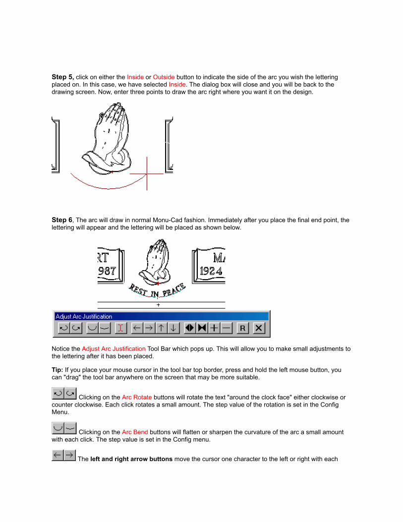
Step 5, click on either the Inside or Outside button to indicate the side of the arc you wish the letteringplaced on. In this case, we have selected Inside. The dialog box will close and you will be back to thedrawing screen. Now, enter three points to draw the arc right where you want it on the design.
Step 6, The arc will draw in normal Monu-Cad fashion. Immediately after you place the final end point, thelettering will appear and the lettering will be placed as shown below.
Notice the Adjust Arc Justification Tool Bar which pops up. This will allow you to make small adjustments tothe lettering after it has been placed.
Tip: If you place your mouse cursor in the tool bar top border, press and hold the left mouse button, youcan "drag" the tool bar anywhere on the screen that may be more suitable.
Clicking on the Arc Rotate buttons will rotate the text "around the clock face" either clockwise orcounter clockwise. Each click rotates a small amount. The step value of the rotation is set in the ConfigMenu.
Clicking on the Arc Bend buttons will flatten or sharpen the curvature of the arc a small amountwith each click. The step value is set in the Config menu.
The left and right arrow buttons move the cursor one character to the left or right with each

click. The up and down arrow buttons will move the cursor up or down one line of lettering if there are morethan one line in the group.
The Up and Down arrow buttons move the cursor up or down one line of lettering if the letteringgroup contains multiple lines of lettering.
buttons spread out or contract equally the lettering by increasing or decreasing the spacebetween letters a small amount with each mouse click. The <> button increases the amount of space andthe >< button decreases it. This feature is great to spread out a family name "by eye" till it "looks good".
Clicking on the + button will add more space between the letters. The - button removes space.The step value is set in the Config menu. We call these the Arc Lettering Spread buttons.
The R button will reset any changes you may have made to the original values and the Xbutton will exit and finish the command.
Step 7, Click on the X to complete the command.
As with any lettering group, you may Right Click on the insertion point once the command has beencompleted to move the lettering and thereby adjust it's location. You may also Right Click and select AdjustArc from the menu to pop the tool bar back up for more adjustments later.
Note: If you are placing lettering "on top" of a component such as you might if you are placing letteringinside wedding bands you will get the component edit dialog which has the words Add Lettering at thebottom of the list. This works the same as described in Step 1.
Two Alternate Methods
You may have noticed back in Step 3 that there are 3 methods available for locating the placement of thelettering on an Arc. In the example above, we used the easiest method which is Use Mouse. There are alsothe Radius and Coordinate Methods.
Radius Method
This method allows you to select the X and Y coordinates of a circle on which you may wish to placelettering. This is an easy way to put lettering around an emblem.
Coordinate Method
This method allows you to manually enter the coordinates of the 3 points which make up the arc on whichyou wish to place lettering. This is the same as using the Use Mouse method and typing in the coordinatesinstead of clicking their location with the mouse. We include this method here just to remain consistent withthe MSDOS Monu-Cad System.
Lettering - Advanced
Lettering - Editing - Adding

Right Mouse Button
New Features Version 5.0
Version 5.0 and later allow multiple lines of lettering on and arc with and without panels.
Click the BACK button to return to the previous page.

Menus & CommandsAt the top of the Monu-Cad Lite! main screen are 8 drop down menus which are activated by Left Clicking on one of themenu names (File, Edit, Display, Object etc). (In Monu-Cad Pro there are 12 menus)
Notice the * in the drawing above just below the praying hands. This is the 0,0 reference point. All coordinates aremeasured from this reference point in decimal inches. This is similar to laying a Zero Center Ruler on the joint of the die.For a 3-0 x 2-0 die, the bottom joint at the center is 0,0. The left bottom corner is -18,0. The bottom right corner is 18,0.The top center of the die is 0, 24. And in the above case, the bottom of the Family Name Lettering is 0, 13.5. (note! The 0,0reference point cannot be turned off with the PR command)
In the following descriptions you will see 2 letters such as the DX shown on the first line in the menu below. These twoletters represent the keyboard "shortcut" commands that will perform the same function as clicking on the menu item.These two letters will be shown in the form (DX). Remember to click on the "links" for more information.
Clicking "File" drops down the menu below:

Erase (DX) goto Drawing EraseLoad (DL) goto Drawing LoadLoad Variation(D2) goto Load Drawing Variation"SlideShow" (D3) goto Load Drawing Variation "Slide Show Presentation"Save (DS) goto Drawing SavePrint (DP) goto Drawing PrintLayout Save (LS) goto Saves drawing as "stock standard layout file"Next Largest Monument goto Saves lettering, Erases current .mcd file and loads the next largest size of
same description, redisplays lettering. (This feature must have appropriate.mcd files installed for this to be operable.
Next Smallest Monument goto Same as aboveConfig goto Displays configuration settings formsQuit goto Exits program Monu-Cad fashion (QU-n-Q)Exit goto Exits program Windows fashion
Clicking "Edit" drops down the menu below:
Preserve All Lettering goto Saves all lettering groups to a bufferRestore Lettering goto Moves "preserved" lettering from buffer to screen
Clicking "Display" drops down the menu below:

Zoom All (ZA) goto Fits everything in drawing onto screen in one moveZoom Window (ZW) goto Zooms up to full screen size everything which is wholly
inside a user drawn windowZoom Previous (ZP) goto Jumps back to previous zoomZoom Up (ZU) goto Zooms in in stepsZoom Back (ZB) goto Zooms out in stepsPan (PA) goto Allows user defined panningRedraw (RD) goto Refreshes image display
Clicking "Object" drops down the menu below:
Move (OM) goto Moves an object on the screenCopy (OC) goto Makes a second copy of objectMove Point (MP) goto Moves an object on the screenErase (OE) goto Erases an objectErase Last (EL) goto Erases last item placed on screenUnerase (UE) goto Reverses last erase operationExplode (OE) goto Explodes lettering group
Clicking "Window" drops down the menu below:

Window Erase (WE) goto Erases all in user created window
Click your BACK button to return to the previous page.
Goto MCL-Menu Commands Part II
Goto Monu-Cad Pro 2000 menus

MCL-Menu Commands IIClicking "Component" drops down the menu below:
Component Place (CP) goto Places component on screenComponent Scale (CZ) goto Resizes component to new valueComponent Rotate (CR) goto Rotates Component
Clicking "Controls" drops down the menu below:
Tolerance (TO) goto Sets "capture" distanceScreen Ratio (SR) goto Allows calibration of screenCursor Size (CU) goto Changes cursor size
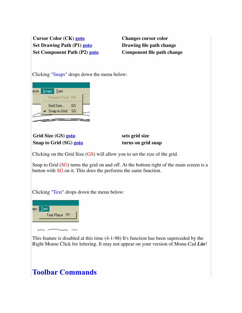
Cursor Color (CK) goto Changes cursor colorSet Drawing Path (P1) goto Drawing file path changeSet Component Path (P2) goto Component file path change
Clicking "Snaps" drops down the menu below:
Grid Size (GS) goto sets grid sizeSnap to Grid (SG) goto turns on grid snap
Clicking on the Grid Size (GS) will allow you to set the size of the grid.
Snap to Grid (SG) turns the grid on and off. At the bottom right of the main screen is abutton with SG on it. This does the performs the same function.
Clicking "Text" drops down the menu below:
This feature is disabled at this time (4-1-98) It's function has been superceded by theRight Mouse Click for lettering. It may not appear on your version of Monu-Cad Lite!
Toolbar Commands

In addition to the menus at the top there is also a "shortcut tool bar".
These 12 icons provide quick ways to perform 12 common tasks. Simply clicking inthese icons (small images) will begin the command.
Drawing Erase (DX) goto
Drawing Load (DL) goto
Load Drawing Variation (D2) goto
Load Next "Slide Show" Design (D3) goto
Component Place (CP) goto
Drawing Save (DS) goto
Drawing Print (DP) goto
Zoom Window (ZW) goto
Zoom Previous (ZP) goto
Pan (PA) goto
Zoom All (ZA) goto
Redraw (RD) goto
Additional Screen Features
Status Bar
At the far left is the word Command>. When you enter a command such as Zoom

Window (ZW), you will be prompted here in plain English for the actions to beperformed to complete the command.
Coordinates
At the far Right, is a display which on the first line after X: Y: shows the currentposition of the cursor in screen X and Y coordinates. These numbers represent inchesin decimal. To determine how high the family name is above the joint of a Die, simplymove the cursor to the bottom of the lettering. The Y value is the number of inches thecursor is above the joint. The X value is the number of inches either Left or Right ofCenter.
The SG button turns on or off the Grid Control.
The numbers to the Right of the SG button are the Extents of the drawing on thescreen. In the above case the Extents are showing that the current drawing on thescreen is 46.2737 inches wide by 31.2570 inches high. These numbers will alwaysrepresent the maximum width and height of the drawing.
Additional Commands
These commands may not be on a drop down menu.
Tool Tips goto On screen "reminder" messagesEscape (Esc) goto Universal "Bail Out" command

Space Bar goto Repeats previous commandReference Points (PR) goto Turns on and off reference pointsConstruction Points (PC) goto Turns on and off construction points
Click your BACK button to return to the previous page.

Components - Adding &Editing
A Component is a piece of memorial artwork such as a cross, emblem, praying hands,wedding bands, special panel etc. It really can be just about anything and thecomponents that you have, are loaded into your component directory and appear on thefile selector dialog when it appears. For our purposes, a Component is a small designwhich has a name of it's own and can be picked up and moved independently of therest of the memorial artwork.
Placing a Component
When you click on the Component menu and select component Place or type CP on thekeyboard or click on the green folder in the toolbar, the dialog box shown belowwill be displayed.

See File Selector Operation
To select a component, click on a name such as 1AMROS32.mcc and click the Placebutton. The above box will disappear and an outline of the component will show on thescreen and it will be attached to the mouse cursor. You may then move the componentto a place of your choice on the memorial. When you decide on a proper place to putthe component, click the mouse and it will be placed at the coordinates where youclicked. You may also elect to manually enter the coordinates on the keyboard for amore precise placement. goto Manual Keyboard Coordinate Entry
Editing Components
Once a Component has been placed on the memorial, you can Right Click on thecomponent's Red Reference Point and a dialog box offering choices will pop up next tothe component.

Clicking on Move will "attach" the component to the mouse and you will be able tomove it on the screen to a new location. Click to Left mouse button to "anchor" thecomponent in place.
Clicking the Rotate option will produce an input box where you can enter a rotationvalue. Entering the value 15 will rotate the component 15 degrees to the left (counterclockwise). A value of -15 will rotate 15 degrees to the right (clockwise).
Clicking on the Scale option will allow you to alter the size of the component. Thedefault value is 1 for the X value and 1 for the Y value. Changing these values to 2 forthe X and 2 for the Y will double the size of the component. In Memorial work the Xand Y values are always changed by the exact same amounts.
Note! Please do not use the scale function to turn a 2 inch cross into a 5 inch cross.While it may look Ok on the screen, the sandblast lines will also increase to twice thesize. If your system provides you with various different size components then the bestbet is to exchange a 2 inch cross for a properly made 5 inch cross instead of scaling asmaller one into a larger one. Also, it is almost certain that a 10" Head of the VirginMary scaled down to 3 inches to fit on a marker cannot be sandblasted in stone. Usescaling with caution and respect.
Clicking on Flip will reverse the component's direction. A set of praying hands facingthe right will be turned over in place and will face the left after the execution of theFlip option.
When you click on the Replace option, the file selector will appear to offer you achoice of items to replace the current component with. When a component is selectedand the Place button is clicked, the first component will be replaced by the second.
Erase removes the component from the drawing.
Run Component Place Movie

Click your BACK button to return to the previous page.
Return to MCL-Menu Commands II

Printing a Memorial Design(DP)
Printing is made very easy with Monu-Cad programs The quickest way to print is to click on the littleprinter Icon (shortcut) on the tool bar which will start the print function. You may also type DP or clickon Print in the file menu.
After you click on the printer icon, you will see the print preview screen below:
To begin printing, simply click on the yellow "PRINT" button. That's all there is to it!

Click on the Exit Button or Press Esc to return to the Monu-Cad program.
You may also change the output size, location, orientation and printer parameters by clicking on thecontrol buttons located on the screen.
Quick Help
Size button allows you to change the image size to one of 3 preset sizes or "zoom all"
Center button centers the image in the printable paper area
Show fills button turns on/off any filled areas that may be in the drawing
Portrait / Landscape buttons change paper orientation
Copies edit box selects the number of copies to print
Scale edit box allows you to set the desired scale ... roller buttons select integernumbers or type in decimal fractional amounts.
Update button updates the screen after the new scale amount has been entered
Output buttons set the print quality or darkness of print
Setup button allows access to printer setup options
Print button starts the printing process
Help button pops up brief help menu
Exit button exits and returns to main draw screen
Click your BACK button to return to the previous page.

Panels Adding & EditingPanels are added to lettering groups by way of selection buttons in the advancedsection of the Click & Type lettering editor shown below:
Panel Style offers 3 selections or no panel at all.
Each of the three panel styles can be drawn with:
one hair line for raised letters in a panel;
a single sandblast line for normal work;
or a double sandblast line for more detailed work.
with square corners
with chipped (concave) corners
with rounded corners

click here to see the available panel styles
The width of the panel is determined by which of two input boxes has a value placed init:
Panel Width
If this input box contains a value, the panels will be forced to this with regardless of theamount of lettering in the panel. This is commonly used for inscription panels. In otherwords, the panel becomes a fixed size, the height of which is determined by the spaceabove and below lines of lettering plus the height of the letters. Common values are 10- 14 inches for inscriptions. There is no default value.
End Space
A value placed in End Space will place that amount of space automatically in front ofand following a line of lettering. The panel is automatically adjusted in widthdepending on the amount of lettering in the panel. This is used for family names.Common values are 1.5 inches or 2 inches. The default value is -0-.
Top Line to Top of Panel
This input box sets the amount of space placed between the top of the first line oflettering in a panel and the inside of the top panel line. The default is .5 inches.
Space Below
This input box sets the amount of space that immediately appears below the currentlyselected line of lettering. In a multi line inscription, a different value may be input foreach line of lettering. Click on the line of lettering you wish to set this value for beforesetting the value. The default is .5 inches.
Click your BACK button to return to the previous page.
Goto Monu-Cad Lite! Intro
Goto Monu-Cad Pro Quick Help

Demo Version LimitationsMonu-Cad Programs require the attachment of a "Security Device" to the hostcomputer in order for the program to be able to perform all standard functions.However, to allow potential customers to "try before you buy", we have created thesedemo versions. (These programs are not really demo versions, they are the actual programs.However, they are limited in their operation when no security device is attached.) We hope you willenjoy trying the programs out.
The "Demo" programs are restricted in the following ways:
The programs can only load the included "demo" .MCD drawing files and .MCCcomponent files. These will be located in the folders named Demo-ALL;
Only 10 alphabets (fonts) will function;
You can print out a drawing but you cannot save one to the Hard Disk Drive.
If you are seeing a screen similar to the one below when you start a program, you havea non functioning security device or one isn't attached to the computer.

To obtain a security device to unlock the full potential of Monu-Cad Lite!, contact theoffices of Monu-Cad directly.
Click your BACK button to return to the previous page.
Goto Monu-Cad - The Company

Click and Type MovieClick Here to Play Click & Type Movie
This Movie is a Windows AVI clip. It is expected that it will run on any Windows '95computer which has Internet Explored Version 3.02 or later installed. Best results areobtained with Internet Explorer Ver. 4.0. Please make sure your video is set for 800 x600 resolution, High Color Mode.
If you receive an error message such as "unable to render AVI..." when attempting torun the movie, try to run it a again. Sometimes it doesn't run the first time.
If you experience difficulty running this movie, please let us know. Be prepared todescribe your computer equipment, memory size, hard disk drive size and version ofInternet Explorer.
Other MoviesRun Lettering on an Arc Movie
Run Component Place Movie
Run Erase Last Movie
Run Window Erase - Unerase Movie
Run Zooms Movie
Goto About This Help Program
Goto Monu-Cad - The Company
Click your BACK button to return to the previous page.

Intro to CommandsCommands are what make Monu-Cad Lite! perform. When you first start the program,Monu-Cad Lite! will patiently wait for you to tell it what you would like to do. In fact,it tries to help you by anticipating some of your wishes. For example, on startup,Monu-Cad Lite! (when run in stand alone mode) presents you with a file selectorbecause it "knows" that the first thing you will want to do is load a drawing. Sometimesit can be very stubborn! If in the above example you do not enter a drawing name tostart with, it will sit there refusing to go on until you enter a name!
Commands are selected in several ways. To maintain consistency with theManufacturing Version of the Monu-Cad System, all commands except a few new onescan be executed by entering two letters on the keyboard. These commands likeDrawing Save (DS), Drawing Load (DL) and Zoom Window (ZW) are easy toremember and probably easiest to enter from the keyboard.
However, part of the ease of operation of Monu-Cad Lite! comes from not having toremember these commands. At the top of the main screen are Menu Titles. When youclick on these words, menus of commands will "drop down". Then to select the desiredcommand, simply Left click your mouse on the command name.
In both cases, when the command requires several steps, you will be prompted for thenecessary steps. The prompt appears in the lower left corner of the main screen on the"command bar".
In addition, there is a "Tool Bar" located at the top of the main screen which contains11 Icons which will execute the most common 11 commands just by clicking on theIcon.
Many hours have been devoted to the design of the command structure used in Monu-Cad Lite! in our attempt to provide you with the easiest possible way to design andlayout a memorial. We hope that you will find Monu-Cad Lite! a pleasure to workwith.
We will appreciate any feedback you may have in regard to problems you mayencounter or better yet, any suggestions you may have to help improve Monu-CadLite! Comments and suggestions are best written down and Faxed to us at 607-264-3307.
Goto MCL Menu Commands

Goto MCPro menu Commands
Click your BACK button to return to the previous page.

Simple File SelectorOperation
If you do not have the thumbnail file selector option, the simple file selector dialog boxabove appears whenever you enter the command for loading or saving a file. Even ifyou have the thumbnail selector option, there are times when you will see this simplefile selector because there is no thumbnail component to be displayed. The selectoroperates in almost the same way whether you are saving or loading files.
When you are loading a file or placing a component, either type in a name in the inputbox
or click on a name and then click on the open button.
When you are saving either accept the default, type in a name in the input box or clickon a name and then click on the save button.
There is a "scroll bar" at the bottom of the file name area.
If you place your mouse cursor on the right or left arrows and click once, the list ofnames will scroll to the right or left.

In addition, you can click on a name and then type a character on the keyboard and thefile selector will "jump" to the names which begin with the letter you typed. Entering aZ will go to the end of the list and entering a zero will go to the beginning of the list.
The little icon at the top of the dialog box will move "up one directory".
The icon changes the file display from a horizontal scroll to a vertical listing.
The box displays the current directory youare about to load from or save to.
The file type at the bottom determines the file extension which will be displayed. Thisis usually fixed to only one particular file type. However, in the case of the IPcommand, several file extensions will be available.
Goto MCL-Menu Commands
Tip: When selecting a name you may "Double Click" on the name and eliminatehaving to click on the save, open or place buttons.
Click your BACK button to return to the previous page.

Space Bar CommandThis simple command will become one of your "best friends". Pressing the space barwill repeat the previous command. When you are making multiple moves, pressing thespace bar between moves will save you from having to repeatedly type in a commandor search for a drop down menu.
Return to MCL-Menu Commands II
Click your BACK button to return to the previous page.

Reference Points (PR)Reference Points are little RED markers which appear in components and letteringgroups which act like a "handle on a coffee cup". When you want to move acomponent or lettering group, you must "pick it up by the handle" and move it with acommand like Move Point (MP) or Object Move (OM). In addition, you can RightClick on the Reference Point and select any of the commands which show on the popup menu.
The reference points are always there but you can elect to show them or hide them.When you type PR and then RD (redraw), if the points were off they will now show onthe screen. It is a "toggle" command. If you repeat the command, if they were on, theythen become turned off.
Notice the small * at the bottom center of the hands and book. These are referencepoints.
In the Display drop down menu, Config Sub Tab menu, is a configuration setting calledReference Points. Checking this box will turn Reference Points on which is the defaultsetting.
goto Config Tab Menu
return to MCL-Menu Commands
Click your BACK button to return to the previous page.

Construction Points (PC)When any line is drawn from point A to point B on the Monu-Cad Master System, asmall "x" is placed at both the beginning and ending points of the line. This is so thatthe operator can clearly see on the screen where a line starts and ends. They are alsopresent in arcs and circles and perform many useful functions for the operator.However, when showing a drawing to a retail customer, having all these little points allover the screen doesn't look very well. The image below is of the same carving; firstwith the Construction Points turned off; then with them turned on.
You may never have a reason to turn the construction points on. However, should theyever become accidentally turned on, type PC and then RD to turn them off.
return to MCL-Menu Commands.htm
Click your BACK button to return to the previous page.

Tool Tips
In the image above you will see a yellow rectangle with the words "Zoom Window(ZW)" in it. This is a tool tip. When you place your mouse pointer over a button orword on the screen and pause for a second, a tool tip will "pop up" giving you a hint ordescription of what the button is used for. Tool tips are built in "Memory joggers". Tooltips are another reason for the ease of use of Monu-Cad Lite!
Return to MCL-Menu Commands II
Click your BACK button to return to the previous page.

Manual KeyboardCoordinate Entry
Whenever you are moving lettering or placing a component there is an alternate way toselect the placement point other than using the mouse. For example, if you are placinga cross and you wish to place it on the centerline of the memorial and 3 inches up fromthe bottom, simply type in on the keyboard 0 , 3 <enter>. (zero-comma-three and thenpress the enter key). The Reference Point in the cross will be placed precisely on thecenter line and 3 inches up from the joint (bottom) of the memorial.
In another example, lets say that there is a family name on a monument and you wouldlike to move it upward. To begin, place the mouse cursor over the Red Reference Pointin the name and Right Click. Then, select Move and left click. Now when you moveyour mouse, the family name moves with it. When you get the name to about whereyou want it, take your hand off of the mouse. Look in the lower right corner of thescreen at the current coordinates. The X value represents the current distance left orright of center of the red reference point. The Y value represents the distance in inchesthat the lettering is above the joint. To center the family name, use 0 (zero) for the Xvalue. If the current Y value is something like 13.4693, round it to 13.5. Type in 0 ,13.5 and press the Enter Key. The lettering will be placed precisely on the center lineand 13.5 inched above the joint.
Click your BACK button to return to the previous page.

Escape Command (ESC)The Escape command is the "universal bail out" command. Whenever you are in themiddle of a command and wish to abort, press the Esc key on the keyboard. This willabort the command and allow you to start again.
Return to MCL-Menu Commands II
Click your BACK button to return to the previous page.

Erase (DX)Typing the command DX or clicking Erase on the File menu option or clicking on theErase Icon on the tool bar will ask you for confirmation and if you agree,everything on the screen will erase at once. If you made changes and didn't first savethe file, all changes will be lost. This command is normally used to erase what is on thescreen in preparation for doing a Drawing Load (DL) to load another drawing withoutleaving the program. A quick way to erase all is to type DX Y (drawing erase-yes).
Return to MCL-Menu Commands II
Tip: Experienced operators often enter DX Y DL in quick sequence to load an newdrawing.

Loading a DrawingWhen the sign on screen closes, the file selector shown below will be displayed. (please note that the screen you seemay differ slightly from that shown here due to program additions or changes. It may have additional selectionsdepending on the type of installation selected)
This file selector is a standard Windows type file selector and follows normal Windows commands. The little yellow"folder" labeled "Demo-ALL contains the demonstration drawings. Click on the folder once to highlite it and then click onOpen. The file selector will change to the form shown below:
To select a drawing, click on a filename to highlite it and then click on Open. In the above case, the drawing fileDemo_DD02.mcd is about to be selected. When we clicked on Open, the following is what was displayed:

To load a new drawing, it is best to erase the current one first. This can be done by dropping down the File menuand Clicking on Erase (DX). Then click on the Drawing Load (DL) Icon and the file selector will again appear.
However, you might want to load a monument base drawing under a die. In this case, entering DL and selecting the basedrawing will load the second drawing "on top" of the first. If the base has been drawn at the correct coordinates, it will fitunder the die exactly in the correct place.
Click your BACK button to return to the previous page.
Return to MCL-Menu Commands II
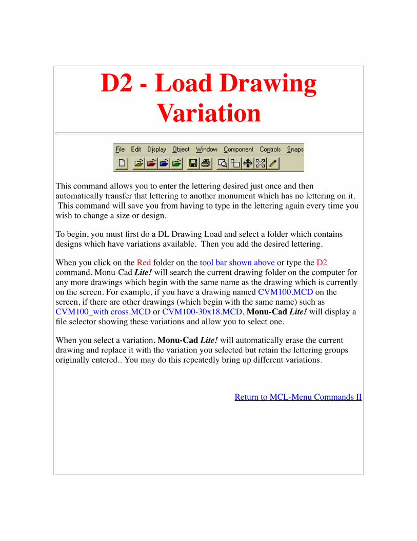
D2 - Load DrawingVariation
This command allows you to enter the lettering desired just once and thenautomatically transfer that lettering to another monument which has no lettering on it. This command will save you from having to type in the lettering again every time youwish to change a size or design.
To begin, you must first do a DL Drawing Load and select a folder which containsdesigns which have variations available. Then you add the desired lettering.
When you click on the Red folder on the tool bar shown above or type the D2command, Monu-Cad Lite! will search the current drawing folder on the computer forany more drawings which begin with the same name as the drawing which is currentlyon the screen. For example, if you have a drawing named CVM100.MCD on thescreen, if there are other drawings (which begin with the same name) such asCVM100_with cross.MCD or CVM100-30x18.MCD, Monu-Cad Lite! will display afile selector showing these variations and allow you to select one.
When you select a variation, Monu-Cad Lite! will automatically erase the currentdrawing and replace it with the variation you selected but retain the lettering groupsoriginally entered.. You may do this repeatedly bring up different variations.
Return to MCL-Menu Commands II

Load "Slide Show"Drawing (D3)
This additional "Drawing Load" option will erase the currently displayed drawing andreplace it while preserving the current lettering providing that a special criteria is met.
For this feature to work properly, the initial .MCD drawing file and the one which is toreplace it must have in common:
Both drawings must have the same number of lettering groups;
All lettering groups in each drawing must contain the same number of lines oflettering.
If the above criteria are not met, an error message will be generated.
This feature has been provided with the intent of providing a useful way to cyclethrough a series of memorial designs in which the lettering is always laid out in asimilar fashion. For example, one may have a series of 2-0 x 1-0 markers which allhave three lines of lettering. Using this feature, the operator could load the first markerin the series and edit the lettering to reflect the needs of the customer. Then, by clickingon the BLUE folder in the Tool Bar and clicking on the next design in the series, thenext design would be loaded and the lettering would be automatically replaced by thelettering used in the first marker.
Note that if the second design loaded is for example a single monument, as long as thenumber of groups of lettering are the same number and as long as the number of linesof lettering in each group is the same, the monument layout will replace the markerlayout and the lettering will be automatically changed to that of the first selectedmarker.
To cancel the effects of this feature and return to normal operation, simply erase thecurrent memorial with the DX Drawing Erase command and load another memorialusing the DL Drawing Load command.
Return to MCL-Menu Commands II

Saving a Finished DrawingWhen you have finished making modifications to your memorial layout and are readyto save your work, Click on the "File Menu". The Menu will drop down:
Then click on Save. (You may also type in the two letters DS for Drawing Save insteadof Clicking on the Menu). A "file selector" dialog box similar to the one below willappear:

You may type in a new file name to call the saved drawing or you may click on anexisting name in which case the current drawing will replace the one already existing.If the drawing name you choose to save under is one which has been designated a"Stock Standard Layout", then you will not be allowed to over write the originaldrawing and must select a new name to save it under. Please select a file name of 8characters or less. (Check with the company supporting your MCLite! software for themethod of file naming he prefers that you use.) Finally, click on Save and the file willbe saved.
Click your BACK button to return to the previous page.
Return to MCL-Menu Commands

Printing a Memorial Design(DP)
Printing is made very easy with Monu-Cad programs The quickest way to print is to click on the littleprinter Icon (shortcut) on the tool bar which will start the print function. You may also type DP or clickon Print in the file menu.
After you click on the printer icon, you will see the print preview screen below:
To begin printing, simply click on the yellow "PRINT" button. That's all there is to it!

Click on the Exit Button or Press Esc to return to the Monu-Cad program.
You may also change the output size, location, orientation and printer parameters by clicking on thecontrol buttons located on the screen.
Quick Help
Size button allows you to change the image size to one of 3 preset sizes or "zoom all"
Center button centers the image in the printable paper area
Show fills button turns on/off any filled areas that may be in the drawing
Portrait / Landscape buttons change paper orientation
Copies edit box selects the number of copies to print
Scale edit box allows you to set the desired scale ... roller buttons select integernumbers or type in decimal fractional amounts.
Update button updates the screen after the new scale amount has been entered
Output buttons set the print quality or darkness of print
Setup button allows access to printer setup options
Print button starts the printing process
Help button pops up brief help menu
Exit button exits and returns to main draw screen
Click your BACK button to return to the previous page.
Layout Save (LS)This command is only used by Master Monu-Cad operators who set up Monu-CadLite! satellite systems. It allows the saving of a drawing file in such as way as toprevent the satellite system operator from accidentally over writing the contents of a"stock standard" file.
Note: This command is only available on MCPro MasterSystems.
The Layout Save command is available fromthe File Menu.
This command gives the Monu-Cad Prooperator the ability to save a file in a uniqueway which "marks" the file to internally "WriteProtect" it.
A .MCD file saved using this save methodcannot be overwritten by a user of Monu-CadLite!
To use this command, Click on Layout Save inthe File Menu or type LS on the keyboard.Then, follow the directions on the screen.
Goto MCL-Menu Commands

Next Largest MonumentThis is an advanced feature of Monu-Cad Lite! and may or may not be implementedon your system. If the appropriate .MCD drawing files are present, when you click onthis menu item, Monu-Cad Lite! saves all lettering, erases the current .mcd file andloads the next largest size of same description and then re displays all lettering on thenext largest size memorial.
The lettering is displayed at the same coordinates that it was on the first memorial.Should the lettering not be placed correctly, you will have to move it to the correctlocation.
return to MCL-Menu Commands.htm
For master users
Monument sizes are to be located in a directory called /AltSizes under the current MCD directory.
Alternate monument sizes are indicated with a double dash followed by a single digit (i.e. alternatesize for BERN.MCD would have the following filenames: BERN--1.MCD, BERN--5.MCD, ..., etc.) Ifa drawing's filename is not in the previous format then is is assumed to have a size of 5. This allowsnormal filenames to be used in the main MCD subdirectory and the alternate sizes to be placed in theAltSize directory.
In other words,
bern--1.mcd would be 4 sizes smaller
"
"
bern--4.mcd would be one size smaller
Bern--5.mcd would be the same as bern.mcd--There is no need for this
Bern--6.mcd would be one size larger

"
"
bern--9.mcd would be 4 sizes larger

Next Smallest MonumentThis is an advanced feature of Monu-Cad Lite! and may not be implemented on yoursystem. If the appropriate .MCD drawing files are present, when you click on thismenu item, Monu-Cad Lite! saves all lettering, erases the current .mcd file and loadsthe next smaller size of same description and then re displays all lettering on the nextlargest size memorial.
The lettering is displayed at the same coordinates that it was on the first memorial.Should the lettering not be placed correctly, you will have to move it to the correctlocation.
return to MCL-Menu Commands.htm

ConfigClicking on this menu selection displays the configuration settings Tab dialog box shownbelow. Although the heading refers to Monu-Cad Pro, the same settings are available in Monu-Cad Lite!
Kern Tab
Exaggerated Serifs turns on or off theability to use a letter style with "fatter"serifs on certain roman alphabets likeModified and Condensed Roman. Thenormal setting is to have this box checked.
Serif Split Size determines the size of theletter at which this feature beginsfunctioning. It is normally set at 1.5 inches.Letters below this set size will haveexaggerated serifs.
Single Line Thickness sets the width ofpanel sandblast lines.
Frosted Line sets the width of frostedpanel lines
M/D/Y Attributes sets the default blockingfor Month/Day/Year Justification option
Skip Trailing Punctuation determineswhether the length of the line of lettering ismeasured excluding the width of a trailingperiod or comma or including it. With thisfeature checked, the length of the nameJohn J. will be measured and centered asif the period after the J wasn't there. Whenin doubt, turn this feature on.
Disable Save To DTA when checkeddisables dialog allowing saving changes toDTA table after Lettering Adjust
Display Tab

Construction Points when checked turnson the points
Reference Points turns on the points
Mouse Cursor sets the size and color ofthe "cross hairs"
Screen Ratio see screen ratio page
Tolerance sets the "capture area" seetolerance page
Show Simple Lettering Group turns onsimple lettering group option whenchecked. Skips the simple lettering groupdialog box when un checked. See lettering
Path/Files Tab
This Tab allows you to set the defaultpaths for the program. they are usuallypreset for you.
Drawing Path[P1} sets default .mcd path.
Alternate Drawing Path when checkedwill cause all drawings to be saved to thisone folder.
Component Path[P2] sets default path toload .mcc files from.
Alternate Component Path for

Component Saves when checked willcause all components to be saved to thisone folder.
Split Component Path allows you to set aspecial folder up to hold just those specialcomponents used in split and split2justified date configurations.
DWG Path allows you to set the defaultpath for the Import command.
Cutter Files sets the path where cutterfiles will be placed.
Font Pat: sets the path where font filesare stored
Logo File specifies the name of the .pcximage to be loaded at sign on.
Show File Security Options see FileSecurity Options
Grid Tab
Snap to Grid sets the default gridsetting...ON or OFF
Grid Size sets the default grid size

Ortho Mode sets the default Ortho Modesetting ON or OFF
Units Tab
This configuration menu allows youto set the type and accuracy of thedrawing units desired. These valuescan also be changed by using thevarious units commands duringnormal program operation.

Arc Lettering Adjust Tab
Rotate step sets the amount of rotation thatoccurs when you adjust Lettering on an Arc
Flex Distance is the step value that occurswhen you adjust the arc shape in Letteringon an Arc.
Added Space sets the amount of spaceadded when you spread out letters inLettering on an Arc.

Defaults Tab
Version 3.0 and later.
Seed Fill Tolerance is a value whichattempts to allow you to fill a drawingwhich has some gaps in it. this tells the SDcommand to ignore gaps under .0625inches wide.
Fill Layer sets the default layer that fillsare placed on.
Start Up Method determines the way inwhich MCPro starts. Use DOS methodcauses the program to begin with a file

menu appearing automatically. If youuncheck this box, MCPro will start with ablank screen "Windows Style" and thedefault drawing name will be "Untitled".
Granite Finish Method are experimentalsettings for office use only. No explanationis herein given.
Zoom Limits sets the initial size of thescreen area and is the screen areadisplayed when you enter a ZL ZoomLimits command.
Fillet Radius is the default value that theradius of a fillet is set at. This can bechanged with the RF command as well assetting it here.
Functions Key Tab
Version 3.0 and later.
This section of the Config menu allowsyou to program a command or simplecommand string to a function key. Inaddition to the keys F1 through F12, youmay also use the combination of the ShiftKey plus a Function Key, Control Key plusa Function Key or both Shift and ControlKeys plus a Function Key.
In the example shown to the left, you willsee that we have programmed thecommand combination LISA and A3SA tothe Shift F1 and Shift F2 keys. The

commands shown for the F1 through F9keys are the defaults we have preprogrammed for these keys. They may bechanged but we suggest you keep them atthe default setting and use the otheravailable spaces for your individualcustomizations.
Import/Export Paths
Version 4.0 and later.
This section of the Config menu allowsyou set the path to folders containing thedifferent file types you would like to import.
When using the IP command, justselecting the file extension willautomatically log you into the folder youhave preset in this menu.

Click BACK button to return to previous page.

Quit (QU)To exit the program with this command, type the two letters QU. You will get amessage box offering you the choice to save the drawing. After you enter your choiceyou will exit. A quick "Monu-Cad" way to exit is to type QU N Q (QU-no, I don't wantto save-Q)
You may also exit by clicking in the upper right corner on the X button in standardWindows fashion or by clicking on Exit in the File menu.
Return toMCL-Menu Commands
Click BACK button to return to previous page.

ExitSimply click this command to exit the program.
Return to MCL-Menu Commands

Preserve All LetteringThis is a fairly simple but very useful command. When you click on this menu item, allof the lettering groups will be saved to a buffer in the program. Then you can eraseeverything on the screen with the DX command, load another memorial drawing andclick on Restore All Lettering in the Edit menu. The lettering that you saved into thebuffer will be placed on the new memorial exactly where it was when it was saved.
Tip: if you display a 3-0 monument on the screen and the lettering is too long for thefamily name and you wish to bring up a 3-6 instead, with this command you can savethe lettering, load the 3-6 and restore the lettering. Saves re typing....
Return to MCL-Menu Commands

Restore All LetteringThis command compliments the Preserve All Lettering command. See that commandfor details.
Goto Preserve All Lettering

Zoom All (ZA)The Zoom All (ZA) command scales everything currently in the drawing to a sizewhich will make all fit on the screen at one time and displays all. This is a nicecommand which makes it very easy to return to where you were when the drawing firstloaded. If drawing objects are off to the side and you forget where you are, type ZAand all will be OK!
The Zoom All command may be accessed from the Display drop down menu and alsoby clicking on the tool bar icon.
Run Zooms Movie
Return to MCL-Menu Commands

Zoom Window (ZW)The Zoom Window command allows you to "zoom in" and "blow up" a section of thememorial on the screen. Use this feature to make it easier to see carving details or tomake placing lettering easier.
To execute the command, type ZW, click on the Zoom Window command in theDisplay drop down menu or click on the Zoom Window Icon in the tool bar.
Next you must place a rectangular "window" around that which you wish to magnify.You do this by clicking your mouse in the upper left corner of the area you wish tozoom in on. Then you move your mouse toward the lower right corner of the area youwish to zoom in on. As you move the mouse, you will see a rectangle forming aroundthe area. When the rectangle encloses the area you wish to magnify, click your leftmouse button. The area within the rectangle will be magnified to fill the whole screen.If you place the first mouse click incorrectly, press the Escape (Esc) key on thekeyboard to abort the command.
The area in the rectangle from the image above becomes magnified to the image shown

below...
You may repeat this operation as often as you like. Use the Zoom All (ZA), ZoomPrevious (ZP) or Zoom Back (ZB) commands to "undo" the Zoom Window.
Run Zooms Movie
Return to MCL-Menu Commands

Zoom Previous (ZP)The Zoom Previous command will resize the screen to the image that was displayedthe last time you entered a zoom command. For example, if you have a monument onthe screen and have done a Zoom Window around the family name, when you enterZP, the view on the screen will immediately change to the original image. If you enterZP again, you will be returned to the view which shows the family name enlarged.
Run Zooms Movie
Return to MCL-Menu Commands

Zoom Up (ZU)When you need to get in "a little closer" to see better what you are doing, type ZU andthen place your mouse cursor on the item you wish to see better and Left click themouse. The image will "zoom in" about 50% closer. Notice the the item you "zoomedup" on will be in the center of the screen. You may also click on the Zoom Upcommand in the Display menu.
Run Zooms Movie
Return to MCL-Menu Commands

Zoom Back (ZB)The Zoom Back command is the opposite of the Zoom Up command. Use Zoom Backwhen you want to get back a ways from the object on the screen. When you type ZB orclick on the Zoom Back command in the Display menu, you will be prompted to clickthe mouse on the screen. When you click, the screen will zoom back about 50% andthe center of the screen will be the position where you clicked the mouse.
Run Zooms Movie
Return to MCL-Menu Commands

Pan (PA)The Pan command (PA) allows you to move the memorial on the screen. This may notbe a commonly used command but it is available in the event you may need it.
To execute the Pan command, type in PA and then click on the memorial. The part ofthe memorial that you clicked on will now be moved to the center of the screen. Thiscommand may also be executed by clicking on the Pan command in the Display dropdown menu.
Return to MCL-Menu Commands

Redraw (RD)As you are working on the screen, when you move items over the top of one another,little bits and pieces of the image will disappear and it will look like there are dots andfragments on the screen. This is because Monu-Cad Programs do not automaticallyredraw the screen image with every move. To do so would slow the operation of theprogram. To restore a clean image to the screen, simply type RD (redraw) or click onthe little Pencil Icon on the tool bar.
Return to MCL-Menu Commands II
Object Move (OM)The Object Move command is similar to the Move Point Command. To execute, typein OM and then Left click on the lettering group or component reference point. Theobject will become attached to the cursor and can be moved to a new location. Toanchor the object in place, Left click again. This command may also be selected fromthe Object drop down menu. This is another command which is present here tomaintain compatibility with the manufacturing system where in it has additionalimportance.
Return to MCL-Menu Commands
See OM Command details
Click BACK button to return to previous page.

Move Point (MP)This command is in Monu-Cad Lite! to maintain compatibility with theManufacturing System. You can move Components by Right Clicking on thecomponent and selecting the Move option. However, you can also type MP, click onthe Reference point and move the component to its new location. This command is alsoavailable in the Object drop down menu. This command is most useful when you haveexploded a lettering group and wish to move individual letters.
In Monu-Cad pro 2000, MP is a very valuable tool. For example, afteryou have drawn a line or arc, entering MP and then clicking on a pointwill cause that point to "attach" itself to the cursor and follow it as youmove the mouse on the screen. When you select a new location for thepoint, click the left mouse button and the point will be placed at thecoordinates where you have clicked the mouse. You may also manuallyenter a coordinate value on the keyboard to anchor the point.
Tip:Pressing the Esc (Escape key) during the operation will abort thecommand.
Return to MCL-Menu Commands

Object Erase (OE)This command is very simple. When you wish to erase an object, type OE and Leftclick on the lettering group or component. The object will be erased. The commandmay also be selected from the Object drop down menu.
Return to MCL-Menu Commands
Click BACK button to return to the previous page.

Erase Last (EL)Clicking this menu option or typing EL will erase the last item placed on the screen.Goto MCL-Menu Commands
Run Erase Last Movie
Tip: Experienced operators will often type EL to remove a component which was justplaced. UE or Un Erase will reverse the EL. If your customer is sitting with you, youcan repeatedly place and erase a set of hands to show what the memorial looks likewith and without them with this command.

Un Erase (UE)This simple command will often save many headaches. Simply type UE or drop downthe Object menu and click on Unerase to restore the last drawing item or section youerased. On the Object menu, the word Unerase will be "grayed out" if there is nothingto "unerase". Run Un Erase Movie
Return to MCL-Menu Commands

Object Explode (OX)Lettering in Monu-Cad Windows programs is treated a bit differently than in Monu-Cad MSDOS. In the manufacturing system, every letter is a discrete "object" untoitself.
However, in Windows, whenever lettering is placed on a Memorial, the line of letteringor "group" of lines of lettering are considered to be one "object" in the same way that acomponent is "one object" even though it is composed of many discrete lines, arcs andcircles. In this way, the lettering can be easily moved, scaled, rotated or changed in onestep. If a panel is chosen to be placed around the lettering, it also is treated as part ofthe "lettering group" or object.
There are times when it becomes necessary to "dissolve" the group into it's individualparts for good reason. This process is known as "Exploding the Group". This isaccomplished with the Object Explode command.
To Explode a lettering group, type OX (or click on the menu command Object Explodein the object menu) and click your Left mouse button on the lettering group. You willsee a warning message displayed explaining that once you do this, you cannot "regroup" the lettering. When you agree to continue, the group will "break apart" into theindividual letters and panel parts. In the image below you can see the "before andafter". Notice the Reference Points in the letters and the Construction Points in thepanel lines. (To see these points, both PC and PR must be turned on)
Once the group has been exploded, the individual letters may be moved independentlyof one another and the panel lines can be erased with the WE Window Erase command.This action cannot be reversed once a lettering group has been exploded.

Return to MCL-Menu Commands
Click the BACK button to return to the previous page.

Window Erase (WE)The Window Erase command allows you to selectively erase portions of the memorialdrawn on the screen.
To execute the Window Erase command, first, click on the Window drop down menu.Second, click on the "Window Erase (WE)" command. The command now officiallystarts. (You could also simply type WE on the keyboard and the command will begin)
Next you must place a rectangular "window" around that which you wish to erase. Youdo this by clicking your mouse in the upper left corner of the area you wish to erase.Then you move your mouse toward the lower right corner of the area you wish toerase. As you move the mouse, you will see a rectangle forming around the area. Whenthe rectangle wholly encloses the area you wish to erase, click your left mouse button.The objects which are wholly enclosed by the rectangle will be erased. If you place thefirst mouse click incorrectly, press the Escape (Esc) key on the keyboard to abort thecommand. Unerase (UE) will restore that which you have erased.
Run Window Erase - Unerase Movie
Return to MCL-Menu Commands
Tip: The WE command can be used to remove lettering panels, books, crosses andanything which can be wholly surrounded with a rectangle. If you are erasing acomponent or lettering, you are better off to Right click on the component's referencepoint and then clicking on "erase".

Component Place (CP)Goto Components - Adding Editing
Run Component Place Movie

Component Scale (CZ)Clicking on the Component Scale option in the Component drop down menu or typingCZ will allow you to alter the size of the component being placed. The default value is1 for the X value and 1 for the Y value. Changing these values to 2 for the X and 2 forthe Y will double the size of the component. In Memorial work the X and Y values arealways changed by the exact amounts.
Note! Any component placed after this value is changed from zero will be placedscaled to that setting. To stop components from unwanted size changes, this must bereset to zero. An easier way to rotate components is to place them and then Right clickthe component and set the scale value for the individual component.
Tip:Try using Window Scale (WZ) in Monu-Cad Pro and you will be able to visually seeand adjust the size.
also see CZ
Return to MCL-Menu Commands II

Component Rotate (CR)Clicking the Rotate option on the Component drop down menu or typing CR willproduce an input box where you can enter a rotation value. Entering the value 15 willrotate the component 15 degrees to the left. A value of -15 will rotate 15 degrees to theright.
Note! Any component placed after this value is changed from zero will be placedrotated to that setting. To stop components from unwanted rotation, this must be resetto zero. An easier way to rotate components is to place them and then Right click thecomponent and set the rotation value for the individual component.
This command is available in both Monu-Cad Lite! and Monu-Cad Pro 2000 programs.
Tip:In Monu-Cad Pro, try using the Window Rotate (WR) command. You will be able tovisually observe and set the rotation value.
Return to MCL-Menu Commands II

Tolerance (TO)When you move your mouse cursor near an object that you want to move or edit, it isnot necessary that you be right "on top" of the reference point in order to select theobject. However, it is necessary to establish a "capture area" around the reference pointoutside of which the command will not find the point and fail to operate. This is whatthe Tolerance value is. It is set at a default of .25 inches. It can be adjusted by typingTO but for working with average size memorials, .25 inches is just about right. Clickhere for more info.
Return to MCL-Menu Commands II

Screen Ratio (SR)This command is present in the event that there is a calibration problem with yourmonitor. It most likely will not be used and we suggest that you not use this commandwithout supervision. It has been maintained here for consistency with themanufacturing system software.
see SR
Return to MCL-Menu Commands II

Cursor Size (CZ)Clicking on this menu item or typing CZ will allow you to set the size of the cursor(the cross hairs). Goto MCL-Menu Commands II

Cursor Color (CK)Clicking on this menu item or typing CK will allow you to set the size of the cursor(the cross hairs). Goto MCL-Menu Commands II

Set Drawing Path (P1)Clicking on this command in the Controls drop down menu or typing P1 will allow youto set the default drawing path for file loading and saving. This command is duplicatedin the Config section of the File menu. It is maintained here for consistency with theMonu-Cad Manufacturing System.
Return to MCL-Menu Commands
Set Component Path (P2)Clicking on this command in the Controls drop down menu or typing P2 will allow youto set the default component path for file loading and saving. This command isduplicated in the Config section of the File menu. It is maintained here for consistencywith the Monu-Cad Manufacturing System.
Return to MCL-Menu Commands

Grid Size (GS)Clicking on the Grid Size (GS) will allow you to set the size of the grid. The grid is avery useful feature. It controls and restricts the movement of the cursor to easilynoticed increments. For example, if the grid size is set at 1/2 inch, when moving afamily name on the screen, one can very place the name because the cursor will onlymove in 1/2 inch steps. The grid control can be turned on and off with the Snap Grid(SG) command.
return to MCL-Menu Commands
Goto Snap to Grid (GS)

Snap to Grid (GS)Snap to Grid (SG) turns the grid on and off. It is another "toggle" command. The term"snap to" means that the cursor is forced to move in increments set by the grid size. Atthe bottom right of the main screen is a button with SG on it. This button performs thesame function as typing SG or clicking on the controls menu option. The GS or GridSize command sets the size of the grid to a user selected size. The default value is .5inches.
Tip: When the grid is "on", it is much easier to place a Family name or Component at adesired location.
return to MCL-Menu Commands
Goto Grid Size (GS)

Flip Chart is a Windows '95 computer program designed to assist Memorial Retailersand Salespersons in the process of making a Memorial Sales Presentation to a retailcustomer.
The Flip Chart program is modeled after the actual physical "sales kit" used by theprograms author in the course of selling numerous Memorials to retail customers overa period of many years. The primary focus of the program is to allow the organizedpresentation of many different images of memorials thereby assisting the Salespersonin counseling the retail customer through the Memorial selection process. Once anappropriate memorial selection has been made, the Flip Chart program provides a linkto the Monu-Cad Lite! program through which the Memorial Design selection andlettering can be customized to the customer's satisfaction. The completedcustomization may then be printed out on paper. The Flip Chart and Monu-Cad Lite!programs were designed to work together in this fashion. However, either Flip Chartor Monu-Cad Lite! may be operated independently of one another depending on theneeds of the operator.
Screen Resolution Warning
Flip Chart Was designed to be operated at a Video Screen Resolution of 800x 600 and at a color depth of 16 bit (high color) mode. For optimum results,please change your video settings to these parameters.

Additional Features
Provisions are made in the Flip Chart program to allow for a "photo tour" through theSalesperson's Monument Physical Display and/or Manufacturing Facilities (to helpbuild customer confidence). Images of memorials may be placed in 19 separate maincategories and an unlimited number of sub categories to aid in the users organization.
Goto Table of Contents
Tools are also provided to help the Master Monu-Cad operator name the categories andsub categories, create these categories on the computer's Hard Disk Drive, moveimages between the categories, establish, modify and arrange ordered lists of images,preview the order of images in the lists, and save these changes. Goto Edit View Lists
A bookmark feature is included to mark customer memorial selections. Thebookmarked selections may be re displayed to the customer without having to searchfor these selections through the greater number of images. The bookmark list may beviewed, reordered, modified and deleted according to the operator's needs. Goto EditBookmarks
A feature is also included which allows the user to change the basic colors of theprogram to suit his individual preference. Goto Change Colors
Goto Starting Flip Chart
Click your BACK button to return to the previous page.

Starting Flip ChartAfter installing the Monu-Cad Lite! Full Demo Disk, a large Yellow MONU-CADIcon will appear on your Windows '95 Desktop as pictured below:
Double click the Yellow MONU-CAD Icon.
The MONU-CAD Program group will appear as shown below:

To start the Flip Chart Program, double click the Icon.
Goto Sign on Screen
Additional Information
The Icon labeled Convert95 will run the conversion program used by MONU-CADMaster System operators in setting up the Flip Chart Images. Unless you are a Monu-Cad Master System operator, the program will not normally run and will display anerror message.
The Icon labeled CTDemo1.AVI is an extra copy of the Click & Type Moviecontained within this help file. It can be run by double clicking on it.
The MCLite Icon starts the Monu-Cad Lite! program independently of Flip Chart.Goto Starting Monu-Cad Lite!
The MCL Readme Icon will bring up the default word processor and display any lastminute comments the Monu-Cad staff may wish you to read. We suggest that you readthis information.
The Icon labeled Remote1 is a program used by the Monu-Cad Main office toremotely communicate with the security device which permits full access to the Monu-

Cad Lite! program. Use this only upon direction of the Monu-Cad Staff.
The Icon labeled Unwise is the Uninstall Program. Double clicking on this icon willbegin the Uninstall procedure which will remove the programs and files installed fromthe Full Demo CD. (Wise is the producer of the install program and they chose to labelthe uninstaller Unwise instead of Uninstall!)
Goto Sign on Screen
Click your BACK button to return to the previous page.

Sign on ScreenWhen Flip Chart starts up, the first screen you will see is the "Splash Screen" shownbelow:
The purpose of this screen is simply to welcome you to the program and to provide acopyright notice. To proceed, simply click on the lettering "Click Here to Begin".
Goto Company ID Screen
Click your BACK button to return to the previous page.

Company ID ScreenFollowing the Start up screen is an image screen we will call the Company ID Screen. On this screen is a place holder foran image of the company the salesperson is representing. The screen below is a sample showing one idea.
It is a good idea to begin the sales presentation with an image which clearly demonstrates to the customer the pride that thesalesperson has in his company and to begin to build brand recognition. The above image can be an picture of the place ofbusiness, a special featured memorial, a person, a company logo or just about anything you feel will facilitate the salespresentation. This image can be a scanned in image, a digital camera photo, a computer generated image or a photo fromsomething like a Kodak photo CD. The staff at Monu-Cad will gladly assist our customers in preparing the image used onthis screen.
Goto Table of Contents
The Exit Button
Clicking your mouse on the exit button will end the program execution. This is the usual way to terminate the program.When ever you desire to exit the program, simply click on the Exit buttons which look like the one above with the exitdoor. If you are several screens deep into the program, clicking on the Exit buttons will bring you back to the screenabove.

Goto Sign on Screen
The "Begin" Button
Clicking your mouse on this button will close the screen above and take you to the Table of Contents Screen where youwill begin the actual process of displaying images of memorials.
Goto Table of Contents
Click your BACK button to return to the previous page.

TOC
The purpose of the table of contents screen is to help organize and categorize the different memorial styles and types sothat it will be easy and natural for the salesperson to find a particular type of memorial he may be looking for to show thecustomer. The author of this program remembers going into a customer's home with a leather briefcase (a large one) whichcontained multiple leather bound volumes of 8 x 10 pictures of different types of memorials. On the binding of eachvolume was a label indicating roughly what was inside. The Table of contents screen is somewhat like having one verylarge volume of pictures with an quick and easy way to locate the desired picture.
The Categories
On the TOC screen are 20 categories. The titles selected approximate the common memorial styles available today andallows for five undefined categories. These category titles can be changed to suit the user's preference. For example, oneFlip Chart User prefers to use the description "Single Tablet" to describe a single upright memorial and "Pillow Marker" todescribe a single slant. All of the first 19 category titles can be altered as needed. To do so, the Master Monu-Cad userneeds to call Monu-Cad for assistance. The information needed to alter these titles is not contained in this documentation.Category #20, "Review Bookmarks" cannot be changed.
The Category Selector

When you place your mouse cursor over one of the category titles and click, the color will change to white and a "dropdown" selector box (combo box) will appear showing the original title and any sub categories that there may be.
To select the desired category, click once again on the desired title. To change to another general category (from say #2 to# 7), you will have to click twice... once on the newly selected general category which will "close the box" on the previouscategory and a second time on the new category which will "open the box" on the new selection.
Upon clicking on the desired title in the drop down box, the first image in the series installed for that category will bedisplayed. Goto Memorial Image Display
"A Tour of Our Company" category #1
This first category was designed with the idea of filling it out with numerous photos of the Monument Company makingthe sales presentation to help familiarize the customer with the company the salesperson represents and to build customerconfidence. It's sort of a "Show and Tell" category. The program designer suggests that this category be used to showcompany image building type photographs, industry photos such as quarries, how granite memorials are made, handtooling, equipment, vehicles, plant and office personnel. Here is a place to use your imagination!
"Categories 2 through 19"
These categories were designed to contain images of various different memorial styles and designs. An almost unlimitednumber of images may be placed in each category.
"Category #20, Review Bookmarks"
This category title cannot be modified and is reserved to display images which were entered into the Bookmarks List byclicking on the "ADD Bookmark" button in the "Memorial Browser". Please refer to the "Memorial Image Display"section for more details. Goto Memorial Image Display
"Exit" button
Clicking on the Exit button will return you to the Company ID screen. From there you can click on that screen's Exitbutton to terminate the program. Goto Company ID Screen
"Configuration" button
Clicking on the Configuration button will exit the TOC screen and display the Configuration screen. See the section ofConfiguration for details. Goto Configuration Screen
Click your BACK button to return to the previous page.


Memorial Image Display
Memorial "Browser" Screen
The screen shown above will appear with each image shown. We think of it as a "Memorial Browser". Right below theimage of the memorial are three white labels containing lettering.
These three labels contain from left to right:
1. The number of images in this category and the current image number;
2. The name of the category in case you have forgotten;
3. The computer file name of the image being shown.
Immediately below these three labels is the "Browser Control" area containing five control buttons which operate theimage browser.
"Previous" button

Clicking your mouse on this button will change the image displayed to the previous image. If you are on image #1,clicking this button will return you to the table of contents.
"Table of Contents" button
This button is an Exit to the Table of Contents should you wish to leave this category without having to view all of theimages. Look at it as a "shortcut" to the TOC. Goto Table of Contents
"MCL Edit" button
Clicking on this button will link to the Monu-Cad Lite! program and display on the screen the Black and White "vector "drawing of the memorial which was displayed in Flip Chart. For Illustration Goto Loading a Drawing
The vector drawing may be re lettered with the desired lettering to personalize the inscription to that appropriate for thecustomer. The design can be changed, items such as emblems and religious symbols added, types and styles of letteringaltered and much more. Consult the Monu-Cad Lite! Help file for additional information on modifying memorial letteringand design. Goto MCL Intro
"Add Bookmark" button
Clicking on this button will add the name of this image to a special "bookmark" list. This will help you to keep track of thepotential memorial designs your customer may be interested in purchasing. At any time you may return to the TOC andselect the "Review Bookmarks" category to view the images contained in the bookmark list. Images may be reorganized inthe book mark list, deleted, viewed, or the list may be cleared by going to the Edit Bookmarks feature in the Configurationscreen. Goto Edit Bookmarks
"Next" button
Clicking this button will display the next image in the series. If the current image is the last one in the series, clicking thisbutton will return you to the TOC. Goto Table of Contents
Click your BACK button to return to the previous page.

Configuration Screen
The Purpose of this screen is to provide for branching to the features of Flip Chartwhich can be changed by the user to modify and customize the operation of the FlipChart Program.
"Edit View Lists" button
Clicking on this button will close the Configuration screen and display the Edit ViewLists Screen. The operation of the Edit View Lists portion of the program is explainedin detail in the Edit View Lists portion of this Help Manual. Goto Edit View Lists
"Edit Bookmarks" button

Clicking on this button will close the configuration screen and display the BookmarksEdit Screen. Details for editing the bookmarks are contained in the Edit Bookmarksportion of this Help Manual. Goto Edit Bookmarks
"Change Colors" button
Clicking on this button will close the configuration screen and display the ChangeColors screen. Details on changing the default program colors are contained in theChange Colors portion of this Help Manual. Goto Change Colors
Click your BACK button to return to the previous page.

Edit View Lists
The Edit View Lists Screen was designed to provide you with a way to determine which images are displayed in eachcategory and the order in which they are displayed. This section is usually set up by the Master Monu-Cad operator toachieve a desired goal. To that end, the Add/Edit Categories button requires a password to gain entry. This password isonly available to the Master operators.
Steps for creating an ordered viewing list:
Select a category to create the list for as in step 1 above. Click on one of the 19 main category titles or scroll down to findand select the desired sub category if one is present. A listing of the available images will appear in the "File List" under"Step 2" above.
Glance over at the "Ordered List" and decide if you want to edit that list, add to it, remove from it or erase it entirely andstart a new listing. If you decide to erase it and start a new list, then click on the "Clear List" button at the bottom right. Ifnot, then click on a file name in the "View List" and click on "Add To" to add the image name to the Ordered List. Toremove an image name from the Ordered List, click on that image name in the Ordered List and then click on "DeleteFrom". This will remove the name from the list. Rearranging the order of the names in the list is as simple as clicking onthe name in the Ordered List and then click on the "Move Up" or "Move Down" button.

When you have finished rearranging a list, click on the save list button to make your changes permanent.
Below the View List is a button labeled Move Files. This will allow you to move files between directories on the hard diskdrive. This operation is best left to the Master Monu-Cad operator as one can easily move files in such a way as to renderthe program inoperable.
Every time you click on a file name, the image in that file will be displayed at the bottom of the screen. To zoom in on thatimage, simply click on the image. To zoom back, click on the image again.
Clicking on the Exit button will return you to the Table of Contents.
Goto Table of Contents
Click your BACK button to return to the previous page.
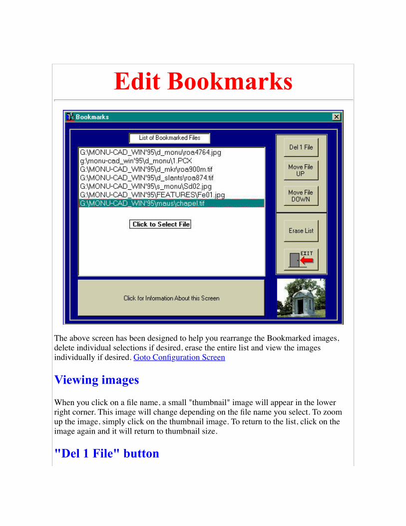
Edit Bookmarks
The above screen has been designed to help you rearrange the Bookmarked images,delete individual selections if desired, erase the entire list and view the imagesindividually if desired. Goto Configuration Screen
Viewing images
When you click on a file name, a small "thumbnail" image will appear in the lowerright corner. This image will change depending on the file name you select. To zoomup the image, simply click on the thumbnail image. To return to the list, click on theimage again and it will return to thumbnail size.
"Del 1 File" button

Highlite a file name and click on this button to erase that particular image from the list.When you return to the TOC, that image will not be in the Review Bookmarkscategory.
"Move File Up" button
Click on a filename to highlite it. When you click on this button, the file name willmove up in the listing. Use this to change the order of images in the list.
"Move File Down" button
Click on a filename to highlite it. When you click on this button, the file name willmove down in the listing. Use this to change the order of images in the list.
"Erase List" button
Clicking on this button will erase the whole list. You will be given a second chance tochange your mind. Use this to clear the list to start a new list with a new customer.
Goto Configuration Screen
Click your BACK button to return to the previous page.

Change Colors
The purpose of this feature is to allow you to adjust the colors of the program to yourpreferences. There are five preset color combinations which are set simply by clickingon the individual button. These buttons are labeled Preset Red through Preset Yellow.
In addition, if you desire to "fine tune" the color combinations, you may click on theBackground, Font and Foreground buttons and adjust each color individually. Theoperation of this fine tune adjustment is a bit strange due to the infinite wisdom of thepeople at Microsoft. Playing with the combinations can't hurt anything and you will getthe feel of it after a few attempts.
Goto Configuration Screen

Click your BACK button to return to the previous page.

UtilitiesClick on one of the links below to select that Utility Program's information page.
Convert95.exe
UpgradeKL.exe
New MCScan
MonuPaint
(old)
MONUSCAN
(old)
Remote3
MonuCut95
Click your BACK button to return to the previous page.

Convert95
Convert95 is a utility program designed to make converting Monu-Cad MSDOS files to the newWindows format a simple and quick task. This program will only be of use to Monu-Cad users whoare changing from their MSDOS systems to Windows. This program is designed to only run onMonu-Cad Master Security Devices.
When you launch Convert95, the program will sign on as shown below:
Convert95 will convert .DWG, .CMP, .KW1 & .KW2 and alphabet files to Windows.MCD, .MCC, and .FNT file formats.
This menu allows you to select the desired operation.
Note that the MCD to DWG conversion will not function properly with files made with thenew Monu-Cad Pro 2000. This was only available with earlier versions for conversion toMSDOS programs.
Using DWG-> MCD for an example, once selected, the next screen will appear:
This menu allows you to select the depth of security desired.
All Your Satellites allows both you and all your MCLite satellites to read the convertedfiles.
Specific Satellite allows conversion so that only you and one specific satellite can readthe converted files.
Only You imprints the file so that only you, the Master Operator can read the convertedfiles.
Masters Only imprints the file so that any Monu-Cad Master operator can read theconverted files.
Cancel will abort the program.

The normal selection will be All Your Satellites
After the security level has been selected, you are ready to select one or more files to convert. the file selectorbelow shows the selection of one file "bern.dwg"
Using standard Windows functions, you can select one file by clicking on it, or several by holding down the control keywhile clicking on multiple file names. You can also select all the files in a folder at one time by entering Ctrl-A afterclicking in the "white" area to change the "focus" to that area.
Once the files have been selected, click on Open to proceed. The dialog box shown below will appear:

This dialog allows you to select the destination path for the files. To change the path, click on the ellipsis (button with 3dots) to browse to another folder.
Following the destination path selection, the conversion will take place. The screen below is what you will see:
The progress indicator will advance as the number of filesconverted progresses. In the event a file cannot be converted,error messages will appear in the Messages box.
File names which have spaces or illegal DOS characters in thefile names will cause errors.
Click the Done button when the conversion is finished to returnto the main menu.
Most file paths will be preset for you. However, in some installations, paths will need to be changed. The Config buttonon the front page will pop up the following screen on which you can set the desired paths:
Note!!
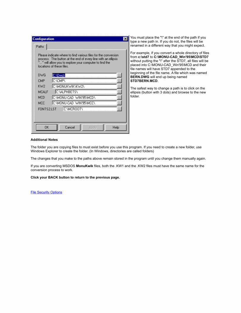
You must place the "\" at the end of the path if youtype a new path in. If you do not, the files will berenamed in a different way that you might expect.
For example, if you convert a whole directory of filesfrom c:\std7 to C:\MONU-CAD_Win'95\MCD\STD7without putting the "\" after the STD7, all files will beplaced into C:\MONU-CAD_Win'95\MCD and theirfile names will have STD7 appended to thebeginning of the file name. A file which was namedBERN.DWG will end up being namedSTD7BERN.MCD.
The safest way to change a path is to click on theellipsis (button with 3 dots) and browse to the newfolder.
Additional Notes
The folder you are copying files to must exist before you use this program. If you need to create a new folder, useWindows Explorer to create the folder. (In Windows, directories are called folders)
The changes that you make to the paths above remain stored in the program until you change them manually again.
If you are converting MSDOS MonuKwik files, both the .KW1 and the .KW2 files must have the same name for theconversion process to work.
Click your BACK button to return to the previous page.
File Security Options

MonuCut Program IntroMonuCut is a program designed to process the output data from the Monu-Cad Pro CAD program through to theStencil Cutting machinery. (Also referred to as MonuCut95)
Monu-Cut functions include: ( * indicates future features)
Selection of single and/or multiple files to cut
Selection of amount of space to leave between cuttings
Manual Control of cutter functions
Cutter knife alignment, depth setting assistance and cutter movement testing
Custom configuration of the serial port to the cutter requirements
Saving of multiple cutter configuration profiles*
Automatic Erasure of cut files after cutting*
Automatic logging and relocation of processed .MCD files after cutting*
Starting MonuCut
There are 2 ways you can start the MonuCut Program:
Method #1
Double Click on the icon in the Program Group below:

Method #2
Click on the "Launch MonuCut" button from within Monu-Cad pro:

Above is the Cutter Output Screen located within the Monu-Cad Pro Program. When you click on Cut in the File menu or enterthe command DC at the keyboard, this screen will appear. Clicking on the "Launch MonuCut" button will startMonuCut95 from inside Monu-Cad Pro.
Click here to Goto next step
Note!!
MonuCut is one of Monu-Cad's "living" programs which means that it is constantly being improved and expanded. Somefunctions may be shown on the face of the program but do not work at this time. This does not mean that something has beenleft out of your program. It just means that an improvement is being planned will be added in the future.

MonuCut OperationMonuCut95 Version 2.0.278
Start Up Screen:
When the MonuCut program starts, the screen below appears:
This Screen allows you to make selections from the menu of choices in the left panel.The choices shown in dark black letters are the currently available choices and the"grayed out" choices are future options currently being developed.
The underlined letter such as the "x" in the word Exit is a "hot key" which means thatyou can exit the program by pressing the key combination Alt-x as well as clicking onthat button with your mouse. All underlined letters which appear on the face of abutton are hot keys and perform in this way.

Select Files to Cut
The "file selection" screen allows you to select from among the files in your"FilesToCut" folder those you wish to send to the cutter for cutting.
To select a file, simply "double click" on the file name in the left most column. Afterdoing so the selected name will appear in the second column. You may do thisrepeatedly filling the second column with names. To begin the cutting operation, one ormore names must appear in the second column.
If you have made a mistake and wish to start over, you may click on the "Clear List"button which will remove all names from the second column. As an alternative, youmay click on one name and then click the "Delete File" button to remove just the onename from the second column.
Once you have finished selecting files to cut, click on the yellow CUT button and thenext CUT screen will appear.
Cut Screen:

The Files which appear in the "List of Files to Cut will be cut in the order shown whenyou press the large Yellow "Cut" button or press the key combination Alt-C. If youwish to change this order, Click on Exit and reselect the files in the desired order.
The space to be left between cuttings is shown in the space between stencils box. Thedefault value set is .25 inches. This may be set to the amount of desired space from 0 toseveral inches.
To Abort the cutting process, simple click on the Red ABORT button or enter Alt-A.
During the cutting process, the Exit Button is disabled.
The "Gas Gauge" at the top of the screen indicates the progress of each file as it isbeing output to the cutter. The little "vectors" window will count up the number oflines, arcs and circles being output. It is there just in case you may be interested andhas no bearing on the process.
Manual Control:

This screen affords you the ability to test the communication between the cutter and theprogram . When the program is configured properly, the correct cable(s) are beingused, the cutter is turned on and is on line and the buffer (if one is used) is also turnedon and connected properly clicking on the HOME button should "home" the cutter. Theother buttons should move the material in and out and the cutting head back and forth.
Note!!
If manual control does not perform the stated functions, you will not be able to send afile to the cutter for cutting. A good habit to get into is to always test thecommunication between the program and the cutter before beginning a cutting session.
The "Manual Cutter Command Entry" input box is to assist the main Monu-Cad Officepersonnel in diagnosing cutter problems. This should not be used unless you arespecifically directed to do so.
Configure Program Screen:

Note!! Only use this if you need to create a custom configuration file!
The Configuration Screen allows you to set up the output of the program to match theparameters of the cutter or pen plotter connected to the computer. In it's currentversion, it will configure the Grafityp CSR-700 and TURBO cutters in both 466 and700 mm widths, the Graphtec friction feed cutter, the Gerber HS 750 and GS750+cutters, the Newing Hall AccuTrack and most other HPGL language plotters.
The title bar displays the version number of the MonuCut program. If your screendoesn't look exactly like the image above, you probably have an earlier version. Thelatest version is always available on our web site. It is not necessary to have the latestversion. If the version you are currently running works fine for you we would suggestthat you not download the upgrade.

What's different in this version (2.0.278) is that the configuration screen is now limitedto creating the configuration file which is loaded from the start up screen. In previousversions, you could also configure the program on the 'fly". Now you create theconfiguration file and just reload that file from the start up screen.
Clicking the Help button produces the following screen:
Contact the Monu-Cad Office for additional help in configuring your plotter.

MCScan - New 2002 Scan ProgramInputting new designs into your Monu-Cad System is a very simple process when using the MCScan Program.
The MCScan Program now consists of only 1 program MCScan which performs Scan, Paint and raster to vectorconversion all within one program.
MCScan is a custom made "paint" program which will allow you to scan in a Black & White line drawing such as a carving oremblem and fill in the sandblast lines black. The filled in carving can then be saved to a file called a Black & White .PCX file. If youhave never operated a paint program before, it is a lot like a computerized Etch-A-Sketch. MCScan has been designed to operate inBlack & White 2 color mode only specifically for scanning in monument line drawings.
MCScan then converts the scanned and filled "Bitmap" image into lines, arcs and circles for importing into Monu-Cad Pro.
MCScan
To launch the MCScan program, double click on the MCScan Icon in the MONU-CAD program folder. Theprogram signs on as shown below.
To scan in an image, click on the File Menu. It will drop down as shown below:

Click on ScanSetup and select your scanner. If there is no scanner listed to select then you must install your scanner drivers. Thescanner setup dialog appears as shown below:
Next, click on Scan in the File Menu.
At this point we cannot show you images of the scanner program as it will differ with each scanner. However, here are the basics:
The scanner program will load. Place your Black and White line drawing into the scanner. Set up the parameters in your scannerprogram to scan in Black & White Line Drawing mode at 300 x 300 pixels per inch. (sometimes this is called Line Art or possiblyText mode) Do not scan in color or gray scale modes.
Start the scan. When the scanner has finished scanning, the image will be automatically transferred into the MCScan program.Below is an example of what you should see. You will have to slide the scroll bars around to find the image as it is very large; 4 to 8times larger than your screen size. You may also need to Zoom Out on the image to get something that resembles the image below.

Remember GARBAGE IN = GARBAGE OUT. If the original drawing has clean, closed and connected black lines on a clean whitebackground, the scan will require practically no clean up.
At this point we better tell you what the tools are and how to use them. Only the Fill Tool will normally be needed if the scanneddrawing is of good quality. The remaining tools are provided in case you may need them.
This tool creates a filled in black oval. Hold down Ctrl key for a circle.
This tool creates a hollow black outline oval. Hold down Ctrl key for a circle.
This tool creates a filled in black rectangle. Hold down Ctrl key for a square.
This tool creates a hollow black outline rectangle. Hold down Ctrl key for a square.
This tool draws a straight line. Click and drag to draw. Hold down Ctrl key for ORTHO mode.
This tool draws a freehand line. Click and drag to draw. Used for patching small holes.
This is your Zoom in/out tool. Left button to Zoom in. Right mouse button to Zoom out.
This Fill Tool fills in an area solid. Place the pointer inside an area to fill and click once.
This is an adjustable size eraser tool. Size adjusted like the line size.
This is a fixed size eraser tool.
This is your UNDO tool. Clicking on it will undo the last operation. It is 1 level deep.

The little box with the number 1 in it at the right of the tool bar adjusts the width of the line and size of the eraser.
Note! When using any of the draw commands above, you normally use the left mouse button to draw with a Black line.Because the program is only 2 color (Black & White) if you draw using the Right Mouse Button, you can draw in White.This will allow you to turn the solid rectangle tool into a sort of Window Erase when you use the right button to draw itwith. Experiment a bit! You can't hurt anything!
To fill in the sandblast lines, click on the Fill Tool and point it inside the area to fill and click once. If the drawing is solid blacklines with no holes in them, you will fill the average drawing or carving in just a few minutes. With a little practice your drawingshould like something the one below. Note that the parts of the drawing which are "off the screen" are to be filled in also. If the linesare not connected and have "holes" in the line, the fill will "bleed out" through the hole. If this happens, click on UNDO, patch thehole and try again.
Once you reach this point the only thing left to do is to save the drawing to a file. Drop down the File menu and click on Save As.The dialog box below will pop up to allow you to give your file a name and save it. It isn't necessary to add the .PCX to the file name.Just type a standard windows file name click on the Save button. This is done to save your scanning and filling efforts in the eventsomething goes wrong later and you wish to try a second time.
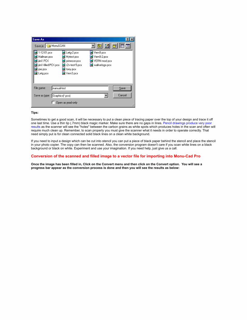
Tips:
Sometimes to get a good scan, it will be necessary to put a clean piece of tracing paper over the top of your design and trace it offone last time. Use a thin tip (.7mm) black magic marker. Make sure there are no gaps in lines. Pencil drawings produce very poorresults as the scanner will see the "holes" between the carbon grains as white spots which produces holes in the scan and often willrequire much clean up. Remember, to scan properly you must give the scanner what it needs in order to operate correctly. Thatneed simply put is for clean connected solid black lines on a clean white background.
If you need to input a design which can be cut into stencil you can put a piece of black paper behind the stencil and place the stencilin your photo copier. The copy can then be scanned. Also, the conversion program doesn't care if you scan white lines on a blackbackground or black on white. Experiment and use your imagination. If you need help, just give us a call.
Conversion of the scanned and filled image to a vector file for importing into Monu-Cad Pro
Once the image has been filled in, Click on the Convert menu and then click on the Convert option. You will see aprogress bar appear as the conversion process is done and then you will see the results as below:

At this point, we are close to finishing the conversion process. Click on the file menu and Save AS shown below:
Note that the vector file is being saved in the "Batch" folder under the main Monu-Cad folder with the file extension .txt. Type in a name where it says "untitled" as shown above and click the Save button.
Once this has been done, close the MCScan program and launch Monu-Cad Pro.
Importing into Monu-Cad Pro
To import the vector file into Monu-Cad Pro, from a blank MCPro screen type LB, select the same file name you saved thevector file under and return, return, return (return or enter key 3 times). Then do a Zoom All (ZA). Result shown below:

At this point, save it as a .MCD, edit, modify etc. as you would any other Monu-Cad drawing.
Tip:
If you look close at the image above, you will notice that some of the straight lines are not completely straight but are"stair stepped". We find that many users spend incredible amounts of time straightening out a scanned and converteddrawing. Please keep in mind that yes, the lines are not perfectly straight. However, a computer screen, being digital andvery low resolution, exaggerates and distorts this way out of proportion.
We have seen many scanned drawings which when cut on the cutter in raw form (before any manual editing) and a secondtime after hours of manual editing, come out the same!! Run some cutter tests with raw, unedited scanned drawings andsee what you think! You'll be surprised!

Note!! as of 2-1-2002 this program has been replaced by MCSCAN. This information is retained here in the event you do not have thenew MCScan program. goto MCScan for details
MonuScan ProgramsInputting new designs into your Monu-Cad System is a very simple process when using the MonuScanPrograms.
The MonuScan Program set consists of 2 programs; MonuPaint and MONUSCAN.
MonuPaint is a custom made "paint" program which will allow you to scan in a Black & White line drawing such as acarving or emblem and fill in the sandblast lines black. The filled in carving is then saved to a file called a Black & White.PCX file. If you have never operated a paint program before, it is a lot like a computerized Etch-A-Sketch. MonuPainthas been designed to operate in Black & White 2 color mode only specifically for scanning in monument line drawings.
MONUSCAN is a program which then converts the scanned and filled "bitmap" image into lines, arcs and circles forimporting into Monu-Cad Pro.
MonuPaint
To launch the MonuPaint program, double click on the MonuPaint Icon in the MONUCADprogram folder. The program signs on as shown below.

To scan in an image, click on the File Menu. It will drop down as shown below.
Click on ScanSetup and select your scanner. If there is no scanner listed to select then you must install your scannerdrivers. The scanner setup dialog appears as shown below.

Next, click on Scan in the File Menu.
At this point we cannot show you images of the scanner program as it will differ with each scanner. However, here arethe basics:
The scanner program will load. Place your Black and White line drawing into the scanner. Set up the parameters in yourscanner program to scan in Black & White Line Drawing mode at 300 x 300 pixels per inch. (sometimes this is calledLine Art or possibly Text mode) Do not scan in color or gray scale modes.
Start the scan. When the scanner has finished scanning, the image will be automatically transferred into the MonuPaintprogram. Below is an example of what you should see. You will have to slide the scroll bars around to find the image asit is very large; 4 to 8 times larger than your screen size. You may also need to Zoom Out on the image to getsomething that resembles the image below.

Remember GARBAGE IN = GARBAGE OUT. If the original drawing has clean, closed and connected black lines on aclean white background, the scan will require practically no clean up.
At this point we better tell you what the tools are and how to use them. Only the Fill Tool will normally be needed ifthe scanned drawing is of good quality. The remaining tools are provided in case you may need them.
This tool creates a filled in black oval. Hold down Ctrl key for a circle.
This tool creates a hollow black outline oval. Hold down Ctrl key for a circle.
This tool creates a filled in black rectangle. Hold down Ctrl key for a square.
This tool creates a hollow black outline rectangle. Hold down Ctrl key for a square.
This tool draws a straight line. Click and drag to draw. Hold down Ctrl key for ORTHO mode.
This tool draws a freehand line. Click and drag to draw. Used for patching small holes.
This is your Zoom in/out tool. Left button to Zoom in. Right mouse button to Zoom out.

This Fill Tool fills in an area solid. Place the pointer inside an area to fill and click once.
This is an adjustable size eraser tool. Size adjusted like the line size.
This is a fixed size eraser tool.
This is your UNDO tool. Clicking on it will undo the last operation. It is 1 level deep.
The little box with the number 1 in it at the right of the tool bar adjusts the width of the line and size of theeraser.
Note! When using any of the draw commands above, you normally use the left mouse button to draw with aBlack line. Because the program is only 2 color (Black & White) if you draw using the Right Mouse Button,you can draw in White. This will allow you to turn the solid rectangle tool into a sort of Window Erase whenyou use the right button to draw it with. Experiment a bit! You can't hurt anything!
To fill in the sandblast lines, click on the Fill Tool and point it inside the area to fill and click once. If the drawing issolid black lines with no holes in them, you will fill the average drawing or carving in just a few minutes. With a littlepractice your drawing should like something the one below. Note that the parts of the drawing which are "off the screen"are to be filled in also. If the lines are not connected and have "holes" in the line, the fill will "bleed out" through the hole.If this happens, click on UNDO, patch the hole and try again.

Once you reach this point the only thing left to do is to save the drawing to a file. Drop down the File menu and click onSave As. The dialog box below will pop up to allow you to give your file a name and save it. Make sure the file nameyou use has only 8 characters or less. It isn't necessary to add the .PCX to the file name. Just type in the 8 or lesscharacters and click on the Save button.
After the file is saved, exit the MonuPaint Program and run the MONUSCAN program to convert the image.
Tips:
Sometimes to get a good scan, it will be necessary to put a clean piece of tracing paper over the top of your design andtrace it off one last time. Use a thin tip (.7mm) black magic marker. Make sure there are no gaps in lines. Pencildrawings produce very poor results as the scanner will see the "holes" between the carbon grains as white spots whichproduces holes in the scan and often will require much clean up. Remember, to scan properly you must give thescanner what it needs in order to operate correctly. That need simply put is for clean connected solid black lines on aclean white background.
If you need to input a design which can be cut into stencil you can put a piece of black paper behind the stencil andplace the stencil in your photo copier. The copy can then be scanned. Also, the conversion program doesn't care if youscan white lines on a black background or black on white. Experiment and use your imagination. If you need help, justgive us a call.
IP
MONUSCAN
Click the BACK button to return to the previous page.

Note!! as of 2-1-2002 this program has been replaced byMCSCAN. This information is retained here in the event youdo not have the new MCScan program. goto MCScan for details
MONUSCANMONUSCAN
To launch the MONUSCAN program, double click the MONUSCAN Icon in theMONUCAD Programs Folder.
This version of MONUSCAN is a MSDOS program. However, it works well under Windows and is verysimple to operate. Basically, under normal circumstances, one has only to enter the input file name, outputfile name and then press the F1 key to start the program. The conversion will proceed automatically andcreate a .DWG output file which can then be loaded into Monu-Cad Pro.
When MONUSCAN first signs on, press any key to pass by the sign on screen. On the first line >Input filefrom scanner< , enter the 8 character (or less) input file name which will be the same name you used whenyou saved the file in MonuPaint. On the second line >Output CAD file< , enter the 8 character (or less)output file name of your choice. This will be the filename that will appear in the Input File Selector in Monu-Cad Pro when you import the results of the conversion. File name extensions are not necessary.
Then press the F1 key on the keyboard to begin the conversion. If the parameters are set correctly andthe drawing was of good quality and filled in correctly, in less than a minute you will have a file that can besent directly to the cutter from Monu-Cad Pro with little or no clean up! The output file will be placed intothe C:\DWG folder. This is the default folder for the Monu-Cad Pro 2000 Import (IP) command.

When the conversion is completed, you will pop back into Windows automatically. Then launch Monu-CadPro 2000 and import the converted file.
The program settings above work perfectly for a 1:1 ratio (real world size carving) line drawing. The onlysetting that you might need to change from time to time is the Allowable Errors setting. The current settingis 2. This setting determines the number of arcs that appear in the output file. If you change this from 2 to1, you will get 4 times as many arcs as are necessary and the shape will be different. Only lower thissetting when scanning smaller than real world size items.
When you are in the program, if you highlight a category and press the F2 key, a help screen will pop updescribing what the setting does.
File Selector Operation
IP
MonuScan Programs
Click the BACK button to return to the previous page.

Remote3 Program
The Remote3 program allows the main Monu-Cad Office personnel to adjust values in yoursecurity device remotely over the phone. When it is necessary to use this program, you will beadvised by the main office staff.
Click the BACK button to return to the previous page.
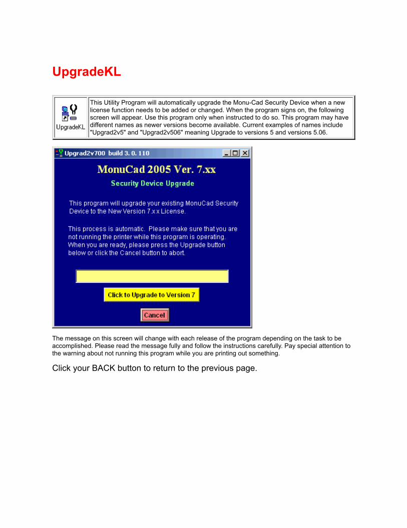
UpgradeKL
This Utility Program will automatically upgrade the Monu-Cad Security Device when a newlicense function needs to be added or changed. When the program signs on, the followingscreen will appear. Use this program only when instructed to do so. This program may havedifferent names as newer versions become available. Current examples of names include"Upgrad2v5" and "Upgrad2v506" meaning Upgrade to versions 5 and versions 5.06.
The message on this screen will change with each release of the program depending on the task to beaccomplished. Please read the message fully and follow the instructions carefully. Pay special attention tothe warning about not running this program while you are printing out something.
Click your BACK button to return to the previous page.

Thumbnail File SelectorBelow is a snapshot of our new Visual Thumbnail File Selector. The main benefit of this form of file selector is the ability to see an image ofthe file about to be loaded "before" it is loaded. This feature is an available "option" at nominal added cost on all Monu-Cad Programs.Thumbnails is a modern computer term for small images that are only large enough to fit on your thumbnail! To see the thumbnail selectorin operation launch either MCPro-T or MCLite-T. This is an optional feature
To select a file you, in typical Windows fashion, double click on the folder to open. In the example above, the Demo-All folder has beenopened. To select the file Demo_DD02.mcd, click on the image and then click on the OK button and the file will load into Monu-Cad Pro.You may also double click on the image to save time and skip a step. The thumbnail selector works for both .MCD and .MCC files.
In Monu-Cad Pro 2002, in the Toggles Bar is a button labeled TH. When button is pressed "in", the Thumbnail Selector is active. When thebutton is "out", the file selector reverts to the plain text style file selector. See Toggle Bar and File Selector Operation for more details.
How it works
The Thumbnail File Selector has been designed to "work in the background" to make it's operation transparent to users. When it is used toview the files in a folder for the first time, the program will make a small image for each and every file in that folder. You may not see thishappen because it quickly makes the first 10 images. If you jump from the top of the file list to the bottom, it will stop making images andrestart at the place where you currently have the selector located. If you remain in that folder long enough, it will make all of the images andrest.
The images are saved in a special folder in the selected parent folder called Thumbnails. Once a thumbnail image has been made, it issaved for future recall. When you load a file and then change it and resave it, the thumbnail image will be updated automatically to reflect thechanges on the next access.
The Thumbnail file Selector is available in 3 different variations:
1. The Visual File Selector itself as described above;
2. The Visual File Selector with the ability to perform a local database search;
3. The Visual File Selector with the ability to perform a database search across a Network.

Click Here for descriptions of the Thumbnail File Selector with Database Search Options
Click the BACK button to return to the previous page.

Thumbnail File Selector .....with Database Search This exclusive Monu-Cad feature will allow you to "ask the computer" to find for you any drawing (.mcd file) orcomponent (.mcc file) in your collection of files according to the search parameters that you enter. For example, youmay choose to ask the computer to "show you" all of the crosses in your computer which are less than 5 incheswide and 10 inches tall. In seconds, the search engine will show you thumbnail images of all the crosses that matchthis description without regard to what folder or directory these files may reside in! With this feature, every time youenter the command for a Drawing Load or Component Place, you may have the computer search for the desiredfile rather than manually hunting through all your files to find the desired one.
This feature is optional and you will only have it in your version of Monu-Cad Pro if you have ordered it.
Normal Thumbnail File Selector Screen
How it Works
In order for this technology to operate properly, a data sheet must first be filled out for each file that you desire tohave respond to search requests. On this data sheet you will enter or select the parameters that best describe thefile. If the contents is a cross, you enter the word cross as a keyword. Enter the word "hands" if the file contains aset of praying hands. When you click on the find button and enter the keyword "cross" and then click on the QueryButton (or press return), the program will find and show you thumbnail images of all the files in the database that theword "cross" has been entered as one of the keywords.
You may fill out all, some, a few or none of the data sheets. You don't have to do this all at one time. But the fewerdata sheets with data entered on them the less files will be found in a search. We suggest that you take a moderateapproach and take a moment every time you load a file to fill out the data sheet. With each data sheet filled out andadded to the database, the more productive the feature will become.

Individual File Data Sheets
If you place your mouse cursor over the thumbnail image of the contents of a .mcd or .mcc file and click your RightMouse Button, a data sheet for that particular file will appear as shown below. In this example, the data sheet for fileSTDR049.mcc is shown. (the red rectangle was added for emphasis)
In the File Properties section, the data sheet shows the file name and path, size, type and date last modified.
The Database Information section displays the Category selections and Keywords that have been entered forthis particular file, the extents (width and height) of the contents of the file and any descriptive comments that havebeen entered.
Note that the width and height is reset automatically every time you open and re-save the file. Many files arepreset to 48" x 36" as this was the default size entered when these files were converted over from the DOS version.We are adding a utility to our SatCheck program which will automatically open all your .mcd and .mcc files and resetthe size to the actual extents of the file. This utility should be available by the time you receive this documentation.
It is important to note here that you the operator will need to fill out a data sheet for every file you wish torespond to any database search queries you may make. Most records will be blank when the program isdelivered with the exception of possibly some sample or example entries.
Example Data Sheet Screen
Performing a Database Search
In the first image above you will see a button labeled "Find". Clicking on the Find button will change the screen tothat which you see below. The Database Query screen is blank because a search or query has not been made asyet.
Example "before" Database Query Screen

In our office sample database, many data sheets have been filled out for files that contain crosses and the word"cross" has been entered as a keyword in these data sheets. In the image below, you see the results of entering thekeyword "cross" in the keyword field on the Database Query screen followed by a click on the Query button. Notethat at the bottom of the window there is an entry that reads "323 files". In this particular search, the search enginefound 323 files which match the search description. This search took less than 3 seconds!
When the desired file is found, double clicking on the image will load the drawing if you were in the Drawing Loadcommand at the time you began the search. If you initiated the search while doing a Component Place command,double clicking on the image will select the component to be placed.
Example "after" Database Query Screen

Also notice that in this example, only the one keyword "cross" was used. Assuming that all the cross files have the correct size extentsrecorded, by dropping down the Width and Height combo boxes, we could have "narrowed" the search down to just crosses which weresmaller than a particular size!
Filling out the data sheets does not have to be an overly intense task. We have found that in actual practice specifying just one or twokeywords will be enough to get us the file we are looking for. The other 3 categories General, Type and Design are really optional.
Keywords
Keywords can include basic descriptive words such as car, truck, cross, and star. You are not limited as to what you type in but we have foundthat simple words will usually suffice. Dog and cat may be better choices than Greyhound, Persian or feline. As with most things, "KISS" or"keep it simple" is good advice. Pickup Truck is better than Pickuptruck.
Good keywords often include the name of a customer that uses that particular design. A search on ABC Granite will return all the filescommonly used by that customer.
Example "after" Database Query Screen "match all" search

Keyword Search Type
On the screen above, just below the keywords entry box are 2 check boxes:
Match any keyword will display any file which contains any one of the keywords entered
Match all keywords will display only those files which contain those exact specific keywords
The search type will depend on which check box is selected prior to clicking on the Query button or pressing the Enter key.
Keyword Shortcuts
You can also use global shortcuts in keywords. An example I often use the keyword "bull*" The star * character placed after the bull meansto the computer to show all files which have keywords which begin with the 4 letters "bull" and any other letters after the bull is acceptable.When we use this example in our sample database we get back images of a bull, bulldozer, bull elephant and bull dogs.
Create New folder Button
This feature will allow you to create a new folder or sub folder in which to move or create files without having to exit Monu-Cad and using aprogram like Explorer to create a new folder. There is no way to erase a folder from within the thumbnail file selector.
Moving Files
The thumbnail file selector will allow you to move files from one folder to another with the standard Windows "Drag and Drop" method. Simplyclick on the thumbnail image and drag it to the folder in the left pane of your choice.
When you use the file selector to move files, the database will automatically be updated. Without this feature, every time you move filesoutside of Monu-Cad the database would get messed up and loose track of where the files are. It is strongly recommended that you alwaysmove Monu-Cad files from within the thumbnail file selector rather than using an outside program.
Deleting Files
If you right click on the thumbnail image of a file and then press the Delete key on your keyboard you may erase files from within theThumbnail File Selector. Erasing files this way will help keep the database in synch.

Clean Up Database Button
Should you erase or move files outside of the Monu-Cad file selector, the database will not know that they have been moved or are gone.Clicking on this button will synchronize the database with the actual files present. This prevents the database from growing very large andcontaining many records for non existing files and suffering a performance penalty.
"Clean up Database" doesn't have to be used every time you move files. It should only be used to eliminate erased items from the databasewhen the database doesn't know they were erased because MCPro wasn't used to do the erasing.
Technical Considerations
The database information and data is contained in a file called MonuCad.mdb. It is located in the \MONU-CAD_Win'95 folder. This file mustbe located in this folder in order for the database feature to operate properly. An empty database file (MonuCad.mdb) is shipped with yourcopy of Monu-Cad Pro and is automatically installed in the local folder where it is designed to be placed. Note that this file is necessary to theprogram operation. If this file is not present, Monu-Cad Pro will not automatically create an empty database to use. Remember to include thisimportant file in your backup procedure.
All .mcd and .mcc files must be placed in folders which are located as sub folders to the \MONU-CAD_Win'95 parent folder. In computerspeak, all sub folders containing .mcd and .mcc files must be "children" of the \MONU-CAD_Win'95 parent folder. If you create a folder forexample C:\My_Drawings and place files into it, the database search feature will not recognize that these files exist.
Program Naming Conventions
Versions of Monu-Cad Pro 2000 which have the database search feature will have the suffix -TD or -TDn added to the program name.(MCPro-TD or MCPro-TDn). The main difference is that the "n" means that this particular version will function over a Local Area Network.
Network Use Considerations
In order for the network version to operate properly, the server computer must have a Parent Folder named \MONU-Cad_Win'95 and the.mcd and .mcc files must be placed in folders that are children of this parent folder.
A separate MonuCad.mdb file must be copied to the server parent folder to hold the data information for the .mcd and .mcc files located onthe server. When the client accesses files on the server, the .mdb file on the server will serve up the database information. When local filesare accessed, the .mdb on the local client computer will supply the information. Thus, when working in a client / server network, there will beone master .mdb file on the server and a local one on each client.
For the Network drive to appear in the Thumbnail Selector Tree, the Network drive must be mapped (mounted) to a local drive on the clientcomputer.
Note to advanced users!
Simply stated, this is the first time that this kind of a tool has been made available in a Monument CAD program. We at Monu-Cad arelearning as we go along in the same way you are. Any comments or suggestions you may have are welcome. Email all comments [email protected]

The Organization
Monumental Computer Applications, Inc. (product name MONU-CAD) was startedin December 1986 and is incorporated in the state of New York. The goal of ourcompany is to provide superior computer systems for the Point of Sale of CemeteryMemorials in addition to systems to automate and speed the manufacture of memorials.Due to the specialized needs of the Monument Industry, Monu-Cad has paid specialattention to include in their software programs those features which only a truemonument draftsperson would realize are necessary in a computer system designedspecifically for the Monument Industry. Today there are over 385 Monu-CadManufacturing Systems in use throughout the US, Canada and Europe, over 600 Monu-Cad Lite! installations and the numbers continue to increase daily.
High on our list of concerns is the ability to provide quick, efficient service to ourcustomers when help is needed. It is and has been our goal from the beginning to rendera superior quality service which will return our customers to full manufacturingoperation within 24 hours whenever help is needed and whenever humanly possible todo so.
Our computer manufacturing system proudly supports and includes a library of over13,600 memorial designs and over 90 "memorial specific" alphabets. We believe thatour systems produce cut stencil rubber in less time and with much more reliability thanany other comparable solution available today.
Jim Faliveno, the president and founder of Monu-Cad, is a retail memorial dealer withover 30 years experience in the Cemetery Memorial Industry. His work experiencesinclude hand stencil cutting as a shop employee, setting, draftsman, field salesman, salesmanager and business owner. Jim has taught Sales Management for the NationalMonument Association (MBNA) and has served as president of the New York StateMonument Dealers Association. Jim's unique and imaginative way of selling memorials

and his deep understanding of the Memorial Industry provides the foundation andbackground for the creation of the Monu-Cad software programs.
In 1984, due to an employee's illness, Jim began working to develop a computer systemwhich would eliminate the need for manual stencil cutting and which would at the sametime serve as a point of sale memorial design system to assist in selling retail customers.Today, we are proud to claim that the Monu-Cad system can perform 24 hours ofmanual stencil cutting work in just 1 1/2 hours!
In 1996, Monu-Cad released the first version of Monu-Cad Lite! which was anMSDOS based program designed to be inexpensive and was to be used primarily forpoint of sale presentation. The program received an enthusiastic reception in many partsof the industry. However, it was considered to require more knowledge on the part ofthe operator than many felt was necessary. While the concept was excellent, the actualproduct was a bit to involved for the average person to use. A far simpler and easier waywas needed.
Unfazed by the market reaction, Jim increased his efforts and with the help of hisexcellent staff, now has proudly released Monu-Cad Lite! for Windows '95-98-ME-NT-XP with "Click & Type" ™. Field tests have shown that the basics of Monu-CadLite! for Windows can be taught in less than 15 minutes and a person can become quiteproficient in it's operation after only 2 hours of working with the program!
Goto Click & Type Movie
In 1999, Monu-Cad released Monu-Cad Pro 2000 for Windows 95-98-NT. Thisprogram has been designed to provide the ease of use of Monu-Cad Lite! but alsoincludes all the drafting and manufacturing features found in the MSDOS Monu-Cadmanufacturing program in a much improved Windows format. Please refer to thesection of this manual MCPro Help for more information.
February of 2002 began a new chapter for Monu-Cad. With the release of Version 5.0 ofMonu-Cad Pro 2002, we once again set a new standard in manufacturing ease andutility. This new version contains features found no where else in the computer industry.With the new MonuRender full color rendering option for point of sale use, we nowbring a new dimension to memorial presentation drawings!
Updated versions were shipped in 2003 and again in 2005 continually adding morefeatures at the request of our customers. The progress continues!
With Monu-Cad Programs and "Click & Type", now anyone can be a MemorialLayout Expert!

Included on this CD is a version of Monu-Cad Lite! with "Click & Type", Monu-CadPro 2005 and several additional support programs available at the time this manual wascreated. The most recent releases can be downloaded from our web site at www.monu-cad.com. Check our web site often for the latest releases and information.
The Staff at Monu-Cad welcomes your input and suggestions for improvements to ourprograms and we solicit any reports concerning any problems or short comings you mayhave discovered. With your help we can continue to improve our products and services.
Monumental Computer Applications, Inc.
9 Genesee StreetCherry Valley, N. Y. 13320
607-264-3653607-264-3307 FAXwww.monu-cad.com
Goto Monu-Cad Lite! Intro Page
Goto Flip Chart Intro Page
Goto Monu-Cad Pro 2005 Intro Page

Click the BACK button to return to previous page

How to OrderMonu-Cad Lite! and Flip Chart are priced at $149.00 per copy with an annualsoftware support/software upgrade/usage fee of $100.00 per year.
Monu-Cad Pro 2005 is available in a number of price categories ranging from$1,999.00 to $6,497.00 depending on features selected. Please contact our office for acomplete literature package. Additional information is also available on our web site atwww.monu-cad.com.
Please contact our main office to place your order.
Monumental Computer Applications, Inc.9 Genesee Street
Cherry Valley, N. Y. 13320607-264-3611
607-264-3307 FAXwww.monu-cad.com
Goto Monu-Cad - The Company
Click your BACK button to return to the previous page.

ManufacturingConsiderations
For the Monu-Cad Lite! to be useful, it must be "filled out" with designs, alphabets,images and components which are similar to the type of memorials sold in your area.Agreeably, this is a very important part of using a point of sale memorial designprogram.
Secondly, it is important to consider the manufacturer who is going to produce thememorials designed with this program. Due to the fact that most memorials areindividually custom made, it is important that the design submitted to the manufacturerin fact be able to be manufactured by that producer. For example, every manufacturerproduces an "American Beauty Rose" in a particular way. If the design produced bythis program is to be used directly in manufacturing, the rose shown should be the rosethe manufacturer can produce. There are also other very real manufacturing concernssuch as the width of sandblast lines etc.
This is an area for discussion and the Staff at Monu-Cad will be pleased to share theirknowledge about these matters. Call our main office at your convenience and we willarrange a discussion with our experts in this area.
Goto 1st Introduction
Click your BACK button to return to the previous page.
Smaller CompaniesThe Monu-Cad Lite! program by itself is a small wonder! However, it cannot performits intended purpose unless it is complimented with a series of designs, components,alphabets and images which are useful to you.
To be specific, for example, your favorite "best selling" design may be unknown to us.There must be a way to enter your favorite designs into the program. Then, there aredesign copyright considerations.
The current plan for usage of Monu-Cad Lite! by an individual operator is to refer thatperson to one of the many Monu-Cad Master Manufacturing operations located acrossthe US and Canada for assistance. There are also companies which produce designs foruse in Monu-Cad Lite! who offer design "packages" for sale.
Perhaps a Point of Sale Version of Monu-Cad Pro 2002 would be a better choice forsome smaller dealers. We also now have an entry level package of software and cutterdesigned just for low volume retailers priced at $9,995.00.
Please contact our main office for details and specifics.
Goto Monu-Cad - The Company

Large CompaniesThere are many considerations when deciding to implement Monu-Cad Lite!throughout a large organization. In addition to the number of copies of the product topurchase, there are the questions concerning the computers necessary on which tooperate the program. Then there is always the question of using laptops vs. desktopcomputers. Where to buy them? How much to spend? Specifications?
Of great concern is the question of "who" is going to set up the design series to beused. Who is going to maintain and supervise it? Who is going to manufacture thememorials? Modem transmission of completed designs? How is it all going to workout?
The staff at Monu-Cad have the answers to these and many other questions. We arewilling to share our ideas and make suggestions. There is no charge for this service.Please call to arrange a consultation or discussion session with our experts.
Goto Monu-Cad - The Company