L~SA A4rn ii'n~i f-~~ .~-AA-~(At-(4Vl1~ ~j, - Defense Technical ...
37
RI Form Approved REPORT DOCUMENTATION PAGE OMB No. 0704-0188 Public reporting burden for this collection of information is estimated to average 1 hour per response, including the time for reviewing instructions, searching existing data sources, gathering and maintaining the data needed, and completing and reviewing this collection of information. Send comments regarding this burden estimate or any other aspect of this collection of information, including suggestions for reducing this burden to Department of Defense, Washington Headquarters Services, Directorate for Information Operations and Reports (0704-0188) 1215 Jefferson Davis Highway, Suite 1204, Arlington. VA 22202- 4302 Respondents should be aware that notwithstanding any other provision of law, no person shall be subject to any penalty for failing to comply with a collection of information if it does not display a currently valid OMB control nupber. PL§f&j DO NOT RETURN YOUR FORM TO THE ABOVE ADDRESS. 1. REPORT DATE (DD-MM-YYY) 2. REPORT TYPE 3. DATES COVERED (From - To) 09-01-2006 Annual Pertormance Report 09-09-2008 - 09-08-2007 4. TITLE AND SUBTITLE Sa. CONTRACT NUMBER L~SA A4rn ii'n~i f-~~ 5b. GRANT NUMBER FA9550-05-1-0280 (II...)jes 7 oni <31 Onv_! 5c. PROGRAM ELEMENT NUMBER 6. AUTHOR(S) 5d. PROJECT NUMBER Mason A. Peck Se. TASK NUMBER 5f. WORK UNIT NUMBER 7. PERFORMING ORGANIZATION NAME(S) AND ADDRESS(ES) 8. PERFORMING ORGANIZATION REPORT NUMBER Cornell University 9. SPONSORING I MONITORING AGENCY NAME(S) AND ADDRESS(ES) 10. SPONSOR/MONITOR'S ACRONYM(S) AFOSR Arlington, VA AFOSR AFRL/VS Kirtland, NM AIAA Reston, VA 11. SPONSOR(MONITOR'S REPORT NASA . Langley, VA NUMBER(S) 42. DISTRIBUTION / AVAILABILITY/ TEMENT ~ ~ .~-AA-~(At-(4Vl1~ ~j, AFRL-SR-AR-TR-08 -0029 13. SUPPLEMENTARY NOTES 14. ABSTRACT CUSat is Cornell University's entry in the University Nanosatellite Program (UNP4) . The student team has met many of the objectives of the program already, including education and outreach. The project promises a first-ever, end-to-end in-orbit inspection system. With centimeter-level accuracy, carrier-phase differential GPS enables CUSat to navigate and use its cameras to gather target-satellite imagery. In the ground segment, image-processing techniques verify the CDGPS position and orientation estimates and provide a 3D model of the target satellite for the data end-user. 15. SUBJECT TERMS 16. SECURITY CLASSIFICATION OF: 17. LIMITATION 18. NUMBER 19a. NAME OF RESPONSIBLE PERSON None OF ABSTRACT OF PAGES Mason A. Peck a. REPORT b. ABSTRACT c. THIS PAGE None 20 19b. TELEPHONE NUMBER (include area None None None code) (607) 255-4023 Standard Form 298 (Rev. 8-98) Presclbed by ANSI Std. Z39.18 2
-
Upload
khangminh22 -
Category
Documents
-
view
2 -
download
0
Transcript of L~SA A4rn ii'n~i f-~~ .~-AA-~(At-(4Vl1~ ~j, - Defense Technical ...

RI Form ApprovedREPORT DOCUMENTATION PAGE OMB No. 0704-0188
Public reporting burden for this collection of information is estimated to average 1 hour per response, including the time for reviewing instructions, searching existing data sources, gathering and maintaining thedata needed, and completing and reviewing this collection of information. Send comments regarding this burden estimate or any other aspect of this collection of information, including suggestions for reducingthis burden to Department of Defense, Washington Headquarters Services, Directorate for Information Operations and Reports (0704-0188) 1215 Jefferson Davis Highway, Suite 1204, Arlington. VA 22202-4302 Respondents should be aware that notwithstanding any other provision of law, no person shall be subject to any penalty for failing to comply with a collection of information if it does not display a currentlyvalid OMB control nupber. PL§f&j DO NOT RETURN YOUR FORM TO THE ABOVE ADDRESS.
1. REPORT DATE (DD-MM-YYY) 2. REPORT TYPE 3. DATES COVERED (From - To)09-01-2006 Annual Pertormance Report 09-09-2008 - 09-08-2007
4. TITLE AND SUBTITLE Sa. CONTRACT NUMBER
L~SA A4rn ii'n~i f-~~ 5b. GRANT NUMBERFA9550-05-1-0280
(II...)jes 7 oni <31 Onv_! 5c. PROGRAM ELEMENT NUMBER
6. AUTHOR(S) 5d. PROJECT NUMBERMason A. Peck
Se. TASK NUMBER
5f. WORK UNIT NUMBER
7. PERFORMING ORGANIZATION NAME(S) AND ADDRESS(ES) 8. PERFORMING ORGANIZATION REPORTNUMBER
Cornell University
9. SPONSORING I MONITORING AGENCY NAME(S) AND ADDRESS(ES) 10. SPONSOR/MONITOR'S ACRONYM(S)AFOSR Arlington, VA AFOSRAFRL/VS Kirtland, NM
AIAA Reston, VA 11. SPONSOR(MONITOR'S REPORTNASA . Langley, VA NUMBER(S)
42. DISTRIBUTION / AVAILABILITY/ TEMENT
~ ~ .~-AA-~(At-(4Vl1~ ~j, AFRL-SR-AR-TR-08 -0029
13. SUPPLEMENTARY NOTES
14. ABSTRACTCUSat is Cornell University's entry in the University Nanosatellite Program (UNP4) . Thestudent team has met many of the objectives of the program already, including education andoutreach. The project promises a first-ever, end-to-end in-orbit inspection system. Withcentimeter-level accuracy, carrier-phase differential GPS enables CUSat to navigate and useits cameras to gather target-satellite imagery. In the ground segment, image-processingtechniques verify the CDGPS position and orientation estimates and provide a 3D model of thetarget satellite for the data end-user.
15. SUBJECT TERMS
16. SECURITY CLASSIFICATION OF: 17. LIMITATION 18. NUMBER 19a. NAME OF RESPONSIBLE PERSONNone OF ABSTRACT OF PAGES Mason A. Peck
a. REPORT b. ABSTRACT c. THIS PAGE None 20 19b. TELEPHONE NUMBER (include areaNone None None code)
(607) 255-4023
Standard Form 298 (Rev. 8-98)Presclbed by ANSI Std. Z39.18
2

CUSat: An End-to-End In-Orbit Inspection SystemUniversity Nanosatellite Program
Annual Performance Report2007
Prepared for the Air Force Office of Scientific ResearchUniversity Nanosatellite Program 4
Grant No. FA9550-05-1-0280
20080118121Dr. Mason A. Peck JuAssistant Professor 212 Upson HallSibley School of Mechanical and Aerospace Engineering Ithaca, NY 14853Cornell University (607) 255-4023

1.0 Objectives
The CUSat project includes many objectives, both programmatic and technical. The followingdescription of these objectives includes a brief explanation of their relevance to our sponsors.The programmatic objectives (POs) are laid out in the Nanosat-4 User's Guide (UN4-001 Rev-March 2005):
" PO 1: Educational outreach to students in grades K-12
* PO 2: Attendance and participation at program Milestone Events
* PO 3: Student involvement
o PO 3.1: Involvement of students at all levels of the Nanosat program, includingmanagement, engineering, test, and hardware assembly. Universities are expectedto have a student Program Manager.
o PO 3.2: Involvement of students from a range of engineering and other disciplines.
o PO 3.3: Involvement of students at various education levels, (e.g. undergraduate andgraduate).
o PO 3.4: Students are expected to present their designs at all design reviews.
CUSat's technical objectives (TOs) are the following:
" TO 1: Demonstrate an end-to-end in-orbit inspection system
Here, "end-to-end," refers to the scope of the in-orbit inspection architecture. CUSatincludes a space segment, a ground segment, and a data segment. Taken as a whole,these segments form an in-orbit inspection system that autonomously images a targetspacecraft, downlinks this imagery to the ground, recovers a three-dimensional shapefrom these images, and conveys them in a responsive manner to data end users.
" TO 1.1: Demonstrate space-segment technologies for in-orbit inspection
These technologies address several Air Force and NASA needs, including responsiveness,robustness, and safety.
o TO 1.1.1: AII-GPS guidance and navigation
GPS is a technology that is largely platform independent and works well for precisionnavigation (both absolute and relative) in a variety of orbits. Other technologies,such as earth sensors and star trackers, have their appropriate applications but arenot sufficiently broad in their applicability for CUSat's purpose. This purpose is toserve as demonstration of a turn-key inspection system, one that can be used formany different spacecraft without time-consuming and risky modifications. CUSat'sgeneric design demonstrates responsiveness in that missions that demand aninspection capability can use an off-the-shelf CUSat design rather than a customone. The low cost of an all-GPS system is another important reason for CUSat'simplementation of it, given our cost constraints, but this demonstration can also
enable future low-cost missions.
3

o, TO 1.1.2:Autonomous navigation with carrier-phase differential GPS (CDGPS)
Navigation here refers to the estimation and control of position, along with higher-level decision functions.
" TO 1.1.3:Attitude determination with CDGPS
" TO 1.1.4:Fault-tolerant inspection architecture
Meeting this objective will demonstrate that a low-cost system can be fault tolerantwithout depending on redundant devices, but rather by cross-strapping criticalfunctionality among multiple subsystems.
0 TO 1.1.5:Collision-Free Navigation
This objective is achieved as a combination of functions, including the mission design(orbit mechanics), fault tolerance, and precision navigation
* TO 1.2: Demonstrate ground-segment technologies for in-orbit inspection.
0 Demonstrate ground operations for autonomous inspection
CUSat's concept of operation is designed to reach the "sweet spot" of combinedautonomy and ground-controller interaction. The ground will be responsible fordecisionmaking regarding changes in mission phase (such as separation or anomalyresolution) but not in the day-to-day activities. The telemetry and command systemis based on providing data for diagnosis of CUSat's health and a small number ofcritical commands and uploads but not for realtime "joystick" control.
0 Demonstrate a responsive, distributed ground segment
Northrop Grumman Mission Systems (NGMS) has partnered with CUSat, offeringaccess to some of its ground-station assets. NGMS will work with CUSat to developa means of conveying data among at least three ground stations (one in SouthernCalifornia, one in Colorado, and one in Ithaca, NY) ina way that allows a distributedend-user community to access the inspection data.
* TO 1.3: Demonstrate data-segment technologies for in-orbit inspection.
CUSat will demonstrate the use of familiar image-processing techniques to create athree-dimensional shape from still images taken in orbit. These algorithms will runwithin the ground-station software. This surface-map data will serve as the primarydata product for end users. The design of the spacecraft will be such that it can beanalyzed by these imaging techniques.
* TO 2: Demonstrate Nanosatellite Technologies
CUSat uses a number of approaches from other small satellites. Those heritagesolutions do not represent significant value as demonstrations. However, we willdemonstrate three unique technologies.
o Demonstrate the ACS-in-a-box device (the IMI-C) from Intellitech MicrosystemsInc.. This device consists of three reaction wheels, three mag torquers, a three-
4

axis magnetometer, a sun sensor, and an earth sensor. CUSat will demonstrateits functionality, but the system will be able to perform without this device.
o Demonstrate rapid, modular assembly. A key element of responsive space, thisdemonstration will be realized via the design of CUSat's electronics backplane,which includes modular, common connectors and a mechanical strategy formounting electronics cards within common-sized shielding boxes. Thesecomponents can be removed and replaced with relative ease.
o Demonstrate an all-propulsive, pulsed-plasma thrustser (PPT) attitude-controlsystem. While the IMI-C provides CUSat with considerable functionality, thebaseline design includes eight PPTs, in an eight-for-seven redundant attitude-and position-control actuator suite. The safety of these non-combustive,lightweight devices makes them ideal for inspection of manned spacecraft.
0
2.0 Status of Effort
CUSat is a multi-year effort to design, build, and launch an autonomous on orbit inspection satellite system. CUSatis a student project team in the College of Engineering and is part of the University Nanosat-4 Competition, a twoyear, cyclic program run by the Air Force Research Lab (AFRL). For the University Nanosat Competition, studentteams design their own mission and build a satellite to perform their mission. Each team goes through severaldesign reviews by the AFRL, leading up to a final review in which a single winning team is chosen. This teamreceives additional support from the AFRL and is given a launch opportunity.
Mission and OperationsCUSat is Cornell University's entry into the University Nanosat Competition. CUSat's mission is defined as follows:
CUSat demonstrates an end-to-end autonomous on orbit inspection system. Centimeter-level
accurate Carrier-phase Differential GPS (CDGPS) enables CUSat to navigate and use its cameras to gather
target-satellite imagery. In the Ground Segment, image-processing techniques verify the CDGPS relative
distance and orientation estimates and provide a 3D model of the target satellite for the user.[1]
The primary goal is to demonstrate cooperative, on orbit inspection. The driving technology that helps to achieve
this goal is Carrier-phase Differential GPS, a differential GPS technique that allows measurement of relative vectorsbetween antennas with better than 1cm accuracy. By using two identical satellites with three GPS antennas each,CUSat is able to measure relative vectors between the two satellites and gain an attitude estimate of eachindividual satellite. This data is used to direct visual inspection using on-board cameras. The acquired images arethen downlinked to a ground station for 3D reconstruction.Both satellites will launch in a single stack as a secondary payload on the launch vehicle. After separation from thelaunch vehicle, the stack will power on and begin to charge its batteries. The stack will then initiate groundcommunication. After a system checkout, the ground will issue a command for the stack to separate. Onceseparation has occurred, the satellites will enter an autonomous inspection mode where pictures are takenautomatically when the opportunity arises. The ground stations will then request these images for download. [2]
5

Program, StructureCUSat has historically followed a project-oriented structure. Professor Mason Peck, the Principal Investigator, is incharge of all project operations. The Program Manager, typically a student who has been with the program for along time, reports to Professor Peck. Work on CUSat is then divided up into several subsystems. Each subsystemhas a lead which reports to the Program Manager.
Program Schedule and MilestonesThe AFRL specifies that the following reviews take place for all entrants to the competition:
* Systems Concept Review - May 2005
* Preliminary Design Review -August 2005
* Critical Design Review - February 2006
• Proto-Qualification Review - August 2006
* Flight Competition Review - March 2007
In addition to these reviews, CUSat conducted several internal reviews described later in this report.
Design MaturityCUSat delivered one fully functional prototype flight unit for the Flight Competition Review (FCR). This unitcontained a complete and functional electrical bus. Most custom printed circuit boards (PCBs) were professionallypopulated by Northrop Grumman Space Technology, the remainder were assembled in-house. The proto-flightunit also contained a complete structure. Most structural components were machined in-house. Severalcomponents were manufactured by Moog, Inc. Space Systems. Since the proto-flight hardware was intended to beused for the actual flight units, all of it was appropriately tracked per the CUSat Configuration Management andQuality Assurance (CM/QA) Plan.On the subsystem level, the vast majority of hardware was delivered except for several large ticket items. Theselarge-ticket items included the inter-satellite Motorized Lightband Separation System, flight solar cells and solarcell honeycomb panels. Most of these were excluded because of budget constraints.The purpose of the prototype build was to demonstrate the ability of the team to deliver functional, high qualityhardware. Another purpose of the prototype was to identify any integration issues and unresolved design issues.
6

100 .
90
~~77070
60
E N Hardware0 5050 N Software
40
a 30
20
100
Figure 1 - FCR Hardware Design Maturity 131
Flight Competition Review (FCR)The Flight Competition Review served as a major design review milestone. However, the main purpose of thereview was to allow the AFRL to choose a winning team to which they would offer continued support and a launchopportunity. For the competition, one of the author's main responsibilities was to develop a plan to complete theprogram upon a win at FCR. This document was labeled the Post-FCR Action Plan (CUSAT-SYS-0026)[3] andconstitutes a large portion of the work for the initial sections of the report.Cornell's entry was chosen as the winner of the competition based on technical merit, relevance to the AFRL,program documentation, as well as several other factors. As a result of this decision, the AFRL committed tosupporting the program through completion. This necessitated heavy planning for delivery of hardware qualified forspace flight, software that was thoroughly tested, and a ground support system capable of running the mission.
Program Deliverables and GoalsCompletion of the CUSat program is contingent upon delivery of several large items:
" Flight Hardware
Two identical satellite units that satisfy the hardware requirements set forth in the CUSat
Requirements document. Problems identified with the proto-flight unit needed to be fixed,
whether by physical changes to the hardware or modifications to the design. Additionally, a
full two sets of flight hardware plus several spare pieces of hardware needed to be
manufactured. Hardware delivery is contingent upon a successful integration process as well
as a rigorous and well documented testing process.
" Flight Software
Flight software includes embedded code for smaller systems, baseline code for the flight
7

computer, high-level control code, as well as filters, estimators, and controllers. All of this
software needs to be verified on the ground through a combination of simulation and test.
* Ground Stations
Well designed and maintained ground stations are essential for mission success. Final
delivery requires that ground stations be ready to receive telemetry and send commands. A
central server and ground station network also needs to be complete. Hardware acquisitions
(such as antennas) are also key to ground station delivery.
* Mission Operations
Well defined operating procedures as well as trained operators are also critical for mission
success. Part of the overall delivery package includes a team capable of handling routine as
well as unforeseen operating conditions for the lifetime of the CUSat mission. This team
needs to maintain knowledge across generations of graduates.
Scope of this ReportThe scope of this project includes work done by the author after the Flight Competition Review (FCR). At this point,the project had been in progress for about two years. This project focused on bringing a prototype system throughdelivery as a flight-ready, robust, tested system. The report is split into four sections.
Program ManagementLeading the CUSat team towards completion of the flight units was the primary purpose of this project. The reportdetails planning for the flight build as well as several reviews and other tools that were used to accomplish goals setforth in the beginning of the semester. Regular communication between the AFRL, the University, Professor Peck,and team members was also a key part of the project. Program schedule, budget, and organization are all covered inthis section of the report.
Camera Interface Board (CAM IB)This semester, a lot of technical work was done to redesign the Camera Interface Board (CAM IB) after identifyingserious design flaws during FCR. This section of the report outlines system requirements, describes the designprocess, and shows how the design met the requirements.
Power Board CompletionPower board design was done as a senior honors project. FCR integration exposed several design flaws with thesafety inhibit design. These flaws were addressed as part of this project. The updated design is described in thissection of the report.
System Level Trade Studies and AnalysisThis project also dealt with several system-level design decisions. There were also several specific design tasksrelating to hardware work. All of these tasks contribute to the larger goal of creating a flight-ready system to meetprogram requirements and accomplish mission objectives.
8

Program ManagementThis section details the work done to plan for final delivery to the AFRL. A large portion of this work was donebefore FCR to demonstrate the ability of our program to finish and our desire to deliver a complete, functionalsystem. Planning was required on several levels. First, a budget needed to be developed to ensure that delivery wasnot impeded by funding constraints. Also, a large portion of the team was graduating at the end of the year, so a wellthought-out recruitment effort was essential to continued program success. Remaining design work from issuesidentified during FCR also needed to be planned for. Finally, the extensive integration and testing process needed tobe spelled out and scheduled to ensure success.
Post-FCR Action PlanThe Post-FCR Action Plan[3] was a major first step in the planning process. A current budget was presented todemonstrate the ability to finish the program given extended AFRL funding. Remaining build and design issueswere also presented to give an honest yet hopeful timeline for flight unit delivery. An assembly, integration, and test(AI&T) schedule was also presented to show our expected completion time.
Project Level GoalsThe following goals were identified as necessary for successful project completion:
1. Resolve remaining design issues identified after FCR.
During the prototype build, several design issues were identified. These ranged in severity from very minor(improperly sized bolts) to severe (lack of ability to build solar panels). To ensure successful resolution of theseissues, a post-FCR debriefing meeting was held. A system-wide list of outstanding actions was assembled andspecific actions were assigned to specific team members. Team members were informed that their grade for thecoming semester directly depended on their ability to resolve these issues.Several issues were identified as beyond the scope of a particular subsystem or beyond the expertise of certain teammembers. These issues included:
* Solar Panel Construction
* Communications Antenna Design
These trades are addressed directly later in this report.
2. Finish machining of structural and propulsion components.
Design of a machining schedule and finalization of part drawings was assigned to Ofer Eldad, the mechanical lead.With Ofer's guidance, the structural design and manufacturing teams on CUSat were was able to lay out amachining schedule and finish major machining efforts on time.
3. Finish design and build of electrical subsystems.
Several electrical systems required direct attention. These included:
* Camera Interface PCB
* Propulsion Electronics
* Power PCB Redesign
These designs are addressed directly later in this report.
9

4. Rigorously test subsystem hardware.
5. Integrate and test all hardware to verify system requirements.
While test plans had been developed before FCR, most of them had not been run on hardware and were inadequatefor requirement verification. Part of the work done this semester included setting up a testing process and trainingnew members to carry out the tests.
6. Maintain a program budget to ensure adequate funding.
An overall budget was developed as part of the Post-FCR Action Plan. This is included in this report.7. Develop comprehensive ground support and mission operations systems and train
personnel.
Two major milestones for the ground segment this semester were acquisition of ground station software and theformation of the mission ops team. A mission ops team was formed this semester with the goal of developing acoherent set of recommended operating procedures (ROPs) for ground station operation. Ground station softwaretrades are discussed later in this report.
BudgetA forward looking budget was developed for the Post-FCR Action Plan. Each foreseen expenditure was listed bysubsystem. The results are summarized in Table 1.
Table 1 - rlmnr ugt131
Subsystem Resources Required CostNone s1
~$0
SAdditional Cameras $5,000SAdditional FPGA Boards $3,500SLenses $2,550
$2,550Additional Flight Computer $550
~$550None so
I Additional Connectors/Supplies $500
SFabrication of Flight PCBs $4,000
$4,500Support Equipment/Materials $5,000
~$5,000
PPU Electronics Fabrication $4,000
PPT Stock/Manufacture $500PPT Wiring Harness $2,500
SBusek Testing $500
$4,500SFabrication of Flight PCBs $2,000
Solar Cells $76,750
10

$108,750
Fabrication of Flight PCBs $1,000Antenna Fabrication $500
$1,500
Honeycomb Panels $5,000Motorized Lightband $80,000
$225,000Antennas/RF Equipment and Computers so
MAESTRO and GUI so
a Other Expenses J $10,000
$10,000Total Program Cost Remaining:
$208,350
PersonnelA large number of experienced CUSat members were graduating at the end of the spring semester. In order tomitigate the risk of losing knowledge, an aggressive recruitment process was started before the end of the semester.Team leads were asked to submit a list ofjobs that needed to be filled. Several information sessions were run andadvertisements were put out to attract new students to the team. Students were encouraged to fill out an applicationform and submit it to the team leadership. After interviewing prospective candidates, the team leads were asked tosubmit a list of candidates that they wanted to accept.In order to acclimate new members, an orientation session was run. This consisted of a Powerpoint presentation thatdescribed the team history, progress, documentation procedures, and how to use the team website. New memberswere assigned documentation to read before starting work [4].
ScheduleA long term delivery schedule was designed for the Post-FCR Action Plan. The schedule sets hardware delivery inJanuary of 2008. The AFRL has requested that we stick to this schedule and deliver flight hardware between Januaryand March of 2008.
iI

CD 70077 N,n. ou'loo I Stan ~l~7 ~ 7 .o7
3 /7 0.
I- Right Co O/Itt.. A-i-1 0 daint 5. 2607 S. 2w0 326
Pin.1 D.Wgn 1*-1- 0 d.yo P1/410 P " 1Il 1107 Gois
I P-A.0(p AloM OdFv* Mo. I1170 W . 11MT /4 Wn1(1NT2i
ow Wa 000 n" RoHnInu0 670,00 y. Yft 12/2M W*d111/0 12MV0 wi
FlPight RodM- ft,*wM0 Odays Mon I1f21106 Mon irM001 il2s
HSMWM0/ Doihow'y 24 d0o0 Su. WSW10 Fri 11406
0 SOID, P"016 lA40 10 S.. 322M70 Th.10W4/
FnakCvLavouoIAPWA700rft I/7,0/ 2K 7 T,'.4//07
P&W (FMc*. 7r.b00O 6-o. r,. "427.7 7/'. 104t
12 LUght-d 144 0 (IFN S. 2W710 Thu. 1W44)7
/2 /0W Lqn"007 0- PSC /I77 L ,3257 7 .19 ('7
14 UghtNonO 07/00 D"ir bon Pl7C S. / 4*W'7 Th /2.47
'S CusonPCDB A lun07 3o.2MY10 Thu VIVO
R--S. PCs. (7o/ O /. , 4.2c7.77 T,u 517
1 Fab r74 Teal E0/. POrt I F' W, 7 Th, 0.1C7V
2D FOD-Wo, by/NGST I F(7 . VII/0.7 TN177
27/ F-1-74/r C-k.wn 2-. F &0.77 Thu &.2/177
G2 TS C"omme000 440 ne Su 12&107 Thu VIV IVNNENO?
24 I'/M 00 PI(7j0,rb,1 'w 0,7 3,/25r7 Th,41617
25 Pop Pa0 NGST I8 / 7,07 (427 7 & Th.7 CT
Aiod,Amdd*O/7 Pamt I 714 Sun VM2V Thu.4(0/77
7 /.-br PT, S-7 Y2K 077 u7,. V ~Figure 2 - Post-FCR System Schedule 131
To",.o 0,/7 T1/ /1. 7 4n77 :/17 0. C47 A.7 ~~' /7 '0V 7 3 07
1 4gi W7/w Ul4 dap F Ar/22107 PH/ IWO0$-
23 E*cironc. B.. AIT 0.... r,, &=?, Th,.7'2S7.7
2. WPi4tM-P,. MAT7 3-S. F,, 7,27T77 T,, & 1"7
20 Pwua-M0 7
AT 2-. r7 &ti7v7 0,, &W7
20 C.-M0(AT 2-07 r,i a3i.7 Th, 6 3,7
3 BonyB..AM&T 2.-7 F/ , 1(47T7 Th,.9,27V7
20 SOW0 PWW1/A&T 2-,0 r, 1CS77 TNu. (10"?
TAC Ammi-r AT 3.07. Fr-ai"?/ T. 07237
.7 GPS (407/IMAT 3,.yo 1. (C2.07 ,,/28M?
--71 r101.3/C747/7h T"NI 2- kio 1/7(2907 F" VM07
-2 Sh. 10ME 2 . %$ 1// (2IM7 F// 1(/231C?
42 UqN70907MAT 2- M01 1/0 (20.7 F,. 12/7V7
FL &i A*0/ T/I. 4 M10 12AU/T07 F'/ V4,Do
15 0//UOOr// asy.4 F,/,O -T F1,7 1 .0
77 Softw"7000470,7 - + 120dWo7 Sun 320107 7/4161
Q fai Soft-4710/ 070777/wt 6.0- S. 2,25V7 T, S2,M
40 1.040/9770 Fl" 7/7 Cow FuI, S.V25,+7 Th, 1-9t7 [GN/C NWV-0/0 D.Oft-N01 Sun07 210.7 .7/1217
$I GN/C Cbd olin W F.4170N COMWWt. 2-4/ r,,. 7 F".,7
03 0-.4. 1"..,o 000-v. 1040 4". Sun 10 VISI Thu&/0
54 Gnium .;p-iu loo,707rchavDiwvo G-1 S... 2SI0? T,. &.,7
00 Wound S/I/.Wwt /707(7001107 0.10 2. 1 2,07 Fr, 5/3,7
14 1AtOCi5g..2,7 Fl 0.477 07,2,7
0.' 0f0400107 0/07 40Iw W&ID32.7 Th.A,r0/77
00 G,ono S.Vr..,H Uft-0 007.W7Il 2-0-7 S., 12S0.D T7/,17V___
G2,un Soro.wM TuWV1 2. F,, 7/27:07 Tn, S'Pt7
Figure 3 - Post-FCR System Schedule (ctd) 131
12

While the overall program schedule was defined before FCR as shown in Figure 2 and Figure 3, a more detailedscliedule wis set up using Microsoft Project to keep the team on track. This schedule was kept up to date on theinternal website and was updated weekly at the leads meetings. Specific tasks and deadlines were assigned directlyto different team members. An example of part of this schedule is shown below in Figure 4.
.. . ... ....... ....... NNNOW
-i. -0? T. Ies. 0- OIL; o =wI-
,, em o 'A -V
Figure5 1* 409 -u Deale rorm2cedl Eapl75
risk and1omletne. This was prtu 11.1w a
Figure 5.5 2~h7 0
CAMtei Stea,Roso,m
TIC nee w warraoy- w
It CT ina 2 *_o 15D" "w
PROP u Da DSct
CM- A-eA Fligh m-ep -
*900 s~. 220010* 108 usaw0
HMdoe. arevre ... ".zRV
AFi gurep - Detailed Pg Schedule Exmpl
COn adton totaknJciniemeyta ebradusse,aHwrem Stts hrtws loeelpd
Thc aLnd Ja p r of tu eren Kin
risk Wand e ws p a uere s eind
Figure W5.Jeey ei
atrad in aterbe Auhif eacnsil uhrtCHM 8 JOrnm TovnSIA=e Seey Robl
07T JereS.asy 7K.e,71n
TCigure D5n L Tardwar StatusHhart 16
PROP Dl 0. D1 5Ri:tt0
HAM R:,,,N::' 0.11-c! toSUR
COH9P 5542. 025010079 Kevin
CAM*5 Ud5005 I20 my Kevin5* 00
Top Wabl Jeremy00 Ks 057 20"' 05 '7 a
Figure 4 -Detildwrorm Scheule Eampl 61
Inaditontotacin atin tmsbytem ebe ad ubyse, Hrdar tausChrtwa ls dveopd

CommunicationsWeekly meetings were held on three levels to discuss progress and high-level issues. These meetings occurred everyMonday and helped to foster communication between people working on various levels of the project.
Leads MeetingThis meeting involved all of the subteam leads. Weekly progress was discussed. This gave the leads a chance towork out some inter-subsystem issues. The system level schedule was also discussed and updated at each of thesemeetings. At the end of each meeting, action items were assigned to various leads.
Meeting with Professor PeckThis meeting included the PI (Professor Peck), the PM (the author), and the lead mechanical systems engineer (OferEldad). The purpose of this meeting was to update Professor Peck on the team status as well as to work out high-level issues, such as those dealing with the University or the AFRL. Professor Peck would also offer technicaladvice when the team would encounter a particularly difficult problem.
AFRL TeleconThis weekly phone conference consisted of a small group of subteam leads as well as the lead Systems Engineer andProgram Manager for the University Nanosat Program at the AFRL. The purpose of the conference was to updatethe AFRL as to team status and work out delivery related issues. The AFRL would also offer technical advice.
Integration and Testing
GoalsThe overall purpose of the Integration and Testing (I&T) effort was to satisfy system level goal number (5). Severallower level goals were derived to accomplish this test.
1. Implement and enforce rigorous Configuration Management and Quality Assurance
(CM/QA) procedures.
2. Develop meaningful test procedures that verify system and subsystem level requirements.
3. Test all flight hardware and run integration tests using rigorous test procedures.
CM/QA procedures were already well defined at the start of the project based on AFRL recommendations. The mainchallenge was gaining momentum in the testing area. Most I&T members were new and unfamiliar with thehardware and the testing process. To kick-start the process, the author organized and helped with several initialhardware tests. Once the testing phase had started, the I&T team members were able to continue the process anddevelop high-quality test procedures.
Ground Segment and Mission OperationsUp until FCR, the ground segment and mission operations had received significantly less focus than the spacesegment. It was recognized that these sectors of CUSat would play a pivotal role as hardware development came toan end. As a result, a large part of the team (about one third) was devoted to ground segment and mission operationswork.
14

Review*Several reviews were held as stage-gates to ensure that the team was on task and to provide concrete deadlines thathad to be met. Some of these reviews were on the team level, but others included industry experts and the AFRL.
Post-FCR ReviewThe Post-FCR Review was designed to make sure that issues identified during FCR were not ignored and forgotten.For the review, each team met with the program manager and outgoing program manager to discuss issues with theirsubsystem. These issues were recorded and turned into action items. This list of action items was used as thedeliverable list for the subteam in the next semester. These are included in the appendix.
Red Team ReviewThis review took place on September 28 h, 2007. Attendees included industry experts and AFRL employees. Thereview was an all-day event that consisted of several presentations where the reviewers were encouraged to askquestions and write down action items. Presentations were design to show the current state of the program and toencourage discussion about high-risk and still unresolved issues with the design [7].
Operations ROPs ReviewThis internal review took place mid-semester. The purpose was to review the first draft of several of theRecommended Operation Procedures (ROPs) designed by the mission operations team. Team members gavefeedback and assigned action items to each of the ROPs.
15

Camera Interface Board (CAM IB)The original Camera Interface Board (CAM IB) design used four boards:
* The Heron FPGA5 board
This board was used to capture image data from the cameras.
* The Heron Base board
The FPGA5 board mounted directly to this board. The Base board provided power to the
FPGA.
" The CAM IB
This board interfaced between the Heron FPGA5/Base and the flight computer through the
Jumper Board. It was mounted on standoffs on the side of the camera electronics enclosure.
* The CAM lB Jumper Board
This board held the connector for the box enclosure and jumper wires from the connector
to the CAM lB.
The decision was made to replace the Heron Base board as well as the side board with a single Camera InterfaceBoard (CAM IB). See the Trade Studies section for details on this decision. The CAM IB had the following derivedrequirements:
1. The CAM IB shall provide all necessary functionality for the FPGA5 board originally provided
by the Heron Base board.
2. The CAM IB shall provide an RS-485 link to the Heron FPGA5 board.
3. The CAM IB shall provide an interface to the flight computer as specified by the Electrical
ICD.
4. The CAM IB shall be capable of reprogramming the Heron FPGA5 using JTAG.
To satisfy requirement (1), several documents from Heron were obtained [8,9,10]. These documents provided exactdimensions of the Heron FPGA5 board as well as descriptions of most of the interface pins. However, the interfaceused was designed for much more complicated systems and many pins were unused on the Heron Base board. Adiagram of the Base/FPGA board setup is shown in Figure 6.
16

HRON HFi-ON.BASEI
LEN S/
//
//
/
Figure 6 - Diagram of the Heron Base Board 181
SchematicUsing the signal list from the specification, each pin on the base board was probed to measure:
• Resistance to ground
• Resistance to 5V
• Resistance to 3.3V
• Voltage when the board was powered
Unfortunately, these measurements were recorded by hand and are not included in the report. However, the circuitdiagram in Figure 7 shows the results of the analysis.This allowed the elimination of many unused features in the spec. After many checks to the recorded measurements,a schematic was drawn for the CAM 113. The schematic mimicked the connections as they were done on the Baseboard.
17

JF
,-=
Figure 7 - CAM IB Connections to FPGAIn situations where the exact connection for a pin was unclear, several "do not load" (DNL) resistors were placed toallow the populator of the board to change the functionality if necessary.5V and 3.3V lines were required for the CAM IB microcontroller and FPGA board. These were generated using thefollowing circuit:UNREG 12V= D2
r, BAS16
vVCC C9
U2TV VOUT U3 V -3.
; 0z & 5 RS-, MAX4372T U7
0CURRENT SENSE On - JTAG_-33
C22 C23:10uFLM 0
C20 C21
Figure 8 - CAM IB Power RegulationThe PT78ST105H is a switching regulator that outputs 5V at up to 1.5A, more than sufficient for the FPGA andmicrocontroller. This device is recommended by the Electrical ICD (CUSAT-SYS-01 1). The MAX4372T is acurrent-sense amplifier used to measure the current output. The LM3480 is a small package 3.3V linear regulatorand was chosen since the 3.3V line is used only for low power applications. Originally a plan was in place to useseparate analog and digital grounds, however there was no sensitive analog circuitry onboard, so these grounds wereconnected here.For RS-485 communication, the MAX3083 chip was used as specified in the Electrical ICD (CUSAT-SYS-0 11).One chip was used for CUCP communication while another was used for communication with the FPGA.
0, IuFVCC 0AuF
MA)G08s3 IINC VCC U8 14 C5 MAX0083
CAM TX -1 "13 ; +7 1.0uF R2 1 . ... 14 C 17
CAMTM D NCAM EN I CAM_TxB CU Ck RE A TTx
CA-RX D Z CAM-RxB CUCP EN DE 1TGND CAM RXA CUCP_RX RxB- k .--- I N D Ny 9 ._ RxA
Figure 9 - CAM 1B RS-485
18

A 5V to 3.3V level converter was required for JTAG signals and some FPGA signals, such as the reset line. A 3.3Vto 5V level converter was not required since the microcontroller, which runs off of 5V, considers any level above3.OV as "high". The TC74LCX244FT octal buffer chip was chosen as it can be used as a level converter. Enablelines were tied to the microcontroller for additional functionality.
VCC-3.3
Us 0. 1.0uF
JTAG ENJTA TI 2 /EN_I VCC < N85E
JTAd_TDI 1A1 /EN-2 18CAMR RX3 2Y4 1Y1 17 TDI
JTATSCAM RX5A A 16 _.d1X-6:-2Y3 1Y2 isTM
JTAG_TCK 7 1A3 2A3FPGA RST5 X 8 2Y2 1Y3 13 --- < TCK
1A4 2AF2 FPGA RST33X 0 2Y 1 y4 110 GND 2A1I
TC74LCX244FT
Figure 10 - CAM 1B Level Converter
The microcontroller used was the Atmel ATMEGA 128, as specified in the Electrical ICD (CUSAT-SYS-01 1). Allcontrol and sensor lines were hooked up to the microcontroller.
/PCC AV VC8 2
CUCP TX 3 E GD6CU -R P E 1 AR F 6
S IEN 4PE2 PF -- CURRENT SENSECAM EN -PE3 PF1 M oVCCtSENlEF PGA ST5 PE4 PF2 THERM
7 pE5 FN44 8E PEG 114
PE7 PF
PS0 PE6
JTAG N 121P2 GNLJTA%-1 PS2 VCC
4PS3 VpAGT AG:Z: P8 PAI
JTAG-TCOP PA2 4 -I PB7 PA,3
RST PG3 P"AL-K
C3-* T I CRESET I 7PA6 4C3 I ------- , JTAGPO
22GND PG24XTAL2 PC7X7AL1 P,; 4PDO PC5POI P 4
CAmA nl bx i d2 PctCAA RE PD3 , C2
P_ 04 Pc, 3
PD6 PG1PD6 P I
Y1P14 74 WH,
Figure 11 - CAM 1B MicrocontrollerThe layout of the camera enclosure box required the construction of a jumper board to hold the backplane connector.To save money, this board was built as part of the CAM IB and the two boards were cut apart before population.The jumper schematic is shown here:
19

18jLINK2 IB -UNK1 aACKPLANEUNI 2 A IA--
UNE 1 1 1A 1 1UNREG-12V1 UNREG-12V ESV-GNO 1A SV_GNDN1
28 2 il GNO'RxA 3A 24
- RxB14 B R.B1l TxA I
R4 44 -
BA 5-SA 6 6 A7A 1A
&A 6 1
IBLINK IBLINK
CON20
Figure 12 - CAM IB Jumper Board
LayoutThe dimensions of the board were specified by the structures team. Using structural drawings, an initial boardoutline was done. Initially, the board was designed using two layers; however it became apparent that the routingwas too complicated and required more versatility. As a result, the board was upgraded to four layers, using a planelayer for ground and 5V. This was still an improvement, however, over the old design which used six layers.The connectors to the FPGA and backplane were placed first since their locations were specified by the Heronspecification. The resultin la out is shown below:
Figure 13 - CAM 1B Layout
20

Power Board Completion
Power Subsystem Circuit Boards
System RequirementsPWR S3. Power distribution shall be centralized.
Source: I&T S2
PWR $3.1. Power shall be capable of toggling the powered state of all other subsystems.
PWR S3.2. Power regulation shall be distributed.
PWR S3.2.1. PWR shall monitor all distribution line voltages.
PWR S3.2.2. PWR shall monitor all distribution line currents.
PWR S4. PWR shall contain the safety inhibits.Source: UN4-001A Sec. 5.1
PWR S4.1. The safety inhibits shall have double fault tolerance on the positive potential of any
power source.
PWR S4.2. While enabled, the safety inhibits shall prevent power flow from any power sourceon CUSat prior to Launch Vehicle separation.
PWR S4.2.1. Safety inhibits shall be disabled via separation microswitches on the Launch Vehicle
Lightband.[ll]
Engineering WorkUpon testing of the FCR power boards, several issues were found with the safety inhibit switches. The safetyinhibits consisted of relays designed to prevent powering of the spacecraft before separation. Testing during FCRshowed that the FCR design satisfied requirements PWR S6 through PWR S6.22. However, further testing showedthat flaws in the design of the safety inhibit circuit prevented the circuit from fulfilling requirement PWR S7.2. 1 asthe inhibits were never disabled.The safety inhibits are implemented using four Leach XL-AIA relays. These are high reliability, hermetically sealedrelays that latch once they are switched. The relays are initially switched off during launch. After separation fromthe launch vehicle, microswitches on the separation system will allow current to flow from the solar arrays to therelay coils. The root cause of this was shown to be improper grounding of the circuit, which caused current to flowthrough the unpowered microcontroller and did not allow the relays to switch. As a result, a new design wasrequired along with a new revision of the power boards.In addition to fixing the grounding issue, several other optimizations were made. One optimization was the ability toswitch off the circuit that drove the inhibit relay coils. This was desired because the coil driver circuit utilized aboost converter that did not need to be powered after the relays flipped. The power draw was significant and noise-inducing, so it was deemed worthwhile to change the design.The safety inhibits work by prohibiting current flow between power sources and loads. The AFRL requires thatthere be three independent inhibits between any two power sources or any power source and a load on the positive
21

side and one on the negative side. The diagram below shows how this applies to the CUSat system. ThemiZroswitcfes on the Lightband allow current to flow once separation has occurred. A 28V boost converter (calledthe "coil driver" in this design) produces a 28V power line for the relay coils. Each separation switch then activatesa control line that allows the relay coils to switch using the 28V power line. Once the relays have been activated, therest of the system receives power. The power system microcontroller can activate an optical isolator to disable the28V line. Since the relays are latching, the 28V power may be disabled soon after the microcontroller receivespower without changing the state of the relays.
Figure 14 - Safety Inhibit Power FlowThe boost converter used to drive the coils is shown below. The MC34063A is a switch-mode regulatorcontrolLer. Component values were selected off of the datasheet example. The power supply to theconverter is controlled by a MOSFET switch which is normally puLled tow (on). The INHIBIT_CTRL line iscontrolled by the optical isolator in Figure 15. A "do not load" resistor is provided to allow the use of1U2V relays should the part become available.
AIn
.M176A 16 1
The boutpt capactr u wahnsed todrivethecoilsisshon part ai Ty. It30. w s iffitc ode rgratoThotler Coponnt values wer chsenbaed of oft datasheeitt ape Thefficutpl to fidhare
capacitors qualified for space use with high enough voltage ratings. The low value implies there will benotable ripple voltage on the line. This is approximately equal to the RC decay on the line between
switching cycles:1
V, p,= V0 (1 - .R--'!)Where Vo is the output voltage, in this case 28 R is the approximate impedance of the relay cols, and
f is the switching frequency of the coil driver. The coils have a rated resistance of 760 Ohms. Sincethere are four of them in parallel, R is approximately 190 Ohms. f is defined by C17lB as per thedatasheet of the controller chip and is approximately 40kHz. This gives a ripple voltage of about 0.4Vor 0.8V peak-to-peak. This is well within the switching tolerance of the relays.
22

Relay coiLs are driven by the 28V line and are controlled by MOSFET switches on the Low side. Theseswitches are pulled tow (off), but are activated by the Lightband microswitches. An optical isolatorallows the microcontroller to control the INHIBIT_CTRL ine as discussed earlier. The optical isolationremoves grounding concerns that caused the original failure of the system.Note that although the ground return ines of all power sources need to be disconnected beforeseparation, 10 MOhm resistors are used to prevent buildup of static charge.
mt~u [-------- - -
Figure 15 - Power Board Inhibit CircuitChanges to the schematic were large enough to force a complete re-layout of the power boards. Completeschematics and layout pictures are included in the appendix.
23
System Level Trade Studies and AnalysisThis section explains several system level trade studies that were completed as part of the project.
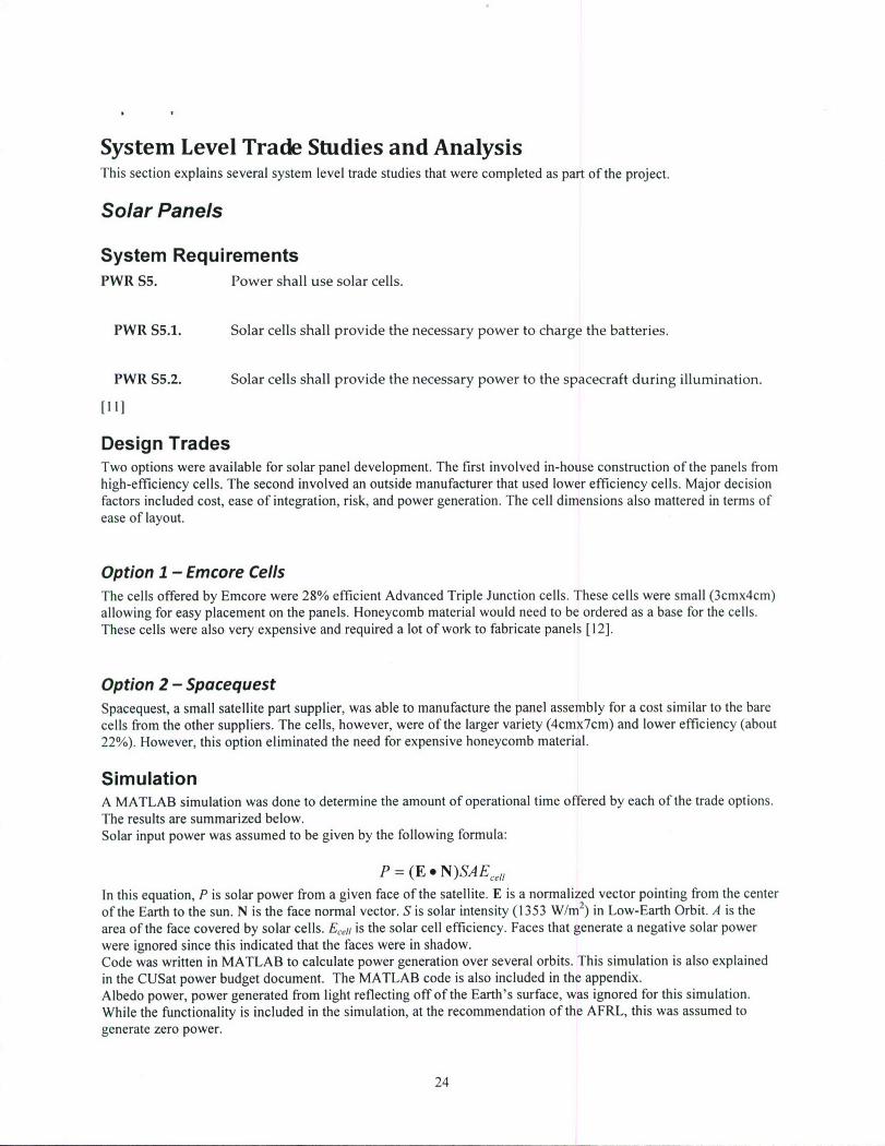
Solar Panels
System RequirementsPWR S5. Power shall use solar cells.
PWR S5.1. Solar cells shall provide the necessary power to charge the batteries.
PWR S5.2. Solar cells shall provide the necessary power to the spacecraft during illumination.
[Il]
Design TradesTwo options were available for solar panel development. The first involved in-house construction of the panels fromhigh-efficiency cells. The second involved an outside manufacturer that used lower efficiency cells. Major decisionfactors included cost, ease of integration, risk, and power generation. The cell dimensions also mattered in terms ofease of layout.
Option 1 - Emcore CellsThe cells offered by Emcore were 28% efficient Advanced Triple Junction cells. These cells were small (3cmx4cm)allowing for easy placement on the panels. Honeycomb material would need to be ordered as a base for the cells.These cells were also very expensive and required a lot of work to fabricate panels [12].
Option 2 - SpacequestSpacequest, a small satellite part supplier, was able to manufacture the panel assembly for a cost similar to the barecells from the other suppliers. The cells, however, were of the larger variety (4cmx7cm) and lower efficiency (about22%). However, this option eliminated the need for expensive honeycomb material.
SimulationA MATLAB simulation was done to determine the amount of operational time offered by each of the trade options.The results are summarized below.Solar input power was assumed to be given by the following formula:
P = (E * N)SAE, ,,In this equation, P is solar power from a given face of the satellite. E is a normalized vector pointing from the centerof the Earth to the sun. N is the face normal vector. S is solar intensity (1353 W/m2) in Low-Earth Orbit. A is thearea of the face covered by solar cells. E,ei is the solar cell efficiency. Faces that generate a negative solar powerwere ignored since this indicated that the faces were in shadow.Code was written in MATLAB to calculate power generation over several orbits. This simulation is also explainedin the CUSat power budget document. The MATLAB code is also included in the appendix.Albedo power, power generated from light reflecting off of the Earth's surface, was ignored for this simulation.While the functionality is included in the simulation, at the recommendation of the AFRL, this was assumed togenerate zero power.
24

The simulation assumed an orbit normal pointing scheme as specified in the Concept of Operations. Results wereplotled basea on inclination angle and time of year. Parameters such as cell efficiency, battery efficiency, and cellplacement were taken into account.To calculate expected power consumption, several assumptions were necessary. One such assumption was theefficiency of the battery array. From work in earlier semesters (detailed in the CUSat Power Analysis document),this value was estimated at 80%. In other words, 80% of energy used to charge the batteries was assumed to berecoverable from the cells.
Operational Time per Orbit
30,
25-
0
60 80
40 6040
20 20
Inclination (0) 0Angle of Sun From Ascending Ni
Figure 16 -Spacequest Power Simulation
Operational lime per Orbit
30,
.n..n..o.AgleofSun.rm-Acedin.N
t 0
40 40:-:'" " 60
20 20
Inclnaton () 0Angle of Sun From Ascending N(
Figure 17 -Emcore Power SimulationThe resulting operational times were fairly similar, with only several minutes difference per orbit of operationaltime.
DecisionIn the end, the decision was made to go with Spacequest for solar cell supply. While the cell efficiency was lower,the power simulation showed that the mission was not significantly affected by the loss of power. The reduced cost,schedule risk, and technical risk far outweighed the reduced power availability.
25

Cqmmiqnication Antennas
Design TradesThe Telemetry and Command (T&C) subsystem had wrestled with different options for antenna design for a verylong time. The original design called for a wire loop antenna on the top and bottom of the spacecraft. During the fallof 2006, the team members decided to design a patch antenna using a dielectric material to increase efficiency. Noone on the team had much technical experience with antenna design, so a system level trade was done to encourageoutside participation.
Option 1 - Wire Loop AntennaA lot of analysis had been done early on with this antenna design. Link budgets and initial gain pattern simulationsshowed that it would most likely verify requirements. However, no one on the team had the technical expertise toverify these results. This antenna would be simple to construct. Initial concerns with mounting of the antenna wererelieved when the AFRL informed the team that epoxy was a sufficient means of affixing the antenna [ 13].
Option 2 - Patch AntennaThis antenna design was done with help from a contact at Ball Aerospace. The antenna was slightly bigger andharder to manufacture due to the rare dielectric material used. However, the simple PCB-based design was attractiveand the gain pattern was well understood.
DecisionThe decision was made to return to the original design upon confirmation of the gain pattern and link budgetnumbers. The patch antenna was found to be nearly impossible to manufacture and was a large burden on the solarpanels as it was larger and hard to place.
Propulsion Electronics
Design TradesThe original design of the Propulsion Power Unit (PPU) was based directly off of a heritage design from theDawgstar program. To generate the 2.8kV required for Teflon ablation, the Dawgstar PPU used a flyback convertercircuit. CUSat members attempted to copy this configuration but ran into problems with design of the centraltransformer. AFRL personnel suggested components from Pico electronics that would be able to generate the highvoltages required for CUSat's PPU.
Option 1 - Flyback ConverterThis design was reasonably well understood, however design of the transformer had caused continual delays andburnouts of parts. In order to go with this design, the transformer issues would need to be definitively solved.
Option 2 - Pico Electronics ConvertersPico electronics produces high-voltage DC-DC converters. These "magic black boxes" are capable of producing therequired voltage to charge the PPU capacitors. These parts were recommended by members of the AFRL. However,availability of parts and space-worthiness were concerns at first. These concerns were later alleviated when it wasfound that Pico can produce Aerospace quality versions of their parts that meet mil-specs. The cost of these deviceswas relatively low compared to the unknown costs associated with the transformer.
26

DQcisiouIn this case, the obvious decision was to go with the devices from Pico electronics. It was a better decision in termsof cost, technical risk, and schedule risk.
Camera Interface Circuit Board
System RequirementsHARN S6. The wiring harness shall interface to COTS devices via interface boards.
Source: Error! Reference source not found.
HARN S6.1. Interface boards shall regulate power for COTS boards.
HARN 86.2. Interface boards shall monitor voltage.
HARN S6.3. Interface boards shall monitor current consumption.
HARN S6.4. Interface boards shall monitor COTS board temperature.
HARN S6.5. Interface boards shall communicate with C&DH.[11]
Design TradesThe purpose of the Camera Interface Board (CAM IB) is to interface the Heron FPGA, which controls picturecapture from the cameras, with the CUSat data bus. The original design of this board had to be scrubbed before FCRbecause of mislabeling of dimensions on the enclosure. A new board was designed that sat on the side of the box.The trade options were to continue with this design or to replace the box "side-board" as well as the baseboard forthe FPGA with a single, less dense board.
Option 1 - CAM lB with "Side-Board"The side-board design was found to have minor flaws during FCR integration. Most of these flaws were a result ofimproper pin numbering. While this option would be easy to redesign to remove these errors, it posed severalstructural issues and required complicated harnessing. It also wasted power by powering an unnecessary base-boardfor the FPGA.
Option 2 - Replace BaseboardFor this option, a new base-board would be reverse engineered to hold the FPGA. This would eliminate structuralconcerns of the side-board and also reduce harnessing and power consumption. However, there was significanttechnical risk as a new board design is always risky.
DecisionThe decision was made to use a new base-board design. This required significant technical work on the part of theauthor. Design details are explained in the Design section. While this increased schedule risk, the technical risk waslow and the new design mitigated many outstanding structural and harness-related issues.
27

Grouncl Segment and Mission Operations
RequirementsGS S1. The Ground Segment shall be able to command the Flight Computer.
Source: SYS S16; GS F1
GS S2. Multiple ground stations shall be networked together.
Source: Error! Reference source not found.[11]
Design TradesThere were two software packages available for ground station support. Orbital's MAESTRO was originallydonated to the program sometime in 2006. However, the software was difficult to use and set up. The contact atOrbital who had originally offered support had also left the company. L-3 Communication's InControl softwareseemed easier to integrated and set up, however the software had not yet been obtained by CUSat.
Option 1 - MAESTROMAESTO is very well respected, real-time software for satellite control and mission management. CUSat alreadyhad two licenses donated at an earlier time. However, the software only ran on Sun Solaris and many attempts byCUSat members to run the software had resulted in little success. Orbital had also lost interest in software support.
Option 2 - InControlInControl is designed to be high reliability software for fleets of satellites. The software also runs on Windows,which was a big benefit for CUSat members. However, while L-3 was interested in donating the software, we hadno official guarantee that this would go through.
DecisionIt was decided that CUSat would use InControl for ground segment control. The features and support far outweighedthe risks associated with using MAESTRO. L-3 representatives were very helpful and the license donation wentthrough quickly.
28

Results
Hardware DeliveryFlight delivery was originally scheduled for January 2008. The AFRL decided to push this date back to March 2008to accommodate software delivery with the hardware. However, the original plan of hardware delivery by January isstill a goal of the program. TABLE XXX shows the status of hardware deliverables as of the writing of this report.
Table 2 - Hardware StatusStatus Description
Electronics
Arcom Vipers Delivered
GPS Boards DeliveredGPS IB Delivered
CDH IB Delivered
CAM IB Testing EDU The parts are in house. Once the design is verified, the flight units will beassembled.
Power DeliveredHarnessingPower DeliveredDistributionT&C Control Being Design is verified. Boards need to be refabricated due to populationBoard Refabricated error.Propulsion Ordered Need to verify design and build flight units once the parts come in.ControlPropulsion Ordered Need to verify design and build flight units once the parts come in.PowerPropulsion D/I Ordered Need to verify design and build flight units once the parts come in.
Camera FPGAs Needs Flight Connectors need to be replaced.Prep
HAM Radios Needs Flight Needs to be disasembled and prepared for integration. Parts are inPrep house.
Cameras Ordered Waiting on order.
Diagnostic Needs Redesign Current revision works for ground support, but a new version is desired.Board
Mechanical
CDH Box DeliveredCAM Lid Delivered
Top Wall Delivered
Bottom Wall Delivered
Side Walls Delivered
HAM Box Delivered
Stiffener Delivered
PPTs Need to make Waiting on Ultem stock to make nozzles.nozzles
29

Lifting Harness Not Manufactured
Assembly Base Delivered
Harnesses
Periph 1 Waiting on Parts
Periph 2 Waiting on Parts
Periph 3 Under Construction
Periph 4 Waiting on Parts
Camera Data Waiting on PartsPower Board- Under Constructionto-BoardUmbillical Under Construction
For the electronics, the remaining design items are the propulsion boards and the Diagnostic Board. The propulsionboards have been designed and parts have been ordered. Once the parts come in, design verification with a test unitwill begin. This process should conclude before the end of the calendar year. After this, assembly of the flight unitswill begin barring any unforseen problems. The Diagnostic Board (DB) is a lower priority and therefore has beenput off until other board work is done. The DB is currently in its second revision. The second revision DB isadequate for testing of almost all spacecraft systems. A third revision, however, is needed to enable easierintegration and test of the safety inhibits.With the exception of the PPT nozzles, all mechanical hardware has been delivered. All hardware has been anodizedor alodined as appropriate. Fit checks have been performed on all mechanical hardware. PPT nozzles have beendelayed due to processing issues with the Ultem stock. Once the Ultem order goes through and the stock arrives,manufacturing will begin immediately. This will most likely not affect the delivery schedule.Wiring harness construction has been delayed due to a large delay in the connector part order. These parts willslowly trickle in over the next few weeks. As the parts come in, the harnesses will be constructed. The harnessconstruction schedule puts Periph 3, the Umbilical harnesses, and the power connectors first since these are first onthe critical path for flight build and test. These parts should be finished before the end of the calendar year.
Integration and TestEvery effort is being made to ensure that hardware is ready for Integration and Test (I&T) once the spring semesterstarts in January. Several pieces of flight hardware, including the CDH 1B and the Power Boards, have already beenrun though their official test plans. The remaining hardware testing will be completed in January.
CAM IBThe CAM lB test unit has been populated and design checkout has begun. The lB correctly powers and initializesthe Heron FPGA5 board. The IB also correctly implements the interface to the flight computer. The remaining test
items include using the board to take a picture and reprogramming the FPGA using the JTAG interface.The backplane connector receptacle board that was part of the CAM IB needs to be reordered due to pin hole sizing.This should be relatively inexpensive and very low risk.
Power BoardsThe power board flight units have been populated and are undergoing testing. The design verification unitsuccessfully passed all tests. The flight boards are currently awaiting loading of the relays and will then be sent tothe Survivability team for flight preparations.
30

Conclusion
Status of the ProgramA majority of hardware items have been delivered as of the writing of this report. The ground segment and missionoperations teams have made significant progress this semester and will continue to train new team members anddevelop solutions next semester. With machining of structural parts nearly complete, several of the mechanicalengineers will shift focus to vibration analysis and integration work. Most electronics parts should be delivered bythe end of the calendar year.Several items are still at risk:
Table 3 - Risk AssessmentItems at Risk Schedule Technical Personnel Bude
Propulsion Igniters
PPT Manufacturing
T&C Control Boards
Software Development
T&C Antenna and RadiosThe CAM 1B poses some schedule risk as it is currently behind other boards. The wiring harness has been delayedby a large amount. Additionally, the team lost experienced harness personnel last semester, adding technical risk.The propulsion electronics are far behind schedule compared to the other electronics parts. The igniters are a largerisk as they have not yet fired successfully.PPT manufacturing offers mild schedule risk as it depends on several part orders. The T&C boards are currentlybehind schedule due to a construction error. Software development is still in early stages, and therefore poses a riskin several categories. The T&C antenna and radios are far behind schedule and offer large technical risks to theprogram.
Future WorkThis winter break will consist of a large push to catch up in terms of electronics. The goal is to deliver all theelectronics boards before the year is over. In the spring semester, work will focus on rapid I&T to meet the Marchdeadline. Software work will need to progress to the testing stage where software can be tested on the flighthardware.Figure 18 shows the overall schedule for next semester.
31

F-aS PPOP. "'Ift ~ [ 4 oo' nna, Ftvr a
I 71-~E~n,i ann - ~ oT!1 .
&ToFRFaa0 I"n llta1,J ,106
P af.-Iln.CnPtf UT n A.0 2 1., ,27 . IVon
5 ~ ~ ~ ~ ~ ~ ~ ~ ~ ~ ~ , nA.nlcnnnnn-M a, 6'2' l3
T-,onsAk30.£3n, . ,Ioll "10 1o
7: 00.63 I.3 .03 C0 ,,s14*
Figure 18 - Forward Looking Schedule
32

References1. CUSat, Mission Definition (CUSAT-SYS-001F), March 6, 2007
2. CUSat, Concept of Operations (CUSAT-SYS-019C), March 6, 2007
3. CUSat, Post-FCR Action Plan (CUSAT-SYS-026), March 6, 2007
4. CUSat, Recruiting Presentation for Summer/Fall 2007, April 17, 2007
5. CUSat, Hardware Schedule, retrieved November 15th, 2007
6. CUSat, Hardware Status Chart, retrieved November 15th, 2007
7. CUSat, Red Team Review Slides, September 28, 2007
8. Hunt Engineering, HERON-BASE1 User Manual Rev. A, January 12, 2001
9. Hunt Engineering, HERON-FPGA5 User Manual Rev. E, May 5, 2005
10. Hunt Engineering, Hunt Engineering ResOurce Node Specification Rev. B, August 22, 2002
11. CUSat, Requirements (CUSAT-SYS-022F), March 6, 2007
12. Emcore, ATJ(M) Datahseet
13. CUSat, TC Subsystem Design (CUSAT-D-TC-001D), March 6, 2007
33

Action Items from Post-FCR Review
ADCNS 9 Top and bottom walls" ACS revising, testing * Tight lid fits on" ADS testing, sun ack 0 Stiffener* MOMS SW 0 Alodining parts* GNC Supervisor * Flight helicoil replacement* Lightband delivery, configuration, etc... 0 Cam mount hole drills* GEONS integration & test 0 90 degree edges need to go, they need to* Position controller be rounded
o Completing orbital design o Edge rounding spec needs to beo Determine how we do controller made
" IMI - upgrade?o Stop vibratingIo Another supplier? HARN
" Operations 0 Cam box lid
* Spin table * Active sync in umbilical
* Software people * Harness inventory
" ACS/delta v budget 0 Review by Dale S.* CAM IB
CAM * CDH IB mount holes* Lens - does it fit in the top panel 0 DB new Rev" Camera code - 2 cameras * PCB torque values for airborn connectors" Calibration procedure and how they fit" Lens mounting 0 CAM harness tools" Vibe test* Mounting bracket didn't line up PWR
* Focal length * Solar cell design
* Inter-cam IB connector 0 Next revision
" Heater & thermistor mounting 0 Sensors
" Replace the base board? 9 Battery box design + assembly
* Mechanical fitting of baseboard 0 Lightband boost circuit* Switches on driver, boost
CDH 0 12V relay order* Centralized distribution
GS * HAM powering (6V)" Need software people * Fault tolerance (cross-strapping)" Re-contact david schevers* Doppler compensation w/ TS-2000 PROP
PROP-EGPS * Igniter test
" Receiver code - 2 weeks for passing around a PPT test in TVC* Capacitors on receivers 0 Keep current PPU" ADS test * DI board needs to be screwed
MANF* Paperwork traceability PROP-M" Consistency in CM/QA rules
34

* Particles coming off of PPTs near LV * Lightband POC, lightband contact - Matt(mission constraint) RozekTesting * Vibe test electronics packaging - Megan
o Igniters 0 Grounding architecture -James Maxwello New PPU 0 Alternate launch configurations - Patricko EMI Conrado Thermal * FEA- Megan
Harness design
STR
* Honeycomb panels - ask the AFRL* Get the FEA model to match the testing" Wall 2 wall connectors is a crappy design* Fasteners
o JSCo Ultem
" Alodine/anodize parts, need to researchmore
" Stand-offs checkout (ultem)* Battery box, materials* Lightband people* Tolerancing analysis
SURV* Materials -* Conduction pathways* Testing on working hardware* Thermal model reflects CONOPS correctly* Actual thermistor location in e-ics" Tantalum sheets to kill SEUs
TC* Kenwood radios EMI w/ PPTs* SEUs in radio" Radio - on/off control switch* HAM box inside the wall" Radio design* HAM Radio powering voltage range* Cabling* UCF Radio guy
AI&T" Assy procedures - revise each one
" MGSE needs to be fixed, finished* Re-structure procedures to help mechanical
integration" Backplane torquing tool" Need to assess tools for each procedure" No phillips head screws on spacecraft
System-wide issues
35

3.0 Personnel Supported
The only paid labor on this program is that of Dr. Jinwoo Lee, a post-doctoral researcherat Cornell, 10% of whose time is paid by the program for his participation as an expert inrealtime control and communications electronics.
4.0 Publications
The following publications and presentations have appeared the inception of the project:
K. Young, J. Fikentscher, A. Kelsey, J. Rostoker, 0. Eldad, D. Gershman, B. Doyle, K.Graf, and M. Peck, "A GPS-based Attitude Determination System for Small Satellites,"2006 Small Satellite Conference, Logan, Utah, August 14-17, 2006
"The Physics of Very Small Satellites," Miami Museum of Science, Miami, FL, Jan. 23,2006.
"Systems Architecture for an In-Orbit Inspection Technology Demonstrator," 3rd Mid-Atlantic AIAA Conference, Baltimore, MD., Nov. 5, 2005
5.0 Interactions and Transitions
5.1 Participation and Presentations
Two presentations have come out of this project. Dr. Peck provided a keynote speech atthe Mid-Atlantic Regional Conference on November 5, 2005. He presented an overviewof the CUSat project, including its connection with responsive-space efforts and NASA'sVision for Space Exploration. Deborah Sunter, the Ground Segment lead, presented herpaper on CUSat Concept of Operations.
5.2 Consultative and Advisory Functions
Dr. Peck serves as a consultant in Spacecraft Systems Engineering. In addition to hisindustry background, his CUSat experience has been brought to bear for consulting withBoeing Satellite Systems, where engineers are creating a process for training inrequirements development. His contributions include proposing an object-orientedrequirements-allocation process, the same one used on CUSat. The Applied Physics Labmay also bring in Dr. Peck for consulting activities related to classified nanosatelliteproject proposals. Those discussions are ongoing. Dr. Peck also recently served on apanel reviewing the spacecraft design project for final-year students at the NavalPostgraduate School.
5.3 Transitions
CUSat's innovative use of CDGPS for attitude and navigation is being considered foradoption by Northrop Grumman Space Systems. They are collaborating with Cornell in
36

.thedevelopment of a responsive ground segment for inspection-related data products.These promising collaborative possibilities add value to the CUSat project and provideencouragement to the students.
6.0 Inventions and Patent Disclosures
CUSat has not patented its technologies.
37