Low Cycle Fatigue of Composite Materials in Army Structural ...
95
x ARMY RESEARCH LABORATORY Low Cycle Fatigue of Composite Materials in Army Structural Applications: A Review of Literature and Recommendations for Research by Vasyl M. Harik, Bruce K. Fink, Travis A. Bogetti, J. Robert Klinger, and John W. Gillespie, Jr. ARL-TR-2242 June 2000 Approved for public release; distribution is unlimited. DTIC QUALITY WWWJfflD 4 20000727 291
-
Upload
khangminh22 -
Category
Documents
-
view
4 -
download
0
Transcript of Low Cycle Fatigue of Composite Materials in Army Structural ...
■x
ARMY RESEARCH LABORATORY
Low Cycle Fatigue of Composite Materials in Army Structural
Applications: A Review of Literature and Recommendations for Research
by Vasyl M. Harik, Bruce K. Fink, Travis A. Bogetti, J. Robert Klinger, and John W. Gillespie, Jr.
ARL-TR-2242 June 2000
Approved for public release; distribution is unlimited.
DTIC QUALITY WWWJfflD 4
20000727 291

The findings in this report are not to be construed as an official Department of the Army position unless so designated by other authorized documents.
Citation of manufacturer's or trade names does not constitute an official endorsement or approval of the use thereof.
Destroy this report when it is no longer needed. Do not return it to the originator.

Army Research Laboratory Aberdeen Proving Ground, MD 21005-5069
ARL-TR-2242 June 2000
Low Cycle Fatigue of Composite Materials in Army Structural Applications: A Review of Literature and Recommendations for Research
Vasyl M. Harik, Bruce K. Fink, Travis A. Bogetti, and J. Robert Klinger Weapons and Materials Research Directorate, ARL
John W. Gillespie, Jr. Center for Composite Materials, University of Delaware
Approved for public release; distribution is unlimited.

Abstract
Low cycle fatigue (LCF) of laminate composite structures used in Army applications is assessed to identify the key physical phenomena occurring during LCF processes and to determine their main characteristics. Special attention is given to the LCF conditions inherent in Army structures (i.e., high cyclic or pulse loads reaching up to 90% of the ultimate strength in a fraction of a second). A summary of fatigue-related issues in laminate composites employed in Army land combat systems is presented. Analysis indicates that finite strain rate effects are important under LCF conditions and the pulse vibration fatigue (PVF). Fatigue damage mechanisms, evolution patterns of damage, and damage accumulation processes are singled out and thoroughly analyzed as the key mechanical phenomena contributing to the changes in the material damage state and the property degradation under fatigue conditions. Possible correlation between ballistic and LCF performance is discussed. Various models for damage accumulation and fatigue life predictions are reviewed. Recommendations for fundamental research in the areas relevant to the LCF of composite structures are included to establish a conceptual framework for the U.S. Army Research Laboratory (ARL) LCF Program.
11

Acknowledgments
Dr. V. M. Harik is supported by a National Research Fellowship awarded by the
American Society for Engineering Education (ASEE) and the Postdoctoral Research Program at
the U.S. Army Research Laboratory, Aberdeen Proving Ground, MD. The following researchers
are gratefully acknowledged for useful discussions: Professors K. L. Reifsnider (Virginia Tech);
R. Talreja (Georgia Tech); J. Lambros and G. Palmese (University of Delaware);
Drs. T. K. O'Brien (ARL-NASA Langley); C. P. R. Hoppel, S. H. McKnight, and J. Tzeng
(ARL); and A. Paesano (University of Delaware).
111

INTENTIONALLY LEFT BLANK.
IV

Table of Contents
Page
Acknowledgments in
1. Introduction 1
2. LCF-Related Issues in Army Applications 2
2.1 Design for Fatigue Performance 3 2.1.1 Fatigue Simulation Codes for Design 4 2.1.2 Recommendations for Fatigue Design 5 2.2 LCF Behavior of Composites 6 2.2.1 Basic Physical Phenomena Relevant to the LCF Studies 7 2.2.2 Recommendations for the LCF Studies 7 2.3 LCF of Thick-Section Composites 8 2.3.1 LCF Testing of Thick-Section Composites 8 2.3.2 Recommendations for Studies of Thick-Section Composites 9 2.4 Optimization of Interphases for LCF Performance 10 2.4.1 Fracture Toughness of Fiber/Matrix Interfaces 11 2.4.2 Recommendations for Studies of Interphases 11 2.5 Fatigue of Adhesive Joints in Composite Structures 12 2.5.1 Repair of Composite Structures 13 2.5.2 Recommendations for Studies of Adhesive Joints 14 2.6 Environmental Effects on Army Systems 14 2.6.1 Environmental Effects on Integrity of Interfaces 14 2.6.2 Recommendations for Studies of Environmental Effects 15
3. Fatigue Damage Mechanisms: Structural Effects 15
3.1 Fatigue Damage in Unidirectional Laminated Composites 17 3.1.1 Damage Caused by Axial Fatigue Loading 17 3.1.2 Damage Caused by Off-Axis Fatigue Loading 18 3.2 Damage in Cross-Ply Laminates 19 3.3 Damage in Woven Fiber Composites 20
4. Modeling of Damage Accumulation 21
4.1 An Initiatial Damage State of Composites 22 4.2 Micromechanical Analysis of Individual Cracks 23 4.3 Analysis of Delamination Growth in PMCs 24 4.4 Micromechanical Analysis of Voids 25 4.5 Continuum Damage Mechanics of Multiple Cracks and Voids 26
5. Fatigue Life Prediction 27
5.1 Micromechanical Fatigue Models 28 5.2 Phenomenological Fatigue Models 29 5.2.1 Models Based on Strength and Stiffness 30 5.2.2 Statistical Fatigue Models 31
Recommendations for ARL LCF Program
Page
.32
6.1 Recommendations for Design-for-Fatigue Research 33 6.2 Recommendations for the LCF Characterization 34 6.3 Recommendations for Investigation of Thick-Section Composites 34 6.4 Recommendations for Studies of Interphasial Effects on LCF 35 6.5 Recommendations for Studies of Adhesive Joints 36 6.6 Recommendations for Investigation of Environmental Effects 37
7. References 39
Appendix: Material Performance Simulation Code MRLife 57
Distribution List 65
Report Documentation Page 85
VI

1. Introduction
Advances in composite manufacturing technology lead to significant improvements in the mechanical properties of composite materials used in defense industries. Better control of processing defects, reduction of void content, and optimization of interphase properties improve
structural performance of composites and yield higher strength-to-weight ratios, stiffness, and fracture toughness. However, multifunctional hybrid composite materials with further enhanced
properties must be developed to meet the unprecedented needs of Army land combat systems for speed and mobility without sacrificing ballistic protection (Burns 1998).
The newly developing hybrid composite structures consist of a number of dissimilar materials, which themselves represent complex composite systems. The mechanical properties of novel hybrid composites are optimized by designing and tailoring various types of interphases at the molecular and nanostructural level. The properties of polymers adjacent to solid surfaces can be significantly perturbed, which can result in dramatic changes in bulk composite material behavior (Palmese and McCullough 1994; Fink and McCullough 1999; VanLandingham et al. 1999). New materials with functionally graded properties can be used to achieve optimal structural performance of the designed hybrid systems (Suresh and Mortensen 1998). It is imperative that such advanced composite structures possess superior mechanical properties over a long period of service life in harsh environmental conditions. The full potential of composites as advanced materials can be realized only if the deterioration of long-term material properties can be properly understood and controlled. Poor fatigue performance may significantly reduce the weight advantage of many composites (Reifsnider 1991; Talreja 1993). This is especially important for the Army systems subjected to the low cycle fatigue (LCF) conditions (i.e., high cyclic or pulse loads reaching up to 90-95% of the ultimate strength in a fraction of a second).
In addition to novel design strategies, the modeling of composite material structures must be enhanced to enable cost-effective design practices. New modeling capabilities rooted into fundamental research (Talreja 1987, 1996; Reifsnider 1991; Case and Reifsnider 1998) are especially needed for simulation of the high-load LCF environment inherent in many Army land combat systems. To extend the life cycle of new hybrid structures, the deterioration of composite properties such as strength, toughness, durability, and impact resistance must be
understood and controlled. The advanced modeling capabilities, when integrated with appropriate design philosophies and methodologies, will result in significant performance improvements of vehicles, ordnance, and other Army polymer composite structures.

The purpose of this report is to assess the material issues affecting the fatigue behavior of various composite structures used in Army applications and to identify the key physical phenomena present in fatigue processes and their main characteristics. Special attention is given to the effects of LCF conditions inherent in Army systems. A summary of fatigue-related issues
in laminate composites used in Army applications is presented in section 2. Following Talreja (1987) and Reifsnider (1991), the fatigue damage mechanisms and the kinetics of fatigue damage accumulation processes are singled out as the key mechanical processes controlling the property degradation rates under fatigue conditions (section 3). Various models for damage accumulation and fatigue life predictions are reviewed in sections 4 and 5, respectively. General
recommendations for fundamental research in the areas relevant to the LCF of composite
structures are included in section 2 and summarized in section 6. The literature review is not
intended to be exhaustive. This report highlights the main issues and trends in the fatigue
research, which are potentially useful for improved understanding of the LCF performance of
Army land combat structures.
2. LCF-Related Issues in Army Applications
Many composite structures used in Army applications are subjected to severe fatigue loading conditions and harsh environment over long periods of time. Their fatigue life and performance depend on their fatigue damage tolerance and the rates of property degradation under cyclic or pulse loads. The LCF conditions occur when an Army land combat system is used under high loads that may be as high as 90-95% of the ultimate strength (section 2.2). Such high values of loading are reached in a fraction of a second. The low cycle and high cycle (i.e., lower load level) fatigue have common damage mechanisms and similar property degradation mechanisms. Both LCF and high cycle fatigue (HCF) conditions are relevant to the following examples of Army applications:
• composite armored vehicles (e.g., Crusader, Scout, vehicle shock absorption systems, and next generation vehicles [Davila, Chen, and Baker 1998]);
• composite assault bridge and future line-of-communication bridging;
• weapon systems (e.g., Howitzer trails, mortar base plate, electromagnetic gun components, Crusader cannon, gun tube overwraps, etc. [Tzeng 1999]);
• rotorcraft systems (e.g., Comanche, Apache, etc. [O'Brien et al. 1998]);

• lightweight personnel protection systems.
In the following section, the material issues relevant to fatigue performance of composite
structures used in various Army land combat systems are discussed. First, examples of design requirements for fatigue performance in several Army applications are discussed in section 2.1. A brief review of existing fatigue analysis codes and complementary analysis tools, which can be used for structural and microstructural design optimization, is also presented in section 2.1.
Most common industrial applications of LCF models are highlighted in section 2.2. Fatigue
issues in Army applications involving the thick-section composite are analyzed in section 2.3.
The role of interphases and adhesive joints on fatigue performance is discussed in sections 2.4 and 2.5, respectively. Environmental effects on Army land combat systems are reviewed in section 2.6. Recommendations for fundamental research in the areas critical for understanding the LCF phenomena are included.
2.1 Design for Fatigue Performance. The fatigue performance characteristics of the composite materials used are required for finding the optimal design solutions for numerous Army structures. The following sections highlight software solutions that can be used to meet the design and fatigue analysis needs. For design of Army systems, special attention is given to the effects of high loads on the thick-section composite structures in the LCF conditions. Postrepair performance of new hybrid composites is also evaluated to assess the retained ballistic protection capabilities.
Knowledge of the property degradation rates is especially important for the design of systems in which fatigue performance is critical. The design requirements for fatigue performance vary from one Army system to another. For instance,
• the composite base plate of a mortar should withstand the maximum pressure of about 16 ksi for at least 3,000 service cycles,
• the composite barrel of a mortar is designed for a similar range of pressures but for 10 fatigue loading cycles,
• the composite compulsator for an electromagnetic gun is design to be in service for about 10 loading cycles (in service, the rotating gun compulsator experiences strain rates between 1 and 10 (in/in s) while it decelerates; the peak banding stress is calculated to be 155 ksi for the maximum rotor tip speed of 400 m/s), and
• the howitzer trails are designed for 5,000 effective full charges under maximum loads.
To address the Army after next (AAN) goals, most of the aforementioned design requirements should be doubled or the weight of structures should be halved.
Most of the design decisions are currently based on the static mechanical properties of composite materials and simple relations for fatigue performance. Such phenomenological criteria are predominantly based on experimental data and have limited predictive capabilities. Limitations of current fatigue life prediction models for composites force large factors of safety for the designed structures. The associated deficiencies in the design-for-fatigue methodologies lead to heavier "overdesigned" structures that tend to be more costly than necessary.
2.1.1 Fatigue Simulation Codes for Design. The MRLife simulation code (Case and
Reifsnider 1998) is developed for the simulation of performance and fatigue life prediction of
composite laminates. MRLife is suited for fatigue analysis of critical material elements in a wide
variety of problems involving polymer matrix systems (see Appendix). Such problems include
delamination and failure of notched and unnotched materials with or without moisture diffusion. The pointwise effects caused by thermal loads, creep, stress relaxation, and aging can also be accounted for in the MRLife's fatigue analysis of material elements. The LCF behavior of polymer matrix composites (PMCs) can be also predicted by using the MRLife fatigue performance simulation code.
Engineering Mechanics Technology, Inc. (Harris and Dedhia 1997) has developed two codes, Smart Crack and Non-Linear Smart Crack, for the linear and nonlinear analysis of fatigue crack propagation in metals. The linear analysis is based on linear elastic fracture mechanics and use of the mode I stress intensity factor for characterization of the near-crack-tip conditions. In the nonlinear analysis, the plasticity is described by the Ramberg-Osgood constitutive relation. The creep is simulated by a power law relation. The capability of the metal-oriented codes to perform fatigue analysis of composite structures is obviously limited.
The impact of various microstructures on macroscopic behavior of composites can be analyzed by using the theory of homogenization (Ericksen 1986) or "smearing-unsmearing" methodology (Chou, Carleone, and Hsu 1972). This methodology is implemented in a software program called LAMP AT, which was developed by Bogetti, Hoppel, and Burns (1995), for structural analysis and design of thick-section laminated composite structures. The code LAMP AT is intended to be used in conjunction with typical commercial finite element analysis (FEA) codes. At the preprocessing stage, LAMP AT is utilized to generate the effective, homogeneous, three-dimensional properties of a laminate, which are used as input for an FEA
code. It may be possible to link the LAMP AT capabilities with a fatigue performance simulation code (see Appendix).
For the structural design and stress analysis purposes, LAMP AT can be employed as a postprocessing tool. It can conduct a detailed ply-level-based failure assessment of a composite structure. The failure assessment is based on a wide variety of lamina failure criteria. The results can be portrayed graphically by PATRAN (PDA Engineering) in order to visualize the critically loaded regions within a structure. A postprocessing program with similar capabilities has been developed by Harik (1997) to carry out complementary analyses of stress and strain
distributions obtained from the FEA of composite structures performed by the FEA commercial code ABAQUS (Hibbitt, Karlsson and Sorensen Inc). The program is called Post-ABAQUS, as it is designed to extend the postprocessing capabilities of the commercial code ABAQUS-POST. These postprocessing programs can be supplemented with simple S-N relations (i.e., stress level vs. number of cycles) for the basic fatigue analysis.
Another post-FEA program, called MSC/FATIGUE, has been developed by MacNeal- Schwendler Co. It offers new simulation capabilities for the effects of random vibrations on material properties. The fatigue life predictions are based on frequency response and the random vibration FEA techniques. The program is especially useful for the design of electronic components, microelectromechanical systems (MEMS), wind turbines, and various components in engines.
2.1.2 Recommendations for Fatigue Design. Development of new design methodologies that would include the assessment of fatigue performance is closely linked with the development of new fatigue modeling capabilities and associated design strategies. The short-term design requirements can be met by experimental characterization of specific composite materials (i.e., S- N curves, residual strength analysis, stiffness degradation rates, etc.). The experimental characterization should be preceded by thorough stress analysis of the composite structure involved in order to determine the critical structural elements, the types of critical loads, and expected damage and failure modes.
The experimental data can be used to develop simple fatigue life prediction models for specific composite structures. It should be noted that such models are phenomenological in nature and are limited to specific groups of composite materials and types of loading under consideration (see section 5.2). Phenomenological fatigue models can be linked with LAMPAT's structural analysis capabilities (Bogetti, Hoppel, and Burns 1995). The corresponding design- for-fatigue strategies may also include other postprocessing software tools.

In order to meet the long-term design requirements and carry out multilevel structural optimization analyses, one needs to overcome the limitations of simple phenomenological models and acquire advanced modeling capabilities for fatigue performance assessment. To avoid
excessive duplication on one hand and accelerate the progress in the design-for-fatigue efforts on the other hand, it is important to consider and evaluate current state-of-the-art fatigue simulation technologies. The MRLife simulation code (see Appendix) is suited for fatigue performance analysis of a wide variety of polymer and ceramic composite systems. The MRLife code may simulate delamination and failure of notched and unnotched materials with or without moisture diffusion. The effects caused by thermal loads, creep, stress relaxation, and aging can also be
accounted for in MRLife's fatigue analysis. The LCF modeling capabilities of the MRLife code
can be validated via selected benchmark experiments.
The modeling capabilities of the MRLife fatigue performance simulation code can be linked
with the structural analysis capabilities of commercial FEA codes (e.g., ANSYS, ABAQUS, etc.). The postprocessing software programs like LAMP AT can be incorporated into the design-for- fatigue strategies for complementary stress and strain analyses. Development of more robust methodologies for the assessment of long-term properties should result in better design strategies and more efficient use of composite materials in weight-critical applications.
2.2 LCF Behavior of Composites. LCF is a critical loading condition for many Army land combat composite systems and is not well understood. The unique features of LCF effects on hybrid composite systems have not been studied in any great detail. Most of publications on the LCF involve either metals, metal alloys, or, in some cases, metal matrix composites (Coffin 1969; Solomon et al. 1987; Rie and Portella 1998). Corresponding applications include:
• gas turbine and engine components made of titanium alloys for high-temperature creep-fatigue conditions (e.g., compressor discs, the disc rim, rotor blades, etc.),
• pressure vessels in power industries (e.g., cast-iron combustion chambers, steel pipes and
tubes, etc.),
• multicycle forming operations (e.g., forging, rolling and drawing),
• defense applications (helicopter gears, shock absorbers, etc.), and
• structural applications in construction industry (Barnes 1990).

The LCF of PMCs or thick-section hybrid structures has received little attention. Walrath and Adams (1980) examined the LCF range for the pure epoxy resin during standard fatigue
characterization tests in late 1970s. Other researchers have also reached the LCF loads in some
of their fatigue experiments with PMCs; however, the unique features of the LCF range have not
been identified (Mandell 1981; Barnes 1990; Reifsnider 1991; Case and Reifsnider 1998). Chaphalkar (1998) and Harik et al. (1999) are among few researchers who have investigated the effects of high LCF loads on thick-section PMCs in work recently performed under the Army- sponsored Tuskegee Research Consortium and ARL Postdoctoral Research Program.
2.2.1 Basic Physical Phenomena Relevant to the LCF Studies. LCF conditions are characterized by the high loads applied to a material over a fraction of a second and then repeated for a finite number of loading cycles. The corresponding strain rates may vary between 1 and 10
in/in-s, or even more than 100 in/in-s for some weapon systems. Since the LCF loads may reach 90-95% of the static ultimate strength, the material behavior of the composite's constituents may no longer be regarded as linear. Indeed, when the strains exceed 4-5%, the matrix material and the interphase undergo finite deformation, while fibers may experience interfacial debonding and fracture. The strain rates and nonlinear deformation encountered under a LCF loading are not as high as those seen during a ballistic impact. However, it is plausible that the material degradation mechanisms and material properties affecting the LCF performance of composites are similar to those determining the ballistic performance of Army combat composite systems. The extent of possible correlation between the LCF and ballistic performance of composite materials is not known.
Section 3 presents a review of typical fatigue damage mechanisms that are activated in composites having different microstructures. The effect of LCF conditions on typical damage mechanisms needs to be thoroughly examined. Patterns of damage evolution in the laminates with typical structures (e.g., unidirectional, cross-ply, and woven fiber composites) are also discussed in section 3. Classification of different stages in the damage accumulation processes is presented in section 4. A summary of the damage accumulation models and modeling approaches is included in section 5. The effects of LCF conditions on damage accumulation processes and the property degradation rates need to be evaluated.
2.2.2 Recommendations for LCF Studies. More fundamental research is needed in the area of modeling and characterization of polymer composite materials subjected to low-cycle or pulse- vibration fatigue (PVF). The need to develop a physical understanding of the mechanisms and
phenomena associated with fatigue-induced failure in PMCs is especially important. The effects of LCF conditions on typical damage mechanisms and the extent of plastic deformation (Hill

1950; Drucker 1967) can be evaluated by thorough experimental testing and detailed nondestructive monitoring of fatigue damage accumulation processes (Sasaki 1997). Comparative analysis of material degradation mechanisms present during LCF and ballistic loadings is required in order to determine the extent of possible correlation between the LCF and ballistic performance of composite structures in Army land combat applications. Experimental characterization is also needed for the development of novel LCF/PVF models and realistic service life prediction of thick-section composites in various Army systems. More accurate service life prediction capability for Army structures under LCF conditions would enable optimization for performance and cost.
2.3 LCF of Thick-Section Composites. The LCF behavior of thick-section composites is
of special interest to Army applications. Multi-ply composites are part of integral armor
composite systems. Advances in integral armor and other complex composite systems depend
on a thorough understanding of possible failure mechanisms. Although, mechanics of anisotropic
plates (Lekhnitskii 1968) and layered materials (Chou, Carleone, and Hsu 1972; Christensen 1979; Ericksen 1986) has been vigorously investigated, general fatigue behavior and LCF of thick- section composites have received little attention to date (Solomon and Halford 1987; Rie and Portella 1998). LCF behavior of homogeneous thick-section composites must be understood before LCF of their heterogeneous hybrid counterparts can be addressed. A review of typical
mechanisms of fatigue damage accumulation is presented in section 3. In particular, the dependence of patterns of damage evolution on different microstructures is analyzed. Understanding the fatigue damage mechanisms and their interaction with overall mechanical
response is needed to adequately model and predict LCF behavior.
2.3.1 LCF Testing of Thick-Section Composites. LCF performance of multilayer composites has not been studied in any great detail either analytically or experimentally. Fatigue behavior of composite materials is typically evaluated by experiments involving either tension-tension or
tension-compression loading. Even for non-hybrid thick-section composites, sufficient load transfer between tensile grips and the specimen is difficult to achieve (Bakis and Stinchcomb 1986; Chaphalkar 1998). During flexural fatigue, which is relevant to the thick-section integral armor applications, both compressive and tensile loads are present. Bending fixtures are sufficiently robust for LCF testing of thick-section hybrid composite beams.
Composite materials with toughened matrices usually have better fatigue performance. The
mechanisms of toughening in PMCs include interfacial debonding and interfacial void formation
around rubber or thermoplastic particles, plastic shear localization, and dissipation of energy through viscoelastic relaxation. Viscoelastic relaxation is accompanied by a temperature rise;
8

because the polymer matrix is a poor thermal conductor, the dissipation of heat is slow and local temperature increases (Joseph 1990). Shen, Chen and Sauer (1983) demonstrated that at higher, stresses hysteretic heating is quite extensive in the specimens of cast poly-methyl methacrylate
subjected to tension-compression fatigue. As a result, so-called hot spots, extensive plastic deformation and voids are possible in PMCs. Thus, premature catastrophic failure of a composite structure can result.
Fundamental research is required to determine the role of localized heating and viscoelastic interfaces (Holmes et al. 1999) in the failure of composites under LCF conditions. Development
of robust numerical techniques for viscoelastic models with geometric nonlinearities is especially
important (Harik 1997; Harik and Cairncross 1999). A better understanding of the viscoelastic failure mechanisms will allow for the improved ability to predict catastrophic failures of composites under fatigue through computer modeling.
2.3.2 Recommendations for Studies of Thick-Section Composites. The load transfer problems commonly encountered during tension and compression testing of thick-section composites are easily avoided in flexural fatigue testing. Flexural fatigue tests can be carried out by using a three-point or a four-point bending fixture scaled up from existing testing fixtures (Whitney, Daniel, and Pipes 1984; Carlsson and Gillespie 1990). Recent advances in nonintrusive techniques for nondestructive testing allow systematic analysis of fatigue damage accumulation within the specimen being tested. Such techniques include x-rays, x-ray-based computed tomography, video-imaging, acoustic wave scattering, infrared thermal imaging, and embedded fiber optics (Carlsson and Gillespie 1990; Fink and Corona-Bittick 1999; Flores et al. 1998). Material damage assessment prior to, during, and following fatigue tests can enable greater understanding of material's fatigue behavior and damage accumulation processes. From this information, possible deviations from typical damage mechanisms can be evaluated and understanding of fatigue performance of the thick-section composites can be advanced.
Comprehensive analysis of the fatigue damage data (e.g., damage location, type, shape, size, and evolution patterns [Talreja 1993; Sasaki 1997]) and gross experimental measurements of macroscopic mechanical properties (e.g., stiffness, residual strength) can provide the physical foundation for future analytical and finite element fatigue models. Once the fatigue behavior of homogeneous multi-ply composites is more fully understood, the fatigue of heterogeneous hybrid composites can be analyzed by more sophisticated fatigue models. It should be noted that the hybrid composites possess layers with significant differences in stiffnesses that would lead to the deformations violating the basic assumptions used in classical bending analyses.

Ultimately, a more complete understanding of fatigue damage mechanisms in thick-section
and integrated composites will be invaluable to advancing the applicability of composites in the
Army systems. The resulting knowledge incorporated into useful models should yield reliable
predictions of the fatigue life of composite structural components subjected to various fatigue conditions. It will enable life-cycle design of thick-section composite Army structures subjected
to LCF.
2.4 Optimization of Interphases for LCF Performance. A primary concern for composites being used under LCF conditions, which involve high loads, is premature failure.
Thick-section composites typically fail at stresses and strains that are well below the expected
failure limits. This early failure is often attributed to the existence of critically sized processing
and/or material defects and interfacial problems in the interphase region between the matrix and
the reinforcing phase (Drzal 1983, 1986; Sottos 1990; Palmese 1992; Skourlis 1995; Hrivnak
1996; Harik 1997; VanLandingham 1997; Fink and McCullough 1999). Evaluation of interphasial mechanical properties can be carried out experimentally (Sottos 1990; VanLandingham 1997) or theoretically (Palmese 1992; Chu and Rokhlin 1996). Modification of either the polymer matrix or the reinforcing fibers to improve the adhesion between the material components has proven to be a key in the optimization of performance of various composite structures. Such optimization should be based on rapidly developing interfacial mechanics of fiber-reinforced materials (Clyne and Watson 1991; Harik 1997; Harik and Lambros, to be published).
The extent of the interphase region in composites is significant (Hughes 1991). For instance, a 1 cm3 of a composite is filled with a fiber volume content of 60% and contains as many as 3 million single filaments. The total area of the fiber surface is 3,400 cm2. As a result, the matrix and its ability to adhere to a fiber are paramount to the effective transfer of the mechanical load in the composite (Eriksonand Plueddemann 1974; Drzal 1983, 1986; Fishman 1991; Piggott 1991). The interface between matrix and fiber has many commonalties with the interfacial region in laminated systems (O'Brien 1991). In both cases, a large surface area plays a direct role in the load transfer from the matrix to the reinforcing constituent. Stinchcomb and Reifsnider (1975) emphasized that "the way the interface interacts with the matrix and with the fibers is quite important in determining fatigue damage initiation in composite materials." Reifsnider (1994), Subramanian, Reifsnider, and Stinchcomb (1995), and Subramanian et al. (1996) demonstrated that the fiber-matrix interphase can significantly affect the mechanical properties and fatigue behavior of composites.
The fiber-matrix interphases (Drzal 1983; Hughes 1991; Palmese 1992; Sottos, Hiemstra, and
Scott 1994; Hrivnak 1996; Fink and McCullough 1999) are known to affect the local material
10

properties (Skourlis 1995; VanLandingham 1997), stress distribution (Sottos 1990; Cervenka 1995; Kharik 1997), interphasial deformation (Grabovsky and Kohn 1995; Harik and Lambros, to be published) and nucleation of interfacial cracks (Harik 1997), which may interact with
transverse cracks (Bailey and Parvizi 1981) and affect the fatigue behavior (Reifsnider 1994;
Lesko, Rau, and Riffle 1995). Reinforcing fibers and particles themselves may serve as stress raisers and lead to interfacial cracking (Eshelby 1957). Fiber-matrix debonding and cracks may significantly reduce the load transfer between matrix and the fibers and cause cracking in composites (Sottos, Li, and Agrawal 1994; Budiansky, Hutchinson, and Slutsky 1995). Interfacial damage (Keer, Dundurs, and Kiattikomol 1973; Hashin 1991; Pan, Green, and Hellman 1996) or material inhomogeneity of interphases also affects the elastic properties of composites (Jasiuk and Kouider 1993; Lagache et al. 1994; Low et al. 1995; Theocaris and Demakos 1995;
Lutz and Zimmerman 1996), the residual stresses (Jayaraman and Reifsnider 1993), and their macroscopic behavior (Tsai, Arocho, and Gause 1990; Kharik 1997; Kim and Mai 1991,1998).
2.4.1 Fracture Toughness of Fiber/Matrix Interfaces. In understanding failure at the interface, one must closely examine the polymer matrix and its interaction with the interfacial surfaces (Wool 1995; Hrivnak 1996). It has been known that surface treatments can improve the interfacial bond strength in fiber-reinforced composites (Shorthall and Yip 1976). Recently, research on polymer films demonstrated that a polymer chain adapts to the presence of an interface so the physical properties of the polymer films are affected (Drzal 1986; Palmese and McCullough 1994; Skourlis 1995; Fink and McCullough 1999; VanLandingham et al. 1999). Such phenomena may lead to reduced glass transition temperatures, increased diffusion rates, and nonuniform curing (Palmese 1992; Skourlis 1995). In a thermoplastic polymer, such as polystyrene, the surface has a glass transition temperature that is significantly lower than that for the bulk material (Skourlis 1995).
Lesko, Rau, and Riffle (1995) investigated fatigue performance of a woven carbon/vinyl ester composite that had carbon fibers sized with the thermoplastic coating. The sizing considered led to an improved bond between the matrix and fibers. This resulted in better fatigue durability of the composite with thermoplastic interphase in relation to the composites with unsized carbon fibers. Oyama et al. (1996) show that the interdiffusion at the interface between the poly-vinyl pyrollidone sizing considered by Lesko, Rau, and Riffle (1995) and the vinyl ester resin is easily facilitated. This leads to an order of magnitude larger interphasial thickness, which allows greater energy absorption by the interphase.
2.4.2 Recommendations for Studies of Interphases. The LCF performance of composite structures can be affected by improving energy-absorbing capabilities of the fiber/matrix
11
interphase (DiAnselmo, Accorsi, DiBenedetto 1992; Kim and Mai 1998). Subramanian et al. (1995, 1996) demonstrated that the interphasial properties may influence the fatigue behavior of composites. The energy absorption mechanisms such as fiber-matrix debonding, interfacial void
growth, fiber push-out, or frictional fiber sliding (Kim and Mai 1998) should be extensively investigated. A new test apparatus called Dynamic Interphase-Loading Apparatus (DILA), developed by Tanoglu et al. (to be published), can be employed to characterize the fiber-matrix interphase properties around an individual fiber under various strain rates. This knowledge should also contribute to the understanding of the ballistic performance of composite structures, develop new methodology for experimental characterization of interphase mechanical properties
(Wang and Chiang 1996), and advance the physical understanding of various interfacial
phenomena (Verpoest and Jones 1991).
The AAN armor systems may benefit from the hybrid composite structures involving glass
and carbon fibers. Such composite systems would have high durability and corrosion resistance due to glass fibers and superior specific stiffness and strength due to the carbon fiber reinforcement (Mahfuz et al. 1995, 1996). It is known that glass fiber/vinyl ester composites have good static and long-term fatigue durability. The majority of commercially available carbon fiber tows are not sized for optimal chemical compatibility with the vinyl ester resin. Therefore, the adequacy of the strength and fatigue performance of composites with the carbon fiber/vinyl-
ester interphases is uncertain. The fatigue characterization of vinyl-ester systems is also important because of advances in new co-injection resin transfer molding (CIRTM) technology
involving vinyl-ester resin (Fink, McKnight, and Gillespie 1998; Fink and Gillespie 1999).
2.5 Fatigue of Adhesive Joints in Composite Structures. Composite integral armor can be viewed simplistically as a composite system of five basic subsystems that are connected by adhesive bonds. The composite subsystems include a thin graphite/epoxy or glass/epoxy face sheet, a ceramic tile for ballistic protection, a rubber layer to mitigate damage to the composite backing during initial fracture of the ceramic, and a thick composite layer for structural and ballistic performance. Each layer has very distinctive mechanical properties that induce unique stress distributions in the adhesive layers. The prevalent loading modes are compression and flexure (Davila, Chen, and Baker 1998). The integrity of adhesive joints and interfaces must be maintained under severe fatigue loading in order to retain the ballistic performance. It is important before and after a ballistic impact and after consequent repairs. Appropriate analysis can be carried out with analytical models that take into account the effect of inclusions on the
mechanical response of plates subjected to poit loads.
12
The adhesion of the interphases between the constituent materials strongly affects ballistic performance, damage tolerance, and long-term durability. Modification of these interfaces could change the modes of failure and energy-absorption characteristics. To optimize the ballistic performance, it is important to isolate the effect of high-strain-rate loading in the adhesive
bondline. The interfaces between dissimilar materials in hybrid composite structures (Delale and Erdogan 1988) have many common features with the interphase between the matrix and a fiber. Indeed, both cases involve large surface areas that play an important role in the load transfer from one constituent material to another. Henceforth, the fatigue performance studies of both types of interphases can be linked together. New processing techniques, such as CIRTM (Fink,
McKnight, and Gillespie 1998; Fink and Gillespie 1999) that has been shown to provide improved ballistic properties in composite armor and create diffused interphases between dissimilar resin layers in a composite structure (Fink, McKnight, and Gillespie 1998).
2.5.1 Repair of Composite Structures. A ballistic impact of a composite armor structure induces multiple cracks and delamination within the structure. Interfacial debonding and delamination fractures are effective mechanisms for absorption of projectile energy (Monib et al. 1999). However, the defects induced may reduce the residual strength of the composite structure so that it may no longer possess the required structural and ballistic characteristics. If such characteristics are below the design allowables then immediate repairs are needed. Fundamental studies are needed to predict the postrepair performance of hybrid composite structures (Fink and Gillespie 1999). The structural integrity of repaired components may influence the constraining pressure effects on adjacent regions of a composite structure and their property degradation (Coffin and Rogers 1967; Harik 1997; Harik and Cairncross 1999).
The repair of complex composite structures should be carried out as a comprehensive structural maintenance program. Establishing such a program should include evaluation of the following aspects:
• sources of structural deterioration in Army systems,
• susceptibility of each Army structure to various sources of deterioration,
• the consequences of deterioration to continued battle worthiness,
• the effectiveness of detection methods in finding structural deterioration (taking into account inspection thresholds and intervals,
13
• the effectiveness of the repair in restoring load-carrying and ballistic capabilities and the effect on the integrity of an Army structure, and
• the effectiveness of prevention and control measures to mitigate existing and anticipated problems.
2.5.2 Recommendations for Studies of Adhesive Joints. A comprehensive study of primary LCF damage evolution mechanisms in ballistically impacted and repaired Army structures is needed. Reliable prediction of the ballistic damage tolerance of various Army systems is possible, only if the LCF mechanics of damaged hybrid structures is well understood. The LCF
performance of damaged composites has to be evaluated in order to set the guidelines for the
repair program. The postrepair mechanics of complex composite'systems is also closely linked
with the mechanics of in-service degradation processes such as fatigue, corrosion, and the effects
of discrete ballistic impacts.
2.6 Environmental Effects on Army Systems. Future Army applications of polymer- matrix and hybrid composites presume that the composite structures will experience considerable exposure to a wide range of temperatures and humidity levels. Hence, during service life, the mechanical fatigue loading is often complemented with various environmental conditions. The resulting physical environment may involve thermomechanical loads, moisture effects, chemical corrosion, mechanical wear, etc. In the moist or chemically active environment, degradation of mechanical properties may be especially severe since the pre-existing defects and developing
matrix cracking may lead to significant plasticization of the matrix. Dramatic changes in the material damage state can lead to premature failure.
Adams, Bowles, and Herakovich (1986) demonstrated that transverse tracking, which is common under fatigue conditions, significantly reduces the coefficient of thermal expansion. In the 1980s, a number of researchers* showed how the moisture uptake increases due to matrix cracking and affects the matrix material properties. Wang, Bogetti, and Gillespie (1998) showed that the fiber-matrix interphase has higher moisture content that leads to increased stress concentration and higher probability of interfacial failure.
2.6.1 Environmental Effects on Integrity of Interfaces. Interfacial mechanical properties may deteriorate due to a number of environmental effects. In humid environments, the composite
See Wang, Bogetti, and Gillespie (1998).
14

structures can absorb water or chemically active vapors. Absorbed moisture can affect the
residual stress states, stress concentration, material damage state, molecular network structure,
and glass transition temperature. Furthermore, plasticization of the interphase may also be
caused by moisture absorption (Wang, Bogetti, and Gillespie 1998). Such interphasial changes
would affect the load transfer between the matrix and reinforcing fibers and the macroscopic
damage state. In the toughened matrices, along with the aforementioned interfacial phenomena,
there may be additional interfacial problems such as crazing around rubber particles.
Fiber-reinforced plastics exhibit values of hardness and thermal resistance that are lower then
those of metallic materials. Surface microcracks may nucleate from the surface flaws and notches
and evolve into matrix cracks under mechanical and environmental fatigue conditions. As the
microcracks grow, they may interact with the matrix macrocracks. This would increase the crack
density and the probability of changes in the material damage state. Protective coating of
composites (Paesano, Visconti, and Penasa 1992) may impede the growth of surface defects.
Metallic or ceramic coatings usually improve the hardness and thermal fatigue resistance of
PMCs (Vishwanath, Varna, and Rao 1990). Such coatings have advanced surface properties and
a coat-substrate adhesion that is strong enough to withstand high loads present in structures
under LCF. The only drawback is that high adhesion is achieved by high-temperature processing,
that is not always well tolerated by the plastic substrate.
2.6.2 Recommendations for Studies of Environmental Effects. Long-term exposure of Army
composite structures to a humid and/or chemically active environment can significantly affect the
material properties, material damage states, ballistic performance, and fatigue life of Army
systems. During moisture absorption, various fatigue events such as matrix microcracking,
interfacial debonding, and property degradation of the matrix and the interphase take place. On
the other hand, the external mechanical loads may initiate different structural defects and induce
the material damage states that cause higher rates of moisture absorption. These deleterious
effects require in-depth studies especially in the area of interfacial properties of composites,
kinetics of fatigue damage, and material damage states. The microstructural and macrostructural
interphases play a critical role in load transfer between dissimilar constituent materials and
structural components.
3. Fatigue Damage Mechanisms: Structural Effects
Advances in fatigue life prediction capability require understanding of the fundamental
mechanisms of material degradation during service life. The changes in macroscopic mechanical
15

behavior of composites and the corresponding rates of property degradation strongly depend on the patterns of damage evolution. High loads and moderate strain rates associated with the LCF conditions may affect the initiation of damage and the kinetics of fatigue damage accumulation between different material damage states. Under fatigue loading conditions, composite systems accumulate extensive microstructural and macroscopic damage. The complex nature of damage in composite systems can be understood only if the microstructural effects are also considered, as different microstructures lead to different patterns of fracture and damage accumulation (Talreja 1993,1994), which result in different material damage states (Case and Reifsnider 1998).
On a microscopic level, the mechanical damage occurs through various uncoupled (i.e.,
noninteractive) and coupled (i.e., interactive) damage and failure modes. A particular damage
mechanism may involve a number of different damage modes (Talreja 1987). On a macroscopic
level, accumulation of damage leads to significant changes in material properties (e.g., stiffness,
strength, thermal, and electric conductivities [Case and Reifsnider 1998]), as well as changes in
the material damage state. The effects of high loads and finite strain rates on various damage and failure modes depend on microstructural elements (e.g., properties of fibers and their sizing, properties, and structure of interphases) and macrostructural elements (e.g., stacking sequence, interlaminar layers, and through-thickness reinforcement).
Laminated composite structures have inherently low interlaminar fracture toughness (Reifsnider 1991). As a result, their most prevalent fatigue failure mode is delamination. The process of mterlaminar delamination of composites, its initiation, and growth are complex mechanical phenomena (O'Brien et al. 1982; O'Brien 1991). The delamination failure is usually preceded by extensive damage accumulation in the matrix, fiber-matrix interphase and interlaminar
region (Talreja 1987). Different types of fatigue damage influence each other and affect the damage evolution patterns (Broutmanand Sahu 1969; Mandell 1981; Mandelll et al. 1984; Pook
1995,1997,1998; Talreja, to be published).
The evolution of fatigue damage in most composite systems can be described by a series of material damage states (Reifsnider 1994) and a set of damage mechanisms (Talreja 1987). These
mechanisms can be divided into six groups:
• evolution of existing damage (deformation of microvoids, propagation of microcracks, void-crack interaction, coalescence of voids),
• fiber damage mechanisms (evolution of surface defects, nucleation of surface cracks due to
surface roughness, failure caused by the interfacial stress concentration),
16

• interfacial damage mechanisms (nucleation of interfacial cracks, debonding of the interface, interfacial separation and sliding, microcracking in the interphase, interfacial void formation),
• matrix damage mechanisms (nucleation of microcracks from existing flaws, propagation of microcracks, formation of transverse macrocracks),
• interlaminar damage mechanisms (interlaminar debonding, interlaminar cracking), and
• through-the-thickness splitting of composite laminates.
As noted before, a particular type of damage mechanism can be associated with one or more fracture modes. For instance, formation of a transverse matrix microcrack is associated with
mode I crack opening that is caused by the normal tensile stresses. The interfacial crack opening, which may affect the transverse matrix macrocracking, is associated with mode I and mode II crack opening. Mode II is caused by the pure shear failure. Mode I has dominant influence on the interfacial separation (Hashin 1991; Harik 1997). Intrinsic strength of a composite material is often controlled by these highly localized stress conditions and fracture events.
3.1 Fatigue Damage in Unidirectional Laminated Composites. The activation of particular fatigue damage mechanisms in unidirectional composites depends on the type of loading (e.g., tension-tension, tension-compression, compression-compression), its value with respect to the ultimate strength of structural components, the loading rate, and the direction of loading (e.g., parallel, inclined or perpendicular to the fiber direction). First, the fatigue damage is analyzed under the most common tensile loads parallel to fibers.
3.1.1 Damage Caused by Axial Fatigue Loading. Fatigue damage in unidirectional composites usually starts with transverse microcracking in the matrix, breakage of individual weak fibers, and longitudinal interfacial debonding. The matrix microcracking can evolve into a network of macrocracks via crack propagation and crack bridging. The evolution of macrocracks may be affected by the interfacial debonding and finite separation of the fiber-matrix interface through crack interaction and crack bridging. The surface cracks and notches may evolve into matrix cracks and interact with the matrix macrocracks as well. Initially, matrix cracking can be considered homogeneous and non-interactive throughout individual plies (Talreja 1987). The crack density may reach a steady state as the characteristic damage state (CDS) sets in (Reifsnider 1977). The transverse cracks may also induce an interlaminar fracture and consequent
delamination of different plies (see sections 4.2 and 4.3). This stage in the fatigue damage accumulation often leads to the final failure of a laminate composite.
17

The broken fibers cause shear-stress concentrations at the interface around the fracture site (Gamstedt and Talreja 1999). This usually leads to localized interfacial failure with the length of
debonding being equal to a few fiber diameters. The extent of debonding depends on the shear
strength of the interface. The segments of a broken fiber usually separate and form a void. The void formed induces stress concentration for the longitudinal tensile stress
The individual fiber breakage occurs when the applied stresses exceed the strength of the weakest fibers in the unidirectional composite. This may happen as the service loads of higher values are being applied. Initially, such fiber failures and associated intralaminar voids do not
significantly affect overall strength of the composite as the fibers failed are the weakest in the
plies so they carry a relatively small amount of load. Such isolated failures are usually
noninteractive when they occur.
The intralaminar voids, which are formed after a few individual fibers fail, may interact with
existing or newly formed microcracks in the surrounding material. As a result, these microvoids may grow along with the wing-shaped macrocracks on both sides. The growing macrocracks may reach the neighboring fibers and introduce interfacial stress concentration that may lead either to the fiber failure by cleavage or to the interfacial shear failure (Tanimoto and Amijima 1975; Talreja 1987; Reifsnider 1991). The interfacial debonding promotes the macrocrack bridging, formation of a macrovoid, and the tensile failure of the neighboring fibers. When interaction and
the consequent coalescence of neighboring macrovoids begin, the final failure of a composite is
imminent.
3.1.2 Damage Caused by Off-Axis Fatigue Loading. Under off-axis fatigue loading, the probability of fiber breakage will rapidly decrease as the off-axis orientation angle increases. The predominant damage mechanisms involve matrix cracking and interfacial debonding between the matrix and reinforcing fibers. Any crack nucleated at the fiber-matrix interface is subjected to the normal stress in transverse direction and the tangential stress along the fiber direction. These stresses result in opening and sliding crack displacements, respectively. The relative magnitudes of these crack displacements depend on the off-axis angle defining the orientation of fibers. This also applies to the plies having ±45° or ±30° orientation angles.
The opening mode of the interfacial crack growth under fatigue conditions has a greater effect on the degradation of macroscopic mechanical properties of unidirectional composites. This fracture mode increases porosity of the composite and leads to complete local debonding of fibers and interfacial microvoids. The voids with complete circumferential debonding of the interface increase effective porosity of the composite and lead to macrovoids. Interaction between
18

interfacial voids and matrix microcracking may result in the wing-shaped macrocracks on both sides of a microvoid. Such voids usually become macrovoids via the damage mechanisms described in the previous section.
The crack-opening mode affects the fatigue limit that is defined by the limiting applied strain below which no crack growth can occur (Talreja 1987). The fatigue limit will be the lowest under the transverse loading normal to the fiber direction. At the maximum off-axis angle, the opening
mode of crack growth will be the only active damage mechanism. The mechanical properties of the fiber-matrix interface or the matrix material properties determine the minimum strain required for the initiation of transverse fiber debonding.
3.2 Damage in Cross-Ply Laminates. The fatigue damage mechanisms in cross-ply laminates include interfacial debonding of transverse fibers (in the 90° plies), transverse matrix
cracking, individual fiber breakage, interfacial shear failure, and mterlaminar fracture (Owen 1974; Bailey and Parvizi 1981; Berglund, Varna, and Yuan 1992). Broutman and Sahu (1969) have shown that debonding of the transverse fibers constitutes the first damage mechanism activated under fatigue loading in cross-ply laminates. The resulting transverse interfacial cracks may interact with the matrix microcracking near the fiber-matrix interphase. This often leads to the bridging of the existing transverse cracks. The macrocracks then grow toward mterlaminar interfaces and cause stress concentrations in the mterlaminar region. Interlaminar delamination may follow the crack growth, since the most likely initiation sites for delamination are the transverse cracks in the matrix (Crossman et al. 1980; Korczynsky and Morley 1981; Kim and Mai 1991; O'Brien 1993).
The interfacial and transverse cracking in the 90° plies is a progressive type of damage. Their
growth has probabilistic nature (Fukunaga et al. 1984). The developed transverse cracks approximately span the thickness and width direction of the 90° layer. The transverse cracking
may reach a saturation state (i.e., the characteristic damage state) before the final failure of a composite. Such a network of macrocracks not only creates stress concentrations and the delamination sites, but may also induce the fiber breakage in adjacent 0° plies. Such fracture events have progressive character, as opposed to the breakage of individual weak fibers in the 0°
plies, which is a nonprogressive type of failure. The weak-fiber breakage may result in a damage state when the neighboring microvoids start interacting with each other, matrix microcracks or the transverse macrocracks. Such interaction is characteristic for the last stage in the fatigue damage accumulation before the final failure.
19

It should be noted that when the [0n/90m]s laminates are being loaded, there are two competing
fracture modes during the initial stage of loading. The aforementioned matrix and interfacial cracking in transverse direction can be accompanied by the free-edge delamination. It is caused
by the interlaminar tensile stress at the free edge (Pipes and Pagano 1970). Wang and Crossman (1980) demonstrated that the free-edge effects are usually small in the [0/90]s type composites
and mat edge delamination cannot occur alone. Consequently, Korczynsky and Morley (1981),
Crossman and Wang (1982), O'Brien et al. (1982), Kim and Mai (1991), and O'Brien (1993) have been studying the initiation of delamination from existing transverse cracks. Transverse cracking
may also cause local longitudinal splitting (Harik et al. 1999).
3.3 Damage in Woven Fiber Composites. The fatigue damage in woven fiber composites
begins with the nucleation of numerous cracks during the first cycle of loading (Tanimoto and
Amijima 1975). The crack density then gradually reaches a constant value for the characteristic
damage state. The cracks first form in the resin area near the fibers perpendicular to the load
direction (i.e., transverse fibers). Later, the cracks grow through the resin matrix surrounding the transverse fibers toward the adjacent longitudinal fibers. These cracks may branch off when they reach any material inhomogeneity such as a fiber or fiber-matrix interphase. Depending on the interphasial properties, a propagating crack may be "attracted" or "repelled" by the encountered
inhomogeneity (Patton and Santare 1993).
The woven laminates, similar to the commonly used glass/epoxy and graphite/epoxy systems,
usually experience matrix cracking under tensile stresses greater than the strength of plies. During the loading process of these relatively brittle matrices, the progressive formation of cracks results in gradual changes in the compliance of the composite. The progressive nucleation of cracks continues until the CDS (i.e., characteristic damage state) is reached in the crack-saturated matrix (Reifsnider 1977). The final crack spacing is the same for cyclic and fatigue loading. It is also independent of load history, environmental conditions, and residual and moisture-induced
stresses.
It is important to know whether the transverse matrix cracks remain in the resin phase or propagate into the resin/interphase areas between the transverse fibers. If cracks remain in the resin phase, then there should be no considerable damage and corresponding property degradation
in the composite (Tanimoto and Amijima 1975). The matrix cracks may also form parallel to woven fabric lamina. Their length and density increase with an increasing number of loading
cycles. These cracks may also reach a steady state as well.
20

Damage in woven composites and other composite systems can be characterized by a number of methods. The commonly used S-N curves describe the residual strength of composites, which depends on the number of cycles to failure. Talreja (1987) proposed the strain-based fatigue-life
diagrams that characterize the residual strain-to-failure vs. number of loading cycles. Talreja's fatigue-life diagrams provide a conceptually useful way of mapping the fatigue damage mechanisms onto a strain-vs.-cycle diagram. The diagrams do not characterize any of the rate- controlling parameters that could be derived only from more quantitative deterministic or statistical models for fatigue damage accumulation.
4. Modeling of Damage Accumulation
The fatigue damage accumulation models should reflect the physics of microscopic damage initiation, the mechanics of crack propagation or void growth within composite materials, and the changes in the macroscopic material damage state. The evolution of damage in laminated composites, which are inhomogeneous and highly anisotropic, is inherently complicated. The finite element methods (Bathe 1982; Zienkiewicz and Taylor 1989; Kaliakin 1996) proved to be powerful tools for most accurate and robust modeling of nonlinear deformation and fracture of multiphase materials (Bogetti, Gillespie, and Lamontia 1994; Bogetti, Hoppel, and Burns 1995; Harik 1997), interfacial fracture (Needleman 1987; Li and Kaliakin 1993; Nath, Fenner, and Galiotis 1996; Harik 1997), evolution of voids (Needleman 1972; Becker et al. 1988) and viscoelastic effects (Brinson and Knauss 1992; Chen, Davila, and Baker 1998). However, there are many difficulties with numerical stability and error analysis of nonlinear finite element simulations (Nochetto 1990; Szabo and Babuska 1991).
The patterns of fatigue damage accumulation are influenced by the level of loads relative to the ultimate strength of composite constituents, the rate of loading, and various environmental conditions. The damage accumulation process can be characterized by the loss of stiffness, residual strength, residual strain-to-failure (Talreja 1987), residual fatigue life (Case and Reifsnider 1998), and nondimensional groups of physical parameters (Bridgman 1922). The process of fatigue damage accumulation can be divided into several stages such as initiation of damage, growth of pre-existing defects, noninteractive and interactive evolution of multiple cracks and microvoids, and unstable damage accumulation (Talreja 1987; Reifsnider 1991; Hahn 1979). Each such stage can be described by one or more material damage state (Reifsnider 1994). Significant loads and strain rates associated with the LCF may have considerable effects on each stage of fatigue damage accumulation.
21

4.1 An Initial Damage State of Composites. The initial macroscopic properties of PMCs depend on the extent of processing-induced damage (e.g., microvoids, cracking, and imperfect
interfaces) and environmental effects that constitute an initial damage state (IDS) of a composite
(Harik 1997). In most theoretical analyses, the ideal structural state (ISS) is assumed as the initial state of a composite system without any damage. The ISS characteristics include a
flawless lay-up, perfect interfacial and interlaminar bonding, uniform fiber radii, negligible fiber waviness, controlled distributions of fibers, absence of microvoids and flaws, negligible residual stresses, and uniform degree of cure (Hull 1981). Variations in constituents properties and manufacturing processes may result in different IDSs for composites having the same ISS.
Different IDSs result in the structural states having distinct macroscopic mechanical properties.
In the previous section, various damage evolution patterns are discussed for several types of
laminate composites. Most of these patterns involve initiation of transverse interfacial cracks
and/or transverse matrix cracking. Interfacial defects and cracking may be also initiated by thermal loads (Sottos 1990) and by material processing (Harik 1997). Such cracking defines the
initial damage state of a composite. The stress analyses, which are based on the unconstrained transverse tensile strength of the 90° layer, can predict the onset of transverse cracking (Garret
and Bailey 1977; Bailey, Curtis, and Parvizi 1979; and Adams, Bowles, and Herakovich 1986). However, the crack initiation strains predicted by these methods are unrealistically small in the case of thin transverse layers. In practice, the constraining effect of the 0° layers on the transverse crack growth in the 90° is significant. It results in much higher strains required for the
onset of transverse cracking.
The fracture mechanics approach, which is based on an energy criterion, is able to describe the thickness effect constraining the crack growth. This method postulates that a microcrack will form when the released energy due to crack propagation is greater than some critical value. This value is called the critical energy release rate. This method is proved to be effective for predicting transverse cracking in brittle thermoset composites. In the case of tough thermoplastic composites, this method is not as effective (Berglund et al. 1992). The ductile aspects of material behavior under finite strain rates can be simulated by various viscous material models (Bingham
1922; Nadai 1950; Harik 1997; Barbat et al. 1997).
Micromechanical analysis of fatigue damage may take into account the initial variations in the
microstructural mechanical properties. Manders et al. (1983) and Gao and Reifsnider (1993) introduced micromechanical models that analyze the effect of statistical distributions for the strength of fiber, matrix, and the fiber-matrix interface. The activation of different damage and
failure modes is investigated by employing a number of criteria for the onset of fracture and
22

failure. For different levels of loading, the degradation of mechanical properties and stress
redistributions are examined for both monotonic and cyclic loading. These models can be used to
carry out parametric studies and sensitivity analyses for various property distributions (Gao and
Reifsnider 1993). As a result, this methodology can be useful for structural optimization of
composites.
4.2 Micromechanical Analysis of Individual Cracks. Microscopic analysis of damage
resolves localized stress and strain concentrations and individual fracture events (Love 1944;
Timoshenko and Goodier 1951; Landau and Lifshitz 1986). Many analytical models have been
proposed to solve the transverse cracking problem (e. g., Reifsnider 1977; Parvizi and Bailey
1978; Bailey, Curtis, and Parvizi 1979; Flaggs 1985; Dvorak and Laws 1987; Gillespie and
Hansen 1996; Akshantala and Talreja 1998). Garret and Bailey (1977) used the shear-lag theory
to derive a second-order differential equation for the amount of stress, Aa, transferred from the
0° ply to the 90° damaged ply:
d2A<7 + 02AC7 = O, (1)
where % = x/t and the constant 0 is given by <j>2 = G^Q where C, = — + -—. Here, GJJ, ET,
and EL are the shear, transverse, and longitudinal moduli, respectively, for the unidirectional
composite. In the derivation of the shear-stress transfer coefficient, (/>, the through-thickness
uniformity of the displacement in the transverse plies in x-direction was assumed.
A number of researchers made various improvements to the Garret-Bailey analysis. Manders
et al. (1983) extended the Garret-Bailey analysis to include the effects of neighboring
microcracks. Oginand Smith (1987) assumed that the displacement in the 90° plies is parabolic
in z, and derived the Garret-Bailey equation with
(j)2=3GTrCv (2)
Han, Hahn, and Croman (1987) obtained the same results. Reifsnider (1977) and Dvorak and
Laws (1987) introduced a shear transfer layer between the ply groups, which is characterized by
the effective shear stiffness, 0, as an adjustable parameter. Reifsnider's analysis yields
<t>2=^&, (3) 'o
23

where G is the shear modulus of the shear transfer layer and to is its thickness. In this approach, the shear stiffness, G/to, of the shear stress transfer layer is an unknown parameter that must be
determined by fitting experimental data.
The shear-lag method is simple and gives reasonable predictions of stiffness reductions. However, it ignores the shear and through-thickness deformation due to the opening displacement of a transverse crack. Moreover, the shear-lag solution predicts a non-zero shear stress on the transverse crack surfaces, which violates the no-shear boundary condition. Since the shear-lag approach is essentially one-dimensional, it can not provide complete stress distributions.
Hashin (1985, 1986) proposed a two-dimensional analysis of the mechanical response in the
x-z plane by using the principle of rninimum complementary energy in the variational framework.
In contrast to the shear-lag models, Hashin's closed-form solution satisfies the no-shear stress
boundary condition. It also estimates the interlaminar stresses. The through-thickness variations
of the axial normal stresses are assumed to be small. Varna and Berglund (1991, 1992) modified Hashin's variational model to take into account a normal-stress gradient in the 0° layer. However, the stress gradient in the 90° layer was still neglected. All of the aforementioned models describe
stress distributions around a transverse crack that spans the whole thickness and the whole width of the transverse layer. The growth process of the transverse crack was not considered. Wang and Crossman (1980) suggested an energy method for the investigation of initiation and growth of transverse cracks and edge delamination in composite laminates. They assumed that a microcrack exists in the 90° layer of the matrix. Conditions for the stable crack growth were investigated in
the framework of "effective flaws."
Akshantala and Talreja (1998) proposed a mechanistic model of the evolution of transverse cracking in cross-ply laminates that are subjected to cyclic tension in the longitudinal direction. The unique feature of their model is that it takes into account delamination associated with transverse cracks so the progressive delamination induces further formation of transverse cracks. In the region between transverse cracks, the stresses are estimated by a variational approach, which was shown to yield an accurate solution away from the crack planes. This model allows an effective prediction of the transverse crack density and changes in the macroscopic elastic moduli.
4.3 Analysis of Delamination Growth in PMCs. Composite laminates develop significant
interlaminar stresses under axial tension (Pipes and Pagano 1991). Wang and Crossman (1980) pointed out that the free-edge effects are usually small in the composites having [0/90]s lay-up,
so the edge delamination cannot occur alone. Hence, the combined effect of matrix cracking and free edge delamination should be investigated (Salpekar and O'Brien 1991). O'Brien et al. (1982)
24

have developed an effective test for experimental characterization of the interlaminar fracture
toughness of composites and studies of the interlaminar crack growth. Whitcomb (1991) and O'Brien (1993) showed that the initiation of delamination occurs at existing transverse cracks or other sources of material nonhomogeneity. Inclusions may attract or repel a propagating crack so that it may change its path (Patton and Santare 1993).
In the fatigue performance analysis (e.g., MRLifel 1, see Appendix), delamination can be also assumed to be caused by the interlaminar stresses at a free edge. The strain energy release rate, G, for the interlaminar crack is then estimated by a fracture mechanics approach in conjunction with the laminated plate theory (O'Brien 1991):
G = ^(Elam-E'), (4)
where £ is the strain, t is the thickness of the laminate, and E^ and E* are laminate moduli before
delamination and after total delamination, respectively. The estimate is independent of the delamination length, but it takes into account the thickness of the laminate. This results in the O'Brien-Paris law,
T- = *GB, (5) an
for the interlaminar crack growth from a delaminated edge under fatigue loading. Here, a is the delamination length, n is the number of cycles, and A and B are experimentally determined constants. This model for the interlaminar fatigue crack growth is similar to the Paris law for fatigue crack growth in metals.
4.4 Micromechanical Analysis of Voids. Interfacial debonding, sliding and separation, and interfacial void formation are among interfacial problems that may occur during processing and finite-strain-rate LCF loading. These interfacial problems can later lead to premature failure. Recently these interfacial problems have been studied by a number of researchers (e.g., Xia et al. 1994; Budiansky, Evans, and Hutchinson 1995; Jasiuk and Kouider 1993; and Harik and Cairncross 1999). When such materials are subjected to compressive or extensional loads, interfacial voids may occur by further decohesion of the matrix material from the inclusions (Hashin 1991).
Budiansky, Hutchinson, and Slutsky (1982) investigated the evolution of isolated spherical voids in an infinite linear viscous solid subjected to various bi-axial stresses. The effect of outside pressure on the final shape of such voids was extensively analyzed. Deformation of
25

spherical cavities has been also studied by Rice, Rudnicki, and Simons (1978) for a class of fluid- infiltrated elastic materials. For viscous materials, Budiansky, Hutchinson, and Slutsky (1982) showed that tension or transverse compression loads lead to elongated ellipsoidal voids. Harik
and Cairncross (1999) showed that similar tendencies develop in plane compression flows around cylindrical inclusions, although the deformation of cavities is no longer homogeneous. Needleman (1987) and Lee and Batt (1989) studied formation of interfacial separation and evolution of interfacial voids at rigid inclusions in an elastic-viscoplastic matrix. In particular, it was noted that the shear stiffness parameter of the phenomenologically described interface had insignificant effect on the voids studied. In the case of compression flows around cylindrical particles with
perfectly weak interfaces, Harik and Cairncross (1999) showed that the interfacial sliding has
rather small influence on the voids as they are formed by predominantly normal interfacial
separation. Such voids may grow and collapse (Lee and Dawson 1993; Lee and Mear 1994). The
monotonically growing voids may lead to void coalescence (Koplik and Needleman 1988) and
unstable failure.
4.5 Continuum Damage Mechanics of Multiple Cracks and Voids. In contrast to the traditional (differential) fracture mechanics, the Continuum Damage Mechanics (CDM) describes the accumulation of multiple cracking or voidage and their effect on the degradation of macroscopic mechanical properties (Kachanov 1958,1986; Chaboche 1981; Lemaitre 1984, 1992; Krajcinovic 1989; Talreja 1990; Voyiadjis 1998, 1999). Kachanov (1958) was the first to describe the effect of multiple voids on high-temperature creep behavior by introducing an internal damage variable D. Macroscopic effects of damage are described by
e0 <r0(l-Z>), (6)
and
V D = \
<7o(l-£). (7)
where n, p, e0, and GQ are experimentally determined parameters and a and e denote
unidirectional stress and strain, respectively. The damage variable D is assumed to be a scalar function. Although there is contrary microscopic evidence indicating the directional
characteristics of damage, the scalar damage is a useful modeling variable (Kachanov 1958, 1986). This approach is relatively simple, and it can be readily related to the experimental data on
26

macroscopic mechanical properties. More general models were developed by Lemaitre (1984, 1992), Talreja (1987, 1990, 1996), Krajcinovic (1989), Arnold and Kruch (1991), Voyiadjis and
Echle (1998), and Voyiadjis and Park (1999).
The damage variable D and the corresponding accumulation of damage can be characterized by the stiffness loss measured during testing (Burr, Hild, and Leckie 1995). In 1984, Ashby and Dyson* established a connection between the damage parameter D and the property deterioration occurring in metals subjected to a high-temperature environment. A functional map linking the operating conditions and various damage mechanisms was constructed. In 1987, Cocks and Leckie* recast these results into the CDM format. In 1991, Hall and Hayhurst* demonstrated how the CDM method can accurately predict the type and growth of internal damage in engineering structures under high-temperature conditions. Arnold and Wilt (1993), Voyiadjis and Echle (1998) developed computational algorithms based on CDM models for deformation, damage accumulation, and lifetime prediction of composites.
In the CDM models, the matrix constitutive properties are locally averaged and determined with respect to the damaged local volume. The effect of transverse cracks is reflected in the constitutive equation via introduction of homogenized effective layers instead of the cracked transverse layers. These models usually provide only in-plane stress components because the stresses are derived from the effective constitutive equations and classical laminate theory. As a result, the out-of-plane stress and interlaminar stresses cannot be determined by the CDM methods. This restricts the effectiveness of the CDM methods, since the interlaminar fracture constitutes a very common failure mechanism that has to be taken into account.
5. Fatigue Life Prediction Advanced composite materials perform well in weight-critical structural applications. To
ensure the weight advantage of laminates, one needs to improve their fatigue performance, as they are prone to delamination failures under fatigue conditions (O'Brien 1991). This is especially important for Army land combat systems that are often subjected to high loads and moderate
strain rates under the LCF conditions. In order to improve the mechanical behavior of these composites under any fatigue loading, it is necessary to link their material and structural characteristics to their fatigue life span. Schaffand Davidson (1997a, b) point out that current
See Burr, Hild, and Leckie (1995).
27
life prediction models are ineffective for the PMCs. Counterbalancing of this deficiency leads to "overdesigned" structures and large factors of safety, which inevitably result in heavier and more
costly structural components. Hence, heavier vehicles have much lower vehicle performance,
which translates into reduced mobility.
The development of service life prediction models requires not only understanding of the basic mechanisms of material degradation but also reliable models of damage accumulation and damage effects on the macroscopic mechanical properties (Sendeckyj 1990). The presence of high loads and significant strain rates under LCF loading conditions requires nonlinear modeling
capabilities. The fatigue life predictions can be based on either the rate of damage accumulation
or on the rate of property degradation. These approaches can be characterized as
micromechanical or mechanistic and phenomenological or macromechanical, respectively.
Micromechanical models quantitatively account for the rnicrostructural effects and progression of damage. Macroscopic phenomenological models are based on macroscopic properties (strength, stiffness, etc). A hybrid approach involving prediction of damage growth and property
degradation can also be used.
5.1 Micromechanical Fatigue Models. Micromechanical fatigue models provide a quantitative account for the effects of a particular microstructure and the transient evolution of microscopic damage in composites. Such mechanistic models are independent of lay-ups and type of loading, so they are adaptable to various geometric variations. These models usually require minimal experimentally obtained input. As a result, such models promise to be useful for wide variety of existing and new composite materials. However, the complex nature of fatigue phenomena in highly anisotropic materials poses major challenges for understanding and accurate modeling of the physical processes occurring on the microscopic level.
Gao and Reifsnider (1993) introduced micromechanical models that analyze the effect of statistical distributions for the strength of fiber, matrix, and the fiber-matrix interphase on the macroscopic mechanical properties. The activation of different failure modes is investigated by
employing a number of failure criteria. For different levels of loading, the degradation of mechanical properties and stress redistributions are examined for both static and cyclic loading. Dzenis, Joshi, and Bogdanovich (1993) and Dzenis (1996) proposed other micromechanical damage models which may include stochastic effects in damage evolution. These models can be used to carry out parametric studies and sensitivity analyses for various property distributions (Gao and Reifsnider 1992). As a result, this methodology can be useful for structural
optimization of composites.
28
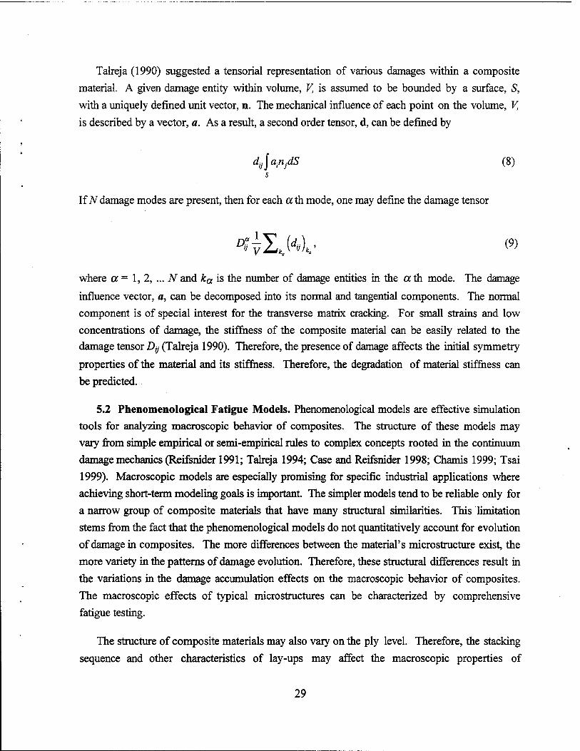
Talreja (1990) suggested a tensorial representation of various damages within a composite material. A given damage entity within volume, V, is assumed to be bounded by a surface, S,
with a uniquely defined unit vector, n. The mechanical influence of each point on the volume, V,
is described by a vector, a. As a result, a second order tensor, d, can be defined by
d^a^dS (8) s
If N damage modes are present, then for each ath mode, one may define the damage tensor
where a = 1,2, ... N and ka is the number of damage entities in the a th mode. The damage
influence vector, a, can be decomposed into its normal and tangential components. The normal component is of special interest for the transverse matrix cracking. For small strains and low concentrations of damage, the stiffness of the composite material can be easily related to the damage tensor Dy (Talreja 1990). Therefore, the presence of damage affects the initial symmetry
properties of the material and its stiffness. Therefore, the degradation of material stiffness can be predicted.
5.2 Phenomenological Fatigue Models. Phenomenological models are effective simulation tools for analyzing macroscopic behavior of composites. The structure of these models may vary from simple empirical or semi-empirical rules to complex concepts rooted in the continuum damage mechanics (Reifsnider 1991; Talreja 1994; Case and Reifsnider 1998; Chamis 1999; Tsai 1999). Macroscopic models are especially promising for specific industrial applications where achieving short-term modeling goals is important. The simpler models tend to be reliable only for a narrow group of composite materials that have many structural similarities. This limitation stems from the fact that the phenomenological models do not quantitatively account for evolution of damage in composites. The more differences between the material's microstructure exist, the more variety in the patterns of damage evolution. Therefore, these structural differences result in the variations in the damage accumulation effects on the macroscopic behavior of composites. The macroscopic effects of typical microstructures can be characterized by comprehensive fatigue testing.
The structure of composite materials may also vary on the ply level. Therefore, the stacking sequence and other characteristics of lay-ups may affect the macroscopic properties of
29

composites as well. The microstructural effects also include local stress distributions and stress concentrations that vary from one composite to another, even if they have the same
microstructure. Such variations result from pre-existing or processing-induced defects, which are also not accounted for in phenomenological models. Local stress distributions may also change as
the characteristics of loading change. Hence, simple macroscopic models are sensitive to the type of fatigue loading. This sensitivity of empirical models to the initial microstructure is typical for mathematical modeling of any ill-conditioned physical problem. The effects of typical structural variations can be often evaluated by additional experimental testing. Multiple experiments are also required for fatigue analyses based on the time-temperature superposition hypothesis (Tsai
1999). This dependency on large amounts of experimental input for each type of material, lay-
up, and loading is a major disadvantage of all phenomenological models.
5.2.1 Models Based on Strength and Stiffness. The phenomenological life prediction models
characterize the degradation of macroscopic mechanical properties, such as strength, stiffness,
etc. The material's strength and stiffness are the primary characteristics of mechanical behavior that could be easily monitored. As a consequence, there are stiffness-based and strength-based models for fatigue life predictions. The fatigue failure of a composite occurs when the current stress applied is equal to (or greater than) its residual strength. It is physically natural to employ this failure criterion in the strength-based fatigue models (Case and Reifsnider 1998; Appendix).
These models are often characterized as "wearout" models.
The models, which use the composite's stiffness as their primary variable, additionally require formulation of fundamental failure criteria. Hahn and Kim, O'Brien and Reifsnider, Whitworth and Farrow (Schaff and Davidson 1997a) introduced failure criteria based on the secant modulus. The failure criteria based on the static strain to failure were proposed by Hwang and Han (1986), and Poursartip, Ashby and Beaumont (1986). The stiffness-based fatigue models associated with the aforementioned criteria provide reasonable fatigue life predictions for
constant amplitude and/or two-stress amplitude loadings. The degradation rates for the Young's modulus and the strength of composites can be evaluated via experimental testing. The experimentally determined rates can be characterized by such concepts as the fatigue degradation modulus (Hwang and Han 1986) and a factor for degradation of strength (Schaff and Davidson 1997a, b). These fatigue parameters are often used in the phenomenological life prediction models to characterize the degradation of mechanical properties or the residual strength, the
remaining fatigue life, etc. It should be emphasized that the rates of material property degradation are important material parameters that should be known during any design process.
30

For instance, initially stiff composites may have worse fatigue performance than some more compliant composite materials because of their high rates of the modulus degradation.
5.2.2 Statistical Fatigue Models. The residual strength and fatigue life of composites are
statistical quantities, in general (Fukunaga et al. 1984; Talreja 1987; Chamis 1999). Two- parameter Weibull functions are commonly used in the strength-based fatigue models to describe the residual strength distribution after arbitrary load history. These functions can also describe
the probability of the composite's failure and fatigue life distributions after an arbitrary number of fatigue cycles. The two-parameter Weibull functions are defined by the scale, which
represents the 63.2 percentile of the distribution, and the shape, which characterizes the degree of scatter in the statistical data. Both the scale and shape parameters can be determined by experimental testing and the method of maximum likelihood (Talreja 1987).
The shape parameter for strength at zero cycles, B/0), must equal the static shape factor, Bs.
The shape parameter usually decreases with increasing cycling, as the residual strength distributions become more disperse during fatigue testing (Schaff and Davidson 1997a). The range of values involved in the residual strength distribution becomes wider as the number of fatigue cycles increases. The Weibull scale parameters are defined as the 63.2 percentile of the respective distribution functions. Experimental data on the initial static strength and the residual strength of composites can be represented by the Weibull scale parameters. Schaff and Davidson (1997a, b) developed models for constant amplitude and two-stress amplitude fatigue with a reduced number of experimentally determined parameters. The Schaff-Davidson models are based on the following assumptions:
• environmental and frequency-related effects are negligible,
• the residual strength, R(n), initially equals the static strength, Ro (it is also assumed to be a monotonically decreasing function of fatigue cycles, n,n>N),
• the residual strength, R(n), the static strength, RQ, and the final cycle number, N, are
assumed to be the Weibull scale parameters (i.e., they are defined as the 63.2 percentile of their respective distribution functions),
• the Weibull shape parameter, Bß is a linear decreasing function of fatigue cycles (i.e., the
residual strength distribution range of values becomes monotonically wider during
fatigue),
• the failure occurs when the residual strength, R(n), equals the peak stress, Smax,
31
• the stress ratio, rs = S^Smax, is constant during fatigue, and
• the residual strength relation is given by a power law, which is defined by the rate of strength \oss,f(Ro, rs, S^, and the strength degradation parameter, v.
The strength degradation parameter v can characterize a wide variety of the degradation rates of material properties under fatigue loading. In the case when v < 1, there is a rapid degradation
of strength in the beginning of service life. Linear strength degradation corresponds to v = 1. The case when v »1 is characterized by the "sudden death" behavior. The fatigue life predictions by
the Schaff-Davidson model compare well with experimental results for low-high and high-low
two-stress amplitude fatigue tests (Schaffand Davidson 1997b). The "cycle mix" effect of the
changing loading sequences has been taken into account by introducing a "cycle mix factor"
(Schaffand Davidson 1997b). It is a scale parameter used for the degradation of the residual
strength during the transition cycles. As a result, the model can be also used to simulate the pulse loading conditions. Probabilistic sensitivity factors can be also used to account for uncertainty in
the performance and durability evaluation of composite structures (Chamis 1999).
6. Recommendations for ARL LCF Program
The LCF conditions are unique to many Army land combat systems and are not well understood. Army engineers need to develop a clear physical understanding of LCF and the effects of material microstructure on fatigue damage processes, a methodology for LCF characterization of PMCs, and novel LCF models for optimization of designs and realistic service life prediction of Army combat systems (e.g., gun components, integral armor, rotorcraft applications, etc.). The broad range of fatigue problems encountered in Army structural applications (see section 2) can be addressed only by a comprehensive research and development program. Significant organizational and research efforts should be focused on establishing a knowledge base and infrastructure for a coordinated ARL LCF Program. Such a program will enable ARL engineers to meet current and future Army needs for solutions to numerous fatigue
related problems in design and repair of composite structures.
The conceptual framework for the ARL LCF Program has to reflect the Army needs for the design-for-fatigue methodology and robust predictive capabilities for microstructural design
optimization and LCF life prediction of structures which have thick sections and complex anisotropic microstructure. In order to develop reliable LCF models, the effects of fiber-matrix
interphase and adhesive joints in hybrid composites have to be accounted for. These issues are
32

unique to mechanics of composite materials and have not been examined in the studies dealing with fatigue of metals. The effects of chemical and hydro-thermal environment on material degradation processes and accumulation of damage also have unique features which are specific to composite
materials used by the Army.
6.1 Recommendations for Design-for-Fatigue Research. Section 2.1 includes some recommendations for future research concerning design methodologies, which can be summarized
as follows.
• Assess the structural stress analysis data on specific Army composite structures in order to identify the critical structural elements, the types of critical loads, and expected damage and failure modes.
• Carry out experimental fatigue testing of specific composite materials used in Army land combat systems. Such experimental characterization would yield S-N curves, residual strength data, stiffness degradation rates, etc.
•
•
•
•
•
Develop methodologies for fatigue life assessment based on either the experimentally determined property degradation rates or phenomenological fatigue life prediction models involving initial damage criteria or one-cycle fracture analysis.
Implement phenomenological fatigue models into the LAMPAT's structural analysis capabilities. Develop design methodologies that would include an assessment of fatigue performance based on engineering fatigue analysis.
Develop new phenomenological and micromechanical fatigue modeling capabilities that can account for microstructural effects such as interphasial effects, interfacial damage, stacking sequence effects, etc.
Evaluate current state-of-the-art fatigue simulation technology such as MRLife simulation code (see Appendix), which is suited for fatigue performance analysis of a wide variety of polymer and ceramic composite systems. The use of MRLife code would accelerate the progress in the design-for-fatigue efforts.
Assess the possibility of linking the modeling capabilities of MRLife fatigue performance simulation code with the structural analysis capabilities of commercial FEA codes (e. g., ANSYS, ABAQUS, etc.) and with composites-specific postprocessing software programs like LAMP AT.
33
6.2 Recommendations for the LCF Characterization. Section 2.2 includes some recommendations for future research concerning LCF for the ARL LCF Program, which can be
summarized as follows.
• Assess the effect of high loads and various strain rates on the transient stress distributions in critical structural elements of Army composite structures. Characterize the associated nonlinear material behavior and identify expected damage and failure
modes.
• Perform experimental fatigue testing of test coupons representing the critical structural
elements and carry out detailed nondestructive monitoring of fatigue damage accumulation
processes for cyclic loading above 50% of the ultimate strength.
• Develop conceptual maps for physical understanding of the mechanisms and phenomena
associated with fatigue-induced failure in PMCs under LCF conditions.
• Evaluate the effects of LCF conditions on typical damage mechanisms and the kinetics of
damage accumulation processes.
• Examine evolution of ballistic damage under LCF conditions, develop models for LCF assessment of ballistically damaged PMC structures, and validate these models.
• Develop novel LCF/PVF models accounting for fiber-matrix interphase effects and
realistic service life prediction methodology for various Army composite systems.
• Develop a design optimization methodology based on service life prediction capabilities
for Army structures under LCF conditions.
6.3 Recommendations for Investigation of Thick-Section Composites. The thick- section PMCs are unique to Army systems and should serve as a focal point for the ARL LCF Program. Section 2.3 includes some recommendations for future studies of thick-section composites, which can be summarized as follows.
• Identify critical thick-section structural elements in Army land combat systems and assess the types of critical loads and expected damage and failure modes. This assessment should be based on the structural stress analysis data for specific Army
composite structures.
34

• Identify similarities and differences in mechanical behavior of the thick-section structures
in Army applications and other thick-section homogeneous and heterogeneous structures used in industry. This analysis should be based on existing theoretical and experimental
data.
• Select appropriate test fixtures that could be scaled up and used for comprehensive fatigue characterization of the test coupons representing the critical thick-section structural elements of interest to Army.
•
•
Identify nondestructive damage evaluation techniques (e.g., x-rays, computed tomography, acoustic wave scattering, infrared thermal imaging, and embedded fiber
optics), which would be appropriate for detailed nondestructive monitoring of fatigue damage accumulation in the thick-section composites.
Characterize different types of fatigue damage, and their unique features, and determine the dominant fatigue damage mechanisms in the thick-section composites.
Develop various "damage healing" techniques (e.g., heating of magnetic microscopic particles under loading) for different types of fatigue damage in the thick-section composites, especially for interlaminar delamination.
• Develop conceptual maps describing the accumulation processes of fatigue damage in the thick-section composites under a wide range of loading conditions.
• Identify phenomenological fatigue models that can predict the stiffness degradation rates and fatigue life of the thick-section composites.
• Develop design optimization methodologies that would include an assessment of fatigue performance based on engineering fatigue analysis of the thick-section composite structures.
• Develop new phenomenological and micromechanical fatigue modeling capabilities that can account for microstructural effects in the thick-section structures (e.g., interphasial effects, interfacial damage, stacking sequence effects, etc.).
6.4 Recommendations for Studies of Interphasial Effects on LCF. The ARL LCF Program will help ARL engineers to meet the AAN goals if the full potential of the "material-by- design" approach is realized. Section 2.4 includes some recommendations for research concerning the effects of mechanical properties of the fiber-matrix interphases on LCF behavior of PMCs
35

and damage accumulation of composite structures. These recommendations can be summarized
as follows.
•
•
•
•
Develop experimental methodology and an appropriate data reduction scheme for characterization of the fiber-matrix interphase properties around an individual fiber under various strain rates. A new test apparatus called DILA and developed by Tanoglu et al.
(to be published) can be employed.
Develop a physical understanding of the energy absorption mechanisms activated in the interphasial region between a fiber and the matrix (e.g., interfacial debonding, interfacial
void growth, fiber push-out, and frictional fiber sliding).
Characterize the effect of energy-absorbing capabilities of the fiber-matrix interphase on
the LCF and ballistic performance of typical Army land combat composite structures.
Develop models describing various energy-absorbing mechanisms activated in the fiber-
matrix interphase and predict the possible effects on the LCF fatigue performance of
composites.
Develop a physical understanding of the matrix toughening mechanisms activated around rubber or thermoplastic particles in the matrix (e.g., interfacial debonding, interfacial void
growth, plastic shear localization, and other).
Develop techniques for "interfacial damage healing" (e.g., heating of magnetic microscopic
particles distributed around fibers) for different types of PMCs.
Develop models describing various matrix toughening mechanisms activated in around particles in the matrix and predict the possible effects on the LCF fatigue performance of
composites.
6.5 Recommendations for Studies of Adhesive Joints. Section 2.5 includes some recommendations for investigation of the role of adhesive joints in composites, which can be
summarized as follows.
• Identify the adhesive joints between dissimilar composite materials which are critical for ballistic and LCF performance of specific Army land combat systems. This assessment
should be based on the structural stress analysis of specific Army structures.
•
36

•
•
•
Develop models describing the effects of adhesive joints on the ballistic damage tolerance
of various Army land combat systems.
Develop phenomenological and micromechanical fatigue models that can describe the LCF
mechanics of damaged hybrid structures and predict the LCF performance of damaged
composite systems.
Develop experimental methodology and an appropriate data reduction scheme for characterization of the energy absorption capabilities of various adhesive joints under the
strain rates encountered during a ballistic impact or in LCF conditions.
Select appropriate test fixtures that can be used for fatigue and fracture toughness
characterization of the test coupons representing the damaged and repaired structural
elements.
• Characterize different types of fatigue damage, damage evolution rates, and determine the dominant fatigue damage mechanisms in the damaged and repaired composites.
• Develop conceptual maps describing the accumulation processes of fatigue damage in the damaged and repaired composites under a wide range of loading conditions.
• Develop phenomenological and micromechanical fatigue models that can be used to predict the stiffness degradation rates and fatigue life of the damaged and repaired composite systems.
6.6 Recommendations for Investigation of Environmental Effects. Section 2.6 includes some recommendations for future studies of environmental effects on composites, which can be summarized as follows.
• Identify the possible ranges of temperatures and humidity levels and types of chemical environment to which typical Army land combat systems may be exposed to during
service life.
• Identify typical groups of physical/chemical conditions for various Army systems to determine whether the mechanical fatigue loading and ballistic impacts will be complemented with thermomechanical loads, moisture effects, chemical corrosion,
mechanical wear, etc.
37
•
•
•
•
•
Develop experimental methodology for fatigue testing of composite structures that have
been exposed to various environmental conditions.
Develop experimental testing fixtures for fatigue characterization of composite structures
that are being exposed to various environmental conditions.
Develop models describing the effects of material heterogeneity, re-existing defects and developing interfacial and matrix cracking on the absorption and propagation of moisture.
Develop models describing the effects of material heterogeneity such as existing defects
and developing interfacial and matrix cracking on the degradation of mechanical properties
due to the moist or chemically active environment.
Perform experimental and theoretical characterization of beneficial effects caused by the
use of various protective coatings on the reduction of absorption and propagation of
moisture.
38
7. References
Adams, D. S., D. E. Bowles, and C. T. Herakovich. "Thermally Induced Transverse Cracking in
Graphite-Epoxy Cross-Ply Laminates." Journal of Reinforced Plastics and Composites,
vol. 5, pp. 152-160,1986.
Akshantala, N. V., and R. Talreja. "A Mechanistic Model for Fatigue Damage Evolution in
Composite Laminates." Mechanics of Materials, vol. 29, pp. 123-140,1998.
Arnold, S. M., and S. Kruch. "A Differential CDM Model for Fatigue of Unidirectional Metal
Matrix Composites." NASA Technical Memorandum 105726, NASA Langley, Hampton,
VA, 1991.
Arnold, S. M., and T. E. Wilt. "A Deformation and Life Prediction of a Circumferentially
Reinforced SiC/Ti-15-3 Ring." Reliability, Stress Analysis and Failure Prevention,
ASME-DE, vol. 55, pp. 231-238, American Society of Mechanical Engineers,
Philadelphia, PA, 1993.
Bailey, J. E., P. T. Curtis, and A. Parvizi. "On the Transverse Cracking and Local Longitudinal
Splitting Behavior of Glass and Carbon Fibre Epoxy Cross-Ply Laminates and the Effect
of Poisson and Thermally Generated Strains." Proceedings of Royal Society of London,
vol. A366, pp. 599-609, London, 1979.
Bailey, J. E., and A. Parvizi. "On Fibre Debonding Effects and the Mechanism of Transverse Ply
Failure in Cross-Ply Laminates of Glass/Fibre/Thermoset Composite." Journal of
Material Science, vol. 16, pp. 649-656, 1981.
Bakis, C. E., and W. W. Stinchcomb. "Response of Thick, Notched Laminates Subjected to
Tension-Compression Cyclic Loads." ASTM-STP-907, pp. 314-334, American Society
for Testing of Materials, Philadelphia, PA, 1986.
Barbat, A. H., S. Oiler, E. Onate, and A. Hanganu. "Viscous Damage Model for Timoshenko
Beam Structures." International Journal of Solids and Structures, vol. 34, pp.
3953-3976,1997.
Barnes, B. "Bond and Low Cycle Fatigue Behavior of Thermoset Composite Reinforcing for the
Concrete Industry." Report No. DE91000201/XAB, Ames Laboratory, U.S. Department
of Energy, Ames, IW, 1990.
39

Bathe, K.J. Finite Element Procedures in Engineering Analysis. Englewood Cliffs, NJ: Prentice-
Hall, 1982.
Becker, R., A. Needleman, O. Richmond, and V. Tvergaard. "Void Growth and Failure in
Notched Bars." Journal of Mechanics and Physics of Solids, vol. 36, pp. 317-351,1988.
Berglund, L. A., J. Varna, and J. Yuan. "Transverse Cracking and Local Delamination in [0/90] Carbon Fiber/Toughened Epoxy Laminates." Journal of Reinforced Plastics and
Composites, vol. 11, pp. 643-655, June 1992.
Bingham, E. C. Fluidity and Plasticity. New York: McGraw-Hill, 1922.
Bogetti, T. A., J. W. Gillespie, Jr., and M. A. Lamontia. "The Influence of Ply Waviness With
Nonlinear Shear on the Stiffness and Strength Reduction of Composite Laminates." ARL-
TR-585, U.S. Army Research Laboratory, Aberdeen Proving Ground, MD, 1995.
Bogetti, T. A., C. P. R. Hoppel, and B. P. Burns. "LAMPAT: A Software Tool for Analyzing and Designing Thick Laminated Composite Structures." ARL-TR-890, U.S. Army Research Laboratory, Aberdeen Proving Ground, MD, 1995.
Bridgman, P. W. Dimensional Analysis. New Haven, CT: Yale University, 1922.
Broutman, L. J., and S. Sahu. "Progressive Damage of a Glass Reinforced Plastic During Fatigue." Proceedings of 24th SPI Conference, 1 ID, New York, NY, 1969.
Budiansky, B., A. G. Evans, and J. W. Hutchinson. "Fiber-Matrix Debonding Effects on Cracking in Aligned Fiber Ceramic Composites." International Journal of Solids and
Structures, vol. 32, no. 4, pp. 315-328,1995.
Budiansky, B., J. W. Hutchinson, and S. Slutsky. "Void Growth and Collapse in Viscous Solids." Mechanics of Solids, pp. 13-45, H. Hopkins and M. Sewell (editors), Oxford: Pergamon Press, 1982.
Burns, B. "Development of Multifunctional Composite Systems for Army Applications." 13th
ASC Technical Conference, Baltimore, MD, 1998.
Burr, A., F. Hild, and F. A. Leckie. "Micro-Mechanics and Continuum Damage Mechanics."
Archive of Applied Mechanics, vol. 65, pp. 437-456,1995.
40

Carlsson, L. A., and J. W. Gillespie, Jr. (editors). Delaware Composites Design Encyclopedia.
Lancaster, PA: Technomic Publishing Co., 1990.
Case, S. W., and K. L. Reifsnider. MRLifell -A Strength and Life Prediction Code for Laminated
Composite Materials. Materials Response Group, Virginia Polytechnic Institute and
State University, Blacksburg, VA, 1998.
Cervenka, A. "Interphases and Their Effect on the Stress Field in Composites." Part 1: The Role of an Anisotropie Interphase." Composite Interfaces, vol. 3, pp. 135-167,1995.
Chaboche, J. L. "CDM - A Tool to Describe Phenomena Before Crack Initiation." Nuclear
Engineering and Design, vol. 64, pp. 233-247, 1981.
Chamis, C. C. "Simplified Composite Micromechanics Equations for Strength, Fracture Toughness, Impact Resistance and Environmental Effects." NASA Technical Memorandum 83696, NASA Lewis Research Center, Cleveland, OH, 1984.
Chamis, C. C. "Probabilistic Evaluation of Composite Performance and Durability." Composites
2000: An International Symposium on Composite Materials, pp. 43^44, University of Delaware, 5-7 October, Newark, DE, 1999.
Chaphalkar, P. "Performance Evaluation and Modeling of Twill Woven Laminates." Ph.D. thesis, North Carolina A&T State University, 1998.
Chen, T. K., C. G. Davila, and D. J. Baker. "Analysis of Tile-Reinforced Composite Armor. Part 2: Viscoelastic Response Modeling." 21st Army Science Conference, Norfolk, VA, June 1998.
Chou, P. C, J. Carleone, and C. M. Hsu. "Elastic Constants of Layered Media." Journal of
Composite Materials, vol. 6, pp. 80-93,1972.
Christensen, R. M. "Effective Moduli of Cylindrical and Lamellar Systems." Mechanics of
Composite Materials, pp. 73-105, New York: Wiley, 1979.
Chu, Y. C, and S. I. Rokhlin. "Effective Elastic Moduli of Fiber-Matrix Interphases in High- Temperature Composites." Metallurgical and Materials Transactions, Series A, vol. 27, pp. 165-182, 1996.
41

Clyne, T. W., and M. C. Watson. "Interfacial Mechanics of the Fiber-Reinforced Metals."
Composites Science and Technology, vol. 42, pp. 25-55,1991.
Coffin, C. F., Jr. (editor). Manual on Low Cycle Fatigue Testing. ASTM-STP-465, American
Society for Testing of Materials, Philadelphia, PA, 1969.
Coffin, L. F., and H. C. Rogers. "Influence of Pressure on the Structural Damage in Metal Forming Processes." Transactions of ASM, vol. 60, pp. 672-686,1967.
Crossman, F. W., and A. S. D. Wang. "The Dependence of Transverse Cracking and
Delamination on Ply Thickness in Graphite/Epoxy Laminates." Damage of Composite
Materials, pp. 118-128, K. L. Reifsnider (editor), ASTM-STP-775, American Society for
Testing of Materials, Philadelphia, PA, 1982.
Crossman, F. W., W. J. Warren, A. S. D. Wang, and G. E. Law. "Initiation and Growth of Transverse Cracks and Edge Delamination in Composite Laminates. Part 2: Experimental Correlation." Journal of Composite Materials (Supplement), vol. 14, pp. 88-96,1980.
Davila, C. G., T.-K. Chen, and D. J. Baker. "Analysis of Tile-Reinforced Composite Armor. Part 1: Advanced Modeling and Strength Analyses." 21st Army Science Conference,
Norfolk, VA, June 1998.
Delale, F., and F. Erdogan. "On the Mechanical Modeling of the Interfacial Region in Bonded Half-Planes." Journal of Applied Mechanics, vol. 55, pp. 317-324,1988.
DiAnselmo, A., M. L. Accorsi, and A. T. DiBenedetto. "The Effect of Interphase on the Stress and Energy Distribution in the Embedded Single Fiber Test." Composites Science and
Technology, vol. 44, pp. 215-225,1992.
Drucker, D. C. Introduction to Mechanics ofDeformable Solids. New York: McGraw-Hill, 1967.
Drzal, L. T. "Composite Interphase Characterization." SAMPE Journal, pp. 7-13, September/October, 1983.
Drzal, L. T. "The Interphase in Epoxy Composites." Advances in Polymer Science, vol. 75, pp. 1-32, Berlin: Springer-Verlag, 1986.
Dvorak, G. J., andN. Laws. "Analysis of Progressive Matrix Cracking in Composite Laminates -
First Ply Failure." Journal of Composite Materials, vol. 21, pp. 309-319,1987.
42

Dzenis, Y. A. "Stochastic Damage Evolution Modeling in Laminates." Journal of Thermoplastic
Composite Materials, vol. 9, pp. 21-34, 1996.
Dzenis, Y. A., S. P. Joshi, and A. E. Bogdanovich. "Damage Analysis of Laminates Under Cyclic Loading." International Conference on Composite Materials, ICCM-9, London, 1993.
Ericksen, J. L. (editor). Homogenization and Effective Moduli of Materials and Media. Berlin:
Springer-Verlag, 1986.
Erikson, P. W., and E. P. Plueddemann. "Mechanics of Load Transfer at the Interface." Composite Materials, vol. 6, pp. 1-31, E. P. Plueddemann (editor), New York, NY:
Academic Press, 1974.
Eshelby, J. D. "The Determination of the Elastic Field of an Ellipsoidal Inclusion and Related Problems." Proceedings of Royal Society of London, Series A, vol. 241, pp. 376-390, 1957.
Fink, B. K., and K. Corona-Bittick. "Embedded Fiber Optic Sensors for Integral Armor." Technical Report, U.S. Army Research Laboratory, Aberdeen Proving Ground, MD, to be published.
Fink, B. K., and J. W. Gillespie, Jr. "Non-Polluting Composites Repair and Remanufacturing for Military Applications: Co-Injection Resin Transfer Molding." Technical Report, U.S. Army Research Laboratory, Aberdeen Proving Ground, MD, to be published.
Fink, B. K., and R. L. McCullough. "Interphase Research Issues." Composites. Part A: Applied Science and Manufacturing, vol. 30, pp. 1-2,1999.
Fink, B. K., S. H. McKnight, and J. W. Gillespie, Jr. "Co-Injection Resin Transfer Molding for Integral Armor." Proceedings of the 21st Army Science Conference, Norfolk, VA, June 1998.
Fishman, S. G. "Control of Interfacial Behavior in Structural Composites." Proceedings of the
8th International Conference on Composite Materials, pp. 19-23, SAMPE, Honolulu, 1991.
Flaggs, D. L. "Prediction of Tensile Matrix Failure in Composite Laminates." Journal of
Composite Materials, vol. 19, pp. 29-39,1985.
43

Flores, F., T. A. Bogetti, B. K. Fink, D. Heider, and J. W. Gillespie, Jr. "Experimental
Investigation for Validation of the Thermo-Mechanical Response of Vinyl Ester Resin." Proceedings of the 13th Annual Technical Conference on Composite Materials, pp.
802-814, American Society for Composites, Baltimore, MD, 21-23 September, 1998.
Fukunaga, H., T. W. Chou, W. M. Peters, and K. Schulte. "Probabalistic Failure Strength Analysis of Graphite/Epoxy Cross-Ply Laminates." Journal of Composite Materials,
vol. 18, pp. 339-349, 1984.
Gamstedt, E. K., and R. Talreja. "Fatigue Damage Mechanisms in Unidirectional Carbon-Fibre- Reinforced Plastics." Journal of Material Science, to be published.
Gao, Z., and K. L. Reifsnider. "Micromechanics of Tensile Strength in Composite Systems."
Composite Materials: Fatigue and Fracture, vol. 4, pp. 453-470, ASTM-STP-1156,
W. W. Stinchcomb and N. E. Ashbaugh (editors), American Society for Testing of Materials, Philadelphia, PA, 1993.
Garrett, K. W., and J. E. Bailey. "Multiple Transverse Fracture in 90 Degree Cross-Ply Laminates of Glass Fiber-Reinforced Polyester." Journal of Materials Science, vol. 12, pp. 157-167, 1977.
Gibson, R. F. Principles of Composite Material Mechanics. New York, NY: McGraw Hill, 1994.
Gillespie, Jr., J. W., and U. Hansen. "Transverse Cracking of Composite Laminates With Interleaves: A Variational Approach." Key Engineering Materials, vol. 121, pp. 521-548, 1996.
Grabovsky, Y., and R. V. Kohn. "Microstructures Minimizing the Energy of a Two-Phase Elastic Composite in Two Space Dimensions: The Vigdergauz Microstructure." Journal
of Mechanics and Physics of Solids, vol. 43, pp. 949-972,1995.
Hahn, H. T. "Fatigue Behavior and Life Prediction of Composite Laminates." Testing and
Design, Fifth ASTM Conference, ASTM-STP-674, pp. 383-417, American Society for Testing and Materials, Philadelphia, PA, 1979.
Han, Y. M., H. T. Hahn, and R. B. Croman. "A Simplified Analysis of Transverse Ply Cracking in Cross-Ply Laminates." Composites Science and Technology, vol. 31, pp. 165-175,
1987.
44

Harik, V. M. "Experimental and Theoretical Studies of Interfacial Effects in Multiphase Media."
Ph.D. Dissertation, University of Delaware, Newark, DE, 1997.
Harik, V. M., and R. A. Cairncross. "Evolution of Interfacial Voids Around a Cylindrical
Inclusion." Journal of Applied Mechanics, vol. 66, pp. 310-314, June 1999.
Harik, V. M., J. R. Klinger, B. K. Fink, T. A. Bogerti, A. Paesano, and J. W. Gillespie, Jr. "Low
Cycle Fatigue of Unidirectional Glass/Epoxy Composites." Proceedings of the ASME
Symposium on Durability and Damage Tolerance in Composite Materials and Structures,
in "Damage and Durability of Composite Materials and Structures," AMD-vol. 232,
MD-vol. 86, American Society of Mechanical Engineers, Philadelphia, PA, 1999.
Harik, V. M., and J. Lambros. "Modelling of Interphase Effects on Local Stress Distributions in
Composites." Mathematical Modelling and Scientific Computing, vol. 8, to be published.
Harris, D. 0., and D. Dedhia. User Manual: Non-Linear Smartcrack 1.0. Engineering
Mechanics Technology Inc., Palo Alto, CA, 1997.
Hashin, Z. "Analysis of Cracked Laminates: A Variational Approach." Mechanics of
Materials, vol. 4, pp. 121-131,1985.
Hashin, Z. "Analysis of Stiffness Reduction of Cracked Cross-Ply Laminates." Engineering
Fracture Mechanics, vol. 25, pp. 771-781, 1986.
Hashin, Z. "The Spherical Inclusion With Imperfect Interface." Journal of Applied Mechanics,
vol. 53, pp. 444-449, 1991.
Hill, R. The Mathematical Theory of Plasticity. Oxford: Clarendon Press, 1950.
Holmes, G. A., R. C. Peterson, D. L. Hunston, W. G. McDonough, and C. L. Schutte. "The
Effect of Nonlinear Viscoelasticity on Interfacial Shear Strength Measurements."
National Institute of Standards and Technology, 1999.
Hoppel, C. P. R, R N. Pangborn, and R. W. Thomson. "Damage Accumulation During Multiple
Stress Level Fatigue of Short Glass Fiber Reinforced Styrene-Maleic Anhydride."
Proceedings of the 13th Annual Technical Conference on Composite Materials, American
Society for Composites, Baltimore, MD, 21-23 September, 1998.
45

Hrivnak, J. "Optimization of the Surface Free Energy on Carbon Fibers and Its Effect on Interphase Formation." Ph.D. thesis, University of Delaware, Newark, DE, 1996.
Hughes, J. D. H. "The Carbon Fibre/Epoxy Interface - A Review." Composites Science and
Technology, vol. 41, pp. 13-45, 1991.
Hull, D. An Introduction to Composite Materials. Cambridge: Cambridge University Press, 1981.
Hwang, W., and K. S. Han. "Fatigue of Composites-Fatigue Modulus Concept and Life Prediction." Journal of Composite Materials, vol. 20, pp. 154-165, 1986.
Jasiuk, I., and M. W. Kouider. "The Effect of an Inhomogeneous Interphase on the Elastic
Constants of Transversely Isotropie Composites." Mechanics of Materials, vol. 15,
pp. 53-63, 1993.
Jayaraman, K., and K. L. Reifsnider. "The Interphase in Unidirectional Fiber-Reinforced Epoxies: Effect on Residual Thermal Stresses." Composites Science and Technology,
vol. 47, pp. 119-129, 1993.
Jones, R. M. Mechanics of Composite Materials. New York, NY: Hemisphere Publishing Co.,
1975.
Joseph, D. D. Fluid Dynamics of Viscoelastic Liquids. Berlin: Springer-Verlag, 1990.
Kachanov, L. M. "Time of the Rupture Process Under Creep Conditions." Izvestia Akademii NaukS.S.S.R, Otdel Tekhnicheskikh Nauk, vol. 8, pp. 26-31, 1958 (in Russian).
Kachanov, L. M. Introduction to Continuum Damage Mechanics. Boston, MA: Martinus Nijhoff Publishers, 1986.
Kaliakin, V. N. Introduction to Approximate Solution Techniques With Emphasis on Finite
Element Method. Newark, DE: Copy Maven, 1996.
Keer, L. M., J. Dundurs, and K. Kiattikomol. "Separation of a Smooth Circular Inclusion From a Matrix." International journal of Engineering Science, vol. 11, pp. 1221-1233,1973.
Kharik, V. M. "Response of Composites Under Compression Loads: Finite Element Modeling."
Journal of the Mechanical Behavior of Materials, vol. 8, pp. 29-40,1997.
46
Kim, J.-K., and Y.-W. Mai. "High Strength, High Fracture Toughness Fiber Composites With
Interface Control - a Review." Composites Science and Technology, vol. 41, pp.
333-378, 1991.
Kim, J.K., and Y.W. Mai. Engineered Interfaces in Fiber Reinforced Composites. Oxford:
Elsevier, 1998.
Kim, T. W., H. J. Kim, and S. Im. "Delamination Crack Originating From Transverse Cracking in
Cross-Ply Composite Laminates Under Extension." International Journal of Solids and
Structures, vol. 27, pp. 1925-1935, 1991.
Koplik, J., and A. Needleman. "Void Growth and Coalescence in Porous Plastic Solids."
Internationaljournal of Solids and Structures, vol. 24, pp. 835-853,1988.
Korczynsky, K., and J. G. Morley. "Constrained Cracking in Cross-Ply Laminates." Journal of
Materials Science, vol. 16, pp. 1785-1795,1981.
Krajcinovic, D. "Damage Mechanics." Mechanics of Materials, vol. 8, pp. 117-197,1989.
Lagache, M., A. Agbossou, J. Pastor, and D. Miller. "Role of Interphase on the Elastic Behavior
of Composite Materials: Theoretical and Experimental Analysis." Journal of Composite
Materials, vol. 28, pp. 1140-1157,1994.
Landau, L. D., and E. M. Lifshitz. Theory of Elasticity. New York: Pergamon Press, 1986.
Lekhnitskii, S. G. Anisotropie Plates. Translated by S. W. Tsai and T. Cheron. London: Gordon
and Breach, 1968.
Lemaitre, J. A Course on Damage Mechanics. Berlin: Springer, 1992.
Lemaitre, J. "How to Use Damage Mechanics." Nuclear Engineering Design, vol. 80, pp.
233-245,1984.
Lee, B. J., and M. E. Mear. "Studies of the Growth and Collapse of Voids in Viscous Solids."
Transactions of the ASME, vol. 116, pp. 348-358, American Society of Mechanical
Engineers, July 1994.
Lee, Y., and T. Bart. "An Investigation of Void Formation on a Bonded Interface of Power Law
Creep Materials Containing a Cylindrical Particle." Acta Mechanica, vol. 79, pp.
183-197,1989.
47
Lee, Y. S., and P. R. Dawson. "Modeling Ductile Void Growth in Viscoplastic Materials - Part I:
Void Growth Model." Mechanics of Materials, vol. 15, pp. 21-34, 1993.
Lesko, J. J., A. Rau, and J. S. Riffle. "The Effect of Interphase Properties on the Durability of
Woven Carbon/Vinyl Ester Matrix Composites." Proceedings of the 10th ASC Technical
Conference, 18-20 October, Blacksburg, VA, 1995.
Li, J., and V. N. Kaliakin. "Numerical Simulation of Interfaces in Geomaterials: Development of
New Zero-Thickness Interface Elements." Civil Engineering TR 93-6, University of
Delaware, Newark, DE, July 1993.
Lorenzo, L., and H. T. Hahn. "Fatigue Failure Mechanisms in Unidirectional Composites."
Composite Materials: Fatigue and Fracture, ASTM-STP-907, pp. 210-232, H. T. Hahn
(editor), American Society for Testing of Materials, Philadelphia, PA, 1986.
Love, A. E. H. The Mathematical Theory of Elasticity. New York, NY: Dover, 1944.
Low, B. Y., S. D. Gardner, C. U. Pittman, and R. M. Hacket. "A Micromechanical
Characterization of Graphite-Fiber/Epoxy Composites Containing a Heterogeneous
Interphase Region." Composites Science and Technology, vol. 52, pp. 589-606, 1995.
Lutz, M. P., and R. W. Zimmerman. "Effect of the Interphase Zone on the Bulk Modulus of a
Particulate Composite." Journal of Applied Mechanics, vol. 63, pp. 855-861,1996.
Mahfuz, H., M. Maniruzzaman, J. Krishnagopalan, A. Haque, M. Ismail, and S. Jeelani.
"Fatigue Damage and Effects of Stress Ratio on the Fatigue Life of Carbon-Carbon
Composites." Journal of Theoretical and Applied Fracture Mechanics, vol. 24, pp.
21-31,1995.
Mahfuz, H., A. Haque, D. Yu, and S. Jeelani. "Response of Resin Transfer Molded (RTM)
Composites Under Reversed Cyclic Loading." ASME Journal of Engineering Materials
and Technology, vol. 118, pp. 49-57, 1996.
Mandell, J. F. "Fatigue Behavior of Fiber-Resin Composites." Research Report R81-2, Defense
Technical Information Center, U.S. Department of Defense, Arlington, VA, 1981.
48

Mandell, J. F., D. H. Grande, T. H. Tsiang, and F. J. McGarry. "A Modified Microdebonding
Test for Direct In-Situ Fiber/Matrix Bond Strength Determination in Fiber Composites."
ASTM D30 Symposium on Composite Materials: Testing and Design, 7th Conference,
American Society for Testing of Materials, Philadelphia, PA, 1984.
Manders, P. W., T. W. Chou, F. R. Jones, and J. W. Rock. "Statistical Analysis of Multiple
Fracture in [0/90/0] Glass Fiber/Epoxy Resin Laminates." Journal of Materials Science,
vol. 19, pp. 2876-2886, 1983.
Monib, A., X. Huang, J. W. Gillespie, Jr., B. K. Fink, and G. Thomas. "Defect Criticality of
Composite Laminates Subjected to Ballistic Impact." Journal of Composite Materials, to
be published.
Nadai, A. Theory of Flow and Fracture of Solids. New York, NY: McGraw-Hill, 1950.
Nath, R. B., D. N. Fenner, and C. Galiotis. "Finite Element Modelling of Interfacial Failure in
Model Carbon Fibre-Epoxy Composites." Journal of Material Science, vol. 31, pp.
2879-2883, 1996.
Needleman, A. "Void Growth in Elastic-Plastic Medium." ASME Journal of Applied Mechanics,
vol. 39, pp. 964-970, 1972.
Needleman, A. "A Continuum Model for Void Nucleation by Inclusion Debonding." Journal of
Applied Mechanics, vol. 54, pp. 525-531, 1987.
O'Brien, T. K. "Delamination of Composite Materials." Fatigue of Composite Materials,
Composite Materials Series, vol. 4, pp. 181-198, K. L. Reifsnider (editor), New York,
NY: Elsevier, 1991.
O'Brien, T. K. "Local Delamination in Laminates With Angle Ply Matrix Cracks. Part II:
Delamination Fracture Analysis and Fatigue Characterization." Composite Materials:
Fatigue and Fracture, vol. IV, ASTM-STP-1156, W. W. Stinchcomb and N. E. Ashbaugh
(editors), pp. 507-517, American Society for Testing of Materials, Philadelphia, PA,
1993.
O'Brien, T. K., N. J. Johnston, D. H. Morris, and R. A. Simonds. "A Simple Test for the
Interlaminar Fracture Toughness of Composites." SAMPE Journal, vol. 18, no. 4, pp.
8-18,1982.
49

O'Brien, T. K., P. Minguet, M. Cvitkovich, R. Krueger, and S. Owsley. "Skin/Stringer
Disbonding in Reinforced Composite Panels." Technical Program Summary of the Army
Research Lab Vehicle Technology Center, NASA Langley Research Center, Hampton,
VA, 1998.
Ogin, S. L., and P. A. Smith. "Model for Matrix Cracking in Cross-Ply Laminates." ESA
Journal, vol. 11, pp. 45-55, 1987.
Owen, M. J. "Fatigue Damage in Glass-Fiber-Reinforced Plastics." Composite Materials:
Fracture and Fatigue, vol. 5, L. J. Boutman (editor), Chapter 7, New York, NY:
Academic Press, 1974.
Oyama, H. T., S. Davis, J. P. Wightman, and J. S. Riffle. "Interdiffusion at the Interface Between
Poly-Vinyl Pyrollidone and Vinyl Ester." Polymer Preprints, Proceedings of the 1996
AChS Meeting, Orlando, FL, 1996.
Paesano, A., I. C. Visconti, and M. Penasa. "An Investigation of Antiwear Coatings on Fibre-
Reinforced Plastics." Composites Manufacturing, vol. 3, pp. 7-13, 1992.
Palmese, G. R. "Origin and Influence of Interphase Material Property Gradients in
Thermosetting Composites." Ph.D. thesis, University of Delaware, Newark, DE, 1992.
Palmese, G. R., and R. L. McCullough. "Kinetic and Thermodynamic Considerations Regarding
Interphase Formation in Thermosetting Composite Systems." Journal of Adhesion,
vol. 44, pp. 29-49, 1994.
Palmese, G. R., R. L. McCullough, and N. R. Sottos. "Relationship Between Interphase
Composition, Material Properties, and Residual Thermal Stresses in Composite
Materials." Journal of Adhesion, vol. 52, pp. 101-113,1995.
Pan, M. J., D. J. Green, and J. R. Hellmann. "Influence of Interfacial Microcracks on the Elastic
Properties of Composites." Journal of Material Science, vol. 31, pp. 3179-3184, 1996.
Parvizi, A., and J. E. Bailey. "On Multiple Transverse Cracking in Glass-Fiber Epoxy Cross-Ply
laminates." Journal of Materials Science, vol. 13, pp. 2131-2141, 1978.
Patton, E. M., and M. H. Santare. "Crack Path Prediction Near an Elliptical Inclusion"
Engineering Fracture Mechanics, vol. 44, pp. 195-205,1993.
50

Piggott, M. R. "Micromechanics of Fibre-Polymer Interfaces." Interfacial Phenomena in
Composite Materials, I. Verpoest and F. Jones (editors), pp. 3-8, Oxford: Butterworth-
Heinemann, 1991.
Pipes, R. B. and N. J. Pagano. "Interlaminar Stresses in Composite Laminates Under Uniform
Axial Extension." Journal of Composite Materials, vol. 4, pp. 538-548, 1970.
Pook, L. P. "On Fatigue-Crack Paths." International Journal of Fatigue, vol. 17, no. 1, pp.
5-13,1995.
Pook, L. P. "Determination of Fatigue Crack Paths." International Journal for Bifurcation and
Chaos, vol. 7, no. 2, pp. 469-475, 1997.
Pook, L. P., and M. J. Podbury. "A Failure Mechanism Map for Angle Notch Charpy Tests on
a Mild Steel." International Journal of Fracture, vol. 90, nos. 1-2, pp. L3-L8, 1998.
Poursartip, A., M. F. Ashby, and P. W. R. Beaumont. "The Fatigue Damage Mechanics of a
Carbon Fibre Composite Laminate: I - Development of the Model." Composites Science
and Technology, vol. 25, pp. 193-218, 1986.
Reifsnider, K. L. "Some Fundamental Aspects of the Fatigue and Fracture Response of
Composite Materials." Proceedings of the 14th Annual Meeting ofSES, Bethlehem, PA,
1977.
Reifsnider, K. L. (editor). Damage in Composite Materials. ASTM-STP-775, American Society
for Testing of Materials, Philadelphia, PA, 1982.
Reifsnider, K. L. (editor). Fatigue of Composite Materials. Composite Materials Series, vol. 4.
London: Elsevier, 1991.
Reifsnider, K. L. "Modelling of the Interphase in Polymer-Matrix Composite Material System."
Composites, no. 7, pp. 461^469,1994.
Rice, J. R., J. W. Rudnicki, and D. A. Simons. "Deformation of Spherical Cavities and Inclusions
in Fluid-Infiltrated Elastic Materials." International Journal of Solids and Structures,
vol. 14, pp. 289-303, 1978.
Rie, K.-T., and P. D. Portella (editors). Low Cycle Fatigue and Elasto-Plastic Behavior of
Materials. Oxford: Elsevier, 1998.
51

Salpekar, S. A., and T. K. O'Brien. "Combined Effect of Matrix Cracking and Free Edge
Delamination." Composite Materials: Fatigue and Fracture, pp. 287-311, T. K. O'Brien
(editor), American Society for Testing of Materials, Philadelphia, PA, 1991.
Sasaki, K. "Estimation of Low Cycle Fatigue Failure and Microscopic Change of CFRP -
Observation of AE Measurement and Microscopic View of CFRPs." Journal of the
Society of Material Science, Japan, vol. 46, pp. 295-301, 1997.
Schaff, J. R., and B. D. Davidson. "Life Prediction Methodology for Composite Structures.
Part I: Constant Amplitude and Two-Stress Level Fatigue." Journal of Composite
Materials, vol. 31, pp. 128-157, 1997.
Schaff, J. R., and B. D. Davidson. "Life Prediction Methodology for Composite Structures.
Part II: Spectrum Fatigue." Journal of Composite Materials, vol. 31, pp. 158-181, 1997.
Sendeckyj, G. P. "Life Prediction for Resin-Matrix Composite Materials." Composite Materials
Series: Fatigue of Composites, pp. 431-483, K. L. Reifsnider (editor), New York, NY:
Elsevier, 1990.
Shen, J., C. C. Chen, and J. A. Sauer. "Ductile Fracture in Fatigue of PMMA." Polymer
Communications, vol. 24, pp. 167-170, 1983.
Shorthall, J. B., and H. W. C. Yip. "The Interfacial Bond Strength in Glass-Fibre/Polyester Resin
Composite Systems. Part 2: The Effect of Surface Treatment." Journal of Adhesion,
vol. 8, pp. 155-169,1976.
Skourlis, T. P. "Structure and Properties of the Interphase in Coated Carbon Fiber Epoxy
Systems." Ph.D. thesis, University of Delaware, Newark, DE, 1995.
Solomon, H. D., G. R. Halford, L. R. Kaisand, and B. N. Leis (editors). Low Cycle Fatigue,
ASTM-STP-942, American Society for Testing of Materials, Philadelphia, PA, 1987.
Sottos, N. R. "The Influence of Interphase Regions on Local Thermal Stresses and Deformations
in Composites." Ph.D. thesis, University of Delaware, Newark, DE, 1990.
Sottos, N. R., D. L. Hiemstra, and W. R. Scott. "Correlating Interphase Glass Transition and
Interfacial Microcracking in Polymer Composites." Fracture Mechanics, vol. 25, ASTM-
STP-1220, F. Erdogan and R. J. Hartranft (editors), American Society for Testing of
Materials, Philadelphia, PA, 1994.
52

Sottos, N. R., L. Li, and G. Agrawal. "The Effects of Interphase Properties on Interfacial Shear
Strength in Polymer Matrix Composites." Journal of Adhesion, vol. 45, pp. 105-124,
1994.
Stinchcomb, W. W., and K. L. Reifsnider. "Fatigue Damage Mechanisms in Composite
Materials." Fatigue Mechanisms, ASTM-STP-675, pp. 762-787, American Society for
Testing and Materials, Philadelphia, PA, 1979.
Subramanian, S., J. J. Lesko, K. L. Reifsnider, and W. W. Stinchcomb. "Characterization of the
Fiber-Matrix Interphase and Its Influence on Mechanical Properties of Unidirectional
Composites." Journal of Composite Materials, vol. 30, no. 3, pp. 309-332, 1996.
Subramanian, S., K. L. Reifsnider, and W. W. Stinchcomb. "A Cumulative Damage Model to
Predict the Fatigue Life of Composite Laminates Including the Effect of a Fibre-Matrix
Interphase." International Journal of Fatigue, vol. 17, no. 5, pp. 343-351, 1995.
Sun, C. T., and S. Li. "Three-Dimensional Effective Elastic Constants for Thick Laminates."
Journal of Composite Materials, vol. 22, pp. 629-639, 1988.
Sun, C. T., and W. C. Liao. "Analysis of Thick Section Composite Laminates Using Effective
Moduli." Journal of Composite Materials, vol. 24, pp. 977-993, 1990.
Suresh, S., and A. Mortensen. "Fundamentals of Functionally Graded Materials." IOM
Communications, Institute of Materials, London, 1998.
Szabo, B., and I. Babuska. Finite Element Analysis. New York, NY: John Wiley and Sons, 1991.
Talreja, R. Fatigue of Composite Materials. Lancaster, PA: Technomic, 1987.
Talreja, R. "Internal Variable Damage Mechanics of Composite Materials Yielding." Damage
and Failure of Anisotropie Solids, pp. 509-533, J. P. Boehler (editor), London:
Mechanical Engineering Publications, 1990.
Talreja, R. "Fatigue of Fiber Composites." Materials Science and Technology, vol. 13, pp.
584-607, T. W. Chou (editor), Weinheim: VCH, 1993.
Talreja, R. (editor). Damage Mechanics of Composite Materials. London: Elsevier, 1994.
53

Talreja, R. "A Synergistic Damage Mechanics Approach to Durability of Composite Material
Systems." Progress in Durability Analysis of Composite Systems. Rotterdam: Balkerma,
1996.
Talreja, R. "Damage Mechanics and Fatigue Life Assessment of Composite Materials."
International Journal of Damage Mechanics, to be published.
Tanimoto, T., and S. Amijima. "Progressive Nature of Fatigue Damage of Glass Fiber Reinforced
Plastics." Journal of Composite Materials, vol. 9, pp. 380-390, 1975.
Tanoglu, M., S. H. McKnight, G. R. Palmese, and J. W. Gillespie, Jr. "A New Technique to
Characterize the Fiber/Matrix Interphase Properties Under High-Strain-Rates."
Composites, Part A, to be published.
Theocaris, P. S., and C. B. Demakos. "The Effect of Coatings With Smoothly Changing
Transverse Rigidities on the Stiffness of Encapsulated Anisotropie Fiber Composites."
Composites Science and Technology, vol. 54, pp. 23-34, 1995.
Timoshenko, S. P., and J. N. Goodier. Theory of Elasticity. New York, NY: McGraw-Hill, 1951.
Tsai, S. W. "Durability of Bonded and Bolted Joints of Composite Laminates." Composites
2000: An International Symposium on Composite Materials, p. 16, University of
Delaware, 57 October, Newark, DE, 1999.
Tsai, H. C, A. M. Arocho, and L. W. Gause. "Prediction of Fiber-Matrix Interphase Properties
and Their Influence on Interface Stress, Displacement and Fracture Toughness of
Composite Material." Materials Science and Engineering, vol. 126, pp. 295-304, 1990.
Tzeng, J. T. "Dynamic Fracture of Composite Gun Tubes." ARL-TR-1869, U.S. Army
Research Laboratory, Aberdeen Proving Ground, MD, 1999.
VanLandingham, M. "Durability Characterization of Polymer and Polymer Composite
Systems." Ph.D. thesis, University of Delaware, Newark, DE, 1997.
VanLandingham, M. R., R. R. Dagastine, R. Eduljee, R. L. McCullough, and J. W. Gillespie, Jr.
"Characterization of Nanoscale Property Variations in Polymer Composite Systems:
Part 1: Experimental Results." Composites. Part A: Applied Science and Manufacturing,
vol. 30, pp. 75-83, 1999.
54
Varna, J., and L. A. Berglund. "Multiple Transverse Cracking and Stiffness Reduction in Cross-
Ply Laminates." Journal of Composites Technology and Research, vol. 13, pp. 97-108,
1991.
Varna , J., and L. A. Berglund. "A Model for Prediction of the Transverse Cracking Strain in
Cross-Ply Laminates." Journal of Reinforced Plastics and Composites, vol. 11, pp.
708-718, July 1992.
Verpoest, I., and F. Jones (editors). Interfacial Phenomena in Composite Materials. Oxford:
Butterworth-Heinemann, 1991.
Vishwanath, B., A. P. Varna, and C. V. S. K. Rao. "Friction and Wear of a Glass Woven
Roving/Modified Phenolic Composites." Composites A, vol. 21, pp. 531-541,1990.
Voyiadjis, G. Z., and B. Deliktas. "A Coupled Anisotropie Damage Model for the Inelastic
Response of Composite Materials." Computer Methods in Applied Mechanics and
Engineering, to be published.
Voyiadjis, G. Z., and R. Echle. "HCF Damage Evolution in UD MMCs Using a Micro-
Mechanical Approach." Mechanics of Materials, vol. 30, pp. 91-110, 1998.
Voyiadjis, G. Z., and T. Park. "Kinematics of Damage for Finite-Strain Elasto-Plastic Solids."
International Journal of Engineering Science, vol. 37, pp. 803-830, 1999.
Walrath, D. E., and D. F. Adams. "Fatigue Behavior of Hercules 3501-6 Epoxy Resin." Report
No. NADC-78139-60, Naval Air Development Command, Contract NG2289-78-C-0340,
Washington, DC, 1980.
Wang, A. S. D., and F. W. Crossman. "Initiation and Growth of Transverse Cracks and Edge
Delamination in Composite Laminates. Part 1: An Energy Method." Journal of
Composite Materials (Supplement), vol. 14, pp. 71-87, 1980.
Wang, Q., and F. P. Chiang. "Experimental Characterization of Interphase Mechanical Properties
of Composites." Composites, Part B, vol. 27, pp. 123-128, 1996.
Wang, T., T. Bogetti, and J. W. Gillespie, Jr. "Effects of Property Gradients on Non-Uniform
Moisture Absorption in the Fiber/Matrix Interphase." 13th ASC Conference, Baltimore,
MD, 21-23 September 1998.
55

Whitney, J. M., Structural Analysis of Laminated Anisotropie Plates. Lancaster, PA: Technomic
Publishing Co., 1987.
Whitney, J. M., I. M. Daniel, and R. B. Pipes. Experimental Mechanics of Fiber Reinforced
Composite Laminates. New Jersey: Prentice Hall, 1984.
Wool, R. P. Polymer Interfaces. Munich: Hanser, 1995.
Xia, Z. C, J. W. Hutchinson, A. G. Evans, and B. Budiansky. "On Large Scale Sliding in Fiber-
Reinforced Composites." Journal of Mechanics and Physics of Solids, vol. 42, no. 7,
pp. 1139-1158, 1994.
Zienkiewicz, O. C, and R. L. Taylor. The Finite Element Method. New York, NY: McGraw-Hill,
1989.
56

Appendix:
Material Performance Simulation Code MRLife
57

INTENTIONALLY LEFT BLANK
58

1. Introduction
The MRLife simulation code1 is developed by the Materials Response Group (Virginia
Polytechnic Institute) for the simulation of performance and fatigue life prediction for composite
laminates. The following summary of the code's capabilities is based on the MRLife 11 User
Manual.1 As a result, this review is not intended to reflect the current development efforts at
Virginia Polytechnic Institute and State University, Blacksburg, VA.
MRLife 11 is suited for fatigue analysis of a wide variety of problems. Such problems include
delamination and failure of notched and unnotched materials with or without moisture diffusion.
The effects caused by thermal loads, creep, stress relaxation and aging can also be accounted for
in the analysis. The stacking sequence in a composite may vary and include up to 28 plies. This
capability allows one to assess the fatigue performance of 56 plies in a thick symmetric laminate.
The reduction in stiffness and strength of each ply is governed separately. The degradation rate
equations involve polynomial functions that may be different for each ply
The continuum mechanics representation of stiffness change requires knowledge of the
lamina phenomenological constants that characterize the mtralaminar damage effects. The
continuum damage mechanics parameters depend on the crack spacing evolution among other
things. A power law approximates the crack density. Micromechanical calculations of the
lamina properties may take into consideration the transversely isotropic properties of different
fiber sizings.
2. Micromechanical Modeling
2.1 Evaluation of Mechanical Properties. A concentric cylinder (CC) model of Pagano and
Tandon1 is implemented to analyze the mechanical properties of a long fiber surrounded by a sheath of matrix material. The boundary of the outer cylinder is subjected to average strains £,°.
The composite stress field Gy is determined by the volume averaging of the stress field over the
fiber and matrix. The effective elastic moduli are evaluated by setting the strain and expansion
strain components equal to zero, excluding one strain component each time. The free-edge effects
are not taken into account. The Halpin-Tsai equations provide another approximate scheme for
1 Case, S. W., and K. L. Reifsnider. MRLife 11 - A Strength and Life Prediction Code for Laminated Composite Materials. Materials Response Group, Virginia Polytechnic Institute and State University, 1998.
59

determining the mechanical properties of each lamina along the fiber direction by using the rule-
of-mixture approach.
The Young's modulus in the transverse direction can be evaluated by a number of models
(e.g., Chamis's model,2 Gibson's model, the Halpin-Tsai equations and the CC model). The shear modulus can be estimated by the models of Chamis,2 Christensen,3 Gibson,4 Halpin and Tsai.5
The axial Poisson's ratio is calculated by using either the rule-of-mixtures or the CC model. Thermal and environmental effects are taken into account via the expansion strain. The axial and transverse expansion coefficients, CX12 and ß12 are evaluated by the CC model2 and by the
Schapery model.1 The effectiveness of all models is demonstrated by comparing the results with
the exact solution of Averill and Carman1 for hexagonally packed fibers.
2.2 The Tensile Strength Models. The tensile strength of polymer matrix composites
(PMCs) in the fiber direction is evaluated by the model developed by Gao and Reifsnider.1 The
model is based on the probability analysis carried out by Batdorf.1 Batdorf considered N fibers surrounded by the matrix material. Damage in the composite system is assumed to involve only the fiber breakage characterized by so-called singlets, doublets, or i-plets. The fiber failures are assumed to conform to a two-parameter Weibull representation. The probability of failure is approximated by employing Reifsnider's formula for the reliability of a fiber having a linear stress variation.1 As a result, one may estimate the number of i-plets, Q, and construct a schematic diagram for several i-plets as a function of the applied stress. The envelope of intersection points formed defines the set of unstable fiber breakage that lead to the composite failure. The failure stress is given by the lowest load at which any unstable i-plet lies on the envelope formed.
The broken fibers induce stress concentration and interfacial debonding close to the fracture site. In the Gao-Reifsnider model,1 the stress concentrations and the ineffective lengths for each group of adjacent fiber fractures are predicted by the shear-lag theory. The core of broken fiber(s) is flanked by a layer of unbroken fibers and the outer layer of a homogenized material with effective properties. It is assumed that the core of i broken fibers is approximated by a circular cross section with the Young's modulus determined by the rule-of-mixtures. The degree
1 Case, S. W., and K. L. Reifsnider. MRLifell - A Strength and Life Prediction Code for Laminated Composite Materials. Materials Response Group, Virginia Polytechnic Institute and State University, 1999.
2 Chamis, C. C. "Simplified Composite Micromechanics Equations for Strength, Fracture Toughness, Impact Resistance and Environmental Effects." NASA Technical Memorandum 83696, NASA Lewis Research Center, Cleveland, OH, 1984.
3 Christensen, R. M. Effective Modulii of Cylindrical and Lamellar Systems. Mechanics of Composite Materials, pp. 73105. New York, NY: Wiley, 1979.
4 Gibson, R. F. Principles of Composite Material Mechanics. New York, NY: McGraw Hill, 1994. 5 Jones, R. M. Mechanics of Composite Materials. New York, NY: Hemisphere Publishing Co., 1975.
60

of interfacial debonding is defined by a shear parameter, which can represent complete fiber- matrix debonding and elastic-perfectly-plastic behavior. The ineffective length is defined as the distance required for the stress on the adjacent fibers to reach 95% of the far-field stress.
The tensile strength of PMCs in the fiber direction can be also evaluated by Reifsnider's model.1 This model is also based on the Batdorfs analysis similarly to the Gao-Reifsnider model;1 however, the failure criterion is modified. Another modification of the Gao-Reifsnider
model involves some changes in the approximate geometry calculations and the effective stiffness
of the core of broken fibers.1 The tensile strength of ceramic matrix composites in the fiber direction is evaluated by the model developed by Curtin.1 In this model, a ceramic matrix is reinforced with uniaxial fibers conforming to the two-parameter Weibull function. The initial elastic properties of the composite are estimated by the rule of mixtures. The load-bearing capacity of the composite is adjusted after matrix cracking and individual fiber breakage,
depending on the fiber slip length.
2.3 The Compressive Strength Models. The compressive strength of PMCs in the fiber direction is evaluated by the model developed by Xu and Reifsnider.1 It employs a beam-on- elastic foundation model to consider the critical load for fiber microbuckling. Interfacial slipping of the matrix is taken into account in this model. The half-wavelengths of buckled fibers are determined by applying the minimum fiber buckling load condition. The cylindrical fibers are approximated by the square beams having the same cross-sectional area The stiffness of the foundation is determined through an elasticity solution to a foundation model problem.
The compressive strength of PMCs in the fiber direction can be also determined by the model developed by Fleck and Budiansky.1 This model takes into account the plastic deformation via kink bands. The Ramburg-Osgood relation is employed to model the material nonlinearity. In this model, effects of the initial misalignment and variations in the shear angle are accounted for. The limiting load for fiber crushing can be estimated by the rule of mixtures.
2.4 The Transverse and Shear Strength Models. The transverse tensile strength can be estimated by the model introduced by Gibson.2 The model is based on the standard rule of mixtures, so it does not take into account the changes in fiber packing. More complex models,2
which are also implemented, can simulate the effects of hexagonal and square packing. The in- plane shear strength can be evaluated by the three analogous models suggested by Gibson.2 The
1 Case, S. W., and K. L. Reifsnider. MRLifell - A Strength and Life Prediction Code for Laminated Composite Materials. Materials Response Group, Virginia Polytechnic Institute and State University, 1998 2 Gibson, R. F. Principles of Composite Material Mechanics. New York, NY: McGraw Hill, 1994.
61

Gibson's family of models also provides an estimate for the transverse compression strength. It is also based on the rule of mixtures approach.
3. Methodology of Damage Analysis
In the damage models implemented, several important features of the complex physical behavior of composite systems are taken into account. The damage modeling is carried out for
various fatigue loadings, including the influence of creep and aging. The combined effects of the loading conditions considered are characterized by using a set of damage accumulation concepts.
The transverse matrix cracking in laminate composites is described by Talreja's tensorial
representation1 described in section 5.1. In MRLifel 1, delamination is assumed to be caused by
the interlaminar stresses at a free edge. The strain energy release rate, G, for the interlaminar
crack is estimated by a fracture mechanics approach in conjunction with the laminated plate theory. The estimate is independent of the delamination length, but it takes into account the
thickness of the laminate. The O'Brien-Paris law1 is employed for the mterlamiriar crack growth from a delaminated edge under fatigue loading. This model for the interlaminar fatigue crack growth is similar to the Paris law for fatigue crack growth in metals.
To model accumulation of damage, MRLifel 1 employs a scheme developed by Reifsnider et al.1 for composites under fatigue loading. It is first postulated that the damage can be characterized by the remaining strength, which is a function of the level of load and a generalized time. The equivalence between different fractions of fatigue life, which correspond to the same reduction in remaining strength under different loads, is also postulated. The remaining fatigue life at the load applied is determined by the amount of generalized time required to reduce the remaining strength to the applied load level. As a result, the effect of changes in loading may be
taken into account by adding the respective reductions in remaining strength. Since the strength reduction curves may be nonlinear, the rernaining strength and corresponding life prediction calculations are path dependent.
MRLifel 1 has an extensive library of failure criteria. Once an appropriate criterion for failure is chosen, the normalized rernaining strength can be defined as an internal state variable for a damaged material system. The Kachanov's continuity function \y is the second state variable
related to the Helmholtz free energy. A specific damage accumulation process for a particular
1 Case, S. W., and K. L. Reifsnider. MRLifel 1 - A Strength and Life Prediction Code for Laminated Composite Materials. Materials Response Group, Virginia Polytechnic Institute and State University, 1998
62

failure mode has its own damage kinetics, which is described by special rate equations (e.g., a
power law, etc).
The damage kinetic equations require inputs about the evolution of damage and its effect on the failure of representative material elements. The concepts of representative "critical" and "subcritical" material elements are used to characterize the accumulation of damage within the composite laminate. The 0° plies in a cross-ply laminate represent an example of "critical"
elements, while 90° plies represent "subcritical" elements on the ply level. The micromechanical
effects can be also incorporated into such framework.
63

INTENTIONALLY LEFT BLANK.
64

NO. OF COPIES ORGANIZATION
DEFENSE TECHNICAL INFORMATION CENTER DTIC DDA 8725 JOHN J KINGMAN RD STE0944 FT BELVOIR VA 22060-6218
HQDA DAMOFDT 400 ARMY PENTAGON WASHINGTON DC 20310-0460
OSD OUSD(A&T)/ODDDR&E(R) RJTREW THE PENTAGON WASHINGTON DC 20301-7100
DPTYCGFORRDA US ARMY MATERIEL CMD AMCRDA 5001 EISENHOWER AVE ALEXANDRIA VA 22333-0001
INST FOR ADVNCD TCHNLGY THE UNIV OF TEXAS AT AUSTIN PO BOX 202797 AUSTIN TX 78720-2797
DARPA B KASPAR 3701 N FAIRFAX DR ARLINGTON VA 22203-1714
NO. OF COPIES
1
ORGANIZATION
DIRECTOR US ARMY RESEARCH LAB AMSRLD DR SMITH 2800 POWDER MILL RD ADELPHI MD 20783-1197
DIRECTOR US ARMY RESEARCH LAB AMSRLDD 2800 POWDER MILL RD ADELPHI MD 20783-1197
DIRECTOR US ARMY RESEARCH LAB AMSRL CS AS (RECORDS MGMT) 2800 POWDER MILL RD ADELPHI MD 20783-1145
DIRECTOR US ARMY RESEARCH LAB AMSRL CILL 2800 POWDER MILL RD ADELPHI MD 20783-1145
ABERDEEN PROVING GROUND
DIRUSARL AMSRL CI LP (BLDG 305)
NAVAL SURFACE WARFARE CTR CODEB07JPENNELLA 17320 DAHLGRENRD BLDG 1470 RM 1101 DAHLGREN VA 22448-5100
US MILITARY ACADEMY MATH SCI CTR OF EXCELLENCE DEPT OF MATHEMATICAL SCI MADN MATH THAYER HALL WEST POINT NY 10996-1786
65

NO. OF COPIES ORGANIZATION
NO. OF COPIES ORGANIZATION
DIRECTOR US ARMY RESEARCH LAB AMSRL CP CA D SNIDER 2800 POWDER MILL RD ADELPHI MD 20783-1145
COMMANDER US ARMY MATERIEL CMD AMXMIINT 5001 EISENHOWER AVE ALEXANDRIA VA 22333-0001
DIRECTOR US ARMY RESEARCH LAB AMSRL OP SDTA 2800 POWDER MILL ROAD ADELPHI MD 20783-1145
DIRECTOR US ARMY RESEARCH LAB AMSRLOPSDTL 2800 POWDER MILL ROAD ADELPHI MD 20783-1145
DIRECTOR US ARMY RESEARCH LAB AMSRL OP SDTP 2800 POWDER MILL ROAD ADELPHI MD 20783-1145
DIRECTOR US ARMY RESEARCH LAB AMSRL OP CI AD TECH PUB BR RECORDS MGMT ADMIN 2800 POWDER MILL ROAD ADELPHI MD 20783-1197
HQDA DAMIFTT NOLAN BLDG WASHINGTON DC 20310-1025
DIRECTOR DA OASARDA SARD SO 103 ARMY PENTAGON WASHINGTON DC 20310-0103
DEPUTY ASST SCY FOR R&T SARDTT RM 3EA79 THE PENTAGON WASHINGTON DC 20301-7100
COMMANDER US ARMY ARDEC AMSTAARAEWW EBAKER JPEARSON PICATDSfNY ARSENAL NJ 07806-5000
COMMANDER US ARMY ARDEC AMSTAARTD CSPINELLI PICATINNY ARSENAL NJ 07806-5000
COMMANDER US ARMY ARDEC AMSTAARFSE TGORA PICATINNY ARSENAL NJ
COMMANDER US ARMY ARDEC AMSTAARCCHA WANDREWS SMUSALLI RCARR M LUCIANO ELOGSDEN TLOUZEIRO PICATINNY ARSENAL NJ 07806-5000
COMMANDER US ARMY ARDEC AMSTAARCC GPAYNE J GEHBAUER CBAULBEU HOPAT PICATINNY ARSENAL NJ 07806-5000
66

NO. OF NO. OF COPIES ORGANIZATION COPIES ORGANIZATION
1 COMMANDER 1 COMMANDER US ARMY ARDEC US ARMY ARDEC AMSTAARCCHP AMSTAARFSPA JLUTZ PKISATSKY PICAT1NNY ARSENAL NJ PICATINNY ARSENAL NJ
• 07806-5000 07806-5000
1 COMMANDER 2 COMMANDER US ARMY ARDEC US ARMY ARDEC
. AMSTAARFSFT AMSTAARCCHC CLIVECCHIA HCHANIN PICATINNY ARSENAL NJ SCfflCO 07806-5000 PICATINNY ARSENAL NJ
07806-5000 1 COMMANDER
US ARMY ARDEC 9 COMMANDER AMSTAARQACTC C DATCT
US ARMY ARDEC AMSTA AR CCW R
PICATINNY ARSENAL NJ 07806-5000
COMMANDER US ARMY ARDEC AMSTA AR M DDEMELLA FDIORIO PICATINNY ARSENAL NJ 07806-5000
COMMANDER US ARMY ARDEC AMSTA AR FSA AWARNASH BMACHAK MCHIEFA PICATINNY ARSENAL NJ 07806-5000
COMMANDER US ARMY ARDEC AMSTA AR FSPG MSCHIKSNIS D CARLUCCI PICATINNY ARSENAL NJ 07806-5000
PDONADIA FDONLON PVALENTI CKNUTSON GEUSTICE SPATEL GWAGNECZ RSAYER FCHANG PICATINNY ARSENAL NJ 07806-5000
COMMANDER US ARMY ARDEC AMSTA AR CCL FPUZYCKI RMCHUGH D CONWAY EJAROSZEWSKI RSCHLENNER MCLUNE PICATINNY ARSENAL NJ 07806-5000
COMMANDER US ARMY ARDEC AMSTA AR QACT DRIGOGLIOSO PICATINNY ARSENAL NJ 07806-5000
67

NO. OF COPIES ORGANIZATION
NO. OF COPIES ORGANIZATION
11
COMMANDER US ARMY ARDEC AMSTA AR SRE DYEE PICATINNY ARSENAL NJ 07806-5000
COMMANDER US ARMY ARDEC AMSTA AR WET TSACHAR BLDG 172 PICATINNY ARSENAL NJ 07806-5000
COMMANDER US ARMY ARDEC SMCAR ASF PICATINNY ARSENAL NJ 07806-5000
COMMANDER US ARMY ARDEC AMSTA AR WELF INTELLIGENCE SPECIALIST MGUERRJERE PICATINNY ARSENAL NJ 07806-5000
PROJECT MANAGER TANK MAIN ARMAMENT SYSTEMS SFAEGSSCTMA R MORRIS CK3MKER D GUZOWICZ EKOPACZ RROESER RDARCY RMCDANOLDS LDULISSE C ROLLER J MCGREEN BPATTER PICATINNY ARSENAL NJ 07806-5000
PEO FIELD ARTILLERY SYSTEMS SFAEFASPM H GOLDMAN TMCWILLIAMS PICATINNY ARSENAL NJ 07806-5000
PM SADARM SFAEGCSSSD COL B ELLIS MDEVINE R KOWALSKI WDEMASSI JPRJTCHARD SHROWNAK
PICATINNY ARSENAL NJ 07806-5000
COMMANDER US ARMY ARDEC PRODUCTION BASE MODERN ACTY AMSMCPBMK PICATINNY ARSENAL NJ 07806-5000
COMMANDER U S ARMY TACOM PM TACTICAL VEHICLES SFAETVL SFAETVM SFAETVH 6501 ELEVEN MILE RD WARREN MI 48397-5000
COMMANDER US ARMY TACOM PM ABRAMS SFAEASMAB 6501 ELEVEN MILE RD WARREN MI 48397-5000
COMMANDER US ARMY TACOM PMBFVS SFAEASMBV 6501 ELEVEN MJLE RD WARREN MI 48397-5000
68
NO. OF COPIES ORGANIZATION
NO. OF COPIES ORGANIZATION
COMMANDER USARMYTACOM PMAFAS SFAEASMAF 6501 ELEVEN MILE RD WARREN MI 48397-5000
COMMANDER U S ARMY TACOM PM SURV SYS SFAEASMSS TDEAN SFAEGCSSWGSIM DCOCHRAN 6501 ELEVEN MILE RD WARREN MI 48397-5000
COMMANDER U S ARMY TACOM PMRDT&E SFAEGCSSWAB JGODELL 6501 ELEVEN MILE RD WARREN MI 48397-5000
COMMANDER USARMYTACOM PM SURVIVABLE SYSTEMS SFAEGCSSWGSIH MRYZYI 6501 ELEVEN MILE RD WARREN MI 48397-5000
COMMANDER U S ARMY TACOM PMBFV SFAEGCSSWBV S DAVIS 6501 ELEVEN MILE RD WARREN MI 48397-5000
COMMANDER U S ARMY TACOM PM LIGHT TACTICAL VEHICLES AMSTATRS AJJ MILLS MS 209 6501 ELEVEN MILE RD WARREN MI 48397-5000
14
COMMANDER USARMYTACOM PM GROUND SYSTEMS INTEGRATION SFAEGCSSWGSI RLABATILLE 6501 ELEVEN MILE RD WARREN MI 48397-5000
COMMANDER USARMYTACOM CHIEF ABRAMS TESTING SFAEGCSSWABQT TKRASKIEWICZ 6501 ELEVEN MILE RD WARREN MI 48397-5000
COMMANDER US ARMY TACOM AMSTA SF WARREN MI 48397-5000
COMMANDER SMCWVQAEQ BVANINA BLDG44 WATERVLJET ARSENAL WATERVLIETNY 12189-4050
COMMANDER USARMYTACOM ASMTATRR JCHAPIN R MCCLELLAND D THOMAS JBENNETT D HANSEN AMSTA JSK S GOODMAN JFLORENCE KIYER J THOMSON AMSTA TRD D OSTBERG LHINOJOSA BRAJU AMSTA CSSF HHUTCHINSON F SCHWARZ WARREN MI 48397-5000
69

NO. OF COPIES ORGANIZATION
NO. OF COPIES ORGANIZATION
1 COMMANDER SMCWV SPM TMCCLOSKEY BLDG 253 WATERVLIET ARSENAL WATERVLIETNY 12189-4050
10 BENET LABORATORIES AMSTAARCCB RFISCELLA GD ANDREA MSCAVULO G SPENCER P WHEELER K MINER J VASILAKIS G FRIAR R HASENBEIN SMCAR CCB R S SOPOK WATERVLIETNY 12189
2 TSM ABRAMS ATZKTS SJABURG WME1NSHAUSEN FTKNOXKY40121
3 ARMOR SCHOOL ATTNATZKTD RBAUEN JBERG APOMEY FT KNOXKY 40121
2 HQ IOC TANK AMMO TEAM AMSIO SMT R CRAWFORD W HARRIS ROCK ISLAND IL 61299-6000
1 DIRECTOR U S ARMY AMCOM SFAE AVRAM TV DCALDWELL BUILDING 5300 REDSTONE ARSENAL AL 35898
10
DIRECTOR USARMYCECOM NIGHT VISION AND ELECTRONIC SENSORS DIRECTORATE AMSEL RD NV CM CCD R ADAMS R MCLEAN A YINGST AMSEL RDNVVISP E JACOBS 10221 BURBECKRD FT BELVOIR VA 22060-5806
CDR USA AMCOM AVIATION APPLIED TECH DIR J SCHUCK FT EUSTIS VA 23604-5577
USARMYCRREL PDUTTA 72LYMERD HANOVER NH 03755
USARMYCERL RLAMPO 2902NEWMARKDR CHAMPAIGN IL 61822
U S ARMY CORP OF ENGINEERS CERDCTLIU CEWETTTAN 20 MASS AVE NW WASHINGTON DC 20314
DIRECTOR US ARMY NATL GRND INTEL CTR D LEITER SEITELMAN MHOLTUS M WOLFE S MJNGLEDORF H C ARDLEIGH J GASTON WGSTATTENBAUER R WARNER JCREDER 220 SEVENTH STREET NE CHARLOTTESVBLLE VA 22091
70

NO. OF NO. OF COPES ORGANIZATION COPIES ORGANIZATION
6 US ARMY SBCCOM SOLDIER SYSTEMS CENTER BALLISTICS TEAM
1 COMMANDANT U S ARMY FIELD ARTILLERY CTR AT FT SILL
• JWARD MARINE CORPS TEAM J MACKIEWICZ
ATFS CD LTC BÜMGARNER FT SILL OK 73503 5600
• BUS AREA ADVOCACY TEAM 1 CHIEF US AIC WHASKELL LTCTJCUMMINGS SSCNC WST ATZB COM
• WNYKVIST T MERRILL
FT BENNING GA 31905-5800
S BEAUDOIN 1 NAVAL AIR SYSTEMS CMD KANSAS ST J THOMPSON NATICK MA 01760-5019 48142 SHAW RD UNIT 5
US ARMY COLD REGIONS RSCH & ENGRNGLAB PDUTTA 72LYMERD HANOVER NH 03755
SYSTEM MANAGER ABRAMS BLDG 1002 RM 110 ATZK TS LTC J H NUNN FTKNOXKY40121
US ARMY RESEARCH OFFICE ACROWSON JCHANDRA HEVERETT JPRATER R SINGLETON GANDERSON DSTEPP D KISEROW JCHANG PO BOX 12211 RESEARCH TRIANGLE PARK NC 27709-2211
DIRECTORATE OF CMBT DEVELOPMENT C KJORO 320 ENGINEER LOOP STE 141 FT LEONARD WOOD MO 65473-8929
PATUXENT RIVER MD 20670
NAVAL SURFACE WARFARE CTR DAHLGREN DIV CODE G06 DAHLGRENVA 22448
NAVAL SURFACE WARFARE CTR TECH LIBRARY CODE 323 17320 DAHLGREN RD DAHLGREN VA 22448
NAVAL RESEARCH LAB IWOLOCKCODE6383 R BADALIANCE CODE 6304 LGAUSE WASHINGTON DC 20375
NAVAL SURFACE WARFARE CTR CRANE DIVISION M JOHNSON CODE 20H4 LOUISVILLE KY 40214-5245
COMMANDER NAVAL SURFACE WARFARE CTR CADEROCK DIVISION R PETERSON CODE 2020 M CRITCHFIELD CODE 1730 BETHESDA MD 20084
NAVAL SURFACE WARFARE CTR U SORATHIA C WILLIAMS CD 6551 9500 MACARTHUR BLVD WEST BETHESDA MD 20817
71

NO. OF COPIES ORGANIZATION
NO. OF COPIES ORGANIZATION
DAVID TAYLOR RESEARCH CTR SHIP STRUCTURES & PROTECTION DEPARTMENT CODE 1702 JCORRADO BETHESDA MD 20084
DAVID TAYLOR RESEARCH CTR R ROCKWELL WPHYILLAIER BETHESDA MD 20054-5000
OFFICE OF NAVAL RESEARCH D SIEGEL CODE 351 800NQUINCYST ARLINGTON VA 22217-5660
NAVAL SURFACE WARFARE CTR J FRANCIS CODE G30 D WILSON CODE G32 RD COOPER CODE G32 JFRAYSSECODEG33 EROWECODEG33 TDURANCODEG33 L DE SIMONE CODE G33 R HUBBARD CODE G33 DAHLGREN VA 22448
NAVAL SEA SYSTEMS CMD DLESE 2531 JEFFERSON DAVIS HIGHWAY ARLINGTON VA 22242-5160
NAVAL SURFACE WARFARE M LACY CODE B02 17320 DAHLGREN RD DAHLGREN VA 22448
OFFICE OF NAVAL RES JKELLY 800 NORTH QUINCEY ST ARLINGTON VA 22217-5000
NAVAL SURFACE WARFARE CTR CARDEROCK DIVISION R CRANE CODE 2802 C WILLIAMS CODE 6553 3ALEGGETTCIR BETHESDA MD 20054-5000
NAVSEA OJRI PEO DD21 PMS500 G CAMPONESCHI 2351 JEFFERSON DAVIS HWY ARLINGTON VA 22242-5165
EXPEDITIONARY WARFARE DIVN85 FSHOUP 2000 NAVY PENTAGON WASHINGTON DC 20350-2000
AFRLMLBC 2941 P STREET RM136 WRIGHT PATTERSON AFB OH 45433-7750
AFRLMLSS RTHOMSON 2179 12TH STREET RM 122 WRIGHT PATTERSON AFB OH 45433-7718
AFRL FABRAMS J BROWN BLDG653 2977 P STREET STE 6 WRIGHT PATTERSON AFB OH 45433-7739
AFRL MLS OL 7278 4TH STREET BLDG 100 BAY D L COULTER HILL AFB UT 84056-5205
OSD JOINT CCD TEST FORCE OSD JCCD R WILLIAMS 3909 HALLS FERRY RD VICKSBURG MS 29180-6199
DEFENSE NUCLEAR AGENCY INNOVATIVE CONCEPTS DIV RROHR 6801 TELEGRAPH RD ALEXANDRIA VA 22310-3398
72

NO. OF COPIES ORGANIZATION
NO. OF COPIES ORGANIZATION
WATERWAYS EXPERIMENT D SCOTT 3909 HALLS FERRY RD SC C VICKSBURG MS 39180
DARPA MVANFOSSEN SWAX LCHRISTODOULOU 3701 N FAIRFAX DR ARLINGTON VA 22203-1714
SERDP PROGRAM OFC PM P2 CPELLERIN B SMITH 901 N STUART ST SUITE 303 ARLINGTON VA 22203
FAA MIL HDBK17 CHAIR LBLCEWICZ 1601 LIND AVE SW ANM115N RENTON VA 98055
FAA TECH CENTER DOPLINGERAAR431 P SHYPRYKEVICH AAR 431 ATLANTIC CITY NJ 08405
OFC OF ENVIRONMENTAL MGMT USDEPT OF ENERGY PRITZCOVAN 19901 GERMANTOWN RD GERMANTOWN MD 20874-1928
LOS ALAMOS NATL LAB FADDESSIO MS B216 PO BOX 1633 LOS ALAMOS NM 87545
OAK RIDGE NATL LAB RM DAVIS PO BOX 2008 OAK RIDGE TN 37831-6195
DIRECTOR LAWRENCE LIVERMORE NATLLAB RCHRISTENSEN S DETERESA FMAGNESS M FINGER MS 313 M MURPHY L 282 PO BOX 808 LTVERMORE CA 94550
NIST RPARNAS J DUNKERS M VANLANDINGHAM MS 8621 J CHIN MS 8621 D HUNSTON MS 8543 J MARTIN MS 8621 DDUTHINHMS8611 100 BUREAU DR GAITHERSBURG MD 20899
OAK RIDGE NATL LAB CEBERLEMS8048 PO BOX 2009 OAK RIDGE TN 37831
OAK RIDGE NATL LAB CD WARREN MS 8039 PO BOX 2009 OAK RIDGE TN 37922
DIRECTOR SANDIA NATL LABS APPLIED MECHANICS DEPT DIVISION 8241 WKAWAHARA KPERANO D DAWSON PN1ELAN PO BOX 969 LIVERMORE CA 94550-0096
LAWRENCE LIVERMORE NATIONAL LAB M MURPHY PO BOX 808 L 282 LIVERMORE CA 94550
73

NO. OF COPES ORGANIZATION
NO. OF COPIES ORGANIZATION
NASA LANGLEY RESEARCH CTR MS 266 AMSRLVS WELBER FBARTLETTJR GFARLEY HAMPTON VA 23681-0001
NASA LANGLEY RESEARCH CTR T GATES MS 188E HAMPTON VA 23661-3400
USDOT FEDERAL RAILROAD RDV31MFATEH WASHINGTON DC 20590
DOTFHWA JSCALZI 400 SEVENTH ST SW 3203 HNG 32 WASHINGTON DC 20590
FHWA EMUNLEY 6300 GEORGETOWN PIKE MCLEAN VA 22101
CENTRAL INTELLIGENCE AGENCY OTIWDAGGT WLWALTMAN PO BOX 1925 WASHINGTON DC 20505
MARINE CORPS INTEL ACTY DKOSITZKE 3300 RUSSELL RD SUITE 250 QUANTICO VA 22134-5011
NATL GRND INTELLIGENCE CTR DIRECTOR IANGTMT 220 SEVENTH ST NE CHARLOTTESVILLE VA 22902-5396
DIRECTOR DEFENSE INTELLIGENCE AGENCY TA5KCRELLING WASHINGTON DC 20310
GRAPHITE MASTERS INC J WILLIS 3815MEDFORDST LOS ANGELES CA 90063-1900
ADVANCED GLASS FIBER YARNS T COLLINS 281 SPRING RUN LN STE A DOWNINGTON PA 19335
COMPOSITE MATERIALS INC D SHORTT 19105 63 AVE NE PO BOX 25 ARLINGTON WA 98223
COMPOSITE MATERIALS INC RHOLLAND 11 JEWEL COURT OR1NDACA 94563
COMPOSITE MATERIALS INC CRILEY 14530 S ANSON AVE SANTA FE SPRINGS CA 90670
COMPOSLX DBLAKE LDLXON 120ONEILLDR HEBRUN OHIO 43025
CYTEC FTBERITE RDUNNE DKOHU MGJLLIO RMAYHEW 1300 REVOLUTION ST HAVRE DE GRACE MD 21078
SIMULA JCOLTMAN RHUYETT 10016 S51ST ST PHOENIX AZ 85044
SIOUX MFG BKREL PO BOX 400 FT TOTTENND 58335
74

NO. OF COPIES ORGANIZATION
NO. OF COPIES ORGANIZATION
PROTECTION MATERIALS INC MMHJLER FCRTT.TF.Y 14000 NW 58 CT MIAMI LAKES EL 33014
FOSTER MILLER J J GASSNER M ROYLANCE WZUKAS 195 BEAR HILL RD WALTHAM MA 02354-1196
ROM DEVELOPMENT CORP ROMEARA 136 SWINEBURNE ROW BRICK MARKET PLACE NEWPORT RI02840
TEXTRON SYSTEMS TFOLTZ MTREASURE 201 LOWELL ST WILMINGTON MA 08870-2941
JPS GLASS LCARTER PO BOX 260 SLATER RD SLATER SC 29683
O GARA HESS & EISENHARDT MGILLESPIE 9113LESAINTDR FAIRFIELD OH 45014
MULIKEN RESEARCH CORP HKUHN M MACLEOD PO BOX 1926 SPARTANBURG SC 29303
CONNEAUGHT INDUSTRIES INC J SANTOS PO BOX 1425 COVENTRY RI 02816
BATTELLE CRHARGREAVES 505 KING AVE COLUMBUS OH 43201-2681
BATTELLE N ATICK OPERATIONS JCONNORS BHALPIN 209 W CENTRAL ST STE302 NATICK MA 01760
BATTELLE NW DOE PNNL THALLMSK231 BATTELLE BLVD RICHLAND WA 99352
P ACMC NORTHWEST LAB M SMITH G VAN ARSDALE RSHIPPELL PO BOX 999 RICHLAND WA 99352
ARMTEC DEFENSE PRODUCTS SDYER 85 901 AVE 53 PO BOX 848 COACHELLA CA 92236
ADVANCED COMPOSITE MAILS CORP PHOOD J RHODES 1525 S BUNCOMBE RD GREERSC 29651-9208
GLCCINC JRAY M BRADLEY 103 TRADE ZONE DR STE26C WEST COLUMBIA SC 29170
AMOCO PERFORMANCE PRODUCTS M MICHNO JR J BANISAUKAS 4500 MCGINNIS FERRY RD ALPHARETTA GA 30202-3944
75

NO. OF COPIES ORGANIZATION
1 SAIC M PALMER 2109AIRPARKRDSE ALBUQUERQUE NM 87106
1 SAIC ATTN G CHRYSSOMALLIS 3800 W 80TH ST STE 1090 BLOOMINGTON MN 55431
NO. OF COPIES
1 AAI CORPORATION DRTGSTASTNY PO BOX 126 HUNT VALLEY MD 21030-0126
1 JOHN HEBERT PO BOX 1072 HUNT VALLEY MD 21030-0126
12 ALUANT TECHSYSTEMS INC CCANDLAND CAAKHUS RBECKER BSEE NVLAHAKUS RDOHRN S HAGLUND D FISHER W WORRELL RCOPENHAFER MHISSONG DKAMDAR 600 2ND ST NE HOPKINS MN 55343-8367
3 ALUANT TECHSYSTEMS INC J CONDON ELYNAM J GERHARD WV01 16 STATE RT 956 PO BOX 210 ROCKET CENTER WV 26726-0210
1 APPLIED COMPOSITES WGRISCH 333 NORTH SIXTH ST ST CHARLES JL 60174
ORGANIZATION
PROJECTILE TECHNOLOGY INC 515 GILES ST HAVRE DE GRACE MD 21078
CUSTOM ANALYTICAL ENG SYS INC A ALEXANDER 13000 TENSOR LNNE FLINTSTONE MD 21530
LORAL VOUGHT SYSTEMS G JACKSON KCOOK 1701 W MARSHALL DR GRAND PRAIRIE TX 75051
AEROJET GEN CORP D PUJLASCH TCOULTER CFLYNN DRUBAREZUL MGREDSfER 1100 WEST HOLLYVALE ST AZUSACA 91702-0296
HEXCELJNC RBOE FPOLICELU JPOESCH PO BOX 98 MAGNAUT 84044
HERCULES INC G KUEBELER J VERMEYCHUK BMANDERVJLLEJR HERCULES PLAZA WILMINGTON DE 19894
BRIGS COMPANY J BACKOFEN 2668 PETERBOROUGH ST HERDON VA 22071-2443
ZERNOW TECHNICAL SERVICES LZERNOW 425 W BONITA AVE STE 208 SAN DIMASCA 91773
76

NO. OF COPIES ORGANIZATION
NO. OF COPIES ORGANIZATION
OLEST CORPORATION FIINCHBAUGH DIV ESTEINER B STEWART PO BOX 127 RED LION PA 17356
ÖLEN CORPORATION LWHITMORE 10101 9TH ST NORTH ST PETERSBURG FL 33702
DOWUT STIDRICK 15 STERLING DR WALUNGFORD CT 06492
SIKORSKY AIRCRAFT GJACARUSO TCARSTENSAN BKAY S GARBO M S S330A J ADELMANN 6900 MAIN ST PO BOX 9729 STRATFORD CT 06497-9729
PRATT & WHITNEY D HAMBRICK 400 MAIN ST MS 114 37 EAST HARTFORD CT 06108
AEROSPACE CORP G HAWKINS M4 945 2350 E EL SEGUNDO BLVD EL SEGUNDO CA 90245
CYTEC FmERTTE MUN WWEB 1440 N KRAEMER BLVD ANAHEIM CA 92806
HEXCEL TBITZER 11711 DUBLIN BLVD DUBLIN CA 94568
BOEING RBOHLMANN PO BOX 516 MC 5021322 ST LOUIS MO 63166-0516
BOEING DEFENSE AND SPACE GRP W HAMMOND J RUSSELL S4X55 PO BOX 3707 SEATTLE WA 98124-2207
BOEING ROTORCRAFT PMINGURT PHANDEL 800 B PUTNAM BLVD WALUNGFORD PA 19086
BOEING DOUGLAS PRODUCTS DIV LJ HART SMITH 3855 LAKEWOOD BLVD D8000019 LONG BEACH CA 90846-0001
LOCKHEED MARTIN S REEVE 8650COBBDR D73 62MZ0648 MARIETTA GA 30063-0648
LOCKHEED MARTIN SKUNK WORKS DFORTNEY 1011 LOCKHEED WAY PALMDALE CA 93599-2502
LOCKHEED MARTIN RFIELDS 1195 IRWIN CT WINTER SPRINGS FL 32708
MATERIALS SCIENCES CORP BW ROSEN 500 OFFICE CENTER DR STE 250 FORT WASHINGTON PA 19034
77
NO. OF COPES ORGANIZATION
NORTHRUP GRUMMAN CORP ELECTRONIC SENSORS & SYSTEMS DIV E SCHOCH 1745A WEST NURSERY RD MAILSTOP V 16 LINTHICUM MD 21090
NORTHROP GRUMMAN ENVIRONMENTAL PROGRAMS ROSTERMAN A YEN 8900 E WASHINGTON BLVD PICO RIVERA CA 90660
UNITED DEFENSE LP PO BOX 359 D MARTIN SANTA CLARA CA 95052
UNITED DEFENSE LP PO BOX 58123 G THOMAS SANTA CLARA CA 95052
UNITED DEFENSE LP MAIL DROP M53 RBARRETT V HORVATICH 328WBROKAWRD SANTA CLARA CA 95052-0359
UNITED DEFENSE LP GROUND SYSTEMS DIVISION M PEDRAZZI MAIL DROP N09 A LEE MAIL DROP Nil M MACLEAN MAIL DROP N06 1205 COLEMAN AVE SANTA CLARA CA 95052
UNITED DEFENSE LP 4800 EAST RIVER RD R BRYNSVOLD PJANKEMS170 T GIOVANETTIMS236 BVANWYKMS389 MINNEAPOLIS MN 55421-1498
NO. OF COPIES ORGANIZATION
2 GENERAL DYNAMICS LAND SYSTEMS DREES MPASK PO BOX 2074 WARREN MI 48090-2074
GENERAL DYNAMICS LAND SYSTEMS DIVISION DBARTLE PO BOX 1901 WARREN MI 48090
GENERAL DYNAMICS LAND SYSTEMS MUSKEGON OPERATIONS W SOMMERS JR 76 GETTY ST MUSKEGON MI 49442
GENERAL DYNAMICS AMPHIBIOUS SYS SURVIVABILITY LEAD G WALKER 991 ANNAPOLIS WAY WOODBRIDGE VA 22191
.INSTITUTE FOR ADVANCED TECH THEHNE HFAIR P SULLIVAN W REINECKE IMCNAB 4030 2 W BRAKER LN AUSTIN TX 78759
CIVIL ENGR RSCH FOUNDATION H BERNSTEIN PRESIDENT RBELLE 1015 15TH ST NW STE 600 WASHINGTON DC 20005
ARROW TECH ASSO 1233 SHELBURNE RD STE D 8 SOUTH BURLINGTON VT 05403-7700
78
NO. OF NO. OF COPIES ORGANIZATION COPIES ORGANIZATION
1 CONSULTANT 1 UNIVERSITY OF UTAH REICHELBERGER DEPT OF MECH & INDUSTRIAL 409 W CATHERINE ST ENGR BEL AIR MD 21014-3613 S SWANSON
SALT LAKE CITY UT 84112 1 UCLA MANE DEPT ENGRIV
, H THOMAS HAHN 2 PENNSYLVANIA STATE UNIV LOS ANGELES CA 90024-1597 RMCNITT
CBAKIS 2 U OF DAYTON RESEARCH INSTUTE 227 HAMMOND BLDG
RANYKJM UNIVERSITY PARK PA 16802 AJITKROY 300 COLLEGE PARK AVE 1 PENNSYLVANIA STATE UNIV DAYTON OH 45469-0168 RENATA S ENGEL
245 HAMMOND BLDG 1 MIT
PLAGACE UNIVERSITY PARK PA 16801
77 MASS AVE 1 PURDUE UNIVERSITY CAMBRIDGE MA 01887 SCHOOL OF AERO & ASTRO
CTSUN 1 nT RESEARCH CENTER
DROSE W LAFAYETTE IN 47907-1282
201 MILL ST 1 STANFORD UNIVERSITY ROME NY 13440-6916
GEORGIA TECH RESEARCH INSTITUTE GEORGIA INSTITUTE OF TECHNOLOGY P FRIEDERICH ATLANTA GA 30392
MICHIGAN ST UNIVERSITY RAVERHL 3515 EBMSM DEPT EAST LANSING MI 48824-1226
UNIVERSITY OF KENTUCKY LYNNPENN 763 ANDERSON HALL LEXINGTON KY 40506-0046
UNIVERSITY OF WYOMING D ADAMS PO BOX 3295 LARAMEWY 82071
DEPARTMENT OF AERONAUTICS AND AEROBALLISTICS DURANT BUILDING STSAI STANFORD CA 94305
UNIVERSITY OF DAYTON JMWHTTNEY COLLEGE PARK AVE DAYTON OH 45469-0240
UNIVERSITY OF DELAWARE CTR FOR COMPOSITE MATERIALS J GBLLESPIE MSANTARE GPALMESE S YARLAGADDA SADVANI DHEIDER DKUKICH 201 SPENCER LABORATORY NEWARK DE 19716
79

NO. OF COPIES ORGANIZATION
NO. OF COPIES ORGANIZATION
UNIVERSITY OF ILLINOIS AT URBANA CHAMPAIGN NATL CENTER FOR COMPOSITE MATERIALS RESEARCH 216 TALBOT LABORATORY J ECONOMY 104 S WRIGHT ST URBANA IL 61801
THE UNIVERSITY OF TEXAS AT AUSTIN CENTER FOR ELECTROMECHANICS J PRICE A WALLS JJOTZMTILRR 10100 BURNETRD AUSTIN TX 78758-4497
VA POLYTECHNICAL INSTITUTE & STATE UNIVERSITY DEPTOFESM MWHYER KREIFSNIDER RJONES BLACKSBURG VA 24061-0219
NORTH CAROLINA STATE UNIVERSITY CIVIL ENGINEERING DEPT WRASDORF PO BOX 7908 RALEIGH NC 27696-7908
UNIVERSITY OF MARYLAND DEPT OF AEROSPACE ENGINEERING ANTHONY JVEZINI COLLEGE PARK MD 20742
DREXEL UNIVERSITY ALBERT SD WANG 32ND AND CHESTNUT STREETS PHILADELPHIA PA 19104
SOUTHWEST RSCH INSTITUTE ENGR & MATL SCIENCES DIV J RIEGEL 6220CULEBRARD PO DRAWER 28510 SAN ANTONIO TX 78228-0510
ABERDEEN PROVING GROUND
1 COMMANDER US ARMY MATERIEL SYS ANALYSIS PDIETZ 392 HOPKINS RD AMXSYTD APGMD 21005-5071
1 DIRECTOR US ARMY RESEARCH LAB AMSRLOPAPL APG MD 21005 5066
115 DIRUSARL AMSRLCI AMSRLCIH
WSTUREK AMSRLCIS
A MARK AMSRLCSIOFI
M ADAMSON AMSRLSLB
J SMITH AMSRLSLBA AMSRLSLBL
DBELY R HENRY
AMSRLSLBG AYOUNG
AMSRLSLI AMSRLWMB
A HORST E SCHMIDT
AMSRLWMBA WDAMICO FBRANDON
AMSRLWMBC PPLOSTINS DLYON JNEWHL SWELKERSON AZffiLINSKI
AMSRLWMBD BPORCH RFIFER RPESCE RODRIGUEZ BRICE
80

NO. OF COPIES ORGANIZATION
ABERDEEN PROVING GROUND (CONT)
AMSRLWMBE GWREN CLEVERITT D KOOKER
AMSRLWMBR C SHOEMAKER J BORNSTEIN
AMSRLWMM D VBECHNICKI GHAGNAUER J MCCAULEY BTANNER
AMSRLWMMA R SHUFORD P TOUCHET N BECK TAN D FLANAGAN LGfflORSE D HARRIS S MCKNIGHT PMOY S NGYUEN P PATTERSON G RODRIGUEZ ATEETS RYIN
AMSRLWMMB BFINK J BENDER TBLANAS T BOGETTI RBOSSOLI LBURTON KBOYD S CORNELISON PDEHMER RDOOLEY WDRYSDALE GGAZONAS S GHIORSE DGRANVILLE D HOPKINS C HOPPEL DHENRY R KASTE MKLUSEWITZ MLEADORE RLEB
NO. OF COPIES ORGANIZATION
ABERDEEN PROVING GROUND (CONT)
AMSRLWMMB E RIGAS JSANDS D SPAGNUOLO W SPURGEON JTZENG EWETZEL AABRAHAMIAN MBERMAN AFRYDMAN TU WMCINTOSH E SZYMANSKI
AMRSLWMMC JBEATTY JSWAB ECHIN J MONTGOMERY A WERESCZCAK J LASALVIA J WELLS
AMSRLWMMD WROY S WALSH
AMSRLWMT BBURNS
AMSRLWMTA WGILUCH THAVEL JRUNYEON MBURKINS E HORWATH BGOOCH WBRUCHEY
AMSRLWMTC R COATES
AMSRLWMTD A DAS GUPTA THADUCH TMOYNIHAN FGREGORY ARAJENDRAN MRAFTENBERG MBOTELER TWEERASOORIYA D DANDEKAR A DIETRICH
81

NO. OF COPES ORGANIZATION
ABERDEEN PROVING GROUND (CONT)
AMSRLWMTE ANIILER J POWELL
AMSRLSSSD H WALLACE
AMSRLSSSER RCHASE
AMSRLSSSEDS RREYZER R ATKINSON
AMSRLSEL R WEINRAUB J DESMOND D WOODBURY
82

NO. OF COPIES ORGANIZATION
1 R MARTIN MERL LTD TAMWORTHRD HERTFORD SGI 3 7DG UK
NO. OF COPIES
PWLAY SMC SCOTLAND DERA ROSYTH ROSYTH ROYAL DOCKYARD DUNFERMLINE FIFE KY 11 2XR UK
T GOTTESMAN CIVIL AVIATION ADMINSTRATION PO BOX 8 BEN GURION INTERNL AIRPORT LOD 70150 ISRAEL
SANDRE . AEROSPATIALE ABTECCRTEMD132 316 ROUTE DE BAYONNE TOULOUSE 31060 FRANCE
J BAUER DAIMLER BENZ AEROSPACE D 81663 MÜNCHEN MUNICH GERMANY
DRA FORT HALSTEAD PETER N JONES DAVID SCOTT MKEHINTON SEVEN OAKS KENT TN 147BP UNITED KINGDOM
MR FRANCOIS LESAGE DEFENSE RESEARCH ESTAB VALCART1ER PO BOX 8800 COURCELETTE QUEBEC COA IRO CANADA
ORGANIZATION
ROYAL MILITARY COLLEGE OF SCIENCE SHRIVENHAM DBULMAN B LAWTON SWINDON WILTS SN6 8LA UNITED KINGDOM
SWISS FEDERAL ARMAMENTS WKS WALTER LANZ ALLMENDSTRASSE 86 3602 THUN SWITZERLAND
PROFESSOR SOL BODNER ISRAEL INSTITUTE OF TECHNOLOGY FACULTY OF MECHANICAL ENGR HAIFA 3200 ISRAEL
DSTO MATERIALS RSRCH LAB DR NORBERT BURMAN NAVAL PLATFORM VULNERABILITY SHIP STRUCTURES & MATERIALS DIV PO BOX 50 ASCOT VALE VICTORIA AUSTRALIA 3032
PROFESSOR EDWARD CELENS ECOLE ROYAL MILITAIRE AVE DE LA RENAISSANCE 30 1040 BRUXELLE BELGIQUE
DEF RES ESTABLISHMENT VALCARTIER ALAIN DUPUIS 2459 BOULEVARD PIE XI NORTH VALCARTIER QUEBEC CANADA PO BOX 8800 COURCELETTE GOA IRO QUEBEC CANADA
83
NO. OF COPIES ORGANIZATION
NO. OF COPIES ORGANIZATION
INSTITUT FRANCO ALLEMAND DE RECHERCHES DE SANIT LOUIS DEMARCGIRAUD RUE DU GENERAL CASS AGNOU BOITEPOSTALE34 F 68301 SAINT LOUIS CEDEX FRANCE
JMANSON ECOLE POLYTECH DMXLTC CH 1015 LAUSANNE SWITZERLAND
TNO PRINS MAURITS LAB DRROBUSSELSTEIN LANGE KLEIWEG 137 PO BOX 45 2280AARIJSWÜK THE NETHERLANDS
FOA NAT L DEFENSE RESEARCH ESTAB DR BO JANZON RHOLMLIN DIR DEPT OF WEAPONS & PROTECTION S 172 90 STOCKHOLM SWEDEN
DEFENSE TECH & PROC AGENCY GRND MRICREWTHER GENERAL HERZOG HAUS 3602 THUN SWITZERLAND
MINISTRY OF DEFENCE RAFAEL DRMEIRMAYSELESS ARMAMENT DEVELOPMENT AUTH PO BOX 2250 HAIFA 31021 ISRAEL
DRAKE PERSSON DYNAMEC RESEARCH AB PARADISGRND 7 S 151 36 SODERTAUE SWEDEN
ERNST MACH INSTITUT EMI DIRECTOR HAUPTSTRASSE 18 79576 WEE. AM RHEIN GERMANY
ERNST MACH INSTITUT EMI DR ALOIS STEP ECKERSTRASSE 4 7800FREroURG GERMANY
DRIRHANSPASMAN TNO DEFENSE RESEARCH POSTBUS 6006 2600 JA DELFT THE NETHERLANDS
DRBITAN HIRSCH TACHKEMONYST6 NETAMUA 42611 ISRAEL
PROF DR MANFRED HELD DEUTSCHE AEROSPACE AG DYNAMICS SYSTEMS PO BOX 1340 D 86523 SCHROBENHAUSEN GERMANY
84

REPORT DOCUMENTATION PAGE Form Approved OMB No. 0704-0188
Public reporting burden lor this collection of information lb estimated to ave,ag. 1 hour p., response, including Ih. time lor r.vi.wing instructions, »«clung existing «let» •°"'"*' gathering and maintaining .he dala needed, and completing and reviewing the collection of information. Send comment« regarding thi. burden «etimat. or any «her aspect of Ih» collection of information, including suggestions for reducing this burden, to Washington Headquarters Services, Directorate for Information Operation« and Report. 1215 J.rf.r«on Davis Highway, Suite 1204. Arlington, VA 22202 -J307, and to the Office of Management and Budget. Paperwoih Reduction Proiect(0704-0188). Washington. DC 2030.1. ^««^T^^^^^^^T!rT^T^r^^ n t-tr-r-tnrrr TX/OC AMI-» nrtTCC f*l 1. AGENCY USE ONLY (Leave blank) 2. REPORT DATE
June 2000
3. REPORT TYPE AND DATES COVERED
Final. Scp - Dec 98
4. TITLE AND SUBTITLE
Low Cycle Fatigue of Composite Materials in Army Structural Applications: A Review of Literature and Recommendations for Research
6. AUTHOR(S)
Vasyl M. Harik. Bruce K. Fink. Travis A. Bogctti. J. Robert Klinger. and John W. Gillcspie. Jr.*
7. PERFORMING ORGANIZATION NAME(S) AND ADDRESS(ES)
U.S. Army Research Laboratory ATTN: AMSRL-WM-MB Aberdeen Proving Ground. MD 21005-5069
9. SPONSORING/MONITORING AGENCY NAMES(S) AND ADDRESS(ES)
5. FUNDING NUMBERS
622618 AH80
8. PERFORMING ORGANIZATION REPORT NUMBER
ARL-TR-2242
10.SPONSORING/MONITORING AGENCY REPORT NUMBER
11. SUPPLEMENTARY NOTES
♦Center for Composite Materials. University of Delaware. Newark. DE 19716
12a. DISTRIBUTION/AVAILABILITY STATEMENT Approved for public release: distribution is unlimited.
12b. DISTRIBUTION CODE
13. ABSTRACT (Maximum 200 words)
Low cycle fatigue (LCF) of laminate composite structures used in Army applications is assessed to identify the key physical phenomena occurring during LCF processes and to determine their main characteristics. Special attention is given to the LCF conditions inherent in Army structures (i.e.. high cyclic or pulse loads reaching up to 90% of the ultimate strength in a fraction of a second). A summary of faliguc-rclatcd issues in laminate composites employed in Army land combat systems is presented. Analysis indicates that finite strain rate effects arc important under LCF conditions and the pulse vibration fatigue (PVF). Fatigue damage mechanisms, evolution patterns of damage, and damage accumulation processes arc singled out and thoroughly analyzed as the key mechanical phenomena contributing to the changes in the material damage state and the property degradation under fatigue conditions. Possible correlation between ballistic and LCF performance is discussed. Various models for damage accumulation and fatigue life predictions arc reviewed. Recommendations for fundamental research in the areas relevant to the LCF of composite structures arc included to establish a conceptual framework for the U.S. Army Research Laboratory
(ARL) LCF Program.
14. SUBJECT TERMS
low cycle fatigue, composites, laminates. PMCs
17. SECURITY CLASSIFICATION OF REPORT
UNCLASSIFIED
18. SECURITY CLASSIFICATION OF THIS PAGE
UNCLASSIFIED
19. SECURITY CLASSIFICATION OF ABSTRACT
UNCLASSIFIED
15. NUMBER OF PAGES
88 16. PRICE CODE
20. LIMITATION OF ABSTRACT
UL
NSN 7540-01-280-5500 85 Standard Form 298 (Rev. 2-89) Prescribed by ANSI Std. 239-18 298-102

INTENTIONALLY LEFT BLANK.
86

USER EVALUATION SHEET/CHANGE OF ADDRESS
This Laboratory undertakes a continuing effort to improve the quality of the reports it publishes. Your comments/answers to the items/questions below will aid us in our efforts.
1. ARL Report Number/Author ARL-TR-2242 (Harik) Date of Report June 2000
2. Date Report Received
3. Does this report satisfy a need? (Comment on purpose, related project, or other area of interest for which the report will be
used.) —
4. Specifically, how is the report being used? (Information source, design data, procedure, source of ideas, etc.),
5. Has the information in this report led to any quantitative savings as far as man-hours or dollars saved, operating costs
avoided, or efficiencies achieved, etc? If so, please elaborate. ,
6. General Comments. What do you think should be changed to improve future reports? (Indicate changes to organization,
technical content, format, etc.)
Organization
CURRENT Name E-mail Name ADDRESS
Street or P.O. Box No.
City, State, Zip Code
7. If indicating a Change of Address or Address Correction, please provide the Current or Correct address above and the Old
or Incorrect address below.
Organization
OLD Name ADDRESS
Street or P.O. Box No.
City, State, Zip Code
(Remove this sheet, fold as indicated, tape closed, and mail.) (DO NOT STAPLE)