Low-Cost, Open Source IoT-Based SCADA System Design ...
24
electronics Article Low-Cost, Open Source IoT-Based SCADA System Design Using Thinger.IO and ESP32 Thing Lawrence Oriaghe Aghenta * and Mohammad Tariq Iqbal * Department of Electrical and Computer Engineering, Faculty of Engineering and Applied Science, Memorial University of Newfoundland (MUN), St. John’s, NL A1B 3X5, Canada * Correspondence: [email protected] (L.O.A.); [email protected] (M.T.I.) Received: 30 June 2019; Accepted: 20 July 2019; Published: date Abstract: Supervisory Control and Data Acquisition (SCADA) is a technology for monitoring and controlling distributed processes. SCADA provides real-time data exchange between a control/monitoring centre and field devices connected to the distributed processes. A SCADA system performs these functions using its four basic elements: Field Instrumentation Devices (FIDs) such as sensors and actuators which are connected to the distributed process plants being managed, Remote Terminal Units (RTUs) such as single board computers for receiving, processing and sending the remote data from the field instrumentation devices, Master Terminal Units (MTUs) for handling data processing and human machine interactions, and lastly SCADA Communication Channels for connecting the RTUs to the MTUs, and for parsing the acquired data. Generally, there are two classes of SCADA hardware and software; Proprietary (Commercial) and Open Source. In this paper, we present the design and implementation of a low-cost, Open Source SCADA system by using Thinger.IO local server IoT platform as the MTU and ESP32 Thing micro-controller as the RTU. SCADA architectures have evolved over the years from monolithic (stand-alone) through distributed and networked architectures to the latest Internet of Things (IoT) architecture. The SCADA system proposed in this work is based on the Internet of Things SCADA architecture which incorporates web services with the conventional (traditional) SCADA for a more robust supervisory control and monitoring. It comprises of analog Current and Voltage Sensors, the low-power ESP32 Thing micro-controller, a Raspberry Pi micro-controller, and a local Wi-Fi Router. In its implementation, the current and voltage sensors acquire the desired data from the process plant, the ESP32 micro-controller receives, processes and sends the acquired sensor data via a Wi-Fi network to the Thinger.IO local server IoT platform for data storage, real-time monitoring and remote control. The Thinger.IO server is locally hosted by the Raspberry Pi micro-controller, while the Wi-Fi network which forms the SCADA communication channel is created using the Wi-Fi Router. In order to test the proposed SCADA system solution, the designed hardware was set up to remotely monitor the Photovoltaic (PV) voltage, current, and power, as well as the storage battery voltage of a 260 W, 12 V Solar PV System. Some of the created Human Machine Interfaces (HMIs) on Thinger.IO Server where an operator can remotely monitor the data in the cloud, as well as initiate supervisory control activities if the acquired data are not in the expected range, using both a computer connected to the network, and Thinger.IO Mobile Apps are presented in the paper. Keywords: open source; SCADA; Thinger.IO; Internet of Things; ESP32 Thing; Raspberry Pi; automation; instrumentation and control 1. Introduction The acronym, SCADA, stands for Supervisory Control And Data Acquisition. A SCADA system is a collection of both software and hardware components that allows for the supervision and control of Electronics 2019, 8, 822; doi:10.3390/electronics8080822 www.mdpi.com/journal/electronics
-
Upload
khangminh22 -
Category
Documents
-
view
1 -
download
0
Transcript of Low-Cost, Open Source IoT-Based SCADA System Design ...
electronics
Article
Low-Cost, Open Source IoT-Based SCADA SystemDesign Using Thinger.IO and ESP32 Thing
Lawrence Oriaghe Aghenta * and Mohammad Tariq Iqbal *
Department of Electrical and Computer Engineering, Faculty of Engineering and Applied Science,Memorial University of Newfoundland (MUN), St. John’s, NL A1B 3X5, Canada* Correspondence: [email protected] (L.O.A.); [email protected] (M.T.I.)
Received: 30 June 2019; Accepted: 20 July 2019; Published: date�����������������
Abstract: Supervisory Control and Data Acquisition (SCADA) is a technology for monitoringand controlling distributed processes. SCADA provides real-time data exchange between acontrol/monitoring centre and field devices connected to the distributed processes. A SCADAsystem performs these functions using its four basic elements: Field Instrumentation Devices (FIDs)such as sensors and actuators which are connected to the distributed process plants being managed,Remote Terminal Units (RTUs) such as single board computers for receiving, processing and sendingthe remote data from the field instrumentation devices, Master Terminal Units (MTUs) for handlingdata processing and human machine interactions, and lastly SCADA Communication Channelsfor connecting the RTUs to the MTUs, and for parsing the acquired data. Generally, there are twoclasses of SCADA hardware and software; Proprietary (Commercial) and Open Source. In this paper,we present the design and implementation of a low-cost, Open Source SCADA system by usingThinger.IO local server IoT platform as the MTU and ESP32 Thing micro-controller as the RTU.SCADA architectures have evolved over the years from monolithic (stand-alone) through distributedand networked architectures to the latest Internet of Things (IoT) architecture. The SCADA systemproposed in this work is based on the Internet of Things SCADA architecture which incorporatesweb services with the conventional (traditional) SCADA for a more robust supervisory controland monitoring. It comprises of analog Current and Voltage Sensors, the low-power ESP32 Thingmicro-controller, a Raspberry Pi micro-controller, and a local Wi-Fi Router. In its implementation, thecurrent and voltage sensors acquire the desired data from the process plant, the ESP32 micro-controllerreceives, processes and sends the acquired sensor data via a Wi-Fi network to the Thinger.IO localserver IoT platform for data storage, real-time monitoring and remote control. The Thinger.IO serveris locally hosted by the Raspberry Pi micro-controller, while the Wi-Fi network which forms theSCADA communication channel is created using the Wi-Fi Router. In order to test the proposedSCADA system solution, the designed hardware was set up to remotely monitor the Photovoltaic(PV) voltage, current, and power, as well as the storage battery voltage of a 260 W, 12 V Solar PVSystem. Some of the created Human Machine Interfaces (HMIs) on Thinger.IO Server where anoperator can remotely monitor the data in the cloud, as well as initiate supervisory control activitiesif the acquired data are not in the expected range, using both a computer connected to the network,and Thinger.IO Mobile Apps are presented in the paper.
Keywords: open source; SCADA; Thinger.IO; Internet of Things; ESP32 Thing; Raspberry Pi;automation; instrumentation and control
1. Introduction
The acronym, SCADA, stands for Supervisory Control And Data Acquisition. A SCADA systemis a collection of both software and hardware components that allows for the supervision and control of
Electronics 2019, 8, 822; doi:10.3390/electronics8080822 www.mdpi.com/journal/electronics
Electronics 2019, 8, 822 2 of 24
plants and industrial processes both locally and remotely. The system involves the examination,collection, and processing of data in real time, as well as data logging for historical purposes.The architectural design of a standard SCADA system starts with Remote Terminal Units (RTUs),and/or Programmable Logic Controllers (PLCs). These RTUs and PLCs are micro-controllers ormicroprocessors that communicate and interact with Field Instrumentation Devices (FIDs) such assensors, actuators, valves, pumps and transmitters. These communication data are routed from thecontrollers or processors via a SCADA Communication Channel to the SCADA computers known asMaster Terminal Units (MTUs) where the data are interpreted and displayed on a Human MachineInterface (HMI) allowing operators and important decision makers to analyze and react to processevents [1–5].
SCADA technology has evolved over the past 30 years as a method of monitoring and controllingdistributed processes [5]. Before the emergence of SCADA, plant personnel had to monitor andcontrol industrial processes via selector switches, push buttons, and dials (for analog signals), whichmeant that plants needed to maintain a good number of personnel on site during production tobe able to carry out these manual monitoring and control tasks. As industrial processes grew andsites became more remote in nature, relays and timers were used to assist in the supervision andcontrol of processes, which meant that fewer number of personnel were required on site to overseetheir operations. While relays and timers provided a decent level of automation, they required moreresources to manage their operations. The need to automate more processes, which coupled withthe difficulties associated with the previous monitoring and control solutions gave birth to the firstgeneration SCADA systems in the 1970s called Monolithic SCADA, and they were stand-alone units.With the advent of Local Area Network (LAN) and HMI softwares in the 1980s and 1990s, and withcomputer systems getting smaller and smarter, it became possible to connect SCADA systems to relatedsystems which gave rise to the second generation SCADA called Distributed SCADA. Unfortunatelythen, the communications were typically proprietary which meant that the connections outside of thevendors of a particular SCADA system were not possible [2–4].
Later in the 1990s and 2000s, SCADA began to implement open system architectures withcommunication protocols that were no longer vendor specific, leading to more connection capabilitiesin the form of a wide area network. This resulted in a more improved SCADA system called NetworkedSCADA system (3rd generation). With computer technologies growing rapidly, this SCADA wasquickly out of date as other technologies were becoming more efficient and more in tune with thelatest Information Technology (IT) developments. SCADA manufacturers had to rise to the challengeto come up with a SCADA architecture with great advantages over older SCADA systems. This isthe Internet of Things SCADA architecture (4th generation) which incorporates cloud services withthe conventional SCADA system for more robust monitoring and control [6]. This SCADA allows forreal-time plant information to be accessed from anywhere around the world using various operatingsystems and platforms [2,3,7]. The Internet of Things (IoT) concept has to do with the connectionof physical objects with embedded electronics, software, sensors and connectivity to enable datainterchange between these devices and an operator over a common platform or the web [6–10].
Presently, as in the past, automation companies such as Emerson, Siemens, Schneider Electric,and Allen Bradley develop various forms of SCADA hardware and software which they sell asturnkey solutions to end users. Examples of such solutions include Ovation SCADA communicationserver (Emerson), Simatic WinCC (Siemens), Clear SCADA server (Schneider Electric), and MicroSCADA (Allen Bradley) [3,11]. Currently, these systems come with various IoT-based MTUs for datavisualization and process management such as the Totally Integrated Automation (TIA) portal inSiemens’ Simatic WinCC [11]. In addition to the huge initial capital costs of buying these SCADAsystems, which are in thousands of dollars, the end user is made to pay for annual maintenance andsupport fees to use the SCADA system solutions. For very large companies, like most companies inthe Oil and Gas sectors, the costs of owning these commercial SCADA systems might be justifiableor affordable. However, for smaller companies with no enormous financial resources, but with the
Electronics 2019, 8, 822 3 of 24
need to deploy SCADA solutions to monitor and control their distributed facilities, such as companiesin the power sector or renewable generation systems, these commercial SCADA solutions do notrepresent a profitable choice. With the commercial systems, there is also the problem of interoperabilitywith the existing infrastructures, for example power electronic converters in a power system [12].Seamless communication among devices in modern power systems is the key to successful SCADAimplementation [13,14]. Therefore, a low-cost, open source SCADA solution represents the most viablesolution [4,7,12].
In this work, we propose a low-cost, open source SCADA system based on the most recent SCADAarchitecture, which is the Internet of Things [6,10,15]. Our proposed SCADA system uses reliable andcommonly available components to achieve the four basic functions of a SCADA system which theavailable commercial SCADA systems also perform: Data acquisition, networked data communication,data presentation, and remote monitoring and supervisory control [1,9].
The remainder of this paper is organized as follows. In Section 2, we present the relatedworks, problem statements, and the proposed SCADA system as a solution to the identifiedproblems. In Section 3, we present system descriptions, including the proposed SCADA systemdesign configurations. In Section 4, we present the components of the proposed SCADA systemand the detailed description of each of the components. Section 5 presents the implementationmethodology, Section 6 presents the prototype design, Section 7 presents the experimental setup of theproposed SCADA system, and Section 8 presents the testing carried out and the results. In Section 9,the key features of the designed SCADA system are discussed, including the system cost and powerconsumption analysis. The paper is concluded in Section 10, and future work presented in Section 11.
2. Literature Review
The research communities all over the world have tried to solve the problems associated withcommercial SCADA systems (high costs and compatibility issues) by developing various open sourceSCADA solutions, each with varying costs and functionalities. Rajkumar et al. [16] have proposeda low-cost, open source SCADA system using Arduino Uno micro-controller as the sensor gateway,and ZigBee Radio Modules for data transmission from their field instrumentation devices such as flowsensors, temperature sensors, level sensors, control valves, and pumps to a data processing software,which they created with Java, where reports on the state of the process facility are generated andvisualized. In [17], a form of low-cost web-based SCADA solution is proposed. In this solution, RadioFrequency (RF) Receivers connected to a controller circuitry collect plant data, and the data are madeavailable to the controller which, in turn parses the data to a driver circuitry for set point verificationbefore the data get transmitted via the internet to a web-based SCADA server for visualization.The proposed solution here is complex as it involves the use of a mathematical model for dataverification in the controller and driver circuitries before transmission to the web-based SCADA server.
Elsewhere, Merchan et al. [18] implemented an open source SCADA system by using thegeneral purpose programming platform, Python. Their proposed system is made up of three layers:a Device Layer, which is the process plant being managed, a Controller Layer, which comprises of twoPLCs, and lastly, a Supervision Layer comprising of HMI SCADA client, and Python Open PlatformCommunications Unified Architecture (OPC-UA) Server with Structured Query Language (MySQL)Database, both installed in a Raspberry Pi3. Here, communication between the control devices isvia Ethernet. This solution uses a lot of components which means more power consumption andless reliability of the resultant SCADA system. The authors in [19] have implemented a form ofopen source SCADA system for the monitoring of the level and flow rate of water in a containerby using the open source SCADA platform called OpenSCADA where HMIs are created for datavisualization. The major issues here are that the OpenSCADA software is not entirely free as it requiresuser subscriptions, and the proposed solution involves a large amount of logical programming foraccurate data acquisition and visualization in the OpenSCADA platform.
Electronics 2019, 8, 822 4 of 24
Similar to [19], Avhad et al. [20] have proposed a form of open source automation system usingVijeo Citect SCADA software as the MTU, AtMEGA 2560 micro-controller as the RTU for sensordata collection, and ModBus protocol as the communication channel between the MTU and theRTU. In another development, Mononen et al. [21] proposed a low-cost open source SCADA systemcomprising of sensor network for data collection, and a microprocessor for data processing andtransmission via UDP Ethernet frame to a cloud environment. The cloud environment is composedof virtual machines running user-defined algorithms in the cloud for accurate data processing andhandling. Just like [21], the authors in [7] have developed a low-cost SCADA system based on IoTtechnology where the RTU is connected to the field devices through TCP/IP and supported on a NoSQLdatabase. The functionalities of their developed system were evaluated using a traffic managementprocess. The major problem with these systems is that they are complex systems which will be difficultfor an ordinary end-user to use. Furthermore, the solution in [21] is prone to errors as it requires agreat deal of user-defined algorithms in the cloud.
In this paper, we present the detailed design of a SCADA system using very few low-cost,low-power, and completely open source components. In our proposed SCADA solution, a locallyinstalled Thinger.IO Server IoT Platform serves as the Master Terminal Unit where HMIs are createdfor data visualization and processing, and the versatile Sparkfun ESP32 Thing micro-controller servesas the Remote Terminal Unit for receiving and sending the sensor data from the Field InstrumentationDevices (sensors), while a local Wi-Fi Network provides the Communication Channel between theMTU and the RTU, resulting in a form of industrial network as implemented by the commercialSCADA vendors all over the world [3,9,11].
The authors in [22–24] have used Thinger.IO to implement their respective remote monitoring andautomation systems. In their systems, the acquired sensor data are sent to Thinger.IO cloud platformwhere HMI dashboards are created for data visualization. In [22], the visualized data are used forsmart home energy decisions, while the acquired data in [23] are used for RESTful motion detectionwhere the operator is notified of process changes via the Thinger.IO platform. The implemented systemin [24] is a smart emergency response system using the powerful IoT properties of the Thinger.IOplatform. Unlike our work where a locally installed Thinger.IO IoT server is used, these authors haveused the web-based Thinger.IO platform requiring the public internet for access which means thatthe resulting monitoring solutions are vulnerable to internet attacks. Security in a SCADA systemis a serious issue as attacks on a SCADA system can compromise the critical process facilities beingmanaged [4,9,25,26]. To ensure the security of a SCADA system, several techniques can be used.Some of these techniques include a security technique focused on the communication channel ornetwork as discussed in [27–29], a technique focused on protecting the hardware components asin [30], and a data-driven technique focused on protecting the cloud server as discussed in [6,25,31,32],or a combination of two or more of these techniques [27,33]. The SCADA system proposed in thiswork considers a combination of some of these security techniques, including the private networkmanagement and the data-driven private cloud server management techniques. Here, because themain cloud server is locally hosted on Memorial University (MUN) network, the operator has fullcontrol of the security of the system and can take several measures to protect the data in the cloud, suchas ensuring access control, whitelists, authentication, authorization, firewalls, regular risk assessment,continuous monitoring and log analysis, updating and patching regularly, etc. [6,15,25,28]. This is whywe propose a locally installed Thinger.IO IoT server in this work, and to the best of our knowledgefrom reviewed literatures, and related works, we have not found a SCADA system solution where alocally installed Thinger.IO IoT server has been used.
It should be noted that the SCADA system solution presented in this paper is similar infunctionalities to our previous open source IoT-based SCADA system [9], where we used a locallyinstalled EMONCMS IoT server as the Master Terminal Unit, and Arduino Uno and Raspberry Pias the RTUs to receive sensor data, with Node-RED flows, which used Ethernet for communication,serving as the Communication Channel between the MTU and the RTUs. However, as the components
Electronics 2019, 8, 822 5 of 24
and the design and implementation methodologies used in both systems are totally different, the workpresented here is not a continuation of our previous work but rather a different open source SCADAsystem solution meant to tackle the shortcomings in the available commercial SCADA systems, and thereviewed open source SCADA system solutions. Also, in our previous open source SCADA systemsolution, more components were used which meant more difficulty in implementation and usage, morepower consumption, less reliability, and more cost. Furthermore, unlike our previous SCADA systemsolution where a single configuration was considered, two configurations are tested and presentedin this current work. The first configuration is one in which data on the Thinger.IO IoT platformare accessible over the internet as long as the user is within the Memorial University network andhas the authorizations to connect to the network. In this case, the Raspberry Pi micro-controllerhosting the Thinger.IO IoT Server is connected to MUN Network using an RJ45 Ethernet cable.The second configuration is such that only the users connected to the locally created Wi-Fi Network(this connection is either wireless or via network cables to the LAN ports of the Wi-Fi Router) canconnect to the Thinger.IO IoT platform for data visualization, remote monitoring and supervisorycontrol. This second configuration creates a form of industrial network which is only accessible toauthorized users on the network. In either configurations, the proposed SCADA system solutionhere will help to tackle the mentioned setbacks in the systems presented in literatures, high costand compatibility issues in the available commercial SCADA systems, and the minor setbacks in ourprevious SCADA system solution by using fewer components which are known to consume less power,and are less expensive, while ensuring the same robust SCADA functionalities as in both our previouswork and the available commercial SCADA system solutions.
The rest of this paper is dedicated to the system and components descriptions, implementationmethodology, prototype design, experimental setup and testing of the proposed low-cost, open sourceIoT-based SCADA system solution.
3. System Description
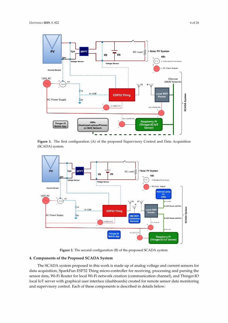
The proposed low-cost, open source SCADA system is based on the Internet of Things (IoT)SCADA architecture which is the fourth and most recent SCADA architecture [4,9,10]. In connectingthe hardware components together, two configurations are considered. In the first configuration,the Raspberry Pi is connected to MUN Network via an Ethernet cable so that users on the networkwith the right authorizations can visualize the acquired data on the Thinger.IO IoT server platform.Also, in this configuration, by opening the Thinger.IO port on MUN network, users can access thestored data over the internet using their private office or home network. In the second configuration,the Raspberry Pi is connected to one of the LAN ports of the local Wi-Fi Router such that only themachines connected to the Wi-Fi network, either wirelessly or via Ethernet cables connected to theLAN ports of the Router, can access the data on Thinger.IO local server IoT platform by using the IPaddress of the Raspberry Pi. Although the first configuration is more flexible, the second configurationis more secure, as this configuration ensures a kind of industrial network is created, with externalinternet users, even on MUN network, shut out. In either of the configurations, the ESP32 Thing canconnect to the Thinger.IO server over Wi-Fi by using the IP address of the Raspberry Pi. The twoconfigurations are shown below in Figures 1 and 2 respectively:
Electronics 2019, 8, 822 6 of 24
Figure 1. The first configuration (A) of the proposed Supervisory Control and Data Acquisition(SCADA) system.
Figure 2. The second configuration (B) of the proposed SCADA system.
4. Components of the Proposed SCADA System
The SCADA system proposed in this work is made up of analog voltage and current sensors fordata acquisition, SparkFun ESP32 Thing micro-controller for receiving, processing and parsing thesensor data, Wi-Fi Router for local Wi-Fi network creation (communication channel), and Thinger.IOlocal IoT server with graphical user interface (dashboards) created for remote sensor data monitoringand supervisory control. Each of these components is described in details below:
Electronics 2019, 8, 822 7 of 24
4.1. Sensors
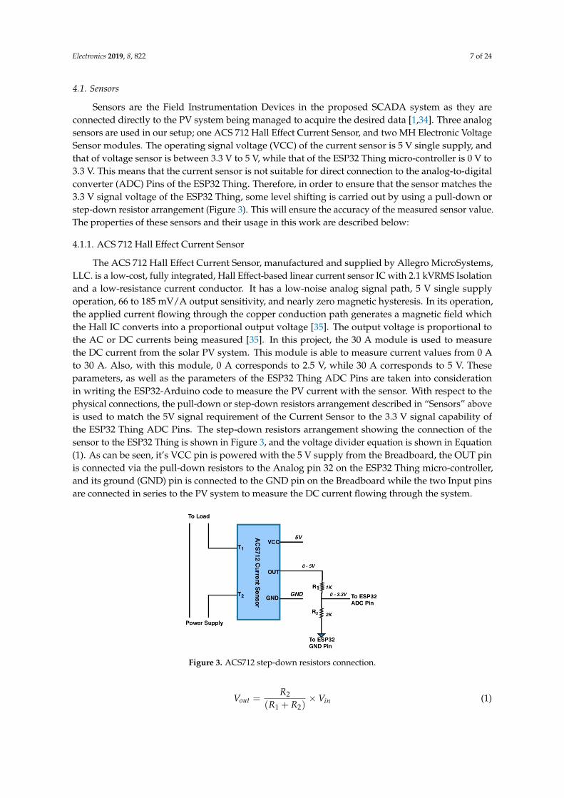
Sensors are the Field Instrumentation Devices in the proposed SCADA system as they areconnected directly to the PV system being managed to acquire the desired data [1,34]. Three analogsensors are used in our setup; one ACS 712 Hall Effect Current Sensor, and two MH Electronic VoltageSensor modules. The operating signal voltage (VCC) of the current sensor is 5 V single supply, andthat of voltage sensor is between 3.3 V to 5 V, while that of the ESP32 Thing micro-controller is 0 V to3.3 V. This means that the current sensor is not suitable for direct connection to the analog-to-digitalconverter (ADC) Pins of the ESP32 Thing. Therefore, in order to ensure that the sensor matches the3.3 V signal voltage of the ESP32 Thing, some level shifting is carried out by using a pull-down orstep-down resistor arrangement (Figure 3). This will ensure the accuracy of the measured sensor value.The properties of these sensors and their usage in this work are described below:
4.1.1. ACS 712 Hall Effect Current Sensor
The ACS 712 Hall Effect Current Sensor, manufactured and supplied by Allegro MicroSystems,LLC. is a low-cost, fully integrated, Hall Effect-based linear current sensor IC with 2.1 kVRMS Isolationand a low-resistance current conductor. It has a low-noise analog signal path, 5 V single supplyoperation, 66 to 185 mV/A output sensitivity, and nearly zero magnetic hysteresis. In its operation,the applied current flowing through the copper conduction path generates a magnetic field whichthe Hall IC converts into a proportional output voltage [35]. The output voltage is proportional tothe AC or DC currents being measured [35]. In this project, the 30 A module is used to measurethe DC current from the solar PV system. This module is able to measure current values from 0 Ato 30 A. Also, with this module, 0 A corresponds to 2.5 V, while 30 A corresponds to 5 V. Theseparameters, as well as the parameters of the ESP32 Thing ADC Pins are taken into considerationin writing the ESP32-Arduino code to measure the PV current with the sensor. With respect to thephysical connections, the pull-down or step-down resistors arrangement described in “Sensors” aboveis used to match the 5V signal requirement of the Current Sensor to the 3.3 V signal capability ofthe ESP32 Thing ADC Pins. The step-down resistors arrangement showing the connection of thesensor to the ESP32 Thing is shown in Figure 3, and the voltage divider equation is shown in Equation(1). As can be seen, it’s VCC pin is powered with the 5 V supply from the Breadboard, the OUT pinis connected via the pull-down resistors to the Analog pin 32 on the ESP32 Thing micro-controller,and its ground (GND) pin is connected to the GND pin on the Breadboard while the two Input pinsare connected in series to the PV system to measure the DC current flowing through the system.
Figure 3. ACS712 step-down resistors connection.
Vout =R2
(R1 + R2)× Vin (1)
Electronics 2019, 8, 822 8 of 24
where Vout = ESP32 ADC Voltage (3.3 V), and Vin = Sensor Input Voltage from the Breadboard(5 V), while and R1 and R2 are calculated to match these voltage values using the voltage dividerequation above.
4.1.2. MH Electronic Voltage Sensor Modules
This is a low-cost analog voltage sensor capable of detecting supply voltages in the range of0.025 V to 25 V. The sensor uses the concept of voltage divider to measure voltage. This voltage divideris a series connection of a 30 K resistor and a 7.5 K resistor. Its operating voltage range is 3.3 V to 5.0 V,and the voltage analog resolution is 0.000806 V for a 12-bit ADC [36]. In our setup, two voltage sensorsare used; one of the voltage sensors is connected in parallel to the PV system to measure the voltageacross it while the second one is connected in parallel across the lead acid battery system to measurethe storage battery voltage. For the first voltage sensor, PIN S is connected to Analog PIN 34 on theESP32, PIN—is connected to a GND pin on the ESP32 while its GND and VCC pins are connected inparallel across the PV panel output to measure the voltage across the PV system (PIN + on the sensoris not used). For the second voltage sensor, PIN S is connected to Analog PIN 35 on the ESP32, PIN—isconnected to a GND pin on the ESP32 while its GND and VCC pins are connected (after the MPPTmodule) in parallel across the battery to measure the battery voltage (PIN + on the sensor is not used).
4.2. ESP32 Thing Micro-Controller (RTU)
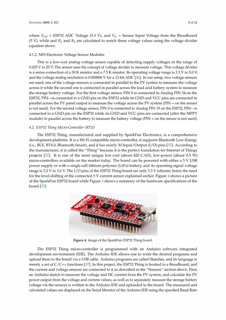
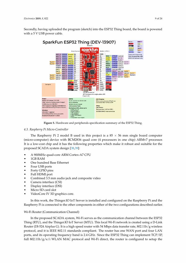
The ESP32 Thing, manufactured and supplied by SparkFun Electronics, is a comprehensivedevelopment platform. It is a Wi-Fi compatible micro-controller, it supports Bluetooth Low-Energy(i.e., BLE, BT4.0, Bluetooth Smart), and it has nearly 30 Input/Output (I/O) pins [37]. According tothe manufacturer, it is called the “Thing” because it is the perfect foundation for Internet of Thingsprojects [37]. It is one of the most unique low-cost (about $20 CAD), low-power (about 0.5 W)micro-controllers available on the market today. The board can be powered with either a 5 V USBpower supply or with a single-cell lithium-polymer (LiPo) battery, and its operating signal voltagerange is 2.2 V to 3.6 V. The I/O pins of the ESP32 Thing board are only 3.3 V tolerant, hence the needfor the level shifting of the connected 5 V current sensor explained earlier. Figure 4 shows a pictureof the SparkFun ESP32 board while Figure 5 shows a summary of the hardware specifications of theboard [37].
Figure 4. Image of the SparkFun ESP32 Thing board.
The ESP32 Thing micro-controller is programmed with an Arduino software integrateddevelopment environment (IDE). The Arduino IDE allows one to write the desired programs andupload them to the board via a USB cable. Arduino programs are called Sketches, and its language ismerely a set of C/C++ functions [37]. In this project, the ESP32 Thing is hooked to a Breadboard, andthe current and voltage sensors are connected to it as described in the “Sensors” section above. First,an Arduino sketch to measure the voltage and DC current from the PV system, and calculate the PVpower output from the voltage and current values, as well as to separately measure the storage batteryvoltage via the sensors is written in the Arduino IDE and uploaded to the board. The measured andcalculated values are displayed on the Serial Monitor of the Arduino IDE using the specified Baud Rate.
Electronics 2019, 8, 822 9 of 24
Secondly, having uploaded the program (sketch) into the ESP32 Thing board, the board is poweredwith a 5 V USB power cable.
Figure 5. Hardware and peripherals specification summary of the ESP32 Thing.
4.3. Raspberry Pi Micro-Controller
The Raspberry Pi 2 model B used in this project is a 85 × 56 mm single board computer(micro-computer) device with BCM2836 quad core (4 processors in one chip) ARMv7 processor.It is a low-cost chip and it has the following properties which make it robust and suitable for theproposed SCADA system design [38,39]:
• A 900MHz quad-core ARM Cortex-A7 CPU• 1GB RAM• One hundred Base Ethernet• Four USB ports• Forty GPIO pins• Full HDMI port• Combined 3.5 mm audio jack and composite video• Camera interface (CSI)• Display interface (DSI)• Micro SD card slot• VideoCore IV 3D graphics core.
In this work, the Thinger.IO IoT Server is installed and configured on the Raspberry Pi and theRaspberry Pi is connected to the other components in either of the two configurations described earlier.
Wi-Fi Router (Communication Channel)
In the proposed SCADA system, Wi-Fi serves as the communication channel between the ESP32Thing (RTU), and the Thinger.IO IoT Server (MTU). This local Wi-Fi network is created using a D-LinkRouter (DI-524 Airplus G). It is a high speed router with 54 Mbps data transfer rate, 802.11b/g wirelessprotocol, and it is IEEE 802.11 standards compliant. The router has one WAN port and four LANports, and its operating frequency band is 2.4 GHz. Since the ESP32 Thing can implement TCP/IP,full 802.11b/g/e/i WLAN MAC protocol and Wi-Fi direct, the router is configured to setup the
Electronics 2019, 8, 822 10 of 24
needed local Wi-Fi network for transmitting the sensor data from the ESP32 Thing to the Thinger.IOIoT Server by using the server IP address to identify the platform. For the Wi-Fi access control andsecurity purposes, the ESP32 Thing connects to the router using the Wi-Fi network name (SSID) andthe assigned password.
4.4. Thinger.IO Local Server IoT Platform
Thinger.IO is a powerful open source platform for the Internet of Things (IoT). It supportsRepresentational State Transfer (REST) Application Programming Interface (API) which enablescontrolling and reading of smart devices [40]. Representational State Transfer (REST) is an architecturebased on web standards which uses HTTP protocol for communication. This protocol enablesinteroperability among the different machines on the internet by treating each and every component asa resource, such that each resource can be accessed by a common interface utilizing the general HTTPmethods like OPTIONS, GET, PUT, POST, and DELETE, etc., [22–24,40]. The specific response of eachresource is gotten in JSON/XML format [40]. Some of the important features of the protocol whichmake it possible to connect and manage IoT devices are automatic discovery of API, and bandwidthsavings [24]. Thinger.IO is wholly supported by GitHub (the popular open source developmentplatform) [40].
Thinger.IO IoT platform supports the integration of Arduino compatible hardware (any board thatcan be programmed with Arduino IDE, such as Arduino + Ethernet, Arduino + Wi-Fi, ESP32/8266/13,NodeMCU, TC CC320, etc.), Linux-powered devices like the Raspberry Pi, Intel Edison or any otherLinux computer running Ubuntu or MacOS, and the ARM Mbed platform and compatible devices.The IoT platform has a Cloud Console with a beautifully designed front-end where a user can managethe connected devices and visualize the device information in the cloud [40]. To start an IoT project inThinger.IO, the first step is to create devices by adding the device parameters which will grant accessto connect the devices to the Thinger.IO account. Any device on the platform must be registered tohave access to the cloud, and each device is identified by its unique identifier and credentials, suchthat an infinite number of devices can be added to the cloud platform without one device interferingwith the other (Figure 7). Once a user creates an account on the Thinger.IO cloud, access token isobtained from the user’s Username and Password, and this access token grants authorization accessto the account resources of the connected devices. On the Cloud Console is a Statistics section wherea user can see some basic information about the account such as the number of connected devices,endpoints, data buckets, statistics about device consumption in terms of sent and received data, as wellas a Google Map of the approximate current locations of the connected devices (Figure 12). In theCloud Console, an operator can add or remove devices, create real-time dashboards, access the deviceAPI, and perform other device and data management operations [22–24,40]. Also, the left side ofthe Statistics screen has a main menu with all the platform features needed to build IoT projects(Figure 6) [40].
One unique feature of the Thinger.IO IoT platform is that it allows an operator to discover theresources defined in the connected devices. A resource, in this case, can be a sensor reading like current,voltage, temperature, humidity, pressure, or any actionable element like a light, a relay, a motor, etc.Once a device is connected to an account, an operator can access its resources and explore the API RESTendpoints using the API Explorer which is accessible over the Device Dashboard by clicking on a smallblue button called Device API (Figure 6). Essentially, any device resource is like a callback functionthat can be called (on demand) through a REST API. On the Thinger.IO platform, four different typesof resources can be defined, one for input (sending data to the device), one for output (sending data orinformation from the device), one for input/output (sending and receiving information in one call),and lastly, a callback resource which can be executed without sending or receiving information [40].From the API perspective, the input and output data can be any JavaScript Object Notation (JSON)document [40].
Electronics 2019, 8, 822 11 of 24
Thinger.IO has a Local Server option where a user can purchase (one-off) the hardware orhardware installation ISO image and install it on a standalone or networked machine for propermanagement. It also has a web-based server option which can be accessed using its URL just like everyother web-application [40]. For example, the authors in [22–24] used the web-based server option.Both the web-based and local server options have IoT capability as the data stored in them can beaccessed remotely with an internet enabled computer or with an internet enabled phone via Thinger.IOmobile app or phone browser. However, the locally-installed server option is more secure as the userhas a better control of the server and stored data for security purposes [40]. In this paper, the localserver option is used. The low-cost Thinger.IO Raspberry Pi ISO Image (about $15.00 CAD) has beenpurchased, installed and configured on a Raspberry Pi machine.
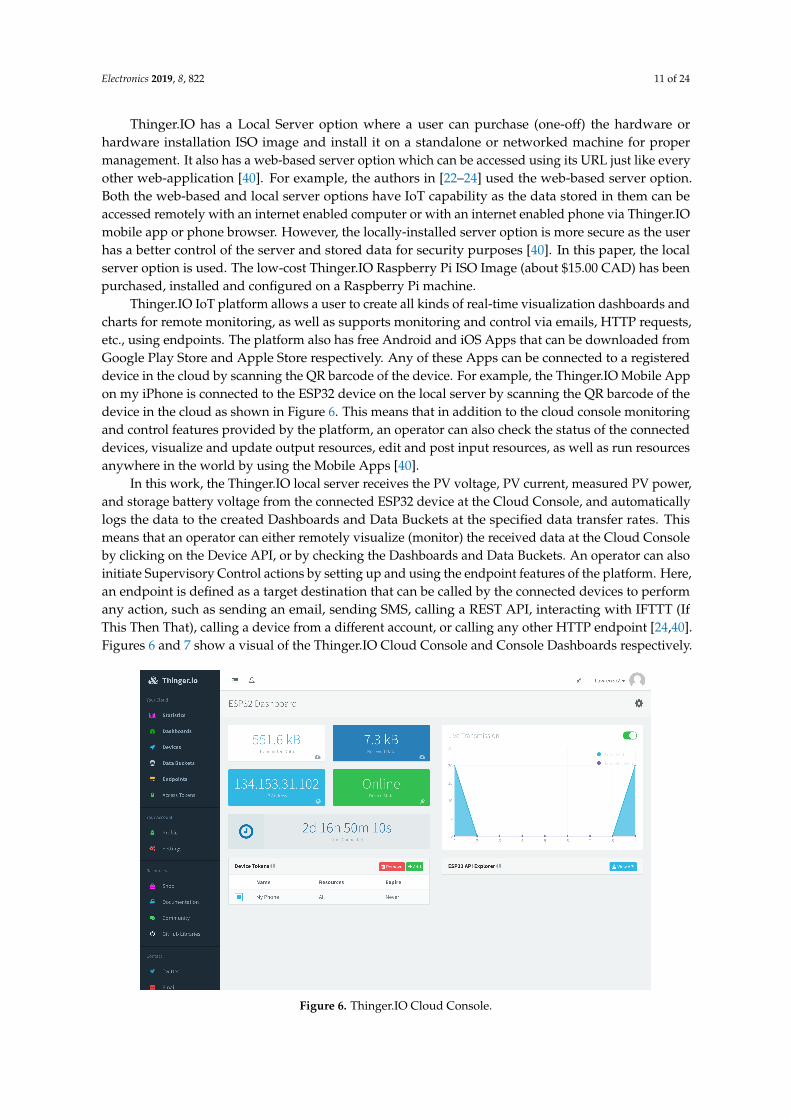
Thinger.IO IoT platform allows a user to create all kinds of real-time visualization dashboards andcharts for remote monitoring, as well as supports monitoring and control via emails, HTTP requests,etc., using endpoints. The platform also has free Android and iOS Apps that can be downloaded fromGoogle Play Store and Apple Store respectively. Any of these Apps can be connected to a registereddevice in the cloud by scanning the QR barcode of the device. For example, the Thinger.IO Mobile Appon my iPhone is connected to the ESP32 device on the local server by scanning the QR barcode of thedevice in the cloud as shown in Figure 6. This means that in addition to the cloud console monitoringand control features provided by the platform, an operator can also check the status of the connecteddevices, visualize and update output resources, edit and post input resources, as well as run resourcesanywhere in the world by using the Mobile Apps [40].
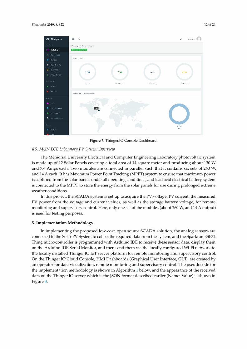
In this work, the Thinger.IO local server receives the PV voltage, PV current, measured PV power,and storage battery voltage from the connected ESP32 device at the Cloud Console, and automaticallylogs the data to the created Dashboards and Data Buckets at the specified data transfer rates. Thismeans that an operator can either remotely visualize (monitor) the received data at the Cloud Consoleby clicking on the Device API, or by checking the Dashboards and Data Buckets. An operator can alsoinitiate Supervisory Control actions by setting up and using the endpoint features of the platform. Here,an endpoint is defined as a target destination that can be called by the connected devices to performany action, such as sending an email, sending SMS, calling a REST API, interacting with IFTTT (IfThis Then That), calling a device from a different account, or calling any other HTTP endpoint [24,40].Figures 6 and 7 show a visual of the Thinger.IO Cloud Console and Console Dashboards respectively.
Figure 6. Thinger.IO Cloud Console.
Electronics 2019, 8, 822 12 of 24
Figure 7. Thinger.IO Console Dashboard.
4.5. MUN ECE Laboratory PV System Overview
The Memorial University Electrical and Computer Engineering Laboratory photovoltaic systemis made up of 12 Solar Panels covering a total area of 14 square meter and producing about 130 Wand 7.6 Amps each. Two modules are connected in parallel such that it contains six sets of 260 W,and 14 A each. It has Maximum Power Point Tracking (MPPT) system to ensure that maximum poweris captured from the solar panels under all operating conditions, and lead acid electrical battery systemis connected to the MPPT to store the energy from the solar panels for use during prolonged extremeweather conditions.
In this project, the SCADA system is set up to acquire the PV voltage, PV current, the measuredPV power from the voltage and current values, as well as the storage battery voltage, for remotemonitoring and supervisory control. Here, only one set of the modules (about 260 W, and 14 A output)is used for testing purposes.
5. Implementation Methodology
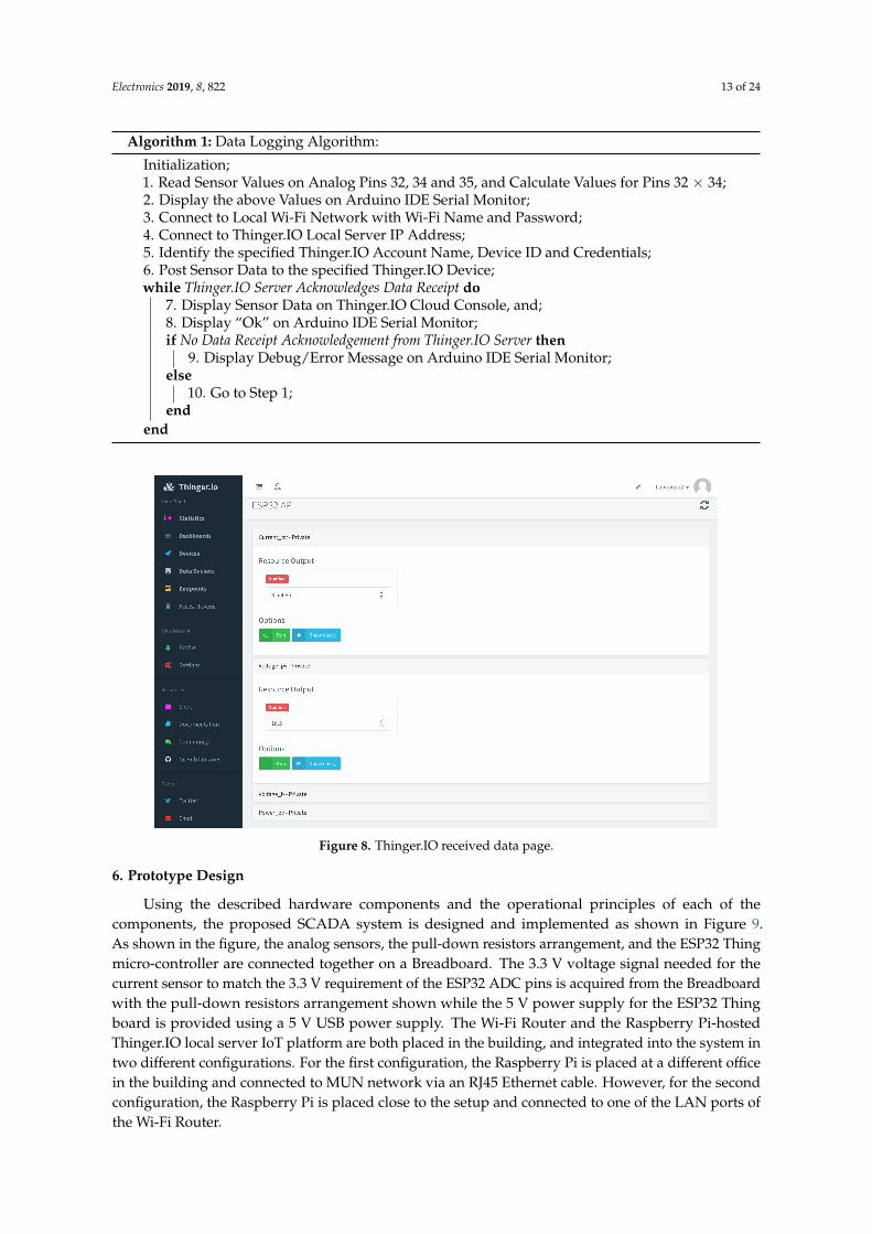
In implementing the proposed low-cost, open source SCADA solution, the analog sensors areconnected to the Solar PV System to collect the required data from the system, and the Sparkfun ESP32Thing micro-controller is programmed with Arduino IDE to receive these sensor data, display themon the Arduino IDE Serial Monitor, and then send them via the locally configured Wi-Fi network tothe locally installed Thinger.IO IoT server platform for remote monitoring and supervisory control.On the Thinger.IO Cloud Console, HMI Dashboards (Graphical User Interface, GUI), are created byan operator for data visualization, remote monitoring and supervisory control. The pseudocode forthe implementation methodology is shown in Algorithm 1 below, and the appearance of the receiveddata on the Thinger.IO server which is the JSON format described earlier (Name: Value) is shown inFigure 8.
Electronics 2019, 8, 822 13 of 24
Algorithm 1: Data Logging Algorithm:
Initialization;1. Read Sensor Values on Analog Pins 32, 34 and 35, and Calculate Values for Pins 32 × 34;2. Display the above Values on Arduino IDE Serial Monitor;3. Connect to Local Wi-Fi Network with Wi-Fi Name and Password;4. Connect to Thinger.IO Local Server IP Address;5. Identify the specified Thinger.IO Account Name, Device ID and Credentials;6. Post Sensor Data to the specified Thinger.IO Device;while Thinger.IO Server Acknowledges Data Receipt do
7. Display Sensor Data on Thinger.IO Cloud Console, and;8. Display “Ok” on Arduino IDE Serial Monitor;if No Data Receipt Acknowledgement from Thinger.IO Server then
9. Display Debug/Error Message on Arduino IDE Serial Monitor;else
10. Go to Step 1;end
end
Figure 8. Thinger.IO received data page.
6. Prototype Design
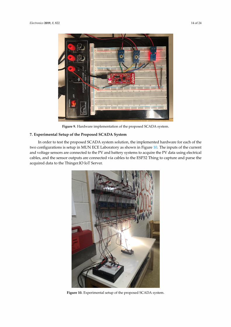
Using the described hardware components and the operational principles of each of thecomponents, the proposed SCADA system is designed and implemented as shown in Figure 9.As shown in the figure, the analog sensors, the pull-down resistors arrangement, and the ESP32 Thingmicro-controller are connected together on a Breadboard. The 3.3 V voltage signal needed for thecurrent sensor to match the 3.3 V requirement of the ESP32 ADC pins is acquired from the Breadboardwith the pull-down resistors arrangement shown while the 5 V power supply for the ESP32 Thingboard is provided using a 5 V USB power supply. The Wi-Fi Router and the Raspberry Pi-hostedThinger.IO local server IoT platform are both placed in the building, and integrated into the system intwo different configurations. For the first configuration, the Raspberry Pi is placed at a different officein the building and connected to MUN network via an RJ45 Ethernet cable. However, for the secondconfiguration, the Raspberry Pi is placed close to the setup and connected to one of the LAN ports ofthe Wi-Fi Router.
Electronics 2019, 8, 822 14 of 24
Figure 9. Hardware implementation of the proposed SCADA system.
7. Experimental Setup of the Proposed SCADA System
In order to test the proposed SCADA system solution, the implemented hardware for each of thetwo configurations is setup in MUN ECE Laboratory as shown in Figure 10. The inputs of the currentand voltage sensors are connected to the PV and battery systems to acquire the PV data using electricalcables, and the sensor outputs are connected via cables to the ESP32 Thing to capture and parse theacquired data to the Thinger.IO IoT Server.
Figure 10. Experimental setup of the proposed SCADA system.
Electronics 2019, 8, 822 15 of 24
8. Testing and Results
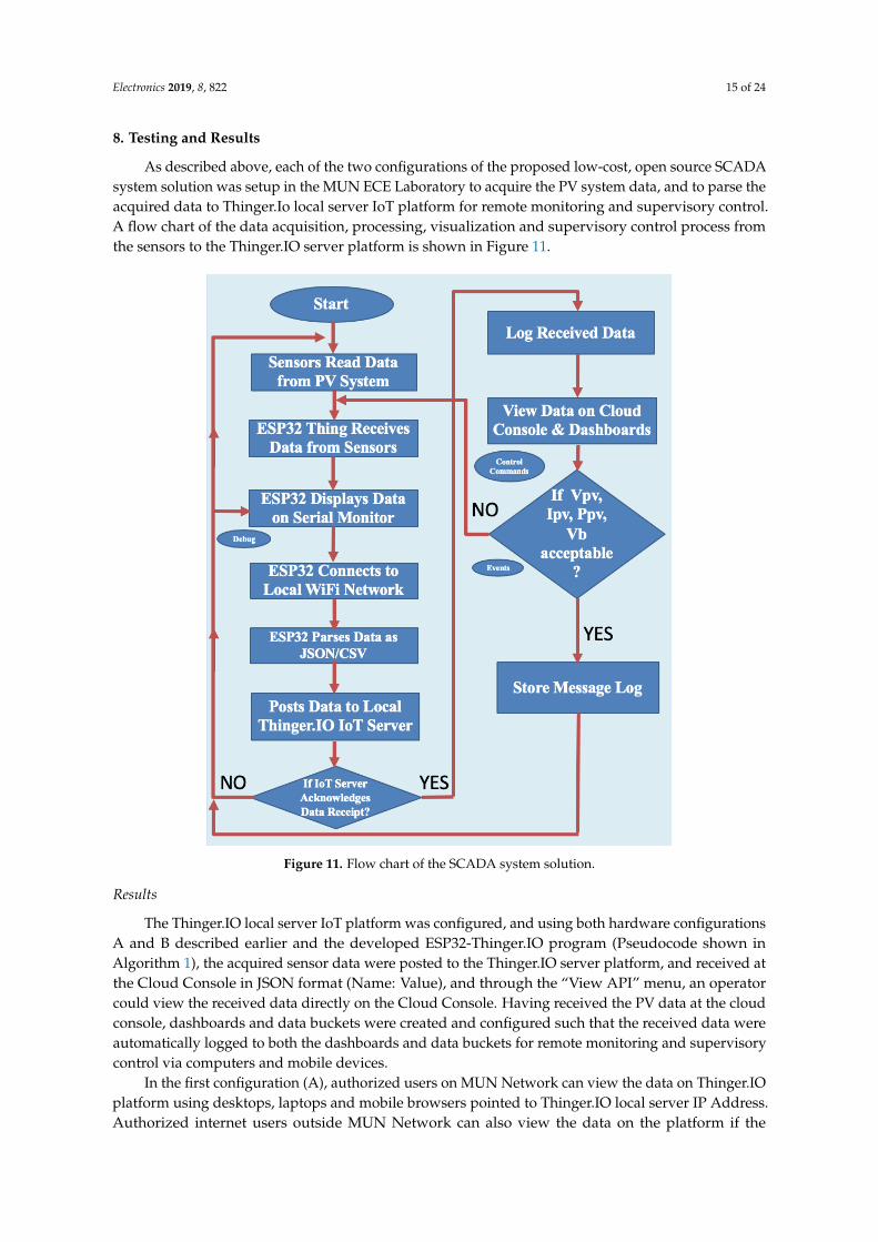
As described above, each of the two configurations of the proposed low-cost, open source SCADAsystem solution was setup in the MUN ECE Laboratory to acquire the PV system data, and to parse theacquired data to Thinger.Io local server IoT platform for remote monitoring and supervisory control.A flow chart of the data acquisition, processing, visualization and supervisory control process fromthe sensors to the Thinger.IO server platform is shown in Figure 11.
Figure 11. Flow chart of the SCADA system solution.
Results
The Thinger.IO local server IoT platform was configured, and using both hardware configurationsA and B described earlier and the developed ESP32-Thinger.IO program (Pseudocode shown inAlgorithm 1), the acquired sensor data were posted to the Thinger.IO server platform, and received atthe Cloud Console in JSON format (Name: Value), and through the “View API” menu, an operatorcould view the received data directly on the Cloud Console. Having received the PV data at the cloudconsole, dashboards and data buckets were created and configured such that the received data wereautomatically logged to both the dashboards and data buckets for remote monitoring and supervisorycontrol via computers and mobile devices.
In the first configuration (A), authorized users on MUN Network can view the data on Thinger.IOplatform using desktops, laptops and mobile browsers pointed to Thinger.IO local server IP Address.Authorized internet users outside MUN Network can also view the data on the platform if the
Electronics 2019, 8, 822 16 of 24
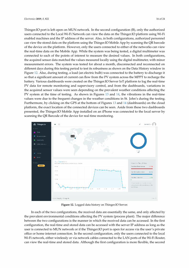
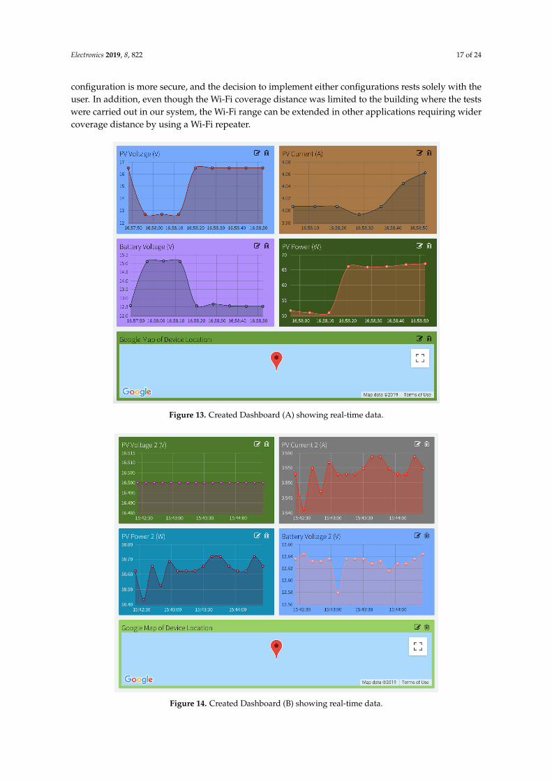
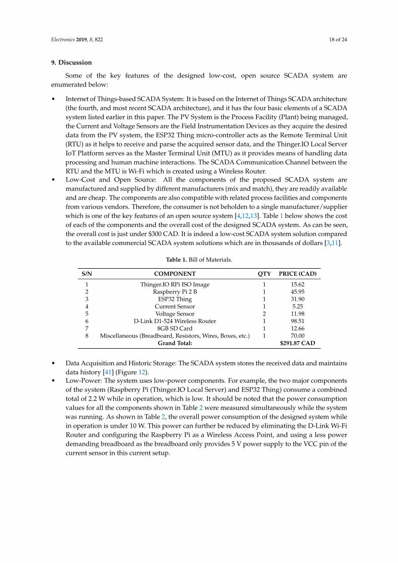
Thinger.IO port is left open on MUN network. In the second configuration (B), only the authorizedusers connected to the Local Wi-Fi Network can view the data on the Thinger.IO platform using Wi-Fienabled machines and the IP address of the server. Also, in both configurations, authorized personnelcan view the stored data on the platform using the Thinger.IO Mobile App by scanning the QR barcodeof the device on the platform. However, only the users connected to either of the networks can viewthe real-time data on the Mobile App. While the system was being tested, a digital multimeter wasconnected to each of the points of interest to measure the desired values. In both configurations,the acquired sensor data matched the values measured locally using the digital multimeter, with minormeasurement errors. The system was tested for about a month, disconnected and reconnected ondifferent days during this testing period to test its robustness as shown on the Data History window inFigure 12. Also, during testing, a load (an electric bulb) was connected to the battery to discharge itso that a significant amount of current can flow from the PV system across the MPPT to recharge thebattery. Various dashboards were created on the Thinger.IO Server IoT platform to log the real-timePV data for remote monitoring and supervisory control, and from the dashboards, variations inthe acquired sensor values were seen depending on the prevalent weather conditions affecting thePV system at the time of testing. As shown in Figures 13 and 14, the vibrations in the real-timevalues were due to the frequent changes in the weather conditions in St. John’s during the testing.Furthermore, by clicking on the GPS at the bottom of Figures 13 and 14 (dashboards) on the cloudplatform, the exact location of the connected devices can be seen. Aside from these two dashboardspresented, the Thinger.IO Mobile App installed on an iPhone was connected to the local server byscanning the QR Barcode of the device for real-time monitoring.
Figure 12. Logged data history on Thinger.IO Server.
In each of the two configurations, the received data are essentially the same, and only affected bythe prevalent environmental conditions affecting the PV system (process plant). The major differencebetween the two configurations is the manner in which the received data can be accessed. In the firstconfiguration, the real-time and stored data can be accessed with the server IP address as long as theuser is connected to MUN network or if the Thinger.IO port is open for access via the user’s privateoffice or home internet connection. In the second configuration, only the users connected to the localWi-Fi network, either wirelessly or via network cables connected to the LAN ports of the Wi-Fi Router,can view the real-time and stored data. Although the first configuration is more flexible, the second
Electronics 2019, 8, 822 17 of 24
configuration is more secure, and the decision to implement either configurations rests solely with theuser. In addition, even though the Wi-Fi coverage distance was limited to the building where the testswere carried out in our system, the Wi-Fi range can be extended in other applications requiring widercoverage distance by using a Wi-Fi repeater.
Figure 13. Created Dashboard (A) showing real-time data.
Figure 14. Created Dashboard (B) showing real-time data.
Electronics 2019, 8, 822 18 of 24
9. Discussion
Some of the key features of the designed low-cost, open source SCADA system areenumerated below:
• Internet of Things-based SCADA System: It is based on the Internet of Things SCADA architecture(the fourth, and most recent SCADA architecture), and it has the four basic elements of a SCADAsystem listed earlier in this paper. The PV System is the Process Facility (Plant) being managed,the Current and Voltage Sensors are the Field Instrumentation Devices as they acquire the desireddata from the PV system, the ESP32 Thing micro-controller acts as the Remote Terminal Unit(RTU) as it helps to receive and parse the acquired sensor data, and the Thinger.IO Local ServerIoT Platform serves as the Master Terminal Unit (MTU) as it provides means of handling dataprocessing and human machine interactions. The SCADA Communication Channel between theRTU and the MTU is Wi-Fi which is created using a Wireless Router.
• Low-Cost and Open Source: All the components of the proposed SCADA system aremanufactured and supplied by different manufacturers (mix and match), they are readily availableand are cheap. The components are also compatible with related process facilities and componentsfrom various vendors. Therefore, the consumer is not beholden to a single manufacturer/supplierwhich is one of the key features of an open source system [4,12,13]. Table 1 below shows the costof each of the components and the overall cost of the designed SCADA system. As can be seen,the overall cost is just under $300 CAD. It is indeed a low-cost SCADA system solution comparedto the available commercial SCADA system solutions which are in thousands of dollars [3,11].
Table 1. Bill of Materials.
S/N COMPONENT QTY PRICE (CAD)
1 Thinger.IO RPi ISO Image 1 15.622 Raspberry Pi 2 B 1 45.953 ESP32 Thing 1 31.904 Current Sensor 1 5.255 Voltage Sensor 2 11.986 D-Link D1-524 Wireless Router 1 98.517 8GB SD Card 1 12.668 Miscellaneous (Breadboard, Resistors, Wires, Boxes, etc.) 1 70.00
Grand Total: $291.87 CAD
• Data Acquisition and Historic Storage: The SCADA system stores the received data and maintainsdata history [41] (Figure 12).
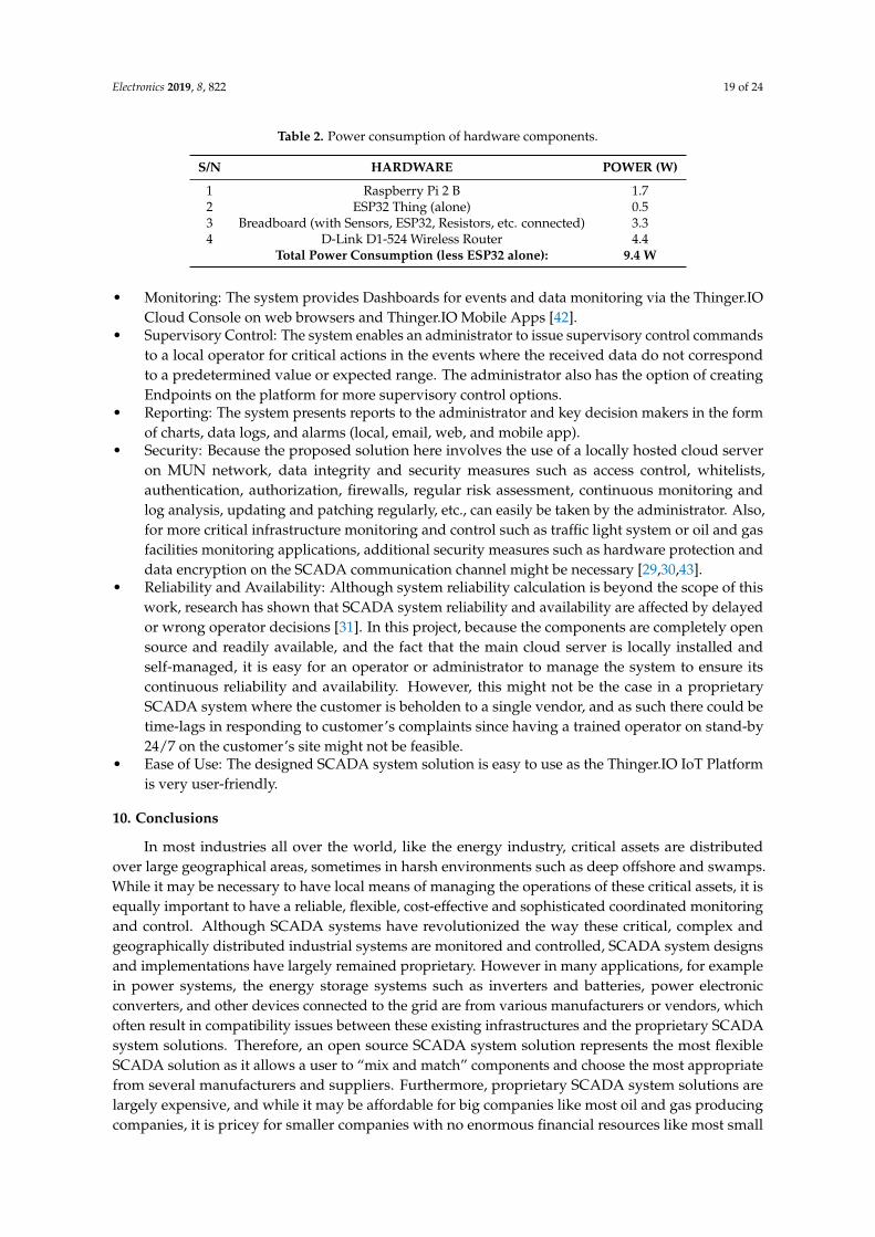
• Low-Power: The system uses low-power components. For example, the two major componentsof the system (Raspberry Pi (Thinger.IO Local Server) and ESP32 Thing) consume a combinedtotal of 2.2 W while in operation, which is low. It should be noted that the power consumptionvalues for all the components shown in Table 2 were measured simultaneously while the systemwas running. As shown in Table 2, the overall power consumption of the designed system whilein operation is under 10 W. This power can further be reduced by eliminating the D-Link Wi-FiRouter and configuring the Raspberry Pi as a Wireless Access Point, and using a less powerdemanding breadboard as the breadboard only provides 5 V power supply to the VCC pin of thecurrent sensor in this current setup.
Electronics 2019, 8, 822 19 of 24
Table 2. Power consumption of hardware components.
S/N HARDWARE POWER (W)
1 Raspberry Pi 2 B 1.72 ESP32 Thing (alone) 0.53 Breadboard (with Sensors, ESP32, Resistors, etc. connected) 3.34 D-Link D1-524 Wireless Router 4.4
Total Power Consumption (less ESP32 alone): 9.4 W
• Monitoring: The system provides Dashboards for events and data monitoring via the Thinger.IOCloud Console on web browsers and Thinger.IO Mobile Apps [42].
• Supervisory Control: The system enables an administrator to issue supervisory control commandsto a local operator for critical actions in the events where the received data do not correspondto a predetermined value or expected range. The administrator also has the option of creatingEndpoints on the platform for more supervisory control options.
• Reporting: The system presents reports to the administrator and key decision makers in the formof charts, data logs, and alarms (local, email, web, and mobile app).
• Security: Because the proposed solution here involves the use of a locally hosted cloud serveron MUN network, data integrity and security measures such as access control, whitelists,authentication, authorization, firewalls, regular risk assessment, continuous monitoring andlog analysis, updating and patching regularly, etc., can easily be taken by the administrator. Also,for more critical infrastructure monitoring and control such as traffic light system or oil and gasfacilities monitoring applications, additional security measures such as hardware protection anddata encryption on the SCADA communication channel might be necessary [29,30,43].
• Reliability and Availability: Although system reliability calculation is beyond the scope of thiswork, research has shown that SCADA system reliability and availability are affected by delayedor wrong operator decisions [31]. In this project, because the components are completely opensource and readily available, and the fact that the main cloud server is locally installed andself-managed, it is easy for an operator or administrator to manage the system to ensure itscontinuous reliability and availability. However, this might not be the case in a proprietarySCADA system where the customer is beholden to a single vendor, and as such there could betime-lags in responding to customer’s complaints since having a trained operator on stand-by24/7 on the customer’s site might not be feasible.
• Ease of Use: The designed SCADA system solution is easy to use as the Thinger.IO IoT Platformis very user-friendly.
10. Conclusions
In most industries all over the world, like the energy industry, critical assets are distributedover large geographical areas, sometimes in harsh environments such as deep offshore and swamps.While it may be necessary to have local means of managing the operations of these critical assets, it isequally important to have a reliable, flexible, cost-effective and sophisticated coordinated monitoringand control. Although SCADA systems have revolutionized the way these critical, complex andgeographically distributed industrial systems are monitored and controlled, SCADA system designsand implementations have largely remained proprietary. However in many applications, for examplein power systems, the energy storage systems such as inverters and batteries, power electronicconverters, and other devices connected to the grid are from various manufacturers or vendors, whichoften result in compatibility issues between these existing infrastructures and the proprietary SCADAsystem solutions. Therefore, an open source SCADA system solution represents the most flexibleSCADA solution as it allows a user to “mix and match” components and choose the most appropriatefrom several manufacturers and suppliers. Furthermore, proprietary SCADA system solutions arelargely expensive, and while it may be affordable for big companies like most oil and gas producingcompanies, it is pricey for smaller companies with no enormous financial resources like most small
Electronics 2019, 8, 822 20 of 24
power companies, especially power companies into renewable generation systems. Therefore, an opensource SCADA solution represents the most cost effective solution as the user is not beholden to asingle vendor.
In this paper, a low-cost, open source SCADA system solution based on the Internet of Things(IoT) SCADA architecture, which is the most recent SCADA architecture, has been presented. Thehardware design of the proposed SCADA system solution has been carried out, and the implementedsystem has the four basic elements needed in a SCADA system, including Field InstrumentationDevices (Current and Voltage Sensors), Remote Terminal Units (ESP32 Thing micro-controller), MasterTerminal Units (Thinger.IO IoT Server Platform), and SCADA Communication Channel (Local Wi-FiNetwork). In order to validate the functionalities of the designed SCADA system, it was setup andtested at the Memorial University Electrical and Computer Engineering Laboratory to acquire andremotely monitor a 260 W, 12 V Solar PV System data, as well as to initiate supervisory control activitieswhenever necessary. From the tests, the system was found to be capable of carrying out the desiredfunctions of a SCADA system which include Data Acquisition, Networked Data Communication,Data Presentation, and Remote Monitoring and Supervisory Control. The power consumption ofeach of the components was measured while the system was in operation and the entire system wasfound to require low power for operation, less than 10 W. The overall cost of the system was alsofound to be below $300 CAD which is extremely low for such a critical solution. Furthermore, theacquired real-time PV data visualized at the Thinger.IO IoT Server Cloud Console and Dashboardswere found to be within the same range as the data locally measured using the conventional digitalmultimeter. From information security and system reliability points of view, because the main cloudserver is privately hosted and self-managed on own network, data security measures such as accesscontrol, authorization, authentication, whitelisting, firewalls, log analysis, etc., are easily implemented,and since the system is self-managed, it means that the operator or administrator is readily available tocarry out these tasks, thereby ensuring the security, reliability and availability of the proposed system.
Although a PV system has been used as the process plant for testing purposes in this work,the designed SCADA system can also be applied in other industries and fields to remotely monitor andcontrol critical infrastructures such as electric power generation, transmission and distribution systems,buildings, facilities and environments, oil and gas production facilities, mass transit systems, waterand sewage systems, and traffic signal systems. However, it should be noted that the designed systemfor this particular application is not a plug and play turnkey solution or a one-size-fits-all system forthe above possible applications as further measures will need to be taken to customize the systemfor any chosen application in order to guarantee its functionalities, reliability and security, whichmight increase the overall cost and power consumption presented in this application. For example,for outdoor deployment of the proposed SCADA system, options for boxes and shields will have tobe considered for the electronic components to prevent damage due to moisture and wild animals.Also, to increase the security of the proposed SCADA system for very critical applications like oiland gas facilities monitoring and traffic signal control, additional security measures such as dataencryption algorithms can be implemented on the ESP32 micro-controller side to encrypt the acquiredsensor data before sending them to the Thinger.IO server, and at the server side, data decryption andfurther security measures can be carried out. These could relatively increase the overall cost and powerconsumption of the system.
11. Future Work
In the future, endpoints can be created on Thinger.IO platform to carry out more supervisorycontrol events like sending an email, sending an SMS, calling a REST API, interacting with IFTTT(If This Then That), calling a device from a different account, or calling any other HTTP endpointdirectly from the server to complement the current supervisory control strategy where an administratorhas to notify a local operator of any abnormal variations in the received data for necessary actions.Also, to further reduce the overall power consumption which is already low, the D-Link Wi-Fi
Electronics 2019, 8, 822 21 of 24
Router can be eliminated, and the Raspberry Pi configured as a Wireless Access Point to provide theWi-Fi connection needed for communication between the ESP32 Thing and the Thinger.IO Server.Furthermore, to increase the security of the proposed SCADA system, especially when the system isdeployed in very critical applications like oil and gas facilities monitoring and traffic signal control,data encryption algorithms can be implemented on the ESP32 micro-controller side to encrypt theacquired sensor data before sending them to the Thinger.IO server, and on the server side, datadecryption and further security measures can be carried out.
Author Contributions: L.O.A. carried out most of the research work, and he was supervised by M.T.I. during theresearch. M.T.I. also reviewed and corrected the Manuscript, provided the required components and contributedresearch ideas throughout the research.
Funding: This research was funded by the Natural Sciences and Engineering Research Council of Canada (NSERC)Energy Storage Technology Network (NESTNet).
Acknowledgments: The authors would like to thank the School of Graduate Studies, Faculty of Engineering andApplied Science, Memorial University and the Natural Sciences and Engineering Research Council of Canada(NSERC) Energy Storage Technology Network (NESTNet) for providing the necessary funds and the conduciveenvironment to carry out this research. The authors would also like to acknowledge the technical and emotionalsupports of friends and families during the difficult period of carrying out this research work.
Conflicts of Interest: The authors declare that there is no conflict of interest regarding the publication of this paper.All the components and software used in the actualization of this work were selected on a professional basis.
Abbreviations
The following major abbreviations are used in this manuscript:
SCADA Supervisory Control And Data AcquisitionIoT Internet of ThingsHMI Human Machine InterfacePLC Programmable Logic ControllerMTU Master Terminal UnitRTU Remote Terminal UnitFID Field Instrumentation DeviceREST Representative State TransferMUN Memorial University of NewfoundlandAPI Application Programming InterfaceGUI Graphical User InterfaceADC Analog-to-Digital ConverterI/O Input/OutputHTTP HyperText Transfer ProtocolQR Quick ResponsePV Photovoltaic
References
1. Lu, X. Supervisory Control and Data Acquisition System Design for CO2 Enhanced Oil Recovery. TechnicalReport No. UCB/EECS-2014-123. Master of Engineering Thesis, EECS Department, University of California,Berkeley, CA, USA, 21 May 2014.
2. Anderson, M. Supervisory Control and Data Acquisition. Available online: https://realpars.com/scada/(accessed on 3 June 2019).
3. Industrial Automation and Control. Available online: https://www.schneider-electric.com/en/work/products/industrial-automation-control/ (accessed on 10 June 2019).
4. Abbey, L. Telemetry/SCADA Open Systems vs Proprietary Systems. Available online: https://www.abbey.co.nz/telemetry--scada-open-vs-proprietary-systems-2003.html (accessed on 21 June 2019).
Electronics 2019, 8, 822 22 of 24
5. Boyer, S.A. SCADA: Supervisory Control and Data Acquisition, 4th ed.; International Society ofAutomation: Research Triangle Park, NC, USA, 2009. Available online: https://automation.isa.org/files/chapters/SCADA-Supervisory-Control-and-Data-Acquisition-Fourth-Edition-Chapter-10.pdf (accessedon 9 July 2019).
6. Sheng, Z.; Mahapatra, C.; Zhu, C.; Leung, V.C.M. Recent Advances in Industrial Wireless Sensor NetworksToward Efficient Management in IoT. IEEE Access 2015, 3, 622–637. [CrossRef]
7. Medrano, K.; Altuve, D.; Belloso, K.; Bran, C. Development of SCADA using a RTU based on IoT controller.In Proceedings of the 2018 IEEE International Conference on Automation/XXIII Congress of the ChileanAssociation of Automatic Control (ICA-ACCA), Concepcion, Chile, 17–19 October 2018; pp. 1–6. [CrossRef]
8. Al-Kuwari, M.; Ramadan, A.; Ismael, Y.; Al-Sughair, L.; Gastli, A.; Benammar, M. Smart-home automationusing IoT-based sensing and monitoring platform. In Proceedings of the 2018 IEEE 12th InternationalConference on Compatibility, Power Electronics and Power Engineering (CPE-POWERENG 2018), Doha,Qatar, 10–12 April 2018; pp. 1–6. [CrossRef]
9. Aghenta, L.O.; Iqbal, M.T. Development of an IoT Based Open Source SCADA System for PV SystemMonitoring. In Proceedings of the 32nd IEEE Canadian Conference on Electrical and Computer Engineering(CCECE 2019), Edmonton, AB, Canada, 5–8 May 2019.
10. Fortino, G.; Savaglio, C.; Zhou, M. Toward opportunistic services for the industrial Internet of Things.In Proceedings of the 2017 13th IEEE Conference on Automation Science and Engineering (CASE), Xi’an,China, 20–23 Auguest 2017; pp. 825–830. [CrossRef]
11. Unique Automation Portfolio. Available online: https://new.siemens.com/ca/en/products/automation.html (accessed on 10 June 2019).
12. Almas, M.S.; Vanfretti, L.; Løvlund, S.; Gjerde, J.O. Open source SCADA implementation and PMUintegration for power system monitoring and control applications. In Proceedings of the 2014 IEEE PESGeneral Meeting/ Conference and Exposition, National Harbor, MD, USA, 27–31 July 2014; pp. 1–5.[CrossRef]
13. Thomas, M.S.; McDonald, J.D. Power System SCADA and Smart Grids; CRC Press: Boca Raton, FL, USA,19 December 2017. [On-line]. Available online: https://books.google.ca/books?id=bAhEDwAAQBAJ(accessed on 23 June 2019).
14. Shabani, H.; Ahmed, M.M.; Khan, S.; Hameed, S.A.; Habaebi, M.H.; Zyoud, A. Novel IEEE802.15.4Protocol for Modern SCADA communication systems. In Proceedings of the 2014 IEEE 8th InternationalPower Engineering and Optimization Conference (PEOCO2014), Langkawi, Malaysia, 24–25 March 2014;pp. 597–601. [CrossRef]
15. Sajid, A.; Abbas, H.; Saleem, K. Cloud-Assisted IoT-Based SCADA Systems Security: A Review of the Stateof the Art and Future Challenges. IEEE Access 2016, 4, 1375–1384. [CrossRef]
16. Rajkumar, R.I.; Alexander, T.J.; Devi, P. ZigBee based design of low cost SCADA system for industrial processapplications. In Proceedings of the 2016 IEEE International Conference on Computational Intelligence andComputing Research (ICCIC), Chennai, India, 15–17 December 2016; pp. 1–4. [CrossRef]
17. Unde, M.D.; Kurhe, P.S. Web based control and data acquisition system for industrial application monitoring.In Proceedings of the 2017 International Conference on Energy, Communication, Data Analytics and SoftComputing (ICECDS), Chennai, India, 1–2 August 2017; pp. 246–249. [CrossRef]
18. Merchán, D.F.; Peralta, J.A.; Vazquez-Rodas, A.; Minchala, L.I.; Astudillo-Salinas, D. Open Source SCADASystem for Advanced Monitoring of Industrial Processes. In Proceedings of the 2017 International Conferenceon Information Systems and Computer Science (INCISCOS), Quito, Ecuador, 23–25 November 2017;pp. 160–165. [CrossRef]
19. Prokhorov, A.S.; Chudinov, M.A.; Bondarev, S.E. Control systems software implementation using open sourceSCADA-system OpenSCADA. In Proceedings of the 2018 IEEE Conference of Russian Young Researchers inElectrical and Electronic Engineering (EIConRus), Moscow, Russia, 29 January–1 February 2018; pp. 220–222.[CrossRef]
20. Avhad, M.; Divekar, V.; Golatkar, H.; Joshi, S. Microcontroller based automation system using industrystandard SCADA. In Proceedings of the 2013 Annual IEEE India Conference (INDICON), Mumbai, India,13–15 December 2013; pp. 1–6. [CrossRef]
Electronics 2019, 8, 822 23 of 24
21. Mononen, T.; Mattila, J. A low-cost cloud-extended sensor network for supervisory control. In Proceedingsof the 2017 IEEE International Conference on Cybernetics and Intelligent Systems (CIS) and IEEE Conferenceon Robotics, Automation and Mechatronics (RAM), Ningbo, China, 19–21 November 2017; pp. 502–507.[CrossRef]
22. Kodali, R.K.; Yerroju, S. Energy Efficient Home Automation Using IoT. In Proceedings of the 2018International Conference on Communication, Computing and Internet of Things (IC3IoT), Chennai, India,15–17 February 2018; pp. 151–154. [CrossRef]
23. Kodali, R.K.; Gorantla, V.S.K. RESTful Motion Detection and Notification using IoT. In Proceedings of the2018 International Conference on Computer Communication and Informatics (ICCCI), Coimbatore, India,4–6 January 2018; pp. 1–5. [CrossRef]
24. Kodali, R.K.; Mahesh, K.S. Smart emergency response system. In Proceedings of the TENCON 2017—2017IEEE Region 10 Conference, Penang, Malaysia, 5–8 November 2017; pp. 712–717. [CrossRef]
25. Piggin, R.S.H. Securing SCADA in the cloud: Managing the risks to avoid the perfect storm. In Proceedingsof the IET and ISA 60th International Instrumentation Symposium 2014, London, UK, 24–26 June 2014;pp. 1–6. [CrossRef]
26. Mo, Y.; Chabukswar, R.; Sinopoli, B. Detecting Integrity Attacks on SCADA Systems. IEEE Trans. ControlSyst. Technol. 2014, 22, 1396–1407. [CrossRef]
27. Yang, Y.; Xu, H.; Gao, L.; Yuan, Y.; McLaughlin, K.; Sezer, S. Multidimensional Intrusion Detection Systemfor IEC 61850-Based SCADA Networks. IEEE Trans. Power Deliv. 2017, 32, 1068–1078. [CrossRef]
28. Rosa, L.; Freitas, M.; Mazo, S.; Monteiro, E.; Cruz, T.; Simões, P. A Comprehensive Security Analysis of aSCADA Protocol: From OSINT to Mitigation. IEEE Access 2019, 7, 42156–42168. [CrossRef]
29. Iqbal, A.; Iqbal, M.T. Low-Cost and Secure Communication System for SCADA System of Remote Microgrids.J. Electr. Comput. Eng. 2019, 2019, 1986325. [CrossRef]
30. Alves, T.; Das, R.; Morris, T. Embedding Encryption and Machine Learning Intrusion Prevention Systems onProgrammable Logic Controllers. IEEE Embed. Syst. Lett. 2018, 10, 99–102. [CrossRef]
31. Nasr, P.M.; Yazdian-Varjani, A. Toward Operator Access Management in SCADA System: DeontologicalThreat Mitigation. IEEE Trans. Ind. Inform. 2018, 14, 3314–3324. [CrossRef]
32. Falco, G.; Caldera, C.; Shrobe, H. IIoT Cybersecurity Risk Modelling for SCADA Systems. IEEE InternetThings J. 2018, 5, 4486–4495. [CrossRef]
33. Yang, Y.; McLaughlin, K.; Sezer, S.; Littler, T.; Im, E.G.; Pranggono, B.; Wang, H.F. MultiattributeSCADA-Specific Intrusion Detection System for Power Networks. IEEE Trans. Power Deliv. 2014,29, 1092–1102. [CrossRef]
34. Endi, M.; Elhalwagy, Y.Z.; Hashad, A. Three-layer PLC/SCADA system Architecture in process automationand data monitoring. In Proceedings of the 2010 the 2nd International Conference on Computer andAutomation Engineering (ICCAE), Singapore, 26–28 February 2010; pp. 774–779. [CrossRef]
35. Current Sensor ICs. Available online: https://www.allegromicro.com/en/Products/Current-Sensor-ICs/Zero-To-Fifty-Amp-Integrated-Conductor-Sensor-ICs.aspx (accessed on 24 June 2019).
36. 25V Voltage Sensor Module. Available online: https://hobbycomponents.com/sensors/389-25v-voltage-sensor-module (accessed on 24 June 2019).
37. Jimblom. ESP32 Thing Hookup Guide. Available online: https://learn.sparkfun.com/tutorials/esp32-thing-hookup-guide (accessed on 31 May 2019).
38. Shete, R.; Agrawal, S. IoT based urban climate monitoring using Raspberry Pi. In Proceedings of the2016 International Conference on Communication and Signal Processing (ICCSP), Melmaruvathur, India,6–8 April 2016; pp. 2008–2012. [CrossRef]
39. Raspberry Pi 2 Model B. Available online: https://www.raspberrypi.org/products/raspberry-pi-2-model-b/(accessed on 3 June 2019).
40. Thinger.io—Documentation. Available online: http://docs.thinger.io (accessed on 27 June 2019).41. Bagri, A.; Netto, R.; Jhaveri, D. Supervisory Control ad Data Acquisition. Int. J. Comput. Appl. 2014, 102, 1–5.42. Tautz-Weinert, J.; Watson, S.J. Using SCADA data for wind turbine condition monitoring—A review.
IET Renew. Power Gener. 2017, 11, 382–394. [CrossRef]
Electronics 2019, 8, 822 24 of 24
43. Grilo, A.M.; Chen, J.; Díaz, M.; Garrido, D.; Casaca, A. An Integrated WSAN and SCADA System forMonitoring a Critical Infrastructure. IEEE Trans. Ind. Inform. 2014, 10, 1755–1764. [CrossRef]
Sample Availability: All the materials, data and software used in this project, including the ESP32-Arduino Codeused in the data logging phase, are available from L.O.A.
© 2019 by the authors. Licensee MDPI, Basel, Switzerland. This article is an open accessarticle distributed under the terms and conditions of the Creative Commons Attribution(CC BY) license (http://creativecommons.org/licenses/by/4.0/).