Locomotion of inchworm-inspired robot made of smart soft composite (SSC)
11
This content has been downloaded from IOPscience. Please scroll down to see the full text. Download details: IP Address: 147.46.119.251 This content was downloaded on 17/07/2015 at 00:28 Please note that terms and conditions apply. Locomotion of inchworm-inspired robot made of smart soft composite (SSC) View the table of contents for this issue, or go to the journal homepage for more 2014 Bioinspir. Biomim. 9 046006 (http://iopscience.iop.org/1748-3190/9/4/046006) Home Search Collections Journals About Contact us My IOPscience
Transcript of Locomotion of inchworm-inspired robot made of smart soft composite (SSC)

This content has been downloaded from IOPscience. Please scroll down to see the full text.
Download details:
IP Address: 147.46.119.251
This content was downloaded on 17/07/2015 at 00:28
Please note that terms and conditions apply.
Locomotion of inchworm-inspired robot made of smart soft composite (SSC)
View the table of contents for this issue, or go to the journal homepage for more
2014 Bioinspir. Biomim. 9 046006
(http://iopscience.iop.org/1748-3190/9/4/046006)
Home Search Collections Journals About Contact us My IOPscience

Locomotion of inchworm-inspired robotmade of smart soft composite (SSC)
Wei Wang1, Jang-Yeob Lee1, Hugo Rodrigue1, Sung-Hyuk Song1,Won-Shik Chu2 and Sung-Hoon Ahn1,2
1Department of Mechanical and Aerospace Engineering, Seoul National University, Gwanak-Ro 566,Gwanak-gu, Seoul, Korea, 151-7422 Institute of Advanced Machinery and Design, Seoul National University, Gwanak-Ro 566, Gwanak-gu,Seoul, Korea, 151-742
E-mail: [email protected]
Received 1 July 2014, revised 1 August 2014Accepted for publication 26 August 2014Published 7 October 2014
AbstractA soft-bodied robot made of smart soft composite with inchworm-inspired locomotion capableof both two-way linear and turning movement has been proposed, developed, and tested. Therobot was divided into three functional parts based on the different functions of the inchworm:the body, the back foot, and the front foot. Shape memory alloy wires were embeddedlongitudinally in a soft polymer to imitate the longitudinal muscle fibers that control theabdominal contractions of the inchworm during locomotion. Each foot of the robot has threesegments with different friction coefficients to implement the anchor and sliding movement.Then, utilizing actuation patterns between the body and feet based on the looping gait, the robotachieves a biomimetic inchworm gait. Experiments were conducted to evaluate the robot’slocomotive performance for both linear locomotion and turning movement. Results show that theproposed robot’s stride length was nearly one third of its body length, with a maximum linearspeed of 3.6 mm s−1, a linear locomotion efficiency of 96.4%, a maximum turning capability of4.3 degrees per stride, and a turning locomotion efficiency of 39.7%.
S Online supplementary data available from stacks.iop.org/BB/9/046006/mmedia
Keywords: inchworm-inspired robot, shape memory alloy, smart soft composite
(Some figures may appear in colour only in the online journal)
1. Introduction
In nature, soft tissues and organs comprise most of the massof animals belonging to either invertebrate or chordate phyla.Since most of their bodies are comprised of soft elements,these animals to have a strong ability to adapt to a variety ofliving environments, even in unexpected situations. In orderto replicate the versatility found in living creatures, soft robotswere developed using of a combination of soft materials andstiff components. Soft robotics has benefited greatly fromadvances in materials science, new manufacturing technolo-gies, biomechanics, and computational simulations [1].Recent research in the field of soft robotics focuses on theapplication of soft or compliant materials combined withsmart actuators, such as shape memory alloys (SMAs), lead
zirconate titanate, and pneumatics, to provide the drivingforce of the robot. Soft morphing robots based on biomimeticprinciples are capable of continuous locomotion in harmonywith their environments. Without making use of traditionalmechanical components, they can be built to be lightweightand capable of a diverse range of locomotion. The advantagesof soft-bodied robots are reflected in their large and complexdeformation, compact architecture, lightweight robot struc-ture, and their control method based on body morphology [2].In recent studies, various underwater soft robots have beendeveloped, including one by Mazzolai et al that mimics thearm structure of an octopus via a braided sleeve that usesSMA coils as transverse actuators for elongation deformation[3]. Villanueva et al used bioinspired SMA compositeactuators to mimic the locomotion and appearance of a
Bioinspiration & Biomimetics
Bioinspir. Biomim. 9 (2014) 046006 (10pp) doi:10.1088/1748-3182/9/4/046006
1748-3182/14/046006+10$33.00 © 2014 IOP Publishing Ltd Printed in the UK1

jellyfish [4]. Kim et al proposed a bionic marine turtle flipperusing an SMA-actuated smart soft composite (SSC) structurecapable of coupled bending and twisting locomotion [5, 6].Marchese et al developed a soft-bodied fish robot with fluidicelastomer actuators to perform rapid escape responses [7].Some studies have been conducted on robots that mimic thebehavior of caterpillars and worms, such as a caterpillar-inspired robot developed by Lin et al that is actuated by SMAcoil actuators installed in a soft body capable of rollinglocomotion [8]. Seok et al used an SMA-coil-actuated, brai-ded mesh tube with a fixed volume by applying Pascal'sprinciple to mimic the peristaltic locomotion of an earthworm[9]. A pneumatically actuated quadrupedal soft robot made ofsilicone and capable of multiple gaits was developed byShepherd et al [10]. A few pneumatic robot hands made ofeither silicone or granular materials have also been developed[11, 12].
A few studies have been conducted on inchworm-basedrobots that use the inchworm’s distinctive locomotion pattern.Koh et al built an inchworm robot named Omegabot, whichwas made of SMA springs and smart composite micro-structures (SCM). It could move in only one direction and hada stride length of around 1/6 of its body length [13]. Using asimilar principle, a centimeter-scale, motor-actuatedinchworm robot with bidirectional claws was designed by Leeet al [14]. This robot also moved in a single direction and hada similar stride length. Ueno et al [15] developed aninchworm robot capable of two-way movement by usingelectroconjugate fluid (ECF) to produce body deformationand suction at the robot’s feet. However, this robot wasconnected to an external ECF tank and required high voltage.Using glass fiber reinforced plastic, Kim et al [16] built aninchworm robot capable of one-directional movement with avery small stride of 1/24 of its body length. These inchworm-based robots have small stride lengths, and most are onlycapable of unidirectional movement.
In this study, a soft, morphing, inchworm-inspired robotmade of SSCs was designed and fabricated to be both thin and
lightweight. This was done by combining three materials toform an SSC: SMA wires, polydimethylsiloxane (PDMS),and a thin polyvinyl chloride (PVC) plate. SMA-based SSCsare capable of large deformation although they are small,lightweight, and noise-free. In order to replicate the functionsof a living inchworm, the robot was divided into three func-tional parts, consisting of the body and both the front andback feet, to generate the required deformation at differentsteps of each stride. This soft inchworm-inspired robot iscapable of large-stride, two-way, linear locomotion and ofturning in either direction. Its locomotion efficiency was alsoevaluated and analyzed.
2. Biological analysis
The caterpillar has a pressurized-fluid-column-form coelomcomprising its head, thorax, and abdomen. It is a proficientcrawler through the use of its front true legs and its well-developed foot-like organs called prolegs. Caterpillars have avery complex muscular system since they only have long-itudinal and oblique muscle fibers in their abdomens, and theylack circumferential muscles [17]. For soft animals withoutskeletons, muscles play a central role in defining the shape ofbody movements [18]. Caterpillar muscles have long sarco-meres, where each thick filament is surrounded by 10–12 thinfilaments that are quite different from skeletal muscles [19]. Aconstitutive model of the muscle structure of the tobaccohornworm caterpillar, a family member of the inchworm, wasdeveloped by Dorfman et al [21] and showed that the mainlongitudinal muscles of this arthropod had a nonlinearpseudo-elastic stress-deformation response, and can thus beconsidered to be nonlinear pseudo-elastic composites [20].
An inchworm is a kind of caterpillar of the geometermoth that has only two or three pairs of prolegs at its rear endand true legs at its front. Other types of caterpillars haveprolegs located all along their body. The different body partsand locations of the different leg types of an inchworm are
Figure 1. (a) An inchworm. (b) Side view of an inchworm and (c) sketch of its main muscular structures.
2
Bioinspir. Biomim. 9 (2014) 046006 W Wang et al

shown in figure 1. Figure 1 also shows a real inchworm withits longitudinal muscles contracted (top left) and a crosssection of its abdomen showing its main muscle structure (topright). The contraction of the longitudinal muscle fibers leadsto a bending deformation of the body of the inchworm, whichresults in a shortening of its overall length. Then, by immo-bilizing the true legs and prolegs alternately, it uses a loopinggait for locomotion. If the longitudinal muscle fibers areactuated symmetrically, then the inchworm undergoes a linearlocomotion, but if it contracts its longitudinal muscle fibersasymmetrically, then the body undergoes a nonsymmetricdeformation, which results in a turning locomotion using oneof the feet as an anchor. Nonetheless, for both the linear andturning movements, the locomotion sequence of an inchwormis the same and can be divided into two stages: an anchor-pulllocomotion and an anchor-push locomotion, as shown infigure 2.
3. Robot design
3.1. Locomotion principle
As described in the last section, the body of the inchworm isan isotropic soft material and the muscle tissues of its abdo-men are longitudinal fibers used for linear contraction.Therefore, based on the morphology of the inchworm, SMAwires are selected to implement the function of the long-itudinal fibers of the inchworm, and PDMS is used to createthe body of the inchworm robot since it is soft, isotropic, andbonds well with the SMA wires. Referring to the sketch of theinchworm muscle structure shown in figure 1, the contractionof the longitudinal muscle fibers generate different deforma-tions of the abdomen, such as bending and turning, dependingon which muscle fibers are contracted. The robot structurewas designed to be thin in order to obtain a large deformation,with two pairs of parallel SMA wires placed symmetrically oneach side of the robot along the axial plane of the body. Inorder to imitate the locomotion patterns of the inchworm, theSMA wires can be actuated using different patterns to obtaindifferent deformation patterns. As shown in the center of
figure 3, actuating all four SMA wires induces a symmetricalbending deformation of the body. Actuating only the pair ofSMA wires located on one side of the body results in adeviation angle of the body of φ, as shown in figure 3 on theleft and on the right. To achieve a large deviation angle of thebody, the robot was designed with a large width. With thisconfiguration, the actuation of all SMA wires is used to obtainlinear locomotion, while the actuation of only one of the pairof SMA wires is used for turning locomotion.
Generally, inchworm locomotion is based on the anchor-motion crawling principle, where the legs are used foranchoring. In order to complete a stride, an inchworm needsto use its front and back legs sequentially for anchoringduring body contraction and stretching. The design of theanchor-motion mechanism of the robot is very important forproducing inchworm-like locomotion. To enable the robot’sfeet to change states between holding and sliding on smoothground, the feet are designed segmentally, as shown infigure 4. There are three segments for each foot; two sidesegments are covered with polyimide (PI) film to obtain a low
Figure 2. Locomotion of an inchworm for one stride.
Figure 3. Conceptual design of body-bending structure: (left to right)right deviated bending, neat bending, and left deviated bending. (a)Oblique view. (b) Top view. (c) A-A section view.
Figure 4. Conceptual design of feet segment. (a) Status withoutactuation. (b) Convex status by actuating SMA 2. (c) Concave statusby actuating SMA 1.
3
Bioinspir. Biomim. 9 (2014) 046006 W Wang et al

friction force with the ground, and the middle segment is silicone to gain a high friction force with the ground. Figure 4 shows the two SMA wires, named SMA 1 and SMA 2, embedded on the top and bottom portions of the robot’s feet. Actuating SMA 1 leads to a concave shape, resulting in the middle high-friction segment touching the ground, while actuating SMA 2 deforms the structure into a convex shape, resulting in the two low-friction segments touching the ground. The front and rear feet alternate between low and high coefficients of friction (COF) to generate a friction difference, which prevents the robot from sliding in one direction during the upward stroke of the body and in the other direction during the downward stroke.
Figure 5(a) shows the robot’s structure compared with aninchworm. Both are divided into three parts, referred to as thebody, the middle section, and the feet (at both ends).Figure 5(b) shows the deformation of the robot throughouteach stride, with the stride length denoted as λ, which cor-responds to the forward distance achieved by accomplishing acomplete cycle combining the anchor-pull and anchor-pushmotions. The transition in foot shape between the twomotions is shown in the middle.
3.2. Robot architecture
SMA wires were used as the active components, and wereembedded in the matrix eccentrically to obtain large bendingdeformation. The stiffness of the host structure, the effectivebendable length, the eccentricity of the SMA wires, and theirdimensions influence the bending properties of the structure.The robot structure was designed as a thin, rectangular shapewith a structure size of 196 × 140 × 4 mm (length ×width ×thickness). Figure 6 shows the detailed design of the overallstructure. In this figure, the eight SMA wires are gathered infour different groups: SMA-front (SMA-front-1 and SMA-back-2), SMA-back (SMA-back-1 and SMA-front-2), SMA-left (SMA-left-1 and SMA-left-2), and SMA-right (SMA-right-1 and SMA-right-2). The actuation of a group refers toactuating both corresponding SMA wires simultaneously. TheSMA wires in each group were connected in series, such thatthey are simultaneously actuated. The forward and backwarddirections were defined arbitrarily, as the locomotion is thesame in both directions. The robot foot was segmented into
sections with different friction coefficients. Both ends of thefoot were covered by PI film to reduce the COF. A PVC platewith a thickness of 0.4 mm was used to reduce the weight ofthe overall structure, enhance its stability, and to allow thestructure to obtain a larger and faster recovery stroke. Theedges of the PVC plate were embedded in the PDMS matrixto couple them, but the center region wasn’t embedded inPDMS, thus reducing the weight of the structure. The carbonrods were used to maintain the intended shape of the matrixduring the linear and turning locomotion of the robot and toseparate the deformation of the body and the feet. The PDMShas a transition area with a thickness of 1 mm between thefoot and body to further decouple the deformation of the bodyand the feet. The specific parameters of robot structure aresummarized and shown in table 1.
3.3. Materials and fabrication
The chosen silicone is PDMS (Dow Corning Sylgard 184),since it is highly flexible. It is also highly stable since itselasticity isn’t affected by temperature changes, it has highshear stability, high thermal stability, and dielectric stability[21, 22]. The SMA wires used in this research are FLEX-INOL (Ni: 55 wt%, Ti: 45 wt%, Dynalloy, US). They havediameters of 152 um for the feet and of 203 um for the body.The PVC plate was cut by a laser machine (M-300 laserplatform, universal Laser Systems, Australia) with rectangular
Figure 5. (a) Structure comparison between the robot structure andan inchworm. (b) Locomotion sequence of inchworm-inspired robotwith an ideal stride length of λ.
Figure 6. Overall robot structure and its components.
Table 1. Parameters of robot structure.
Robot parameter Value
Robot structure dimension (mm) 196 L× 140 W× 4 TBody structure dimension (mm) 158 L× 140 W× 4 TFeet structure dimension (mm) 140 L× 8 W× 4 TRobot structure weight (g) 63.0
L, W, and T: length, width, and thickness.
4
Bioinspir. Biomim. 9 (2014) 046006 W Wang et al

holes along the sides to prevent delamination with the PDMSmatrix. The main material properties of SMA and PDMS arelisted in tables 2 and 3, respectively.
To assemble and build the structure, an acrylonitrilebutadiene styrene (ABS) mold is built using a three-dimen-sional printer (Dimension 768 SST, Stratasys, USA) thatpositions the components within the matrix while the PDMScures. First, the SMA wires are positioned within the moldand prestrained by 3–4%. Second, the PVC plate is positionedin the mold. Third, the PDMS solution with a weight ratio of10:1 monomer and hardener is mixed, degassed in a vacuumcasting pump, and poured into the mold. The assembly isthen placed in an oven at a temperature of 58 °C for 10 h tocure the PDMS. This temperature was chosen because it isbelow the actuation temperature of the SMA wires. After thecuring process, the specimen is taken out of the oven andthe ABS mold is removed. The PI film is then glued atthe feet.
4. Experimental method
4.1. Control unit
The experiments were conducted on a flat, horizontal rubbermat at room temperature. Through experimentation, theactuating currents for the 152- and 203 um-diameter SMAwires embedded in the SSC were determined to be 550 mAand 1000 mA, respectively. The setup for the control processof the inchworm robot is shown in figure 7. The CompactRIO9024 and NI 9264 modules (National Instruments, USA) wereused to regulate the current, and Labview 2012 was used toinput the current patterns. Using this setup, the current pat-terns, including the actuation time and the magnitude of thecurrents for each channel, were set individually, with twochannels used to actuate the SMA wires in the feet and twochannels for the SMA wires in the body, for a total of fourchannels. A digital camera was used to record the locomotionof the robot, and the displacements of the robot were mea-sured visually using a ruler.
4.2. Linear locomotion
For the linear locomotion of the robot, all four SMA wires inthe body were actuated simultaneously. The actuation pattern,
with rectangular waves for the forward locomotion, is illu-strated in figure 8. In this figure, two strides of 15 s each areapplied for a period of 30 s, as illustrated in the time periodshown in light grey; the waiting time to allow cooling of theSMA wires in the feet before they are actuated in the otherdirection is shown in dark grey. When actuating the SMAwires (SMA-front or SMA-back), both of the feet deform inthe opposite direction to provide contact with the low-frictionsegment of the feet on one side of the robot and the high-friction segment on the other side. So when either is actuated,the locomotion is restricted to only one direction. The SMAwires in the body also need to maintain maximum deforma-tion for a few seconds for the feet to change their shapes. Byswitching the sequence of actuation for the SMA-front andSMA-back wires, the direction of locomotion can be inverted.SMA-left and SMA-right are used to bend the body part,while the PVC plate is used to help the shape recovery.Figure 9 (middle) shows the robot at different steps of thelocomotion, with the shape of each foot shown on the left andright. The robot was actuated to move forward and thenbackward for five strides, totaling 75 s each. The resultsshowed that the effective average stride length was 54 mm
Table 2. Material properties of SMA [23].
Parameter Value
Martensite Young’s modulus =E 23.2m GPaAustenite Young’s modulus =E 49.5a GPaMartensite start temperature =M 77s °CMartensite finish temperature =M 42f °CAustenite start temperature =A 81s °CAustenite finish temperature =A 106f °CSMA wire diameter 152 um, 203 umSMA initial strain ε = ∼3 4%ini
Table 3. Material properties of PDMS (Sylgard 184).
Parameter Value
PDMS Young’s modulus 1.8 MPa (25 °C)PDMS specific gravity 1.03 (25 °C)Useful temperature range −45 °C to 200 °CPoisson’s ratio 0.45
Figure 7. Schematic diagram of control process.
Figure 8. Current patterns for linear locomotion during two periods.
5
Bioinspir. Biomim. 9 (2014) 046006 W Wang et al

during ten periods, with a total distance of 540 mm in 150 sand a corresponding average speed of 3.6 mm s−1.
4.3. Turning locomotion
Just like the muscle fibers in the abdomen of the inchworm,an asymmetrical contraction of the SMA wires can be used toproduce a turning locomotion. For the turning locomotion, theSMA wires were actuated on only one side of the body.Therefore, the turning locomotion is done by using the samepattern as the linear locomotion, but by actuating only SMA-left or SMA-right. The current patterns for the left-turninglocomotion during two periods are shown in figure 10. Fortystrides with a left-turning locomotion were completed byactuating only SMA-left, to obtain a total turn of 90 degreesequaling 2.3 degrees per stride. The resulting locomotion ofthe forty combined strides is shown in figure 11.
5. Results and discussion
5.1. Friction coefficient test
A brief study on an inchworm, conducted to provide back-ground on both the morphology and locomotion of theinchworm, was used as the basis for the design of aninchworm robot. For the design of the robot’s feet, the realinchworm has true legs and well-developed gripping prolegsto grip surfaces. For the robot built in this research, the overalllocomotion principle of the robot is a looping gait that relieson a principle similar to that of the inchworm; however, ratherthan using true legs and prolegs to grip the locomotion sur-face, we used alternating low- and high-friction feet segmentsto implement the locomotion.
Since the difference in friction between the segments ofthe feet plays a crucial role, an experiment was conducted tomeasure the static and dynamic COF of the material used inthe low- and high-friction segments of the feet. This experi-ment was conducted according to the ASTM D 1894 stan-dard, using a tensile testing machine (5948 MicroTester,Instron, US) with a friction fixture (2810-005, Instron, US).The COF of the PDMS and PI film structures to the rubbermaterial were tested three times each, and the results areshown in figure 12. From the results, one can see that thestatic and dynamic COFs of PDMS-rubber (1.22 and 0.56) areapproximately four and nine times of those of PI-rubber (0.30and 0.06), respectively.
5.2. Locomotion efficiency analysis
5.2.1. Linear locomotion efficiency analysis. To achievelocomotion, the feet change from being used as anchors tosliding, depending on whether the high-friction or low-friction segment of the foot is in contact with the ground.However, some sliding may occur in the anchored feet, whichreduces the overall stroke length of the robot. The schematicof the robot’s linear locomotion for one stride is shown infigure 13, with the loss in stroke length due to slipping of theanchored feet shown as a2 and b2. For the anchor-pull
Figure 9. Linear locomotion for one period. The back and front viewshow the configuration of the feet at each step throughout the stride.
Figure 10. Current patterns for left-turning locomotion during twoperiods.
Figure 11. Turning locomotion for forty periods, turning angle of 90degrees.
6
Bioinspir. Biomim. 9 (2014) 046006 W Wang et al

process, the forward displacements of the rear foot and thesliding displacement of the front foot are assumed to be a1 anda2. In the ensuing anchor-push process, the forwarddisplacements of the front foot and the sliding displacementof the rear foot are assumed to be b2 and b1. Therefore, theeffective stride length, λeff , can be calculated from either thedisplacement of the front foot or the displacement of the backfoot, as in (1):
λ = − = −a b b a . (1)eff 1 2 1 2
Ideally, there would be no slip in the anchored feet,which means that both a2 and b2 would be equal to zero. Theresulting stride length would be maximal for the robot’scontraction, and this ideal stride length, λideal, can becalculated as in (2), where L relax and Lcontract are the relaxedand contracted length of the robot structure:
λ = −L L . (2)ideal relax contract
Based on this ideal stride length, the linear locomotionefficiency of the robot can be expressed as in (3):
ηλ
λ=
.(3)linear
eff
ideal
Using the results obtained in section 4.2, the effectivestride length was calculated to be 54 mm, and the ideal stridelength of the robot during the ten periods was 56 mm. Theresulting linear locomotion efficiency is 96.4%, as in (4):
η = =54
5696.4%. (4)linear
5.2.2. Turning locomotion efficiency analysis. The turninglocomotion efficiency is calculated by considering thedeformation of the robot during the stride of the turninglocomotion. As shown in figure 14, during the anchor-pullprocess of a left-turning stride, the clockwise rotation angle ofthe rear foot and the anticlockwise rotation sliding angle ofthe front foot are assumed to be α1 and α2. In the followinganchor-push process, the anticlockwise rotation angle of thefront foot and the clockwise rotation sliding angle of the rearfoot are assumed to be β2 and β1. Therefore, the effectiveturning angle, θeff , can be calculated as in (5):
θ α β β α= − = − . (5)eff 1 1 2 2
In the ideal turning locomotion, the sliding angle of theanchored feet should be zero (that is, α β= = 02 1 ). Then, theideal turning angle for each stride of θideal can be calculated asin (6), where φ is the deviation angle of the body, as shown infigure 14:
θ α β φ= = = . (6)ideal 1 2
Then, the efficiency of the turning locomotion can beexpressed as in (7):
ηθ
θ= . (7)turning
eff
ideal
Using the results obtained in section 4.3, the averageturning angle was calculated to be 2.3 degrees per stride, andthe ideal turning angle was calculated to be 10.8 degrees perstride. The turning locomotion efficiency was calculated to be21.3%, as in (8):
η = °°
=2.3
10.821.3%. (8)turning
In order to improve the robot’s turning locomotionefficiency, the experiments were repeated with the samerobot, where the low- and high-friction segments of the feetwere interchanged by removing the PI film from the two sidesof the feet and attaching a single PI film to the middle sectionof the feet. These changes are shown in figure 15. Using thesame method, a left-turning motion was tested, taking 21strides to complete a 90 degree turn, so the average turningangle of the robot was determined to be 4.3 degrees per stride.Also, the ideal turning angle was measured to be 10.8 degrees
Figure 12. COF of PDMS and PI films to rubber material.
Figure 13. Schematic of robot real linear locomotion. (Top tobottom) Initial, transitional, and final positions.
7
Bioinspir. Biomim. 9 (2014) 046006 W Wang et al
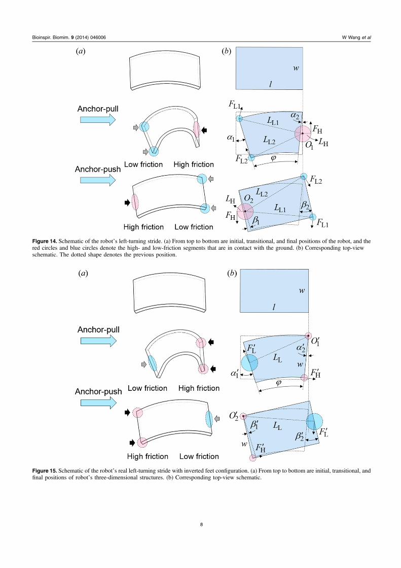
Figure 14. Schematic of the robot’s left-turning stride. (a) From top to bottom are initial, transitional, and final positions of the robot, and thered circles and blue circles denote the high- and low-friction segments that are in contact with the ground. (b) Corresponding top-viewschematic. The dotted shape denotes the previous position.
Figure 15. Schematic of the robot’s real left-turning stride with inverted feet configuration. (a) From top to bottom are initial, transitional, andfinal positions of robot’s three-dimensional structures. (b) Corresponding top-view schematic.
8
Bioinspir. Biomim. 9 (2014) 046006 W Wang et al
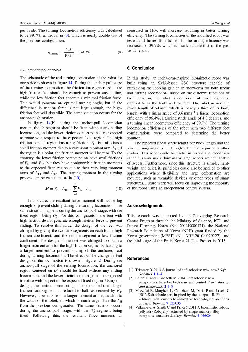
per stride. The turning locomotion efficiency was calculatedto be 39.7%, as shown in (9), which is nearly double that ofthe previous configuration:
η = °°
=4.3
10.839.7%. (9)turning
5.3. Mechanical analysis
The schematic of the real turning locomotion of the robot forone stride is shown in figure 14. During the anchor-pull stageof the turning locomotion, the friction force generated at thehigh-friction feet should be enough to prevent any sliding,while the low-friction feet generate a minimal friction force.This would generate an optimal turning angle, but if thedifference in friction force is not large enough, the high-friction feet will also slide. The same situation occurs for theanchor-push motion.
In figure 14(b), during the anchor-pull locomotionmotion, the O1 segment should be fixed without any slidinglocomotion, and the lower friction contact points are expectedto rotate with respect to the expected fixed region. The highfriction contact region has a big friction, FH, but also has asmall friction moment due to a very short moment arm, LH; ifthe region is a point, the friction moment will be zero. To thecontrary, the lower friction contact points have small frictionsof FL1 and FL2, but they have nonignorable friction momentsto the expected fixed region due to their very long momentarms of LL1 and LL2. The turning moment in the turningprocess can be calculated as in (10):
∑= ⋅ − ⋅=
M F L F L . (10)i
H H
1
2
Li Li
In this case, the resultant force moment will not be bigenough to prevent sliding during the turning locomotion. Thesame situation happens during the anchor-push stage, with thefixed region being O2. For this configuration, the feet withhigh friction do not generate enough friction force to preventsliding. To resolve this issue, the design of the feet waschanged by giving the two side segments on each foot a highfriction coefficient, and the middle segment a low frictioncoefficient. The design of the feet was changed to obtain alonger moment arm for the high-friction segments, leading toa larger moment to prevent sliding of the anchored footduring turning locomotion. The effect of the change in feetdesign on the locomotion is shown in figure 15. During theanchor-pull stage of the turning locomotion, the anchoredregion centered on ′O1 should be fixed without any slidinglocomotion, and the lower friction contact points are expectedto rotate with respect to the expected fixed region. Using thisdesign, the friction force acting on the nonanchored, high-friction foot segment, is reduced to half, as denoted by ′FH.However, it benefits from a longer moment arm equivalent tothe width of the robot, w, which is much larger than the LH
from the previous configuration. The same situation occursduring the anchor-push stage, with the ′O2 segment beingfixed. Following this, the resultant force moment, as
measured in (10), will increase, resulting in better turningefficiency. The turning locomotion of the modified robot wastested, and the results indicated that the turning efficiency wasincreased to 39.7%, which is nearly double that of the pre-vious results.
6. Conclusion
In this study, an inchworm-inspired biomimetic robot wasbuilt using an SMA-based SSC structure capable ofmimicking the looping gait of an inchworm for both linearand turning locomotion. Based on the different functions ofthe inchworm, the robot is comprised of three segments,referred to as the body and the feet. The robot achieved astride length of 54 mm, which is nearly a third of its bodylength, with a linear speed of 3.6 mms−1 a linear locomotionefficiency of 96.4%, a turning stride angle of 4.3 degrees, anda turning linear locomotion efficiency of 39.7%. The turninglocomotion efficiencies of the robot with two different feetconfigurations were compared to determine the bettersolution.
The reported linear stride length per body length and thestride turning angle is much higher than that reported in otherstudies. This robot could be useful in rescue and reconnais-sance missions where humans or larger robots are not capableof access. Furthermore, since this structure is simple, light-weight, and quiet, its principles could also be applied to otherapplications where flexibility and large deformation arerequired, such as wearable devices or other types of smartstructures. Future work will focus on improving the mobilityof the robot using an independent control system.
Acknowledgments
This research was supported by the Converging ResearchCenter Program through the Ministry of Science, ICT, andFuture Planning, Korea (No. 2013K000371), the NationalResearch Foundation of Korea (NRF) grant funded by theKorea government (MEST) (No. NRF-2010-0029227), andthe third stage of the Brain Korea 21 Plus Project in 2013.
References
[1] Trimmer B 2013 A journal of soft robotics: why now? SoftRobotics 1 1–4
[2] Laschi C and Cianchetti M 2014 Soft robotics: newperspectives for robot bodyware and control Front. Bioeng.and Biotechnol. 2 1–5
[3] Mazzolai B, Margheri L, Cianchetti M, Dario P and Laschi C2012 Soft-robotic arm inspired by the octopus: II. Fromartificial requirements to innovative technological solutionsBioinsp. Biomim. 7 025005
[4] Villanueva A, Smith C and Priya S 2011 A biomimetic roboticjellyfish (Robojelly) actuated by shape memory alloycomposite actuators Bioinsp. Biomim. 6 036004
9
Bioinspir. Biomim. 9 (2014) 046006 W Wang et al

[5] Kim H J, Song S H and Ahn S H 2013 A turtle-like swimmingrobot using a smart soft composite (SSC) structure SmartMater. Struct. 22 014007
[6] Ahn S H, Lee K T, Kim H J, Wu R Z, Kim J S and Song S H2012 Smart soft composite: an integrated 3D soft morphingstructure using bend-twist coupling of anisotropic materialsInt. J. Precis. Eng. Manuf. 13 631–4
[7] Marchese A D, Onal C D and Rus D 2014 Autonomous softrobotic fish capable of escape maneuvers using fluidicelastomer actuators Soft Robotics 1 75–87
[8] Lin H T, Leisk G G and Trimmer B 2011 GoQBot: acaterpillar-inspired soft-bodied rolling robot Bioinsp.Biomim. 6 026007
[9] Seok S, Onal C D, Wood R, Rus D and Kim S 2010 Peristalticlocomotion with antagonistic actuators in soft robotics IEEEInt. Conf. on Robotics and Automation (ICRA) 1228–33
[10] Shepherd R F, Ilievski F, Choi W, Morin S A, Stokes A A,Mazzeo A D, Chen X, Wang M and Whitesides G M 2011Multigait soft robot Proc. of the National Academy ofSciences 108 20400–3
[11] Deimel R and Brock O 2013 A compliant hand based on anovel pneumatic actuator Proc. of the IEEE Int. Conf. onRobotics and Automation (ICRA) 2047–53
[12] Deimel R and Brock O 2014 A novel type of compliant,underactuated robotic hand for dexterous grasping Robotics:Science and Systems (RSS) (Berkeley, USA 12–16July 2014)
[13] Koh J S and Cho K J 2009 Omegabot: biomimetic inchwormrobot using SMA coil actuator and smart compositemicrostructures (SCM) Int. Conf. on Robotics andBiomimetics 1154–59
[14] Lee D, Kim S, Park Y L and Wood R J 2011 Design ofcentimeter-scale inchworm robots with bidirectional clawsIEEE Int. Conf. on Robotics and Automation 3197–204
[15] Ueno S, Takemura K, Yokota S and Edamura K 2012An inchworm robot using electro-conjugatefluid IEEE Int. Conf. on Robotics and Biomimetics1017–22
[16] Kim M S, Chu W S, Lee J H, Kim Y M and Ahn S H 2011Manufacturing of inchworm robot using shape memoryalloy (SMA) embedded composite structure Int. J. Precis.Eng. Manuf. 12 565–8
[17] Lin H T, Slate D J, Paetsch C R, Dorfmann A L andTrimmer B A 2011 Scaling of caterpillar body propertiesand its biomechanical implications for the use of ahydrostatic skeleton The Journal of Experimental Biology214 1194–204
[18] Trueman E R 1975 The Locomotion of Soft-Bodied Animals(London: Edward Arnold Press)
[19] Rheuben M B and Kammer A E 1980 Comparison ofslow larval and fast adult muscle innervated by the samemotor neurone The Journal of Experimental Biology 84103–18
[20] Dorfmann A, Trimmer B A and Woods W A 2007 Aconstitutive model for muscle properties in a soft-bodied arthropod Journal of the Royal Society Interface 4257–69
[21] Schneider F, Fellner T, Wilde J and Wallrabe U 2008Mechanical properties of silicones for MEMS J. Micromech.Microeng. 18 065008
[22] Rodrigue H, Bhandari B, Han M W and Ahn S H 2014 Ashape memory alloy–based soft morphing actuator capableof pure twisting motion J. Intell. Mater. Syst. Struct.1045389–4536008
[23] Wang G and Shahinpoor M 1997 Design, prototyping andcomputer simulations of a novel large bending actuatormade with a shape memory alloy contractile wire SmartMater. Struct. 6 214
10
Bioinspir. Biomim. 9 (2014) 046006 W Wang et al