
Locating Fault on Transmission Line with Static Var ... - MDPI
14
energies Article Locating Fault on Transmission Line with Static Var Compensator Based on Phasor Measurement Unit Ngo Minh Khoa and Doan Duc Tung * Faculty of Engineering and Technology, Quy Nhon University, Binh Dinh 820000, Vietnam; [email protected] * Correspondence: [email protected]; Tel.: +84-905-799-386 Received: 23 August 2018; Accepted: 7 September 2018; Published: 9 September 2018 Abstract: The flexible alternating current transmission systems (FACTS) have been widely used in modern power systems. Because of the presence of the FACTS devices, distance relays in transmission lines may inaccurately locate fault locations. Therefore, it is significant to find a mechanism for locating fault in transmission lines connected to FACTS in which a static var compensator (SVC) is investigated in this work. Based on the development of a phasor measurement unit (PMU) with global positioning system (GPS), this paper proposes a new method for calculating apparent impedance seen by the distance relay location while a short-circuit fault occurs in a transmission line connected the SVC to the midpoint of the line. According to the method, sampled voltage and current measurement at the relay and SVC locations are synchronized using PMUs and the synchronized measurements are then used to calculate a new apparent impedance and to locate the fault location in the line. The method in this paper has the capability for fast calculation and it also has the robustness for identifying different fault types in power systems. Matlab/Simulink software is applied to simulate the study results and to evaluate the correctness of the modeling and effectiveness of the proposed method for locating fault in this paper. Keywords: distance relay; transmission line; static var compensator (SVC); phasor measurement unit (PMU); global positioning system (GPS) 1. Introduction Distance protection relays are widely used as the main protection scheme for transmission lines in power systems. A digital distance relay operates based on the measured impedance calculated from sampled voltage and current data at the relay locations at substations. The setting of distance relays’ operating zones is obtained from the line impedance protected by the relay. During a short-circuit fault, the apparent impedance trajectory falls inside the operating zones and as a consequence of the trip signal will be sent to the associated circuit breaker to disconnect the faulty line in order to maintain the normal operating mode of the power system [1,2]. Recently, the flexible alternating current transmission systems (FACTS) controllers in power systems have been used to improve power transfer capability and enhance controllability and stability of the power system [3,4]. However, the FACTS devices may also cause the transmission line to lead to deterioration of distance relay operation resulting in inaccurate estimation of short-circuit fault location in transmission lines such as over-reach and under-reach for different cases [5–7]. The improper working of distance relay can lead to incorrect tripping and it not only decreases the reliability and security of the power system but also can institute the cascade tripping and blackouts in the system [8]. There exists literature on the performance of distance protection relay in transmission lines with the presence of the shunt FACTS devices [5,9–12]. The work in [5] presented the performance of the distance protection relay of transmission lines with the shunt FACTS devices. The performance of Energies 2018, 11, 2380; doi:10.3390/en11092380 www.mdpi.com/journal/energies
-
Upload
khangminh22 -
Category
Documents
-
view
8 -
download
0
Transcript of Locating Fault on Transmission Line with Static Var ... - MDPI

energies
Article
Locating Fault on Transmission Line with Static VarCompensator Based on Phasor Measurement Unit
Ngo Minh Khoa and Doan Duc Tung *
Faculty of Engineering and Technology, Quy Nhon University, Binh Dinh 820000, Vietnam;[email protected]* Correspondence: [email protected]; Tel.: +84-905-799-386
Received: 23 August 2018; Accepted: 7 September 2018; Published: 9 September 2018
Abstract: The flexible alternating current transmission systems (FACTS) have been widely used inmodern power systems. Because of the presence of the FACTS devices, distance relays in transmissionlines may inaccurately locate fault locations. Therefore, it is significant to find a mechanism forlocating fault in transmission lines connected to FACTS in which a static var compensator (SVC) isinvestigated in this work. Based on the development of a phasor measurement unit (PMU) with globalpositioning system (GPS), this paper proposes a new method for calculating apparent impedance seenby the distance relay location while a short-circuit fault occurs in a transmission line connected theSVC to the midpoint of the line. According to the method, sampled voltage and current measurementat the relay and SVC locations are synchronized using PMUs and the synchronized measurementsare then used to calculate a new apparent impedance and to locate the fault location in the line.The method in this paper has the capability for fast calculation and it also has the robustness foridentifying different fault types in power systems. Matlab/Simulink software is applied to simulatethe study results and to evaluate the correctness of the modeling and effectiveness of the proposedmethod for locating fault in this paper.
Keywords: distance relay; transmission line; static var compensator (SVC); phasor measurement unit(PMU); global positioning system (GPS)
1. Introduction
Distance protection relays are widely used as the main protection scheme for transmission linesin power systems. A digital distance relay operates based on the measured impedance calculated fromsampled voltage and current data at the relay locations at substations. The setting of distance relays’operating zones is obtained from the line impedance protected by the relay. During a short-circuitfault, the apparent impedance trajectory falls inside the operating zones and as a consequence ofthe trip signal will be sent to the associated circuit breaker to disconnect the faulty line in order tomaintain the normal operating mode of the power system [1,2]. Recently, the flexible alternatingcurrent transmission systems (FACTS) controllers in power systems have been used to improve powertransfer capability and enhance controllability and stability of the power system [3,4]. However,the FACTS devices may also cause the transmission line to lead to deterioration of distance relayoperation resulting in inaccurate estimation of short-circuit fault location in transmission lines such asover-reach and under-reach for different cases [5–7]. The improper working of distance relay can leadto incorrect tripping and it not only decreases the reliability and security of the power system but alsocan institute the cascade tripping and blackouts in the system [8].
There exists literature on the performance of distance protection relay in transmission lines withthe presence of the shunt FACTS devices [5,9–12]. The work in [5] presented the performance of thedistance protection relay of transmission lines with the shunt FACTS devices. The performance of
Energies 2018, 11, 2380; doi:10.3390/en11092380 www.mdpi.com/journal/energies

Energies 2018, 11, 2380 2 of 14
the distance relay was evaluated for the shunt FACTS devices applied for midpoint voltage control.The impact of two types of shunt FACTS controllers including the static var compensator (SVC) andthe static synchronous compensator (STATCOM) on the distance protection relay were studied fordifferent fault types, fault locations and system conditions in power systems. The results in the papershowed the adverse effects of the midpoint shunt FACTS compensation of transmission line on bothnon-pilot and directional comparison blocking distance protection schemes. The authors Singh andRajiv in [9] also considered the performance of the distance protection relays which were applied toprotect the shunt FACTS compensated transmission lines. The shunt FACTS devices were assumedfor connecting to the midpoint of the line and the study was carried out in three stages includinganalyzing analytically the errors introduced in the impedance measurement due to the presence of theshunt FACTS devices on the line, using transient simulation software, EMTDC to simulate the responseof these devices for different fault conditions and system conditions, and confirming the findings bytesting the commercial relay validate the analytical and simulation studies. The measured impedanceat the relaying point in the presence of SVC was studied in [10]. In the paper, the measured impedanceat the relaying point was calculated due to the effective parameters to confirm that the presence ofSVC on a transmission line had a great influence on the tripping characteristic of the distance relays inpower systems. In addition, its controlling parameters as well as its installation location also affectedthe tripping characteristic of the distance protection relay. In [11], Albasri et al. made a comparativestudy of the performance of distance protection relays for transmission lines compensated by shuntFACTS controllers/devices including SVC and STATCOM also applied for midpoint voltage control.The impact of these devices was studied to evaluate their influence on the performance of various thedistance protection schemes on transmission lines for different fault types, fault locations, and systemconditions. The work published in [12] analyzed the impact of STATCOM on the apparent impedanceseen by the conventional distance relay protecting a transmission line. Analytical and simulationresults were carried out in the paper to confirm that the implication of applying STATCOM on thedistance relay was highly dependent on the sophisticated modeling of STATCOM especially its controlsystem considering practical constraints. Moreover, different power system operating conditions,STATCOM control system settings and fault scenarios investigated showed the STATCOM effects onthe distance relay tripping characteristics dramatically.
For mitigating the influence of shunt FACTS devices on distance protection relay and makingadaptive distance protection relay tripping characteristics in power systems, there are many publishedworks recently [13–20]. In [13], the influence of SVC at the midpoint of transmission line on distancerelay operation was analyzed. It made a result in inaccurate estimation of faults locations i.e., over-reachor under reach for the different cases. The paper proposed a new algorithm that utilized synchronizedphasor measurements to improve the operation of adaptive distance protection zone in many aspects.The authors of the paper [14] also proposed an adaptive distance protection scheme for improvingthe performance of the conventional distance protection scheme for shunt FACTS compensatedline connecting farm. The adaptive tripping characteristics for high resistance line-to-ground faultwith the shunt-FACTS devices considering appropriate operating conditions was addressed in thepaper. The work in [15] proposed an adaptive distance relay algorithm for the shunt compensatedtransmission line. The STATCOM was the shunt device studied in the paper to investigate its impacton the performance of the distance protection relay on the line. An adaptive zone setting for distancerelay tripping characteristics was proposed and evaluated for different types of faults different typesof fault, different fault resistances, and load angles. The wavelet approach for transient currentbased multi terminal transmission system protection scheme in the presence of SVC was studiedand proposed in [16]. The work carried out the most important problem of the distance protectionwas severe under reaching, which was caused by current injection at the point of connection to thesystem. Then, the paper proposed an efficient method based on wavelet transform, which was usedfor finding the detailed coefficients of the signals utilized to calculate fault index. The method wasevaluated for the detection, classification, and location of the fault on transmission line connected

Energies 2018, 11, 2380 3 of 14
to a SVC. The work presented in [17] studied practical solutions for mitigating the adverse impactson the distance protection schemes used to protect transmission lines that were compensated byFACTS controllers/devices including SVC and STATCOM. The modifications were proposed formitigating these impacts and implementing in commercial relays under various faults and varyingoperating conditions. In addition, application of an adaptive neuro-fuzzy inference system (ANFIS),high-frequency voltage standing-wave ratio-based grounding electrode line fault supervision andtransient fault current sensor based on the Rogowski coil were researched in [18–20] for modeling thedistance protection relay, identifying the transient current faults, and mitigating the effects of FACTSon the distance protection relay in power systems.
A PMU is a device that is used to measure the phasor values of current and voltage on an electricitygrid using a common time source for synchronization. Time synchronization allows synchronizedreal-time measurements of multiple remote measurement points on the grid. PMUs are considered tobe one of the most important measuring devices in the future of power systems [21,22]. For protectionrelay in power systems, PMUs were studied for purpose of locating fault in transmission line [23–25].In [23], the fault location techniques for transmission lines based on PMU data were presented. Thetwo-ended data were assumed to be measured by PMUs to identify the fault location on transmissionlines. The work presented in [24] proposed an algorithm for distance protection and fault locationbased on PMU. The algorithm was applied for series-compensated transmission lines and utilizedthe PMU to develop a distance protection and fault location scheme using synchronized voltage andcurrent measurements from both local and remote end substations. Moreover, for fault location andisolation for redundant inertial measurement unit under quantization, the authors in [25] proposed amethod using the three-channel filters to detect the soft fault and conducts theoretical implementationand the Monte Carlo simulation was carried out in order to verify the validity of the fault detectionand isolation with redundant strap down inertial measurement unit. The work in [26] designed anadaptive fault-tolerant control (FTC) scheme using the hybrid of the dynamic surface control techniqueand adaptive first-order filters to reduce significantly the computational burden and improve furtherthe control performance. Al-Mohammed et al. reported a comprehensive survey of fault locationbased on synchronized measurements [27]. The paper addressed the advantages and disadvantages ofthe existing methods for locating fault based on PMU and also highlighted the area for future research.
To address the aforementioned problems, this paper developed a simple power system modelingincluding a transmission line connected a SVC at the midpoint of the transmission line and single-phasefaults are established to research the problems. A new method uses PMUs’ measurements at thedistance protection relay and SVC locations for calculating the apparent impedance seen by the relayon the line and then it was used for locating fault location on the line connected SVC at the midpointlocation. The rest of this paper is structured as follows. Section 2 presents the background of theproposed method for locating the fault in transmission line connected to a SVC at the midpoint ofthe line. Section 3 establishes the simulation modeling in Matlab/Simulink software (R2011b.) andanalyzes the simulation results to evaluate the proposed method. Finally, the paper is concluded withSection 4.
2. Materials and Methods
2.1. The Study Power System
The one-line diagram of the study power system developed in this paper is shown in Figure 1.The system comprises a 220 kV transmission line with the length of 200 km and two substationsconnected to two ends of the line. In addition, a SVC is connected to the midpoint of theline. The current transformers (CTs) and voltage transformers (VTs) are placed at two ends andthe midpoint of the line to measure currents and voltages at the locations. The feasible and simplemethod is proposed in this paper in which the currents and voltages are measured at the relay and SVClocations with the support of PMUs. Using high-speed optical fiber data communication, these signals

Energies 2018, 11, 2380 4 of 14
are then transmitted to the relay location to calculate apparent impedance and locate the fault inthe line.
SVC
Mid-point
FCB
TX
RX
TX
RX
GPS
Substation
A
Substation
B
isvcusvciAuA uBiBusvcisvc
CB
Optical fiber
communication link
Optical fiber
communication link
Optical fiber
communication link
Optical fiber
communication link
Phasor & sequence
component estimation
using PMU
Distance
relay A
Phasor & sequence
component estimation
using PMU
Distance
relay B
Figure 1. The one-line diagram of the study power system.
2.2. Phasor Measurement Unit (PMU)
The PMU is used in power systems to provide real-time synchronized measurements withbetter than one microsecond synchronization accuracy, which is obtained by GPS signals. The PMUtechnology establishes both the magnitude and phase angle of phasor information in real time.An advantage of referring phase angle to global reference time is useful for capturing a wide areasnapshot of power systems [24]. Effective application of this technology is helpful for mitigatingblackouts and learning real-time behavior of power system. A phasor is a complex number thatrepresents both the magnitude and phase angle of the sine waveform found in alternating currentsystem. The waveform can be represented as follows:
x (t) = Xm cos (ωt + φ) , (1)
where Xm is the magnitude of the sinusoidal waveform; ω = 2π f is the instantaneous frequency ofthe signal in radians per second; and φ is the phase angle. In phasor notation, it can be representedas follows:
~X =Xm√
26 φ, (2)
where Xm/√
2 is the root mean square (RMS) value of the sinusoidal waveform.From the real axis, positive phase angles are calculated in a counterclockwise direction. Because
the frequency of the sinusoidal is inherent in the phasor definition, it is clear that all phasorsinvolved a single phasor diagram must have the same frequency [27]. Phasor representation ofthe sinusoidal waveform means that the signal maintains stationary at all times, leading to a constantphasor representation as shown in Figure 2. These concepts must be modified when practical phasormeasurements are to be carried out for the input signals are not constant, and their frequency maybe a variable. Currents and voltages obtained from the secondary winding of CTs and VTs located insubstations are the analog inputs to the PMU. All three phase currents and voltages are used to carryout the positive sequence measurement. The current and voltage signals are converted to voltages with
Energies 2018, 11, 2380 5 of 14
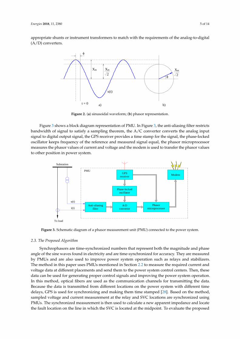
appropriate shunts or instrument transformers to match with the requirements of the analog-to-digital(A/D) converters.
t = 0
Xm
2
a)
b)
Xm
2
Xm
x(t)
Figure 2. (a) sinusoidal waveform; (b) phasor representation.
Figure 3 shows a block diagram representation of PMU. In Figure 3, the anti-aliasing filter restrictsbandwidth of signal to satisfy a sampling theorem, the A/C converter converts the analog inputsignal to digital output signal, the GPS receiver provides a time stamp for the signal, the phase-lockedoscillator keeps frequency of the reference and measured signal equal, the phasor microprocessormeasures the phasor values of current and voltage and the modem is used to transfer the phasor valuesto other position in power system.
u(t)
i(t)Anti-aliasing
filter
A/Dconverter
Phasor
microprocessor
Modem
Phase-locked
oscillator
GPS
receiver
Substation
PMU
To load
Figure 3. Schematic diagram of a phasor measurement unit (PMU) connected to the power system.
2.3. The Proposed Algorithm
Synchrophasors are time-synchronized numbers that represent both the magnitude and phaseangle of the sine waves found in electricity and are time-synchronized for accuracy. They are measuredby PMUs and are also used to improve power system operation such as relays and stabilizers.The method in this paper uses PMUs mentioned in Section 2.2 to measure the required current andvoltage data at different placements and send them to the power system control centers. Then, thesedata can be used for generating proper control signals and improving the power system operation.In this method, optical fibers are used as the communication channels for transmitting the data.Because the data is transmitted from different locations on the power system with different timedelays, GPS is used for synchronizing and making them time stamped [28]. Based on the method,sampled voltage and current measurement at the relay and SVC locations are synchronized usingPMUs. The synchronized measurement is then used to calculate a new apparent impedance and locatethe fault location on the line in which the SVC is located at the midpoint. To evaluate the proposed

Energies 2018, 11, 2380 6 of 14
method, the distance protection relay A is considered for analyzing the simulation results in this paper.In Figure 4, the sequence networks of the study system are shown. The new expression of apparentimpedance at the relay A is derived using sequence components of synchronized voltage and currentmeasurement based on PMUs at relay and SVC locations.
SVC
I svc1
.
Rf
If1
.
U A1
.U B1
.
I A1
.I B1
.Im1
.0.5ZL1 (x-0.5)ZL1 (1-x)ZL1ZA1
EA
.
ZB1
EB
.
U A2
.U B2
.
I A2
.I B2
.Im2
.0.5ZL2 (x-0.5)ZL2 (1-x)ZL2ZA2 ZB2
U A0
.U B0
.
I A0
.I B0
.Im0
.0.5ZL0 (x-0.5)ZL0 (1-x)ZL0ZA0 ZB0
F
SVC
I svc2
.
Rf
If2
.
F
SVC
I svc0
.
Rf
If0
.
F
a)
b)
c)
U svc1
.
U svc2
.
U svc0
.
Figure 4. The sequence networks. (a) the positive sequence network; (b) the negative sequence network;(c) the zero sequence network.
When an SVC is connected at the midpoint of the line and a short-circuit fault (F) occurs on thesegment line between the SVC and the substation B as shown in Figure 1, the sequence components ofcurrent and voltage at the relay A are expressed as follows:
Im1 = IA1 + Isvc1, (3)
Im2 = IA2 + Isvc2, (4)
Im0 = IA0 + Isvc0, (5)
UA1 = 0.5 IA1ZL1 + Im1 (x− 0.5) ZL1 + R f I f 1, (6)
UA2 = 0.5 IA2ZL2 + Im2 (x− 0.5) ZL2 + R f I f 2, (7)
UA0 = 0.5 IA0ZL0 + Im0 (x− 0.5) ZL0 + R f I f 0, (8)
where IA1, IA2, and IA0 are positive, negative and zero sequence currents at the relay A, respectively;Isvc1, Isvc2, and Isvc0 are positive, negative and zero sequence currents at the SVC, respectively; Im1, Im2,and Im0 are positive, negative and zero sequence currents on the line segment between the SVC andthe fault locations, respectively; I f 1, I f 2, and I f 0 are positive, negative and zero sequence fault currents,respectively; UA1, UA2, and UA0 are positive, negative and zero sequence voltages at the relay A,respectively; ZL1, ZL2, and ZL0 are positive, negative and zero sequence line impedance, respectively;R f is fault resistance; and x is the length of the segment from the relay A to the fault location in per

Energies 2018, 11, 2380 7 of 14
unit. The phase-a voltage at the relay A is UA which can be determined from the sequence componentsas follows:
UA = UA1 + UA2 + UA0= xIAZL1 +
[(x− 0.5) (ZL0 − ZL1)
(Isvc + Isvc0
)+ xIA0 (ZL0 − ZL1)
]+ R f I f .
(9)
In fact, the zero-sequence current component of the SVC ( Isvc0) can be eliminated because of deltaconnection at one side of the coupling transformer which is used to connect the SVC to the system.In addition, we consider that R f = 0 therefore Equation (9) can be rewritten as follows:
UA = xIAZL1 +[(x− 0.5) (ZL0 − ZL1) Isvc + xIA0 (ZL0 − ZL1)
]. (10)
The expression of apparent impedance (Zoldapp) at the relay A which is defined by the conventional
method is expressed as follows:
Zoldapp =
UA
IA + KIA0, (11)
where K is the compensation factor and given by K = (ZL0 − ZL1)/ZL1
Substituting Equation (10) in Equation (11), we get:
Zoldapp = xZL1 +
(x− 0.5) IsvcZL1
IA + KIA0. (12)
The distance protection algorithm proposed for the main purpose of this paper is to make distanceprotection algorithm for locating fault when SVC is connected at the midpoint of the transmission line.The apparent impedance seen by the relay A can be determined by the segment line impedance fromthe relay A to SVC and the segment line impedance from SVC to fault location. Therefore, based on theapproach for calculating apparent impedance at the distance relay [1], the proposed algorithm in thispaper uses voltage and current measurement both of the SVC and the relay A location to determinethe new expression of apparent impedance at the relay A as follows:
Znewapp =
UA − Usvc
IA + KIA0+
Usvc
Im + KIm0=
UA − Usvc
IA + KIA0+
Usvc
IA + Isvc + KIA0, (13)
where UA, and Usvc are the voltages at the relay A and SVC locations, respectively.From Equation (13), we can see clearly that the apparent impedance at the relay A is a function of
voltage and current at the relay A location (UA, IA), voltage and current at the SVC location (Usvc, Isvc).The digital distance relay A takes the voltage and current samples from instrument transformers at therelay A and SVC locations. In order to calculate phasor (fundamental only), the voltage and currentsamples are pre-processed using fast Fourier transform (FFT). The symmetrical voltages and currentsare used to calculate the apparent impedance (Znew
app ) at the relay A location. Finally, it is comparedwith the setting zones of the Mho characteristic to make trip signal as shown in Figure 5. In powersystems, distance relay acts as the main protection for faults within zone 1, while, for zone 2 and zone3, it acts as a backup protection for the adjacent line. Zone 1 reach is normally set only up to 80–90% ofthe protected line. For ensuring full coverage of the protected line, zone 2 is set at minimum 120% ofthe protected line. For faults within zone 2 reach, tripping signal will be sent at a delayed time wherethe relay acts as the backup protection for the main protection at the adjacent line. The tripping timefor zone 2 is normally set at several hundred miliseconds. Backup protection for entire adjacent lineis covered by zone 3 reach. It is normally set at least 2.25 times the impedance of protected adjacentline. The set tripping time for zone 3 reach is typically several seconds. The relay setting with threesetting zones of first zone (Z1), second zone (Z2) and third zone (Z3) of a distance relay [13] which are

Energies 2018, 11, 2380 8 of 14
80%, 120%, and 225% of the line from the substation A to the substation B respectively is expressedas follows:
Z1 = 0.8ZL1,Z2 = 1.2ZL1,Z3 = 2.25ZL1,
(14)
where ZL1 is the positive sequence impedance of the line from the substation A to the substation B.The proposed algorithm in Figure 5 is comprised of the following steps:
Step 1. Analog-to-digital converter is used to convert the analog input voltage and current signals atrelays and SVC locations which are synchronized using PMUs with GPS to digital signals.
Step 2. The voltage and current phasors (fundamental only) at relays and SVC locations are extractedby using Fast Fourier Transform (FFT).
Step 3. The method of symmetrical components is applied to calculate sequence components of voltageand current measurement at relays and SVC locations.
Step 4. The new expression of apparent impedance at the distance relays is applied to calculate Znewapp
using (13), which is proposed in this paper.Step 5. The new apparent impedance (Znew
app ) is compared with the setting zones (Z1, Z2, and Z3) of theMho characteristic.
Step 6. Time delay function of relay is initiated.Step 7. Finally, trip signal is transferred to the circuit breaker.
Measure U A & I A
Extract U A & I A phasor
using FFT
Calculate sequence
components of U A & I A
Calculate Znewapp using (13)
uA iA
Measure U svc & I svc
Extract U svc & I svc phasor
using FFT
Calculate sequence
components of U svc & I svc
isvc
GPS
synchronization
Measure U B & I B
Extract U B & I B phasor
using FFT
Calculate sequence
components of U B & I B
uB iB
Znewapp Z1 ?
NoNo No
1 11
1
Time delay Time delay
Yes YesYes
Trip signal
No
2
Time delay Time delay
Yes YesYes
Trip signal
No
2
No
2
2
usvc
Znewapp Z2 ? Znew
app Z3 ? Znewapp Z1 ? Znew
app Z2 ? Znewapp Z3 ?
Calculate Znewapp using (13)
Figure 5. The proposed algorithm for locating fault in transmission line with a SVC.
3. Results and Discussion
The study power system as shown in Figure 1 comprises a transmission line with 200 km lengthfrom substation A to substation B. A SVC is located at the midpoint of the line and two distance relaysat the ends of the line. The detailed model of the SVC is used to model in here and the power systemparameters have been provided in Appendix A. Matlab/Simulink software is used to model andsimulate the system. In order to verify and evaluate the proposed method, different study cases are

Energies 2018, 11, 2380 9 of 14
taken into account in this section as follows:
Case 1: Without SVC,Case 2: With SVC operating at +100 Mvar capacitive mode,Case 3: With SVC operating at −100 Mvar inductive mode.
In all of the cases, a single-phase to ground fault 150 km away from relay A is assumed to occurat 0.2 s and total time of simulation is 0.6 s. Then, the voltage and current signals at the relay and SVClocations are acquired to calculate apparent impedance at the relay A using both of the conventionaland proposed methods. The simulation results for each case are presented in detail as follows:
Case 1: Without SVC.
The simulation results of Case 1 “without SVC” are shown in Figure 6. At the period of time from0 s to 0.2 s, the system is normal operating mode; therefore, all measurements in this period are alsonormal as shown in Figure 6a–d. However, it is noted that the current of SVC is zero because there isno SVC connected to the line in this case as shown in Figure 6b.
0 0.1 0.2 0.3 0.4 0.5 0.60
50
100
150
200
250
Time (s)(a)
Vol
tage
(kV
)
Voltage at Relay AVoltage at SVC
0 0.1 0.2 0.3 0.4 0.5 0.6−0.5
0.0
0.5
1.0
1.5
2.0
2.5
3.0
Time (s)(b)
Cur
rent
(kA
)
Current at Relay ACurrent at SVC
0 0.1 0.2 0.3 0.4 0.5 0.60
50
100
150
200
250
300
350
400
Time (s)(c)
App
aren
t im
peda
nce
(Ω)
Conventional methodProposed method
0.2 0.25 0.3 0.35 0.438
40
42
44
46
48
50
0 0.1 0.2 0.3 0.4 0.5 0.6 0.0
1.0
2.0
3.0
4.0
5.0
6.0
7.0
Time (s)(d)
Len
gth
(pu)
Conventional methodProposed method
0.2 0.25 0.3 0.35 0.4
0.65
0.7
0.75
0.8
0.85
Figure 6. The simulation results of Case 1. (a) voltage measurement; (b) current measurement;(c) apparent impedance at relay A; (d) fault location.
A single-phase to ground fault 150 km away from relay A occurs at 0.2 s. Because of the fault,the voltages at the relay A and SVC locations are reduced as shown in Figure 6a, the current at therelay A location is increased, but the current at SVC is still zero because there is no SVC in this case asshown in Figure 6b. The apparent impedances at the relay A using both the conventional and proposedmethods are similar and they are dramatically reduced when the fault occurs at 0.2 s. In Figure 6c,the solid line represents the conventional method and the dashed line represents the proposed method.Finally, the simulation result for locating fault is presented in Figure 6d. In this case, the results of fault

Energies 2018, 11, 2380 10 of 14
location using the conventional and proposed method are similar because no SVC is connected to theline. The result of the fault location is determined by length in per unit of the line away from the relayA and the length result as shown in Figure 6d is 0.75 pu, which is 150 km away from the relay A.
Case 2: With SVC operating at +100 Mvar Capacitive Mode.
The simulation results of Case 2 “With SVC operating at +100 Mvar capacitive mode” are shown inFigure 7. At the period of time from 0 s to 0.2 s, the system is at steady state; therefore, all measurementsin this period are also normal as shown in Figure 7a–d. The simulation results in the period of Case 2are different from Case 1. Because of the SVC operating at +100 Mvar capacitive mode, the voltage atSVC location is higher than the voltage at relay A as shown in Figure 7a. In addition, the current atSVC is about 400 A as shown in Figure 7b. The apparent impedance and fault location at the relay A inthis period are shown in Figure 7c and Figure 7d, respectively.
0 0.1 0.2 0.3 0.4 0.5 0.60
50
100
150
200
250
Time (s)(a)
Vol
tage
(kV
)
Voltage at Relay AVoltage at SVC
0 0.1 0.2 0.3 0.4 0.5 0.60.0
0.5
1.0
1.5
2.0
2.5
3.0
Time (s)(b)
Cur
rent
(kA
)
Current at Relay ACurrent at SVC
0 0.1 0.2 0.3 0.4 0.5 0.60
50
100
150
200
250
300
350
400
450
Time (s)(c)
App
aren
t im
peda
nce
(Ω)
Conventional methodProposed method
0.2 0.25 0.3 0.35 0.438
40
42
44
46
48
50
0 0.1 0.2 0.3 0.4 0.5 0.60.0
1.0
2.0
3.0
4.0
5.0
6.0
7.0
8.0
Time (s)(d)
Len
gth
(pu)
Conventional methodProposed method
0.2 0.25 0.3 0.35 0.4
0.65
0.7
0.75
0.8
0.85
Figure 7. The simulation results of Case 2. (a) voltage measurement; (b) current measurement;(c) apparent impedance at relay A; (d) fault location.
Because the single-phase to ground fault in 150 km away from the relay A occurs at 0.2 s,the voltages at the relay A and SVC locations are reduced as shown in Figure 7a. The current at therelay A location is increased but the current at SVC is decreased as shown in Figure 7b. The apparentimpedances at the relay A using both the conventional method and proposed methods are dramaticallyreduced when the fault occurs at 0.2 s as shown in Figure 7c. The magnification of the apparentimpedance at the relay A in the period of time from 0.2 s to 0.4 s is also shown in Figure 7c. In Figure 7c,it is clear that the simulation results of the conventional and proposed method are different becausethe SVC is operating +100 Mvar capacitive mode. Finally, the simulation result of fault location inFigure 7d shows that the proposed method locates the fault accurately than the conventional method.

Energies 2018, 11, 2380 11 of 14
Case 3: With SVC operating at −100 Mvar inductive mode.
Figure 8 shows the simulation results of Case 3 “With SVC operating at −100 Mvar inductivemode”. At the period of time from 0 s to 0.2 s, the system is at steady state (pre-fault); therefore,all measurements in this period are also normal as shown in Figure 8a–d. It is clear that thesimulation result in this period of Case 3 is also different from Case 1 and Case 2. The voltageat SVC location is lower than the voltage at the relay A as shown in Figure 8a because of the SVCoperating at −100 Mvar inductive mode. Moreover, the current at SVC is about 400 A as shownin Figure 8b. The apparent impedance and fault location at the relay A in this period are shown inFigure 8c and Figure 8d, respectively.
When the single-phase to ground fault in 150 km away from the relay A occurs at 0.2 s, the voltagesat the relay A and SVC locations are reduced as shown in Figure 8a, the current at the relay A locationis increased but the current at SVC is decreased as shown in Figure 8b. The apparent impedancesat the relay A using both the conventional method and proposed methods are dramatically reducedwhen the fault occurs at 0.2 s as shown in Figure 8c. The magnification of apparent impedance at therelay A in the period of time from 0.25 s to 0.6 s is also shown in Figure 8c. In Figure 8c, it is clearthat the simulation results of the conventional and proposed methods are different because the SVCis operating −100 Mvar inductive mode. Finally, the simulation result of fault location in Figure 8dshows that the proposed method locates the fault accurately than the conventional method.
0 0.1 0.2 0.3 0.4 0.5 0.60
50
100
150
200
250
Time (s)(a)
Vol
tage
(kV
)
Voltage at Relay AVoltage at SVC
0 0.1 0.2 0.3 0.4 0.5 0.60.0
0.5
1.0
1.5
2.0
2.5
3.0
Time (s)(b)
Cur
rent
(kA
)
Current at Relay ACurrent at SVC
0 0.1 0.2 0.3 0.4 0.5 0.60
50
100
150
200
250
300
350
400
Time (s)(c)
App
aren
t im
peda
nce
(Ω)
Conventional methodProposed method
0.2 0.25 0.3 0.35 0.438
40
42
44
46
48
50
0 0.1 0.2 0.3 0.4 0.5 0.60.0
1.0
2.0
3.0
4.0
5.0
6.0
7.0
Time (s)(d)
Len
gth
(pu)
Conventional methodProposed method
0.2 0.25 0.3 0.35 0.4
0.65
0.7
0.75
0.8
0.85
Figure 8. The simulation results of Case 2. (a) voltage measurement; (b) current measurement;(c) apparent impedance at relay A; (d) fault location.
4. Conclusions
Based on the synchronized voltage and current measurements at the distance protection relayand SVC locations using PMUs, the proposed method in this paper has been considered as a useful

Energies 2018, 11, 2380 12 of 14
approach to calculate the apparent impedance at the relay while a fault occurs in the transmissionline connecting a SVC to the midpoint. The voltage and current measurements are synchronizedusing PMUs with GPS and are used to extract their sequence components using FFT. The newexpression is used to calculate the apparent impedance at the distance relay based on the components.The simulation results show that the distance relay determines fault location and makes relay tripdecisions accurately by using the proposed method. To evaluate the proposed method, the effectivenessof the fault location of the proposed method has been compared to the effectiveness of the conventionalmethod through the simulation results. The proposed method is simple to implement for distanceprotection relay of transmission lines in which SVC is connected to the midpoint and operated withdifferent modes. Finally, the main contribution of this paper is to propose a feasible method: (i) todetermine the apparent impedance seen by the distance relay that only uses the voltage and currentmeasurements synchronized using PMUs at the relay and SVC locations in the transmission line;and (ii) to make a simple method for locating faults in the power systems and improving the faultlocation accuracy of the conventional method.
Author Contributions: N.M.K and D.D.T. proposed the idea and then performed the simulation inMatlab/Simulink software. N.M.K. analyzed the simulation results and wrote the paper. Finally, all the authorsread and confirmed the final manuscript.
Funding: This research received no external funding.
Acknowledgments: This research was supported by Quy Nhon University, the code number of the project:T2018.569.18.
Conflicts of Interest: The authors declare no conflict of interest.
Appendix A
The Power System Parameters in Figure 1:
Voltage source A:Nominal voltage 220 kVPhase angle 10
Fundamental frequency 50 HzPositive-sequence impedance 0.8929 + j5.2088 ΩZero-sequence impedance 0.8929 + j5.2088 ΩVoltage source B:Nominal voltage 220 kVPhase angle 0
Fundamental frequency 50 HzPositive-sequence impedance 0.8929 + j5.2088 ΩZero-sequence impedance 0.8929 + j5.2088 ΩTransmission Line:Length 200 kmpositive-sequence resistance 0.01273 Ω/kmzero-sequence resistance 0.3864 Ω/kmpositive-sequence inductance 0.0009337 H/kmzero-sequence inductance 0.0041264 H/kmSVC:Rating capacitive ±100 Mvar
References
1. Ismail, M.M.; Hassan, M.A.M. Distance Relay Protection for Short and Long Transmission Line.In Proceedings of the 2013 5th International Conference on Modelling, Identification and Control (ICMIC),Cairo, Egypt, 31 August–2 Sepetember 2013.
2. Zalitis, I.; Dolgicers, A.; Kozadajevs, J. A distance protection based on the estimation of system modelparameters. In Proceedings of the IEEE Manchester PowerTech, Manchester, UK, 18–22 June 2017.

Energies 2018, 11, 2380 13 of 14
3. Wydra, M. Performance and Accuracy Investigation of the Two-Step Algorithm for Power System State andLine Temperature Estimation. Energies 2018, 11, 1005, doi:10.3390/en11041005.
4. Dai, L.V.; Tung, D.D.; Dong, T.L.T.; Quyen, L.C. Improving Power System Stability with GramianMatrix-Based Optimal Setting of a Single Series FACTS Device: Feasibility Study in Vietnamese PowerSystem. Complexity 2017, 2017, doi:10.1155/2017/3014510.
5. Albasri, F.A.; Sidhu, T.S.; Varma, R.K. Impact of Shunt-FACTS on Distance Protection of Transmission Lines.In Proceedings of the Power Systems Conference: Advanced Metering, Protection, Control, Communication,and Distributed Resources, Clemson, SC, USA, 14–17 March 2006.
6. Ghorbani, A.; Mozafari, B.; Khederzadeh, M. Impact of SVC on the protection of transmission lines. Int. J.Electr. Power Energy Syst. 2012, 42, 702–709, doi:10.1016/j.ijepes.2012.04.029.
7. Khoa, N.M.; Hieu, N.H.; Viet, D.T. A Study of SVC’s Impact Simulation and Analysis for DistanceProtection Relay on Transmission Lines. Int. J. Electr. Comput. Eng. 2017, 7, 1686–1695,doi:10.11591/ijece.v7i4.pp1686-1695.
8. Henna, M.Y.E.; Nagy, S.A. Prevention of Cascaded Events of Distance Relay Zone Three Using Logic Controls,In Proceedings of the International Conference on Electrical and Computer Engineering, Benghazi, Libya,26–28 March 2013.
9. Singh, S.T.; Rajiv, K.V. Performance of distance relays on shunt-FACTS compensated transmission lines.IEEE Trans. Power Deliv. 2005, 20, 1837–1845, doi:10.1109/TPWRD.2005.848641.
10. Kazemi, A.; Jamali, S.; Shateri, H. Measured Impedance by Distance Relay in Presence of SVC onTransmission Line. Int. Rev. Electr. Eng. 2006, 5, 2214–2219, doi:10.1109/IECON.2006.347294.
11. Albasri, F.A.; Sidhu, T.S.; Varma, R.K. Performance comparison of distance protection schemes forshunt-FACTS compensated transmission lines. IEEE Trans. Power Deliv. 2007, 22, 2116–2125,doi:10.1109/TPWRD.2007.900283.
12. Khederzadeh, M.; Ghorbani, A. STATCOM modeling impacts on performance evaluation of distanceprotection of transmission lines. Eur. Trans. Electr. Power 2011, 21, 2063–2079, doi:10.1002/etep.541.
13. Thakre, M.P.; Kale, V.S. An adaptive approach for three zone operation of digital distance relay with static varcompensator using PMU. Int. J. Electr. Power Energy Syst. 2016, 77, 327–336, doi:10.1016/j.ijepes.2015.11.049.
14. Dubey, R.; Samantaray, S.R.; Panigrahi, B.K. Adaptive distance protection scheme for shunt-FACTScompensated line connecting wind farm. IET Gener. Trans. Distrib. 2016, 10, 247–256,doi:10.1049/iet-gtd.2015.0775.
15. Biswal, S.; Biswal, M. Adaptive distance relay algorithm for shunt compensated transmission line.In Proceedings of the International Conference on Electrical Power and Energy Systems (ICEPES), Bhopal,India, 14–16 December 2016.
16. Sree, Y.M.; Kumar, G.R.; Vaidehi, M.; Priya, G.V. Wavelet approach for transient current based multiterminal transmission system protection scheme in the presence of SVC. In Proceedings of the InternationalConference on Electrical, Electronics, and Optimization Techniques, Chennai, India, 3–5 March 2016.
17. Albasri, F.A.; Sidhu, T.S.; Varma, R.K. Mitigation of Adverse Effects of Midpoint Shunt-FACTS CompensatedTransmission Lines on Distance Protection Schemes. In Proceedings of the Power Engineering SocietyGeneral Meeting, Tampa, FL, USA, 24–28 June 2007.
18. Azriyenni, A.; Mustafa, M.W. Application of ANFIS for Distance Relay Protection in Transmission Line.Int. J. Electr. Comput. Eng. 2015, 5, 1311–1318, doi:10.11591/ijece.v5i6.pp1311-1318.
19. Teng, Y.; Li, X.; Huang, Q.; Wang, Y.; Jing, S.; Jiang, Z.; Zhen, W. A Novel High-Frequency VoltageStanding-Wave Ratio-Based Grounding Electrode Line Fault Supervision in Ultra-High Voltage DCTransmission Systems. Energies 2017, 10, 309, doi:10.3390/en10030309.
20. Liu, Y.; Xie, X.; Hu, Y.; Qian, Y.; Sheng, G.; Jiang, X. A Novel Transient Fault Current Sensor Based on thePCB Rogowski Coil for Overhead Transmission Lines. Sensors 2016, 16, 742, doi:10.3390/16050742.
21. Mandava, S.; Vanishree, J.; Ramesh, V. A Spanning Tree Approach in Placing Multi-channel and MinimumChannel PMU’s for Power System Observability. Int. J. Electr. Comput. Eng. 2015, 5, 518–524,doi:10.11591/ijece.v5i3.pp518-524.
22. Ghorbani, A., Soleymani, S. and Mozafari, B. A PMU-based LOE protection of synchronous generator in thepresence of GIPFC. IEEE Trans. Power Deliv. 2016, 31, 551–558, doi:10.1109/TPWRD.2015.2440314.
23. Yin, H.; Fan, L. PMU Data-Based Fault Location Techniques. In Proceedings of the North American PowerSymposium, Arlington, TX, USA, 26–28 September 2010.

Energies 2018, 11, 2380 14 of 14
24. Zeinhom, A.N. Phasor measurement unit-based distance protection and fault location algorithm forseries-compensated transmission lines. In Proceedings of the Saudi Arabia Smart Grid Conference (SASG),Jeddah, Saudi Arabia, 14–17 December 2014.
25. Zhang, T.; Wang, F.; Fu, W. Fault Detection and Isolation for Redundant Inertial Measurement Unit underQuantization. Appl. Sci. 2018, 8, 865, doi:10.3390/app8060865.
26. Khebbache, H.; Labiod, S.; Tadjine, M. Adaptive sensor fault-tolerant control for a class of multi-inputmulti-output nonlinear systems: Adaptive first-order filter-based dynamic surface control approach.ISA Transac. 2018, doi:10.1016/j.isatra.2018.07.037.
27. Al-Mohammed, A. H.; Abido, M. A. Fault Location Based on Synchronized Measurements: A ComprehensiveSurvey. Sci. World J. 2014, 2014, doi:10.1155/2014/845307.
28. Ghorbani, A.; Ebrahimi, S.Y.; Ghorbani, M. Active power based distance protection scheme in the presenceof series compensators. Prot. Control Modern Power Syst. 2017, 2, doi:10.1186/s41601-017-0034-4.
c© 2018 by the authors. Licensee MDPI, Basel, Switzerland. This article is an open accessarticle distributed under the terms and conditions of the Creative Commons Attribution(CC BY) license (http://creativecommons.org/licenses/by/4.0/).