
LinkRunner 10G User Guide v1.3
469
LINKRUNNER ® 10G User Guide Tap a link to go directly to the app's chapter. Search this PDF for a specific term or phrase. Scroll down to view the full list of Contents. NetAlly Network Testing Apps AutoTest Ping/TCP Capture Cable Discovery Path Analysis Performance iPerf Link-Live App Store Software v1.3 Published July 28, 2020
-
Upload
khangminh22 -
Category
Documents
-
view
1 -
download
0
Transcript of LinkRunner 10G User Guide v1.3

LINKRUNNER® 10GUser Guide
Tap a link to godirectly to the app's chapter.Search this PDF for a specific termor phrase.Scroll down to view the full list of Contents.
NetAlly Network Testing Apps
AutoTest Ping/TCP
Capture Cable
Discovery Path Analysis
Performance iPerf
Link-Live App Store
Software v1.3 Published July 28, 2020

Contents
Contact Us 12
Introduction 13How to Use this Guide 14The PDF Reader App 14
Buttons and Ports 19Charging and Power 23Safety and Maintenance 25Legal Notification 28
Home and Android Interface 29Home Screen 30Navigating the Android System 32Android Status Bar and Notifications 36Notification Panel 36
Apps Screen and Store 39Device Settings 42Quick Settings Panel 43
Connecting to Wi-Fi 47Captive Portals 50
Sharing 52Sharing Files to Link-Live 53Sharing from the Files App 55
2

Saving a Screenshot 58
LinkRunner 10G Settings and Tools 59Navigation Drawer 60About Screen 62Exporting Logs 63
Test and Management Ports 64Configuring the Ports 65Test Ports 67Management Port 68
Test and Port Status Notifications 69Test Port Notifications 70Management Port Notifications 71Discovery Notifications 72VNC/Link-Live Remote 72
LinkRunner 10G General Settings 74Wired 75Management 76Preferences 80
Trending Graphs 81Common Icons 85Floating Action Button (FAB) and Menu 86Common Tools 89
3

Web Browser/Chrome 89Telnet/SSH 89Camera and Flashlight 91
Software Management 93Managing Files 94Files Application 94How to Move or Copy a File 97Using a Micro SD Card 98Using a USB Drive 99Ejecting Storage Media 100Using a USB Type-C to USB Cable 101
Updating Software 103Remote Access 109Using VNC 110Using Link-Live Remote 111
Managing NetAlly App Settings 113Resetting Testing App Defaults 113Saving App Settings Configurations 117Exporting and Importing Settings 120
Restoring LinkRunner 10G FactoryDefaults 125Changing the Language 127
4

LinkRunner 10G TestingApplications 129
AutoTest App and Profiles 130AutoTest Overview 132Managing Profiles and Profile Groups 135Factory Default Profiles 135Adding New Profiles 136Profile Groups 138Creating New Profile Groups 143
Main AutoTest Screen 146Periodic AutoTest 148Periodic AutoTest Settings 148Running Periodic AutoTest 150
Wired AutoTest Profiles 153Wired Profile Results 158PoE Test Results 160Wired Link Test Results 163802.1X Test Results 168VLAN Test Results 170Switch Test Results 172Wired Profile FAB 179
Wired Profile Settings 183
5

PoE Test Settings 184Wired Connection Settings 187VLAN Settings 191Stop After 193HTTP Proxy 194
DHCP, DNS, and Gateway Tests forWired AutoTests 196DHCP or Static IP Test 197DNS Test 209Gateway Test 214
Test Targets for Wired AutoTests 219Adding and Managing Test Targets 220Target Test Results Screens 224AutoTest Ping Test 227AutoTest TCP Connect Test 233HTTP Test 237FTP Test 248
Ping/TCP Test App 258Ping/TCP Settings 259Populating Ping/TCP from AnotherApp 259Configuring Ping/TCP SettingsManually 262
6

Running Ping/TCP Tests 266
Capture App 270Capture Settings 271Running and Viewing Captures 275
Discovery App 280Introduction to Discovery 282Main Discovery List Screen 284Searching the Discovery List 287Filtering the Discovery List 289Sorting the Discovery List 292Security Auditing – BatchAuthorization 294Refreshing Discovery 299Uploading Discovery Results to Link-Live 300
Discovery Details Screens 302Top Details Card 304Lower Cards in Device Details 309Problems 311Addresses 312TCP Port Scan 313VLANs 316
7

Interfaces 317SNMP 323Connected Devices 325Resources 326SSIDs 327Discovery App Floating Action Menu 329
Device Types 335Routers 336Switches 337Unknown Switches 338Network Servers 340Hypervisors 341Virtual Machines 342Wi-Fi Controllers 344Access Points (APs) 345Wi-Fi Clients 346VoIP Phones 346Printers 348SNMP Agents 349NetAlly Tools 350Hosts/Clients 351
Discovery Settings 353SNMP Configuration 356
8

Active Discovery Ports 364Devices Discovered Through OtherDevices 365Device Health Interval 371ARP Sweep Rate 372SNMP Query Delay 373
Problem Settings 374TCP Port Scan Settings 378
Path Analysis App 381Introduction to Path Analysis 382Path Analysis Settings 383Populating Path Analysis fromAnother App 383Configuring Path Analysis Manually 383
Running Path Analysis 387Path Analysis Results and SourceLinkRunner Cards 389Layer 3 Hops 392Layer 2 Devices 397Uploading Path Analysis Results toLink-Live 402
Performance Test App 404
9

Introduction to Performance Testing 406Running LinkRunner as a PerformancePeer 408
iPerf Test App 412iPerf Settings 414Saving Custom iPerf Settings 414Test Accessories in Discovery 415Configuring iPerf Settings 418
Running an iPerf Test 422Uploading iPerf Results to Link-Live 426
Link-Live Cloud Service 428Getting Started in Link-Live CloudService 430Quick Claiming on the Unit 430Claiming Manually 433After Claiming 435Unclaiming 436
Link-Live App Features 438Saving Locally Only 441Job Comment 443Link-Live and Testing Apps 446Link-Live Sharing Screens 447
10

Sharing a Text File to Link-Live 450
Cable Test App 453Cable Test Settings 454Running Cable Test 455Open Cable TDR Testing 456Terminated WireView Testing 459Toning Function 461Uploading Cable Test Results to Link-Live 462
Specifications and Compliance 463Specifications 464General 464Environmental Specifications 465
Certifications and Compliance 467
11
Contact UsOnline: NetAlly.com
Phone: (North America) 1-844-TRU-ALLY(1-844-878-2559)
NetAlly2075 Research ParkwayColorado Springs, CO 80920For additional product resources, visitNetAlly.com/Products/LinkRunner10G.
For customer support, visitNetAlly.com/Support.
Register your LinkRunner 10GRegistering your product with NetAlly gives youaccess to valuable information on productupdates, troubleshooting procedures, andother services.
Register on the NetAlly Support Page.
12

IntroductionThe LinkRunner 10G is a rugged, hand-held toolfor testing and analyzing copper and fiber. Itfeatures applications developed by NetAlly fornetwork discovery, measurement, andvalidation, which are available from the Homeand Apps screens.
All NetAlly hand-held testers include access toLink-Live Cloud Service at Link-Live.com. Link-Live is an online system for collecting,organizing, analyzing, and reporting your testresults. Test data is automatically uploadedonce your tester is properly configured. VisitLink-Live.com and "Claim" your LinkRunnerto access these features.
13
LinkRunner 10G User Guide
Back to Title and Contents

How to Use this GuideThis User Guide describes the LinkRunner 10G'stesting functionality and basic elements of theAndroid interface.
The guide is meant for users who are know-ledgeable about network operations, tests, andmeasurements.
The LinkRunner 10G may also be referred to asjust LinkRunner or the "unit" in this guide.
The PDF Reader AppA PDF reader application is pre-installed onyour LinkRunner to allow easy navigation ofthis guide:
l Tap blue links to go to their destinations.Underlined blue links open externalwebsites.
l Touch headings in the Contents list thatstarts on page 2 to go to the correspondingsections.
l Use the Search function in the uppertoolbar to find specific terms in the guide.
Introduction
14

Once you enter a term and search, the termappears at the top of the PDF reader screen.Touch the left and right arrows to searchforwards and backwards in the guide for theterm. In the image below, the user hassearched "problems."
l To scroll quickly up or down in the guide,touch and drag the page number tabat the right. Drag the tab to the very top of
Introduction
15

the screen to return to the title page.
l Touch and hold the page number tabto open a dialog that allows you to returnto the previous page you were viewing.
NOTE: Touching the back buttons, or, will not take you back to your previous
place in a PDF.
l To browse the PDF Contents orBookmarks, touch the action overflow icon
in the upper tool bar.
Introduction
16

Select Contents to view the list of chaptersand choose a section to read.
l Tap the blue Back to Title and Contentslink wherever it appears to return to thetitle page with app links.
Introduction
17

Back to Title and Contents
l Scroll to show or hide the app toolbars atthe top of the Adobe Reader screen and thefloating action button (FAB) at thebottom right.
l Tap the screen twice to zoom in or out.
To download this guide onto another device,you can transfer the PDF file using one of themethods described in the Managing Filessection, or go toNetAlly.com/Products/LinkRunner10G.
Introduction
18

Buttons and PortsButton and port functions on your LinkRunnerunit are described below.
1G/10G Fiber Port
RJ-45 Cable Test and Management Port
USB Type-APort
Micro SD Card Slot
USB Type-C and Power Port
Touchscreen
Microphone
Power Button and LED
VolumeButtons
Speaker
RJ-45 Ethernet Port with Link and Activity LEDs
Camera and
Flash
FEATURE DESCRIPTION
Fiber Port1G/10GBASE-X
Connects to anSFP adapterand fiber cable for networktesting. NOTE: 100FX SFPs arenot supported.
Introduction
19

FEATURE DESCRIPTIONRJ-45 LAN Port10M/100M/1G/2.5G/5G/10G-BASE-T
Connects to a copper Ethernetcable for network testingCharges the unit if PoE Class 4or higher is available
Transmit LEDsGreen LED lit: LinkedYellow LED flashing: Activity
USB Type-A Port Connects to any USB deviceRJ-45 Cable Testand ManagementPort
Connects to anEthernet cablefor patch cable testing andunitmanagement
USB Type-COn-the-Go Port
Connects to a USB Type-Cconnector for file transfer andto the included AC adapter forcharging the unit
Power Buttonand LED
Green LED:Unit is powered onRed LED:Unit is charging
Microphone Allows voice input
Camera and Flash Captures images and acts as aflashlight
Micro SD CardSlot
Used for removable storageexpansion (See Inserting aMicro SD Card below.)
Volume Buttons Increase or decrease theaudio volume
Speaker Produces audio
Introduction
20

See Test and Management Ports for detailedexplanations of the port functions.
Refer to the product Specifications if needed.
Inserting a Micro SD CardA Micro SD card must be inserted with themetal contacts facing the front (towards thetouchscreen) of the unit, as shown below.
The card should slide in easily when properlyoriented. You may need a paperclip orthumbnail to carefully push the SD card in farenough to engage the spring mechanism forinsertion and removal.
Introduction
21

Using a Kensington LockThe Kensington Lock slot is the right, front venthole on the bottom of the unit, as shownbelow.
Introduction
22

Charging and PowerYour LinkRunner 10G includes a USB-C 15V/3Apower adapter.
WCAUTION: Only the NetAlly-supplied poweradapter is supported.
To begin charging the internal Lithium Ionbattery, plug the included power adapter intoan AC outlet and the USB-C charging port onthe left side of the unit. The Power LED buttonturns red when the unit is in charging modeand turns off at full charge. The unit will fullycharge in 2-4 hours via AC power.
When in charging mode (meaning the unit is offbut plugged into an AC power source), the unitwill turn on once every 24 hours and top offthe battery charge, then power off again.
Tap the power button briefly to view thebattery level on the screen while the unit is incharging mode.
When on battery power only, the unit will runfor 3-4 hours, depending on the type of testingbeing conducted.
Introduction
23

Back to Title and Contents
Powering Onl To start up the unit, hold down the power
button for approximately one second, untilthe power button LED turns green.
l When the display goes into Sleep mode, thepower LED remains on. Touch the powerbutton briefly to wake up the display. Setthe timing for display sleep and auto poweroff in the Device Settings.
l To shut down or restart, hold the powerbutton for one second until the “Power off”and "Restart" dialog box appears on thetouchscreen, and then touch Power off orRestart.
l If the unit is unresponsive to a normalpower off, press and hold the power buttonfor five seconds to perform a hardshutdown.
Introduction
24

Safety and MaintenanceObserve the following safety information:
Use only the Adapter provided to charge thebattery.
Ensure that the Adapter is easily accessible.
Use the proper terminals and cables for allconnections.
WCAUTION: To avoid possible electric shockor personal injury, follow these guidelines:
l Do not use the product if it is damaged.Before using the product, inspect the case,and look for cracked or missing plastic.
l Do not operate the product aroundexplosive gas, vapor, or dust.
l Do not try to service the product. There areno serviceable parts.
l Do not replace the battery. There is risk ofexplosion if the battery is replaced by anincorrect battery type.
l Dispose of battery packs and electronics incompliance with your institution's disposalinstructions.
Introduction
25

l Use as directed. If this product is used in amanner not specified by the manufacturer,the protection provided by the productmay be impaired.
Safety Symbols
WWarning or Caution: Risk ofdamage to or destruction ofequipment or software.
X Warning: Risk of electrical shock.
j Not for connection to a publictelephone system.
* Class 1 Laser Product. Do not lookinto the laser.
CleaningTo clean the display, use a lens cleaner and asoft, lint-free cloth.
To clean the case, use a soft cloth that is moistwith water or a weak soap.
Scratches on the dark-colored plastic can beremoved by lightly scrubbing a 1:2 mixture of
Introduction
26

toothpaste to water onto the affected surfacewith a bristled brush.
WCAUTION: Do not use solvents or abrasivematerials that may damage the product.
Introduction
27

Legal NotificationUse of this product is subject to the Terms andConditions available athttp://NetAlly.com/terms-and-conditions orwhich accompanies the product at the time ofshipment or, if applicable, the legal agreementexecuted by and between NetAlly and thepurchaser of this product.
Open-Source Software Acknowledgment: Thisproduct may incorporate open-sourcecomponents. NetAlly will make available open-source code components of this product, ifany, at Link-Live.com/OpenSource.
NetAlly reserves the right, at its sole discretion,to make changes at any time in its technicalinformation, specifications, service, andsupport programs.
© 2019, 2020 NetAlly
Introduction
28

Home and AndroidInterfaceThis chapter explains how to use the features ofthe Android Home screen and user interface tonavigate and organize your device.
The LinkRunner 10G interface supports many ofthe operations typical of any Android device.Use dragging and swiping motions on thetouchscreen to navigate through apps, openside menus, drag down the Notification Panelfrom the Status Bar at the top of the Homescreen, or drag up the Apps screen from thebottom.
29
LinkRunner 10G User Guide
Back to Title and Contents

Home ScreenHome and Android Interface
30
Like other Android devices, your LinkRunner10G Home screen is customizable. The imageabove shows the default configuration, but youcan add, remove, and reorganize app icons andwidgets to serve your purposes.
You can also create more Home pages bytouching, holding, and dragging an app icon tothe right from the main Home screen.
See the Apps screen section for instructions onadding more apps to your Home pages.
Home and Android Interface
31

Navigating the AndroidSystemThe navigation actions you can perform tomove through screens and panels on theLinkRunner 10G are the same as those youwould use to navigate an Android phone ortablet.
The main device navigation buttons appear atthe bottom of the touch screen.
The back icon returns to the previousscreen.
The circle icon opens the Home screen.
The square icon displays your recentlyused applications for easily switchingbetween then. This is also the screenwhere you can close, or stop, the openapplications.
TIP: Double tap the square icon toswitch back to the previous app youwere using and to switch back andforth between two app screens (like atesting app and this User Guide).
Home and Android Interface
32

SwipingTouch and drag your finger or "swipe" up,down, left, and right to move through pages ofthe Home screen and applications, scroll up ordown, and pull out navigation drawers andpanels.
Long PressingTouch and hold or "long press" files orapplication icons to reveal additionaloperations.
For example, you can long press a file name inthe Files Application to reveal the top toolbarwith options for sharing , deleting, ormoving the file.
Additional options often appear in an overflowmenu, designated by the action overflow icon
.
Home and Android Interface
33
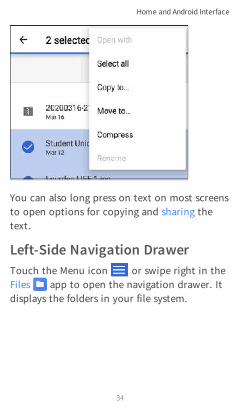
You can also long press on text on most screensto open options for copying and sharing thetext.
Left-Side Navigation DrawerTouch the Menu icon or swipe right in theFiles app to open the navigation drawer. Itdisplays the folders in your file system.
Home and Android Interface
34

Back to Title and Contents
NOTE: In the Files app, you may need to tapthe action overflow icon at the top rightand select Show Internal Storage tonavigate to the LinkRunner-10G folder andsub-folders, as shown above.
See the Navigation Drawer topic for more.
Home and Android Interface
35

Android Status Bar andNotifications
The Status Bar across the top of the screendisplays notification icons from the Androidsystem as well as LinkRunner 10G-specific iconsrelated to your network connections and teststatuses.
See Test and Port Status Notifications fordetails about the icons and notificationsrelated to LinkRunner 10G networkconnections, testing, and management.
Touch and swipe down on the Status Bar toopen the Notification Panel.
Notification PanelThe Notification Panel contains notificationsfrom your device, such as downloads andinstalls, inserted hardware, capturedscreenshots, app and connection statuses, andupdates. The panel also displays commonAndroid settings icons for quick access.
Home and Android Interface
36

Swipe (touch and drag) downwards on theStatus Bar at very top of the screen to slidedown the Notification Panel.
l Touch the title and down arrow on anotification (or swipe down on it) toexpand the box and view more details oroptions.
Home and Android Interface
37
l Touch the middle of a notification to openthe related app, image, or device settings orto perform other related actions.
l Swipe left on a notification to dismiss it.
NOTE: Because they are essential to theLinkRunner testing functions, you cannotdismiss the test and management port-related test and port status notifications.
l Touch CLEAR ALL at the lower right of thepanel to dismiss all Android System noti-fications.
Home and Android Interface
38

Apps Screen and StoreTo access the apps that are not shown on theHome screen, swipe up on the Home screen ortouch the up arrow icon .
Home and Android Interface
39

The Apps screen displays all the apps on yourdevice. The image above is an example. YourApps screen may contain different third-partyapps.
l Tap an app's icon to open the app.
l Hold and drag an icon upwards to add it toyour Home screens.
l Touch and hold (long press) an icon to viewApp Info or access widgets you can add tothe Home screen and other actions you canperform.
App StoreFrom the Home Screen or Apps Screen, openthe NetAlly App Store to download third-party Android applications to use on yourLinkRunner 10G.
NOTE: Your unit must be "claimed" to Link-Live Cloud Service at Link-Live.com toaccess the App Store.
Home and Android Interface
40

Back to Title and Contents
Touchthesearchicon tosearchfor anApp.
To request that an App be added to the AppStore, visit the Apps page at Link-Live.com,and select the floating action button (FAB) at
the lower right corner to Request orUpload an App.
Home and Android Interface
41

Device SettingsTo access the Android system device settings,touch the Settings icon at the bottom ofthe Home screen.
Home and Android Interface
42

Use the device settings screen to adjust thedisplay, sound, and date/time; view installedapplications and memory devices; connect toWi-Fi; or reset to factory defaults.
Quick Settings PanelYou can also access some of the most commondevice settings, like Wi-Fi, from the QuickSettings Panel by swiping down from theStatus Bar at the top of the touchscreen.
Swipe down twice to open the full QuickSettings Panel.
Home and Android Interface
43

l Touch and drag the slider control at the topof the panel to adjust the screen's bright-ness.
l Tap an icon in the panel to enable ordisable the corresponding feature. Forexample, you can turn the unit'sWi-Fior screen Auto-rotate functions on oroff from the quick settings.
Home and Android Interface
44

l Touch and hold an icon to open therelevant device setting screen, if there isone. For example, touch and hold the Wi-Fiicon to open Android's Wi-Fi settings orthe Auto-Rotate icon to open Displaysettings.
l Tap the pencil icon at the bottom of theQuick Settings Panel to configure the iconcontrols that appear in the panel.
Auto Power OffActivating the Auto Power Off function helps toextend the battery run time.
1. From the Device Settings , selectDisplay.
2. On the Display settings screen, touchDevice auto power off.
3. In the pop-up dialog box, select how longyou want the unit to remain On with noactivity occurring. It will automaticallypower off after the selected period ofinactivity has passed.
Home and Android Interface
45

Back to Title and Contents
Similarly, you can adjust the setting thatcontrols when the display goes into Sleepmode from the Display settings screen.
Home and Android Interface
46

Connecting to Wi-FiNOTE: Wi-Fi connectivity requires the use ofa supported external USB adapter:
l Edimax N150
l Edimax AC1200
To connect your LinkRunner to a Wi-Finetwork, access the Android Wi-Fi DeviceSettings using either method below:
l Open the device Wi-Fi settings from themain Device Settings screen by touching theSettings icon and selecting Network &Internet > Wi-Fi.
l Open device Wi-Fi settings from the QuickSettings panel by dragging down the topStatus Bar and touching and holding (longpressing) the Wi-Fi icon.
Home and Android Interface
47

Either path opens the Wi-Fi settings screen.
1. Ensure the Wi-Fi feature is On.
2. Touch an available Wi-Fi network in thelist.
Home and Android Interface
48

3. Enter the network's security credentials.
Most networks only require a password,but depending on the security settings,some may also require a companyusername, EAP type, authentication type,certificate, or other credentials.
4. After entering credentials, touch CONNECT.
The network you selected moves to the top ofthe list, and your connection status is displayedbelow its name in device and quick settings.
Home and Android Interface
49

The Status Bar displays the Wi-Fi status iconat the top right of the screen.
Captive PortalsWhen you try to connect to a network with aCaptive Portal requirement, this Android noti-fication icon appears in the top Status Bar.Drag down from the top of the screen to openthe notification.
Touch the notification to open a web browserwindow where you can enter the requiredinformation for the captive portal. Whenfinished, you should be able to access theinternet through the connected network.
Home and Android Interface
50

Back to Title and Contents
If you are trying to connect to a network with acaptive portal, but the Android notification isnot appearing, check that the Captive PortalDetection setting is enabled in Device Settings
> Network & Internet.
Home and Android Interface
51

SharingLinkRunner 10G allows you to “share” imagesand files like you would on any Android device.When you see the Share icon , touch it toview your configured sharing options.
For example, the image below shows anexpanded Screenshot notification from the topnotification panel.
Touch SHARE to open the “Share with” pop-updialog, where you can choose a sharingmethod, such as email, messaging, or uploadingto Link-Live Cloud Service online.
Home and Android Interface
52

Sharing Files to Link-LiveFrom the “Share with” dialog box (and otherscreens on the LinkRunner), touch the Link-Live option to share (upload) a file to Link-LiveCloud Service at Link-Live.com.
Files can be attached to a test result oruploaded individually to the Uploaded Filespage on Link-Live.
The example below shows the Link-Live sharingscreen for a screenshot image.
Home and Android Interface
53

The SAVE TO LAST TEST RESULT optionattaches the image to your most recently run
Home and Android Interface
54

AutoTest, Performance, iPerf, or Cable Testresult on Link-Live.com.
Sharing from the Files AppFiles from internal or external storage can alsobe shared to Link-Live.com from the AndroidFiles app. For most file types, you can onlyupload one selected file at a time, but multipleimage files can be shared at once.
1. With the Files app opened, navigate to thefolder containing the files you want toshare using the left-side navigation drawer.
2. Long press on a file to select it.
Home and Android Interface
55

3. Touch the share icon in the top toolbar.
4. If needed, touch the Link-Live option.
Home and Android Interface
56

5. Enter any Comments you would likeattached to your file.
6. Select SAVE TO LAST TEST RESULT orSAVE TO UPLOADED FILES.
Home and Android Interface
57

You files are uploaded and viewable on Link-Live.com.
See the Link-Live chapter for more informationon using Link-Live with your LinkRunner 10G.
Saving a ScreenshotOn the LinkRunner 10G unit, press and hold thePower button and the Volume Down button atthe same time for one second to save ascreenshot of the current screen. (See Buttonsand Ports for button locations).
When a screenshot is taken, the unit beeps anddisplays the captured screenshot notification inthe Notification Panel. Open the notification toshare the image using Link-Live, Bluetooth, oranother configured application.
Home and Android Interface
58

LinkRunner 10GSettings and ToolsThe LinkRunner 10G features a common set oftools and General Settings that apply tomultiple NetAlly apps and testing behaviors.This chapter covers settings, icons, andnotifications specific to LinkRunner 10G.
(See the Device Settings topic for informationon the Android system settings.)
Access common settings and informationalscreens for the NetAlly testing apps (likeAutoTest or Capture) by opening the left-sideNavigation Drawers or Settings .
59
LinkRunner 10G User Guide
Back to Title and Contents

Navigation DrawerMany Android apps, including the NetAlly testapps, contain additional settings, tools, andinformation in a "navigation drawer" thatslides out from the left side of the screen.
To open the navigation drawer:
l Touch the menu icon at the top left ofthe testing application screens.
l Touch and drag (swipe) to the right fromthe very left side of the app screens.
General Settings and Tools
60

As an example, the AutoTest navigation drawer(above) provides access to the enabled AutoTestprofiles, AutoTest Settings, General Settings,and the About screen.
Settings for each specific app are described inthe chapter for the app.
General Settings and Tools
61

About ScreenGeneral Settings and Tools
62

The About screen displays the serial number,MAC addresses, software versions, SFP detailsand current AllyCare contract status for yourLinkRunner 10G.
If a User-Defined MAC is enabled in the NetAllyapps' General Settings, (User-defined) appearsnext to the MAC address on the About screen.
Exporting LogsThe About screen contains the Export Logsfunction, which allows you to save your unit'slogs for analysis by NetAlly's technical supportteam.
Touch the EXPORT LOGS link on the Aboutscreen to download a .tgz file to theDownloads folder on your unit. Open the Filesapp to transfer the file using email or anothermethod. (See Managing Files.)
General Settings and Tools
63

Test and ManagementPortsThe LinkRunner 10G has two wired RJ-45copper ports and a fiber port, each withspecific test or management functionsdescribed in this section.
Either the top copper port or fiber port can actas the Wired Test Port, so in total, theLinkRunner has two network interfaces:1 Wired Test, and 2 Wired Management.
Refer to Buttons and Ports and the technicalSpecifications if needed.
General Settings and Tools
64

Configuring the PortsThe NetAlly apps' General Settings controlLinkRunner's use of the test and managementports. The General Settings are accessible fromthe left-side navigation drawer in NetAlly'stesting apps, such as AutoTest, Capture, andiPerf.
The app-specific settings for many of theindividual NetAlly testing apps (like the iPerfSettings above) also let you choose whichports the app uses for its test or analysis.
General Settings and Tools
65

All of the ports are described below next totheir corresponding status icons.
General Settings and Tools
66

Test PortsLinkRunner runs Wired AutoTests, Captures,Discovery, and comprehensive network analysesover the test ports.You must run an AutoTest Wired Profile inorder to establish a link on the Wired testports. If the AutoTest app is not currentlyopen, the last Wired Profile in the profile listruns automatically when you power on theunit or LinkRunner detects a new copper link inthe top Wired Test Port. Wired fiberconnections must be started manually in theAutoTest app.
NOTE: If both the top fiber and copperports are connected to an active network,the LinkRunner uses the fiber link as theWired Test Port connection.
Wired Copper Test Port: The coppertest port is the RJ-45 port on the top of theunit. To disable, unplug the connection.
Wired Fiber Test Port: The SFP andfiber test port is also on the top of the unit.To disable, unplug the connection.
General Settings and Tools
67

Management PortLinkRunner can run Discovery, Ping/TCPConnect tests, Path Analysis, and iPerf tests onthe management port, but not AutoTests,packet captures, or Performance tests.
The Management Port provide a more stablenetwork connection than the Test Ports, as theTest Ports may frequently drop link andreconnect or resume scanning.
Wired Management Port: The wiredmanagement port is the RJ-45 port on theleft side of the unit.
General Settings and Tools
68

Test and Port StatusNotificationsLinkRunner 10G shows notifications from theNetAlly testing apps and unit ports in the topStatus Bar and Notification Panel. Swipe downon the Status Bar to view the notifications.
On each notification, you can touch the titleand down arrow to expand the box and viewmore details or options.
The following LinkRunner icons may appear inyour Status Bar with the meanings described.
NOTE: Read Test and Management Ports fordescriptions of the port functions.
Also, see General Settings for settings thatcontrol port functions.
General Settings and Tools
69

Test Port NotificationsActive network connections on the test portsare established using the AutoTest app.
A Wired Test Port connection, called the"Wired Port" in app settings, is established ineither the top RJ-45 Ethernet port or the topFiber port.
NOTE: If both the fiber and top copperports are connected to an active network,the LinkRunner uses the fiber link as the"Wired Port" for testing.
General Settings and Tools
70

Periodic AutoTest is running or hascompleted. When Periodic AutoTest is running,the Wired Test Port may not be available toother testing apps.
Management Port Notifications
A Management Port connection isestablished through the left-side RJ-45Management port and/or the main Android Wi-Fi adapter.
A Wired Management Port connectionis established through the left-side RJ-45Management port. Its details are displayed
General Settings and Tools
71

under the Management Port notification(above).
If your Management connection is lost, thefollowing notification displays.
Discovery NotificationsThe Discovery notifications show the progressof the discovery process. See the Discovery appchapter for more information.
The active discovery process is running andhas progressed to the specified percentage.
No links are currently available for activediscovery, either because none of the portsenabled for discovery are connected orAutoTest is running. Discovery is temporarilydisabled when AutoTest is running.
VNC/Link-Live Remote
A remote VNC connection is active througha standalone VNC client and/or the Remote
General Settings and Tools
72

Back to Title and Contents
function in Link-Live Cloud Service.
General Settings and Tools
73

LinkRunner 10G GeneralSettingsLinkRunner's General Settings control test andmanagement-related connections that affectmultiple test apps.
Access the General Settings from the left-sidenavigation drawer in the NetAlly testingapps, such as AutoTest, Discovery, Capture,iPerf, etc.
See also Test and Management Ports and Testand Port Status Notifications for relatedinformation on port functionality and statusicons.
General Settings and Tools
74

WiredWired General Settings control functions of theWired Test Port.
Test PoE before Link: By default, an AutoTestWired Profile performs the Link test before thePoE test may be able to complete. Enable thissetting to make your LinkRunner complete thePoE test before the Link test. Enabling thissetting forces PoE negotiation to be completedbefore establishing link, improving com-patibility with some switches.
Receive Only: Enabling this setting prevents theLinkRunner from transmitting packets on theWired Test Port. You can also use the Stop After
General Settings and Tools
75

function in Wired AutoTest Profile Settings tohide the AutoTest cards that require transmitcapability. Set the AutoTest Stop After settingto Switch. Otherwise, when Receive Only isenabled, the Wired DHCP/Static IP test shows aResult Code of "Interface is configured to onlyreceive packets," and the subsequent tests donot run.
User-Defined MAC: This setting affects the WiredTest Port only. Tap the toggle switch to enablea user-defined MAC address. When enabled, anadditional User-Defined MAC field appearsunder the toggle setting. Touch the lower fieldto enter your desired MAC address for theLinkRunner. When a User-Defined MAC isenabled, (User-defined) appears next to theMAC address on the About screen and onrelevant test result screens.
ManagementThese settings affect management-relatedfunctions on the LinkRunner, including remoteaccess.
General Settings and Tools
76

VNCTouch VNC to open the VNC settings screen andconfigure your unit's VNC connections forremote operation.
See Remote Access for more information aboutconnecting to a VNC client or Link-Live Remote.
General Settings and Tools
77
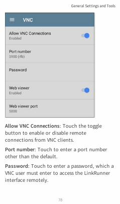
Allow VNC Connections: Touch the togglebutton to enable or disable remoteconnections from VNC clients.
Port number: Touch to enter a port numberother than the default.
Password: Touch to enter a password, which aVNC user must enter to access the LinkRunnerinterface remotely.
General Settings and Tools
78

NOTE: If you set a Password here in theVNC settings, the password is required toconnect to both a standalone VNC clientand the Remote feature at Link-Live.com.
Web viewer: Touch the toggle to enable ordisable web viewer access.
Web viewer port: Touch to enter a portnumber other than the default.
Link-Live RemoteThis setting enables or disables the LinkRun-ner's remote control function in Link-LiveCloud Service at Link-Live.com.
NOTE: The Link-Live Remote feature is onlyavailable to customers with an activeAllyCare subscription. See NetAlly.-com/Support for more information.
Access the Remote function on the Unitspage at Link-Live.com by selecting the claimedLinkRunner 10G.
EthernetDHCP: This setting controls IP addressassignment of the RJ-45 Wired Management
General Settings and Tools
79

Back to Title and Contents
Port on the left side of the LinkRunner. Bydefault, DHCP is enabled. Touch this field andtap the toggle button to disable DHCP andenter static IP information.
Preferences
Distance Unit: This is the unit LinkRunner usesfor distance measurements in the testing apps,specifically Cable Test. Touch the field toswitch between Feet and Meters.
General Settings and Tools
80

Trending GraphsMany of the LinkRunner 10G testing appsfeature time-based line graphs of recorded meas-urements, which you can pan and zoom toview different time intervals. For example, theimage below shows the Response Time graphfrom the Ping Test Results Screen.
These graphs update in real time and save anddisplay data for up to 24 hours (depending ontest type and/or link status).
General Settings and Tools
81

Under each graph, a legend table indicates themeasurements that correspond to each plottedcolor.
For another example, the image below showsthe Capture app graph.
l To pan, or move backward and forward intime, touch and drag (swipe) left and right
General Settings and Tools
82

on each graph.
l To zoom in on a specific point in time,double tap the point on the graph. Theview zooms in 2x (or displays half theamount of time) for each double tap.
l To zoom in or out, decreasing or increasingthe time interval displayed, drag the slideror tap the slider bar below the graphs.
⸰ The largest time interval (maximumzoom out) is the total time data hasaccumulated.
l To reset the graph to the default timeinterval, tap the zoom reset icon .
⸰ The zoom reset icon appears once youhave zoomed or panned on the graph.
⸰ The default time interval varies acrossdifferent apps.
The following apps and screens containtrending graphs:
l Ping/TCP – Ping Testl Capturel Discovery – Interface Statisticsl Performance
General Settings and Tools
83

l iPerf
General Settings and Tools
84

Common IconsThe icons below appear in multiple NetAlly testand Android apps.
Menu Icon - opens the left navigationdrawer or other menus
Refresh Icon - restarts testing andmeasuring on the current screen
Settings Icon - opens configurationoptions for the current app
Save Icon - saves settings or files orloads saved configurations
Floating Action Button (FAB) - opensthe Floating Action Menu, whichcontains additional actions
Action Overflow Icon - contains addi-tional actions
Directional Arrows (or Carets) -indicate the ability to "drill in," open ascreen, or expand a panel for moredetailed information, or to change theorder of a list
General Settings and Tools
85

For explanations of the LinkRunner icons thatappear in the Status Bar at the top of thescreen, see Test and Port Status Notifications.
Floating Action Button(FAB) and MenuMany Android applications, including NetAlly'sAutoTest and Discovery apps, feature a FloatingAction Button or "FAB" that opens afloating action menu with more options foranalysis.
The FAB on the main AutoTest app screenallows you to add new testing Profiles.
The FAB on the Discovery app's Detailsscreen opens other apps for furthertesting of the selected device.
General Settings and Tools
86

Floating action menus that appear in thetesting applications are described more spe-cifically in the relevant chapters. For example,see Discovery App Floating Action Menu in the
General Settings and Tools
87

Discovery app chapter for a more detailed illus-tration.
General Settings and Tools
88

Common ToolsWeb Browser/ChromeSome of the testing apps, like AutoTest,Ping/TCP, and Discovery, give you the optionto Browse to internet addresses using a webbrowser application. LinkRunner has GoogleChrome pre-installed.
Telnet/SSHStarting with v1.1, LinkRunner has theJuiceSSH application pre-installed. Boththe AutoTest and Discovery apps provideoptions to start a Telnet or SSH session usingthe current device address. Selecting theseoptions opens JuiceSSH and starts a session.You can also open JuiceSSH from the Appsscreen.
The JuiceSSH app maintains a list of previousconnections. When opened from a NetAlly app,JuiceSSH uses the first connection in the listthat matches the IPv4 address or device nameand type. If no match is found, a newconnection entry is created and used.
General Settings and Tools
89

As a third-party app, JuiceSSH contains its owntutorials. For additional help, touch the actionoverflow button at the top right of theJuiceSSH app screen, and select View our FAQ.
General Settings and Tools
90

Camera and FlashlightThe camera lens and flash are located on theback of the unit. (See Buttons and Ports.)
The Camera application is located in theApps screen and on the Home screen bydefault. Tap the icon to open the camera appand take a photo, which you can then share toother applications.
Additionally, once a Wired AutoTest Profile hascompleted, the floating action button appearsand provides the option of opening the cameraapplication to take and attach a picture to theAutoTest result uploaded to Link-Live CloudService.
General Settings and Tools
91
Back to Title and Contents
The Flashlight feature can be accessed from theQuick Settings Panel by swiping down twicefrom the top of the screen.
General Settings and Tools
92

Software ManagementThis chapter explains how to save and transferfiles, reset app and device defaults, update yoursoftware, and remotely access your LinkRunner10G.
Tap a link below to skip to your desired topic:
Managing Files
Updating Software
Remote Access
Resetting App Defaults
Restoring Factory Defaults
93
LinkRunner 10G User Guide
Back to Title and Contents

Managing FilesIn LinkRunner 10G's Android operating system,images, documents, and other files reside in afolder system, where you can copy, move, andpaste them between folders or to externalstorage locations.
See also Navigating LinkRunner 10G.
Files ApplicationThe Files app allows you to access the filessaved on your LinkRunner. Touch the iconat the bottom of the Home Screen (or from theApps screen) to manage your files.
NOTE: In the Files app, you may need to tapthe action overflow icon at the top rightand select Show Internal Storage tonavigate to the LinkRunner-10G folder andsub-folders, as shown below.
Software Management
94

l Tap a folder or file to open it.
l Long press on folders or files to selectmultiple and to view additional file man-agement operations in the top toolbar,including the Share and Delete buttons.
l Tap the action overflow icon to see evenmore actions, such as to create a newfolder, move a file, delete an item, and to
Software Management
95

show or hide the main internal storagefolder.
l Open the left-side navigation drawer toeasily navigate through the top-level foldersand attached storage devices.
Software Management
96

How to Move or Copy a File1. Long press on a file to select it. You can
then select more files as needed by tappingthem.
Software Management
97

2. Touch the overflow icon at the topright.
3. Select Copy to... or Move to.... Yourselected action button appears at thebottom of the screen.
4. Navigate to the folder where you want tomove or copy the file.
5. Touch the Move or Copy button at thebottom of the screen.
Using a Micro SD CardTo use a Micro SD card for storage, insert itinto the Micro SD card slot on the left side ofyour LinkRunner 10G. See Inserting a Micro SDcard.
A Micro SD card icon appears in the StatusBar at the top of the screen. Pull down the topNotification Panel to reveal the SD card noti-fication.
Software Management
98
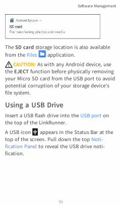
The SD card storage location is also availablefrom the Files application.
WCAUTION: As with any Android device, usethe EJECT function before physically removingyour Micro SD card from the USB port to avoidpotential corruption of your storage device'sfile system.
Using a USB DriveInsert a USB flash drive into the USB port onthe top of the LinkRunner.
A USB icon appears in the Status Bar at thetop of the screen. Pull down the top Noti-fication Panel to reveal the USB drive noti-fication.
Software Management
99

The USB storage location is now available fromthe Files application.
WCAUTION: As with any Android device, usethe EJECT function before physically removingyour USB drive from the USB port to avoidpotential corruption of your storage device'sfile system.
Ejecting Storage MediaYou can eject storage media from the expandedAndroid notification (as shown above) in theNotification Panel or from the left-sidenavigation drawer in the Files app (below).
Software Management
100

Using a USB Type-C to USB Cable1. Plug a USB-C cable into the USB-C port on
the left side of the LinkRunner, andconnect to a PC or tablet.
2. On the LinkRunner Unit, open the Androiddevice settings by tapping the Settingsicon at the bottom of the Home screen.
3. Select Connected devices.
4. On the Connected devices screen, selectUSB.
5. In the pop-up dialog, touch Transfer filesto enable file transfer.
Software Management
101

Back to Title and Contents
NOTE: LinkRunner does not charge througha USB cable connected to a PC.
6. On your PC or tablet, navigate to theLinkRunner 10G folder if it does not pop upautomatically. From there, you can move,copy, and paste files to and from theLinkRunner 10G's file system.
WCAUTION: As with any Android device, usethe EJECT function before physically dis-connecting the USB cable from your PC orLinkRunner to avoid potential corruption ofyour storage device's file system. See EjectingStorage Media above.
Software Management
102

Updating SoftwareYour LinkRunner 10G accesses software updatesfrom the Link-Live Cloud Service "Over-the-Air"(OTA). However, you can also manuallydownload and install updates if you do notwant to claim your unit to Link-Live. SeeManual Updates below.
Over-the-Air UpdatesYou must create an account and "claim" yourLinkRunner 10G unit at Link-Live.com for theLinkRunner to find and download softwareupdates. See Getting Started in Link-Live.
The first time you claim your LinkRunner 10Gto Link-Live, a software update may beavailable. If so, an update icon appears inthe Status Bar. Slide down the Top NotificationPanel, and select the notification to updateyour unit.
Software Management
103

1. To check for available software updates atany time, open the Link-Live App fromthe Home screen.
2. In the Link-Live App, touch the menu iconor swipe right to open the left-side Nav-
igation Drawer.
3. Touch Software Update.The Software Update screen opens anddisplays the version number of anyavailable updates. You can touch the blue-linked Release Notes to read descriptions ofthe updated features in the new version.
Software Management
104

4. If both an Android and an ApplicationUpdate are available, install the Androidupdate first.
5. Touch Download + Install to update theAndroid operating system or the NetAllyApplications. Each update must beinstalled separately.
The files download and install. When finished,the unit will restart.
Software Management
105
After updating Android, check the SoftwareUpdate screen again in case an ApplicationUpdate is still required.
Manual UpdatesYou can acquire the update files from Link-Live.com or by contacting NetAlly's TechnicalSupport at NetAlly.com/Support.
To download the software update files from theLink-Live.com website, open the left-sidenavigation drawer by clicking the menu icon
, and select Support > SoftwareDownloads.
1. Download the update files for the Androidsystem (lr10g-ota-user.zip) and Applic-ations (.apk) to a PC or your LinkRunnerunit.
2. If you are updating both the Android OSand Applications, install the Androidupdate first.
Updating the Android OSReference Buttons and Ports if needed.
Software Management
106

1. Copy the .zip file to a Micro SD cardinserted into your LinkRunner.
2. Power off your LinkRunner unit.
3. Press and hold the volume up button andpress the power button to start up theLinkRunner in Recovery Mode. Continueholding the volume up button until theRecovery screen appears.
4. In Recovery Mode, use the volume buttonsto highlight “apply update from SD card,”and press the power button to confirm theselection.
5. Use the volume buttons to highlight thecorrect update file on the Micro SD card,and press the power button to confirm.
The LinkRunner will open the Updater, installthe Android update, and then restart with theupdate installed.
After updating Android, be sure to check theavailable Applications update version todetermine if an Applications update is stillrequired.
Software Management
107

Back to Title and Contents
Updating the Applications1. Copy the .apk file to a USB flash drive or a
Micro SD card inserted into yourLinkRunner.
2. In the Link-Live App , open the left-sidenavigation drawer, and select SoftwareUpdate.
3. On the Software Update screen, touch theaction overflow icon at the top right,and select Manual Update.
4. Navigate to the USB drive or Micro SD cardwhere you saved the update file.
5. Tap the update file to select it.
The LinkRunner will open the Updater, installthe .apk files for the NetAlly apps, and thenrestart with the updates installed.
Software Management
108

Remote AccessLinkRunner supports remote access and controlusing either a standalone VNC client or theLink-Live Remote feature, which utilizes a VNCclient through the Link-Live website.
NOTE: The Link-Live Remote feature is onlyavailable to customers with an activeAllyCare subscription. See NetAlly.-com/Support for more information.
While you can establish remote connectionsusing the Wired Test Port on the LinkRunner,the Management Port provide more stablelinks for remote control; the test ports maydisconnect and reconnect frequently.
See Test and Management Ports.
The top notifications are the quickest way tofind assigned IP addresses for your LinkRunnerports. Swipe down from the Status Bar to viewthem.
Software Management
109
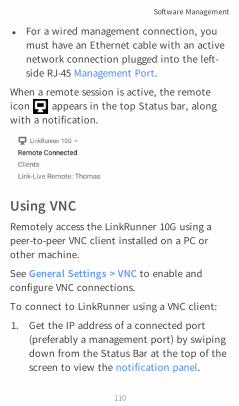
l For a wired management connection, youmust have an Ethernet cable with an activenetwork connection plugged into the left-side RJ-45 Management Port.
When a remote session is active, the remoteicon appears in the top Status bar, alongwith a notification.
Using VNCRemotely access the LinkRunner 10G using apeer-to-peer VNC client installed on a PC orother machine.
See General Settings > VNC to enable andconfigure VNC connections.
To connect to LinkRunner using a VNC client:
1. Get the IP address of a connected port(preferably a management port) by swipingdown from the Status Bar at the top of thescreen to view the notification panel.
Software Management
110

2. Provide the Test or Management Port's IPaddress to your chosen VNC client applic-ation.
3. Connect using your VNC client.
4. If needed, enter the password that is set inthe VNC settings.
Using Link-Live RemoteThe Link-Live Remote feature uses end-to-endencryption, allowing secure remote control ofyour LinkRunner.
On your LinkRunner, go to General Settings >Link-Live Remote to ensure the feature isenabled.
NOTE: If a Password is enabled in the VNCGeneral Settings, you must also enter thesame password to access the Remote featurein Link-Live.
1. If you have AllyCare, sign in to Link-Live.com to access the Link-Live Remotefeature. Your LinkRunner must be claimed.
Software Management
111

Back to Title and Contents
2. Navigate to the Units page at Link-Live.com.
3. Select the LinkRunner you want to remotecontrol from the list of claimed units.
4. Click or touch the REMOTE icon at thetop right of the page to open an embeddedwindow containing the LinkRunnerinterface.
5. If necessary, at the top of the window,enter the Password set in General Settings> Management > VNC on the LinkRunnerunit.
To use the Link-Live website while your remotesession is active, you will need to open a newLink-Live tab or window.
Software Management
112

Managing NetAlly AppSettingsThis chapter explains the processes forresetting, loading, saving, importing, andexporting the test settings for individualNetAlly testing apps, such as AutoTest,Discovery, and Performance.
For instructions on restoring factory defaults tothe entire EtherScope unit, see RestoringLinkRunner 10G Factory Defaults.
Resetting Testing App DefaultsOnce you have adjusted settings in the NetAllyapps, at some point, you may need to reset anapp's settings to the defaults. The followingprocess resets all app-specific settings to thefactory defaults.
WCAUTION: This operation will delete allsaved settings, including testing profiles andother application data.
The Discovery app is used as an example in thefollowing steps:
Software Management
113

1. Access the App Info screen by long pressing(touch and hold) on a app's icon on theHome or Apps screen.
2. Touch App info.
Software Management
114

3. On the App info screen, select Storage.(You can also access the App Storage screenfrom Device Settings > Storage >Internal shared storage > Other apps.)
4. On the Storage screen for the app youselected, touch CLEAR DATA.
Software Management
115

5. When the "Delete app data?" dialogappears, tap OK.
All of the app's settings are reset to factorydefaults.
Software Management
116

Saving App SettingsConfigurationsMany of the NetAlly testing applications allowyou to save and load a configuration of settingsby selecting the save button that appears atthe top right within the app's main screen.
The following apps enable you to save and loadsettings configurations:
l AutoTest Settings, including Profile Groupsl Discovery Settingsl Discovery > Problem Settingsl Performance Settingsl iPerf Settings
The iPerf app is shown below as an example.
Software Management
117

The following options display in a drop-downmenu:
l Load: Open a previously saved and namedsettings configuration.
Software Management
118

l Save As: Save the current settings with anexisting name, or enter a new custom name.
l Import: Import a previously exportedsettings file.
l Export: Create an export file of the currentsettings, and save it to internal orconnected external storage.
See Exporting and Importing App Settings(below) for more details.
Software Management
119

Saving a Default Test App ConfigurationIf you find you are frequently resetting appdefaults, you can save the default con-figuration of settings for later use within theNetAlly testing apps. Loading a saved defaultconfiguration within an app allows you toaccess the default settings without deletingother configurations. This strategy can be mostuseful for Discovery Settings and ProblemSettings.
1. Go to an app's settings screen.
2. With all settings set to the defaults, tap thesave button and Save As.
3. Save a default configuration with anobvious name like "Default Profiles" or"Discovery Defaults."
4. Do not change the settings in your defaultconfiguration to non-defaults without alsosaving a new, custom-named configuration.
Exporting and Importing SettingsLinkRunner 10G provides functionality forexporting and importing saved test app settings
Software Management
120

for transfer to additional units.
The following apps enable you to import andexport settings configurations:
l AutoTest Settings, including Profile Groupsl Discovery Settingsl Discovery > Problem Settingsl Performance Settingsl iPerf Settings
The AutoTest Settings are shown as an examplein the images below.
l Touch the save button to import newapp settings or export the currently activeand selected app settings.
Software Management
121
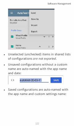
l Unselected (unchecked) items in shared listsof configurations are not exported.
l Unsaved configurations without a customname are auto-named with the app nameand date:
l Saved configurations are auto-named withthe app name and custom settings name:
Software Management
122

l You can rename the export file as needed.
l Settings can be saved to any connectedexternal or internal storage. See ManagingFiles for instructions on accessing foldersand moving files.
l Settings are saved with the .o file extension.
Software Management
123

Back to Title and Contents
l Selecting Import from an app opens theFiles app, where you can navigate to andselect the .o file you want to import.
l Imported settings configurations willoverwrite existing saved configurations withthe same name that are already in the app.
Software Management
124
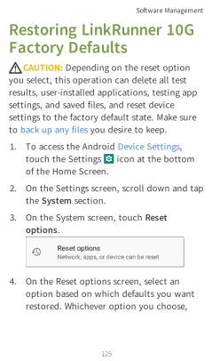
Restoring LinkRunner 10GFactory DefaultsWCAUTION: Depending on the reset optionyou select, this operation can delete all testresults, user-installed applications, testing appsettings, and saved files, and reset devicesettings to the factory default state. Make sureto back up any files you desire to keep.
1. To access the Android Device Settings,touch the Settings icon at the bottomof the Home Screen.
2. On the Settings screen, scroll down and tapthe System section.
3. On the System screen, touch Resetoptions.
4. On the Reset options screen, select anoption based on which defaults you wantrestored. Whichever option you choose,
Software Management
125

LinkRunner displays a list of the items thatwill be reset based on the option.
5. Touch RESET to initiate your chosen resettype.
6. The unit may ask you to confirm a finaltime before resetting. Touch the final con-firmation button to reset your LinkRun-ner's defaults.
The device restarts with factory defaultsettings.
Software Management
126

Changing the LanguageNOTE: The LinkRunner 10G supports Japanesebeginning with version 1.1.
1. To change the interface language, go toDevice Settings by touching the Settingsicon at the bottom of the Home screen.
2. On the Settings screen, scroll down andselect the System section, and then,Languages & input.
3. On the Languages & input screen, touchLanguages.
4. On the Language preferences screen, select+ Add a language.
5. Touch to select the name of your desiredlanguage option.
6. On the Language preferences screen, touchthe icon to the right of the language, anddrag your desired language option to the
Software Management
127

top (1) spot on the list.
The LinkRunner displays the chosen languages,as available, in the priority order shown on theLanguage preferences screen.
Software Management
128

LinkRunner 10G TestingApplicationsThis section of the User Guide describes theNetAlly-developed network testing apps. Eachapp is specially designed for fast analysis andintuitive operation to enhance and simplifyyour network tasks.
Open the testing apps by selecting their iconsfrom the Home screen or the Apps screen.

AutoTest App andProfiles
AutoTest is the most comprehensive NetAllytesting application on LinkRunner 10G. Itallows you to quickly run a variety of test typesand save their configurations and networkcredentials for access whenever you need them.The app is fully customizable with test"Profiles" for Wired network connections, andindividual Test Targets.
AutoTest establishes the Wired Test Portconnection used by other testing apps, likePing/TCP, Capture, and Performance.
AutoTest results are automatically uploaded toLink-Live Cloud Service once you haveclaimed your LinkRunner.
130
LinkRunner 10G User Guide
Back to Title and Contents
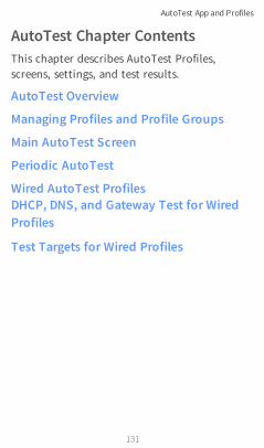
AutoTest Chapter ContentsThis chapter describes AutoTest Profiles,screens, settings, and test results.
AutoTest Overview
Managing Profiles and Profile Groups
Main AutoTest Screen
Periodic AutoTest
Wired AutoTest ProfilesDHCP, DNS, and Gateway Test for WiredProfiles
Test Targets for Wired Profiles
AutoTest App and Profiles
131

AutoTest OverviewAutoTest consists of three distinct testinglevels: Test Targets, Profiles, and ProfileGroups.
At the bottom level is a set of individual TestTargets that connect to network services, suchas a web app or FTP site. A Test Target definesparameters including type, target URL/IPaddress, port number, and Pass/Fail thresholds.More complex tests, like HTTP, allow furtherPass/Fail criteria, such as strings that must ormust not be contained in the HTTP body.
AutoTest App and Profiles
132

A Test Target can be added to and used in anynumber of Profiles.
A Profile contains a series of individual networktests. There is one Profile type: Wired whichincludes connection tests and credentials for aWired VLAN. Profiles provide an automated andconsistent way to verify a network from layer 1through layer 7.
A Profile can be added to and used in anynumber of Profile Groups.
A Profile Group is a custom-named collectionof Profiles. Profile Groups are designed to allowfurther automation for testing multiplenetworks or network elements with a single tapof the START button.
Here are some examples of useful ProfileGrouping schemes:
l Testing multiple Wired VLANs on a trunkport.
l Testing wired access from a conferenceroom.
AutoTest App and Profiles
133

Back to Title and Contents
You can create as many Profile Groups, Profiles,and Test Targets as you want.
AutoTest App and Profiles
134

Managing Profiles andProfile GroupsProfiles are a series, or suite, of tests designedto analyze the different characteristics of yournetworks. The LinkRunner 10G AutoTest appfeatures one type of test profile:
Wired Profiles test copper and fiberconnections.
Factory Default ProfilesThe LinkRunner begins with a default version ofthe Wired AutoTest profile type which you cancustomize, delete, or replace for your purposes.
AutoTest App and Profiles
135

To customize each Profile with the requirednetwork settings and a custom name, touch theProfile name first, and then select the settings
icon.
NOTE: Touching the settings icon on themain AutoTest screen (shown above) opensthe AutoTest Settings and Profile Groupscreen, not the individual Profile settings.
l The default Wired Profile runs automaticallyand establishes a wired link as soon as yourunit is powered on and an active Ethernetconnection is available on the top RJ-45port.
NOTE: The default Wired Profile does notrun automatically over a fiber link. Youmust touch START in AutoTest to run aWired Profile on a fiber connection.
Adding New ProfilesTo add new test profiles to the currentAutoTest, tap the floating action button (FAB)on the AutoTest screen.
The profile's configuration screen appears afteryou select the type of profile you want to add.
AutoTest App and Profiles
136

See the topic for each profile type for adescription of its settings.
Once you have configured the profile's settings,tap the back button at the bottom of thescreen to open and run the new test profile.
AutoTest App and Profiles
137

Profile GroupsLinkRunner 10G also allows you to save ProfileGroups. Profile Groups are simply the includedlist of test Profiles and the order in which theyrun when you start an AutoTest. (See AutoTestOverview for more explanation of ProfileGroups.) You can configure and select Profilesand Profile Groups for different locations, jobs,networks, or other purposes.
To manage your Profiles and Profile Groups,touch the Settings button on the mainAutoTest screen (with the list of Profiles).
AutoTest App and Profiles
138

AutoTest Settings ScreenThe AutoTest Settings screen contains thePeriodic AutoTest and Profile Group settings.
You can perform these actions on the AutoTestSettings screen:
l Check or uncheck the boxes to include orexclude a test Profile from the currently
AutoTest App and Profiles
139

active Profile Group.
l Tap the up and down arrows toreorder the test Profiles on this and themain AutoTest screen for the Profile Group.
l Touch the action overflow icon toDuplicate or Delete a Profile.CAUTION: When you delete a Profile, it isdeleted from all Profile Groups. To removea Profile from the current group, simplyuncheck it.
l Touch any Profile's name to open the testand connection settings for the Profile.
l Touch the save icon to perform thefollowing actions:
o Load: Open a previously saved settingsconfiguration, which includes the ProfileGroup.
o Save As: Save the current settings andProfile Group with an existing name or anew custom name.
See also Saving App Settings Con-figurations.
AutoTest App and Profiles
140

o Import: Import a previously exportedsettings file.
o Export: Create an export file of thecurrent settings, and save it to internalor connected external storage.
See Exporting and Importing AppSettings for more details.
Each Profile Group can run one or many of thethree Profiles types. Your saved Profiles areavailable across all of your Profile Groups.
Custom AutoTest Settings/Profile GroupNamesBy default, the AutoTest app screen shows"AutoTest" in the header, and the AutoTestSettings screen header is "AutoTest Settings."Once you save a custom name, the namedisplays in the AutoTest app header and in theAutoTest Settings screen header.
In the example below, the user saves a customAutoTest configuration named "SpringsCampus."
AutoTest App and Profiles
141

The main AutoTest app screen now displays thecustom name in the header.
AutoTest App and Profiles
142
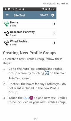
Creating New Profile GroupsTo create a new Profile Group, follow thesesteps:
1. Go to the AutoTest Settings and ProfileGroup screen by touching on the main
AutoTest screen.
2. Uncheck the boxes for any Profiles you donot want included in the new ProfileGroup.
3. Touch the FAB to add new test Profilesto be included in your new Profile Group.
AutoTest App and Profiles
143

4. Tap the up and down arrows tochange the order in which the test Profileswill run. Unchecked profiles will auto-matically move to the bottom of the listonce you leave and revisit this screen.
5. Tap , and select Save As. A dialog boxopens, where you can enter the new name.
6. Enter a new Profile Group name, and touchSAVE. The LinkRunner returns to theProfile Group screen with the new groupname shown as the title.
AutoTest App and Profiles
144

Back to Title and Contents
AutoTest App and Profiles
145
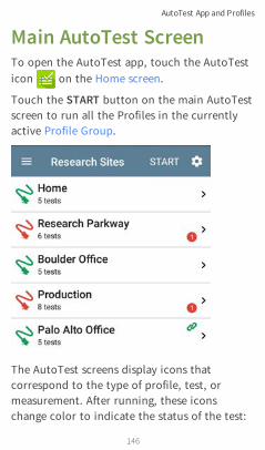
Main AutoTest ScreenTo open the AutoTest app, touch the AutoTesticon on the Home screen.
Touch the START button on the main AutoTestscreen to run all the Profiles in the currentlyactive Profile Group.
The AutoTest screens display icons thatcorrespond to the type of profile, test, ormeasurement. After running, these iconschange color to indicate the status of the test:
AutoTest App and Profiles
146

Back to Title and Contents
l Green indicates a successful test or meas-urement within the set threshold.
l Yellow indicates a Warning condition.
l Red indicates test Failure.
The number of warnings or failures within eachtest profile is also displayed in a colored circleto the right of each profile card: (2Warnings, 1 Failure). The thresholds thatcontrol the colored test gradings are adjustablein the settings screens for each profile andtest type.
The green link icon indicates an activenetwork connection.
Each profile and test is summarized on a card.Touch a profile's or individual test's card toopen and view test result details, including thecauses of any Warnings or Failures.
AutoTest App and Profiles
147

Periodic AutoTestThe Periodic AutoTest feature allows you torepeatedly run AutoTests for a specifiedamount of time.
Periodic AutoTest SettingsTo enable and configure Periodic AutoTest,open the AutoTest Settings and Profile Groupscreen, and tap Periodic AutoTest.
The Periodic AutoTest settings screen displays.
AutoTest App and Profiles
148

Tap the Periodic AutoTest field to enable, andadjust the settings below as needed.
Interval: Amount of time between eachAutoTest run
Duration: Total length of time PeriodicAutoTests run
AutoTest App and Profiles
149

Add Comment: Enabling this setting allows youto attach a comment to the Periodic AutoTestresult in Link-Live Cloud Service. The commentwill appear as a label on the Link-Live.comResults page. This setting and the Commentsetting below are enabled by default.
Comment: This field appears if the AddComment setting is enabled. Enter the labelyou want to be attached to the uploadedPeriodic AutoTest result on Link-Live. Thedefault is "Periodic AutoTest."
Append Date & Time: This field appears if theAdd Comment setting is enabled and adds anumeric date and time to the end of theComment above.
Running Periodic AutoTestTouch START on the main AutoTest screen tobegin Periodic AutoTests. AutoTests willcontinue to run at the set Interval for theselected Duration or until you touch STOP inAutoTest.
AutoTest App and Profiles
150

The Periodic AutoTest Status is summarized atthe bottom of the AutoTest screens. Passes and
AutoTest App and Profiles
151
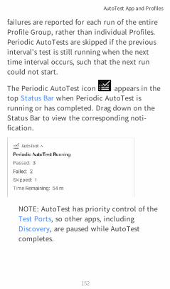
failures are reported for each run of the entireProfile Group, rather than individual Profiles.Periodic AutoTests are skipped if the previousinterval's test is still running when the nexttime interval occurs, such that the next runcould not start.
The Periodic AutoTest icon appears in thetop Status Bar when Periodic AutoTest isrunning or has completed. Drag down on theStatus Bar to view the corresponding noti-fication.
NOTE: AutoTest has priority control of theTest Ports, so other apps, includingDiscovery, are paused while AutoTestcompletes.
AutoTest App and Profiles
152

Wired AutoTest ProfilesA Wired Profile runs a series of tests over yourcopper or fiber network connection.
AutoTest App and Profiles
153
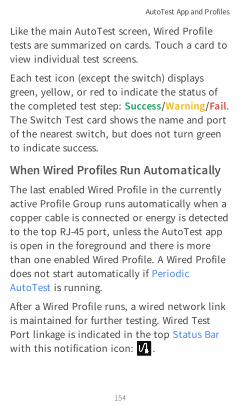
Like the main AutoTest screen, Wired Profiletests are summarized on cards. Touch a card toview individual test screens.
Each test icon (except the switch) displaysgreen, yellow, or red to indicate the status ofthe completed test step: Success/Warning/Fail.The Switch Test card shows the name and portof the nearest switch, but does not turn greento indicate success.
When Wired Profiles Run AutomaticallyThe last enabled Wired Profile in the currentlyactive Profile Group runs automatically when acopper cable is connected or energy is detectedto the top RJ-45 port, unless the AutoTest appis open in the foreground and there is morethan one enabled Wired Profile. A Wired Profiledoes not start automatically if PeriodicAutoTest is running.
After a Wired Profile runs, a wired network linkis maintained for further testing. Wired TestPort linkage is indicated in the top Status Barwith this notification icon: .
AutoTest App and Profiles
154

Wired-Profile-Specific TestsThe tests that are specific to a Wired Profileinclude the following:
l PoE
l Wired Link
l 802.1X
l VLAN
l Switch
AutoTest App and Profiles
155

The 802.1X card only appears if the 802.1Xsetting is enabled for the Wired Profile.
The VLAN test card appears if the VLAN settingis enabled or if VLAN-tagged traffic is detectedduring the AutoTest.
PoE, Wired Link, 802.1X, VLAN, and SwitchResults are described next.
AutoTest App and Profiles
156

Back to Title and Contents
l Skip to Wired Profile Settings.
l Skip to DHCP, DNS, and Gateway Tests.
l Skip to Test Targets.
AutoTest App and Profiles
157

Wired Profile ResultsThe image below shows a completed AutoTestWired Profile.
AutoTest App and Profiles
158

On the Wired Profile screens, you can performthese actions:
l Touch any of the test result cards, likePoE, Link, or Switch to open the
individual test result screens.
l From any individual test screen, tap thesettings icon to go directly to thesettings for the current test.
l On the individual test screens, touch blueunderlined links to open a Discovery appDetails screen showing the selected deviceor ID.
NOTE: You may need to Configure SNMPsettings in the Discovery app to see all theavailable information about a networkcomponent, such as name and portinformation.
l Touch other BLUE LINKS or the blue actionoverflow icon at the bottom of the testresults screens for additional actions.
NOTE: Blue links and action icons do notappear on every test results screen, and ifthe active connection is dropped, you may
AutoTest App and Profiles
159

need to rerun the Profile to re-establish linkand enable additional actions.
PoE Test Results
The card for the Power over Ethernet (PoE) testdisplays the measured Voltage, Class, andWattage.
Refer to PoE Settings if needed.
Touch the card to open the PoE results screen.
AutoTest App and Profiles
160

PoE Test Results Screen
In addition to the information from the PoEcard, the PoE test screen shows these results:
ClassRequested Class: Class selected in the PoEtest settings
AutoTest App and Profiles
161

Received Class: Class acknowledgmentreceived from the switch
TruePower™ Power: Measured wattage withload.
NOTE: The PoE card displays additionalTruePower™ results only if TruePower isenabled in the Wired Profile PoE Settings.
VoltageUnloaded: Measured voltage without load
TruePower™ Voltage: Measured voltagewith load
Positive: Positive PoE cable pair IDs
Negative: Negative PoE cable pair IDs
PSE Type: Switch's advertised PowerSourcing Equipment (PSE) type. Recognizedtypes are 1 – 4, LTPoE++, Cisco UPOE, andPoE Injectors. PSE supporting UPOE are clas-sified under Type 2. If the type cannot bedetermined, "1/2" is displayed.
Negotiation: Negotiation status for UPOEand Class 4 (UPOE or LLDP)
AutoTest App and Profiles
162

Result Codes: Final status of the test (Successor Failure)
Wired Link Test ResultsThe Wired Link card indicates whether you canconnect to an active network switch.
The Link test card for a copper Ethernetconnection displays the advertised speed andduplex capabilities in gray text and thedetected speed and duplex in black text.
LinkRunner can test and display information forlink speeds up to 10G.
For a Fiber connection, the Link test cardshows the connection speed and duplex.
The link icon turns yellow (displays aWarning) under the following conditions:
AutoTest App and Profiles
163

l LinkRunner has linked at a speed slowerthan the maximum advertised speed.
l The link is using half duplex.
l For links faster than 1G, LinkRunner hasdetected a minimum SNR value below theset threshold.
Touch the card to open the Link test screen.
AutoTest App and Profiles
164

Wired Link Test Screen
The Wired Link test screen shows the following:
AutoTest App and Profiles
165

SpeedAdvertised Speed: Speed capability asreported by the switch
Actual Speed: Link speed as measured byLinkRunner 10G
DuplexAdvertised Duplex: Duplex capabilitiesreported by the switch
Actual Duplex: Duplex in use as detected byLinkRunner
RJ-45 Details (Copper)Rx Pair: Link receive pair
Multi-Gigabit Details (Copper)
This table appears only when the Wired Profileis linked at speeds higher than 1G. Each twistedpair channel is graded based on the minimumSNR observed. Data in the table updates eachsecond as long as the link persists.
Channel: Channels A, B, C, and D rep-resenting the twisted pairs in the cable
AutoTest App and Profiles
166

Delay Skew: Difference in propagation delaybetween sets of wired pairs. Channel A actsas the reference for the other channel meas-urements.
SNR: Current signal-to-noise ratio on eachchannel
Min SNR: Lowest SNR measurement sincelink was established
Threshold: Multi-Gigabit SNR Thresholdfrom the Wired Connection settings
SFP Details (Fiber)
Rx Power: Link receive power
AutoTest App and Profiles
167

Wavelength: Wavelength (in nanometers) atwhich the fiber connection is operating
Results Codes: Final status of the test (Successor Failure)
802.1X Test ResultsThe 802.1X test card only displays if the 802.1Xsetting is enabled in the Wired Profile Settings.
The card shows the EAP type selected in theWired Connection settings and the username orcertificate used. The 802.1X icon turns green ifthe connection is successful and yellow if802.1X authentication fails.
AutoTest App and Profiles
168

802.1X Test Screen
The 802.1X screen also shows the time it tookfor the authentication process to completealong with Result Codes.
Tap the blue CONNECT LOG link to view the802.1X Connect Log.
AutoTest App and Profiles
169

Select the action overflow icon at the topright on the Connect Log screen to attach thelog to its associated AutoTest result on theLink-Live website. You can also attach theConnect Log from the floating action menuon the main Wired Profile screen.
VLAN Test ResultsThe VLAN card only displays if the VLAN settingis enabled in the Wired Profile Settings or ifAutoTest detects VLAN-tagged traffic.
The top line on the VLAN test card shows theconfigured VLAN settings (image above) or"Untagged" (image below) if VLAN disabled butVLAN-tagged traffic is seen.
Untagged indicates that no VLAN tag is presentin either received or transmitted frames, alsoreferred to as the Native VLAN.
AutoTest App and Profiles
170

The second line on the VLAN card displays thetop VLANs with the most detected traffic.
Touch the card to open the full VLAN screen.
VLAN Test Screen
AutoTest App and Profiles
171

The VLAN test screen displays the real-timetraffic the LinkRunner detects on the topVLANs. Up to nine VLANs with the highest trafficare displayed as colored portions of the piechart. The table on the lower part of the VLANscreen lists all the VLANs seen.
Switch Test ResultsThe results available for the Switch Test arebased on Discovery Protocol advertisementsand SNMP system group information. SNMPforwarding table data is used to determine theNearest Switch. See Discovery Settings forSNMP configuration instructions.
The Switch test card displays the NearestSwitch and the port name. The Switch iconremains black if the test is successful.
l If the LinkRunner does not detect anynetwork traffic moving through the switchafter 45 seconds, the switch icon turnsyellow.
AutoTest App and Profiles
172

l If the connection is lost while the WiredAutotest is running, the switch icon turnsred.
l If the LinkRunner was unable to identify thenearest switch, "Nearest Switch Not Found"displays on the Switch card.
The LinkRunner continues to search for thenearest switch, even after the AutoTestcompletes.
Touch the Switch card to open the full switchresults screen.
Switch Test Results ScreenInformation on the Switch Test screen isorganized by the order in which it was
AutoTest App and Profiles
173

received, either via Discovery Protocol advert-isements or SNMP.
AutoTest App and Profiles
174

Each section represents a unique port advert-isement as defined by protocol type and MACaddress.
The switch results screen shows the followingdata fields:
Status: Time elapsed after link was establishedbefore network traffic was received from theswitch
Nearest Switch: Name of the switchdetermined to be closest to the LinkRunner
Port: Detected Port name
Description: Configured descriptionreported by the switch
VLAN ID: VLAN ID number (if present)
Voice VLAN ID: Voice VLAN ID number (ifpresent)
IP and MAC Addresses: Discovered switchaddresses
Location: Configured location reported bythe switch. This field only appears if theLinkRunner has SNMP access to the NearestSwitch.
AutoTest App and Profiles
175

Contact: Configured contact personreported by the switch. This field onlyappears if the LinkRunner has SNMP accessto the Nearest Switch.
Model: Switch model name and/or number
Type: Discovery Protocol - CDP, LLDP, EDP,FDP, or SNMP. (First Seen) displays next tothe protocol type first seen by the LinkRun-ner.
Last Seen: For non-SNMP discoveryprotocols (CDP, LLDP, EDP, or FDP), thetime the advertisement was last received bythe LinkRunner
Last Updated: For SNMP only, the time theinformation was gathered from SNMP tables
SNMP information, if available, appears at thebottom of the screen once the discoveryprocess has acquired relevant data.
AutoTest App and Profiles
176

Switch: Below the Nearest Switch, otherswitches seen via advertisements or SNMP
At the bottom of the switch test screen, touchthe blue links or the action overflow iconto open other apps or tools with the target (inthis case, the Nearest Switch) pre-populated.
AutoTest App and Profiles
177

For example, INTERFACE DETAILS opens theInterface Details screen for the Switch Port inthe Discovery app.
NOTE: The Interface Details action link onlyappears in the Switch results if LinkRunnerhas current Discovery data, and AutoTestwas able to identify the nearest switch andconnected interface.
The Ping, TCP Connect, and Capture selectionsopen the corresponding NetAlly apps,populated with the switch's address. Browse
AutoTest App and Profiles
178

opens Google Chrome, and Telnet or SSH openthe JuiceSSH app.
DHCP, DNS, and Gateway ResultsSee DHCP, DNS, and Gateway Tests.
Target TestsSee the Test Targets topic for information ontarget test results.
Wired Profile FABThe floating action button (FAB) on AutoTestProfile screens allows you to add Test Targetsto the Profile, as well as attach comments, animage, and an 802.1X Connection Log to thisAutoTest result on the Link-Live website.
AutoTest App and Profiles
179
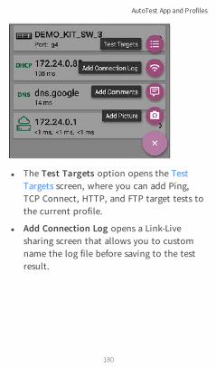
l The Test Targets option opens the TestTargets screen, where you can add Ping,TCP Connect, HTTP, and FTP target tests tothe current profile.
l Add Connection Log opens a Link-Livesharing screen that allows you to customname the log file before saving to the testresult.
AutoTest App and Profiles
180
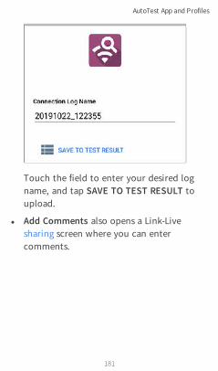
Touch the field to enter your desired logname, and tap SAVE TO TEST RESULT toupload.
l Add Comments also opens a Link-Livesharing screen where you can entercomments.
AutoTest App and Profiles
181

Back to Title and Contents
Touch the fields to enter your desiredcomments, and tap SAVE TO LAST TESTRESULT to upload them.
l The Add Picture function lets you open theGallery or Camera app to select or take aphoto that is then uploaded and attachedto your test result.
See the Link-Live App chapter to learn aboutLink-Live and uploading.
AutoTest App and Profiles
182

Wired Profile SettingsThese settings control the wired test portconnection, PoE test, the thresholds forPass/Warning/Fail results, and any user-addedtest targets.
Touch the settings icon on the Wired profilescreen, or add a new Wired profile, to configurethe profile's settings.
AutoTest App and Profiles
183

On the Wired Profile settings screen, toucheach field described below as needed toconfigure the profile. Changed settings are auto-matically applied. When you finish configuring,tap the back button to return to the profile.
NameTouch the Name field to enter a custom namefor the profile. This name appears on the mainAutoTest screen profile card and the WiredProfile screen header.
PoE Test SettingsOpen PoE Test settings to enable or disable PoEand configure the PD Class.
AutoTest App and Profiles
184

PoE TestTouch the toggle button to enable or disablethe PoE test portion of the current WiredProfile.
Powered Device ClassTouch to select a PoE class setting to matchyour switch's (or PoE injector's) available class.LinkRunner supports these classes:
l 802.3af Classes 0-3
l 802.3at PoE+ Class 4
l Cisco's UPOE, which can provide up to 51 W
l 802.3bt Classes 5-8
Select the PoE Injector option if you are usinga non-IEEE injector.
NOTE: LinkRunner may not receive the totalwattage advertised by your switch orinjector because of power loss over thecable.
NOTE: LinkRunner automatically negotiatesCisco UPOE over LLDP, up to 51 W. LLDPmust be enabled on the switch for
AutoTest App and Profiles
185

negotiation to succeed. If the UPOE Class isselected on your LinkRunner but LLDP isnot enabled on your Cisco switch, nego-tiation will fail.
LLDPThis toggle button appears if Class 4 (25.50 W) isselected. Enable this setting if LLDP is enabledon the switch you are testing. Class 4 LLDPmust be enabled on the switch for AutoTest todetect it successfully. If the LLDP setting isenabled but your switch does not supportLLDP, negotiation will fail.
Requested Power (W)This setting appears if UPOE is selected in thePowered Device Class setting shown above or ifthe Powered Device Class is set to PoE Injectorand TruePower is enabled. Touch to enter aRequested Power other than the default, ifneeded. If you touch the backspace button onthe pop-up number pad and clear the defaultvalue, the valid power range is displayed.
AutoTest App and Profiles
186

TruePower™TruePower validates that the Switch (PowerSourcing Equipment) and cabling can providethe requested power under load by applying aload equivalent to the selected class to mimic aPowered Device (PD). Tap the toggle button toenable the TruePower feature.
General Settings that Affect PoESee the Wired section in General Settings for adescription of the Test PoE before Link setting.
Wired Connection SettingsOpen Wired Connection settings to configurespeed and duplex.
AutoTest App and Profiles
187

Speed/DuplexTouch to select the speed and duplex optionthat you want to test your network against.The default is Auto negotiation.
When speed is set to Auto, LinkRunner auto-negotiates to the highest possible speed/duplexsupported by the link partner. You can select afixed speed/duplex for the copper interface.This setting does not force the link speed/-duplex on the fiber interface, but does controlwhich speed is attempted first when using amulti-rate SFP. As a result, this setting canenable the EtherScope to connect faster viafiber.
AutoTest App and Profiles
188

802.1XTouch the toggle field to enable wired 802.1Xauthentication in the current Profile. Enablingthis setting also enables an 802.1X test card onthe Wired AutoTest results screen.
The following settings appear when 802.1Xauthentication is enabled. Enter all necessarycredentials, such as EAP type, username andpassword, or certificate.
AutoTest App and Profiles
189
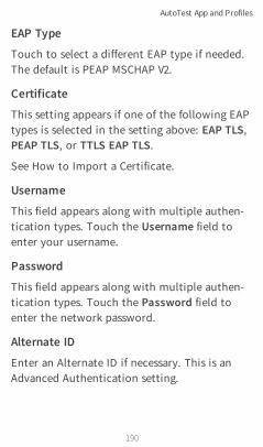
EAP Type
Touch to select a different EAP type if needed.The default is PEAP MSCHAP V2.
Certificate
This setting appears if one of the following EAPtypes is selected in the setting above: EAP TLS,PEAP TLS, or TTLS EAP TLS.
See How to Import a Certificate.
Username
This field appears along with multiple authen-tication types. Touch the Username field toenter your username.
Password
This field appears along with multiple authen-tication types. Touch the Password field toenter the network password.
Alternate ID
Enter an Alternate ID if necessary. This is anAdvanced Authentication setting.
AutoTest App and Profiles
190

Multi-gigabit SNR ThresholdWhen a Wired Profile links at speeds higher than1 Gbps, a table appears on the Link Test screenshowing Multi-gigabit Details. This thresholdgrades SNR measurements on the four twistedpairs. A Minimum SNR below the selectedthreshold will display a yellow warningcondition. The default is 5 dB.
VLAN Settings
Touch to open the VLAN settings screen. Slidethe toggle to the right to enable VLAN testing.Enabling this setting also enables a VLAN test
AutoTest App and Profiles
191

card on the Wired AutoTest results screen. Onceenabled, VLAN ID and VLAN Priority fieldsappear. Touch these fields to open a pop-upnumber pad and enter the correct ID andpriority. Touch OK to save them.
AutoTest App and Profiles
192

DHCP, DNS, and Gateway SettingsSee DHCP, DNS, and Gateway Tests.
Test TargetsTouch the Test Targets field to open the TestTargets screen and add custom Ping, TCPConnect, HTTP, or FTP Tests to your AutoTestprofile.See Test Targets for Wired Profiles.
Stop After
AutoTest App and Profiles
193

This setting directs the Wired Profile to stoptesting after the selected test step. Theexcluded test cards will not appear on theProfile results screen.
HTTP ProxyThe Proxy control lets you specify a proxyserver through which the LinkRunnerestablishes a network connection. In AutoTest,these settings are used when HTTP Proxy isenabled in an HTTP or FTP Test Target.
To use the proxy settings with a web browser,run the Profile, and then, open the webbrowser while the unit remains linked.
Open the HTTP Proxy screen to enable proxysettings.
AutoTest App and Profiles
194

Back to Title and Contents
Touch each field to open a pop-up keyboardand enter the appropriate Address, Port,Username, and Password. Touch OK to saveyour entries.
AutoTest App and Profiles
195

DHCP, DNS, and GatewayTests for Wired AutoTests
These tests are included in Wired AutoTestProfiles.Access AutoTest's DHCP, DNS, and Gatewaysettings from the Wired Profile settings screen,or by touching the settings button from thefull results screen for each test type.
Touch blue links or the blue action overflowicon on the test results screens foradditional actions.
AutoTest App and Profiles
196
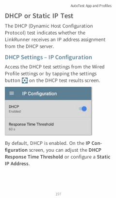
DHCP or Static IP TestThe DHCP (Dynamic Host ConfigurationProtocol) test indicates whether theLinkRunner receives an IP address assignmentfrom the DHCP server.
DHCP Settings – IP ConfigurationAccess the DHCP test settings from the WiredProfile settings or by tapping the settingsbutton on the DHCP test results screen.
By default, DHCP is enabled. On the IP Con-figuration screen, you can adjust the DHCPResponse Time Threshold or configure a StaticIP Address.
AutoTest App and Profiles
197

DHCP
DHCP is enabled by default. Touch the togglebutton to disable DHCP and enter static IPaddresses.
(DHCP only) Response Time Threshold
This field only appears if DHCP is enabled. TheResponse Time Threshold controls how longthe LinkRunner waits for a DHCP serverresponse before failing the Link and DHCP tests.
AutoTest App and Profiles
198
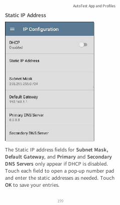
Static IP Address
The Static IP address fields for Subnet Mask,Default Gateway, and Primary and SecondaryDNS Servers only appear if DHCP is disabled.Touch each field to open a pop-up number padand enter the static addresses as needed. TouchOK to save your entries.
AutoTest App and Profiles
199
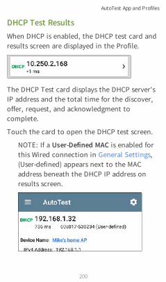
DHCP Test ResultsWhen DHCP is enabled, the DHCP test card andresults screen are displayed in the Profile.
The DHCP Test card displays the DHCP server'sIP address and the total time for the discover,offer, request, and acknowledgment tocomplete.
Touch the card to open the DHCP test screen.
NOTE: If a User-Defined MAC is enabled forthis Wired connection in General Settings,(User-defined) appears next to the MACaddress beneath the DHCP IP address onresults screen.
AutoTest App and Profiles
200

DHCP Test Results Screen
Device Name: The discovered name of theDHCP Server, or, if no name could bediscovered, the IP address
IPv4 Address: IP address of the server
AutoTest App and Profiles
201
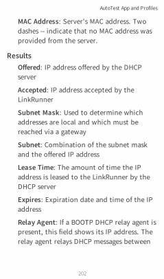
MAC Address: Server's MAC address. Twodashes -- indicate that no MAC address wasprovided from the server.
ResultsOffered: IP address offered by the DHCPserver
Accepted: IP address accepted by theLinkRunner
Subnet Mask: Used to determine whichaddresses are local and which must bereached via a gateway
Subnet: Combination of the subnet maskand the offered IP address
Lease Time: The amount of time the IPaddress is leased to the LinkRunner by theDHCP server
Expires: Expiration date and time of the IPaddress
Relay Agent: If a BOOTP DHCP relay agent ispresent, this field shows its IP address. Therelay agent relays DHCP messages between
AutoTest App and Profiles
202

DHCP clients and DHCP servers on differentIP networks.
End User Response Time table and chart:Breakdown of the times for the process ofacquiring a DHCP IP address
Offer: Time between when the LinkRunnersent the discovery and received an addressoffer from the DHCP server
AutoTest App and Profiles
203

Acknowledge: Time between LinkRunnersending the request and receiving theacknowledgment from the DHCP server
Total Time: Total amount of timeconsumed by the DHCP process
Threshold: The DHCP Response TimeThreshold from the DHCP test settings,which controls how long the LinkRunnerwaits for a DHCP server response beforefailing the DHCP test.
End User Response Time: A pie chartshowing the Offer and Acknowledgmenttimes as percentages
IPv6 Addresses: Addresses obtained via routeradvertisement
Results Codes: Final status of the test (Successor Failure)
AutoTest App and Profiles
204

The additional actions available on the DHCPtest screen include opening the Path Analysis,Ping/TCP, or Capture apps populated with theDHCP server address, browsing to the IPv4address in the web browser, starting a Telnet orSSH session, or viewing the Connect Log.
Static IP Test ResultsIf DHCP is disabled, the DHCP test becomes a"Static IP" test and the Subnet and addressesthat were entered in the DHCP test settings aredisplayed.
AutoTest App and Profiles
205
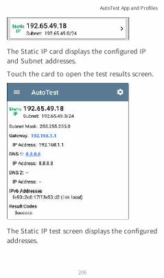
The Static IP card displays the configured IPand Subnet addresses.
Touch the card to open the test results screen.
The Static IP test screen displays the configuredaddresses.
AutoTest App and Profiles
206

Subnet: Combination of the subnet mask andthe offered IP address
Subnet Mask: Used to determine whichaddresses are local and which must be reachedvia a gateway
Gateway: Resolved hostname of the Gateway orits IP address if no name could be discovered
IP Address: IP address of the Gateway
DNS (1 and 2): Names and IP addresses ofPrimary and Secondary DNS servers
IPv6 Addresses: Addresses obtained via routeradvertisement
Results Codes: Final status of the test (Successor Failure)
Duplicate IP AddressThe DHCP and Static IP tests also detect andreport the presence of a device using the sameIP address (duplicate IP). If the configuredaddress is in use, the AutoTest fails.
AutoTest App and Profiles
207
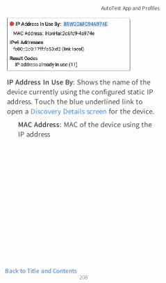
Back to Title and Contents
IP Address In Use By: Shows the name of thedevice currently using the configured static IPaddress. Touch the blue underlined link toopen a Discovery Details screen for the device.
MAC Address: MAC of the device using theIP address
AutoTest App and Profiles
208

DNS TestFor overview information, see DHCP, DNS, andGateway Tests.
The DNS (Domain Name System) server testchecks the performance of DNS serversresolving the specified URL. The LinkRunnerobtains DNS addresses through DHCP or staticaddress configuration.
DNS Test Settings
AutoTest App and Profiles
209

DNS Test
If desired, you can tap the top field on the DNSSettings screen and switch the toggle to disablethe DNS test in your current AutoTest. Whenthis setting is disabled, the DNS card does notappear on the main AutoTest results screen,and the following settings are hidden.
Lookup Name
This is the URL the DNS server(s) will attemptto resolve. Touch the field to enter a URL otherthan the default: www.google.com.
IP Protocol Version
Touch the field to switch between IPv4 andIPv6.
Lookup Time Threshold
This threshold controls how long theLinkRunner waits for a response from the DNSserver(s) before the test is failed. The default is1 second. Touch the field to select or enter anew threshold.
AutoTest App and Profiles
210

DNS Test ResultsThe server name and lookup time for DNS 1 areshown on the DNS test card.
Touch the card to open the DNS test resultsscreen.
DNS Test Results Screen
AutoTest App and Profiles
211

Lookup Name: Name resolved by the DNSservers
Threshold: Lookup Time Threshold from theDNS test settings
DNS #: Name of the listed DNS server
Lookup IP: Resolved IP address
Lookup Time: Time to receive the IPaddress after the lookup request sent
Results Codes: Final status of the test (Successor Failure) for each DNS server
AutoTest App and Profiles
212
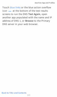
Back to Title and Contents
Touch blue links or the blue action overflowicon at the bottom of the test resultsscreens to run the DNS Test Again, openanother app populated with the name and IPaddress of DNS 1, or Browse to the PrimaryDNS server in your web browser.
AutoTest App and Profiles
213

Gateway TestFor overview information, see DHCP, DNS, andGateway Tests.
This test indicates whether the default Gatewaycould be successfully pinged and identifies theaddress of the current IPv4 and IPv6 routers.
Gateway Test Settings
Gateway Test
If desired, you can tap the top field on theGateway Test screen and switch the toggle todisable the Gateway test in your currentAutoTest. When this setting is disabled, theGateway card does not appear on the mainAutoTest results screen, and the followingsetting is hidden.
AutoTest App and Profiles
214

Timeout Threshold
The only other setting for the Gateway Test isthe timeout threshold, which indicates howlong the LinkRunner will wait for a responsefrom the gateway before grading the test as afail. Tap the field to select one of the valueoptions, or enter a custom value.
Gateway Test ResultsLinkRunner gets the Gateway's IP address fromDHCP or the static IP configuration, and usesSNMP to acquire system group information andstatistics for the port that services the LinkRun-ner's subnet. See Discovery Settings forinformation about SNMP configuration.
The Gateway test card shows the gateway's IPaddress and the three Ping response times.
AutoTest App and Profiles
215

Gateway Test Results Screen
IPv4 Gateway Name: Resolved hostname of theGateway or its IP address if no name could bediscovered
IPv4 Address: Internal IPv4 address of theGateway
AutoTest App and Profiles
216

MAC Address: Server's MAC address. Twodashes -- indicate that no MAC address wasprovided from the server.
IPv6 Address: Router's IPv6 address (ifavailable)
IPv6 Gateway Name: Name advertised by theIPv6 router (if available)
Protocols: Routing protocols the LinkRunnerused to obtain the Gateway data
Ping Results
l Response Times from the three Pings sentto the gateway
l Threshold: Gateway Timeout Threshold con-figured in the gateway settings
Results Codes: Final status of the test (Successor Failure) for each of the three Gateway Pings
AutoTest App and Profiles
217

Back to Title and Contents
Touch blue links or the blue action overflowicon at the bottom of the test resultsscreens to run the Gateway TEST AGAIN, openanother app, Browse to the Gateway's IPv4Address, or start a Telnet or SSH session to theGateway.
AutoTest App and Profiles
218

Test Targets for WiredAutoTests
AutoTest Target tests are user-assignableendpoints to which LinkRunner 10G attemptsto connect each time the AutoTest profile runs.These tests ensure availability of internal orexternal websites, servers, and devices to usersof your network.
Tap a link below to go to the test's topic:PingTCP ConnectHTTPFTP
AutoTest App and Profiles
219

Adding and Managing Test TargetsTo add test targets to AutoTest profiles andmanage your saved targets, open the TestTargets screen from the Wired Profile Settings
or by touching the FAB on the Wired
Profile results screens.
The Test Targets screen lists all of the definedand saved Test Targets. Checked boxes indicatethe Test Targets that are enabled in the currentProfile. Remember, Test Targets can be addedto and used in any number of Wired Profiles.
AutoTest App and Profiles
220

On the Test Targets screen, you can performthese actions:
l Select the checkboxes for each Target youwant to include in the current Wiredprofile.
l Tap the up and down arrows toreorder the saved Test Targets on this
AutoTest App and Profiles
221
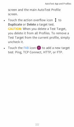
screen and the main AutoTest Profilescreen.
l Touch the action overflow icon toDuplicate or Delete a target test.CAUTION: When you delete a Test Target,you delete it from all Profiles. To remove aTest Target from the current profile, simplyuncheck it.
l Touch the FAB icon to add a new targettest: Ping, TCP Connect, HTTP, or FTP.
AutoTest App and Profiles
222

l Touch any target's name, or add a newtarget, to open the test's settings, whereyou can enter a custom test name, targetaddress, and thresholds.
AutoTest App and Profiles
223

Target Test Results ScreensThe Target Test type icons display green,yellow, or red to indicate the status (or grade)of the completed test portions:Success/Warning/Fail.
As an example, in the Ping test image below,the entire Ping test is graded with a Warningbecause the third Ping was not returned withinthe Timeout Threshold configured in thesettings.
The third Response Time displays two dashes --to indicate that no response was received, and
AutoTest App and Profiles
224

under the Results heading, the yellow dotpoints out the third Response Time as thereason for the Warning. Additionally, the thirdResult Code lists "Timeout error" as the reasonfor the Warning.
Additional Target Test Actions
After the Target test has completed, touch anyof the blue links to perform additional actions,including opening other testing apps.
l Touch the blue linked Device Name to opena Discovery Details app screen for theselected device. From there, you can openother apps and run additional tests.
l Touch TEST AGAIN to run just the targettest again.
l Touch PATH ANALYSIS to open the PathAnalysis app. The path Destination will beconfigured with the current target.
l Touch the action overflow icon toopen the listed apps or tools with the target
AutoTest App and Profiles
225

Back to Title and Contents
pre-populated, for example:
⸰ Open the Ping/TCP app with the currenttarget address.
⸰ Run a packet Capture on traffic from thetest target.
⸰ Browse to the target URL on the internetwith your web browser app.
AutoTest App and Profiles
226

AutoTest Ping TestA Ping test sends an ICMP echo request to theselected target to determine whether the serveror client can be reached and how long it takesto respond. The AutoTest Target Ping Testsends three Pings to the target and reports theresponse times. The target can be an IPv4address, IPv6 address, or named server (URL orDNS).
AutoTest App and Profiles
227

Ping Test Settings
Name: This field allows you to assign a customname to the test. The name appears on thetarget test card in the profile.
Device Name: Enter the IP address or URL ofthe server you want to ping. If you enter an IP
AutoTest App and Profiles
228

address, the DNS lookup portion of the test isskipped.
IP Protocol Version: IPv4 is used by default.Touch the field to switch between IPv4 andIPv6.
Frame Size (bytes): This setting specifies thetotal size of the payload and the header sent.Valid sizes are 64 bytes to 1518 bytes. To testthe Maximum Transmission Unit (MTU) along aroute to a target, select the MTU frame size youwant to test, and set Do Not Fragment toEnabled.
Do Not Fragment: Touch the toggle button toenable.
Timeout Threshold: This threshold controlshow long the LinkRunner waits for a responsefrom the target before failing the test.
Ping Test Results
AutoTest App and Profiles
229

The Ping card shows the Ping test nameentered in the Ping test settings and the threePing response times from the target.
Touch the card to open the Ping results screen.
AutoTest Ping Results Screen
Device Name: Hostname or address of thetarget device
l IPv4 or IPv6 Address: IP address of thetarget device
AutoTest App and Profiles
230

l MAC Address: Target device's MAC address.The two dashes -- indicate that no MACaddress was provided from the server.
Results
l Lookup Time: How long it took to resolvethe URL into an IP address
l Response Times: How long it took for theLinkRunner to receive a response from thetarget after sending each of the three Pings
l Threshold: The Timeout Thresholdindicated in the test's settings
Results Codes: Final status of the test (Successor Failure) for each of the three Pings
AutoTest App and Profiles
231

Touch blue links or the blue action overflowicon at the bottom of the test resultsscreens to run the Ping TEST AGAIN, openanother testing app, Browse to the Ping targetaddress in your web browser, or start a Telnetor SSH session.
AutoTest App and Profiles
232

AutoTest TCP Connect TestA TCP Connect test opens a TCP connectionwith the selected target to test for port avail-ability using a 3-way handshake (SYN, SYN/ACK,ACK). The AutoTest Target TCP Connect testruns three connection tests and reports theresponse times.
TCP Connect Test Settings
AutoTest App and Profiles
233

Name: This field allows you to assign a customname to the test. The name appears on thetarget test card in the profile.
Device Name: Enter the IP address or URL ofthe target you want to test. If you enter an IPaddress, the DNS lookup portion of the testwill be skipped.
IP Protocol Version: IPv4 is used by default.Touch the field to switch between IPv4 andIPv6.
Port: Specify the TCP port number LinkRunnerwill use to connect to the target.
Timeout Threshold: This threshold controlshow long the LinkRunner waits for a responsefrom the target before failing the test.
TCP Connect Test Results
The TCP card shows the test name entered inthe settings and the three response times fromthe target.
Touch the card to open the TCP results screen.
AutoTest App and Profiles
234

AutoTest TCP Results Screen
Device Name: DNS name of the device tested
IPv4 or IPv6 Address: IP address of thetarget device
MAC Address: Device's MAC address. Thetwo dashes -- indicate that no MAC addresswas provided.
Port: Port number tested
AutoTest App and Profiles
235

Back to Title and Contents
ResultsLookup Time: How long it took to resolvethe URL into an IP address
Response Times: How long it took for theLinkRunner to receive a response from theserver for each of the three connect tests
Threshold: The Timeout Thresholdindicated in the test's settings
Results Codes: Final status of the test (Successor Failure) for each of the three Pings
AutoTest App and Profiles
236

HTTP TestThe HTTP test performs a comprehensive enduser response time (EURT) measurement whendownloading the specified web page. The targetcan be an IPv4 address, IPv6 address, or URL.
HTTP Test SettingsHTTP settings allow test grading criteria basedon responses and return code in addition tothe time threshold.
AutoTest App and Profiles
237

Name
This field allows you to assign a custom nameto the test. The name appears on the target testcard in the profile.
AutoTest App and Profiles
238

URL
Enter a target address. To reach web serversthat operate on a non-default port, enter acolon (:) and specify the port number after theURL.
IP Protocol Version
IPv4 is used by default. Touch the field toswitch between IPv4 and IPv6.
Allow Redirects
Touch the toggle button to permit webredirects when trying to connect to the target.
Response Time Threshold
This threshold controls how long theLinkRunner waits for a response from the URLbefore failing the test. Touch the field tochange the value.
Web Page Transfer Size
This setting allows you to limit the amount ofdata downloaded, ranging from the HTMLHeader Only to the entire page (ALL). Touch thefield to select a different transfer size.
AutoTest App and Profiles
239
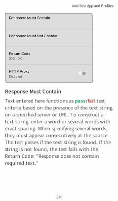
Response Must Contain
Text entered here functions as pass/fail testcriteria based on the presence of the text stringon a specified server or URL. To construct atext string, enter a word or several words withexact spacing. When specifying several words,they must appear consecutively at the source.The test passes if the text string is found. If thestring is not found, the test fails with theReturn Code: "Response does not containrequired text."
AutoTest App and Profiles
240

Response Must Not Contain
Like the setting above, except text entered herefunctions as pass/fail test criteria based on theabsence of the text string on a specified serveror URL. The test passes if the text string is notfound. If the string is found, the test fails withthe return code: "Response contains excludedtext."
Return Code
The Return Code set here functions as pass/failtest criteria. The default is "OK (HTTP 200)."Touch the field to select a different ReturnCode from the list. If your selected Return Codevalue matches the actual return code value, thetest passes, and if LinkRunner receives adifferent return code, the test fails.
HTTP ProxyThe Proxy control in target test settings utilizesthe server address and port specified in themain profile settings. Touch the toggle to usethose Proxy settings. See Wired Profile Settings.
AutoTest App and Profiles
241

HTTP Test Results
The HTTP card shows the test name entered inthe test settings and response time from thetarget.
AutoTest App and Profiles
242
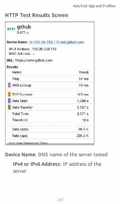
HTTP Test Results Screen
Device Name: DNS name of the server tested
IPv4 or IPv6 Address: IP address of theserver
AutoTest App and Profiles
243
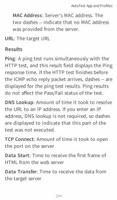
MAC Address: Server's MAC address. Thetwo dashes -- indicate that no MAC addresswas provided from the server.
URL: The target URL
Results
Ping: A ping test runs simultaneously with theHTTP test, and this result field displays the Pingresponse time. If the HTTP test finishes beforethe ICMP echo reply packet arrives, dashes -- aredisplayed for the ping test results. Ping resultsdo not affect the Pass/Fail status of the test.
DNS Lookup: Amount of time it took to resolvethe URL to an IP address. If you enter an IPaddress, DNS lookup is not required, so dashesare displayed to indicate that this part of thetest was not executed.
TCP Connect: Amount of time it took to openthe port on the server
Data Start: Time to receive the first frame ofHTML from the web server
Data Transfer: Time to receive the data fromthe target server
AutoTest App and Profiles
244
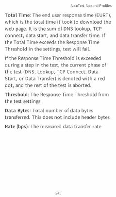
Total Time: The end user response time (EURT),which is the total time it took to download theweb page. It is the sum of DNS lookup, TCPconnect, data start, and data transfer time. Ifthe Total Time exceeds the Response TimeThreshold in the settings, test will fail.
If the Response Time Threshold is exceededduring a step in the test, the current phase ofthe test (DNS, Lookup, TCP Connect, DataStart, or Data Transfer) is denoted with a reddot, and the rest of the test is aborted.
Threshold: The Response Time Threshold fromthe test settings
Data Bytes: Total number of data bytestransferred. This does not include header bytes
Rate (bps): The measured data transfer rate
AutoTest App and Profiles
245

End User Response Time : Pie chart of thetimes for each phase of the test (DNS, Lookup,TCP Connect, Data Start, and Data Transfer)
Results Codes: Final status of the test (Successor Failure)
The HTTP test also shows the Return Code fromthe website server.
AutoTest App and Profiles
246

Back to Title and Contents
Touch blue links or the blue action overflowicon at the bottom of the test resultsscreens to run the HTTP TEST AGAIN, openanother testing app, or Browse to the targetaddress in your web browser.
AutoTest App and Profiles
247

FTP TestThe FTP test performs a file upload to ordownload from an FTP server, allowing veri-fication of server and network performance.The target can be an IPv4 address, IPv6 address,or URL. The results provide a completebreakdown of the overall file transfer time intoits component parts.
FTP Test SettingsFTP settings allow you to specify a Get or Puttest and the file path and name.
AutoTest App and Profiles
248

Name
This field allows you to assign a custom nameto the test. The name appears on the target testcard in the profile.
AutoTest App and Profiles
249
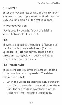
FTP Server
Enter the IPv4 address or URL of the FTP serveryou want to test. If you enter an IP address, theDNS Lookup portion of the test is skipped.
IP Protocol Version
IPv4 is used by default. Touch the field toswitch between IPv4 and IPv6.
File
This setting specifies the path and filename ofthe file that is downloaded from (Get) oruploaded to (Put) the server, based on theDirection setting below. Touch the field toenter the file path and name.
File Transfer Size
This setting lets you limit the amount of datato be downloaded or uploaded. The defaulttransfer size is ALL.
l When the Direction setting is Get, a transfersize of ALL causes the download to continueuntil the entire file is downloaded or theResponse Time Threshold is exceeded.
AutoTest App and Profiles
250

Specifying a transfer size that is greater thanfile being retrieved does not cause the testto fail. The test stops when the file hasfinished downloading.
l When the Direction setting is Put, thedefault transfer size of ALL causes theLinkRunner to create and upload a file thatis 10 MB.
Direction
Touch the toggle button to switch between aGet (download the File from the server) or Put(upload the File to the server) test.
l If Direction is set to Get, the file isretrieved, and the size and data rate are cal-culated. This data is discarded as soon as itis downloaded and is not retained on theLinkRunner.
l If Direction is set to Put, the File namedabove is created on the FTP server. The sizeof this file is determined by the FileTransfer Size setting. The file contains atext string indicating that it was sent from
AutoTest App and Profiles
251

the LinkRunner, and the test string isrepeated to produce the set file size.
Response Time Threshold
This threshold controls how long theLinkRunner waits for a response from the FTPserver before failing the test. Touch the field tochange the value.
Username and Password
Enter these credentials to access the targetserver you specified. Enter "anonymous" as theusername to establish an anonymousconnection. The test will fail if the configuredusername or password are not valid on thetarget FTP server.
AutoTest App and Profiles
252

HTTP ProxyThe Proxy control in target test settings utilizesthe server address and port specified in themain profile settings. See Wired ProfileSettings.
FTP Test Results
The FTP card shows the test name entered inthe test settings and response time from thetarget.
AutoTest App and Profiles
253

FTP Test Results Screen
Device Name: Hostname of the server tested
IPv4 or IPv6 Address: IP address of theserver
AutoTest App and Profiles
254
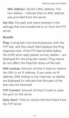
MAC Address: Server's MAC address. Thetwo dashes -- indicate that no MAC addresswas provided from the server.
Get File: File path and name entered in thesettings that was transferred to or from the FTPserver.
Results
Ping: A ping test runs simultaneously with theFTP test, and this result field displays the Pingresponse time. If the FTP test finishes beforethe ICMP echo reply packet arrives, dashes -- aredisplayed for the ping test results. Ping resultsdo not affect the Pass/Fail status of the test.
DNS Lookup: Amount of time it took to resolvethe URL to an IP address. If you enter an IPaddress, DNS lookup is not required, so dashesare displayed to indicate that this part of thetest was not executed.
TCP Connect: Amount of time it took to openthe port on the server
Data Start: Time to receive the first frame fromthe FTP server
AutoTest App and Profiles
255

Data Transfer: Time to receive the file from thetarget server
Total Time: The end user response time (EURT),which is the total time it took to download theweb page. It is the sum of DNS lookup, TCPconnect, data start, and data transfer time. Ifthe Total Time exceeds the Response TimeThreshold in the settings, the test will fail.
If the Response Time Threshold is exceededduring a step in the test, the current phase ofthe test (DNS, Lookup, TCP Connect, DataStart, or Data Transfer) is denoted with a reddot, and the rest of the test is aborted.
Threshold: The Response Time Threshold fromthe test settings
Data Bytes: Total number of data bytestransferred. This does not include header bytes.
Rate (bps): The measured data transfer rate
AutoTest App and Profiles
256
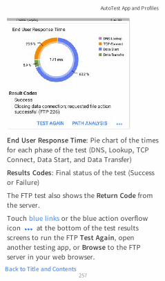
Back to Title and Contents
End User Response Time: Pie chart of the timesfor each phase of the test (DNS, Lookup, TCPConnect, Data Start, and Data Transfer)
Results Codes: Final status of the test (Successor Failure)
The FTP test also shows the Return Code fromthe server.
Touch blue links or the blue action overflowicon at the bottom of the test resultsscreens to run the FTP Test Again, openanother testing app, or Browse to the FTPserver in your web browser.
AutoTest App and Profiles
257

Ping/TCP TestApp
The Ping/TCP test app runs a Ping or TCPConnect test to your chosen target, allowingyou to monitor connectivity changes.
A Ping test sends an ICMP echo request to theselected target to determine whether the serveror client can be reached and how long it takesto respond. A TCP Connect test opens a TCPconnection with the selected target to test forport availability using a 3-way handshake (SYN,SYN/ACK, ACK).
You can open the TCP/Ping app from the Homescreen, or you can select Ping or TCP Connectfrom another app, such as AutoTest orDiscovery, while viewing a device's details.
258
LinkRunner 10G User Guide
Back to Title and Contents

Ping/TCP SettingsTo configure a test, you can manually enter ahostname or IP address in the settings, or youcan select Ping or TCP Connect from anothertesting app's device screen.
Populating Ping/TCP from AnotherAppWhen you open the Ping/TCP app from anotherapp, the address is pre-populated as the Ping orTCP target device. For example, the FAB menuon the Discovery app screen shown belowcontains the option to open the Ping/TCP app.
Ping/TCP Test App
259

If the Ping/TCP app is opened from this screen,the IPv4 address from the Discovery app isalready configured as the Ping/TCP target.
Ping/TCP Test App
260

Ping/TCP Test App
261

Configuring Ping/TCP SettingsManuallyTo configure the target and settings manually,open the app's settings .
Ping/TCP Test App
262
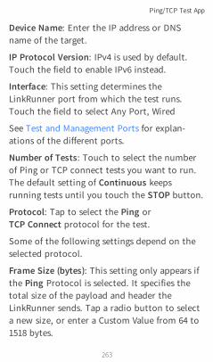
Device Name: Enter the IP address or DNSname of the target.
IP Protocol Version: IPv4 is used by default.Touch the field to enable IPv6 instead.
Interface: This setting determines theLinkRunner port from which the test runs.Touch the field to select Any Port, Wired
See Test and Management Ports for explan-ations of the different ports.
Number of Tests: Touch to select the numberof Ping or TCP connect tests you want to run.The default setting of Continuous keepsrunning tests until you touch the STOP button.
Protocol: Tap to select the Ping orTCP Connect protocol for the test.
Some of the following settings depend on theselected protocol.
Frame Size (bytes): This setting only appears ifthe Ping Protocol is selected. It specifies thetotal size of the payload and header theLinkRunner sends. Tap a radio button to selecta new size, or enter a Custom Value from 64 to1518 bytes.
Ping/TCP Test App
263

To test the Maximum Transmission Unit (MTU)along a route to a target, select the MTU framesize you want to test, and set the Do NotFragment setting (below) to Enabled.
Interval: This setting only appears if the PingProtocol is selected. It controls how much timepasses between each Ping sent from theLinkRunner. By default, Pings are sent onceevery second (1 s). Tap a radio button to selecta different interval, or enter a Custom Valuebetween 100 and 10,000 milliseconds.
Port: This setting only appears if the TCPConnect Protocol is selected. It indicates theport number your LinkRunner will use toconnect to the target address for a TCP PortOpen test. If needed, touch the Port field toopen a pop-up number pad and enter a newport number. Touch OK to save it.
Timeout Threshold: This threshold controlshow long the LinkRunner waits for a responsefrom the target before the test is failed.
Do Not Fragment: This setting only appears ifthe Ping Protocol is selected. Touch the toggle
Ping/TCP Test App
264

Back to Title and Contents
button to enable. See the Frame Size settingdescription above.
Ping/TCP Test App
265

Running Ping/TCP TestsYour unit must be connected to an active wirednetwork (Test or Management Port) to run Pingand TCP Connect tests. Icons in the top StatusBar indicate whether and how your LinkRunneris connected. See Connection Notifications fordescriptions of the connection status icons,and select the appropriate Interface (or AnyPort) from the Ping/TCP settings.
The default target is google.com. Open the appsettings to enter a new target.
To begin the test, touch START.
If the Number of Tests setting is set toContinuous, the Ping/TCP app runs tests toyour selected target until you touch STOP.
Ping/TCP Test App
266

Device Name: Hostname or address of thetarget device
IPv4 or IPv6 Address: IP address of the targetdevice
Ping/TCP Test App
267

MAC Address: Target device's MAC address. Thetwo dashes -- indicate that no MAC address wasprovided from the device.
Port: The port number used for the TCPConnect test. This field does not appear in Pingtest results.
Interface: The LinkRunner Test or ManagementPort from which the test is running
Results
l Started: Time the test started
l Status: Most recent test status
l Sent: Number of Pings or TCP SYN packetssent to the target
l Received: Number of Ping or TCP SYN/ACKpackets returned from the target
l Lost: Number of Pings or TCP packets thatwere not returned from the target
Response Time graph: Plots the target device'sresponse times in milliseconds. The graph savesand displays data for up to 24 hours in the pastif the unit stays linked.
Ping/TCP Test App
268

To pan and zoom on the graph, you can swipe,double tap, and move the slider. See theTrending Graphs topic for an overview of thegraph controls.
Response: Table display of the Current,Minimum, Maximum, and Average responsetime measurements
Limit: The Timeout Threshold from thePing/TCP app's settings
Ping/TCP Test App
269
CaptureApp
Packet capture is the process of recordingnetwork traffic in the form of packets as datastreams back and forth over the wiredconnection. Packet captures can help youanalyze network problems, debug client/servercommunications, track applications andcontent, ensure that users are adhering toadministration policies, and verify networksecurity.
On LinkRunner, the capture process uses theWired Test port .
You can open the Capture app from the Homescreen or using a link from another app, such asAutoTest or Discovery.
270
LinkRunner 10G User Guide
Back to Title and Contents

Capture SettingsThe Capture app settings allow you todesignate file and slice sizes, and apply filters tocapture and analyze only certain packet types.For example, you can set a filter to captureonly packets related to a specific application(based on IP address and port number).
When you open Capture from Home and do notconfigure any filters, all packets from theswitch are captured. The default capture savesall the packets sent from the local switch to theLinkRunner.
If you open the Capture app from anotherNetAlly test app, Capture filters are auto-matically applied. Filters that can be appliedfrom other apps include Wired IP and MAC.
The Capture settings are saved until you clearthe filters or open the app with new filtersapplied.
Touch the settings icon in the Capturescreen to configure capture settings.
Capture App
271

File Size Limit: Touch this field to specify a sizefor the capture file. The default size is 1 MB,and largest size allowed is 1000 MB. The capture
Capture App
272

stops when the captured file reaches this size.When capture is running, the capture screendisplays the current file size as data is captured.
Slice Size: Touch this field to select a specificframe slice size or enter a custom value. TheSlice Size setting limits how much of eachpacket is captured. A smaller slice size is usefulwhen you are interested in the packet’s headerbut do not need to see all the payload data.The default is Full Packet.
Wired FiltersAll filters are disabled by default unless youopen Capture from another app. Touch thefields below to enable and enter filter values.
MAC: Enter the MAC address of a host tocapture only packets that contain the host'sMAC address as the source or destination.
IP: Enter the IP address of a host to captureonly traffic to and from the host. You canspecify an IPv4 or IPv6 address.
VLAN: Enter a VLAN number to capture onlytraffic tagged for that VLAN.
Capture App
273

Back to Title and Contents
Port: Specify a port number to capture onlytraffic from that UDP or TCP port. For example,select port 80 to capture HTTP traffic only.
NOT: Touch the toggle to enable this setting,which directs the LinkRunner NOT to capturethe values you have entered in the filters above.For example, if you have set up a filter tocapture traffic to and from IP 10.250.0.70 onPort 80 and you enable NOT, all traffic will becaptured except traffic to and from 10.250.0.70on port 80.
Capture App
274
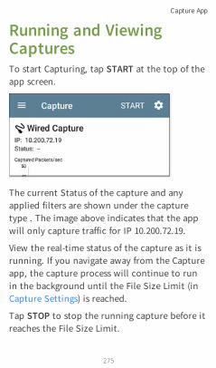
Running and ViewingCapturesTo start Capturing, tap START at the top of theapp screen.
The current Status of the capture and anyapplied filters are shown under the capturetype . The image above indicates that the appwill only capture traffic for IP 10.200.72.19.
View the real-time status of the capture as it isrunning. If you navigate away from the Captureapp, the capture process will continue to runin the background until the File Size Limit (inCapture Settings) is reached.
Tap STOP to stop the running capture before itreaches the File Size Limit.
Capture App
275

The Wired graph plots the type and number ofpackets being captured during the time thecapture is running. By default, wired capturesinclude Unicast, Broadcast, and Multicastpacket types.
Capture App
276

To pan and zoom on the graphs, you canswipe, double tap, and move the slider. See theTrending Graphs topic for an overview of thegraph controls.
Once a capture is completed, the Save Capturedialog appears automatically.
Tap the Save icon to reopen this dialog.
Capture App
277

Captures are saved as .pcap files. Touch any ofthe fields in the dialog to enter changes.
File Name: Capture files are automaticallynamed using the date and time. Touch thisfield to enter a custom name.
Capture App
278

Save to: By default, capture files are saved inthe Downloads folder in the LinkRunner filesystem, but you can also save them to a MicroSD card or USB storage device or choose adifferent folder by touching the Save to field.See also Managing Files.
Save to Link-Live: You can also upload capturefiles to Link-Live and then download them foranalysis on a PC. Capture (.pcap) files appear onthe Uploaded Files page in Link-Live.
Comment: This comment will be attached toyour capture file when it is uploaded to Link-Live.
Job Comment: This is the persistent JobComment that uploads to Link-Live with all testresults and files, until you change it. Changingthe Job Comment here will change itthroughout your unit.
Capture App
279

DiscoveryApp
The LinkRunner 10G Discovery applicationcreates an inventory of the devices on yournetworks along with their attributes: devicetypes, names, addresses, interfaces, VLANs,resources, and other connected or associateddevices. The app allows you to identify andanalyze network devices and acts as a jumping-off point for further analysis using other apps,such as Path Analysis and connection tests.Devices are discovered in the local broadcastdomains where the LinkRunner is physicallyconnected. By default, discovery processes runout of both test and management ports.
Note: AllyCare is required to use thisapplication. Please visit:NetAlly.com/AllyCare Support and Features.
280
LinkRunner 10G User Guide
Back to Title and Contents
Discovery Chapter ContentsThis chapter describes how the Discoveryprocess and app screens work, shows examplesof Discovery data, and details the Discoverysettings.
Introduction to Discovery
Main Discovery List Screen
Discovery Details Screens
Device Types
Discovery Settings
Problem Settings
TCP Port Scan Settings
Discovery App
281

Introduction to DiscoveryDiscovery finds, classifies, and displays thedetails of network components. Informationprovided by Discovery can include thefollowing:
l IP, BSSID, and MAC addresses
l Device Names
l Device Connectivity
l SNMP Data
l Network Problems
l Interface Details and Statistics
Devices are discovered via ARP and Pingsweeps; SNMP, DNS, mDNS, and netBIOSqueries; and passive traffic monitoring.Discovery classifies each device as it is found.Up to 2,000 devices can be reported.
The Discovery app also detects Problems withdiscovered devices, including Warning andFailure conditions.
The LinkRunner's discovery process beginswhen the unit is powered on. Once a network
Discovery App
282

connection (test or management) is established,the active discovery process begins.
Discovery notification icons indicate theprogress of active discovery. This iconindicates that no links are currently availablefor active discovery, either because none of theports enabled for discovery are connected orbecause AutoTest is running.
The Discovery app consistently monitorsnetwork traffic, but the active discoveryprocess reruns every 90 minutes by default. Youcan select a different Refresh Interval in theDiscovery Settings.
Discovery App
283

Main Discovery List ScreenThe main Discovery screen lists all the devicesthe LinkRunner has discovered.
Discovery App
284
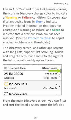
Like in AutoTest and other LinkRunner screens,the icons in Discovery change color to indicatea Warning or Failure condition. Discovery alsodisplays device icons in Blue to indicateProblem-related information that does notconstitute a warning or failure, and Green toindicate that a previous Problem has beenresolved. (See the Problem Settings to adjustenabled Problems and thresholds.)
The Discovery screen, and other app screenswith long lists, support fast scrolling. Touchand drag the scrollbar handle to the right ofthe list to scroll quickly up and down.
From the main Discovery screen, you can filterand sort the listed devices, open the left side
Discovery App
285

navigation drawer to configure settings, andtouch a device's card to view its details.
Discovery App
286

Discovery List CardsThe information displayed on each device cardvaries depending on the selected Sort elementand the data the LinkRunner was able todiscover.
The lower left field displays the characteristicby which the Discovery list is currently sorted.In the image above, the list is sorted by MACaddress. See Discovery Sorts in this topic formore about sorting.
Searching the Discovery ListThe main Discovery screen offers a searchfeature. Tap the search icon at the top of
Discovery App
287

the screen to search discovered devices.
Discovery App
288

Filtering the Discovery ListTouch the filter button near the top left ofthe main Discovery screen to set filters thatcontrol which devices are displayed in the list.
The Filters screen displays the number ofdevices or domains discovered for eachcategory. Touch a category name to selectfilters by checking the boxes. The mainDiscovery screen will show only those devicesor IDs that fall under your chosen filterparameters.
Discovery App
289

When filters are selected, those active filters aredisplayed at the top of the Filters screen.
l Tap the × button to the right of each filterto clear it.
l Touch the clear filter icon at the top rightto clear all filters.
Discovery App
290

Once you have selected a filter, the Filtersscreen is also filtered for that characteristic. Forexample, in the image above, the user hasselected the "Network Tools" device type. As aresult, only those subnets, addresses, etc. witha discovered Network Tool remain selectable inthe filters list.
Back on the main Discovery screen, the screentitle shows the number of filtered devices outof the total discovered devices (in the imageabove, 152 filtered devices out of 1308 total).
Discovery App
291

The number of active filters displays to the leftof the filter icon (3 active filters in the imageabove).
Sorting the Discovery ListTap the Sort bar or down arrow to open theSort drop-down menu.
Discovery App
292
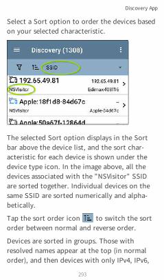
Select a Sort option to order the devices basedon your selected characteristic.
The selected Sort option displays in the Sortbar above the device list, and the sort char-acteristic for each device is shown under thedevice type icon. In the image above, all thedevices associated with the "NSVisitor" SSIDare sorted together. Individual devices on thesame SSID are sorted numerically and alpha-betically.
Tap the sort order icon to switch the sortorder between normal and reverse order.
Devices are sorted in groups. Those withresolved names appear at the top (in normalorder), and then devices with only IPv4, IPv6,
Discovery App
293

and MAC addresses appear below, respectively.Reversing the normal sort order reverses thedevices within the groups but does not changethe order of the groups.
Security Auditing – BatchAuthorizationBatch Authorization allows the user to extendthe LinkRunner 10G's filtering to organizedevices into the following security categories:
l Authorized: For devices approved for use onyour network
l Neighbor: For devices owned and con-trolled by neighboring organizations
l Flagged: To give visibility to a specificdevice
l Unknown: For devices that have not beenidentified or classified
l Unauthorized: For devices that should notbe on the network and may present asecurity risk
l Unspecified:Default unassigned Author-ization status
Discovery App
294

Once categorized, it is simple to immediatelyidentify any new devices on the network byfiltering according to Authorization type. Newdevices will be identified as Unspecified.
To use the Batch Authorization feature, createa filter that identifies the devices you want tocategorize. For example, you could filter onSSIDs used by other offices in your building.Once you have filtered the list of discovereddevices, select the overflow menu.
Select Set Authorization to see how thesedevices are currently categorized and thenumber of devices in each category.
Discovery App
295

NOTE: The initial selection on this screendefaults to the category with the highestcount. If other categories have non-zerocounts, selecting OK will change the author-ization setting for all devices to the selectedcategory.
Discovery App
296

Select the appropriate security category. As inthe example, if these devices belong to otheroffices, select: Neighbor and then tap the OKbutton.
You will now be able to sort the list ofdiscovered devices and clearly identify the
Discovery App
297

security category of the devices. Devices fromother offices will be identified as: Neighbor
Discovery App
298

NOTE: Batch Authorization operates on thedefault MAC address of a device. If a devicehas multiple MACs, authorization will onlybe set on the default MAC address. Devicesthat do not have a discovered MAC address,such as unknown switches and off-netdevices, cannot have an authorizationsetting.
Refreshing DiscoveryTouch the action overflow icon at the topright of the main Discovery screen, and selectRefresh Discovery to refresh the activeDiscovery process.
Discovery App
299

REFRESH DISCOVERY restarts the activediscovery process without clearing the alreadydiscovered devices.
CLEAR AND RERUN DISCOVERY clears theaccumulated results and restarts the discoveryprocess.
Uploading Discovery Results toLink-LiveTouch the action overflow icon at the topright of the main Discovery screen, and selectUpload to Link-Live to send the currentDiscovery results to the Analysis page onLink-Live.com.
Discovery App
300

Back to Title and Contents
See the Link-Live chapter for more information.
Discovery App
301
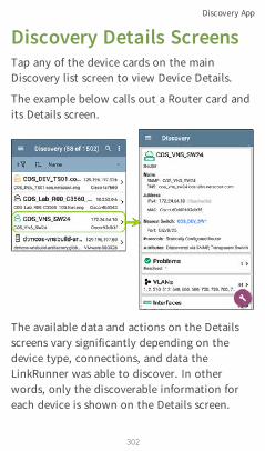
Discovery Details ScreensTap any of the device cards on the mainDiscovery list screen to view Device Details.
The example below calls out a Router card andits Details screen.
The available data and actions on the Detailsscreens vary significantly depending on thedevice type, connections, and data theLinkRunner was able to discover. In otherwords, only the discoverable information foreach device is shown on the Details screen.
Discovery App
302
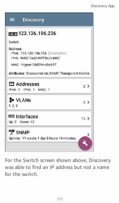
For the Switch screen shown above, Discoverywas able to find an IP address but not a namefor the switch.
Discovery App
303

Each Details screen shows additionalinformation about the selected device, anyProblems detected by the LinkRunner, andcounts for other connected or correspondingnetwork elements.
See Device Types for specifics about thedifferent devices the LinkRunner can discover.
Top Details CardThe top card on the Details screen summarizesthe discovered data for the selected device.
Discovery App
304
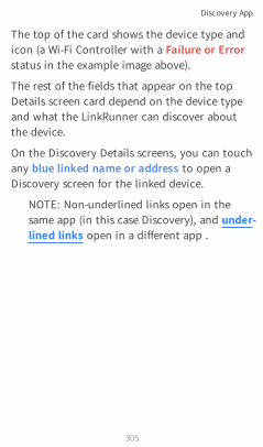
The top of the card shows the device type andicon (a Wi-Fi Controller with a Failure or Errorstatus in the example image above).
The rest of the fields that appear on the topDetails screen card depend on the device typeand what the LinkRunner can discover aboutthe device.
On the Discovery Details screens, you can touchany blue linked name or address to open aDiscovery screen for the linked device.
NOTE: Non-underlined links open in thesame app (in this case Discovery), and under-lined links open in a different app .
Discovery App
305

The Nearest Switch and Wi-Fi Controller linksopen a Discovery app Details screen for thosedevices.
Data Fields on the Top Details CardThe following fields may appear on the topcard on a Device Details screen, depending on
Discovery App
306

the device type and the informationLinkRunner was able to discover:
Name: Discovered hostname(s) of the device.This section can display user-defined, DNS,mDNS, SNMP, NetBIOS, AP, and VirtualMachine names as discovered.
Address: Discovered IPv4, IPv6, BSSID, and/orMAC addresses of the device. This sectiondisplays the default (first discovered) addressesof each type. For more addresses, select theAddresses card when available.
Authorization: This field shows the user-assigned Authorization status of the device.See Assigning a Name and Authorization toa Device.
Nearest Switch: Name or address of the switchidentified as closest to the device
Port: Physical port where the device isconnected
VLAN ID: ID of the VLAN the device is on
Protocols: Routing protocols, discovered viapacket analysis, operating on the device ornetwork
Discovery App
307

Back to Title and Contents
Services: Network services provided by thisdevice, such as DHCP or DNS
Attributes: Other discovered attributes aboutthe device
Wi-Fi Controller: Name and address of the Wi-FiController for a Lightweight AP
AP: Access Point to which the device isconnected
SSID: Name of the network on which thedevice is operating
Security: AP's security type
Hypervisor: Name of the hypervisor on which avirtual machine is operating
Virtual Machine: Name of the virtual machine
Guest OS: Operating system running on thevirtual machine
Memory Reservation: Amount of memoryreserved for the virtual machine
Last Seen: Time at which LinkRunner mostrecently detected the device
Discovery App
308

Lower Cards in Device DetailsTap any of the lower cards on a Device Detailsscreen to view more discovered characteristicsand "drill down" to specific Problems,Addresses, Interfaces, etc. for the selecteddevice.
Screens with a list, such as Addresses shownbelow, also offer Sort options.
Discovery App
309

The rest of this topic provides examples of eachtype of Details screen and options foradditional analysis.
Remember, you can touch any card with a rightpointing arrow to open a new screen withmore information about the device or char-acteristic.
Discovery App
310

ProblemsThe Problems card shows the icon color of thehighest severity problem, and the number ofdetected Warning, Failure or Error,Information, and Resolved conditions for thedevice or network component.
Tap the Problems card to view the Problemslist screen (unless only 1 Problem is detected,in which case, the detailed Problem descriptionopens, skipping the list screen).
Discovery App
311

Tap the sort field to sort the list by Severity orby the time when the problem was FirstDetected.
On the Problems list screen, touch a Problem'srow to read a detailed description.
Touch the action overflow button at the topright of the Problem list or description screento Clear Problems.
See Problem Settings to select which problemsare detected and displayed by your unit.
Addresses
Discovery App
312
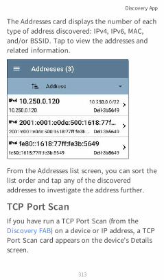
The Addresses card displays the number of eachtype of address discovered: IPv4, IPv6, MAC,and/or BSSID. Tap to view the addresses andrelated information.
From the Addresses list screen, you can sort thelist order and tap any of the discoveredaddresses to investigate the address further.
TCP Port ScanIf you have run a TCP Port Scan (from theDiscovery FAB) on a device or IP address, a TCPPort Scan card appears on the device's Detailsscreen.
Discovery App
313

This card lists open port numbers and showsthe total quantity of open ports. Tap the cardto open the TCP Port Scan screen.
You can also open this screen from theDiscovery floating action menu.
Discovery App
314

The top of the TCP Port Scan results screenshows the name or IP address of the testeddevice and the following fields:
IP address: IP address of the device that wasscanned
Discovery App
315

Interface: Test or management port from whichthe test ran, set in the TCP Port Scan settings
Scan List: List of port numbers tested
Results
Status: Current status of the port scan
Port/Description: List of all the detectedopen ports with their descriptions
See also TCP Port Scan Settings.
VLANsThe VLANs card displays the VLAN IDs thisdevice is using or for which it is configured.
This card does not appear if no VLANs aredetected or configured. Tap the card to openthe VLANs screen.
Discovery App
316

The VLANs Details screen also shows thedescription with each VLAN ID.
InterfacesInterface are discovered using SNMP.
The Interfaces card shows the number of Upand Down interfaces and the total number ofInterfaces to the right.
Discovery App
317

Tap the card to view the list of Interfaces.
Like other Discovery list screens, the Interfaceslist provides a number of Sort options, and theselected sort option affects the type ofinformation displayed. The image above showsInterfaces sorted by Status (up or down). Theimage below shows Interfaces sorted by MACAddress, so each Interface's MAC address isdisplayed.
Discovery App
318

Touching an Interface row opens a newDiscovery Details screen for the selectedInterface.
Discovery App
319

The Interface Details screen contains adescription of the interface and informationabout its Status, Connected Device and Port,and Address.
MTU: Maximum Transmission Unit, themaximum packet frame size configured on theinterface port
Discovery App
320

From this screen, you can touch the lowercards to review any discovery VLANs andDevices for the Interface as well as graphs ofthe Interface Statistics.
Discovery App
321

The Statistics screen displays real-time trendinggraphs of Utilization, Packet Discards, PacketErrors. See the Trending Graphs topic for anoverview of the graphs' pan and zoom controls.
Below the trending graphs are pie charts ofPacket transfers to and from the Interface.
Discovery App
322

SNMPThis card shows device details gathered viaSNMP and SNMP connectivity to the device.
The SNMP card displays the SNMP Uptime.Touch the card for SNMP Details.
Discovery App
323

SNMP System Group: These data fields aregathered from the system group and other keydevice version information.
SNMP: SNMP versions the device supports,Engine ID (for v3), and how the LinkRunner iscurrently communicating with the device,
Discovery App
324

along with credentials, including theCommunity String in use
Connected DevicesThe Connected Devices card appears on theDetails screen for Unknown Switches. While theLinkRunner may be unable to directly identifythe connected switch, the devices connected toit provide clues about where the switch isoperating.
The Connected Devices card shows the numberof discovered devices that are connected to theUnknown Switch. Touching the card opens aDiscovery list screen with the connecteddevices.
Discovery App
325
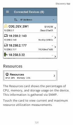
Resources
The Resources card shows the percentages ofCPU, memory, and storage usage on the device.This information is gathered via SNMP.
Touch the card to view current and maximumresource utilization measurements.
Discovery App
326

By default, LinkRunner displays a Warningcondition if CPU, Memory, or Storageutilization is above 90%. You can adjustproblem detection and thresholds in the WiredProblem Settings accessed from the Discoverynavigation drawer.
SSIDsThe SSIDs card appears in the Details for Wi-FiControllers. This information is gathered viaSNMP.
This card shows the number of SSIDs gatheredfrom SNMP. Tap the card to view the list ofSSIDs.
Discovery App
327

On the SSIDs screen, each SSID is shown withits Security type(s) and any VLANs. SSIDs with acheckmark to the left are enabled, and thosewith an × are disabled.
Discovery App
328
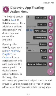
Discovery App FloatingAction Menu
The floating actionbutton (FAB) onDetails screens offersadditional actionsdepending on thedevice type andconnectionavailable.
Opening otherNetAlly apps, suchas Path Analysis,Ping/TCP, orCapture, from aDetails screen willauto-populate thenew app with thedevice's nameand/or address. Inthis way, theDiscovery app provides a helpful shortcut andprevents you from needing to type in targetaddresses or hostnames in other testing apps.
Discovery App
329

l Touching TCP Port Scan opens the TCP PortScan screen in the Discovery app.
l Selecting Browse opens Google Chrome.
l Telnet or SSH open the JuiceSSH app.l For devices with a MAC address or BSSID,
touching Name and Authorization opens adialog where you can assign a custom username and Authorization status.
Discovery App
330

Auto-Populating Device AddressesWhen another app is opened from the FAB, thedefault address and name shown on the TopDetails Card are the targets populated.
For example, the Router shown in the Detailsscreen below has multiple IPv4 and MACaddresses (which can be viewed by touchingthe Addresses card).
Discovery App
331

When a user opens the FAB and selects adifferent app, such as Path Analysis, only theaddress and name listed at the top of theDetails screen will be populated in the PathAnalysis app.
Discovery App
332

Discovery App
333
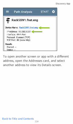
Back to Title and Contents
To open another screen or app with a differentaddress, open the Addresses card, and selectanother address to view its Details screen.
Discovery App
334
Device TypesThe Discovery app lists and analyzes the typesof devices explained in this section. Differentdata may be available to the LinkRunnerdepending on the device type, how it wasdiscovered, and your configured settings.
See Discovery Settings for SNMP Configurationand Devices Discovered Through Other Devicesoptions.
For descriptions of the different Details cardsand screens, see Discovery Details.
The images in the rest of this section representan example of the data Discovery may displayfor each device type.
Discovery App
335

RoutersLinkRunner discovers IP routers by monitoringtraffic and querying hosts.
Discovery App
336

SwitchesSwitches are also discovered by monitoringtraffic and querying hosts.
Discovery App
337

Unknown SwitchesUnknown switches are detected indirectlybased on analysis of the traffic going throughsurrounding switches. Though the LinkRunnercannot identify the switch itself, it can sensewhere a switch is active on the network via thedevice MAC addresses in that space.
Unknown Switches are numbered by theLinkRunner as they are discovered. Thesenumbers may change the next time thediscovery process runs.
The Unknown Switches Details screen showsthe number of devices connected to the switchand allows you to view the devices that areconnected by tapping the Connected Devices
Discovery App
338

card. The connected devices provide cluesabout where the unknown switch may belocated.
Discovery App
339
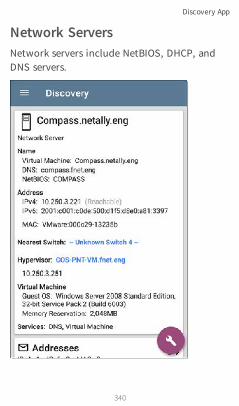
Network ServersNetwork servers include NetBIOS, DHCP, andDNS servers.
Discovery App
340

HypervisorsVMware hypervisors are discovered via SNMP.The hypervisor's SNMP agent must be enabledfor the LinkRunner to discover it and classify itas a hypervisor.
Discovery App
341

Virtual MachinesVMware virtual machines are discovered fromVMware client table in SNMP-enabled VMwarehypervisors. Devices are also classified as VirtualMachines if they have a VMware MAC.
Discovery App
342

Discovery App
343

Wi-Fi ControllersLinkRunner can discover SNMP enabled Wi-Ficontrollers, including Cisco and Aruba Wi-FiControllers.
Discovery App
344
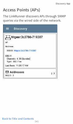
Back to Title and Contents
Access Points (APs)The LinkRunner discovers APs through SNMPqueries via the wired side of the network.
Discovery App
345

Wi-Fi ClientsWireless clients are discovered through SNMPqueries through the wired side of the network.
VoIP PhonesVoIP discovery provides visibility into the VoIPand layer 2/3 configuration of the network.
Discovery App
346

Discovery App
347

PrintersThe LinkRunner identifies IP printers via theSNMP Printer MIB and IPX printers viadiagnostic requests and queries.
Discovery App
348

SNMP AgentsSNMP agents are discovered using SNMPqueries. See SNMP Configuration.
NOTE: If LinkRunner cannot discover theSNMP agents on your devices, they may beconnected to another subnet, like a man-agement subnet. Solve this issue by addingthe subnet to Extended Ranges.
See also SNMP Details.
Discovery App
349

NetAlly ToolsThe LinkRunner can also identify other NetAllynetwork testers, including LinkRunners,AirCheck G2s, OneTouches, LinkRunners (ATand G2), and Test Accessories.
The image above shows several NetAlly tools asthey appear in the main Discovery list.
Discovery App
350

LinkRunner displays all the information it cangather about each tool on the Details screen.
Hosts/ClientsOther hosts and clients are discovered by trafficmonitoring and querying. If a host cannot beidentified as belonging to one of the othercategories (Switch, Router, VoIP device, etc.)then it is categorized as Host/Client.
Discovery App
351

Back to Title and Contents
Discovery App
352

Discovery SettingsDiscovery configurations include SNMPsettings, Community Strings and the order inwhich they are used, Credential Sets, Ports,Extended Ranges, and process intervals.
Access the Discovery settings screen by slidingout the left-side navigation drawer or tappingthe menu icon , and selecting DiscoverySettings.
(Touch here to skip to Problem Settings, TCPPort Scan, or back to General Settings.)
Discovery App
353

To adjust Discovery Settings:
1. On the Discovery Settings screen, toucheach field described in this topic, asneeded, to select or enter your requiredconfiguration elements.
Discovery App
354

2. When you finish configuring, tap the backbutton to return to the main DiscoveryList screen.
3. Then, Refresh Discovery from the actionoverflow menu to apply the new con-figuration.
You can load, save, import, and exportconfigured Discovery settings by touching thesave button on this screen.
l Load opens a previously saved Discoveryconfiguration.
l Save As saves the current configurationwith an existing name or a new customname.
l Import: Import a previously exportedsettings file.
l Export: Create an export file of the currentsettings, and save it to internal orconnected external storage.
See Managing Testing App Settings for moreinstructions.
Discovery App
355

After you have saved a configuration, thecustom name you entered appears in the titleof the Discovery Settings screen. In the imagebelow, a user has saved a custom configurationnamed "South Campus," which replaces the"Discovery Settings" screen title.
SNMP ConfigurationThe MIB (Management Information Base) ofSNMP managed devices contains informationsuch as device configuration, interface con-figuration and statistics, SNMP tables (like hostresource and route tables) and VLAN details.Through the Discovery process, the LinkRunnerinterrogates MIBs to determine the device type,ports, connected subnets, and other data.
Discovery App
356

SNMP credentials are required to communicatewith the SNMP agents on your interconnectdevices, such as switches and routers. TheDiscovery Settings allow you to enter the SNMPcommunity strings and credential sets theLinkRunner uses to communicate with thosedevices.
SNMPv1/v2Touch the toggle button to enable or disableSNMPv1 and v2 queries. This setting is enabledby default and uses the Community Stringsconfigured in the next setting.
Community StringsTouch this field to open the CommunityStrings list screen and add, edit, or removecommunity strings.
Discovery App
357

The LinkRunner uses the checked strings in theorder shown on this screen. If it does notreceive a response from the queried deviceusing one string, it sends the next string.
NOTE: This screen and others in theDiscovery settings operate much like theAutoTest Profile Group screen.
Discovery App
358
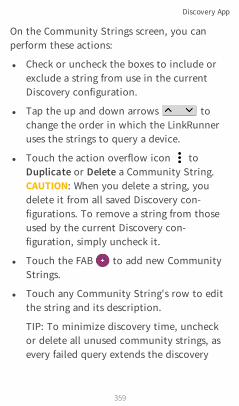
On the Community Strings screen, you canperform these actions:
l Check or uncheck the boxes to include orexclude a string from use in the currentDiscovery configuration.
l Tap the up and down arrows tochange the order in which the LinkRunneruses the strings to query a device.
l Touch the action overflow icon toDuplicate or Delete a Community String.CAUTION: When you delete a string, youdelete it from all saved Discovery con-figurations. To remove a string from thoseused by the current Discovery con-figuration, simply uncheck it.
l Touch the FAB to add new CommunityStrings.
l Touch any Community String's row to editthe string and its description.
TIP: To minimize discovery time, uncheckor delete all unused community strings, asevery failed query extends the discovery
Discovery App
359

time. You can also arrange the communitystrings in the order they are used most.
SNMPv3Touch the toggle button to enable or disableSNMPv3 queries. This setting is enabled bydefault and uses the Credentials configured inthe next setting.
NOTE: If this setting is enabled, but noSNMPv3 credentials are configured, theLinkRunner will discover the engine IDs ofall SNMPv3 agents. This is a good way todiscover if a device support SNMPv3.
CredentialsTouch this field to open the Credentials listscreen.
Discovery App
360
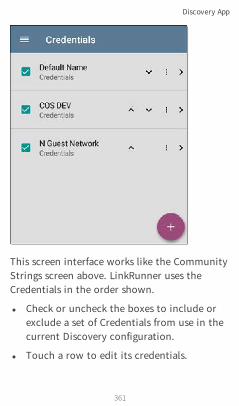
This screen interface works like the CommunityStrings screen above. LinkRunner uses theCredentials in the order shown.
l Check or uncheck the boxes to include orexclude a set of Credentials from use in thecurrent Discovery configuration.
l Touch a row to edit its credentials.
Discovery App
361

l Touch the FAB to add new credentials.
On the Credentials Sets screen, tap each field toselect or enter the credentials required.
Name
Touch the Name field to enter a custom namefor the Credential Set.
Discovery App
362

Back to Title and Contents
Username
Touch to enter the SNMPv3 username.
Authorization Type and Password
LinkRunner Discovery supports two SNMPv3Authorization types: HMAC-SHA and HMAC-MD5. If Authorization is required, enter theappropriate password.
Privacy Type and Password
LinkRunner Discovery supports four PrivacyTypes: CBC-DES, AES-128, AES-192, AND AES-256. If needed, enter the appropriate PrivacyPassword.
Discovery App
363
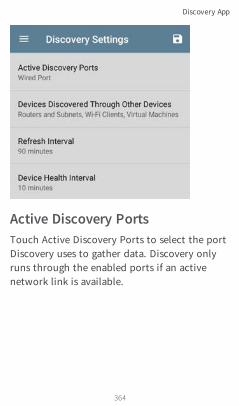
Active Discovery PortsTouch Active Discovery Ports to select the portDiscovery uses to gather data. Discovery onlyruns through the enabled ports if an activenetwork link is available.
Discovery App
364

Discovery uses all of the ports by default.Uncheck them to limit which ports are used.NOTE: The top Wired Port refers to the Testport. An AutoTest Wired Profile must run toestablish test port links. The last listed WiredProfile runs automatically when you start upthe LinkRunner if a connection is available.
See also Test and Management Ports.
Devices Discovered Through OtherDevicesBy default, LinkRunner discovers devices fromSNMP tables of other devices. If you do notwant Discovery to automatically find devices
Discovery App
365

from SNMP tables of the device types listedhere, you can uncheck their boxes.
Routers and SubnetsWhen the Routers and Subnets checkbox isenabled, any discovered routers are included indiscovery results. In addition, if Discovery hasSNMP access to a discovered router, its routingtables are read, and the next hop routers areadded to the Discovery list. If any local subnetsare available in the routing tables, these are
Discovery App
366

also added to the Subnets list. This processcontinues until all the available SNMPcredentials are tried for the added routers.
NOTES: Discovery does not sweep every dis-covered subnet; discovered subnets are onlyadded to the subnets list. To performdiscovery in a specific subnet, see ExtendedRanges above.
If another site has routers you want todiscover using this process, but there isn’t alocal next hop link from this site, you canadd one of the routers of that site todiscovery, and the process will run fromthat router and find the routers on that siteas well. Add the subnet of the router or justthe router’s IP address with a mask of /32 toExtended Ranges.
SwitchesWhen the Switches checkbox is enabled,discovery adds any switches that it finds inSNMP neighbor tables of other devices to theDiscovery list.
Discovery App
367

For example, when LinkRunner is reading theCDP and LLDP caches of one switch, it willcontain other switches. If this option isenabled, the LinkRunner adds those otherswitches, even if they are not in discoveryranges.
NOTE: To Discover switches at another site,add one of the switches of that site toDiscovery Extended Ranges.
VoIP DevicesWhen the VoIP Devices checkbox is enabled,discovery will add any VoIP devices that it findsin SNMP tables of other devices regardless ofthe subnet. These are usually found in theLLDP-MED tables of the switches. Enabling theSwitches option provides the best chance offinding all your VoIP devices.
Wi-Fi ClientsWhen the Wi-Fi Clients checkbox is enabled,discovery will add any wireless clients it findsin SNMP tables of APs and Wireless LANControllers. Enabling this option along with
Discovery App
368

Back to Title and Contents
Switches provides best chance of finding all Wi-Fi clients.
Virtual MachinesWhen the Virtual Machines checkbox is enabled,discovery adds any virtual machines that itfinds in SNMP tables of other devices. These areusually found in the ESX host > SNMP tables.Adding the subnets of your ESX hosts toExtended Ranges helps with finding your virtualmachines.
Discovery App
369

Refresh IntervalThis setting controls the time between runs ofthe Discovery process. By default, Discoveryruns every 90 minutes. Touch the RefreshInterval field to select a different interval, up to8 hours.
The Manual option turns off regular automaticDiscovery, and the process will only refresh if
Discovery App
370

you select Refresh Discovery from the mainDiscovery list screen.
Device Health IntervalDiscovery automatically runs a set of networkhealth tests to search for network Problems,such as high utilization, discards, or errors onall discovered interfaces and device resources.
The selected time Refresh Interval is theminimum time between each run of the DeviceHealth tests. Touch the field to disable DeviceHealth testing or to change the interval fromthe default of 10 minutes to 30 or 60 minutes.
Discovery App
371

Disabling the Device Health testing affects thetypes of Problems that Discovery can detect.
See also Problem Settings.
ARP Sweep RateTouch the ARP Sweep Rate field to select a ratebetween 5 and 100 ARP requests per second.
This setting can prevent the LinkRunner fromshutting down ports that sense too many ARPsare being sent.
Discovery App
372

Back to Title and Contents
SNMP Query Delay
This function controls how long yourLinkRunner waits between SNMP queries to keytables that can cause CPU spikes in the SNMPagents, including the ARP cache, IP addresstable, routing tables, and FDB tables.
The default SNMP Query delay is No Delay.When querying the key large tables, theLinkRunner asks for more data as soon as aresponse has been received. You can select a 1or 5 second delay if needed.
Discovery App
373
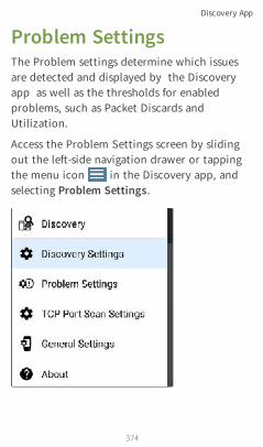
Problem SettingsThe Problem settings determine which issuesare detected and displayed by the Discoveryapp as well as the thresholds for enabledproblems, such as Packet Discards andUtilization.
Access the Problem Settings screen by slidingout the left-side navigation drawer or tappingthe menu icon in the Discovery app, andselecting Problem Settings.
Discovery App
374

(Touch here to go to Discovery Settings or backto General Settings.)
As with Discovery Settings, you can save, load,import, and export configured ProblemSettings by touching the save button on thisscreen. See Managing Testing App Settings formore instructions.
Discovery App
375

All Problem types are enabled by default. Tapthe toggle button to the right to disable eachone.
Discovery App
376

Back to Title and Contents
Touch the red , yellow , or blueinformation icons to the right of each Problemto read a detailed description andrecommended actions. Red icons indicateFailure conditions and yellow indicate Warningconditions. Blue icons are simply inform-ational.
When you finish configuring, tap the backbutton to return to the main Discoveryscreen.
Discovery App
377

TCP Port Scan SettingsThe TCP Port Scan feature checks for openports on the current device from the DiscoveryDetails screen's FAB. The LinkRunner scansmany ports simultaneously and reports theopen port's numbers.
Access the TCP Port Scan Settings by slidingout the left-side navigation drawer or tappingthe menu icon in the Discovery app.
Select TCP Port Scan Settings.
Discovery App
378

Interface
This setting determines the LinkRunner portfrom which the port scan runs. Touch the fieldto select Any Port, Wired Test Port, or WiredManagement Port. See Test and ManagementPorts for explanations of the different ports.
Scan List
This setting contains the port numbers that aretested during the port scan. Tap the field toenter different port numbers, or ranges,separated by commas.
Discovery App
379

Timeout Threshold
This threshold controls how long theLinkRunner waits for a response from eachport. Once all the ports in the Scan List havehad this amount of time to respond, the scanends, and the TCP Port Scan results screen liststhe ports that responded within the threshold.
See also the TCP Port Scan results card andscreen.
Discovery App
380
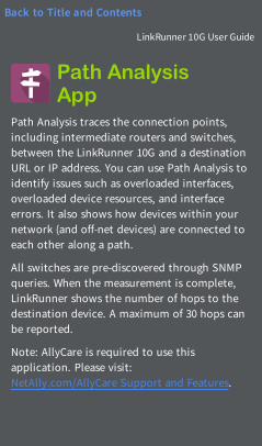
Path AnalysisApp
Path Analysis traces the connection points,including intermediate routers and switches,between the LinkRunner 10G and a destinationURL or IP address. You can use Path Analysis toidentify issues such as overloaded interfaces,overloaded device resources, and interfaceerrors. It also shows how devices within yournetwork (and off-net devices) are connected toeach other along a path.
All switches are pre-discovered through SNMPqueries. When the measurement is complete,LinkRunner shows the number of hops to thedestination device. A maximum of 30 hops canbe reported.
Note: AllyCare is required to use thisapplication. Please visit:NetAlly.com/AllyCare Support and Features.
381
LinkRunner 10G User Guide
Back to Title and Contents

Introduction to PathAnalysisPath Analysis combines Layer 3 and Layer 2measurements.
The Layer 3 measurement combines the classicLayer 3 IP (UDP, ICMP, or TCP) traceroutemeasurement with a view of the path throughthe Layer 2 switches.
The Layer 2 measurement discovers switchesbetween the router hops by looking for therouters' MAC addresses in the switchforwarding tables by sending SNMP queries toall discovered switches. The switches found inthe path are displayed between the router hopswhen the measurement finishes.
Path Analysis is most effective when you haveconfigured the Discovery app with SNMPcredentials. See SNMP Configuration in theDiscovery Settings topic to learn how.
Path Analysis App
382
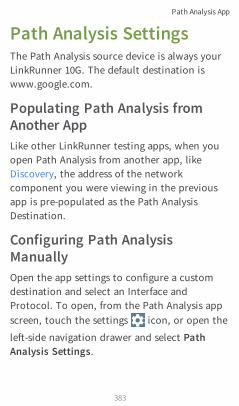
Path Analysis SettingsThe Path Analysis source device is always yourLinkRunner 10G. The default destination iswww.google.com.
Populating Path Analysis fromAnother AppLike other LinkRunner testing apps, when youopen Path Analysis from another app, likeDiscovery, the address of the networkcomponent you were viewing in the previousapp is pre-populated as the Path AnalysisDestination.
Configuring Path AnalysisManuallyOpen the app settings to configure a customdestination and select an Interface andProtocol. To open, from the Path Analysis appscreen, touch the settings icon, or open the
left-side navigation drawer and select PathAnalysis Settings.
Path Analysis App
383

On the Path Analysis Settings screen, toucheach field as needed to configure your target:
Device Name: Touch to enter the IP address orDNS name of the Path destination. The defaultis www.google.com.
Interface: This setting determines theLinkRunner port from which the test runs.Touch the field to select Any Port, Wired TestPort, or Wired Management Port .
Path Analysis App
384

LinkRunner must have an active network linkon the selected port to run a Path Analysis. IfAny Port is selected, available links are used inthe order shown in the Interface dialog above.
See Test and Management Ports for explan-ations of the different ports and how to link.
Protocol: Tap to select the Connect (TCP), Ping(ICMP), or Echo (UDP/7) protocol for your PathAnalysis.
TCP Port: This field only appears if you haveselected the Connect (TCP) Protocol. Tap toenter the port number over which you want torun Path Analysis. You may need to enter aspecific port number because routes can vary
Path Analysis App
385

Back to Title and Contents
based on the port number and/or may beblocked by firewalls.
Path Analysis App
386

Running Path AnalysisTouch the START button at the top of the appscreen to begin a Path Analysis.
NOTE: LinkRunner must be linked on theInterface (Port) selected in the app'ssettings. See Test and Management Ports forhelp.
Path Analysis App
387

Like AutoTest, Path Analysis results arepresented on cards. The top card shows themain test details, the second card showsinformation for the source device (your
Path Analysis App
388

LinkRunner 10G), and the following cards showthe Layer 2 and Layer 3 Hops in the path, whichare sequentially ordered.
Touch any blue linked name or address in thePath Analysis results screens to open theDiscovery app and further examine the linkedelement.
Path Analysis Results and SourceLinkRunner Cards
The top Path Analysis results card shows thepath's Destination address at the top, followed
Path Analysis App
389

by the three response times from the TCPConnect, Ping, or Echo tests.
Device Name: Resolved DNS name or IP addressof the destination entered in the settings
IP Address: IPv4 address of the target des-tination
Interface: The Interface option selected inthe settings
Protocol: The Protocol selected in thesettings (TCP, Ping, or Echo)
TCP Port: The port number used for a TCPConnect Protocol. This field does notappear for Ping or Echo Protocol results.
ResultsStarted: Time at which the Path Analysisbegan
Status: Current status of the Path Analysistest, including any error messages
UPLOAD TO LINK-LIVE: Touch this link toupload your results to a Link-Live account. SeeUploading Path Analysis Results to Link-Livelater in this topic.
Path Analysis App
390

Source LinkRunner Card
The source This LinkRunner card displays theport from which the Path Analysis ran.
l For Wired Test or Management port analyses(shown above), this card displays con-nection speed and duplex.
NOTE: This card and screen only display acustom name for your LinkRunner if youhave claimed it to Link-Live.
Touch the card to view more details.
The image below shows the source LinkRunnercard from a Wired Path Analysis, which displaysthe link speed and duplex.
Path Analysis App
391

Beneath the LinkRunner source card, the Hopcards show Layer 2 and Layer 3 devicesdetermined to be in the Path.
Layer 3 HopsEach Layer 3 Hop card displays the device typeicon, DNS name (if discovered), and IP address.
Beneath the name (or IP), the response timesfor each Connect (TCP), Ping (ICMP), or Echo(UDP/7) display in milliseconds. On the rightside is the router Hop number of this device inthe path.
Path Analysis App
392

Touch the card to view the hop Details screen.
No ReplySometimes Path Analysis displays Hop cardswith "No Reply" (as shown below). This resultmeans that the device in that portion of thepath did not send an ICMP TTL timeoutresponse.
Path Analysis App
393

Split RoutePath Analyses may obtain a "Split Route" result(as shown above), meaning that two or three
Path Analysis App
394

different routers within same hop responded tothe three requests.
Tap a Split Route card to view the DNS namesand IP addresses of the responding routers.
Layer 3 Interfaces and StatisticsStatistics for Interfaces on Layer 3 devices maybe identified and measured if the LinkRunnerhas SNMP access.
Path Analysis App
395

Touch a Hop card to see a summary of InterfaceDetails and Statistics, if they are available.
See also Layer 2 Switch Interfaces and Statisticsbelow.
Network Problems in Path AnalysisThe Hop cards can also show detectedProblems based on the Problem Settings in theDiscovery app and display the device type iconsin the corresponding colors.
The yellow switch icon in the image aboveindicates a Warning status.
Path Analysis App
396

Tapping the blue linked switch name will opena Discovery Details screen for the switch, wherethe user can investigate the cause of theWarning.
Layer 2 DevicesLayer 2 devices can be switches or APs.
Layer 2 SwitchesThe image below displays an example of a PathAnalysis to a device on the local broadcastdomain with two switches in the Layer 2portion of the path.
Path Analysis App
397

The LinkRunner is able to identify these Layer 2switches and their interfaces because it hasconfigured SNMP access to the switches.
Path Analysis App
398
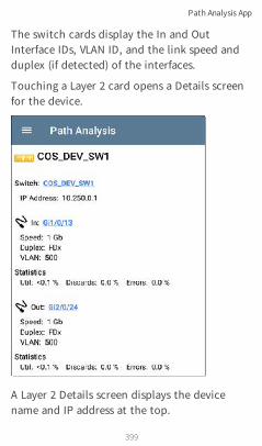
The switch cards display the In and OutInterface IDs, VLAN ID, and the link speed andduplex (if detected) of the interfaces.
Touching a Layer 2 card opens a Details screenfor the device.
A Layer 2 Details screen displays the devicename and IP address at the top.
Path Analysis App
399

NOTE: The yellow switch icon in the imageabove indicates a Warning status. SeeNetwork Problems in Path Analysis later inthis topic.
Layer 2 Switch Interfaces and StatisticsLayer 2 Switch Details screens in Path Analysisdisplay a summary of the Interface Statistics(described below). To view all availableinformation for these interfaces, tap their bluelinks to open a Interface Details screen in theDiscovery app.
Statistics for Interfaces on Layer 2 switches maybe identified and measured if the LinkRunnerhas SNMP access.
In/Out: Indicates the interface type and name.The interface name often contains the physicalport number where the switch is connected tothe network.
Util: Percentage of total interface capacitybeing used
Discards: Percentage of total packets thathave been dropped
Path Analysis App
400
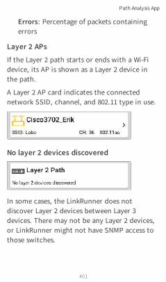
Errors: Percentage of packets containingerrors
Layer 2 APs
If the Layer 2 path starts or ends with a Wi-Fidevice, its AP is shown as a Layer 2 device inthe path.
A Layer 2 AP card indicates the connectednetwork SSID, channel, and 802.11 type in use.
No layer 2 devices discovered
In some cases, the LinkRunner does notdiscover Layer 2 devices between Layer 3devices. There may not be any Layer 2 devices,or LinkRunner might not have SNMP access tothose switches.
Path Analysis App
401

The Layer 2 card may also display a result of"No switches found," which indicates thatDiscovery has not found any switches withSNMP access to determine if the switches are inthe path. If this is an unexpected result, checkand verify your SNMP Configuration andExtended Ranges in the Discovery app settings.
Uploading Path Analysis Resultsto Link-LiveTouching the UPLOAD TO LINK-LIVE link on thetop card opens the Link-Live sharing screen forpath analysis results:
Path Analysis App
402

Back to Title and Contents
Path Analysis results are uploaded to theAnalysis page on Link-Live.
Path Analysis App
403
Performance TestApp
The LinkRunner 10G's line rate PerformanceTest provides Peer capability to support point-to-point performance testing of a traffic streamacross wired IPv4 network infrastructure. Thistest quantifies network performance in terms oftarget rate, throughput, loss, latency, andjitter.
404
LinkRunner 10G User Guide
Back to Title and Contents

The Performance Test runs from the Wired TestPort (top RJ-45 or Fiber port), and an AutoTestWired Profile must connect successfully toestablish link on the port. When you start upthe LinkRunner, the last Wired Profile in the listof active AutoTest profiles runs automatically ifan active Ethernet connection is detected onthe top RJ-45 port. Otherwise, you may need tomanually run a Wired AutoTest to link. SeeWired AutoTest Profiles to review.
Performance Test App
405

Introduction toPerformance TestingNetwork performance is measured between aSource device, on which the test is configuredand controlled, and up to four Endpoint devicesthat exchange traffic with the source. There aretwo endpoint types: Peers and Reflectors.
When using a Peer endpoint, separate upstreamand downstream measurements can be shownfor Throughput, Loss, Latency, and Jitter.
When using a Reflector, the LinkRunner reportsround-trip data for all measurements. Separateupstream and downstream traffic meas-urements are not possible.The LinkRunner 10G can act as a Peer for a testconducted by a different source device, such asan EtherScope nXG or a OneTouch AT 10G.
Other NetAlly testers work with the LinkRunnerto perform network performance testing:
l EtherScope nXG can act as the Source or aPeer for Performance tests.(NetAlly.com/products/EtherScopenXG)
Performance Test App
406

l OneTouch AT 10G can act as the Source or aPeer for Performance tests.(NetAlly.com/products/OneTouch)
In this ChapterRunning LinkRunner as a Performance Peer
Performance Test App
407

Running LinkRunner as aPerformance PeerLinkRunner 10G can act as a Peer for aEtherScope nXG or a OneTouch AT 10G actingas the source and controller.
To access the LinkRunner Performance Peer,tap the menu button in the Performanceapp and select Performance Peer.
The Wired Test Port must be linked (by runningan AutoTest Wired Profile) for the Performance
Performance Test App
408

Peer function to run. If the port is not linked, aStatus message displays, "The wired test port isnot linked."
Performance Peer SettingThe only setting for the Performance Peerfunction is the Communication UDP Port.
Touch the settings button on the PerformancePeer screen to change the port number. Thedefault NetAlly performance test port is 3842.
NOTE: The UDP port number entered heremust match the port number used by yoursource device.
Running the PeerTap START on the Performance Peer screen tostart the Peer.
Performance Test App
409
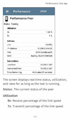
The screen displays real-time status, utilization,and rates for as long as the test is running.
Status: The current status of the peer
UtilizationRx: Receive percentage of the link speed
Tx: Transmit percentage of the link speed
Performance Test App
410

AddressLink: Link speed and duplex of the estab-lished Wired Test Port connection
IP Address: Address of the LinkRunner to beentered into the controlling source device
Port: UDP Communication port in use bythe peer
MAC: The LinkRunner's MAC address
ConnectionsLast Peer: Address of the previous peer thatwas connected to the LinkRunner
Connected Peer: Address of the peer that iscurrently connected to the LinkRunner
Time Remaining: Amount of time left forthe current test
Performance Test App
411

iPerf TestApp
iPerf is a standardized network performancetool used to measure UDP or TCP throughputand loss.
The iPerf app runs an iPerf3 performance testto a NetAlly Test Accessory or an iPerf serverendpoint.
412
LinkRunner 10G User Guide
Back to Title and Contents

The NetAlly Test Accessory runsnetwork connection tests, uploadsresults to Link-Live Cloud Service, andacts as an iPerf server endpoint foriPerf tests run by other NetAllyhandheld testers.
Learn more about the Test Accessory fromNetAlly.com/products/TestAccessory.
If you are using an iPerf server installed on a PCor other device as an endpoint, iPerf version 3is required to run the LinkRunner iPerf test.You can download iPerf server software fromhttps://iperf.fr.
iPerf Test App
413

iPerf SettingsTo run an iPerf test, you must configure yourLinkRunner unit to communicate with youriPerf endpoint. You can manually enter an iPerfserver address, or select a NetAlly TestAccessory's address in the iPerf settings.
Saving Custom iPerf SettingsThe iPerf app allows you to save a con-figuration of settings for running an iPerf testto the same endpoint later.
Touch the save icon to load, save, import,and export configured settings. See Saving AppSettings Configurations for more instructions.
Once you save a settings configuration, thecustom name you entered appears at the top of
iPerf Test App
414

the iPerf settings and results screens. In theexample images here, the user has saved acustom iPerf configuration called "Server RoomEndpoint."
Test Accessories in DiscoveryYou can start an iPerf test from the Detailsscreen for a Test Accessory in the Discovery appusing the floating action button.
1. Open the Discovery app, and select anactive Test Accessory from the main
iPerf Test App
415

Discovery list to open its Details screen.
2. Open the floating action button (FAB)menu.
iPerf Test App
416

NOTE: You can select Browse in thefloating action menu to open the TestAccessory's Web Interface, where you canview its status and configure its settings.
3. Then, select the iPerf app button.
The iPerf app opens with the IP addresspopulated from the Test Accessory inDiscovery.
iPerf Test App
417

Configuring iPerf SettingsTo configure the iPerf test settings manually,open the settings on the iPerf screen.
iPerf Test App
418

Touch each field to enter or revise selections asneeded. Changed settings are automaticallyapplied. When you finish configuring, tap theback button to return to the iPerf testscreen.
Interface: This setting determines theLinkRunner port from which the test runs.Touch the field to select Any Port, Wired TestPort, or Wired Management Port. See Test andManagement Ports for explanations of thedifferent ports.
IPv4 Address: Touch the field to enter or selectthe IPv4 address of the target iPerf server. OnlyIPv4 addresses are allowed for iPerf testing.
iPerf Test App
419

A drop-down list in the IPv4 Address dialogshows all the Test Accessories the LinkRunnerhas discovered through the discovery process,as well as any Test Accessories that are claimedto the same Link-Live organization as yourLinkRunner.
NOTE: Clear the address field in the dialogto see the full list of discovered TestAccessory addresses.
Port: The default iPerf3 port number is 5201.Tap the field to enter a different port number.
NOTE: The iPerf port number entered heremust match the port number used by youriPerf server. If needed, consult the TestAccessory User Guide(NetAlly.com/products/TestAccessory).
Duration: This setting is the length of time forone direction, Upstream or Downstream, of theiPerf test. If the Direction setting below is setto both Upstream/Downstream, the total testtime will be twice the value set here. Tap thefield to select a new duration or enter a customvalue. The default is 10 seconds.
iPerf Test App
420

Back to Title and Contents
Protocol: TCP is the default protocol. Tap theUDP selector to switch to UDP.
NOTE: iPerf tests running the TCP protocolautomatically run at the fastest ratepossible. When running a UDP protocol test,the iPerf app attempts to run at theselected Bandwidth.
Direction: You can run an iPerf test Upstream,Downstream, or both. The default is Upstreamand Downstream. Touch this field to set thetest for only one direction.
Upstream and Downstream Bandwidth: Thesefields only appear if the UDP Protocol isselected. They specify the desired targetbandwidth for the iPerf Test using the UDPprotocol.
Upstream and Downstream Thresholds:Thresholds are the values the LinkRunner usesto grade the test as Pass or Fail. iPerfthresholds are throughput rates. The default is10 Mbps. Tap the threshold fields to select adifferent value or enter a custom one.
iPerf Test App
421

Running an iPerf TestEnsure that you have an active link on theInterface (Test or Management Port) fromwhich you are running the iPerf test. TheWired test port requires that an AutoTest WiredProfile (which runs automatically) has run toestablish link. The Management port links auto-matically if a connection is available.
Tap the START button on the main iPerf screento begin testing.
iPerf Test App
422
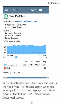
Test characteristics and status are displayed atthe top of the iPerf results screen while thelower part of the screen displays a real-timegraph of the TCP or UDP Upload and/orDownload speeds.
iPerf Test App
423

To pan and zoom on the graphs, you canswipe, double tap, and move the slider. See theTrending Graphs topic for an overview of thegraph controls.
Device Name: Hostname or address of the iPerfserver or Test Accessory
IP Address: IPv4 address of the iPerf server
Interface: The LinkRunner Test or ManagementPort from which the test is running
Results
l Duration: Configured Duration from theiPerf settings
l Started: Time the test started
l Status: Success or failure status of the test
TCP/UDP Throughput Up and Down graphs:The iPerf graphs plot the throughput rate to(Up) or from (Down) the iPerf server in Mbps.
The table below each graph displays theCurrent, Minimum, Maximum, and Averagerates.
iPerf Test App
424

Limit: This is the Threshold from theiPerf app's settings. The threshold value is alsodisplayed on the graph as a red dotted line.
iPerf Test App
425
UDP Packet Loss Up and Down graphs: Whenrunning a UDP protocol test, the iPerf resultsalso display graphs and tables of Packet Loss.Values for the number and percentage ofpackets lost are displayed in the table belowthe graph. The Packet Loss Up graph and tabledo not display measurements until results arereceived from the iPerf server at the end of theupstream test.
Note that the Packet Loss Up number could bemuch less than the Packet Loss Down number.
Uploading iPerf Results to Link-LiveTo send your iPerf results to the Link-Livewebsite, touch the action overflow buttonat the top right of the iPerf screen, and thentouch Upload to Link-Live.
iPerf Test App
426

The Link-Live sharing screen opens and allowsyou to revise the auto-generated filename andattach comments to the iPerf result, which willbe displayed on the Results page on Link-Live.com.
iPerf Test App
427

Link-Live CloudService
Link-Live Cloud Service is a free, online systemfor collecting, tracking, organizing, analyzing,and reporting your test results. AutoTest resultsare automatically uploaded once yourLinkRunner 10G is claimed.
428
LinkRunner 10G User Guide
Back to Title and Contents

The comprehensive LinkRunner 10G offers morefeatures for analyzing your network in Link-Livethan previous testers. Claim your LinkRunner toLink-Live.com to access these functions:
l Check for software updates and update yourLinkRunner 10G software.
l Download third-party applications from theNetAlly App Store to use on your LinkRun-ner.
l Automatically upload AutoTest results eachtime you run AutoTest.
l Attach test and Job comments to Link-Liveuploads, and automatically sort your resultsand files into folders in Link-Live.
l Upload test, discovery, and analysis resultsfrom the NetAlly apps, including Discovery,Path Analysis, and iPerf. See Link-Live andTesting Apps for more about uploading.
Link-Live Cloud Service
429

Getting Started in Link-Live Cloud ServiceTo start, create a user account at Link-Live.com, and sign in. You can open the Link-Live website in the LinkRunner's web browserto create and manage your account.
Quick Claiming on the Unit1. Open the Link-Live app , and touch
CLAIM NOW on the app screen.
2. In the Link-Live claiming dialog, touchQUICK CLAIM.
Link-Live Cloud Service
430

A web browser window opens to the Link-Live.com website.
3. Sign in if you haven't already.
Once you are signed in, Link-Live attemptsto claim your unit. You do not need toenter the MAC.
Link-Live Cloud Service
431

4. If an Update is available, note the updatinginstructions, and touch CONTINUE.
5. If desired, revise the name and descriptionof your LinkRunner unit.
Link-Live Cloud Service
432

Otherwise, touch the × to finish theclaiming process.
Claiming ManuallyOn Link-Live.com1. The first time you sign in to Link-Live.com,
a pop-up window appears, prompting youto claim a device.
If you already have a user account andother devices claimed to Link-Live, navigateto the Units page from the left sidenavigation drawer, and click the Claim Unitbutton at the lower right corner of thescreen .
Link-Live Cloud Service
433

2. Then, select the LinkRunner 10G image, andfollow the claiming instructions on theLink-Live website.
On the LinkRunner 10G Unit1. Open the Link-Live app. Your unit's MAC
address is displayed.
2. Touch CLAIM NOW on the Link-Live appscreen.
3. When prompted by the instructions on theLink-Live website, enter the MAC address.
After you claim your LinkRunner 10G to Link-Live, a software update may be available. If so,a notification appears in the Status Bar .Open the Top Notification Panel, and select thenotification to update your unit.
Link-Live Cloud Service
434

See Updating Software for more information.
After ClaimingOnce your LinkRunner is claimed to the Link-Live Cloud Service, it will automatically uploadyour AutoTest results each time you runAutoTest. You can also upload a test commentand a picture with your test results using theAutoTest Wired Profile's floating action buttons(FABs), and you can automatically sort yourresults into folders in Link-Live using test andJob comments.
If your LinkRunner is not connected to anactive network, any test results, comments, orimages are stored in memory (buffered) anduploaded once a connection is established.
For more information on how to the use theLink-Live.com website, click or touch thenavigation menu icon at the top left of theLink-Live.com pages, and select .
Link-Live Cloud Service
435

UnclaimingYou may need to unclaim your unit from Link-Live to transfer it to another user or if you nolonger want to send any information to Link-Live.com.
To unclaim your LinkRunner from Link-Livefrom your unit, open the About screen fromthe left-side navigation drawer in the Link-Liveapp, and touch UNCLAIM.
Link-Live Cloud Service
436

Back to Title and Contents
Link-Live Cloud Service
437
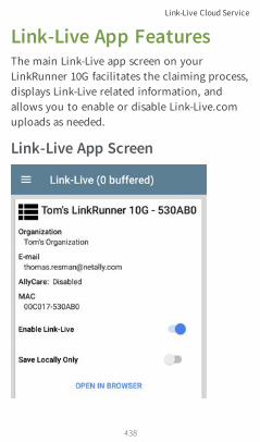
Link-Live App FeaturesThe main Link-Live app screen on yourLinkRunner 10G facilitates the claiming process,displays Link-Live related information, andallows you to enable or disable Link-Live.comuploads as needed.
Link-Live App Screen
Link-Live Cloud Service
438

The "(# buffered)" in the Link-Live screenheader indicates the number of files stored inthe device memory when no active networkconnection is available. The buffered file typesare listed below the main app card.
Link-Live Cloud Service
439
These will upload to Link-Live.com once yourLinkRunner is connected to an active network.
The LinkRunner unit's name that displays onthe Link-Live.com is shown to the right of theLink-Live icon . You can change this nameon the Link-Live.com Units page.
Organization is the Link-Live organizationwhere the unit is claimed.
E-mail is the first e-mail address assigned to theunit, which receives test result notificationemails.
The Organization and Email address shownhere are assigned on the Link-Live.com website.The fields displayed in LinkRunner's Link-Liveapp are informational.
The Enable Link-Live toggle button turns theLink-Live features on or off. If Link-Live isdisabled here, the LinkRunner cannot uploadtest results or check for software updates. TheUpload to Link-Live options will not appear inthe testing apps.
Link-Live Cloud Service
440

Touch the OPEN IN BROWSER link to openLink-Live.com on the LinkRunner's webbrowser.
Saving Locally OnlyIf you do not want to send your results to theLink-Live website, you can still save resultslocally to your LinkRunner as JSON files.
Touch the Save Locally Only toggle field in theLink-Live app to save the JSON files to yourunit.
Select SHOW FILES to open the Files app. The.json files are saved in the Downloads >TestResults folder.
Link-Live Cloud Service
441

See the Managing Files topic for an overview ofthe Files app.
You can transfer the JSON files to a PC foranalysis, or you can download a JSON viewerapp from the App Store on yourLinkRunner.
With Save Locally Only enabled, options foruploading or saving to Link-Live (described inthe Link-Live and Testing Apps section below)will still display in the NetAlly testing apps.
Link-Live Cloud Service
442

However, the results will be saved to theinternal Link-Live storage folder, and notuploaded to Link-Live.com.
Job CommentThe left-side navigation drawer for the Link-Liveapp lets you enter or change the Job Comment.The Job Comment attaches to all test resultsand files uploaded to Link-Live, until youchange or delete it. In contrast, otherComments, like those attached to WiredAutoTest profiles or Discovery results, are onlyattached to one set of test results or uploadedfile.
Both comment types appear on Link-Livesharing screens like the one below:
Link-Live Cloud Service
443

To enter or change the Job Comment in theLink-Live app:
1. With the Link-Live app open, touch themenu icon or swipe right from the leftside of the screen.
Link-Live Cloud Service
444

2. Touch the Job: field.
3. Enter a comment in the dialog box.
4. Touch SAVE.
Note that the Job Comment field appears inother Link-Live sharing screens, allowing you tochange it from multiple locations on theLinkRunner. No matter where you change theJob Comment, it is updated everywhere on theunit.
Software UpdatesThe left-side navigation drawer for the Link-Liveapp also lets you check for and download anyavailable software updates. See UpdatingSoftware in the Software Management chapter.
Link-Live Cloud Service
445

Link-Live and Testing AppsOnce your unit is claimed, the Link-Live appworks with several of the testing apps toupload test results, discovery and analysis data,comments, and images to the Link-Live website.Link-Live.com categorizes the uploads fromdifferent apps on corresponding webpages, asshown below:
LINK-LIVE WEBPAGE APP UPLOADS
Results
AutoTest, Performance, iPerf,and Cable Test resultsImages, Connection Logs, andother files when saved to atest result
Uploaded Files Captures, Images, ConnectionLogs, and other file types
Analysis Discovery and Path Analysisresults
If your unit is not claimed to Link-Live.com orif Link-Live is disabled on the app screen, thelinks and buttons for uploading to Link-Live inthe testing apps will not appear.
Link-Live Cloud Service
446

Link-Live Sharing Screens
Whenever you select a button or link, like thoseabove, to Upload, Save, or Share to Link-Live, aLink-Live sharing screen appears with theappropriate options for the data type.
For example, the Link-Live sharing screen forDiscovery app data allows you to upload to theAnalysis page on Link-Live.com.
Link-Live Cloud Service
447

The Link-Live sharing screen for a screenshot orother image allows you to attach it to the mostrecently run (AutoTest, iPerf, or Cable) testresult on the Results page, or just to theUploaded Files page on Link-Live.com.
Link-Live Cloud Service
448

Remember, the regular Comment field uploadsonly to the current result or file, while the JobComment field uploads with all results and filesuntil you change it.
Link-Live Cloud Service
449

Sharing a Text File to Link-LiveYou can also select and share text by longpressing text on the unit's screen. Text files areattached to the last test results on Link-Live.com.
1. Long press a text string to select it.
2. Touch Select All if needed.
Link-Live Cloud Service
450

3. Touch SHARE.
4. Select the Link-Live icon to open the Link-Live sharing screen.
Link-Live Cloud Service
451

5. Format any comments as needed, and thentouch SAVE TO LAST TEST RESULT.
Link-Live Cloud Service
452
Cable TestApp
LinkRunner 10G's Cable Test can help youdetermine cable length and fault status, verifywiremapping of patch and structured cabling,and locate cable connections using toning. Thecable testing port is the RJ-45 port on the leftside of the LinkRunner unit. Connect a cable tothis port for testing and tracing with the tonefunction.
453
LinkRunner 10G User Guide
Back to Title and Contents
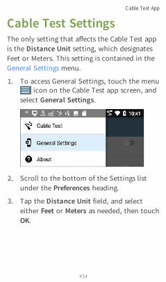
Cable Test SettingsThe only setting that affects the Cable Test appis the Distance Unit setting, which designatesFeet or Meters. This setting is contained in theGeneral Settings menu.
1. To access General Settings, touch the menuicon on the Cable Test app screen, and
select General Settings.
2. Scroll to the bottom of the Settings listunder the Preferences heading.
3. Tap the Distance Unit field, and selecteither Feet or Meters as needed, then touchOK.
Cable Test App
454

Running Cable TestRefer to LinkRunner 10G's Buttons and Ports asneeded.
l With an open or unterminated cableconnected to the RJ-45 cable test port (leftside of the unit), you can measure length,identify shorts and splits, and locate opens.
l Using a cable terminated with a WireViewCable ID accessory, you can measure cablelength and identify shorts, opens, splitpairs, crossover cables, normal or negativepair polarity, and shielded cables.
l LinkRunner 10G cannot perform a cable teston a cable that is connected to a switch;however, you can still use the toningfunction to trace the cable to theconnected port.
l Additionally, you cannot run a cable test oruse the toning feature if the unit detectsvoltage on the connected cable. Thelightning bolt icon on the Cable Test screenindicates detected voltage.
Cable Test App
455

To start the cable test, tap START at the topright of the Cable Test app screen.
Open Cable TDR TestingLinkRunner 10G can measure the length of acable and detect some faults by measuring theelectrical reflections of the cable using TimeDomain Reflectometry (TDR). Connect an opencable (unterminated) into the RJ-45 port on theleft side of the LinkRunner unit to measure itslength and view any shorts, opens, or splits.
Cable Test App
456
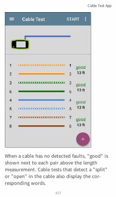
When a cable has no detected faults, "good" isshown next to each pair above the lengthmeasurement. Cable tests that detect a "split"or "open" in the cable also display the cor-responding words.
Cable Test App
457

This unterminated cable test image shows ashorted cable between pins 4, 5, and 7.
Cable Test App
458

Terminated WireView TestingUsing a WireView accessory provides moredetailed, per-wire results. A WireView #1 isincluded with your LinkRunner 10G. AdditionalWireViews 2-6 are available for purchase.
To run a terminated cable test, connect the leftside RJ-45 port to a cable terminated with anexternal WireView Cable ID accessory.
The terminated cable test screen displays thenumber of the WireView attached, unless acable fault prevents the LinkRunner fromdetecting the WireView.
Cable Test App
459

The image above indicates a crossover betweenpairs 1, 2 and 3, 6 and a WireView accessorynumber 5.
Cable Test App
460

* IntelliTone is a trademark of Fluke Networks.
The last row of WireView results indicateswhether the cable is shielded: an unbroken linebetween sh means a shielded cable is detected.
Toning FunctionYou can also trace a cable using a FlukeNetworks* IntelliTone™ Probe, or any analogprobe, and the Tone function.
Connect a cable into the left side RJ-45 port,touch the FAB, andselect the appropriateTone option for yourprobe. The LinkRunner10G emits the tonethrough the cable, andthe probe detects it,allowing you to tracethe wire or locate it inthe switch closet.
Cable Test App
461

Uploading Cable Test Results toLink-LiveTouch the action overflow icon at the topright of the Cable Test screen, and selectUpload to Link-Live to send the current CableTest result to the Results page on Link-Live.com.
See the Link-Live chapter for more information.
Cable Test App
462

Specifications andComplianceRequired compliance information is containedin this chapter.
463
LinkRunner 10G User Guide
Back to Title and Contents

SpecificationsGeneral
Dimensions 4.05 in x 7.67 in x 2.16 in(10.3 cm x19.5 cm x5.5 cm)
Weight 1.677 lbs (0.76 kg)
Battery Rechargeable lithium-ionbatterypack (7.2 V, 6.4 Ah, 46 Wh)
BatteryLife
Typical operating life is 3-4 hours(infinite onPoE). Typical charge timeis 3 hours.
Display 5.0-inch color LCDwith capacitivetouchscreen (720 x 1280 pixels)
HostInterfaces
RJ-45 Cable Test and ManagementPortUSB Type-APortUSB Type-C On-the-GoPort
SD CardPort Supports Micro SD card storage
MemoryApproximately 8 GB available forstoring test results and user applic-ations
ChargingUSB Type-C 45-W adapter:AC Input Power 100-240 V, 50-60 Hz;DC Output Power 15 V (3 A)
Specifications and Compliance
464

MediaAccess
Copper: 10M/100M/1G/2.5G/5G/10GFiber SFP Adapters: 1G/10GBASE-X
Cable TestPair lengths, opens, shorts, splits,crossed, straight through, andWireView ID
ToneGenerator
Digital tone: [455 KHz];Analog tones: [400 Hz, 1 KHz]
LEDs 2 LEDs (Activity and Link Indicators)
Environmental Specifications
OperatingTemperature
32ºF to 113ºF (0ºC to +45ºC)NOTE: The battery will notcharge if the internal tem-perature of the unit is above113ºF (45ºC).
Operatingrelative humidity(% RH withoutcondensation)
90% (50ºF to 95ºF; 10ºC to35ºC) 75% (95ºF to 113ºF;35ºC to 45ºC)
StorageTemperature -4ºF to 140ºF (-20ºC to +60ºC)
Shock andvibration
Meets the requirements of MIL-PRF-28800F for Class 3Equipment
Specifications and Compliance
465

Safety IEC 61010-1:2010: Pollutiondegree 2
Altitude Operating: 4,000 m; Storage:12,000 m
Specifications and Compliance
466

Certifications andComplianceWCAUTION: Changes or modifications notexpressly approved by the party responsible forcompliance could void the user's authority tooperate the equipment.
P Conforms to relevant EuropeanUniondir-ectives.
Conforms to relevant Australian Safetyand EMC standards.
�Complies with 47 CFR Part 15 require-ments of the U.S. Federal Com-munications Commission.
) Listed by the CanadianStandards Asso-ciation.
Industry Canada Class A emission compliancestatement: This Class A digital apparatus complies withCanadian ICES-003. Avis de conformité à la réglementationd'Industrie Canada Cet appareil numérique de la classe Aest conforme à la norme NMB-003 du Canada.
This device is not capable of transmitting in 5600-5650MHz. This restriction is for the protection of EnvironmentCanada’s weather radars operating in this band.
Specifications and Compliance
467

This device complies with part 15 of the FCC Rules.Operation is subject to the following two conditions: (1)This device may not cause harmful interference, and (2)this device must accept any interference received,including interference that may cause undesiredoperation.
L’exploitation est autorisée aux deux conditionssuivantes : 1. L’appareil ne doit pas produire de brouillage;2. L’appareil doit accepter tout brouillage radioélectriquesubi, même si le brouillage est susceptible d’en com-promettre le fonctionnement.
EMCIEC 61326-1:2013: Basic Elec-tromagnetic Environment; CISPR 11:Group 1, Class A
Group 1: Equipment has intentionally generated and/oruses conductively-coupled radio frequency energy that isnecessary for the internal function of the equipmentitself.
Class A: Equipment is suitable for use in all estab-lishments other than domestic and those directlyconnected to a low-voltage power supply network thatsupplies buildings used for domestic purposes. Theremay be potential difficulties in ensuring electromagneticcompatibility in other environments due to conductedand radiated disturbances.
Accessory Information:Adapter Model No.: FSP045-A1BRInput: AC 100-240 V, 50/60 Hz 1.2 AOutput: DC 15 V, 3 A
Specifications and Compliance
468

Battery: 3250mAh, 7.2 V 6.4 Ah
Specifications and Compliance
469