
LIGHT RAIL VEHICLE - Wikimedia Commons
311
STANDARD LIGHT RAIL VEHICLE SPECIFICATION TECHNICAL SECTION NOTICE Thi5 document is disseminated under the sponsorship of the Department of Transportation in the interest of information exchange. The United States Govern- ment assumes no liability for its contents or use thereof. The preparation of this specification h.. beef' financed in part through a grant from the United State. Department of Transportation, Urban Mae. Transportation Adminiatration under the Urban Malla Transportation Act of 1984, as amencMd. "\
-
Upload
khangminh22 -
Category
Documents
-
view
0 -
download
0
Transcript of LIGHT RAIL VEHICLE - Wikimedia Commons

STANDARDLIGHT RAIL VEHICLE
SPECIFICATION
TECHNICAL SECTION
NOTICE
Thi5 document is disseminated under the sponsorshipof the Department of Transportation in the interestof information exchange. The United States Government assumes no liability for its contents or usethereof.
The preparation of this specification h.. beef'financed in part through a grant from theUnited State. Department of Transportation,Urban Mae. Transportation Adminiatrationunder the Urban Malla Transportation Act of1984, as amencMd.
"\


This Specification was developed in cooperation with the followingmass transit operators, consulting engineers, and governmental agency:
MASSACHUSETTS BAY TRANSPORTATION AUTHORITY
SAN FRANCISCO MUNICIPAL RAILWAY
SOUTHEASTERN PENNSLYVANIA TRANSPORT~TION AUTHORITY
SHAKER HEIGHTS RAPID TRANSIT
PORT AUTHORITY OF ALLEGHENY COUNTY
TRANSPORT OF NEW JERSEY
EL PASO CITY LINES
TORONTO TRANSIT COMMISSION
SISTEMA DE TRANSPORTE COLECTIVO (MEXICO CITY TRANSIT)
PARSONS BRINCKERHOFF-TUDOR-BECHTEL, CONSULTANTS
LOUIS T. KLAUDER AND ASSOCIATES
* * * * * * * * * * * * * * * * * * * * * * *
UNITED STATES DEPARTMENT OF TRANSPORTATIONURBAN MASS TRANSPORTATION ADMINISTRATION
* * * * * * * * * * * * * * * * * * * * * * *
This Specification was developed from a variety of source documents: Guideline Specification for Urban Rail Cars (Boeing draft forUMTA)i the IRT Rapid Transit Car Specification; the L. T. Klauder Associates Specification for the San Francisco Municipal Railway; and theMBTA Surface Rail Car Type 6 Specification. We also gratefully acknow·ledge the cooperation and assistance provided to us in the course ofthis project by the car manufacturers, major equipment suppliers, andItaff representatives of the transit agencies •
. "' 1


TABLE OF CONTENTS
Section 1 - General Requirements
1. 1 - Definitions & Abbreviations1. 1. 1 - Definitions1. 1. 2 - Abbreviations
1. 2 - Description of Work1. 3 - Shipment1. 4 - Intent of Contract Drawings & Specifications1. 5 - Contractor's Drawings & Data Requirements1. 6 - Purchaser Furnished Materials1. 7 - Inspection
Section 2 - Systems Requirements
2. 1 - General Design Criteria2. 1. 1 Systems Engineering2. 1. 2 Industrial Design2. 1. 3 Fail-Safe Design2. 1. 4 Equipment Design Requirements2. 1. 5 Design Life2. 1. 6 Environmental Factors2. 1. 7 Track & Wayside Limitations2. 1. 8 Clearance Requirements2. 1. 9 Weights2. 1.10 Vibration Shock Criteria2. 1.11 Identification2. 1.12 Interfaces
2. 2 - Performance Requirements2. 2. 1 Acceleration Requirements2. 2. 2 Continuous Speed Requirements2. 2. 3 Deceleration Requirements2. 2. 4 Wheel Slip-Spin Protection2. 2. 5 Blending2. 2. 6 Jerk Limit2. 2. 7 Load Weigh Requirements2. 2. 8 Control Response Time2. 2. 9 Wheel Diameter2. 2.10 Control & Interlock Signals2. 2.11 Audible Noise & Vibration2. 2.12 Ride Criteria2. 2.13 Weight Distribution2. 2.14 Radio Frequency Interface2. 2.15 Maintainability2. 2.16 Reliability
111


ConstructionMaterialsCushion Inserts
Side & Door WindowsWindshieldCab Windows
ThermalAccousticalUrethane Foam Insulation
Section 2 - Systems Requirements (Continued)
2. 3 - Design Verification Requirements2. 3. 1 Testing2. 3. 2 Design Data & Drawings2. 3. 3 Mock-ups & Samples2. 3. 4 Safety Plan & AnalysesFig. 2-1 Traction CapabilityFig. 2-2 Minimum Performance RequirementsFig. 2-3 Ride CriteriaFig. 2-4 Radio Frequency Interference Limits
Section 3 - 'Car Body
3. 1 - General Design3. 2 - Materials
3. 2. 1 Steel3. 2. 2 Aluminum3. 2. 3 Exterior Finish
3. 3 - Construction Methods3. 4 - Stress LEvels3. 5 - Design Calculations3. 6 - Articulation Section3. 7 - Underframe
3. 7. 1 End Structures3. 7. 2 Sills & Bolsters3. 7. 3 Under floor Equipment Supports3. 7. 4 Undercoating
3. 8 - Roof & Wall Structure3. 8. 1 Skirts3. 8. 2 Side Panels
3. 9 - Exterior Accessories3. 9. 1 Roof Mat3. 9. 2 Roof Shroud3. 9. 3 Rub Rails & Advertising Card Holders3. 9. 4 Rain Gutter3. 9. 5 Jack Pads
3.10 - Floor & Framing3.10. 1 Strength Requirements3.10. 2 Covering
3.11 - Car Interior3.11. 1 Ceiling3.11. 2 Side & End Walls
3.12 - Insulation3.12. 13.12. 23.12. 3
3.13 - Windows3.13. 13.13. 23.13. 3
3.14 - Seats3.14. 13.14. 23.14. 3


Section 3 - Car Body (Continued)
3.15 - Door Assemblies
3.16 -
3.17 -
3.15. 13.15. 23.15. 33.15. 4
Steps3.16. 13.16. 23.16. 3
Interior3.17. 13.17. 23.17. 33.17. 43.17. 53.17. 63.17. 7
ConstructionMaterials & AppearanceOperationOperation & Control
Low Level OnlyHigh & Low LevelHigh Level Only
AccessoriesVentilation DuctsStanchions, Rails & WindscreensUnderfloor & Underseat Equipment BoxesPassenger Station Stop Request SignalGraphicsDestination SignsRun Number Sign
Section 4 - Couplers & Draft Gear
CouplerGeneral DesignStrength RequirementsCoupler MovementWearGaugesCentering
4. 24. 34. 4
4. 1 - Mechanical4. 1. 14. 1. 24. 1. 34. 1. 44. 1. 54. 1. 6
- Draft Gear- Coupling/Uncoupling Control- Electrical Coupling
4. 4. 1 General Design4. 4. 2 Contacts4. 4. 3 Contact Block4. 4. 4 Connections4. 4. 5 Creepage4. 4. 6 Isolation4. 4. 7 Air Line
Section 5 - Operator's Cab
5. 1 - Cab Requirements5. 2 - Equipment Requirements
5. 2. 1 Control Console5. 2. 2 Fare Box5. 2. 3 Cab Seat5. 2. 4 Switch Iron Storage Bracket5. 2. 5 Coat. Hnnqer
"


Section 5 - Operator's Cab (Continued)
5. 2 - Equipment5. 2. 65. 2. 75. 2. 85. 2. 95. 2.105. 2.115. 2.125. 2.135. 2.145. 2.15
Requirements (Continued)Locker & TrashOverhead Air DiffuserDemisterVisorInterior MirrorsExterior MirrorsWindshield WipersWindshield WasherWarning DeviceSwitches and Controls
Section 6 - Door Control
6. 1 - Door Operation6. 1. 1 Mechanism
6. 2 - Control Functions6. 2. 1 Door Control6. 2. 2 Door Selection6. 2. 3 Passenger Loading6. 2. 4 External Control
6. 3 - Signals, Indicators & Interlocks6. 3. 1 Door Status6. 3. 2 Passenger Stop Request6. 3. 3 Passenger Emergency6. 3. 4 Warning Signals
6. 4 - Cut Out Switches6. 5 - Test & Data Requirements
Section 7 - Air Comfort System
7. 1 - System operation7. 2 - Ventilation Requirements
7. 2. 1 Blower Units7. 2. 2 Air Filters7. 2. 3 Air Ducting7. 2. 4 Diffusers, Grilles & Outlets
7. 3 - Heating Requirements7. 3. 1 Heating Elements7. 3. 2 Integral Heating-Air Conditioning7. 3. 3 Auxiliary Cab Heat7. 3. 4 Heating & Fan System7. 3. 5 Lay-Over7. 3. 6 Protection
7. 4 - Air Conditioning7. 4. 1 Criteria7. 4. 2 Evaporator Units7. 4. 3 Compresser/Condenser7. 4. 4 Refrigerant Lines7. 4. 5 Temperature Control
\il


Section 7 - Air Comfort System (Continued)j
7. 5 - Electrical Control7. 6 - Test & Data Requirements
Section 8 - Lighting
8. 1 - Criteria8. 1. 1 Interior Lighting Requirements8. 1. 2 Headlights
8. 2 - Interior Lighting Systems8. 2. 1 Main Interior Lighting Fixtures8. 2. 2 Fluorescent Lighting Power Supply8. 2. 3 Main Interior Lighting Control8. 2. 4 Front Door Interior Lighting8. 2. 5 step-well Lights8. 2. 6 Operating Cab Lights
8. 3 - Exterior Lighting8. 3. I Headlights8. 3. 2 Stoplights8. 3. 3 Marker Lights8. 3. 4 Destination Sign Lights8. 3.5 Overload Indicator
8. 4 - Emergency Lighting8. 5 - Lighting Test & Data Requirements
Section 9 - Auxiliary Electrical EquipIT.ent & Wiringz
9. 1 - Acceptable Configurations9. 2 - Low Voltage dc Supply
9. 2. 1 Emergency Power9. 3 - System Components
9. 3. 1 Motor Generator9. 3. 2 Motor Alternator9. 3. 3 Static Converter9. 3. 4 Storage Battery9. 3. 5 Auxiliary Circuit Control9. 3. 6 Auxiliary Circuit Protection9. 3. 7 Low Voltage Breaker Panel9. 3. 8 Operator's Console9. 3. 9 Master Controller Requirements9. 3.10 Train1ine & Circuit Reqmirements9. 3.11 Pantograph9. 3.12 Trolley Apparatus9. 3.13 Track Switch Equipment9. 3.14 Convenience Outlets9. 3.15 Automatic Speed Control
\j i I


Section 9 - Auxiliary Electrical (Continued)
9. 4 - Wiring Requirements9. 4. 1 Undercar Wiring9. 4. 2 Ground Connections9. 4. 3 Wire & Terminal Marking9. 4. 4 Wire Standards
9. 5 - Packaging9. 5. 1 Battery Enclosure
9. 6 - Systems Test & Data Requirements
Section 10 - propulsion Systam& Control
10. 1 - Acceptable10. 1. 110. 1. 2
·10. 1. 310. 1. 410. 1. 5
System ConfigurationsSwitched Resistor SystemChopper ControlSeparate ExcitationPulse Width ModulationNumber of Traction Motors
10. 2 - Duty Cycle Rating10. 3 - Interference Limits10. 4 - Audible Noise10. 5 - Performance Characteristics
10. 5. 1 Sensitivity of Response10. 5. 2 Jerk Limit10. 5. 3 Load Weighing10. 5. 4 Dynamic Brake Feedback10. 5. 5 Dynamic Brake Capability10. 5. 6 Mode Change10. 5. 7 Operation In Trains Up To 4 Cars10. 5. 8 Direction Change10. 5. 9 Cutout Control10. 5.10 Slip-Spin10. 5.11 Overspeed Protection10. 5.12 Visual Annunciation10. 5.13 Circuit Protection10. 5.14 Energy Consumption10. 5.15 Adjustments
10. 6 - System Components10. 6. 1 D.C. Traction Motors10. 6. 2 A.C. Traction Motors10. 6. 3 Gear Drive10. 6. 4 Dynamic Brake & Motoring Resistors10. 6. 5 Static Power Devices10. 6. 6 Contactors10. 6. 7 Main Switches10. 6. 8 Line Filters10. 6. 9 Ground Brush10. 6.10 Speed Sensing10. 6.11 Current Measurement10. 6.12 Line Breaker .,'10. 6.13 Wiring & Cable ViiI
10. 7 - Packaging


Section 11 - Truck Assemblies
Wheels, Axles, Gears, Roller Bearing JournalsIdentificationHollow Axles
The HubElastomeric CushioningCurrent ShuntsTolerance LimitsThe TireWheel-Axle AssemblyRemachiningIdentification
11. 1 - General Design Requirements11. 1. 1 Weights & Dimensions11. 1. 2 Ride Quality
11. 2 - Suspension System11. 2. 1 Passenger Load Indicator11. 2. 2 Restriction of Car Body Motion11. 2. 3 Air Spring Suspension11. 2. 4 Car Body-Truck Interface Member11. 2. 5 Suspension
11. 3 - Truck Frame-11. 3. 1 Truck Frames11. 3. 2 Positive Mechanical Connections11. 3. 3 Tram11. 3. 4 Equalization11. 3. 5 Wearing Parts11. 3. 6 Side Frame
11. 4 - Shock Absorbers & Radius Rods11. 4. 1 Hydraulic Shock Absorbers11. 4. 2 Radius Rods
11. 5 - Journal Bearings11. 6 - Wheels
11. 6. 111. 6. 211. 6. 311. 6. 411. 6. 511. 6. 611. 6. 711. 6. 8
11. 7 - Axles11. 7. 111. 7. 211. 7. 3
- Brakes- Cab Signal Receivers- Odometer- Safety Bars (Life-Guards)- Test & Data Requirements
11. 811. 911.1011.1111.12
Section 12 - Friction Brake System
12. 1 - System Description12. 2 - System Design12. 3 - Acceptable Configurations
12. 3. 1 An All-Electric System12. 3. 2 Spring & Pneumatic12. 3. 3 Spring & Hydraulic12. 3. 4 Pneumatic12. 3. 5 Hydraulic
IX


Section 12 - Friction Brake System (Continued)
12. 4 - Power Source12. 5 - Performance Characteristics
12. 5. 1 Control12. 5. 2 Jerk Limit12. 5. 3 Weight Unbalance12. 5. 4 Response12. 5. 5 Noise12. 5. 6 Thermal Capacity12. 5. 7 Storage Capacity
12. 6 - System Components12. 6. 1 Disc & Hub12. 6. 2 Caliper & Pads12. 6. 3 Blending Circuit12. 6. 4 Slip-Spin Circuit12. 6. 5 Air Compresser12. 6. 6 Hydraulic Power Unit12. 6. 7 Parking Brake12. 6. 8 Track Brake12. 6. 9 Sanding Devices12. 6.10 Annunciators12. 6.11 Brake Cut-Out12. 6.12 Test Points
12. 7 - Packaging & Installation12. 7. 1 Code Requirements12. 7. 2 Support12. 7. 3 Protection
12. 8 - Test & Data Requirements
Section 13 - Vehicle Communications
13. 1 - General13. 2 - System Operation13. 3 - Communications System Control Head
13. 3. 1 Up-Momentary13. 3. 2 Center Normal13. 3. 3 Down-Momentary13. 3. 4 Mode Selection
13. 4 - Public Address System13. 4. 1 General13. 4. 2 Speakers13. 4. 3 Power Amplifier Assembly13. 4. 4 Distribution Network & Loud Speakers13. 4. 5 Control Relay Panel13. 4. 6 Environmental Requirements
13. 5 - Intercom System
x


Section 13 - Vehicle Communications (Continued)
13. 6 - FM Train Radio13. 6. 1 General13. 6. 2 Transmitter Circuitry13. 6. 3 Receiver Circuitry13. 6. 4 Train Mounted Antenna13. 6. 5 Handset13. 6. 6 Train to Wayside Data Transmission
13. 7 - Sound Powered Phone Line13. 8 - Special Tools13. 9 - Special Test Equipment13.10 - Packaging & Location
13.10. 1 Common Equipment13.10. 2 Wiring
13.11 - Test & Data Requirements
Section 14 - Emergency Systems
14. 1 - Emergency14. 2 - Emergency14. 3 - Emergency
14. 3. 114. 3. 214. 3. 3
14. 4 - Testing
BrakingLightingSystem Components & Provisions
Passenger Emergency SwitchesAn Operator's Emergency SwitchEmergency Jack
15. 7
Section 15 - System Support
15. 1 - Value Engineering15. 2 - Safety Requirements
15. 2. 1 Safety Plan15. 2. 2 Safety Analyses
15. 3 - Education & Training15. 3. 1 Educational Program15. 3. 2 Outline & Schedule of Educational Program15. 3. 3 Classroom Instructions15. 3. 4 Number of Personnel Attending
15. 4 - Publications15. 4. 1 Quantities15. 4. 2 Manual Organization15. 4. 3 Operator's Instruction Manual15. 4. 4 Heavy Repair Maintenance Manual15. 4. 5 Running Maintenance & Servicing Manual15. 4. 6 Parts Catalog15. 4. 7 Changes & Revisions
15. 5 - Spare & Replacement Parts15. 5. 1 Spare & Replacement Parts List Format15. 5. 2 Spare Part Quantities15. 5. 3 Repair Components
jl.5.. 6 - Support Equipment '- ' ..15. 6. 1 Equipment ListTechnical Services
'Al


Section 16 - Management Systems & Quality Assurance
16. 1 - Management Plan16. 2 - Configuration Management
16. 2. 1 Identification16. 2. 2 Documentation16. 2. 3 Records16. 2. 4 Change Control16. 2. 5 Change Negotiation16. 2. 6 Change Screening16. 2. 7 Accountability16. 2. 8 Modifications
16. 3 - Quality Assurance16. 3. 1 Procedures16. 3. 2 Methods16. 3. 3 Receiving Inspection16. 3. 4 Statist~cal Sampling Plans16. 3. 5 Inspection & Acceptance Tests16. 3. 6 Changes to Drawings & Specifications16. 3. 7 Shipping & Packaging Inspection16. 3. 8 Calibration/Certification16. 3. 9 Quality Assurance Publications16. 3.10 Quality Assnrance ~ecords
Section 17 - Materials & Workmanship
Castings & ForgingsSheet, Rolled, Plate & Extrusions
Stainless SteelCastingsLow Alloy High Tensile Steel
Materials Handling ControlsOperating Envi~onrnent
SubstitutionsManufacturerMaterials Maintenance
I, General Purpose CompoundsII, Structural GasketsIII, SheetingIV, Bumper, Bearing & Mounting PadsV, Cempressible-Gasket Materials
GroupGroupGroupGroupSI:lOUP
17. 1 - General17. 1. 117. 1. 217. 1. 317. 1. 417. 1. 5
17. 2 - Steel17. 2. 117. 2. 217. 2, 3
17. 3 - Aluminum17. 3. 117. 3. 2
17. 4 - Elastomers17. 4. 117. 4. 217. 4. 317. 4. 417. 4. 5
17. 5 - Glass17. 5. 1 Design Requirements
17. 6 - Wire, Cable, Conduit & Fittings17. 6. 1 Wire & Cable17. 6. 2 High-Temperature Wire & Cable17. 6. 3 Communication Wire & Cable17. 6. 4 Conduit General17. 6. 5 Aluminum Conduit17. 6. 6 Steel Conduit17. 6. 7 Pu11boxes,Outlet & Junct~~n Boxes
;( \ \


Section 17 - Materials & Workmanship (Continued)
17. 7 - Welding17. 7. 1 Welding Materials17. 7. 2 Preparation of Base Material17. 7. 3 Welding Procedures17. 7. 4 Quality Control17. 7. 5 Specific Requirements17. 7. 6 Inspection by Owner
17. 8 - Brazing & Soldering17. 8. 1 Brazing17. 8. 2 Soldering
17. 9 - Paint & Application17. 9. 1 Preparation & Application17. 9. 2 Exposed Ferrous Metal17. 9. 3 Unexposed Ferrous Metal17. 9. 4 Unexposed Aluminum17. 9. 5 Fiberglass Reinforced Plastic17. 9. 6 Interior Sheet Metal Enclosures17. 9. 7 Touch-Up
17.10 - Protection of Metals17.10. 1 Galvanizing17.10. 2 Isolation Coating17.10. 3 Permanent Protective Finishes
17.11 - Fasteners17.11. 1 Locking Devices17.11. 2 Rivets
17.12 - Composite Materials17.12. 1 Plastic Film-Faced Metal17.12. 2 High Pressure Laminated Melanine Plastic
17.13 - Plastic Sheets & Laminates17.13. 1 Fiberglass-Reinforced Plastic17.13. 2 Production Methods17.13. 3 Fiberglass Finishes17.13. 4 Mechanical Properties Certification17.13. 5 Fastening Fiberglass17.13. 6 High-Pressure Laminate Me1anine Plastic17.13. 7 Thermoplastic Material
17.14 - Thermal Insulation17.14. 1 Installation17.14. 2 Materials17.14. 3 Performance
17.15 - Marking Films17.15. 1 Film17.15. 2 Adhesive17.15. 3 Chemical Resistance
17.16 - Caulking & Sealing17.16. 1 Caulking Compounds17.16. 2 Surface Preparation17.16. 3 Application17.16. 4 Cleaning
XII'


Section 17 - Materials & Workmanship (Continued)
17.17 - Piping & Pressure Vessels17.17. 1 Piping17.17. 2 Pressure Vessels
17.18 - Filters17.18. 1 Design Requirements17.18. 2 Filter Media
17.19 - Bearings & Lubrication17.19. 1 Anti-Friction Bearings17.19. 2 Sleeve Bearings, Bushings17.19. 3 Lubrication
17.20 - Resilient Foams17.20. 1 Latex Foam
17.21 - P.lywood & Sandwich Panels17.2l. 1 Materials & Structures17.2l. 2 Fire Retardant Treatment17.2l. 3 Metal-Faced Plywood Core Panels17.2l. 4 Honeycomb Core Panels
17.22 - Sound Damping Materials
Section 18 - OWner Furnished Equipment
18. 1 - Fare Collection18. 2 - Cab Signal System18. 3 - Jacks & Blocks18. 4 - Testing Requirements
~ection 19 - Diagnostic Test Equipment
19. 1 - General Requirements19. 1. 1 Power19. 1. 2 Protection
19. 2 - Testing Requirements19. 2. 1 Rate of Testing19. 2. 2 Test Capability19. 2. 3 Measurements19. 2. 4 Controls19. 2. 5 Displays19. 2. 6 Self-Test Capability
19. 3 - Interface Requirements19. 4 - Static Test
19. 4. 1. Wiring Verification19. 4. 2 Circuit & Component Status
19. 5 - Dynamic Tests19. 5. 1 Motor & Car Dynamics Simulation19. 5. 2 Control Sequence Test
19. 6 - Calibration Tests19. 6. 1 Overload Relays19. 6. 2 Retest


Section 19 - Diagnostic Test Equipment (Continued)
19. 7 - Fault Isolation19. 8 - Test Program19. 9 - Spare Parts19.10 - Publications & Training
Drawings
No. 1No. 2No. 3No. 4No.5No. 6No.7No. 8No. 9 - 18No.l9 - 23
Floor Plan, Side & Front ElevationLongitudinal & Lateral SectionsCab Layout & ConsoleStatic & Dynamic Cross-SectionsStandard Wheel ProfilesVehicle Borne Communication SystemStandard Door KeyCar Nomenclature DiagramSFMR Track ProfilesSFMR Vertical & Horizontal Curves
Appendix A - Special Requirements, MBTA
Appendix B - Special Requirements, SFMR
xv

\

Technical Specifications - Section 1 7
9
12
Wherever in the specifications and other contract documents the 14followinq abbrevia~ions and terms, or pronouns in place of them 15arp us~d, the intent and meaning shall be interpre~ed dS tollows: 16
1.1.1 DP.finitiQn§ 1R
~gd~nd~ - written interpretations of, or rev~s~ons to, any of 20t.hf'> contract documents issued hy the Purchaser before the bid 21opening.
~Qh~§iQTIL Coeffici~nt-2i - During rolling contact, the ratio 23hetween the longitudinal tangential torce at the wheel-rail 24interface and normal force. 25
~QroY~1 - Reviewed and proclaimed acceptable for intended 27use by the Purchaser. 28
Bi~ Ar. individual, tirm, pRrtnership, corporation, or 30combina t.ion t:hereof submi ttinq a proposal for the work 31contemplated, acting directly or throuqh a duly authorize~ 32representative.
BIgndi!EI - In traction, a simultaneous dynamic and mechanical 3Ubrake application, with the effort of each continuously 35proportioned to achieve the required total braking eftort. 36
car;Vehiclp - A complete assembly, r~ady to operate. 3Q
rhang~_ Orner - An crder executed by the Purchaser and issueo U1to the Contrac~or amending the contract drawings or 42speci fications.
ro~i The mode of operation of a car or train in which 114
propulsion (po~tive tract.ion) i~ inactive and minimum oraking 45effort is in effect.
contract - The written agrepment covpring the performance of 07the procurement. 48
£:~:mt.r~£tJlQ£~nt.§ - The Noticf' to Bi'lders and Invitations to c::oEid, the Contract Forms, the Gf'>neral Tf"rms and Conditions, C;1the Technical Specifications and the drawings listed, or 52amendments thE'ret.o, and suprlement_al drawings approvea by th"" S3Purchaser which show the character, dimpnsions, and c3.eta ils :,llof the procurement.
1-1

~~~~tor The person or persons, firm, partnership, S6corporation, or combination thereof which has entered into a 57procurement contract with the Purchaser. 58
£ontractor~s Draw1ngs Items such as detail drawings, 60calculations, and catalog cuts which are prepared by the 61Contractor to supplement or detail contract drawings or 62specifications, and which are contractual requirements, or 63are prepared at the contractor's option to detail his work.
Day.§ - Unless otherwise designated, days as used in the 65specification will be understood to mean calendar days. 66
Qriv~ A system consisting of one or several motors, their 68dirpct control equipment (power circuits), and the associated 69mechanical devices required to ~roduce a useful output. 70
F.ngineer - The person or firm designated by the Purchaser as 72his technical representative. 73
Failsafe A characteristic of a system which ensures that 75any malfunction affecting safety will cause the system to 76revert to a state that is known to be safe. 77
Ind!cated - As used in this specification, "Indicated" shall 79be un<'lerstood to mean, "as shown on the contract drawings, as 80described in the specifications, or as required by other 81contract document.s".
Interface - The points where two or more subsystems, systems, 83p?rsons, or firms must meet to assure continuity of the 84project.
~ - Time rate of change of acceleration and deceleration, 86equal to the second derivative of velocity. The normal units 88are mile~ per hour ~er second per second.
~Q~g weighing A function incorporated in the traction 90system which measures gross car weight. Its purpose is to 92permit control of tractive effort in order to achieve aconstant effort-to-weight ratio. 93
Noti£~_of_compl~tion - The formal, written notice issued hy 95the Purchaser when all of the procurement under the contract 96has been complete<'l.
Pa~~YL_Parties - organizations ~ntering into an agreement. 99Used synonymousl y with OWner and Purchaser. 100
proof (lise<'l as a SUffix) Apparatus is designated as 102splashproof, dustproof, etc., whe n so constructed, protected, 103or treated that its successful operation is not interfered 104with when subjected to the specified material or condition. 105
1-2

prQI!Qglmac1'" out.properlyschedule
The bid orand sublli tted
signed andof bid Hems.
offer of the bidder for the work whenon the prescribed proposal form,
certified, and which includas the
107108109
rQr£h~~gr Ow~ - The agency which is procuring the cars. 112(se.a "pF.lrties tl )
Ee~undancy - The existence in a system of more than one m~an~ 114of accomplishing a given function. 115
I~llahilil~ The probability of performing a specified 117funct i on, without failurf" and within design parameters, for 11 Rthe period of time intended under actual operating 119condi tions.
s~rviceL as in Service Use a §ervice ~~~ng - The o~eration 121of the cars under normal conditions with fare-paying 122rassengers.
SliEL-~l - During braking, ~he condition existing when the 124rotational spe~d of the wheel is slower than that ior rure 125rolling contact between tread and rail. 126
~£~~1_ Ra~ing The steady-state speed attained by the 12Rtrain when resisting forces exactly equal tractive forces. 12q
~~E'(l,_schedule - The average sp~ed of a train trom terminal 131to t 0 rminal obtained by dividing the distance between thes o 132points hy the tim~ taken to make the trip including time for 133intermediatp. station stops.
§pin, Whee! During acceleration, the condition existing 115wflan thf' rotationa 1 speed of the wheel is faster thc:i.n that 136tor pure rolling contact between tread and rail. 137
fl!~2--2ignal A signal having a constant value prior to a 139certain instant and a different value immediately thereafter. 140
Stop, _Fmergency - The stopping of a train by an emergency 142hrake application. Once initiated, the brake appl1cation 144cannot bp released until the train has stopped. 145
.§!:QI2L2~vi£~ (Full) - The stopping of a train by an open- 147loop braking application. Brake application can be released 149ano reapplieo.
112D! (used as a suffix) Apparatus is designated as 151watertiqht, dusttight, etc., wh~n so constructed that the 152c.nclosing case will exclude the specified material. 153
Time, ronstant - Time interval from thp. beginning of change 155of a controlled variable in resr-onse to a step-forcing 156function to the attainment of a stated value. 157
1- 3

Ti~L-TIead - Time from the occurrence of a step change of th~ 159con+rol signal to the beginning of change of the controlled 160variable.
Tim~L__ nown The lapsed time during which equipment is not 162capable of doing useful work because of maladjustment, 163malfunction, or maintenance in progress. 164
Tim~f-E~r~ion - Time from the occurrence of a step change of 1nncontrol siqnal to the first attainment of the new steady- 167s~a+p value of th@ controlled variable, within a designated 16Baccur.1cy.
Time, warmup - The elapsed time from application of pow@r to 170an operahle n@vicF until it is capahle of ~erforming its 171intended function.
Traction syst@m The system of wheel, motors, driving 173mechanism~, hrakes, direct controls, and appurtenances that 174propels or retards a car in response to input control 175s ign.1 Is.
lI~m - A condition of ideal truck geometry in which the axles 177ar~ perfectly parallel and thE wheels longitudinally in 178rerfect alignment. The c~nters of the journal bearings 179represent +he corners of a p~rfect rectangle. Tram is 180checked by measuring the diagonal and longitudinal distancesbetween referenc€ points on the axle bearing housing. lA1
vital-fircuit - ~ny circuit and its elements, the function of 183which affects the safety of train operations. Vital circuit 185design is based on a maximum failure rate of 1 x 10- 9 in anyunsafe mode of failure.
~2£nc Track - Th@ vertical distance between the plane of any 187three of four rail head contact points (two on each rail) 188forming a rectangle and the remaining point. 189
weiqht2L-~ctual - The measured weights of finished cars 191ready-to-run. 192
~~igh!§L-!~lgned - The loaded car categories assigned by the 194Purchaser as the basis for traction system design and for 195subsystpm and vehicle testing as indicated. Four weight 197categories are assiqned:
AWOAWlAW2AW3
Empty car ready to runCar with seated loadCar with normal loadCar with crush load.
200202204206
~2!~ - where the context will allow, the termmean the production of goods and servicesaccordance with the contract.
1-4
I1work" shallfurnished in
208209

~'.2__~reviations. 211
'f.."-.R 'f.ssociation of Americar Railroads. 214
AI~ American Insurance Association (formerly National 21~
Poard of Fire UndF.rwriters). 217
l'FI
~ISC
1IIsr
AMCA.
J'NSI
APl\
!>.REJI..
}\SMF
1l.STM
AWPA
AWS
DOT
rIA
FCC
FPA
FS
ICC
IEC
IEEE
IES
I PCl\A
IRT
Air Filter Institute
American Gear Manufacturers' Association.
Am~rican Institute of steeJ construction.
American Iron and ste~l Institute.
~ir Moving and conditioning Association.
American National standard Institute.
Amprican Plywood Association.
American Railway Engineering Association.
American society of Mechanical Engineers.
American society for Testing and Materials.
American wire Gauge.
American wood Preservers Association.
American welding soci@ty.
United states Department of Transportation.
Electrical Industries Association.
Federal communications commission.
Federal Railroad Administration.
Federal Specification.
Interstate Commerce Commission.
International Flectrotechnical Committee.
Insitut.ue of Electrical and Electron~c Engineers.
Illuminating Engineering Society.
Insulated Power Cable Engineers Association.
Institute for Rapid Transit.
1-5
220
223
226
229
232
23'1
23R
24LJ
247
250
253
256
258
261
264
267
270
273
276
279
282
285
288

JAN
NCA
NEe
NFMJI.
NFPl
PUC
FMA
SAE
SPI
tIL
tJMTA
USl'.S
Joint Army-Navy
Joint Industrial Ccuncil.
Noise Criterion, Alt~rnate
National Electrical Code
National Electrical Manufacturers' Association.
National Fire Protection Association.
Public utiliti~s.Commission.
Fubber Manufacturers' Association.
socipty of Automotive Engineers.
society of Plastics Industry.
Undprwriters' Laboratories, Inc.
urban Mass Transportation l\.dministration.
Uniten states of America Standard.
291
294
297
300
303
,06
30Q
312
315
318
321
324
327
Th~ work specified includes the· design, manufacture, shop 332tp~tinq, furnishing, delivery and performance testing of light 333rail vehicl~s. The light rail vehicles shall be uniform 334throughout for both propertiES, except as otherwise indicated in 335these specifications. Vehicles, in the quantity indicated, for 316delivery to the destination indicated are contained in the 337Contract Documents.
1.2.1 The work includes: 340
a) complete engineering design. 343
b) All work required to provide technical data, samples, 345mocKups, material tests, ccmponent tests, and subsystem 346tests indicated.
CombinedauxiliaryDocuments.
c)
d)
Manufacture of equipment and systems as required fortesting and demonstraticn.
systems testing of traction equipment andelectrical system as required by the contract
348349
351352
e) Development, manufacture, and testing of diagnostic test 355equipment (if sUfplied).
1-6

f)
q)
Manufacture of light rail vehicles.
Spare parts, special tools and test equipmentinnicat~C1.
358
as 1603f-1
h) Tpchnical personnel and all inst:rumentation and tpst 3f.3apparat. 11R rpquired to nernor.stratp the aLiliti' ot cars to 3b4nertorm in accordance with these specifications and all 3~S
rpwork r"'quired for acceptance of the cal.S as revenup 36Fvphicles.
i) Final dpslgn, drawings, and nata aA required for cars as 368reworked and approved following performance 369nemonst.rat ion.
;) Peports and manuals on design, manufacture, and testing 371of cars, with drawings and data, for cars as reworked 372an(l approved following performance C1emonstration. 371
k) Training of purchaser personnelinni eaten.
as required and 377
1:.hl The cars, if shipped hy rai l, sha 11 not bE: sltitJpen on 383th"lir own wheels. 11 .§J:!ilmed ~ ~, all car§. shall be 384suitablY pro~!~g sgain§! damage from hand!~ ~rrQ !~Qm 38~
f'X posur~ 1:.Q ill ~rin~ environment. 386
1..:..l.:..£ Such parts that must be removed to permit silipmE'nt 388shall be securely boxed and shirred with Ule car to which 389they belong. 390
1.3.3 The cars shall be secured against unlawtul entry 392durinq transit by sealing closed all doors and exterior 3q3compartments. Any special temporary fittings such as straps, 394grab handles and locking devices during transit requi~ed for 395shipment of the cars shall be provided by the Contractor at 196his expE'nse.
~j The intent of the Contract Drawings and specitications 401is to de9crib~ complete items to be procured. When the 403contract drawings or specifications describe items in general 404terms but not in completE detail, the best general practiceshall be followed and only materials and workmanship ot first 405class qualit:y shall be used. 406
~~~1 The Contract Documents ar€ complementary and are 408int~ndeCi to provi~e for a complete product. Should it appear 410t hat the work to be dcne or any of the matters relative 411
1-7

thAreto are not sufficiently detailed or explainea in the 411specifications or the contract drawings, the Contractor shall 412apply to the Purchaser for such further written explanations 413as may C~ necessary and shall conform to them as part of the 414contract. In the event of any doubt or question arising with 415resp~ct to the true meaning of the specifications or thp 41f,contract drawings, reference shall he made to the Purchaser 417whose decision thereon shall be final. 418
'.4.1 In the event of discrepancies betweenspecifications and the drawings, the specifications shalluso.r'l.
thpbe
L120Ll21
'.4.~ In case of differencEs hEtween small- and large-scale 423drawings, the large-scale drawings shall govern. Schedules 425on drawings shall take precedence over conflicting notations 426of drawings. In the event of discrepancy between any drawing 427anli thE' figures written thereon, the figures, unless 428otherwi se oirected, shall govern over scale dimensions. 429
432
..h~ •..1 The contract Drawings shall be supplemented by detail 434drawings furnish8d r.y the Contractor. Contractor's drawings 436which must be regularly submitted for approval shall he 437limited to those necessary to convey concept, design, overall U38assembly aSfects, interfaces, and sys~ems operation.
The Contractor shall frepare and submit for approval complete 440arrangement drawings of the car. These drawings shall show 442the floor plan, reflected ceiling plan, undertloor equipment 443arranqement, inside longitudinal sections ot both sides of 444the car, exterior side elevations of both sides of the car, 445elevation views of both ends of the car and sufficient 446transverse sections through the car to show all variations in 447cross section, such as at windows and at doors. One of the 448transverse sections shall show an outlin6 of extreme 449movements permitted by the car suspension.
Drawings shall include details necessary tor the 451installation, maintenance and repair of all equipment 452provided. The Ccntractor shall submit seven cop~es of all 453catalog cnts, and drawings, to the Purchaser tor review. The 455drawings shall be acccmfanied by a letter of transmittal induplicate, listing the numbers and dates ot the drawings 456submitted. Drawings shall be complete and shall bear the 457dabo., t he name, the drallllinq r,umber, and Contract number. One 459set of drawings will be returnEd to the Contractor approvedor disapproved and marked with corrections to be made. All 461changes to drawings made by the Contractor shall beresubmitt€d for review in the same manner with changes 462identifieo.
1-8

~~ Drawings shall have been ap~roveu by the Purchaser 464before any fabrication involving such drawings is performed. 465
~2~J The Contractor shall supply quality reproducible 467drawings of all assemblies, suhassemblies and arrangements of 468~h~ car as firally furnished, accepted and modified. UfQIncluded shall be complete reproducible drawings of all 470material furnished to thE Contractor by his suppliers, down 471to and including the module and circuit board level. In both 472of thes~ cases outline drawings shall not ne consideredacceptable. Each Drawing shall include a complete and 471specific reference to all other drawings which represent thp 474next higher order of assembly. .
~~ Reproducible Material Identification Lists including a 476Contractor Number, a supplier Number and provision for 477Purchaser's Stores Number shall also be furnished by the 478Contractor and his suppl iers which stlall provide thpPurchaser with all the information required tor him to u79procure for himself such materials as are used in the 480construction of all parts of the car to the end tndt the 481Purchaser shall not need to request information from theContractor at any future date. These lists shall in all 4R3cases take the form of reproducible Bills o~ Materialssuitable for loose binding, and shall be adequately cross- 484referenced on the related drawings and the Bill of Material.
1~2~ ~ll contractor drawings shall be prepared in 486accordance with the "Am~rican Drafting Standards Manual" 487seri@s Y14, and shall be prepared so that reduction can be 48Amane to an '1-inch vertical dimension. The tollowing USAS 489standard for the preparation of drawings shall apply:
Z32.13Y32.2
Y32.14
Abbreviations for TJse on DrawingsGraphic Symtols for Electrical andDiagramsGraphic Symbols for Logic Diagrams
492Electronic 493
494496
In no case shall ~nY draWing, diagram,(including Bill of Materials) whichContractor or his suppliers as partrequirements exceed 30 by 60 inches.
sketch or the likeis supplied by theof the Contract
~98
499500
J~~~ Electrical schematic drawings shall indicate all wire 502numbers, references to other drawings of any and all 503manufacturers to which connections are made, nominal 504voltages, currents and frequencies, significant r~sistance 505values, and the rating of all loads. Devices shall be 506labeled in agreement with the identification appearing on theactual device, and their locations on the cars shall be 507shown.
1.5.7 Before final acceptance of the work, but following 509modifications, if any, during the guarantee period, thp. 510Contractor shall submit to the Purchaser two microtilm copies 511

of each as-built, approved drawing, and ~art6 lists, and on~ ~12
micrnfilm copy of each operation and maintenance manual, on35 mm microfilm. The microfilm shall conform to the 514requiremEnts of Military Sppcification MIL-M-986BB tor type 1 515silvEr halide microfilm, Class I, for first yeneration usage.r."lch rppl of microfilm suhmitted shall be accompanied by a 51f>drr1winq l1st containing the fol1owinq information: Contract ~17
nllmbpr, drawinq nurrber, dra1lliing title including syst'?m or r:,1Bsubsystem identification, originator ot the drawing,Contractor"s name, and date of approval. The sequence of 520images on the microfilm and the listed information pertinpntto the framp shall have an exact corresponuence. Military 522Sppcification MIL-M-9868B apFlies to the quality of microfilmonly. preparation of drawings shall be adequate to insure 523legibility of all items •
.l.n Purchaser Furnisheg M2t~ill~ 526
~2~1 Drawings and data to be furnished by the Purchaser to 528th~ Contractor for inst.allation of Purchaser- furnisheo 529material as innicated in Section 1R, will be delivered to the 530Contractor in accordance with the requirements of thpContrRctor's arproved progress sch~dulp. Any de~ay in 532furnishinq draw:lngs and data for Purchaser-turnished~quipmpnt to the ccntractor ~ill be cause for an ~xtension of 531t.:ime.
1.0.:.2 Material furnished by the Purchaser in accordance with 535Section 18 will he available to meet the Contr~ctor's 536nelivery requirements indicated on the Contractor's approved 537proqress Rchpdule. Any delay in delivery ot Purchaser- 538furnishen equ1pmpnt will be cause for an ext~n6ion ot time. 539Such ~aterials shall b€ delivered aboard carrier at 540Contractor's plant, and shall b~ unloaded and stored by the 541COntractor at his eXfense. ~ll cost.s of storing, handling 542and installinq Purchaser-furnished materials shall be 543considered as included in the contract price paid for theitem involving such Purchaser-furnished material. The 545Contractor will be held responsible for all materialsfurnlshen to him and he shall pay all demurrage and storaqe 546charges. Should any Purchaser-furnished materials be lost or 547damagEd from any cause whatsoev~r after receipt by the ~48
contractor, the Contractor shall be liabl~ to the Purchaser 549for the cost of replacing or repairing such Purchaserfurnish~d materials and the costs thereof may be deducted 5~O
from any monies due or to become due the Contractor.
1.7.1 The PurchaEer shall be notified whenever work is to 555beqin or is to be resumed on this Contract. Authorized 557representatives of the Purchaser shall be permitted access toall portions of the work at all times. All work shall be 51)9
1-10

subject to inspection and shall be prosecuted in a systematic 559manr~r. The presence of the Inspector shall net ~ss&n the 561obligation of the Contractor for performance of his work in 562accordance with the Contract requirements, or b~ deemed a 561defens~ on the part of the contractor for infraction thereof.
~I~£ Tne Purchaser may hav~ stationeu on tIle work site 565during ~he construction, Inspectors representing the 566Purchaser who are authorized to inspect all work done and all 567mat€rials furnished, take measurements, detc~mine allquantities of work done as Frovided in the specifications, 568and make periodic estimates of the Contractor's ~ork, and 56greport to the Purchaser as to the progress of the work andth~ manner in which it is being performed. 570
~~l The Inspectcr will also report to the Purchaser if the 572work performed by the contractor fails to tultill the 573requirements of the Specifications and the Contract. Th~ 575Tnspector shall call to the attention of the Contractor anysuch failure or other infringement. such inspection, 577however, shall not relieve the Contractor from any obliqationto perform the work in strict accordance with the 578requirements of the Specifications. In caSd ot any dispute ~79
as to materials furnished or the manner of pertorrning thework, th~ Inspector shall have the authority to suspend work 580until the question at issue can he referred to and be decided 581by the Purchaser.
1.7.~ The Tnsp~ctor shall not ce authorized to revoke, S83alter, enlarge, relax, or release any requirements of the 58U
,specifications, or to approve or accept any portion of the 585work, or to issue instructions contrary to the plans andSpecifications. He shall in no case act as foreman or 586perform other duties for the contractor nor interfere with ~87
the management of the ~ork by the latter. Any advice which SS8he may give the Contractor shall in no way be construed asbinding the Purchaser in any way or release the Contractor 589from the fulfillment of the terms of the Contract. 590
1.1.2 If the Purchaser shall have reasonable evidence that 592defective work has been permitted by the contractor, or that 593defpctive materials have been used, and shall desire to make 594an examination of ~ork partly or fully completed, theContractor shall furnish the arrliances and labor for making 595such investiqation and inspection as may be required by the 596Purchaser. Any imperfect ccnstruction or materials which may 597be disclosed shall be promptly repaired or replaced. If 599investigation discloses no defect, the expense of suchinvestigation shall be borne by the Purchaser. 600
1.7.6 To facilitate the inspection of the materials by the 602inspectors, all materials intended for use in the cars shall 603be marked or stored so as to he readily identifiable, and 604shall be adequately protected during handling and storage. 60S
1-11

1.7.7 Material, equipment and apparatus which nas been 607inspected and accepted by the Purchaser shall ~ so marked or 608so stored as to be readily identified.
l~~ Material or equipment, or parts thereof, intended for 610use on the cars, which is rejected by the Purchaser as 611unsuitable, or not in conformity with these opecifications, 612shall te corrected to comfly with these Specifications, or 613shall be clearly marked and so disposed of as to assure thatit will not be used or offered for use again on these cars 614and proper material or equipment shall be substituted without 615delay.
1-12

Technical Specifications - Section 2 7
9
1'hi~ sectionmanufactureparameters,acoustical,requirementsdefine".
establishes the criteria for the design andof the Light Rail Vehicle, including operationalstrength, performance, reliability, vibration,di~nsional and environmental requirements. Thpfor verification and proof of design are also
12131411)
Thp Light Rail Vehicle shall be designed ana manufactured to 20operate successfully within the intended environment of city 21street, private right-of-way, and subway operat~on. The vehicle 23shall be designed for hi-directional operation with both endsidentical and with equal performance and control in either 24direction. Normal operation will utilize trains of from one to 25four vehicles at speeds generally not exceeding 50 mph. For 27design purposes, the San Francisco system profiles, as shown inthe Contract Drawings, shall be used. 28
2~1~1__SY§!~m2-~~[!~g. The Contractor shall consider 30the Car, the passenger, the operator, the maintainer, the 31operating and maintenance procedures, and the maintenance and 32test equipment as elements of a single vehicle system, to beintegrated into an operational configuration in the specified 33operational environments. This shall be accomplished through 34the use of a systems engineering program to;
a) Transform specification requirements into aof system performance parametersconfiguration.
descriptionand system
3637
b) Integrate relatedcompatibility o£interfaces in adesign.
technical parame ters and assureall physical, functional, and program
manner which optimizes the vehicle
394041
c) Integrate reliability, maintainability, safety and human 43factors into the total engineering effort. 44
The systems engineering shall be a closed-loop, iterative 46process. The closed loop shall feed design solutions back 48into the system for functional analysis to determine that 49requirements are met or to assess the impact of varioussolutions upon the original requirements. 50
This requirement does not impose a specific systems 52engin~ering process or manaqement technique, organizational 53
2-1

structure, or form of internal documentation; it shallstructured to suit the project and to conform toContractor's organization and methods.
bethe
54
55
1~1~£--!ngustr1~1 Design. The Contract Drawings indicate ~7
only a general industrial design of the vehicle. It shall, 59however, be the Contractor's responsibility to employ thetechniques of industrial design in order to obtain a vehicle 60with pleasing appearance, ease of manufacture and 61maintenance, long life, and maximum passenger comfort andsafety.
The principles of human factors engineering shall be applied 63early to the design program to assure a reliaole, efficient, 64and safe interface between man as an operator, maintainer, 65and passenger, and the equipment. This will enhance operator 66performance and passenger acceptance and result in minimum 67maintenance activity and time. The areas of major human 68factors engineering are:
a) The identification and investigation of areas where 10interactions of individuals and car elements affect 71performance, passenger acceptance and cost. 72
b) The determination of man-equipment functional 74requirements and translation of them into engineering 75design information.
c) Evaluate the finished article to verify that acceptable 77levels of human performance, for both operator and 78maintainer, can be achieved and that the passenger 79environment fulfills the pre-established criteria.
Items of design that require human factors evaluation 81include: 82
Cab arrangementTemperature and VentilationSeating ComfortNoise controlDay-Night VisibilityEmergency VisibilityNormal Ingress-Egress ProvisionsEmergency Ingress-Egress ProvisionsGraphics and Safety InformationEquipment Arrangement for MaintenanceWorking Space, Access, Steps, and Grab Handles
858687888990919293q495
2.1.3 Fail-Safe Design. All operating equipment affecting 98personal--safety and forming a part of the vehicle shall be 99designed to operate in a fail-safe manner as approved.Indicator circuits shall utilize normally closed contacts 100(de-energized coil) to indicate a system failure. Controls 102shall be designed so that power supply or signal failure willresult in a safe mode of operation. The design of vital 104
2-2

circuits shall be based on a maximum failure rate ot 1 x 10- 9 105in any unsafe modes of failure.
l~l£~__ Equi£ID~t Design Regui!~m~n!§. Modular desiqn 107principles shall be empl~yed to the greatest extent 108practical. Modular desiqn 1S defined as: packaging 109elpctrical or mechanical components toqether in replaceable 110sUbassemblies according to the logical function which theyperform and using standardized dimensions and compon~nts to 111achieve flexibility in use. 112
Standard, commercially available industrial components that 114mept the operational and life requirements of thisspecification shall be used wherever possible, particularly 115in the case of items which require r~placement at predictable 116intervals. Components or subassemblies requiring occasional 117removal shall be readily plug-in units, adequately identified 118and keyed to prevent misapplication.
The n~ed for adjustments shall be avoided wherever possible. 121Adiustment points shall be readily acc~ssible, adequately 122identified and self-locking by approved methods to prevent 123inanvertent operation and drift.
All systems shall be desiqned for operation in the most 125restrictive specified ambient conditions and assum1ng maximum 126power supply tolerances ("worsecase" design).
The car body and attached equipment shall be designed to 128provide necessary clearanCES for special track work, dwarf 129signals, station platforms, and inteqral parts of th~ 130structures in and over which the cars will be operated. (Ref.Drawing No.4)
~he following guidelines are suggested to achieve crashworthy 132design goals for front end collisions of empty cars: 133
Vehicle to withstand 2.5 mph impact with solid object 135and sustain 2ero damage. 136
Vehicle to withstand 5 mph impact with damage confined 138to draft gear assembly. 139
Vehicle to withstand 10 mph impact with solid object 141with damage confined to forward two feet ot vehicle, 142m~asured from extreme end of car, and with no hazardous 143electrical damage.
Vehicle to withstand higher than 10 mph impact speeds 145with moderate damage to vehicle structure. 146
Verification of the ext~nt to which crashworthy design goals 148have been achieved shall be accomplished either by actual 149specimen tests or by analysis performed to the satisfaction 150of the OWner.
2-3

The framing structure shall be designed to carry the normal 152loans efficiently and to provide a car structure which shall, 153under the indicated conditions, dissipate the energy of low 154speed impact. This shall be accomplished with minimum shock 155and with maximum plastic deformations. Ends of the car body 157shall incorporate an anticlimb feature of such design that in 158accidental contact between cars when couplers are not engagedor when the impact force is sufficient to release draft gear, 159the anticlimb elements will mate to prevent understructure 160override or telescoping and allow energy distribution. (Ref. 161Section 3)
The anticlimb feature shall further be so designed as to 163absorb low speeo minor contact energy between transit 164vehicles and with non-transit vehicles encountered in surface 165operations without causing permanent deformation of the car 166underframe and to minimize injuries to passengers andoperating personnel.
l:..1:.2__Q!lsigjL11fe. The Light Rail Vehicle shallfor a normal service life of 30 years surfaceoperation in the humid and salt-air coastalintended. Annual average mileage is estimated tomi-les per car.
2.1.~_F.nvironmentalFactor§
be designedand subwayenvironment
be 40,000
168169110171
173
a)
b)
c)
Maximum ambient temperature
Minimum ambient temperature
Average annual precipitation
105 F.
-10 F.
40 in.
176
178
180
183
a)
b)
c)
d)
e)
f)
q)
h)
Minimum lateral radiusat centerline of tracks
Maximum super-elevation
Radius of minimum verticalcurve-crest
Radius of minimum verticalcurve-sag
Track gauge
Maximum grade
Maximum running railvertical wear
Station platform height
2-4
42 ft. 0 in.
6 in.
310 ft. 0 in.
460 ft. 0 in.
4 ft. 8.5 in.
9 percent
0.5 in.
185186
188
190191
193194
196
198
200201
203

(from top of rail) in. 204
l~l~~__Cl~n£~ Begui~m~n~. The Light Rail Vehicle and 207attached equipment shall be designed to operate at all times 208within the dynamic outline shown in the Contract Drawings. 209General dimensions shall be as shown on the drawings, as 210specifien elsewhere in this specification, or as indicaterl 211helow:
12 feet to 19 feet
8 ft. 10.25 in.
a)
h)
c)
d)
e)
f)
g)
h)
i)
j)
k)
1)
m)
Length of car on cent~rline
over anti-climbers (maximum)
Length of car over drawbarpullinq faces (maximum)
Distance, center to centerof trucks (maximum)
Truck wheel base (maximum)
Truck wheel base (minimum)
Wheel diameter, new wheels
Wheel rliameter, worn wheels
overhead contact wire range
Distance, top of rail to top ofpower collector (locked down)
Maximum allowed car width
Width of car at front cornerposts (maximum)
wirlth of side door openings
Height of car, from top of roofequipment to top of rail(maximum)
71 ft. 0
7 J ft. 0
23 ft. 0
6 ft. 6
5 ft. 11
26
24
11ft. 6
5 ft. 7
4 ft. b
11ft. 4
in.
in.
in.
in.
in.
in.
in.
in.
in.
in.
in.
214215
217218
220221
223
225
227
229
231
233234
236
238239
241
243244245
n)
0)
Height of car floor from top ofrail
Minimum running clearance afterall wear and deflection. Trucksundercar equipment vertical curve
2 ft. 10 in.
2.5 in.2.0 in.
247248
250251252
p) Height of centerline of couplerface from top of rail
2541 ft. 5.5 in. max. 255
q) Minimum clearance top of rail tocoupler over crest and sagvertical curves
2-5
Oft. 4 in.
257258259

r) Height, floor to bottom of windowsheet opening (minimum) 2 it. 8 in.
s) Height, floor to top of windowsheet opening (minimum) 6 ft. 0 in.
t) Height, floor to headlining of car(minimum at car centerline) 7 ft. 1 in.
u) Height, door openings over carfloor (minimum) 6 ft. 3 in.
v) Height from top of rail tocenterline of anticlimber 21 in.
w) Minimum seat width 344 in.
x) Minimum seat spacing 29 in.
y) Minimum aisle width 29 in.
261262
2644265
267268
270271
273274
276
278
280
_1~1~~~i9bt2. For preliminary design performance purposes 283the tarqet weight of each Light Rail Vehicle shall be defined 284as follows:
a) Empty car operating weight (AWO) 69,000 lb.
b) Seated load car weight (AWl) 79,540 lb.(AWO plus 10,540 lb. passenger load)
C) Normal load car weight (AW2) 84,500 lb.(AWO plus 15,500 lb. passenger load)
d) Crush load car weight (AW3) 102,945 lb.(AWO plus 33,945 lb. passenger load)
287
289290
292293
295296
The empty car operating weight as defined above does not 299include equipment furnished by the Owner. 300
l~l~lQ_-yibratiQn and SbQck ~1teri~. All vehicle equipment 302shall he designed to operate without damage or degradation of 303performance when subjected to vibration and shocks 304encountered durinq normal service. car body-mounted 305components shall be designed to withstand vibrations of notless than 0.2 g at frequencies up to 100 Hz and randomly 306oriented shock loads of 2 q. Trucks and truck frame-mounted 308components shall be designed to withstand vibrations of not 309less than 4 g at frequencies up to 100 Hz in all directionsand shock loads of not less than 8 g vertically and 6 g 310horizontally. Truck axle-mounted components shall he 311designed to withstand vibrations of not less than 6 g at 312frequencies up to 100 Hz in all directions and shock loads of 313not less than A q in each major axis.
2-6

2.1.11 Identification. All vehicles will be identical in 315their identification designations. Vehicle car body and 317equipment shall be identified in accordance with thefollowing convention (Ref. Contract Drawing No.8): 318
a) Sect ions of t he vehicle shall be nesignated "A" and "B". 321
b) Operation of the vehicle from the A-Section shall define ]23that end to be "Forward". ]24
c) with the Operator in the A-Section Cab, items located on 326+he Operator's right shall be de~lgnat;.ed "Right" and 327items on his left shall be designated "Left". 328
d) Mulitple items such as axles, motors, doors, windows, 330etc., shall be numbered consecutively, either "Right" of 331"Left", from forward to rear. 332
~~2 Interfa~ 334
a) The vehicle equipment shall be designed, tested for 3J6nominal 600 vdc operation, but shall be constructed to 337operate with normal voltage variations and power 338isolation gaps without damage or tailure of the 339equipment to function as specified. The average direct 340current line voltage at the trolley wire is 575 voltswhich shall be used as the basis of design. The full 341load line voltage will range between 415 volts and 590volts with occasional swings due to unusual load demands 343as low as 450 volts and as high as 750 volts duringvehicle power regeneration.
b) Provisions shall be made for electrical and mechanical 345interface requirements of cab signal equipment to be 346furnished by the Owner, and speed control equipmentsupplied under this contract. Details of the equipment 347will be mane available to the contractor as required.
c) Provisions shall be made for installationcollection equipment in an approved location.equipment and design details will be suppliedOwner. The Contractor shall provide allhardware and support structure as required.
ot fareFare box
by thp.mounting
349351
352353
d) Provisions shall be made for electrical interface with 355600 vdc shop power for moving cars in and out of t.he 356repair shops with the pantograph in the locked down 357position. Details of the shop power supply feed 358equipment will be made available to the Contractor as 359required.
2~~__fgrformance Regulrements
2-7
362

Thp followinq paragraphs establish the performance required of 364the Light Raii Vehicle as an integrated system. Equipment shall 366be designed to properly interface and successfully produce the 367specified performance values. The basis of design shall be as 368follows:
a) All acceleration and braking rates shall be based on lev~l 370tangent dry track except as otherwise noted. 371
h) All acceleration rates shall be based on actual car weightplus a passenger load of 15,500 pounds. Braking rates shallbe based on actual car weight AW3 (actual car weight plus33,945 lbs. passenger load).
373375
c} Acceleration rates and running speeds shall include train 377resistance and gear losses. 378
j} Braking rates shall not include train resistance but may 380include motor and gear losses. 381
e) New wheel ~read diameter (design basis) shall be 26 inches 384nominal. Maximum differences from average of any axle speed 385on car shall not exceed one percent. 386
f) Acceleration and braking ratesmeasured at car axles withoutsuspension characteristics.
shall be assumed to beconsideration of vehicle
388389
g) Vehicle braking rates shall be available over the full 391operating speed range. 392
h} standard Davis formula, modified to allow for three trucks 394per car, shall be used in the computation of single and 395multiple vehicle train reBi~tance values. 396
i) For the purposes. of design calculation, standard assumed 398values of inertia and tractive effort shall be used. Total 400inertia of the vehicle including the effect of rotatingparts, shall be assumed to be 100 pounds per ton per mphps. 401
j) vehicles shall be designed for op~ration in any combination 403consisting of from one to four cars. Provisions shall be 405made to allow towing one dead AWO car with another AWO car 406over the profiles specified in the Contract Drawings.
k) Normal operating speed will generally not exceed 50 mph. 409
1) Equipment shall be designed for specified performance at 575 412volts.
m) Equipment control power shall be 37.5 vdc (nominal 32 volt 414battery) as available at the auxiliary electrical system. 415(Ref. Section 9). 416
~2.1 Acceleration Regu1rements~ The Light Rail vehicle 419
2-8

shall provide acceleration ~apabiliti~s as follows: 420
a)
b)
c)
r'l)
F)
f)
Maximum full accel erat ien rate - 3. 1 mphps
Nominal full acceleration ratE - 2.8 mphps
Minimum full acceleration rate - 2.5 mvhps
Time to reach 50 mph from a standinq start shallnot exceed 37 seconds.
Distance traveled in 20 seconds from standingstart shall be at least 600 feet.
Deviation from the nominal full accelpration rateof 2. A mphps shall not excel"'d 10 percent. (Ret.fiqur p numbers 2-1 and 2-2)
422
424
426
428429
431432
434435436
~~l__Contip~Q~Sp~ed Reguirements. The vehicle shall be 439capable of maintaining a normal operating speed of 50 mph 440over the specified range of wheel wear. Overspeed protection 442Ehall b~ provided to prevent the vehicle from attaining speed 443Clreater than maximum safe speed of 60 mpn on downgradeopt?ration. 1'he vehicle operating within specified 444performance limits in single consist with AW2 load shall be 445capable of operating from a stop at Castro street Sta~ion toa stop at Forest Hills Station (Ref. S.P.M.R. Dwg. 13 and 14) 446with a maximum total run time of 155 seconds. 447
1~~]~j The service braking system shall provide 451braking capability for all vehicle weights up to AW3 and 452over the entir~ speed range up to overapeed cut-off as 453follows:
a)
b)
c)
Maximum full braking rate
Nominal full braking rate
Minimum full braking rate
4.0 mphps
3.5 mphps
3.0 mphps
456
458
460
d) Deviation from the nominal full braking rate shallnot exceed the values indicated and the averagebraking rate over any 5 second time period shallnot deviate from the requ~sted rate by more than 10percent. The service braking system shall includehoth dynamic/ regenerative and friction brakescontinuously blended a~d jerk limited to attain thedesired brak.ing rate over the ent~re operatingspeed ranqe (Ref figure 2-1). In the event ofdynamic braxe failurE, the friction brake systemshall have the capability of providing an averagebrak.ing rate (V/t) not less than the minimum ratespecified above ever the entire operating range.
2-9
463464465466467468469470471
472473474

At speeds below 30 mph the service brake system 475must provide at least 1.7 mphps brake rate on a 9' 476downgrade.
A minimum braking rate of 0.5 mflhps shall ue available 478to ~he Opera~or. 47q
1.:.1.:.1.:.1 Thp emergency braking system shall utilize the 481capahilities of the service brake plus the application 482of maqnetic track brakes and sand as required. 483Emerqency braking rates shall be available as tollows 484for vehicle weights up to AW3. Emergency brake 485application shall not be jerk limitea and shall beinterlocked to effect an jrretriev~ble stop.
a) In the speed range of maximum to 30 mph, the 41:H3average (v/t) emerqency brakinq rate snall be not 489less tn~n 4.0 mphps.
b) In th e speed range of 30 mph to 0 mph, thE:: d veraqe 491(v/t) emerqency braking rate shall be not less than 492
.§.:.Q.-IDl?lrQ.§.
2.2.~ ~b~~1__SliE=Spin Protection. A system shall be 495provided to detect and control wheel slip and spin on each 496car whetter random or synchronous. The slip-spin system 498shall be desiqned for fail-safe operation such that the 499normal system failure mode will not prevent the application 500of service brakes at any rate less than desired. 501
lLhW Thp sliF-spin system shall be tunctiondl under 503all acceleration and all service braking commands. 504Corrections for wheel slip shall not be attempted if a 505full emerqency brake application has been requested. 506Failure of any component in the slip-spin system shall 507not prevent development of a full emergency brake 508application.
l.:..~.:.1 In the event that the sli p-spi n system fails t_o 510restore braking effort at the desired rate by normal 511modulation within 3 seconds, sand shall be automatically 512app1i~~ to the wheel/rail interface. The method of 513achipvinq the 3 second timing limit shall also beinherently fail-safe. 514
h~~~.l Upon detection of a spin during acceleration, 516power shall be reduced on a non-jerk limited basis until 517the slip is corrected. Power shall be re-applied 519automatically under jerk limited control.
~2.4.~ Upon detection of a wheel slip during brakinq, 521the dynamic braking effort shall be reduc~d to a minimum 522and wheel slip control shall be maintained by the 523friction brake only on a per truck or per axle basis.
2-10

When the slip condition has been corrected and the 524desired braking rate is being maintained, the dynamic 525brakes may be restored. Re-application of any braking 526effort shall not cause vehicle jerk in excess of that 527specified. Release of brake under slip-spin control 528shall no~ be jerk limit~d.
1~~2 __Slip:spiD-~fici~ncy is defined as the average 530car deceleration or acceleration rate (mpnps) expressed 531as a percentage of the rate which available adhesion is 532capable of supporting durinq any continuous sequence of 533the wheel slip-spin frotection system. The efficiency 535of the Light Rail vehicle wheel slip-spin system shall 536be a least !Q percent in acceleration and 12 percent inbraking over the speed ranqe between maximum and 537approximately 5 mph.
2~2__ Blending. The dynamic brake and friction brake 540systems shall be continuously blended to insure theavailability of any desired braking rate throughout the 541operating speed range. The blending device shall essentially 543be a summing network that continuously monitors the brakinq 544effort being produced by dynamic brakes and the brakinq 545command siqnal level. Whenever the dynamic braking effort is 546not sufficient to maintain the requested retardation, the 547blendinq circuit shall call for supplemental friction brake 548effort.
The blending circuit shall be designed for fail-safe 550operation in that absence of any braking input signal shall 552result in full friction brake application. In addition, the 554blending circuit shall perform the indicated functions within 555the jerk limit, response times, and accuracy criteria 556specified.
~l~~_.~eI~-1!m!!. In response to a step input command 558signal, the average rate of change of acceleration or 559deceleration shall be not more than 3.0 mphpsps under all 560normal operating conditions. Rate change requests less than 562the jerk limit shall follow. the command signal within 563specified accuracy limits. Jerk rate circuits shall produce 564essentially linear outputs and shall be designed for fail- 565safe operation such that maximum available braking rate shall 566not be reduced.
a) The jerk rate may be adjustable between 2.0 mphpsps and 5693.0 mphpsps and shall be set at 2.5 mphpsps, plus orminus 5 percent.
b) The jerk rate limits specified shall apply to all normal 572power and service braking applications and to re- 573applications of power and braking when controlled by theslip-spin protection system. 574
2-11

c) Release and application of power when traversing primary 576power isolation gaps need not be jerk limited. 577
d) Emergency brake applications shall not be jerk limited. 580
e) Friction brake release at zero speed shall not be jerk 583limited.
f) Immediate changes from power to brake (with no stop in 585coast position), the power release shall not be jerk 586limit.ed.
~l~l__ Load_weigh Requirements. ~ load weighing system shall 588be provided to produce signals proportional to vehicle load 589(AWO to AW3) to both the propulsion and braking systems to 590effect the requirements of paragraph 2.2. Accuracy of the 591load weighing system shall allow compliance with vehicle 592acceleration and braking requirements indicated above.
Failure of the load weighing system shall not result in 595acceleration or braking rates less than provided for actual 596vehicle weight nor greater than normal rate provided for a 597fUlly loaded car. Emergency braking rates shall never be 598less than that provided for actual car weight. 59q
l L 2.8 _coptrol ~esponse Time. The maximum allowable dead 601times for all detection and control systems in response to a 602step input command shall be as follows: 603
a)
b)
c)
Modulation within a poweror brake mode
Mode changes
Slip-spin control
0.2 second
0.5 second
0.1 second
606607
609
611
2.1~2__ Wheel Diameter. Provisions shall be made for 614adjustment of vehicle rates in order to maintain specified 616rates throughout the indicated range of wheel wear. Manual 617adjustment points shall he adequately identified andaccessible.
2.2.~__£2n~~o! anS--lnterlock _2!gnals. Propulsion and 619braking systems shall respond to trainlined traction command 620signals within limitations and accuracy indicated. 621
a) ~2!-selection. Selection of propulsion or braking mode 623shall be a direct result of the Master Controller handle 624position. The actual signal may be either voltage or 625current but shall follow the fail-safe p~inciple of 626using higher level signals for propulsion mode and lowerlevel or zero (loss of signal) to request braking. 627Transition between modes shall utilize a minimum deadband. The circuit shall employ "two wire" design to 628
2-12

minimize false energization. Car body components 629snaIl not be used in lieu of a return wire circuit.
b) propulsion and Braking trainlined command signals shall 631be essentially analog, linear and fail-safe in design. 632Either a current loop dc or ac signal or an incremental 633digital coded signal may be employed provided the 634performance requirements regarding minimum values,sensitivity and accuracy can be fulfilled. 635
c) Emerqenc:L~ommand signal shall override jerk limit and 637slip-spin control to apply friction and trdck brakes as 638r@quired. The train lined signal shall result from 639either the master Controller position or the emergency 640switches located within the car.
d) Pirec~ion signals shall be a four-wire tra~nlined 6q2voltage signal originated at the operating console. 643selection shall be either "forward" or "reverse" 644utilizing two wires for each. The reverser control 645shall be mechanically interlocked with the Transferswitch to prevent local reverser operation when not in 646the "Operate" position of the switch. 647
2.2£11- Audible ~!s~ and VibratiQD. The vehicle shall be 649designed and manufactured so that the noise and vibration 650criteria outlined are not exceeded. Methods shall be 651incorporated in the design to attenuate equipment noise or 652vibration which does not meet the noise and vibration level 653limitations indicated. Particular attention shall be given 655in the design of all equipment to insure minimum generation 656of noise and vibration, and in the attentuation of airborne 657and structure-borne vibration along the path from source to 658passenger. Unless otherwise stated, noise herein means sound 659pressure level as defined in the latest revision of ANSI S1.4 660for General Purpose Sound Level Meters. All noise levels 661listed are in decibels referred to 0.0002 microbar as 662measured on the itA" scale of a standard Sound Level Meter, 663abbreviated dBA. Unless otherwise specified, the "slow" 664meter scale shall be used. Noise criteria specifed are based 666on measurements taken in essentially a free-field environment 661such as outdoors, away frOm any reflective surfaces othp.r 668than a ballast and tie trackbed and the adjacent ground where 669the vehicle is resting. Interior noise criteria apply to 670measurements taken in a complete but empty car. Sound 671transmission losses specifed for car body floors, walls, and 672ceilings refer to sound insulation values obtained by 673measurement procedures outlined in ASTM E90-boT or ASTM E336-61T, Recommended Practices, except that octave band rather 674than one-third octave band measurements are specified. For 676test and measurements the contractor shall use a sound levelmeter meetinq the requirements of the latest revisions to 677ANSI s'.~, Specification for General Purpose Sound Level 678Meters. Where octave band or one-third octave band 679measurements are specified, the contractor shall use an 680
2-13

analyzer meeting the requirements for Class II Filters as 681given in the latest revision to ANSI S1.11, Specification for 682Octave, Half-Octave, and Third-octave Band Filter Sets. 683
2.2.11.1vehicle:
a) The noise produced by each traction motor shall not 689exceed 85 dBA at fifteen feet from the center of 690the motor, in any direction, while operating at all 692speeds from zero to the equivalent of 50 mph carspeed and at loads equivalent to maximum dynamic 693braking in either direction.
b) Noise produced by each propulsion system gearing 695shall not create levels in excess of 85 dBA at 696fifteen feet from the geometric center of each 697gearbox, in any direction, and with gears rotatingin either direction at all speeds from zero to the 698eqUivalent of 50 mph car speed and at loads 699equivalent to maximum dynamic braking.
c) Noise produced by the individual operation of all 701undercar equipment units, inclUding air comfort 702system, motors and generators, blowers, brakes, 70]compressors, valves and other noise generatingcomponents, except traction motors and gears, shall 704not exceed 65 dBA at fifteen feet. from the center 705of the equipment while it is operating under normal 706conditions and loads. All duct work, baffles or 707appurtenances which form a part of the installedassembly shall be included. 708
~2.11!2 ~ipm~ nQ~ after install2tion gO ~£1~: 712
a) The noise produced by the Traction Motors and 714Gearing sets of a complete' truck, mounted under the 715car body, with all wheels spinning under no-load 716conditions at all speeds from zero to the 717equivalent of 50 mph shall not exceed dS dBA whenmeasured at a distance of fifteen feet from the 718center of the truck on the horizontal plane passing 719through the axle shafts.
b) The noise produced by the individual operation of 720all undercar equipment and operating systems, 721except traction motors and gearing, shall not 722exce~d 65 dBA at fifteen feet from the carcenterline, on either side and on the horizontal 723plane passing through the shaft or equipment 724centerline, while the equipment is operating atnormal conditions with the car at rest. The 726equipment must be complete, installed under thecar, and all components of each system operating 727during tests for noise level.
2-14

~~~11,3 Pure Ton!!. The noise limits set forth above 730for Traction Motors, Undercar Equipment, the complete 731Truck/Traction System Sets and the mounted Undercar 732Equipment must be reduced by three dBA if significant 733pure tones in the range from 300 Hz to 4000 Hz are 734present in the noise. pure tone noise shall be 735considered significant in this context if anyone-third 736octave band sound pressure level is five dB, or more, 737higher than the average of the two adjacent one-thirdoctaves containing no pure tone or "tonal" noise. 738
~lLl1,4 Inter~or ~ise. with all auxiliary equipment 740simultaneously operating at normal conditions, the noise 741level in the car interior shall not exceed 65 dBA at all 742locations at least one foot from any car body surface. 743with anyone system or unit operating at normal 744conditions, the car interior noise shall not exceed 60 745dBA at all locations at least one foot from any car body 746surface.
,.2,11,5 Doors. NOise produced by operation of only 748the vehicle doors on one side of the car shall not 149exceed 65 dBA, on the fast meter scale, at any point in 750the car except within one foot of the doors. 751
l.:.2.:..11.:..2- Transmission ¥>~ 753
a) The car body floor structure in its completed form, 756including all noise leakage at locations such asopenings in the car for air supply and return 757duets, shall have average sound transmission losses 758of at least 35 dB in the octave band with 1000 Hz 759center frequency.
b) The car body walls, windows, roof and doors, 761including all the noise leakage around doors and 762through any openings shall have an average sound 763tranmission loss of at least 30 dB in the octave 764band with 1000 Hz center frequency.
££2.11,7 wayside Noise Lim!~. Average noise values 766generated by the Light Rail vehicle operating on tie and 767ballast ~angent track at 40 mph shall not exceed 80 dBA 168measured 50 feet from track centerline. Track 169conditions shall be as specified for ride requirementswith new ground rail.
_2,2,11.8 All equipment shallrattling and resonance atrunning speed by the useresilient mounts or similarrequirement, but not limitingare such accessories as:
2-15
be designed to eliminateall speeds up to maximumof damping, gasketing,methods. Included in thisthe generality thereof,
172773774716177

windowsseatswiringpipingventilating ductsventilating grillesdoors
wall panelslighting fixtures & coversstanchionshandrailswindscreensgrab handlesfire extinguishers
780781782783784785786
~2.11.~ _Vibration. Equipment and auxiliaries mounted 789anywhere on the car, car body, or trucks shall not cause 790vertical or horizontal vibrations anywhere on the car 791floor, walls, ceilings, panels, and seat frames in 792excess of 0.04 G peak at any frequency up to 60 Hz. The 793vibration of any traction motor, detached and supported 794on rubber shall not exceed a displacement of 0.0015 inch 795peak-to-peak measured anywhere on the motor whilerotating at speeds corresponding to maximum running 796speed and at half of maximum running speed. 797
2. 2. 12 Fide .£!!teria. Throughout the operational 799environment, the Light Rail Vehicle shall be designed to be 800free from objectional vibration and shock. All equipment 801mounted in the passenger area shall be free from resonance to 802avoid annoying audio and visual distraction. The ride 804quality of the vehicle shall be evaluated on test sections of 805ballasted track with welded rail maintained within thealignment limits as follows: 806
a) Gauge + 1/8 inch
b) warp (tangent) + 1/4 inch of cross level- in 31 ft.
c) Superelevation + 1/4 inch of cross levelin 31 ft.
d) Horizontal alignment(tangent) + 1/4 inch in 62 ft.
e) Horizontal alignment(curve) + 1/4 inch from designated
ordinate, 62 foot chord
809
811812
814815
817818
820821822
The track modulus (or rail support modulus of elasticity) 825will be at least 3000 pounds/inch. Under these conditions, 827vertical and horizontal accelerations measured over the truck 828center on the floor of a car uniformly loaded shall not 829exceed the acceptable limits indicated on the ride criteria 830graph, figure 2-3.
used forindicated
assumedshall be
1~1~11_~21gbt Distri~tiop. Th~ weights to bestructural analysis and design are those weightsabove. Distribution of passenger load will beuniform over the car length. Equipment item weightsassigned to the actual location on the structure.
2-16
A32833A35837838

.£.:.2.13.1 Design of the v~hiclE' and arrangement of A40attached equipment shall be such that the following 841limits of weight variation and balance are maintained: 842
a)
h)
C)
Actual vehicle weight
Weight measured underE"ach end truck
weight measured undercenter truck
100 perc(:nt
38 to 40 percent
20 to 24 percent
845
8418~t3
850851
d)
Not~: If all three vehicle trucks aremotored, weight balance betweentrucks shall be within four percent.
In addition. to me~ting the weight distributionlimits above, a typical car uniformly loaded toweight AW2, shall not have any whe~l support loadthat exceed 115 percent of the loaa on any otherwheel of the sam~ truck.
851854855
858859660861
l~~~l~_-E~gio_frequencylnterferencg. The Light Rail Vehicle 864and all installed equipment shall not cause in~erterence, 865eit_hpr on board or to the wayside, in excess of the following 866limits:
a) BetweE-n the frequenciEs of 14 KHz and dS MHz the maximum 868interference limit shall be as indicated on Fig. 2-4. 869
b) Between 88 MHz and 600 MHz, the maximum limit shall be 8 872dB above 1 microvolt/meter/ kilocycle ot bandwidth. 813(Reference figure 2-4, Modified military standard A74interference limits).
2.2.1~ Main~ainability--. Maximum consideration to 871maintainenance, troubleshooting, component removal, repair, 878and inspection shall be qiven in the design of the vehicle, 819its systems, and components. The objective of R81maintainability consideration is to minimiz~ maintenance 882costs (labor and material), vehicle downtime, and the need 883for specially or highly skilled repairmen.
The following' checklist shall be used as a guide in th~ 886design for maximum maintainability:
a) Systematic fault-isolation procedures shall be 888developed for inclusion in the maintenance manuals. 889
b) Built-in test points shall be provided and marked. 892
C) Failure indicators shall be provided. R95
d) All test points, fault indicators, moau~es, wire 891junctions, pipes, tubinq, etc., must be identified 898
2-11

by nameplates, color coding, number coding, or 899other means to assist the maintenance repairman.
e) The placement of components in equipment cabinets, 901enclosures, or confined places snaIl give the most 902acc""ssible positions to those items requirinq the 901most frequent maintenance.
f) [loor panels and openings shall be of sufficient 90Squantity, size and placement to permit ready access 906from normal work areas.
g) Assemblies or components that are functionally 90Binterchangeable shall be physically 909interchangeable. Assemblies or components that are 910not functionally interchangeable shall not be 911physically interchangeable.
h) standanlcomponE'ntspossible.
commerciallyand hardware
availableshall be
industrialused wherever
913914
i) Acc~ss shall be providedstructural components tocracks and corrosion.
whereallow
possibleinspection
tofor
916917
j) Major components shall be designed f0r ease of 920removal. (Ref. 2.3.1.10(i»).
k) Mf>ans shall be provided to verify the operability 922of redundant hardware components, and their 923swi t.chinq devices, during maintenance, trouble- 924shoot1nq and test.
2.l~~ R~liability. In addition to meeting the performance 927requirements, the vehicle shall incorporate high standards of 929reliability to insure that the operating cost and performancego~ls ar~ achieved. The vehicl~ and subsystem reliability 931r~quirements are established in the following paragraphs.
1~2.16.1 Definiti2n§ 933
a)
b)
Mean Time B~en Failures ~BF) The meanoperating mileage/time betwaen independentfailures. An indeFendent failure is the failure ofa system or component to perform its intendedfunction when that failure is not induced by thefailure of another system or component. A failureshall be defined as a component condition requiringremoval of the car from service for correctiveaction.
fail£~~~t~ - The frequency of failure, expressedas failures per hour, failures per thousand miles,
2-18
935936937938
940
942943

etc. Failure rate is the mathematical reciprocal 944of MTBF.
1£1L1~ The following reliability goals have been 946established for the various subsystems and components of 947the vehicle based on normal maintenance as recommend~d 948by the contractor and approved by the OWner.
ID!!2SYS~m MTBF ~verage ~~
Propulsion 1400 hrs - 21,000 milesFriction Brake 4000 hrs - 60,000 milesAuxiliary Electrical
and Controls 1400 hrs - 21,000 milesDoor/Step Operation
and Control 1500 hrs - 22,500 miles
952
954955956957958959
The Friction Brake subsystem is defined to include all 962items specified in section 12 except the Track Brake 963<12.6.8) and the sanding devices (12.6.9).
The Auxiliary Electrical and Controls subsystem is 965defined to include primary to intermediate and low 966voltage conversions devices, emergency and regulation 967circuitry, circuit protection devices, storage battery,operator's console and the master controller. 968
l.2.1~1 A reliability analysis shall be made on the 970final vehicle design. This analysis is to demonstrate 972that the vehicle will meet the reliability goals. The 974analysis shall contain, as a minimum, a description ofthe data base used, adjustment factors used and 975rationale for their use, system failure criteria, system 976failure modes and effects, and predicted schedule 977reliability and subsystem MTBF's. This analysis shall 979be approved by the Owner prior to release of the design 980to manufacture.
1£~~ A plan setting forth the reliability program 982~hat will be followed shall also be submitted for 983approval. The plan shall, as a minimum, identify th~ 984organization responsible for managing the reliability 985program and how the Contractor will me~t the reliability 986requirements . during design, t~st, manufacture, and 987service. Thp- plan shall further describe how compliance 988by subcontractors with reliability requirements will be 989assured. Progress reports which detail the 990implementation of the approved reliability plan shall be 991submitted to the owner on a monthly basis.
~~~~ After vehicle delivery, failuxesrates shall be monitored to verify thatcars comply with the stated reliabilitydemonstration will consist of measuring
2-19
and failurethe deliveredgoals. Thl':'
the subsystem
993995997998

MTBF's on 50 cars for each property for a period of 2 9gayears in revenue service. The reliability goals 1000specified are to be demonstrated. Malfunctions 1001resulting from accidents or vandalism will be discountedfor the demonstration. During the demonstration, th~ 1003car will be maintained by the maintenance crews of the 1004operating agencies according to the approved maintenance 1005concept and instruction manuals.
If the results of the reliability verification 1001demonstration clearly indicate a failure to meet the 1008predicted reliability values, the systems aftected shall 1009be reviewed in detail and modified on all vehicles asnecessary to comply with the reliability requirements. 1010
~~__De§ign Verification Reguirement§ 1012
Proof and verification of vehicle design shall be demonstrated to 1014the Owner by the use of three basic engineering tools: 1015
a) Testing of components, systems, combination of systems and 1018completed vehicles.
b) Submittal of drawings, photographs, calCUlations, design 1021data, etc.
c) Production of models, mock-ups and samples. 1024
The following paragraphs establish the minimum requirements 1026necessary to prove the vehicle design and performance. 1027
l~l~l_~stinq. The complete Light Rail Vehicle system shall 1029be subjected to a compreh€nsive test program to substantiate 1030the design and performance characteristics, assure 1031operational compatibility with the transit system, and in 1032some cases, determine the service lives of systems andcompon~nts to optimize reliability and maintainability 1033characteristics.
The contractor shall conduct the test program in accordance 1036with the following requirements. 1031
2~3.1.1 T~st Plan. An overall test program plan shall 1039be prepared containing all tests necessary to 1040demonstrate that the vehicle will perform satisfactorily 1041under all conditions specified for the designed life of 10Q2the equipment. The plan shall include an outline of the 1043test program, test equipment and facilities to be used, 1044and any additional data r~quired to illustrate the test 1045program, including a detailed testing schedule listingsignificant milestones in the test program. The test 1046plan shall be subnitted to the owner for approval prjor 1047to the initiation of testing to provide a basis for 1048
2-20

measure~n~ of contractorachievement.
technical progress and 1049
1~~~1.2 Test p#Qcedures. A detailed test proc€dure forsystem and components shall be prepared and submitted to~he owner for approval prior to the start of testing asrequired.
The test procedures shall outline each test to beconducted and shall refer to the applicable requirementof the specification. The procedure shall specify testobjectives, success/failure parameters, the number ofunits to be tested, sequence of testing, equipment to beused for testing, test specimen configuration,instrumentatiOn requirements, description of test setup,test methodology to be used in performance of test, typeof data/report to be issued, and, if an outside testingagency is to be used, the name and location of same.For standard items, and subject to prior approval,certified test results of prior testing may be used.
~~3&1.3 CQmR2n~nt~ to be used for testing must berepresenta~ive of production components. Any deviationsfrom this requirement must be subject to approval fromthe owner. Components used for testing must be clearlyidentified as test components.
2~3.1~ _ Final te~~_~~ shall be prepareddocumenting the results obtained and submitted forapproval. Reports will be identified by a contractordocument number and will refer to the contractor partnumber and serial numbers of the test hardware. Allsalient test results (as well as a discussion of anydeviations from the approved test procedure) shall beincluded in the sequence used for testing, plusphotographs and any additional data necessary to supportthe test results. supplier test reports shall beapproved by the Contractor prior to submittal to theOwner.
~~3.1~~__F~ilu;e~. In the event that failures occurduring any testing, a failure report will identify theunit being tested, identify the cause (5) of tailure,indicate whether corrective action is necessary, and th~
eKtent of such action. Where no change is determinednecessary, justification for the decision shall beprovided. Where a failure occurs during testing, thetesting will be suspended pending evaluation by theOwner and the Contractor to the effect on testingcompleted and the need to conduct additional tests usingthe reworked parts.
~3&'A~ The testing program is generally divided intothe following categories:
2-21
105110521053
1055105610511058
1059106010611062
10631064
1066106710681069
1071107210731074
10751076
107710781079
10811083
108410851086
1081
10881089
10921093

a)
b)
c)
0)
AcceEtange/Qualificatigu-- labo!~~2EY-~st~ Oncomponents, subsystems and, in some cases, completesystems. These tests shall be designed todetermine equipment suitability and compatibilityto perform in the vehicle system.
vehicle systems t~ing - generally conducted atthe contractor's plant on vehicle installedsyst~msr interfaces and car body items. Thesetests may be conducted at various stages of vehicleproduction.
Completed ~~hicle performancf tests shall bedesigned to prove over-all systems performance andallow component adjustment required to meetspecified performance parameters. Initialperformance testing shall be cond.ucted by theContractor at his own test facility on level trackof suitable gauge, length and alignment. Anyadditional testing deemed necessary to verifyperformance r and to be conducted on the Owner'spropertYr shall be done so at the contractor'seKpense. Reasonable maintenance facilities andstoraqe will be provided by the OWner during onsite testing on the owner's property.
Prior to final acceptance r the owner at his expensemay make additional operating tests of individualcars or in trains of up to and including 4 cars.These tests may be witnessed by a representative ofthe contractor who may also participate and providetechnical assistance at the request of the OWner.Defects disclosed by such tests shall be correctedby the Contractor at his expense provided the testsdo not exceed the vehicle requirements specifieo.
109510961097
1098
1100110111021103
110511061107
1108.1109
11101111
11121113
1115111611171118
11191120
~l~l--Notif!£!!!2n. The Owner shall be notified 30days in advance of each test regarding test, locationand date. The owner will retain the right to witnessany or all testing as desired. Adequate records shallbe maintained to establish that testing was conductedsatisfactorily. Test records shall be available to theOwner for inspection upon request.
l~~~ Compon~nt acceEtan£~/gug~ificat~ontests shallhe performed on the following items:
112511261127
11281129
11311132
a) DC__!!actioD . Motor qualification and acceptancetests shall be performed in accordance with therequirements of USAS C35.1 - 1962 (or later) exceptstray load losses may be calculated as a percentageof no load core loss. AC Traction motors shall be
2-22
11H11351136
1138

tested in accordance with IEEE Standard 112A. 1139Total qualification type test shall be conducted on 1139at least 5 traction motors picked at random. 1140
b) ~ktion Gear unit qualification shall include a100 hour test on one gear unit which shall be axlemounted with load simulation. The test shallsubject the unit to conditions that are in generaltwenty percent more severe than would occur underthe most extreme operating conditions. (i.e.,accelerations and deceleration rates, maximumspeed, and working cycles are all increased twpntypercent). Decelerations shall include the effectof dynamic braking.
114211431144
11451146
1147
1148
The test shall be started with the unit at room 1150temperature (60 to 80 degrees F). A fan or other 1152device shall be provided so that the temperaturerise as measured in the oil sump shall not exceed 115380 degrees F with an ambient not greater than 80degrees F. Th~ direction of rotation shall be 1155reversed every successive hour until the 100-hours 1156test is completed. NOise tests as specified in 1157this section shall also be performed.
During test, the gear unit shall display no signs 1159of excessive heat, noise or vibration. It, during 1161test, the gear unit indicates distress, only threeintervals of 20 minutes each shall be allowed for 1162maintenance and repair purposes. Atter completion 1163of the test, the gear unit shall be disassembledand all parts examined. Any sign of unusual 1165deterioration of any part shall be investigatedjointly with the Owner. The Supplier shall submit 1167to the Owner, for approval, his report of the testresults, and his recommendations for such 1168modifications as may be necessary to meet the 1169requirements of these Specifications. This report 1170shall include test records of running time, oiltemperatures, vibration and sound level readings 1171taken at such intervals as required to verifycompliance with these Specifications. 1172
c) Traction Gear acceptance tests shall include testson up to five percent of all gear units selected atrandom by the OWner. The units shall be testedunder 100 percent of rated load at 40 mphequivalent car speed for one hour in eachdirection. During the routine tests, the noise andvibration produced by each gear unit and the gearsump oil temperature shall be continuouslymonitored. All gear units Which produce oiltemperature or noise beyond the limits establishedin these Specifications shall be rejected. Shouldit be necessary to reject gear units, the Owner
2-23
117411751176
117711781179
1180
1182

reserves the right to select additional uni~s for 1183testing.
d)
e)
Motor Generator/Alternator or static converterq~lification and" acceptance tests shall includenormal commercial tests in accordance with currentapplicable USAS standards. In addition thequalification tests shall include heat runs andtests to determine the effects of high transientline voltages.
a-Batle~~ sam£l~ taken from the production lotshall be tested to establish proof that thebatteries will meet the requirements of thesespecifications. The testing shall include adischarge CYCle, charqe retention on open circuit,and vibration and impact resistance tests.
11851186118711B8
1189
11911192
1194
1195
f) Fri£i1Qn_brake s~stem
include the followingproduction units tocharacteristics:
qualification tests shalltests on one at the first
determine tne following
11971198
1199
(1 )
(2)
(3)
(4 )
Response The friction brake system shall betested to verify the response ~ndicated, bothwith respect to dynamic brake feedback signaland signals from the slip-spin control system.
Lin~arity. Dynamometer test runs shall bemade for simulated car weight AWl from each ofthe entry speeds of 10, 30, 50, and 55 mph.For each entry speed, input signals callingfor 25, 50, 75, and 100 percent of fullservice braking effort shall be used. Resultsshall be plotted to show proportionalitybetween input signal and output oraking effortover the speed range.
Brak~~ capacity. The system shall betested on a dynamometer or flywheel to verifythe brake system capacity. The disc surfacetemperature shall be measured and recordedthroughout the test. At the completion ofthis test the brake unit shall remain in anundamaged, operable conoition.
Proof ~~~. The braking system shall becompletely assembled and tested to verifystrength and quality of all pressure parts.The system shall test successfully at 300percent of normal operating pressure for aduration of five minutes.
2-24
120112021203
1206
1207
12081209
1210
121212131214
1215
1216
1218
121912201221

The pressure system on each car shall, after 1223complete assembly, tpst successfully at 150 1224percent of normal operating pressure.
(5)
(6)
(7)
Fatigu~~. A test setup shall be arrangedso that a brake unit is exposed as nearly asis practicable to the same conditions it wouldencounter in service, particularly with regardto shoe force and force developed from brakingtorque. It shall be subjected to two millioncycles of the working loads predicted with noresultant damage.
Brake s~stem- Endurance Test. A completefriction brake system shall be subjected to anendurance test of one half million cycles ofnormal apply and release applications. Allperformance shall be in accordance with theperformance requirements.
Brake s~stem EnvilQnmental _ Te~. If apneumatic system is used, a test setup in anapproved environment laboratory shall be madeto simulate severe climatic conditions thesystem would encounter in service, includingconditions of high humidity with rapidtemperature fluctuations near and belowfreezing. If it is impractical to test acomplete braking system, parts of the systemmay be simulated. During environmental tests,ambient temperature and humidity shall berecorded.
122612271228
12291230
12321233
1235
12371238
12391240
12411242
1244
g) Traction £9ntlo~stem Tests. If a resistanceswitching type controller is used, minimal testingon all units shall include the following;
124612471248
(1)
(2)
Without motor current, test the Propu1sionMotor Controllers of the car for correctsequence of operation by operating each MasterController and observing the tunctioning andsequencing of the various pieces of apparatusinvolved.
Without motor current, operate each MasterController and check functioning of the BrakeController and apparatus tor both propersequence and relationship between the brakingcontrol units.
125012511252
1253
125512561257
If the control system uses solid state components, 1259tests shall be made usinq motOl: currents with 1260simulation of propulsion and braking system 1261components as required. For qualification testing, 1262
2-25

one control unit shall be sUbjected to maximum 1262ranqe of line and control voltages as indicated. 1263
h) £9mb~~~ystems Lab T~~t. The equipment providedfor these tests shall include a propulsion system,friction brake system, auxiliary electrical system,load weighing and Operator's controls. Usingsimulated traction loads, the tests shalldemonstrate the ability of included systems to meetthe specified performance requirements at theextreme operating limits. This test shall beperformed prior to vehicle installation.
Minimum test results shall include:
1265126612671268
126912701271
1274
(1) Torque control vs traction syst~rn response 1276(acceleration, braking and speed modulation) • 1277
(2) Response time of systems to step inputcommand.
( 3) Demonstration of jerk. limits.
(4 ) Accuracy of torque response.
( 5) compatibility of dynamic and friction brakeduring blending.
12791280
1283
1286
12881289
(6) Response to ~heel slip and spin conditions. 1292
(7) Power interru~tion effect on all systems. 1295
i) Truck_ Qualification Tests. One Complete TruckFrame and Truck Bolster (or equivalent interfacemember) shall be sUbjected to static and fatiguetests as described below. Dummy axles, journalbearings, springs and associated hardware shall beapplied as required.
1291129812991300
1301
(1 )
(2)
The ... sta~!g_ Tes~--!&~g~ shall include avertical load equal to at least 200~ of thenormal Truck load and loads in otherdirections which shall simulate in magnitudethe highest loads encountered in normalservice. The proposeo arrangement andmaqnitude of loadings for these tests shall besubmitted to the OWner for approval.
Using standard experimental stress analysistechniques, areas of stress concentrationshall be located. Strain gauges shall bepositioned at known strain points and readingstaken to determine that stresses are withinthe design requirements for principal loadingsencountered in service. An adequate number of
2-26
130313041305
13061307
1308
13101311131213 13
13141315

s~rain gauges shall be supplied at points of 1315stress concentration. 1316
(3)
(U)
(5)
(6)
bF!!ti9U!.-~ using mean vertical loads equalto the maximum car weight with normal maximumpassenger load and corresponding laterallongitudinal and accessory support loadingsshall be performed. The proposed arrangementand magnitude of loadings for this test shallbe submitted for approval. The Fatigue Testwill be run for two million cycles.
ArticulatiQD Truck. The above testing assumesthat all Trucks are of identical design. Inthe event that the Truck under theArticulation Section is significantlydifferent in design, the tests described aboveshall be be repeated for this second type ofTruck.
fressure Test. If the truck bolster is usedas part of the air suspension volume, it shallbe tested and stamped to satisfy requirementsof ASME Unfired Pressure Vessel code, SectionVIII. During the static tests, the bolsterpressure shall be the maximum required by theASME code, and during fatigue testing, theservice pressure required for load equivalentto the maximum sprung weight per truck on thebody suspension.
Sbock and Vibrat~on test shall ve performed todemonstrate the conformance of trucks andtruck components to the requirements ofparagraph 2.1.10.
13181319
13201321
1323
13251327
13281329
13311332
133313341335
1336
133813391340
certified reports of these tests shall be 1342submitted for approval. 1343
j) Cou~l~and draft gear qualification tests shall 1345include tests pertaining to the performance and 1346capacities of the following:
1)
2)
3)
4)
5)
6)
coupler draft and buff loading
Draft gear deflection and emergencyrelease
Anchor-casting static loading
Gathering range and mechanical coupling
Electrical coupling
Coupler assembly wear and life
2-21
131.19
13511352
1354
1356
1358
1360

k)
1)
m)
n)
E"xpectancy
windshielg qualification teats 8hal~ includevertical and horizontal impact tests in accordancewith applicable current USAS Publications •
.QQ2.! and high/low level step systems qualificationtests shall include an accelerated life-test of 1.5million cycles for doors and 500,000 cycles forsteps on one of each of the respective systems.These tests shall be completed before the first caris ready for final assembly. Failures recordedduring testing must correlate within specifiedreliability values. speed and noise tests shall beperformed at the beginning and end of the life-testfor comparative evaluation.
Egyipment _~ise qualification tests prior toinstallation shall be performed on equipmentproduced early in the production phase. Testconditions shall be those applicable to preinstalled equipment as stated in the noisecri'teria ..
Traction Motor Vibr~!2ll tests prior toinstailatro~Shill be performed in conjunction withother tests on one motor randomly selected.
1361
13641305
13671368
13691371
13721373
137513761377
13791380
0) ~~ged comp~t2 and assemblies thatreceive testing as parts of a systemtested at the point of manufacture as partquality assurance proqram.. Test resultsavailable for the Owner's inspection.
do notshall beof th~
shall be
1382138313841385
~~3.1.i--Car Bogy and---!ns~~lleg Equiement. The 1388following tests shall be conducted on vehicle installed 1389systems as indicated:
a) ~_~ody_~ompre~~ion~Vertical_~. One Car to 1392be selected at random by the Owner from the firstfour cars being constructed shall be squeeze-tested 1393as a bare car body structure by the contractor to 1394prov~ compliance of the structure with thisspecification. The test shall Le made at the 1395Contractor's plant or approved facility withtesting capability equal to A.A.H.'s test facility 1396in Chicaqo, Illinois.
(1) The Car shall be a structurally complete shell 1399excluding only such items as exterior andinterior trim, windows, doors, seats, liqhts, 1400interior lining, etc. Underfloor apparatus 1401may be substantially complete, it desired ..
2-28

(2)
( 3)
(4)
(5)
( 6)
For testing purposes the Car shall beseparated into an "Aft or "B" section and theArticulated section which shall be used inconjunction with its truck or a simulatedtruck to provide an appropriate mounting pointin the testing machine since no anti-climberor draft stop exist on that end of thesection.
During the test the section shall be supportedon trucks to allow longitudinal movement. Thesection shall be loaded with sufficient deadweight to bring the total weight up to thenormal ready-to-run value. This loading shallbe distributed approximately according to thedistribution of the weight in the finishedsection.
The compressive force of the testing machineshall be applied by hydraulic power and theforce measured by means independent of thoseproducing the force - eliminating error due tofriction. Sufficiently recent calibration ofthe longitudinal force measuring device mustbe avaiable to insure accuracy to within plusor minus 1~.
A test load of 75,000 lbs. shall be applied tothe draft stop in the draft gear housing bymeans of a ram. This load shall be appliedhorizontally at the vertical centerline ofdraft. No allowance shall be made tor thecamber of the car body. The ram shall besupported at the end sill but shall remainfree to move lonqitudinally with respect tothe end sill. Cushioning means such as leadsheets, shall be provided to assure uniformbearing at the draft stop. The regUlar draftqear carrier shall be installed and shallsupport the inner end of this ram. In asimilar manner, a test of equal to 1.8 g (1.8times the actual empty car weight) (unlessOwner accepts lesser design comprpssionstrength) shall be applied to the anti-climberat the longitudinal centerline of car over anarea not to exceed six inches high by twelveinches wide.
For the Compression Tests, loads shall beapplied in increments of the I~ximum load asfollows: 25, 50, 75, 87.5 and 100~, and shallbe returned to zero after each load incrementto check the possible beginning ot permanentdeformation. Deflection and strain readingsshall be taken before the test, at all load
2-29
14031404
14051406
1407
14091411
14121413
1414
141614171418
14191420
142214231424
14251426
14271428
1430
1432
1433
14341435
14371438
143914401441

increments an~ at zero loadings after each 1442increment. ~o avoid distuLoing the ~recise 1443location of load application devices, a loadnot exceeding two percent of the ap~licable 1444maximum longitudinal loading may be used inplace of zero loading at all zero loading 1445conditions.
(1)
(8)
strain gauges shall be applied at approvedpoints. These strain gauges shall be usedwith calibrating means to suit the materialused and other factors which might affect theaccuracy of the readings. Using standardexperimental stress analysis techniques, areasof stress concentrations shall be located forsubsequent strain gauge installation. SR-4electric strain gauges, Huggenbergermechanical strain gauges, or other gaugesspecifically suitable for the applicationshall be used as required. Sufficient numberof strain Gauges per section shall be used.vertical deflection shall be measured in theregion of the side sill by precise opticalmethods or by means of a wire stretchedbetween corner posts. This wire shall befastened at one end and held tight by means ofa weight with the wire passing over a pulleyat the other end. Deflections may be measuredusing scales with mirrors located at thedesired measurem~nt locations. Deflectionsshall be measured to the nearest .01", and thedeflections shall be considered as the averageof the readings taken on both sides. Thedeflection measured at any preliminary loadapplication may be disregarded to eliminatethe influence of whatever friction may bepresent. Deflection between bolsters andcenter of the section shall be determined byplotting the data determined above. Alternatemeans of measuring carbody vertical deflectionwhich provides equivalent accuracy will beacceptable.
verticg! Load. One car to be selected atrandom by the Owner from the first four carsbeing constructed shall be given a verticalload test as a bare body structure to providecompliance of the structure wi ttl thesespecifications. The test shall be conductedin an apr-roved test facility similar to thatnoted in the Compression Test above. The testmay be conducted on an individual Sectionbasis or as a complete car as appropriate.However, a sufficient number of strain gaugesshall be applied to the whole car at a~prov€d
2-30
14411449
14501451
145214531454
14551456
1457
14581459
14601461
1462
14631464
1465
1466
1468
1469
1411
14721473
1474
1476
147714781479

points of stress concentration. Each tested 1480carbody section shall be subjected to avertical load equal to the weight of t.he 1481corresponding crush-loaded car body section(applied in increments in a manner similar to 1482the Compression Test loading).
The OWner reserves the right to test a second car 1484during the construction period. Should such a test 1486as above be ordered, it shall be at OWner's cost.
0) ~£ondi~inq Test. The Air conditioning systpm(if installed) in one of the cars selected atrandom shall be tested in an approved climatelaboratory capable of being heated to andmaintaining a temperature of 100 degrees F and ofmaintaining any level of humidity between 25$ and90~. Temperature in the climatd laboratory shallbe uniform throughout; a maximum of 5 deqreesvariation will be permitted from the rail to 2 feetabove the roof and from end to end of the car.Fans may be used to circulate air.
14B814891490
1491149214931494
14951496
( 1)
(2)
(3)
The testing shall begin after the car has beenexposed to temperatures at 100 Degrees F forat least sixteen (16) hours and with theinterior temperature of the car at 100 DegreesF. The length of time required to stabilizetemperatures, after air conditioning equipmentis energized, shall be measured. Testingshall include a functional check of allapparatus including thermostats and controls,an air balance test, a pressurization test,and a temperature and relative humidity checkto show com~liance with the specitied coolingrequirements. The proportion of fresh andrecirculated air and the total volume of airdelivered by the evaporator blowers shall bemeasured and recorded.
The speed, supply voltage and current demandof the equipment shall be measured andcontinuously recorded for all of the testconditions. Arrangement of recording ammetersshall be such as to allow determination of theindividual current demands and supply voltageof the freon compressor, evaporator motor,hpat units, and condenser motor. Tests shallbe made with the apparatus runn~ng,at 575 VDC(Nominal Car Design) and 450 VOC (Minimum carDesign).
After temperat.ures have leveled off (for eachtest condition) the temperatures at a minimumof 16 "key" locations inclUding th~ operating
2-31
14981499
1500150115021503
1504
150515061507
1508
15101511
15131514
15151516
1517
151915201521

compartment, shall be recorded every minutefor 30 consecutive minutes in order todetermine temperature swing as the coolingapparatus cycles. Tests shall be run atambient temFeratures of 65 degrees D.B./60degrees W.B., 80 degrees D.B./75 degrees W.B.,and 95 degrees D.B./78 degrees W.B.
15211522
1523
1524
Performance of this test does not relieve theContractor from making a final adjustment inservice should it be required on account ofcar dynamics, solar load, etc.
152615271528
A sample of refrigerant shall be taken fromthe Air Conditioning system (if installed) ofthe first car after the other tests have beencompleted and analyzed for contaminents by anapproved laboratory. If this test shouldreveal an unacceptable level of contaminents,as specified by the air conditioning apparatusSupplier, the charqing procedure shall bechanged as necessary and another test shall bemade to verify the new procedure, continuinquntil an acceptable result is obtained.
15301531
15321533
1534
15351536
1547
15441546
153815391540
154115421543
H~2t!D9-§ysteID--!~~_. In conjunction with airconditioning tests (if performed), the HeatingSystem shall be tested on one car in an approvedclimate laboratory capable of being cooled to andmaintaining a temperature of 30 degrees F.Temperature in the climate laboratory shall beuniform throughout; a maximum of 5 degreesvariation will be permitted from the rail to 2 feetabove the roof and from end to end of the car.Fans may be used to circulate air. The climate labshall be capable of reasonably simulating theeffect of wind wipe on the car for speeds of atleast 50 mph.
(1) The testing shall begin with the interior 1549temperature of the car at 30 degrees F and the 1550length of time required to stabilizetemperatures, after heating equipment is 1551energized, shall be measured.
c)
(2) Testing shall include functional checks of all 1553apparatus including thermostats and controls, 1554and a temperature check to show compliancewith the specified heating requirements. The 1556various phases of this test will cover carbody temperature stabilization periods and 1557distribution. Test shall be made at outside 1558tem~eratures just above and just below theoperating temperatures of the fresh air 1559
2-32

thermostats in addition to a test at 30 1559deqrees F.
(3)
(4)
The speed, supply voltage, and current demandsof the equi~ment shall be measured andcontinuously recorded for allot the testconditions. Arrangement of recording ammetersshall be such as to allow determination of theindividual current demands and supply voltageof the cab heater, floor heat, and each heatunit. Heating tests shall be run at 575 VDC(Nominal Car Design) and 450 VDC (Minimum CarDesign) for each outside temperature conditionincluding at least 30 degrees F, 45 degrees F,and 60 degrees F.
After temperatures have leveled off (tor eachtest condition) the tempeLature of at leastsixteen (16) "key" locations including theoperating compartment, shall be recorded everyminute for 30 consecutive minutes to determinetemperature swing as the heating apparatuscycles. Heat transfer through the car bodyshall be verified by test.
Performance of this test does not relieve theContractor from making final adjustment inservice should it be required on account ofcar dynamics, solar load, etc.
15611562
1563
1564156515661567
1568
151015711512
1513
1514
151615711578
d)
e)
HgDdbI~/ParkiDg_~~ systems test shall beperformed on one of the first vehicles selected bythe Owner. The system design shall be demonstratedby measuring the horizontal force required to movethe car with the handbrake applied with a typicaloperational force. The test shall be performedwith new trake shoes and fully worn shoes.
~ter Tigbtnes~ Acceptance~~~2. Each Car shallbe subjected to a complete test tor watertightness. All exterior appointments wh~ch mayaffect water tightness of the car body such asdestination siqns, indication lights and crewswitches shall be installed at the time of thistest. The test shall be made before installationof sound deadening material, thermal insulation.and interior finish, which would conceal theinterior of the sides and ends. The water shall besprayed from a nozzle configuration as approvedthat will fully test the sides, roof and ends ofthe cars. The orifice opening in the nozzles shallbe one-quarter inch diameter. The spray-cone from~~ch nozzle shall overlap the adjacent cones.
2-33
1580158115821583
1584
15U6158115B81589
159015911592
1593
159415951596

All spray applications shall run for ten minutes 1598before the inspection for leaks begins and shall 1599run continuously during the inspection.
The pressure of the water during the test shall 1601simulate the conditions existing at a car speed of 1602at least 55 mph.
f) ~~iring accePt~~testingshall be performed onall cars after the wiring and equipmentinstallation is completed and shall consist of:
160416051606
(1 )
(2)
(3)
WirinY-£QUtinYi~YCherks. All circuits shallbe tested to ensure continuity and correctpolari ty of equipment and devices. All framegrounds and terminal connections shall hechecked for tightness.
Insulati2n--Res1stance I~~. A megohmetershall be connected between all car circuitsand the car body. The low- and high-voltagecircuits shall be tested individually or inconvenient groups. The battery shall bedisconnected from the circuits and allsemiconductor devices shall be protectedagainst the test voltage. With the testvoltage applied, the minimum value ofinsulation shall be one megohm. The value ofthe test voltaqe and duration of applicationshall be as recommended by the cable andequipment manufacturer. All circuits shallfunction and perform normally after this test.
~igh PQt~ntial Tests. A high potential testershall be connected between all primary powercircuits, their connected apparatus and thecar body. The battery and all sem~conductors
shall be protected against and shall not besubject to the high potential test. The carshall be solidly grounded. The value of thehigh potential and the duration of applicationshall be two times the normal voltage plus1,000 volts, for one minute or as recommendedby the cable and equipment manufacturer. Allcircuits shall function and perform normallyafter this test.
160816091610
161216131614
1616
16171618
1619
16201621
1623162416251626
16281629
1630
1632
g) Functional Checks. The followinq tests shall be 1634made on ail cars prior to track operation. 1635
(1) High potential test on pantograph and other 1637primary circuits. 1638
(2) Programmed test sequence of Diagnostic Test 1640Set (if supplied). 1641
2-34

(3) Functional checks and adjustments as required 164]on all systems installed. 1644
( 4) Functional checks of control, auxiliary andannunciator circuits, trainlines and warningdevices.
16461647
(5) complete pressure systems tested atnormal operating pressure.
150% 16491650
2.3.1.10 __performa~~~ test~ on completed vehicles shall 1652be conducted in accordance ~ith the following: 1653
a) clealance~~ Complete dimensional and clearancecheck of the car and car-mounted equipment shall bemade on the first completed car or a completed carselected by the OWner.
165516561657
(The OWner will make clearance runs after delivery 1659to the operating property at his own expense.) 1660
b)
c)
d)
e)
weiqh~_Qistributi2n-Testsshall be performed on thefirst two completed cars or on two completed carsrandomly selected by the Owner to verify compliancewith the requirements of Paragraph 2.2. The weightunder each wheel and under each truck shall bE'measured and recorded with the cars empty and withthe cars uniformly loaded to weight AW2.
weighing All completed cars shall be weighed. Thescale used in weighing cars shall be maintainedwithin tolerances set forth in Chapter 12, Part 5,section C of the AREA Manual. certified weighttickets shall be furnished on all cars.
Llght_-!ntens1ty readings (foot candles) andbrightness levels and ratios shall be taken atlocations indicated (without light from otherSOurces) on one of the first cars.
~io Ipterfelence tests shall be performed on thefirst two completed cars or on two completed carsrandomly selected by the Owner. The test shall beperformed on the Owner's or the Contractor's trackin all operating modes. Readinqs shall be taken atvarious speeds, and car loads with auxiliaryelectrical apparatus operating. The testprocedures shall generally be those established inMilitary Standard 461A for measurement of vehicleradio interference over the frequency ranqe of0.015 MHz to 600 MHz. The tests shall be performedwith antennas mounted at a distance of 50 to 100feet transverse to the moving vehicle. Loopantennas mounted on moving vehicle may also be usedfor measurements taken in the frequency range of
2-35
1662166316641665
1666
1670
16711672
16141675
1676
167816791680
1681
1683
1684168516861688
1689

0.014 MHz to 3.0 MHz. The dipole antenna shall he 1691polarized both vertically and horizontally todefine plane of maximum interference. Each test 1693run shall be repeated at least twice to determineaverage values. sequenced operation of car 1694equipment shall be made to define the noiseqenerating source in case of measurements exceeding 1695the limits defined in the Performance Requirements, 1696Paragraph 2.2.
f) Ride Quality Test~ shall be performed on two pilotcars or on two of the first production carsselected by the Owner. The tests shall provecompliance with the ride quality op€cifications ofparaqraph 2.2. The tests shall be conducted on thecontractor' s track. Car weiqht shall be AWl.
169816991700
17021703
Within the track alignment limits indicated, the 1706cars shall be operated at varying opeeds up to 50 1707mph.
vertical,(magnitude
9 and 10floor overthe center
simulatedperformed
q)
The cars shall be instrumented to recordlateral, and longitudinal accelerationand frequency) for vibrations up to .20Hz. The sensors shall be mounted on thethe pivot point of one end truck andtruck. A safe running check withsuspension system failure shall also beover the entire speed range.
!i2!!llLtest~ after equiplTlE'nt installation shall beperformed on one of the first five vehiclesselected at random and shall be in accordance withparagraph 2.2 and the following test conditions.
Conformance with the specifications is to bebased on measurements taken in essentially afree-field environment such as outdoors, awayfrom any reflecting surfaces other than theground on which the car is resting, except fortransmission loss measurements. Allmeasurements shall be made at locations wherereflected sound such as retlections fromnearby walls, floor or ot.her equipment, willnot influence the directly radiated sound fromthe equipment measured by more than two dB.All measurements shall be made with an ambientsound level in the vicinity of the testmeasurement locations of not less than ten(10) dB below the noise produced by the
equipment beinq measured, when evaluated usinqthe same scale or octave band. Whereauxiliary methods of driving or loadinqequipment such as motors or dynamotors are
2-36
1709171017111712171317141715
171717 1817191720
172217231724
17251726
1727
1728
17291730
1731
17 33
1734

required, these devices shall be temporarilyenclosed or baffled to eliminate their effecton the equipment noise being measured. Carbody transmission loss measurements shall notbe performed with the Car near other source ofinterference. For equipment noisemeasurements with the car stationary or onjacks, the Car shall be locatea out-of-doorson an at-grade tie and ballast trackbed. Carbody transmission loss measurements may beperformed outdoors or indoors by using forexample, a climate laboratory room as areverberation room. For vehicle bodytransmission loss measurements the Contractormay use the procedures outlined in ASTM E33667T, Tentative Recommended Practice forMeasurement of Airborne sound Insulation inBuildings. Alternately, the Contractor mayuse the Car Public Address System or othermeans to create a random noise of constantlevel, for the frequency range encompassingthe 250 Hz to 2000 Hz center frequency octavebands, with sufficient sound pressure levelinside the car that the noise transmittedthrough the car body is at least ten dB higherthan the outside ambient SPL in each octaveband. The car body sound insulation can thenbe determined by using a sound level meter andoctave band analyzer to record the average SPLinside the car in the 250, 500, 1000, and 2000Hz center frequency octave bands at a distanceof twelve inches from all car ,surfaces atvarious locations such as the tloor (inclUdingduct openings), walls, windows, doors androof.
173417351736
17371738
17391740
1741
1742
1743
17441745
1146
17471748
1749
17501751
1752
1753
1754
For the preceding tests, completed test report 1756shall include the fOllowing: 1757
(1)
(2)
( 3)
(4 )
( 5)
Description of noise or vibration source beingmeasured, including pertinent statisticalinformation.
Description of the environment where noise orvibration source is measured, including asketch showing source position.
operating conditions of noise or vibrationsource during measurements.
Pertinent meteorological data, if applicable.
Locations and orientations of microphones withrespect to noise source.
2-37
17591760
17621763
17651766
1769
17711772

(6) Equipment used for making measurements. 1775
(7) Description and measurement of ambient noises. 1778
(8) Data obtained* including range of variation. 1781
(9) Instrument settings and corrections. 1764
(10) Summary of results and conclusions. 1187
h)
i)
j)
A vibration t~ shall be performed on one of thefirst five cars selected at random. Measurementsand recordings shall be made of peak-to-peakamplitudes* peak accelerations and peak velocitiesof vibrations at the floor deck, seat frames, wallsand ceiling panels in the vicinity of eachoperating or energized car component. (Ref. para.2.2.11.9)
~ntainability test on one of the completedvehicles shall include a de~nstration of troubleshooting procedures, component replacement, systemscalibration and adjustments, and selectedmaintenance provisions required such as removal oftrucks in a minimum of headroom and separation·of A~ B sections. This test may be performed inconjunction with the personnel training program ifapproved.
veb191~Eunning !est~ shall be performed on systemsrelated to propulsion and braking on pilot cars ortwo of the first production vehicles selected bythe Owner. The tests shall verify the requirementsof paragraphs 2.2.1 through 2.2.10. Braking testsshall use system combinations of friction brakeonly, blended brake and emergency.
Data shall include:
17891791
1792
1793
179517961191
1798
17991800
18021803180418051806
1807
1810
, (1) Recorder traces of control and mode signalstogether with traction response at variousrates and speed levels.
181218131814
(2) Traction response to stepsignal.
(3) Jerk limit accuracy.
(4) Torque response accuracy.
input command 1817
1820
1823
(5) Average stoppingspeeds.
distances from various 1826
(6) Blended brake accuracy.
2-38
1829

(7) Maximum undercar temperatures. 1832
( 8)
(9)
Recorder traces showing r~sponse to slip-spinconditions.
Effect of power interruptions.
18341~35
1838
k} Performance Tests. compliance with the performancespecifications of paragraph 2.2 shall bedemonstrated by the Contractor on each car ~rior toacceptance. A method for c~lculating carperformance at (AW2) based on test data obtained atempty weight may be used along with empty car testdata to prove compliance. Allowances shall 0e madefor th~ car load-weighinq system.
18401841
1R42
18431844
For each test the following parameters shall be 1846recorded simUltaneously On a multiple-channel 1847recording oscillograph:
1)
m)
(1) Horizontal acceleration and deceleration
(2) Car speed (independent of wheel sl1p-slide)
(3) Line voltage
(4) Traction motor current
(5) Trainline siqnals (propulsion and braking)
(6) Brake pressure
(7) Time
All charts obtained from the recordings shall heforwarded to and become the propErty of the Owner.
Any adjustments required to obtain valuescorrespondinq to the specification rate ofacceleration, speed, or deceleration shall be note~
in an individual car logbook.
Reliability verification Tests shall be conductedon the Operating Properties in accordance withSection 2.2.16.
E~~-fQnsumptiQn Efficiency. Estimated enerqyconsumption for the propUlsion system and itsauxiliaries shall be established by Lhe bidder froma computer simulation of the follow1ng trainperformance. A train consisting ot one car ofweiqht AW2 shall op~rate roundtrip betweenEmbarcadaro station and La Playa on the Muni "N"linp as shown in contract drawings pages LRV 14through LRV 17 inclusive. All operation snaIl be
2-39
1849
1852
18S4
1856
1RS9
1861
1863
186S1866
186818691870
18721873
1875187 (,1877187818791BRO
18811882

perform~d in accordancE with the speed lim~ts inboth tunnel and street operation. speeds shall belimited to 10 mph on small, 50 to 100 feet radius,surface street curves. All operation shall beperformed in accordance with the parameters listedrere and the SFMR Signal specification.
primary power from the overhead contact wire shallbe 575 vdc. wheel diameter will be assumed to be26 inches. The total running time for one roundtrip between the indicated terminal stations,including 8.5 seconds dwells at surface stops, 15seconds dwells at subway stations and 0 seconds atterminals enroute shall not exceed 5d minutes. Theestimated energy consumed shall be established inkilowatt hours per car mile and obtained from thetrain performance of this computer simulation.
Actual energy consumption of the propulsion systemand its necessary propulsion system auxiliarieswill be established by the Engineer during thefollowing tests:
A one-car train will be operated on the sametrack section as indicated tor the abovecomputer simulation to verity the estimateddata in actual performance. All conditions asnear as practicable, will be the s~ne as thoseapplied in the computer simulation.
The car will be loaded to the equivalent ofAW2 and the actual ~rack section used for thetests will be the same as tha~ used in thesimulation. The energy consumption shall beestatlished from average values of the energyconsumed. All operations will be under thejoint control of the Engineer and thecontractor. Adjustments in power consumptionwill be made for differencps in train controlperformance assumed during th~ computersimulation. Adjustment in recorded energyconsumption will be made for variations fromthose values assumed in the computersimulation, such as: overhead line voltage,wheel diameter, train resistance, averagespeed, ambient temperature, and rotationalinertia of car equipment. A minimum of tenround trips by the one-car train over the fulllength of the designated track section will beperformed during these tests.
All power and parameter instrumentation willhave a standard calibration which shall hechecked both before and after the car tests.Detailed procedures for the test will be
2-40
18821883
1884
1885
1888188918901891
18921894
1895
18971898
1899
1Q01190219031904
1905
1907190819091910
1912
1916
1917
19181919192019211922
1924192519261<}27

mutually agreed upon by the manufacturer and 1928the Engineer.
The actual adjusted energy consumption of the 1930propulsion system will be compared with the 1931estimate listed in the proposal Form. 1932
2.3.~__Qesign Qata And Drawing~. A comprenensive vehicle 1934design data and drawing submittal program in accordance with 1935the Contract requirements shall be established. These 1937submittals will allow the Owner to review and approve theconcepts, design, and methods to be used by the Contractor to 1938achieve the design and performance specified and to use this 1939review as an aid in achieving operational compatability withthe transit system. 1940
2.3.1£1-. Des1gp Data and Drawing Scbedule. A design 1942data and drawing schedule shall be prepared and 1943submitted for approval. The schedule shall consist of a 1944listing of all known drawings (with estimated SUbmittaldates) that are to be used to coordinate the design, 1945manufacture and testing operations between the 1946Contractor and the Owner. In addition, the list shall 1947contain drawings to be used for operation andmaintenance of the vehicle during test. All drawings 1949and data submitted shall be kept up-to-date during th~
design and construction of the cars. 1950
1~~2,2 Exampl~! of drawings and designsubmitted with typical representativecoordination objectives are as follows:
data todesign
beand
195219531954
a)
b)
CleArance ~iggrams. The car body and attachedequipment shall be designed to provide necessaryclearances for the trucks, special track work,track signals, station platforms, and integralparts of the structures. The Contractor shallprepare c1earance diagrams of the proposed carsprior to completion of the car body design. Thediagrams shall include complete outlines of theproposed cars, including pantograph, and shallreflect all possible suspension limits and wear.
vehic~_Q[awings. The supplier shall submitdrawinqs showing a complete and comprehensivearrangement of the cars. These drawings shall showthe floor plan, reflected ceiling plan, underfloorequipment arrangement, an inside longitudinalsection of both sides of the cars, elevation viewof both ends of the cars and significant transversesections through the cars. Particular attentionshall be given to the arrangement and mounting ofunderfloor equipment to achieve optimum combinationof weight distribution, access for maintenance andutilization of cooling air flow. The underfloor
2-41
195619571958
1959
1961
1962
196419651966
19671968
1970
191119721913

equipment drawings shall show clearanc~ lines and 1973all underfloor mounted equipment. A weight 1975distribution analysis shall be submitted with theunderfloor arrangement drawings. 1976
C) vehicle PhotoqraQh§.photographs, size 8submitted as follows:
Three sets of unmountedinches by 10 inches shall be
1<}7819791980
(1)
(2)
During or at the end of each of at least fivemajor stages on the first car construction andassembly, with progress photographs showing atleast ten views at each stage.
At the completion of the first car, showing atleast ten views.
198219831984
19861987
d) outline Drawings of all major eqUipment components 1989showing: 1990
(1) Overall dimensions, orientation, points of 1992normal support and methods of support during 1993mounting and removal.
(2) Location of access doors and covers showing 1995relation to equipment inside enclosure. 1996
(3) Required drawout space and space for opening 1998of access doors. 1999
Locations and spaceventilation intake andcable entrances.
requirements forexhaust openings and
20012002
e)
(5) Estimated volume and weight.
car Body stress Analysis. The Contractor shallsubmit to the Owner for approval, a completesummary of static, dynamic and tatigue stressanalyses of the Car structure and major Equipmentsupports, to show compliance with the strengthlevel requirements herein specified. specialemphasis shall be placed on analyses of the EndSill, Side Sill, Top Chord Members, Body and Doorposts (including their attachment to the Roof andUnderframe structure), Coupler Mounting, EnnUnderframe unit, Articulation End Structure andFloor Framing adjacent to side entrance Doors.(The use of vertically oriented bolts in tensionfor the support of underfloor apparatus shall beavoided wherever possible. If used, the expressedwritten approval of the OWner for each apparatusshall be required.)
2-42
2005
20072008
200920102011
2012
20132014
201520162017
2018

f) Sub'Ylt~m Wiring and Piping Installations. Wiringdesign and piping layouts shall be coordinated toachieve slmFlicity, reliability, and access formaintenance. Data requirements include:
2020202120222023
(1)
( 2)
(3)
Single line, control schematic, and functionalblock diagrams for each subsystem.
single line piping, instrument, and flowdiagrams for all hydraulic and pneumaticsystems, showing all valves, operators, andcontrol components.
Graphs and curves giving response andfunctional characteristics for all SUbsystemsand major components.
20252026
202820292030
20322033
g)
h)
i)
General c~ol c1rcuits_!nterface~. Data shall besubmitted including interfaces between and withinsubsystems. Examples of these interfaces areoperator controls to other systems, propulsion,friction brake, etc. The type of data shallinclude type of signal, range, circuit loading andimpedance, type of transducer or pickUp, mechanicalrequirements, etc.
Transient vo1t~g~ _ Protection. Analysis withtechniques used to protect all vehicle systems,from transients due to line gaps, load surges,switching, and faults, shall be submitted. Powersource information will be made available duringdesign. For preliminary design purposes assumetransients on the primary power of 2,500 volts peakwith total energy of 150 watt-seconds.
D90r contXQl. The design of control and indicationcircuits shall be coordinated with the requirementsof train contro1, train line, and manua1 controlfunctions to ensure proper performance andprotection against false operation. Datarequirements include response to input signal andreliability analyses with respect to talse openingof doors.
203520362037
2039
2040
20422043
2045
20462047
204920502051
2053
205&1
j) PX2Eylsion System Technical Data.data shall be furnished:
The following 20562057
(1) capability curves of tractive effort versus 2059command-signal and speed for both positive and 2060negative traction mode;
(2) Single line diagram of power circuitsfunctional diagram of the controlinclUding input and output signals;
2-43
andloop
20622063

interface 20762077
(3)
(4)
(5)
(6 )
Propulsion motor characteristics based onperformance criteria, specified wheel size,and offered gear ratio, showing motor voltage,speed and efficiency versus motor current andtractive effort versus motor current for bothpropulsion and braking modes;
Typical cross section of traction motor;
Typical cross section of gear drive units;
Detail of coupling and mountingbetween gearbox and traction motor;
206520662067
2068
2011
2014
(7) Anticipated resilient characteristics, 2019including natural frequency of gear and motor 2080unit suspension.
(R) Number and connection of power semiconductors 2082used in Propulsion circuits together with 2083current and voltage rating of each.
(9) Propulsion system estimated energy consumption 2085over a mutally selected section of track. 2086
k} Fricti2D--Brakes S~~m Technicil- Dat2_following data shall be furnished:
The 20892090
(1) capability curve of tractive effort versus 2092command signal and speed; 2093
(2) Functional diagram showing control loop and 2095values of all input and output signals; 2096
(3) Curves of operating pressures versus torque 2098for full operating speed range; 2099
(4 )
(S)
Tabulation of all electrical loads, givingboth maximum instantaneous and average demand:
A comprehensive description of the measuresincorporated in the design in order to meetfail-safety requirements, the MTBF objective,and the service and inspection interval;
2101210
210421052106
showingvalves,
operating
(6) system flowfunctionalreservoirs,units:
diagram, if applicable,arrangement of all
adjustment points and
210821092110
(7) Typical cross section and details of one brake 2112unit including mounting details; 2113

(8) Description of friction material proposed 2115together with experience data from comparable 2116applications.
1) Truck Techn!£al Data.submitted:
The following shall be 21182119
(1) Drawings showing both truck assembli~s
including safety bars in plan, side and frontview. The Drawings shall identify all welds,and indicate relation of welded seams to theneutral axes of the weIdment. Generalarrangement, load paths, provision forequalization, and interfaces shall be clearlyshown. A quality control procedure shall besubmitted outlining the proposed methods ofassuring the structural integrity of truckframe members, with particular attention tocritical sections and minimization,inspection, and repair of defects.
21212122212321242125
212621272128
2129
(2) The following truck data shall be submitted 2132for both trUCKS: 2133
•
••••
Height, overall, abovetop of rail:Width, overall;Length, overall;Wheelbase;Weight, estimated, groupedinto axle assembly, frame,suspension parts, and bodymounted portions.
213621372138213921402141214221432144
(3) A list of car body motion limits in relation 2146to truck shall be provided as follows: 2147
••••
Vertical (Up and down), inches;Lateral, inches;Longitudinal, inches;Roll, degrees.
2149215021512152
(4) suspension data shall be provided as follows: 2156
suspensionnot linear)(at workingmaintained
••••
Type of primary and main suspension;Manufacurer of air spring (if used);Damping constant of each shock absorber,pounds/incb/second;Spring constant of body(ex~res6ed as a curve, ifpounds/inch;vertical, lateralheight with ends of springsparallel) i
2-45
21602162216321642165216621672168

•
•
•
••
Relationship of air spring ~ressur~ tovertical force at constant height andalso at various heights;Total air spring volume, includingauxiliary cushion volume;Air spring damping orifice sizes anddam~ing rates, vertical and roll;Air supply requirements;vertical spring constants or loaddeflection curves of all resilient truckcomponents other than the body suspensionsystem.
21692170
21712112217321142116217721782179
Material specifications and static and dynamic(5)design stress levelscomponents, axles andincluded.
of truck framesprings shall be
21812182
(6) Preliminary detail drawings and material 2184specifications shall be provided for: 2185
• Axles; 2188• Wheels; 2189• Journal bearings; 2190• Hydraulic shock absorbers; 2191• Elastomeric journal bearing support; 2192• safety bar assembly. 2193
m) Auxiliary Electricel System Techn~~~d: D~t~· The 2197following data shall be submitted: 2198
(1 )
( 2)
( 3)
(q)
Operating characteristics of auxiliary systempower supply components;Low-voltage power supply/battery chargeroperating characteristics,Battery discharge curves and chargingrequirements;Tabulation of all low voltage dc loads,giving:
Maximum and average current, circuitbreaker ratings, continuous orintermittent load.
2200220122022203220422052207
22082209
n) Reliabi.ity Analysis and Plan as indica~eo in 2211sections 2.2.16 shall be submitted. 2212
~~~__Moc!=y~ and samples shall be furnished by thecontractor to facilitate physical design concept interchangebetween the Contractor and Owner and shall include thefollowing:
2.3~~_1 fron~_ End MockuE. The contractor shallconstruct a Full scale Mockup of the front end of the"A" body section extendinq from (and including) thefirst row of Passenger Seats to the face of the Coupler.
2-46
221422152216
221822192220

The Mock-up shall bE complete with regard LO hoth8xterior and interior details and shall show the resultsof human factor engineFrinq in the location andarranqement of all devices including (but not limitedto) Control console, Doors, Lockers, Winascreens,Windows, windshield ~ipers, Destination ~igns, FareCollection, Passenger seats, etc.
The Mock-up shall be inspected and approveu by Loe Ownerbefore the end arrangement is finalized, but no laterthan six months after award of contract.
The front door system portion included with the FrontEnd Mock-up shall be accurate in all mechanical detailsand be representativE of all thf" actual components whichshall be used in actual production.
2. 3.:,..l.:.L_Side.. Door~.Q.Jfigh/~ste.!LMockuE. A fullsi ze Mock-up of the complete Door and the High/Low stepSyst€'m including the actuating mechanisms shall beprovided by the Contractor for approval by the Ownerprior to actual construction of the cars. This Mock-upmust be accurate in all mechanical deta.ils and bE:representative of the actual components which shall beused in actual production, includinq finished exposedsurfaces and housings. It shall encompass enough of thedoor and hi/lo step section so tnat the owner canphys ically measure and evaluate gaps and n_Iati ve~~sitions between the steps the car floor, tht stationplatform and the street level.
2.3.3.3 UnQ~!flooI Arrangem€nt. 1'0 eff~ciently
determine the routing and placement of unaerfloorequipment, wiring, piping and ducting a full scalt;; mockup of the vehicle underfloor arrangement shall b~ made.Actual or simulated equipment shall be install6d on themock-up in order to design ductinq, interconnect wirinqand piping. Accessibility and maintainabilLty ofunderfloor equipment shall he demonstrated 01. the mockup. The Contractor shall revise the mOCK-Up asnecessary during the design period and shall arrange forthe Owner's periodic review.
2.3.3.4 S~mples of interior materials, s~ats,
decorations, signs, and other item::; l.eyuirinq the:Owner's subjective evaluation and approval shall befurnished during the vehicle design period.
~.:,..l.:,.~__ Safe!;;,L_ Plan and Analyses shall bE: submittE-rl inaccordance with Paragraph 15.2.
2-47
22212222
22232224
222622272228
223022312232
223472352236
2238
2239224022412242
2241
22457.2462247
224822492250275122522253
2255225622')7
22f,O2261


zo.....e:{e:t:W-lWo·oe:{
1- .V-MAX.ALLOWABLE EXCURSION ± 10%
3 I V \ ~OMINAL F~LL A~~~LE:~-~~I~N 1I- ------- --.\ RATE LEVEL 2·8 M.P.H.P.S. I
\'\
2 1-+----1------- '\
I'" APPROXI MArrE'...... MOTOR CHARACTERISTIC,
H-__-+-_------1~_.....- .....-+---l _ I 1
1,1'-- JERK LIMITING I ............ ".. .
............... ;
.........._ I
, -----+
~....-:dm~<tu
Z0
I.... C\JU<l .a:: (!)
.... LL
•10 20 30 40 50 55
I I
CAR SPEED (M.P.H.)I
III,
I I 0I I z, Ii
l-- I .- E::J
"ClCQ)"0"Q
<t,I
3 ----- ----- -- - --..-.=---==r------..-----.=->-==---- ---
-- ~--+-- ----~--! i I41---- - ,- ---- _-"- -l. ..... _
21------i-------f-----
0r------l------l---------1r---------1r------t---,
(/)
a:Ia::E
zoI<ta:w-lWUu.Jo
NOMINAL DECELERATION (BLENDED
SERVICE BRAKE LEVEL 3·5 M.P.H.PS.) --------&
'\
\ MAX. AVERAGE DEVIATION + 10 %
L.....--_ MAX. ALLOWANCE EXCURSION ± 0·5 M.P.H.PS
:J. if 8


I ----- ----1
50
40
x~ 302-
--" --- . -~ -- - -~ - _..~-- - --- - ---" _. ..- -- - - "--
--- - - _ ..... -
~~
~
/V
V/
V CAR WEIGHT AW 2
LEVEL TANGENT TRACK
I,- - ..- -_.- -~._-
/40302010o
10
20
CLtJLtJ~(/)
Q:<ItU
~
---?::...~
TIME (SEC.) MINIMUM PERFORMANCE
REQUIREMENTS
FIG. 2 - 2


I
-10 , r'\. VERTICAL. TANGENT TRACK
·09 HORIZONTAL, l, "-..
-01 TANGENT TRACK , "" HORIZONTAL, CURVED TRACK:
~ ·m " '" ~ FT. TEST LENGTH
:.1 -0. " "' K)()()- 3000 FT. RADIUS
, " "' IN. -0:5 ' ' ''' I I~ ,IlL ", I I I I
_~ -04 " '" J
e , ~
, 1",,- : ::I -03 ", "
a " Ni "'-, _~_ I I IIII ·02iiiuU4
5618'10432·S -6 ·1 -8 -9 I
FREQUENCY, Nz.
·4-3·2~ ·011 I I I I
'6·1 I
IIII. I I. I I I I I I I
Mean Vertical and Horizontal Ride Vibrations from anyFive Second Running Period, Measured on the Car Floor overthe Truck Center, shall fall to the left of and below therespective Acceleration Lines. No Peak Acceleration Value(half amplitude) shall exceed O.15G.
RIDE CRITERIA
FIG. 2- 3


-120 .......~r--. i
~ r--.110 -....... --_..
!'....... I~ ........100 ~IL. STD. 461 A
90I'--r---....~
~ i'-.1: 80I-g~ SAE LIMITSa 70Z~
60N1:
~ 502 CAR WEIGHT AW 2
"~ LEVEL TANGENT TRACK40-/Ie
CD"0
30~
20
10·01 0·1 1·0 10 100 1000
G,
C\ f = MHZ~ RADIO FREQUENCY
INTERFERENCE LIMITS
FIG. 2- 4


Technical specifications - section 3 7
This section specifies the car body and various subsystems 12therein for the Light Rail vehicle. The Cdr body shall be 1ijconstructed and assembled in conformity with the general 15arranqem~nt and dimensions shown on the Contract drawings andwith this specification. 16
lL1-_Q~eral Design 19
The framing, sheathing and other related structures of the car 21hody shall form an integrated unit capable of resisting, without 22destructive deformation or undue wear, the buffing and other 23stresees inherent in the type of service for which the cars are 24intended.
Th~ car body and attached equipment shall be designed to provide 26necessary clearance for the trucks and cables with the car on a 27curve of minimum radius, with worn wheels, and maxim~ passenger 28load. The car body shall also be designed to provide adequate 29clearance under maximum sway conditions at high speed. (see Car 30Clearance diagram).
It shall be the primary object of the design to provide for the 32maximum safety of the passengers, particularly in extreme end of 33car impacts by promoting maximum-post-yield energy absorption in 34the underframe and end structure of the cars. 35
The car body sha11 be constructed of Low Alloy High Tensile 40steel, stainless steel or aluminum, or combinations of these 41materials. All materials (metals, plastics, etc.) used in the 42fabricat.ion of the car body s~ructure and its associated parts 43shall be of an approved type and quality. 44
3.2,1 steel A car body constructed of steel shall be a 46welded s~ructure of stainless or Low Alloy High Tensile steel 47including the entire underframe, body structure, side, end 48and roof sheets. Screwed or bolted fastenings shall be used 49for removable parts and rivets may be used in locations where 50welding is impracticable and where no protrusions shall be 51visible on the side sheets.
3~2,2 _bluminum A car body constructed of an approved 53aluminum alloy shall be an int~grated structure including all 54primary structural members of the car framing. The body 56bolster, draft sills, end sills, an~i-cliDlbers and other
3-1

adjacent structures shall be a welded unit of Low Alloy High 57Tensile steel. Between the bolsters, aluminum cross sills 58may be used only if such element that the Contractor intends 59to employ to support equipment therefrom has specific 60approval by the Owner. Adequate isolation between dissimilarmetals shall be provided.
3.1~1__ ExteriQr Finish The car body shall be painted 63overall. The color scheme shall be as selected and approved 64by the Owner. The application of paints shall be as 65described in Section 17 of this specification. Prior to 67fabrication of the car sides, a sample side shall be erectedand finish painted to enable the Owner to determine whether 68or not the proposed finishing methods will provide side 69sheets of satisfactory' smoothness.
All joints between members in the car body shall be securely 74fastened to make the entire car frame act as one unit. Visible 76riveting or welding as seen by a person standing on the waysideor inside the car shall be permitted only wnen no other 77alternative is economically viable. Exterior exposed spot welds 79or rivets on the sides, roof, and ends of the cars shall be 80arranged in regularly spaced patterns. Either spot welds or 81rivets where visible must be ground smooth and filled asnecessary so as to be practically invisible to the naked eye upon 82close inspection after the final coatings of paint have been 83applied.
Adequate drainage shall be provided in all lower body structure 85members. 86
l~!__~~vels 89
With the maximum vertical static load (AW3) applied to the ready- 91to-run car, no stress other than bearing shall be produced in 92excess of 50 percent of the yield strength of the material used.Under thp combined maximum vertical load and an end load, applied 93horizontally at the end sills, equivalent to 2 g (two times the 94actual empty car weight), the following conditions shall be met: 95
a) stress in the principal framing members shall be notgreater than the yield point of the material.
b) Permanent set as indicated by the applied strain gaugesshall not exceed 20 percent of the yield strain of thematerial where:
yield strain (f) = __ stre§§ at yield (S) .Modulus of Elasticity (E)
3-2
9899
101102103
105106

Th~ supplier shall submit complete summary stress calculations of 114the car structure and major equipment supports to show the desiqn 115stresse~ and their compliance with the requirements indicated. 116These calculations shall be submitted for the approval of the 117Owner and shall show the followinq, as a minimum: 11A
a) A structural diagram of t.he car body showing all members and 120indicating the member by material, area, section modulus, 121weight. and applicable standard code designation. Fastening 123methods shall be shown inclUding design loads. Thickness of 124all sheathing materials shall also be indicated.
126127
diagrams of the principalside sills, top chord members,
b) Representat.ive stress-strainframing members, includingbody and door posts.
c) The expected conditions of stress in all of the principal 129framing members under elastic strain together with the end 130load producing maximum elastic strain. 131
d) An evaluation of the modes of structural ot failure under 133conditions of extreme end loading and the minimum loading 134init.iating such failures, inclUding an analysis of the 135interlocking of longitudinal members of cars or other meansto prevent telescoping and jackknifing of cars. This 137evaluation shall also show the conditions generatedthroughout a car traveling at 40 mph striking a standing car, 138and the effectiveness of the anti-climbing features of the 139end-of-car construction.
e) An analysis of the attachment of the coupler/draft gear to 141~he car underframe. 142
f) A tabulation of deflections and na~ural frequencies of the 144car body under each of the indicated vertical load 145conditions. calculations showing the deflection of the car 1~6
structure under maximum loading conditions shall be included. 141These calculations shall show the deflections of the side 148framing and the principal ~ransverse members such as cross- 149bearers, bolsters, and end sills. Calculations shall show 150longitudinal shortening of the car structure between bolsters 151and between end sills under statically resisted end loadsapplied at the center of the end member and the lateral and 152vertical deflection of the car body structure under this end 153loading.
Unlike traditional single cars or married pairs, the articulation 158section utilized on these cars shall be considered an intergral 159part of the car body unit. passenger access from section to 161section shall be provided without use of train doors and with 162
3-3

maximum ease and safety. special consideration shall be given to 163insuring that the articulation section is weather-sealed and that 164it benefits fully from the ventilation, heating, and lighting 165systems. When on level tangent track the articulation section 166floor surface shall be level with the body section floor height. 167
~. 6.1:..1 The short articulation body structure rigidly attached 170to its truck shall be located between the "A" and "B" body 171sections and properly supporting their ends. When completed, 172the articulation section shall present an appearance withrespect to the rest of the car of being a single, smooth 173structure. overlapping this articulation section on the 174outside, shall be the "A" and "B" body sections, but they 175shall approximate as closely as possible a single, smooth 176overall body structure when on level tangent track. 177
1~~L1 The articulation section shall require a careful 179evaluation of alternative concepts, and the Contractor is 180encouraged to SUbmit his own designs which shall meet the 181intent of these specifications and provide a suitable means 182for accomplishing the articulation function. Openings, 183spaces or edges which can in any way endanger the life orlimb of passengers, either inside or outside, shall be 184avoided. Particular attention shall be directed to 185variations from gap to closure which will occur in the 186extremes of vertical and horizontal curvature encountered.
The completed design must permit .the "A" and "Bn body 188sections and the articulation section to rotate freely with 189respect to each other externally and internally in both the 190horizontal and vertical planes to a degree consistent with 191the required clearances. Roll from one section with respect 192to another shall be minimized. Forces causing this type of 193loading, such as track conditions on horizontal and vertical 194curves, shall be absorbed in any combination by thesuspension systems on the three trucks. 195
In the event of a collision or other damage to the ends of 191the car, buffing loads shall be transmitted across the 198articulation section with minimum damage or deformation to 199the articulation section. Vertical shear strength values 200shall be provided at the articulation ends to provide anti- 201climbing and anti-telescoping protection at this location.
Particular attention shall be devoted to the degree of weight 203transfer which may occur when the vehicle is required to 204traverse both ver~ical and horizontal curves simultaneously. 205
. Adequate tracking shall be provided under all conditions of 206operation. The Contractor shall calculate the conditions 207under which wheel load reduction will occur and present the 208results to the Owner.
It shall be possible to disconnect the articulation section 210from the "A" and "B" sections with minimum time and effort 211for maintenance pur~oses.
3-4

~~l suitable duct runs for flexible hoses,cabling must be provided across the articulationthe floor line and centered as closely aseliminate excess length and unnecessary flexing.
wiring, andsection atpossible to
213214215
lL1__YuQerfra~ 218
3.I~__1 _ End St{uctures. At the cab end, a transverse 220structural shelf shall be Frovided just below the bottom of 221the windshield extending between the corner posts and 222attaching securely theretc and to the end frame sheet. The 224lower section of the end framing up to the bottom of thewindshield shall be constructed of adequate structural 225members which include additional posts for operatorprotection, and metal or approved panels fastened securely tothe floor, sides and posts at the end opening. The upper 227section of the end frame, including the windshield and roofend, shall be constructed of die formed metal, or approved 228equal and must provide a smooth, flush and contoured 229appearance. The anit-climber function shall be attached to 230the end frame through suitable energy absorption devices and 231shall be constructed of Low Alloy High Tensile Steel, or 232approved equal. The energy absorption devices may be either 233part of or separate from the end structure, but in either 234case, these devices shall remain functional following low 235speed impacts.
3.7~1-- Sills and eolster§ Side sills, if used, extending 237between end underframe units on both sides of all car body 238sections, shall be welded to transverse members. Where side 240s111s are interrupted at doorways, the side sill longitudinalloads must be carried by body sills, or by shorter 241longitudinal members located inboard of the step risers, or 242by longitudinal members at the bottom of the skirt, or by a 243combination of these. Framing members and shear panels must 244be provided to carry adequately the resulting conjugate 245reac~ions under the anticipated vertical and collision 246loading conditions.
Body sills, if used, extending between the body bolsters, 248shall be welded to the transverse floor members and braced 2ij9sufficiently by cross members. The cross members and bolster 251beams shall connect to the side sill members.
The Contractor shall be required to submit suitable bolster 253(or equivalent) designs to the OWner for approval prior to 254construction of the car and in accordance with truck 255provisions in this specification.
J&1:~.1 The welding requirements of paragraph 3.7.2 are 257intended for steel construction. Aluminum construction 259methods shall require specific approval by Owner.
3-5

261262264265
SUpp9r~. Supports forshall be of Low Alloy HighWhere possible, supports
horizontal flanges of side,
3.7.3 Underfloor Eguipme~
underfloor boxes and apparatusTensile steel or approved equal.for heavy apparatus shall rest oncenter or body sills.
The use of vertically oriented bolts in tension for the 267support of under floor apparatus shall be avoided wherever 268possible, and shall require the approval of the OWner. In no 270case shall such bolts be used without installation of safetystraps or other approved devices. Dissimilar metals shall 272not be used at connections requiring frequent disassembly for 273maintenance or removal and replacement ot equipment.Equipment and apparatus supported on or by resilient mounts 274shall also be provided with safety straps. 275
NO underfloor equipment or apparatus shall be supported by 277bolts in holes tapped in the floor structure. 278
~!. undercoating. A corrosive resistant and sound 280deadening undercoating of approved type shall be applied to 281the entire underframe including the top of sub-floor sheets 282and inside of side and end sheets. Undercoating is not 283required on stainless steel, aluminum or glass fiber itemsexcept for sound deadening purposes.
The car roof framing shall be constructed of suitable materials 289and shall be designed and arranged to obtain adequate strength 290and rigidity. The entire design shall be submitted to the OWner 291for approval prior to construction. The roof framing shall be so 293designed and arranged as to permit the installation and fastening 294of the required pieces of apparatus. Roof sheets shall be of 295sufficient strength so as not to be permanently deformed when 296passing through a mechanical car washer. In addition, they shall 297also be capable of supporting without permanent deformation 298concentrated loads of 250 lbs. 30 inches apart as might be 299applied by no more than three men working on the roof. The 300assembly must provide a smooth, flush contoured appearance withno joints visible from a high station platform. 301
l~l-_S~irts. side skirts shall be provided below the rub 303rail around the whole car except for the space at the car 304ends required for proper coupler swing clearance, and with 305some opening if necessary for truck swing. They sha~l not be 306load bearing members and shall be designed for ease ofremoval and repair in the event of damage or accident. The 307skirts shall be constructed of metal or molded glass fiber,but in any case must provide a surface finish of the same 308standard as the rest of the exterior. 309
3.~~l-__~lde _Pan~ls. Side sheets, presenting a smooth flush ]11appearance shall be attached to the outside of the posts from 312
3-6

the edge of the roof to the rub rail. Proper protection 314shall be provided against electrolytic action if dissimilar 315metals are used.
Int~rior stiffeners between the side finish sheets and the 317int~rior side lining may be added as necessary for strength, 318but every effort shall be made to keep the car weight to a 319minimum.
Adequate space shall be Frovided in the side lining to 321accommodate thermal insulation and ducting. 322
l~~~j A roof mat shall be installed to provide an anti-slip 328walkinq area on the roof of each car. The mat shall extend 330along each side cf all roof mounted equipment and to the endof the car for access. The mat shall be located inside the 331area enclosed by the roof shroud and shall be cemented in 332place with a suitable adhesive material so that its edges 333will be securely fastened.
hhL_Roof §.1ll:Qyg. The roof mounted equipment, shall be 335enclosed along the sides and ends by a low shroud, if 336required. The shroud shall be generally parallel with the 337car sides and ends as shown on the drawings. It may be 339constructed of metal or molded reinforced glass fiber, andshould be sufficiently free of the roof sheets to permit 340water run off and equipment cooling.
3.~__ RUb Ra11s and Advertising Card Holde{s. Rub rails 342shall be incorporated the length of the car as shown in the 343contract drawings. The ends shall be tapered or capped to 344prevent snagging.
The rails shall also incorporate a liprail and down of the upper rail,spaced 30n vertically so as to entrap144" x 30" advertising card.
turned up on the lowerand the rails shall beand hold a standard
346
347348
The rails shall be mounted so as to permit moisture to drain 351and not corrode the side sheets.
3.9.4 Rain gutters shall be installed on the roof along the 353'SIdes of both "A" and "B" main body sections and over the 354destination sign area on both cab ends. These may be 356separately formed and attached or may be integral with theroof structure such as can be obtained with aluminum 357@xtrusions. The Contractor may also use lower rub rail 358elements to provide combined rub rail and gutter. Gutters 360will also be provided behind the shroud sections.
3-7

3.~_-d2£!L_pads. The entire car body structure, "A". "B". 362and articulation sections shall be deslqned so that it may be 363jacked and raised as a slnqle integrated unit by means of )64jacking pads installed at suitable locations for use by jacks 365or other lifting devices. In addition, the pads shall be 366located such that the "A" and "B" body sections may be lifted 367sufficiently to permi~ diconnection of the articulation unit 368and then further to permit the "A" and "B" body sections to 369be fully raised individually. The articulation section shall 370also be provided with jacking pads such that it may also be 371lifted individually. The bottom of the jack pad shall have a 372non-skid surface to provide frictional resistance against 373incidental horizontal loadings.
The car shall be built such that a side to side differential 375jacking load of 10,000 pounds shall not cause any damage. 376
1~lQ F1QQ!-snd Fram!Dg 379
If space limitations allow, a sub-floor shall be provided, as 381necessary, to aid in noise attenuation. This sub-tloor, if 383furnished, shall be one to three inches below the main floor and 384shall include a layer of insulating material as approved by the 385Owner.
The floor panels shall be constructed of approved materials and 387shall be insulated from the metallic structure by sound deadening 388material, if required to meet the noise and vibrationrequirements specified. All exposed edqes of the floor, 389including openings for ducts and conduits shall be weatherproofed 390and sealed, and joints between floor sections shall be 391waterproofed and sealed. The floor shall be flat and shall notexhibit any visible buckles cr ~aviness.
Floor hatches or access panels shall be provided if required for 393motor maintenance. 394
3~lQ£1 strength Regu1rement§. The floor deck shall deflect 396not more than 1/250 of the short span between supports from 397the sum of dead loads plus uniform live passenger load of 100 398pounds per square foot. arranged to produce the maximum 399deflection.
l~lQ~l_ covering. The floor covering under the seats shall 401be one-eighth inch thick smooth rubber sheet or approved 402equal, and along the center aisle including the door to door 403area lengthwise between doors shall be three-sixteenths inch 404ribbed rubber sheet or approved equal. The ribbing shall run 405fore and aft along the floor, and in the transverse area 406between the doors, the ribbing shall run in a transversedirection. In the articulation sEction the ribb~ng shall 407also run lengthwise. The floor covering shall be installed 408in an approved manner to facilitate easy replacement. Where 410the floor covering reaches the walls of the car body, it
3-8

shall curve up with a three inch minimum radius to me~t the 411heater guard ~ith its top edge protected by an approved 412moulning. At all door openings and step wells the floor 413covering shall connect properly with the threshold plates (or 414their equivalent mouldings, if any). The color and design 415shall be as approved.
l~ll_-£a!-!nterior 418
Thp interior of the vehicle shall be generally pleasing in 420appparance, and shall be free of sharp corners or edges to reduce 421possibility of injury in either normal operation or collision. 422Surfaces requiring paint shall be avoided. 423
All interior lining attachments subject to vibration shall be 425installed with an anti-squeak tape or other approved material. 426
~'1.1 ceiling. ceiling sheets shall be madeplastic or melamine faced material, withcarllnes or purlines. All joints shall beapproved battens.
of an approvedall joints at
covered with
428429430
1~11~_-2ide and~2-H!l!~. The interior s~ae and end finish 432above the window sills shall he an approved melamine face 433material or an ap~roved moulded reinforced fiber plastic 434glass material, integrally colored so as not to require 435painting. All joints shall be properly supported and coveren 436with approved battens.
The interior side and end finish below the window sills shall 438be melamine-faced or other approved material and pattern 439compatible with the other materials in the car. All joints 441shall be properly supported and covered with approvedbattens.
Both thermal and acoustical insulation sha~~ be provided 446throuqhout the car as required to meet the performance objectives 447indicated.
l~l~1--!hermal. The ce1linq and walls of the car shall 449include thermal insulation, installed against the inside of 450the exterior surface to provide a total heat transfer 451coefficient, excluding windows and doors, for the walls and 452roof of 0.30 BtU/hour-square foot-degree F. Side doors and 453floor (if sub-floor is used) shall also be thermallyinsulated where possible. 454
~L1-_ACoustical. An approved noise damping material shall 456be applied to the inner side of the floor, roof, and side 457sheets, panels, and other metal surfaces 1n a manner approved 458
3-9

by the Owner. The car body as a whole shall meet the noise 459requirements as stated in section 2 of this specitication. 460
3.12.3 Urethan foam insulation shall not be acceptable for 462use in construction of the Light Rail Vehicle. 463
The various windows in the car shall have the dimensions and 468location as generally shown on the Contract drawings. 469
All windows, except_ as indicated, shall be of the single qlazed 471fixed type, supported directly to the structure with rubber 472glazing strips. The ends of the glazing rubber shall be at the 473top of the window frame and the joint shall be adequately sealed 474to prevent leakaqe. The glazing strips snaIl be laced from 416outside of the car.
All sash frames and glazing strips shall be so arranged such that 478they are easily removable from the outside for repair or 479replacement. In all cases they shall have internally rounded 480corners, both inside and outside the car, to facilitate cleaninq. 481
~1~1 Sige . and P22!-~~. The side and doorthe passenger section shall be neutral gray tintedsafety sheet glass. They shall have approximatelyvisible ray light transmission and shall be atfourth of an inch in thickness •
windows inlaminated
50 percentleast one-
483484486487
3. 13.2fixedshallshall
. windshield. The windshield shall be single glazedtype utilizing safety plate/float glass. The glass
be at least nine-six~eenths of an inch in thickness andbe untinted.
489491492
~~ Cab Window!. The operator's side window in the cabs 494shall be of a two piece design and shall consist of one fixed 495section and one sliding section. The sliding section shall 497be arranged to slide freely in either direction. It shall 498also include the necessary locks, be effectivelyweatherstripped, reinforced for hard usage and designed to 499eliminate rattling •. Tinted glass shall not be provided. 500
The cab side window shall be laminated safety sheet glass and 502at least one-fourth of an inch in thickness. 503
Each car shall have a complete set of cross and/or longitudinal 508seats as indicated in the drawings, and shall be made 'vandal 509resistant to the maximum extent possible. 510
One cab seat shall be provid€d at each end of the car and shall 512conform to the specifications in section 5. 513
3-10

The general shape and dimensions shall be as indicated. Minimum 515seat depth shall be 20 inches and seat spacing shall be not lessthan 29 inches. The seat and back shall have an approved contour 516~o insur~ passenger comfort. The seat depth shall be defined as 518the total dimension from front to back exclusive of grab rail. 519
~~l __construction.follows:
The strength requirements shall be as 521522
a)
b)
First, the seat shall withstand a longitudinal force(acting in the direction from front of seat to back ofseat and equally distributed alonq the grab handle) of300 pounds per passenger (total 600 pounds) with adeformation of less than 3/4 inch with no failure.
Second, the seat shall withstand a vertical load appliedat the front edge at the center line of each sittinqposition of 400 pounds with no permanent deformation orother failure.
524525526527528
530531532
The seats shall be supported on the wall side by the heater 534guare or the wall structure and on the aisle side, if 535required by underseat equipment boxes or ceiling suspended 536stanchions.' A grab handle shall extend across the top of the 537entire seat back and shall be firmly attached to the seat 538frame of transverse seats only. The top member of selected 539seat frames of transverse seats shall be fitted with a 540stanchion socket on the aisle end as shown on seatinqdrawings. Each passenger SEat frame and its support shall be 542constructed as an integrated unit. The seat shall be 54~
constructed and cantilevex or ceiling mounted such thathousekeeping can be effective while kept to an absolute 545minimum.
Seats which provide access to underseat equipment boxes shall 547be desiqned to allow easy and frequent removal without wear 548or damage to any part, but shall be equipped with a simple 549latch device to prevent unauthorized access. 550
~~1_ Material~. seats and backs shal~ be fiberglass 552r~inforced polyester plastic. The plastic material shall be 554integrally colored to match the interior scheme of the car. 555The seat shall have an approved surface texture to maximize 556passenger safety. All seat grab handles shall be of 557stainless steel or an approved equal. 558
l~~~l--cushiQD Inse~~ for all passenger seats shall be 560provided. The cushions shall be removable, provided for both 562bottom and back installation, not less than one-halt inch 563thick, contoured for maximum comfort, and constructed of fire 564retardent materials. Owner approval shall be required for 565both construction and installation methods. Design of the 567seat assembly shall be such that, the seat may be usednormally without the cushion inserts. 568
3-11

1~ QOor Assemblie~ 571
Door design shall not differ for the high/low level loading or 573low only loading. The number and location of the side door 574panels shall be as shown on the contract drawings. 575
3.15~ Construction. The doors shall be of hollow aluminum, 577or other approved material, internally reinforced and joined 578into an integral unit by appropriate means. They shall be 579constructed of ample thickness material to provide properstrength and rigidity to sustain a concentrated load of 200 580lbs. applied perpendicularly to the plane of the door at the 581center of the front edge with a maximum deflection of one- 582fourth inch without a set while the door is supported at both 583ends. ~he mounting hardware such as hinges, pins, operating 584arms, etc. must be reinforced aqainst possible damage. 585Joints and edges shall be thoroughly sealed against moistur~ 586but drain holes shall be located in the bottom of the door 587panels to allow the escape of condensed moisture. All edges 589of the door panels or door frames shall be equipped withneoprene gaskets, so shaped that when the panels are closed a 590weatherproof seal is obtained. These gaskets shall be easily 592removable for maintenance and replacement, and the door 593panels themselves must be easily removable trom the operatinqmechanism for repair or replacement. 594
All passenger side doors shall be vibration tree and provide 596a tight seal against the weather elements when closed. The ~98
door panels, when closed, shall be flush with the car bodyexterior. All joints between adjacent body side panels and 599doors shall be as unobtrusive as possible. 600
3.12~1_ Materials and ~P2far~n~. The surface tinishes of 602the door panels shall be compatible with the other parts of 603the car. Interiors may be faced with other approved 604materials, if desired, but in any case must be of the same 605color and teKt.ure as the rest of the car interior. Exteriors 607must be as smooth as the balance of the car body, and presentan appearance free of welds, rivets, etc., after the final 608color coats of paint are applied. Flush mounted stainless 610steel "kick plates" approximately 8 inches high above floor 611level shall be installed on the inside surface at the bottom 612of each door leaf (Both high and low level steps).
3.15.3 gperation. The opening operation shall be 614accomplished in two phases or equivalent: First, the door 615panels shall move outward from the car body to a distance 616sufficient to clear the outside of the car body and to remain 617clear of platform edqes. This distance shall not exceed two 618inches. second, the door panels shall move forward and 619backward respectively parallel and as close to the car sides 620as possible. In the open position they shall come to rest 621clear of the door/step opening and therefore, no door pockets 622or cutouts in the steps shall be required in the car. The 624doors shall operate in this manner for the high and low level
3-12

loading modes (whether of fixed or changeable step design and 625shall in no way interfere with the operation of the steps). 626
~.15.4 _Op~r~t~2n--_andcontrol shall be as described in 629Section 6. 630
step arrangements and locations will vary from Owner to Owner and 635will consist of three basic types. First there will be a low 637level loading only arrangement, second high and low level loading 638
. and third a high level only configuration, which will not 639actually contain steps. The numbering and location of the 640different step confiqurations shall be as shown on the contract 641drawings.
3.1~~1_ ~~__Level Only. Low level loading shall be 643accomplished with three step risers such that distance from 644the first step riser (external to the car) to the street 645surface (i.e., top or rail) shall not exceed fourteen inches. 646The second riser (Wholly within the car) shall be 641approximately ten inches and the third step riser (also 648within the car) to the interior floor surface level shall be 649approximately ten inches. The steps shall be permanently 650fixed and shall permit a passenger to ascend safely from the 651stre~t surface to the interior floor surface - a distance of 65234 inches. The steps and wells shall be formed of ~einforced 653corrosion resistant material designed to suppo~t a static 654load of 500 pounds and a dynamic load of 1000 pounds. 655
The top surface shall be covered with long-wearing, anti-slip 657material such as ribbed rubber sheet, with appropriate nosing 658or approved equal. Adequate drainage from the steps and 659wells shall be provided. The nosing shall be integrally 660colored yellow and shall provide a color band four inches 661wide.
3.16.2 Uiqh -aDd Low Leve!. In order to accommodate both 663subway platform and street level loading a step to threshold 664chanqeover shall be provided at door locations designated A2, 665A3, 82 and 83. The changeover shall be operated by 666electromechanical or other approved means and shall be 667controlled from a finger s~itch on the cab console (Ref.Section 6). These two modes and the changeove~ cycle sha~l 668not interfere with the operation and physical position of the 669doors. The steps must aleo be capable of remaining in either 670position for extended periods of time whether or not power is 671available to the car.
Interlocks shall be provided such that when changing f~am one 613mode to the other, the doors cannot be opened until the steps 674are either fully raised or fully lowered. similarly the step 616mode cannot be changed unless the doors are fully closed.
3-13

The changeable steps shall function in the following basic 678manner: when changing from low to high level or vice versa 679the top surface of both steps shall remain horizontal at all 680times and a device to shield the vertical space between the 6R1two steps shall be present at all times. No gaps greater 682than one eighth inch shall be permitted and similarly no 683linkage shall be exposed at any time. The steps shall meet 684the same material strength and nosing requirements as those 6A5d~scribed in Section 3.16.1, including a static load of 500pounds during operation.
The entire mechanism shall be constructed such that it shall 681operate extended periods of time without unusual maintenance 688requirements and in an environment in which dirt, debris, and 689water may be common occurences. In addition, its operation 691shall be integrated with that of the doors and together they 692shall provide for simplicity, reliability, ruggedness, and 693ease of maintenance.
3~1&~1_ Hjgh Level 0Dl~. Although no steps will be included 695in the high level only locations, if installed, a threshold 696and loading area shall be required. This threshold and 698loading area shall be a sinqle surface permanently set flush 699with the normal interior floor level and covered with thesame material. The threshold shall also incorporate an 701appropriate nosing or approved equal at the door side which 102shall be interqrally colored yellow and shall provide a color 703band four inches wide.
l~ll--lnteIio~ Accessori§s 106
1~11~1 Ventilation Ducts. The necessary ducting and p1p1ng 708shall be as described in the Air Comfort Section. The 710Contractor shall make every effort to satisfy theserequirements when sizing and shaping walls, floors, etc. 711
3.17~l- Stanchions. Rails an2--W!ndscreeng. Locations and 713sizes of the various stanchions, rails, and windscreens shall 714be as shown on the drawings, The outside surfaces of 716stanchions shall be clad with stainless steel or an approved 717plastic material. All fasteners shall be vandalpl:·oof. The 119qrab rails shall be of the same material construction as thatof stanchions and shall be designed to not require any 720lateral supports.
The windscreens shall be constructed of plymetal or other 723approved material faced with melamine of the same color andtexture as the other interior linings below the belt line. 724The plymetal shall be "L" shaped extending from tloor to 725ceiling against the interior side wall and to the floor in 721the outl='r area.
Thl=' hand grip attached to the windscreens shall be of the 729same material as that of stanchions. 730
3-14

]~jl~] UnderffQQr.and Underse~!-EgulQmept~~~. Underfloor 732boxes, except as approved by the Owner, shall be provided 733with top-hinged access panels which shall have suitable means 734for ready removal, where necessary, and shall be water and 735dusttight where required. Where equipment is located under 736seats, an equipment box of approved design shall be provided. 737Such enclosures shall be corrosion resistant and protected 738internally according to the requirements of the equipment as 739specified in the appropriate equipment sections. 140
~l~~__passepg~ stati2D--st02-Reg~st Signal. A passenger 742station stop request signal shall be provided which shall 741permit any passenger in any car of a train to alert the 144operator to stop and shall consist of the following: 745
a)
b)
c)
d)
e)
A sinqle vinyl covered stainless steel pull cord orapproved equal shall be provided on each side of the carsuspended just above th~ top of the side windows andattached to the side walls with white bronze (orapproved equal) fittings. The cord shall be connectedto a rugged but attractively housed electromechanicalswitch surface-mounted on the side walls. No more thanone pull cord and one switch per car side may be usedbetween door locations.
An audible non-repeating chime signal and light shall beinstalled in each cab area. Tone shall be distinct fromother audible alarms and sounded only once untilcanceled.
One operatinq switch shall be provided on eachoperator's console for reset and acknowledge purposes.
Two passenger stop request lights shall be installed onthe ceiling of each vehicle section. They shall belighted such that the words "Stop Request" in blackappear against a red background. Size shall besufficient for adequate vision.
operation of lights and chimes shall be trainlined sothat when any pull cord on any car is activated, allrequest liqhts and chime signals on all cars willfunction. Lights shall remain illuminated until thevehicle has stopped and doors have been opened.
748749
750752153754
755
757759760
762763
765767
769
771772773114775
]~lL5 GraQbics shall be provided as follows: 778
a) Car Numbers - The car number shall be applied in areas 780to be approved and in a sequence also to be selected by 782the owner.
b) Logo type - A logo type design shall be applied tocar exterior in areas to be selected by the OWner.design shall be furnished by the OWner.
3-15
theLogo
784786

c) Car builder's name plate - Two builder's plates may be 789applied- to the interior of each car. One each may be 790applied on top of rear wall of cab.
d) All console switches or wall exposed switches and 792operating devices shall be labelled by engraving into 793the panel, or other approved means. 794
e) All hidden devices shall be labelled with aluminum 196anodized plates. 791
f) other designations Additional graphics shallprovided for passenger and safety information.
be 199800
3.11~6 Destination Signs. Illuminated end and side 803destination signs, installed in dust-proof enclosures of an 804approved type and design, shall be provided for each car and 805shall be located as shown on the drawings. The signs and 806sign mechanisms shall each be furnished as a unit. The sign 807enclosure shall provide for easy access inside the car to thecurtain, the mechanisms and the lamps, as well as provide an 808easy access to the glass for cleaning. The destination signs 810shall be easily readable in the daylight from outside the car 811without illumination.
All car borne destination signs may be local~y controlled in 813each car from a master control switch located in each cab. 814The master control shall provde for manually selected, but 815power driven operation of the destination and route signs. 816All signs of the car shall operate simultaneously and 811maintain proper correspondence.
The end destination sign shall be back lettered and easily 819readable through a peephole. The peephole shall be covered 821with a transparent plastic material of approved type and 822design. A pointer, easil~ visible through the peephole, is 823to be mounted in an approved location to indicate proper 824alignment of the sign exposure. The end destination sign 825enclosure will be ~rovided with an access door with a hidden 826continuous hinge. The access door shall be equipped with 821latchinq devices to hold the door firmly in the open position 828and firmly in the closed position. The door shall be 829reinforced structurally to prevent drumming and shall be 830rattle-proof.
The side destination signs shall be installed on each side of 832each car as shown on drawings. The signs shall be easily 834readable from inside and outside of the car during daylightwithout illumination. The sign enclosure shall be hinged and 836shall be equipped with an a~~roved latching device to hold 831the side sign fi.rmly in the closed position without rattle. 838
The curtain for all signs, shall have translucent letters on 840a black background. Diagonal red stripes may be specifiEd on 842certain exposures to overlay route letters and adjacent 843
3-16

background. The curtain shall not deteriorate under the heat 844of the sign lamps, shall be relatively unaffected by sunlight 845and ozone, and shall not become brittle with age.
Dimensions of the lettering represent an absolute minimum. A 849final determination of appropriate size will be made by ~he
Owner when the cab mock-up is completed. The lettering shall 851be of the following types:
a)
b)
c}
End Signs (Exterior)
Route letter - vertical block approximatelynine inches high.
Designation - vertical block approximatelysix inches high.
Destination - Inclin€d block (with top ofletters inclined six degreesto the right from the vertical)approximately six inches highif single line and four incheshigh if two lines are required.
Side signs (Exterior)
Rnute letter - vertical block approximatelyfive and one-half inches high.
Designation - Vertical block approximatelyfour inches high.
Destination - Inclined block (six degreesas above) approximately fourinches high if single lineand two and one-half incheshigh if two lines are required.
Side Signs (Interior)
Route Letter - vertical block approximatelythree inches high.
Designation - vertical block approximatelytwo inches high.
854
856857
859860
862863864865866867
869
871872
874875
877878879880881
883
885886
888B89
In the interest of simplicity and reliability it is intended 892that the interior and exterior exposures on the side signs be 893provided on the same curtain and that one drive mechanism per B94curtain be utilized. ThUS, a typical side sign When unrolled 895would appear to have half of the wording upside down with 896respect to the other half properly spaced so that they read 897correctly and simultaneously on interior and exterior side 898signs when installed.
3-17

l~jl~l_-EYn Number_§!gn. A three olgit manually operated run 900numher sign shall be provided and installed to the right of 901the operator position in each cab. Size and location shall Q02be such that the sign can be easily read tt~ough thewindshield from street level. 903
3-18

Technical Srecification - section 4 7
COUPLERS f, DRAFT GEAR q
This s<"ctjon df'fines the requirements fer ecuFler and l1raft year 12::;y~t~ms +:0 be provideo at both ends of Each 1.ight Rail VehiclE-. 13Thf coupler system shall allow vehicles to te couplect as close as 14practicable within the allc'Ill/ed clearancE limitations and still. 1')
allow sufficient horizontal and vf'rtical freedom fer normal 16aperat:on through severe curves and grades as indicated. 17Flectrical cables and air lines (if installed) shall be provided 18with the required flexibility and support to withstand the 19intFnoed service without damage or unnecessary maintenance. 20
l~. 1 W'chanical C0ill21~! 22
~~ General Design. The ccuFler shall te a hook or latch 24type slack-free, tight-lock transit cour-ler and shall ce 25constructed of cast and fabricated ste~l. An automatic 26re]ease feature shall be inccr~crated in the coupler which 27upon a buff load cf apt;roximately 7S,000 lbs. Shall permit 28the coupler head to move back and tte anti-climbers to mate 29and t_ransfer the buff load te the car structure. Couplersann drawbars may have either clevis, ball, cr other approved 30type anchoraqes. A suitable greas£ seal shall be provided to 31insure positive lubrication cf the entire pivot, if required. 32
4.1~ Strength Requirements. The coupler and drawbar shall 34pach he able to withstand a load of 100,000 lbs. in either 35compression or tension, with no permanent deformation. The 36anchorage, its attachment to th~ car underframe, and the 37underframe shall withstand any leads ~hich can be transmittedto them by the coupler. All parts of the coupler on which it 39is possible fer a man to stand in attemFting to cli.mb to the 40windshield, markpr lights, etc., shall withstand, withoutpermanent deformaticn, a vertical lead of 360 lbs. 41
Tn addition, the coufler and attachments shallsufficipnt strFngth to allow the vehicl~ to be lifted,proper hlocking, if required for re-railinq purroses.
havt::with
434445
~~1~1 The couplers whpn coupled shall be capable of 47negotiating horizontal and vertical curves as specified with 48any normal track irregularities, and with one car tully 49loaded with worn wheels, and the adjacent car unloaded with 50new whpels. Gathering range shall be not less than two and 51one-quarter inches in all directions. 'Ine coupler carrier 52and slide bar shall be designed to allow for the negotiation 53of minimum radius lateral and vertical curves by coupled 54cars. If required to allow negotiation of minimum radius 55
4-1

vertical curves ana to provide proper alignrrent fer coupliny, 56th~ carrier may be s~ring leaded. A lateral stop shall be 58provided to positively limit thE' coupler swing and preventdamage to thp car cody in ca se of dpra iJ IT1E'nt. 5<1
hhL_wear. coupler and drawbar rivets and carrier.·s siiall 61he equipped with shims, re~lac€atle bushings, wear plat€s or 63other means of compensating for wear. All important bearingsurfaces in the ~rawbar and coupler shall be bushed with 64rAadily replaceable hardened steel bushings. If a slide bar 65is provided, it shall include a stainless steel wpar flate orother approved material. Provision shall be made tor thelnh'rica tion of the drawbar in an apFroved mann~"r. 66
~~1~2 _ Ga~~_ One set of gauges, which will provid€ 68accpptance standards for every surface critical to ttle 69op"'ration of the coupler, shall be frovide~ to each owner. 70
4.1~_centering. The coupler shall hE provided with a 72d€vice to automatically maintain the coupler head in its 73cpntered position when not coupled. ~he position shall be 74maintained to a degre~ of accuracy that will allow coupling 75wi thin the speci fied gathering range. The cent.ering dE:vice 76shall be designed to allow th~ coupler to De manually 77releasen and positioned for coupling under abnormalconditions. Reset shall be manual. 78
hl~1 The draft gear shall be cushioned by use of ruLber in 83the coupler shank in hoth tuff and pull. The draft year 84deflection shall net exceed one and one-half inches bctore 85th~ automatic release feature releasES the coupler bead. The 86draft gear shall have sufficient ca~acity to allow d train of 87four operating cars to rush or pull a train of four ddad oars 88(all with a maximum load ot passengers per car) in an 89emFrge:-ncy over all grades and curves on the systems ot thE::ownArs.
Ll~J~j_ The couplers and their associated locking and q3plrctrical apparatus shall be controlled en a non-trainlined 94tasis. Merhanical coupling action shall he automatic. g~
~lpctrical coupling shall be by remote switch as described 96below. Uncouplinq artion shall be initiated by use at a 97remote, standard key or-erated switch lecated under the SKirt 98arra near each end on the cab (left) side of the vehicle. 99Provision shall be made fer manual operation at the coupler 100hea.d.
F'~motp coupler control shall alsc he rrovid<:>d on each 102Opf'rator's console to control couplEr action at. that location 103
4-2

only. Electrical isolation and coupler action may be an 104integral function when initiated frorr the orerator's cab.
~ll.1 ~n elec~ric head carable of automatically making all 108of the necessary electrical conrections between cars plus 109sufficient contacts to complete six srare circuits at 30 110ampere capacity each between cars shall be provided at both 111enos of the car. The electric head shall be affix~d beneath 112the ~chanical coupl~r if possitle. Flectric coupler buttontype contacts and trainlines shall be sc arranged that cars 113may be turned with respect to other cars, and specitied 114functions will not be affected. Thp electric coupl~rs shall 1'5maintain positive contact under all connitions, and shall be 116capable of withstanding all of the coupling impacts to whicht_b o car couplers t,Jill te subjectEd in service. Provision 117Rhall be made to safeguard the electric couplers from carnage 118in the event of improper alignment t,Jhen coupling. 11q
4.4.2 Contacts. Fach electric tutton contact shall be ot 121S;fficieontcapacity to handle the Jraximum load to which it 122will be subjected and shall have a silver contact face. 123sppcial attention shall be paid to the problem of 124interrupting highly inductive circuits. For assurance of 126reliability, critical control circuit trainlines shallutilize redundant coupler contact~ placed in non-adjacent 127loca Hons.
U.4.3 Cont~ct Block. The electric coupler contact block 129shall be ot moisture and weather resistant design. Each 130coupl~r shall be fitted with a weather-tight cover to protect 131the contacts from the elements. The cover~ shall be spring- 132closed and arranged to c~en automatically when cars are 133coupled. Additionally, a rubber insulation block gasket 134shall be attached to the perimeter of the face of the 135electric coupler in such a manner that ~hen the drawbars are 136coupled the material shall form a waterproof seal to protect 137the contacts. The sealing material shall be so arranged thatit will not interfere with the electrical contacts. The 138contact block shall be so designed as to be readily removable 139for repairs or re~lacement.
Covers shall be provideo with adequate protection against 141damage caused by maintenance personnel using the couFler as a 143step.
~~i--Conne£~ions to the back of the electric coupler 145contacts shall be designed to prevent interference between 146adjacent connections, and shall be accessible for 147maintenance. Connections from electric couplers to car body 148shall be by means of a mUlti~le-conductor cable, with lock~ng 149typF' plugs and receptacles used at the car body end of thecable. Sufficient conductors shall be provided to include 150
U-3

all trainlinAs and required s~ares. The m~thod of connection lS1shall protect the wiring from flexing and breakage in service 152a~~ allow for ease of service and maintenance by ~ermitting 153rapid removal and replacement of the entire electric coupler4 154
~~ CreeEa.9~4 Electric courIer design shall provide tor 156maxi~lm creepage distance bet~pen adjacent electrical 157connectors and tetween electrical connectors and any metal 158part connected tc the car body. Where creepage paths involv~ 159surfaces not readily accessible for cleaning the minimum 160di~tancp shall be one and one-half inches.
44U~& __Isolation. Electrical design shall provide for a 162meanS of electrical isolation of vehicles without 163mechanically uncoupling4 The electrical isolation device or 164drum switch shall be provided at each end of the vehicle and 165shall be actuated by the coupler control described above4Each isolation device shall provide for the required number 166of trainline circuits and spares. In the l1ncourled ~osition 167all loop circuits shall be ccm~letEd as required for normal 168or~ration. The device shall be acc€ssible and designed for 169rapid replacement and repair.
Ll.U.7 Air Line. If conventional airtrakes are furnished on 171th~ vehIcle-,--provision shall be made for trainlined air, it 172r~quired by brake system design.
4-4

Technical specification - section 5 7
This section defines and generally outlines the rbquirements for 12the operator's cab areas a~ ""ell as the equipment ana control 13devices locatEd therein. 1U
" complete Operator's cab shall be lccat~d left of center at each 19enn of the vehicle. The cats shall be fully enclosed as 21indicated in the contract dra~ings to prevent unauthorized 22access. The enclosure shall be designed so that the O~erator's 23v iew is not cbstructed nor shall the passengf'!rs' view be undul y 25obstructed. Moveable ~anels shall provide access tor Operators 2Fin hoth normal and emergency situations. The panel opening shall 28he adequate in normal c~eration for the Operator to observe fare 29collection, dispense transfers and provide passenger information. 30
The panel/windscreen section directly behind the Operator shall 32he designed to prevent the pa~s€nger section light from 33interfering with the Operator's vision during night operation. A 35tinted upper panel or a curtain ~ould fulfill this requirement.
The decor of the cat area and tr.e operating controls shall be 37designed to present a pleasing ann functional afpearance. The 39Contractor shall perform an a~rropriate human factors analysis toinsure that the cab space and centrol devices dre of proper 40design and dimension to assure safe optimal operator performance. 41
When the cab area is clcsed and locked, controls or switches 44shall not be accessible tc unauthorizen personnel. 45
Design solutions as proposed by the Contractor shall be 47demonstrated ~y a full scale mock-up as described in section 2. 48
5.2.1 The Control Console as described in Section 9 Shall he S3d~signe~ to provide adequate knee clearance for a 97 S4percentile male operator.
5.2.2 Fare Box. Provisicn shall be made in the cab and cah 56pntry door design to accommodate standard tare boxes 57furnished by the Owner. A means of enclosing the to~ of the 58fare box when it is not in use shall be incorporated in the 59cah enclosure.
5-1

5.1.:.1_ Ca!2~at. 'The operatinq areas of eacll car shall be f, 1equi pped with an operator's seat, of approved design, l.ocat~d (,2as shown on the drawings. The seat and back cushion shall be 64upholstered with self-extinguishing rubb~r foam and covered 65with heavy duty perforated or ventilated vinyl fabric. The 66seat shall be designed to te adjustable 4 inches verticallyand ~ inches in a forward-backward direction. Back support 67shall also be adjustable. The seat and its integral arm 68rests shall be designed to swivel 90 degrees either side of 69r.he center position and it shall also be possible to latch it 70in the center position and in a position rotat~d 90 degrees 71to the ri~ht_ The seat framE shall he of stainless ste~l 72tubular construction and shall be designed tor hard usage. 73
1).2.4 Switch Iron_Qtora.9..§ Eracket. A "Switc.b Iron" storagp 75hracket shall be rrcvided in each cab. It shall be located 77on the cab side of the rear partition and shall hold the 78switch iron safely ~ithout vitrat.ion or ra"C.tliny and shallfacilitate easy use cf the iron. Detail dimensions of the 80tool will be furnished by the Cwner during cab design. 81
5.2._5__Coat-ll2nger. A coat hanger of approved design shall ~3
be provided and installed cehind the opera't.or in a mar,ner 84tha~ will not oestruct the Cperator's view nor create asafety hazard.
5.2.6 Locker and Trash- An Orerator's lOCKer tor personal 86belongings and a detachable ~rash basket Shdll be provided. 87Location shall be developAd during mock-up design. 88
5.2.J.__-2~b~.sL~ir_ niff£§!.!_ ;',n overhead air diffuspr 90integrated with the rressure ventilation system or the air 91conditioning system, if installed, shall be ~rovided in each 92cab. It shall te arranged so that the Operator can ar'ijust g3both quantity and direction conveniently by ffiednH oi external 94controls. Diffuser requirements arp indicated in section 7. 9"
5.bL -p. Demist~r device as descrit:ed in Section 7 shall he eninstall~d to efficiently clear hoth windshield and cab side 98window panels.
5.2.=.2_Vis.Qr. Two ad justable visors of approved design st,all 100b€ provided in each cab such that the Operator can limit. 101light coming through the windshield and the side window. 102They shall be designed to rermit v~rtical and hor~zontal 103adjustm?nt: and may te full window or windshield width. Visor 105material shall be polarized to permit proper aspect signalvision.
2.2.1~-lnt~ior_Ml~Qr§of arfrov~d design shall be provided 107in the cabs on both ends of thp car. They shall be designed 109to permit easy adjustment ty the operator and stlall yivE- aqood view to the rear from tbe Cpprator's seat. They shall 110he of rugged construction and mounted with friction catctldevices such that they can move out of the way without damage 111
5-2

and without injuring passengers and rersonn~l it accidentallystruck. The actual numtEr, location and tield ot visionshall be determined when the full-sized cah area mock-up isconstructed for approval by the Owner.
1;.2.:..11_ 1\x.terlQLMiI£Q[§ of approved <'!esign shall be providedon the right and l~ft nal"'d sides at roth ends ot the car.They shall be designed to rpr~jt pasy adjustment by theOp~rator from the outside and stall rrovide an aaetJuate vipwtrom tne operator's seat. They shall be of ruggedconstruction and mounted sprinq loaded open with a camingaction by the clesing door te tring them flush with the carbody. The actual number, location and field or vision shallbe detrrmined when the full-~ized cab area mock-up iscomplt:>tl?d.
2~~ll--Windshield_~iper§of arrroved design with Pantoqraph!rms arranged to maintain the hlade in vertical positionshall hf" provided on windstields at toth cab limds. At lEastRO'; of the width and 60~ of thE' height of the windsnield mustbe £WE"pt OVf'>r a complete cycle. Heavy duty constructionshall he used throughout with s!JE'cial attention devoted tothe attachment of the blade to the arm to m~nimize vibrationand oscillation at high sreeds. Jf two blades are used, t.hewiper m"'chanism shall be synchronized so that the two bladepaths ov~rlap tut do not collide. This may be accom~lished
by the use of one or t~o drive units at tile Contractor'sdi scretion.
The drive units shall provide two speeds of operation and theblades shall return to a "~ark" position at Extreme ends oftheir sweep. They shall operate on low voltage de power orair pressure.
The wiper operating mechanisrr shall be readily accessible forrepair or replacement.
S.2.13 A_ Wingsh!~!2-bash~~ device of approved design shallbe provided on the car such that adjustable jets are providedalong the body ~indow ledge below both sections of thewindshield. The jets shall be' arranged to spray th~
windshield in a rattern that ~ill permit the windshield wiperblades to clear the windshield effectively. Typicalautomotivp type washer solvents shall be used in the unit.Low voltage control shall be available on tile console.Solvent reservoir capacity shall te not less than one gallon.
5.2.14 ~arn~Cey!£~. An electric, electronic or ~neumatic
type of warning device shall be provided at each end of thf'>vehicle. centrol shall be by consol p switch (gong) and footpedal (horn) installed in each cat. sound shall emanate onlyat the head end of the vehicle and shall be either "Horn" or"Gong" as selected.
5-3
112113114115
11711 8119120121122123124125
127128130
132133
135136137·138
140141143
145146
1481491';0151152153
154
156157158159

The high-low platform mode s .... itch r if provided, (kef. section 1616) shall select a "Horn" tone or "Gong" tone, as required. 1F2
.,5.2.12 In addition to the atove described items, each cab 164shall include the fall 0 .... ir.g located within easy aCcess or 165view of the op:"rat.or: 1E f.
Operators Emergency switch (Section 14) H9
Sander Centrel (Section 12) 171
Passenger Stop Request". (Section 3) 173
Doer Control (S..::ction 6) 175
Cab Light (Section 8) 177
Control Breaker Locker (Section 9) 179
Indicators (Section 9) 181
Controller and Misc. switches (Section 9) 183
Cab Signal and Speed Control (Sections 9 & 18) 185
5-L1

Technical'sre.cification~ - section 6 7
This section nefines the requir~rr.ent~ tor door system o~eration 12and control, high-low step central and associated signal and 13safpty circuit devices.
A~ nescribed in section 3, the Light Rail Vehicle Qoor and step 18operation rF'qllires that a unique method of control be employed to 19insure safety and reliability. 20
The basic nocr contrel shall provide two modes ot operation: 22Fir~t, operator-actuated opening and closing of selected doors 23;:>.lonq any given side of the car and second, otJerator-actuat.ed 2411 nlocking of the interior rassenger-opera ted "Touch Bars II 25i~stall~d at each door location along a~y given side. 26
7\11 si(~,:::- d00rs shall contain an etstruct.ion protection device. A 30force of twenty rcunds or rrore at any poin~ shall cause thisfeature to operate. When activated, this device will cause the 32door to release and rerrain released for an adjustable time feriod 33of one to five secondS, then the door will attempt to closeagain.
Tn addition, a special automatic feature shall also be included 35such that the door opposite the cats at both ends shall be held 37shut and locked whenever the high/lew changeable steps of a car 38arp spt for high-level operation. Thus, these doors shall not 39op~n at high-level r-lattorm staticn stops.
6.1.1 Mechanism. The door operator mechanism shetll be 41designerl to contrel individual door panels but in no case ~2
shall it drive any of the high/low level stef etppdratus. The 44f'ntire plug noor sut-system shall be int.egrated into thehigh/low level step sub-system to insure compatible operation 45and shall provide for simplicity, reliability, ruggedness, 46and ease of maintenance. ~ll operating mechanisms shall be 47enclosed as far as praeticahle so as to be clear of the door 48areas and step well and out of reach of passeng~rs.
The operating mechanisw ~hall be driven by low voltage 50electrical power or air and shall be locatad tor ease of 51access for maintenance and repair while not intruding into 52the passenger space. Forces generated by the mechanism 53an~/or operating linkages shall te slightly higher than the 54sensitive edge activaticn rressure. A value of thirty pounds 55measured at mid-travel is considered maximum. The noor 56operating mechanisms shall te designed to operate quietly.
f--1

The mechanism and/or o(:€ratinq linkages shall tJrovide 57sufficient damping to keep thA doors from oscillating about SR't"h~ open or closed end stops. The doors shall be hell1 clasen ")9by the operating mechanism, and in the event at a loss of 60power at any door, the gecmetry of the linkage shall allowthe doors to te opened manually. In tIlt::: interest ot 62passenger safety, a force perpendicular to the door panel(such as a passenger lEaning against the panel) shall not 63cause the door to oren. In an emergency, persons wishing to 64open the door manually shall be required to taKe overt action 65to release the linkage or lock and slide the panel sideways(parallel to the car side) to open the door. The speed of 66
t.he doors shall be such that one and one-halt seconds nominalopening and two second rominal closing (bot.h including f.7cushioning) may elarse. These cycles shall be adjustable 68around these values plus or minus 20 percent.
The overall elarsed time trom the moment of initiating action 70to op~n R door te corrFletion of a cycle shall be somewhat 71lonq~r since a door closing warning bell will be incluued at 77each door location. ThE doors shall be operable by manual 73passenger operation when the battery supply is ott or the car 74is placed in the emergency traking mode and s~~ed is reducedto 't"wo rriles per hour or less.
6.2 Control Functions 77
6.2.1 Door rontrol. Provision shall be made to o~en, close, 79unlock, and lock all dears or each car by use at switches 81mounted on the Operator's console of that car only. Door 82control shall net be trainlined. switches shall be arranged 83on the console tc "gecgrarhically" correspor.d with rignt and 84left door positions on the car. Three switches per side 8Cishall be conveniently placed and identified OP~N-CLOSE Front 8f(Rear for left doors), OPEN-CLOSE center and UnlocK-Lock.The switches shall te heavy-duty industrial tY[.Je wide toggle 87suitable for frequent service. "Open" and "Unlocked" 88positions shall he illuminated.
a)
h)
c)
Activation of the "Open" switch shall cause tbe selected 90doors to open fully within the specified time. 91
Mom@ntary rrotien of the "Unlock" pushbutton shall 93activate thE passenger-operated "Touch Bars" on any 94given side doer location. ~ lighted indication shall be 9~
shown on the console and at the door WHen doors are 96unlocked. When any Touch Par is operated, the door-open 97indication shall be illuminated. 98
A signal to close doors shall activate an audible low- 100levei alarrr tc ~arn ~assengers and cause the selected 101doors to fully close and lock.
6-2

6.2.1.1 One interior Passenger Operated Touch Bar shall 103be located adjacent to each Door Panel at each of the lOUdoor locations. Passengers wishing to alight from the 105car at a stcp must push the touch bar to open the door. 106This may be accomplished only if the car speed has been 107reduced helcw t~o miles per hour and the operator has 108derressed t.he "Unlcck" button on his console, in which 10Qcase an indicator at each affected door location shall 110he illuminated and shall remain so until the door iseither opened or relccked. Closure and locKing of the 112door shall be accomplished by an adjustable timing 113function. Any given touch bar shall operate only the 114door panel at that location. Touch bars must be 115accessible from outside thp car when the door panel is 116open to allow passenger exit. assistance.
6.2.1.2 The door o~erating function shall be 118interlocked sc that dcors cannot he opened or unlocked 119until the vehicle has reached essentially zero speed 120(less than 2 m~h).
6.2.2 D90r selection shall be provided only by the 122arrangement of console mounted operation control switches. 123Door operation control function shall only be effective with 124the car energizaticn/t1:ansfer s1Nitch in "Operate" or lIStand- 125by".
6.2. 3 pass~g~Q.gdi!}g. A t1No-position switell sliall be 127provided on the console to allow the selection of high 128(subway) or low (surface) level platform loading. In the 129"Low n position, only doors on the side opposite the operatorshall be operable from the console switches. In the "High" 131position, t.he center doors 1Nj.th changeablt::: steps on both~ides of the car shall be made operahle. In adaition, the 133"High" position shall be interlocked with other door controls 13qto insure that all low-level doors remain locked closed.Interlocks shall also be frovided to insure that high-level 135doors cannot open until the associated step is in the 1]6selected position.
The "High-Low" swi.tch shall control step movement on the side 138opposite the operator only and provide local audible warning 139whenever the switch is thrcwn, provided the associated door 140is fully closed and locked.
Subway operation requires the use of a vehicle horn. Withthe switch in "High" ~osition, thE' warning device shall actas a horn. In the "Low" position, the warning tone shall besimilar to a "gong" 01: bell.
143
145146
Indicators shall be provided on the Operator's console to 148indicate "High" 01: "Low" level step position. '49
6.2.~ _EKternalexternal control
cont~Ql. Provision shall be made forof front doors on each end of the vehicle.
6-3
151152

A crew switch operated ty standard key shall be installed 153near the front cerner of the car in a suitable and protected 154location. Control shall be available to open or close the 15~
door in any vehicle mode. If the normal power supply is not 1~7
available (dead tattery), means shall he availaule tor ma~ual 15Runlock and open functions.
~n additional control s~itch shall be in~tdlled in a 160protected and concealed tut accessible location near the 161center and on toth sides of the vehicle. This switcb shall 163function to open and clOSe all doors of the car on that side.
Ne~r the front doors on the interior vehicle tront wall a 165single switch shall be rrovided to close center doors only. 166The switch shall le accessitle to an o~erato~ standing 1n7outside the front dear or on the front door st~p. 168
f~_Signal~Indicatorsand Int€rlocks 171
6.3. 1 _Door status. An indication and interlock. circuit 173shall be provided tc verify that all doors on a car or train 174are closed and locked. The console-mounted indicator shall 176indicate red when any door is open or g~!! when all doors 177are locked closed. An additional red pilot type ligh~ shall 17 q
b~ installed outside and above each door location to irldicate 1ROwhen doors at that location are not closed and locked.
The Door status circuit shall be a fail-safe "Loop Circuit" 182connected as a trainline function. It shall be interlocked 184with propulsion and brake control to effect a full sErvice 185brake signal whenever a docr is open. Propulsion command 186siqnals shall not be effective until all doors are locked in 187the closed position.
6.3.2 __Passenger stop E~g~~§t signal shall oe a trainlined 189indication. Signal functions and indications shall be as 190defined in Secticns 3 and 5. 191
h3. 3 _~§senger Emergency swit.ches, located as described in 1 q3section 14, may be integral ~ith the "Door Status" circuit to 194effect a vehicle stop as required. 195
6.3.4 warning signal§. A door clcsing warning nell or chime 197shall he provided at each door location and shall 198automatically scund approximately one to two seconds prior to 199the door closing. This same device shall be used to warn 200passengers of a step level change.
f. 4 .1 Key operat.€d swi tch€ s shall be prOV1<..1E:<l at each door 206location to cut cut and bY-rass t.he interlock. tunetion of the 207associated door. An indication of the cut-out action shall 208
6-4

bp lTlild.e both inside and outside at tt.E' door location. Thf' 210inRide indicaticn shall le rrominantly located and shallstat-e "NO'I in Service tt • ChangeablE- step 0P'=rat~on shall also 211be made inoperative at the res~ective location. 212
6.U..!.1 ". "by-pass" s\io;itch shall he furnishea in each 214operatinq cab area and mounted in an accessible location 215visible by supervi sory personnE" 1. Location dnd mountinq 216shall be such as to discourage iwrroper use. 1he door hy- 217pass switch shall allow t-.hf' affect.ed car to oferate wi thoutbenefit of the dcors closed interlock circuit. The switch 219shall b~ sealed by tearable ~lastic in the "normal" positionand properly identified with respect to operating safety. 220
223
Door and step control and associated apparatus sha~l be subjected 225+-0 life and endurance tests outljned in Section 2. 22f.
6-S


Technical s~ecitication - Section 7 7
AI R CCMFCR! SYSTEM 9
This s~ction specifies the Air ccmtort systFrn requirements for 12thp Liqht Rail Vehicle. 7h€ system ~hall include Heating and 14Ventilation pquipment, temperature controls and air conditioning 15system.
7.1 System operation 17
The air comfort system shall be designed for continuous control 1qof hr.>atinq, ventilation and, if chosen, air conditioning. If an 21integrated heating and air ccndi tioning Syst.E"ffi is chosen by theOwnpr, t.emperatur€s shall be continuously maintained within the 22allowable limits. A system utilizing only i"leating and 23ventilation shall maintain specified t€mreratur~ and adequate air 24flow whenever heat is required and specified ventilation at all 25othp. r times.
Heating shall belevel, window silla comb ination.utilizl?d.
accomrlished by use of strip heaters at floorconvEction, duct h€atEr~, overhead heaters orDynamic trake recovery heat shall not he
272829
Ventilation units shall provide fresh and r~-circulated air 31through continuous overhead diffusers. 32
Air Conditioning units shall be efficiently placed on the vehicle 34to maintain effective cooling. separate systems for 6ach vehicle 36passenger section may be required.
Unless otherwise approved, all system apparatus and control shall 38meet the requirements of AAF Electric Section "Recommended 39spci fico tionsfor 1'.ir Conditioning". Installation design shall 41provide maximum accessibility to all uni~s wi~hou~ causinginterference to maintenance features of other systems. 42
All units of the system shall conform to the vibration, shock, 44interference, transient and noise requirements established in 45Sect ion 2.
7.2 V~ntilation Reguiremen!§
Blowers, filters, ducting and diffusers shall be designed to 50provide const,ant circulation air flow within t1:1e passenger areas 51of the vehicle. Air velocities throughout the car shall be 52approximately 100 feet per minute. The system shall provide not 53less than 6000 cfm total volume of air (without air conditioning)or 3500 cfm total volume (with air conditioning) air and maintain 5u
7-1

a static pressurF'> of at least 1/A inch watpr witIlin a closed and 51)stopp~d v~hicle. outside fresh air shall be appruximaLely 40 56percEnt of the total air volume.
7.2.1 Blower Units shall be designed far 600 vdc or ~8
auxiliary ac OFeration within the subway dud surface 59environment defined. Blower installation shall be overhead fOor end wall and shall meet all noise and vibration 61requirements specified. Blo~er maintenance cycle shall be no 62less than 30 days.
7.2._2__t!r Fil~ shall te Frovided to filter both fresh and 64return air. Filters shall be commercially available, ~6
disposable media, standard size, at least ~ inches deep with ~7
capacity for 30 days normal operation between changes.Filters shall be readily accessible for maintenance. ~8
7.2.3 ~~_~ing shall be adequately insulated and 70constructed of fire retardent materials. Ducts shall be 72designed to provide specified air volume without exce~ding
1800 feet per minute air velocities within t.he ductl:). 73
Transition ducts shall utilize neoprene-coated glass tiher or 75other matE~rial designed for long life, tire retardent 76qualities and ability to ~ithstand supplementary heating 77system service.
Ducting exposed to passenger vi~w shall be faced with 79material that matches the adjacent interior vetlicle panel 80surfaces and integrated with interior design.
7.2.4 Diffu§'ll§..L-Grilles and cutlets shall be designed to 82provide evenly distributed air at velociti~s less than 1200 83feet per minute. Installations shall be flush-mounted with 84exposed surfac€s des igned to complement otc,er interior 85fpatures.
A me~hod of air flow adjustment by use of a standard 87screwdriver shall be provided to balance and equalize air 88flow in all passenger areas. If adjustment is exposed, a 89non-standard tool shall be provided. In the cab areas, air 90flow adjustment shall be provided by use of an exposed hand 91control.
~rilles and outlets that are designed for access shall be q3provided with safety catches and limit chains or cables. 94
7.3 Heating Reg~ir~n!§ 97
1\11 vehicle heating shall be accoIT!plished by thermQstatically- 99controlled plectric floor, duct or overhead heater units not 100associated with prcpulsion or braking resistors. Electric 102heaters shall operate from 600 vdc power using low voltage dcpower for control. The system shall I:e designed tu maintain an 104
7-2
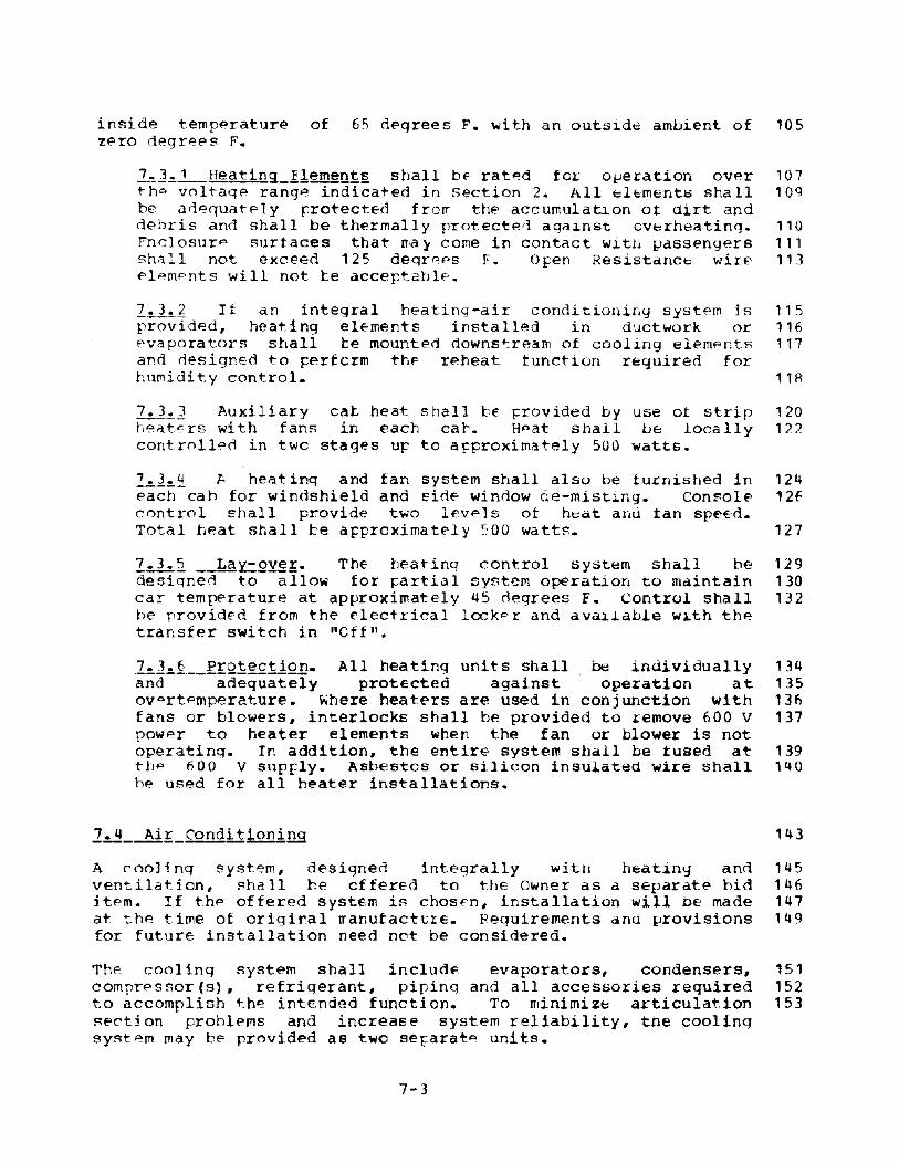
inside temp~rature of 65 d~qrees F. ~ith an outs~d€ ambient of lOSZfOro degr€E's F.
l~l~_l__Heating_I!~~nl~ shall b~ rat~d for o~eration over 101tho voltaqe range indicated in Section 2. All ~lemento shall 109be ad€~uatPly ~rotected fro~ the accumulation ot dirt anddebris ano shall be thermally protected agal.nst overheating. 110Fnclosur p surfaces that IT;a}' come in contact witH passengers 111shall not exceeo 125 deqrpps F. Open Resistanc~ wire 113pl~mpnts will not te acceptable.
I.3.1 If an integral heating-air conch tionin<j system is 115provided, heating el~ments installed in ductwork or 116evaporators shall be mounted downstream of cooling elempnts 111and designed to ~erfcrm thF reheat function required forhumidity control. 118
~l~] Auxiliary caL heat shall be Frovided by use at strip 120heat~rs with fans in each ca~. Hpat shall be locally 122controlled in twc stages Uf to aFproximately 500 watts.
hl=-~ A heat ing and fan system shall also be furnished in 124each cah for windshield and sid~ window de-misting. Console 126cnntrol shall provide two levels ot heat and tan sp~€d.
Total tleat shall be a~pro)(imatel y 500 watts. 127
I.3.2 __La~-oy~!. The tleating control system shall he 129designed to allo~ for rartial system operation to maintain 130car temperature at approximatEly 45 degrees F. Control shall 132be prov ided from the E'lectrica I locKP r and a val.J.able w~th thetransfer s~itch in "Cff".
7.3.6 Protection. All heating units shall be individually 134and adequately protEcted against operation at 135ovprtemperature. Where heaters are used in conjunction with 136fans or blowers, interlocks shall be provided to remove 600 V 137power to heater elements when the fan or blower is notoperating. In addition, the entire system shall be tused at 139the 600 V supply. Asbestos or silicon insulated wire shall 140be used for all heater installations.
A cooling system, designed integrally with heat1ny and 145ventilat.ion, shall be cffered to t.he Owner as a separate hid 146itfOm. If the offered system is chos~n, installation will be made 147at the time of origiral rranufact~rE. Requirements and provisions 149for future installation need not be considered.
The cooling system shall include evaporators, condensers, 151compressor(s), refrigerant, pipinq and all accessories required 152to accomplish the intended functien. To minimiz~ articula~ion 153~pctjon prohlpms and increase system reliability, the coolinqsyst~m may be provided as two se~arat~ units.
7-3

7.4.1 Criteria. 'Ihe following crit€ria shall be used for 155cooling system design: 156
a) Interior car temrerature 75 F. or 20 F_ belowoutside ambientabove 95 F.
b) Interior Relative Humidity 51) percent
c) Air Flow tot.al per car 3500 cfm (minimum)
d) Evapcrat.er fresh air 9C: F. Dry Bulo78 F. Wtt Bulb
€' ) Condenser ambient 105 F.
f) passenger Lead 120
g) SuppI y voltage 600 vdc or aux. ae
h) Fre>sh air 30-40 percent of total
159160H1
163
161:)
167168
170
172
174
176
All cooling units shall be designed for operation within the 179indicated environmental, noise and vibration requirements of 180Section 2. Resilient mounting shall be utilized on all units 181which incorporate rotating parts. Access panels and 183sufficient spacE shall te provided for adjustment, routi~e
maintenance or replacement. 184
7.~:.:._2_~porator units shall be supplied as an integral 1B6design with ventilaticn blc~ers and heater units. At least 188two evaporator units shall be furnished for aaequate airdistribut.ion in the vehicle. Elcwers shall be optrable when 190other cooling system components are not being utilized or 191have failed.
The evaporator ceil shall te ccnstructed ot aluminum plate 193and fin, copper tut.es and aluminum plate-t.ype tins, or oth~r 194approved construction. The tutular t.yp~ shall have the tubes 195E:>cpan(led to provide a mechanical bond wi th the fins. For 197modulated op~ration, at least two refriqer6.nt distrihutionheaders shall he provided, each operated by a solenoid valve. 198~n air fil~er as indicated shall b~ installed upstream of tho 1q9co11. Minimum fin thickness shall be 0.008 inch. 200
Split high-low side evaforatorsme~t applicahle standards ontlexible refrigerant fittingscompon~nts.
shall have couplings thatall refrigerant lines, andshall be used between
202203204
~.dequate condensate drainage under all operating conditions 207of hrakinq and grades shall te provided.
7.4.3 Compressor/CQnden~gt. Fach car body section shall be 209equipped with one dr} type condenser dnu direct or gear 210
7-4

dr iV4?n comfressor designed as an integral unit. Belt dri ves 212will not be acceptable in this application. This sub-system 213~hall also include a liquid receiver, sightglass, filterdrier, service connections and automatic pump down control if 214required ty detail desiqn.
The unit shall be caparl€ of op~rating at reduced capacity 216with an inlet air tem~erature of 125 F. and shall continue to 217operate for short durations not to fxceed 10 minutes with an 218inlet air temrerature of 13~ F.
7.4.3.1 The Condene~I--£oil shall be constructed of 220aluminum plate and fin, ccprer tubes and aluminum plate- 221type fins, or other aprroved construction. The tubular 223type shall have the tubes expanded to provide apermanent mechanical tond with the fin~. Unless a 225suitable filter is rrcvided upstrpam at the coil, amaximum of 144 fins Fer foot of coil, or equivalent 226shall be utilized. Minimum fin thickness shall be 0.008 227inch. The condenser inlets shall be scrdened to prevent 228pntry of rocks and other debris.
7~4.3.1 Comp~~Qr~ shall be designed to meet all 230environmental, noise and service requirements indicated 231and shall te recirrocating or rotary as approved by the 232Owner. Power input shall t€ fOO vdc or available AC. 233
a)
b)
~ rO~~~£Qmlr~§sor shnll utilize a singl~
integrated rctating assembly carried by atleast two bEarings. The rotating assemblyshall consist of a shaft, motOl:' armature, andthe ccm~resscr impellers. Motor windingsshall be insulated with materials resistant tothe refrigerant and oil. A thermal switchshall be rrovided in the housing near motorwindings to open the mcto~ circuit whenoverheating occurs. Eearing lubrication mayhe accomplished by passing a small quantity ofrefrigerant oil-mixture into the bearing andmotor cavities. Th~ system refrigerant chargeshall contain a sufficient quantity of oil tomaintain a 1.0 percent oil mixture circulatingin the system. Tbe impellers and the motorrotor shall te dynamically balanced in twoplanes to ~ithin 0.04 and 0.05 gram-inches,respectively.
A reciQ[Q~t!n9-!Y~ of comrressor shall be ofaccessible, rrulticylinder design, utilizingring rlate valves and replaceable cylinderliners. It shall te fitted with cylinderunlcaders that operate to lift the suctionvalves from tte valve seats and effectivelyunload the cylinders, with a correspondingreduction in rower requirement for start and
7-5
235
237
239
2141
2422in244
245
246247
248
250251
2')2
253254

stop operation. The com~ressor shall utilize 25~
oil filtration and force fe~d luLr~cation.
The ccmrres~cr and drive shall be mounted on a 256common base supported by vibration isolators. 257ThE" rotary speed of the comrressor shall not 258ex~eed 1800 rpm.
7.4.U Re>frigerant. Line§. sball be installed with adequate 260insulation, support and protection. All joints in 262refrigerant lines shall be silver brazed witIl tiller metalconforming to latest applicable AS'f!Vl standards. 263Refrigeration riping shall he in accordance with USAS Code 2f.UB31.5, latest edition. The refrigeration system shall be dry 265an~ clean prior to filling with refrigerant. DEsign shall 266include valving of liquid lines to prevent loss ofrefrigerant when replacing major components. 267
7.4.Svehicledesignwi thinband.within
Tem~~atll~£QntrQ! shall sense ana control theinterior environment. The system shall be of modularutilizing low voltaqe dc power. Air temperature
a closed car shall t~ maintained within a 2 degree F.Sensitivity cf temperature sensing devices shall be
plus or rrinus one degree F.
269271272
273
The entire heating and cooling control schedule band shall be 275manually adjustable over a range of plus or minus 4 degrees 216F. This requirement may be satisfipd by use of "plug in" 277~ h""rmostats.
Normal activation of the entir~ air comfort system shall be 282automatic whenever the console transfer switch is placed in 283"standby" or "Operate". Circuit breaker control shall be 284available in the electric lccker to disconnect individual units 285of the system.
For pre-cooling or ~est purrcses, a method shall be madeavailable on the electric locker panel to activate the systemwhil o in "Lay-up" mode.
287288
291
Fefer to section 2 fcr environmental testing and system data 293reqlli rempnts.
7-6

Technical Srecifications - Section 8 7
LIGHTING SYSTEMS 9
This section specifies the requiremFnts tor all lighting ~ystems 12on the Liqht Rail Vehicle. Interior lighting system~ shall 14include high frequency inverter ballast operated fluorescentlamps over the main Fassenger areas in the ~ and B units, front 16door area lighting, operator cat lights and door/ste~ lights. 17The exterior lighting shall include headliqhts, marker lights, 18destination sign liqhts, and sto~ lights. 19
The lighting systems shall ce designed for the vibrational loads, 24the shock loads, and the environmental conditions specified in 25se~tion 2, and they shall be desiqned for the applicable voltaqe 26ranges specified in Section 9. Ihe lighting systems shall not 27dpteriorate rapidly in effectiveness through the collection of 28dirt, shall be attractive in apFearance, and shall be free ofrattles and vibrations when in service. 2 Q
The lighting fixtures shall be desiqned to provide ease of 31cleaninq lamp and ballast, changeout., adjustments and housing 32removal.
A.1.1 InteriQL-1lgh!!ng Reguirement§. The average intensity 34of the illumination within the car at an elevation of 33 to 3566 inches above the floor and on the upper surtace of a 36transverse 45 degree Flane at the passenger seats shall be at 37least 35 foot-candles at rated voltage.
Th@ average light intensity at the floor in the ~assenger 39aisles and articulation section shall be not less than 20 40foot-candles.
The average light intensity at the car entrances and exits 42within 20 inches of the doors shall be not less than 20 foot- 43candles at the floor.
The brightness ratio between lighting fixturesceiling shall be nct grea~er than 40/1.
and adjacent 4546
The brightness ratio of liqhting fixture to walls (excepting 48windows) shall be net greater than 10/1. 49
Fixture lumen output in the zone 60 t.o qO degrees from nadir 51shall be not qreater than 12 percent ot the total lumen 52output of the fixture.
8-1

Noise qenErated by lighting system com~onentH snall notaudible in an NC~ 70 car ambient.
bp c:;,u55
P~hL_.-Bf~.Qligh~§. shall rrovide sufficient illumincl1::.ion to 57enable the c~erator in the car to see, in a clear atmosphere, 58an object as large as a man cf average size standing erect at 59a distance of nOO feet ahead of ann in front ot the car. FO
Full intensity ~hall be ohtained on 32 vucfeature shall be rrcvided.
and dipping 62~3
Headlight adjustments shallvehicle headlights shall bestandards.
bE made availavle. Deliveredadjusted ppr applicable ShE
6566
B.2.1 Main InteriQL-l:!.gbtin9-Eixtures. Tne passenger 71section, except in the articulation unit, shall be 72illuminated by continuous fluorescent fixtures mounted in the 73ceiling above the seats. The fluorescent fixtures shall not 74extend into the cab areas.
The light fixtures shall he dust and moisture proot and may 7Fbe combined with the air diffusers. All exposed portions of 78the fixtures (exc€rt lens) shall be unpainted stainless steel 79or brushed aluminum. In addition to the support obtained 80from lock tyre terminal rins and sockets, the lam~s shallalso be supported ty aprroved clamrs around the tute ends. 81The lamps shall be of warm white color utilizing standard 82pins and no longer than 48 inches. Lamps shall be designed 84for average life of 20,000 hours.
The fixtures shall utilizE a~rroved diffusers contained in a 86hinged door with the locking device arranged to required use 87of a special (but simple) tool to open. L~ns materiCil shall 89re polycarbonate. The fixtures shall be arranged on circuits 90with adjacent lamps or pairs of lamps connected to ditferent 91circni t.S. The m~tal fixt.ure rousing and retlectoro shall be 92qrounded to the ground hUl;:. 9]
8. 2.:.L_.Iluor~.§£~t_Li.9.btin.9-E.Q~!.-.-2lli2ElY- The fluorescent 9Slightinq system shall utilize high frequency combination 96inv~rter/ballast power suprly units mounted at the lightinq g7tixtures cr a single central inverter mounted unaer thE" car. 98Power for either tYFe unit shall te provided from thp two 99wire ungrounded and unregulated low voltaye supply. Master 101oi rcui t breakers for normal and emerger,cy lighting shall beprovided in the electrical lccker. 102
Jk2. 2.1 Inverter Ballastmounting at-the-fi"i<turEtostart or instant startfrequency shall t~ not less
8-2
uni~s shall be desiyned foropErat~ one ox two rapidfluorescent lamps. out-putthan 2~,OOO Hz with an input
1041 0 I)
106

voltag~ of 24 volts dc. Out put voltage ana frequency 108regulation shall te determined by lam~ loadrequirements. The units shall not cause a r~duction in 110normal expected lamr lit~.
The inverter circuit shall he solid state with internal 112short circuit, overload, open load circuit and over- 113tem~~rature ~rotection. Efficiency shall be not less 114than 75 Fercent with input powpr ana environmentalconditions indicated. 115
Shielded cable shall be used cetween the ~nverters and 117the load with lock tyre plug connectors utilized at the 118inverter ballast units.
8.2.2.2 Central Inverter. A solid state invelter with 120minimurn-cut~ot-trequ~nc~-of1500 Hz shall be detiiyned to 121provide fluorescent larrp Fower as required tor the 122vehicle. The central inverter, if used, shall be 123mounted und€'r the vehicle floor. Outflut vOl.tage and 1214frequency regulation shall be determined bi loadrequirempnts at either rapid or instant s~art lamps. 125~d~quatp internal shert circuit, overloaa, open circuit 126an d oVf>r-temperature r reteC':t ion sha 11 be provided. 127
Lock typP plug connE'C':tors shall be utilizea at the 129fixtures fcr ease of ~aintPnanc€. 130
8.2.LMg,!n rnteriQ!:_Light1ng Control. Tm: main interior 132liqhting shall be locally controlled by a switch on the 133console of each ca~. The switch shall be arranged to 134function in the opera~ing cab when the car is activated and 135t.he transfer switch is in either stand by or operatepositions. The basic centrel system shall function on 32 vde 136operating the wain lights through appropriate relay 137circuitry. Approximately 25 percent of the main interior 138liqhts shall be on the emergency power circuit. see section 1398.4.
8.2.4 Front Doo~nt~~lQ~ighting. If it is determined 141that additional lighting is required at each front door area 142in ord~r to meet the intensity criteria and increase the fare 143collection visibility, serarately controlled incandescent 144fixtures shall be rrovided. They shall be of recessed 145ceiling type and pre-focused to illuminate the desired area. 146Local control shall be made availacle on the console to 141extinguish the adjacent door area lighting and minimize 1148Operat.or glare.
8.2.5 steR-well Ligbt§. Incandescent step-well lights 150operated on low voltagE dc power shall be providea in the 151side walls of the step-wells on the basis of one per door 152panel. The light fixtures shall be tlush with the side walls 153so as not to interfere with the step operation (if installed) 154
8-3
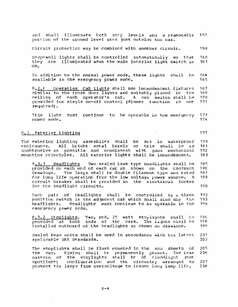
ann shall illuminate both sUr lew:ls dnd a reasonable 15c;portiun of the ground level area just outsid~ tn8 car.
Circuit frotecticn may be combined with another circuit. 15A
Step-well lights shall be controlled automatically so that 160thpy are illuminated ~hen the main interior light s~itch in 161ON.
In addition to the normal power mode, these lights' shall be 164available in the errergency pc~er mode. 165
8.2.6 ~erating Cab Ligh!§ shall use incandescentsimilar to the front door lights and suitably placedceiling of pach operator's cab. A cab switchproviden for simfle on-off centrel (dimmer functionrequj. red) •
fixturE'Sin the
shall beis not.
167169170171
'This liqht must continuE to he operahle in the emergency 173power mode. 174
The exterior lighting assemblies shallAnclosures. All bright metal ~€zels
unobtrusive as possible and consistentmountinq principles. All exterior lights
be set in waterproofor trim shall be aswith good mechanical
shall be incandescent.
177
179181182183
8.3.1__-lleadligh!2 Two sealed beam type headlights shall he 185provided on l"ach end of each car as shown on the Contract 186drawings. The lamfs shall be douhle filament type ana rated 187for long life operation from thp low voltag~ l-'0wer source. .7\ 189circuit breaker shall be rrcvid€d in the electrical lockerfor the headlight circuits. 190
Fach pair of Headlights shall be cont.rolled by d thrAA 192position swi,t.ch in the adjaCEnt cah which shall also dip the 193headlights. Headlights must continue to be operable in the 19q~mergpncy rower wode.
f..3._2_StoQJj.gh.t§. T\'io, red, 25 wat.t stol-'lignts shall C-":' 19£;provided at both ends of the cars. The l1ghts shall he 198installed out.hoard of the headlights as shown on drawinqs. 199
Sealed beam units shall be u~ed in accordance with tne latest 201applicablf.' SAE standards. 202
Thr> stoplights shall be flush {flounted in t.he end sheets of 20Sthe car. ll.iming shall bE' permanently preset. The beam 206pattern of t-hf.' stq:lights shall be of tloodlignt (notspotliqht) configuration and thE circuitry arranged to 207protect thE lamps from cvervcltage to insure lung lamp lif~. 208
8-4

II
The circuit shall be interlocked ~ith the transfer switch to 210prevent stop light operation only on the head-end of a car or 211train. A master circuit treaker for each car's stoplight 212syst~m shall be rrcvided in the ~l~ctrical locker. 213
Note that these lights must cont.inue to be operable in the 215emergency [ower mode. 216
P.l.:.]__~~~L.-1!.9bS.§.. Two marker lights shall be located 218near each upper end corner of each car (eight per car). The 220lights shall be in accordance with the latest AAR SignalManual, Part 136. The marker light lens shall be gre~n and 222red. The lights shall operate on low voltage de power with a 223master circuit breaker ~rovidEd in the electrical lccker and 224controlled by a switch on thE- Operator's console. 'Ihe marker 2251 iqllt.S shall he interlocked with the reverser control torrovide green on the forward end and red on the rear. All 227marker lights sha 11 indicate "red" when rdverser is inneutral.
Marker lightspower mode.
must continUE to te operable in the emergency 229230
8. '3. _4_~~inatio!!.Sign..1igh.!.§. Each destination sign shall 232be provided with a fluorescent lamp suitably arran~ed for 233even illumination. All signs shall be visible from the 234outside of the car and tte side signs shall also be visible 235from the inside. Relamping shall he from the inside. A 237master circuit breaker for each car's destination signliqhtinq system shall be rrovided in th~ electrical locker. 23ASign light control shall be grouped with interior lighting on 239a common switch.
It is DQt nec~ssary for these lights to be operable in thA 241event of a 600 vdc propulsion power failure. 242
].3.~~~lQ~d Iugic~tQr. Each car shall be equipped with 244line breaker overload indicator lights similar to Adams r. 245Westlake Model '1399, or an approved equal. Ti1e .ligllts shall 247be equipped with tlue lens and shall be installed for 24Aexterior visibility on each side of the car.
b4.1 The following light shallemergency power conditions:
remain functional uncier 253254
a) All lights near the doors; 257
h)
c)
Other mid-car fluorescent lighting in the A and Bunits such that the total interior emergencylighting is 25 percent of the normal interiorliqhting;
All of the step-well liqhts;
8-5
2592602f;1262
264

d) Operatinq cab light;
~) Headlights;
f) A.11 of the marker lights;
g) A.II of the st.of lightE.
~~£ In the event ef less of auxiliary pow~r, alllights shall remain illuminated for at least 10 seconds.emergency relay shall then operate and illuminateem~rgency lights only as described above.
31.:.2-_Lightiug 'rests and rata Fe9uirements
2fif)
268
270
272
main 275The 277the
278
281
The lighting tests end data r~quirements shall tie in accordance 2B~
with Section 2. 784
8-(,

Technical specifications - Section 9 7
This section specifies the Auxiliary Electrical system, inter- 12systems controls, wiring and trainline requirements, current 13collection, switching equipment and the operator's console 14control devices for the Light Rail vehicle. The Auxiliary 15Electrical system shall include primary power conversion, storage 16battery and emergency funcions, vehicle 'control functions andassociated protection and regulation devices. 17
All operating components of the system shall meet the performance 19requirements specified when operating continuously from no-load 20to full load at the input supply voltage variations, transients, 21ambient temperature, and noise levels indicated in section 2. 22Automatic shut-down and restart capability shall be provided. 23
Static devices shall be used to the greatest extent possible. 26All circuits shall be adequately protected and insulated from 27ground. Provisions shall be mane for grounding enclosures and 28chassis to the vehicle ground bus. Radio interference generated 29by any component or wiring shall be suppressed.
2~1--a~£eptab~eConfigyrations 32
Auxiliary electrical power conversion and utilization shall be 34accomplished by one of the following methods: 35
a) Motor generator set operating directly on the 600 volt line 31with output suitable for supplying all low voltage control 38and auxiliary circuits.
b) Static inverter operating on 600 volts and supp1yinq AC 40auxiliary loads as required plus Low Voltage dc load by use 41of a static rectifier.
c) Motor Alternator operating on 600 volt input and supplying AC 43auxiliary loads as required plus Low Voltage de loads by use 44of a static rectifier.
d) static converter operating onisolated low voltage dc powercircuit loads.
600 volts and supplyingto the battery and control
4647
2£~_~~YQl!aqe 4c_Supel~ 50
The low voltage dc power supply shall be of sufficient capacity 52to charge the battery and maintain substantially constant voltage 53
9-1

for traction control, t.rainline control, vehicle lighting, and 54other auxiliary circuit. power requirement.s. 55
Th~ power supply shall supply dc power at. the nominal voltage 57requir~d to automatically maint.ain t.he battery in a fully charged 58condition. The regulated output shall be continuously adjustable 59between approximately 35 and 40 volts and shall hold th~ 60adjustment point under all operating conditions. Voltage 61regulation shall be plus or minus 4 percent with input voltagevariation of plus or minus 20 percent and a load variation of 62zero to maximum connected load. 63
Circuit protection shall be provided to adequately protect power 65supply components as well as prevent over charge of tne battery 66(automatic shut-down). Indicators shall be prOVided on the 67Op€'rator's console to warn of "Overcharge" and "Low Charge". 68
~~1--EmergencY-f2~shall be made available oy use of a 71voltage sensor/timing circuit which shall sense a total lossof power at the Low voltage dc power supply bus. Upon loss 73of power, the timer circuit shall begin a ten second delay.At the end of the delay, the circuit shall cause emergency 74loads only to be fed from the storaqe battery. Upon 76restoration of low voltage dc power output for not less than5 seconds, the circuit shall reset and reconnect the normal 77low voltage loads (Ref. Sec~ion 14).
Fmerqency load shall include ~he following: 80
a)b)c)0)e)f)
g)h)
Approximately 25 percent. of interior lighting_Exterior marker lights, stO[ lights and headlights.Door control and door operator power.Communications.Braking control and actuating power.operatnr's Console Indicators, Lighting
& Interlocksstep Well Lights.Cab Signal/ASC power
838U85868788899091
~~1~j~1~ GeDerat2I. A motor generator set shall he 97designed for opera~ion from the 600 vdc primary power sUPI=,ly. 98output load requirements ~ith regulation and protection as 99indicated shall be established by the Contrdctor during 100vehicle design. The motor generator set shall be dynamically 101balanced and resiliently mounted to the vehicle structure. 102Saf~ty straps or hangers shall also be prOVided. 103
Bearings shall be anti-friction, sealed lubricationpin type fittings installed as required. The setself-ventilated and rated in accordance with USASclass F insulation. Windings shall be given
9-2
type withshdll heC35.1 foran epoxy
105107
109

polyester or approved equal vacuum-pressure impregnation 109insulation treatment.
Commutator brushes shall not require replacement at intervals 111less than one year. Brush holders shall be designed to 113maintain constant Fressure throughout the lite of the 114brushes.
Adequate circuit protection shall be provided. 111
~]~l Motgr Alternator. A motor alternator shall be rated 119for the final established load as determined by the 120Contractor. The de portion of the machine shall meet the 121r~quirements indicated for a motor generator. The 123alternating current output shall be 120/208 V, 3 phase, 60 Hzor as r~quired by other auxiliary systems. voltage 125regulation shall be provided to maintian variations of lessthan plus or minus 5 percent. Frequency shall be regulated 127within 5 cycles. Circuit Frotection shall include a primary 128fuse, inverse time delay load protection and over temperature 129protection.
9.3 L 3 §~atic £Qnyerter. A static inverter and/or converter 131furnished to supply low voltage power shall be adequately 132rated for the final established load. semiconductor 133assemblies shall be functionally grouped and mounted inmodular form for ease of maintenance. Detail design of 135static circuits shall be governed by manufacturer's latestthyristor application recommendations. Protection and output 137regulation shall be as indicated. The output to the battery 138charger power supply shall be isolated from 600 volts.
9.~!-- stot~ge ~~tter~. A nickel cadmium storage battery 140with tubular or flat pocket plates and rated for emergencyduty cycle service in the indicated operating environment 141over a normal service life of not less than 15 years shall be 142provided. The battery shall be controlled at rated charge by 143connection to the regulated dc output of the low voltage de 144power supply. It shall retain a peak charge while in normal 145operation without periodic higher rate equalizing charges. 146
During power supply failure or shutdown, the battery shall 148supply power at 32 volts de nominal to the control and 149lighting loads. It shall be capable of supplying sufficient 150discharge current to carryall low voltage loads continuously 151for 10 seconds, followed by the in~icated emergency load 152continuous for one hour, within the ambient temperaturerange. At the end of this discharge sequence, the voltage as 153measured at the battery terminals shall be not less than 24 154volts or one volt per cell, whichever is greater.
Discharge beyond the rating of the battery shallpermanently damage the cells or reduce capacity.
9-3
not 156151

Cell containers shall be gastight and free of rough spots, 160pinholes or cracks. If required, an air gap shall he 161providen between cells for heat dissipation. Cell containers 162may be assembled in a compact arrangement and supported on 163rubber or plastic pads.
Vent. capssprayproofcontainer.corrosion.provided.
shall be of the captive type and shall bewhile still allowing gas to escape from theAll external metal parts shall be protected fromIntercell connectors, jumpers and lugs shall he
165166167168
Electrolyte capacity shall be sufficient to require addition 170of water during normal maintenance period only. Means shall 172be provided to indicate maximum and minimum levels.
overt@mperature protection shall be provided at the battery 175oox.
9.1~2__-auxiliar~__Circuit_Control. The Auxi~iary Electrical 177system shall i.nclude a sufficient number of 600 volt circuit 178contactors of approved type and proper capacity to control 179auxiliary loads as r~quired. Control of the 600 volt 180contactors shall be by low voltage dc with a switch panellocated at each operating cab area. 600 vdc shall not he 182routed to the passenger or operating cab area tor any purposeother than heating system use.
If ac auxiliary systems are provided, control shall also be 184provided by use of low voltage switches in the cab area. 185
9.3.6 _Auxi!ia~~CircuitProtect!QU shall be provided by a 188600 volt fuse box located outside the car in a weatherproofenclosure. A 32-volt switch, shall be provided in the fuse 189box cabinet, interlocked with a secondary door over the fuse 190compartment, so designed as to prevent personnel from coming 191in contact with live circuits and shall require that the 600- 192volt line be disconnected from the fuses before permittinqaccess for renewal of fuses. This switch shall break the 32- 194volt feed to the 600-volt auxiliary circuit control switches. 195The fuse panel base shall be transite, ebony asbestos or an 196approved equal, polished on both s1de~. The fuses or 198fusetrons as recommended by the manufacturer, shall bE'8eparated from its adjacent fuse by a suitable barrier made 199of insulating and heat resistant material. A green liqht 200shall be mounted outside the 600-volt fuse box door and wiredso that it shall be illuminated when the auxiliary circuit 201contactor is de-energized. If the fuse box is contained 202within the contactor compartment, the fuse box cover shall be 203labeled in one half inch minimum lettering:
WARNING: 206
ALL 600-VOLT CIRCUITS ALIVE 208UNTIL FUSE BOX DOOR IS OPEN 209
9-4

AND GREEN LIGHT IS ON 210
9~~1__-L~-XE!~~g~_~reak~r Pa~l. Each Auxiliary Electrical 214system shall include a low volta~e switch and circuit breaker 215panel located in the cat area at one end of the car. Each 217panel enclosure shall include a door with continuous hinqe,anti-rattle device and standard key operGted, automatic 218latchinq lock.
All 32-volt circuits requiring protection shall be equipped 220with heavy duty, vibration proof twc pole circuit breaker 221~ypP swit.ches, of proper capacity, with instantaneous 222magnetic ~ype trip or approved equal. The circuit break~rs 223shall clearly show "Open" and "Closed" positions and Shall be 224easily removable. All circuit breakers shall have their 225respective current rating clearly and permanently marked on 226the operating handle. suitable name plates shall be provided 227for each panel, clearly identifying the circuit which each 228circuit breaker switch controls.
The following Switches, Breakers, and Indicators shall he 230included in the Electrical Locker. It is not desired that 232these devices be dUFlicated at both ends of the car, butrather that similar or related functions be grouped together 233at the one end. Low voltaqe items shall be isolated from600V relay control devices. The only exceptions are that 234Duplex Convenience outlets and Work Liqhts shall be provided 235at both ends. The final configuration shall be subject ~o 236approval.
Battery Bus 239propulsion Control 240Friction Brake Control 241Master Controller 242Communications 243Door Signal 244Door Con~rol 245Step System (if installed) 246Door/step by-pass (sealed) 247Pantograph Control 248Interior Lighting (number as required) 249Exterior Lighting 250Destination Sign Lightinq 251Destination Sign Control (if installed) 252Fare collection Equipment 253wiper/washer System 254Cab and console panel Lights 255Cab Signal System (if installed) 256Air Comfort Control (if installed) 257M-G (M-A) set relay control 258Air Compressor relay control (if installed) 259Hydraulic Pump relay control (if installed) 260Heating System relay control 261Ventilation Blower relay control 262
9-5

Air Conditioning relay control (if installed) 263Convenience outlets 264Propulsion cut-out 265Friction brake cut-out (sealed) 266Track brake cut-out (sealed) 267Slip-slide cut-out (sealed) 268sander cut-out (sealed) 269Four Spare main Feed Breakers 270ASC cut-out/By-pass (sealed) 271Cab Signal Cut-out (sealed) 272
_2.:.1.:.8 _operator'LConsole. An Operator's console shall be 275furnished in each cab area of the vehicle. The console shall 277include a Master controller, door contrOl, destination signcontrol (if installed), track switch control, pantograph 278control.. coupler centrol (where required), speedometer, 279communications, transfer switch, various operator convenience 280pedals & switches and both audible and visual performancewarning indicators. Contrel location and general arrangement 282shall be as shown in the contract Drawings.
Console material shall be corrosion resistant and designed 284for extended trouble-free life. switches and push buttons 286shall be generally rear-mounted on hinged panels so that only 2A7operating handles protrude above the surface. Any visible 288fasteners on the console face shall be of tamper proof headdesign and finished to mateh the console face. Push buttons 290and switches mounted in the vicinity of the controller handleshall be arranged to permit unobstructed operation of th~ 291controller handle.
Console switches shall bE heavy duty toggle type with wide 293and extended actuating surfaces for ease of operation. The 295console switches and indicators that utilize illuminationshall be provided with an automatic dimmer device that will 296sense ambient light and regulate the intensity of 297illumination. The following switches on the operator's 298console shall be individually illuminated:
All door switches'T'rack switchHeadlight controlcab liqht switchWarning device (horn & gong)
301302303304305
Each console switch shall be prOVided with proper 308identification .. in an approved manner clearly identifying thl'? 309function which each controls and indicating the t>osition of 310the handle.
The following switches shall be iY1cluded in the operator's 312control Console at both ends in accordance with the Cab 313Layout Drawings. Note that Foot Pedals are also indicated 314and shall be considered as part of the cab EqUipment althouqh 315actually not mounted in the Console as such.
9-6

functi2n Identification No. POBi~~on~ 318
pantograph pan.-Down/up 2 320
Fare collection 322Equipment Fare-Off/on 2 323
Passenqer Stop 325Request switches Pass.Stop-Off/on 2 326
Operator's Overhead 328Cab Liqht Cab. Lt.-Off/on 2 329
Panel Illumination Panel Lts.-Off/on 2 331
Cab Heat Cab Heat-Off/hi/lo 3 333
Windshield Demister Oemist-Off/hi/lo 3 335
Windshield Washer 337(If installed) Wash-Off/on MS 338
Windshield wiper Wipe-Off/hi/lo 3 340
Passenqer Loading - 342HighlLow Level Load-Hi/lo 2 343
Roll-back protection 345(Track Brake) Off/on MS 346
Track Switch Trk.SW.-Power MS 348
Car Body Lights, 350Exterior Body Lts.-Off/on 2 351
Interior Liqhting Interior Lts.-off/on 2 353
Destination Sign Lights Oeste Lts.-Off/on 2 355
Headliqhts Head Lts.-Off/h!/lg 3 357
Reset (Normal/rest) Reset-Norm/Reset MS 359
Sander Foot Pedal Ms361
Note: "Off" or "Normal" positions of SWitches areback toward Operator and activation requirespressing forward. MS means momentary switch.
363364365
switches for door control shall be oriented toward right and 368left sides of console to control doors on their respective 369sides of the vehicle.
A transfer switch shall be installed in each operating area 371as indicated. The switch shall be a three position rotary 373
9-7

~ype, of approved design, to be operat~d by the master 374control k~y which shall be supplied with the switch. The 375switch shall be so arranged that in the "Qperate" or"standby" postion, the key cannot be removed from the switch. 376The switch shall energize the control and console circuits on 371its respective end of the car only. Allot the Switches, 378Control Devices, Foot Pedals, etc. in all Cabs shall beelectrically and/or mechanically inoperable whenever the Cab 379Transfer key Switch is in the lILay-up" position. In the- 381"Lay-upU Key out position all Systems shall bedeactivated including all Battery Systems. There shall be no 383load of any kind on the Battery in this position. In the 384"Standby" post ion, control of train lined functions shall notbe possible.
It- shall b@ noted that the Car (or Train) may, in 386emerqencies, be operated from any Cab. Appropriate operating 388Procedures will be provided to prevent unauthorized use of 389this feature. Further, the Cab Transfer/Key Swiech circuitry 390shall be arranged to prevent. operation of the Train unless 391all forward direction Transfer/Key switches - except theOperating Cab Transfer/Key Switch - are in the "stand-by" 392position. The switch may be aS$igned additional functions if 393the Contractor so desires, subject to approval. 394
The Master Controller with deadman feature shall Ut: installed 396for Left hand operation. Control from front to back shall be 398acceleration, coast, braking and emergency braking. 399
Adequate shielding of the indicator panel for operation in 401bright sunlight shall be provided. 402
The indicator panel shall include the following: 405
a)b)c)d)e)f)q)h)i)
propulsion overloadBrakes ONDoor statusLow Voltage Power Supply Statuspassenger EmergencyPassenger stop RequestCab Signal Cut-outHiqh/Low step positionCab signal display surrounding the Speedometer face
408409410411412413414415416
Provisions shall be made for installation oi Destination sign 419control. An analoq type sFeedometer shall be provided and 420installed as shown.
Communications shall require installation of the following 423it~ms :
a)b)c)d)
HandsetSpeakerselector controlVolume control
9-8
426421428429

e) Transmit Indicator 430
Foot pedals shall be installed for control of vehicle horn, 433qong and sanders. 434
9.3.9 Master _S;0Dtroll~F Re~i£em!mt~. Control of both 436propulsion and braking shall be obtained through a sinqle- 437handle, all-electric type, manual Master Controller provideo 438in ~ach Operator's cab.
The Master Controller Handle shall move fore and aft in a 440vertical plane at a comfortable height on the ConsolE as 441indicated with the Power Position reached by motion of th~ 442Handle away from the Operator and Braking Positions reached 443by motion of the Handle toward the Operator.
The Master controlleroperated switches ofcontrolling functions.
shall use easily replaceable Cammodular construction to carry out its
445446
The Master Controller shall have a "Dead-Man" feature, which 448shall function electrically to produce an Emergency Brake 449Application identical to that produced by placing the Master 450Control. Handle in emergency. The "Dead-Man" feature shall be 451rendered ineffective when in full service brake position,park, or when Cab Transfer/Key Switch 1s in "Lay-up". The 453Controller handle shall consist of a single round Shafttopped by a large plastic Sphere or "T" handle and arranged 454to mc,ve fore and aft. The sphere shall be spring-loaded such 455that it must be pressed and held down by the Operator to 456satisfy the "Dead-Man" feature. The entire handle shall be 457human engineered to minimize strain and fatigue on the 458Operator. The exact size of the shaft and sphere, spring- 459loading characteristics, handle travel between detents, and 460other operational features shall be deterfiined at the time 461the full-size Cab Mock-Up is reviewed for approval.
The Master Controller detents (identified positions) shall be 464as follows:
a)b)c)d)e)f)g)h)
Maximum PowerFull Field (if required by propulsion system)Minimum Power (3 to 5 mph speed)coastMinimum Brake (0.5 mphps)Full service Brake (Park)Full Service plus Track BrakeEmergency
467468469470471472473474
Between the Maximum and Minimum Power positions,variable tractive effort shall be available.variable braking effort shall be availableMinimum and Full service brake positions.
9-9
continuouslyContinuouslybetween the
477479
480

The Master controller shall also include a removable handle 482reverser control with three positions; Forward, Neutral and 483Peverse. The reverser control shall interface with thE 484direction trainlines and shall be interlocked to allow q85operation only when the Transfer switch is in the "Operate" 1186position and the Master Controller is in Full service brakepositi.on. with the Reverser handle removed, the Master 487Controller shall be locked in the "Full service Brake" 488position.
Master Controller circuits shall interlock with the 490propulsion Overload Reset Trainline so that: the reset 491function will be effective only when the Master Controller 492Handle is placed in Coast or Brake position and the Reverserhandle is in "Forward" or "Reverse". The Cont:roller circuits 4q3shall also interface with the Automatic Speed Control Systpm 494(if installed). An independent switch operation shall take q95place only while in full service brake position, to permitASC recovery from overspeed condit~ons and for 496acknowledgement of receipt of a more restrictive Cab Siqnal 497speed Code (if installed). The Contractor shall co-ordinate 498this interface.
9.3.10 _ Trainl!ne & Ci~9uit Requirementsconnections for control of at least the followingshall be made between all cars:
Electricalfunctions
500501
propUlsion 504Braking 505Magnetic Track Braking 506
507Door and Traction Interlock 508pantograph Control 509Sanders 510Communications systems 511
(Intercom and Public Address) 512
passenger Emergency 514passenger stop Request 515Appropriate overload, fault and status indicators 516
To simplify the circuitry and minimize the number. of electric 519coupler contacts certain car operational teatures may be 520controlled locally within a car when it is in train operation 521providing that prior approval is obtained.
At least eight spare trainline wires shall run from end to 523end of the car. They shall be AWG No. 12 and four of them 525shall be shielded. The wires shall terminate in the 526trainline junction box at each end of the car but shall not 527be connected to terminal blocks; they shall be bWldled neatly 528and clamped in an unused corner of the box. They shall be 529marked as ~pecified.
9-10

9~3#10,l- The following vehicle control circuits are 531vital to safety and shall be subjected to maximum design 532analysis and manufacturing quality control. Routing of 534these circuits shall be such that interference fromother circuitry will be minimized. The functions are: 536
a)b)C)d)e)f)g)h)
propulsion CommandBrake CommandEmergency stopDirection controlDoor controlDoor Indication & InterlockAutomatic speed ControlAutomatic switchover to Emergency Battery Power
539540541542543544545546
All vital circuits shall utlize components of known high 549reliability. To achieve maximum fail safe operation, 551redundancy techniques shall be used where ~pplicable. 552
~11-_Panto9raph. The Light Rail Vehicle shall be provided 554with a single Pantograph Overhead Power Collection Device 555designed for automatic operation and proper collection at 556specified speeds and operating conditions. The collection 557Devices shall be of a renewable insert, self lUbricating type sse(carbon graphite, etc.) such that wear on the overheadcontact wire is minimized and that no special treatment (such 559as lubrication) is required. It is recognized that portions 560of the existing overhead distribution system may require 561adjustment and/or rebuilding to meet the requirements of thevehicle. The Contractor shall not be required to assume any 563liability for the actual condition of the overhead except to 564insure that the Pantograph shall operate properly. The Car 565structure shall be suitably designed to support thePantograph as described herein. 566
The single automatic Pantograph of approved type shall be 569fitted near the center of the car adjacent to thearticulation section. It shall provide proper horizontal and 571vertical tracking while giving the aesthetic appearance of 572being small and lightweight. Raised mounting bases extending 573far above the roof line shall not be permitted.
The entire Assembly shall be designed to track properly at 575minimum but adjustable contact pressures and at speeds up to 576maximum vehicle speed. The rressure shall not vary more than 577five percent over the entire working range. 578
The Assembly shall incorporate an automatic powered 580capability for raising and lowering the Pantograph between 581the wire contact position and the stowed position at the Car 582Body Roof. This function shall be accomplished by means of 583spring pressure holding the Pantograph in the raised position 584and an electric or pneumatic mechanism lowering it into the 595locked down postion. An automatic, positive action latch 586shall be. provided to effectively hold the Pantograph in the 587
9-11

lowpred position. ThE" sprinqs which raise the Pantographshall be protected to prevFnt ice from forming between springcoils. In addition an insulated rope shall be provided tolower and lock down the pantograph from inside the Car.
A permanent shoe Device shall be affix~d to the top of thePantograph such that it can be easily replaced in the ev~nt
of damage and shall contain a Renewable Insert of approvedmaterial which shall normally provide the actual contact withthe wire. The Device shall be free to pivot as necessary totrack the wire and all special work and shall be able toconduct the necessary full starting current loads for shortperiods of time or frequently repetitive cycles as well asthe normal operating loads under all conditions ofacceleration with all Auxiliaries operating. The surfacecontact area shall be in accordance with the Manufacturer'srecommendations. The suggested maximum length of the ShoeAssembly is 31 inches with curved horns extending no morethan eight inches on either side. It is the intent of thisspecification that the Shoe and the relatedPam:.ographApparatus be kept to the smallest possible physical size.
The Pantograph control shall be operated fr~n the oatterycircuit and controlled throuah the trainline from theoperating cab. Each cab shall be equipped with a momentarycontact switch of approved type connected to the Pantographcontrol trainline. The pantograph control functions sralloccur only when the Transfer Control switch is in thenOperate" or "standby" positions.
Appropriate lightning arrestor and circuit protection shallhe provided, shall l:e weather protected, and shall be mount~d
in or adjacent to the Pantograph base on the roof. A circuitbreaker, if provided, shall be controlled from the cab. Thefeed shall be from Pantogra~h to arrestor and directly to theCircuit Breaker without taps to other circuitry or s~lices inbetween. This feeder shall be routed separately through thecar side walls and be suita.bly insulated and pLocected.
588SA9590591
593594595596597
. 598599
600602
60360~
605
606
608609610
611
612
614615617618
619620621
623
a)
b)
Troll~.Y. The Car shall be equipped with two Ohio BrassCompany's OB Form 11 light-weight trolley base orapproved equal. Trolley base shall be designed toinsure adequate tension of shoe on the wire whenoperating over wire installed at a height of 22 feetabove rail head. Trolley base shall be mounted oninsulated trolley boards in a manner approved by theOwnpr.
Irolley ~~. Reinforced butt welded steel trolleypoles with 62 inch reinforcement, 13 feet 6 inches lonq,shall be fitted with the specified current collectinqdevices to be furnished with each car. An additionalbridle rope loop shall be i.nstalled 16 inches from the
9-12
625626627628
629630
632fl33634635

trolley end of the pole. The pole shall be insulated to 637prevent electrical contact with the car body during 638lowering or raising action.
c) Qutrent QQllectiqn Dev~c~. OB Form J-6 trolley harp and 640renewable carbon insert shoe and insert, as manufactured 641by Ohio Brass Company, or equal, shall be furnished and 642installed on the troll~y pole.
d) !£oll~~~ri~{. A latEst design trolley retriever 644(O.B.Model 18467-2000, or approved equal) sholl be ~45
installed at a location selected by the Owner.Provision shall be made for drainage of the mountinq 646brackets. The Retriever shall be equipped with 30 feet 647of NO. 9 trolley rope, and shall be able to hold up to 8 648feet of rope wound in the retriever.
e) H2~ for holding the trolley poles in the lowered 650position snaIl be furnished and installed. The hook 6~2
shall be securely and permanently fastened to roofframing at the rear of the car and shall be adequately 653secured to the body through an electrically insulated 654spacer.
f) A trolley rope gua[d shall be installed at the ends of 656the car to prevent chafing of trolley rope by car body, 657and to permit free movement of trolley rope through all 658normal trolley pole positions.
g) ~ lightninq_!rlest~£ and adequate circuit protection 660shall be installed on each car. The arrester shall be 662capacitor type incorporating a built-in discharge 663resistor, or an approved equal. The lightning arrester 664shall be attached to a trolley board of the trolleymounting base. A sealant of an approved type shall be 666applied between the lightning arrester and the trolley 667mounting board and shall also be applied to the boltsused to attach the lightning arrester to the trolley 668mounting boards.
9.3.11- Track switch Egu!pment. Surface street switch 670throwing equipment shall be provided to operate in the 671following manner. An edge-wound resistor shall be connected 672to the 600 vdc supply by a contactor under the control of a 673trainlined momentary contact switch on the operator'sconsole. The resistor shall be designed to draw 50 percent 674more than normal auxiliary load current when trolley voltageis at 500 volts. The contactor shall operate from low 676voltage power and shall be circuit protected. A thermalrelay shall be included to protect against prolonged 677application of track switch current.
~~!-_£QDvenieDce_Outlets. A duplex 32 VDC Convenience 679Outlet shall be provided in each of the Electrical Lockers in 680
9-13

both cabs. The outlets shall be rated at 50 amperes and 681shall provide for use of pluqs with grounding connections. 682
If ac auxiliary power is furnished on the vehicle, 684convenience outlets may be for 120 vac equip~nt as approved 685by the Owner.
~]~12__Automatic Speed CQn~l. The vehicle shall be 687equipped with an Automatic Speed Control (ASC) system which 688will enforce the speed limit data transmitted from the right 689of way to the car-borne Cab Signal system. The Ase System 690shall automatically place the Car in full service brakingwhenever the Car exceeds speed limit in force at the time. 691Additionally, the ASC System shall monitor the vehicle 692deceleration rate whenever this braking is ~nitiated. If the 694Car does not achieve an axle deceleration rate of three (3)miles per hour per second the ASC System shall make an 695emergency brake application. In normal operation the 696Operator shall be required to place his control handle in the 697Full Service Brake position whenever the audible alarminforms him that such action is required due to exceeding a 699spp.ed limit. Means to by-pass the Ase System ~n the event of 700failure shall be provided in the form of a sealed switch 701placed in the Electric Locker. operation of this Switch 702shall allow the Car to be operated in the normal manner. An 703Indicator on the cab console shall light when the ASC Systemis bypassed and exterior Indicator Lights shall be 704extinguished.
a)
b)
The ASC System shall be supplied nominal 32 volts DCfrom th~ low voltage power supply. This supply may beSUbject to fluctuations as high as 40 volts and as lowas 24 volts. The ASC equipment shall be designed tooperate satisfactorily under these extreme voltages andat all values in between. The ASC System shall achieveelectrical isolation from the car electrical systemthrough the use of a transformer-coupled Inverter.
The ASC System shall receive input data from the gearbox mounted speed sensors, the Cab Signal System and theMaster Controller. The Ase System shall continuouslymonitor the car speed using the axle speed data suppliedby gear box-mounted Sensors. The Ase system shallamplify the Sensor signals and make them available,transformer isolated and at the required power level, tothe other car torne systems requiring car speed dataincluding, but not limited to, the spin-Slide DetectionSystem, the Propulsion system, the r'rietion Brakesystem, cab speedometers, and the Door Control system.Authorized Speed information will be provided to the ASCsystem by the Cab Signal System. The nature andtransmission of these data shall be in a form designedto preserve the electrical isolation of the two systemswhile preventing transmission of erroneous orsuperfluous speed commands.
9-14
70670R
709710711
712
714715716717718
719720
721722723725
726727

c} Th~ ASC System shall receive from the cab signal system 729discrete circuit closures corresponding to established 730authorized speed limits. The absence of Qny circuit 731closure shall correspond to the minimum speed limit.These circuit closures shall be double-wire, dOllble- 732break, dry contacts rated at a minimum of three amperes, 733non-inductive load or equivalent. All such circuit 734closures shall be representEd by a minimum of two wires.When the cab Signal system is cut-out the Ase System 735shall impose a 50 miles per hour authorized speed. 736
d) The Ase System design shall make use of fail-safe 738techniques to detect sensor electrical failures and 739performance deteriorations. The design shall make use 140of all axle speed sensors to prevent i.nadvertentdetection of Sensor failure due to wheel slide or spin. 741The car speed shall be continuously compared with the 742speed authorized by the Cab Signal System. At the point 744where car speed exceeds authorized speed by two milesper hour, the Detector Circuits shall cause an Alarm to 745sound and shall also cause the car to be placed in Full 746service Braking. The Detection System shall be treated 147as Vital Circuitry and fail-safe criteria shall apply. 748
The Operator shall be required to place his Master 750Controller Handle in the Full service Brake position 751after the Alarm beqins sounding and keep it in that 752position until the Car reach~s two miles per hour abovethe authorized speed, otherwise the ASC system shall 753bring the car to a speed of two miles per hour or l~9s. 754During the time that th~ Car speed is greater than the 755authorized by two miles per hour or more, a Visual 756Indication shall be supplied on the Operatorts Console.It shall remain illuminated as long as the ASC System 757holds the Car in braking.
e} When the car enters a tracK section containing a lower 759authorized speed the Ase system sha11 detect that the 760Car is above the new speed limit within one-quarter 761second of receipt of this data from the Cab Signal 762System. Through proper interfaces the ABC system shall 763then de-energize all applicable Trainlines and place the 764car in Full Service Brake under jerk limited control.The elapsed time from receipt of the Cab Signal data to 765the full call for braking shall not exceed one and one- 766half seconds. The Audible Alarm shall sound 767continuously starting with the detection of overspeed 768and shall be silenced only by placement of the MasterController Handle in the Full Service Brake position. 769The Operator shall be required to so move the Controller 770Handle before the Car has reached the new speed limit 771and keep it in that position until the Car has reached 772this speed limit. Failure to do so shall result in the 773ASC system bringing the car speed to two miles per hour 774or less.
9-15

f)
g)
h)
i)
Whenever the ASC System places the Car in Full ServiceBrake because of operation at more than two miles perhour above the authorized speed limit it shall monitorthe S~rvice Brake performance. The ASC System shallcontain a failure Detection Circuit which shall applythe Emergency Brake whenever the ASC System has placedthe car in Full service Braking hut the Car has notachieved at least a 3.0 mphps deceleration rate withintwo seconds of the time Full Service Brake is requested.This Detection may be accomplished by continuouscomparison of Car velocity with a Speed-time Profileproduced by a Function Generator, direct generation ofcar deceleration using derivative circuits or by otherapproved means. The Emergency Brake application shallbe made by de-energizing the Emergency Trainline. TheFailure Detection circuit, once triggered, shall remainin that state until the Car has reached a speed of twomiles per hour or less, to inform the operator that theCar Service Braking System is not performing properlyand that the Car should be operated at reduced speed.
The ASC System shall incorporate a mUlti-step SWitchwhich the maintenance staff shall use to correct theeffects of variation in wheel size upon rate detection,velocity detection and speedometer accuracy. Proper us~
of this switch alone shall calibrate the ASC System todetect the specified rates within the tolerance of (0.0, +0.15) miles per hour per second actual rate, todetect car speed within the tolerance of (-2, +0) milesper hour actual speed, and to maintain speedometeraccuracy-of (-2, +0) miles per hour actual speed for anywheel size between, and including, 26.5 and 24 inches.Each position, of the s~itch shall be marked in terms oftape size or wheel diameter and the Switch shall beequipped with a mechanical locking device of approveddesign which shall prevent drift due to vibration andaccidental operation by maintenance personnel due toinadvertent physical contact. No other on-carcalibration of the ASC System shall be required.
The audible alarm shall be of the electronic oscillatorand loudspeaker type. The sound level shall be capableof adjustment only by the maintenance staff. TheAudible Alarm shall produce a continuous tone whichshall be pleasant but authoritative to the eaL and shallhave a dominant frequency no higher than 2,000 Hz.
Two Speedometers marked from 'Zero to seventy milE::s perhour shall be supplied, one for each Control Cab. Theyshall be of the milliameter type. The Speedometersshall be driven from circuits in the ASC System andseparate calibration adjustments shall be provided foreach speedometer. The speedometer shall be of a lowinertia type and shall not lag behind the detected car
9-16
776777778780
781782
783784785786787788790
791792
793
795796197798
199800
801802
803804
805806807
809811812
813
815817818
819820821

speed by more than one mile per hour. This tolerance 822shall apply over the entire speed range.
j) one small green Indicating Light shall be provided on 824both sides of the ear directly above the DOor Light 825nearest the Cab. The circuit shall not oe trainlined A26and only the A~C Lights on the lead Car of a train shall 827function.
Both green Lights shall be illuminated when the ASC 829feature is cut in and the Car is normally activated. 830
k) The design and packaging of the Ase System shall provide 832for ease of maintenance and troubleshooting in 833accordance with the provisions contained herein. 834
1) It is essential that the ASC System be fail-sate with 836respect to detecting overspeed conditions, ch~cking 837brake performance, and initiating corrective actions, 838including the application of Emergency Braking.
The following are presented as guide-lines for the 840design of the ASC System: 841
(1) self-detecting comfonent failures shall cause the 843Emergency Brake to apply and the Train to stop (2 844MPH or less).
(2) Non-self-detecting component failures shall not 846cause unsafe consequences and shall not, when added 847to other failures, cause unsafe consequences. 848
(3) Any number of simultaneous component failures 850attributable to the same cause or related causes 851shall not cause unsafe consequences.
(4) Broken wires, damaged or dirty contacts, relays 853failing ~o respond when energized, or loss of power 854shall not result in an unsafe condition.
(5) All relays used shall be vital as defined by the 856Communication and Signal section of the AAR Manual. 857As an alternative, the use of non-vital relays or 858electronic circuits will be acceptable for any 859application which would call for vital relaysprovided sufficient checks are incorporated to 860detect welded relay contacts and stuck or weldedrelay armatures, or if the electronic circuiting 861meets fail-safe criteria.
(6) In establishing fail-safe criteria for electronic 863circuitry, components shall be considered to b able 864to fail in either the open or shorted condition. 865It shall te assumed that multi-terminal devices can 866fail with any combination of opens, shorts, or 867
9-17

partial shorts between terminals.assumed that any amplifieroscillation.
It shall also be 868can break into
2~_~ng Regui£~ID~~
The following standards shall apply to all wiring,car body and in the enclosures supplied by others:
871
both on the 873874
a) All wiring shall be performed by or under the direction of an 876experienced wireman. The wireman shall be provided with 878appropriate tools for skinning insulation, cutting, tinning, 879soldering and attaching mechanical or compression typeterminals to the conductors. 880
b) Care must be taken in removing insulation from the conductor 882to avoid nicking of the wire or strands of the conductor. 883
c) Wire in ducts and conduit shall be free of kinks,abrasions and inmllation skinning.
insulation 885886
d) All car and control circuit wiring shallthat specified in the latest revision ofProtection Association'S National(A.N.S.r.-C1) •
be at least equal tothe National FireElectrical Code.
B88889890
e) The layout of wiring shall te desiqned in advance of itsinstallation and in cooperation with those turnishing therela~ed equipment. Insofar as practical, all wiring shall befabricated on the bench into convenient units and installedin prefabricated groupings and standardized locations.Splicing and taping will not be acceptable.
892R93894895896897
903
899900902
means ofgrounds.circuitsarranged
All circuits and branches must be separable byterminal boards to isolate when searching forSoldered connections are not acceptable. AllSUbject to annual high potential test sha~l be sothat they can be conveniently set up for said test.
f)
q) Insulation resistance to ground of all nominal 32 voltcontrol wiring when measured individually either with a 500volt megger, a resistance bridge instrument or the voltmeterammeter method shall be at least ten megohms. Insulationresistance to ground of all wiring normally operating between32 and 600 volts shall be ten megohms minimum when measuredas above. Insulation resistance to ground of all wiringnormally operating above 600 volts shall be two megohmsminimum when measured in the same manner.
905906907908
909910911
h) Wires which operate at potentials differing by 50 volts ormere shall not be placed in the same conduits, raceways,ducts, or junction boxes and shall not be cabled together.All wiring connected to a given piece of electric apparatusshall be insulated for the highest voltage so connected.
913914915916911
9-18

where it is impossible to avoid having wires at different 918voltage in the same enclosure, the wires shall be physically 919separated with the higher voltage taped separately. Wires 921connect~d to transient-qenerating apparatus such asunsuppressed contactor coils shall not be run adjacent to 922wires carrying signals to, from or between semi-conductor 923circuits. Where space restrictions make separation 924impossitle, shielded wire shall be used for al~ conductors 925involved. Wires for cab signal and ASC (if either or both 926are installed) shall be run separately to avoid inductive 927interference from other Wiring. Wiring for communications, 928cab signal and the ASC System be done in an approved manner 929to conform with the requirements established by th~
manufacturers of such apparatus. 930
i) Pulling compound, if used, shall be non-conductive, non- 932hyqroscopic, non-odorous and not attract vermin. 933
j) 1\11 auxiliary (non-traction) 600 volt wiring shall be 935protected under all circumstances. No wire shall he 937connected to a source capable of supplying current ofsufficient magnitude to destroy the wire without having 938protection.
2~!~1_ Undercar ~iring. All unoercar wiring where possible 940shall be run in plastic coated metal raceways and wire ducts 941in an approved manner, and securely fastened, with necessary 942sound insulation to prevent wear and rattle. Vital circuit 943wiring shall, in all cases, be protected to assure achievingthe vital ciruict failure rate as specified in Paragraph 94415.2. Environmental factors shall De taken into 945consideration in designing protection for vital circuit 946wiring. Hypalon or equivalent insulated wire of adequate 947physical strength (NO. 6 or larger) may be cleated in place 948using cleats made of approved synthetic material, at frequentintervals without conduit or raceways, provided strain relief 949bushings are used at locations leaving and entering conduit, 950wire reaceways or equipment enclosures. Conduit may be used 951for certain runs only with the approval of the Owner. BOX 952connectors shall be the insulated throat type and strainrelief bushings shall be provided with non-metallic end 953bushings.
Conduit, if required in the truck area and approved by the 955Owner, shall be standard weight galvanized steel with 956threaded fittings. The fittings, outlet, terminal and 957junction boxes for car wiring shall be as manufactured by the 958Thomas and Betts Company, Appleton, crouse-Hinds, PyleNational, or approved equal. All covers shall be gasketed 960using approved materials. Interiors of junction boxes shall 961be suitably protected by insulating paint againstcondensation and corrosion. When more than one supplier is 963used, all fittings which require covers and are of the same 964size shall be supplied by the same manufacturer.
9-19

9.4,1.1 Electrical connections between "A" and "B" and 966Articulation Body Sections shall be carried in body 967mounted devices. Multi-conductor cables shall be used 968across ~he ~rticulaticn Section and connections on 969either side shall be by means of wiring on terminalblocks or approved connectors. Cable wires and terminal 971blocks shall be marked in accordance with Section 9.4.3.sufficient conductors shall be provided to make all of 972the necessary electrical connections between the body 973sections plus eight spare circuits of Which four shall 974be shielded.
~~~ Conductors shall preferably be attached to 976terminals by mechanical means but may be soldered where 977authori2ed. Where possible, the terminals used On 978conductors of No. 10 A.w.G. size or smaller, shall be of 979the inSUlating type and shall be SO designed as tosecurely grip and hold the insulation on the conductor. 980Conductors which will be subjected to motion relative to 981the terminal shall be protected by proper means to 982eliminate breakage of the conductor at or near thp 983terminal. Compression terminals, or an approved equal, 984shall be used on motor, trolley and ground leads where 985required. sufficient slack shall be provided in all 986wires and cables to prevent breaking or pulling out of 987bushings or terminals.
9.~~2 Ground conD~ctions. Depending upon the sel~ction of 989metals to be used 1n the construction of the car body 990structure, the requirements for grounding of electrical 991circuits shall be as follows:
a)
b)
c)
structure entirely of stainless steel or of low alloyhigh tensile sheet-electrical circuits may be groundedto the car body. Grounding connections to each truckshall be made through copper or bronze of adequate areabrazed to the car body. ~lt.ernatively the contractormay at his discretion follow the methods specifiedbelow.
structure constructed entirely of aluminum - electricalcircuits sh~ll be grounded to the car body in accordancewith section VII (2) of the ALCOA Publication,"Specifications covering thE Use of Aluminum in RapidTransit and other Passenger carrying Railway or RailroadVehicles". (June 16, 1970 or latest edition) - exceptthat a ground connection.shall be made to each truck.
If, during vehicle testinq, it becomes apparent thatcontrol clrcuit and semi-conductor circuit malfunctionsare the result of poor grounding and/or ground loops,the Contractor shall be prepared to use the followinqmethod:
9-20
993994q95996997
998
100010011002
1003100U1005
100710081009

Circuits connected to the low voltage dc bus shallbe two-wire and ungrounded. The negative bus barof the low voltage dc bus shall be solidlyconnected to the car ground bus at one point. Thecar ground bus shall be a solid bare copper barinstalled on the car underframe and connected toone of the two ground brushes per truck. Theconnection between the ground brushes dnd the carground bus shall be made by compression ground lugsand flexible conductor. All circuit and equipmentgrounds, except 600 v circuits shall be connectedto the car ground bus. All electrical equipmentenclosures, chassis, control panels, circuitconductor shields, wye points, or neutral points ofauxiliary power ac circuits shall be solidlyconnected with non-spliced ground conductors to thecar ground bus. Connections shall be tinned, hiqhpressure bolted joints.
Shielded circuits shall have continuous unbrokenshields the full length of the circuit. shieldencircuits other than trainline circuies shall begrounded at one end of thp circuit only toconvenient points on the car ground bus. Vitaltrainline circuits shall have their shieldsconnected through the car coupler contacts andshall be grounded to the car ground bus through thetransfer switch on the controlling car only. Theground connections shall be brazed, welded, boltedor riveted. Bare connections shall be insulatedagainst exposure to severe environment such as hightemperatures, vibration, humidity and dirt.
q .hL_ Wire .. & Ter!!'!!lSL~~inq. All electrical conductors,whether individual wires or cables, shall be assigned circuitdesignations on an integrated system basis for the entirecar. On all individual wires and the exterior of all cablesthese designations shall take the form of an embossed andcolored stamping. This marking technique shall not in anyway cause damage, or otherwise render ineffective, theconductor or its insulation. The individual conduc~ors
within any cable shall be appropriately color-coded and fUllreference to these color codes shall be included on alldocuments relating to the cables. The contractor shallinsure that his own forces and his suppliers adhere to thesame method of marking and color-coding and that alldesignations are consistent across all apparatusinterconnections whether or not from the same suppliers.Markings shall be placed at close intervals for a distance ofeighteen inches at the terminal ends of all individual wiresand cables and at intervals of not more than every three feetfor the remainder of the wire or cable length. Allelectrical connections terminals whether strip type, plug,socket, etc. shall be assigned circuit designations on anintegrated systems basis for the entire car as described
9-21
10111013
1015
10161017
10181019
10201021
102210231024
10261028
10291030
1031
1033
10341035
1037103810391040104110421043104410115
10117
10481049
1050105110521054
10551056

above. The markings shall be of a type that are permanent innatur~ and readily identifiable after all connections are inplace. The only exceptions to the marking requirement shallbe in the case of short connecting leads wholly withincomplete components such as motor windings, electroniccircuit packages, etc. and in all cases all input, output,power, and control terminals shall be identified on anintegrated system basis.
1057105810591060
10611062
The following wire numbering system, as presently used by 1064MBTA, shall be applied as required and applicable. 1065
a}
b)
c)
The System followed in this standard nUIwering of wiresis that each branch circuit will have a standardassigned marking based upon its use. In the case oftrolley or battery feeds (and returns) the assignedmarking will be a letter or letters. After passingthrough any arparatus the numerals 1,2,3, etc., will beadded in sequence to the basic letter or letters.
In the case of control and auxiliary circuits theassigned marking will be a number. After passingthrough any apparatus the letters A,B,C,D, will be addedin sequence to the basic number
Train line wires for multiple unit cars will havestandard number or letter designations, but not acombination of the two. They will not have thE: subletters or sub-numerals but will be considered merely asjumpers or paralleling connections between similarcircuits on each car.
IB2L1f-Y - 600 Vo~ts dc
106710681069
1071
1072
10741076
1077
1079108010811082
1084
TTl, T2, Etc.
Main Trolley Leadwill be used as the main trolleylead passes through apparatus suchas main switch, etc.
1087108810891090
TAl, TA2, Etc. Are 600V or trolley feeds to theseveral auxiliary circuits
10921093
G Trolley ground or return 1095
BATTERY - 32 vol.tt-.No!!l1n2.! 1097
GAGAAGFGA1, GA2, Etc •
B+
Generator armature positiveGenerator armature negativeGenerator fieldIs the same circuit after pdssingthrouqh apparatus such as fuses,circuit breakers or contactors
Battery lead positive
9-22
109911001101110211031104
1107

BB1,B2,Etc.
Battery negativeAre battery feeds for vdriouscontrol or auxiliary circuits
1108'1091110
1112
B+Bo123456789
10111213141516171819202122232425262728293031
32
33343536373839404142
43
Battery FositiveEattery negativeResetForward PowerReverse power
Dynamic trakeCoastSwitching (Min. accel.)Intermediate (Accel.) F.F.Max. Accel. (Inter.) F.F.Max. Accel. (Min. field)Friction brake applicationFriction trake-releaseTrack switch controlTraCK switch contactor
HornDoor control - RiqhtDoor control - RightDoor control - LeftDoor control - LeftDoor interlock relayBuzzerChimesSanderPublic addressPublic addressPublic addressPublic addressIntercomIntercomHeating and air conditioning
control (A-Section)Heating and air conditioning
control (B-seetion)Heater and BlowerDoor signal light circuitConvenience outletsOverload signal light circuitover-voltage lightUnder-voltage liqhtLock-out relayRadioAuxiliary circuit contactorAir conditioning and overhead heat
contactorMotor-generator contactor
9-23
111411151116111711181119112011211122112311241125112~
112711281129113011311132113311341135113611371138113911401141114211431144114511461147114811491150115111521153115411551156115711581159116011611162

44454647484950
51521:)3545556
57
58
59
606162636465666768697071727373a74757677787980818283848586878889909192
Emergency M. V.Car body light controloperating area lightEquipment compartment lightsEmergency lightsMarker lightsCar body-door well & destination
sign lightscar body & door well lightsHead lightsstop liqhtsoperatinq area heater controloperating area heater contactorAir conditioning evaporator blower
(A-section)Air conditioning evaporator blower
(B-Section)Air conditioning compressor
contactor (A-section)Air conditioning compressor
contaetor (E-section)
Floor heatFloor heatFloor heat blowerFloor heat blowerOverhead heatOverhean heatAir compressor/hydraulic pumpLow Voltage SupplyAutomatic trip stopTrip cut-outTrack brake controlTrack brake coils .1 truckTrack trake coils #2 truckTrack trake coils .3 truckDrawbar cut-out switch .1 end openDrawbar cut-out switch '1 end closedDrawbar cut-out switch 12 end openDrawbar cut-out switch .2 end closedTrolley pole/pantograph relayTrolley pole/pantograph interlockPassenger emergency switchFare collection equipmPntFare collection equipment lightDefroster motorDefroster heaterDrain valve heaterHigh-Low step ControlWindow washer Controlwindehield wiper ControlSlip-spin ControlReceiver coilsReceiver coilscab signal control
9-24
1163116411651166116711681169117011711172117311741175117611771178117911801181118211831184118511861187118811891190119111921193119411951196119711981199120012011202120312041205120612071208120912101211121212131214121'112161217

939q95
Cab signal circuits 121812191220
2~~!~re standard§. All conductors shall be of softannealed copper, properly tinned, and shall have theproperties and characteristics specified in the latestrevision of A.S.T.M. Specification B-33.
122312241225
Wires for control and auxiliary circuits shall not bE smaller 1227than No. 12 A.W.G., except within equipment enclosures ano 1228for special apparatus where special types of wire are 1229recommended for use by the manufacturers and approved by theOwner. The stranding and nominal 0.0. of flexible cables 1230~hall be as required for IPCEA class H.
These cables shall be 600-volt extrainsulated neoprene jacket, General Electric58215, or approved equal.
flexible, rubberCo.'s type 81-
12321233
Except for wall mounted control panel equipment, components of 1239the Auxiliary Electrical system shall be constructed forcontinuous duty underneath the car. The enclosures shall be 1241weatherproof, adequately ventilated and shall withstand theextremes of temperature, vibration, shock and acceleration 1242forces, as indicated. separate threaded conduit entrances for 1243input and output wiring connections shall be provided. 1244
All compartments containing 600 volts shall be suitably marked: 1246
WARNING: 600 VOLTS 1248
Lettering should be not less than 1/2" high and be of such acolor as to show clearly against the background. The letteringshall be in a conspicuous loca~ion.
All switches and fuses shall be provided with an appropriate nameplate clearly identifying the circuit which each controls andidentifying the position of the switch handles.
Multipin positive lock connectors with metal or molded housingmay be provided as a~proved. The connector shall include plugand receptacle. Wire ~erminations shall be screw type or crimptype. connector pins shall ~rovide conductivity equal to therecommended wire Si2~.
2~2~1_ Battery EDclosur~. The battery shall be installedunder the car in a battery compartment box utilizing a weldedsteel structural frame and reinforced glass fiber outercovering. All cells shall be accessible from the side of thecar tor removal as required and for normal maintenance withan automatic filler device. All cells shall be arranged to
9-25
12501252
125412551256
1258126012611262
126412651266126112681269

facilitate electrolyte level inspection without removal of 1270any component other than the access panel.
Acc(:)ss to the battE"ry shall be by mp.ans of an dl-'lJroved typecove r arranged to te removat=lE". ThE' cover shall be ey.ui ppedwith anti-rattle devices and furnished with suitable ldtches.The box shall be provided with mpans for adequate ventilationof the tattery.
RpfFT to Section 2.3 for test and data submittal requirements.
9-26
1272127412751276
1279
1281

Technical Specification - Section 10 7
fB2.eULSION S,XSTEM & CONTROL 9
This section establishes the desigr., manufacture, installation 12and performance requirements for the Light Rail Vehicle 13Propulsion system. The Fropulsion system shall be turnished as a 14complete set of equipment for operation of the vehicle in 15accordance with requirements of section 2. The system shall 16include power modulation devices, traction motors, drive gear 11units, control logic, circuit protection devices and allaccessories necessary to meet the specified requirements of 18propulsion and dynamic braking. 19
l~1-_AcceQtAble system Configuration§ 22
The following propulsion system concepts may be considered for 24application on the Light Rail Vehicle. Additional concepts will 25be considered by the own€r if proof of performance and 26reliability can be shown. The propUlsion system concept chosen 21shall have been proven in either ~merican or foreign revenue 28service of similar severity and shall perform within the 29capability, accuracy, reliability and other requirements 30indicated.
J9~),1 -2!1~ed Re81§~o~ ~ystem. power modulation shall be 32accomplished by either transition or transitionless 33("straight parallel") design. Control of resistance shall be 34accomplished by means of electro-mechanical or pneumaticcontactors, assisted by solid state devices Where 35appropriate, or pilot motor driven cam-operated contactors 36assisted by solid state devices wherever appropriate or 31accelerator type control. Field strength control Shall be 38provided by contac~ors and field shun~s as required to 39produce the specified perfcrmance, Requirements for the ~O
minimum number of resistanc~ steps will be determined by the 41sensitivity and accuracy requirements indicated in Section 2but shall not be less 20 in either monitoring or brakingmodes. continuous control of dynamic braking shall be 42prOVided over the braking capability range with full 43retarding effort available down to a car speed of 44approximately 10 mph.
l~l~1--£hQPper control. Power modulation in both propUlsion 46and dynamic braking shall be accomplished by use of 41thyristor-chopp~r control. The system shall include de 48series wound traction motors, field shunting, resistors, 49contaetors and protection devices as required. The chopper 50firing rate shall be such that interference with otherv@hicle systems and wayside cab signal equipment is 51minimized. Line filtering shall be provided to suppress 52
10-1

transients within limits specified. Dynamic braking shall be 53continuously available throuahout the capability range nown 54to a car speed of 5 mph.
ll:.1.:.1 _Separate _~~citation. A thyristor-cIlopper control 56system similar to paragraph 10.1.2 above. This system shall 57utilize separately excited traction motors and regulated 58field excitation coordinated with the power modulation 59through contrel logic. Dynamic braking capability down to at 60least 5 mph shall be provided by m~ans of motor field control 61using primary power as the normal power source. Field 62control shall be protected against less of power when thevehicle passes through a power isolation gap or for any 63reason experiences a loss of primary power.
lQ.:.!.:.~ __ pulse Width Modulation. A propuls~on system 65utilizing inverter controi--ot-ac induction motor frequency 66ann applied voltage to maintain desired positive or negative 67torque may be provided. The system shall include de traction 68motors, inverters, reactors, logic, brake resistors, power 69contactors and line filter network as required. Braking 70shall be available withir the capabili~y range down to atleast 5 mph.
1~2 ~he number of traction motors provided with each 72vehicle propulsion system shall be determined by factors 73relatpn to ease of control, size, weiqht, reliability and 74maintenance. In any case, all traction motors shall he 76id~ntical and completely interchangeable. 77
~he propulsion system shall produce full required performance 82with inlut power variations indicated in Section 2. The duty 84cycle to be considered in design of the sy~tem is indicated in 85th~ N-Line track profiles (drawinqs 14 througl1 17). Assump no 86layover time at ~ither end of the line, dwell time of 8.5 seconds 87at surface stops and 15 seconds at subway stops, 10 mph speed On 88surface curves of less than 100 feet radius, single car 89op~ration, Aw2 load and a maximum round trip time ot 58 minutes.In addition, consideration must be qiven to surface operation in 90heavy rush-hour traffic in the determination of overload 91capabili+y.
Provisions must- be made to overrioe the normal rate control in 93order to tow one empty dead car with another empty car u~ a 9 94percent. grade at slow speed in an emerqency.
lQ.!. l.!.1systemminus
switching line transients generated by the propulsionshall be supfressed so that they do not exceed plus or20 percent of no load voltaqe. It a chopper or
10-2
99100102

inverter control system is furnished, the modulated current 103at firing rates below 100 Hz shall not exceed 5 percent of 104maximum propulsion curren~.
lQ~~ Radio frequency interference limits as specified in 106section 2 shall not be exceeded by the propulsion system 107during normal operation. The system shall,nowever, be 109designed to operate in an environment of high ambient 110electrical noise.
113
Components of the propulsion system shall not produce audible 115noise levels exceeding the decibel levels indicated in Section 2. 116If operating equipment does not meet noise limits, approved means 117of sound attenua~ion shall be provided as part of the equipment. 118Acoustic devices shall have maint.enance cycles coordinated with 119those of their related equipment, and shall be designed to ensure 120minimum interference with equipment maintenance. 121
10.5~XfQrmance Charaeteristic§ 124
1Q~5.1 sensitivitY-2f Resp~. The propulsion system shall 126establish the tractive effort in response to the command 127siqnal demand within the limitations indicated in section 2, 128Performance Requirements. The indicated sensitivity shall be 129independent of car s~eed, ~eight, and normal battery voltage 130and shall not degrade over the normal maintenance cycle of 131the equipment. The propulsion system shall have the 132sensitivity to respond to any command signal change greater 133than five percent of full-scale.
10.~~1__Jexk Limit. The propulsion system shall provide for 135jerk limiting of input commands and internal modulation as 137indicated in Section 2.
10.51 1 _Lo~~. __~~i9hing. A load 'weigh circuit shall be 139provided to modify the torque output of the propulsion system 140in proportion to passenger load. The circuit shall be 141effective in both motoring and braking and shall follow the 142failure characteristics indicated in section 2.
1Q~~£!_-2ynamic ~~!ke Feedbac!. A signal which indicates the 144dynamic braking effort shall be made available for monitoring 145by the friction brake control system. The siqnal range shall 147be determined during final system design and coordinated by 148the Contrac~or. The accuracy of the signal shall be within 149plus or minus three percent fUll scale at any value of 150dynamic braking effort. Zero output, however, shall indicate 151minimum braking effort or system failure.
l~~£~__Dynami~_ ~rake Cfpabilitl. The propulsionshall provide retardation rates at least equal to 2.8
10-3
systemmphps
153154

from 50 mph to normal fade-out speed. Above 50 mph, 155electrical brake rates may be governed by other motorcharacteristics that determine maximum current and voltage 156limits. To provide the specified overall vehicle 157performance, electrical brakinq may be supplemented with 158friction braking as required.
lQ~2~~-Mode~bEugg. The propulsion system shall directly 160utilize mode selection signals as indicated in Section 2. 161The transition between motorinq and braking modes shall he 162smooth and within the response times indicated. 163
10.5.7 For operation in trains up to 4 cars, the propulsion 165syst~m shall respond to the trainlined tractive effort 166command signals as defined in section 2. The translation 168devices shall operate within the allowed sensitivity range to 169produce smooth acceleration and braking forces. Design shall 170be such that system output will not degrade over the norma 1maintenancE period. 171
10.~ft __Directi2n-_£hange shall be provided by traction motor 173rotation reversal. The reversing circuit shall respond to 174the trainlined direction control siqnals as indicated. A 175chanqe of direction shall be possible only when the car is at 176rest and the propulsion power circuits are de-energizeo.Response of the propulsion system to a change ot direction 177signal shall result in a comFlete transfer. The system shall 179not responn to a direction change signal while d transfer ofdirection is in Froces8. A m~chanical interlock bEtween 181direction control and the master controller shall be provided 182to prevent erroneous operation.
1Q~~~2--rutQut cont~l. Provisions shall bc included to 184allow a car to be isolated from propulsion con~rol sig~als 185and main power for towing purposes. with the system cut-out 186throuqh a switch or circuit breaker in the electrical locker, 187it shall be possible to operate the car in a train at normal 188speeds with no damaginq effects. All other system~ shall 189remain operational and propulsion cut out shall not affectthe operation of the Master Controller on the cut-out car. 190Switch position shall clearly indicate the cut-out condition. 191
lQ~~1Q Slip-Spin. The propulsion system shall respond to 193signals indicating 'liheel slir: er spin. In both propulsion 194and braking mOdes the receipt of this command shall 195immediately cause propulsion centrol to release or reducetractive effort in order to correct the wheel slip or spin as 196required.
Any timina devices used to control slip-spin shall be 198adjustable and of fail-safE' design. 199
No attempt shall be made to modulate dynamicregenerative) braking in order to correct wheel slip.
10-4
(or 201202

lQ~~L1!~ _2xersQeed p£ptection shall be provided as defined 204in Section 2. The overspeed device shall prevent a vehicle '05from exceeding safe running speed with new or worn wheels. 206To insure maximum comfort and minimum equipment wear. an 207operatinq band of approximately 5 mph between propulsion andbraking shall be used for overspeed correction. If an 208Automatic Speed Control system is supplied, the overs peedprotection may be an integral part. 209
jO.5~11--y!§ual~unci!iionshall be provided to indicate 21'npropulsion System overload" to the operator. 212
10.5.13 circuit _~otection. ~dequately rated sensing and 214fault clearing devices shall be provided as design requires 215to protect propUlsion system components. Fault clearing 216devices shall be adequately shielded to prevent damage to 211adjacent equipment or vehicle structure.
1~2~j! EDe~ ~9Dsymption. The kilowatt hours consumed by 219the propUlsion system in satisfying the performance criteria 220shall be the minimum possible consistent with the optimum 221capability of the system. Estimated consumed energy shall 222include that required by the propUlsion system including its 223auxiliaries such as equipmen~ blowers and low voltage controlpower, as required for normal performance. 224
jO.5~12 Adiustment~. Tractive effort output & jerk ra~e 226limit functions shall be adjustable in order to set initial 227performance and to allow for wheel wear. critical 228adjustments shall be made available above floor level in an 229accessible location by use of tamper-proof screw-head devicesas approved.
lJhL_~ystems Component§ 232
10.6.1 D.C, Traction MOtor~ as manufactured by a recognized 234motor manufac~urer, with the following basic design features 235shall be supplied with the frofulsion system: 236
•
•
•
•
~ - de series wound, or separately excited.
~!Yf - axle-mounted parallel or right angle.
19~y.ation - Class F minimum.
~closure - Splash-proof.
239
242
245
248
• ~ntilat!onventilated.
Forced ventilated or dueted self- 251
• Duty - Thermally rated for repetitive starts, stops, 254reversals, reverse jogqing, and dynamic braking for one 255to four car operation.
10-5

• Mounting - Mounted to truck 258
• Shaft coupling - A splined, or taper f1t couplinq as 260approved by the owner, between traction motor and gear 262unit shafts.
• Motor standard USAS C35.1-1962, Rotating Electric 264Machinery,-except as ctherwise specified. 265
• Commutator Brushes shall not require raplacement at 267intervalS--less -than 40,000 miles of operation with po 268appreciable commutator wear ano sha~l be accessible 269through removable covers on the motors trom an 270inspection pit and/or hatches, if required, in rhefloor.
• Br~__llQl~~§ shall maintain constantthroughout the life of the brushes.
pressure 272273
.1Q..:...!2..:..1~1 Each traction motor sr.all be resiliently 276mounted in the truck. Unsprung mass shall be kept to a 278m1nlmum. safety straps or hangars shall be provided as 279required to prevent motor damage in the event of motor 280mount- failure.
lQ~~ DC traction motors shall be either blower 282forced-ventilated or self ventilated with air ducted 283from points above or just below the belt line of thecar. Air intakes shall be designed for instal~ation of 284replaceable filter elements at a later date if deemed 285necessary. If filter elements are used, they shall have 286a service life of at least 8,000 miles. The design 288shall include protective screens to prevent accumulationof leaves & debris. 289
Inspection covers shall be provided with gaskets for 292watertight installation.
Metal covprs in quantity of 5 percent of total numhor of 294motors shall be provided to protect the motor air intake 295area when trucks are being steam cleaned.
lQ.6.1.J Motor insulation shall be unaffected by air 297borne foreign material including dust, water and s~ow. 298Insulation shall be Class F or better with frame and 299armature manufactured by vacuum-pressure impregnatioh. 100
10.6.1.! Armatures shall be dynamically balanced to 302.002 inch-ounce fer pound of rotating mass using metal 303correction weights either welded or wedg~d in place.Armatures shall be banded on both ends dnd shall be 304mechanically arranged to permit replacement of the 305armature shaft without disturbing the commutator or 306winnings.
10-6

Connections between ccmmutator risers and armature coil 308leads shall be "TIG" welded in a manner that shall 309prevent separation under all conditions including 310extreme over-temperature.
Commutator risers shall be of sufficient size to allow 312for three armature rewinds. 313
10.6.1.5 Traction motors shall be proviaed with anti- 315frictIOn bearings of the sealed lubrication type. 316Grease cavities shall contain sufficient lUbricant to 317allow operation for three years without relUbrication. 318Motor bearings shall be provided with lubrication 319fittings as required.
1.Q~.§~-'_~£.-ttact1Q!lMotor!!, as manufactured by a recoqnized 321motor manufacturer, shall be supplied with the followinq 322basic design features:
a}
b)
c)
d)
e)
f)
q)
h)
i)
IY~ - Three phase ac innuction
~iv£ - Axle mounten parallel or right angle gear
Insulation - Class F minimum
~nclosur~ - Splash-proof or totally enclosed
Y~DS!!at~9n - Self or forcen ventilated
QyiY - Thermally rated for repetitive starts,stops, reversals, reverse jogging, and dynamic(regenerative) braking for one to four caroperation
Mount~!lg - Truck frame, resilient
£Qugl!ng - splined or taper fit coupling asapproved by ~he owner
~tO[~!Ddar~ - IEEE 112A, "Test Procedure forPolyphase Induction Motors and Generators"
325
327
329
331
]]]
335336337338
340
342343
345346
The requirements for mounting, ventilation, insulation, 349overhaul and lubrication shall be as specified above for dc 350traction motors.
10.6.:3_~ear Dr;ive. Each motored axle shall be driven by a 352gear unit which may be either parallel or right angle single 353reduction or double reducticn drive designed and manufactured 354for bi-directional service. The gear drive chosen shall be 355approved by the owner and shall have exhibited a successful 356operating history under sirniliar service conditions. Gear 357geometry and finishinq techniques shall be selected to ensuremaximum service life and comFliance with the indicated 358acoustic requirements. Vibration and ambient temperature 359
10-7

!"equirements shall be as indicated in Section 2.and accessible oiltight inspection covers shall beon the housinq for visual inspection of the gears.
H.emovableprovided
361
362
lQ.6.3~ The dynamic characteristics ot the assembly 364and its mountings shall he coordinated with the various 365sources of vibrational excitation to minimize resona~ce. 366Side stabilization shall be provided if required. The 368support and torque reactions of axle-mounted gear unitsand propulsion motors shall be transmitted if required 369to the truck frame through reislient mounts. Thes~ 370mounts and associated hardware shall not restrict theindividual axle movements allowed by the design of tr.e 371truck. All major mechanical joints shall be accessible 372for visual inspection. The traction motor shall be 373removable from the truck without removal of the gearbox. 374
lQ~~l~ Gear Units shall be equipped with Anti- 376friction Bearings throughout. Bearing design and 378selection shall require inspection or adjustment no morefrequently than once every 250,000 miles. Bearings 380shall be designed to have a B-10 lite of at least500,000 miles of service. 381
1Q.6.3~1 Gears shall be designed and a~plied to require 383inspection and adjustment no more frequently than once 384in every 500,000 miles for parallel gears and 250,000miles for right angle qears. One or two "Break-in 385Inspections" during the first 500,000 miles of operation 386will be acceptable. Gears shall be desLgned to have a 387life of a least 1,000,000 miles.
10.6.3.~ The lubrication system shall ensure adequate 389flow of oil or grease to the gears, bearings, couplings 390and other parts as required. Scuffing and abnormal wear 391shall be prevented under the most severe operatingconditions for the class of service specified. openings 393with removable plugs located for ~asy access shall beprovided for filling and draining. Drain plugs shall be 395maqnetic and lock-wired in place. Lubricant capacity 396shall be large to insure adequate cooling. All seals on 397rotating parts shall be of the labyrinth type.
jQ~2~~__DYD~mic Brake & Motoring Resistors shall be edge- 399wound ribbon type or of equal strength constuction as 400approved by the owner and shall have sufficient capacity to 401provide required capability. The grids shall De isolated 402trom their frames and the frames isolated from the car body 403wi~h high temperature insulation. Provision shall be made 404for qrid expansion to prevent warping. The resistor grids 40~
shall be either self-ventilated or force ventilated withadequate interlocks to prevent overheating. If resistors are 406roof mounted, covers shall be provided to protect fromoverhead vandal damage. covers shall allow ddequate coolinq 408and permit access for maintenancp.
10-8

10.~~ stat!~ pow~~i&~. The power semiconductor 410ass~mblie8 shall be functionally grouped, keyed and mounted 411in modular form ~ facilitate maintenance and easy removal. 412Detail design of static power control circuits shall be 413governed by the manufacturer's latest thyristor application 414recommendations. Forced air shall be used where required for 415heat sink temperature stabilization. Adjustment points' 416normally needed for tuneup, rate settings, and maintenance 417shall be readily accessible.
1Q.s..§L6__._cootactors. All propulsion system contaetors and 419controllers shall be rated for maximum current capacity and 420overload interruption capability as dictated by system 421design. All contacts shall bp. designed for trouble-free 422operation throuqhout the normal vehicle overhaul period. 423They shall be installed for free-air ventilation and readily 424accessible for routine inspection and maintenance.
10~~_-MS!n--swltch. A single pole main power switch shall 427be provided. The switch shall, in the open position, 428disconnect primary power from the propUlsion system only. 429Auxiliary power shall not be disconnected from the line. The 431switch shall be rated for maximum continuous current at 600volts dc. It shall be mounte~ in an enclosure, accessible 432from the side of the car and shall be arranged so that when 433the enclosure cover is opened, the switch shall open. An 434approved locking device shall be provided to secure the coverin the closed position.
12.:.2.1.~__L!~filters. Line filter capacitors shall be 436designed for optimum service life. Forced air cooling, if 438required, shall be an integral part of the propUlsion system. 439A bleeder resistor to discharge the capacitor bank when not 440energized shall be provided. It shall include an indicator 442visible from beside or below the car to show the state of 443capacitor charqe. In addition to filtering the power 444component of the propUlsion system, the filter shall to the 445qreatest extent practicable suppress high frequency voltaq~ 446transients caused by commutating thyristors.
lQ.l.2L2-~YD2-~rusb. Each axle of motored and unmotored 448truCks shall be provided with a two circuit Ground Brush and 449Brushholder to shunt return current to the Axles around the 450Anti-friction Bearings. The Brushes shall contact rings made 451of cast brass (A.S.T.M.-B 145 alloy 4) or similiar material 452pressed on the Axle. The brushes shall be spring-loaded 453against the contact ring and designed to maintain constant 454spring force durinq normal brush life. The brush contact 455area shall have a current capacity sufficient to carry theintended load. The Brush and its Holder shall be protected 457from mechanical injury, dirt and oil by a housing having a 458cover easily removable for access. One ground brush contact 459on each axle shall be used exclusively for 600V currentreturn and the other contact for low voltage ground.
10-9

1.Q~§.:.19 Sl?~d sensing. AccuratE speed intelligence will be 461required by various vehicle systems. Interchangeable speed 463sensing devices shall be provided and installed at or on @achgear unit and at each axle cf the center truck, if required.Speed sensors shall me~t all mechanical requirements of the 464qear unit equipment. Mounting shall be such as to avoid 465Lubricant loss. Speed Sensors shall be connected to the Car 466Body by Hose-encased Wires terminated in a waterproof quick- 467disconnect device or multi-pin connector to facilitat~ truck 468removal. In designing, installing and wiring sensors, the 469Contractor shall consider the severit'y of the moisture 470conditions encountered in street railway operation.
Speed sensors or circuits may be provided as an integral part 472of the traction motor. The circuit shall be reliable and 474able to successsfully perform under the adverse environment 475cf motor transients, el€ctrical noise, viuration and 476t~mperature.
Speed sensor and circuit design shall be subject to approval 478by the owner. 479
10.6~11__~rrent M~~~~. Means shall be provided for q82meaeuring propulsion and braking currents ~n 6ach motor loop 483from inside the car to aid in diaqnostic and calioration 484tests using commerical lew impedance pen recorders. These 4A6output terminals shall not be connected directly to 600 veltcircuits but shall be driven from solid state current 487measuring devices. Each motor pair circuit shall also 488contain an ammeter test shunt to which a standard meter can 489he attached when required.
1~~~__1!Df-Break~. An overlaod circuit oreaker, the 491function of which may be combined with a line switch 492function, shall be provided. The arc chute shall open to the 493atmospher€ in a manner that provides positive protection and 494insulation to the car body and nearby equipment. The breaker 495shall have sufficient capacity for overload interruption 496without damage. The breaker reset function shall be remote 497and available for reset of the overload when not in power.
10.§~11 ~irlng__f __ca£1~. All propulsion system wire and 499cable shall be rated for maxi~um design currents and minimum 500voltage drop throughout the Expected voltage range (3% S01maximum drop, continuous; C)% maximum drop, intermitt*':'nt).The continuous current in any circuit shall not exceed values 502specified in the National Electric Code NFPA 70. SOl
Primary power wiring shall be flexible copper with insulation 505Floperties in accordance with or better than the current 50~
IPCEA Publication requirements. 507
Motor Lead cables fromclamshell type quickrAmoval. Connections
trucks to car body shall includedisconnect devices for ease of truck
shall include wat€rproof sleev~s &
10-10
S0951051 1

jackets for protection and insulation. cables and connectors 513shall be grouped to prevent incorrect connection andadequately supported to prevent undo stress ana fatigue. 514Cable routing and support shall be subject to approval by the 515Own~r.
Th~ propUlsion system control and power devices shall be 521assembled in weatherproof enclosures suitable for undercarmountinq and street service as indicated. The components shall 523be assembled within the enclosures so that control functions arp 524qrouped. All components shall be arranged to ensure adequate 525heat rejection. Heat producing components shall be 526compartmentalized as necessary for the protection of sensitive 527devices. Vital circuits and critical static devices shall be 528placed to obtain the best thermal and vibrational stability. 529
Appropriate corrosion resistant screens and guards shall he ~31
providen to protect underfloor equipment from wheel splash, ~32
flying ballast or other simi liar objects. Screens and guards 534shall be easily removable for maintenance and shall not prevent 535adequat~ cooling of underfloor mounted equipment.
10-11


Technical specification - section 11 1
TBUC~ ASSE;MBLIES 9
This section specifies the design and functional requirements of 12the truck assemblies for the Liqht Rail Vehicle. The word 14"truck" includes all truck components from the rail to andincludinq the first components rigidly fastened to the car body. 15It does not include gears, motors, wiring, brake system, train 16control components or their mounting brackets, except that any 11mechanical interface requiring welding or drilling on the truck 18shall be part of the truck.
Each car shall be equippedmounted under the Articulationoutboard end of the "A" Bodyend of the "8" Body section.
with three two-axle Trucks; oneUnit center line, one under thesection and one under the outboard
232425
The trucks shall be designed for safe operation at maximum 21vehicle speed. structural components of the truck shall be 28de~igned to minimize resonant vibration under the operating 29conditions indicated. Where possible, surface contact between 30the truck components shall be made through suitable elastomeric 31materials to impede transmission of vibration and sound. 32
Mountin~ arrangements for gear box, motors, brakes and other 34accessories shall be located and sized to accommodate the 35function intended. Components shall be interchangeable betwe~n 36all trucks to the greatest extent practical. 31
Trucks shall be constructed of cast or welded steel or 39combina~ion ~hereof and may be of either inboard or outboard 40frame desiqn as approved by the OWner.
The trucks shall not be acceptable unless manufactured by a q2supplier with five (5) years experience in electric railway q3passenger vehicle truck design and manufacture on a fleet of at 4qleast 100 vehicles.
The trucks in normal service under the stated conditions and with 46proper inspection and maintenance shall have a service life equal 41to that of the car body, without structural repairs or 48alteration.
Truck design shall be such that the car body isthe Truck frame by a secondary Suspension systemthe widest possible spring base. The Truckincorporate a Primary suspension system at eachwhich has a spring rate sufficient for
11- 1
supported aboveso as to provideframe shall alsoJournal ~earing
safe operation.
50515253

Equalization shall be provided between the side frames by mEans 54of elastomer or steel coil springs at each Journal Bearing or by 55a system of ball-joint linkages connecting the side frames. 56
Trucktrackshallrail.
equalization shall be such that with the Truck on levelunder "empty car" load, jacking one journal bow two inches
not cause any other wheel tread to lose contact with th~
585960
Truck Design shall be such that with the Car being decelerated at 62the specified maximum rate, reductions in wheel loading, due to 63Weight Transfer shall nct exceed seven and one-half percent (7- 641/2') •
Previsions shall be made to permit the use of a wheel truing 66machine to turn wheels without removal of trucks. Access to axle 68centers shall be available.
Provisions shall be made for removal of trucks from the car in 70areas of minimum headroom such as the subway section. It shall 72not be necessary to raise the car body more than the Iunimumdistance required to permit the Truck Frame, Traction Motors, and 73Gear Units to pass beneath the underfloor apparatus. Any parts 75requiring removal to permit this shall be fastened withaccessible bolts, pins cr other approved removable fasteners. 76
The Truck Frame and all Truck parts, including Motor supports and 78Magnetic Track Brake apparatus, shall be capable of withstanding, 79with ample factors of safety, the maximum stresses imposed by the 80forces acting on the frame, including track shocks, motor torque, 81friction brakes, track brakes and any combination of these forcesover the full range of passenger loading and operating 82conditions.
Threaded fasteners, adjustment points, and structurally critical 84locations shall be accessible for inspection and work using 85conventional means and tools.
1J..=..1.!..L Weights & Dime{l~~ons. Trucks shall be designed to 87obtain the minimum weight consistent with adequate strength, 88durability, performance and low maintenance. With a fully 90loaded car, the maximum static load that the trucks must bedesigned to support may be varied to the same extent dS th~ 91weight of the car body and its equipment is modified by 92applicable options included in this specification.
The completely assembled trucks must not exceed the clearance 94limits required between truck and car body, or between truck 95and roadway for safe operation with full allowance made for 96wheel wear, static and dynamic spring deflection, spring 97breakage, horizontal and vertical curves and any otherpossible movement of the trucks and associated parts. The 99minimum clearance above the top of the running rail (exceptdirectly over the rail) shall be 2-1/2" after all the above 100factors have been taken into consideration.
11-2

The nominal wheel qauge of the trucks shall be 4'-8-1/4". 103
The wheel base of the trucks shall be not les8 than 5'11". or 105more than 6'6". 106
11! 1 ,1 _R.l£L_~yality. All requirements for minimum ride 108quality as specified in section 2 shall be demonstrated prior 109to vehicle acceptance. 110
11~1_~~~Dsion~~ 112
Each truck shall have a body suspension system consisting of 114springs. air springs, or a combination of air springs with coil 115sprinq backup, in which case the coil springs shall be capable of 116supporting 85 plus or minus 10 Fercent of the ~mpty weight of thecar ann shall be located to minimize the po~sibility of air 118sprinq puncture in case of coil sprinq breakage. The sprinqs 119shall be augmented by elastomeric stops to support the car bodyin the event of failure. Safe operation of the car snall be 121assured at all speeds when any or all sprinqs are inoperative. 122If a Primary suspension is supplied for equalization purposes, 123then elastomeric Blocks will suffice for this function. They 125shall not be considered adequate if the Truck is frame equalized.
11.2,1 A method of indicatinq passenger load to propulsion 127and brake control shall be provided. Load weigh system 129design will be dependent on suspension design but shall meetthe accuracy and fail-safe requirements as outlined in 130section 2.
11.2.~ The suspension shall so restrict the motion of the 132Car Body that the body cannot, under any conditions, exceed 133the dynamic outline shown on drawing Number 4. The dynamic 134outline of the design vehicle includes the following maximumcar body movements: 135
a)
b)
2~rtlefl, yew!rd
Track construction tolerance
Car construction tolerance
car body deflection
Bounce against stope
vertical track curvature
Wheel Wear
11-]
1/4"
1/2"
1/2"
1-1/2"
1/4"
(+) 3"
1"
139
140
141
142
143
145
146
147

Max. suspension Deflection
Vertical Track Curvature 1/1+ If
(-)3-1/2"
148
149
150
c) Lateral Moyement 152
Truck centering on car body tolerance 1/4" 153
Car body against stops 1-1/2" 154
Car construction tolerance 1/8" 155
Truck assembly tolerance 1/8 1• 156
Body roll shall not exceed three degrees in reference to 160track plane under all ccnditions, includi.ng suspension 161failure on one side of the t.ruck while the other side is 162raised solidly against the vertical stop, wi.th all truckwheels in contact with the rail head. 163
Under static conditions on level track, the suspension of the 165car on the truck shall retain the centerline of the car floor 166over the center of the truck within one-quarter inch in the 167lateral direction, regardless of the weight distribution in 168the vehicle due to passenger location unbalance.
~~ If an air spring suspension system is provided, the 170air spring pressure shall be controlled by leveling valves. 111These valves shall centrol the height of the floor to 172compensate for changes in passenger load and distri.bution. 173The air pressure in the air springs shall provide control 114intelligence for propulsion and brake. The leveling valves 176shall have an inherent response delay of from two to four 177seconds, after which the car floor height shall stabilize to 178compensate for weight changes of not less than 600 powlds per 119truck. The air spring pressure shall reflect the supported 180weight on each truck with a repeatable accuracy of plus or 181minus five percent on any car (truck-to-truck variation).
Valve arm free- play shall not exceed plus or minus one-eighth 184inch.
sudden loss of suspension air pressure on either side of a 186truck shall initiate rapid venting of the opposite bag. 187
If pneumatic load weighing is provided, each air sprinq 189assembly shall have a suitable connection for a pressuretransducer or air pipe connection for a load weigh signal to 190the friction brake and propulsion systems. 191
11-4

When the car is s~anding on a 6 inch superelevated curve, the 193floor of an evenly loaded or empty vehicle shall be held at a 194difference from ~h. 8upereleva~ion not greater than one inch 1951n 100 inches.
The suspension system shall maintain the top of the carfloor, over the truck center, at 34 inches ~lus zero minusone inch above the top of the rail when car is standinglevel.
191198199
Provision shall be made in the ~ruck design for up to 2 201inches of vertical adjustment to compensate for wear of 202wheels and wear or settlement of other truck parts. The 204adjustments shall be readily accomplishad with standardmaintenance shop equifment, and shall not impair the 205operation of the truck.
The body suspension system shall have a natural frequency in 207the vertical direction not exceening 1.5 Hz. 208
11£1L! The car Body-Truck Interfa£~Member shall be of cast 210steel or welded steel construction. welded Members shall be 212stress relieved after all primary welding is c~nplete.
critical areas of welds or castings shall be maqnetic 213particle and radiographically inspected. The Interface 215Member shall be connected to the Car Body or Truck. so as toprovide the widest possible spring base. 216
11,2J~ __~uspens1on. The relatively long platform overhanq 218beyond the End Truck centers presents a suspension design 219problem quite different from that of conventional railroad 220and rapid transit cars. Regardless of detail, the suspension 221design shall be such as to minimize contact with elastomeric 222lateral stops when traversing switches and curves at normaloperatinq speeds. Lateral and Vertical Stops shall be 224designed with a progressive rate 80 as to produce a low force 225at initial contact, which shall build up as the stop iscompressed. stops shall develop sufficient force to limit 226motion properly but shall not go solid under any operating 221conditions. It is pointed out that these Cars (unlike other 228railroad or rapid transit cars) will be operated around 229curves with little or no superelevation and of relativelysharp radius. The Lateral stops shall provide proper 231cushioning under these conditions, even though the suspension 232shall be designed to prevent contact at normal operatingspeeds.
l~~--I£uck frame 234
11£3.1 __Truck--frame, shall be cast steel or fabricated and 236welded steel. Cast steel shall be suitable for welding. All 239castings shall be carefully inspected for defects by visualand magnetic particle methode. During initial production, 241the soundness of truck frame castings and major structural 242
11-5

welds, particularly in areas of potential stress 242concentration, shall be verified by radiographic inspection 243of not less than 10 truck frames selected at random 244throughout the production run. Repair of casting defects 245shall be in accordance with AAR specification M-201-6b. The 246quality of all repairs of defects which might impair thestrength of the casting shall be verified by magnetic 247particle inspection or by radiography. All welding shall be 248as indicated in section 17. All truck frame members shall be 249free from injurious defects and shall have a workmanlike 250finish. Where pockets or partially enclosed spaces exist, 251adequate drainage shall be provided so that no moisture 252collects.
All drilled or tapped holes in any part of the truck 254structure shall have chamfered or rounded edges. Sharp edges 256or corners on machined surfaces shall be relieved.
11.:.1.:.1 positive mechanical connections Shedl be provided 258between car body and trucks, such that the trucks shall be 259raised with the car body when it is lifted. These 261connections shall be detachable by convent.ional hand tools topermit detrucking. 262
If c€nter bearings are provided, large diameter ball bearing 264rings are preferred. Effective sound deadening shall be 266achieved.
11.3.3 Trsm. The truck frame assembly, when centrally 268loaded to one half the assigned car weight AW2, shall 269maintain the axles parallel to within plus or minus 0.020 270inch at the journal cent.ers, shall limit the differencebetween diagonally opposed bearing locations to 0.10 inch, 271and shall not permit the range of wheel support loads, 272measured at the rail, to exceed 1,000 pounds. Tram marks 273located within 0.005 inch of their true position, shall beprovided.
Wh€n loaded as above, and with a hori2onta~, longitudinal 275couple equivalent to 3,000 pounds times 59 inches, applied at 276diagonally opposite wheel or journal centers, the truck 211assembly shall not allow a relative longitudinal d~splacement 278of the side frames greater than 0.20 inch, measured at thejournal centers. 279
11~~ ~gualization. The truck assembly shall allow 281movement of each journal bearing location in the vertical 282direction to allow equalization of weight distribution over 283the four wheels of one truck. On a complete car ready-to- 284run, lifting any Wheel of a truck shall not change the weight 285distribution at any wheel of that truck a value that will 286cause an unsafe condition.
The method of Equalization shall be by means of Elastomer or 288Steel Coil springs or by a system of Ball-joint Linkages 289
11-6

providing frame equalization. Regardless of the type chosen. 290there shall be no sliding surfaces involved in the method of 291retaining the Journal Bearings in their proper positions.
side Bearinqs or equivalents shall be designed to permit 293rotation of the Truck and to transmit vertical loads from the 294Interface Member to the Truck Frames and shall not require 295lubrication.
Elastomeric Sprinqs shall utilize the latest developments in 297materials and shall have a minimum amount of "Creep". 298Provisions shall be made in the Truck design to COMpensate 299for "Creep" and keep the Truck properly levelled. 300
11£l~ A~l~a~!ng~t§ in the Truck shall be kept at a 302minimum and shall be provided with renewable liners of Teflon 303or other non-metallic materials as approved by the owner. 304
11,3 L 6 __Each S1~[I~IDe shall be fitted with two liftinq 307surfaces approximately six inches long by four inches wide to 308support the truck and car during wheel grinding or propulsion 309checkout. The exact location and size of these surfaces 310shall be subject to the owner's approval.
llL!--3h££!.Absorbers & Rad~R22~ 313
11~~~j ijyd~auli~ SbOC!_~Esorbers shall be provided on each 316Truck. They shall be connected to the car body as required 317by design and shall adequately damp lateral and vertical 318movement. They shall not prevent the car body from centering 319on the Truck after a lateral movement. The Shock Absorbers 321shall be connected with elastomer fittings which shall 322prevent transmission of vibration into the car body.
Lateral shock absorbers shall be the rotary type. vertical 325shock absorbers may be the telescopic type. If a suspension 326sys~em is provided that utilizes damping orifice design.vertical shock absorbers may not be required. 327
The Contractor shall be responsible for determining the 329proper Shock Absorber parameters to optimize the ride 330quality. To this end and as part of the ride quality tests 331he shall agree to substitute HydraUlic Shock Absorbers with 332different parameters or alter the existing units as may be 333necessary based on field tests conducted on the intendedoperating systems. Changes found necessary shall be made to 334the entire fleet at no cost to the Owner.
~~l- Radius Rod~ may be provided on each Truc~ connecting 336the Interface Member to the car body or Truck Frame as 337appropriate to the design. The Rods, if used, shall be 338located so as to restrict wheel load weight transfer to the 339value specified. Anchor Brackets shall be designed to 340withstand the loads imposed by collisions at speeds up to 15 341
11-7

mph and deceleration rates of up to 10 MPHPS in normal 3~1
service, both on the Interface Member and on the Car body. 342It is desired that the Radius Rods become distorted before 343the Anchor Brackets under extreme loading conditions in 344excess of those defined above.
Adequate clearance shall be ~rovided between the radius rods 346and all parts of the car body and apparatus. The radius rods 348shall not be located in front of any electrical arc chutes ofthe fuse boxes, disconnects, etc. 349
11.5 Jour~al Bearings 352
Journal Bearings shall be tapered or cylindrical roller bearings 354of approved design, grease lubricated, sealed by labyrinth seals 355and havinq a B-10 service life of 500,000 miles at 90 percent of 356the assigned car weight A~2.
Journal bearings may be supported in cylindrical grommets of 358elastomeric material positively retained in the ends of the side 359frames by means of fitted caps bolted to the side frames. 360
The clamping arrangement shall be so designed that the weight of 362the car will keep the bearing in place, should the cap fastening 363fail or become loose.
11.6 WheeJr§ 366
The cars shall be equipped with 26 ip-ch diameter, mUltiple wear 368resilient wheels of a basic three element design consisting of a 369hub, elastomeric cushioning, and renewable tire assembled as an 370integrated unit without torque bolts or other accessory mounting 371hardware and which shall be capable of safe operation up tomaximum speeds. The basic design shall have been in existence 372for at least five y~ars and commercially available to any transit 373authority. Further, the desiqn shall have been proven in revenue 374service and/or successful testing at a recognized testing 375facility other than that of the Supplier (such as is provided by 376the AAR or available on a transit property).
~~-!h~Hub (or wheel center) may be constructed of 378forged or cast aluminum or forged and normalized steel. 379
11.6.2 The elastorneric cY~hioning shall be provided by 381rubber blocks pressed in between the hub and tire (or rim) 382with radial prestressing larger than the wheel load seen in 383normal service. The tire shall be provided with a limitinq 384flanqe on the inner side to prevent excessive lateral 385deflection. cushioning may also be provided by the use of 386plastic material pressure moulded between the hub and rim of 387the wheel.
11-8

389391392
shunts withprovide anThe shunts
11,§,3 Currens-shunt!. Multiple return currentwelded or brazed metal connections shallelectrical path around t.he resilient elements.shall be designed for easy visual inspection.
11.6,4 __Toleran~ limits of wheels shall be 26 inches in 394diameter. plus or minus 0.020 inches. Wheels shall be 395supplied in marked pairs matched in diameter to within 0.012 396inches. When the wheel-axle assemblies are rolled on th€ 397journals. the treads shall not show total indicator readings 398greater than 0.012 inches.
1!~~ The.ti[~ shall be constructed of rolled steel in 400accordance wit~ ASTM A551-65. Class DHT. 321 ~o 363 BHN and 401the tread/flange contour shall be as shown on Drawinqs. 402Further the tire shall be capable of normal service down to a 403condemning limit of 24 inches in diameter when properly trued 404over its life span. The overall design shall be such that 405the wheel may be turned on an ordinary wheel lathe or on 406modern "Hegenscheidt" or "Stan-Ray" truing machines.Further. the tire design shall be such that it may be remov~d 407when it has reached the condemning limit without damage to 408the elastomeric cushioning and the hub and such that a new 409tire may be fitted to them; thus rpturning the wheel assembly 410to essentially new condition. The tire renewal process shall 411be repeatable for an indefinite period (but no less than five 412times) and shall be accomplished in a simple and effectivemanner. The Contractor shall supply at least two sets of any 413specialized hand tools and gauges which are required to 414accomplish the re-tiring.
~~_ Wheel-Axle A!Sem~. The Wheels shall be fitted to 416the Axle in a manner approved by the Owner. Tapered Axles 417shall not be used. The distance between gauge points on the 418flanges of each pair of mounted wheels shall be between 4feet 8-1/16 inches and 4 feet 8-3/16 inches. 419
Provisions shall be made for hydraulically assisted Wheel 421removal including an internal annular groove in the Hub. a 422port connecting the groove to the outside of the Hub, a 423threaded connection for the pressure application device at 424the outer end of the port. and a secure closure for thethreaded connection. which shall be removable with standard 425tools and be of non-metallic non-corrosive material. 426
11,6,7_ Bemach1ning. If of steel. Wheels shall be machined 428allover, removing mill scale and decarburized material from 429the plates. Plates shall be shot-peened to an agreed-upon 430standard followinq machining.
~§~~ Ident1f!cat12D- ~heels shall be legibly identified 432as to serial Number. Manufacturer's Name. Date rolled, and 433Heat Number. Wheel and axle data, including pressure graphs 434required for installation, shall be provided to the OWner. 435
11-9

!.hI-Axles 438
Hollow Axles of the tubular type may be used but tapered desiqns 440shall not be permitted. The interior of the axles shall be 442smooth and free of sharp shoulders and sudden changes in 443diameter.
11.7~ __Wheels L A!1~~ Gear~L-E0ll!!-B~aring Journals,etc., 446shall be mounted using pressures and fits specified in the 447AAR Wheel Manual except back to back Wheel dimension may be 448modi fied to suit the Resilient Wheel.
Mounted wheels shall be concentric between oearing seat 450diameters and tread at the plane of the taping line within 4510.007" total indicated radius and shall not exceed 0.0075" 452out-of-parallel to each other or to a plane perpendicular to 453the center line of the Axle.
11.:.1:.l_-!~!ltification. Each axle shallManufacturer in accordance with AAR(current issue) where applicable.
be marked by theSpecification M-101
455457
A serial number, as provided by the owner, shall be legibly 459and permanently stamped on the gear seat end of each axle. 460The date of manufacture, manufacturer's name and heat number 461shall be stamped on the oppcsite end of the axle. characters 463shall be not less than1/4" high. The contractor shall 4614furnish the Owner with a record of the manufacturer's serialand heat numbers listed together with the appropriate serial 465numbers of the cars and trucks in which they are installed. 466
11.7.:.1- Hollow Axl~s shall be hot-rolled AISI 5150 steel 468tubing, normalized, tempered, and subcritically quenched 469after rough machining to provide a suitaole strength and 470maximum fatigue life. Finished Axles shall, as a minimum, 471conform to the physical property requirements of AAR 472specification M-101-68, Grade F. cold rolled stress relief 473grooves shall be provided at the edges of all Wheel, Bearing, 474Gear and other seats for pressed-on components. The ends of 475each Axle shall be open and machined to accept 60 degreelathe centers which spall be concentric with the outside 476diameters of the axle bearing seats within +0.001 inches. 477
All machined surfaces on finished hollow Axles shall undergo 479magnetic particle inspection in accordance with ASTM A275-61 480and shall be rejected if laps, seams, or cracks are detected. 481steel shall undergo tests and inspections in accordance with 482AAR M-101 (current issue). steel which shows solid non- 483metallic impurities not well scattered over the field may be 484rejected by the OWner.
Axles shall be rejected which are galled or otherwise scarred 486when pressing on wheels or gear components. In the absence 488of visible evidence of such galling or scarring, the use of
11-10

exc~ssive or abrupt change in pressing force shall be tak~n 490as cause for rejection of the assembly •
.1.1%..!!~~ke§ 49 3
Provisions for properly mounting the Disc Friction Brake or tread 495brake Apparatus shall be made. Similarly, provisions for 497mounting the Magnetic Track Brake shall be made. The track Brake 498shall be supported from a basically unsprung element of the Truckso that tolerance to the running rail clearance ot 3/8 to 1/2 499inch specified in section 12 is held within plus or minus 1/4 500inch for all values of load up to 31,000 pounds. 501
lhL_ca!LSigML~!Y~.§ 504
The Cars may be equipped with Cab Signal apparatus provided by 506the Owner and it may be necessary to mount the Receiver units on 507the Truck depending upon the actual final selection of the 508system.
1.1.:.1Q...-Qii2met~ 511
An Odometer regist.ering t.he total miles of operation in both 513directions shall be furnished and applied to one end of one truck 514axle. It shall be of t.he "Hub-odometer" type as manufactured by 515the Engler Instrument corporaticn or approved equal. 516
As a protect.ion against foreign objects, people, or animals 521becoming caught under the front of the car and Trucks, "safety 522Bars" shall be provided fore and aft of motor trucks. These 524shall be at least five feet wide (centered on the Truck) and sixinches high and may be made of wood, reinforced glass fiber or 525other approved material. They shall be mounted to maintain 526adequate clearances including four inches from bottom of Bar to 521top of Rail and be arranged for ease of replacement in the eventof damaqe. 528
All truck system required data, stress calculations and tests are 533fl'stablished in section 2. 534
11-11


Technical specification - Section 12 7
This section defines the friction braking system for the Light 12Rail vehicle. The friction brake system is the reserve as well 14as the final stopping system of the car and shall be designed and 15manufactured with attention to fail-safe operation, ease of 16maintenance and high reliability.
The total friction brake system shall include an energy source, 20reservoirs, control logic, brake units at each axle, track 21brakes, sandinq devices and all accessories necessary to control 22retarding torque to the axles in response to el~ctrical control 23signals specified. Basic performance and environmental 24requirements with reqard to accuracy, rates, jerk limiting, load 25weigh, blending, sli~-s~in, maintainability and reliability shall 26be as defined in Section 2. The friction brake system shall 27perform the following basic functions:
a) supplement dynamic brake to provide full service blended 30braking rates.
b) Provide emergency brake rates with the assistance of 33track brakes and sand.
c) Provide full service and emergency braking in the event 35of dynamic brake failure. 36
d) Act as a parking brake system. 38
j~£l. ~X§~§m Design_ q,The following fail-safe guidelines shall be used in the design of 44the brake system: 45
a) Fail-safe circuit component failures shall cause the 47brakes to apply and the train to stop. 48
b} Other component failures, whether individual or when 51added to other failures, shall not cause unsafe 52consequences.
c) Any number of simultaneous component failures 54attributable to the same or related causes shall not 55cause unsafe consequences. 56
12-1

d) Broken wires, damaged or dirty contacts, relays tailing 58to rp.spond when energized, or loss of power shall not ~q
result in an unsafe condition. 60
e) In establishing fail-safe criteria for electronic 62circuitry, comt:onents sha,ll be considered to be able to 63fail in either the ofen or shorted condition. It shall 65be assumed that multi-terminal devices can fail with any 66combination of Ofens, shorts, or partial shorts.
f) Redundant systems, if used to assure fail-safe 68operation, must include annunciation of failure. 69
~l_~£eEtable-£Qnfigufations 72
Th~ friction brake system provided for the Light Rail Vehicle 74shall include one or more inboard disc and caliper units per axle 75of all trucks. Friction brake discs and pads shall b~ 77interchangeable among all trucks to the greatest extent practical 78consistent with minimizing the number of discs per axle.Actuatinq and control methods may be chosen as follows: 79
l.?d.:.L ~n All-Electric system utilizing spring force for 81brake application and electrical solenoid or pilot motor 82release.
11~1~1--2£~ing and Pneuma~i£. spring force brake application 84with release controlled by use of pneumatic actuators. AS
ll.sJ..:..L_§E.ring and ~auli£.with release contrclled byactuators.
Spring forc~ brake applicationutilization of hydraulic
878A
ll~]~~ _~~1i£. Conventional pneumatic brakeutilizinq air pressure as the brake unit applicationRedundancy and fail-safe features shall be included tosafe vehicle operation.
systemforce.insure
90919293
~l~ __llY~ulic. A system utilizing hydraulic pressure at 95the brake unit for application of retardation force. This 97system shall also be desiqned with redundancy and fail safefeatures to insure safe vehicle operation. 98
The friction brake electronic centrol equipment shall use the 103vehicle low voltage supply as a power source. In the event a 105pneumatic or hydraulic system is furnished, compressor or pump 106power shall be either 600 Vdc or auxiliary system ac.
12-2

12.5,1 __Cpntrol. The friction brake system shall be 111controlled on a per car or per truck basis from the master 112controller command signals, dynamic brake feedback signal, 113load weigh signal and internal slip-spin and blending siqnals 114as required. Accuracy of control shall be in accordance with 115the performance requirements indicated in Section 2. The 117caoability of providing performance shall be verified bydynamometer or flywheel test as indicated. 118
1~£5.2 ~erk Limit. Tractive effort produced by the triction 120brake system shall be jerk limited at the specified value 121except as follows: 122
a) Response to sliF-spin control. 125
b) Brake release at zero speed. 128
C) Response to emergency stop command. 131
d) For change of command signal at rates less than the 133specified jerk limit, the friction brake system shall 134follow the command signal exactly. 135
~~ weight-Ynpalanc~. with friction units acting on each 137axle of the vehicle, the system shall be designed to allow 138for the unbalance of weight between end trucks and the center 139truck. control of the unbalanced effort shall be 140accomplished by design of the control system or the actuating 141unit. Brake pads and/or shoes shall be identical and 142interchangeable for all axles.
12,5,4 Re,pons!. The friction brake system shall respond to 145changes in dynamic braking effort to result in the overallperformance indicated. As a minimum requirement, the 147response of the system to a step change of dynamic brake 148feedback signal shall be as follows:
a) When the step change of signal is from 25 to 75 150percent of maximum braking, the tiae reqUired for 151the friction brake system to change from 25 to 55 152percent of maximum shall not be greater than 0.5 153second and dead time shall not exceed 0.2 second. 154
b) When the step change of siqnal is from 75 topercent maximum braking, the time required forfriction brake system to change from 75 topercent shall net be greater than 0.5 seconddead time shall net exceed 0.2 second.
25the
q5and
156151158159160
c) In response to a release command from slip-spin 162control, the friction brake system dead time shall 163not be greater than 0.1 second. 164
1l~~ Response to an emergency command signal shall 166result in use of all friction braking systems, including 167
12-3

sanders and track brakes as required to attain thE 168desired deceleration rate specified. Jerk limitinq and 169slip-spin control shall not be used in emergency mode.
12~~~2- Noise. All truck mounted friction brake equipment 171shall not produce noise levels greater than 6 dBA below the 172level created by traction motors and gears when operated at a 113speed of 50 mph. No audible clatter or rattle shall be 174produced when special track work is being negotiated. 115
11~~~§ Iher~21_capa91tY. The friction brake system shall 171have the capacity to bring a fully loaded car (AW3) to rest 178within 1000 feet of th€ point of ful~ service brake 17qapplication from a car speed of 55 mph on level tanqent 180track. In addition, the system shall be designed to produce 181the above level of performance at any time during a round 182trip over the SFMR N-Line with dynamic brakes inoperative, 183car fUlly loaded and making all scheduled passenger stops on 184surface and in subway. Speed and dwell-time characteristics 185are as described in Paragraph 10.2.
12.2L1-_Storage---£gp!~ity. If a pneumatic or hydraulic 187actuation system is chosen, the friction brake system shall 188have sufficient storage capacity after loss of compressor or 189hydraulic power unit drive power, for 15 full brake 190applications and releases. Full brake applications shall be 191at a torque equivalent to nominal rate for car weight of AW3. 192Normal torque modulation shall be available. It shall be 193assumed that the power loss occurs when the mdin air or oil 194storage reservoir is at its minimum service pressure level.
l£~§__~~st~m £2IDEQneD~~ 197
12.6~1 _Disc !-HYE. The disc and hub shall have the thermal 199characteristics and strength to resist warping and cracking 200due to thermal stress. The disc shall be vented with radial 202ribs separating the two friction surfaces to provide a 203Sorrocco-type blower capable of providing sufficient coolinqbetween stops. The disc shall be constructed of two 205mechanically locked, matched and balanced segments to 206facilitate maintenance. The segments shall be keyed to each 207other and to the hub in such a manner that improper assembly 208shall not be possible. When assembled, the disc shall 209statically balance within 10 oz-inches. Care shdll be taken 210to minimize the intrusion of foreign matter which mayinterfere with disc and caliper performance. 211
11~&~1- ~aliper_& P~gs. The disc brake caliper shall be a 213floating type designed to follow the disc and move normal to 214the disc with each brake application as required. The 216caliper shall include an automatic slaCK adjustment featurewhich shall take up for brake pad wear as well as assure 217draq-free runninq. The disc brake pads and holders shall be 218designed for quick re~lacement without disassembly of the 219
12-4

caliper unit. Brake pads shall be designed for a minimum 220life of 25 r OOO miles in normal service.
1~~~1_ Blenging Circuit. The brake blending circuit shall 222be a solid state or electropneumatic electrical summing 223network which shall continuously monitor the jerk limited 224command signal, dynamic brake feedback signal, load weigh 225signal, and the friction brake effort to produce the overall 226deceleration requirements as defined in Section 2. Design of 228the circuit shall employ fail-safe pr1nciples in that tailureof any circuit component shall not result in braking effort 229less than requested. 230
11L~~i- Slie:spin clrcu!1. A solid state e~ectronic slip- 232spin detection and control circuit shall be provided as an 233integral part of friction brake control to perform the wheel 234protection requirements as defined in Section 2. The system 235shall detect and correct for wheel slip or spin of bothrandom and synchronous nature in all modes ot operation 236except emergency. Use of sand in the correction of slip-spin 237shall be automatic. A cut-out switch which wi~l disable the 238slip-spin circuit shall be installed in the s~ip slide 239control enclosure.
1~~&.5 Air ComHresso~. If required by friction brake and/or 2q1suspension system design, the air compressor shall be of a 242heavy duty type of adequate capacity to supply compressed air 2q3to systems as required. The compressor shall be a package 244unit complete with motor, starter, lubrication system, 2q5filters, silencers, cooling system, safety valves, automatic 246drain valves, piping, wiring and all accessories required for 247a complete installation. The aftercooler shall be designed 248to provide discharge compressed air within 5 degrees F. of 2q9ambient air temperature. Provisions (which may include 250heaters, air dryers, purge devices, etc.) shall be made toinsure against frozen air lines when extreme ambient 251conditions are present and the vehicle is either operating orin yard lay-up. Power shall be made available at all times 253for heaters if required to prevent freezing of air lines. 254
~.!!,J,6 _HYdraUlic Powe. Uni~. The power unit shall be 256complete with positive displacement pump, oil reservoir, 257close-coupled motor drive, motor starter and controls, 258external or internal pressure relief valve, and allaccessories necessary for a complete installation. Pump 260design rating and reservoir capacity shall be adequate tomeet all braking system requirements. Pump and reservoir may 262be an integral unit providinq all code and safetyrequirements are met. Hydraulic fluid shall be a non-aqueous 264fluid with fire resistant quality equal to or exceeding 265Brayco 776. All gaskets, seals, piping, materials and 266components within the hydraulic system shall not be adversely 267affected by normal service contact with the fluid. 268
12-5

12.6~l-_parkipg B~~~. A parking brake function, which may 270be an integral part of the service brake, shall be provided 271on each vehicle. The parkinq brake/hand brake shall have the 272capability to hold a fully loaded car on a nine percent grade 273without power available. Design shall be such that the 275parking/hand brake function can be utilized from each cab 276with no power source available. It shall also be semi- 277automatic in that it shall be applied when the vehicle is 278placed in the lay-up mode and the cab transfer key has beenremoved from the master controller. Parking brake shall be 280interlocked with propulsion control to prevent application of 2A1power when the parking brake is set on single car or train.
11.:.2.8 _Track ~!. Each vehicle shall be fitted with SiK 283Magnetic Track Brake Assemblies. One assembly shall be 285mounted between the wheels on both sides of each truck and 286shall be arranged parallel to the rail so that a maKimum 287contact area is provided between the brake shoe and the railhead when energized. Each shall be designed to contact the 288rail through a magnetic coil winding pUlling the shoe down to 289the rail when energized and held off by a spring-operated 290retrieving mechanism. The mounting devices shall be rigidly 291attached to the truck but: each shoe shall be arranged to 292function independently of the others.
a) The Track Brake system shall be effective at all 294speeds from maximum down to a full stop over all 295conditions of curves and grades. Althouqh 296simultaneous activation with the other brakingsystems shall be required in the emergency mode, 297controlled blending shall not be required for the 298track t:rakes.
b) The Track Brakes shall be constructed of material 300sufficiently strong to survive the railway 301environment of both paved and open trackconstruction and shall be fully waterproof. The 303coil shall be enclosed in a non-magnetic corrosionresistant case with all coil voids filled with 304approved material to form a hermetically sealed 305unit. The coil shall be electrically isolated from 306all grounds and shall be terminated in an insulated 307two pin built-in coupler socket. Flexible leads 308with coupler at the car body end shall be used toconnect the unit to the appropriate carwirinq. 309The connection at the Track Brake shall be sealed 310by a tapered rubber bushing and a gland nut. 311
c) All forces generated by interaction between the 313track brake shoe and the rail shall be transmitted 314to the truck through bonded rubber elements 315qenerally similar to t.hose shown in TransitResearch corporation Drawings but modified in 316geometry to fit the particular truck and trackbrake supplied. If it is necessary to remove the 318
12-6

track brake to renew the rubber elements, then they 319shall be applied to the track brake shoe assemblyrather than the truck. Track brake mounting which 320does not require rubber elements but which providesfor quiet operation will also be acceptable as 321approved by the Owner.
d) The portion of the track brake shoe which comes in 323contact with the rail shall be made readily 324renewable. A non-magnetic filler material between 325the pole faces shall also provide a wearinq 326surface. The exposed combination shall present a 327smooth surface to the rail head to help prevent the 328formation of ridges on the rail head and providemaximum contact. The track brake shoe shall not 330protrude laterally beyond the rail head on the 331gauge-side more than one and three-eighths inchesin the zone between the head of the rail and two 332inches above it, and shall not protrude laterally 333on the outside of the rail more than one-half inch 334in the zone betwen the rail head and one-halt inchabove it. In the de-enerqized mode, the face of 335the shoe shall be carried at a distance of three- 336eighths to one-half inch above the rail head.Provision for wear adjustment shall be included. 337The spring suspension shall be selected to support 338the track brake unit above the rail head at all 339times and under all normal track conditions whp.nnot energized.
e) The Track Brakes shall operate from the low voltage 341auxiliary power supply and shall be arranged to 3q2operate from the Master Controller in the emergency 343mode in conjunction with the dynamic braking 344system, the friction braking system and the track 345sanding equipment. A separate Track Brake control 346switch shall be provided on the operator's console. 347The switch shall be momentary contact and 348identified as "Roll-Back Prevention". This manual 350function shall be trainlined.
f) Track brake cut-outelectric locker areafunctioning mode.
shall be provided in thebut shall be sealed in the
352354
g) A visual and audible indication of the energized 357mode shall be provided on the cab console. 358
h) Th~ track brakes shall be similar to General 360Electric Type ES-10~ or approved equal for a one 361piece shoe. 362
~§~ sandipg Devices. Each car shall be prOVided with 364four sandboxes and eight sanding nozzles arranged to deposit 365sand on both rails just ahead of the leading truck in each
12-7

direction of travel. Two nozzels at each track location 366shall be unconnected spares for truck rotation (Ref. drawing 361'B) • sander controls shall be interlocked with the reverser 368to deposit sand ahead of the wheels only. It is preferred 310that each nozzle be as close to the rail and the wheel aspossible to insure depositing sand on the rail head and under 371the wheel. Truck mounted nozzles connected by flexible hoses 312to the car body lines are most desirable. Nozzles shall be 31qdesigned to reject water caused by wheel splash.
a) The sanders shall be operated by air pressure or 316electrically with reservoirs, traps, piping and 317nozzles for each of the sander locations. The 319reservoirs shall be located under passenger seatson both sides of the car. The boxes shall be of 380stainless steel design and arranged to permit easyfilling from outside the car. The exterior surface 382shall be designed to match the vehicle interiordesign. capacity shall be at least two cubic feet 383per box and the design shall be such that foreign 384matter cannot get into the box under normaloperation. sand box covers shall be locked using 385the Standard DOor Key.
b) The sand boxes shall feed by gravity to adjustable 381flow sand traps mounted under the car. The output 388of the trap shall be through piping or hose of an 389approved design arranged to minimize all small 390radius bends. standard pipe tees and 90 degree 391elbows shall not be used.
The entire system shall be water proof in design to 393prevent clogging the lines and provide proper flow. 394
C) sander control shall be from the low voltage power 396supply and shall function properly over the range )91of 2q to 40 vdc. A single rate of flow shall be 399provided when actuated (although mechanicallyadjustable by shop personnel). The sanders shall 400be operated from the Master COntroller in the 401Emergency Mode and by slip-spin control duringnormal braking. To prevent excessive loss of sand, 402the sander shall cease delivery of sand when the 403car has stopped. In addition, a separate, 404manually-operated Foot Pedal contrOlling thesanders only shall be available for use by the 405operator at any time regardless of the braking or 406propulsion mode then in effect and shall apply tothe rail at any car speed inclUding zero. In any 408of these modes only the leading pairs of sanders inthe direction of travel shall be actuated with the 409selection of the appropriate pairs being made by 410circuitry in the energized cab. These functions 411shall be on a trainlined basis such that thesanders in all cars are actuated in unison. 412
12-8

A Sander Cu~-ou~ shall be provided in ~he Electric Locker on 414a local car basis and shall be sealed in the functioning 415mode.
12.6.10 -bnnYnciato[s. The friction brakeinclude devices and circuits to indicatefunctions:
system shallthe following
417418
a) Trainlined red indication on operator's console for 421"Brakes ON" (includes parking brake).
b) Gauge indications on console representing air or 424hydraulic pressure •
. c) Loca 1 console indication of "BraKe ON", which 426includes parking Brake, (Ref. item (a) above). 427
d)
e)
Visual and audible indication of trackenergized.
Any system cut-out or by pass action.
brake 430
11£§~1j Brake Cut-o~1. The friction brake system design 434shall include a method to release and cut-out the brakes, if ~35
required, to allow a vehicle to be towed. An electrical 436cut-out control, if applicable, shall be accessible at theelectric locker area and sealed in the normal tunctioning 437mode. A manual cut-out, accessible from the side of the car, 438shall be provided.
12.6.11 Test Points. The friction brake electronic control 440system shall include test points to be used by automatic test 441equipment. Exact parameters to be checked will be determined 442by the contractor and approved by the Owner during detail 443design. Gauqes shall be provided as required within 444equipment enclosures to facilitate maintenance. 445
11£1~_ code Requiremepts. Design and installation ofbrake system components shall conform in all respectsthe latest revision of section VIII of the ASME BoilerPressure Vessel Code for unfired Pressure Vessels.
airwith
and
450451452453
Design and installation of hydraulic brake system compon~nts 455shall conform with the latest revision of the Joint Industry 456Conference (JIC) Hydraulic standards for Industrial 457Equipment, with the following modifications:
a) Mounting of pumps and relief valvesreservoirs will be permitted only·whenassembly is readily removable forinspection and replacement.
12-9
insidethe pumprepair,
459460~61

b) Return fluid shall not be required to haveperipheral flow along reservoir side wall unlesssuch flow is required for adequate cooling of thefluid (reference paragraph H5.1.3B).
463465466
c) If filter is used in the fluid return line, it 469shall be of the by-pass type and shall not restrict 470the return flew from the brake cylinders (reference 411paragraph H6.1.6).
d) Couplings between hydraulic tUbing and flexible 473hose shall be of the self-sealing quick-disconnect 474type to prevent escape of fluid when disconnected 475(reference paragraph H4.1.8). 476
12.7.2 __support. Adjacent air or oil hoses, pipes and tubes 478shall be suitably supported to minimize vibration, rubbing S 479chafing. Routing that requires other piping or cables as 480sole means of support will not be acceptable. 481
~L1- r.rotection. All components of the friction brake 483system shall be adequately protected from damage and weather 484when operating in the surface-subway environment intended. 485If a pneumatic system is chosen, the contractor shall emplOy 486a positive method as necessary (air dryers, heaters, drains, 487blow-down, etc.) to guard against frozen air lines. This 488feature shall be proven by test as indicated.
Data submittals and test requirements are outlined in Section 4942.
12-10

Technical S~ecification - section 13 7
VEHICLE CCMMUNICATIONS 9
This section specifies the functional and design requirements of 12the vehicle communications systems which shall include both radio 13and pUblic address equipment. The contractor shall furnish and 15install all items required to fulfill the minimum requirements 16indicated.
Communications systems shall be furnished and installed in each 21car to provide the following facilities: 22
13.1,1 A public addressing capability for the Operator to 24make public announcements to the passengers. 25
13.1L1 Two-way radio communications between the operator and 27wayside stations, including train to wayside selective call 28(if selected) and train to wayside data transmission.
13.1.~ Two-way, wire-line, communications between operating 30personnel in e~ch cab of a multi-car train. 31
13.1&! A public addressing capability for messages from 33wayside stations to be delivered over the public address 34system employing the radio cOlllmunications system. This 36capability shall be enabled only when the Transfer Switch inin the "operate" position.
11£~--2YstemLQperatioD 39
The public address and FM train system shall operate on nominal 4132 VDC supplied from the unregulated and unfiltered low Voltage 42bus, and the systemss shall be automatically activated whenever 43the car is energized. ~£h §ybsv~tem ~1l ~ ~~idually 44Ef9i~£t~g !~Qm ~lectricil ~amagf ~ ~ircyit brea~. 45
The radio communications systems shall employ a single P.F. 41frequency channel to transmit and a single, but different, R.F. 48frequency channel to recieve. Provisions shall be made to change 49the frequencies of the channel fairs by the substitution of 50frequency determininq elements. The transmit/receive unit shall S1be capable of operating on anyone of up to four frequency 52channel pairs. control functions shall be actuated by continuous S3sub-audible tones modulated on the R.F. carrier. Two separate 55and discrete tone codes shall be employed. One tone shall 56actuate a decOder which shall unsquelch the receiver and allowprocessing of the audio message. The second discrete tone, when 58
13-1

transmitted, shall actuate a second decoder which shall connect 59thp audio output of the radio communications network to the train 60public address system and allow public announcements to be madefrom the remote locations. The train radio audio output shall 62connpct to the train public address system only when the Transfer 63Switch in in the "Operat~" position. Whenever the second tone is 64used, the audio output shall be connected to the input of the 65public address system for as long as the tone is present. At the 66cessation of the sub-audible tone, this connection shall bebroken.
Preceding any puh1ic announcement, a local tone annunc~ator shall 68be energized to alert passengers that an announcement is forth 69coming. The annunciator shall possess a pleasant, chime-like 70quali ty.
A control head shall be provided consisting of a hand set and an 72associated hookswitch, speaker, function switch and associated 73wiring. The system shall be so designed that, except for the cab 74intercommunication mode, whenever the handset is off-hook, the 75speaker shall be muted. The control head shall permit the 76operator manually to select the mode of operation in the absence 77of the subaudible control codes.
13. 3~QIDmuni£atipns Systgms ControLHead 80
A control head shall be furnished and installed in each cab as 82shown on the contract plans or as approved by the Engineer and 83shall consist of a paging s~eaker, handset, handset hookswitch, 84mode or function switch with indicators, route selection switch,volume control, "Power ON" light, transmit light and circuitry to 86implement control requirements. Indicator lights shall be 87automatically compensated in brightness for variance in ambient 88light intensity.
The mode or function switch shall be a three position, spring- 90return to center switch. selection of the operating function 92shall be accomplished as follows:
j]~l~l__gp:mQm~Q~~rY - the handset shall be connected to the 94pUblic address system and messages can be presented over the 95car speakers throughout the train.
~~_-£~t~I~uQ~m~l- the handset shall be connected to the 97output of the trains radio communications system. The public 99address system and intercab communicaton network shall not beconnected. Communications between the operator and wayside 100base stations shall be implemented.
13.3.1 __QQ~Q=mQ~nt~~ the handset shallthe wire-line intercab communication network.shall be implemented between operators intrain over the train lines. In this
13-2
be connected toCommunication
all cabs in themode, radio
102104
106

communications shall be heard over the cab speaker even 106though the handset is off-hook. 107
1~1~! Mode s~le~i2n. The entire system shall be channel 109revertinq and it shall not be necessary to hold the mode 110switch in any position to continue any operation once 111selected. Returninq the handset to the cradle shall 112automatically cancel the previous mode selected and restore 113the entire system to the normal wayside to operator mode.Fail-safe circuitry shall be used such that the system also 114reverts to the normal mode in the event of a circuit tailure 115or loss of power. Also, removing the handset from the cradle 116when in the normal mode only shall silence the paging speaker 117until the handset is returned to the cradle and disable thetone coded squelch decoder. 118
Removing the handset frcm its hooKswitch when the mode switch 120is either in the "normal" position or "up" position shall 121mute the local speaker and transfer the sound to the ear 122piece of the handset. with the mode switch in the "down" 123position r the speaker shall still be connected to the radio 124communications system and radio messages shall continue to heheard through the s~eaker. 125
A tone annunuciating system shall also be provided to alert 121the operators and/or passengers to any messages. For 129operator-to-operator and wayside-to-operator modes, the toneshall be heard 9nly in the cabs over the cab speaker or 130handset. For the modes involving public announcements, the 131tone shall also be heard over the loudspeakers in the 132passenger areas of the cars. The tone shall have a pleasant, 133chime-like quality and shall precede each messagetransmission. 134
..11.s.!..29lU:ic address System 137
~~!~_.gener~l. The public address system shall permit the 139operator to make announcements from any cab to the passengers 140through use of speakers in the passenger areas of the cars 141connected by a system of trainlines, relays and amplifiers.Each car shall be provided with beth a pre-amplifier and 142power amplifier. The pre-amFlifier shall drive the power 143amplifier r which shall then drive the car speakers. In M-U 144train operation, the circuitry shall be arranged such thatthe head end car pre-amFlifier drives the power amplifiers in 145that car and all succeeding cars by means of train lines. 146Pre-amplifiers shall not be connected in series across cars. 147All low energy level trainline wires shall be provided with 148adequate shieldinq and balanced to keep noise interference 149and cross-talk to a minimum.
13.4.2 ~~~~. Eight (8) speakers per car (four (4) in 151~ach body section) shall be located in the passenger areas of 152the cars. They shall be mounted in the ceiling panels to 153
13-3

provide ev@n covpraqe in each body section. Each speaker 154shall be mounted in a suitable acoustical enclosure linedwith "Kimsul", as manufactured by Kimberly-Claz;k Corp., or an 155approved equal, to a depth of 2 inches. Each enclosure shall 156have a minimum of 900 cubic inches inside volume and shallprovide a 1/2" clearance between the back of the speaker and 157the inside of the enclosure. The speakers and enclosures 158shall be securely mounted above the headlining. The 159loudspeaker enclosure may project into the main overhead airduct if necessary but such projection shall be held to a 160minimum. The loudspeakers shall be connected electrically so 161that they are in phase and are properly matched for impedance 162as well as for the desired power. Electrical connections to 163each speaker shall be made with Cinch Manufacturing Co·s.No. S302-AB(F) and No. P-302-CTL{M) mating and locking plugs 164and receptacles, or approved equals. The enclosure and 166loudspeaker shall be removable from the car as a completeunit. The loudspeakers shall be specifically designed for 167transportation service and shall be a" types with an overall 169depth not to exceed 2 inches. They shall employ at least 4 169oz. minimum of magnetic material in an efficient maqnetic 170struct.ure.
Measured on-axis response shall be within 15db fz;om 65 to 1722,500 Hz. with a broad art.iculation plateau of at least 8db 173in the 2,500 3,500 Hz. reaion versus the 1,000 Hz. 174response. The speakers shall have a gradual rollof£ in 175response above the 4,000 Hz. region. Average power handlinq 176capacity shall be at least 5 watts minimum with continuoussine wave input at any frequency within the speaker1s 177normally-operating range wit.hout cone breakUps, rattles, etc. 178
13,4.!-.Power Amp11fi~~ Assembl~ 180
a) The power output of the amplifier shall be a minimum of 18210 watts with less than l' distortion when operating 183with normal supply voltage. The amplifier shall deliver 184at least 5 watts of pOtNer in an p.mergency when thesupply voltage is reduced to 20 volts. 185
The amplifier shall be capable of delivering its rated 187power at the rated distortion within the voltage 188operating range of 24 to 40 volts.
b) The siqnal to noise ratio of the amplifier below 190compression threshold shall be at least 65db. 191
c)
d)
The frequency response shall be within. 1db from 200 to 193a,ooo hz., with provision for a 6db per-octave roll off 194below 200 Hz.
The amplifier shall contain a compressor-limiter section 196carefully designed to hold the output level within 2db 197past threshold wit.h a change in input of 40db. Suitable 199circuit provision shall be incorporated so that if this
13-4

40db compression range is exceeded symmetrical clipping 200will prevent the resumption of the normal input-outputgain relationship. 201
The attack time of the corn~ressor shall be fixed at 10 203milliseconds and the release time shall be adjustable 204but shall be factory set at 800 milliseconds tor a 20db 205incremental input.
e) The electrical performance characteristicsam~lifier shall meet or exceed the following:
ot the 207208
(1) Input necessary to drive the power amplifier to 210full rated output - 5 millivolts 211
(2) Input necessary to drive the compressor amplifier 213into com~ression - 20 millivolts 214
(3) Distortion not to exceed 1~ THD for 10 watts output 216at 1,000 Hz. 217
(4) Input impedance nominal 50-250 ohms 220
(5) Output impedance - 70.7 volt line transformer or 16 224ohms for direct coupling.
f) The amplifier shall be basically stable and there shall 226be no o~cillation present for any normal operation of 227the system and for any setting of the amplifier 228controls.
g) The amplifier power supply shall have provl.sl.on for 230transient voltage spike protection for up to at least 2311,000 volts within duration of up to 2 milliseconds.
h) Controls shall include but not be limited to 233"compression adjust set" and "local car speaker level". 234
i) The power amplifier may be designed as a single 236integrated assembly but shall have all silicon solid 231state circuitry and be housed in a steel box. Within 238any unit, construction implementing separate electricalfunctions shall be r:rovided on printed circuit. boards. 239The unit.s shall be mounted in such a way that they may 240be removed from the top without removing the bot.tom of 241the enclosure. All electrical connections shall be made 242through a fixed plug in the amplifier chassis (one per 243unit) and a self-aligning receptacle in the bottom ofthe enclosures.
All controls shall be adjustable from the top of thp 245amplifier with the cover in place but shall be 246acceBsiblp only to authorized ~rsonnel, and allterminals and wires shall be properly identified 241according to the standard car format.
13-5

with speech input, the amplifier shall be capable of 249operatinq continuously with full output, at rated input 250line voltaqe, without damage to transistors or other 251components.
The amplifier shall have a minimum output of 10 wattswith rated input voltage. Distortion shall not exceed1~ THD at full output in the frequency range of 200 to8,000 Hz.
253255
j) The mechanical requirements of the amFlifier shall be as 257follows: 258
(1) The amplifier front plate shall be 3/32 inch thick 260aluminum and shall be finished to match the 261interior of the cab. The chassis and amplifier 262enclosure shall be 16 gauge cadmium plated coldrolled steel. The assembled amplifier and 264enclosure shall form a dust tight unit.
( 2) Each and every comFonent and method of assembly 266shall be approved by the Engineer pz:ior to 267manufacture of the amplifier unit.
(3) The complete amplifier and box shall be submitted 269for approval prior to manufacture. 270
(4) The amplifier and its base shall be designed to be 272as tamper proof and theft proof as possible. The 274amplifier shall be held to the base by two approvedheavy-duty spring loaded fasteners: In addition, 275provision shall be made to lock the amplifier toits base by means of an approved lock and key to 276reasonably protect the amplifier against vandalismand forcible removal from the car. 277
The amplifier and bracket assembly shall be secured 279by captive bolt head, tamperproof screws. 280
Five extension harnesses, four feet long, for any 282necessary servicing or adjustments of the amplifier 283shall be supplied.
13.4~_Di~tributi£~~work ~p'd Loudamplifier shall feed a distributionoperate as a system consisting of acable of AWG .18 stranded wire.
5ee~§. Each powernetworK designed toshielded twisted pair
2A628728B
The line matching transformers, if used, shall have a primary 290winding to terminate a 70.7 volt line with a secondary 291impendance of 8 ohms. Power taps shall be a 2, 1, and 0.5 292watt. Frequency response of the distribution network shall 293be + 2db from 100 to 10,000 Hz. The tota~ harmonic 294distortion shall not excced 1% in the ranqe 100 to 1,000 Hz.Efficiency shall be at least 90' on the 2 watt tap at 1,000 295
13-6

Hz. The coil-to-coil insulation shall withstand a 1,000 296volts rms test at 60 Hz.
Speakers shall be properly phased and balanced for equal 298sound level distribution throughout each car's interior. In 300the final system, balance consideration shall be given to theambient noise level existinq at each ind~vidual speaker 301location.
~~_Cont~0!~2~~!. Controls, relays and other 303apparatus required for operation of the pUblic address system 304~hall be mounted on one panel of laminated phenolic of a 305quality suitable for switchboards. One pUblic address 306control relay panel shall be used per car.
All relays and swiches shall be conveniently located, of 308approved design, ruggedly ccnstructed, provide ample wiring 109contact, be positive in action and be capable ot withstanding 310conditions encountered in normal transit service, all asapproved by the Owner. 311
1J.4£§ _EnvirQomeptal Reguiremen~§. All equipment comprising 313the public address system and associated equipment shall be 314capable of operating within rated specifications under any 315combinations of the ambient conditions specified in section2.
13.5__Inte[com Sys~ID 318
Each car shall, be supplied with a complete, transistorized, 320approved intercom system with maximum intelligibility under 321subway operating conditions. The system shall be designed to 322permit an operator located in an operating cab to communicate 323with any other cab by means of the handset through a shieldedpair of trainline wires. The system shall be powered from the 325nominal 32 volt battery supply on the car.
There shall be one position on the control head selector switch 327for the intercom system. 328
The system shall provide a frequency response of 300 to 3,000 Hz. 330! 3dbi impedance 600 ohms ncminal, balanced and shielded, with up 331to 20 milliamps oir~ct current superimposed at a nominal 37.5 332volts D.C.i zero dbm nominal at 1,000 Hz.; and noise minus 35 333dhmo.
The intercom system shall operate in trains varying in number up 335to four cars without noticeable variations in sound level. 336
The system shall be free from interference of audio signals and 338switching transients produced by all other electrical equipment 339on the cars or along the line. There shall be a minimum of 70db 340signal to noise ratio in the signal train line.
13-7

Th~ system, as installed, shall be properly protected from damage 342caus~d by dust, moisture and vibration. The system shall he 344suitably protected from electrical overloads and short circuits.
All components such as resistors, .capacitors, transistors, 346diodes, etc. shall be commercially available types. The intercom 348system equipment shall meet performance specifications includedherein under the conditions specified. 349
1]~§~1_ General. The radio equipment shall consist of a 354radio set, control packages, intercablinq kit and such other 355items as shall be required for a complete, highly reliable, 356two-way FM railroad radio installation. It shall be designed 357to transmit and recieve on specific frequencies in the 470 to488 MHz band. 358
Th~ radio set shall be a compact, rugged, unit consistinq of 360transmitter and receiver assemblies in a fUlly enclosed 361housing. The radio set shall be designed to withstand the 362severe conditions encountered in railroad operation and shall 363operate as specified throuqhout a temperature range of -30 364degrees c. to +60 degrees C.
operationsubjectedas set
The equipment shall be capable ofspecifications after havinq beenshock, humidity and vibration testsstandards RS-152A, RS-204 and RS-220.
within ratedto applicable
forth in EIA
366367368
The radio set, when contained in its housing shall meet or 370exceed all performance speicifications as set forth in EIA 371standards RS-152, RS-204, at an ambient temperature of +60 372deqrees C. While subjected to a 251 duty cycle consisting offive minutes "transmit", fifteen minutes "receive", for a 373period of seven hours, followed by ten seconds "transmit", 20 374seconds "receive", for one hour.
The radio set housing shall completely enclose the 376transmitter and receiver drawer unit and shall fit with a 377maximum of required clearance. The housing shall be devoid 378of any louvE>rs or other openings, thereby protecting theradio set from dirt, dust, and splashing water. 379
The base and top cover shall be at least 18 gaugeresist damage and protect internal components.handle shall be provided as an aid in removing andthe radio set.
steel toA strongcarrying
381383
The housing shall include a baseplate to mount the radio set 385in the rack specified in the Association ot American 386Railroads Communications Manual, section 12.10 para. C9A 387(rlrawing C-3967) or an approved equal.
13-8

The radio set and housing shall not exc~ed a size which 389precludes it being mounted propprly under one of the back-to- 390back passenger seats.
The transmitter and reciever circuitry shdll be mounted on 392and protected by heavy gauge metal sub-chassis section or 393sections. These sections shall be securely fastened to form 394a mechanically solid unit. External heat radiators shall be 395used to keep the radio interior within conservative operating 396temperatures without allo~ing air-born contaminents to getinto the radio's interior.
The radio shall be capable of operation through a power 398supply for a nominal 32 VDC primary power source over the 399ranqe of 24 to 40 volts.
The equipment shall employ non-heated quartz crystals to 401control both the transmitter and receiver frequencies. The 403crystal and compensating circuits shall be housed in asealed~ factory-adjusted~ plug-in module to assure precise 404frequency control. The oscillator module shall maintain 405frequency stability with .00051 of the assigned center 406frequency over an ambient temperature range of -30 degrees C.to +60 degrees C. (+25 degree C. reference), and within 407.000151 with any primary power supply voltage between 24 and 40840 VOC. A variable reactance shall be included to permit 409setting the oscillatcr to the exact operating frequency. 410
Metering of all essential circuits shall be accomplished, 412while the radio is installed and operating, preferably 413without the necessity of removing the top cover of the radioset housing. Tuning and alignment shall be readily 414accomplished with an external 0-50 microampere single-scale 415meter and appropriate cable.
All interconnecting cables shall be furnished with the unit. 418The cables shall be insulated, waterproof and oil resistant 419and must be capable of withstanding the abrasive conditions 420to which they are subjected in a mobile installation. The 421cable shall incorporate suitable plugs or terminals formaking the required connections. Positive "lock-in" 422facilities at the mobile housing shall be provided for theexternal cable. All exposed wiring shall be armored or in 423conduit so that passenger do not have access to them.Couplers to the radio shall not be exposed. 424
Fuses shall be, if possible, installed as an integral part of 426the radio unit. Fuses not meeting this criteria shall be 428housed in a mounted metal enclosure.
All electrical interconnects to the radio shall be made 430throuqh a suitable multi-pin connector. Cable 432recommendations to the control location (outside of theequipment cabinet) shall be provided by the radio 433manufacturer to the Contractor.
13-9

The transmitter-receiver equipment shall be designed to 435operate in conjunction with the train equipment in such 436manner that neither shall impair the operation of the other.
The power supply shall employ solid-state circuitry for 438developing the regulated operating voltages necessary for 439operation from the primary power source of the rapid transit 440car.
Ynlg§§ otherwise a~troved ~ the OWner, ~ E2~ supply 442shall, !2~ ~ integral..E!n 2! ~ traDsmi1:ter-rec!iv~r 2!l9 443mYst ~ provis!2D for transi~nt XQ~tag~ jy~kes YE !Q at 444~.t 1,000 volts !!ith ~ £yration YE .t2 ~~ milliseconds. 445The Contractor shall be responsible to ens~e that transients 446encountered in the train will not damage components of the 447train radio equipment.
~~ Tranamitter_gi[cuitr~. The interstage coupling coils 449between each multiplier stage shall use reactance tuning and 450efficient· shielding methods to obtain maximum harmonic 451suppression and minimum overall spurious radiation.
A variable reactance in the oscillator shall be provided for 453the purpose of adjusting the crystal circuit to the exact 454operating frequency.
crystal control and over-all design characteristics of the 456transmitter shall maintain frequency stability to within ~ 457.0005' from -30 degrees c. to +60 degrees c. ambient (+25 458degrees C. reference).
The rated R.F. power output of the transmitter when operated 460at the minimum supply voltage shall be not less than 22 461watts, in accordance with EIA Standard RS-152A, section 2. 462
The transmitter radiodesigned to operate withinto a nominal 50 ohmvariable reactance shallto the antenna circuit.
frequency output circuits shall bea standing wave ratio of 2:1 or lessload. Adjustable coupling and abe Frovided to match the transmitter
464465466467
Spurious and harmonic radiations shall each be attenuated at 469least -60db relative to the rated carrier level. 410
Full modulation of the transmitter is required using normal 472voice levels directed into the microphone of the handset. 473
The transmitter modulation shall be 20F3. The modulator 477shall be capable of handling modulation frequencies from 300to 3,000 Hz. A low pass filter shall be incorporated after 478the modulation limiter to attenuate all frequencies above 4793,000 Hz. as required by the Technical Standards paragraphsof the applicable Rule Parts of the FCC Rules and 480Regulations.
13-10

The Deviation Limi~er Circuit shall have performance 482characteristics such that a 20db increase in audio signal 483input over that required for 2/3 maximum deviation shall not 484increase deviation to more than full permissible systemdeviation. The Deviation Limiter shall continue to function 485as ~pecified with input power variations up to • 201. A 4811,000 Hz. tone shall be uSed as a s~anddrd referencefrequency in 8~tting the Deviation Control. 488
The modulator and associated audio circuits sheill exhibit 490sufficient sensitivity to allow 2/3 maximum deviation from a 491microphone input of 0.10 volt! 3db.
Audio harmonic distortion shall not exceed 5% with a 1,000 493Hz. test tone at a level sufficient to produce 2/3 maximum 494deviation.
The transmitter shall be completely solid stat~, except for 497the hermetically sealed antenna switching device.
The transmitter shall have a timer to cut ott transmission 499and alert the operator with a 1 KHz tone, in the event of a 500transmission or a radio malfunction which results in R.F. 501power being radiated for more than one minute. The timer 502shall reset instantly and the alert tone shall cease, oncethe push-to-talk control is released and/or the maltunction 503is corrected. The blue transmit indicator shall illuminate 504at full normal intensity whenever R.F. power is being 505radiated.
The transmitter shall have a protective circuit, which will 501preven~ damaqe to the R.F. staqes should the antenna circuit 508fail and which will automatically reset when proper operation 509is restored.
The transmitter shall incorporate a SUbsonic (70 to 200 Hz.) 511continuous tone encoder, which generates a continuous, pure, 512hiqhly stable tone.
The tone encoder circuitry shall be designed SO as to inhibit 514transmission of "squelch tails". 515
PM noise and residual hum shall be at least 70dD below 2/3 511maximum deviation at 1,000 Hz. as measured through a standard 5186db per octave de-emphasis network.
Audio frequency response shall not vary more than +1, -3db 520from a true 6db per octav€ pre-emphasis characteristic from 521300 to 3,000 Hz. as referred to the 1,000 Hz. level.
Adjustments shall be possible without the necessity of 523special patch cords or intercablinq. All tuning adjustments 525in the tuning procedure (except final amplifier tuning) shallutilize peak meter readings as the· indication ot proper 526adjustment.
13-11

The transmitter shall operate on one of up to four 528frequencies which may be separated up to + 500 kHz. from 529circuit resonance without compromise of single frequency 530specifications. Greater channel separation shall be possible 531with operating performance and efficiency reduced as the 532separation from circuit resonance exceeds this value.
13.6.3 Receiv~l c~rcuitry. A double superheterodyne type of 534receiver shall be used, with each frequency conversion 535crystal-controlled. All tuned circuits shall be completely 536independent of the transmitter section. For reliability, 531miniaturization and low power consumption, the receiver shallbe completely solid state and designed to withstand 538transients and voltage variations encountered in heavyrailroad service. 539
There shall be at least two transistorized limiter stages 541preceding the discriminator. Essentially, noise excitation 543alone shall saturate the second limiter at all times.
545546
highthe
A variable reactance shall be provided in the localfrequency oscillator, for the purpose of adjustingcrystal circuit to the exact operating frequency.
crystal control and design characteristics shall maintain 548overall frequency stability to within ~O.0005i over the 549operational band, from -30 degrees c. to +60 degrees c. 550ambient (+25 degrees C. reference).
The antenna input circuit shall utilize multiple tuned 552circuits of the variable reactance type. 553
A noise compensated squelch circuit shall be employed to 555reduce noise during standby periods. This circuit shall 551provide a noise compensated type adjustable sensitivity withcontinuously variable control. The squelch shall not respond 559to noise bursts. sensitivity shall be such that the squelch 560will open at levels of 0.25 microvolts or less.
All tuneable circuit adjustments required shall be available 562from one side of the chassis and readily accessible while th~ 563train radio equipment is installed in the cab.
An I.F. amplifier shall incorporate a fixed tuned filter 565which shall be the major factor in determining the bandwidth 566of the receiver.
The receiver modulation acceptance shall be ~ 7.5 Hz. 569maximum.
The R.F. input impedance at the antenna terminals shall be 511designed to operate from a 50 ohm antenna circuit. 512
The audio stages of the receiver shall deliver an output of 514at least four watts in accordance with AAR specifications 515
13-12

12.10 for train carried units, or if a more efficient system 576is proposed by the Contractor, he shall demonstrate to thesatisfaction of the Engineer, that the audio output is of 577sufficient level to override the ambient noise level inherent 578in the train operator's cab.
All spurious responses shall he attenuated at least 100dh 580below the on-frequency signal level which produces 20dh of 581noise quieting.
The usable sensitivity shall be 0.25 microvolts or less 583measured by the ElA 12db SINAD method. 584
All noise and residual hum shall be at least 40db below the 586audio output level. 5H7
The receiver shall incorporate 2 subsonic (70 to 200 Hz.) 589continuous tone decoders, ~hich will unsquelch the receiver 590upon reception of the properly coded, on-frequency signal. 591
The carrier-actuated squelch circuit shall be of the noise- 593compensated, adjustable-sensitivity type. At the threshold 595setting, a signal of .25uV or less shall provide positivesquelch opening. The squelch circuit shall be designed so as 596not to respond to noise bursts. with anon-frequency signal 597at the receiver input, the squelch control set at thethreshold and the audio modulation adjusted and held constant 598at the maximum rated system deviation, the sens1tivity of the 599squelch circuit shall not exceed the rated threshold 600sensitivity as the modulating frequency is varied over therange from 300 to 3,000 Hz.
The capture ratio of the receiver shall be bdb or less. 603
The operation of the tone decoder circuit shall not degrade 605the capture ratio. 606
The receiver squelch circuitry shall be so designed so as to 608eliminate reception of "squelch tails". 609
Tone coded squelch sensitivity shall be at least 0.25 611micrOVOlts. 612
Audio distortion shall be less than 101 at rated output.
Audio frequency response shall be within +2db to -8db asEtA RS-204 specification.
615
per 617618
The intermodulation spurious response attenuation at the 620usable sensitivity level shall be at least 80db. 621
selectivity characteristics shall be such that an R.F. signal 623! 30 KHz. removed from the center frequency shall be 624attenuated at least 80db per AAR Standard 12.10.
13-13

..11:,6" 4__Trs1.n•• f::!ountesL Ant~D!H!. The antenna shall be of a 626riqid railroad mobile type. The antenna, after being mounted 628on a car, shall maintain a VSWR of less than 2:1 over a 629frequency range of 20 MHz. centered on the operatingfrequency of the train-to-wayside system. 630
Mechanically, the antenna shall be completely enclosed in a 632nonconductive, high impact resistant case with the exception 633of an approved R.F. connector, and if required, a tuning 634adjustment which shall have a weatherproof seal. The antenna 635shall be low profile type as approved by the OWner.
A waterproof method of mounting the antenna to the train 637surface shall be provided, as approved by the Owner. 638
The antenna shall be mounted on the roof of the cars in such 640a manner and location so as not to interfere with the normal 641operation of the car or its associated equipment. The 643antenna installation shall not obstruct the vision of any ofthe train crew during operations aboard the train and shall 644not protrude' in such a manner as to possibly be a safety 645hazaro or interfere with any wayside equipment such as cases,messengers, cables, etc. 646
The antenna, and other comFonents of the radio installation 648which are mounted in such a manner as to protrude externally 649from the car, shall be so designed and constructed so that 650they are immune to the chemicals and detergents normally used 651during the car washing process, and shall be mounted in sucha manner and location so as not to interfere with, nor damage 652mechanical car washer brushes and shall be designed to 653withstand forces generated by these brushes.
~~ Handset. An approved weatherproof handset with a 655push-to-talk bar switch shall be supplied as part of the 656equipment. The microphone element of the handset shall have 657noise canceling characteristics. The handset cable shall be 658of the self-retracting, tensile, rubber-coveredmulticonductor type and shall be detachable from the radio 659installation employing special tool and as approved by the 660Engineer. A handset holder device shall be provided for 661positivp holdinq of the handset with an approved connector. 662The handset holder shall incorporate a switch which will 663defeat the continuous tone coded squelch circUitry of the 664radio receiver and mute the loudspeaker whenever the handset 665ts removed from the holder. The tone squelch circuit shall 666be reactivated when the handset is replaced in the holder.
13,6~~ _Tr~in tQ W~yside Data Transmissi~. The Contractor 668shall furnish as part of the train borne two-way radio 669package, means to transmit train to wayside digital data. 670
At the beqinning of each vehicle voice transmission,vehicle data train shall be transmitted.
13-14
the 672673

The data to be transmitted shall consist of car number, route 675number and miscellaneous alarms and data. 676
The car number shall be preset internally and shall consist 678of a four digit number. 679
The route number shall consist of a two diyit numbEr 681adjustable by thumb wheel switch cn the tront ot the radio 682control panel. The route number shall only be transmitted 683when the transfp.r switch is in the "operate" position. 684
In addition to the route number and the car number, a minimum 686of five. digits shall be made available for various alarms. 687The data package shall include the necessary input to allow 688for the connections of those alarm functions at a later date. 689Provisions shall be included to transmit odometer readings at 690a future date.
The selective call feature shall be available throuqh 692inherently incorporated circuitry. Where control functions 694are specified herein to be actuated by the use of continuoussub-audible tones modulated on the RF carrier, the Contractor 695may propose an alternate method which incorporates the 696provisions for control function actuation into the data 697transmission equipment. All control function requirements 698shall be as specified else~here.
The Contractor shall submit a technical description of his 700data transmission technique for approval. 701
A sound powered phone circuit shall be provided on the car to 706facilitate inspection, maintenance and test work and shall 707consist of a single pair with a~propriate weatherproof jacks in 708parallel. As a minimum, jacks shall be located in the electrical 709lockers in both cabs and under the car at locations convenient to 710all major apparatus such as the controller, air-conditioning (if 711installed), etc. Technical personnel shall be able to reach all 712locations when equipped with souno powered phones having ten foot 713leads. The Contractor shall submit a location diagram prior to 71qconstruction of the cars. The contractor shall furnish to each 715Owner, four sound powered telephone sets, as approved. 716
l1£~--22€-£ial_!QQl§ 719
The Contractor shall provide a complete list of special tools and 721unit prices of each. By special tools, is meant, those tools not 723commonly used in day-to-day work by the average technician and 724may include, but not be limited to such devices as specialwrenches, cutting devices, sockets, soldering devices of unusual 125shape or size, maintenance aids invented by the manufacturer. 726
13-15

The Contractor shall compile and submit a list of recommended 731test equipment necessary to maintain and repair all components of 732the procured system. This list shall show most recent prices as 733purchased from the equipment manufacturer. This list shall be in 734addition to any equipment provided under the contract.
~l~~kag!ng and Locat1gn 737
All communications system enclosures shall be designed for rail 739operation in the environment indicated. Access to all units 741shall be limited to authorized personnel only. Maintenance 742adjustments shall be accessible without equipment removal. Where 743design requires, adequate RFI shielding shall be provided.
13.10.1 Common Equipmen~. Communication equipment common to 745operation from either cab may be located in the passenger 746area provided tamperproof access panels are provided.
13.1Q&~ .Wiring. Interconnecting cable and wire shall be 748twisted pairs of soft annealed, stranded and tinned copper. 749Each twisted pair shall be shielded with a 60 percent woven 750copper wire shield. The outer jacket shall be waterproof, 751abrasion resistant, and shall provide insulation resistance 752qreater than one megohm per 100 feet between shield andground.
13.11.._~ and Data Re9Yi!ement~ 755
Requirements for data submittals and system testing are indicated 757in section 2. 758
13-16

Technical Specification - S~ction 14 7
This section defines emergency requirements and generally 12outlines the emergency featurE's provided as part at individual 13syst~m desiqn. Tte philosophy e~rloyed throughout the design of 14the Light Rail Vehicle dictates tha't. systems shall tail in a safe 15manner. with fail-safety a rrimE" design factor, emergency action 1 f,
will often be automatic, with human recognition and reaction time 1Aeliminated from the emergency action loor. 1 Q
22
An emergency braking rate as specified in section 2 will be made 24available whenever the fcllo~ing actions are taken or events 2~
occur:
a) Master Controller handle is plac~d in "Emergency" position. 28
b) Operator removes hand frcm ccntrol1~r (Dead Man feature) ~hen 31not in full service trake or emergency position and transferswH:cb is not in "lay-uF" fosition. 32
Whenever power to the lc~ vcltage dc power supply is disconnected 37as a result of malfunction, loss of 600 v primary power, 38derailment or other cause, the auxiliary electrical system will 39initiate an automatic Bwitchover to emergency battery power. All 41lightinq will remain normal for apfroximately ten seconds, afterwhich time the following ~ill be availahle for a period of not U2less than one hour:
a) ~pproximately 25 percen~ of in~erior fluorescent lighting. 45
b) Floor lighting and special lighting near doors. 48
c) Exterior marker and stop lights. 51
d) Door control power. S4
~) Friction brake and propulsier centrol power. 57
f) Communications power. 60
q) Cab signal/ASC power. 63
14.3 Emergency syste~ CQ~onents & Provisions 66
14-1

14.3.1 Passenger em~rgency s~itches shall be installp-o in 68the main body sections cf each car. Each switch shall be 70installp-d in the same enclosure that houses the sidedestination sign and it shall be mounted tacing the 71longitudinal centerline of the car, so as to be easily 72accessible to ~ermit emergency operation of the switch by a 73passenger. They shall be flush-mounted, recessed into the 7Usign enclosure and glass or plastic covered with trim to 75match other interior metal trirr of the car. If enclosure is 76glass covered, an emergency hammer with chain and clip shall 77be provided adjacent to the passenger emergency switch. 78Identification of each passenger switch shall be provided in 79accordance with these specifications. 80
The emergency switches shall be wiredwhen pulled down to actuate theautomatically cause the vehicle orservice braking and indicate withoperator's cab.
in such aemergency,train to
an audible
manner thatthey shallap£ly full
alarm in the
828384
14.3.2 An Operator'seach cab area inlocation. Activaticnshall cause actionemergency.
emerg§n£y-§~it£h shall be provided ina readily accessible and identifiedof any operator's emergency switch
as described above for passenger
86878889
14.3.3 Emergen£Y-Jack. Provision shall be made to store a 91car jack and blocks as furnished by the Owner. The equipment 93box shall be located under a Fassenger seat near the vehicleright front end. The bex shall be ot corrosion-proof qSmaterial, faced to match the interior vehicle finish, and 96large enough to acccmmodate a jack, handle and associatedwooden blocks. Access shall require a standard car key and 98shall be identified per graphic standards of section 3. qg
102
Emergency systems shall be functionally tested prior to vehicle 105acceptance.
14-2

7echnical Specifications - section 15 7
§X.§!IL.§UPPCRT 9
This section es~alishes the requirements for su~port of the Light 12Rail Vehicle Ccntract, both prior to and after d~livery of 13v~hicles to the Owner. Systems support includes ~ldns and 15studi~s to improve operation, safety, reliability, and gen~ral 16efficiency as well as specific requirements for Owner ~ducation, 17publications, spare parts, and special equipment for maintenance 1Aand "esting.
The Contractor shall irrplement value-pngineering principles on 23all phases of the design and production of the vehicles. Value- 25engineering will be directed to~ard the reduction of cost to the 26Owner or enhancement of value in terms of safety, service life,reliability, waintainability, and operating cost. Proposals 28submitted in detail to the Owner will be evaluated and acceptedor rejected per the applicatle terms of the contract. 29
System designs and operational procedures should consider, but 34are not limited to, the fcllo~ing: 35
a) Avoiding, eliminat.ing, or reducing hazards identified by 37analysis, design selection, material selection, or 3Rsubstitution. The design of vital circuits Shall be based on 39a maximum failure rate of 1x 10-. in any unsafe mode of 40failure.
b) Controlling and minimizing hazards to personnel or public, 42equipmen~ and material which cannot te avoided or eliminated. 43
c) Incorporating fail-sate ~rinciples where failures would 45disable the system or cause human injury, damage to 46equipment, or inadvertent oreration of critical equipment. 47
d) Locating eqiprrent ccm~onents so that access to them by the 49required personnel during operation, maintenance, repair, or 50adjustm~nt shall net require exposur~ to hazards such as 51entrapment, chewical burnE, electrical shock, cutting edges, 52sharp points, or toxic atmosp~eres.
e) ~voiding undue ex~oeure cf operating and/or maintenance 54personnel to physiological stresses which might cause errors 55leading to mishaps.
15-1

f) Providing suitable warning and caution notes in operations, 57assembly, maintenance, and repair instructions; and 58distinctive markings on hazardous com~onents, equipment, or 59facilities for personnel protection.
15.2.1 safety Pisn. A safety plan, to be submitted 30 days 62after contract award, shall be developed to describe the 63safety program for the Light Fail Vehicle system. The plan 64will describe the responsibility for carrying out the safetyprogram and the means through which safety deficiencies and 65hazards can he corrected during the design, test and 66manufacture phases. Subcontractor responsibi1ities and 67safety control shall be eXflained: analysis techniques shall 68be described: and hazard classifications shall be defined.
15.2.2 safety An~lY§es shall be made of the system design. 71These analyses shall include preliminary, operational and 72critical subsystem hazard analyses. The results of these 74analyses shall be reported as well as the action taken on all 75identified hazards to verify achievement at optimumoperational safety.
safety shall be monitored throughout all phases of the 77vehicle contract and the anaylsis updated as dppropriate and 78action taken when indicated. 79
Reference: Mil std 882. 82
The Contractor shall provide an adequate educa~ional program for 87the Owner's personnel tc insure satisfactory use, servicing and 88maintenance of the equipment furnished. The program shall 90include formal and informal instruction with extensive use of 91slides, models, mock-ups, samfles, manuals, diagrams and othertraining aids. The Contractor shall assume no knowledge of the 93features of the vehicle on the part of the Owner's personnel and 94shall design the proqram to bring the level of knowledge to one 95fully adequate for the objective. Ee may assume that maintenance 9F.personnel have the basic skills rertinent to their crafts. 97
15.3.1 As a part of his bid submission, the Contractor shall 99furnish the Owner with the educational program he intends to 100provide to enable the OWner to evaluate the adequacy of the 101proposed program. These details shall include the hours of 102classroom and field instruction that will be provided, the 103qualifications of the instructors, a list ot training aids to 104be used and furnished, and a hrief description at the scopeof instruction to be covered. lOS
15.3.2 The Contractor shall, within 90 days after award of 107contract, suhmit to the Owner for his approval a detailed 108outline of the Educational Program and a schedule for its 109presentation. The program for operating and maintenance 110
15-2

personnel shall be carried out in two phases. The first 112phase shall be present.ed prior to the delivery ot tile carsand shall cover basic irstruction including fundamentals and 113qen~ral familiarization with the cars and their components. 114The second fhase of instruction shall be carried out 115commencing approximately 30 days after the delivery of the 116first cars. This phase shall include in-defth instruction 117covering at least the follo~ing subjects:
a)
h)
c)
d)
e)
f)
g)
h)
i)
j)
Air Conditioning and heatinq systems, inclUdingtheir controle.
Auxiliary power supply system, including batterygenerator and controls.
Braking systerr, inclUding controls.
communication systems, including radio, publicaddress, and inter-communication systems.
Couplers and courIer centrols.
Diagnostic testing, including operation, use andmaintenance of the equipment (if provided).
Door control systerr, including foor operators.
Lighting controls.
Propulsion system, including traction motors andcontrols.
Trucks, including tearings, bearing surfaces,transmissions, suspension, shock absorbers, levelingvalves.
120121
123124
126
12812 Q
131
133134
136
13R
140141
1431U4145
15.1~ __Cl~~~m__ inst+u~tions shall include not only 148physical analysis and functioning of the parts under 149discussion but also the essentials of routine maintenance, 150in~luding lubrication schedules, materials, and methods,where applicable. content cf instructional material shall be 152consistent with the content of the pertinent publications 153provided under paragra~h 15.4. The Contractor's 154recommendations for test frequency, limits, and methods,including instruments required, shall be covered where 155applicable. When methcds of access, removal, dismantling, or 156application are not self evident, the instruction silall cover 158these matters. (Overhaul (;rocedures need not be includedsince they are to be sUFPlied in detailed maintenance 159manuals).
~t the conclusicn of the classroom instructions, the 161Contractor shall furnish to the Owner a complete set of 162lesson plans, classroom notes, film, slides and tapes used 1n 163presenting the ccurses.
1':-3

The formal classroom instruction shall be conducted in a 165suitable classroom furnished by the Owner on his premises. 166Informal field instructions rray also be conducted on Owner's 167property at his discretion. 168
The extent of instruction in the Contractor's and 170subcontractor's shops shall be at the discretion of the 171Contractor. The Owner shall request access to these shops 172for limited numbers of supervisory and technical personnel to 173familiarize them with assemtly methods. The Contractor shall 174make a reasonable effort to comply with such request, but not 115to the detriment of producticn.
~~ As a guide to the magnitude of educational effort 111required, the following approximate quantities of l'ersonn~l 178from each Owner will attend:
a}
b)
Engineers and supervisory Personnel
Maintenance Personnel
181
183
15.~ Publication§ 187
The publications shall be designed for continuous, long-term 189service except for the loose-leaf feature required below. Draft 191copies or gcC11ey proofs shall be submitted to the purchaser for 192approval not l~ss than 60 days cefore the deadline for finalprinting. 193
All publications shall be in loose-leaf form on good grade paper 195with punch holes reinforced with plastic, clotb, or metallic 196material. Five- or seven-ring binders are acceptable in lieu of 197reinforced paper.
Pocket size manual dimensions shall not exceed 5 inches wide and 1997 inches high. All ethers shall use nominal 8-1/2 x 11 inch 201sheets.
All covers shall be resistant to oil, moisture, and wear to a 203high degree commensurate with their intended uses. Diagrams and 205illustrations shall not be loose or in pockets. Line drawings 206are required, in reduced size.
5~~__Qyantitie~ Manuals shall be provided to each Owner 208in the quantities and categories as follows; 209
a) Operator's Instructional Manual - 500 (pocket size). 212
b) Running Maintenance & servicing Manual - ~£ (pocket size) 21L
c) Heavy Repair Maintenance Manual - 12 216
d) Renewal Parts Catalog - 25 218
15-4

15,~.2 Manual QI9.S!lizatiS1tl. The car shall be treated as a 221wholp and not as a groufing of disassociated parts. The 223material in all manuals and the parts catalog 61la11 besimilarly organized and indexed, with a standard numberinq 224systp.m as approved ty the Owner. 225
All vphic1e systern~ shall le included and all sections shall 227be subdivided, to the extent required by the subject matter, 228into the following topics:
a)
h)
c)
d)
e)
f)
g)
h)
i)
j)
General Subsystem Descripticn and operation.
Block Diagrams.
Signal Flcw Diagrams.
Functional Sche"atics.
Functional wiring and/or Pipinq Diagrams.
Troubleshooting Techniques.
Lubrication and Cleaninq, including frequency,methods, and trade identificaticns of recommendedmaterials; component lccation and de scription.
Inspection and maintenance standards includingwear limits, settings, and tolerances.
Installation and Removal.
Test and Evaluation Procedures •
231
233
235
237
239
241
243244245
247248
250
252
..12:.!!.:.3 The OperatQJ;:~Jn~t!1!£lli!L~2!lYSlshal~ contain all 255information needed for the optimum operation of tile vehicle. 256It shall include general vehicle familiarization material; 257location, function, and operation of all contzols, gauqes, 258indicators, and switches; emergency r-rocedures; and trouble 259symptoms and diagncsis methods; and safety precautions.
15.4,!- The HeavY_Repair Maintenance Ma~! shall contain a 261detailed analysis of each componen~ of the car 80 that 262maintainers can effectively and safely service, inspect, 263maintain, adjust, troubleshoo~. r~pair, replace, and overhaulit.
15.4~2-_The Runnin9-MaintfDance and seryicin-9-Manugl shall 265enable the maintainer to have with him, in convenient form, 266all information needed fer on-car servicing, includinq 267lubrication, inspection, runninq maintenance and adjustment, 268and on-line trcutle diagnosif, and safety precautions.
15.4.6 .The Parts catalog shall enumerate and describe every 270component ~ith its related parts, including the supplier's 271numbpr, the contractoz's number, the commercial equivalents, 272
1S-5

and provision for entry of the purchaser's number. Cutaway 273and exploded drawings shall be used tc permit identificationof all parts not readily identified by description. Parts 275common to different com~onents (as, for example, bolts andnuts) shall bear the same ccntractor's number. Each part or 277component shall be identified as being part of the nextlarger assembly. 278
15.4.1-__£bange~nd~isions. Following the issue of each 280publicai.on, the Ccntractor shall provide revised pages 281covering any changes, whether required by change of design or 282procedures or due to error, and the revisions shall be kept 283current during the warranty period. Manual and catalog 284revisions shall be supplied to the Owner before orcoincidental with the arrival of the altered parts of 285components.
15.5 SQare and Feplacement Pa~!§ 288
The Contractor shall prepare and submit to the Owner a 290recommended spare and replacement ~arts list in addition to 291repair components included in the contract tor the vehicle,special test and su~~ort equipment. This listing will become a 292worki.ng document to be used by the Owner in the procurement of 293spare and replacement parts.
15.5.1_~re ang F~Qla~nt-Parts b1§t-Form2~. The spare 295and replacement ~arts list shall group listed parts by the 296subsystems defined by secticns of this specification. The 298listing for each item shall give com~lete ordering andprocurement information for that item. Long lead-time items 299shall be specifically noted. Each item listing shall contain 300at least the following information: item name, description, 301rating, current ~rice, manufacturer's name, part number, anddrawing reference number. Items that are common to more than 303one subsystem shall be suitatly cross-reference.
15.5.2 Spare Par~Q~~ntitie§. The Contractor shall 305recommend the minimum quantit~ of spare parts required to 306perform normal maintenance and to maintain the operation of 307the vehicles.
15.5.3 R~air £QIDeQU~n!§. The following list of repair 310components shall be designated as one lot and shall he 311delivered to the Owner as indicated in the contract. The 312OWnp.r reserves the right to increase the requirea number ofany item on the following list, but not to exceed 100 percent 313up to 6 months prior to delivery of the first vroductionvehicle.
If any modifications are req~ired in the course of production 315or testing to allow the cars to comply with these 31~
specifications, all affected repair components shall he 317
, 5-6

adjusted, modifiEd, rebuilt er replaced to insure their 317proper oppration.
ThE! followinq it.E!ms shall b~ rrovided in quantities indicated 320in the contract documents.
a)
h)
c)
Propulsien Contreller and Resistor Assembli~s,
comrl eteTraction Motors, complete with Coupling attachedTrac~ion Motcr Brushes (if a DC motor)Tract.ion Power ContactorsMotor/gear coupling Units, ccmrleteFriction Brake ActuatorsFriction Brake CiscsFOr ict.ion Brake Disc Ca liFer uni tf=!, complE:t~
Frict.ion Brake Cise PadsTrack Brake units, com~lete
Track Brake Wear PlatesInduc~ive and Resistive Metor Shunts (it required)Line Filters (if required)
Truck, completeWheel and Axle Assemblies (including gear boxes
and journals)Wheel Tires
323
32532632732A329330331332333334.B51360337338
340
342343344345
]47
coupler Assemblies (including mechanical head, 349electrical portion, centering device, un- 350coupling actuatox, draft gear, stopa, carrying 351bar, and necessary hoses and cables with 352connectors) 353
Electric portion (including cables) 354Electric portien cov~r assembly (if prOVided) 355Drum switches (if used) 356Mechanical pcrtion 351
e)
Fluid §ystems
Air CompressorsAir Tanks with ValvesSander AssembliesHydraulic Pumps (if installed)Hydraulic Reservoir/control Units (if installed)
359
361362363364365
361
Motor-generator or Motor-Alternator sets, or Static 369Inverters, complete 310
Lighting Inverter ballast units 371
15-7

static control cards, ccm~lete sets for each 372type of equipment on car 373
Windshield ~ifer and Washer Assemblies 374ASC Sub-Systems (if installed) 375Fadio/P.A. Communications systews includiny control 376
box and handset 6 carbody speakers 317Incadescent lighting fixtures 37BBattery 379Windshield wiper Blades (if not standard automotive 380
blade) 381Circuit Ereakers 382Fuses 383Gongs (Gong/Horn package) 384Horns (if separate) 385Passenger St.ation stop Request Signal Switches 386Passenger Statien Stop Request Signals 387Passenger Emergency switches 6 Covers 388
f)
g)
h)
i)
600 VDC Power CollectiQD
Pantograph Power CollEction AssembliesPantograph Shoe Assemblies, comrletePantograph Shoe InsertsTrolley pole AssembliesTrolley Pole Shoe Inserts
~her Eleclli£2LJ!LY.2~g)
Air Conditioning Compresser/Condenser Units,complete (if installed)
Air Conditioning Evaporator Units, comvletewith strif heaters (if installed)
Air Conditioning compresser/condenser Motors(if installed)
Air Conditioning Fvaporator Motors (if installed)Ventilation Fans with Motors (if installed)Strir Heaters, sidewallDoor Operators including linkagesDoer control UnitsHigh/Low Level step Operators includiny linka~es
(if installed)step Control units (if installed)Passenger Touch Ear and Sensitive Edge Assemblies
Centpr Double Coor Pan~ls (including glassand glazing)
Front Double Coor Panels (including glassand glazing)
Changeable Steps (if installed)
Windshield and Front Destination Sign Components
15-8
390
392393394395396
398
400401402403404405406407408409410411412413414
416
41R419420421422
424
426

side WindowsOperator's Cab ~indow and Sash~ind8creens, interiorLigh~ Diffusers, in~ericr
Headlight Assembliesstop Light AssembliesMarker Light AssemtliesCab Enclosure Door Windo.s
seat Framesseat Cushions, tc~h bo~tc~s and backsoperator's Cat Seats
k) Destination sign§
Destination Sign Sys~ems, front, completeDestination Sign systems, si~e, completeDestination Sign Curtains, frontDestination Sign Cur~ains, side
l) cat
Destination Sign control Units, completeReverser Assemtlies, comr-Iete (if used)Master centroller Ass€lYtlies, completeFoot Pedal ~ssemtlies, eomr-leteFinger Switches, comJ.:lete, each typeIns~rument Pods (including gauges, lights),
completespeedometer, Cab signal (if installed)Windshield Demister Assemblies, completeAuxiliary Cab Heaterscab Enclosing roors & HardwareSun VisorsMirror (intericr & exterior)
m) ~
Skirting panels, e~terior
Rub Rails (with inserts), exteriorArticulation Diaphragm components
n) Misc~llaneous
specialized Hand Tools not normally found inMechanic's er Electrician's tool kits suchlug crimping tools, motor/gear couf11ngpuller, etc.
Wheel GaugesCoupler GaugesFlooring, Articulation, fittedFlooring, standard roll widths, each typeHoses, each type, ~ith fittings, if pre-fab
15-9
427428429430431432433434
416
438439440
442
444445446447
449
4S1452453454455456451458459460461462463
465
467468469
471
473as 474
415476477478479480481

Cables, each tYfe, with connectors, if pre-tabCable, power, each typeCable, centrcl, each tyreCable, control/signal, shielded, each typ~
Door weather Seal StrirsAir srring eom~onents
Truck Safety barsWire, power, each ty!~e
Wire, control, each tYFeGlazing, each tYFeHydraulic press or ring qas torch for assembly of
resilient wheels as a~fropriate
4824834844854864874AA489490491492491
497
Support equipment is defined as the tools, test equipment, jacks, 4q9jigs, fixtures, hoists, cranes, etc., that are required in order 500to maintain and operate the vehicles. 501
15.6.1 Eguipment List. The Ccntractor will furniSh to the 503Owner a list of all shop sUFPort equipment required to 504operate and maintain the cars. The list shall be organized 505as follows:
a) Common hand tools required ty mechanics, electricians and electronics repairmen.
b) Tools required to ferform inspections and otherpreventive maintenance.
c) Equipment to facilitatE the movement and liftingof heavy equipment.
d) Test sets and instruments.
e) Machine shcp, sheet metal shcp, ufholstery shop,etc., equipment.
f) support equipment which is required for correctivemaintenance and is net called out in any preceding category. List these items by the subsystemtor which they are required.
15.7 T~chnic~l SerYi£f§
508509
511512
514S15
517
522523524525
529
Th~ Contractor shall make available to each Owner, it requested, 531at least 2 field service engineers who are comfetent and fully 532qualified in the maintenance and oFeration of the cars. These 53Ufield servic~ engineers shall assist the OWner in overcoming any 535diffjcl1ltie~ in the operation or maintenance of the cars; theyshall turther serve as on-site representatives ot the car 536contractor for any component failure claims or WCtrranty claims 537against the contract. The field service engineers sltall be 538
15-10

available from the delivery of the first car and then for 1 year 539after the delivery of the last car •
•
15-11


Technical Srecitications - Section 16 7
This section outlines the general management requir~ments that 12are considered necessary for proper implementation of thp 13Contract and to assure a satisfactory level of product quality. 14
The manaqement systems shall be sutfici~ntly comprehensive to 16pnable the Owner to ascertain, with a high degree of contidence, 17that thp Contractor ~ill meet the requirements ot this 18s~cification, and to enable him to monitor the contractual 19eftort to determine the degree to which objectives of thp 20contract are being achieved. The management s~stems shall 21include plans fer pxcgram management, system engineering, 22manufacturing, configuration management, inbcrtace management,data manaqement, and re~ortinq. 23
A descriptive plan5ubmitted to theThe management planto:
of proposed oontract management shall beOwner within 30 days after award ot contract.shall include, but is not necessarily limited
282931
a) o~g~U1~ioU2!-Chaf~ including a definition ot the 34responsibilities and qualifications of personnel thereon. 3S
h) Methods and CQmmYni£~tiQn§ to toe used to 37control ~he program schedule, techncal performance, 38program changes, subcontracts, material procurement, and 39field service support. 40
c) ~ Master Program S£hedul~ showing key milestones and 42events. "3
d) ~FlQ~Char~ indicating all ~roject tasks keyed to 45milestones of the master I:rogram and task integration. 46(Critical Path Network). 47
e) Program Fevie~ to determine whether the planned 49~echnical program effort should te revised as the pro- 50gram progresses. 51
f) ~1gll-FeY1~~~ conducted on a periodic basis to assess 53the degree of corrrietion of technical efforts related 54to major milestones. 55
g) ~2D~hly Progress~Eor~§ to indicate work cowfleted, 57work in progress, majcr protlems, schedule deviations, 58organizational changes and subcontractor program progress. 59
16-1

Configuration management comprises the three elements of product 6Sidf"nt.ification, change centrol, and configuration accountability fifias described below:
16.2.1 Identification. The Contractor's technical 68documentaticn--ShalI--be produced to commercial standards and 69shall bf' capable of defining the approved configuration of 70system equipment under d€velopment, test, production, or in 71operational use. The technical documentation shall identify 72the configuration to the lc~est level required to assure 73repeatable performance, quality, and reliability.
16.2.2 Do~~n~ati2n. The Contractor shall employ and 75maintain technical documentation records which will portray 76the following:
a)
b)
c)
The composition of any part numr-er at any level interms of sur-ordinate rart numbers (excludinycomponent numbers).
All next-assemtly Fart numbers of any equipment.
The specification dccumpnt, specification controldrawings, or source central drawing numbers associated with any subcontractor, vendor, or supplierpart numbers.
798081
83
85868788
16.2.3 Records. The Centractor's documentationcapable of identitying engineering changes cilld ofthe record of superseded con£igurat_ion requirementsitems which have been formally accepted.
shall beretainingaffecting
919293
The Contrac'tor will en-ploy a sys1:em identifying numbers for 95specifications, drawings, and associated documents which will 96assure that t=arts, assemblies, and ins1:allations are uniquely 97identifiable with regard to form, fit and function.
16.2.4 changL-f2.nll2!. The Contractor shall apl?ly orderly 99con~rols tc ~he management of engineering design changes, to 100changes of tern's and conditicns of the contract, and to 101changes of quantities or sch€dules.
Changes may be either of t~o tYr~s: 104
a)
b)
Changes that are permissible for accomplisrunent by theContractor without negctiation.
Changes that require purchaser approval prior torelease.
16-2
107108
110111

...1,,:"6'""."'5'2o..:._5:o-~_C..h-.a~n..9_e_..Ne 92t i ~j:£!!.shall be negotiated priorcars:
Changes of the following typeto incorporation in production
114115
a)
b)
c)
d)
p)
f)
Contract specificationE, ~rice or fee, guarant~es,
delivery, or schedules.
~quipment reliability and/or maintainability.
Performance as stated, ~hether in definite terms ofgoals or as e~perienced in items in service use.
Intprchanqeability or a change in categcry regardingr~rlaceability.
safety.
Equiprrent or facilities ~roduced by other vendorsto the extent that the affected other vendor(s)must accomplish an engineering change to maintain compatibility.
11R119
121
123124
126127
'31132133134
16.2.6 Change s£Ieening. The Contractor shall assure that 137proposals for change, when sub~itted, have been screened at 138management levels high enough to assure that only essential 139changes are proposed. Such ~roposals must have received the 140necessary coordination in the Contractor's organization to 141assure that all potential impacts of the change have b~en 1u2considered. This include£ system safety, reliability, 143maintainability, and human factors in addition to productionschedules, incorporation points, tests, procurement, retrofit 144requirements, documentation including handbooks and manuals,and effect on spare parts, either existing or proposed. 145
16~~_ , Acc2Yntat11itY· The Contractor snall maintain 147records such that the configurat~on of any item being 148delivered is definable in terms of its component part 1Q9numbers; differences between the as-built configuration and 150the engineering released documentation; and the status of 151change approvals and their inccrporations.
16.2.8 ModificatiQ!l§- Field modifications to retrofit 153delivered vehicles shall be subject to the Owner's 154availability schedule. Modifications to be incorporated on a 155vPhicle shall be held to a minimum and planned as a complete 156package which includes hardware, approved engineering,affected spares and maintenance manual revisions as required. 157
Thp Quality Assurance program, including regulat~ng frocedures, 162methods and Frocesses to be used to ensure compliance with the 163specification of the contract shall te documented and subject to 164review and approval of the Owner. It shall be evidence by: 165
16-]

16.3.1 Procedures. 1he Quality Assurance shall be evid~nced 168hy establishmen~ of: 169
a) Estahlishment of firm rrocuremp.ntspecifications.
and performance 171172
h) Firm rrocedure fer transmission of quality requirements 174and s~andards to subcontractors and suppliers and 175assuring their comrliance.
c) Adequate testing to assure repetitive ~roduct conformity 177to design requirements. 178
d) Total programconformance.
surveillance and verification of 181
16 .. 3.2 Methods. The Contractor shall outline the rnethod(s) 183to be used for the selection and control at subcontractors. 184These methods shall identify tbe means for: 185
a} selection of qualified rrocurement sourc~s. 189
b) Evaluation and assessment of sub contractor's quality 192system_
c} Transmission of all design, safety, maintainability, 194human factors, configuration management, reliability,and quality requirements to procurement sources. 19~
d) Monitoring of sub contractor quality pertormance.. 198
e} Evaluation of procured articles against furchase order 201requirements.
16 .. 3.. 3 Receiving Inspection.. 1he Contra.ctor's receivinq 203lnspection shall rrcvide for the inspection of all incoming 204materials. Tnsrection shall be 100 percent or partial, 205established by a valid statistical sampling plan. All 206material certifications and test reports used as the basisfor acceptance of materials shall be preserved. A material 208identification system shall be used to preclude the use ofwrong materials during manufacture. 209
16.3.U '§1llistic~.L-..§ampli!!9.-_f!~!l2. Statistical quality 211assurances aprlications used in acceptanct! of parts, 212materia Is, and/or rrccesses ty the surplier sIlall be fully 213documented and based on generally recognized and accepted 214statistical quality assurance systpms..
16.3.5 Inspectio!J and AccertaL£e Tests. Tlle Contractor 216shall inspect and physically or functionally acceptance-test 217all items to be delivered under the terms at the contract. 218Inspect ion shall cccur at appropriate points in the 219manufacturing sequence to assure quality consideration for 220compliance with dra~ing and t~st specifications, process 221
16-4

specificat.ions, and quality standards. Non-contorming 222materials shall be identified as discrepant, segregated, and 223reviewed for disposition.
16.3.6 Chanqes to Drawings and Sgeci1i£stion§- The 225Contractor shall assure that inspection and acceptance tests 226are based on the latest srecitied reV1s~on or ehange to 227drawings and specifications. An acceptable change control 228syst.em as defined in ether sectiens of this document sllall be 229maintained.
16.3.7 Sh!EE1n~nd f2ck2g1n9-!D~pection. The Contractor's 231quality assurance system shall rrovide and enforce procedurps 232for the proper inspection of product(s) to assure completion 233of manufacturing prior to shipment. All shi~ments shall he 234packed and marked as required to preclude damage during 235shipment to destination.
16.3.8 Calibration/Certification. The Contractor shall 237demonstrate an effective calibration/certification system 238with primary standards traceat:le to t.he Nationdl Bureau of 239standards. The system shall assure the accuracy of equipment 240and tools used to support this contract. 241
16.3.9_ Quali~8§§~n£~Put!1£2tion§. The Contractor shall 243establish and maintain written procedures defining his 244quality assurance s}istern. The frocedures shall encompass all 245phases of the syst:em t:o include, but not: be limited to, 246control of suppliers, receiving inspection, production ann 247process ccnt:rol, functional test, discrepancy control,measuring and test: equipment calibration/cerLitication, 248drawing control, shipping inspection, and other quality 249assurance procedures in order t:o meet the requirements of the 250contract.
16.3~Q_ Quality Assuranc~B!co~g§. Adequate records shall 252be maintained by the Contractor to provide evidence of 253quality and accountability. These records shall include 254results of inspections, tests, process controls,certification of froCeSS€s and personnel, and discrepant 255material (including disposition). These records shall he 257maintained complete and available to the uwner at all times 258during the performance of the contract and for ulree yearsfollowing.
16-5


Technical specification - Section 17 7
~EEIALS AN&_WORKMANSHIP 9
This section contains general requirements for materials and 12workmanship to be used in the fabrication of the Light Rail 13Vehicle. All workmanship shall be of highest grade and shall 14conform to the best manufacturing practices in all respects. All 16work shall be performed by qualified workmen and mechanics,highly skilled in each particular trade or craft. 17
212223
intendenmarked orshall be
17&1,1 ~eri~Handlin9-controls All materialsfor use in the fabrication of this vehicle shall bestored so as to be readily identified, andadequately protected during handling and storage.
11"s2 -9~ratiD9-JnYiIQDmeDt. All materials to be used in 25construction of the cars shall be of such composition and 26shall hav~ the necessary physical characteristics to 27withstand the conditions indicated in section 2.1 and performsatisfactorily in accordance with the requirements of section 282.2.
11L1.3 _ Subst1tytl0U!. The Contractor may submit to the 30OWner for consideration substitute material or materials 31which the Contractor represents to be of at least equal 32quality and of required characteristics to the material ormaterials specified herein. All substitute materials shall 34be submitted for the approval of the owner prior to 35commencement of the fabrication work. Submission of 36substitute materials that form part of the basic structuralsystem of the ear shall be accompanied by a comparative 37design analysis.
11.1,,4 Manufactu;:!{. All similar materials shall be the 39products of one manufacturer insofar as is practicable. 40Materials obtained from more than one manufacturer shall be 41compatible for application as indicated. 42
11.1.~__Materials ~1~nt~DaDce. All car body materials used 44by Contractor shall be readily repaired and maintained using 45~qulpment & practices typically available in the Owner's 46facilities or be provided by the Contractor as required.
All materials and workmanship shall conform to the requirements 51of the in~icated ASTM Specification for the designated steel. 52
11-1

17~1~j_~ainless _~~. All materials, workmanship, and 54identification markings shall conform to the requirements of 55the AlSI committee on Stainless Steel Procedures. stainless 57steel shall conform to the mechanical properties indicated inthe AlSI or other applicable standards for the specified 58alloy.
All stainless steel exposed to view in the finished work, 60both on the interior and exterior of the car body shall be 61unprotected and shall have a No. 4 finish, or a No. 36 grit 62finish, unless otherwise stated in this specification.
Chemical composition of stainless steel alloys shall conform 64to AlS! specifications except for carbon content, which shall 65be as follows:
Material .050 inch thick and overMaterial less than .050 inch thick
0.12~ Maximum0.15% Maximum
6970
structures of stainless steel shall be so designed that the 74sum of the direct stresses to ~hich any part is subjected 75shall not exceed the following percentage of the yield 76strength of the material used:
Further reductions shall be made to compensatewhere required. Approplriate stress reductionsfor column or plate stability effects.
Tension and CompressionShearBearing
Bolsters(or equival!m£)
391251621
other Than 79Bolsters- 80
SOl 823", 83621 94
for fatigue 87shall be made 89
1~l. 2 castings. Except for traction motor manufacture, 93steel castings shall conform to or exceed the requirements ofASTM A 27-65, Grades 65-30 to 70-36, or other approved alloys 94with similar certified properties, as determined by intended 95use.
High-strength steel castings shall conform to or exceed the 97requirements of ASTM A 148-65, Grades 80-40 to 90-60, or 98other approved alloys with similar certified properties, as 99determined by intended use.
l1~l~l-~sH.T~ Low-alloy high-tensile steel, where used, 101shall be a nickel-containing low alloy, corrosion-resistant 102stp.el with a high tensile .strength, conforming to ASTM 103Specification A-242 or as approved by the Owner, and shallhave a smooth surface free from pitting. 104
17-2

structures of low-alloy high-tensile steel shall be so 106designed that the sum of the direct stresses to which any 101part is subjected shall not exceed the following percentage 108of the yield strength of the material used:
Tension andCompression
ShearBearing
Bolsters(or equivalent)
39"25'62"
Otherthan Bol sters
50"31"62"
112113
1151161171,18
Further reductions shall be made to compensate for fatigue 122where required. Ap~ropriate stress reductions shall be made 124for column or plate stability effects. Static tests may be 125submitted to justify use of higher computed stresses.
All materials and workmanship shall conform to the requirements 130of, and shall be identified by the designations as used by 131Aluminum Assocation Standards for Aluminum Mill Products. 132
The forming of aluminum parts, their joining by halting, 134riveting, and welding; and the protection at contact surfaces 135shall conform to requirements of the Aluminum Company of 136America's Specification covering use of Aluminum in Rapid Transit 131and other passenger carrying railway or railroad venicles.
Design stresses shall be maintained within the limits specified 139in the latest Aluminum Company of America, Handbook of Design 140stresses for Aluminum, except where these limits exceed thoserequired for steel structure.
Further reductions shall be made to compensate tor fatigue where 143required. Appropriate stress reductions shall be made for column 1~~
or plate stability effects.
11Ll,1.__C~stiD~_~FOI9!D9!. castings and forgings shall 146be alloys and-tempers as follows, and shall conform to the 141ASTM specification indicated:
sand Perm-Mold Die Die 151Cast __~ast --£aet ---I:orqi 152
356-T6 A356-T6 364-TS 6061-T6 154~3-F 155
B26-65 B108-66 BB5-60 8247-66 156
17-3

11~1~1 Sheetr.Rol!~g, Plate, and ~~~rusion§ Sheet aluminum 160shall be wrought alloy and temper 5083-H-321, 6061-T6, 3003- 161HH, 5005-H34, 5052-H32, or 5052-H34. All aluminum sheet 162exposed to view in the finished work, both on the interiorand exterior of the car body, shall be mechanically leveled, 163equivalent to the standard industry specfication of 164"stretcher-leveled" for carbon steel sheet.
r 112d shapes, plate and extrusions shall be wrought alloy 166ana temppr 6061-T6, 5083-Hl11, 6063-T5 or 5083-H321. 167
Unless otherwise indicated, all elastomeric parts shallcomposed from neoprene or other suitable elastomer compoundedcured to perform satisfactorily at temperatures bttween 0 anddegrees F and when exposed to atmospheric conditionscontaminant s encountered on a system of this type.
heand150and
172173174175
All elastomeric compounds and parts shall be certified by the 117supplier to equal or exceed the physical and performance 178characteristics listed under the various groups described below, 179when tested by the ASTM methods indicated. Hardness grades shall 180be suitable to the application, and shall be sUbject to approval 181by the Owner.
11~~~roup Ie ~~~L!l Purpose ComEoun2~. Channe~ glazing 183and panel gaskets, glazing bead, spacers, wedges, setting 184blocks and miscellaneous sealing and mounting strips shall be 185made of a high-quality vulcanized elastomeric compound.Extrusions and formed gaskets shall be 6~ooth, of uniform 186dimensions and shall conform to the physical requirements for 187the appropriate hardness indicated. Size, cross section, 188hardness, corner treatment, and special design requirementsand packaging shall be as indicated and as approved by the 189Own<;r.
Hardness,durometer A
Tensile strength
Elongation,ultimat<?
Bri ttlenf>sstemperature
Test~ethod
D 2240-64T
o 412-64T
D 412-64T
o 746-64'f
Performance Requirement§Values Units
Hardness Grads:_2~ ~~ 70_ __ ___
1500 1500 1500 psi, min.
400 350 300 ~ min.
-40F -40F -40F
192193194195
197198
200
202203
205206
Tear resistance o 624-54
17-4
200 200 200 Ib/inch 208

Flame resistance
(Die C)
C 542-65T
minimum
Must not propagate flame
209
211
Resistance toheat aging: D 573-53Change in originalproperties after70 hours at 212F.
Hardness
ElongationTensile s~rength
+15- 5-40-15
+15- 5-40-15
+15- 5-14 0-15
pointsmaximumi max.~ max.
213214215216217218219220221
Resistance tooil aging: D 471-64Change in volumeafter 70 hourimmersion in ASTMoil NO.3 at 212F. +80 +80 +80 ~ max.
223224225226227228
Resistance toozone: D 1149-64condition afterexposure to 100pphm ozone in airfor 100 hours at104F(sample under No No NO201 strain) cracks cracks cracks
230231232233234235236237
Resistance topermanent set:compression setafter 22 hoursat 158F
o 39S-61 (Method B)
25 2S 25 I max.
239240241242243
11L!~1_ GrQYQ IJ. strueturll_gasket!. This group, including 246qlazing and panel gaskets, shall be made of high-quality 247vulcanized elastomeric compound. Gaskets shall be smooth, of 248uniform dimensions and shall conform to the requirements of 249ASTM specification C 542-65T. Gasket size, cross section, 250corner treatment, packaging and other special requirements 251shall be as indicated. Separate filler strips, when used, 252shall have a hardness of 80!5 durometer A points and a 253minimum tensile strength of 1800 psi.
17.4~_~Up Ill. Sheeting Sheet materials shall be made 255from a high-quality vulcanized elastomeric compound. All 257sheeting shall have a minimum thickness of 1/16 inch unlessotherwise indicated and shall be free trom pinholeR, 256blemishes and other imperfections. Parts using sheet 259materials shall be as indicated and shall conform to therequirements of International Union of Railway Code, 260specification No. 845 OR.
17-5

Physical f!o~rty
Hardness,Durometer A.
Tensile strength
Elonqation at break
Brittlenesst~mperature
Tear res istance
TestMethod
o 2240-64T
D 412-64T
D 412-64T
D 746-64T
o 624-54(Oie C)
Performance Requirements____ lValues ~Unitsl-___
60.!.5 points
2000 psi, minimum
3001, minimum
-40 F
150 Ib/inch, minimum
263264
266261
269
211
213214
276277
Flame resistance C 542-65T
ResistancB toheat aging: D 573-62Change in originalproperties after70 hours at 212F.
HardnessElongationTensile strength
Must not propagate flame
+10 points, maximum-401, maximum-151, maximum
279
281282283284285286287288
Resistance tooil aging:Change in volumeafter 70 hoursimmersion in ASTMoi 1 No.] at 2 12F •
REsistance toozone;Condit_ion afterexposure tolOa pphm ozonein air for 100hours at 104 F(S ample under20 ~ strain).
o 41'-64T
D1149-64
+801, maximum
No cracks
290291292293294295
297298299300301302303304305
Resistance topermanent sP.t:Comprl?ssion setafter 22 hours at158F.
o 395-61 (Method B)
30~, maximum
307308309310311
11.4.4 ~Qy.p---!.YL-_Bumper, BeaD.n9:_ and. Moun:tilliL_~ds 314Elastomeric pads shall be made from a high-quality vulcanized 315elastomeric compound. Extrusions shall be smooth, ot uniform 316dimensions, and shall conform to the physical requirements 317for the appropriate hardness indicated. Size, cross section, 318
11-6

hardness, and special design requirements shall be as . 318indicated or as ap~roved by the OWner. 319
performan~~gu~remen~~ 322Values Units 323
Test Hardness Grade 324
Fh~i£~l-f~2Efrty _ MethQ£-_ _21L_M.-__.2Q_ 325
Hardness, 327duromp.ter A D 2240-64T 50!,5 60!:5 10!5 points 328
Tensile strength D 412-6qT 2500 2500 2500 psi, min. 330
Elongat.ion at break D 412- 64T 400 350 300 ~, min. 332
Tear resistance D 624-54 225 225 225 lb/inch, 334(Die C) ml.nimum 335
Low temperature 337stiffness: D 791-64 338Maximum Young's 339modulus at -40F. 10,000 10,000 10,000 psi 340
Resistance to 342heat aging: D 573-53 343Change in original 344properties after 34570 hours at 212F. 346
Hardness .15 +15 +15 points, 347maximum 348
Elongation -40 -40 -40 I, max. 349Tensile strength !15 .!15 !,15 I, max. 350
Resistance to 352011 aging: D 471-64 353Change in volume 354after 70 hour 355immersion in ASTM 356
Oil No.3 at 212F. +80 +80 +80 I, max. 357
Resistance to 359ozone: D 1149-64 360Condition after 361exposure to 100- 362pphm ozone in air 363for 100 hours at 36410 4F (sample under No No No 3652O," strain) cracks cracks cracks 366
Resistance to 368permanent set: 0 395-61 (Method B) 369Compression set 370after 22 hours 371at 15BF. 25 25 25 i. max. 372
17-7

~~_ Group y. C9m~I~Ssibl~-Ga~Mat~ria~. Elastomeric 375compressible gaskets shall be made from a high-quality, 376closed-cell expanded elastomeric compound certified to 377conform to the requirements of ASTM Specification D 10S6-65T,Type S, Class SBE 41L-45L. All material shall have a minimum 379thickness of 1/8 inch unless otherwise specifiea and shall be 380free from voids, cracks, blemishes and other imperfections.weather-stripping and other similar applications using 381compressible gasket materials shall be as indicated and as 382approved by the Owner.
Brittlenesstemperature
Flam~ resistance
Test. _l:1fithod
o 736-54T
o 1692-59T
Performance Requirements__.a.(val~f'. Units}_
-40F
Self-extinguishing
385386
388389
391
Resistance topermanent set: 0 1056-65TCompression setafter 22 hours at158F, 50S deflection(30 minute recoveryperiod) •
R~sistanct=> toheat aqinq: D 1056-65TChange in originaldeflection valueafter7 days at 158F.
25~, maximum
!.301, maximum
39339U395396397398399
401402403404405406
Resistance toozone:Condition afterexposure to 100pphm ozone in airfor 100 hours at104F(sample under20Cl strain).
D 1149-64
No cracks
408409410411412413414415
11.:2__g!~ 41 8
Laminated safety sheet glass shall be used exclusively and shall 420be comprised of two lights of glass laminated to a center sh~~t 421of plasticizeo polyvinyl-butyral resin of not less than 0.OU5 422inch thickness. The membranes shall be resistant to ultra-violet 423and visihle light and heat. Edges of the glass shall be seamed 424or smooth cut after fabrication. Overlap of one sheet of qlass 425with respect to the other shall no~ exceed 1/32 inch. The 427overall dimensions of individual lights, as supplied shall beheld within plus or minus 1/16" the dimensions ordered. Minimum 429thicknesses and light transmissivity are specified in Section 3.
17-8

17,5,1 Design _R!gvirement§ Glass shall be designed towithstand the following wind pressures with a deflection notgreater than length/180, and a safety factor not less than2.5:
431432433
•
•
•
Group I, windshields
Group II, car sidewindows
Group III, car interiorwindows, including cabdoor window
100 pounds per square 436foot (equivalent to 175 mph) 437
70 pounds per square foot 439(equivalent to 125 mph) 440
15 pounds per square foot 442443444
In addition, the windshield shall be able to withstand Impact 447Test NO.8, specified in ANSI Specification Z26.1, modified 448to drop the shot bag from a height of sixteen feet. 449
~~~ __Wire aDg ~able. Type of wire, insulation 454requirements, materials, shielding methods, and 455identification of wire and cable used for primary, auxiliary, 456control, and communications applications shall be in accordance with IPCEA Publications No. S-19-81 (4th Edition) 457for rubber-insulated wire and cable and No. S-61-402 for 458thermoplastic-insulated wire and cable and snall be subject 459to the Owner's approval.
General purpose (NO. 12 AWG minimum) cable shall be used to 461connect all circuits of the car wiring installation, except 462high temperature, public address and intercom applications. 463600-volt cable shall be used for low-voltage controlcircuits. 600-volt cable shall be used for ac or de 464auxiliary power circui~s. Cable used on primary power 465circuits shall be insulated for 600 volts dc or asrecommended by the cable supplier. Single and multiconduetor 466cable shall be constructed as follows: 467
a) Conductors shall be annealed, tinned copper wire 469conforming to the requirements of ASTM Specification No. 410B33-63, "Tinned soft or annealed copper wire for 471electrical purposes". The conductors shall be Class Istranded in accordance ~ith above IPCEA Publications. 472
b) Each conductor shall be separately covered with 474insulation. The insulation shall be a heat- and 475moisture-proof material suitable for use at conductor 476temperatures not exceeding 75 degrees C in dry and wetlocations. If chlorosulfonated polyethylene insulation 477is used, conductor temperatures may not exceed 90 C in 478dry locations or 75 C in wet locations. Material shall 479be rubber, neoprene, polyvinylchloride (PVC) ,
17-9

polyethylene (PE), or chlorosulfonated polyethylene 480(hypa Ion) • The insulation shall meet all requirements 481of th~ indicated IPCEA or AAR Publications.
c)
d)
Except for chlorosulfonated polyethylene insulatedsingle conductor cable, jackets shall be applied overeach insulated conductor of cables. An overall sheathshall be applied as the outer covering of allmulticonductor cables. The jacket and sheath materialshall be neoprene (heavy duty), PVC or PE compounds andshall meet all the r~quirements of the indicated IPCEApublications.
Insulation shielding shall b~
4B~
484485
486487488
491
(1)
(2 )
A separate or common shield over multiconductorcable for vital circuits, orover the multiconductor cable for public addressand intercom circuits indicated.
493494495496
e) A non-conducting separator shall be applied between the 498conductor and the insulation on conductor sizes greater . 499than No. 5 AWG.
l1~£~l__High-Temperatyre Wire and cable. Wire and cable, 501insulated and jacketed with asbestos, silicone ruuber or 502polytetrafluorethylene (TFE), shall be used in locations 503where the operating temperatures will exceed the limits of 504the other indicated insulations. This tyP€ of wire and cable 505shall not be bundled together or run with any other type ofcable.
Conductor material shall be tinned copper wire.stranding shall be used for sizes No. 20 AWG to No.and Class H shall be used for larger sizes.
Class K10 AWG,
507508509
Asbestos wire and cable, which is preferred for heating 511circuits, shall be constructed and tested in accordance with 512USAS C8.36-1962 "Requirement.s for Asbestos, Asbestor-varnished Cloth and Asbestos-Thermoplastic Insulated wire and 513Cables" (IPCEA Publication No. 8-28- 357, 2nd Edition). The 514type used shall be rated for maximum conductor temperature of 515110 degreE"'s C.
silicone and TFE-coated wire shall be rated for maximum 518conductor temperature of 110 degrees c.
17.6.3 _Commu~icstl~1le a~d cable shall consist of twisted 520pairs of not less than No. 16 AWG soft annealed, tinned 521copper. Stranding shall be not less than 26 strands. Each 522conductor shall be polyethylene insulated. The effective 523capacity between the two conductors of the twisted pair shall 524be not greater than 30 picofarads per foot. Each twisted 525pair shall be shielded with a woven wire shield providing notless t.han 60~ coverage. Shield wire shall be soft annealed, 527
17-10

tinned copper. The jacket shall be waterproof, abrasion- 528resistant, and shall provide insulation resistance greater 529than one meqohm per 100 feet between shield and water.
All control and communication conduit runs longer than five 53'feet shall have at least "0 percent of the required number 532of conductors, and in no case shall have fewer than two spare 533conductors.
11L2~~ __CQUduiS•. Genera!. It is preferred that all car 530wiring be installed in metal or approved plastic raceways. 537Where absolutely required, conduit may be used as follows: 538
a) Ligu~~-tight f!~!jp~e co~! shall be galvanized Bteel 540or aluminum, free from burrs, slivers and scale, and 541shall have interlocking convolutions Which permit short 542radius bends without accidental opening. doth inside 543and outside surfaces shall be protected againstcorrosion. A moisture-proof and oil-proof plastic 544jacket shall be extruded over the outer surtace. The 546jacket shall be capable of conforming to the minimumbend of the conduit without cracking and without 547failure. The flexible steel shall conform to the 548requirements of standard UL'. The flexible aluminum 549Characteristics shall be equal to or better than that 550specified for steel.
b) Ibinwal! ~onduit 2£ !l~ctIi£il Metalli£ TUbing (EMTl 552shall be fabricated in standard lengths from a liqht- 554gauge, high-strength aluminum or steel. It shall be 556circular in cross section, threadless, and torm a truetube of uniform thickness and strength. seams shall be 558welded. The conduit or EMT shall be protected on the 559inside and outside surfaces with a corrosion-resistant 560coating. The interior surface shall be smooth and free 561from injurious defects. steel EMT shall conform to the 562requirements of USAS C-80.3 and Standard UL 787.Aluminum EMT characteristics shall be equal to or better 563than that specified for steel. 564
c) Cqnduit fiSting,. connectors, couplings, elbows, 566nipples, bushings, locknuts, universal joints, expansion 567joints, and other conduit fi~~ings shall be manufactured 568parts of material suitable for the associated conduit 569and for the intended usage. They shall be installed to 570provide a firm mechanical assembly with good electrical 571conductivity throughout.
d) !it!ings for tlexl~l!-a!¥mipumor s~eel Honduit shall be 574manufactured for specific application with the flexible2Qndui! with which they are to be used. They shall be 576treated and coated acccrding to the requirements forliquid-tight flexible conduit. 577
17-11

e) !!~gs for EM! shall be corrosion-protected metal,compression type or watertight screw type, which neitherdeform the conduit nor produce indentations which reducethe cross section or interfere with pUlling of wire.All fittings shall conform to Standard UL 797.
579580581582583
17.6.i __Aluminum CODd~. Rigid aluminum conduit shall 586consist of seamless, rigid, aluminum alloy conforming to USAS 587C-AO.5 and to the requirements of Standard UL-6. All threads 589shall be covered with an oxidation-inhibiting compound.
Aluminum fittings shall be used to assemble aluminum conduit 591and shall be made of the same grade and alloy as the conduit. 592
17.6.6 -2!~~onduit. Rigid steel conduit shall be mild 595steel in standard lengths with threaded ends and hot-dipped 596zinc-coated exterior and interior surfaces. It shall be free 597of burrs and projections, circular in cross section, ofuniform wall thickness, and shall conform to the requirements 598of USAS C-aO.1. The threads per inch and length shall 599conform to American standard Pipe Threads B-2.1-1960. 600
Steel fittings shall be used to assemble steel conduit. 602ElbOWS, nipples and couplings shall be made of the same grade 603of steE"1 as that employed in 'the s'traight length of conduit. 604All fittings shall be treated, coated, and threaded according 605to the rE"quirements for zinc-coated rigid steel conduit. All 607fittings shall ccnform to standard UL 6.
1lL2~ __Puflboxes, outlet and junction .boxe~ shall be 609provided specifically for application with the conduit and 610cable sys'tems with which they are 'to be used. Boxes, covers, 611and fittings of ferrous metal shall be hot-dip galvanized 612
. inside and ou'tside after fabrication. wea'thertight boxes and 613fittings shall be constructed to exclude beating rain, with 614all cover holes threaded and all covers gasketed. Small 615sheet me'tal enclosures such as outle~ boxes and fittingsshall he not less than 14 gauge. Boxes shall be of 616sufficient size to provide freE" space for conductors in 617accordance with NFPA Code 70.
All welding, unless otherwise indicated, shall be in accordancewith the requirements of the American Welding society, asspecified in the current AWS specifications.
622623624
All welders shall be tested to establish their ability to operate 626welding equipmen't and produce the types of welds specified. 627Before performing welding, welders shall qualify for the type of 628welding by having met conditions of 'the latest edition of 629"Weldinq Qualifications", Section IX, ASME Boiler and Pressure 630Vessel Code, or approved equivalent.
17-12

17.2.1 Welding Mater!al§. welding rod, wire, or filler 632material shall be chosen with respect to make, type. size, 633composition, and suitability to the application. Welding 635electrodes for steel for manual shielded metal-arc weldingshall conform to applicable AWS standards or the E60 or E10 636series of the specification for Mild steel Arc-weldingElectrodes ASTM A233, latest edition; bare electrodes and 637granular flux used in the submerged-arc process shall conform 638to the provisions of AISC section 1.11.3. The welding of 640aluminum shall ccnform ~ith the provisions andrecommendations of the AWS publication "welding Aluminum". 641The welding materials for stainless steel shall conform with 642the provisions and recommendations of the publication 643"Welding Qualifications of welders", and Section IX of the 644ASME Boiler and Pressure Ves~el Code, latest edition.
11~1~1_ Pr~paration ot Base Material. The edges or surfaces 646of all r.arts to be joined by welding shall be prepared by 647chipping, grinding or thermal cutting with machine-controlled 648torches. All edges of mating parts of a joint shall be 649prepared as necessary by machining, flame cutting plus 650grinding, or other suitable means. At the time of welding, 651all surfaces to be joined shall be clean of coatings and 652films such as rust, oxide, mill scale, oil, grease, corrosionproducts and other foreign matter. 653
Procedures shall be developed to ensure that the arc cut 655surface of any heat-treatable aluminum alloy does not exhibit 656hot, short cracks.
Aluminum surfaces, in preparation for res~stance welding, 658shall be precleaned by mechanical means, such as wire 659brushing, steel wool abrasion, emery cloth abrasion, or by 660chemical etching. If the latter process is adopted, 661production control of the cleaned surface shall be 662established by surface resistance measurements. Production 663resistance welding of aluminum shall be done on materialwi~hin a surface resistance range of 10 to 50 micro-ohms. 664All soil, dirt, or hydrocarbon residue from preliminary 665manufacturing operations shall be removed prior to welding. 666The addition of clean oil to the surface to control handling 661marks durinq the welding operation is permissible. 668
17,1.3 weld!ng Frocegyre§. The Contractor shall establish 610and follow welding procedures covering all types ot welding 671indicated. welding procedures shall be submitted to the 672Owner as indicated before any welding is performed. welding 674procedures shall include the following information, whenapplicable:
••
Cleaning methods
Type of welding process
17-13
678
679

•
•
•
•
•
•
•
•
•
•
•
•
••
•
•
•
•
Type of base material
Electrode type and diameter
Filler metal type and diameter
Type and amount of shielding gas
Type and amount of backing gas
Amperage
volta~e and polarity
Arc length
Welding speed
Filler wire feed
Use of chill blocks and back-up bars
Method of restraint at joint
S@quence of welding
Preheat
Post-heat and stress relief
Edge and surface condition
Joint design
Defect limits
680
681
682
683
684
685
686
687
688
689
690
691
692
693
694
695
696
697
The Contractor shall prepare a resistance welding schedule 701for producing welds for each resistance welding condition to 102be encountered in production. This schedule shall be 703submitted to the Owner after it has been certified to show 704compliance with the performance requirements by actual orsimulated production tests. After approval, qualification 706trials on the various joint designs in the cars shall be 707made. The welding schedules thus developed shall be recorded 108and production carried within plus or minus 10 percent of the 709listed values. Changes outside this range shall be 710requalified. Resistance welding schedules shall includ~ the 711followinq information:
•
•
Thickness of each sheet of material being welded
Electrode diameter and tip radius
17-14
715
716

•
•
•
Net electrode force
welding current
welding time
717
718
719
17,7,~ ~itY_£QDtrol. As a minimum, th~ Contractor shall 723perform thp following functions to ensure qual~ty in thp 724weldinq as indicated.
The validity of welding schedules shall be established hy 726tensile shear tests, macroetch, and visual examination tor 727cracks, indentation and surface condition of representative 728welds.
Destructive tests on joints simulating each resistance welded 730joint in production shall be performed at random. Such welds 732shall be evaluated by tensile shear tests. Unsatisfactory 731results shall be corrected by adjustment of the weldinqprocedures or schedules. Parts welded since the last 735satisfactory test welds shall be inspected to determine weld 736quality, by test approved by the OWner. Wype of material, 737thiCkness and precleaninq of the test weld material shall bethe same as that used in production. 138
All welds designed to carry frimary stresses in members such 140as side sills, end frames, bolsters and other important frame 741memhers, shall be inspected by the Contractor for defective 742weldinq. Defects in excess of limits indicated or 743established in the approved procedures shall be cause for 744rejection of the work affected. These limi.ts shall include: 745
•
••••
••
•
Cracks, regardless of length, magnitude,or location;
Overlaps;
Lack of penetration;
IncomFlete fusion;
Inclusions from porosity or slag, deleteriousmaterialS or any other cause, except if theydo not materially affect the strength of thewelded joint and do not indicate impropertechnique or an unsatisfactory procedure;
Undercuts;
Surface appearance;
size of weld.
17-15
748749
751
753
755
757758759760761
763
765
767

Resistance welds shall be rejected if they have the following 170defects in excess of limits indicated or established in the 771approved procedures:
•
•
•
•
Improper penetration;
voids, porosity or cracks;
pitted, sFattered or discolored surface;
Indentation, surface blemishes or surfacewrinkling, (exposed areas only).
774
776
718
180781
When a production weld has been determined to be sUbstandard, 184all production since the previous acceptable production 785quality control test shall be segregated, and disposition 786shall be recommended to the Owner for approval. All parts 787with substandard welds shall be rejected or rewelded.Rewelded parts shall be in full compliance with these 788Specifications and the approved welding procedures. 789
17.7.5 __speci£1f--Reguirements. Weldingaccordance with the following requirements:
shall be in 791792
a) Fillet welds shall be extended around the endsmembers wherever practical.
of 794795
b) Manual welds of thickness greater than 1/4 inch shall bemade with two or more passes as approved by the owner.Machine welds of any thickness may be made with one ormore passes as approved by the Owner. Each successivebead shall not be applied until all scale is completelyreomved from the underlyinq bead and surrounding metal.
797798799801
802
c) All qrinding of welds shall be performed indirection of the weld.
the 804805
d)
e)
Welded truck frame members and car body end underframesshall be stress relieved as required for the materialwelded and welding process used.
All parts which are to be joined by welding shall beadequately supported during the welding process toensure a neat appearing final assembly with distortionswithin the Contractor's specified tolerance as approvedby the owner.
801808809
811812813814
f) Inert gas welding of aluminum shall bethe gas tungsten arc (Tig) or gasprocess.
done by eit.hermetal arc (Mig)
816817
g) All welding shall be such that complete and adequate 819fusion with the base materials is obtained on all welds. 820
17-16

h) coatings which will improve corrosion resistancesealing characteristics without adversely affectingweldability and weld properties of the material mayapplied prior to welding.
orthe
be
822823824
i) Resistance welding operations shall employ accurate 826control of current, time, electrode size and shape, and 827tip force, to produce uniform welds of specified 828strength which will not be subject to surface corrosion. 829All welding machines shall be equipped wich timer as 830required for each particular resistance welding process. 831Means shall be provided on all machines to suitably 832indicate directly the settings for each variable which 833must be controlled in crder to make satisfactory welds. 834
j) All welds shall equal or exceed the value for shear 830Atrenqth shown on the approved schedule and drawinqs. 837
k) For each type of metal pile-up or built-up assemnly to 839be resistance welded, a prior sample of the pile-up 840shall first be welded with the prescribed settinqs of 841current, time and tip pressure and static tested for 842ultimate shear strength. A record of the test shall be 843maintained. The record shall include current, time and aLf4pressure values, in addition to the ultimate shear value 845of the weld.
minimize warpaqe andtack welding, Skip
devices and sequences
1) Th~ process used shall be chosen toresidual stresses. To this end,welding, offset welding and othershall be used where necessary.
847649850
11~1~~ Inspectton_b~ Owner The OWner may reject any weld 852which, upon visual inspection or observation during or after 853welding, does not conform to dimensional accuracy, exhibits 854warpage, does not conform to Specifications regarding extent, 855distribution, size, contour and continuity of welds, or show 856flaws, or other defects in appearance in excess of thestandards established by the approved sample. 851
The Owner may request the requalification of a welder when 859questions arise regarding the welder's ability to make 860satisfactory welds. The Owner may request the making of test 861welds to decide any question which may arise as to the 862suitability of any method or procedure used.
Inspection and tests by the Owner shall not preclude any 864inspection by the fabricator or contractor as required to 865maintain his own quality control or relieve the Contractor of 866the responsibility to maintain the indicated level of 867quality.
l~~_Brazi~~§Qld~ring 869
17-17

The Contractor shall be responsible for the quality and 871performance of all brazed and soldered joints or parts. 872
jl~~~]_~ra~ing All brazing, unlessthe Owner, shall be accomplishedrequirements and recommendations ofSociety as specified in the currentHandbook.
otherwise approved byin accordance with thethe American welding
AWS Welding and Brazing
874875876877
All brazers shall be tested to establish their ability to 879operate brazing equipment and produce the types of brazing 880required. Before Ferforming any brazing, all brazers shall 881be required to qualify for the type of brazing by having met 882all pertinent conditions of the latest edition of "Welding 883Qualifications", Section IX, ASME Boiler and Pressure Vessel 884code, or approved equivalent.
The Contractor shall be responsi.ble for the selection of 886materials and methods used for all brazing operations 887performed. The Contractor shall establish quality-control 888procedures which will ensure uniform, high-quality brazing. 889The Contractor may, at his option, rework defective brazed 890joints, subject to the approval of the Owner. 891
17.8.2 Soldering. solder shall be at least equal in quality 893to that designated as ASNI No.1, Class B. A flux of non- 895corrosive type shall be applied immediately before soldering.A.n automatic temperature controlled solder pot shall be used. 896
The interiorrequired byinstructionsthe Owner'smay be used.
and exterior of the Car body shall be painted asthe Owner and in accordance with the OWn~r's
as to color scheme, striping, and lettering. withapproval, paint materials other than the following
902903905
~2~_Preparati9nand ApPlication. All paint shall be 907mixed, thinned, or otherwise prepared for application, in 908accordance with the paint manufacturer's recommendations. 909Thinning materials or paint additives Shall be those 910recommended or approved by the paint manufacturer. 911
A.Il surfaces shall be comFletely free of rust, scale, grease 913and at.her foreign material immediately preceding each coat of 914primer or finish paint. All body dents, roughness or other 916surface imperfections shall be removed by straightening, 917filing and sanding, prior to application of the first priming 918coat. Surfaces to be painted shall be prepared as 919recommended or approved by the paint manufacturer. 920
Painting materials shall be sprayed or dipped and baked on or 922air dried in accordance with the paint manufacturer's written 923
17-18

instruction, the service requirements of the surface or part 924to be painted, and the method of painting. Each coat shall 926be unifor~ly applied to the thickness recommended by thepaint manufacturer over all surfaces to be covered and shall 927present a neat appearance free from runs, sags, or othp.r 928application defects. Minimum dry film thicKness of each 929prime coat and each finish coat shall be 0.0015 inch. 930
17.9:2 .~'P2sed~,ous met21 under car equipment and car 932body structure including framinq and sheet metal enclosures, 933excluding wh~ls, galvanized metal and stainless steel, shall 934be painted as follows:
a)
b)
Prime coat shall be one-component styrenatedprimer, zince chromate or equal.
Finish coat shall be one or two-component epoxy enamel,E. I. duPont de Nemours and co~pany No. 823enamel and No. VG-8339 activator, or W. P. FUllerand Company No. 2600 series Epolith, or equal.
937938
940941942943
17.9.1 Unexposed ferrous metal parts, sheet metal worK, car 946body framing, excludinq galvanized metal and stainless steel, 947shall be painted with epoxy primer. 948
l1..1..2.:.!L.Jlnexposed aluminum shall be painted as £0110"'s: 950
a}
b)
Pretreatment coat shall be E.l. duPont de Nemoursand Company No. 577 coating reduced with No. 578activator, or W.P. Fuller and Company No. 785Bbase and No. 7861 acid component, or equal.
Prime coat shall be t~o component epoxy zincchromate, E.l. duPont de Nemours and Company No.825-8031 primer, No. VG-8339 activator, and No.T-3871 thinner or W.P. Fuller and Company No.5148-34 base, NO. 183-c-495 activator, and No. 6612~hinner, or equal.
953954955956
958959960961962963
17&9&5 __Fiberglass:{e!nfQ[ced pla§t1c (exterior only) shall 966be painted as follows: 967
a)
b)
Prime coat shall be two component epoxy zincchromate, E.l. duPont de Nemours and Company No.825-8031 primer, No. VG-8339 activator, No. T-J871thinner, or W.P. Fuller and Company No. 514-H-34base, No. 183-C-495 activator, and 6612 thinner orequal.
Finish coat shall be synthetic acrylic enamel,E.l. duPont de Nemours and Company No. 890 Luciteor W.P. Fuller and Company Astron, or equal.
910971972973974975
917978979
11.:.~~ Inter!QI of sheet metal equipment enclosures shall be 982painted as follows: 983
17-19

a)
b)
Prime coat shall be two component epoxy zincchromate, E.I. duPont de Nemours and Company No.825-8031 primer, No. VG-8339 activator, No.T-3871 thinner, or W.P. Fuller and Company No.514-H-34 base, No. 183-C-495 activator, and No.6612 thinner, or equal.
Finish coat shall be synthetic acrylic enamel,E.I. duPont de Nemours and Company No. 890Lucite or W.P.Fuller and Company Astron, or equal.Finish color shall be white.
986987988989990991
993994995996
17.9.!- Tquch-uE. All painted surfaces whichor damaged during shipment, storage, handlingshall receive touch-up paint as requiredsatisfactory appearance. Touch-up paint shallin all respects to original paint.
are scratchedor installationto present a
be identical
999100010011002
1005
The provisions of this paragraph shall, unless otherwise 1007indicated, apply to all metals to be used in the fabrication 1008process.
1~O.1 Galvanizing. All ferrous metal, unless specifiedelsewhere to be frotected by other methods or as notrequiring protection, shall be galvanized by the appropriatemethod in accordance with the requirements of ASTM A123-65 orASTM ~386-61. All required galvanizing shall be done afterfabrication. Minor damage to galvanized coatings shall berepaired in accordance with FS O-G-93 or MIL-P-21035.
17~~ !sglatiQD ~oating§. Isolation of incompatiblemetals and materials shall be provided in all installations.
copper,except in refrigeration coils, shall not come incontact with dissimilar metals, except tin, lead or stainlesssteel. When copper abuts, overlaps, or is joined to suchdiss imilar metals, it shall be coated wi't.h bituminous plasticcement or separated by other inert material.
F~!!Q.9!!--!!Letal fa~teDer.§., clips and brackets installed duringassembly of the car and its various components shall beisolated from aluminum and from copper by non-extrudabledielectric separators, including PVC films or equivalent.
17.10.3 _Permanent PIo~ective Finisb~. Except as otherwiseindicated, all aluminum exposed to view in the finished work,on the interior of the car body, shall have a protectiveelectro-chemical, hard-oxide process (anodic) coating.coating thickness shall be not less than 0.0008 inch;coating weiqht shall be not less than 35 milligrams persquare inch.
17-20
1010101110121013101410151016
10181019
10211022102310241025
1027102810291030
103210331034103510361037

samples from roach ~roduction lot of materials with the above 103~
specified protective finishes aFPlied, shall be certified hy 1041the manufacturer to be in accordance with the followinq ""STMTest MAthods: 10Ll(
cOnting w~iqht
coating thicknessStaining
ASTM RASTM RASTM B
1]7 -1+524t+-62T13b-b3T
1 ('!.j S1 0 Li I, 04 I
All mech ani cal fast.eners sha 11 ccnform tootherwise indicated or approved. Allstainless steel, alurrinum, chromium,steel depenninq on specific application.conform to ASTM A 165-55, Type NS.conform to ASTM A 166-61T, Type OS.dichromate treatment.
USA Standaras, unlessfasteners shall be
zinc, or cadmium-pl~terl
Cadmium plating shallChromium pldting Fhall
zinc shall ~nclude
10 c.310 'i ",
'O'~'t:
10571 (F) Ii1 0 <:' 'j
Fasteners shall be of the mechanical or threaded type, unless 10h2otherwise approv~d by the Owner. All threaded fasteners shall 1063conform to U~:;AS Class 2 thread requirements, unless otherwise 10f,4indicatEd. All threaded fasteners shall be self-locking or 1065provided with locking devices. 1066
11~11~1 __Locking__Devi~§.hF those listed below, asservice ann function:
Locking methods or devices shallaFpropriatp for the parcicular
1068101.191070
a)
b)
c) ~~lf=lockl~9-nut§ shall be with nylon inserts orinterf~rence threads. The bolt or stud threads shallbe chamfered and at least one and one-halt threadsshall project through the nylon locking collar orouter interference thread. All self-locking nutsshall comply with the Industrial Fastener Instituterequirements with regard to locking ability.self-locking nuts shall not be used onequipment requiring periodic removal andreplacement~ Re-using of self-locking nutsshall no~ be allowed.
1073
107')
107710781079'080108 1108)1083108410~5
10861087
~1~£ __Eiv~!~. Aluminum rivets shall be 6061 alloy ann 1090t~mper 2017-T4 or 2117-T3 reheat treated with the following 1092minimum mechanical properties: 1093
a) Tensil~ Strenqth - Ultimate
- Yield
17-21
55,000 psi
32,000 psi
10 97
1099

b) Elonqation - in :2 inches 121
c:) Hardness 105 Brinell
d) Sheer strength 33,000 psi
e) Fatigue - 500,000,000 cycles Moore 18,000 psi
f) Modulus of Elasticity 10.0 x 10·
steel rivets shall conform to the following:
1101
1103
1105
1107
1109
1111
••
structuralHiqh Strength
ASTM '" 141- 58ASTM A 195-59
11131114
This paragraph specifies materials to be used in the vehicleformed for fabrication from, or by the permanent combination of,two or more basic materials as indicated, including plastic filmfaced metal and laminated melamine plastics.
11.12.1 Plastic film-faced metal sha~~ be a two-plylami~ated-;aterial co~sisting of a ;Ulticolor print, clearseal, vinyl plastic film-facing, permanently bonded to ametal base sheet.
Vinyl plastic film thickness shall not be ~e6s than 0.008inch. The polyvinyl chloride shall be coated with a clearfilm of polyvinyl fluoride not less than 0.0005 inch thick.
Metal base sheet shall be sheet aluminum type 3003-H14 alloy,not less than 0.050 inch thick. The unfaced side of thealuminum sheet shall be painted as specified in Article17.9.4.
1118
1120112111221123
112511261127
112911311132
113411361137
Bonding adhesives shall be selected in accordance with vinyl 1139manufacturer's recommendations. 1140
Vinyl plastic film facing shall not support combustion, and 1143shall be certified to be self-extinguishing when tested by 1144ASTM Test Method D1692-59T.
Plastic film facing shall be certified by the manufacturer to 111+6be in accordance with ~he physical and performance 1147characteristics indicated below: 111+8
ASTM Te~MethQd Minimum Requirement 1151
Tensile strength 0638-64TTear strength 01004-66Abrasion resistance 01044-56
11-22
4400 psi910 Ib/in2000 revolutionsper mil of coatingthickness using CS-10
11531154115511561157

Accelerated lightaqing
D1499-64wheel160 hours - no effect
115811591160
jl~l~l High;Er~SSY~t-laminated~~lamiD~ Elas~ shall be 1163two-ply laminated material consisting of a hard plastic film 1164facing permanently tonded to a base sheet. The composite 1166shall conform to NEMA Standard LD1-1964, general purposetype, Class 1, and shall be certified to be self- 1167extingu ishing when tested in accordance with ASTM D635-63. 1168
11~11__flas~c Sheets and_Laminates 1171
This paragraph specifies the responsibilities of the contractor '173in assuring that the plastic sheets and laminates, used in the 1174fabrication of the vehicle~ are of the highest quality. 1175
1l~~ __ribe+~s-reiDforced_~tic shall be a laminated 1117polymeric reinforced material of composition as follows: 1118
a)
b)
£
d)
Resins shall be of good commercial grade, thermosetting,fire-retardant polyester materials, selected to meet thephysical and molding requirements indicated. Resinsshall be piqmented to match the colors indicated.
Fiberglass reinforcement shall be mat, fabric, wovenrovinq, continuous roving, chopped strand preforms,chopped spun roving, or swirl mat, as required to meetthe physical and process requirements indicated. Glasscontent by weight shall be 30 to 40 percent, except asotherwise approved.
Gelcoat shall be resistant to scuffing, fire andweather, perspiration and cleaninq agencs. Gelcoatsshall be pigmented to match the color indicated. Theminimum thickness of gelcoat shall be 0.015 inch. unlessotherwise approved. A primer qelcoat shall be used whenthe surface of the finished panel is to be painted.
Additives, fillers monomers, catalysts, activators andinhibitors, pigments, and flameproofing materials shallbe added to the resin mixes as required to obtainfinished products ~ith the characteristics indicated.Mineral filler shall not exceed 28 percent of thefinished weight for the preformed matched die moldingprocess.
118211831185
1188118911901192
1193
11951197
119811991200
120212031204120512061207
17.1]~1 Production Methods. Fiberglass-reinforced plastic 1209shall be manufactured by one of the following methods, or 1210other methods as approved by the OWner: 1211
Method I Open Molding 1213Hand Lay-up 121 4Spray Lay-up 1215
17-23

Method II Matched Die MoldingPreform
12171218
Production techniques shall ensure that glass fiberreinforcement is distributed throughout the final product insuch a manner to avoid resin rich sections. Reinforcedplastic parts shall have greater thickness at attachmentpoints and edqes as required and approved. No exposed sharpedges on parts shall be permitted.
l~lJ~l__ Fiberglass Finishes. All open molded parts shall hegelcoated except as approved by the OWner. Plastic laminateswhich are to be painted shall be pigmented light grey andshall be sanded and filled before the prime and finish coatsare applied. Plastic laminates which are not to be paintedshall be uniformly pigmented to match the color indicated.Surfaces shall be uniform, smooth, and free of porosity andcraz ing.
17.13.4 Mechanical Fropert~_c~ftificati2D Fiberglassreinforced plastic materials shall be certified to conform tothe following characteristics:
122112221224
1226
12281230
1231123212331234
12361237
1240
ASTMM~£hsnic!1_Pro~rty Test open-~olding
Tpnsile Strength 0638-64T 14,000 psi
Compressive Strength D695-63T 20,000 psi
Matched DieMolding .f~eform
18,000 psi
24,000 psi
12421243
1245
1247
Flexural Strength
Impact strength
Hardness
Flammability
Heat Res istance
D790-66
D256-56
None
0635-63
None
23,000 psi 32,000 psi
10 ft-Ib/inch 13 ft-lb/inchof notch of notch
45 Barcol 45 Barcol
self-Extinguishing
175 degress F Continuous
1249
12511252
1254
1256
1258
Thickness None 1/8 inch 1/8 inch 1260
Conditioning of test specimens shall conform to ASTM D618-61. 1262
1~1~ Fastening of fiberglassthrough metal joints, strips orWashers or similar inserts shall bepanels when joined.
parts shall be by boltingother approved inserts.bonded between fiberglass
1265126612671268
17~11~~__ High~~Ie lam!DateS-m~iDeElastic shall be 1270two-ply laminated material consisting of a hard plastic film 1271
17-24

facing permanently bonded to a base sheet. High-pressur€ 1213laminated melamine plastic shall conform to the NEMA Standard 1214LDl-1964, general purposE type, class 1, and shall becprt if ied to be self-extinguishinq when testeti in dccordance 1215with ASTM D63S-63.
11~1~l-_ThP-Lm£~~~i£-~!ialshall be an acrylic-polyvinyl 1277chloride alloy or pclycarbonate and shall ue certified to 1278cnnform to the followinq characteristics. otner materialsmay be used subjpct to approval by the Owner:
SpEcific Gravity
Tpnsile Strength ~ 13°F
Flpxural Modulus ofElasticity ~ 73°F
Flammabili t.y
Hardness, Shore D
Shrinkaqe a ft.erHeating for TenMinutf"!s iil3800F
D792
D638
D635
D1106
1.33 to 1.3 b
5500 psi, minimum
325,000 ps~, minimum
Self-Extingu~tihing
72
15", rna ximum
12811282
1284
1286
12fl81289
1291
1293
The nominal thickness of thermoplastic material sheet beforeforming shall be 1/8 inch or greater when used tor carinterior paneling.
Insulation materials shall be rlgid, non-riqid, or spray-on type.Materials shall be non-absorptive of fluids and gases, s~lf
extingUishing, and vermin-~rccf, and shall have the requiredproperties to meet the noise, vibration and h~at loss limitsindicated.
13001301
1304
1307130A
13091310
All materials shall be graded and labeled asrecoqniz~d industry associations or societies.permanently affixed to, or im~rinted on,containers of the materialS.
standard with theLabels shall beth~ packages or
131213141315
11.1q.1 Installation. All insulation mater~als shall beinstaIle~---rn----accordance with the manufacturer'srecommendations. Rigid and non-rigid preformed insulationshall be secured with mechanical fasteners or tire-resistantadhesive, or both. Spray-on insulation shall be applied oversurfaces free from dirt, greaSE and other contaminants whichmiqht affect the adherence of the material. Parts subject to
17-25
1311131813191320132113221324

corrosion shall be given required protection prior to 1324recpiving insulation. 1325
11~1~~1 Materials shall be selected by the contractor to 1327meet the performance requirements indicated. The followinq 1329materials are acceptable for use on the car. other materials 1330may be used subject to approval by the OWner:
Glass fiber preformed boardPolystyrene preformed board
17.14,3 ~formaDce. Insulation materials shallcertified to conform to the following requirements:
b) liQn=rigid !n§y.ati2D
Spun glass fiber in flexible rolls or battsMineral wool batts
1333
13351336
1338
13401341
be 13441345
13481349
1351
135313541355
13571358
136013611362
13641365
136713681369
Reguirement ___
2.5 perm at 90F and50~ relative humidity
Flame spread 25 max.Fuel contributed 20 max.Smoke Developed 20 max.
self-extinguishing
Flame Spread 25 max.Fuel Contributed 20 max.Smoke Developed 20 max.
self-extingui shing
E84-61
C35S-64,WaterMethod
E84-61
01692-68
D1692-68
ASTMTest Method
Glass FiberBoard
PolystyreneBoard
Non-rigidInsulation
Spray-onInsulation
b) Vapor BarrierRating
___~~rtY _
a) Flame Resistance
Note: A vapor transmission rate of one grain of watervapor per square foot per hour at a pressuredifference of one inch of mercury is defined asone perm.
1371137213731374
Thermal insulation materials shall be certified to have a 1377thermal conductivity (k) of not greater than 0.25 1378Btul (hr) (sq.ft.) (degree F/in.) when tested in accordance with 1379ASTM c177-63.
17-26

17~12 ~~~kin~ Filill2. All markinq film material and adhesives,shall conform to th~ requir~ments of MIL-M-43411, Type II, exc~pt
as mo~ified her~in. AFPlication techniques shall be inaccordance with th~ manufacturer's rpcommendations.
17~12~1 -!ilm shall be flexible, pigmented, ~olymF.ric
material, such as mylar or approved equal. The film shall beprocesspn with ccmpatibl~ scr~En process pastds and clearcoats as r~comlTlend,~d by thE~ manutacturer. The processen filmshall be sufficjently flexible to pE"rmit application over annconformation to the moderately contoured surfac~s ind~cated.
Overall thickness of the precessed film shall be between0.0015 and 0.0045 inch.
The processed film shall he suffici~ntly opaque, so that whenapplied it shall com~letely hide a contrasting blacK printedleqend and white surface.
1382138313B4
138613RA
13901391
1394139c;
The processed film with legend marked thereon shall haveinitial 60 degrees gloss value of 40 when t~sted
accordance with ASTM Method D 523-66T.
anin
13911398
11~~1 Adhesiy~ shall he precoted to the ti1m and shallform a durable bond to smooth, clean, corrosion and weatherresistant surfaces to which they are to be applied; shall heof uniform thickness, non-corrosive to applied surfaces, and~hall hav~ no staining effect on the film.
Applied plastic film markings shall hav~ heat resistance~ufficient to retain aohesion after one week of continuouspxposure to a temperature of 150 degrees F.
17.12~~~mi£~!Eg§is~£~. Prop~rly applied plastic filmmarkings shall withstand immersion in the following liguidsat t~mppratures of 10 degrees to 90 degrees F, showinq noappreciable decrease in adhesion, color or generalappearance.
1400140114021403
140514061407
140914101411
1412
1415
Reference Fuel (MIL-F-8199A,15 parts xylol - 85 partsminpral spirits hy weight)
Distilled Water
SAE No. 20 Motor Oil
1
24
24
141814191420
1422
1424
1428
Application of all caulking and sealing compounds shall be in 1431accordance with the manufacturers' recommendations.
11-27

11~&£1 ~~ulking_£9mp2YDds shall be non-staining, and shallbe supplied in colors closely matching those ot adjacentmaterials and surfaces.
Caulkinq primers shall be quick-drying, colorless, nonstaining sealers of the type and consistency as recommendedby the manufacturer of the caulking mater~a15, for theparticUlar surfaces involved.
Packing [Backstop) shall be non-staining resilient material,such as glass fiber roving, or neoprene, butyl, polyurethaneor other closed-cell foams, or other compressible material,compatible with the caulking compound used.
Butyl tape shall be extruded aluminum color polyisobutylenesealer compounded of 100-percent solids.
11£1§.2 Surface PreQaration. Joints, spaces and juncturesto be packed and caulked or sealed shall be completelycleaned of all dirt, dust, oil, and other foreign materialswhich would adversely affect the caUlking work. Surfacesshall be thoroughly dry before application of caulingcompounds. When so stipulated by the manufacturer of thesealants, paint and other protective coatings shall beremoved from surfaces to be caulked prior to priming andapplication of sealants. Preparation of surfaces to havepolysulfide liquid polymer or silicone compounds applieddirectly to them shall conform to manufacturer'srecommendations.
When caulking against aluminum frame members with adhesivetype compounds, all film type isolation or separationcoatings which have been applied to the aluminum surfacesshall be removed immediately before applying the caUlking, tothe maximum depth of the caulking seam.
17.16.3 ApplicatiQn. Compounds shall be applied withpneumatic gun having proper size nozzles exerting sufficientpressure to fill completely all voids and joints. Unlessotherwise indicated, the entire perimeter of each openinqshall be caulked. Where the use of the gun is impracticable,suitable hand tools shall be used. The finish of caulkingjoints on flush surfaces, and in internal corners shall beneatly pointed. All excess material shall be removed.caulking, where exposed, shall be free of wrinkles anduniformly smooth.
Application of polysulfied compounds shall be in strictaccordance with the manufacturer's recommendations. Storageshall be at temperatures below 50 deqrees F. Compounds shallnot be used when they become too jelled to be discharged in acontinuous flow from the gun. Modification of caulkingcompounds by addition of liquids, solvents, or powders shallnot be permitted. When using two-part compounds, only the
17-28
14331434
143614371438
144014411442
14441445
1447144814491450
14511452
14541455
1457145814591460
146214631465
14661467146814691470
147214741475
147714781479

amount of caulking which can be installed within four hoursshall be mixed.
11~1~~__~lganing. All adjoining surfaces, flnisheti, andfixtures shall be carefully protected throughout the caulkingopprations, ano any stai~s, marks or damage thereco as aresult of caulking and sealing work shall be corrected in amanner satisfactory to the Ownpr.
1480
1482148314841485
141-j8
All pipina and pressure vesselssp~cifications shall be of high quality.
furnished under tresA 14901491
~~_pi£ing. All piping, valves, fittings, installationmethods, and testing ~hall be in accordance with the latestedition of the code for pressure Piping, USAS 831.1. Jointsin a straight run of pipe, which serve tile sale purpose ofconnecting pipe lengths, shall not be used unless a~proved hythf' Owner.
Following installation, all piping systems shall be cleanedby flushing with an approved cleaning solution or by otherOwner approved methods.
Following installation, all piping systems shall be pressuretested in accordance with the latest edition of the code forPressure Pipina, USAS B31.1. All leaks which appear duringpressure testing shall be repaired, after which the systemshall be retested.
11~11~1__Pressure vess~. All unfired pressure vesselsfurnished under these specifications shall contorm to thelatest revision of section VIII of the ASME Boiler andPressure vessel code for Unfired Pressure Ves~els. Testreports shall he furnished for each pressure vessel, and eachpressurp vessel shall be stamped to document the test.
Filters for use on auxiliary equipment such as air compressorsand control cabinets shall be selected in accordance withmanufacturer's recommendations for the specific equipmentinvolved. All filters shall be the replaceable media type,unless othprwise indicated. Filters shall be designed to meetthe performance requirements of each installation, as indicatedand as approved by the Owner.
17.1~~1- pesigD_Feguire~§. Filter sizes shall be selectedto meet air flow velocity and capacity requirements of theair cUstribution system. Filters shall be designed tooperate at air velocities u~ to 600 feet per minu~e with adust removing efficiency of not less than 80 percent by
17-29
1493149414951496
1497
14991500
1502150315041505
1507150815091510
1511
1514
151615171518151915201521
1523152415251526

weight as described in AFI "Code for Testing Air CleaninqDevices Used in General Ventilation", section 1, dated 1954.
17.18.2 Filter medi2 shall be resin-bonded, spun-glass fibermaterial having an uncompressed thickness not less than 3-1/2inches. It shall be non-absorptive of fluids and qases,self-extinguishing, and verminproof. Filter material shallbe processed in such a manner that material density increasesprogressively from air inlet to air exit side and shall becoated with not less than 24 grams per square foot of a dustretaining, viscous adhesive film. This film shall be stableat temperatures up to 150 degrees F. The filter pad shall becut not less than 1/2 inch oversize to ensure adequatesealing between edge of pad and its case.
11.19 Bearings and Lubrication
11~12~1 Anti-Friction Bearings. Whenever space and rotaryspeeds permit, cylindrical or tapered roller bearings shallbe the method of rotary shaft support. Optionally, ballbearings may be used, subject to the OWner's approval.
All bearings subject to airborne and liquid contaminationshall be sealed by labyrinth seals.
All bearings not internally splash or bath lubricated shallbe provided with standard grease fittings or plugs, and, iffeasible, shall have drain plugs. Subject to approval by theOWner, ball bearings of one-inch shaft size and smaller maybe factory 'lubricated for life'.
Installation and removal of bearings shall be accomplishedwithollt major disassembly of related components and in nocase shall thrust be carried across the rolling elements inpressing a bearing onto its seat.
Bearings and lubricants must perform satisfactorily in atemperature range of 0 to 150 degrees F and under shock loadsto 12 g as indicated.
17.19. 2 Slee~~ringsl ~h!ng~. Sleeve bearings shall beused on shafts up to one-inch diameter if space limitationspreclude the use of anti-friction bearings and for all shaftswith rotary motion of less than one full revolution.
Sleeve bearinqs and bushings shall be assured full fluid filmlubrication by oil bath, wick, drip oiler, or other OWnerapproved methods. Self-lubricated bushings (sintered metal)shall not be used for shafts ~ith speeds greater than 500rpm.
sleeve bearings supporting ferrous shafts shall be composedof bronze, brass, or aluminum alloys as approved by theOwnpr.
17-30
15271528
15301531153215341535
153615371538
1539
1S42
154415451547
15491550
1552155315541555
155715581559
15611562
1564156515661567
1569157015711572
15741575

11~12~1 __-1~b[i£~tion. All lubricants shall be productsapproved by the manufacturer of the equipment concerned, andi~ addition, shall confcrm to applicable SAE or ASTMsp~cifications. MUlti-purpose lubricants shall be used wherepossible, as w~ll as products containinq solid additives,such as graphite and molybdenum disulfide.
oil filler, drain, and inspection plugs shall be readilyaccessible with the car over a pit, and shall be protected bylock wi res or other Owner-a'pproved safety fastenel:S. oildrain plnqs shall have provisions for trapping magneticparticles.
All foam materials shall be graded and labeled in accordance withthe recognized industry associations or societies.
..1bl.Q~..1_-ba-llx Foam. All materials and workmanship shallconform to the requirements of RMA Buyers Specification"Latex Foam". Molded material shall have a high resistanceto tearing, flexing, wetting and exposure to flame. Ceredand slab or uncored stock shall be selected to best meetrequirements of each particular application. Grades of stockshall be subjected to approval by the Owner.
Tolerances on dimensions of latex foam rubber products shallmeet the requirements set forth in ASTM D 1055, Table II.
Plywood subject to exposure to, and absoption of, moisture shallbe isloated from contact with aluminum by not less than two coatsof an aluminum paint formulated for application to wood.
11.21.1__ Mater.isls . and .§tructure. Unless otherwispspecified, all Flywood shall be structural r grade, markedand qraded B-B.G-1. EXT-DFPA.PS 1-66. Inner plies shall begrade B solid and jointed core. All plywood shall have aminimum number of Flies, as follows:
15711518157q15801581
158315841586
1589
15911592
1594159515961598
1600
16021603
1606
160816091610
1612161316151616
Thickness of Plywoog
3/8-inch or less
1/2-inch to 3/4-inch
greater than 3/Q-inch
Minimum Number_of Plie~
3
5
7
1619
1622
1624
1626
17.£~l--_Fire~ardan! Treatmept. All plywood shall bepressure treated with flame retardant materials prior toapplication of any surfacing material. Treatment shall
17-31
162916301631

conform to AWPA specification C-27B. Treatment materialsshall be non-toxic to man and non-corrosive to all materialsused for vehicle constructicn.
Treated plywood shall be certifed to meet the flame resistantrequirements of MIL-L-19140 C, and shall not exceed thefollowing fire hazard classifications, according to ASTM TestMethod E84 -61 :
Flame Spread, 15:
Fuel contributed, 30;
smoke Developed, 15.
After treatment, all plywood shall be Kiln-dried to amoisture content of less than 18 percent and then storedunder cover. Treated plywood shall be primed or sealed assoon as possible after fabrication.
1632
1633
163516361637
1640
1642
164716481650
11~1~~_ Metal-fac~p ~lywoodrequirements of MIL-P-8053C.aluminum type 2024, 6061,51409.
core pane~s shall conform to theMet.al facing shall be sheet
or 7075, or stainless steel, SAE
165316541655
17.21.4 __Honeycomb core ~anel~ shall conform to the 1657requirements of MIL-C-7438D, MIL-H-21040A, and MIL-A-9067C. 1659(Latest editions.)
jl~l1--22Ynd Damp!pg Materia~ 1664
Sound dampingapproved bybe sufficientindicated.
material used in fabrication of the car shall asOWner. The thickness of the damping material shallto meet the noise and vibration requirements
166616671668
The damping material shall have a vibration decay rate of notless than 45 decibels per second as measured by the Geiger Plate,or other approved method. The damping material shall have ahydro-dynamically smooth finish.
It shall be resistant to dilute acids, greases, gasolines,aliphatic oils and vermin, and must not support combustion. Itshall be unaffected by sunlight and ozone, and shall not becomebrittle with age. Application of this damping compound shall bein accordance with the manufacturer's recommendations.
17-32
167016711672
16741676
16781679

Technical specifications - section 18 7
This section outlines the equirm€nt that will be p~ocu~ed and 12furnished by the Owner for Contractor installation on the Liqht 13Rail Vehicle. The detail installation and power requirement 14information nec~ssary for a ccmrlete installation will he 15provided to the Contractor as vehicle design schedule dictates. 16
19
Each car shall be equipped with electrically operated fare 21collection equipment to be furnished by the Owner and installed 22by the Contractor. The equirment shall be located in the 23vestibule on the operating ends of each car, as generally shown 24on the Contract drawings. It shall be attached to the floor in a 25secure manner so as to be reasonably safe from damage due to 26vandalism and shall ~e readily replaceable from inside the car. 27The equipment shall operate from the low voltage de source, 28t.hrongh circuit breaker rrotectien in the electric locker. 20
32
Provisions shall be made fer installation by the contractor of 14cab signal system pquipment as furnished by the Owner. systems 36furnished for use on different properties will not necessarily beidentical in design. For estimating purposes, the Contracto~ 38shall assume that cab signal equiplTl€nt will be similiar in 39complexity to that used on ethe~ transit properties. In any 40case, provision shall be made for installation of t~uck mountedantenna equipment, electronic logic equi{:ment, read-out devices 41and console controls.
18.3 Jac~nd_~lo£kswillspecified in section 14.
be furnished for installation as 4445
48
Functional or qualification testing of Owner furnishedshall not be a Contract.or responsirility. The Contractorhowever, perform wiring and installation tests andsufficient time in his test schedule for Cwner desi~nated
tests by others.
18-1
systemsshall,
providesystem
sor:;253
54


Technical SrEcifications - Section 1Y
This section estatlisheE the r~quirement~ for Diagnostic Testr'qlli pmpnt (D'lF) to be provioFd in conjunction \ol/ith dnd tor thl"purpost:' of t.E'stjnq the Light Rail Vehirlp. Purchase ot the DTEshall he optional and offered as a serarate contract it~m. Thetest sets shall be delivered witt initial delivery ot v~hicles
anr'l. are to 1'e \1FE'd as autcrnatic maintenance tools to vl"rifysystpm operation, perform troutlFshooting analysis and calibratepropulsion systems.
19.1 General Reguirements
7
o
12131')
16
1R19
22
ThE test set shall include all cables, connectors, and associated 24equipment rEquired to interface witt the various system test 2~
points. The diagnostic test set shall be a completely self- 26cont ainpd, automatic system ""hich "'ill control all dynamic tests 27and fault-isolation sequences necessary for fIofer checkout, 28trouble rliagnosis, and calibration.
The DTE shall be a self-contained mobile system provided wittl 30pnpumatic wheels and steering rrechanism so as to tac~litdte its 31movement. Provision fer to~ing th~ test equipment with a power 32t-rllck will also lip included. The TfOst Set will be tJrovided with 33a wheel locking mechanism to prevent movement during use.
The enclosure of the Diagnostic Test Equipment snal~ contain all 35thp units that make up a set with the exception ot the external 36hook-up cables. The equipment enclosure shall not exceed six 37feet in height, five feet in ~idth. It shall be constructed of a 38welned steel frame and enclosed ry removable meta~ panels. The 40enclosure shall be custom designed to include panel sealing, dripproofing, and corrosion resistant finish. Adequate cool~ng and 42air filtration shall be provided to facil~tate equipmentoperation in an amtient tem~etature environment ranging trom 20 0 43F to 120 0 F with relative humidities of 10~ to 90~. A work- 45writing surface shall te included and located tor maximumuSEfulness by e~erating personnel. 46
Cumbersome or subassemblies heavier than 20 pounds which require Li8frequent service in the oFerating equipnent ~nclosure shall be 49provided with roll-out slides so that they may be pUlled out 50without lifting. The slide shall be capable of locking the 51assembly into a test or rraintenance position. All modular and 52plug-in units shall te readily accessihle for removal withoutdi~asst:'mbly of enclosures or rFmoval of other apfaratus. Plug-in 54units must have ccrrect oIientaticn clparly indicated.
19-1

All el~ctronic equir-ment shall be of modular design with solid 56state circuitry wherever practical. 57
All components,identified. Allidentified as tocontrol positionideo t.ified.
sub-assmeblies and assemblies shall be readilycontrols and adjustments shall be clearly
function, and marked or indexed so that theor direction of rotation can be readily
59616263
Quick-disconnect, hand-cFerated connectors shall be used wherever 65possible unless there are specific reasons to discourage removal. 66
19.1.1 power. Available power for the test equipment will 68he 120/208 volt 1: 10%, 3 phase, 5 wire, 60 Hz !:.2 Hz, fly" 69Connection.
The power input recet:tacle shall be mounted and identified on 71the diagnostic test equipment cabinet. The receptacles shall 73be of the heavy duty, circuit breaking, locking type andprovided with a self-closing, rust Froof, gasketed cover. 7UThe receptacles shall be r-rovided with a separate grounding 75contact, identified for connection to the equipment grounding 76conductor. The grounding contact shall be extra long to make 77first and break last. A five-conductor cable shall be 78provided for the three-phase power. The power cables shall 79be 100 feet long and provided wit.h a plug matching thereceptacle. The neutral wire will not be used as an 81equipment grounding conductcr.
A flexible, insulated grounding conductor shall be ~rovided 83for connecticn of the cabinet and chassis to an external 8Ugrounding system through the grounding contact provided in 85the power input ~eceFtacles.
19.1.2 Pr~ction. The diagnostic test equipment shall be 87self-protected in the event of an overload or short circuit 88condition. To insure maximum personnel safety, the test set 89shall employ a maximum cf 50 vdc to those car control and 90propulsion circuits which would normally operate at 600 vdc.
19.2.1 Fate of ~~~~ing. The ov€rall testing rate, including qSsetup and takedo~n time, tut excluding extensive diagnostic 9froutines, repair, calib~aticn adjustments, and re-test shall 97not exceed one hour per car using no more than two operators.
19.2.2 T~~capabil1~y. The diagnostic test equipment shall 99have the capability of performing expanded and modified test 100programs to meet future requirements. It will include, hut 102no~. be limited to, a capacity of 100 test points.
19.2.3 Measurements. The specific parametersmeasured, as well as their range and the accuracy with
19-2
to hewhich
104105

~hey must be measured, ~ill be dptermined by the diaynostic 106test equipment supplier in conjunction with desiyners of 101specific systems to be t€Eted. For bid purposes, it shall be lORassumed that propulsion, friction brake, s~eed control, 109trainlines, and auxiliary ro~er systpms will Le tested.
'The (Hagnostic test equipr,ent shall incluae ~he followingmeasurement accuracy capability:
a) Dynamic simulation ..!.5'!i
t) Rate Measurements (current) .!.5;\
r) voltage and Current Measurements .!.h
d) Rpsis~.ance Measurerrents
0.10 to 10 ohms !:.10~ F. S.10 ohms tc 10 Megchms + 11- F. S.
111112
115
117
121
12312U
1Q.2.:..9-,,£.Qnill1..§- The diagnostic test equipment shall 127incl ude circuitry fcr ccntrolling the sequence, execution, 128evaluation, and display of all electrical checks_ 129
The functional and emergency controls to be furnished on the 131test equipment console shall include tut not be restricted to 132the follo\\ling:
a)
c)
d)
EMEFGENCY STCF
POWf.F ON/OFF
TES'I FUNCTION
LeakageContinuit}'OverloadDynamic SequencEStatic converterMotorFnvironmental Auxiliariesll1r Brakes
TFS'I MODE
135
137
139
141142143144145146147148
150
Proceed 152Peset 153Sto~ 154Automatic 155Self Test 1~6
19.2.5 DisDlay.§. The test results shall be presented by 159visual displays. Ttese disrlays will include HIGH, GO, or 161LO~ indications and the test set status. In addition, a 163
19-3

dpvice utilizing alrha-numeric symbols will dis{.:lay test 163results and 0Feratcr directicn. 164
19.2~6 Se!f-Teg CaEab.J:lity. The test equipment shall have 166a self-test capability. ~ self-test shall identi~y a f~ult 168in the test equipment. Calibration and alignment will be 169planned for three-month intervals. Special calibration 170standards shall be furnished as required. .
19.3 Interface Reguirements 173
External hook-up multi-conductor cables shall be furnished to 175connect the vehicle systems ~ith the test equipment. A minimum 177number of cable connections will be used to connect the testequipment to the unit under test. Cables shall be flexible, 179abrasive resistant, and oil resistant. A method for layout and 180support of the external hook-up cables shall be included with the 181diagnostic test equirment. Nc more than two operators will be 182reqUired to make cable connecticns.
Connpctors used in the interfacE between the test equipment and 184thE unit. under test shalltlave recessed pins to prevent bending 185and hreaking during frequent use. 186
Interface between the diagncstictest set and the car under test 188shall be accomplished by cable connections to the existing 189equipment connections on the car such as 600 v disconnect, the 190motor disconnect box, etc. Additional test poincs tor dynamic 191operational tests shall be rrovided on shorting plug-type 192connectors on the propulsion control units. The quantity and 193cost of these test pcints will t.e kept to a minimum, consistent 194with reliability and tEEt effectiveness.
Voltage transient suppression devices shall be provided where 196necessary on internal leads interfacing with the excernal hook-up 197cables from the vehicle.
19.4.1_ wirin~rif~£gtiQn. Car wiring will be verified hy 202making de leakage and continuity tests in the tra~nline and 204in the vital power and control circuits wherever practical. 205
a) Leakage test shall recognize normal conduction anddetect short circuits between two points. Themeasurements shall include insulation resistance checkbetween trainline and carhody ground; insulationresistance check between power, aUxiliary power andcontrol circuits and carbody ground; and high potentialcheck of insulation tetween power circuits; theconnected devices and carhody ground.
19-4
207209
210211212213

b) Continuity tests shall check trainline continuity and 215detect op~n circuits and incorrect term1nations at the 21hcoupler contacts.
c) Tr~ction motor leakagE and continuity t~sts shall be 218provided such that these devices may be checkeo at th~ 219discretion of the operator. This capab11ity is to 221included in both the manual and automatic nodes ~ut do~s 222not require sequencing ~ith other testiny ot vro~ulsion
and control circuitry. 223
j.2~~l__£ircuit·_~D1-~Q!!l~Q!l!mi_.§t.2tus. static tests SCtdll t~€ 225performed on the fcllo~inq circuits and com~onents to assure 226proper operation of the car, for calibration purposes wherp 227needed, and for fault isolation tests. ~h1S 11St is 22Rrepresentative.
•••••
Overload RE!layf;static ConVErter CircuitsLine RelayAuxiliary MotorsSpeed Pickups
231232233234235
1C:l.5_._1_t1Q.t.QI~n~L~y.-£ynamicssimulation shall be provided 240ry the diagnostic test equipment so as to exercise the 241propulsion system while the car remains a~ a standstill in 242the shop. RealiEtic analcg sirrulation shall be provided to 243simulatp motor characteristics as well as train resistdnce to 2UUpermit a sequentially ccntrolled program including 245acceleration and traking mOdES. A visual disVldy shall 246in1ica~e results of the function tested.
A means shall he included on the test s~t to provide the 248train line functions for car oreration. 249
Output jacks shall D€ rrcvided for intertace connt:ctors to 251chart recorders for simulated Armature and Yi~ld currents, 252~ccpleration, V€locity, and motor back emf. 253
l~~~ontrol SegygD£e 7€§!. The evaluation of the system 255responses to a sequentially controlled program will determine 256th9 operation condition of each function. Measurements made 258during the program shall include relative speed,acceleration, armature current, field current, switching 259times, and operating ot contactors and relays. 2~0
Calibration procedure of the propulsion equi~ment shdll be 2t5performed at a standstill under GO/NO-GO conditions without 266requiring repeated track testing. P. (",a/NO-GO or GO/High/LOW 267display will provide an indication of the setting as a centrol is
19-5

facilit.atedelay
ac1justeo toinclude timeadjustments.
calibration. These proceduresrelays, overload relays, ~nd
shallmagamp
269
270
19.6~1_-9Y~Q2g Relays. Each overload relay trip point will 272be adjusted by the application of an overload current. The 274test set shall te capable of supplying a 1 volt, 2000 ampoverload to the overload relays. A selection of current/time 276slopes shall be provided.
19.6~ Retest. Upon ccmpletion of calibration of a circuit, 278the circuit shall be retested under dynamic test conditions, 279if applicable.
In the Dynamic Test mode, the test set shall fault isolate to a 285function. This type of detecticn shall establish an area of the 286car system where a component may have broken down or failed to 287opf'rate.
A fault isolation technique shall te employed to assist the 289operator in fault isclation to a replacement part. The 291replacement part level will be determined to be compatible withexis~ing sf.ares procurement policies. Adequate display 293information and controls shall te provided for proper man-machineinterface. A retest capability to verify that the malfunctioning 295unit has been properly repaired shall he included in tile system. 296
Th(~ intial test prograrrs shall be prepared and verified by the 302Contractor. The test selections and DTF acceptance tpst 303procedure shall be subject to a~rroval by the Owner. 304
19.9 Spare Parts 307
The Cont-ractor shall submit a spare parts list w.hich can be used 309for future procurement of spare parts. The spare farts li~t 311shall be qroured by system and sub-system functions for stocking 312identification and shall include complete ordering andprocurement information fer components and sub-assemblies. The 314Contractor shall recommend a quantity of spare parts to providethe maintenance requirements for at least one year. Where spare 316parts are common tc rrore than one system or SUb-system, theContractor shall include a cross reference and indexing system in 317~he spare parts list. 31R
321
19-6

Pe~uirements for training of personnelOp~ration and Maintenance manuals shallse~ion 15 of this Specification.
19-7
andbe
pub11cation ofas indicated in
323324


L-,~-----
--;>" ----jI

~
I
o
--'<Z
o::>f-
t9Z
S
zoU:J)
oi<U
cOZo
;fli
(/)1z,0';::~
UU
L.l..JlicO"
J~;5;.. '<Q
.....:~
:Qi ~ ~g; ~ C;
~
~~
'";.;g~ ~~~~~
ld "N'll O! 11~'"i ,<>i-,G
-,~~ _Ol-----------l
:01§~
z
I
0
~,
~
j

C' : ii.i
/==r1 I'
:'co~
uJ'0
~
--' -'0 uif) :c2 ~
0 :>U
-~
:<f-- oL:),Oi-t,~ f--
?;: :r:l?-
cD ~<L
~--'0if)
20
'1u
~
«:«:
z2>uIf)
-r
D,,'-r~- III
U,-"III----
. ~~
---t-------l
<:

( CAll.
4'_1'
__~'~4' ~
WITH ~'ROLL
100 - --- '- ------e----- ---- 1-------
NOTE,
DYNAMIC OJTLlNE. SHOWN FOR LEVEL
TANGENT TRACK CONDITION,
TANGI;NT POINT--- f--
------!\\
~Ir'
- --jf---- - -,~-+ ------- -------'-----+---\l---~-_+-
~+---OYNAMICI OUTLINr
70
80
ST,f\TICa DYNAMIC C~055-5[CTIONS
Adc*lIIum No.1
fjl;LT RAI~
IIIII '- NOM, Fi.OOR
~~~~u~~0 ',: HI;IGHT
! II SMFR 5u8WAv ~
I PLATFORM
I t::::~~
STA IC CAf\.au LINe ---+,---
10 '1.'1.) ~O 40 ,,0 00
4',4' <I. TO SIDe SHens
B'-10"4' OVtR "u~ RAILS
4 8" TO PLATFOHlv'i FACE
II I
I
"O-f--- -------,------I
I50-i--,-+---f---!-----j----+1---11---I-I
II40 -+-+-+---+---+---+---++--l--I--+---
I
o
i I 1.. /0 -----+-t-ROL L 5,.OWf, A~OUT
_II POINTA55uMCDTO AXLE It, I'"lr.'LAT·i~)eONMLt<t ABpV /..AIL
-20 'r -- -1-- ,4 ~
I ,-l------' ~ ,,'MIN CLeARANCe-30 --j'--- f+- 1---- f----.-----_ t 'OR UND,ReODY
t -1---~=: 1-----=_ H-__J.._ '[' ~muIP~~ __ UTOP OF RAILrt· 2"'2' MIN (LE-ARAN(EI FO' TWC<5d MOTO'5
-40 -ti,---t---+---+----+----\-1+-,---
SYMM, AbOUT ~~
~o
£.I
~ I0
I20
10
CAR
• LAHf,AL TOLERANCE.seAL E 1'2' 1'-0' DWG • 4
--liGHT I'.-All VE-HIClE;-

"1-'--tf------1r•
SLOPE I IN 20
TAPERED
MUN I
COMPROMISE TREAD
ASTM A"I 65 CLASS DHT
SLOPE I IN 40
M1:) TA
S TANDAfl..D WHeEL PR.OF-I LE; S
DWG.· 5
LIGHT "f\IL Vt-HICLc

I
'0
AB.51'f-AK~Il~ .!J
.,? ,j .2:..'0<-.. (' --''0
\.) '0 1!:i:-~~L~~:''Tr:) ~--- =.--..0
-\/JJTf/lCOM-""
J/L1..l/MI,vATfD P& 6mTC'¥~~
\\RA/J/tJ Al/T~ ;2~r~;;T1A1G TiJ RAfJlO\p A. VPdll.JlANr§-UP'
(TYPICAL)
7TRAINCCI/Pi~R
y
I. ItJIJIIJ-<-DPfIlJTdll
f'.A.j dPUJ!o£
Z, R A. TO / (II( MO/U- GJ/l6
3. IJ/TfRCdJf Td Ill. CAR~ /11 TRAIN.
y
.HircrnjMIKE
iJUTPUTJ
r
mAIN INN/< OO/rfA/UNICATIONSCONT/20L PtJl#J'/ Z {'ONTROl PO/NT t
1--£) .f:;
VEHICLE BORNE
COMMUNICATIONS SYSTEM
CITY "'''10 COIJ"'lTY OF SAN FRANCISCO
PUBLIC UTILITIES COMMISSION
SAN FRANCISCO MUNICIPAL RAILWAY
EqUIP/lEA'! LAYOUT
{]
;';l'NDIOEl/TiCAl.T~ A' fiJI);ACTIVATEO tJ,Q IJfJOf-NffJ 131'~{JJII~OLe TRANSFER Ski/TOt
~,4 jPhi~t=R~
~f
/
F~ {t/1 J, "-..J :a(J~!f-T&-lJU .3W/TC/f/-
#1i\l6-(P ~!nTC/f
j,f!J!fj jPKR} /J/jA8Lf6 T,plll CtJNTIUl
Wffl:'A/ C'rr )lI)O/(; 011 )fPO'< C,f/Jjl6
" ~ tfQPlf'A 1A/JTC·RfYE-IUIO,VJ,J(JPL,f-J( '5" PND,4 E-hD 4--_ ------~
TI2.411/ L/)/f CDMMUN. PAI/2-jki
AIXJV~ !JR()I/N!?
'-----------11 r
NA: Z/!.foTf'~OEO ~t<I/ELCJI
I> I I ,'
lJa- WA"f~;oe AlJrOMAT/C PM;"..6ELECTNE 7JtJ.H - rtJNE A
~ . ReMOTE PA61N6 : !jg,[r/E
[1-' (~U------l' /W"7Wn"AI!>LE. ~ TRAm •
t/.6. AFEIVNA CAl>L£
."""""U RtPEATENAbLE/£JI5Aeil
TYPICAL COMMUNIC.4T10NS P4TII
'\
I NO I V / D UA L _-.--f-L~ UZJ/j P .M tV r I 1--\= -- ___":":--~"O"=:22;,,)- i ",. 0tt:::t.:=-_~.,.":m",. ""R"
______________~~~'i'P_~_<_~_!_"'~"'".>.""~"'·."''''-O~":.....'--L_-_J_~__-_'_I_-'ILR V-6
I)

•
'3':11&" +·000·~iJ -.ooe"
APPROXIMATELY :"" DIA., FULL LENGTH
-+-o\--+~'::=-==:==l:===~~ .187" +. 000·T -·006"
3"~--2-----
8I"-32
'078 11 +.000·-·oo~"
STEEL DROP FORGING
HARDEN TO ROCKWELL B-7~ - 8-80
:liJ -15TANDAR-D 000"" KeY
DWG.· 7
LIGHT ~Al L VEHICLE

END DOOR.
FixeD LOW sTep AXLE 1 ~' ·f
AXLE Q t -t
A-1
A- SECTIONIY fOR.WA~D END'
CENTEP-- DOOR..SON MUNI CA~ ONLY A-3DOO,,"5 HAVE: H IGH- L.OW~~Tf;P ME:CHANISM.
A-2
AXLf 3 ~~;.....I
AXLe 4 -......~-
ARTICULATION
C:E;NTE-R. DOO~5 B-2
AXLE 5 t· ·t
B-3
B-SEC TJON
END Doa"
AXLE b
f) -1'+0
TOP VIEW
SAND Box LOCATIONS
• MeTA CARS (2l0C.)
O. SFMR CARS (4 LOC.)
Addendum No.1
CAp.., NOME-NCLATUi<..E DIAGI'AM
DWG." 8
L IGHT ~A I L VE: Hie L E-

SA~ FItANC1.~CO ~UNICJJ~_L ItAILW~!
MUN I METltO ItAIL SYSTEM SUMMAItY(SHOWING NEW SUBWAY 'OItTION AND
EXISTING TUNNIL * SUIt'ACI 'OniONS I
DITAILI or IACH L1NI IHOWN ON 'OLLOWING 'AGIIAND 'NCLUDI • CUIVATUII IN 'In IADIUS
OIADI IN %NUMI.. 0' TIACKSPASSINOII STOl'l lSHOWN ..... ,1001 0' tAILDIITANCI
c)-c.....c... N
.. ITH AVI
L
II
:IA""'>z ...::I'.""
I
..
'AIAVAL ST.
.-:::::tOTH AVI
tiii>cI!...•..
M
"OAD IT"
•
I'MIUNlOOI'
,I
I,I
II
IMIUCADno
MONTOOMnv
I'OWILL ST.
CENnl
I'AU I NIW'CAl SHOl'l IX ISTING ICAl Houn IIXISTINO I
LINI DlSIONATIONl... -CHUICHK -'NOUSIDIL -,AIAVAlM-OCIAN VIIWN -JUDAH
LIOINDo IUIWAV STATIONo CUTUCK I'OINT- 1'I01'0$lD
IXISTIHO flACK--- - - -- 1'10l'OSED TUCK" ' ," , ' ," SUIWAV',".)(",' ClOSS OVII-SUIWAV
• • • • • TUNNIL411 11111 I'IIVATI IIOHT 0. WAY

II:..IGH'T jOF w ....yj 1 1 II"TI-I.",~l!..
I ·~v L' I I ~ r I I I ...1 ,I I -,~e~1~ __ IR:l\4~'; _ Ic..UlC-'fE .0., T~"'lCK. 11<".=~oo'lti> "'N;~'--~::~FT i ~ I I I LLC~ ~ I' f-O--r ,)T-~l d ~ ~"lU:= I - -..0 0 _ 3l I III \) ~ ~~ l_~::> £L-~.p~ L 1 I I I ~ I 61 ..; T~, II ~ .., ~ .. I..//'
L I I I I i I 1,,:)2.~W I I I' n.!' I I AGe, 0 ~ i J< A I l, I I r '»> > ») '1.--;.~ 0 ~ •• '.5. I._ ~'J. ~.. !rrr..~w 4. 4..S.. 'lit 5.,. •• ,,. 1- ~,.
ST. FE::AtJ C' S Cl ~C l E To ~ A~GHJT ST.
E"'-.Q"'tl
c.u~vt=
Jl: ....NOQL;
R.-<;>o·-s,.2.:..Z.5<FOIl'Z. .... Il~
o IF TeA ~ R,"7";e.' I~r~-.-r1----1Jr-.:=-=.::.:..::.:::j:...----4-
... Qil '&".tIL ~::h- '"• '30£) FT I r" 0 i I 0 I I;:: t= ... Cl i'" - .,--~ . ~....-. . •C:o~FT [-=-.. '" ~ '.. ,~. ~~. /: ~//'. ,'~,' I :1JroI ,.: I ~ II ..i I ...ii tJ": 0
~.!*~.~(/./~,~r~-J7~ ..~.. ~~(,1.~~-~r~-~I~~-~~~-~~~~~~~~~~~~J,. ...... ::) FT'. ;'. '"., //-', I', ./,····t·/><·T //:" L.,./ I
~~<V~TA;';Z:~~f)~:;~,'~',J~;</jT;;~--: ',;',1?'/>(Y., /> /.
.>111 FE.l.':.T12.5.I2.MIL".... GE ¢F ~.6..1
ItJI. io..".. u.I~Z.~
'301 ... , •.,,,e.o ..7.5"
1:"' PKOF-ILE F- Te..Iloo.Ct:-ill I ! I I I~ • •• • •• • I.d ..'. • •• • 11: ,\!l ~ U hi p E' e OF T e,A C l:::- 5 1/,; ~tJ ::><{ CJ~ I 'I I!j) i I ~ I I
>--'a.
•S Ae~EUT ST. ~1.Y:Y10~TH AVE-. I I
ItOI \971
o C E A /-.J ,; : E '.ofI;' t L I )-...l2
~-:::......~.; 0 ,0.::> I.:-"x .,~ot::~ __ :::Bt J
~C.\..11 ,''-' PEf.T
6A.1-1 fe.A.t...lCI5CO t'11UIJICIPAL ~AIL'r/AY1111 Fe OY:=trt El-lT CC~ PO e,6,Ttot.J
5PE'CIFICATIO~ FOg I--tfW ELECTf'IC'tl'UL T/PLE- - U."-.IlT 5L',::''''''AY-9UEF~CE-
2.A./L CA~5
IY1UNI ,eAC\r( C.HAe.T

\")
z
o
~
"" ..,•u,
,-..w
'"
':J. UJo
U - J..( U) 7.oJ IJJ ~I- _.I J. ~,
-,1._ z2:J
E
().u:z.III \11- 1:v \1J2>-{arJeu.
u..o..:z.~,,-ill
,(){)// g..
f------
J!g
.( II
~---+---'q
Zt.I
"o :t---f--j----r--+-+-f--~---+---- ~
Q.o1:If)
zo~\J
t---t-I-.-+--+----f-- II~~J---+---i ~
Z()l.I
•t---+1-----+--+--+-f--AA-ft---+----j ~
! 'III II
II'
• IIr----H-t--+--+--+-t---,t---+--4-
IIII
I t---++--1--t--t--ir---t--.---t----loI-i.....\IJ
•
•
•
•
•
..,.,
.....---------------.....- .......------ ......__1-.0 -I

)0o
Z
o
0tv:ZIII \lJ-EU \U
~l '2 >~ -! 0• ll.l tu
... U- [L:L ::I.E
..(-
ill
:
..,1--I~lt----~
t-I01
1-"
I .11
$.1
~~ ·:'1..
Iu. 1
I0: s
'1'.1IlJI
~I4:: s
-.' ,.,.
G
",.-_. ~ :.;
~
-"
I, Il '.__.11
• I,.
••
•
•
•
•
".
II J
1::'OJ." .,
: ,I
.""'t; aN" "';'J."Y'~"
~-'.:--r-l--~---=;..:., :,-,:,,;,-_":":''':''';';..---1
~ i: ,,~,,>,' I14. 1 ii , I
I; H-..:r-- H· .:.... "",:",,,.1._ --
~ oc~
; O~'a~ Je - ~r ._~ •--;--l.i I '.' ~ ~
~ lll'~ .'. ~ ~:T. v '0:\.' c.l u~' -~! I :.:.......< r ---., -1--
: :1 ..... .. ::::: .:.::..» ~' ~~ 01 :~.·i:::"· ..· u! ••!. _ .•:,111"."" J ell; ~I •..:..•..•....::<.. -u:: -.-.- ~1-
~l:~ .. ::>i ~, ;U: _ ;:'::, n. : 2
1_:--.•.<::: ' •- -os,is' .•.'.. } :':::'. L-tt------
I=./i ..> ".: :~ -;<.i.'~ c-
O~'L' I .... :.... I- ' •••.• :.:.:.,....... ._ I __
, -I·: '.: ••. +~ <1 [I :'-.......:: Ir' < li-!.Vl = .'.>: •.•... ,1IA" .;:;;.-.;;---
.J $ :." .:. ...: _ . .1- .__ ~
~ ,'_>.> :. IIi. _< ••••.•.••:. • I H
t 41 1>' ".). ! ~ -t_ .:' /> • I ~ s ~- ""-r= .: .. ------4. --. a
Ill&. ~+ .~ :..~> ·>t \"tJ In n 9 '/):c e~'
• " (I \.1,0,>_ .L ". ... r, .: 'I;;;. "':.'.:'. _ .•__.-J ._ . _ ~..
LU
~ 1~ ~~I II' I--~ CO
'I:;j
---~-IS~
e
e--~
e
=
.:..... .- .. ' I-i 00'5:) !
-- -+-'--O-O-....-~----f·..-:L-! - .-
~...-......- ... ".., "~".~'r--.,.,-r--"""""TT~~
::. ." ;~~!-L I- "
$,'"'' ~T
..........• :.+-·.__e,.H.·-l110'"1.::.:' ..' I
=i.i • I
i 0 .- : :. !I 00 < I ·.::.. :.:...:.:., '_ ----l>" .,:-: 1
: -::::»
, to I . -V Vt}UH?::.l !
>- -'_:_"''; '~·<i•.<.·<:::::.+_~_·-+t- :-H-j s
i .=":' I • , ~9,-""'~ :< ::.:.: I :
~ ==1\ I. e '. ~~.·8 .'.j---~ -~
-<.......... '- =----- I:'.. I."''' •..L~ I~
s. '.,\:...:.. :.

~
I w-,..'"
II
Q
;:!. I~ ?"lZ'.!).'-~·
I c oJ R.v..r- ot-.--..z ~'J.= t::'-
I
I'
_0 :ltlQ I. ,.s. u. .:.,. A~E~.
OF' T~AC:~~:sr..'. 4. 4.S.. '" ~, .. 6" 50'" 7a ~,.
,,vEST PO~TAL TO ~TA. 75+00
lZ \tir~. ~s
l'12..VE OF Tli!:.~~Ck.
o t=--F;o;:)con
20~FTt ) i ~ ~ 8 MI~O"~>:/ //: //7, />7, / .... 7, /, 0 /'"~ / Y'/ / /J77 /~,/1~/~//1////y///
w:.....L.
/ ' //' / ' ,/
I II IIl~L'~ I IT=lf "> ~
'j'Z<A//i~
SEE 514££T 6
gi-I~o ~ 0 _ .. p~ ~~IL-E- 0,:" ~~ .AGIo::::.. _ __ _IJt --L----!--- ----J-----I---. __ I_I -- - J1" -11,:8,' I "11 !:lO "'I.P. H. ............ - ......__
~ ~ --4 EURE~Ar I-JUMe>E:.,L O~ .. I2.ACl::::..·p STATION
III ~ BE: CLOGE/n)'''.'51 _. N~W
AG t Of:' T~ AGII:::- . -z::z:z-~7.!l. _ 6.011 .", 9 .. "',. 'a. .0.'. II. ILo;. 'UI I2.S. ..~ ..
!J ~'-..l ~J ~=... ~'~ACK. CHAE.Tr .I::: ~.I. ~
."1,,\ L.HJ:~,-:~
T'/,'/; ~ J
lY1. U N I5A.f..I FeA..l-.1c\~co !'I1VtJlCIPAL ~.&.rLWAY
Itr'lP~O"Et1\El-lT CoepO~AT/OI\I
5\A 7 :-;> +00 TO E.,o.., ~T POeT A L
i\'9<>0 lJ») 0 ~~" Ie",,, "00t _ _ rei ' d
~--- -.--. i I I
~
SfeCIFICATIO\..l FOg ~:=\V 'fll:qelc "".: \. ~ULiIPl~ - Ut--llT sU'::'YJAY-5')EFl..C=- }, :l ,"c·".• '.....UT eA,IL CA.R.5 ~(lV \<:?'71 I

001lo~'t> OC'+"'Z.IS ~
• ...'~
1\ f::i ..,I :i1.- O~ '0
~lr-~ ,
.1~ nlI-
,l: s:I ,. ..OJ~
,~
.i~ « '-i ~ I-L-. :'01> '0 ' ~ .' I ~~ lJ•
Irl(I "" ~ --,0
'j .- -I---U ; .... {I
l) " :vt ;: ,'J"JO~ '0 () .. - --~
III I Y- :.J 11 .:.,7."'C.2
~ J" U ,fj( .i- - (J6f I/jg'( " : 0« r ..,:t
1:II '.
j ~ l;''' > ~' III[I)
t ··n-I'-l 0;", OC 'I 1 . '...'-,:; <
~ ~ , I" 0 4 r- .,
I f- ,
1 t::i '"'" ~ f)o' r- ': .J• t W,} ,- -
Cl+..
~p" • ., )it"1 Y.-o .. ..... -" :; f).. / • II '
2' lL.l-i ~ --, -
I I ::> ...[~ I'-,'.j
~~;n (S'.,I It -In J! E
I ~I.,' I oJ) WI ~ :>""C!~ '" 1 :x: :r (j
"
~~ i'. n: z:
L'~
, ','''1 1: ~ 1- :i-I L'~~ 0'0 '0~r .R ~
I.... ~ ~ •t- Il II' >-- 'k',11\
I91 '0 c:i ..(
IIL
.." 1·0- ~ ~t1JI, 1 0'i'.\'1 0 611 ;0- 0 -1 2 tuu
~ o·sl ',1 jJ tl-<lI -~s·~ ~ 0 'Z(~.Jr:: 0 -4 a
~1':2' '!! • - ~ III ',? ... O.l ",lL, + .. I r- __wI-- - ......- - ----1 "!
6': ~ .(_..E:"j ~.. r-- \
1'1 ...J 1l.J~<; i'p' 'i nl~'''''I
~::> "", 0. \~ 04 If)<: -II ~-' : t<\ r': -z ~ '\: " n- O
3~V_"," ~r . ,I .t "t U II) - n.
~ 00'71,
01. ",', "
~ '0 U_.:.1" 4 • nJ lLJ..c
\J 0<;" 1 ,:7.'0, ,-~ - :z-~• :2 G1 "
~7• ci F
.- () ;c; If)
~I~=~I i
~J~ I j- :::>c..) III IIIr .. ; ~ ,n ::E o~..(t'''', ~- . 0 il. <We;I~ ' ..... )/ u.. V1 uU. II.
Gl.-'-i] ~'O 0 0 _1('-:" ' ,01>~~\
u:: , ' v 0 ... r-~~'O I., - 4., • 1-1 OJ " .0 LJ'" " =z.
::l2.JliT <; ';l.:.!.' 00'1' "- ~'J ill0 tJl ,,..,
~ + VI UJ> :Jr j-t- :> ,"'~o _
~; I- :E -:).«tl l-\t
~ r ~ " , l- f' u 1lJ 1-1:J 00' z~ J ~ , "i2 ~ l1J nJu ~~ ~') >
':J -r- \ ;~ .J IJ ~ ~ • ..{ 0 - .....• ' , '" -rII 4:~
v !! ~ cu. u-o...u
tlf :i~ t- ' I u- lL Ut-
t- WI ,~ '-:. \LJ-'~
ti~ ~ :I.E ~:>
~l0 ~
n I ..(- \i)~(} "J.R I
~ I ,} '" D. 0 ' ," • ~') U)e- :J' l--ol !!
~' uJ " ~ 'o.!JIII - :tt- ,..,"'jJ \lUI r .J iOiL
"l ' l}i - ",'''-l~
~lL - I--
0 " .(0 '.i'J:I~
,<~:J 0
~ III ,,~ '0 2- • ", • " !:l[l " ~, ~ .. , D. ' '~'r
,,"'( '"~0 b''i : ~i '"
-r~~
''''':'. , ,I tJ.'~" I ..,' ~ ~.{
()
r......'\(..' s (,
~ 1--- VI " ."..
~~(!I, -- .: 'r" " , :x:
I" <,,,:
t'<" , " ~ '\ z ..j~
~ ,~ j , ..~ v '"-',.
I~\,~ -- I-
0-
n" " I r \- s ()
~- ! '" rl
P, Ii") Q ..!
., •" :f -pilia ..... .I' " ",
,~'Ip .. Ci E,"j k~ " I r.:
I ' \ ~I ''" ,~" '" II
"--l ' ~- ~~ 0
q>8!dn--~- . - od.' 1« '. ' o .
J~~l --. I--~§ § t 00'/ ~i ~ ~t
l':~ t-~
I- ,7.~ I-~V' lJ, IL
~~ ,
~ , I" u 0o "~i&,. ~ 0 1 ~_ :06 0 0 0 :I
\.,: ~, 00'" ,,-.: ,,'" ,11 to! - ( -;- " 0__.L._ ___, ~"\..J •Q ,.: ..
';,,+C:'?~ "'o;I'.L;j,Od .Lo;:",-::a IQQ +L.,<;;.1"

g1\
1\ ~O·;J\ ..., I
4 Iu(l ,
0 II
II
0I
~ Ii

1o-\50:'I'fl~ JUO"'-H
g (l~ Cl.. 2V5. 0 ~ 'Tl:;..,A.C Lc:..
~
iii ~ ~ ~ ~ '.l. u ... ::: ;~ r- .il trl 0~OO FT' n" ,; ..) .s Q " ..( • .j ,.; () If•
[200 PT I~ 't. ~;:: ~ ~ Ii! ..
II I II II II J I II II !I I I I..-.II II II . /////V//// /«<~ //////, ///.~// //////100l"T , Ll . I /L, /
I n ..~ , II I
r%'l/~Wij'// C0://V ,~//~" '/:////V//>/ //>~<> ~</// " /: / /'//'/ '///-~ v/. <///..0 ' // /,,/,,' /<> "'1l0~ I Le" 0;:: -r~AC~ ::..(
ilj,• • • • • •0.~ • • • • • • • • • • • • • •
~ ~. • • • • • • • • • • • • • • • • • • ~J t-JUM ~~12... Or: TIZ-A ell: ~,~I-
1'9"26 I I '=' 2,<0l':t ~~.a. L OF " AIL-
• 0 -:me> ,. I.S• ' &. L,. '''' ...,. .w ..... ,.. 5.,,, •• ..". 7. l'"LA PLAYA To Z5~ AvE.
JUO"," H "TH.l',,'il!: 12."'7'/t r:. 1J:.'111~4
~ Cl );;z,ve. 0 F T~( ll::..4&.:..,'Jl-JIt
C' ... " ~ ~ n n ~ .. ~ o .... n .... ~ 0 0 n n ~ ~ ~.. - ~ .- ~ ~~...
:lOO~ ..,,.: - oJ or ~ Vi ,: ,.: 0 of 0 "t II) '" d of. .;0
!~on ~ II II II 'IT' • 11...--- --n l--rr- .-/ / ///// //// '/// /// / /////1////' /////// / ' '/ // .. / / / / /, '///
V,ic/ // /'0:?"~all// /'i"//.0////// '/'/.'i////// <//// /// ~ V//// ,'////V//,/ '//// >//// ////>I 0 P"'T ' /
V.£~~ /.-:-:/,//./, ///////V"'////V////V//h~/>/<~' //// :~! ////. /////v/// ' . ./ /// /// /. ,,////"----..L,J~ : -<-, ~ '/
Pl2.0F i~e. OF Ti=lA.C.~~
il. 1II II
• • • • ~. • • • • • • • • • ~
• •~i
• %, • ~E.~ OF • l=- • • • • • ~ .;1 NUM Ta.....c\<=- III
If'\.I':!> 2.6 I"'"Z.B
19 -e. ~01= I<.....s eo A.'L-
7.51l1 600" .,,1\ 9" .,.,. \Olll 10·5l1li 1\111 IL~. lUI 12.5. .'N IJ'"" 14,..... 14.SM 15M
2.5 TH AvE. To 3R.D AVE
;g 5J..~ FeA.~C\5CO lYIVJ.JICIPAL el.ILWAY
l -.....:.....Ilrt pe OVEl1\ =~T Co~poeATIOtJ rYlUNI 'lCACK. CHAE.T
~, SUD ,t.dl STeEt.T100 " \ 0 50" 1.:>C" """ SPEClflCATIOI-J foe }..\E\v ElEqelct:::__
.,•.", ! d 'It'ULT/PL:- - UI-JIT ~Ue."""AY-SUe.FACE-I/;~J. I, L I I-J 'i:?
s C .... \... ILl ".IT ~~IL CA,R.5 Nov. 1'371

'llll;.V NGht;~ ~ ~ C"'It\. 15' '!t- z.~o IE. I 511 I I£- t\1 TUNH'lH...,.~ 't"F .. '! ... • I"'R 3 ~l v"'e;l' ,;it 3 C!o:Je. 12 F TeA C K
i1 II i~ I ""- rr---tlT- iL, I It) 11 "'I of lL ~ 0 0i~oo no I ....
~ .,;
rzo~/';'{>~'Y// 'i,I,' :(//,/ ~.;///~-'--- -/// </. '/., I II
-/~.0«/' /~'/>/~ /. // ~'/-' ./ ~;% 7~ /. ----r- 7 . ~ "~ -<10~,.~/ •
,~fr~/)/;PI ~ ,,/ ",- /,' /// ,
<~;;.{:/~~// ' /0j;< /;// ~--,Lr~ , .. ," '....:
r:--~////;,~/
. ./
/ // /,/ « ..,// // :// ,'/ / . / ,
pg.o ILl:. OF 1" e ~ CKS
tI • •> • • • . ...
~~ I.---_._- ------ ------ ----- ~=~--=:..1----===- ------ t= -=====.~ ._---- - ---- ----- ---,- --- --• • • • "TU~IH
11 :I
SUN~&T L
lJ Utl'e.E~ OF § TI?AC~ S SI ... 0
t -1---- ~
I~Z6
, I \~Z& 2 t>ll L; "'-GE:" O~
• 0 ..., '. 1.5. ' &. • ,Z.I• ... "'11 .11 ...... ,.. s,.. ... ..". 7- ~,..
~~D. AVE "TO DUBOCE TULlI-JEL PO~TAL
aoo~..1'"'\ PUBOC,!
4OC1ff.~L;..; 2.00 t.
C.U ;>VE 01" 1'e.~CK4
0 0~oo l=T " ----
~ .. 0 ... ~ 02.00 FT «I 0 «I
I I • I - -: I,IOOFY «I ...//0, i:':/ />///;~/ /;'-/<j~ .':,'/ /1//,/;-;,'1 ,- ,/1
P2. D,.llE' )t: l&!~ctp~ 0.. ...;
! ,( . • ,,----
., , -~~A.'
~ . • f •,2
,- -- , ..-c.
e u Ulrt e>t=f u .;' ..,,:~..OF T~"'C ~
:>
f :J; .uI '!I 2. a J LINa NE.W
AGE OF e A I L-'T.'" _a.ooo ..'" .... .,.'11 1011 10. "'I n. IL!>' lUI IU. n/ll
'DUBOCE TU.,H1El POI?TA.L Tb h1 Ae.KET ST~EET
~OA"" fe.A.tJCISCO MV~ICIPAL ~AILWAY
Ilt1P~Q'JEtflE~'T COepO~Al'OI-J frlUNI 'E:ACK. CHAE.T"- Ct. L:L .sT.-S')~t~ET "11~1I1EL
'00 ~u ,00 100,:) ,,00 srECIFICATIO\.J fOe \-.tE\<.I E-uqP\C II ~ J'
l:::.-= _ • _art ! • . It'ULTJPLE- - UIJIT 5U?>',../AY -sUe.FA:C& l L 1 .... 1 L?~C4,", ..... "~IT eA,IL C~R.5 Nov. 1971

... C H UIC.C.1 I~
JL~r\:I~1'"~~IGMT C ... W"'V '5' lZ.
Q. .--M .
~-< CU ~"'E. 01' TSZACI. 150'1 2.00'R" 100'" 7~ "FT.R. •
'".
o ~ ~..g
011I~OFT to! '- n In n <? 0 0 1112 Il) Ion t"'l 19
Q I~ I. ~ II ~ ~ '" "( ill! I ~ II f .~ L .~. T N,";lr.:: ;-1 r-: I ul J..: q -cit Ii) $.-zooim· .. to ..,..~ I,~ P II - I I - II n II -II- 10 11- ;our
//-r7/ ///7/ /./ / ./V//// .' . ~ !II Ci I ,.:.1100 ~~ /
r~0~/ L·
(/{'//,/v/'j/,%-~////: /~~? //'»>V//)::/ .//L//·v//· . v//./> ///// ///// /////oFT' /./ /// /1' ./
,.: P-.O': lL.a 01 I: .,.~ .... c: ,,~fl
~I •• • • • • J • • • • • ~,.0 • • • • • • • • • • I- ,I)
....UM8E.~ OF- Til ~c.,,~: ...
I'BI~
"'5& OF R.A. IL.
- 0 . - III ~.. - I. ..J.,. •• ..,. •• 4.'• ... .s,.. _.. . ...,. -'M "j.
30"!:!:i .5T. "TO IT~ .5T.
CHUIfoC.H -'CiA -CUlt.VI! 0" -riRl' cw..
~OO"
too ~T " ft 0 ~ roo 0 q I~
1~~,;\1 ~ II :! I d III d I~ I ~ I ~ I~ it
o' FT/,/, v////. r///// '/////. ,./'/////V// it
PA.OPIL I!:: OF "Til ~Cl£...
·N- IN~
~ I. • • .=
~..• •
fl ; • • • •UMal!::.R. :;,TltACtc: YO . •leI Q. .... IIW
_1_-... 0". ~ IL..
: 7 .•• ..6.0_ ..,. '11 .... 10_ ...,. II • I~~. lUI 11.'. ..J.,..
I n~ 5T TO 0 UBOC.e. ST.
~ 6A.~ Fe..-\~C\~CO MV~IC'PAL e.ILwAY,eACK. C.HAe.TIh1 pe OV EN' E~'T COepoeATIO... fY1U~1
~ C .. l r.:. C H 5,.~ ~: 1: T'00 0 !I'O lOCO ,- SffCIFIC4.Tlo\.J rrog l-t EW E L[qE~ IIJ' L , } I l-:-t __
! ! !
ttlUL TIPLE- - U/-JIT ~U~WAY -~ue~A:C!ac."'e I'" P." ~~IL CAR5 Nov' "'71

fRY/Nt{ c1%.-'-.;;;.;...--.;...."'-----
----------f-----
1","
~
.~ -+---T"--~-...--,,-
~~I.~ I
-J ·~t.__A--.f-~·--~!tiJ M?/~: . "~:;' ... /. (Jul.1/dd /,"0&1. i ~C !&1.i'C : /~/ :.5/
'Z.//7J/d~ /'''OCl( t gC ;It) EC: /~2 ~.5i· I4, R~~'''~/','t:~ O,"O/,"'/{: ,: 6.f7 I4, For Mt:'di/i'ed '/1-1 ~curve, SF"? I3L -.2_"32:5, ,cor /2 QL,S. Sp,.#".2, .see AL-I097
CITY AND COUNTY OF SAN FRANCISCO PUBLIC UTILITIES COMMISSION
UTILITIES ENGINEERING BUREAU

/"4:[/;- , I"~
---·4,/3 i
,~7,/ I,---./:,l~ ,.,J~,.~,?~;; (!!::/0 E C; 4/(')11
_':.~",,/'L':: /~ ....,,,C"'£ b.3C ,"C _-:C ,. /:::~'7 /?.. £.' ~ '" _ ~, ~"., ,-' ':,' '.., A //'1 .-•• r.t."./""" ""'/t .:.... .,;,. /_.-, (-', II ... /VV,_ ... ,
3. ;:Or 11100: /11'1cur.", ,-':":;: C_.4. For /2 0L.s,Sp->f2 1 see -'
~
~'\I'.'~., I.,.....
~l--\
\",
..
Ir!
-----~ ~ 88;~
CITY AND COUNTY OF SAN FRANCISCO PUBLIC UTILITIES COMMISSIO~j
UTILITIES El'JGINEER!NG BUREAU I
u~1.:5/:,,;E.i';- / / ff /',.,1 4 j/,£AIU J" ff ;./0 ,'.':'/ -?/') V,- 1,1 CU '? V· ..· r:":" 'I. r:;/,/..?" ,.
II /.. , -.. ..c... '..., ;;* , .... , -. ",., _.. _J If Y· t: v-,----~----------~------~-----~--------------,---,~ rL· TR. """"'"av&o ISL4.L":.,": _"'-0 ,- CAl. ~~ .............:.. L",tr.: ...T
J"'1 .,..J.: ...... ..' '" . I RI.VISION----:.---+--.,.----1-------------'--------1---------'-----,--- ,-- ------__I !_1 ,-C_H_'_,,_1~,:..._-_{_:._,--\ APP"OVIlD DRAWINO NO. I"tV", ',"~ t",.
',,,<NoaD AL ..?(;' Z/3 ._________________r;,.;~..";..'·..;.;.,;;.l..;;;,..._.._.,;;.;"~_.. ..:_ • ._...,-..

~ /./;:8/-2;
..
No,-e:
--_._----,-_.-
, ./ ..-4·81.
CITY AND COUNTY OF SAN FRANCISCO PUBL.IC UTILITIES COMMISSiON
UTILITIES ENGINEERING 8UHl:::AU
,\/ L:"R "/CA./.. "- L//' ""='/ -, /~ \ / r A 'e.;, , • _ it- rT~ ,. <'It' '''' ~./, ." / n L.; --" ". -:" V. .--~"""'-Vi.... "-- .........

".."-L"
" .
•":.'t.~
, -..~I:
-..:..
0:-
lI!'"....-~
" - I...•'I:! I I(:, ..) ~'O I'I II • I III,
:-- -".. ~r~
~-.
-~- ~.- ..
J !tI
,...~~
.-~••
.-;:-.:::
-."'*'1:-~
..
..-~•••••~~
.- ....... -;!-
."l"~... -.a~-'1-

r-----,-\.. , , 9.9'6t'{9~1I~' 14.975G·{14~1!~)1'l.J·';i~'U{'''.IOJI-!4m3 {s.O~1 i6 H I'
•
III /097. ~ ...- -"" ~ . .--"
...
Chords, Deflu/ion Illlqlu & O/f.ids (Inside Pei! Jn° S!andcrd Lort!!}] 5pil~1/ rr 2,
11.-.
~.
i(s,~.
1::9~ II Il--~' J;----''I~ I ---....~ . --,
t I ,~ • ' f ., 'I I ~- -..........
. 'n.',I, 0', D:lnnqkO.U.·58 't Dt{An91e1-/H Defllng!l2-31·38 I fM.Rn~e4~/5·":?+~ -~• II Jlul. {'Ol . \_ . _\. ! I _..::::.
-'. J - \ -'/1 0...---------/ '( , '/ I I \i I :~Cnord 4.9999 5,aJ -ao~ I r .-l ~
C~DTri 9.9915' (fD~O) ~_ioo II-~~ I 'I ------.'-., ~! I ~ 'I I _____
Ch~r' 14.990zfli,!sJI! ~.~, r! I -----
aJrd 19!J6J)(J9:n~1
I~o~o' I, Z~ 20:0'---1- 3~4 'f I II 0-0 --- 5·'• .-- -o-e'
~ .:::~ 12 Sf~~ar lor Spira! '/2 J1
00 0- ct ~ r-. 0...:/~- In "' en en --r-: ~~ ~.. :;.;~~ ... :- ~ • CI") _ --
I~ _.. ~ .....; '-0 Qo:a~ C"-O- ~ 00 ~~
("-'0
..-

Appendix A - Liqht Rail Vehicle 7
Section 2 12
All vehicles manufactured for and delivered to MBTA shall include 14all requirements and provisions specified in this section. 1S
Vehicles manufactured for and delivere<l to MllTA shall incluiie all 20requirements and provisions specifieii in this section with th~ 21followinq exceptions:
a) All door locations shall be provided with steps for low 23platform and street loading. 24
b) Markings for l~gends, lettering and numbering, as 26specified, shall be properly applied to the car. Th~ 28graphics for the MBTA cars shall conform to the MBTAmanual "Guidelines and Standard", Part V, Graphics.Interior letters and numbers shall be water size decals 29on transparent base and shall be in accordance with the 10Authority's "Guidelines and Standards", Part V,Graphics, Helvetica s~yle medium, and the color shall 31have sharr contrast to the color over which it is 32applied.
c) The sign mechanisms shall be manually controlled by a 3ijknob and sh~ll be so designed as to permit continu~d 3Sease of operation without need for lUbrication.
d) The design and spacinq of lettering for destination 37siqns shall be as approved and the letter style shall 38conform to the MBTA Manual "Guidelines and standards", 39Part V, Graphics. The curtain for the end and side 40destination signs shall be long enough to accomodate the 41exposures as indicated on META signing sheet .33revised.
vehicles manufactured for and delivered to MBTA shall include all 46requirements and provisions specified in this section with thq 47following exceptions:
a) Coupler adapters must be provided if rp.quired to p~rmit 49only mechanical coupling with existing PCC cars which 50
A-1
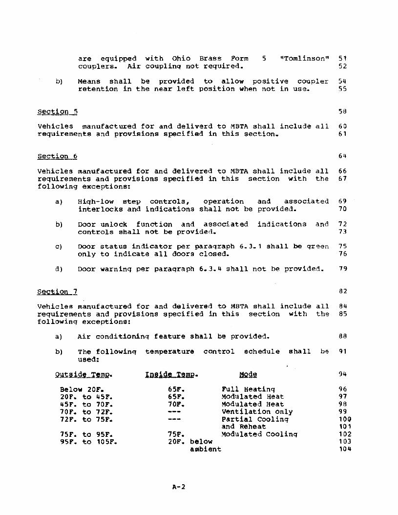
are equipped with Ohio Brass Formcouplers. Air couplinq not required.
5 "Tomlinson" 5152
b) Means shall be provided to allow positive coupler 54retention in the near left position when not in use. 55
vehicles manufactured for and deliverd to MBTA shall include all 60requirements and provisions specified in this section. 61
section 6 64
vehicles manufactured for and delivered to MBTA shall include all 66requirements and provisions specified in this section with the 61following exceptions:
a) High-low step controls, operation and associated 69interlocks and indications shall not be provided. 10
b) Door unlock function and associated indications and 72controls shall not be provided. 73
c) Door status indicator per paraqraph 6.3.1 shall be green 75only to indicate all doors closed. 76
d) Door warning per paragraph 6.3.4 shall not be provided. 19
section 7 82
Vehicles manufactured for and delivered to MBTA shall include all 84requirements and provisions specified in this section with the 85followinq exceptions:
a) Air conditioning feature shall be provided. 88
b) The followin~ temperature control schedule shall be 91used:
75F.20F. below
ambient
QY~ll.9.LIU1?
Below 20F.20F. to 45F.145F. to 70F.10F. to 72F.72F. to 75F.
15F. to 95F.95F. to 105F.
In.lide I§mg.
65F.65F.10F.
A-2
Full HeatingModulated HeatMOdulated HeatVentilation onlyPartial Coolingand ReheatModulated Cooling
94
9697989910G101102103104

Vehicles manufactured for and delivered to MBTA shall include all 110requirements and provisions specified in this section. 111
section 9 114
Vehicles manufactured for and delivered to MBTA shall include all 116requirements and provisions specified in this section with the 117following exceptions:
a) Trolley poles and associated equipaent shall not be 120provided on production vehicles.
b) Trolley poles, pantographs and associated equipment 122shall be provided on the first three (pilot~ vehicles. 123
c) Automatic speed control shall not be provided (9.3.15) 125but provisions shall be made for possible future 126installation of automatic speed control equipment. 127
section 1Q 130
Vehicles manufactured for and delivered to MBTA shall include all 132requirements and provisions in this section. 133
.§ection 11 136
Vehicles manufactured for and delivered to MBTA shall include all 138requirements and provisions specified in this section with the 139following exception:
a) suspension system need not provide constantheight.
floor 141142
section 12 145
Vehicles manufactured for and delivered to MBTA shall include all 147requirements and provisions specified in this section with the 148following exception:
a) Sanders shallinterface ondirection.
apply sand only to the wheel-railthe right side of the vehicle in each
150151
b) A separate track brake control switch on the Operator's 153console shall not be provided. 154
sections 13, 14, ~1§, 17 and 18
A-J
157

Vehicles manufactured for and delivered to MBTA shall include all 159requirements and provisions specified in these sections. 160
A-4

Appendix B - Liqht Rail Vehicle 7
SPECIAL REQUIREME~I2-=-§FMR 9
vehicles manufactured for and delivered to SFMR shall include all 14requirements and provisions specified in this section. 15
gectiQIL] 18
Vehicles delivered to SFMR shall include: 21
a) Movable steps at door locations A2, A3, B2, and B3. 24
b) Doors shall be openable from the inside by means of 26passenger operated push bars when unlocked by operator. 27
c) The graphics for the MUN! cars shall be as shown on MUNI 29drawings which shall be furnished by the OWner during 30vehicle desiqn.
d) All exterior destination signs (both end and side) shall 32be desiqned to accomodate the present Municipal Railway 33signing found on all of that property's other vehicles. 34This requires the use of either a single or split type 35twin curtain system provided that all combinations of 36signs can be selected quickly and properly displayed.with either arrangement, a total of forty 2-way 37destination combinations shall be possible.
All destination signs shall be simultaneously controlled 39from the cab. 40
§ectiQD~ 43
Vehicles manufactured for and delivered to SFMR shall include all 45requirements and provisions specified in this section with the 46following exception:
a) Means shall be provided to allow the use of an Owner 48furnished portable tow-bar connected to the car body. 49Tow-bar details will be furnished by SFMR during vehicle 50desiqn.
section 5
B-1
53

vehicles manufactured for and delivered to SFMR shall include all 55requirements and provisions specified in this section with the 56following eKception:
a) Exterior mirrors per paragraph 5.2.11 shall be 58operational at all times. Cam action is not necessary. 60
Vehicles manufactured for and delivered to SFMR shall include all 65requirements and provisions specified in this section with the 66followinq exception:
a) Door status indicator per paragraph 6.3.1 shall be red 68only to indicate doors open. 69
sec.t1.Q!Ll 72
Vehicles manufactured for and delivered to SFMR shall include all 74requirements and provisions specified in this section with the 75followinq exceptions:
a) "Layover" heating need not be provided. 16
b) San Francisco ambient temperature range of 30F. to 95F. 80shall be used for desiqn. 81
c) Air conditioning shall not be provided. 84
Section 8 87
Vehicles manufactured for and delivered to SFMR shall include all 89requirements and provisions specified in this section. 90
section 9 93
Vehicles manufactured for and delivered to SFMR shall include all 95requirements and provisions specified in this section with the 96following exceptions:
a) Trolley poles and associated equipment shall not be 99provided.
b) Full service plus track brake detent shall not be 101provided on the Master controller. 102
§ect!.Q.illLj.Q~n,g-1.1 105
vehicles manufactured for and delivered to SFMR shall inclu~e all 107requirements and provisions specified in these sections. 108
B-2

section 12 111
vehicles manufactured for and delivered to SFMR shall include all 113requirements and provisions specified in this section with the 114followinq exception:
a) Track brakes shall not be operated from th~ master 117controller.
Vehicles manufactured for and delivered to SFMR shall include all 122requirements and provisions specified in these sections. 123
B-)


![JU orSe.] - Wikimedia Commons](https://static.fdokumen.com/doc/165x107/631d4c356c6907d36801b2da/ju-orse-wikimedia-commons.jpg)