Life Safety Solutions - Ruskin
322
Combination Fire and Smoke Dampers, Smoke Dampers, Curtain and Multiple Blade Fire Dampers and Ceiling Fire Dampers II-MBF-FSD(R)-814/Replaces II-MBF-FSD(R)-312 © RUSKIN 2014 Life Safety Solutions Specification and Installation Instruction Manual ALL STATED SPECIFICATIONS ARE SUBJECT TO CHANGE WITHOUT PRIOR NOTICE OR OBLIGATION
-
Upload
khangminh22 -
Category
Documents
-
view
0 -
download
0
Transcript of Life Safety Solutions - Ruskin

Click to Return to: INDEX FSD SD IBD/DFD CFD
Combination Fire and Smoke Dampers, Smoke Dampers,Curtain and Multiple Blade Fire Dampers
and Ceiling Fire Dampers
II-MBF-FSD(R)-814/Replaces II-MBF-FSD(R)-312 © RUSKIN 2014
Life Safety SolutionsSpecification and Installation Instruction Manual
ALL STATED SPECIFICATIONS ARE SUBJECT TO CHANGE WITHOUT PRIOR NOTICE OR OBLIGATION
Combination Fire and Smoke Dampers, Smoke Dampers,Curtain and Multiple Blade Fire Dampers
and Ceiling Fire Dampers
II-MBF-FSD(R)-314/Replaces II-MBF-FSD(R)-312 © RUSKIN 2014
®
Life Safety SolutionsSpecification and Installation Instruction Manual
ALL STATED SPECIFICATIONS ARE SUBJECT TO CHANGE WITHOUT PRIOR NOTICE OR OBLIGATION

AUGUST 2014
Fire/Smoke Catalog Index How to Use This Document
This is an interactive, dynamic document, best utilized within a PDF viewer. There are live links built‐in throughout the document. All blue text links to either a website or another page within this document. Also, the bottom of every page includes “jump to” links to speed up navigation within this document.
RUSKIN LABOR SAVERS
OPERATION, MAINTENANCE AND REPORTS Product Data Description
FSDOM-514 Operation & Maintenance Instructions Report #1113 Testing and Maintenance of Life Safety Dampers Report #114 Dynamic Fire Damper Testing and Maintenance ERTRFSD-102 Advantages of True Round Fire/Smoke Dampers Report #8190:1 Airfoil Blade Design Advantages Report #398 Combination Fire/Smoke Damper Release Devices
TESTING AND MAINTENANCE OPTIONS II-ClassicDI-4B-413 Classic Damper Inspector Spec WirelessDI-1212 Wireless Damper Inspector II-DTS-514 Electronic Resettable Fuse Link with Damper Test Switch “DTS” II-DTS-SD-1212 Damper Test Switch for Smoke Dampers Spec MCP3/34-305 Single Damper Control Panel “Lights Only” Spec MCP4/44-305 Single Damper Control Panel “lights and Test Switch” Spec MCPB/1.5-305 Single Damper Control Panel “On/Off or Test Switch” No lights Spec MCP1/14-305 Single Damper Control Panel “For use with TS-150 Fire Stat” Spec MCP10/20-305 Multiple Damper Control Panel “For use with TS-150 Fire Stat”
Product Data Description Installation COMBINATION FIRE/SMOKE DAMPERS
Combination Fire Smoke Damper Selection and Application Guide FSD60LP, FSD60-2LP, Low Profile, Ultra-Low Pressure Drop 1 ½ hour Rated; Class 1 or 2 leakage II-FSDLP-514 FSD37LP, FSD36LP FSDR60(SS) True Round Ultra-Low Leakage Class I, 1 ½ hour Rated (II-FSDR25-514) II-FSDR60(SS)-514 FSD60, FSD60-2 FSD60VFSD60M FSD60 Series High Performance Class I, II and III, 1 ½ hour Rated II-FSD60-514 FSD60-BALFSD60-XPFSD35, 36 and 37 FSD35 Series Class I, II and III 1 ½ hour Rated II-FSD36-514 FSD60-3, M and BAL FSD60-3 Series High Performance Class I and II, 1 ½ hour Rated II-FSD60-3-514 FSD35SS, 36SS, 37SS Series Class I, II and III, 1 ½ hour Rated II-FSDSS-514
GRILLE or SHAFT COMBINATION FIRE/SMOKE DAMPERS FSD60FA and FSD36FA Front Access FSD, Class I and II, 1 ½ hour Rated II-FSDFA-514
Actuator Replacement and Wiring Accessibility for FSD36FA and FSD60FA II-FSDFA-209 FSDxxGA FSD “Grille Access”, Class I and II, 1 ½ hour Rated II-FSDGA-514 FSDxxOW FSD “Out of Wall”, Class I and II, 1 ½ hour Rated II-FSDOW-514 FSD60C and FSD36C “Tunnel Corridor” Fire Smoke Damper, Class I and II, 1 hour Rated II-FSD60/36C-1 FSDR60C True Round “Tunnel Corridor” Fire Smoke Damper 1 hour Rated II-FSDR60C-514 DFSDR1 1 Round Tunnel Corridor / Ceiling Fire Damper II-DFSDR1-514
SMOKE DAMPERS Smoke Damper Selection and Application Guide True Round Class 1 Leakage Rated Smoke Damper Aluminum Air Foil Blade Class 1 Leakage Rated Smoke Damper Galvanized Air Foil Blade Class 1 and 2 Leakage Smoke Damper Galvanized Vertical Air Foil Blade Class 1, 2 Leakage Smoke Damper II-SD-514
SDRS25 (SS)SD50 SD60 and SD60-2 SD60V SD35, 36 and 37 Galvanized Vertical Vee-Grove Blade Class 1, 2 & 3 Leakage Smoke Damper SD35SS, 36SS and 37SS Stainless Steel Vertical Vee-Grove Blade Class 1, 2 & 3 Leakage Smoke Damper SD60M and BAL Modulating and Balancing Air Foil Blade Class 1 and 2 Leakage Smoke DamperSD120 Heavy Duty Smoke Damper II-SD102-514
LINK TO UL "Marking and Application Guide"

Product Data Description Installation CURTAIN & MULTIPLE BLADE FIRE DAMPERS
Static/Dynamic Fire Damper Selection Application Guide
FDR25 and FDR25SS True Round 1 ½ Hour Fire Damper II-FDR25-514
DIBD2 and DIBD2SSIBD2 and IBD2SS Standard Curtain Fire Dampers 11/2 Hour Rated II-IBD-514IBDT, T1 and T2 DIBD20, 40 and 60 Integral Sleeve/Frame Curtain Fire Dampers 11/2 Hour Rated II-IBD20-514 IBD20, 40 and 60 DIBD23 and DIBD23SS Standard Curtain Fire Dampers 3 Hour Rated II-IBD23-514 IBD23 and IBD23SS DIBD230, 430 & 630 Integral Sleeve/Frame Curtain Fire Dampers 3 Hour Rated II-IBD230-514 IBD230, 430 and 630 DFD60 DFD35 Multiple Blade Fire Dampers 3 Hour Rated II-FD60-514 FD60 FD35 (D)FD35SS Stainless Steel Multiple Blade Fire Dampers 11/2 Hour Rated II-FD35SS-514 DFD60-3FD60-3 Multiple Blade Fire Dampers 3 Hour Rated II-FD60-3-514 DIBD2(SS)-CULIBD2(SS)-CUL Standard Curtain Fire Dampers 11/2 Hour Rated (Canada) II-IBD-CUL-714 IBDT, T1 and T2-CUL DIBD20, 40 & 60-CUL IBD20, 40 & 60-CUL Integral Sleeve/Frame Curtain Fire Dampers 11/2 Hour Rated (Canada) II-IBD20-CUL-714 DIBD23(SS)-CULIBD23(SS)-CUL Standard Curtain Fire Dampers 3 Hour Rated (Canada) II-IBD23-CUL-714 DIBD230, 430 & 630-CUL IBD230, 430 & 630-CUL Integral Sleeve/Frame Curtain Fire Dampers 3 Hour Rated (Canada) II-IBD230-CUL-714
GRILLE and SHAFT FIRE DAMPERS (D)IBD2(SS)GA “Grille Access” Curtain Fire Damper 11/2 Hour Rated II-(D)IBD2GA-514 (D)FD60GA (D)FD35(SS)GA “Grille Access” Multiple Blade Fire Damper 11/2 Hour Rated II-FD35/60GA-514 (D)IBD2(SS)/OW “Out of Wall” Curtain Fire Damper 11/2 Hour Rated II-(D)IBD2OW-514 (D)FD60-OW (D)FD35(SS)-OW “Out of Wall” Multiple Blade Fire Damper 11/2 Hour Rated II-FD35/60OW-514 (D)IBD2G, 20G Grille Mounting Curtain Fire Damper 11/2 Hour Rated II-(D)IBD2G-714
INSTALLATION INSTRUCTION SUPPLEMENTS Product Data Description
Framing Details Recommended Framing in wood or metal stud walls
II-U438-514 Cavity Shaft Wall Metal Stud Framing Details II-CSWC-514 Metal Stud Framing in Tunnel Corridor Shaft-Wall Ceiling Detail II-MFD-514 Mullions for Dampers in Oversized Wall Openings Detail
Duct ConnectionII-FSBC-514 Flange System Breakaway Connections (Duct Mate, TDF, TDC and Ward) II-TDFADD-514 TDF and TDC Field Add-On Flange Connections
Extend and Trim Damper SleeveII-EDS-514 Extension of Fire and Combination Fire and Smoke Damper Sleeves II-FSDTrim-410 Trimming of Fire & Combination F/S Damper Sleeves
Sealants and Fire Stop MaterialII-FIRESTOP-814 Optional Firestop InstallationII-SEAL-814 Optional Sealant Installation Instructions
GRILLE AND TRANSFER OPENINGSII-TRANS-514 Transfer Openings for Duct Terminators Installation Instructions II-G-Angle-514 (D)IBD, FD and FSD Grille Mounting Angles Installation Instructions II-DECK-1104 Concrete Floor with Steel Deck Installation Instructions
DFD-LP Low Profile; Low Pressure, Drop Dynamic 1 ½ Hour Fire Damper II-DFD-LP-114
Product Data Description SMACNA INSTALLATION INSTRUCTION RECOMMENDATIONS
5.4 Minimum Sleeve Thickness5.9 Out of Wall Fire Damper Installation 5.10 Out of Wall Fire Smoke Damper Installation 5.12 Duct Liner Interruption 5.13 Duct Insulation6.4 Multiple Penetrations6.5 Diagonal Penetration
FUSE LINKS and SWITCH PACKAGES II-EFL-514 Electronic Resettable Fuse Link “EFL” II-DTS-514 Electronic Resettable Fuse Link with Damper Test Switch “DTS” II-EFLSP-514 EFL/SP100 Electric Resettable Fuse Link and SP100 Switch Package “EFL/SP100” II-DTS-SD-514 Damper Test Switch for Smoke Dampers II-TS150-514 TS150 FireStat for "Reopenable" Fire and Smoke Dampers II-SP100FK-514 SP100 Switch Package Field Installation Instructions Spec SP200-514 SP200 Switch Package for Curtain Fire Damper II-PFL-514 Pneumatic Fuse Link “PFL” Spec FLAP-110 Fuse Link Replacements
SMOKE DETECTORS II-DSDF-D4120-514 System Sensor D-4120 Flow Duct Smoke Detector II-DSDN-2151-714 System Sensor 2151 No Flow Duct Smoke Detector II-DSDF-DH98-514 Hochiki DH-98 Flow Duct Smoke Detector II-DSDN-HS100-514 Air Products and Controls HS-100-P No Flow Duct Smoke Detector
Product Data Description Installation CEILING RADIATION DAMPERS
Ceiling Radiation Damper For Wood Construction CFD2, 3, 3.5 and 4 CFD5 CFD8 CFD7T CFD7 CFDR7T
CFD2, CFD3, CFD3.5 and CFD4 Standard Ceiling Fire Dampers Ceiling Fire Damper for Lay-In ceilings Low Profile Ceiling Fire Damper Ceiling Fire Damper for Open Web Wood Truss Assemblies Ceiling Fire Damper for Wood Joist Assemblies True Round Ceiling Fire Damper for Open Web Wood Truss Assemblies
CFD2W, 3W, 4W DFSDR1
Fiberglass Duct Board Plenum for Ceiling Dampers Installation Supplement CFD7 Installation Supplement for Ceiling Design G548 CFD7 Installation Supplement for Ceiling Design L524 Warnock Hersey Classified Ceiling Radiation Damper Motorized Ceiling Fire Damper
II-CFD-1008 II-CFD(R)5-1008II-CFD8-1008 II-CFDWT-614 II-CFD7-1008 II-CFDR7-T-614 II-Ductboard-507 II-CFD7 Supp-1004 II-CFD7 SuppL524-1004 II-CFDW-1103 II-DFSDR1-514

The contractor guide to save time and money
Fire, Smoke
& Combination
Fire/Smoke
Dampers
Click to Return to: INDEX FSD SD IBD/DFD CFD
2
Page HeadContents
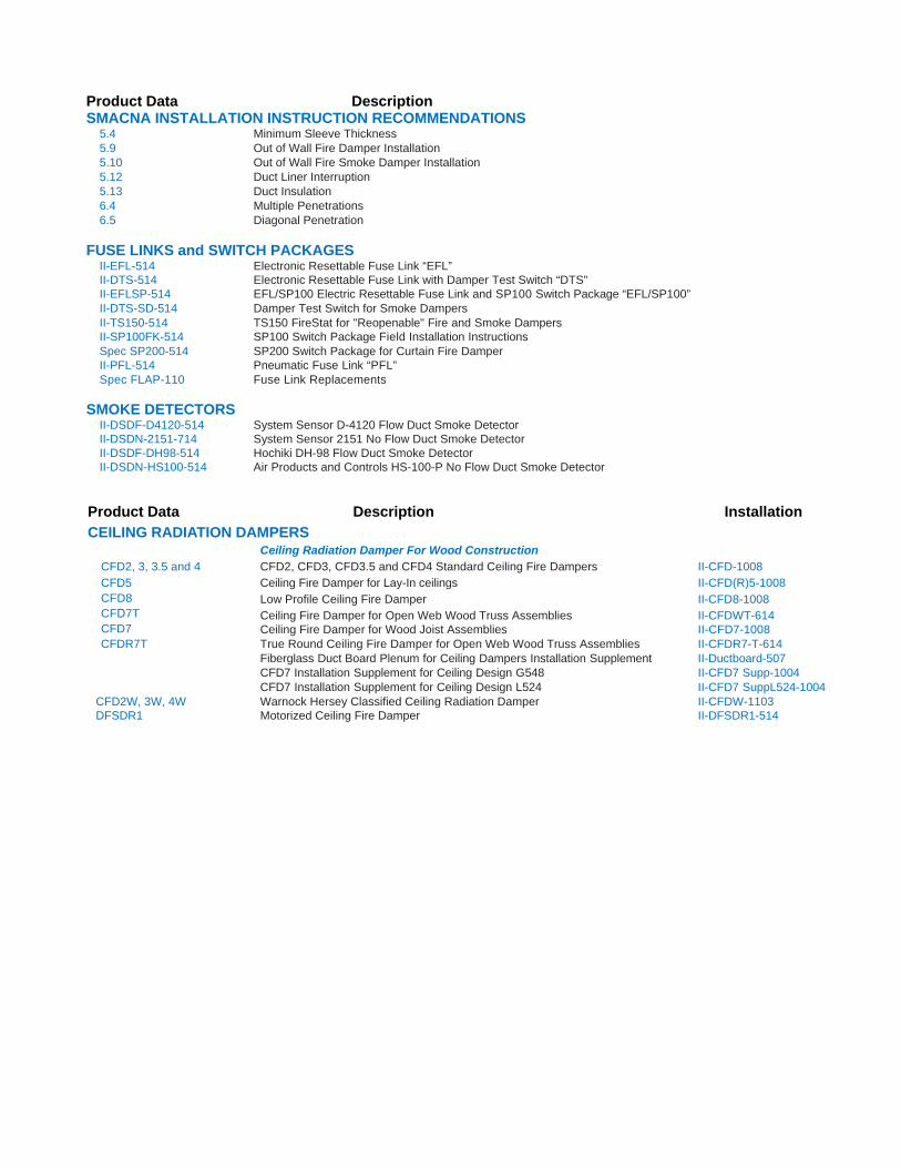
Labor Savers — Installation aids Page
#1 One SIde angLe InStaLLatIOn 3
#2 IntegraL and factOry SLeeveS 3
#3 factOry aSSeMBLed IntegraL SLeeve 4
#4 unIverSaL fLange Breakaway cOnnectIOnS 4
#5 IntegraL acceSS dOOrS factOry InStaLLed 4
#6 S-and-drIveMate Breakaway cOnnectIOnS 4
#7 ruSkIn taggIng and PackagIng OPtIOnS 5
#8 InStaLLatIOn and aIrfLOw In any dIrectIOn 5
Labor Savers — application Solutions#9 fdr25 and fSdr25 true rOund daMPerS 5
#10 frOnt acceSS cOMBInatIOn fIre/SMOke daMPerS 5
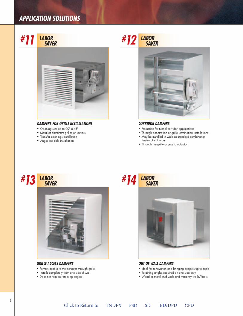
#11 daMPerS fOr grILLe InStaLLatIOnS 6
#12 cOrrIdOr daMPerS 6
#13 grILLe acceSS daMPerS 6
#14 Out Of waLL daMPerS 6
#15 SMOke detectOrS 7
#16 SecurIty BarS 7
#17 daMPer teSt SwItcH dtS 7
#18 wOOd truSS radIatIOn daMPerS cfd7(t) 7
Labor Savers — Installation Options #19 OPtIOnaL angLe SeaLant 8
#20 OPtIOnaL fIreStOP InStaLLatIOn 8
#21 OPtIOnaL duct SeaLantS fOr Breakaway cOnnectIOnS 8
#22 fIeLd SLeeve extenSIOnS 8
Click to Return to: INDEX FSD SD IBD/DFD CFD

3
InStaLLatIOn aIdS
Save TimeSave Money
Save Now!Ruskin Labor Savers are UL approved products and installation methods for fire, smoke and combination fire/smoke dampers that save contractors money.
Labor Savers can be ordered in three different categories:
• Installation Aids
• Application Solutions
• Installation Options
•LaborSavers—InstallationAidsSupplied with each damper to reduce thehandling time at the job site.
•LaborSavers—ApplicationSolutionsDampers that have been specifically engineeredfor unique applications.
•LaborSavers—InstallationOptionsSpecialized UL approved installation methodsthat go beyond standard installations.
Ruskin products are made to exacting standards and specifications, and are supported by a technical sales force in every major city nationwide. And, with the Ruskin Express Program we can guarantee your delivery.
LaBOr Saver#1
One SIde angLe InStaLLatIOn• Ruskin FAST Angles• One piece angle shipped with the damper• Available in 1-½" or 2-½"• Metal, wood and masonry walls/floors• Permits damper installation before or after drywall installation• Approved for all Ruskin fire, smoke and fire/smoke dampers
LaBOr Saver#2
IntegraL and factOry SLeeveS • Delivered to jobsite and ready to install• Many sleeve lengths and gauges• Eliminates field sleeves and special handling
.comClick to Return to: INDEX FSD SD IBD/DFD CFD
4
InStaLLatIOn aIdS
LaBOr Saver#4
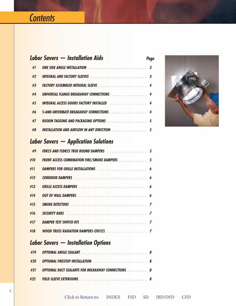
unIverSaL fLange Breakaway cOnnectIOnS• Breakaway connection with bolted corners and metal cleats• Breakaway connection with Butyl or Neoprene gaskets• Factory installed onto the sleeve• Available on all fire, smoke and combination fire/smoke dampers
LaBOr Saver#6
S-and-drIveMate Breakaway cOnnectIOnS• Ruskin’s Drivemate #14880• Factory hemmed sleeves complement drive mate• Easy to use, worry free connections that stay joined
LaBOr Saver#3
factOry aSSeMBLed IntegraL SLeeve • Fewer pieces to handle with multiple sections• Angle option around entire perimeter• Assembled for larger openings
LaBOr Saver#5
IntegraL acceSS dOOrS factOry InStaLLed• Factory installed between damper and duct connection• Correct placement of access doors• Available with all fire and
combination fire/smoke dampers
Damper shown with factory mounted TDF Flange
new
Click to Return to: INDEX FSD SD IBD/DFD CFD
Click to Return to: INDEX FSD SD IBD/DFD CFD

5
InStaLLatIOn aIdS
aPPLIcatIOn SOLutIOnS
InStaLLatIOn and aIrfLOw In any dIrectIOn• Combination fire/smoke, and smoke damper flexibility• Bi-directional airflow• Ability to rotate dampers for actuator access
LaBOr Saver#8
LaBOr Saver#10
LaBOr Saver#7
ruSkIn taggIng and PackagIng OPtIOnS• Factory packaged by floor or area to eliminate sorting
by hand at job site• Speeds handling of larger orders• No additional cost
LaBOr Saver#9
fdr25 and fSdr25 true rOund daMPerS• Retaining plate one or two sides approved• Easy installation in round or square openings using cinch plate(s)• Wood or metal stud walls and masonry walls/floors• Shipped complete with integral sleeve• Lower cost than square to round transitions
frOnt acceSS cOMBInatIOn fIre/SMOke daMPerS• Designed for corridor or shaft
wall applications• Permits Front Access to actuator
through grille• Installs from one side of wall• Low height dampers• Shortest assembly depth in the industry• Does not require retaining angles
Click to Return to: INDEX FSD SD IBD/DFD CFD
Click to Return to: INDEX FSD SD IBD/DFD CFD
6
aPPLIcatIOn SOLutIOnS
LaBOr Saver#12
cOrrIdOr daMPerS• Protection for tunnel corridor applications• Through penetration or grille termination installations• May be installed in walls as standard combination
fire/smoke damper• Through the grille access to actuator
LaBOr Saver#13
grILLe acceSS daMPerS• Permits access to the actuator through grille• Installs completely from one side of wall• Does not require retaining angles
LaBOr Saver#14
Out Of waLL daMPerS• Ideal for renovation and bringing projects up-to code• Retaining angles required on one side only• Wood or metal stud walls and masonry walls/floors
LaBOr Saver#11
daMPerS fOr grILLe InStaLLatIOnS• Opening size up to 90" x 48"• Metal or aluminum grilles or louvers• Transfer openings installation• Angle one side installation
Click to Return to: INDEX FSD SD IBD/DFD CFD

7
aPPLIcatIOn SOLutIOnS
LaBOr Saver#15 LaBOr
Saver#16
SMOke detectOrS• Available in Flow
or NoFlow detectors• Factory mounted on smoke
or combination fire/smoke dampers• Wired for single point connection• Can be shipped loose
SecurIty BarS• Available with fire, smoke and combination fire/smoke
dampers• Available in ½," ¾" and 1" diameter bars• Factory installed
LaBOr Saver
LaBOr Saver#17 #18
daMPer teSt SwItcH dtS• Eliminates field wiring to a remote panel• Allows easy testing of the dampers during installation
and commissioning• Continues to save during required inspection and
testing though the life of the building
wOOd truSS radIatIOn daMPerS cfd7(t)• Wood truss or joist construction• Factory or field supplied plenums• Assembly designed to except grills with
up to 2½" grille depths• Through ceiling membrane penetration
new
Click to Return to: INDEX FSD SD IBD/DFD CFD
8
LaBOr Saver#20
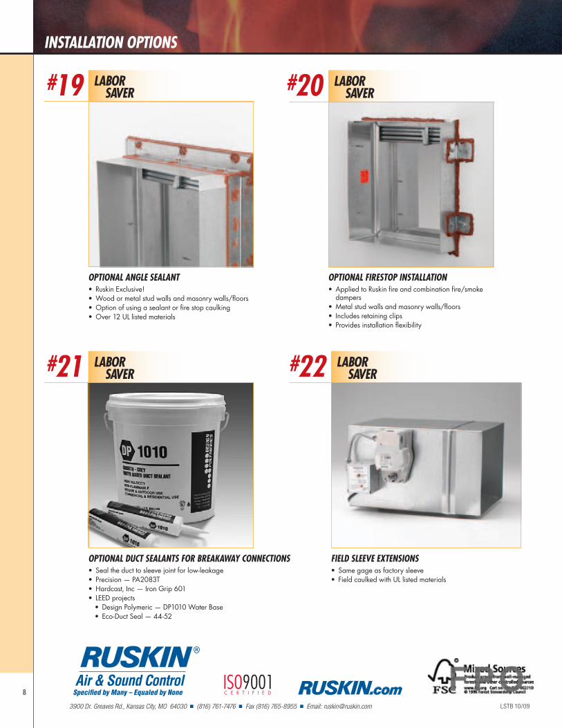
OPtIOnaL fIreStOP InStaLLatIOn• Applied to Ruskin fire and combination fire/smoke
dampers• Metal stud walls and masonry walls/floors• Includes retaining clips• Provides installation flexibility
LaBOr Saver#22
fIeLd SLeeve extenSIOnS• Same gage as factory sleeve• Field caulked with UL listed materials
OPtIOnaL duct SeaLantS fOr Breakaway cOnnectIOnS• Seal the duct to sleeve joint for low-leakage• Precision — PA2083T• Hardcast, Inc — Iron Grip 601• LEED projects
• Design Polymeric — DP1010 Water Base• Eco-Duct Seal — 44-52
LaBOr Saver#21
InStaLLatIOn OPtIOnS
LaBOr Saver#19
OPtIOnaL angLe SeaLant• Ruskin Exclusive!• Wood or metal stud walls and masonry walls/floors• Option of using a sealant or fire stop caulking• Over 12 UL listed materials
LSTB 10/09
Specified by Many – Equaled by None
R
Air & Sound Control
3900 Dr. Greaves Rd., Kansas City, MO 64030 n (816) 761-7476 n Fax (816) 765-8955 n Email: [email protected]
ISO9001C E R T I F I E D .com
3900 Dr. Greaves Rd. • Kansas City, MO 64030 • (816) 761-7476 • FAX (816) 765-8955
OPERATION & MAINTENANCE INSTRUCTIONS
FSDOM-514/Replaces FSDOM-413 © Ruskin 2014
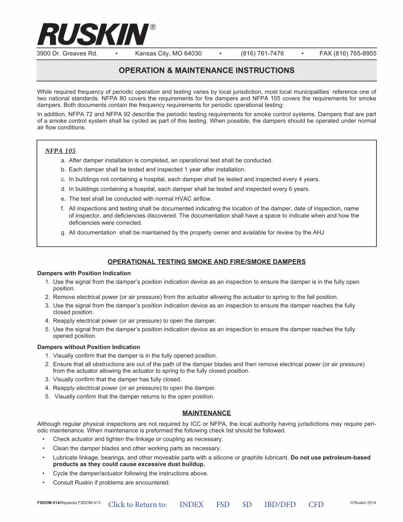
While required frequency of periodic operation and testing varies by local jurisdiction, most local municipalities’ reference one oftwo national standards. NFPA 80 covers the requirements for fire dampers and NFPA 105 covers the requirements for smokedampers. Both documents contain the frequency requirements for periodic operational testing:In addition, NFPA 72 and NFPA 92 describe the periodic testing requirements for smoke control systems. Dampers that are partof a smoke control system shall be cycled as part of this testing. When possible, the dampers should be operated under normalair flow conditions.
OPERATIONAL TESTING SMOKE AND FIRE/SMOKE DAMPERSDampers with Position Indication
1. Use the signal from the damper’s position indication device as an inspection to ensure the damper is in the fully openposition.
2. Remove electrical power (or air pressure) from the actuator allowing the actuator to spring to the fail position.3. Use the signal from the damper’s position indication device as an inspection to ensure the damper reaches the fully
closed position.4. Reapply electrical power (or air pressure) to open the damper.5. Use the signal from the damper’s position indication device as an inspection to ensure the damper reaches the fully
opened position.
Dampers without Position Indication1. Visually confirm that the damper is in the fully opened position.2. Ensure that all obstructions are out of the path of the damper blades and then remove electrical power (or air pressure)
from the actuator allowing the actuator to spring to the fully closed position.3. Visually confirm that the damper has fully closed.4. Reapply electrical power (or air pressure) to open the damper.5. Visually confirm that the damper returns to the open position.
MAINTENANCEAlthough regular physical inspections are not required by ICC or NFPA, the local authority having jurisdictions may require peri-odic maintenance. When maintenance is preformed the following check list should be followed.
• Check actuator and tighten the linkage or coupling as necessary.• Clean the damper blades and other working parts as necessary.• Lubricate linkage, bearings, and other moveable parts with a silicone or graphite lubricant. Do not use petroleum-based
products as they could cause excessive dust buildup.• Cycle the damper/actuator following the instructions above.• Consult Ruskin if problems are encountered.
NFPA 105a. After damper installation is completed, an operational test shall be conducted.b. Each damper shall be tested and inspected 1 year after installation.c. In buildings not containing a hospital, each damper shall be tested and inspected every 4 years.d. In buildings containing a hospital, each damper shall be tested and inspected every 6 years.e. The test shall be conducted with normal HVAC airflow.f. All inspections and testing shall be documented indicating the location of the damper, date of inspection, name
of inspector, and deficiencies discovered. The documentation shall have a space to indicate when and how thedeficiencies were corrected.
g. All documentation shall be maintained by the property owner and available for review by the AHJ
Click to Return to: INDEX FSD SD IBD/DFD CFD
PERIODIC PERFORMANCE TESTING FOR (D)IBD, (D)FD AND CFD DAMPERS
3900 Dr. Greaves Rd.Kansas City, MO 64030(816) 761-7476FAX (816) 765-8955www.ruskin.com
®
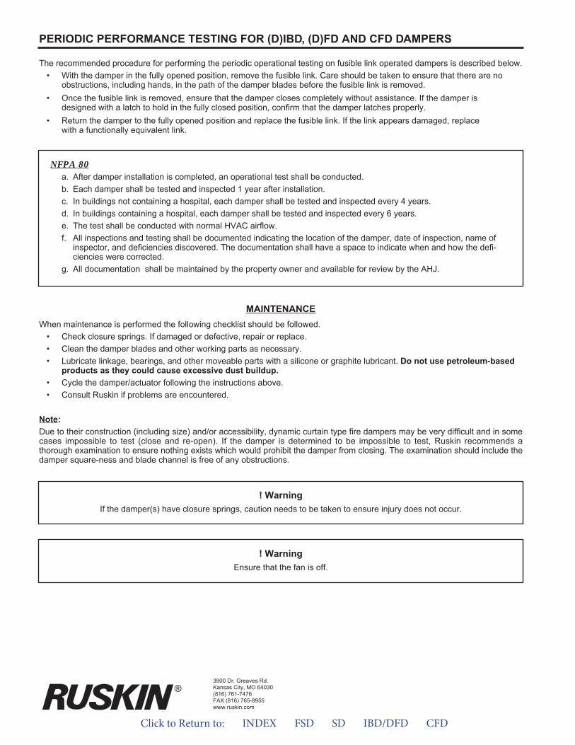
The recommended procedure for performing the periodic operational testing on fusible link operated dampers is described below.• With the damper in the fully opened position, remove the fusible link. Care should be taken to ensure that there are no
obstructions, including hands, in the path of the damper blades before the fusible link is removed.• Once the fusible link is removed, ensure that the damper closes completely without assistance. If the damper is
designed with a latch to hold in the fully closed position, confirm that the damper latches properly.• Return the damper to the fully opened position and replace the fusible link. If the link appears damaged, replace
with a functionally equivalent link.
MAINTENANCEWhen maintenance is performed the following checklist should be followed.
• Check closure springs. If damaged or defective, repair or replace.• Clean the damper blades and other working parts as necessary.• Lubricate linkage, bearings, and other moveable parts with a silicone or graphite lubricant. Do not use petroleum-based
products as they could cause excessive dust buildup.• Cycle the damper/actuator following the instructions above.• Consult Ruskin if problems are encountered.
Note:Due to their construction (including size) and/or accessibility, dynamic curtain type fire dampers may be very difficult and in somecases impossible to test (close and re-open). If the damper is determined to be impossible to test, Ruskin recommends a thorough examination to ensure nothing exists which would prohibit the damper from closing. The examination should include thedamper square-ness and blade channel is free of any obstructions.
! WarningIf the damper(s) have closure springs, caution needs to be taken to ensure injury does not occur.
NFPA 80a. After damper installation is completed, an operational test shall be conducted.b. Each damper shall be tested and inspected 1 year after installation.c. In buildings not containing a hospital, each damper shall be tested and inspected every 4 years.d. In buildings containing a hospital, each damper shall be tested and inspected every 6 years.e. The test shall be conducted with normal HVAC airflow.f. All inspections and testing shall be documented indicating the location of the damper, date of inspection, name of
inspector, and deficiencies discovered. The documentation shall have a space to indicate when and how the defi-ciencies were corrected.
g. All documentation shall be maintained by the property owner and available for review by the AHJ.
! WarningEnsure that the fan is off.
Click to Return to: INDEX FSD SD IBD/DFD CFD
Click to Return to: INDEX FSD SD IBD/DFD CFD
ENGINEERING REPORTTOPIC: TESTING a nd MAINTENANCE of LIFE SAFETY DAMPERS
Report No. 1113 November 2013 By Kent Maune
PurposeLife safety dampers like fire dampers, smoke dampers, combination fire/smoke dampers, ceiling fire (radiation) dampers that perform as an integral part of a building’s fire protection strategy must function properly during a fire or life safety emergency. Proper installation, commissioning and periodic performance testing are required to ensure these dampers function as intended in a fire emergency.
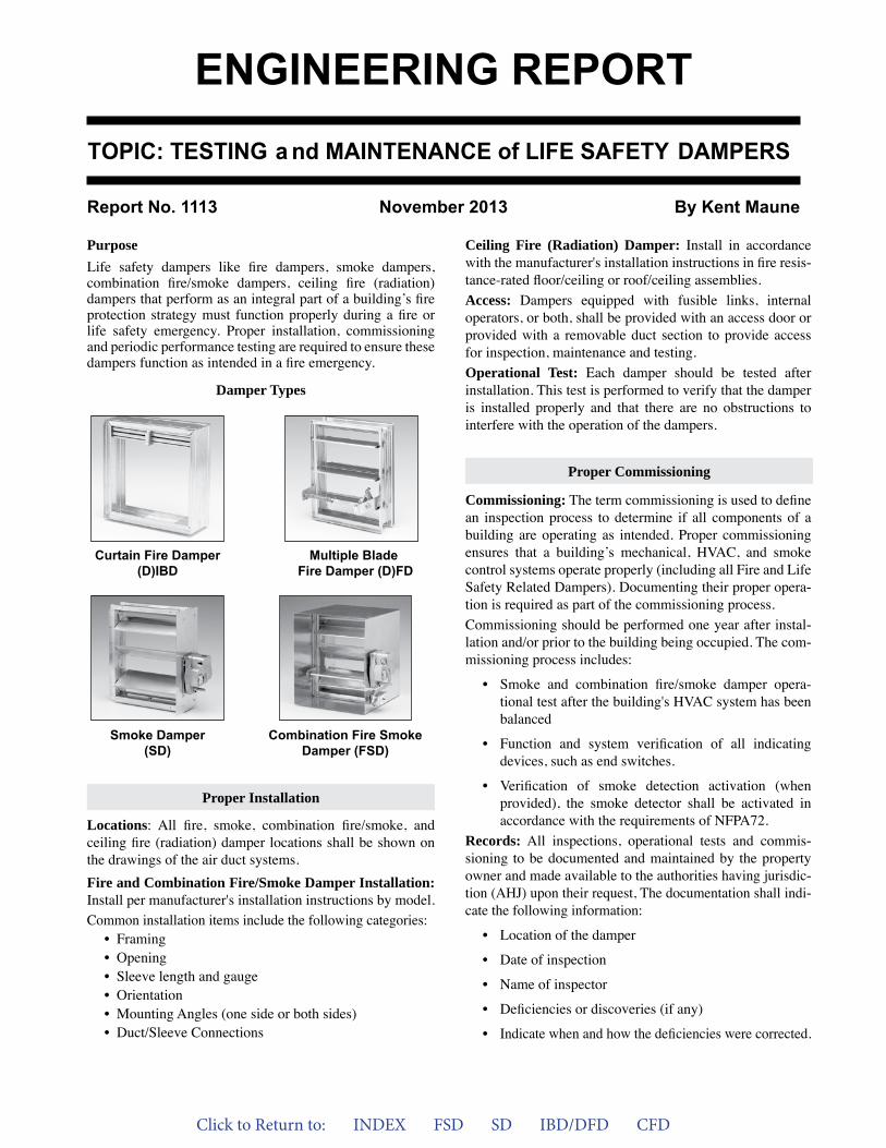
Damper Types
Locations: All fire, smoke, combination fire/smoke, and ceiling fire (radiation) damper locations shall be shown on the drawings of the air duct systems.Fire and Combination Fire/Smoke Damper Installation: Install per manufacturer's installation instructions by model.Common installation items include the following categories:
• Framing• Opening• Sleeve length and gauge• Orientation• Mounting Angles (one side or both sides)• Duct/Sleeve Connections
Curtain Fire Damper(D)IBD
Multiple BladeFire Damper (D)FD
Smoke Damper(SD)
Combination Fire SmokeDamper (FSD)
Ceiling Fire (Radiation) Damper: Install in accordance with the manufacturer's installation instructions in fire resis-tance-rated floor/ceiling or roof/ceiling assemblies.Access: Dampers equipped with fusible links, internal operators, or both, shall be provided with an access door or provided with a removable duct section to provide access for inspection, maintenance and testing.Operational Test: Each damper should be tested after installation. This test is performed to verify that the damper is installed properly and that there are no obstructions to interfere with the operation of the dampers.
Commissioning: The term commissioning is used to define an inspection process to determine if all components of a building are operating as intended. Proper commissioning ensures that a building’s mechanical, HVAC, and smoke control systems operate properly (including all Fire and Life Safety Related Dampers). Documenting their proper opera-tion is required as part of the commissioning process.Commissioning should be performed one year after instal-lation and/or prior to the building being occupied. The com-missioning process includes:
• Smoke and combination fire/smoke damper opera-tional test after the building's HVAC system has beenbalanced
• Function and system verification of all indicatingdevices, such as end switches.
• Verification of smoke detection activation (whenprovided), the smoke detector shall be activated inaccordance with the requirements of NFPA72.
Records: All inspections, operational tests and commis-sioning to be documented and maintained by the property owner and made available to the authorities having jurisdic-tion (AHJ) upon their request, The documentation shall indi-cate the following information:
• Location of the damper
• Date of inspection
• Name of inspector
• Deficiencies or discoveries (if any)
• Indicate when and how the deficiencies were corrected.
Proper Installation
Proper Commissioning
Click to Return to: INDEX FSD SD IBD/DFD CFD
Damper Types: These fall into one of the two following categories depending upon the operability:
1. Dampers Requiring a Fusible Link to OperateMost fire dampers and ceiling fire (radiation) dampers, and some older generation combination fire/smoke dampers are held in an open position by a fusible link. The fusible link melts at a specified temperature, allowing gravity or a spring to close the damper. After the fusible link has melted, these dampers remain closed until reopened manually and a new fusible link is installed.2. Dampers That Do Not Require a Fusible Link to OperateSmoke dampers and most combination fire/smoke damp-ers do not use fusible links to operate. These dampers use an electric or pneumatic actuator to operate the damper. A bi-metallic disc type thermostat is used to interrupt electrical power or air pressure to the actuator at a specified tempera-ture. Once the electrical power or air pressure is interrupted the spring return feature of the actuator closes the damper.
Fire Life Safety related dampers that are properly applied and installed, and that have the proven ability to function as intended through a building commissioning process, should require no specific on-going maintenance beyond the peri-odic testing described below to confirm functionability.Although the required frequency of this periodic opera-tion testing varies by local jurisdiction, most local require-ments reference one of two national standards, either NFPA 80 or NFPA 105. NFPA 80 covers the requirements for fire dampers and NFPA 105 covers the requirements for smoke dampers. Both documents contain the following frequency requirements for periodic operation testing:Each damper shall be tested and inspected one year after installation. The test and inspection frequency shall then be every 4 years, except in hospitals, where the frequency shall be every 6 years.
Non-Fusible Link Operated Dampers
The recommended procedure for performing periodic opera-tion testing on dampers that do not require a fusible link to operate is described below. Two procedures are described for dampers without position indication switches and dampers with position indication switches.
The first procedure describes how to test dampers without position indication switches. This requires full access to the damper/actuator and it is similar to fusible link operated dampers.
1. Visually confirm that the damper is in the full-openposition.
2. Ensure that all obstructions, including hands, areout of the path of the damper blades and then remove electrical power or air pressure from the actuator to allow the actuator's spring return feature to close the damper.
3. Visually confirm that the damper closes completely.4. Reapply electrical power or air pressure to reopen the
damper.5. Visually confirm that the damper is in the full-open
position.
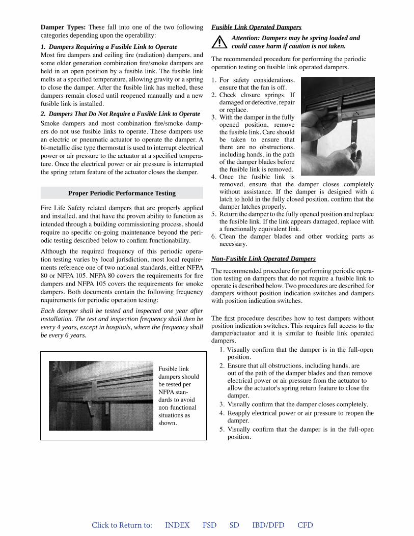
1. For safety considerations,ensure that the fan is off.
2. Check closure springs. Ifdamaged or defective, repairor replace.
3. With the damper in the fullyopened position, removethe fusible link. Care shouldbe taken to ensure thatthere are no obstructions,including hands, in the pathof the damper blades beforethe fusible link is removed.
4. Once the fusible link isremoved, ensure that the damper closes completelywithout assistance. If the damper is designed with alatch to hold in the fully closed position, confirm that thedamper latches properly.
5. Return the damper to the fully opened position and replacethe fusible link. If the link appears damaged, replace witha functionally equivalent link.
6. Clean the damper blades and other working parts asnecessary.
Proper Periodic Performance Testing
Fusible Link Operated DampersAttention: Dampers may be spring loaded and could cause harm if caution is not taken.
The recommended procedure for performing the periodic operation testing on fusible link operated dampers.
Fusible link dampers should be tested per NFPA stan-dards to avoid non-functional situations as shown.
Click to Return to: INDEX FSD SD IBD/DFD CFD
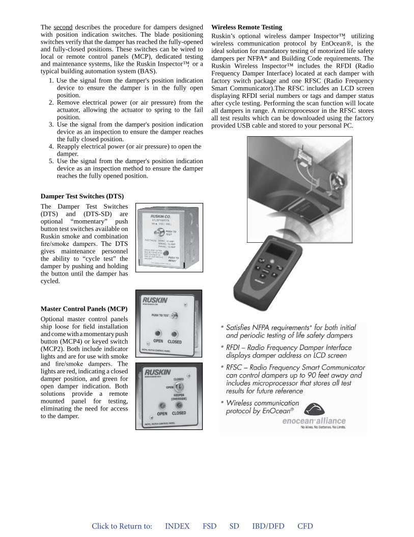
Wireless Remote TestingRuskin’s optional wireless damper Inspector™, utilizing wireless communication protocol by EnOcean®, is the ideal solution for mandatory testing of motorized life safety dampers per NFPA* and Building Code requirements. The Ruskin Wireless Inspector™ includes the RFDI (Radio Frequency Damper Interface) located at each damper with factory switch package and one RFSC (Radio Frequency Smart Communicator).The RFSC includes an LCD screen displaying RFDI serial numbers or tags and damper status after cycle testing. Performing the scan function will locate all dampers in range. A microprocessor in the RFSC stores all test results which can be downloaded using the factory provided USB cable and stored to your personal PC.
Damper Test Switches (DTS)The Damper Test Switches (DTS) and (DTS-SD) are optional “momentary” push button test switches available on Ruskin smoke and combination fire/smoke dampers. The DTS gives maintenance personnel the ability to “cycle test” the damper by pushing and holding the button until the damper has cycled.
Master Control Panels (MCP)Optional master control panels ship loose for field installation and come with a momentary push button (MCP4) or keyed switch (MCP2). Both include indicator lights and are for use with smoke and fire/smoke dampers. The lights are red, indicating a closed damper position, and green for open damper indication. Both solutions provide a remote mounted panel for testing, eliminating the need for access to the damper.
The second describes the procedure for dampers designed with position indication switches. The blade positioning switches verify that the damper has reached the fully-opened and fully-closed positions. These switches can be wired to local or remote control panels (MCP), dedicated testing and maintenance systems, like the Ruskin Inspector™, or a typical building automation system (BAS).
1. Use the signal from the damper's position indicationdevice to ensure the damper is in the fully open position.
2. Remove electrical power (or air pressure) from theactuator, allowing the actuator to spring to the failposition.
3. Use the signal from the damper's position indicationdevice as an inspection to ensure the damper reaches the fully closed position.
4. Reapply electrical power (or air pressure) to open thedamper.
5. Use the signal from the damper's position indicationdevice as an inspection method to ensure the damper reaches the fully opened position.
Click to Return to: INDEX FSD SD IBD/DFD CFD
List of Publications Referenced in this DocumentUL 555 Standard for Fire DampersUL 555S Standard for Smoke DampersUL 555C Standard for Ceiling DampersUL 263 Standard for Fire Tests of Building and Construc-tion MaterialsNFPA 80 Standard for Fire Doors and Other Opening ProtectivesNFPA 105 Standard for the installation of Smoke Door As-semblies and Other Opening ProtectivesNFPA 72 National Fire Alarm and Signaling CodeNFPA 92 Standard for Smoke Control Systems
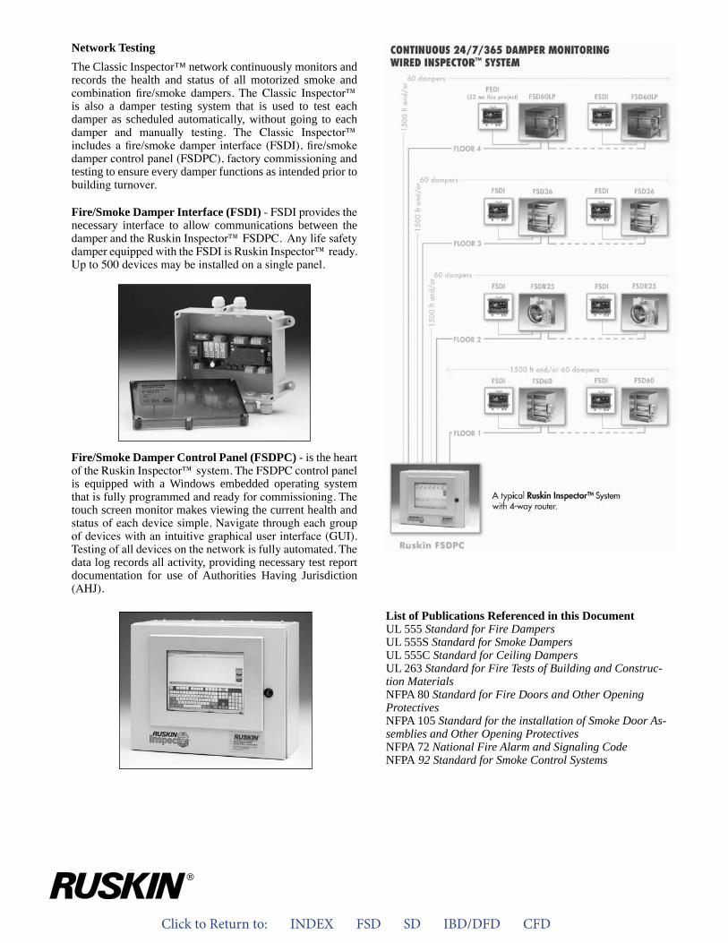
Network TestingThe Classic Inspector™ network continuously monitors and records the health and status of all motorized smoke and combination fire/smoke dampers. The Classic Inspector™ is also a damper testing system that is used to test each damper as scheduled automatically, without going to each damper and manually testing. The Classic Inspector™ includes a fire/smoke damper interface (FSDI), fire/smoke damper control panel (FSDPC), factory commissioning and testing to ensure every damper functions as intended prior to building turnover.
Fire/Smoke Damper Interface (FSDI) - FSDI provides the necessary interface to allow communications between the damper and the Ruskin Inspector™ FSDPC. Any life safety damper equipped with the FSDI is Ruskin Inspector™ ready. Up to 500 devices may be installed on a single panel.
Fire/Smoke Damper Control Panel (FSDPC) - is the heart of the Ruskin Inspector™ system. The FSDPC control panel is equipped with a Windows embedded operating system that is fully programmed and ready for commissioning. The touch screen monitor makes viewing the current health and status of each device simple. Navigate through each group of devices with an intuitive graphical user interface (GUI). Testing of all devices on the network is fully automated. The data log records all activity, providing necessary test report documentation for use of Authorities Having Jurisdiction (AHJ).
Click to Return to: INDEX FSD SD IBD/DFD CFD
Report No. 114 By Kent Maune
The testing and maintenance of fire dampers is not anew idea. However, more and more Authorities Hav-ing Jurisdiction (AHJ’s) and building owners arerequiring fire dampers to be operational tested andmaintained on a regular basis. The reason for thisrequirement is a greater awareness of the life andproperty protection capabilities of the dampers.
AHJ’s are requiring operational test to determine ifthe damper will function when needed in order toresist the spread of fire. Operational testing normallyinvolves removing or melting the fusible link and let-ting the damper close. Once the damper has provento close, it is reopened and the fuse link replaced. Allthe dampers installed in a building must be testedprior to occupancy and again 1 year later under nor-mal operating conditions. Reference NFPA 80 andNFPA 105
Operational test and regular maintenance presents acouple of problems.
1. Most fire dampers are installed in areas of thebuilding that are not easily accessible. Firedampers are installed in penetrations of fire wallsand floors as required by the building codes andaccess to the damper itself is normally through asmall access door.
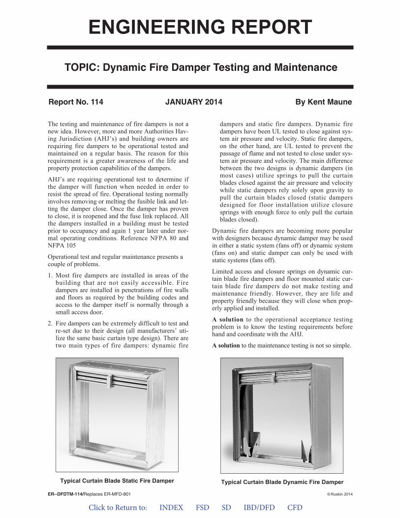
2. Fire dampers can be extremely difficult to test andre-set due to their design (all manufacturers’ uti-lize the same basic curtain type design). There aretwo main types of fire dampers: dynamic fire
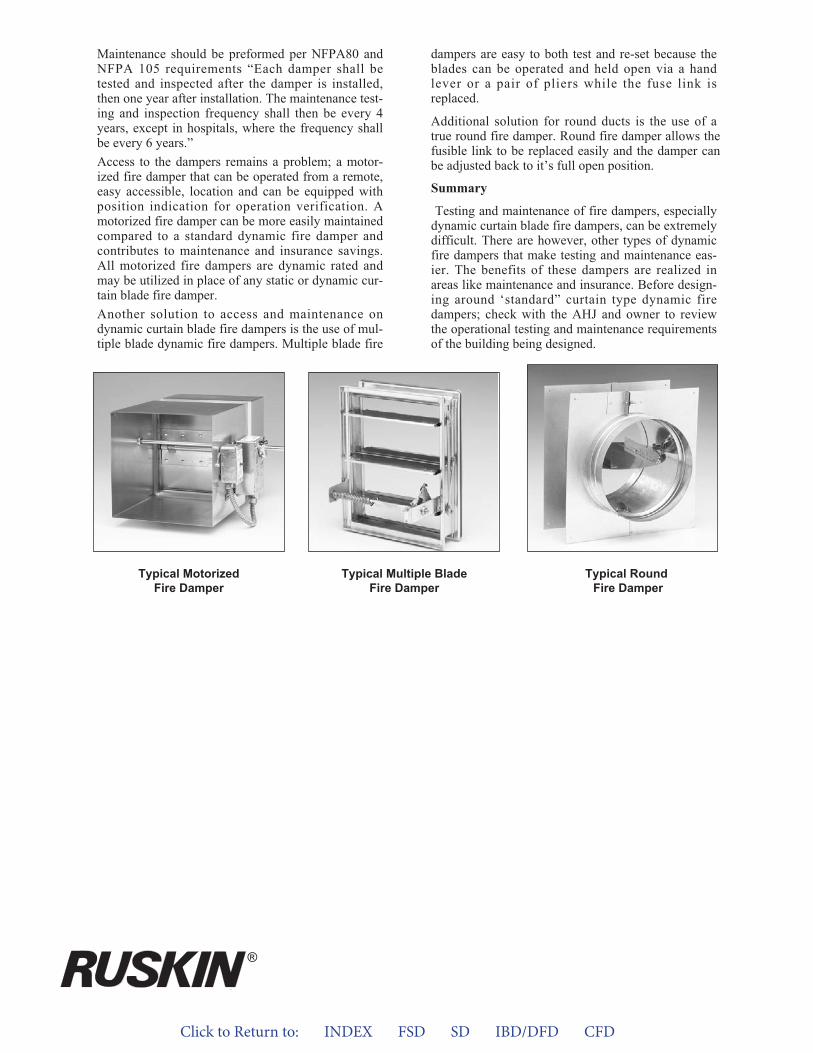
dampers and static fire dampers. Dynamic firedampers have been UL tested to close against sys-tem air pressure and velocity. Static fire dampers,on the other hand, are UL tested to prevent thepassage of flame and not tested to close under sys-tem air pressure and velocity. The main differencebetween the two designs is dynamic dampers (inmost cases) utilize springs to pull the curtainblades closed against the air pressure and velocitywhile static dampers rely solely upon gravity topull the curtain blades closed (static dampersdesigned for floor installation utilize closuresprings with enough force to only pull the curtainblades closed).
Dynamic fire dampers are becoming more popularwith designers because dynamic damper may be usedin either a static system (fans off) or dynamic system(fans on) and static damper can only be used withstatic systems (fans off).
Limited access and closure springs on dynamic cur-tain blade fire dampers and floor mounted static cur-tain blade fire dampers do not make testing andmaintenance friendly. However, they are life andproperty friendly because they will close when prop-erly applied and installed.
A solution to the operational acceptance testingproblem is to know the testing requirements beforehand and coordinate with the AHJ.
A solution to the maintenance testing is not so simple.
TOPIC: Dynamic Fire Damper Testing and Maintenance
ER--DFDTM-114/Replaces ER-MFD-801 © Ruskin 2014
ENGINEERING REPORT
Typical Curtain Blade Dynamic Fire DamperTypical Curtain Blade Static Fire Damper
JANUARY 2014
Click to Return to: INDEX FSD SD IBD/DFD CFD
Maintenance should be preformed per NFPA80 andNFPA 105 requirements “Each damper shall betested and inspected after the damper is installed,then one year after installation. The maintenance test-ing and inspection frequency shall then be every 4years, except in hospitals, where the frequency shallbe every 6 years.”Access to the dampers remains a problem; a motor-ized fire damper that can be operated from a remote,easy accessible, location and can be equipped withposition indication for operation verification. Amotorized fire damper can be more easily maintainedcompared to a standard dynamic fire damper andcontributes to maintenance and insurance savings.All motorized fire dampers are dynamic rated andmay be utilized in place of any static or dynamic cur-tain blade fire damper.Another solution to access and maintenance ondynamic curtain blade fire dampers is the use of mul-tiple blade dynamic fire dampers. Multiple blade fire
dampers are easy to both test and re-set because theblades can be operated and held open via a handlever or a pair of pliers while the fuse link isreplaced.
Additional solution for round ducts is the use of a true round fire damper. Round fire damper allows the fusible link to be replaced easily and the damper can be adjusted back to it’s full open position.
Summary
Testing and maintenance of fire dampers, especiallydynamic curtain blade fire dampers, can be extremelydifficult. There are however, other types of dynamicfire dampers that make testing and maintenance eas-ier. The benefits of these dampers are realized inareas like maintenance and insurance. Before design-ing around ‘standard” curtain type dynamic firedampers; check with the AHJ and owner to reviewthe operational testing and maintenance requirementsof the building being designed.
Typical MotorizedFire Damper
Typical RoundFire Damper
Typical Multiple BladeFire Damper
®

Click to Return to: INDEX FSD SD IBD/DFD CFD
HVAC system designers are specifying moreround duct today than ever before. The rea-sons for more round duct are:1. Round duct performs better than squareduct.
2. Round duct can be produced more economi-cally than square duct.
3. Round duct is stronger than comparablysized square duct.
The same can be said for dampers. Roundfire/smoke dampers have better pressure dropand airflow performance than their square orrectangular counterparts. Round fire/smokedampers are built from less material andtherefore cost less to produce. Once thedesigner has selected round duct, the overallinstalled cost of round dampers versus squaredampers with transitions is greatly reduced.There are fewer pieces to handle. Sleeves areintegral to the damper and retaining platesmake round dampers installable in either
square or round openings within fire ratedwalls and floors. Noise through a rounddamper is also significantly reduced becauseof the even airflow characteristics.
This engineering report compares rounddampers to their square counterparts usingindexed product costs and typical performancecriteria.
ENGINEERING REPORTTOPIC: Advantages of True Round
Fire/Smoke Dampers
By Richard Cravy
FIGURE 1 FIGURE 2
Round versus square advantages
1. Installation time reduced2. Fewer piece parts at job site3. Lower product cost4. Less noise generation5. Less pressure drop6. Factory shipped retaining plates7. Integral sleeve
ERTRFSD-102/Replaces 294:1
Click to Return to: INDEX FSD SD IBD/DFD CFD
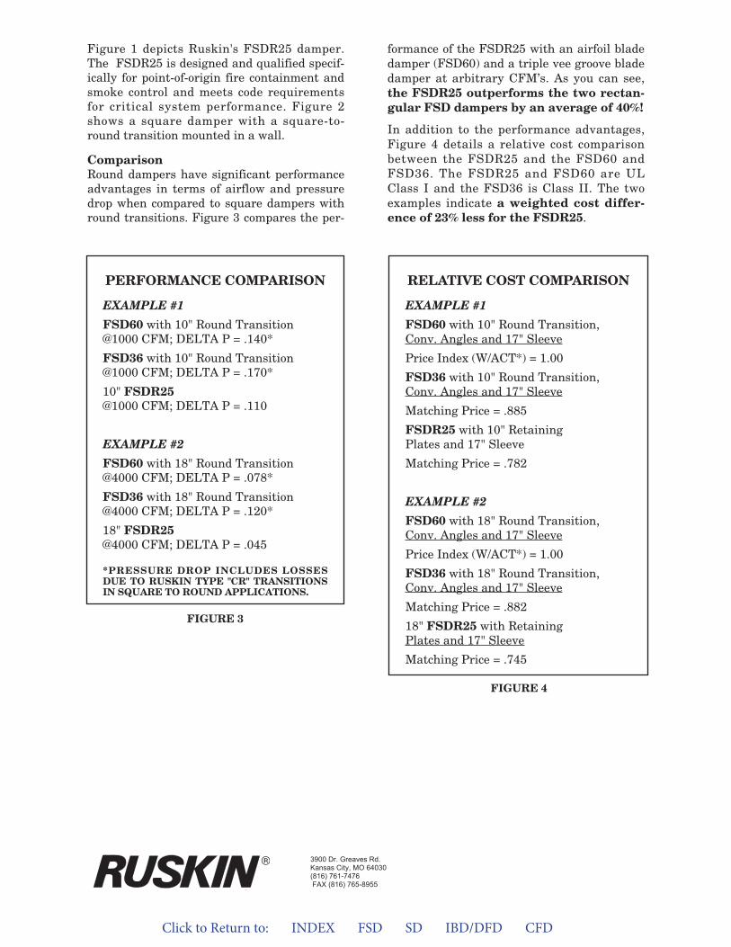
Figure 1 depicts Ruskin's FSDR25 damper.The FSDR25 is designed and qualified specif-ically for point-of-origin fire containment andsmoke control and meets code requirementsfor critical system performance. Figure 2shows a square damper with a square-to-round transition mounted in a wall.
ComparisonRound dampers have significant performanceadvantages in terms of airflow and pressuredrop when compared to square dampers withround transitions. Figure 3 compares the per-
formance of the FSDR25 with an airfoil bladedamper (FSD60) and a triple vee groove bladedamper at arbitrary CFM’s. As you can see,the FSDR25 outperforms the two rectan-gular FSD dampers by an average of 40%!
In addition to the performance advantages,Figure 4 details a relative cost comparisonbetween the FSDR25 and the FSD60 andFSD36. The FSDR25 and FSD60 are ULClass I and the FSD36 is Class II. The twoexamples indicate a weighted cost differ-ence of 23% less for the FSDR25.
PERFORMANCE COMPARISON
EXAMPLE #1
FSD60 with 10" Round Transition@1000 CFM; DELTA P = .140*
FSD36 with 10" Round Transition@1000 CFM; DELTA P = .170*
10" FSDR25@1000 CFM; DELTA P = .110
EXAMPLE #2
FSD60 with 18" Round Transition@4000 CFM; DELTA P = .078*
FSD36 with 18" Round Transition@4000 CFM; DELTA P = .120*
18" FSDR25@4000 CFM; DELTA P = .045
*PRESSURE DROP INCLUDES LOSSESDUE TO RUSKIN TYPE "CR" TRANSITIONSIN SQUARE TO ROUND APPLICATIONS.
RELATIVE COST COMPARISON
EXAMPLE #1
FSD60 with 10" Round Transition,Conv. Angles and 17" Sleeve
Price Index (W/ACT*) = 1.00
FSD36 with 10" Round Transition,Conv. Angles and 17" Sleeve
Matching Price = .885
FSDR25 with 10" RetainingPlates and 17" Sleeve
Matching Price = .782
EXAMPLE #2
FSD60 with 18" Round Transition,Conv. Angles and 17" Sleeve
Price Index (W/ACT*) = 1.00
FSD36 with 18" Round Transition,Conv. Angles and 17" Sleeve
Matching Price = .882
18" FSDR25 with RetainingPlates and 17" Sleeve
Matching Price = .745
FIGURE 4
FIGURE 3
3900 Dr. Greaves Rd.Kansas City, MO 64030(816) 761-7476FAX (816) 765-8955
Click to Return to: INDEX FSD SD IBD/DFD CFD
There are several pieces of information out there stating airfoil blades on dampers are unnecessary.To help your engineers make up their own minds as to the correct blade to specify, here are five rea-sons to specify an airfoil blade over a triple-V-groove or modified flat blade:
1. BLADE STRENGTH
2. STATIC PRESSURE LOSS
3. SEALING ABILITY
4. FIRE PROTECTION ABILITY
5. NOISE PRODUCED
Now, let's look at these five reasons in detail.
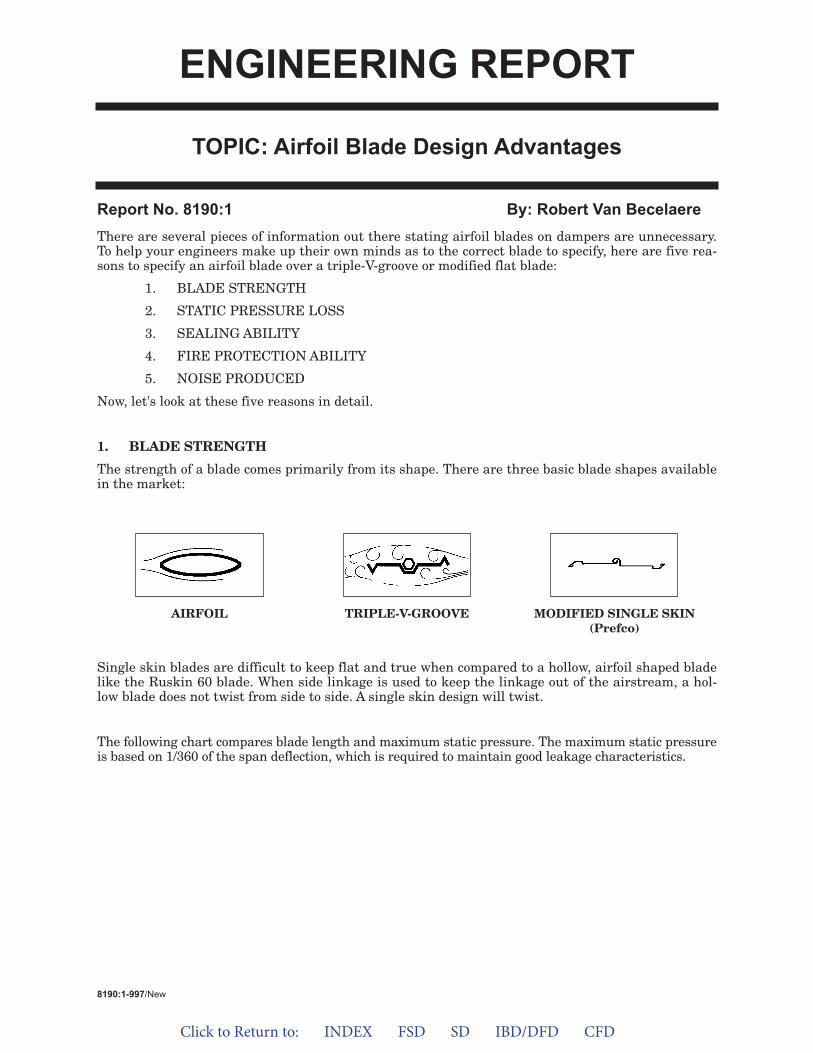
1. BLADE STRENGTH
The strength of a blade comes primarily from its shape. There are three basic blade shapes availablein the market:
Single skin blades are difficult to keep flat and true when compared to a hollow, airfoil shaped bladelike the Ruskin 60 blade. When side linkage is used to keep the linkage out of the airstream, a hol-low blade does not twist from side to side. A single skin design will twist.
The following chart compares blade length and maximum static pressure. The maximum static pressureis based on 1/360 of the span deflection, which is required to maintain good leakage characteristics.
Report No. 8190:1 By: Robert Van Becelaere
TOPIC: Airfoil Blade Design Advantages
AIRFOIL TRIPLE-V-GROOVE MODIFIED SINGLE SKIN(Prefco)
8190:1-997/New
ENGINEERING REPORT
Click to Return to: INDEX FSD SD IBD/DFD CFD
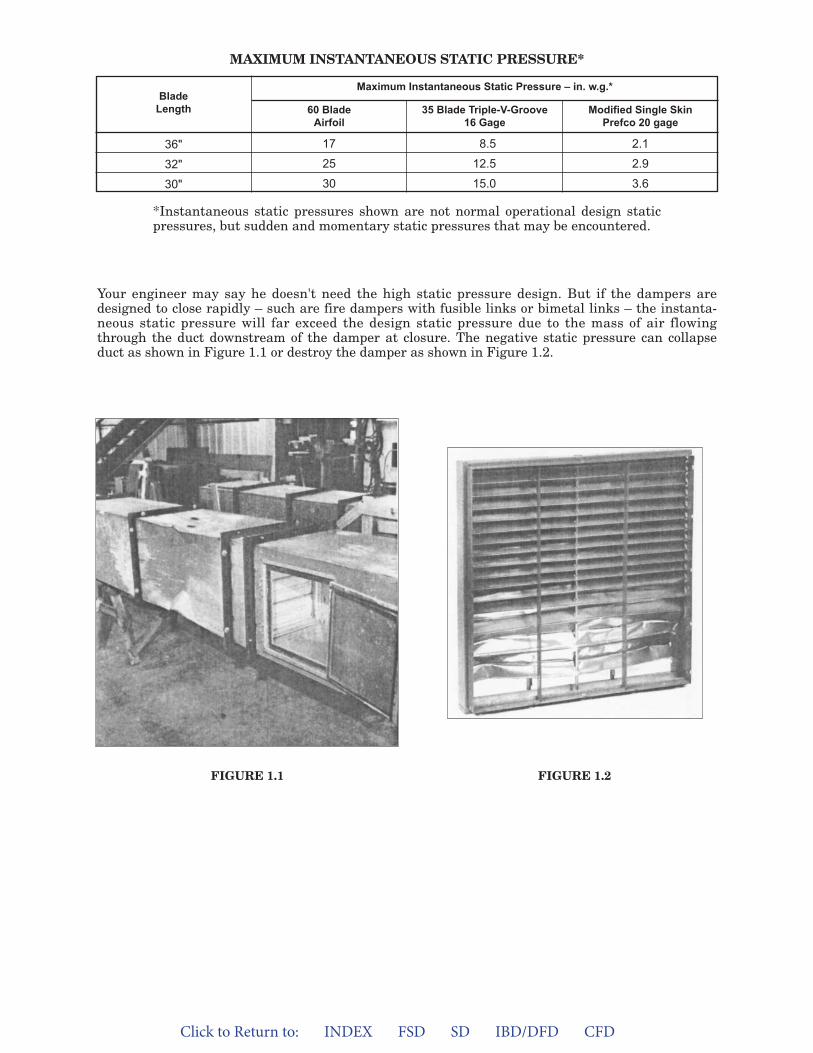
Your engineer may say he doesn't need the high static pressure design. But if the dampers aredesigned to close rapidly – such are fire dampers with fusible links or bimetal links – the instanta-neous static pressure will far exceed the design static pressure due to the mass of air flowingthrough the duct downstream of the damper at closure. The negative static pressure can collapseduct as shown in Figure 1.1 or destroy the damper as shown in Figure 1.2.
FIGURE 1.1 FIGURE 1.2
BladeLength
36"
32"
30"
17
25
30
8.5
12.5
15.0
2.1
2.9
3.6
Maximum Instantaneous Static Pressure – in. w.g.*
60 BladeAirfoil
35 Blade Triple-V-Groove16 Gage
Modified Single SkinPrefco 20 gage
*Instantaneous static pressures shown are not normal operational design staticpressures, but sudden and momentary static pressures that may be encountered.
MAXIMUM INSTANTANEOUS STATIC PRESSURE*
Click to Return to: INDEX FSD SD IBD/DFD CFD
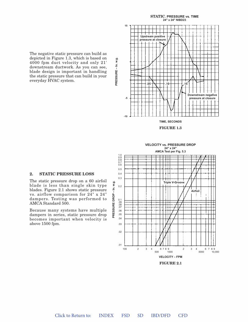
The negative static pressure can build asdepicted in Figure 1.3, which is based on4000 fpm duct velocity and only 21'downstream ductwork. As you can see,blade design is important in handlingthe static pressure that can build in youreveryday HVAC system.
2. STATIC PRESSURE LOSS
The static pressure drop on a 60 airfoilblade is less than single skin typeblades. Figure 2.1 shows static pressurevs. airflow comparison for 24" x 24"dampers. Testing was performed toAMCA Standard 500.
Because many systems have multipledampers in series, static pressure dropbecomes important when velocity isabove 1500 fpm.
Upstream positivepressure at closure
Downstream negativepressure at closure
TIME, SECONDS
FIGURE 1.3
VELOCITY vs. PRESSURE DROP24" x 24"
AMCA Test per Fig. 5.3
STATIC. PRESSURE vs. TIME24" x 24" NIBD23
VELOCITY – FPM
FIGURE 2.1
.05 .10 .15
Triple V-Groove
Airfoil
100 2 3 4 6 7 8 9 2 3 4 6 7 8 9500 1000 5000 10,000
1.00.90.80.70.6
0.5
0.4
0.3
0.2
0.1.09.08.07.06.05
.04
.03
.02
.01
15
-5
-10PR
ESSU
RE
–In
.w.g
.PR
ESSU
RE
DR
OP
–In
.w.g
.
Click to Return to: INDEX FSD SD IBD/DFD CFD
3900 Dr. Greaves Rd.Kansas City, MO 64030(816) 761-7476FAX (816) 765-8955
www.ruskin.com
3. SEALINGABILITY
The 60 hollow shape, airfoil blade doesnot twist when force is exerted from oneedge. Single skin blades depend on off-sets or bends in the blade to make itstrong; these bends do not give supportto the blade in a twisting action. Trytwisting a piece of paper and see howone edge bends and the other edge doesnot. A hollow shape blade movesthroughout its length when twisted onone end, giving excellent blade-to-bladesealing action.
4. FIRE PROTECTIONABILITY
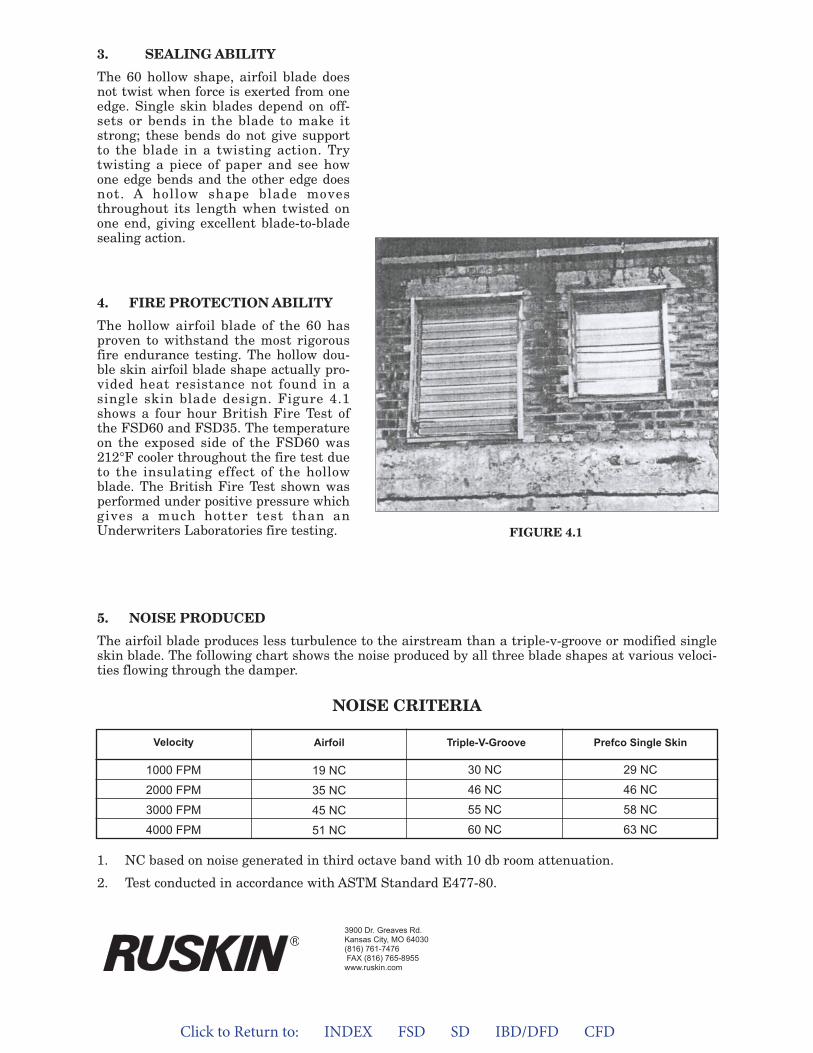
The hollow airfoil blade of the 60 hasproven to withstand the most rigorousfire endurance testing. The hollow dou-ble skin airfoil blade shape actually pro-vided heat resistance not found in asingle skin blade design. Figure 4.1shows a four hour British Fire Test ofthe FSD60 and FSD35. The temperatureon the exposed side of the FSD60 was212°F cooler throughout the fire test dueto the insulating effect of the hollowblade. The British Fire Test shown wasperformed under positive pressure whichgives a much hotter test than anUnderwriters Laboratories fire testing.
5. NOISE PRODUCED
The airfoil blade produces less turbulence to the airstream than a triple-v-groove or modified singleskin blade. The following chart shows the noise produced by all three blade shapes at various veloci-ties flowing through the damper.
1. NC based on noise generated in third octave band with 10 db room attenuation.
2. Test conducted in accordance with ASTM Standard E477-80.
NOISE CRITERIA
Velocity
1000 FPM
2000 FPM
3000 FPM
4000 FPM
19 NC
35 NC
45 NC
51 NC
30 NC
46 NC
55 NC
60 NC
29 NC
46 NC
58 NC
63 NC
Airfoil Triple-V-Groove Prefco Single Skin
FIGURE 4.1
Click to Return to: INDEX FSD SD IBD/DFD CFD
Combination Fire/Smoke dampers are part ofa larger category of products known as lifesafety products. They are tested in accordancewith the stringent requirements of Underwrit-ers Laboratory (U.L.) Standards for SafetyUL555 and UL555S. Fire/smoke dampersmust be dependable and quick acting to savelife and property.
U.L. testing requires release devices offire/smoke dampers to sense heat and operatewithin a one minute time frame. Testing offusible rod and fusible link devices (used onmost fire/smoke dampers) have shown they,typically, barely meet the one minute criteria.
Ruskin provides additional insurance withfast acting heat detection for fire smoke/dampers. The Ruskin Electronic Fuse Link(EFL) and Pneumatic Fuse Link (PFL) detectheat in 1/3 to 1/2 the time of standard fuse rodsor fuse links. Quicker detection simply meansincreased safety and property protection infire conditions.
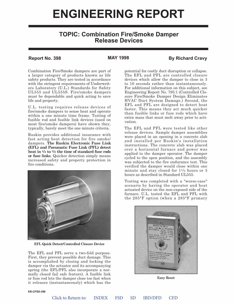
The EFL and PFL serve a two-fold purpose.First, they prevent possible duct damage. Thisis accomplished by closing and locking thedamper via the actuator and its accompanyingspring (the EFL/PFL also incorporate a nor-mally closed fail safe feature). A fusible linkor fuse rod lets the damper close too fast whenit releases (instantaneously) which has the
potential for costly duct disruption or collapse.The EFL and PFL are controlled closuredevices which allow the damper to close in 3to 10 seconds rather than instantaneously.For additional information on this subject, seeEngineering Report No. 795:1 (Controlled Clo-sure Fire/Smoke Damper Design EliminatesHVAC Duct System Damage.) Second, theEFL and PFL are designed to detect heatfaster. This means they act much quickerthan fusible links or fuse rods which haveextra mass that must melt away prior to acti-vation.
The EFL and PFL were tested like otherrelease devices. Sample damper assemblieswere placed in an opening in a concrete slaband installed per Ruskin's installationinstructions. The concrete slab was placedover a horizontal furnace and power wasapplied to the damper operator. The dampercycled to the open position, and the assemblywas subjected to the fire endurance test. Thisverified the damper would close within oneminute and stay closed for 11/2 hours or 3hours as described in Standard UL555.
Testing was completed with a "worse-case"scenario by having the operator and heatactuated device on the non-exposed side of thefurnace. U.L. tested the EFL and PFL withthe 285°F option (when a 285°F primary
Report No. 398 By Richard CravyMAY 1998
EasyReset
EFLQuickDetect/ControlledClosureDevice
ER-CFSD-398
TOPIC: Combination Fire/Smoke DamperRelease Devices
ENGINEERING REPORT
Click to Return to: INDEX FSD SD IBD/DFD CFD
release device is qualified, the next lower tem-perature device is automatically qualified). Ittook only 1/2 the time after furnace ignitionfor the EFL 285°F to close the damper (vs. afuse rod or link). The PFL 285°F required only13 seconds after furnace ignition to close thedamper. Such a big improvement providesadditional insurance against loss of life andproperty.
Ruskin has a whole line of quick releasedevices. In addition to the EFL and PFL thereis the TS150EZ. The TS150EZ is the "reopen-able Firestat" option and is designed fordynamic smoke management systems. Allthese devices offer controlled closure whilebeing quick detecting. They also allow thedamper to be reset from outside the duct. TheEFL is standard on all fire smoke damperswith electric actuators. The PFL is standard
on all fire smoke dampers with pneumaticactuators. If remote blade position indicationis needed, Ruskin can provide an SP100switch. When a pneumatic actuator is orderedwith a non-standard EFL or TS150EZ an EPswitch is required to interface between thetwo.
To summarize: Ruskin developed these quickdetecting, controlled closure devices toimprove life safety and to better protect prop-erty and ductwork. Quicker heat responsetime prevents the spread of flame and smokethrough the ductwork while eliminating dam-age that can be caused by instantaneous clo-sure.
Contact your local Ruskin representative formore information on these or any otherRuskin fire smoke damper advantage.
SUGGESTED SPECIFICATIONEach combination fire/smoke damper shall be equipped with a quick detect heat-actuated tem-perature release device to prevent duct and HVAC component damage. Instantaneous damperclosure is unacceptable.
All fire/smoke dampers equipped with a UL approved electric actuator shall have an EFL orPFL when pneumatic actuators are provided. The EFL/PFL shall release in half the time of afuse rod or link at temperatures of 165°F (74°C), 212°F (100°C) or 285°F (141°C).
Upon detection, the EFL/PFL shall close and lock the damper during test, smoke detection,power failure, or fire conditions through actuator closure spring. At no time shall the actuatordisengage from damper blades.
The EFL/PFL shall allow the damper to be automatically and remotely resettable after test,smoke detection, or power failure conditions.
3900 Dr. Greaves Rd.Kansas City, MO 64030(816) 761-7476FAX (816) 765-8955www.ruskin.com
®

Click to Return to: INDEX FSD SD IBD/DFD CFD
Testing and Maintenance
OptionsClassic Damper Inspector System
Wireless Damper InspectorDamper Test Switch ‘DTS’ (Combination Fire Smoke Dampers)
Damper Test Switch Smoke Dampers ‘DTS-SD’Master Control Panel (Lights Only) ‘MCP3’
Master Control Panel (Test Switch and Lights) ‘MCP4’Master Control Panel (Push Test Button or On-Off) ‘MCPB’ or
‘MCP1.5’Master Control Panel (Used with the TS-150 Fire Stat) ‘MCP1’
or ‘MCP2’ (keyed Switch)Master Control Panel (Used with the TS-150 Fire Stat) ‘MCP10’
or ‘MCP20’ for up to 20 dampers
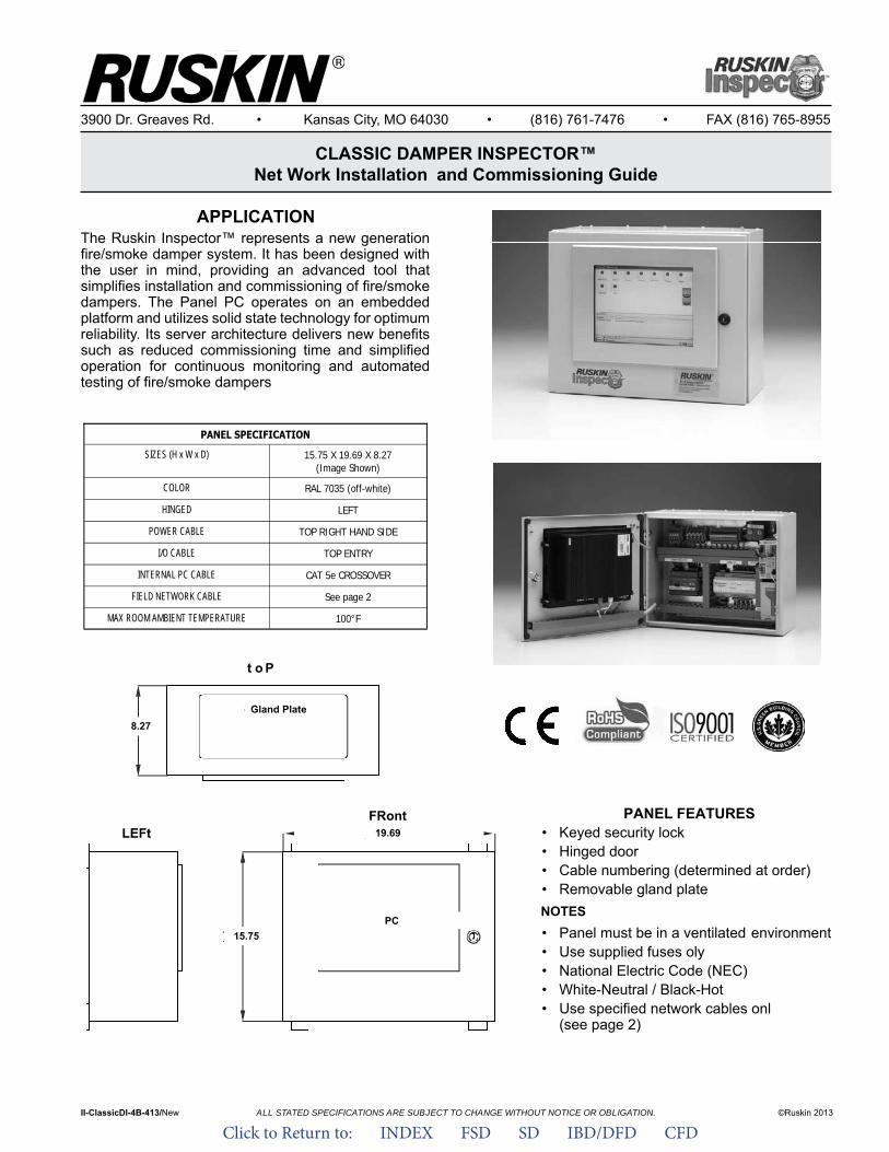
PANEL SPECIFICATION
SIZES (H x W x D) 15.75 X 19.69 X 8.27 (Image Shown)
COLOR RAL 7035 (off-white)
HINGED LEFT
POWER CABLE TOP RIGHT HAND SIDE
I/O CABLE TOP ENTRY
INTERNAL PC CABLE CAT 5e CROSSOVER
FIELD NETWORK CABLE See page 2
MAX ROOM AMBIENT TEMPERATURE 100°F
Ruskin Inspector™ FSDPC Panel PC Specifications & Features
Page 1 of 4 © Ruskin 2012
PANEL FEATURES Keyed security lockHinged door Cable numbering(determined at order) Removable gland plate
NOTES
Panel must be in a ventilated environment Use supplied fuses only National Electric Code (NEC) White-Neutral / Black-Hot Use specified network cables only
ALL STATED SPECIFICATIONS ARE SUBJECT TO CHANGE WITHOUT NOTICE OR OBLIGATION.
3900 Dr. Greaves Rd. • Kansas City, MO 64030 • (816) 761-7476 • FAX (816) 765-8955
CLASSIC DAMPER INSPECTOR™Net Work Installation and Commissioning Guide
II-ClassicDI-4B-413/New ©Ruskin 2013
PANEL SPECIFICATION
SIZES (H x W x D)
15.75 X 19.69 X 8.27 (Image Shown)
COLOR RAL 7035 (off-white)
HINGED LEFT
POWER CABLE TOP RIGHT HAND SIDE
I/O CABLE TOP ENTRY
INTERNAL PC CABLE CAT 5e CROSSOVER
FIELD NETWORK CABLE See page 2
MAX ROOM AMBIENT TEMPERATURE 100°F
Ruskin Inspector™ FSDPC Panel PC Specifications & Features
Page 1 of 4 © Ruskin 2012
PANEL FEATURES Keyed security lockHinged door Cable numbering(determined at order) Removable gland plate
NOTES
Panel must be in a ventilated environment Use supplied fuses only National Electric Code (NEC)White-Neutral / Black-Hot Use specified network cablesonly
PANEL SPECIFICATION
SIZES (H x W x D) 15.75 X 19.69 X 8.27 (Image Shown)
COLOR RAL 7035 (off-white)
HINGED LEFT
POWER CABLE TOP RIGHT HAND SIDE
I/O CABLE TOP ENTRY
INTERNAL PC CABLE CAT 5e CROSSOVER
FIELD NETWORK CABLE See page 2
MAX ROOM AMBIENT TEMPERATURE 100°F
Ruskin Inspector™ FSDPC Panel PC Specifications & Features
Page 1 of 4 © Ruskin 2012
PANEL FEATURES Keyed security lockHinged doorCable numbering(determined at order)Removable gland plate
NOTES
Panel must be in a ventilatedenvironmentUse supplied fuses onlyNational Electric Code (NEC) White-Neutral / Black-HotUse specified network cablesonlyAPPLICATION
The Ruskin Inspector™ represents a new generation fire/smoke damper system. It has been designed with the user in mind, providing an advanced tool that simplifies installation and commissioning of fire/smokedampers. The Panel PC operates on an embedded platform and utilizes solid state technology for optimum reliability. Its server architecture delivers new benefitssuch as reduced commissioning time and simplifiedoperation for continuous monitoring and automated testing of fire/smoke dampers
PANEL FEATURES• Keyed security lock• Hinged door• Cable numbering (determined at order)• Removable gland plateNOTES• Panel must be in a ventilated environment• Use supplied fuses oly• National Electric Code (NEC)• White-Neutral / Black-Hot• Use specified network cables onl
(see page 2)
LEFtFRont
15.75PC
APPLICATION Patent Pending
* Reference NFPA 72, 80, 90A, 92B and 105
STANDARD CONSTRUCTION
ENCLOSURE5" (127mm) x 7" (178mm) x 2-1/2" (63.5mm) 18 gage (1.2mm) Galvanized steelNEMA 1CIRCUIT BOARDIntegrated transformer 120V primary 16V secondaryOnboard LED diagnostics (damper position and relay contact)Manual test push buttonEnOcean communication protocolHUMIDITY99%, non-condensingTEMPERATURE RANGE0°F to 130°FPOWER REQUIREMENTS115V 50/60 Hz FEATURESAGENCY LISTINGS * Wireless sensorFCC ID: SZV-STM300C * Satisfies NFPA 72, 80, 90 and 105 testing requirementsIC: 5713A-STM300C * 42" long wire harnesses factory terminated at circuit boardRADIO FREQUENCY * Onboard LED diagnostics315Mhz for US Applications * Integrated manual test button at each damper location
* USB cable for programming and downloading
VARIATIONSRuskin model RFDI is available with the following variations atadditional cost
* Factory programming of RFSC (damper tag/ID)* 868.3Mhz radio frequency (Europe and Asia)
NOTES:1. Dimensions shown in ( ) indicate metric units2. Refer to Installation Instructions for additional details3. Requires the purchase of (minimum of one) RFSC
Spec RFDI/1212-New ALL STATED SPECIFICATIONS ARE SUBJECT TO CHANGE WITHOUT NOTICE OR OBLIGATION ©RUSKIN 2012
3900 Dr. Greaves Rd. * Kansas City, MO 64030 * (816) 761-7476 * Fax (816) 765-8955
RFDI WIRELESS DAMPER INSPECTOR™
Top: RFSC (Radio Frequency Smart Communicator)Bottom: RFDI (Radio Frequency Damper Interface)
Ruskin’s wireless damper system, utilizing wireless communication protocol by EnOcean®, is the ideal solution for mandatory testing of motorized life safety dampers per NFPA* and Building Code requirements. The Ruskin
Wireless InspectorTM includes the RFDI (Radio Frequency Damper Interface) located at each damper with factory switch package and one RFSC (Radio Frequency Smart Communicator). The RFSC includes an LCD screen displaying RFDI serial numbers or tags and damper status after cycle testing.Performing the scan function, will locate all dampers in range. A microprocessor in the RFSC stores all test results and the factory provided
USB cable can be downloaded and stored on your personal PC.
PANEL SPECIFICATION
SIZES (H x W x D) 15.75 X 19.69 X 8.27 (Image Shown)
COLOR RAL 7035 (off-white)
HINGED LEFT
POWER CABLE TOP RIGHT HAND SIDE
I/O CABLE TOP ENTRY
INTERNAL PC CABLE CAT 5e CROSSOVER
FIELD NETWORK CABLE See page 2
MAX ROOM AMBIENT TEMPERATURE 100°F
Ruskin Inspector™ FSDPC Panel PC Specifications & Features
Page 1 of 4 © Ruskin 2012
PANEL FEATURES Keyed security lock Hinged door Cable numbering(determined at order) Removable gland plate
NOTES
Panel must be in a ventilated environment Use supplied fuses only National Electric Code (NEC) White-Neutral / Black-Hot Use specified network cables only
PANEL SPECIFICATION
SIZES (H x W x D) 15.75 X 19.69 X 8.27 (Image Shown)
COLOR RAL 7035 (off-white)
HINGED LEFT
POWER CABLE TOP RIGHT HAND SIDE
I/O CABLE TOP ENTRY
INTERNAL PC CABLE CAT 5e CROSSOVER
FIELD NETWORK CABLE See page 2
MAX ROOM AMBIENT TEMPERATURE 100°F
Ruskin Inspector™ FSDPC Panel PC Specifications & Features
Page 1 of 4 © Ruskin 2012
PANEL FEATURES Keyed security lockHinged door Cable numbering(determined at order) Removable gland plate
NOTES
Panel must be in a ventilated environment Use supplied fuses only National Electric Code (NEC) White-Neutral / Black-Hot Use specified network cables only
t o P
8.27Gland Plate
19.69
Click to Return to: INDEX FSD SD IBD/DFD CFD

2 Amp Fused
Switched Spur
Power to Power to Power to Actuator Position Actuator Position Actuator Position
Network Cable
Local Local Local
Network Cable
Fire/Smoke Damper Interface
(FSDI)
Network Cable Network Cable
Fire/Smoke Damper Interface
(FSDI)
7.86 x 6.68 x 2.95
Fire/Smoke Damper Interface
(FSDI)
STANDARD NETWORK SPECIFICATION & RULES
WARNING: The Ruskin Inspector™ system is a life safety damper monitoring & test solution requiring specific net-work cables that are fundamental to the stable and reli-able operation of the network. There are no alternatives or equivalents acceptable. Use of alternate cables will void all warranties and such cables will have to be replaced to allow stable and reliable operation.
NETWORK CABLE SPECIFICATION Ruskin recommends the following network cable for use with the Inspector network. Consult with Ruskin before using any other cable to ensure it will be compatible.
1 pair 22AWG Stranded Unshielded Level 4 Ple-num Echelon/Lonworks Blue Jacket TYPE CMP/CSA FT6 (MADE IN THE USA)
Network Rules: NO ‘EQUIVALENTS’ NO ‘ALTERNATIVES’
1. All devices to be wired in a "daisy chain" fashion as shown in the illustration above. 2. Standard network rules apply i.e. network cables must NOT be run alongside any high voltage and/or high
frequency sources. If FSDI’s are wired in areas of high voltage such as plant rooms/lift lobbies,network cable must be installed in dedicated conduit.
3. Network cable types must NOT be mixed on a cable segment. 4. Maximum TOTAL wire length for cable segment must not exceed 1650 feet 5. If greater than 60 network devices and/or cable segment length of greater than 1650 feet, a network extender
must be utilized. 6. Damper interfaces must be wired on a dedicated power supply.
Page 2 of 4 © Ruskin 2012
Ruskin Inspector™ Typical Network Wiring Details
TYPICAL NET WORK WIRING DETAILS
1. All devices to be wired in a “daisy chain” fashion as shown in the illustration above.2. Standard network rules apply i.e. network cables must NOT be run alongside any high voltage and/or
high frequency sources. If FSDI’s are wired in areas of high voltage such as plant rooms/elevator lobbies, network cable must be installed in dedicated conduit.
3. Network cable types must NOT be mixed on a cable segment.4. Maximum TOTAL wire length for cable segment must not exceed 1650 feet.5. If greater than 60 dampers and/or cable segment length of greater than 1650 feet, a network extender
must be utilized.6. Damper interfaces must be wired on a dedicated power supply.
WARnInG: The Ruskin Inspector™ system is a life safety damper monitoring & test solution requiring specific network cables that are fundamental to the stable and reliable opera-tion of the network. There are no alternatives or equivalents acceptable. Use of alternate cables will void all warranties and such cables will have to be replaced to allow stable and reliable operation.
nEt Wo RK CABLE SPECIFICAt IonRuskin recommends the following network cable for use with the Inspector™ network. Consult with Ruskin before using any other cable to ensure it will be compatible.
1 pair 22AWG Stranded Unshielded Level 4 Plenum Echelon/Lonworks Blue Jacket ty PE CMP/CSA Ft 6 (MADE In t HE USA)
Click to Return to: INDEX FSD SD IBD/DFD CFD
CONTRACTOR'S INSTALLATION / COMMISSIONING GUIDE
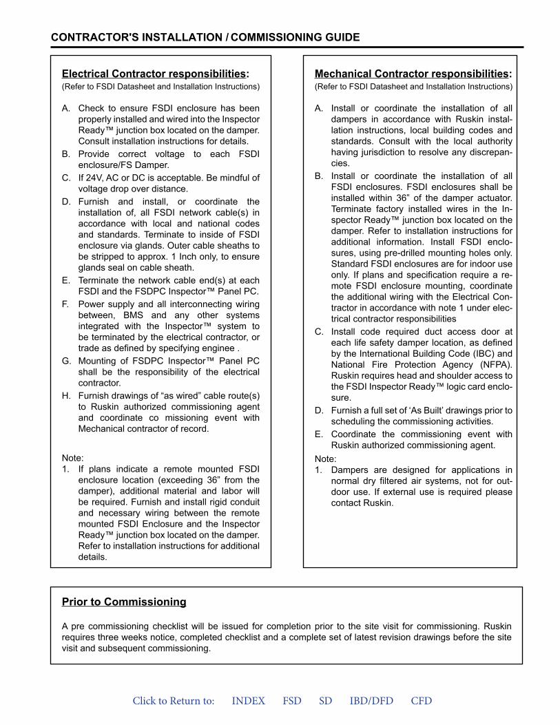
Electrical Contractor responsibilities:(Refer to FSDI Datasheet and Installation Instructions)
A. Check to ensure FSDI enclosure has been properly installed and wired into the Inspector Ready™ junction box located on the damper. Consult installation instructions for details.
B. Provide correct voltage to each FSDI enclosure/FS Damper.
C. If 24V, AC or DC is acceptable. Be mindful of voltage drop over distance.
D. Furnish and install, or coordinate the installation of, all FSDI network cable(s) in accordance with local and national codes and standards. Terminate to inside of FSDI enclosure via glands. Outer cable sheaths to be stripped to approx. 1 Inch only, to ensure glands seal on cable sheath.
E. Terminate the network cable end(s) at each FSDI and the FSDPC Inspector™ Panel PC.
F. Power supply and all interconnecting wiring between, BMS and any other systems integrated with the Inspector™ system to be terminated by the electrical contractor, or trade as defined by specifying enginee .
G. Mounting of FSDPC Inspector™ Panel PC shall be the responsibility of the electrical contractor.
H. Furnish drawings of “as wired” cable route(s) to Ruskin authorized commissioning agent and coordinate co missioning event with Mechanical contractor of record.
Note:1. If plans indicate a remote mounted FSDI
enclosure location (exceeding 36” from thedamper), additional material and labor willbe required. Furnish and install rigid conduitand necessary wiring between the remotemounted FSDI Enclosure and the InspectorReady™ junction box located on the damper.Refer to installation instructions for additionaldetails.
Prior to Commissioning
A pre commissioning checklist will be issued for completion prior to the site visit for commissioning. Ruskin requires three weeks notice, completed checklist and a complete set of latest revision drawings before the site visit and subsequent commissioning.
Mechanical Contractor responsibilities:(Refer to FSDI Datasheet and Installation Instructions)
A. Install or coordinate the installation of all dampers in accordance with Ruskin instal-lation instructions, local building codes and standards. Consult with the local authority having jurisdiction to resolve any discrepan-cies.
B. Install or coordinate the installation of all FSDI enclosures. FSDI enclosures shall be installed within 36” of the damper actuator. Terminate factory installed wires in the In-spector Ready™ junction box located on the damper. Refer to installation instructions for additional information. Install FSDI enclo-sures, using pre-drilled mounting holes only. Standard FSDI enclosures are for indoor use only. If plans and specification require a re-mote FSDI enclosure mounting, coordinate the additional wiring with the Electrical Con-tractor in accordance with note 1 under elec-trical contractor responsibilities
C. Install code required duct access door at each life safety damper location, as definedby the International Building Code (IBC) and National Fire Protection Agency (NFPA). Ruskin requires head and shoulder access to the FSDI Inspector Ready™ logic card enclo-sure.
D. Furnish a full set of ‘As Built’ drawings prior to scheduling the commissioning activities.
E. Coordinate the commissioning event with Ruskin authorized commissioning agent.
Note:1. Dampers are designed for applications in
normal dry filtered air systems, not for out-door use. If external use is required pleasecontact Ruskin.
Click to Return to: INDEX FSD SD IBD/DFD CFD
COMMISSIONING
3900 Dr. Greaves Rd. Kansas City, MO 64030 (816) 761-7476FAX (816) 765-8955www.ruskin.com
Printed on recycled paperusing vegetable based inks
Printed on recycled paper using vegetable based inks
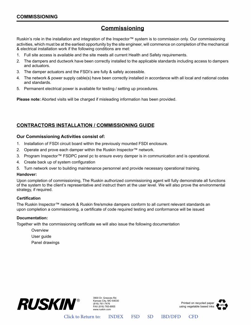
Commissioning
Ruskin’s role in the installation and integration of the Inspector™ system is to commission only. Our commissioningactivities, which must be at the earliest opportunity by the site engineer, will commence on completion of the mechanical & electrical installation work if the following conditions are met:1. Full site access is available and the site meets all current Health and Safety requirements.2. The dampers and ductwork have been correctly installed to the applicable standards including access to dampers
and actuators.3. The damper actuators and the FSDI’s are fully & safely accessible.4. The network & power supply cable(s) have been correctly installed in accordance with all local and national codes
and standards.5. Permanent electrical power is available for testing / setting up procedures.
Please note: Aborted visits will be charged if misleading information has been provided.
CONTRACTORS INSTALLATION / COMMISSIONING GUIDE
Our Commissioning Activities consist of:1. Installation of FSDI circuit board within the previously mounted FSDI enclosure.2. Operate and prove each damper within the Ruskin Inspector™ network.3. Program Inspector™ FSDPC panel pc to ensure every damper is in communication and is operational.4. Create back up of system configuration5. Turn network over to building maintenance personnel and provide necessary operational training.Handover:Upon completion of commissioning, The Ruskin authorized commissioning agent will fully demonstrate all functionsof the system to the client’s representative and instruct them at the user level. We will also prove the environmentalstrategy, if required.
CertificationThe Ruskin Inspector™ network & Ruskin fire/smoke dampers conform to all current relevant standards anupon completion a commissioning, a certificate of code required testing and conformance will be issued
Documentation:Together with the commissioning certificate we will also issue the following documentation
OverviewUser guidePanel drawings
Click to Return to: INDEX FSD SD IBD/DFD CFD
ALL STATED SPECIFICATIONS ARE SUBJECT TO CHANGE WITHOUT NOTICE OR OBLIGATION.Spec WIRELESSDI-1212/New © Ruskin 2012
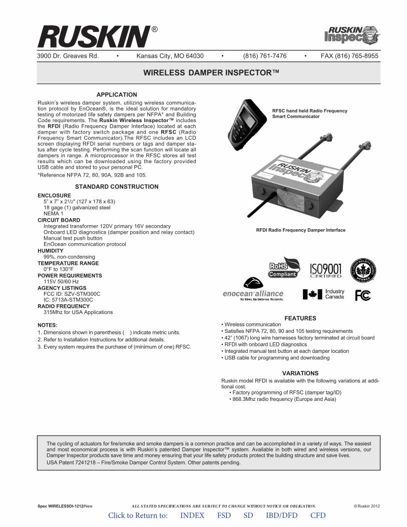
APPLICATIONRuskinʼs wireless damper system, utilizing wireless communica-tion protocol by EnOcean®, is the ideal solution for mandatorytesting of motorized life safety dampers per NFPA* and BuildingCode requirements. The Ruskin Wireless Inspector™ includesthe RFDI (Radio Frequency Damper Interface) located at eachdamper with factory switch package and one RFSC (RadioFrequency Smart Communicator).The RFSC includes an LCDscreen displaying RFDI serial numbers or tags and damper sta-tus after cycle testing. Performing the scan function will locate alldampers in range. A microprocessor in the RFSC stores all testresults which can be downloaded using the factory providedUSB cable and stored to your personal PC.*Reference NFPA 72, 80, 90A, 92B and 105.
STANDARD CONSTRUCTIONENCLOSURE
5” x 7” x 21/2" (127 x 178 x 63)18 gage (1) galvanized steelNEMA 1
CIRCUIT BOARDIntegrated transformer 120V primary 16V secondaryOnboard LED diagnostics (damper position and relay contact)Manual test push buttonEnOcean communication protocol
HUMIDITY99%, non-condensing
TEMPERATURE RANGE0°F to 130°F
POWER REQUIREMENTS115V 50/60 Hz
AGENCY LISTINGSFCC ID: SZV-STM300CIC: 5713A-STM300C
RADIO FREQUENCY315Mhz for USA Applications
NOTES:1. Dimensions shown in parenthesis ( ) indicate metric units.2. Refer to Installation Instructions for additional details.3. Every system requires the purchase of (minimum of one) RFSC.
FEATURES• Wireless communication• Satisfies NFPA 72, 80, 90 and 105 testing requirements• 42” (1067) long wire harnesses factory terminated at circuit board• RFDI with onboard LED diagnostics• Integrated manual test button at each damper location• USB cable for programming and downloading
VARIATIONSRuskin model RFDI is available with the following variations at addi-tional cost.
• Factory programming of RFSC (damper tag/ID)• 868.3Mhz radio frequency (Europe and Asia)
3900 Dr. Greaves Rd. • Kansas City, MO 64030 • (816) 761-7476 • FAX (816) 765-8955
WIRELESS DAMPER INSPECTOR™
®
RFDI Radio Frequency Damper Interface
RFSC hand held Radio FrequencySmart Communicator
The cycling of actuators for fire/smoke and smoke dampers is a common practice and can be accomplished in a variety of ways. The easiestand most economical process is with Ruskinʼs patented Damper Inspector™ system. Available in both wired and wireless versions, ourDamper Inspector products save time and money ensuring that your life safety products protect the building structure and save lives.USA Patent 7241218 – Fire/Smoke Damper Control System. Other patents pending.
Click to Return to: INDEX FSD SD IBD/DFD CFD
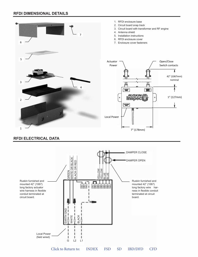
1. RFDI enclosure base2. Circuit board snap track3. Circuit board with transformer and RF engine4. Antenna shield5. Installation instructions6. RFDI enclosure cover7. Enclosure cover fasteners
RFDI ELECTRICAL DATA
1
2
3
5
6
7
4
42" (1067mm) nominal
5" (127mm)
7" (178mm)
ActuatorPower
Open/Close Switch contacts
Local Power
Local Power(field wired)
Ruskin furnished and mounted 42" long factory wire harness in flexible conduit terminated at circuit board.
Ruskin furnished and mounted 42" long factory actuator wire harness in flexible conduit terminated at circuit board
1. RFDI enclosure base2. Circuit board snap track3. Circuit board with transformer and RF engine4. Antenna shield5. Installation instructions6. RFDI enclosure cover7. Enclosure cover fasteners
RFDI DIMENSIONAL DETAILS
RFDI ELECTRICAL DATA
Ruskin furnished andmounted 42” (1067)long factory actuatorwire harness in flexibleconduit terminated atcircuit board.
Local Power(field wired)
Ruskin furnished andmounted 42” (1067)long factory wire har-ness in flexible conduitterminated at circuitboard.
DAMPER CLOSE
DAMPER OPEN
GR
EE
NW
HIT
EO
RB
LAC
KB
LAC
KO
RR
ED
EA
RTH
GN
D
WH
ITE
BLA
CK
YE
LLO
WY
ELL
OW
BLU
EB
LUE
G L2 L1
Click to Return to: INDEX FSD SD IBD/DFD CFD
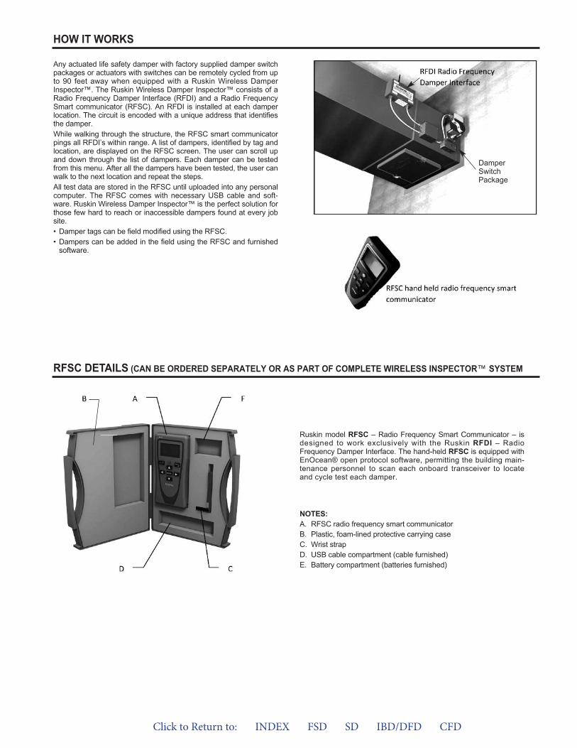
RFSC DETAILS (CAN BE ORDERED SEPARATELY OR AS PART OF COMPLETE WIRELESS INSPECTOR™ SYSTEM
Ruskin model RFSC – Radio Frequency Smart Communicator – isdesigned to work exclusively with the Ruskin RFDI – RadioFrequency Damper Interface. The hand-held RFSC is equipped withEnOcean® open protocol software, permitting the building main-tenance personnel to scan each onboard transceiver to locateand cycle test each damper.
NOTES:A. RFSC radio frequency smart communicatorB. Plastic, foam-lined protective carrying caseC. Wrist strapD. USB cable compartment (cable furnished)E. Battery compartment (batteries furnished)
Any actuated life safety damper with factory supplied damper switchpackages or actuators with switches can be remotely cycled from upto 90 feet away when equipped with a Ruskin Wireless DamperInspector™. The Ruskin Wireless Damper Inspector™ consists of aRadio Frequency Damper Interface (RFDI) and a Radio FrequencySmart communicator (RFSC). An RFDI is installed at each damperlocation. The circuit is encoded with a unique address that identifiesthe damper.While walking through the structure, the RFSC smart communicatorpings all RFDIʼs within range. A list of dampers, identified by tag andlocation, are displayed on the RFSC screen. The user can scroll upand down through the list of dampers. Each damper can be testedfrom this menu. After all the dampers have been tested, the user canwalk to the next location and repeat the steps.All test data are stored in the RFSC until uploaded into any personalcomputer. The RFSC comes with necessary USB cable and soft-ware. Ruskin Wireless Damper Inspector™ is the perfect solution forthose few hard to reach or inaccessible dampers found at every jobsite.• Damper tags can be field modified using the RFSC.• Dampers can be added in the field using the RFSC and furnished
software.
HOW IT WORKS
DamperSwitchPackage
Click to Return to: INDEX FSD SD IBD/DFD CFD
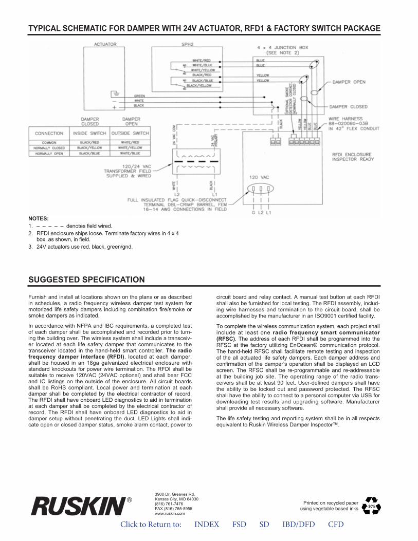
NOTES:1. – – – – – denotes field wired.2. RFDI enclosure ships loose. Terminate factory wires in 4 x 4
box, as shown, in field.3. 24V actuators use red, black, green/gnd.
TYPICAL SCHEMATIC FOR DAMPER WITH 24V ACTUATOR, RFD1 & FACTORY SWITCH PACKAGE
SUGGESTED SPECIFICATION
Furnish and install at locations shown on the plans or as describedin schedules, a radio frequency wireless damper test system formotorized life safety dampers including combination fire/smoke orsmoke dampers as indicated.
In accordance with NFPA and IBC requirements, a completed testof each damper shall be accomplished and recorded prior to turn-ing the building over. The wireless system shall include a transceiv-er located at each life safety damper that communicates to thetransceiver located in the hand-held smart controller. The radiofrequency damper interface (RFDI), located at each damper,shall be housed in an 18ga galvanized electrical enclosure withstandard knockouts for power wire termination. The RFDI shall besuitable to receive 120VAC (24VAC optional) and shall bear FCCand IC listings on the outside of the enclosure. All circuit boardsshall be RoHS compliant. Local power and termination at eachdamper shall be completed by the electrical contractor of record.The RFDI shall have onboard LED diagnostics to aid in terminationat each damper shall be completed by the electrical contractor ofrecord. The RFDI shall have onboard LED diagnostics to aid indamper setup without penetrating the duct. LED Lights shall indi-cate open or closed damper status, smoke alarm contact, power to
circuit board and relay contact. A manual test button at each RFDIshall also be furnished for local testing. The RFDI assembly, includ-ing wire harnesses and termination to the circuit board, shall beaccomplished by the manufacturer in an ISO9001 certified facility.
To complete the wireless communication system, each project shallinclude at least one radio frequency smart communicator(RFSC). The address of each RFDI shall be programmed into theRFSC at the factory utilizing EnOcean® communication protocol.The hand-held RFSC shall facilitate remote testing and inspectionof the all actuated life safety dampers. Each damper address andconfirmation of the damperʼs operation shall be displayed an LCDscreen. The RFSC shall be re-programmable and re-addressableat the building job site. The operating range of the radio trans-ceivers shall be at least 90 feet. User-defined dampers shall havethe ability to be locked out and password protected. The RFSCshall have the ability to connect to a personal computer via USB fordownloading test results and upgrading software. Manufacturershall provide all necessary software.
The life safety testing and reporting system shall be in all respectsequivalent to Ruskin Wireless Damper Inspector™.
3900 Dr. Greaves Rd.Kansas City, MO 64030(816) 761-7476FAX (816) 765-8955www.ruskin.com
Printed on recycled paperusing vegetable based inks
Click to Return to: INDEX FSD SD IBD/DFD CFD
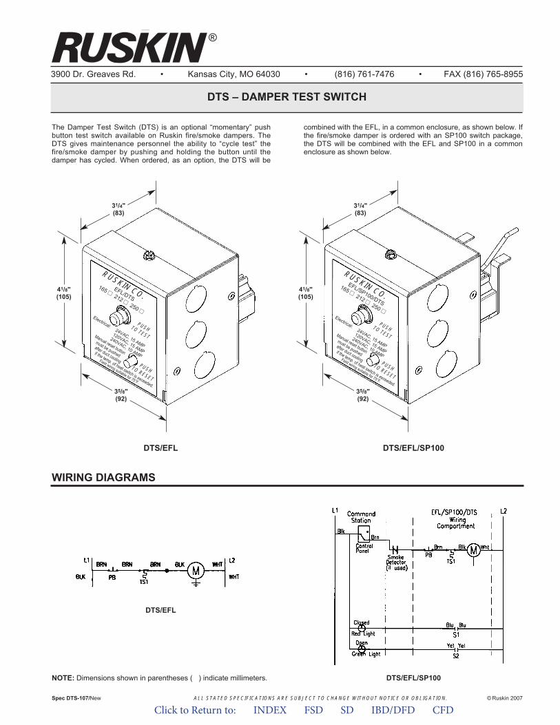
ALL STATED SPECIFICATIONS ARE SUBJECT TO CHANGE WITHOUT NOTICE OR OBLIGATION.
3900 Dr. Greaves Rd. • Kansas City, MO 64030 • (816) 761-7476 • FAX (816) 765-8955
DTS – DAMPER TEST SWITCH
The Damper Test Switch (DTS) is an optional “momentary” pushbutton test switch available on Ruskin fire/smoke dampers. TheDTS gives maintenance personnel the ability to “cycle test” thefire/smoke damper by pushing and holding the button until thedamper has cycled. When ordered, as an option, the DTS will be
combined with the EFL, in a common enclosure, as shown below. Ifthe fire/smoke damper is ordered with an SP100 switch package,the DTS will be combined with the EFL and SP100 in a commonenclosure as shown below.
Spec DTS-107/New © Ruskin 2007
®
35/8"(92)
31/4"(83)
41/8"(105)
DTS/EFL DTS/EFL/SP100
EFL/DTS
165 ■■212 ■■
250 ■■Electrical:
24VAC, 15 AMP
120VAC, 15 AMP
240VAC, 10 AMP
PUSH TO
TEST
PUSH TO
RESET
RU
SKIN C
O.
Manual reset button
must be pushed
after duct cooling
if the temp. of heat switch is exceeded.
Field wiring suitable for 75°F.
35/8"(92)
31/4"(83)
41/8"(105)
EFL/SP100/DTS
165 ■■212 ■■
250 ■■Electrical:
24VAC, 15 AMP
120VAC, 15 AMP
240VAC, 10 AMP
PUSH TO
TEST
PUSH TO
RESET
RU
SKIN C
O.
Manual reset button
must be pushed
after duct cooling
if the temp. of heat switch is exceeded.
Field wiring suitable for 75°F.
NOTE: Dimensions shown in parentheses ( ) indicate millimeters.
WIRING DIAGRAMS
DTS/EFL/SP100
DTS/EFL
Click to Return to: INDEX FSD SD IBD/DFD CFD
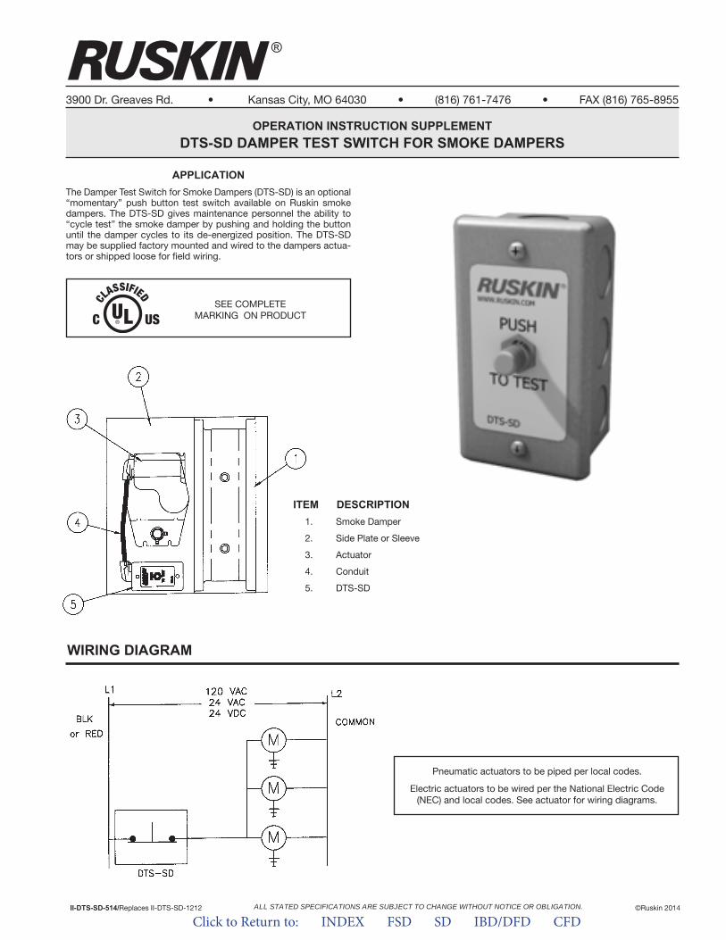
ALL STATED SPECIFICATIONS ARE SUBJECT TO CHANGE WITHOUT NOTICE OR OBLIGATION.
®
3900 Dr. Greaves Rd. • Kansas City, MO 64030 • (816) 761-7476 • FAX (816) 765-8955
APPLICATIONThe Damper Test Switch for Smoke Dampers (DTS-SD) is an optional “momentary” push button test switch available on Ruskin smoke dampers. The DTS-SD gives maintenance personnel the ability to “cycle test” the smoke damper by pushing and holding the button until the damper cycles to its de-energized position. The DTS-SD may be supplied factory mounted and wired to the dampers actua-tors or shipped loose for field wiring.
OPERATION INSTRUCTION SUPPLEMENTDTS-SD DAMPER TEST SWITCH FOR SMOKE DAMPERS
II-DTS-SD-514/Replaces II-DTS-SD-1212 ©Ruskin 2014
WIRING DIAGRAM
SEE COMPLETEMARKING ON PRODUCT
ITEM DESCRIPTION1. Smoke Damper
2. Side Plate or Sleeve
3. Actuator
4. Conduit
5. DTS-SD
Pneumatic actuators to be piped per local codes.
Electric actuators to be wired per the National Electric Code (NEC) and local codes. See actuator for wiring diagrams.
Click to Return to: INDEX FSD SD IBD/DFD CFD
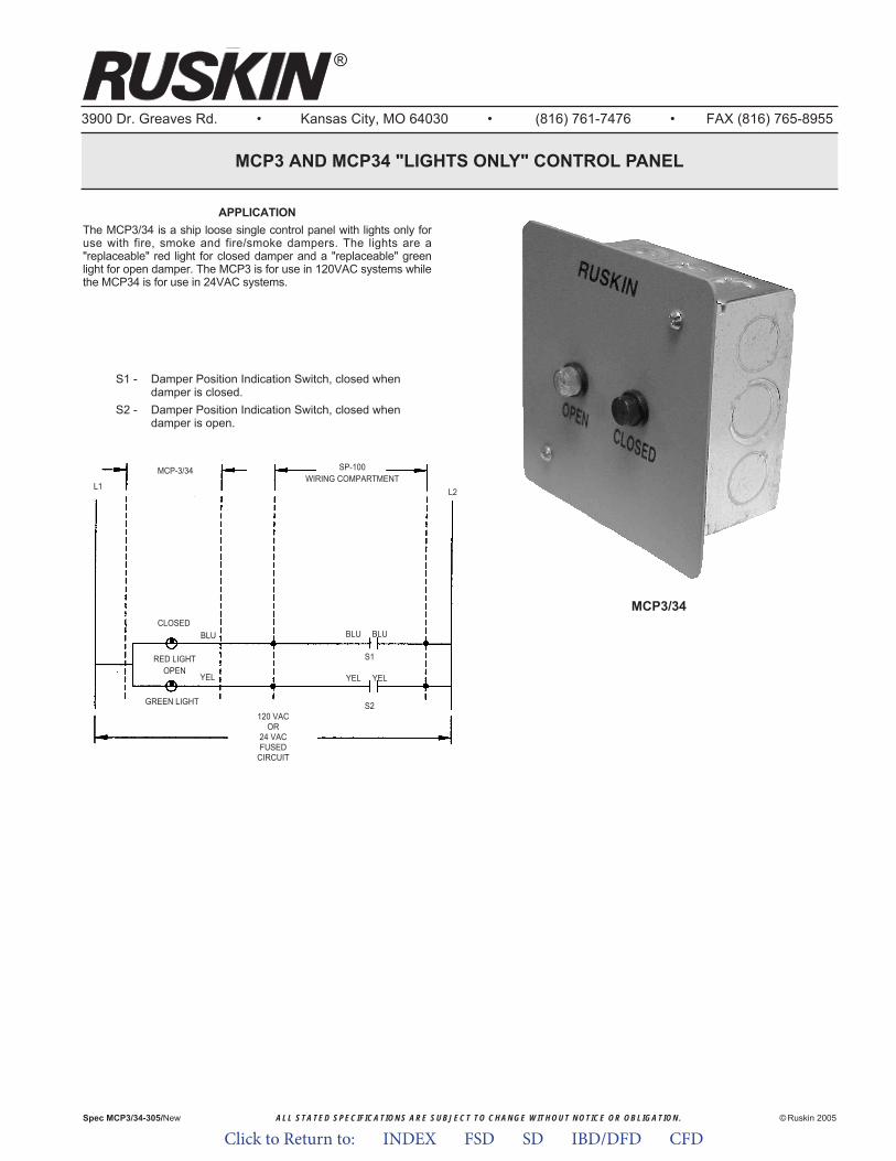
ALL STATED SPECIFICATIONS ARE SUBJECT TO CHANGE WITHOUT NOTICE OR OBLIGATION.
3900 Dr. Greaves Rd. • Kansas City, MO 64030 • (816) 761-7476 • FAX (816) 765-8955
MCP3 AND MCP34 "LIGHTS ONLY" CONTROL PANEL
© Ruskin 2005
®
Spec MCP3/34-305/New
APPLICATIONThe MCP3/34 is a ship loose single control panel with lights only foruse with fire, smoke and fire/smoke dampers. The lights are a"replaceable" red light for closed damper and a "replaceable" greenlight for open damper. The MCP3 is for use in 120VAC systems whilethe MCP34 is for use in 24VAC systems.
MCP3/34
S1 - Damper Position Indication Switch, closed whendamper is closed.
S2 - Damper Position Indication Switch, closed whendamper is open.
L1L2
SP-100WIRING COMPARTMENT
CLOSED
RED LIGHTOPEN
GREEN LIGHT
BLUBLUBLU
S1
S2
YELYELYEL
MCP-3/34
120 VACOR
24 VACFUSED
CIRCUIT
Click to Return to: INDEX FSD SD IBD/DFD CFD
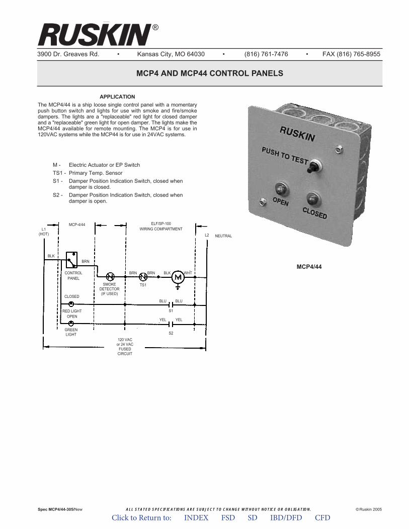
ALL STATED SPECIFICATIONS ARE SUBJECT TO CHANGE WITHOUT NOTICE OR OBLIGATION.
3900 Dr. Greaves Rd. • Kansas City, MO 64030 • (816) 761-7476 • FAX (816) 765-8955
MCP4 AND MCP44 CONTROL PANELS
© Ruskin 2005
®
Spec MCP4/44-305/New
APPLICATIONThe MCP4/44 is a ship loose single control panel with a momentarypush button switch and lights for use with smoke and fire/smokedampers. The lights are a "replaceable" red light for closed damperand a "replaceable" green light for open damper. The lights make theMCP4/44 available for remote mounting. The MCP4 is for use in120VAC systems while the MCP44 is for use in 24VAC systems.
MCP4/44
M - Electric Actuator or EP SwitchTS1 - Primary Temp. SensorS1 - Damper Position Indication Switch, closed when
damper is closed.S2 - Damper Position Indication Switch, closed when
damper is open.
L1(HOT) L2
ELF/SP-100WIRING COMPARTMENT
CONTROLPANEL
RED LIGHTOPEN
GREENLIGHT
BLUBLU
BLK
S1
S2
YELYEL
MCP-4/44
120 VACor 24 VAC
FUSEDCIRCUIT
BRN
CLOSED
SMOKEDETECTOR(IF USED)
BRN BRN BLK WHT
TS1M
NEUTRAL
Click to Return to: INDEX FSD SD IBD/DFD CFD
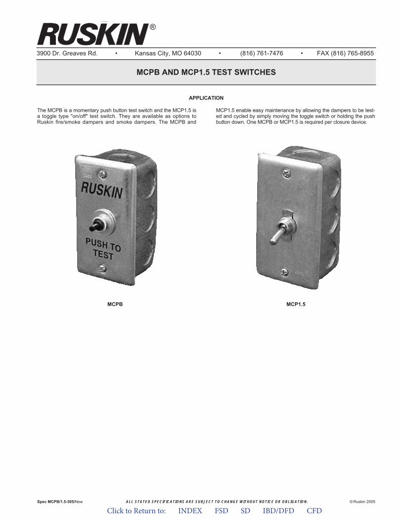
ALL STATED SPECIFICATIONS ARE SUBJECT TO CHANGE WITHOUT NOTICE OR OBLIGATION.
3900 Dr. Greaves Rd. • Kansas City, MO 64030 • (816) 761-7476 • FAX (816) 765-8955
MCPB AND MCP1.5 TEST SWITCHES
© Ruskin 2005
®
Spec MCPB/1.5-305/New
MCPB MCP1.5
The MCPB is a momentary push button test switch and the MCP1.5 isa toggle type "on/off" test switch. They are available as options toRuskin fire/smoke dampers and smoke dampers. The MCPB and
MCP1.5 enable easy maintenance by allowing the dampers to be test-ed and cycled by simply moving the toggle switch or holding the pushbutton down. One MCPB or MCP1.5 is required per closure device.
APPLICATION
Click to Return to: INDEX FSD SD IBD/DFD CFD
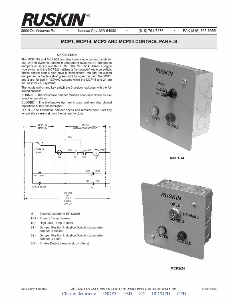
L1 L2TS-150
WIRING COMPARTMENT
BRN
ORGCONTROLPANEL
RED LIGHT
GREEN LIGHT
TS1SD TS2
BLKM
WHT
REDBLU
S1
S2
YELYEL
MCP-1/14MCP-2/24
ALL STATED SPECIFICATIONS ARE SUBJECT TO CHANGE WITHOUT NOTICE OR OBLIGATION.
3900 Dr. Greaves Rd. • Kansas City, MO 64030 • (816) 761-7476 • FAX (816) 765-8955
MCP1, MCP14, MCP2 AND MCP24 CONTROL PANELS
© Ruskin 2005
®
Spec MCP1/14-305/New
MCP2/24
APPLICATIONThe MCP1/14 and MCP2/24 are ship loose single control panels foruse with in dynamic smoke management systems on fire/smokedampers equipped with the TS150. The MCP1/14 utilizes a toggletype switch and the MCP2/24 utilizes a "removable" key type switch.These control panels also have a "replaceable" red light for closeddamper and a "replaceable" green light for open damper. The MCP1and 2 are for use in 120VAC systems while the MCP14 and 24 arefor use in 24VAC systems.The toggle switch and key switch are 3 position switches with the fol-lowing options:NORMAL – The fire/smoke damper remains open until closed by ele-vated temperatures.CLOSED – The fire/smoke damper closes and remains closedregardless of any sensor signal.OPEN – The fire/smoke damper opens and remains open until anytemperature sensor signals the damper to close.
120 VACOR
24VACFUSED
CIRCUIT
M - Electric Actuator or EP SwitchTS1 - Primary Temp. SensorTS2 - High Limit Temp. SensorS1 - Damper Position Indication Switch, closed when
damper is closed.S2 - Damper Position Indication Switch, closed when
damper is open.SD - Smoke Detector (optional, by others)
MCP1/14
Click to Return to: INDEX FSD SD IBD/DFD CFD
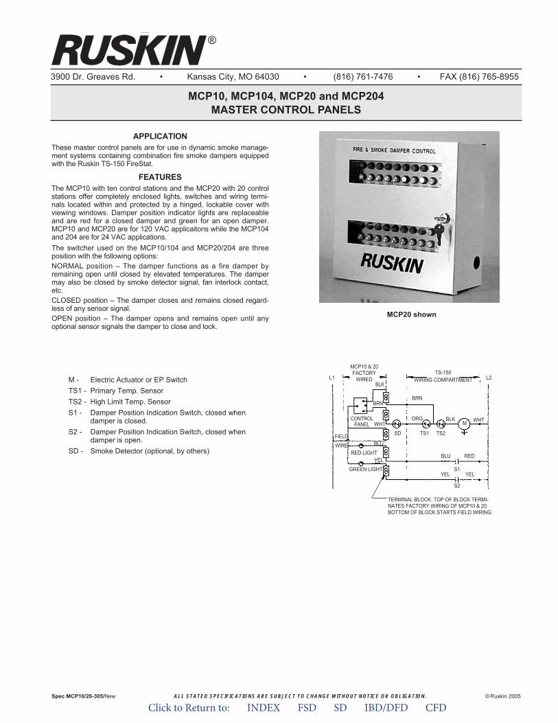
ALL STATED SPECIFICATIONS ARE SUBJECT TO CHANGE WITHOUT NOTICE OR OBLIGATION. © Ruskin 2005Spec MCP10/20-305/New
APPLICATIONThese master control panels are for use in dynamic smoke manage-ment systems containing combination fire smoke dampers equippedwith the Ruskin TS-150 FireStat.
FEATURESThe MCP10 with ten control stations and the MCP20 with 20 controlstations offer completely enclosed lights, switches and wiring termi-nals located within and protected by a hinged, lockable cover withviewing windows. Damper position indicator lights are replaceableand are red for a closed damper and green for an open damper.MCP10 and MCP20 are for 120 VAC applicaitons while the MCP104and 204 are for 24 VAC applications.The switcher used on the MCP10/104 and MCP20/204 are threeposition with the following options:NORMAL position – The damper functions as a fire damper byremaining open until closed by elevated temperatures. The dampermay also be closed by smoke detector signal, fan interlock contact,etc.CLOSED position – The damper closes and remains closed regard-less of any sensor signal.OPEN position – The damper opens and remains open until anyoptional sensor signals the damper to close and lock.
M - Electric Actuator or EP SwitchTS1 - Primary Temp. SensorTS2 - High Limit Temp. SensorS1 - Damper Position Indication Switch, closed when
damper is closed.S2 - Damper Position Indication Switch, closed when
damper is open.SD - Smoke Detector (optional, by others)
L1 L2TS-150
WIRING COMPARTMENT
BRNBRN
BLK
ORGCONTROLPANEL
RED LIGHT
FIELD
WIRE
GREEN LIGHT
TS1SD TS2
BLKM WHT
WHT
REDBLU
BLU
S1
S2
YEL
YEL
YEL
MCP10 & 20FACTORY
WIRED
TERMINAL BLOCK. TOP OF BLOCK TERMI-NATES FACTORY WIRING OF MCP10 & 20.BOTTOM OF BLOCK STARTS FIELD WIRING.
3900 Dr. Greaves Rd. • Kansas City, MO 64030 • (816) 761-7476 • FAX (816) 765-8955
MCP10, MCP104, MCP20 and MCP204MASTER CONTROL PANELS
®
MCP20 shown
Click to Return to: INDEX FSD SD IBD/DFD CFD

CONTROL PANEL LAYOUTFOR MCP10 AND MCP20
TERMINAL PANEL LAYOUTFOR MCP10 AND MCP20
1 2 3 4 5 6 7 8 9 10 11 12 13 14 15 16 17 18 19 201 2 3 4 5 6 7 8 9 10
RED LIGHT CIRCUITS
GREEN LIGHT CIRCUITS
SWITCH & LIGHT CIRCUITS(COMMON PER CHANNEL)
EMERGENCY OPEN CIRCUITS
NORMAL OPERATION CIRCUITS
BLUEWIREBLOCK
YELLOWWIREBLOCK
WHITEWIREBLOCK
BLACKWIREBLOCK
BROWNWIREBLOCK
RED LIGHT
GREEN LIGHT
TOGGLESWITCH
RED LIGHT
GREEN LIGHT
TOGGLESWITCH
TERMINAL NO.
TERMINAL NO.
BLUE
YELLOW
BLACKWHITE
BROWN
TYPICAL WIRINGEACH CHANNEL
BLUE
YELLOW
BLACKWHITE
BROWNTYPICAL WIRING EACH CHANNEL
TOGGLE SWITCH UP MAKES WHITE TO BROWN (NORMAL POS. DAMPER OPEN)CENTER POS. OFF (DAMPER CLOSED)
DOWN MAKES WHITE TO BLACK (DAMPER OPEN FOR EMERGENCY)11 12 13 14 15 16 17 18 19 20
3900 Dr. Greaves Rd.Kansas City, MO 64030(816) 761-7476FAX (816) 765-8955
www.ruskin.com
®
Click to Return to: INDEX FSD SD IBD/DFD CFD
Click to Return to: INDEX FSD SD IBD/DFD CFD
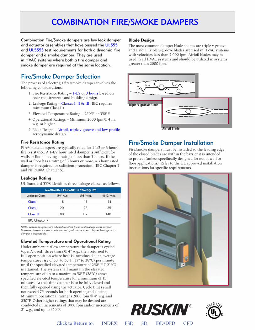
Click to Return to: INDEX FSD SD IBD/DFD CFD
Combination Fire/Smoke dampers are low leak damper and actuator assemblies that have passed the UL555 and UL555S test requirements for both a dynamic fire damper and a smoke damper. They are used in HVAC systems where both a fire damper and smoke damper are required at the same location.
Fire/Smoke Damper SelectionThe process of selecting a fire/smoke damper involves the following considerations:
1. Fire Resistance Rating – 1-1⁄2 or 3 hours based oncode requirements and building design.
2. Leakage Rating – Classes I, II & III (IBC requiresminimum Class II).
3. levated Temperature Rating – 250°F or 350°F
4. Operational Ratings – Minimum 2000 fpm @ 4 in.w.g. or higher.
5. Blade Design – Airfoil, triple v-groove and low-profileaerodynamic design.
Fire Resistance RatingFire/smoke dampers are typically rated for 1-1⁄2 or 3 hours fire resistance. A 1-1⁄2 hour rated damper is sufficient for walls or floors having a rating of less than 3 hours. If the wall or floor has a rating of 3 hours or more, a 3 hour rated damper is required for sufficient protection. (IBC Chapter 7 and NFPA90A Chapter 5).
Leakage RatingUL Standard 555S identifies three leakage classes as follows:
MaxIM
Leakage Class
UM LEaKaGE IN CFM/SQ. FT.
@4" w.g. @8" w.g. @12" w.g.
Class I 8 11 14
Class II 20 28 35
Class III 80 112 140
IBC Chapter 7
HVAC system designers are advised to select the lowest leakage class damper. However, there are some smoke control applications when a higher leakage class damper is acceptable.
Elevated Temperature and Operational RatingUnder ambient airflow temperature the damper is cycled (open/closed) three times @ 4" w.g., then returned to full-open position where heat is introduced at an average temperature rise of 30º to 50ºF (17º to 28ºC) per minute until the specified elevated temperature of 250º F (121ºC) is attained. The system shall maintain the elevated temperature of up to a maximum 50ºF (28ºC) above specified elevated temperature for a minimum of 15 minutes. At that time damper is to be fully closed and then fully opened using the actuator. Cycle times shall not exceed 75 seconds for both opening and closing. Minimum operational rating is 2000 fpm @ 4" w.g. and 250ºF. Other higher ratings that may be desired are conducted in increments of 1000 fpm and/or increments of 2" w.g., and up to 350ºF.
Blade DesignThe most common damper blade shapes are triple v-groove and airfoil. Triple v-groove blades are used in HVAC systems with velocities less than 2,000 fpm. Airfoil blades may be used in all HVAC systems and should be utilized in systems greater than 2000 fpm.
Fire/Smoke Damper InstallationFire/smoke dampers must be installed so the leading edge of the closed blades are within the barrier it is intended to protect (unless specifically designed for out of wall or floor applications). Refer to the UL approved installation instructions for specific requirements.
Triple V-groove Blade
Airfoil Blade
Note: 3 hour and large 1-1/2 hour applications require mounting angles two sides.
COMBINATION FIRE/SMOKE DAMPERS
®
Elevated Temperature Rating
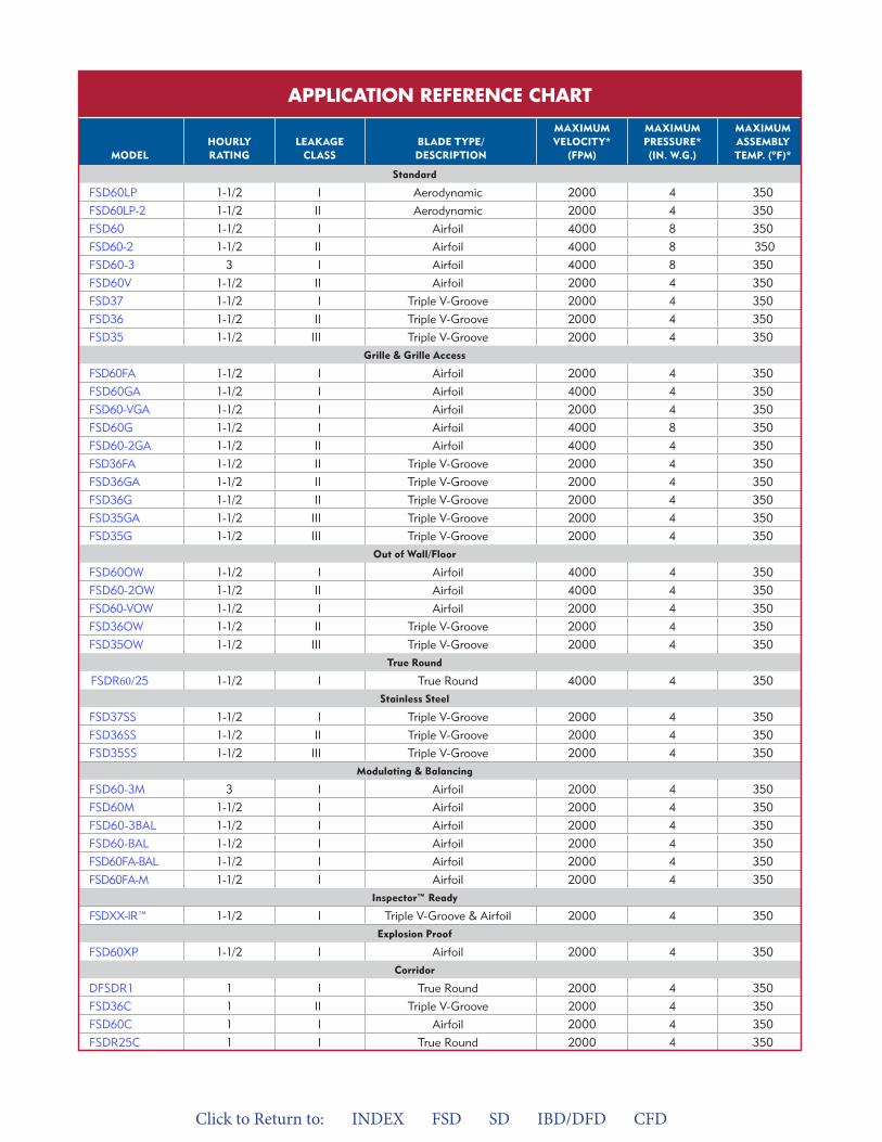
Click to Return to: INDEX FSD SD IBD/DFD CFD
COMBINaTION FIRE/SMOKE DaMPER MODELS
SEE PaGE # MODEL
HOURLY RaTING
LEaKaGE CLaSS
BLaDE TYPE/ DESCRIPTION
MaxIMUM VELOCITY*
(FPM)
MaxIMUM PRESSURE* (IN. w.G.)
MaxIMUM aSSEMBLYTEMP. (ºF)*
Standard
4 FSD60LP 1-1/2 I Aerodynamic 2000 4 350
4 FSD60LP-2 1-1/2 II Aerodynamic 2000 4 350
4 FSD60 1-1/2 I Airfoil 4000 8 350
4 FSD60-2 1-1/2 II Airfoil 4000 8 350
4 FSD60-3 3 I Airfoil 4000 8 350
4 FSD60V 1-1/2 II Airfoil 2000 4 350
7 FSD37 1-1/2 I Triple V-Groove 2000 4 350
7 FSD36 1-1/2 II Triple V-Groove 2000 4 350
7 FSD35 1-1/2 III 2000 4 350Triple V-Groove Grille & Grille access
5 FSD60FA 1-1/2 I Airfoil 2000 4 350
5 FSD60GA 1-1/2 I Airfoil 4000 4 350
FSD60-VGA 1-1/2 I Airfoil 2000 4 350
FSD60G 1-1/2 I Airfoil 4000 8 350
FSD60-2GA 1-1/2 II Airfoil 4000 4 350
8 FSD36FA 1-1/2 II Triple V-Groove 2000 4 350
8 FSD36GA 1-1/2 II Triple V-Groove 2000 4 350
FSD36G 1-1/2 II Triple V-Groove 2000 4 350
8 FSD35GA 1-1/2 III Triple V-Groove 2000 4 350
FSD35G 1-1/2 III 2000 4 350Triple V-GrooveOut of wall/Floor
5 FSD60OW 1-1/2 I Airfoil 4000 4 350
FSD60-2OW 1-1/2 II Airfoil 4000 4 350
FSD60-VOW 1-1/2 I Airfoil 2000 4 350
8 FSD36OW 1-1/2 II Triple V-Groove 2000 4 350
8 FSD35OW 1-1/2 III Triple V-Groove 2000 4 350True Round
8 FSDR60/25 1-1/2 I 4000 4 350True Round Stainless Steel
7 FSD37SS 1-1/2 I Triple V-Groove 2000 4 350
7 FSD36SS 1-1/2 II Triple V-Groove 2000 4 350
FSD35SS 1-1/2 III Triple V-Groove 2000 4 350Modulating & Balancing
5 FSD60-3M 3 I Airfoil 2000 4 350
5 FSD60M 1-1/2 I Airfoil 2000 4 350
FSD60-3BAL 1-1/2 I Airfoil 2000 4 350
6 FSD60-BAL 1-1/2 I Airfoil 2000 4 350
6 FSD60FA-BAL 1-1/2 I Airfoil 2000 4 350
FSD60FA-M 1-1/2 I 2000 4 350AirfoilInspector™ Ready
7 FSDXX-IR™ 1-1/2 I Triple V-Groove & Airfoil 2000 4 350Explosion Proof
6 FSD60XP 1-1/2 I 2000 4 350AirfoilCorridor
9 DFSDR1 1 I True Round 2000 4 350
9 FSD36C 1 II Triple V-Groove 2000 4 350
9 FSD60C 1 I Airfoil 2000 4 350
9 FSDR25C 1 I True Round 2000 4 350
APPLICATION REFERENCE CHART
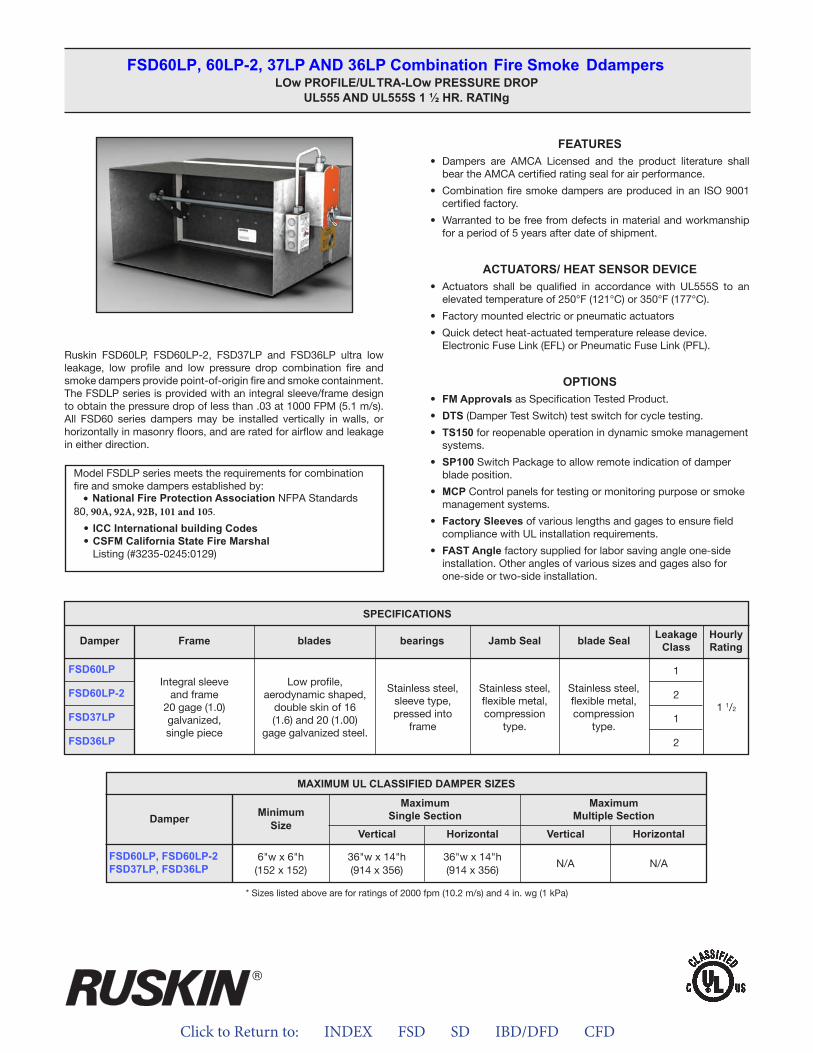
Click to Return to: INDEX FSD SD IBD/DFD CFD
Ruskin FSD60LP, FSD60LP-2, FSD37LP and FSD36LP ultra low leakage, low profile and low pressure drop combination fire and smoke dampers provide point-of-origin fire and smoke containment. The FSDLP series is provided with an integral sleeve/frame design to obtain the pressure drop of less than .03 at 1000 FPM (5.1 m/s). All FSD60 series dampers may be installed vertically in walls, or horizontally in masonry floors, and are rated for airflow and leakage in either direction.
FEATURES• Dampers are AMCA Licensed and the product literature shall
bear the AMCA certified rating seal for air performance.
• Combination fire smoke dampers are produced in an ISO 9001certified factory.
• Warranted to be free from defects in material and workmanshipfor a period of 5 years after date of shipment.
ACTUATORS/ HEAT SENSOR DEVICE• Actuators shall be qualified in accordance with UL555S to an
elevated temperature of 250°F (121°C) or 350°F (177°C).
• Factory mounted electric or pneumatic actuators
• Quick detect heat-actuated temperature release device.Electronic Fuse Link (EFL) or Pneumatic Fuse Link (PFL).
OPTIONS• FM Approvals as Specification Tested Product.
• DTS (Damper Test Switch) test switch for cycle testing.
• TS150 for reopenable operation in dynamic smoke managementsystems.
• SP100 Switch Package to allow remote indication of damperblade position.
• MCP Control panels for testing or monitoring purpose or smokemanagement systems.
• Factory Sleeves of various lengths and gages to ensure fieldcompliance with UL installation requirements.
• FAST Angle factory supplied for labor saving angle one-sideinstallation. Other angles of various sizes and gages also forone-side or two-side installation.
FSD60LP, 60LP-2, 37LP AND 36LP Combination Fire Smoke Ddampers LOw PROFILE/ULTRA-LOw PRESSURE DROP
UL555 AND UL555S 1 ½ HR. RATINg
Model FSDLP series meets the requirements for combination fire and smoke dampers established by:
•80, 90A, 92A, 92B, 101 and 105.
National Fire Protection Association NFPA Standards
• ICC International building Codes• CSFM California State Fire Marshal
Listing (#3235-0245:0129)
SPECIFICATIONS
FSD60LP
FSD60LP-2
FSD37LP
FSD36LP
Frame blades bearings Jamb Seal blade Seal LeakageClass
HourlyRatingDamper
Integral sleeveand frame
20 gage (1.0)galvanized,single piece
Low profile, aerodynamic shaped,
double skin of 16(1.6) and 20 (1.00)
gage galvanized steel.
Stainless steel,sleeve type,pressed into
frame
Stainless steel,flexible metal,compression
type.
Stainless steel,flexible metal,compression
type.
1
2
1
2
1 1/2
* Sizes listed above are for ratings of 2000 fpm (10.2 m/s) and 4 in. wg (1 kPa)
MAXIMUM UL CLASSIFIED DAMPER SIZES
Damper
FSD60LP, FSD60LP-2 FSD37LP, FSD36LP
MinimumSize
MaximumSingle Section
MaximumMultiple Section
Vertical VerticalHorizontal Horizontal
6"w x 6"h(152 x 152)
36"w x 14"h(914 x 356)
36"w x 14"h(914 x 356)
N/A N/A
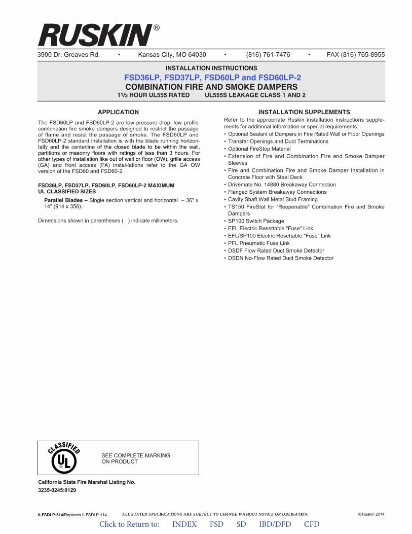
ALL STATED SPECIFICATIONS ARE SUBJECT TO CHANGE WITHOUT NOTICE OR OBLIGATION.
3900 Dr. Greaves Rd. • Kansas City, MO 64030 • (816) 761-7476 • FAX (816) 765-8955
INSTALLATION INSTRUCTIONSFSD36LP, FSD37LP, FSD60LP and FSD60LP-2 COMBINATION FIRE AND SMOKE DAMPERS
11/2 HOUR UL555 RATED UL555S LEAKAGE CLASS 1 AND 2
II-FSDLP-514/Replaces II-FSDLP-114 © Ruskin 2014
®
INSTALLATION SUPPLEMENTSRefer to the appropriate Ruskin installation instructions supple-ments for additional information or special requirements:• Optional Sealant of Dampers in Fire Rated Wall or Floor Openings• Transfer Openings and Duct Terminations• Optional FireStop Material• Extension of Fire and Combination Fire and Smoke Damper
Sleeves• Fire and Combination Fire and Smoke Damper Installation in
Concrete Floor with Steel Deck• Drivemate No. 14880 Breakaway Connection• Flanged System Breakaway Connections• Cavity Shaft Wall Metal Stud Framing• TS150 FireStat for "Reopenable" Combination Fire and Smoke
Dampers• SP100 Switch Package• EFL Electric Resettable "Fuse" Link• EFL/SP100 Electric Resettable "Fuse" Link• PFL Pneumatic Fuse Link• DSDF Flow Rated Duct Smoke Detector• DSDN No-Flow Rated Duct Smoke Detector
APPLICATIONThe FSD60LP and FSD60LP-2 are low pressure drop, low profile combination fire smoke dampers designed to restrict the passage of flame and resist the passage of smoke. The FSD60LP and FSD60LP-2 standard installation is with the blade running horizon-tally and the centerline of the closed blade to be within the wall, partitions or masonry floors with ratings of less than 3 hours. For other types of installation like out of wall or floor (OW), grille access (GA) and front access (FA) instal-lations refer to the GA OW version of the FSD60 and FSD60-2.
FSD36LP, FSD37LP, FSD60LP, FSD60LP-2 MAXIMUMUL CLASSIFIED SIZESParallel Blades – Single section vertical and horizontal – 36" x14" (914 x 356).
Dimensions shown in parentheses ( ) indicate millimeters.
California State Fire Marshal Listing No.3235-0245:0129
SEE COMPLETE MARKINGON PRODUCT
Click to Return to: INDEX FSD SD IBD/DFD CFD
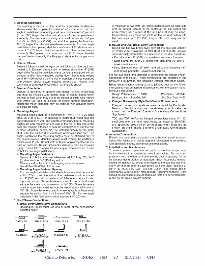
1. Opening ClearanceThe opening in the wall or floor shall be larger than the damper/sleeve assembly to permit installation or expansion. For twoangle installations the opening shall be a minimum of 1/8" per foot(3 per 305) larger than the overall size of the damper/sleeveassembly. The maximum opening size shall not exceed 1/8" perfoot (3 per 305) plus 2" (51), nor shall the opening be less than1/4" (6) larger than the damper/sleeve assembly. For one angleinstallations, the opening shall be a minimum of 1/4" (6) to a maxi-mum of 1" (25) larger than the overall size of the damper/sleeveassembly. The opening may be as much as 2” (51) larger than thedamper/sleeve assembly if a 16 gage (1.6) mounting angle is uti-lized.
2. Damper SleeveSleeve thickness must be equal to or thicker than the duct con-nected to it. Damper sleeve shall not extend more than 6" (152)beyond the fire wall or partition unless damper is equipped with anactuator and/or factory installed access door. Sleeve may extendup to 16" (406) beyond the fire wall or partition on sides equippedwith actuator and/or factory installed access door. Sleeve shallterminate at both sides of wall within dimensions shown.
3. Damper OrientationDamper is designed to operate with blades running horizontallyand must be installed with leading edge of closed blades withinthe wall or floor when they are in the closed position. Use "MountWith Arrow Up" label as a guide for proper damper orientation.Horizontal mount dampers may be installed with actuator aboveor below the floor.
4. Mounting AnglesMounting angles shall be a minimum of 11/2" x 11/2" x 20 gagesteel (38 x 38 x 1.0). For openings in metal stud, wood stud andconcrete/masonry wall and concrete/masonry floors, mountingangles are only required on one side of the wall or top side of thefloor and must be attached to both the damper/sleeve and the wallor floor. Mounting angles may be installed directly to the metalstud under the wallboard on metal stud wall installations only. Twoangle installation the mounting angles must be attached only tothe damper/sleeve. Mounting angles must overlap the partition aminimum of 1" (25). Do not weld or fasten angles together at cor-ners of dampers. Ruskin fire/smoke dampers may be installedusing Ruskin FAST angle for one angle installation or RuskinPFMA for two angle installations.a. Mounting Angle Fasteners
Sleeve: #10 bolts or screws Maximum of 1/2” long (13), 3/16"(3) steel rivets or 1/2" (13) long welds.Masonry wall or floor: #10 self-tapping concrete screwsWood/Steel Stud Wall: #10 screws.
b. Mounting Angle Fastener SpacingFor one angle installations the sleeve fasteners shall be spacedat 6" (152) o.c. and the wall or floor fasteners shall be spacedat 12" (305) o.c. with a minimum of 2 fasteners on each side,top and bottom. Screw fasteners used in metal stud mustengage the metal stud a minimum of 1/2" (13). Screw fastenersused in wood stud must engage the wood stud a minimum of3/4" (19). Screw fasteners used in masonry walls or floors mustengage the wall or floor a minimum of 11/2" (38). For two angleinstallations the fasteners shall be spaced at 8" (203) o.c.
5. Duct/Sleeve Connectionsa. Break-away Duct/Sleeve Connections
Rectangular ducts must use one or more of the connectionsdepicted below:
A maximum of two #10 (M5) sheet metal screws on each sideand the bottom, located in the center of the slip pocket andpenetrating both sides of the slip pocket may be used.Connections using these slip joints on the top and bottom withflat drive slips up to 20" (508) long on the sides may also beused.
b. Round and Oval Break-away ConnectionsRound and flat oval break-away connections must use either a4" (102) wide drawband or #10 (M5) sheet metal screwsspaced equally around the circumference of the duct as follows:• Duct diameters 22" (559) and smaller – maximum 3 screws.• Duct diameters over 22" (559) and including 36" (914) –
maximum 5 screws.• Duct diameters over 36" (914) and up to and including 191"
(4851) total perimeter – maximum 8 screws.For flat oval ducts, the diameter is considered the largest (major)dimension of the duct. These connections are depicted in theSMACNA Fire, Smoke, and Radiation Damper Installation Guide.Note: When optional sealing of these joints is desired, the follow-ing sealants may be applied in accordance with the sealant manu-facturer's instructions:
Design Polymerics – DP 1010 Precision – PA2084THardcast, Inc. – Iron Grip 601 Eco Duct Seal 44-52
c. Flanged Break-away Style Duct/Sleeve Connections.Flanged connection systems manufactured by Ductmate,Nexus or Ward are approved break-away when installed asshown on the Flanged Systems Breakaway ConnectionsSupplement.TDC and TDF roll-formed flanged connections using 3/8" (10)steel bolts and nuts, and metal cleats, as tested by SMACNA,are approved break-away connections when installed asshown on the Flanged Systems Breakaway ConnectionsSupplement.
6. Actuator ConnectionsElectric and pneumatic actuators are to be connected in accor-dance with wiring and piping diagrams developed in compliancewith applicable codes, ordinances and regulations.
7. Installation and MaintenanceTo ensure optimum operation and performance; the damper mustbe installed so it is square and free from racking. Do not com-press or stretch the damper frame into the duct or opening. Do notlift damper using blades or actuators. Each fire/smoke dampershould be maintained, cycled and tested at intervals not less thanevery six months and in accordance with the latest editions orNFPA 80, 90A, 92A, 92B, 105 and UL864, local codes and inaccordance with actuator manufacturer recommendations. Careshould be exercised to ensure that such tests are performed safe-ly and do not cause system damage.
Click to Return to: INDEX FSD SD IBD/DFD CFD
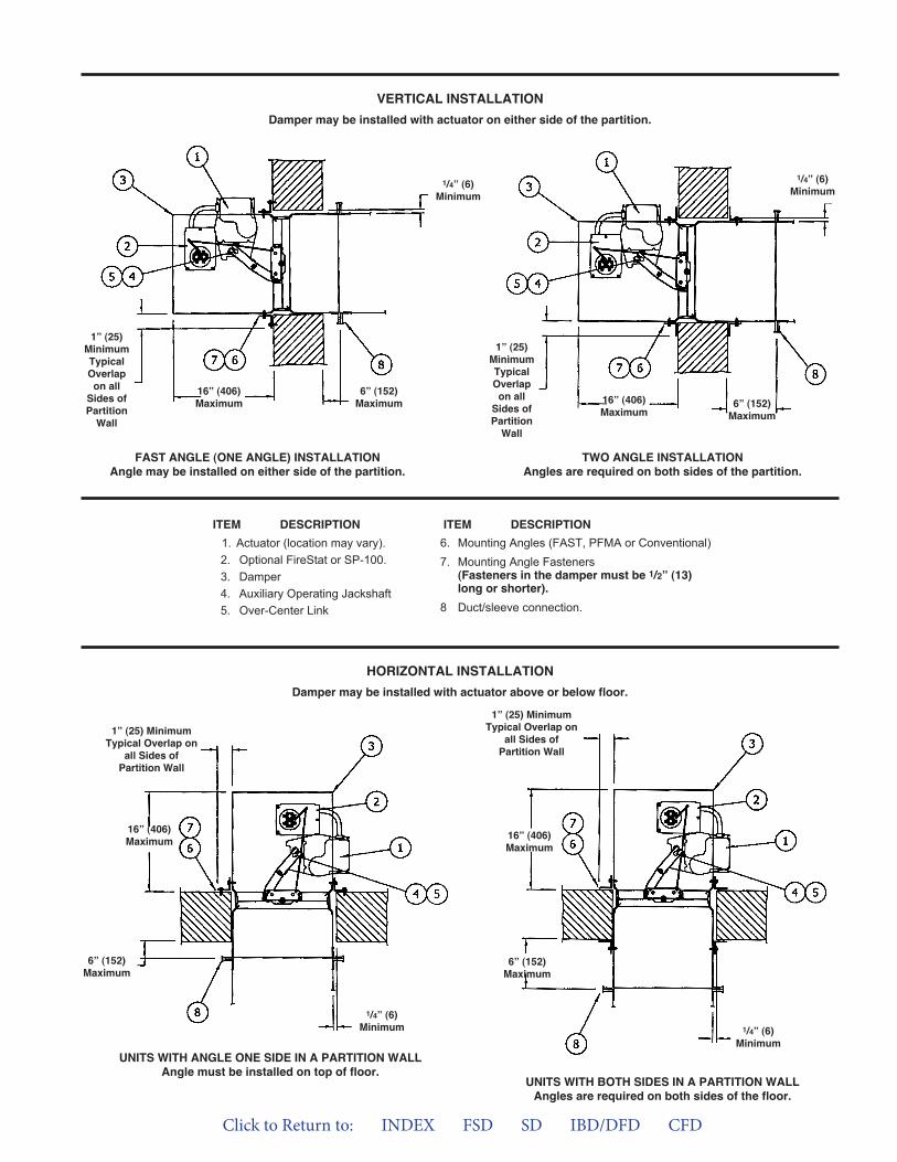
VERTICAL INSTALLATIONDamper may be installed with actuator on either side of the partition.
FAST ANGLE (ONE ANGLE) INSTALLATIONAngle may be installed on either side of the partition.
TWO ANGLE INSTALLATIONAngles are required on both sides of the partition.
ITEM DESCRIPTION6. Mounting Angles (FAST, PFMA or Conventional)7. Mounting Angle Fasteners
(Fasteners in the damper must be 1/2” (13)long or shorter).
8 Duct/sleeve connection.
ITEM DESCRIPTION1. Actuator (location may vary).2. Optional FireStat or SP-100.3. Damper4. Auxiliary Operating Jackshaft5. Over-Center Link
1” (25)MinimumTypicalOverlapon allSides ofPartitionWall
16” (406)Maximum
6” (152)Maximum
1/4” (6)Minimum
1” (25)MinimumTypicalOverlapon allSides ofPartitionWall
16” (406)Maximum
6” (152)Maximum
1/4” (6)Minimum
HORIZONTAL INSTALLATIONDamper may be installed with actuator above or below floor.
1” (25) MinimumTypical Overlap on
all Sides ofPartition Wall
16” (406)Maximum
6” (152)Maximum
UNITS WITH ANGLE ONE SIDE IN A PARTITION WALLAngle must be installed on top of floor.
UNITS WITH BOTH SIDES IN A PARTITION WALLAngles are required on both sides of the floor.
1/4” (6)Minimum
1” (25) MinimumTypical Overlap on
all Sides ofPartition Wall
16” (406)Maximum
6” (152)Maximum
1/4” (6)Minimum
Click to Return to: INDEX FSD SD IBD/DFD CFD

Click to Return to: INDEX FSD SD IBD/DFD CFD
ApplicA tionRuskin FSDR25 and FSDR25SS “true round” low leak combination fire and smoke dampers provide point-of-origin fire and smoke con-tainment. The FSDR series is the ideal choice when round duct is used on a project. FSDR25 series dampers may be installed verti-cally in walls, or horizontally in masonry floors, and is rated for air-flow and leakage in either direction. The FSDR25 is rated for velocity up to 4000 fpm (20.3 m/s) and 4 in. wg (1 kPa).
The integral frame and unique “Cinch Plate” design provides a low cost, easy to install, high performing damper.
FEATURES• Combination fire smoke dampers are produced in an ISO 9001
certified factory
• Warranted to be free from defects in material and workmanshipfor a period of 5 years after date of shipment.
ACTUATORS/ HEAT SENSOR DEVICE• Actuators shall be qualified in accordance with UL555S to an
elevated temperature of 250°F (121°C) or 350°F (177°C).
• Factory mounted electric or pneumatic actuators
• Quick detect heat-actuated temperature release device.Electronic Fuse Link (EFL) or Pneumatic Fuse Link (PFL).
OPTIONS• FM Approvals as Specification Tested Product.
• DTS (Damper Test Switch) test switch for cycle testing.
• TS150 for reopenable operation in dynamic smoke managementsystems.
• DSDF/DSDN Duct Smoke Detector (Flow rated and No-Flow).
• SP100 Switch Package to allow remote indication of damperblade position.
• MCP Control panels for testing or monitoring purpose or smokemanagement systems.
• Factory Sleeves of various lengths and gages to ensure fieldcompliance with UL installation requirements.
• FAST Angle factory supplied for labor saving angle one-sideinstallation. Other angles of various sizes and gages also forone-side or two-side installation.
FSDR25, FSDR60 And FSDR25SS Combination Fire Smoke DdamperTRUE ROUND ULTRA-LOW LEAKAGE
UL555 and UL555S CLASS 1; 1 ½ HR. RATING
Model FSDR25 series meets the requirements for combination fire and smoke dampers established by:
• National Fire Protection Association NFPA Standards 80, 90A, 92A, 92B, 101 and 105.
• ICC International Building Codes• CSFM California State Fire Marshal -
Listing (#3235-0245:0128) FSDR25(SS)Listing (#3235-0245:0120) FSDR25C
• New York City (MEA 252-05-E)
MAXIMUM UL CLASSIFIED DAMPER SIZES
Damper
FSDDR25, FSDR25SS
Minimum Size Maximum Size
6" Dia. (152) 24" Dia. (609)
SPECIFICATIONS
FSDR25FSDR60
FSDR25SS
Frame Blades Bearings Blade SealLeakage
ClassHourlyRating
Damper
1 1/21
20 gage (.9)galvanized steel.
Standard 17" (432) long
Two-piece 14 gage(1.9) equivalent thickness
galvanized steel.
Stainless steelsleeve type,pressed into
frame
Silicone edge type sandwiched between two piece blade.Full circumference smoke
seal to 450°F (232°C).
20 gage (.9) 304stainless steel.Standard 17"
(432) long
Two-piece 14 gage(1.9) equivalent thickness
304 stainless steel.
Stainless steelsleeve type,pressed into
frame
Silicone edge type sandwichedbetween two piece blade.Full circumference smoke
seal to 450°F (232°C).
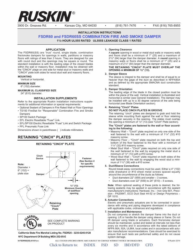
ALL STATED SPECIFICATIONS ARE SUBJECT TO CHANGE WITHOUT NOTICE OR OBLIGATION.
3900 Dr. Greaves Rd. • Kansas City, MO 64030 • (816) 761-7476 • FAX (816) 765-8955
INSTALLATION INSTRUCTIONSFSDR60 and FSDR60SS COMBINATION FIRE AND SMOKE DAMPER
11/2 HOUR UL555 RATED UL555S LEAKAGE CLASS 1 RATED
APPLICATIONThe FSDR60(SS) are “true” round, single blade, combinationfire/smoke dampers for openings in walls, partitions or masonryfloors with ratings of less than 3 hours. They are designed for usewith round duct and the openings may be square or round. Thestandard installation is with the leading edge of the closed bladeswithin the wall or masonry floor. Installation may be obtained withthe “CINCH” plage on one side for metal stud or masonry walls and“CINCH” plate both sides for wood stud wall and masonry floors.MOUNTING
Vertical or horizontal.MINIMUM SIZE
6" (152) diameter.MAXIMUM UL CLASSIFIED SIZE
24" (610) diameter.
INSTALLATION SUPPLEMENTSRefer to the appropriate Ruskin installation instructions supple-ments for additional information or special requirements:• Optional Sealant of Dampers in Fire Rated Wall or Floor Openings• TS150 FireStat for "Reopenable" Combination Fire and Smoke
Dampers• SP100 Switch Package• EFL Electric Resettable "Fuse" Link• EFL/SP100 Electric Resettable "Fuse" Link and Switch Package• PFL Pneumatic Fuse LinkDimensions shown in parentheses ( ) indicate millimeters.
II-FSDR60(SS)-814/New © Ruskin 2014
®
1. Opening ClearanceA square opening in wood or metal stud walls or masonry wallsand floors shall be a minimum of 1" (25) and a maximum of21/2" (64) larger than the damper diameter. A round opening inmasonry walls or floors shall be a minimum of 1" (25) and amaximum of 21/2" (64) larger than the damper diameter.THE RETAINING "CINCH" PLATE MUST OVERLAP THEOPENING A MINIMUM OF 1/2" (13).
2. Damper SleeveThe sleeve is integral to the damper and shall be of equal to orheavier than the gage of the duct as described in NFPA90Aand as defined by the appropriate SMACNA duct constructionstandard.
3. Damper OrientationThe leading edge of the blade in the closed position must bewithin the plane of the wall. Vertical installation is illustrated andhorizontal is similar (see General Installation). The damper maybe installed with up to a 30 degree variance of the axle beinghorizontal (see Blade Orientation section).
4. Retaining "Cinch" PlatesDO NOT PLACE CINCH PLATES IN GROOVEThe retaining “cinch” plates are designed to grab and hold thesleeve while mounting flush against the wall or floor retainingthe damper securely in the opening. The plates must overlapthe opening a minimum of 1/2" (13) (see "Cinch" Plate section).The "Cinch" plates are fastened to the wall or floor accord-ing to the following:• Masonry Wall – "Cinch" plate required on only one side of the
wall fastened to the wall with a minimum of 11/4" (32) #10masonry screw.
• Masonry Floor – "Cinch" plate required on both the top andbottom of the floor fastened to the floor with a minimum of11/4" (32) #10 masonry screw.
• Metal Stud Wall – "Cinch" plate required on only one side ofthe wall fastened to the wall by engaging the metal stud aminimum of 1/2" (13) with a #10 screw.
• Wood Stud Wall – "Cinch" plate required on both sides of thewall fastened to the wall by engaging the wood stud a mini-mum of 11/2" (38) with a #10 screw.
5. Duct/Sleeve ConnectionsRound break-away connections must be used. Either a 4" (102)wide drawband or #10 sheet metal screws spaced equallyaround the circumference of the ducts as follows:• Duct diameters 22" (559) and smaller – 3 screws.• Duct diameters over 22" (559) to 24" (610) – 5 screws.
Note: When optional sealing of these joints is desired, the fol-lowing sealants may be applied in accordance with the sealantmanufacturer's instructions: Hardcast, Inc. - Iron Grip 601, Preci-sion - PA2084T, ECO Duct Seal 44-52 or Design Polymerics –DP 1010.
6. Actuator ConnectionsElectric and pneumatic actuators are to be connected in accor-dance with wiring and piping diagrams developed in compliancewith applicable codes, ordinances and regulations.
7. Installation and MaintenanceDo not compress or stretch the damper frame into the duct oropening. Lift or handle the damper using sleeve or frame. Do notlift damper using blade or actuators. Each fire/smoke dampershould be maintained, cycled and tested at intervals not less thanevery six months and in accordance with the latest editions ofNFPA 90A, 92A, UL864, local codes and in accordance with actu-ator manufacturer recommendations. Care should be exercised toensure that such tests are performed safely and do not causesystem damage.
RETAINING "CINCH" PLATESRETAINING "CINCH" PLATE
1/2" (13)Minimum Overlap
of wall/flooropening
Note:Diameter +6" (152) =plate size
CinchDevice
Damper
Fastener(See Section 4
for specificrequirements)
SEE COMPLETE MARKING ON PRODUCT
Retaining“Cinch”
Plate
California State Fire Marshal Listing No. FSDR25 - 3235-0245:0128NYC Department Of Building MEA 252-05-E
Click to Return to: INDEX FSD SD IBD/DFD CFD
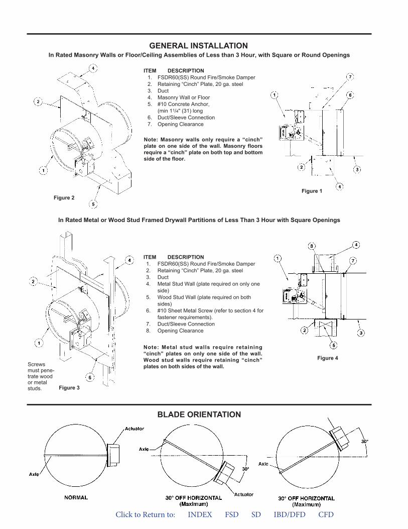
In Rated Metal or Wood Stud Framed Drywall Partitions of Less Than 3 Hour with Square Openings
In Rated Masonry Walls or Floor/Ceiling Assemblies of Less than 3 Hour, with Square or Round Openings
ITEM DESCRIPTION1. FSDR60(SS) Round Fire/Smoke Damper2. Retaining “Cinch” Plate, 20 ga. steel3. Duct4. Masonry Wall or Floor5. #10 Concrete Anchor,
(min 11/4" (31) long6. Duct/Sleeve Connection7. Opening Clearance
ITEM DESCRIPTION1. FSDR60(SS) Round Fire/Smoke Damper2. Retaining “Cinch” Plate, 20 ga. steel3. Duct4. Metal Stud Wall (plate required on only one
side)5. Wood Stud Wall (plate required on both
sides)6. #10 Sheet Metal Screw (refer to section 4 for
fastener requirements).7. Duct/Sleeve Connection8. Opening Clearance
Figure 2Figure 1
Figure 3
Figure 4
GENERAL INSTALLATION
Note: Metal stud walls require retaining“cinch” plates on only one side of the wall.Wood stud walls require retaining “cinch”plates on both sides of the wall.Screws
must pene-trate woodor metalstuds.
Note: Masonry walls only require a “cinch”plate on one side of the wall. Masonry floorsrequire a “cinch” plate on both top and bottomside of the floor.
BLADE ORIENTATION
Click to Return to: INDEX FSD SD IBD/DFD CFD
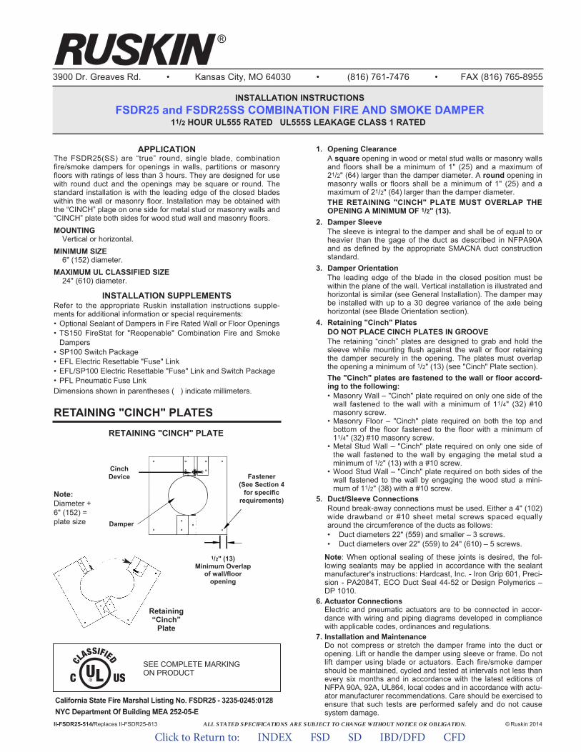
ALL STATED SPECIFICATIONS ARE SUBJECT TO CHANGE WITHOUT NOTICE OR OBLIGATION.
3900 Dr. Greaves Rd. • Kansas City, MO 64030 • (816) 761-7476 • FAX (816) 765-8955
INSTALLATION INSTRUCTIONSFSDR25 and FSDR25SS COMBINATION FIRE AND SMOKE DAMPER
11/2 HOUR UL555 RATED UL555S LEAKAGE CLASS 1 RATED
APPLICATIONThe FSDR25(SS) are “true” round, single blade, combinationfire/smoke dampers for openings in walls, partitions or masonryfloors with ratings of less than 3 hours. They are designed for usewith round duct and the openings may be square or round. Thestandard installation is with the leading edge of the closed bladeswithin the wall or masonry floor. Installation may be obtained withthe “CINCH” plage on one side for metal stud or masonry walls and“CINCH” plate both sides for wood stud wall and masonry floors.MOUNTING
Vertical or horizontal.MINIMUM SIZE
6" (152) diameter.MAXIMUM UL CLASSIFIED SIZE
24" (610) diameter.
INSTALLATION SUPPLEMENTSRefer to the appropriate Ruskin installation instructions supple-ments for additional information or special requirements:• Optional Sealant of Dampers in Fire Rated Wall or Floor Openings• TS150 FireStat for "Reopenable" Combination Fire and Smoke
Dampers• SP100 Switch Package• EFL Electric Resettable "Fuse" Link• EFL/SP100 Electric Resettable "Fuse" Link and Switch Package• PFL Pneumatic Fuse LinkDimensions shown in parentheses ( ) indicate millimeters.
II-FSDR25-514/Replaces II-FSDR25-813 © Ruskin 2014
®
1. Opening ClearanceA square opening in wood or metal stud walls or masonry wallsand floors shall be a minimum of 1" (25) and a maximum of21/2" (64) larger than the damper diameter. A round opening inmasonry walls or floors shall be a minimum of 1" (25) and amaximum of 21/2" (64) larger than the damper diameter.THE RETAINING "CINCH" PLATE MUST OVERLAP THEOPENING A MINIMUM OF 1/2" (13).
2. Damper SleeveThe sleeve is integral to the damper and shall be of equal to orheavier than the gage of the duct as described in NFPA90Aand as defined by the appropriate SMACNA duct constructionstandard.
3. Damper OrientationThe leading edge of the blade in the closed position must bewithin the plane of the wall. Vertical installation is illustrated andhorizontal is similar (see General Installation). The damper maybe installed with up to a 30 degree variance of the axle beinghorizontal (see Blade Orientation section).
4. Retaining "Cinch" PlatesDO NOT PLACE CINCH PLATES IN GROOVEThe retaining “cinch” plates are designed to grab and hold thesleeve while mounting flush against the wall or floor retainingthe damper securely in the opening. The plates must overlapthe opening a minimum of 1/2" (13) (see "Cinch" Plate section).The "Cinch" plates are fastened to the wall or floor accord-ing to the following:• Masonry Wall – "Cinch" plate required on only one side of the
wall fastened to the wall with a minimum of 11/4" (32) #10masonry screw.
• Masonry Floor – "Cinch" plate required on both the top andbottom of the floor fastened to the floor with a minimum of11/4" (32) #10 masonry screw.
• Metal Stud Wall – "Cinch" plate required on only one side ofthe wall fastened to the wall by engaging the metal stud aminimum of 1/2" (13) with a #10 screw.
• Wood Stud Wall – "Cinch" plate required on both sides of thewall fastened to the wall by engaging the wood stud a mini-mum of 11/2" (38) with a #10 screw.
5. Duct/Sleeve ConnectionsRound break-away connections must be used. Either a 4" (102)wide drawband or #10 sheet metal screws spaced equallyaround the circumference of the ducts as follows:• Duct diameters 22" (559) and smaller – 3 screws.• Duct diameters over 22" (559) to 24" (610) – 5 screws.
Note: When optional sealing of these joints is desired, the fol-lowing sealants may be applied in accordance with the sealantmanufacturer's instructions: Hardcast, Inc. - Iron Grip 601, Preci-sion - PA2084T, ECO Duct Seal 44-52 or Design Polymerics –DP 1010.
6. Actuator ConnectionsElectric and pneumatic actuators are to be connected in accor-dance with wiring and piping diagrams developed in compliancewith applicable codes, ordinances and regulations.
7. Installation and MaintenanceDo not compress or stretch the damper frame into the duct oropening. Lift or handle the damper using sleeve or frame. Do notlift damper using blade or actuators. Each fire/smoke dampershould be maintained, cycled and tested at intervals not less thanevery six months and in accordance with the latest editions ofNFPA 90A, 92A, UL864, local codes and in accordance with actu-ator manufacturer recommendations. Care should be exercised toensure that such tests are performed safely and do not causesystem damage.
RETAINING "CINCH" PLATESRETAINING "CINCH" PLATE
1/2" (13)Minimum Overlap
of wall/flooropening
Note:Diameter +6" (152) =plate size
CinchDevice
Damper
Fastener(See Section 4
for specificrequirements)
SEE COMPLETE MARKING ON PRODUCT
Retaining“Cinch”
Plate
California State Fire Marshal Listing No. FSDR25 - 3235-0245:0128NYC Department Of Building MEA 252-05-E
Click to Return to: INDEX FSD SD IBD/DFD CFD
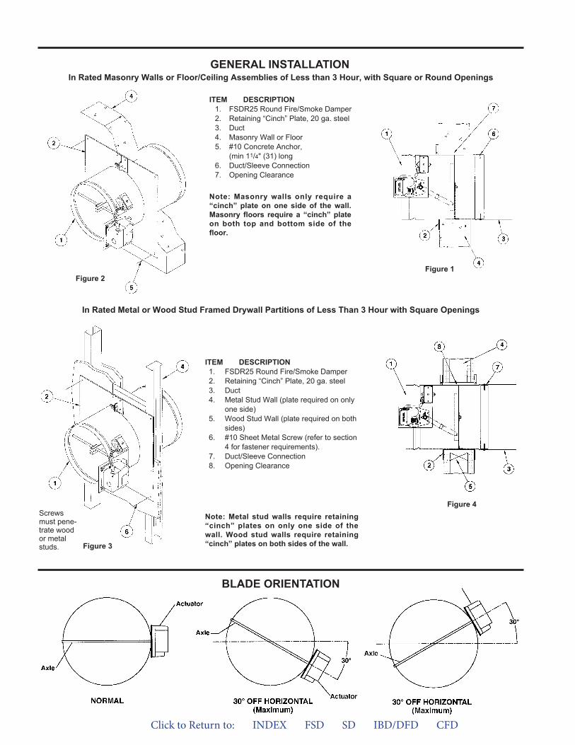
In Rated Metal or Wood Stud Framed Drywall Partitions of Less Than 3 Hour with Square Openings
In Rated Masonry Walls or Floor/Ceiling Assemblies of Less than 3 Hour, with Square or Round Openings
ITEM DESCRIPTION1. FSDR25 Round Fire/Smoke Damper2. Retaining “Cinch” Plate, 20 ga. steel3. Duct4. Masonry Wall or Floor5. #10 Concrete Anchor,
(min 11/4" (31) long6. Duct/Sleeve Connection7. Opening Clearance
ITEM DESCRIPTION1. FSDR25 Round Fire/Smoke Damper2. Retaining “Cinch” Plate, 20 ga. steel3. Duct4. Metal Stud Wall (plate required on only
one side)5. Wood Stud Wall (plate required on both
sides)6. #10 Sheet Metal Screw (refer to section
4 for fastener requirements).7. Duct/Sleeve Connection8. Opening Clearance
Figure 2Figure 1
Figure 3
Figure 4
GENERAL INSTALLATION
Note: Metal stud walls require retaining“cinch” plates on only one side of thewall. Wood stud walls require retaining“cinch” plates on both sides of the wall.
Screwsmust pene-trate woodor metalstuds.
Note: Masonry walls only require a“cinch” plate on one side of the wall.Masonry floors require a “cinch” plateon both top and bottom side of thefloor.
BLADE ORIENTATION
Click to Return to: INDEX FSD SD IBD/DFD CFD
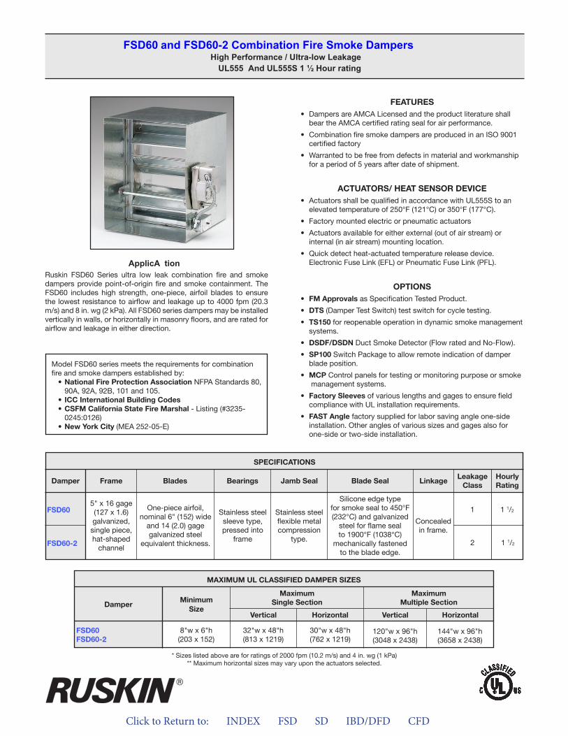
Click to Return to: INDEX FSD SD IBD/DFD CFD
ApplicA tionRuskin FSD60 Series ultra low leak combination fire and smoke dampers provide point-of-origin fire and smoke containment. The FSD60 includes high strength, one-piece, airfoil blades to ensure the lowest resistance to airflow and leakage up to 4000 fpm (20.3 m/s) and 8 in. wg (2 kPa). All FSD60 series dampers may be installed vertically in walls, or horizontally in masonry floors, and are rated for airflow and leakage in either direction.
FEATURES• Dampers are AMCA Licensed and the product literature shall
bear the AMCA certified rating seal for air performance.
• Combination fire smoke dampers are produced in an ISO 9001certified factory
• Warranted to be free from defects in material and workmanshipfor a period of 5 years after date of shipment.
ACTUATORS/ HEAT SENSOR DEVICE• Actuators shall be qualified in accordance with UL555S to an
elevated temperature of 250°F (121°C) or 350°F (177°C).
• Factory mounted electric or pneumatic actuators
• Actuators available for either external (out of air stream) orinternal (in air stream) mounting location.
• Quick detect heat-actuated temperature release device.Electronic Fuse Link (EFL) or Pneumatic Fuse Link (PFL).
OPTIONS• FM Approvals as Specification Tested Product.
• DTS (Damper Test Switch) test switch for cycle testing.
• TS150 for reopenable operation in dynamic smoke managementsystems.
• DSDF/DSDN Duct Smoke Detector (Flow rated and No-Flow).
• SP100 Switch Package to allow remote indication of damperblade position.
• MCP Control panels for testing or monitoring purpose or smokemanagement systems.
• Factory Sleeves of various lengths and gages to ensure fieldcompliance with UL installation requirements.
• FAST Angle factory supplied for labor saving angle one-sideinstallation. Other angles of various sizes and gages also forone-side or two-side installation.
FSD60 and FSD60-2 Combination Fire Smoke DampersHigh Performance / Ultra-low Leakage
UL555 And UL555S 1 ½ Hour rating
Model FSD60 series meets the requirements for combination fire and smoke dampers established by:
• National Fire Protection Association NFPA Standards 80, 90A, 92A, 92B, 101 and 105.
• ICC International Building Codes• CSFM California State Fire Marshal - Listing (#3235-
0245:0126)• New York City (MEA 252-05-E)
FSD60
FSD60-2
SPECIFICATIONS
Frame Blades Bearings Jamb Seal Blade Seal LinkageLeakage
ClassHourlyRating
Damper
5" x 16 gage (127 x 1.6)galvanized,single piece,hat-shaped
channel
One-piece airfoil,nominal 6" (152) wide
and 14 (2.0) gagegalvanized steel
equivalent thickness.
Stainless steelsleeve type,pressed into
frame
Stainless steelflexible metalcompression
type.
Silicone edge typefor smoke seal to 450°F (232°C) and galvanized
steel for flame seal to 1900°F (1038°C)
mechanically fastenedto the blade edge.
Concealedin frame.
1 1 1/2
2 1 1/2
* Sizes listed above are for ratings of 2000 fpm (10.2 m/s) and 4 in. wg (1 kPa)** Maximum horizontal sizes may vary upon the actuators selected.
MAXIMUM UL CLASSIFIED DAMPER SIZES
Damper
FSD60FSD60-2
MinimumSize
MaximumSingle Section
MaximumMultiple Section
Vertical VerticalHorizontal Horizontal
8"w x 6"h(203 x 152)
32"w x 48"h(813 x 1219)
30"w x 48"h(762 x 1219)
120"w x 96"h(3048 x 2438)
144"w x 96"h(3658 x 2438)
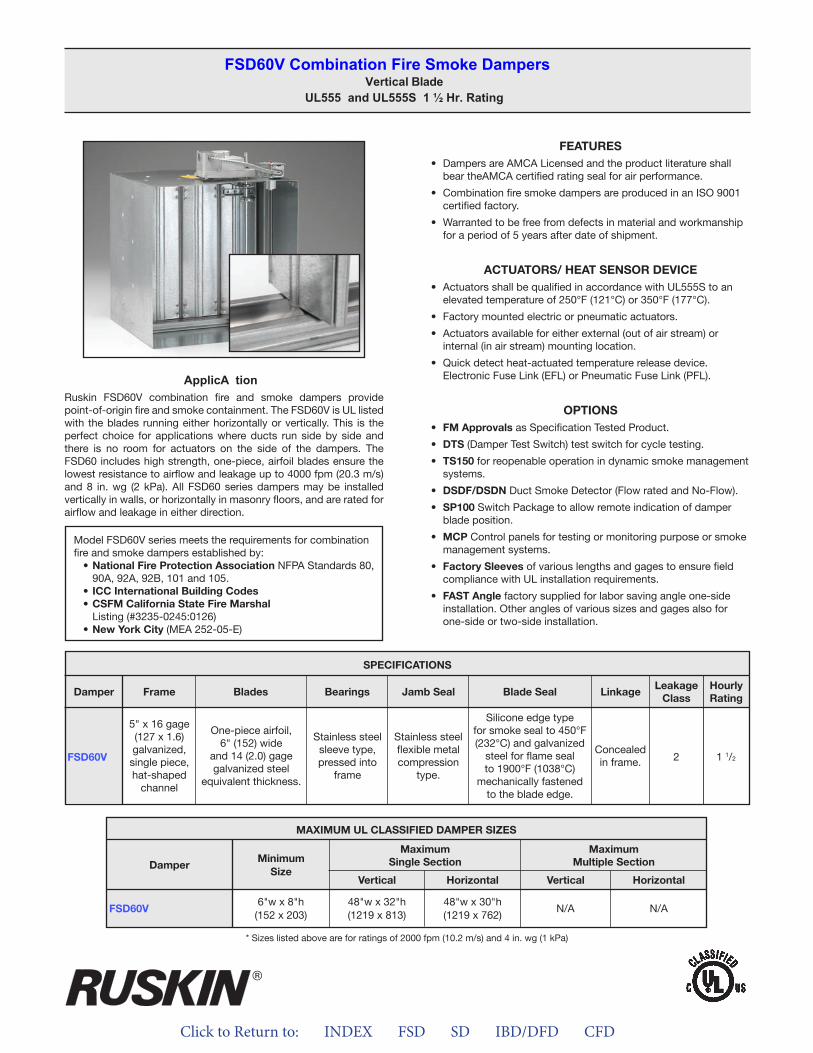
Click to Return to: INDEX FSD SD IBD/DFD CFD
ApplicA tionRuskin FSD60V combination fire and smoke dampers provide point-of-origin fire and smoke containment. The FSD60V is UL listed with the blades running either horizontally or vertically. This is the perfect choice for applications where ducts run side by side and there is no room for actuators on the side of the dampers. The FSD60 includes high strength, one-piece, airfoil blades ensure the lowest resistance to airflow and leakage up to 4000 fpm (20.3 m/s) and 8 in. wg (2 kPa). All FSD60 series dampers may be installed vertically in walls, or horizontally in masonry floors, and are rated for airflow and leakage in either direction.
FEATURES• Dampers are AMCA Licensed and the product literature shall
bear theAMCA certified rating seal for air performance.
• Combination fire smoke dampers are produced in an ISO 9001certified factory.
• Warranted to be free from defects in material and workmanshipfor a period of 5 years after date of shipment.
ACTUATORS/ HEAT SENSOR DEVICE• Actuators shall be qualified in accordance with UL555S to an
elevated temperature of 250°F (121°C) or 350°F (177°C).
• Factory mounted electric or pneumatic actuators.
• Actuators available for either external (out of air stream) orinternal (in air stream) mounting location.
• Quick detect heat-actuated temperature release device.Electronic Fuse Link (EFL) or Pneumatic Fuse Link (PFL).
OPTIONS• FM Approvals as Specification Tested Product.
• DTS (Damper Test Switch) test switch for cycle testing.
• TS150 for reopenable operation in dynamic smoke managementsystems.
• DSDF/DSDN Duct Smoke Detector (Flow rated and No-Flow).
• SP100 Switch Package to allow remote indication of damperblade position.
• MCP Control panels for testing or monitoring purpose or smokemanagement systems.
• Factory Sleeves of various lengths and gages to ensure fieldcompliance with UL installation requirements.
• FAST Angle factory supplied for labor saving angle one-sideinstallation. Other angles of various sizes and gages also forone-side or two-side installation.
FSD60V Combination Fire Smoke DampersVertical Blade
UL555 and UL555S 1 ½ Hr. Rating
Model FSD60V series meets the requirements for combination fire and smoke dampers established by:
• National Fire Protection Association NFPA Standards 80, 90A, 92A, 92B, 101 and 105.
• ICC International Building Codes• CSFM California State Fire Marshal
Listing (#3235-0245:0126)• New York City (MEA 252-05-E)
* Sizes listed above are for ratings of 2000 fpm (10.2 m/s) and 4 in. wg (1 kPa)
MAXIMUM UL CLASSIFIED DAMPER SIZES
Damper
FSD60V
MinimumSize
MaximumSingle Section
MaximumMultiple Section
Vertical VerticalHorizontal Horizontal
6"w x 8"h(152 x 203)
48"w x 32"h(1219 x 813)
48"w x 30"h(1219 x 762)
N/A N/A
FSD60V
SPECIFICATIONS
Frame Blades Bearings Jamb Seal Blade Seal LinkageLeakage
ClassHourlyRating
Damper
5" x 16 gage (127 x 1.6)galvanized,single piece,hat-shaped
channel
One-piece airfoil,6" (152) wide
and 14 (2.0) gagegalvanized steel
equivalent thickness.
Stainless steelsleeve type,pressed into
frame
Stainless steelflexible metalcompression
type.
Silicone edge typefor smoke seal to 450°F (232°C) and galvanized
steel for flame seal to 1900°F (1038°C)
mechanically fastenedto the blade edge.
Concealedin frame. 2 1 1/2
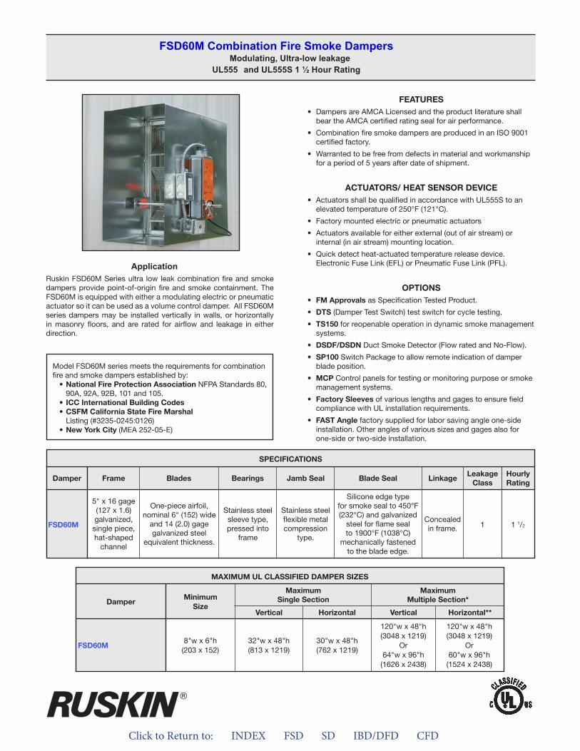
Click to Return to: INDEX FSD SD IBD/DFD CFD
ApplicationRuskin FSD60M Series ultra low leak combination fire and smoke dampers provide point-of-origin fire and smoke containment. The FSD60M is equipped with either a modulating electric or pneumatic actuator so it can be used as a volume control damper. All FSD60M series dampers may be installed vertically in walls, or horizontally in masonry floors, and are rated for airflow and leakage in either direction.
FEATURES• Dampers are AMCA Licensed and the product literature shall
bear the AMCA certified rating seal for air performance.
• Combination fire smoke dampers are produced in an ISO 9001certified factory.
• Warranted to be free from defects in material and workmanshipfor a period of 5 years after date of shipment.
ACTUATORS/ HEAT SENSOR DEVICE• Actuators shall be qualified in accordance with UL555S to an
elevated temperature of 250°F (121°C).
• Factory mounted electric or pneumatic actuators
• Actuators available for either external (out of air stream) orinternal (in air stream) mounting location.
• Quick detect heat-actuated temperature release device.Electronic Fuse Link (EFL) or Pneumatic Fuse Link (PFL).
OPTIONS• FM Approvals as Specification Tested Product.
• DTS (Damper Test Switch) test switch for cycle testing.
• TS150 for reopenable operation in dynamic smoke managementsystems.
• DSDF/DSDN Duct Smoke Detector (Flow rated and No-Flow).
• SP100 Switch Package to allow remote indication of damperblade position.
• MCP Control panels for testing or monitoring purpose or smokemanagement systems.
• Factory Sleeves of various lengths and gages to ensure fieldcompliance with UL installation requirements.
• FAST Angle factory supplied for labor saving angle one-sideinstallation. Other angles of various sizes and gages also forone-side or two-side installation.
FSD60M Combination Fire Smoke DampersModulating, Ultra-low leakage
UL555 and UL555S 1 ½ Hour Rating
Model FSD60M series meets the requirements for combination fire and smoke dampers established by:
• National Fire Protection Association NFPA Standards 80, 90A, 92A, 92B, 101 and 105.
• ICC International Building Codes• CSFM California State Fire Marshal
Listing (#3235-0245:0126)• New York City (MEA 252-05-E)
FSD60M
SPECIFICATIONS
Frame Blades Bearings Jamb Seal Blade Seal LinkageLeakage
ClassHourlyRating
Damper
5" x 16 gage (127 x 1.6)galvanized,single piece,hat-shaped
channel
One-piece airfoil,nominal 6" (152) wide
and 14 (2.0) gagegalvanized steel
equivalent thickness.
Stainless steelsleeve type,pressed into
frame
Stainless steelflexible metalcompression
type.
Silicone edge typefor smoke seal to 450°F (232°C) and galvanized
steel for flame seal to 1900°F (1038°C)
mechanically fastenedto the blade edge.
Concealedin frame. 1 1 1/2
MAXIMUM UL CLASSIFIED DAMPER SIZES
Damper
FSD60M
MinimumSize
MaximumSingle Section
MaximumMultiple Section*
Vertical VerticalHorizontal Horizontal**
8"w x 6"h(203 x 152)
32"w x 48"h(813 x 1219)
30"w x 48"h(762 x 1219)
120"w x 48"h(3048 x 1219)
Or64"w x 96"h
(1626 x 2438)
120"w x 48"h(3048 x 1219)
Or60"w x 96"h
(1524 x 2438)

Click to Return to: INDEX FSD SD IBD/DFD CFD
ApplicationRuskin FSD60-BAL series ultra low leak combination fire and smoke dampers provide point-of-origin fire and smoke containment. The FSD60-BAL is equipped with a 24VAC/VDC actuator with built in potentiometer that allows the damper to open to numerous positions and still drive full open for smoke control purposes. All FSD60-BAL series dampers may be installed vertically in walls, or horizontally in masonry floors, and are rated for airflow and leakage in either direction.
FEATURES• Dampers are AMCA Licensed and the product literature shall
bear the AMCA certified rating seal for air performance.
• Combination fire smoke dampers are produced in an ISO 9001certified factory.
• Warranted to be free from defects in material and workmanshipfor a period of 5 years after date of shipment.
ACTUATORS/ HEAT SENSOR DEVICE• Actuators shall be qualified in accordance with UL555S to an
elevated temperature of 250°F (121°C).
• Actuators available for either external (out of air stream) orinternal (in air stream) mounting location.
• Quick detect heat-actuated temperature release device.Electronic Fuse Link (EFL) or Pneumatic Fuse Link (PFL).
OPTIONS• FM Approvals as Specification Tested Product.
• DTS (Damper Test Switch) test switch for cycle testing.
• TS150 for reopenable operation in dynamic smoke managementsystems.
• DSDF/DSDN Duct Smoke Detector (Flow rated and No-Flow).
• SP100 Switch Package to allow remote indication of damperblade position.
• MCP Control panels for testing or monitoring purpose or smokemanagement systems.
• Factory Sleeves of various lengths and gages to ensure fieldcompliance with UL installation requirements.
• FAST Angle factory supplied for labor saving angle one-sideinstallation. Other angles of various sizes and gages also forone-side or two-side installation.
FSD60-BAl Combination Fire Smoke DampersBallancing, Ultra-low Leakage
UL555 and UL555S 1 ½ Hr.
Model FSD60-BAL series meets the requirements for combina-tion fire and smoke dampers established by:
• National Fire Protection Association NFPA Standards 80,90A, 92A, 92B, 101 and 105.
• ICC International Building Codes• CSFM California State Fire Marshal
Listing (#3235-0245:0126)• New York City (MEA 252-05-E)
FSD60-BAL
SPECIFICATIONS
Frame Blades Bearings Jamb Seal Blade Seal LinkageLeakage
ClassHourlyRating
Damper
5" x 16 gage (127 x 1.6)galvanized,single piece,hat-shaped
channel
One-piece airfoil,nominal 6" (152) wide
and 14 (2.0) gagegalvanized steel
equivalent thickness.
Stainless steelsleeve type,pressed into
frame
Stainless steelflexible metalcompression
type.
Silicone edge typefor smoke seal to 450°F (232°C) and galvanized
steel for flame seal to 1900°F (1038°C)
mechanically fastenedto the blade edge.
Concealedin frame. 1 1 1/2
MAXIMUM UL CLASSIFIED DAMPER SIZES
Damper
FSD60-BAL
MinimumSize
MaximumSingle Section
MaximumMultiple Section*
Vertical VerticalHorizontal Horizontal**
8"w x 6"h(203 x 152)
32"w x 48"h(813 x 1219)
30"w x 48"h(762 x 1219)
N/A N/A
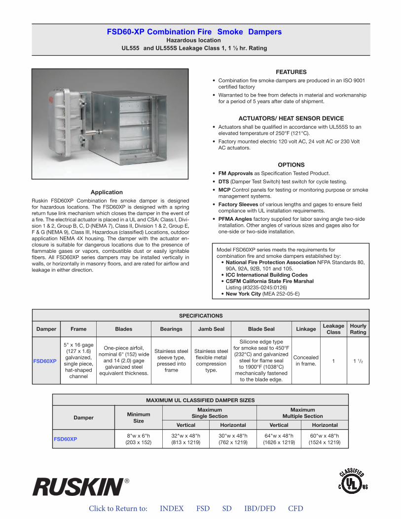
Click to Return to: INDEX FSD SD IBD/DFD CFD
ApplicationRuskin FSD60XP Combination fire smoke damper is designed for hazardous locations. The FSD60XP is designed with a spring return fuse link mechanism which closes the damper in the event of a fire. The electrical actuator is placed in a UL and CSA: Class I, Divi-sion 1 & 2, Group B, C, D (NEMA 7), Class II, Division 1 & 2, Group E, F & G (NEMA 9), Class III, Hazardous (classified) Locations, outdoor application NEMA 4X housing. The damper with the actuator en- closure is suitable for dangerous locations due to the presence of flammable gases or vapors, combustible dust or easily ignitable fibers. All FSD60XP series dampers may be installed vertically in walls, or horizontally in masonry floors, and are rated for airflow and leakage in either direction.
FEATURES• Combination fire smoke dampers are produced in an ISO 9001
certified factory
• Warranted to be free from defects in material and workmanshipfor a period of 5 years after date of shipment.
ACTUATORS/ HEAT SENSOR DEVICE• Actuators shall be qualified in accordance with UL555S to an
elevated temperature of 250°F (121°C).
• Factory mounted electric 120 volt AC, 24 volt AC or 230 VoltAC actuators.
OPTIONS• FM Approvals as Specification Tested Product.
• DTS (Damper Test Switch) test switch for cycle testing.
• MCP Control panels for testing or monitoring purpose or smokemanagement systems.
• Factory Sleeves of various lengths and gages to ensure fieldcompliance with UL installation requirements.
• PFMA Angles factory supplied for labor saving angle two-sideinstallation. Other angles of various sizes and gages also forone-side or two-side installation.
FSD60-XP Combination Fire Smoke DampersHazardous location
UL555 and UL555S Leakage Class 1, 1 ½ hr. Rating
Model FSD60XP series meets the requirements for combination fire and smoke dampers established by:
• National Fire Protection Association NFPA Standards 80, 90A, 92A, 92B, 101 and 105.
• ICC International Building Codes• CSFM California State Fire Marshal
Listing (#3235-0245:0126)• New York City (MEA 252-05-E)
MAXIMUM UL CLASSIFIED DAMPER SIZES
Damper
FSD60XP
MinimumSize
MaximumSingle Section
MaximumMultiple Section
Vertical VerticalHorizontal Horizontal
8"w x 6"h(203 x 152)
32"w x 48"h(813 x 1219)
30"w x 48"h(762 x 1219)
64"w x 48"h(1626 x 1219)
60"w x 48"h(1524 x 1219)
FSD60XP
SPECIFICATIONS
Frame Blades Bearings Jamb Seal Blade Seal LinkageLeakage
ClassHourlyRating
Damper
5" x 16 gage (127 x 1.6)galvanized,single piece,hat-shaped
channel
One-piece airfoil,nominal 6" (152) wide
and 14 (2.0) gagegalvanized steel
equivalent thickness.
Stainless steelsleeve type,pressed into
frame
Stainless steelflexible metalcompression
type.
Silicone edge typefor smoke seal to 450°F (232°C) and galvanized
steel for flame seal to 1900°F (1038°C)
mechanically fastenedto the blade edge.
Concealedin frame. 1 1 1/2
ALL STATED SPECIFICATIONS ARE SUBJECT TO CHANGE WITHOUT NOTICE OR OBLIGATION.
3900 Dr. Greaves Rd. • Kansas City, MO 64030 • (816) 761-7476 • FAX (816) 765-8955
INSTALLATION INSTRUCTIONSFSD60, FSD60-2, FSD60-V, FSD60XP, FSD60M AND FSD60-BAL
COMBINATION FIRE AND SMOKE DAMPERS11/2 HOUR UL555 RATED UL555S LEAKAGE CLASS 1 AND 2 RATED
II-FSD60-514/ Replaces II-FSD60-114 © Ruskin 2014
®
INSTALLATION SUPPLEMENTSRefer to the appropriate Ruskin installation instructions supple-ments for additional information or special requirements:• Optional Sealant of Dampers in Fire Rated Wall or Floor Openings• Transfer Openings and Duct Terminations• Optional FireStop Material• Extension of Fire and Combination Fire and Smoke Damper
Sleeves• Fire and Combination Fire and Smoke Damper Installation in
Concrete Floor with Steel Deck• Drivemate No. 14880 Breakaway Connection• Flanged System Breakaway Connections• Cavity Shaft Wall Metal Stud Framing• TS150 FireStat for "Reopenable" Combination Fire and Smoke
Dampers• SP100 Switch Package• EFL Electric Resettable "Fuse" Link• EFL/SP100 Electric Resettable "Fuse" Link• PFL Pneumatic Fuse Link• DSDF Flow Rated Duct Smoke Detector• DSDN No-Flow Rated Duct Smoke Detector
APPLICATIONThe FSD60 series combination fire and smoke dampers designedto restrict the passage of flame and resist the passage of smoke.The FSD60, 60-2, 60C, 60M, 60-BAL and 60XP are designed forinstallation with the blades running horizontally while the FSD60-Vis designed for installation with the blades running vertically. Thestandard installation for all models is with the leading edge of theclosed blades within the wall, partitions, or masonry floors with rat-ings of less than 3 hours. For out of the wall or grille access installa-tions refer to the GA and OW versions of the FSD60 and FSD60-2.
FSD60 and FSD60-2 MAXIMUM UL CLASSIFIED SIZES –OPPOSED BLADE
Single section vertical – 32"w x 48"h (813 x 1219).Single section horizontal – 30"w x 48"h (762 x 1219).Multiple sections vertical – 120"w x 96"h (3048 x 2438).Multiple sections horizontal – 144"w x 96"h (3658 x 2438).
FSD60M MAXIMUM UL CLASSIFIED SIZES –OPPOSED BLADE
Single section vertical – 32"w x 48"h (813 x 1219).Single section horizontal – 30"w x 48"h (762 x 1219).Multiple sections vertical – 120"w x 48"h (3048 x 1219).Multiple sections horizontal – 120"w x 48"h (3048 x 1219) or
60”w x 96”h (1524 x 2438).
FSD60-BAL MAXIMUM UL CLASSIFIED SIZES –OPPOSED BLADE
Single section vertical – 32"w x 48"h (813 x 1219).Single section horizontal – 30"w x 48"h (762 x 1219).
FSD60-V MAXIMUM UL CLASSIFIED SIZES –OPPOSED BLADE
Single section vertical – 48"w x 32"h (1219 x 813)
FSD60XP MAXIMUM UL CLASSIFIED SIZES –OPPOSED BLADE
Single section vertical – 32"w x 48"h (813 x 1219).Single section horizontal – 30"w x 48"h (762 x 1219).Multiple sections vertical – 64"w x 48"h (1626 x 1219).Multiple sections horizontal – 60"w x 48"h (1529 x 1219).
Dimensions shown in parentheses ( ) indicate millimeters.
California State Fire Marshal Listing No.FSD60, 60-2, 60M, 60-BAL, 60V and 60XP – 3235-0245:0126 NYC Department Of Building MEA 252-05-E
SEE COMPLETE MARKING ON PRODUCT
Click to Return to: INDEX FSD SD IBD/DFD CFD
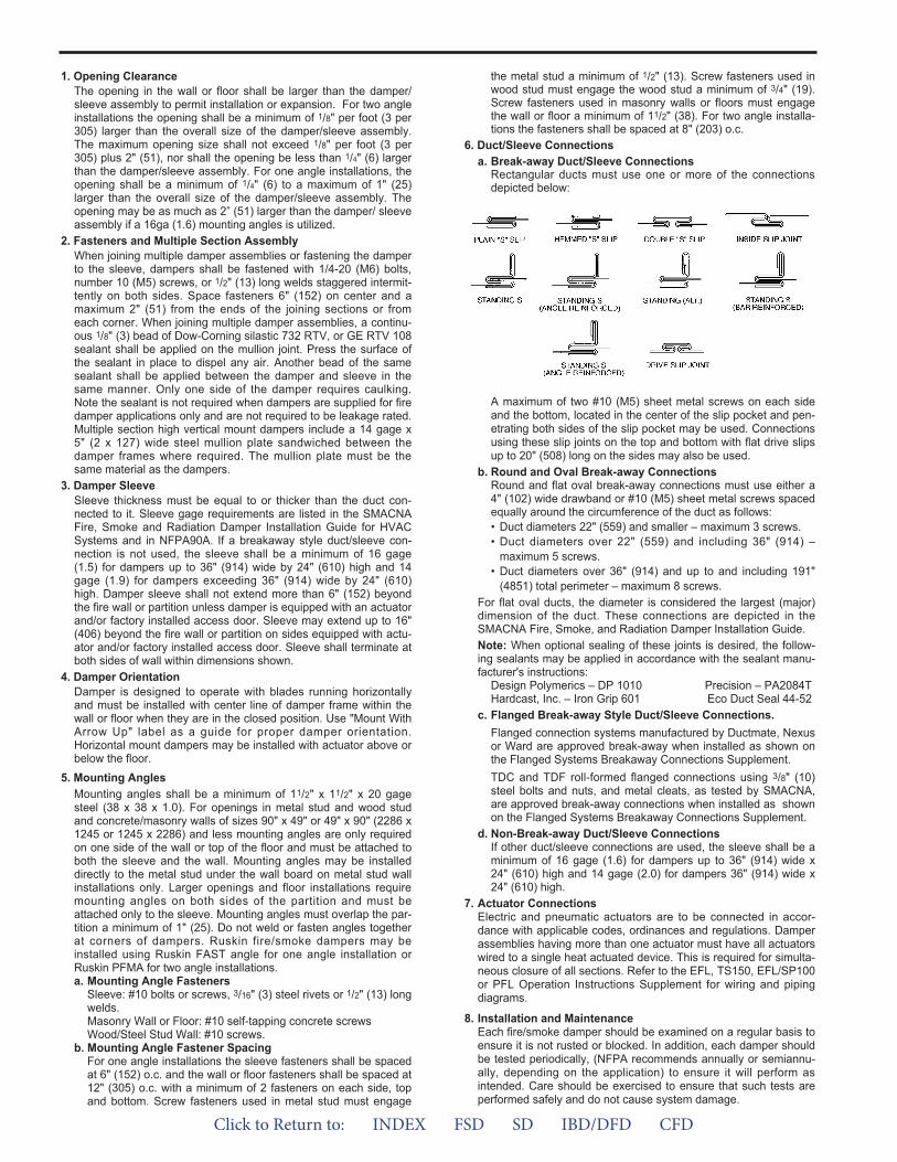
1. Opening ClearanceThe opening in the wall or floor shall be larger than the damper/sleeve assembly to permit installation or expansion. For two angleinstallations the opening shall be a minimum of 1/8" per foot (3 per305) larger than the overall size of the damper/sleeve assembly.The maximum opening size shall not exceed 1/8" per foot (3 per305) plus 2" (51), nor shall the opening be less than 1/4" (6) largerthan the damper/sleeve assembly. For one angle installations, theopening shall be a minimum of 1/4" (6) to a maximum of 1" (25)larger than the overall size of the damper/sleeve assembly. Theopening may be as much as 2” (51) larger than the damper/ sleeveassembly if a 16ga (1.6) mounting angles is utilized.
2. Fasteners and Multiple Section AssemblyWhen joining multiple damper assemblies or fastening the damperto the sleeve, dampers shall be fastened with 1/4-20 (M6) bolts,number 10 (M5) screws, or 1/2" (13) long welds staggered intermit-tently on both sides. Space fasteners 6" (152) on center and amaximum 2" (51) from the ends of the joining sections or fromeach corner. When joining multiple damper assemblies, a continu-ous 1/8" (3) bead of Dow-Corning silastic 732 RTV, or GE RTV 108sealant shall be applied on the mullion joint. Press the surface ofthe sealant in place to dispel any air. Another bead of the samesealant shall be applied between the damper and sleeve in thesame manner. Only one side of the damper requires caulking.Note the sealant is not required when dampers are supplied for firedamper applications only and are not required to be leakage rated.Multiple section high vertical mount dampers include a 14 gage x5" (2 x 127) wide steel mullion plate sandwiched between thedamper frames where required. The mullion plate must be thesame material as the dampers.
3. Damper SleeveSleeve thickness must be equal to or thicker than the duct con-nected to it. Sleeve gage requirements are listed in the SMACNAFire, Smoke and Radiation Damper Installation Guide for HVACSystems and in NFPA90A. If a breakaway style duct/sleeve con-nection is not used, the sleeve shall be a minimum of 16 gage(1.5) for dampers up to 36" (914) wide by 24" (610) high and 14gage (1.9) for dampers exceeding 36" (914) wide by 24" (610)high. Damper sleeve shall not extend more than 6" (152) beyondthe fire wall or partition unless damper is equipped with an actuatorand/or factory installed access door. Sleeve may extend up to 16"(406) beyond the fire wall or partition on sides equipped with actu-ator and/or factory installed access door. Sleeve shall terminate atboth sides of wall within dimensions shown.
4. Damper OrientationDamper is designed to operate with blades running horizontallyand must be installed with center line of damper frame within thewall or floor when they are in the closed position. Use "Mount WithArrow Up" label as a guide for proper damper orientation.Horizontal mount dampers may be installed with actuator above orbelow the floor.
5. Mounting AnglesMounting angles shall be a minimum of 11/2" x 11/2" x 20 gagesteel (38 x 38 x 1.0). For openings in metal stud and wood studand concrete/masonry walls of sizes 90" x 49" or 49" x 90" (2286 x1245 or 1245 x 2286) and less mounting angles are only requiredon one side of the wall or top of the floor and must be attached toboth the sleeve and the wall. Mounting angles may be installeddirectly to the metal stud under the wall board on metal stud wallinstallations only. Larger openings and floor installations requiremounting angles on both sides of the partition and must beattached only to the sleeve. Mounting angles must overlap the par-tition a minimum of 1" (25). Do not weld or fasten angles togetherat corners of dampers. Ruskin fire/smoke dampers may beinstalled using Ruskin FAST angle for one angle installation orRuskin PFMA for two angle installations.a. Mounting Angle Fasteners
Sleeve: #10 bolts or screws, 3/16" (3) steel rivets or 1/2" (13) longwelds.Masonry Wall or Floor: #10 self-tapping concrete screwsWood/Steel Stud Wall: #10 screws.
b. Mounting Angle Fastener SpacingFor one angle installations the sleeve fasteners shall be spacedat 6" (152) o.c. and the wall or floor fasteners shall be spaced at12" (305) o.c. with a minimum of 2 fasteners on each side, topand bottom. Screw fasteners used in metal stud must engage
the metal stud a minimum of 1/2" (13). Screw fasteners used inwood stud must engage the wood stud a minimum of 3/4" (19).Screw fasteners used in masonry walls or floors must engagethe wall or floor a minimum of 11/2" (38). For two angle installa-tions the fasteners shall be spaced at 8" (203) o.c.
6. Duct/Sleeve Connectionsa. Break-away Duct/Sleeve Connections
Rectangular ducts must use one or more of the connectionsdepicted below:
A maximum of two #10 (M5) sheet metal screws on each sideand the bottom, located in the center of the slip pocket and pen-etrating both sides of the slip pocket may be used. Connectionsusing these slip joints on the top and bottom with flat drive slipsup to 20" (508) long on the sides may also be used.
b. Round and Oval Break-away ConnectionsRound and flat oval break-away connections must use either a4" (102) wide drawband or #10 (M5) sheet metal screws spacedequally around the circumference of the duct as follows:• Duct diameters 22" (559) and smaller – maximum 3 screws.• Duct diameters over 22" (559) and including 36" (914) –
maximum 5 screws.• Duct diameters over 36" (914) and up to and including 191"
(4851) total perimeter – maximum 8 screws.For flat oval ducts, the diameter is considered the largest (major)dimension of the duct. These connections are depicted in theSMACNA Fire, Smoke, and Radiation Damper Installation Guide.Note: When optional sealing of these joints is desired, the follow-ing sealants may be applied in accordance with the sealant manu-facturer's instructions:
Design Polymerics – DP 1010 Precision – PA2084THardcast, Inc. – Iron Grip 601 Eco Duct Seal 44-52
c. Flanged Break-away Style Duct/Sleeve Connections.Flanged connection systems manufactured by Ductmate, Nexusor Ward are approved break-away when installed as shown onthe Flanged Systems Breakaway Connections Supplement.TDC and TDF roll-formed flanged connections using 3/8" (10)steel bolts and nuts, and metal cleats, as tested by SMACNA,are approved break-away connections when installed as shownon the Flanged Systems Breakaway Connections Supplement.
d. Non-Break-away Duct/Sleeve ConnectionsIf other duct/sleeve connections are used, the sleeve shall be aminimum of 16 gage (1.6) for dampers up to 36" (914) wide x24" (610) high and 14 gage (2.0) for dampers 36" (914) wide x24" (610) high.
7. Actuator ConnectionsElectric and pneumatic actuators are to be connected in accor-dance with applicable codes, ordinances and regulations. Damperassemblies having more than one actuator must have all actuatorswired to a single heat actuated device. This is required for simulta-neous closure of all sections. Refer to the EFL, TS150, EFL/SP100or PFL Operation Instructions Supplement for wiring and pipingdiagrams.
8. Installation and MaintenanceEach fire/smoke damper should be examined on a regular basis toensure it is not rusted or blocked. In addition, each damper shouldbe tested periodically, (NFPA recommends annually or semiannu-ally, depending on the application) to ensure it will perform asintended. Care should be exercised to ensure that such tests areperformed safely and do not cause system damage.
Click to Return to: INDEX FSD SD IBD/DFD CFD
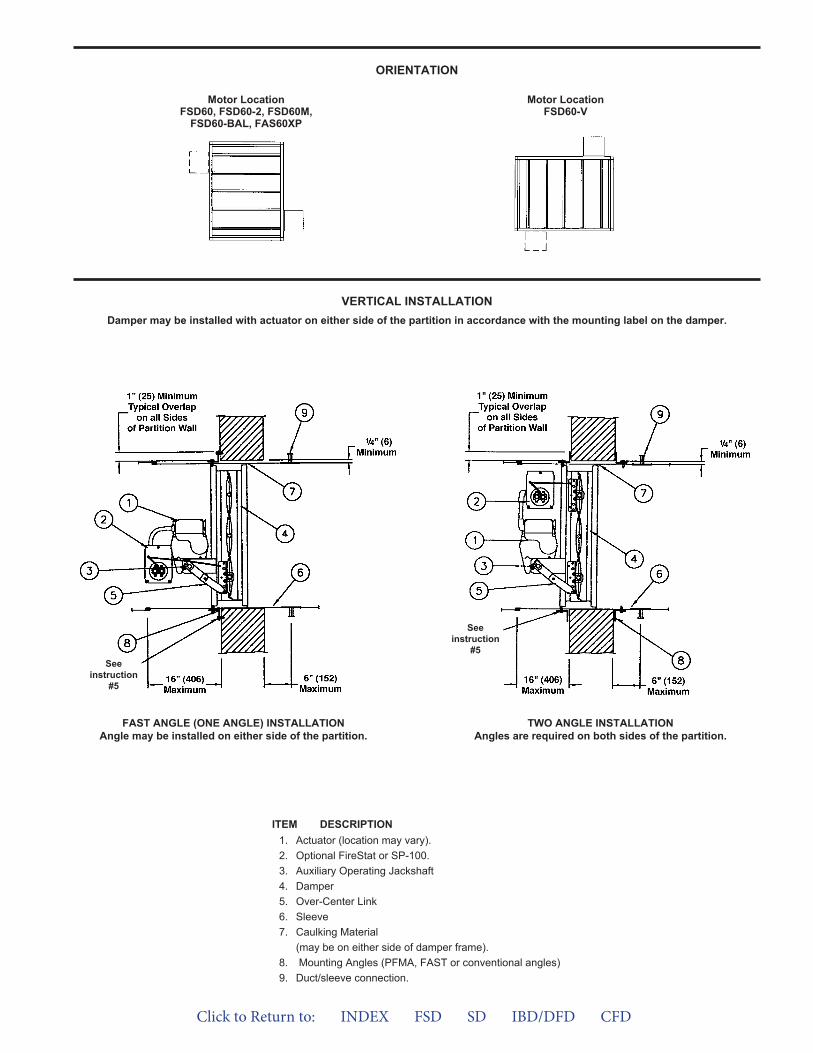
ORIENTATION
VERTICAL INSTALLATIONDamper may be installed with actuator on either side of the partition in accordance with the mounting label on the damper.
FAST ANGLE (ONE ANGLE) INSTALLATIONAngle may be installed on either side of the partition.
TWO ANGLE INSTALLATIONAngles are required on both sides of the partition.
ITEM DESCRIPTION1. Actuator (location may vary).2. Optional FireStat or SP-100.3. Auxiliary Operating Jackshaft4. Damper5. Over-Center Link6. Sleeve7. Caulking Material
(may be on either side of damper frame).8. Mounting Angles (PFMA, FAST or conventional angles)9. Duct/sleeve connection.
Motor LocationFSD60, FSD60-2, FSD60M,
FSD60-BAL, FAS60XP
Motor LocationFSD60-V
Seeinstruction
#5See
instruction#5
Click to Return to: INDEX FSD SD IBD/DFD CFD
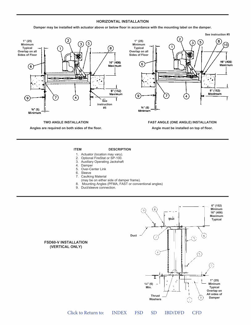
TWO ANGLE INSTALLATION
Angles are required on both sides of the floor.
FAST ANGLE (ONE ANGLE) INSTALLATION
Angle must be installed on top of floor.
ITEM DESCRIPTION1. Actuator (location may vary).2. Optional FireStat or SP-100.3. Auxiliary Operating Jackshaft4. Damper5. Over-Center Link6. Sleeve7. Caulking Material
(may be on either side of damper frame).8. Mounting Angles (PFMA, FAST or conventional angles)9. Duct/sleeve connection.
1” (25)MinimumTypical
Overlap on allSides of Floor
1” (25)MinimumTypical
Overlap on allSides of Floor
HORIZONTAL INSTALLATIONDamper may be installed with actuator above or below floor in accordance with the mounting label on the damper.
Seeinstruction
#5
See instruction #5
FSD60-V INSTALLATION(VERTICAL ONLY)
ThrustWashers
1/4" (6)Min.
Duct
6" (152)Mininum16" (406)Maximum
Typical
1" (25)MininumTypical
Overlap onAll sides of
Damper
Wall
Click to Return to: INDEX FSD SD IBD/DFD CFD
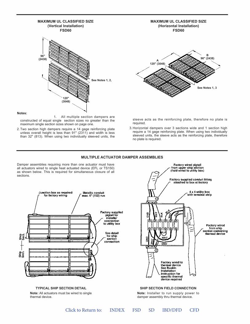
96"(2438)
B96" (2438)
120"(3048)
MAXIMUM UL CLASSIFIED SIZE(Vertical Installation)
FSD60
MAXIMUM UL CLASSIFIED SIZE(Horizontal Installation)
FSD60
See Notes 1, 2,
See Notes 1, 3
A120" (3048)
1. All multiple section dampers areconstructed of equal single section sizes no greater than themaximum single section sizes shown on page one.
2. Two section high dampers require a 14 gage reinforcing plateunless overall height is less than 91" (2311) and width is lessthan 32" (813). When using two individually sleeved units, the
sleeve acts as the reinforcing plate, therefore no plate isrequired.
3. Horizontal dampers over 3 sections wide and 1 section highrequire a 14 gage reinforcing plate. When using two individuallysleeved units, the sleeve acts as the reinforcing plate, thereforeno plate is required.
Notes:
MULTIPLE ACTUATOR DAMPER ASSEMBLIES
Damper assemblies requiring more than one actuator must haveall actuators wired to single heat actuated device (EFL or TS150)as shown below. This is required for simultaneous closure of allsections.
TYPICAL SHIP SECTION DETAILNote: All actuators must be wired to singlethermal device.
SHIP SECTION FIELD CONNECTIONNote: Installer to run supply power todamper assembly thru thermal device.
Click to Return to: INDEX FSD SD IBD/DFD CFD
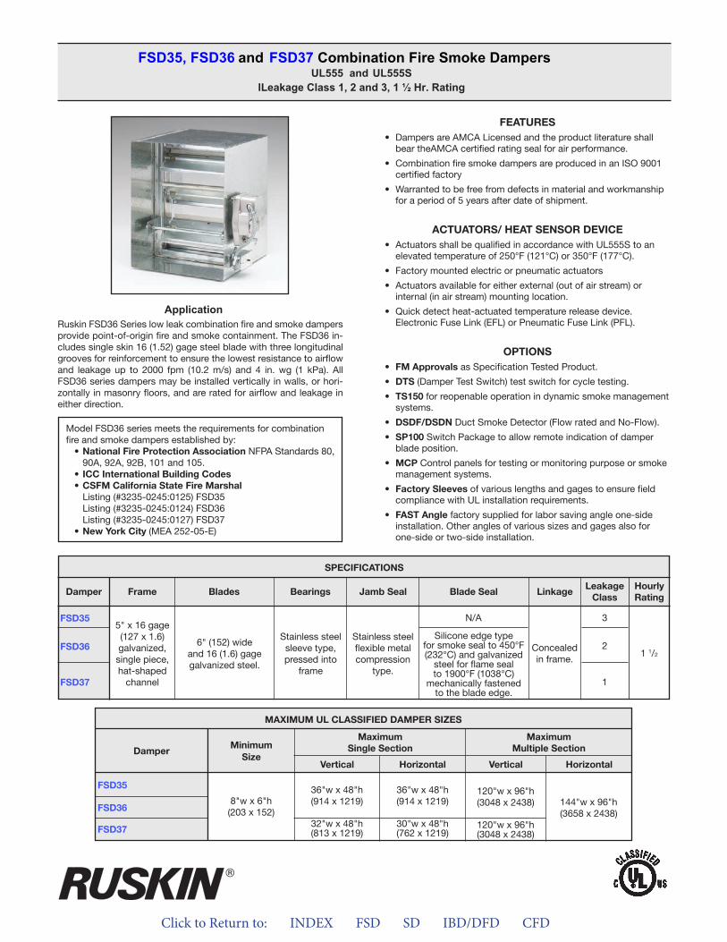
Click to Return to: INDEX FSD SD IBD/DFD CFD
ApplicationRuskin FSD36 Series low leak combination fire and smoke dampers provide point-of-origin fire and smoke containment. The FSD36 in-cludes single skin 16 (1.52) gage steel blade with three longitudinal grooves for reinforcement to ensure the lowest resistance to airflow and leakage up to 2000 fpm (10.2 m/s) and 4 in. wg (1 kPa). All FSD36 series dampers may be installed vertically in walls, or hori-zontally in masonry floors, and are rated for airflow and leakage in either direction.
FEATURES• Dampers are AMCA Licensed and the product literature shall
bear theAMCA certified rating seal for air performance.
• Combination fire smoke dampers are produced in an ISO 9001certified factory
• Warranted to be free from defects in material and workmanshipfor a period of 5 years after date of shipment.
ACTUATORS/ HEAT SENSOR DEVICE• Actuators shall be qualified in accordance with UL555S to an
elevated temperature of 250°F (121°C) or 350°F (177°C).
• Factory mounted electric or pneumatic actuators
• Actuators available for either external (out of air stream) orinternal (in air stream) mounting location.
• Quick detect heat-actuated temperature release device.Electronic Fuse Link (EFL) or Pneumatic Fuse Link (PFL).
OPTIONS• FM Approvals as Specification Tested Product.
• DTS (Damper Test Switch) test switch for cycle testing.
• TS150 for reopenable operation in dynamic smoke managementsystems.
• DSDF/DSDN Duct Smoke Detector (Flow rated and No-Flow).
• SP100 Switch Package to allow remote indication of damperblade position.
• MCP Control panels for testing or monitoring purpose or smokemanagement systems.
• Factory Sleeves of various lengths and gages to ensure fieldcompliance with UL installation requirements.
• FAST Angle factory supplied for labor saving angle one-sideinstallation. Other angles of various sizes and gages also forone-side or two-side installation.
FSD35, FSD36 and FSD37 Combination Fire Smoke DampersUL555 and UL555S
lLeakage Class 1, 2 and 3, 1 ½ Hr. Rating
Model FSD36 series meets the requirements for combination fire and smoke dampers established by:
• National Fire Protection Association NFPA Standards 80, 90A, 92A, 92B, 101 and 105.
• ICC International Building Codes• CSFM California State Fire Marshal
Listing (#3235-0245:0125) FSD35Listing (#3235-0245:0124) FSD36Listing (#3235-0245:0127) FSD37
• New York City (MEA 252-05-E)
FSD35
FSD37
FSD36
SPECIFICATIONS
Frame Blades Bearings Jamb Seal Blade Seal LinkageLeakage
ClassHourlyRating
Damper
5" x 16 gage (127 x 1.6)galvanized,single piece,hat-shaped
channel
6" (152) wideand 16 (1.6) gagegalvanized steel.
Stainless steelsleeve type,pressed into
frame
Stainless steelflexible metalcompression
type.
Silicone edge typefor smoke seal to 450°F (232°C) and galvanized
steel for flame seal to 1900°F (1038°C)
mechanically fastenedto the blade edge.
Concealedin frame.
3N/A
2
1
1 1/2
MAXIMUM UL CLASSIFIED DAMPER SIZES
Damper
FSD35
FSD36
FSD37
MinimumSize
MaximumSingle Section
MaximumMultiple Section
Vertical VerticalHorizontal Horizontal
8"w x 6"h(203 x 152)
36"w x 48"h(914 x 1219)
32"w x 48"h(813 x 1219)
36"w x 48"h(914 x 1219)
30"w x 48"h(762 x 1219)
120"w x 96"h(3048 x 2438)
120"w x 96"h(3048 x 2438)
144"w x 96"h(3658 x 2438)
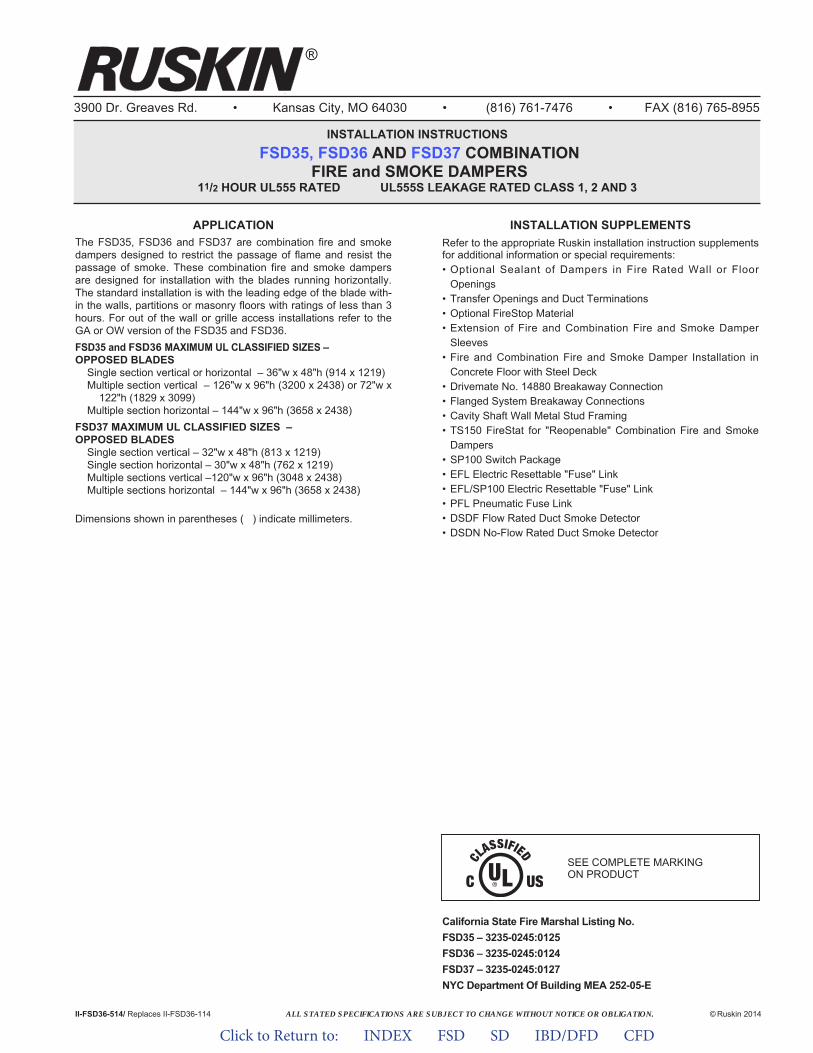
ALL STATED SPECIFICATIONS ARE SUBJECT TO CHANGE WITHOUT NOTICE OR OBLIGATION.
3900 Dr. Greaves Rd. • Kansas City, MO 64030 • (816) 761-7476 • FAX (816) 765-8955
INSTALLATION INSTRUCTIONSFSD35, FSD36 AND FSD37 COMBINATION
FIRE and SMOKE DAMPERS11/2 HOUR UL555 RATED UL555S LEAKAGE RATED CLASS 1, 2 AND 3
II-FSD36-514/ Replaces II-FSD36-114 © Ruskin 2014
®
APPLICATIONThe FSD35, FSD36 and FSD37 are combination fire and smokedampers designed to restrict the passage of flame and resist thepassage of smoke. These combination fire and smoke dampersare designed for installation with the blades running horizontally.The standard installation is with the leading edge of the blade with-in the walls, partitions or masonry floors with ratings of less than 3hours. For out of the wall or grille access installations refer to theGA or OW version of the FSD35 and FSD36.FSD35 and FSD36 MAXIMUM UL CLASSIFIED SIZES –OPPOSED BLADES
Single section vertical or horizontal – 36"w x 48"h (914 x 1219)Multiple section vertical – 126"w x 96"h (3200 x 2438) or 72"w x
122"h (1829 x 3099)Multiple section horizontal – 144"w x 96"h (3658 x 2438)
FSD37 MAXIMUM UL CLASSIFIED SIZES –OPPOSED BLADES
Single section vertical – 32"w x 48"h (813 x 1219)Single section horizontal – 30"w x 48"h (762 x 1219)Multiple sections vertical –120"w x 96"h (3048 x 2438)Multiple sections horizontal – 144"w x 96"h (3658 x 2438)
Dimensions shown in parentheses ( ) indicate millimeters.
INSTALLATION SUPPLEMENTSRefer to the appropriate Ruskin installation instruction supplementsfor additional information or special requirements:• Optional Sealant of Dampers in Fire Rated Wall or Floor
Openings• Transfer Openings and Duct Terminations• Optional FireStop Material• Extension of Fire and Combination Fire and Smoke Damper
Sleeves• Fire and Combination Fire and Smoke Damper Installation in
Concrete Floor with Steel Deck• Drivemate No. 14880 Breakaway Connection• Flanged System Breakaway Connections• Cavity Shaft Wall Metal Stud Framing• TS150 FireStat for "Reopenable" Combination Fire and Smoke
Dampers• SP100 Switch Package• EFL Electric Resettable "Fuse" Link• EFL/SP100 Electric Resettable "Fuse" Link• PFL Pneumatic Fuse Link• DSDF Flow Rated Duct Smoke Detector• DSDN No-Flow Rated Duct Smoke Detector
California State Fire Marshal Listing No.FSD35 – 3235-0245:0125 FSD36 – 3235-0245:0124 FSD37 – 3235-0245:0127 NYC Department Of Building MEA 252-05-E
SEE COMPLETE MARKING ON PRODUCT
Click to Return to: INDEX FSD SD IBD/DFD CFD
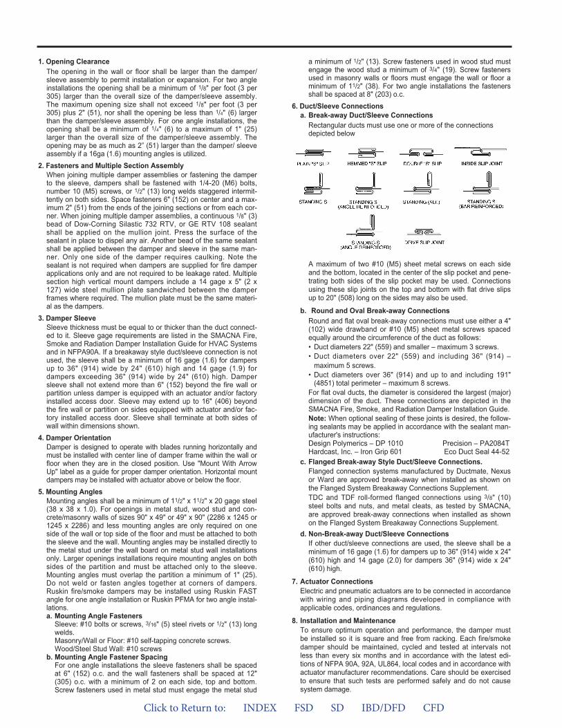
a minimum of 1/2" (13). Screw fasteners used in wood stud mustengage the wood stud a minimum of 3/4" (19). Screw fastenersused in masonry walls or floors must engage the wall or floor aminimum of 11/2" (38). For two angle installations the fastenersshall be spaced at 8" (203) o.c.
6. Duct/Sleeve Connectionsa. Break-away Duct/Sleeve Connections
Rectangular ducts must use one or more of the connectionsdepicted below
A maximum of two #10 (M5) sheet metal screws on each sideand the bottom, located in the center of the slip pocket and pene-trating both sides of the slip pocket may be used. Connectionsusing these slip joints on the top and bottom with flat drive slipsup to 20" (508) long on the sides may also be used.
b. Round and Oval Break-away ConnectionsRound and flat oval break-away connections must use either a 4"(102) wide drawband or #10 (M5) sheet metal screws spacedequally around the circumference of the duct as follows:• Duct diameters 22" (559) and smaller – maximum 3 screws.• Duct diameters over 22" (559) and including 36" (914) –
maximum 5 screws.• Duct diameters over 36" (914) and up to and including 191"
(4851) total perimeter – maximum 8 screws.For flat oval ducts, the diameter is considered the largest (major)dimension of the duct. These connections are depicted in theSMACNA Fire, Smoke, and Radiation Damper Installation Guide.Note: When optional sealing of these joints is desired, the follow-ing sealants may be applied in accordance with the sealant man-ufacturer's instructions:Design Polymerics – DP 1010 Precision – PA2084THardcast, Inc. – Iron Grip 601 Eco Duct Seal 44-52
c. Flanged Break-away Style Duct/Sleeve Connections.Flanged connection systems manufactured by Ductmate, Nexusor Ward are approved break-away when installed as shown onthe Flanged System Breakaway Connections Sup ple ment.TDC and TDF roll-formed flanged connections using 3/8" (10)steel bolts and nuts, and metal cleats, as tested by SMACNA,are approved break-away connections when installed as shownon the Flanged System Breakaway Connections Sup ple ment.
d. Non-Break-away Duct/Sleeve ConnectionsIf other duct/sleeve connections are used, the sleeve shall be aminimum of 16 gage (1.6) for dampers up to 36" (914) wide x 24"(610) high and 14 gage (2.0) for dampers 36" (914) wide x 24"(610) high.
7. Actuator ConnectionsElectric and pneumatic actuators are to be connected in accordancewith wiring and piping diagrams developed in compliance withapplicable codes, ordinances and regulations.
8. Installation and MaintenanceTo ensure optimum operation and performance, the damper mustbe installed so it is square and free from racking. Each fire/smokedamper should be maintained, cycled and tested at intervals notless than every six months and in accordance with the latest edi-tions of NFPA 90A, 92A, UL864, local codes and in accordance withactuator manufacturer recommendations. Care should be exercisedto ensure that such tests are performed safely and do not causesystem damage.
1. Opening ClearanceThe opening in the wall or floor shall be larger than the damper/sleeve assembly to permit installation or expansion. For two angleinstallations the opening shall be a minimum of 1/8" per foot (3 per305) larger than the overall size of the damper/sleeve assembly.The maximum opening size shall not exceed 1/8" per foot (3 per305) plus 2" (51), nor shall the opening be less than 1/4" (6) largerthan the damper/sleeve assembly. For one angle installations, theopening shall be a minimum of 1/4" (6) to a maximum of 1" (25)larger than the overall size of the damper/sleeve assembly. Theopening may be as much as 2” (51) larger than the damper/ sleeveassembly if a 16ga (1.6) mounting angles is utilized.
2. Fasteners and Multiple Section AssemblyWhen joining multiple damper assemblies or fastening the damperto the sleeve, dampers shall be fastened with 1/4-20 (M6) bolts,number 10 (M5) screws, or 1/2" (13) long welds staggered intermit-tently on both sides. Space fasteners 6" (152) on center and a max-imum 2" (51) from the ends of the joining sections or from each cor-ner. When joining multiple damper assemblies, a continuous 1/8" (3)bead of Dow-Corning Silastic 732 RTV, or GE RTV 108 sealantshall be applied on the mullion joint. Press the surface of thesealant in place to dispel any air. Another bead of the same sealantshall be applied between the damper and sleeve in the same man-ner. Only one side of the damper requires caulking. Note thesealant is not required when dampers are supplied for fire damperapplications only and are not required to be leakage rated. Multiplesection high vertical mount dampers include a 14 gage x 5" (2 x127) wide steel mullion plate sandwiched between the damperframes where required. The mullion plate must be the same materi-al as the dampers.
3. Damper SleeveSleeve thickness must be equal to or thicker than the duct connect-ed to it. Sleeve gage requirements are listed in the SMACNA Fire,Smoke and Radiation Damper Installation Guide for HVAC Systemsand in NFPA90A. If a breakaway style duct/sleeve connection is notused, the sleeve shall be a minimum of 16 gage (1.6) for dampersup to 36" (914) wide by 24" (610) high and 14 gage (1.9) fordampers exceeding 36" (914) wide by 24" (610) high. Dampersleeve shall not extend more than 6" (152) beyond the fire wall orpartition unless damper is equipped with an actuator and/or factoryinstalled access door. Sleeve may extend up to 16" (406) beyondthe fire wall or partition on sides equipped with actuator and/or fac-tory installed access door. Sleeve shall terminate at both sides ofwall within dimensions shown.
4. Damper OrientationDamper is designed to operate with blades running horizontally andmust be installed with center line of damper frame within the wall orfloor when they are in the closed position. Use "Mount With ArrowUp" label as a guide for proper damper orientation. Horizontal mountdampers may be installed with actuator above or below the floor.
5. Mounting AnglesMounting angles shall be a minimum of 11/2" x 11/2" x 20 gage steel(38 x 38 x 1.0). For openings in metal stud, wood stud and con-crete/masonry walls of sizes 90" x 49" or 49" x 90" (2286 x 1245 or1245 x 2286) and less mounting angles are only required on oneside of the wall or top side of the floor and must be attached to boththe sleeve and the wall. Mounting angles may be installed directly tothe metal stud under the wall board on metal stud wall installationsonly. Larger openings installations require mounting angles on bothsides of the partition and must be attached only to the sleeve.Mounting angles must overlap the partition a minimum of 1" (25).Do not weld or fasten angles together at corners of dampers.Ruskin fire/smoke dampers may be installed using Ruskin FASTangle for one angle installation or Ruskin PFMA for two angle instal-lations.a. Mounting Angle Fasteners
Sleeve: #10 bolts or screws, 3/16" (5) steel rivets or 1/2" (13) longwelds.Masonry/Wall or Floor: #10 self-tapping concrete screws.Wood/Steel Stud Wall: #10 screws
b. Mounting Angle Fastener SpacingFor one angle installations the sleeve fasteners shall be spacedat 6" (152) o.c. and the wall fasteners shall be spaced at 12"(305) o.c. with a minimum of 2 on each side, top and bottom.Screw fasteners used in metal stud must engage the metal stud
Click to Return to: INDEX FSD SD IBD/DFD CFD
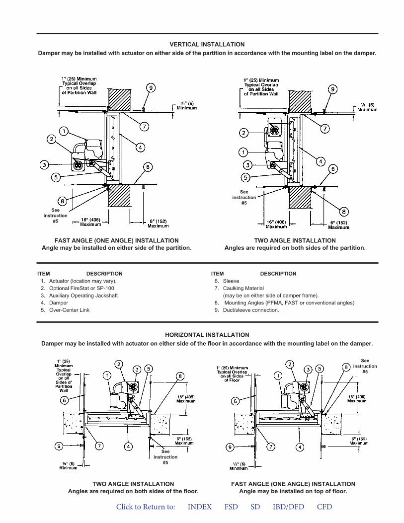
VERTICAL INSTALLATIONDamper may be installed with actuator on either side of the partition in accordance with the mounting label on the damper.
TWO ANGLE INSTALLATIONAngles are required on both sides of the floor.
HORIZONTAL INSTALLATIONDamper may be installed with actuator on either side of the floor in accordance with the mounting label on the damper.
ITEM DESCRIPTION1. Actuator (location may vary).2. Optional FireStat or SP-100.3. Auxiliary Operating Jackshaft4. Damper5. Over-Center Link
ITEM DESCRIPTION6. Sleeve7. Caulking Material
(may be on either side of damper frame).8. Mounting Angles (PFMA, FAST or conventional angles)9. Duct/sleeve connection.
FAST ANGLE (ONE ANGLE) INSTALLATIONAngle may be installed on either side of the partition.
TWO ANGLE INSTALLATIONAngles are required on both sides of the partition.
FAST ANGLE (ONE ANGLE) INSTALLATIONAngle may be installed on top of floor.
See instruction
#5
See instruction
#5
See instruction
#5
See instruction
#5
Click to Return to: INDEX FSD SD IBD/DFD CFD
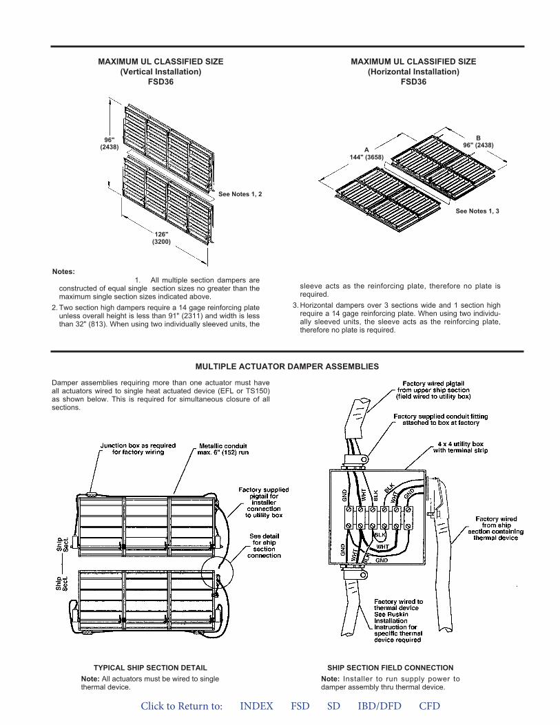
96"(2438)
B96" (2438)
126"(3200)
MAXIMUM UL CLASSIFIED SIZE(Vertical Installation)
FSD36
MAXIMUM UL CLASSIFIED SIZE(Horizontal Installation)
FSD36
See Notes 1, 2
See Notes 1, 3
A144" (3658)
1. All multiple section dampers areconstructed of equal single section sizes no greater than themaximum single section sizes indicated above.
2. Two section high dampers require a 14 gage reinforcing plateunless overall height is less than 91" (2311) and width is lessthan 32" (813). When using two individually sleeved units, the
sleeve acts as the reinforcing plate, therefore no plate isrequired.
3. Horizontal dampers over 3 sections wide and 1 section highrequire a 14 gage reinforcing plate. When using two individu-ally sleeved units, the sleeve acts as the reinforcing plate,therefore no plate is required.
Notes:
MULTIPLE ACTUATOR DAMPER ASSEMBLIES
Damper assemblies requiring more than one actuator must haveall actuators wired to single heat actuated device (EFL or TS150)as shown below. This is required for simultaneous closure of allsections.
TYPICAL SHIP SECTION DETAILNote: All actuators must be wired to singlethermal device.
SHIP SECTION FIELD CONNECTIONNote: Installer to run supply power todamper assembly thru thermal device.
Click to Return to: INDEX FSD SD IBD/DFD CFD
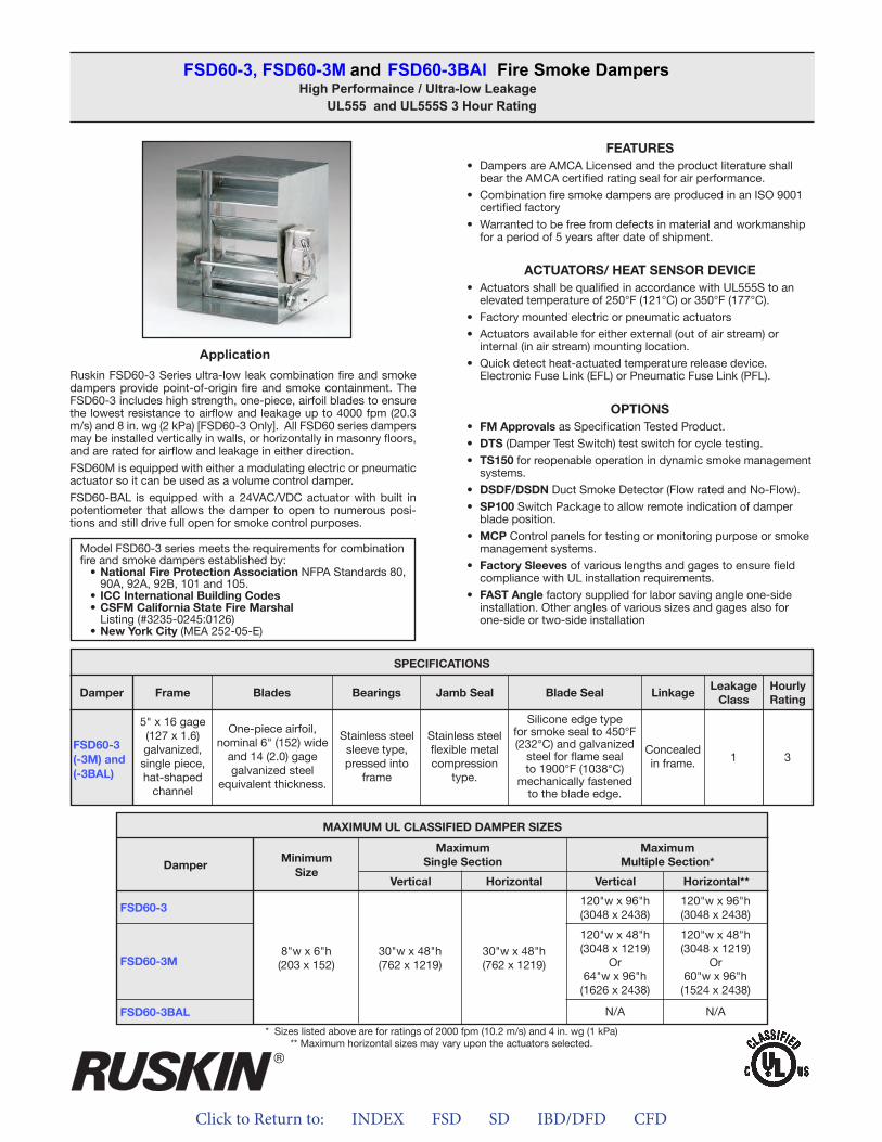
Click to Return to: INDEX FSD SD IBD/DFD CFD
ApplicationRuskin FSD60-3 Series ultra-low leak combination fire and smoke dampers provide point-of-origin fire and smoke containment. The FSD60-3 includes high strength, one-piece, airfoil blades to ensure the lowest resistance to airflow and leakage up to 4000 fpm (20.3 m/s) and 8 in. wg (2 kPa) [FSD60-3 Only]. All FSD60 series dampers may be installed vertically in walls, or horizontally in masonry floors, and are rated for airflow and leakage in either direction.
FSD60M is equipped with either a modulating electric or pneumatic actuator so it can be used as a volume control damper.
FSD60-BAL is equipped with a 24VAC/VDC actuator with built in potentiometer that allows the damper to open to numerous posi-tions and still drive full open for smoke control purposes.
FSD60-3, FSD60-3M and FSD60-3BAl Fire Smoke DampersHigh Performaince / Ultra-low Leakage
UL555 and UL555S 3 Hour Rating
Model FSD60-3 series meets the requirements for combination fire and smoke dampers established by:
• National Fire Protection Association NFPA Standards 80, 90A, 92A, 92B, 101 and 105.
• ICC International Building Codes• CSFM California State Fire Marshal
Listing (#3235-0245:0126)• New York City (MEA 252-05-E)
MAXIMUM UL CLASSIFIED DAMPER SIZES
DamperMinimum
Size
MaximumSingle Section
MaximumMultiple Section*
Vertical VerticalHorizontal Horizontal**
8"w x 6"h(203 x 152)
30"w x 48"h(762 x 1219)
30"w x 48"h(762 x 1219)
120"w x 96"h(3048 x 2438)
120"w x 96"h(3048 x 2438)
FSD60-3
120"w x 48"h(3048 x 1219)
Or64"w x 96"h
(1626 x 2438)
120"w x 48"h(3048 x 1219)
Or60"w x 96"h
(1524 x 2438)
FSD60-3M
N/A N/AFSD60-3BAL
FEATURES• Dampers are AMCA Licensed and the product literature shall
bear the AMCA certified rating seal for air performance.
• Combination fire smoke dampers are produced in an ISO 9001certified factory
• Warranted to be free from defects in material and workmanshipfor a period of 5 years after date of shipment.
ACTUATORS/ HEAT SENSOR DEVICE• Actuators shall be qualified in accordance with UL555S to an
elevated temperature of 250°F (121°C) or 350°F (177°C).
• Factory mounted electric or pneumatic actuators
• Actuators available for either external (out of air stream) orinternal (in air stream) mounting location.
• Quick detect heat-actuated temperature release device.Electronic Fuse Link (EFL) or Pneumatic Fuse Link (PFL).
OPTIONS• FM Approvals as Specification Tested Product.
• DTS (Damper Test Switch) test switch for cycle testing.
• TS150 for reopenable operation in dynamic smoke managementsystems.
• DSDF/DSDN Duct Smoke Detector (Flow rated and No-Flow).
• SP100 Switch Package to allow remote indication of damperblade position.
• MCP Control panels for testing or monitoring purpose or smokemanagement systems.
• Factory Sleeves of various lengths and gages to ensure fieldcompliance with UL installation requirements.
• FAST Angle factory supplied for labor saving angle one-sideinstallation. Other angles of various sizes and gages also forone-side or two-side installation
FSD60-3(-3M) and(-3BAL)
SPECIFICATIONS
Frame Blades Bearings Jamb Seal Blade Seal LinkageLeakage
ClassHourlyRating
Damper
5" x 16 gage (127 x 1.6)galvanized,single piece,hat-shaped
channel
One-piece airfoil,nominal 6" (152) wide
and 14 (2.0) gagegalvanized steel
equivalent thickness.
Stainless steelsleeve type,pressed into
frame
Stainless steelflexible metalcompression
type.
Silicone edge typefor smoke seal to 450°F (232°C) and galvanized
steel for flame seal to 1900°F (1038°C)
mechanically fastenedto the blade edge.
Concealedin frame. 1 3
* Sizes listed above are for ratings of 2000 fpm (10.2 m/s) and 4 in. wg (1 kPa)** Maximum horizontal sizes may vary upon the actuators selected.
ALL STATED SPECIFICATIONS ARE SUBJECT TO CHANGE WITHOUT NOTICE OR OBLIGATION.
3900 Dr. Greaves Rd. • Kansas City, MO 64030 • (816) 761-7476 • FAX (816) 765-8955
INSTALLATION INSTRUCTIONSFSD60-3, FSD60-3M AND FSD60-3BAL COMBINATION FIRE AND SMOKE DAMPER
3 HOUR UL555 RATED UL555S LEAKAGE CLASS 1 RATED
II-FSD60-3-514/ Replaces II-FSD60-3-114 © Ruskin 2014
INSTALLATION SUPPLEMENTSRefer to the appropriate Ruskin installation instructions supple-ments for additional information or special requirements:• Optional Sealant of Dampers in Fire Rated Wall or Floor Openings• Transfer Openings and Duct Terminations• Optional FireStop Material• Extension of Fire and Combination Fire and Smoke Damper
Sleeves• Fire and Combination Fire and Smoke Damper Installation in
Concrete Floor with Steel Deck• Drivemate No. 14880 Breakaway Connection• Flanged System Breakaway Connections• TS150 FireStat for "Reopenable" Combination Fire and Smoke
Dampers• SP100 Switch Package• EFL Electric Resettable "Fuse" Link• EFL/SP100 Electric Resettable "Fuse" Link and Switch Package• PFL Pneumatic Fuse Link• DSDF Flow Rated Duct Smoke Detector• DSDN No-Flow Rated Duct Smoke Detector
APPLICATIONThe FSD60-3 combination fire and smoke damper is designed torestrict the passage of flame and resist the passage of smoke. TheFSD60-3 is designed for installation with the blades running hori-zontally. The standard installation is with the leading edge of theclosed blades within the wall, partition or masonry floor with a fireresistance rating of 3 hours or more.
FSD60-3 MAXIMUM UL CLASSIFIED SIZES –OPPOSED BLADE
Single section vertical – 30"w x 48"h (762 x 1219)Single section horizontal – 30"w x 48"h (762 x 1219)Multiple sections vertical – 120"w x 96"h (3048 x 2438)Multiple sections horizontal – 144"w x 96"h (3658 x 2438)
FSD60-3M MAXIMUM UL CLASSIFIED SIZES –OPPOSED BLADE
Single section vertical – 30"w x 48"h (762 x 1219)Single section horizontal – 30"w x 48"h (762 x 1219)Multiple sections vertical – 120"w x 96"h (3048 x 2438)
60"w x 96"h (1524 x 2438)Multiple sections horizontal – 120"w x 96"h (3048 x 2438)
60"w x 96"h (1524 x 2438)FSD60-3BAL MAXIMUM UL CLASSIFIED SIZES –OPPOSED BLADE
Single section vertical – 30"w x 48"h (762 x 1219).Single section horizontal – 30"w x 48"h (762 x 1219).
Note: Dimensions shown in parentheses ( ) indicate millimeters.
California State Fire Marshal Listing No.FSD60-3, 60-3M and 60-BAL– 3235-0245:0126NYC Department Of Building MEA 252-05-E
SEE COMPLETE MARKING ON PRODUCT
Click to Return to: INDEX FSD SD IBD/DFD CFD
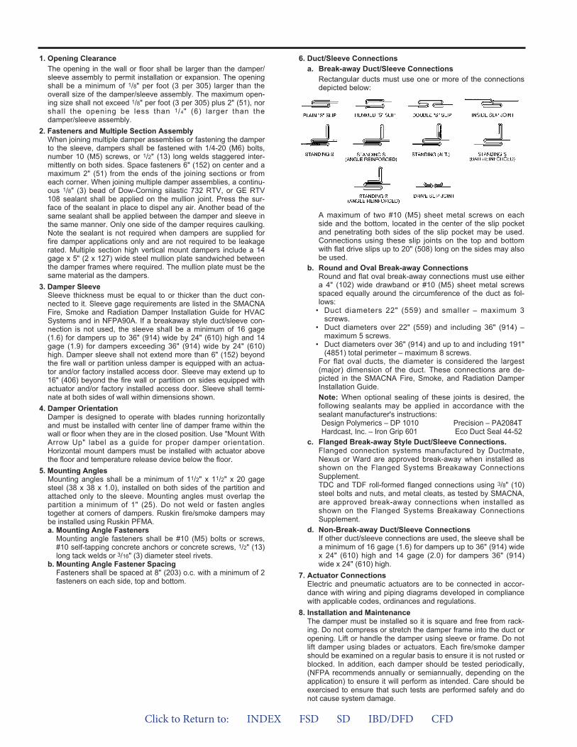
1. Opening ClearanceThe opening in the wall or floor shall be larger than the damper/sleeve assembly to permit installation or expansion. The openingshall be a minimum of 1/8" per foot (3 per 305) larger than theoverall size of the damper/sleeve assembly. The maximum open-ing size shall not exceed 1/8" per foot (3 per 305) plus 2" (51), norshall the opening be less than 1/4" (6) larger than thedamper/sleeve assembly.
2. Fasteners and Multiple Section AssemblyWhen joining multiple damper assemblies or fastening the damperto the sleeve, dampers shall be fastened with 1/4-20 (M6) bolts,number 10 (M5) screws, or 1/2" (13) long welds staggered inter-mittently on both sides. Space fasteners 6" (152) on center and amaximum 2" (51) from the ends of the joining sections or fromeach corner. When joining multiple damper assemblies, a continu-ous 1/8" (3) bead of Dow-Corning silastic 732 RTV, or GE RTV108 sealant shall be applied on the mullion joint. Press the sur-face of the sealant in place to dispel any air. Another bead of thesame sealant shall be applied between the damper and sleeve inthe same manner. Only one side of the damper requires caulking.Note the sealant is not required when dampers are supplied forfire damper applications only and are not required to be leakagerated. Multiple section high vertical mount dampers include a 14gage x 5" (2 x 127) wide steel mullion plate sandwiched betweenthe damper frames where required. The mullion plate must be thesame material as the dampers.
3. Damper SleeveSleeve thickness must be equal to or thicker than the duct con-nected to it. Sleeve gage requirements are listed in the SMACNAFire, Smoke and Radiation Damper Installation Guide for HVACSystems and in NFPA90A. If a breakaway style duct/sleeve con-nection is not used, the sleeve shall be a minimum of 16 gage(1.6) for dampers up to 36" (914) wide by 24" (610) high and 14gage (1.9) for dampers exceeding 36" (914) wide by 24" (610)high. Damper sleeve shall not extend more than 6" (152) beyondthe fire wall or partition unless damper is equipped with an actua-tor and/or factory installed access door. Sleeve may extend up to16" (406) beyond the fire wall or partition on sides equipped withactuator and/or factory installed access door. Sleeve shall termi-nate at both sides of wall within dimensions shown.
4. Damper OrientationDamper is designed to operate with blades running horizontallyand must be installed with center line of damper frame within thewall or floor when they are in the closed position. Use "Mount WithArrow Up" label as a guide for proper damper orientation.Horizontal mount dampers must be installed with actuator abovethe floor and temperature release device below the floor.
5. Mounting AnglesMounting angles shall be a minimum of 11/2" x 11/2" x 20 gagesteel (38 x 38 x 1.0), installed on both sides of the partition andattached only to the sleeve. Mounting angles must overlap thepartition a minimum of 1" (25). Do not weld or fasten anglestogether at corners of dampers. Ruskin fire/smoke dampers maybe installed using Ruskin PFMA.a. Mounting Angle Fasteners
Mounting angle fasteners shall be #10 (M5) bolts or screws,#10 self-tapping concrete anchors or concrete screws, 1/2" (13)long tack welds or 3/16" (3) diameter steel rivets.
b. Mounting Angle Fastener SpacingFasteners shall be spaced at 8" (203) o.c. with a minimum of 2fasteners on each side, top and bottom.
6. Duct/Sleeve Connectionsa. Break-away Duct/Sleeve Connections
Rectangular ducts must use one or more of the connectionsdepicted below:
A maximum of two #10 (M5) sheet metal screws on eachside and the bottom, located in the center of the slip pocketand penetrating both sides of the slip pocket may be used.Connections using these slip joints on the top and bottomwith flat drive slips up to 20" (508) long on the sides may alsobe used.
b. Round and Oval Break-away ConnectionsRound and flat oval break-away connections must use eithera 4" (102) wide drawband or #10 (M5) sheet metal screwsspaced equally around the circumference of the duct as fol-lows:
• Duct diameters 22" (559) and smaller – maximum 3screws.
• Duct diameters over 22" (559) and including 36" (914) –maximum 5 screws.
• Duct diameters over 36" (914) and up to and including 191"(4851) total perimeter – maximum 8 screws.
For flat oval ducts, the diameter is considered the largest(major) dimension of the duct. These connections are de -picted in the SMACNA Fire, Smoke, and Radiation DamperInstallation Guide.Note: When optional sealing of these joints is desired, thefollowing sealants may be applied in accordance with thesealant manufacturer's instructions:Design Polymerics – DP 1010 Precision – PA2084THardcast, Inc. – Iron Grip 601 Eco Duct Seal 44-52
c. Flanged Break-away Style Duct/Sleeve Connections.Flanged connection systems manufactured by Ductmate,Nexus or Ward are approved break-away when installed asshown on the Flanged Systems Breakaway ConnectionsSupplement.TDC and TDF roll-formed flanged connections using 3/8" (10)steel bolts and nuts, and metal cleats, as tested by SMACNA,are approved break-away connections when installed asshown on the Flanged Systems Breakaway ConnectionsSupplement.
d. Non-Break-away Duct/Sleeve ConnectionsIf other duct/sleeve connections are used, the sleeve shall bea minimum of 16 gage (1.6) for dampers up to 36" (914) widex 24" (610) high and 14 gage (2.0) for dampers 36" (914)wide x 24" (610) high.
7. Actuator ConnectionsElectric and pneumatic actuators are to be connected in accor-dance with wiring and piping diagrams developed in compliancewith applicable codes, ordinances and regulations.
8. Installation and MaintenanceThe damper must be installed so it is square and free from rack-ing. Do not compress or stretch the damper frame into the duct oropening. Lift or handle the damper using sleeve or frame. Do notlift damper using blades or actuators. Each fire/smoke dampershould be examined on a regular basis to ensure it is not rusted orblocked. In addition, each damper should be tested periodically,(NFPA recommends annually or semiannually, depending on theapplication) to ensure it will perform as intended. Care should beexercised to ensure that such tests are performed safely and donot cause system damage.
Click to Return to: INDEX FSD SD IBD/DFD CFD
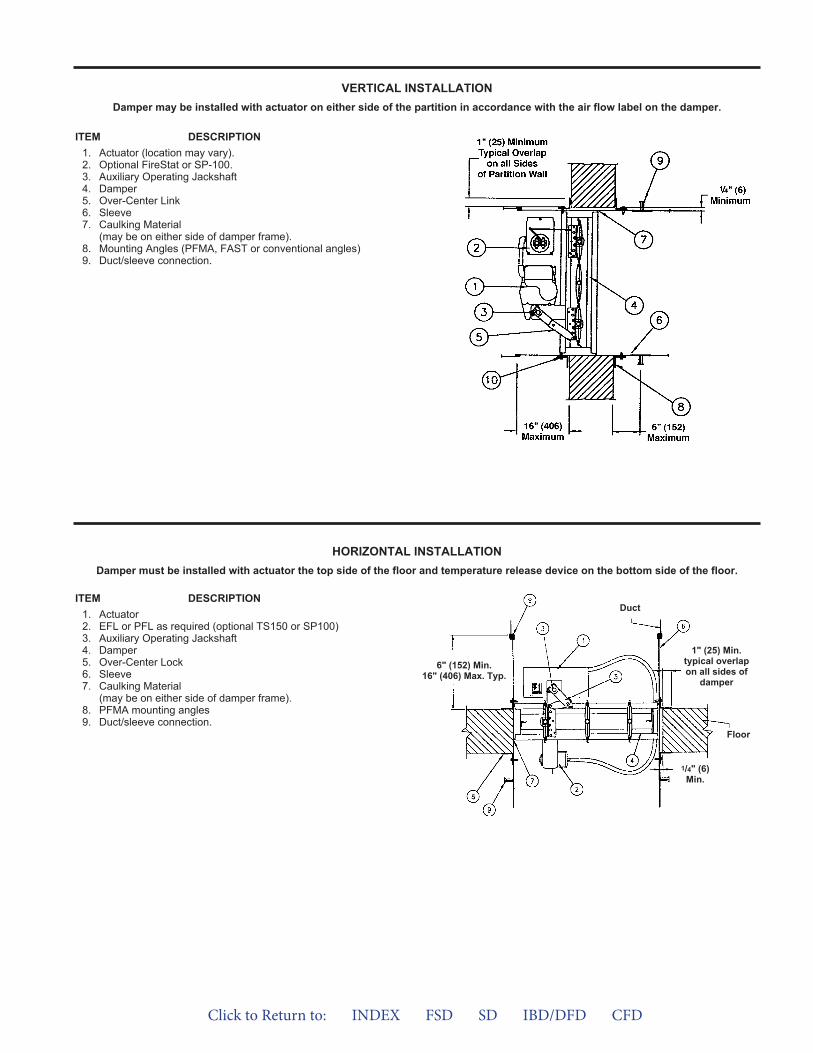
ITEM DESCRIPTION1. Actuator (location may vary).2. Optional FireStat or SP-100.3. Auxiliary Operating Jackshaft4. Damper5. Over-Center Link6. Sleeve7. Caulking Material
(may be on either side of damper frame).8. Mounting Angles (PFMA, FAST or conventional angles)9. Duct/sleeve connection.
6" (152) Min.16" (406) Max. Typ.
1/4" (6)Min.
Duct
1" (25) Min.typical overlapon all sides of
damper
ITEM DESCRIPTION1. Actuator2. EFL or PFL as required (optional TS150 or SP100)3. Auxiliary Operating Jackshaft4. Damper5. Over-Center Lock6. Sleeve7. Caulking Material
(may be on either side of damper frame).8. PFMA mounting angles9. Duct/sleeve connection.
VERTICAL INSTALLATIONDamper may be installed with actuator on either side of the partition in accordance with the air flow label on the damper.
HORIZONTAL INSTALLATIONDamper must be installed with actuator the top side of the floor and temperature release device on the bottom side of the floor.
Floor
Click to Return to: INDEX FSD SD IBD/DFD CFD
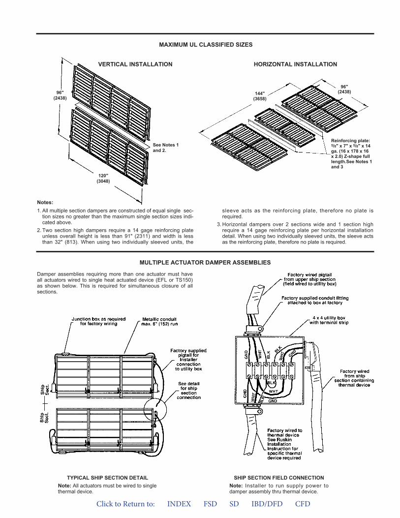
MAXIMUM UL CLASSIFIED SIZES
HORIZONTAL INSTALLATIONVERTICAL INSTALLATION
120"(3048)
96"(2438)
See Notes 1and 2.
1. All multiple section dampers are constructed of equal single sec-tion sizes no greater than the maximum single section sizes indi-cated above.
2. Two section high dampers require a 14 gage reinforcing plateunless overall height is less than 91" (2311) and width is lessthan 32" (813). When using two individually sleeved units, the
sleeve acts as the reinforcing plate, therefore no plate isrequired.
3. Horizontal dampers over 2 sections wide and 1 section highrequire a 14 gage reinforcing plate per horizontal installationdetail. When using two individually sleeved units, the sleeve actsas the reinforcing plate, therefore no plate is required.
Notes:
MULTIPLE ACTUATOR DAMPER ASSEMBLIES
Damper assemblies requiring more than one actuator must haveall actuators wired to single heat actuated device (EFL or TS150)as shown below. This is required for simultaneous closure of allsections.
TYPICAL SHIP SECTION DETAILNote: All actuators must be wired to singlethermal device.
SHIP SECTION FIELD CONNECTIONNote: Installer to run supply power todamper assembly thru thermal device.
96"(2438)
Reinforcing plate:5/8" x 7" x 5/8" x 14ga. (16 x 178 x 16x 2.0) Z-shape fulllength.See Notes 1and 3
144"(3658)
Click to Return to: INDEX FSD SD IBD/DFD CFD
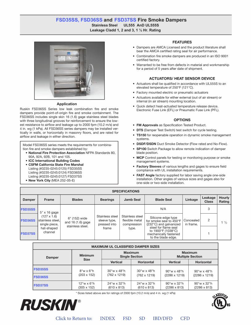
Click to Return to: INDEX FSD SD IBD/DFD CFD
ApplicationRuskin FSD36SS Series low leak combination fire and smoke dampers provide point-of-origin fire and smoke containment. The FSD36SS includes single skin 16 (1.6) gage stainless steel blades with three longitudinal grooves for reinforcement to ensure the low-est resistance to airflow and leakage up to 2000 fpm (10.2 m/s) and 4 in. wg (1 kPa). All FSD36SS series dampers may be installed ver-tically in walls, or horizontally in masonry floors, and are rated for airflow and leakage in either direction.
FEATURES• Dampers are AMCA Licensed and the product literature shall
bear the AMCA certified rating seal for air performance.
• Combination fire smoke dampers are produced in an ISO 9001certified factory.
• Warranted to be free from defects in material and workmanshipfor a period of 5 years after date of shipment.
ACTUATORS/ HEAT SENSOR DEVICE• Actuators shall be qualified in accordance with UL555S to an
elevated temperature of 250°F (121°C).
• Factory mounted electric or pneumatic actuators
• Actuators available for either external (out of air stream) orinternal (in air stream) mounting location.
• Quick detect heat-actuated temperature release device.Electronic Fuse Link (EFL) or Pneumatic Fuse Link (PFL).
OPTIONS• FM Approvals as Specification Tested Product.
• DTS (Damper Test Switch) test switch for cycle testing.
• TS150 for reopenable operation in dynamic smoke managementsystems.
• DSDF/DSDN Duct Smoke Detector (Flow rated and No-Flow).
• SP100 Switch Package to allow remote indication of damperblade position.
• MCP Control panels for testing or monitoring purpose or smokemanagement systems.
• Factory Sleeves of various lengths and gages to ensure fieldcompliance with UL installation requirements.
• FAST Angle factory supplied for labor saving angle one-sideinstallation. Other angles of various sizes and gages also forone-side or two-side installation.
FSD35SS, FSD36SS and FSD37SS Fire Smoke Dampers Stainless Steel UL555 AnD UL555S
Leakage Cladd 1, 2 and 3, 1 ½ Hr. Rating
Model FSD36SS series meets the requirements for combina-tion fire and smoke dampers established by:
• National Fire Protection Association NFPA Standards 80, 90A, 92A, 92B, 101 and 105.
• ICC International Building Codes• CSFM California State Fire Marshal
Listing (#3235-0245:0125) FSD35SSListing (#3235-0245:0124) FSD36SSListing (#3235-0245:0127) FSD37SS
• New York City (MEA 252-05-E)
FSD35SS
FSD37SS
FSD36SS
SPECIFICATIONS
Frame Blades Bearings Jamb Seal Blade Seal LinkageLeakage
ClassHourlyRating
Damper
5" x 16 gage (127 x 1.6)
stainless steel,single piece,hat-shaped
channel
6" (152) wideand 16 (1.6) gage
stainless steel.
Stainless steelsleeve type,pressed into
frame
Stainless steelflexible metalcompression
type.
Silicone edge typefor smoke seal to 450°F (232°C) and galvanized
steel for flame seal to 1900°F (1038°C)
mechanically fastenedto the blade edge.
Concealedin frame.
3N/A
2
1
1 1/2
MAXIMUM UL CLASSIFIED DAMPER SIZES
Damper
FSD35SS
FSD36SS
FSD37SS
MinimumSize
MaximumSingle Section
MaximumMultiple Section
Vertical VerticalHorizontal Horizontal
30"w x 48"h(762 x 1219)
8"w x 6"h(203 x 152)
12"w x 6"h(305 x 152)
24"w x 32"h(610 x 813)
24"w x 32"h(610 x 813)
90"w x 32"h(2286 x 813)
90"w x 32"h(2286 x 813)
30"w x 48"h(762 x 1219)
90"w x 48"h(2286 x 1219)
90"w x 48"h(2286 x 1219)
* Sizes listed above are for ratings of 2000 fpm (10.2 m/s) and 4 in. wg (1 kPa)
ALL STATED SPECIFICATIONS ARE SUBJECT TO CHANGE WITHOUT NOTICE OR OBLIGATION.
3900 Dr. Greaves Rd. • Kansas City, MO 64030 • (816) 761-7476 • FAX (816) 765-8955
INSTALLATION INSTRUCTIONSFSD35SS, FSD36SS AND FSD37SS
COMBINATION FIRE AND SMOKE DAMPERS11/2 HOUR UL555 RATED UL555S LEAKAGE RATED CLASS 1, 2 AND 3
II-FSDSS-514/Replaces II-FSDSS-114 © Ruskin 20014
®
APPLICATIONThe FSD35SS, FSD36SS and FSD37SS are combination fire andsmoke dampers designed to restrict the passage of flame andresist the passage of smoke. These combination fire and smokedampers are designed for installation with the blades running hori-zontally. The standard installation is with the leading edge of theblade with-in the walls, partitions or masonry floors with ratings ofless than 3 hours. For out of the wall or grille access installationsrefer to the GA or OW version of the FSD35SS, FSD36SS andFSD37SS.FSD35SS AND FSD36SS MAXIMUM UL CLASSIFIED SIZES –OPPOSED BLADE
Single section vertical or horizontal – 30"w x 48"h (762 x 1219)Multiple sections vertical or horizontal – 90"w x 48"h (2286 x
1219)FSD37SS MAXIMUM UL CLASSIFIED SIZES –OPPOSED BLADE
Single section vertical or horizontal – 24"w x 32"h (610 x 813)Multiple sections vertical or horizontal – 90"w x 32"h (2286 x
813)
Dimensions shown in parentheses ( ) indicate millimeters.
INSTALLATION SUPPLEMENTSRefer to the appropriate Ruskin installation instructions supple-ments for additional information or special requirements:• Optional Sealant of Dampers in Fire Rated Wall or Floor
Openings• Transfer Openings and Duct Terminations• Optional FireStop Material• Extension of Fire and Combination Fire and Smoke Damper
Sleeves• Drivemate No. 14880 Breakaway Connection• Flanged System Breakaway Connection• Cavity Shaft Wall Metal Stud Framing• TS150 FireStat for "Reopenable" Combination Fire and Smoke
Dampers• SP100 Switch Package• EFL Electric Resettable "Fuse" Link• EFL/SP100 Electric Resettable "Fuse" Link• PFL Pneumatic Fuse Link• DSDF Flow Rated Duct Smoke Detector• DSDN No-Flow Rated Duct Smoke Detector
California State Fire Marshal Listing No.FSD35(SS) – 3235-0245:0125FSD36(SS) – 3235-0245:0124FSD37(SS) – 3235-0245:0127NYC Department Of Building MEA 252-05-E
SEE COMPLETE MARKING ON PRODUCT
Click to Return to: INDEX FSD SD IBD/DFD CFD
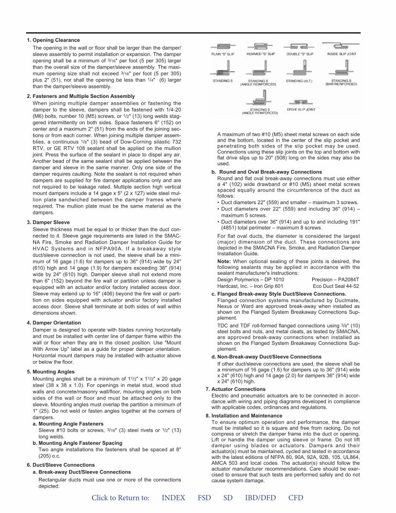
A maximum of two #10 (M5) sheet metal screws on each sideand the bottom, located in the center of the slip pocket andpenetrating both sides of the slip pocket may be used.Connections using these slip joints on the top and bottom withflat drive slips up to 20" (508) long on the sides may also beused.
b. Round and Oval Break-away ConnectionsRound and flat oval break-away connections must use eithera 4" (102) wide drawband or #10 (M5) sheet metal screwsspaced equally around the circumference of the duct asfollows:• Duct diameters 22" (559) and smaller – maximum 3 screws.• Duct diameters over 22" (559) and including 36" (914) –
maximum 5 screws.• Duct diameters over 36" (914) and up to and including 191"
(4851) total perimeter – maximum 8 screws.For flat oval ducts, the diameter is considered the largest(major) dimension of the duct. These connections aredepicted in the SMACNA Fire, Smoke, and Radiation DamperInstallation Guide.Note: When optional sealing of these joints is desired, thefollowing sealants may be applied in accordance with thesealant manufacturer's instructions:Design Polymerics – DP 1010 Precision – PA2084THardcast, Inc. – Iron Grip 601 Eco Duct Seal 44-52
c. Flanged Break-away Style Duct/Sleeve Connections.Flanged connection systems manufactured by Ductmate,Nexus or Ward are approved break-away when installed asshown on the Flanged System Breakaway Connections Sup -ple ment.TDC and TDF roll-formed flanged connections using 3/8" (10)steel bolts and nuts, and metal cleats, as tested by SMACNA,are approved break-away connections when installed asshown on the Flanged System Breakaway Connections Sup -ple ment.
d. Non-Break-away Duct/Sleeve ConnectionsIf other duct/sleeve connections are used, the sleeve shall bea minimum of 16 gage (1.6) for dampers up to 36" (914) widex 24" (610) high and 14 gage (2.0) for dampers 36" (914) widex 24" (610) high.
7. Actuator ConnectionsElectric and pneumatic actuators are to be connected in accor-dance with wiring and piping diagrams developed in compliancewith applicable codes, ordinances and regulations.
8. Installation and MaintenanceTo ensure optimum operation and performance, the dampermust be installed so it is square and free from racking. Do notcompress or stretch the damper frame into the duct or opening.Lift or handle the damper using sleeve or frame. Do not liftdamper using blades or actuators. Dampers and theiractuator(s) must be maintained, cycled and tested in accordancewith the latest editions of NFPA 80, 90A, 92A, 92B, 105, UL864,AMCA 503 and local codes. The actuator(s) should follow theactuator manufacturer recommendations. Care should be exer-cised to ensure that such tests are performed safely and do notcause system damage.
1. Opening ClearanceThe opening in the wall or floor shall be larger than the damper/sleeve assembly to permit installation or expansion. The damperopening shall be a minimum of 3/16" per foot (5 per 305) largerthan the overall size of the damper/sleeve assembly. The maxi-mum opening size shall not exceed 3/16" per foot (5 per 305)plus 2" (51), nor shall the opening be less than 1/4" (6) largerthan the damper/sleeve assembly.
2. Fasteners and Multiple Section AssemblyWhen joining multiple damper assemblies or fastening thedamper to the sleeve, dampers shall be fastened with 1/4-20(M6) bolts, number 10 (M5) screws, or 1/2" (13) long welds stag-gered intermittently on both sides. Space fasteners 6" (152) oncenter and a maximum 2" (51) from the ends of the joining sec-tions or from each corner. When joining multiple damper assem-blies, a continuous 1/8" (3) bead of Dow-Corning silastic 732RTV, or GE RTV 108 sealant shall be applied on the mullionjoint. Press the surface of the sealant in place to dispel any air.Another bead of the same sealant shall be applied between thedamper and sleeve in the same manner. Only one side of thedamper requires caulking. Note the sealant is not required whendampers are supplied for fire damper applications only and arenot required to be leakage rated. Multiple section high verticalmount dampers include a 14 gage x 5" (2 x 127) wide steel mul-lion plate sandwiched between the damper frames whererequired. The mullion plate must be the same material as thedampers.
3. Damper SleeveSleeve thickness must be equal to or thicker than the duct con-nected to it. Sleeve gage requirements are listed in the SMAC-NA Fire, Smoke and Radiation Damper Installation Guide forHVAC Systems and in NFPA90A. If a breakaway styleduct/sleeve connection is not used, the sleeve shall be a mini-mum of 16 gage (1.6) for dampers up to 36" (914) wide by 24"(610) high and 14 gage (1.9) for dampers exceeding 36" (914)wide by 24" (610) high. Damper sleeve shall not extend morethan 6" (152) beyond the fire wall or partition unless damper isequipped with an actuator and/or factory installed access door.Sleeve may extend up to 16" (406) beyond the fire wall or parti-tion on sides equipped with actuator and/or factory installedaccess door. Sleeve shall terminate at both sides of wall withindimensions shown.
4. Damper OrientationDamper is designed to operate with blades running horizontallyand must be installed with center line of damper frame within thewall or floor when they are in the closed position. Use "MountWith Arrow Up" label as a guide for proper damper orientation.Horizontal mount dampers may be installed with actuator aboveor below the floor.
5. Mounting AnglesMounting angles shall be a minimum of 11/2" x 11/2" x 20 gagesteel (38 x 38 x 1.0). For openings in metal stud, wood studwalls and concrete/masonry wall/floor, mounting angles on bothsides of the wall or floor and must be attached only to thesleeve. Mounting angles must overlap the partition a minimum of1" (25). Do not weld or fasten angles together at the corners ofdampers.a. Mounting Angle Fasteners
Sleeve #10 bolts or screws, 3/16" (3) steel rivets or 1/2" (13)long welds.
b. Mounting Angle Fastener SpacingTwo angle installations the fasteners shall be spaced at 8"(205) o.c.
6. Duct/Sleeve Connectionsa. Break-away Duct/Sleeve Connections
Rectangular ducts must use one or more of the connectionsdepicted:
Click to Return to: INDEX FSD SD IBD/DFD CFD
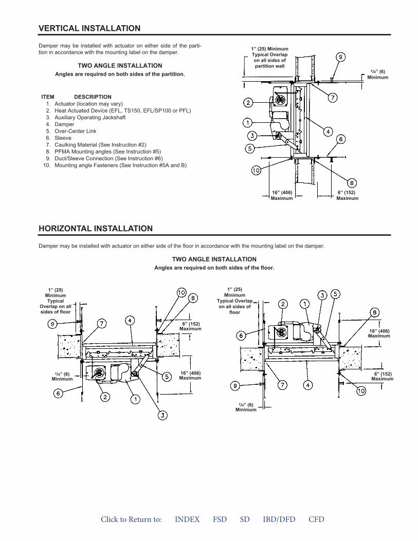
Damper may be installed with actuator on either side of the parti-tion in accordance with the mounting label on the damper.
TWO ANGLE INSTALLATIONAngles are required on both sides of the partition.
VERTICAL INSTALLATION
ITEM DESCRIPTION1. Actuator (location may vary)2. Heat Actuated Device (EFL, TS150, EFL/SP100 or PFL)3. Auxiliary Operating Jackshaft4. Damper5. Over-Center Link6. Sleeve7. Caulking Material (See Instruction #2)8. PFMA Mounting angles (See Instruction #5)9. Duct/Sleeve Connection (See Instruction #6)
10. Mounting angle Fasteners (See Instruction #5A and B)
1” (25) MinimumTypical Overlapon all sides ofpartition wall
1/4” (6)Minimum
16” (406)Maximum
6” (152)Maximum
Damper may be installed with actuator on either side of the floor in accordance with the mounting label on the damper.
TWO ANGLE INSTALLATIONAngles are required on both sides of the floor.
HORIZONTAL INSTALLATION
1” (25)MinimumTypical
Overlap on allsides of floor
1” (25)Minimum
Typical Overlapon all sides of
floor
16” (406)Maximum
6” (152)Maximum
16” (406)Maximum
6” (152)Maximum
1/4” (6)Minimum
1/4” (6)Minimum
Click to Return to: INDEX FSD SD IBD/DFD CFD
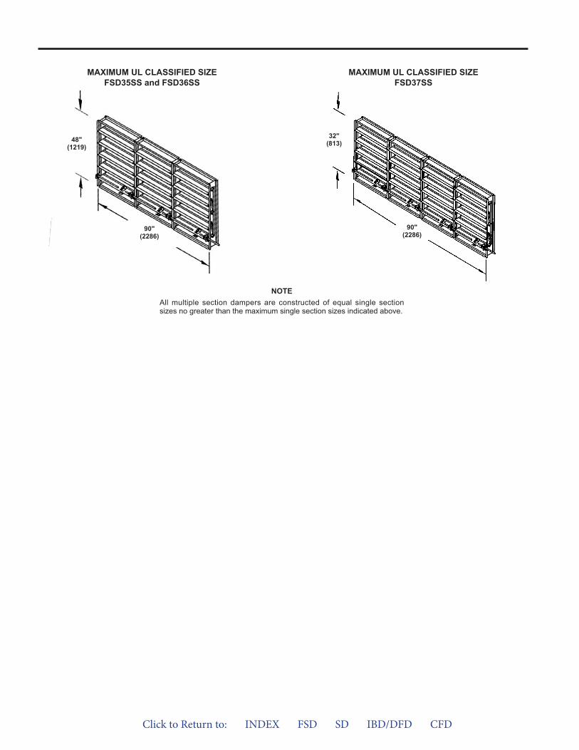
90"(2286)
MAXIMUM UL CLASSIFIED SIZEFSD35SS and FSD36SS
MAXIMUM UL CLASSIFIED SIZEFSD37SS
NOTEAll multiple section dampers are constructed of equal single sectionsizes no greater than the maximum single section sizes indicated above.
48"(1219)
90"(2286)
32"(813)
Click to Return to: INDEX FSD SD IBD/DFD CFD
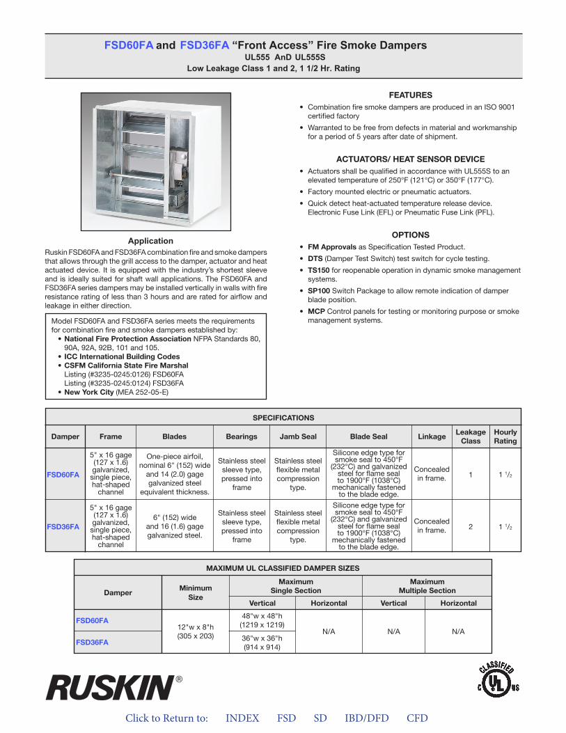
Click to Return to: INDEX FSD SD IBD/DFD CFD
ApplicationRuskin FSD60FA and FSD36FA combination fire and smoke dampers that allows through the grill access to the damper, actuator and heat actuated device. It is equipped with the industry’s shortest sleeve and is ideally suited for shaft wall applications. The FSD60FA and FSD36FA series dampers may be installed vertically in walls with fire resistance rating of less than 3 hours and are rated for airflow and leakage in either direction.
FEATURES• Combination fire smoke dampers are produced in an ISO 9001
certified factory
• Warranted to be free from defects in material and workmanshipfor a period of 5 years after date of shipment.
ACTUATORS/ HEAT SENSOR DEVICE• Actuators shall be qualified in accordance with UL555S to an
elevated temperature of 250°F (121°C) or 350°F (177°C).
• Factory mounted electric or pneumatic actuators.
• Quick detect heat-actuated temperature release device.Electronic Fuse Link (EFL) or Pneumatic Fuse Link (PFL).
OPTIONS• FM Approvals as Specification Tested Product.
• DTS (Damper Test Switch) test switch for cycle testing.
• TS150 for reopenable operation in dynamic smoke managementsystems.
• SP100 Switch Package to allow remote indication of damperblade position.
• MCP Control panels for testing or monitoring purpose or smokemanagement systems.
FSD60FA and FSD36FA “Front Access” Fire Smoke DampersUL555 AnD UL555S
Low Leakage Class 1 and 2, 1 1/2 Hr. Rating
Model FSD60FA and FSD36FA series meets the requirements for combination fire and smoke dampers established by:
• National Fire Protection Association NFPA Standards 80, 90A, 92A, 92B, 101 and 105.
• ICC International Building Codes• CSFM California State Fire Marshal
Listing (#3235-0245:0126) FSD60FAListing (#3235-0245:0124) FSD36FA
• New York City (MEA 252-05-E)
FSD60FA
FSD36FA
SPECIFICATIONS
Frame Blades Bearings Jamb Seal Blade Seal LinkageLeakage
ClassHourlyRating
Damper
5" x 16 gage (127 x 1.6)galvanized,single piece,hat-shaped
channel
5" x 16 gage (127 x 1.6)galvanized,single piece,hat-shaped
channel
One-piece airfoil,nominal 6" (152) wide
and 14 (2.0) gagegalvanized steel
equivalent thickness.
6" (152) wideand 16 (1.6) gagegalvanized steel.
Stainless steelsleeve type,pressed into
frame
Stainless steelsleeve type,pressed into
frame
Stainless steelflexible metalcompression
type.
Stainless steelflexible metalcompression
type.
Silicone edge type forsmoke seal to 450°F
(232°C) and galvanized steel for flame seal to 1900°F (1038°C)
mechanically fastenedto the blade edge.
Silicone edge type forsmoke seal to 450°F
(232°C) and galvanized steel for flame seal to 1900°F (1038°C)
mechanically fastenedto the blade edge.
Concealedin frame.
Concealedin frame.
1
2
1 1/2
1 1/2
MAXIMUM UL CLASSIFIED DAMPER SIZES
Damper
FSD60FA
FSD36FA
MinimumSize
MaximumSingle Section
MaximumMultiple Section
Vertical VerticalHorizontal Horizontal
12"w x 8"h(305 x 203)
N/A N/A N/A
48"w x 48"h(1219 x 1219)
36"w x 36"h(914 x 914)
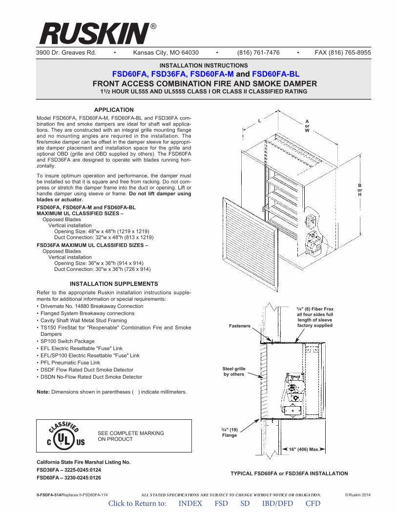
ALL STATED SPECIFICATIONS ARE SUBJECT TO CHANGE WITHOUT NOTICE OR OBLIGATION.
3900 Dr. Greaves Rd. • Kansas City, MO 64030 • (816) 761-7476 • FAX (816) 765-8955
INSTALLATION INSTRUCTIONSFSD60FA, FSD36FA, FSD60FA-M and FSD60FA-BL
FRONT ACCESS COMBINATION FIRE AND SMOKE DAMPER 11/2 HOUR UL555 AND UL555S CLASS I OR CLASS II CLASSIFIED RATING
II-FSDFA-514/Replaces II-FSD60FA-114 © Ruskin 2014
APPLICATIONModel FSD60FA, FSD60FA-M, FSD60FA-BL and FSD36FA com-bination fire and smoke dampers are ideal for shaft wall applica-tions. They are constructed with an integral grille mounting flangeand no mounting angles are required in the installation. Thefire/smoke damper can be offset in the damper sleeve for appropri-ate damper placement and installation space for the grille andoptional OBD (grille and OBD supplied by others). The FSD60FAand FSD36FA are designed to operate with blades running hori-zontally.
To insure optimum operation and performance, the damper mustbe installed so that it is square and free from racking. Do not com-press or stretch the damper frame into the duct or opening. Lift orhandle damper using sleeve or frame. Do not lift damper usingblades or actuator.FSD60FA, FSD60FA-M and FSD60FA-BLMAXIMUM UL CLASSIFIED SIZES –
Opposed BladesVertical installation
Opening Size: 48"w x 48"h (1219 x 1219)Duct Connection: 32"w x 48"h (813 x 1219)
FSD36FA MAXIMUM UL CLASSIFIED SIZES –Opposed Blades
Vertical installationOpening Size: 36"w x 36"h (914 x 914)Duct Connection: 30"w x 36"h (726 x 914)
INSTALLATION SUPPLEMENTSRefer to the appropriate Ruskin installation instructions supple-ments for additional information or special requirements:• Drivemate No. 14880 Breakaway Connection• Flanged System Breakaway connections• Cavity Shaft Wall Metal Stud Framing• TS150 FireStat for "Reopenable" Combination Fire and Smoke
Dampers• SP100 Switch Package• EFL Electric Resettable "Fuse" Link• EFL/SP100 Electric Resettable "Fuse" Link• PFL Pneumatic Fuse Link• DSDF Flow Rated Duct Smoke Detector• DSDN No-Flow Rated Duct Smoke Detector
Note: Dimensions shown in parentheses ( ) indicate millimeters.
TYPICAL FSD60FA or FSD36FA INSTALLATION
16" (406) Max.
Fasteners
Steel grilleby others
3/4" (19)Flange
1/4" (6) Fiber Fraxall four sides fulllength of sleevefactory supplied
AorW
L
BorH
California State Fire Marshal Listing No.FSD36FA – 3225-0245:0124FSD60FA – 3230-0245:0126
SEE COMPLETE MARKING ON PRODUCT
®
Click to Return to: INDEX FSD SD IBD/DFD CFD
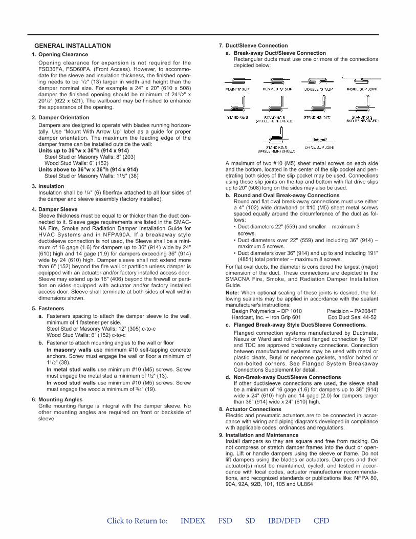
GENERAL INSTALLATION1. Opening Clearance
Opening clearance for expansion is not required for theFSD36FA, FSD60FA. (Front Access). However, to accommo-date for the sleeve and insulation thickness, the finished open-ing needs to be 1/2" (13) larger in width and height than thedamper nominal size. For example a 24" x 20" (610 x 508)damper the finished opening should be minimum of 241/2" x201/2" (622 x 521). The wallboard may be finished to enhancethe appearance of the opening.
2. Damper OrientationDampers are designed to operate with blades running horizon-tally. Use “Mount With Arrow Up” label as a guide for properdamper orientation. The maximum the leading edge of thedamper frame can be installed outside the wall:Units up to 36”w x 36”h (914 x 914)
Steel Stud or Masonry Walls: 8” (203)Wood Stud Walls: 6” (152)
Units above to 36”w x 36”h (914 x 914)Steel Stud or Masonry Walls: 11/2" (38)
3. InsulationInsulation shall be 1/4" (6) fiberfrax attached to all four sides ofthe damper and sleeve assembly (factory installed).
4. Damper SleeveSleeve thickness must be equal to or thicker than the duct con-nected to it. Sleeve gage requirements are listed in the SMAC-NA Fire, Smoke and Radiation Damper Installation Guide forHVAC Systems and in NFPA90A. If a breakaway styleduct/sleeve connection is not used, the Sleeve shall be a mini-mum of 16 gage (1.6) for dampers up to 36" (914) wide by 24"(610) high and 14 gage (1.9) for dampers exceeding 36" (914)wide by 24 (610) high. Damper sleeve shall not extend morethan 6" (152) beyond the fire wall or partition unless damper isequipped with an actuator and/or factory installed access door.Sleeve may extend up to 16" (406) beyond the firewall or parti-tion on sides equipped with actuator and/or factory installedaccess door. Sleeve shall terminate at both sides of wall withindimensions shown.
5. Fastenersa. Fasteners spacing to attach the damper sleeve to the wall,
minimum of 1 fastener per side.Steel Stud or Masonry Walls: 12” (305) c-to-cWood Stud Walls: 6” (152) c-to-c
b. Fastener to attach mounting angles to the wall or floorIn masonry walls use minimum #10 self-tapping concreteanchors. Screw must engage the wall or floor a minimum of11/2" (38).In metal stud walls use minimum #10 (M5) screws. Screwmust engage the metal stud a minimum of 1/2" (13).In wood stud walls use minimum #10 (M5) screws. Screwmust engage the wood a minimum of 3/4" (19).
6. Mounting AnglesGrille mounting flange is integral with the damper sleeve. Noother mounting angles are required on front or backside ofsleeve.
7. Duct/Sleeve Connectiona. Break-away Duct/Sleeve Connection
Rectangular ducts must use one or more of the connectionsdepicted below:
A maximum of two #10 (M5) sheet metal screws on each sideand the bottom, located in the center of the slip pocket and pen-etrating both sides of the slip pocket may be used. Connectionsusing these slip joints on the top and bottom with flat drive slipsup to 20" (508) long on the sides may also be used.b. Round and Oval Break-away Connections
Round and flat oval break-away connections must use eithera 4" (102) wide drawband or #10 (M5) sheet metal screwsspaced equally around the circumference of the duct as fol-lows:• Duct diameters 22" (559) and smaller – maximum 3
screws.• Duct diameters over 22" (559) and including 36" (914) –
maximum 5 screws.• Duct diameters over 36" (914) and up to and including 191"
(4851) total perimeter – maximum 8 screws.For flat oval ducts, the diameter is considered the largest (major)dimension of the duct. These connections are depicted in theSMACNA Fire, Smoke, and Radiation Damper InstallationGuide.Note: When optional sealing of these joints is desired, the fol-lowing sealants may be applied in accordance with the sealantmanufacturer's instructions:
Design Polymerics – DP 1010 Precision – PA2084THardcast, Inc. – Iron Grip 601 Eco Duct Seal 44-52
c. Flanged Break-away Style Duct/Sleeve Connections.Flanged connection systems manufactured by Ductmate,Nexus or Ward and roll-formed flanged connection by TDFand TDC are approved breakaway connections. Connectionbetween manufactured systems may be used with metal orplastic cleats, Butyl or neoprene gaskets, and/or bolted ornon-bolted corners. See Flanged System BreakawayConnections Supplement for detail.
d. Non-Break-away Duct/Sleeve ConnectionsIf other duct/sleeve connections are used, the sleeve shallbe a minimum of 16 gage (1.6) for dampers up to 36" (914)wide x 24" (610) high and 14 gage (2.0) for dampers largerthan 36" (914) wide x 24" (610) high.
8. Actuator ConnectionsElectric and pneumatic actuators are to be connected in accor-dance with wiring and piping diagrams developed in compliancewith applicable codes, ordinances and regulations.
9. Installation and MaintenanceInstall dampers so they are square and free from racking. Donot compress or stretch damper frames into the duct or open-ing. Lift or handle dampers using the sleeve or frame. Do notlift dampers using the blades or actuators. Dampers and theiractuator(s) must be maintained, cycled, and tested in accor-dance with local codes, actuator manufacturer recommenda-tions, and recognized standards or publications like: NFPA 80,90A, 92A, 92B, 101, 105 and UL864
Click to Return to: INDEX FSD SD IBD/DFD CFD
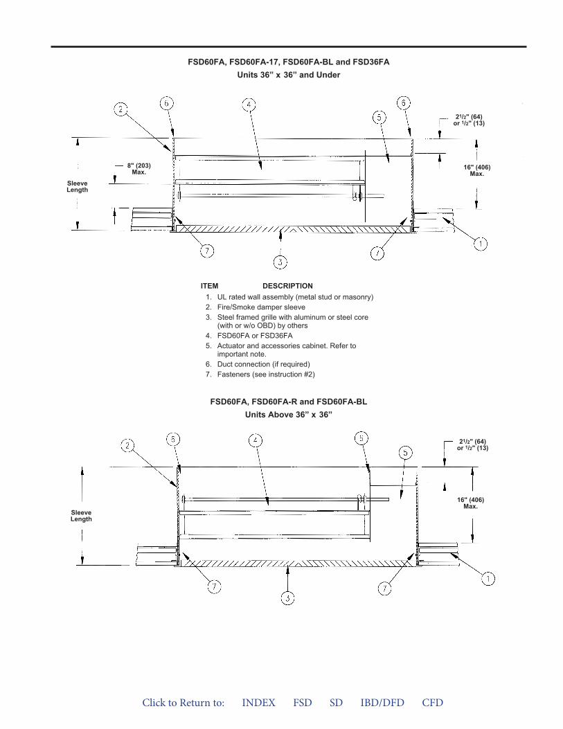
FSD60FA, FSD60FA-R and FSD60FA-BLUnits Above 36” x 36”
ITEM DESCRIPTION1. UL rated wall assembly (metal stud or masonry)2. Fire/Smoke damper sleeve3. Steel framed grille with aluminum or steel core
(with or w/o OBD) by others4. FSD60FA or FSD36FA5. Actuator and accessories cabinet. Refer to
important note.6. Duct connection (if required)7. Fasteners (see instruction #2)
SleeveLength
8" (203)Max.
21/2" (64)or 1/2" (13)
SleeveLength
FSD60FA, FSD60FA-17, FSD60FA-BL and FSD36FAUnits 36” x 36” and Under
16" (406)Max.
21/2" (64)or 1/2" (13)
16" (406)Max.
Click to Return to: INDEX FSD SD IBD/DFD CFD
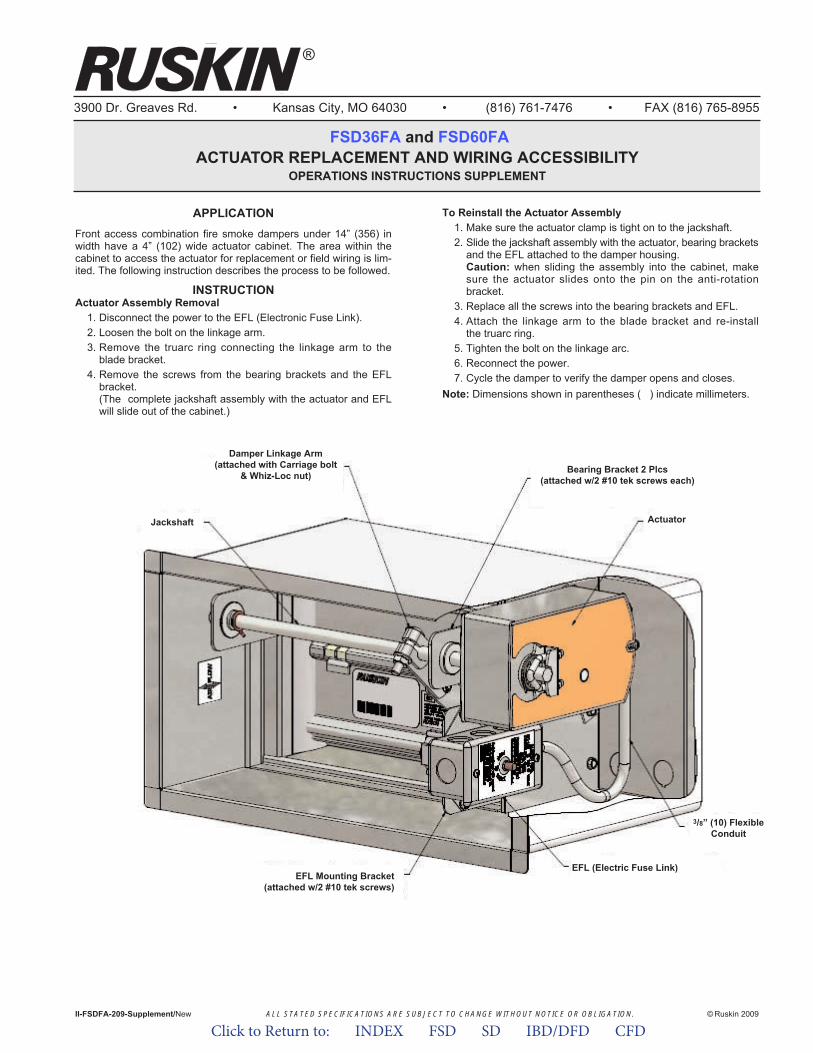
ALL STATED SPECIFICATIONS ARE SUBJECT TO CHANGE WITHOUT NOTICE OR OBLIGATION.
3900 Dr. Greaves Rd. • Kansas City, MO 64030 • (816) 761-7476 • FAX (816) 765-8955
FSD36FA and FSD60FAACTUATOR REPLACEMENT AND WIRING ACCESSIBILITY
OPERATIONS INSTRUCTIONS SUPPLEMENT
II-FSDFA-209-Supplement/New © Ruskin 2009
®
APPLICATIONFront access combination fire smoke dampers under 14” (356) inwidth have a 4” (102) wide actuator cabinet. The area within thecabinet to access the actuator for replacement or field wiring is lim-ited. The following instruction describes the process to be followed.
INSTRUCTIONActuator Assembly Removal
1. Disconnect the power to the EFL (Electronic Fuse Link).2. Loosen the bolt on the linkage arm.3. Remove the truarc ring connecting the linkage arm to the
blade bracket.4. Remove the screws from the bearing brackets and the EFL
bracket.(The complete jackshaft assembly with the actuator and EFLwill slide out of the cabinet.)
To Reinstall the Actuator Assembly1. Make sure the actuator clamp is tight on to the jackshaft.2. Slide the jackshaft assembly with the actuator, bearing brackets
and the EFL attached to the damper housing.Caution: when sliding the assembly into the cabinet, makesure the actuator slides onto the pin on the anti-rotationbracket.
3. Replace all the screws into the bearing brackets and EFL.4. Attach the linkage arm to the blade bracket and re-install
the truarc ring.5. Tighten the bolt on the linkage arc.6. Reconnect the power.7. Cycle the damper to verify the damper opens and closes.
Note: Dimensions shown in parentheses ( ) indicate millimeters.
Jackshaft Actuator
3/8” (10) FlexibleConduit
EFL (Electric Fuse Link)EFL Mounting Bracket
(attached w/2 #10 tek screws)
Bearing Bracket 2 Plcs(attached w/2 #10 tek screws each)
Damper Linkage Arm(attached with Carriage bolt
& Whiz-Loc nut)
Click to Return to: INDEX FSD SD IBD/DFD CFD
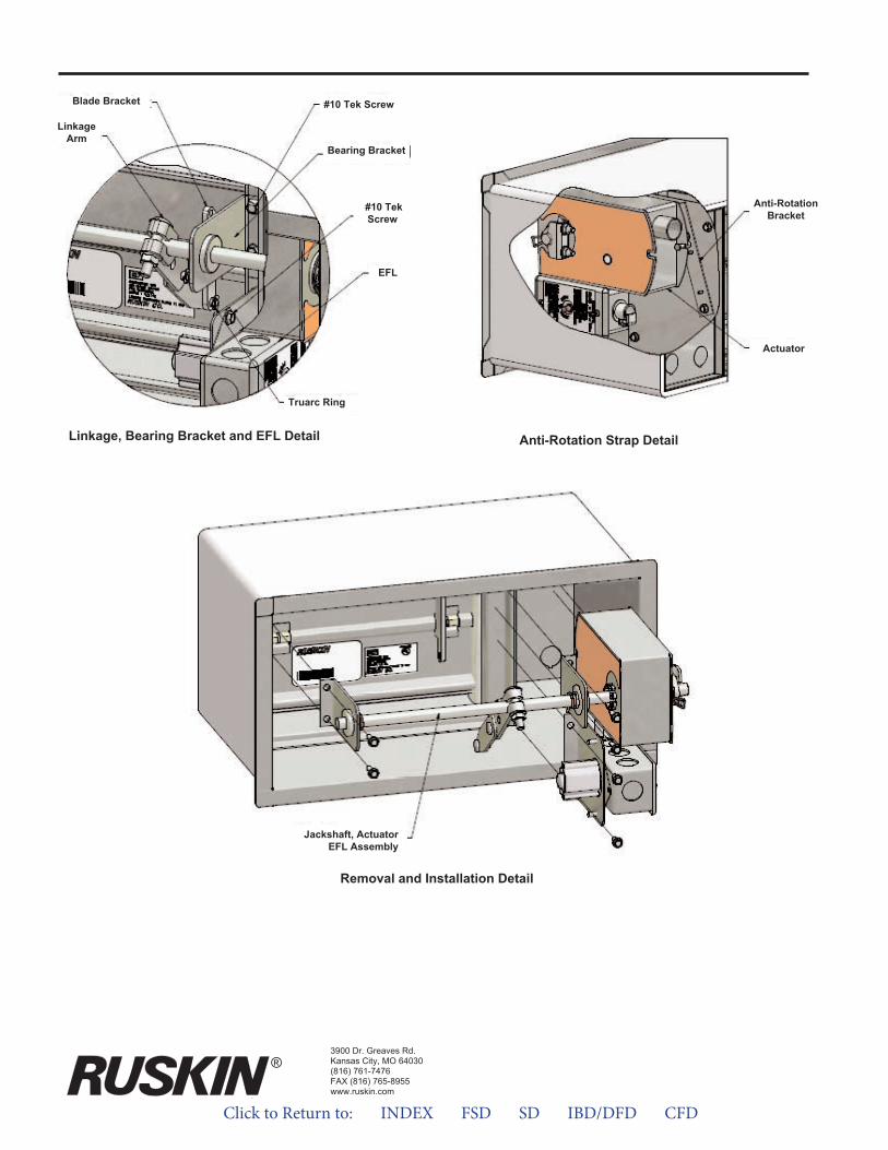
3900 Dr. Greaves Rd.Kansas City, MO 64030(816) 761-7476FAX (816) 765-8955www.ruskin.com
®
Anti-Rotation Strap Detail
Anti-RotationBracket
Actuator
Jackshaft, ActuatorEFL Assembly
Removal and Installation Detail
LinkageArm
Blade Bracket #10 Tek Screw
EFL
Linkage, Bearing Bracket and EFL Detail
Bearing Bracket
#10 TekScrew
Truarc Ring
Click to Return to: INDEX FSD SD IBD/DFD CFD

Click to Return to: INDEX FSD SD IBD/DFD CFD
ApplicationRuskin FSDxxGA series dampers are “out of wall’ Grille Access combination fire and smoke dampers. These dampers allow through the grille access to the damper, actuator and heat actuated device and are ideally suited for shaft wall applications. The FSDxxGA series dampers may be installed vertically in walls with fire resistance rating of less than 3 hours and are rated for airflow and leakage in either direction.
FEATURES• Combination fire smoke dampers are produced in an ISO 9001
certified factory
• Warranted to be free from defects in material and workmanshipfor a period of 5 years after date of shipment.
ACTUATORS/ HEAT SENSOR DEVICE• Actuators shall be qualified in accordance with UL555S to an
elevated temperature of 250°F (121°C) or 350°F (177°C).
• Factory mounted electric or pneumatic actuators.
• Quick detect heat-actuated temperature release device.Electronic Fuse Link (EFL) or Pneumatic Fuse Link (PFL).
OPTIONS• FM Approvals as Specification Tested Product.
• DTS (Damper Test Switch) test switch for cycle testing.
• TS150 for reopenable operation in dynamic smoke managementsystems.
• SP100 Switch Package to allow remote indication of damperblade position.
• MCP Control panels for testing or monitoring purpose or smokemanagement systems.
FSDxxGA “Grille Access Combination Fire Smoke DampersUL555 AnD UL555S
Leakage Class 1 and 2, 1 ½ Hr. Rating
Model FSD60GA and FSD36GA series meets the requirements for combination fire and smoke dampers established by:
• National Fire Protection Association NFPA Standards 80, 90A, 92A, 92B, 101 and 105.
• ICC International Building Codes• CSFM California State Fire Marshal
Listing (#3235-0245:0126) FSD60GAListing (#3235-0245:0124) FSD36GA
• New York City (MEA 252-05-E)
FSD36GA
FSD60GA
FSD60-2GA
FSD60VGA
FSD36SS/GA
SPECIFICATIONS
Frame Blades Bearings Jamb Seal Blade Seal LinkageLeakage
ClassHourlyRating
Damper
5" x 16 gage (127 x 1.6)galvanized,single piece,hat-shaped
channel
5" x 16 gage (127 x 1.6)galvanized,single piece,hat-shaped
channel
5" x 16 gage (127 x 1.6)
stainless steel,single piece,hat-shaped
channel
One-piece airfoil,nominal 6" (152) wide
and 14 (2.0) gagegalvanized steel
equivalent thickness.
6" (152) wideand 16 (1.6) gagegalvanized steel.
6" (152) wideand 16 (1.6) gage
stainless steel.
Stainless steelsleeve type,pressed into
frame
Stainless steelsleeve type,pressed into
frame
Stainless steelsleeve type,pressed into
frame
Stainless steelflexible metalcompression
type.
Stainless steelflexible metalcompression
type.
Stainless steelflexible metalcompression
type.
Silicone edge type forsmoke seal to 450°F
(232°C) and galvanized steel for flame seal to 1900°F (1038°C)
mechanically fastenedto the blade edge.
Silicone edge type forsmoke seal to 450°F
(232°C) and galvanized steel for flame seal to 1900°F (1038°C)
mechanically fastenedto the blade edge.
Silicone edge type forsmoke seal to 450°F
(232°C) and galvanized steel for flame seal to 1900°F (1038°C)
mechanically fastenedto the blade edge.
Concealedin frame.
Concealedin frame.
Concealedin frame.
1
2
2
2
2
1 1/2
1 1/2
1 1/2
1 1/2
1 1/2
MAXIMUM UL CLASSIFIED DAMPER SIZES
Damper
All Models
MinimumSize
MaximumSingle Section
MaximumMultiple Section
Vertical VerticalHorizontal Horizontal
12"w x 10"h(305 x 254)
N/A N/A N/A36"w x 36"h(914 x 914)
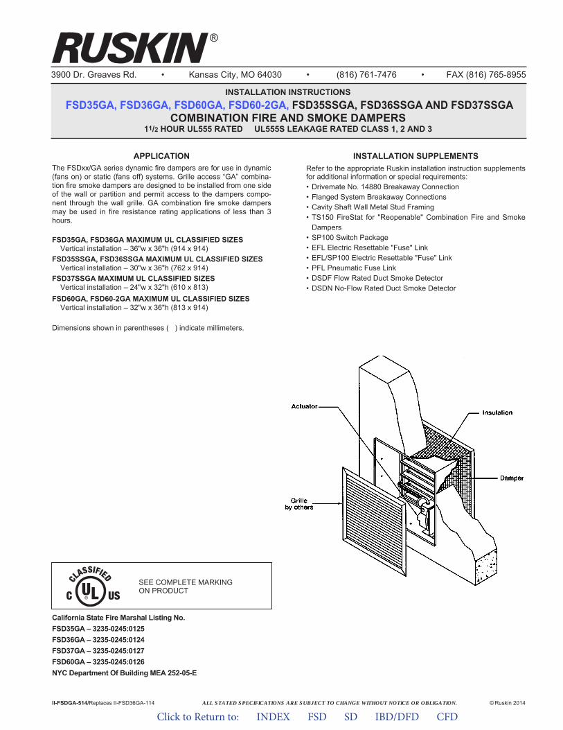
ALL STATED SPECIFICATIONS ARE SUBJECT TO CHANGE WITHOUT NOTICE OR OBLIGATION.
3900 Dr. Greaves Rd. • Kansas City, MO 64030 • (816) 761-7476 • FAX (816) 765-8955
INSTALLATION INSTRUCTIONSFSD35GA, FSD36GA, FSD60GA, FSD60-2GA, FSD35SSGA, FSD36SSGA AND FSD37SSGA
COMBINATION FIRE AND SMOKE DAMPERS11/2 HOUR UL555 RATED UL555S LEAKAGE RATED CLASS 1, 2 AND 3
II-FSDGA-514/Replaces II-FSD36GA-114 © Ruskin 2014
®
INSTALLATION SUPPLEMENTSRefer to the appropriate Ruskin installation instruction supplementsfor additional information or special requirements:• Drivemate No. 14880 Breakaway Connection• Flanged System Breakaway Connections• Cavity Shaft Wall Metal Stud Framing• TS150 FireStat for "Reopenable" Combination Fire and Smoke
Dampers• SP100 Switch Package• EFL Electric Resettable "Fuse" Link• EFL/SP100 Electric Resettable "Fuse" Link• PFL Pneumatic Fuse Link• DSDF Flow Rated Duct Smoke Detector• DSDN No-Flow Rated Duct Smoke Detector
California State Fire Marshal Listing No.FSD35GA – 3235-0245:0125FSD36GA – 3235-0245:0124FSD37GA – 3235-0245:0127FSD60GA – 3235-0245:0126NYC Department Of Building MEA 252-05-E
APPLICATIONThe FSDxx/GA series dynamic fire dampers are for use in dynamic(fans on) or static (fans off) systems. Grille access “GA” combina-tion fire smoke dampers are designed to be installed from one sideof the wall or partition and permit access to the dampers compo-nent through the wall grille. GA combination fire smoke dampersmay be used in fire resistance rating applications of less than 3hours.
FSD35GA, FSD36GA MAXIMUM UL CLASSIFIED SIZES Vertical installation – 36"w x 36"h (914 x 914)
FSD35SSGA, FSD36SSGA MAXIMUM UL CLASSIFIED SIZES Vertical installation – 30"w x 36"h (762 x 914)
FSD37SSGA MAXIMUM UL CLASSIFIED SIZES Vertical installation – 24"w x 32"h (610 x 813)
FSD60GA, FSD60-2GA MAXIMUM UL CLASSIFIED SIZESVertical installation – 32"w x 36"h (813 x 914)
Dimensions shown in parentheses ( ) indicate millimeters.
SEE COMPLETE MARKING ON PRODUCT
Click to Return to: INDEX FSD SD IBD/DFD CFD
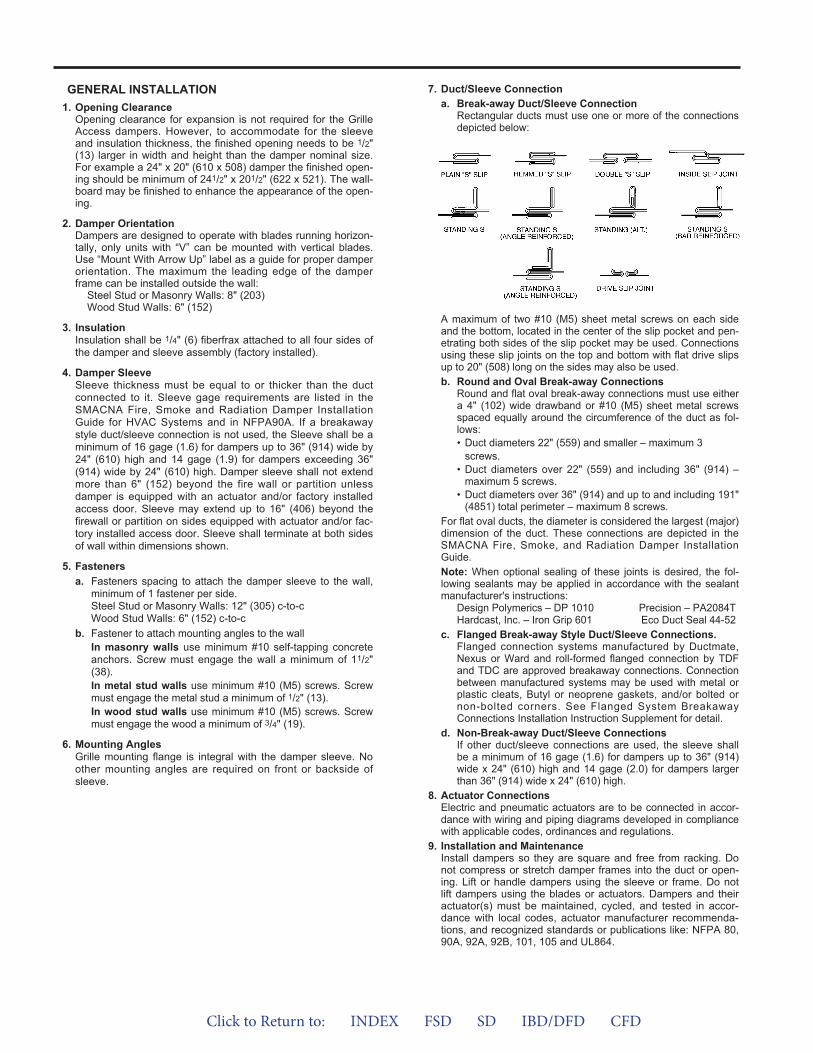
GENERAL INSTALLATION1. Opening Clearance
Opening clearance for expansion is not required for the GrilleAccess dampers. However, to accommodate for the sleeveand insulation thickness, the finished opening needs to be 1/2"(13) larger in width and height than the damper nominal size.For example a 24" x 20" (610 x 508) damper the finished open-ing should be minimum of 241/2" x 201/2" (622 x 521). The wall-board may be finished to enhance the appearance of the open-ing.
2. Damper OrientationDampers are designed to operate with blades running horizon-tally, only units with “V” can be mounted with vertical blades.Use “Mount With Arrow Up” label as a guide for proper damperorientation. The maximum the leading edge of the damperframe can be installed outside the wall:
Steel Stud or Masonry Walls: 8" (203)Wood Stud Walls: 6" (152)
3. InsulationInsulation shall be 1/4" (6) fiberfrax attached to all four sides ofthe damper and sleeve assembly (factory installed).
4. Damper SleeveSleeve thickness must be equal to or thicker than the ductconnected to it. Sleeve gage requirements are listed in theSMACNA Fire, Smoke and Radiation Damper InstallationGuide for HVAC Systems and in NFPA90A. If a breakawaystyle duct/sleeve connection is not used, the Sleeve shall be aminimum of 16 gage (1.6) for dampers up to 36" (914) wide by24" (610) high and 14 gage (1.9) for dampers exceeding 36"(914) wide by 24" (610) high. Damper sleeve shall not extendmore than 6" (152) beyond the fire wall or partition unlessdamper is equipped with an actuator and/or factory installedaccess door. Sleeve may extend up to 16" (406) beyond thefirewall or partition on sides equipped with actuator and/or fac-tory installed access door. Sleeve shall terminate at both sidesof wall within dimensions shown.
5. Fastenersa. Fasteners spacing to attach the damper sleeve to the wall,
minimum of 1 fastener per side.Steel Stud or Masonry Walls: 12" (305) c-to-cWood Stud Walls: 6" (152) c-to-c
b. Fastener to attach mounting angles to the wallIn masonry walls use minimum #10 self-tapping concreteanchors. Screw must engage the wall a minimum of 11/2"(38).In metal stud walls use minimum #10 (M5) screws. Screwmust engage the metal stud a minimum of 1/2" (13).In wood stud walls use minimum #10 (M5) screws. Screwmust engage the wood a minimum of 3/4" (19).
6. Mounting AnglesGrille mounting flange is integral with the damper sleeve. Noother mounting angles are required on front or backside ofsleeve.
7. Duct/Sleeve Connectiona. Break-away Duct/Sleeve Connection
Rectangular ducts must use one or more of the connectionsdepicted below:
A maximum of two #10 (M5) sheet metal screws on each sideand the bottom, located in the center of the slip pocket and pen-etrating both sides of the slip pocket may be used. Connectionsusing these slip joints on the top and bottom with flat drive slipsup to 20" (508) long on the sides may also be used.b. Round and Oval Break-away Connections
Round and flat oval break-away connections must use eithera 4" (102) wide drawband or #10 (M5) sheet metal screwsspaced equally around the circumference of the duct as fol-lows:• Duct diameters 22" (559) and smaller – maximum 3
screws.• Duct diameters over 22" (559) and including 36" (914) –
maximum 5 screws.• Duct diameters over 36" (914) and up to and including 191"
(4851) total perimeter – maximum 8 screws.For flat oval ducts, the diameter is considered the largest (major)dimension of the duct. These connections are depicted in theSMACNA Fire, Smoke, and Radiation Damper InstallationGuide.Note: When optional sealing of these joints is desired, the fol-lowing sealants may be applied in accordance with the sealantmanufacturer's instructions:
Design Polymerics – DP 1010 Precision – PA2084THardcast, Inc. – Iron Grip 601 Eco Duct Seal 44-52
c. Flanged Break-away Style Duct/Sleeve Connections.Flanged connection systems manufactured by Ductmate,Nexus or Ward and roll-formed flanged connection by TDFand TDC are approved breakaway connections. Connectionbetween manufactured systems may be used with metal orplastic cleats, Butyl or neoprene gaskets, and/or bolted ornon-bolted corners. See Flanged System BreakawayConnections Installation Instruction Supplement for detail.
d. Non-Break-away Duct/Sleeve ConnectionsIf other duct/sleeve connections are used, the sleeve shallbe a minimum of 16 gage (1.6) for dampers up to 36" (914)wide x 24" (610) high and 14 gage (2.0) for dampers largerthan 36" (914) wide x 24" (610) high.
8. Actuator ConnectionsElectric and pneumatic actuators are to be connected in accor-dance with wiring and piping diagrams developed in compliancewith applicable codes, ordinances and regulations.
9. Installation and MaintenanceInstall dampers so they are square and free from racking. Donot compress or stretch damper frames into the duct or open-ing. Lift or handle dampers using the sleeve or frame. Do notlift dampers using the blades or actuators. Dampers and theiractuator(s) must be maintained, cycled, and tested in accor-dance with local codes, actuator manufacturer recommenda-tions, and recognized standards or publications like: NFPA 80,90A, 92A, 92B, 101, 105 and UL864.
Click to Return to: INDEX FSD SD IBD/DFD CFD
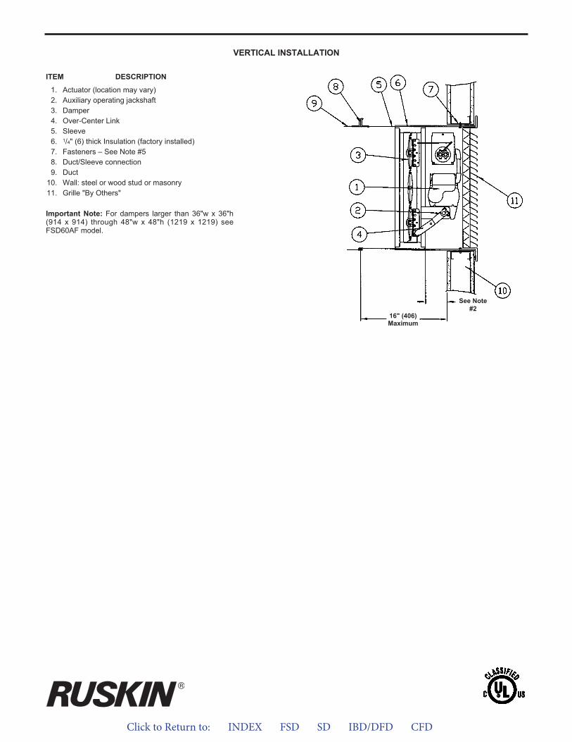
Click to Return to: INDEX FSD SD IBD/DFD CFD
VERTICAL INSTALLATION
ITEM DESCRIPTION
1. Actuator (location may vary)2. Auxiliary operating jackshaft3. Damper4. Over-Center Link5. Sleeve6. 1/4" (6) thick Insulation (factory installed)7. Fasteners – See Note #58. Duct/Sleeve connection9. Duct
10. Wall: steel or wood stud or masonry11. Grille "By Others"
Important Note: For dampers larger than 36"w x 36"h(914 x 914) through 48"w x 48"h (1219 x 1219) seeFSD60AF model.
16" (406)Maximum
See Note#2

Click to Return to: INDEX FSD SD IBD/DFD CFD
ApplicationRuskin FSDxxOW series dampers are “out of wall” or “out of floor” combination fire and smoke dampers. The OW series dampers are designed so that the damper may be installed up to 8" (203) outside the fire rated wall or floor assembly. The FSDxxOW series dampers may be installed vertical (in walls) or horizontal (concrete floors) with fire resistance rating of less than 3 hours and are rated for airflow and leakage in either direction.
FEATURES• Combination fire smoke dampers are produced in an ISO 9001
certified factory
• Warranted to be free from defects in material and workmanshipfor a period of 5 years after date of shipment.
ACTUATORS/ HEAT SENSOR DEVICE• Actuators shall be qualified in accordance with UL555S to an
elevated temperature of 250°F (121°C) or 350°F (177°C).
• Factory mounted electric or pneumatic actuators
• Actuators available for either external (out of air stream) orinternal (in air stream) mounting location.
• Quick detect heat-actuated temperature release device.Electronic Fuse Link (EFL) or Pneumatic Fuse Link (PFL).
OPTIONS• FM Approvals as Specification Tested Product.
• DTS (Damper Test Switch) test switch for cycle testing.
• TS150 for reopenable operation in dynamic smoke managementsystems.
• DSDF/DSDN Duct Smoke Detector (Flow rated and No-Flow).
• SP100 Switch Package to allow remote indication of damperblade position.
• MCP Control panels for testing or monitoring purpose or smokemanagement systems.
• Factory Sleeves of various lengths and gages to ensure fieldcompliance with UL installation requirements.
• FAST Angle factory supplied for labor saving angle one-sideinstallation. Other angles of various sizes and gages also forone-side or two-side installation.
FSDXX/oW “Out of Wall” Combination Fire Smoke Dampersul555 AnD ul555S
leAkAge clASS i AnD ii, 1 ½ Hr. rA ting
Model FSD60/OW and FSD36/OW series meets the require-ments for combination fire and smoke dampers established by:
• National Fire Protection Association NFPA Standards 80, 90A, 92A, 92B, 101 and 105.
• ICC International Building Codes• CSFM California State Fire Marshal
Listing (#3235-0245:0126) FSD60/OWListing (#3235-0245:0124) FSD36/OW
• New York City (MEA 252-05-E)
FSD36/OW
FSD60/OW
FSD60-2/OW
FSD60V/OW
FSD36SS/OW
SPECIFICATIONS
Frame Blades Bearings Jamb Seal Blade Seal LinkageLeakage
ClassHourlyRating
Damper
5" x 16 gage (127 x 1.6)galvanized,single piece,hat-shaped
channel
5" x 16 gage (127 x 1.6)galvanized,single piece,hat-shaped
channel
5" x 16 gage (127 x 1.6)
stainless steel,single piece,hat-shaped
channel
One-piece airfoil,nominal 6" (152) wide
and 14 (2.0) gagegalvanized steel
equivalent thickness.
6" (152) wideand 16 (1.6) gagegalvanized steel.
6" (152) wideand 16 (1.6) gage
stainless steel.
Stainless steelsleeve type,pressed into
frame
Stainless steelsleeve type,pressed into
frame
Stainless steelsleeve type,pressed into
frame
Stainless steelflexible metalcompression
type.
Stainless steelflexible metalcompression
type.
Stainless steelflexible metalcompression
type.
Silicone edge type forsmoke seal to 450°F
(232°C) and galvanized steel for flame seal to 1900°F (1038°C)
mechanically fastenedto the blade edge.
Silicone edge type forsmoke seal to 450°F
(232°C) and galvanized steel for flame seal to 1900°F (1038°C)
mechanically fastenedto the blade edge.
Silicone edge type forsmoke seal to 450°F
(232°C) and galvanized steel for flame seal to 1900°F (1038°C)
mechanically fastenedto the blade edge.
Concealedin frame.
Concealedin frame.
Concealedin frame.
1
2
2
2
2
1 1/2
1 1/2
1 1/2
1 1/2
1 1/2
MAXIMUM UL CLASSIFIED DAMPER SIZES
Damper
All Models
MinimumSize
MaximumSingle Section
MaximumMultiple Section
Vertical VerticalHorizontal Horizontal
8"w x 6"h(195 x 152)
N/A N/A N/A36"w x 36"h(914 x 914)
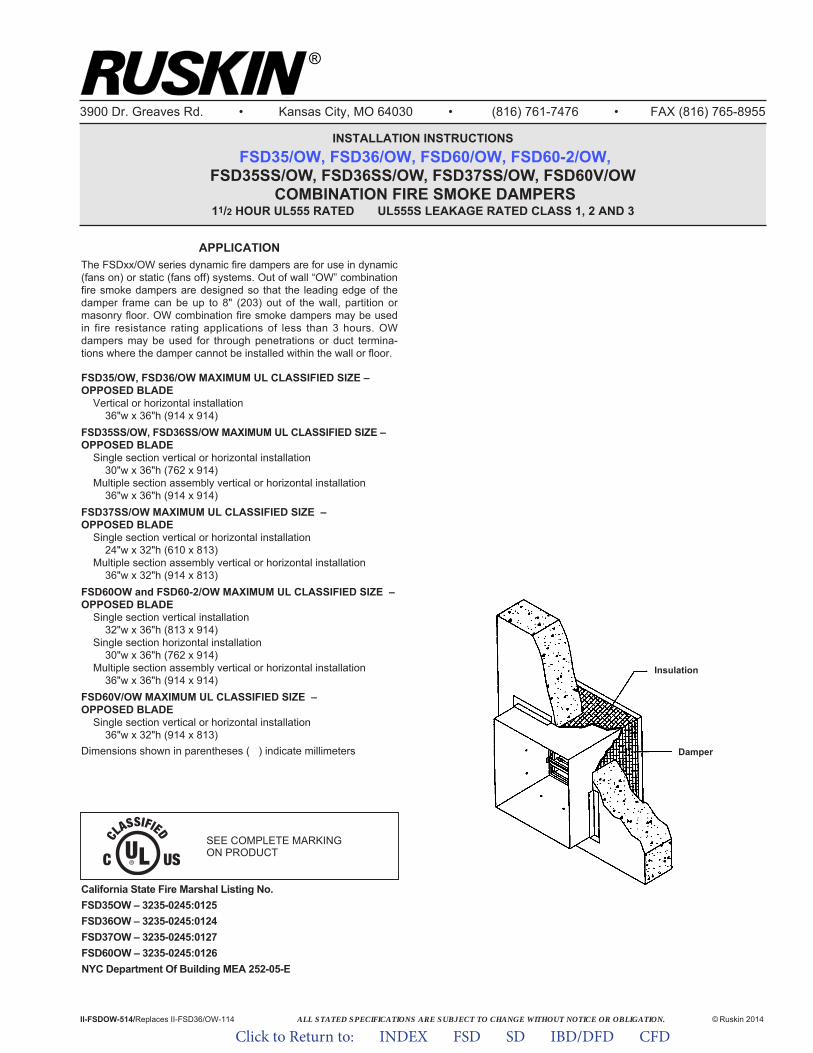
ALL STATED SPECIFICATIONS ARE SUBJECT TO CHANGE WITHOUT NOTICE OR OBLIGATION.
3900 Dr. Greaves Rd. • Kansas City, MO 64030 • (816) 761-7476 • FAX (816) 765-8955
INSTALLATION INSTRUCTIONSFSD35/OW, FSD36/OW, FSD60/OW, FSD60-2/OW,
FSD35SS/OW, FSD36SS/OW, FSD37SS/OW, FSD60V/OW COMBINATION FIRE SMOKE DAMPERS
11/2 HOUR UL555 RATED UL555S LEAKAGE RATED CLASS 1, 2 AND 3
II-FSDOW-114/Replaces II-FSD36/OW-109 © Ruskin 2014
®
Insulation
Damper
California State Fire Marshal Listing No.FSD35GA – 3235-0245:0125FSD36GA – 3235-0245:0124FSD37GA – 3235-0245:0127FSD60GA – 3235-0245:0126NYC Department Of Building MEA 252-05-E
SEE COMPLETE MARKINGON PRODUCT
APPLICATIONThe FSDxx/OW series dynamic fire dampers are for use in dynamic(fans on) or static (fans off) systems. Out of wall “OW” combinationfire smoke dampers are designed so that the leading edge of thedamper frame can be up to 8" (203) out of the wall, partition ormasonry floor. OW combination fire smoke dampers may be usedin fire resistance rating applications of less than 3 hours. OWdampers may be used for through penetrations or duct termina-tions where the damper cannot be installed within the wall or floor.
FSD35/OW, FSD36/OW MAXIMUM UL CLASSIFIED SIZE –OPPOSED BLADE
Vertical or horizontal installation36"w x 36"h (914 x 914)
FSD35SS/OW, FSD36SS/OW MAXIMUM UL CLASSIFIED SIZE –OPPOSED BLADE
Single section vertical or horizontal installation30"w x 36"h (762 x 914)
Multiple section assembly vertical or horizontal installation36"w x 36"h (914 x 914)
FSD37SS/OW MAXIMUM UL CLASSIFIED SIZE –OPPOSED BLADE
Single section vertical or horizontal installation24"w x 32"h (610 x 813)
Multiple section assembly vertical or horizontal installation36"w x 32"h (914 x 813)
FSD60OW and FSD60-2/OW MAXIMUM UL CLASSIFIED SIZE –OPPOSED BLADE
Single section vertical installation32"w x 36"h (813 x 914)
Single section horizontal installation30"w x 36"h (762 x 914)
Multiple section assembly vertical or horizontal installation36"w x 36"h (914 x 914)
FSD60V/OW MAXIMUM UL CLASSIFIED SIZE –OPPOSED BLADE
Single section vertical or horizontal installation36"w x 32"h (914 x 813)
Dimensions shown in parentheses ( ) indicate millimeters
California State Fire Marshal Listing No.FSD35OW – 3235-0245:0125FSD36OW – 3235-0245:0124FSD37OW – 3235-0245:0127FSD60OW – 3235-0245:0126NYC Department Of Building MEA 252-05-E
ALL STATED SPECIFICATIONS ARE SUBJECT TO CHANGE WITHOUT NOTICE OR OBLIGATION.II-FSDOW-514/Replaces II-FSD36/OW-114 © Ruskin 2014
Click to Return to: INDEX FSD SD IBD/DFD CFD
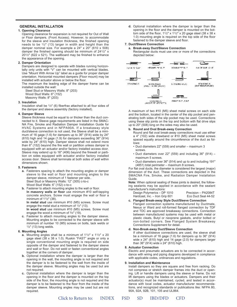
GENERAL INSTALLATION1. Opening Clearance
Opening clearance for expansion is not required for Out of Wallor Floor dampers. (Front Access). However, to accommodatefor the sleeve and insulation thickness, the finished openingneeds to be 1/2" (13) larger in width and height than thedamper nominal size. For example a 24" x 20" (610 x 508)damper the finished opening should be minimum of 241/2" x201/2" (622 x 521). The wallboard may be finished to enhancethe appearance of the opening.
2. Damper OrientationDampers are designed to operate with blades running horizon-tally only units with “V” can be mounted with vertical blades.Use “Mount With Arrow Up” label as a guide for proper damperorientation. Horizontal mounted dampers (Floor mount) may beinstalled with actuator above or below the floor.The maximum the leading edge of the damper frame can beinstalled outside the wall:
Steel Stud or Masonry Walls: 8" (203)Wood Stud Walls: 6" (152)Masonry Walls: 8" (203)
3. InsulationInsulation shall be 1/4" (6) fiberfrax attached to all four sides ofthe damper and sleeve assembly (factory installed).
4. Damper SleeveSleeve thickness must be equal to or thicker than the duct con-nected to it. Sleeve gage requirements are listed in the SMAC-NA Fire, Smoke and Radiation Damper Installation Guide forHVAC Systems and in NFPA90A. If a breakaway styleduct/sleeve connection is not used, the Sleeve shall be a mini-mum of 16 gage (1.6) for dampers up to 36" (914) wide by 24"(610) high and 14 gage (1.9) for dampers exceeding 36" (914)wide by 24" (610) high. Damper sleeve shall not extend morethan 6" (152) beyond the fire wall or partition unless damper isequipped with an actuator and/or factory installed access door.Sleeve may extend up to 16" (406) beyond the firewall or parti-tion on sides equipped with actuator and/or factory installedaccess door. Sleeve shall terminate at both sides of wall withindimensions shown.
5. Fastenersa. Fasteners spacing to attach the mounting angles or damper
sleeve to the wall or floor and mounting angles to thedamper sleeve, minimum of 1 fastener per side..Steel Stud or Masonry Walls: 12” (305) c-to-cWood Stud Walls: 6” (152) c-to-c
b. Fastener to attach mounting angles to the wall or floor.In masonry walls or floor use minimum #10 self-tappingconcrete anchors. Screw must engage the wall or floor aminimum of 11/2" (38).In metal stud use minimum #10 (M5) screws. Screw mustengage the metal stud a minimum of 1/2" (13).In wood stud use minimum #10 (M5) screws. Screw mustengage the wood a minimum of 3/4" (19).
c. Fastener to attach mounting angles to the damper sleeve.Mounting angles to be connected to the damper sleeve withminimum of number 10 (M5) screws on bolts, tack welds or1/2" (13) long welds.
6. Mounting Anglesa. Mounting angles shall be a minimum of 11/2" x 11/2" x 20
gage steel (38 x 38 x 1.0). Ruskin “FAST” angle or only asingle conventional mounting angle is required on sideopposite of the damper and fastened to the damper sleeveand wall or floor. Do not weld or fasten conventional anglestogether at the corners of damper.
b. Optional installation where the damper is larger than theopening in the wall, the mounting angle is not required andthe damper is to be fastened to the wall from the inside ofthe damper sleeve. Mounting angles may be used but arenot required.
c. Optional installation where the damper is larger than theopening in the floor and the damper is mounted on the topside of the floor, the mounting angle is not required and thedamper is to be fastened to the floor from the inside of thedamper sleeve. Mounting angles may be used but are notrequired.
d. Optional installation where the damper is larger than theopening in the floor and the damper is mounted on the bot-tom side of the floor, 11/2" x 11/2" x 20 gage steel (38 x 38 x1.0) mounting angle is required on the top side of the floorfastened to the damper sleeve and floor.
7. Duct/Sleeve Connectiona. Break-away Duct/Sleeve Connection
Rectangular ducts must use one or more of the connectionsdepicted below:
A maximum of two #10 (M5) sheet metal screws on each sideand the bottom, located in the center of the slip pocket and pen-etrating both sides of the slip pocket may be used. Connectionsusing these slip joints on the top and bottom with flat drive slipsup to 20" (508) long on the sides may also be used.b. Round and Oval Break-away Connection
Round and flat oval break-away connections must use eithera 4" (102) wide drawband or #10 (M5) sheet metal screwsspaced equally around the circumference of the duct as fol-lows:• Duct diameters 22" (559) and smaller – maximum 3
screws.• Duct diameters over 22" (559) and including 36" (914) –
maximum 5 screws.• Duct diameters over 36" (914) and up to and including 191"
(4851) total perimeter – maximum 8 screws.For flat oval ducts, the diameter is considered the largest (major)dimension of the duct. These connections are depicted in theSMACNA Fire, Smoke, and Radiation Damper InstallationGuide.Note: When optional sealing of these joints is desired, the follow-ing sealants may be applied in accordance with the sealantmanufacturer's instructions:
Design Polymerics – DP 1010 Precision – PA2084THardcast, Inc. – Iron Grip 601 Eco Duct Seal 44-52
c. Flanged Break-away Style Duct/Sleeve ConnectionFlanged connection systems manufactured by Ductmate,Nexus or Ward and roll-formed flanged connection by TDFand TDC are approved breakaway connections. Connectionbetween manufactured systems may be used with metal orplastic cleats, Butyl or neoprene gaskets, and/or bolted ornon-bolted corners. See Flanged System BreakawayConnections Supplement for detail.
d. Non-Break-away Duct/Sleeve ConnectionIf other duct/sleeve connections are used, the sleeve shallbe a minimum of 16 gage (1.6) for dampers up to 36" (914)wide x 24" (610) high and 14 gage (2.0) for dampers largerthan 36" (914) wide x 24" (610) high.
8. Actuator ConnectionElectric and pneumatic actuators are to be connected in accor-dance with wiring and piping diagrams developed in compliancewith applicable codes, ordinances and regulations.
9. Installation and MaintenanceInstall dampers so they are square and free from racking. Donot compress or stretch damper frames into the duct or open-ing. Lift or handle dampers using the sleeve or frame. Do notlift dampers using the blades or actuators. Dampers and theiractuator(s) must be maintained, cycled, and tested in accor-dance with local codes, actuator manufacturer recommenda-tions, and recognized standards or publications like: NFPA 80,90A, 92A, 92B, 101, 105 and UL864.
Click to Return to: INDEX FSD SD IBD/DFD CFD
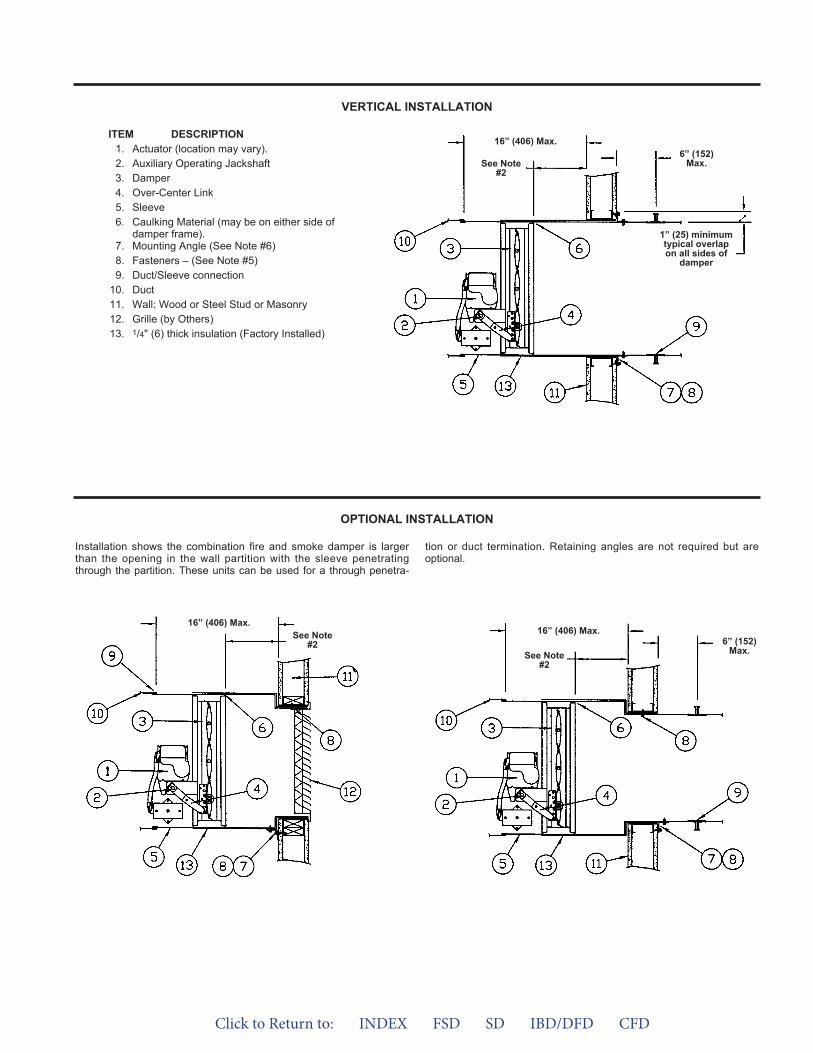
VERTICAL INSTALLATION
OPTIONAL INSTALLATION
ITEM DESCRIPTION1. Actuator (location may vary).2. Auxiliary Operating Jackshaft3. Damper4. Over-Center Link5. Sleeve6. Caulking Material (may be on either side of
damper frame).7. Mounting Angle (See Note #6)8. Fasteners – (See Note #5)9. Duct/Sleeve connection
10. Duct11. Wall: Wood or Steel Stud or Masonry12. Grille (by Others)13. 1/4" (6) thick insulation (Factory Installed)
Installation shows the combination fire and smoke damper is largerthan the opening in the wall partition with the sleeve penetratingthrough the partition. These units can be used for a through penetra-
tion or duct termination. Retaining angles are not required but areoptional.
See Note#2
16” (406) Max.6” (152)
Max.
1” (25) minimumtypical overlapon all sides of
damper
See Note#2
16” (406) Max.6” (152)
Max.See Note
#2
16” (406) Max.
Click to Return to: INDEX FSD SD IBD/DFD CFD
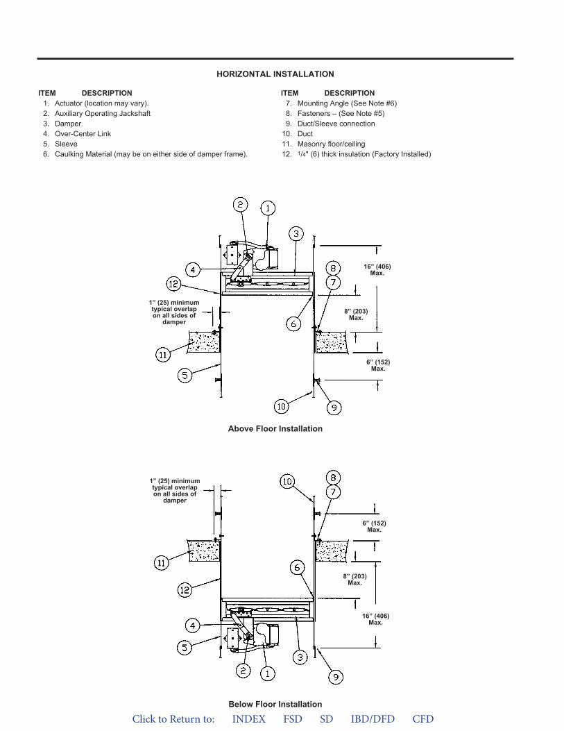
HORIZONTAL INSTALLATION
ITEM DESCRIPTION1. Actuator (location may vary).2. Auxiliary Operating Jackshaft3. Damper4. Over-Center Link5. Sleeve6. Caulking Material (may be on either side of damper frame).
ITEM DESCRIPTION7. Mounting Angle (See Note #6)8. Fasteners – (See Note #5)9. Duct/Sleeve connection
10. Duct11. Masonry floor/ceiling12. 1/4" (6) thick insulation (Factory Installed)
Above Floor Installation
Below Floor Installation
16” (406)Max.
6” (152)Max.
1” (25) minimumtypical overlapon all sides of
damper8” (203)
Max.
16” (406)Max.
6” (152)Max.
1” (25) minimumtypical overlapon all sides of
damper
8” (203)Max.
Click to Return to: INDEX FSD SD IBD/DFD CFD
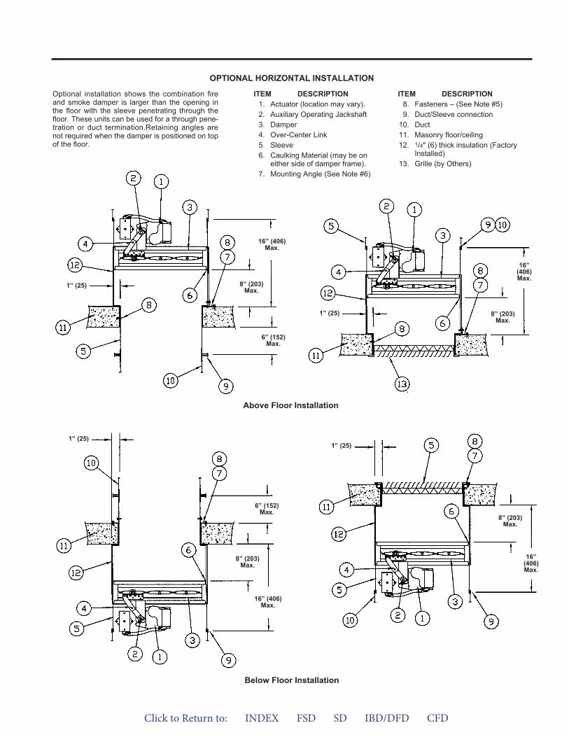
OPTIONAL HORIZONTAL INSTALLATION
ITEM DESCRIPTION1. Actuator (location may vary).2. Auxiliary Operating Jackshaft3. Damper4. Over-Center Link5. Sleeve6. Caulking Material (may be on
either side of damper frame).7. Mounting Angle (See Note #6)
ITEM DESCRIPTION8. Fasteners – (See Note #5)9. Duct/Sleeve connection
10. Duct11. Masonry floor/ceiling12. 1/4" (6) thick insulation (Factory
Installed)13. Grille (by Others)
Optional installation shows the combination fireand smoke damper is larger than the opening inthe floor with the sleeve penetrating through thefloor. These units can be used for a through pene-tration or duct termination.Retaining angles arenot required when the damper is positioned on topof the floor.
Above Floor Installation
Below Floor Installation
16” (406)Max.
6” (152)Max.
8” (203)Max.
1” (25)
16”(406)Max.
8” (203)Max.
1” (25)
16”(406)Max.
8” (203)Max.
1” (25)
16” (406)Max.
6” (152)Max.
8” (203)Max.
1” (25)
Click to Return to: INDEX FSD SD IBD/DFD CFD
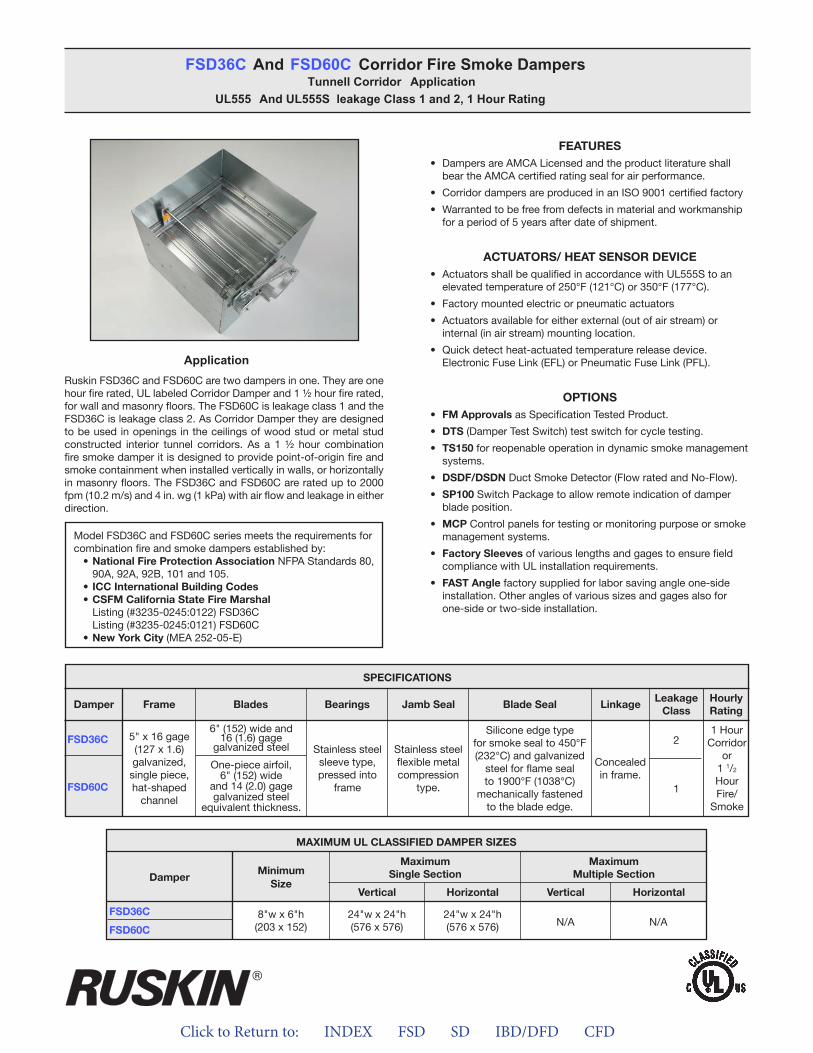
Click to Return to: INDEX FSD SD IBD/DFD CFD
ApplicationRuskin FSD36C and FSD60C are two dampers in one. They are one hour fire rated, UL labeled Corridor Damper and 1 ½ hour fire rated, for wall and masonry floors. The FSD60C is leakage class 1 and the FSD36C is leakage class 2. As Corridor Damper they are designed to be used in openings in the ceilings of wood stud or metal stud constructed interior tunnel corridors. As a 1 ½ hour combination fire smoke damper it is designed to provide point-of-origin fire and smoke containment when installed vertically in walls, or horizontally in masonry floors. The FSD36C and FSD60C are rated up to 2000 fpm (10.2 m/s) and 4 in. wg (1 kPa) with air flow and leakage in either direction.
FEATURES• Dampers are AMCA Licensed and the product literature shall
bear the AMCA certified rating seal for air performance.
• Corridor dampers are produced in an ISO 9001 certified factory
• Warranted to be free from defects in material and workmanshipfor a period of 5 years after date of shipment.
ACTUATORS/ HEAT SENSOR DEVICE• Actuators shall be qualified in accordance with UL555S to an
elevated temperature of 250°F (121°C) or 350°F (177°C).
• Factory mounted electric or pneumatic actuators
• Actuators available for either external (out of air stream) orinternal (in air stream) mounting location.
• Quick detect heat-actuated temperature release device.Electronic Fuse Link (EFL) or Pneumatic Fuse Link (PFL).
OPTIONS• FM Approvals as Specification Tested Product.
• DTS (Damper Test Switch) test switch for cycle testing.
• TS150 for reopenable operation in dynamic smoke managementsystems.
• DSDF/DSDN Duct Smoke Detector (Flow rated and No-Flow).
• SP100 Switch Package to allow remote indication of damperblade position.
• MCP Control panels for testing or monitoring purpose or smokemanagement systems.
• Factory Sleeves of various lengths and gages to ensure fieldcompliance with UL installation requirements.
• FAST Angle factory supplied for labor saving angle one-sideinstallation. Other angles of various sizes and gages also forone-side or two-side installation.
FSD36C And FSD60C Corridor Fire Smoke DampersTunnell Corridor Application
UL555 And UL555S leakage Class 1 and 2, 1 Hour Rating
Model FSD36C and FSD60C series meets the requirements for combination fire and smoke dampers established by:
• National Fire Protection Association NFPA Standards 80, 90A, 92A, 92B, 101 and 105.
• ICC International Building Codes• CSFM California State Fire Marshal
Listing (#3235-0245:0122) FSD36CListing (#3235-0245:0121) FSD60C
• New York City (MEA 252-05-E)
FSD36C
FSD60C
SPECIFICATIONS
Frame Blades Bearings Jamb Seal Blade Seal LinkageLeakage
ClassHourlyRating
Damper
5" x 16 gage (127 x 1.6)galvanized,single piece,hat-shaped
channel
One-piece airfoil,6" (152) wide
and 14 (2.0) gagegalvanized steel
equivalent thickness.
6" (152) wide and16 (1.6) gage
galvanized steel Stainless steelsleeve type,pressed into
frame
Stainless steelflexible metalcompression
type.
Silicone edge typefor smoke seal to 450°F (232°C) and galvanized
steel for flame seal to 1900°F (1038°C)
mechanically fastenedto the blade edge.
Concealedin frame.
2
1
1 HourCorridor
or 1 1/2
HourFire/
Smoke
MAXIMUM UL CLASSIFIED DAMPER SIZES
Damper
FSD36C
FSD60C
MinimumSize
MaximumSingle Section
MaximumMultiple Section
Vertical VerticalHorizontal Horizontal
8"w x 6"h(203 x 152)
24"w x 24"h(576 x 576)
24"w x 24"h(576 x 576) N/A N/A
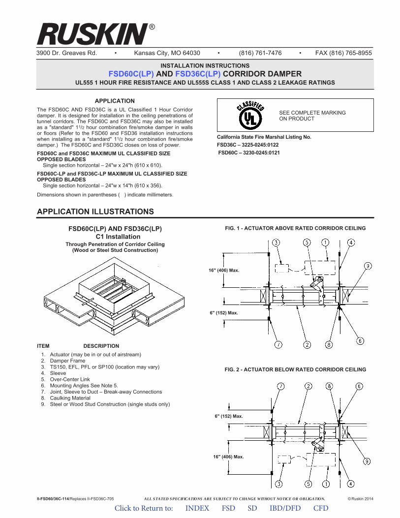
ALL STATED SPECIFICATIONS ARE SUBJECT TO CHANGE WITHOUT NOTICE OR OBLIGATION.
3900 Dr. Greaves Rd. • Kansas City, MO 64030 • (816) 761-7476 • FAX (816) 765-8955
INSTALLATION INSTRUCTIONSFSD60C(LP) AND FSD36C(LP) CORRIDOR DAMPER
UL555 1 HOUR FIRE RESISTANCE AND UL555S CLASS 1 AND CLASS 2 LEAKAGE RATINGS
© Ruskin 2014
®
II-FSD60/36C-114/Replaces II-FSD36C-705
ITEM DESCRIPTION1. Actuator (may be in or out of airstream)2. Damper Frame3. TS150, EFL, PFL or SP100 (location may vary)4. Sleeve5. Over-Center Link6. Mounting Angles See Note 5.7. Joint, Sleeve to Duct – Break-away Connections8. Caulking Material9. Steel or Wood Stud Construction (single studs only)
FSD60C(LP) AND FSD36C(LP)C1 Installation
Through Penetration of Corridor Ceiling(Wood or Steel Stud Construction)
FIG. 1 - ACTUATOR ABOVE RATED CORRIDOR CEILING
FIG. 2 - ACTUATOR BELOW RATED CORRIDOR CEILING
California State Fire Marshal Listing No.FSD36C – 3225-0245:0122FSD60C – 3230-0245:0121
16" (406) Max.
16" (406) Max.
6" (152) Max.
6" (152) Max.
APPLICATIONThe FSD60C AND FSD36C is a UL Classified 1 Hour Corridordamper. It is designed for installation in the ceiling penetrations oftunnel corridors. The FSD60C and FSD36C may also be installedas a "standard" 11/2 hour combination fire/smoke damper in wallsor floors (Refer to the FSD60 and FSD36 installation instructionswhen installing as a "standard" 11/2 hour combination fire/smokedamper.) The FSD60C and FSD36C closes on loss of power.FSD60C and FSD36C MAXIMUM UL CLASSIFIED SIZEOPPOSED BLADES
Single section horizontal – 24"w x 24"h (610 x 610).FSD60C-LP and FSD36C-LP MAXIMUM UL CLASSIFIED SIZEOPPOSED BLADES
Single section horizontal – 24"w x 14"h (610 x 356).
Dimensions shown in parentheses ( ) indicate millimeters.
APPLICATION ILLUSTRATIONS
SEE COMPLETE MARKINGON PRODUCT
Click to Return to: INDEX FSD SD IBD/DFD CFD
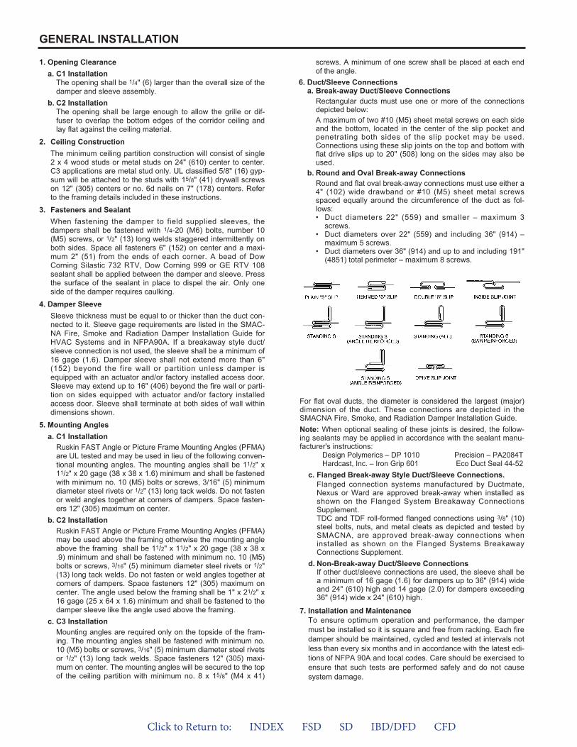
1. Opening Clearancea. C1 Installation
The opening shall be 1/4" (6) larger than the overall size of thedamper and sleeve assembly.
b. C2 InstallationThe opening shall be large enough to allow the grille or dif-fuser to overlap the bottom edges of the corridor ceiling andlay flat against the ceiling material.
2. Ceiling ConstructionThe minimum ceiling partition construction will consist of single2 x 4 wood studs or metal studs on 24" (610) center to center.C3 applications are metal stud only. UL classified 5/8" (16) gyp-sum will be attached to the studs with 15/8" (41) drywall screwson 12" (305) centers or no. 6d nails on 7" (178) centers. Referto the framing details included in these instructions.
3. Fasteners and SealantWhen fastening the damper to field supplied sleeves, thedampers shall be fastened with 1/4-20 (M6) bolts, number 10(M5) screws, or 1/2" (13) long welds staggered intermittently onboth sides. Space all fasteners 6" (152) on center and a maxi-mum 2" (51) from the ends of each corner. A bead of DowCorning Silastic 732 RTV, Dow Corning 999 or GE RTV 108sealant shall be applied between the damper and sleeve. Pressthe surface of the sealant in place to dispel the air. Only oneside of the damper requires caulking.
4. Damper SleeveSleeve thickness must be equal to or thicker than the duct con-nected to it. Sleeve gage requirements are listed in the SMAC-NA Fire, Smoke and Radiation Damper Installation Guide forHVAC Systems and in NFPA90A. If a breakaway style duct/sleeve connection is not used, the sleeve shall be a minimum of16 gage (1.6). Damper sleeve shall not extend more than 6"(152) beyond the fire wall or partition unless damper isequipped with an actuator and/or factory installed access door.Sleeve may extend up to 16" (406) beyond the fire wall or parti-tion on sides equipped with actuator and/or factory installedaccess door. Sleeve shall terminate at both sides of wall withindimensions shown.
5. Mounting Anglesa. C1 Installation
Ruskin FAST Angle or Picture Frame Mounting Angles (PFMA)are UL tested and may be used in lieu of the following conven-tional mounting angles. The mounting angles shall be 11/2" x11/2" x 20 gage (38 x 38 x 1.6) minimum and shall be fastenedwith minimum no. 10 (M5) bolts or screws, 3/16" (5) minimumdiameter steel rivets or 1/2" (13) long tack welds. Do not fastenor weld angles together at corners of dampers. Space fasten-ers 12" (305) maximum on center.
b. C2 InstallationRuskin FAST Angle or Picture Frame Mounting Angles (PFMA)may be used above the framing otherwise the mounting angleabove the framing shall be 11/2" x 11/2" x 20 gage (38 x 38 x.9) minimum and shall be fastened with minimum no. 10 (M5)bolts or screws, 3/16" (5) minimum diameter steel rivets or 1/2"(13) long tack welds. Do not fasten or weld angles together atcorners of dampers. Space fasteners 12" (305) maximum oncenter. The angle used below the framing shall be 1" x 21/2" x16 gage (25 x 64 x 1.6) minimum and shall be fastened to thedamper sleeve like the angle used above the framing.
c. C3 InstallationMounting angles are required only on the topside of the fram-ing. The mounting angles shall be fastened with minimum no.10 (M5) bolts or screws, 3/16" (5) minimum diameter steel rivetsor 1/2" (13) long tack welds. Space fasteners 12" (305) maxi-mum on center. The mounting angles will be secured to the topof the ceiling partition with minimum no. 8 x 15/8" (M4 x 41)
screws. A minimum of one screw shall be placed at each endof the angle.
6. Duct/Sleeve Connectionsa. Break-away Duct/Sleeve Connections
Rectangular ducts must use one or more of the connectionsdepicted below:A maximum of two #10 (M5) sheet metal screws on each sideand the bottom, located in the center of the slip pocket andpenetrating both sides of the slip pocket may be used.Connections using these slip joints on the top and bottom withflat drive slips up to 20" (508) long on the sides may also beused.
b. Round and Oval Break-away ConnectionsRound and flat oval break-away connections must use either a4" (102) wide drawband or #10 (M5) sheet metal screwsspaced equally around the circumference of the duct as fol-lows:• Duct diameters 22" (559) and smaller – maximum 3
screws.• Duct diameters over 22" (559) and including 36" (914) –
maximum 5 screws.• Duct diameters over 36" (914) and up to and including 191"
(4851) total perimeter – maximum 8 screws.
GENERAL INSTALLATION
For flat oval ducts, the diameter is considered the largest (major)dimension of the duct. These connections are depicted in theSMACNA Fire, Smoke, and Radiation Damper Installation Guide.Note: When optional sealing of these joints is desired, the follow-ing sealants may be applied in accordance with the sealant manu-facturer's instructions:
Design Polymerics – DP 1010 Precision – PA2084THardcast, Inc. – Iron Grip 601 Eco Duct Seal 44-52
c. Flanged Break-away Style Duct/Sleeve Connections.Flanged connection systems manufactured by Ductmate,Nexus or Ward are approved break-away when installed asshown on the Flanged System Breakaway ConnectionsSupplement.TDC and TDF roll-formed flanged connections using 3/8" (10)steel bolts, nuts, and metal cleats as depicted and tested bySMACNA, are approved break-away connections wheninstalled as shown on the Flanged Systems BreakawayConnections Supplement.
d. Non-Break-away Duct/Sleeve ConnectionsIf other duct/sleeve connections are used, the sleeve shall bea minimum of 16 gage (1.6) for dampers up to 36" (914) wideand 24" (610) high and 14 gage (2.0) for dampers exceeding36" (914) wide x 24" (610) high.
7. Installation and MaintenanceTo ensure optimum operation and performance, the dampermust be installed so it is square and free from racking. Each firedamper should be maintained, cycled and tested at intervals notless than every six months and in accordance with the latest edi-tions of NFPA 90A and local codes. Care should be exercised toensure that such tests are performed safely and do not causesystem damage.
Click to Return to: INDEX FSD SD IBD/DFD CFD
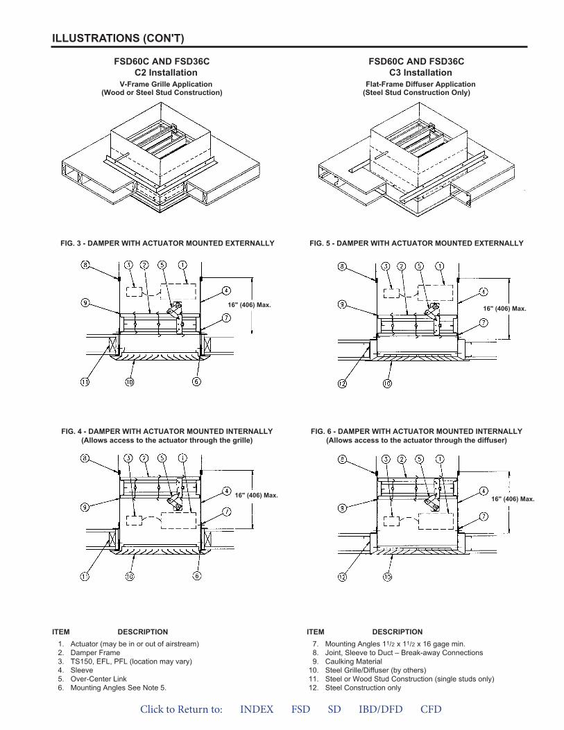
FSD60C AND FSD36CC2 Installation
V-Frame Grille Application(Wood or Steel Stud Construction)
FIG. 3 - DAMPER WITH ACTUATOR MOUNTED EXTERNALLY
FIG. 4 - DAMPER WITH ACTUATOR MOUNTED INTERNALLY(Allows access to the actuator through the grille)
FIG. 5 - DAMPER WITH ACTUATOR MOUNTED EXTERNALLY
FIG. 6 - DAMPER WITH ACTUATOR MOUNTED INTERNALLY(Allows access to the actuator through the diffuser)
FSD60C AND FSD36CC3 Installation
Flat-Frame Diffuser Application(Steel Stud Construction Only)
16" (406) Max. 16" (406) Max.
16" (406) Max.16" (406) Max.
ILLUSTRATIONS (CON'T)
ITEM DESCRIPTION1. Actuator (may be in or out of airstream)2. Damper Frame3. TS150, EFL, PFL (location may vary)4. Sleeve5. Over-Center Link6. Mounting Angles See Note 5.
ITEM DESCRIPTION7. Mounting Angles 11/2 x 11/2 x 16 gage min.8. Joint, Sleeve to Duct – Break-away Connections9. Caulking Material
10. Steel Grille/Diffuser (by others)11. Steel or Wood Stud Construction (single studs only)12. Steel Construction only
Click to Return to: INDEX FSD SD IBD/DFD CFD
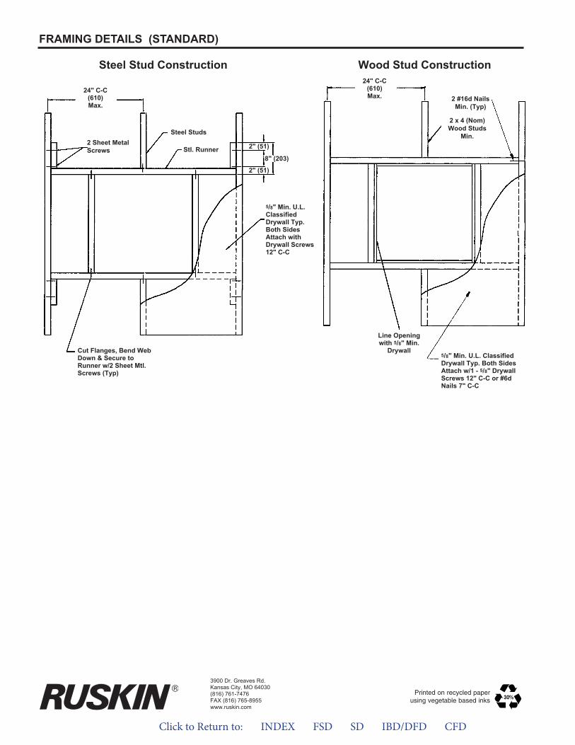
Wood Stud Construction
2 x 4 (Nom)Wood Studs
Min.
24" C-C(610)Max. 2 #16d Nails
Min. (Typ)
5/8" Min. U.L. ClassifiedDrywall Typ. Both SidesAttach w/1 - 5/8" DrywallScrews 12" C-C or #6dNails 7" C-C
Line Openingwith 5/8" Min.
Drywall
Steel Stud Construction
Steel Studs
Stl. Runner
24" C-C(610)Max.
2 Sheet MetalScrews
5/8" Min. U.L.ClassifiedDrywall Typ.Both SidesAttach withDrywall Screws12" C-C
Cut Flanges, Bend WebDown & Secure toRunner w/2 Sheet Mtl.Screws (Typ)
2" (51)
8" (203)
2" (51)
FRAMING DETAILS (STANDARD)
3900 Dr. Greaves Rd.Kansas City, MO 64030(816) 761-7476FAX (816) 765-8955www.ruskin.com
Printed on recycled paperusing vegetable based inks
Click to Return to: INDEX FSD SD IBD/DFD CFD
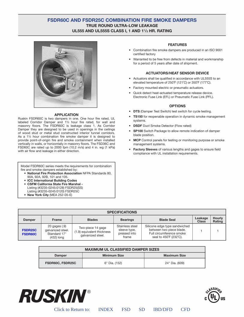
®
Click to Return to: INDEX FSD SD IBD/DFD CFD
FSDR60C AND FSDR25C COMBINATION FIRE SMOKE DAMPERSTRUE ROUND ULTRA-LOW LEAKAGE
UL555 AND UL555S CLASS I, 1 AND 11/2 HR. RATING
APPLICATIONRuskin FSDR60C is two dampers in one. One hour fire rated, UL labeled Corridor Damper and 1½ hour fire rated, for wall and masonry floors. The FSDR60C is leakage class 1. As Corridor Damper they are designed to be used in openings in the ceilings of wood stud or metal stud constructed interior tunnel corridors. As a 1½ hour combination fire smoke damper it is designed to provide point-of-origin fire and smoke containment when installed vertically in walls, or horizontally in masonry floors. The FSD36C and FSD60C are rated up to 2000 fpm (10.2 m/s) and 4 in. wg (1 kPa) with air flow and leakage in either direction.
Model FSDR60C series meets the requirements for combination fire and smoke dampers established by: • NationalFireProtectionAssociationNFPA Standards 80,
90A, 92A, 92B, 101 and 105.• ICCInternationalBuildingCodes• CSFMCaliforniaStateFireMarshal-
Listing (#3235-0245:0128) FSDR25(SS) Listing (#3235-0245:0120) FSDR25C• NewYorkCity(MEA 252-05-E)
FEATURES• CombinationfiresmokedampersareproducedinanISO9001
certified factory
• Warrantedtobefreefromdefectsinmaterialandworkmanshipfor a period of 5 years after date of shipment.
ACTUATORS/HEAT SENSOR DEVICE• ActuatorsshallbequalifiedinaccordancewithUL555Stoan
elevatedtemperatureof250˚F(121˚C)or350˚F(177˚C).
• Factorymountedelectricorpneumaticactuators.
• Quickdetectheat-actuatedtemperaturereleasedevice. Electronic Fuse Link (EFL) or Pneumatic Fuse Link (PFL).
OPTIONS• DTS (Damper Test Switch) test switch for cycle testing.
• TS150 for reopenable operation in dynamic smoke management systems.
• DSDF Duct Smoke Detector (Flow rated)
• SP100 Switch Package to allow remote indication of damper blade position.
• MCP Control panels for testing or monitoring purpose or smoke management systems.
• FactorySleeves of various lengths and gages to ensure field compliance with UL installation requirements.
MAXIMUM UL CLASSIFIED DAMPER SIZES
Damper
FSDR60C, FSDR25C
MinimumSize
6" Dia. (152)
MaximumSize
24" Dia. (609)
Click to Return to: INDEX FSD SD IBD/DFD CFD
APPLICATION
)
FSDR60C and FSDR25C COMBINATION FIRE SMOKE DAMPERSTRUE ROUND ULTRA-LOW LEAKAGE
UL555 AND UL555S CLASS I, 1 AND 1 ½ HR. RATING
60C
)
60C C
CC
Ruskin FSDR60C is two dampers in one. One hour fire rated, UL labeled Corridor Damper and 1 ½ hour fire rated, for wall and masonry floors. The FSDR60C is leakage class 1. As Corridor Damper they are designed to be used in openings in the ceilings of wood stud or metal stud constructed interior tunnel corridors. As a 1 ½ hour combination fire smoke damper it is designed to provide point-of-origin fire and smoke containment when installed vertically in walls, or horizontally in masonry floors. The FSD36C and FSD60C are rated up to 2000 fpm (10.2 m/s) and 4 in. wg (1 kPa) with air flow and leakage in either direction.
SPECIFICATIONS
Damper
FSDR25CFSDR60C
Frame
20 gages (.9)galvanized steel.Standard17"
(432) long
Blades
Two-piece 14 gage(1.9) equivalent thickness
galvanized steel.
Bearings
Stainless steelsleeve type,pressed into
frame
BladeSeal
Silicone edge type sandwichedbetween two piece blade.Full circumference smokesealto450˚F(232˚C).
HourlyRating
1
LeakageClass
1
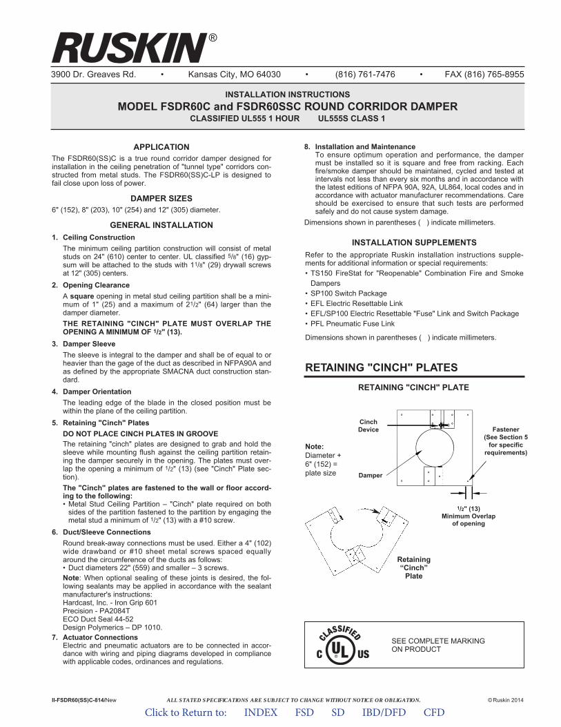
ALL STATED SPECIFICATIONS ARE SUBJECT TO CHANGE WITHOUT NOTICE OR OBLIGATION.
3900 Dr. Greaves Rd. • Kansas City, MO 64030 • (816) 761-7476 • FAX (816) 765-8955
INSTALLATION INSTRUCTIONSMODEL FSDR60C and FSDR60SSC ROUND CORRIDOR DAMPER
CLASSIFIED UL555 1 HOUR UL555S CLASS 1
APPLICATIONThe FSDR60(SS)C is a true round corridor damper designed forinstallation in the ceiling penetration of "tunnel type" corridors con-structed from metal studs. The FSDR60(SS)C-LP is designed tofail close upon loss of power.
DAMPER SIZES6" (152), 8" (203), 10" (254) and 12" (305) diameter.
GENERAL INSTALLATION1. Ceiling Construction
The minimum ceiling partition construction will consist of metalstuds on 24" (610) center to center. UL classified 5/8" (16) gyp-sum will be attached to the studs with 11/8" (29) drywall screwsat 12" (305) centers.
2. Opening ClearanceA square opening in metal stud ceiling partition shall be a mini-mum of 1" (25) and a maximum of 21/2" (64) larger than thedamper diameter.THE RETAINING "CINCH" PLATE MUST OVERLAP THEOPENING A MINIMUM OF 1/2" (13).
3. Damper SleeveThe sleeve is integral to the damper and shall be of equal to orheavier than the gage of the duct as described in NFPA90A andas defined by the appropriate SMACNA duct construction stan-dard.
4. Damper OrientationThe leading edge of the blade in the closed position must bewithin the plane of the ceiling partition.
5. Retaining "Cinch" PlatesDO NOT PLACE CINCH PLATES IN GROOVEThe retaining "cinch" plates are designed to grab and hold thesleeve while mounting flush against the ceiling partition retain-ing the damper securely in the opening. The plates must over-lap the opening a minimum of 1/2" (13) (see "Cinch" Plate sec-tion).The "Cinch" plates are fastened to the wall or floor accord-ing to the following:• Metal Stud Ceiling Partition – "Cinch" plate required on both
sides of the partition fastened to the partition by engaging themetal stud a minimum of 1/2" (13) with a #10 screw.
6. Duct/Sleeve ConnectionsRound break-away connections must be used. Either a 4" (102)wide drawband or #10 sheet metal screws spaced equallyaround the circumference of the ducts as follows:• Duct diameters 22" (559) and smaller – 3 screws.Note: When optional sealing of these joints is desired, the fol-lowing sealants may be applied in accordance with the sealantmanufacturer's instructions:Hardcast, Inc. - Iron Grip 601Precision - PA2084TECO Duct Seal 44-52Design Polymerics – DP 1010.
7. Actuator ConnectionsElectric and pneumatic actuators are to be connected in accor-dance with wiring and piping diagrams developed in compliancewith applicable codes, ordinances and regulations.
8. Installation and MaintenanceTo ensure optimum operation and performance, the dampermust be installed so it is square and free from racking. Eachfire/smoke damper should be maintained, cycled and tested atintervals not less than every six months and in accordance withthe latest editions of NFPA 90A, 92A, UL864, local codes and inaccordance with actuator manufacturer recommendations. Careshould be exercised to ensure that such tests are performedsafely and do not cause system damage.
Dimensions shown in parentheses ( ) indicate millimeters.
II-FSDR60(SS)C-814/New © Ruskin 2014
RETAINING "CINCH" PLATESRETAINING "CINCH" PLATE
1/2" (13)Minimum Overlap
of opening
Retaining“Cinch”
Plate
Note:Diameter +6" (152) =plate size
CinchDevice
Damper
Fastener(See Section 5
for specificrequirements)
INSTALLATION SUPPLEMENTSRefer to the appropriate Ruskin installation instructions supple-ments for additional information or special requirements:• TS150 FireStat for "Reopenable" Combination Fire and Smoke
Dampers• SP100 Switch Package• EFL Electric Resettable Link• EFL/SP100 Electric Resettable "Fuse" Link and Switch Package• PFL Pneumatic Fuse Link
Dimensions shown in parentheses ( ) indicate millimeters.
SEE COMPLETE MARKING ON PRODUCT
®
Click to Return to: INDEX FSD SD IBD/DFD CFD
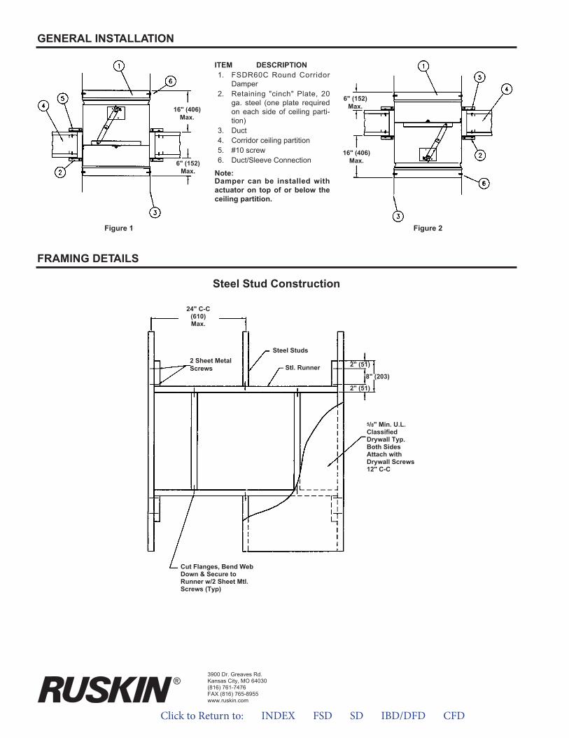
3900 Dr. Greaves Rd.Kansas City, MO 64030(816) 761-7476FAX (816) 765-8955www.ruskin.com
Steel Stud Construction
Steel Studs
Stl. Runner
24" C-C(610)Max.
2 Sheet MetalScrews
5/8" Min. U.L.ClassifiedDrywall Typ.Both SidesAttach withDrywall Screws12" C-C
Cut Flanges, Bend WebDown & Secure toRunner w/2 Sheet Mtl.Screws (Typ)
2" (51)
8" (203)
2" (51)
FRAMING DETAILS
GENERAL INSTALLATION
16" (406)Max.
6" (152)Max.
16" (406)Max.
6" (152)Max.
Figure 1 Figure 2
ITEM DESCRIPTION1. FSDR60C Round Corridor
Damper2. Retaining "cinch" Plate, 20
ga. steel (one plate requiredon each side of ceiling parti-tion)
3. Duct4. Corridor ceiling partition5. #10 screw6. Duct/Sleeve Connection
Note:Damper can be installed withactuator on top of or below theceiling partition.
®
Click to Return to: INDEX FSD SD IBD/DFD CFD
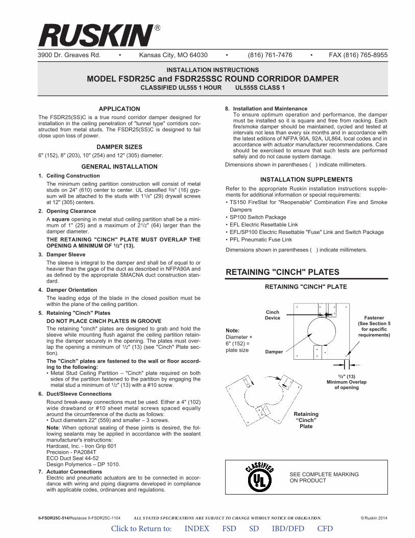
ALL STATED SPECIFICATIONS ARE SUBJECT TO CHANGE WITHOUT NOTICE OR OBLIGATION.
3900 Dr. Greaves Rd. • Kansas City, MO 64030 • (816) 761-7476 • FAX (816) 765-8955
INSTALLATION INSTRUCTIONSMODEL FSDR25C and FSDR25SSC ROUND CORRIDOR DAMPER
CLASSIFIED UL555 1 HOUR UL555S CLASS 1
APPLICATIONThe FSDR25(SS)C is a true round corridor damper designed forinstallation in the ceiling penetration of "tunnel type" corridors con-structed from metal studs. The FSDR25(SS)C is designed to failclose upon loss of power.
DAMPER SIZES6" (152), 8" (203), 10" (254) and 12" (305) diameter.
GENERAL INSTALLATION1. Ceiling Construction
The minimum ceiling partition construction will consist of metalstuds on 24" (610) center to center. UL classified 5/8" (16) gyp-sum will be attached to the studs with 11/8" (29) drywall screwsat 12" (305) centers.
2. Opening ClearanceA square opening in metal stud ceiling partition shall be a mini-mum of 1" (25) and a maximum of 21/2" (64) larger than thedamper diameter.THE RETAINING "CINCH" PLATE MUST OVERLAP THEOPENING A MINIMUM OF 1/2" (13).
3. Damper SleeveThe sleeve is integral to the damper and shall be of equal to orheavier than the gage of the duct as described in NFPA90A andas defined by the appropriate SMACNA duct construction stan-dard.
4. Damper OrientationThe leading edge of the blade in the closed position must bewithin the plane of the ceiling partition.
5. Retaining "Cinch" PlatesDO NOT PLACE CINCH PLATES IN GROOVEThe retaining "cinch" plates are designed to grab and hold thesleeve while mounting flush against the ceiling partition retain-ing the damper securely in the opening. The plates must over-lap the opening a minimum of 1/2" (13) (see "Cinch" Plate sec-tion).The "Cinch" plates are fastened to the wall or floor accord-ing to the following:• Metal Stud Ceiling Partition – "Cinch" plate required on both
sides of the partition fastened to the partition by engaging themetal stud a minimum of 1/2" (13) with a #10 screw.
6. Duct/Sleeve ConnectionsRound break-away connections must be used. Either a 4" (102)wide drawband or #10 sheet metal screws spaced equallyaround the circumference of the ducts as follows:• Duct diameters 22" (559) and smaller – 3 screws.Note: When optional sealing of these joints is desired, the fol-lowing sealants may be applied in accordance with the sealantmanufacturer's instructions:Hardcast, Inc. - Iron Grip 601Precision - PA2084TECO Duct Seal 44-52Design Polymerics – DP 1010.
7. Actuator ConnectionsElectric and pneumatic actuators are to be connected in accor-dance with wiring and piping diagrams developed in compliancewith applicable codes, ordinances and regulations.
8. Installation and MaintenanceTo ensure optimum operation and performance, the dampermust be installed so it is square and free from racking. Eachfire/smoke damper should be maintained, cycled and tested atintervals not less than every six months and in accordance withthe latest editions of NFPA 90A, 92A, UL864, local codes and inaccordance with actuator manufacturer recommendations. Careshould be exercised to ensure that such tests are performedsafely and do not cause system damage.
Dimensions shown in parentheses ( ) indicate millimeters.
II-FSDR25C-514/Replaces II-FSDR25C-1104 © Ruskin 2014
RETAINING "CINCH" PLATESRETAINING "CINCH" PLATE
1/2" (13)Minimum Overlap
of opening
Retaining“Cinch”
Plate
Note:Diameter +6" (152) =plate size
CinchDevice
Damper
Fastener(See Section 5
for specificrequirements)
INSTALLATION SUPPLEMENTSRefer to the appropriate Ruskin installation instructions supple-ments for additional information or special requirements:• TS150 FireStat for "Reopenable" Combination Fire and Smoke
Dampers• SP100 Switch Package• EFL Electric Resettable Link• EFL/SP100 Electric Resettable "Fuse" Link and Switch Package• PFL Pneumatic Fuse Link
Dimensions shown in parentheses ( ) indicate millimeters.
SEE COMPLETE MARKINGON PRODUCT
Click to Return to: INDEX FSD SD IBD/DFD CFD
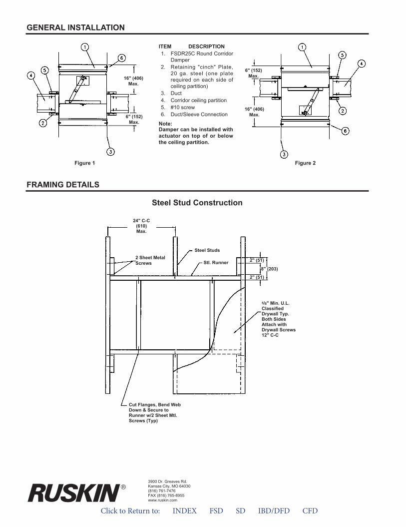
3900 Dr. Greaves Rd.Kansas City, MO 64030(816) 761-7476FAX (816) 765-8955www.ruskin.com
Steel Stud Construction
Steel Studs
Stl. Runner
24" C-C(610)Max.
2 Sheet MetalScrews
5/8" Min. U.L.ClassifiedDrywall Typ.Both SidesAttach withDrywall Screws12" C-C
Cut Flanges, Bend WebDown & Secure toRunner w/2 Sheet Mtl.Screws (Typ)
2" (51)
8" (203)
2" (51)
FRAMING DETAILS
GENERAL INSTALLATION
16" (406)Max.
6" (152)Max.
16" (406)Max.
6" (152)Max.
Figure 1 Figure 2
ITEM DESCRIPTION1. FSDR25C Round Corridor
Damper2. Retaining "cinch" Plate,
20 ga. steel (one platerequired on each side ofceiling partition)
3. Duct4. Corridor ceiling partition5. #10 screw6. Duct/Sleeve Connection
Note:Damper can be installed withactuator on top of or belowthe ceiling partition.
Click to Return to: INDEX FSD SD IBD/DFD CFD

Click to Return to: INDEX FSD SD IBD/DFD CFD
ApplicAtionThe DFSDR1 is two dampers in one. DFSDR1 is a one hour fire rated, UL labeled Corridor Damper leakage class 1 that is de-signed to be used in ceiling openings of wood stud or metal stud constructed interior tunnel corridors. The DFSDR1 is classified as a ceiling damper with a one hour fire resistance rating (See DFSDR1 in the Ceiling Fire Damper).
FEAtURES• Corridor dampers are produced in an ISO 9001 certified factory
• Warranted to be free from defects in material and workmanshipfor a period of 5 years after date of shipment.
ActUAtoRS/ HEAt SEnSoR DEVicE• Actuators shall be qualified in accordance with UL555S to an
elevated temperature of 250°F (121°C) or 350°F (177°C).
• Factory mounted electric or pneumatic actuators
• Quick detect heat-actuated temperature release device.Electronic Fuse Link (EFL) or Pneumatic Fuse Link (PFL).
optionS• FM Approvals as Specification Tested Product.
• DtS (Damper Test Switch) test switch for cycle testing.
• tS150 for reopenable operation in dynamic smoke managementsystems.
• Sp100 Switch Package to allow remote indication of damperblade position.
• Mcp Control panels for testing or monitoring purpose or smokemanagement systems.
DFSDR1 CORRIDOR FIRE SMOKE DAMPER lay-in DIFFUSER cORRIDOR DAMpER
Ul555 and Ul555S LEAKAGE 1, 1 HR. Rating
Model DFSDR1 series meets the requirements for combination fire and smoke dampers established by:
• national Fire protection Association NFPA Standards 80, 90A, 92A, 92B, 101 and 105.
• icc international Building codes• cSFM california State Fire Marshal
Listing (#3235-0245:0114)• new york city (MEA 252-05-E)
SpEciFicAtionS
DFSDR1
Frame Blades Bearings Blade Sealleakage
classHourlyRating
Damper
20 gage (1.0)galvanized steel12" (305) long
Two piece 14 gage(1.9) equivalent
thicknessgalvanized steel.
Stainless steelsleeve type,pressed into
frame
Silicone edge type sandwich between two
piece blades. Full circumference smoke seal to 450°F (232°C).
1 Hour Corridor1
MAXiMUM Ul clASSiFiED DAMpER SiZES
Damper
DFSDR1
Minimum Size Maximum Size
6" Dia.(152)
12" Dia.(305)
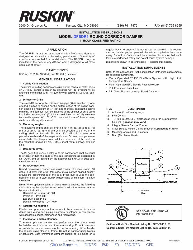
ALL STATED SPECIFICATIONS ARE SUBJECT TO CHANGE WITHOUT NOTICE OR OBLIGATION.
3900 Dr. Greaves Rd. • Kansas City, MO 64030 • (816) 761-7476 • FAX (816) 765-8955
INSTALLATION INSTRUCTIONSMODEL DFSDR1 ROUND CORRIDOR DAMPER
1 HOUR CLASSIFIED RATING
APPLICATIONThe DFSDR1 is a true round combination fire/smoke dampersdesigned for installation in the ceiling penetration of "tunnel type"corridors constructed from metal studs. The DFSDR1 may beinstalled on the neck of any diffuser, and is designed to fail closeupon loss of power.
DAMPER SIZES6" (152), 8" (203), 10" (254) and 12" (305) diameter.
GENERAL INSTALLATION1. Ceiling ConstructionThe minimum ceiling partition construction will consist of metal studson 24" (610) center to center. UL classified 5/8" (16) gypsum will beattached to the studs with 11/8" (29) drywall screws at 12" (305) cen-ters. 2. Diffuser or GrilleThe steel diffuser or grille, minimum 24 gage (.6) is supplied by oth-ers and is sized to overlap on the bottom edges of the ceiling parti-tion opening a minimum of 3/4" (19) and fit snugly against the ceilingmaterial. The damper must be fastened to the diffuser or grille usingNo. 8 (M4) screws, 3/16" (5) tubular steel rivets, or 1/4" (6) minimumtack welds spaced 6" (152) O.C. Use a minimum of three screws,rivets or welds equally spaced.3. Mounting AnglesThe mounting angles shall be 11/2" x 11/2" x 16 ga. (38 x 38 x 1.6)(min.) by 271/2" (674) long and shall be secured to the top of theceiling rated partition with No. 8 x 15/8" (M4 x 41) screws, oneplaced at each end of the angle (minimum). Screws must penetratemetal studs. The damper frame will then be secured at the center tothe mounting angles by No. 8 (M4) sheet metal screws, two perside.4. Damper SleevesThe 20 gage (.9) sleeve is integral to the damper and shall be equalto or heavier than the gage of the duct connecting as described inNFPA90A and as defined by the appropriate SMACNA duct con-struction standard.5. Duct ConnectionsRound break-away connections must consist of a steel clamp, 16gage (1.6) steel wire or 3 - #10 sheet metal screws spaced equallyaround the circumference of the duct. If flex duct is used the con-nections shall be a steel clamp, plastic strap or minimum 18 gagesteel wire.Note: When optional sealing of these joints is desired, the followingsealants may be applied in accordance with the sealant manu -facturer's instruction.
Hardcast Inc. – Iron Grip 601Precision – PA2084TEco Duct Seal 44-52Design Polymerics – DP 1010
6. Actuator ConnectionElectric and pneumatic actuators are to be connected in accor-dance with wiring and piping diagrams developed in compliancewith applicable codes, ordinances and regulations.7. Installation and MaintenanceTo ensure optimum operation and performance, the damper mustbe installed so it is round and free from racking. Do not compressor stretch the damper frame into the duct or opening. Lift or handlethe damper using sleeve or frame. Do not lift damper using bladesor actuators. Each fire/smoke dampers should be examined on a
regular basis to ensure it is not rusted or blocked. It is recom-mended the damper be operated (the actuator cycled) at least onceevery 6 months. Care should be exercised to ensure that suchtests are performed safely and do not cause system damage.Dimensions shown in parentheses ( ) indicate millimeters.
INSTALLATION SUPPLEMENTSRefer to the appropriate Ruskin installation instruction supplementsfor special requirements.• Motor Operated TS150 FireState System with High Limit
Temperature Sensor• Motor Operated EFL Electric Resettable Link• PFL Pneumatic Fuse Link• SP100 on Fire and Leakage Rated Dampers
II-DFSDR1-514/Replaces II-DFSDR1-807 © Ruskin 2014
®
California State Fire Marshal Listing No. 3225-0245:0101.California State Fire Marshal Listing No. 3230-0245:0114.
ITEM DESCRIPTION1. Actuator (location may vary)2. Flex Conduit3. TS150 FireStat, EFL (electric fuse link) or PFL (pneumatic
fuse link) (location may vary)4. Integral Sleeve Damper Frame5. Steel Surface Mount Ceiling Diffuser (supplied by others)6. Mounting Angles and Fasteners7. Duct (Flexible or Hard)
231/2 (597)Max.
SEE COMPLETE MARKING ON PRODUCT
Click to Return to: INDEX FSD SD IBD/DFD CFD
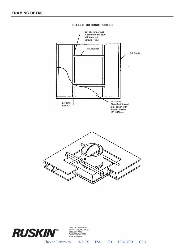
STEEL STUD CONSTRUCTION
5/8" (16) ULClassified drywallmin. attach withdrywall screws12" (305) c-c
24" (610max. C-C
Stl. Runner
Stl. Studs
Cut stl. runner web& secure to stl. studw/2 sheet mtl.screws (Typ.)
FRAMING DETAIL
3900 Dr. Greaves Rd.Kansas City, MO 64030(816) 761-7476FAX (816) 765-8955www.ruskin.com
®
Click to Return to: INDEX FSD SD IBD/DFD CFD
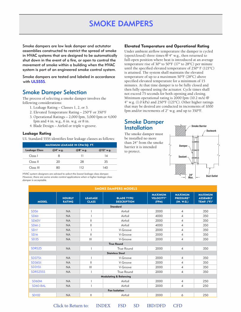
Click to Return to: INDEX FSD SD IBD/DFD CFD
SMOKE DaMPERS MODELS
SEE PaGE # MODEL
HOURLYRaTING
LEaKaGECLaSS
BLaDE TYPE/DESCRIPTION
MaxIMUM VELOCITY*
(FPM)
MaxIMUM PRESSURE*(IN. w.G.)
MaxIMUMaSSEMBLYTEMP. (ºF)*
Standard
11 SD50 NA I Airfoil 2000 4 350
11 SD60 NA I Airfoil 4000 4 350
11 SD60V NA II Airfoil 2000 4 350
11 SD60-2 NA II Airfoil 4000 4 350
12 SD37 NA I V-Groove 2000 4 350
12 SD36 NA II V-Groove 2000 4 350
12 SD35 NA III V-Groove 2000 4 350True Round
12 SDRS25 NA I 2000 4 350True RoundStainless Steel
12 SD37SS NA I V-Groove 2000 4 350
12 SD36SS NA II V-Groove 2000 4 350
SD35SS NA III V-Groove 2000 4 350
SDRS25SS NA I 2000 4 350True RoundModulating & Balancing
11 SD60M NA I Airfoil 2000 4 250
11 SD60-BAL NA I Airfoil 2000 4 250Fan Isolation
12 SD102 NA II Airfoil 2000 6 250
Smoke dampers are low leak damper and actutatorassemblies constructed to restrict the spread of smokein HVAC systems that are designed to be automaticallyshut down in the event of a fire, or open to control themovement of smoke within a building when the HVACsystem is part of an engineered smoke control system.
Smoke dampers are tested and labeled in accordancewith UL555S.
Smoke Damper SelectionThe process of selecting a smoke damper involves thefollowing considerations:
1. eakage Rating – Classes 1, 2, or 3.2. levated Temperature Rating – 250°F or 350°F3. Operational Ratings – 2,000 fpm, 3,000 fpm or 4,000
fpm and 4 in. w.g., 6 in. w.g. or 8 in.4. lade Design – Airfoil or triple v-groove.
Leakage RatingUL Standard 555S identifies four leakage classes as follows:
MaxIMUM LEaKaGE IN CFM/SQ. FT.
Leakage Class @4" w.g. @8" w.g. @12" w.g.
Class I 8 11 14
Class II 20 28 35
Class III 80 112 140
HVAC system designers are advised to select the lowest leakage class damper.However, there are some smoke control applications when a higher leakage classdamper is acceptable.
Elevated Temperature and Operational RatingUnder ambient airflow temperature the damper is cycled(open/closed) three times @ 4" w.g., then returned tofull-open position where heat is introduced at an averagetemperature rise of 30º to 50ºF (17º to 28ºC) per minuteuntil the specified elevated temperature of 250º F (121ºC)is attained. The system shall maintain the elevatedtemperature of up to a maximum 50ºF (28ºC) abovespecified elevated temperature for a minimum of 15minutes. At that time damper is to be fully closed andthen fully opened using the actuator. Cycle times shallnot exceed 75 seconds for both opening and closing.Minimum operational rating is 2000 fpm (10.2 m/s) @4" w.g. (1.0 kPa) and 250ºF (121ºC). Other higher ratingsthat may be desired are conducted in increments of 1000fpm and/or increments of 2" w.g. and up to 350ºF.
Smoke DamperInstallationThe smoke damper mustbe installed no morethan 24" from the smokebarrier it is intendedto protect.
Duct Outlet24"Max.
Ductwork
Smoke Barrier
Sealant
Damper
SMOKE DAMPERS
SMOKE DaMPERS MODELS
SEEPaGE # MODEL
HOURLYRaTING
LEaKaGE CLaSS
BLaDE TYPE/DESCRIPTION
MaxIMUMVELOCITY*
(FPM)
MaxIMUMPRESSURE* (IN. w.G.)
MaxIMUMaSSEMBLYTEMP. (ºF)*
Standard
11 SD50 NA I Airfoil 2000 4 350
11 SD60 NA I Airfoil 4000 4 350
11 SD60V NA II Airfoil 2000 4 350
11 SD60-2 NA II Airfoil 4000 4 350
12 SD37 NA I V-Groove 2000 4 350
12 SD36 NA II V-Groove 2000 4 350
12 SD35 NA III V-Groove 2000 4 350True Round
12 SDRS25 NA I True Round 2000 4 350Stainless Steel
12 SD37SS NA I V-Groove 2000 4 350
12 SD36SS NA II V-Groove 2000 4 350
SD35SS NA III V-Groove 2000 4 350
SDRS25SS NA I True Round 2000 4 350Modulating & Balancing
11 SD60M NA I Airfoil 2000 4 250
11 SD60-BAL NA I Airfoil 2000 4 250Fan Isolation
12 SD102 NA II Airfoil 2000 6 250
Ruskin Life Safety Dampers meet Agency Listings shown on back cover.
*For metric units, please see back cover.
10 RUSKIN LIFE SAFETY DAMPERS
SMOKE DAMPERS
Smoke dampers are low leak damper and actutator assemblies constructed to restrict the spread of smoke in HVAC systems that are designed to be automatically shut down in the event of a fire, or open to control the movement of smoke within a building when the HVAC system is part of an engineered smoke control system.
Smoke dampers are tested and labeled in accordance with UL555S.
Smoke Damper SelectionThe process of selecting a smoke damper involves the following considerations:
1. Leakage Rating – Classes 1, 2, or 3.2. Elevated Temperature Rating – 250°F or 350°F3. Operational Ratings – 2,000 fpm, 3,000 fpm or 4,000
fpm and 4 in. w.g., 6 in. w.g. or 8 in. 4. Blade Design – Airfoil or triple v-groove.
Leakage RatingUL Standard 555S identifies four leakage classes as follows:
MaxIMUM LEaKaGE IN CFM/SQ. FT.
Leakage Class @4" w.g. @8" w.g. @12" w.g.
Class I 8 11 14
Class II 20 28 35
Class III 80 112 140
HVAC system designers are advised to select the lowest leakage class damper. However, there are some smoke control applications when a higher leakage class damper is acceptable.
Elevated Temperature and Operational RatingUnder ambient airflow temperature the damper is cycled (open/closed) three times @ 4" w.g., then returned to full-open position where heat is introduced at an average temperature rise of 30º to 50ºF (17º to 28ºC) per minute until the specified elevated temperature of 250º F (121ºC) is attained. The system shall maintain the elevated temperature of up to a maximum 50ºF (28ºC) above specified elevated temperature for a minimum of 15 minutes. At that time damper is to be fully closed and then fully opened using the actuator. Cycle times shall not exceed 75 seconds for both opening and closing. Minimum operational rating is 2000 fpm (10.2 m/s) @ 4" w.g. (1.0 kPa) and 250ºF (121ºC). Other higher ratings that may be desired are conducted in increments of 1000 fpm and/or increments of 2" w.g. and up to 350ºF.
Smoke Damper InstallationThe smoke damper must be installed no more than 24" from the smoke barrier it is intended to protect.
Duct Outlet24"Max.
Ductwork
Smoke Barrier
Sealant
Damper
SMOKE DaMPERS MODELS
SEEPaGE # MODEL
HOURLY RaTING
LEaKaGE CLaSS
BLaDE TYPE/ DESCRIPTION
MaxIMUM VELOCITY*
(FPM)
MaxIMUM PRESSURE* (IN. w.G.)
MaxIMUM aSSEMBLY TEMP. (ºF)*
Standard
11 SD50 NA I Airfoil 2000 4 350
11 SD60 NA I Airfoil 4000 4 350
11 SD60V NA II Airfoil 2000 4 350
11 SD60-2 NA II Airfoil 4000 4 350
12 SD37 NA I V-Groove 2000 4 350
12 SD36 NA II V-Groove 2000 4 350
12 SD35 NA III V-Groove 2000 4 350True Round
12 SDRS25 NA I True Round 2000 4 350Stainless Steel
12 SD37SS NA I V-Groove 2000 4 350
12 SD36SS NA II V-Groove 2000 4 350
NA III V-Groove 2000 4 350SDRS25SS NA I True Round 2000 4 350
Modulating & Balancing
11 SD60M NA I Airfoil 2000 4 250
11 SD60-BAL NA I Airfoil 2000 4 250Fan Isolation
12 SD102 NA II Airfoil 2000 6 250
Ruskin Life Safety Dampers meet Agency Listings shown on back cover.
*For metric units, please see back cover.
10 RUSKIN LIFE SAFETY DAMPERS
SMOKE DAMPERS
Smoke dampers are low leak damper and actutatorassemblies constructed to restrict the spread of smokein HVAC systems that are designed to be automaticallyshut down in the event of a fire, or open to control themovement of smoke within a building when the HVACsystem is part of an engineered smoke control system.
Smoke dampers are tested and labeled in accordancewith UL555S.
Smoke Damper SelectionThe process of selecting a smoke damper involves thefollowing considerations:
1. Leakage Rating – Classes 1, 2, or 3.2. Elevated Temperature Rating – 250°F or 350°F3. Operational Ratings – 2,000 fpm, 3,000 fpm or 4,000
fpm and 4 in. w.g., 6 in. w.g. or 8 in.4. Blade Design – Airfoil or triple v-groove.
Leakage RatingUL Standard 555S identifies four leakage classes as follows:
MaxIMUM LEaKaGE IN CFM/SQ. FT.
Leakage Class @4" w.g. @8" w.g. @12" w.g.
Class I 8 11 14
Class II 20 28 35
Class III 80 112 140
HVAC system designers are advised to select the lowest leakage class damper.However, there are some smoke control applications when a higher leakage classdamper is acceptable.
Elevated Temperature and Operational RatingUnder ambient airflow temperature the damper is cycled(open/closed) three times @ 4" w.g., then returned tofull-open position where heat is introduced at an averagetemperature rise of 30º to 50ºF (17º to 28ºC) per minuteuntil the specified elevated temperature of 250º F (121ºC)is attained. The system shall maintain the elevatedtemperature of up to a maximum 50ºF (28ºC) abovespecified elevated temperature for a minimum of 15minutes. At that time damper is to be fully closed andthen fully opened using the actuator. Cycle times shallnot exceed 75 seconds for both opening and closing.Minimum operational rating is 2000 fpm (10.2 m/s) @4" w.g. (1.0 kPa) and 250ºF (121ºC). Other higher ratingsthat may be desired are conducted in increments of 1000fpm and/or increments of 2" w.g. and up to 350ºF.
Smoke DamperInstallationThe smoke damper mustbe installed no morethan 24" from the smokebarrier it is intendedto protect.
Duct Outlet24"Max.
Ductwork
Smoke Barrier
Sealant
Damper
SD35SS
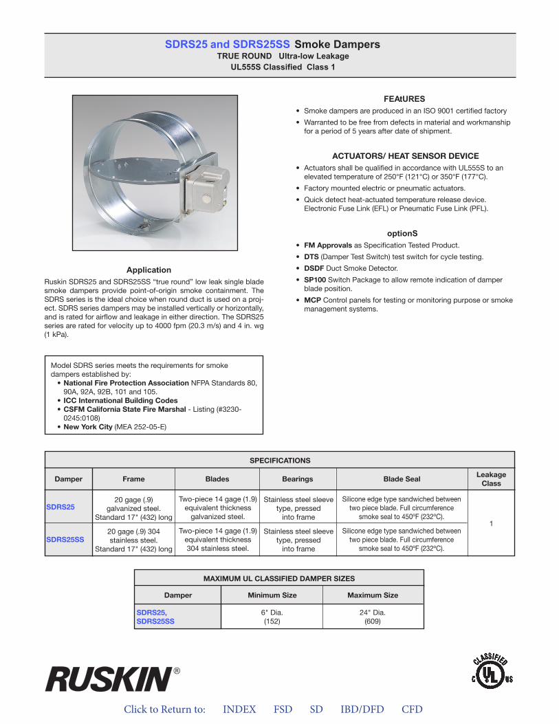
Click to Return to: INDEX FSD SD IBD/DFD CFD
ApplicationRuskin SDRS25 and SDRS25SS “true round” low leak single blade smoke dampers provide point-of-origin smoke containment. The SDRS series is the ideal choice when round duct is used on a proj-ect. SDRS series dampers may be installed vertically or horizontally, and is rated for airflow and leakage in either direction. The SDRS25 series are rated for velocity up to 4000 fpm (20.3 m/s) and 4 in. wg (1 kPa).
FEAtURES• Smoke dampers are produced in an ISO 9001 certified factory
• Warranted to be free from defects in material and workmanshipfor a period of 5 years after date of shipment.
ACTUATORS/ HEAT SENSOR DEVICE• Actuators shall be qualified in accordance with UL555S to an
elevated temperature of 250°F (121°C) or 350°F (177°C).
• Factory mounted electric or pneumatic actuators.
• Quick detect heat-actuated temperature release device.Electronic Fuse Link (EFL) or Pneumatic Fuse Link (PFL).
optionS• FM Approvals as Specification Tested Product.
• DTS (Damper Test Switch) test switch for cycle testing.
• DSDF Duct Smoke Detector.
• SP100 Switch Package to allow remote indication of damperblade position.
• MCP Control panels for testing or monitoring purpose or smokemanagement systems.
SDRS25 and SDRS25SS Smoke DampersTRUE ROUND Ultra-low Leakage
UL555S Classified Class 1
Model SDRS series meets the requirements for smoke dampers established by:
• National Fire Protection Association NFPA Standards 80, 90A, 92A, 92B, 101 and 105.
• ICC International Building Codes• CSFM California State Fire Marshal - Listing (#3230-
0245:0108)• New York City (MEA 252-05-E)
SPECIFICATIONS
SDRS25
SDRS25SS
Frame Blades Bearings Blade SealLeakage
ClassDamper
20 gage (.9) galvanized steel.
Standard 17" (432) long
20 gage (.9) 304stainless steel.
Standard 17" (432) long
Two-piece 14 gage (1.9)equivalent thickness
galvanized steel.
Two-piece 14 gage (1.9)equivalent thickness304 stainless steel.
Stainless steel sleevetype, pressed
into frame
Stainless steel sleevetype, pressed
into frame
Silicone edge type sandwiched betweentwo piece blade. Full circumference
smoke seal to 450ºF (232ºC).
Silicone edge type sandwiched betweentwo piece blade. Full circumference
smoke seal to 450ºF (232ºC).
1
MAXIMUM UL CLASSIFIED DAMPER SIZES
Damper
SDRS25,SDRS25SS
Minimum Size Maximum Size
6" Dia.(152)
24" Dia.(609)
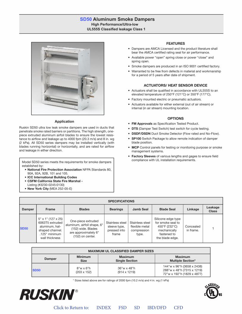
Click to Return to: INDEX FSD SD IBD/DFD CFD
ApplicationRuskin SD50 ultra low leak smoke dampers are used in ducts that penetrate smoke rated barriers or partitions. The high strength, one-piece extruded aluminum airfoil blades to ensure the lowest resis-tance to airflow and leakage up to 4000 fpm (20.3 m/s) and 8 in. wg (2 kPa). All SD50 series dampers may be installed vertically (with blades running horizontal) or horizontally, and are rated for airflow and leakage in either direction.
FEATURES• Dampers are AMCA Licensed and the product literature shall
bear the AMCA certified rating seal for air performance.
• Available power “open” spring close or power “close” andspring open.
• Smoke dampers are produced in an ISO 9001 certified factory.
• Warranted to be free from defects in material and workmanshipfor a period of 5 years after date of shipment.
ACTUATORS/ HEAT SENSOR DEVICE• Actuators shall be qualified in accordance with UL555S to an
elevated temperature of 250°F (121°C) or 350°F (177°C).
• Factory mounted electric or pneumatic actuators.
• Actuators available for either external (out of air stream) orinternal (in air stream) mounting location.
OPTIONS• FM Approvals as Specification Tested Product.
• DTS (Damper Test Switch) test switch for cycle testing.
• DSDF/DSDN Duct Smoke Detector (Flow rated and No-Flow).
• SP100 Switch Package to allow remote indication of damperblade position.
• MCP Control panels for testing or monitoring purpose or smokemanagement systems.
• Factory Sleeves of various lengths and gages to ensure fieldcompliance with UL installation requirements.
SD50 Aluminum Smoke DampersHigh Performance/Ultra-low
UL555S Classified leakage Class 1
Model SD50 series meets the requirements for smoke dampers established by:
• National Fire Protection Association NFPA Standards 80, 90A, 92A, 92B, 101 and 105.
• ICC International Building Codes• CSFM California State Fire Marshal -
Listing (#3230-0245:0130)• New York City (MEA 252-05-E)
SD50
SPECIFICATIONS
Frame Blades Bearings Jamb Seal Blade Seal LinkageLeakage
ClassDamper
5" x 1" (127 x 25)6063T5 extruded aluminum, hat-
shaped channel. .125" minimum wall thickness
One-piece extruded aluminum, airfoil shape, 6"
(152) wide. Blades are approximately 6"
(152) on center.
Stainless steelsleeve type,pressed into
frame
Stainless steelflexible metalcompression
type.
Silicone edge typefor smoke seal to
450°F (232°C) mechanically fastened to
the blade edge.
Concealedin frame.
1
MAXIMUM UL CLASSIFIED DAMPER SIZES
Damper
SD50
MinimumSize
MaximumSingle Section
MaximumMultiple Section*
8"w x 6"h(203 x 152)
36"w x 48"h(914 x 1219)
144"w x 96"h (3658 x 2438)288"w x 48"h (7315 x 1219)72"w x 192"h (1829 x 4877)
* Sizes listed above are for ratings of 2000 fpm (10.2 m/s) and 4 in. wg (1 kPa)
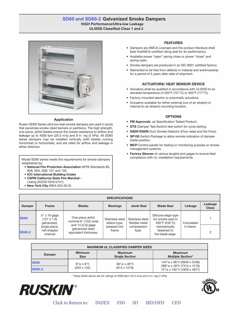
Click to Return to: INDEX FSD SD IBD/DFD CFD
ApplicationRuskin SD60 Series ultra low leak smoke dampers are used in ducts that penetrate smoke rated barriers or partitions. The high strength, one-piece, airfoil blades ensure the lowest resistance to airflow and leakage up to 4000 fpm (20.3 m/s) and 8 in. wg (2 kPa). All SD60 series dampers may be installed vertically (with blades running horizontal) or horizontally, and are rated for airflow and leakage in either direction.
FEATURES• Dampers are AMCA Licensed and the product literature shall
bear theAMCA certified rating seal for air performance.
• Available power “open” spring close or power “close” andspring open.
• Smoke dampers are produced in an ISO 9001 certified factory.
• Warranted to be free from defects in material and workmanshipfor a period of 5 years after date of shipment.
ACTUATORS/ HEAT SENSOR DEVICE• Actuators shall be qualified in accordance with UL555S to an
elevated temperature of 250°F (121°C) or 350°F (177°C).
• Factory mounted electric or pneumatic actuators.
• Actuators available for either external (out of air stream) orinternal (in air stream) mounting location.
OPTIONS• FM Approvals as Specification Tested Product.
• DTS (Damper Test Switch) test switch for cycle testing.
• DSDF/DSDN Duct Smoke Detector (Flow rated and No-Flow).
• SP100 Switch Package to allow remote indication of damperblade position.
• MCP Control panels for testing or monitoring purpose or smokemanagement systems.
• Factory Sleeves of various lengths and gages to ensure fieldcompliance with UL installation requirements.
SD60 and SD60-2 Galvanized Smoke DampersHiGH Performance/Ultra-low Leakage
UL555S Classified Class 1 and 2
Model SD60 series meets the requirements for smoke dampers established by:
• National Fire Protection Association NFPA Standards 80, 90A, 92A, 92B, 101 and 105.
• ICC International Building Codes• CSFM California State Fire Marshal -
Listing (#3230-0245:0131)• New York City (MEA 252-05-E)
SD60
SD60-2
SPECIFICATIONS
Frame Blades Bearings Jamb Seal Blade Seal LinkageLeakage
ClassDamper
5" x 16 gage(127 x 1.6)galvanized, single piece, hat-shaped
channel
One-piece airfoil nominal 6" (152) wide
and 14 (2.0) gagegalvanized steel
equivalent thickness.
Stainless steelsleeve type,pressed into
frame
Stainless steelflexible metalcompression
type.
Silicone edge typefor smoke seal to
450°F (232°C) mechanically fastened to
the blade edge.
Concealedin frame.
1
2
MAXIMUM UL CLASSIFIED DAMPER SIZES
Damper
SD60
SD60-2
MinimumSize
MaximumSingle Section
MaximumMultiple Section*
8"w x 6"h(203 x 152)
36"w x 48"h(914 x 1219)
144"w x 96"h (3658 x 2438)288"w x 48"h (7315 x 1219)72"w x 192"h (1829 x 4877)
* Sizes listed above are for ratings of 2000 fpm (10.2 m/s) and 4 in. wg (1 kPa)
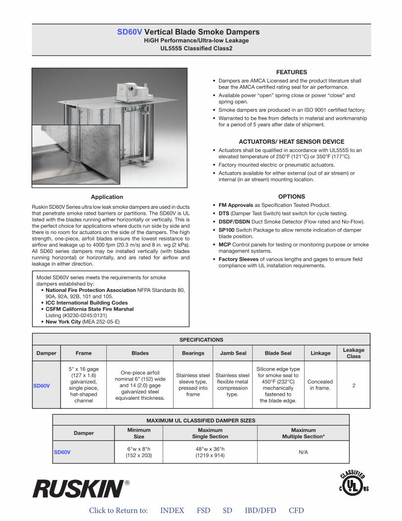
Click to Return to: INDEX FSD SD IBD/DFD CFD
ApplicationRuskin SD60V Series ultra low leak smoke dampers are used in ducts that penetrate smoke rated barriers or partitions. The SD60V is UL listed with the blades running either horizontally or vertically. This is the perfect choice for applications where ducts run side by side and there is no room for actuators on the side of the dampers. The high strength, one-piece, airfoil blades ensure the lowest resistance to airflow and leakage up to 4000 fpm (20.3 m/s) and 8 in. wg (2 kPa). All SD60 series dampers may be installed vertically (with blades running horizontal) or horizontally, and are rated for airflow and leakage in either direction.
FEATURES• Dampers are AMCA Licensed and the product literature shall
bear the AMCA certified rating seal for air performance.
• Available power “open” spring close or power “close” andspring open.
• Smoke dampers are produced in an ISO 9001 certified factory.
• Warranted to be free from defects in material and workmanshipfor a period of 5 years after date of shipment.
ACTUATORS/ HEAT SENSOR DEVICE• Actuators shall be qualified in accordance with UL555S to an
elevated temperature of 250°F (121°C) or 350°F (177°C).
• Factory mounted electric or pneumatic actuators.
• Actuators available for either external (out of air stream) orinternal (in air stream) mounting location.
OPTIONS• FM Approvals as Specification Tested Product.
• DTS (Damper Test Switch) test switch for cycle testing.
• DSDF/DSDN Duct Smoke Detector (Flow rated and No-Flow).
• SP100 Switch Package to allow remote indication of damperblade position.
• MCP Control panels for testing or monitoring purpose or smokemanagement systems.
• Factory Sleeves of various lengths and gages to ensure fieldcompliance with UL installation requirements.
SD60V Vertical Blade Smoke DampersHiGH Performance/Ultra-low Leakage
UL555S Classified Class2
Model SD60V series meets the requirements for smoke dampers established by:
• National Fire Protection Association NFPA Standards 80, 90A, 92A, 92B, 101 and 105.
• ICC International Building Codes• CSFM California State Fire Marshal
Listing (#3230-0245:0131)• New York City (MEA 252-05-E)
* Sizes listed above are for ratings of 2000 fpm (10.2 m/s) and 4 in. wg (1 kPa)
MAXIMUM UL CLASSIFIED DAMPER SIZES
Damper
SD60V
MinimumSize
MaximumSingle Section
MaximumMultiple Section*
6"w x 8"h(152 x 203)
48"w x 36"h(1219 x 914)
N/A
SD60V
SPECIFICATIONS
Frame Blades Bearings Jamb Seal Blade Seal LinkageLeakage
ClassDamper
5" x 16 gage(127 x 1.6)galvanized, single piece, hat-shaped
channel
One-piece airfoil nominal 6" (152) wide
and 14 (2.0) gagegalvanized steel
equivalent thickness.
Stainless steelsleeve type,pressed into
frame
Stainless steelflexible metalcompression
type.
Silicone edge typefor smoke seal to
450°F (232°C) mechanically fastened to
the blade edge.
Concealedin frame. 2

Click to Return to: INDEX FSD SD IBD/DFD CFD
ApplicationRuskin SD36 Series low leak smoke dampers are used in ducts that penetrate smoke rated barriers or partitions. The SD36 series damper is constructed with V-Groove blades for velocities up to 2,000 fpm (10.2 m/s) and 4" w.g. (1 kPa). All SD36 series dampers may be installed vertically (with blades running horizontal) or horizontally, and are rated for airflow and leakage in either direction.
FEATURES• Dampers are AMCA Licensed and the product literature shall
bear the AMCA certified rating seal for air performance.
• Smoke dampers are produced in an ISO 9001 certified factory.
• Warranted to be free from defects in material and workmanshipfor a period of 5 years after date of shipment.
ACTUATORS/ HEAT SENSOR DEVICE• Actuators shall be qualified in accordance with UL555S to an
elevated temperature of 250°F (121°C) or 350°F (177°C).
• Factory mounted electric or pneumatic actuators.
• Actuators available for either external (out of air stream) orinternal (in air stream) mounting location.
OPTIONS• FM Approvals as Specification Tested Product.
• DTS (Damper Test Switch) test switch for cycle testing.
• DSDF/DSDN Duct Smoke Detector (Flow rated and No-Flow).
• SP100 Switch Package to allow remote indication of damperblade position.
• MCP Control panels for testing or monitoring purpose or smokemanagement systems.
• Factory Sleeves of various lengths and gages to ensure fieldcompliance with UL installation requirements.
SD35, SD36 and SD37 Smoke DampersUL555S Classified
Leakage Class 1, 2 and 3
Model SD36 series meets the requirements for smoke dampers established by:
• National Fire Protection Association NFPA Standards 80, 90A, 92A, 92B, 101 and 105.
• ICC International Building Codes• CSFM California State Fire Marshal
Listing (#3230-0245:0131)• New York City (MEA 252-05-E)
* Sizes listed above are for ratings of 2000 fpm (10.2 m/s) and 4 in. wg (1 kPa)
MAXIMUM UL CLASSIFIED DAMPER SIZES
Damper
SD35
SD36
SD37
MinimumSize
MaximumSingle Section
MaximumMultiple Section*
8"w x 6"h(203 x 152)
36"w x 48"h(914 x 1219)
144"w x 96"h (3658 x 2438)288"w x 48"h (7315 x 1219)72"w x 192"h (1829 x 4877)
SD35
SD36
SD37
SPECIFICATIONS
Frame Blades Bearings Jamb Seal Blade Seal LinkageLeakage
ClassDamper
5" x 16 gage(127 x 1.6)galvanized, single piece, hat-shaped
channel
16 (1.6) gagegalvanized steel,
triple V-Groove shaped.
Stainless steelsleeve type,pressed into
frame
Stainless steelflexible metalcompression
type.
Silicone edge typefor smoke seal to
450°F (232°C) mechanically fastened to
the blade edge.
Concealedin frame.
3N/A
2
1
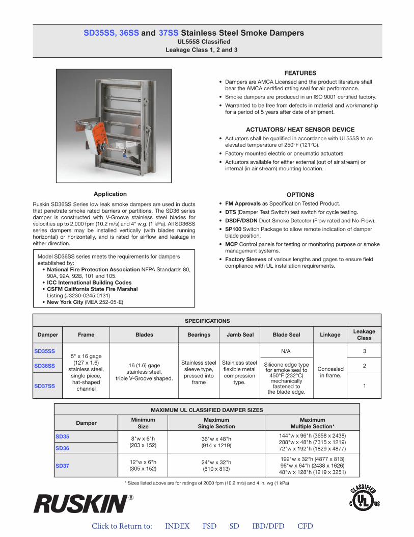
Click to Return to: INDEX FSD SD IBD/DFD CFD
ApplicationRuskin SD36SS Series low leak smoke dampers are used in ducts that penetrate smoke rated barriers or partitions. The SD36 series damper is constructed with V-Groove stainless steel blades for velocities up to 2,000 fpm (10.2 m/s) and 4" w.g. (1 kPa). All SD36SS series dampers may be installed vertically (with blades running horizontal) or horizontally, and is rated for airflow and leakage in either direction.
FEATURES• Dampers are AMCA Licensed and the product literature shall
bear the AMCA certified rating seal for air performance.
• Smoke dampers are produced in an ISO 9001 certified factory.
• Warranted to be free from defects in material and workmanshipfor a period of 5 years after date of shipment.
ACTUATORS/ HEAT SENSOR DEVICE• Actuators shall be qualified in accordance with UL555S to an
elevated temperature of 250°F (121°C).
• Factory mounted electric or pneumatic actuators
• Actuators available for either external (out of air stream) orinternal (in air stream) mounting location.
OPTIONS• FM Approvals as Specification Tested Product.
• DTS (Damper Test Switch) test switch for cycle testing.
• DSDF/DSDN Duct Smoke Detector (Flow rated and No-Flow).
• SP100 Switch Package to allow remote indication of damperblade position.
• MCP Control panels for testing or monitoring purpose or smokemanagement systems.
• Factory Sleeves of various lengths and gages to ensure fieldcompliance with UL installation requirements.
SD35SS, 36SS and 37SS Stainless Steel Smoke Dampers UL555S Classified
Leakage Class 1, 2 and 3
Model SD36SS series meets the requirements for dampers established by:
• National Fire Protection Association NFPA Standards 80, 90A, 92A, 92B, 101 and 105.
• ICC International Building Codes• CSFM California State Fire Marshal
Listing (#3230-0245:0131)• New York City (MEA 252-05-E)
* Sizes listed above are for ratings of 2000 fpm (10.2 m/s) and 4 in. wg (1 kPa)
MAXIMUM UL CLASSIFIED DAMPER SIZES
Damper
SD35
SD36
SD37
MinimumSize
MaximumSingle Section
MaximumMultiple Section*
12"w x 6"h(305 x 152)
8"w x 6"h(203 x 152)
24"w x 32"h(610 x 813)
36"w x 48"h(914 x 1219)
192"w x 32"h (4877 x 813)96"w x 64"h (2438 x 1626)48"w x 128"h (1219 x 3251)
144"w x 96"h (3658 x 2438)288"w x 48"h (7315 x 1219)72"w x 192"h (1829 x 4877)
SD35SS
SD36SS
SD37SS
SPECIFICATIONS
Frame Blades Bearings Jamb Seal Blade Seal LinkageLeakage
ClassDamper
5" x 16 gage(127 x 1.6)
stainless steel, single piece, hat-shaped
channel
16 (1.6) gagestainless steel,
triple V-Groove shaped.
Stainless steelsleeve type,pressed into
frame
Stainless steelflexible metalcompression
type.
Silicone edge typefor smoke seal to
450°F (232°C) mechanically fastened to
the blade edge.
Concealedin frame.
3N/A
2
1
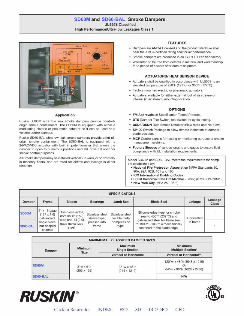
Click to Return to: INDEX FSD SD IBD/DFD CFD
ApplicationRuskin SD60M ultra low leak smoke dampers provide point-of- origin smoke containment. The SD60M is equipped with either a modulating electric or pneumatic actuator so it can be used as a volume control damper.
Ruskin SD60-BAL ultra low leak smoke dampers provide point-of- origin smoke containment. The SD60-BAL is equipped with a 24VAC/VDC actuator with built in potentiometer that allows the damper to open to numerous positions and still drive full open for smoke control purposes.
All Smoke dampers may be installed vertically in walls, or horizontally in masonry floors, and are rated for airflow and leakage in either direction.
FEATURES• Dampers are AMCA Licensed and the product literature shall
bear the AMCA certified rating seal for air performance.
• Smoke dampers are produced in an ISO 9001 certified factory.
• Warranted to be free from defects in material and workmanshipfor a period of 5 years after date of shipment.
ACTUATORS/ HEAT SENSOR DEVICE• Actuators shall be qualified in accordance with UL555S to an
elevated temperature of 250°F (121°C) or 350°F (177°C).
• Factory mounted electric or pneumatic actuators.
• Actuators available for either external (out of air stream) orinternal (in air stream) mounting location.
OPTIONS• FM Approvals as Specification Tested Product.
• DTS (Damper Test Switch) test switch for cycle testing.
• DSDF/DSDN Duct Smoke Detector (Flow rated and No-Flow).
• SP100 Switch Package to allow remote indication of damperblade position.
• MCP Control panels for testing or monitoring purpose or smokemanagement systems.
• Factory Sleeves of various lengths and gages to ensure fieldcompliance with UL installation requirements.
SD60M and SD60-BAL Smoke Dampers UL555S Classified
High Performance/Ultra-low Leakages Class 1
Model SD60M and SD60-BAL meets the requirements for damp-ers established by:
• National Fire Protection Association NFPA Standards 80, 90A, 92A, 92B, 101 and 105.
• ICC International Building Codes• CSFM California State Fire Marshal - Listing (#3230-0245:0131)• New York City (MEA 252-05-E)
MAXIMUM UL CLASSIFIED DAMPER SIZES
Damper
SD60M
SD60-BAL
MinimumSize
MaximumSingle Section
Vertical or Horizontal Vertical or Horizontal**
MaximumMultiple Section*
8"w x 6"h(203 x 152)
36"w x 48"h(914 x 1219)
N/A
120"w x 48"h (3048 x 1219)Or
64"w x 96"h (1626 x 2438)
SD60M
SD60-BAL
SPECIFICATIONS
Frame Blades Bearings Jamb Seal Blade Seal LinkageLeakage
ClassDamper
5" x 16 gage(127 x 1.6)galvanized, single piece, hat-shaped
channel
One-piece airfoil, nominal 6" (152) wide and 14 (2.0) gage galvanized
steel.
Stainless steelsleeve type,pressed into
frame
Stainless steelflexible metalcompression
type.
Silicone edge type for smoke seal to 450°F (232°C) and
galvanized steel for flame seal to 1900ºF (1038ºC) mechanically
fastened to the blade edge.
Concealedin frame.
1
1
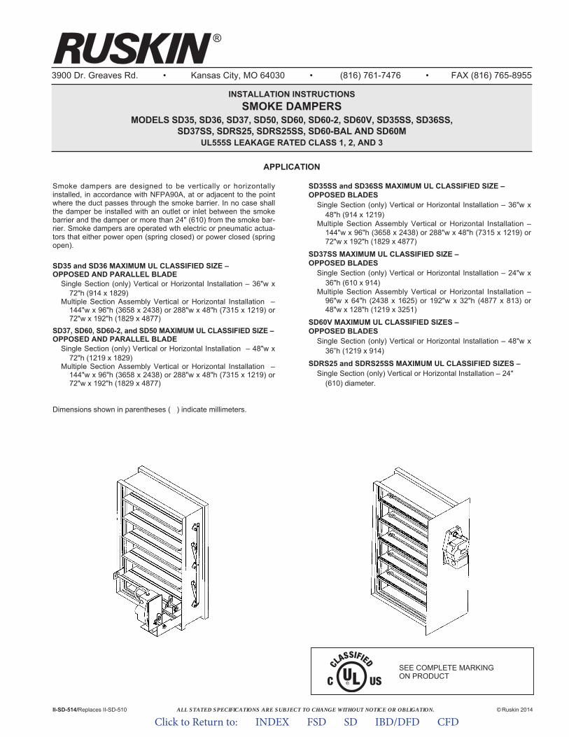
ALL STATED SPECIFICATIONS ARE SUBJECT TO CHANGE WITHOUT NOTICE OR OBLIGATION.
3900 Dr. Greaves Rd. • Kansas City, MO 64030 • (816) 761-7476 • FAX (816) 765-8955
INSTALLATION INSTRUCTIONSSMOKE DAMPERS
MODELS SD35, SD36, SD37, SD50, SD60, SD60-2, SD60V, SD35SS, SD36SS,SD37SS, SDRS25, SDRS25SS, SD60-BAL AND SD60M
UL555S LEAKAGE RATED CLASS 1, 2, AND 3
Smoke dampers are designed to be vertically or horizontallyinstalled, in accordance with NFPA90A, at or adjacent to the pointwhere the duct passes through the smoke barrier. In no case shallthe damper be installed with an outlet or inlet between the smokebar rier and the damper or more than 24" (610) from the smoke bar-rier. Smoke dampers are operated wth electric or pneumatic actua-tors that either power open (spring closed) or power closed (springopen).
SD35 and SD36 MAXIMUM UL CLASSIFIED SIZE –OPPOSED AND PARALLEL BLADE
Single Section (only) Vertical or Horizontal Installation – 36"w x 72"h (914 x 1829)
Multiple Section Assembly Vertical or Horizontal Installation – 144"w x 96"h (3658 x 2438) or 288"w x 48"h (7315 x 1219) or72"w x 192"h (1829 x 4877)
SD37, SD60, SD60-2, and SD50 MAXIMUM UL CLASSIFIED SIZE –OPPOSED AND PARALLEL BLADE
Single Section (only) Vertical or Horizontal Installation – 48"w x 72"h (1219 x 1829)
Multiple Section Assembly Vertical or Horizontal Installation – 144"w x 96"h (3658 x 2438) or 288"w x 48"h (7315 x 1219) or72"w x 192"h (1829 x 4877)
SD35SS and SD36SS MAXIMUM UL CLASSIFIED SIZE –OPPOSED BLADES
Single Section (only) Vertical or Horizontal Installation – 36"w x 48"h (914 x 1219)
Multiple Section Assembly Vertical or Horizontal Installation – 144"w x 96"h (3658 x 2438) or 288"w x 48"h (7315 x 1219) or72"w x 192"h (1829 x 4877)
SD37SS MAXIMUM UL CLASSIFIED SIZE –OPPOSED BLADES
Single Section (only) Vertical or Horizontal Installation – 24"w x 36"h (610 x 914)
Multiple Section Assembly Vertical or Horizontal Installation – 96"w x 64"h (2438 x 1625) or 192"w x 32"h (4877 x 813) or 48"w x 128"h (1219 x 3251)
SD60V MAXIMUM UL CLASSIFIED SIZES –OPPOSED BLADES
Single Section (only) Vertical or Horizontal Installation – 48"w x36”h (1219 x 914)
SDRS25 and SDRS25SS MAXIMUM UL CLASSIFIED SIZES –Single Section (only) Vertical or Horizontal Installation – 24"
(610) diameter.
II-SD-514/Replaces II-SD-510 © Ruskin 2014
®
SEE COMPLETE MARKING ON PRODUCT
APPLICATION
Dimensions shown in parentheses ( ) indicate millimeters.
Click to Return to: INDEX FSD SD IBD/DFD CFD
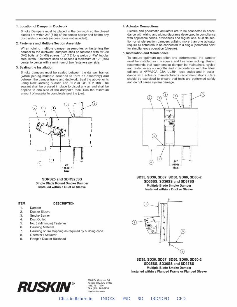
1. Location of Damper in DuctworkSmoke Dampers must be placed in the ductwork so the closedblades are within 24" (610) of the smoke barrier and before anyduct inlets or outlets (access doors not included).
2. Fasteners and Multiple Section AssemblyWhen joining multiple damper assemblies or fastening thedamper to the ductwork, dampers shall be fastened with 1/4"-20(M6) bolts, #10 (M5) screws, 1/2" (13) long welds or 3/16" tubularsteel rivets. Fasteners shall be spaced a maximum of 12" (305)center to center with a minimum of two fasteners per side.
3. Sealing the InstallationSmoke dampers must be sealed between the damper frames(when joining multiple sections to form an assembly) andbetween the damper frame and ductwork. Seal the above jointsusing Dow-Corning Silastic 732 RTV or GE RTV 108. Thesealant shall be pressed in place to dispel any air and shall beapplied to one side of the damper's face. Use the minimumamount of material to completely seal the joint.
4. Actuator ConnectionsElectric and pneumatic actuators are to be connected in accor-dance with wiring and piping diagrams developed in compliancewith applicable codes, ordinances and regulations. Multiple sec-tion or single section dampers utilizing more than one actuatorrequire all actuators to be connected to a single (common) pointfor simultaneous operation (closure).
5. Installation and MaintenanceTo ensure optimum operation and performance, the dampermust be installed so it is square and free from racking. Ruskinrecommends that each smoke damper be maintained, cycledand tested every six months and in accordance with the latesteditions of NFPA90A, 92A, UL864, local codes and in accor-dance with actuator manufacturer's recommendations. Careshould be exercised to ensure that tests are performed safelyand do not cause system damage.
SDRS25 and SDRS25SSSingle Blade Round Smoke Damper
Installed within a Duct or Sleeve
SD35, SD36, SD37, SD50, SD60, SD60-2SD35SS, SD36SS and SD37SS
Multiple Blade Smoke DamperInstalled within a Duct or Sleeve
SD35, SD36, SD37, SD50, SD60, SD60-2SD35SS, SD36SS and SD37SS
Multiple Blade Smoke DamperInstalled within a Flanged Frame or Flanged Sleeve
ITEM DESCRIPTION1. Damper2. Duct or Sleeve3. Smoke Barrier4. Duct Outlet5. No. 8 (Minimum) Fastener6. Caulking Material7. Caulking or fire stopping as required by building code.8. Operator / Actuator9. Flanged Duct or Bulkhead
3900 Dr. Greaves Rd.Kansas City, MO 64030(816) 761-7476FAX (816) 765-8955www.ruskin.com
®
Click to Return to: INDEX FSD SD IBD/DFD CFD
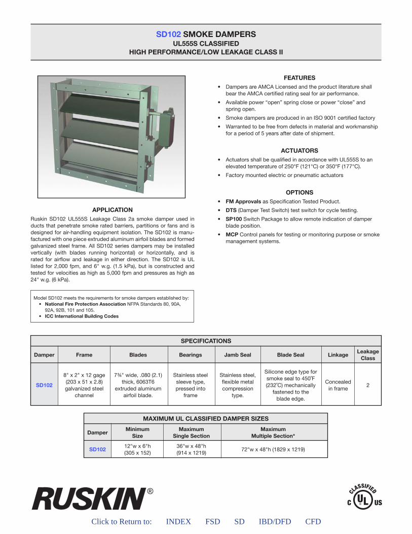
®
Click to Return to: INDEX FSD SD IBD/DFD CFD
SD102 SMOKE DAMPERSUL555S CLASSIFIED
HIGH PERFORMANCE/LOW LEAKAGE CLASS II
APPLICATIONRuskin SD102 UL555S Leakage Class 2a smoke damper used in ducts that penetrate smoke rated barriers, partitions or fans and is designed for air-handling equipment isolation. The SD102 is manu-factured with one piece extruded aluminum airfoil blades and formed galvanized steel frame. All SD102 series dampers may be installed vertically (with blades running horizontal) or horizontally, and is rated for airflow and leakage in either direction. The SD102 is UL listed for 2,000 fpm, and 6" w.g. (1.5 kPa), but is constructed and tested for velocities as high as 5,000 fpm and pressures as high as 24" w.g. (6 kPa).
FEATURES• Dampers are AMCA Licensed and the product literature shall
bear the AMCA certified rating seal for air performance.
• Available power “open” spring close or power “close” andspring open.
• Smoke dampers are produced in an ISO 9001 certified factory
• Warranted to be free from defects in material and workmanshipfor a period of 5 years after date of shipment.
ACTUATORS• Actuators shall be qualified in accordance with UL555S to an
elevated temperature of 250°F (121°C) or 350°F (177°C).
• Factory mounted electric or pneumatic actuators
OPTIONS• FM Approvals as Specification Tested Product.
• DTS (Damper Test Switch) test switch for cycle testing.
• SP100 Switch Package to allow remote indication of damperblade position.
• MCP Control panels for testing or monitoring purpose or smokemanagement systems.
Model SD102 meets the requirements for smoke dampers established by:• National Fire Protection Association NFPA Standards 80, 90A,
92A, 92B, 101 and 105.• ICC International Building Codes
MAXIMUM UL CLASSIFIED DAMPER SIZES
Damper
SD102
MinimumSize
12"w x 6"h(305 x 152)
MaximumSingle Section
36"w x 48"h(914 x 1219)
MaximumMultiple Section*
72"w x 48"h (1829 x 1219)
SPECIFICATIONS
Damper
SD102
Frame
8" x 2" x 12 gage(203 x 51 x 2.8)galvanized steel
channel
Blades
7¾" wide, .080 (2.1)thick, 6063T6
extruded aluminum airfoil blade.
Bearings
Stainless steelsleeve type,pressed into
frame
Jamb Seal
Stainless steel,flexible metalcompression
type.
Blade Seal
Silicone edge type forsmoke seal to 450˚F (232˚C) mechanically
fastened to the blade edge.
Linkage
Concealedin frame
LeakageClass
2
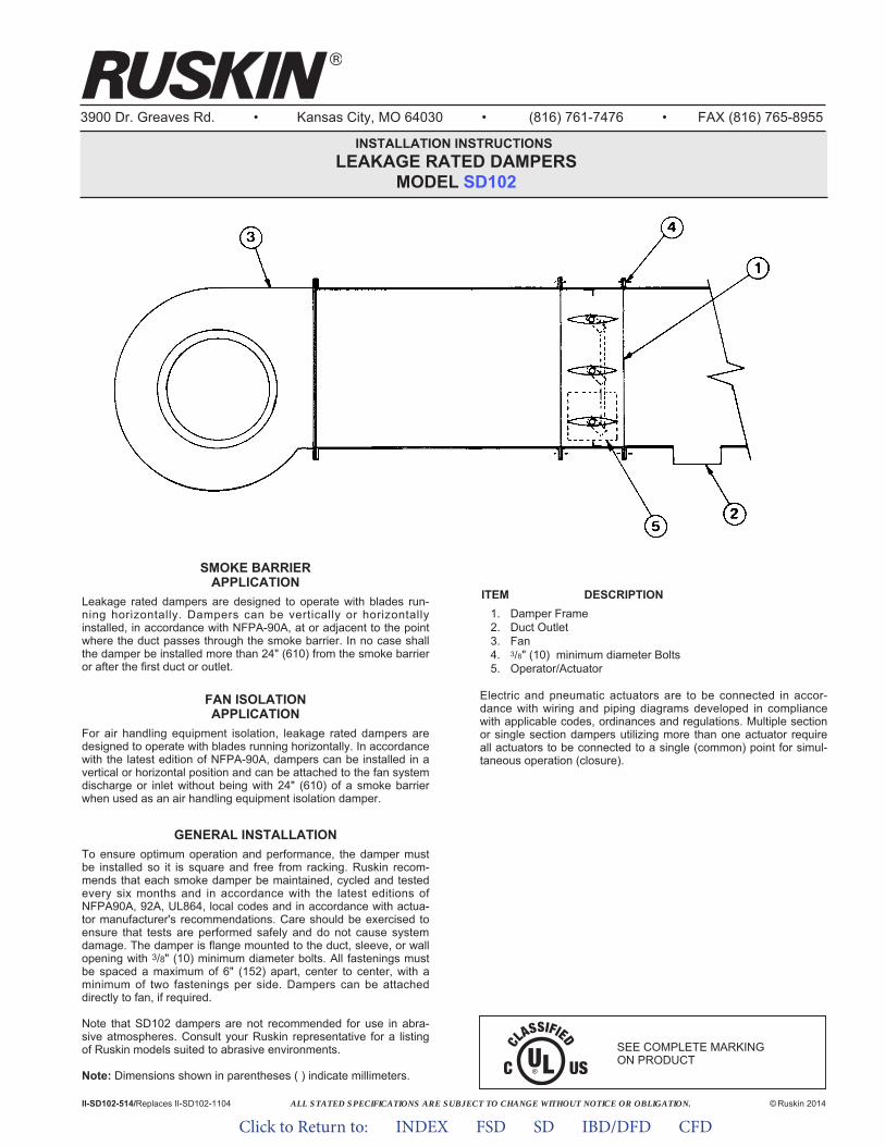
ALL STATED SPECIFICATIONS ARE SUBJECT TO CHANGE WITHOUT NOTICE OR OBLIGATION.
3900 Dr. Greaves Rd. • Kansas City, MO 64030 • (816) 761-7476 • FAX (816) 765-8955
INSTALLATION INSTRUCTIONS LEAKAGE RATED DAMPERS
MODEL SD102
© Ruskin 2014II-SD102-514/Replaces II-SD102-1104
SMOKE BARRIERAPPLICATION
Leakage rated dampers are designed to operate with blades run-ning horizontally. Dampers can be vertically or horizontallyinstalled, in accordance with NFPA-90A, at or adjacent to the pointwhere the duct passes through the smoke barrier. In no case shallthe damper be installed more than 24" (610) from the smoke barrieror after the first duct or outlet.
FAN ISOLATIONAPPLICATION
For air handling equipment isolation, leakage rated dampers aredesigned to operate with blades running horizontally. In accordancewith the latest edition of NFPA-90A, dampers can be installed in avertical or horizontal position and can be attached to the fan systemdischarge or inlet without being with 24" (610) of a smoke barrierwhen used as an air handling equipment isolation damper.
GENERAL INSTALLATIONTo ensure optimum operation and performance, the damper mustbe installed so it is square and free from racking. Ruskin recom-mends that each smoke damper be maintained, cycled and testedevery six months and in accordance with the latest editions ofNFPA90A, 92A, UL864, local codes and in accordance with actua-tor manufacturer's recommendations. Care should be exercised toensure that tests are performed safely and do not cause systemdamage. The damper is flange mounted to the duct, sleeve, or wallopening with 3/8" (10) minimum diameter bolts. All fastenings mustbe spaced a maximum of 6" (152) apart, center to center, with aminimum of two fastenings per side. Dampers can be attacheddirectly to fan, if required.
Note that SD102 dampers are not recommended for use in abra-sive atmospheres. Consult your Ruskin representative for a listingof Ruskin models suited to abrasive environments.
Note: Dimensions shown in parentheses ( ) indicate millimeters.
ITEM DESCRIPTION1. Damper Frame2. Duct Outlet3. Fan4. 3/8" (10) minimum diameter Bolts5. Operator/Actuator
Electric and pneumatic actuators are to be connected in accor-dance with wiring and piping diagrams developed in compliancewith applicable codes, ordinances and regulations. Multiple sectionor single section dampers utilizing more than one actuator requireall actuators to be connected to a single (common) point for simul-taneous operation (closure).
SEE COMPLETE MARKING ON PRODUCT
Click to Return to: INDEX FSD SD IBD/DFD CFD

Click to Return to: INDEX FSD SD IBD/DFD CFD 13
Fire dampers are UL555 tested and labeled devices installed in ducts and air transfer openings of air distribution systems, designed to close upon the detection of heat. Fire dampers, when closed interrupt migratory airflow, resist the passage of flame and maintain the integrity of the fire rated barrier.
Fire Damper SelectionThe process of selecting a fire damper involves the following considerations:
Fire Resistance RatingFire dampers are typically rated for 1-1/2 or 3 hours fire resistance. A 1-1/2 rated damper is sufficient for wall or floors having a rating of less than 3 hours. If the wall or floor has a rating of 3 hours or more, a 3 hour rated damper is required for sufficient protection. (IBC Chapter 7 and NFPA90A Chapter 5).
Dynamic Closure RatingFire dampers are rated for either static (fans off) or dynamic (fans on) HVAC systems. Static fire dampers have not been tested for closure under airflow and therefore can only be applied in HVAC systems that are designed to shut down in the event of a fire. Dynamic fire dampers have been tested for closure under airflow and carry both an airflow velocity (fpm) and pressure differential (w.g) rating. Minimum operational rating is 2000 fpm and 4" w.g. Other higher ratings that may be desired are conducted in increments of 1000 fpm and/or increments of 2" w.g. A dynamic fire damper should be selected based on the conditions it will operate in after installation.
InstallationFire dampers can be installed in the floor (horizontal) with vertical airflow or they can be installed in walls (vertical) with horizontal airflow.
The damper blades must close within the plane of the rated barrier, unless an “out of wall/floor” fire damper model is used.
Fire dampers use a variety of spring mechanisms depending on size, rating and vertical or horizontal mounting. So, it is important to recognize that dampers must be ordered according to their installed position for proper operation and features. For a wall opening the damper orientation is vertical mount, and a floor opening the damper orientation is horizontal mount.
Damper TypeThere are two main types of fire dampers: curtain type and multiple blade type. The curtain blade is the most commonly used fire damper because it costs less than the multiple blade type and, in most cases, is less restrictive to the air flow. Multiple blade fire dampers, however, are available in larger sizes and can be easier to test and re-open. Dynamic multiple blade fire dampers are airflow closure rated for higher velocities and pressures than curtain type fire dampers.
FIRE DAMPERS
FIRE DAMPERS
Curtain Type Fire Damper
Typical Fire Damper Installation(Fast Angle)
Multiple Blade Fire Damper
DIBD2 FD60
FIRE DAMPERS
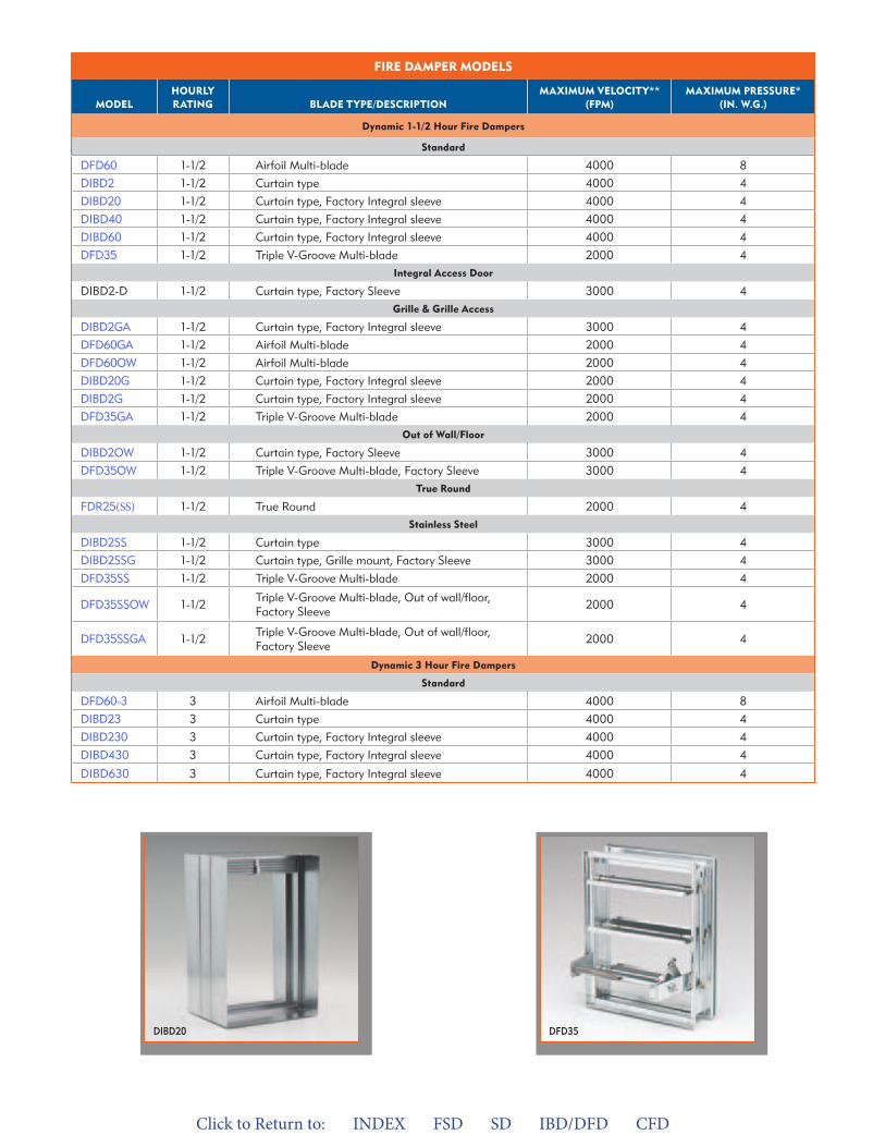
Click to Return to: INDEX FSD SD IBD/DFD CFD
FIRE DaMPER MODELS
MODELHOURLY RaTING BLaDE TYPE/DESCRIPTION
MaxIMUM VELOCITY** (FPM)
MaxIMUM PRESSURE* (IN. w.G.)
Dynamic 1-1/2 Hour Fire Dampers
Standard
DFD60 1-1/2 Airfoil Multi-blade 4000 8
DIBD2 1-1/2 Curtain type 4000 4
DIBD20 1-1/2 Curtain type, Factory Integral sleeve 4000 4
DIBD40 1-1/2 Curtain type, Factory Integral sleeve 4000 4
DIBD60 1-1/2 Curtain type, Factory Integral sleeve 4000 4
DFD35 1-1/2 Triple V-Groove Multi-blade 2000 4
DIBD2-D 1-1/2
Integral access Door
Curtain type, Factory Sleeve 3000 4
DIBD2GA 1-1/2
Grille & Grille access
Curtain type, Factory Integral sleeve 3000 4
DFD60GA 1-1/2 Airfoil Multi-blade 2000 4
DFD60OW 1-1/2 Airfoil Multi-blade 2000 4
DIBD20G 1-1/2 Curtain type, Factory Integral sleeve 2000 4
DIBD2G 1-1/2 Curtain type, Factory Integral sleeve 2000 4
DFD35GA 1-1/2 Triple V-Groove Multi-blade 2000 4Out of wall/Floor
DIBD2OW 1-1/2 Curtain type, Factory Sleeve 3000 4
DFD35OW 1-1/2 Triple V-Groove Multi-blade, Factory Sleeve 3000 4 True Round
FDR25(SS) 1-1/2 True Round 2000 4 Stainless Steel
DIBD2SS 1-1/2 Curtain type 3000 4
DIBD2SSG 1-1/2 Curtain type, Grille mount, Factory Sleeve 3000 4
DFD35SS 1-1/2 Triple V-Groove Multi-blade 2000 4
DFD35SSOW 1-1/2 Triple V-Groove Multi-blade, Out of wall/floor, Factory Sleeve 2000 4
DFD35SSGA 1-1/2 Triple V-Groove Multi-blade, Out of wall/floor, Factory Sleeve 2000 4
Dynamic 3 Hour Fire Dampers
Standard
DFD60-3 3 Airfoil Multi-blade 4000 8
DIBD23 3 Curtain type 4000 4
DIBD230 3 Curtain type, Factory Integral sleeve 4000 4
DIBD430 3 Curtain type, Factory Integral sleeve 4000 4
DIBD630 3 Curtain type, Factory Integral sleeve 4000 4
DFD35DIBD20
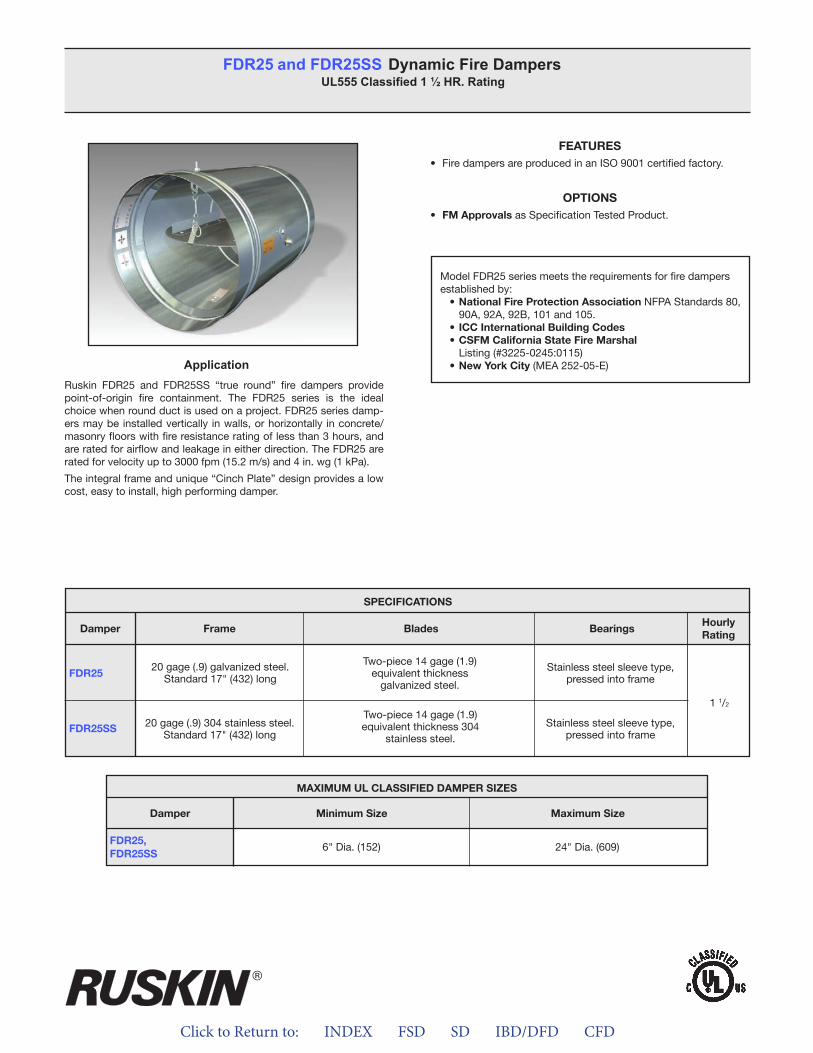
Click to Return to: INDEX FSD SD IBD/DFD CFD
ApplicationRuskin FDR25 and FDR25SS “true round” fire dampers provide point-of-origin fire containment. The FDR25 series is the ideal choice when round duct is used on a project. FDR25 series damp-ers may be installed vertically in walls, or horizontally in concrete/masonry floors with fire resistance rating of less than 3 hours, and are rated for airflow and leakage in either direction. The FDR25 are rated for velocity up to 3000 fpm (15.2 m/s) and 4 in. wg (1 kPa).
The integral frame and unique “Cinch Plate” design provides a low cost, easy to install, high performing damper.
FEATURES• Fire dampers are produced in an ISO 9001 certified factory.
OPTIONS• FM Approvals as Specification Tested Product.
FDR25 and FDR25SS Dynamic Fire DampersUL555 Classified 1 ½ HR. Rating
Model FDR25 series meets the requirements for fire dampers established by:
• National Fire Protection Association NFPA Standards 80, 90A, 92A, 92B, 101 and 105.
• ICC International Building Codes• CSFM California State Fire Marshal
Listing (#3225-0245:0115)• New York City (MEA 252-05-E)
MAXIMUM UL CLASSIFIED DAMPER SIZES
Damper
FDR25,FDR25SS
Minimum Size Maximum Size
6" Dia. (152) 24" Dia. (609)
SPECIFICATIONS
FDR25
FDR25SS
Frame Blades BearingsHourlyRating
Damper
1 1/2
20 gage (.9) galvanized steel.Standard 17" (432) long
Two-piece 14 gage (1.9) equivalent thickness
galvanized steel.
Stainless steel sleeve type,pressed into frame
20 gage (.9) 304 stainless steel.Standard 17" (432) long
Two-piece 14 gage (1.9) equivalent thickness 304
stainless steel.
Stainless steel sleeve type,pressed into frame
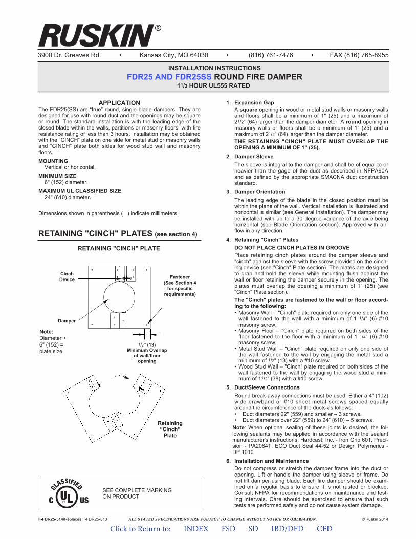
ALL STATED SPECIFICATIONS ARE SUBJECT TO CHANGE WITHOUT NOTICE OR OBLIGATION.
3900 Dr. Greaves Rd. • Kansas City, MO 64030 • (816) 761-7476 • FAX (816) 765-8955
INSTALLATION INSTRUCTIONSFDR25 AND FDR25SS ROUND FIRE DAMPER
11/2 HOUR UL555 RATED
II-FDR25-514/Replaces II-FDR25-813 © Ruskin 2014
®
1. Expansion GapA square opening in wood or metal stud walls or masonry wallsand floors shall be a minimum of 1" (25) and a maximum of21/2" (64) larger than the damper diameter. A round opening inmasonry walls or floors shall be a minimum of 1" (25) and amaximum of 21/2" (64) larger than the damper diameter.THE RETAINING "CINCH" PLATE MUST OVERLAP THEOPENING A MINIMUM OF 1" (25).
2. Damper SleeveThe sleeve is integral to the damper and shall be of equal to orheavier than the gage of the duct as described in NFPA90Aand as defined by the appropriate SMACNA duct constructionstandard.
3. Damper OrientationThe leading edge of the blade in the closed position must bewithin the plane of the wall. Vertical installation is illustrated andhorizontal is similar (see General Installation). The damper maybe installed with up to a 30 degree variance of the axle beinghorizontal (see Blade Orientation section). Approved with air-flow in any direction.
4. Retaining "Cinch" PlatesDO NOT PLACE CINCH PLATES IN GROOVEPlace retaining cinch plates around the damper sleeve and"cinch" against the sleeve with the screw provided on the cinch-ing device (see "Cinch" Plate section). The plates are designedto grab and hold the sleeve while mounting flush against thewall or floor retaining the damper securely in the opening. Theplates must overlap the opening a minimum of 1" (25) (see"Cinch" Plate section).The "Cinch" plates are fastened to the wall or floor accord-ing to the following:• Masonry Wall – "Cinch" plate required on only one side of the
wall fastened to the wall with a minimum of 1 1/4" (6) #10masonry screw.
• Masonry Floor – "Cinch" plate required on both sides of thefloor fastened to the floor with a minimum of 1 1/4" (6) #10masonry screw.
• Metal Stud Wall – "Cinch" plate required on only one side ofthe wall fastened to the wall by engaging the metal stud aminimum of 1/2" (13) with a #10 screw.
• Wood Stud Wall – "Cinch" plate required on both sides of thewall fastened to the wall by engaging the wood stud a mini-mum of 11/2" (38) with a #10 screw.
5. Duct/Sleeve ConnectionsRound break-away connections must be used. Either a 4" (102)wide drawband or #10 sheet metal screws spaced equallyaround the circumference of the ducts as follows:• Duct diameters 22" (559) and smaller – 3 screws.• Duct diameters over 22" (559) to 24” (610) – 5 screws.
Note: When optional sealing of these joints is desired, the fol-lowing sealants may be applied in accordance with the sealantmanufacturer's instructions: Hardcast, Inc. - Iron Grip 601, Preci-sion - PA2084T, ECO Duct Seal 44-52 or Design Polymerics -DP 1010
6. Installation and MaintenanceDo not compress or stretch the damper frame into the duct oropening. Lift or handle the damper using sleeve or frame. Donot lift damper using blade. Each fire damper should be exam-ined on a regular basis to ensure it is not rusted or blocked.Consult NFPA for recommendations on maintenance and test-ing intervals. Care should be exercised to ensure that suchtests are performed safely and do not cause system damage.
RETAINING "CINCH" PLATES (see section 4)
RETAINING "CINCH" PLATE
Retaining“Cinch”
Plate
Note:Diameter +6" (152) =plate size
CinchDevice
Damper
Fastener(See Section 4
for specificrequirements)
APPLICATIONThe FDR25(SS) are “true” round, single blade dampers. They aredesigned for use with round duct and the openings may be squareor round. The standard installation is with the leading edge of theclosed blade within the walls, partitions or masonry floors; with fireresistance rating of less than 3 hours. Installation may be obtainedwith the “CINCH” plate on one side for metal stud or masonry wallsand “CINCH” plate both sides for wood stud wall and masonryfloors.MOUNTING
Vertical or horizontal.MINIMUM SIZE
6" (152) diameter.MAXIMUM UL CLASSIFIED SIZE
24" (610) diameter.
Dimensions shown in parenthesis ( ) indicate millimeters.
1/2" (13)Minimum Overlap
of wall/flooropening
SEE COMPLETE MARKING ON PRODUCT
Click to Return to: INDEX FSD SD IBD/DFD CFD
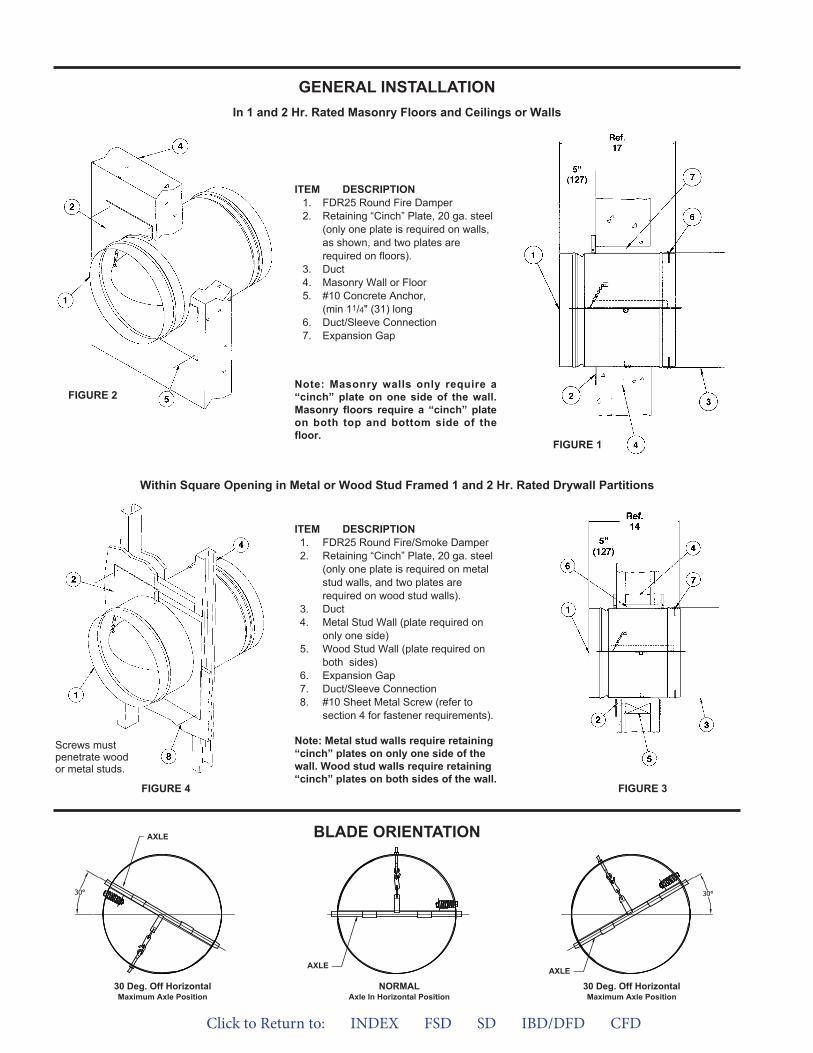
GENERAL INSTALLATIONIn 1 and 2 Hr. Rated Masonry Floors and Ceilings or Walls
Within Square Opening in Metal or Wood Stud Framed 1 and 2 Hr. Rated Drywall Partitions
ITEM DESCRIPTION1. FDR25 Round Fire/Smoke Damper2. Retaining “Cinch” Plate, 20 ga. steel
(only one plate is required on metalstud walls, and two plates arerequired on wood stud walls).
3. Duct4. Metal Stud Wall (plate required on
only one side)5. Wood Stud Wall (plate required on
both sides)6. Expansion Gap7. Duct/Sleeve Connection8. #10 Sheet Metal Screw (refer to
section 4 for fastener requirements).
BLADE ORIENTATION
ITEM DESCRIPTION1. FDR25 Round Fire Damper2. Retaining “Cinch” Plate, 20 ga. steel
(only one plate is required on walls,as shown, and two plates arerequired on floors).
3. Duct4. Masonry Wall or Floor5. #10 Concrete Anchor,
(min 11/4" (31) long6. Duct/Sleeve Connection7. Expansion Gap
FIGURE 1
FIGURE 3
FIGURE 2
FIGURE 4
Screws mustpenetrate woodor metal studs.
Note: Metal stud walls require retaining“cinch” plates on only one side of thewall. Wood stud walls require retaining“cinch” plates on both sides of the wall.
Note: Masonry walls only require a“cinch” plate on one side of the wall.Masonry floors require a “cinch” plateon both top and bottom side of thefloor.
30 Deg. Off HorizontalMaximum Axle Position
NORMALAxle In Horizontal Position
30 Deg. Off HorizontalMaximum Axle Position
AXLE
AXLE AXLE
Click to Return to: INDEX FSD SD IBD/DFD CFD
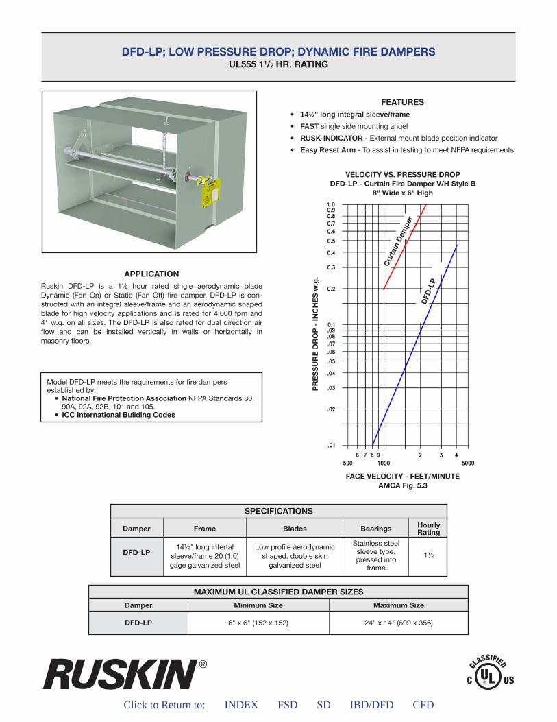
®
Click to Return to: INDEX FSD SD IBD/DFD CFD
DFD-LP; LOW PRESSURE DROP; DYNAMIC FIRE DAMPERSUL555 11/2 HR. RATING
APPLICATIONRuskin DFD-LP is a 1½ hour rated single aerodynamic blade Dynamic (Fan On) or Static (Fan Off) fire damper. DFD-LP is con-structed with an integral sleeve/frame and an aerodynamic shaped blade for high velocity applications and is rated for 4,000 fpm and 4" w.g. on all sizes. The DFD-LP is also rated for dual direction air flow and can be installed vertically in walls or horizontally in masonry floors.
Model DFD-LP meets the requirements for fire dampers established by: • NationalFireProtectionAssociationNFPA Standards 80, 90A, 92A, 92B, 101 and 105. • ICCInternationalBuildingCodes
FEATURES• 14½" long integral sleeve/frame
• FAST single side mounting angel
• RUSK-INDICATOR - External mount blade position indicator
• Easy Reset Arm - To assist in testing to meet NFPA requirements
MAXIMUM UL CLASSIFIED DAMPER SIZES
Damper
DFD-LP
MinimumSize
6" x 6" (152 x 152)
MaximumSize
24" x 14" (609 x 356)
SPECIFICATIONS
Damper
DFD-LP
Frame
14½" long intertalsleeve/frame 20 (1.0)gage galvanized steel
Blades
Low profile aerodynamicshaped, double skin
galvanized steel
Bearings
Stainless steelsleeve type,pressed into
frame
HourlyRating
1½
FACE VELOCITY - FEET/MINUTEAMCAFig.5.3
VELOCITY VS. PRESSURE DROPDFD-LP-CurtainFireDamperV/HStyleB
8"Widex6"High
PRESSUREDROP-INCHESw.g.
CurtainDamper
DFD
-LP
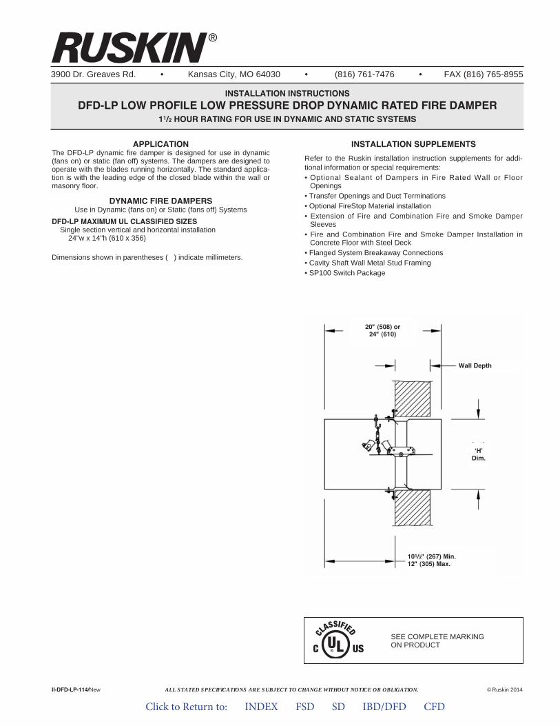
ALL STATED SPECIFICATIONS ARE SUBJECT TO CHANGE WITHOUT NOTICE OR OBLIGATION.
3900 Dr. Greaves Rd. • Kansas City, MO 64030 • (816) 761-7476 • FAX (816) 765-8955
INSTALLATION INSTRUCTIONSDFD-LP LOW PROFILE LOW PRESSURE DROP DYNAMIC RATED FIRE DAMPER
11/2 HOUR RATING FOR USE IN DYNAMIC AND STATIC SYSTEMS
APPLICATIONThe DFD-LP dynamic fire damper is designed for use in dynamic(fans on) or static (fan off) systems. The dampers are designed tooperate with the blades running horizontally. The standard applica-tion is with the leading edge of the closed blade within the wall ormasonry floor.
DYNAMIC FIRE DAMPERSUse in Dynamic (fans on) or Static (fans off) Systems
DFD-LP MAXIMUM UL CLASSIFIED SIZESSingle section vertical and horizontal installation24"w x 14"h (610 x 356)
Dimensions shown in parentheses ( ) indicate millimeters.
II-DFD-LP-114/New ©Ruskin 2014
®
INSTALLATION SUPPLEMENTSRefer to the Ruskin installation instruction supplements for addi-tional information or special requirements:• Optional Sealant of Dampers in Fire Rated Wall or FloorOpenings
• Transfer Openings and Duct Terminations• Optional FireStop Material installation• Extension of Fire and Combination Fire and Smoke DamperSleeves
• Fire and Combination Fire and Smoke Damper Installation inConcrete Floor with Steel Deck
• Flanged System Breakaway Connections• Cavity Shaft Wall Metal Stud Framing• SP100 Switch Package
SEE COMPLETE MARKING ON PRODUCT
20" (508) or24" (610)
101/2" (267) Min.12" (305) Max.
‘H’Dim.
Wall Depth
Click to Return to: INDEX FSD SD IBD/DFD CFD
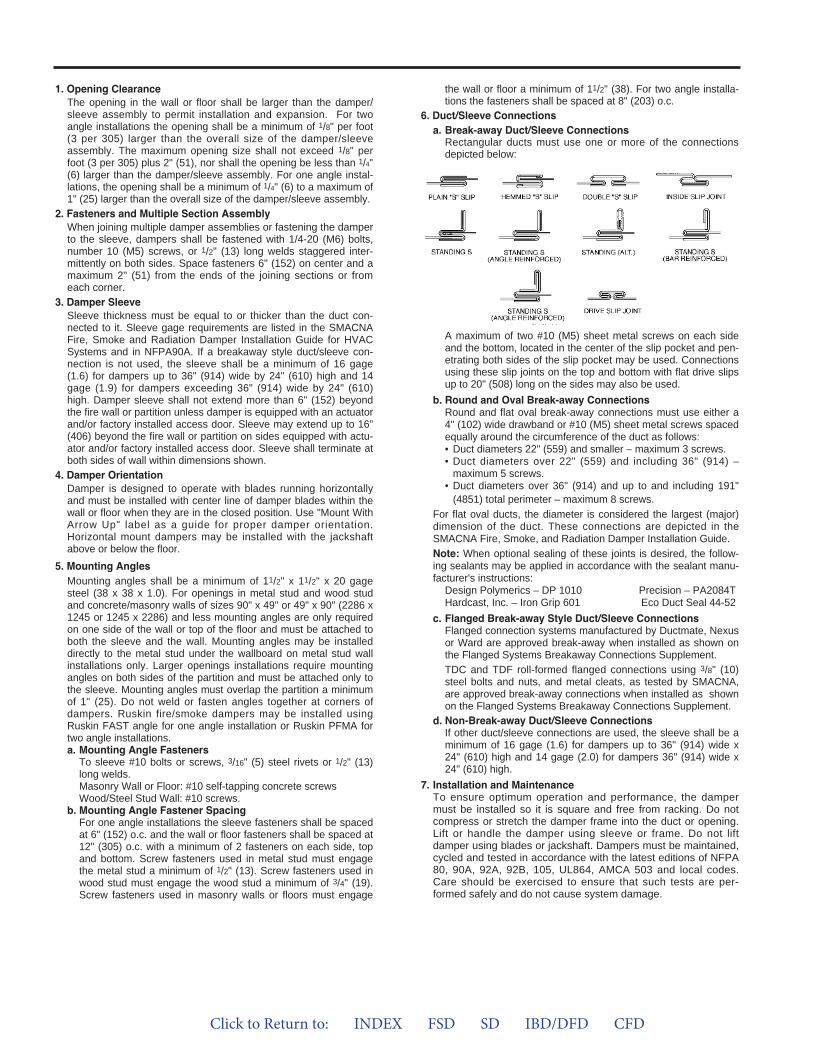
1. Opening ClearanceThe opening in the wall or floor shall be larger than the damper/sleeve assembly to permit installation and expansion. For twoangle installations the opening shall be a minimum of 1/8" per foot(3 per 305) larger than the overall size of the damper/sleeveassembly. The maximum opening size shall not exceed 1/8" perfoot (3 per 305) plus 2" (51), nor shall the opening be less than 1/4"(6) larger than the damper/sleeve assembly. For one angle instal-lations, the opening shall be a minimum of 1/4" (6) to a maximum of1" (25) larger than the overall size of the damper/sleeve assembly.
2. Fasteners and Multiple Section AssemblyWhen joining multiple damper assemblies or fastening the damperto the sleeve, dampers shall be fastened with 1/4-20 (M6) bolts,number 10 (M5) screws, or 1/2" (13) long welds staggered inter-mittently on both sides. Space fasteners 6" (152) on center and amaximum 2" (51) from the ends of the joining sections or fromeach corner.
3. Damper SleeveSleeve thickness must be equal to or thicker than the duct con-nected to it. Sleeve gage requirements are listed in the SMACNAFire, Smoke and Radiation Damper Installation Guide for HVACSystems and in NFPA90A. If a breakaway style duct/sleeve con-nection is not used, the sleeve shall be a minimum of 16 gage(1.6) for dampers up to 36" (914) wide by 24" (610) high and 14gage (1.9) for dampers exceeding 36" (914) wide by 24" (610)high. Damper sleeve shall not extend more than 6" (152) beyondthe fire wall or partition unless damper is equipped with an actuatorand/or factory installed access door. Sleeve may extend up to 16"(406) beyond the fire wall or partition on sides equipped with actu-ator and/or factory installed access door. Sleeve shall terminate atboth sides of wall within dimensions shown.
4. Damper OrientationDamper is designed to operate with blades running horizontallyand must be installed with center line of damper blades within thewall or floor when they are in the closed position. Use "Mount WithArrow Up" label as a guide for proper damper orientation.Horizontal mount dampers may be installed with the jackshaftabove or below the floor.
5. Mounting AnglesMounting angles shall be a minimum of 11/2" x 11/2" x 20 gagesteel (38 x 38 x 1.0). For openings in metal stud and wood studand concrete/masonry walls of sizes 90" x 49" or 49" x 90" (2286 x1245 or 1245 x 2286) and less mounting angles are only requiredon one side of the wall or top of the floor and must be attached toboth the sleeve and the wall. Mounting angles may be installeddirectly to the metal stud under the wallboard on metal stud wallinstallations only. Larger openings installations require mountingangles on both sides of the partition and must be attached only tothe sleeve. Mounting angles must overlap the partition a minimumof 1" (25). Do not weld or fasten angles together at corners ofdampers. Ruskin fire/smoke dampers may be installed usingRuskin FAST angle for one angle installation or Ruskin PFMA fortwo angle installations.a. Mounting Angle FastenersTo sleeve #10 bolts or screws, 3/16" (5) steel rivets or 1/2" (13)long welds.Masonry Wall or Floor: #10 self-tapping concrete screwsWood/Steel Stud Wall: #10 screws.
b. Mounting Angle Fastener SpacingFor one angle installations the sleeve fasteners shall be spacedat 6" (152) o.c. and the wall or floor fasteners shall be spaced at12" (305) o.c. with a minimum of 2 fasteners on each side, topand bottom. Screw fasteners used in metal stud must engagethe metal stud a minimum of 1/2" (13). Screw fasteners used inwood stud must engage the wood stud a minimum of 3/4" (19).Screw fasteners used in masonry walls or floors must engage
the wall or floor a minimum of 11/2" (38). For two angle installa-tions the fasteners shall be spaced at 8" (203) o.c.
6. Duct/Sleeve Connectionsa. Break-away Duct/Sleeve ConnectionsRectangular ducts must use one or more of the connectionsdepicted below:
A maximum of two #10 (M5) sheet metal screws on each sideand the bottom, located in the center of the slip pocket and pen-etrating both sides of the slip pocket may be used. Connectionsusing these slip joints on the top and bottom with flat drive slipsup to 20" (508) long on the sides may also be used.
b. Round and Oval Break-away ConnectionsRound and flat oval break-away connections must use either a4" (102) wide drawband or #10 (M5) sheet metal screws spacedequally around the circumference of the duct as follows:• Duct diameters 22" (559) and smaller – maximum 3 screws.• Duct diameters over 22" (559) and including 36" (914) –maximum 5 screws.
• Duct diameters over 36" (914) and up to and including 191"(4851) total perimeter – maximum 8 screws.
For flat oval ducts, the diameter is considered the largest (major)dimension of the duct. These connections are depicted in theSMACNA Fire, Smoke, and Radiation Damper Installation Guide.Note: When optional sealing of these joints is desired, the follow-ing sealants may be applied in accordance with the sealant manu-facturer's instructions:Design Polymerics – DP 1010 Precision – PA2084THardcast, Inc. – Iron Grip 601 Eco Duct Seal 44-52
c. Flanged Break-away Style Duct/Sleeve ConnectionsFlanged connection systems manufactured by Ductmate, Nexusor Ward are approved break-away when installed as shown onthe Flanged Systems Breakaway Connections Supplement.TDC and TDF roll-formed flanged connections using 3/8" (10)steel bolts and nuts, and metal cleats, as tested by SMACNA,are approved break-away connections when installed as shownon the Flanged Systems Breakaway Connections Supplement.
d. Non-Break-away Duct/Sleeve ConnectionsIf other duct/sleeve connections are used, the sleeve shall be aminimum of 16 gage (1.6) for dampers up to 36" (914) wide x24" (610) high and 14 gage (2.0) for dampers 36" (914) wide x24" (610) high.
7. Installation and MaintenanceTo ensure optimum operation and performance, the dampermust be installed so it is square and free from racking. Do notcompress or stretch the damper frame into the duct or opening.Lift or handle the damper using sleeve or frame. Do not liftdamper using blades or jackshaft. Dampers must be maintained,cycled and tested in accordance with the latest editions of NFPA80, 90A, 92A, 92B, 105, UL864, AMCA 503 and local codes.Care should be exercised to ensure that such tests are per-formed safely and do not cause system damage.
Click to Return to: INDEX FSD SD IBD/DFD CFD
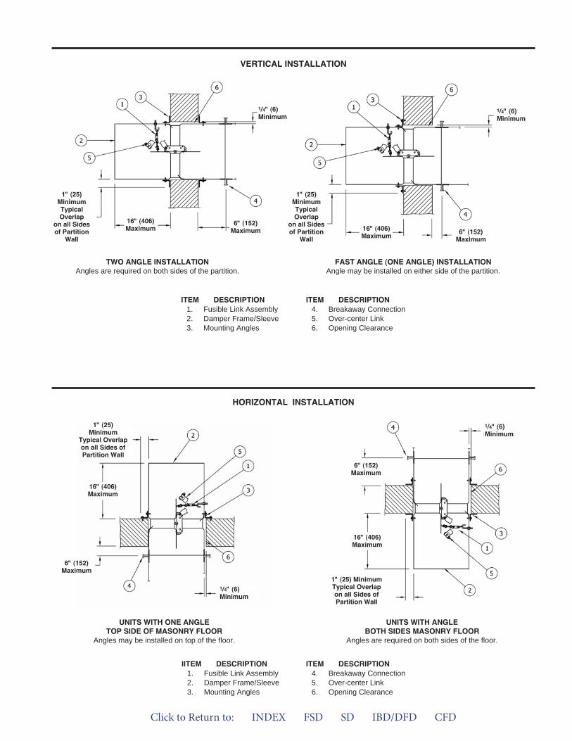
VERTICAL INSTALLATION
HORIZONTAL INSTALLATION
ITEM DESCRIPTION1. Fusible Link Assembly2. Damper Frame/Sleeve3. Mounting Angles
ITEM DESCRIPTION4. Breakaway Connection5. Over-center Link6. Opening Clearance
IITEM DESCRIPTION1. Fusible Link Assembly2. Damper Frame/Sleeve3. Mounting Angles
ITEM DESCRIPTION4. Breakaway Connection5. Over-center Link6. Opening Clearance
FAST ANGLE (ONE ANGLE) INSTALLATIONAngle may be installed on either side of the partition.
TWO ANGLE INSTALLATIONAngles are required on both sides of the partition.
UNITS WITH ANGLEBOTH SIDES MASONRY FLOOR
Angles are required on both sides of the floor.
UNITS WITH ONE ANGLETOP SIDE OF MASONRY FLOOR
Angles may be installed on top of the floor.
16" (406)Maximum 6" (152)
Maximum
1/4" (6) Minimum
1" (25)MinimumTypicalOverlap
on all Sidesof Partition
Wall16" (406)Maximum 6" (152)
Maximum
1/4" (6) Minimum
1" (25)MinimumTypicalOverlap
on all Sidesof Partition
Wall
16" (406)Maximum
6" (152)Maximum
1/4" (6) Minimum
1" (25)Minimum
Typical Overlapon all Sides ofPartition Wall
16" (406)Maximum
6" (152)Maximum
1/4" (6) Minimum
1" (25) MinimumTypical Overlapon all Sides ofPartition Wall
Click to Return to: INDEX FSD SD IBD/DFD CFD
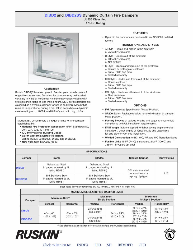
Click to Return to: INDEX FSD SD IBD/DFD CFD
ApplicationRuskin DIBD2(SS) series dynamic fire dampers provide point-of origin fire containment. Dynamic fire dampers may be installed vertically in walls or horizontally in concrete/masonry floors with fire resistance rating of less than 3 hours. DIBD series dampers are classified as a dynamic damper for use in an HVAC system that remains in operational during a fire. DIBD series have a dynamic closure rating up to 4000 fpm (20.3 m/s) and 4 in. wg (1 kPa).
FEATURES• Dynamic fire dampers are produced in an ISO 9001 certified
factory.
TRANSITIONS AND STYLES• A Style – Frame and blades in the airstream
o 75 to 85% free area
• B Style – Blades out of the airstreamo 80 to 90% free areao Not air tight
• C Style – Blades and frame out of the airstreamo Square or rectangular enclosureo 95 to 100% free areao Sealed assembly
• CR Style – Blades and frame out of the airstreamo Round enclosureo 95 to 100% free areao Sealed assembly
• CO Style – Blades and frame out of the airstreamo Oval enclosureo 95 to 100% free areao Sealed assembly
OPTIONS• FM Approvals as Specification Tested Product.
• SP200 Switch Package to allow remote indication of damperblade position.
• Factory Sleeves of various lengths and gages to ensure fieldcompliance with UL installation requirements.
• FAST Angle factory supplied for labor saving angle one-sideinstallation. Other angles of various sizes and gages alsofor one-side or two-side installation.
• Welded Construction for BC, WC, WR and WO Transition Styles
• Fusible Links 165ºF (74ºC) is standard. 212ºF (100ºC) and285ºF (141ºC) are optional
DIBD2 and DIBD2SS Dynamic Curtain Fire Dampers UL555 Classified
1 ½ Hr. Rating
Model DIBD series meets the requirements for fire dampers established by:
• National Fire Protection Association NFPA Standards 80, 90A, 92A, 92B, 101 and 105.
• ICC International Building Codes• CSFM California State Fire Marshal
Listing (#3225-0245:0005) DIBD2 and DIBD2SS• New York City (MEA 252-05-E)
DIBD2
DIBD2SS
SPECIFICATIONS
Frame Blades Closure Springs Hourly RatingDamper
Galvanized Steel(in gages required by UL
listing R5531)
Galvanized Steel(in gages required by UL
listing R5531) 301 stainless steelconstant force orspring clip type304 Stainless Steel
(in gages required by ULlisting R5531)
304 Stainless Steel(in gages required by UL
listing R5531)
1 1/2
MAXIMUM UL CLASSIFIED DAMPER SIZES
Damper
DIBD2
DIBD2SS
MaximumSingle Section
Minimum Size**Maximum
Multiple Section**
VerticalVertical VerticalHorizontalHorizontal Horizontal**
6"w x 6"h(152 x 152)
4"w x 4"h(102 x 102)
33"w x 36"h(838 x 914)
24"w x 24"h(610 x 610)
24"w x 24"h(610 x 610)
72"w x 48"h(1829 x 1219)99"w x 24"h(2515 x 610)48"w x 72"h
(1219 x 1829)
36"w x 48"h(914 x 1219)
24"w x 24"h(610 x 610)
** See product data sheets for more details on single and multiple section sizing.
* Sizes listed above are for ratings of 2000 fpm (10.2 m/s) and 4 in. wg (1 kPa)
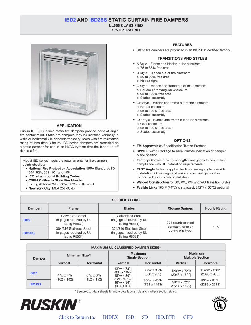
Click to Return to: INDEX FSD SD IBD/DFD CFD
APPLICATION
IBD2 AND IBD2SS STATIC CURTAIN FIRE DAMPERS UL555 CLASSIFIED
1 ½ HR. RATING
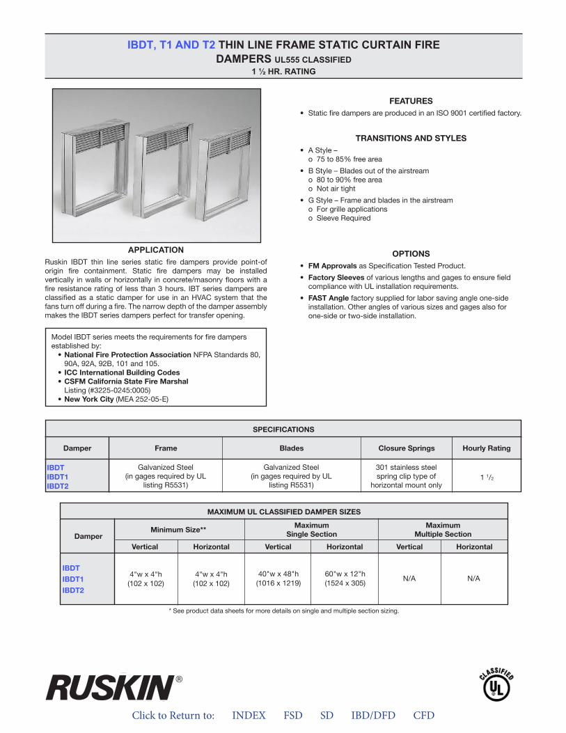
Click to Return to: INDEX FSD SD IBD/DFD CFD
APPLICATION
IBDT, T1 AND T2 THIN LINE FRAME STATIC CURTAIN FIRE DAMPERS UL555 CLASSIFIED
1 ½ HR. RATING
ALL STATED SPECIFICATIONS ARE SUBJECT TO CHANGE WITHOUT NOTICE OR OBLIGATION.
3900 Dr. Greaves Rd. • Kansas City, MO 64030 • (816) 761-7476 • FAX (816) 765-8955
INSTALLATION INSTRUCTIONS11/2 HOUR UL CLASSIFIED
CURTAIN TYPE (D)IBD2, (D)IBD2SS AND IBDT FIRE DAMPERS
APPLICATIONThe fire damper models shown on this sheet are marked with a11/2 hour fire damper label and are approved for use in fire walls ormasonry floors with ratings of less than 3 hours. Fire Dampersrequire a field-or factory-installed sleeve. Select a sleeve of suffi-cient length to permit mounting angles attachment. Static andDynamic dampers must be installed with leading edge of theclosed blades within the wall or floor.
STATIC FIRE DAMPERS – IBD modelsNot for use in Dynamic (fans on) Systems.
MODEL IBD2 MAXIMUM SIZESingle Section
Vertical Installation – 48"w x 30"h or 33"w x 72"h (1219 x 762 or 838 x 1829) or 36"w x 36"h (914 x 914).
Horizontal Installation – 30"w x 451/2"h (762 x 1156) or 33"wx 38"h (838 x 965).
Multiple Section AssemblyVertical Installation – 120"w x 72"h (3048 x 1829).Horizontal Installation – 90"w x 91"h (2286 x 2311) or 114"w x
38"h (2896 x 965). MODEL IBD2SS MAXIMUM SIZE
Single SectionVertical Installation – 48"w x 30"h or 33"w x 72"h (1219 x
762 or 838 x 1829) or 36"w x 36"h (914 x 914).Horizontal Installation – 30"w x 451/2"h (762 x 1156) or 33"w
x 38"h (838 x 965).Multiple Section Assembly
Vertical Installation – 99"w x 72"h (2515 x 1829).Horizontal Installation – 90"w x 91"h (2286 x 2311) or 114"w x
38"h (2896 x 965). MODEL IBDT, IBDT1 and IBDT2 MAXIMUM SIZE
Single SectionVertical Installation – 40"w x 48"h (1016 x 1219).Horizontal Installation – 60"w x 12"h (1524 x 305).
DYNAMIC FIRE DAMPERSUse in Dynamic (fans on) or Static (fans off) Systems
MODEL DIBD2 MAXIMUM SIZESingle Section
Vertical Installation – 33"w x 36"h (838 x 914).Horizontal Installation – 24"w x 24"h (610 x 610).
Multiple Section AssemblyVertical Installation – 72"w x 48"h (1828 x 1219) or 48"w x
72"h (1219 x 1828) or 120"w x 24"h (3048 x 610).MODEL DIBD2X MAXIMUM SIZE
Single SectionVertical Installation – 18"w x 24"h (457 x 610).Horizontal Installation – 18"w x 24"h (457 x 610) or 24"w x
18" h (610 x 457).Multiple Section Assembly
Horizontal Installation – 36"w x 48"h (914 x 1219) or 48"w x 36"h (1219 x 914).
MODEL DIBD2SS MAXIMUM SIZESingle Section
Vertical or Horizontal Installation – 24"w x 24"h (610 x 610).Multiple Section Assembly
Vertical Installation – 72"w x 48"h (1828 x 1219) or 48"w x72"h (1219 x 1828) or 90”w x 24”h (2286 x 610).
II-IBD-514/Replaces II-IBD-114 © Ruskin 2014
®
INSTALLATION SUPPLEMENTSRefer to the appropriate Ruskin installation instruction supplementsfor additional information or special requirements:• Optional Sealant of Dampers in Fire Rated Wall or Floor
Openings• Transfer Openings and Duct Terminations• Optional FireStop Material• Extension of Fire and Combination Fire and Smoke Damper
Sleeves• Fire and Combination Fire/Smoke Dampers Installation in
Concrete Floor with Steel Deck• Drivemate No. 14880 Breakaway Connection• Flanged System Breakaway Connections• Mullions for Dampers in Oversized Concrete Wall Openings
Notes:1. Dimensions shown in parentheses ( ) indicate millimeters.2. All multiple section dampers are constructed of equal single
section sizes no greater than the maximum single section sizesindicated above.
California State Fire Marshal Listing No. 3225-245:005
SEE COMPLETE MARKING ON PRODUCT
Click to Return to: INDEX FSD SD IBD/DFD CFD
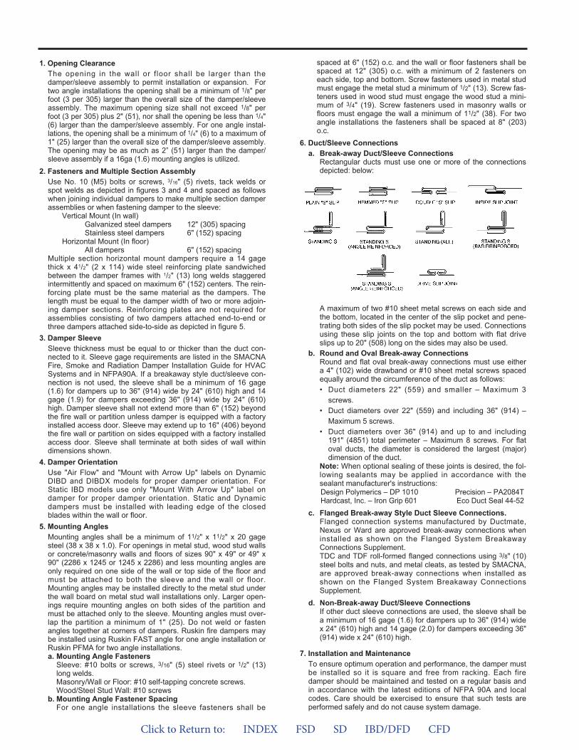
1. Opening ClearanceThe opening in the wall or f loor shall be larger than thedamper/sleeve assembly to permit installation or expansion. Fortwo angle installations the opening shall be a minimum of 1/8" perfoot (3 per 305) larger than the overall size of the damper/sleeveassembly. The maximum opening size shall not exceed 1/8" perfoot (3 per 305) plus 2" (51), nor shall the opening be less than 1/4"(6) larger than the damper/sleeve assembly. For one angle instal-lations, the opening shall be a minimum of 1/4" (6) to a maximum of1" (25) larger than the overall size of the damper/sleeve assembly.The opening may be as much as 2” (51) larger than the damper/sleeve assembly if a 16ga (1.6) mounting angles is utilized.
2. Fasteners and Multiple Section AssemblyUse No. 10 (M5) bolts or screws, 3/16" (5) rivets, tack welds orspot welds as depicted in figures 3 and 4 and spaced as followswhen joining individual dampers to make multiple section damperassemblies or when fastening damper to the sleeve:
Vertical Mount (In wall)Galvanized steel dampers 12" (305) spacing Stainless steel dampers 6" (152) spacing
Horizontal Mount (In floor)All dampers 6" (152) spacing
Multiple section horizontal mount dampers require a 14 gagethick x 41/2" (2 x 114) wide steel reinforcing plate sandwichedbetween the damper frames with 1/2" (13) long welds staggeredintermittently and spaced on maximum 6" (152) centers. The rein-forcing plate must be the same material as the dampers. Thelength must be equal to the damper width of two or more adjoin-ing damper sections. Reinforcing plates are not required forassemblies consisting of two dampers attached end-to-end orthree dampers attached side-to-side as depicted in figure 5.
3. Damper SleeveSleeve thickness must be equal to or thicker than the duct con-nected to it. Sleeve gage requirements are listed in the SMACNAFire, Smoke and Radiation Damper Installation Guide for HVACSystems and in NFPA90A. If a breakaway style duct/sleeve con-nection is not used, the sleeve shall be a minimum of 16 gage(1.6) for dampers up to 36" (914) wide by 24" (610) high and 14gage (1.9) for dampers exceeding 36" (914) wide by 24" (610)high. Damper sleeve shall not extend more than 6" (152) beyondthe fire wall or partition unless damper is equipped with a factoryinstalled access door. Sleeve may extend up to 16" (406) beyondthe fire wall or partition on sides equipped with a factory installedaccess door. Sleeve shall terminate at both sides of wall withindimensions shown.
4. Damper OrientationUse "Air Flow" and "Mount with Arrow Up" labels on DynamicDIBD and DIBDX models for proper damper orientation. ForStatic IBD models use only "Mount With Arrow Up" label ondamper for proper damper orientation. Static and Dynamicdampers must be installed with leading edge of the closedblades within the wall or floor.
5. Mounting AnglesMounting angles shall be a minimum of 11/2" x 11/2" x 20 gagesteel (38 x 38 x 1.0). For openings in metal stud, wood stud wallsor concrete/masonry walls and floors of sizes 90" x 49" or 49" x90" (2286 x 1245 or 1245 x 2286) and less mounting angles areonly required on one side of the wall or top side of the floor andmust be attached to both the sleeve and the wall or floor.Mounting angles may be installed directly to the metal stud underthe wall board on metal stud wall installations only. Larger open-ings require mounting angles on both sides of the partition andmust be attached only to the sleeve. Mounting angles must over-lap the partition a minimum of 1" (25). Do not weld or fastenangles together at corners of dampers. Ruskin fire dampers maybe installed using Ruskin FAST angle for one angle installation orRuskin PFMA for two angle installations.a. Mounting Angle Fasteners
Sleeve: #10 bolts or screws, 3/16" (5) steel rivets or 1/2" (13)long welds.Masonry/Wall or Floor: #10 self-tapping concrete screws.Wood/Steel Stud Wall: #10 screws
b. Mounting Angle Fastener SpacingFor one angle installations the sleeve fasteners shall be
spaced at 6" (152) o.c. and the wall or floor fasteners shall bespaced at 12" (305) o.c. with a minimum of 2 fasteners oneach side, top and bottom. Screw fasteners used in metal studmust engage the metal stud a minimum of 1/2" (13). Screw fas-teners used in wood stud must engage the wood stud a mini-mum of 3/4" (19). Screw fasteners used in masonry walls orfloors must engage the wall a minimum of 11/2" (38). For twoangle installations the fasteners shall be spaced at 8" (203)o.c.
6. Duct/Sleeve Connectionsa. Break-away Duct/Sleeve Connections
Rectangular ducts must use one or more of the connectionsdepicted: below:
A maximum of two #10 sheet metal screws on each side andthe bottom, located in the center of the slip pocket and pene-trating both sides of the slip pocket may be used. Connectionsusing these slip joints on the top and bottom with flat driveslips up to 20" (508) long on the sides may also be used.
b. Round and Oval Break-away ConnectionsRound and flat oval break-away connections must use eithera 4" (102) wide drawband or #10 sheet metal screws spacedequally around the circumference of the duct as follows:• Duct diameters 22" (559) and smaller – Maximum 3
screws.• Duct diameters over 22" (559) and including 36" (914) –
Maximum 5 screws.• Duct diameters over 36" (914) and up to and including
191" (4851) total perimeter – Maximum 8 screws. For flatoval ducts, the diameter is considered the largest (major)dimension of the duct.
Note: When optional sealing of these joints is desired, the fol-lowing sealants may be applied in accordance with thesealant manufacturer's instructions:Design Polymerics – DP 1010 Precision – PA2084THardcast, Inc. – Iron Grip 601 Eco Duct Seal 44-52
c. Flanged Break-away Style Duct Sleeve Connections.Flanged connection systems manufactured by Ductmate,Nexus or Ward are approved break-away connections wheninstalled as shown on the Flanged System BreakawayConnections Supplement.TDC and TDF roll-formed flanged connections using 3/8" (10)steel bolts and nuts, and metal cleats, as tested by SMACNA,are approved break-away connections when installed asshown on the Flanged System Breakaway ConnectionsSupplement.
d. Non-Break-away Duct/Sleeve ConnectionsIf other duct sleeve connections are used, the sleeve shall bea minimum of 16 gage (1.6) for dampers up to 36" (914) widex 24" (610) high and 14 gage (2.0) for dampers exceeding 36"(914) wide x 24" (610) high.
7. Installation and MaintenanceTo ensure optimum operation and performance, the damper mustbe installed so it is square and free from racking. Each firedamper should be maintained and tested on a regular basis andin accordance with the latest editions of NFPA 90A and localcodes. Care should be exercised to ensure that such tests areperformed safely and do not cause system damage.
Click to Return to: INDEX FSD SD IBD/DFD CFD

VERTICAL INSTALLATION
HORIZONTAL INSTALLATION
FIGURE 1
6" or 16"(152 or 406) Max.
See Note 3
Duc
t Con
nect
ions
Styl
e A
Styl
e B
Styl
e C
, CR
, & C
O1" (25) min. typical
overlapon all sides of
damper
See Note 5
Wall
SleeveSee Note 3
1/4" (6) Min.See Note 1
6" or 16"(152 or 406) Max.
See Note 3
Duc
t Con
nect
ions
Styl
e A
Styl
e B
Styl
e C
, CR
, & C
O
1" (25) min. typicaloverlap
on all sides ofdamper
Wall
SleeveSee Note 3
1/4" (6) Min.See Note 1
See Note 5
TWO ANGLE INSTALLATION ONE ANGLE INSTALLATION
6" or 16"(152 or 406) Max.
See Note 3
Duct ConnectionsStyle A
Style B
Style C, CR,& CO
SleeveSee Note 3
SeeNote 5
1/4" (6) Min.See Note 1
MasonryFloor/
Ceiling
1" (25) Min.typical overlapon all sides of
damper
6" or 16"(152 or 406) Max.
See Note 3
Duct ConnectionsStyle A
Style B
Style C, CR,& CO
SleeveSee Note 3
SeeNote 5
1/4" (6) Min.See Note 1
MasonryFloor/Ceiling
1" (25) Min.typical overlapon all sides of
damper
FIGURE 2
TWO ANGLE INSTALLATION ONE ANGLE INSTALLATION
Click to Return to: INDEX FSD SD IBD/DFD CFD
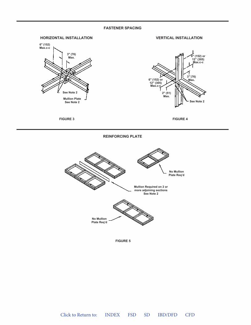
FIGURE 5
FASTENER SPACING
REINFORCING PLATE
VERTICAL INSTALLATIONHORIZONTAL INSTALLATION
FIGURE 4FIGURE 3
See Note 2
Mullion PlateSee Note 2
6" (152)Max.c-c
3" (76)Max.
See Note 2
6" (152) or12” (305)Max.c-c
2" (51)Max.
6" (152) or12” (305)Max.c-c
3" (76)Max.
No MullionPlate Req’d
No MullionPlate Req’d
Mullion Required on 2 ormore adjoining sections
See Note 2
Click to Return to: INDEX FSD SD IBD/DFD CFD
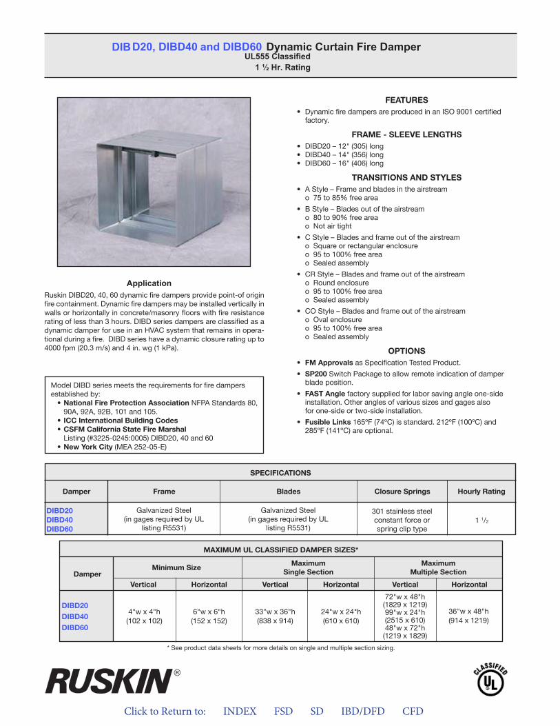
Click to Return to: INDEX FSD SD IBD/DFD CFD
ApplicationRuskin DIBD20, 40, 60 dynamic fire dampers provide point-of origin fire containment. Dynamic fire dampers may be installed vertically in walls or horizontally in concrete/masonry floors with fire resistance rating of less than 3 hours. DIBD series dampers are classified as a dynamic damper for use in an HVAC system that remains in opera-tional during a fire. DIBD series have a dynamic closure rating up to 4000 fpm (20.3 m/s) and 4 in. wg (1 kPa).
FEATURES• Dynamic fire dampers are produced in an ISO 9001 certified
factory.
FRAME - SLEEVE LENGTHS• DIBD20 – 12" (305) long • DIBD40 – 14" (356) long • DIBD60 – 16" (406) long
TRANSITIONS AND STYLES• A Style – Frame and blades in the airstream
o 75 to 85% free area
• B Style – Blades out of the airstreamo 80 to 90% free areao Not air tight
• C Style – Blades and frame out of the airstreamo Square or rectangular enclosureo 95 to 100% free area o Sealed assembly
• CR Style – Blades and frame out of the airstreamo Round enclosure o 95 to 100% free area o Sealed assembly
• CO Style – Blades and frame out of the airstreamo Oval enclosure o 95 to 100% free area o Sealed assembly
OPTIONS• FM Approvals as Specification Tested Product.
• SP200 Switch Package to allow remote indication of damperblade position.
• FAST Angle factory supplied for labor saving angle one-sideinstallation. Other angles of various sizes and gages also for one-side or two-side installation.
• Fusible Links 165ºF (74ºC) is standard. 212ºF (100ºC) and285ºF (141ºC) are optional.
DIB D20, DIBD40 and DIBD60 Dynamic Curtain Fire DamperUL555 Classified
1 ½ Hr. Rating
Model DIBD series meets the requirements for fire dampers established by: • National Fire Protection Association NFPA Standards 80, 90A, 92A, 92B, 101 and 105. • ICC International Building Codes • CSFM California State Fire Marshal Listing (#3225-0245:0005) DIBD20, 40 and 60 • New York City (MEA 252-05-E)
MAXIMUM UL CLASSIFIED DAMPER SIZES*
Damper
DIBD20
DIBD40
DIBD60
MaximumSingle Section
Minimum SizeMaximum
Multiple Section
VerticalVertical VerticalHorizontalHorizontal Horizontal
6"w x 6"h(152 x 152)
4"w x 4"h(102 x 102)
33"w x 36"h(838 x 914)
24"w x 24"h(610 x 610)
72"w x 48"h(1829 x 1219)99"w x 24"h(2515 x 610)48"w x 72"h
(1219 x 1829)
36"w x 48"h(914 x 1219)
* See product data sheets for more details on single and multiple section sizing.
APPLICATIONRuskin DIBD20, 40, 60 dynamic fire dampers provide point-of originfire containment. Dynamic fire dampers may be installed vertically in walls or horizontally in concrete/masonry floors with fire resistance rating of less than 3 hours. DIBD series dampers are classified as adynamic damper for use in HVAC system that remains in operationalduring a fire. DIBD series have a dynamic closure rating up to 4000fpm (20.3 m/s) and 4 in. wg (1 kPa).
FEATURES• Dynamic fire dampers are produced in an ISO 9001 certified factory
FRAME - SLEEVE LENGTHS• DIBD20 – 12” (305) long• DIBD40 – 14” (356) long• DIBD60 – 16” (406) long
TRANSITIONS AND STYLES• A Style – Frame and blades in the airstream
o 75 to 85% free area• B Style – Blades out of the airstream
o 80 to 90% free areao Not air tight
• C Style – Blades and frame out of the airstreamo Square or rectangular enclosureo 95 to 100% free areao Sealed assembly
• CR Style – Blades and frame out of the airstreamo Round enclosureo 95 to 100% free areao Sealed assembly
• CO Style – Blades and frame out of the airstreamo Oval enclosureo 95 to 100% free areao Sealed assembly
OPTIONS• FM Approvals as Specification Tested Product.• SP200 Switch Package to allow remote indication of damper
blade position.• Factory Sleeves of various lengths and gages to ensure field
compliance with UL installation requirements.• FAST Angle factory supplied for labor saving angle one-side
installation. Other angles of various sizes and gauges also forone-side or two-side installation.
• Fusible Links 165ºF (74ºC) is standard. 212ºF (100ºC) and285ºF (141ºC) are optional
SPECIFICATIONSDamper Frame Blades Closure Springs Hourly Rating
DIBD20DIBD40DIBD60
Galvanized Steel(in gauges required by UL
listing R5531)
Galvanized Steel(in gauges required by UL
listing R5531)
301 stainless steelconstant force orspring clip type
1 ½
* See product data sheets for more details on single and multiple section sizing.
Model DIBD series meets the requirements for combination fire and smoke dampers established by:
• National Fire Protection Association NFPA Standards 80, 90A, 92A,92B, 101 and 105.
• ICC International Building Codes• CSFM California State Fire Marshal –• Listing (#3225-0245:0005) DIBD20, 40 and 60• New York City (MEA 252-05-E)
MAXIMUM UL CLASSIFIED DAMPER SIZES*
Damper Minimum Size MaximumSingle Section
MaximumMultiple Section
Vertical Horizontal Vertical Horizontal Vertical HorizontalDIBD20DIBD40DIBD60 4”w x 4”h
(102 x 102)6"w x 6"h
(152 x 152)
33"w x 36"h(838 x 914) 24"w x 24"h
(610 x 610)
72"w x 48"h(1829 x 1219)99”w x 24”h(2515 x 610)48”w x 72”h
(1219 x 1829)
36”w x 48”h(914 x 1219)
DIBD20, DIBD40 and DIBD60 Dynamic Curtain Fire Damper UL555 Classified 1 ½ Hr. Rating
®
DIBD20DIBD40DIBD60
SPECIFICATIONS
Frame Blades Closure Springs Hourly RatingDamper
Galvanized Steel(in gages required by UL
listing R5531)
Galvanized Steel(in gages required by UL
listing R5531)
301 stainless steelconstant force orspring clip type
1 1/2
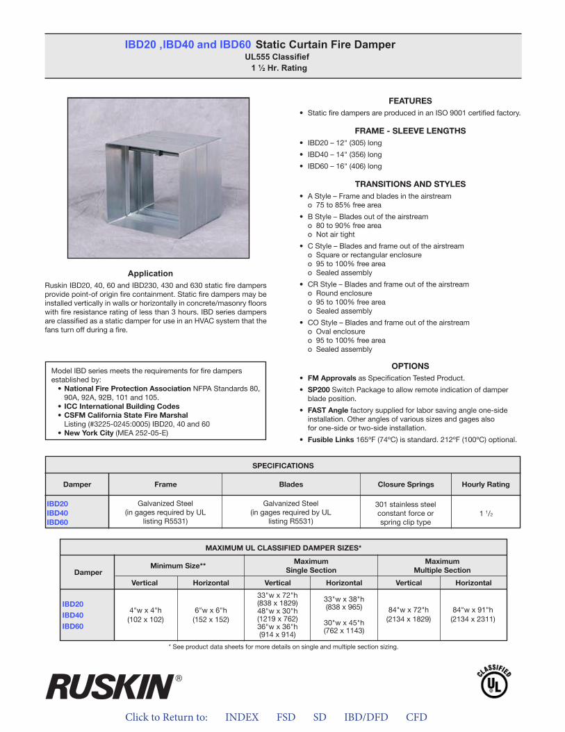
Click to Return to: INDEX FSD SD IBD/DFD CFD
ApplicationRuskin IBD20, 40, 60 and IBD230, 430 and 630 static fire dampers provide point-of origin fire containment. Static fire dampers may be installed vertically in walls or horizontally in concrete/masonry floors with fire resistance rating of less than 3 hours. IBD series dampers are classified as a static damper for use in an HVAC system that the fans turn off during a fire.
FEATURES• Static fire dampers are produced in an ISO 9001 certified factory.
FRAME - SLEEVE LENGTHS• IBD20 – 12" (305) long
• IBD40 – 14" (356) long
• IBD60 – 16" (406) long
TRANSITIONS AND STYLES• A Style – Frame and blades in the airstream
o 75 to 85% free area
• B Style – Blades out of the airstreamo 80 to 90% free area o Not air tight
• C Style – Blades and frame out of the airstreamo Square or rectangular enclosureo 95 to 100% free area o Sealed assembly
• CR Style – Blades and frame out of the airstreamo Round enclosureo 95 to 100% free areao Sealed assembly
• CO Style – Blades and frame out of the airstream o Oval enclosure o 95 to 100% free area o Sealed assembly
OPTIONS• FM Approvals as Specification Tested Product.
• SP200 Switch Package to allow remote indication of damperblade position.
• FAST Angle factory supplied for labor saving angle one-sideinstallation. Other angles of various sizes and gages alsofor one-side or two-side installation.
• Fusible Links 165ºF (74ºC) is standard. 212ºF (100ºC) optional.
IBD20 , IBD40 and IBD60 Static Curtain Fire DamperUL555 Classifief
1 ½ Hr. Rating
Model IBD series meets the requirements for fire dampers established by:
• National Fire Protection Association NFPA Standards 80,90A, 92A, 92B, 101 and 105.
• ICC International Building Codes• CSFM California State Fire Marshal
Listing (#3225-0245:0005) IBD20, 40 and 60• New York City (MEA 252-05-E)
APPLICATIONRuskin IBD20, 40, 60 and IBD230, 430 and 630 static fire dampersprovide point-of origin fire containment. Static fire dampers may be installed vertically in walls or horizontally in concrete/masonry floorswith fire resistance rating of less than 3 hours. IBD series dampersare classified as a static damper for use in HVAC system that the fans turn off during a fire.
FEATURES• Static fire dampers are produced in an ISO 9001 certified factory
FRAME - SLEEVE LENGTHS• IBD20 – 12” (305) long• IBD40 – 14” (356) long• IBD60 – 16” (406) long
TRANSITIONS AND STYLES• A Style – Frame and blades in the airstream
o 75 to 85% free area• B Style – Blades out of the airstream
o 80 to 90% free areao Not air tight
• C Style – Blades and frame out of the airstreamo Square or rectangular enclosureo 95 to 100% free areao Sealed assembly
• CR Style – Blades and frame out of the airstreamo Round enclosureo 95 to 100% free areao Sealed assembly
• CO Style – Blades and frame out of the airstreamo Oval enclosureo 95 to 100% free areao Sealed assembly
OPTIONS• FM Approvals as Specification Tested Product.• SP200 Switch Package to allow remote indication of damper
blade position.• FAST Angle factory supplied for labor saving angle one-side
installation. Other angles of various sizes and gauges also forone-side or two-side installation.
• Fusible Links 165ºF (74ºC) is standard. 212ºF (100ºC) optional
SPECIFICATIONSDamper Frame Blades Closure Springs Hourly Rating
IBD20IBD40IBD60
Galvanized Steel(in gauges required by UL
listing R5531)
Galvanized Steel(in gauges required by UL
listing R5531)
301 stainless steelconstant force orspring clip type
1 ½
* See product data sheets for more details on single and multiple section sizing.
Model IBD series meets the requirements for combination fire and smoke dampers established by:
• National Fire Protection Association NFPA Standards 80, 90A, 92A,92B, 101 and 105.
• ICC International Building Codes• CSFM California State Fire Marshal –• Listing (#3225-0245:0005) IBD20, 40 and 60• New York City (MEA 252-05-E)
MAXIMUM UL CLASSIFIED DAMPER SIZES*
Damper Minimum Size** MaximumSingle Section
MaximumMultiple Section
Vertical Horizontal Vertical Horizontal Vertical Horizontal
IBD20IBD40IBD60 4”w x 4”h
(102 x 102)6"w x 6"h
(152 x 152)
33"w x 72"h(838 x 1829)48"w x 30"h(1219 x 762)36"w x 36"h(914 x 914)
33"w x 38"h(838 x 965)
30"w x 45"h(762 x 1143) 84"w x 72"h
(2134 x 1829)
84”w x 91”h(2134 x 2311)
IBD20, IBD40 and IBD60 Static Curtain Fire DamperUL555 Classified 1 ½ Hr. Rating
®
IBD20IBD40IBD60
SPECIFICATIONS
Frame Blades Closure Springs Hourly RatingDamper
Galvanized Steel(in gages required by UL
listing R5531)
Galvanized Steel(in gages required by UL
listing R5531)
301 stainless steelconstant force orspring clip type
1 1/2
MAXIMUM UL CLASSIFIED DAMPER SIZES*
Damper
IBD20
IBD40
IBD60
MaximumSingle Section
Minimum Size**Maximum
Multiple Section
VerticalVertical VerticalHorizontalHorizontal Horizontal
6"w x 6"h(152 x 152)
4"w x 4"h(102 x 102)
33"w x 72"h(838 x 1829)48"w x 30"h(1219 x 762)36"w x 36"h(914 x 914)
33"w x 38"h(838 x 965)
30"w x 45"h(762 x 1143)
84"w x 91"h(2134 x 2311)
84"w x 72"h(2134 x 1829)
* See product data sheets for more details on single and multiple section sizing.
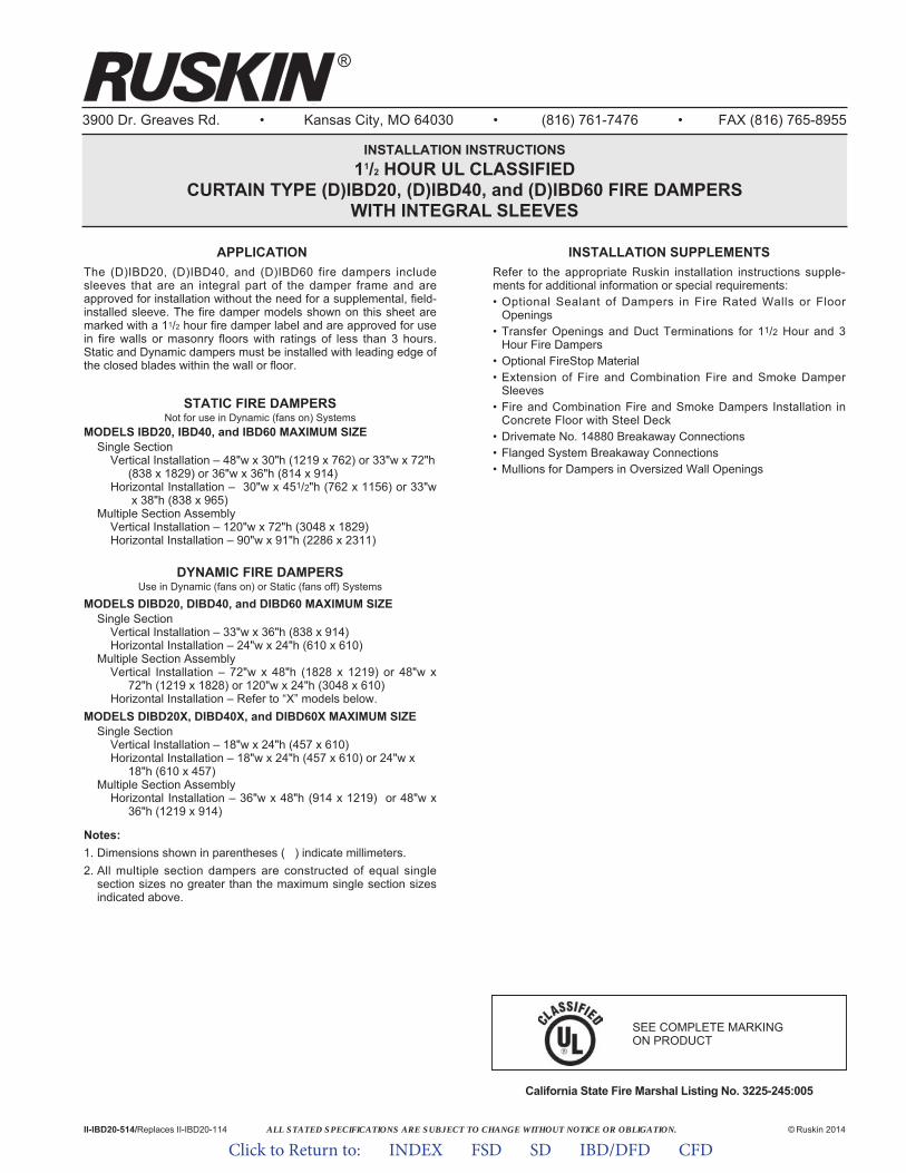
ALL STATED SPECIFICATIONS ARE SUBJECT TO CHANGE WITHOUT NOTICE OR OBLIGATION.
3900 Dr. Greaves Rd. • Kansas City, MO 64030 • (816) 761-7476 • FAX (816) 765-8955
INSTALLATION INSTRUCTIONS11/2 HOUR UL CLASSIFIED
CURTAIN TYPE (D)IBD20, (D)IBD40, and (D)IBD60 FIRE DAMPERSWITH INTEGRAL SLEEVES
APPLICATIONThe (D)IBD20, (D)IBD40, and (D)IBD60 fire dampers includesleeves that are an integral part of the damper frame and areapproved for installation without the need for a supplemental, field-installed sleeve. The fire damper models shown on this sheet aremarked with a 11/2 hour fire damper label and are approved for usein fire walls or masonry floors with ratings of less than 3 hours.Static and Dynamic dampers must be installed with leading edge ofthe closed blades within the wall or floor.
STATIC FIRE DAMPERSNot for use in Dynamic (fans on) Systems
MODELS IBD20, IBD40, and IBD60 MAXIMUM SIZESingle Section
Vertical Installation – 48"w x 30"h (1219 x 762) or 33"w x 72"h (838 x 1829) or 36"w x 36"h (814 x 914)
Horizontal Installation – 30"w x 451/2"h (762 x 1156) or 33"wx 38"h (838 x 965)
Multiple Section AssemblyVertical Installation – 120"w x 72"h (3048 x 1829)Horizontal Installation – 90"w x 91"h (2286 x 2311)
DYNAMIC FIRE DAMPERSUse in Dynamic (fans on) or Static (fans off) Systems
MODELS DIBD20, DIBD40, and DIBD60 MAXIMUM SIZESingle Section
Vertical Installation – 33"w x 36"h (838 x 914)Horizontal Installation – 24"w x 24"h (610 x 610)
Multiple Section AssemblyVertical Installation – 72"w x 48"h (1828 x 1219) or 48"w x
72"h (1219 x 1828) or 120"w x 24"h (3048 x 610)Horizontal Installation – Refer to “X” models below.
MODELS DIBD20X, DIBD40X, and DIBD60X MAXIMUM SIZESingle Section
Vertical Installation – 18"w x 24"h (457 x 610)Horizontal Installation – 18"w x 24"h (457 x 610) or 24"w x
18"h (610 x 457)Multiple Section Assembly
Horizontal Installation – 36"w x 48"h (914 x 1219) or 48"w x 36"h (1219 x 914)
Notes:1. Dimensions shown in parentheses ( ) indicate millimeters.2. All multiple section dampers are constructed of equal single
section sizes no greater than the maximum single section sizesindicated above.
California State Fire Marshal Listing No. 3225-245:005
II-IBD20-514/Replaces II-IBD20-114 © Ruskin 2014
®
INSTALLATION SUPPLEMENTSRefer to the appropriate Ruskin installation instructions supple-ments for additional information or special requirements:• Optional Sealant of Dampers in Fire Rated Walls or Floor
Openings• Transfer Openings and Duct Terminations for 11/2 Hour and 3
Hour Fire Dampers• Optional FireStop Material• Extension of Fire and Combination Fire and Smoke Damper
Sleeves• Fire and Combination Fire and Smoke Dampers Installation in
Concrete Floor with Steel Deck• Drivemate No. 14880 Breakaway Connections• Flanged System Breakaway Connections• Mullions for Dampers in Oversized Wall Openings
SEE COMPLETE MARKING ON PRODUCT
Click to Return to: INDEX FSD SD IBD/DFD CFD
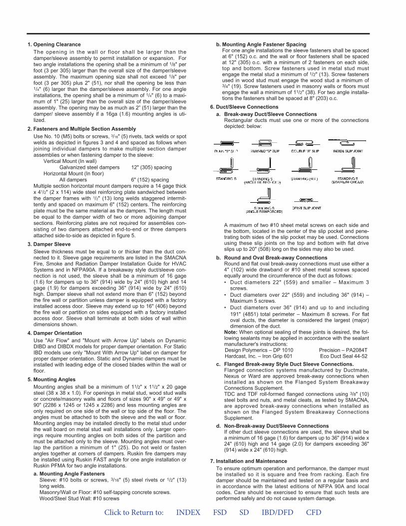
1. Opening ClearanceThe opening in the wall or f loor shall be larger than thedamper/sleeve assembly to permit installation or expansion. Fortwo angle installations the opening shall be a minimum of 1/8" perfoot (3 per 305) larger than the overall size of the damper/sleeveassembly. The maximum opening size shall not exceed 1/8" perfoot (3 per 305) plus 2" (51), nor shall the opening be less than1/4" (6) larger than the damper/sleeve assembly. For one angleinstallations, the opening shall be a minimum of 1/4" (6) to a maxi-mum of 1" (25) larger than the overall size of the damper/sleeveassembly. The opening may be as much as 2” (51) larger than thedamper/ sleeve assembly if a 16ga (1.6) mounting angles is uti-lized.
2. Fasteners and Multiple Section AssemblyUse No. 10 (M5) bolts or screws, 3/16" (5) rivets, tack welds or spotwelds as depicted in figures 3 and 4 and spaced as follows whenjoining individual dampers to make multiple section damperassemblies or when fastening damper to the sleeve:
Vertical Mount (In wall)Galvanized steel dampers 12" (305) spacing
Horizontal Mount (In floor)All dampers 6" (152) spacing
Multiple section horizontal mount dampers require a 14 gage thickx 41/2" (2 x 114) wide steel reinforcing plate sandwiched betweenthe damper frames with 1/2" (13) long welds staggered intermit-tently and spaced on maximum 6" (152) centers. The reinforcingplate must be the same material as the dampers. The length mustbe equal to the damper width of two or more adjoining dampersections. Reinforcing plates are not required for assemblies con-sisting of two dampers attached end-to-end or three dampersattached side-to-side as depicted in figure 5.
3. Damper SleeveSleeve thickness must be equal to or thicker than the duct con-nected to it. Sleeve gage requirements are listed in the SMACNAFire, Smoke and Radiation Damper Installation Guide for HVACSystems and in NFPA90A. If a breakaway style duct/sleeve con-nection is not used, the sleeve shall be a minimum of 16 gage(1.6) for dampers up to 36" (914) wide by 24" (610) high and 14gage (1.9) for dampers exceeding 36" (914) wide by 24" (610)high. Damper sleeve shall not extend more than 6" (152) beyondthe fire wall or partition unless damper is equipped with a factoryinstalled access door. Sleeve may extend up to 16" (406) beyondthe fire wall or partition on sides equipped with a factory installedaccess door. Sleeve shall terminate at both sides of wall withindimensions shown.
4. Damper OrientationUse "Air Flow" and "Mount with Arrow Up" labels on DynamicDIBD and DIBDX models for proper damper orientation. For StaticIBD models use only "Mount With Arrow Up" label on damper forproper damper orientation. Static and Dynamic dampers must beinstalled with leading edge of the closed blades within the wall orfloor.
5. Mounting AnglesMounting angles shall be a minimum of 11/2" x 11/2" x 20 gagesteel (38 x 38 x 1.0). For openings in metal stud, wood stud wallsor concrete/masonry walls and floors of sizes 90" x 49" or 49" x90" (2286 x 1245 or 1245 x 2286) and less mounting angles areonly required on one side of the wall or top side of the floor. Theangles must be attached to both the sleeve and the wall or floor.Mounting angles may be installed directly to the metal stud underthe wall board on metal stud wall installations only. Larger open-ings require mounting angles on both sides of the partition andmust be attached only to the sleeve. Mounting angles must over-lap the partition a minimum of 1" (25). Do not weld or fastenangles together at corners of dampers. Ruskin fire dampers maybe installed using Ruskin FAST angle for one angle installation orRuskin PFMA for two angle installations.a. Mounting Angle Fasteners
Sleeve: #10 bolts or screws, 3/16" (5) steel rivets or 1/2" (13)long welds.Masonry/Wall or Floor: #10 self-tapping concrete screws.Wood/Steel Stud Wall: #10 screws
b. Mounting Angle Fastener SpacingFor one angle installations the sleeve fasteners shall be spacedat 6" (152) o.c. and the wall or floor fasteners shall be spacedat 12" (305) o.c. with a minimum of 2 fasteners on each side,top and bottom. Screw fasteners used in metal stud mustengage the metal stud a minimum of 1/2" (13). Screw fastenersused in wood stud must engage the wood stud a minimum of3/4" (19). Screw fasteners used in masonry walls or floors mustengage the wall a minimum of 11/2" (38). For two angle installa-tions the fasteners shall be spaced at 8" (203) o.c.
6. Duct/Sleeve Connectionsa. Break-away Duct/Sleeve Connections
Rectangular ducts must use one or more of the connectionsdepicted: below:
A maximum of two #10 sheet metal screws on each side andthe bottom, located in the center of the slip pocket and pene-trating both sides of the slip pocket may be used. Connectionsusing these slip joints on the top and bottom with flat driveslips up to 20" (508) long on the sides may also be used.
b. Round and Oval Break-away ConnectionsRound and flat oval break-away connections must use either a4" (102) wide drawband or #10 sheet metal screws spacedequally around the circumference of the duct as follows:• Duct diameters 22" (559) and smaller – Maximum 3
screws.• Duct diameters over 22" (559) and including 36" (914) –
Maximum 5 screws.• Duct diameters over 36" (914) and up to and including
191" (4851) total perimeter – Maximum 8 screws. For flatoval ducts, the diameter is considered the largest (major)dimension of the duct.
Note: When optional sealing of these joints is desired, the fol-lowing sealants may be applied in accordance with the sealantmanufacturer's instructions:Design Polymerics – DP 1010 Precision – PA2084THardcast, Inc. – Iron Grip 601 Eco Duct Seal 44-52
c. Flanged Break-away Style Duct Sleeve Connections.Flanged connection systems manufactured by Ductmate,Nexus or Ward are approved break-away connections wheninstalled as shown on the Flanged System BreakawayConnections Supplement.TDC and TDF roll-formed flanged connections using 3/8" (10)steel bolts and nuts, and metal cleats, as tested by SMACNA,are approved break-away connections when installed asshown on the Flanged System Breakaway ConnectionsSupplement.
d. Non-Break-away Duct/Sleeve ConnectionsIf other duct sleeve connections are used, the sleeve shall bea minimum of 16 gage (1.6) for dampers up to 36" (914) wide x24" (610) high and 14 gage (2.0) for dampers exceeding 36"(914) wide x 24" (610) high.
7. Installation and MaintenanceTo ensure optimum operation and performance, the damper mustbe installed so it is square and free from racking. Each firedamper should be maintained and tested on a regular basis andin accordance with the latest editions of NFPA 90A and localcodes. Care should be exercised to ensure that such tests areperformed safely and do not cause system damage.
Click to Return to: INDEX FSD SD IBD/DFD CFD
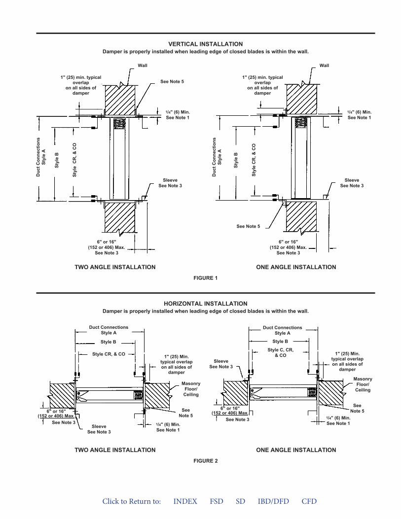
VERTICAL INSTALLATIONDamper is properly installed when leading edge of closed blades is within the wall.
FIGURE 1
6" or 16"(152 or 406) Max.
See Note 3
Duc
t Con
nect
ions
Styl
e A
Styl
e B
Styl
e C
R, &
CO
1" (25) min. typicaloverlap
on all sides ofdamper
See Note 5
Wall
SleeveSee Note 3
1/4" (6) Min.See Note 1
6" or 16"(152 or 406) Max.
See Note 3
Duc
t Con
nect
ions
Styl
e A
Styl
e B
Styl
e C
R, &
CO
1" (25) min. typicaloverlap
on all sides ofdamper
Wall
SleeveSee Note 3
1/4" (6) Min.See Note 1
6" or 16"(152 or 406) Max.
See Note 3
Duct ConnectionsStyle A
Style B
Style CR, & CO
SleeveSee Note 3
SeeNote 5
1/4" (6) Min.See Note 1
MasonryFloor/
Ceiling
1" (25) Min.typical overlapon all sides of
damper
See Note 5
TWO ANGLE INSTALLATION ONE ANGLE INSTALLATION
FIGURE 2
TWO ANGLE INSTALLATION ONE ANGLE INSTALLATION
6" or 16"(152 or 406) Max.
See Note 3
Duct ConnectionsStyle A
Style B
Style C, CR,& CO
SleeveSee Note 3
SeeNote 5
1/4" (6) Min.See Note 1
MasonryFloor/Ceiling
1" (25) Min.typical overlapon all sides of
damper
HORIZONTAL INSTALLATIONDamper is properly installed when leading edge of closed blades is within the wall.
Click to Return to: INDEX FSD SD IBD/DFD CFD

FIGURE 5
FASTENER SPACING
REINFORCING PLATE
VERTICAL INSTALLATION HORIZONTAL INSTALLATION
FIGURE 4FIGURE 3
See Note 2
Reinforcing PlateSee Note 2
No ReinforcingPlate Req’d
6" (152)Max.c-c
3" (76)Max.
See Note 2
12" (305)Max.c-c
12" (305)Max.
12" (305)Max.c-c
3" (76)Max.
Reinforcing Plate required on2 or more adjoining sections
See Note 2
No ReinforcingPlate Req’d
Click to Return to: INDEX FSD SD IBD/DFD CFD
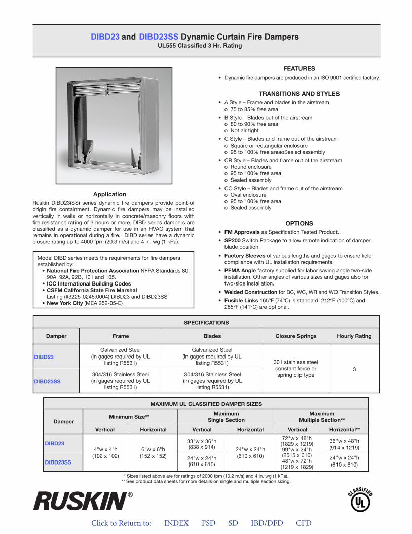
Click to Return to: INDEX FSD SD IBD/DFD CFD
ApplicationRuskin DIBD23(SS) series dynamic fire dampers provide point-of origin fire containment. Dynamic fire dampers may be installed vertically in walls or horizontally in concrete/masonry floors with fire resistance rating of 3 hours or more. DIBD series dampers are classified as a dynamic damper for use in an HVAC system that remains in operational during a fire. DIBD series have a dynamic closure rating up to 4000 fpm (20.3 m/s) and 4 in. wg (1 kPa).
DIBD23 and DIBD23SS Dynamic Curtain Fire Dampers UL555 Classified 3 Hr. Rating
Model DIBD series meets the requirements for fire dampers established by:
• National Fire Protection Association NFPA Standards 80, 90A, 92A, 92B, 101 and 105.
• ICC International Building Codes• CSFM California State Fire Marshal
Listing (#3225-0245:0004) DIBD23 and DIBD23SS• New York City (MEA 252-05-E)
FEATURES• Dynamic fire dampers are produced in an ISO 9001 certified factory.
TRANSITIONS AND STYLES• A Style – Frame and blades in the airstream
o 75 to 85% free area
• B Style – Blades out of the airstreamo 80 to 90% free areao Not air tight
• C Style – Blades and frame out of the airstreamo Square or rectangular enclosureo 95 to 100% free areaoSealed assembly
• CR Style – Blades and frame out of the airstreamo Round enclosureo 95 to 100% free areao Sealed assembly
• CO Style – Blades and frame out of the airstreamo Oval enclosureo 95 to 100% free areao Sealed assembly
OPTIONS• FM Approvals as Specification Tested Product.
• SP200 Switch Package to allow remote indication of damperblade position.
• Factory Sleeves of various lengths and gages to ensure fieldcompliance with UL installation requirements.
• PFMA Angle factory supplied for labor saving angle two-sideinstallation. Other angles of various sizes and gages also fortwo-side installation.
• Welded Construction for BC, WC, WR and WO Transition Styles.
• Fusible Links 165ºF (74ºC) is standard. 212ºF (100ºC) and285ºF (141ºC) are optional.
DIBD23
DIBD23SS
SPECIFICATIONS
Frame Blades Closure Springs Hourly RatingDamper
Galvanized Steel(in gages required by UL
listing R5531)
304/316 Stainless Steel(in gages required by UL
listing R5531)
304/316 Stainless Steel(in gages required by UL
listing R5531)
Galvanized Steel(in gages required by UL
listing R5531) 301 stainless steelconstant force orspring clip type
3
Damper
DIBD23
DIBD23SS
MaximumSingle Section
Minimum Size**Maximum
Multiple Section**
VerticalVertical VerticalHorizontalHorizontal Horizontal**
6"w x 6"h(152 x 152)
4"w x 4"h(102 x 102)
24"w x 24"h(610 x 610)
36"w x 48"h(914 x 1219)
24"w x 24"h(610 x 610)
72"w x 48"h(1829 x 1219)99"w x 24"h(2515 x 610)48"w x 72"h
(1219 x 1829)
33"w x 36"h(838 x 914)
24"w x 24"h(610 x 610)
* Sizes listed above are for ratings of 2000 fpm (10.2 m/s) and 4 in. wg (1 kPa).** See product data sheets for more details on single and multiple section sizing.
MAXIMUM UL CLASSIFIED DAMPER SIZES
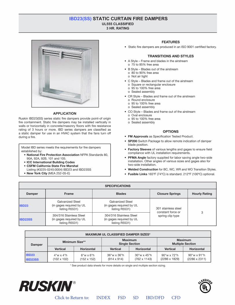
Click to Return to: INDEX FSD SD IBD/DFD CFD
APPLICATION
IBD23(SS) STATIC CURTAIN FIRE DAMPERS UL555 CLASSIFIED
3 HR. RATING
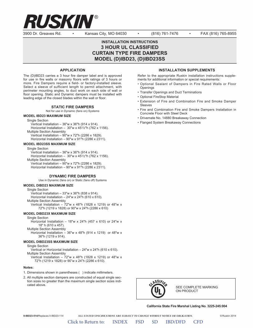
ALL STATED SPECIFICATIONS ARE SUBJECT TO CHANGE WITHOUT NOTICE OR OBLIGATION.
3900 Dr. Greaves Rd. • Kansas City, MO 64030 • (816) 761-7476 • FAX (816) 765-8955
INSTALLATION INSTRUCTIONS3 HOUR UL CLASSIFIED
CURTAIN TYPE FIRE DAMPERSMODEL (D)IBD23, (D)IBD23SS
APPLICATIONThe (D)IBD23 carries a 3 hour fire damper label and is approvedfor use in fire walls or masonry floors with ratings of 3 hours ormore. Fire Dampers require a field- or factory-installed sleeve.Select a sleeve of sufficient length to permit attachment, withperimeter mounting angles, to duct work on each side of wall orfloor opening. Static and Dynamic dampers must be installed withleading edge of the closed blades within the wall or floor.
STATIC FIRE DAMPERSNot for use in Dynamic (fans on) Systems
MODEL IBD23 MAXIMUM SIZESingle Section
Vertical Installation – 36"w x 36"h (914 x 914).Horizontal Installation – 30"w x 451/2"h (762 x 1156).
Multiple Section AssemblyVertical Installation – 90"w x 72"h (2286 x 1829).Horizontal Installation – 90"w x 91"h (2286 x 2311).
MODEL IBD23SS MAXIMUM SIZESingle Section
Vertical Installation – 36"w x 36"h (914 x 914).Horizontal Installation – 30"w x 451/2"h (762 x 1156).
Multiple Section AssemblyVertical Installation – 90"w x 72"h (2286 x 1829).Horizontal Installation – 90"w x 91"h (2286 x 2311).
DYNAMIC FIRE DAMPERSUse in Dynamic (fans on) or Static (fans off) Systems
MODEL DIBD23 MAXIMUM SIZESingle Section
Vertical Installation – 33"w x 36"h (838 x 914).Horizontal Installation – 24"w x 24"h (610 x 610).
Multiple Section AssemblyVertical Installation – 72"w x 48"h (1828 x 1219) or 48"w x
72"h (1219 x 1828) or 90"w x 24"h (2286 x 610)MODEL DIBD23X MAXIMUM SIZE
Single SectionHorizontal Installation – 18"w x 24"h (457 x 610) or 24"w x
18" h (610 x 457).Multiple Section Assembly
Horizontal Installation – 36"w x 48"h (914 x 1219) or 48"w x 36"h (1219 x 914).
MODEL DIBD23SS MAXIMUM SIZESingle Section
Vertical or Horizontal Installation – 24"w x 24"h (610 x 610).Multiple Section Assembly
Vertical Installation – 72"w x 48"h (1828 x 1219) or 48"w x72"h (1219 x 1828) or 90”w x 24”h (2286 x 610).
Notes:1. Dimensions shown in parentheses ( ) indicate millimeters.2. All multiple section dampers are constructed of equal single sec-
tion sizes no greater than the maximum single section sizes indi-cated above.
California State Fire Marshal Listing No. 3225-245:004
II-IBD23-514/Replaces II-IBD23-114 © Ruskin 2014
®
INSTALLATION SUPPLEMENTSRefer to the appropriate Ruskin installation instructions supple-ments for additional information or special requirements:• Optional Sealant of Dampers in Fire Rated Walls or Floor
Openings• Transfer Openings and Duct Terminations• Optional FireStop Material• Extension of Fire and Combination Fire and Smoke Damper
Sleeves• Fire and Combination Fire and Smoke Dampers Installation in
Concrete Floor with Steel Deck• Drivemate No. 14880 Breakaway Connection• Flanged System Breakaway Connections
SEE COMPLETE MARKING ON PRODUCT
Click to Return to: INDEX FSD SD IBD/DFD CFD
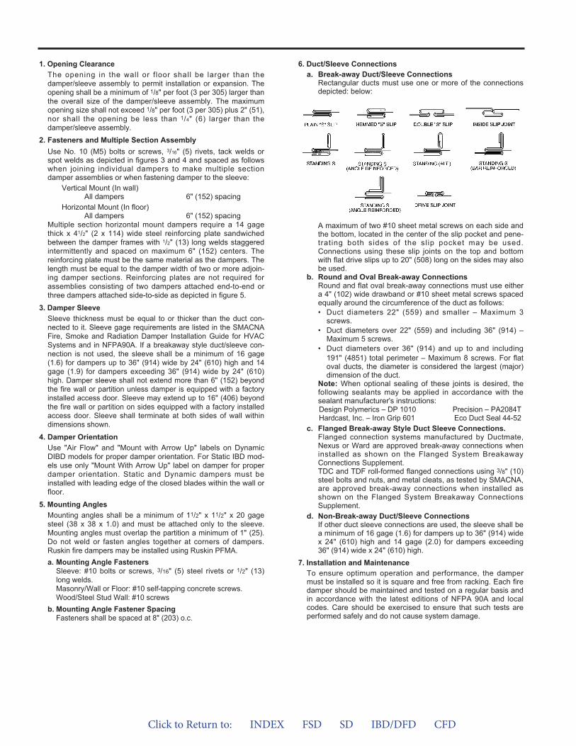
1. Opening ClearanceThe opening in the wall or f loor shall be larger than thedamper/sleeve assembly to permit installation or expansion. Theopening shall be a minimum of 1/8" per foot (3 per 305) larger thanthe overall size of the damper/sleeve assembly. The maximumopening size shall not exceed 1/8" per foot (3 per 305) plus 2" (51),nor shall the opening be less than 1/4" (6) larger than thedamper/sleeve assembly.
2. Fasteners and Multiple Section AssemblyUse No. 10 (M5) bolts or screws, 3/16" (5) rivets, tack welds orspot welds as depicted in figures 3 and 4 and spaced as followswhen joining individual dampers to make multiple sectiondamper assemblies or when fastening damper to the sleeve:
Vertical Mount (In wall)All dampers 6" (152) spacing
Horizontal Mount (In floor)All dampers 6" (152) spacing
Multiple section horizontal mount dampers require a 14 gagethick x 41/2" (2 x 114) wide steel reinforcing plate sandwichedbetween the damper frames with 1/2" (13) long welds staggeredintermittently and spaced on maximum 6" (152) centers. Thereinforcing plate must be the same material as the dampers. Thelength must be equal to the damper width of two or more adjoin-ing damper sections. Reinforcing plates are not required forassemblies consisting of two dampers attached end-to-end orthree dampers attached side-to-side as depicted in figure 5.
3. Damper SleeveSleeve thickness must be equal to or thicker than the duct con-nected to it. Sleeve gage requirements are listed in the SMACNAFire, Smoke and Radiation Damper Installation Guide for HVACSystems and in NFPA90A. If a breakaway style duct/sleeve con-nection is not used, the sleeve shall be a minimum of 16 gage(1.6) for dampers up to 36" (914) wide by 24" (610) high and 14gage (1.9) for dampers exceeding 36" (914) wide by 24" (610)high. Damper sleeve shall not extend more than 6" (152) beyondthe fire wall or partition unless damper is equipped with a factoryinstalled access door. Sleeve may extend up to 16" (406) beyondthe fire wall or partition on sides equipped with a factory installedaccess door. Sleeve shall terminate at both sides of wall withindimensions shown.
4. Damper OrientationUse "Air Flow" and "Mount with Arrow Up" labels on DynamicDIBD models for proper damper orientation. For Static IBD mod-els use only "Mount With Arrow Up" label on damper for properdamper orientation. Static and Dynamic dampers must beinstalled with leading edge of the closed blades within the wall orfloor.
5. Mounting AnglesMounting angles shall be a minimum of 11/2" x 11/2" x 20 gagesteel (38 x 38 x 1.0) and must be attached only to the sleeve.Mounting angles must overlap the partition a minimum of 1" (25).Do not weld or fasten angles together at corners of dampers.Ruskin fire dampers may be installed using Ruskin PFMA.a. Mounting Angle Fasteners
Sleeve: #10 bolts or screws, 3/16" (5) steel rivets or 1/2" (13)long welds.Masonry/Wall or Floor: #10 self-tapping concrete screws.Wood/Steel Stud Wall: #10 screws
b. Mounting Angle Fastener SpacingFasteners shall be spaced at 8" (203) o.c.
6. Duct/Sleeve Connectionsa. Break-away Duct/Sleeve Connections
Rectangular ducts must use one or more of the connectionsdepicted: below:
A maximum of two #10 sheet metal screws on each side andthe bottom, located in the center of the slip pocket and pene-trating both sides of the slip pocket may be used.Connections using these slip joints on the top and bottomwith flat drive slips up to 20" (508) long on the sides may alsobe used.
b. Round and Oval Break-away ConnectionsRound and flat oval break-away connections must use eithera 4" (102) wide drawband or #10 sheet metal screws spacedequally around the circumference of the duct as follows:• Duct diameters 22" (559) and smaller – Maximum 3
screws.• Duct diameters over 22" (559) and including 36" (914) –
Maximum 5 screws.• Duct diameters over 36" (914) and up to and including
191" (4851) total perimeter – Maximum 8 screws. For flatoval ducts, the diameter is considered the largest (major)dimension of the duct.
Note: When optional sealing of these joints is desired, thefollowing sealants may be applied in accordance with thesealant manufacturer's instructions:Design Polymerics – DP 1010 Precision – PA2084THardcast, Inc. – Iron Grip 601 Eco Duct Seal 44-52
c. Flanged Break-away Style Duct Sleeve Connections.Flanged connection systems manufactured by Ductmate,Nexus or Ward are approved break-away connections wheninstalled as shown on the Flanged System BreakawayConnections Supplement.TDC and TDF roll-formed flanged connections using 3/8" (10)steel bolts and nuts, and metal cleats, as tested by SMACNA,are approved break-away connections when installed asshown on the Flanged System Breakaway ConnectionsSupplement.
d. Non-Break-away Duct/Sleeve ConnectionsIf other duct sleeve connections are used, the sleeve shall bea minimum of 16 gage (1.6) for dampers up to 36" (914) widex 24" (610) high and 14 gage (2.0) for dampers exceeding36" (914) wide x 24" (610) high.
7. Installation and MaintenanceTo ensure optimum operation and performance, the dampermust be installed so it is square and free from racking. Each firedamper should be maintained and tested on a regular basis andin accordance with the latest editions of NFPA 90A and localcodes. Care should be exercised to ensure that such tests areperformed safely and do not cause system damage.
Click to Return to: INDEX FSD SD IBD/DFD CFD
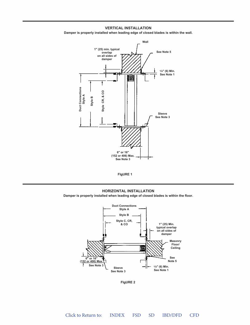
VERTICAL INSTALLATIONDamper is properly installed when leading edge of closed blades is within the wall.
FIgURE 1
6" or 16"(152 or 406) Max.
See Note 3
Duc
t Con
nect
ions
Styl
e A
Styl
e B
Styl
e C
R, &
CO
1" (25) min. typicaloverlap
on all sides ofdamper
See Note 5
Wall
SleeveSee Note 3
1/4" (6) Min.See Note 1
6" or 16"(152 or 406) Max.
See Note 3
Duct ConnectionsStyle A
Style B
Style C, CR,& CO
SleeveSee Note 3
SeeNote 5
1/4" (6) Min.See Note 1
MasonryFloor/
Ceiling
1" (25) Min.typical overlapon all sides of
damper
FIgURE 2
HORIZONTAL INSTALLATIONDamper is properly installed when leading edge of closed blades is within the floor.
Click to Return to: INDEX FSD SD IBD/DFD CFD
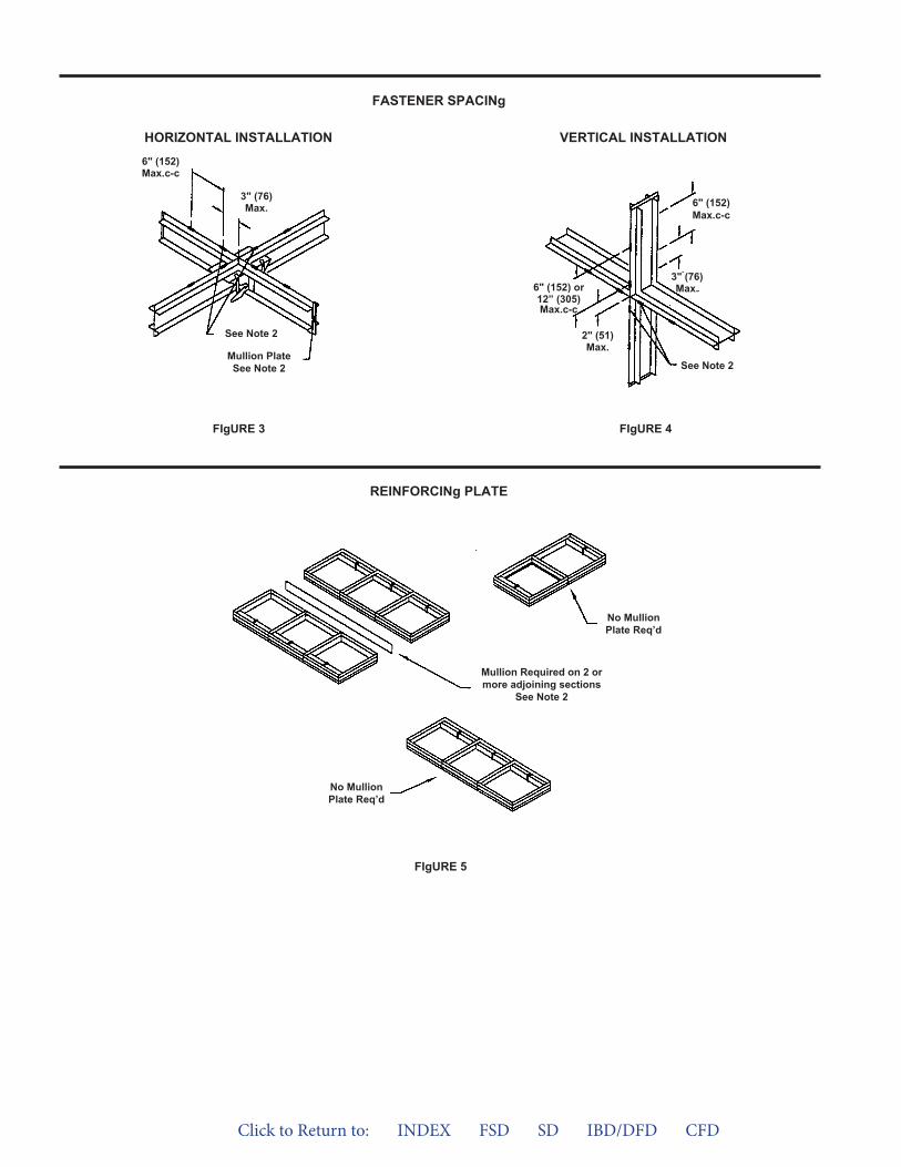
FIgURE 5
FASTENER SPACINg
REINFORCINg PLATE
VERTICAL INSTALLATIONHORIZONTAL INSTALLATION
FIgURE 4FIgURE 3
See Note 2
Mullion PlateSee Note 2
6" (152)Max.c-c
3" (76)Max.
See Note 2
6" (152) or12” (305)Max.c-c
2" (51)Max.
6" (152)Max.c-c
3" (76)Max.
No MullionPlate Req’d
No MullionPlate Req’d
Mullion Required on 2 ormore adjoining sections
See Note 2
Click to Return to: INDEX FSD SD IBD/DFD CFD
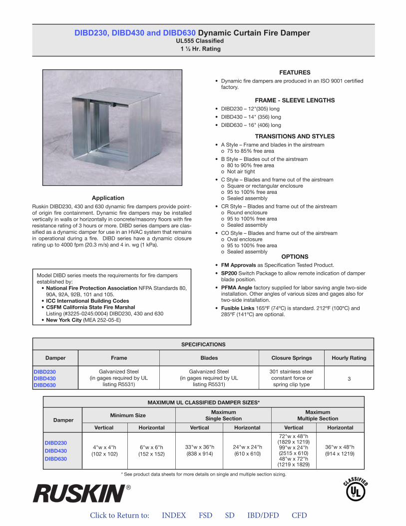
Click to Return to: INDEX FSD SD IBD/DFD CFD
ApplicationRuskin DIBD230, 430 and 630 dynamic fire dampers provide point-of origin fire containment. Dynamic fire dampers may be installed vertically in walls or horizontally in concrete/masonry floors with fire resistance rating of 3 hours or more. DIBD series dampers are clas-sified as a dynamic damper for use in an HVAC system that remains in operational during a fire. DIBD series have a dynamic closure rating up to 4000 fpm (20.3 m/s) and 4 in. wg (1 kPa).
FEATURES• Dynamic fire dampers are produced in an ISO 9001 certified
factory.
FRAME - SLEEVE LENGTHS• DIBD230 – 12"(305) long
• DIBD430 – 14" (356) long
• DIBD630 – 16" (406) long
TRANSITIONS AND STYLES• A Style – Frame and blades in the airstream
o 75 to 85% free area
• B Style – Blades out of the airstream o 80 to 90% free area o Not air tight
• C Style – Blades and frame out of the airstream o Square or rectangular enclosure o 95 to 100% free area o Sealed assembly
• CR Style – Blades and frame out of the airstream o Round enclosure o 95 to 100% free area o Sealed assembly
• CO Style – Blades and frame out of the airstreamo Oval enclosureo 95 to 100% free area o Sealed assembly
OPTIONS• FM Approvals as Specification Tested Product.
• SP200 Switch Package to allow remote indication of damperblade position.
• PFMA Angle factory supplied for labor saving angle two-side installation. Other angles of various sizes and gages also fortwo-side installation.
• Fusible Links 165ºF (74ºC) is standard. 212ºF (100ºC) and285ºF (141ºC) are optional.
DIBD230, DIBD430 and DIBD630 Dynamic Curtain Fire Damper UL555 Classified
1 ½ Hr. Rating
Model DIBD series meets the requirements for fire dampers established by:
• National Fire Protection Association NFPA Standards 80, 90A, 92A, 92B, 101 and 105.• ICC International Building Codes• CSFM California State Fire Marshal Listing (#3225-0245:0004) DIBD230, 430 and 630• New York City (MEA 252-05-E)
APPLICATIONRuskin DIBD230, 430 and 630 dynamic fire dampers provide point-of origin fire containment. Dynamic fire dampers may be installed vertically in walls or horizontally in concrete/masonry floors with fire resistance rating of 3 hours or more. DIBD series dampers areclassified as a dynamic damper for use in HVAC system thatremains in operational during a fire. DIBD series have a dynamicclosure rating up to 4000 fpm (20.3 m/s) and 4 in. wg (1 kPa).
FEATURES• Dynamic fire dampers are produced in an ISO 9001 certified factory
FRAME - SLEEVE LENGTHS• DIBD230 – 12” (305) long• DIBD430 – 14” (356) long• DIBD630 – 16” (406) long
TRANSITIONS AND STYLES• A Style – Frame and blades in the airstream
o 75 to 85% free area• B Style – Blades out of the airstream
o 80 to 90% free areao Not air tight
• C Style – Blades and frame out of the airstreamo Square or rectangular enclosureo 95 to 100% free areao Sealed assembly
• CR Style – Blades and frame out of the airstreamo Round enclosureo 95 to 100% free areao Sealed assembly
• CO Style – Blades and frame out of the airstreamo Oval enclosureo 95 to 100% free areao Sealed assembly
OPTIONS• FM Approvals as Specification Tested Product.• SP200 Switch Package to allow remote indication of damper
blade position.• Factory Sleeves of various lengths and gages to ensure field
compliance with UL installation requirements.• PFMA Angle factory supplied for labor saving angle two-side
installation. Other angles of various sizes and gauges also fortwo-side installation.
• Fusible Links 165ºF (74ºC) is standard. 212ºF (100ºC) and285ºF (141ºC) are optional
SPECIFICATIONSDamper Frame Blades Closure Springs Hourly Rating
DIBD230DIBD430DIBD630
Galvanized Steel(in gauges required by UL
listing R5531)
Galvanized Steel(in gauges required by UL
listing R5531)
301 stainless steelconstant force orspring clip type
3
* See product data sheets for more details on single and multiple section sizing.
Model DIBD series meets the requirements for combination fire and smoke dampers established by:
• National Fire Protection Association NFPA Standards 80, 90A, 92A,92B, 101 and 105.
• ICC International Building Codes• CSFM California State Fire Marshal –• Listing (#3225-0245:0004) DIBD230, 430 and 630• New York City (MEA 252-05-E)
MAXIMUM UL CLASSIFIED DAMPER SIZES*
Damper Minimum Size MaximumSingle Section
MaximumMultiple Section
Vertical Horizontal Vertical Horizontal Vertical Horizontal
DIBD230DIBD430DIBD630
4”w x 4”h(102 x 102)
6"w x 6"h(152 x 152)
33"w x 36"h(838 x 914) 24"w x 24"h
(610 x 610)
72"w x 48"h(1829 x 1219)99”w x 24”h(2515 x 610)48”w x 72”h
(1219 x 1829)
36”w x 48”h(914 x 1219)
DIBD230, DIBD430 and DIBD630 Dynamic Curtain Fire Damper UL555 Classified 1 ½ Hr. Rating
®
DIBD230DIBD430DIBD630
SPECIFICATIONS
Frame Blades Closure Springs Hourly RatingDamper
Galvanized Steel(in gages required by UL
listing R5531)
Galvanized Steel(in gages required by UL
listing R5531)
301 stainless steelconstant force orspring clip type
3
MAXIMUM UL CLASSIFIED DAMPER SIZES*
Damper
DIBD230
DIBD430
DIBD630
MaximumSingle Section
Minimum SizeMaximum
Multiple Section
VerticalVertical VerticalHorizontalHorizontal Horizontal
6"w x 6"h(152 x 152)
4"w x 4"h(102 x 102)
36"w x 48"h(914 x 1219)
72"w x 48"h(1829 x 1219)99"w x 24"h(2515 x 610)48"w x 72"h
(1219 x 1829)
33"w x 36"h(838 x 914)
24"w x 24"h(610 x 610)
* See product data sheets for more details on single and multiple section sizing.
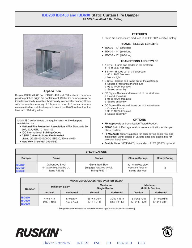
Click to Return to: INDEX FSD SD IBD/DFD CFD
ApplicA tionRuskin IBD20, 40, 60 and IBD230, 430 and 630 static fire dampers provide point-of origin fire containment. Static fire dampers may be installed vertically in walls or horizontally in concrete/masonry floors with fire resistance rating of 3 hours or more. IBD series dampers are classified as a static damper for use in an HVAC system that the fans turn off during a fire.
FEATURES• Static fire dampers are produced in an ISO 9001 certified factory.
FRAME - SLEEVE LENGTHS• IBD230 – 12" (305) long
• IBD430 – 14" (356) long
• IBD630 – 16" (406) long
TRANSITIONS AND STYLES• A Style – Frame and blades in the airstream
o 75 to 85% free area
• B Style – Blades out of the airstreamo 80 to 90% free area
o Not air tight
• C Style – Blades and frame out of the airstreamo Square or rectangular enclosureo 95 to 100% free area o Sealed assembly
• CR Style – Blades and frame out of the airstreamo Round enclosure o 95 to 100% free areao Sealed assembly
• CO Style – Blades and frame out of the airstream o Oval enclosure
o 95 to 100% free area o Sealed assembly
OPTIONS• FM Approvals as Specification Tested Product.
• SP200 Switch Package to allow remote indication of damperblade position.
• PFMA Angle factory supplied for labor saving angle two-sideinstallation. Other angles of various sizes and gages also fortwo-side installation.
• Fusible Links 165ºF (74ºC) is standard. 212ºF (100ºC) optional.
IBD230 IBD430 and IBD630 Static Curtain Fire Damper UL555 Classified 3 Hr. Rating
Model IBD series meets the requirements for fire dampers established by:
• National Fire Protection Association NFPA Standards 80, 90A, 92A, 92B, 101 and 105.• ICC International Building Codes• CSFM California State Fire Marshal
Listing (#3225-0245:0004) IBD230, 430 and 630• New York City (MEA 252-05-E)
MAXIMUM UL CLASSIFIED DAMPER SIZES*
Damper
IBD230IBD430IBD630
MaximumSingle Section
Minimum Size**Maximum
Multiple Section
VerticalVertical VerticalHorizontalHorizontal Horizontal
6"w x 6"h(152 x 152)
4"w x 4"h(102 x 102)
84"w x 91"h(2134 x 2311)
84"w x 72"h(2134 x 1829)
36"w x 36"h(914 x 914)
30"w x 45"h(762 x 1143)
* See product data sheets for more details on single and multiple section sizing.
IBD230IBD430IBD630
SPECIFICATIONS
Frame Blades Closure Springs Hourly RatingDamper
Galvanized Steel(in gages required by UL
listing R5531)
Galvanized Steel(in gages required by UL
listing R5531)
301 stainless steelconstant force orspring clip type
3
APPLICATIONRuskin IBD20, 40, 60 and IBD230, 430 and 630 static fire dampersprovide point-of origin fire containment. Static fire dampers may be installed vertically in walls or horizontally in concrete/masonry floorswith fire resistance rating of 3 hours or more. IBD series dampersare classified as a static damper for use in HVAC system that the fans turn off during a fire.
FEATURES• Static fire dampers are produced in an ISO 9001 certified factory
FRAME - SLEEVE LENGTHS• IBD230 – 12” (305) long• IBD430 – 14” (356) long• IBD630 – 16” (406) long
TRANSITIONS AND STYLES• A Style – Frame and blades in the airstream
o 75 to 85% free area• B Style – Blades out of the airstream
o 80 to 90% free areao Not air tight
• C Style – Blades and frame out of the airstreamo Square or rectangular enclosureo 95 to 100% free areao Sealed assembly
• CR Style – Blades and frame out of the airstreamo Round enclosureo 95 to 100% free areao Sealed assembly
• CO Style – Blades and frame out of the airstreamo Oval enclosureo 95 to 100% free areao Sealed assembly
OPTIONS• FM Approvals as Specification Tested Product.• SP200 Switch Package to allow remote indication of damper
blade position.• PFMA Angle factory supplied for labor saving angle two-side
installation. Other angles of various sizes and gauges also fortwo-side installation.
• Fusible Links 165ºF (74ºC) is standard. 212ºF (100ºC) optional
SPECIFICATIONSDamper Frame Blades Closure Springs Hourly Rating
IBD230IBD430IBD630
Galvanized Steel(in gauges required by UL
listing R5531)
Galvanized Steel(in gauges required by UL
listing R5531)
301 stainless steelconstant force orspring clip type
3
* See product data sheets for more details on single and multiple section sizing.
Model IBD series meets the requirements for combination fire and smoke dampers established by:
• National Fire Protection Association NFPA Standards 80, 90A, 92A,92B, 101 and 105.
• ICC International Building Codes• CSFM California State Fire Marshal –• Listing (#3225-0245:0004) IBD230, 430 and 630• New York City (MEA 252-05-E)
MAXIMUM UL CLASSIFIED DAMPER SIZES*
Damper Minimum Size** MaximumSingle Section
MaximumMultiple Section
Vertical Horizontal Vertical Horizontal Vertical Horizontal
IBD230IBD430IBD630 4”w x 4”h
(102 x 102)6"w x 6"h
(152 x 152)36"w x 36"h(914 x 914) 30"w x 45"h
(762 x 1143) 84"w x 72"h(2134 x 1829)
84”w x 91”h(2134 x 2311)
IBD230 IBD430 and IBD630 Static Curtain Fire Damper UL555 Classified 3 Hr. Rating
®

ALL STATED SPECIFICATIONS ARE SUBJECT TO CHANGE WITHOUT NOTICE OR OBLIGATION.
3900 Dr. Greaves Rd. • Kansas City, MO 64030 • (816) 761-7476 • FAX (816) 765-8955
INSTALLATION INSTRUCTIONS3 HOUR UL CLASSIFIED
CURTAIN TYPE (D)IBD230, (D)IBD430, and (D)IBD630 FIRE DAMPERSWITH INTEGRAL SLEEVES
APPLICATIONThe (D)IBD230, (D)IBD430, and (D)IBD630 fire dampers includesleeves that are an integral part of the damper frame and areapproved installation without the need for a supplemental, field-installed sleeve. Select the damper with sufficient length to permitattachment, with perimeter mounting angles, to ductwork to eachside of wall or floor opening. The fire damper models shown on thissheet are marked with a 11/2 hour fire damper label and areapproved for use in fire walls or masonry floors with ratings of lessthan 3 hours. Static and Dynamic dampers must be installed withleading edge of the closed blades within the wall or floor.
STATIC FIRE DAMPERSNot for use in Dynamic (fans on) Systems
MODELS IBD230, IBD430, and IBD630 MAXIMUM SIZESingle Section
Vertical Installation – 36"w x 36"h (914 x 914).Horizontal Installation – 30"w x 451/2"h (762 x 1156).
Multiple Section AssemblyVertical Installation – 90"w x 72"h (2286 x 1829).Horizontal Installation – 90"w x 91"h (2286 x 2311).
DYNAMIC FIRE DAMPERSUse in Dynamic (fans on) or Static (fans off) Systems
MODELS DIBD230, DIBD430, and DIBD630 MAXIMUM SIZESingle Section
Vertical Installation – 33"w x 36"h (838 x 914)Horizontal Installation – 24"w x 24"h (610 x 610)
Multiple Section AssemblyVertical Installation – 72"w x 48"h (1828 x 1219) or 48"w x
72"h (1219 x 1828) or 90"w x 24"h (2286 x 610)MODELS DIBD230X, DIBD430X, and DIBD630X MAXIMUM SIZE
Single SectionHorizontal Installation – 18"w x 24"h (457 x 610) or 24"w x
18" h (610 x 457)Multiple Section Assembly
Horizontal Installation – 36"w x 48"h (914 x 1219) or 48"w x 36"h (1219 x 914)
Notes:1. Dimensions shown in parentheses ( ) indicate millimeters.2. All multiple section dampers are constructed of equal single sec-
tion sizes no greater than the maximum single section sizes indi-cated above.
California State Fire Marshal Listing No. 3225-245:004
II-IBD230-514/Replaces II-IBD230-114 © Ruskin 2014
®
INSTALLATION SUPPLEMENTSRefer to the appropriate Ruskin installation instructions supple-ments for additional information or special requirements:• Optional Sealant of Dampers in Fire Rated Walls or Floor
Openings• Transfer Openings and Duct Terminations for 11/2 Hour and 3
Hour Fire Dampers• Optional FireStop Material• Extension of Fire and Combination Fire and Smoke Damper
Sleeves• Fire and Combination Fire and Smoke Dampers Installation in
Concrete Floor with Steel Deck• Drivemate No. 14880 Breakaway Connections• Flanged System Breakaway Connections
SEE COMPLETE MARKING ON PRODUCT
Click to Return to: INDEX FSD SD IBD/DFD CFD
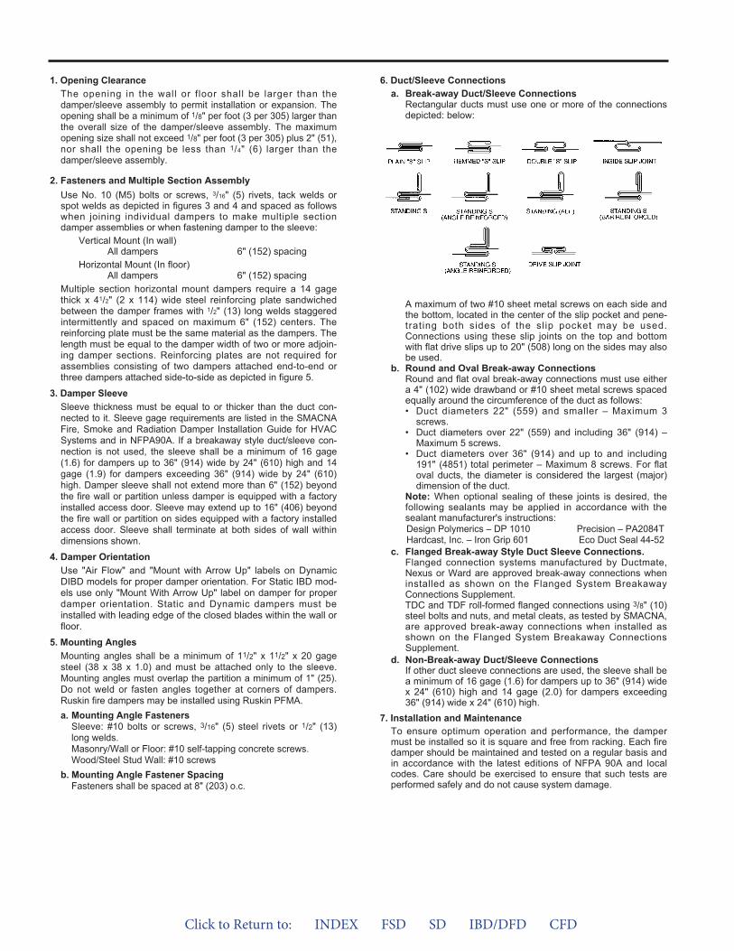
1. Opening ClearanceThe opening in the wall or f loor shall be larger than thedamper/sleeve assembly to permit installation or expansion. Theopening shall be a minimum of 1/8" per foot (3 per 305) larger thanthe overall size of the damper/sleeve assembly. The maximumopening size shall not exceed 1/8" per foot (3 per 305) plus 2" (51),nor shall the opening be less than 1/4" (6) larger than thedamper/sleeve assembly.
2. Fasteners and Multiple Section AssemblyUse No. 10 (M5) bolts or screws, 3/16" (5) rivets, tack welds orspot welds as depicted in figures 3 and 4 and spaced as followswhen joining individual dampers to make multiple sectiondamper assemblies or when fastening damper to the sleeve:
Vertical Mount (In wall)All dampers 6" (152) spacing
Horizontal Mount (In floor)All dampers 6" (152) spacing
Multiple section horizontal mount dampers require a 14 gagethick x 41/2" (2 x 114) wide steel reinforcing plate sandwichedbetween the damper frames with 1/2" (13) long welds staggeredintermittently and spaced on maximum 6" (152) centers. Thereinforcing plate must be the same material as the dampers. Thelength must be equal to the damper width of two or more adjoin-ing damper sections. Reinforcing plates are not required forassemblies consisting of two dampers attached end-to-end orthree dampers attached side-to-side as depicted in figure 5.
3. Damper SleeveSleeve thickness must be equal to or thicker than the duct con-nected to it. Sleeve gage requirements are listed in the SMACNAFire, Smoke and Radiation Damper Installation Guide for HVACSystems and in NFPA90A. If a breakaway style duct/sleeve con-nection is not used, the sleeve shall be a minimum of 16 gage(1.6) for dampers up to 36" (914) wide by 24" (610) high and 14gage (1.9) for dampers exceeding 36" (914) wide by 24" (610)high. Damper sleeve shall not extend more than 6" (152) beyondthe fire wall or partition unless damper is equipped with a factoryinstalled access door. Sleeve may extend up to 16" (406) beyondthe fire wall or partition on sides equipped with a factory installedaccess door. Sleeve shall terminate at both sides of wall withindimensions shown.
4. Damper OrientationUse "Air Flow" and "Mount with Arrow Up" labels on DynamicDIBD models for proper damper orientation. For Static IBD mod-els use only "Mount With Arrow Up" label on damper for properdamper orientation. Static and Dynamic dampers must beinstalled with leading edge of the closed blades within the wall orfloor.
5. Mounting AnglesMounting angles shall be a minimum of 11/2" x 11/2" x 20 gagesteel (38 x 38 x 1.0) and must be attached only to the sleeve.Mounting angles must overlap the partition a minimum of 1" (25).Do not weld or fasten angles together at corners of dampers.Ruskin fire dampers may be installed using Ruskin PFMA.a. Mounting Angle Fasteners
Sleeve: #10 bolts or screws, 3/16" (5) steel rivets or 1/2" (13)long welds.Masonry/Wall or Floor: #10 self-tapping concrete screws.Wood/Steel Stud Wall: #10 screws
b. Mounting Angle Fastener SpacingFasteners shall be spaced at 8" (203) o.c.
6. Duct/Sleeve Connectionsa. Break-away Duct/Sleeve Connections
Rectangular ducts must use one or more of the connectionsdepicted: below:
A maximum of two #10 sheet metal screws on each side andthe bottom, located in the center of the slip pocket and pene-trating both sides of the slip pocket may be used.Connections using these slip joints on the top and bottomwith flat drive slips up to 20" (508) long on the sides may alsobe used.
b. Round and Oval Break-away ConnectionsRound and flat oval break-away connections must use eithera 4" (102) wide drawband or #10 sheet metal screws spacedequally around the circumference of the duct as follows:• Duct diameters 22" (559) and smaller – Maximum 3
screws.• Duct diameters over 22" (559) and including 36" (914) –
Maximum 5 screws.• Duct diameters over 36" (914) and up to and including
191" (4851) total perimeter – Maximum 8 screws. For flatoval ducts, the diameter is considered the largest (major)dimension of the duct.
Note: When optional sealing of these joints is desired, thefollowing sealants may be applied in accordance with thesealant manufacturer's instructions:Design Polymerics – DP 1010 Precision – PA2084THardcast, Inc. – Iron Grip 601 Eco Duct Seal 44-52
c. Flanged Break-away Style Duct Sleeve Connections.Flanged connection systems manufactured by Ductmate,Nexus or Ward are approved break-away connections wheninstalled as shown on the Flanged System BreakawayConnections Supplement.TDC and TDF roll-formed flanged connections using 3/8" (10)steel bolts and nuts, and metal cleats, as tested by SMACNA,are approved break-away connections when installed asshown on the Flanged System Breakaway ConnectionsSupplement.
d. Non-Break-away Duct/Sleeve ConnectionsIf other duct sleeve connections are used, the sleeve shall bea minimum of 16 gage (1.6) for dampers up to 36" (914) widex 24" (610) high and 14 gage (2.0) for dampers exceeding36" (914) wide x 24" (610) high.
7. Installation and MaintenanceTo ensure optimum operation and performance, the dampermust be installed so it is square and free from racking. Each firedamper should be maintained and tested on a regular basis andin accordance with the latest editions of NFPA 90A and localcodes. Care should be exercised to ensure that such tests areperformed safely and do not cause system damage.
Click to Return to: INDEX FSD SD IBD/DFD CFD
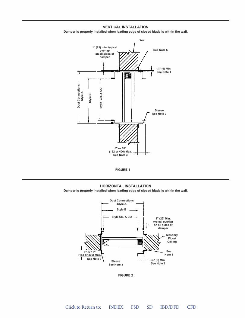
VERTICAL INSTALLATIONDamper is properly installed when leading edge of closed blade is within the wall.
FIGURE 1
6" or 16"(152 or 406) Max.
See Note 3
Duc
t Con
nect
ions
Styl
e A
Styl
e B
Styl
e C
R, &
CO
1" (25) min. typicaloverlap
on all sides ofdamper
See Note 5
Wall
SleeveSee Note 3
1/4" (6) Min.See Note 1
6" or 16"(152 or 406) Max.
See Note 3
Duct ConnectionsStyle A
Style B
Style CR, & CO
SleeveSee Note 3
SeeNote 5
1/4" (6) Min.See Note 1
MasonryFloor/
Ceiling
1" (25) Min.typical overlapon all sides of
damper
FIGURE 2
HORIZONTAL INSTALLATIONDamper is properly installed when leading edge of closed blade is within the wall.
Click to Return to: INDEX FSD SD IBD/DFD CFD
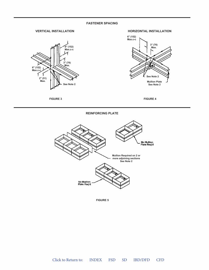
FIGURE 5
FASTENER SPACING
REINFORCING PLATE
VERTICAL INSTALLATION HORIZONTAL INSTALLATION
FIGURE 4FIGURE 3
See Note 2
Mullion PlateSee Note 2
6" (152)Max.c-c
3" (76)Max.
See Note 2
6" (152)Max.c-c
2" (51)Max.
6" (152)Max.c-c
3" (76)Max.
Mullion Required on 2 ormore adjoining sections
See Note 2
Click to Return to: INDEX FSD SD IBD/DFD CFD
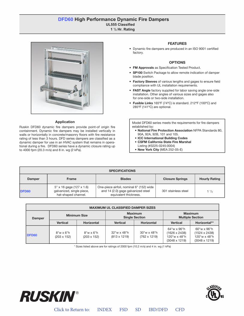
Click to Return to: INDEX FSD SD IBD/DFD CFD
ApplicationRuskin DFD60 dynamic fire dampers provide point-of origin fire containment. Dynamic fire dampers may be installed vertically in walls or horizontally in concrete/masonry floors with fire resistance rating of less than 3 hours. DFD series dampers are classified as a dynamic damper for use in an HVAC system that remains in opera-tional during a fire. DFD60 series have a dynamic closure rating up to 4000 fpm (20.3 m/s) and 8 in. wg (2 kPa).
FEATURES• Dynamic fire dampers are produced in an ISO 9001 certified
factory.
OPTIONS• FM Approvals as Specification Tested Product.
• SP100 Switch Package to allow remote indication of damperblade position.
• Factory Sleeves of various lengths and gages to ensure fieldcompliance with UL installation requirements.
• FAST Angle factory supplied for labor saving angle one-sideinstallation. Other angles of various sizes and gages alsofor one-side or two-side installation.
• Fusible Links 165ºF (74ºC) is standard. 212ºF (100ºC) and285ºF (141ºC) are optional.
DFD60 High Performance Dynamic Fire Dampers UL555 Classified
1 ½ Hr. Rating
Model DFD60 series meets the requirements for fire dampers established by:
• National Fire Protection Association NFPA Standards 80, 90A, 92A, 92B, 101 and 105.
• ICC International Building Codes• CSFM California State Fire Marshal
Listing (#3225-0245:0004)• New York City (MEA 252-05-E)
MAXIMUM UL CLASSIFIED DAMPER SIZES
Damper
DFD60
MaximumSingle Section
Minimum SizeMaximum
Multiple Section
VerticalVertical VerticalHorizontalHorizontal Horizontal**
8"w x 6"h(203 x 152)
8"w x 6"h(203 x 152)
60"w x 96"h(1524 x 2438)120"w x 48"h(3048 x 1219)
64"w x 96"h(1626 x 2438)120"w x 48"h(3048 x 1219)
32"w x 48"h(813 x 1219)
30"w x 48"h(762 x 1219)
* Sizes listed above are for ratings of 2000 fpm (10.2 m/s) and 4 in. wg (1 kPa)
DFD60
SPECIFICATIONS
Frame Blades Closure Springs Hourly RatingDamper
5" x 16 gage (127 x 1.6)galvanized, single piece,
hat-shaped channel.
One-piece airfoil, nominal 6" (152) wideand 14 (2.0) gage galvanized steel
equivalent thickness.301 stainless steel 1 1/2
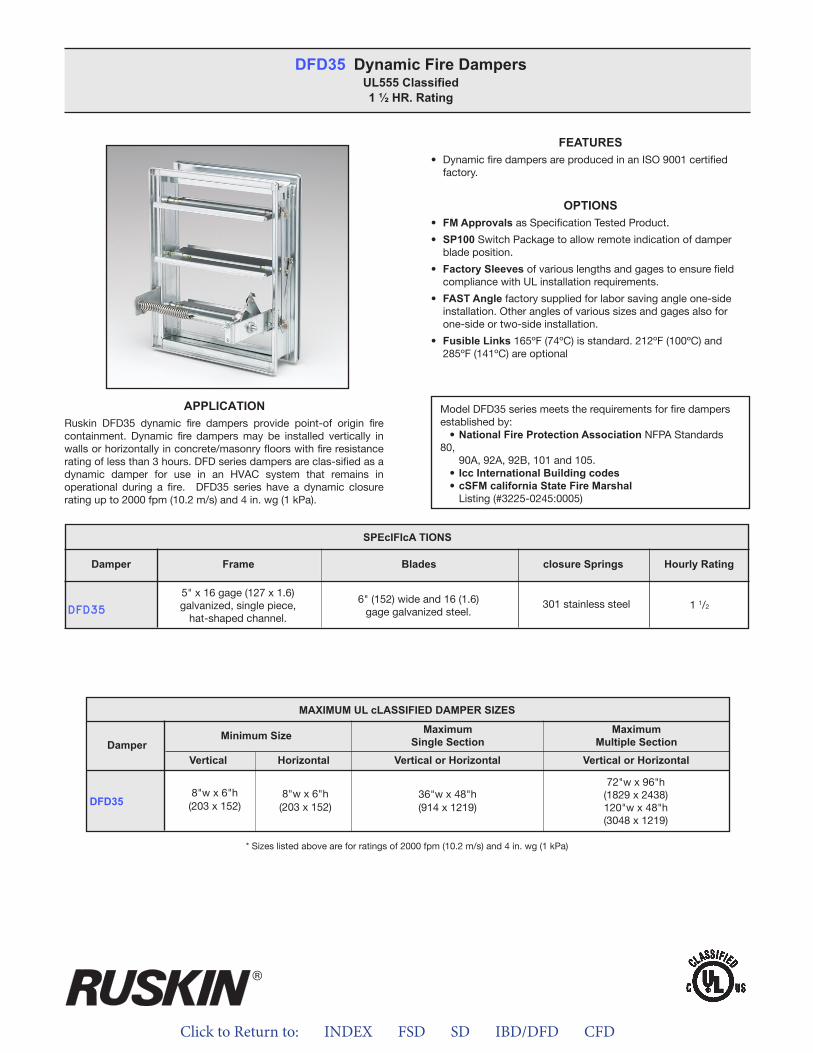
Click to Return to: INDEX FSD SD IBD/DFD CFD
FEATURES• DynamicfiredampersareproducedinanISO9001certified
factory.
OPTIONS• FM ApprovalsasSpecificationTestedProduct.• SP100SwitchPackagetoallowremoteindicationofdamper
bladeposition.
• Factory SleevesofvariouslengthsandgagestoensurefieldcompliancewithULinstallationrequirements.
• FAST Anglefactorysuppliedforlaborsavingangleone-sideinstallation.Otheranglesofvarioussizesandgagesalsoforone-sideortwo-sideinstallation.
• Fusible Links165ºF(74ºC)isstandard.212ºF(100ºC)and285ºF(141ºC)areoptional
DFD35 Dynamic Fire DampersUL555 Classified 1 ½ HR. Rating
ModelDFD35seriesmeetstherequirementsforfiredampersestablishedby:• National Fire Protection AssociationNFPAStandards
80,90A,92A,92B,101and105.
• Icc International Building codes• cSFM california State Fire MarshalListing(#3225-0245:0005)
APPLICATIONRuskin DFD35 dynamic fire dampers provide point-of origin firecontainment. Dynamic fire dampersmay be installed vertically inwallsorhorizontallyinconcrete/masonryfloorswithfireresistanceratingoflessthan3hours.DFDseriesdampersareclas-sifiedasadynamic damper for use in an HVAC system that remains inoperational during a fire. DFD35 series have a dynamic closureratingupto2000fpm(10.2m/s)and4in.wg(1kPa).
SPEcIFIcA TIONS
Frame Blades closure Springs Hourly RatingDamper
5"x16gage(127x1.6)galvanized,singlepiece,hat-shapedchannel.
6"(152)wideand16(1.6)gagegalvanizedsteel.
301stainlesssteel 11/2
MAXIMUM UL cLASSIFIED DAMPER SIZES
Damper
DFD35
MaximumSingle SectionMinimum Size Maximum
Multiple SectionVertical or HorizontalVertical Vertical or HorizontalHorizontal
8"wx6"h(203x152)
8"wx6"h(203x152)
72"wx96"h(1829x2438)120"wx48"h(3048x1219)
36"wx48"h(914x1219)
*Sizeslistedaboveareforratingsof2000fpm(10.2m/s)and4in.wg(1kPa)
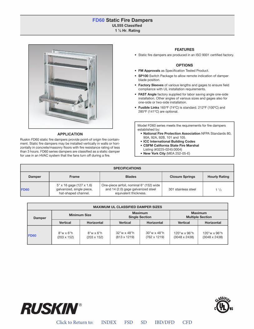
Click to Return to: INDEX FSD SD IBD/DFD CFD
FEATURES• StaticfiredampersareproducedinanISO9001certifiedfactory.
OPTIONS• FM ApprovalsasSpecificationTestedProduct.
• SP100SwitchPackagetoallowremoteindicationofdamperbladeposition.
• Factory SleevesofvariouslengthsandgagestoensurefieldcompliancewithULinstallationrequirements.
• FAST Anglefactorysuppliedforlaborsavingangleone-sideinstallation.Otheranglesofvarioussizesandgagesalsoforone-sideortwo-sideinstallation.
• Fusible Links165ºF(74ºC)isstandard.212ºF(100ºC)and285ºF(141ºC)areoptional.
FD60 Static Fire DampersUL555 Classified 1 ½ Hr. Rating
ModelFD60seriesmeetstherequirementsforfiredampersestablishedby:• National Fire Protection AssociationNFPAStandards80,90A,92A,92B,101and105.
• ICC International Building Codes• CSFM California State Fire MarshalListing(#3225-0245:0004)
• New York City(MEA252-05-E)
APPLICATIONRuskinFD60staticfiredampersprovidepoint-oforiginfirecontain-ment.Staticfiredampersmaybeinstalledverticallyinwallsorhori-zontallyinconcrete/masonryfloorswithfireresistanceratingoflessthan3hours.FD60seriesdampersareclassifiedasastaticdamperforuseinanHVACsystemthatthefansturnoffduringafire.
FD60
SPECIFICATIONS
Frame Blades Closure Springs Hourly RatingDamper
5"x16gage(127x1.6)galvanized,singlepiece,hat-shapedchannel.
One-pieceairfoil,nominal6"(152)wideand14(2.0)gagegalvanizedsteel
equivalentthickness.301stainlesssteel 11/2
MAXIMUM UL CLASSIFIED DAMPER SIZES
Damper
FD60
MaximumSingle Section
Minimum SizeMaximum
Multiple Section
VerticalVertical VerticalHorizontalHorizontal Horizontal
8"wx6"h(203x152)
8"wx6"h(203x152)
120"wx96"h(3048x2438)
120"wx96"h(3048x2438)
32"wx48"h(813x1219)
30"wx48"h(762x1219)
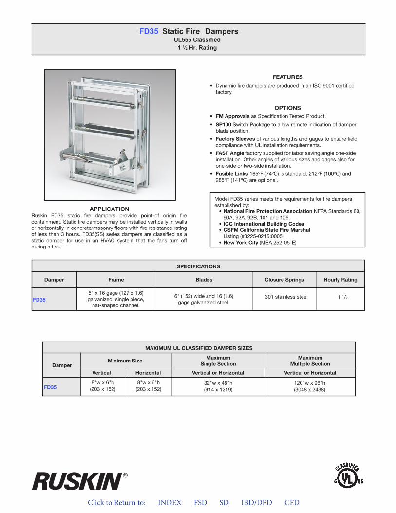
Click to Return to: INDEX FSD SD IBD/DFD CFD
FEATURES• DynamicfiredampersareproducedinanISO9001certified
factory.
OPTIONS• FM ApprovalsasSpecificationTestedProduct.
• SP100SwitchPackagetoallowremoteindicationofdamperbladeposition.
• Factory SleevesofvariouslengthsandgagestoensurefieldcompliancewithULinstallationrequirements.
• FAST Anglefactorysuppliedforlaborsavingangleone-sideinstallation.Otheranglesofvarioussizesandgagesalsoforone-sideortwo-sideinstallation.
• Fusible Links165ºF(74ºC)isstandard.212ºF(100ºC)and285ºF(141ºC)areoptional.
FD35 Static Fire DampersUL555 Classified
1 ½ Hr. Rating
ModelFD35seriesmeetstherequirementsforfiredampersestablishedby:• National Fire Protection AssociationNFPAStandards80,90A,92A,92B,101and105.
• ICC International Building Codes• CSFM California State Fire MarshalListing(#3225-0245:0005)
• New York City(MEA252-05-E)
MAXIMUM UL CLASSIFIED DAMPER SIZES
Damper
FD35
MaximumSingle Section
Minimum SizeMaximum
Multiple Section
Vertical or HorizontalVertical Vertical or HorizontalHorizontal
8"wx6"h(203x152)
8"wx6"h(203x152)
32"wx48"h(914x1219)
120"wx96"h(3048x2438)
APPLICATIONRuskin FD35 static fire dampers provide point-of origin firecontainment.Staticfiredampersmaybeinstalledverticallyinwallsorhorizontallyinconcrete/masonryfloorswithfireresistanceratingof lessthan3hours.FD35(SS)seriesdampersareclassifiedasastatic damper for use in an HVAC system that the fans turn offduringafire.
FD35
SPECIFICATIONS
Frame Blades Closure Springs Hourly RatingDamper
5"x16gage(127x1.6)galvanized,singlepiece,hat-shapedchannel.
6"(152)wideand16(1.6)gagegalvanizedsteel.
301stainlesssteel 11/2
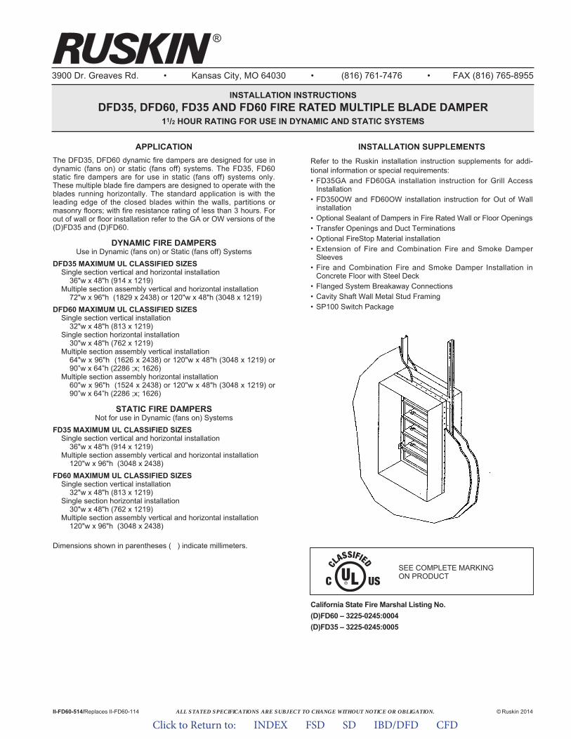
ALL STATED SPECIFICATIONS ARE SUBJECT TO CHANGE WITHOUT NOTICE OR OBLIGATION.
3900 Dr. Greaves Rd. • Kansas City, MO 64030 • (816) 761-7476 • FAX (816) 765-8955
INSTALLATION INSTRUCTIONSDFD35, DFD60, FD35 AND FD60 FIRE RATED MULTIPLE BLADE DAMPER
11/2 HOUR RATING FOR USE IN DYNAMIC AND STATIC SYSTEMS
APPLICATIONThe DFD35, DFD60 dynamic fire dampers are designed for use indynamic (fans on) or static (fans off) systems. The FD35, FD60static fire dampers are for use in static (fans off) systems only.These multiple blade fire dampers are designed to operate with theblades running horizontally. The standard application is with theleading edge of the closed blades within the walls, partitions ormasonry floors; with fire resistance rating of less than 3 hours. Forout of wall or floor installation refer to the GA or OW versions of the(D)FD35 and (D)FD60.
DYNAMIC FIRE DAMPERSUse in Dynamic (fans on) or Static (fans off) Systems
DFD35 MAXIMUM UL CLASSIFIED SIZESSingle section vertical and horizontal installation
36"w x 48"h (914 x 1219)Multiple section assembly vertical and horizontal installation
72"w x 96"h (1829 x 2438) or 120"w x 48"h (3048 x 1219)DFD60 MAXIMUM UL CLASSIFIED SIZES
Single section vertical installation32"w x 48"h (813 x 1219)
Single section horizontal installation30"w x 48"h (762 x 1219)
Multiple section assembly vertical installation64"w x 96"h (1626 x 2438) or 120"w x 48"h (3048 x 1219) or90”w x 64”h (2286 ;x; 1626)
Multiple section assembly horizontal installation60"w x 96"h (1524 x 2438) or 120"w x 48"h (3048 x 1219) or90”w x 64”h (2286 ;x; 1626)
STATIC FIRE DAMPERSNot for use in Dynamic (fans on) Systems
FD35 MAXIMUM UL CLASSIFIED SIZESSingle section vertical and horizontal installation
36"w x 48"h (914 x 1219)Multiple section assembly vertical and horizontal installation
120"w x 96"h (3048 x 2438)FD60 MAXIMUM UL CLASSIFIED SIZES
Single section vertical installation32"w x 48"h (813 x 1219)
Single section horizontal installation30"w x 48"h (762 x 1219)
Multiple section assembly vertical and horizontal installation120"w x 96"h (3048 x 2438)
Dimensions shown in parentheses ( ) indicate millimeters.
California State Fire Marshal Listing No.(D)FD60 – 3225-0245:0004(D)FD35 – 3225-0245:0005
II-FD60-514/Replaces II-FD60-114 © Ruskin 2014
®
INSTALLATION SUPPLEMENTSRefer to the Ruskin installation instruction supplements for addi-tional information or special requirements:• FD35GA and FD60GA installation instruction for Grill Access
Installation• FD350OW and FD60OW installation instruction for Out of Wall
installation• Optional Sealant of Dampers in Fire Rated Wall or Floor Openings• Transfer Openings and Duct Terminations• Optional FireStop Material installation• Extension of Fire and Combination Fire and Smoke Damper
Sleeves• Fire and Combination Fire and Smoke Damper Installation in
Concrete Floor with Steel Deck• Flanged System Breakaway Connections• Cavity Shaft Wall Metal Stud Framing• SP100 Switch Package
SEE COMPLETE MARKING ON PRODUCT
Click to Return to: INDEX FSD SD IBD/DFD CFD
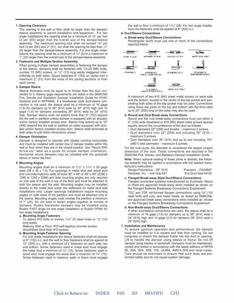
1. Opening ClearanceThe opening in the wall or floor shall be larger than the damper/sleeve assembly to permit installation and expansion. For twoangle installations the opening shall be a minimum of 1/8" per foot(3 per 305) larger than the overall size of the damper/sleeveassembly. The maximum opening size shall not exceed 1/8" perfoot (3 per 305) plus 2" (51), nor shall the opening be less than 1/4"(6) larger than the damper/sleeve assembly. For one angle instal-lations, the opening shall be a minimum of 1/4" (6) to a maximum of1" (25) larger than the overall size of the damper/sleeve assembly.
2. Fasteners and Multiple Section AssemblyWhen joining multiple damper assemblies or fastening the damperto the sleeve, dampers shall be fastened with 1/4-20 (M6) bolts,number 10 (M5) screws, or 1/2" (13) long welds staggered inter-mittently on both sides. Space fasteners 6" (152) on center and amaximum 2" (51) from the ends of the joining sections or fromeach corner.
3. Damper SleeveSleeve thickness must be equal to or thicker than the duct con-nected to it. Sleeve gage requirements are listed in the SMACNAFire, Smoke and Radiation Damper Installation Guide for HVACSystems and in NFPA90A. If a breakaway style duct/sleeve con-nection is not used, the sleeve shall be a minimum of 16 gage(1.6) for dampers up to 36" (914) wide by 24" (610) high and 14gage (1.9) for dampers exceeding 36" (914) wide by 24" (610)high. Damper sleeve shall not extend more than 6" (152) beyondthe fire wall or partition unless damper is equipped with an actuatorand/or factory installed access door. Sleeve may extend up to 16"(406) beyond the fire wall or partition on sides equipped with actu-ator and/or factory installed access door. Sleeve shall terminate atboth sides of wall within dimensions shown.
4. Damper OrientationDamper is designed to operate with blades running horizontallyand must be installed with center line of damper blades within thewall or floor when they are in the closed position. Use "Mount WithArrow Up" label as a guide for proper damper orientation.Horizontal mount dampers may be installed with the jackshaftabove or below the floor.
5. Mounting AnglesMounting angles shall be a minimum of 11/2" x 11/2" x 20 gagesteel (38 x 38 x 1.0). For openings in metal stud and wood studand concrete/masonry walls of sizes 90" x 49" or 49" x 90" (2286 x1245 or 1245 x 2286) and less mounting angles are only requiredon one side of the wall or top of the floor and must be attached toboth the sleeve and the wall. Mounting angles may be installeddirectly to the metal stud under the wallboard on metal stud wallinstallations only. Larger openings installations require mountingangles on both sides of the partition and must be attached only tothe sleeve. Mounting angles must overlap the partition a minimumof 1" (25). Do not weld or fasten angles together at corners ofdampers. Ruskin fire/smoke dampers may be installed usingRuskin FAST angle for one angle installation or Ruskin PFMA fortwo angle installations.a. Mounting Angle Fasteners
To sleeve #10 bolts or screws, 3/16" (5) steel rivets or 1/2" (13)long welds.Masonry Wall or Floor: #10 self-tapping concrete screwsWood/Steel Stud Wall: #10 screws.
b. Mounting Angle Fastener SpacingFor one angle installations the sleeve fasteners shall be spacedat 6" (152) o.c. and the wall or floor fasteners shall be spaced at12" (305) o.c. with a minimum of 2 fasteners on each side, topand bottom. Screw fasteners used in metal stud must engagethe metal stud a minimum of 1/2" (13). Screw fasteners used inwood stud must engage the wood stud a minimum of 3/4" (19).Screw fasteners used in masonry walls or floors must engage
the wall or floor a minimum of 11/2" (38). For two angle installa-tions the fasteners shall be spaced at 8" (203) o.c.
6. Duct/Sleeve Connectionsa. Break-away Duct/Sleeve Connections
Rectangular ducts must use one or more of the connectionsdepicted below:
A maximum of two #10 (M5) sheet metal screws on each sideand the bottom, located in the center of the slip pocket and pen-etrating both sides of the slip pocket may be used. Connectionsusing these slip joints on the top and bottom with flat drive slipsup to 20" (508) long on the sides may also be used.
b. Round and Oval Break-away ConnectionsRound and flat oval break-away connections must use either a4" (102) wide drawband or #10 (M5) sheet metal screws spacedequally around the circumference of the duct as follows:• Duct diameters 22" (559) and smaller – maximum 3 screws.• Duct diameters over 22" (559) and including 36" (914) –
maximum 5 screws.• Duct diameters over 36" (914) and up to and including 191"
(4851) total perimeter – maximum 8 screws.For flat oval ducts, the diameter is considered the largest (major)dimension of the duct. These connections are depicted in theSMACNA Fire, Smoke, and Radiation Damper Installation Guide.Note: When optional sealing of these joints is desired, the follow-ing sealants may be applied in accordance with the sealant manu-facturer's instructions:
Design Polymerics – DP 1010 Precision – PA2084THardcast, Inc. – Iron Grip 601 Eco Duct Seal 44-52
c. Flanged Break-away Style Duct/Sleeve ConnectionsFlanged connection systems manufactured by Ductmate, Nexusor Ward are approved break-away when installed as shown onthe Flanged Systems Breakaway Connections Supplement.TDC and TDF roll-formed flanged connections using 3/8" (10)steel bolts and nuts, and metal cleats, as tested by SMACNA,are approved break-away connections when installed as shownon the Flanged Systems Breakaway Connections Supplement.
d. Non-Break-away Duct/Sleeve ConnectionsIf other duct/sleeve connections are used, the sleeve shall be aminimum of 16 gage (1.6) for dampers up to 36" (914) wide x24" (610) high and 14 gage (2.0) for dampers 36" (914) wide x24" (610) high.
7. Installation and MaintenanceTo ensure optimum operation and performance, the dampermust be installed so it is square and free from racking. Do notcompress or stretch the damper frame into the duct or opening.Lift or handle the damper using sleeve or frame. Do not liftdamper using blades or jackshaft. Dampers must be maintained,cycled and tested in accordance with the latest editions of NFPA80, 90A, 92A, 92B, 105, UL864, AMCA 503 and local codes.Care should be exercised to ensure that such tests are per-formed safely and do not cause system damage.
Click to Return to: INDEX FSD SD IBD/DFD CFD
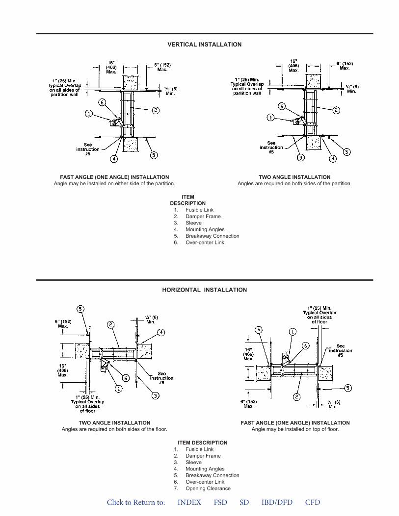
VERTICAL INSTALLATION
HORIZONTAL INSTALLATION
ITEMDESCRIPTION
1. Fusible Link2. Damper Frame3. Sleeve4. Mounting Angles5. Breakaway Connection6. Over-center Link
ITEM DESCRIPTION1. Fusible Link2. Damper Frame3. Sleeve4. Mounting Angles5. Breakaway Connection6. Over-center Link7. Opening Clearance
FAST ANGLE (ONE ANGLE) INSTALLATIONAngle may be installed on either side of the partition.
TWO ANGLE INSTALLATIONAngles are required on both sides of the partition.
TWO ANGLE INSTALLATIONAngles are required on both sides of the floor.
FAST ANGLE (ONE ANGLE) INSTALLATIONAngle may be installed on top of floor.
Click to Return to: INDEX FSD SD IBD/DFD CFD
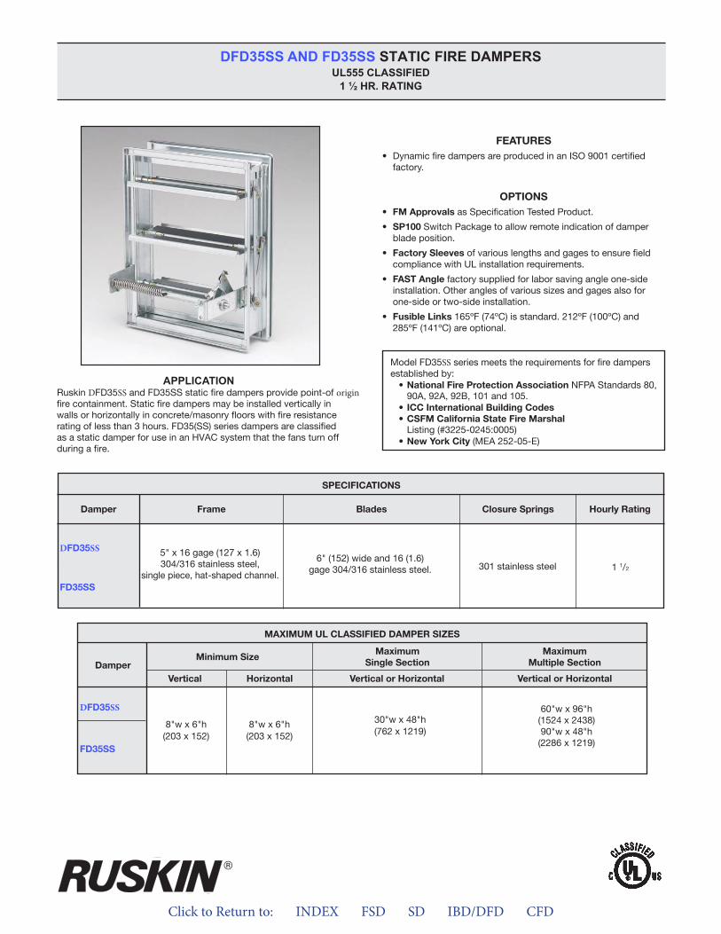
Click to Return to: INDEX FSD SD IBD/DFD CFD
DFD35SS AND FD35SS STATIC FIRE DAMPERS UL555 CLASSIFIED
1 ½ HR. RATING
SS
D SS
APPLICATIOND SS origin
D SS
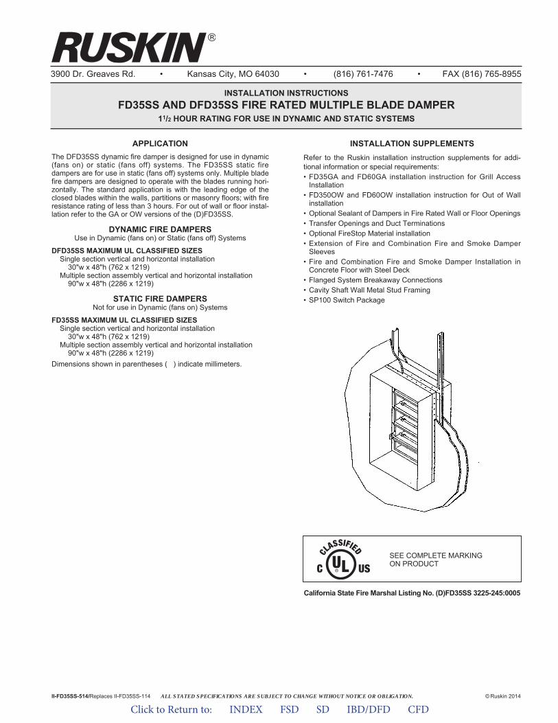
ALL STATED SPECIFICATIONS ARE SUBJECT TO CHANGE WITHOUT NOTICE OR OBLIGATION.
3900 Dr. Greaves Rd. • Kansas City, MO 64030 • (816) 761-7476 • FAX (816) 765-8955
INSTALLATION INSTRUCTIONSFD35SS AND DFD35SS FIRE RATED MULTIPLE BLADE DAMPER
11/2 HOUR RATING FOR USE IN DYNAMIC AND STATIC SYSTEMS
APPLICATIONThe DFD35SS dynamic fire damper is designed for use in dynamic(fans on) or static (fans off) systems. The FD35SS static firedampers are for use in static (fans off) systems only. Multiple bladefire dampers are designed to operate with the blades running hori-zontally. The standard application is with the leading edge of theclosed blades within the walls, partitions or masonry floors; with fireresistance rating of less than 3 hours. For out of wall or floor instal-lation refer to the GA or OW versions of the (D)FD35SS.
DYNAMIC FIRE DAMPERSUse in Dynamic (fans on) or Static (fans off) Systems
DFD35SS MAXIMUM UL CLASSIFIED SIZESSingle section vertical and horizontal installation
30"w x 48"h (762 x 1219)Multiple section assembly vertical and horizontal installation
90"w x 48"h (2286 x 1219)
STATIC FIRE DAMPERSNot for use in Dynamic (fans on) Systems
FD35SS MAXIMUM UL CLASSIFIED SIZESSingle section vertical and horizontal installation
30"w x 48"h (762 x 1219)Multiple section assembly vertical and horizontal installation
90"w x 48"h (2286 x 1219)Dimensions shown in parentheses ( ) indicate millimeters.
California State Fire Marshal Listing No. (D)FD35SS 3225-245:0005
II-FD35SS-514/Replaces II-FD35SS-114 © Ruskin 2014
INSTALLATION SUPPLEMENTSRefer to the Ruskin installation instruction supplements for addi-tional information or special requirements:• FD35GA and FD60GA installation instruction for Grill Access
Installation• FD350OW and FD60OW installation instruction for Out of Wall
installation• Optional Sealant of Dampers in Fire Rated Wall or Floor Openings• Transfer Openings and Duct Terminations• Optional FireStop Material installation• Extension of Fire and Combination Fire and Smoke Damper
Sleeves• Fire and Combination Fire and Smoke Damper Installation in
Concrete Floor with Steel Deck• Flanged System Breakaway Connections• Cavity Shaft Wall Metal Stud Framing• SP100 Switch Package
SEE COMPLETE MARKING ON PRODUCT
Click to Return to: INDEX FSD SD IBD/DFD CFD
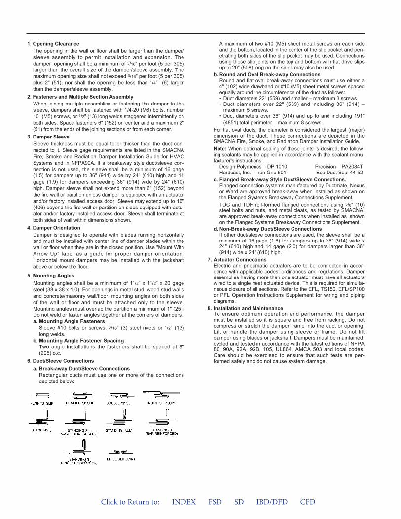
1. Opening ClearanceThe opening in the wall or floor shall be larger than the damper/sleeve assembly to permit installation and expansion. Thedamper opening shall be a minimum of 3/16" per foot (5 per 305)larger than the overall size of the damper/sleeve assembly. Themaximum opening size shall not exceed 3/16" per foot (5 per 305)plus 2" (51), nor shall the opening be less than 1/4" (6) largerthan the damper/sleeve assembly.
2. Fasteners and Multiple Section AssemblyWhen joining multiple assemblies or fastening the damper to thesleeve, dampers shall be fastened with 1/4-20 (M6) bolts, number10 (M5) screws, or 1/2" (13) long welds staggered intermittently onboth sides. Space fasteners 6" (152) on center and a maximum 2"(51) from the ends of the joining sections or from each corner.
3. Damper SleeveSleeve thickness must be equal to or thicker than the duct con-nected to it. Sleeve gage requirements are listed in the SMACNAFire, Smoke and Radiation Damper Installation Guide for HVACSystems and in NFPA90A. If a breakaway style duct/sleeve con-nection is not used, the sleeve shall be a minimum of 16 gage(1.5) for dampers up to 36" (914) wide by 24" (610) high and 14gage (1.9) for dampers exceeding 36" (914) wide by 24" (610)high. Damper sleeve shall not extend more than 6" (152) beyondthe fire wall or partition unless damper is equipped with an actuatorand/or factory installed access door. Sleeve may extend up to 16"(406) beyond the fire wall or partition on sides equipped with actu-ator and/or factory installed access door. Sleeve shall terminate atboth sides of wall within dimensions shown.
4. Damper OrientationDamper is designed to operate with blades running horizontallyand must be installed with center line of damper blades within thewall or floor when they are in the closed position. Use "Mount WithArrow Up" label as a guide for proper damper orientation.Horizontal mount dampers may be installed with the jackshaftabove or below the floor.
5. Mounting AnglesMounting angles shall be a minimum of 11/2" x 11/2" x 20 gagesteel (38 x 38 x 1.0). For openings in metal stud, wood stud wallsand concrete/masonry wall/floor, mounting angles on both sidesof the wall or floor and must be attached only to the sleeve.Mounting angles must overlap the partition a minimum of 1" (25).Do not weld or fasten angles together at the corners of dampers.a. Mounting Angle Fasteners
Sleeve #10 bolts or screws, 3/16" (3) steel rivets or 1/2" (13)long welds.
b. Mounting Angle Fastener SpacingTwo angle installations the fasteners shall be spaced at 8"(205) o.c.
6. Duct/Sleeve Connectionsa. Break-away Duct/Sleeve Connections
Rectangular ducts must use one or more of the connectionsdepicted below:
A maximum of two #10 (M5) sheet metal screws on each sideand the bottom, located in the center of the slip pocket and pen-etrating both sides of the slip pocket may be used. Connectionsusing these slip joints on the top and bottom with flat drive slipsup to 20" (508) long on the sides may also be used.
b. Round and Oval Break-away ConnectionsRound and flat oval break-away connections must use either a4" (102) wide drawband or #10 (M5) sheet metal screws spacedequally around the circumference of the duct as follows:• Duct diameters 22" (559) and smaller – maximum 3 screws.• Duct diameters over 22" (559) and including 36" (914) –
maximum 5 screws.• Duct diameters over 36" (914) and up to and including 191"
(4851) total perimeter – maximum 8 screws.For flat oval ducts, the diameter is considered the largest (major)dimension of the duct. These connections are depicted in theSMACNA Fire, Smoke, and Radiation Damper Installation Guide.Note: When optional sealing of these joints is desired, the follow-ing sealants may be applied in accordance with the sealant manu-facturer's instructions:
Design Polymerics – DP 1010 Precision – PA2084THardcast, Inc. – Iron Grip 601 Eco Duct Seal 44-52
c. Flanged Break-away Style Duct/Sleeve Connections.Flanged connection systems manufactured by Ductmate, Nexusor Ward are approved break-away when installed as shown onthe Flanged Systems Breakaway Connections Supplement.TDC and TDF roll-formed flanged connections using 3/8" (10)steel bolts and nuts, and metal cleats, as tested by SMACNA,are approved break-away connections when installed as shownon the Flanged Systems Breakaway Connections Supplement.
d. Non-Break-away Duct/Sleeve ConnectionsIf other duct/sleeve connections are used, the sleeve shall be aminimum of 16 gage (1.6) for dampers up to 36" (914) wide x24" (610) high and 14 gage (2.0) for dampers larger than 36"(914) wide x 24" (610) high.
7. Actuator ConnectionsElectric and pneumatic actuators are to be connected in accor-dance with applicable codes, ordinances and regulations. Damperassemblies having more than one actuator must have all actuatorswired to a single heat actuated device. This is required for simulta-neous closure of all sections. Refer to the EFL, TS150, EFL/SP100or PFL Operation Instructions Supplement for wiring and pipingdiagrams.
8. Installation and MaintenanceTo ensure optimum operation and performance, the dampermust be installed so it is square and free from racking. Do notcompress or stretch the damper frame into the duct or opening.Lift or handle the damper using sleeve or frame. Do not liftdamper using blades or jackshaft. Dampers must be maintained,cycled and tested in accordance with the latest editions of NFPA80, 90A, 92A, 92B, 105, UL864, AMCA 503 and local codes.Care should be exercised to ensure that such tests are per-formed safely and do not cause system damage.
Click to Return to: INDEX FSD SD IBD/DFD CFD
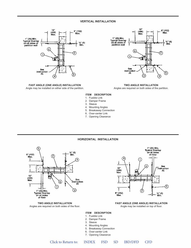
VERTICAL INSTALLATION
HORIZONTAL INSTALLATION
FAST ANGLE (ONE ANGLE) INSTALLATIONAngle may be installed on either side of the partition.
TWO ANGLE INSTALLATIONAngles are required on both sides of the partition.
TWO ANGLE INSTALLATIONAngles are required on both sides of the floor.
FAST ANGLE (ONE ANGLE) INSTALLATIONAngle may be installed on top of floor.
ITEM DESCRIPTION1. Fusible Link2. Damper Frame3. Sleeve4. Mounting Angles5. Breakaway Connection6. Over-center Link7. Opening Clearance
ITEM DESCRIPTION1. Fusible Link2. Damper Frame3. Sleeve4. Mounting Angles5. Breakaway Connection6. Over-center Link7. Opening Clearance
Click to Return to: INDEX FSD SD IBD/DFD CFD
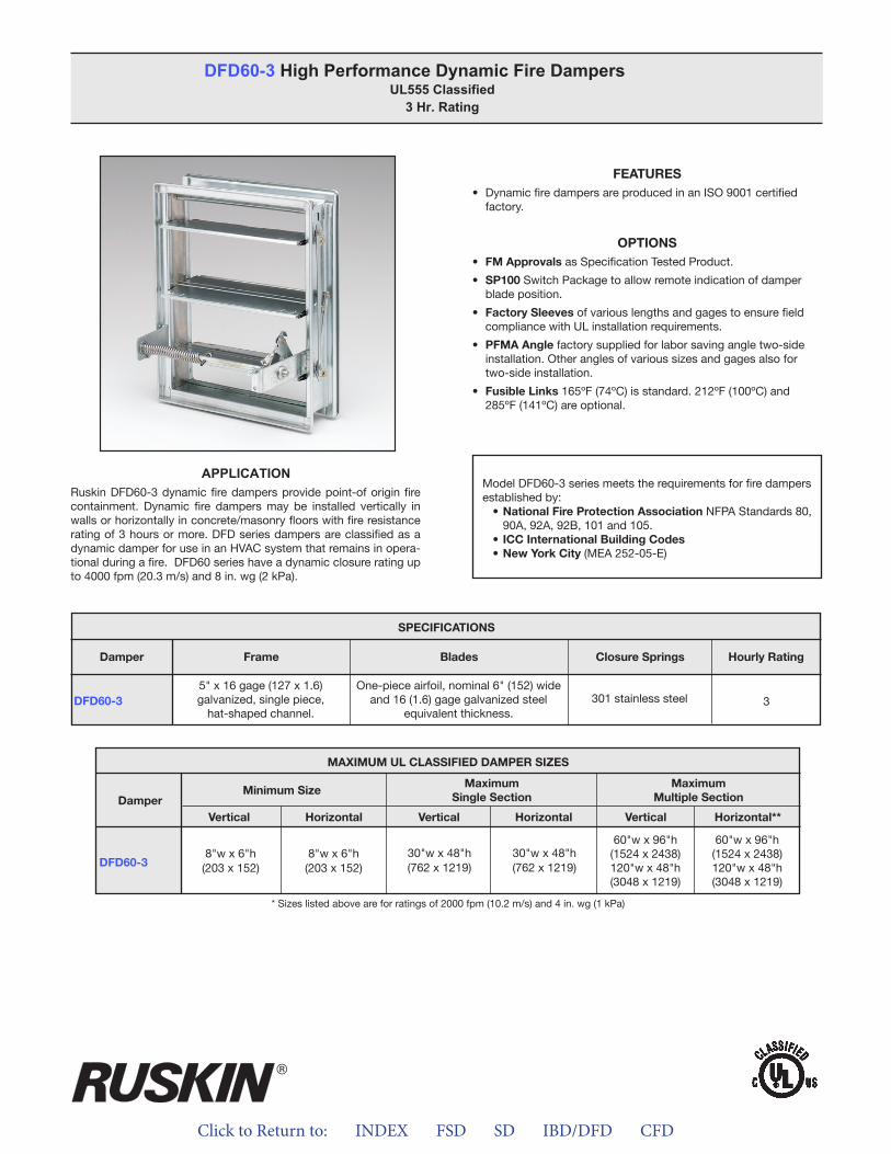
Click to Return to: INDEX FSD SD IBD/DFD CFD
FEATURES• DynamicfiredampersareproducedinanISO9001certified
factory.
OPTIONS• FM ApprovalsasSpecificationTestedProduct.
• SP100SwitchPackagetoallowremoteindicationofdamperbladeposition.
• Factory Sleeves ofvariouslengthsandgagestoensurefieldcompliancewithULinstallationrequirements.
• PFMA Anglefactorysuppliedforlaborsavingangletwo-sideinstallation.Otheranglesofvarioussizesandgagesalsofortwo-sideinstallation.
• Fusible Links165ºF(74ºC)isstandard.212ºF(100ºC)and285ºF(141ºC)areoptional.
DFD60-3 High Performance Dynamic Fire Dampers UL555 Classified
3 Hr. Rating
ModelDFD60-3seriesmeetstherequirementsforfiredampersestablishedby:• National Fire Protection AssociationNFPAStandards80,90A,92A,92B,101and105.
• ICC International Building Codes• New York City(MEA252-05-E)
APPLICATIONRuskinDFD60-3dynamicfiredampersprovidepoint-oforiginfirecontainment. Dynamic fire dampersmay be installed vertically inwallsorhorizontallyinconcrete/masonryfloorswithfireresistanceratingof3hoursormore.DFDseriesdampersareclassifiedasadynamicdamperforuseinanHVACsystemthatremainsinopera-tionalduringafire.DFD60serieshaveadynamicclosureratingupto4000fpm(20.3m/s)and8in.wg(2kPa).
DFD60-3
SPECIFICATIONS
Frame Blades Closure Springs Hourly RatingDamper
5"x16gage(127x1.6)galvanized,singlepiece,hat-shapedchannel.
One-pieceairfoil,nominal6"(152)wideand16(1.6)gagegalvanizedsteel
equivalentthickness.301stainlesssteel 3
MAXIMUM UL CLASSIFIED DAMPER SIZES
Damper
DFD60-3
MaximumSingle Section
Minimum SizeMaximum
Multiple Section
VerticalVertical VerticalHorizontalHorizontal Horizontal**
8"wx6"h(203x152)
8"wx6"h(203x152)
60"wx96"h(1524x2438)120"wx48"h(3048x1219)
60"wx96"h(1524x2438)120"wx48"h(3048x1219)
30"wx48"h(762x1219)
30"wx48"h(762x1219)
*Sizeslistedaboveareforratingsof2000fpm(10.2m/s)and4in.wg(1kPa)
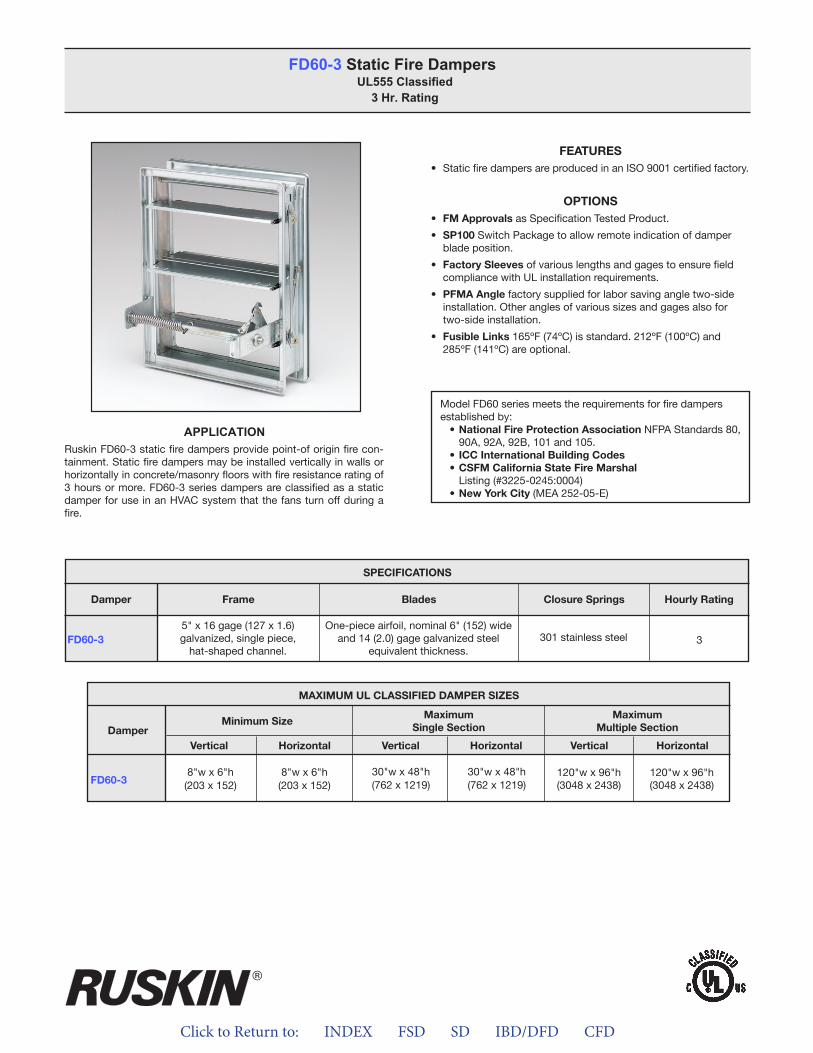
Click to Return to: INDEX FSD SD IBD/DFD CFD
FEATURES• StaticfiredampersareproducedinanISO9001certifiedfactory.
OPTIONS• FM ApprovalsasSpecificationTestedProduct.
• SP100SwitchPackagetoallowremoteindicationofdamperbladeposition.
• Factory SleevesofvariouslengthsandgagestoensurefieldcompliancewithULinstallationrequirements.
• PFMA Anglefactorysuppliedforlaborsavingangletwo-sideinstallation.Otheranglesofvarioussizesandgagesalsofortwo-sideinstallation.
• Fusible Links165ºF(74ºC)isstandard.212ºF(100ºC)and285ºF(141ºC)areoptional.
FD60-3 Static Fire DampersUL555 Classified
3 Hr. Rating
ModelFD60seriesmeetstherequirementsforfiredampersestablishedby:• National Fire Protection AssociationNFPAStandards80,90A,92A,92B,101and105.
• ICC International Building Codes• CSFM California State Fire MarshalListing(#3225-0245:0004)
• New York City(MEA252-05-E)
APPLICATIONRuskinFD60-3staticfiredampersprovidepoint-oforiginfirecon-tainment.Staticfiredampersmaybeinstalledverticallyinwallsorhorizontallyinconcrete/masonryfloorswithfireresistanceratingof3hoursormore.FD60-3seriesdampersareclassifiedasastaticdamperforuseinanHVACsystemthatthefansturnoffduringafire.
FD60-3
SPECIFICATIONS
Frame Blades Closure Springs Hourly RatingDamper
5"x16gage(127x1.6)galvanized,singlepiece,hat-shapedchannel.
One-pieceairfoil,nominal6"(152)wideand14(2.0)gagegalvanizedsteel
equivalentthickness.301stainlesssteel 3
MAXIMUM UL CLASSIFIED DAMPER SIZES
Damper
FD60-3
MaximumSingle Section
Minimum SizeMaximum
Multiple Section
VerticalVertical VerticalHorizontalHorizontal Horizontal
8"wx6"h(203x152)
8"wx6"h(203x152)
120"wx96"h(3048x2438)
120"wx96"h(3048x2438)
30"wx48"h(762x1219)
30"wx48"h(762x1219)
ALL STATED SPECIFICATIONS ARE SUBJECT TO CHANGE WITHOUT NOTICE OR OBLIGATION.
3900 Dr. Greaves Rd. • Kansas City, MO 64030 • (816) 761-7476 • FAX (816) 765-8955
INSTALLATION INSTRUCTIONSDFD60-3 AND FD60-3 FIRE RATED MULTIPLE BLADE DAMPER
3 HOUR UL555 RATING FOR USE IN DYNAMIC AND STATIC SYSTEMS
APPLICATIONThe DFD60-3 dynamic fire damper is designed for use in dynamic(fans on) or static (fans off) systems. The FD60-3 static firedampers are for use in static (fans off) systems only. Multiple bladefire dampers are designed to operate with the blades running hori-zontally. The standard application is with the leading edge of theclosed blades within the walls, partitions or masonry floors; with fireresistance rating of 3 hours or more.
DYNAMIC FIRE DAMPERSUse in Dynamic (fans on) or Static (fans off) Systems
DFD60-3 MAXIMUM UL CLASSIFIED SIZESSingle section vertical and horizontal installation
30"w x 48"h (762 x 1219)Multiple section assembly vertical and horizontal installation
60"w x 96"h (1524 x 2438) or 120"w x 48"h (3048 x 1219) or90”w x 64”h (2286 x 1626)
STATIC FIRE DAMPERSNot for use in Dynamic (fans on) Systems
FD60-3 MAXIMUM UL CLASSIFIED SIZESSingle section vertical and horizontal installation
30"w x 48"h (762 x 1219)Multiple section assembly vertical and horizontal installation
120"w x 96"h (3048 x 2438)
Dimensions shown in parentheses ( ) indicate millimeters.
California State Fire Marshal Listing No. (D)FD60-3 3225-245:0004
II-FD60-3-514/Replaces II-FD60-3-114 © Ruskin 2014
®
INSTALLATION SUPPLEMENTSRefer to the appropriate Ruskin installation instructions supple-ments for additional information or special requirements:• Optional Sealant of Dampers in Fire Rated Wall or Floor Openings• Transfer Openings and Duct Terminations• Optional FireStop Material• Extension of Fire and Combination Fire and Smoke Damper
Sleeves• Fire and Combination Fire and Smoke Damper Installation in
Concrete Floor with Steel Deck• Drivemate No. 14880 Breakaway Connection• Flanged System Breakaway Connections• Cavity Shaft Wall Metal Stud Framing• SP100 Switch Package
SEE COMPLETE MARKING ON PRODUCT
Click to Return to: INDEX FSD SD IBD/DFD CFD
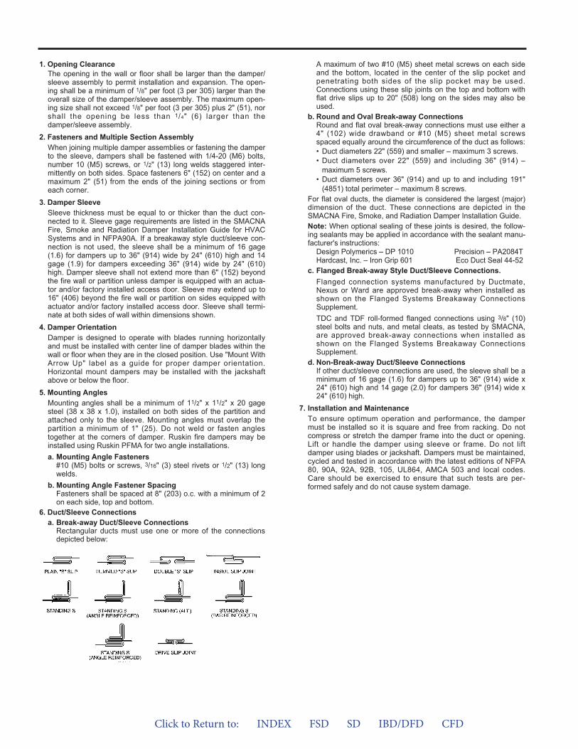
1. Opening ClearanceThe opening in the wall or floor shall be larger than the damper/sleeve assembly to permit installation and expansion. The open-ing shall be a minimum of 1/8" per foot (3 per 305) larger than theoverall size of the damper/sleeve assembly. The maximum open-ing size shall not exceed 1/8" per foot (3 per 305) plus 2" (51), norshall the opening be less than 1/4" (6) larger than thedamper/sleeve assembly.
2. Fasteners and Multiple Section AssemblyWhen joining multiple damper assemblies or fastening the damperto the sleeve, dampers shall be fastened with 1/4-20 (M6) bolts,number 10 (M5) screws, or 1/2" (13) long welds staggered inter-mittently on both sides. Space fasteners 6" (152) on center and amaximum 2" (51) from the ends of the joining sections or fromeach corner.
3. Damper SleeveSleeve thickness must be equal to or thicker than the duct con-nected to it. Sleeve gage requirements are listed in the SMACNAFire, Smoke and Radiation Damper Installation Guide for HVACSystems and in NFPA90A. If a breakaway style duct/sleeve con-nection is not used, the sleeve shall be a minimum of 16 gage(1.6) for dampers up to 36" (914) wide by 24" (610) high and 14gage (1.9) for dampers exceeding 36" (914) wide by 24" (610)high. Damper sleeve shall not extend more than 6" (152) beyondthe fire wall or partition unless damper is equipped with an actua-tor and/or factory installed access door. Sleeve may extend up to16" (406) beyond the fire wall or partition on sides equipped withactuator and/or factory installed access door. Sleeve shall termi-nate at both sides of wall within dimensions shown.
4. Damper OrientationDamper is designed to operate with blades running horizontallyand must be installed with center line of damper blades within thewall or floor when they are in the closed position. Use "Mount WithArrow Up" label as a guide for proper damper orientation.Horizontal mount dampers may be installed with the jackshaftabove or below the floor.
5. Mounting AnglesMounting angles shall be a minimum of 11/2" x 11/2" x 20 gagesteel (38 x 38 x 1.0), installed on both sides of the partition andattached only to the sleeve. Mounting angles must overlap thepartition a minimum of 1" (25). Do not weld or fasten anglestogether at the corners of damper. Ruskin fire dampers may beinstalled using Ruskin PFMA for two angle installations.a. Mounting Angle Fasteners
#10 (M5) bolts or screws, 3/16" (3) steel rivets or 1/2" (13) longwelds.
b. Mounting Angle Fastener SpacingFasteners shall be spaced at 8" (203) o.c. with a minimum of 2on each side, top and bottom.
6. Duct/Sleeve Connectionsa. Break-away Duct/Sleeve Connections
Rectangular ducts must use one or more of the connectionsdepicted below:
A maximum of two #10 (M5) sheet metal screws on each sideand the bottom, located in the center of the slip pocket andpenetrating both sides of the slip pocket may be used.Connections using these slip joints on the top and bottom withflat drive slips up to 20" (508) long on the sides may also beused.
b. Round and Oval Break-away ConnectionsRound and flat oval break-away connections must use either a4" (102) wide drawband or #10 (M5) sheet metal screwsspaced equally around the circumference of the duct as follows:• Duct diameters 22" (559) and smaller – maximum 3 screws.• Duct diameters over 22" (559) and including 36" (914) –
maximum 5 screws.• Duct diameters over 36" (914) and up to and including 191"
(4851) total perimeter – maximum 8 screws.For flat oval ducts, the diameter is considered the largest (major)dimension of the duct. These connections are depicted in theSMACNA Fire, Smoke, and Radiation Damper Installation Guide.Note: When optional sealing of these joints is desired, the follow-ing sealants may be applied in accordance with the sealant manu-facturer's instructions:
Design Polymerics – DP 1010 Precision – PA2084THardcast, Inc. – Iron Grip 601 Eco Duct Seal 44-52
c. Flanged Break-away Style Duct/Sleeve Connections.Flanged connection systems manufactured by Ductmate,Nexus or Ward are approved break-away when installed asshown on the Flanged Systems Breakaway ConnectionsSupplement.TDC and TDF roll-formed flanged connections using 3/8" (10)steel bolts and nuts, and metal cleats, as tested by SMACNA,are approved break-away connections when installed asshown on the Flanged Systems Breakaway ConnectionsSupplement.
d. Non-Break-away Duct/Sleeve ConnectionsIf other duct/sleeve connections are used, the sleeve shall be aminimum of 16 gage (1.6) for dampers up to 36" (914) wide x24" (610) high and 14 gage (2.0) for dampers 36" (914) wide x24" (610) high.
7. Installation and MaintenanceTo ensure optimum operation and performance, the dampermust be installed so it is square and free from racking. Do notcompress or stretch the damper frame into the duct or opening.Lift or handle the damper using sleeve or frame. Do not liftdamper using blades or jackshaft. Dampers must be maintained,cycled and tested in accordance with the latest editions of NFPA80, 90A, 92A, 92B, 105, UL864, AMCA 503 and local codes.Care should be exercised to ensure that such tests are per-formed safely and do not cause system damage.
Click to Return to: INDEX FSD SD IBD/DFD CFD
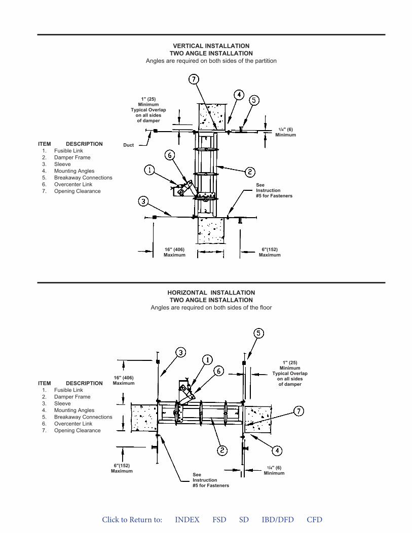
VERTICAL INSTALLATIONTWO ANGLE INSTALLATION
Angles are required on both sides of the partition
1" (25)Minimum
Typical Overlapon all sidesof damper
1/4" (6)Minimum
16" (406)Maximum
6"(152)Maximum
ITEM DESCRIPTION1. Fusible Link2. Damper Frame3. Sleeve4. Mounting Angles5. Breakaway Connections6. Overcenter Link7. Opening Clearance
ITEM DESCRIPTION1. Fusible Link2. Damper Frame3. Sleeve4. Mounting Angles5. Breakaway Connections6. Overcenter Link7. Opening Clearance
HORIZONTAL INSTALLATIONTWO ANGLE INSTALLATION
Angles are required on both sides of the floor
Duct
SeeInstruction#5 for Fasteners
1" (25)Minimum
Typical Overlapon all sidesof damper
1/4" (6)Minimum
16" (406)Maximum
6"(152)Maximum
SeeInstruction#5 for Fasteners
Click to Return to: INDEX FSD SD IBD/DFD CFD
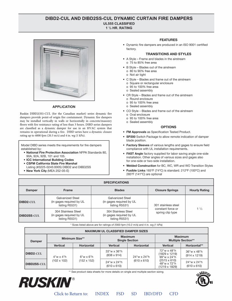
Click to Return to: INDEX FSD SD IBD/DFD CFD
APPLICATION
DIBD2-CUL AND DIBD2SS-CUL DYNAMIC CURTAIN FIRE DAMPERS UL555 CLASSIFIED
1 ½ HR. RATING
-CUL
-CUL
-CUL
-CUL
Ruskin DIBD2(SS)-CUL (for the Canadian market) series dynamic fire dampers provide point-of origin fire containment. Dynamic fire dampers may be installed vertically in walls or horizontally in concrete/masonry floors with fire resistance rating of less than 3 hours. DIBD series dampers are classified as a dynamic damper for use in an HVAC system that remains in operational during a fire. DIBD series have a dynamic closure rating up to 4000 fpm (20.3 m/s) and 4 in. wg (1 kPa).
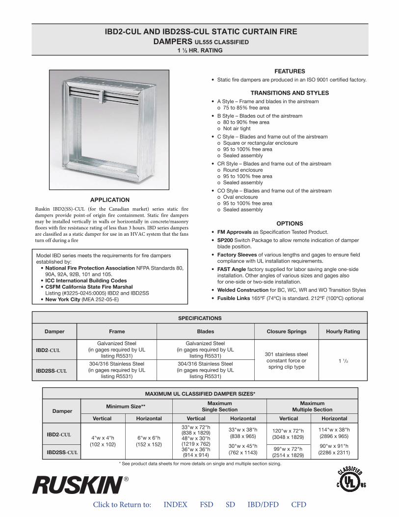
Click to Return to: INDEX FSD SD IBD/DFD CFD
APPLICATION
IBD2-CUL AND IBD2SS-CUL STATIC CURTAIN FIRE DAMPERS UL555 CLASSIFIED
1 ½ HR. RATING
-CUL
-CUL
-CUL
-CUL
Ruskin IBD2(SS)-CUL (for the Canadian market) series static fire dampers provide point-of origin fire containment. Static fire dampers may be installed vertically in walls or horizontally in concrete/masonry floors with fire resistance rating of less than 3 hours. IBD series dampers are classified as a static damper for use in an HVAC system that the fans turn off during a fire
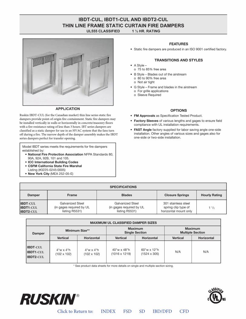
Click to Return to: INDEX FSD SD IBD/DFD CFD
APPLICATION
IBDT-CUL, IBDT1-CUL AND IBDT2-CULTHIN LINE FRAME STATIC CURTAIN FIRE DAMPERS
UL555 CLASSIFIED 1 ½ HR. RATING
-CUL-CUL-CUL
-CUL-CUL-CUL
Ruskin IBDT-CUL (for the Canadian market) thin line series static fire dampers provide point-of origin fire containment. Static fire dampers may be installed vertically in walls or horizontally in concrete/masonry floors with a fire resistance rating of less than 3 hours. IBT series dampers are classified as a static damper for use in an HVAC system that the fans turn off during a fire. The narrow depth of the damper assembly makes the IBDT series dampers perfect for transfer opening.
ALL STATED SPECIFICATIONS ARE SUBJECT TO CHANGE WITHOUT NOTICE OR OBLIGATION.
3900 Dr. Greaves Rd. • Kansas City, MO 64030 • (816) 761-7476 • FAX (816) 765-8955
INSTALLATION INSTRUCTIONS11/2 HOUR UL CLASSIFIED
CURTAIN TYPE (D)IBD2-CUL, (D)IBD2SS-CUL AND IBDT-CUL FIRE DAMPERS
APPLICATIONThe fire damper models shown on this sheet are marked with a11/2 hour fire damper label and are approved for use in fire walls ormasonry floors with ratings of less than 3 hours. Fire Dampersrequire a field-or factory-installed sleeve. Select a sleeve of suffi-cient length to permit mounting angles attachment. Static andDynamic dampers must be installed with leading edge of theclosed blades within the wall or floor.
STATIC FIRE DAMPERS – IBD modelsNot for use in Dynamic (fans on) Systems.
MODEL IBD2-CUL MAXIMUM SIZESingle Section
Vertical Installation – 48"w x 30"h or 33"w x 72"h (1219 x 762 or 838 x 1829) or 36"w x 36"h (914 x 914).
Horizontal Installation – 30"w x 451/2"h (762 x 1156) or 33"wx 38"h (838 x 965).
Multiple Section AssemblyVertical Installation – 120"w x 72"h (3048 x 1829).Horizontal Installation – 90"w x 91"h (2286 x 2311) or 114"w x
38"h (2896 x 965). MODEL IBD2SS-CUL MAXIMUM SIZE
Single SectionVertical Installation – 48"w x 30"h or 33"w x 72"h (1219 x
762 or 838 x 1829) or 36"w x 36"h (914 x 914).Horizontal Installation – 30"w x 451/2"h (762 x 1156) or 33"w
x 38"h (838 x 965).Multiple Section Assembly
Vertical Installation – 99"w x 72"h (2515 x 1829).Horizontal Installation – 90"w x 91"h (2286 x 2311) or 114"w x
38"h (2896 x 965). MODEL IBDT-CUL, IBDT1-CUL and IBDT2-CUL MAXIMUM SIZE
Single SectionVertical Installation – 40"w x 48"h (1016 x 1219).Horizontal Installation – 60"w x 12"h (1524 x 305).
DYNAMIC FIRE DAMPERSUse in Dynamic (fans on) or Static (fans off) Systems
MODEL DIBD2-CUL MAXIMUM SIZESingle Section
Vertical Installation – 33"w x 36"h (838 x 914).Horizontal Installation – 24"w x 24"h (610 x 610).
Multiple Section AssemblyVertical Installation – 72"w x 48"h (1828 x 1219) or 48"w x
72"h (1219 x 1828) or 120"w x 24"h (3048 x 610).MODEL DIBD2X-CUL MAXIMUM SIZE
Single SectionVertical Installation – 18"w x 24"h (457 x 610).Horizontal Installation – 18"w x 24"h (457 x 610) or 24"w x
18" h (610 x 457).Multiple Section Assembly
Horizontal Installation – 36"w x 48"h (914 x 1219) or 48"w x 36"h (1219 x 914).
MODEL DIBD2SS-CUL MAXIMUM SIZESingle Section
Vertical or Horizontal Installation – 24"w x 24"h (610 x 610).Multiple Section Assembly
Vertical Installation – 72"w x 48"h (1828 x 1219) or 48"w x72"h (1219 x 1828) or 90”w x 24”h (2286 x 610).
II-IBD-CUL-714/New © Ruskin 2014
®
INSTALLATION SUPPLEMENTSRefer to the appropriate Ruskin installation instruction supplementsfor additional information or special requirements:• Optional Sealant of Dampers in Fire Rated Wall or Floor
Openings• Transfer Openings and Duct Terminations• Optional FireStop Material• Extension of Fire and Combination Fire and Smoke Damper
Sleeves• Fire and Combination Fire/Smoke Dampers Installation in
Concrete Floor with Steel Deck• Drivemate No. 14880 Breakaway Connection• Flanged System Breakaway Connections• Mullions for Dampers in Oversized Concrete Wall Openings
Notes:1. Dimensions shown in parentheses ( ) indicate millimeters.2. All multiple section dampers are constructed of equal single
section sizes no greater than the maximum single section sizesindicated above.
California State Fire Marshal Listing No. 3225-245:005
SEE COMPLETE MARKING ON PRODUCT
Click to Return to: INDEX FSD SD IBD/DFD CFD
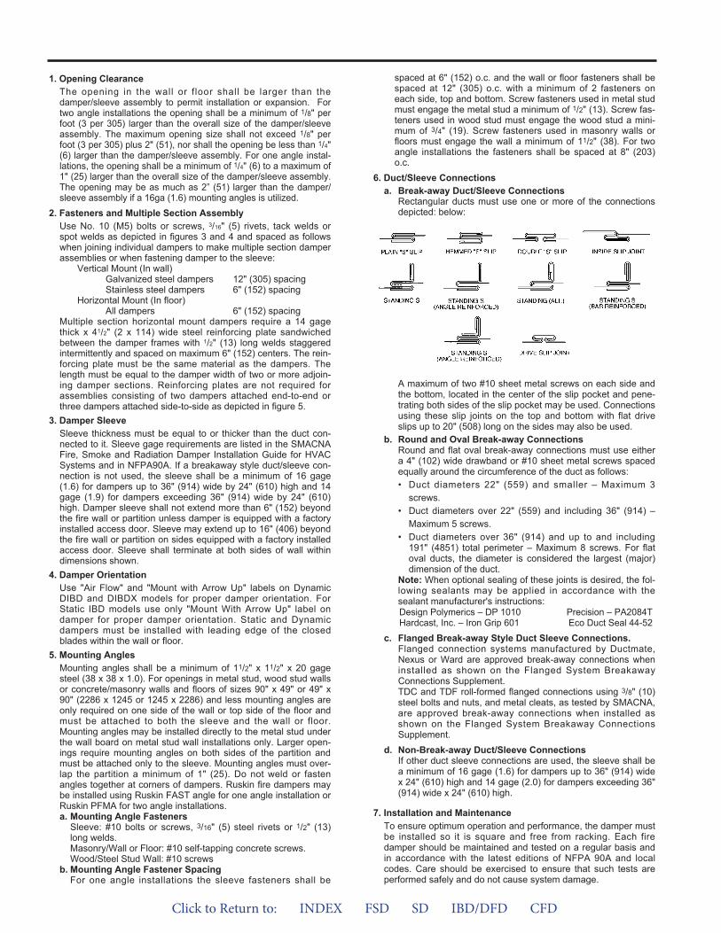
1. Opening ClearanceThe opening in the wall or f loor shall be larger than thedamper/sleeve assembly to permit installation or expansion. Fortwo angle installations the opening shall be a minimum of 1/8" perfoot (3 per 305) larger than the overall size of the damper/sleeveassembly. The maximum opening size shall not exceed 1/8" perfoot (3 per 305) plus 2" (51), nor shall the opening be less than 1/4"(6) larger than the damper/sleeve assembly. For one angle instal-lations, the opening shall be a minimum of 1/4" (6) to a maximum of1" (25) larger than the overall size of the damper/sleeve assembly.The opening may be as much as 2” (51) larger than the damper/sleeve assembly if a 16ga (1.6) mounting angles is utilized.
2. Fasteners and Multiple Section AssemblyUse No. 10 (M5) bolts or screws, 3/16" (5) rivets, tack welds orspot welds as depicted in figures 3 and 4 and spaced as followswhen joining individual dampers to make multiple section damperassemblies or when fastening damper to the sleeve:
Vertical Mount (In wall)Galvanized steel dampers 12" (305) spacing Stainless steel dampers 6" (152) spacing
Horizontal Mount (In floor)All dampers 6" (152) spacing
Multiple section horizontal mount dampers require a 14 gagethick x 41/2" (2 x 114) wide steel reinforcing plate sandwichedbetween the damper frames with 1/2" (13) long welds staggeredintermittently and spaced on maximum 6" (152) centers. The rein-forcing plate must be the same material as the dampers. Thelength must be equal to the damper width of two or more adjoin-ing damper sections. Reinforcing plates are not required forassemblies consisting of two dampers attached end-to-end orthree dampers attached side-to-side as depicted in figure 5.
3. Damper SleeveSleeve thickness must be equal to or thicker than the duct con-nected to it. Sleeve gage requirements are listed in the SMACNAFire, Smoke and Radiation Damper Installation Guide for HVACSystems and in NFPA90A. If a breakaway style duct/sleeve con-nection is not used, the sleeve shall be a minimum of 16 gage(1.6) for dampers up to 36" (914) wide by 24" (610) high and 14gage (1.9) for dampers exceeding 36" (914) wide by 24" (610)high. Damper sleeve shall not extend more than 6" (152) beyondthe fire wall or partition unless damper is equipped with a factoryinstalled access door. Sleeve may extend up to 16" (406) beyondthe fire wall or partition on sides equipped with a factory installedaccess door. Sleeve shall terminate at both sides of wall withindimensions shown.
4. Damper OrientationUse "Air Flow" and "Mount with Arrow Up" labels on DynamicDIBD and DIBDX models for proper damper orientation. ForStatic IBD models use only "Mount With Arrow Up" label ondamper for proper damper orientation. Static and Dynamicdampers must be installed with leading edge of the closedblades within the wall or floor.
5. Mounting AnglesMounting angles shall be a minimum of 11/2" x 11/2" x 20 gagesteel (38 x 38 x 1.0). For openings in metal stud, wood stud wallsor concrete/masonry walls and floors of sizes 90" x 49" or 49" x90" (2286 x 1245 or 1245 x 2286) and less mounting angles areonly required on one side of the wall or top side of the floor andmust be attached to both the sleeve and the wall or floor.Mounting angles may be installed directly to the metal stud underthe wall board on metal stud wall installations only. Larger open-ings require mounting angles on both sides of the partition andmust be attached only to the sleeve. Mounting angles must over-lap the partition a minimum of 1" (25). Do not weld or fastenangles together at corners of dampers. Ruskin fire dampers maybe installed using Ruskin FAST angle for one angle installation orRuskin PFMA for two angle installations.a. Mounting Angle Fasteners
Sleeve: #10 bolts or screws, 3/16" (5) steel rivets or 1/2" (13)long welds.Masonry/Wall or Floor: #10 self-tapping concrete screws.Wood/Steel Stud Wall: #10 screws
b. Mounting Angle Fastener SpacingFor one angle installations the sleeve fasteners shall be
spaced at 6" (152) o.c. and the wall or floor fasteners shall bespaced at 12" (305) o.c. with a minimum of 2 fasteners oneach side, top and bottom. Screw fasteners used in metal studmust engage the metal stud a minimum of 1/2" (13). Screw fas-teners used in wood stud must engage the wood stud a mini-mum of 3/4" (19). Screw fasteners used in masonry walls orfloors must engage the wall a minimum of 11/2" (38). For twoangle installations the fasteners shall be spaced at 8" (203)o.c.
6. Duct/Sleeve Connectionsa. Break-away Duct/Sleeve Connections
Rectangular ducts must use one or more of the connectionsdepicted: below:
A maximum of two #10 sheet metal screws on each side andthe bottom, located in the center of the slip pocket and pene-trating both sides of the slip pocket may be used. Connectionsusing these slip joints on the top and bottom with flat driveslips up to 20" (508) long on the sides may also be used.
b. Round and Oval Break-away ConnectionsRound and flat oval break-away connections must use eithera 4" (102) wide drawband or #10 sheet metal screws spacedequally around the circumference of the duct as follows:• Duct diameters 22" (559) and smaller – Maximum 3
screws.• Duct diameters over 22" (559) and including 36" (914) –
Maximum 5 screws.• Duct diameters over 36" (914) and up to and including
191" (4851) total perimeter – Maximum 8 screws. For flatoval ducts, the diameter is considered the largest (major)dimension of the duct.
Note: When optional sealing of these joints is desired, the fol-lowing sealants may be applied in accordance with thesealant manufacturer's instructions:Design Polymerics – DP 1010 Precision – PA2084THardcast, Inc. – Iron Grip 601 Eco Duct Seal 44-52
c. Flanged Break-away Style Duct Sleeve Connections.Flanged connection systems manufactured by Ductmate,Nexus or Ward are approved break-away connections wheninstalled as shown on the Flanged System BreakawayConnections Supplement.TDC and TDF roll-formed flanged connections using 3/8" (10)steel bolts and nuts, and metal cleats, as tested by SMACNA,are approved break-away connections when installed asshown on the Flanged System Breakaway ConnectionsSupplement.
d. Non-Break-away Duct/Sleeve ConnectionsIf other duct sleeve connections are used, the sleeve shall bea minimum of 16 gage (1.6) for dampers up to 36" (914) widex 24" (610) high and 14 gage (2.0) for dampers exceeding 36"(914) wide x 24" (610) high.
7. Installation and MaintenanceTo ensure optimum operation and performance, the damper mustbe installed so it is square and free from racking. Each firedamper should be maintained and tested on a regular basis andin accordance with the latest editions of NFPA 90A and localcodes. Care should be exercised to ensure that such tests areperformed safely and do not cause system damage.
Click to Return to: INDEX FSD SD IBD/DFD CFD
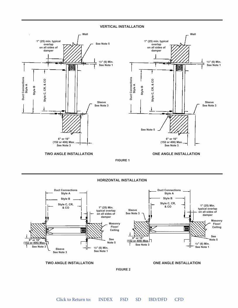
VERTICAL INSTALLATION
HORIZONTAL INSTALLATION
FIGURE 1
6" or 16"(152 or 406) Max.
See Note 3
Duc
t Con
nect
ions
Styl
e A
Styl
e B
Styl
e C
, CR
, & C
O1" (25) min. typical
overlapon all sides of
damper
See Note 5
Wall
SleeveSee Note 3
1/4" (6) Min.See Note 1
6" or 16"(152 or 406) Max.
See Note 3
Duc
t Con
nect
ions
Styl
e A
Styl
e B
Styl
e C
, CR
, & C
O
1" (25) min. typicaloverlap
on all sides ofdamper
Wall
SleeveSee Note 3
1/4" (6) Min.See Note 1
See Note 5
TWO ANGLE INSTALLATION ONE ANGLE INSTALLATION
6" or 16"(152 or 406) Max.
See Note 3
Duct ConnectionsStyle A
Style B
Style C, CR,& CO
SleeveSee Note 3
SeeNote 5
1/4" (6) Min.See Note 1
MasonryFloor/
Ceiling
1" (25) Min.typical overlapon all sides of
damper
6" or 16"(152 or 406) Max.
See Note 3
Duct ConnectionsStyle A
Style B
Style C, CR,& CO
SleeveSee Note 3
SeeNote 5
1/4" (6) Min.See Note 1
MasonryFloor/Ceiling
1" (25) Min.typical overlapon all sides of
damper
FIGURE 2
TWO ANGLE INSTALLATION ONE ANGLE INSTALLATION
Click to Return to: INDEX FSD SD IBD/DFD CFD
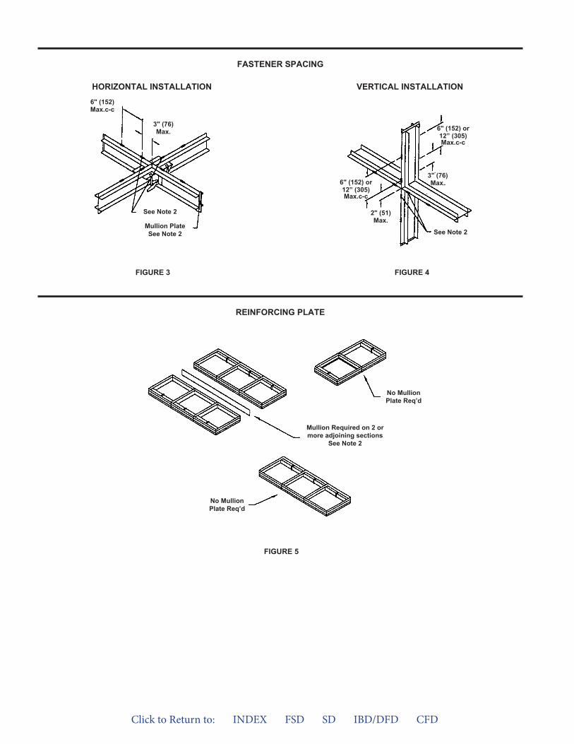
FIGURE 5
FASTENER SPACING
REINFORCING PLATE
VERTICAL INSTALLATIONHORIZONTAL INSTALLATION
FIGURE 4FIGURE 3
See Note 2
Mullion PlateSee Note 2
6" (152)Max.c-c
3" (76)Max.
See Note 2
6" (152) or12” (305)Max.c-c
2" (51)Max.
6" (152) or12” (305)Max.c-c
3" (76)Max.
No MullionPlate Req’d
No MullionPlate Req’d
Mullion Required on 2 ormore adjoining sections
See Note 2
Click to Return to: INDEX FSD SD IBD/DFD CFD
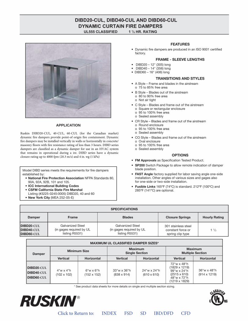
Click to Return to: INDEX FSD SD IBD/DFD CFD
APPLICATION
-CUL-CUL-CUL
-CUL-CUL-CUL
DIBD20-CUL, DIBD40 -CUL AND DIBD60-CULDYNAMIC CURTAIN FIRE DAMPERS
UL555 CLASSIFIED 1 ½ HR. RATING
Ruskin DIBD20-CUL, 40-CUL, 60-CUL (for the Canadian market) dynamic fire dampers provide point-of origin fire containment. Dynamic fire dampers may be installed vertically in walls or horizontally in concrete/masonry floors with fire resistance rating of less than 3 hours. DIBD series dampers are classified as a dynamic damper for use in an HVAC system that remains in operational during a ire. DIBD series have a dynamic closure rating up to 4000 fpm (20.3 m/s) and 4 in. wg (1 kPa)
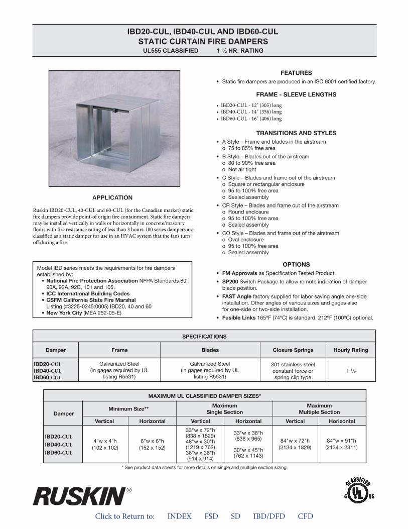
Click to Return to: INDEX FSD SD IBD/DFD CFD
APPLICATION
-CUL-CUL-CUL
-CUL-CUL-CUL
IBD20-CUL, IBD40-CUL AND IBD60-CULSTATIC CURTAIN FIRE DAMPERS
UL555 CLASSIFIED 1 ½ HR. RATING
Ruskin IBD20-CUL, 40-CUL and 60-CUL (for the Canadian market) static fire dampers provide point-of origin fire containment. Static fire dampers may be installed vertically in walls or horizontally in concrete/masonry floors with fire resistance rating of less than 3 hours. I80 series dampers are classified as a static damper for use in an HVAC system that the fans turn off during a fire.
• IBD20-CUL - 12" (305) long• IBD40-CUL - 14" (356) long• IBD60-CUL - 16" (406) long
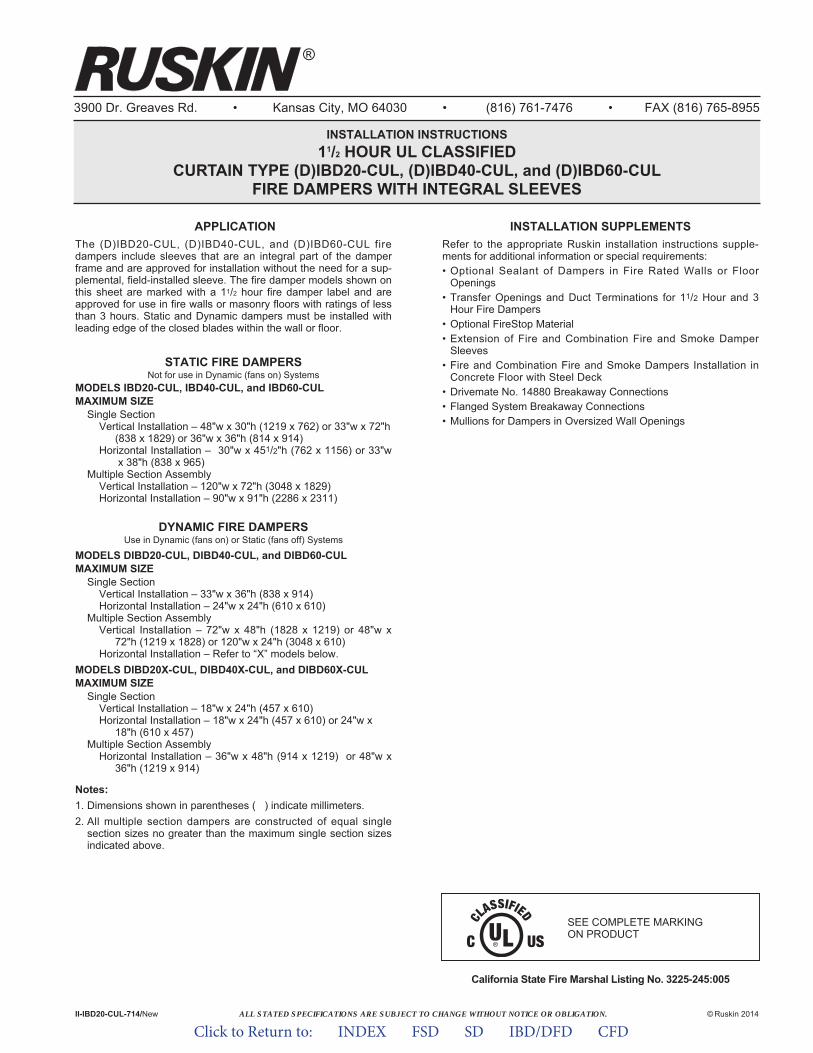
ALL STATED SPECIFICATIONS ARE SUBJECT TO CHANGE WITHOUT NOTICE OR OBLIGATION.
3900 Dr. Greaves Rd. • Kansas City, MO 64030 • (816) 761-7476 • FAX (816) 765-8955
INSTALLATION INSTRUCTIONS11/2 HOUR UL CLASSIFIED
CURTAIN TYPE (D)IBD20-CUL, (D)IBD40-CUL, and (D)IBD60-CULFIRE DAMPERS WITH INTEGRAL SLEEVES
APPLICATIONThe (D)IBD20-CUL, (D)IBD40-CUL, and (D)IBD60-CUL firedampers include sleeves that are an integral part of the damperframe and are approved for installation without the need for a sup-plemental, field-installed sleeve. The fire damper models shown onthis sheet are marked with a 11/2 hour fire damper label and areapproved for use in fire walls or masonry floors with ratings of lessthan 3 hours. Static and Dynamic dampers must be installed withleading edge of the closed blades within the wall or floor.
STATIC FIRE DAMPERSNot for use in Dynamic (fans on) Systems
MODELS IBD20-CUL, IBD40-CUL, and IBD60-CUL MAXIMUM SIZE
Single SectionVertical Installation – 48"w x 30"h (1219 x 762) or 33"w x 72"h
(838 x 1829) or 36"w x 36"h (814 x 914)Horizontal Installation – 30"w x 451/2"h (762 x 1156) or 33"w
x 38"h (838 x 965)Multiple Section Assembly
Vertical Installation – 120"w x 72"h (3048 x 1829)Horizontal Installation – 90"w x 91"h (2286 x 2311)
DYNAMIC FIRE DAMPERSUse in Dynamic (fans on) or Static (fans off) Systems
MODELS DIBD20-CUL, DIBD40-CUL, and DIBD60-CUL MAXIMUM SIZE
Single SectionVertical Installation – 33"w x 36"h (838 x 914)Horizontal Installation – 24"w x 24"h (610 x 610)
Multiple Section AssemblyVertical Installation – 72"w x 48"h (1828 x 1219) or 48"w x
72"h (1219 x 1828) or 120"w x 24"h (3048 x 610)Horizontal Installation – Refer to “X” models below.
MODELS DIBD20X-CUL, DIBD40X-CUL, and DIBD60X-CUL MAXIMUM SIZE
Single SectionVertical Installation – 18"w x 24"h (457 x 610)Horizontal Installation – 18"w x 24"h (457 x 610) or 24"w x
18"h (610 x 457)Multiple Section Assembly
Horizontal Installation – 36"w x 48"h (914 x 1219) or 48"w x 36"h (1219 x 914)
Notes:1. Dimensions shown in parentheses ( ) indicate millimeters.2. All multiple section dampers are constructed of equal single
section sizes no greater than the maximum single section sizesindicated above.
California State Fire Marshal Listing No. 3225-245:005
II-IBD20-CUL-714/New © Ruskin 2014
®
INSTALLATION SUPPLEMENTSRefer to the appropriate Ruskin installation instructions supple-ments for additional information or special requirements:• Optional Sealant of Dampers in Fire Rated Walls or Floor
Openings• Transfer Openings and Duct Terminations for 11/2 Hour and 3
Hour Fire Dampers• Optional FireStop Material• Extension of Fire and Combination Fire and Smoke Damper
Sleeves• Fire and Combination Fire and Smoke Dampers Installation in
Concrete Floor with Steel Deck• Drivemate No. 14880 Breakaway Connections• Flanged System Breakaway Connections• Mullions for Dampers in Oversized Wall Openings
SEE COMPLETE MARKING ON PRODUCT
Click to Return to: INDEX FSD SD IBD/DFD CFD
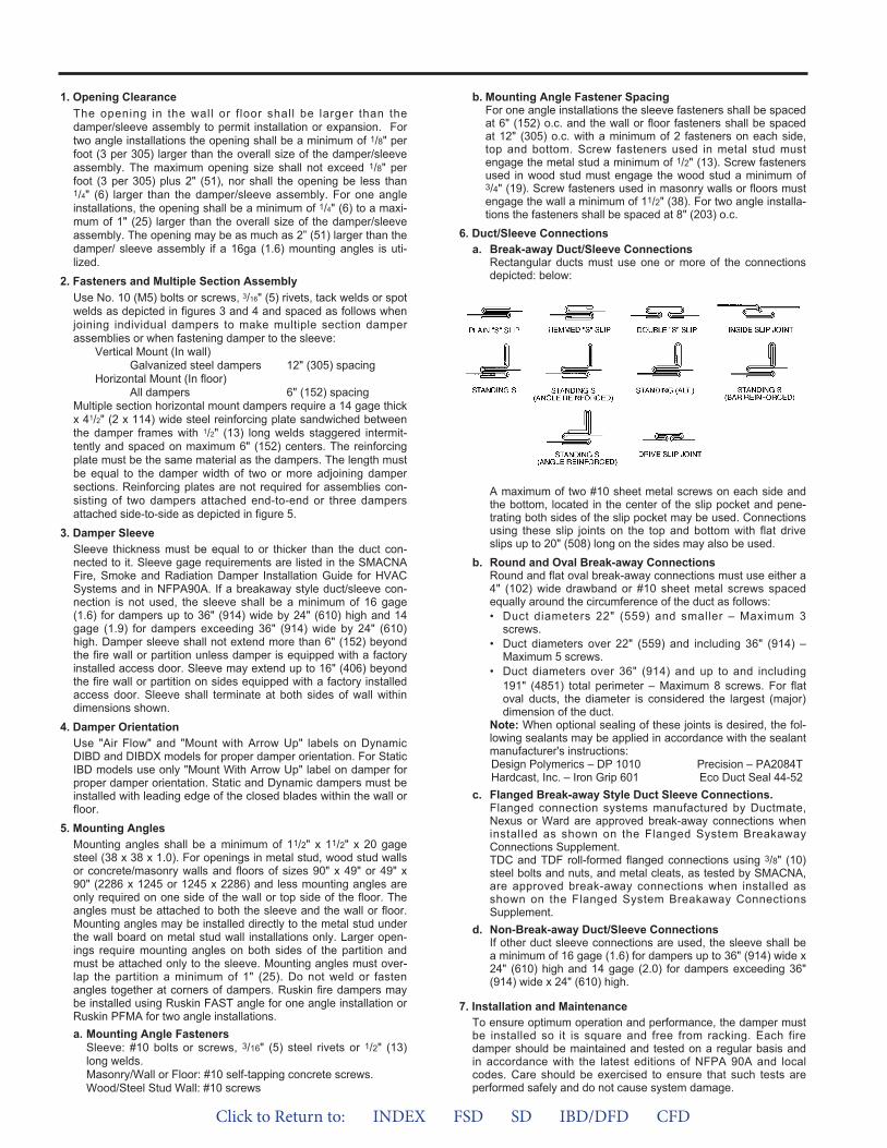
1. Opening ClearanceThe opening in the wall or f loor shall be larger than thedamper/sleeve assembly to permit installation or expansion. Fortwo angle installations the opening shall be a minimum of 1/8" perfoot (3 per 305) larger than the overall size of the damper/sleeveassembly. The maximum opening size shall not exceed 1/8" perfoot (3 per 305) plus 2" (51), nor shall the opening be less than1/4" (6) larger than the damper/sleeve assembly. For one angleinstallations, the opening shall be a minimum of 1/4" (6) to a maxi-mum of 1" (25) larger than the overall size of the damper/sleeveassembly. The opening may be as much as 2” (51) larger than thedamper/ sleeve assembly if a 16ga (1.6) mounting angles is uti-lized.
2. Fasteners and Multiple Section AssemblyUse No. 10 (M5) bolts or screws, 3/16" (5) rivets, tack welds or spotwelds as depicted in figures 3 and 4 and spaced as follows whenjoining individual dampers to make multiple section damperassemblies or when fastening damper to the sleeve:
Vertical Mount (In wall)Galvanized steel dampers 12" (305) spacing
Horizontal Mount (In floor)All dampers 6" (152) spacing
Multiple section horizontal mount dampers require a 14 gage thickx 41/2" (2 x 114) wide steel reinforcing plate sandwiched betweenthe damper frames with 1/2" (13) long welds staggered intermit-tently and spaced on maximum 6" (152) centers. The reinforcingplate must be the same material as the dampers. The length mustbe equal to the damper width of two or more adjoining dampersections. Reinforcing plates are not required for assemblies con-sisting of two dampers attached end-to-end or three dampersattached side-to-side as depicted in figure 5.
3. Damper SleeveSleeve thickness must be equal to or thicker than the duct con-nected to it. Sleeve gage requirements are listed in the SMACNAFire, Smoke and Radiation Damper Installation Guide for HVACSystems and in NFPA90A. If a breakaway style duct/sleeve con-nection is not used, the sleeve shall be a minimum of 16 gage(1.6) for dampers up to 36" (914) wide by 24" (610) high and 14gage (1.9) for dampers exceeding 36" (914) wide by 24" (610)high. Damper sleeve shall not extend more than 6" (152) beyondthe fire wall or partition unless damper is equipped with a factoryinstalled access door. Sleeve may extend up to 16" (406) beyondthe fire wall or partition on sides equipped with a factory installedaccess door. Sleeve shall terminate at both sides of wall withindimensions shown.
4. Damper OrientationUse "Air Flow" and "Mount with Arrow Up" labels on DynamicDIBD and DIBDX models for proper damper orientation. For StaticIBD models use only "Mount With Arrow Up" label on damper forproper damper orientation. Static and Dynamic dampers must beinstalled with leading edge of the closed blades within the wall orfloor.
5. Mounting AnglesMounting angles shall be a minimum of 11/2" x 11/2" x 20 gagesteel (38 x 38 x 1.0). For openings in metal stud, wood stud wallsor concrete/masonry walls and floors of sizes 90" x 49" or 49" x90" (2286 x 1245 or 1245 x 2286) and less mounting angles areonly required on one side of the wall or top side of the floor. Theangles must be attached to both the sleeve and the wall or floor.Mounting angles may be installed directly to the metal stud underthe wall board on metal stud wall installations only. Larger open-ings require mounting angles on both sides of the partition andmust be attached only to the sleeve. Mounting angles must over-lap the partition a minimum of 1" (25). Do not weld or fastenangles together at corners of dampers. Ruskin fire dampers maybe installed using Ruskin FAST angle for one angle installation orRuskin PFMA for two angle installations.a. Mounting Angle Fasteners
Sleeve: #10 bolts or screws, 3/16" (5) steel rivets or 1/2" (13)long welds.Masonry/Wall or Floor: #10 self-tapping concrete screws.Wood/Steel Stud Wall: #10 screws
b. Mounting Angle Fastener SpacingFor one angle installations the sleeve fasteners shall be spacedat 6" (152) o.c. and the wall or floor fasteners shall be spacedat 12" (305) o.c. with a minimum of 2 fasteners on each side,top and bottom. Screw fasteners used in metal stud mustengage the metal stud a minimum of 1/2" (13). Screw fastenersused in wood stud must engage the wood stud a minimum of3/4" (19). Screw fasteners used in masonry walls or floors mustengage the wall a minimum of 11/2" (38). For two angle installa-tions the fasteners shall be spaced at 8" (203) o.c.
6. Duct/Sleeve Connectionsa. Break-away Duct/Sleeve Connections
Rectangular ducts must use one or more of the connectionsdepicted: below:
A maximum of two #10 sheet metal screws on each side andthe bottom, located in the center of the slip pocket and pene-trating both sides of the slip pocket may be used. Connectionsusing these slip joints on the top and bottom with flat driveslips up to 20" (508) long on the sides may also be used.
b. Round and Oval Break-away ConnectionsRound and flat oval break-away connections must use either a4" (102) wide drawband or #10 sheet metal screws spacedequally around the circumference of the duct as follows:• Duct diameters 22" (559) and smaller – Maximum 3
screws.• Duct diameters over 22" (559) and including 36" (914) –
Maximum 5 screws.• Duct diameters over 36" (914) and up to and including
191" (4851) total perimeter – Maximum 8 screws. For flatoval ducts, the diameter is considered the largest (major)dimension of the duct.
Note: When optional sealing of these joints is desired, the fol-lowing sealants may be applied in accordance with the sealantmanufacturer's instructions:Design Polymerics – DP 1010 Precision – PA2084THardcast, Inc. – Iron Grip 601 Eco Duct Seal 44-52
c. Flanged Break-away Style Duct Sleeve Connections.Flanged connection systems manufactured by Ductmate,Nexus or Ward are approved break-away connections wheninstalled as shown on the Flanged System BreakawayConnections Supplement.TDC and TDF roll-formed flanged connections using 3/8" (10)steel bolts and nuts, and metal cleats, as tested by SMACNA,are approved break-away connections when installed asshown on the Flanged System Breakaway ConnectionsSupplement.
d. Non-Break-away Duct/Sleeve ConnectionsIf other duct sleeve connections are used, the sleeve shall bea minimum of 16 gage (1.6) for dampers up to 36" (914) wide x24" (610) high and 14 gage (2.0) for dampers exceeding 36"(914) wide x 24" (610) high.
7. Installation and MaintenanceTo ensure optimum operation and performance, the damper mustbe installed so it is square and free from racking. Each firedamper should be maintained and tested on a regular basis andin accordance with the latest editions of NFPA 90A and localcodes. Care should be exercised to ensure that such tests areperformed safely and do not cause system damage.
Click to Return to: INDEX FSD SD IBD/DFD CFD
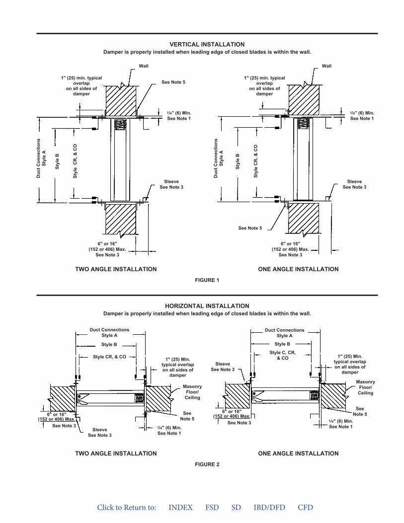
VERTICAL INSTALLATIONDamper is properly installed when leading edge of closed blades is within the wall.
FIGURE 1
6" or 16"(152 or 406) Max.
See Note 3
Duc
t Con
nect
ions
Styl
e A
Styl
e B
Styl
e C
R, &
CO
1" (25) min. typicaloverlap
on all sides ofdamper
See Note 5
Wall
SleeveSee Note 3
1/4" (6) Min.See Note 1
6" or 16"(152 or 406) Max.
See Note 3
Duc
t Con
nect
ions
Styl
e A
Styl
e B
Styl
e C
R, &
CO
1" (25) min. typicaloverlap
on all sides ofdamper
Wall
SleeveSee Note 3
1/4" (6) Min.See Note 1
6" or 16"(152 or 406) Max.
See Note 3
Duct ConnectionsStyle A
Style B
Style CR, & CO
SleeveSee Note 3
SeeNote 5
1/4" (6) Min.See Note 1
MasonryFloor/
Ceiling
1" (25) Min.typical overlapon all sides of
damper
See Note 5
TWO ANGLE INSTALLATION ONE ANGLE INSTALLATION
FIGURE 2
TWO ANGLE INSTALLATION ONE ANGLE INSTALLATION
6" or 16"(152 or 406) Max.
See Note 3
Duct ConnectionsStyle A
Style B
Style C, CR,& CO
SleeveSee Note 3
SeeNote 5
1/4" (6) Min.See Note 1
MasonryFloor/Ceiling
1" (25) Min.typical overlapon all sides of
damper
HORIZONTAL INSTALLATIONDamper is properly installed when leading edge of closed blades is within the wall.
Click to Return to: INDEX FSD SD IBD/DFD CFD
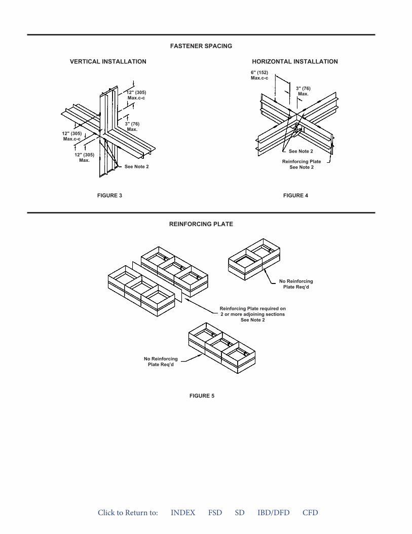
FIGURE 5
FASTENER SPACING
REINFORCING PLATE
VERTICAL INSTALLATION HORIZONTAL INSTALLATION
FIGURE 4FIGURE 3
See Note 2
Reinforcing PlateSee Note 2
No ReinforcingPlate Req’d
6" (152)Max.c-c
3" (76)Max.
See Note 2
12" (305)Max.c-c
12" (305)Max.
12" (305)Max.c-c
3" (76)Max.
Reinforcing Plate required on2 or more adjoining sections
See Note 2
No ReinforcingPlate Req’d
Click to Return to: INDEX FSD SD IBD/DFD CFD
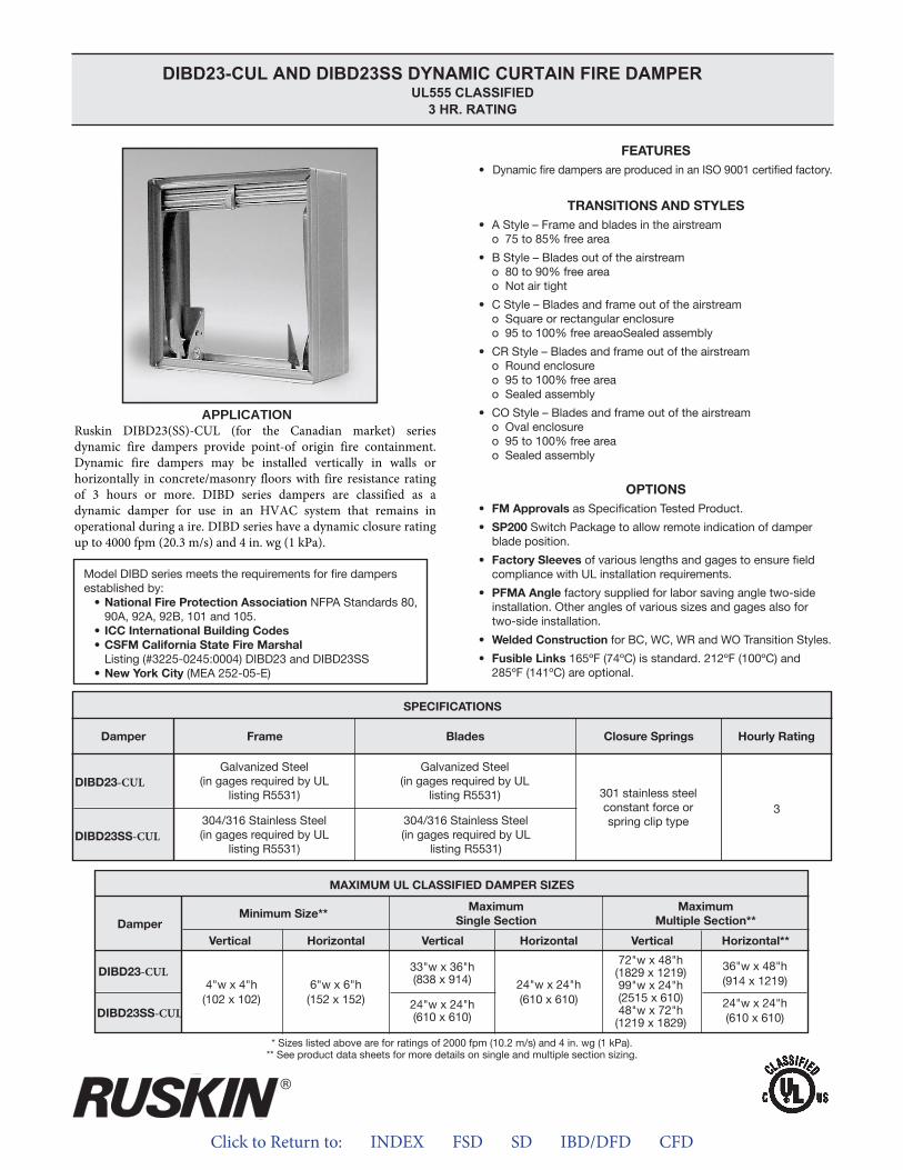
Click to Return to: INDEX FSD SD IBD/DFD CFD
APPLICATION
-CUL
-CUL
-CUL
-CUL
DIBD23-CUL AND DIBD23SS DYNAMIC CURTAIN FIRE DAMPERUL555 CLASSIFIED
3 HR. RATING
Ruskin DIBD23(SS)-CUL (for the Canadian market) series dynamic fire dampers provide point-of origin fire containment. Dynamic fire dampers may be installed vertically in walls or horizontally in concrete/masonry floors with fire resistance rating of 3 hours or more. DIBD series dampers are classified as a dynamic damper for use in an HVAC system that remains in operational during a ire. DIBD series have a dynamic closure rating up to 4000 fpm (20.3 m/s) and 4 in. wg (1 kPa).
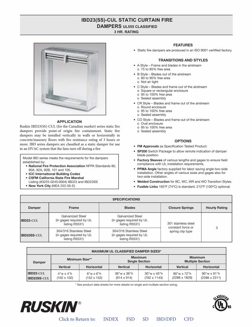
Click to Return to: INDEX FSD SD IBD/DFD CFD
APPLICATION
IBD23(SS)-CUL STATIC CURTAIN FIRE DAMPERS UL555 CLASSIFIED
3 HR. RATING
-CUL-CUL
-CUL
-CUL
Ruskin IBD23(SS)-CUL (for the Canadian market) series static fire dampers provide point-of origin fire containment. Static fire dampers may be installed vertically in walls or horizontally in concrete/masonry floors with fire resistance rating of 3 hours or more. IBD series dampers are classified as a static damper for use in an HVAC system that the fans turn off during a fire
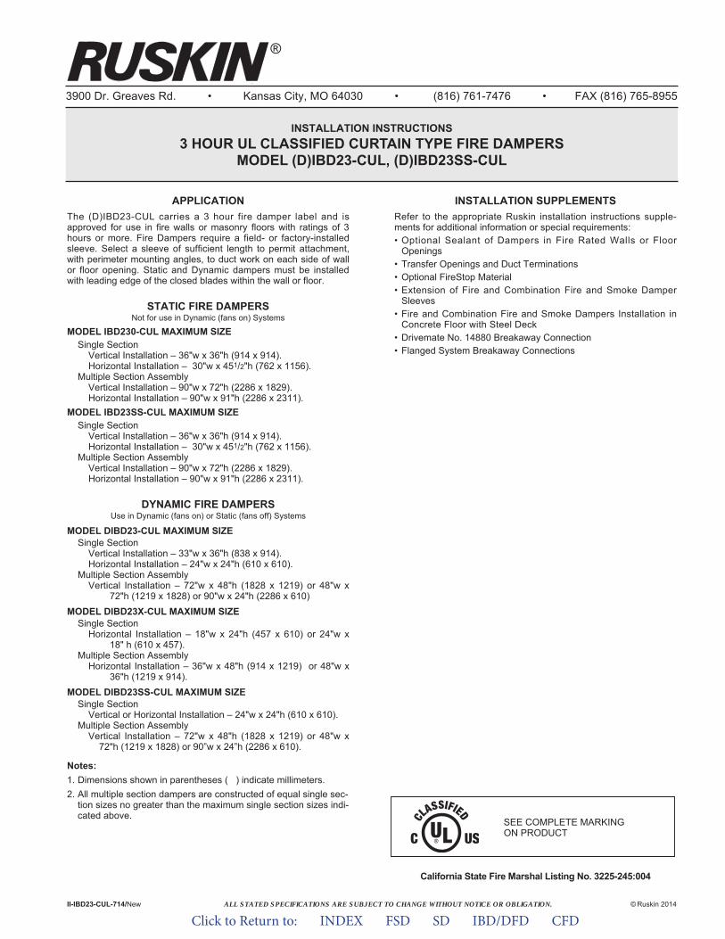
ALL STATED SPECIFICATIONS ARE SUBJECT TO CHANGE WITHOUT NOTICE OR OBLIGATION.
3900 Dr. Greaves Rd. • Kansas City, MO 64030 • (816) 761-7476 • FAX (816) 765-8955
INSTALLATION INSTRUCTIONS3 HOUR UL CLASSIFIED CURTAIN TYPE FIRE DAMPERS
MODEL (D)IBD23-CUL, (D)IBD23SS-CUL
APPLICATIONThe (D)IBD23-CUL carries a 3 hour fire damper label and isapproved for use in fire walls or masonry floors with ratings of 3hours or more. Fire Dampers require a field- or factory-installedsleeve. Select a sleeve of sufficient length to permit attachment,with perimeter mounting angles, to duct work on each side of wallor floor opening. Static and Dynamic dampers must be installedwith leading edge of the closed blades within the wall or floor.
STATIC FIRE DAMPERSNot for use in Dynamic (fans on) Systems
MODEL IBD230-CUL MAXIMUM SIZESingle Section
Vertical Installation – 36"w x 36"h (914 x 914).Horizontal Installation – 30"w x 451/2"h (762 x 1156).
Multiple Section AssemblyVertical Installation – 90"w x 72"h (2286 x 1829).Horizontal Installation – 90"w x 91"h (2286 x 2311).
MODEL IBD23SS-CUL MAXIMUM SIZESingle Section
Vertical Installation – 36"w x 36"h (914 x 914).Horizontal Installation – 30"w x 451/2"h (762 x 1156).
Multiple Section AssemblyVertical Installation – 90"w x 72"h (2286 x 1829).Horizontal Installation – 90"w x 91"h (2286 x 2311).
DYNAMIC FIRE DAMPERSUse in Dynamic (fans on) or Static (fans off) Systems
MODEL DIBD23-CUL MAXIMUM SIZESingle Section
Vertical Installation – 33"w x 36"h (838 x 914).Horizontal Installation – 24"w x 24"h (610 x 610).
Multiple Section AssemblyVertical Installation – 72"w x 48"h (1828 x 1219) or 48"w x
72"h (1219 x 1828) or 90"w x 24"h (2286 x 610)MODEL DIBD23X-CUL MAXIMUM SIZE
Single SectionHorizontal Installation – 18"w x 24"h (457 x 610) or 24"w x
18" h (610 x 457).Multiple Section Assembly
Horizontal Installation – 36"w x 48"h (914 x 1219) or 48"w x 36"h (1219 x 914).
MODEL DIBD23SS-CUL MAXIMUM SIZESingle Section
Vertical or Horizontal Installation – 24"w x 24"h (610 x 610).Multiple Section Assembly
Vertical Installation – 72"w x 48"h (1828 x 1219) or 48"w x72"h (1219 x 1828) or 90”w x 24”h (2286 x 610).
Notes:1. Dimensions shown in parentheses ( ) indicate millimeters.2. All multiple section dampers are constructed of equal single sec-
tion sizes no greater than the maximum single section sizes indi-cated above.
California State Fire Marshal Listing No. 3225-245:004
II-IBD23-CUL-714/New © Ruskin 2014
®
INSTALLATION SUPPLEMENTSRefer to the appropriate Ruskin installation instructions supple-ments for additional information or special requirements:• Optional Sealant of Dampers in Fire Rated Walls or Floor
Openings• Transfer Openings and Duct Terminations• Optional FireStop Material• Extension of Fire and Combination Fire and Smoke Damper
Sleeves• Fire and Combination Fire and Smoke Dampers Installation in
Concrete Floor with Steel Deck• Drivemate No. 14880 Breakaway Connection• Flanged System Breakaway Connections
SEE COMPLETE MARKING ON PRODUCT
Click to Return to: INDEX FSD SD IBD/DFD CFD

1. Opening ClearanceThe opening in the wall or f loor shall be larger than thedamper/sleeve assembly to permit installation or expansion. Theopening shall be a minimum of 1/8" per foot (3 per 305) larger thanthe overall size of the damper/sleeve assembly. The maximumopening size shall not exceed 1/8" per foot (3 per 305) plus 2" (51),nor shall the opening be less than 1/4" (6) larger than thedamper/sleeve assembly.
2. Fasteners and Multiple Section AssemblyUse No. 10 (M5) bolts or screws, 3/16" (5) rivets, tack welds orspot welds as depicted in figures 3 and 4 and spaced as followswhen joining individual dampers to make multiple sectiondamper assemblies or when fastening damper to the sleeve:
Vertical Mount (In wall)All dampers 6" (152) spacing
Horizontal Mount (In floor)All dampers 6" (152) spacing
Multiple section horizontal mount dampers require a 14 gagethick x 41/2" (2 x 114) wide steel reinforcing plate sandwichedbetween the damper frames with 1/2" (13) long welds staggeredintermittently and spaced on maximum 6" (152) centers. Thereinforcing plate must be the same material as the dampers. Thelength must be equal to the damper width of two or more adjoin-ing damper sections. Reinforcing plates are not required forassemblies consisting of two dampers attached end-to-end orthree dampers attached side-to-side as depicted in figure 5.
3. Damper SleeveSleeve thickness must be equal to or thicker than the duct con-nected to it. Sleeve gage requirements are listed in the SMACNAFire, Smoke and Radiation Damper Installation Guide for HVACSystems and in NFPA90A. If a breakaway style duct/sleeve con-nection is not used, the sleeve shall be a minimum of 16 gage(1.6) for dampers up to 36" (914) wide by 24" (610) high and 14gage (1.9) for dampers exceeding 36" (914) wide by 24" (610)high. Damper sleeve shall not extend more than 6" (152) beyondthe fire wall or partition unless damper is equipped with a factoryinstalled access door. Sleeve may extend up to 16" (406) beyondthe fire wall or partition on sides equipped with a factory installedaccess door. Sleeve shall terminate at both sides of wall withindimensions shown.
4. Damper OrientationUse "Air Flow" and "Mount with Arrow Up" labels on DynamicDIBD models for proper damper orientation. For Static IBD mod-els use only "Mount With Arrow Up" label on damper for properdamper orientation. Static and Dynamic dampers must beinstalled with leading edge of the closed blades within the wall orfloor.
5. Mounting AnglesMounting angles shall be a minimum of 11/2" x 11/2" x 20 gagesteel (38 x 38 x 1.0) and must be attached only to the sleeve.Mounting angles must overlap the partition a minimum of 1" (25).Do not weld or fasten angles together at corners of dampers.Ruskin fire dampers may be installed using Ruskin PFMA.a. Mounting Angle Fasteners
Sleeve: #10 bolts or screws, 3/16" (5) steel rivets or 1/2" (13)long welds.Masonry/Wall or Floor: #10 self-tapping concrete screws.Wood/Steel Stud Wall: #10 screws
b. Mounting Angle Fastener SpacingFasteners shall be spaced at 8" (203) o.c.
6. Duct/Sleeve Connectionsa. Break-away Duct/Sleeve Connections
Rectangular ducts must use one or more of the connectionsdepicted: below:
A maximum of two #10 sheet metal screws on each side andthe bottom, located in the center of the slip pocket and pene-trating both sides of the slip pocket may be used.Connections using these slip joints on the top and bottomwith flat drive slips up to 20" (508) long on the sides may alsobe used.
b. Round and Oval Break-away ConnectionsRound and flat oval break-away connections must use eithera 4" (102) wide drawband or #10 sheet metal screws spacedequally around the circumference of the duct as follows:• Duct diameters 22" (559) and smaller – Maximum 3
screws.• Duct diameters over 22" (559) and including 36" (914) –
Maximum 5 screws.• Duct diameters over 36" (914) and up to and including
191" (4851) total perimeter – Maximum 8 screws. For flatoval ducts, the diameter is considered the largest (major)dimension of the duct.
Note: When optional sealing of these joints is desired, thefollowing sealants may be applied in accordance with thesealant manufacturer's instructions:Design Polymerics – DP 1010 Precision – PA2084THardcast, Inc. – Iron Grip 601 Eco Duct Seal 44-52
c. Flanged Break-away Style Duct Sleeve Connections.Flanged connection systems manufactured by Ductmate,Nexus or Ward are approved break-away connections wheninstalled as shown on the Flanged System BreakawayConnections Supplement.TDC and TDF roll-formed flanged connections using 3/8" (10)steel bolts and nuts, and metal cleats, as tested by SMACNA,are approved break-away connections when installed asshown on the Flanged System Breakaway ConnectionsSupplement.
d. Non-Break-away Duct/Sleeve ConnectionsIf other duct sleeve connections are used, the sleeve shall bea minimum of 16 gage (1.6) for dampers up to 36" (914) widex 24" (610) high and 14 gage (2.0) for dampers exceeding36" (914) wide x 24" (610) high.
7. Installation and MaintenanceTo ensure optimum operation and performance, the dampermust be installed so it is square and free from racking. Each firedamper should be maintained and tested on a regular basis andin accordance with the latest editions of NFPA 90A and localcodes. Care should be exercised to ensure that such tests areperformed safely and do not cause system damage.
Click to Return to: INDEX FSD SD IBD/DFD CFD
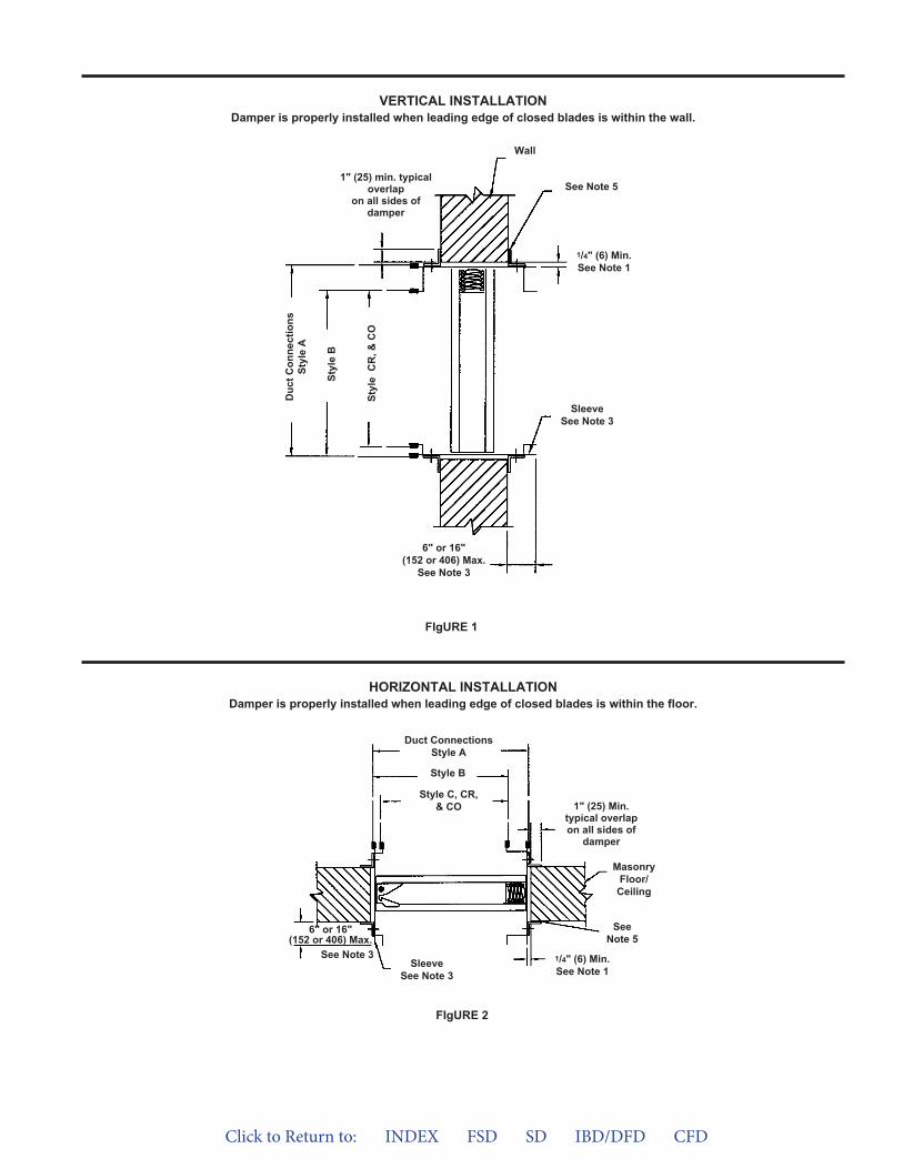
VERTICAL INSTALLATIONDamper is properly installed when leading edge of closed blades is within the wall.
FIgURE 1
6" or 16"(152 or 406) Max.
See Note 3
Duc
t Con
nect
ions
Styl
e A
Styl
e B
Styl
e C
R, &
CO
1" (25) min. typicaloverlap
on all sides ofdamper
See Note 5
Wall
SleeveSee Note 3
1/4" (6) Min.See Note 1
6" or 16"(152 or 406) Max.
See Note 3
Duct ConnectionsStyle A
Style B
Style C, CR,& CO
SleeveSee Note 3
SeeNote 5
1/4" (6) Min.See Note 1
MasonryFloor/
Ceiling
1" (25) Min.typical overlapon all sides of
damper
FIgURE 2
HORIZONTAL INSTALLATIONDamper is properly installed when leading edge of closed blades is within the floor.
Click to Return to: INDEX FSD SD IBD/DFD CFD

FIgURE 5
FASTENER SPACINg
REINFORCINg PLATE
VERTICAL INSTALLATIONHORIZONTAL INSTALLATION
FIgURE 4FIgURE 3
See Note 2
Mullion PlateSee Note 2
6" (152)Max.c-c
3" (76)Max.
See Note 2
6" (152) or12” (305)Max.c-c
2" (51)Max.
6" (152)Max.c-c
3" (76)Max.
No MullionPlate Req’d
No MullionPlate Req’d
Mullion Required on 2 ormore adjoining sections
See Note 2
Click to Return to: INDEX FSD SD IBD/DFD CFD
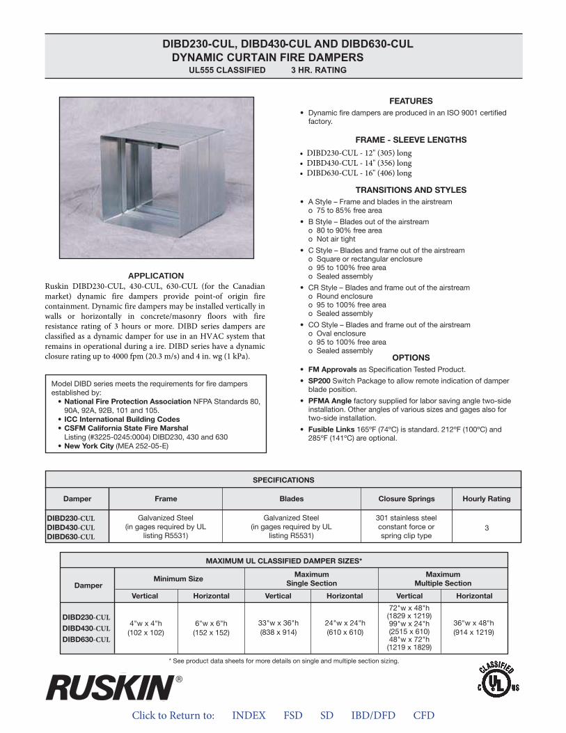
Click to Return to: INDEX FSD SD IBD/DFD CFD
APPLICATION
-CUL-CUL-CUL
-CUL-CUL-CUL
DIBD230-CUL, DIBD4 30 -CUL AND DIBD630-CULDYNAMIC CURTAIN FIRE DAMPERS
UL555 CLASSIFIED 3 HR. RATING
Ruskin DIBD230-CUL, 430-CUL, 630-CUL (for the Canadian market) dynamic fire dampers provide point-of origin fire containment. Dynamic fire dampers may be installed vertically in walls or horizontally in concrete/masonry floors with fire resistance rating of 3 hours or more. DIBD series dampers are classified as a dynamic damper for use in an HVAC system that remains in operational during a ire. DIBD series have a dynamic closure rating up to 4000 fpm (20.3 m/s) and 4 in. wg (1 kPa).
• DIBD230-CUL - 12" (305) long• DIBD430-CUL - 14" (356) long• DIBD630-CUL - 16" (406) long
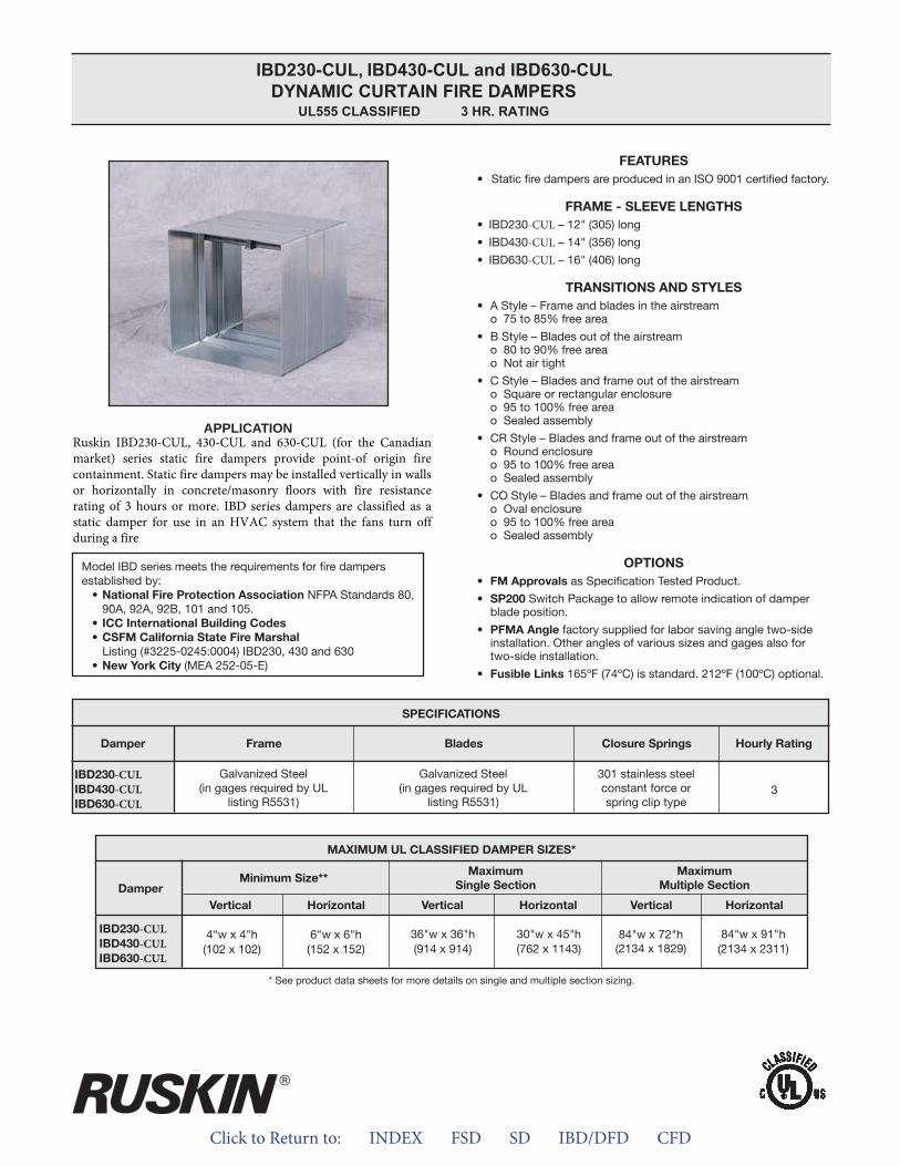
Click to Return to: INDEX FSD SD IBD/DFD CFD
APPLICATION
-CUL -CUL -CUL
-CUL-CUL-CUL
-CUL-CUL-CUL
Ruskin IBD230-CUL, 430-CUL and 630-CUL (for the Canadian market) series static fire dampers provide point-of origin fire containment. Static fire dampers may be installed vertically in walls or horizontally in concrete/masonry floors with fire resistance rating of 3 hours or more. IBD series dampers are classified as a static damper for use in an HVAC system that the fans turn off during a fire
IBD230-CUL, IBD430-CUL and IBD630-CULDYNAMIC CURTAIN FIRE DAMPERS
UL555 CLASSIFIED 3 HR. RATING
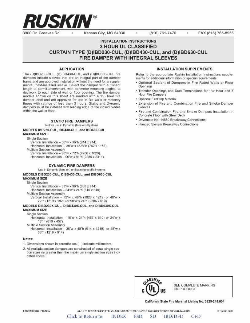
ALL STATED SPECIFICATIONS ARE SUBJECT TO CHANGE WITHOUT NOTICE OR OBLIGATION.
3900 Dr. Greaves Rd. • Kansas City, MO 64030 • (816) 761-7476 • FAX (816) 765-8955
INSTALLATION INSTRUCTIONS3 HOUR UL CLASSIFIED
CURTAIN TYPE (D)IBD230-CUL, (D)IBD430-CUL, and (D)IBD630-CUL FIRE DAMPER WITH INTEGRAL SLEEVES
APPLICATIONThe (D)IBD230-CUL, (D)IBD430-CUL, and (D)IBD630-CUL firedampers include sleeves that are an integral part of the damperframe and are approved installation without the need for a supple-mental, field-installed sleeve. Select the damper with sufficientlength to permit attachment, with perimeter mounting angles, toductwork to each side of wall or floor opening. The fire dampermodels shown on this sheet are marked with a 11/2 hour firedamper label and are approved for use in fire walls or masonryfloors with ratings of less than 3 hours. Static and Dynamicdampers must be installed with leading edge of the closed bladeswithin the wall or floor.
STATIC FIRE DAMPERSNot for use in Dynamic (fans on) Systems
MODELS IBD230-CUL, IBD430-CUL, and IBD630-CULMAXIMUM SIZE
Single SectionVertical Installation – 36"w x 36"h (914 x 914).Horizontal Installation – 30"w x 451/2"h (762 x 1156).
Multiple Section AssemblyVertical Installation – 90"w x 72"h (2286 x 1829).Horizontal Installation – 90"w x 91"h (2286 x 2311).
DYNAMIC FIRE DAMPERSUse in Dynamic (fans on) or Static (fans off) Systems
MODELS DIBD230-CUL, DIBD430-CUL, and DIBD630-CULMAXIMUM SIZE
Single SectionVertical Installation – 33"w x 36"h (838 x 914)Horizontal Installation – 24"w x 24"h (610 x 610)
Multiple Section AssemblyVertical Installation – 72"w x 48"h (1828 x 1219) or 48"w x
72"h (1219 x 1828) or 90"w x 24"h (2286 x 610)MODELS DIBD230X-CUL, DIBD430X-CUL, and DIBD630X-CULMAXIMUM SIZE
Single SectionHorizontal Installation – 18"w x 24"h (457 x 610) or 24"w x
18" h (610 x 457)Multiple Section Assembly
Horizontal Installation – 36"w x 48"h (914 x 1219) or 48"w x 36"h (1219 x 914)
Notes:1. Dimensions shown in parentheses ( ) indicate millimeters.2. All multiple section dampers are constructed of equal single sec-
tion sizes no greater than the maximum single section sizes indi-cated above.
California State Fire Marshal Listing No. 3225-245:004
II-IBD230-CUL-714/New © Ruskin 2014
®
INSTALLATION SUPPLEMENTSRefer to the appropriate Ruskin installation instructions supple-ments for additional information or special requirements:• Optional Sealant of Dampers in Fire Rated Walls or Floor
Openings• Transfer Openings and Duct Terminations for 11/2 Hour and 3
Hour Fire Dampers• Optional FireStop Material• Extension of Fire and Combination Fire and Smoke Damper
Sleeves• Fire and Combination Fire and Smoke Dampers Installation in
Concrete Floor with Steel Deck• Drivemate No. 14880 Breakaway Connections• Flanged System Breakaway Connections
SEE COMPLETE MARKING ON PRODUCT
Click to Return to: INDEX FSD SD IBD/DFD CFD

1. Opening ClearanceThe opening in the wall or f loor shall be larger than thedamper/sleeve assembly to permit installation or expansion. Theopening shall be a minimum of 1/8" per foot (3 per 305) larger thanthe overall size of the damper/sleeve assembly. The maximumopening size shall not exceed 1/8" per foot (3 per 305) plus 2" (51),nor shall the opening be less than 1/4" (6) larger than thedamper/sleeve assembly.
2. Fasteners and Multiple Section AssemblyUse No. 10 (M5) bolts or screws, 3/16" (5) rivets, tack welds orspot welds as depicted in figures 3 and 4 and spaced as followswhen joining individual dampers to make multiple sectiondamper assemblies or when fastening damper to the sleeve:
Vertical Mount (In wall)All dampers 6" (152) spacing
Horizontal Mount (In floor)All dampers 6" (152) spacing
Multiple section horizontal mount dampers require a 14 gagethick x 41/2" (2 x 114) wide steel reinforcing plate sandwichedbetween the damper frames with 1/2" (13) long welds staggeredintermittently and spaced on maximum 6" (152) centers. Thereinforcing plate must be the same material as the dampers. Thelength must be equal to the damper width of two or more adjoin-ing damper sections. Reinforcing plates are not required forassemblies consisting of two dampers attached end-to-end orthree dampers attached side-to-side as depicted in figure 5.
3. Damper SleeveSleeve thickness must be equal to or thicker than the duct con-nected to it. Sleeve gage requirements are listed in the SMACNAFire, Smoke and Radiation Damper Installation Guide for HVACSystems and in NFPA90A. If a breakaway style duct/sleeve con-nection is not used, the sleeve shall be a minimum of 16 gage(1.6) for dampers up to 36" (914) wide by 24" (610) high and 14gage (1.9) for dampers exceeding 36" (914) wide by 24" (610)high. Damper sleeve shall not extend more than 6" (152) beyondthe fire wall or partition unless damper is equipped with a factoryinstalled access door. Sleeve may extend up to 16" (406) beyondthe fire wall or partition on sides equipped with a factory installedaccess door. Sleeve shall terminate at both sides of wall withindimensions shown.
4. Damper OrientationUse "Air Flow" and "Mount with Arrow Up" labels on DynamicDIBD models for proper damper orientation. For Static IBD mod-els use only "Mount With Arrow Up" label on damper for properdamper orientation. Static and Dynamic dampers must beinstalled with leading edge of the closed blades within the wall orfloor.
5. Mounting AnglesMounting angles shall be a minimum of 11/2" x 11/2" x 20 gagesteel (38 x 38 x 1.0) and must be attached only to the sleeve.Mounting angles must overlap the partition a minimum of 1" (25).Do not weld or fasten angles together at corners of dampers.Ruskin fire dampers may be installed using Ruskin PFMA.a. Mounting Angle Fasteners
Sleeve: #10 bolts or screws, 3/16" (5) steel rivets or 1/2" (13)long welds.Masonry/Wall or Floor: #10 self-tapping concrete screws.Wood/Steel Stud Wall: #10 screws
b. Mounting Angle Fastener SpacingFasteners shall be spaced at 8" (203) o.c.
6. Duct/Sleeve Connectionsa. Break-away Duct/Sleeve Connections
Rectangular ducts must use one or more of the connectionsdepicted: below:
A maximum of two #10 sheet metal screws on each side andthe bottom, located in the center of the slip pocket and pene-trating both sides of the slip pocket may be used.Connections using these slip joints on the top and bottomwith flat drive slips up to 20" (508) long on the sides may alsobe used.
b. Round and Oval Break-away ConnectionsRound and flat oval break-away connections must use eithera 4" (102) wide drawband or #10 sheet metal screws spacedequally around the circumference of the duct as follows:• Duct diameters 22" (559) and smaller – Maximum 3
screws.• Duct diameters over 22" (559) and including 36" (914) –
Maximum 5 screws.• Duct diameters over 36" (914) and up to and including
191" (4851) total perimeter – Maximum 8 screws. For flatoval ducts, the diameter is considered the largest (major)dimension of the duct.
Note: When optional sealing of these joints is desired, thefollowing sealants may be applied in accordance with thesealant manufacturer's instructions:Design Polymerics – DP 1010 Precision – PA2084THardcast, Inc. – Iron Grip 601 Eco Duct Seal 44-52
c. Flanged Break-away Style Duct Sleeve Connections.Flanged connection systems manufactured by Ductmate,Nexus or Ward are approved break-away connections wheninstalled as shown on the Flanged System BreakawayConnections Supplement.TDC and TDF roll-formed flanged connections using 3/8" (10)steel bolts and nuts, and metal cleats, as tested by SMACNA,are approved break-away connections when installed asshown on the Flanged System Breakaway ConnectionsSupplement.
d. Non-Break-away Duct/Sleeve ConnectionsIf other duct sleeve connections are used, the sleeve shall bea minimum of 16 gage (1.6) for dampers up to 36" (914) widex 24" (610) high and 14 gage (2.0) for dampers exceeding36" (914) wide x 24" (610) high.
7. Installation and MaintenanceTo ensure optimum operation and performance, the dampermust be installed so it is square and free from racking. Each firedamper should be maintained and tested on a regular basis andin accordance with the latest editions of NFPA 90A and localcodes. Care should be exercised to ensure that such tests areperformed safely and do not cause system damage.
Click to Return to: INDEX FSD SD IBD/DFD CFD
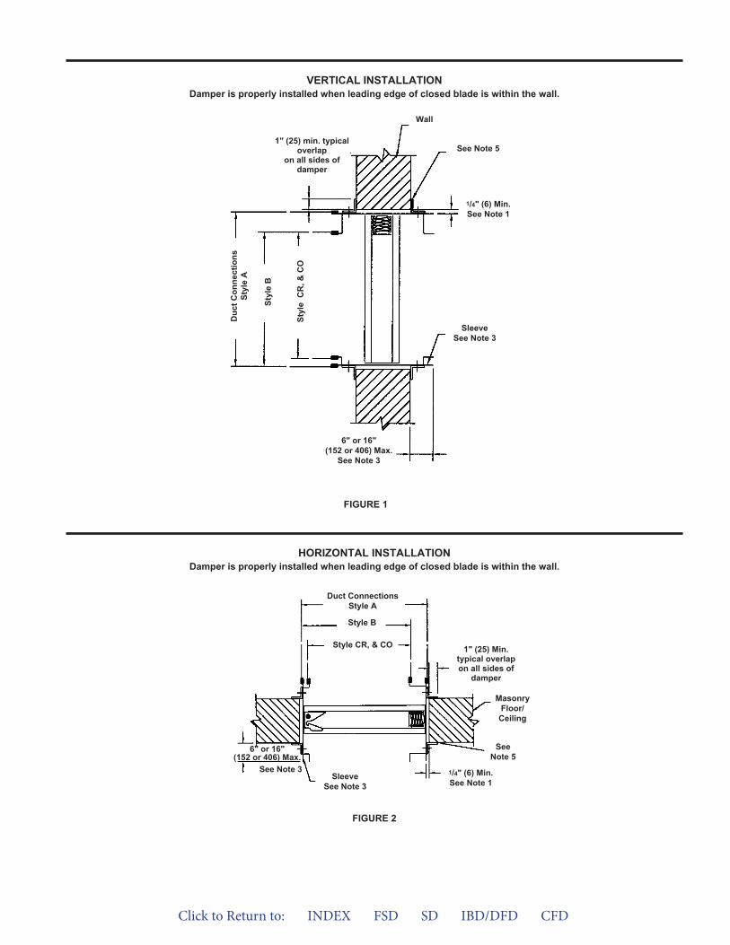
VERTICAL INSTALLATIONDamper is properly installed when leading edge of closed blade is within the wall.
FIGURE 1
6" or 16"(152 or 406) Max.
See Note 3
Duc
t Con
nect
ions
Styl
e A
Styl
e B
Styl
e C
R, &
CO
1" (25) min. typicaloverlap
on all sides ofdamper
See Note 5
Wall
SleeveSee Note 3
1/4" (6) Min.See Note 1
6" or 16"(152 or 406) Max.
See Note 3
Duct ConnectionsStyle A
Style B
Style CR, & CO
SleeveSee Note 3
SeeNote 5
1/4" (6) Min.See Note 1
MasonryFloor/
Ceiling
1" (25) Min.typical overlapon all sides of
damper
FIGURE 2
HORIZONTAL INSTALLATIONDamper is properly installed when leading edge of closed blade is within the wall.
Click to Return to: INDEX FSD SD IBD/DFD CFD
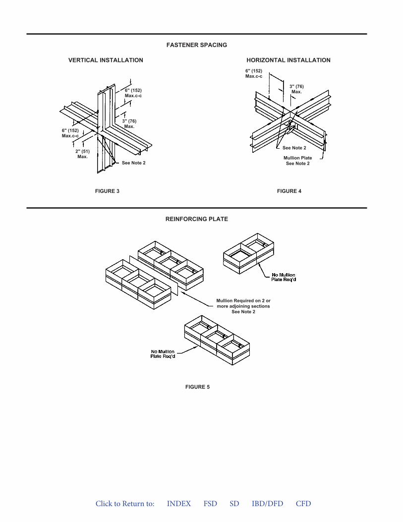
FIGURE 5
FASTENER SPACING
REINFORCING PLATE
VERTICAL INSTALLATION HORIZONTAL INSTALLATION
FIGURE 4FIGURE 3
See Note 2
Mullion PlateSee Note 2
6" (152)Max.c-c
3" (76)Max.
See Note 2
6" (152)Max.c-c
2" (51)Max.
6" (152)Max.c-c
3" (76)Max.
Mullion Required on 2 ormore adjoining sections
See Note 2
Click to Return to: INDEX FSD SD IBD/DFD CFD
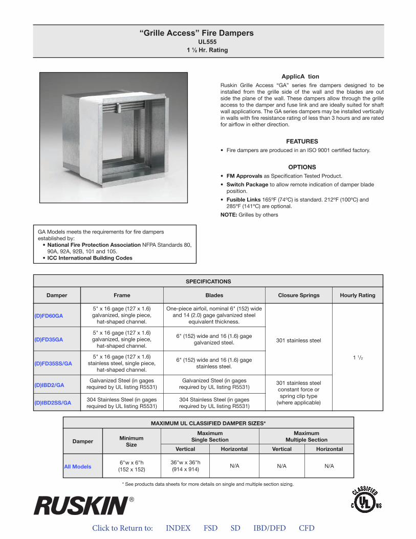
Click to Return to: INDEX FSD SD IBD/DFD CFD
ApplicA tionRuskin Grille Access “GA” series fire dampers designed to be installed from the grille side of the wall and the blades are out side the plane of the wall. These dampers allow through the grille access to the damper and fuse link and are ideally suited for shaft wall applications. The GA series dampers may be installed vertically in walls with fire resistance rating of less than 3 hours and are rated for airflow in either direction.
FEATURES• Fire dampers are produced in an ISO 9001 certified factory.
OPTIONS• FM Approvals as Specification Tested Product.
• Switch Package to allow remote indication of damper bladeposition.
• Fusible Links 165ºF (74ºC) is standard. 212ºF (100ºC) and285ºF (141ºC) are optional.
NOTE: Grilles by others
“Grille Access” Fire Dampers UL555
1 ½ Hr. Rating
GA Models meets the requirements for fire dampers established by:
• National Fire Protection Association NFPA Standards 80, 90A, 92A, 92B, 101 and 105.
• ICC International Building Codes
MAXIMUM UL CLASSIFIED DAMPER SIZES*
Damper
All Models
MaximumSingle SectionMinimum
Size
MaximumMultiple Section
Vertical VerticalHorizontal Horizontal
6"w x 6"h(152 x 152)
N/A N/A36"w x 36"h(914 x 914)
N/A
* See products data sheets for more details on single and multiple section sizing.
(D)FD60GA
(D)FD35GA
(D)FD35SS/GA
(D)IBD2/GA
(D)IBD2SS/GA
SPECIFICATIONS
Frame Blades Closure Springs Hourly RatingDamper
5" x 16 gage (127 x 1.6)galvanized, single piece,
hat-shaped channel.
5" x 16 gage (127 x 1.6)galvanized, single piece,
hat-shaped channel.
5" x 16 gage (127 x 1.6)stainless steel, single piece,
hat-shaped channel.
Galvanized Steel (in gagesrequired by UL listing R5531)
304 Stainless Steel (in gagesrequired by UL listing R5531)
Galvanized Steel (in gagesrequired by UL listing R5531)
304 Stainless Steel (in gagesrequired by UL listing R5531)
One-piece airfoil, nominal 6" (152) wide and 14 (2.0) gage galvanized steel
equivalent thickness.
6" (152) wide and 16 (1.6) gage galvanized steel.
6" (152) wide and 16 (1.6) gage stainless steel.
301 stainless steelconstant force orspring clip type
(where applicable)
301 stainless steel
1 1/2
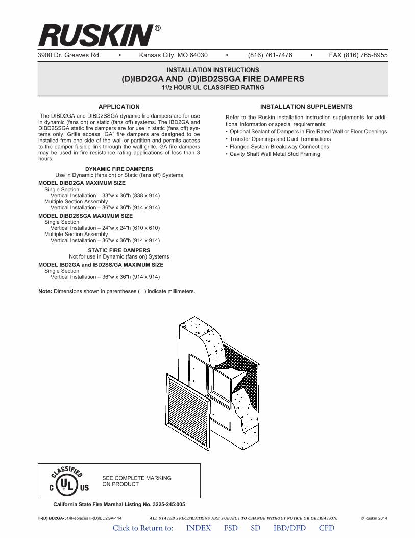
ALL STATED SPECIFICATIONS ARE SUBJECT TO CHANGE WITHOUT NOTICE OR OBLIGATION.
3900 Dr. Greaves Rd. • Kansas City, MO 64030 • (816) 761-7476 • FAX (816) 765-8955
INSTALLATION INSTRUCTIONS(D)IBD2GA AND (D)IBD2SSGA FIRE DAMPERS
11/2 HOUR UL CLASSIFIED RATING
II-(D)IBD2GA-514Replaces II-(D)IBD2GA-114 © Ruskin 2014
®
APPLICATIONThe DIBD2GA and DIBD2SSGA dynamic fire dampers are for use
in dynamic (fans on) or static (fans off) systems. The IBD2GA andDIBD2SSGA static fire dampers are for use in static (fans off) sys-tems only. Grille access “GA” fire dampers are designed to beinstalled from one side of the wall or partition and permits accessto the damper fusible link through the wall grille. GA fire dampersmay be used in fire resistance rating applications of less than 3hours.
DYNAMIC FIRE DAMPERSUse in Dynamic (fans on) or Static (fans off) Systems
MODEL DIBD2GA MAXIMUM SIZESingle Section
Vertical Installation – 33"w x 36"h (838 x 914)Multiple Section Assembly
Vertical Installation – 36"w x 36"h (914 x 914)MODEL DIBD2SSGA MAXIMUM SIZE
Single SectionVertical Installation – 24"w x 24"h (610 x 610)
Multiple Section AssemblyVertical Installation – 36"w x 36"h (914 x 914)
STATIC FIRE DAMPERSNot for use in Dynamic (fans on) Systems
MODEL IBD2GA and IBD2SS/GA MAXIMUM SIZESingle Section
Vertical Installation – 36"w x 36"h (914 x 914)
Note: Dimensions shown in parentheses ( ) indicate millimeters.
California State Fire Marshal Listing No. 3225-245:005
INSTALLATION SUPPLEMENTSRefer to the Ruskin installation instruction supplements for addi-tional information or special requirements:• Optional Sealant of Dampers in Fire Rated Wall or Floor Openings• Transfer Openings and Duct Terminations• Flanged System Breakaway Connections• Cavity Shaft Wall Metal Stud Framing
SEE COMPLETE MARKING ON PRODUCT
Click to Return to: INDEX FSD SD IBD/DFD CFD
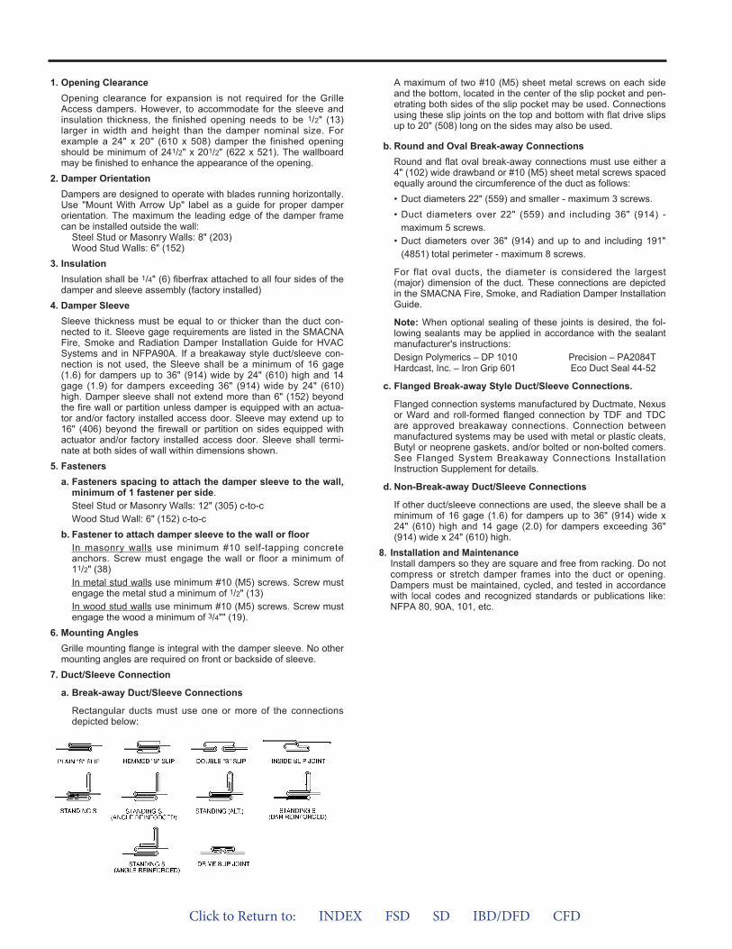
1. Opening ClearanceOpening clearance for expansion is not required for the GrilleAccess dampers. However, to accommodate for the sleeve andinsulation thickness, the finished opening needs to be 1/2" (13)larger in width and height than the damper nominal size. Forexample a 24" x 20" (610 x 508) damper the finished openingshould be minimum of 241/2" x 201/2" (622 x 521). The wallboardmay be finished to enhance the appearance of the opening.
2. Damper OrientationDampers are designed to operate with blades running horizontally.Use "Mount With Arrow Up" label as a guide for proper damperorientation. The maximum the leading edge of the damper framecan be installed outside the wall:
Steel Stud or Masonry Walls: 8" (203)Wood Stud Walls: 6" (152)
3. InsulationInsulation shall be 1/4" (6) fiberfrax attached to all four sides of thedamper and sleeve assembly (factory installed)
4. Damper SleeveSleeve thickness must be equal to or thicker than the duct con-nected to it. Sleeve gage requirements are listed in the SMACNAFire, Smoke and Radiation Damper Installation Guide for HVACSystems and in NFPA90A. If a breakaway style duct/sleeve con-nection is not used, the Sleeve shall be a minimum of 16 gage(1.6) for dampers up to 36" (914) wide by 24" (610) high and 14gage (1.9) for dampers exceeding 36" (914) wide by 24" (610)high. Damper sleeve shall not extend more than 6" (152) beyondthe fire wall or partition unless damper is equipped with an actua-tor and/or factory installed access door. Sleeve may extend up to16" (406) beyond the firewall or partition on sides equipped withactuator and/or factory installed access door. Sleeve shall termi-nate at both sides of wall within dimensions shown.
5. Fastenersa. Fasteners spacing to attach the damper sleeve to the wall,
minimum of 1 fastener per side.Steel Stud or Masonry Walls: 12" (305) c-to-cWood Stud Wall: 6" (152) c-to-c
b. Fastener to attach damper sleeve to the wall or floorIn masonry walls use minimum #10 self-tapping concreteanchors. Screw must engage the wall or floor a minimum of11/2" (38)In metal stud walls use minimum #10 (M5) screws. Screw mustengage the metal stud a minimum of 1/2" (13)In wood stud walls use minimum #10 (M5) screws. Screw mustengage the wood a minimum of 3/4"" (19).
6. Mounting AnglesGrille mounting flange is integral with the damper sleeve. No othermounting angles are required on front or backside of sleeve.
7. Duct/Sleeve Connection
a. Break-away Duct/Sleeve Connections
Rectangular ducts must use one or more of the connectionsdepicted below:
A maximum of two #10 (M5) sheet metal screws on each sideand the bottom, located in the center of the slip pocket and pen-etrating both sides of the slip pocket may be used. Connectionsusing these slip joints on the top and bottom with flat drive slipsup to 20" (508) long on the sides may also be used.
b. Round and Oval Break-away ConnectionsRound and flat oval break-away connections must use either a4" (102) wide drawband or #10 (M5) sheet metal screws spacedequally around the circumference of the duct as follows:• Duct diameters 22" (559) and smaller - maximum 3 screws.• Duct diameters over 22" (559) and including 36" (914) -
maximum 5 screws.• Duct diameters over 36" (914) and up to and including 191"
(4851) total perimeter - maximum 8 screws.
For flat oval ducts, the diameter is considered the largest(major) dimension of the duct. These connections are depictedin the SMACNA Fire, Smoke, and Radiation Damper InstallationGuide.
Note: When optional sealing of these joints is desired, the fol-lowing sealants may be applied in accordance with the sealantmanufacturer's instructions:Design Polymerics – DP 1010 Precision – PA2084THardcast, Inc. – Iron Grip 601 Eco Duct Seal 44-52
c. Flanged Break-away Style Duct/Sleeve Connections.
Flanged connection systems manufactured by Ductmate, Nexusor Ward and roll-formed flanged connection by TDF and TDCare approved breakaway connections. Connection betweenmanufactured systems may be used with metal or plastic cleats,Butyl or neoprene gaskets, and/or bolted or non-bolted comers.See Flanged System Breakaway Connections InstallationInstruction Supplement for details.
d. Non-Break-away Duct/Sleeve Connections
If other duct/sleeve connections are used, the sleeve shall be aminimum of 16 gage (1.6) for dampers up to 36" (914) wide x24" (610) high and 14 gage (2.0) for dampers exceeding 36"(914) wide x 24" (610) high.
8. Installation and MaintenanceInstall dampers so they are square and free from racking. Do notcompress or stretch damper frames into the duct or opening.Dampers must be maintained, cycled, and tested in accordancewith local codes and recognized standards or publications like:NFPA 80, 90A, 101, etc.
Click to Return to: INDEX FSD SD IBD/DFD CFD
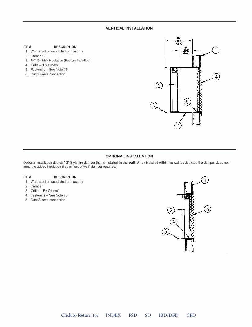
ITEM DESCRIPTION1. Wall: steel or wood stud or masonry2. Damper3. 1/4" (6) thick insulation (Factory Installed)4. Grille – “By Others”5. Fasteners – See Note #56. Duct/Sleeve connection
ITEM DESCRIPTION1. Wall: steel or wood stud or masonry2. Damper3. Grille – “By Others”4. Fasteners – See Note #55. Duct/Sleeve connection
VERTICAL INSTALLATION
OPTIONAL INSTALLATIONOptional installation depicts "G" Style fire damper that is installed in the wall. When installed within the wall as depicted the damper does notneed the added insulation that an "out of wall" damper requires.
Click to Return to: INDEX FSD SD IBD/DFD CFD
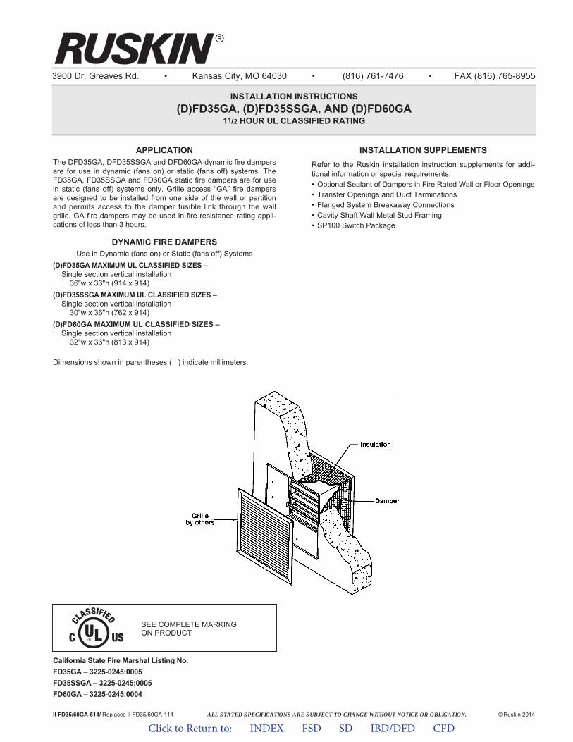
ALL STATED SPECIFICATIONS ARE SUBJECT TO CHANGE WITHOUT NOTICE OR OBLIGATION.
3900 Dr. Greaves Rd. • Kansas City, MO 64030 • (816) 761-7476 • FAX (816) 765-8955
INSTALLATION INSTRUCTIONS(D)FD35GA, (D)FD35SSGA, AND (D)FD60GA
11/2 HOUR UL CLASSIFIED RATING
II-FD35/60GA-514/ Replaces II-FD35/60GA-114 © Ruskin 2014
®
APPLICATIONThe DFD35GA, DFD35SSGA and DFD60GA dynamic fire dampersare for use in dynamic (fans on) or static (fans off) systems. TheFD35GA, FD35SSGA and FD60GA static fire dampers are for usein static (fans off) systems only. Grille access “GA” fire dampersare designed to be installed from one side of the wall or partitionand permits access to the damper fusible link through the wallgrille. GA fire dampers may be used in fire resistance rating appli-cations of less than 3 hours.
DYNAMIC FIRE DAMPERSUse in Dynamic (fans on) or Static (fans off) Systems
(D)FD35GA MAXIMUM UL CLASSIFIED SIZES –Single section vertical installation
36"w x 36"h (914 x 914)(D)FD35SSGA MAXIMUM UL CLASSIFIED SIZES –
Single section vertical installation30"w x 36"h (762 x 914)
(D)FD60GA MAXIMUM UL CLASSIFIED SIZES –Single section vertical installation
32"w x 36"h (813 x 914)
Dimensions shown in parentheses ( ) indicate millimeters.
INSTALLATION SUPPLEMENTSRefer to the Ruskin installation instruction supplements for addi-tional information or special requirements:• Optional Sealant of Dampers in Fire Rated Wall or Floor Openings• Transfer Openings and Duct Terminations• Flanged System Breakaway Connections• Cavity Shaft Wall Metal Stud Framing• SP100 Switch Package
California State Fire Marshal Listing No.FD35GA – 3225-0245:0005FD35SSGA – 3225-0245:0005FD60GA – 3225-0245:0004
SEE COMPLETE MARKING ON PRODUCT
Click to Return to: INDEX FSD SD IBD/DFD CFD
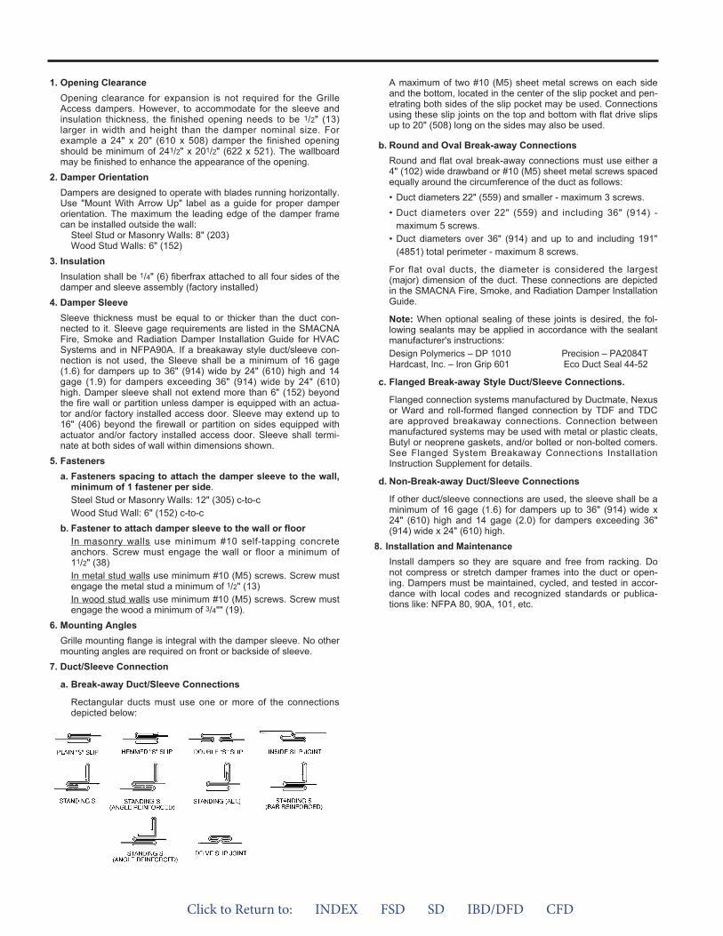
1. Opening ClearanceOpening clearance for expansion is not required for the GrilleAccess dampers. However, to accommodate for the sleeve andinsulation thickness, the finished opening needs to be 1/2" (13)larger in width and height than the damper nominal size. Forexample a 24" x 20" (610 x 508) damper the finished openingshould be minimum of 241/2" x 201/2" (622 x 521). The wallboardmay be finished to enhance the appearance of the opening.
2. Damper OrientationDampers are designed to operate with blades running horizontally.Use "Mount With Arrow Up" label as a guide for proper damperorientation. The maximum the leading edge of the damper framecan be installed outside the wall:
Steel Stud or Masonry Walls: 8" (203)Wood Stud Walls: 6" (152)
3. InsulationInsulation shall be 1/4" (6) fiberfrax attached to all four sides of thedamper and sleeve assembly (factory installed)
4. Damper SleeveSleeve thickness must be equal to or thicker than the duct con-nected to it. Sleeve gage requirements are listed in the SMACNAFire, Smoke and Radiation Damper Installation Guide for HVACSystems and in NFPA90A. If a breakaway style duct/sleeve con-nection is not used, the Sleeve shall be a minimum of 16 gage(1.6) for dampers up to 36" (914) wide by 24" (610) high and 14gage (1.9) for dampers exceeding 36" (914) wide by 24" (610)high. Damper sleeve shall not extend more than 6" (152) beyondthe fire wall or partition unless damper is equipped with an actua-tor and/or factory installed access door. Sleeve may extend up to16" (406) beyond the firewall or partition on sides equipped withactuator and/or factory installed access door. Sleeve shall termi-nate at both sides of wall within dimensions shown.
5. Fastenersa. Fasteners spacing to attach the damper sleeve to the wall,
minimum of 1 fastener per side.Steel Stud or Masonry Walls: 12" (305) c-to-cWood Stud Wall: 6" (152) c-to-c
b. Fastener to attach damper sleeve to the wall or floorIn masonry walls use minimum #10 self-tapping concreteanchors. Screw must engage the wall or floor a minimum of11/2" (38)In metal stud walls use minimum #10 (M5) screws. Screw mustengage the metal stud a minimum of 1/2" (13)In wood stud walls use minimum #10 (M5) screws. Screw mustengage the wood a minimum of 3/4"" (19).
6. Mounting AnglesGrille mounting flange is integral with the damper sleeve. No othermounting angles are required on front or backside of sleeve.
7. Duct/Sleeve Connection
a. Break-away Duct/Sleeve Connections
Rectangular ducts must use one or more of the connectionsdepicted below:
A maximum of two #10 (M5) sheet metal screws on each sideand the bottom, located in the center of the slip pocket and pen-etrating both sides of the slip pocket may be used. Connectionsusing these slip joints on the top and bottom with flat drive slipsup to 20" (508) long on the sides may also be used.
b. Round and Oval Break-away ConnectionsRound and flat oval break-away connections must use either a4" (102) wide drawband or #10 (M5) sheet metal screws spacedequally around the circumference of the duct as follows:• Duct diameters 22" (559) and smaller - maximum 3 screws.• Duct diameters over 22" (559) and including 36" (914) -
maximum 5 screws.• Duct diameters over 36" (914) and up to and including 191"
(4851) total perimeter - maximum 8 screws.
For flat oval ducts, the diameter is considered the largest(major) dimension of the duct. These connections are depictedin the SMACNA Fire, Smoke, and Radiation Damper InstallationGuide.
Note: When optional sealing of these joints is desired, the fol-lowing sealants may be applied in accordance with the sealantmanufacturer's instructions:Design Polymerics – DP 1010 Precision – PA2084THardcast, Inc. – Iron Grip 601 Eco Duct Seal 44-52
c. Flanged Break-away Style Duct/Sleeve Connections.
Flanged connection systems manufactured by Ductmate, Nexusor Ward and roll-formed flanged connection by TDF and TDCare approved breakaway connections. Connection betweenmanufactured systems may be used with metal or plastic cleats,Butyl or neoprene gaskets, and/or bolted or non-bolted comers.See Flanged System Breakaway Connections InstallationInstruction Supplement for details.
d. Non-Break-away Duct/Sleeve Connections
If other duct/sleeve connections are used, the sleeve shall be aminimum of 16 gage (1.6) for dampers up to 36" (914) wide x24" (610) high and 14 gage (2.0) for dampers exceeding 36"(914) wide x 24" (610) high.
8. Installation and MaintenanceInstall dampers so they are square and free from racking. Donot compress or stretch damper frames into the duct or open-ing. Dampers must be maintained, cycled, and tested in accor-dance with local codes and recognized standards or publica-tions like: NFPA 80, 90A, 101, etc.
Click to Return to: INDEX FSD SD IBD/DFD CFD
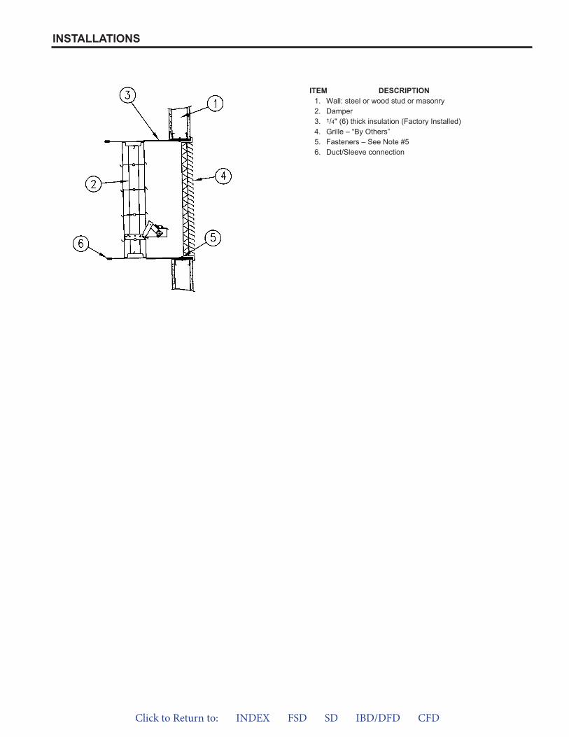
ITEM DESCRIPTION1. Wall: steel or wood stud or masonry2. Damper3. 1/4" (6) thick insulation (Factory Installed)4. Grille – “By Others”5. Fasteners – See Note #56. Duct/Sleeve connection
INSTALLATIONS
Click to Return to: INDEX FSD SD IBD/DFD CFD
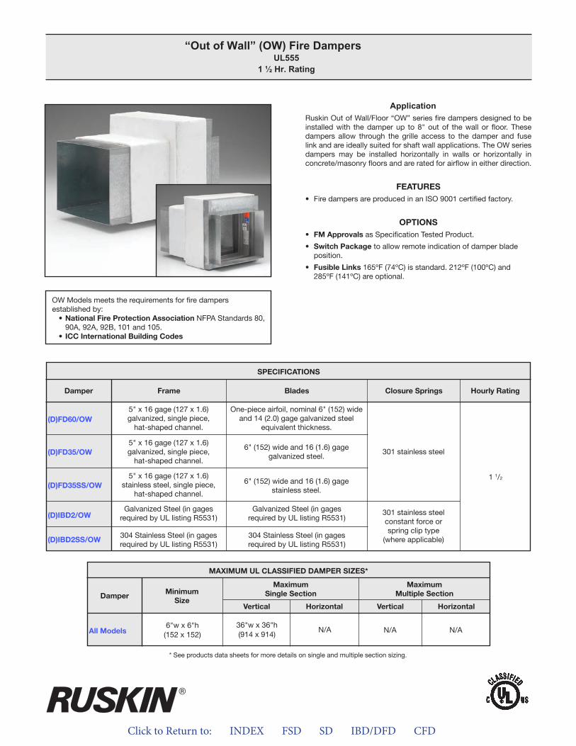
Click to Return to: INDEX FSD SD IBD/DFD CFD
ApplicationRuskin Out of Wall/Floor “OW” series fire dampers designed to be installed with the damper up to 8" out of the wall or floor. These dampers allow through the grille access to the damper and fuse link and are ideally suited for shaft wall applications. The OW series dampers may be installed horizontally in walls or horizontally in concrete/masonry floors and are rated for airflow in either direction.
FEATURES• Fire dampers are produced in an ISO 9001 certified factory.
OPTIONS• FM Approvals as Specification Tested Product.
• Switch Package to allow remote indication of damper bladeposition.
• Fusible Links 165ºF (74ºC) is standard. 212ºF (100ºC) and285ºF (141ºC) are optional.
“Out of Wall” (OW) Fire Dampers UL555
1 ½ Hr. Rating
OW Models meets the requirements for fire dampers established by:
• National Fire Protection Association NFPA Standards 80, 90A, 92A, 92B, 101 and 105.
• ICC International Building Codes
(D)FD60/OW
(D)FD35/OW
(D)FD35SS/OW
(D)IBD2/OW
(D)IBD2SS/OW
SPECIFICATIONS
Frame Blades Closure Springs Hourly RatingDamper
5" x 16 gage (127 x 1.6)galvanized, single piece,
hat-shaped channel.
5" x 16 gage (127 x 1.6)galvanized, single piece,
hat-shaped channel.
5" x 16 gage (127 x 1.6)stainless steel, single piece,
hat-shaped channel.
Galvanized Steel (in gagesrequired by UL listing R5531)
304 Stainless Steel (in gagesrequired by UL listing R5531)
Galvanized Steel (in gagesrequired by UL listing R5531)
304 Stainless Steel (in gagesrequired by UL listing R5531)
One-piece airfoil, nominal 6" (152) wide and 14 (2.0) gage galvanized steel
equivalent thickness.
6" (152) wide and 16 (1.6) gage galvanized steel.
6" (152) wide and 16 (1.6) gage stainless steel.
301 stainless steelconstant force orspring clip type
(where applicable)
301 stainless steel
1 1/2
MAXIMUM UL CLASSIFIED DAMPER SIZES*
Damper
All Models
MaximumSingle SectionMinimum
Size
MaximumMultiple Section
Vertical VerticalHorizontal Horizontal
6"w x 6"h(152 x 152)
N/A N/A36"w x 36"h(914 x 914)
N/A
* See products data sheets for more details on single and multiple section sizing.
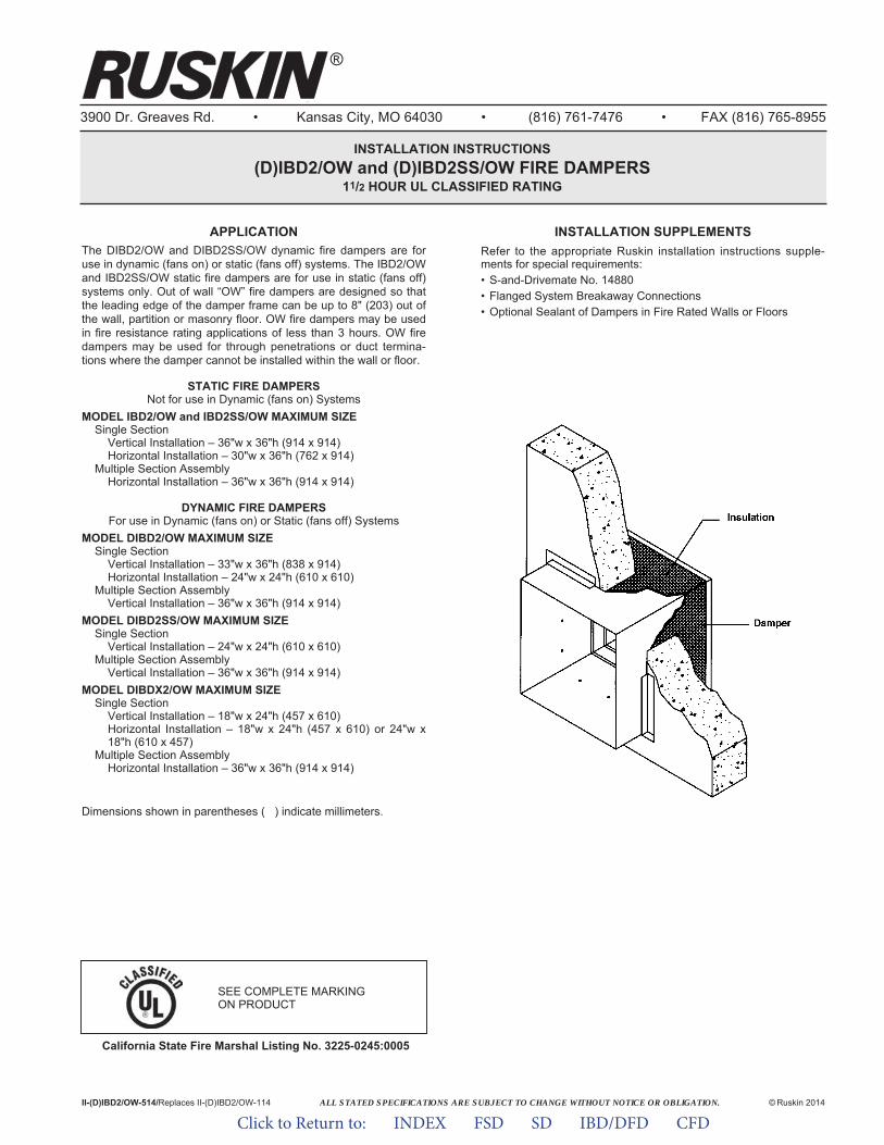
ALL STATED SPECIFICATIONS ARE SUBJECT TO CHANGE WITHOUT NOTICE OR OBLIGATION.
3900 Dr. Greaves Rd. • Kansas City, MO 64030 • (816) 761-7476 • FAX (816) 765-8955
INSTALLATION INSTRUCTIONS(D)IBD2/OW and (D)IBD2SS/OW FIRE DAMPERS
11/2 HOUR UL CLASSIFIED RATING
II-(D)IBD2/OW-514/Replaces II-(D)IBD2/OW-114 © Ruskin 2014
INSTALLATION SUPPLEMENTSRefer to the appropriate Ruskin installation instructions supple-ments for special requirements:• S-and-Drivemate No. 14880• Flanged System Breakaway Connections• Optional Sealant of Dampers in Fire Rated Walls or Floors
APPLICATIONThe DIBD2/OW and DIBD2SS/OW dynamic fire dampers are foruse in dynamic (fans on) or static (fans off) systems. The IBD2/OWand IBD2SS/OW static fire dampers are for use in static (fans off)systems only. Out of wall “OW” fire dampers are designed so thatthe leading edge of the damper frame can be up to 8" (203) out ofthe wall, partition or masonry floor. OW fire dampers may be usedin fire resistance rating applications of less than 3 hours. OW firedampers may be used for through penetrations or duct termina-tions where the damper cannot be installed within the wall or floor.
STATIC FIRE DAMPERSNot for use in Dynamic (fans on) Systems
MODEL IBD2/OW and IBD2SS/OW MAXIMUM SIZESingle Section
Vertical Installation – 36"w x 36"h (914 x 914)Horizontal Installation – 30"w x 36"h (762 x 914)
Multiple Section AssemblyHorizontal Installation – 36"w x 36"h (914 x 914)
DYNAMIC FIRE DAMPERSFor use in Dynamic (fans on) or Static (fans off) Systems
MODEL DIBD2/OW MAXIMUM SIZESingle Section
Vertical Installation – 33"w x 36"h (838 x 914)Horizontal Installation – 24"w x 24"h (610 x 610)
Multiple Section AssemblyVertical Installation – 36"w x 36"h (914 x 914)
MODEL DIBD2SS/OW MAXIMUM SIZESingle Section
Vertical Installation – 24"w x 24"h (610 x 610)Multiple Section Assembly
Vertical Installation – 36"w x 36"h (914 x 914)MODEL DIBDX2/OW MAXIMUM SIZE
Single SectionVertical Installation – 18"w x 24"h (457 x 610) Horizontal Installation – 18"w x 24"h (457 x 610) or 24"w x18"h (610 x 457)
Multiple Section AssemblyHorizontal Installation – 36"w x 36"h (914 x 914)
Dimensions shown in parentheses ( ) indicate millimeters.
California State Fire Marshal Listing No. 3225-0245:0005
SEE COMPLETE MARKING ON PRODUCT
®
Click to Return to: INDEX FSD SD IBD/DFD CFD
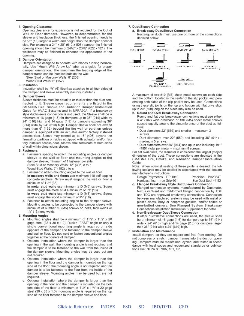
1. Opening ClearanceOpening clearance for expansion is not required for the Out ofWall or Floor dampers. However, to accommodate for thesleeve and insulation thickness, the finished opening needs tobe 1/2" (13) larger in width and height than the damper nominalsize. For example a 24" x 20" (610 x 508) damper the finishedopening should be minimum of 241/2" x 201/2" (622 x 521). Thewallboard may be finished to enhance the appearance of theopening.
2. Damper OrientationDampers are designed to operate with blades running horizon-tally. Use “Mount With Arrow Up” label as a guide for properdamper orientation. The maximum the leading edge of thedamper frame can be installed outside the wall:
Steel Stud or Masonry Walls: 8” (203)Wood Stud Walls: 6” (152)
3. InsulationInsulation shall be 1/4" (6) fiberfrax attached to all four sides ofthe damper and sleeve assembly (factory installed).
4. Damper SleeveSleeve thickness must be equal to or thicker than the duct con-nected to it. Sleeve gage requirements are listed in theSMACNA Fire, Smoke and Radiation Damper InstallationGuide for HVAC Systems and in NFPA90A. If a breakawaystyle duct/sleeve connection is not used, the Sleeve shall be aminimum of 16 gage (1.6) for dampers up to 36" (914) wide by24" (610) high and 14 gage (1.9) for dampers exceeding 36"(914) wide by 24" (610) high. Damper sleeve shall not extendmore than 6" (152) beyond the fire wall or partition unlessdamper is equipped with an actuator and/or factory installedaccess door. Sleeve may extend up to 16" (406) beyond thefirewall or partition on sides equipped with actuator and/or fac-tory installed access door. Sleeve shall terminate at both sidesof wall within dimensions shown.
5. Fastenersa. Fasteners spacing to attach the mounting angles or damper
sleeve to the wall or floor and mounting angles to thedamper sleeve, minimum of 1 fastener per side.Steel Stud or Masonry Walls: 12” (305) c-to-cWood Stud Walls: 6” (152) c-to-c
b. Fastener to attach mounting angles to the wall or floor.In masonry walls and floors use minimum #10 self-tappingconcrete anchors. Screw must engage the wall or floor aminimum of 11/2" (38).In metal stud walls use minimum #10 (M5) screws. Screwmust engage the metal stud a minimum of 1/2" (13).In wood stud walls use minimum #10 (M5) screws. Screwmust engage the wood a minimum of 3/4" (19).
c. Fastener to attach mounting angles to the damper sleeve.Mounting angles to be connected to the damper sleeve withminimum of number 10 (M5) screws on bolts, tack welds or1/2" (13) long welds.
6. Mounting Anglesa. Mounting angles shall be a minimum of 11/2" x 11/2" x 20
gage steel (38 x 38 x 1.0). Ruskin “FAST” angle or only asingle conventional mounting angle is required on sideopposite of the damper and fastened to the damper sleeveand wall or floor. Do not weld or fasten conventional anglestogether at the corners of damper.
b. Optional installation where the damper is larger than theopening in the wall, the mounting angle is not required andthe damper is to be fastened to the wall from the inside ofthe damper sleeve. Mounting angles may be used but arenot required.
c. Optional installation where the damper is larger than theopening in the floor and the damper is mounted on the topside of the floor, the mounting angle is not required and thedamper is to be fastened to the floor from the inside of thedamper sleeve. Mounting angles may be used but are notrequired.
d. Optional installation where the damper is larger than theopening in the floor and the damper is mounted on the bot-tom side of the floor, a minimum of 11/2" x 11/2" x 20 gagesteel (38 x 38 x 1.0) mounting angle is required on the topside of the floor fastened to the damper sleeve and floor.
7. Duct/Sleeve Connectiona. Break-away Duct/Sleeve Connection
Rectangular ducts must use one or more of the connectionsdepicted below:
A maximum of two #10 (M5) sheet metal screws on each sideand the bottom, located in the center of the slip pocket and pen-etrating both sides of the slip pocket may be used. Connectionsusing these slip joints on the top and bottom with flat drive slipsup to 20" (508) long on the sides may also be used.b. Round and Oval Break-away Connection
Round and flat oval break-away connections must use eithera 4" (102) wide drawband or #10 (M5) sheet metal screwsspaced equally around the circumference of the duct as fol-lows:• Duct diameters 22" (559) and smaller – maximum 3
screws.• Duct diameters over 22" (559) and including 36" (914) –
maximum 5 screws.• Duct diameters over 36" (914) and up to and including 191"
(4851) total perimeter – maximum 8 screws.For flat oval ducts, the diameter is considered the largest (major)dimension of the duct. These connections are depicted in theSMACNA Fire, Smoke, and Radiation Damper InstallationGuide.Note: When optional sealing of these joints is desired, the fol-lowing sealants may be applied in accordance with the sealantmanufacturer's instructions:
Design Polymerics – DP 1010 Precision – PA2084THardcast, Inc. – Iron Grip 601 Eco Duct Seal 44-52
c. Flanged Break-away Style Duct/Sleeve ConnectionFlanged connection systems manufactured by Ductmate,Nexus or Ward and roll-formed flanged connection by TDFand TDC are approved breakaway connections. Connectionbetween manufactured systems may be used with metal orplastic cleats, Butyl or neoprene gaskets, and/or bolted ornon-bolted corners. See Flanged System BreakawayConnections Installation Instruction Supplement for detail.
d. Non-Break-away Duct/Sleeve ConnectionIf other duct/sleeve connections are used, the sleeve shallbe a minimum of 16 gage (1.6) for dampers up to 36" (914)wide x 24" (610) high and 14 gage (2.0) for dampers largerthan 36" (914) wide x 24" (610) high.
8. Installation and MaintenanceInstall dampers so they are square and free from racking. Donot compress or stretch damper frames into the duct or open-ing. Dampers must be maintained, cycled, and tested in accor-dance with local codes and recognized standards or publica-tions like: NFPA 80, 90A, 101, etc.
Click to Return to: INDEX FSD SD IBD/DFD CFD
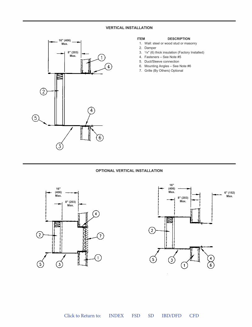
ITEM DESCRIPTION1. Wall: steel or wood stud or masonry2. Damper3. 1/4" (6) thick insulation (Factory Installed)4. Fasteners – See Note #55. Duct/Sleeve connection6. Mounting Angles – See Note #67. Grille (By Others) Optional
16" (406)Max.
8" (203)Max.
VERTICAL INSTALLATION
OPTIONAL VERTICAL INSTALLATION
16"(406)Max.
8" (203)Max.
16"(406)Max.
8" (203)Max.
6" (152)Max.
Click to Return to: INDEX FSD SD IBD/DFD CFD
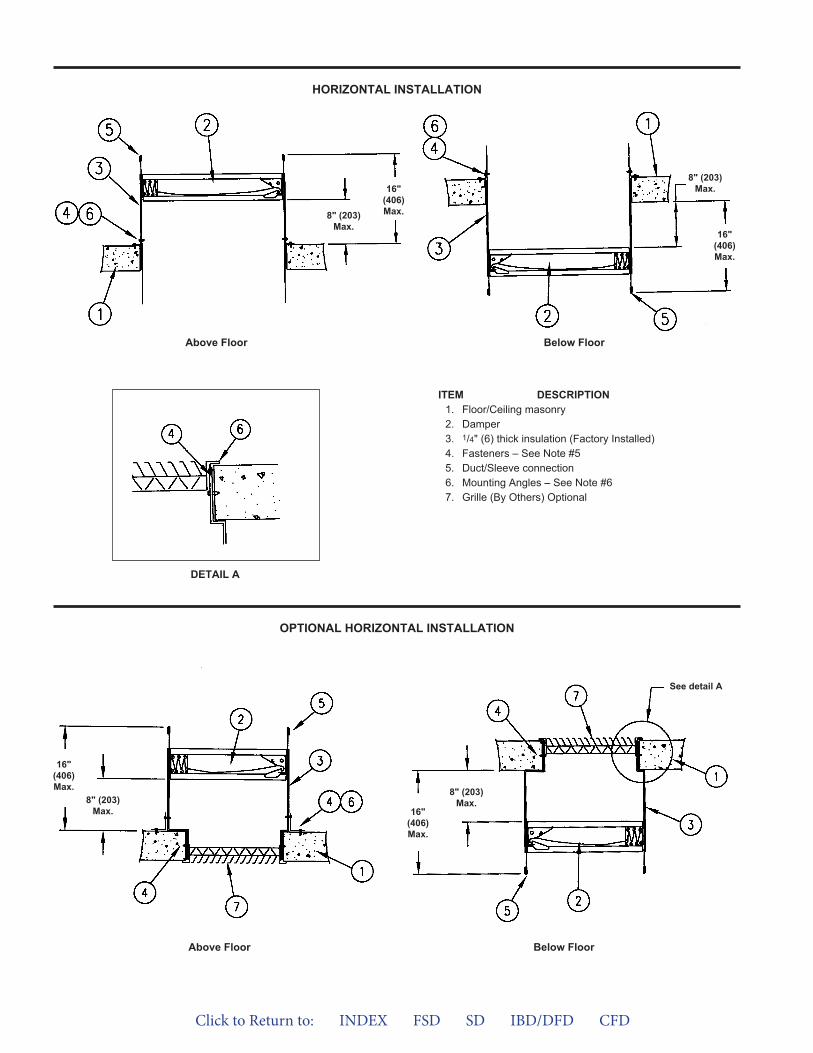
OPTIONAL HORIZONTAL INSTALLATION
ITEM DESCRIPTION1. Floor/Ceiling masonry2. Damper3. 1/4" (6) thick insulation (Factory Installed)4. Fasteners – See Note #55. Duct/Sleeve connection6. Mounting Angles – See Note #67. Grille (By Others) Optional
16"(406)Max.8" (203)
Max.16"
(406)Max.
8" (203)Max.
HORIZONTAL INSTALLATION
DETAIL A
Below Floor
Above Floor Below Floor
Above Floor
16"(406)Max.
8" (203)Max. 16"
(406)Max.
8" (203)Max.
See detail A
Click to Return to: INDEX FSD SD IBD/DFD CFD
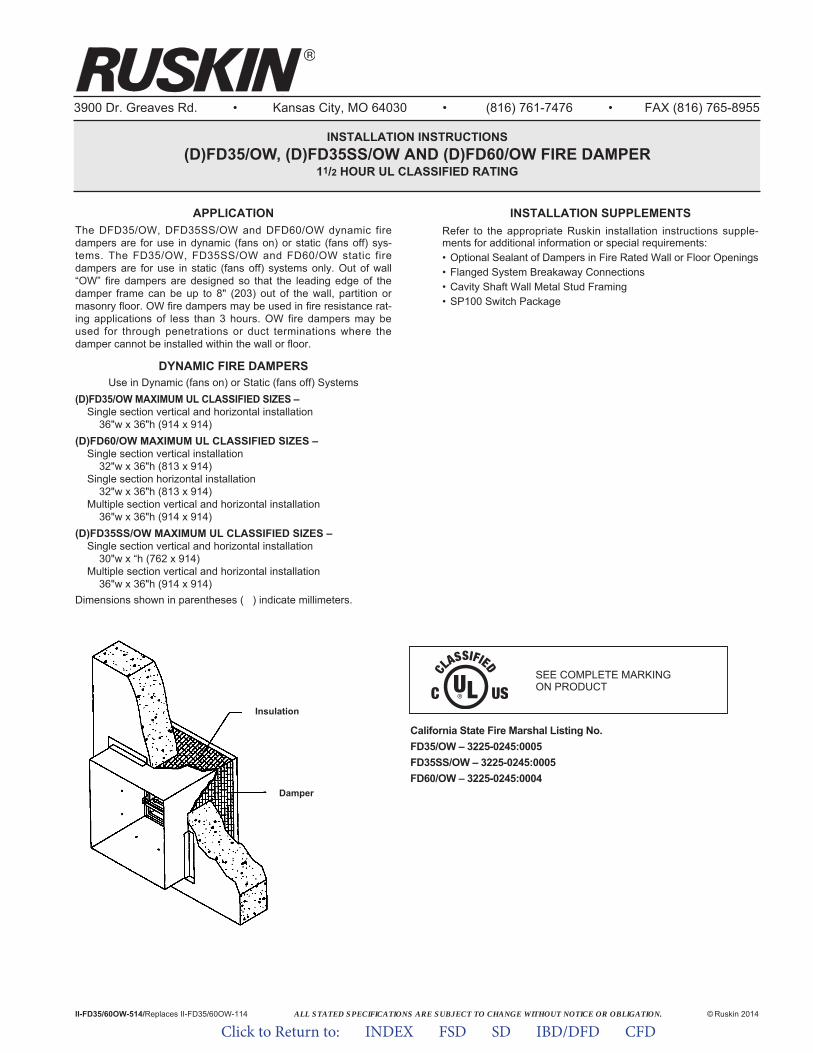
ALL STATED SPECIFICATIONS ARE SUBJECT TO CHANGE WITHOUT NOTICE OR OBLIGATION.
3900 Dr. Greaves Rd. • Kansas City, MO 64030 • (816) 761-7476 • FAX (816) 765-8955
INSTALLATION INSTRUCTIONS(D)FD35/OW, (D)FD35SS/OW AND (D)FD60/OW FIRE DAMPER
11/2 HOUR UL CLASSIFIED RATING
II-FD35/60OW-514/Replaces II-FD35/60OW-114 © Ruskin 2014
APPLICATIONThe DFD35/OW, DFD35SS/OW and DFD60/OW dynamic firedampers are for use in dynamic (fans on) or static (fans off) sys-tems. The FD35/OW, FD35SS/OW and FD60/OW static firedampers are for use in static (fans off) systems only. Out of wall“OW” fire dampers are designed so that the leading edge of thedamper frame can be up to 8" (203) out of the wall, partition ormasonry floor. OW fire dampers may be used in fire resistance rat-ing applications of less than 3 hours. OW fire dampers may beused for through penetrations or duct terminations where thedamper cannot be installed within the wall or floor.
DYNAMIC FIRE DAMPERSUse in Dynamic (fans on) or Static (fans off) Systems
(D)FD35/OW MAXIMUM UL CLASSIFIED SIZES –Single section vertical and horizontal installation
36"w x 36"h (914 x 914)(D)FD60/OW MAXIMUM UL CLASSIFIED SIZES –
Single section vertical installation32"w x 36"h (813 x 914)
Single section horizontal installation32"w x 36"h (813 x 914)
Multiple section vertical and horizontal installation36"w x 36"h (914 x 914)
(D)FD35SS/OW MAXIMUM UL CLASSIFIED SIZES –Single section vertical and horizontal installation
30"w x “h (762 x 914)Multiple section vertical and horizontal installation
36"w x 36"h (914 x 914)Dimensions shown in parentheses ( ) indicate millimeters.
Insulation
Damper
INSTALLATION SUPPLEMENTSRefer to the appropriate Ruskin installation instructions supple-ments for additional information or special requirements:• Optional Sealant of Dampers in Fire Rated Wall or Floor Openings• Flanged System Breakaway Connections• Cavity Shaft Wall Metal Stud Framing• SP100 Switch Package
SEE COMPLETE MARKING ON PRODUCT
California State Fire Marshal Listing No.FD35/OW – 3225-0245:0005FD35SS/OW – 3225-0245:0005FD60/OW – 3225-0245:0004
Click to Return to: INDEX FSD SD IBD/DFD CFD
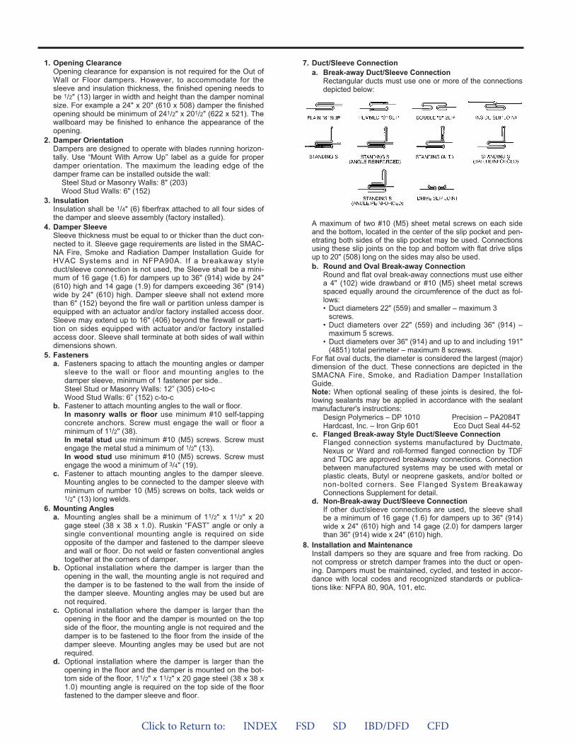
1. Opening ClearanceOpening clearance for expansion is not required for the Out ofWall or Floor dampers. However, to accommodate for thesleeve and insulation thickness, the finished opening needs tobe 1/2" (13) larger in width and height than the damper nominalsize. For example a 24" x 20" (610 x 508) damper the finishedopening should be minimum of 241/2" x 201/2" (622 x 521). Thewallboard may be finished to enhance the appearance of theopening.
2. Damper OrientationDampers are designed to operate with blades running horizon-tally. Use “Mount With Arrow Up” label as a guide for properdamper orientation. The maximum the leading edge of thedamper frame can be installed outside the wall:
Steel Stud or Masonry Walls: 8" (203)Wood Stud Walls: 6" (152)
3. InsulationInsulation shall be 1/4" (6) fiberfrax attached to all four sides ofthe damper and sleeve assembly (factory installed).
4. Damper SleeveSleeve thickness must be equal to or thicker than the duct con-nected to it. Sleeve gage requirements are listed in the SMAC-NA Fire, Smoke and Radiation Damper Installation Guide forHVAC Systems and in NFPA90A. If a breakaway styleduct/sleeve connection is not used, the Sleeve shall be a mini-mum of 16 gage (1.6) for dampers up to 36" (914) wide by 24"(610) high and 14 gage (1.9) for dampers exceeding 36" (914)wide by 24" (610) high. Damper sleeve shall not extend morethan 6" (152) beyond the fire wall or partition unless damper isequipped with an actuator and/or factory installed access door.Sleeve may extend up to 16" (406) beyond the firewall or parti-tion on sides equipped with actuator and/or factory installedaccess door. Sleeve shall terminate at both sides of wall withindimensions shown.
5. Fastenersa. Fasteners spacing to attach the mounting angles or damper
sleeve to the wall or floor and mounting angles to thedamper sleeve, minimum of 1 fastener per side..Steel Stud or Masonry Walls: 12” (305) c-to-cWood Stud Walls: 6” (152) c-to-c
b. Fastener to attach mounting angles to the wall or floor.In masonry walls or floor use minimum #10 self-tappingconcrete anchors. Screw must engage the wall or floor aminimum of 11/2" (38).In metal stud use minimum #10 (M5) screws. Screw mustengage the metal stud a minimum of 1/2" (13).In wood stud use minimum #10 (M5) screws. Screw mustengage the wood a minimum of 3/4" (19).
c. Fastener to attach mounting angles to the damper sleeve.Mounting angles to be connected to the damper sleeve withminimum of number 10 (M5) screws on bolts, tack welds or1/2" (13) long welds.
6. Mounting Anglesa. Mounting angles shall be a minimum of 11/2" x 11/2" x 20
gage steel (38 x 38 x 1.0). Ruskin “FAST” angle or only asingle conventional mounting angle is required on sideopposite of the damper and fastened to the damper sleeveand wall or floor. Do not weld or fasten conventional anglestogether at the corners of damper.
b. Optional installation where the damper is larger than theopening in the wall, the mounting angle is not required andthe damper is to be fastened to the wall from the inside ofthe damper sleeve. Mounting angles may be used but arenot required.
c. Optional installation where the damper is larger than theopening in the floor and the damper is mounted on the topside of the floor, the mounting angle is not required and thedamper is to be fastened to the floor from the inside of thedamper sleeve. Mounting angles may be used but are notrequired.
d. Optional installation where the damper is larger than theopening in the floor and the damper is mounted on the bot-tom side of the floor, 11/2" x 11/2" x 20 gage steel (38 x 38 x1.0) mounting angle is required on the top side of the floorfastened to the damper sleeve and floor.
7. Duct/Sleeve Connectiona. Break-away Duct/Sleeve Connection
Rectangular ducts must use one or more of the connectionsdepicted below:
A maximum of two #10 (M5) sheet metal screws on each sideand the bottom, located in the center of the slip pocket and pen-etrating both sides of the slip pocket may be used. Connectionsusing these slip joints on the top and bottom with flat drive slipsup to 20" (508) long on the sides may also be used.b. Round and Oval Break-away Connection
Round and flat oval break-away connections must use eithera 4" (102) wide drawband or #10 (M5) sheet metal screwsspaced equally around the circumference of the duct as fol-lows:• Duct diameters 22" (559) and smaller – maximum 3
screws.• Duct diameters over 22" (559) and including 36" (914) –
maximum 5 screws.• Duct diameters over 36" (914) and up to and including 191"
(4851) total perimeter – maximum 8 screws.For flat oval ducts, the diameter is considered the largest (major)dimension of the duct. These connections are depicted in theSMACNA Fire, Smoke, and Radiation Damper InstallationGuide.Note: When optional sealing of these joints is desired, the fol-lowing sealants may be applied in accordance with the sealantmanufacturer's instructions:
Design Polymerics – DP 1010 Precision – PA2084THardcast, Inc. – Iron Grip 601 Eco Duct Seal 44-52
c. Flanged Break-away Style Duct/Sleeve ConnectionFlanged connection systems manufactured by Ductmate,Nexus or Ward and roll-formed flanged connection by TDFand TDC are approved breakaway connections. Connectionbetween manufactured systems may be used with metal orplastic cleats, Butyl or neoprene gaskets, and/or bolted ornon-bolted corners. See Flanged System BreakawayConnections Supplement for detail.
d. Non-Break-away Duct/Sleeve ConnectionIf other duct/sleeve connections are used, the sleeve shallbe a minimum of 16 gage (1.6) for dampers up to 36" (914)wide x 24" (610) high and 14 gage (2.0) for dampers largerthan 36" (914) wide x 24" (610) high.
8. Installation and MaintenanceInstall dampers so they are square and free from racking. Donot compress or stretch damper frames into the duct or open-ing. Dampers must be maintained, cycled, and tested in accor-dance with local codes and recognized standards or publica-tions like: NFPA 80, 90A, 101, etc.
Click to Return to: INDEX FSD SD IBD/DFD CFD

VERTICAL INSTALLATION
OPTIONAL VERTICAL INSTALLATION
ITEM DESCRIPTION1. Wall: steel or wood stud or masonry2. Damper3. 1/4" (6) thick insulation (Factory Installed)4. Fasteners – See Note #55. Duct/Sleeve connection6. Mounting Angles – See Note #67. Grille (By Others) Optional
6"(152)Max.
16"(406)Max.
8"(203)Max.
6"(152)Max.
16"(406)Max. 8"
(203)Max.
Click to Return to: INDEX FSD SD IBD/DFD CFD
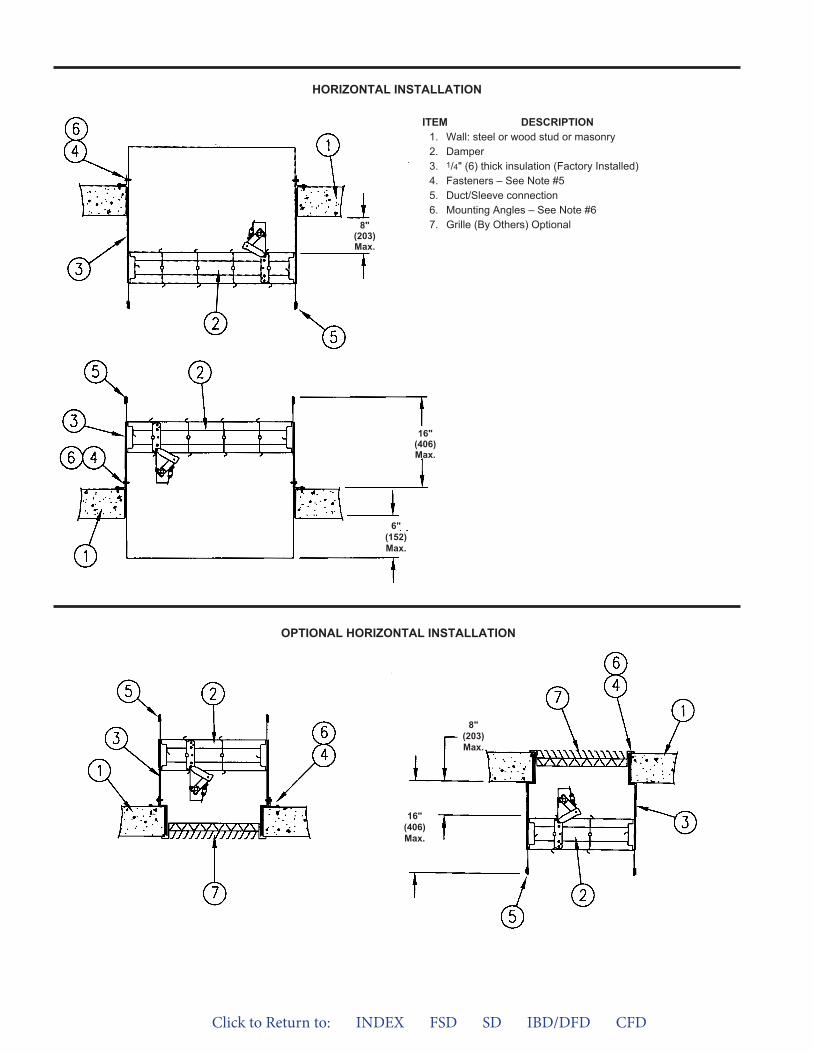
OPTIONAL HORIZONTAL INSTALLATION
HORIZONTAL INSTALLATION
6"(152)Max.
16"(406)Max.
8"(203)Max.
16"(406)Max.
8"(203)Max.
ITEM DESCRIPTION1. Wall: steel or wood stud or masonry2. Damper3. 1/4" (6) thick insulation (Factory Installed)4. Fasteners – See Note #55. Duct/Sleeve connection6. Mounting Angles – See Note #67. Grille (By Others) Optional
Click to Return to: INDEX FSD SD IBD/DFD CFD

®
Click to Return to: INDEX FSD SD IBD/DFD CFD
FIRE AND COMBINATION FIRE SMOKE DAMPERS FOR GRILLE MOUNTINGUL555 CLASSIFIED
1½ HR. RATING
APPLICATIONIBD2G, IBD2SSG (Static) and DIBD2G, DIBD2SSG (Dynamic) curtain type fire dampers for grille installation may be installed vertically in walls or horizontally in floors with fire resistance ratings of less than 3 hours. Model ‘G’ curtain fire dampers are offset in a sleeve to fit within the wall/floor plane behind the customer’s supplied grille. The damper/sleeve assembly is installed with angle one side (FAST) to allow the use of all types of grilles.
Model ‘G’ dampers require access to both sides of the wall/floor for the proper installation; however access through the grille for inspec-tion or maintenance is permissible.
For application where the damper would be installed outside the plane of the wall or floor refer to model GA (Grille Access) or OW (Out of Wall).
FEATURES• Dampers are produced in an ISO 9001 certified factory
• FAST Angle factory supplied for labor saving angle one-sideinstallation.
OPTIONS• FM Approvals as Specification Tested Product.
• SP200 Switch Package to allow remote indication of damperblade position.
• Factory Sleeves of various lengths and gages to ensure fieldcompliance with UL installation requirements.
• Fusible Links 165ºF (74ºC) is standard. 212ºF (100ºC) and285ºF (141ºC) are optional
Models meets the requirements for combination fire and smoke dampers established by:
• National Fire Protection Association NFPA Standards 80, 90A, 92A, 92B, 101 and 105.
• ICC International Building Codes• New York City (MEA 252-05-E)
SPECIFICATIONS
Damper
All Models
Frame
Galvanized Steel(in gages required by UL listing R5531)
Blades
Galvanized Steel(in gages required by UL listing R5531)
Closure Springs
301 stainless steelWhen Required
Hourly Rating
1½
MAXIMUM UL CLASSIFIED DAMPER SIZES
Damper
DIBD2G
DIBD20G
IBD2G
IBD20G
DIBD2SSG
IBD2SSG
(D)FD35G
(D)FD60G
FSD36G
FSD60G
Minimum Size**
Vertical Horizontal
4" x 4"(102 x 102)
6" x 6"(152 x 152)
4" x 4"(102 x 102)
6" x 6"(152 x 152)
6" x 6"(152 x 152)
6" x 6"(152 x 152)
Maximum Single Section
Vertical Horizontal
Maximum Multiple Section**
Vertical Horizontal**
72" x 48"(1828 x 1219) N/A
33" x 36"(838 x 914) N/A
90" x 48" 90" x 48"(2286 x 1219) (2286 x 1219)
33" x 38"(838 x 965) N/A
72" x 48"(1828 x 1219) N/A
90" x 48" 90” x 48”(2286 x 1219) (2286 x 1219)
6" x 6"(152 x 152)
33" x 36"(838 x 914)
24" x 24"(610 x 610)
36" x 36"(914 x 914)
33" x 38"(838 x 965)
24" x 24"(610 x 610)
24" x 24"(610 x 610)
36" x 36"(914 x 914)
33" x 38"(838 x 965)
36" x 48"(914 x 1219)
36" x 48"(914 x 1219)
32" x 48"(813 x 1219)
30" x 48"(762 x 1219) 90" x 48"
(2286 x 1219)90" x 48"
(2286 x 1219)36" x 48"(914 x 1219)
36" x 48"(914 x 1219)
32" x 48"(813 x 1219)
30" x 48"(762 x 1219)
8" x 6"(203 x 152)
8" x 6"(203 x 152)
* Dynamic sizes listed above are for ratings of 2000 fpm (10.2 m/s) and 4 in. wg(1 kPa)** See product data sheets for more details on single and multiple section sizing.
ALL STATED SPECIFICATIONS ARE SUBJECT TO CHANGE WITHOUT NOTICE OR OBLIGATION.
3900 Dr. Greaves Rd. • Kansas City, MO 64030 • (816) 761-7476 • FAX (816) 765-8955
INSTALLATION INSTRUCTIONS(D)IBD2G, (D)IBD2SSG, (D)IBD20G, IBDTG
CURTAIN TYPE FIRE DAMPERS FOR GRILLE MOUNTING11/2 HOUR UL555 CLASSIFIED
APPLICATIONThe Model G curtain fire damper is designed to be mounted behinda grille in the wall or floor. Model G dampers are offset in the dampersleeve for appropriate damper placement within the wall or floor.Model G dampers are designed for one side-mounting angle instal-lation. Sleeve and/or mounting angles may be factory or field fur-nished. Grille may be installed on both sides of the wall or floor if noduct connection is required (Grille by others).
STATIC FIRE DAMPERSNot for use in Dynamic (fans on) Systems.
MODEL IBD2G and IBD2SSG MAXIMUM SIZESingle Section
Vertical – 48"w x 30"h (1219 x 762) or 33"w x 48"h or (838x 1219) or 36"w x 36"h (914 x 914).
Horizontal – 30"w x 451/2"h (762 x 1156) or 33"w x 38"h (838x 965).
Multiple Section AssemblyVertical – 90"w x 48"h (2286 x 1219) or 48"w x 72"h (1219 x
x 1829).Horizontal – 90"w x 48"h (2286 x 1219) or 48"w x 90"h (1219
x 2286). MODEL IBD20G MAXIMUM SIZE
Single SectionVertical – 48"w x 30"h (1219 x 762) or 33"w x 48"h or (838
1219) or 36"w x 36"h (914 x 914).Horizontal – 30"w x 451/2"h (762 x 1156) or 33"w x 38"h (838
x 965).MODEL IBDTG, IBDT1G and IBDT2G MAXIMUM SIZE
Single SectionVertical – 40"w x 48"h (1016 x 1219).Horizontal – 60"w x 12"h (1524 x 305).
DYNAMIC FIRE DAMPERSUse in Dynamic (fans on) or Static (fans off) Systems
MODEL DIBD2G MAXIMUM SIZESingle Section
Vertical – 33"w x 36"h (838 x 914).Horizontal – 24"w x 24"h (610 x 610).
Multiple Section AssemblyVertical – 72"w x 48"h (1828 x 1219) or 48"w x 72"h (1219 x
1829).MODEL DIBDX2G MAXIMUM SIZE
Single SectionHorizontal – 18"w x 24"h (457 x 610) or 24"w x 18"h (610 x
457).Multiple Section
Horizontal – 36"w x 48"h (914 x 1219) or 48"w x 36"h (1219 x914).
MODEL DIBD2SSG MAXIMUM SIZESingle Section
Vertical or Horizontal – 24"w x 24"h (610 x 610).Multiple Section Assembly
Vertical – 72"w x 48"h (1829 x 1219) or 48"w x 72"h (1219 x 1829).
MODEL DIBD20G MAXIMUM SIZESingle Section
Vertical – 33"w x 36"h (838 x 914).Horizontal – 24"w x 24"h (610 x 610).
II-(D)IBDG-714/Replaces II-(D)IBDG-114 © Ruskin 2014
INSTALLATION SUPPLEMENTSRefer to the appropriate Ruskin installation instruction supplementsfor additional information or special requirements:• Optional Sealant of Dampers in Fire Rated Wall or Floor Openings• Transfer Openings and Duct Terminations• Optional FireStop Material• Extension of Fire and Combination Fire and Smoke Damper
Sleeves• Fire and Combination Fire and Smoke Dampers Installation in
Concrete Floor with Steel Deck• Drivemate No. 14880 Breakaway Connection• Flanged System Breakaway Connections• Cavity Shaft Wall Metal Stud Framing
Notes:1. Dimensions shown in parentheses ( ) indicate millimeters.2. All multiple section dampers are constructed of equal single
section sizes no greater than the maximum single section sizesindicated above.
California State Fire Marshal Listing No. 3225-245:0005
SEE COMPLETE MARKING ON PRODUCT
Click to Return to: INDEX FSD SD IBD/DFD CFD

1. Opening ClearanceThe opening in the wall or floor shall be larger than the damper/sleeve assembly to permit installation and expansion. The maxi-mum opening size shall not exceed 1/8" (3) (3/16" for stn. stl.) perfoot (3 per 305), nor shall be less than 1/4" (6) larger than thedamper/sleeve assembly. The opening shall be a maximum of 1"(25) larger than the overall size of the damper/sleeve assembly.
2. Fasteners and Multiple Section AssemblyUse No. 10 (M5) bolts or screws, 3/16" (5) rivets, tack welds orspot welds as depicted in figures 1 and 2 and spaced as followswhen joining individual dampers to make multiple section damperassemblies or when fastening damper to the sleeve:
Vertical Mount (In wall)Galvanized steel dampers 12" (305) spacing Stainless steel dampers 6" (152) spacing
Horizontal Mount (In floor)All dampers 6" (152) spacing
Multiple section horizontal mount dampers require a 14 gagethick x 41/2" (2 x 114) wide steel reinforcing plate sandwichedbetween the damper frames with No. 10 (M5) bolts or screws,3/16" (5) rivets, tack welds or spot welds staggered intermittentlyand spaced on maximum 6" (152) centers. The reinforcing platemust be the same material as the dampers. The length must beequal to the damper width of two or more adjoining damper sec-tions. Reinforcing plates are not required for assemblies consist-ing of two dampers attached end-to-end or three dampersattached side-to-side as depicted in figure 3.
3. Damper SleeveSleeve thickness must be equal to or thicker than the duct con-nected to it. Sleeve gage requirements are listed in the SMACNAFire, Smoke and Radiation Damper Installation Guide for HVACSystems and in NFPA90A. If a breakaway style duct/sleeve con-nection is not used, the sleeve shall be a minimum of 16 gage (1.6)for dampers up to 36" (914) high and 14 gage (1.9) for dampersexceeding 36" (914) wide by 24" (610) high. Damper sleeve shallnot extend more than 6" (152) beyond the fire wall or partitionunless damper is equipped with installed access door. Sleeve mayextend up to 16" (406) beyond the fire wall or partition on sideequipped with a factory installed access door. Sleeve shall termi-nate at both sides of wall within dimensions shown.
4. Damper OrientationUse "Air Flow" and "Mount with Arrow Up" labels on DynamicDIBD and DIBDX models for proper damper orientation. ForStatic IBD models use only "Mount With Arrow Up" label ondamper for proper damper orientation.
5. Mounting AnglesMounting angles shall be a minimum of 11/2" x 11/2" x 20 gage steel(38 x 38 x 1.0). For openings in metal stud, wood stud walls orconcrete/masonry walls and floors of sizes 90" x 48" (2286 x 1219)or 48" x 90" (1219 x 2286) and less. Mounting angles are onlyrequired on one side of the wall or topside of the floor and must beattached to both the sleeve and the wall or floor. Mounting anglesneed to overlay the wall or Floor by minimum of 1" (25). Mountingangles may be installed directly to the metal studs under the wall-board on metal stud installation only. For larger openings see"Transfer Opening and Duct Termination" installation supplement.a. Mounting Angle Fasteners
Sleeve: #10 bolts or screws, 3/16" (3) steel rivets or 1/2" (13) longor welds.Masonry/Wall or Floor: #10 self-tapping concrete screws.Wood/Steel Stud Wall: #10 screws
b. Mounting Angle Fastener SpacingSleeve fasteners shall be spaced at 6" (152) o.c. and the wall orfloor fasteners shall be spaced at 12" (305) o.c. with a minimumof 2 on each side, top and bottom. Screw fasteners used inmetal stud must engage the metal stud a minimum of 1/2" (13).Screw fasteners used in wood stud must engage the wood aminimum of 3/4" (19). Screw fasteners used in masonry walls orfloors must engage the wall a minimum of 11/2" (38).
6. Duct/Sleeve Connectionsa. Break-away Duct/Sleeve Connections
Rectangular ducts must use one or more of the connectionsdepicted: below:
A maximum of two #10 (M5) sheet metal screws on each sideand the bottom, located in the center of the slip pocket andpenetrating both sides of the slip pocket may be used. Con-nections using these slip joints on the top and bottom with flatdrive slips up to 20" (508) long on the sides may also be used.
b. Round and Oval Break-away ConnectionsRound and flat oval break-away connections must use eithera 4" (102) wide drawband or #10 (M5) sheet metal screwsspaced equally around the circumference of the duct as fol-lows:• Duct diameters 22" (559) and smaller – Maximum 3
screws.• Duct diameters over 22" (559) and including 36" (914) –
Maximum 5 screws.• Duct diameters over 36" (914) and up to and including
191" (4851) total perimeter – Maximum 8 screws.For flat oval ducts, the diameter is considered the largest (major)dimension of the duct. These connections are depicted in theSMACNA Fire, Smoke, and Radiation Damper Installation Guide.Note: When optional sealing of these joints is desired, the follow-ing sealants may be applied in accordance with the sealant man-ufacturer's instructions:
Design Polymerics – DP 1010 Precision – PA2084THardcast, Inc. – Iron Grip 601 Eco Duct Seal 44-52
c. Flanged Break-away Style Duct Sleeve Connections.Flanged connection systems manufactured by Ductmate,Nexus or Ward are approved break-away connections wheninstalled as shown on the "Flanged System Breakaway Con-nections Supplement."TDC and TDF roll-formed flanged connections using 3/8" (10)steel bolts and nuts, and metal cleats, as tested by SMACNA,are approved break-away connections when installed asshown on the "Flanged System Breakaway Connections Sup-plement."
d. Non-Break-away Duct/Sleeve ConnectionsIf other duct sleeve connections are used, the sleeve shall bea minimum of 16 gage (1.6) for dampers up to 36" (914) widex 24" (610) high and 14 gage (2.0) for dampers exceeding 36"(914) wide x 24" (610) high.
7. Installation and MaintenanceTo ensure optimum operation and performance, the damper mustbe installed so it is square and free from racking. Each firedamper should be maintained and tested on a regular basis andin accordance with the latest editions of NFPA 90A and localcodes. Care should be exercised to ensure that such tests areperformed safely and do not cause system damage.
Click to Return to: INDEX FSD SD IBD/DFD CFD
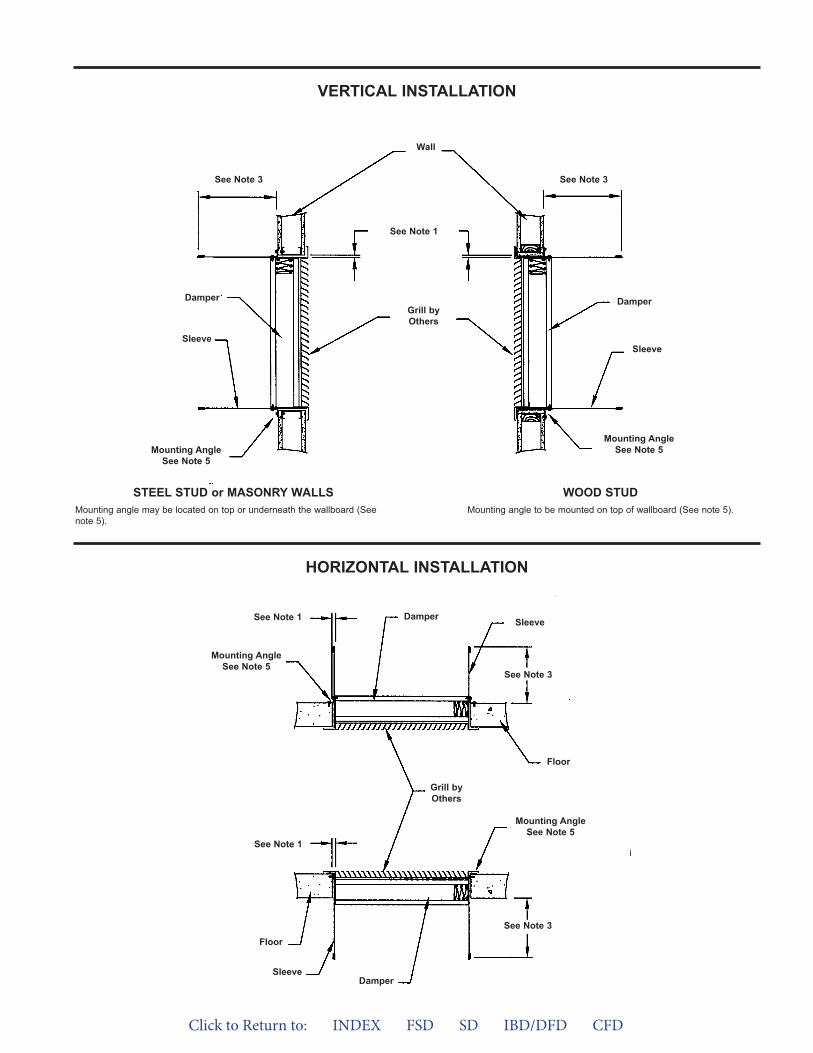
VERTICAL INSTALLATION
HORIZONTAL INSTALLATION
Wall
See Note 1
Grill byOthers
See Note 3
Damper
Sleeve
Mounting AngleSee Note 5
Mounting AngleSee Note 5
Damper
Sleeve
See Note 3
Damper
Grill byOthers
See Note 1
Floor
Sleeve
Mounting AngleSee Note 5
Mounting AngleSee Note 5
Floor
See Note 3
See Note 3
SleeveSee Note 1
Damper
STEEL STUD or MASONRY WALLSMounting angle may be located on top or underneath the wallboard (Seenote 5).
WOOD STUDMounting angle to be mounted on top of wallboard (See note 5).
Click to Return to: INDEX FSD SD IBD/DFD CFD
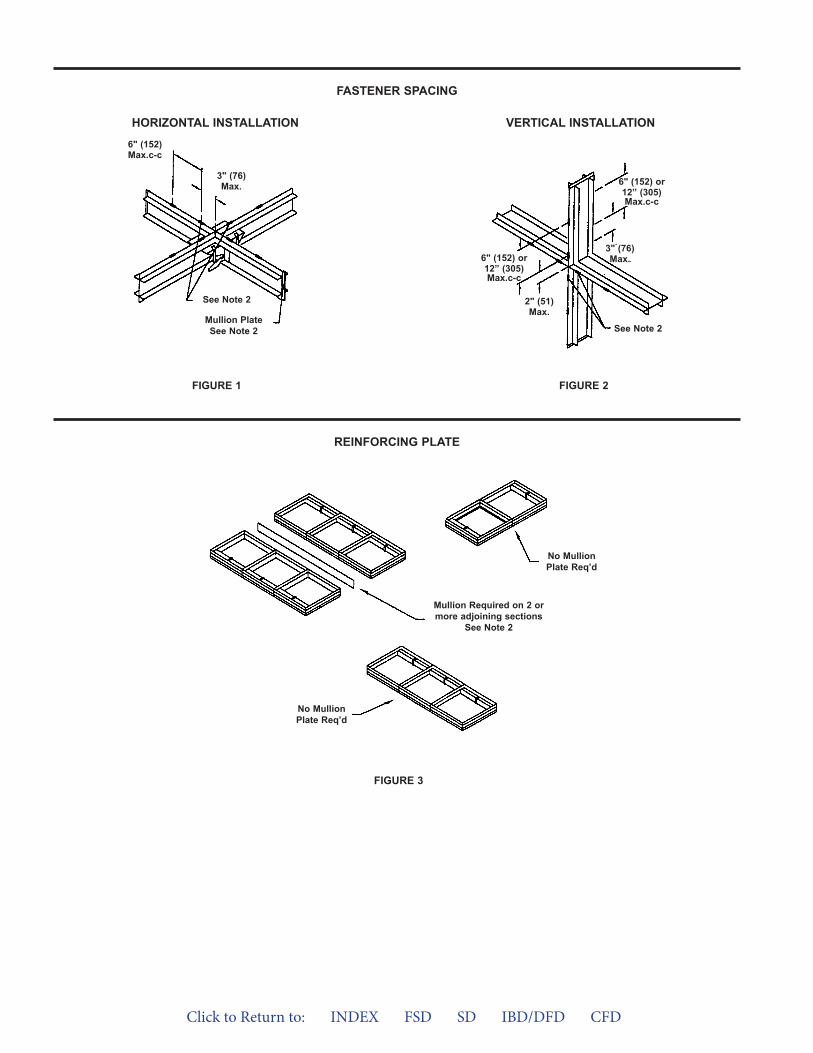
FIGURE 3
FASTENER SPACING
REINFORCING PLATE
VERTICAL INSTALLATIONHORIZONTAL INSTALLATION
FIGURE 2FIGURE 1
See Note 2
Mullion PlateSee Note 2
6" (152)Max.c-c
3" (76)Max.
See Note 2
6" (152) or12” (305)Max.c-c
2" (51)Max.
6" (152) or12” (305)Max.c-c
3" (76)Max.
No MullionPlate Req’d
No MullionPlate Req’d
Mullion Required on 2 ormore adjoining sections
See Note 2
Click to Return to: INDEX FSD SD IBD/DFD CFD
Click to Return to: INDEX FSD SD IBD/DFD CFD
INSTALLATIONINSTRUCTIONSUPPLEMENTS
FRAMINGRECOMMENDED FRAMING FOR OPENINGS IN WOOD AND METAL STUD WALLSCAVITY SHAFT WALL METAL STUD FRAMINGMETAL STUD FRAMING FOR COMBINATION FIRE AND SMOKE DAMPERS IN TUNNEL CORRIDOR SHAFT-WALL CEILINGSSUPPORT MULLIONS FOR DAMPERS IN OVERSIZED WALL OPENINGS
®
Duct ConnectionsFLANGED SYSTEM BREAKAWAY CONNECTIONSTDF AND TDC FIELD ADD-ON CONNECTIONS
Extend and Trim Damper SleeveEXTENSION OF FIRE AND COMBINATION FIRE AND SMOKE DAMPER SLEEVESTRIMMING OF FIRE AND COMBINATION FIRE SMOKE DAMPER SLEEVES
Sealants and Fire Stop MaterialOPTIONAL FIRESTOP MATERIALOPTIONAL SEALANT OF DAMPERS IN FIRE RATED WALL OR FLOOR OPENINGS
Grille and Transfer OpeningsTRANSFER OPENINGS AND GRILLE DUCT TERMINATIONS11/2 HOUR UL CLASSIFIED DAMPERS WITH GRILLE MOUNTING ANGLESFIRE AND COMBINATION FIRE AND SMOKE DAMPER INSTALLATION IN CONCRETE FLOOR WITH STEEL DECK

Click to Return to: INDEX FSD SD IBD/DFD CFD
INSTRUCTIONS1. Frame wall openings as shown.2. Double vertical studs are not required for
openings 36"w x 36"h (914 x 914) or smaller.3. All construction and fasteners must meet the
requirements of the appropriate wall designand/or local codes.
4. Consult the authority having jurisdiction forother acceptable framing methods.
NOTEThe Metal Stud Construction and Wood StudConstruction figures at the bottom of the pagedepict mounting angles installed on both sides ofthe partition. A single angle may be sufficient.Refer to the instructions for single angle installa-tion requirements.
Figure 1
Figure 2
Metal StudFraming Shown
INSTRUCTION INSTRUCTIONS SUPPLEMENTRECOMMENDED FRAMING FOR OPENINGS IN WOOD AND METAL STUD WALLS
16" (406)O.C. Max.
(woodstuds)
16" (406)O.C. Max.
(woodstuds)
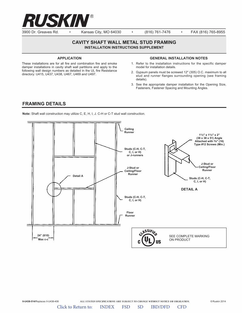
ALL STATED SPECIFICATIONS ARE SUBJECT TO CHANGE WITHOUT NOTICE OR OBLIGATION.
3900 Dr. Greaves Rd. • Kansas City, MO 64030 • (816) 761-7476 • FAX (816) 765-8955
CAVITY SHAFT WALL METAL STUD FRAMINGINSTALLATION INSTRUCTIONS SUPPLEMENT
© Ruskin 2014II-U438-514/Replaces II-U438-408
APPLICATIONThese installations are for all fire and combination fire and smokedamper installations in cavity shaft wall partitions and apply to thefollowing wall design numbers as detailed in the UL fire Resistancedirectory: U415, U437, U438, U467, U469 and U497.
GENERAL INSTALLATION NOTES1. Refer to the installation instructions for the specific damper
model for installation details.2. Gypsum panels must be screwed 12" (305) O.C. maximum to all
stud and runner flanges surrounding opening (see framingdetails).
3. See the appropriate damper installation for the Opening Size,Fasteners, Fastener Spacing and Mounting Angles.
11/2" x 11/2" x 2"(38 x 38 x 51) Angle
Attached with 5/8" (16)Type #12 Screws (Min.)
DETAIL A
Detail A
J-Stud orCeiling/Floor
RunnerJ-Stud or
Ceiling/FloorRunner
Studs (C-H, C-T,C, I, or H)
Studs (C-H, C-T,C, I, or H)
FRAMING DETAILS
Studs (C-H, C-T,C, I, or H)
or J-runners
CeilingRunner
FloorRunner
24” (610)Max c-c
Note: Shaft wall construction may utilize C, E, H, I, J. C-H or C-T stud wall construction.
SEE COMPLETE MARKING ON PRODUCT
Click to Return to: INDEX FSD SD IBD/DFD CFD
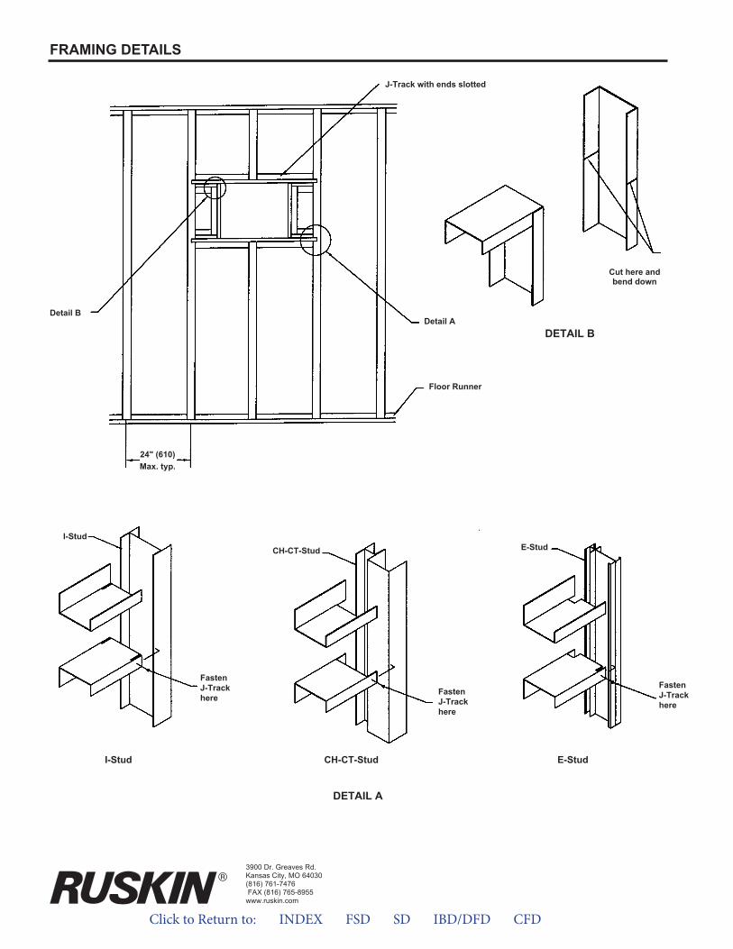
3900 Dr. Greaves Rd.Kansas City, MO 64030(816) 761-7476FAX (816) 765-8955
www.ruskin.com
FRAMING DETAILS
J-Track with ends slotted
DETAIL A
I-Stud
I-Stud
CH-CT-Stud
CH-CT-Stud
E-Stud
E-Stud
Detail A
Floor Runner
24" (610)Max. typ.
Detail B
DETAIL B
Cut here andbend down
FastenJ-Trackhere
FastenJ-Trackhere
FastenJ-Trackhere
Click to Return to: INDEX FSD SD IBD/DFD CFD
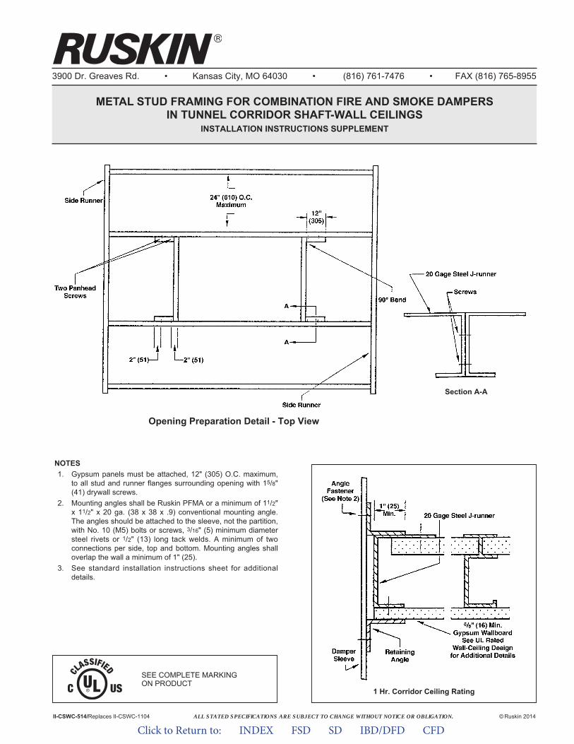
ALL STATED SPECIFICATIONS ARE SUBJECT TO CHANGE WITHOUT NOTICE OR OBLIGATION.
3900 Dr. Greaves Rd. • Kansas City, MO 64030 • (816) 761-7476 • FAX (816) 765-8955
METAL STUD FRAMING FOR COMBINATION FIRE AND SMOKE DAMPERSIN TUNNEL CORRIDOR SHAFT-WALL CEILINGS
INSTALLATION INSTRUCTIONS SUPPLEMENT
II-CSWC-514/Replaces II-CSWC-1104 © Ruskin 2014
NOTES1. Gypsum panels must be attached, 12" (305) O.C. maximum,
to all stud and runner flanges surrounding opening with 15/8"(41) drywall screws.
2. Mounting angles shall be Ruskin PFMA or a minimum of 11/2"x 11/2" x 20 ga. (38 x 38 x .9) conventional mounting angle.The angles should be attached to the sleeve, not the partition,with No. 10 (M5) bolts or screws, 3/16" (5) minimum diametersteel rivets or 1/2" (13) long tack welds. A minimum of twoconnections per side, top and bottom. Mounting angles shalloverlap the wall a minimum of 1" (25).
3. See standard installation instructions sheet for additionaldetails.
Section A-A
1 Hr. Corridor Ceiling Rating
Opening Preparation Detail - Top View
SEE COMPLETE MARKING ON PRODUCT
Click to Return to: INDEX FSD SD IBD/DFD CFD
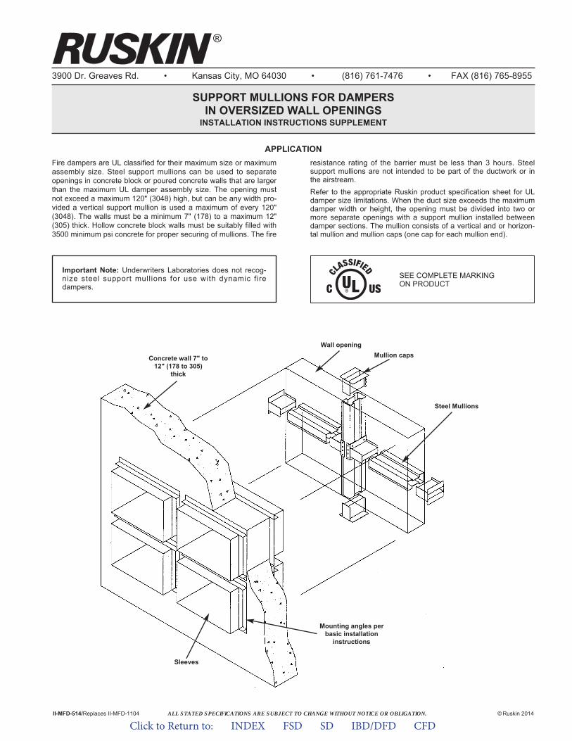
ALL STATED SPECIFICATIONS ARE SUBJECT TO CHANGE WITHOUT NOTICE OR OBLIGATION.
3900 Dr. Greaves Rd. • Kansas City, MO 64030 • (816) 761-7476 • FAX (816) 765-8955
SUPPORT MULLIONS FOR DAMPERSIN OVERSIZED WALL OPENINGS
INSTALLATION INSTRUCTIONS SUPPLEMENT
© Ruskin 2014
®
II-MFD-514/Replaces II-MFD-1104
Fire dampers are UL classified for their maximum size or maximumassembly size. Steel support mullions can be used to separateopenings in concrete block or poured concrete walls that are largerthan the maximum UL damper assembly size. The opening mustnot exceed a maximum 120" (3048) high, but can be any width pro-vided a vertical support mullion is used a maximum of every 120"(3048). The walls must be a minimum 7" (178) to a maximum 12"(305) thick. Hollow concrete block walls must be suitably filled with3500 minimum psi concrete for proper securing of mullions. The fire
resistance rating of the barrier must be less than 3 hours. Steelsupport mullions are not intended to be part of the ductwork or inthe airstream.Refer to the appropriate Ruskin product specification sheet for ULdamper size limitations. When the duct size exceeds the maximumdamper width or height, the opening must be divided into two ormore separate openings with a support mullion installed betweendamper sections. The mullion consists of a vertical and or horizon-tal mullion and mullion caps (one cap for each mullion end).
APPLICATION
Sleeves
Mounting angles perbasic installation
instructions
Concrete wall 7" to12" (178 to 305)
thick
Wall openingMullion caps
Steel Mullions
Important Note: Underwriters Laboratories does not recog-nize steel support mullions for use with dynamic firedampers.
SEE COMPLETE MARKING ON PRODUCT
Click to Return to: INDEX FSD SD IBD/DFD CFD
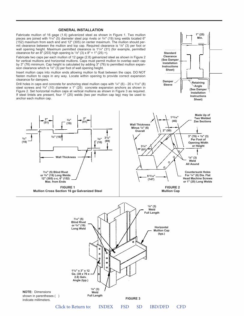
GENERAL INSTALLATIONFabricate mullion of 16 gage (1.6) galvanized steel as shown in Figure 1. Two mullionpieces are joined with 3/16" (5) diameter steel pop rivets or 3/4" (19) long welds located 6"(152) maximum from each end and 12" (305) on center maximum. The mullion should per-mit clearance between the mullion and top cap. Required clearance is 1/8" (3) per foot orwall opening height. Maximum permitted clearance is 11/4" (31) (for example, permittedclearance for an 8" (203) high opening is 1/8" (3) x 8" = 1" (25) +).Fabricate two caps per each mullion of 12 gage (2.8) galvanized steel as shown in Figure 2for vertical mullions and horizontal mullions. Caps must permit mullion to overlap each capby 3" (76) minimum. Cap height is calculated by adding 3" (76) to permitted mullion expan-sion clearance which is 1/8" (3) per foot of wall opening height.Insert mullion caps into mullion ends allowing mullion to float between the caps. DO NOTfasten mullion to caps in any way. Locate within opening to provide correct expansionclearance for dampers.Drill holes in caps and concrete for anchoring steel mullion caps with 1/4" (6) - 20 x 5/16" (8)steel screws and 3/8" (10) diameter x 1" (25) concrete expansion anchors as shown inFigure 2. Set horizontal mullion caps at vertical mullions as shown in Figure 3 as required.If steel lintels are present, four 1" (25) welds (two per mullion cap leg) may be used toanchor each mullion cap.
DamperSleeve
StandardClearance
(See DamperInstallationInstructions
Sheet)
RetainingAngle
(See DamperInstallationInstructions
Sheet)
1" (25)Min.
FIGURE 1Mullion Cross Section 16 ga Galvanized Steel
FIGURE 3
NOTE: Dimensionsshown in parentheses ( )indicate millimeters.
1/8" (3)Weld
Full Length
3/4"(19)
3/4" (19)
2"(51)
31/2"(89)
1/8" (3)Weld
Full Length
HorizontalMullion Cap
(typ.)
3/16" (5)Blind Rivetor 3/4" (19)Long Weld
3/16" (5) Blind Rivetor 3/4" (19) Long Welds12" (305) c-c, 6" (152)
Max. from Ends
11/2" x 3" x 12Ga. (38 x 76 x
2.8) Galv.Angle (typ.)
2"(51)
3/4"(19)
3/8"(10)
Wall Thickness
Countersunk HolesFor 1/4" (6) Dia. Flat
Head Machine Screwsor 1" (25) Long Welds
31/4"(81)
113/16"(46)
513/16"(147)
2" (50)
3" (76) + 1/8" (3)Per Foot of
Opening Widthor Height
Made Up ofTwo WeldedZee Sections
1/8" (3)Weld
All Aound
Wall ThicknessMinus 1/4" (6)
Overall
FIGURE 2Mullion Cap
Click to Return to: INDEX FSD SD IBD/DFD CFD
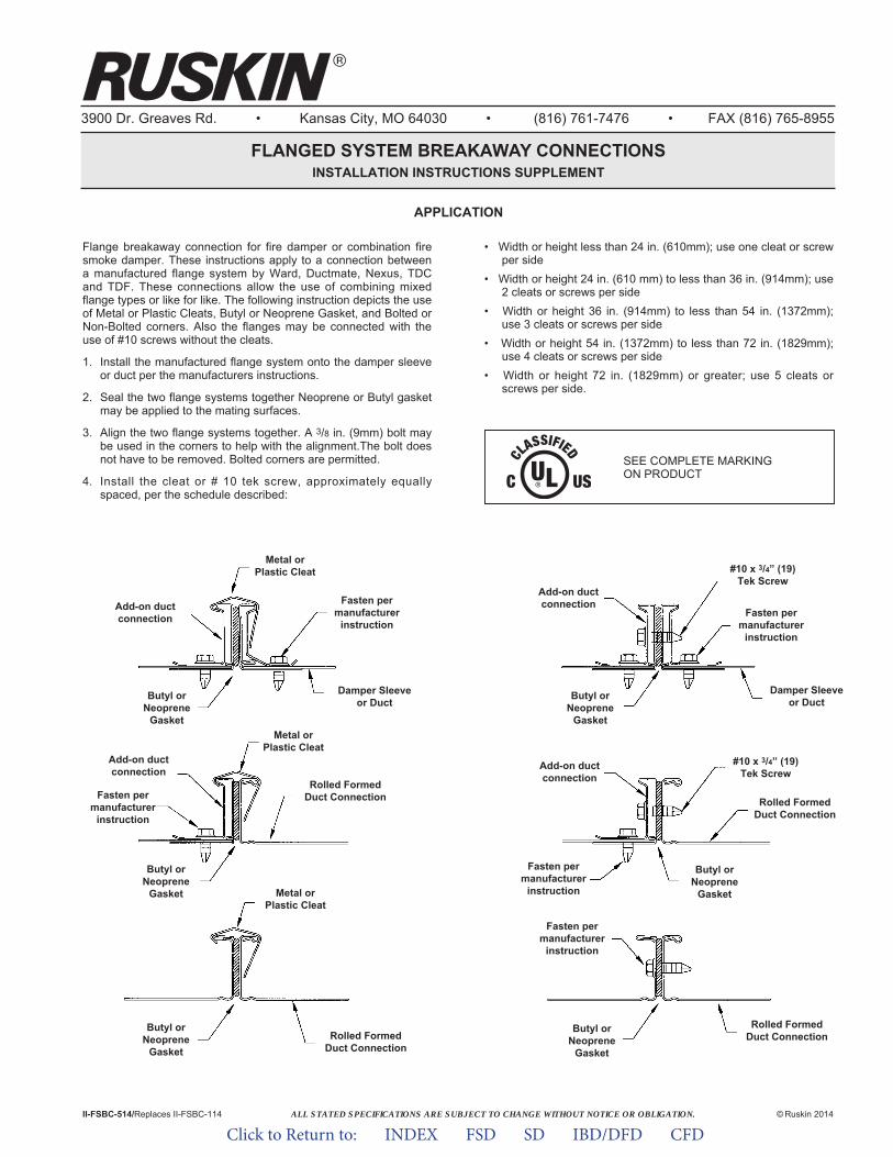
ALL STATED SPECIFICATIONS ARE SUBJECT TO CHANGE WITHOUT NOTICE OR OBLIGATION.
3900 Dr. Greaves Rd. • Kansas City, MO 64030 • (816) 761-7476 • FAX (816) 765-8955
FLANGED SYSTEM BREAKAWAY CONNECTIONSINSTALLATION INSTRUCTIONS SUPPLEMENT
Flange breakaway connection for fire damper or combination firesmoke damper. These instructions apply to a connection betweena manufactured flange system by Ward, Ductmate, Nexus, TDCand TDF. These connections allow the use of combining mixedflange types or like for like. The following instruction depicts the useof Metal or Plastic Cleats, Butyl or Neoprene Gasket, and Bolted orNon-Bolted corners. Also the flanges may be connected with theuse of #10 screws without the cleats.
1. Install the manufactured flange system onto the damper sleeveor duct per the manufacturers instructions.
2. Seal the two flange systems together Neoprene or Butyl gasketmay be applied to the mating surfaces.
3. Align the two flange systems together. A 3/8 in. (9mm) bolt maybe used in the corners to help with the alignment.The bolt doesnot have to be removed. Bolted corners are permitted.
4. Install the cleat or # 10 tek screw, approximately equallyspaced, per the schedule described:
• Width or height less than 24 in. (610mm); use one cleat or screwper side
• Width or height 24 in. (610 mm) to less than 36 in. (914mm); use2 cleats or screws per side
• Width or height 36 in. (914mm) to less than 54 in. (1372mm);use 3 cleats or screws per side
• Width or height 54 in. (1372mm) to less than 72 in. (1829mm);use 4 cleats or screws per side
• Width or height 72 in. (1829mm) or greater; use 5 cleats orscrews per side.
II-FSBC-514/Replaces II-FSBC-114 © Ruskin 2014
SEE COMPLETE MARKING ON PRODUCT
APPLICATION
Add-on ductconnection
Metal orPlastic Cleat
Damper Sleeveor Duct
Fasten permanufacturer
instruction
Butyl orNeoprene
Gasket
Add-on ductconnection
Add-on ductconnection
Add-on ductconnection
Fasten permanufacturer
instruction
Fasten permanufacturer
instruction
Fasten permanufacturer
instruction
Butyl orNeoprene
Gasket
Butyl orNeoprene
Gasket
Butyl orNeoprene
Gasket
Butyl orNeoprene
Gasket
Butyl orNeoprene
Gasket
Metal orPlastic Cleat
Metal orPlastic Cleat
Rolled FormedDuct Connection
Rolled FormedDuct Connection
Rolled FormedDuct Connection
Rolled FormedDuct Connection
Damper Sleeveor Duct
Fasten permanufacturer
instruction
#10 x 3/4” (19)Tek Screw
#10 x 3/4” (19)Tek Screw
Click to Return to: INDEX FSD SD IBD/DFD CFD
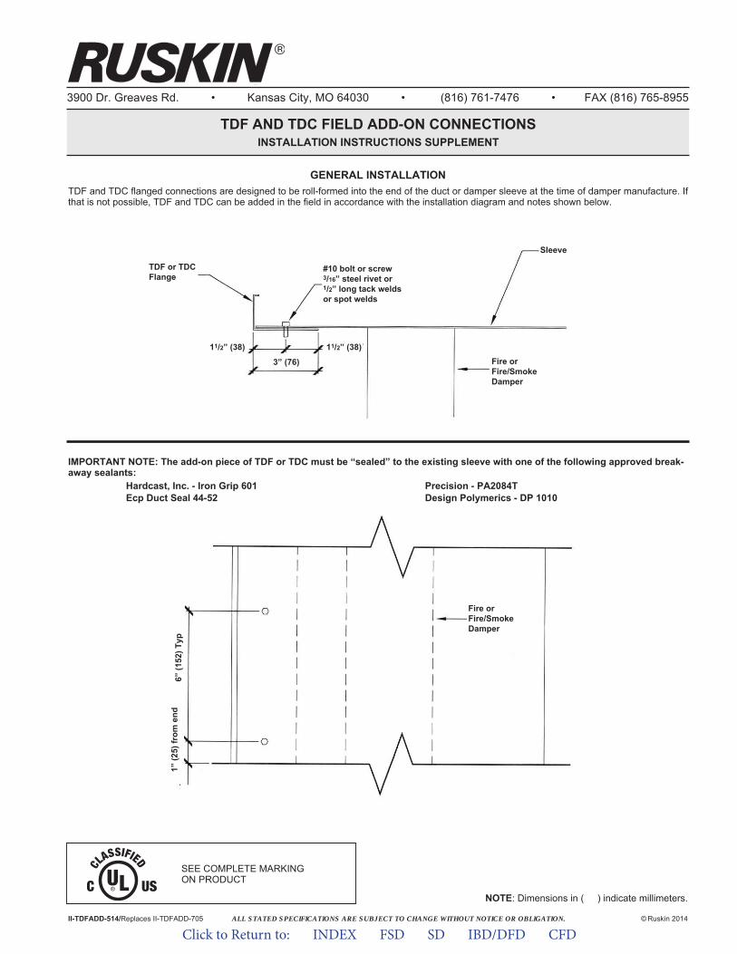
ALL STATED SPECIFICATIONS ARE SUBJECT TO CHANGE WITHOUT NOTICE OR OBLIGATION.
3900 Dr. Greaves Rd. • Kansas City, MO 64030 • (816) 761-7476 • FAX (816) 765-8955
TDF AND TDC FIELD ADD-ON CONNECTIONSINSTALLATION INSTRUCTIONS SUPPLEMENT
GENERAL INSTALLATIONTDF and TDC flanged connections are designed to be roll-formed into the end of the duct or damper sleeve at the time of damper manufacture. Ifthat is not possible, TDF and TDC can be added in the field in accordance with the installation diagram and notes shown below.
II-TDFADD-514/Replaces II-TDFADD-705 © Ruskin 2014
NOTE: Dimensions in ( ) indicate millimeters.
IMPORTANT NOTE: The add-on piece of TDF or TDC must be “sealed” to the existing sleeve with one of the following approved break-away sealants:
Hardcast, Inc. - Iron Grip 601 Precision - PA2084TEcp Duct Seal 44-52 Design Polymerics - DP 1010
Sleeve
#10 bolt or screw3/16” steel rivet or1/2” long tack weldsor spot welds
TDF or TDCFlange
11/2” (38)
3” (76)
11/2” (38)Fire orFire/SmokeDamper
Fire orFire/SmokeDamper
1” (2
5) fr
om e
nd6”
(152
) Typ
SEE COMPLETE MARKING ON PRODUCT
Click to Return to: INDEX FSD SD IBD/DFD CFD
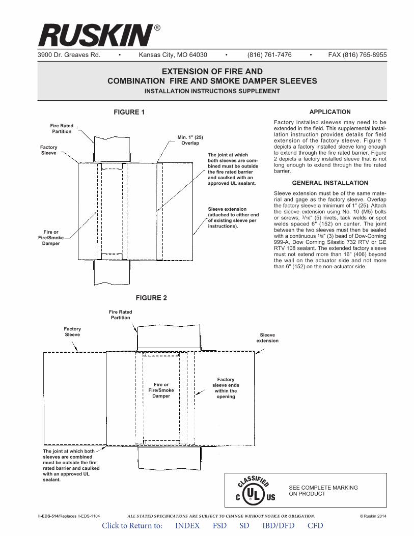
ALL STATED SPECIFICATIONS ARE SUBJECT TO CHANGE WITHOUT NOTICE OR OBLIGATION.
3900 Dr. Greaves Rd. • Kansas City, MO 64030 • (816) 761-7476 • FAX (816) 765-8955
EXTENSION OF FIRE ANDCOMBINATION FIRE AND SMOKE DAMPER SLEEVES
INSTALLATION INSTRUCTIONS SUPPLEMENT
APPLICATIONFactory installed sleeves may need to beextended in the field. This supplemental instal-lation instruction provides details for fieldextension of the factory sleeve. Figure 1depicts a factory installed sleeve long enoughto extend through the fire rated barrier. Figure2 depicts a factory installed sleeve that is notlong enough to extend through the fire ratedbarrier.
GENERAL INSTALLATIONSleeve extension must be of the same mate-rial and gage as the factory sleeve. Overlapthe factory sleeve a minimum of 1" (25). Attachthe sleeve extension using No. 10 (M5) boltsor screws, 3/16" (5) rivets, tack welds or spotwelds spaced 6" (152) on center. The jointbetween the two sleeves must then be sealedwith a continuous 1/8" (3) bead of Dow-Corning999-A, Dow Corning Silastic 732 RTV or GERTV 108 sealant. The extended factory sleevemust not extend more than 16" (406) beyondthe wall on the actuator side and not morethan 6" (152) on the non-actuator side.
II-EDS-514/Replaces II-EDS-1104 © Ruskin 2014
®
FIGURE 1
FIGURE 2
FactorySleeve
Fire RatedPartition
Fire orFire/Smoke
Damper
Factorysleeve endswithin theopening
Sleeveextension
FactorySleeve
Fire RatedPartition
Fire orFire/Smoke
Damper
The joint at whichboth sleeves are com-bined must be outsidethe fire rated barrierand caulked with anapproved UL sealant.
Sleeve extension(attached to either endof existing sleeve perinstructions).
Min. 1" (25)Overlap
The joint at which bothsleeves are combinedmust be outside the firerated barrier and caulkedwith an approved ULsealant.
SEE COMPLETE MARKING ON PRODUCT
Click to Return to: INDEX FSD SD IBD/DFD CFD
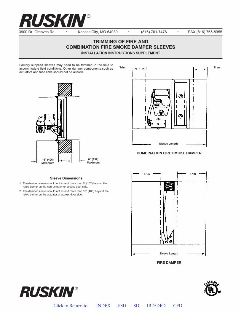
Click to Return to: INDEX FSD SD IBD/DFD CFD
3900 Dr. Greaves Rd. • Kansas City, MO 64030 • (816) 761-7476 • FAX (816) 765-8955
TRIMMING OF FIRE ANDCOMBINATION FIRE SMOKE DAMPER SLEEVES
INSTALLATION INSTRUCTIONS SUPPLEMENT
Factory supplied sleeves may need to be trimmed in the field toaccommodate field conditions. Other damper components such asactuators and fuse links should not be altered.
®
16” (406)Maximum
6” (152)Maximum
Sleeve Dimensions1. The damper sleeve should not extend more than 6” (152) beyond the
rated barrier on the non-actuator or access door side.2. The damper sleeve should not extend more than 16” (406) beyond the
rated barrier on the actuator or access door side.
Sleeve Length
COMBINATION FIRE SMOKE DAMPER
Trim Trim
Sleeve Length
FIRE DAMPER
Trim Trim

ALL STATED SPECIFICATIONS ARE SUBJECT TO CHANGE WITHOUT NOTICE OR OBLIGATION.
3900 Dr. Greaves Rd. • Kansas City, MO 64030 • (816) 761-7476 • FAX (816) 765-8955
OPTIONAL FIRESTOP MATERIALINSTALLATION INSTRUCTIONS SUPPLEMENT
APPLICATIONApplication of firestopping caulk in the annular space sur-rounding a 11/2 or 3 hour curtain type or multi-blade fire andcombination fire and smoke dampers is not required. However,if the Authority Having Jurisdiction or the installation warrantsfirestopping in place of a "standard" retaining angle installation,these instructions apply.1. Wall or Floor Assembly –
Concrete wall or floor – must be a minimum 21/2" thick normalweight (100 - 150 pcf) or minimum 41/2" thick lightweight concrete.The wall may be constructed of any UL Classified Concrete Block.Gypsum wallboard/stud wall – must be constructed of the mate-rials and in the manner specified in the U400 Series Wall and Par-tition Designs in the UL Fire Resistance Directory. Studs shall beminimum 31/2" (89) steel channel spaced a maximum 24" (610)on center. Opening must be completely framed.
2. Damper – Ruskin fire or fire/leakage rated damper in minimum 20gage (1.0) sleeve. Damper size shall not exceed 90" x 48" (2286x 1219) or 48" x 90" (1219 x 2286).
3. Expansion Clearance – The opening in the wall or floor must bea minimum of 1/8" per foot (3 per 305) larger than the overalldamper/sleeve assembly. The maximum opening size is 1" (25)larger than the minimum clearance with a 11/2" (38) maximumspace between the damper sleeve and wall or floor.
4. Packing (Optional) – Polyethylene backer rod, recessed fromboth surfaces of wall or floor to accommodate the required thick-ness of fill material.
5. Fill Material – Fire stop caulk applied to a minimum 5/8" (16)thickness for 11/2 hour dampers or 1" (25) for 3 hour damperswithin the annular space and flush with both surfaces of the wallor bottom surface of floor. If the damper/sleeve assembly comesinto contact with the wall or floor, a minimum 3/8" (10) diameterbead shall be applied to the interface between the sleeve andcontact surface.Hilti Corporation - FS-One, CP6063M - #M-CP 25WB+Speci fied Technologies, Inc. - SpecSeal® Series SSS or LCIJohn Manville International, Inc. - FiretempTM CIRectorseal - Metacaulk 1000, Metacaulk 350i, Biostop 500+ orBiostop 350i
6. Retaining Clip – (Walls Only), 1" x 2" x 2" x 16 gage (25 x 51 x51 x 1.6) angle attached to one side of the wall with 11/2" (38) long#8 wallboard screws or #8 masonry screws in masonry walls. The1" (25) leg of the angle shall be attached to the damper sleevewith 1/2" (13) long #10 sheet metal screws. The angles arerequired to be spaced a maximum of 6" (152) from the top ofsleeve and spaced a maximum of 12" (305) on center on thesides of the unit only.
7. Retaining Angle – Retaining angles are required on side of wallopposite retaining clips for 3 hour vertical dampers larger than 24"x 24" and on top side of floor for all horizontal fire dampers.Ruskin PFMA as shown in the supplemental installation instruc-tions or minimum 11/2 x 11/2 x 16 gage (38 x 38 x 1.6) galvanizedretaining angles may be substituted for the caulking on the side ofwall opposite the retaining clips. The angle must overlap the wallor floor a minimum of 1" (25) and shall be attached to the sleeveof the fire damper with #10 bolts or screws, 1/2" (13) long tackwelds or 3/16" (5) diameter steel rivets with a minimum of two con-nections on each side, top and bottom of the damper. Space fas-teners 8" (203) on center. Do not weld or fasten angles togetherat corners of damper.
II-FIRESTOP-814/Replaces II-FIRESTOP-1008 © Ruskin 2014
Horizontal Installation
VerticalInstallation
Min.3/8" (10)
Bead
SEE COMPLETE MARKING ON PRODUCT
Click to Return to: INDEX FSD SD IBD/DFD CFD
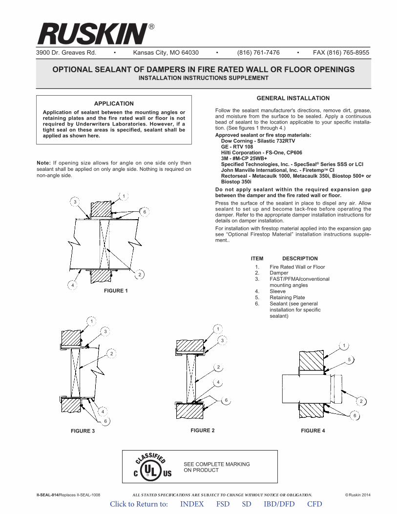
ALL STATED SPECIFICATIONS ARE SUBJECT TO CHANGE WITHOUT NOTICE OR OBLIGATION.
3900 Dr. Greaves Rd. • Kansas City, MO 64030 • (816) 761-7476 • FAX (816) 765-8955
OPTIONAL SEALANT OF DAMPERS IN FIRE RATED WALL OR FLOOR OPENINGSINSTALLATION INSTRUCTIONS SUPPLEMENT
© Ruskin 2014II-SEAL-814/Replaces II-SEAL-1008
FIGURE 1
FIGURE 3 FIGURE 4FIGURE 2
APPLICATIONApplication of sealant between the mounting angles orretaining plates and the fire rated wall or floor is notrequired by Underwriters Laboratories. However, if atight seal on these areas is specified, sealant shall beapplied as shown here.
2
6
5
1
1
3
2
4
6
1
6
2
4
3
1
3
2
4
6
ITEM DESCRIPTION1. Fire Rated Wall or Floor2. Damper3. FAST/PFMA/conventional
mounting angles4. Sleeve5. Retaining Plate6. Sealant (see general
installation for specificsealant)
GENERAL INSTALLATION
Note: If opening size allows for angle on one side only thensealant shall be applied on only angle side. Nothing is required onnon-angle side.
Follow the sealant manufacturer's directions, remove dirt, grease,and moisture from the surface to be sealed. Apply a continuousbead of sealant to the location applicable to your specific installa-tion. (See figures 1 through 4.)Approved sealant or fire stop materials:
Dow Corning - Silastic 732RTVGE - RTV 108Hilti Corporation - FS-One, CP6063M - #M-CP 25WB+Speci fied Technologies, Inc. - SpecSeal® Series SSS or LCIJohn Manville International, Inc. - FiretempTM CIRectorseal - Metacaulk 1000, Metacaulk 350i, Biostop 500+ orBiostop 350i
Do not apply sealant within the required expansion gapbetween the damper and the fire rated wall or floor.Press the surface of the sealant in place to dispel any air. Allowsealant to set up and become tack-free before operating thedamper. Refer to the appropriate damper installation instructions fordetails on damper installation.For installation with firestop material applied into the expansion gapsee “Optional Firestop Material” installation instructions supple-ment..
SEE COMPLETE MARKING ON PRODUCT
Click to Return to: INDEX FSD SD IBD/DFD CFD
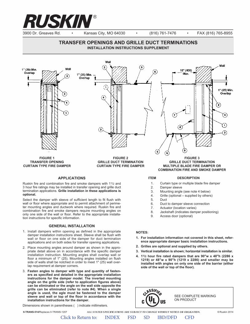
ALL STATED SPECIFICATIONS ARE SUBJECT TO CHANGE WITHOUT NOTICE OR OBLIGATION.
3900 Dr. Greaves Rd. • Kansas City, MO 64030 • (816) 761-7476 • FAX (816) 765-8955
TRANSFER OPENINGS AND GRILLE DUCT TERMINATIONSINSTALLATION INSTRUCTIONS SUPPLEMENT
© Ruskin 2014II-TRANS-514/Replaces II-TRANS-1207
APPLICATIONSRuskin fire and combination fire and smoke dampers with 11/2 and3 hour fire ratings may be installed in transfer opening and grille ducttermination applications. Grille installation in these applications isoptional.Select the damper with sleeve of sufficient length to fit flush withwall or floor where appropriate and to permit attachment of perime-ter mounting angles and ductwork where required. Ruskin fire andcombination fire and smoke dampers require mounting angles ononly one side of the wall or floor. Refer to the appropriate installa-tion instructions for specific information.
GENERAL INSTALLATION1. Install dampers within opening as defined in the appropriate
damper installation instructions sheet. Sleeve shall be flush withwall or floor on one side of the damper for duct terminationapplications and on both sides for transfer opening applications.
2. Place mounting angles around damper as shown in the appro-priate detail above on in accordance with the specific damperinstallation instruction. Mounting angles shall overlap wall orfloor a minimum of 1" (25). Mounting angles installed on flushside of walls shall be notched in order to meet 1" (25) wall over-lap requirement at damper corners.
3. Fasten angles to damper with type and quantity of fasten-ers as specified and detailed in the appropriate installationinstructions for the damper model. The inverted mountingangle on the grille side (refer to application figures above)can be eliminated or the angle on the wall side opposite thegrille can be eliminated (refer to note #4). When a singleangle is used, the agle must be fastened to the dampersleeve and wall or top of the floor in accordance with theinstallation instructions for the damper.
Dimensions shown in parentheses ( ) indicate millimeters.
ITEM DESCRIPTION1. Curtain type or multiple blade fire damper2. Damper sleeve3. Mounting angle (see note 4 below)4. Grille (optional – supplied by others)5. Duct6. Duct to damper sleeve connection7. Actuator (location varies)8. Jackshaft (indicates damper positioning)9. Access door (optional)
NOTES: 1. For installation information not covered in this sheet, refer-
ence appropriate damper basic installation instructions.2. Grilles are optional and supplied by others.3. Vertical installation is shown; horizontal installation is similar.4. 11/2 hour fire rated dampers that are 90"w x 48"h (2286 x
1219) or 48"w x 90"h (1219 x 2286) and smaller may beinstalled with angles on only one side of the barrier (eitherside of the wall or top of the floor).
FIGURE 1TRANSFER OPENING
CURTAIN TYPE FIRE DAMPER
FIGURE 2GRILLE DUCT TERMINATION
CURTAIN TYPE FIRE DAMPER
FIGURE 3GRILLE DUCT TERMINATION
MULTIPLE BLADE FIRE DAMPER ORCOMBINATION FIRE AND SMOKE DAMPER
SEE COMPLETE MARKING ON PRODUCT
Click to Return to: INDEX FSD SD IBD/DFD CFD
ALL STATED SPECIFICATIONS ARE SUBJECT TO CHANGE WITHOUT NOTICE OR OBLIGATION.
3900 Dr. Greaves Rd. • Kansas City, MO 64030 • (816) 761-7476 • FAX (816) 765-8955
INSTALLATION INSTRUCTIONS SUPPLEMENT11/2 HOUR UL CLASSIFIED DAMPERS WITH GRILLE MOUNTING ANGLES
FOR RUSKIN (D)IBD, FD AND FSD DAMPERS
APPLICATIONStyle G fire and combination fire and smoke damper includes grillemounting angles for flush installation of a minimum 26 gage (.021)steel frame grille with the wall or floor. No additional mountingangles are required on the grille side of the wall or floor. Thedamper is offset in the damper sleeve for appropriate damperplacement within the wall or floor.
CURTAIN FIRE DAMPERSSTATIC FIRE DAMPERS
Not for use in dynamic (fans on) systems.
MINIMUM SIZEVertical Installation – 4"w x 4"h (102 x 102).Horizontal Installation – 6"w x 6"h (152 x 152).
MAXIMUM SIZESingle section
Vertical InstallationIBD2 - 48"w x 30"h (1219 x 762) or
30"w x 48"h (762 x 1219).IBD20 - 48"w x 30"h (1219 x 762) or
30"w x 48"h (762 x 1219).IBDT - 40"w x 32"h (1016 x 813) or
32"w x 48"h (813 x 1219).Horizontal Installation
IBD2 - 24"w x 18"h (610 x 457) or18"w x 24"h (457 x 610).
IBD20 - 24"w x 18"h (610 x 457) or18"w x 24"h (457 x 610).
IBDT - 24"w x 12"h (610 x 305).
Note: Dimensions shown in parentheses ( ) indicate millimeters.
California State Fire Marshal Listing No. 3225-245:005 California State Fire Marshal Listing No. 3225-245:102
II-G-Angle-514/Replaces II-IBD Style G -109 © Ruskin 2014
DYNAMIC FIRE DAMPERSSee label on damper for maximum air flow and pressure.
MINIMUM SIZEVertical Installation – 4"w x 4"h (102 x 102).Horizontal Installation – 6"w x 6"h (152 x 152).
MAXIMUM SIZESingle section
Vertical InstallationDIBD2 - 32"w x 36"h (813 x 914)DIBD20 - 32"w x 36"h (13 x 914)
Horizontal InstallationDIBD2 - 24"w x 18"h (610 x 457) or
18"w x 24"h (457 x 610).DIBD20 - 24"w x 18"h (610 x 457) or
18"w x 24"h (457 x 610).
COMBINATION FIRE/SMOKE DAMPERSAND MULTIPLE BLADE FIRE DAMPERS
MINIMUM SIZEFSD35 – 5"w x 6"h (127 x 152).FSD36, 37, 60, 60-2, FD35, FD60 – 8"w x 6"h (203 x 152).
MAXIMUM SIZEFSD60, 60-2, FD60 - 32” x 48” (813 x 1219)FSD35, 36, 37, FD35 – 32"w x 48"h (813 x 1219) or 48"w x32"h (1219 x 813).
INSTALLATION SUPPLEMENTSRefer to the appropriate Ruskin installation operation instructionssupplements for special requirements:• Drivemate No. 14880 Breakaway Connection• Flanged System Breakaway Connection• Optional Sealant of Dampers in Fire Rated Wall or Floor
Openings• Cavity Shaft Wall Metal Stud Framing• Extension of Fire and Combination Fire and Smoke Damper
Sleeves.
SEE COMPLETEMARKING ON PRODUCT
®
Click to Return to: INDEX FSD SD IBD/DFD CFD
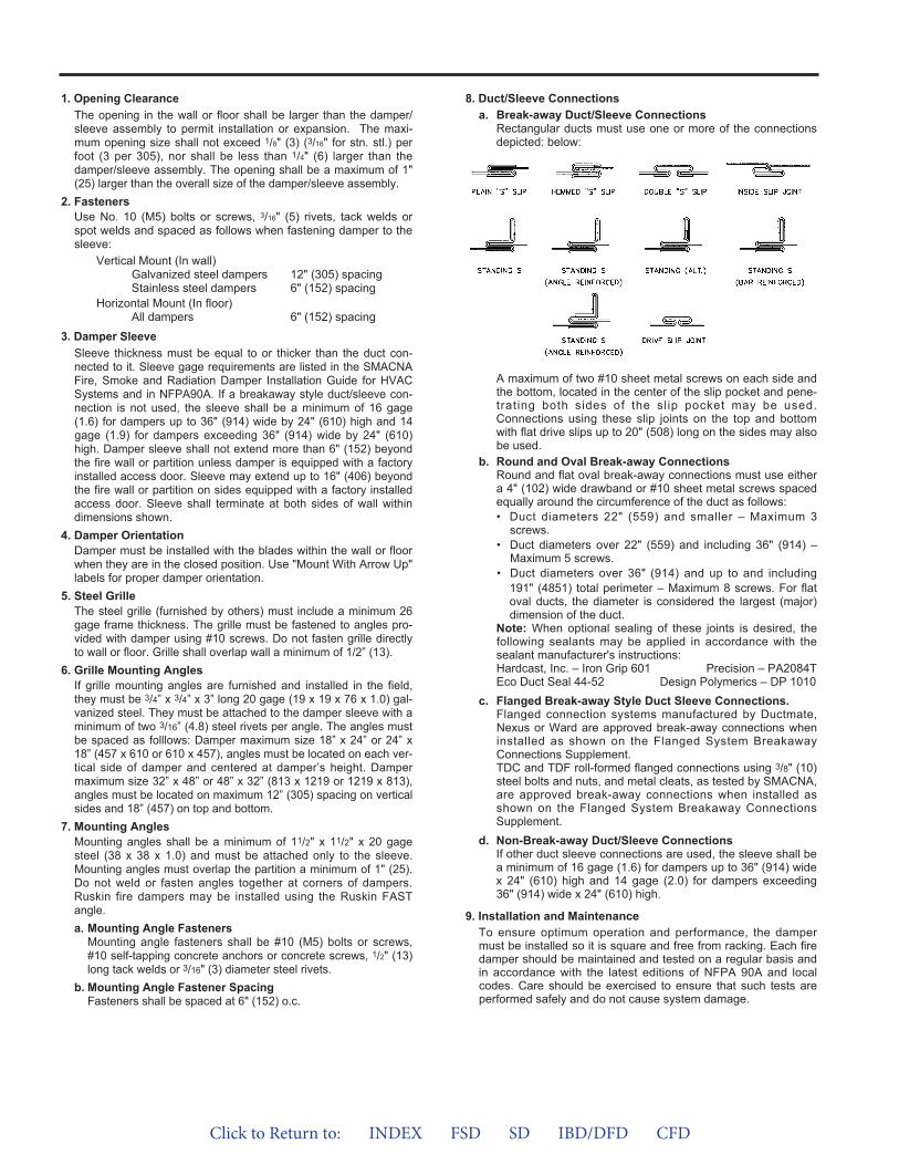
1. Opening ClearanceThe opening in the wall or floor shall be larger than the damper/sleeve assembly to permit installation or expansion. The maxi-mum opening size shall not exceed 1/8" (3) (3/16" for stn. stl.) perfoot (3 per 305), nor shall be less than 1/4" (6) larger than thedamper/sleeve assembly. The opening shall be a maximum of 1"(25) larger than the overall size of the damper/sleeve assembly.
2. FastenersUse No. 10 (M5) bolts or screws, 3/16" (5) rivets, tack welds orspot welds and spaced as follows when fastening damper to thesleeve:
Vertical Mount (In wall)Galvanized steel dampers 12" (305) spacing Stainless steel dampers 6" (152) spacing
Horizontal Mount (In floor)All dampers 6" (152) spacing
3. Damper SleeveSleeve thickness must be equal to or thicker than the duct con-nected to it. Sleeve gage requirements are listed in the SMACNAFire, Smoke and Radiation Damper Installation Guide for HVACSystems and in NFPA90A. If a breakaway style duct/sleeve con-nection is not used, the sleeve shall be a minimum of 16 gage(1.6) for dampers up to 36" (914) wide by 24" (610) high and 14gage (1.9) for dampers exceeding 36" (914) wide by 24" (610)high. Damper sleeve shall not extend more than 6" (152) beyondthe fire wall or partition unless damper is equipped with a factoryinstalled access door. Sleeve may extend up to 16" (406) beyondthe fire wall or partition on sides equipped with a factory installedaccess door. Sleeve shall terminate at both sides of wall withindimensions shown.
4. Damper OrientationDamper must be installed with the blades within the wall or floorwhen they are in the closed position. Use "Mount With Arrow Up"labels for proper damper orientation.
5. Steel GrilleThe steel grille (furnished by others) must include a minimum 26gage frame thickness. The grille must be fastened to angles pro-vided with damper using #10 screws. Do not fasten grille directlyto wall or floor. Grille shall overlap wall a minimum of 1/2” (13).
6. Grille Mounting AnglesIf grille mounting angles are furnished and installed in the field,they must be 3/4” x 3/4” x 3” long 20 gage (19 x 19 x 76 x 1.0) gal-vanized steel. They must be attached to the damper sleeve with aminimum of two 3/16” (4.8) steel rivets per angle. The angles mustbe spaced as folllows: Damper maximum size 18” x 24” or 24” x18” (457 x 610 or 610 x 457), angles must be located on each ver-tical side of damper and centered at damper’s height. Dampermaximum size 32” x 48” or 48” x 32” (813 x 1219 or 1219 x 813),angles must be located on maximum 12” (305) spacing on verticalsides and 18” (457) on top and bottom.
7. Mounting AnglesMounting angles shall be a minimum of 11/2" x 11/2" x 20 gagesteel (38 x 38 x 1.0) and must be attached only to the sleeve.Mounting angles must overlap the partition a minimum of 1" (25).Do not weld or fasten angles together at corners of dampers.Ruskin fire dampers may be installed using the Ruskin FASTangle.a. Mounting Angle Fasteners
Mounting angle fasteners shall be #10 (M5) bolts or screws,#10 self-tapping concrete anchors or concrete screws, 1/2" (13)long tack welds or 3/16" (3) diameter steel rivets.
b. Mounting Angle Fastener SpacingFasteners shall be spaced at 6" (152) o.c.
8. Duct/Sleeve Connectionsa. Break-away Duct/Sleeve Connections
Rectangular ducts must use one or more of the connectionsdepicted: below:
A maximum of two #10 sheet metal screws on each side andthe bottom, located in the center of the slip pocket and pene-trating both sides of the slip pocket may be used.Connections using these slip joints on the top and bottomwith flat drive slips up to 20" (508) long on the sides may alsobe used.
b. Round and Oval Break-away ConnectionsRound and flat oval break-away connections must use eithera 4" (102) wide drawband or #10 sheet metal screws spacedequally around the circumference of the duct as follows:• Duct diameters 22" (559) and smaller – Maximum 3
screws.• Duct diameters over 22" (559) and including 36" (914) –
Maximum 5 screws.• Duct diameters over 36" (914) and up to and including
191" (4851) total perimeter – Maximum 8 screws. For flat oval ducts, the diameter is considered the largest (major) dimension of the duct.
Note: When optional sealing of these joints is desired, thefollowing sealants may be applied in accordance with thesealant manufacturer's instructions:Hardcast, Inc. – Iron Grip 601 Precision – PA2084TEco Duct Seal 44-52 Design Polymerics – DP 1010
c. Flanged Break-away Style Duct Sleeve Connections.Flanged connection systems manufactured by Ductmate,Nexus or Ward are approved break-away connections wheninstalled as shown on the Flanged System BreakawayConnections Supplement.TDC and TDF roll-formed flanged connections using 3/8" (10)steel bolts and nuts, and metal cleats, as tested by SMACNA,are approved break-away connections when installed asshown on the Flanged System Breakaway ConnectionsSupplement.
d. Non-Break-away Duct/Sleeve ConnectionsIf other duct sleeve connections are used, the sleeve shall bea minimum of 16 gage (1.6) for dampers up to 36" (914) widex 24" (610) high and 14 gage (2.0) for dampers exceeding36" (914) wide x 24" (610) high.
9. Installation and MaintenanceTo ensure optimum operation and performance, the dampermust be installed so it is square and free from racking. Each firedamper should be maintained and tested on a regular basis andin accordance with the latest editions of NFPA 90A and localcodes. Care should be exercised to ensure that such tests areperformed safely and do not cause system damage.
Click to Return to: INDEX FSD SD IBD/DFD CFD
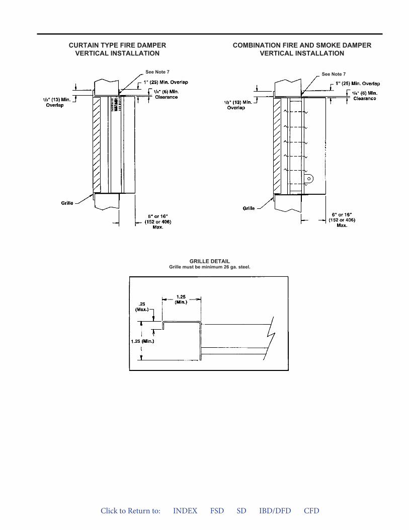
CURTAIN TYPE FIRE DAMPERVERTICAL INSTALLATION
COMBINATION FIRE AND SMOKE DAMPERVERTICAL INSTALLATION
GRILLE DETAILGrille must be minimum 26 ga. steel.
See Note 7 See Note 7
Click to Return to: INDEX FSD SD IBD/DFD CFD
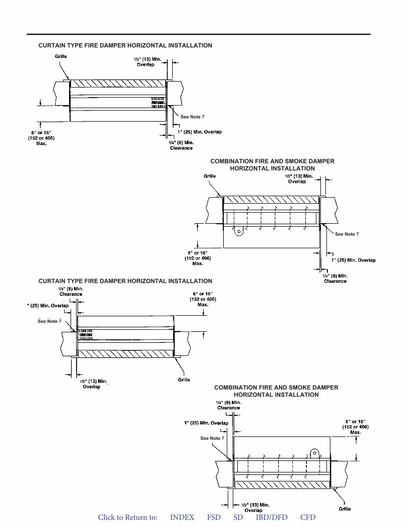
CURTAIN TYPE FIRE DAMPER HORIZONTAL INSTALLATION
COMBINATION FIRE AND SMOKE DAMPERHORIZONTAL INSTALLATION
CURTAIN TYPE FIRE DAMPER HORIZONTAL INSTALLATION
COMBINATION FIRE AND SMOKE DAMPERHORIZONTAL INSTALLATION
See Note 7
See Note 7
See Note 7
See Note 7
Click to Return to: INDEX FSD SD IBD/DFD CFD
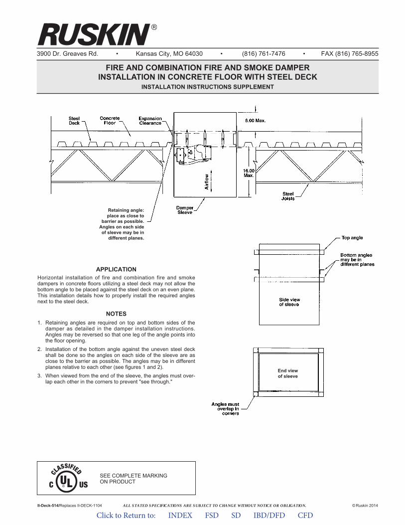
ALL STATED SPECIFICATIONS ARE SUBJECT TO CHANGE WITHOUT NOTICE OR OBLIGATION.
3900 Dr. Greaves Rd. • Kansas City, MO 64030 • (816) 761-7476 • FAX (816) 765-8955
FIRE AND COMBINATION FIRE AND SMOKE DAMPERINSTALLATION IN CONCRETE FLOOR WITH STEEL DECK
INSTALLATION INSTRUCTIONS SUPPLEMENT
APPLICATIONHorizontal installation of fire and combination fire and smokedampers in concrete floors utilizing a steel deck may not allow thebottom angle to be placed against the steel deck on an even plane.This installation details how to properly install the required anglesnext to the steel deck.
NOTES1. Retaining angles are required on top and bottom sides of the
damper as detailed in the damper installation instructions.Angles may be reversed so that one leg of the angle points intothe floor opening.
2. Installation of the bottom angle against the uneven steel deckshall be done so the angles on each side of the sleeve are asclose to the barrier as possible. The angles may be in differentplanes relative to each other (see figures 1 and 2).
3. When viewed from the end of the sleeve, the angles must over-lap each other in the corners to prevent "see through."
II-Deck-514/Replaces II-DECK-1104 © Ruskin 2014
Retaining angle:place as close to
barrier as possible.Angles on each sideof sleeve may be in
different planes.
End viewof sleeve
SEE COMPLETE MARKING ON PRODUCT
Click to Return to: INDEX FSD SD IBD/DFD CFD

Click to Return to: INDEX FSD SD IBD/DFD CFD
SMACNAINSTALLATIONINSTRUCTION
RECOMMENDATIONS The following installations are form the SMACNA’s “Fire, Smoke
and Radiation Damper Installation Guide for HVAC System” Fifth Edition
SHEET METAL AND AIR CONDITIONING CONTRACTORS’ NATIONAL ASSOCIATION, INC.
The following installations are from the SMACNA’s “Fire, Smokeand Radiation Damper Installation Guide for HVAC System”
Fifth Edition
Minimum Sleeve ThicknessOut of Wall Fire Damper Installation
Out of Wall Fire Smoke Damper InstallationDuct Liner Interruption
Duct InsulationMultiple PenetrationsDiagonal Penetration
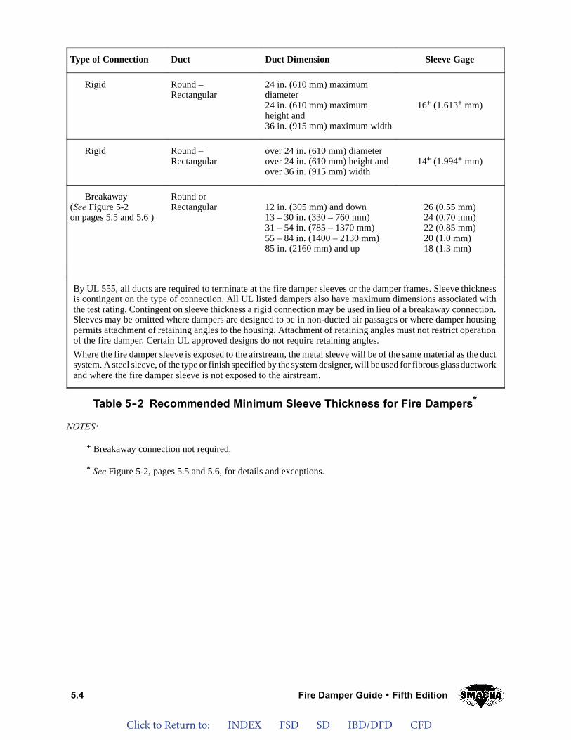
Click to Return to: INDEX FSD SD IBD/DFD CFD
5.4 Fire Damper Guide Fifth Edition
Type of Connection Duct Duct Dimension Sleeve Gage
Rigid Round –Rectangular
24 in. (610 mm) maximumdiameter24 in. (610 mm) maximumheight and36 in. (915 mm) maximum width
16+ (1.613+ mm)
Rigid Round –Rectangular
over 24 in. (610 mm) diameterover 24 in. (610 mm) height andover 36 in. (915 mm) width
14+ (1.994+ mm)
Breakaway(See Figure 5-2on pages 5.5 and 5.6 )
Round orRectangular 12 in. (305 mm) and down
13 – 30 in. (330 – 760 mm)31 – 54 in. (785 – 1370 mm)55 – 84 in. (1400 – 2130 mm)85 in. (2160 mm) and up
26 (0.55 mm)24 (0.70 mm)22 (0.85 mm)20 (1.0 mm)18 (1.3 mm)
By UL 555, all ducts are required to terminate at the fire damper sleeves or the damper frames. Sleeve thicknessis contingent on the type of connection. All UL listed dampers also have maximum dimensions associated withthe test rating. Contingent on sleeve thickness a rigid connection may be used in lieu of a breakaway connection.Sleeves may be omitted where dampers are designed to be in non-ducted air passages or where damper housingpermits attachment of retaining angles to the housing. Attachment of retaining angles must not restrict operationof the fire damper. Certain UL approved designs do not require retaining angles.Where the fire damper sleeve is exposed to the airstream, the metal sleeve will be of the same material as the ductsystem. A steel sleeve, of the type or finish specified by the system designer, will be used for fibrous glass ductworkand where the fire damper sleeve is not exposed to the airstream.
Table 5--2 Recommended Minimum Sleeve Thickness for Fire Dampers*
NOTES:
+ Breakaway connection not required.
* See Figure 5-2, pages 5.5 and 5.6, for details and exceptions.
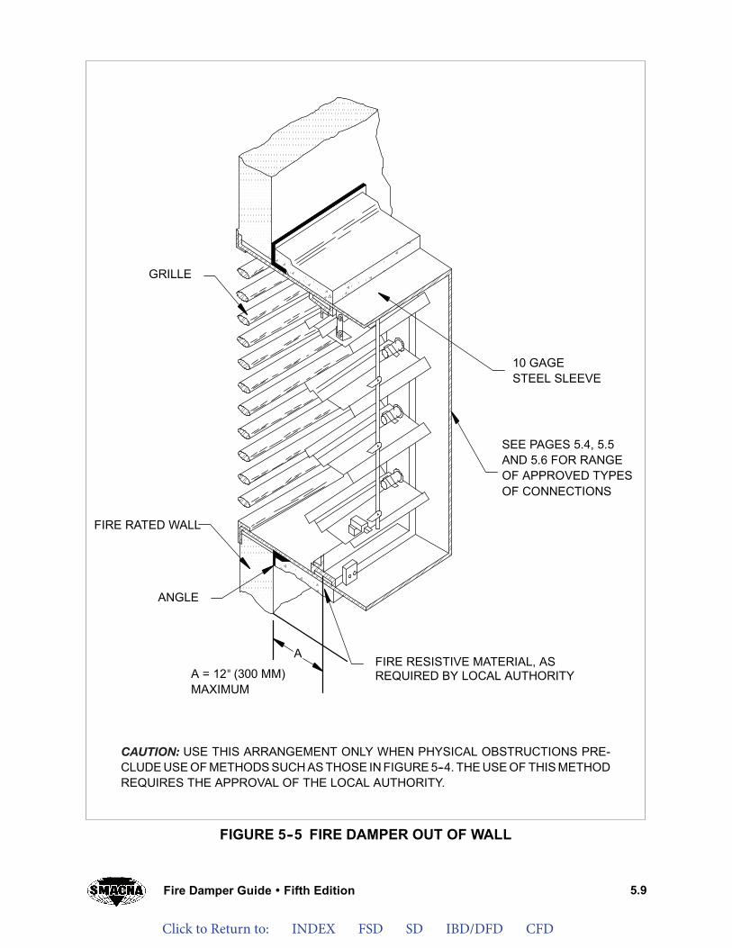
Click to Return to: INDEX FSD SD IBD/DFD CFD
5.9Fire Damper Guide Fifth Edition
CAUTION: USE THIS ARRANGEMENT ONLY WHEN PHYSICAL OBSTRUCTIONS PRE-CLUDE USE OF METHODS SUCH AS THOSE IN FIGURE 5--4. THE USE OF THIS METHODREQUIRES THE APPROVAL OF THE LOCAL AUTHORITY.
FIRE RESISTIVE MATERIAL, ASREQUIRED BY LOCAL AUTHORITYA = 12” (300 MM)
MAXIMUM
ANGLE
FIRE RATED WALL
A
GRILLE
SEE PAGES 5.4, 5.5AND 5.6 FOR RANGEOF APPROVED TYPESOF CONNECTIONS
10 GAGESTEEL SLEEVE
FIGURE 5--5 FIRE DAMPER OUT OF WALL
"
CAUTION:
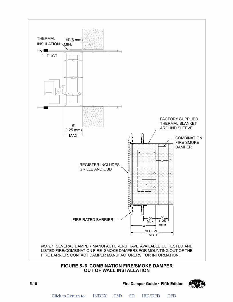
Click to Return to: INDEX FSD SD IBD/DFD CFD
5.10 Fire Damper Guide Fifth Edition
FIGURE 5--6 COMBINATION FIRE/SMOKE DAMPEROUT OF WALL INSTALLATION
NOTE: SEVERAL DAMPER MANUFACTURERS HAVE AVAILABLE UL TESTED ANDLISTED FIRE/COMBINATION FIRE--SMOKE DAMPERS FOR MOUNTING OUT OF THEFIRE BARRIER. CONTACT DAMPER MANUFACTURERS FOR INFORMATION.
DUCT
THERMALINSULATION
1/4”(6 mm)MIN.
5”(125 mm)
X
5”Max.
ASLEEVELENGTH
5”(125mm)
FACTORY SUPPLIEDTHERMAL BLANKETAROUND SLEEVE
COMBINATIONFIRE SMOKEDAMPER
REGISTER INCLUDESGRILLE AND OBD
FIRE RATED BARRIER
MAX.
"
"
""
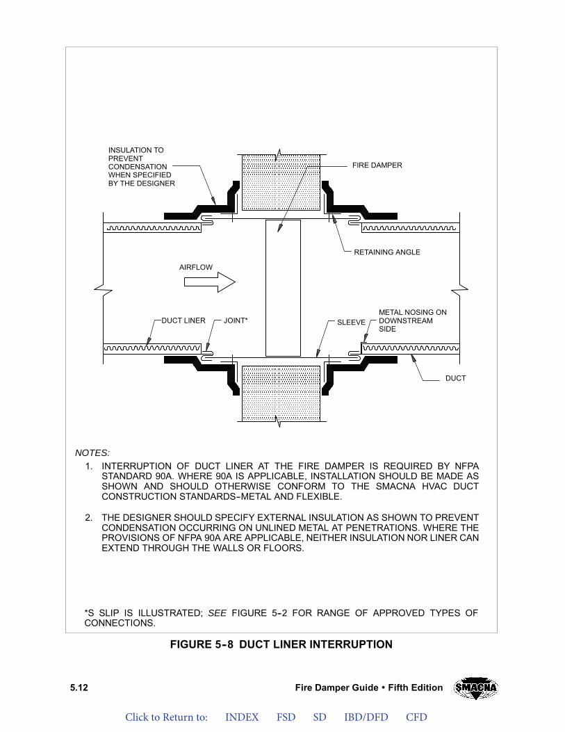
Click to Return to: INDEX FSD SD IBD/DFD CFD
5.12 Fire Damper Guide Fifth Edition
FIGURE 5--8 DUCT LINER INTERRUPTION
FIRE DAMPER
INSULATION TOPREVENTCONDENSATIONWHEN SPECIFIEDBY THE DESIGNER
AIRFLOW
DUCT LINER JOINT* SLEEVEMETAL NOSING ONDOWNSTREAMSIDE
DUCT
RETAINING ANGLE
NOTES:1. INTERRUPTION OF DUCT LINER AT THE FIRE DAMPER IS REQUIRED BY NFPA
STANDARD 90A. WHERE 90A IS APPLICABLE, INSTALLATION SHOULD BE MADE ASSHOWN AND SHOULD OTHERWISE CONFORM TO THE SMACNA HVAC DUCTCONSTRUCTION STANDARDS--METAL AND FLEXIBLE.
2. THE DESIGNER SHOULD SPECIFY EXTERNAL INSULATION AS SHOWN TO PREVENTCONDENSATION OCCURRING ON UNLINED METAL AT PENETRATIONS. WHERE THEPROVISIONS OF NFPA 90A ARE APPLICABLE, NEITHER INSULATION NOR LINER CANEXTEND THROUGH THE WALLS OR FLOORS.
*S SLIP IS ILLUSTRATED; SEE FIGURE 5--2 FOR RANGE OF APPROVED TYPES OFCONNECTIONS.
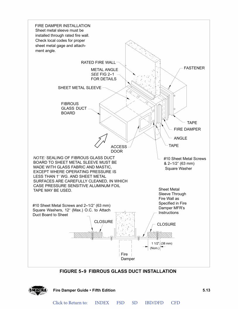
Click to Return to: INDEX FSD SD IBD/DFD CFD
5.13Fire Damper Guide Fifth Edition
FIGURE 5--9 FIBROUS GLASS DUCT INSTALLATION
FIRE DAMPER INSTALLATION
CLOSURE
ACCESSDOOR
FIBROUSGLASS DUCTBOARD
Sheet metal sleeve must beinstalled through rated fire wall.Check local codes for propersheet metal gage and attach-ment angle.
METAL ANGLESEE FIG 2--1FOR DETAILS
RATED FIRE WALL
SHEET METAL SLEEVE
#10 Sheet Metal Screws& 2--1/2” (63 mm)Square Washer
1 1/2”; (38 mm)(Nom.)
FireDamper
ANGLE
TAPE
TAPE
FASTENER
FIRE DAMPER
CLOSURE
Sheet MetalSleeve ThroughFire Wall asSpecified in FireDamper MFR’sInstructions
#10 Sheet Metal Screws and 2--1/2” (63 mm)Square Washers, 12” (Max.) O.C. to AttachDuct Board to Sheet
NOTE: SEALING OF FIBROUS GLASS DUCTBOARD TO SHEET METAL SLEEVE MUST BEMADE WITH GLASS FABRIC AND MASTIC,EXCEPT WHERE OPERATING PRESSURE ISLESS THAN 1” WG. AND SHEET METALSURFACES ARE CAREFULLY CLEANED, IN WHICHCASE PRESSURE SENSITIVE ALUMINUM FOILTAPE MAY BE USED.
"
"
"
""
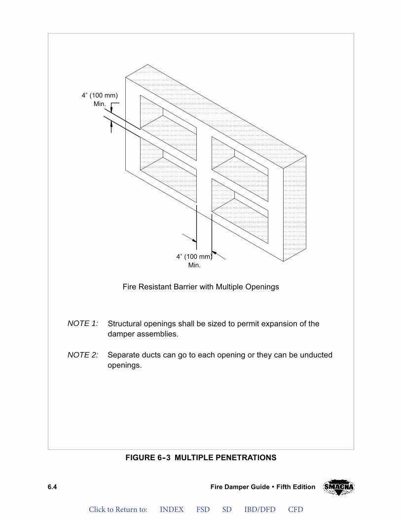
Click to Return to: INDEX FSD SD IBD/DFD CFD
6.4 Fire Damper Guide Fifth Edition
FIGURE 6--3 MULTIPLE PENETRATIONS
Fire Resistant Barrier with Multiple Openings
NOTE 1: Structural openings shall be sized to permit expansion of thedamper assemblies.
NOTE 2: Separate ducts can go to each opening or they can be unductedopenings.
4” (100 mm)Min.
4” (100 mm)Min.
"
"
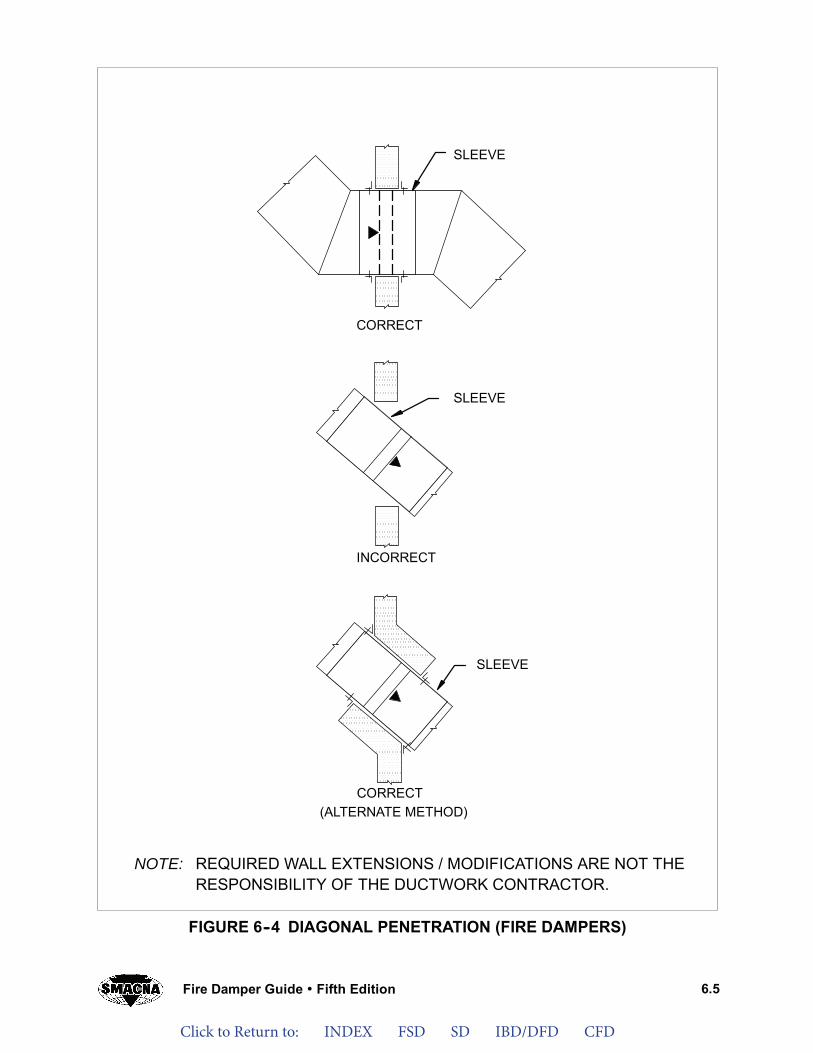
Click to Return to: INDEX FSD SD IBD/DFD CFD
6.5Fire Damper Guide Fifth Edition
FIGURE 6--4 DIAGONAL PENETRATION (FIRE DAMPERS)
CORRECT
INCORRECT
CORRECT(ALTERNATE METHOD)
SLEEVE
SLEEVE
SLEEVE
NOTE: REQUIRED WALL EXTENSIONS / MODIFICATIONS ARE NOT THERESPONSIBILITY OF THE DUCTWORK CONTRACTOR.

FSWFUSWITC
E LCH
INKPAKS aCKAandAGEd ES
Click to Return to: INDEX FSD SD IBD/DFD CFD
Electronic Resettable Fuse Linl "EFL"Electronic Resettable Fuse Link with Damper Test Switch “DTS”
EFL/SP100 Electric Resettable Fuse Link and SP100 Switch Package “EFL/SP100”
Damper Test Switch for Smoke Dampers TS150 FireStat for "Reopenable" Fire and Smoke Dampers
SP100 Switch Package Field Installation Instructions SP200 Switch Package for Curtain Fire Damper
Pneumatic Fuse Link “PFL” Fuse Link Replacements
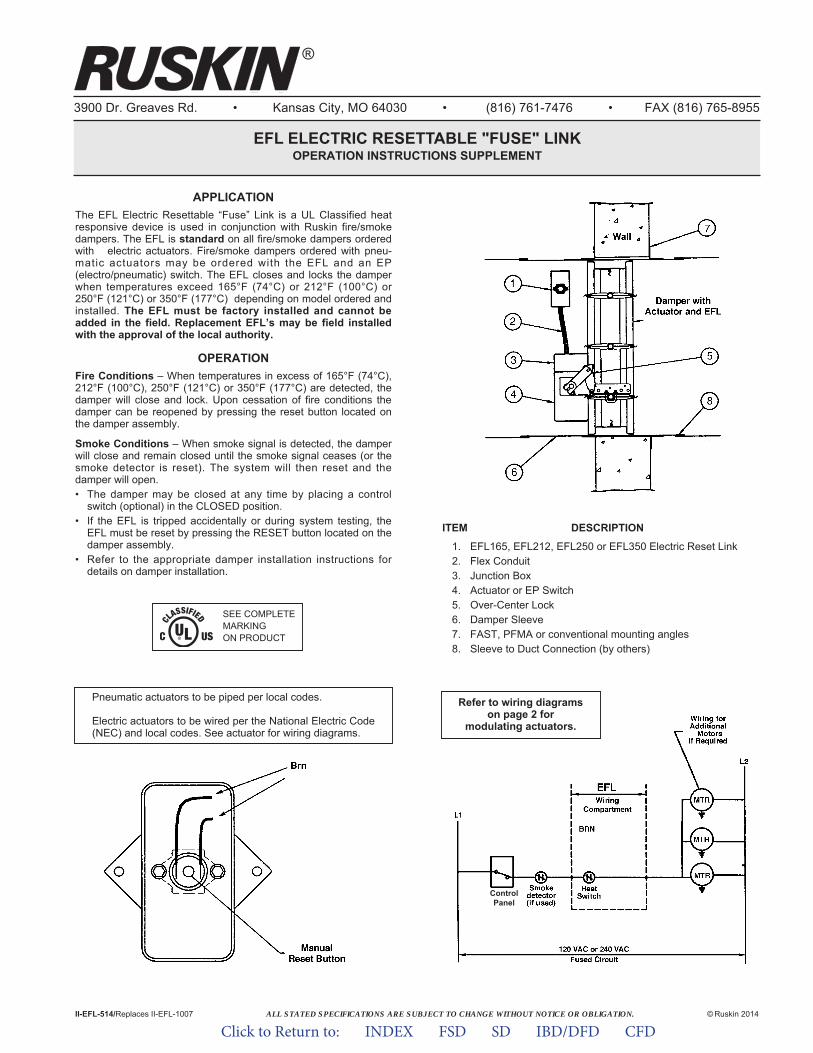
3900 Dr. Greaves Rd. • Kansas City, MO 64030 • (816) 761-7476 • FAX (816) 765-8955
EFL ELECTRIC RESETTABLE "FUSE" LINKOPERATION INSTRUCTIONS SUPPLEMENT
APPLICATION The EFL Electric Resettable “Fuse” Link is a UL Classified heatresponsive device is used in conjunction with Ruskin fire/smokedampers. The EFL is standard on all fire/smoke dampers orderedwith electric actuators. Fire/smoke dampers ordered with pneu-matic actuators may be ordered with the EFL and an EP(electro/pneumatic) switch. The EFL closes and locks the damperwhen temper a tures exceed 165°F (74°C) or 212°F (100°C) or250°F (121°C) or 350°F (177°C) depending on model ordered andinstalled. The EFL must be factory installed and cannot beadded in the field. Replacement EFL’s may be field installedwith the approval of the local authority.
OPERATIONFire Conditions – When temperatures in excess of 165°F (74°C),212°F (100°C), 250°F (121°C) or 350°F (177°C) are detected, thedamper will close and lock. Upon cessation of fire conditions thedamper can be reopened by pressing the reset button located onthe damper assembly.
Smoke Conditions – When smoke signal is detected, the damperwill close and remain closed until the smoke signal ceases (or thesmoke detector is reset). The system will then reset and thedamper will open.• The damper may be closed at any time by placing a control
switch (optional) in the CLOSED position.• If the EFL is tripped accidentally or during system testing, the
EFL must be reset by pressing the RESET button located on thedamper assembly.
• Refer to the appropriate damper installation instructions fordetails on damper installation.
II-EFL-514/Replaces II-EFL-1007 © Ruskin 2014
ITEM DESCRIPTION
1. EFL165, EFL212, EFL250 or EFL350 Electric Reset Link2. Flex Conduit3. Junction Box4. Actuator or EP Switch5. Over-Center Lock6. Damper Sleeve7. FAST, PFMA or conventional mounting angles8. Sleeve to Duct Connection (by others)
Pneumatic actuators to be piped per local codes.
Electric actuators to be wired per the National Electric Code(NEC) and local codes. See actuator for wiring diagrams.
ControlPanel
SEE COMPLETEMARKING ON PRODUCT
Refer to wiring diagramson page 2 for
modulating actuators.
ALL STATED SPECIFICATIONS ARE SUBJECT TO CHANGE WITHOUT NOTICE OR OBLIGATION.
®
Click to Return to: INDEX FSD SD IBD/DFD CFD
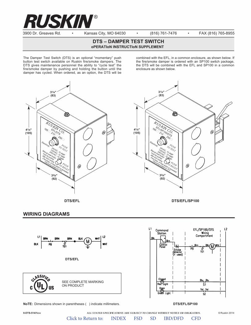
®
ALL STATED SPECIFICATIONS ARE SUBJECT TO CHANGE WITHOUT NOTICE OR OBLIGATION.
3900 Dr. Greaves Rd. • Kansas City, MO 64030 • (816) 761-7476 • FAX (816) 765-8955
DTS – DAMPER TEST SWITCHoPERATIoN INSTRUCTIoN SUPPLEMENT
The Damper Test Switch (DTS) is an optional “momentary” pushbutton test switch available on Ruskin fire/smoke dampers. TheDTS gives maintenance personnel the ability to “cycle test” thefire/smoke damper by pushing and holding the button until thedamper has cycled. When ordered, as an option, the DTS will be
combined with the EFL, in a common enclosure, as shown below. Ifthe fire/smoke damper is ordered with an SP100 switch package,the DTS will be combined with the EFL and SP100 in a commonenclosure as shown below.
II-DTS-514/New © Ruskin 2014
35/8"(92)
31/4"(83)
41/8"(105)
DTS/EFL DTS/EFL/SP100
EFL/DTS
165 �212 �
250 �Electrical:
24VAC, 15 AMP
120VAC, 15 AMP
240VAC, 10 AMP
PUSH TO TEST
PUSH TO RESET
RUSKIN CO.
Manual reset button
must be pushed
after duct cooling
if the temp. of heat switch is exceeded.
Field wiring suitable for 75°F.
NoTE: Dimensions shown in parentheses ( ) indicate millimeters.
WIRING DIAGRAMS
DTS/EFL/SP100
DTS/EFL
SEE COMPLETE MARKING ON PRODUCT
35/8"(92)
31/4"(83)
41/8"(105)
EFL/SP100/DTS
165 �212 �
250 �Electrical:
24VAC, 15 AMP
120VAC, 15 AMP
240VAC, 10 AMP
PUSH TO TEST
PUSH TO RESET
RUSKIN CO.
Manual reset button
must be pushed
after duct cooling
if the temp. of heat switch is exceeded.
Field wiring suitable for 75°F.
Click to Return to: INDEX FSD SD IBD/DFD CFD
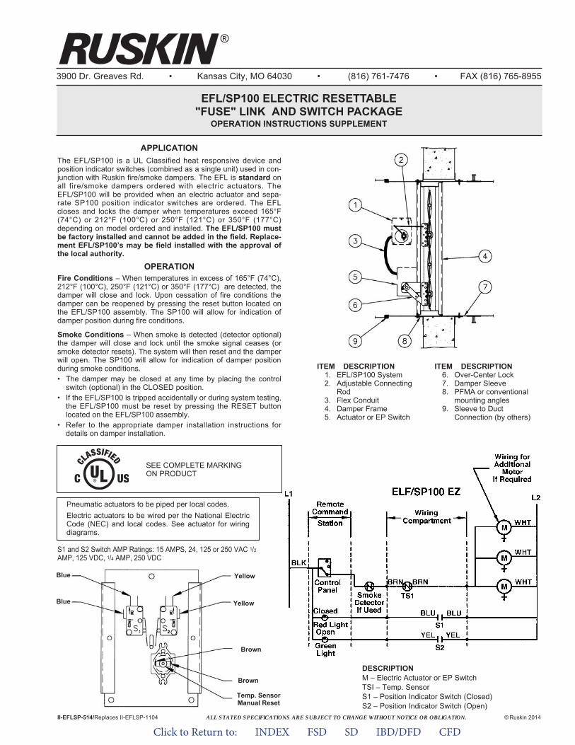
ALL STATED SPECIFICATIONS ARE SUBJECT TO CHANGE WITHOUT NOTICE OR OBLIGATION.
3900 Dr. Greaves Rd. • Kansas City, MO 64030 • (816) 761-7476 • FAX (816) 765-8955
EFL/SP100 ELECTRIC RESETTABLE"FUSE" LINK AND SWITCH PACKAGE
OPERATION INSTRUCTIONS SUPPLEMENT
II-EFLSP-514/Replaces II-EFLSP-1104 © Ruskin 2014
ITEM DESCRIPTION1. EFL/SP100 System2. Adjustable Connecting
Rod3. Flex Conduit4. Damper Frame5. Actuator or EP Switch
ITEM DESCRIPTION6. Over-Center Lock7. Damper Sleeve8. PFMA or conventional
mounting angles9. Sleeve to Duct
Connection (by others)
Pneumatic actuators to be piped per local codes.Electric actuators to be wired per the National ElectricCode (NEC) and local codes. See actuator for wiringdiagrams.
DESCRIPTIONM – Electric Actuator or EP SwitchTSI – Temp. SensorS1 – Position Indicator Switch (Closed)S2 – Position Indicator Switch (Open)
APPLICATION The EFL/SP100 is a UL Classified heat responsive device andposition indicator switches (combined as a single unit) used in con-junction with Ruskin fire/smoke dampers. The EFL is standard onall fire/smoke dampers ordered with electric actuators. TheEFL/SP100 will be provided when an electric actuator and sepa-rate SP100 position indicator switches are ordered. The EFLcloses and locks the damper when temperatures exceed 165°F(74°C) or 212°F (100°C) or 250°F (121°C) or 350°F (177°C)depending on model ordered and installed. The EFL/SP100 mustbe factory installed and cannot be added in the field. Replace-ment EFL/SP100’s may be field installed with the approval ofthe local authority.
OPERATIONFire Conditions – When temperatures in excess of 165°F (74°C),212°F (100°C), 250°F (121°C) or 350°F (177°C) are detected, thedamper will close and lock. Upon cessation of fire conditions thedamper can be reopened by pressing the reset button located onthe EFL/SP100 assembly. The SP100 will allow for indication ofdamper position during fire conditions.
Smoke Conditions – When smoke is detected (detector optional)the damper will close and lock until the smoke signal ceases (orsmoke detector resets). The system will then reset and the damperwill open. The SP100 will allow for indication of damper positionduring smoke conditions.• The damper may be closed at any time by placing the control
switch (optional) in the CLOSED position.• If the EFL/SP100 is tripped accidentally or during system testing,
the EFL/SP100 must be reset by pressing the RESET buttonlocated on the EFL/SP100 assembly.
• Refer to the appropriate damper installation instructions fordetails on damper installation.
Brown
Brown
Yellow
YellowBlue
Blue
Temp. SensorManual Reset
S1 and S2 Switch AMP Ratings: 15 AMPS, 24, 125 or 250 VAC 1/2AMP, 125 VDC, 1/4 AMP, 250 VDC
SEE COMPLETE MARKING ON PRODUCT
®
Click to Return to: INDEX FSD SD IBD/DFD CFD

ALL STATED SPECIFICATIONS ARE SUBJECT TO CHANGE WITHOUT NOTICE OR OBLIGATION.
®
3900 Dr. Greaves Rd. • Kansas City, MO 64030 • (816) 761-7476 • FAX (816) 765-8955
APPLICATIONThe Damper Test Switch for Smoke Dampers (DTS-SD) is an optional “momentary” push button test switch available on Ruskin smoke dampers. The DTS-SD gives maintenance personnel the ability to “cycle test” the smoke damper by pushing and holding the button until the damper cycles to its de-energized position. The DTS-SD may be supplied factory mounted and wired to the dampers actua-tors or shipped loose for field wiring.
DTS-SD DAMPER TEST SWITCH FOR SMOKE DAMPERSOPERATION INSTRUCTION SUPPLEMENT
II-DTS-SD-514/Replaces II-DTS-SD-1212 ©Ruskin 2014
WIRING DIAGRAM
SEE COMPLETEMARKING ON PRODUCT
ITEM DESCRIPTION1. Smoke Damper
2. Side Plate or Sleeve
3. Actuator
4. Conduit
5. DTS-SD
Pneumatic actuators to be piped per local codes.
Electric actuators to be wired per the National Electric Code (NEC) and local codes. See actuator for wiring diagrams.
Click to Return to: INDEX FSD SD IBD/DFD CFD
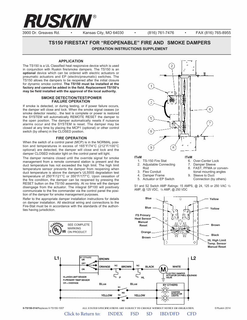
ALL STATED SPECIFICATIONS ARE SUBJECT TO CHANGE WITHOUT NOTICE OR OBLIGATION.
3900 Dr. Greaves Rd. • Kansas City, MO 64030 • (816) 761-7476 • FAX (816) 765-8955
TS150 FIRESTAT FOR “REOPENABLE” FIRE AND SMOKE DAMPERS OPERATION INSTRUCTIONS SUPPLEMENT
II-TS150-514/Replaces II-TS150-1007 © Ruskin 2014
S1 and S2 Switch AMP Ratings: 15 AMPS, @ 24, 125 or 250 VAC 1/2
AMP, @ 125 VDC, 1/4 AMP, @ 250 VDC
ITeM 1. TS-150 Fire Stat2. Adjustable Connecting
Rod3. Flex Conduit4. Damper Frame5. Actuator or EP Switch
ITeM 6. Over-Center Lock7. Damper Sleeve8. FAST, PFMA or conven-
tional mounting angles9. Sleeve to Duct
Connection (by others)
APPLICATIONThe TS150 is a UL Classified heat responsive device which is usedin conjunction with Ruskin fire/smoke dampers. The TS150 is anoptional device which can be ordered with electric actuators orpneumatic actuators and EP (electro/pneumatic) switches. TheTS150 allows the dampers to be reopened after the initial closurefor dynamic smoke control. The TS150 must be installed at thefactory and cannot be added in the field. Replacement TS150’smay be field installed with the approval of the local authority.
SMOKE DETECTION/TEST/POWERFAILURE OPERATION
If smoke is detected, or during testing, or if power failure occurs,the damper will close and lock. When the smoke signal ceases (orsmoke detector resets) , the test is complete or power is restoredthe SYSTEM will automat ically REMOTE RESET the damper tothe open position. The damper automatically resets if nuisancealarms occur and the SYSTEM is reset. The damper may beclosed at any time by placing the MCP1 (optional) or other controlswitch (by others) in the CLOSED position.
FIRE OPERATIONWhen the switch of a control panel (MCP) is in the NORMAL posi-tion and temperatures in excess of 165°F/74°C (212°F/100°C optional) are detected, the damper will close and lock and the damper CLOSED indicator light on the control panel will light.The damper remains closed until the override signal for smokemanagement from a remote command station is present and theduct temperature has not exceeded the high limit. The high limittemperature sensor prevents the damper from reopening whenduct temperature is above the damper's UL555S degradation testtemperature of 250°F/121°C or 350°F/177°C. Upon cessation ofthe fire condition, the damper can be reopened by pressing theRESET button on the TS150 assembly. At no time will the damperdisengage from the actuator. The integral SP100 will positivelycommunicate to the fire commander via the control panel the posi-tion of the damper for smoke management purposes.Refer to the appropriate damper installation instructions for detailson damper installation. All electrical wiring and connections to theFire-Stat must be in accordance with the standards of the authori-ties having jurisdiction.
BY OTHeRS
BLue BLue
Black
Blue
Blue
Brown
Yellow
Yellow
Orange
Brown
FS PrimaryHeat Sensor
ManualReset
HL High LimitTemp. SensorManual Reset
SEE COMPLETEMARKING ON PRODUCT
Click to Return to: INDEX FSD SD IBD/DFD CFD
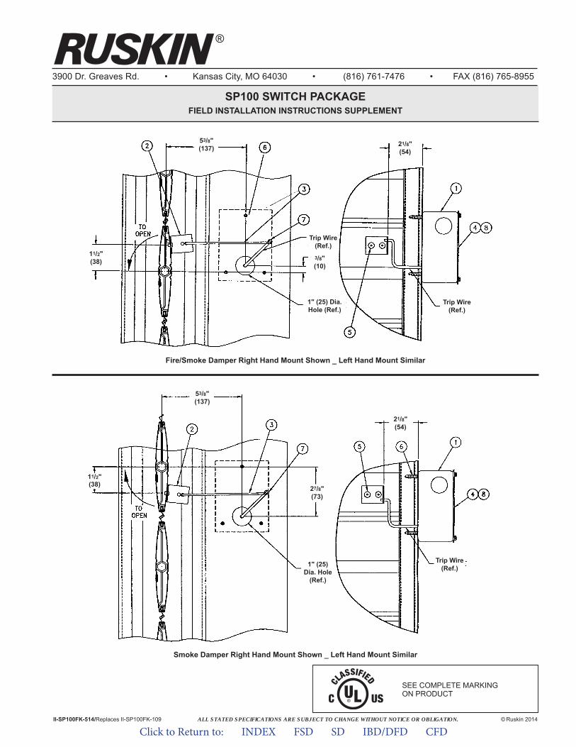
ALL STATED SPECIFICATIONS ARE SUBJECT TO CHANGE WITHOUT NOTICE OR OBLIGATION.
3900 Dr. Greaves Rd. • Kansas City, MO 64030 • (816) 761-7476 • FAX (816) 765-8955
SP100 SWITCH PACKAGEFIELD INSTALLATION INSTRUCTIONS SUPPLEMENT
© Ruskin 2014
®
II-SP100FK-514/Replaces II-SP100FK-109
Fire/Smoke Damper Right Hand Mount Shown _ Left Hand Mount Similar
53/8"(137)
3/8"(10)
Trip Wire(Ref.)
1" (25) Dia.Hole (Ref.)
1" (25)Dia. Hole
(Ref.)
11/2"(38)
11/2"(38) 27/8"
(73)
21/8"(54)
Trip Wire(Ref.)
Trip Wire(Ref.)
53/8"(137)
21/8"(54)
SEE COMPLETE MARKING ON PRODUCT
Smoke Damper Right Hand Mount Shown _ Left Hand Mount Similar
Click to Return to: INDEX FSD SD IBD/DFD CFD

SP100 FIELD INSTALLATION INSTRUCTIONS
SP100 WIRING
S1 – Damper position indicator switch. Closed when damperis closed.
S2 – Damper position indicator switch. Closed when damperis open.
B1 – Remote position indicator lamp.B2 – Remote position indicator lamp.
S1 – Damper position indicator switch. Closed when damperis open.
S2 – Damper position indicator switch. Closed when damperis closed.
B1 – Remote position indicator lamp.B2 – Remote position indicator lamp.
INSTALLATION1. Obtain authorization from the local fire protection authority prior
to installation of the SP100.2. Verify all parts are included in parts kit (see item list).3. SP100 must be linked to a power blade (power blades are all
blades on parallel blade dampers and every other blade, startingwith the bottom blade, on opposed blade dampers, see detail atright).
4. Refer to installation details on page 1. For fire/smokedampers locate the blade bracket (#2) approximately 11/2" (38)above the center line of the blade and 21/8" (54) from the outsideof the frame on a power blade. Mark and drill #30 (.128 dia.) holeand rivet the blade bracket to the blade with 2, 1/8" (3) pop rivets(#5). For smoke dampers install the blade bracket same as thefire/smoke damper except locate it 11/2" (38) below the centerline of the blade.
5. For fire/smoke dampers locate the 1" (25) dia. hole for theSP100 3/8" (10) above and 53/8" (136) from the center line of thepower blade. Slip the SP100 assembly trip wire into 1" (25) dia.hole and center trip wire in hole.For smoke dampers install the SP100 same as the fire/smokedampers except locate the 1" (25) dia. hole 27/8" (73) below thecenter line of the power blade.If the 1" (25) dia. hole cannot be located as indicated, locate it asclose as possible to the dimensions shown.
6. Attach the SP100 to the damper sleeve with (3) #10 screws andsecure into place so SP100 does not rotate (screw heads will beon inside of box).
7. Insert the "Z" end of the link rod (#3) into the blade bracket (#2).Slip the other end over the trip lever on the SP100 (#1) andsecure in place with 3/32" (2) push nut (#7).
8. Cycle the damper to verify switch actuation. Link rod may beformed as required to activate the switches (do not over strokethe switches).
Dimensions in parenthesis ( ) indicate millimeters.
PARTS LIST(refer to page 1)
ITEM DESCRIPTION QTY.
1 SP100 12 Blade Bracket 13 Link Rod 14 Cover Plate 15 Pop Rivet, 1/8" x 1/4" 26 Screw, #10 x 1/2" 37 Push Nut, 3/32" 18 Label 1
LEFTHANDSIDE
RIGHTHANDSIDE
3900 Dr. Greaves Rd.Kansas City, MO 64030(816) 761-7476FAX (816) 765-8955www.ruskin.com
®
Click to Return to: INDEX FSD SD IBD/DFD CFD
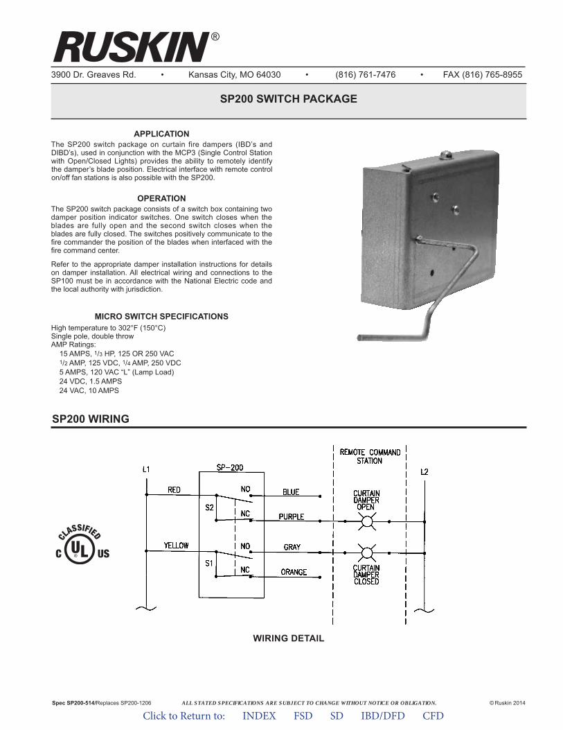
ALL STATED SPECIFICATIONS ARE SUBJECT TO CHANGE WITHOUT NOTICE OR OBLIGATION.
3900 Dr. Greaves Rd. • Kansas City, MO 64030 • (816) 761-7476 • FAX (816) 765-8955
SP200 SWITCH PACKAGE
© Ruskin 2014Spec SP200-514/Replaces SP200-1206
APPLICATIONThe SP200 switch package on curtain fire dampers (IBD’s andDIBD’s), used in conjunction with the MCP3 (Single Control Stationwith Open/Closed Lights) provides the ability to remotely identifythe damper’s blade position. Electrical interface with remote controlon/off fan stations is also possible with the SP200.
OPERATIONThe SP200 switch package consists of a switch box containing twodamper position indicator switches. One switch closes when theblades are fully open and the second switch closes when theblades are fully closed. The switches positively communicate to thefire commander the position of the blades when interfaced with thefire command center.
Refer to the appropriate damper installation instructions for detailson damper installation. All electrical wiring and connections to theSP100 must be in accordance with the National Electric code andthe local authority with jurisdiction.
MICRO SWITCH SPECIFICATIONSHigh temperature to 302°F (150°C)Single pole, double throwAMP Ratings:
15 AMPS, 1/3 HP, 125 OR 250 VAC1/2 AMP, 125 VDC, 1/4 AMP, 250 VDC5 AMPS, 120 VAC “L” (Lamp Load)24 VDC, 1.5 AMPS24 VAC, 10 AMPS
SP200 WIRING
WIRING DETAIL
®
Click to Return to: INDEX FSD SD IBD/DFD CFD
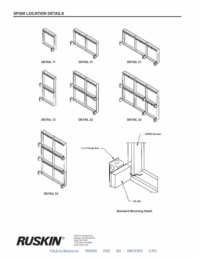
3900 Dr. Greaves Rd.Kansas City, MO 64030(816) 761-7476FAX (816) 765-8955www.ruskin.com
SP200 LOCATION DETAILS
DETAIL 11 DETAIL 21 DETAIL 31
DETAIL 12 DETAIL 22
DETAIL 23
Standard Mounting Detail
SP-200
DETAIL 32
(D)IBD Damper
2 x 4 Handy Box
®
Click to Return to: INDEX FSD SD IBD/DFD CFD
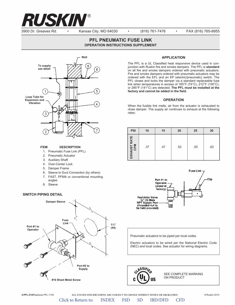
ALL STATED SPECIFICATIONS ARE SUBJECT TO CHANGE WITHOUT NOTICE OR OBLIGATION.
3900 Dr. Greaves Rd. • Kansas City, MO 64030 • (816) 761-7476 • FAX (816) 765-8955
PFL PNEUMATIC FUSE LINKOPERATION INSTRUCTIONS SUPPLEMENT
APPLICATIONThe PFL is a UL Classified heat responsive device used in con-junction with Ruskin fire and smoke dampers. The PFL is standardon all fire and smoke dampers ordered with pneumatic actuators.Fire and smoke dampers ordered with pneumatic actuators may beordered with the EFL and an EP (electric/pneumatic) switch. ThePFL closes and locks the damper via a standard replaceable fuselink when temperatures in excess of 165°F (74°C), 212°F (100°C),or 285°F (141°C) are detected. The PFL must be installed at thefactory and cannot be added in the field.
OPERATIONWhen the fusible link melts, air from the actuator is exhausted toclose damper. The supply air continues to exhaust at the followingrates:
II-PFL-514/Replaces PFL-1104 © Ruskin 2014
Loop Tube forExpansion and
Vibration
To supplysee detail
Damper Sleeve
FuseLink
Port #2 toSupply
Port #1 toOperator
13/4"(44)
#10 Sheet Metal Screw
SWITCH PIPING DETAIL
Wall
Pneumatic actuators to be piped per local codes.
Electric actuators to be wired per the National Electric Code(NEC) and local codes. See actuator for wiring diagrams.
ITEM DESCRIPTION1. Pneumatic Fuse Link (PFL)2. Pneumatic Actuator3. Auxiliary Shaft4. Over-Center Lock5. Damper Frame6. Sleeve to Duct Connection (by others)7. FAST, PFMA or conventional mounting
angles8. Sleeve
PSIEX
HAUS
T RA
TEC
FM10
.37 .47 .52 .55 .62
15 20 25 30
SEE COMPLETE MARKING ON PRODUCT
Click to Return to: INDEX FSD SD IBD/DFD CFD
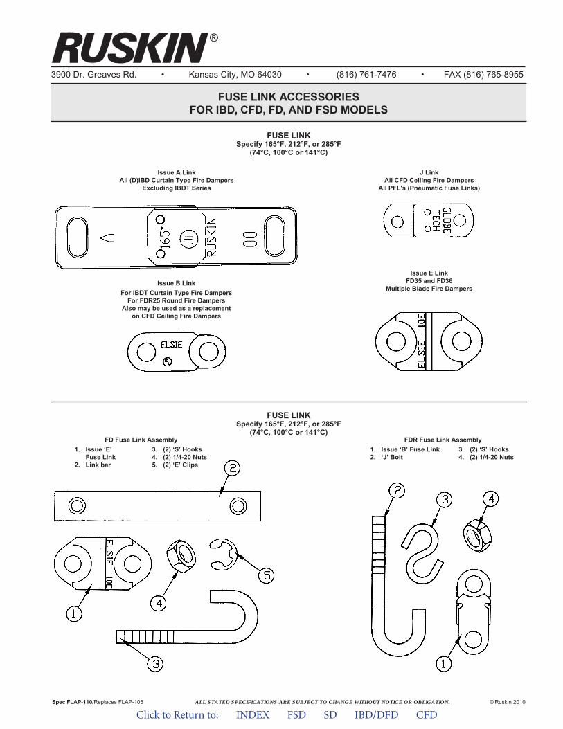
3900 Dr. Greaves Rd. • Kansas City, MO 64030 • (816) 761-7476 • FAX (816) 765-8955
FUSE LINK ACCESSORIESFOR IBD, CFD, FD, AND FSD MODELS
®
ALL STATED SPECIFICATIONS ARE SUBJECT TO CHANGE WITHOUT NOTICE OR OBLIGATION. © Ruskin 2010Spec FLAP-110/Replaces FLAP-105
FUSE LINKSpecify 165°F, 212°F, or 285°F
(74°C, 100°C or 141°C)
FUSE LINKSpecify 165°F, 212°F, or 285°F
(74°C, 100°C or 141°C)
Issue A LinkAll (D)IBD Curtain Type Fire Dampers
Excluding IBDT Series
Issue B LinkFor IBDT Curtain Type Fire Dampers
For FDR25 Round Fire DampersAlso may be used as a replacement
on CFD Ceiling Fire Dampers
J LinkAll CFD Ceiling Fire Dampers
All PFL's (Pneumatic Fuse Links)
Issue E LinkFD35 and FD36
Multiple Blade Fire Dampers
FD Fuse Link Assembly1. Issue ‘E’ 3. (2) ‘S’ Hooks
Fuse Link 4. (2) 1/4-20 Nuts2. Link bar 5. (2) ‘E’ Clips
FDR Fuse Link Assembly1. Issue ‘B’ Fuse Link 3. (2) ‘S’ Hooks2. ‘J’ Bolt 4. (2) 1/4-20 Nuts
Click to Return to: INDEX FSD SD IBD/DFD CFD
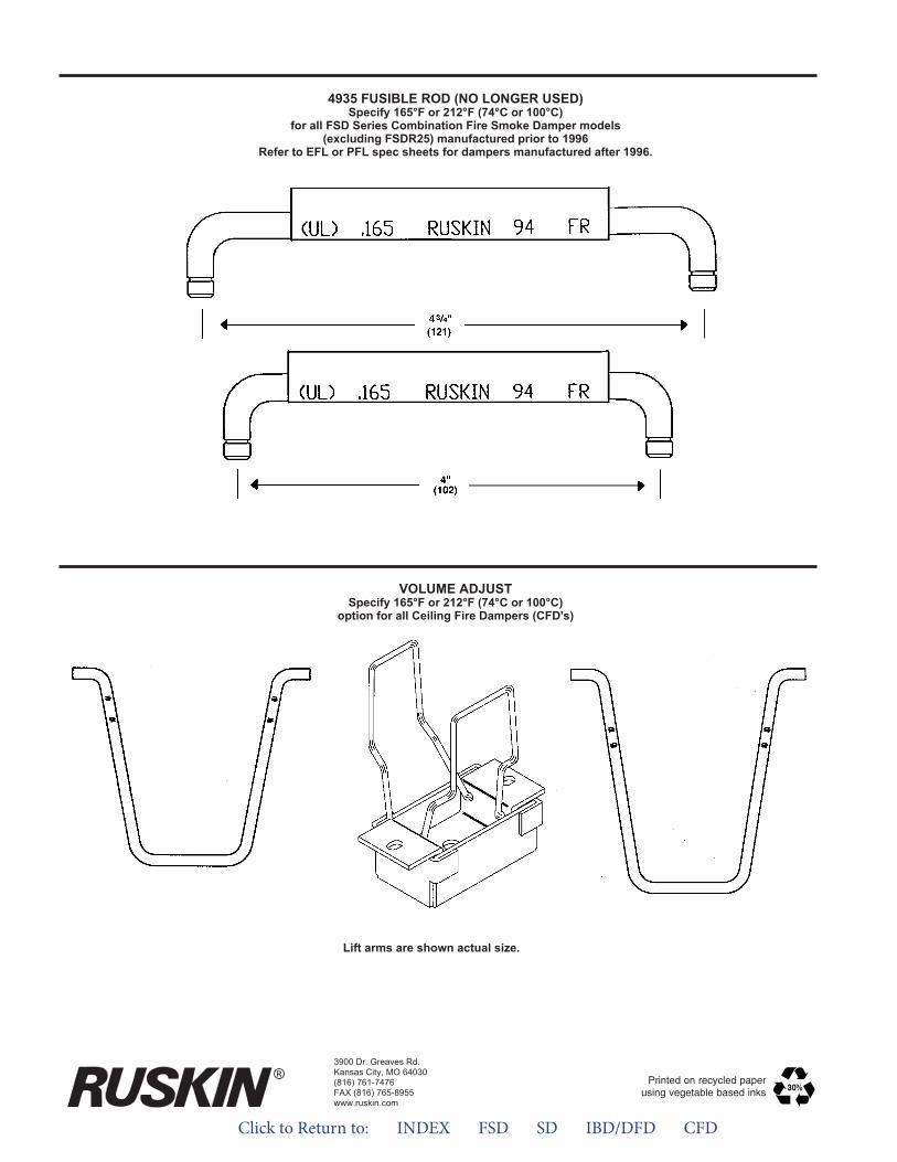
4935 FUSIBLE ROD (NO LONGER USED)Specify 165°F or 212°F (74°C or 100°C)
for all FSD Series Combination Fire Smoke Damper models(excluding FSDR25) manufactured prior to 1996
Refer to EFL or PFL spec sheets for dampers manufactured after 1996.
VOLUME ADJUSTSpecify 165°F or 212°F (74°C or 100°C)
option for all Ceiling Fire Dampers (CFD's)
Lift arms are shown actual size.
3900 Dr. Greaves Rd.Kansas City, MO 64030(816) 761-7476FAX (816) 765-8955www.ruskin.com
® Printed on recycled paperusing vegetable based inks
Click to Return to: INDEX FSD SD IBD/DFD CFD

Click to Return to: INDEX FSD SD IBD/DFD CFD
Duct SmokeDetectors
System Sensor D4120 Flow Duct Smoke DetectorSystem Sensor 2151 No Flow Duct Smoke Detector
Hochiki DH-98 Flow Duct Smoke DetectorAir Products and Controls HS-100-P No- Flow Duct
Smoke Detector
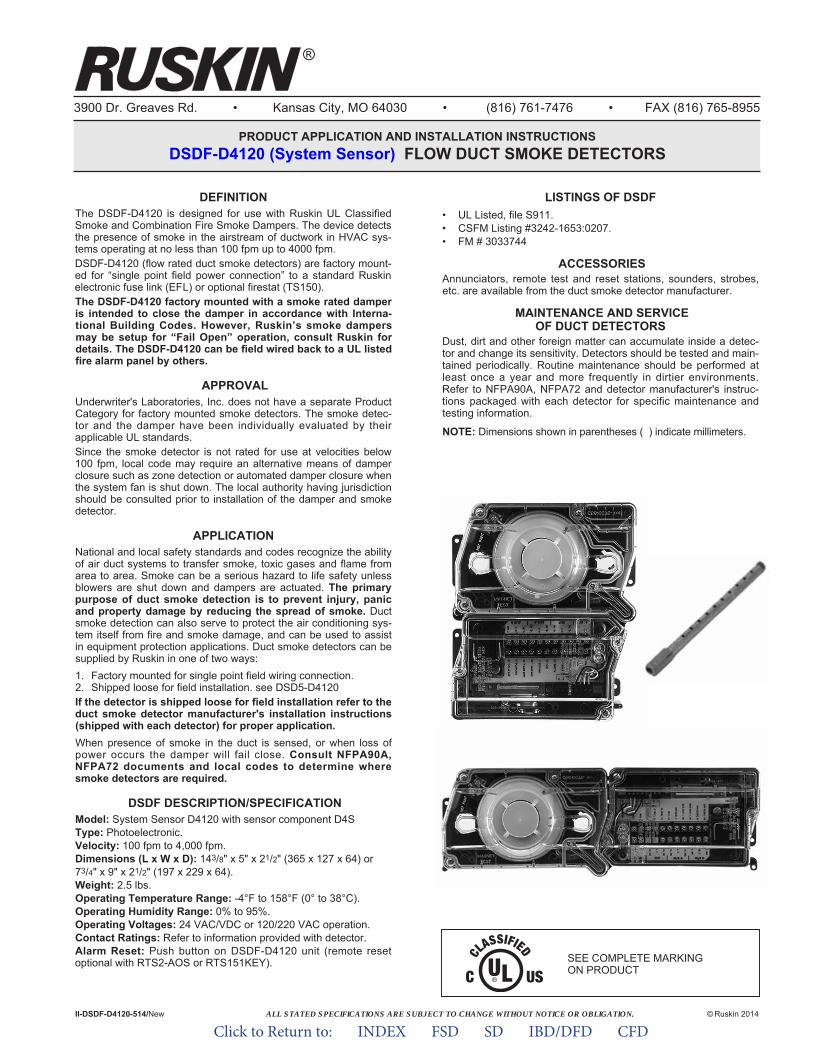
ALL STATED SPECIFICATIONS ARE SUBJECT TO CHANGE WITHOUT NOTICE OR OBLIGATION.
3900 Dr. Greaves Rd. • Kansas City, MO 64030 • (816) 761-7476 • FAX (816) 765-8955
PRODUCT APPLICATION AND INSTALLATION INSTRUCTIONSDSDF-D4120 (System Sensor) FLOW DUCT SMOKE DETECTORS
II-DSDF-D4120-514/New © Ruskin 2014
®
®
DEFINITIONThe DSDF-D4120 is designed for use with Ruskin UL ClassifiedSmoke and Combination Fire Smoke Dampers. The device detectsthe presence of smoke in the airstream of ductwork in HVAC sys-tems operating at no less than 100 fpm up to 4000 fpm.DSDF-D4120 (flow rated duct smoke detectors) are factory mount-ed for “single point field power connection” to a standard Ruskinelec tronic fuse link (EFL) or optional firestat (TS150).The DSDF-D4120 factory mounted with a smoke rated damperis intended to close the damper in accordance with Interna-tional Building Codes. However, Ruskin’s smoke dampersmay be setup for “Fail Open” operation, consult Ruskin fordetails. The DSDF-D4120 can be field wired back to a UL listedfire alarm panel by others.
APPROVALUnderwriter's Laboratories, Inc. does not have a separate ProductCategory for factory mounted smoke detectors. The smoke detec-tor and the damper have been individually evaluated by theirapplicable UL standards.Since the smoke detector is not rated for use at velocities below100 fpm, local code may require an alternative means of damperclosure such as zone detection or automated damper closure whenthe system fan is shut down. The local authority having jurisdictionshould be consulted prior to installation of the damper and smokedetector.
APPLICATIONNational and local safety standards and codes recognize the abilityof air duct systems to transfer smoke, toxic gases and flame fromarea to area. Smoke can be a serious hazard to life safety unlessblowers are shut down and dampers are actuated. The primarypurpose of duct smoke detection is to prevent injury, panicand property damage by reducing the spread of smoke. Ductsmoke detection can also serve to protect the air conditioning sys-tem itself from fire and smoke damage, and can be used to assistin equipment protection applications. Duct smoke detectors can besupplied by Ruskin in one of two ways:1. Factory mounted for single point field wiring connection.2. Shipped loose for field installation. see DSD5-D4120If the detector is shipped loose for field installation refer to theduct smoke detector manufacturer's installation instructions(shipped with each detector) for proper application.When presence of smoke in the duct is sensed, or when loss ofpower occurs the damper will fail close. Consult NFPA90A,NFPA72 documents and local codes to determine wheresmoke detectors are required.
DSDF DESCRIPTION/SPECIFICATIONModel: System Sensor D4120 with sensor component D4SType: Photoelectronic.Velocity: 100 fpm to 4,000 fpm.Dimensions (L x W x D): 143/8" x 5" x 21/2" (365 x 127 x 64) or73/4" x 9" x 21/2" (197 x 229 x 64).Weight: 2.5 lbs.Operating Temperature Range: -4°F to 158°F (0° to 38°C).Operating Humidity Range: 0% to 95%.Operating Voltages: 24 VAC/VDC or 120/220 VAC operation.Contact Ratings: Refer to information provided with detector.Alarm Reset: Push button on DSDF-D4120 unit (remote resetoptional with RTS2-AOS or RTS151KEY).
LISTINGS OF DSDF• UL Listed, file S911.• CSFM Listing #3242-1653:0207.• FM # 3033744
ACCESSORIESAnnunciators, remote test and reset stations, sounders, strobes,etc. are available from the duct smoke detector manufacturer.
MAINTENANCE AND SERVICEOF DUCT DETECTORS
Dust, dirt and other foreign matter can accumulate inside a detec-tor and change its sensitivity. Detectors should be tested and main-tained periodically. Routine maintenance should be performed atleast once a year and more frequently in dirtier environments.Refer to NFPA90A, NFPA72 and detector manufacturer's instruc-tions packaged with each detector for specific maintenance andtesting information.
NOTE: Dimensions shown in parentheses ( ) indicate millimeters.
SEE COMPLETE MARKING ON PRODUCT
Click to Return to: INDEX FSD SD IBD/DFD CFD
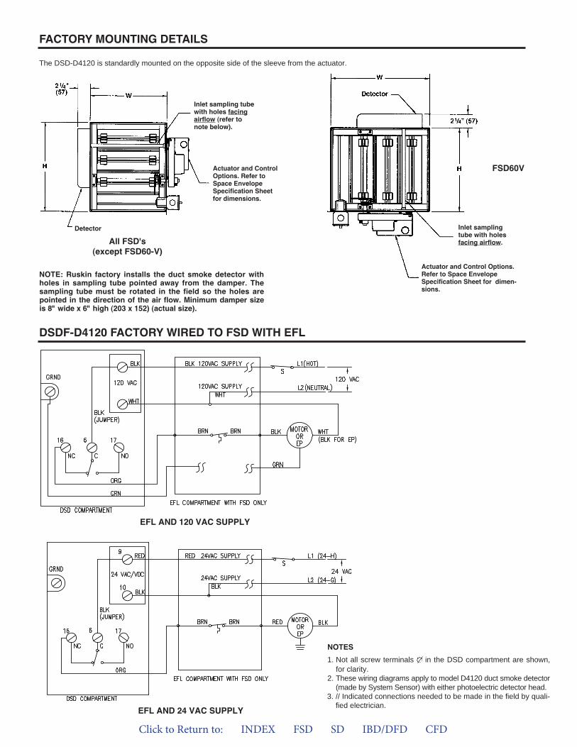
FACTORY MOUNTING DETAILS
DSDF-D4120 FACTORY WIRED TO FSD WITH EFL
The DSD-D4120 is standardly mounted on the opposite side of the sleeve from the actuator.
Actuator and ControlOptions. Refer toSpace EnvelopeSpecifica tion Sheetfor dimensions.
Inlet sampling tubewith holes facingairflow (refer tonote below).
Inlet samplingtube with holesfacing airflow.
Actuator and Control Options.Refer to Space EnvelopeSpecifi cation Sheet for dimen-sions.
NOTE: Ruskin factory installs the duct smoke detector withholes in sampling tube pointed away from the damper. Thesampling tube must be rotated in the field so the holes arepointed in the direction of the air flow. Minimum damper sizeis 8" wide x 6" high (203 x 152) (actual size).
FSD60V
All FSD's(except FSD60-V)
Detector
NOTES1. Not all screw terminals in the DSD compartment are shown,for clarity.
2. These wiring diagrams apply to model D4120 duct smoke detector(made by System Sensor) with either photoelectric detector head.
3. // Indicated connections needed to be made in the field by quali-fied electrician.EFL AND 24 VAC SUPPLY
EFL AND 120 VAC SUPPLY
Click to Return to: INDEX FSD SD IBD/DFD CFD
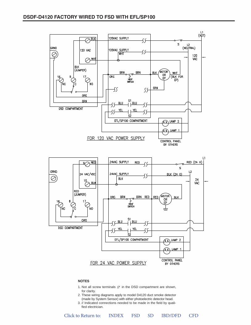
DSDF-D4120 FACTORY WIRED TO FSD WITH EFL/SP100
1. Not all screw terminals in the DSD compartment are shown,for clarity.
2. These wiring diagrams apply to model D4120 duct smoke detector(made by System Sensor) with either photoelectric detector head.
3. // Indicated connections needed to be made in the field by quali-fied electrician.
NOTES
Click to Return to: INDEX FSD SD IBD/DFD CFD
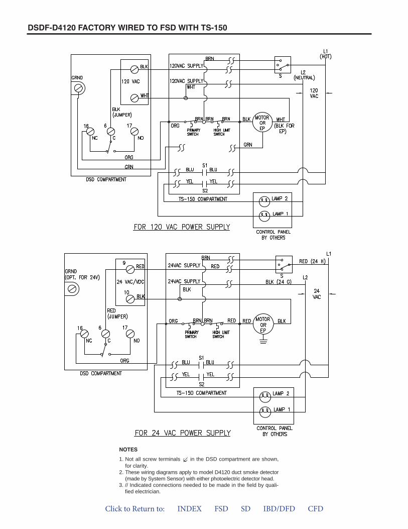
DSDF-D4120 FACTORY WIRED TO FSD WITH TS-150
1. Not all screw terminals in the DSD compartment are shown,for clarity.
2. These wiring diagrams apply to model D4120 duct smoke detector(made by System Sensor) with either photoelectric detector head.
3. // Indicated connections needed to be made in the field by quali-fied electrician.
NOTES
Click to Return to: INDEX FSD SD IBD/DFD CFD
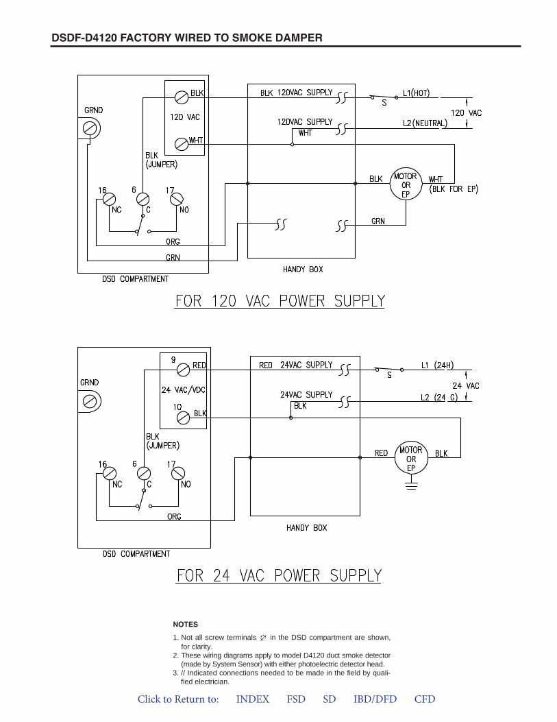
DSDF-D4120 FACTORY WIRED TO SMOKE DAMPER
1. Not all screw terminals in the DSD compartment are shown,for clarity.
2. These wiring diagrams apply to model D4120 duct smoke detector(made by System Sensor) with either photoelectric detector head.
3. // Indicated connections needed to be made in the field by quali-fied electrician.
NOTES
Click to Return to: INDEX FSD SD IBD/DFD CFD
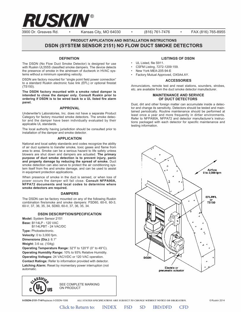
ALL STATED SPECIFICATIONS ARE SUBJECT TO CHANGE WITHOUT NOTICE OR OBLIGATION.
3900 Dr. Greaves Rd. • Kansas City, MO 64030 • (816) 761-7476 • FAX (816) 765-8955
PRODUCT APPLICATION AND INSTALLATION INSTRUCTIONSDSDN (SYSTEM SENSOR 2151) NO FLOW DUCT SMOKE DETECTORS
II-DSDN-2151-714/Replaces II-DSDN-1006 © Ruskin 2014
DEFINITIONThe DSDN (No Flow Duct Smoke Detector) is designed for usewith Ruskin UL555S classified smoke dampers. The device detectsthe presence of smoke in the airstream of ductwork in HVAC sys-tems without a minimum operating velocity.DSDN are factory mounted for “single point field power connection”to a standard Ruskin electronic fuse link (EFL) or optional firestat(TS150).The DSDN factory mounted with a smoke rated damper isintended to close the damper only. Consult Ruskin prior toordering if DSDN is to be wired back to a UL listed fire alarmpanel.
APPROVALUnderwriter's Laboratories, Inc. does not have a separate ProductCategory for factory mounted smoke detectors. The smoke detec-tor and the damper have been individually evaluated by theirapplicable UL standards.The local authority having jurisdiction should be consulted prior toinstallation of the damper and smoke detector.
APPLICATIONNational and local safety standards and codes recognize the abilityof air duct systems to transfer smoke, toxic gases and flame fromarea to area. Smoke can be a serious hazard to life safety unlessblowers are shut down and dampers are actuated. The primarypurpose of duct smoke detection is to prevent injury, panicand property damage by reducing the spread of smoke. Ductsmoke detection can also serve to protect the air conditioning sys-tem itself from fire and smoke damage, and can be used to assistin equipment protection applications.When presence of smoke in the duct is sensed, or when loss ofpower occurs the damper will fail close. Consult NFPA90A,NFPA72 documents and local codes to determine wheresmoke detectors are required.
DAMPERSThe DSDN can be factory mounted on any of the following Ruskincombination fire/smoke and smoke dampers: FSD60, 60-II, 60-3,60-V, 37, 36, 35, 34, SD60, 60-II, 37, 36, 35, 34.
DSDN DESCRIPTION/SPECIFICATIONModel: System Sensor 2151Base: B114LP - 120 VACBase: B114LPBT - 24 VAC/DCType: Photoelectronic.Velocity: 0 to 3,000 fpm.Dimensions (Dia.): 6.1"Weight: 3.6 oz. (104g)Operating Temperature Range: 32°F to 120°F (0° to 49°C).Operating Humidity Range: 10% to 93% Relative Humidity.Operating Voltages: 24 VAC/VDC or 120 VAC operation.Contact Ratings: Refer to information provided with detector.Latching Alarm: Reset by momentary power interruption (notautomatic.
LISTINGS OF DSDN• UL Listed, file S911.• CSFM Listing, 7272-1209:159.• New York MEA-205-94-E• Factory Mutual Approved, OX5A4.AY.
ACCESSORIESAnnunciators, remote test and reset stations, sounders, strobes,etc. are available from the duct smoke detector manufacturer.
MAINTENANCE AND SERVICEOF DUCT DETECTORS
Dust, dirt and other foreign matter can accumulate inside a detec-tor and change its sensitivity. Detectors should be tested and main-tained periodically. Routine maintenance should be performed atleast once a year and more frequently in dirtier environments.Refer to NFPA90A, NFPA72 and detector manufacturer’s instruc-tions packaged with each detector for specific maintenance andtesting information.
SEE COMPLETE MARKING ON PRODUCT
®
Click to Return to: INDEX FSD SD IBD/DFD CFD
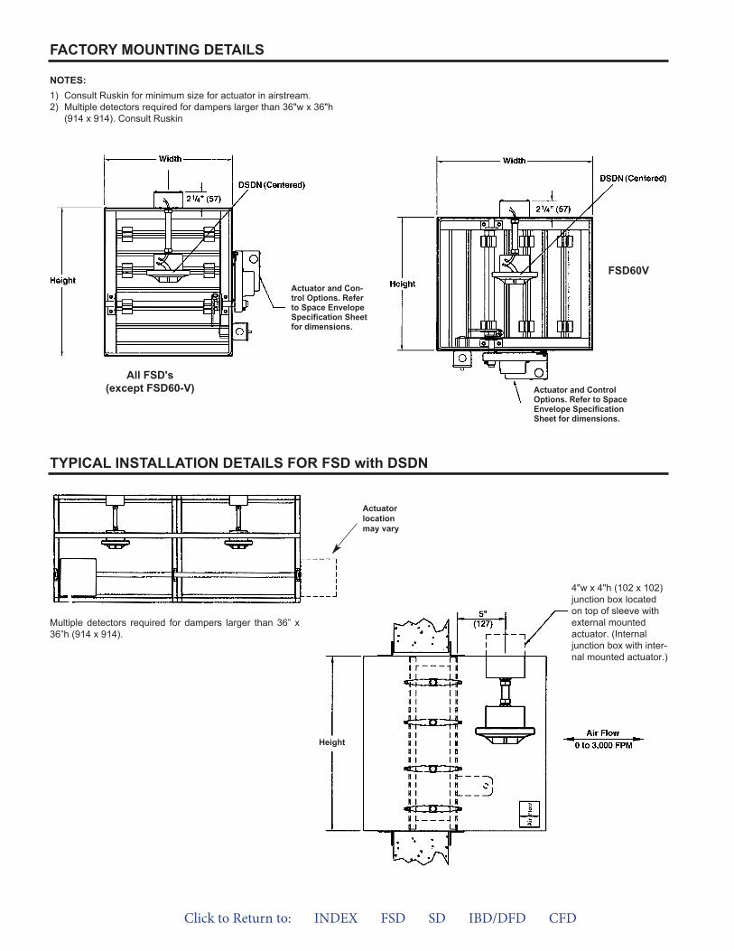
FACTORY MOUNTING DETAILS
TYPICAL INSTALLATION DETAILS FOR FSD with DSDN
NOTES:1) Consult Ruskin for minimum size for actuator in airstream.2) Multiple detectors required for dampers larger than 36"w x 36"h
(914 x 914). Consult Ruskin
4"w x 4"h (102 x 102)junction box locatedon top of sleeve withexternal mountedactuator. (Internaljunction box with inter-nal mounted actuator.)
Actuator and Con-trol Options. Referto Space EnvelopeSpecifica tion Sheetfor dimensions.
Actuator and ControlOptions. Refer to SpaceEnvelope Specifi cationSheet for dimensions.
FSD60V
All FSD's(except FSD60-V)
Height
Actuatorlocationmay vary
Multiple detectors required for dampers larger than 36” x36”h (914 x 914).
Click to Return to: INDEX FSD SD IBD/DFD CFD
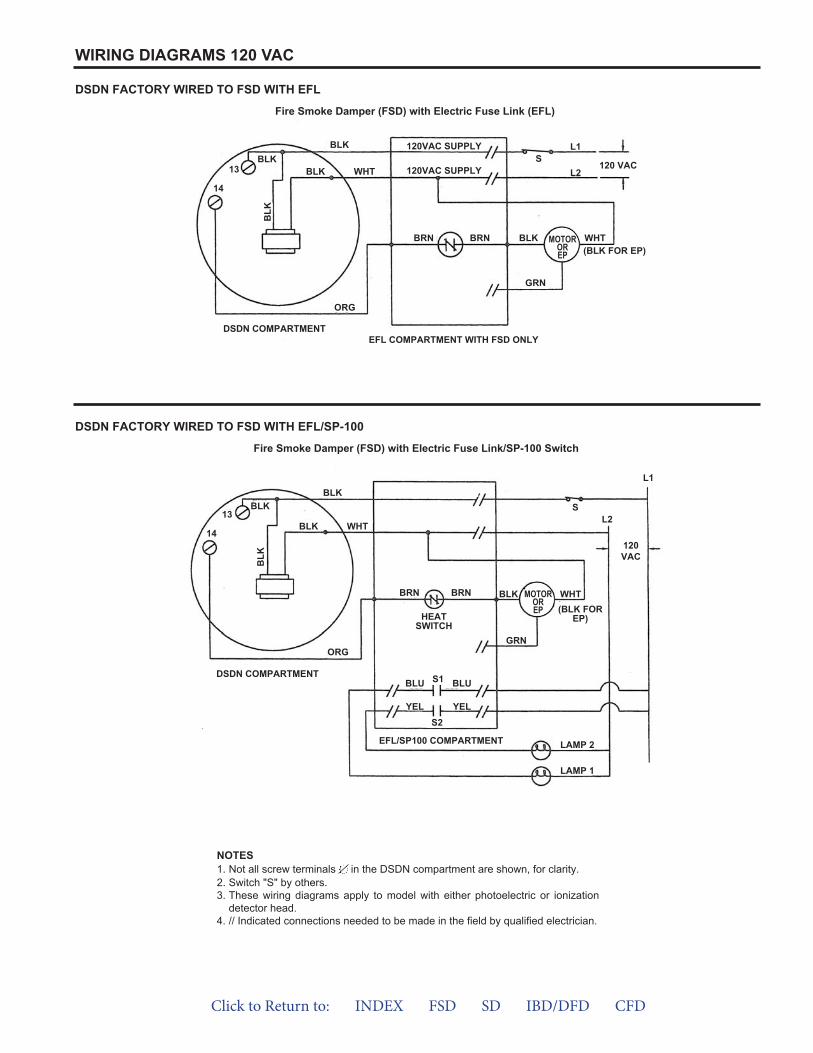
WIRING DIAGRAMS 120 VAC
DSDN FACTORY WIRED TO FSD WITH EFL
Fire Smoke Damper (FSD) with Electric Fuse Link (EFL)
DSDN FACTORY WIRED TO FSD WITH EFL/SP-100
Fire Smoke Damper (FSD) with Electric Fuse Link/SP-100 Switch
NOTES1. Not all screw terminals in the DSDN compartment are shown, for clarity.2. Switch "S" by others.3. These wiring diagrams apply to model with either photoelectric or ionization
detector head.4. // Indicated connections needed to be made in the field by qualified electrician.
DSDN COMPARTMENTEFL COMPARTMENT WITH FSD ONLY
14
13BLK
BLK
BLK WHT
BLK
ORG
BRN BRN BLK
GRN
WHT(BLK FOR EP)
120VAC SUPPLY
120VAC SUPPLYS
L1
L2120 VAC
MOTOROREP
DSDN COMPARTMENT
EFL/SP100 COMPARTMENT
14
13BLK
BLKS
L1
L2
120VAC
BLK WHT
BLK
ORG
BLK
GRN
BRN
BLU BLU
YEL YEL
LAMP 2
LAMP 1
BRN
HEATSWITCH
WHT(BLK FOR
EP)
MOTOROREP
S1
S2
Click to Return to: INDEX FSD SD IBD/DFD CFD
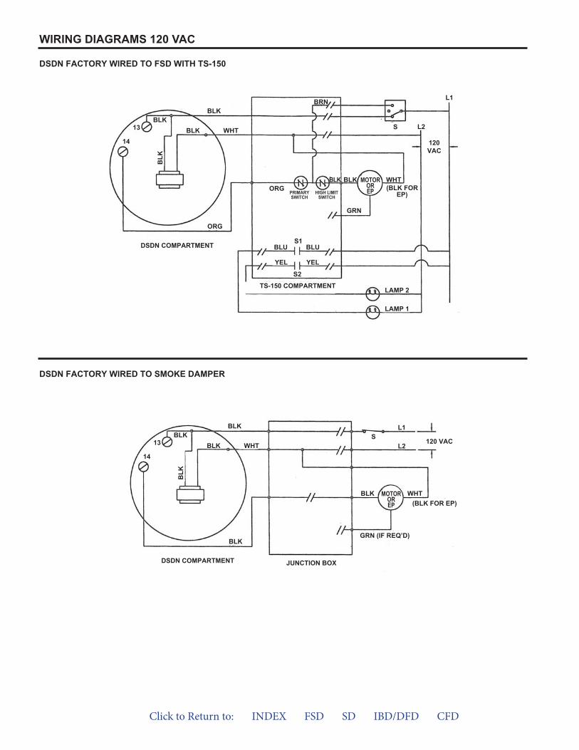
WIRING DIAGRAMS 120 VAC
DSDN FACTORY WIRED TO FSD WITH TS-150
DSDN FACTORY WIRED TO SMOKE DAMPER
DSDN COMPARTMENT
TS-150 COMPARTMENT
14
13BLK
BLK
WHT
ORG
ORGPRIMARYSWITCH
HIGH LIMITSWITCH
BRN
S L2
L1
120VAC
LAMP 2
LAMP 1
BLKBLK
GRN
WHT(BLK FOR
EP)
BLK
BLK
MOTOROREP
BLU BLU
YELYEL
S1
S2
DSDN COMPARTMENT JUNCTION BOX
GRN (IF REQ’D)
(BLK FOR EP)WHTBLK
14
13BLK
BLK
WHT
BLK
BLK
BLK
MOTOROREP
SL1
L2120 VAC
Click to Return to: INDEX FSD SD IBD/DFD CFD
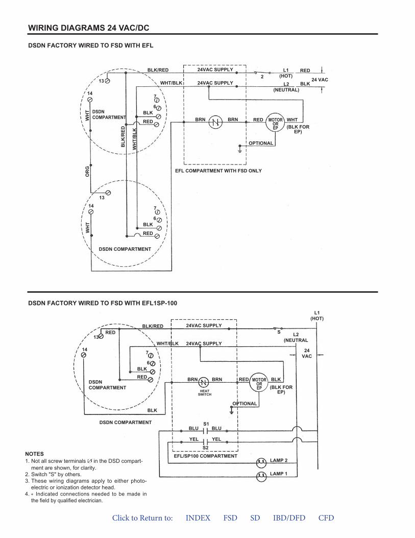
WIRING DIAGRAMS 24 VAC/DC
DSDN FACTORY WIRED TO FSD WITH EFL
DSDN FACTORY WIRED TO FSD WITH EFL1SP-100
NOTES1. Not all screw terminals in the DSD compart-
ment are shown, for clarity.2. Switch "S" by others.3. These wiring diagrams apply to either photo-
electric or ionization detector head.4. Indicated connections needed to be made in
the field by qualified electrician.
DSDN COMPARTMENT
DSDN COMPARTMENT RED WHT
(BLK FOREP)
L1(HOT)
L2(NEUTRAL)
24 VAC
RED
BLK2
OPTIONAL
EFL COMPARTMENT WITH FSD ONLY
14
13
13
7
6
RED
BLK
7
6
RED
BLK
14
WH
T
BLK/RED
24VAC SUPPLY
24VAC SUPPLY
BRN BRN
WHT/BLK
BLK
/RED
OR
GW
HT
WH
T/B
LK
MOTOROREP
DSDN COMPARTMENT
DSDN COMPARTMENT
14
13
7
6
RED
BLK
BLK
BLK/RED
WHT/BLK 24VAC SUPPLY
24VAC SUPPLYS
L1(HOT)
L2(NEUTRAL
24VAC
REDBRN BRN
HEATSWITCH
BLK(BLK FOR
EP)
OPTIONAL
MOTOROREP
EFL/SP100 COMPARTMENT
BLU BLU
YELYEL
S1
S2
LAMP 2
LAMP 1
RED
Click to Return to: INDEX FSD SD IBD/DFD CFD
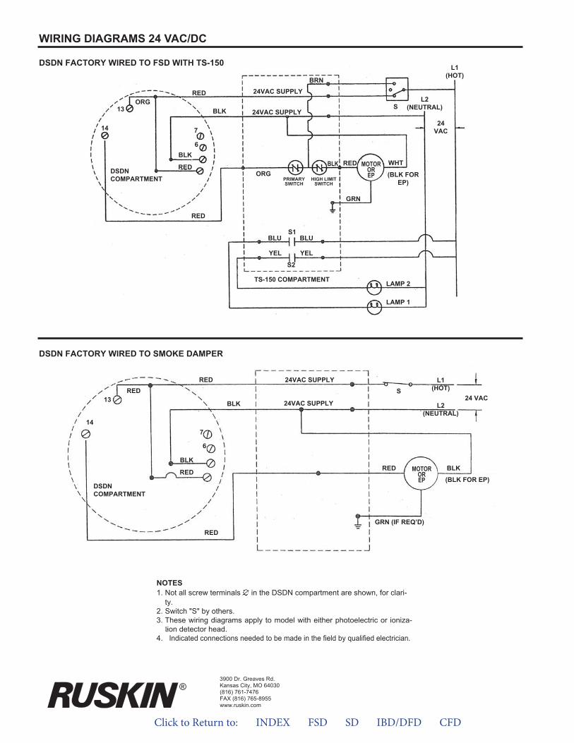
WIRING DIAGRAMS 24 VAC/DC
DSDN FACTORY WIRED TO FSD WITH TS-150
DSDN FACTORY WIRED TO SMOKE DAMPER
3900 Dr. Greaves Rd.Kansas City, MO 64030(816) 761-7476FAX (816) 765-8955www.ruskin.com
®
NOTES1. Not all screw terminals in the DSDN compartment are shown, for clari-
ty.2. Switch "S" by others.3. These wiring diagrams apply to model with either photoelectric or ioniza-
tion detector head.4. Indicated connections needed to be made in the field by qualified electrician.
DSDN COMPARTMENT
14
13ORG
7
6
RED
RED
BLK
RED
BRN
BLK 24VAC SUPPLY
24VAC SUPPLY
S
L1(HOT)
L2(NEUTRAL)
24VAC
REDORG
BLK
PRIMARYSWITCH
HIGH LIMITSWITCH
WHT
(BLK FOREP)
GRN
MOTOROREP
TS-150 COMPARTMENT
BLU BLU
YELYEL
S1
S2
LAMP 2
LAMP 1
DSDN COMPARTMENT
14
13RED
7
6
RED
REDGRN (IF REQ’D)
RED BLKBLK
RED
BLK
MOTOROREP (BLK FOR EP)
24VAC SUPPLY
24VAC SUPPLY L1(HOT)S
L2(NEUTRAL)
24 VAC
Click to Return to: INDEX FSD SD IBD/DFD CFD
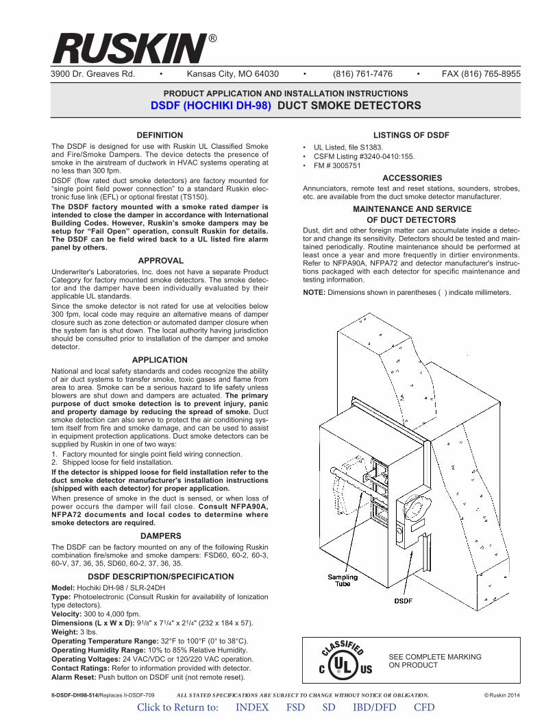
ALL STATED SPECIFICATIONS ARE SUBJECT TO CHANGE WITHOUT NOTICE OR OBLIGATION.
3900 Dr. Greaves Rd. • Kansas City, MO 64030 • (816) 761-7476 • FAX (816) 765-8955
PRODUCT APPLICATION AND INSTALLATION INSTRUCTIONS DSDF (HOCHIKI DH-98) DUCT SMOKE DETECTORS
II-DSDF-DH98-514/Replaces II-DSDF-709 © Ruskin 2014
DEFINITIONThe DSDF is designed for use with Ruskin UL Classified Smokeand Fire/Smoke Dampers. The device detects the presence ofsmoke in the airstream of ductwork in HVAC systems operating atno less than 300 fpm.DSDF (flow rated duct smoke detectors) are factory mounted for“single point field power connection” to a standard Ruskin elec -tronic fuse link (EFL) or optional firestat (TS150).The DSDF factory mounted with a smoke rated damper isintended to close the damper in accordance with InternationalBuilding Codes. However, Ruskin’s smoke dampers may besetup for “Fail Open” operation, consult Ruskin for details.The DSDF can be field wired back to a UL listed fire alarmpanel by others.
APPROVALUnderwriter's Laboratories, Inc. does not have a separate ProductCategory for factory mounted smoke detectors. The smoke detec-tor and the damper have been individually evaluated by theirapplicable UL standards.Since the smoke detector is not rated for use at velocities below300 fpm, local code may require an alternative means of damperclosure such as zone detection or automated damper closure whenthe system fan is shut down. The local authority having jurisdictionshould be consulted prior to installation of the damper and smokedetector.
APPLICATIONNational and local safety standards and codes recognize the abilityof air duct systems to transfer smoke, toxic gases and flame fromarea to area. Smoke can be a serious hazard to life safety unlessblowers are shut down and dampers are actuated. The primarypurpose of duct smoke detection is to prevent injury, panicand property damage by reducing the spread of smoke. Ductsmoke detection can also serve to protect the air conditioning sys-tem itself from fire and smoke damage, and can be used to assistin equipment protection applications. Duct smoke detectors can besupplied by Ruskin in one of two ways:1. Factory mounted for single point field wiring connection.2. Shipped loose for field installation.If the detector is shipped loose for field installation refer to theduct smoke detector manufacturer's installation instructions(shipped with each detector) for proper application.When presence of smoke in the duct is sensed, or when loss ofpower occurs the damper will fail close. Consult NFPA90A,NFPA72 documents and local codes to determine wheresmoke detectors are required.
DAMPERSThe DSDF can be factory mounted on any of the following Ruskincombination fire/smoke and smoke dampers: FSD60, 60-2, 60-3,60-V, 37, 36, 35, SD60, 60-2, 37, 36, 35.
DSDF DESCRIPTION/SPECIFICATIONModel: Hochiki DH-98 / SLR-24DHType: Photoelectronic (Consult Ruskin for availability of Ionizationtype detectors).Velocity: 300 to 4,000 fpm.Dimensions (L x W x D): 91/8" x 71/4" x 21/4" (232 x 184 x 57).Weight: 3 lbs.Operating Temperature Range: 32°F to 100°F (0° to 38°C).Operating Humidity Range: 10% to 85% Relative Humidity.Operating Voltages: 24 VAC/VDC or 120/220 VAC operation.Contact Ratings: Refer to information provided with detector.Alarm Reset: Push button on DSDF unit (not remote reset).
LISTINGS OF DSDF• UL Listed, file S1383.• CSFM Listing #3240-0410:155.• FM # 3005751
ACCESSORIESAnnunciators, remote test and reset stations, sounders, strobes,etc. are available from the duct smoke detector manufacturer.
MAINTENANCE AND SERVICEOF DUCT DETECTORS
Dust, dirt and other foreign matter can accumulate inside a detec-tor and change its sensitivity. Detectors should be tested and main-tained periodically. Routine maintenance should be performed atleast once a year and more frequently in dirtier environments.Refer to NFPA90A, NFPA72 and detector manufacturer's instruc-tions packaged with each detector for specific maintenance andtesting information.
NOTE: Dimensions shown in parentheses ( ) indicate millimeters.
SEE COMPLETE MARKING ON PRODUCT
®
Click to Return to: INDEX FSD SD IBD/DFD CFD
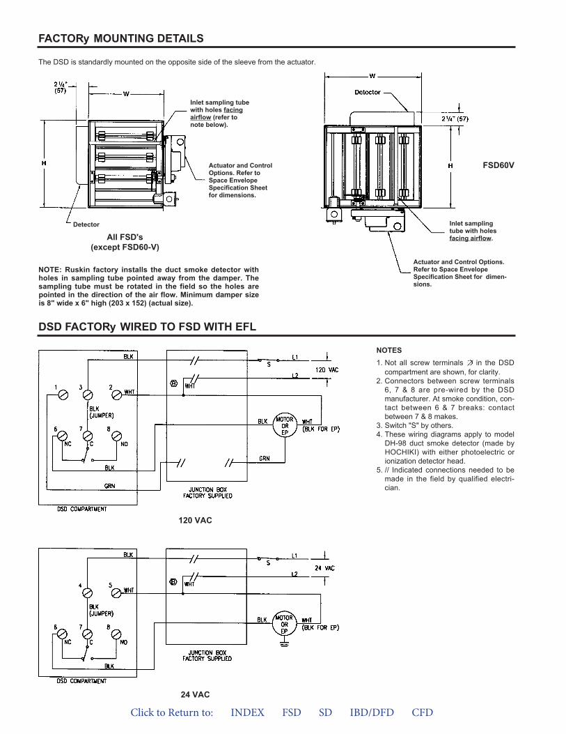
FACTORy MOUNTING DETAILS
DSD FACTORy WIRED TO FSD WITH EFL
The DSD is standardly mounted on the opposite side of the sleeve from the actuator.
Actuator and ControlOptions. Refer toSpace EnvelopeSpecifica tion Sheetfor dimensions.
Inlet sampling tubewith holes facingairflow (refer tonote below).
Inlet samplingtube with holesfacing airflow.
Actuator and Control Options.Refer to Space EnvelopeSpecifi cation Sheet for dimen-sions.
NOTE: Ruskin factory installs the duct smoke detector withholes in sampling tube pointed away from the damper. Thesampling tube must be rotated in the field so the holes arepointed in the direction of the air flow. Minimum damper sizeis 8" wide x 6" high (203 x 152) (actual size).
FSD60V
All FSD's(except FSD60-V)
Detector
NOTES1. Not all screw terminals in the DSD
compartment are shown, for clarity.2. Connectors between screw terminals
6, 7 & 8 are pre-wired by the DSDmanufacturer. At smoke condition, con-tact between 6 & 7 breaks: contactbetween 7 & 8 makes.
3. Switch "S" by others.4. These wiring diagrams apply to model
DH-98 duct smoke detector (made byHOCHIKI) with either photoelectric orionization detector head.
5. // Indicated connections needed to bemade in the field by qualified electri-cian.
120 VAC
24 VAC
Click to Return to: INDEX FSD SD IBD/DFD CFD
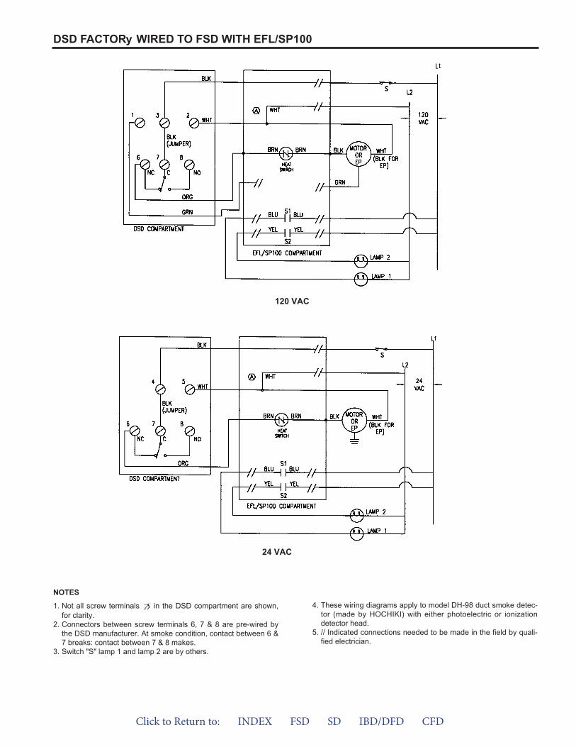
DSD FACTORy WIRED TO FSD WITH EFL/SP100
24 VAC
120 VAC
1. Not all screw terminals in the DSD compartment are shown,for clarity.
2. Connectors between screw terminals 6, 7 & 8 are pre-wired bythe DSD manufacturer. At smoke condition, contact between 6 &7 breaks: contact between 7 & 8 makes.
3. Switch "S" lamp 1 and lamp 2 are by others.
4. These wiring diagrams apply to model DH-98 duct smoke detec-tor (made by HOCHIKI) with either photoelectric or ionizationdetector head.
5. // Indicated connections needed to be made in the field by quali-fied electrician.
NOTES
Click to Return to: INDEX FSD SD IBD/DFD CFD
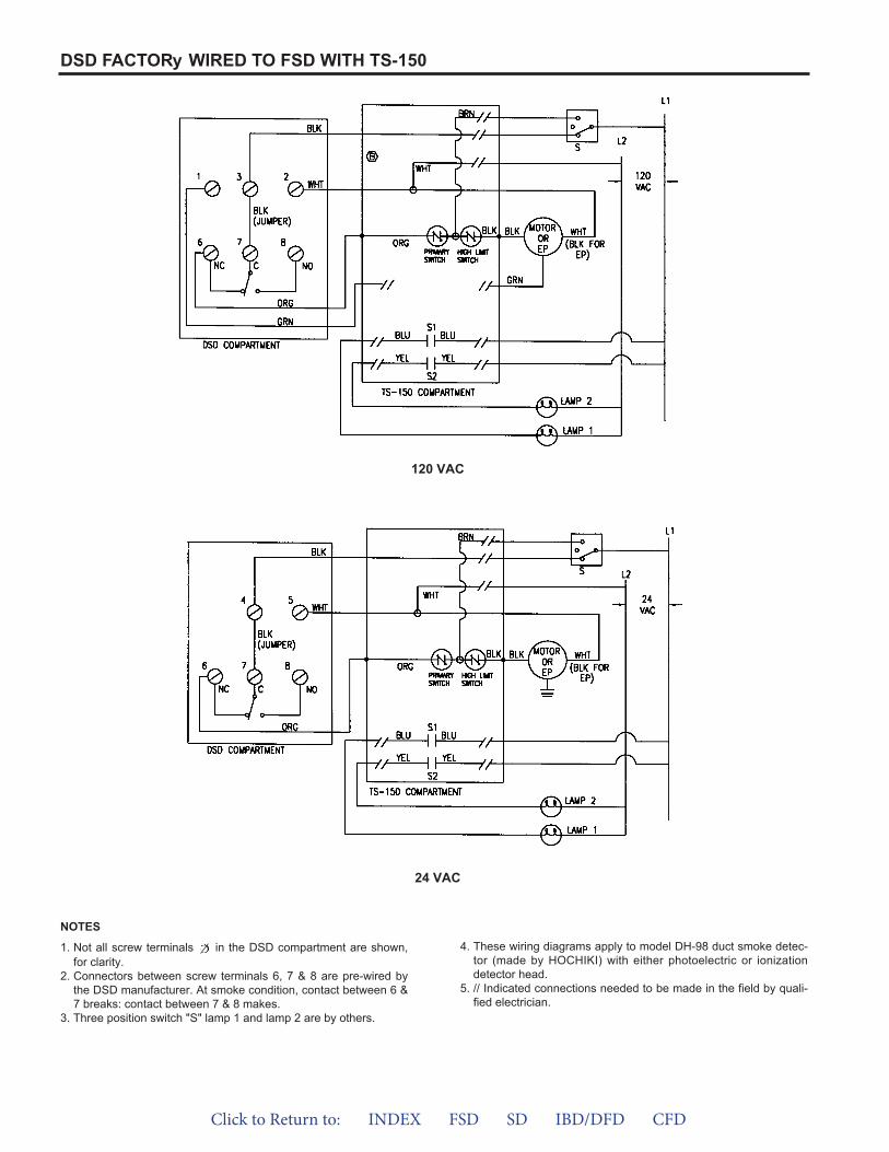
DSD FACTORy WIRED TO FSD WITH TS-150
120 VAC
24 VAC
1. Not all screw terminals in the DSD compartment are shown,for clarity.
2. Connectors between screw terminals 6, 7 & 8 are pre-wired bythe DSD manufacturer. At smoke condition, contact between 6 &7 breaks: contact between 7 & 8 makes.
3. Three position switch "S" lamp 1 and lamp 2 are by others.
4. These wiring diagrams apply to model DH-98 duct smoke detec-tor (made by HOCHIKI) with either photoelectric or ionizationdetector head.
5. // Indicated connections needed to be made in the field by quali-fied electrician.
NOTES
Click to Return to: INDEX FSD SD IBD/DFD CFD

DSDF SHOWN SUPPLIED WITH FSDR25 (TRUE ROUND FIRE/SMOKE DAMPER)
CAN BE FACTORy SUPPLIED MOUNTEDAND WIRED OR SHIPPED LOOSE.
HOCHIKI DH-98DUCT SMOKE
DETECTOR
DAMPERDIA.
14” (356)SLEEVE LENGTH
20 GA. GALV.
ADDITIONAL WIRING DIAGRAMDH-98-P
Click to Return to: INDEX FSD SD IBD/DFD CFD
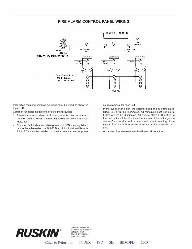
FIRE ALARM CONTROL PANEL WIRING
Installation requiring common functions must be wired as shown inFigure 5B.Common functions include one or all of the following:* Remote common alarm indication, remote pilot indication,
remote common reset, common shutdown and common visualindication.
• Common fault indication (when green pilot LED is extinguished)cannot be achieved on the DH-98 Duct Units. Individual RemotePilot LED’s must be installed to monitor detector head or power
source removal for each unit.• In the event of an alarm, the detector head and duct unit alarm
(Red) LED’s will be illuminated. All remaining duct unit alarmLED’s will not be illuminated. All remote alarm LED’s fitted tothe duct units will be illuminated when any of the units go intoalarm. Only the duct unit in alarm will permit resetting of thesystem from the built in test/reset switch on that particular ductunit.
• A common Remote reset switch will reset all detectors.
3900 Dr. Greaves Rd.Kansas City, MO 64030(816) 761-7476FAX (816) 765-8955www.ruskin.com
®
Click to Return to: INDEX FSD SD IBD/DFD CFD
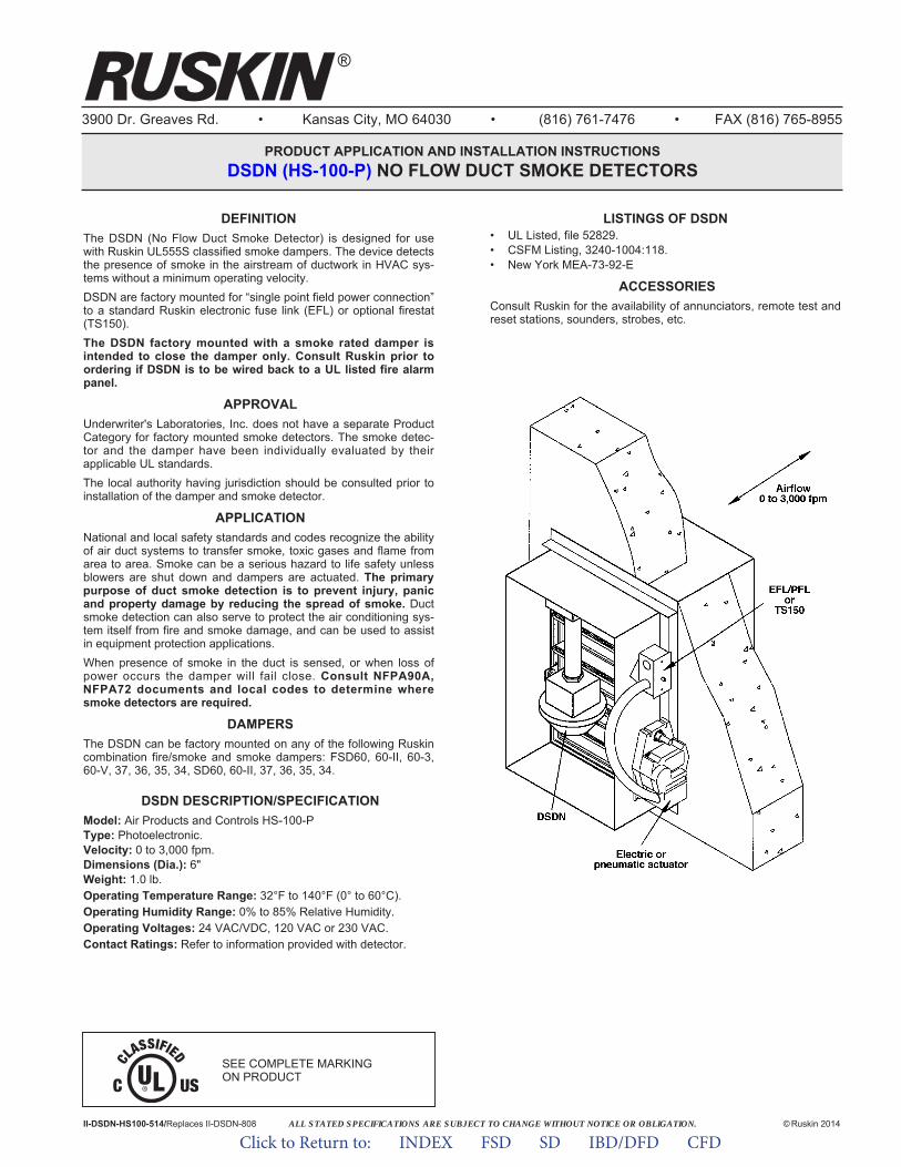
ALL STATED SPECIFICATIONS ARE SUBJECT TO CHANGE WITHOUT NOTICE OR OBLIGATION.
3900 Dr. Greaves Rd. • Kansas City, MO 64030 • (816) 761-7476 • FAX (816) 765-8955
PRODUCT APPLICATION AND INSTALLATION INSTRUCTIONSDSDN (HS-100-P) NO FLOW DUCT SMOKE DETECTORS
II-DSDN-HS100-514/Replaces II-DSDN-808 © Ruskin 2014
DEFINITIONThe DSDN (No Flow Duct Smoke Detector) is designed for usewith Ruskin UL555S classified smoke dampers. The device detectsthe presence of smoke in the airstream of ductwork in HVAC sys-tems without a minimum operating velocity.DSDN are factory mounted for “single point field power connection”to a standard Ruskin electronic fuse link (EFL) or optional firestat(TS150).The DSDN factory mounted with a smoke rated damper isintended to close the damper only. Consult Ruskin prior toordering if DSDN is to be wired back to a UL listed fire alarmpanel.
APPROVALUnderwriter's Laboratories, Inc. does not have a separate ProductCategory for factory mounted smoke detectors. The smoke detec-tor and the damper have been individually evaluated by theirapplicable UL standards.The local authority having jurisdiction should be consulted prior toinstallation of the damper and smoke detector.
APPLICATIONNational and local safety standards and codes recognize the abilityof air duct systems to transfer smoke, toxic gases and flame fromarea to area. Smoke can be a serious hazard to life safety unlessblowers are shut down and dampers are actuated. The primarypurpose of duct smoke detection is to prevent injury, panicand property damage by reducing the spread of smoke. Ductsmoke detection can also serve to protect the air conditioning sys-tem itself from fire and smoke damage, and can be used to assistin equipment protection applications.When presence of smoke in the duct is sensed, or when loss ofpower occurs the damper will fail close. Consult NFPA90A,NFPA72 documents and local codes to determine wheresmoke detectors are required.
DAMPERSThe DSDN can be factory mounted on any of the following Ruskincombination fire/smoke and smoke dampers: FSD60, 60-II, 60-3,60-V, 37, 36, 35, 34, SD60, 60-II, 37, 36, 35, 34.
DSDN DESCRIPTION/SPECIFICATIONModel: Air Products and Controls HS-100-PType: Photoelectronic.Velocity: 0 to 3,000 fpm.Dimensions (Dia.): 6"Weight: 1.0 lb.Operating Temperature Range: 32°F to 140°F (0° to 60°C).Operating Humidity Range: 0% to 85% Relative Humidity.Operating Voltages: 24 VAC/VDC, 120 VAC or 230 VAC.Contact Ratings: Refer to information provided with detector.
LISTINGS OF DSDN• UL Listed, file 52829.• CSFM Listing, 3240-1004:118.• New York MEA-73-92-E
ACCESSORIESConsult Ruskin for the availability of annunciators, remote test andreset stations, sounders, strobes, etc.
SEE COMPLETE MARKING ON PRODUCT
®
Click to Return to: INDEX FSD SD IBD/DFD CFD
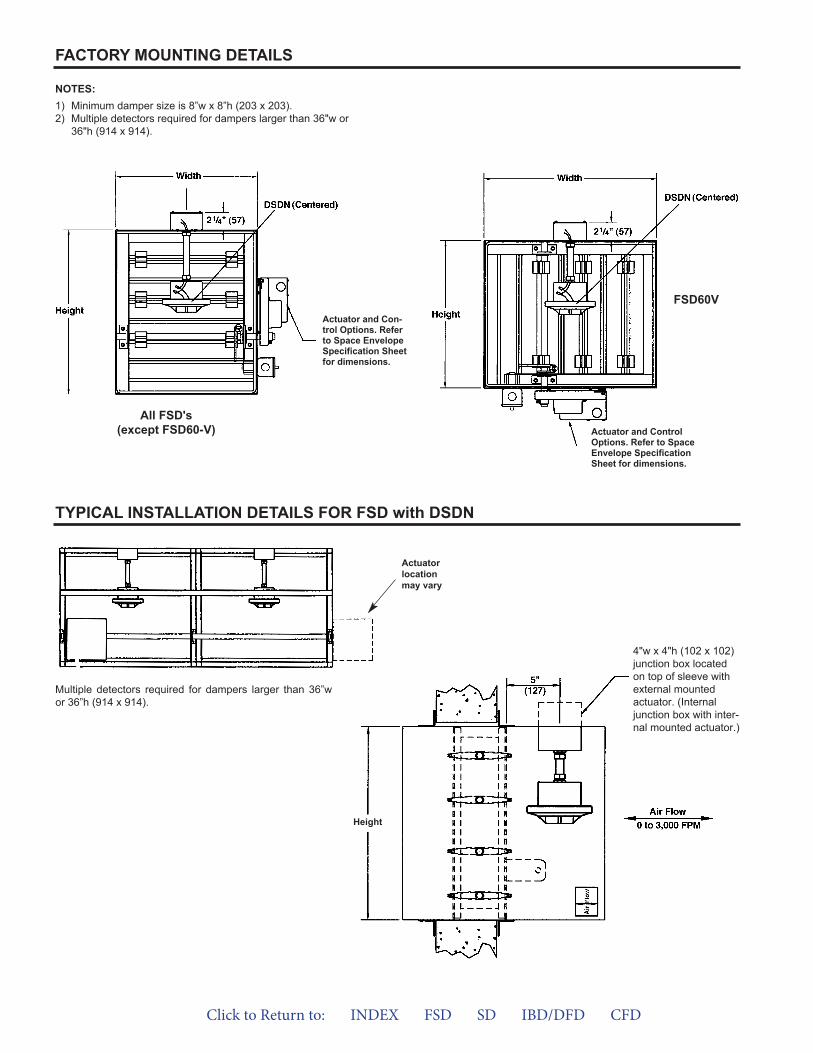
FACTORY MOUNTING DETAILS
TYPICAL INSTALLATION DETAILS FOR FSD with DSDN
NOTES:1) Minimum damper size is 8”w x 8”h (203 x 203).2) Multiple detectors required for dampers larger than 36"w or
36"h (914 x 914).
4"w x 4"h (102 x 102)junction box locatedon top of sleeve withexternal mountedactuator. (Internaljunction box with inter-nal mounted actuator.)
Actuator and Con-trol Options. Referto Space EnvelopeSpecifica tion Sheetfor dimensions.
Actuator and ControlOptions. Refer to SpaceEnvelope Specifi cationSheet for dimensions.
FSD60V
All FSD's(except FSD60-V)
Height
Actuatorlocationmay vary
Multiple detectors required for dampers larger than 36”wor 36”h (914 x 914).
Click to Return to: INDEX FSD SD IBD/DFD CFD
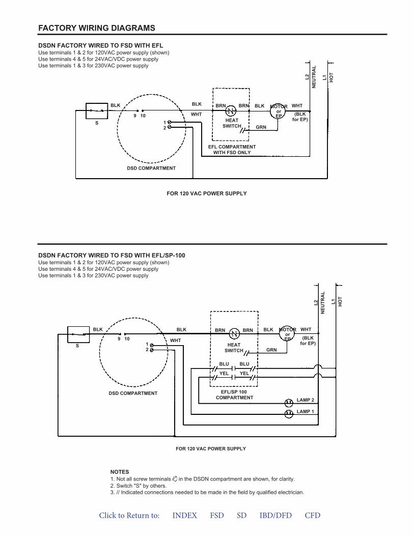
FACTORY WIRING DIAGRAMS
DSDN FACTORY WIRED TO FSD WITH EFLUse terminals 1 & 2 for 120VAC power supply (shown)Use terminals 4 & 5 for 24VAC/VDC power supplyUse terminals 1 & 3 for 230VAC power supply
DSDN FACTORY WIRED TO FSD WITH EFL/SP-100Use terminals 1 & 2 for 120VAC power supply (shown)Use terminals 4 & 5 for 24VAC/VDC power supplyUse terminals 1 & 3 for 230VAC power supply
NOTES1. Not all screw terminals in the DSDN compartment are shown, for clarity.2. Switch "S" by others.3. // Indicated connections needed to be made in the field by qualified electrician.
FOR 120 VAC POWER SUPPLY
FOR 120 VAC POWER SUPPLY
EFL COMPARTMENTWITH FSD ONLY
DSD COMPARTMENT EFL/SP 100COMPARTMENT
BLK BLK BLK WHT
WHT9 1012 GRN
(BLKfor EP)
MOTORorEP
L1 HO
T
L2N
EUTR
AL
S
DSD COMPARTMENT
BLK BLK BLK WHT
WHT9 1012 GRN
(BLKfor EP)
MOTORorEP
L1 HO
T
L2N
EUTR
AL
S
BLU BLU
YELYEL
LAMP 2
LAMP 1
BRN BRN
HEATSWITCH
BRN BRN
HEATSWITCH
Click to Return to: INDEX FSD SD IBD/DFD CFD
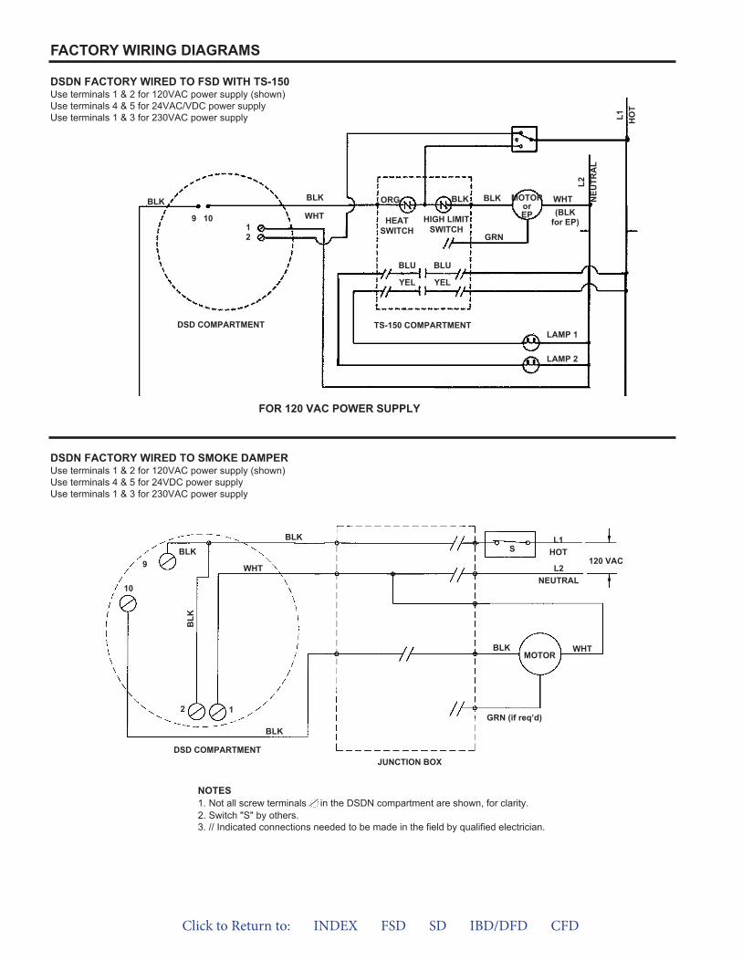
FACTORY WIRING DIAGRAMS
DSDN FACTORY WIRED TO FSD WITH TS-150Use terminals 1 & 2 for 120VAC power supply (shown)Use terminals 4 & 5 for 24VAC/VDC power supplyUse terminals 1 & 3 for 230VAC power supply
DSDN FACTORY WIRED TO SMOKE DAMPERUse terminals 1 & 2 for 120VAC power supply (shown)Use terminals 4 & 5 for 24VDC power supplyUse terminals 1 & 3 for 230VAC power supply
NOTES1. Not all screw terminals in the DSDN compartment are shown, for clarity.2. Switch "S" by others.3. // Indicated connections needed to be made in the field by qualified electrician.
FOR 120 VAC POWER SUPPLY
DSD COMPARTMENTJUNCTION BOX
TS-150 COMPARTMENTDSD COMPARTMENT
BLK BLK BLK WHT
WHT9 1012 GRN
(BLKfor EP)
MOTORorEP
L1 HO
T
L2N
EUTR
AL
ORG BLK
HEATSWITCH
HIGH LIMITSWITCH
BLU BLU
YEL YEL
LAMP 1
LAMP 2
BLKBLK
WHT9
10
2GRN (if req’d)
MOTOR
L1HOT
L2NEUTRAL
1
BLK WHT
120 VAC
BLK
BLK
S
Click to Return to: INDEX FSD SD IBD/DFD CFD
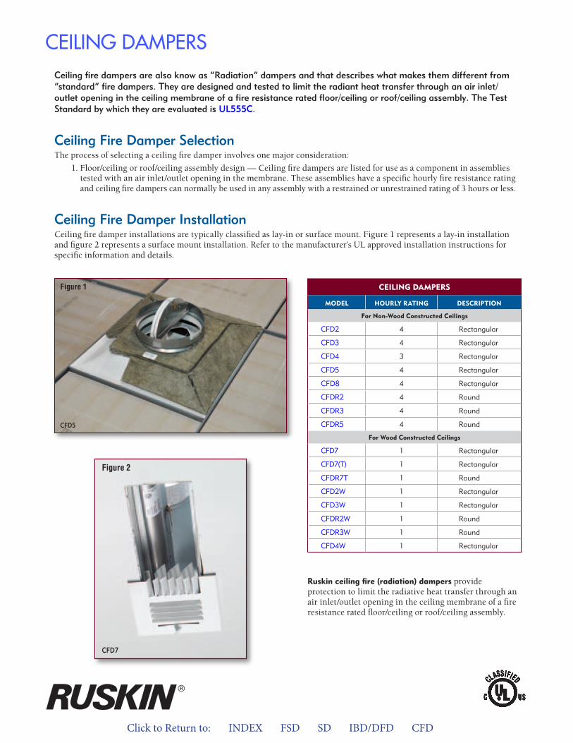
Click to Return to: INDEX FSD SD IBD/DFD CFD16 RUSKIN LIFE SAFETY DAMPERS
Ceiling fire dampers are also know as “Radiation” dampers and that describes what makes them different from “standard” fire dampers. They are designed and tested to limit the radiant heat transfer through an air inlet/outlet opening in the ceiling membrane of a fire resistance rated floor/ceiling or roof/ceiling assembly. The Test Standard by which they are evaluated is UL555C.
Ceiling Fire Damper SelectionThe process of selecting a ceiling fire damper involves one major consideration:
1. Floor/ceiling or roof/ceiling assembly design — Ceiling fire dampers are listed for use as a component in assembliestested with an air inlet/outlet opening in the membrane. These assemblies have a specific hourly fire resistance ratingand ceiling fire dampers can normally be used in any assembly with a restrained or unrestrained rating of 3 hours or less.
Ceiling Fire Damper InstallationCeiling fire damper installations are typically classified as lay-in or surface mount. Figure 1 represents a lay-in installation and figure 2 represents a surface mount installation. Refer to the manufacturer’s UL approved installation instructions for specific information and details.
CEILING DAMPERS
CEILING DaMPERS
MODEL HOURLY RaTING DESCRIPTION
For Non-wood Constructed Ceilings
CFD2 4 Rectangular
CFD3 4 Rectangular
CFD4 3 Rectangular
CFD5 4 Rectangular
CFD8 4 Rectangular
CFDR2 4 Round
CFDR3 4 Round
CFDR5 4 Round
For wood Constructed Ceilings
CFD7 1 Rectangular
CFD7(T) 1 Rectangular
CFDR7T 1 Round
CFD2W 1 Rectangular
CFD3W 1 Rectangular
CFDR2W 1 Round
CFDR3W 1 Round
CFD4W 1 Rectangular
Ruskin ceiling fire (radiation) dampers provide protection to limit the radiative heat transfer through an air inlet/outlet opening in the ceiling membrane of a fire resistance rated floor/ceiling or roof/ceiling assembly.
Figure 2
CFD7
CFD5
Figure 1
CEILING DAMPERS
Click to Return to: INDEX FSD SD IBD/DFD CFD
Selection & Application Guide for Wood Truss and Joist Floor/Ceiling or Roof/Ceiling Designs
R
Ceiling Radiation Dampers for wood construction
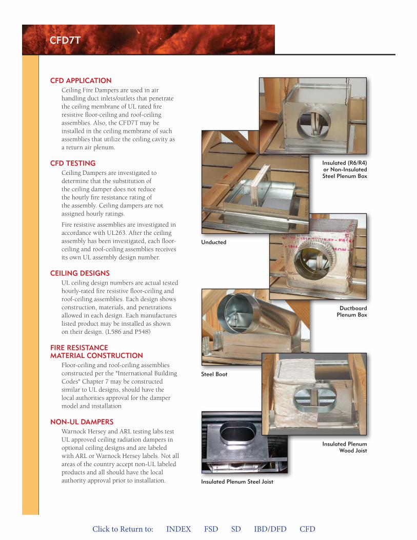
Click to Return to: INDEX FSD SD IBD/DFD CFD
CFD7T
CFD appliCaTionCeiling Fire Dampers are used in air handling duct inlets/outlets that penetrate the ceiling membrane of UL rated fire resistive floor-ceiling and roof-ceiling assemblies. Also, the CFD7T may be installed in the ceiling membrane of such assemblies that utilize the ceiling cavity as a return air plenum.
CFD TesTingCeiling Dampers are investigated to determine that the substitution of the ceiling damper does not reduce the hourly fire resistance rating of the assembly. Ceiling dampers are not assigned hourly ratings.
Fire resistive assemblies are investigated in accordance with UL263. After the ceiling assembly has been investigated, each floor-ceiling and roof-ceiling assemblies receives its own UL assembly design number.
Ceiling DesignsUL ceiling design numbers are actual tested hourly-rated fire resistive floor-ceiling and roof-ceiling assemblies. Each design shows construction, materials, and penetrations allowed in each design. Each manufactures listed product may be installed as shown on their design. (L586 and P548)
Fire resisTanCe maTerial ConsTruCTion
Floor-ceiling and roof-ceiling assemblies constructed per the "International Building Codes" Chapter 7 may be constructed similar to UL designs, should have the local authorities approval for the damper model and installation
non-ul DampersWarnock Hersey and ARL testing labs test UL approved ceiling radiation dampers in optional ceiling designs and are labeled with ARL or Warnock Hersey labels. Not all areas of the country accept non-UL labeled products and all should have the local authority approval prior to installation. insulated plenum steel Joist
steel Boot
insulated plenum Wood Joist
Ductboard plenum Box
unducted
insulated (r6/r4) or non-insulated steel plenum Box
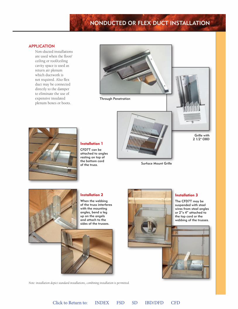
Click to Return to: INDEX FSD SD IBD/DFD CFD
grille with 2 1/2" oBD
surface mount grille
Installation 1
CFD7T can be attached to angles resting on top of the bottom cord of the truss.
Installation 2
When the webbing of the truss interferes with the mounting angles, bend a leg up on the angels and attach to the sides of the trusses.
Installation 3
The CFD7T may be suspended with steel wires from steel angles or 2”x 4” attached to the top cord or the webbing of the trusses.
Note: installation depict standard installations, combining installation is permitted.
appliCaTionNon-ducted installations are used when the floor/ceiling or roof/ceiling cavity space is used as return air plenum which ductwork is not required. Also flex duct may be connected directly to the damper to eliminate the use of expensive insulated plenum boxes or boots.
Through penetration
nonDuCTeD or Flex DuCT insTallaTion
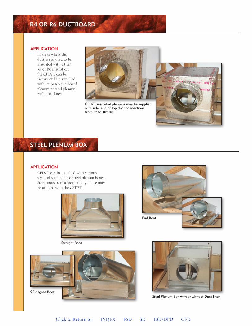
Click to Return to: INDEX FSD SD IBD/DFD CFD
r4 or r6 DuCTBoarD
CFD7T insulated plenums may be supplied with side, end or top duct connections from 3“ to 10“ dia.
appliCaTionIn areas where the duct is required to be insulated with either R4 or R6 insulation, the CFD7T can be factory or field supplied with R4 or R6 ductboard plenum or steel plenum with duct liner.
steel plenum Box with or without Duct liner
straight Boot
end Boot
90 degree Boot
appliCaTionCFD7T can be supplied with various styles of steel boots or steel plenum boxes. Steel boots from a local supply house may be utilized with the CFD7T.
sTeel plenum Box
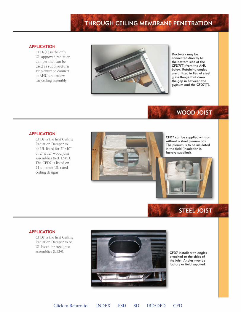
Click to Return to: INDEX FSD SD IBD/DFD CFD
Through Ceiling memBrane peneTraTion
appliCaTionCFD7(T) is the only UL approved radiation damper that can be used as supply/return air plenum to connect to AHU unit below the ceiling assembly.
appliCaTionCFD7 is the first Ceiling Radiation Damper to be UL listed for steel joist assemblies (L524).
appliCaTionCFD7 is the first Ceiling Radiation Damper to be UL listed for 2” x10” or 2” x 12” wood joist assemblies (Ref. L501). The CFD7 is listed on 21 different UL rated ceiling designs.
Ductwork may be connected directly to the bottom side of the CFD7(T) from the ahu below. retaining angles are utilized in lieu of steel grille flange that cover the gap in between the gypsum and the CFD7(T).
CFD7 installs with angles attached to the sides of the joist. angles may be factory or field supplied.
CFD7 can be supplied with or without a steel plenum box. The plenum is to be insulated in the field (insulation is factory supplied).
WooD JoisT
sTeel JoisT
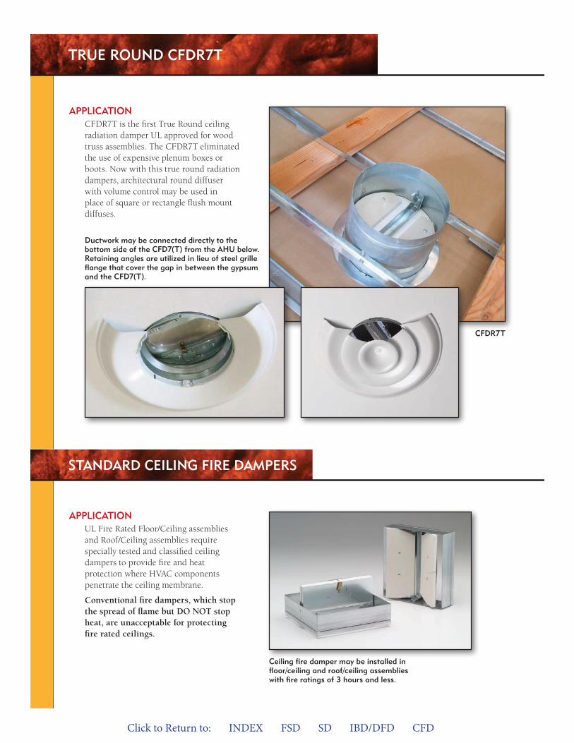
Click to Return to: INDEX FSD SD IBD/DFD CFD
True rounD CFDr7T
Ductwork may be connected directly to the bottom side of the CFD7(T) from the ahu below. retaining angles are utilized in lieu of steel grille flange that cover the gap in between the gypsum and the CFD7(T).
appliCaTionCFDR7T is the first True Round ceiling radiation damper UL approved for wood truss assemblies. The CFDR7T eliminated the use of expensive plenum boxes or boots. Now with this true round radiation dampers, architectural round diffuser with volume control may be used in place of square or rectangle flush mount diffuses.
Ceiling fire damper may be installed in floor/ceiling and roof/ceiling assemblies with fire ratings of 3 hours and less.
appliCaTionUL Fire Rated Floor/Ceiling assemblies and Roof/Ceiling assemblies require specially tested and classified ceiling dampers to provide fire and heat protection where HVAC components penetrate the ceiling membrane.
Conventional fire dampers, which stop the spread of flame but DO NOT stop heat, are unacceptable for protecting fire rated ceilings.
sTanDarD Ceiling Fire Dampers
CFDr7T
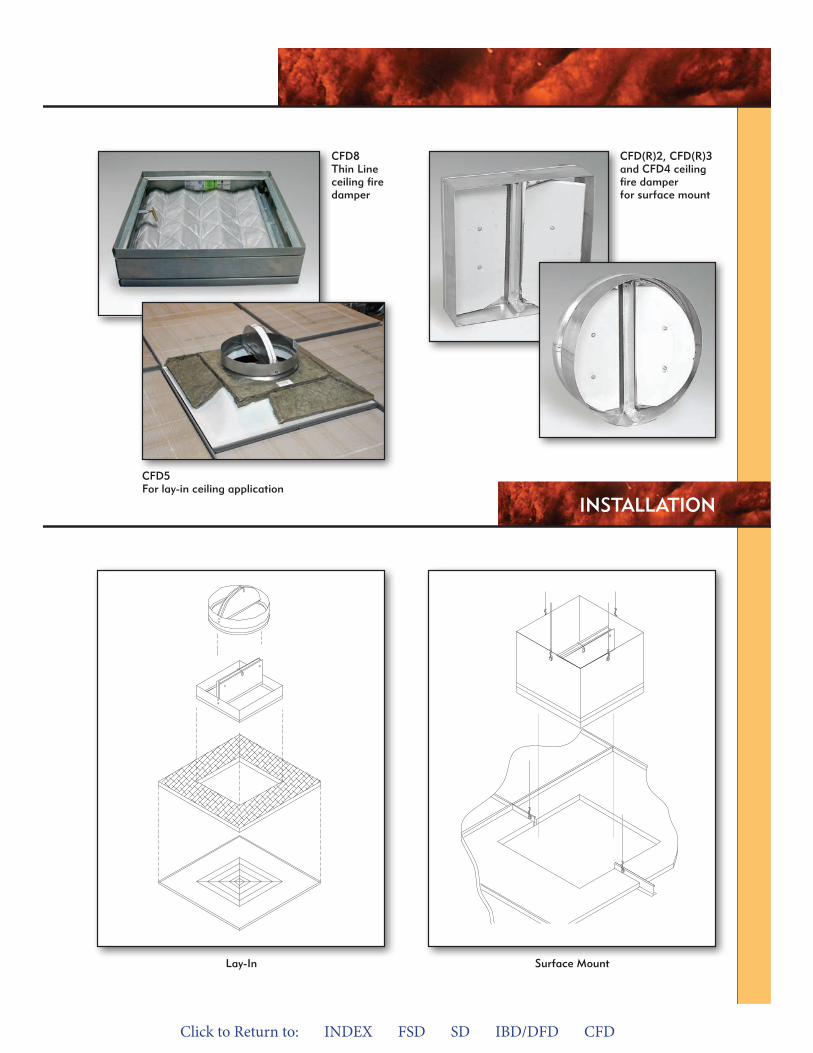
Click to Return to: INDEX FSD SD IBD/DFD CFD
lay-in surface mount
insTallaTion
CFD(r)2, CFD(r)3 and CFD4 ceiling fire damper for surface mount
CFD5For lay-in ceiling application
CFD8Thin line ceiling fire damper
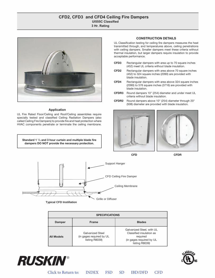
Click to Return to: INDEX FSD SD IBD/DFD CFD
ApplicationUL Fire Rated Floor/Ceiling and Roof/Ceiling assemblies require specially tested and classified Ceiling Radiation Dampers (also called Ceiling Fire Dampers) to provide fire and heat protection where HVAC components penetrate or terminate the ceiling membrane.
CONSTRUCTION DETAILSUL Classification testing for ceiling fire dampers measures the heat transmitted through, and temperatures above, ceiling penetrations with ceiling dampers. Smaller dampers meet these criteria without thermal insulation, but larger dampers require insulation to provide acceptable performance.
CFD3 Rectangular dampers with area up to 70 square inches (452) meet UL criteria without blade insulation.
CFD2 Rectangular dampers with area above 70 square inches (452) to 324 square inches (2090) are provided with blade insulation.
CFD4 Rectangular dampers with area above 324 square inches (2090) to 576 square inches (3716) are provided with
blade insulation.
CFDR3 Round dampers 10" (254) diameter and under meet UL criteria without blade insulation.
CFDR2 Round dampers above 10" (254) diameter through 20" (508) diameter are provided with blade insulation.
CFD2, CFD3 and CFD4 Ceiling Fire Dampers Ul555C Classified 3 Hr. Rating
Standard 1 1/2 and 3 hour curtain and multiple blade firedampers DO NOT provide the necessary protection.
APPLICATIONUL Fire Rated Floor/Ceiling and Roof/Ceiling assemblies requirespecially tested and classified Ceiling Radiation Dampers (also called Ceiling Fire Dampers) to provide fire and heat protection where HVAC components penetrate or terminate the ceilingmembrane.
CONSTRUCTION DETAILSUL Classification testing for ceiling fire dampers measures the heattransmitted through, and temperatures above, ceiling penetrationswith ceiling dampers. Smaller dampers meet these criteria with outthermal insulation, but larger dampers require insulation to provide acceptable performance.
CFD3 Rectangular dampers with area up to 70 square inches(452) meet UL criteria without blade insulation.
CFD2 Rectangular dampers with area above 70 square inches(452) to 324 square inches (2090) are provided with blade insulation.
CFD4 Rectangular dampers with area above 324 square inches(2090) to 576 square inches (3716) are provided withblade insulation.
CFDR3 Round dampers 10” (254) diameter and under meet ULcriteria without blade insulation.
CFDR2 Round dampers above 10” (254) diameter through 20”(508) diameter are provided with blade insulation.
CFD CFDR
Support Hanger
CFD Ceiling Fire Damper
Ceiling Membrane
Grille or DiffuserTypical CFD Instillation
SPECIFICATIONSDamper Frame Blades
All Models Galvanized Steel(in gauges required by UL
listing R8039)
Galvanized Steel, with UL Classified insulation as
required(in gauges required by UL
listing R8039)
Standard 1 ½ and 3 hour curtain and multiple blade fire dampers DO NOT provide the necessary protection.
®
CFD2, CFD3 and CFD4 Ceiling Fire Dampers UL555C Classified
3 Hr. Rating
All Models
SpECIFICATIONS
Frame BladesDamper
Galvanized Steel, with ULClassified insulation as
required(in gages required by UL
listing R8039)
Galvanized Steel(in gages required by UL
listing R8039)
CFD CFDR
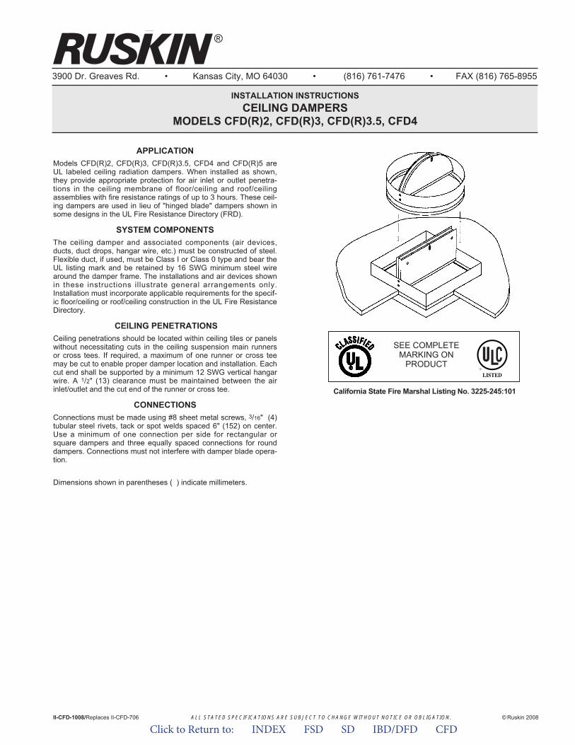
ALL STATED SPECIFICATIONS ARE SUBJECT TO CHANGE WITHOUT NOTICE OR OBLIGATION.
3900 Dr. Greaves Rd. • Kansas City, MO 64030 • (816) 761-7476 • FAX (816) 765-8955
INSTALLATION INSTRUCTIONSCEILING DAMPERS
MODELS CFD(R)2, CFD(R)3, CFD(R)3.5, CFD4
APPLICATIONModels CFD(R)2, CFD(R)3, CFD(R)3.5, CFD4 and CFD(R)5 areUL labeled ceiling radiation dampers. When installed as shown,they provide appropriate protection for air inlet or outlet penetra-tions in the ceiling membrane of floor/ceiling and roof/ceilingassemblies with fire resistance ratings of up to 3 hours. These ceil-ing dampers are used in lieu of "hinged blade" dampers shown insome designs in the UL Fire Resistance Directory (FRD).
SYSTEM COMPONENTSThe ceiling damper and associated components (air devices,ducts, duct drops, hangar wire, etc.) must be constructed of steel.Flexible duct, if used, must be Class I or Class 0 type and bear theUL listing mark and be retained by 16 SWG minimum steel wirearound the damper frame. The installations and air devices shownin these instructions illustrate general arrangements only.Installation must incorporate applicable requirements for the specif-ic floor/ceiling or roof/ceiling construction in the UL Fire ResistanceDirectory.
CEILING PENETRATIONSCeiling penetrations should be located within ceiling tiles or panelswithout necessitating cuts in the ceiling suspension main runnersor cross tees. If required, a maximum of one runner or cross teemay be cut to enable proper damper location and installation. Eachcut end shall be supported by a minimum 12 SWG vertical hangarwire. A 1/2" (13) clearance must be maintained between the airinlet/outlet and the cut end of the runner or cross tee.
CONNECTIONSConnections must be made using #8 sheet metal screws, 3/16" (4)tubular steel rivets, tack or spot welds spaced 6" (152) on center.Use a minimum of one connection per side for rectangular orsquare dampers and three equally spaced connections for rounddampers. Connections must not interfere with damper blade opera-tion.
Dimensions shown in parentheses ( ) indicate millimeters.
California State Fire Marshal Listing No. 3225-245:101
II-CFD-1008/Replaces II-CFD-706 © Ruskin 2008
®
SEE COMPLETEMARKING ON
PRODUCT
Click to Return to: INDEX FSD SD IBD/DFD CFD
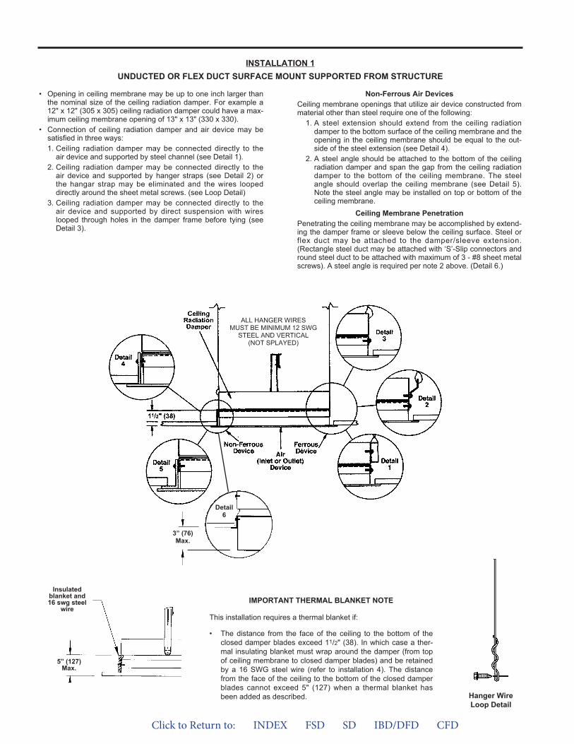
• Opening in ceiling membrane may be up to one inch larger thanthe nominal size of the ceiling radiation damper. For example a12" x 12" (305 x 305) ceiling radiation damper could have a max-imum ceiling membrane opening of 13" x 13" (330 x 330).
• Connection of ceiling radiation damper and air device may besatisfied in three ways:1. Ceiling radiation damper may be connected directly to the
air device and supported by steel channel (see Detail 1).2. Ceiling radiation damper may be connected directly to the
air device and supported by hanger straps (see Detail 2) orthe hangar strap may be eliminated and the wires loopeddirectly around the sheet metal screws. (see Loop Detail)
3. Ceiling radiation damper may be connected directly to theair device and supported by direct suspension with wireslooped through holes in the damper frame before tying (seeDetail 3).
Non-Ferrous Air Devices Ceiling membrane openings that utilize air device constructed frommaterial other than steel require one of the following:
1. A steel extension should extend from the ceiling radiationdamper to the bottom surface of the ceiling membrane and theopening in the ceiling membrane should be equal to the out-side of the steel extension (see Detail 4).
2. A steel angle should be attached to the bottom of the ceilingradiation damper and span the gap from the ceiling radiationdamper to the bottom of the ceiling membrane. The steelangle should overlap the ceiling membrane (see Detail 5).Note the steel angle may be installed on top or bottom of theceiling membrane.
Ceiling Membrane PenetrationPenetrating the ceiling membrane may be accomplished by extend-ing the damper frame or sleeve below the ceiling surface. Steel orflex duct may be attached to the damper/sleeve extension.(Rectangle steel duct may be attached with ‘S’-Slip connectors andround steel duct to be attached with maximum of 3 - #8 sheet metalscrews). A steel angle is required per note 2 above. (Detail 6.)
INSTALLATION 1UNDUCTED OR FLEX DUCT SURFACE MOUNT SUPPORTED FROM STRUCTURE
IMPORTANT THERMAL BLANKET NOTE
This installation requires a thermal blanket if:
• The distance from the face of the ceiling to the bottom of theclosed damper blades exceed 11/2" (38). In which case a ther-mal insulating blanket must wrap around the damper (from topof ceiling membrane to closed damper blades) and be retainedby a 16 SWG steel wire (refer to installation 4). The distancefrom the face of the ceiling to the bottom of the closed damperblades cannot exceed 5" (127) when a thermal blanket hasbeen added as described. Hanger Wire
Loop Detail
5” (127)Max.
Insulatedblanket and16 swg steel
wire
ALL HANGER WIRESMUST BE MINIMUM 12 SWG
STEEL AND VERTICAL(NOT SPLAYED)
3” (76)Max.
Detail6
Click to Return to: INDEX FSD SD IBD/DFD CFD

• Opening in ceiling membrane may be up to one inch larger thanthe nominal size of the ceiling radiation damper. For example a12" x 12" (305 x 305) ceiling radiation damper could have amaximum ceiling membrane opening of 13" x 13" (330 x 330).
• Connection of ceiling radiation damper, grille and steel duct dropmay be satisfied in two ways:1. Ceiling radiation damper and grille neck may be connected
directly to the duct drop (see Detail 1).2. Ceiling radiation damper may be connected directly to the
grille neck and then the duct drop connected to the damper(see Detail 2).
Non-Ferrous Air Devices Air devices that have non-ferrous frames.
Ceiling membrane openings that utilize air device constructed frommaterial other than steel require one of the following:
INSTALLATION 2DUCTED SURFACE MOUNT SUPPORTED FROM DUCTWORK
ALL HANGER WIRESMUST BE MINIMUM 12 SWG
STEEL AND VERTICAL(NOT SPLAYED)
IMPORTANT THERMAL BLANKET NOTE
This installation requires a thermal blanket if:
• The distance from the face of the ceiling to the bottom of theclosed damper blades exceed 11/2" (38). In which case a ther-mal insulating blanket must wrap around the damper (from topof ceiling membrane to closed damper blades) and be retainedby a 16 SWG steel wire (refer to installation 4). The distancefrom the face of the ceiling to the bottom of the closed damperblades cannot exceed 5" (127) when a thermal blanket hasbeen added as described.
Hanger WireLoop Detail
5” (127)Max.
Insulatedblanket and16 swg steel
wire
1. A steel duct drop should extend to the bottom surface of theceiling membrane and the opening in the ceiling membraneshould be equal to the outside of the duct drop (see Detail 3).
2. A steel angle should be attached to the bottom of the ceilingradiation damper and span the gap from the ceiling radiationdamper to the bottom of the ceiling membrane. The steelangle should overlap the ceiling membrane (see Detail 4).Note the steel angle may be installed on top or bottom of theceiling membrane.
Ceiling Membrane PenetrationPenetrating the ceiling membrane may be accomplished by extend-ing the damper frame or sleeve below the ceiling surface. Steel orflex duct may be attached to the damper/sleeve extension.(Rectangle steel duct may be attached with ‘S’-Slip connectors andround steel duct to be attached with maximum of 3 - #8 sheet metalscrews). A steel angle is required per note 2 above. (Detail 5)
3” (76)Max.
Detail6
Click to Return to: INDEX FSD SD IBD/DFD CFD
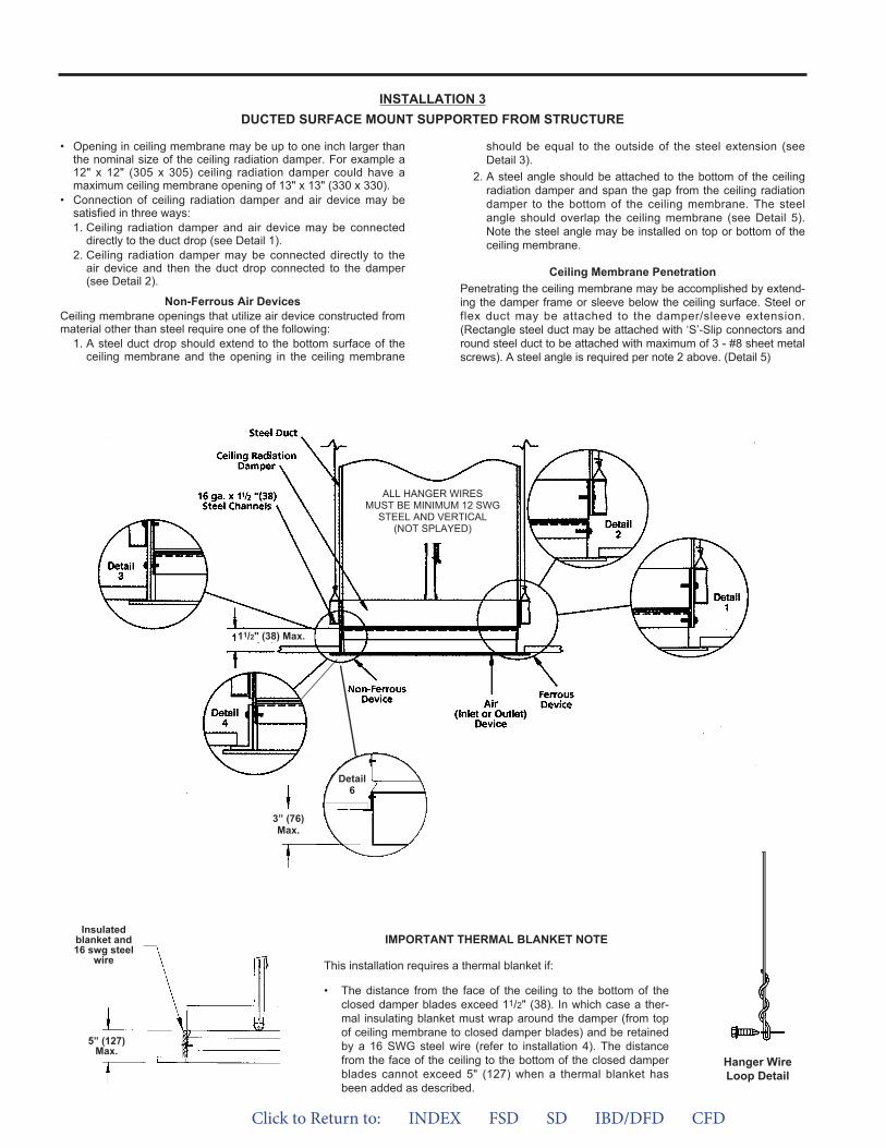
• Opening in ceiling membrane may be up to one inch larger thanthe nominal size of the ceiling radiation damper. For example a12" x 12" (305 x 305) ceiling radiation damper could have amaximum ceiling membrane opening of 13" x 13" (330 x 330).
• Connection of ceiling radiation damper and air device may besatisfied in three ways:1. Ceiling radiation damper and air device may be connected
directly to the duct drop (see Detail 1).2. Ceiling radiation damper may be connected directly to the
air device and then the duct drop connected to the damper(see Detail 2).
Non-Ferrous Air Devices Ceiling membrane openings that utilize air device constructed frommaterial other than steel require one of the following:
1. A steel duct drop should extend to the bottom surface of theceiling membrane and the opening in the ceiling membrane
INSTALLATION 3DUCTED SURFACE MOUNT SUPPORTED FROM STRUCTURE
ALL HANGER WIRESMUST BE MINIMUM 12 SWG
STEEL AND VERTICAL(NOT SPLAYED)
IMPORTANT THERMAL BLANKET NOTE
This installation requires a thermal blanket if:
• The distance from the face of the ceiling to the bottom of theclosed damper blades exceed 11/2" (38). In which case a ther-mal insulating blanket must wrap around the damper (from topof ceiling membrane to closed damper blades) and be retainedby a 16 SWG steel wire (refer to installation 4). The distancefrom the face of the ceiling to the bottom of the closed damperblades cannot exceed 5" (127) when a thermal blanket hasbeen added as described.
11/2" (38) Max.
Hanger WireLoop Detail
5” (127)Max.
Insulatedblanket and16 swg steel
wire
should be equal to the outside of the steel extension (see Detail 3).
2. A steel angle should be attached to the bottom of the ceilingradiation damper and span the gap from the ceiling radiationdamper to the bottom of the ceiling membrane. The steelangle should overlap the ceiling membrane (see Detail 5).Note the steel angle may be installed on top or bottom of theceiling membrane.
Ceiling Membrane PenetrationPenetrating the ceiling membrane may be accomplished by extend-ing the damper frame or sleeve below the ceiling surface. Steel orflex duct may be attached to the damper/sleeve extension.(Rectangle steel duct may be attached with ‘S’-Slip connectors andround steel duct to be attached with maximum of 3 - #8 sheet metalscrews). A steel angle is required per note 2 above. (Detail 5)
3” (76)Max.
Detail6
Click to Return to: INDEX FSD SD IBD/DFD CFD
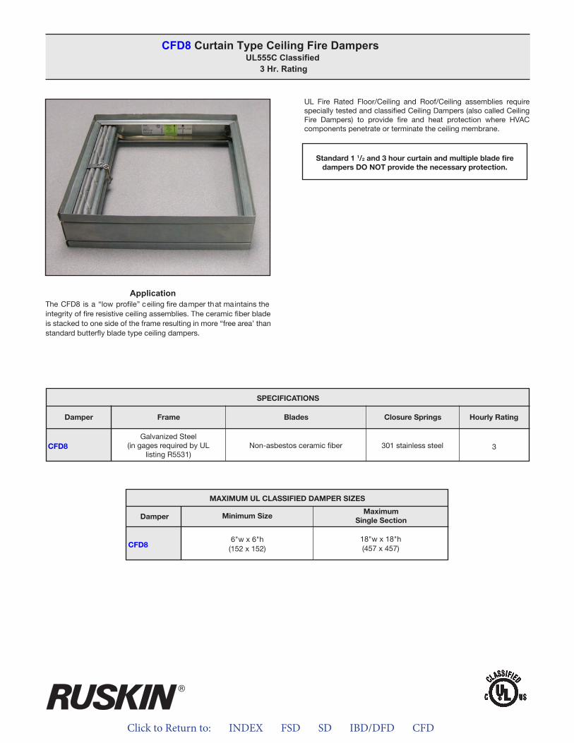
Click to Return to: INDEX FSD SD IBD/DFD CFD
ApplicationThe CFD8 is a “low profile” ceiling fire damper that maintains the integrity of fire resistive ceiling assemblies. The ceramic fiber blade is stacked to one side of the frame resulting in more “free area’ than standard butterfly blade type ceiling dampers.
UL Fire Rated Floor/Ceiling and Roof/Ceiling assemblies require specially tested and classified Ceiling Dampers (also called Ceiling Fire Dampers) to provide fire and heat protection where HVAC components penetrate or terminate the ceiling membrane.
CFD8 Curtain Type Ceiling Fire Dampers UL555C Classified
3 Hr. Rating
Standard 1 1/2 and 3 hour curtain and multiple blade firedampers DO NOT provide the necessary protection.
CFD8
SpeCiFiCaTiONS
Frame Blades Closure Springs Hourly RatingDamper
Galvanized Steel(in gages required by UL
listing R5531)Non-asbestos ceramic fiber 301 stainless steel 3
MaXiMUM UL CLaSSiFieD DaMpeR SiZeS
Damper
CFD8
MaximumSingle Section
Minimum Size
6"w x 6"h(152 x 152)
18"w x 18"h(457 x 457)
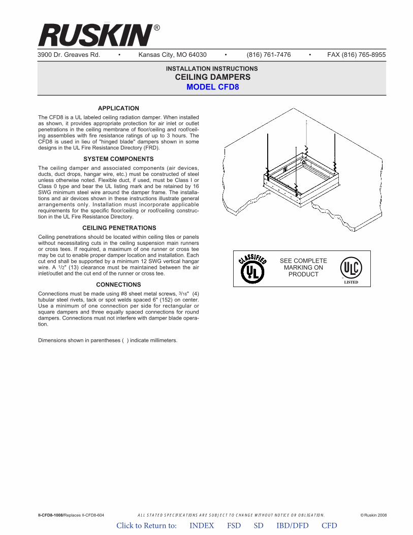
ALL STATED SPECIFICATIONS ARE SUBJECT TO CHANGE WITHOUT NOTICE OR OBLIGATION.
3900 Dr. Greaves Rd. • Kansas City, MO 64030 • (816) 761-7476 • FAX (816) 765-8955
INSTALLATION INSTRUCTIONS CEILING DAMPERS
MODEL CFD8
APPLICATIONThe CFD8 is a UL labeled ceiling radiation damper. When installedas shown, it provides appropriate protection for air inlet or outletpenetrations in the ceiling membrane of floor/ceiling and roof/ceil-ing assemblies with fire resistance ratings of up to 3 hours. TheCFD8 is used in lieu of "hinged blade" dampers shown in somedesigns in the UL Fire Resistance Directory (FRD).
SYSTEM COMPONENTSThe ceiling damper and associated components (air devices,ducts, duct drops, hangar wire, etc.) must be constructed of steelunless otherwise noted. Flexible duct, if used, must be Class I orClass 0 type and bear the UL listing mark and be retained by 16SWG minimum steel wire around the damper frame. The installa-tions and air devices shown in these instructions illustrate generalarrangements only. Installation must incorporate applicablerequirements for the specific floor/ceiling or roof/ceiling construc-tion in the UL Fire Resistance Directory.
CEILING PENETRATIONSCeiling penetrations should be located within ceiling tiles or panelswithout necessitating cuts in the ceiling suspension main runnersor cross tees. If required, a maximum of one runner or cross teemay be cut to enable proper damper location and installation. Eachcut end shall be supported by a minimum 12 SWG vertical hangarwire. A 1/2" (13) clearance must be maintained between the airinlet/outlet and the cut end of the runner or cross tee.
CONNECTIONSConnections must be made using #8 sheet metal screws, 3/16" (4)tubular steel rivets, tack or spot welds spaced 6" (152) on center.Use a minimum of one connection per side for rectangular orsquare dampers and three equally spaced connections for rounddampers. Connections must not interfere with damper blade opera-tion.
Dimensions shown in parentheses ( ) indicate millimeters.
II-CFD8-1008/Replaces II-CFD8-604 © Ruskin 2008
®
SEE COMPLETEMARKING ON
PRODUCT
Click to Return to: INDEX FSD SD IBD/DFD CFD
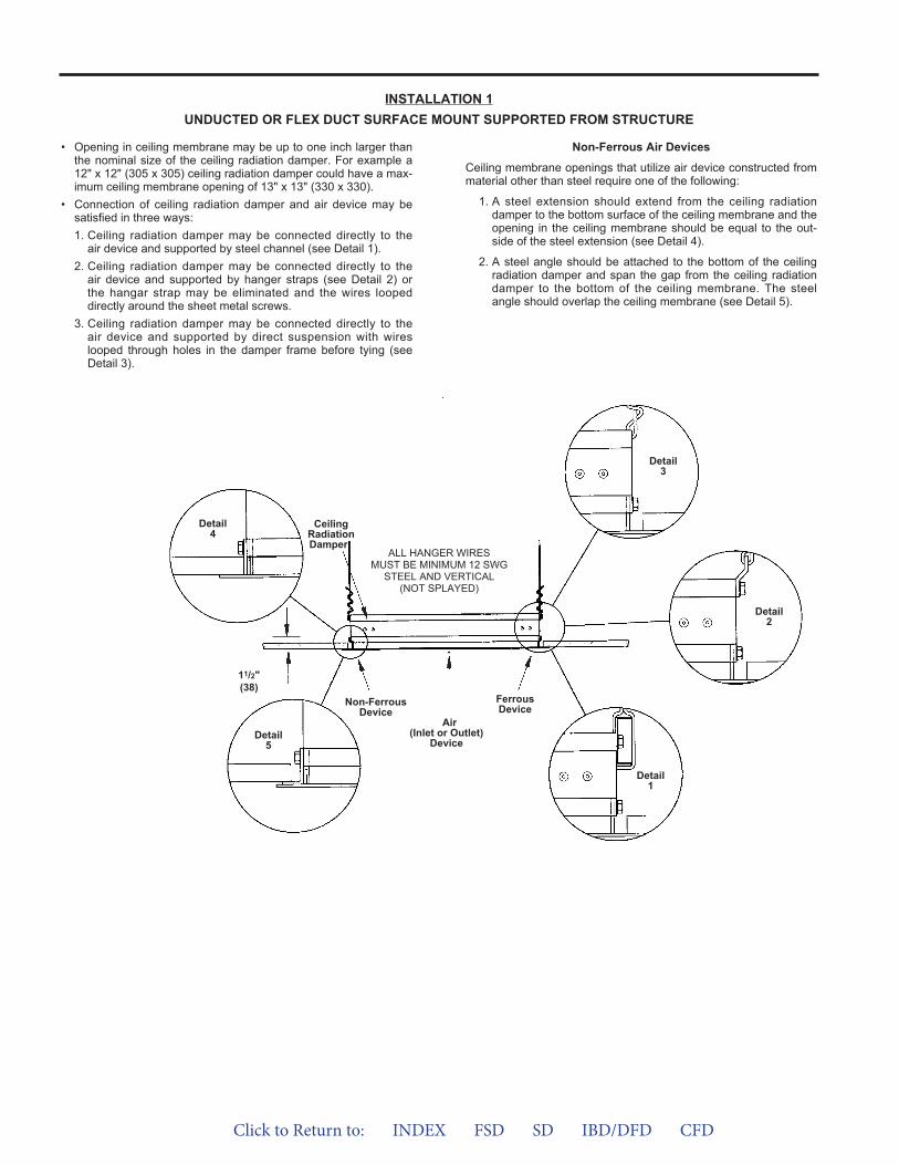
• Opening in ceiling membrane may be up to one inch larger thanthe nominal size of the ceiling radiation damper. For example a12" x 12" (305 x 305) ceiling radiation damper could have a max-imum ceiling membrane opening of 13" x 13" (330 x 330).
• Connection of ceiling radiation damper and air device may besatisfied in three ways:1. Ceiling radiation damper may be connected directly to the
air device and supported by steel channel (see Detail 1).2. Ceiling radiation damper may be connected directly to the
air device and supported by hanger straps (see Detail 2) orthe hangar strap may be eliminated and the wires loopeddirectly around the sheet metal screws.
3. Ceiling radiation damper may be connected directly to theair device and supported by direct suspension with wireslooped through holes in the damper frame before tying (seeDetail 3).
Non-Ferrous Air Devices
Ceiling membrane openings that utilize air device constructed frommaterial other than steel require one of the following:
1. A steel extension should extend from the ceiling radiationdamper to the bottom surface of the ceiling membrane and theopening in the ceiling membrane should be equal to the out-side of the steel extension (see Detail 4).
2. A steel angle should be attached to the bottom of the ceilingradiation damper and span the gap from the ceiling radiationdamper to the bottom of the ceiling membrane. The steelangle should overlap the ceiling membrane (see Detail 5).
INSTALLATION 1UNDUCTED OR FLEX DUCT SURFACE MOUNT SUPPORTED FROM STRUCTURE
CeilingRadiationDamper
ALL HANGER WIRESMUST BE MINIMUM 12 SWG
STEEL AND VERTICAL(NOT SPLAYED)
11/2"(38)
Air(Inlet or Outlet)
Device
Detail4
Detail5
Detail1
Detail2
Detail3
Non-FerrousDevice
FerrousDevice
Click to Return to: INDEX FSD SD IBD/DFD CFD
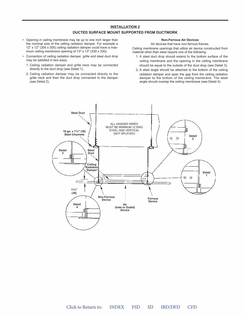
• Opening in ceiling membrane may be up to one inch larger thanthe nominal size of the ceiling radiation damper. For example a12" x 12" (305 x 305) ceiling radiation damper could have a max-imum ceiling membrane opening of 13" x 13" (330 x 330).
• Connection of ceiling radiation damper, grille and steel duct dropmay be satisfied in two ways:1. Ceiling radiation damper and grille neck may be connected
directly to the duct drop (see Detail 1).2. Ceiling radiation damper may be connected directly to the
grille neck and then the duct drop connected to the damper(see Detail 2).
Non-Ferrous Air Devices Air devices that have non-ferrous frames.
Ceiling membrane openings that utilize air device constructed frommaterial other than steel require one of the following:
1. A steel duct drop should extend to the bottom surface of theceiling membrane and the opening in the ceiling membrane should be equal to the outside of the duct drop (see Detail 3).
2. A steel angle should be attached to the bottom of the ceilingradiation damper and span the gap from the ceiling radiationdamper to the bottom of the ceiling membrane. The steelangle should overlap the ceiling membrane (see Detail 4).
INSTALLATION 2DUCTED SURFACE MOUNT SUPPORTED FROM DUCTWORK
ALL HANGER WIRESMUST BE MINIMUM 12 SWG
STEEL AND VERTICAL(NOT SPLAYED)
CeilingRadiationDamper
Air(Inlet or Outlet)
Device
Detail3
Detail4
Steel Duct
Detail1
Detail2
Non-FerrousDevice Ferrous
Device
SteelDuct
16 ga. x 11/2" (38)Steel Channels
11/2"(38)
Click to Return to: INDEX FSD SD IBD/DFD CFD
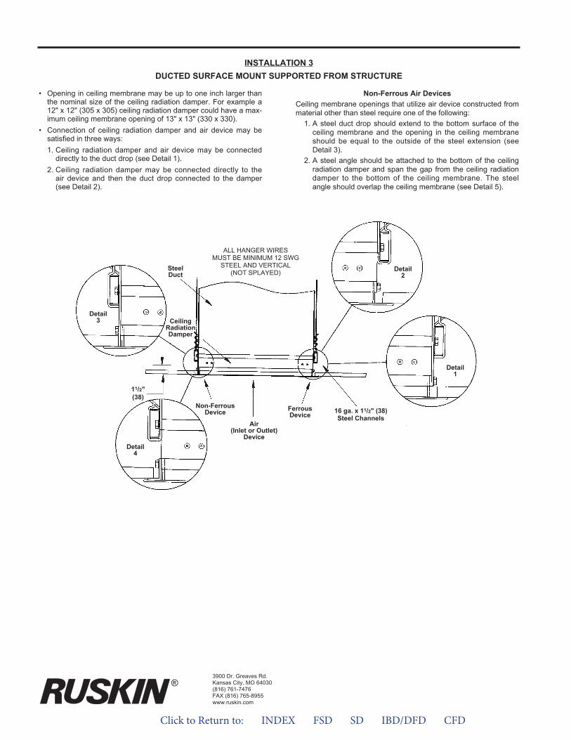
• Opening in ceiling membrane may be up to one inch larger thanthe nominal size of the ceiling radiation damper. For example a12" x 12" (305 x 305) ceiling radiation damper could have a max-imum ceiling membrane opening of 13" x 13" (330 x 330).
• Connection of ceiling radiation damper and air device may besatisfied in three ways:1. Ceiling radiation damper and air device may be connected
directly to the duct drop (see Detail 1).2. Ceiling radiation damper may be connected directly to the
air device and then the duct drop connected to the damper(see Detail 2).
Non-Ferrous Air Devices Ceiling membrane openings that utilize air device constructed frommaterial other than steel require one of the following:
1. A steel duct drop should extend to the bottom surface of theceiling membrane and the opening in the ceiling membraneshould be equal to the outside of the steel extension (seeDetail 3).
2. A steel angle should be attached to the bottom of the ceilingradiation damper and span the gap from the ceiling radiationdamper to the bottom of the ceiling membrane. The steelangle should overlap the ceiling membrane (see Detail 5).
INSTALLATION 3DUCTED SURFACE MOUNT SUPPORTED FROM STRUCTURE
ALL HANGER WIRESMUST BE MINIMUM 12 SWG
STEEL AND VERTICAL(NOT SPLAYED)
CeilingRadiationDamper
Air(Inlet or Outlet)
Device
Detail3
Detail4
Detail1
Detail2
Non-FerrousDevice Ferrous
Device
SteelDuct
3900 Dr. Greaves Rd.Kansas City, MO 64030(816) 761-7476FAX (816) 765-8955www.ruskin.com
®®
16 ga. x 11/2" (38)Steel Channels
11/2"(38)
Click to Return to: INDEX FSD SD IBD/DFD CFD
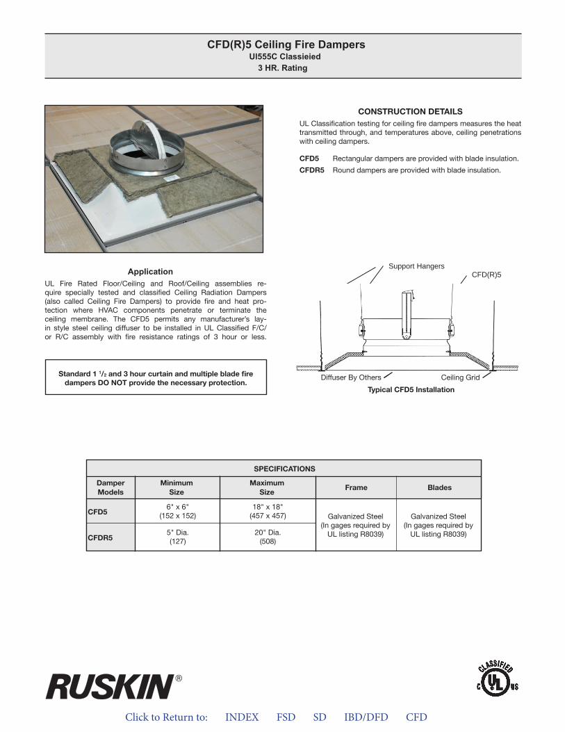
Click to Return to: INDEX FSD SD IBD/DFD CFD
ApplicationUL Fire Rated Floor/Ceiling and Roof/Ceiling assemblies re-quire specially tested and classified Ceiling Radiation Dampers (also called Ceiling Fire Dampers) to provide fire and heat pro-tection where HVAC components penetrate or terminate the ceiling membrane. The CFD5 permits any manufacturer’s lay-in style steel ceiling diffuser to be installed in UL Classified F/C/or R/C assembly with fire resistance ratings of 3 hour or less.
CONSTRUCTION DETAILSUL Classification testing for ceiling fire dampers measures the heat transmitted through, and temperatures above, ceiling penetrations with ceiling dampers.
CFD5 Rectangular dampers are provided with blade insulation.
CFDR5 Round dampers are provided with blade insulation.
CFD(R)5 Ceiling Fire Dampers Ul555C Classieied
3 HR. Rating
Standard 1 1/2 and 3 hour curtain and multiple blade firedampers DO NOT provide the necessary protection.
Typical CFD5 Installation
APPLICATIONUL Fire Rated Floor/Ceiling and Roof/Ceiling assemblies requirespecially tested and classified Ceiling Radiation Dampers (also called Ceiling Fire Dampers) to provide fire and heat protection where HVAC components penetrate or terminate the ceilingmembrane. The CFD5 permits any manufacturer’s lay-in style steelceiling diffuser to be installed in UL Classified F/C/or R/C assemblywith fire resistance ratings of 3 hour or less.
CONSTRUCTION DETAILSUL Classification testing for ceiling fire dampers measures the heattransmitted through, and temperatures above, ceiling penetrationswith ceiling dampers.
CFD5 Rectangular dampers are provided with blade insulation.
CFDR5 Round dampers are provided with blade insulation.
Support Hangers CFD(R)5
Diffuser Ceiling Grid
Typical CFD5 Installation
SPECIFICATIONSDamper Frame Blades
All Models Galvanized Steel(in gauges required by UL
listing R8039)
Galvanized Steel(in gauges required by UL
listing R5531)
Standard 1 ½ and 3 hour curtain and multiple blade fire dampers DO NOT provide the necessary protection.
®
CFD(R)5 Ceiling Fire Dampers UL555C Classified
3 Hr. Rating
Diffuser By Others Ceiling Grid
CFD5
CFDR5
SpECIFICATIONS
Frame BladesDamperModels
MinimumSize
MaximumSize
Galvanized Steel(In gages required by
UL listing R8039)
Galvanized Steel(In gages required by
UL listing R8039)
6" x 6"(152 x 152)
5" Dia.(127)
18" x 18"(457 x 457)
20" Dia.(508)
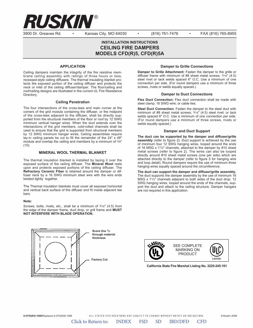
ALL STATED SPECIFICATIONS ARE SUBJECT TO CHANGE WITHOUT NOTICE OR OBLIGATION.
3900 Dr. Greaves Rd. • Kansas City, MO 64030 • (816) 761-7476 • FAX (816) 765-8955
INSTALLATION INSTRUCTIONSCEILING FIRE DAMPERS
MODELS CFD(R)5, CFD(R)5A
APPLICATIONCeiling dampers maintain the integrity of the fire resistive mem-brane ceiling assembly with ratings of three hours or less,recessed-style ceiling diffusers. The thermal insulating blanket pro-tects the exposed portion of the ceiling diffuser and protects theneck or inlet of the ceiling diffuser/damper. The floor/ceiling androof/ceiling designs are illustrated in the current UL Fire ResistanceDirectory.
Ceiling PenetrationThe four intersections of the cross-tees and main runner at thecomers of the grid module containing the diffuser, or the midpointof the cross-tees adjacent to the diffuser, shall be directly sup-ported from the structural members of the floor or roof by 12 SWGminimum vertical hanger wires. When the duct extends over theintersections of the grid members, cold-rolled channels shall beused to ensure that the grid is supported from structural membersby 12 SWG minimum hanger wires. Ceiling assemblies requirelay-in ceiling panels be cut to fill the remainder of the 24" x 48"module and overlap the ceiling and members by a minimum of 3/8"(10).
MINERAL WOOL THERMAL BLANKET
The thermal insulation blanket is installed by laying it over theexposed surface of the ceiling diffuser. The Mineral Wool restsupon and protects exposed portions of the ceiling diffuser. TheRefractory Ceramic Fiber is retained around the damper or dif-fuser neck by a 16 SWG minimum steel wire with the wire endstwisted tightly together.
The Thermal insulation blankets must cover all exposed horizontaland vertical back surface of the diffuser and fit inside adjacent teebars.
Note:Screws, bolts, rivets, etc., shall be a minimum of 3/16" (4.5) fromthe edge of the damper frame, duct drop, or grill frame and MUSTNOT INTERFERE WITH BLADE OPERATION.
II-CFD(R)5-1008/Replaces II-CFD(R)5-1006 © Ruskin 2008
®
Damper to Grille ConnectionsDamper to Grille Attachment: Fasten the damper to the grille ordiffuser frame with minimum of #8 sheet metal screws, 3/16" (4.5)steel rivet or tack welds spaced 6" O.C. Use a minimum of oneconnection per side. (For round dampers use a minimum of threescrews, rivets or welds equally spaced.)
Damper to Duct ConnectionsFlex Duct Connection: Flex duct connection shall be made withsteel clamp; 16 SWG wire; or cable ties.Steel Duct Connection: Fasten the damper to the steel duct withminimum of #8 sheet metal screws; 3/16" (4.5) steel rivet; or tackwelds spaced 6" O.C. Use a minimum of one connection per side.(For round dampers use a minimum of three screws, rivets orwelds equally spaced.)
Damper and Duct SupportThe duct can be supported by the damper and diffuser/grilleassembly (refer to figure 2). Duct support is achieved by the useof minimum four 12 SWG hanging wires, looped around the endsof 16 MSG x 11/2" channels, attached to the damper by #10 sheetmetal screws (refer to figure 2). The wires can also be loopeddirectly around #10 sheet metal screws (one per side) which areattached directly to the damper (refer to figure 5 for hanging wireand loop detail). Round dampers require the use of minimum threehanging wires equally spaced around the circumference.The duct can support the damper and diffuser/grille assembly.The duct supports the damper assembly by the use of minimum 16MSG x 11/2" channels adjacent to both sides of the duct drop. 12SWG hanging wires, looped around the ends of the channels, sup-port the duct and attach to the ceiling structure. Damper hangarsare not required in this application.
Score line 1/2through materialthickness
Factory Cut
California State Fire Marshal Listing No. 3225-245:101
SEE COMPLETEMARKING ON
PRODUCT
Click to Return to: INDEX FSD SD IBD/DFD CFD
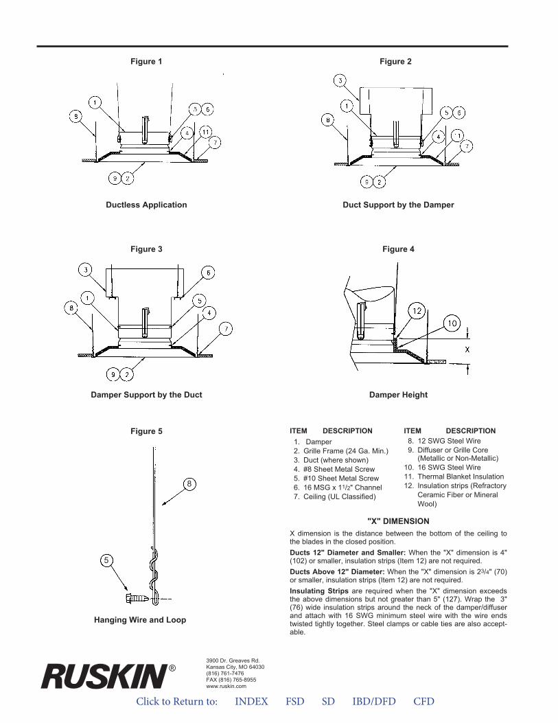
"X" DIMENSIONX dimension is the distance between the bottom of the ceiling tothe blades in the closed position.Ducts 12" Diameter and Smaller: When the "X" dimension is 4"(102) or smaller, insulation strips (Item 12) are not required.Ducts Above 12" Diameter: When the "X" dimension is 23/4" (70)or smaller, insulation strips (Item 12) are not required.Insulating Strips are required when the "X" dimension exceedsthe above dimensions but not greater than 5" (127). Wrap the 3"(76) wide insulation strips around the neck of the damper/diffuserand attach with 16 SWG minimum steel wire with the wire endstwisted tightly together. Steel clamps or cable ties are also accept-able.
ITEM DESCRIPTION1. Damper2. Grille Frame (24 Ga. Min.)3. Duct (where shown)4. #8 Sheet Metal Screw5. #10 Sheet Metal Screw6. 16 MSG x 11/2" Channel7. Ceiling (UL Classified)
ITEM DESCRIPTION8. 12 SWG Steel Wire9. Diffuser or Grille Core
(Metallic or Non-Metallic)10. 16 SWG Steel Wire11. Thermal Blanket Insulation12. Insulation strips (Refractory
Ceramic Fiber or MineralWool)
Ductless Application Duct Support by the Damper
Damper Support by the Duct Damper Height
3900 Dr. Greaves Rd.Kansas City, MO 64030(816) 761-7476FAX (816) 765-8955www.ruskin.com
®
Figure 5
8
5
Figure 1 Figure 2
Figure 3 Figure 4
Hanging Wire and Loop
Click to Return to: INDEX FSD SD IBD/DFD CFD
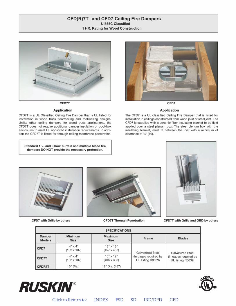
Click to Return to: INDEX FSD SD IBD/DFD CFD
ApplicationCFD7T is a UL Classified Ceiling Fire Damper that is UL listed for installation in wood truss floor/ceiling and roof/ceiling designs. Unlike other ceiling dampers for wood truss applications, the CFD7T does not require additional damper insulation or boot/box enclosures to meet UL approved installation requirements. In addi-tion the CFD7T is listed for through ceiling membrane penetration.
ApplicationThe CFD7 is a UL classified Ceiling Fire Damper that is listed for installation in ceilings constructed from wood joist or steel joist. The CFD7 is supplied with a ceramic fiber insulating blanket to be field applied over a steel plenum box. The steel plenum box with the insulating blanket, must fit between the joist with a minimum of clearance of ¾" (19).
CFD(R)7T and CFD7 Ceiling Fire Dampers Ul555C Classified
1 HR. Rating for Wood Construction
Standard 1 1/2 and 3 hour curtain and multiple blade firedampers DO NOT provide the necessary protection.
CFD7 with Grille by others CFD7T Through Penetration CFD7T with Grille and OBD by others
CFD7T CFD7
CFD7
CFD7T
CFDR7T
SPeCiFiCaTiONS
Frame BladesDamperModels
MinimumSize
MaximumSize
Galvanized Steel(In gages required by
UL listing R8039)
Galvanized Steel(In gages required by
UL listing R8039)
4" x 4"(102 x 102)
4" x 4"(102 x 102)
18" x 18"(457 x 457)
16" x 12"(406 x 305)
18" Dia. (457)5" Dia.
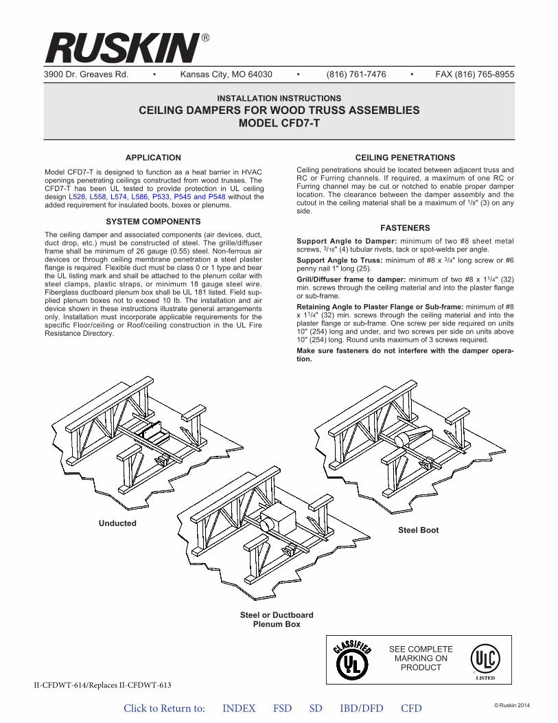
Click to Return to: INDEX FSD SD IBD/DFD CFD
3900 Dr. Greaves Rd. • Kansas City, MO 64030 • (816) 761-7476 • FAX (816) 765-8955
INSTALLATION INSTRUCTIONSCEILING DAMPERS FOR WOOD TRUSS ASSEMBLIES
MODEL CFD7-T
APPLICATIONModel CFD7-T is designed to function as a heat barrier in HVAC openings penetrating ceilings constructed from wood trusses. The CFD7-T has been UL tested to provide protection in UL ceiling design L528, L558, L574, L586, P533, P545 and P548 without the added requirement for insulated boots, boxes or plenums.
SYSTEM COMPONENTSThe ceiling damper and associated components (air devices, duct,duct drop, etc.) must be constructed of steel. The grille/diffuserframe shall be minimum of 26 gauge (0.55) steel. Non-ferrous airdevices or through ceiling membrane penetration a steel plasterflange is required. Flexible duct must be class 0 or 1 type and bearthe UL listing mark and shall be attached to the plenum collar withsteel clamps, plastic straps, or minimum 18 gauge steel wire.Fiberglass ductboard plenum box shall be UL 181 listed. Field sup-plied plenum boxes not to exceed 10 Ib. The installation and airdevice shown in these instructions illustrate general arrangementsonly. Installation must incorporate applicable requirements for thespecific Floor/ceiling or Roof/ceiling construction in the UL FireResistance Directory.
Unducted
CEILING PENETRATIONSCeiling penetrations should be located between adjacent truss andRC or Furring channels. If required, a maximum of one RC orFurring channel may be cut or notched to enable proper damperlocation. The clearance between the damper assembly and thecutout in the ceiling material shall be a maximum of 1/8" (3) on anyside.
FASTENERSSupport Angle to Damper: minimum of two #8 sheet metalscrews, 3/16" (4) tubular rivets, tack or spot-welds per angle.Support Angle to Truss: minimum of #8 x 3/4" long screw or #6penny nail 1" long (25).Grill/Diffuser frame to damper: minimum of two #8 x 11/4" (32)min. screws through the ceiling material and into the plaster flangeor sub-frame.Retaining Angle to Plaster Flange or Sub-frame: minimum of #8x 11/4" (32) min. screws through the ceiling material and into theplaster flange or sub-frame. One screw per side required on units10" (254) long and under, and two screws per side on units above10" (254) long. Round units maximum of 3 screws required.Make sure fasteners do not interfere with the damper opera-tion.
Steel or DuctboardPlenum Box
Steel Boot
SEE COMPLETEMARKING ON
PRODUCT
II-CFDWT-614/Replaces II-CFDWT-613
© Ruskin 2014
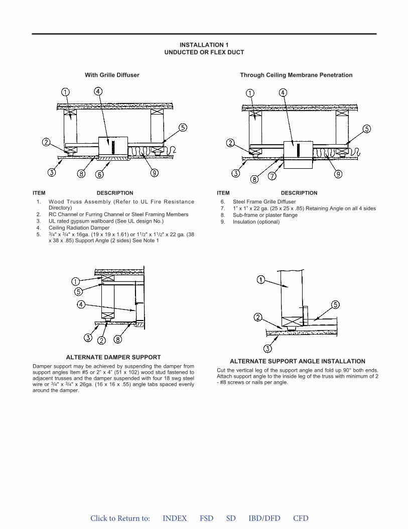
Click to Return to: INDEX FSD SD IBD/DFD CFD
INSTALLATION 1UNDUCTED OR FLEX DUCT
With Grille Diffuser Through Ceiling Membrane Penetration
ITEM DESCRIPTION1. Wood Truss Assembly (Refer to UL Fire Resistance
Directory)2. RC Channel or Furring Channel or Steel Framing Members3. UL rated gypsum wallboard (See UL design No.)4. Ceiling Radiation Damper5. 3/4" x 3/4" x 16ga. (19 x 19 x 1.61) or 11/2" x 11/2" x 22 ga. (38
x 38 x .85) Support Angle (2 sides) See Note 1
ITEM DESCRIPTION6. Steel Frame Grille Diffuser7. 1” x 1” x 22 ga. (25 x 25 x .85) Retaining Angle on all 4 sides8. Sub-frame or plaster flange9. Insulation (optional)
ALTERNATE SUPPORT ANGLE INSTALLATIONCut the vertical leg of the support angle and fold up 90° both ends.Attach support angle to the inside leg of the truss with minimum of 2- #8 screws or nails per angle.
ALTERNATE DAMPER SUPPORTDamper support may be achieved by suspending the damper fromsupport angles Item #5 or 2” x 4” (51 x 102) wood stud fastened toadjacent trusses and the damper suspended with four 18 swg steelwire or 3/4" x 3/4" x 26ga. (16 x 16 x .55) angle tabs spaced evenlyaround the damper.
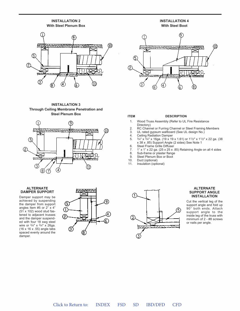
Click to Return to: INDEX FSD SD IBD/DFD CFD
INSTALLATION 2With Steel Plenum Box
INSTALLATION 3Through Ceiling Membrane Penetration and
Steel Plenum Box
INSTALLATION 4With Steel Boot
ITEM DESCRIPTION1. Wood Truss Assembly (Refer to UL Fire Resistance
Directory)2. RC Channel or Furring Channel or Steel Framing Members3. UL rated gypsum wallboard (See UL design No.)4. Ceiling Radiation Damper5. 3/4" x 3/4" x 16ga. (19 x 19 x 1.61) or 11/2" x 11/2" x 22 ga. (38
x 38 x .85) Support Angle (2 sides) See Note 16. Steel Frame Grille Diffuser7. 1” x 1” x 22 ga. (25 x 25 x .85) Retaining Angle on all 4 sides8. Sub-frame or plaster flange9. Steel Plenum Box or Boot
10. Duct (optional)11. Insulation (optional)
ALTERNATESUPPORT ANGLE
INSTALLATIONCut the vertical leg of thesupport angle and fold up90° both ends. Attachsupport angle to theinside leg of the truss withminimum of 2 - #8 screwsor nails per angle.
ALTERNATEDAMPER SUPPORT
Damper support may beachieved by suspendingthe damper from supportangles Item #5 or 2” x 4”(51 x 102) wood stud fas-tened to adjacent trussesand the damper suspend-ed with four 18 swg steelwire or 3/4" x 3/4" x 26ga.(16 x 16 x .55) angle tabsspaced evenly around thedamper.
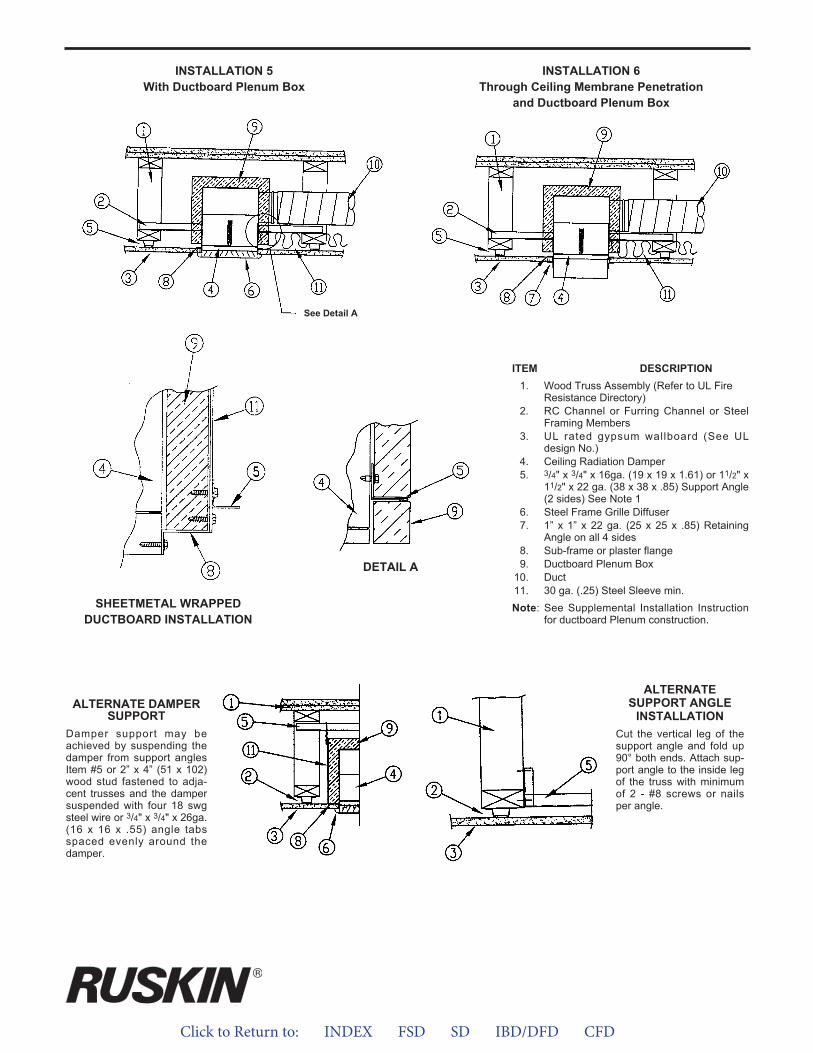
Click to Return to: INDEX FSD SD IBD/DFD CFD
INSTALLATION 5With Ductboard Plenum Box
INSTALLATION 6Through Ceiling Membrane Penetration
and Ductboard Plenum Box
ITEM DESCRIPTION1. Wood Truss Assembly (Refer to UL Fire
Resistance Directory)2. RC Channel or Furring Channel or Steel
Framing Members3. UL rated gypsum wallboard (See UL
design No.)4. Ceiling Radiation Damper5. 3/4" x 3/4" x 16ga. (19 x 19 x 1.61) or 11/2" x
11/2" x 22 ga. (38 x 38 x .85) Support Angle(2 sides) See Note 1
6. Steel Frame Grille Diffuser7. 1” x 1” x 22 ga. (25 x 25 x .85) Retaining
Angle on all 4 sides8. Sub-frame or plaster flange9. Ductboard Plenum Box
10. Duct11. 30 ga. (.25) Steel Sleeve min.Note: See Supplemental Installation Instruction
for ductboard Plenum construction.SHEETMETAL WRAPPED
DUCTBOARD INSTALLATION
ALTERNATESUPPORT ANGLE
INSTALLATIONCut the vertical leg of thesupport angle and fold up90° both ends. Attach sup-port angle to the inside legof the truss with minimumof 2 - #8 screws or nailsper angle.
See Detail A
DETAIL A
ALTERNATE DAMPERSUPPORT
Damper support may beachieved by suspending thedamper from support anglesItem #5 or 2” x 4” (51 x 102)wood stud fastened to adja-cent trusses and the dampersuspended with four 18 swgsteel wire or 3/4" x 3/4" x 26ga.(16 x 16 x .55) angle tabsspaced evenly around thedamper.
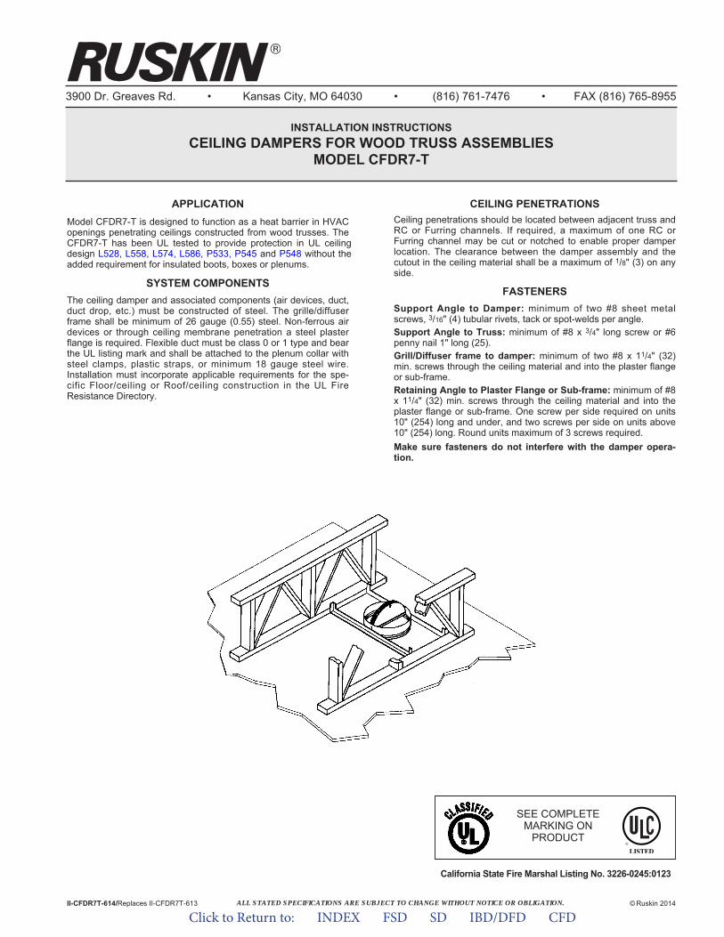
ALL STATED SPECIFICATIONS ARE SUBJECT TO CHANGE WITHOUT NOTICE OR OBLIGATION.
3900 Dr. Greaves Rd. • Kansas City, MO 64030 • (816) 761-7476 • FAX (816) 765-8955
INSTALLATION INSTRUCTIONSCEILING DAMPERS FOR WOOD TRUSS ASSEMBLIES
MODEL CFDR7-T
APPLICATIONModel CFDR7-T is designed to function as a heat barrier in HVAC openings penetrating ceilings constructed from wood trusses. The CFDR7-T has been UL tested to provide protection in UL ceiling design L528, L558, L574, L586, P533, P545 and P548 without the added requirement for insulated boots, boxes or plenums.
SYSTEM COMPONENTSThe ceiling damper and associated components (air devices, duct,duct drop, etc.) must be constructed of steel. The grille/diffuserframe shall be minimum of 26 gauge (0.55) steel. Non-ferrous airdevices or through ceiling membrane penetration a steel plasterflange is required. Flexible duct must be class 0 or 1 type and bearthe UL listing mark and shall be attached to the plenum collar withsteel clamps, plastic straps, or minimum 18 gauge steel wire.Installation must incorporate applicable requirements for the spe-cific Floor/ceiling or Roof/ceiling construction in the UL FireResistance Directory.
II-CFDR7T-614/Replaces II-CFDR7T-613 © Ruskin 2014
CEILING PENETRATIONSCeiling penetrations should be located between adjacent truss andRC or Furring channels. If required, a maximum of one RC orFurring channel may be cut or notched to enable proper damperlocation. The clearance between the damper assembly and thecutout in the ceiling material shall be a maximum of 1/8" (3) on anyside.
FASTENERSSupport Angle to Damper: minimum of two #8 sheet metalscrews, 3/16" (4) tubular rivets, tack or spot-welds per angle.Support Angle to Truss: minimum of #8 x 3/4" long screw or #6penny nail 1" long (25).Grill/Diffuser frame to damper: minimum of two #8 x 11/4" (32)min. screws through the ceiling material and into the plaster flangeor sub-frame.Retaining Angle to Plaster Flange or Sub-frame: minimum of #8x 11/4" (32) min. screws through the ceiling material and into theplaster flange or sub-frame. One screw per side required on units10" (254) long and under, and two screws per side on units above10" (254) long. Round units maximum of 3 screws required.Make sure fasteners do not interfere with the damper opera-tion.
SEE COMPLETEMARKING ON
PRODUCT
California State Fire Marshal Listing No. 3226-0245:0123
Click to Return to: INDEX FSD SD IBD/DFD CFD
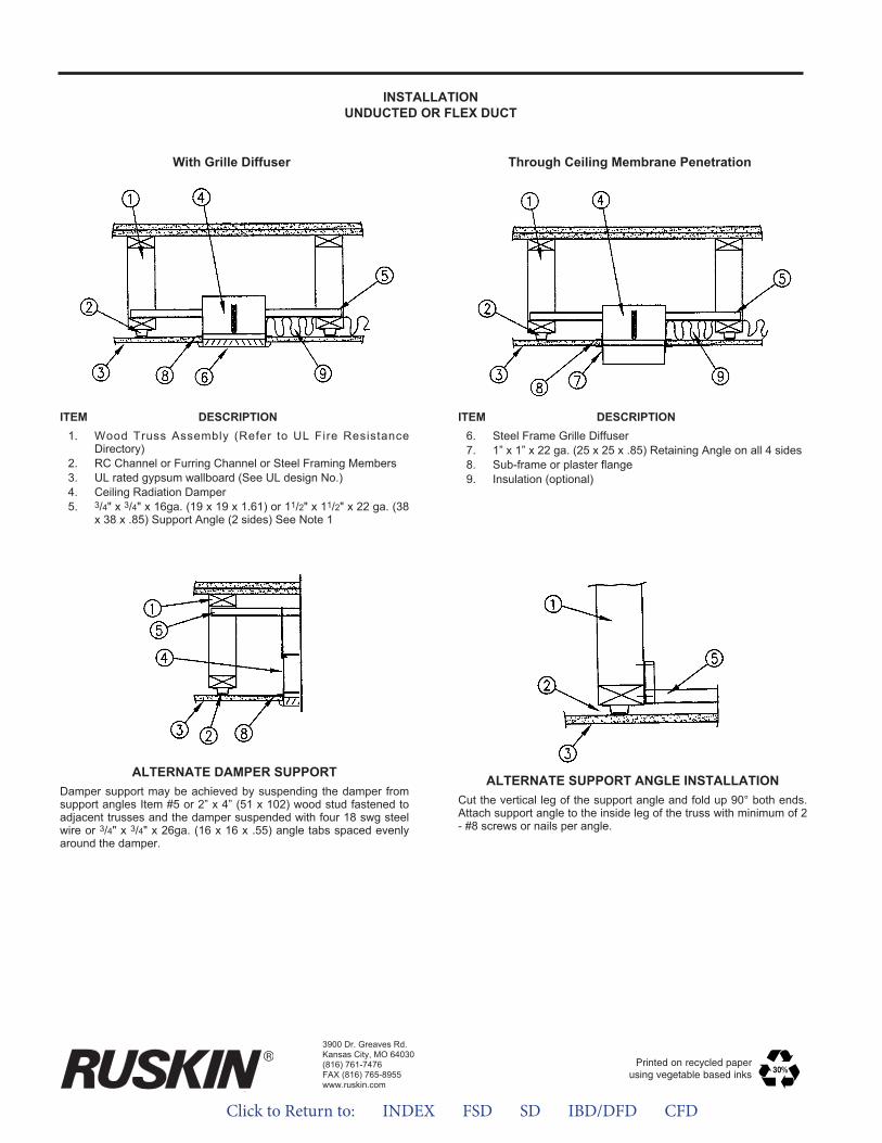
INSTALLATIONUNDUCTED OR FLEX DUCT
With Grille Diffuser Through Ceiling Membrane Penetration
ITEM DESCRIPTION1. Wood Truss Assembly (Refer to UL Fire Resistance
Directory)2. RC Channel or Furring Channel or Steel Framing Members3. UL rated gypsum wallboard (See UL design No.)4. Ceiling Radiation Damper5. 3/4" x 3/4" x 16ga. (19 x 19 x 1.61) or 11/2" x 11/2" x 22 ga. (38
x 38 x .85) Support Angle (2 sides) See Note 1
ITEM DESCRIPTION6. Steel Frame Grille Diffuser7. 1” x 1” x 22 ga. (25 x 25 x .85) Retaining Angle on all 4 sides8. Sub-frame or plaster flange9. Insulation (optional)
ALTERNATE SUPPORT ANGLE INSTALLATIONCut the vertical leg of the support angle and fold up 90° both ends.Attach support angle to the inside leg of the truss with minimum of 2- #8 screws or nails per angle.
ALTERNATE DAMPER SUPPORTDamper support may be achieved by suspending the damper fromsupport angles Item #5 or 2” x 4” (51 x 102) wood stud fastened toadjacent trusses and the damper suspended with four 18 swg steelwire or 3/4" x 3/4" x 26ga. (16 x 16 x .55) angle tabs spaced evenlyaround the damper.
3900 Dr. Greaves Rd.Kansas City, MO 64030(816) 761-7476FAX (816) 765-8955www.ruskin.com
Printed on recycled paperusing vegetable based inks
Click to Return to: INDEX FSD SD IBD/DFD CFD

Click to Return to: INDEX FSD SD IBD/DFD CFD
3900 Dr. Greaves Rd. • Kansas City, MO 64030 • (816) 761-7476 • FAX (816) 765-8955
INSTALLATION INSTRUCTIONSCEILING FIRE DAMPERS
MODEL CFD7
APPLICATIONCeiling fire dampers maintain the integrity of the fire resistive ceil-ing assembly. The floor/ceiling and roof/ceiling designs are illustrat-ed in the current UL Fire Resistance Directory. These installation instructions depict a ceiling fire damper installed in ceiling design L-501, L-502, L-503, L-506, L-507, L-508, L-512, L-513, L-514, L- 515, L-516, L-517, L-519, L-522, L-523, L-524, L-533, L-537, and L-545.
Notes:1. CFD's are shipped from the factory with the blades in the
closed position. The fusible link must be installed to hold theblades in the open position at the time of installation.
2. Screws, bolts, rivets, etc, MUST NOT INTERFERE WITHBLADE OPERATION.
3. Flex duct must be UL listed class I or 0. Steel duct minimum 28(.50) gage and maximum of 20 (.9) gage.
4. The ceiling damper and its components must be installed andsupported as illustrated.
5. Minimum clearance between the damper and joist 3/4" (19).
CEILING PENETRATIONCeiling penetrations should be located in-between floor/ceilingjoist. The opening in the gypsum board should have no gaps larg-er than 1/16" (1.5) between the damper frame and the gypsumboard.
ITEM DESCRIPTION
1. Floor - Ceiling UL rated (See application section for designnumber).
2. Steel box minimum of 24 gage.3. 3/4" x 3/4" 20 gage Mounting Angle4. #6 Nail or #8 Wood Screw5. #8 Sheet metal Screw or Rivet6. 1/2" thick Thermal Blanket (all sides)7. 16 SWG Steel wire, Steel Clamp or Nylon Zip Tie8. 2" x 4" Wood Brace9. Damper Assembly
10. Duct (if required)11. 24 gage x 1" wide Duct Support on 24" centers
2" (51)Max.
SEE COMPLETEMARKING ON
PRODUCT
II-CFD7-1008/Replaces II-CFD7-903
© Ruskin 2008
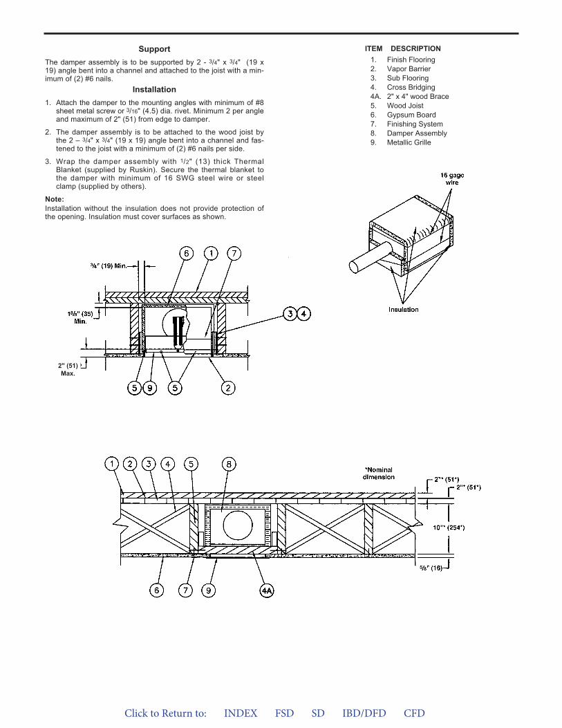
Click to Return to: INDEX FSD SD IBD/DFD CFD
SupportThe damper assembly is to be supported by 2 - 3/4" x 3/4" (19 x19) angle bent into a channel and attached to the joist with a min-imum of (2) #6 nails.
Installation1. Attach the damper to the mounting angles with minimum of #8
sheet metal screw or 3/16" (4.5) dia. rivet. Minimum 2 per angleand maximum of 2" (51) from edge to damper.
2. The damper assembly is to be attached to the wood joist bythe 2 – 3/4" x 3/4" (19 x 19) angle bent into a channel and fas-tened to the joist with a minimum of (2) #6 nails per side.
3. Wrap the damper assembly with 1/2" (13) thick ThermalBlanket (supplied by Ruskin). Secure the thermal blanket tothe damper with minimum of 16 SWG steel wire or steelclamp (supplied by others).
Note:Installation without the insulation does not provide protection ofthe opening. Insulation must cover surfaces as shown.
ITEM DESCRIPTION1. Finish Flooring2. Vapor Barrier3. Sub Flooring4. Cross Bridging4A. 2" x 4" wood Brace5. Wood Joist6. Gypsum Board7. Finishing System8. Damper Assembly9. Metallic Grille
2" (51)Max.
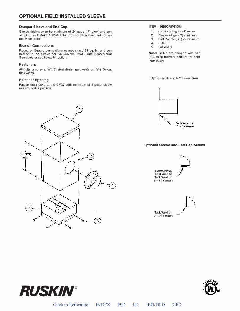
Click to Return to: INDEX FSD SD IBD/DFD CFD
Damper Sleeve and End CapSleeve thickness to be minimum of 24 gage (.7) steel and con-structed per SMACNA HVAC Duct Construction Standards or seebelow for option.
Branch ConnectionsRound or Square connections cannot exced 51 sq. in. and con-nected to the sleeve per SMACNNA HVAC Duct ConstructionStandards or see below for option.
Fasteners#8 bolts or screws, 1/8" (3) steel rivets, spot welds or 1/2" (13) longtack welds.
Fastener SpacingFasten the sleeve to the CFD7 with minimum of 2 bolts, screw,rivets or welds per side.
ITEM DESCRIPTION1. CFD7 Ceiling Fire Damper2. Sleeve 24 ga. (.7) minimum3. End Cap 24 ga. (.7) minimum4. Collar5. Fasteners
Note: CFD7 are shipped with 1/2"(13) thick thermal blanket for fieldinstallation.
OPTIONAL FIELD INSTALLED SLEEVE
Optional Branch Connection
Optional Sleeve and End Cap Seams
Screw, Rivet,Spot Weld orTack Weld on2" (51) centers
Tack Weld on2" (51) centers
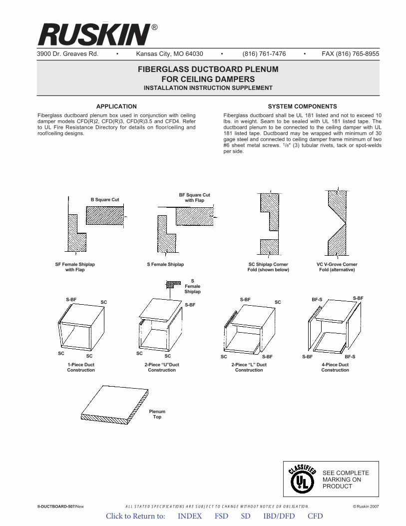
ALL STATED SPECIFICATIONS ARE SUBJECT TO CHANGE WITHOUT NOTICE OR OBLIGATION.
3900 Dr. Greaves Rd. • Kansas City, MO 64030 • (816) 761-7476 • FAX (816) 765-8955
APPLICATIONFiberglass ductboard plenum box used in conjunction with ceilingdamper models CFD(R)2, CFD(R)3, CFD(R)3.5 and CFD4. Referto UL Fire Resistance Directory for details on floor/ceiling androof/ceiling designs.
II-DUCTBOARD-507/New © Ruskin 2007
®
SYSTEM COMPONENTSFiberglass ductboard shall be UL 181 listed and not to exceed 10lbs. in weight. Seam to be sealed with UL 181 listed tape. Theductboard plenum to be connected to the ceiling damper with UL181 listed tape. Ductboard may be wrapped with minimum of 30gage steel and connected to ceiling damper frame minimum of two#6 sheet metal screws. 1/8" (3) tubular rivets, tack or spot-weldsper side.
FIBERGLASS DUCTBOARD PLENUMFOR CEILING DAMPERS
INSTALLATION INSTRUCTION SUPPLEMENT
SF Female Shiplapwith Flap
B Square Cut
S Female Shiplap SC Shiplap CornerFold (shown below)
VC V-Grove CornerFold (alternative)
2-Piece “L” DuctConstruction
4-Piece DuctConstruction
1-Piece DuctConstruction
2-Piece “U”DuctConstruction
PlenumTop
BF Square Cutwith Flap
S-BF SC
SC SC
S-BF SC BF-S S-BF
SC S-BFSC SC
S-BF
SFemaleShiplap
S-BF BF-S
SEE COMPLETEMARKING ONPRODUCT
Click to Return to: INDEX FSD SD IBD/DFD CFD
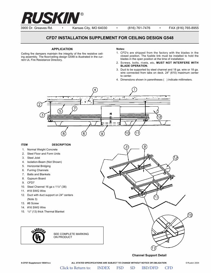
ALL STATED SPECIFICATIONS ARE SUBJECT TO CHANGE WITHOUT NOTICE OR OBLIGATION.
3900 Dr. Greaves Rd. • Kansas City, MO 64030 • (816) 761-7476 • FAX (816) 765-8955
CFD7 INSTALLATION SUPPLEMENT FOR CEILING DESIGN G548
APPLICATIONCeiling fire dampers maintain the integrity of the fire resistive ceil-ing assembly. The floor/ceiling design G548 is illustrated in the cur-rent UL Fire Resistance Directory.
II-CFD7-Supplement 1004/New © Ruskin 2004
®
Notes:1. CFD's are shipped from the factory with the blades in the
closed position. The fusible link must be installed to hold theblades in the open position at the time of installation.
2. Screws, bolts, rivets, etc, MUST NOT INTERFERE WITHBLADE OPERATION.
3. Duct to be supported by steel channel and 18 ga. wire or 18 ga.wire connected from tabs on deck. 24" (610) maximum centerto center.
4. Dimensions shown in parentheses ( ) indicate millimeters.
ITEM DESCRIPTION
1. Normal Weight Concrete2. Steel Floor and Form Units3. Steel Joist4. Isolation-Beam (Not Shown)5. Horizontal Bridging6. Furring Channels7. Batts and Blankets8. Gypsum Board9. CFD7
10. Steel Channel 16 ga x 11/2" (38)11. #18 SWG Wire12. Duct with duct support on 24" centers
(Note 3)13. #8 Screw14. #16 SWG Wire15. 1/2" (13) thick Thermal Blanket
Channel Support Detail
SEE COMPLETE MARKING ON PRODUCT
Click to Return to: INDEX FSD SD IBD/DFD CFD
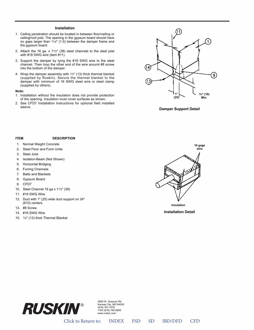
Installation1. Ceiling penetration should be located in between floor/ceiling or
ceiling/roof joist. The opening in the gypsum board should haveno gaps larger than 1/16" (1.5) between the damper frame andthe gypsum board.
2. Attach the 16 ga. x 11/2" (38) steel channels to the steel joistwith #18 SWG wire (item #11).
3. Support the damper by tying the #18 SWG wire to the steelchannel. Then loop the other end of the wire around #8 screwinto the bottom of the damper.
4. Wrap the damper assembly with 1/2" (13) thick thermal blanket(supplied by Ruskin). Secure the thermal blanket to thedamper with minimum of 16 SWG steel wire or steel clamp(supplied by others).
Note:1. Installation without the insulation does not provide protection
of the opening. Insulation must cover surfaces as shown.2. See CFD7 Installation Instructions for optional field installed
sleeve. Damper Support Detail
Installation Detail
ITEM DESCRIPTION
1. Normal Weight Concrete2. Steel Floor and Form Units3. Steel Joist4. Isolation-Beam (Not Shown)5. Horizontal Bridging6. Furring Channels7. Batts and Blankets8. Gypsum Board9. CFD7
10. Steel Channel 16 ga x 11/2" (38)11. #18 SWG Wire12. Duct with 1" (25) wide duct support on 24"
(610) centers13. #8 Screw14. #16 SWG Wire15. 1/2" (13) thick Thermal Blanket
Insulation
16 gagewire
1"(25)
3/4" (19)Min.
3900 Dr. Greaves Rd.Kansas City, MO 64030(816) 761-7476FAX (816) 765-8955
www.ruskin.com
®
Click to Return to: INDEX FSD SD IBD/DFD CFD

ALL STATED SPECIFICATIONS ARE SUBJECT TO CHANGE WITHOUT NOTICE OR OBLIGATION.
3900 Dr. Greaves Rd. • Kansas City, MO 64030 • (816) 761-7476 • FAX (816) 765-8955
CFD7 INSTALLATION SUPPLEMENT FOR CEILING DESIGN L524
APPLICATIONCeiling fire dampers maintain the integrity of the fire resistive ceil-ing assembly. The floor/ceiling designs L524 is illustrated in thecurrent UL Fire Resistance Directory.
II-CFD7 SupplementL524-1004/New © Ruskin 2004
®
Notes:1. CFD's are shipped from the factory with the blades in the
closed position. The fusible link must be installed to hold theblades in the open position at the time of installation.
2. Screws, bolts, rivets, etc, MUST NOT INTERFERE WITHBLADE OPERATION.
3. The ceiling damper and its components must be installed andsupported as ilustrated.
4. Dimensions shown in parentheses ( ) indicate millimeters.ITEM DESCRIPTION
1. Floor or roof assembly2. Steel box minimum 24 gage.3. 3/4" x 3/4" 20 gage mounting angle4. Minimum #8 sheet metal screw or rivet5. 1/2" thick Thermal Blanket (all sides)6. 16 SWG steel wire, steel clamp or nylon zip tie7. Ceiling damper assembly8. Duct (if required)9. 24 gage x 1" wide duct support on 24" centers
10. Steel joist
SEE COMPLETE MARKING ON PRODUCT
Click to Return to: INDEX FSD SD IBD/DFD CFD
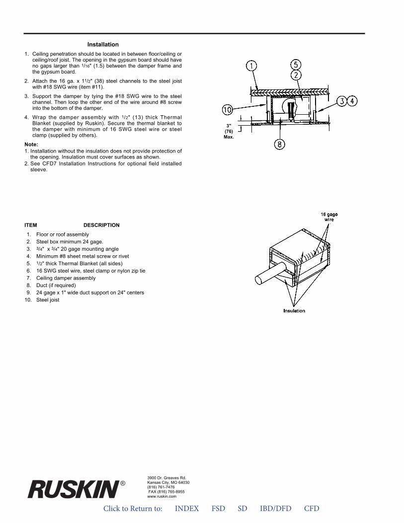
Installation1. Ceiling penetration should be located in between floor/ceiling or
ceiling/roof joist. The opening in the gypsum board should haveno gaps larger than 1/16" (1.5) between the damper frame andthe gypsum board.
2. Attach the 16 ga. x 11/2" (38) steel channels to the steel joistwith #18 SWG wire (item #11).
3. Support the damper by tying the #18 SWG wire to the steelchannel. Then loop the other end of the wire around #8 screwinto the bottom of the damper.
4. Wrap the damper assembly with 1/2" (13) thick ThermalBlanket (supplied by Ruskin). Secure the thermal blanket tothe damper with minimum of 16 SWG steel wire or steelclamp (supplied by others).
Note:1. Installation without the insulation does not provide protection of
the opening. Insulation must cover surfaces as shown.2. See CFD7 Installation Instructions for optional field installed
sleeve.
ITEM DESCRIPTION
1. Floor or roof assembly2. Steel box minimum 24 gage.3. 3/4" x 3/4" 20 gage mounting angle4. Minimum #8 sheet metal screw or rivet5. 1/2" thick Thermal Blanket (all sides)6. 16 SWG steel wire, steel clamp or nylon zip tie7. Ceiling damper assembly8. Duct (if required)9. 24 gage x 1" wide duct support on 24" centers
10. Steel joist
3900 Dr. Greaves Rd.Kansas City, MO 64030(816) 761-7476FAX (816) 765-8955
www.ruskin.com
®
3"(76)Max.
Click to Return to: INDEX FSD SD IBD/DFD CFD
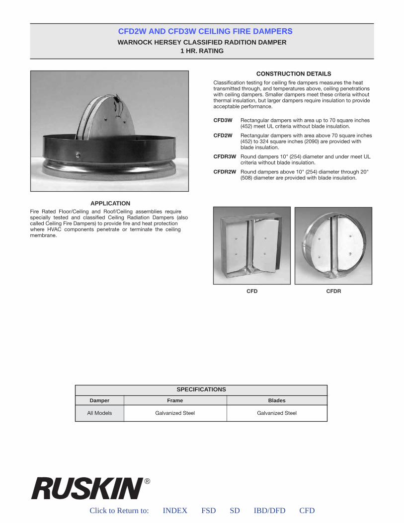
®
Click to Return to: INDEX FSD SD IBD/DFD CFD
CFD2W AND CFD3W CEILING FIRE DAMPERSWARNOCK HERSEY CLASSIFIED RADITION DAMPER
1 HR. RATING
APPLICATIONFire Rated Floor/Ceiling and Roof/Ceiling assemblies require specially tested and classified Ceiling Radiation Dampers (also called Ceiling Fire Dampers) to provide fire and heat protection where HVAC components penetrate or terminate the ceiling membrane.
CONSTRUCTION DETAILSClassification testing for ceiling fire dampers measures the heat transmitted through, and temperatures above, ceiling penetrations with ceiling dampers. Smaller dampers meet these criteria without thermal insulation, but larger dampers require insulation to provide acceptable performance.
CFD3W Rectangular dampers with area up to 70 square inches (452) meet UL criteria without blade insulation.
CFD2W Rectangular dampers with area above 70 square inches (452) to 324 square inches (2090) are provided with blade insulation.
CFDR3W Round dampers 10" (254) diameter and under meet ULcriteria without blade insulation.
CFDR2W Round dampers above 10" (254) diameter through 20" (508) diameter are provided with blade insulation.
SPECIFICATIONS
Damper
All Models
Frame
Galvanized Steel
Blades
Galvanized Steel
Click to Return to: INDEX FSD SD IBD/DFD CFD
a
W
W
W
W
W and WWarnock Hersey Classified Radition damper
1
Galvanized Steel Galvanized Steel
Click to Return to: INDEX FSD SD IBD/DFD CFD
a
W
W
W
W
W and WWarnock Hersey Classified Radition damper
1
Galvanized Steel Galvanized Steel
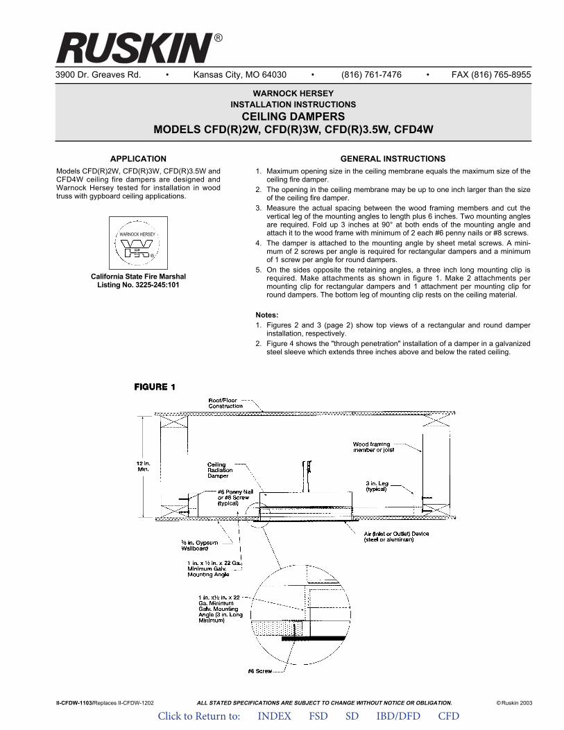
ALL STATED SPECIFICATIONS ARE SUBJECT TO CHANGE WITHOUT NOTICE OR OBLIGATION.
3900 Dr. Greaves Rd. • Kansas City, MO 64030 • (816) 761-7476 • FAX (816) 765-8955
WARNOCK HERSEYINSTALLATION INSTRUCTIONS
CEILING DAMPERSMODELS CFD(R)2W, CFD(R)3W, CFD(R)3.5W, CFD4W
APPLICATIONModels CFD(R)2W, CFD(R)3W, CFD(R)3.5W andCFD4W ceiling fire dampers are designed andWarnock Hersey tested for installation in woodtruss with gypboard ceiling applications.
California State Fire MarshalListing No. 3225-245:101
II-CFDW-1103/Replaces II-CFDW-1202 © Ruskin 2003
®
WARNOCK HERSEY
®
GENERAL INSTRUCTIONS1. Maximum opening size in the ceiling membrane equals the maximum size of the
ceiling fire damper.2. The opening in the ceiling membrane may be up to one inch larger than the size
of the ceiling fire damper.3. Measure the actual spacing between the wood framing members and cut the
vertical leg of the mounting angles to length plus 6 inches. Two mounting anglesare required. Fold up 3 inches at 90° at both ends of the mounting angle andattach it to the wood frame with minimum of 2 each #6 penny nails or #8 screws.
4. The damper is attached to the mounting angle by sheet metal screws. A mini-mum of 2 screws per angle is required for rectangular dampers and a minimumof 1 screw per angle for round dampers.
5. On the sides opposite the retaining angles, a three inch long mounting clip isrequired. Make attachments as shown in figure 1. Make 2 attachments permounting clip for rectangular dampers and 1 attachment per mounting clip forround dampers. The bottom leg of mounting clip rests on the ceiling material.
Notes:1. Figures 2 and 3 (page 2) show top views of a rectangular and round damper
installation, respectively.2. Figure 4 shows the "through penetration" installation of a damper in a galvanized
steel sleeve which extends three inches above and below the rated ceiling.
Click to Return to: INDEX FSD SD IBD/DFD CFD

3900 Dr. Greaves Rd.Kansas City, MO 64030(816) 761-7476FAX (816) 765-8955
www.ruskin.com
®
Click to Return to: INDEX FSD SD IBD/DFD CFD
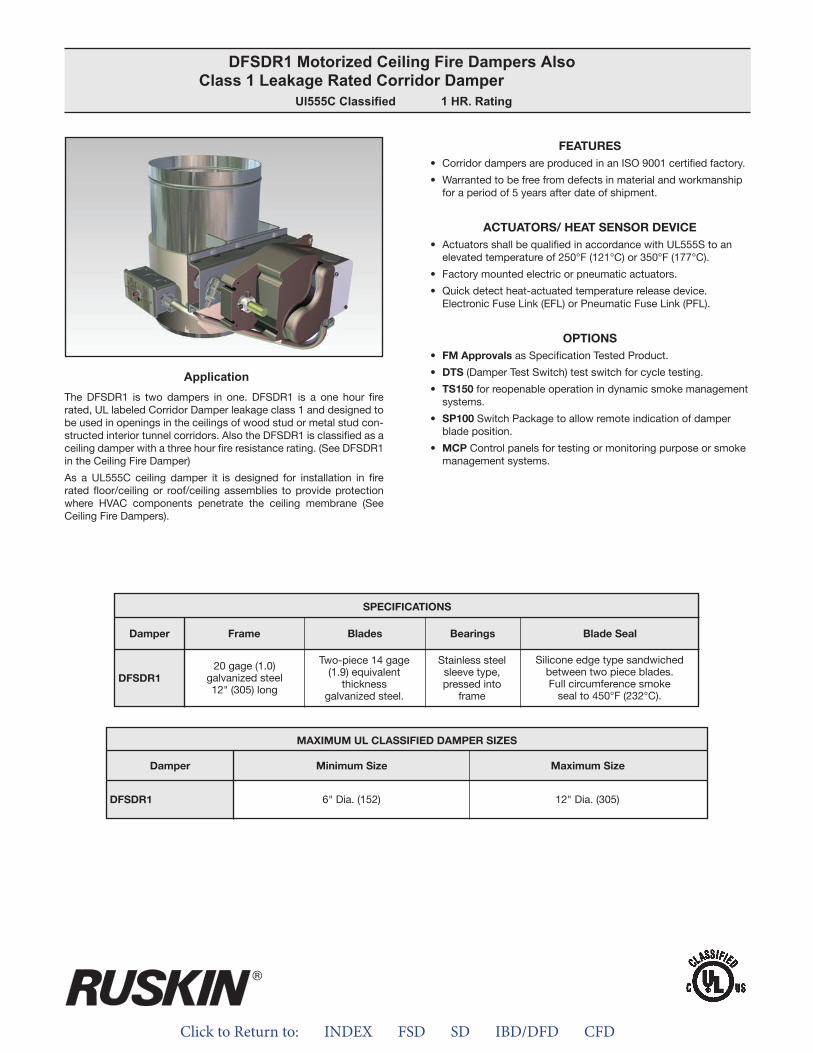
Click to Return to: INDEX FSD SD IBD/DFD CFD
ApplicationThe DFSDR1 is two dampers in one. DFSDR1 is a one hour fire rated, UL labeled Corridor Damper leakage class 1 and designed to be used in openings in the ceilings of wood stud or metal stud con-structed interior tunnel corridors. Also the DFSDR1 is classified as a ceiling damper with a three hour fire resistance rating. (See DFSDR1 in the Ceiling Fire Damper)
As a UL555C ceiling damper it is designed for installation in fire rated floor/ceiling or roof/ceiling assemblies to provide protection where HVAC components penetrate the ceiling membrane (See Ceiling Fire Dampers).
FEATURES• Corridor dampers are produced in an ISO 9001 certified factory.
• Warranted to be free from defects in material and workmanshipfor a period of 5 years after date of shipment.
ACTUATORS/ HEAT SENSOR DEVICE• Actuators shall be qualified in accordance with UL555S to an
elevated temperature of 250°F (121°C) or 350°F (177°C).
• Factory mounted electric or pneumatic actuators.
• Quick detect heat-actuated temperature release device.Electronic Fuse Link (EFL) or Pneumatic Fuse Link (PFL).
OPTIONS• FM Approvals as Specification Tested Product.
• DTS (Damper Test Switch) test switch for cycle testing.
• TS150 for reopenable operation in dynamic smoke managementsystems.
• SP100 Switch Package to allow remote indication of damperblade position.
• MCP Control panels for testing or monitoring purpose or smokemanagement systems.
DFSDR1 Motorized Ceiling Fire Dampers Also Class 1 Leakage Rated Corridor Damper
Ul555C Classified 1 HR. Rating
MAXIMUM UL CLASSIFIED DAMPER SIZES
Damper
DFSDR1
Minimum Size Maximum Size
6" Dia. (152) 12" Dia. (305)
SPECIFICATIONS
DFSDR1
Frame Blades Bearings Blade SealDamper
20 gage (1.0)galvanized steel12" (305) long
Two-piece 14 gage(1.9) equivalent
thickness galvanized steel.
Stainless steelsleeve type,pressed into
frame
Silicone edge type sandwiched between two piece blades.Full circumference smoke
seal to 450°F (232°C).
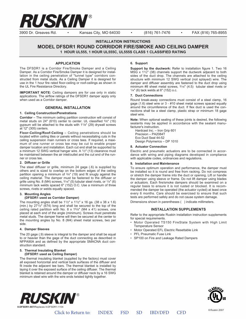
Click to Return to: INDEX FSD SD IBD/DFD CFD
3900 Dr. Greaves Rd. • Kansas City, MO 64030 • (816) 761-7476 • FAX (816) 765-8955
INSTALLATION INSTRUCTIONSMODEL DFSDR1 ROUND CORRIDOR FIRE/SMOKE AND CEILING DAMPER
1 HOUR UL555, 1 HOUR UL555C, UL555S CLASS 1 CLASSIFIED RATING
APPLICATIONThe DFSDR1 is a Corridor Fire/Smoke Damper and a CeilingDamper. As a Corridor Fire/Smoke Damper it is designed for instal-lation in the ceiling penetration of "tunnel type" corridors con-structed from metal studs. As a Ceiling Damper it is designed foruse in the 1 hour fire rated floor-ceiling or roof-ceilings as shown inthe UL Fire Resistance Directory.
IMPORTANT NOTE: Ceiling dampers are for use only in staticapplications. The airflow ratings of the DFSDR1 damper apply onlywhen used as a Corridor damper.
GENERAL INSTALLATION1. Ceiling Construction/PenetrationsCorridor – The minimum ceiling partition construction will consist ofmetal studs on 24" (610) center to center. UL classified 5/8" (16)gypsum will be attached to the studs with 11/8" (29) drywall screwsat 12" (305) centers.Floor-Ceiling/Roof-Ceiling – Ceiling penetrations should belocated within ceiling tiles or panels without necessitating cuts in theceiling suspension main runners or cross tees. If required, a maxi-mum of one runner or cross tee may be cut to enable properdamper location and installation. Each cut end shall be supported bya minimum 12 SWG vertical hangar wire. A 1/2" (13) clearance mustbe maintained between the air inlet/outlet and the cut end of the run-ner or cross tee.2. Diffuser or GrilleThe steel diffuser or grille, minimum 24 gage (.6) is supplied byothers and is sized to overlap on the bottom edges of the ceilingpartition opening a minimum of 3/4" (19) and fit snugly against theceiling material. The damper must be fastened to the diffuser orgrille using No. 8 (M4) screws, 3/16" (5) tubular steel rivets, or 1/4" (6)minimum tack welds spaced 6" (152) O.C. Use a minimum of threescrews, rivets or welds equally spaced.3. Mounting Angles
(DFSDR1 used as Corridor Damper)The mounting angles shall be 11/2" x 11/2" x 16 ga. (38 x 38 x 1.6)(min.) by 271/2" (674) long and shall be secured to the top of theceiling rated partition with No. 8 x 15/8" (M4 x 41) screws, oneplaced at each end of the angle (minimum). Screws must penetratemetal studs. The damper frame will then be secured at the center tothe mounting angles by No. 8 (M4) sheet metal screws, two perside.4. Damper SleevesThe 20 gage (.9) sleeve is integral to the damper and shall be equalto or heavier than the gage of the duct connecting as described inNFPA90A and as defined by the appropriate SMACNA duct con-struction standard.5. Thermal Insulating Blanket
(DFSDR1 used as Ceiling Damper)The thermal insulating blanket (supplied by the factory) must coverall exposed horizontal and vertical back surfaces of the diffuser andfit inside the adjacent tee bars. The thermal blanket is installed bylaying it over the exposed surface of the ceiling diffuser. The thermalblanket is retained around the damper or diffuser neck by a 16 SWGminimum steel wire with the wire ends twisted tightly together.
6. SupportSupport by the ductwork: Refer to installation figure 1. Two 16MSG x 11/2" (38) channels support the ductwork adjacent to bothsides of the duct drop. The channels are attached to the ceilingstructure with minimum 12 SWG vertical (not splayed) wire. Thedamper and diffuser assembly are fastened to the duct drop usingminimum #8 sheet metal screws, 3/16" (4.5) tubular steel rivets or1/4" (6) tack welds at 6" (152) o.c.7. Duct ConnectionsRound break-away connections must consist of a steel clamp, 16gage (1.6) steel wire or 3 - #10 sheet metal screws spaced equallyaround the circumference of the duct. If flex duct is used the con-nections shall be a steel clamp, plastic strap or minimum 18 gagesteel wire.Note: When optional sealing of these joints is desired, the followingsealants may be applied in accordance with the sealant manu-facturer's instruction.
Hardcast Inc. – Iron Grip 601Precision – PA2084TEco Duct Seal 44-52Design Polymerics – DP 1010
8. Actuator ConnectionElectric and pneumatic actuators are to be connected in accor-dance with wiring and piping diagrams developed in compliancewith applicable codes, ordinances and regulations.9. Installation and MaintenanceTo ensure optimum operation and performance, the damper mustbe installed so it is round and free from racking. Do not compressor stretch the damper frame into the duct or opening. Lift or handlethe damper using sleeve or frame. Do not lift damper using bladesor actuators. Each fire/smoke dampers should be examined on aregular basis to ensure it is not rusted or blocked. It is recom-mended the damper be operated (the actuator cycled) at least onceevery 6 months. Care should be exercised to ensure that suchtests are performed safely and do not cause system damage.Dimensions shown in parentheses ( ) indicate millimeters.
INSTALLATION SUPPLEMENTSRefer to the appropriate Ruskin installation instruction supplementsfor special requirements.• Motor Operated TS150 FireState System with High Limit
Temperature Sensor• Motor Operated EFL Electric Resettable Link• PFL Pneumatic Fuse Link• SP100 on Fire and Leakage Rated Dampers
II-DFSDR1-807/Replaces II-DFSDR1-1104© Ruskin 2007

Click to Return to: INDEX FSD SD IBD/DFD CFD
STEEL STUD CONSTRUCTION
5/8" (16) ULClassified drywallmin. attach withdrywall screws12" (305) c-c
24" (610max. C-C
Stl. Runner
Stl. Studs
Cut stl. runner web& secure to stl. studw/2 sheet mtl.screws (Typ.)
CORRIDOR INSTALLATION
FLOOR-CEILING /ROOF-CEILING NSTALLATION
231/2 (597)Max.
ITEM DESCRIPTION1. Actuator (location may vary)2. Flex Conduit3. TS150 FireStat, EFL (electric fuse link) or PFL (pneumatic
fuse link) (location may vary)4. Integral Sleeve Damper Frame5. Steel Surface Mount Ceiling Diffuser (supplied by others)6. Mounting Angles and Fasteners7. Duct (Flexible or Hard)
FIGURE 1Fire Rated Ceiling with Steel Duct Drop
FIGURE 2Fire Rated Ceiling with Flex Duct
ITEM DESCRIPTION1. Integral Sleeve Damper Frame2. Surface Mount or Lay-In Ceiling Diffuser3. Duct (Flexible or Hard)4. U.L. Classified fire-rated ceiling. Refer to the UL
Fire Resistance Directory for design information.5. 12 Gage Steel Wire6. 16 MSG x 11/2" Channel7. Thermal Blanket Insulation