Licensed Microwave Options for the Broadcast Industry - SBE ...
37
Page 1 Cielo Networks, Inc. - Proprietary Licensed Microwave Options for the Broadcast Industry
-
Upload
khangminh22 -
Category
Documents
-
view
4 -
download
0
Transcript of Licensed Microwave Options for the Broadcast Industry - SBE ...

Page 1Cielo Networks, Inc. - Proprietary
Licensed
Microwave
Options for
the
Broadcast
Industry
Page 2
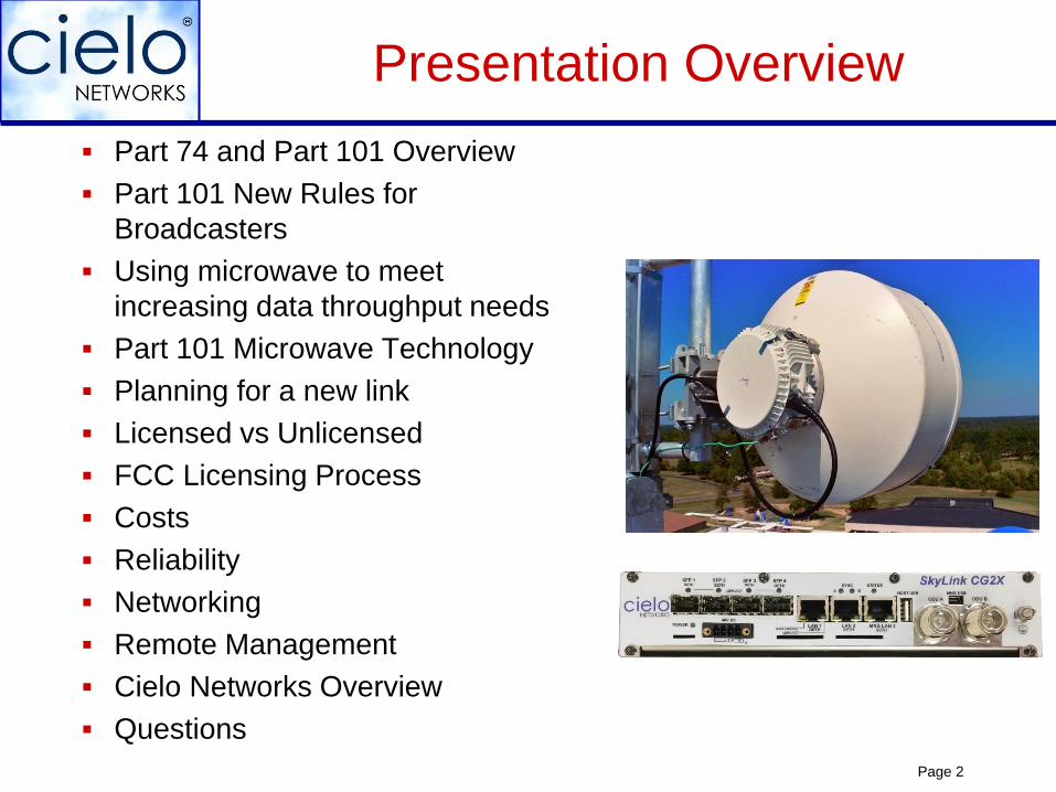
Presentation Overview
Part 74 and Part 101 Overview
Part 101 New Rules for
Broadcasters
Using microwave to meet
increasing data throughput needs
Part 101 Microwave Technology
Planning for a new link
Licensed vs Unlicensed
FCC Licensing Process
Costs
Reliability
Networking
Remote Management
Cielo Networks Overview
Questions
Page 3
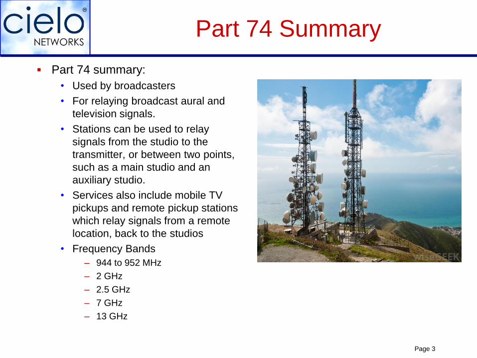
Part 74 Summary
Part 74 summary:
• Used by broadcasters
• For relaying broadcast aural and
television signals.
• Stations can be used to relay
signals from the studio to the
transmitter, or between two points,
such as a main studio and an
auxiliary studio.
• Services also include mobile TV
pickups and remote pickup stations
which relay signals from a remote
location, back to the studios
• Frequency Bands
– 944 to 952 MHz
– 2 GHz
– 2.5 GHz
– 7 GHz
– 13 GHz
Page 4
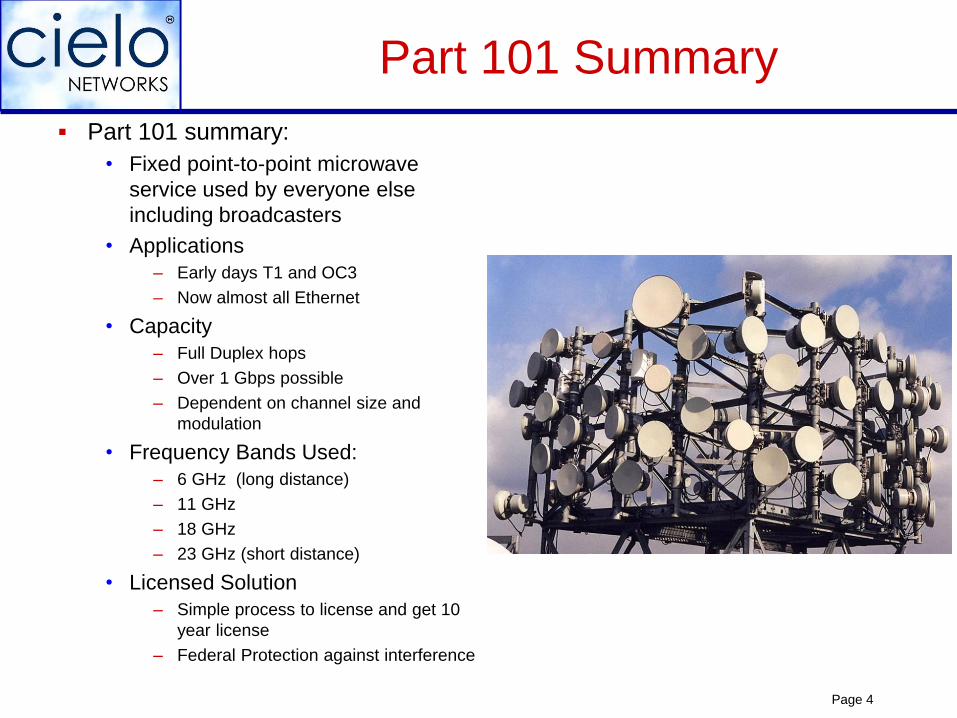
Part 101 Summary
Part 101 summary:
• Fixed point-to-point microwave
service used by everyone else
including broadcasters
• Applications
– Early days T1 and OC3
– Now almost all Ethernet
• Capacity
– Full Duplex hops
– Over 1 Gbps possible
– Dependent on channel size and
modulation
• Frequency Bands Used:
– 6 GHz (long distance)
– 11 GHz
– 18 GHz
– 23 GHz (short distance)
• Licensed Solution
– Simple process to license and get 10
year license
– Federal Protection against interference
Page 5
FCC Rules Change for
Common Carriers
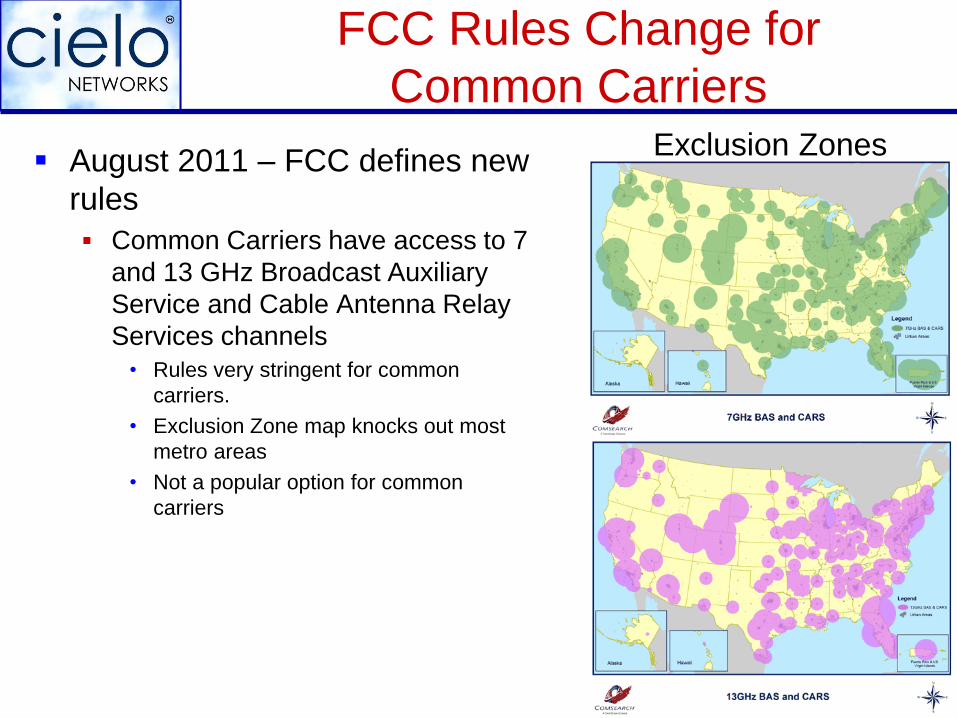
August 2011 – FCC defines new
rules
Common Carriers have access to 7
and 13 GHz Broadcast Auxiliary
Service and Cable Antenna Relay
Services channels
• Rules very stringent for common
carriers.
• Exclusion Zone map knocks out most
metro areas
• Not a popular option for common
carriers
Exclusion Zones
Page 6
FCC Rules Change
For Broadcasters Broadcasters have access to Part 101 frequencies –
eliminating the “Final mile” rule Opens up options for “final mile” needs for studio to
transmitter.
Primary or backup broadcast links at 6, 11, 18, and 23 GHz
These channels are full duplex.
Not only the Final Mile to the transmitter site: Use for out-of-band capacity for a high speed connection to
the transmitter site for remote management of equipment at site, remote file storage, surveillance, etc.
Consider new applications. Connect remote offices together with your own private network.
Page 7
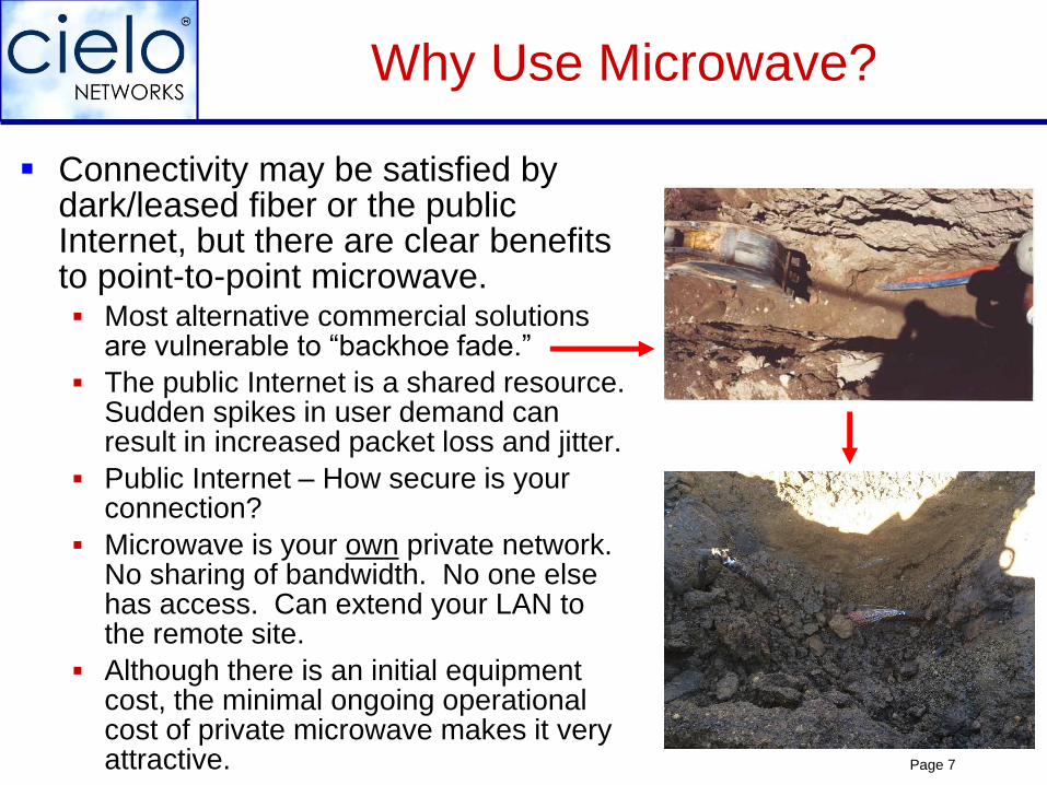
Connectivity may be satisfied by dark/leased fiber or the public Internet, but there are clear benefits to point-to-point microwave. Most alternative commercial solutions
are vulnerable to “backhoe fade.”
The public Internet is a shared resource. Sudden spikes in user demand can result in increased packet loss and jitter.
Public Internet – How secure is your connection?
Microwave is your own private network. No sharing of bandwidth. No one else has access. Can extend your LAN to the remote site.
Although there is an initial equipment cost, the minimal ongoing operational cost of private microwave makes it very attractive.
Why Use Microwave?
Page 8
Microwave and other technologies can be combined for even higher system reliability.
• Use it as a backup to your primary connection (alternative path protection)
Time to market for microwave – be connected in days.
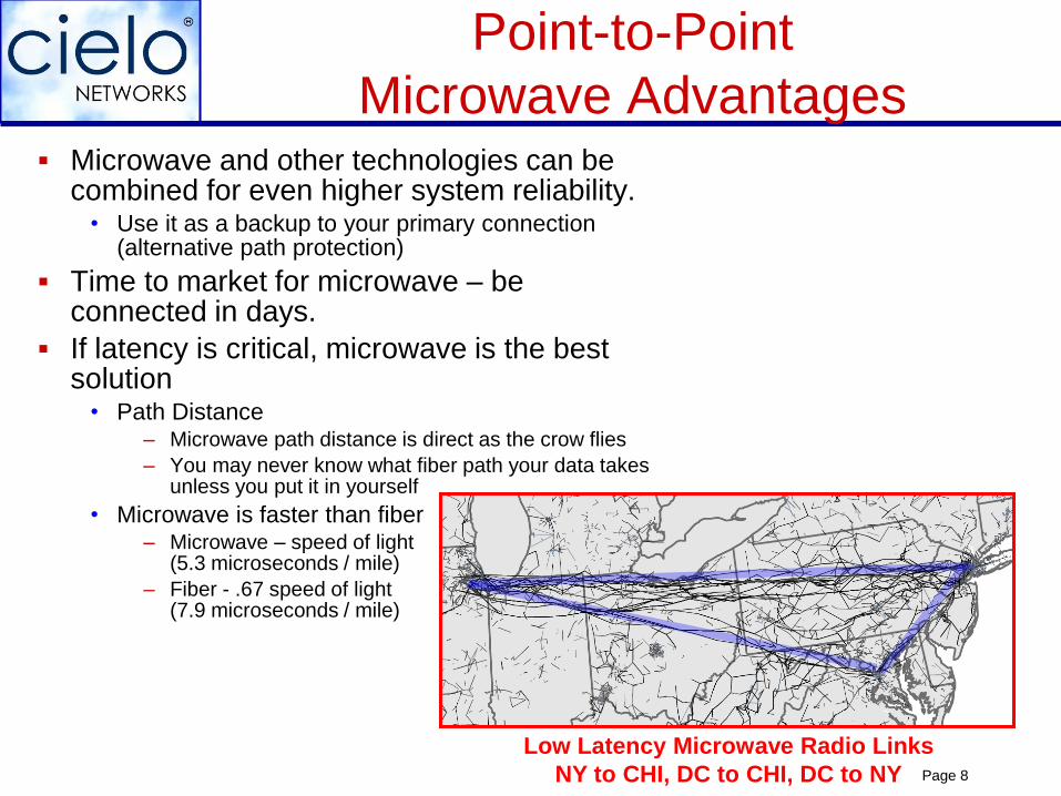
If latency is critical, microwave is the best solution
• Path Distance– Microwave path distance is direct as the crow flies
– You may never know what fiber path your data takes unless you put it in yourself
• Microwave is faster than fiber– Microwave – speed of light
(5.3 microseconds / mile)
– Fiber - .67 speed of light(7.9 microseconds / mile)
Point-to-Point
Microwave Advantages
Low Latency Microwave Radio Links
NY to CHI, DC to CHI, DC to NY
Page 9
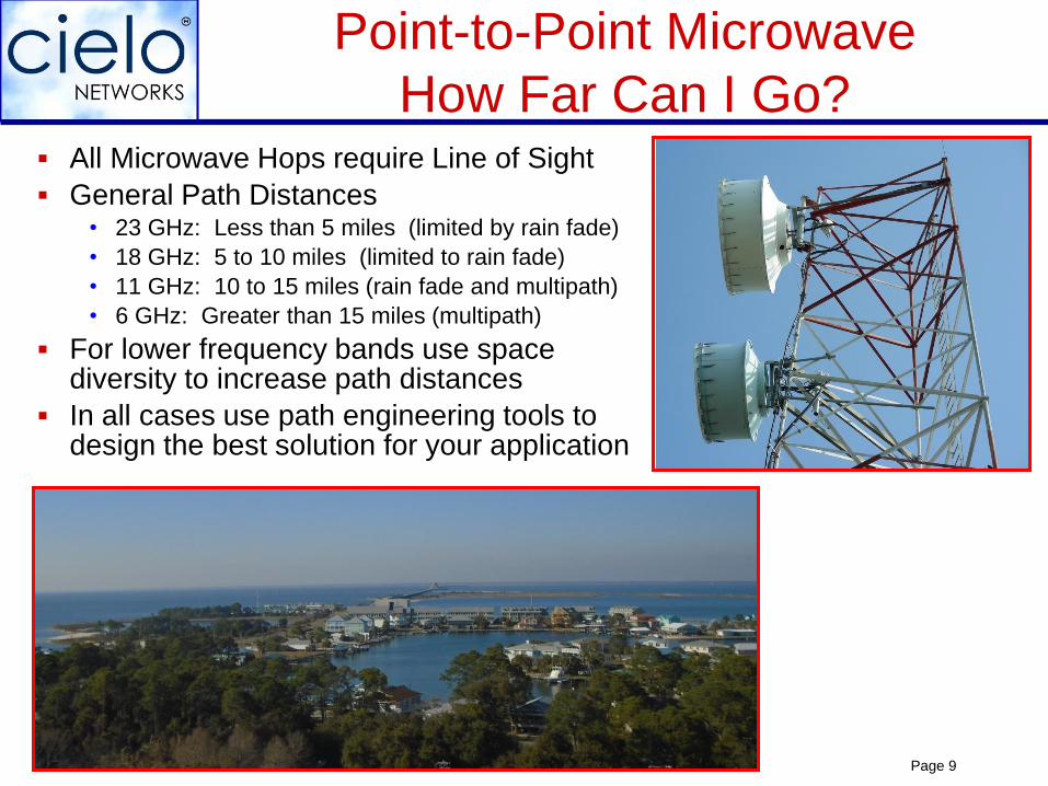
All Microwave Hops require Line of Sight
General Path Distances• 23 GHz: Less than 5 miles (limited by rain fade)
• 18 GHz: 5 to 10 miles (limited to rain fade)
• 11 GHz: 10 to 15 miles (rain fade and multipath)
• 6 GHz: Greater than 15 miles (multipath)
For lower frequency bands use space diversity to increase path distances
In all cases use path engineering tools to design the best solution for your application
Point-to-Point Microwave
How Far Can I Go?
Page 10
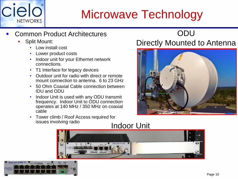
Common Product Architectures Split Mount:
• Low install cost
• Lower product costs
• Indoor unit for your Ethernet network connections.
• T1 Interface for legacy devices
• Outdoor unit for radio with direct or remote mount connection to antenna. 6 to 23 GHz
• 50 Ohm Coaxial Cable connection between IDU and ODU
• Indoor Unit is used with any ODU transmit frequency. Indoor Unit to ODU connection operates at 140 MHz / 350 MHz on coaxial cable
• Tower climb / Roof Access required for issues involving radio
Microwave Technology
Indoor Unit
ODU
Directly Mounted to Antenna

Page 11
Common Product Architectures Radio mounted indoors
• Product Cost – Similar to split mount
• Higher install cost – elliptical waveguide, dehydrator
• More rack space required for radio
• All electronics indoors – No need to climb the tower unless the antenna moves.
• 6 and 11 GHz – High Power Radios
Microwave Technology
1+1 HSB
Page 12
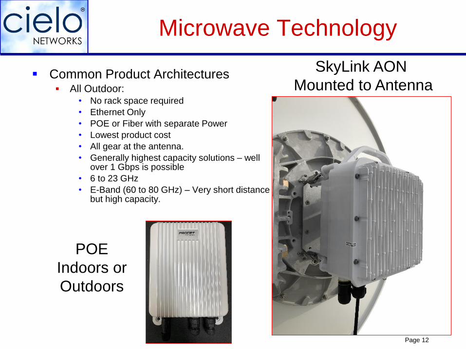
Common Product Architectures All Outdoor:
• No rack space required
• Ethernet Only
• POE or Fiber with separate Power
• Lowest product cost
• All gear at the antenna.
• Generally highest capacity solutions – well over 1 Gbps is possible
• 6 to 23 GHz
• E-Band (60 to 80 GHz) – Very short distance but high capacity.
Microwave Technology
SkyLink AON
Mounted to Antenna
POE
Indoors or
Outdoors
Page 13
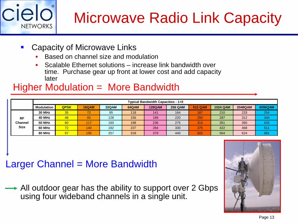
Capacity of Microwave Links Based on channel size and modulation
Scalable Ethernet solutions – increase link bandwidth over time. Purchase gear up front at lower cost and add capacity later
All outdoor gear has the ability to support over 2 Gbps using four wideband channels in a single unit.
Microwave Radio Link Capacity
Higher Modulation = More Bandwidth
Larger Channel = More Bandwidth
Modulation QPSK 16QAM 32QAM 64QAM 128QAM 256 QAM 512 QAM 1024 QAM 2048QAM 4096QAM
30 MHz 35 72 95 118 141 164 187 210 233 254
40 MHz 48 93 128 156 189 220 250 287 312 340
50 MHz 60 117 160 198 236 275 313 351 390 425
60 MHz 72 140 192 237 284 330 375 422 468 511
80 MHz 97 195 257 318 379 440 502 564 624 681
RF
Channel
Size
Typical Bandwidth Capacities - 1+0

Page 14
There are all types of antennas for different applications. Direct Mount up to 6 foot
Large antennas for long hops
High wind antenna
Extreme environment
Existing antenna – if in good shape can often be used
Antennas
Page 15
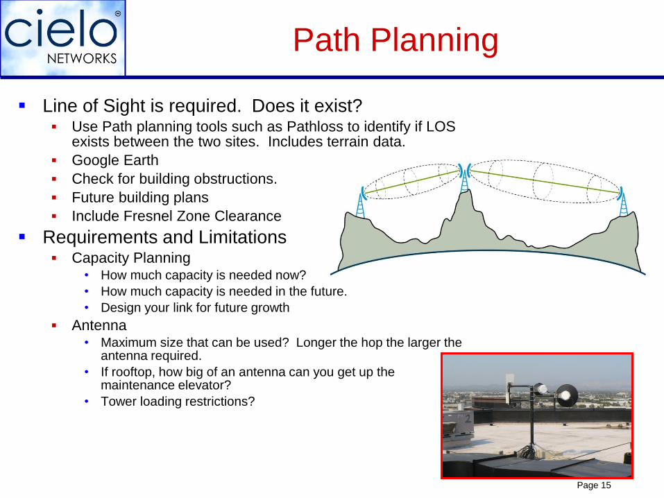
Line of Sight is required. Does it exist? Use Path planning tools such as Pathloss to identify if LOS
exists between the two sites. Includes terrain data.
Google Earth
Check for building obstructions.
Future building plans
Include Fresnel Zone Clearance
Requirements and Limitations Capacity Planning
• How much capacity is needed now?
• How much capacity is needed in the future.
• Design your link for future growth
Antenna• Maximum size that can be used? Longer the hop the larger the
antenna required.
• If rooftop, how big of an antenna can you get up the maintenance elevator?
• Tower loading restrictions?
Path Planning
Page 16
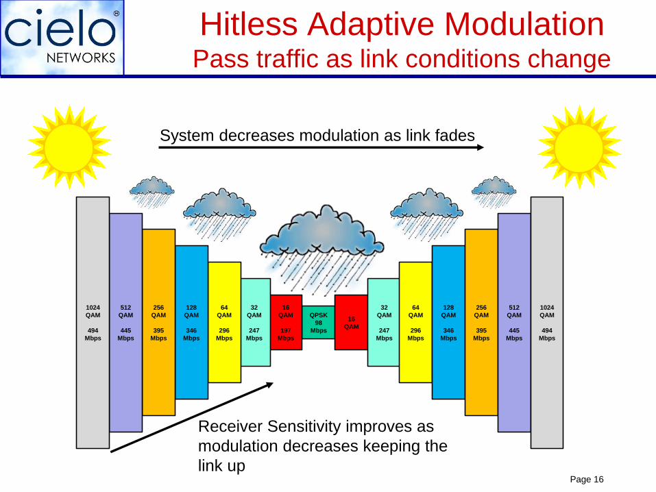
Hitless Adaptive ModulationPass traffic as link conditions change
QPSK
98
Mbps
16
QAM
32
QAM
247
Mbps
64
QAM
296
Mbps
128
QAM
346
Mbps
256
QAM
395
Mbps
512
QAM
445
Mbps
1024
QAM
494
Mbps
16
QAM
197
Mbps
32
QAM
247
Mbps
64
QAM
296
Mbps
128
QAM
346
Mbps
256
QAM
395
Mbps
512
QAM
445
Mbps
1024
QAM
494
Mbps
System decreases modulation as link fades
Receiver Sensitivity improves as
modulation decreases keeping the
link up
Page 17
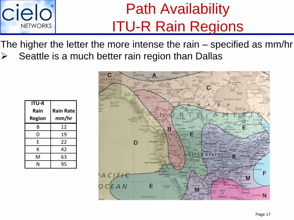
Path Availability
ITU-R Rain RegionsThe higher the letter the more intense the rain – specified as mm/hr
Seattle is a much better rain region than Dallas
ITU-R
Rain
Region
Rain Rate
mm/hr
B 12
D 19
E 22
K 42
M 63
N 95
Page 18
General Path Availability
Tables
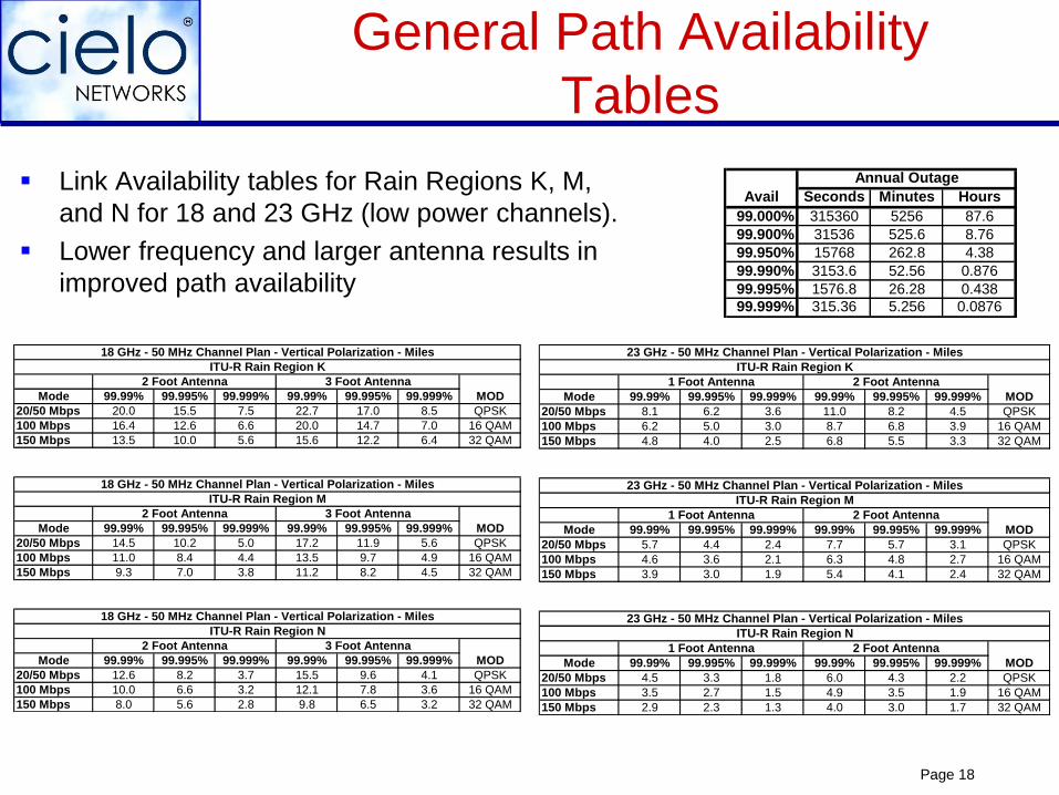
Mode 99.99% 99.995% 99.999% 99.99% 99.995% 99.999%
20/50 Mbps 20.0 15.5 7.5 22.7 17.0 8.5 QPSK
100 Mbps 16.4 12.6 6.6 20.0 14.7 7.0 16 QAM
150 Mbps 13.5 10.0 5.6 15.6 12.2 6.4 32 QAM
Mode 99.99% 99.995% 99.999% 99.99% 99.995% 99.999%
20/50 Mbps 14.5 10.2 5.0 17.2 11.9 5.6 QPSK
100 Mbps 11.0 8.4 4.4 13.5 9.7 4.9 16 QAM
150 Mbps 9.3 7.0 3.8 11.2 8.2 4.5 32 QAM
Mode 99.99% 99.995% 99.999% 99.99% 99.995% 99.999%
20/50 Mbps 12.6 8.2 3.7 15.5 9.6 4.1 QPSK
100 Mbps 10.0 6.6 3.2 12.1 7.8 3.6 16 QAM
150 Mbps 8.0 5.6 2.8 9.8 6.5 3.2 32 QAM
3 Foot Antenna
MOD
18 GHz - 50 MHz Channel Plan - Vertical Polarization - Miles
2 Foot Antenna 3 Foot Antenna
MOD
ITU-R Rain Region K
ITU-R Rain Region M
ITU-R Rain Region N
18 GHz - 50 MHz Channel Plan - Vertical Polarization - Miles
2 Foot Antenna 3 Foot Antenna
MOD
18 GHz - 50 MHz Channel Plan - Vertical Polarization - Miles
2 Foot Antenna
Mode 99.99% 99.995% 99.999% 99.99% 99.995% 99.999%
20/50 Mbps 8.1 6.2 3.6 11.0 8.2 4.5 QPSK
100 Mbps 6.2 5.0 3.0 8.7 6.8 3.9 16 QAM
150 Mbps 4.8 4.0 2.5 6.8 5.5 3.3 32 QAM
Mode 99.99% 99.995% 99.999% 99.99% 99.995% 99.999%
20/50 Mbps 5.7 4.4 2.4 7.7 5.7 3.1 QPSK
100 Mbps 4.6 3.6 2.1 6.3 4.8 2.7 16 QAM
150 Mbps 3.9 3.0 1.9 5.4 4.1 2.4 32 QAM
Mode 99.99% 99.995% 99.999% 99.99% 99.995% 99.999%
20/50 Mbps 4.5 3.3 1.8 6.0 4.3 2.2 QPSK
100 Mbps 3.5 2.7 1.5 4.9 3.5 1.9 16 QAM
150 Mbps 2.9 2.3 1.3 4.0 3.0 1.7 32 QAM
2 Foot Antenna
MOD
23 GHz - 50 MHz Channel Plan - Vertical Polarization - Miles
1 Foot Antenna 2 Foot Antenna
MOD
ITU-R Rain Region K
ITU-R Rain Region M
ITU-R Rain Region N
MOD
23 GHz - 50 MHz Channel Plan - Vertical Polarization - Miles
1 Foot Antenna 2 Foot Antenna
23 GHz - 50 MHz Channel Plan - Vertical Polarization - Miles
1 Foot Antenna
Seconds Minutes Hours
99.000% 315360 5256 87.6
99.900% 31536 525.6 8.76
99.950% 15768 262.8 4.38
99.990% 3153.6 52.56 0.876
99.995% 1576.8 26.28 0.438
99.999% 315.36 5.256 0.0876
Annual Outage
Avail Link Availability tables for Rain Regions K, M,
and N for 18 and 23 GHz (low power channels).
Lower frequency and larger antenna results in
improved path availability

Page 19
Site Survey Generally done after the Path analysis that confirms line of
sight, what antenna size is required in order to meet your requirements.
Can you get access necessary to put up the link?
Where is the IDU going to be installed?
Cable run from the IDU to the ODU / antenna?
Space available on tower or rooftop
Tower analysis required with the new antenna load?
Radio Link Planning
Page 20
Unlicensed vs. Licensed Bands
Unlicensed band users have: no vested rights or “first use” preference
no formal recourse against interferers
Unlicensed bands increasingly congested Permanent or random interference common
Link QOS suffers, link revenues always at risk
Any functional link often impossible
Costs of interference investigation & resolution, if even
possible, are substantial - truck rolls, spectrum
analysis, finding interferers, tower climbs, etc.
FCC licensed links insure carrier grade QOS Area frequency exclusivity insures interference free channel
License initial validity of 10 years insures interference
immunity at reasonable cost: • Commercial user typically < $1/day
• Government or non-profit user typically < 50 cents/day
Page 21
FCC Licensing
Simple – straight forward process
Use license coordinators to perform the coordination, PCN, and
application submittal Comsearch – Ashburn, VA
Radyn – Bethesda, MD
Micronet – Plano, TX
Cost: Less than $2500 per hop turnkey
Page 22
FCC Licensing
New links can only be licensed if they do not interfere with existing links
FCC license is valid for 10 years – can be renewed
Typical period from initiation of licensing process until link can be
turned up is 35 – 40 days:
5 days for engineering
15 (expedited) to 30 days PCN letter distribution
1 to 2 days for filing FCC application
Once the FCC application is filed a link can be turned up and operated
“conditionally”
Exception is 23 GHz High Power Channels – can take 2 to 3 months for
issuance of license and the ability to start transmitting
FCC has 18 GHz quiet zones – Baltimore and Denver area
Once link is turned-up, file Notice of Completion. 18 months from
application date to get link turned-up.
Page 23
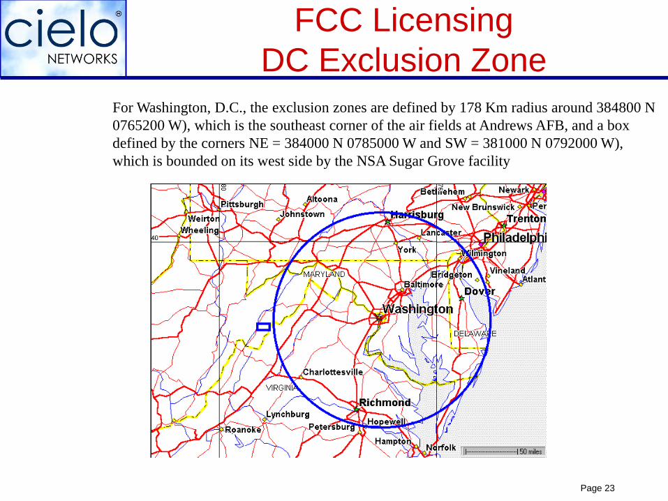
FCC Licensing
DC Exclusion Zone
For Washington, D.C., the exclusion zones are defined by 178 Km radius around 384800 N
0765200 W), which is the southeast corner of the air fields at Andrews AFB, and a box
defined by the corners NE = 384000 N 0785000 W and SW = 381000 N 0792000 W),
which is bounded on its west side by the NSA Sugar Grove facility
Page 24
Antenna Sizes
FCC Requirements
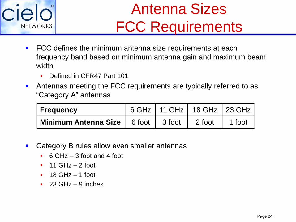
FCC defines the minimum antenna size requirements at each
frequency band based on minimum antenna gain and maximum beam
width
Defined in CFR47 Part 101
Antennas meeting the FCC requirements are typically referred to as
“Category A” antennas
Category B rules allow even smaller antennas
6 GHz – 3 foot and 4 foot
11 GHz – 2 foot
18 GHz – 1 foot
23 GHz – 9 inches
Frequency 6 GHz 11 GHz 18 GHz 23 GHz
Minimum Antenna Size 6 foot 3 foot 2 foot 1 foot
Page 25
Maximum Channel Size
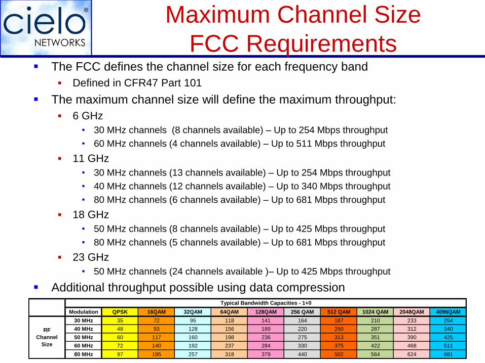
FCC Requirements The FCC defines the channel size for each frequency band
Defined in CFR47 Part 101
The maximum channel size will define the maximum throughput:
6 GHz
• 30 MHz channels (8 channels available) – Up to 254 Mbps throughput
• 60 MHz channels (4 channels available) – Up to 511 Mbps throughput
11 GHz
• 30 MHz channels (13 channels available) – Up to 254 Mbps throughput
• 40 MHz channels (12 channels available) – Up to 340 Mbps throughput
• 80 MHz channels (6 channels available) – Up to 681 Mbps throughput
18 GHz
• 50 MHz channels (8 channels available) – Up to 425 Mbps throughput
• 80 MHz channels (5 channels available) – Up to 681 Mbps throughput
23 GHz
• 50 MHz channels (24 channels available )– Up to 425 Mbps throughput
Additional throughput possible using data compression
Modulation QPSK 16QAM 32QAM 64QAM 128QAM 256 QAM 512 QAM 1024 QAM 2048QAM 4096QAM
30 MHz 35 72 95 118 141 164 187 210 233 254
40 MHz 48 93 128 156 189 220 250 287 312 340
50 MHz 60 117 160 198 236 275 313 351 390 425
60 MHz 72 140 192 237 284 330 375 422 468 511
80 MHz 97 195 257 318 379 440 502 564 624 681
RF
Channel
Size
Typical Bandwidth Capacities - 1+0
Page 26
General Cost of Part 101 Gear
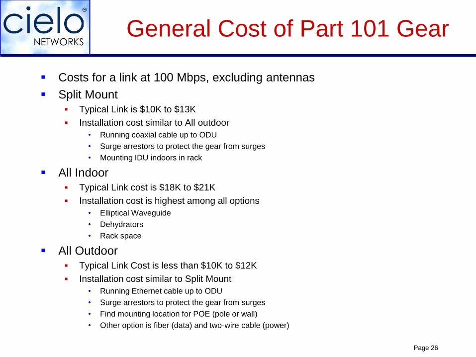
Costs for a link at 100 Mbps, excluding antennas
Split Mount Typical Link is $10K to $13K
Installation cost similar to All outdoor
• Running coaxial cable up to ODU
• Surge arrestors to protect the gear from surges
• Mounting IDU indoors in rack
All Indoor Typical Link cost is $18K to $21K
Installation cost is highest among all options
• Elliptical Waveguide
• Dehydrators
• Rack space
All Outdoor Typical Link Cost is less than $10K to $12K
Installation cost similar to Split Mount
• Running Ethernet cable up to ODU
• Surge arrestors to protect the gear from surges
• Find mounting location for POE (pole or wall)
• Other option is fiber (data) and two-wire cable (power)
Page 27Cielo Networks, Inc. - Proprietary
Reliability of Microwave Gear
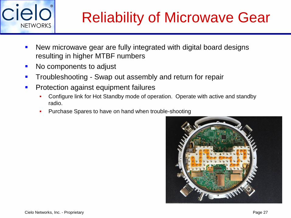
New microwave gear are fully integrated with digital board designs
resulting in higher MTBF numbers
No components to adjust
Troubleshooting - Swap out assembly and return for repair
Protection against equipment failures Configure link for Hot Standby mode of operation. Operate with active and standby
radio.
Purchase Spares to have on hand when trouble-shooting
Page 28
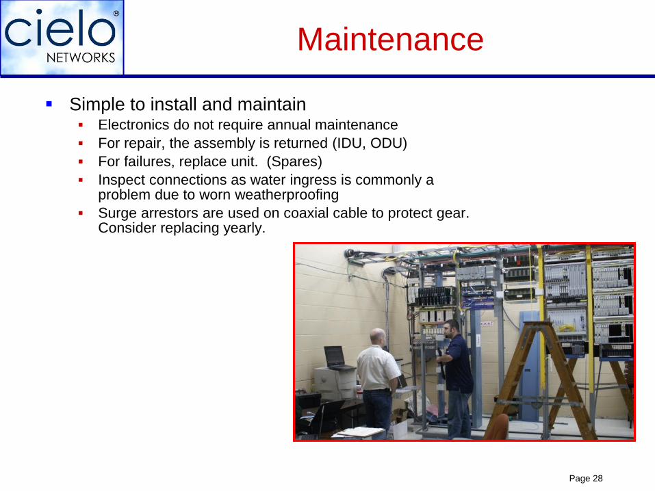
Simple to install and maintain Electronics do not require annual maintenance
For repair, the assembly is returned (IDU, ODU)
For failures, replace unit. (Spares)
Inspect connections as water ingress is commonly a problem due to worn weatherproofing
Surge arrestors are used on coaxial cable to protect gear. Consider replacing yearly.
Maintenance
Page 29
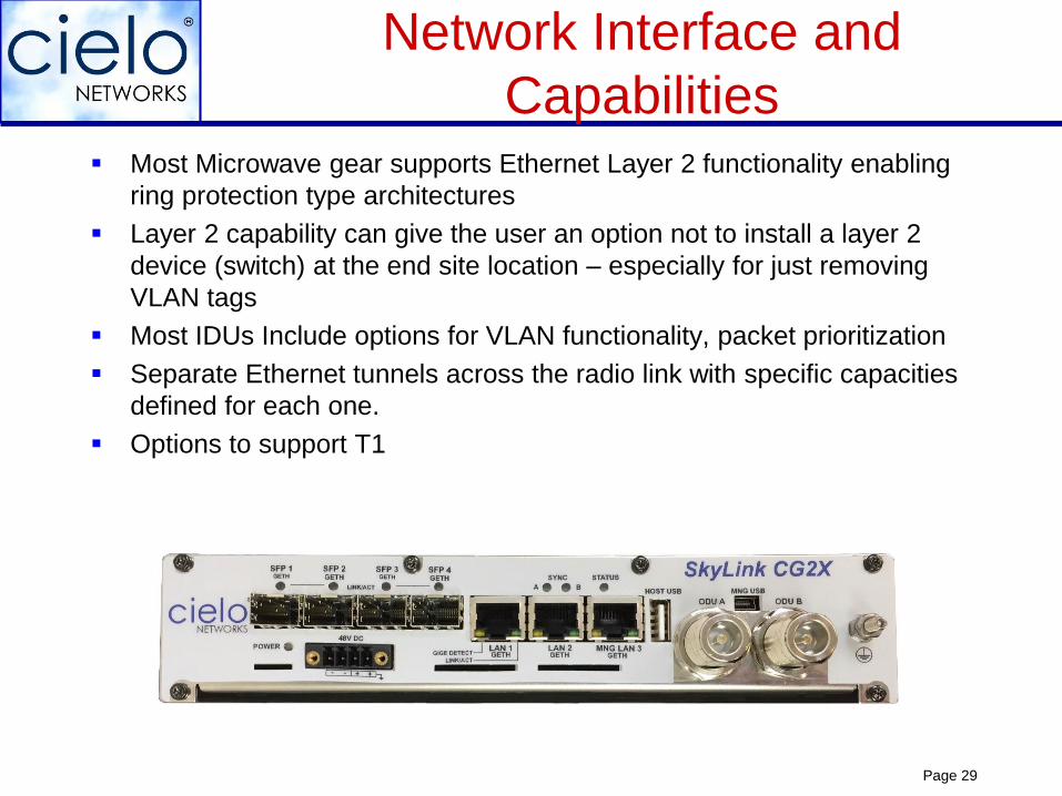
Network Interface and
Capabilities Most Microwave gear supports Ethernet Layer 2 functionality enabling
ring protection type architectures
Layer 2 capability can give the user an option not to install a layer 2
device (switch) at the end site location – especially for just removing
VLAN tags
Most IDUs Include options for VLAN functionality, packet prioritization
Separate Ethernet tunnels across the radio link with specific capacities
defined for each one.
Options to support T1
Page 30
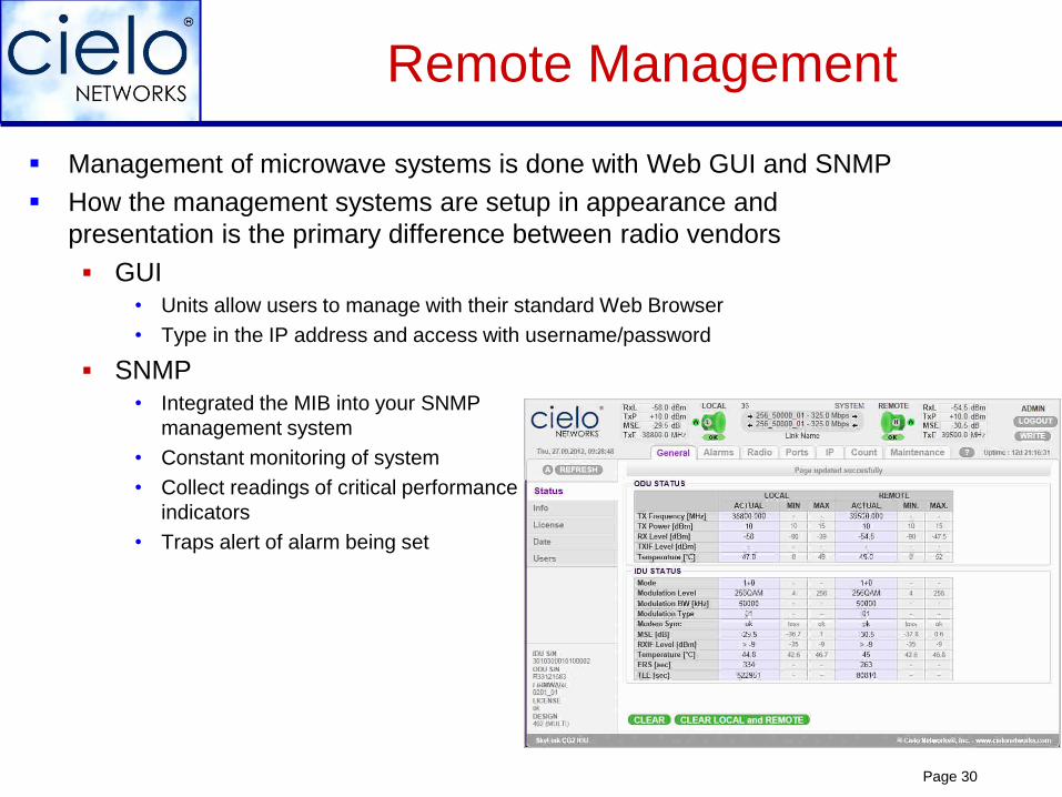
Remote Management
Management of microwave systems is done with Web GUI and SNMP
How the management systems are setup in appearance and
presentation is the primary difference between radio vendors
GUI• Units allow users to manage with their standard Web Browser
• Type in the IP address and access with username/password
SNMP• Integrated the MIB into your SNMP
management system
• Constant monitoring of system
• Collect readings of critical performance
indicators
• Traps alert of alarm being set

Page 31
Company Overview
20+ year old microwave company focused specifically on Fixed Wireless products (MW & MMW)
Based in San Diego, CA area.
Serve a diverse customer base (public, private and government)
Customers & networks throughout USA and internationally
All systems FCC, NTIA & ETSI compliant/certified
Assist customers with network design, training, field support, 3rd party equipment, & technical expertise/consulting
Numerous alliances and relationships with nationwide installers & integrators
Superb credit rating & highly capitalized. No debt
Strong customer reputation
Page 32
Company History
Early 2000s, focused on E-rate customers. Deployed several thousand links to support K-12 school systems in 40+ States
Expanded customer base to reach Business to Business ISP market and Federal, State and Local Government customers (Cielo products are certified to be deployed at DOD locations and other sensitive 3 letter government agencies)
Grew customer portfolio to include rural Telcos, ISPs, a few international carriers and CenturyLink (Southeast U.S.)
Developed Ultra-Low Latency products for High Frequency Trading segment. Maintain roughly 60-70% market share of HFT business
Advancing in new markets with high capacity all outdoor
microwave and millimeter wave solutions
Page 33
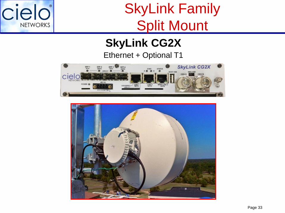
SkyLink Family
Split MountSkyLink CG2XEthernet + Optional T1
Page 34
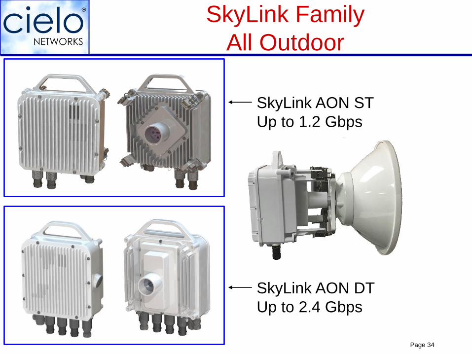
SkyLink Family
All Outdoor
SkyLink AON ST
Up to 1.2 Gbps
SkyLink AON DT
Up to 2.4 Gbps
Page 35
Contact Information
Sale Lilly – sales
662-316-0212
Brian Wright – technical
972-273-0680
Web: www.cielonetworks.com
HQ: San Diego, CA
Page 36
Questions?
Page 37Cielo Networks, Inc. - Proprietary
Thank You