
leonard l. williams justice center 7th floor fit-out may 2, 2019 ...
369
LEONARD L. WILLIAMS JUSTICE CENTER 7 TH FLOOR FIT-OUT MAY 2, 2019 #MJ0217000001 TEVEBAUGH ARCHITECTURE ADDENDUM #2 TA PROJECT NO. 17042 00 91 04 - 1 SECTION 00 91 04 ADDENDUM #4 1. PROJECT INFORMATION A. Project Name: 7 th Floor Fit-Out B. Owner: Administrative Offices of the Courts C. Civil Engineer: N/A D. Architect: Tevebaugh Architecture E. Structural Engineer: MacIntosh Engineering F. MPE Engineer: DEDC, LLC G. Architect Project Number: #17042 H. Date of Addendum: May 2, 2019 2. NOTICE TO BIDDERS A. This Addendum is issued to all registered plan holders pursuant to the Conditions of the Contract. This Addendum serves to clarify, revise, and supersede information in the Project Manual, Drawings, and previously issued Addenda. Portions of the Addendum affecting the Contract Documents shall be incorporated into the Contract by enumeration of the Addendum in the Owner/Contractor Agreement. B. The Bidder shall acknowledge receipt of this Addendum to the Architect / Owner. C. The date for receipt of bids is not changed by this Addendum, at the same time and location. 3. ATTACHMENTS A. This addendum includes the following attached Documents and Specification Sections: 1. Specification Section 00 41 13 – Bid Form 2. Specification Section 00 73 46 – Wage Determination Schedule – Page 2 3. Specification Section 01 10 00 – Summary of Work 4. Specification Section 01 21 00 – Allowances 5. Specification Section 01 22 00 – Unit Prices 6. Specification Section 27 10 00 – BSD – Structured Cabling 7. Specification Section 27 40 00 – Audio and Video Communication
-
Upload
khangminh22 -
Category
Documents
-
view
0 -
download
0
Transcript of leonard l. williams justice center 7th floor fit-out may 2, 2019 ...
LEONARD L. WILLIAMS JUSTICE CENTER 7TH FLOOR FIT-OUT MAY 2, 2019 #MJ0217000001
TEVEBAUGH ARCHITECTURE ADDENDUM #2 TA PROJECT NO. 17042 00 91 04 - 1
SECTION 00 91 04
ADDENDUM #4
1. PROJECT INFORMATION
A. Project Name: 7th Floor Fit-Out
B. Owner: Administrative Offices of the Courts
C. Civil Engineer: N/A
D. Architect: Tevebaugh Architecture
E. Structural Engineer: MacIntosh Engineering
F. MPE Engineer: DEDC, LLC
G. Architect Project Number: #17042
H. Date of Addendum: May 2, 2019
2. NOTICE TO BIDDERS
A. This Addendum is issued to all registered plan holders pursuant to the Conditions of the Contract. This Addendum serves to clarify, revise, and supersede information in the Project Manual, Drawings, and previously issued Addenda. Portions of the Addendum affecting the Contract Documents shall be incorporated into the Contract by enumeration of the Addendum in the Owner/Contractor Agreement.
B. The Bidder shall acknowledge receipt of this Addendum to the Architect / Owner.
C. The date for receipt of bids is not changed by this Addendum, at the same time and location.
3. ATTACHMENTS
A. This addendum includes the following attached Documents and Specification Sections:
1. Specification Section 00 41 13 – Bid Form 2. Specification Section 00 73 46 – Wage Determination Schedule – Page 2 3. Specification Section 01 10 00 – Summary of Work 4. Specification Section 01 21 00 – Allowances 5. Specification Section 01 22 00 – Unit Prices 6. Specification Section 27 10 00 – BSD – Structured Cabling 7. Specification Section 27 40 00 – Audio and Video Communication
7TH FLOOR FIT-OUT LEONARD L. WILLIAMS JUSTICE CENTER #MJ0217000001 MAY 2, 2019
ADDENDUM #2 TEVEBAUGH ARCHITECTURE 00 91 04 - 2 TA PROJECT NO. 17042
8. Drawing Sheet A404 – Enlarged Plans & Reflected Ceiling Plans – Courtroom 7A and 7F
9. Drawing Sheet A408 – Enlarged Elevations – Courtroom 7A and 7F 10. Drawing Sheet A501 – Millwork Plans & Elevations – Courtrooms 7A 11. Drawing Sheet A502 – Millwork Plans & Elevations – Courtrooms 7B & 7C, 7D 12. Drawing Sheet A503 – Millwork Plans & Elevations – Courtrooms 7E 13. Drawing Sheet A504 – Millwork Plans & Elevations – Courtrooms 7F 14. Drawing Sheet A511 – Millwork Details - Courtrooms 15. Drawing Sheet A521 – Ceiling Details 16. Drawing Sheet M100a – Mechanical – 7th Floor Ductwork Area A 17. Drawing Sheet M100b – mechanical – 7th Floor Ductwork Area B 18. Drawing Sheet M110 – Mechanical – 7th Floor Reflected Ceiling Plan 19. Drawing Sheet E100 – Electrical New Work 7th Floor Power Plan 20. Drawing Sheet E200 – Electrical New Work 7th Floor Lighting Plan 21. Drawing Sheet E400 – Electrical – Courtroom 7A & 7F Lighting Plans 22. Drawing Sheet E401 – Electrical – Courtroom 7E Lighting Plan 23. Drawing Sheet SAD000 – General Notes, Legends, & Abbreviations 24. Drawing Sheet SAD100 – Security – New Work – 7th Floor – Diagram 25. Drawing Sheet SAD110 – Security – New Work – 7th Floor – Overall 26. Drawing Sheet SAD200 – AV Flow Diagram – New Work – 7th Floor (1 of 4) 27. Drawing Sheet SAD201 – AV Flow Diagram – New Work – 7th Floor (2 of 4) 28. Drawing Sheet SAD202 – AV Flow Diagram – New Work - 7th Floor (3 of 4) 29. Drawing Sheet SAD203 – AV Flow Diagram – new Work – 7th Floor (4 of 4) 30. Drawing Sheet SAD210 – AV – New Work – 7th Floor 31. Drawing Sheet SAD211 – AV – New Work – 7th Floor – Courts 7A, 7B, 7C, & 7D 32. Drawing Sheet SAD212 – AV – New Work – 7th Floor – Court 7E 33. Drawing Sheet SAD213 – AV – New Work – 7th Floor – Court 7F 34. Drawing Sheet SAD310 – Data – New Work – 7th Floor
4. REVISIONS TO PREVIOUS ADDENDA
A. REVISE specification section 00 91 03 “Addendum #3” footer from 00 91 02 to 00 91 03.
5. REVISIONS TO DIVISIONS 00 and 33 OF THE SPECIFICATIONS
A. Specification section 00 41 13 – Bid Form
1. REPLACE specification section 00 41 13 “Bid Form” in its entirety with the attached specification section 00 41 13 “Bid Form.”
LEONARD L. WILLIAMS JUSTICE CENTER 7TH FLOOR FIT-OUT MAY 2, 2019 #MJ0217000001
TEVEBAUGH ARCHITECTURE ADDENDUM #2 TA PROJECT NO. 17042 00 91 04 - 3
B. Specification Section 00 73 46 – Wage Determination Schedule
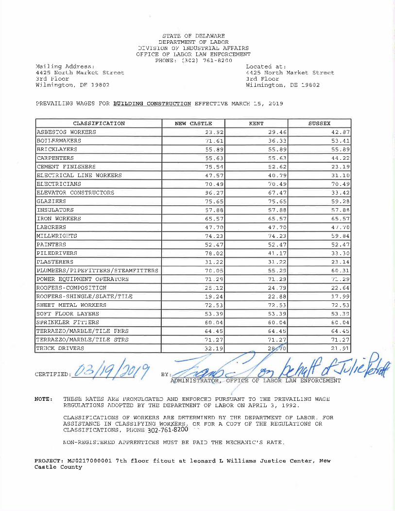
1. REPLACE PAGE 2 of specification section 00 73 46 “Wage Determination Schedule” with the attached Page 2 (Prevailing Wage Schedule).
C. Specification Section 01 10 00 – Summary of Work
1. REVISE specification section 01 10 00 “Summary of Work” in accordance with attached specification section 01 10 00 “Summary of Work”. Removed wording has been struck through. Added working has been bolded.
D. Specification section 01 21 00 - Allowances
1. REVISE specification section 01 21 00 “Allowances” in accordance with attached specification section 01 21 00 “Allowances”. Removed wording has been struck through. Added working has been bolded.
E. Specification section 01 22 00 - Unit Prices
1. REVISE specification section 01 22 00 “Unit Prices” in accordance with attached specification section 01 22 00 “Unit Prices”. Removed wording has been struck through. Added working has been bolded
F. Specification Section 27 10 00 – BSD – Structured Cabling
1. REPLACE specification section 27 10 00 “BSD – Structured Cabling” in its entirety.
G. Specification Section 27 40 00 – Audio and Video Communication
1. REPLACE specification section 27 40 00 “Audio and Video Communication” in its entirety.
6. REVISIONS TO DRAWING SHEETS
A. Drawing Sheet A404 – Enlarged Plans & Reflected Ceiling Plans – Courtroom 7A and
7F
1. REVISE sheet A404 in accordance with attached sheet A404. All changes have been clouded.
B. Drawing Sheet A408 – Enlarged Elevations – Courtroom 7A and 7F
1. REVISE sheet A408 in accordance with attached sheet A408. All changes have been clouded.
7TH FLOOR FIT-OUT LEONARD L. WILLIAMS JUSTICE CENTER #MJ0217000001 MAY 2, 2019
ADDENDUM #2 TEVEBAUGH ARCHITECTURE 00 91 04 - 4 TA PROJECT NO. 17042
C. Drawing Sheet A501 – Millwork Plans & Elevations – Courtrooms 7A
1. REVISE sheet A501 in accordance with attached sheet A501. All changes have been clouded.
D. Drawing Sheet A502 – Millwork Plans & Elevations – Courtrooms 7B & 7C, 7D
1. REVISE sheet A502 in accordance with attached sheet A502. All changes have been clouded.
E. Drawing Sheet A503 – Millwork Plans & Elevations – Courtrooms 7E
1. REVISE sheet A503 in accordance with attached sheet A503. All changes have been clouded.
F. Drawing Sheet A504 – Millwork Plans & Elevations – Courtrooms 7F
1. REVISE sheet A504 in accordance with attached sheet A504. All changes have been clouded.
G. Drawing Sheet A511 – Millwork Details - Courtrooms
1. REVISE sheet A511 in accordance with attached sheet A511. All changes have been clouded.
H. Drawing Sheet A521 – Ceiling Details
1. REVISE sheet A521 in accordance with attached sheet A521. All changes have been clouded.
I. Drawing Sheet M100a – Mechanical – 7th Floor Ductwork Area A
1. REVISE sheet M100a in accordance with attached sheet M100a. All changes have been clouded.
J. Drawing Sheet M100b – mechanical – 7th Floor Ductwork Area B
1. REVISE sheet M100b in accordance with attached sheet M100b. All changes have been clouded.
K. Drawing Sheet M110 – Mechanical – 7th Floor Reflected Ceiling Plan
1. REVISE sheet M110 in accordance with attached sheet M110. All changes have been clouded.
LEONARD L. WILLIAMS JUSTICE CENTER 7TH FLOOR FIT-OUT MAY 2, 2019 #MJ0217000001
TEVEBAUGH ARCHITECTURE ADDENDUM #2 TA PROJECT NO. 17042 00 91 04 - 5
L. Drawing Sheet E100 – Electrical New Work 7th Floor Power Plan
1. REVISE sheet E100 in accordance with attached sheet E100. All changes have been clouded.
M. Drawing Sheet E200 – Electrical New Work 7th Floor Lighting Plan
1. REVISE sheet E200 in accordance with attached sheet E200. All changes have been clouded.
N. Drawing Sheet E400 – Electrical – Courtroom 7A & 7F Lighting Plans
1. REVISE sheet E400 in accordance with attached sheet E400. All changes have been clouded.
O. Drawing Sheet E401 – Electrical – Courtroom 7E Lighting Plan
1. REVISE sheet E401 in accordance with attached sheet E401. All changes have been clouded.
P. Drawing Sheet SAD000 – General Notes, Legends, & Abbreviations
1. REVISE sheet SAD000 in accordance with attached sheet SAD000. All changes have been clouded.
Q. Drawing Sheet SAD100 – Security – New Work – 7th Floor – Diagram
1. REVISE sheet SAD100 in accordance with attached sheet SAD100. All changes have been clouded.
R. Drawing Sheet SAD110 – Security – New Work – 7th Floor – Overall
1. REVISE sheet SAD110 in accordance with attached sheet SAD110. All changes have been clouded.
S. Drawing Sheet SAD200 – AV Flow Diagram – New Work – 7th Floor (1 of 4)
1. REVISE sheet SAD200 in accordance with attached sheet SAD200. All changes have been clouded.
T. Drawing Sheet SAD201 – AV Flow Diagram – New Work – 7th Floor (2 of 4)
1. REVISE sheet SAD201 in accordance with attached sheet SAD201. All changes have been clouded.
7TH FLOOR FIT-OUT LEONARD L. WILLIAMS JUSTICE CENTER #MJ0217000001 MAY 2, 2019
ADDENDUM #2 TEVEBAUGH ARCHITECTURE 00 91 04 - 6 TA PROJECT NO. 17042
U. Drawing Sheet SAD202 – AV Flow Diagram – New Work - 7th Floor (3 of 4)
1. REVISE sheet SAD202 in accordance with attached sheet SAD202. All changes have been clouded.
V. Drawing Sheet SAD203 – AV Flow Diagram – new Work – 7th Floor (4 of 4)
1. REVISE sheet SAD203 in accordance with attached sheet SAD203. All changes have been clouded.
W. Drawing Sheet SAD210 – AV – New Work – 7th Floor
1. REVISE sheet SAD210 in accordance with attached sheet SAD210. All changes have been clouded.
X. Drawing Sheet SAD211 – AV – New Work – 7th Floor – Courts 7A, 7B, 7C, & 7D
1. REVISE sheet SAD211 in accordance with attached sheet SAD211. All changes have been clouded.
Y. Drawing Sheet SAD212 – AV – New Work – 7th Floor – Court 7E
1. REVISE sheet SAD212 in accordance with attached sheet SAD212. All changes have been clouded.
Z. Drawing Sheet SAD213 – AV – New Work – 7th Floor – Court 7F
1. REVISE sheet SAD213 in accordance with attached sheet SAD213. All changes have been clouded.
AA. Drawing Sheet SAD310 – Data – New Work – 7th Floor
1. REVISE sheet SAD310 in accordance with attached sheet SAD310. All changes have been clouded.
7. BIDDER’S QUESTIONS received through April 26th, 2019 at 8am.
Q1. I noticed in the presentation today that a schedule of values is required to be submitted with our bid form. This is normally submitted post bid and we are very rushed on bid day trying to get the paperwork in order. Can this requirement be changed to post bid like the drug forms and other documents?
A1: The Schedule of Values will be due within 18 days of award of bid along with the Drug Testing Forms (Specification Section 00 81 14) and the Affidavit of Employee Drug Testing Program (Specification Section 00 41 13). Previously answered in Addendum #1.
LEONARD L. WILLIAMS JUSTICE CENTER 7TH FLOOR FIT-OUT MAY 2, 2019 #MJ0217000001
TEVEBAUGH ARCHITECTURE ADDENDUM #2 TA PROJECT NO. 17042 00 91 04 - 7
Q2. I noticed today that the recessed concrete slab areas are very rough and uneven. Will any grinding, levelling, or patching be required at these floor areas?
A2: The recessed floor areas will receive a raised floor. The surface of the recessed slab shall meet the raised floor manufacture’s requirements for installation. Edges of the upper slab around the recessed slab shall be patched as required to properly install the flooring in those areas per the flooring manufacturer’s requirements for installation. Previously answered in Addendum #2.
Q3. I was wondering if the State could provide the name of the company that does maintenance of the glass curtainwall so that we could contact them about removing and replacing pieces to accommodate the construction elevator? A3: The company that the facility has had success with in the past is:
Patrick McIntyre Synergy Glass & Door Service 1116 MacDade Blvd. Unit G Collingdale, PA 19023 Phone: (484) 540-3117 Fax: (484) 540-3124 [email protected] www.synergyglassanddoor.com Previously answered in Addendum #1.
Q4. ModernControls is requesting that Johnson Controls FX by ModernControls be added as a Pre-Approved State of Delaware Building Automation System Product / Manufacture.
A4: Per specification section 23 09 50-2.01-C, please see section 01 25 00 – Substitution Procedures. Previously answered in Addendum #2.
Q5. At the pre-bid meeting there was mention that the project is to be done between the hours of 4:30pm to 7:00am. Please confirm.
A5: The hours set forth in specification section 01 14 00-1.2-B-1, issued with this addendum, are to be considered typical owner occupancy hours. All other hours are to be considered to be the typical available working hours. The site superintendent will need to coordinate with Capitol Police weekly and daily to find out about any other special proceedings or special owner occupancy hours. When extended occupancy hours occur, the superintendent can choose to schedule the contractors differently or start with only work that adheres to the general guidelines for restrictions of work during owner occupied hours, as set forth in specification section 01 14 00-1.4-A. Previously answered in Addendum #2.

7TH FLOOR FIT-OUT LEONARD L. WILLIAMS JUSTICE CENTER #MJ0217000001 MAY 2, 2019
ADDENDUM #2 TEVEBAUGH ARCHITECTURE 00 91 04 - 8 TA PROJECT NO. 17042
Q6. Please identify the project start and finish dates. A6: The start date shall be addressed once the successful bidder has received their
Purchase Order from the State and the Pre-Construction meeting has been scheduled. Bidders are to include a schedule with their bids. Previously answered in Addendum #2.
Q7. Per the walk thru there was discussion in regards to the items that are being stored in
the space. A7: Per General Note H. on drawing sheets AD101a, AD101b, AD102a, and
AD102b, all items left are to be removed and disposed of. Bidders shall assume that everything present in the space during bidding will be remaining at the time of construction start. Previously answered in Addendum #2.
Q8. 3-D Fabrication is requesting that the AWI Certification “Stamp on Submittals” be waived. Although 3-D Fabrication meets all standards that the AWI Certification requires, we are not officially certified.
A8: The AWI Certification requirement will not be waived for this project. Previously answered in Addendum #2.
Q9. The tile carpeting spec is listed in the TOC but is not in the spec book.
A9: The Tile Carpeting specification has been added to the bidding documents via this addendum. Previously answered in Addendum #2.
Q10. The spec section 087100 under hardware sets says to match the existing key system. Can you tell us what this is?
A10: The existing cores are 7 pin interchangeable (Coremax), from Best Access Systems. The keying system is patented and the cores and keys will have to be purchased through and authorized dealer and coordinated with the state. The state currently uses General Supply Company in Bethlehem, PA. Previously answered in Addendum #3.
LEONARD L. WILLIAMS JUSTICE CENTER 7TH FLOOR FIT-OUT MAY 2, 2019 #MJ0217000001
TEVEBAUGH ARCHITECTURE ADDENDUM #2 TA PROJECT NO. 17042 00 91 04 - 9
Q11. Regarding the construction elevator; if the design team worked with any particular company, can you provide the contact information to us? A11: The team worked with Delaware Elevator during design. Our contact was: PJ Laviola Residential & Special Applications General Manager 22100 Allen Drive, Salisbury, MD 21801 Email: [email protected] Phone: 410-749-3489 Ext. 1061 Previously answered in Addendum #2.
Q12. According to the finish schedule A801, RS-2 motorized double shades are to go in the north courtroom. The only windows in the north courtroom are the clerestory windows along the north elevation. I do not see any mounting details for these shades. Should these be recessed in a pocket in the ACT ceiling?
A12. These shades shall be mounted similarly to E2/A102a. Previously answered in Addendum #3.
Q13. The finish schedule does not have any location listed for RS-1 manual single shades. Detail E2/A102a shows a manual single shade and is called out along the east elevation. This appears typical for the entire elevation. There is no indication of RS-1 on any other exterior windows in the area of work. Please confirm that the east elevation is the only RS-1 location.
A13. See drawing sheet A801, issued with this Addendum. Previously answered in Addendum #2.
Q14. Will you be issuing a list of what contractors tour through the space?
A14. We will not be issuing a list of contractors that have toured the space. Previously answered in Addendum #2.
Q15. After reviewing Addendum # 2 with specifications of working hours. Is this project intended to be ONLY 2nd shift work or is it allowed 1st shift work and any disruptive work would have to be done on 2nd shift? Please clarify.
A15. Please see specification section 01 14 00 “Work Restrictions,” issued in this Addendum. Previously answered in Addendum #3.
Q16. The Summary of Work says “Separate contracts shall be awarded for furniture, audio visual, information technology, and security work.” Does this include everything to do with these trades including structured and other cabling, back boxes, terminations, etc.?
A16. Please see specification section 01 10 00 “Summary of Work”, issued with this addendum.

7TH FLOOR FIT-OUT LEONARD L. WILLIAMS JUSTICE CENTER #MJ0217000001 MAY 2, 2019
ADDENDUM #2 TEVEBAUGH ARCHITECTURE 00 91 04 - 10 TA PROJECT NO. 17042
Q17. In addendum 2, answer 6, you now want a schedule with the bid and not just a duration as per the bid form?
A17. A Schedule of Performance (project schedule) is required to be submitted with this bid. Previously answered in Addendum #3.
Q18. Is all wood: baseboard, chair rail and general wood millwork to be used to come in factory finished?
A18. All wood shall be shop finished. Previously answered in Addendum #3.
Q19. Is WB-3, listed in the Finish Schedule on sheet A801, used in this project?
A19. WB-3 is not utilized in this project. Previously answered in Addendum #3.
Q20. Is exterior work (i.e. construction elevator, etc.) limited to the same working hours and restrictions as interior work?
A20. Exterior work is guided by the same restrictions as interior work for this project. Previously answered in Addendum #3.
Q21. Is the carpet to be full spread / direct glued over top of the access flooring?
A21. Carpet shall be direct glued over top of the access floor. Previously answered in Addendum #3.
Q22. Kitchenette 7611 shows VCT going over the access flooring. This is not recom-
mended as any movement of the access floor can / will crack the VCT. Can you please verify that VCT is to go into this space?
A22. In lieu of VCT-1 in Kitchenette 7611, please provide access flooring with inte-grated, factory-applied finish; B.O.D. Tarkett homogenous vinyl tile with matte finish and iQ PUR surface treatment negating the need for waxing or other finish coating. Finish color and pattern to be selected from manufacturer’s full range of homogenous vinyl tile patterns and colors.
Q23. Should the elevator in vestibule 7E202 have a card reader? The elevator in vestibule 7A202 currently has a card reader.
A23. The elevator in vestibule 7E202 is to receive a card reader. Please also see updated SAD series drawings attached to this addendum.

LEONARD L. WILLIAMS JUSTICE CENTER 7TH FLOOR FIT-OUT MAY 2, 2019 #MJ0217000001
TEVEBAUGH ARCHITECTURE ADDENDUM #2 TA PROJECT NO. 17042 00 91 04 - 11
Q24. Should both doors in vestibule 7E202 (door numbers 7E201 and 7F201) and the door to sound lock vestibule 7E201 (door number 7EB) have magnetic locks?
A24. Doors number 7E201 and 7F201 are to receive card readers; door 7EB shall only have card reader access on the institutional side with request to exit on the courtroom side. Please also see updated SAD series drawings attached to this addendum.
Q25. Should the door entering JP Courtroom from vestibule 7A202 (door number 7A201) have a card reader? This door currently has one when exiting JP Courtroom to vesti-bule 7A202.
A25. Door 7A201 is not to receive card readers. Please also see updated SAD series drawings attached to this addendum.
Q26. Is the wage rate sheet correct, as the spec book is dated April?
A26. Please see up-to-date prevailing wage rates, dated 03/19/2019, issued in this Addendum. These are the wage rates that have been posted to My Marketplace.
Q27. Is there glycol in the existing chilled water or hot water systems?
A27. There is no glycol in the existing chilled water or hot water systems.
Q28. Can “General Polymers” be added under manufacturers and “Fastop 12 SL Self-Leveling Urethane Slurry System” be added under products for specification section 09 67 23 “Resinous Flooring”?
A28. This substitution has been declined.
Q29. Can product “Johnson Controls – Model TSS” be added under products for specifica-tion section 23 36 00 “Air Terminal Units”?
A29. This substitution has been declined.
END OF SECTION

7TH FLOOR FIT-OUT LEONARD L. WILLIAMS JUSTICE CENTER #MJ0217000001 MAY 2, 2019
ADDENDUM #2 TEVEBAUGH ARCHITECTURE 00 91 04 - 12 TA PROJECT NO. 17042
THIS PAGE LEFT INTENTIONALLY BLANK

LEONARD L. WILLIAMS JUSTICE CENTER 7TH FLOOR FIT-OUT MAY 2, 2019 #MJ0217000001
TEVEBAUGH ARCHITECTURE BID FORM TA PROJECT NO. 17042 00 41 13 - 1
7TH FLOOR FITOUT LEONARD L. WILLIAMS JUSTICE CENTER
#MJ0217000001
BID FORM For Bids Due: (DATE) To: (OWNER) Name of Bidder: Delaware Business License No.: Taxpayer ID No.: (A copy of Bidder’s Delaware Business License must be attached to this form.)
(Other License Nos.):
Phone No.: ( ) - Fax No.: ( ) - The undersigned, representing that he has read and understands the Bidding Documents and that this bid is made in accordance therewith, that he has visited the site and has familiarized himself with the local conditions under which the Work is to be performed, and that his bid is based upon the materials, systems and equipment described in the Bidding Documents without exception, hereby proposes and agrees to provide all labor, materials, plant, equipment, supplies, transport and other facilities required to execute the work described by the aforesaid documents for the lump sum itemized below: $
($ )
ALLOWANCES
ADD
ALLOWANCE No. 1: UNFORESEEN CONDITIONS $75,000 (SEVENTY-FIVE THOUSAND DOLLARS) ALLOWANCE No. 2: STORED ITEMS REMOVAL $ 5,000 (FIVE-THOUSAND DOLLARS)
ALTERNATES
ADD
ALTERNATE No. 1: Public corridor separation alternate with laminated glass. $ ALTERNATE No. 2: Public corridor separation alternate with ballistic resistant glazing. $
7TH FLOOR FIT-OUT LEONARD L. WILLIAMS JUSTICE CENTER #MJ0217000001 MAY 2, 2019
BID FORM TEVEBAUGH ARCHITECTURE 00 41 13- 2 TA PROJECT NO. 17042
7TH FLOOR FITOUT LEONARD L. WILLIAMS JUSTICE CENTER
#MJ0217000001
BID FORM
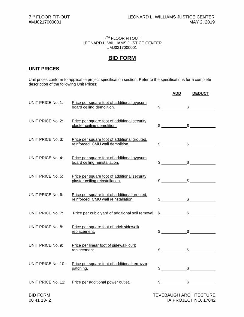
UNIT PRICES Unit prices conform to applicable project specification section. Refer to the specifications for a complete description of the following Unit Prices:
ADD DEDUCT
UNIT PRICE No. 1: Price per square foot of additional gypsum board ceiling demolition. $ $
UNIT PRICE No. 2: Price per square foot of additional security
plaster ceiling demolition. $ $ UNIT PRICE No. 3: Price per square foot of additional grouted,
reinforced, CMU wall demolition. $ $
UNIT PRICE No. 4: Price per square foot of additional gypsum
board ceiling reinstallation. $ $ UNIT PRICE No. 5: Price per square foot of additional security
plaster ceiling reinstallation. $ $ UNIT PRICE No. 6: Price per square foot of additional grouted,
reinforced, CMU wall reinstallation. $ $ UNIT PRICE No. 7: Price per cubic yard of additional soil removal. $ $ UNIT PRICE No. 8: Price per square foot of brick sidewalk
replacement. $ $ UNIT PRICE No. 9: Price per linear foot of sidewalk curb
replacement. $ $ UNIT PRICE No. 10: Price per square foot of additional terrazzo
patching. $ $ UNIT PRICE No. 11: Price per additional power outlet. $ $

LEONARD L. WILLIAMS JUSTICE CENTER 7TH FLOOR FIT-OUT MAY 2, 2019 #MJ0217000001
TEVEBAUGH ARCHITECTURE BID FORM TA PROJECT NO. 17042 00 41 13 - 3
7TH FLOOR FITOUT LEONARD L. WILLIAMS JUSTICE CENTER
#MJ0217000001
BID FORM
UNIT PRICES Unit prices conform to applicable project specification section. Refer to the specifications for a complete description of the following Unit Prices:
ADD DEDUCT
UNIT PRICE No. 12: Price per additional voice and data outlet. $ $ UNIT PRICE No. 13: Price per additional foot of plumbing piping
supply and installation. $ $ UNIT PRICE No. 14: Price per 30 yard dumpster for removal of
items left on 7th floor by owner. $ $

7TH FLOOR FIT-OUT LEONARD L. WILLIAMS JUSTICE CENTER #MJ0217000001 MAY 2, 2019
BID FORM TEVEBAUGH ARCHITECTURE 00 41 13- 4 TA PROJECT NO. 17042
7TH FLOOR FITOUT LEONARD L. WILLIAMS JUSTICE CENTER
#MJ0217000001
BID FORM I/We acknowledge Addendums numbered and the price(s) submitted include any cost/schedule impact they may have. This bid shall remain valid and cannot be withdrawn for thirty (30) days from the date of opening of bids (60 days for School Districts and Department of Education), and the undersigned shall abide by the Bid Security forfeiture provisions. Bid Security is attached to this Bid. The Owner shall have the right to reject any or all bids, and to waive any informality or irregularity in any bid received. This bid is based upon work being accomplished by the Sub-Contractors named on the list attached to this bid. Should I/We be awarded this contract, I/We pledge to achieve substantial completion of all the work within calendar days of the Notice to Proceed. The undersigned represents and warrants that he has complied and shall comply with all requirements of local, state, and national laws; that no legal requirement has been or shall be violated in making or accepting this bid, in awarding the contract to him or in the prosecution of the work required; that the bid is legal and firm; that he has not, directly or indirectly, entered into any agreement, participated in any collusion, or otherwise taken action in restraint of free competitive bidding. Upon receipt of written notice of the acceptance of this Bid, the Bidder shall, within twenty (20) calendar days, execute the agreement in the required form and deliver the Contract Bonds, and Insurance Certificates, required by the Contract Documents. I am / We are an Individual / a Partnership / a Corporation By Trading as (Individual’s / General Partner’s / Corporate Name) (State of Corporation) Business Address: Witness: By: ( Authorized Signature ) (SEAL) ( Title ) Date:

LEONARD L. WILLIAMS JUSTICE CENTER 7TH FLOOR FIT-OUT MAY 2, 2019 #MJ0217000001
TEVEBAUGH ARCHITECTURE BID FORM TA PROJECT NO. 17042 00 41 13 - 5
ATTACHMENTS Sub-Contractor List Non-Collusion Statement Bid Security Schedule of Performance (Others as Required by Project Manuals) DUE WITHIN 18 DAYS OF AWARD OF BID Drug Testing Forms Affidavit of Employee Drug Testing Program Schedule of Values

7TH FLOOR FIT-OUT LEONARD L. WILLIAMS JUSTICE CENTER #MJ0217000001 MAY 2, 2019
BID FORM TEVEBAUGH ARCHITECTURE 00 41 13- 6 TA PROJECT NO. 17042
THIS PAGE LEFT INTENTIONALLY BLANK
LEONARD L. WILLIAMS JUSTICE CENTER 7TH FLOOR FIT-OUT MAY 2, 2019 #MJ0217000001
TEVEBAUGH ARCHITECTURE BID FORM TA PROJECT NO. 17042 00 41 13 - 7
7TH FLOOR FITOUT LEONARD L. WILLIAMS JUSTICE CENTER
#MJ0217000001
BID FORM
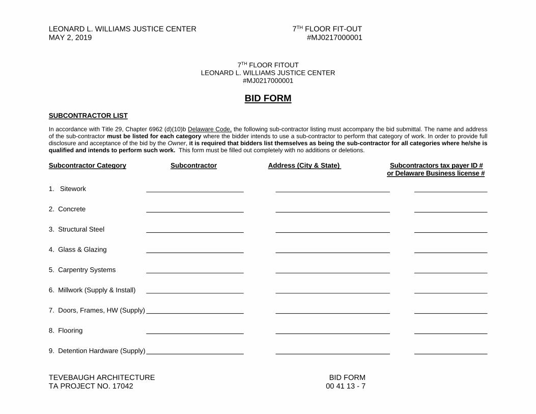
SUBCONTRACTOR LIST In accordance with Title 29, Chapter 6962 (d)(10)b Delaware Code, the following sub-contractor listing must accompany the bid submittal. The name and address of the sub-contractor must be listed for each category where the bidder intends to use a sub-contractor to perform that category of work. In order to provide full disclosure and acceptance of the bid by the Owner, it is required that bidders list themselves as being the sub-contractor for all categories where he/she is qualified and intends to perform such work. This form must be filled out completely with no additions or deletions. Subcontractor Category Subcontractor Address (City & State) Subcontractors tax payer ID # or Delaware Business license # 1. Sitework 2. Concrete 3. Structural Steel 4. Glass & Glazing 5. Carpentry Systems 6. Millwork (Supply & Install) 7. Doors, Frames, HW (Supply) 8. Flooring 9. Detention Hardware (Supply)
7TH FLOOR FIT-OUT LEONARD L. WILLIAMS JUSTICE CENTER #MJ0217000001 MAY 2, 2019
BID FORM TEVEBAUGH ARCHITECTURE 00 41 13- 8 TA PROJECT NO. 17042
7TH FLOOR FITOUT LEONARD L. WILLIAMS JUSTICE CENTER
#MJ0217000001
BID FORM
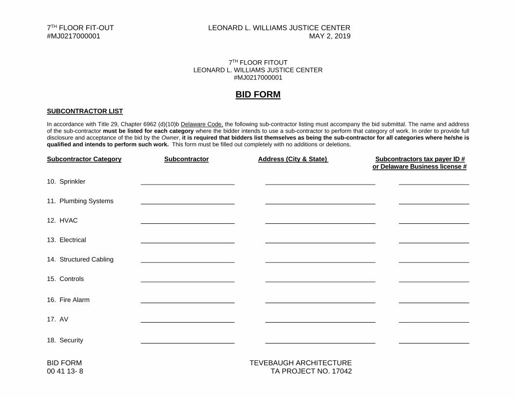
SUBCONTRACTOR LIST In accordance with Title 29, Chapter 6962 (d)(10)b Delaware Code, the following sub-contractor listing must accompany the bid submittal. The name and address of the sub-contractor must be listed for each category where the bidder intends to use a sub-contractor to perform that category of work. In order to provide full disclosure and acceptance of the bid by the Owner, it is required that bidders list themselves as being the sub-contractor for all categories where he/she is qualified and intends to perform such work. This form must be filled out completely with no additions or deletions. Subcontractor Category Subcontractor Address (City & State) Subcontractors tax payer ID # or Delaware Business license # 10. Sprinkler 11. Plumbing Systems 12. HVAC 13. Electrical 14. Structured Cabling 15. Controls 16. Fire Alarm 17. AV
18. Security

LEONARD L. WILLIAMS JUSTICE CENTER 7TH FLOOR FIT-OUT MAY 2, 2019 #MJ0217000001
TEVEBAUGH ARCHITECTURE BID FORM TA PROJECT NO. 17042 00 41 13 - 9
7TH FLOOR FITOUT LEONARD L. WILLIAMS JUSTICE CENTER
#MJ0217000001
BID FORM
NON-COLLUSION STATEMENT
This is to certify that the undersigned bidder has neither directly nor indirectly, entered into any agreement, participated in any collusion or otherwise taken any action in restraint of free competitive bidding in connection with this proposal submitted this date to the Office of Management and Budget, Division of Facilities Management. All the terms and conditions of the Leonard L. Williams Justice Center 7th Floor Fit-Out Project have been thoroughly examined and are understood. NAME OF BIDDER: AUTHORIZED REPRESENTATIVE (TYPED): AUTHORIZED REPRESENTATIVE (SIGNATURE): TITLE: ADDRESS OF BIDDER: E-MAIL: ___________________________________________________ PHONE NUMBER: Sworn to and Subscribed before me this day of 20 . My Commission expires . NOTARY PUBLIC .
THIS PAGE MUST BE SIGNED AND NOTARIZED FOR YOUR BID TO BE CONSIDERED.

7TH FLOOR FIT-OUT LEONARD L. WILLIAMS JUSTICE CENTER #MJ0217000001 MAY 2, 2019
BID FORM TEVEBAUGH ARCHITECTURE 00 41 13- 10 TA PROJECT NO. 17042
7TH FLOOR FITOUT LEONARD L. WILLIAMS JUSTICE CENTER
#MJ0217000001
BID FORM
AFFIDAVIT OF
EMPLOYEE DRUG TESTING PROGRAM 4104 Regulations for the Drug Testing of Contractor and Subcontractor Employees Working on Large Public Works Projects requires that Contractors and Subcontractors implement a program of mandatory drug testing for Employees who work on Large Public Works Contracts funded all or in part with public funds. We hereby certify that we have in place or will implement during the entire term of the contract a Mandatory Drug Testing Program for our employees on the jobsite, including subcontractors that complies with this regulation: Contractor/Subcontractor Name: Contractor/Subcontractor Address: Authorized Representative (typed or printed): Authorized Representative (signature): Title: Sworn to and Subscribed before me this day of 20 . My Commission expires . NOTARY PUBLIC .
THIS PAGE MUST BE SIGNED AND NOTARIZED FOR YOUR BID TO BE CONSIDERED.
END OF SECTION


LEONARD L. WILLIAMS JUSTICE CENTER 7TH FLOOR FIT-OUT MAY 2, 2019 #MJ0217000001
TEVEBAUGH ARCHITECTURE SUMMARY OF WORK TA PROJECT NO. 17042 01 10 00 - 1
SECTION 01 10 00
SUMMARY OF WORK
PART 1 - GENERAL
1.1 RELATED DOCUMENTS A. Drawings and general provisions of the Contract, including General and Supplementary
Conditions and other Division 1 Specification Sections, apply to this Section.
1.2 WORK COVERED BY CONTRACT DOCUMENTS A. The Project consists of fit-out of a portion of the existing Leonard L. Williams Justice
Center. With the exception of work required to accommodate the exterior construction elevator, the renovation is interior. 1. Project Location: 500 North King Street, Wilmington, DE 19801 2. Owner State of Delaware, Department of Administrative Services, Division of
Facilities Management: Carvel State Office Building, 820 North French Street, Wilmington, DE 19801
B. Contract Documents, dated April 2, 2019 were prepared for the Project by Tevebaugh Architecture: Two Mill Road, Suite #210, Wilmington, DE 19806
C. The Work consists of demolition and removal of selective areas and systems as
delineated in the demolition drawings, and new work constructing new administrative space, courtrooms, and courtroom support spaces.
D. The Work will be constructed under a single prime contract.
1.3 WORK UNDER OTHER CONTRACTS A. Separate Contract: The Owner shall employ specialty contractors for certain areas of
work relating to this fit-out. Those operations will be conducted simultaneously with work under this Contract. That Contract includes the following: 1. Contract:
a. Separate contracts shall be awarded for Furniture, Audio Visual, Information Technology, and Security work., apart from installation of the Jury Seats.
b. Security programming shall be by building security vendor, but contracted through this contract. See SAD series drawings and security specifications for further information.
c. Queueing system shall be by specified vendor, but contracted through this contract. See SAD series drawings for further information.
d. Information technology equipment not specified in SAD series drawings or specifications, such as telephone equipment, printers, and

7TH FLOOR FIT-OUT LEONARD L. WILLIAMS JUSTICE CENTER #MJ0217000001 MAY 2, 2019
SUMMARY OF WORK TEVEBAUGH ARCHITECTURE 01 10 00 - 2 TA PROJECT NO. 17042
personal employee workstations, shall be by owner. All equipment specified in SAD series drawings and specifications are part of the contract.
B. Cooperate fully with separate contractors so that work under those contracts may be
carried out smoothly, without interfering with or delaying work under this Contract.
1.4 WORK SEQUENCE A. The Work will be conducted in one phase.
1.5 CONTRACTOR USE OF PREMISES A. General: During the construction period the Contractor shall have use of designated
areas of the premises for construction operations, including use of designated areas of the site.
B. Use of the Site: Limit use of the premises to work in areas indicated. Confine operations
to areas within contract limits indicated. Do not disturb portions of the site beyond the areas in which the Work is indicated. 1. Owner Occupancy: Building will be occupied during construction. 2. Driveways and Entrances: Keep driveways and entrances serving the
premises clear and available to the Owner, the Owner's employees, and emergency vehicles at all times. Do not use these areas for parking or storage of materials. Schedule deliveries to minimize space and time requirements for storage of materials and equipment on-site.
3. A construction elevator shall be provided and installed as part of this contract on the south façade of the building as depicted on the ASP and S series drawings. Contractors are not to utilize interior stairs or elevators.
C. Use of the Existing Building: Maintain the existing building in a weathertight condition
throughout the construction period. Repair damage caused by construction operations. Take all precautions necessary to protect the building and its occupants during the construction period.
1.6 OWNER-FURNISHED PRODUCTS A. The Owner will furnish furniture and equipment through other contracts as shown on
floor plans. The Work includes providing support systems to receive Owner's equipment, and mechanical and electrical connections.
1.7 MISCELLANEOUS PROVISIONS
1. Grass areas are off limits to truck traffic. 2. Start and stop times each day for construction to be as specified by the Owner in
specification Section 01 14 00 “Work Restrictions”.

LEONARD L. WILLIAMS JUSTICE CENTER 7TH FLOOR FIT-OUT MAY 2, 2019 #MJ0217000001
TEVEBAUGH ARCHITECTURE SUMMARY OF WORK TA PROJECT NO. 17042 01 10 00 - 3
3. Contractor to protect areas noted on drawings including all areas noted as Existing to Remain or Not In Contract that they must pass through.
PART 2 - PRODUCTS (Not Applicable)
PART 3 – EXECUTION (Not Applicable)
END OF SECTION

7TH FLOOR FIT-OUT LEONARD L. WILLIAMS JUSTICE CENTER #MJ0217000001 MAY 2, 2019
SUMMARY OF WORK TEVEBAUGH ARCHITECTURE 01 10 00 - 4 TA PROJECT NO. 17042
THIS PAGE LEFT INTENTIONALLY BLANK
LEONARD L. WILLIAMS JUSTICE CENTER 7TH FLOOR FIT-OUT MAY 2, 2019 #MJ0217000001
TEVEBAUGH ARCHITECTURE ALLOWANCES TA PROJECT NO. 17042 01 21 00 - 1
SECTION 01 21 00
ALLOWANCES
PART 1 - GENERAL
1.1 RELATED DOCUMENTS
A. Drawings and general provisions of the Contract, including General and Supplementary Conditions and other Division 01 Specification Sections, apply to this Section.
1.2 SUMMARY
A. Section includes administrative and procedural requirements for allowances.
1.3 DEFINITIONS
A. Allowance: An amount set aside in a construction contract for work that is not fully defined.
1. Allowances described in this Section are part of the Work only if an “Allowance Authorization Form” is submitted and approved.
1.4 PROCEDURES
A. Coordination: Revise or adjust affected adjacent work as necessary to completely integrate work of the allowance into Project.
B. Notification: When an allowance is needed to be used in accordance with the schedule following, the “Allowance Authorization Form” must be filled out by the Contractor and submitted to the Owner and the Architect. If the usage of the allowance is approved, the Owner and Architect shall sign-off on the form and return a copy to the Contractor.
C. Execute accepted allowance work under the same conditions as other work of the Contract.
D. Schedule: A schedule of allowances is included at the end of this Section.
PART 2 - PRODUCTS (Not Used)
PART 3 - EXECUTION
7TH FLOOR FIT-OUT LEONARD L. WILLIAMS JUSTICE CENTER #MJ0217000001 MAY 2, 2019
ALLOWANCES TEVEBAUGH ARCHITECTURE 01 21 00 - 2 TA PROJECT NO. 17042
3.1 SCHEDULE OF ALTERNATES
A. Allowance No. 1: Unforeseen Conditions
1. This allowance is for additional unforeseen work that may be required to complete the work in the contract documents but is not known at the time of the completion of the contract documents due to concealed existing conditions. The value of this allowance, seventy-five thousand dollars ($75,000.00), is included in the bid form as part of the contract amount.
B. Allowance No. 2: Stored Items Removal
1. This allowance is for the manpower to remove items that have been left on the 7th floor by the owner, as described in General Note H on drawing sheets AD101a, AD101b, AD102a, and AD102b. This allowance does not include the dumpster, which is listed under unit prices. Please see 01 22 00 “Unit Prices” for more information about the dumpster. The value of this allowance, five-thousand dollars ($5,000.00), is included in the bid form as part of the contract amount.
END OF SECTION

LEONARD L. WILLIAMS JUSTICE CENTER 7TH FLOOR FIT-OUT MAY 2, 2019 #MJ0217000001
TEVEBAUGH ARCHITECTURE UNIT PRICES TA PROJECT NO. 17042 01 22 00 - 1
SECTION 01 22 00
UNIT PRICES
PART 1 - GENERAL
1.1 RELATED DOCUMENTS
A. Drawings and general provisions of the Contract, including General and Supplementary Conditions and other Division 1 Specification Sections, apply to this Section.
1.2 SUMMARY
A. This Section includes administrative and procedural requirements for unit prices.
1.3 DEFINITIONS
A. Unit Price: An amount proposed by bidders and stated on the Bid Form for a given unit of work defined in the Bidding Requirements that may be added to or deducted from the Contract amount based on actual quantities installed. Changes can be to either add additional work or delete work.
B. The cost or credit for each unit price is the net price to be added to or deducted from the Contract Sum to adjust for the actual quantity installed and includes all overhead, profit, supervision and miscellaneous costs. No other adjustments are made to the Contract Sum.
1.4 PROCEDURES
A. Coordination: Modify or adjust affected adjacent work as necessary to completely integrate work of the unit price into Project. 1. Include as part of each unit price, miscellaneous devices, accessory objects, and
similar items incidental to or required for a complete installation whether or not indicated as part of unit price.
B. Execute unit prices under the same conditions as other work of the Contract.
C. Schedule: A Schedule of Unit Prices and Allowances is included at the end of this Section. Specification Sections referenced in schedule contain requirements for materials necessary to achieve the work described under each unit price.
PART 2 - PRODUCTS (Not Used)

7TH FLOOR FIT-OUT LEONARD L. WILLIAMS JUSTICE CENTER #MJ0217000001 MAY 2, 2019
UNIT PRICES TEVEBAUGH ARCHITECTURE 01 22 00 - 2 TA PROJECT NO. 17042
PART 3 - EXECUTION
3.1 SCHEDULE OF UNIT PRICES
A. Unit Price No 1: Additional Gypsum Board Ceiling Demolition: Provide unit price per square foot for demolition of additional existing gypsum board ceiling assembly of construction similar to the new work gypsum board ceilings detailed and specified in the Bid Documents.
B. Unit Price No 2: Additional Security Plaster Ceiling Demolition: Provide unit price per square foot for the demolition of additional existing security plaster ceiling.
C. Unit Price No 3: Additional Grouted, Reinforced, CMU Partition Demolition: Provide unit price per square foot for additional demolition of portions of existing reinforced CMU partitions similar to partition type P6S, but with 8” thick CMU in lieu of 6” CMU.
D. Unit Price No 4: Additional Gypsum Board Ceiling Reinstallation: Provide unit price per square foot for reinstallation of additional existing gypsum board ceiling assembly of construction similar to the new work gypsum board ceilings detailed and specified in the Bid Documents.
E. Unit Price No 5: Additional Security Plaster Ceiling Reinstallation: Provide unit price per square foot for the reinstallation of additional existing security plaster ceiling to match existing.
F. Unit Price No 6: Additional Grouted, Reinforced, CMU Partition Replacement: Provide unit price per square foot for additional reinstallation of portions of existing reinforced CMU partitions similar to partition type P6S, but with 8” thick CMU in lieu of 6” CMU.
G. Unit Price No 7: Additional Removal of Soil: Provide unit price per cubic yard for removal of soil.
H. Unit Price No 8: Replacement of Existing Brick Sidewalk: Provide unit price per square foot to replace existing brick sidewalk at south of building to match existing.
I. Unit Price No 9: Replacement of Sidewalk Curb: Provide unit price per linear foot to replace sidewalk curb in kind.
J. Unit Price No 10: Patch Terrazzo Finish Flooring: Provide unit price per square foot to patch existing terrazzo finish flooring to match existing terrazzo flooring in public corridor.
K. Unit Price No 11: Additional Power Outlet and Associated Wiring: Provide unit price for additional data outlet and wiring as delineated in Bid Document.
L. Unit Price No 12: Additional Data Outlet and Associated Wiring: Provide unit price for additional data outlet and wiring as delineated in Bid Documents.
M. Unit Price No 13: Additional Plumbing Piping: Provide unit price per linear foot for supply and installation of additional plumbing piping.
LEONARD L. WILLIAMS JUSTICE CENTER 7TH FLOOR FIT-OUT MAY 2, 2019 #MJ0217000001
TEVEBAUGH ARCHITECTURE UNIT PRICES TA PROJECT NO. 17042 01 22 00 - 3
N. Unit Price No 14: Price per 30 yard dumpster for removal of items left on the 7th floor by owner: Provide a unit price for the deliver, use, and tipping of a 30 yard dumpster. This is for use only for owner-left items on the 7th floor; not for general demolition or construction waste. Manpower for removal of owner-let items on the 7th floor is covered under allowances. See specification 01 21 00 “Allowances.”
END OF SECTION

7TH FLOOR FIT-OUT LEONARD L. WILLIAMS JUSTICE CENTER #MJ0217000001 MAY 2, 2019
UNIT PRICES TEVEBAUGH ARCHITECTURE 01 22 00 - 4 TA PROJECT NO. 17042
THIS PAGE LEFT INTENTIONALLY BLANK

LEONARD L. WILLIAMS JUSTICE CENTER 7th FLOOR FIT-OUTAPRIL 10, 2019 #MJ0217000001
DEDC, LLC STRUCTURED CABLINGDEDC PROJECT NO. 18P015 27 10 00-1
SECTION 27 10 00STRUCTURED CABLING
PART 1 GENERAL1.01 RELATED REQUIREMENTS
A. Section 07 84 13 - Penetration Firestopping.1.02 REFERENCE STANDARDS
A. Delaware Sate-Wide Information Techanology and Architecture Standards (NE-Cabling-002)B. Delaware Sate-Wide Information Techanology and Architecture Standards (AC-Wireless-001)C. NFPA 70 - National Electrical Code; Most Recent Edition Adopted by Authority Having
Jurisdiction, Including All Applicable Amendments and Supplements.D. TIA-607 - Generic Telecommunications Bonding and Grounding (Earthing) for Customer
Premises; 2015c, with Addendum (2017).E. ANSI/J-STD-607 - Commercial Building Grounding (Earthing) and Bonding Requirements for
Telecommunications; Rev A, 2002.1.03 SUBMITTALS
A. See Section 01 31 00 - Project Management and Coordination, for submittal procedures.B. Product Data: Provide manufacturer's standard catalog pages and data sheets for each
product.1. Storage and handling requirements and recommendations.2. Installation methods.
C. Shop Drawings: Show compliance with requirements on isometric schematic diagram ofnetwork layout, showing cable routings, telecommunication closets, rack and enclosure layoutsand locations, service entrance, and grounding, prepared and approved by BICSI RegisteredCommunications Distribution Designer (RCDD).
D. Manufacturer Qualifications.E. Evidence of qualifications for installer.F. Project Record Documents: Prepared and approved by BICSI Registered Communications
Distribution Designer (RCDD).1. Record actual locations of outlet boxes and distribution frames.2. Show as-installed color coding, pair assignment, polarization, and cross-connect layout.3. Identify distribution frames and equipment rooms by room number on drawings.
G. Operation and Maintenance Data: List of all components with part numbers, sources of supply,and operation and maintenance instructions; include copy of project record documents.
1.04 QUALITY ASSURANCEA. Manufacturer Qualifications: At least 3 years experience manufacturing products of the type
specified.B. Installer Qualifications: A company having at least 3 years experience in the installation and
testing of the type of system specified, and:1. Employing a BICSI Registered Communications Distribution Designer (RCDD).2. Supervisors and installers factory certified by manufacturers of products to be installed.
1.05 DELIVERY, STORAGE, AND HANDLINGA. Store products in manufacturer's unopened packaging until ready for installation.B. Keep stored products clean and dry.

7TH FLOOR FIT-OUT LEONARD L. WILLIAMS JUSTICE CENTER#MJ0217000001 APRIL 10, 2019
STRUCTURED CABLING DEDC, LLC27 10 00-2 DEDC PROJECT NO. 18P015
1.06 WARRANTYA. See Section 01 78 23 - Operation and Maintenance Data, for additional warranty requirements.B. Correct defective Work within a 2 year period after Date of Substantial Completion.
PART 2 PRODUCTS2.01 NETWORK CABLING AND EQUIPMENT
A. The contractor shall refer to Delaware Sate-Wide Information Techanology and ArchitectureStandards (NE-Cabling-002) for product requirements for cabling and equipment.
B. Network switches shall be CISCO Catatlyst 3850 series.2.02 WIRELESS ACCESS POINT
A. The contractor shall refer to Delaware Sate-Wide Information Techanology and ArchitectureStandards (AC-Wireless-001) for product requirements for installaiton of wireless accesspoints.
B. Wireless access points shall be Aerohive AP250 or Cisco Aironet 1852i as indicated inAC-Wireless-001.
DELAWARE STATE-WIDE INFORMATION
TECHNOLOGY AND ARCHITECTURE STANDARDS
These standards are adopted by the Department of Technology and Information (DTI), through the Technology and Architecture Standards Committee (TASC), and are applicable to all Information Technology use throughout the State of Delaware. Any questions or comments should be directed to [email protected].
Page 1 of 69 8/9/2016 11:54:59 AM CablingandWiringStandard-State.doc
Standard ID:
NE-Cabling-002
Title:
Structured Cabling System Standards and Specifications for State-Managed Facilities
Domain:
Network and Storage
Discipline:
Cabling
Revision Date: Revision no.: Original date:
1/8/2016 6 7/21/2008
A. Authority: Title 29, Chapter 90C provides broad statutory authority to the Department of Technology and Information to implement statewide and interagency technology solutions, policy, standards and guidelines for the State of Delaware's technology infrastructure. "Technology" means computing and telecommunications systems, their supporting infrastructure and interconnectivity used to acquire, transport, process, analyze, store and disseminate information or data electronically. The term "technology" includes systems and equipment associated with e-government and Internet initiatives.
B. Applicability: Applies to all State of Delaware communications and computing resources. DTI is
an Executive Branch Agency and has no authority over the customers in Legislative and Judicial Branches, as well as School Districts, and other Federal and Local Government entities that use these resources. However, all users, including these entities, must agree to abide by all policies, standards promulgated by DTI as a condition of funding, access and continued use of these resources.
C. Purpose: Cable configuration and installation is critical to providing connectivity in State buildings. This standard provides guidance for the design and installation of cabling. This standard provides guidance and requirements for data, voice, and CATV structured cabling systems and support infrastructure in all State owned and leased facilities and buildings.
DELAWARE STATE-WIDE INFORMATION
TECHNOLOGY AND ARCHITECTURE STANDARDS
These standards are adopted by the Department of Technology and Information (DTI), through the Technology and Architecture Standards Committee (TASC), and are applicable to all Information Technology use throughout the State of Delaware. Any questions or comments should be directed to [email protected].
Page 2 of 69 8/9/2016 11:54:59 AM CablingandWiringStandard-State.doc
Table of Contents PART 1 Scope...................................................................................................................................... 3
PART 2 Process ................................................................................................................................... 3 PART 3 Executive Summary ............................................................................................................... 3 PART 4 Objective ................................................................................................................................ 4 PART 5 Credits .................................................................................................................................... 5 PART 6 Introduction............................................................................................................................ 5
PART 7 Procedures.............................................................................................................................. 8 PART 8 Horizontal Distribution System ............................................................................................. 9
PART 9 Communications/Data Rooms/Closets (General) ................................................................ 11 PART 10 MDF & IDF Product Specifications .................................................................................. 25 PART 11 Information Outlets ............................................................................................................ 37 PART 12 Cable Routing Systems ...................................................................................................... 42
PART 13 Cabling-General ................................................................................................................. 43 PART 14 Horizontal CABLING - Category 6 UTP Data ................................................................. 44
PART 15 Vertical Distribution Systems ............................................................................................ 47 PART 16 Campus Cabling................................................................................................................. 50 PART 17 Patch Cables....................................................................................................................... 51
PART 18 Fire Stop - Penetration Sealant .......................................................................................... 55 PART 19 Testing ............................................................................................................................... 55
PART 20 Appendix A – Communications Planning Checklist ........................................................ 60 PART 21 Appendix B - Cable Installation Checklist ........................................................................ 61
PART 22 Appendix C - Quality Assurance ....................................................................................... 62 PART 23 Appendix D - Codes, Regulations and Standards .............................................................. 63 PART 24 Appendix E - Warranty ...................................................................................................... 63
PART 25 Appendix F - Bid/Quote Response Format ....................................................................... 63 PART 26 Appendix G - Outside - DELDOT Specific Requirements - Traffic
Construction……...………………………………………………………………………………….65
PART 27 Appendix H - Certified Contractor List ............................................................................. 69
DELAWARE STATE-WIDE INFORMATION
TECHNOLOGY AND ARCHITECTURE STANDARDS
These standards are adopted by the Department of Technology and Information (DTI), through the Technology and Architecture Standards Committee (TASC), and are applicable to all Information Technology use throughout the State of Delaware. Any questions or comments should be directed to [email protected].
Page 3 of 69 8/9/2016 11:54:59 AM CablingandWiringStandard-State.doc
PART 1 SCOPE
A. Areas Covered: This standard covers the best practices and installation requirements for Voice, Data, CATV cabling and support structures including conduits and raceways, Voice and Data rooms and closets.
B. Environments: This standard applies to all State owned and leased building and office spaces. It is concerned with all Data, Voice and CATV cabling projects, whether they are for new construction or revisions additions and upgrades to existing systems.
PART 2 PROCESS
A. Adoption: These standards have been adopted by the Department of Technology and Information (DTI) through the Technology and Architecture Standards Committee (TASC) and are applicable to all Information Technology use throughout the State of Delaware.
B. Revision: Technology is constantly evolving; therefore, the standards will need to be regularly reviewed. It is the intent of the TASC to review each standard annually. The TASC is open to suggestions and comments from knowledgeable individuals within the State, although we ask that they be channeled through your Information Resource Manager (IRM).
C. Contractors: Contractors or other third parties are required to comply with these standards when proposing technology solutions to DTI or other State entities. Failure to do so could result in rejection by the Delaware Technology Investment Council. For further guidance, or to seek review of a component that is not rated below, contact the TASC at [email protected].
D. Implementation responsibility: DTI and/or the organization’s technical staff will implement these best practices during the course of normal business activities, including business case review, architectural review, project execution and the design, development, or support of systems.
E. Enforcement: DTI will enforce these best practices during the course of normal business activities, including business case and architectural review of proposed projects and during the design, development, or support of systems. These best practices may also be enforced by others during the course of their normal business activities, including audits and design reviews.
F. Contact us: Any questions or comments should be directed to [email protected].
PART 3 EXECUTIVE SUMMARY
Because of ever-advancing Industry Standards and new Alliances between Cable and Hardware Manufactures and Vendors, this document seeks to enhance and clarify the State of Delaware’s wiring and cabling standards and specifications for Structured Cabling Systems. Approved Contractors under State of Delaware Contract # 05-441-TL are required to adhere to these specifications and standards.
The structured cabling system will support Voice, Data, and imaging applications within State-owned and -leased office facilities. This document describes the Structured Cabling System requirements to be met in the proposals for Communications cabling by Vendors and Contractors. These requirements encompass all materials, design, engineering, installation, supervision, and training services for a Structured Cabling System.

DELAWARE STATE-WIDE INFORMATION
TECHNOLOGY AND ARCHITECTURE STANDARDS
These standards are adopted by the Department of Technology and Information (DTI), through the Technology and Architecture Standards Committee (TASC), and are applicable to all Information Technology use throughout the State of Delaware. Any questions or comments should be directed to [email protected].
Page 4 of 69 8/9/2016 11:54:59 AM CablingandWiringStandard-State.doc
The following are examples of the Structured Cabling Systems that can be bid for new construction and whole building renovations, in which case all building structured cabling wiring is replaced. The choice of a Structured Cabling System is not limited to the Vendors or Manufactures listed below. The Channel Solutions shall be bid when possible. If a Link solution is bid the State Contact, PM, or DTI (Department of Technology and Information) must authorize the installation. In new construction projects, the default cabling infrastructure shall be Category 6 unless specified otherwise. Where building renovations and additions do not require the removal of the existing structured cabling system, the existing cabling in conjunction with new cabling should maintain the system warranties. If the existing structured cabling system is not Category 5e or better, it must be upgraded to CAT6 or better with a matching patch panel.
• Hubbell Premise Wiring • Ortronics • Panduit • Systimax • Leviton A. Terms and Conditions of Bids/quotes
1. An approved Contractors bid submittal should be based on the materials, systems, equipment, and Standards described in this document and in the bid response format of the attached example. Refer to Appendix G. All bids must be submitted in accordance with the specifications and information contained herein, as well as with any addenda, if required.
2. The bid package shall be accompanied by a presale warranty commitment, binding the Installation Contractor and Manufacturer to the customer-selected extended warranty package as described in State Contract # 05-441-TL page 21 section 3) paragraph b).
3. At any point in time, should you require clarification or have any questions pertaining to the content of this document, please call The State of Delaware Department of Technology and Information (DTI). 302-739-9500
PART 4 OBJECTIVE
This document has been developed as a source of information to assist in the design, implementation and maintenance of Voice, Data and Broad Band communications systems. It contains standards and specifications which guide users through structured cabling system design, planning, and installation.
To maximize the usefulness of this document, access to the various TIA/EIA (Telecommunications Industry Association/Electronic Industries Alliance), IEEE (Institute of Electrical and Electronics Engineers), BISCI, (Building Industry Consulting Service International), NEC (National Electrical Code), NFPA (National Fire Protection Association) Communications Standards, and implementation and installation Manuals for further reference is required. This document assumes that users have communications knowledge and training in all aspects of design, implementation, installation, and testing of a Voice/Data communications system. This document does not address safety issues associated with use. It is the individual’s responsibility to use established and appropriate safety and health practices and to determine the applicability of all regulations.
DELAWARE STATE-WIDE INFORMATION
TECHNOLOGY AND ARCHITECTURE STANDARDS
These standards are adopted by the Department of Technology and Information (DTI), through the Technology and Architecture Standards Committee (TASC), and are applicable to all Information Technology use throughout the State of Delaware. Any questions or comments should be directed to [email protected].
Page 5 of 69 8/9/2016 11:54:59 AM CablingandWiringStandard-State.doc
PART 5 CREDITS
Communications Cabling Construction Developed by: State of Delaware Department of Technology & Information 801 Silver Lake Blvd. Dover, DE 19904
The content of this document is drawn from experience, as well as other documents and manuals, including the following:
• NEC 2011/2013 Code book • NFPA-70 Publications • TIA/EIA Communications Building Wiring Standards • IEEE Publications & Standards • BICSI Communications Distribution Design and Installation Publications • MOTOROLA R56 Standards and Guideline for Communications • Various Manufactures Publications and Requirements
PART 6 INTRODUCTION
Any Structured Universal Cabling System installed for the Agencies of the State of Delaware is designed to meet known and anticipated technology needs within the State. An advanced building cabling system provides for more than communication services; it provides an infrastructure for an institution’s entire communications network. Instead of being a basic utility, it is as important as the high-tech systems that transmit signals over it and is an integral component of the State’s overall information network.
These designs provide a universal and flexible cabling system for workstations, conference rooms, and laboratories. Today’s cabling system must be multi- functional and provide service for telephones, computers, fax machines, LANs, WANs, broad band fiber optic and coaxial systems (CATV, SATV, CCTV.), Data Centers, computer-aided design workstations, Audio Video systems (AV), and other technologies. For a cabling system to be capable of meeting today’s technology and institutional demands, it must have high bandwidth capacity and transmission speed while being extremely flexible.
This wiring architecture incorporates the applicable ANSI/EIA/TIA standards, BICSI guidelines and the latest technologies. This cabling distribution plan can integrate all types of systems from a variety of vendors. The design uses a subsystem approach, which allows for changes in the system without affecting other parts of the system. The Main Distribution Frame (MDF) and Intermediate Distribution Frame (IDF) Room equipment racks are designed to allow for growth, and the cable routing is accomplished through the provision of cable trays, conduits, sleeves, raceways, and cable hangers where required. Ease of administration and recordkeeping for moves and changes is readily apparent, as is the flexibility that a structured cabling system provides.
The wiring medium for the Communications Cable Network consists of Category 6 – 6a 24AWG Unshielded Twisted Pair (UTP) for station cabling and multi pair twisted copper for backbone cabling to support low-speed voice or Data, Category 6 or 6a for high speed LAN technologies, and 50/125 micron multi-mode fiber optic cable and 50/125 micron multi-mode for even higher bandwidth requirements. The unshielded twisted pair (UTP) Category 6 or 6a LAN cables can support Data transmission rates of 100, 250 and 500 Mb/Sec
DELAWARE STATE-WIDE INFORMATION
TECHNOLOGY AND ARCHITECTURE STANDARDS
These standards are adopted by the Department of Technology and Information (DTI), through the Technology and Architecture Standards Committee (TASC), and are applicable to all Information Technology use throughout the State of Delaware. Any questions or comments should be directed to [email protected].
Page 6 of 69 8/9/2016 11:54:59 AM CablingandWiringStandard-State.doc
respectively according to EIA/TIA Standards and manufacturers’ specifications. These leading edge components, combined with the open wiring architecture, provide the technology, flexibility, and modularity that allow the system to grow and change to meet changing needs.
The central distribution location of the system is the Fiber Optic, coaxial and Copper Main Distribution Frame (MDF) located within the centrally located MDF/IDF Room of each building. Various fiber optic, coaxial and copper riser cables terminate on the MDF and extend to the Communications Rooms/Closets (IDFs) located throughout the buildings. Each building typically has one MDF/IDF Room and a varying number of IDF rooms/closets dictated by the horizontal station cabling limitation of 100 meters for high performance cable. The distance from the information outlet to the termination within the IDF is limited to 90 meters (the permanent link). The IDF room/closet houses the Intermediate Distribution Frame (IDF), Copper and Fiber Optic IDF Patch Panels, Local Area Network (LAN) equipment, and other electronics. Both the riser cables and the horizontal station cables feeding the floor’s workstations information outlets terminate in the IDF on Data patch panels, Voice 110 hardware, and Fiber Optic Patch Panels. These termination points act as the cross-connect point between the MDF and the floor that is being served. Large floors are divided into zones, via an imaginary line, with each zone being served by its respective IDF room/closet. (See figure 1)
Each work area and workstation is served by an information outlet, which provides the jacks for plugging in telephones, computers, broad band coaxial systems, fax machines, modems, and other devices at the desktop. The information outlets are served by varying sets of cables consisting of fiber optic and copper technologies, which originate in the IDF Room. IDF outlets are typically displayed as varying types of triangles (shaded, half-shaded, etc.) on blueprints. (See figure 2)
A subsystem architectural approach, using the latest technologies, provides a comfortable level of assurance that the system will support new applications and industry standards as they emerge.
DELAWARE STATE-WIDE INFORMATION
TECHNOLOGY AND ARCHITECTURE STANDARDS
These standards are adopted by the Department of Technology and Information (DTI), through the Technology and Architecture Standards Committee (TASC), and are applicable to all Information Technology use throughout the State of Delaware. Any questions or comments should be directed to [email protected].
Page 7 of 69 8/9/2016 11:54:59 AM CablingandWiringStandard-State.doc
Drawing Redacted
DELAWARE STATE-WIDE INFORMATION
TECHNOLOGY AND ARCHITECTURE STANDARDS
These standards are adopted by the Department of Technology and Information (DTI), through the Technology and Architecture Standards Committee (TASC), and are applicable to all Information Technology use throughout the State of Delaware. Any questions or comments should be directed to [email protected].
Page 8 of 69 8/9/2016 11:54:59 AM CablingandWiringStandard-State.doc
PART 7 PROCEDURES
Designing a cable system for an institution involves various organizations and individuals and requires a great deal of coordination. Once an institution is designated for wiring, AutoCAD drawings of the floor plans need to be acquired. AutoCAD is a type of computer aided drafting (CAD) format. These files are plotted and converted to blueprints that serve as the working drawings for site surveys and engineering purposes. Based on interviews with the agency's staff and Technical Coordinator will draw triangles on the drawing displaying the locations that information outlets are to be located. Also, tentative locations for the Communications/Data rooms/closets will be marked on the drawings. This information will be approved by the institution’s officialsand sent to the engineering team.
The engineers will survey the building—floor plans for new construction—and evaluate the communications rooms/closets, plan cable routing, and review the information outlet locations. The necessary adjustments will be made during the site survey, and the engineer will leave the site with the proper approvals from the agency's management if there are major changes such as room relocations.
The engineering team will then design the cable system for the building. The end product will be submitted to the agency's Technical Coordinator for comment and/or revision. If no adjustments are necessary, the blueprints are issued to the contractor for construction.
Drawing Redacted
DELAWARE STATE-WIDE INFORMATION
TECHNOLOGY AND ARCHITECTURE STANDARDS
These standards are adopted by the Department of Technology and Information (DTI), through the Technology and Architecture Standards Committee (TASC), and are applicable to all Information Technology use throughout the State of Delaware. Any questions or comments should be directed to [email protected].
Page 9 of 69 8/9/2016 11:54:59 AM CablingandWiringStandard-State.doc
PART 8 HORIZONTAL DISTRIBUTION SYSTEM The horizontal structured cable plant is the portion of the communications wiring system that extends from the information outlet to the Communications/Data room/closet.
A. Horizontal Distribution System General 1. The horizontal distribution system includes the:
• Information outlet at the workstation• Cables connecting the workstation to the Communications/Data room/closet• Intermediate routing and distribution systems
2. The horizontal distribution system should be configured in a star topology. All communicationsoutlets within a work area should be connected to a single Communications/Data room/closet, asdefined by the zone concept.
3. This infrastructure must serve all of the Communications requirements of the agency or owner.
4. Communications applications served by the horizontal system can include:
• Voice (e.g., telephones)• Data (e.g., terminal connectivity, modems, etc.)• Local area networks (e.g. Ethernet)• Audio & Video (e.g., CATV, video conferencing and security monitoring)• Graphics & Imaging
5. When designing a horizontal distribution system, include capacity to satisfy long- termrequirements as well as initial plans. Ensure that the distribution system has the flexibility toaccommodate necessary moves, additions, changes, and system growth.
6. After construction, the horizontal distribution system is typically difficult to access. Therefore thetime, effort, coordination, and skills required for changes can be extremely costly. In addition,access to the horizontal distribution system frequently causes disruption to the user community.
7. All Horizontal Workstation Communications and broad band coaxial system cabling will be "home-run" from the information outlet location to the termination point within the corresponding IDF orMDF/IDF room.
8. Horizontal cable paths will be in a "streets and avenues" manner, typically following mainwalkways.
9. Horizontal cables are to be fastened onto hangers five feet apart with all cables bundled with tiewraps, and are to have a small amount of slack visible.
10. Cables must not rest on any structures or the hung ceiling. Cables are not to be fastened to ducts,pipes, conduits, or any other existing structures. Cable bundles should be secured to the slaboverhead to avoid any conflict with or EMI from flexible electrical conduits, transformers, motors,etc.
11. Some cabling shall run to workstation and other outlets through cavities in the dry wall andopenings in sheet metal or wooden studs within the dry wall construction. The sheet metal studswill not have gaskets for this purpose, so it is the Contractor's responsibility to exercise extremecare in snaking cable through these areas, so as to avoid damage to the cable jacketing.
DELAWARE STATE-WIDE INFORMATION
TECHNOLOGY AND ARCHITECTURE STANDARDS
These standards are adopted by the Department of Technology and Information (DTI), through the Technology and Architecture Standards Committee (TASC), and are applicable to all Information Technology use throughout the State of Delaware. Any questions or comments should be directed to [email protected].
Page 10 of 69 8/9/2016 11:54:59 AM CablingandWiringStandard-State.doc
12. The building's horizontal wiring plan is to be installed on all floors from the information outlet to the termination point within the associated IDF Room.
13. Horizontal cable will be installed onto “J” hooks or equivalent in the ceiling or tops of walls near
ceiling. Cables are to be fastened to “J” hooks or equivalent every 5 feet. The cable contractor is to provide and furnish the “J” hooks.
14. All station cable (horizontal) and tie cables that run from relay racks to the wall- mounted frames
are to be plenum-rated.
B. Horizontal Communications Cable Specification
1. For each type of information outlet indicated on the attached drawings, the contractor shall furnish all of the following equipment, install it in the correct configuration, and test it.
2. All cabling, outlets, and termination patch panels used for the Category 6 / ISO Class E data
system may be provided by a single manufacturer and shall be certified as part of the 25 year minimum warranty- Where the installer chooses to use one (1) manufacturer for cabling and a different manufacturer for the outlets and termination patch panels for the Category 6 / ISO Class E data system, the two (2) manufacturers must prove to have compliant interconnecting hardware and shall be certified as part of the 25 year minimum warranty.
3. All Category 6 and 6a UTP & Fiber cabling is to be handled and terminated in accordance with the
Manufacturer’s Premises Communications Application and Installation Guide.
4. In addition to the above manufacturer’s standards, all applicable EIA/TIA Category 6 and Fiber Optic Cable standards are to be strictly adhered to.
5. The fiber optic cable is to be terminated on both ends with an SC type connector on the patch
panels. 6. The contractor is to use Plenum cable for all station 4-pair copper, coaxial, and 2-strand fiber
cabling. 7. Plan routes to ensure that the proposed route on the plans falls within the EIA/TIA distance
limitations (90 meters after termination) for horizontal cabling. 8. Cables serving information outlets that cannot be routed down wall cavities will be enclosed in
latching surface-mount raceways, anchored (not with adhesives) to walls. Contractor will provide all raceway fittings to allow for level and plumb routes from ceiling to information outlet. Proper fill ratios must be observed. Contractor may reference the manufacturer’s catalogs or specifications for correct fittings and fill ratios. Contractor must use all accessory fittings required in order to build a neat and functional installation. This same method will apply to routing horizontal cables to workstation outlets where ceilings are not accessible.
9. The RG-6U Plenum Cable and the RG11U Plenum Cable are to be terminated with F type
connector or connectors. The RG6U Coaxial Station cabling will be terminated onto a rack or wall-mounted “F” Connector Patch Panel located in the IDF Room.
10. The IDF Room side of the Voice four-pair cables serving a standard outlet will be punched down
DELAWARE STATE-WIDE INFORMATION
TECHNOLOGY AND ARCHITECTURE STANDARDS
These standards are adopted by the Department of Technology and Information (DTI), through the Technology and Architecture Standards Committee (TASC), and are applicable to all Information Technology use throughout the State of Delaware. Any questions or comments should be directed to [email protected].
Page 11 of 69 8/9/2016 11:54:59 AM CablingandWiringStandard-State.doc
on the corresponding IDF Room's wall-mounted frame on 110 Cat 6 field-terminated cross-connect terminal blocks.
11. The IDF Room side of the Category 6 – 6a four-pair cables serving a standard outlet will be punched down on individual 110 (Category 6–6a) modular patch panels, 568B wired. The patch panels will be mounted in the relay racks within the IDF rooms.
12. The contractor is to install a wire management panel between all patch panels and above the first
panel as well as one below the last panel. 13. In locations that have wall-mounted racks, the contractor is to use the Cat 6 hinged down patch
panels with associated cable management. In cases where the hinged down series is required, the contractor is to take care to dress the cables neatly and allow for future access to the rear of the panel.
14. Contractor is to label both the front and the rear of the patch panels. The terminations are to follow
this sequence: Workstation 001A, 001B, 002A, 002B. It is acceptable to change numbering for floor or closet designation.
C. Zones
1. A zone is a contiguous area in which all horizontal wiring is homed to a single communications closet.
2. To maintain an orderly, understandable wiring system, it is imperative that the horizontal distribution system be structured in zones.
3. Within a zone, all communications wiring is run to a single communications closet.
4. Other zones use different Communications/Data rooms/closets. Cross-zone horizontal wiring is prohibited. Connections between zones are provided via the vertical distribution system.
PART 9 COMMUNICATIONS/DATA ROOMS/CLOSETS (GENERAL)
The Communications/Data room/closet is a concentration point for communications and LAN services. In this room, premise wiring and cabling are terminated and cross-connected. In addition, active networking devices such as switches are placed here. Communications/Data rooms/closets provide a safe area for housing distribution cabling, premise equipment, and termination fields. These rooms/closets are a focal point for communications services.
In addition to supporting in-house connectivity, the MDF Communications/Data room/closet often provides a termination point for the local telephone company. The entrance facility, or demarcation point (de-mark), is the location where outside communications services, such as copper telephone lines, fiber optic Data circuits, and CATV, are delivered to the building. Typically, distribution of communications services within the building originates at this point and is the responsibility of the owner.
Special considerations must be given when providing the building entrance pathways for the copper, fiber optic, and coaxial cables that service providers will install in to the building de-mark. It is the owner’s responsibility to provide this pathway into the building. Contact DTI for standards and specifications for building entrances.
DELAWARE STATE-WIDE INFORMATION
TECHNOLOGY AND ARCHITECTURE STANDARDS
These standards are adopted by the Department of Technology and Information (DTI), through the Technology and Architecture Standards Committee (TASC), and are applicable to all Information Technology use throughout the State of Delaware. Any questions or comments should be directed to [email protected].
Page 12 of 69 8/9/2016 11:54:59 AM CablingandWiringStandard-State.doc
The following section details the basic requirements for a Communications/Data room/closet. It may be used to assist in:
• Designing new Communications/Data rooms/closets • Assessing and refining existing Communications/Data rooms/closets to support evolving
communications requirements. A. Design Guidelines
The suggested building practices put forth in this section are recommendations and are subject to field conditions and budget constraints. Local building and electrical codes, practices and requirements may supersede the guidelines presented in this section.
1. Sizing of Communications/Data rooms/closets • The Communications/Data room/closet must have enough space to support required
communications systems, including projected growth. • The existing system is likely to be replaced in the future • A new system may, require more (or less) space • The existing system and a new system may need to coexist during a cut-over
2. Location of Communications/Data rooms/closets • Communications/Data rooms/closets should be situated so as to minimize the length and the
quantity of cable runs needed for the distribution systems. • The maximum horizontal distribution cable distance must be less than 90 meters (295 ft.),
independent of media type. This distance represents the cable length from the mechanical termination of the media in the Communications/Data room/closet to the outlet in the work area. This is known as the permanent link.
• Vertical (backbone) distribution system distance limitations vary and are dependent upon media, topology, and facility issues.
3. Unacceptable locations for Communications/Data rooms/closets:
• Anywhere water vapor exists, such as boiler rooms, washrooms, or janitor's closets. • Spaces with corrosives, explosives, and combustibles, including acid, ammonia, chlorine,
oxygen, and petroleum vapors. • Spaces containing steam pipes, drains, or clean-outs. • Areas with high traffic volumes (for security reasons, as well as to minimize the risk of
inadvertent damage) unless separately enclosed. • Areas of high electromagnetic interference (EMI) or radio frequency interference (RFI). Both
adversely affect system performance and reliability.
B. General Room Requirements
1. Electrical • All active Communications, Data and Video systems have specific electrical power
requirements. Plan electrical service to ensure smooth installation, reliable service, and compliance with manufacturers' warranties. Be sure to consider equipment manufacturer's specifications, National Electric Code (NEC) requirements, State and local codes, ordinances, and requirements.
• Electrical devices capable of causing line transients, such as fans, pencil sharpeners, radios,
calculators, and lights, must be separated electrically from the Communications equipment. To
DELAWARE STATE-WIDE INFORMATION
TECHNOLOGY AND ARCHITECTURE STANDARDS
These standards are adopted by the Department of Technology and Information (DTI), through the Technology and Architecture Standards Committee (TASC), and are applicable to all Information Technology use throughout the State of Delaware. Any questions or comments should be directed to [email protected].
Page 13 of 69 8/9/2016 11:54:59 AM CablingandWiringStandard-State.doc
accomplish this, all Communications and Data equipment requires separate electrically isolated ground circuits and/or building grounding. The outlets on these circuits should be labeled and/or color coded. Frequently, orange-colored wall outlets are used to identify power sources used for computing and communications equipment. Utility outlets are also needed in the Communications/Data room/closet for tools, test sets, and other equipment.
• Each Communications/Data room/closet shall have one 110V, 15 Amp electrical convenience outlet and one 110V, 20 Amp dedicated-circuit isolated-ground electrical outlet for the electronic equipment. This is a minimum requirement based on the typical current draw of the networking equipment to be placed. The ground for the equipment outlet should be an isolated ground where possible to avoid line transients. The 110V 20 Amp dedicated circuit isolated ground electrical outlet(s) should be mounted in convenient location to facilitate the use of the shortest equipment power cords. The recommended location is at the top of the rack or on the ladder tray.
• All electrical isolated ground outlets serving Communications and Data equipment must be
attached to non-switched circuits to prevent inadvertent equipment shutdown. It is also recommended that they be on a UPS and/or generator if available.
2. Grounding • Most Communications and Data equipment requires bounding and grounding of equipment
cabinets. Do not use plumbing or conduit (EMT) fixtures as a ground source. Grounding shall meet the NEC and EIA/TIA requirements and practices except where other authorities or codes impose more stringent requirements or practices. (Refer to NEC Chapter 2 article 250 and Chapter 8 Communications Systems, TIA/EIA Standard J-STD-607-A and Motorola R56 Standards and Guideline for Communication site).
• In addition to protecting personnel and equipment from hazardous voltages, the grounding
system may reduce the effect of electromagnetic interference (EMI) throughout the structured cable plant. Improper grounding can result in induced currents that disrupt Communications circuits.
• Ensure that the installation conforms with applicable regulations and practices
• Ensure that each Communications/Data room/closet has an appropriate ground buss bar
• Ensure that grounding is available for cross-connect frames, patch panel racks, Telephone and
Data equipment, as well as testing and maintenance equipment
3. Space • A distance of three feet is the preferred clearance from the front, back, and side of a relay rack.
• If there are space constraints, it is acceptable to provide a minimum of two feet of clearance on
one rack side for access and a minimum of two feet of front and back clearance for cross-connect fields, patch panels, etc. If possible, locate sleeves, cores, slots, and/or conduits together in one area to maximize usable wall space.
4. Rooms/Closets Sizing
DELAWARE STATE-WIDE INFORMATION
TECHNOLOGY AND ARCHITECTURE STANDARDS
These standards are adopted by the Department of Technology and Information (DTI), through the Technology and Architecture Standards Committee (TASC), and are applicable to all Information Technology use throughout the State of Delaware. Any questions or comments should be directed to [email protected].
Page 14 of 69 8/9/2016 11:54:59 AM CablingandWiringStandard-State.doc
• Determine the number of relay racks required for the termination of patch panels and electronic equipment. Assume that free-standing relay racks will be installed and provide three feet of space on all sides of each.
• Determine the amount of wall space that will be required for the installation of termination
equipment. A minimum of four feet should be used as a criterion.
• Determine if the plywood backboard will be furred-out. This equals approximately 4” of space taken from the room.
• Take into account the door swing if the door opens into the room. Ideally the door should open
out from the room.
• Determine how much space any sleeves, conduits, or other equipment require.
• Determine the size of the room by constructing a diagram, to scale, of all of these components, taking into account all the walkways and door swings.
• If a very small number of information outlets are being installed, the minimum size a closet can
be is 4’ wide and 3’ deep. This assumes a 4’ X 8’X 3/4” plywood backboard, one wall-mounted relay rack that has a fiber optic patch panel, 110 blocks, copper patch panels, coax patch panel, LAN hubs and ground buss bar. It is recommended to install plywood on all walls, from the floor to the ceiling.
5. Structural Walls
• Extend from the floor to the deck above (fire wall)
• Be securely fastened to the floor and the deck above
• Conform to national and local construction guidelines
6. Wall Linings
• Each Communications/Data room/closet will contain a minimum of one furred-out or flush sheet of plywood (4’ X 8’) mounted on the wall.
• It is recommended to install plywood floor to ceiling on all walls.
• Securely fasten the plywood to wall framing members to ensure that it can support any attached equipment.
• The plywood is to be 3/4”, A/C grade, and fire-retardant.
• All plywood backboards are to be mounted smooth side out and painted white at time of installation, prior to installation of equipment onto the plywood.
7. Floor Finish
• Keep dust to a minimum in Communications/Data rooms/closets.
• Anti-static Asphalt Tile, Linoleum Tile, or Sealed Concrete is acceptable floor finishes.
DELAWARE STATE-WIDE INFORMATION
TECHNOLOGY AND ARCHITECTURE STANDARDS
These standards are adopted by the Department of Technology and Information (DTI), through the Technology and Architecture Standards Committee (TASC), and are applicable to all Information Technology use throughout the State of Delaware. Any questions or comments should be directed to [email protected].
Page 15 of 69 8/9/2016 11:54:59 AM CablingandWiringStandard-State.doc
8. Ceilings and Doors
• Dropped ceiling height should be at least nine feet from the finished floor to provide adequate space for equipment cabinets and suspended cable trays. Some equipment may require additional height, depending on the manufacturer's specifications. Avoid installing false ceilings in small closets.
• Overhead ceiling vents should be centrally located to maximize air distribution and maintenance access. Avoid placing overhead ceiling vents directly over suspended racks and equipment cabinets.
• All ceiling vents should have diffusers (vent manifolds) securely installed.
• Design doorways with minimum measurements of 36 inches wide. Hinge the doors to open outward.
• All Communications/Data rooms/closets should have door locks and a minimum number of windows, if any. Closets should be kept locked. Provide keys to select personnel who are on-site continuously.
9. Lighting • Within ceilings, position light fixtures at least eight feet above the finished floor.
• Indirect (reflected) lighting is not recommended.
• If possible, minimize heat and glare by using fluorescent light fixtures with protective covers instead of incandescent fixtures.
• Do not place light fixtures where the light may be blocked or filtered.
• Typically, light fixtures should not be directly above or within 12 inches of cabling, equipment cabinets, termination frames or other free-standing equipment.
• Install light fixtures on power circuits separate from those used for communications equipment.
10. Communication/Data Room/Closet Environment
• Manufacturers of most hardware recommend a room environment consisting of a temperature between 72–75° Fahrenheit and a 45–50% humidity level.
• It is recommended that temperature swings do not exceed 10° and humidity remain within a ±5% range.
C. MDF Requirements An MDF Room is a specialized communications closet that may house major communications systems, such as a PBX (private branch exchange), communications processor, and routing equipment. The MDF Room is generally considered to be distinct from an IDF Room because of the complexity of the equipment it contains.
A typical Main Distribution Frame (MDF) Room is composed of a wall-mounted plywood backboard and relay racks designed for mounting termination equipment and electronics (see Figure 3). Most
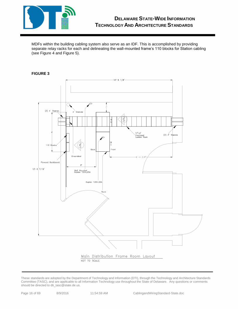
DELAWARE STATE-WIDE INFORMATION
TECHNOLOGY AND ARCHITECTURE STANDARDS
These standards are adopted by the Department of Technology and Information (DTI), through the Technology and Architecture Standards Committee (TASC), and are applicable to all Information Technology use throughout the State of Delaware. Any questions or comments should be directed to [email protected].
Page 16 of 69 8/9/2016 11:54:59 AM CablingandWiringStandard-State.doc
MDFs within the building cabling system also serve as an IDF. This is accomplished by providing separate relay racks for each and delineating the wall-mounted frame’s 110 blocks for Station cabling (see Figure 4 and Figure 5).
FIGURE 3
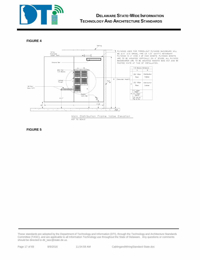
DELAWARE STATE-WIDE INFORMATION
TECHNOLOGY AND ARCHITECTURE STANDARDS
These standards are adopted by the Department of Technology and Information (DTI), through the Technology and Architecture Standards Committee (TASC), and are applicable to all Information Technology use throughout the State of Delaware. Any questions or comments should be directed to [email protected].
Page 17 of 69 8/9/2016 11:54:59 AM CablingandWiringStandard-State.doc
FIGURE 4
FIGURE 5
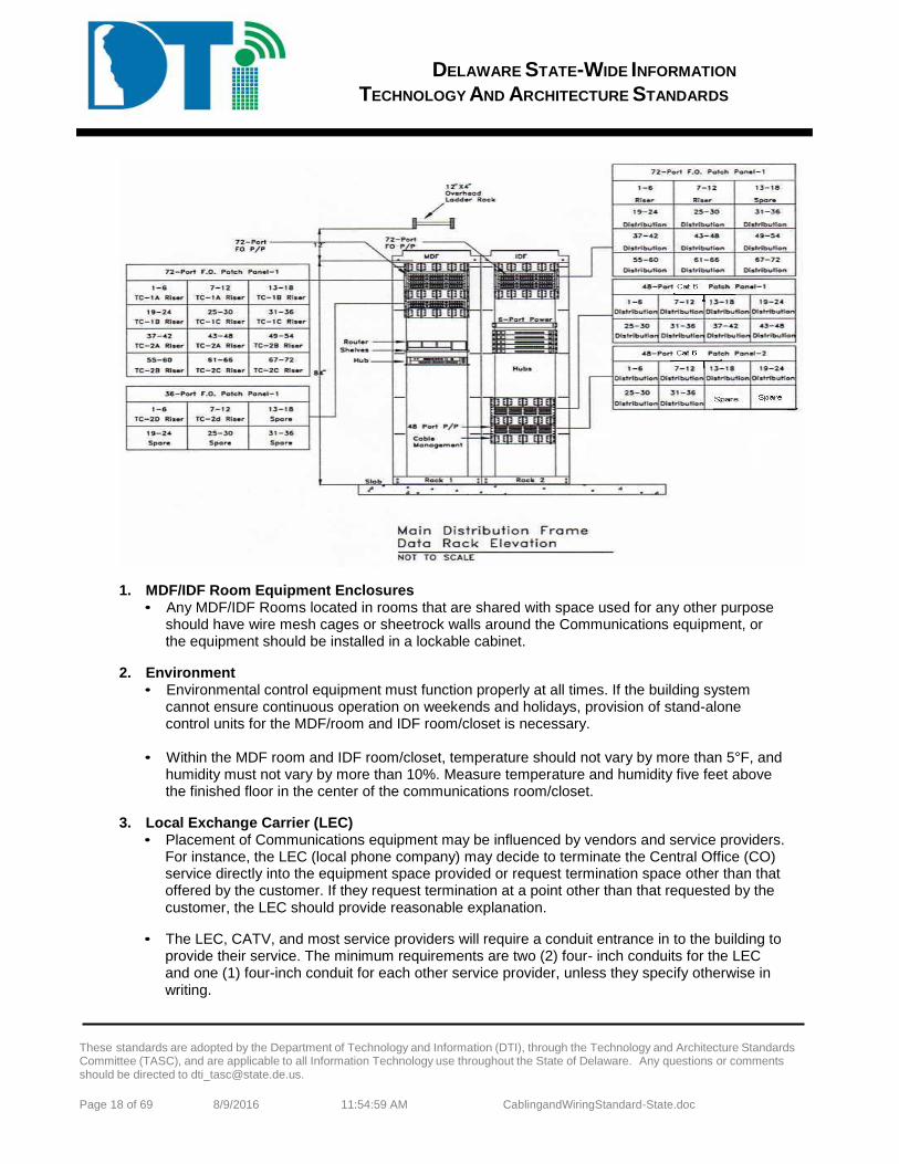
DELAWARE STATE-WIDE INFORMATION
TECHNOLOGY AND ARCHITECTURE STANDARDS
These standards are adopted by the Department of Technology and Information (DTI), through the Technology and Architecture Standards Committee (TASC), and are applicable to all Information Technology use throughout the State of Delaware. Any questions or comments should be directed to [email protected].
Page 18 of 69 8/9/2016 11:54:59 AM CablingandWiringStandard-State.doc
1. MDF/IDF Room Equipment Enclosures • Any MDF/IDF Rooms located in rooms that are shared with space used for any other purpose
should have wire mesh cages or sheetrock walls around the Communications equipment, or the equipment should be installed in a lockable cabinet.
2. Environment
• Environmental control equipment must function properly at all times. If the building system cannot ensure continuous operation on weekends and holidays, provision of stand-alone control units for the MDF/room and IDF room/closet is necessary.
• Within the MDF room and IDF room/closet, temperature should not vary by more than 5°F, and
humidity must not vary by more than 10%. Measure temperature and humidity five feet above the finished floor in the center of the communications room/closet.
3. Local Exchange Carrier (LEC)
• Placement of Communications equipment may be influenced by vendors and service providers. For instance, the LEC (local phone company) may decide to terminate the Central Office (CO) service directly into the equipment space provided or request termination space other than that offered by the customer. If they request termination at a point other than that requested by the customer, the LEC should provide reasonable explanation.
• The LEC, CATV, and most service providers will require a conduit entrance in to the building to provide their service. The minimum requirements are two (2) four- inch conduits for the LEC and one (1) four-inch conduit for each other service provider, unless they specify otherwise in writing.
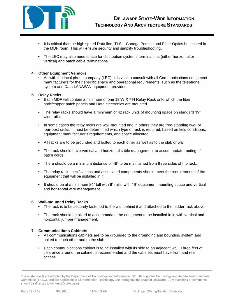
DELAWARE STATE-WIDE INFORMATION
TECHNOLOGY AND ARCHITECTURE STANDARDS
These standards are adopted by the Department of Technology and Information (DTI), through the Technology and Architecture Standards Committee (TASC), and are applicable to all Information Technology use throughout the State of Delaware. Any questions or comments should be directed to [email protected].
Page 19 of 69 8/9/2016 11:54:59 AM CablingandWiringStandard-State.doc
• It is critical that the high speed Data line, TLS – Canoga Perkins and Fiber Optics be located in the MDF room. This will ensure security and simplify troubleshooting.
• The LEC may also need space for distribution systems terminations (either horizontal or vertical) and patch cable terminations.
4. Other Equipment Vendors
• As with the local phone company (LEC), it is vital to consult with all Communications equipment manufacturers for their specific space and operational requirements, such as the telephone system and Data LAN/WAN equipment provider.
5. Relay Racks
• Each MDF will contain a minimum of one 19”W X 7’H Relay Rack onto which the fiber optic/copper patch panels and Data electronics are mounted.
• The relay racks should have a minimum of 42 rack units of mounting space on standard 19” wide rails.
• In some cases the relay racks are wall-mounted and in others they are free-standing two- or four-post racks. It must be determined which type of rack is required, based on field conditions, equipment manufacturer's requirements, and space allocated.
• All racks are to be grounded and bolted to each other as well as to the slab or wall.
• The rack should have vertical and horizontal cable management to accommodate routing of patch cords.
• There should be a minimum distance of 48” to be maintained from three sides of the rack.
• The relay rack specifications and associated components should meet the requirements of the equipment that will be installed in it.
• It should be at a minimum 84” tall with 6” rails, with 19” equipment mounting space and vertical and horizontal wire management.
6. Wall-mounted Relay Racks
• The rack is to be securely fastened to the wall behind it and attached to the ladder rack above.
• The rack should be sized to accommodate the equipment to be installed in it, with vertical and horizontal jumper management.
7. Communications Cabinets
• All communications cabinets are to be grounded to the grounding and bounding system and bolted to each other and to the slab.
• Each communications cabinet is to be installed with its side to an adjacent wall. Three feet of clearance around the cabinet is recommended and the cabinets must have front and rear access.
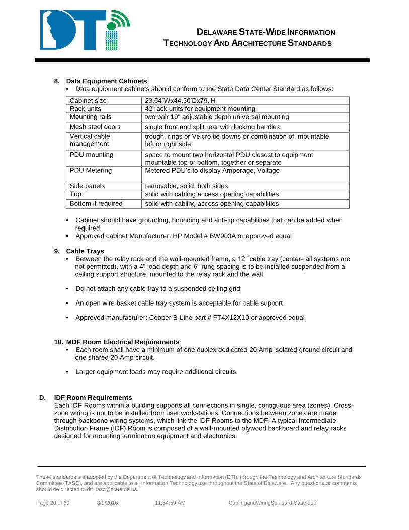
DELAWARE STATE-WIDE INFORMATION
TECHNOLOGY AND ARCHITECTURE STANDARDS
These standards are adopted by the Department of Technology and Information (DTI), through the Technology and Architecture Standards Committee (TASC), and are applicable to all Information Technology use throughout the State of Delaware. Any questions or comments should be directed to [email protected].
Page 20 of 69 8/9/2016 11:54:59 AM CablingandWiringStandard-State.doc
8. Data Equipment Cabinets
• Data equipment cabinets should conform to the State Data Center Standard as follows:
Cabinet size 23.54”Wx44.30’Dx79.’H
Rack units 42 rack units for equipment mounting
Mounting rails two pair 19" adjustable depth universal mounting
Mesh steel doors single front and split rear with locking handles
Vertical cable management
trough, rings or Velcro tie downs or combination of, mountable left or right side
PDU mounting space to mount two horizontal PDU closest to equipment mountable top or bottom, together or separate
PDU Metering Metered PDU’s to display Amperage, Voltage
Side panels removable, solid, both sides
Top solid with cabling access opening capabilities
Bottom if required solid with cabling access opening capabilities
• Cabinet should have grounding, bounding and anti-tip capabilities that can be added when
required. • Approved cabinet Manufacturer: HP Model # BW903A or approved equal
9. Cable Trays
• Between the relay rack and the wall-mounted frame, a 12” cable tray (center-rail systems are not permitted), with a 4" load depth and 6" rung spacing is to be installed suspended from a ceiling support structure, mounted to the relay rack and the wall.
• Do not attach any cable tray to a suspended ceiling grid.
• An open wire basket cable tray system is acceptable for cable support.
• Approved manufacturer: Cooper B-Line part # FT4X12X10 or approved equal
10. MDF Room Electrical Requirements
• Each room shall have a minimum of one duplex dedicated 20 Amp isolated ground circuit and one shared 20 Amp circuit.
• Larger equipment loads may require additional circuits.
D. IDF Room Requirements
Each IDF Rooms within a building supports all connections in single, contiguous area (zones). Cross-zone wiring is not to be installed from user workstations. Connections between zones are made through backbone wiring systems, which link the IDF Rooms to the MDF. A typical Intermediate Distribution Frame (IDF) Room is composed of a wall-mounted plywood backboard and relay racks designed for mounting termination equipment and electronics.
DELAWARE STATE-WIDE INFORMATION
TECHNOLOGY AND ARCHITECTURE STANDARDS
These standards are adopted by the Department of Technology and Information (DTI), through the Technology and Architecture Standards Committee (TASC), and are applicable to all Information Technology use throughout the State of Delaware. Any questions or comments should be directed to [email protected].
Page 21 of 69 8/9/2016 11:54:59 AM CablingandWiringStandard-State.doc
Drawing Redacted

DELAWARE STATE-WIDE INFORMATION
TECHNOLOGY AND ARCHITECTURE STANDARDS
These standards are adopted by the Department of Technology and Information (DTI), through the Technology and Architecture Standards Committee (TASC), and are applicable to all Information Technology use throughout the State of Delaware. Any questions or comments should be directed to [email protected].
Page 22 of 69 8/9/2016 11:54:59 AM CablingandWiringStandard-State.doc
FIGURE 7
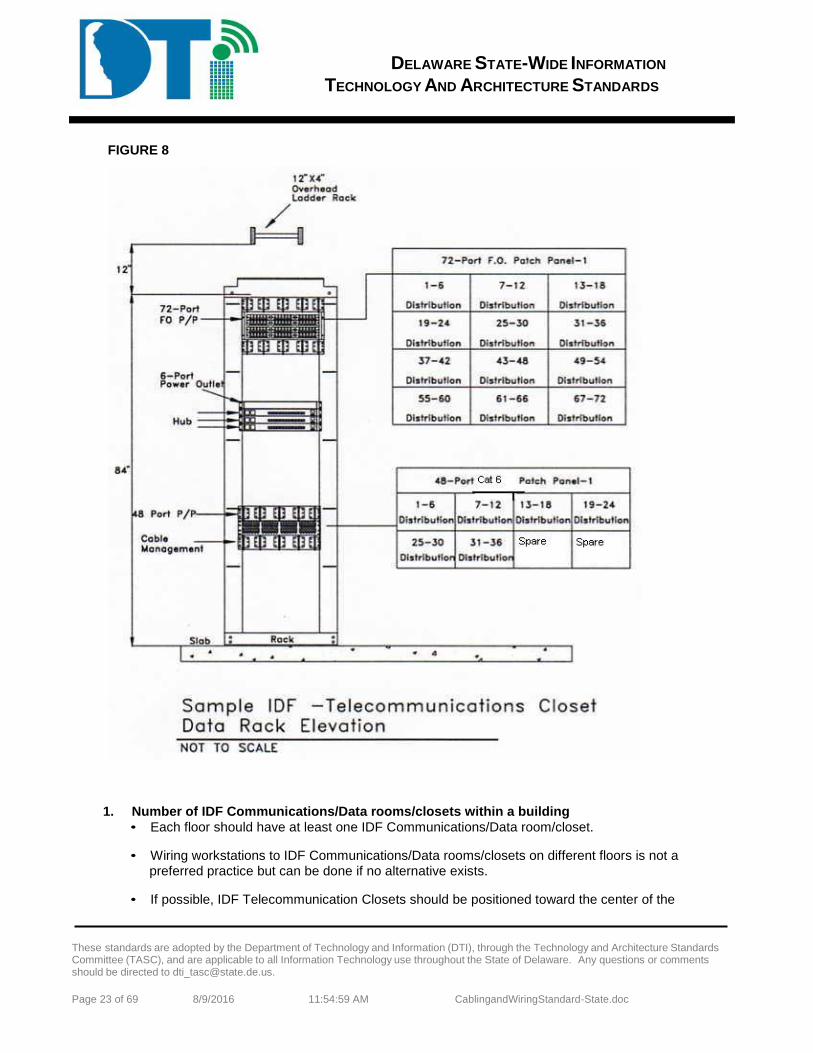
DELAWARE STATE-WIDE INFORMATION
TECHNOLOGY AND ARCHITECTURE STANDARDS
These standards are adopted by the Department of Technology and Information (DTI), through the Technology and Architecture Standards Committee (TASC), and are applicable to all Information Technology use throughout the State of Delaware. Any questions or comments should be directed to [email protected].
Page 23 of 69 8/9/2016 11:54:59 AM CablingandWiringStandard-State.doc
FIGURE 8
1. Number of IDF Communications/Data rooms/closets within a building • Each floor should have at least one IDF Communications/Data room/closet.
• Wiring workstations to IDF Communications/Data rooms/closets on different floors is not a preferred practice but can be done if no alternative exists.
• If possible, IDF Telecommunication Closets should be positioned toward the center of the
DELAWARE STATE-WIDE INFORMATION
TECHNOLOGY AND ARCHITECTURE STANDARDS
These standards are adopted by the Department of Technology and Information (DTI), through the Technology and Architecture Standards Committee (TASC), and are applicable to all Information Technology use throughout the State of Delaware. Any questions or comments should be directed to [email protected].
Page 24 of 69 8/9/2016 11:54:59 AM CablingandWiringStandard-State.doc
building (usually the core area) and stacked vertically, when possible, in multi-story buildings.
2. Plywood Backboard
• Each IDF Room will contain a minimum of one 4’ X 8’ sheet of plywood flush- mounted on the wall.
• Securely fasten the plywood to wall-framing members to ensure that it can support attached equipment.
• The plywood is to be 3/4”, A/C grade and fire retardant.
• All plywood backboards are to be mounted smooth side out and painted with white fire retardant paint at time of installation and prior to installation of equipment onto the plywood.
3. IDF Room Equipment Enclosures
• Any IDF Rooms located in rooms that are share space used for any other purpose should have wire mesh cages or sheetrock walls around the Communications equipment.
4. Relay Racks
• Each MDF will contain a minimum of one 19”W X 7’H Relay Rack onto which the fiber optic/copper patch panels and Data electronics are mounted.
• The relay racks should have a minimum of 42 rack units of mounting space on standard 19” wide rails.
• In some cases the relay racks are wall-mounted and in others they are free-standing two- or four-post racks. It must be determined which type of rack is required, based on field conditions, equipment manufacturer's requirements, and space allocated.
• All racks are to be grounded and bolted to each other as well as to the slab or wall.
• The rack should have vertical and horizontal cable management to accommodate routing of patch cords.
• The relay rack specifications and associated components should meet the requirements of the equipment that will be installed in it.
• It should be at a minimum 84” tall with 6” rails, with 19” equipment mounting space and vertical and horizontal wire management.
5. Wall-Mounted Relay Racks
• The rack is to be securely fastened to the wall behind the rack and attached to the ladder rack above.
• The rack should be sized to accommodate the equipment to be installed in it, with vertical and horizontal jumper management.
6. Communications Cabinets
DELAWARE STATE-WIDE INFORMATION
TECHNOLOGY AND ARCHITECTURE STANDARDS
These standards are adopted by the Department of Technology and Information (DTI), through the Technology and Architecture Standards Committee (TASC), and are applicable to all Information Technology use throughout the State of Delaware. Any questions or comments should be directed to [email protected].
Page 25 of 69 8/9/2016 11:54:59 AM CablingandWiringStandard-State.doc
• All communications cabinets are to be grounded to the grounding and bounding system, bolted to each other and to the slab.
• Each communications cabinet is to be installed with its side to an adjacent wall.
• Three feet of clearance around the cabinet is recommended, and the cabinets must have front and rear access.
7. Cable Trays
• Between the relay rack and the wall-mounted frame, a 12” cable tray (no center rail systems), with a 4" load depth and 6" rung spacing is to be installed suspended from a ceiling support structure, mounted to the relay rack and the wall.
• Do not attach cable trays to the suspended ceiling grid.
• An open wire basket cable tray system is acceptable for cable support.
8. IDF Room Electrical Requirements
• Each Communications/Data room/closet shall have one 110V, 15 Amp electrical convenience outlet and one 110V, 20 Amp dedicated–circuit, isolated-ground electrical outlet for the electronic equipment.
• This is a minimum requirement based on the typical current draw of the networking equipment to be placed.
• The ground for the equipment outlet should be isolated where possible to avoid line transients.
• The 110V 20 Amp dedicated-circuit, isolated-ground electrical outlets should be mounted in convenient location to facilitate the use of the shortest equipment power cords.
• The recommended location is at the top of the rack or on the ladder tray.
• All electrical isolated ground outlets serving Communications and Data equipment must be attached to non-switched circuits to prevent inadvertent equipment shutdown.
• It is also recommended that they be on a UPS and/or generator if available.
PART 10 MDF & IDF PRODUCT SPECIFICATIONS A. Category 6 Patch Panels
In new construction projects, the default cabling infrastructure shall be Category 6 unless specified otherwise. 1. Category 6 Patch Panel Requirements
• Category 6 patch panels shall be standard 8-position, RJ-45 style, un-keyed, in 48-port configurations.
• Panel frames shall be 14-gage steel with rolled edges top and bottom for proper stiffness.
DELAWARE STATE-WIDE INFORMATION
TECHNOLOGY AND ARCHITECTURE STANDARDS
These standards are adopted by the Department of Technology and Information (DTI), through the Technology and Architecture Standards Committee (TASC), and are applicable to all Information Technology use throughout the State of Delaware. Any questions or comments should be directed to [email protected].
Page 26 of 69 8/9/2016 11:54:59 AM CablingandWiringStandard-State.doc
• Panel design shall incorporate plastic push-fasteners to permit hands-free positioning onto standard EIA-310-D 19” mounting rails.
• Panels shall accommodate a minimum of 24 ports for each rack mount unit (1 RMU = 1.75 in.).
• Panels shall be designed for 4-pair, 100 ohm balanced unshielded twisted pair (UTP) cable.
• Panels shall terminate 26-22 AWG solid conductors, with maximum insulation diameter of 0.050 in.
• Panels shall have attached wiring instruction labels to permit either T568A or T568B wiring configurations.
• Panels shall have individual port identification numbers on the front and rear of the panel.
• Panel adapter modules shall be 110-style termination with tin lead solder plated IDC contacts.
• Printed circuit boards shall be fully enclosed front and rear for physical protection.
• Panel contacts shall withstand a minimum of 2000 mating cycles with an FCC 8-position RJ-45 plug, without degradation of electrical or mechanical performance.
• Panel contacts shall be constructed of Beryllium copper for maximum spring force and durability.
• Contact plating shall be a minimum of 50 micro-inches of hard gold in the contact area over 50 micro-inch of nickel.
• Panel termination method shall follow the industry standard 110 IDC punch-down, using a standard 110 impact termination tool.
• Panels shall be compatible with a 4-pair multi-punch impact termination tool designed specifically for the purpose. Bending or other damage to the panel using a multi-pair punch tool shall not occur.
• IDC contact termination towers shall have tapered pair-splitting features to aid wire insertion and minimize pair un-twist.
• IDC contacts shall be Phosphor Bronze with 100 micro-inch tin lead 60/40 plating over nickel.
• Panels shall not require special cords or special installation requirements.
• Panel ports shall accept optional hinged dust covers and port identification icon buttons.
• Space above the adapter ports shall be available for additional labeling per ANSI/TIA/EIA-606-A.
• Category 6 panels shall be backward compatible with existing Category 3, 5, and 5e cabling systems for fit, form, and function.
• Panels shall accept a clip-on rear cable management support bar to provide cable strain relief.

DELAWARE STATE-WIDE INFORMATION
TECHNOLOGY AND ARCHITECTURE STANDARDS
These standards are adopted by the Department of Technology and Information (DTI), through the Technology and Architecture Standards Committee (TASC), and are applicable to all Information Technology use throughout the State of Delaware. Any questions or comments should be directed to [email protected].
Page 27 of 69 8/9/2016 11:54:59 AM CablingandWiringStandard-State.doc
2. Category 6 Patch Panel Performance Requirements
• All transmission performance parameters shall be independently verified by a UL or ETL third party testing organization.
• Category 6 panels shall meet or exceed Category 6 transmission requirements for connecting hardware, as specified in ANSI/TIA/EIA-568-B.2-1, Transmission Performance Specifications for 4-Pair 100 ohm Category 6 Cabling.
• The manufacturer shall provide Category 6 component compliance certificates from third party testing organizations upon request.
• Panels shall be UL LISTED 1863 and CSA certified.
• Panels shall exceed IEEE 802.3 DTE Power specification to 4 times the rated current limits with no degradation of performance or materials.
• Panel contacts shall withstand a minimum of 2000 mating cycles with an FCC 8-position RJ-45 plug, without degradation of electrical or mechanical performance.
• Panels shall be third party verified, error free Gigabit Ethernet performance to IEEE 802.3 standard.
• Category 6 panels shall meet the current draft 10 Gb/s performance requirements of IEEE 802.3an and TSB-155, for a maximum 55-meter channel length. Conditions of requirement No. 10 above apply.
3. Acceptable Manufacturers:
• Hubbell Premise Wiring. The Hubbell products listed in the table below comply with all requirements specified in this document
HUBBELL CATALOG NUMBER
Description
P6E48U NEXTSPEED® Category 6 Patch Panel, 48-Ports PCBLMGT Rear Cable Management Bar
• Or approved equal of: Ortronics, Panduit, Systimax, Leviton
4. Category 6 Patch Panel Installation Requirements • Horizontal and backbone cabling of the proper category shall be fully deployed into the TR, TE,
or ER according to applicable codes and standards.
• Cable slack, service loops, bend radii, and pathway fill ratio shall comply with applicable codes and standards.
• Racks, cabinets, enclosures, and metallic cable pathways shall be bonded to an approved ground according to ANSI-J-STD-607-A.
DELAWARE STATE-WIDE INFORMATION
TECHNOLOGY AND ARCHITECTURE STANDARDS
These standards are adopted by the Department of Technology and Information (DTI), through the Technology and Architecture Standards Committee (TASC), and are applicable to all Information Technology use throughout the State of Delaware. Any questions or comments should be directed to [email protected].
Page 28 of 69 8/9/2016 11:54:59 AM CablingandWiringStandard-State.doc
• Cable ends for termination shall be clean and free from crush marks, cuts, or kinks left from pulling operations.
• Properly mount patch panels into the designated rack, cabinet, or bracket locations with the #12-24 screws provided.
• Terminate cables into the patch panel according to manufacturer’s instructions.
• To maximize transmission performance, maintain wiring pair twists as close as possible to the point of termination.
• The length of wiring pair un-twist in each termination shall be less than 0.5 inches (13 mm).
• Horizontal or backbone cables extending from the panel terminations shall maintain a minimum bend radius of at least 4 times the cable diameter.
• Cable terminations shall have no tensile or bending strain on panel IDC contacts in each installed location.
• Panels shall be properly labeled on front and back with the cable number and port connections for each port.
B. Fiber Enclosures, Adapter Plates, Connectors
1. Fiber Adapter Enclosure Requirements • Enclosure design shall be a modular, rack-mounted, powder coated formed cold rolled steel
enclosure with a removable front cover, rear panel, top panel, and slide-out inner tray.
• Each basic unit delivered shall consist of: (1) enclosure assembly, (2) mounting brackets, (6) cable ties, (5) snap-in cable clips (4) #12-24 mounting screws, (1) adhesive grid label, (4) adhesive cable clips, (2) Velcro cable ties, (3) label holders, and (1) splice tray stud, wing nut, and spacer.
• Material shall be as follows:
a. Enclosure, panels and tray: 16 gage cold rolled steel (CRS)
b. Mounting brackets: 14 gage CRS
c. Front cover: Acrylic (Plexiglas)
• Basic dimensions of the enclosures shall be approximately 17” wide by 12” deep.
• Enclosures shall be available in heights of 3.5” (2 RMU), 5.25” (3 RMU), and 7” (4 RMU) versions.
• Finish shall be black durable powder coat on all surfaces.
• Front door shall be Lexan plastic, hinged at the bottom, with a cap-plugged hole to accept an optional lock. Front door shall also be removable in the fully open position by sliding left off the mounting pins.
DELAWARE STATE-WIDE INFORMATION
TECHNOLOGY AND ARCHITECTURE STANDARDS
These standards are adopted by the Department of Technology and Information (DTI), through the Technology and Architecture Standards Committee (TASC), and are applicable to all Information Technology use throughout the State of Delaware. Any questions or comments should be directed to [email protected].
Page 29 of 69 8/9/2016 11:54:59 AM CablingandWiringStandard-State.doc
• Front door shall be secured in the closed position with lever-action quick-release latches.
• Top cover shall be removable in the forward direction, without fasteners, to provide access to the connector field. Top panel shall also have knockouts for backbone cable entry.
• Rear panel shall be removable without fasteners.
• Enclosure shall be equipped with panel-mounting brackets assembled for 19” rack mounting, compliant to ANSI/EIA-310-D.
• Panel mounting brackets shall be configurable to either 19” or 23” racks.
• Enclosure chassis shall have two mounting bracket locations for either flush mount or center mount on the rack.
• Rear of enclosure shall have two knockouts, top and bottom, for backbone cable entry and internal routing.
• Front of enclosure chassis shall have side cutouts for patch cord entry into, and exit from the enclosure.
• Inner tray shall slide out in the forward direction by releasing the lever-action quick-release latches. Tabs in the chassis shall engage with slots in the inner tray in the outward position to prevent tray from falling out.
• Inner tray shall have rear-located knockouts to match rear chassis knockouts.
• Inner tray panel mounting posts shall accept modular adapter panels, in high- or low-density versions. Adapter panels shall be available in ST multimode/singlemode.
• Splice tray mounting boss shall also accept a stud for mounting blown fiber adapter brackets.
• Inner tray shall have clips for cable ties, and holes to accept snap-in cable clips, front and rear, for complete cable management of patch cords and distribution cable strands.
• Inner tray shall have rear cable tie-down features to accept various diameter backbone cables entering the enclosure.
2. Fiber Adapter Panels Requirements
• Fiber adapter panels shall be a modular, quick-fastening steel plate, powder coated to match the enclosure finish.
• Fiber adapter panels shall have pre-installed SC fiber adapters, available in low- or high-density multi-mode or single-mode applications.
• Each individually bagged unit delivered shall consist of: (1) fully assembled adapter panel, with push-pull fasteners pre-installed.
• Adapter panels shall be constructed of 16 gage cold rolled steel.
• Finish shall be black durable powder coat on all surfaces.
DELAWARE STATE-WIDE INFORMATION
TECHNOLOGY AND ARCHITECTURE STANDARDS
These standards are adopted by the Department of Technology and Information (DTI), through the Technology and Architecture Standards Committee (TASC), and are applicable to all Information Technology use throughout the State of Delaware. Any questions or comments should be directed to [email protected].
Page 30 of 69 8/9/2016 11:54:59 AM CablingandWiringStandard-State.doc
• Basic dimensions of the FSP panels shall be 5.10” length by 1.10” wide.
• Panels shall have two pre-installed, push-pull type quick-release fasteners for quick snap-in installation. Push-pull fasteners shall have an industry standard center distance of 4.65”.
• Panels shall be suitable for mounting either vertically or horizontally.
• Panels shall be available in with SC adapters with precision ceramic alignment sleeves.
• All fiber adapters installed in FSP panels shall have dust caps installed.
• Panels shall be available in low-density and high-density adapter patterns.
3. Fiber Connector Requirements
• Please note OM4 minimum standard
i. Internal Building Installation
1. Installation distances LESS than 1640ft/500m should use OM4-Multimode Fiber.
2. Installation distances GREATER than 1640ft/500m require use of single Mode fiber exclusively.
ii. External Building/Campus Installation
1. Buildings less than 1640ft/500m may use OM4-Multimode Fiber, but use of mixed strand OM4/Single Mode fiber is highly recommended.
2. Installation distances GREATER than 1640ft/500m require use of Single Mode fiber exclusively.
• Connector basic design shall be a factory pre-polished SC optical fiber connector with a zirconium ceramic ferrule. Integral with the connector body is a wedge-activated fiber clamping mechanism to secure the inserted fiber into a mechanical splice with the factory installed cleaved fiber stub. Index-matching gel is supplied factory-injected into the cleaved fiber stub splice to optimize transmission performance. Connector attachment is achieved without tools, by inserting a field-cleaved optical fiber and then extracting the disposable clamp wedges from the connector body.
• Each basic connector unit delivered shall consist of: (1) connector body with disposable clamp wedge, (1) strain relief boot, and (1) plastic dust cap.
• SC multimode factory pre-polished connectors shall be 50 micron laser optimized pre-installed fiber.
• Connector termination method shall utilize an industry standard multi-layer strip tool and bare fiber cleave tool as the only field tools required.
• SC connectors shall have features to enable field verification using a Visual Fault Locator (VFL) during termination.
DELAWARE STATE-WIDE INFORMATION
TECHNOLOGY AND ARCHITECTURE STANDARDS
These standards are adopted by the Department of Technology and Information (DTI), through the Technology and Architecture Standards Committee (TASC), and are applicable to all Information Technology use throughout the State of Delaware. Any questions or comments should be directed to [email protected].
Page 31 of 69 8/9/2016 11:54:59 AM CablingandWiringStandard-State.doc
• Connector materials shall be designed with thermal stability to comply with environmental requirements of ANSI/TIA/EIA-568-B.3 and Telcordia GR-1081-CORE.
• Multimode OM4 and singlemode pre-polished fiber connector materials shall be as follows:
a. Ferrule: zirconium ceramic
b. SC inner body: thermally stable injection molded thermoplastic
c. Dust Cap: nylon or PVC
d. Strain relief boot: UL94-V0 molded PVC
• Pre-polished SC connectors shall require no field polishing.
• Pre-polished Multimode-OM4 SC connector body shall be industry standard aqua for 50 micron multimode, laser optimized.
• colors for specific applications, as designated below:
• Pre-polished OM4 SC connectors shall require no adhesives for termination.
• SC connector internal fiber clamping mechanism shall firmly secure both the inserted glass fiber and the 900 micron buffer layer of the inserted fiber for maximum strain relief.
• All standard mating and interface dimensions for SC connectors shall comply with ANSI/TIA/EIA-604-10 (FOCIS 10).
• Ferrule outside diameter for SC multimode connectors shall be 1.2467mm to 1.2497mm.
• Ferrule outside diameter for SC singlemode connectors shall be 1.2483mm to 1.2497mm.
• SC ferrule tip shall have a PC spherical radius of approximately 7.0 mm radius for multimode and singlemode versions.
• Delivered connectors shall be individually bagged with the dust cap installed to protect from contamination.
• Delivered connectors shall have the disposable clamp activation wedge element pre-installed onto the connector body.
• Connector design and termination technique shall be independent of cable type or manufacturer, and shall be compatible for either 900 micron buffer or 250 micron buffer distribution cables.
• SC connector strain relief boot shall be a Telcordia style slotted design for maximum flexural strain relief.
• Strain relief boot shall be black for multimode, and yellow for singlemode.
• SC connectors shall be available individually bagged in packs of 12.
DELAWARE STATE-WIDE INFORMATION
TECHNOLOGY AND ARCHITECTURE STANDARDS
These standards are adopted by the Department of Technology and Information (DTI), through the Technology and Architecture Standards Committee (TASC), and are applicable to all Information Technology use throughout the State of Delaware. Any questions or comments should be directed to [email protected].
Page 32 of 69 8/9/2016 11:54:59 AM CablingandWiringStandard-State.doc
• Pre-polished SC fiber connectors, when properly installed onto qualified cable, shall meet the 10 Gb/s Ethernet performance requirements of IEEE802.3.
• Pre-polished SC fiber connectors, properly installed onto qualified cable, shall exceed the mechanical and environmental performance requirements of ANSI/TIA/EIA-568-C.3, Annex ‘A’.
• Pre-polished SC fiber connectors, properly installed onto qualified cable, shall exceed the mechanical and environmental performance requirements of Telcordia GR-1081-CORE.
• Qualification test data shall be available from the manufacturer upon request.
4. Acceptable Manufacturers:
• Hubbell Premise Wiring. The Hubbell products listed in the table below comply with all requirements specified in this document
HUBBELL CATALOG NUMBER
Description
FCR350SP36R Fiber Enclosure - 2U Rack Mount Fiber Enclosure, Accepts 6 Adapter Panels
FCR350SP54R Fiber Enclosure - 2U Rack Mount Fiber Enclosure, Accepts 9 Adapter Panels
FCR525SPR Fiber Enclosure - 3U Rack Mount Fiber Enclosure, Accepts 12 Adapter Panels
FCR700SP Fiber Enclosure - 4U Rack Mount Fiber Enclosure, Accepts 15 Adapter Panels
FSPLCDM6AQ Fiber Adapter Panel - 6 LC Duplex, Aqua for MM – Phosphor
Bronze Sleeves FSPLCQM6AQ Fiber Adapter Panel - 6 LC Quad, Aqua for Multimode – Phosphor
Bronze Sleeves FSPLCDS6 Fiber Adapter Panel - 6 LC Duplex, Blue for SM – Zirconia
Ceramic Sleeves FSPLCQS3 Fiber Adapter Panel - 6 LC Quad Blue for SM – Zirconia Ceramic
Sleeves Fiber Connector - LC, MM, 50/125um, OM4 – Aqua, Box of 12 FCLC900K50GM12 Fiber Connector - LC, SM, 9/125 UPC – Blue Box of 12
• Or approved equal of: Ortronics, Panduit, Systimax, Leviton
5. Fiber Installation Requirements
• For FCR-series enclosures, remove top and rear covers, and front door.
• Punch out the desired knockouts for cable entry.
• Using proper method, pull cables into cabinet through the desired knockout entry location.
DELAWARE STATE-WIDE INFORMATION
TECHNOLOGY AND ARCHITECTURE STANDARDS
These standards are adopted by the Department of Technology and Information (DTI), through the Technology and Architecture Standards Committee (TASC), and are applicable to all Information Technology use throughout the State of Delaware. Any questions or comments should be directed to [email protected].
Page 33 of 69 8/9/2016 11:54:59 AM CablingandWiringStandard-State.doc
• Strip the outer sheath and sub sheaths of the fiber cable to provide at least (2) meters service loop of the individual buffered fiber strands.
• Anchor the outer cable sheath into the rear channel of the inner tray using the cable ties provided. Note: in FCR-series enclosures, leave enough slack in the main cable to allow free motion of the inner tray fully outward. Remove cable entry knockouts as required.
• Installed copper and fiber cabling shall be properly strain relieved. Cable service coil, bend radius, and pathway fill ratio shall comply with applicable codes and standards.
• Use the plastic adhesive-backed clips provided to form the fiber strands into a large service coil on the surface of the inner tray. For FCR-series enclosures, be sure the inner tray has full mobility in and out, with no cable kinks or snags.
• Close inner tray and front cover, and lock the quick-release fasteners.
• Install SC fiber adapter panels by firmly using push fasteners to lock in place.
• Leave dust caps installed in the fiber adapter plates until connector termination is performed.
• Follow manufacturer’s termination instructions for pre-polished connectors as specified
• Uncoil the 900-micron buffered strands of cable from the service loop and set-up for termination.
• Un-package the connector, and leave dust cap installed. Firmly press downward on the connector wedge tab to fully seat clamp wedges.
• Slide the strain relief boot onto the fiber strand before stripping.
• Using a fiber strip tool, strip buffered fiber completely to approx. 1.0” of exposed glass fiber.
• CAUTION: Do not nick or scrape the glass fiber with the strip tool.
• Wipe the glass fiber firmly with an alcohol wipe. Always use 99.9% pure reagent grade alcohol for fiber cleaning.
• Mark the 900 micron buffer layer from the strip-off point per instructions.
• Insert the fiber into the cleave tool and cleave the fiber to the specified length from the end of the 900 micron buffer layer. Always keep the cleave tool clean.
• CAUTION: Always dispose of glass fiber waste in an approved container.
• Gently insert the cleaved fiber into the connector body. Rotate connector slightly during insertion to fully seat the fiber into the internal splice.
• Hold the seated fiber in place using slight force to form a bow in the fiber.
• CAUTION: Do not allow the installed fiber to slip backward.
• While holding the fiber seated, squeeze the wedge holder device to activate the clamp, and

DELAWARE STATE-WIDE INFORMATION
TECHNOLOGY AND ARCHITECTURE STANDARDS
These standards are adopted by the Department of Technology and Information (DTI), through the Technology and Architecture Standards Committee (TASC), and are applicable to all Information Technology use throughout the State of Delaware. Any questions or comments should be directed to [email protected].
Page 34 of 69 8/9/2016 11:54:59 AM CablingandWiringStandard-State.doc
then slip the wedge holder off the connector body. Dispose the wedge holder.
• Remove the connector dust cap and inspect the ferrule tip. A 400X microscope is recommended. View of the polished fiber should be a smooth round circle with no scratches, pits, cracks or chips. Use a lint-free wipe to clean off any contamination.
• CAUTION: Do not view ends of live fibers, with or without a microscope.
• Plug the connector into the proper adapter panel and proceed with the next connector. Leave dust cap installed if the connector is not mated.
C. Racks, Horizontal & Vertical Managers
1. Equipment Racks Requirements Racks shall be a structural aluminum construction, having two 6-inch deep rails.
Racks shall feature universal side mounting hole pattern for vertical cable managers.
Racks shall feature a weight load capacity of 1,000 lbs when properly secured to the floor.
Each basic rack delivered shall consist of: (2) vertical rails, (2) base angles, (1) assembly hardware kit, (2) top angles, and (20) #12-24 dog point machine screws for panel mounting.
Racks shall be available in either for 19-inch standard rack configurations.
Tapped holes in the front and rear vertical rails for mounting of panels shall be #12-24 thread size. Powder coat shall not interfere with thread fit.
Standard rack heights of 8 ft (96 in)
Racks with heights of 8 ft shall have a capacity of 51 rack mount units
Rack base angles shall be pre-drilled for floor mounting, and for assembly to vertical rails.
2. Horizontal Managers Requirements
Horizontal Managers shall be 19”W, 3.5”H
Horizontal managers shall be 16ga. Cold rolled steel construction with (6) pass thru holes, and (7) Front mounted 3.5” steel rod D-Rings.
Horizontal managers shall have hinged Aluminum front cover to conceal patch cords.
3. Vertical Managers Requirements
Vertical cable managers shall be 14”D, 10”W
Vertical cable managers shall feature a steel rod construction for increased air flow.
DELAWARE STATE-WIDE INFORMATION
TECHNOLOGY AND ARCHITECTURE STANDARDS
These standards are adopted by the Department of Technology and Information (DTI), through the Technology and Architecture Standards Committee (TASC), and are applicable to all Information Technology use throughout the State of Delaware. Any questions or comments should be directed to [email protected].
Page 35 of 69 8/9/2016 11:54:59 AM CablingandWiringStandard-State.doc
Vertical cable managers shall feature a solid aluminum door that is designed to open left or right and swing out of way for cable management.
Vertical cable managers shall feature power strip mounting brackets on rear of manager.
Vertical cable manager shall accept and include (16) 3" black cable management spools.
4. Acceptable Manufacturers:
• Hubbell Premise Wiring. The Hubbell products listed in the table below comply with all requirements specified in this document
• Cooper B-Line. The Cooper B-Line products listed in the table below comply with all requirements specified in this document
HUBBELL CATALOG NUMBER
Description
HPW84RR19D 84”H, 6”D Equipment Rack HC219CE3N 2U Horizontal Manager w/ 3.5” Front rings and cover XS1010 Vertical Cable Manager, 14”D, 10”W, with door & cable spools
B-Line CATALOG NUMBER
Description
SB55608419U6 84”H, 6”D Equipment Rack SB87019S2FB 2U Horizontal Manager w/ 3.5” Front rings and cover SB860810S084 Vertical Cable Manager, 14”D, 10”W, with door & cable spools
• Or approved equal of: Ortronics, Systimax, Leviton
D. Category 5e-110 Termination Blocks
1. 110 Termination Block Requirements • Category 5e-110 wiring blocks shall be available in 50-pair, 100-pair and 300-pair capacities,
with or without detachable standoff legs.
• Wiring blocks shall be available as kits that include wiring blocks, label strips, and the appropriate quantity of connecting blocks for termination to full capacity.
• Connecting blocks shall accommodate a 5-pair punch-down tool designed specifically for the purpose of Category 5e termination.
• Wiring blocks and connecting blocks shall be constructed of UL94-V0 rated high-impact flame-retardant polycarbonate blend thermoplastic.
• Wiring blocks shall accept 26-22 AWG solid or stranded conductors
• Wiring blocks shall accept conductor insulation diameters of .050 in to .070 in maximum.
DELAWARE STATE-WIDE INFORMATION
TECHNOLOGY AND ARCHITECTURE STANDARDS
These standards are adopted by the Department of Technology and Information (DTI), through the Technology and Architecture Standards Committee (TASC), and are applicable to all Information Technology use throughout the State of Delaware. Any questions or comments should be directed to [email protected].
Page 36 of 69 8/9/2016 11:54:59 AM CablingandWiringStandard-State.doc
• Wiring blocks and connecting blocks shall have a temperature rating of 14 F to 140F with up to 95% non-condensing humidity.
• Wiring blocks shall have through-openings to permit rear cable entry and direct routing to each point of termination.
• Connecting blocks shall connect to the wiring block with a locking force of 35 Lb minimum.
• Connecting blocks shall withstand a minimum of 200 re-terminations without degradation to electrical or mechanical performance.
• IDC contact termination towers on the connecting blocks shall have tapered pair-splitting features to aid wire insertion and minimize pair un-twist. IDC towers shall also have high-definition color-coding.
2. 110 Termination Block Performance Requirements
• A UL or ETL third party testing organization shall independently verify all Category 5e transmission performance parameters.
• Category 5e-110 termination blocks shall meet or exceed Category 5e transmission requirements for connecting hardware, as specified in ANSI/TIA/EIA-568-B.2.
• The manufacturer shall provide Category 5e component compliance certificates from third party testing organization upon request.
• 5e-110 termination blocks shall be UL LISTED 1863.
• 5e-110 termination blocks shall exceed IEEE 802.3 DTE Power specification to 4 times the rated current limits with no degradation of performance or materials.
• 5e-110 termination blocks shall be third party verified, error free Gigabit Ethernet performance to IEEE 802.3 standard.
• 5e-110 termination blocks shall meet or exceed the 4-connector channel performance requirements of Category 5e, per the ANSI/TIA/EIA-568-B.2.
3. Acceptable Manufacturers:
• Hubbell Premise Wiring. The Hubbell products listed in the table below comply with all requirements specified in this document
HUBBELL CATALOG NUMBER
Description
110BLK50FTK5 110 Field Termination Kit, 5e-110/50-pair with 5-Pair Conn. Blocks 110BLK100FTK5 110 Field Termination Kit, 5e-110/100-pair with 5-Pair Conn.
Blocks 110BLK300FTK5 110 Field Termination Kit, 5e-110/300-pair with 5-Pair Conn.
Blocks
DELAWARE STATE-WIDE INFORMATION
TECHNOLOGY AND ARCHITECTURE STANDARDS
These standards are adopted by the Department of Technology and Information (DTI), through the Technology and Architecture Standards Committee (TASC), and are applicable to all Information Technology use throughout the State of Delaware. Any questions or comments should be directed to [email protected].
Page 37 of 69 8/9/2016 11:54:59 AM CablingandWiringStandard-State.doc
• Or approved equal of: Ortronics, Panduit, Systimax, Leviton
4. 110 Installation Requirements
• Follow manufacturer’s instructions.
• Mount 5e-110 wiring blocks in the desired location.
• Route cables through the openings in the wiring block base.
• Terminate UTP cables to the 5e-110 block according to manufacturer’s instructions, using the connecting blocks and proper termination tool.
• To maximize transmission performance, maintain wiring pair twists as close as possible to the point of termination.
• The length of wiring pair un-twist in each termination shall be less than 0.5 inches (13 mm).
• Cables extending from the block terminations shall maintain a minimum bend radius of at least 4 times the cable diameter.
• Cable terminations shall have no tensile or bending strain on IDC contacts after termination. Note: Use the appropriate cable management hardware to relieve cable strain and control bend radius.
PART 11 INFORMATION OUTLETS – DATA & VOICE
A work area has at least one standard Information Outlet consisting of two Data RJ45 jacks. All of the RJ45 jacks shall be Category 6 unless otherwise specified are wired according to the 568B standard.
DATA & VOICE Cabling Requirement Scenarios
DATA PC & VOIP Telephony INFORMATION OUTLET
2x DATA RJ45 CAT 6 Jacks per Information Outlet
No Traditional Voice Wiring Required
DATA PC & TDM/Digital or Analog Phones/PBX
2x DATA RJ45 CAT 6 Jacks per Information Outlet
1x Voice CAT 5e Jack per Information Outlet A. Information Outlet Locations
1. The location of the information outlets is dependent on the environment in which the outlets will be installed. An office environment certainly is different than a laboratory, training room, or manufacturing area. If the outlets are to be wall- mounted, the bottom of the outlet is to be located 15” above of the finished floor under normal conditions. However, there are many exceptions to this rule. If there is existing equipment that does not allow for this, such as a credenza or countertop, the outlet must be placed at a height appropriate to the situation.
2. Locate the outlet where it is closest to the equipment and people it will serve. Keep in mind that the cord from the outlet to the device can be a trip hazard or may span across doors. In an office
DELAWARE STATE-WIDE INFORMATION
TECHNOLOGY AND ARCHITECTURE STANDARDS
These standards are adopted by the Department of Technology and Information (DTI), through the Technology and Architecture Standards Committee (TASC), and are applicable to all Information Technology use throughout the State of Delaware. Any questions or comments should be directed to [email protected].
Page 38 of 69 8/9/2016 11:54:59 AM CablingandWiringStandard-State.doc
environment, each desk or workstation should have an information outlet. If a particular area has a series of fax machines or modems, then additional outlets should be installed. The number of jacks in an outlet is standard, so to maintain the standard, additional information outlets of the same configuration should be installed; do not install non-standard outlets.
3. Computer laboratories or training rooms require a large amount of connectivity in odd locations. Power poles are one solution as is the use of surface-mounted raceway or floor-mounted boxes. Each situation is different and must be considered individually. Again, standards are to be maintained in outlet configurations.
4. When locating an outlet, consideration should be given to the route the cable must take to the information outlet. If the outlet is to be installed on a masonry wall and surface-mount raceway is used for cable routing, the location of the outlet may be more dependent on the path available down or across the wall than where the equipment is located. Each location must be looked at individually to determine if the route to the desired outlet location is possible.
5. Wall-mounted outlets should not be located on heating units, equipment or ductwork. They are always to be located on either a gypsum, sheetrock, or masonry wall.
6. A description of the information outlet configurations follows:
Standard Office Information Outlets consist of: as detailed on the drawings attached to the contract, the contractor will install and terminate (3) four-pair, one UTP Category 6 or 6a for Data cables onto individual RJ45 female jacks.
Computer Laboratory or Training Room Information Outlets: as indicated on the attached drawings, the contractor will install and terminate the designated series of four-pair UTP Category 6 or 6a cables onto individual RJ45 jacks. The number of cables and jacks vary from two to eight, depending upon the furniture configuration and number of PCs to be served.
B. Category 6 Jacks In new construction projects, the default cabling infrastructure shall be Category 6 unless specified otherwise.
1. Category 6 Jack Requirements
Jacks shall be standard 8-position, RJ-45 style, un-keyed, FCC compliant.
Jacks shall be designed for 4-pair, 100 ohm balanced unshielded twisted pair (UTP) cable.
Each jack shall be single unit construction, with snap – fit to industry standard keystone opening (.760” x .580”).
Jack housings shall fully encase and protect printed circuit boards and IDC fields.
Modular jack contacts shall accept a minimum of 2000 mating cycles without degradation of electrical or mechanical performance.
Jack contacts shall be constructed of Beryllium copper for maximum spring force and durability.
Contact plating shall be a minimum of 50 micro-inches of hard gold in the contact area over 50 micro-inch of nickel.
Jack termination method shall follow the industry standard 110 IDC punch-down
DELAWARE STATE-WIDE INFORMATION
TECHNOLOGY AND ARCHITECTURE STANDARDS
These standards are adopted by the Department of Technology and Information (DTI), through the Technology and Architecture Standards Committee (TASC), and are applicable to all Information Technology use throughout the State of Delaware. Any questions or comments should be directed to [email protected].
Page 39 of 69 8/9/2016 11:54:59 AM CablingandWiringStandard-State.doc
Jacks shall be compatible with a 4-pair single punch impact tool designed specifically for the purpose.
IDC contact termination towers shall have tapered pair-splitting features to aid wire insertion and minimize pair un-twist.
Jacks shall terminate 26-22 AWG solid or stranded conductors.
Jacks shall terminate insulated conductors with outside diameters up to .050”.
Jacks shall not require special cords, specialty tools or special installation requirements.
Jacks shall include a translucent stuffer cap for wire retention and to permit visual inspection.
Stuffer cap shall have retention snaps to assure conductor strain relief.
Jacks shall accept FCC compliant 6 position plugs.
Jacks shall accept optional hinged dust covers.
Jacks shall be compatible with ANSI/TIA/EIA-606-A color code labeling.
Jacks shall accept snap-on icons for specific identification.
Jacks shall be available in various colors to meet specific customer applications.
Jacks shall have attached wiring instruction labels to permit either T568A or T568B wiring configurations.
Category 6 jacks shall be backward compatible with existing Category 3, 5, and 5e cabling systems for fit, form, and function.
2. Category 6 Jack Performance Requirements
All transmission performance parameters shall be independently verified by a UL or ETL third party testing organization.
Category 6 jacks shall exceed Category 6 transmission requirements for connecting hardware, as specified in ANSI/TIA/EIA-568-B.2-1, Transmission Performance Specifications for 4-Pair 100 ohm Category 6 Cabling.
Category 6 jacks shall exceed 10 Gb/s transmission requirements for connecting hardware, under the constraints of ANSI/TIA-TSB-155 (current draft).
The manufacturer shall provide Category 6 component compliance certificates from third party testing organization upon request.
Jacks shall be UL LISTED 1863 and CSA certified.
Jacks shall exceed IEEE 802.3 DTE Power specification to 4 times the rated current limits with no degradation of performance or materials.
DELAWARE STATE-WIDE INFORMATION
TECHNOLOGY AND ARCHITECTURE STANDARDS
These standards are adopted by the Department of Technology and Information (DTI), through the Technology and Architecture Standards Committee (TASC), and are applicable to all Information Technology use throughout the State of Delaware. Any questions or comments should be directed to [email protected].
Page 40 of 69 8/9/2016 11:54:59 AM CablingandWiringStandard-State.doc
Jacks shall be third party verified, error free Gigabit Ethernet performance to IEEE 802.3 standard.
Jacks shall exceed 4 Gb/s data transmission capacity within the bandwidth of 1 – 250 MHz when configured in a 4-connector channel.
Jacks shall exceed the 4-connector channel performance requirements of Category 6, per the ANSI/TIA/EIA-568-B.2-1 standard.
Jacks shall exceed the 4-connector Category channel performance requirements for 10 Gb/s transmission over Category 6, according to TIA/TSB-155 (current draft).
The 4-connector channel test configuration shall utilize Category 6 patch panels and Category 6 patch cords, from the same manufacturer, with qualified Category 6 cable.
3. Acceptable Manufacturers:
• Hubbell Premise Wiring. The Hubbell products listed in the table below comply with all requirements specified in this document
HUBBELL CATALOG NUMBER
Description
HXJ6xx NEXTSPEED® Category 6 Jack xx = Jack color. Replace xx with “W” for White, “BK” for Black, “B” for Blue, “GY” for Gray, “GN”
for Green, “OW” for Office White, “OR” for Orange, “R” for Red, “Y” for Yellow. Refer to project drawing for color applications.
• Or approved equal of: Ortronics, Panduit, Systimax, Leviton
4. Category 6 Jack Installation Horizontal cabling of the proper category shall be fully deployed from the TR or TE to each wall
plate location according to applicable codes and standards.
Cable slack, service coil, bend radii, and pathway fill ratio shall comply with applicable codes and standards.
Metallic horizontal cable pathways shall be bonded to an approved ground according to ANSI-J-STD-607-A.
Cable ends for termination shall be clean and free from crush marks, cuts, or kinks left from pulling operations.
Terminate jacks according to manufacturer’s instructions.
To maximize transmission performance, maintain wiring pair twists as close as possible to the point of termination.
The length of wiring pair un-twist in each termination shall be less than 0.5 inches (13 mm).
DELAWARE STATE-WIDE INFORMATION
TECHNOLOGY AND ARCHITECTURE STANDARDS
These standards are adopted by the Department of Technology and Information (DTI), through the Technology and Architecture Standards Committee (TASC), and are applicable to all Information Technology use throughout the State of Delaware. Any questions or comments should be directed to [email protected].
Page 41 of 69 8/9/2016 11:54:59 AM CablingandWiringStandard-State.doc
Jacks shall be properly mounted in plates, frames, or housings with stuffer cap fully installed over IDC contacts.
Horizontal cables extending from mounted jacks shall maintain a minimum bend radius of at least 4 times the cable diameter.
Cable terminations shall have no tensile or bending strain on IDC contacts after assembly of faceplate or housing to the wall outlet.
Jacks shall be tested as part of the installed horizontal cabling system, with faceplates assembled complete and properly mounted.
Each link or channel in the horizontal cabling system shall be identified and tested individually, using an industry standard level III tester with correct settings.
Each jack shall be tested as part of the horizontal channel or link for the parameters listed below.
C. Face Plates
1. Face Plate Requirements Faceplates shall be constructed of high impact, UL94 V-0 rated thermoplastic.
Faceplates shall be 2.75" W x 4.5" H (69.8 mm x 114.3 mm) for single gang and 4.5” X 4.5” (114.3 X 114.3 mm) for double gang.
Port size in each faceplate shall be industry standard vertical keystone opening size (.760” x .580”).
Faceplates shall accept Hubbell XJ-series UTP jacks and Snap-Fit fiber optic, audio, and video modules for multimedia applications.
Faceplates shall provide for ANSI/TIA/EIA-606-A compliant workstation outlet labeling.
Faceplates shall be provided with clear plastic and color-matched label field covers.
Color-matched blank Snap-Fit modules shall be available separately to fill unused ports and openings as required.
Two #6-32 pan head Phillips/slotted mounting screws shall be included with each single gang faceplate.
Four #6-32 pan head Phillips/slotted mounting screws shall be included with each double gang faceplate.
Jacks and Snap-Fit modules shall snap firmly into rear of faceplate and position flush to outer plate surface.
Faceplates shall be compatible with standard NEMA openings and boxes.
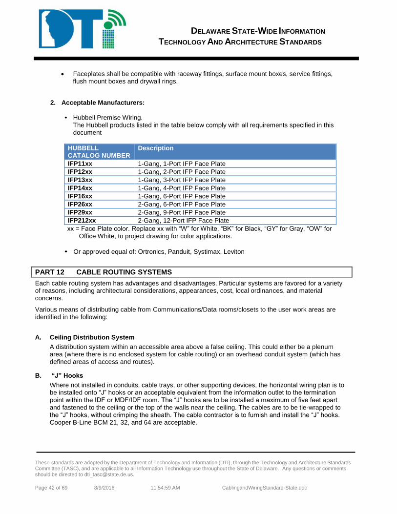
DELAWARE STATE-WIDE INFORMATION
TECHNOLOGY AND ARCHITECTURE STANDARDS
These standards are adopted by the Department of Technology and Information (DTI), through the Technology and Architecture Standards Committee (TASC), and are applicable to all Information Technology use throughout the State of Delaware. Any questions or comments should be directed to [email protected].
Page 42 of 69 8/9/2016 11:54:59 AM CablingandWiringStandard-State.doc
Faceplates shall be compatible with raceway fittings, surface mount boxes, service fittings, flush mount boxes and drywall rings.
2. Acceptable Manufacturers:
• Hubbell Premise Wiring. The Hubbell products listed in the table below comply with all requirements specified in this document
HUBBELL CATALOG NUMBER
Description
IFP11xx 1-Gang, 1-Port IFP Face Plate IFP12xx 1-Gang, 2-Port IFP Face Plate IFP13xx 1-Gang, 3-Port IFP Face Plate IFP14xx 1-Gang, 4-Port IFP Face Plate IFP16xx 1-Gang, 6-Port IFP Face Plate IFP26xx 2-Gang, 6-Port IFP Face Plate IFP29xx 2-Gang, 9-Port IFP Face Plate IFP212xx 2-Gang, 12-Port IFP Face Plate xx = Face Plate color. Replace xx with “W” for White, “BK” for Black, “GY” for Gray, “OW” for
Office White, to project drawing for color applications.
• Or approved equal of: Ortronics, Panduit, Systimax, Leviton
PART 12 CABLE ROUTING SYSTEMS
Each cable routing system has advantages and disadvantages. Particular systems are favored for a variety of reasons, including architectural considerations, appearances, cost, local ordinances, and material concerns.
Various means of distributing cable from Communications/Data rooms/closets to the user work areas are identified in the following: A. Ceiling Distribution System
A distribution system within an accessible area above a false ceiling. This could either be a plenum area (where there is no enclosed system for cable routing) or an overhead conduit system (which has defined areas of access and routes).
B. “J” Hooks
Where not installed in conduits, cable trays, or other supporting devices, the horizontal wiring plan is to be installed onto “J” hooks or an acceptable equivalent from the information outlet to the termination point within the IDF or MDF/IDF room. The “J” hooks are to be installed a maximum of five feet apart and fastened to the ceiling or the top of the walls near the ceiling. The cables are to be tie-wrapped to the “J” hooks, without crimping the sheath. The cable contractor is to furnish and install the “J” hooks. Cooper B-Line BCM 21, 32, and 64 are acceptable.
DELAWARE STATE-WIDE INFORMATION
TECHNOLOGY AND ARCHITECTURE STANDARDS
These standards are adopted by the Department of Technology and Information (DTI), through the Technology and Architecture Standards Committee (TASC), and are applicable to all Information Technology use throughout the State of Delaware. Any questions or comments should be directed to [email protected].
Page 43 of 69 8/9/2016 11:54:59 AM CablingandWiringStandard-State.doc
C. Sleeves and Conduits 1. The use of conduits and sleeves within a building is common for the transport of communications
cable. Conduits and sleeves are to be sized and routes are to be planned within and between buildings in order to route the cable plant from the MDF to IDF and IDF to Information Outlet, and to accommodate any additional cabling required. The sizing of the conduits and sleeves is to be based on the number of cables, the location and environment surrounding the sleeve or conduit, and acceptable conduit fill levels, which are typically 40%. All conduits are to be installed with the appropriate sweep to maintain the required bend radius for copper and fiber optic cable. All sleeves and conduits are to be installed with bushings and suspended according to building industry standards.
2. The following are guidelines to use in determining where sleeves and conduits are to be installed but does not limit nor identify all areas or situations where sleeves and conduits will be required.
All masonry walls that have cables passing through them are to have sleeves installed. Gymnasiums and athletic areas are to have conduits installed to house cables passing through
the area. Each MDF and IDF Room is to have sleeves installed to contain the large number of cables
exiting the room. Conduits are to be installed in areas where cables extend from one building to another via covered or enclosed bridges and corridors.
3. Cable routing is to follow a “streets and avenues” path in corridors where possible. However, there
are a number of reasons for exceptions. In some cases, the corridors do not allow cables to be run because of architectural constraints or inaccessible ceilings. Also, in order to maintain the 90-meter standard for Category 6 cabling, some cables need to be run separately and diagonally to isolated information outlets. Throughout all runs, the contractor is to maintain EIA/TIA standards regarding the proximity of communications cabling to high voltage cabling, motors, transformers, fluorescent lighting, ballasts, etc.
PART 13 CABLING-GENERAL A. All cable shall meet the requirements of the NEC, except where other authorities or codes impose a
more stringent requirement or practice. Codes, such as the NEC, do not normally include transmission performance requirements. This section specifies the essential media transmission characteristics. It is advisable to consult standards associated with the planned service or equipment to determine any specific media limitations.
B. Contractor is to take all necessary precautions to assure that the maximum tensile load and minimum bend radius of all cables (fiber and copper) are not exceeded. When terminating Category 5e & 6 cable, care should be taken to maintain pair twists up to the termination point and not more than 0.5" of the cable pairs shall be untwisted. It is preferred that the cable sheath is also not removed more than 0.5" from the termination point. Tie wraps are to be hand-tightened on cables and are not to crimp the sheath. Contractor is responsible for protecting all connectorized cables from damage by other contractors at the information outlet before and after installation of the outlet faceplates.
C. All riser and station cable installed is to be plenum-rated cable. The fluoropolymer resin that insulates
Category 5e & 6 plenum cables is engineered as a fire safety innovation. The NEC requires that all cable installed in plenum spaces and not encased in conduit must have certain fire resistance and low smoke producing characteristics. Not only are such cables highly resistant to fire but they also produce very little smoke.
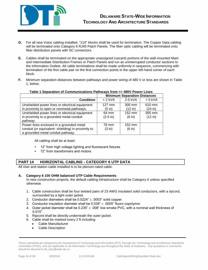
DELAWARE STATE-WIDE INFORMATION
TECHNOLOGY AND ARCHITECTURE STANDARDS
These standards are adopted by the Department of Technology and Information (DTI), through the Technology and Architecture Standards Committee (TASC), and are applicable to all Information Technology use throughout the State of Delaware. Any questions or comments should be directed to [email protected].
Page 44 of 69 8/9/2016 11:54:59 AM CablingandWiringStandard-State.doc
D. For all new Voice cabling installed, "110" blocks shall be used for termination. The Copper Data cabling
will be terminated onto Category 6 RJ45 Patch Panels. The fiber optic cabling will be terminated onto fiber distribution panels with SC connectors.
E. Cables shall be terminated on the appropriate unassigned (vacant) portions of the wall-mounted Main
and Intermediate Distribution Frames or Patch Panels and run as uninterrupted conductor sections to the Information Outlets. All cable terminations shall be made uniformly in sequence, commencing with termination of the first cable pair on the first connection points in the upper left-hand corner of each block.
F. Minimum separation distances between pathways and power wiring of 480 V or less are shown in Table 1, below.
Table 1 Separation of Communications Pathways from <= 480V Power Lines
Minimum Separation Distances Condition < 2 kVA 2-5 kVA > 5 kVA
Unshielded power lines or electrical equipment in proximity to open or nonmetal pathways.
127 mm (5 in)
305 mm (12 in)
610 mm (24 in)
Unshielded power lines or electrical equipment in proximity to a grounded metal conduit pathway
64 mm (2.5 in)
152 mm (6 in)
305 mm (12 in)
Power lines enclosed in a grounded metal conduit (or equivalent- shielding) in proximity to a grounded metal conduit pathway.
76 mm (3 in)
152 mm (6 in)
All cabling shall be at least:
• 12” from high voltage lighting and fluorescent fixtures • 72” from transformers and motors
PART 14 HORIZONTAL CABLING - CATEGORY 6 UTP DATA All riser and station cable installed is to be plenum-rated cable.
A. Category 6 100 OHM balanced UTP Cable Requirements
In new construction projects, the default cabling infrastructure shall be Category 6 unless specified otherwise.
1. Cable construction shall be four twisted pairs of 23 AWG insulated solid conductors, with a ripcord,
surrounded by a tight outer jacket. 2. Conductor diameters shall be 0.0224” .0003” solid copper. 3. Conductor insulation diameter shall be 0.039” .0005” fluoro copolymer. 4. Outer jacket diameter shall be 0.235” .008” low smoke PVC, with a nominal wall thickness of
0.015”. 5. Ripcord shall be directly underneath the outer jacket. 6. Cable shall be marked every 2 ft including
Cable Manufacturer Cable Description
DELAWARE STATE-WIDE INFORMATION
TECHNOLOGY AND ARCHITECTURE STANDARDS
These standards are adopted by the Department of Technology and Information (DTI), through the Technology and Architecture Standards Committee (TASC), and are applicable to all Information Technology use throughout the State of Delaware. Any questions or comments should be directed to [email protected].
Page 45 of 69 8/9/2016 11:54:59 AM CablingandWiringStandard-State.doc
Month and Year of manufacture. Job number.
7. UL, ETL, or CSA agency certification or verification markings shall be marked on the cable jacket according to the certifying agency’s requirements.
8. Color coding of the pairs shall be as follows: Pair 1: White/Blue; Blue Pair 2: White/Orange; Orange Pair 3: White/Green; Green Pair 4: White/Brown; Brown
9. Cable shall be supplied in 1000 ft spools or 1000 ft Reelex boxes.
B. Category 6 100 OHM balanced UTP Cable Performance Requirements 1. All transmission performance parameters shall be independently verified by a UL or ETL third party
testing organization. 2. Cable shall exceed Category 6 transmission requirements specified in ANSI/TIA/EIA-568-B.2-1,
and shall be tested through 550 MHz. 3. Worst-case cable performance shall be +8.0 dB headroom over current TIA/EIA and ISO standards
limits for NEXT and PSNEXT loss, and ELFEXT and PSELFEXT loss. 4. Insertion loss shall be 3.0% lower than standard Hubbell Category 6 plenum and riser cables
described in Section 27 15 13. 5. Worst case electrical performance characteristics shall be as follows:
Characteristic Impedance: 100 + 15 (1.0-100 MHz) 100 + 20 (101-250 MHz) Maximum Conductor Resistance: 9.38 /100 Meters @ 20°C Maximum Resistance Unbalance: 3% Maximum Mutual Capacitance: 5.6 nF/100 Meters @ 1 kHz Maximum Capacitance Unbalance: 330 pF/100 Meters Maximum Delay Skew: 25 ns/100 Meters
6. The manufacturer shall provide Category 6 component compliance certificates from third party testing organization upon request.
7. Cable shall be UL and C(UL) listed. 8. Cable shall exceed IEEE 802.3af DTE Power specification to 4 times the rated current limits with no
degradation of performance or materials. 9. Cable shall be third party verified, error free Gigabit Ethernet performance to IEEE 802.3ab. 10. Cable shall exceed the requirements of TIA/TSB-155: 10 Gb/s Ethernet Operation over 55 Meters
Channel Length. 11. Cable shall meet or exceed the 4-connector channel performance requirements of Category 6, per
the ANSI/TIA/EIA-568-B.2-1 standard. 12. The 4-connector channel test configuration shall utilize Category 6 jacks and patch panels, with
Category 6 patch cords, from the same manufacturer, with qualified Category 6 cable. C. Acceptable Manufacturers:
1. Hubbell Premise Wiring and Hitachi Cable Manchester (HCM)
The Hubbell products listed in the table below comply with all requirements specified in this document
HUBBELL CATALOG NUMBER
Description
DELAWARE STATE-WIDE INFORMATION
TECHNOLOGY AND ARCHITECTURE STANDARDS
These standards are adopted by the Department of Technology and Information (DTI), through the Technology and Architecture Standards Committee (TASC), and are applicable to all Information Technology use throughout the State of Delaware. Any questions or comments should be directed to [email protected].
Page 46 of 69 8/9/2016 11:54:59 AM CablingandWiringStandard-State.doc
C6SPxx NEXTSPEED Category 6 550 MHz – Plenum Spool C6RPxx NEXTSPEED Category 6 550 MHz – Plenum REELEX xx = Cable color. Replace xx with “W” for White, “GY” for Gray, “B” for Blue, “Y” for Yellow. Refer
to project drawing for color applications. HITACHI CATALOG NUMBER
Description
30025-8xx Category 6 – Plenum Spool 30024-8xx Category 6 550 MHz – Riser Spool xx = Cable color. Replace xx with “WH” for White, “GY” for Gray, “BL” for Blue, “Y” for Yellow.
Refer to project drawing for color applications.
2. Or approved equal of: Belden, Berk-Tek, Systemax D. Category 6 100 OHM balanced UTP Cable Installation Requirements
1. Pull cable into conduits, or place into raceway or cable tray as specified. Do not exceed 25 Lb pull force per cable. Use appropriate lubricants as required to reduce pulling friction.
2. All exposed wiring shall be installed in surface raceway. 3. All wiring above ceilings or below access floors shall be installed in cable tray or open-top cable
hangers. 4. Cable slack and service loops shall be stored properly above the ceiling or under the access floor.
A “figure-eight” service loop is recommended for Category 6 cabling to reduce EMI coupling. 5. Pathway fill ratio in conduit, tray, raceway, etc. shall not exceed 40% of pathway cross-sectional
area. 6. Installed cable bend radius shall be greater than 4X cable diameter. Avoid kinking or twisting the
cable during installation. 7. Do not over-tighten cable ties, and do not use staples or clamps to anchor cables. Velcro straps are
recommended. 8. Recommended spacing of cable supports above the ceiling shall be 48”. 9. Maintain the following clearances from EMI sources:
Power cable: 6 in. Florescent lights: 12 in. Transformers and electrical service enclosures: 36 in.
10. Communications cabling that must cross power cables or conduit shall cross at a 90-degree angle, and shall not make physical contact.
11. Length of each horizontal cable run from the TR to the wall outlet shall not exceed 90 meters. 12. Leave sufficient slack for 90 degree sweeps at all vertical drops. 13. Do not install cable in wet areas, or in proximity to hot water pipes or boilers. 14. Cable ends for termination shall be clean and free from crush marks, cuts, or kinks left from pulling
operations. 15. Installed cable jackets shall have no abrasions with exposed conductor insulation or bare copper
‘shiners”. The installer is responsible to replace damaged cables. 16. Horizontal cables extending from mounted jacks or panels shall maintain a minimum bend radius of
at least 4 times the cable diameter. 17. Firestop all cable penetrations through fire-rated barriers per local codes.
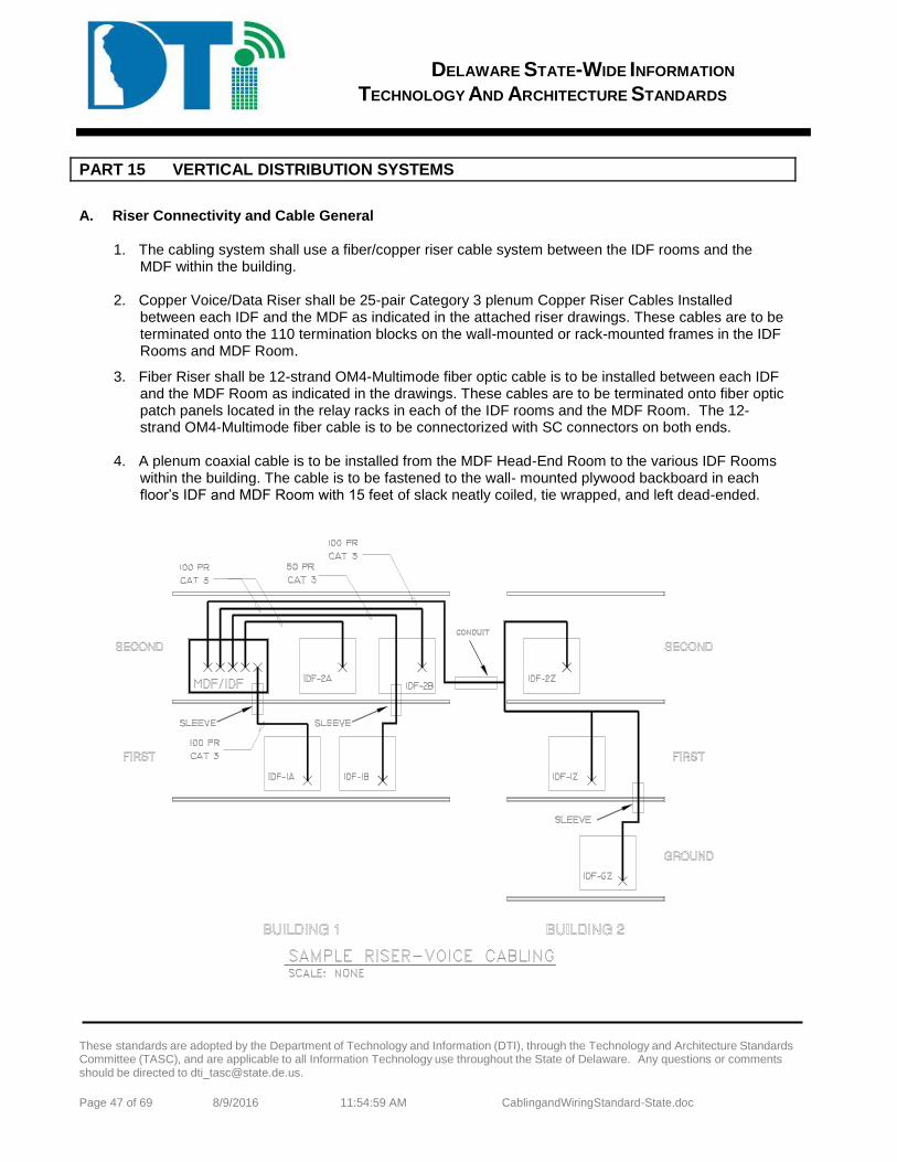
DELAWARE STATE-WIDE INFORMATION
TECHNOLOGY AND ARCHITECTURE STANDARDS
These standards are adopted by the Department of Technology and Information (DTI), through the Technology and Architecture Standards Committee (TASC), and are applicable to all Information Technology use throughout the State of Delaware. Any questions or comments should be directed to [email protected].
Page 47 of 69 8/9/2016 11:54:59 AM CablingandWiringStandard-State.doc
PART 15 VERTICAL DISTRIBUTION SYSTEMS A. Riser Connectivity and Cable General
1. The cabling system shall use a fiber/copper riser cable system between the IDF rooms and the
MDF within the building. 2. Copper Voice/Data Riser shall be 25-pair Category 3 plenum Copper Riser Cables Installed
between each IDF and the MDF as indicated in the attached riser drawings. These cables are to be terminated onto the 110 termination blocks on the wall-mounted or rack-mounted frames in the IDF Rooms and MDF Room.
3. Fiber Riser shall be 12-strand OM4-Multimode fiber optic cable is to be installed between each IDF and the MDF Room as indicated in the drawings. These cables are to be terminated onto fiber optic patch panels located in the relay racks in each of the IDF rooms and the MDF Room. The 12-strand OM4-Multimode fiber cable is to be connectorized with SC connectors on both ends.
4. A plenum coaxial cable is to be installed from the MDF Head-End Room to the various IDF Rooms
within the building. The cable is to be fastened to the wall- mounted plywood backboard in each floor’s IDF and MDF Room with 15 feet of slack neatly coiled, tie wrapped, and left dead-ended.
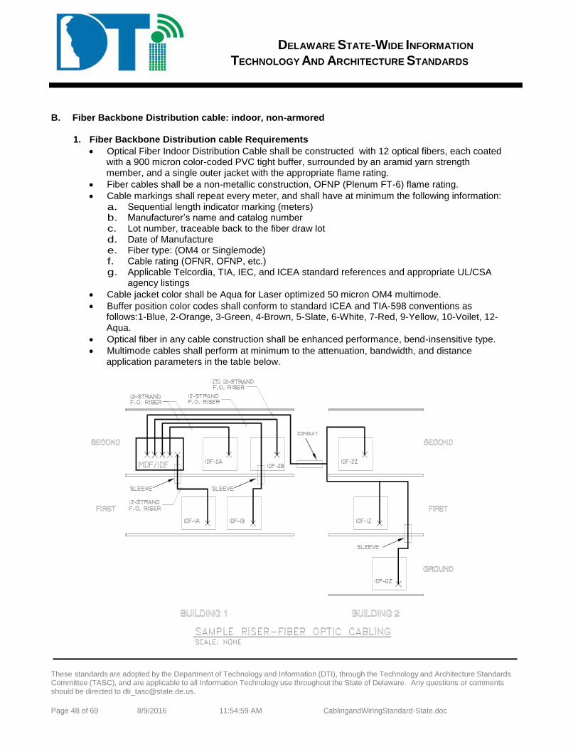
DELAWARE STATE-WIDE INFORMATION
TECHNOLOGY AND ARCHITECTURE STANDARDS
These standards are adopted by the Department of Technology and Information (DTI), through the Technology and Architecture Standards Committee (TASC), and are applicable to all Information Technology use throughout the State of Delaware. Any questions or comments should be directed to [email protected].
Page 48 of 69 8/9/2016 11:54:59 AM CablingandWiringStandard-State.doc
B. Fiber Backbone Distribution cable: indoor, non-armored
1. Fiber Backbone Distribution cable Requirements Optical Fiber Indoor Distribution Cable shall be constructed with 12 optical fibers, each coated
with a 900 micron color-coded PVC tight buffer, surrounded by an aramid yarn strength member, and a single outer jacket with the appropriate flame rating.
Fiber cables shall be a non-metallic construction, OFNP (Plenum FT-6) flame rating. Cable markings shall repeat every meter, and shall have at minimum the following information:
a. Sequential length indicator marking (meters) b. Manufacturer’s name and catalog number c. Lot number, traceable back to the fiber draw lot d. Date of Manufacture e. Fiber type: (OM4 or Singlemode) f. Cable rating (OFNR, OFNP, etc.) g. Applicable Telcordia, TIA, IEC, and ICEA standard references and appropriate UL/CSA
agency listings Cable jacket color shall be Aqua for Laser optimized 50 micron OM4 multimode. Buffer position color codes shall conform to standard ICEA and TIA-598 conventions as
follows:1-Blue, 2-Orange, 3-Green, 4-Brown, 5-Slate, 6-White, 7-Red, 9-Yellow, 10-Voilet, 12-Aqua.
Optical fiber in any cable construction shall be enhanced performance, bend-insensitive type. Multimode cables shall perform at minimum to the attenuation, bandwidth, and distance
application parameters in the table below.
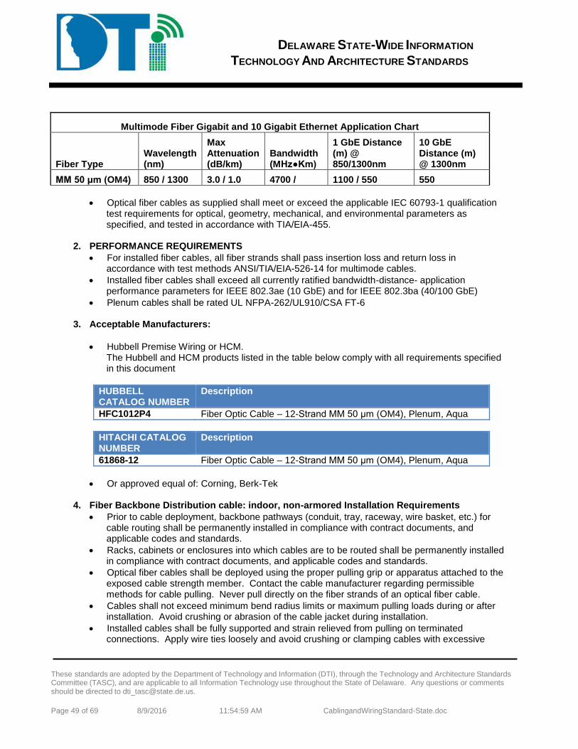
DELAWARE STATE-WIDE INFORMATION
TECHNOLOGY AND ARCHITECTURE STANDARDS
These standards are adopted by the Department of Technology and Information (DTI), through the Technology and Architecture Standards Committee (TASC), and are applicable to all Information Technology use throughout the State of Delaware. Any questions or comments should be directed to [email protected].
Page 49 of 69 8/9/2016 11:54:59 AM CablingandWiringStandard-State.doc
Multimode Fiber Gigabit and 10 Gigabit Ethernet Application Chart
Fiber Type Wavelength (nm)
Max Attenuation (dB/km)
Bandwidth (MHzKm)
1 GbE Distance (m) @ 850/1300nm
10 GbE Distance (m) @ 1300nm
MM 50 μm (OM4) 850 / 1300 3.0 / 1.0 4700 / 1100 / 550 550 Optical fiber cables as supplied shall meet or exceed the applicable IEC 60793-1 qualification
test requirements for optical, geometry, mechanical, and environmental parameters as specified, and tested in accordance with TIA/EIA-455.
2. PERFORMANCE REQUIREMENTS
For installed fiber cables, all fiber strands shall pass insertion loss and return loss in accordance with test methods ANSI/TIA/EIA-526-14 for multimode cables.
Installed fiber cables shall exceed all currently ratified bandwidth-distance- application performance parameters for IEEE 802.3ae (10 GbE) and for IEEE 802.3ba (40/100 GbE)
Plenum cables shall be rated UL NFPA-262/UL910/CSA FT-6
3. Acceptable Manufacturers:
Hubbell Premise Wiring or HCM. The Hubbell and HCM products listed in the table below comply with all requirements specified in this document
HUBBELL CATALOG NUMBER
Description
HFC1012P4 Fiber Optic Cable – 12-Strand MM 50 μm (OM4), Plenum, Aqua
HITACHI CATALOG NUMBER
Description
61868-12 Fiber Optic Cable – 12-Strand MM 50 μm (OM4), Plenum, Aqua
Or approved equal of: Corning, Berk-Tek 4. Fiber Backbone Distribution cable: indoor, non-armored Installation Requirements
Prior to cable deployment, backbone pathways (conduit, tray, raceway, wire basket, etc.) for cable routing shall be permanently installed in compliance with contract documents, and applicable codes and standards.
Racks, cabinets or enclosures into which cables are to be routed shall be permanently installed in compliance with contract documents, and applicable codes and standards.
Optical fiber cables shall be deployed using the proper pulling grip or apparatus attached to the exposed cable strength member. Contact the cable manufacturer regarding permissible methods for cable pulling. Never pull directly on the fiber strands of an optical fiber cable.
Cables shall not exceed minimum bend radius limits or maximum pulling loads during or after installation. Avoid crushing or abrasion of the cable jacket during installation.
Installed cables shall be fully supported and strain relieved from pulling on terminated connections. Apply wire ties loosely and avoid crushing or clamping cables with excessive

DELAWARE STATE-WIDE INFORMATION
TECHNOLOGY AND ARCHITECTURE STANDARDS
These standards are adopted by the Department of Technology and Information (DTI), through the Technology and Architecture Standards Committee (TASC), and are applicable to all Information Technology use throughout the State of Delaware. Any questions or comments should be directed to [email protected].
Page 50 of 69 8/9/2016 11:54:59 AM CablingandWiringStandard-State.doc
force. All non-armored fiber optic riser cables are to be installed in plenum inner-duct. Fibers in inner-
duct or armored plenum riser fiber serving as riser cables are to be installed according to the attached riser drawing. Contractor to size the inner-duct for each cable run. Multiple fiber optic cables can occupy an individual inner-duct when non-armored fiber is not used.
PART 16 CAMPUS CABLING
A. Outside Plant Cabling
1. The contractor is to follow the drawings regarding the installation of outside plant (OSP) cabling to buildings remote from the main building, such as portable rooms, trailers, other small buildings, etc. Many remote buildings can be served by conduits underneath or within ceilings of protected overhangs and bridges.
2. The contractor is to furnish and install outside plant cables and associated protector blocks, splice cases, and grounding where applicable in an approved manner.
3. The contractor will be responsible for obtaining all required right-of-way easements and permits
before any excavation on the property begins. 4. All existing facilities in the area of excavation will be located and marked with paint, stakes, or flags
before any excavation. 5. Outside plant optical fiber cable shall be 50/125 laser-optimized multimode or Singlemode strands
loose-buffer tube water- blocking for outside plant application.
6. Outside plant copper cable will be solid insulated conductors 24 AWG with gel-filled core in 25-, 50-, or 100-pair increments.
7. RG-11 coaxial cable rated for OSP use will be used between buildings. Outside plant cables are to
be routed aerially, underground, or buried by designed. Contractor may provide recommendations as to cable routing for approval.
8. Where noted, the contractor is to use aerial plant cabling between buildings. In cases where cables
are attached to poles or buildings, aerial spans are not to exceed 100 ft from the last pole to the building, using slack span construction (no guying at either end). EIA/TIA guidelines and NEC code are to be strictly adhered to for separation and clearances from power lines and traffic.
9. Underground Cable is to be enclosed in conduit buried at least 24 inches below ground surface. In
situations where fiber optic cables will be used, inner-ducts will be placed inside conduits to ensure physical protection for the cable. Proper fill ratios must be observed as well as proper bend radius. Metal sleeves through the foundation will be used to prevent conduit shearing. Sleeves must extend from inside the foundation wall to a minimum of 12”. The end of the conduit within the building must be securely fastened to withstand the placing of cable. Sleeves are to be sealed with plugs or sealant. Conduit must be bounded and grounded in compliance with EIA/TIA and NEC requirements.
DELAWARE STATE-WIDE INFORMATION
TECHNOLOGY AND ARCHITECTURE STANDARDS
These standards are adopted by the Department of Technology and Information (DTI), through the Technology and Architecture Standards Committee (TASC), and are applicable to all Information Technology use throughout the State of Delaware. Any questions or comments should be directed to [email protected].
Page 51 of 69 8/9/2016 11:54:59 AM CablingandWiringStandard-State.doc
10. Minimum depth of trench should allow for 24 inches of cover from top of cable to final grade. Upon refilling the trench, the soil must be tamped to prevent sunken trench appearance. Conduit sleeves will be used for penetrations through foundation walls, using the same guidelines as for underground cable. OSHA regulations concerning shoring requirements must be followed during all phases of buried cable installation. Contractor must install buried cable so as to meet minimum separation distances from adjacent structures (power, gas, water, etc.) To minimize the chance of accidental dig-up, contractor will install detectable warning tape a minimum 18 inches above cable.
11. Multi-pair protector blocks shall be installed to provide protection from voltage surges and sneak current. The protector panel shall be equipped with 110 wiring block and solid state protector units type 4C, and others depending on the situation. Project Manager will coordinate with contractor. Protector panels shall be installed within 50 feet of each outside plant cable building entry point. Protector panels must be grounded and bounded to the building grounding system.
12. Splice cases shall be provided and installed at both ends of outside plant cables. Splice cases shall be used for cable transition from to inside plant cables. Fiber optic splice cases shall be designed to seal, bind, anchor, and protect cable splices and
transition points from outside plant to inside plant cables. The case shall be fully equipped with a suitable splice kit for the fiber quantities specified.
Copper splice case shall be designed for use with non-pressurized cable. The case shall be of a durable fire-retardant material, single piece with a hinged cover. The case shall be equipped with a cable entrance end plates assembly of adequate size to accommodate entering and exiting cables, ground straps, and all necessary termination, mounting hardware.
13. Pedestal/Cabinet shall have a heavy gauge galvanized steel housing or equivalent and be weather-
resistant for the termination of copper and fiber optic cables. It shall be equipped with ground bar, protector blocks, and adequate space for splice cases to accommodate transition of cables into or out of the cabinet. Pedestal/Cabinet size dependent upon each situation.
14. All OSP cables will be grounded according to EIA/TIA and NEC standards and codes.
15. Contractor is to install a RG-11U Plenum Coaxial cable between the existing CATV Head-End Location and the MDF Room when indicated in the attached drawings. Not all buildings have a CATV Head-End, but if it exists, it will be noted on the attached drawings. These cables are not to be terminated, but must be neatly coiled and tie-wrapped with 40 feet of slack cable remaining at each end.
PART 17 PATCH CABLES
A. Patch cables should meet the minimum performance requirements specified for each system. This requirement specifically prohibits the use of flat, non-twisted (also known as "silver satin") cords for Data or local area network applications. However, "silver satin" patch cables are acceptable for use in telephone systems.
B. The contractor shall provide two Category 6 Patch Cords for each end of each standard outlet for horizontal LAN connectivity. The cords are to be of varying lengths based on the patch panel, electronics equipment, and work area configurations. The quantity and lengths are to be documented and agreed upon, and the owner or Project Manager is to sign for them upon acceptance. These cords are to be stored in the MDF or IDF room for which they are designated.
C. The contractor is to provide dual SC to LC Patch Cords for connectivity for ports or equipment served
DELAWARE STATE-WIDE INFORMATION
TECHNOLOGY AND ARCHITECTURE STANDARDS
These standards are adopted by the Department of Technology and Information (DTI), through the Technology and Architecture Standards Committee (TASC), and are applicable to all Information Technology use throughout the State of Delaware. Any questions or comments should be directed to [email protected].
Page 52 of 69 8/9/2016 11:54:59 AM CablingandWiringStandard-State.doc
by the fiber patch panel. The cords are to be of varying lengths based on the patch panel and electronics equipment configurations. These cords are to be stored in the MDF or IDF room for which they are designated.
D. Fiber Patch Cords
1. Fiber Patch Cord Requirements Provide factory-made, dual SC to LC fiber cables in 1-Meter lengths for every fiber cable
installed. SC Optical fiber patch cords shall be constructed with aramid-reinforced PVC loose-jacket
duplex cable, with optical fibers having a 900-micron PVC buffer coating diameter. Optical fiber used in 10 GbE patch cords shall be laser optimized 50 micron OM4-multimode, per ANSI/TIA/EIA-492AAAC, with no substitutes.
Multimode 50 micron core optical fiber within the patch cord cable shall be graded index type in accordance with ANSI/TIA/EIA-492AAAC, with the following specifications: a. Core diameter: 50 +/-3.0 microns b. Cladding diameter: 125 +/- 2.0 microns c. Core/cladding concentricity: less than 3.0 microns d. Core non-circularity: 6% maximum e. Proof test: 100 kpsi f. Effective modal bandwidth: 5700 MHz•km g. Coating diameter: 245 +/-15 microns h. Buffer diameter: 900 microns nominal
Connector terminations on each end of the fiber patch cord shall be heat-cured epoxy type with a machine polish, inspected 100% for polish quality and mated-pair insertion loss.
Epoxy volume within each connector shall be sufficient to properly surround and strain relieve the fiber and buffer layer at the buffer/fiber transition inside the connector body.
Optical fiber patch cords shall be supplied in a sealed plastic bag with dust caps installed on each end, with insertion loss test results included.
Optical fiber patch cords shall be available in standard lengths of 1, 2, 3, and 5 meters. Optical fiber patch cords shall be manufactured with industry standard SC or LC connector
terminations on each end. Factory mounted connectors on each end of the patch cords shall comply with the applicable
ANSI/TIA/EIA-604 Intermateability standard. Buffered fiber strands within the cable jacket shall be surrounded by aramid (Kevlar) material
serving as a strength member. The aramid (Kevlar) strength member shall be mechanically secured at each connector to
provide tensile strain relief of the optical fiber. Additional strain relief of the buffered fiber shall result from crimping the rear of the connector
during termination. Duplex fiber patch cords shall be a zip-cord cable construction with jacket cross-section
dimensions of 3.0 mm X 6.0 mm for SC style. Duplex fiber patch cords shall have reverse-pair polarity according to ANSI/TIA/EIA-568-B.3
and TIA/EIA-TSB-125. Cable jacket shall be marked with the cable manufacturer, UL Optical Fiber Non-Metallic Riser
rating (Type OFNR) designation, lot number, and fiber core/cladding diameter designation.

DELAWARE STATE-WIDE INFORMATION
TECHNOLOGY AND ARCHITECTURE STANDARDS
These standards are adopted by the Department of Technology and Information (DTI), through the Technology and Architecture Standards Committee (TASC), and are applicable to all Information Technology use throughout the State of Delaware. Any questions or comments should be directed to [email protected].
Page 53 of 69 8/9/2016 11:54:59 AM CablingandWiringStandard-State.doc
Fiber A-B polarity shall be clearly marked on each end of duplex patch cords. Optical fiber patch cord jacket color shall be aqua blue, specifically for 50 micron laser
optimized multimode fiber cables. Fiber patch cord connector materials shall be as follows:
a. SC Ferrules: zirconium ceramic b. SC housings: injection molded thermoplastic c. Dust Cap: nylon or PVC d. Strain relief boot: UL94-V0 molded PVC e. Strain relief boot on all connectors shall be beige. f. SC connector outer housing shall be beige.
2. Fiber Patch Cord Performance Requirements Multimode 50 micron laser optimized patch cords shall have a maximum mated-pair insertion
loss of 0.60 dB per end, with a minimum return loss of –20 dB. Fiber patch cords shall exceed 10 Gigabit Ethernet performance requirements of IEEE 802.3
standard. Fiber patch cords shall exceed the mechanical reliability requirements for tensile, flex, twist and
impact as specified in ANSI/TIA/EIA-568-B.3, Annex ‘A’. Fiber patch cords shall exceed the environmental reliability requirements for high/low
temperature and humidity as specified in ANSI/TIA/EIA-568-B.3, Annex ‘A’.
3. Acceptable Manufacturers:
• Hubbell Premise Wiring. The Hubbell products listed in the table below comply with all requirements specified in this document
HUBBELL CATALOG NUMBER
Description
DFPCLCSCFyyMM (yy=length-1,2,3,5m)
LC-SC Optical Fiber Patch cords, OM4-MM, Aqua
x = Length. Replace x with standard lengths of 1, 2, 3, 5 meters
• Or approved equal of: Ortronics, Panduit, Systimax, Leviton E. Category 6 Patch Cords
In new construction projects, the default cabling infrastructure shall be Category 6 unless specified otherwise. 1. Category 6 Patch Cord Requirements
The contractor shall provide two Category 6 Patch Cords for each end of each standard outlet for horizontal LAN connectivity. The cords are to be of varying lengths based on the patch panel, electronics equipment, and work area configurations. The quantity and lengths are to be documented and agreed upon, and the owner or Project Manager is to sign for them upon acceptance. These cords are to be stored in the MDF or IDF room for which they are designated.
Category 6 patch cords shall be constructed with a clear polycarbonate plug and boot having vertically staggered, trifurcated contacts, each having 50 micro-inches of gold plating.
Plug dimensions and function shall comply with FCC 47, Part 68.5.
DELAWARE STATE-WIDE INFORMATION
TECHNOLOGY AND ARCHITECTURE STANDARDS
These standards are adopted by the Department of Technology and Information (DTI), through the Technology and Architecture Standards Committee (TASC), and are applicable to all Information Technology use throughout the State of Delaware. Any questions or comments should be directed to [email protected].
Page 54 of 69 8/9/2016 11:54:59 AM CablingandWiringStandard-State.doc
Patch cords shall have a snag-less feature, integral to the strain relief boot on each end. Patch cords shall be constructed with category 6 patch cable, with 24 AWG 7/32 tinned copper
stranded conductors, each insulated with polyethylene, and overall jacket with UL flame-retardant PVC.
Patch cords shall be manufactured using a T568B wiring format, and shall function suitably for either T568A or T568B wiring schemes.
Patch cords shall be available in the following colors: black, blue, gray, yellow, orange, red, green, white, and purple. Custom lengths and colors shall be available with a delivery lead-time quotation.
Standard patch cord lengths shall range from1 ft. to 20 ft. Category 6 patch cords shall be backward compatible with existing Category 5 and 5e cabling
systems for fit, form, and function. 2. Category 6 Patch Cords
All transmission performance parameters shall be independently verified by a UL or ETL third party testing organization.
Category 6 patch cords shall be channel performance balanced with Hubbell category 6 jacks, patch panels, and punch-down blocks.
Category 6 patch cords shall meet or exceed Category 6 component transmission requirements for connecting hardware, as specified in ANSI/TIA/EIA-568-B.2-1 standard.
The manufacturer shall provide Category 6 component compliance certificates from third party testing organization upon request.
Patch cords shall be cUL and UL LISTED 1863. Patch cords shall exceed IEEE 802.3 DTE Power specification to 4 times the rated current
limits with no degradation of performance or materials. Patch cords shall be third party verified, error-free Gigabit Ethernet performance to IEEE 802.3
standard. Jacks shall exceed 4 Gb/s data transmission capacity within the bandwidth of 1 – 250 MHz
when configured in a 4-connector channel. Category 6 patch cords shall meet or exceed the 4-connector channel transmission
performance requirements of Category 6, per ANSI/TIA/EIA-568-B.2-1 standard. The 4-connector channel test configuration shall utilize Category 6 patch panels, blocks, and
jacks,
3. Acceptable Manufacturers:
• Hubbell Premise Wiring. The Hubbell products listed in the table below comply with all requirements specified in this document
HUBBELL CATALOG NUMBER
Description
HC6xx01 Category 6 Patch Cord, 1FT HC6xx03 Category 6 Patch Cord, 3FT HC6xx05 Category 6 Patch Cord, 5FT HC6xx07 Category 6 Patch Cord, 7FT HC6xx010 Category 6 Patch Cord, 10FT HC6xx15 Category 6 Patch Cord, 15FT
DELAWARE STATE-WIDE INFORMATION
TECHNOLOGY AND ARCHITECTURE STANDARDS
These standards are adopted by the Department of Technology and Information (DTI), through the Technology and Architecture Standards Committee (TASC), and are applicable to all Information Technology use throughout the State of Delaware. Any questions or comments should be directed to [email protected].
Page 55 of 69 8/9/2016 11:54:59 AM CablingandWiringStandard-State.doc
HC6xx20 Category 6 Patch Cord, 20FT HC6xx25 Category 6 Patch Cord, 25FT xx = Cable Color. Replace xx with “W” for White, “BK” for Black, “B” for Blue, “GY” for Gray, “GN”
for Green, “P” for Purple, “OR” for Orange, “R” for Red, “Y” for Yellow. Refer to project drawing for color applications.
• Or approved equal of: Ortronics, Panduit, Systimax, Leviton
PART 18 FIRE STOP - PENETRATION SEALANT A. Provide fire-resistant silicone foam fill to restore fire ratings to all wall, floor, or ceiling penetrations.
Foam must be UL classified and meet NEC and local code. B. All penetrations through fire-rated floors and walls shall be sealed to prevent the passage of smoke,
fire, toxic gas, or water. The fire rating of the penetration seal shall be at least that of the floor or wall into which it is installed, so that the original fire rating of the floor or wall is maintained as required by Article 300-21 of the National Electric Code.
C. No flammable material may be used to line the chase of the hole in which the fire stop material is to be installed.
D. When damming materials are to be left in place after the seal is complete, then all such materials shall be non-flammable.
E. The sealant shall be poured into the hole after each cable has been spread to allow a minimum of ½" of foam to flow between them. No cables may be touching each other, because contact between cables could allow voids to form in the fire stop.
F. If plastic cartridges are used for smaller installations, the chemical components of the foam shall be pre-measured within the cartridges to ensure the proper ratios.
G. The sealant shall remain resilient and pliable to allow for the removal and/or addition of cable without the necessity of drilling holes. It shall adhere to itself perfectly to allow any and all repairs to be made with the same material. It shall allow for vibration, expansion, and/or contraction of anything passing through the penetration without affecting the seal, or cracking, crumbling, and spalling.
H. When sealant is injected into a penetration, the foam shall expand to surround all the items within the penetration at that time and be fire resistant, maintaining the pass-minute rating.. No heat shall be required to further expand the foam to block the passage of fire and smoke or water.
I. The foam sealant material shall have been subjected to fire exposure testing in accordance with standard time-temperature curve in the Standard, UL, ASTM E
J. 119, and NJPA 251. The foam fire-stop material shall also have been subjected to the hose stream test in accordance with UL 10B.
PART 19 TESTING
A. General Test Procedures
1. Before an application for final acceptance of the work will be considered, all tests stated within this section shall be satisfactorily completed. The communications work shall include miscellaneous tasks, (e.g., removal of panel trims, junction, and pull box covers) deemed necessary to demonstrate compliance with the requirements of the Communications specifications, as well as cable and equipment manufacturers’ recommended installation procedures.
2. Upon completion of testing and problem resolution, all connections must be 100% error free: “Error
DELAWARE STATE-WIDE INFORMATION
TECHNOLOGY AND ARCHITECTURE STANDARDS
These standards are adopted by the Department of Technology and Information (DTI), through the Technology and Architecture Standards Committee (TASC), and are applicable to all Information Technology use throughout the State of Delaware. Any questions or comments should be directed to [email protected].
Page 56 of 69 8/9/2016 11:54:59 AM CablingandWiringStandard-State.doc
free" is defined to mean the item meets all the manufacturers' specifications and recommendations as published in their latest manufacturing manuals for proper installation and testing. In addition, each item must conform with all other related industrial practices and standards, Building Trades, and Electrical and Communications Industry Standards and Practices.
3. Upon successful completion of each item of testing, the Contractor shall issue in writing a certificate
of compliance, along with the test results, to the Project Manager. All failed CAT-5e & 6 – 6a cables and/or Fiber strands shall be clearly labeled and identified as defective, with the type of defect (i.e. open ring side, grounded tip, short, excessive loss, etc.) identified.
4. The Contractor will attempt to remedy any defective copper cable pair or Fiber cable strand and
specify in the documentation the location of the problem as identified during the testing procedures. The Fiber trouble location and identification must be completed with an OTDR.
B. Copper Cable Test Procedures
1. Contractor must complete cable system performance verifications on all copper and fiber cable as specified below and provide the test results to the owner or project manager. Category 5e & 6 – 6a cable must meet or exceed all manufacturer’s and EIA/TIA standards for performance and installation. Fiber cable must also meet or exceed all manufacturer’s and EIA/TIA standards for performance and installation.
2. All copper and fiber optic testing documentation is to be submitted on a CD, as well as 8.5” x 11”
hard copies. 3. At a minimum, in addition to any other required testing, the Contractor shall conduct and report on
the following tests of copper cabling after the installation is complete:
• MDF-to-IDF tests of all new riser pairs installed under this contract, to determine continuity, shorts, crossed pairs, correct pinning, and grounds.
• IDF (110 frame or patch panels)–to-information outlet tests of all new cable pairs installed under this contract, to determine continuity, shorts, crossed pairs, correct pinning, and grounds.
• The coaxial cable is to be tested from the MDF Room to the IDF Room and from the IDF Room to the coax outlet. Contractor is to test for continuity, shorts, and grounds.
• The horizontal Category 5e & 6 – 6a cabling, installed from the IDF Room to the Information Outlet at the workstation, is to be manufacturer certified and warranted for Category 5e or 6 – 6a compliance. All manufacturers’ performance certificates and extended warranties are to be provided to the owner or project manager upon completion of the testing and manufacturer certification. Contractor is to present copies of certificates identifying the contractor as a current certified VAR for the selected cabling system and therefore, qualified to install a certified cable plant.
• All category 5e & 6 – 6a cabling is to be tested end–to-end and documented for Category 5e & 6 – 6a compliance at all frequencies up to and including 100MHz for 5e and 500 for 6 – 6a. Such testing is to comply with the procedures and standards outlined by the cable manufacturer and EIA/TIA TSB - 67 concerning testing of Category 5e & 6 – 6a cable plant.
• A certified Cat 5e & 6 –6a testing system is to be used for such testing to insure that cable pairs are defect free. "Defect free" for the copper cable is defined as a copper pair not having any pair reversals, split pairs, shorts or opens. Test results shall be provided to the Owner or Project Manager within 2 days after testing or 5 days prior to the Owner connecting electronic equipment onto the cable network, whichever is sooner. The contractor must also provide
DELAWARE STATE-WIDE INFORMATION
TECHNOLOGY AND ARCHITECTURE STANDARDS
These standards are adopted by the Department of Technology and Information (DTI), through the Technology and Architecture Standards Committee (TASC), and are applicable to all Information Technology use throughout the State of Delaware. Any questions or comments should be directed to [email protected].
Page 57 of 69 8/9/2016 11:54:59 AM CablingandWiringStandard-State.doc
testing summary reports of all category 5e & 6 – 6a cables including run numbers, and pass/fail results with respect to length, impedance, DC resistance, mutual capacitance, attenuation, NEXT loss, and active ACR. The contractor must also provide spreadsheet analysis of the linearly dependent parameters of length, DC resistance, mutual capacitance, and attenuation; the field measured values shall be compared to the specifications values on one spreadsheet.
• In the event that a CAT-5e or 6 – 6a cable fails to perform to the manufacturer's specifications, the Contractor will, at the owner’s request, remove the cable and replace it with a new cable, replacing the defective cable at no additional expense to the owner.
• End-to-end testing is required for every RJ-45 connection. An owner's representative may accompany the Contractor’s staff to witness the end-to-end testing. End-to-end testing is defined herein as testing all cabling links to the very last termination point. The Contractor is required to supply sufficient quantities of two-way radios and test equipment to ensure that the tests are completed accurately and expeditiously.
• The Owner, DTI, or Project manager may conduct performance tests of transport electronics connected to the cabling system. Successful equipment performance tests do not relieve the Contractor from the specified testing, repair, and documentation requirements.
• The Contractor shall provide to the Owner or Project Manager with copies of all copper-cable test results.
C. Fiber Optic Cable Test Procedures
1. All fiber optic cable and associated equipment lateral, and vertical riser cabling must be thoroughly tested. The fiber cable will be accepted only after each strand is tested in accordance with the specifications defined herein. All strands are to be tested and found to be 100% acceptable.
2. The Contractor shall test all cables, connectors, associated equipment, and hardware furnished by the Contractor upon receipt of same as defined herein.
3. As a minimum, the Contractor shall test, as described below, all optical fiber cable strands installed
within the scope of this proposal:
• Fully test complete links only. Piecemeal testing is not acceptable. • Perform end-to-end, bi-directional attenuation (loss) test for each fiber strand at 850nm and
1300nm wavelengths. Conduct tests in accordance with EIA/TIA-526-14, Method B and with test instrument manufacturer's published instructions. a. Demonstrate that measured link loss does not exceed the expected value
based on the number of mated connector pairs, the connector's published loss per mated pair, and the cable's published loss based on distance.
b. Strands whose measured attenuation falls outside the acceptable range shall be subject to further inspection and testing to determine the nature of the fault. At a minimum, an OTDR shall be used to: determine the true loss for each connector pair and the exact length of the fiber, and to identify the presence of any core damage.
c. Riser end-to-end testing of individual optical fibers is considered to be from the MDF Room to the IDF Rooms distribution panels on each floor.
d. Horizontal end-to-end testing of individual optical fibers is considered to be from each floor’s IDF Room’s Fiber Distribution Panels to the Information Outlet.
• Faults related to connectors shall be corrected and the fiber re-tested as stated above until acceptable attenuation measurements are received.

DELAWARE STATE-WIDE INFORMATION
TECHNOLOGY AND ARCHITECTURE STANDARDS
These standards are adopted by the Department of Technology and Information (DTI), through the Technology and Architecture Standards Committee (TASC), and are applicable to all Information Technology use throughout the State of Delaware. Any questions or comments should be directed to [email protected].
Page 58 of 69 8/9/2016 11:54:59 AM CablingandWiringStandard-State.doc
• Where defects are found to be inherent in the fiber itself, notify the Project Manager in writing. Upon obtaining approval by the Project Manager, replace any cable having fewer than the manufacturer's guaranteed number of serviceable fibers.
• Remove all newly installed defective cables from pathways. Do not abandon cables in place. • All test results and corrective procedures are to be documented and submitted as a
spreadsheet to State/DTI within five (5) working days of test completion. • Considering that the fiber cable plant is to be certified, each test report form shall provide at
least the following information: a. Project name b. Contractor's name c. Date(s) of preparation and of testing d. Fiber type, strand count, connectors and patches e. Designated cable number (regardless of whether only one cable of each type is present)
and individual fiber numbers f. Make, model, serial number, and date of last calibration of test equipment used g. Name of test crew foreman h. Test results: Calculated maximum link loss, length of run, OTDR, and also i. Power Meter-measured link loss for each fiber, pass/fail result, and comments.
• In addition to the tests specified above, the Contractor shall be present while the Owner or Project Manager conducts performance tests of the transport electronics connected to the cabling system; the contractor shall conduct on- the-spot cable tests and effect cable plant repairs as necessary. Successful equipment performance tests do not relieve the Contractor from the specified testing, repair, and documentation requirements.
• Recommended test equipment: a. Optical fiber power meter and Light Source: Siecor CPM-850/1300 meter and OS-100D
Light Source, or equivalent. b. TDR: Tektronix TFP2 FiberMaster, Laser Precision TD-2000 or equivalent with 850nm and
1300nm emitter modules and hard copy printout, or equivalent. c. Optical fiber inspection scope: Cambridge Instruments 10x fiber scope, or equivalent.
• The Contractor shall provide copies of all fiber and copper cable test results to the Owner or Project Manager.
• All fiber optic cabling (workstation and riser) is to be installed in a manner that complies with and allows Owner to receive the manufacturer’s extended warranty. The contractor is to be certified and authorized to provide the extended warranty. A manufacturer's extended warranty is to be provided, through the contractor, upon completion of the testing and manufacturer’s certification. Contractor is to present copies of certificates identifying the contractor as a current certified VAR and therefore, qualified to certify and install the cable plant.
• The Owner and Project Manager reserves the right to observe any or all portions of the testing. Notification of testing is at least three days prior to start of testing.
D. Replacement
Any fiber strand, connector, block, or module installed by the Contractor that fails to meet the loss budget, or that tests below the manufacturer's standards, shall be replaced at no additional cost to the owners or State/DTI. The replacement cable, connector, or part shall be tested after repairs have been made to verify compliance. Only equipment that meets
DELAWARE STATE-WIDE INFORMATION
TECHNOLOGY AND ARCHITECTURE STANDARDS
These standards are adopted by the Department of Technology and Information (DTI), through the Technology and Architecture Standards Committee (TASC), and are applicable to all Information Technology use throughout the State of Delaware. Any questions or comments should be directed to [email protected].
Page 59 of 69 8/9/2016 11:54:59 AM CablingandWiringStandard-State.doc
the installation requirements stated herein shall meet the system’s acceptance requirements.
E. Source Manufacturing/Quality Control
Cables that are supplied by the Contractor, and test outside of the factory test data by a margin of 10 percent on loss, may be deemed non-usable and returned to the manufacturer for replacement.
F. Physical Inspection
Prior to conducting any transmission testing, the following visual inspections will be performed:
1. Verify that all cable has been installed in full compliance with the proposal specifications. 2. Check for physical damage to the Fiber Distribution Panels and termination hardware. 3. Check that all cabling is properly jacketed, installation properly labeled at both ends of the cable,
inner-duct and termination hardware is completed in all IDFs and the MDF Room. 4. Verify that all cable bends are within the manufacturer's specified bend radius. 5. Verify that all cabinets and racks (which require grounding) are properly grounded and comply with
the National and Local Electrical Codes and State Standards for grounding. 6. Verify that the cables are properly approved and structurally supported for termination. 7. Verify that all Delaware Fire Code requirements have been met and satisfied.
G. DOCUMENTATION
Proper labeling and documentation will allow a technician to quickly trace a particular cable link and will significantly reduce the time and costs of moves, additions, changes, and troubleshooting. Both labeling and documentation depend on the use of a system-wide coding scheme that will identify and locate each component of the wiring system and allow all components to be linked in a logical fashion.
There are three components of wiring system documentation:
1. Labeling Communications/Data room/closet termination areas aids in identifying the source and function of a circuit.
2. A labeling scheme simplifies the documentation process. 3. “As built” documents provide a permanent record of the communications infrastructure. These
documents are a critical management resource. As a result, it is imperative that "as built" documentation be prepared as part of the communications infrastructure project. In addition, these documents must be kept current throughout the system's life cycle.
H. Termination Blocks
Labels on the connecting hardware should be coded based on the function of the terminated wiring. Colored designation strips are typically provided with a termination block.
I. Cable and Information Outlet Identification
DELAWARE STATE-WIDE INFORMATION
TECHNOLOGY AND ARCHITECTURE STANDARDS
These standards are adopted by the Department of Technology and Information (DTI), through the Technology and Architecture Standards Committee (TASC), and are applicable to all Information Technology use throughout the State of Delaware. Any questions or comments should be directed to [email protected].
Page 60 of 69 8/9/2016 11:54:59 AM CablingandWiringStandard-State.doc
The Contractor shall furnish and install cable tags labeled with identifying cable numbers mutually agreed upon with contractor and the Owner or Project Manager.
1. The Contractor shall clearly and consistently mark the appropriate designation strip labels on all termination hardware mutually agreed upon with the Owner or Project Manager. Contractor will submit a sample of all designation labels for approval before installation.
2. The Contractor shall affix outlet identification labels, machine printed or typed, with identifying cable numbers as shown on the attached drawings.
3. Subsequent to pulling and terminating cables, the Contractor shall place the appropriate cable tags within six (6) inches of each end of each copper cable and eighteen (18) inches of each optical fiber cable end.
4. If the cable tape becomes illegible or is removed at any time during the job, the 5. Contractor shall immediately replace it with a duplicate preprinted cable tag. 6. The Contractor shall provide the Owner or Project Manager with a listing of all cable identification
numbers, keyed to cable types. 7. Contractor will label each information outlet with the following labeling scheme: If the 1st floor IDF
closet “A” is the origination point of the cable feeding workstation “007” the following is the configuration of the label to be installed:
Floor- IDF Closet - Information Outlet Number Example: 1A-007
8. Contractor will submit for approval a sample of all information outlet designation labels. J. “As-Built” Documentation
Maintaining records and documents is the most important portion of the administration of a communications infrastructure. Maintenance and moves, additions, and changes can become very difficult if a current set of records and documents is not maintained. In fact, isolation and resolution of problems are often delayed because configuration information is either unavailable or outdated.
Subsequent to the installation and prior to acceptance, the Contractor shall prepare and issue As-Built drawings, in an AutoCAD format, that shall reflect the lengths of cables installed and the actual manner and conditions of installation, including all deletions from, additions to, or departures from the contract documents. These documents are to include the information outlet station numbers and cable routing where they vary from the original plan. A copy of these documents will be stored in the MDF, with a master copy located at the Owner or Project Manager.
K. Cable Management System
Wiring and equipment relationships must be maintained in a database or spreadsheet (depending on their complexity). The best approach is to use a third- party vendor's application for tracking cable management. These records contain comprehensive information about the users' communications configuration. The information will be very valuable in the support of long-term user-community communications requirements.
PART 20 APPENDIX A – COMMUNICATIONS PLANNING CHECKLIST
A. Space allocation for Communications/Data room/closets
DELAWARE STATE-WIDE INFORMATION
TECHNOLOGY AND ARCHITECTURE STANDARDS
These standards are adopted by the Department of Technology and Information (DTI), through the Technology and Architecture Standards Committee (TASC), and are applicable to all Information Technology use throughout the State of Delaware. Any questions or comments should be directed to [email protected].
Page 61 of 69 8/9/2016 11:54:59 AM CablingandWiringStandard-State.doc
1. Based on a number of factors, including the:
• Type of equipment to be installed • Size of the phone and data termination backboards • Access to floor cores and conduits • Cable tray requirements • Location, size, and swing of the Communications/Data room/closet door(s)
2. Square footage is not as important as the actual floor dimensions and the placement of the equipment. It is possible to design around some obstacles and still have a functional facility. For instance, an oblong room is not as desirable as a square room having the same square footage.
3. The criteria for establishing the size of a Communications/Data room/closet and determining whether or not it is functionally acceptable are complex. Answering the following questions is the first step in determining the long-term feasibility of a communications room or closet:
• What will be the closet’s primary function: phone, data, or combined services? • Where is it located in proximity to serviced workstations, network rooms, and other
Communications/Data rooms/closets? • What type of equipment is going to be in the room/closet? • Is it wall- and/or rack-mounted? • How much equipment will be put in the room/closet? What are the dimensions of those
devices? • What are their environment requirements? • Based on the type(s) of equipment going into the room/closet, what is the installation,
maintenance, and operator work space required around the equipment? • Can the equipment be attached securely to the structure? • What cable types are being used? What are the cable separation requirements? Where are the
cables terminated within the closet? • Does equipment mounted in the closet require an open space? Is there any other device
needing clear space? • Is the room/closet securable? Do other entities need access to the space? What are their
space requirements? • What size is the door? Does it swing in or out? Can the door be modified? • Is power available? Can it support the room/closet electrical requirements? Can it be modified? • Does the room need air conditioning? Does it ventilate well? Can it be modified? • Where are the floor cores and the ceiling access points for conduits? • Are there expansion requirements? Can the expansion requirements be accommodated by the
room/closet size? Can the closed be enlarged at a later date?
PART 21 APPENDIX B - CABLE INSTALLATION CHECKLIST
A. Check Local Building Codes
The requirements stipulated by Section 800 of the National Electrical Code for Communications cable installations produce an orderly installation. However, it is important to consult your building inspector to determine whether there are special local requirements. Strapping requirements depend upon the building's design, State and Local Standards, and codes. Terminations can be made in standard junction boxes.
DELAWARE STATE-WIDE INFORMATION
TECHNOLOGY AND ARCHITECTURE STANDARDS
These standards are adopted by the Department of Technology and Information (DTI), through the Technology and Architecture Standards Committee (TASC), and are applicable to all Information Technology use throughout the State of Delaware. Any questions or comments should be directed to [email protected].
Page 62 of 69 8/9/2016 11:54:59 AM CablingandWiringStandard-State.doc
B. Coordinate with Other Contractors
Plan to install the cabling system in new buildings after the power wiring, air- handling ducts, and ceiling supports have been installed, but before the ceiling tiles are in place. This will prevent damage to the cable system during construction.
C. Plan the Job
On a blueprint, mark all terminations and desired routings, if known, to accommodate future building modifications.
D. Label the Cables
Label each cable reel and its free end according to the termination locations marked on your blueprint. E. Pull Cable into Place
Deliver the cable from the bottom of each reel, making sure not to kink, crush, or pinch the cable. Pull groups of cables to a logical point and then fan out to the individual termination points. Arrange the cables neatly so they are easily identifiable for relocation. Separate the Communications cables from other cables by at least six inches and avoid sharp edges, tight bends, and locations that would subject the cable to abrasion, corrosion, or moisture. According to the National Electrical Code, low-voltage cables cannot share a tray with power cables. Running signal cables close to power cables may also cause hum pickup. If in doubt about cable locations, consult the standards or the Owner.
F. Remove Slack
Remove slack in lines by pulling the cables back to the wiring room and by adjusting their ceiling location as needed.
G. Label and Cut
Label each cable and then cut it off, making sure to leave enough cable to reach the termination panel. H. Tie Cables Together
Use cable ties to bundle and secure parallel runs together. Place the ties at intervals sufficient to prevent sagging and to maintain neatness. Distances between ties may vary from six inches to four feet, depending on the size of the cables.
I. Strap the Cable
Use straps to fasten the tied cable bundles to hangers at 4-foot or other appropriate intervals. The distance between hangers will vary from 3 to 20 feet, depending upon the strapping surface, the type and number of cables in each bundle, State and Local Standards, and codes. Make sure to support the cables with hangers rather than pipes, conduit, or other structures in the building plenum. If space permits, use existing hangers; otherwise, install new ones. Do not use straps that are too small for the cable diameter because they can cut or pinch the cable insulation.
J. Inspect the Job
Be sure that the cables are not resting on false ceilings or near electrical fixtures or sagging more than three inches from the point of the tie wrap.
PART 22 APPENDIX C - QUALITY ASSURANCE
DELAWARE STATE-WIDE INFORMATION
TECHNOLOGY AND ARCHITECTURE STANDARDS
These standards are adopted by the Department of Technology and Information (DTI), through the Technology and Architecture Standards Committee (TASC), and are applicable to all Information Technology use throughout the State of Delaware. Any questions or comments should be directed to [email protected].
Page 63 of 69 8/9/2016 11:54:59 AM CablingandWiringStandard-State.doc
A. All materials used shall bear the Underwriters' Laboratory, Inc. label, provided a standard has been established for the material in question.
B. All products and materials shall be new and unused, clean, and free of defects, damage, and corrosion.
PART 23 APPENDIX D - CODES, REGULATIONS AND STANDARDS A. All installations and equipment shall be in compliance with, equal to or exceed the minimum
requirements of OSHA, NEC, NEMA, IEEE, SAME, ANSI, UL, EIA, TIA recommendations and the rules, regulations and requirements of the Federal Communications Commission.
B. The installation shall comply fully with all applicable Local, County and State of C. Delaware laws and ordinances, regulations, and codes. D. Local electrical and building codes in Delaware may be more restrictive than national codes,
recommendations or practice. Follow the most restrictive code or recommendations. E. Should any change in plans or Specifications be required to comply with governmental regulations, the
Contractor shall notify the Owner or Project Manager at the time of submitting the construction schedule.
PART 24 APPENDIX E - WARRANTY
Besides the manufacturer’s extended warranty the Contractor shall submit a single Guarantee stating that all portions of the work are in accordance with Contract requirements and guaranteeing all work against faulty and improper material and workmanship, including work and materials of all subcontractors, manufacturers, suppliers, and sub trade specialists, for a period of one (1) year from date of final acceptance by the project manager, State/DTI, and Owner. Where guarantees or warranties for longer terms are provided, such longer terms shall apply. Within 24 hours after notification, the Contractor shall correct any deficiencies that occur during the guarantee period at no additional cost to Owner, all to the satisfaction of the Project Manager and or Owner.
When installed by a Certified Installer and used in a Structured Cable System, the manufacturer’s extended warranty shall cover the installation for a period of 5 years against defects in material and workmanship. It shall also guarantee that it will support any current and future applications designed for Data transmission over the 100/500MHz link/channel, as defined in TIA/EIA 568A Communications Standard.
All move, add and change (MAC) activity shall be covered by the warranty provided it is performed by a Certified Installer.
PART 25 APPENDIX F - BID/QUOTE RESPONSE FORMAT
A. Proposal identification number or control number. This number will be used as a reference for this
individual proposal and will facilitate coordinating multiple bids or quotes for the same location or job site.
B. Requesting State Agency and Contact name, phone number and address. This should be the name of
the State agency requesting the quote or bid and that agency’s contact person’s phone number(s) and address.
C. Building or office location address. This address should be the actual location of the job site. This
address should include the floor numbers, if more than one story, and building numbers or names, if more than one building is involved.
DELAWARE STATE-WIDE INFORMATION
TECHNOLOGY AND ARCHITECTURE STANDARDS
These standards are adopted by the Department of Technology and Information (DTI), through the Technology and Architecture Standards Committee (TASC), and are applicable to all Information Technology use throughout the State of Delaware. Any questions or comments should be directed to [email protected].
Page 64 of 69 8/9/2016 11:54:59 AM CablingandWiringStandard-State.doc
D. Total Cost of Bid/Proposal. This dollar amount should include the total material and labor cost. The material and labor cost should be stated separately and then totaled. Also state whether or not labor costs are based on prevailing wage standards or not.
Example:
Material $3,500.00 Labor Prevailing $2,750.00 Total $6,250.00
E. Scope of Work. This section should be a written description of the work to be performed. It should be
function-specific.
Example:
• Install, terminate both ends, test, and label XX work area locations consisting of one Voice and two Data CAT5e cables and CAT5e 568-B RJ45 jacks.
• Install one Voice cable from the Communications Closet to the Fir/Security Alarm Panel location.
• Using new conduit placed by others, provide and install a 100-pair Category 3 outside plant cable and a 12-strand Multimode Fiber Optic cable in inner-duct from the building communications closet to the boiler room of the main building.
• Provide and install lighting protection at each end of the 100-pair outside plant cable. • Provide and install a 100-pair plenum-rated riser cable from the boiler room to the main
communications closet and terminate on 110 type wall mount hardware. • Terminate the six-strand Multimode Fiber Optic cable in SC type connectors. • Provide and install 7’ relay racks and CAT5e patch panels.
F. Material
The material should be and itemized list with manufacturer's name and part numbers, including all piece parts and quantity of each. Total man hours to complete the job should be included as an item in the list.
Hitachi Cable Blue 30025-8BL 2,800 ft Hitachi Cable White 30025-8WH 2,000 ft Hubbell Jack Single 609501108 14 ea Hubbell Jack Double 60950096 14 ea Hubbell 110 block 30200007 1 ea Hubbell Panel P6E48U 951044344 1 ea CIRCA protector panel 1880ECAS1-100G 2 ea 1 pair fuse CIRCA 4B1E 200 ea etc. etc. etc. Labor Man Hours 72 hr
G. Warranty
This should include the name of the manufacturer from which the State will receive the warranty and the type and length of the warranty or warranties provided with the cabling solution that is proposed
DELAWARE STATE-WIDE INFORMATION
TECHNOLOGY AND ARCHITECTURE STANDARDS
These standards are adopted by the Department of Technology and Information (DTI), through the Technology and Architecture Standards Committee (TASC), and are applicable to all Information Technology use throughout the State of Delaware. Any questions or comments should be directed to [email protected].
Page 65 of 69 8/9/2016 11:54:59 AM CablingandWiringStandard-State.doc
PART 26 APPENDIX G – OUTSIDE PLANT – DELDOT SPECIFIC REQUIREMENTS – TRAFFIC CONSTRUCTION
A. DELDOT FIBER INSTALLATION OVERVIEW
Varied Distances o 200 ft -65km
Locations o Highways/Roadway o Buried conduit o Pole Line
Typical installation methodology & work to include o Backhoe work o Trenching/directional boring o conduit o hand holes o Vaults
DelDot Mandated Safety standards o OSHA – Occupational Safety & Health Administration o All Delaware road work safety requirements shall be in accordance with the DelDOT
Manual on Uniform Traffic Control Devices (MUTCD) for Streets and Highways – Part 6 Temporary Traffic Control.
DelDot Project Initiation Timeframes o Safety is priority one for all DelDOT projects – no road work will not be authorized
without following the proper safety precautions and DelDOT safety approval. It some situations, DelDOT requires 2 week notice prior allowing road work to begin.
B. Deldot Singlemode Fiber Specifications & Purchasing requirements
All fiber and splicing work must meet/exceed specification of Standards Bodies: o ANSI -American National Standard Institute o EIA/TIA -Electronic Industries Associations/Telecommunications Industry
Association Structured cabling systems for commercial buildings
o NECA - National Electrical Contractors Association o BICSI – Building Industry Consulting Services Internation o State of Delaware and Local standards & code o ANSI TIA/EIA 758 (latest reference) Outside Plant Customer Owned
Telecommunications Standard
Fiber Cable Certification o Vendors must provide documentation, on a per job basis, written certification that all
cables and services supplied as a result of this solicitation meet all current applicable ANSI EIA/TIA specifications and BICSI Guidelines
o Testing methodology per section “Deldot Fiber Testing Requirements” o In order to adhere to warranty specifications and to standardize on cable
specifications, the Delaware Department of Transportation has standardized on Corning fiber optic cable, which requires installation by a Corning EWP (Extended Warranty Program) Partnering Company.
C. DelDot Fiber Testing Procedure and Minimum Accepted results
Single Mode Fiber o Maximum Bend Radius
Conductive cable - 15 times the cable’s outside diameter when being pulled Nonconductive cable – 10 times the cable’s outside diameter when under no
DELAWARE STATE-WIDE INFORMATION
TECHNOLOGY AND ARCHITECTURE STANDARDS
These standards are adopted by the Department of Technology and Information (DTI), through the Technology and Architecture Standards Committee (TASC), and are applicable to all Information Technology use throughout the State of Delaware. Any questions or comments should be directed to [email protected].
Page 66 of 69 8/9/2016 11:54:59 AM CablingandWiringStandard-State.doc
load and 20 times the outside diameter when being pulled o Fiber Connector Type
SC connectors – DOT standard is SC only o OTDR Testing & Results
Anritsu –CMA 5000 or equivalent Power meter – Corning OTS 600 Series Power Meter & Light Source or
Equivalent Maximum Loss
Optical fiber attenuation factor 1.5 dB/km standard limit, (e.g., TIA-568-C.3)
Connector Coupling loss .75 dB/pair standard limit, (e.g., TIA-568-C.3)
Fiber splice insertion loss .03 dB standard limit (e.g., TIA-568-C.3) Utilize an optical fiber link transmission performance calculation worksheet
to determine acceptable loss within specified run o Splicing Requirements
Fusion splice according to the manufacturer’s instructions. Secured by a splice closure containing splice trays in groups of 12 or 24
fiber DelDOT has standardized on the 3M Brand splice cases.
o Termination
Rack mounted enclosures are primary in the fiber hub and facilities and mounted on 19 Inch Racks
Pre-terminated Zuse Panel from Corning or equivalent are used for device termination
Wall mounted enclosures with Rack mounted patch panels are used only when specified by the Fiber Committee.
DelDOT has standardized on Corning components for patch panels, enclosures and all related equipment
Factory terminated duplex jumpers comply with optical fiber performance specifications of applicable standards (i.e., ANSI/TIA-568-C.3)
o Administration Adherence to the Outside Plant Fiber Optic Naming Convention provided by
DelDOT Document available upon request. Deliverables – this document is attached, please reference ####.
D. Outside Plant Pathway
Construction Of Outside Plant Pathway
o Shall be in accordance with ANSI TIA/EIA 758 (latest reference) and BICSI Outside Plant-Customer Owned Manual and Telecommunication Distribution Methods Manual.
o Maintenance Hole (Manhole) access – OSHA trained Confined space training o The department requirements contact to One Call before any digging.
Inner duct o Qty 4 – 1” corrugated inner duct is required within 4” PVC or HDPE conduit with
a pull cords and 12 gauge solid tracer wire o All inner ducts will be sealed with rubber inner duct plugs
Conduits
o All Conduit installed unless otherwise designated is 4 inch o Inside buildings, cabinets, Hubs, Telephone pole, Signal Poles or Maintenance
holes and hand holes, end of conduits are to be sealed with rubber conduit plugs, water plug or duct sealer.
DELAWARE STATE-WIDE INFORMATION
TECHNOLOGY AND ARCHITECTURE STANDARDS
These standards are adopted by the Department of Technology and Information (DTI), through the Technology and Architecture Standards Committee (TASC), and are applicable to all Information Technology use throughout the State of Delaware. Any questions or comments should be directed to [email protected].
Page 67 of 69 8/9/2016 11:54:59 AM CablingandWiringStandard-State.doc
E. Product Substitution
All items or services delivered during the life of the contract shall be of the same type and
manufacture as specified or accepted as part of the states contract. The Dept. of Transportation can change specification or vendors of equipment as a benefit
to the state. Vendors are encouraged to offer any like substitute product (s), either generic or brand
name for evaluation especially if an opportunity for cost savings to the state exists. The state requires the submissions in writing with specifications and/or product samples for evaluation prior to any approvals being granted.
F. Highway Safety
Safety is priority one for all DelDOT projects – no road work will not be authorized
without following the proper safety precautions and DelDOT safety approval. It some situations, DelDOT require 2 week notice prior allowing road work to begin.
Deliverables and long term administration of the Fiber Optic Program for Delaware
Department of Transportation The department of Transportation uses federal funds to provide most of the fiber requirements throughout the state of Delaware. Because the FHWA has more stringent requirements about the use of federal funds, the Department of Transportation Fiber Committee has put together a tasking and processing method that covers the requirements of federal reporting, Federal Audits as well as state audits. These additional deliverables are added to the cost of implementation and are covered as a line item in the proposals. Fiber Tasks for the Department of Transportation
- The process for fiber implementation starts with the design phase and can take years to implement or even get funded. Starting at the design level, the department’s fiber committee helps to insure that all the designs cover the fiber requirements as they pertain to the department’s overall strategic plan. It also considers ease of repair, ease of redirection and cost.
- The fiber contractor is responsible for providing quotes for specific requirements as determined by
the department’s fiber committee and the engineering department. The requests come in a formal packet that has a logical design, the footages and parts to be used for the implementation. The fiber contractor produces a quote in the format dictated by the department which includes a narrative of the request and a spreadsheet break out of the components to be used - to include all parts being used and the labor it will take to produce this final product. Examples may be requested if necessary.
- Once the Quote is received it is processed with the department’s final design and then awaits
funding. In some instances this may be weeks. In some instances this funding may never occur. Fiber Contractors Role
- The contract as stated above will provide the department with quotes for specific tasks. When given a Notice to Proceed from the Departments Fiber Committee the task is deemed funded and the work will be schedule as described in the sections above.
- There are several different scenarios that drive the department’s fiber program and requires flexibility
on the Fiber contractors part. Some of these issues are discussed below in more detail. The use of sub-contracts, the need for minor underground construction, tasks that encompass a fair amount of safety requirements due to the location of the sites that are being worked. I.E. I95, SR1 and bridge
DELAWARE STATE-WIDE INFORMATION
TECHNOLOGY AND ARCHITECTURE STANDARDS
These standards are adopted by the Department of Technology and Information (DTI), through the Technology and Architecture Standards Committee (TASC), and are applicable to all Information Technology use throughout the State of Delaware. Any questions or comments should be directed to [email protected].
Page 68 of 69 8/9/2016 11:54:59 AM CablingandWiringStandard-State.doc
work. As a rule most conduits and underground will be in place when the task is requested. There are times when that is not the case and underground construction will be required. Most of the time we are working outside but occasionally we will need to terminate and facilitate indoor facilities throughout the state.
Emergency Requirement
- Daytime call out is a common emergency where the fiber optic in the state has been impacted or severed by construction from the department or from a third party. There are times when it is considered an emergency when the fiber that was close to a project is not impacted, but discovered that it needs to be pulled out of the way and then re-instated. These types of call-outs are less frequent but not uncommon.
- Night Time and weekend call outs usually happen for some of the same reason, and can include
weather events that cut the fiber or a tree falling, etc.. There are a few scenarios where this type of call-out is necessary.
- The fiber contractor must be able to be in contact with the representative from the state within a two
hour time frame, 24 hours a day, seven days a week. The department also expects the contractor to be on site with their equipment, in four hours.
Deliverables Logical Drawing vs. As Built. As a deliverable of a finalized task, the department requires what we call a logical. These are in Visio format and are incorporated into the master documentation of the departments overall fiber documentation. These are not to scale, but do require more detail from a fiber perspective than an as-built. As-builts, we consider to be markups of the original designs with field notes that show any deviation from the original task/ proposal. We do not require a formal as-built but we are not always able to inspect every aspect of the task. If the fiber contractor discovers that the field work deviates from the design, this should be reflected in the field notes, and if easier to explain, in a drawing or a markup of the logical or the as-built . Note: Incorporation of Logical Drawings – The department’s fiber committee will review the logical, provide the quality control function, ask for more detail or clarification if needed, and incorporate the final product into the corridor of the state road information system.
- GPS information – is required from the fiber vendor. This information should be provided to the department in an .mdb format, and include all information as it pertains to the conduit, the fiber, the compass direction, the wells, and intelligent devices. The department will provide the data dictionary for the collection of this information.
The department uses Trimble handhelds for the collection of the data in conjunction with Pathfinder and TerraSync software by Tremble. Both the GPS unit and the software necessary to use it, including the pathfinder licenses and TerraSync licenses, are the responsibility of the contractor.
- ODTR information is provided to the state in the deliverable package and will be reviewed during the quality control process. Failures of fiber strands, for any reason, in the field are unacceptable unless otherwise directed by the fiber committee.
- Power Meter Data is provided to the state in the deliverable package and will be reviewed during the
quality control process. Failures of fiber strands, for any reason, in the field are unacceptable unless otherwise directed by the fiber committee.
- Packing Slips – all equipment bought for a specific task will have packing slips. The department is
required to collect and store copies of these slips for the purpose of audit. Any deliverables packages that do not contain all of the deliverable elements will be rejected.
- Warranty Information – all warranty information as it pertains to the purchases of equipment for a
specific task will be provided to the state in this deliverable package. This is to include the Corning
DELAWARE STATE-WIDE INFORMATION
TECHNOLOGY AND ARCHITECTURE STANDARDS
These standards are adopted by the Department of Technology and Information (DTI), through the Technology and Architecture Standards Committee (TASC), and are applicable to all Information Technology use throughout the State of Delaware. Any questions or comments should be directed to [email protected].
Page 69 of 69 8/9/2016 11:54:59 AM CablingandWiringStandard-State.doc
Cabling System, 25 Year guarantee for all projects.
- Field Notes and Drawings will be digitized/ scanned and provided in the deliverable package.
- Final inspection – although this is not a physical deliverable, no deliverable package will be considered for payment or quality review until a final walk through has taken place.
Deliverable Review
- Fiber Committee Review – all deliverables go through the fiber committee for final review and quality control.
- If there are any omissions or information needs to be clarified or re-surveyed, the committee will
provide the vendor with the request and the payment/ invoice will be put on hold until the requested information is re-submitted.
- Once the new information has been received the fiber committee will review the information and
process payment if all deliverables meet the department’s requirements. Final Documentation Submission Media
o Directory Structure – all deliverables will be provided to the state in a directory structure provided by the department’s Fiber Committee.
o The information can be provided on a CD/DVD or Jump drive, which will be filed with the invoice information and not be returned.
- Invoice
o Submission – Invoice submission should be to the chair of the department’s fiber committee o Payment – payments are processed when all deliverables are met unless otherwise
designated by the department’s fiber committee o Re-submission – in some cases there is a need to request a re-submission due to cost
changes or scope changes. All changes in invoicing should have a valid change request describing the need for the change in scope or cost. These forms are generated by the department’s fiber committee and signed by the fiber contractor.
Invoicing
- Once the department’s fiber committee has processed the deliverables and the invoice has been checked for accuracy, the invoice is submitted for payment by the department’s fiber committee chair.
- All information is filed and stored for review both physically and electronically.
PART 27 APPENDIX H - CERTIFIED CONTRACTOR LIST Certified Contractor List
DELAWARE STATE-WIDE INFORMATION
TECHNOLOGY AND ARCHITECTURE STANDARDS
These standards are adopted by the Department of Technology and Information (DTI), through the Technology and Architecture Standards Committee (TASC), and are applicable to all Information Technology use throughout the State of Delaware. Any questions or comments should be directed to [email protected].
1 of 5 10:34 AM WirelessStandard
Standard ID: AC-Wireless-001
Title: Wireless Standard
Domain: Architecture
Discipline: Network
Revision Date:
Revision no.:
Original date:
11/2/2017
8
7/1/2001
I. Authority, Applicability and Purpose
A. Authority: Title 29, Chapter 90C provides broad statutory authority to the Department of Technology and Information (DTI) to implement statewide and inter-organization technology solutions, policies, standards, and guidelines for the State of Delaware's technology infrastructure. "Technology" means computing and telecommunications systems, their supporting infrastructure and interconnectivity used to acquire, transport, process, analyze, store, and disseminate information or data electronically. Technology includes systems and equipment associated with e-government and Internet initiatives.
B. Applicability: This applies to all State of Delaware communications and computing resources. DTI is an Executive Branch Organization and has no authority over the customers in Legislative and Judicial Branches, School Districts, and other Federal and Local Government entities that use these resources. However, all users must agree to abide by all policies and standards promulgated by DTI as a condition of funding and continued use of these resources.
C. Purpose: The purpose of this standard is to ensure that all access points are secure before attaching to the existing network. The main considerations should be classification of use, intended user, and network security.
II. Scope
A. Audience: State IT personnel are the only intended users of this document.
B. Applicability: This standard will cover all wireless network access to State resources.
DELAWARE STATE-WIDE INFORMATION
TECHNOLOGY AND ARCHITECTURE STANDARDS
These standards are adopted by the Department of Technology and Information (DTI), through the Technology and Architecture Standards Committee (TASC), and are applicable to all Information Technology use throughout the State of Delaware. Any questions or comments should be directed to [email protected].
2 of 5 10:34 AM WirelessStandard
III. Process
A. Adoption: DTI adopted these standards through the Technology and Architecture Standards Committee (TASC). They are applicable to all Information Technology use throughout the State of Delaware.
B. Revision: Technology is constantly changing. It is the intent of TASC to review each standard yearly. Your Information Resource Manager (IRM) will channel your suggestions and comments to TASC.
C. Contractors: DTI requires all contractors or other third parties to comply with these standards when proposing technology solutions to other State entities. Failure to do so could result in rejection by the Delaware Technology Investment Council. For further guidance, or to seek review of a non-rated component, contact TASC at [email protected].
D. Implementation responsibility: DTI and/or the organization’s technical staff will implement this standard during the course of normal business activities, including business case review, architectural review, project execution and the design, development, or support of systems.
E. Enforcement: DTI will enforce this standard during the course of normal business activities, including business case and architectural review of proposed projects and during the design, development, or support of systems. This standard may also be enforced by others during the course of their normal business activities, including audits and design reviews.
F. Contact us: Please direct any questions or comments to [email protected].
IV. Definitions/Declarations
A. Declarations
Where authentication is warranted, time-stamped logging of access is required. When user based authentication is used, the logs should map usernames to IP addresses. When device based authentication is used device to IP address mapping must be retained. These logs should be retained for a minimum of three months.
Proper placement of Access Point (AP) and power levels must be such that it will mitigate, as much as possible, the wireless signal extending into public spaces that are not State owned.
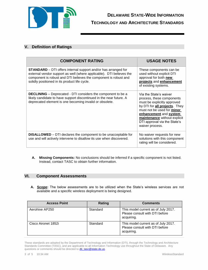
DELAWARE STATE-WIDE INFORMATION
TECHNOLOGY AND ARCHITECTURE STANDARDS
These standards are adopted by the Department of Technology and Information (DTI), through the Technology and Architecture Standards Committee (TASC), and are applicable to all Information Technology use throughout the State of Delaware. Any questions or comments should be directed to [email protected].
3 of 5 10:34 AM WirelessStandard
V. Definition of Ratings
COMPONENT RATING USAGE NOTES
STANDARD – DTI offers internal support and/or has arranged for external vendor support as well (where applicable). DTI believes the component is robust and DTI believes the component is robust and solidly positioned in its product life cycle.
These components can be used without explicit DTI approval for both new projects and enhancement of existing systems.
DECLINING – Deprecated - DTI considers the component to be a likely candidate to have support discontinued in the near future. A deprecated element is one becoming invalid or obsolete.
Via the State’s waiver process, these components must be explicitly approved by DTI for all projects. They must not be used for minor enhancement and system maintenance without explicit DTI approval via the State’s waiver process.
DISALLOWED – DTI declares the component to be unacceptable for use and will actively intervene to disallow its use when discovered.
No waiver requests for new solutions with this component rating will be considered.
A. Missing Components: No conclusions should be inferred if a specific component is not listed. Instead, contact TASC to obtain further information.
VI. Component Assessments
A. Scope: The below assessments are to be utilized when the State’s wireless services are not
available and a specific wireless deployment is being designed.
Access Point Rating Comments
Aerohive AP250
Standard This model current as of July 2017. Please consult with DTI before acquiring.
Cisco Aironet 1852i Standard This model current as of July 2017. Please consult with DTI before acquiring.
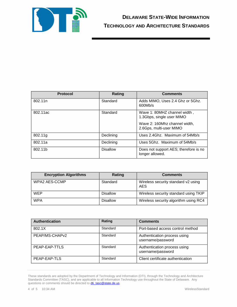
DELAWARE STATE-WIDE INFORMATION
TECHNOLOGY AND ARCHITECTURE STANDARDS
These standards are adopted by the Department of Technology and Information (DTI), through the Technology and Architecture Standards Committee (TASC), and are applicable to all Information Technology use throughout the State of Delaware. Any questions or comments should be directed to [email protected].
4 of 5 10:34 AM WirelessStandard
Protocol Rating Comments
802.11n Standard Adds MIMO, Uses 2.4 Ghz or 5Ghz. 600Mb/s
802.11ac Standard Wave 1: 80MHZ channel width , 1.3Gbps, single user MIMO
Wave 2: 160Mhz channel width, 2.6Gps, multi-user MIMO
802.11g Declining Uses 2.4Ghz. Maximum of 54Mb/s
802.11a Declining Uses 5Ghz. Maximum of 54Mb/s
802.11b Disallow Does not support AES; therefore is no longer allowed.
Encryption Algorithms Rating Comments
WPA2 AES-CCMP Standard Wireless security standard v2 using AES
WEP Disallow Wireless security standard using TKIP
WPA Disallow Wireless security algorithm using RC4
Authentication Rating Comments
802.1X Standard Port-based access control method
PEAP/MS-CHAPv2 Standard Authentication process using username/password
PEAP-EAP-TTLS Standard Authentication process using username/password
PEAP-EAP-TLS Standard Client certificate authentication
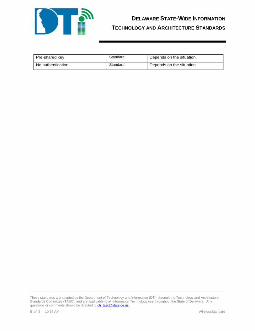
DELAWARE STATE-WIDE INFORMATION
TECHNOLOGY AND ARCHITECTURE STANDARDS
These standards are adopted by the Department of Technology and Information (DTI), through the Technology and Architecture Standards Committee (TASC), and are applicable to all Information Technology use throughout the State of Delaware. Any questions or comments should be directed to [email protected].
5 of 5 10:34 AM WirelessStandard
Pre-shared key Standard Depends on the situation.
No authentication Standard Depends on the situation.
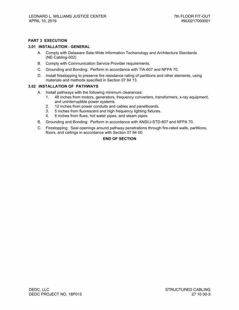
LEONARD L. WILLIAMS JUSTICE CENTER 7th FLOOR FIT-OUTAPRIL 10, 2019 #MJ0217000001
DEDC, LLC STRUCTURED CABLINGDEDC PROJECT NO. 18P015 27 10 00-3
PART 3 EXECUTION3.01 INSTALLATION - GENERAL
A. Comply with Delaware Sate-Wide Information Techanology and Architecture Standards(NE-Cabling-002)
B. Comply with Communication Service Provider requirements.C. Grounding and Bonding: Perform in accordance with TIA-607 and NFPA 70.D. Install firestopping to preserve fire resistance rating of partitions and other elements, using
materials and methods specified in Section 07 84 13.3.02 INSTALLATION OF PATHWAYS
A. Install pathways with the following minimum clearances:1. 48 inches from motors, generators, frequency converters, transformers, x-ray equipment,
and uninterruptible power systems.2. 12 inches from power conduits and cables and panelboards.3. 5 inches from fluorescent and high frequency lighting fixtures.4. 6 inches from flues, hot water pipes, and steam pipes.
B. Grounding and Bonding: Perform in accordance with ANSI/J-STD-607 and NFPA 70.C. Firestopping: Seal openings around pathway penetrations through fire-rated walls, partitions,
floors, and ceilings in accordance with Section 07 84 00.END OF SECTION

7TH FLOOR FIT-OUT LEONARD L. WILLIAMS JUSTICE CENTER#MJ0217000001 APRIL 10, 2019
STRUCTURED CABLING DEDC, LLC27 10 00-4 DEDC PROJECT NO. 18P015
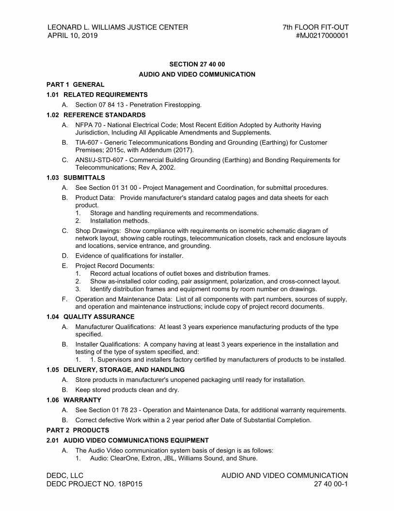
LEONARD L. WILLIAMS JUSTICE CENTER APRIL 10, 2019
7th FLOOR FIT-OUT #MJ0217000001
DEDC, LLC AUDIO AND VIDEO COMMUNICATIONDEDC PROJECT NO. 18P015 27 40 00-1
SECTION 27 40 00AUDIO AND VIDEO COMMUNICATION
PART 1 GENERAL1.01 RELATED REQUIREMENTS
A. Section 07 84 13 - Penetration Firestopping.1.02 REFERENCE STANDARDS
A. NFPA 70 - National Electrical Code; Most Recent Edition Adopted by Authority HavingJurisdiction, Including All Applicable Amendments and Supplements.
B. TIA-607 - Generic Telecommunications Bonding and Grounding (Earthing) for CustomerPremises; 2015c, with Addendum (2017).
C. ANSI/J-STD-607 - Commercial Building Grounding (Earthing) and Bonding Requirements forTelecommunications; Rev A, 2002.
1.03 SUBMITTALSA. See Section 01 31 00 - Project Management and Coordination, for submittal procedures.B. Product Data: Provide manufacturer's standard catalog pages and data sheets for each
product.1. Storage and handling requirements and recommendations.2. Installation methods.
C. Shop Drawings: Show compliance with requirements on isometric schematic diagram ofnetwork layout, showing cable routings, telecommunication closets, rack and enclosure layoutsand locations, service entrance, and grounding.
D. Evidence of qualifications for installer.E. Project Record Documents:
1. Record actual locations of outlet boxes and distribution frames.2. Show as-installed color coding, pair assignment, polarization, and cross-connect layout.3. Identify distribution frames and equipment rooms by room number on drawings.
F. Operation and Maintenance Data: List of all components with part numbers, sources of supply,and operation and maintenance instructions; include copy of project record documents.
1.04 QUALITY ASSURANCEA. Manufacturer Qualifications: At least 3 years experience manufacturing products of the type
specified.B. Installer Qualifications: A company having at least 3 years experience in the installation and
testing of the type of system specified, and:1. 1. Supervisors and installers factory certified by manufacturers of products to be installed.
1.05 DELIVERY, STORAGE, AND HANDLINGA. Store products in manufacturer's unopened packaging until ready for installation.B. Keep stored products clean and dry.
1.06 WARRANTYA. See Section 01 78 23 - Operation and Maintenance Data, for additional warranty requirements.B. Correct defective Work within a 2 year period after Date of Substantial Completion.
PART 2 PRODUCTS2.01 AUDIO VIDEO COMMUNICATIONS EQUIPMENT
A. The Audio Video communication system basis of design is as follows:1. Audio: ClearOne, Extron, JBL, Williams Sound, and Shure.

7TH FLOOR FIT-OUT #MJ0217000001
LEONARD L. WILLIAMS JUSTICE CENTER APRIL 10, 2019
AUDIO AND VIDEO COMMUNICATION DEDC, LLC27 40 00-2 DEDC PROJECT NO. 18P015
2. Controls: Crestron3. Video: Planar, Vaddio, Barco, Extron, and Kramer
B. The basis of design product cut sheets have been included in this specification for clarity andreference.
2.02 AUDIO VIDEO COMMUNICATIONS WIRINGA. The audio video communictions wireing utilized between devices that are to be run in ceiling
spaces shall be shielded and plenum rated.
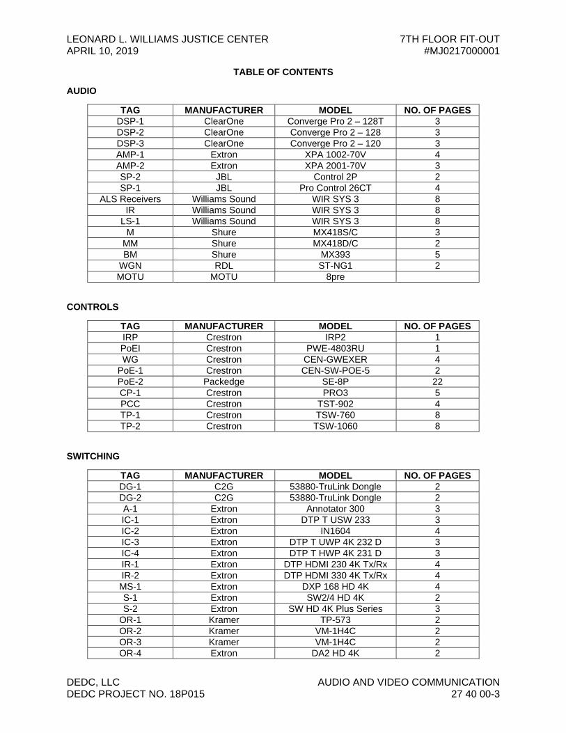
LEONARD L. WILLIAMS JUSTICE CENTER 7TH FLOOR FIT-OUT APRIL 10, 2019 #MJ0217000001
DEDC, LLC AUDIO AND VIDEO COMMUNICATION DEDC PROJECT NO. 18P015 27 40 00-3
TABLE OF CONTENTS
AUDIO
TAG MANUFACTURER MODEL NO. OF PAGES DSP-1 ClearOne Converge Pro 2 – 128T 3 DSP-2 ClearOne Converge Pro 2 – 128 3 DSP-3 ClearOne Converge Pro 2 – 120 3 AMP-1 Extron XPA 1002-70V 4 AMP-2 Extron XPA 2001-70V 3 SP-2 JBL Control 2P 2 SP-1 JBL Pro Control 26CT 4
ALS Receivers Williams Sound WIR SYS 3 8 IR Williams Sound WIR SYS 3 8
LS-1 Williams Sound WIR SYS 3 8 M Shure MX418S/C 3
MM Shure MX418D/C 2 BM Shure MX393 5
WGN RDL ST-NG1 2 MOTU MOTU 8pre
CONTROLS
TAG MANUFACTURER MODEL NO. OF PAGES IRP Crestron IRP2 1 PoEI Crestron PWE-4803RU 1 WG Crestron CEN-GWEXER 4
PoE-1 Crestron CEN-SW-POE-5 2 PoE-2 Packedge SE-8P 22 CP-1 Crestron PRO3 5 PCC Crestron TST-902 4 TP-1 Crestron TSW-760 8 TP-2 Crestron TSW-1060 8
SWITCHING
TAG MANUFACTURER MODEL NO. OF PAGES DG-1 C2G 53880-TruLink Dongle 2 DG-2 C2G 53880-TruLink Dongle 2 A-1 Extron Annotator 300 3 IC-1 Extron DTP T USW 233 3 IC-2 Extron IN1604 4 IC-3 Extron DTP T UWP 4K 232 D 3 IC-4 Extron DTP T HWP 4K 231 D 3 IR-1 Extron DTP HDMI 230 4K Tx/Rx 4 IR-2 Extron DTP HDMI 330 4K Tx/Rx 4 MS-1 Extron DXP 168 HD 4K 4 S-1 Extron SW2/4 HD 4K 2 S-2 Extron SW HD 4K Plus Series 3
OR-1 Kramer TP-573 2 OR-2 Kramer VM-1H4C 2 OR-3 Kramer VM-1H4C 2 OR-4 Extron DA2 HD 4K 2
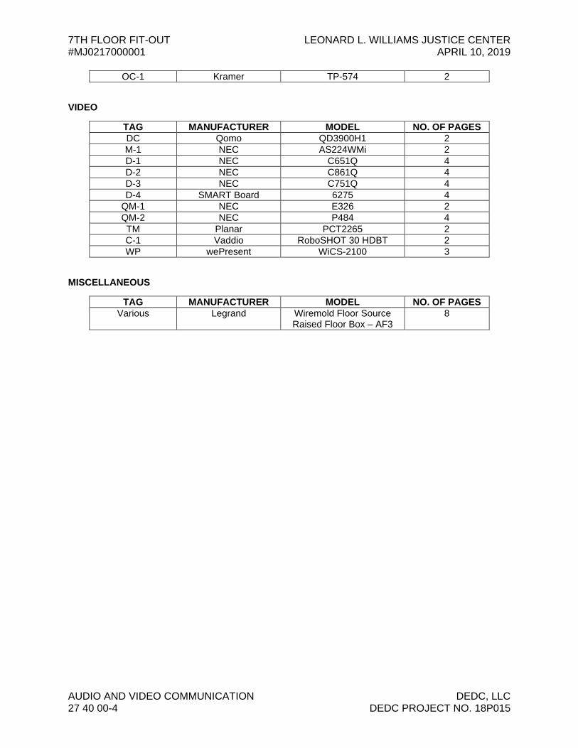
7TH FLOOR FIT-OUT LEONARD L. WILLIAMS JUSTICE CENTER #MJ0217000001 APRIL 10, 2019
AUDIO AND VIDEO COMMUNICATION DEDC, LLC 27 40 00-4 DEDC PROJECT NO. 18P015
OC-1 Kramer TP-574 2
VIDEO
TAG MANUFACTURER MODEL NO. OF PAGES DC Qomo QD3900H1 2 M-1 NEC AS224WMi 2 D-1 NEC C651Q 4 D-2 NEC C861Q 4 D-3 NEC C751Q 4 D-4 SMART Board 6275 4
QM-1 NEC E326 2 QM-2 NEC P484 4 TM Planar PCT2265 2 C-1 Vaddio RoboSHOT 30 HDBT 2 WP wePresent WiCS-2100 3
MISCELLANEOUS
TAG MANUFACTURER MODEL NO. OF PAGES Various Legrand Wiremold Floor Source
Raised Floor Box – AF3 8
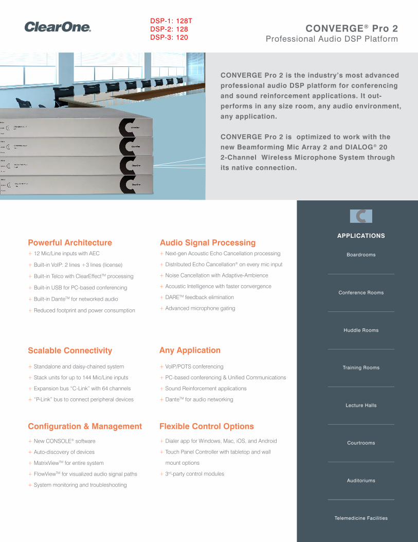
APPLICATIONS
Boardrooms
Conference Rooms
Huddle Rooms
Training Rooms
Lecture Halls
Courtrooms
Auditoriums
Telemedicine Facilities
CONVERGE® Pro 2Professional Audio DSP Platform
Powerful Architecture+ 12 Mic/Line inputs with AEC
+ Built-in VoIP: 2 lines +3 lines (license)
+ Built-in Telco with ClearEffectTM processing
+ Built-in USB for PC-based conferencing
+ Built-in DanteTM for networked audio
+ Reduced footprint and power consumption
Audio Signal Processing+ Next-gen Acoustic Echo Cancellation processing
+ Distributed Echo Cancellation® on every mic input
+ Noise Cancellation with Adaptive-Ambience
+ Acoustic Intelligence with faster convergence
+ DARETM feedback elimination
+ Advanced microphone gating
Scalable Connectivity
+ Standalone and daisy-chained system
+ Stack units for up to 144 Mic/Line inputs
+ Expansion bus “C-Link” with 64 channels
+ “P-Link” bus to connect peripheral devices
Any Application
+ VoIP/POTS conferencing
+ PC-based conferencing & Unified Communications
+ Sound Reinforcement applications
+ DanteTM for audio networking
+ Dialer app for Windows, Mac, iOS, and Android
+ Touch Panel Controller with tabletop and wall
mount options
+ 3rd-party control modules
Flexible Control OptionsConfiguration & Management
+ New CONSOLE® software
+ Auto-discovery of devices
+ MatrixViewTM for entire system
+ FlowViewTM for visualized audio signal paths
+ System monitoring and troubleshooting
CONVERGE Pro 2 is the industry’s most advanced
professional audio DSP platform for conferencing
and sound reinforcement applications. It out-
performs in any size room, any audio environment,
any application.
CONVERGE Pro 2 is optimized to work with the
new Beamforming Mic Array 2 and DIALOG® 20
2-Channel Wireless Microphone System through
its native connection.
DSP-1: 128TDSP-2: 128DSP-3: 120
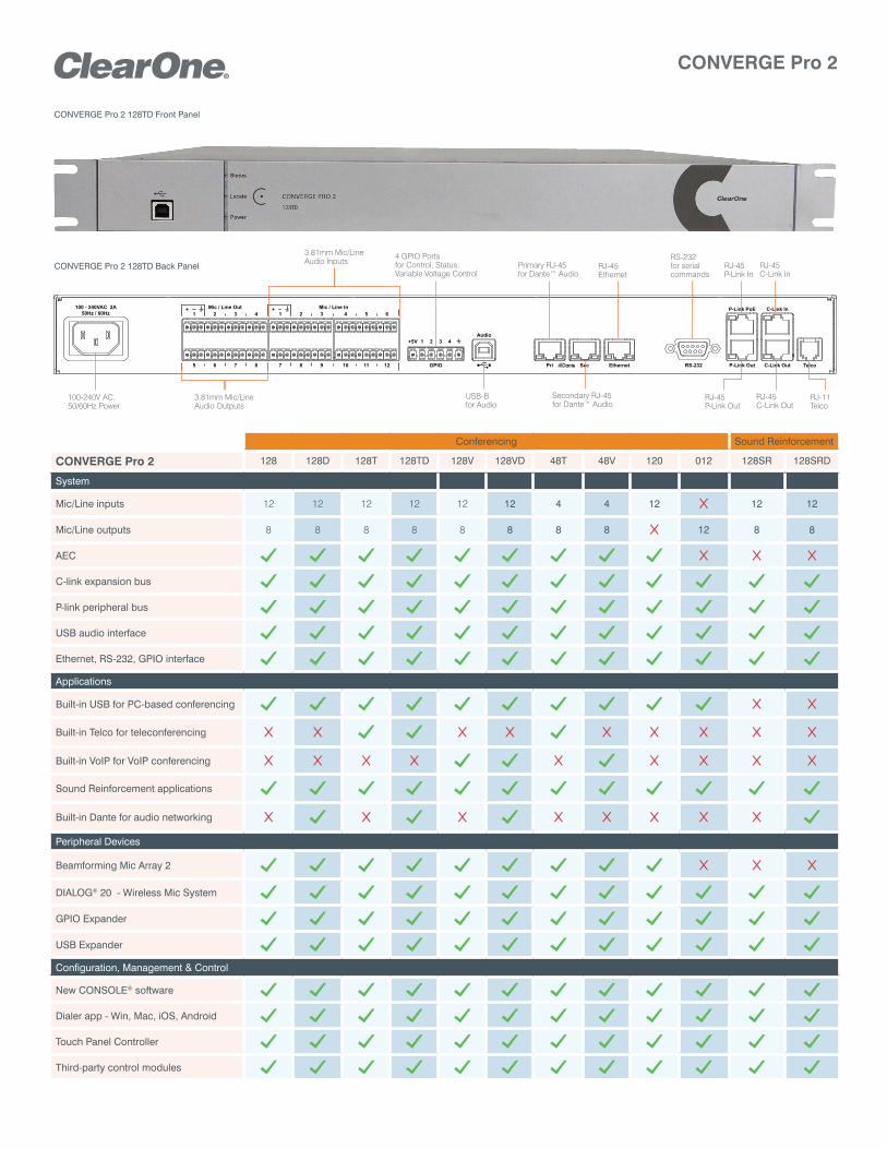
CONVERGE Pro 2
TelcoGPIO SecPri RS-232 P-Link Out
C-Link InP-Link PoE
C-Link Out
+5V 1 2 3 4
1 2 3 4
5 6 7 8
1 2 3 4 5 6
7 8 9 10 11 12
CONVERGE Pro 2 128TD Front Panel
CONVERGE Pro 2 128TD Back Panel
Conferencing Sound Reinforcement
CONVERGE Pro 2 128 128D 128T 128TD 128V 128VD 48T 48V 120 012 128SR 128SRD
System
Mic/Line inputs 12 12 12 12 12 12 4 4 12 12 12
Mic/Line outputs 8 8 8 8 8 8 8 8 12 8 8
AEC
C-link expansion bus
P-link peripheral bus
USB audio interface
Ethernet, RS-232, GPIO interface
Applications
Built-in USB for PC-based conferencing
Built-in Telco for teleconferencing
Built-in VoIP for VoIP conferencing
Sound Reinforcement applications
Built-in Dante for audio networking
Peripheral Devices
Beamforming Mic Array 2
DIALOG® 20 - Wireless Mic System
GPIO Expander
USB Expander
Configuration, Management & Control
New CONSOLE® software
Dialer app - Win, Mac, iOS, Android
Touch Panel Controller
Third-party control modules
3.81mm Mic/Line Audio Inputs RJ-45
P-Link In
4 GPIO Ports for Control, Status, Variable Voltage Control
RJ-11Telco
100-240V AC, 50/60Hz Power
RS-232 for serial commands
RJ-45Ethernet
RJ-45P-Link Out
RJ-45C-Link In
RJ-45C-Link Out
Secondary RJ-45for Dante™ Audio
Primary RJ-45for Dante™ Audio
USB-Bfor Audio
3.81mm Mic/Line Audio Outputs
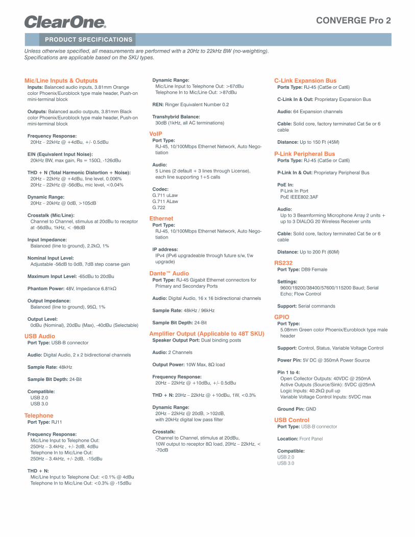
PRODUCT SPECIFICATIONS
CONVERGE Pro 2
Unless otherwise specified, all measurements are performed with a 20Hz to 22kHz BW (no-weighting).Specifications are applicable based on the SKU types.
Mic/Line Inputs & OutputsInputs: Balanced audio inputs, 3.81mm Orange color Phoenix/Euroblock type male header, Push-on mini-terminal block
Outputs: Balanced audio outputs, 3.81mm Black color Phoenix/Euroblock type male header, Push-on mini-terminal block
Frequency Response:20Hz – 22kHz @ +4dBu, +/- 0.5dBu
EIN (Equivalent Input Noise):20kHz BW, max gain, Rs = 150Ω, -126dBu
THD + N (Total Harmonic Distortion + Noise): 20Hz – 22kHz @ +4dBu, line level, 0.006%20Hz – 22kHz @ -56dBu, mic level, <0.04%
Dynamic Range:20Hz – 20kHz @ 0dB, >105dB
Crosstalk (Mic/Line):Channel to Channel, stimulus at 20dBu to receptor at -56dBu, 1kHz, < -98dB
Input Impedance:Balanced (line to ground), 2.2kΩ, 1%
Nominal Input Level:Adjustable -56dB to 0dB, 7dB step coarse gain
Maximum Input Level: -65dBu to 20dBu
Phantom Power: 48V, Impedance 6.81kΩ
Output Impedance:Balanced (line to ground), 95Ω, 1%
Output Level:0dBu (Nominal), 20dBu (Max), -40dBu (Selectable)
USB AudioPort Type: USB-B connector
Audio: Digital Audio, 2 x 2 bidirectional channels
Sample Rate: 48kHz
Sample Bit Depth: 24-Bit
Compatible: USB 2.0USB 3.0
TelephonePort Type: RJ11
Frequency Response: Mic/Line Input to Telephone Out: 250Hz – 3.4kHz , +/- 2dB, 4dBuTelephone In to Mic/Line Out: 250Hz – 3.4kHz, +/- 2dB, -15dBu
THD + N:Mic/Line Input to Telephone Out: <0.1% @ 4dBuTelephone In to Mic/Line Out: <0.3% @ -15dBu
Dynamic Range:Mic/Line Input to Telephone Out: >67dBuTelephone In to Mic/Line Out: >87dBu
REN: Ringer Equivalent Number 0.2
Transhybrid Balance: 30dB (1kHz, all AC terminations)
VoIPPort Type:
RJ-45, 10/100Mbps Ethernet Network, Auto Nego-tiation
Audio:5 Lines (2 default + 3 lines through License), each line supporting 1+5 calls
Codec:G.711 uLawG.711 ALawG.722
EthernetPort Type:
RJ-45, 10/100Mbps Ethernet Network, Auto Nego-tiation
IP address: IPv4 (IPv6 upgradeable through future s/w, f/w upgrade)
Dante™ AudioPort Type: RJ-45 Gigabit Ethernet connectors for
Primary and Secondary Ports
Audio: Digital Audio, 16 x 16 bidirectional channels
Sample Rate: 48kHz / 96kHz
Sample Bit Depth: 24-Bit
Amplifier Output (Applicable to 48T SKU)Speaker Output Port: Dual binding posts
Audio: 2 Channels
Output Power: 10W Max, 8Ω load
Frequency Response: 20Hz – 22kHz @ +10dBu, +/- 0.5dBu
THD + N: 20Hz – 22kHz @ +10dBu, 1W, <0.3%
Dynamic Range:20Hz – 22kHz @ 20dB, >102dB, with 20kHz digital low pass filter
Crosstalk:Channel to Channel, stimulus at 20dBu, 10W output to receptor 8Ω load, 20Hz – 22kHz, < -70dB
C-Link Expansion BusPorts Type: RJ-45 (Cat5e or Cat6)
C-Link In & Out: Proprietary Expansion Bus
Audio: 64 Expansion channels
Cable: Solid core, factory terminated Cat 5e or 6 cable
Distance: Up to 150 Ft (45M)
P-Link Peripheral BusPorts Type: RJ-45 (Cat5e or Cat6)
P-Link In & Out: Proprietary Peripheral Bus
PoE In:P-Link In PortPoE IEEE802.3AF
Audio: Up to 3 Beamforming Microphone Array 2 units + up to 3 DIALOG 20 Wireless Receiver units
Cable: Solid core, factory terminated Cat 5e or 6 cable
Distance: Up to 200 Ft (60M)
RS232Port Type: DB9 Female
Settings: 9600/19200/38400/57600/115200 Baud; Serial Echo; Flow Control
Support: Serial commands
GPIOPort Type:
5.08mm Green color Phoenix/Euroblock type male header
Support: Control, Status, Variable Voltage Control
Power Pin: 5V DC @ 350mA Power Source
Pin 1 to 4:Open Collector Outputs: 40VDC @ 250mAActive Outputs (Source/Sink): 5VDC @25mALogic Inputs: 40.2kΩ pull upVariable Voltage Control Inputs: 5VDC max
Ground Pin: GND
USB ControlPort Type: USB-B connector
Location: Front Panel
Compatible: USB 2.0USB 3.0
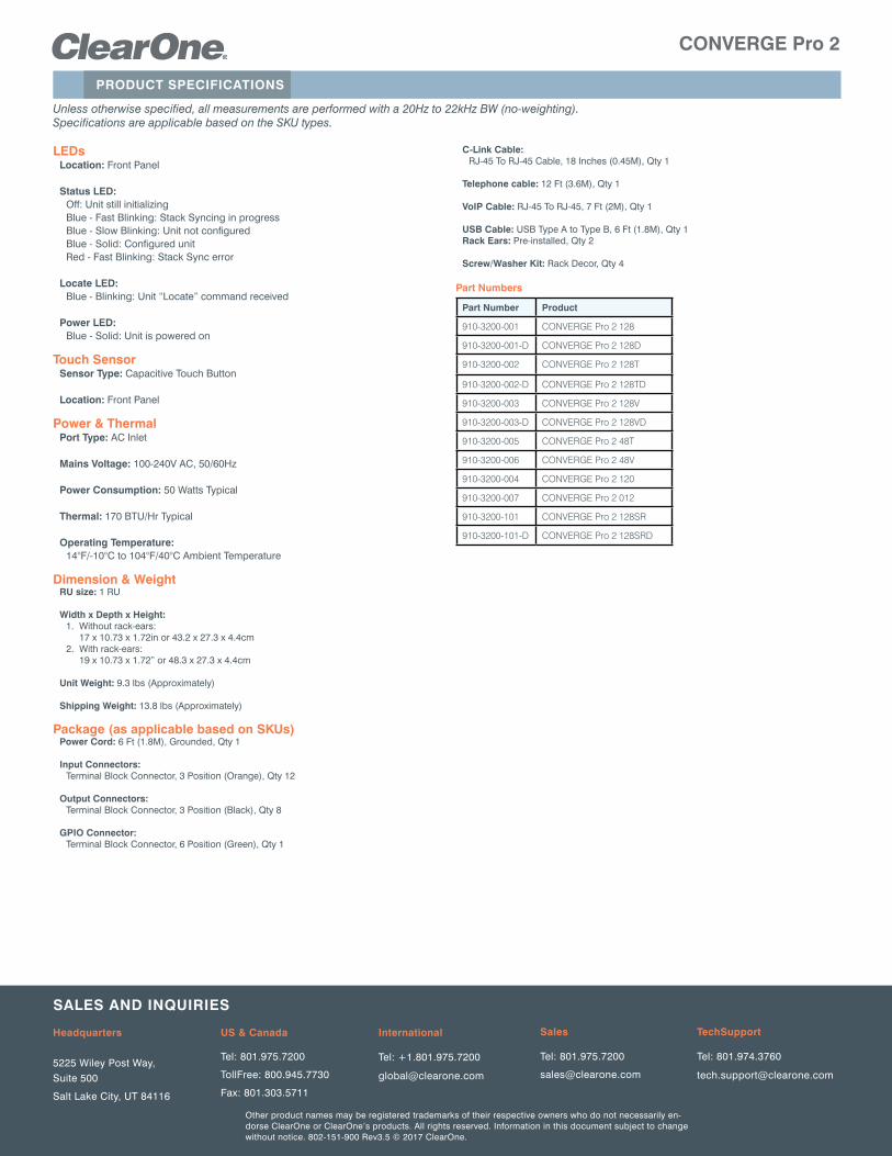
Other product names may be registered trademarks of their respective owners who do not necessarily en-dorse ClearOne or ClearOne’s products. All rights reserved. Information in this document subject to change without notice. 802-151-900 Rev3.5 © 2017 ClearOne.
SALES AND INqUIRIES
Headquarters
5225 Wiley Post Way, Suite 500
Salt Lake City, UT 84116
US & Canada
Tel: 801.975.7200
TollFree: 800.945.7730
Fax: 801.303.5711
International
Tel: +1.801.975.7200
TechSupport
Tel: 801.974.3760
Sales
Tel: 801.975.7200
PRODUCT SPECIFICATIONS
CONVERGE Pro 2
Unless otherwise specified, all measurements are performed with a 20Hz to 22kHz BW (no-weighting).Specifications are applicable based on the SKU types.
LEDsLocation: Front Panel
Status LED: Off: Unit still initializingBlue - Fast Blinking: Stack Syncing in progressBlue - Slow Blinking: Unit not configuredBlue - Solid: Configured unitRed - Fast Blinking: Stack Sync error
Locate LED: Blue - Blinking: Unit “Locate” command received
Power LED:Blue - Solid: Unit is powered on
Touch SensorSensor Type: Capacitive Touch Button
Location: Front Panel
Power & ThermalPort Type: AC Inlet
Mains Voltage: 100-240V AC, 50/60Hz
Power Consumption: 50 Watts Typical
Thermal: 170 BTU/Hr Typical
Operating Temperature: 14°F/-10°C to 104°F/40°C Ambient Temperature
Dimension & WeightRU size: 1 RU
Width x Depth x Height: 1. Without rack-ears:
17 x 10.73 x 1.72in or 43.2 x 27.3 x 4.4cm2. With rack-ears:
19 x 10.73 x 1.72” or 48.3 x 27.3 x 4.4cm
Unit Weight: 9.3 lbs (Approximately)
Shipping Weight: 13.8 lbs (Approximately)
Package (as applicable based on SKUs)Power Cord: 6 Ft (1.8M), Grounded, Qty 1
Input Connectors: Terminal Block Connector, 3 Position (Orange), Qty 12
Output Connectors: Terminal Block Connector, 3 Position (Black), Qty 8
GPIO Connector: Terminal Block Connector, 6 Position (Green), Qty 1
C-Link Cable: RJ-45 To RJ-45 Cable, 18 Inches (0.45M), Qty 1
Telephone cable: 12 Ft (3.6M), Qty 1
VoIP Cable: RJ-45 To RJ-45, 7 Ft (2M), Qty 1
USB Cable: USB Type A to Type B, 6 Ft (1.8M), Qty 1 Rack Ears: Pre-installed, Qty 2
Screw/Washer Kit: Rack Decor, Qty 4
Part Numbers
Part Number Product
910-3200-001 CONVERGE Pro 2 128
910-3200-001-D CONVERGE Pro 2 128D
910-3200-002 CONVERGE Pro 2 128T
910-3200-002-D CONVERGE Pro 2 128TD
910-3200-003 CONVERGE Pro 2 128V
910-3200-003-D CONVERGE Pro 2 128VD
910-3200-005 CONVERGE Pro 2 48T
910-3200-006 CONVERGE Pro 2 48V
910-3200-004 CONVERGE Pro 2 120
910-3200-007 CONVERGE Pro 2 012
910-3200-101 CONVERGE Pro 2 128SR
910-3200-101-D CONVERGE Pro 2 128SRD
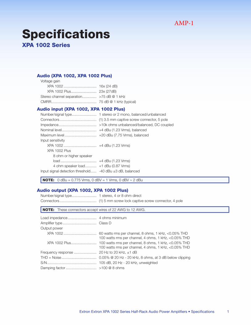
Extron Extron XPA 1002 Series Half-Rack Audio Power Amplifiers • Specifications 1
SpecificationsXPA 1002 Series
Audio (XPA 1002, XPA 1002 Plus)Voltage gain
XPA 1002 16x (24 dB)XPA 1002 Plus 23x (27dB)
Stereo channel separation >75 dB @ 1 kHzCMRR 75 dB @ 1 kHz (typical)
Audio input (XPA 1002, XPA 1002 Plus)Number/signal type 1 stereo or 2 mono, balanced/unbalancedConnectors (1) 35 mm captive screw connector, 5 poleImpedance >10k ohms unbalanced/balanced, DC coupledNominal level +4 dBu (123 Vrms), balancedMaximum level +20 dBu (775 Vrms), balancedInput sensitivity
XPA 1002 +4 dBu (123 Vrms)XPA 1002 Plus
8 ohm or higher speaker load +4 dBu (123 Vrms)4 ohm speaker load +1 dBu (087 Vrms)
Input signal detection threshold -40 dBu ±3 dB, balanced
NOTE: 0 dBu = 0775 Vrms, 0 dBV = 1 Vrms, 0 dBV ≈ 2 dBu
Audio output (XPA 1002, XPA 1002 Plus)Number/signal type 1 stereo, 4 or 8 ohm directConnectors (1) 5 mm screw lock captive screw connector, 4 pole
NOTE: These connectors accept wires of 22 AWG to 12 AWG
Load impedance 4 ohms minimumAmplifier type Class DOutput power
XPA 1002 60 watts rms per channel, 8 ohms, 1 kHz, <005% THD 100 watts rms per channel, 4 ohms, 1 kHz, <005% THD
XPA 1002 Plus 100 watts rms per channel, 8 ohms, 1 kHz, <005% THD 100 watts rms per channel, 4 ohms, 1 kHz, <005% THD
Frequency response 20 Hz to 20 kHz, ±1 dBTHD + Noise 005% @ 20 Hz - 20 kHz, 8 ohms, at 3 dB below clippingS/N 105 dB, 20 Hz - 20 kHz, unweightedDamping factor >100 @ 8 ohms
AMP-1
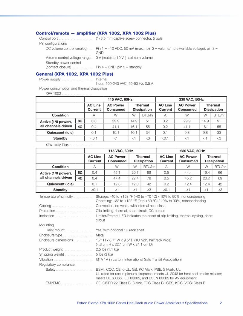
Extron Extron XPA 1002 Series Half-Rack Audio Power Amplifiers • Specifications 2
Control/remote — amplifier (XPA 1002, XPA 1002 Plus)Control port (1) 35 mm captive screw connector, 5 polePin configurations
DC volume control (analog) Pin 1 = +10 VDC, 50 mA (max), pin 2 = volume/mute (variable voltage), pin 3 = GND
Volume control voltage range 0 V (mute) to 10 V (maximum volume)Standby power control (contact closure) Pin 4 = GND, pin 5 = standby
General (XPA 1002, XPA 1002 Plus)Power supply Internal
Input: 100-240 VAC, 50-60 Hz, 05 APower consumption and thermal dissipation
XPA 1002
115 VAC, 60Hz 230 VAC, 50Hz
AC Line Current
AC Power Consumed
Thermal Dissipation
AC Line Current
AC Power Consumed
Thermal Dissipation
Condition A W W BTU/hr A W W BTU/hr
Active (1/8 power), all channels driven
8Ω 03 299 149 51 02 299 149 51
4Ω 04 411 161 55 02 411 161 55
Quiescent (idle) 01 101 101 34 01 98 98 33
Standby <01 <1 <1 <3 <01 <1 <1 <3
XPA 1002 Plus
115 VAC, 60Hz 230 VAC, 50Hz
AC Line Current
AC Power Consumed
Thermal Dissipation
AC Line Current
AC Power Consumed
Thermal Dissipation
Condition A W W BTU/hr A W W BTU/hr
Active (1/8 power), all channels driven
8Ω 04 451 201 69 05 444 194 66
4Ω 04 474 224 76 05 452 202 69
Quiescent (idle) 01 123 123 42 02 124 124 42
Standby <01 <1 <1 <3 <01 <1 <1 <3
Temperature/humidity Storage: -40 to +158 °F (-40 to +70 °C) / 10% to 90%, noncondensing Operating: +32 to +122 °F (0 to +50 °C) / 10% to 90%, noncondensing
Cooling Convection, no vents, with internal heat sinksProtection Clip limiting, thermal, short circuit, DC outputIndication Limiter/Protect LED indicates the onset of clip limiting, thermal cycling, short
circuitMounting
Rack mount Yes, with optional 1U rack shelfEnclosure type MetalEnclosure dimensions 17" H x 87" W x 95" D (1U high, half rack wide)
(43 cm H x 221 cm W x 241 cm D)Product weight 25 lbs (11 kg)Shipping weight 5 lbs (3 kg)Vibration ISTA 1A in carton (International Safe Transit Association)Regulatory compliance
Safety BSMI, CCC, CE, c-UL, GS, KC Mark, PSE, S Mark, UL UL rated for use in plenum airspaces: meets UL 2043 for heat and smoke release; meets UL 60065, IEC 60065, and BSEN 60065 for AV equipment
EMI/EMC CE, CISPR 22 Class B, C-tick, FCC Class B, ICES, KCC, VCCI Class B
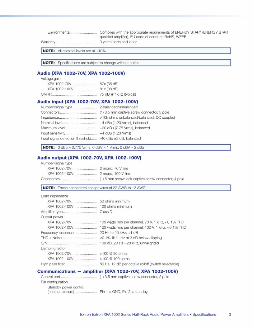
Extron Extron XPA 1002 Series Half-Rack Audio Power Amplifiers • Specifications 3
Environmental Complies with the appropriate requirements of ENERGY STAR® (ENERGY STAR qualified amplifier), EU code of conduct, RoHS, WEEE
Warranty 3 years parts and labor
NOTE: All nominal levels are at ±10%
NOTE: Specifications are subject to change without notice
Audio (XPA 1002-70V, XPA 1002-100V)Voltage gain
XPA 1002-70V 57x (35 dB)XPA 1002-100V 81x (38 dB)
CMRR 75 dB @ 1kHz (typical)
Audio input (XPA 1002-70V, XPA 1002-100V)Number/signal type 2 balanced/unbalancedConnectors (1) 35 mm captive screw connector, 5 poleImpedance >10k ohms unbalanced/balanced, DC coupledNominal level +4 dBu (123 Vrms), balancedMaximum level +20 dBu (775 Vrms), balancedInput sensitivity +4 dBu (123 Vrms)Input signal detection threshold -40 dBu ±3 dB, balanced
NOTE: 0 dBu = 0775 Vrms, 0 dBV = 1 Vrms, 0 dBV ≈ 2 dBu
Audio output (XPA 1002-70V, XPA 1002-100V)Number/signal type
XPA 1002-70V 2 mono, 70 V lineXPA 1002-100V 2 mono, 100 V line
Connectors (1) 5 mm screw lock captive screw connector, 4 pole
NOTE: These connectors accept wires of 22 AWG to 12 AWG
Load impedanceXPA 1002-70V 50 ohms minimumXPA 1002-100V 100 ohms minimum
Amplifier type Class DOutput power
XPA 1002-70V 100 watts rms per channel, 70 V, 1 kHz, <01% THDXPA 1002-100V 100 watts rms per channel, 100 V, 1 kHz, <01% THD
Frequency response 20 Hz to 20 kHz, ±1 dBTHD + Noise <01% @ 1 kHz at 3 dB below clippingS/N 100 dB, 20 Hz - 20 kHz, unweightedDamping factor
XPA 1002-70V >100 @ 50 ohmsXPA 1002-100V >100 @ 100 ohms
High pass filter 80 Hz, 12 dB per octave rolloff (switch selectable)
Communications — amplifier (XPA 1002-70V, XPA 1002-100V)Control port (1) 35 mm captive screw connector, 2 polePin configuration
Standby power control (contact closure) Pin 1 = GND, Pin 2 = standby
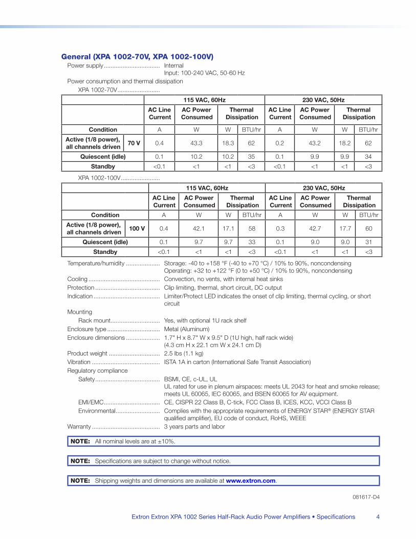
Extron Extron XPA 1002 Series Half-Rack Audio Power Amplifiers • Specifications 4
General (XPA 1002-70V, XPA 1002-100V)Power supply Internal
Input: 100-240 VAC, 50-60 HzPower consumption and thermal dissipation
XPA 1002-70V
115 VAC, 60Hz 230 VAC, 50Hz
AC Line Current
AC Power Consumed
Thermal Dissipation
AC Line Current
AC Power Consumed
Thermal Dissipation
Condition A W W BTU/hr A W W BTU/hr
Active (1/8 power), all channels driven
70 V 04 433 183 62 02 432 182 62
Quiescent (idle) 01 102 102 35 01 99 99 34
Standby <01 <1 <1 <3 <01 <1 <1 <3
XPA 1002-100V
115 VAC, 60Hz 230 VAC, 50Hz
AC Line Current
AC Power Consumed
Thermal Dissipation
AC Line Current
AC Power Consumed
Thermal Dissipation
Condition A W W BTU/hr A W W BTU/hr
Active (1/8 power), all channels driven
100 V 04 421 171 58 03 427 177 60
Quiescent (idle) 01 97 97 33 01 90 90 31
Standby <01 <1 <1 <3 <01 <1 <1 <3
Temperature/humidity Storage: -40 to +158 °F (-40 to +70 °C) / 10% to 90%, noncondensing Operating: +32 to +122 °F (0 to +50 °C) / 10% to 90%, noncondensing
Cooling Convection, no vents, with internal heat sinksProtection Clip limiting, thermal, short circuit, DC outputIndication Limiter/Protect LED indicates the onset of clip limiting, thermal cycling, or short
circuitMounting
Rack mount Yes, with optional 1U rack shelfEnclosure type Metal (Aluminum)Enclosure dimensions 17" H x 87" W x 95" D (1U high, half rack wide)
(43 cm H x 221 cm W x 241 cm D)Product weight 25 lbs (11 kg)Vibration ISTA 1A in carton (International Safe Transit Association)Regulatory compliance
Safety BSMI, CE, c-UL, UL UL rated for use in plenum airspaces: meets UL 2043 for heat and smoke release; meets UL 60065, IEC 60065, and BSEN 60065 for AV equipment
EMI/EMC CE, CISPR 22 Class B, C-tick, FCC Class B, ICES, KCC, VCCI Class BEnvironmental Complies with the appropriate requirements of ENERGY STAR® (ENERGY STAR
qualified amplifier), EU code of conduct, RoHS, WEEEWarranty 3 years parts and labor
NOTE: All nominal levels are at ±10%
NOTE: Specifications are subject to change without notice
NOTE: Shipping weights and dimensions are available at www.extron.com
081617-D4
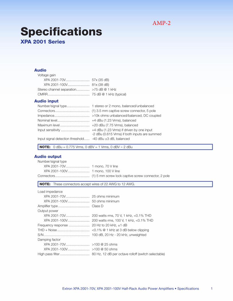
Extron XPA 2001-70V, XPA 2001-100V Half-Rack Audio Power Amplifiers • Specifications 1
SpecificationsXPA 2001 Series
AudioVoltage gain
XPA 2001-70V 57x (35 dB)XPA 2001-100V 81x (38 dB)
Stereo channel separation >75 dB @ 1 kHzCMRR 75 dB @ 1 kHz (typical)
Audio inputNumber/signal type 1 stereo or 2 mono, balanced/unbalancedConnectors (1) 35 mm captive screw connector, 5 poleImpedance >10k ohms unbalanced/balanced, DC coupledNominal level +4 dBu (123 Vrms), balancedMaximum level +20 dBu (775 Vrms), balancedInput sensitivity +4 dBu (123 Vrms) if driven by one input
-2 dBu (0615 Vrms) if both inputs are summedInput signal detection threshold -40 dBu ±3 dB, balanced
NOTE: 0 dBu = 0775 Vrms, 0 dBV = 1 Vrms, 0 dBV ≈ 2 dBu
Audio outputNumber/signal type
XPA 2001-70V 1 mono, 70 V lineXPA 2001-100V 1 mono, 100 V line
Connectors (1) 5 mm screw lock captive screw connector, 2 pole
NOTE: These connectors accept wires of 22 AWG to 12 AWG
Load impedanceXPA 2001-70V 25 ohms minimumXPA 2001-100V 50 ohms minimum
Amplifier type Class DOutput power
XPA 2001-70V 200 watts rms, 70 V, 1 kHz, <01% THDXPA 2001-100V 200 watts rms, 100 V, 1 kHz, <01% THD
Frequency response 20 Hz to 20 kHz, ±1 dBTHD + Noise <01% @ 1 kHz at 3 dB below clippingS/N 100 dB, 20 Hz - 20 kHz, unweightedDamping factor
XPA 2001-70V >100 @ 25 ohmsXPA 2001-100V >100 @ 50 ohms
High pass filter 80 Hz, 12 dB per octave rolloff (switch selectable)
AMP-2
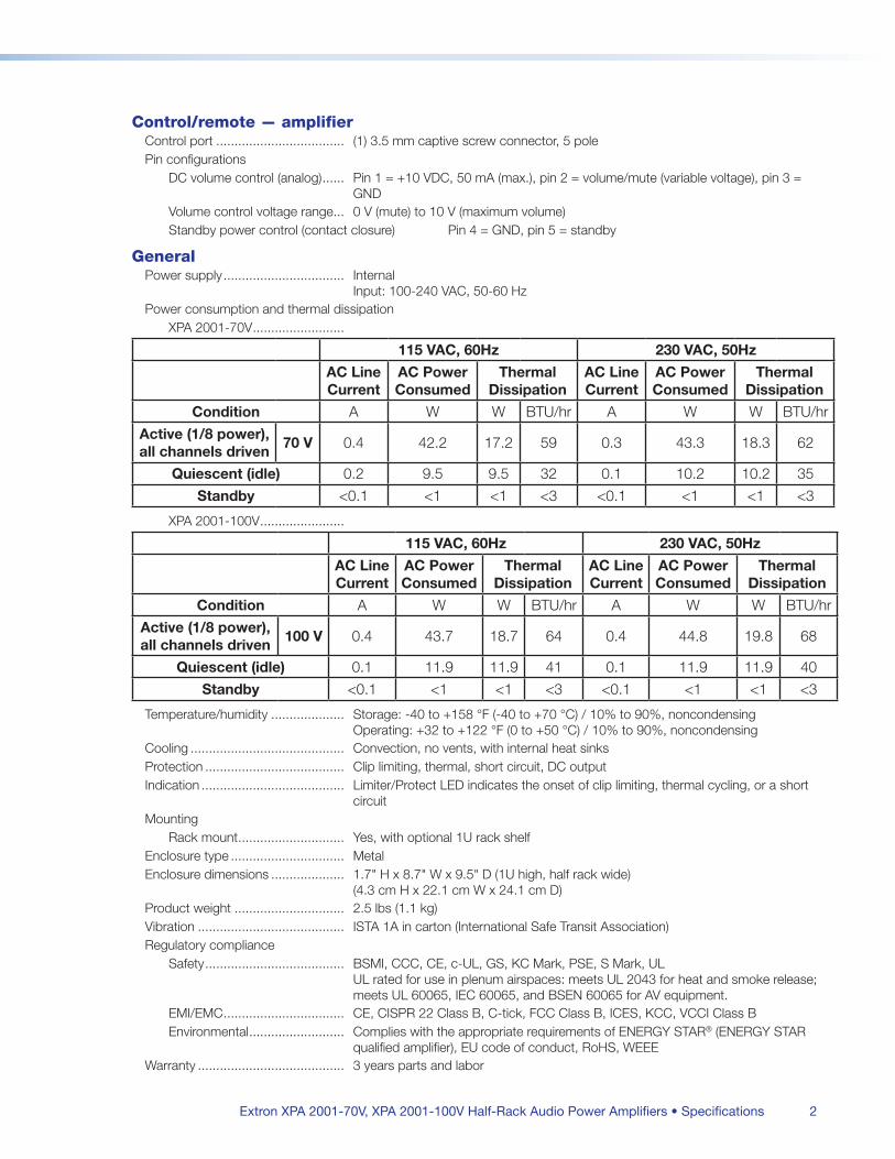
Extron XPA 2001-70V, XPA 2001-100V Half-Rack Audio Power Amplifiers • Specifications 2
Control/remote — amplifierControl port (1) 35 mm captive screw connector, 5 polePin configurations
DC volume control (analog) Pin 1 = +10 VDC, 50 mA (max), pin 2 = volume/mute (variable voltage), pin 3 = GND
Volume control voltage range 0 V (mute) to 10 V (maximum volume)Standby power control (contact closure) Pin 4 = GND, pin 5 = standby
GeneralPower supply Internal
Input: 100-240 VAC, 50-60 HzPower consumption and thermal dissipation
XPA 2001-70V
115 VAC, 60Hz 230 VAC, 50Hz
AC Line Current
AC Power Consumed
Thermal Dissipation
AC Line Current
AC Power Consumed
Thermal Dissipation
Condition A W W BTU/hr A W W BTU/hr
Active (1/8 power), all channels driven
70 V 04 422 172 59 03 433 183 62
Quiescent (idle) 02 95 95 32 01 102 102 35
Standby <01 <1 <1 <3 <01 <1 <1 <3
XPA 2001-100V
115 VAC, 60Hz 230 VAC, 50Hz
AC Line Current
AC Power Consumed
Thermal Dissipation
AC Line Current
AC Power Consumed
Thermal Dissipation
Condition A W W BTU/hr A W W BTU/hr
Active (1/8 power), all channels driven
100 V 04 437 187 64 04 448 198 68
Quiescent (idle) 01 119 119 41 01 119 119 40
Standby <01 <1 <1 <3 <01 <1 <1 <3
Temperature/humidity Storage: -40 to +158 °F (-40 to +70 °C) / 10% to 90%, noncondensing Operating: +32 to +122 °F (0 to +50 °C) / 10% to 90%, noncondensing
Cooling Convection, no vents, with internal heat sinksProtection Clip limiting, thermal, short circuit, DC outputIndication Limiter/Protect LED indicates the onset of clip limiting, thermal cycling, or a short
circuitMounting
Rack mount Yes, with optional 1U rack shelfEnclosure type MetalEnclosure dimensions 17" H x 87" W x 95" D (1U high, half rack wide)
(43 cm H x 221 cm W x 241 cm D)Product weight 25 lbs (11 kg)Vibration ISTA 1A in carton (International Safe Transit Association)Regulatory compliance
Safety BSMI, CCC, CE, c-UL, GS, KC Mark, PSE, S Mark, UL UL rated for use in plenum airspaces: meets UL 2043 for heat and smoke release; meets UL 60065, IEC 60065, and BSEN 60065 for AV equipment
EMI/EMC CE, CISPR 22 Class B, C-tick, FCC Class B, ICES, KCC, VCCI Class BEnvironmental Complies with the appropriate requirements of ENERGY STAR® (ENERGY STAR
qualified amplifier), EU code of conduct, RoHS, WEEEWarranty 3 years parts and labor
Extron XPA 2001-70V, XPA 2001-100V Half-Rack Audio Power Amplifiers • Specifications 3
NOTE: All nominal levels are at ±10%
NOTE: Specifications are subject to change without notice
NOTE: Shipping weights and dimensions are available at www.extron.com
081617-D24
CONTROL 2P®
COMPACT POWERED REFERENCE MONITOR
S-2
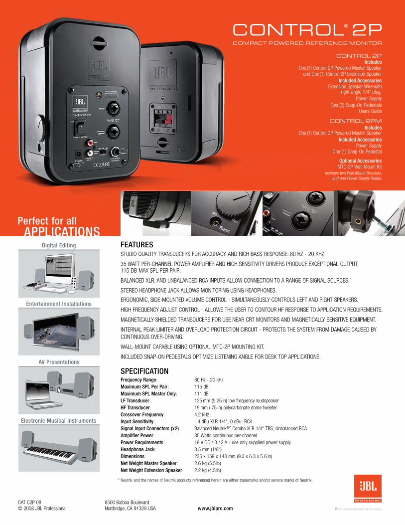
CONTROL 2P®
COMPACT POWERED REFERENCE MONITOR
www.jblpro.com8500 Balboa BoulevardNorthridge, CA 91329 USA
CAT C2P 08© 2008 JBL Professional
STUDIO QUALITY TRANSDUCERS FOR ACCURACY, AND RICH BASS RESPONSE: 80 HZ - 20 KHZ
35 WATT PER-CHANNEL POWER AMPLIFIER AND HIGH SENSITIVITY DRIVERS PRODUCE EXCEPTIONAL OUTPUT:115 DB MAX SPL PER PAIR.
BALANCED XLR, AND UNBALANCED RCA INPUTS ALLOW CONNECTION TO A RANGE OF SIGNAL SOURCES.
STEREO HEADPHONE JACK ALLOWS MONITORING USING HEADPHONES.
ERGONOMIC, SIDE-MOUNTED VOLUME CONTROL - SIMULTANEOUSLY CONTROLS LEFT AND RIGHT SPEAKERS.
HIGH FREQUENCY ADJUST CONTROL - ALLOWS THE USER TO CONTOUR HF RESPONSE TO APPLICATION REQUIREMENTS.
MAGNETICALLY-SHIELDED TRANSDUCERS FOR USE NEAR CRT MONITORS AND MAGNETICALLY SENSITIVE EQUIPMENT.
INTERNAL PEAK LIMITER AND OVERLOAD PROTECTION CIRCUIT - PROTECTS THE SYSTEM FROM DAMAGE CAUSED BY CONTINUOUS OVER-DRIVING.
WALL-MOUNT CAPABLE USING OPTIONAL MTC-2P MOUNTING KIT.
INCLUDED SNAP-ON PEDESTALS OPTIMIZE LISTENING ANGLE FOR DESK TOP APPLICATIONS.
Frequency Range: 80 Hz - 20 kHzMaximum SPL Per Pair: 115 dBMaximum SPL Master Only: 111 dBLF Transducer: 135 mm (5.25 in) low frequency loudspeakerHF Transducer: 19 mm (.75 in) polycarbonate dome tweeterCrossover Frequency: 4.2 kHzInput Sensitivity: +4 dBu XLR 1/4"; 0 dBu RCASignal Input Connectors (x2): Balanced Neutrik®* Combo XLR 1/4" TRS; Unbalanced RCAAmplifier Power: 35 Watts continuous per-channelPower Requirements: 19 V DC / 3.42 A - use only supplied power supplyHeadphone Jack: 3.5 mm (1/8")Dimensions: 235 x 159 x 143 mm (9.3 x 6.3 x 5.6 in)Net Weight Master Speaker: 2.6 kg (5.5 lb)Net Weight Extension Speaker: 2.2 kg (4.5 lb)
FEATURES
SPECIFICATION
Perfect for allAPPLICATIONS
Digital Editing
Entertainment Installations
AV Presentations
Electronic Musical Instruments
CONTROL 2PIncludes
One(1) Control 2P Powered Master Speaker and One(1) Control 2P Extension Speaker
Included AccessoriesExtension Speaker Wire with
right-angle 1/4* plug.Power Supply
Two (2) Snap-On PedestalsUsers Guide
CONTROL 2PMIncludes
One(1) Control 2P Powered Master Speaker Included Accessories
Power SupplyOne (1) Snap-On Pedestal
Optional AccessoriesMTC-2P Wall Mount Kit
Includes two Wall Mount Brackets,and one Power Supply Holder.
* Neutrik and the names of Neutrik products referenced herein are either trademarks and/or service marks of Neutrik.
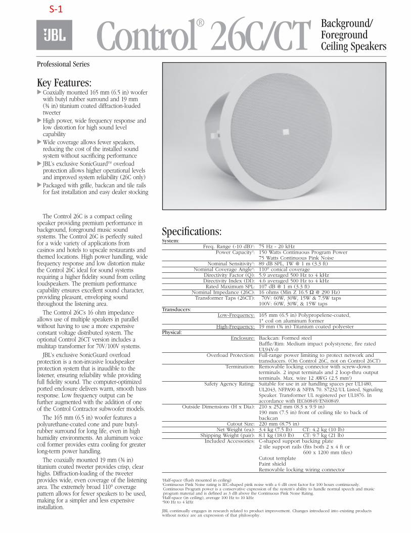
Control® 26C/CT Background/ForegroundCeiling Speakers
Key Features: Coaxially mounted 165 mm (6.5 in) woofer
with butyl rubber surround and 19 mm(¾ in) titanium coated diffraction-loadedtweeter
High power, wide frequency response andlow distortion for high sound levelcapability
Wide coverage allows fewer speakers,reducing the cost of the installed soundsystem without sacrificing performance
JBL’s exclusive SonicGuardTM overloadprotection allows higher operational levelsand improved system reliability (26C only)
Packaged with grille, backcan and tile railsfor fast installation and easy dealer stocking
The Control 26C is a compact ceilingspeaker providing premium performance inbackground, foreground music soundsystems. The Control 26C is perfectly suitedfor a wide variety of applications fromcasinos and hotels to upscale restaurants andthemed locations. High power handling, widefrequency response and low distortion makethe Control 26C ideal for sound systemsrequiring a higher fidelity sound from ceilingloudspeakers. The premium performancecapability ensures excellent sound character,providing pleasant, enveloping soundthroughout the listening area.
The Control 26C’s 16 ohm impedanceallows use of multiple speakers in parallelwithout having to use a more expensiveconstant voltage distributed system. Theoptional Control 26CT version includes amultitap transformer for 70V/100V systems.
JBL’s exclusive SonicGuard overloadprotection is a non-invasive loudspeakerprotection system that is inaudible to thelistener, ensuring reliability while providingfull fidelity sound. The computer-optimizedported enclosure delivers warm, smooth bassresponse. Low frequency output can befurther augmented with the addition of oneof the Control Contractor subwoofer models.
The 165 mm (6.5 in) woofer features apolyurethane-coated cone and pure butyl-rubber surround for long life, even in highhumidity environments. An aluminum voicecoil former provides extra cooling for greaterlong-term power handling.
The coaxially mounted 19 mm (¾ in)titanium coated tweeter provides crisp, clearhighs. Diffraction-loading of the tweeterprovides wide, even coverage of the listeningarea. The extremely broad 110° coveragepattern allows for fewer speakers to be used,making for a simpler and less expensiveinstallation.
Specifications:System:
Freq. Range (-10 dB)1: 75 Hz - 20 kHzPower Capacity2: 150 Watts Continuous Program Power
75 Watts Continuous Pink NoiseNominal Sensitivity3: 89 dB SPL, 1W @ 1 m (3.3 ft)
Nominal Coverage Angle4: 110° conical coverageDirectivity Factor (Q): 5.9 averaged 500 Hz to 4 kHzDirectivity Index (DI): 4.6 averaged 500 Hz to 4 kHzRated Maximum SPL: 107 dB @ 1 m (3.3 ft)
Nominal Impedance (26C): 16 ohms (Min Z 16.5 Ω @ 290 Hz)Transformer Taps (26CT): 070V: 60W, 30W, 15W & 7.5W taps
100V: 60W, 30W, & 15W tapsTransducers:
Low-Frequency: 165 mm (6.5 in) Polypropelene-coated,1" coil on aluminum former
High-Frequency: 19 mm (¾ in) Titanium coated polyesterPhysical:
Enclosure: Backcan: Formed steelBaffle/Rim: Medium impact polystyrene, fire ratedUL94V-0
Overload Protection: Full-range power limiting to protect network andtransducers. (On Control 26C, not on Control 26CT)
Termination: Removable locking connector with screw-downterminals. 2 input terminals and 2 loop-thru outputterminals. Max. wire 12 AWG (2.5 mm2)
Safety Agency Rating: Suitable for use in air handling spaces per UL1480,UL2043, NFPA90 & NFPA 70. S7232/UL Listed, SignalingSpeaker. Transformer UL registered per UL1876. Inaccordance with IEC60849/EN60849.
Outside Dimensions (H x Dia): 210 x 252 mm (8.3 x 9.9 in)190 mm (7.5 in) front of ceiling tile to back ofbackcan
Cutout Size: 220 mm (8.75 in)Net Weight (ea): 3.4 kg (7.5 lb) 1 CT: 4.2 kg (10 lb)
Shipping Weight (pair): 8.1 kg (18.0 lb) CT: 9.7 kg (21 lb)Included Accessories: C-shaped support backing plate
2 tile support rails (fits both 2 x 4 ft or 600 x 1200 mm tiles)
Cutout templatePaint shieldRemovable locking wiring connector
1Half-space (flush mounted in ceiling)2Continuous Pink Noise rating is IEC-shaped pink noise with a 6 dB crest factor for 100 hours continuously.Continuous Program power is a conservative expression of the system’s ability to handle normal speech and musicprogram material and is defined as 3 dB above the Continuous Pink Noise Rating.
3Half-space (in ceiling), average 100 Hz to 10 kHz4500 Hz to 4 kHz
JBL continually engages in research related to product improvement. Changes introduced into existing productswithout notice are an expression of that philosophy.
Professional Series
77744_JBL.Ctrl26C_CT.qxd 3/1/10 10:53 AM Page 1
S-1
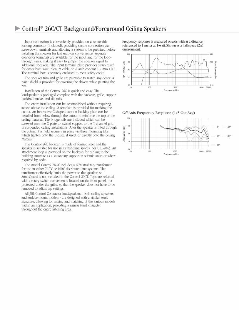
Control® 26C/CT Background/Foreground Ceiling Speakers
Input connection is conveniently provided on a removablelocking connector (included), providing secure connection viascrewdown terminals and allowing a system to be prewired beforeinstalling the speaker for fast snap-on convenience. Separateconnector terminals are available for the input and for the loop-through wires, making it easy to jumper the speaker signal toadditional speakers. The input terminal plate provides strain relieffor either bare wire, plenum cable or ½ inch conduit (12 mm I.D.).The terminal box is securely enclosed to meet safety codes.
The speaker trim and grille are paintable to match any decor. Apaint shield is provided for covering the drivers while painting therim.
Installation of the Control 26C is quick and easy. Theloudspeaker is packaged complete with the backcan, grille, supportbacking bracket and tile rails.
The entire installation can be accomplished without requiringaccess above the ceiling. A template is provided for marking thecutout. An innovative C-shaped support backing plate can beinstalled from below through the cutout to reinforce the top of theceiling material. Tile bridge rails are included which can bescrewed onto the C-plate to extend support to the T-channel gridin suspended ceiling installations. After the speaker is fitted throughthe cutout, it is held securely in place via three mounting tabswhich tighten onto the C-plate, if used, or directly onto the ceilingmaterial.
The Control 26C backcan is made of formed steel and thespeaker is suitable for use in air handling spaces, per U.L.-2043. Anattachment loop is provided on the backcan for cabling to thebuilding structure as a secondary support in seismic areas or whererequired by code.
The model Control 26CT includes a 60W multitap transformer for use in either 70.7V or 100V distributed-line systems. Thetransformer effectively limits the power to the speaker, soSonicGuard is not included in the Control 26CT. Taps are selectedwith a rotary switch conveniently located on the front panel, butprotected under the grille, so that the speaker does not have to beremoved to adjust tap settings.
All JBL Control Contractor loudspeakers - both ceiling speakersand surface-mount models - are designed with a similar sonicsignature, allowing for mixing and matching of the various modelswithin an application, providing a similar tonal characterthroughout the entire listening area.
Frequency response is measured on-axis with at a distancereferenced to 1 meter at 1-watt. Shown as a half-space (2)environment.
Off Axis Frequency Response (1/3 Oct Avg)
77744_JBL.Ctrl26C_CT.qxd 3/1/10 10:53 AM Page 2
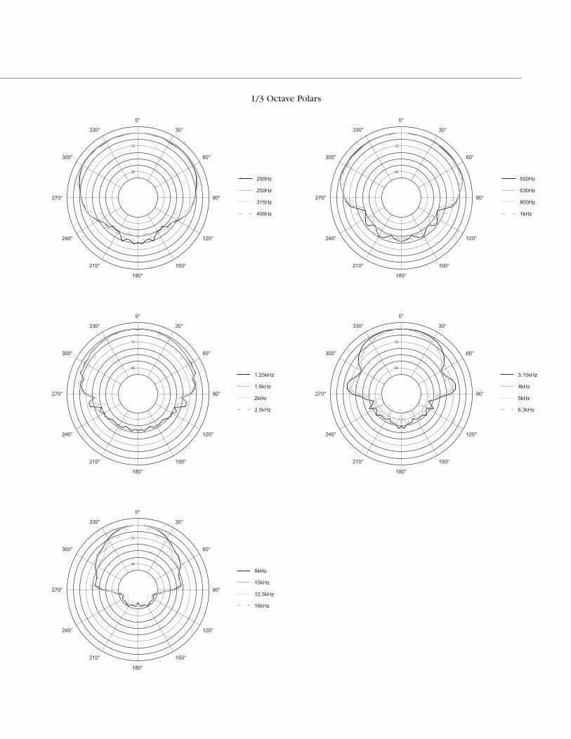
1/3 Octave Polars
77744_JBL.Ctrl26C_CT.qxd 3/1/10 10:53 AM Page 3
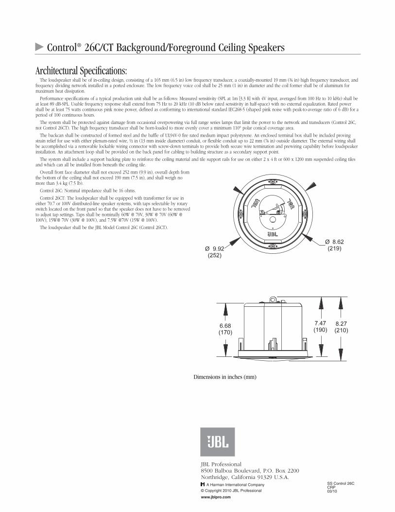
SS Control 26CCRP03/10
Control® 26C/CT Background/Foreground Ceiling Speakers
Architectural Specifications:The loudspeaker shall be of in-ceiling design, consisting of a 165 mm (6.5 in) low frequency transducer, a coaxially-mounted 19 mm (¾ in) high frequency transducer, and
frequency dividing network installed in a ported enclosure. The low frequency voice coil shall be 25 mm (1 in) in diameter and the coil former shall be of aluminum formaximum heat dissipation.
Performance specifications of a typical production unit shall be as follows: Measured sensitivity (SPL at 1m [3.3 ft] with 4V input, averaged from 100 Hz to 10 kHz) shall beat least 89 dB-SPL. Usable frequency response shall extend from 75 Hz to 20 kHz (10 dB below rated sensitivity in half-space) with no external equalization. Rated powershall be at least 75 watts continuous pink noise power, defined as conforming to international standard IEC268-5 (shaped pink noise with peak-to-average ratio of 6 dB) for aperiod of 100 continuous hours.
The system shall be protected against damage from occasional overpowering via full range series lamps that limit the power to the network and transducers (Control 26C,not Control 26CT). The high frequency transducer shall be horn-loaded to more evenly cover a minimum 110° polar conical coverage area.
The backcan shall be constructed of formed steel and the baffle of UL94V-0 fire rated medium impact polystyrene. An enclosed terminal box shall be included provingstrain relief for use with either plenum-rated wire, ½ in (13 mm inside diameter) conduit, or flexible conduit up to 22 mm (⅞ in) outside diameter. The external wiring shallbe accomplished via a removable lockable wiring connector with screw-down terminals to provide both secure wire termination and prewiring capability before loudspeakerinstallation. An attachment loop shall be provided on the back panel for cabling to building structure as a secondary support point.
The system shall include a support backing plate to reinforce the ceiling material and tile support rails for use on either 2 x 4 ft or 600 x 1200 mm suspended ceiling tilesand which can all be installed from beneath the ceiling tile.
Overall front face diameter shall not exceed 252 mm (9.9 in), overall depth fromthe bottom of the ceiling shall not exceed 190 mm (7.5 in), and shall weigh nomore than 3.4 kg (7.5 lb).
Control 26C: Nominal impedance shall be 16 ohms.
Control 26CT: The loudspeaker shall be equipped with transformer for use ineither 70.7 or 100V distributed-line speaker systems, with taps selectable by rotaryswitch located on the front panel so that the speaker does not have to be removedto adjust tap settings. Taps shall be nominally 60W @ 70V, 30W @ 70V (60W @100V), 15W@ 70V (30W @ 100V), and 7.5W @70V (15W @ 100V).
The loudspeaker shall be the JBL Model Control 26C (Control 26CT).
Dimensions in inches (mm)
JBL Professional8500 Balboa Boulevard, P.O. Box 2200Northridge, California 91329 U.S.A.
© Copyright 2010 JBL Professional
www.jblpro.com
A Harman International Company
77744_JBL.Ctrl26C_CT.qxd 3/1/10 10:53 AM Page 4
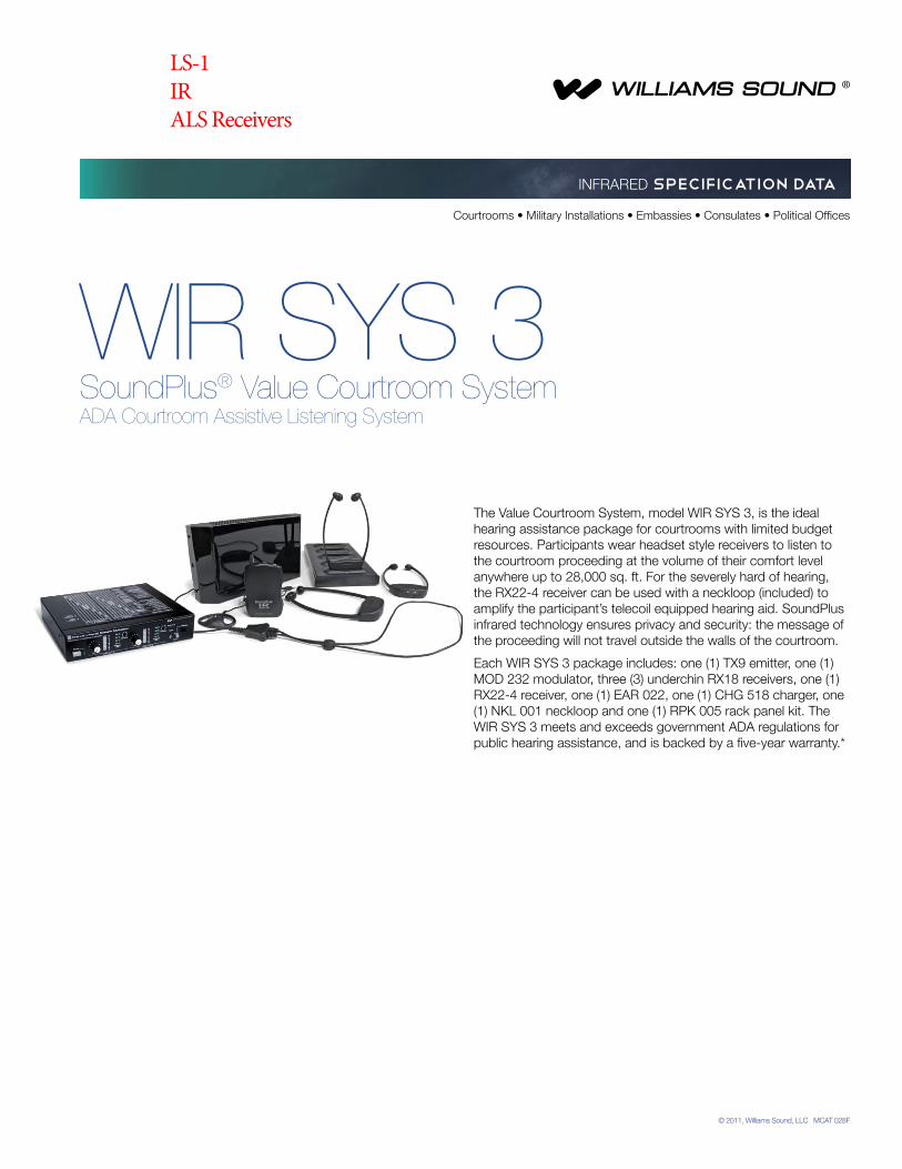
© 2011, Williams Sound, LLC MCAT 028F
WIR SYS 3SoundPlus® Value Courtroom SystemADA Courtroom Assistive Listening System
The Value Courtroom System, model WIR SYS 3, is the ideal hearing assistance package for courtrooms with limited budget resources. Participants wear headset style receivers to listen to the courtroom proceeding at the volume of their comfort level anywhere up to 28,000 sq. ft. For the severely hard of hearing, the RX22-4 receiver can be used with a neckloop (included) to amplify the participant’s telecoil equipped hearing aid. SoundPlus infrared technology ensures privacy and security: the message of the proceeding will not travel outside the walls of the courtroom.
Each WIR SYS 3 package includes: one (1) TX9 emitter, one (1) MOD 232 modulator, three (3) underchin RX18 receivers, one (1) RX22-4 receiver, one (1) EAR 022, one (1) CHG 518 charger, one (1) NKL 001 neckloop and one (1) RPK 005 rack panel kit. TheWIR SYS 3 meets and exceeds government ADA regulations forpublic hearing assistance, and is backed by a five-year warranty.*
Courtrooms • Military Installations • Embassies • Consulates • Political Offices
INFRARED SPECIFICATION DATA
LS-1IRALS Receivers
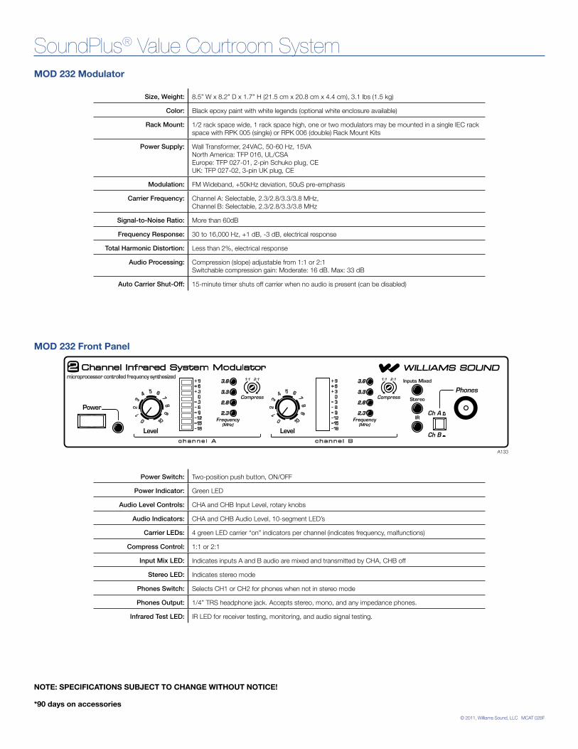
© 2011, Williams Sound, LLC MCAT 028F
SoundPlus® Value Courtroom System
Size, Weight: 8.5” W x 8.2” D x 1.7” H (21.5 cm x 20.8 cm x 4.4 cm), 3.1 lbs (1.5 kg)
Color: Black epoxy paint with white legends (optional white enclosure available)
Rack Mount: 1/2 rack space wide, 1 rack space high, one or two modulators may be mounted in a single IEC rack space with RPK 005 (single) or RPK 006 (double) Rack Mount Kits
Power Supply: Wall Transformer, 24VAC, 50-60 Hz, 15VA North America: TFP 016, UL/CSA Europe: TFP 027-01, 2-pin Schuko plug, CE UK: TFP 027-02, 3-pin UK plug, CE
Modulation: FM Wideband, +50kHz deviation, 50uS pre-emphasis
Carrier Frequency: Channel A: Selectable, 2.3/2.8/3.3/3.8 MHz, Channel B: Selectable, 2.3/2.8/3.3/3.8 MHz
Signal-to-Noise Ratio: More than 60dB
Frequency Response: 30 to 16,000 Hz, +1 dB, -3 dB, electrical response
Total Harmonic Distortion: Less than 2%, electrical response
Audio Processing: Compression (slope) adjustable from 1:1 or 2:1 Switchable compression gain: Moderate: 16 dB. Max: 33 dB
Auto Carrier Shut-Off: 15-minute timer shuts off carrier when no audio is present (can be disabled)
MOD 232 Modulator
MOD 232 Front Panel
A133
Power Switch: Two-position push button, ON/OFF
Power Indicator: Green LED
Audio Level Controls: CHA and CHB Input Level, rotary knobs
Audio Indicators: CHA and CHB Audio Level, 10-segment LED’s
Carrier LEDs: 4 green LED carrier “on” indicators per channel (indicates frequency, malfunctions)
Compress Control: 1:1 or 2:1
Input Mix LED: Indicates inputs A and B audio are mixed and transmitted by CHA, CHB off
Stereo LED: Indicates stereo mode
Phones Switch: Selects CH1 or CH2 for phones when not in stereo mode
Phones Output: 1/4” TRS headphone jack. Accepts stereo, mono, and any impedance phones.
Infrared Test LED: IR LED for receiver testing, monitoring, and audio signal testing.
NOTE: SPECIFICATIONS SUBJECT TO CHANGE WITHOUT NOTICE!
*90 days on accessories
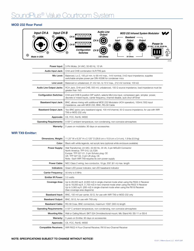
© 2011, Williams Sound, LLC MCAT 028F
SoundPlus® Value Courtroom System
Dimensions, Weight: 11.25” W x 6.25” H x 2.125” D (28.6 cm x 15.9 cm x 5.4 cm), 1.9 lbs (0.9 kg)
Color: Black with white legends, red acrylic lens (optional white enclosure available)
Power Supply: Wall Transformer, 24 VAC, 50-60 Hz, 35 VA, 3-pin MOLEX Connector North America: TFP 010, UL/CSA Europe: TFP 027-01, 2-pin Schuko plug, CE UK: TFP 027-02, 3-pin UK plug, CE Note: Each WIR TX9 requires its own power supply
Power Cable: NEC Class 2 wiring, two-conductor, 18 ga, 200’ (61 m) max. length
Indicators: Green LED power indicator, red LED baseband indicator
Carrier Frequency: 50 kHz to 8 MHz
Emitter IR Power: 3.5 watts
Coverage Area: Up to 28,000 sq.ft. (2,600 m2) in single-channel mode when using the RX22-4 Receiver Up to 18,000 sq.ft. (1,700 m2) in two-channel mode when using the RX22-4 Receiver Up to 3,063 sq.ft. (285 m2) in single-channel mode when using the RX18 Receiver (See coverage area diagrams)
Baseband Input: BNC, 100 mV per carrier, 50 Ω, for use with WIR TX9 or MOD 232 only
Baseband Output: BNC, 50 Ω, for use with TX9 only
Baseband Cable: RG 58 Coax, BNC connectors, maximum 1000’ (300 m) length
Operating Requirements: 0-50º C ambient temperature, non-condensing, non-corrosive atmosphere
Mounting Kits: Wall or Ceiling Mount: BKT 024 Omnidirectional mount, Mic Stand Kit: SS-11 or SS-6
Warranty: 5 years on Emitter, 90 days on accessories
Approvals: CE, FCC, RoHS, WEEE
Compatible Receivers: WIR RX22-4 Four-Channel Receiver, RX18 two-Channel Receiver
A134
MOD 232 Rear Panel
Power Input: 3-Pin Molex, 24 VAC, 50-60 Hz, 15 VA
Audio Input Jack: CHA and CHB combination XLR/TRS jack
Mic Level: Balanced, Lo-Z, 100 µV min. to 90 mV max., 1mV nominal, 3 kΩ input impedance, supplies switchable simplex power per DIN 45596 for condenser mics
Line Level: Balanced or unbalanced, 21 mV min. to 10 V max., 212 mV nominal, 100 kΩ
Audio Line Output Jacks: RCA Jack, CHA and CHB, 500 mV, unbalanced, 100 Ω source impedance, load impedance must be greater than 1kΩ
Configuration Switches: CHA and CHB 8-position DIP switch, selects Mic/Line input, compressor gain, simplex power, discrete or mixed inputs, carrier frequency, channel disable, auto shut-off timer
Baseband Input Jack: BNC, allows mixing with additional MOD 232 Modulator (4CH operation), 100mV, 50Ω input impedance, use with MOD 232, BNC, RG-58 Cable
Baseband Output Jack: Two BNC jacks carry baseband signal, 100 mV/channel, 50 Ω source impedance, for use with WIR TX9 or MOD 232 only
Approvals: CE, FCC, RoHS, WEEE
Operating Requirements: 0-50º C ambient temperature, non-condensing, non-corrosive atmosphere
Warranty: 5 years on modulator, 90 days on accessories
WIR TX9 Emitter:
NOTE: SPECIFICATIONS SUBJECT TO CHANGE WITHOUT NOTICE!
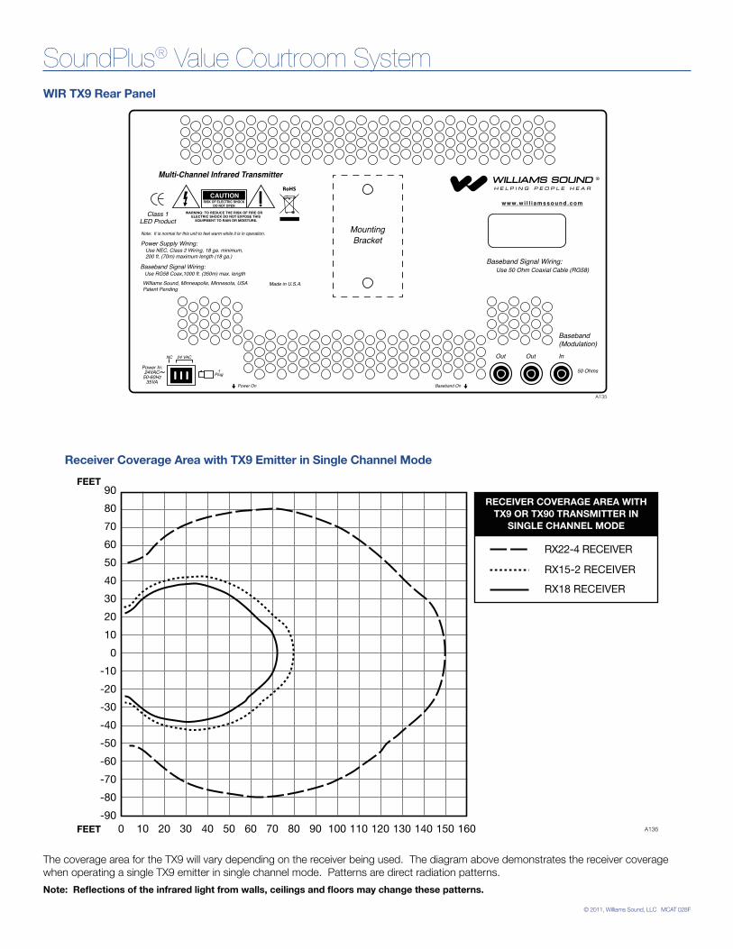
© 2011, Williams Sound, LLC MCAT 028F
SoundPlus® Value Courtroom System
Power On Baseband On
Multi-Channel Infrared Transmitter
Made in U.S.A.
24 VACNC
CAUTIONRISK OF ELECTRIC SHOCK
DO NOT OPEN
WARNING: TO REDUCE THE RISK OF FIRE OR ELECTRIC SHOCK DO NOT EXPOSE THIS EQUIPMENT TO RAIN OR MOISTURE.
Power In:24VAC
50-60Hz35VA
Power Supply Wiring:
Baseband Signal Wiring:Baseband Signal Wiring:
Note: It is normal for this unit to feel warm while it is in operation.
Plug
Use NEC, Class 2 Wiring, 18 ga. minimum,200 ft. (70m) maximum length (18 ga.)
Use 50 Ohm Coaxial Cable (RG58) Use RG58 Coax,1000 ft. (350m) max. length
w w w. w i l l i a m s s o u n d . c o m
InOut Out
50 Ohms
Baseband(Modulation)
~
MountingBracket
RoHS
Class 1LED Product
Williams Sound, Minneapolis, Minnesota, USAPatent Pending
A135
WIR TX9 Rear Panel
Receiver Coverage Area with TX9 Emitter in Single Channel Mode
The coverage area for the TX9 will vary depending on the receiver being used. The diagram above demonstrates the receiver coverage when operating a single TX9 emitter in single channel mode. Patterns are direct radiation patterns.
Note: Reflections of the infrared light from walls, ceilings and floors may change these patterns.
0
0
-10
-20
-30
-40
-50
-60
-70
-80
-90
10
20
30
40
50
60
70
80
90
10 20 30 40 50 60 70 80 90 100 110 120 130 140 150 160
FEET
FEET
RX22-4 RECEIVER
RX18 RECEIVER
RX15-2 RECEIVER
RECEIVER COVERAGE AREA WITH TX9 OR TX90 TRANSMITTER IN
SINGLE CHANNEL MODE
A136
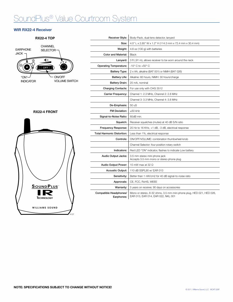
© 2011, Williams Sound, LLC MCAT 028F
SoundPlus® Value Courtroom System
Receiver Style: Body-Pack, dual-lens detector, lanyard
Size: 4.5” L x 2.85” W x 1.2” H (114.3 mm x 72.4 mm x 30.4 mm)
Weight: 4.6 oz (130 g) with batteries
Color and Material: Black
Lanyard: 3 ft (.91 m), allows receiver to be worn around the neck
Operating Temperature: -10° C to +50° C
Battery Type: 2 x AA, alkaline (BAT 001) or NiMH (BAT 026)
Battery Life: Alkaline: 60 hours, NiMH: 30 hours/charge
Battery Drain: 25 mA, nominal
Charging Contacts: For use only with CHG 3512
Carrier Frequency: Channel 1: 2.3 MHz, Channel 2: 2.8 MHz
Channel 3: 3.3 MHz, Channel 4: 3.8 MHz
De-Emphasis: 50 uS
FM Deviation: ±50 kHz
Signal-to-Noise Ratio: 60dB min.
Squelch: Receiver squelches (mutes) at 40 dB S/N ratio
Frequency Response: 25 Hz to 16 KHz, +1 dB, -3 dB, electrical response
Total Harmonic Distortion: Less than 1%, electrical response
Controls: ON/OFF/VOLUME: combination thumbwheel knob
Channel Selector: four-position rotary switch
Indicators: Red LED “ON” indicator, flashes to indicate Low battery
Audio Output Jacks: 3.5 mm stereo mini phone jack Accepts 3.5 mm mono or stereo phone plug
Audio Output Power: 15 mW max at 32 Ω
Acoustic Output: 110 dB SSPL90 w/ EAR 013
Sensitivity: Better than 1 nW/cm2 for 40 dB signal-to-noise ratio
Approvals: CE, FCC, RoHS, WEEE
Warranty: 5 years on receiver, 90 days on accessories
Compatible Headphones/Earphones:
Mono or stereo, 8-32 ohms, 3.5 mm mini phone plug, HED 021, HED 026, EAR 013, EAR 014, EAR 022, NKL 001
RX22-4 FRONT
RX22-4 TOP
ON/OFFVOLUME SWITCH
A137
EARPHONEJACK
"ON" INDICATOR
CHANNELSELECTOR
OFF
WIR RX22-4 Receiver
NOTE: SPECIFICATIONS SUBJECT TO CHANGE WITHOUT NOTICE!
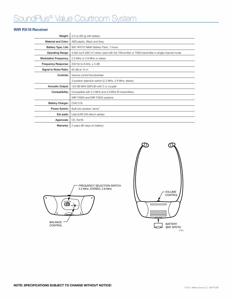
© 2011, Williams Sound, LLC MCAT 028F
SoundPlus® Value Courtroom System
Weight: 2.0 oz (56 g) with battery
Material and Color: ABS plastic, Black and Grey
Battery Type, Life: BAT AP07D NiMH Battery Pack, 7 hours
Operating Range: 3,063 sq ft (285 m2) when used with the TX9 emitter or TX90 transmitter in single-channel mode
Modulation Frequency: 2.3 MHz or 2.8 MHz or stereo
Frequency Response: 200 Hz to 8 kHz, ± 5 dB
Signal to Noise Ratio: 60 dB at 10 m
Controls: Volume control thumbwheel
3-position selection switch (2.3 MHz, 2.8 MHz, stereo)
Acoustic Output: 120 dB MAX SSPL90 with 2 cc coupler
Compatibility: Compatible with 2.3 MHz and 2.8 MHz IR transmitters,
WIR TX900 and WIR TX925 systems
Battery Charger: CHG 518
Power Switch: Built into receiver “arms”
Ear pads: Uses EAR 240 silicon eartips
Approvals: CE, RoHS
Warranty: 5 years (90 days on battery)
WIR RX18 Receiver
NOTE: SPECIFICATIONS SUBJECT TO CHANGE WITHOUT NOTICE!
BATTERY(BAT AP07D)
A163
VOLUMECONTROL
FREQUENCY SELECTION SWITCH2.3 MHz, STEREO, 2.8 MHz
BALANCE CONTROL
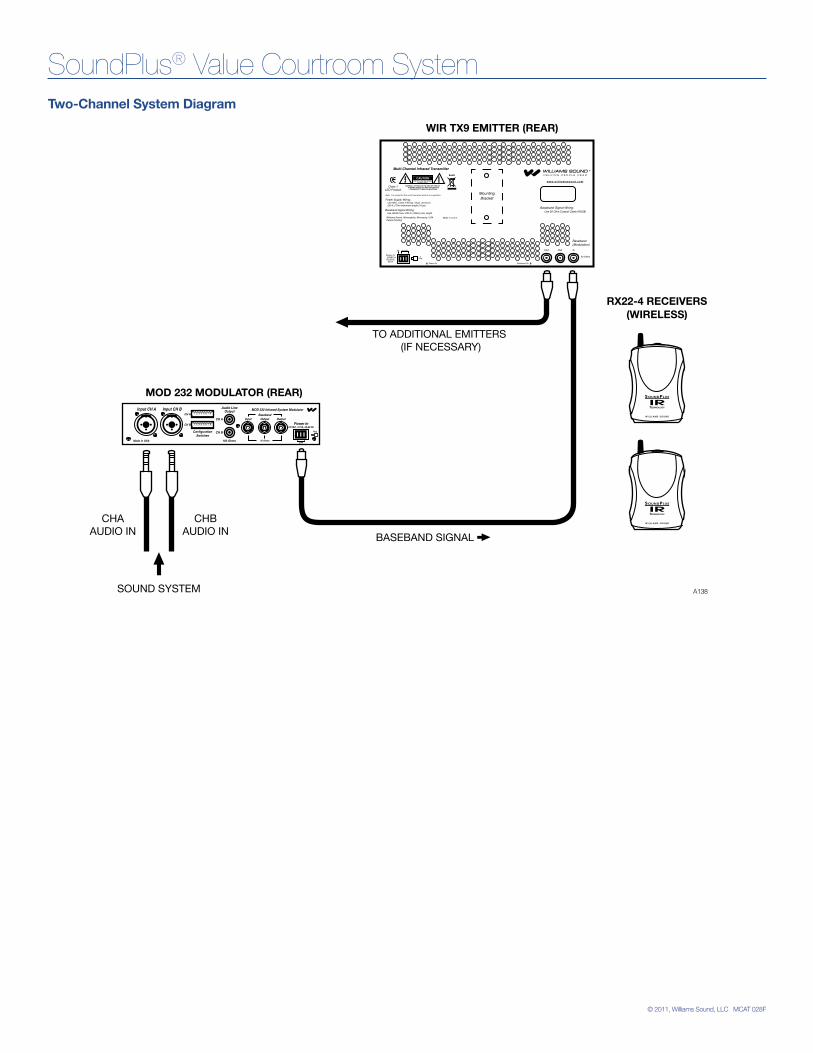
© 2011, Williams Sound, LLC MCAT 028F
SoundPlus® Value Courtroom System
CHAAUDIO IN
CHBAUDIO IN
SOUND SYSTEM
TO ADDITIONAL EMITTERS (IF NECESSARY)
MOD 232 MODULATOR (REAR)
WIR TX9 EMITTER (REAR)
RX22-4 RECEIVERS(WIRELESS)
BASEBAND SIGNAL
A138
Power On Baseband On
Multi-Channel Infrared Transmitter
Made in U.S.A.
24 VACNC
CAUTIONRISK OF ELECTRIC SHOCK
DO NOT OPEN
WARNING: TO REDUCE THE RISK OF FIRE OR ELECTRIC SHOCK DO NOT EXPOSE THIS EQUIPMENT TO RAIN OR MOISTURE.
Power In:24VAC
50-60Hz35VA
Power Supply Wiring:
Baseband Signal Wiring:Baseband Signal Wiring:
Note: It is normal for this unit to feel warm while it is in operation.
Plug
Use NEC, Class 2 Wiring, 18 ga. minimum,200 ft. (70m) maximum length (18 ga.)
Use 50 Ohm Coaxial Cable (RG58) Use RG58 Coax,1000 ft. (350m) max. length
w w w. w i l l i a m s s o u n d . c o m
InOut Out
50 Ohms
Baseband(Modulation)
~
MountingBracket
RoHS
Class 1LED Product
Williams Sound, Minneapolis, Minnesota, USAPatent Pending
Two-Channel System Diagram
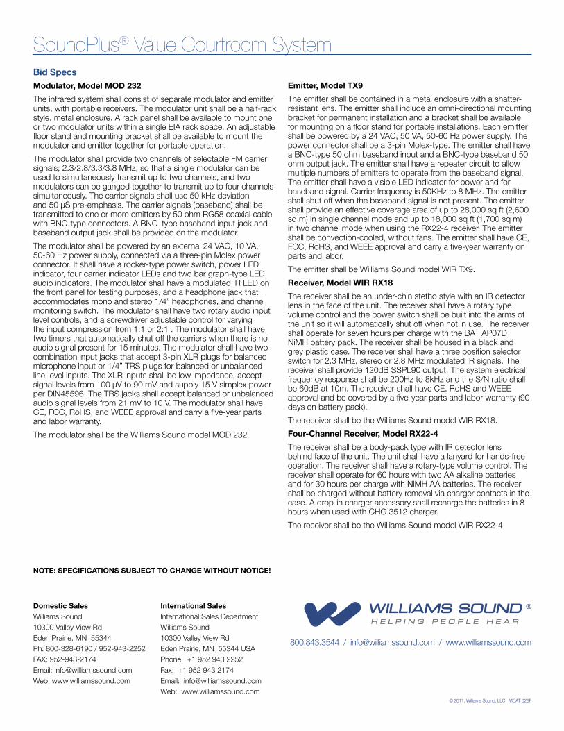
© 2011, Williams Sound, LLC MCAT 028F
Domestic SalesWilliams Sound10300 Valley View RdEden Prairie, MN 55344Ph: 800-328-6190 / 952-943-2252FAX: 952-943-2174Email: [email protected]: www.williamssound.com
International SalesInternational Sales DepartmentWilliams Sound10300 Valley View RdEden Prairie, MN 55344 USAPhone: +1 952 943 2252Fax: +1 952 943 2174Email: [email protected]: www.williamssound.com
800.843.3544 / [email protected] / www.williamssound.com
SoundPlus® Value Courtroom System
NOTE: SPECIFICATIONS SUBJECT TO CHANGE WITHOUT NOTICE!
Bid SpecsModulator, Model MOD 232
The infrared system shall consist of separate modulator and emitter units, with portable receivers. The modulator unit shall be a half-rack style, metal enclosure. A rack panel shall be available to mount one or two modulator units within a single EIA rack space. An adjustable floor stand and mounting bracket shall be available to mount the modulator and emitter together for portable operation.
The modulator shall provide two channels of selectable FM carrier signals; 2.3/2.8/3.3/3.8 MHz, so that a single modulator can be used to simultaneously transmit up to two channels, and two modulators can be ganged together to transmit up to four channels simultaneously. The carrier signals shall use 50 kHz deviation and 50 µS pre-emphasis. The carrier signals (baseband) shall be transmitted to one or more emitters by 50 ohm RG58 coaxial cable with BNC-type connectors. A BNC–type baseband input jack and baseband output jack shall be provided on the modulator.
The modulator shall be powered by an external 24 VAC, 10 VA, 50-60 Hz power supply, connected via a three-pin Molex power connector. It shall have a rocker-type power switch, power LED indicator, four carrier indicator LEDs and two bar graph-type LED audio indicators. The modulator shall have a modulated IR LED on the front panel for testing purposes, and a headphone jack that accommodates mono and stereo 1/4” headphones, and channel monitoring switch. The modulator shall have two rotary audio input level controls, and a screwdriver adjustable control for varying the input compression from 1:1 or 2:1 . The modulator shall have two timers that automatically shut off the carriers when there is no audio signal present for 15 minutes. The modulator shall have two combination input jacks that accept 3-pin XLR plugs for balanced microphone input or 1/4” TRS plugs for balanced or unbalanced line-level inputs. The XLR inputs shall be low impedance, accept signal levels from 100 µV to 90 mV and supply 15 V simplex power per DIN45596. The TRS jacks shall accept balanced or unbalanced audio signal levels from 21 mV to 10 V. The modulator shall have CE, FCC, RoHS, and WEEE approval and carry a five-year parts and labor warranty.
The modulator shall be the Williams Sound model MOD 232.
Emitter, Model TX9
The emitter shall be contained in a metal enclosure with a shatter-resistant lens. The emitter shall include an omni-directional mounting bracket for permanent installation and a bracket shall be available for mounting on a floor stand for portable installations. Each emitter shall be powered by a 24 VAC, 50 VA, 50-60 Hz power supply. The power connector shall be a 3-pin Molex-type. The emitter shall have a BNC-type 50 ohm baseband input and a BNC-type baseband 50 ohm output jack. The emitter shall have a repeater circuit to allow multiple numbers of emitters to operate from the baseband signal. The emitter shall have a visible LED indicator for power and for baseband signal. Carrier frequency is 50KHz to 8 MHz. The emitter shall shut off when the baseband signal is not present. The emitter shall provide an effective coverage area of up to 28,000 sq ft (2,600 sq m) in single channel mode and up to 18,000 sq ft (1,700 sq m) in two channel mode when using the RX22-4 receiver. The emitter shall be convection-cooled, without fans. The emitter shall have CE, FCC, RoHS, and WEEE approval and carry a five-year warranty on parts and labor.
The emitter shall be Williams Sound model WIR TX9.
Receiver, Model WIR RX18
The receiver shall be an under-chin stetho style with an IR detector lens in the face of the unit. The receiver shall have a rotary type volume control and the power switch shall be built into the arms of the unit so it will automatically shut off when not in use. The receiver shall operate for seven hours per charge with the BAT AP07D NiMH battery pack. The receiver shall be housed in a black and grey plastic case. The receiver shall have a three position selector switch for 2.3 MHz, stereo or 2.8 MHz modulated IR signals. The receiver shall provide 120dB SSPL90 output. The system electrical frequency response shall be 200Hz to 8kHz and the S/N ratio shall be 60dB at 10m. The receiver shall have CE, RoHS and WEEE approval and be covered by a five-year parts and labor warranty (90 days on battery pack).
The receiver shall be the Williams Sound model WIR RX18.
Four-Channel Receiver, Model RX22-4
The receiver shall be a body-pack type with IR detector lens behind face of the unit. The unit shall have a lanyard for hands-free operation. The receiver shall have a rotary-type volume control. The receiver shall operate for 60 hours with two AA alkaline batteries and for 30 hours per charge with NiMH AA batteries. The receiver shall be charged without battery removal via charger contacts in the case. A drop-in charger accessory shall recharge the batteries in 8 hours when used with CHG 3512 charger.
The receiver shall be the Williams Sound model WIR RX22-4
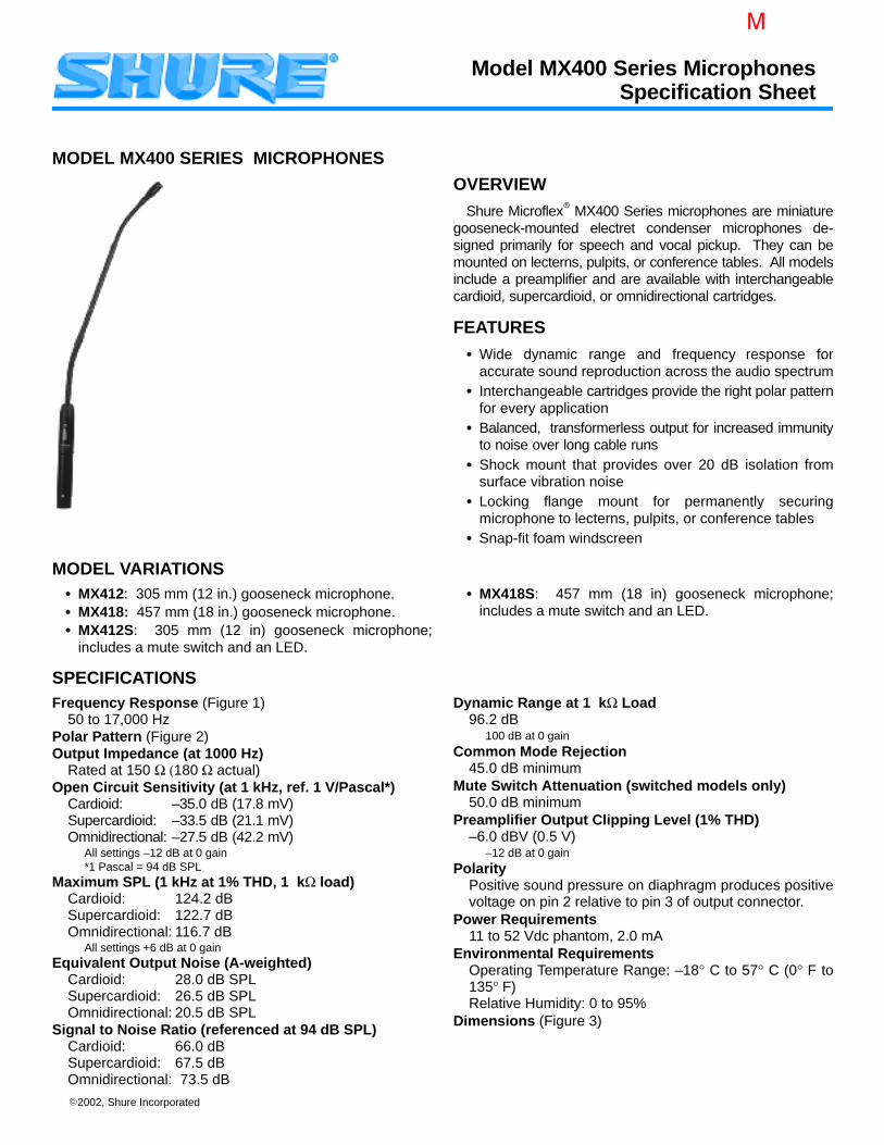
2002, Shure Incorporated
MODEL MX400 SERIES MICROPHONES
OVERVIEW
Shure Microflex MX400 Series microphones are miniaturegooseneck-mounted electret condenser microphones de-signed primarily for speech and vocal pickup. They can bemounted on lecterns, pulpits, or conference tables. All modelsinclude a preamplifier and are available with interchangeablecardioid, supercardioid, or omnidirectional cartridges.
FEATURES
Wide dynamic range and frequency response foraccurate sound reproduction across the audio spectrum
Interchangeable cartridges provide the right polar patternfor every application
Balanced, transformerless output for increased immunityto noise over long cable runs
Shock mount that provides over 20 dB isolation fromsurface vibration noise
Locking flange mount for permanently securingmicrophone to lecterns, pulpits, or conference tables
Snap-fit foam windscreen
MODEL VARIATIONS MX412: 305 mm (12 in.) gooseneck microphone. MX418: 457 mm (18 in.) gooseneck microphone. MX412S: 305 mm (12 in) gooseneck microphone;
includes a mute switch and an LED.
MX418S: 457 mm (18 in) gooseneck microphone;includes a mute switch and an LED.
SPECIFICATIONSFrequency Response (Figure 1)
50 to 17,000 HzPolar Pattern (Figure 2)Output Impedance (at 1000 Hz)
Rated at 150 Ω (180 Ω actual)Open Circuit Sensitivity (at 1 kHz, ref. 1 V/Pascal*)
Cardioid: –35.0 dB (17.8 mV)Supercardioid: –33.5 dB (21.1 mV)Omnidirectional: –27.5 dB (42.2 mV)
All settings –12 dB at 0 gain*1 Pascal = 94 dB SPL
Maximum SPL (1 kHz at 1% THD, 1 kΩ load)Cardioid: 124.2 dBSupercardioid: 122.7 dBOmnidirectional: 116.7 dB
All settings +6 dB at 0 gainEquivalent Output Noise (A-weighted)
Cardioid: 28.0 dB SPLSupercardioid: 26.5 dB SPLOmnidirectional: 20.5 dB SPL
Signal to Noise Ratio (referenced at 94 dB SPL)Cardioid: 66.0 dBSupercardioid: 67.5 dBOmnidirectional: 73.5 dB
Dynamic Range at 1 kΩ Load96.2 dB
100 dB at 0 gainCommon Mode Rejection
45.0 dB minimumMute Switch Attenuation (switched models only)
50.0 dB minimumPreamplifier Output Clipping Level (1% THD)
–6.0 dBV (0.5 V)–12 dB at 0 gain
PolarityPositive sound pressure on diaphragm produces positivevoltage on pin 2 relative to pin 3 of output connector.
Power Requirements11 to 52 Vdc phantom, 2.0 mA
Environmental RequirementsOperating Temperature Range: –18° C to 57° C (0° F to135° F)Relative Humidity: 0 to 95%
Dimensions (Figure 3)
Model MX400 Series MicrophonesSpecification Sheet
M

Specification SheetMODEL MX400 SERIES MICROPHONES
2
CertificationEligible to bear CE Marking. Conforms to European EMC Direc-tive 89/336/EEC. Meets applicable tests and performance crite-ria in European Standard EN55103 (1996) parts 1 and 2, for resi-dential (E1) and light industrial (E2) environments.
REPLACEMENT PARTS
Foam Ball Windscreen A99WS
Locking Metal Windscreen A412MWS
Portable Desktop Base A412B
Stand Adapter A57E
Omnidirectional Cartridge R183B
Supercardioid Cartridge R184B
Cardioid Cartridge R185B
Snap-fit Foam Windscreen (4) RK412WS
Shock Mount A400SM
150o
120o
150o
120o
180o
30o
60o
90o
30o
60o
0
150o
120o
150o
120o
180o
30o
60o
30o
60o
–5 dB
0
90o
–5 dB
–10 dB
–15 dB
90o 90o
500 1,000 2,000 5,000 10,000 20,00050 100 20020
0
+10
–10
500 1,000 2,000 5,000 10,000 20,00050 100 20020
0
+10
–10
500 1,000 2,000 5,000 10,00050 100 20020
0
+10
–10
250 Hz500 Hz1000 Hz
2500 Hz6400 Hz10000 Hz
250 Hz500 Hz1000 Hz
2500 Hz6400 Hz10000 Hz
250 Hz500 Hz1000 Hz
2500 Hz6400 Hz10000 Hz
150o
120o
150o
120o
180o
30o
60o
90o
30o
60o
0
150o
120o
150o
120o
180o
30o
60o
30o
60o–10 dB
–15 dB
0
90o
–10 dB
–15 dB
–20 dB
90o
150o
120o
150o
120o
180o
30o
60o
90o
30o
60o
0
90o
150o
120o
150o
120o
180o
30o
60o
90o
30o
60o
0
–5 dB
–10 dB
–15 dB
90o
90o
20,000
–20 dB
–5 dB
–10 dB
–15 dB
–20 dB
–5 dB
–20 dB
–5 dB
–20 dB –20 dB
–15 dB
–10 dB
Hz
Hz
Hz
Figure 1Figure 2
SUPERCARDIOID
CARDIOID
OMNIDIRECTIONAL
OMNIDIRECTIONAL
CARDIOID
SUPERCARDIOID
TYPICAL FREQUENCY RESPONSETYPICAL POLAR PATTERNS
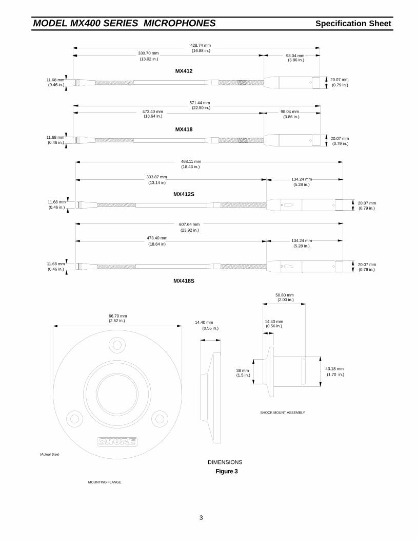
Specification SheetMODEL MX400 SERIES MICROPHONES
3
(3.86 in.)98.04 mm
(5.28 in.)134.24 mm
(18.43 in.)
(13.14 in)
473.40 mm(18.64 in.)
20.07 mm(0.79 in.)
(0.56 in.)
66.70 mm(2.62 in.) 14.40 mm
330.70 mm(13.02 in.)
MX412S
MX418
MX412
20.07 mm(0.79 in.)
Figure 3
DIMENSIONS
20.07 mm(0.79 in.)
14.40 mm(0.56 in.)
(2.00 in.)50.80 mm
(1.70 in.)43.18 mm
MOUNTING FLANGE
SHOCK MOUNT ASSEMBLY
571.44 mm(22.50 in.)
428.74 mm(16.88 in.)
468.11 mm
(3.86 in.)98.04 mm
(0.46 in.)11.68 mm
(0.46 in.)11.68 mm
(0.46 in.)11.68 mm
38 mm(1.5 in.)
(5.28 in.)134.24 mm
(18.64 in)
473.40 mm
20.07 mm(0.79 in.)
MX418S
(Actual Size)
607.64 mm(23.92 in.)
(0.46 in.)11.68 mm
333.87 mm
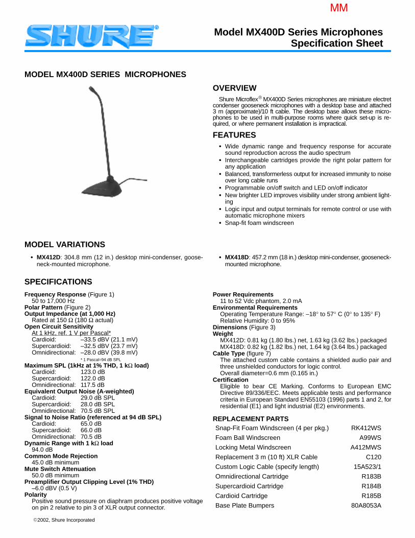
2002, Shure Incorporated
MODEL MX400D SERIES MICROPHONES
OVERVIEWShure Microflex MX400D Series microphones are miniature electret
condenser gooseneck microphones with a desktop base and attached3 m (approximate)/10 ft cable. The desktop base allows these micro-phones to be used in multi-purpose rooms where quick set-up is re-quired, or where permanent installation is impractical.
FEATURES Wide dynamic range and frequency response for accurate
sound reproduction across the audio spectrum Interchangeable cartridges provide the right polar pattern for
any application Balanced, transformerless output for increased immunity to noise
over long cable runs Programmable on/off switch and LED on/off indicator New brighter LED improves visibility under strong ambient light-
ing Logic input and output terminals for remote control or use with
automatic microphone mixers Snap-fit foam windscreen
MODEL VARIATIONS
MX412D: 304.8 mm (12 in.) desktop mini-condenser, goose-neck-mounted microphone.
MX418D: 457.2 mm (18 in.) desktop mini-condenser, gooseneck-mounted microphone.
SPECIFICATIONSFrequency Response (Figure 1)
50 to 17,000 HzPolar Pattern (Figure 2)Output Impedance (at 1,000 Hz)
Rated at 150 Ω (180 Ω actual)Open Circuit Sensitivity
At 1 kHz, ref. 1 V per Pascal*Cardioid: –33.5 dBV (21.1 mV)Supercardioid: –32.5 dBV (23.7 mV)Omnidirectional: –28.0 dBV (39.8 mV)
* 1 Pascal=94 dB SPL
Maximum SPL (1kHz at 1% THD, 1 kΩ load)Cardioid: 123.0 dBSupercardioid: 122.0 dBOmnidirectional: 117.5 dB
Equivalent Output Noise (A-weighted)Cardioid: 29.0 dB SPLSupercardioid: 28.0 dB SPLOmnidirectional: 70.5 dB SPL
Signal to Noise Ratio (referenced at 94 dB SPL)Cardioid: 65.0 dBSupercardioid: 66.0 dBOmnidirectional: 70.5 dB
Dynamic Range with 1 kΩ load94.0 dB
Common Mode Rejection45.0 dB minimum
Mute Switch Attenuation50.0 dB minimum
Preamplifier Output Clipping Level (1% THD)–6.0 dBV (0.5 V)
PolarityPositive sound pressure on diaphram produces positive voltageon pin 2 relative to pin 3 of XLR output connector.
Power Requirements11 to 52 Vdc phantom, 2.0 mA
Environmental RequirementsOperating Temperature Range: –18° to 57° C (0° to 135° F)Relative Humidity: 0 to 95%
Dimensions (Figure 3)Weight
MX412D: 0.81 kg (1.80 lbs.) net, 1.63 kg (3.62 lbs.) packagedMX418D: 0.82 kg (1.82 lbs.) net, 1.64 kg (3.64 lbs.) packaged
Cable Type (figure 7)The attached custom cable contains a shielded audio pair andthree unshielded conductors for logic control.Overall diameter=0.6 mm (0.165 in.)
CertificationEligible to bear CE Marking. Conforms to European EMCDirective 89/336/EEC. Meets applicable tests and performancecriteria in European Standard EN55103 (1996) parts 1 and 2, forresidential (E1) and light industrial (E2) environments.
REPLACEMENT PARTSSnap-Fit Foam Windscreen (4 per pkg.) RK412WS
Foam Ball Windscreen A99WS
Locking Metal Windscreen A412MWS
Replacement 3 m (10 ft) XLR Cable C120
Custom Logic Cable (specify length) 15A523/1
Omnidirectional Cartridge R183B
Supercardioid Cartridge R184B
Cardioid Cartridge R185B
Base Plate Bumpers 80A8053A
Model MX400D Series MicrophonesSpecification Sheet
MM
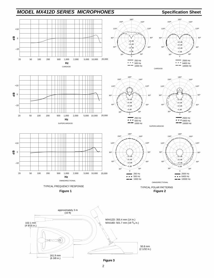
Specification SheetMODEL MX412D SERIES MICROPHONES
2
500 1,000 2,000 5,000 10,000 20,00050 100 20020
0
+10
–10
500 1,000 2,000 5,000 10,000 20,00050 100 20020
0
+10
–10
500 1,000 2,000 5,000 10,00050 100 20020
0
+10
–10
250 Hz500 Hz1000 Hz
2500 Hz6400 Hz10000 Hz
250 Hz500 Hz1000 Hz
2500 Hz6400 Hz10000 Hz
150o
120o
150o
120o
180o
30o
60o
90o
30o
60o
0
150o
120o
150o
120o
180o
30o
60o
30o
60o–10 dB
–15 dB
0
90o
–10 dB
–15 dB
–20 dB
90o
20,000
–5 dB
–20 dB
–5 dB
SUPERCARDIOID
CARDIOID
OMNIDIRECTIONALOMNIDIRECTIONAL
CARDIOID
SUPERCARDIOID
Hz
Hz
Hz
TYPICAL FREQUENCY RESPONSE TYPICAL POLAR PATTERNS
150o
120o
150o
120o
180o
30o
60o
90o
30o
60o
0
150o
120o
150o
120o
180o
30o
60o
30o
60o
–5 dB
0
90o
–5 dB
–10 dB
–15 dB
90o 90o
90o
–20 dB –20 dB
–15 dB
–10 dB
250 Hz500 Hz1000 Hz
2500 Hz6400 Hz10000 Hz
150o
120o
150o
120o
180o
30o
60o
90o
30o
60o
0
90o
150o
120o
150o
120o
180o
30o
60o
90o
30o
60o
0
–5 dB
–10 dB
–15 dB
90o
–20 dB
–5 dB
–10 dB
–15 dB
–20 dB
Figure 1 Figure 2
102.1 mm(4 9/16 in.)
50.8 mm(2 1/32 in.)
161.9 mm(6 3/8 in.)
MX412D: 355.4 mm (14 in.)MX418D: 501.7 mm (19 3/4 in.)
approximately 3 m(10 ft)
Figure 3
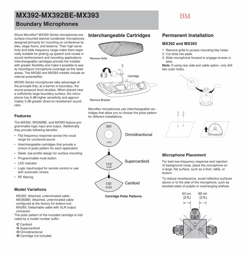
Shure Microflex® MX300 Series microphones are surface-mounted electret condenser microphones designed primarily for mounting on conference ta-bles, stage floors, and lecterns. Their high sensi-tivity and wide frequency range make them espe-cially suitable for picking up speech and vocals in sound reinforcement and recording applications. Interchangeable cartridges provide the installer with greater flexibility and make it possible to eas-ily reconfigure microphone coverage as the need arises. The MX392 and MX393 models include an internal preamplifier.MX300 Series microphones take advantage of the principle that, at a barrier or boundary, the sound pressure level doubles. When placed near a sufficiently large boundary surface, the micro-phone has 6 dB higher sensitivity and approxi-mately 3 dB greater direct-to-reverberant sound ratio.
MX392-MX392BE-MX393Boundary Microphones
FeaturesThe MX392, MX392BE, and MX393 feature pro-grammable logic input and output. Additionally they provide following benefits: • Flat frequency response across the vocal
range for uncolored sound• Interchangeable cartridges that provide a
choice of polar pattern for each application• Sleek, low-profile design for surface mounting• Programmable mute button• LED indicator• Logic input/output for remote control or use
with automatic mixers• RF filtering
Model VariationsMX392: Attached, unterminated cable.MX392BE: Attached, unterminated cable configured at the factory for bottom exit.MX393: Detachable cable with XLR output connector.
The polar pattern of the included cartridge is indi-cated by a model number suffix:
/C Cardioid/S Supercardioid/O Omnidirectional/N Cartridge not included
Interchangeable Cartridges
Remove Grille
Remove Bracket
Cartridge
Microflex microphones use interchangeable car-tridges that allow you to choose the polar pattern for different installations.
R183
R184
R185
Omnidirectional
Supercardioid
Cardioid
Cartridge Polar Patterns
Permanent InstallationMX392 and MX3931. Remove grille to access mounting key holes.2. Cut slots into pads.3. Slide microphone forward to engage screws in
slots.Note: If using rear side-exit cable option, only drill two outer holes.
Microphone PlacementFor best low-frequency response and rejection of background noise, place the microphone on a large, flat surface, such as a floor, table, or lectern.To reduce reverberance, avoid reflective surfaces above or to the side of the microphone, such as beveled sides of pulpits or overhanging shelves.
BM
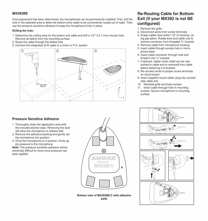
Once placement has been determined, the microphones can be permanently installed. First, drill the hole in the selected area to allow the bottom entry cable to be conveniently routed out of sight. Then use the pressure sensitive adhesive to keep the microphone firmly in place. Drilling the hole: 1. Determine the cutting area for the bottom exit cable and drill a 1/2" (12.7 mm) circular hole.
Remove all debris from the mounting surface.2. Route the cable through the drilled hole.3. Connect the integrated XLR cable to a mixer or P.A. system.
12.7 mm (1/2 in.)
Pressure Sensitive Adhesive1. Thoroughly clean the application area with
the included alcohol wipe. Removing the dustwill allow the microphone to adhere well.
2. Remove the adhesive backing and gently setthe microphone into position.
3. Once the microphone is in position, firmly ap-ply pressure to the microphone.
Note: The pressure sensitive adhesive will be extremely difficult to move once pressure has been applied.
MX392BE/CMICROFLEX
Bottom view of MX392BE/C with adhesive pads
Re-Routing Cable for Bottom Exit (If your MX392 is not BE configured)1. Remove the grille.2. Disconnect wires from screw terminals.3. Grasp rubber boot within 1/2" of housing, us-
ing gas pliers. Rotate boot and cable ccw toremove connector from threaded "L" bracket.
4. Remove cable from microphone housing.5. Insert cable through access hole in micro-
phone base.6. Insert cable connector through hole and
thread it into "L" bracket.7. If desired, rubber strain relief can be reat-
tached to cable end or removed from cablebefore fastening it to bracket.
8. Re-connect wires to proper screw terminalson circuit board.
9. Insert supplied round rubber plug into unusedside cable exit.
10. Reinstall grille and foam screen.11. Insert cable through hole in mounting
surface. Secure microphone to mountingsurface.
MX392BE
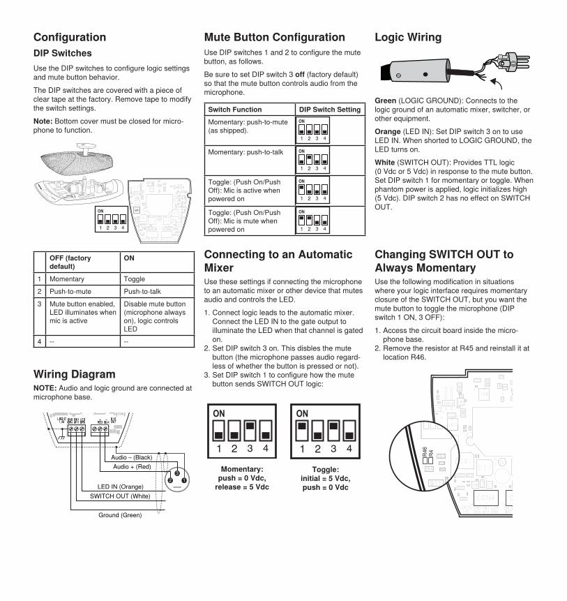
ConfigurationDIP SwitchesUse the DIP switches to configure logic settings and mute button behavior. The DIP switches are covered with a piece of clear tape at the factory. Remove tape to modify the switch settings. Note: Bottom cover must be closed for micro-phone to function.
OFF (factory default)
ON
1 Momentary Toggle2 Push-to-mute Push-to-talk3 Mute button enabled,
LED illuminates when mic is active
Disable mute button (microphone always on), logic controls LED
4 -- --
Wiring DiagramNOTE: Audio and logic ground are connected at microphone base.
Ground (Green)
SWITCH OUT (White)LED IN (Orange)
Audio + (Red)Audio – (Black)
Mute Button ConfigurationUse DIP switches 1 and 2 to configure the mute button, as follows.Be sure to set DIP switch 3 off (factory default) so that the mute button controls audio from the microphone.
Switch Function DIP Switch SettingMomentary: push-to-mute (as shipped).
Momentary: push-to-talk
Toggle: (Push On/Push Off): Mic is active when powered on
Toggle: (Push On/Push Off): Mic is mute when powered on
Connecting to an Automatic MixerUse these settings if connecting the microphone to an automatic mixer or other device that mutes audio and controls the LED.1. Connect logic leads to the automatic mixer.
Connect the LED IN to the gate output toilluminate the LED when that channel is gatedon.
2. Set DIP switch 3 on. This disbles the mutebutton (the microphone passes audio regard-less of whether the button is pressed or not).
3. Set DIP switch 1 to configure how the mutebutton sends SWITCH OUT logic:
Momentary: push = 0 Vdc,
release = 5 Vdc
Toggle: initial = 5 Vdc, push = 0 Vdc
Logic Wiring
Green (LOGIC GROUND): Connects to the logic ground of an automatic mixer, switcher, or other equipment. Orange (LED IN): Set DIP switch 3 on to use LED IN. When shorted to LOGIC GROUND, the LED turns on. White (SWITCH OUT): Provides TTL logic (0 Vdc or 5 Vdc) in response to the mute button. Set DIP switch 1 for momentary or toggle. When phantom power is applied, logic initializes high (5 Vdc). DIP switch 2 has no effect on SWITCH OUT.
Changing SWITCH OUT to Always MomentaryUse the following modification in situations where your logic interface requires momentary closure of the SWITCH OUT, but you want the mute button to toggle the microphone (DIP switch 1 ON, 3 OFF): 1. Access the circuit board inside the micro-
phone base.2. Remove the resistor at R45 and reinstall it at
location R46.
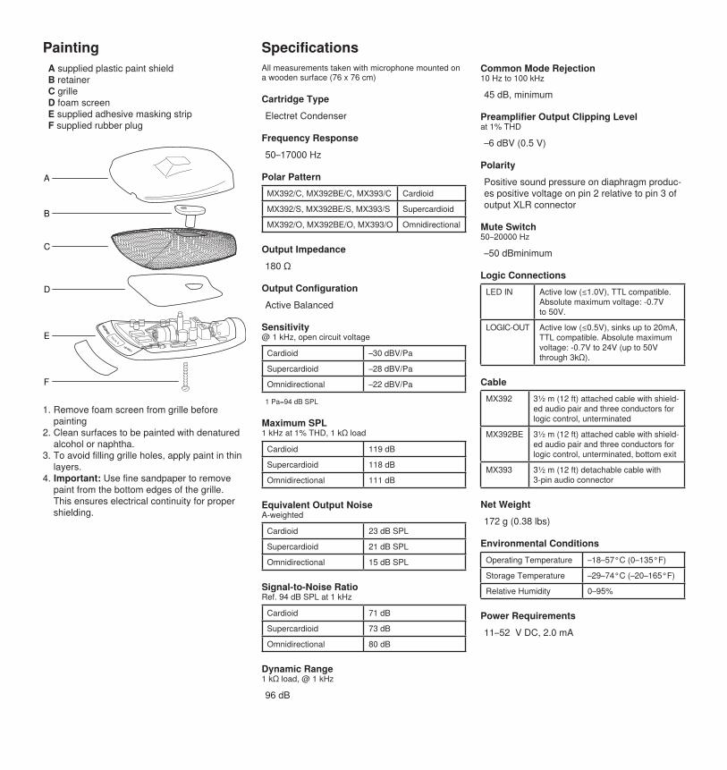
A supplied plastic paint shieldB retainerC grilleD foam screenE supplied adhesive masking stripF supplied rubber plug
SpecificationsPaintingAll measurements taken with microphone mounted on a wooden surface (76 x 76 cm)
Cartridge TypeElectret Condenser
Frequency Response50–17000 Hz
Polar PatternMX392/C, MX392BE/C, MX393/C Cardioid
MX392/S, MX392BE/S, MX393/S Supercardioid
MX392/O, MX392BE/O, MX393/O Omnidirectional
Output Impedance180 Ω
Output ConfigurationActive Balanced
Sensitivity@ 1 kHz, open circuit voltage
Cardioid –30 dBV/Pa
Supercardioid –28 dBV/Pa
Omnidirectional –22 dBV/Pa
1 Pa=94 dB SPL
Maximum SPL1 kHz at 1% THD, 1 kΩ load
Cardioid 119 dB
Supercardioid 118 dB
Omnidirectional 111 dB
Equivalent Output NoiseA-weighted
Cardioid 23 dB SPL
Supercardioid 21 dB SPL
Omnidirectional 15 dB SPL
Signal-to-Noise RatioRef. 94 dB SPL at 1 kHz
Cardioid 71 dB
Supercardioid 73 dB
Omnidirectional 80 dB
Dynamic Range1 kΩ load, @ 1 kHz
96 dB
Common Mode Rejection10 Hz to 100 kHz
45 dB, minimum
Preamplifier Output Clipping Levelat 1% THD
–6 dBV (0.5 V)
PolarityPositive sound pressure on diaphragm produc-es positive voltage on pin 2 relative to pin 3 of output XLR connector
Mute Switch50–20000 Hz
–50 dBminimum
Logic ConnectionsLED IN Active low (≤1.0V), TTL compatible.
Absolute maximum voltage: -0.7V to 50V.
LOGIC-OUT Active low (≤0.5V), sinks up to 20mA, TTL compatible. Absolute maximum voltage: -0.7V to 24V (up to 50V through 3kΩ).
CableMX392 3½ m (12 ft) attached cable with shield-
ed audio pair and three conductors for logic control, unterminated
MX392BE 3½ m (12 ft) attached cable with shield-ed audio pair and three conductors for logic control, unterminated, bottom exit
MX393 3½ m (12 ft) detachable cable with 3-pin audio connector
Net Weight172 g (0.38 lbs)
Environmental ConditionsOperating Temperature –18–57°C (0–135°F)
Storage Temperature –29–74°C (–20–165°F)
Relative Humidity 0–95%
Power Requirements11–52 V DC, 2.0 mA
A
B
C
D
E
F
1. Remove foam screen from grille beforepainting
2. Clean surfaces to be painted with denaturedalcohol or naphtha.
3. To avoid filling grille holes, apply paint in thinlayers.
4. Important: Use fine sandpaper to removepaint from the bottom edges of the grille.This ensures electrical continuity for propershielding.
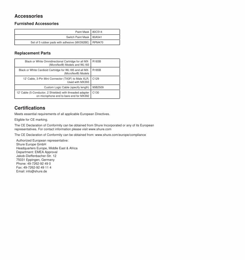
AccessoriesFurnished Accessories
Paint Mask 80C514
Switch Paint Mask 80A541
Set of 5 rubber pads with adhesive (MX392BE) RPM470
Replacement Parts
Black or White Omnidirectional Cartridge for all MX- (Microflex®) Models and WL183
R183B
Black or White Cardioid Cartridge for WL185 and all MX- (Microflex®) Models
R185B
12' Cable, 3-Pin Mini Connector (TA3F) to Male XLR, Used with MX393
C129
Custom Logic Cable (specify length) 95B2509
12' Cable (5-Conductor, 2 Shielded) with threaded adapter on microphone end to bare end for MX392
C130
CertificationsMeets essential requirements of all applicable European Directives. Eligible for CE marking. The CE Declaration of Conformity can be obtained from Shure Incorporated or any of its European representatives. For contact information please visit www.shure.com The CE Declaration of Conformity can be obtained from: www.shure.com/europe/compliance
Authorized European representative:Shure Europe GmbHHeadquarters Europe, Middle East & AfricaDepartment: EMEA ApprovalJakob-Dieffenbacher-Str. 1275031 Eppingen, GermanyPhone: 49-7262-92 49 0Fax: 49-7262-92 49 11 4Email: [email protected]
STICK-ON® SERIESModel ST-NG1 Random Noise Generator
True Random Noise Source Masking Noise Sources Pink Noise White Noise Mic and/or Line Level Noise Signals
The ST-NG1 is part of the group of versatile STICK-ON products from Radio Design Labs. STICK-ONs feature the advanced circuitry for which RDL products are known, combined with unequalled versatility in mounting possibilities. The durable adhesives provided with the ST-NG1 permit permanent or removable mounting. Numerous available mounting accessories, brackets and rack-mount chassis are optionally available to facilitate any system design. STICK-ONs are designed, built and rated for continuous duty in professional A/V systems.
APPLICATION: The ST-NG1 is the ideal choice where random white or pink noise is needed. It is suitable either as a reference noise source for audio measurements; or as a masking noise source in engineered sound or counter-intelligence applications, particularly where true random noise is required.
Amplitude limiting circuitry in the ST-NG1 controls extreme peak excursions while preserving random variations of at least 20 dB. The noise generating circuitry in the ST-NG1 is truly random analog noise occupying the full bandwidth from 20 Hz to 20 kHz. This makes the ST-NG1 ideal in masking environments where secure, random noise is required. Unlike the typical digitally-generated pseudo-random noise generators, which can be decoded and removed by effective intelligence equipment, the ST-NG1 produces no repetitive frequency or amplitude pattern.
Four outputs are available on the ST-NG1. Both a mic-level and line-level output are provided from each noise source. A 25-turn gain-trimming potentiometer is provided for the white noise. A separate 25-turn gain-trimming potentiometer is provided to set the pink-noise level, independent of the white-noise setting. The gain trim for each noise source adjusts both the line and mic output for that source. Each output is balanced low-impedance, and may be wired either balanced or unbalanced. All outputs may be used simultaneously.
Wherever white or pink noise signals are needed, the ST-NG1 is the ideal choice. Use the ST-NG1 individually, or combine it with other RDL products as part of a complete audio/video system.
RDL 659 6th St. Prescott, AZ., USA 86301 (928) 443-9391 FAX (928) 443-9392 www.rdlnet.com
WGN
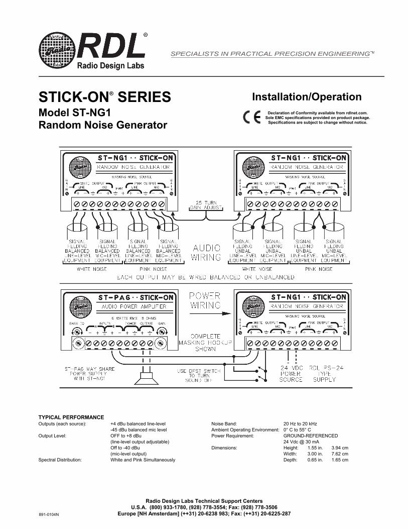
STICK-ON® SERIESModel ST-NG1 Random Noise Generator
TYPICAL PERFORMANCE Outputs (each source): +4 dBu balanced line-level
-45 dBu balanced mic level Output Level: OFF to +8 dBu
(line-level output adjustable)Off to -40 dBu(mic-level output)
Spectral Distribution: White and Pink Simultaneously
Noise Band: 20 Hz to 20 kHz Ambient Operating Environment: 0° C to 55° C Power Requirement: GROUND-REFERENCED
24 Vdc @ 30 mA Dimensions: Height: 1.55 in. 3.94 cm
Width: 3.00 in. 7.62 cmDepth: 0.65 in. 1.65 cm
Installation/OperationDeclaration of Conformity available from rdlnet.com.
Sole EMC specifications provided on product package. Specifications are subject to change without notice.
Radio Design Labs Technical Support Centers U.S.A. (800) 933-1780, (928) 778-3554; Fax: (928) 778-3506
Europe [NH Amsterdam] (++31) 20-6238 983; Fax: (++31) 20-6225-287 891-0104N
™8pre USBUser’s Guide for Windows
1280 Massachusetts AvenueCambridge, MA 02138
Business voice: (617) 576-2760Business fax: (617) 576-3609
Web site: www.motu.comTech support: www.motu.com/support
MOTU
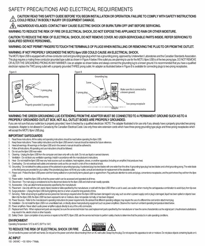
SAFETY PRECAUTIONS AND ELECTRICAL REQUIREMENTS
CAUTION! READ THIS SAFETY GUIDE BEFORE YOU BEGIN INSTALLATION OR OPERATION. FAILURE TO COMPLY WITH SAFETY INSTRUCTIONS COULD RESULT IN BODILY INJURY OR EQUIPMENT DAMAGE.
HAZARDOUS VOLAGES: CONTACT MAY CAUSE ELECTRIC SHOCK OR BURN. TURN OFF UNIT BEFORE SERVICING.
WARNING: TO REDUCE THE RISK OF FIRE OR ELECTRICAL SHOCK, DO NOT EXPOSE THIS APPLIANCE TO RAIN OR OTHER MOISTURE.
CAUTION: TO REDUCE THE RISK OF ELECTRICAL SHOCK, DO NOT REMOVE COVER. NO USER-SERVICEABLE PARTS INSIDE. REFER SERVICING TO QUALIFIED SERVICE PERSONNEL.
WARNING: DO NOT PERMIT FINGERS TO TOUCH THE TERMINALS OF PLUGS WHEN INSTALLING OR REMOVING THE PLUG TO OR FROM THE OUTLET.
WARNING: IF NOT PROPERLY GROUNDED THE MOTU 8pre USB COULD CAUSE AN ELECTRICAL SHOCK.
The MOTU 8pre USB is equipped with a three-conductor cord and grounding type plug which has a grounding prong, approved by Underwriters' Laboratories and the Canadian Standards Association. This plug requires a mating three-conductor grounded type outlet as shown in Figure A below. If the outlet you are planning to use for the MOTU 8pre USB is of the two prong type, DO NOT REMOVE OR ALTER THE GROUNDING PRONG IN ANY MANNER. Use an adapter as shown below and always connect the grounding lug to a known ground. It is recommended that you have a qualified electrician replace the TWO prong outlet with a properly grounded THREE prong outlet. An adapter as illustrated below in Figure B is available for connecting plugs to two-prong receptacles.
WARNING: THE GREEN GROUNDING LUG EXTENDING FROM THE ADAPTER MUST BE CONNECTED TO A PERMANENT GROUND SUCH AS TO A PROPERLY GROUNDED OUTLET BOX. NOT ALL OUTLET BOXES ARE PROPERLY GROUNDED.
If you are not sure that your outlet box is properly grounded, have it checked by a qualified electrician. NOTE: The adapter illustrated is for use only if you already have a properly grounded two-prong receptacle. Adapter is not allowed in Canada by the Canadian Electrical Code. Use only three wire extension cords which have three-prong grounding type plugs and three-prong receptacles which will accept the MOTU 8pre USB plug.
IMPORTANT SAFEGUARDS
1. Read these instructions. All the safety and operating instructions should be read before operating the 8pre USB.2. Keep these instructions. These safety instructions and the 8pre USB owner’s manual should be retained for future reference.3. Heed all warnings. All warnings on the 8pre USB and in the owner’s manual should be adhered to.4. Follow all Instructions. All operating and use instructions should be followed.5. Do not use the 8pre USB near water.6. Cleaning - Unplug the 8pre USB from the computer and clean only with a dry cloth. Do not use liquid or aerosol cleaners.7. Ventilation - Do not block any ventilation openings. Install in accordance with the manufacturer’s instructions.8. Heat - Do not install the 8pre USB near any heat sources such as radiators, heat registers, stoves, or another apparatus (including an amplifier) that produces heat.9. Overloading - Do not overload wall outlets and extension cords as this can result in a risk of fire or electrical shock.10. Grounding - Do not defeat the safety purpose of the polarized or grounding-type plug. A polarized plug has two blades with one wider than the other. A grounding-type plug has two blades and a third grounding prong. The wide blade
or the third prong are provided for your safety. If the provided plug does not fit into your outlet, consult and electrician for replacement of the obsolete outlet.11. Power cord - Protect the 8pre USB power cord from being walked on or pinched by items placed upon or against them. Pay particular attention to cords and plugs, convenience receptacles, and the point where they exit from the 8pre
USB.12. Power switch - Install the 8pre USB so that the power switch can be accessed and operated at all times.13. Disconnect - The main plug is considered to be the disconnect device for the 8pre USB and shall remain readily operable.14. Accessories - Only use attachments/accessories specified by the manufacturer.15. Placement - Use only with the cart, stand, tripod, bracket or table specified by the manufacturer, or sold with the 8pre USB. When a cart is used, use caution when moving the cart/apparatus combination to avoid injury from tip-over.16. Surge protection - Unplug the 8pre USB during lightning storms or when unused for long periods of time.17. Servicing - Refer all servicing to qualified service personnel. Servicing is required when the 8pre USB has been damaged in any way, such as when a power-supply cord or plug is damaged, liquid has been spilled or objects have
fallen into the 8pre USB, the 8pre USB has been exposed to rain or moisture, does not operate normally, or has been dropped.18. Power Sources - Refer to the manufacturer’s operating instructions for power requirements. Be advised that different operating voltages may require the use of a different line cord and/or attachment plug.19. Installation - Do not install the 8pre USB in an unventilated rack, or directly above heat-producing equipment such as power amplifiers. Observe the maximum ambient operating temperature listed below.20. Power amplifiers- Never attach audio power amplifier outputs directly to any of the unit’s connectors.21. Replacement Parts - When replacement parts are required, be sure the service technician has used replacement parts specified by the manufacturer or have the same characteristics as the original part. Unauthorized substitutions
may result in fire, electric shock or other hazards.22. Safety Check - Upon completion of any service or repairs to this MOTU 8pre USB, ask the service technician to perform safety checks to determine that the product is in safe operating conditions.
ENVIRONMENT
Operating Temperature: 10°C to 40°C (50°F to 104°)
TO REDUCE THE RISK OF ELECTRICAL SHOCK OR FIRE
Do not handle the power cord with wet hands. Do not pull on the power cord when disconnecting it from an AC wall outlet. Grasp it by the plug. Do not expose this apparatus to rain or moisture. Do not place objects containing liquids on it.
AC INPUT
100 - 240VAC ~ • 50 / 60Hz • 7 Watts.
3-prong plug
Grounding prong
Properly grounded 3-prong outlet
Grounding lug
Screw
3-prong plug
Adapter
Make sure this is connected to a known ground.
Two-prong receptacle
Figure A Figure B
III
Contents
Part 1: Getting Started
7
Quick Reference: 8pre USB USB Front Panel
8
Quick Reference: 8pre USB USB Rear Panel
9
Quick Reference: MOTU Audio Console
11
About the 8pre USB
15
Packing List and System Requirements
17
Installing the 8pre USB Software
19
Installing the 8pre USB Hardware
Part 2: Using the 8pre USB
27
MOTU Audio Console
31
Front Panel Settings
33
Configuring Host Audio Software
41
Reducing Monitoring Latency
47
CueMix FX
73
MOTU SMPTE Console
77
Troubleshooting
About the Mark of the Unicorn License Agreement and Limited Warranty on Software
TO PERSONS WHO PURCHASE OR USE THIS PRODUCT: carefully read all the terms and conditions of the “click-wrap” license agreement presented to you when you install the software. Using the software or this documentation indicates your acceptance of the terms and conditions of that license agreement.
Mark of the Unicorn, Inc. (“MOTU”) owns both this program and its documentation. Both the program and the documentation are protected under applicable copyright, trademark, and trade-secret laws. Your right to use the program and the documentation are limited to the terms and conditions described in the license agreement.
Reminder of the terms of your license
This summary is not your license agreement, just a reminder of its terms. The actual license can be read and printed by running the installation program for the software. That license agreement is a contract, and clicking “Accept” binds you and MOTU to all its terms and conditions. In the event anything contained in this summary is incomplete or in conflict with the actual click-wrap license agreement, the terms of the click-wrap agreement prevail.
YOU MAY: (a) use the enclosed program on a single computer; (b) physically transfer the program from one computer to another provided that the program is used on only one computer at a time and that you remove any copies of the program from the computer from which the program is being transferred; (c) make copies of the program solely for backup purposes. You must reproduce and include the copyright notice on a label on any backup copy.
YOU MAY NOT: (a) distribute copies of the program or the documentation to others; (b) rent, lease or grant sublicenses or other rights to the program; (c) provide use of the program in a computer service business, network, time-sharing, multiple CPU or multiple user arrangement without the prior written consent of MOTU; (d) translate, adapt, reverse engineer, decompile, disassemble, or otherwise alter the program or related documentation without the prior written consent of MOTU.
MOTU warrants to the original licensee that the disk(s) on which the program is recorded be free from defects in materials and workmanship under normal use for a period of ninety (90) days from the date of purchase as evidenced by a copy of your receipt. If failure of the disk has resulted from accident, abuse or misapplication of the product, then MOTU shall have no responsibility to replace the disk(s) under this Limited Warranty.
THIS LIMITED WARRANTY AND RIGHT OF REPLACEMENT IS IN LIEU OF, AND YOU HEREBY WAIVE, ANY AND ALL OTHER WARRANTIES, BOTH EXPRESS AND IMPLIED, INCLUDING BUT NOT LIMITED TO WARRANTIES OF MERCHANTABILITY AND FITNESS FOR A PARTICULAR PURPOSE. THE LIABILITY OF MOTU PURSUANT TO THIS LIMITED WARRANTY SHALL BE LIMITED TO THE REPLACEMENT OF THE DEFECTIVE DISK(S), AND IN NO EVENT SHALL MOTU OR ITS SUPPLIERS, LICENSORS, OR AFFILIATES BE LIABLE FOR INCIDENTAL OR CONSEQUENTIAL DAMAGES, INCLUDING BUT NOT LIMITED TO LOSS OF USE, LOSS OF PROFITS, LOSS OF DATA OR DATA BEING RENDERED INACCURATE, OR LOSSES SUSTAINED BY THIRD PARTIES EVEN IF MOTU HAS BEEN ADVISED OF THE POSSIBILITY OF SUCH DAMAGES. THIS WARRANTY GIVES YOU SPECIFIC LEGAL RIGHTS WHICH MAY VARY FROM STATE TO STATE. SOME STATES DO NOT ALLOW THE LIMITATION OR EXCLUSION OF LIABILITY FOR CONSEQUENTIAL DAMAGES, SO THE ABOVE LIMITATION MAY NOT APPLY TO YOU.
Update Policy
In order to be eligible to obtain updates of the program, you must complete and return the attached Mark of the Unicorn Purchaser Registration Card to MOTU.
Copyright Notice
Copyright © 2013 by Mark of the Unicorn, Inc. All rights reserved. No part of this publication may be reproduced, transmitted, transcribed, stored in a retrieval system, or translated into any human or computer language, in any form or by any means whatsoever, without express written permission of Mark of the Unicorn, Inc., 1280 Massachusetts Avenue, Cambridge, MA, 02138, U.S.A.
Limited Warranty on Hardware
Mark of the Unicorn, Inc. and S&S Research (“MOTU/S&S”) warrant this equipment against defects in materials and workmanship for a period of TWO (2) YEARS from the date of original retail purchase. This warranty applies only to hardware products; MOTU software is licensed and warranted pursuant to separate written statements.
If you discover a defect, first write or call Mark of the Unicorn at (617) 576-2760 to obtain a Return Merchandise Authorization Number. No service will be performed on any product returned without prior authorization. MOTU will, at its option, repair or replace the product at no charge to you, provided you return it during the warranty period, with transportation charges prepaid, to Mark of the Unicorn, Inc., 1280 Massachusetts Avenue, MA 02138. You must use the product’s original packing material for in shipment, and insure the shipment for the value of the product. Please include your name, address, telephone number, a description of the problem, and the original, dated bill of sale with the returned unit and print the Return Merchandise Authorization Number on the outside of the box below the shipping address.
This warranty does not apply if the equipment has been damaged by accident, abuse, misuse, or misapplication; has been modified without the written permission of MOTU, or if the product serial number has been removed or defaced.
ALL IMPLIED WARRANTIES, INCLUDING IMPLIED WARRANTIES OF MERCHANTABILITY AND FITNESS FOR A PARTICULAR PURPOSE, ARE LIMITED IN DURATION TO TWO (2) YEARS FROM THE DATE OF THE ORIGINAL RETAIL PURCHASE OF THIS PRODUCT.
THE WARRANTY AND REMEDIES SET FORTH ABOVE ARE EXCLUSIVE AND IN LIEU OF ALL OTHERS, ORAL OR WRITTEN, EXPRESS OR IMPLIED. No MOTU/S&S dealer, agent, or employee is authorized to make any modification, extension, or addition to this warranty.
MOTU/S&S ARE NOT RESPONSIBLE FOR SPECIAL, INCIDENTAL, OR CONSEQUENTIAL DAMAGES RESULTING FROM ANY BREACH OF WARRANTY, OR UNDER ANY LEGAL THEORY, INCLUDING LOST PROFITS, DOWNTIME, GOODWILL, DAMAGE OR REPLACEMENT OF EQUIPMENT AND PROPERTY AND COST OF RECOVERING REPROGRAMMING, OR REPRODUCING ANY PROGRAM OR DATA STORED IN OR USED WITH MOTU/S&S PRODUCTS.
Some states do not allow the exclusion or limitation of implied warranties or liability for incidental or consequential damages, so the above limitation or exclusion may not apply to you. This warranty gives you specific legal rights, and you may have other rights which vary from state to state.
MOTU, AudioDesk, Mark of the Unicorn and the unicorn silhouette logo are trademarks of Mark of the Unicorn, Inc.
This equipment has been type tested and found to comply with the limits for a class B digital device, pursuant to Part 15 of the FCC Rules. These limits are designed to provide reasonable protection against harmful interference in a residential installation. This equipment generates, uses, and can radiate radio frequency energy and, if not installed and used in accordance with the instruction manual, may cause harmful interference to radio communications. However, there is no guarantee that interference will not occur in a particular installation. If this equipment does cause interference to radio or television equipment reception, which can be determined by turning the equipment off and on, the user is encouraged to try to correct the interference by any combination of the following measures:
• Relocate or reorient the receiving antenna
• Increase the separation between the equipment and the receiver
• Plug the equipment into an outlet on a circuit different from that to which the receiver is connected
If necessary, you can consult a dealer or experienced radio/television technician for additional assistance.
PLEASE NOTE: only equipment certified to comply with Class B (computer input/output devices, terminals, printers, etc.) should be attached to this equipment, and it must have shielded interface cables in order to comply with the Class B FCC limits on RF emissions.
WARNING: changes or modifications to this unit not expressly approved by the party responsible for compliance could void the user's authority to operate the equipment.

Part 1
Getting Started

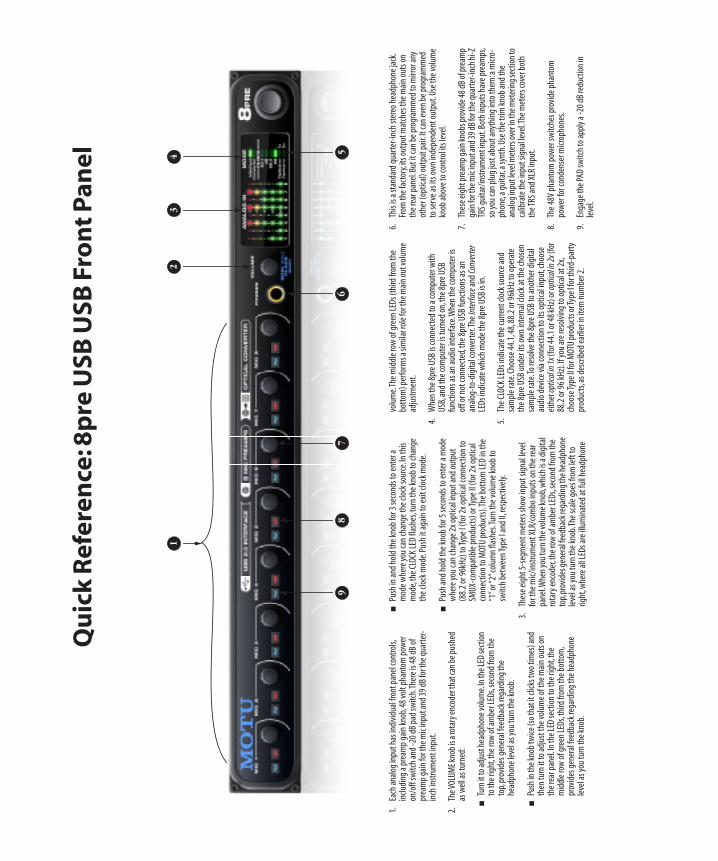
0
Qu
ick
Re
fere
nce
: 8p
re U
SB
US
B F
ron
t P
an
el
13
67
8
4
1.Ea
ch a
nalo
g in
put h
as in
divi
dual
fron
t pan
el c
ontr
ols,
incl
udin
g a
prea
mp
gain
kno
b, 4
8 vo
lt ph
anto
m p
ower
on
/off
sw
itch
and
-20
dB p
ad s
witc
h. T
here
is 4
8 dB
of
prea
mp
gain
for t
he m
ic in
put a
nd 3
9 dB
for t
he q
uart
er-
inch
inst
rum
ent i
nput
.
2.Th
e VO
LUM
E kn
ob is
a ro
tary
enc
oder
that
can
be p
ushe
d as
wel
l as
turn
ed:
Turn
it to
adj
ust h
eadp
hone
vol
ume.
In th
e LE
D se
ctio
n to
the
right
, the
row
of a
mbe
r LED
s, se
cond
from
the
top,
pro
vide
s ge
nera
l fee
dbac
k re
gard
ing
the
head
phon
e le
vel a
s yo
u tu
rn th
e kn
ob.
Push
in th
e kn
ob tw
ice
(so
that
it cl
icks
two
times
) and
th
en tu
rn it
to a
djus
t the
vol
ume
of th
e m
ain
outs
on
the
rear
pan
el. I
n th
e LE
D s
ectio
n to
the
right
, the
m
iddl
e ro
w o
f gre
en L
EDs,
third
from
the
bott
om,
prov
ides
gen
eral
feed
back
rega
rdin
g th
e he
adph
one
leve
l as
you
turn
the
knob
.
Push
in a
nd h
old
the
knob
for 3
sec
onds
to e
nter
a
mod
e w
here
you
can
cha
nge
the
cloc
k so
urce
. In
this
m
ode,
the
CLO
CK L
ED fl
ashe
s, tu
rn th
e kn
ob to
cha
nge
the
cloc
k m
ode.
Pus
h it
agai
n to
exi
t clo
ck m
ode.
Push
and
hol
d th
e kn
ob fo
r 5 s
econ
ds to
ent
er a
mod
e w
here
you
can
cha
nge
2x o
ptic
al in
put a
nd o
utpu
t (8
8.2
or 9
6kH
z) to
Type
I (f
or 2
x op
tical
con
nect
ion
to
SMU
X-co
mpa
tible
pro
duct
s) o
r Typ
e II
(for
2x
optic
al
conn
ectio
n to
MOT
U p
rodu
cts)
. The
bot
tom
LED
in th
e “1
” or “
2” c
olum
n fla
shes
. Tur
n th
e vo
lum
e kn
ob to
sw
itch
betw
een
Type
I an
d II,
resp
ectiv
ely.
3.Th
ese
eigh
t 5-s
egm
ent m
eter
s sh
ow in
put s
igna
l lev
el
for t
he m
ic/i
nstr
umen
t XLR
/com
bo in
puts
on
the
rear
pa
nel. W
hen
you
turn
the
volu
me
knob
, whi
ch is
a d
igita
l ro
tary
enc
oder
, the
row
of a
mbe
r LED
s, se
cond
from
the
top,
pro
vide
s gen
eral
feed
back
rega
rdin
g th
e he
adph
one
leve
l as
you
turn
the
knob
. The
sca
le g
oes
from
left
to
right
, whe
re a
ll LE
Ds
are
illum
inat
ed a
t ful
l hea
dpho
ne
volu
me.
The
mid
dle
row
of g
reen
LED
s (t
hird
from
the
bott
om) p
erfo
rms a
sim
ilar r
ole
for t
he m
ain
out v
olum
e ad
just
men
t.
4.W
hen
the
8pre
USB
is c
onne
cted
to a
com
pute
r with
U
SB, a
nd th
e co
mpu
ter i
s tu
rned
on,
the
8pre
USB
fu
nctio
ns a
s an
aud
io in
terf
ace.
Whe
n th
e co
mpu
ter i
s of
f or n
ot c
onne
cted
, the
8pr
e U
SB fu
nctio
ns a
s an
an
alog
-to-
digi
tal c
onve
rter
. The
Inte
rfac
e
and
Conv
erte
r
LE
Ds
indi
cate
whi
ch m
ode
the
8pre
USB
is in
.
5.Th
e CL
OCK
LED
s in
dica
te th
e cu
rren
t clo
ck s
ourc
e an
d sa
mpl
e ra
te. C
hoos
e 44
.1, 4
8, 8
8.2
or 9
6kH
z to
ope
rate
th
e 8p
re U
SB u
nder
its
own
inte
rnal
clo
ck a
t the
cho
sen
sam
ple
rate
. To
reso
lve
the
8pre
USB
to a
noth
er d
igita
l au
dio
devi
ce v
ia c
onne
ctio
n to
its
optic
al in
put,
choo
se
eith
er
optic
al in
1x
(for
44.
1 or
48
kHz)
or
optic
al in
2x
(for
88
.2 o
r 96
kHz)
. If y
ou a
re re
solv
ing
to o
ptic
al a
t 2x,
ch
oose
Type
II fo
r MOT
U p
rodu
cts o
r Typ
e I f
or th
ird-p
arty
pr
oduc
ts, a
s de
scrib
ed e
arlie
r in
item
num
ber 2
.
6.Th
is is
a s
tand
ard
quar
ter-
inch
ste
reo
head
phon
e ja
ck.
From
the
fact
ory,
its o
utpu
t mat
ches
the
mai
n ou
ts o
n th
e re
ar p
anel
. But
it c
an b
e pr
ogra
mm
ed to
mirr
or a
ny
othe
r (op
tical
) out
put p
air.
It c
an e
ven
be p
rogr
amm
ed
to s
erve
as
its o
wn
inde
pend
ent o
utpu
t. U
se th
e vo
lum
e kn
ob a
bove
to c
ontr
ol it
s le
vel.
7.Th
ese
eigh
t pre
amp
gain
kno
bs p
rovi
de 4
8 dB
of p
ream
p ga
in fo
r the
mic
inpu
t and
39
dB fo
r the
qua
rter
-inc
h hi
-Z
TRS
guita
r/in
stru
men
t inp
ut. B
oth
inpu
ts h
ave
prea
mps
, so
you
can
plu
g ju
st a
bout
any
thin
g in
to th
em: a
mic
ro-
phon
e, a
gui
tar,
a sy
nth.
Use
the
trim
kno
b an
d th
e an
alog
inpu
t lev
el m
eter
s ove
r in
the
met
erin
g se
ctio
n to
ca
libra
te th
e in
put s
igna
l lev
el. T
he m
eter
s co
ver b
oth
the
TRS
and
XLR
inpu
t.
8.Th
e 48
V ph
anto
m p
ower
sw
itche
s pr
ovid
e ph
anto
m
pow
er fo
r con
dens
er m
icro
phon
es.
9.En
gage
the
PAD
sw
itch
to a
pply
a -2
0 dB
redu
ctio
n in
le
vel.
2
59
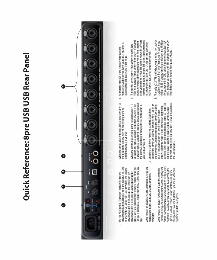
0
Qu
ick
Re
fere
nce
: 8p
re U
SB
US
B R
ea
r P
an
el
12
34
5
1.Th
e tw
o AD
AT o
ptic
al (“
light
pipe
”) p
orts
in th
e to
p ro
w
prov
ide
eigh
t cha
nnel
s of d
igita
l inp
ut a
nd o
utpu
t at 4
4.1
and
48 k
Hz.
At th
e 2x
sam
ple
rate
s (8
8.2
or 9
6 kH
z), t
he to
p ro
w
prov
ides
cha
nnel
s 1-
4 (in
and
out
) and
the
bott
om ro
w
prov
ides
cha
nnel
s 5-
8 (in
and
out
). W
hen
oper
atin
g th
e op
tical
por
ts a
t a 2
x sa
mpl
e ra
te, b
e su
re to
choo
se e
ither
Type
I o
r Typ
e II
oper
atio
n, a
s ex
plai
ned
in it
em 2
. on
the
prev
ious
pa
ge.
Whe
n th
e 8p
re U
SB is
con
nect
ed to
a c
ompu
ter,
thes
e op
tical
po
rts
prov
ide
digi
tal i
nput
and
out
put t
o an
d fr
om th
e co
mpu
ter.
Whe
n th
e 8p
re U
SB is
not
con
nect
ed d
irect
ly to
a c
ompu
ter
(with
USB
), th
e op
tical
inpu
t is d
isab
led
and
the
eigh
t opt
ical
ou
tput
chan
nels
mirr
or a
ny in
com
ing
sign
al o
n th
e 8p
re U
SB’s
eigh
t XLR
/TRS
com
bo ja
ck a
nalo
g in
puts
. By
conn
ectin
g th
e 8p
re U
SB to
ano
ther
dev
ice,
suc
h as
ano
ther
AD
AT-o
ptic
al
equi
pped
inte
rfac
e or
a d
igita
l mix
er, y
ou a
dd a
n ad
ditio
nal
eigh
t mic
inpu
ts to
you
r sys
tem
.
Whe
n th
e 8p
re U
SB is
slav
ing
to it
s opt
ical
inpu
t, it
reso
lves
to
the
inpu
t in
the
top
row
, eve
n w
hen
oper
atin
g at
the
2x
sam
ple
rate
s (8
8.2
or 9
6 kH
z).
Whe
n th
e 8p
re U
SB is
ope
ratin
g at
the
1x s
ampl
e ra
tes
(44.
1 or
48
kHz)
, the
opt
ical
out
put i
n th
e bo
ttom
row
mirr
ors
the
8-ch
anne
l opt
ical
out
put i
n th
e to
p ro
w, a
llow
ing
you
to se
nd
the
8pre
USB
opt
ical
out
put t
o tw
o di
ffer
ent d
estin
atio
ns in
yo
ur s
tudi
o, if
nee
ded.
2.Co
nnec
t a M
IDI d
evic
e he
re u
sing
sta
ndar
d M
IDI c
able
s. Co
nnec
t the
8pr
e U
SB’s
MID
I OU
T po
rt to
the
MID
I IN
por
t on
the
othe
r dev
ice.
Con
vers
ely,
conn
ect t
he 8
pre
USB
’s M
IDI I
N
port
to th
e M
IDI O
UT
port
on
the
othe
r dev
ice.
You
can
conn
ect d
iffer
ent d
evic
es to
eac
h po
rt, s
uch
as a
con
trol
ler
devi
ce to
the
IN p
ort a
nd a
soun
d m
odul
e to
the
OU
T po
rt. Y
ou
can
also
dai
sy-c
hain
MID
I dev
ices
, but
be
sure
to m
anag
e th
eir M
IDI c
hann
els (
so th
at th
ey d
on’t
rece
ive
or tr
ansm
it on
th
e sa
me
chan
nel).
3.Co
nnec
t the
8pr
e U
SB to
the
com
pute
r her
e us
ing
the
stan
dard
USB
cab
le p
rovi
ded
with
you
r uni
t. If
you
need
to
conn
ect o
ther
USB
dev
ices
, use
a U
SB 2
hub
.
4.Th
ese
two
bala
nced
, qua
rter
-inc
h ja
cks
serv
e as
the
8pre
U
SB’s
mai
n ou
tput
s. Yo
u ca
n co
nnec
t the
m to
a se
t of p
ower
ed
stud
io m
onito
rs a
nd th
en c
ontr
ol th
e vo
lum
e fr
om th
e fr
ont
pane
l vol
ume
knob
. To
hear
dis
k tr
acks
in y
our a
udio
soft
war
e on
thes
e m
ain
outs
, ass
ign
the
disk
trac
ks (a
nd m
aste
r fad
er)
to th
ese
mai
n ou
ts (
Mai
n Ou
t 1-2
). Yo
u ca
n al
so u
se C
ueM
ix
DSP
to m
onito
r liv
e 8p
re U
SB in
puts
her
e as
wel
l.
5.Th
ese
eigh
t XLR
/TRS
com
bo ja
ck a
ccep
ts e
ither
a m
ic c
able
or
a ca
ble
with
a q
uart
er-i
nch
plug
. The
pre
amp
for e
ach
inpu
t de
liver
s 48
dB o
f pre
amp
gain
for t
he m
ic in
put a
nd 3
9 dB
for
the
quar
ter-
inch
hi-
Z TR
S gu
itar/
inst
rum
ent i
nput
. Eac
h XL
R (m
ic) i
nput
can
be
supp
lied
with
48V
pha
ntom
pow
er o
r -20
dB
pad
via
its
corr
espo
ndin
g fr
ont-
pane
l sw
itche
s.
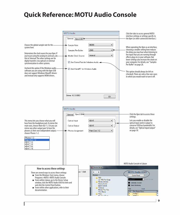
CHAPTER
Quick Reference: MOTU Audio Console
This menu lets you choose what you will hear from the headphone jack. To mirror the main outs, choose Main Out 1-2. Or you can mirror any other output pair. To hear the phones as their own independent output, choose Phones 1-2.
Determines the clock source for your 8pre. If you’re just using the analog ins and outs, set this to ‘Internal’. The other settings are for digital transfers (via optical) or external synchronization to other systems.
Lets you enable or disable the optical input and/or output to conserve USB bus bandwidth. For details, see “Optical input/output” on page 30.
Click the tabs to access general MOTU interface settings or settings specific to the 8pre (or other connected interface.)
When operating the 8pre as an interface, choosing a smaller setting here reduces the delay you may hear when listening to live input that you are running through effects plug-ins in your software. But lower settings also increase the strain on your computer. For details, see “Samples Per Buffer” on page 28.
Click the 8pre tab to access these settings.
Choose the global sample rate for the system here.
Uncheck this option if the Windows audio software you are using with the 8pre USB does not support Windows WaveRT drivers and instead only supports WDM drivers.
This option should always be left on (checked). There are only a few rare cases in which you would want to turn it off.
MOTU Audio Console in Cubase
How to access these settings There are several ways to access these settings:
From the Windows Start menu, choose Programs>MOTU>MOTU Audio Console.
From within Cubase, go to the Device Setup window, click the MOTU Audio ASIO list item and and click the Control Panel button.
From within other applications, refer to their documentation.
9

10
CHAPTER
1 About the 8pre USBOVERVIEWThe 8pre USB is and audio interface that can operate in two general modes: as a USB audio interface or as an analog-to-digital converter.
With a standard 19-inch, single-space, rack-mountable I/O form factor, the 8pre USB connects directly to a computer with a standard USB cable or to another interface with an ADAT optical cable.
As a USB audio interface, the 8pre USB is a complete computer-based hard disk recording system for Mac OS X and Windows that offers eight high-quality mic inputs and at any standard sample rate up to 96kHz, plus one bank of ADAT optical digital I/O that provides 8 channels of digital I/O at any sample rate up to 96 kHz. At 88.2 or 96 kHz, a second bank of dedicated ADAT optical jacks provide input and output on channels 5-8.
When the 8pre USB is not connected to a computer, it operates as an analog-to-digital converter. By connecting the 8pre USB’s optical ports to another audio interface, digital mixer or other digital audio system that supports 8-channel ADAT optical I/O, the 8pre USB becomes an 8-channel analog-to-optical expansion interface that adds eight high-quality mic inputs to the system.
The 8pre USB offers the following features:
Eight 24-bit analog combo XLR/TRS mic/instrument inputs with preamps
Digitally controlled preamp gain, -20 dB pad switch, and 48V phantom power for each mic input, adjustable from the front panel and from the computer
Two 24-bit analog TRS main outputs
Eight-channel ADAT optical digital I/O at sample rates up to 96 kHz
MIDI I/O
On-board SMPTE synchronization
Headphone jack
Main volume knob (for headphone + main outs)
Front-panel 5-segment input meters
Front-panel mode and clock status LEDs
No-latency analog to digital conversion from the eight analog inputs to the eight ADAT optical digital outputs
With its XLR/TRS combo jack inputs, mic preamps, no-latency monitoring of live input and synchronization capabilities, the 8pre USB is a complete, portable “studio in a box” when used with a Mac or Windows computer.
THE 8PRE USB I/O REAR PANELThe 8pre USB rear panel has the following connectors:
Two gold-plated, balanced +4dB quarter-inch (TRS) analog outputs (with 24-bit 96kHz converters)
Eight 24-bit analog combo XLR/TRS mic/instrument inputs with preamps, each equipped with individually switchable 20 dB pad, 48V phantom power and 24-bit 96kHz converters
Two sets of ADAT optical ‘light pipe’ connectors (8 channels of ADAT optical I/O at all supported sample rates)
MIDI IN and MIDI OUT
11
12
One USB jack
16 inputs and 12 outputs
When operating as a USB audio interface, all 8pre USB inputs and outputs can be used simulta-neously, for a total of 16 inputs and 12 outputs:
All inputs and outputs are discrete. In other words, using a mic input does not “steal” an input from the ADAT optical I/O bank. The same is true for the headphone outs and the main outs.
The two banks of ADAT optical ports provide eight channels of input and output at 88.2 or 96 kHz. The upper bank provides channels 1-4 and the lower bank provides channels 5-8.
The headphone output can operate as an independent output pair, or it can mirror any other 8pre USB output pair, such as the main outs.
Mic inputs with 48V phantom power
Eight rear-panel combo (XLR/TRS) jacks with preamps, phantom power and 20 dB pad let you to connect a microphone, guitar or any quarter-inch input. The XLR jack serves as a mic input, and the TRS jack serves as a high-impedance guitar/instrument or line-level input. Dedicated front-panel gain knobs allow you to adjust each input independently. Defeatable 48V phantom power and 20dB pad are supplied by convenient front panel switches.
Converters
All eight analog inputs are equipped with 24-bit 96kHz, 64x oversampling A/D converters. The main outs have 24-bit 128x oversampling D/A converters. All audio is carried to the computer in a 24-bit data stream.
Main Outs
The main outs are equipped with 24-bit 128x oversampling D/A converters and serve as independent outputs for the computer. The main outputs are on balanced TRS +4dB quarter-inch jacks. Both of these jacks can also accept unbalanced plugs.
Optical
The 8pre USB provides two banks of optical “lightpipe” jacks that support the ADAT optical digital I/O format. At 44.1 or 48 kHz, the upper bank provides eight channels of 24-bit digital audio, and the lower bank simply mirrors all 8 channels of the upper bank.
At 88.2 or 96 kHz, the upper bank handles channels 1-4 and the lower bank handles channels 5-8 via the industry Standard S/MUX (“Type I”) protocol for third-party product or MOTU’s own “Type II” protocol for connecting the 8pre USB optically to any MOTU audio interface. For details, see “Setting the 2x optical mode” on page 31.
MIDI I/O
The 8pre USB’s standard MIDI IN and MIDI OUT jacks supply 16 channels of MIDI I/O to and from the computer via the 8pre’s USB connection.
Hi-speed USB 2.0
The 8pre USB connects to any Mac or PC equipped with a Hi-speed USB 2.0, which provides enough bus bandwidth to easily handle all simultaneous inputs and outputs.
Connection Input Output
Mic preamps 24-bit 96kHz on XLR/TRS combo 8 -
Main outputs 24-bit 96kHz on bal/unbal TRS - stereo
Headphone output - stereo
ADAT optical digital (from 44.1 up to 96 kHz) 8 8
Total 16 12
A B O U T T H E 8 P R E U S B
On-board SMPTE synchronization
The 8pre USB can resolve directly to SMPTE time code via any analog input, without a separate synchronizer. The 8pre USB can also generate SMPTE time code via any analog output. The 8pre USB provides a DSP-driven phase-lock engine with sophisticated filtering that provides fast lockup times and sub-frame accuracy.
The included MOTU SMPTE Console™ software provides a complete set of tools to generate SMPTE for striping, regenerating or slaving other devices to the computer. Like CueMix DSP, the synchroni-zation features are cross-platform.
THE 8PRE USB FRONT PANEL
Preamp gain, 48V phantom power and pad
The 8pre USB front panel provides convenient, individual gain control, 48-volt phantom power switch and 20 dB pad switch for each analog input.
Headphone output and main volume control
The 8pre USB front panel includes a quarter-inch stereo headphone output jack and volume knob. The volume knob also controls the rear-panel main outs. Push the knob to toggle between them.
Metering section
The front panel of the 8pre USB displays input metering. The five-segment input meters provide dedicated multi-segment metering for their respective analog inputs.
The Mode lights indicate whether the interface is currently operating as a USB audio interface or an analog-to-optical converter.
The Clock lights indicate the global sample rate and clock source.
16-BIT AND 24-BIT RECORDINGThe 8pre USB system handles all data with a 24-bit signal path, regardless of the I/O format. You can record and play back 16-bit or 24-bit audio files at any supported sample rate via any of the 8pre USB’s analog or digital inputs and outputs. 24-bit audio files can be recorded with any compatible host application that supports 24-bit recording.
INCLUDED SOFTWAREThe 8pre USB software installer provides the following including cross-platform software applications for Mac and Windows.
MOTU Audio Console
MOTU Audio Console provides access to basic hardware settings, such as sample rate, optical I/O format selection, headphone output channel selection, foot switch input programming, and other settings.
MOTU SMPTE Console
MOTU SMPTE Console provides access to the 8pre USB system’s SMPTE time code synchroni-zation features, including locking to time code, generating time code, displaying a time code read-out, and so on.
CueMix FX
CueMix FX gives you complete control over the 8pre USB’s CueMix DSP on-board mixer, which provides no-latency monitoring and mixing of live inputs through your 8pre USB.
CueMix FX provides attractive graphic mixing for quick access to all mixing features, digitally controlled gain, and other settings in your MOTU audio interface.
CueMix FX provides many advanced features, such as an accurate instrument tuner and an extensive arsenal of audio analysis tools, including a real-time FFT, spectrogram “waterfall” display, oscilloscope, and phase analysis tools.
A B O U T T H E 8 P R E U S B
13
14
HOST AUDIO SOFTWAREThe 8pre USB system ships with Windows drivers that allows you to record, edit, play back and mix your 8pre USB projects using your favorite Windows audio software.
A B O U T T H E 8 P R E U S B
CHAPTER
2 Packing List and System RequirementsPACKING LISTThe 8pre USB ships with the items listed below. If any of these items are not present in your 8pre USB box when you first open it, please immediately contact your dealer or MOTU.
One 8pre USB I/O rack unit
One set of removable rack brackets
One USB cable
Power cord
One 8pre Mac/Windows manual
One cross-platform installer disc
Product registration card
WINDOWS SYSTEM REQUIREMENTSThe 8pre USB system requires the following Windows system:
A 1 GHz Pentium-based PC compatible or faster equipped with at least one USB2 port
1 GB RAM; 2 GB or more recommended
Windows 8, 7 or Vista, 32- or 64-bit; Vista SP 2 or later required
Available Hi-speed USB 2.0 port
A large hard drive (preferably at least 250 GB)
PLEASE REGISTER TODAY!Please register your 8pre USB today. There are two ways to register.
Visit www.motu.com/register
OR
Fill out and mail the included product registration card
As a registered user, you will be eligible to receive technical support and announcements about product enhancements as soon as they become available. Only registered users receive these special update notices, so please register today.
Thank you for taking the time to register your new MOTU products!
15

16
P A C K I N G L I S T A N D S Y S T E M R E Q U I R E M E N T S
CHAPTER
3 Installing the 8pre USB SoftwareOVERVIEWInstallation. . . . . . . . . . . . . . . . . . . . . . . . . . . . . . . . . . . . . . . . . . . 17
MOTU Audio drivers . . . . . . . . . . . . . . . . . . . . . . . . . . . . . . . . . 18
MOTU Audio Console . . . . . . . . . . . . . . . . . . . . . . . . . . . . . . . . 18
MOTU MIDI Driver . . . . . . . . . . . . . . . . . . . . . . . . . . . . . . . . . . . 18
CueMix FX . . . . . . . . . . . . . . . . . . . . . . . . . . . . . . . . . . . . . . . . . . . 18
MOTU SMPTE Console . . . . . . . . . . . . . . . . . . . . . . . . . . . . . . . 18
INSTALLATIONBefore you connect the 8pre USB to your computer and power it on, run the 8pre USB software installer. This ensures that all the 8pre USB components are properly installed in your system.
If you’ve already connected the 8pre USB to your computer and powered it on, Windows may issue an alert notifying you that the 8pre USB requires drivers, followed by another window asking you to locate the drivers. If this happens:
1 Cancel the driver search.
2 Power off and disconnect the 8pre USB.
3 Run the MOTU Audio Installer as instructed in the next section.
Run the MOTU Audio installer
Install the 8pre USB software as follows:
1 Insert the MOTU Audio Installer disc; or, if you have downloaded the MOTU Audio installer, locate the folder containing the download.
2 Read the Read Me file for installation assistance and other important information.
3 Open the Setup Audio application.
4 Follow the directions that the installer gives you.
Drivers are installed, along with MOTU Audio Console, CueMix FX, and other components, summarized in the table below.
Software component Purpose For more information
MOTU Audio and MIDI drivers Provides multi-channel audio input and output for MOTU FireWire and USB Audio devices with host audio software.
“MOTU Audio drivers” on page 18
MOTU Audio Console Provides access to all of the settings in the 8pre USB and other MOTU interfaces. Required for 8pre USB operation.
chapter 5, “MOTU Audio Con-sole” (page 27)
CueMix FX Gives you complete control over the 8pre USB’s CueMix DSP on-board mixer, which provides no-latency monitoring and mixing of live inputs through your 8pre USB.
chapter 9, “CueMix FX” (page 47)
MOTU SMPTE Console Provides access to the 8pre USB system’s SMPTE time code sync features.
chapter 10, “MOTU SMPTE Con-sole” (page 73)
17
18
MOTU AUDIO DRIVERS
ASIO
ASIO is an acronym for Audio Streaming Input and Output. The MOTU Audio ASIO driver provides multi-channel audio input and output for applications that support ASIO audio drivers, such as Ableton Live, Avid Pro Tools, Cakewalk SONAR, Cockos Reaper, Propellerhead Reason and Record, Steinberg Cubase and Nuendo, and others.
For details about using the 8pre USB with ASIO, see chapter 7, “Configuring Host Audio Software” (page 33).
WDM
WDM is an acronym for Windows Driver Model. The MOTU Audio WDM driver provides multi-channel audio input and output for applications that support WDM audio drivers.
For details about using the 8pre USB with WDM, see chapter 7, “Configuring Host Audio Software” (page 33).
WaveRTUncheck this option (Figure 5-1 on page 28) if the Windows audio software you are using with your MOTU audio interface does not support Windows WaveRT drivers and instead only supports WDM drivers.
MOTU AUDIO CONSOLEMOTU Audio Console (available in the Start menu) gives you access to all of the settings in the 8pre USB, such as the clock source and sample rate. For complete details, see chapter 5, “MOTU Audio Console” (page 27).
MOTU MIDI DRIVERThis driver allows you to access the 8pre USB’s MIDI input and output ports. The ports are published in Windows and are available to all MIDI software.
CUEMIX FXCueMix FX (available in the Start menu) provides control over the 8pre USB’s no-latency CueMix FX on-board mixing, an instrument tuner, a full-featured oscilloscope, and other audio analysis tools. For details, see chapter 9, “CueMix FX” (page 47).
MOTU SMPTE CONSOLEMOTU SMPTE Console (available in the Start menu) software provides a complete set of tools to resolve the 8pre USB to SMPTE time code, and to generate SMPTE for striping, regenerating or slaving other devices to the computer. For details, see chapter 10, “MOTU SMPTE Console” (page 73).
I N S T A L L I N G T H E 8 P R E U S B S O F T W A R E

CHAPTER
4 Installing the 8pre USB HardwareOVERVIEWHere’s an overview for installing the 8pre USB:
Connect the 8pre USB to your computer . . . . . . . . . . . . 19
Connect the 8pre USB to the computer.
Connect audio inputs and outputs . . . . . . . . . . . . . . . . . . 19
Make optical and analog connections as desired.
Connect MIDI gear. . . . . . . . . . . . . . . . . . . . . . . . . . . . . . . . . . . 21
Connect a controller, synth or control surface.
Operating the 8pre USB as an interface. . . . . . . . . . . . . . 22
An example setup for computer-based mixing/FX.
Operating the 8pre USB as a converter . . . . . . . . . . . . . . 23
An example setup for a mixer-based studio.
Syncing optical devices . . . . . . . . . . . . . . . . . . . . . . . . . . . . . . 24
CONNECT THE 8PRE USB TO YOUR COMPUTER1 Plug one end of the 8pre USB cable (included) into a USB socket on the computer.
2 Plug the other end of the USB cable into the 8pre USB I/O.
CONNECT AUDIO INPUTS AND OUTPUTSThe 8pre USB audio interface has the following audio input and output connectors:
8 combo XLR/quarter-inch analog mic/instrument/line inputs
2 balanced, +4 dB quarter-inch TRS main outs
2 pair of ADAT optical (“Lightpipe”) in/out
Here are a few things you should keep in mind as you are making these connections to other devices.
Mic/instrument/line inputs
Connect a microphone, line-level signal, guitar or other similar instrument to any XLR/quarter-inch combo jack input on the rear panel. If your microphone requires phantom power, engage the 48V phantom power switch on the front panel. Use the gain knobs on the front panel to adjust the preamp gain as needed for each input. The gain knob provides approximately 48 dB of gain for the XLR mic input and 39 dB for the guitar input. Use the input level meters on the front panel (labeled Analog In) to calibrate the level. These meters register for both the XLR and TRS input.
If a line level signal is still too hot with the trim turned all the way down, engage the -20dB pad switch on the front panel.
19
20
Main outs
The main outputs serve as independent outputs. The main out volume is controlled by the volume knob on the front panel. Push the knob to toggle between phone and main out volume control. In a standard studio configuration, the main outs are intended for a pair of studio monitors, but they can also be used as additional outputs for any purpose.
Optical
The 8pre USB provides 8-channel digital input and output at 44.1, 48, 88.2 and 96 kHz. The 8pre USB rear panel provides two sets of ADAT optical (“lightpipe”) connectors: a top row and a bottom row.
Reminder: optical goes OUT to IN and IN to OUT. Input and output are independent. For example, you could connect ADAT optical input from your digital mixer and connect the output to an audio interface connected to your computer.
Optical operation at 44.1 or 48 kHzWhen connected to an ADAT “lightpipe” compatible device, the two optical connectors in the top row provide eight channels of digital input and output at 44.1 and 48 kHz.
In addition, when operating the 8pre USB at a 1x sample rate (either 44.1 or 48 kHz), optical output is duplicated on the second (lower) optical output. This lets you send the 8pre USB’s 8-channel ADAT optical output to two separate destinations in your studio, if needed.
Optical operation at 88.2 or 96 kHzWhen operating the 8pre USB at the 2x sample rates (88.2 or 96 kHz), the top row of optical connectors provides channels 1-4 (in and out) and the bottom row provides channels 5-8 (in and out) when connected to another optical device that supports 88.2/96 kHz optical sample rates.
When operating the optical ports at a 2x sample rate, be sure to choose either Type I or Type II operation, as explained in “Setting the 2x optical mode” on page 31.
Using optical I/O when operating the 8pre USB as an audio interfaceWhen the 8pre USB is connected to a computer (Figure 4-3 on page 22), these optical ports provide digital input and output to and from the computer.
Using optical I/O to operate the 8pre USB as an 8-channel expanderWhen the 8pre USB is not connected directly to a computer via USB, the optical input is disabled and the eight optical output channels mirror any incoming signal on the 8pre USB’s eight XLR/TRS combo jack analog inputs. By connecting the 8pre USB optical output to another device, such as another ADAT-optical equipped interface or a digital mixer, you add an additional eight mic inputs to your system, as demonstrated in Figure 4-4 on page 23. This can be done at any sample rate up to 96 kHz.
To set the sample rate (or clock mode) when operating as an 8-channel optical expander, see “Setting the clock source in converter mode” on page 31.
I N S T A L L I N G T H E 8 P R E U S B H A R D W A R E
CONNECT MIDI GEARConnect your MIDI device’s MIDI IN jack to the 8pre USB’s MIDI OUT jack (Connection A below). Conversely, connect the MIDI device’s MIDI OUT jack to the 8pre USB’s MIDI IN jack (Connection B).
Figure 4-1: Connecting a MIDI device to the 8pre USB.
One-way MIDI connections
MIDI devices that do not receive MIDI data, such as a dedicated keyboard controller, guitar controller, or drum pad, only need Connection B shown in Figure 4-1. Similarly, devices that never send data, such as a sound module, only need Connection A. Make both connections for any device that needs to both send and receive MIDI data.
Connecting additional gear with MIDI THRUs
If you need to connect several pieces of MIDI gear, run a MIDI cable from the MIDI THRU of a device already connected to the 8pre USB to the MIDI IN on the additional device as shown below in Figure 4-2. The two devices then share the 8pre USB’s MIDI OUT port. This means that they share the same set of 16 MIDI channels, too, so try to do this with devices that listen to only one MIDI channel (such as effects modules), which makes it easier to avoid MIDI channel conflicts.
Figure 4-2: Connecting additional devices with MIDI THRU ports.
8pre USBrear panel
MIDI Device
MIDI cables
MIDI IN
MIDI OUT
MIDI OUT
MIDI IN
Connection A
Connection B
MIDI IN
MIDI cable
MIDI DeviceMIDI
IN
MIDI THRU
MIDI OUT
Additional device
8pre USBrear panel
I N S T A L L I N G T H E 8 P R E U S B H A R D W A R E
21
22
OPERATING THE 8PRE USB AS AN INTERFACEHere is a typical studio setup for using the 8pre USB as an audio interface. All mixing and processing can be done in the computer with audio software. During recording, you can use the 8pre
USB’s CueMix™ DSP no-latency monitoring to listen to what you are recording via the main outs, headphone outs, or any other output pair. You can control monitoring from the included MOTU CueMix FX software.
PC
Digital mixer
Optical Out
quarter-inch analog outs
synthesizer
monitors
guitar(with or without an amp)
Figure 4-3: A typical 8pre USB studio setup.
headphones
other inputs (mics, guitars, etc.)
MIDI IN/OUT
8pre USB front panel
8pre USB back panel
USB
OpticalIn Out
Optical In
Mic
I N S T A L L I N G T H E 8 P R E U S B H A R D W A R E
OPERATING THE 8PRE USB AS A CONVERTERAs explained earlier in “Using optical I/O to operate the 8pre USB as an 8-channel expander” on page 20, the 8pre USB can serve as an 8-channel analog-to-digital converter when disconnected from the computer and instead connected to another device equipped with an ADAT optical input. For example, you could connect the 8pre USB optical output to the optical input on a MOTU audio interface, such as the 828, Traveler, or 896. The 8pre USB then serves as an 8-channel expander that adds an additional eight mic inputs
to the interface. The benefit of connecting the 8pre USB in this manner (instead of as another USB interface) is that you can seamlessly integrate the 8pre USB’s inputs into the on-board no-latency CueMix monitor mixing in the interface, since the 8pre USB’s inputs are fed into CueMix via the interface’s optical inputs.
If the device to which you are connecting the 8pre USB supports 2x optical sample rates (88.2 or 96 kHz), you’ll need to use both banks of connectors as discussed in “Optical operation at 88.2 or 96 kHz” on page 20.
ADAT optical In
guitar(with or without
an amp)
Figure 4-4: Using the 8pre USB as an optical converter.
USB2
8pre USB rear panel
828mk3 Hybrid audio interface
ADAT optical Out
other inputs (keyboards mics,
guitars, etc.)
PC
Mic
I N S T A L L I N G T H E 8 P R E U S B H A R D W A R E
23
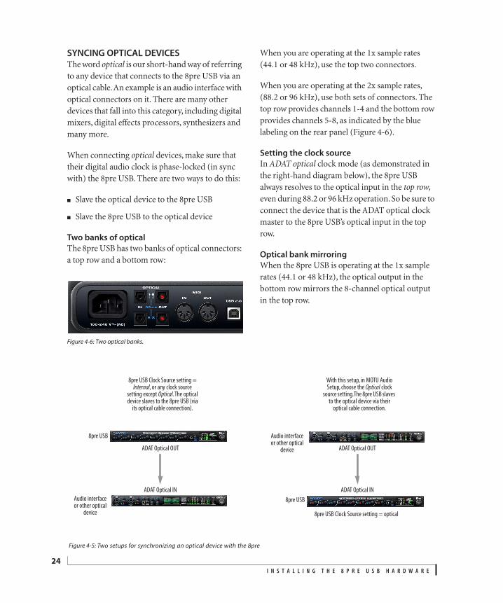
24
SYNCING OPTICAL DEVICESThe word optical is our short-hand way of referring to any device that connects to the 8pre USB via an optical cable. An example is an audio interface with optical connectors on it. There are many other devices that fall into this category, including digital mixers, digital effects processors, synthesizers and many more.
When connecting optical devices, make sure that their digital audio clock is phase-locked (in sync with) the 8pre USB. There are two ways to do this:
Slave the optical device to the 8pre USB
Slave the 8pre USB to the optical device
Two banks of optical
The 8pre USB has two banks of optical connectors: a top row and a bottom row:
Figure 4-6: Two optical banks.
When you are operating at the 1x sample rates (44.1 or 48 kHz), use the top two connectors.
When you are operating at the 2x sample rates, (88.2 or 96 kHz), use both sets of connectors. The top row provides channels 1-4 and the bottom row provides channels 5-8, as indicated by the blue labeling on the rear panel (Figure 4-6).
Setting the clock source
In ADAT optical clock mode (as demonstrated in the right-hand diagram below), the 8pre USB always resolves to the optical input in the top row, even during 88.2 or 96 kHz operation. So be sure to connect the device that is the ADAT optical clock master to the 8pre USB’s optical input in the top row.
Optical bank mirroring
When the 8pre USB is operating at the 1x sample rates (44.1 or 48 kHz), the optical output in the bottom row mirrors the 8-channel optical output in the top row.
ADAT Optical IN
ADAT Optical OUT
Audio interfaceor other optical
device
8pre USB
8pre USB Clock Source setting = Internal, or any clock source
setting except Optical. The optical device slaves to the 8pre USB (via
its optical cable connection).
Figure 4-5: Two setups for synchronizing an optical device with the 8pre
8pre USB Clock Source setting = optical
ADAT Optical IN
ADAT Optical OUT
Audio interfaceor other optical
device
8pre USB
With this setup, in MOTU Audio Setup, choose the Optical clock
source setting. The 8pre USB slaves to the optical device via their
optical cable connection.
I N S T A L L I N G T H E 8 P R E U S B H A R D W A R E

Part 2
Using the 8pre USB

CHAPTER
5 MOTU Audio ConsoleOVERVIEWMOTU Audio Console gives you access to basic 8pre USB hardware settings, such as sample rate, clock source, optical format and more.
Accessing the 8pre USB settings . . . . . . . . . . . . . . . . . . . . . 27
‘General’ tab settings . . . . . . . . . . . . . . . . . . . . . . . . . . . . . . . . 28
Sample Rate . . . . . . . . . . . . . . . . . . . . . . . . . . . . . . . . . . . . . . . . . 28
Samples Per Buffer. . . . . . . . . . . . . . . . . . . . . . . . . . . . . . . . . . . 28
Master Clock Source . . . . . . . . . . . . . . . . . . . . . . . . . . . . . . . . . 29
Optical input/output. . . . . . . . . . . . . . . . . . . . . . . . . . . . . . . . . 30
Use stereo pairs for Windows audio. . . . . . . . . . . . . . . . . . 30
Use WaveRT for Windows audio . . . . . . . . . . . . . . . . . . . . . 30
8pre USB tab settings . . . . . . . . . . . . . . . . . . . . . . . . . . . . . . . . 30
Phones Assignment . . . . . . . . . . . . . . . . . . . . . . . . . . . . . . . . . 30
ACCESSING THE 8PRE USB SETTINGSThere are several ways to access 8pre USB settings:
Open MOTU Audio Console from the Windows Start menu > Programs > MOTU.
From within your host audio software’s audio driver preferences. For example, in Cubase or Nuendo, open the Device Setup window, click VST Audio System and choose MOTU Audio ASIO from the ASIO Driver menu. Then click the MOTU Audio ASIO item in the list and click the Control Panel button.
Most applications provide access only to basic settings such as sample rate and clock source. For access to all settings, open MOTU Audio Console using one of the techniques above.
General tab settings
The General tab (Figure 5-1) provides settings that apply to all connected MOTU FireWire and USB audio interfaces.
8pre USB tab settings
The 8pre USB tab (Figure 5-1) provides settings that apply to a specific 8pre USB interface. If you have several 8pre USB (or other MOTU) interfaces connected, you’ll see a separate tab for each one.
27
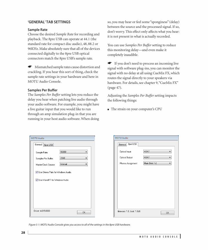
28
‘GENERAL’ TAB SETTINGS
Sample Rate
Choose the desired Sample Rate for recording and playback. The 8pre USB can operate at 44.1 (the standard rate for compact disc audio), 48, 88.2 or 96KHz. Make absolutely sure that all of the devices connected digitally to the 8pre USB optical connectors match the 8pre USB’s sample rate.
Mismatched sample rates cause distortion and crackling. If you hear this sort of thing, check the sample rate settings in your hardware and here in MOTU Audio Console.
Samples Per Buffer
The Samples Per Buffer setting lets you reduce the delay you hear when patching live audio through your audio software. For example, you might have a live guitar input that you would like to run through an amp simulation plug-in that you are running in your host audio software. When doing
so, you may hear or feel some “sponginess” (delay) between the source and the processed signal. If so, don’t worry. This effect only affects what you hear: it is not present in what is actually recorded.
You can use Samples Per Buffer setting to reduce this monitoring delay—and even make it completely inaudible.
If you don’t need to process an incoming live signal with software plug-ins, you can monitor the signal with no delay at all using CueMix FX, which routes the signal directly to your speakers via hardware. For details, see chapter 9, “CueMix FX” (page 47).
Adjusting the Samples Per Buffer setting impacts the following things:
The strain on your computer’s CPU
Figure 5-1: MOTU Audio Console gives you access to all of the settings in the 8pre USB hardware.
M O T U A U D I O C O N S O L E
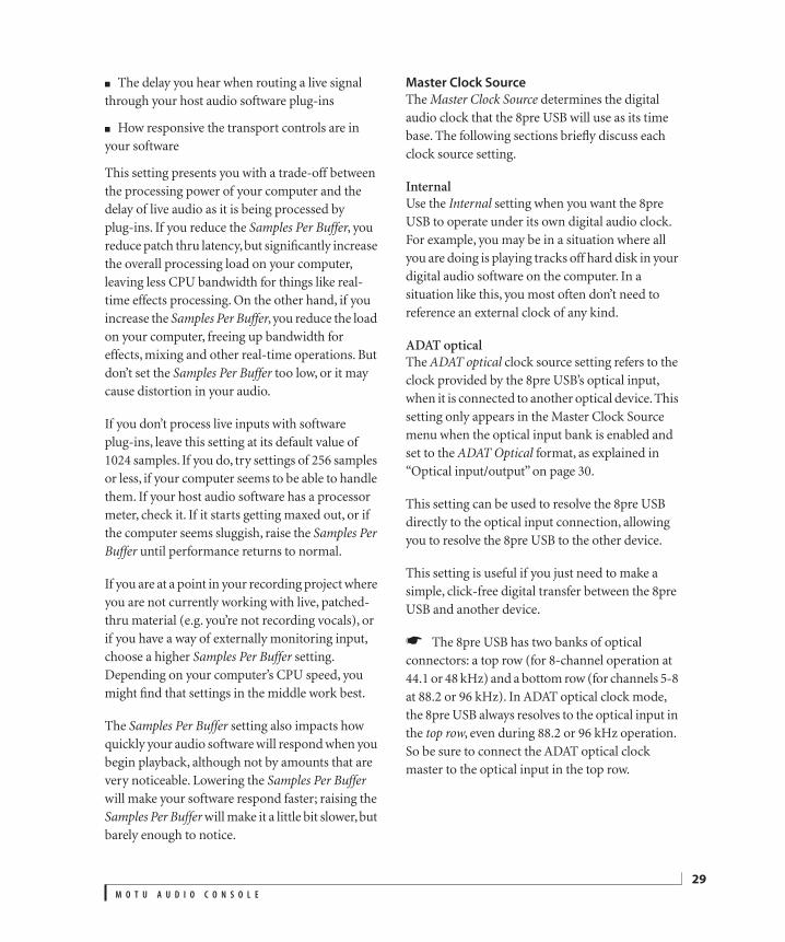
The delay you hear when routing a live signal through your host audio software plug-ins
How responsive the transport controls are in your software
This setting presents you with a trade-off between the processing power of your computer and the delay of live audio as it is being processed by plug-ins. If you reduce the Samples Per Buffer, you reduce patch thru latency, but significantly increase the overall processing load on your computer, leaving less CPU bandwidth for things like real-time effects processing. On the other hand, if you increase the Samples Per Buffer, you reduce the load on your computer, freeing up bandwidth for effects, mixing and other real-time operations. But don’t set the Samples Per Buffer too low, or it may cause distortion in your audio.
If you don’t process live inputs with software plug-ins, leave this setting at its default value of 1024 samples. If you do, try settings of 256 samples or less, if your computer seems to be able to handle them. If your host audio software has a processor meter, check it. If it starts getting maxed out, or if the computer seems sluggish, raise the Samples Per Buffer until performance returns to normal.
If you are at a point in your recording project where you are not currently working with live, patched-thru material (e.g. you’re not recording vocals), or if you have a way of externally monitoring input, choose a higher Samples Per Buffer setting. Depending on your computer’s CPU speed, you might find that settings in the middle work best.
The Samples Per Buffer setting also impacts how quickly your audio software will respond when you begin playback, although not by amounts that are very noticeable. Lowering the Samples Per Buffer will make your software respond faster; raising the Samples Per Buffer will make it a little bit slower, but barely enough to notice.
Master Clock Source
The Master Clock Source determines the digital audio clock that the 8pre USB will use as its time base. The following sections briefly discuss each clock source setting.
InternalUse the Internal setting when you want the 8pre USB to operate under its own digital audio clock. For example, you may be in a situation where all you are doing is playing tracks off hard disk in your digital audio software on the computer. In a situation like this, you most often don’t need to reference an external clock of any kind.
ADAT opticalThe ADAT optical clock source setting refers to the clock provided by the 8pre USB’s optical input, when it is connected to another optical device. This setting only appears in the Master Clock Source menu when the optical input bank is enabled and set to the ADAT Optical format, as explained in “Optical input/output” on page 30.
This setting can be used to resolve the 8pre USB directly to the optical input connection, allowing you to resolve the 8pre USB to the other device.
This setting is useful if you just need to make a simple, click-free digital transfer between the 8pre USB and another device.
The 8pre USB has two banks of optical connectors: a top row (for 8-channel operation at 44.1 or 48 kHz) and a bottom row (for channels 5-8 at 88.2 or 96 kHz). In ADAT optical clock mode, the 8pre USB always resolves to the optical input in the top row, even during 88.2 or 96 kHz operation. So be sure to connect the ADAT optical clock master to the optical input in the top row.
M O T U A U D I O C O N S O L E
29
30
If the ADAT Optical setting does not appear in the menu, it means that the 8pre USB’s optical input is currently turned off. Choose the ADAT optical format from the Optical input menu (Figure 5-1 on page 28).
For further details about this setting, see “Syncing optical devices” on page 24.
SMPTEChoose this setting to resolve the 8pre USB directly to SMPTE time code (LTC) being received via one of the 8pre USB’s audio inputs. For details, see “Setup for SMPTE time code sync” on page 76 and chapter 10, “MOTU SMPTE Console” (page 73).
Use stereo pairs for Windows audio
Some legacy Windows audio applications require audio channels to be grouped in stereo pairs. If you are using old Windows audio software, and you are having issues accessing Audio Express channels from within the software, try enabling the Use Stereo Pairs for Windows Audio option.
Use WaveRT for Windows audio
If your host software supports WaveRT, enable this option. Consult your host application documentation for details.
8PRE USB TAB SETTINGS
Optical input/output
The Optical input and Optical output settings let you enable the 8pre USB’s 8-channel ADAT optical (‘lightpipe’) input and output. If you are not using the optical connections, it is recommended that you turn them off (by choosing Disabled from the menu) to reduce bandwidth and processing overhead.
Phones Assignment
The Phones Assignment setting lets you choose what you will hear from the headphone jack. Choose Main Out 1-2 if you’d like the headphone output to match the main outs. Choose Phones 1-2 if you would like the headphones to serve as their own independent output, which you can access as an independent output destination in your host audio software and as an output destination for the four on-board CueMix FX mix busses.
M O T U A U D I O C O N S O L E
CHAPTER
6 Front Panel SettingsOVERVIEWThe VOLUME knob is a rotary encoder that can be pushed as well as turned. By pushing it repeatedly, or by pushing and holding it in for varying amounts of time, you can adjust several 8pre USB settings as described in the following sections.
Figure 6-1: The VOLUME knob is a push-button rotary encoder.
Except where noted, all of the features described in this chapter are available when the 8pre USB is operating as either an audio interface or an optical converter.
ADJUSTING HEADPHONE VOLUMETurn the VOLUME knob to adjust headphone volume. In the Analog In LED section to the right, the row of amber LEDs, second from the top, provides general feedback regarding the headphone level as you turn the knob.
Figure 6-2: When you adjust headphone volume, the amber row ofLEDs (second from the top) provides feedback as you turn the rotaryencoder.
ADJUSTING MAIN OUT VOLUMEPush in the knob twice (so that it clicks two times) and then turn it to adjust the volume of the main outs on the rear panel. In the LED section to the
right, the middle row of green LEDs, third from the bottom, provides general feedback regarding the headphone level as you turn the knob.
Figure 6-3: When you adjust main out volume, the top-most greenrow of LEDs, third from the bottom, provides feedback as you turn therotary encoder.
SETTING THE 2X OPTICAL MODEPush and hold the knob for 5 seconds to enter a mode where you can change 2x optical input and output (88.2 or 96kHz) to Type I (for 2x optical connection to SMUX-compatible products) or Type II (for 2x optical connection to MOTU products). The bottom LED in the “1” or “2” column flashes. Turn the volume knob to switch between Type I and II, respectively.
Figure 6-4: Setting the optical mode.
SETTING THE CLOCK SOURCE IN CONVERTER MODEWhen the 8pre USB is operating as an optical converter (when it is not connected to a computer via USB), push in and hold the VOLUME knob for 3 seconds to enter a mode where you can change the clock source. In this mode, the CLOCK LED
31
32
flashes, turn the knob to change the clock mode. Push it again to confirm the current clock setting exit clock mode.
F R O N T P A N E L S E T T I N G S
CHAPTER
7 Configuring Host Audio SoftwareOVERVIEWThe 8pre USB provides multi-channel audio input and output for ASIO- and WDM-compatible audio applications, including Ableton Live, Avid Pro Tools, Cockos Reaper, Propellerhead Reason and Record, Steinberg Cubase and Nuendo, Cakewalk SONAR, and others.
Additionally, sample-accurate synchronization is possible with applications that support ASIO 2 or 3’s sample-accurate positioning protocol.
Preparation . . . . . . . . . . . . . . . . . . . . . . . . . . . . . . . . . . . . . . . . . . 33
Run MOTU Audio Console . . . . . . . . . . . . . . . . . . . . . . . . . . . 33
Choosing the MOTU Audio driver. . . . . . . . . . . . . . . . . . . . 34
Reducing latency . . . . . . . . . . . . . . . . . . . . . . . . . . . . . . . . . . . . 38
Working with 8pre USB inputs and outputs . . . . . . . . . 38
Processing live inputs with host plug-ins . . . . . . . . . . . . 39
Working with CueMix FX mixing. . . . . . . . . . . . . . . . . . . . . 39
Synchronization . . . . . . . . . . . . . . . . . . . . . . . . . . . . . . . . . . . . . 39
PREPARATIONTo make sure that everything is ready for your host audio software, install your host audio software first (if you haven’t already done so), and then see these chapters before proceeding:
chapter 3, “Installing the 8pre USB Software” (page 17)
chapter 4, “Installing the 8pre USB Hardware” (page 19).
RUN MOTU AUDIO CONSOLEBefore you run your host audio software, launch MOTU Audio Console to configure your 8pre USB hardware.
MOTU Audio Console provides settings to configure your audio interface and enable the desired inputs and outputs. Only enabled inputs and outputs will be available to your software, so this is an important step. For complete details see chapter 5, “MOTU Audio Console” (page 27).
Figure 7-1: MOTU Audio Console.
For complete details about the 8pre USB settings, see chapter 5, “MOTU Audio Console” (page 27). The following sections provide a brief explanation of each 8pre USB setting.
33
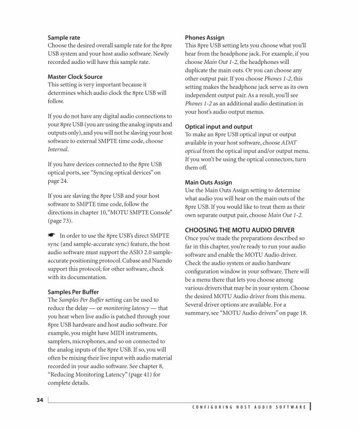
34
Sample rate
Choose the desired overall sample rate for the 8pre USB system and your host audio software. Newly recorded audio will have this sample rate.
Master Clock Source
This setting is very important because it determines which audio clock the 8pre USB will follow.
If you do not have any digital audio connections to your 8pre USB (you are using the analog inputs and outputs only), and you will not be slaving your host software to external SMPTE time code, choose Internal.
If you have devices connected to the 8pre USB optical ports, see “Syncing optical devices” on page 24.
If you are slaving the 8pre USB and your host software to SMPTE time code, follow the directions in chapter 10, “MOTU SMPTE Console” (page 73).
In order to use the 8pre USB’s direct SMPTE sync (and sample-accurate sync) feature, the host audio software must support the ASIO 2.0 sample-accurate positioning protocol. Cubase and Nuendo support this protocol; for other software, check with its documentation.
Samples Per Buffer
The Samples Per Buffer setting can be used to reduce the delay — or monitoring latency — that you hear when live audio is patched through your 8pre USB hardware and host audio software. For example, you might have MIDI instruments, samplers, microphones, and so on connected to the analog inputs of the 8pre USB. If so, you will often be mixing their live input with audio material recorded in your audio software. See chapter 8, “Reducing Monitoring Latency” (page 41) for complete details.
Phones Assign
This 8pre USB setting lets you choose what you’ll hear from the headphone jack. For example, if you choose Main Out 1-2, the headphones will duplicate the main outs. Or you can choose any other output pair. If you choose Phones 1-2, this setting makes the headphone jack serve as its own independent output pair. As a result, you’ll see Phones 1-2 as an additional audio destination in your host’s audio output menus.
Optical input and output
To make an 8pre USB optical input or output available in your host software, choose ADAT optical from the optical input and/or output menu. If you won’t be using the optical connectors, turn them off.
Main Outs Assign
Use the Main Outs Assign setting to determine what audio you will hear on the main outs of the 8pre USB. If you would like to treat them as their own separate output pair, choose Main Out 1-2.
CHOOSING THE MOTU AUDIO DRIVEROnce you’ve made the preparations described so far in this chapter, you’re ready to run your audio software and enable the MOTU Audio driver. Check the audio system or audio hardware configuration window in your software. There will be a menu there that lets you choose among various drivers that may be in your system. Choose the desired MOTU Audio driver from this menu. Several driver options are available. For a summary, see “MOTU Audio drivers” on page 18.
C O N F I G U R I N G H O S T A U D I O S O F T W A R E
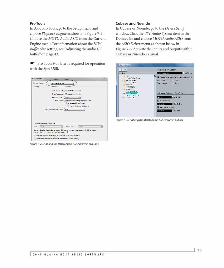
Pro Tools
In Avid Pro Tools, go to the Setup menu and choose Playback Engine as shown in Figure 7-2. Choose the MOTU Audio ASIO from the Current Engine menu. For information about the H/W Buffer Size setting, see “Adjusting the audio I/O buffer” on page 43.
Pro Tools 9 or later is required for operation with the 8pre USB.
Figure 7-2: Enabling the MOTU Audio ASIO driver in Pro Tools
Cubase and Nuendo
In Cubase or Nuendo, go to the Device Setup window. Click the VST Audio System item in the Devices list and choose MOTU Audio ASIO from the ASIO Driver menu as shown below in Figure 7-3. Activate the inputs and outputs within Cubase or Nuendo as usual.
Figure 7-3: Enabling the MOTU Audio ASIO driver in Cubase
C O N F I G U R I N G H O S T A U D I O S O F T W A R E
35
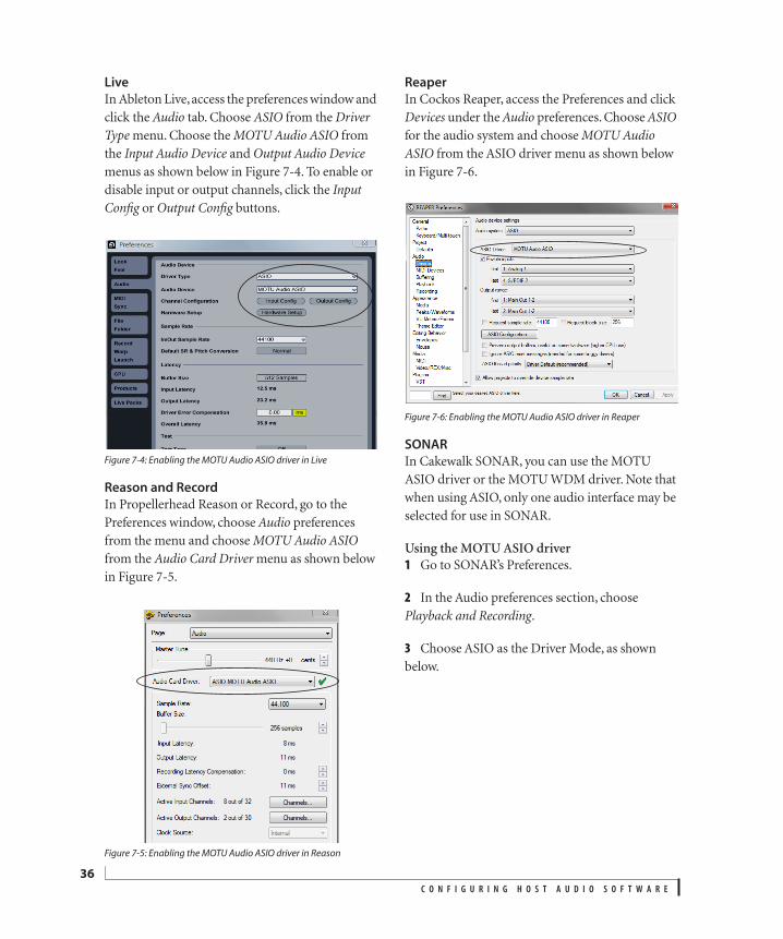
36
Live
In Ableton Live, access the preferences window and click the Audio tab. Choose ASIO from the Driver Type menu. Choose the MOTU Audio ASIO from the Input Audio Device and Output Audio Device menus as shown below in Figure 7-4. To enable or disable input or output channels, click the Input Config or Output Config buttons.
Figure 7-4: Enabling the MOTU Audio ASIO driver in Live
Reason and Record
In Propellerhead Reason or Record, go to the Preferences window, choose Audio preferences from the menu and choose MOTU Audio ASIO from the Audio Card Driver menu as shown below in Figure 7-5.
Figure 7-5: Enabling the MOTU Audio ASIO driver in Reason
Reaper
In Cockos Reaper, access the Preferences and click Devices under the Audio preferences. Choose ASIO for the audio system and choose MOTU Audio ASIO from the ASIO driver menu as shown below in Figure 7-6.
Figure 7-6: Enabling the MOTU Audio ASIO driver in Reaper
SONAR
In Cakewalk SONAR, you can use the MOTU ASIO driver or the MOTU WDM driver. Note that when using ASIO, only one audio interface may be selected for use in SONAR.
Using the MOTU ASIO driver1 Go to SONAR’s Preferences.
2 In the Audio preferences section, choose Playback and Recording.
3 Choose ASIO as the Driver Mode, as shown below.
C O N F I G U R I N G H O S T A U D I O S O F T W A R E
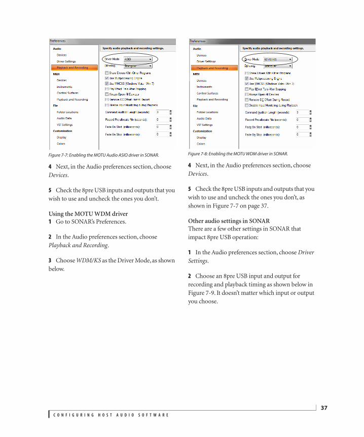
Figure 7-7: Enabling the MOTU Audio ASIO driver in SONAR.
4 Next, in the Audio preferences section, choose Devices.
5 Check the 8pre USB inputs and outputs that you wish to use and uncheck the ones you don’t.
Using the MOTU WDM driver1 Go to SONAR’s Preferences.
2 In the Audio preferences section, choose Playback and Recording.
3 Choose WDM/KS as the Driver Mode, as shown below.
Figure 7-8: Enabling the MOTU WDM driver in SONAR.
4 Next, in the Audio preferences section, choose Devices.
5 Check the 8pre USB inputs and outputs that you wish to use and uncheck the ones you don’t, as shown in Figure 7-7 on page 37.
Other audio settings in SONARThere are a few other settings in SONAR that impact 8pre USB operation:
1 In the Audio preferences section, choose Driver Settings.
2 Choose an 8pre USB input and output for recording and playback timing as shown below in Figure 7-9. It doesn’t matter which input or output you choose.
C O N F I G U R I N G H O S T A U D I O S O F T W A R E
37
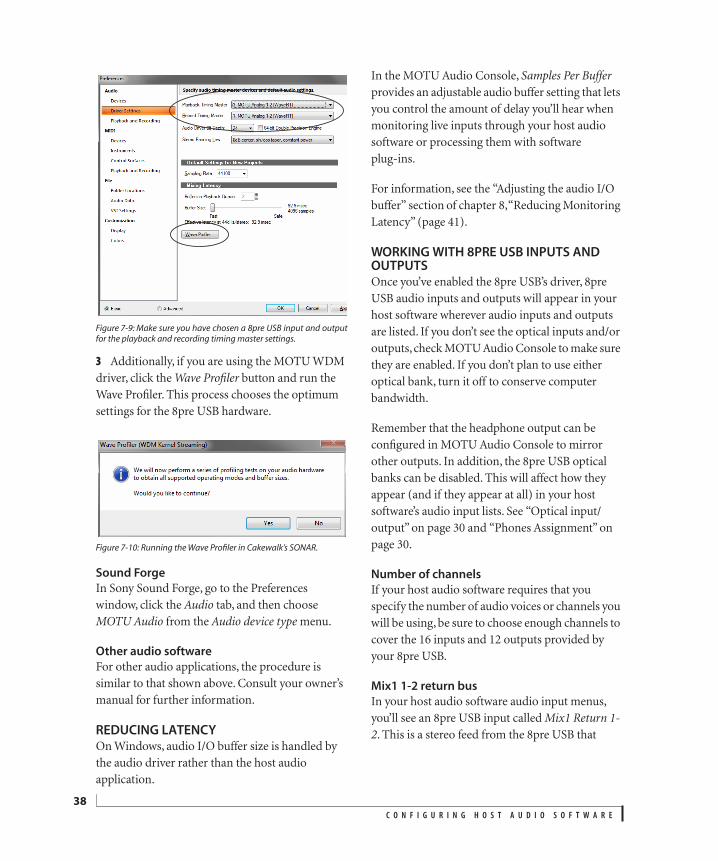
38
Figure 7-9: Make sure you have chosen a 8pre USB input and outputfor the playback and recording timing master settings.
3 Additionally, if you are using the MOTU WDM driver, click the Wave Profiler button and run the Wave Profiler. This process chooses the optimum settings for the 8pre USB hardware.
Figure 7-10: Running the Wave Profiler in Cakewalk’s SONAR.
Sound Forge
In Sony Sound Forge, go to the Preferences window, click the Audio tab, and then choose MOTU Audio from the Audio device type menu.
Other audio software
For other audio applications, the procedure is similar to that shown above. Consult your owner’s manual for further information.
REDUCING LATENCYOn Windows, audio I/O buffer size is handled by the audio driver rather than the host audio application.
In the MOTU Audio Console, Samples Per Buffer provides an adjustable audio buffer setting that lets you control the amount of delay you’ll hear when monitoring live inputs through your host audio software or processing them with software plug-ins.
For information, see the “Adjusting the audio I/O buffer” section of chapter 8, “Reducing Monitoring Latency” (page 41).
WORKING WITH 8PRE USB INPUTS AND OUTPUTSOnce you’ve enabled the 8pre USB’s driver, 8pre USB audio inputs and outputs will appear in your host software wherever audio inputs and outputs are listed. If you don’t see the optical inputs and/or outputs, check MOTU Audio Console to make sure they are enabled. If you don’t plan to use either optical bank, turn it off to conserve computer bandwidth.
Remember that the headphone output can be configured in MOTU Audio Console to mirror other outputs. In addition, the 8pre USB optical banks can be disabled. This will affect how they appear (and if they appear at all) in your host software’s audio input lists. See “Optical input/output” on page 30 and “Phones Assignment” on page 30.
Number of channels
If your host audio software requires that you specify the number of audio voices or channels you will be using, be sure to choose enough channels to cover the 16 inputs and 12 outputs provided by your 8pre USB.
Mix1 1-2 return bus
In your host audio software audio input menus, you’ll see an 8pre USB input called Mix1 Return 1-2. This is a stereo feed from the 8pre USB that
C O N F I G U R I N G H O S T A U D I O S O F T W A R E
matches its main outs. This can be used, for example, to record a final stereo mix for reference and archiving purposes.
Warning: the Mix1 Return 1-2 return inputs can cause feedback loops! DO NOT assign this input to a track assigned to the 8pre USB main outs.
For Mix1 Return 1-2, you can choose whether or not to include audio being sent to the main outs from the computer. See “Mix1 Return Includes Computer Output” on page 52.
The “Phones 1-2” output
Host audio tracks assigned to the Phones 1-2 output pair will be heard on the headphone jack only. If the Phones are set to mirror another output (such as the main outs), the mirrored audio stream is mixed with the phones audio output. For further explanation, see “Phones Assignment” on page 30.
Audio Input and output names
The 8pre USB audio driver supplies text string labels for its inputs and outputs to clearly identify each one, but some applications do not display these labels.
PROCESSING LIVE INPUTS WITH HOST PLUG-INSIf you patch a live input (such as a MIDI synthesizer) through a plug-in effect in your host software, you might hear a slight delay. There are several ways to reduce this delay. For details, see chapter 8, “Reducing Monitoring Latency” (page 41).
WORKING WITH CUEMIX FX MIXINGThe 8pre USB provides external mixing, which you can operate hand-in-hand with your host’s mixing environment. For example, the 8pre USB can serve as a monitor mixer routing channels to musicians, or it can serve as an integrated extension of your host’s mixing environment. If you program an 8pre USB mixing configuration that goes hand in hand
with your host project, be sure to use the file save features in CueMix FX to save the 8pre USB settings as a file in your host project folder for instant recall of all settings. See chapter 9, “CueMix FX” (page 47) for complete details.
SYNCHRONIZATIONYou may encounter situations in which you need to synchronize your audio software and the 8pre USB to the other components of your system.
Synchronizing digital audio connections
If you have devices connected to the 8pre USB digital optical ports, you need to be concerned with the synchronization of the 8pre USB’s digital audio clock with other devices connected to it digitally (if any). For example, if you have a digital mixer connected to the 8pre USB via an ADAT optical light pipe cable, you need to make sure that their audio clocks are phase-locked. For details, see “Syncing optical devices” on page 24. If you don’t have any digital audio devices connected to the 8pre USB, digital audio phase-lock does not apply to you.
Resolving directly to time code (with no synchronizer)
If your host audio software supports ASIO2 or 3’s sample-accurate positioning protocol, then it can resolve to the 8pre USB’s built-in time code synchronization feature. To resolve your 8pre USB directly to SMPTE time code with no additional synchronization devices, use the setup shown in “Setup for SMPTE time code sync” on page 76.
C O N F I G U R I N G H O S T A U D I O S O F T W A R E
39

40
C O N F I G U R I N G H O S T A U D I O S O F T W A R E
CHAPTER
8 Reducing Monitoring LatencyOVERVIEWWhen operating the 8pre USB as an audio interface, monitoring latency is that slight delay you hear when you run an input signal through your host audio software. For example, you might hear it when you drive a live mic input signal through a reverb plug-in running in your audio sequencer.
This delay is caused by the amount of time it takes for audio to make the entire round trip through your computer, from when it first enters an 8pre USB input, passes through the 8pre USB hardware into the computer, through your host audio software, and then back out to an 8pre USB output.
If you don’t need to process a live input with plug-ins, the easiest way to avoid monitoring latency is to use the 8pre USB’s CueMix DSP feature to patch the input directly to your monitor outs via the 8pre USB audio hardware. This is just like bussing inputs to outputs in a digital mixer. For details, see “CueMix DSP hardware monitoring” on page 44.
If you do need to process a live input with plug-ins, or if you are playing virtual instruments live through your 8pre USB audio hardware, you can significantly reduce latency — and even make it completely inaudible, regardless of what host audio application software you use. This chapter explains how.
It is important to note that monitoring delay has no effect on when audio data is recorded to disk or played back from disk. Actual recording and playback is extremely precise.
Monitoring latency does not occur when operating the 8pre USB as an optical expander (in converter mode).
Monitoring live input. . . . . . . . . . . . . . . . . . . . . . . . . . . . . . . . . 42
Adjusting the audio I/O buffer . . . . . . . . . . . . . . . . . . . . . . . 43
Lower latency versus higher CPU overhead . . . . . . . . . . 44
Transport responsiveness . . . . . . . . . . . . . . . . . . . . . . . . . . . . 44
Effects processing and automated mixing . . . . . . . . . . . 44
CueMix DSP hardware monitoring . . . . . . . . . . . . . . . . . . . 44
Two methods for controlling CueMix DSP. . . . . . . . . . . . 44
Using the CueMix FX app. . . . . . . . . . . . . . . . . . . . . . . . . . . . . 45
Controlling CueMix DSP from your audio software . . 45
41
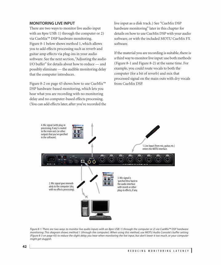
42
MONITORING LIVE INPUTThere are two ways to monitor live audio input with an 8pre USB: 1) through the computer or 2) via CueMix™ DSP hardware monitoring. Figure 8-1 below shows method 1, which allows you to add effects processing such as reverb and guitar amp effects via plug-ins in your audio software. See the next section, “Adjusting the audio I/O buffer” for details about how to reduce — and possibly eliminate — the audible monitoring delay that the computer introduces.
Figure 8-2 on page 43 shows how to use CueMix™ DSP hardware-based monitoring, which lets you hear what you are recording with no monitoring delay and no computer-based effects processing. (You can add effects later, after you’ve recorded the
live input as a disk track.) See “CueMix DSP hardware monitoring” later in this chapter for details on how to use CueMix DSP with your audio software, or with the included MOTU CueMix FX software.
If the material you are recording is suitable, there is a third way to monitor live input: use both methods (Figure 8-1 and Figure 8-2) at the same time. For example, you could route vocals to both the computer (for a bit of reverb) and mix that processed signal on the main outs with dry vocals from CueMix DSP.
PC
1. Live input (from mic, guitar, etc.) enters the MOTU interface.
2. Mic signal goes immedi-ately to the computer (dry, with no effects processing).
3. Mic signal is ‘patched thru’ back to the audio interface with reverb or other plug-in effects, if any.
Figure 8-1: There are two ways to monitor live audio inputs with an 8pre USB: 1) through the computer or 2) via CueMix™ DSP hardwaremonitoring. This diagram shows method 1 (through the computer). When using this method, use MOTU Audio Console’s buffer setting(Figure 8-3 on page 43) to reduce the slight delay you hear when monitoring the live input, but don’t lower it too much, or your computermight get sluggish.
4. Mic signal (with plug-in processing, if any) is routed to the main outs (or other outputs that you’ve specified in the software).
R E D U C I N G M O N I T O R I N G L A T E N C Y
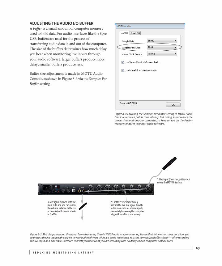
ADJUSTING THE AUDIO I/O BUFFERA buffer is a small amount of computer memory used to hold data. For audio interfaces like the 8pre USB, buffers are used for the process of transferring audio data in and out of the computer. The size of the buffers determines how much delay you hear when monitoring live inputs through your audio software: larger buffers produce more delay; smaller buffers produce less.
Buffer size adjustment is made in MOTU Audio Console, as shown in Figure 8-3 via the Samples Per Buffer setting.
Figure 8-3: Lowering the ‘Samples Per Buffer’ setting in MOTU AudioConsole reduces patch thru latency. But doing so increases theprocessing load on your computer, so keep an eye on the Perfor-mance Monitor in your host audio software.
2. CueMix™ DSP immediately patches the live mic signal directly to the main outs (or other output), completely bypassing the computer (dry, with no effects processing).
3. Mic signal is mixed with the main outs, and you can control the volume (relative to the rest of the mix) with the mic’s fader in CueMix.
Figure 8-2: This diagram shows the signal flow when using CueMix™ DSP no-latency monitoring. Notice that this method does not allow youto process the live input with plug-ins in your audio software while it is being monitored. You can, however, add effects later — after recordingthe live input as a disk track. CueMix™ DSP lets you hear what you are recording with no delay and no computer-based effects.
1. Live input (from mic, guitar, etc.) enters the MOTU interface.
R E D U C I N G M O N I T O R I N G L A T E N C Y
43
44
Lower latency versus higher CPU overhead
The buffer setting has a large impact on the following things:
Patch thru latency
The load on your computer’s CPU
Possible distortion at the smallest settings
How responsive the transport controls are in your audio software
The buffer setting presents you with a trade-off between the processing power of your computer and the delay of live audio as it is being patched through your software. If you reduce the size, you reduce patch thru latency, but significantly increase the overall processing load on your computer, leaving less CPU bandwidth for things like real-time effects processing. On the other hand, if you increase the buffer size, you reduce the load on your computer, freeing up bandwidth for effects, mixing and other real-time operations.
If you are at a point in your recording project where you are not currently working with live, patched-thru material (e.g. you’re not recording vocals), or if you have a way of externally processing inputs, choose a higher buffer size. Depending on your computer’s CPU speed, you might find that settings in the middle work best (256 to 1024).
Transport responsiveness
Buffer size also impacts how quickly your audio software will respond when you begin playback, although not by amounts that are very noticeable. Lowering the buffer size will make your software respond faster; raising the buffer size will make it a little bit slower, but barely enough to notice.
Effects processing and automated mixing
Reducing latency with the buffer size setting has another benefit: it lets you route live inputs through the real-time effects processing and mix automation of your audio software.
CUEMIX DSP HARDWARE MONITORINGThe 8pre USB has a more direct method of patching audio through the system: CueMix DSP. CueMix DSP is a digital mixer in the 8pre USB hardware itself. CueMix DSP has two important benefits:
First, it completely eliminates the patch thru delay (reducing it to a small number of samples — about the same amount as any digital mixer).
Secondly, CueMix DSP imposes no strain on the computer.
The trade-off, however, is that CueMix DSP bypasses your host audio software. Instead, live audio inputs are patched directly through to outputs in the 8pre USB itself and are mixed with disk tracks playing back from your audio software. This means that you cannot apply host-based plug-ins, mix automation, or other real-time effects that your audio software provides. But for inputs that don’t need these types of features, CueMix DSP is the way to go.
On the other hand, if you really need to use the mixing and processing provided by your audio software, you should not use CueMix DSP. Instead, reduce latency with the buffer setting (as explained earlier in this chapter).
TWO METHODS FOR CONTROLLING CUEMIX DSPThere are two ways to control CueMix DSP:
With the 8pre’s CueMix FX software
From within your host audio software (if it supports direct hardware monitoring)
You can even use both methods simultaneously.
R E D U C I N G M O N I T O R I N G L A T E N C Y
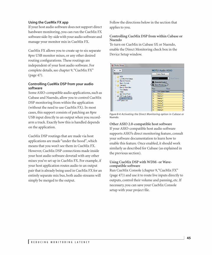
Using the CueMix FX app
If your host audio software does not support direct hardware monitoring, you can run the CueMix FX software side-by-side with your audio software and manage your monitor mix in CueMix FX.
CueMix FX allows you to create up to six separate 8pre USB monitor mixes, or any other desired routing configurations. These routings are independent of your host audio software. For complete details, see chapter 9, “CueMix FX” (page 47).
Controlling CueMix DSP from your audio software
Some ASIO-compatible audio applications, such as Cubase and Nuendo, allow you to control CueMix DSP monitoring from within the application (without the need to use CueMix FX). In most cases, this support consists of patching an 8pre USB input directly to an output when you record-arm a track. Exactly how this is handled depends on the application.
CueMix DSP routings that are made via host applications are made “under the hood”, which means that you won’t see them in CueMix FX. However, CueMix DSP connections made inside your host audio software dovetail with any other mixes you’ve set up in CueMix FX. For example, if your host application routes audio to an output pair that is already being used in CueMix FX for an entirely separate mix bus, both audio streams will simply be merged to the output.
Follow the directions below in the section that applies to you.
Controlling CueMix DSP from within Cubase or NuendoTo turn on CueMix in Cubase SX or Nuendo, enable the Direct Monitoring check box in the Device Setup window.
Figure 8-4: Activating the Direct Monitoring option in Cubase orNuendo.
Other ASIO 2.0-compatible host softwareIf your ASIO-compatible host audio software supports ASIO’s direct monitoring feature, consult your software documentation to learn how to enable this feature. Once enabled, it should work similarly as described for Cubase (as explained in the previous section).
Using CueMix DSP with WDM- or Wave-compatible softwareRun CueMix Console (chapter 9, “CueMix FX” (page 47)) and use it to route live inputs directly to outputs, control their volume and panning, etc. If necessary, you can save your CueMix Console setup with your project file.
R E D U C I N G M O N I T O R I N G L A T E N C Y
45

46
R E D U C I N G M O N I T O R I N G L A T E N C Y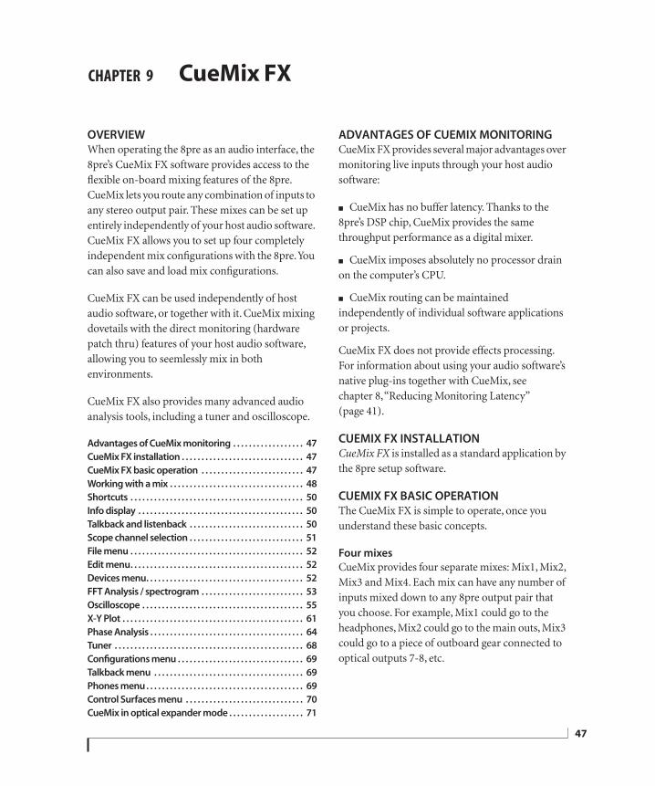
CHAPTER
9 CueMix FXOVERVIEWWhen operating the 8pre as an audio interface, the 8pre’s CueMix FX software provides access to the flexible on-board mixing features of the 8pre. CueMix lets you route any combination of inputs to any stereo output pair. These mixes can be set up entirely independently of your host audio software. CueMix FX allows you to set up four completely independent mix configurations with the 8pre. You can also save and load mix configurations.
CueMix FX can be used independently of host audio software, or together with it. CueMix mixing dovetails with the direct monitoring (hardware patch thru) features of your host audio software, allowing you to seemlessly mix in both environments.
CueMix FX also provides many advanced audio analysis tools, including a tuner and oscilloscope.
Advantages of CueMix monitoring . . . . . . . . . . . . . . . . . . 47
CueMix FX installation . . . . . . . . . . . . . . . . . . . . . . . . . . . . . . . 47
CueMix FX basic operation . . . . . . . . . . . . . . . . . . . . . . . . . . 47
Working with a mix . . . . . . . . . . . . . . . . . . . . . . . . . . . . . . . . . . 48
Shortcuts . . . . . . . . . . . . . . . . . . . . . . . . . . . . . . . . . . . . . . . . . . . . 50
Info display . . . . . . . . . . . . . . . . . . . . . . . . . . . . . . . . . . . . . . . . . . 50
Talkback and listenback . . . . . . . . . . . . . . . . . . . . . . . . . . . . . 50
Scope channel selection . . . . . . . . . . . . . . . . . . . . . . . . . . . . . 51
File menu . . . . . . . . . . . . . . . . . . . . . . . . . . . . . . . . . . . . . . . . . . . . 52
Edit menu. . . . . . . . . . . . . . . . . . . . . . . . . . . . . . . . . . . . . . . . . . . . 52
Devices menu. . . . . . . . . . . . . . . . . . . . . . . . . . . . . . . . . . . . . . . . 52
FFT Analysis / spectrogram . . . . . . . . . . . . . . . . . . . . . . . . . . 53
Oscilloscope . . . . . . . . . . . . . . . . . . . . . . . . . . . . . . . . . . . . . . . . . 55
X-Y Plot . . . . . . . . . . . . . . . . . . . . . . . . . . . . . . . . . . . . . . . . . . . . . . 61
Phase Analysis . . . . . . . . . . . . . . . . . . . . . . . . . . . . . . . . . . . . . . . 64
Tuner . . . . . . . . . . . . . . . . . . . . . . . . . . . . . . . . . . . . . . . . . . . . . . . . 68
Configurations menu . . . . . . . . . . . . . . . . . . . . . . . . . . . . . . . . 69
Talkback menu . . . . . . . . . . . . . . . . . . . . . . . . . . . . . . . . . . . . . . 69
Phones menu. . . . . . . . . . . . . . . . . . . . . . . . . . . . . . . . . . . . . . . . 69
Control Surfaces menu . . . . . . . . . . . . . . . . . . . . . . . . . . . . . . 70
CueMix in optical expander mode . . . . . . . . . . . . . . . . . . . 71
ADVANTAGES OF CUEMIX MONITORINGCueMix FX provides several major advantages over monitoring live inputs through your host audio software:
CueMix has no buffer latency. Thanks to the 8pre’s DSP chip, CueMix provides the same throughput performance as a digital mixer.
CueMix imposes absolutely no processor drain on the computer’s CPU.
CueMix routing can be maintained independently of individual software applications or projects.
CueMix FX does not provide effects processing. For information about using your audio software’s native plug-ins together with CueMix, see chapter 8, “Reducing Monitoring Latency” (page 41).
CUEMIX FX INSTALLATIONCueMix FX is installed as a standard application by the 8pre setup software.
CUEMIX FX BASIC OPERATIONThe CueMix FX is simple to operate, once you understand these basic concepts.
Four mixes
CueMix provides four separate mixes: Mix1, Mix2, Mix3 and Mix4. Each mix can have any number of inputs mixed down to any 8pre output pair that you choose. For example, Mix1 could go to the headphones, Mix2 could go to the main outs, Mix3 could go to a piece of outboard gear connected to optical outputs 7-8, etc.
47
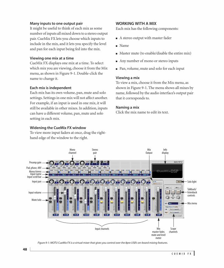
48
Many inputs to one output pair
It might be useful to think of each mix as some number of inputs all mixed down to a stereo output pair. CueMix FX lets you choose which inputs to include in the mix, and it lets you specify the level and pan for each input being fed into the mix.
Viewing one mix at a time
CueMix FX displays one mix at a time. To select which mix you are viewing, choose it from the Mix menu, as shown in Figure 9-1. Double-click the name to change it.
Each mix is independent
Each mix has its own volume, pan, mute and solo settings. Settings in one mix will not affect another. For example, if an input is used in one mix, it will still be available in other mixes. In addition, inputs can have a different volume, pan, mute and solo setting in each mix.
Widening the CueMix FX window
To view more input faders at once, drag the right-hand edge of the window to the right.
WORKING WITH A MIXEach mix has the following components:
A stereo output with master fader
Name
Master mute (to enable/disable the entire mix)
Any number of mono or stereo inputs
Pan, volume, mute and solo for each input
Viewing a mix
To view a mix, choose it from the Mix menu, as shown in Figure 9-1. The menu shows all mixes by name, followed by the audio interface’s output pair that it corresponds to.
Naming a mix
Click the mix name to edit its text.
Figure 9-1: MOTU CueMix FX is a virtual mixer that gives you control over the 8pre USB’s on-board mixing features.
Info display
Input channels Mix master fader,
mute and level meter
Mute/solo
Input pan
Input volume
Input nameInput scroll bar
Mono/stereo
Pad, phase, 48V
Preamp gain
Mono channel
Stereo pair
Mix Output
Scopechannels
Solo light
Talkback/listenback controls
Mix menu
C U E M I X F X
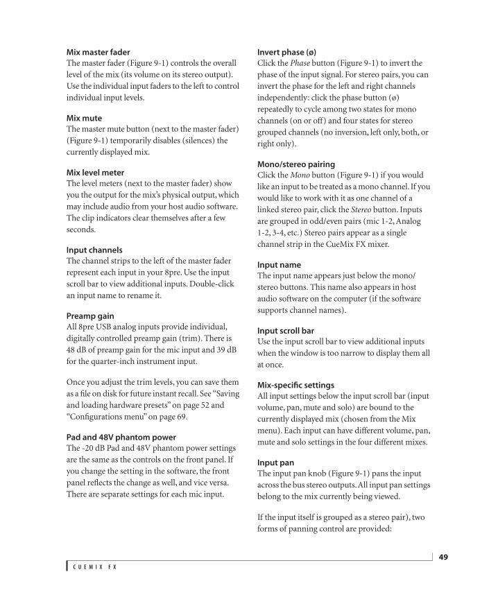
Mix master fader
The master fader (Figure 9-1) controls the overall level of the mix (its volume on its stereo output). Use the individual input faders to the left to control individual input levels.
Mix mute
The master mute button (next to the master fader) (Figure 9-1) temporarily disables (silences) the currently displayed mix.
Mix level meter
The level meters (next to the master fader) show you the output for the mix’s physical output, which may include audio from your host audio software. The clip indicators clear themselves after a few seconds.
Input channels
The channel strips to the left of the master fader represent each input in your 8pre. Use the input scroll bar to view additional inputs. Double-click an input name to rename it.
Preamp gain
All 8pre USB analog inputs provide individual, digitally controlled preamp gain (trim). There is 48 dB of preamp gain for the mic input and 39 dB for the quarter-inch instrument input.
Once you adjust the trim levels, you can save them as a file on disk for future instant recall. See “Saving and loading hardware presets” on page 52 and “Configurations menu” on page 69.
Pad and 48V phantom power
The -20 dB Pad and 48V phantom power settings are the same as the controls on the front panel. If you change the setting in the software, the front panel reflects the change as well, and vice versa. There are separate settings for each mic input.
Invert phase (ø)
Click the Phase button (Figure 9-1) to invert the phase of the input signal. For stereo pairs, you can invert the phase for the left and right channels independently: click the phase button (ø) repeatedly to cycle among two states for mono channels (on or off) and four states for stereo grouped channels (no inversion, left only, both, or right only).
Mono/stereo pairing
Click the Mono button (Figure 9-1) if you would like an input to be treated as a mono channel. If you would like to work with it as one channel of a linked stereo pair, click the Stereo button. Inputs are grouped in odd/even pairs (mic 1-2, Analog 1-2, 3-4, etc.) Stereo pairs appear as a single channel strip in the CueMix FX mixer.
Input name
The input name appears just below the mono/stereo buttons. This name also appears in host audio software on the computer (if the software supports channel names).
Input scroll bar
Use the input scroll bar to view additional inputs when the window is too narrow to display them all at once.
Mix-specific settings
All input settings below the input scroll bar (input volume, pan, mute and solo) are bound to the currently displayed mix (chosen from the Mix menu). Each input can have different volume, pan, mute and solo settings in the four different mixes.
Input pan
The input pan knob (Figure 9-1) pans the input across the bus stereo outputs. All input pan settings belong to the mix currently being viewed.
If the input itself is grouped as a stereo pair), two forms of panning control are provided:
C U E M I X F X
49

50
BalanceBalance works like the balance knob on some radios: turn it left and the right channel dims, turn it right and left channel dims. But the left channel always stays left and the right channel stays right.
WidthWidth spreads the left and right channels across the stereo image, depending on the knob position. Maximum value (turning the pan knob all the way up) maintains the original stereo image: the left channel goes entirely left and right goes entirely right, without attenuation. The minimum value (turning the knob all the way down) creates a mono effect: equal amounts of left and right are combined and sent to both outputs. In between, the left out is a mixture of the left input and some of the right input (and vice-versa) with the effect of narrowing the field.
Input fader
Use the input fader (Figure 9-1) to adjust the input volume in the mix. Note that an input can have different level, pan, mute and solo settings for each mix. Input channel level meters are post-fader.
Input mute/solo
To add an input to a mix, or remove it, click its MUTE button. To solo it, use its SOLO button. The Solo light (Figure 9-1) illuminates when any input is soloed (including inputs that may currently be scrolled off-screen).
SHORTCUTSHold down the following modifier keys as shortcuts:
INFO DISPLAYThe info display shows fly-over help for items in the CueMix FX window.
TALKBACK AND LISTENBACKCueMix FX provides Talkback and Listenback buttons. Talkback allows an engineer in the control room to temporarily dim all audio and talk to musicians in the live room. Conversely, Listenback allows musicians to talk to the control room.
Hardware setup
Figure 9-2 below shows a typical hardware setup for Talkback and Listenback. For Talkback, set up a dedicated mic in your control room and connect it to a mic input on your MOTU audio interface. For Listenback, set up a dedicated listenback mic in the live room for the musicians and connect it to another mic input. For talkback output, set up a headphone distribution amp or set of speakers in the live room, and connect it to the 8pre’s headphone out, as demonstrated below in Figure 9-2.
Figure 9-2: Typical hardware setup for Talkback and Listenback.
Shortcut Result
Shift key Applies your action to all inputs in the mix.
Control key Applies your action to the stereo input pair
Space bar Applies your action to all busses
Double-click Returns the control to its default value (pan center, unity gain, etc.)
Listenback
mic
Control room
Talkback
mic
Main
outs
Live room
Phones
Headphone distribution amp
C U E M I X F X
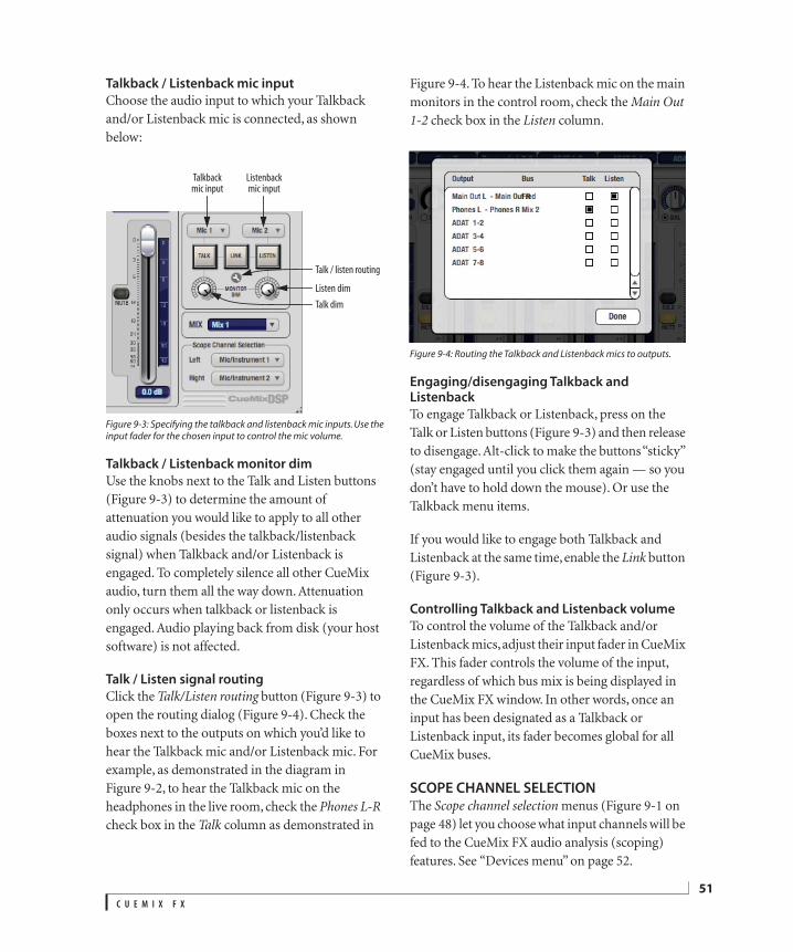
Talkback / Listenback mic input
Choose the audio input to which your Talkback and/or Listenback mic is connected, as shown below:
Figure 9-3: Specifying the talkback and listenback mic inputs. Use theinput fader for the chosen input to control the mic volume.
Talkback / Listenback monitor dim
Use the knobs next to the Talk and Listen buttons (Figure 9-3) to determine the amount of attenuation you would like to apply to all other audio signals (besides the talkback/listenback signal) when Talkback and/or Listenback is engaged. To completely silence all other CueMix audio, turn them all the way down. Attenuation only occurs when talkback or listenback is engaged. Audio playing back from disk (your host software) is not affected.
Talk / Listen signal routing
Click the Talk/Listen routing button (Figure 9-3) to open the routing dialog (Figure 9-4). Check the boxes next to the outputs on which you’d like to hear the Talkback mic and/or Listenback mic. For example, as demonstrated in the diagram in Figure 9-2, to hear the Talkback mic on the headphones in the live room, check the Phones L-R check box in the Talk column as demonstrated in
Figure 9-4. To hear the Listenback mic on the main monitors in the control room, check the Main Out 1-2 check box in the Listen column.
Figure 9-4: Routing the Talkback and Listenback mics to outputs.
Engaging/disengaging Talkback and Listenback
To engage Talkback or Listenback, press on the Talk or Listen buttons (Figure 9-3) and then release to disengage. Alt-click to make the buttons “sticky” (stay engaged until you click them again — so you don’t have to hold down the mouse). Or use the Talkback menu items.
If you would like to engage both Talkback and Listenback at the same time, enable the Link button (Figure 9-3).
Controlling Talkback and Listenback volume
To control the volume of the Talkback and/or Listenback mics, adjust their input fader in CueMix FX. This fader controls the volume of the input, regardless of which bus mix is being displayed in the CueMix FX window. In other words, once an input has been designated as a Talkback or Listenback input, its fader becomes global for all CueMix buses.
SCOPE CHANNEL SELECTIONThe Scope channel selection menus (Figure 9-1 on page 48) let you choose what input channels will be fed to the CueMix FX audio analysis (scoping) features. See “Devices menu” on page 52.
Talkback mic input
Listenback mic input
Listen dim
Talk / listen routing
Talk dim
C U E M I X F X
51
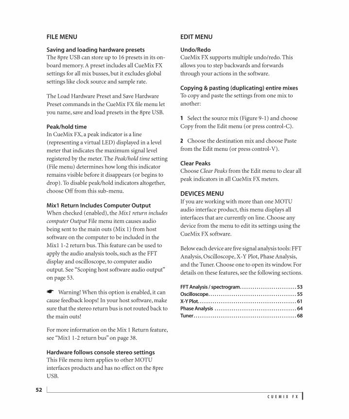
52
FILE MENU
Saving and loading hardware presets
The 8pre USB can store up to 16 presets in its on-board memory. A preset includes all CueMix FX settings for all mix busses, but it excludes global settings like clock source and sample rate.
The Load Hardware Preset and Save Hardware Preset commands in the CueMix FX file menu let you name, save and load presets in the 8pre USB.
Peak/hold time
In CueMix FX, a peak indicator is a line (representing a virtual LED) displayed in a level meter that indicates the maximum signal level registered by the meter. The Peak/hold time setting (File menu) determines how long this indicator remains visible before it disappears (or begins to drop). To disable peak/hold indicators altogether, choose Off from this sub-menu.
Mix1 Return Includes Computer Output
When checked (enabled), the Mix1 return includes computer Output File menu item causes audio being sent to the main outs (Mix 1) from host software on the computer to be included in the Mix1 1-2 return bus. This feature can be used to apply the audio analysis tools, such as the FFT display and oscilloscope, to computer audio output. See “Scoping host software audio output” on page 53.
Warning! When this option is enabled, it can cause feedback loops! In your host software, make sure that the stereo return bus is not routed back to the main outs!
For more information on the Mix 1 Return feature, see “Mix1 1-2 return bus” on page 38.
Hardware follows console stereo settings
This File menu item applies to other MOTU interfaces products and has no effect on the 8pre USB.
EDIT MENU
Undo/Redo
CueMix FX supports multiple undo/redo. This allows you to step backwards and forwards through your actions in the software.
Copying & pasting (duplicating) entire mixes
To copy and paste the settings from one mix to another:
1 Select the source mix (Figure 9-1) and choose Copy from the Edit menu (or press control-C).
2 Choose the destination mix and choose Paste from the Edit menu (or press control-V).
Clear Peaks
Choose Clear Peaks from the Edit menu to clear all peak indicators in all CueMix FX meters.
DEVICES MENUIf you are working with more than one MOTU audio interface product, this menu displays all interfaces that are currently on line. Choose any device from the menu to edit its settings using the CueMix FX software.
Below each device are five signal analysis tools: FFT Analysis, Oscilloscope, X-Y Plot, Phase Analysis, and the Tuner. Choose one to open its window. For details on these features, see the following sections.
FFT Analysis / spectrogram. . . . . . . . . . . . . . . . . . . . . . . . . . . 53
Oscilloscope. . . . . . . . . . . . . . . . . . . . . . . . . . . . . . . . . . . . . . . . . . 55
X-Y Plot. . . . . . . . . . . . . . . . . . . . . . . . . . . . . . . . . . . . . . . . . . . . . . . 61
Phase Analysis . . . . . . . . . . . . . . . . . . . . . . . . . . . . . . . . . . . . . . . 64
Tuner. . . . . . . . . . . . . . . . . . . . . . . . . . . . . . . . . . . . . . . . . . . . . . . . . 68
C U E M I X F X
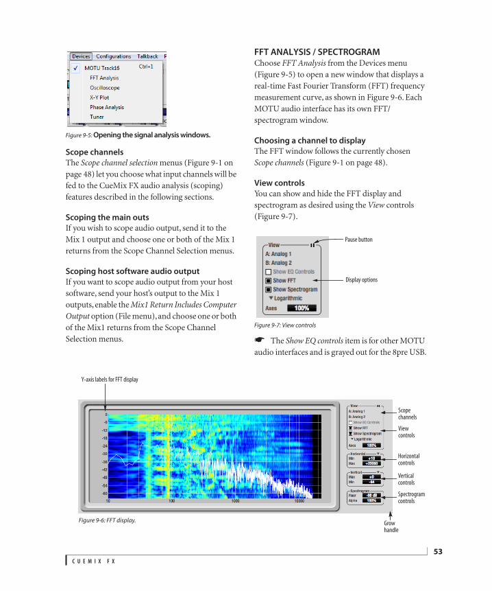
Figure 9-5: Opening the signal analysis windows.
Scope channels
The Scope channel selection menus (Figure 9-1 on page 48) let you choose what input channels will be fed to the CueMix FX audio analysis (scoping) features described in the following sections.
Scoping the main outs
If you wish to scope audio output, send it to the Mix 1 output and choose one or both of the Mix 1 returns from the Scope Channel Selection menus.
Scoping host software audio output
If you want to scope audio output from your host software, send your host’s output to the Mix 1 outputs, enable the Mix1 Return Includes Computer Output option (File menu), and choose one or both of the Mix1 returns from the Scope Channel Selection menus.
FFT ANALYSIS / SPECTROGRAMChoose FFT Analysis from the Devices menu (Figure 9-5) to open a new window that displays a real-time Fast Fourier Transform (FFT) frequency measurement curve, as shown in Figure 9-6. Each MOTU audio interface has its own FFT/spectrogram window.
Choosing a channel to display
The FFT window follows the currently chosen Scope channels (Figure 9-1 on page 48).
View controls
You can show and hide the FFT display and spectrogram as desired using the View controls (Figure 9-7).
Figure 9-7: View controls
The Show EQ controls item is for other MOTU audio interfaces and is grayed out for the 8pre USB.
Figure 9-6: FFT display.
View controls
Y-axis labels for FFT display
Horizontal controls
Vertical controls
Spectrogram controls
Grow handle
Scope channels
Pause button
Display options
C U E M I X F X
53
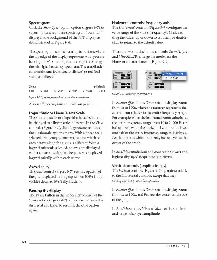
54
Spectrogram
Click the Show Spectrogram option (Figure 9-7) to superimpose a real-time spectrogram “waterfall” display in the background of the FFT display, as demonstrated in Figure 9-6.
The spectrogram scrolls from top to bottom, where the top edge of the display represents what you are hearing “now”. Color represents amplitude along the left/right frequency spectrum. The amplitude color scale runs from black (silence) to red (full scale) as follows:
Figure 9-8: Spectrogram color-to-amplitude spectrum.
Also see “Spectrogram controls” on page 55.
Logarithmic or Linear X-Axis Scale
The x-axis defaults to a logarithmic scale, but can be changed to a linear scale if desired. In the View controls (Figure 9-7), click Logarithmic to access the x-axis scale options menu. With a linear scale selected, frequency is constant, but the width of each octave along the x-axis is different. With a logarithmic scale selected, octaves are displayed with a constant width, but frequency is displayed logarithmically within each octave.
Axes display
The Axes control (Figure 9-7) sets the opacity of the grid displayed in the graph, from 100% (fully visible) down to 0% (fully hidden).
Pausing the display
The Pause button in the upper right corner of the View section (Figure 9-7) allows you to freeze the display at any time. To resume, click the button again.
Horizontal controls (frequency axis)
The Horizontal controls (Figure 9-7) configure the value range of the x-axis (frequency). Click and drag the values up or down to set them, or double-click to return to the default value.
There are two modes for the controls: Zoom/Offset and Min/Max. To change the mode, use the Horizontal control menu (Figure 9-9).
Figure 9-9: Horizontal control menu
In Zoom/Offset mode, Zoom sets the display zoom from 1x to 100x, where the number represents the zoom factor relative to the entire frequency range. For example, when the horizontal zoom value is 1x, the entire frequency range from 10 to 24000 Hertz is displayed; when the horizontal zoom value is 2x, one half of the entire frequency range is displayed. Pos determines which frequency is displayed at the center of the graph.
In Min/Max mode, Min and Max set the lowest and highest displayed frequencies (in Hertz).
Vertical controls (amplitude axis)
The Vertical controls (Figure 9-7) operate similarly to the Horizontal controls, except that they configure the y-axis (amplitude).
In Zoom/Offset mode, Zoom sets the display zoom from 1x to 100x, and Pos sets the center amplitude of the graph.
In Min/Max mode, Min and Max set the smallest and largest displayed amplitude.
Black Blue Green Yellow Orange Red
Silence Full scale
C U E M I X F X
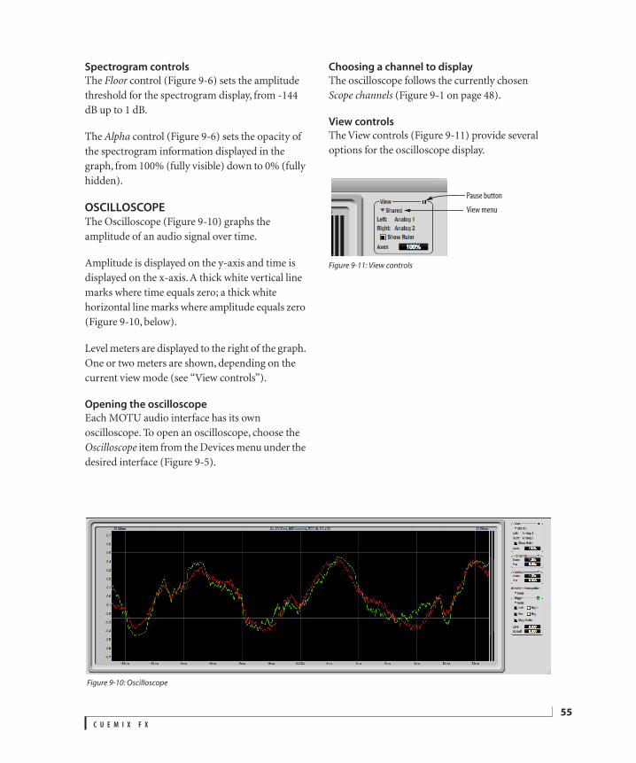
Spectrogram controls
The Floor control (Figure 9-6) sets the amplitude threshold for the spectrogram display, from -144 dB up to 1 dB.
The Alpha control (Figure 9-6) sets the opacity of the spectrogram information displayed in the graph, from 100% (fully visible) down to 0% (fully hidden).
OSCILLOSCOPEThe Oscilloscope (Figure 9-10) graphs the amplitude of an audio signal over time.
Amplitude is displayed on the y-axis and time is displayed on the x-axis. A thick white vertical line marks where time equals zero; a thick white horizontal line marks where amplitude equals zero (Figure 9-10, below).
Level meters are displayed to the right of the graph. One or two meters are shown, depending on the current view mode (see “View controls”).
Opening the oscilloscope
Each MOTU audio interface has its own oscilloscope. To open an oscilloscope, choose the Oscilloscope item from the Devices menu under the desired interface (Figure 9-5).
Choosing a channel to display
The oscilloscope follows the currently chosen Scope channels (Figure 9-1 on page 48).
View controls
The View controls (Figure 9-11) provide several options for the oscilloscope display.
Figure 9-11: View controls
Figure 9-10: Oscilloscope
Pause button
View menu
C U E M I X F X
55
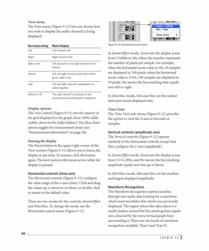
56
View menuThe View menu (Figure 9-11) lets you choose how you wish to display the audio channel(s) being displayed.
Display optionsThe Axes control (Figure 9-11) sets the opacity of the grid displayed in the graph, from 100% (fully visible) down to 0% (fully hidden). The Show Ruler option toggles the measurement items (see “Measurement information” on page 58).
Pausing the displayThe Pause button in the upper right corner of the View section (Figure 9-11) allows you to freeze the display at any time. To resume, click the button again. The level meters will remain active while the display is paused.
Horizontal controls (time axis)
The Horizontal controls (Figure 9-12) configure the value range of the x-axis (time). Click and drag the values up or down to set them, or double-click to return to the default value.
There are two modes for the controls: Zoom/Offset and Min/Max. To change the mode, use the Horizontal control menu (Figure 9-12).
Figure 9-12: Horizontal control menu
In Zoom/Offset mode, Zoom sets the display zoom from 1/1000x to 10x, where the number represents the number of pixels per sample. For example, when the horizontal zoom value is 10x, 10 samples are displayed in 100 pixels; when the horizontal zoom value is 1/10x, 100 samples are displayed in 10 pixels. Pos moves the line marking time equals zero left or right.
In Min/Max mode, Min and Max set the earliest and most recent displayed time.
Time UnitsThe Time Units sub-menu (Figure 9-12) provides the option to view the X axis in Seconds or Samples.
Vertical controls (amplitude axis)
The Vertical controls (Figure 9-12) operate similarly to the Horizontal controls, except that they configure the y-axis (amplitude).
In Zoom/Offset mode, Zoom sets the display zoom from 1/2 to 200x, and Pos moves the line marking amplitude equals zero line up or down.
In Min/Max mode, Min and Max set the smallest and largest displayed amplitude.
Waveform Recognition
The Waveform Recognition option searches through new audio data looking for a waveform which most resembles that which was previously displayed. The region where this takes place is a small window around the line marking time equals zero, denoted by the extra vertical graph lines surrounding it. There are two kinds of waveform recognition available: Type I and Type II.
View menu setting What it displays
Left Left channel only
Right Right channel only
Split screen Left channel on top; right channel on the bottom
Shared Left and right on top of each other; left is green, right is red
Add Left and right channels’ amplitudes are added together
Subtract L-R The right channel’s amplitude is sub-tracted from the left channel’s amplitude
C U E M I X F X
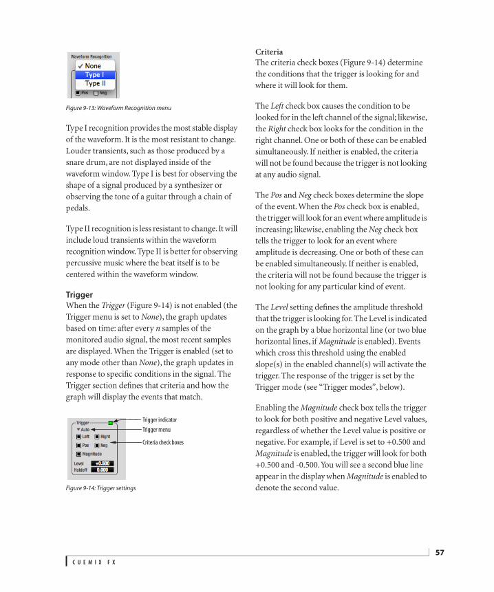
Figure 9-13: Waveform Recognition menu
Type I recognition provides the most stable display of the waveform. It is the most resistant to change. Louder transients, such as those produced by a snare drum, are not displayed inside of the waveform window. Type I is best for observing the shape of a signal produced by a synthesizer or observing the tone of a guitar through a chain of pedals.
Type II recognition is less resistant to change. It will include loud transients within the waveform recognition window. Type II is better for observing percussive music where the beat itself is to be centered within the waveform window.
Trigger
When the Trigger (Figure 9-14) is not enabled (the Trigger menu is set to None), the graph updates based on time: after every n samples of the monitored audio signal, the most recent samples are displayed. When the Trigger is enabled (set to any mode other than None), the graph updates in response to specific conditions in the signal. The Trigger section defines that criteria and how the graph will display the events that match.
Figure 9-14: Trigger settings
CriteriaThe criteria check boxes (Figure 9-14) determine the conditions that the trigger is looking for and where it will look for them.
The Left check box causes the condition to be looked for in the left channel of the signal; likewise, the Right check box looks for the condition in the right channel. One or both of these can be enabled simultaneously. If neither is enabled, the criteria will not be found because the trigger is not looking at any audio signal.
The Pos and Neg check boxes determine the slope of the event. When the Pos check box is enabled, the trigger will look for an event where amplitude is increasing; likewise, enabling the Neg check box tells the trigger to look for an event where amplitude is decreasing. One or both of these can be enabled simultaneously. If neither is enabled, the criteria will not be found because the trigger is not looking for any particular kind of event.
The Level setting defines the amplitude threshold that the trigger is looking for. The Level is indicated on the graph by a blue horizontal line (or two blue horizontal lines, if Magnitude is enabled). Events which cross this threshold using the enabled slope(s) in the enabled channel(s) will activate the trigger. The response of the trigger is set by the Trigger mode (see “Trigger modes”, below).
Enabling the Magnitude check box tells the trigger to look for both positive and negative Level values, regardless of whether the Level value is positive or negative. For example, if Level is set to +0.500 and Magnitude is enabled, the trigger will look for both +0.500 and -0.500. You will see a second blue line appear in the display when Magnitude is enabled to denote the second value.
Trigger indicator
Trigger menu
Criteria check boxes
C U E M I X F X
57
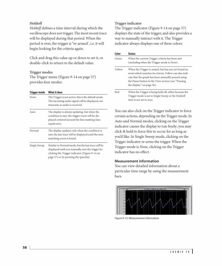
58
HoldoffHoldoff defines a time interval during which the oscilloscope does not trigger. The most recent trace will be displayed during that period. When the period is over, the trigger is “re-armed’, i.e. it will begin looking for the criteria again.
Click and drag this value up or down to set it, or double-click to return to the default value.
Trigger modesThe Trigger menu (Figure 9-14 on page 57) provides four modes:
Trigger indicatorThe Trigger indicator (Figure 9-14 on page 57) displays the state of the trigger, and also provides a way to manually interact with it. The Trigger indicator always displays one of three colors:
You can also click on the Trigger indicator to force certain actions, depending on the Trigger mode. In Auto and Normal modes, clicking on the Trigger indicator causes the display to run freely; you may click & hold to force this to occur for as long as you’d like. In Single Sweep mode, clicking on the Trigger indicator re-arms the trigger. When the Trigger mode is None, clicking on the Trigger indicator has no effect.
Measurement information
You can view detailed information about a particular time range by using the measurement bars.
Figure 9-15: Measurement information
Trigger mode What it does
None The Trigger is not active; this is the default mode. The incoming audio signal will be displayed con-tinuously as audio is received.
Auto The display is always updating, but when the condition is met, the trigger event will be dis-played centered around the line marking time equals zero.
Normal The display updates only when the condition is met; the last trace will be displayed until the next matching event is found.
Single Sweep Similar to Normal mode, but the last trace will be displayed until you manually arm the trigger by clicking the Trigger indicator (Figure 9-14 on page 57) or by pressing the spacebar.
Color Status
Green When the current Trigger criteria has been met (including when the Trigger mode is None).
Yellow When the Trigger is armed, but has not yet found an event which matches its criteria. Yellow can also indi-cate that the graph has been manually paused using the Pause button in the View section (see “Pausing the display” on page 56).
Red When the Trigger is being held off, either because the Trigger mode is set to Single Sweep or the Holdoff time is not set to zero.
C U E M I X F X
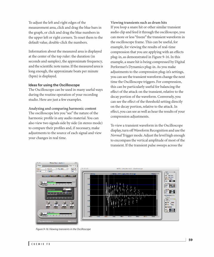
To adjust the left and right edges of the measurement area, click and drag the blue bars in the graph, or click and drag the blue numbers in the upper left or right corners. To reset them to the default value, double-click the numbers.
Information about the measured area is displayed at the center of the top ruler: the duration (in seconds and samples), the approximate frequency, and the scientific note name. If the measured area is long enough, the approximate beats per minute (bpm) is displayed.
Ideas for using the Oscilloscope
The Oscilloscope can be used in many useful ways during the routine operation of your recording studio. Here are just a few examples.
Analyzing and comparing harmonic contentThe oscilloscope lets you “see” the nature of the harmonic profile in any audio material. You can also view two signals side by side (in stereo mode) to compare their profiles and, if necessary, make adjustments to the source of each signal and view your changes in real time.
Viewing transients such as drum hitsIf you loop a snare hit or other similar transient audio clip and feed it through the oscilloscope, you can more or less “freeze” the transient waveform in the oscilloscope frame. This can be useful, for example, for viewing the results of real-time compression that you are applying with an effects plug-in, as demonstrated in Figure 9-16. In this example, a snare hit is being compressed by Digital Performer’s Dynamics plug-in. As you make adjustments to the compression plug-in’s settings, you can see the transient waveform change the next time the Oscilloscope triggers. For compression, this can be particularly useful for balancing the effect of the attack on the transient, relative to the decay portion of the waveform. Conversely, you can see the effect of the threshold setting directly on the decay portion, relative to the attack. In effect, you can see as well as hear the results of your compression adjustments.
To view a transient waveform in the Oscilloscope display, turn off Waveform Recognition and use the Normal Trigger mode. Adjust the level high enough to encompass the vertical amplitude of most of the transient. If the transient pulse sweeps across the
Figure 9-16: Viewing transients in the Oscilloscope
C U E M I X F X
59
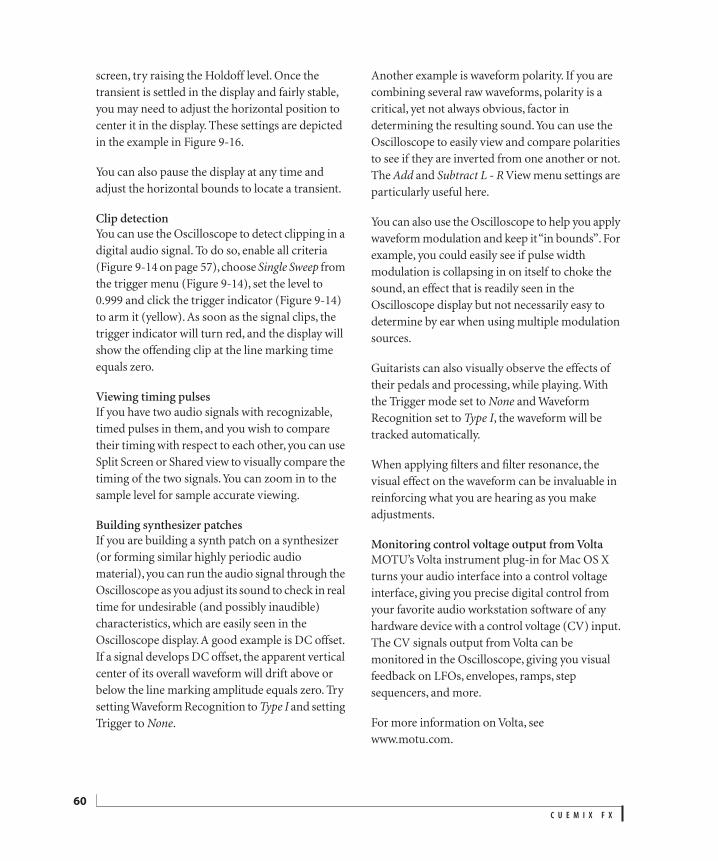
60
screen, try raising the Holdoff level. Once the transient is settled in the display and fairly stable, you may need to adjust the horizontal position to center it in the display. These settings are depicted in the example in Figure 9-16.
You can also pause the display at any time and adjust the horizontal bounds to locate a transient.
Clip detectionYou can use the Oscilloscope to detect clipping in a digital audio signal. To do so, enable all criteria (Figure 9-14 on page 57), choose Single Sweep from the trigger menu (Figure 9-14), set the level to 0.999 and click the trigger indicator (Figure 9-14) to arm it (yellow). As soon as the signal clips, the trigger indicator will turn red, and the display will show the offending clip at the line marking time equals zero.
Viewing timing pulsesIf you have two audio signals with recognizable, timed pulses in them, and you wish to compare their timing with respect to each other, you can use Split Screen or Shared view to visually compare the timing of the two signals. You can zoom in to the sample level for sample accurate viewing.
Building synthesizer patchesIf you are building a synth patch on a synthesizer (or forming similar highly periodic audio material), you can run the audio signal through the Oscilloscope as you adjust its sound to check in real time for undesirable (and possibly inaudible) characteristics, which are easily seen in the Oscilloscope display. A good example is DC offset. If a signal develops DC offset, the apparent vertical center of its overall waveform will drift above or below the line marking amplitude equals zero. Try setting Waveform Recognition to Type I and setting Trigger to None.
Another example is waveform polarity. If you are combining several raw waveforms, polarity is a critical, yet not always obvious, factor in determining the resulting sound. You can use the Oscilloscope to easily view and compare polarities to see if they are inverted from one another or not. The Add and Subtract L - R View menu settings are particularly useful here.
You can also use the Oscilloscope to help you apply waveform modulation and keep it “in bounds”. For example, you could easily see if pulse width modulation is collapsing in on itself to choke the sound, an effect that is readily seen in the Oscilloscope display but not necessarily easy to determine by ear when using multiple modulation sources.
Guitarists can also visually observe the effects of their pedals and processing, while playing. With the Trigger mode set to None and Waveform Recognition set to Type I, the waveform will be tracked automatically.
When applying filters and filter resonance, the visual effect on the waveform can be invaluable in reinforcing what you are hearing as you make adjustments.
Monitoring control voltage output from VoltaMOTU’s Volta instrument plug-in for Mac OS X turns your audio interface into a control voltage interface, giving you precise digital control from your favorite audio workstation software of any hardware device with a control voltage (CV) input. The CV signals output from Volta can be monitored in the Oscilloscope, giving you visual feedback on LFOs, envelopes, ramps, step sequencers, and more.
For more information on Volta, see www.motu.com.
C U E M I X F X
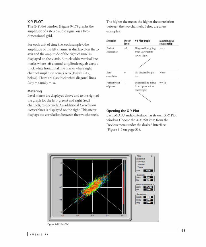
X-Y PLOTThe X-Y Plot window (Figure 9-17) graphs the amplitude of a stereo audio signal on a two-dimensional grid.
For each unit of time (i.e. each sample), the amplitude of the left channel is displayed on the x-axis and the amplitude of the right channel is displayed on the y-axis. A thick white vertical line marks where left channel amplitude equals zero; a thick white horizontal line marks where right channel amplitude equals zero (Figure 9-17, below). There are also thick white diagonal lines for y = x and y = -x.
Metering
Level meters are displayed above and to the right of the graph for the left (green) and right (red) channels, respectively. An additional Correlation meter (blue) is displayed on the right. This meter displays the correlation between the two channels.
The higher the meter, the higher the correlation between the two channels. Below are a few examples:
Opening the X-Y Plot
Each MOTU audio interface has its own X-Y Plot window. Choose the X-Y Plot item from the Devices menu under the desired interface (Figure 9-5 on page 53).
Figure 9-17: X-Y Plot
Situation Meter level
X-Y Plot graph Mathematical relationship
Perfect correlation
+1 Diagonal line going from lower left to upper right:
y = x
Zero correlation
0 No discernible pat-tern
None
Perfectly out of phase
-1 Diagonal line going from upper left to lower right:
y = -x
C U E M I X F X
61
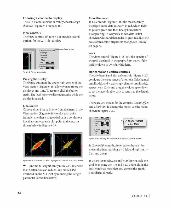
62
Choosing a channel to display
The X-Y Plot follows the currently chosen Scope channels (Figure 9-1 on page 48).
View controls
The View controls (Figure 9-18) provide several options for the X-Y Plot display.
Figure 9-18: View controls
Pausing the displayThe Pause button in the upper right corner of the View section (Figure 9-18) allows you to freeze the display at any time. To resume, click the button again. The level meters will remain active while the display is paused.
Line/ScatterChoose either Line or Scatter from the menu in the View section (Figure 9-18) to plot each point (sample) as either a single pixel or as a continuous line that connects each plot point to the next, as shown below in Figure 9-19.
Figure 9-19: The same X-Y Plot displayed in Line versus Scatter mode.
Line mode is significantly more CPU intensive than Scatter. You can reduce Line mode CPU overhead on the X-Y Plot by reducing the Length parameter (described below).
Color/GrayscaleIn Color mode (Figure 9-18) the most recently displayed audio data is shown in red, which fades to yellow, green and then finally blue, before disappearing. In Grayscale mode, data is first shown in white and then fades to gray. To adjust the scale of this color/brightness change, see “Decay” on page 63.
AxesThe Axes control (Figure 9-18) sets the opacity of the grid displayed in the graph, from 100% (fully visible) down to 0% (fully hidden).
Horizontal and vertical controls
The Horizontal and Vertical controls (Figure 9-20) configure the value range of the x-axis (left channel amplitude), and y-axis (right channel amplitude), respectively. Click and drag the values up or down to set them, or double-click to return to the default value.
There are two modes for the controls: Zoom/Offset and Min/Max. To change the mode, use the menu shown in Figure 9-20.
Figure 9-20: Setting the Horizontal or Vertical control modes.
In Zoom/Offset mode, Zoom scales the axis. Pos moves the lines marking x = 0 left and right, or y = 0 up and down.
In Min/Max mode, Min and Max let you scale the grid by moving the -1.0 and +1.0 points along the axis. Min/Max mode lets you control the graph boundaries directly.
Pause button
C U E M I X F X
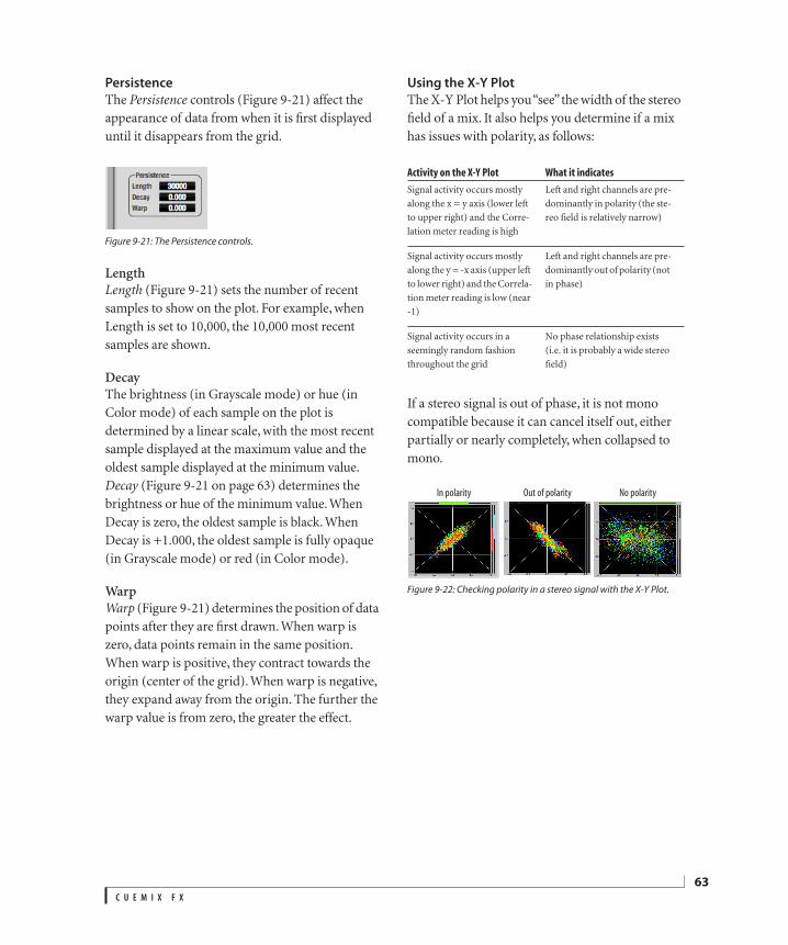
Persistence
The Persistence controls (Figure 9-21) affect the appearance of data from when it is first displayed until it disappears from the grid.
Figure 9-21: The Persistence controls.
LengthLength (Figure 9-21) sets the number of recent samples to show on the plot. For example, when Length is set to 10,000, the 10,000 most recent samples are shown.
DecayThe brightness (in Grayscale mode) or hue (in Color mode) of each sample on the plot is determined by a linear scale, with the most recent sample displayed at the maximum value and the oldest sample displayed at the minimum value. Decay (Figure 9-21 on page 63) determines the brightness or hue of the minimum value. When Decay is zero, the oldest sample is black. When Decay is +1.000, the oldest sample is fully opaque (in Grayscale mode) or red (in Color mode).
WarpWarp (Figure 9-21) determines the position of data points after they are first drawn. When warp is zero, data points remain in the same position. When warp is positive, they contract towards the origin (center of the grid). When warp is negative, they expand away from the origin. The further the warp value is from zero, the greater the effect.
Using the X-Y Plot
The X-Y Plot helps you “see” the width of the stereo field of a mix. It also helps you determine if a mix has issues with polarity, as follows:
If a stereo signal is out of phase, it is not mono compatible because it can cancel itself out, either partially or nearly completely, when collapsed to mono.
Figure 9-22: Checking polarity in a stereo signal with the X-Y Plot.
Activity on the X-Y Plot What it indicates
Signal activity occurs mostly along the x = y axis (lower left to upper right) and the Corre-lation meter reading is high
Left and right channels are pre-dominantly in polarity (the ste-reo field is relatively narrow)
Signal activity occurs mostly along the y = -x axis (upper left to lower right) and the Correla-tion meter reading is low (near -1)
Left and right channels are pre-dominantly out of polarity (not in phase)
Signal activity occurs in a seemingly random fashion throughout the grid
No phase relationship exists (i.e. it is probably a wide stereo field)
In polarity Out of polarity No polarity
C U E M I X F X
63
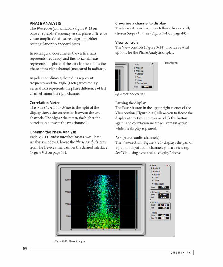
64
PHASE ANALYSISThe Phase Analysis window (Figure 9-23 on page 64) graphs frequency versus phase difference versus amplitude of a stereo signal on either rectangular or polar coordinates.
In rectangular coordinates, the vertical axis represents frequency, and the horizontal axis represents the phase of the left channel minus the phase of the right channel (measured in radians).
In polar coordinates, the radius represents frequency and the angle (theta) from the +y vertical axis represents the phase difference of left channel minus the right channel.
Correlation Meter
The blue Correlation Meter to the right of the display shows the correlation between the two channels. The higher the meter, the higher the correlation between the two channels.
Opening the Phase Analysis
Each MOTU audio interface has its own Phase Analysis window. Choose the Phase Analysis item from the Devices menu under the desired interface (Figure 9-5 on page 53).
Choosing a channel to display
The Phase Analysis window follows the currently chosen Scope channels (Figure 9-1 on page 48).
View controls
The View controls (Figure 9-24) provide several options for the Phase Analysis display.
Figure 9-24: View controls
Pausing the displayThe Pause button in the upper right corner of the View section (Figure 9-24) allows you to freeze the display at any time. To resume, click the button again. The correlation meter will remain active while the display is paused.
A/B (stereo audio channels)The View section (Figure 9-24) displays the pair of input or output audio channels you are viewing. See “Choosing a channel to display” above.
Figure 9-23: Phase Analysis
Pause button
C U E M I X F X
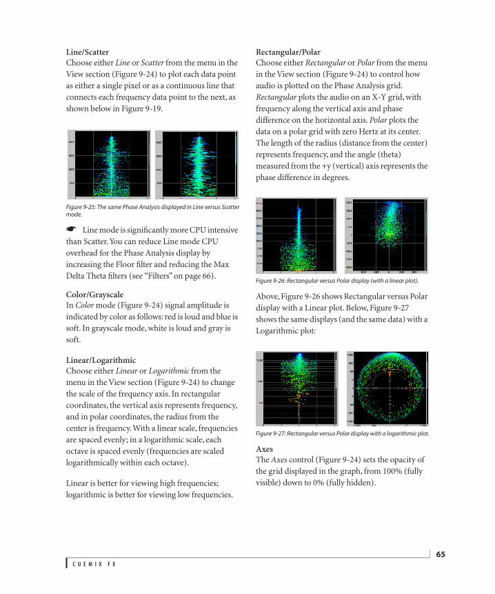
Line/ScatterChoose either Line or Scatter from the menu in the View section (Figure 9-24) to plot each data point as either a single pixel or as a continuous line that connects each frequency data point to the next, as shown below in Figure 9-19.
Figure 9-25: The same Phase Analysis displayed in Line versus Scattermode.
Line mode is significantly more CPU intensive than Scatter. You can reduce Line mode CPU overhead for the Phase Analysis display by increasing the Floor filter and reducing the Max Delta Theta filters (see “Filters” on page 66).
Color/GrayscaleIn Color mode (Figure 9-24) signal amplitude is indicated by color as follows: red is loud and blue is soft. In grayscale mode, white is loud and gray is soft.
Linear/LogarithmicChoose either Linear or Logarithmic from the menu in the View section (Figure 9-24) to change the scale of the frequency axis. In rectangular coordinates, the vertical axis represents frequency, and in polar coordinates, the radius from the center is frequency. With a linear scale, frequencies are spaced evenly; in a logarithmic scale, each octave is spaced evenly (frequencies are scaled logarithmically within each octave).
Linear is better for viewing high frequencies; logarithmic is better for viewing low frequencies.
Rectangular/PolarChoose either Rectangular or Polar from the menu in the View section (Figure 9-24) to control how audio is plotted on the Phase Analysis grid. Rectangular plots the audio on an X-Y grid, with frequency along the vertical axis and phase difference on the horizontal axis. Polar plots the data on a polar grid with zero Hertz at its center. The length of the radius (distance from the center) represents frequency, and the angle (theta) measured from the +y (vertical) axis represents the phase difference in degrees.
Figure 9-26: Rectangular versus Polar display (with a linear plot).
Above, Figure 9-26 shows Rectangular versus Polar display with a Linear plot. Below, Figure 9-27 shows the same displays (and the same data) with a Logarithmic plot:
Figure 9-27: Rectangular versus Polar display with a logarithmic plot.
AxesThe Axes control (Figure 9-24) sets the opacity of the grid displayed in the graph, from 100% (fully visible) down to 0% (fully hidden).
C U E M I X F X
65
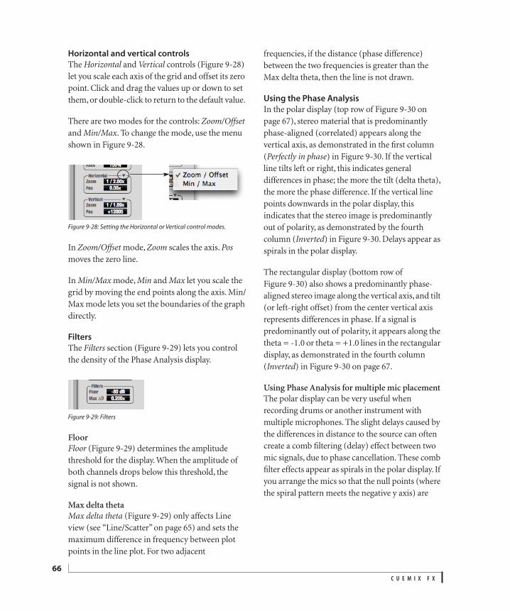
66
Horizontal and vertical controls
The Horizontal and Vertical controls (Figure 9-28) let you scale each axis of the grid and offset its zero point. Click and drag the values up or down to set them, or double-click to return to the default value.
There are two modes for the controls: Zoom/Offset and Min/Max. To change the mode, use the menu shown in Figure 9-28.
Figure 9-28: Setting the Horizontal or Vertical control modes.
In Zoom/Offset mode, Zoom scales the axis. Pos moves the zero line.
In Min/Max mode, Min and Max let you scale the grid by moving the end points along the axis. Min/Max mode lets you set the boundaries of the graph directly.
Filters
The Filters section (Figure 9-29) lets you control the density of the Phase Analysis display.
Figure 9-29: Filters
FloorFloor (Figure 9-29) determines the amplitude threshold for the display. When the amplitude of both channels drops below this threshold, the signal is not shown.
Max delta thetaMax delta theta (Figure 9-29) only affects Line view (see “Line/Scatter” on page 65) and sets the maximum difference in frequency between plot points in the line plot. For two adjacent
frequencies, if the distance (phase difference) between the two frequencies is greater than the Max delta theta, then the line is not drawn.
Using the Phase Analysis
In the polar display (top row of Figure 9-30 on page 67), stereo material that is predominantly phase-aligned (correlated) appears along the vertical axis, as demonstrated in the first column (Perfectly in phase) in Figure 9-30. If the vertical line tilts left or right, this indicates general differences in phase; the more the tilt (delta theta), the more the phase difference. If the vertical line points downwards in the polar display, this indicates that the stereo image is predominantly out of polarity, as demonstrated by the fourth column (Inverted) in Figure 9-30. Delays appear as spirals in the polar display.
The rectangular display (bottom row of Figure 9-30) also shows a predominantly phase-aligned stereo image along the vertical axis, and tilt (or left-right offset) from the center vertical axis represents differences in phase. If a signal is predominantly out of polarity, it appears along the theta = -1.0 or theta = +1.0 lines in the rectangular display, as demonstrated in the fourth column (Inverted) in Figure 9-30 on page 67.
Using Phase Analysis for multiple mic placementThe polar display can be very useful when recording drums or another instrument with multiple microphones. The slight delays caused by the differences in distance to the source can often create a comb filtering (delay) effect between two mic signals, due to phase cancellation. These comb filter effects appear as spirals in the polar display. If you arrange the mics so that the null points (where the spiral pattern meets the negative y axis) are
C U E M I X F X
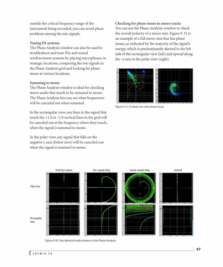
outside the critical frequency range of the instrument being recorded, you can avoid phase problems among the mic signals.
Tuning PA systemsThe Phase Analysis window can also be used to troubleshoot and tune PAs and sound reinforcement systems by placing microphones in strategic locations, comparing the two signals in the Phase Analysis grid and looking for phase issues at various locations.
Summing to monoThe Phase Analysis window is ideal for checking stereo audio that needs to be summed to mono. The Phase Analysis lets you see what frequencies will be canceled out when summed.
In the rectangular view, any lines in the signal that touch the +1.0 or -1.0 vertical lines in the grid will be canceled out at the frequency where they touch, when the signal is summed to mono.
In the polar view, any signal that falls on the negative y axis (below zero) will be canceled out when the signal is summed to mono.
Checking for phase issues in stereo tracksYou can use the Phase Analysis window to check the overall polarity of a stereo mix. Figure 9-31 is an example of a full stereo mix that has phase issues, as indicated by the majority of the signal’s energy, which is predominantly skewed to the left side of the rectangular view (left) and spread along the -y axis in the polar view (right).
Figure 9-31: A stereo mix with phase issues.
Figure 9-30: Two identical audio streams in the Phase Analysis.
Perfectly in phase One-sample delay Twenty-sample delay
Polar view
Rectangular
view
Inverted
C U E M I X F X
67
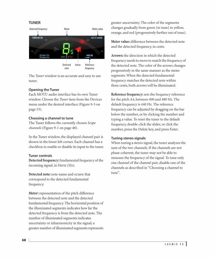
68
TUNER
The Tuner window is an accurate and easy to use tuner.
Opening the Tuner
Each MOTU audio interface has its own Tuner window. Choose the Tuner item from the Devices menu under the desired interface (Figure 9-5 on page 53).
Choosing a channel to tune
The Tuner follows the currently chosen Scope channels (Figure 9-1 on page 48).
In the Tuner window, the displayed channel pair is shown in the lower left corner. Each channel has a checkbox to enable or disable its input to the tuner.
Tuner controls
Detected frequency: fundamental frequency of the incoming signal, in Hertz (Hz).
Detected note: note name and octave that correspond to the detected fundamental frequency.
Meter: representation of the pitch difference between the detected note and the detected fundamental frequency. The horizontal position of the illuminated segments indicates how far the detected frequency is from the detected note. The number of illuminated segments indicates uncertainty or inharmonicity in the signal; a greater number of illuminated segments represents
greater uncertainty. The color of the segments changes gradually from green (in tune) to yellow, orange, and red (progressively further out of tune).
Meter value: difference between the detected note and the detected frequency, in cents.
Arrows: the direction in which the detected frequency needs to move to match the frequency of the detected note. The color of the arrows changes progressively in the same manner as the meter segments. When the detected fundamental frequency matches the detected note within three cents, both arrows will be illuminated.
Reference frequency: sets the frequency reference for the pitch A4, between 400 and 480 Hz. The default frequency is 440 Hz. The reference frequency can be adjusted by dragging on the bar below the number, or by clicking the number and typing a value. To reset the tuner to the default frequency, double-click the slider, or click the number, press the Delete key, and press Enter.
Tuning stereo signals
When tuning a stereo signal, the tuner analyzes the sum of the two channels. If the channels are not phase coherent, the tuner may not be able to measure the frequency of the signal. To tune only one channel of the channel pair, disable one of the channels as described in “Choosing a channel to tune”.
Meter valueMeter Detected frequency
Reference
frequency
ArrowDetected
note
C U E M I X F X
CONFIGURATIONS MENUA configuration is just like a hardware preset (a “snapshot” of all settings in CueMix FX and therefore the 8pre USB hardware itself), except that it can be created and managed using the CueMix FX software on your computer, completely independently of the 8pre USB hardware. The commands in the Configurations menu let you create, save, load, import, export and otherwise manage as many configurations as you wish.
Here is a summary of Configurations menu operations:
Modifying a configuration
The name of the current configuration is displayed in the CueMix FX window title bar. If you make any changes to the settings in CueMix FX, an asterisk appears in front of the name to remind you that the current state of CueMix FX doesn’t match the saved configuration. If you wish to update the saved configuration with the new changes, use the Save command. To save the current state of CueMix FX to another configuration, use Save To. To save as a new, separate configuration, use Create New.
Saving a CueMix FX configuration as a hardware preset
To save a CueMix FX configuration as a hardware preset:
1 Choose the configuration from the Configurations menu to make it the current active configuration.
2 Choose File menu> Save Hardware Preset.
3 Type in a name, choose a preset slot and click OK.
Saving a hardware preset as a CueMix FX configuration
To save a hardware preset as a CueMix FX configu-ration:
1 Choose File menu> Load Hardware Preset to make it the current active preset.
2 Choose Configuration menu> Create New (or Save To) to save it as a configuration.
TALKBACK MENUChoose the commands in the Talkback menu to engage or disengage Talkback or Listenback. See “Talkback and listenback” on page 50.
PHONES MENUThe Phones menu allows you to choose what you will hear on the headphone output, just like the Phones setting in MOTU Audio Console. However, this menu provides one extra option that is exclusive to CueMix FX: Follow Active Mix. This menu item, when checked, causes the headphone output to mirror the output of the current mix being viewed in CueMix FX. For example, if you are currently viewing mix bus 3, the headphones will mirror the mix bus 3 output (whatever it is assigned to).
ConfigurationsMenu item What it does
Create New Lets you name and save a new configuration, which appears at the bottom of the Configura-tions menu.
Save Overwrites the current configuration (checked in the list at the bottom of the menu) with the current settings in CueMix FX.
Save To Same as Save above, except that it lets you first choose the configuration you wish to save to (instead of the current one).
Delete Lets you choose a configuration to perma-nently remove from the menu.
Import Loads all configurations from a configuration file on disk.
Export Saves all current configurations as a file on disk.
Configuration list
Choose any configuration to load it. The cur-rent (last loaded or saved) configuration has a check mark next to it.
C U E M I X F X
69

70
CONTROL SURFACES MENUCueMix FX can be controlled from an automated control surface such as the Mackie Control™. Use the commands in the Control Surfaces menu to enable and configure this feature.
Application follows control surface
When checked, the Application follows control surface menu command makes the CueMix FX window scroll to the channel you are currently adjusting with the control surface, if the channel is not visible when you begin adjusting it. The same is true for the bus tabs: if you adjust a control in a bus that is not currently being displayed, CueMix FX will jump to the appropriate tab to display the control you are adjusting.
Share surfaces with other applications
When the Share surfaces with other applications menu command is checked, CueMix FX releases the control surface when you switch to another application. This allows you to control your other software with the control surface. Here’s a simple way to understand this mode: the control surface will always control the front-most application. Just bring the desired application to the front (make it the active application), and your control surface will control it. When you’d like to make changes to CueMix FX from the control surface, just bring CueMix FX to the front (make it the active application).
When this menu item is unchecked, your control surface will affect CueMix FX all the time, even when CueMix FX is not the front-most application. In addition, you will not be able to control other host audio software with the control surface at any time (because CueMix FX retains control over it at all times). This mode is useful when you do not need to use the control surface with any other software.
CueMix Control Surfaces
CueMix FX includes support for the following control surface products:
Mackie Control™
Mackie HUI™
Mackie Baby HUI™
Use the sub-menu commands in the CueMix Control Surfaces menu item to turn on and configure control surface support, as described briefly below.
EnabledCheck this menu item to turn on control surface operation of CueMix FX. Uncheck it to turn off control surface support.
Configure…Choose this menu item to configure your control surface product. Launch the on-line help for specific, detailed instructions on configuring CueMix FX for operation with your control surface product.
C U E M I X F X
Figure 9-32: Refer to the extensive on-line help for details aboutconfiguring CueMix FX for operation with your control surfaceproduct.
CUEMIX IN OPTICAL EXPANDER MODEWhen the 8pre operates as an optical expander (as discussed in “Operating the 8pre USB as a converter” on page 23), CueMix is hard-wired to route each analog input to its corresponding optical output channel (analog in 1 to optical out 1, analog in 2 to optical out 2, and so on).
In addition, when operating the 8pre at a 1x sample rate (either 44.1 or 48 kHz), the analog input signals are duplicated and sent to both optical output banks. This lets you send the analog input signals to two separate optical destinations, if desired.
When operating the 8pre at a 2x sample rate (88.2 or 96 kHz), the two optical output banks work in concert to provide channels 1-4 and 5-8, respectively, for a total of 8 channels of high-resolution.
C U E M I X F X
71

72
C U E M I X F X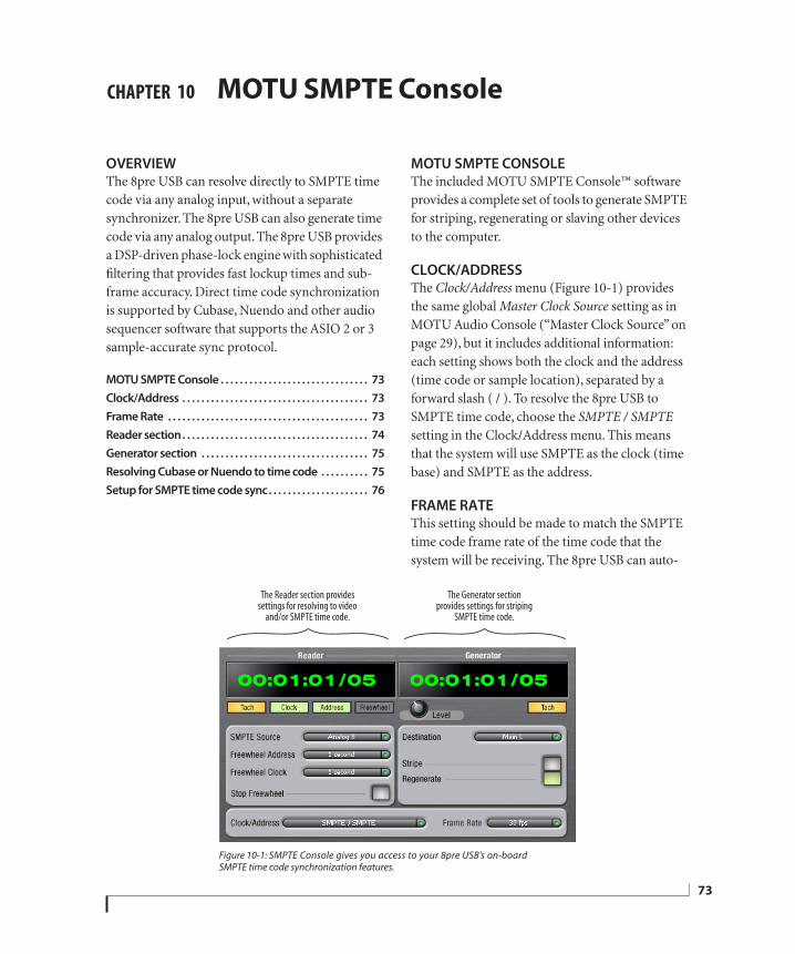
CHAPTER
10 MOTU SMPTE ConsoleOVERVIEWThe 8pre USB can resolve directly to SMPTE time code via any analog input, without a separate synchronizer. The 8pre USB can also generate time code via any analog output. The 8pre USB provides a DSP-driven phase-lock engine with sophisticated filtering that provides fast lockup times and sub-frame accuracy. Direct time code synchronization is supported by Cubase, Nuendo and other audio sequencer software that supports the ASIO 2 or 3 sample-accurate sync protocol.
MOTU SMPTE Console . . . . . . . . . . . . . . . . . . . . . . . . . . . . . . . 73
Clock/Address . . . . . . . . . . . . . . . . . . . . . . . . . . . . . . . . . . . . . . . 73
Frame Rate . . . . . . . . . . . . . . . . . . . . . . . . . . . . . . . . . . . . . . . . . . 73
Reader section. . . . . . . . . . . . . . . . . . . . . . . . . . . . . . . . . . . . . . . 74
Generator section . . . . . . . . . . . . . . . . . . . . . . . . . . . . . . . . . . . 75
Resolving Cubase or Nuendo to time code . . . . . . . . . . 75
Setup for SMPTE time code sync. . . . . . . . . . . . . . . . . . . . . 76
MOTU SMPTE CONSOLEThe included MOTU SMPTE Console™ software provides a complete set of tools to generate SMPTE for striping, regenerating or slaving other devices to the computer.
CLOCK/ADDRESSThe Clock/Address menu (Figure 10-1) provides the same global Master Clock Source setting as in MOTU Audio Console (“Master Clock Source” on page 29), but it includes additional information: each setting shows both the clock and the address (time code or sample location), separated by a forward slash ( / ). To resolve the 8pre USB to SMPTE time code, choose the SMPTE / SMPTE setting in the Clock/Address menu. This means that the system will use SMPTE as the clock (time base) and SMPTE as the address.
FRAME RATEThis setting should be made to match the SMPTE time code frame rate of the time code that the system will be receiving. The 8pre USB can auto-
Figure 10-1: SMPTE Console gives you access to your 8pre USB’s on-boardSMPTE time code synchronization features.
The Reader section provides settings for resolving to video
and/or SMPTE time code.
The Generator section provides settings for striping
SMPTE time code.
73
74
detect and switch to the incoming frame rate, except that it cannot distinguish between 30 fps and 29.97 fps time code, or 23.976 and 24 fps time code. So if you are working with either of these rates, make sure you choose the correct rate from this menu.
READER SECTIONThe Reader section (on the left-hand side of the window in Figure 10-1) provides settings for synchronizing the 8pre USB to SMPTE time code.
Status lights
The four status lights (Tach, Clock, Address and Freewheel) give you feedback as follows:
TachThe Tach light blinks once per second when the 8pre USB has successfully achieved lockup to SMPTE time code and SMPTE frame locations are being read.
ClockThe Clock light glows continuously when the 8pre USB has successfully achieved lockup to an external time base, such as SMPTE time code or the S/PDIF input.
AddressThe Address light glows continuously when the 8pre USB has successfully achieved lockup to SMPTE time code.
FreewheelThe Freewheel light illuminates when the 8pre USB is freewheeling address (time code), clock or both. For details about Freewheeling, see “Freewheel Address” and “Freewheel clock” below.
SMPTE source
Choose the analog input that is connected to the time code source. This is the input that the 8pre USB “listens” to for time code.
Freewheel Address
Freewheeling occurs when there is a glitch or drop-out in the incoming time code for some reason. The 8pre USB can freewheel past the drop-out and then resume lockup again as soon as it receives readable time code. Choose the amount of time you would like the 8pre USB to freewheel before it gives up and stops altogether.
The 8pre USB cannot freewheel address without clock. Therefore, the Freewheel Address setting will always be lower than or equal to the Freewheel Clock setting, and both menus will update as needed, depending on what you choose.
Keep in mind that freewheeling causes the system to keep going for as long as the duration you choose from this menu, even when you stop time code intentionally. Therefore, if you are starting and stopping time code frequently (such as from the transports of a video deck), shorter freewheel times are better. On the other hand, if you are doing a one-pass transfer from tape that has bad time code, longer freewheel times will help you get past the problems in the time code.
The ‘Infinite’ freewheel settingThe Infinite freewheel setting in the Freewheel Address menu causes the 8pre USB to freewheel indefinitely, until it receives readable time code again. To make it stop, click the Stop Freewheeling button.
Freewheel clock
Freewheeling occurs when there is a glitch or drop-out in the incoming SMPTE time code for some reason. The 8pre USB can freewheel past the drop-out and then resume lockup again as soon as it receives a stable, readable clock signal.
M O T U S M P T E C O N S O L E
COMPANY
CONFIDENTIAL
MOTU
The 8pre USB cannot freewheel address without clock. Therefore, the Freewheel Address setting will always be lower than or equal to the Freewheel Clock setting, and both menus will update as needed, depending on what you choose.
The ‘Infinite’ freewheel settingThe Infinite freewheel setting in the Freewheel Clock menu causes the 8pre USB to freewheel indefinitely, until it receives readable time code again. To make it stop, click the Stop Freewheeling button.
Stop Freewheeling
The Stop Freewheeling button stops the system if it is currently freewheeling.
GENERATOR SECTIONThe Generator section (on the right-hand side of the window in Figure 10-1) provides settings for generating SMPTE time code.
Level
Turn the level knob to adjust the volume of the SMPTE time code being generated by the 8pre USB. The level knob disappears when the Destination is set to None.
Tach light
The Tach light blinks once per second when the 8pre USB is generating SMPTE time code.
Destination
In the Destination menu, choose either SMPTE (to generate time code) or None (to turn it off).
Stripe
Click this button to start or stop time code. To set the start time, click directly on the SMPTE time code display in the Generator section and type in the desired start time. Or drag vertically on the numbers.
Figure 10-2: Setting the time code start time.
Regenerate
This option, when enabled, causes the generator to generate time code whenever the 8pre USB is receiving SMPTE time code.
RESOLVING CUBASE OR NUENDO TO TIME CODETo resolve your 8pre USB and Cubase or Nuendo directly to SMPTE time code with no additional synchronization devices, use the setup shown in “Setup for SMPTE time code sync” on page 76. Make sure the Master Clock Source setting in the MOTU Audio Console window is set to SMPTE. Also, make sure that you’ve connected an LTC input signal to a 8pre USB analog input, and that you’ve specified that input in the SMPTE Source menu in SMPTE Console.
Click here to edit the start time, or drag vertically on the numbers.
M O T U S M P T E C O N S O L E
75
76
SETUP FOR SMPTE TIME CODE SYNCThe 8pre USB system can resolve directly to SMPTE time code. It can also generate time code, under its own clock or while slaving to time code. Therefore, the 8pre USB can act both as an audio interface and as a SMPTE time code synchronizer to which you can slave other devices. You can use the 8pre USB to slave your audio software to SMPTE as well, via sample-accurate sync (if your host software supports it).
Figure 10-3: Connections for synchronizing the8pre USB directly to SMPTE time code.
Choose SMPTE as the clock source in MOTU Audio Setup. This setting can also be made in the MOTU SMPTE Console (shown below).SMPTE
time code source
audio cable bearing LTC(Longitudinal Time Code)
USB cable
Launch the MOTU SMPTE Console and specify the SMPTE Source, which is the interface receiving the SMPTE time code. Also, confirm that the Clock Source/Address is SMPTE/SMPTE.
Windows computer running Cubase or other sample-accurate ASIO software
In Cubase, go to the Synchronization window and choose ASIO Audio Device as the Timecode Base.
8pre USB interface
Analog (line) input
Use this setup if you have:
A SMPTE time code source, such as a multitrack tape deck.
An 8pre USB by itself, OR with another slaved device (such as a digital mixer).
Host software that supports sample-accurate sync.
This setup provides:
Continuous sync to SMPTE time code.
Sub-frame timing accuracy.
Transport control from the SMPTE time code source.
M O T U S M P T E C O N S O L E
CHAPTER
11 TroubleshootingWhy does the start sound not play through the 8pre USB? The 8pre USB will only playback audio at a sampling rate of 44.1, 48, 88.2 or 96 kHz.
The computer freezes when it starts upIf the computer is unable to boot up, it may be a conflict with the WDM Driver. As soon as the computer boots up, Windows will try and initialize the WDM Driver. If this fails, your computer will hang. To determine if the WDM Driver is the problem, boot up in Safe Mode or remove the MOTU Audio software with the Add/Remove Programs Control Panel then restart. If that fixes the problem, visit motu.com to download the very latest drivers and then install them.
‘New hardware detected’ windowIf you connect your 8pre USB before running the MOTU Audio installer, Windows will prompt you that new hardware has been detected. Cancel this, and run the 8pre USB Software Installer, rather than allowing Windows to locate the drivers.
Clicks and pops under word clock syncMany problems result from incorrect word clocking. It is essential that all digital devices in the system be word locked. Consult “Choosing a clock source for optical connections” on page 27 for detailed information on how to sync with other gear that is connected optically. Whenever there is any weird noise or distortion, suspect incorrect digital clocking.
Clicks and pops due to hard drive problemsIf you have checked your clock settings and you are still getting clicks and pops in your audio, you may have a drive related problem. Set your Master Clock Source to Internal and try recording just using the analog inputs and outputs of the 8pre
USB. If you encounter the same artifacts you may want try using another drive in your computer. Clicks and pops can also occur when the drive is severely fragmented or there are other drive-related issues. If you are using a USB drive on the same bus as the 8pre USB, it could be that the USB bus is overloaded (too many devices on the same bus). Try removing all devices except the 8pre USB.
Connecting or powering gear during operationIt is not recommended that you connect/disconnect, or power on/off devices connected to the 8pre USB while recording or playing back audio. Doing so may cause a brief glitch in the audio.
8pre USB inputs and outputs are not available in host audio softwareMake sure that the inputs and outputs are enabled. See “Working with Track16 inputs and outputs” on page 53.
No optical inputs or outputs are available in host audio applicationCheck to make sure you have the desired optical inputs and/or outputs enabled in the MOTU Audio Console.
Monitoring - How to monitor inputs?Please refer to the documentation for the audio application that you are using. If your application does not support input monitoring, you will need to use the 8pre USB’s hardware-based CueMix DSP monitoring feature. Please see chapter 8, “Reducing Monitoring Latency” (page 41).
Controlling monitoring latencySee chapter 8, “Reducing Monitoring Latency” (page 41).
77
78
CUSTOMER SUPPORTWe are happy to provide customer support to our registered users. If you haven’t already done so, please take a moment to register on line at motu.com, or fill out and mail the registration card included with your 8pre USB. Doing so entitles you to technical support and notices about new products and software updates.
REPLACING DISKSIf your installer disc becomes damaged, our Customer Support Department will be glad to replace it. You can request a replacement disc by calling our business office at (617) 576-2760 and asking for the customer service department. In the meantime, you can download the latest drivers from www.motu.com.
TECHNICAL SUPPORTIf you are unable, with your dealer’s help, to solve problems you encounter with the 8pre USB system, you may contact our technical support department in one of the following ways:
Tech support hotline: (617) 576-3066 (Monday through Friday, 9 a.m. to 6 p.m. EST)
Online support: www.motu.com/support
Please provide the following information to help us solve your problem as quickly as possible:
The serial number of the 8pre USB system. This is printed on a label placed on the bottom of the 8pre USB rack unit. You must be able to supply this number to receive technical support.
A brief explanation of the problem, including the exact sequence of actions which cause it, and the contents of any error messages which appear on the screen.
The pages in the manual which refer to the parts of the 8pre USB or AudioDesk with which you are having trouble.
The version of your computer’s operating system.
We’re not able to solve every problem immediately, but a quick call to us may yield a suggestion for a problem which you might otherwise spend hours trying to track down.
If you have features or ideas you would like to see implemented, we’d like to hear from you. Please write to the 8pre USB Development Team, MOTU Inc., 1280 Massachusetts Avenue, Cambridge, MA 02138 or send an email to:[email protected].
T R O U B L E S H O O T I N G
02R mixer 2424-bit
optical 12recording 13
48V phantom power 7, 498pre
installing 19rear panel overview 11summary of features 11
8pre USBSMPTE setting 30tab 27
AAbleton Live 33, 36Activity LEDs 13ADAT optical 12, 24, 30
clock source setting 29connecting 20
Analog activity lights 13Application follows control surface 70ASIO 14, 18
SONAR 36Audio
Setup software 17Avid Pro Tools 35
BBalance 50Buffer Size 28, 43
CCakeWalk 14Cakewalk SONAR 36Clear Peaks 52Clock LEDs 13Clock Source 29
SMPTE setting 30Clock source 9
setting in converter mode 31Cockos Reaper 36Combo jacks 8Condenser mic input 7Configurations menu 69Control Surfaces menu 70Controller
connecting 21Converter mode
clock setting 31setup/example 23
Copy/Paste 52Cubase 14, 27, 33
clock source 34enabling the 828 ASIO driver 37Mac OS X 35Main Out Assign 34optical I/O 34phones 34sample rate 34
CueMix Console 44, 47Listenback explained 50talkback settings 50
CueMix DSP 44CueMix FX 47-71
Application follows control surface 70
Configurations menu 69control surfaces 70Control Surfaces menu 70CueMix control surfaces 70Devices menu 52Edit menu 52File menu 52installation 47listenback settings 51Phones menu 69Share surfaces with other applica-
tions 70Talkback menu 69talkback settings 51
Customer support 78
DDelay (latency) 41Devices menu 52Digital converter (see Optical converter)Disc, replacing 78Drivers
ASIO 18installing USB drivers 17Legacy MME (Wave) 9, 18
FFeedback loops 39FFT Analysis 53File menu
Clear Peaks 52Copy/Paste 52Hardware Follows CueMix Stereo
Settings 52Load Hardware Preset 52Mix1 return includes computer out-
put 52, 53Peak/Hold Time 52Save Hardware Preset 52undo/redo 52
Follow Active Mix 69Freewheel
address 74clock 74infinite 74, 75
Front panelmeters 7VOLUME rotary encoder settings 31
GGarageBand
clock source 34Main Out Assign 34optical I/O 34phones 34sample rate 34
General tab 27Guitar
connecting 22
HHardware Follows CueMix Stereo Settings
52Headphone jack 7Headphones
connecting 22controlling output 30jack 13volume 31
Host audio software3rd party software sync 39Main Out Assign 34
HUI 70
IInfinite freewheel 74, 75Inputs
name 49pan 49trim 49
Installationhardware 19software 17
Installer disc, replacing 78Internal (sync setting) 29Invert phase 49
KKeyboard controller
connecting 21
LLatency 28, 29, 34, 41, 43, 44LEDs 7Lightpipe 24, 30
2x mode 31Listenback
explained 50Live 36Load Hardware Preset 52Logic Audio 14Logic Pro/Express
clock source 34Main Out Assign 34optical I/O 34phones 34sample rate 34
MMac OS X 33
input and output names 39Mackie Control 70Main Out Assign
host audio software 34Main outs
jacks 8making connections to 20volume 31volume control 7
Main volume 7Master Clock Source 29Meters 7Mic inputs 8, 19
I N D E X
79
80
connecting 22phantom power 7
MIDIdevices, connecting 21jacks 8Windows driver installation 18
Mix 1 Return 1-2 38Mix1 return includes computer output 52,
53MME driver 9, 18Monitoring 42
thru main outs 20Mono button 49MOTU
ASIO driver 18MOTU Audio Console 27
launching 9MOTU Audio Setup 17MOTU CueMix Console 44, 47MOTU SMPTE Setup 18, 73
NNuendo 14, 27, 33
clock source 34Mac OS X 35Main Out Assign 34optical I/O 34phones 34sample rate 34
OOptical
2x mode 31connectors 20enabling 30LEDs 13overview 12sync 24
Optical converter mode 31setup/example 23
Optimization 44OS X audio software
clock source 34optical I/O 34phones 34sample rate 34
PP LED (pad) 49Packing list 15Pad 49Paste 52Patch thru
latency 29, 44Peak/Hold Time 52Performance 44Phantom power 7, 19, 49Phase 49Phones 7
menu 69Phones 1-2 output 39Phones Assign
3rd party software 34Phones Assignment 30
Pro Tools 33, 35Propellerhead Reason 36Propellerhead Record 36
RReaper 33, 36Reason 33, 36Record 33, 36Regenerate 75Registration 15Return Assign 38
SS/MUX 31Sample rate 9, 28Samplers
connecting 22Samples per buffer 9, 28, 34, 43Save Hardware Preset 52Scope channel selection 51, 53Scope channels 53, 55, 62, 64, 68Share surfaces with other applications 70Show EQ controls 53Show Spectrogram 54SMPTE
overview 73Setup application 73source setting 74sync 73
SMPTE sync 76Software
installation 17SONAR 33, 36Sony
Sound Forge 38Sound Forge 38Sound module
connecting 21Soundtrack Pro
clock source 34Main Out Assign 34optical I/O 34phones 34sample rate 34
Stereo button 49Stop Freewheeling 74Stripe button 75Studio setup (example) 22Synchronization
host software 39Synths
connecting 22System requirements
minimum 15recommended computer 15
TTACH
light (SMPTE Setup Console) 74Talkback
explained 50menu 51, 69settings 51
Technical support 78
Time code sync 73, 76Trim 49Troubleshooting
feedback loop 39TRS/XLR jacks 8Tuner 68Type I, II optical mode 31
UUndo/Redo 52USB
connecting 19connector 8installing drivers 17
Use Stereo Pairs for Windows Audio 9, 30Use WaveRT for Windows Audio 9, 30
VV LED (phantom power) 49Video sync 73Volume
headphone 13VOLUME knob 31
WWave driver 9, 18WDM 18Width 50Windows Driver Model (see WDM)
XXLR/TRS jacks 8
I N D E X
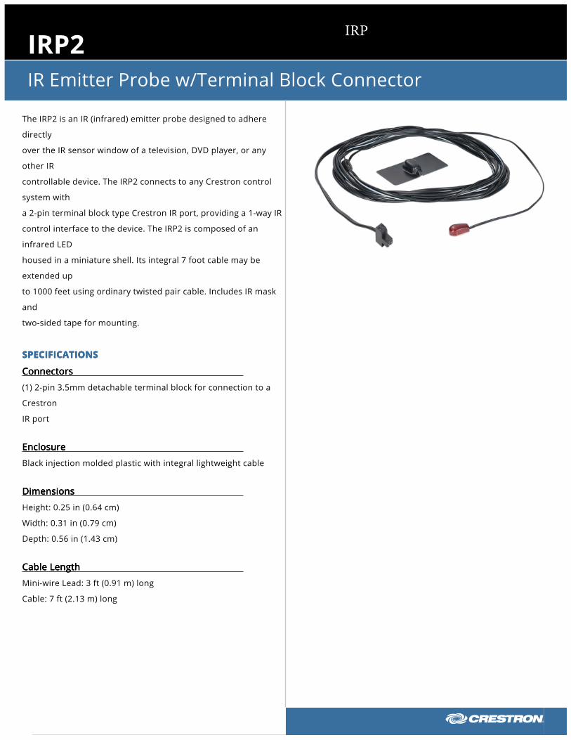
IRP2IR Emitter Probe w/Terminal Block Connector
The IRP2 is an IR (infrared) emitter probe designed to adhere
directly
over the IR sensor window of a television, DVD player, or any
other IR
controllable device. The IRP2 connects to any Crestron control
system with
a 2-pin terminal block type Crestron IR port, providing a 1-way IR
control interface to the device. The IRP2 is composed of an
infrared LED
housed in a miniature shell. Its integral 7 foot cable may be
extended up
to 1000 feet using ordinary twisted pair cable. Includes IR mask
and
two-sided tape for mounting.
SPECIFICATIONSSPECIFICATIONSSPECIFICATIONSSPECIFICATIONS
ConnectorsConnectorsConnectorsConnectors
(1) 2-pin 3.5mm detachable terminal block for connection to a
Crestron
IR port
EnclosureEnclosureEnclosureEnclosure
Black injection molded plastic with integral lightweight cable
DimensionsDimensionsDimensionsDimensions
Height: 0.25 in (0.64 cm)
Width: 0.31 in (0.79 cm)
Depth: 0.56 in (1.43 cm)
Cable LengthCable LengthCable LengthCable Length
Mini-wire Lead: 3 ft (0.91 m) long
Cable: 7 ft (2.13 m) long
IRP
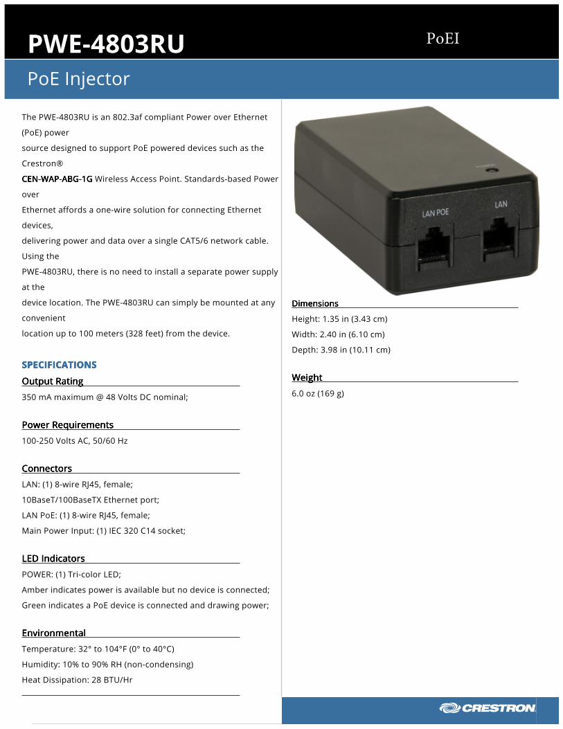
PWE-4803RUPoE Injector
The PWE-4803RU is an 802.3af compliant Power over Ethernet
(PoE) power
source designed to support PoE powered devices such as the
Crestron®
CEN-WAP-ABG-1GCEN-WAP-ABG-1GCEN-WAP-ABG-1GCEN-WAP-ABG-1G Wireless Access Point. Standards-based Power
over
Ethernet affords a one-wire solution for connecting Ethernet
devices,
delivering power and data over a single CAT5/6 network cable.
Using the
PWE-4803RU, there is no need to install a separate power supply
at the
device location. The PWE-4803RU can simply be mounted at any
convenient
location up to 100 meters (328 feet) from the device.
SPECIFICATIONSSPECIFICATIONSSPECIFICATIONSSPECIFICATIONS
Output RatingOutput RatingOutput RatingOutput Rating
350 mA maximum @ 48 Volts DC nominal;
Power RequirementsPower RequirementsPower RequirementsPower Requirements
100-250 Volts AC, 50/60 Hz
ConnectorsConnectorsConnectorsConnectors
LAN: (1) 8-wire RJ45, female;
10BaseT/100BaseTX Ethernet port;
LAN PoE: (1) 8-wire RJ45, female;
Main Power Input: (1) IEC 320 C14 socket;
LED IndicatorsLED IndicatorsLED IndicatorsLED Indicators
POWER: (1) Tri-color LED;
Amber indicates power is available but no device is connected;
Green indicates a PoE device is connected and drawing power;
EnvironmentalEnvironmentalEnvironmentalEnvironmental
Temperature: 32° to 104°F (0° to 40°C)
Humidity: 10% to 90% RH (non-condensing)
Heat Dissipation: 28 BTU/Hr
DimensionsDimensionsDimensionsDimensions
Height: 1.35 in (3.43 cm)
Width: 2.40 in (6.10 cm)
Depth: 3.98 in (10.11 cm)
WeightWeightWeightWeight
6.0 oz (169 g)
PoEI
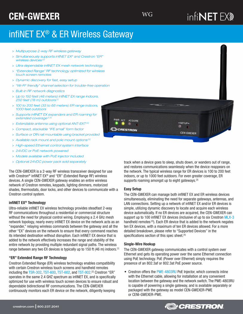
CEN-GWEXER
infiNET EX® & ER Wireless Gateway
crestron.com | 800.237.2041
> Multipurpose 2-way RF wireless gateway
> Simultaneously supports infiNET EX® and Crestron “ER”wireless devices [2]
> Ultra dependable infiNET EX mesh network technology
> “Extended Range” RF technology optimized for wirelesstouch screen remotes
> Dynamic discovery for fast, easy setup
> “Wi-Fi® friendly” channel selection for trouble-free operation
> Built-in RF network diagnostics
> Up to 150 feet (46 meters) infiNET EX range indoors,250 feet (76 m) outdoors [1]
> 100 to 200 feet (33 to 66 meters) ER range indoors,1000 feet outdoors
> Supports infiNET EX expanders and ER roaming forextended coverage [1,3]
> Extendable antenna using optional ANT-EXT [5]
> Compact, stackable “IFE small” form factor
> Surface or DIN rail mountable using bracket provided
> Available rack mount and pole mount options [5]
> High-speed Ethernet control system interface
> 24VDC or PoE network powered
> Models available with PoE injector included
> Optional 24VDC power pack sold separately
The CEN-GWEXER is a 2-way RF wireless transceiver designed for use with Crestron® infiNET EX® and “ER” (Extended Range RF) wireless devices. A single CEN-GWEXER gateway enables an entire wireless network of Crestron remotes, keypads, lighting dimmers, motorized shades, thermostats, door locks, and other devices to communicate with a Crestron control system.
infiNET EX® TechnologyUltra-reliable infiNET EX wireless technology provides steadfast 2-way RF communications throughout a residential or commercial structure without the need for physical control wiring. Employing a 2.4 GHz mesh network topology, nearly every infiNET EX device on the network acts as an “expander,” relaying wireless commands between the gateway and all the other “EX” devices on the network to ensure that every command reaches its intended destination without disruption. Each infiNET EX device that is added to the network effectively increases the range and stability of the entire network by providing multiple redundant signal paths. The wireless range between any two EX devices is typically up to 150 ft (46 m) indoors.[1]
“ER” Extended Range RF TechnologyCrestron Extended Range (ER) wireless technology enables compatibility with certain Crestron wireless touch screens and handheld remotes including the TSR-302, TST-600, TST-602, and TST-902.[2] Crestron “ER” operates in the same 2.4 GHZ spectrum as infiNET EX, and is specifically optimized for use with wireless touch screen devices to ensure robust and dependable bidirectional RF communications. The CEN-GWEXER continuously monitors each ER device on the network, diligently keeping
track when a device goes to sleep, shuts down, or wanders out of range, and restores communications seamlessly when the device reappears on the network. The typical wireless range for ER devices is 100 to 200 feet indoors, or up to 1000 feet outdoors. For even greater coverage, ER supports roaming amongst up to eight gateways.[3]
Easy SetupThe CEN-GWEXER can manage both infiNET EX and ER wireless devices simultaneously, eliminating the need for separate gateways, antennas, and LAN connections. Setting up a network of infiNET EX and/or ER devices is simple, utilizing dynamic discovery to locate and acquire each wireless device automatically. If no ER devices are acquired, the CEN-GWEXER can support up to 100 infiNET EX devices (inclusive of up to six Crestron MLX-3 handheld remotes [2]). Each ER device that is added to the network negates ten EX devices, with a maximum of ten ER devices allowed. For a more detailed breakdown, please refer to “Supported Devices” in the specifications section of this spec sheet.[4]
Single-Wire HookupThe CEN-GWEXER gateway communicates with a control system over Ethernet and gets its operating power over the same Ethernet connection using PoE technology. PoE (Power over Ethernet) simply requires the presence of an 802.3af or 802.3at PoE power source.
• Crestron offers the PWE-4803RU PoE Injector, which connects inlinewith the Ethernet cable, allowing for installation at any convenientlocation between the gateway and the network switch. The PWE-4803RUis capable of powering a single gateway, and is available separately orpackaged with the gateway as model CEN-GWEXER-PWEor CENI-GWEXER-PWE.
WG
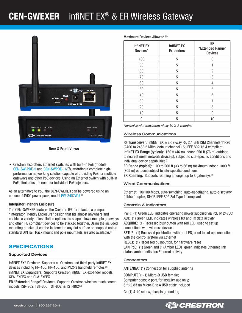
CEN-GWEXER infiNET EX® & ER Wireless Gateway
crestron.com | 800.237.2041
• Crestron also offers Ethernet switches with built-in PoE (modelsCEN-SW-POE-5 and CEN-SWPOE-16 [5]), affording a complete high-performance networking solution capable of providing PoE for multiplegateways and other PoE devices. Using an Ethernet switch with built-inPoE eliminates the need for individual PoE Injectors.
As an alternative to PoE, the CEN-GWEXER can be powered using an optional 24VDC power pack, model PW-2407WU.[5]
Integrator Friendly EnclosureThe CEN-GWEXER features the Crestron IFE form factor, a compact “Integrator Friendly Enclosure” design that fits almost anywhere and enables a variety of installation options. Its shape allows multiple gateways and other IFE compliant devices to be stacked together. Using the included mounting bracket, it can be fastened to any flat surface or snapped onto a standard DIN rail. Rack mount and pole mount kits are also available.[5]
SPECIFICATIONS
Supported Devices
infiNET EX® Devices: Supports all Crestron and third-party infiNET EX devices including HR-100, HR-150, and MLX-3 handheld remotes [2]
infiNET EX Expanders: Supports Crestron infiNET EX expander models CLW-EXPEX and GLA-EXPEXER “Extended Range” Devices: Supports Crestron wireless touch screen models TSR-302, TST-600, TST-602, & TST-902 [2]
Maximum Devices Allowed [4]:
infiNET EX Devices*
infiNET EX Expanders
ER “Extended Range”
Devices
100 5 0
90 5 1
80 5 2
70 5 3
60 5 4
50 5 5
40 5 6
30 5 7
20 5 8
10 5 9
0 5 10
*Inclusive of a maximum of six MLX-3 remotes
Wireless Communications
RF Transceiver: infiNET EX & ER 2-way RF, 2.4 GHz ISM Channels 11-26 (2400 to 2483.5 MHz), default channel 15; IEEE 802.15.4 compliantinfiNET EX Range (typical): 150 ft (46 m) indoor, 250 ft (76 m) outdoor, to nearest mesh network device(s); subject to site-specific conditions and individual device capabilities [1]
ER Range (typical): 100 to 200 ft (33 to 66 m) maximum indoor, 1000 ft (305 m) outdoor, subject to site-specific conditionsER Roaming: Supports roaming amongst up to 8 gateways [3]
Wired Communications
Ethernet: 10/100 Mbps, auto-switching, auto-negotiating, auto-discovery, full/half duplex, DHCP, IEEE 802.3at Type 1 compliant
Controls & Indicators
PWR: (1) Green LED, indicates operating power supplied via PoE or 24VDCACT: (1) Green LED, indicates wireless RX and TX data activity ACQUIRE: (1) Recessed pushbutton with red LED, used to set up connections with wireless devicesSETUP: (1) Recessed pushbutton with red LED, used to set up connection with the control system via Ethernet RESET: (1) Recessed pushbutton, for hardware resetLAN PoE: (1) Green and (1) Amber LEDs, green indicates Ethernet link status, amber indicates Ethernet activity
Connectors
ANTENNA: (1) Connection for supplied antenna
COMPUTER: (1) Micro-B USB female;Computer console port, for installer use only;6 ft (2.83 m) Micro-B to A USB cable included
G: (1) 4-40 screw, chassis ground lug
Rear & Front Views
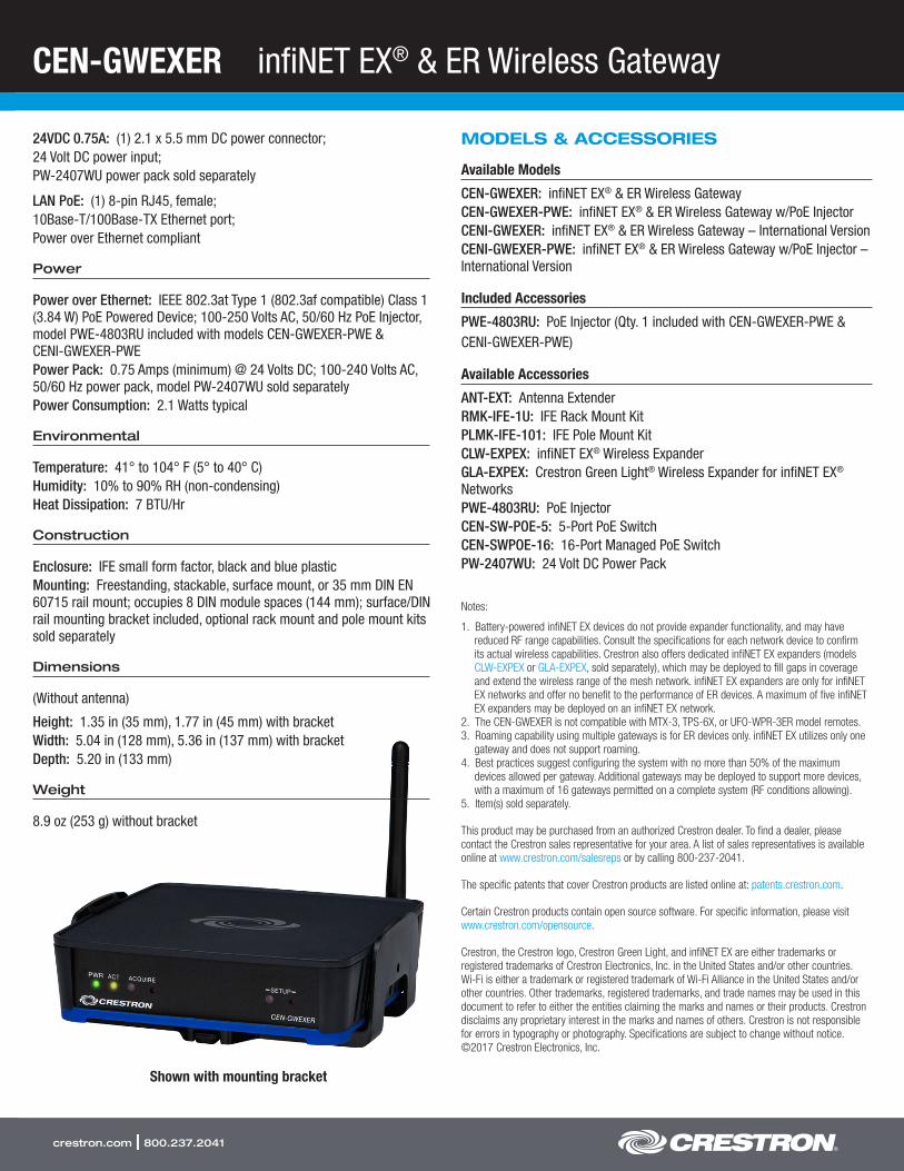
CEN-GWEXER infiNET EX® & ER Wireless Gateway
crestron.com | 800.237.2041
24VDC 0.75A: (1) 2.1 x 5.5 mm DC power connector;24 Volt DC power input;PW-2407WU power pack sold separately
LAN PoE: (1) 8-pin RJ45, female;10Base-T/100Base-TX Ethernet port;Power over Ethernet compliant
Power
Power over Ethernet: IEEE 802.3at Type 1 (802.3af compatible) Class 1 (3.84 W) PoE Powered Device; 100-250 Volts AC, 50/60 Hz PoE Injector, model PWE-4803RU included with models CEN-GWEXER-PWE & CENI-GWEXER-PWEPower Pack: 0.75 Amps (minimum) @ 24 Volts DC; 100-240 Volts AC, 50/60 Hz power pack, model PW-2407WU sold separatelyPower Consumption: 2.1 Watts typical
Environmental
Temperature: 41° to 104° F (5° to 40° C)Humidity: 10% to 90% RH (non-condensing)Heat Dissipation: 7 BTU/Hr
Construction
Enclosure: IFE small form factor, black and blue plasticMounting: Freestanding, stackable, surface mount, or 35 mm DIN EN 60715 rail mount; occupies 8 DIN module spaces (144 mm); surface/DIN rail mounting bracket included, optional rack mount and pole mount kits sold separately
Dimensions
(Without antenna)
Height: 1.35 in (35 mm), 1.77 in (45 mm) with bracketWidth: 5.04 in (128 mm), 5.36 in (137 mm) with bracketDepth: 5.20 in (133 mm)
Weight
8.9 oz (253 g) without bracket
MODELS & ACCESSORIES
Available Models
CEN-GWEXER: infiNET EX® & ER Wireless GatewayCEN-GWEXER-PWE: infiNET EX® & ER Wireless Gateway w/PoE Injector CENI-GWEXER: infiNET EX® & ER Wireless Gateway – International VersionCENI-GWEXER-PWE: infiNET EX® & ER Wireless Gateway w/PoE Injector – International Version
Included Accessories
PWE-4803RU: PoE Injector (Qty. 1 included with CEN-GWEXER-PWE & CENI-GWEXER-PWE)
Available Accessories
ANT-EXT: Antenna ExtenderRMK-IFE-1U: IFE Rack Mount KitPLMK-IFE-101: IFE Pole Mount KitCLW-EXPEX: infiNET EX® Wireless ExpanderGLA-EXPEX: Crestron Green Light® Wireless Expander for infiNET EX® NetworksPWE-4803RU: PoE InjectorCEN-SW-POE-5: 5-Port PoE SwitchCEN-SWPOE-16: 16-Port Managed PoE SwitchPW-2407WU: 24 Volt DC Power Pack
Notes:
1. Battery-powered infiNET EX devices do not provide expander functionality, and may have reduced RF range capabilities. Consult the specifications for each network device to confirm its actual wireless capabilities. Crestron also offers dedicated infiNET EX expanders (models CLW-EXPEX or GLA-EXPEX, sold separately), which may be deployed to fill gaps in coverage and extend the wireless range of the mesh network. infiNET EX expanders are only for infiNET EX networks and offer no benefit to the performance of ER devices. A maximum of five infiNET EX expanders may be deployed on an infiNET EX network.
2. The CEN-GWEXER is not compatible with MTX-3, TPS-6X, or UFO-WPR-3ER model remotes.3. Roaming capability using multiple gateways is for ER devices only. infiNET EX utilizes only one
gateway and does not support roaming.4. Best practices suggest configuring the system with no more than 50% of the maximum
devices allowed per gateway. Additional gateways may be deployed to support more devices, with a maximum of 16 gateways permitted on a complete system (RF conditions allowing).
5. Item(s) sold separately.
This product may be purchased from an authorized Crestron dealer. To find a dealer, please contact the Crestron sales representative for your area. A list of sales representatives is available online at www.crestron.com/salesreps or by calling 800-237-2041.
The specific patents that cover Crestron products are listed online at: patents.crestron.com.
Certain Crestron products contain open source software. For specific information, please visit www.crestron.com/opensource.
Crestron, the Crestron logo, Crestron Green Light, and infiNET EX are either trademarks or registered trademarks of Crestron Electronics, Inc. in the United States and/or other countries. Wi-Fi is either a trademark or registered trademark of Wi-Fi Alliance in the United States and/or other countries. Other trademarks, registered trademarks, and trade names may be used in this document to refer to either the entities claiming the marks and names or their products. Crestron disclaims any proprietary interest in the marks and names of others. Crestron is not responsible for errors in typography or photography. Specifications are subject to change without notice. ©2017 Crestron Electronics, Inc.
Shown with mounting bracket
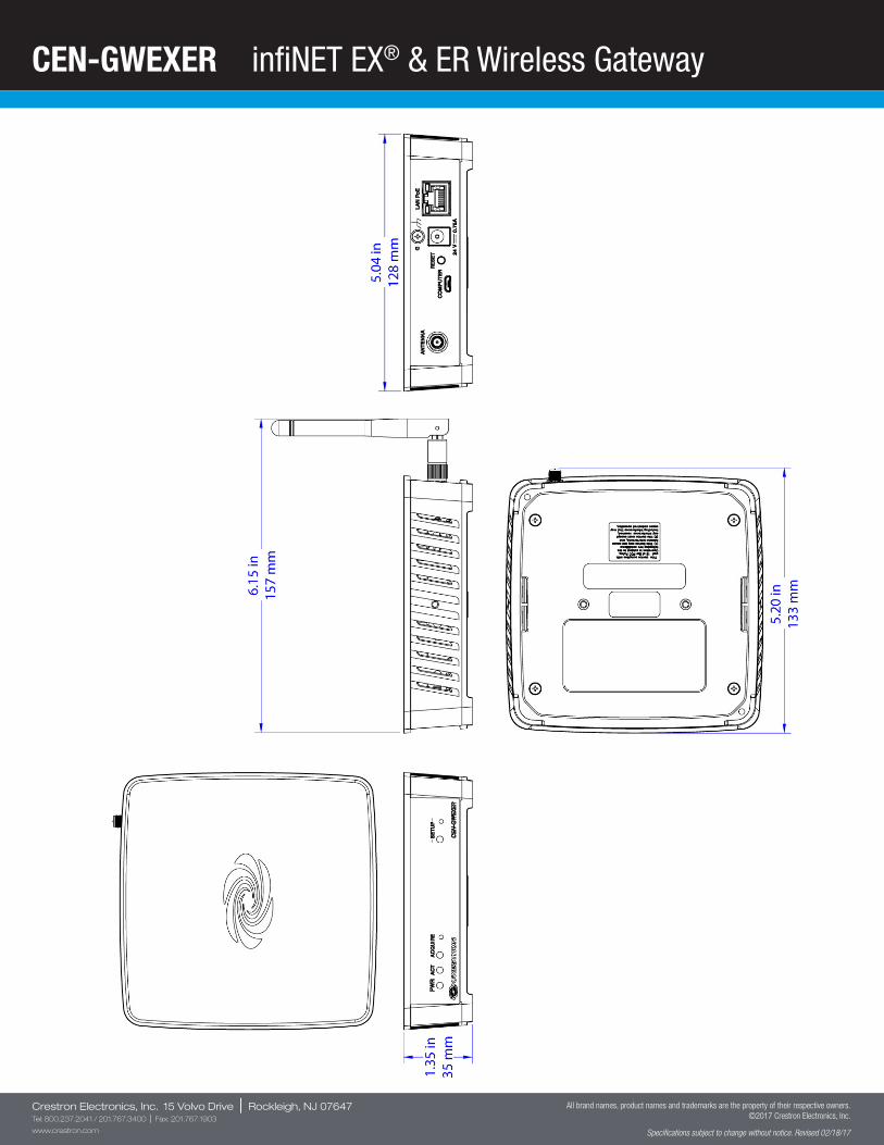
CEN-GWEXER infiNET EX® & ER Wireless Gateway
Crestron Electronics, Inc. 15 Volvo Drive | Rockleigh, NJ 07647Tel: 800.237.2041 / 201.767.3400 | Fax: 201.767.1903
www.crestron.com
All brand names, product names and trademarks are the property of their respective owners. ©2017 Crestron Electronics, Inc.
Specifications subject to change without notice. Revised 02/18/17
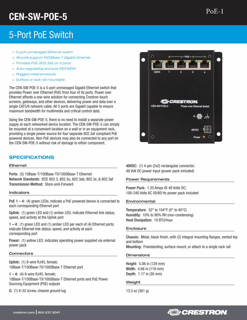
CEN-SW-POE-5
5-Port PoE Switch
crestron.com | 800.237.2041
> 5-port unmanaged Ethernet switch
> All ports support 1000Base-T Gigabit Ethernet
> Provides PoE (802.3af) on 4 ports
> Auto-negotiating and auto MDI/MDIX
> Rugged metal enclosure
> Surface or rack-rail mountable
The CEN-SW-POE-5 is a 5-port unmanaged Gigabit Ethernet switch that provides Power over Ethernet (PoE) from four of its ports. Power over Ethernet affords a one-wire solution for connecting Crestron touch screens, gateways, and other devices, delivering power and data over a single CAT5/6 network cable. All 5 ports are Gigabit capable to ensure maximum bandwidth for multimedia and critical control data.
Using the CEN-SW-POE-5, there is no need to install a separate power supply at each networked device location. The CEN-SW-POE-5 can simply be mounted at a convenient location on a wall or in an equipment rack, providing a single power source for four separate 802.3af compliant PoE powered devices. Non-PoE devices may also be connected to any port on the CEN-SW-POE-5 without risk of damage to either component.
SPECIFICATIONS
Ethernet
Ports: (5) 10Base-T/100Base-TX/1000Base-T EthernetNetwork Standards: IEEE 802.3, 802.3u, 802.3ab, 802.3x, & 802.3afTransmission Method: Store-and-Forward
Indicators
PoE 1 – 4: (4) green LEDs, indicate a PoE powered device is connected to each corresponding Ethernet port
Uplink: (1) green LED and (1) amber LED; indicate Ethernet link status, speed, and activity at the Uplink port
1 – 4: (1) green LED and (1) amber LED per each of (4) Ethernet ports; indicate Ethernet link status, speed, and activity at each corresponding port
Power: (1) yellow LED, indicates operating power supplied via external power pack
Connectors
Uplink: (1) 8-wire RJ45, female;10Base-T/100Base-TX/1000Base-T Ethernet port
1 – 4: (4) 8-wire RJ45, female;10Base-T/100Base-TX/1000Base-T Ethernet ports and PoE Power Sourcing Equipment (PSE) outputs
G: (1) 6-32 screw, chassis ground lug
48VDC: (1) 4-pin (2x2) rectangular connector;48 Volt DC power input (power pack included)
Power Requirements
Power Pack: 1.25 Amps @ 48 Volts DC;100-240 Volts AC 50/60 Hz power pack included
Environmental
Temperature: 32° to 104°F (0° to 40°C)Humidity: 10% to 90% RH (non-condensing)Heat Dissipation: 10 BTU/hour
Enclosure
Chassis: Metal, black finish, with (2) integral mounting flanges, vented top and bottomMounting: Freestanding, surface mount, or attach to a single rack rail
Dimensions
Height: 5.06 in (129 mm)Width: 4.66 in (119 mm)Depth: 1.17 in (30 mm)
Weight
13.5 oz (381 g)
PoE-1
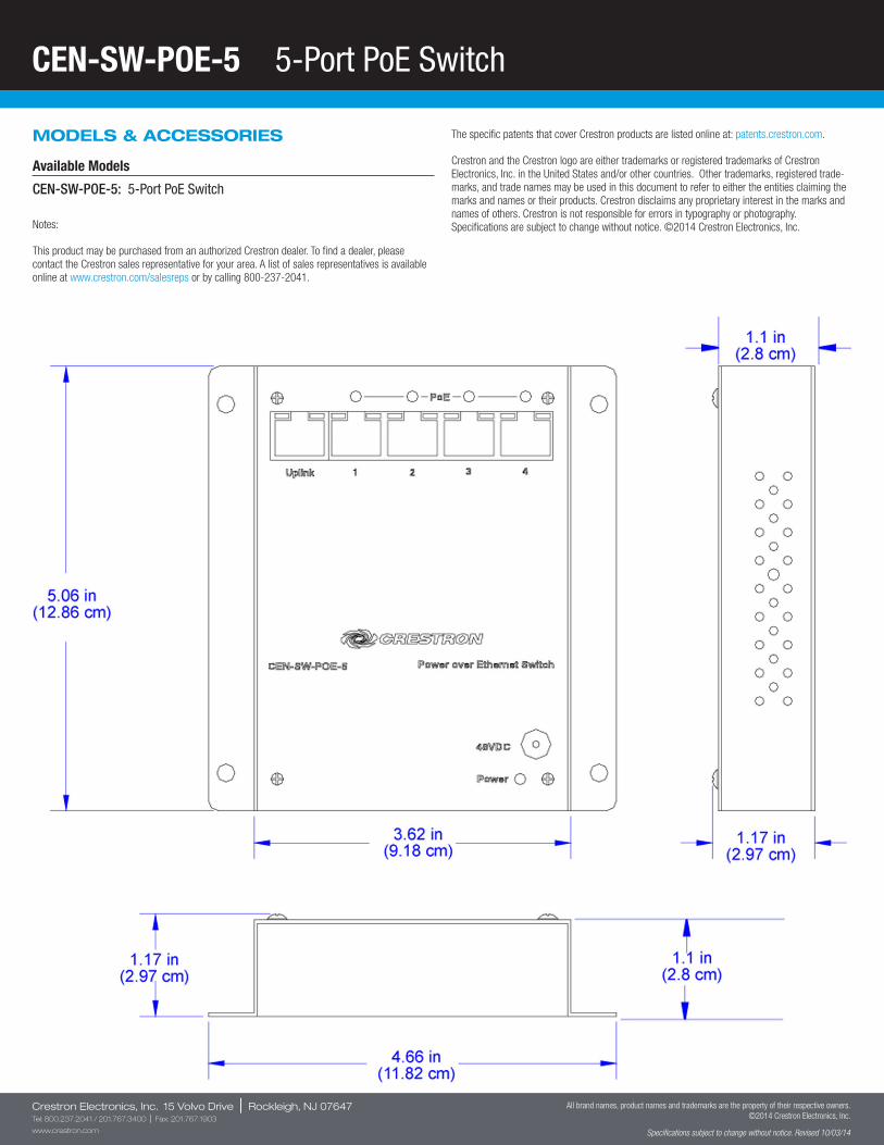
CEN-SW-POE-5 5-Port PoE Switch
Crestron Electronics, Inc. 15 Volvo Drive | Rockleigh, NJ 07647Tel: 800.237.2041 / 201.767.3400 | Fax: 201.767.1903
www.crestron.com
All brand names, product names and trademarks are the property of their respective owners. ©2014 Crestron Electronics, Inc.
Specifications subject to change without notice. Revised 10/03/14
MODELS & ACCESSORIES
Available Models
CEN-SW-POE-5: 5-Port PoE Switch
Notes:
This product may be purchased from an authorized Crestron dealer. To find a dealer, please contact the Crestron sales representative for your area. A list of sales representatives is available online at www.crestron.com/salesreps or by calling 800-237-2041.
The specific patents that cover Crestron products are listed online at: patents.crestron.com.
Crestron and the Crestron logo are either trademarks or registered trademarks of Crestron Electronics, Inc. in the United States and/or other countries. Other trademarks, registered trade-marks, and trade names may be used in this document to refer to either the entities claiming the marks and names or their products. Crestron disclaims any proprietary interest in the marks and names of others. Crestron is not responsible for errors in typography or photography. Specifications are subject to change without notice. ©2014 Crestron Electronics, Inc.

Pakedge Switches
Enterprise Performance
Designed for A/V Applications
Enhanced Security
Advanced Traffic Management
Intuitive GUI
Pakedge switches are designed to meet the most demanding needs of high bandwidth, low latency applications found in high performance commercial and residential A/V networks. Built with enterprise grade
components and encased in solid, industrial quality housing, Pakedge switches provide seamless, scalable, and reliable network connectivity. No matter what your network needs are, there is a Pakedge switch for you.
PoE-2 : SE-8P
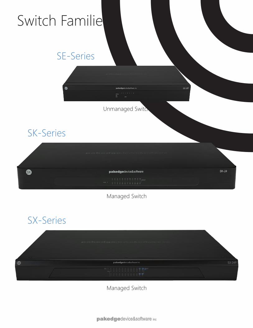
Switch Families
SK-Series
Managed Switch
SX-Series
Managed Switch
SE-Series
Unmanaged Switch
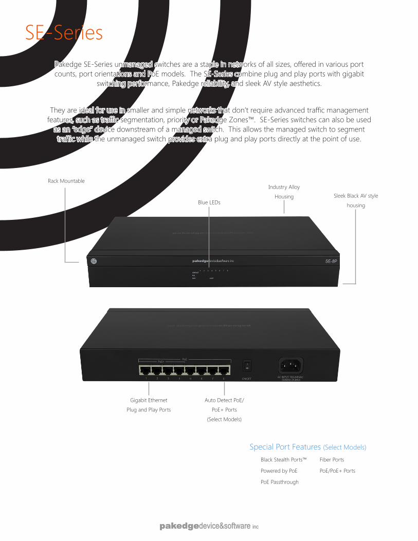
SE-SeriesPakedge SE-Series unmanaged switches are a staple in networks of all sizes, offered in various port counts, port orientations and PoE models. The SE-Series combine plug and play ports with gigabit
switching performance, Pakedge reliability, and sleek AV style aesthetics.
They are ideal for use in smaller and simple networks that don’t require advanced traffic management features, such as traffic segmentation, priority or Pakedge Zones™. SE-Series switches can also be used
as an “edge” device downstream of a managed switch. This allows the managed switch to segment traffic while the unmanaged switch provides extra plug and play ports directly at the point of use.
Rack Mountable
Sleek Black AV style
housingBlue LEDs
Industry Alloy
Housing
Gigabit Ethernet
Plug and Play Ports
Auto Detect PoE/
PoE+ Ports
(Select Models)
Special Port Features (Select Models)
Black Stealth Ports™
Powered by PoE
PoE Passthrough
Fiber Ports
PoE/PoE+ Ports
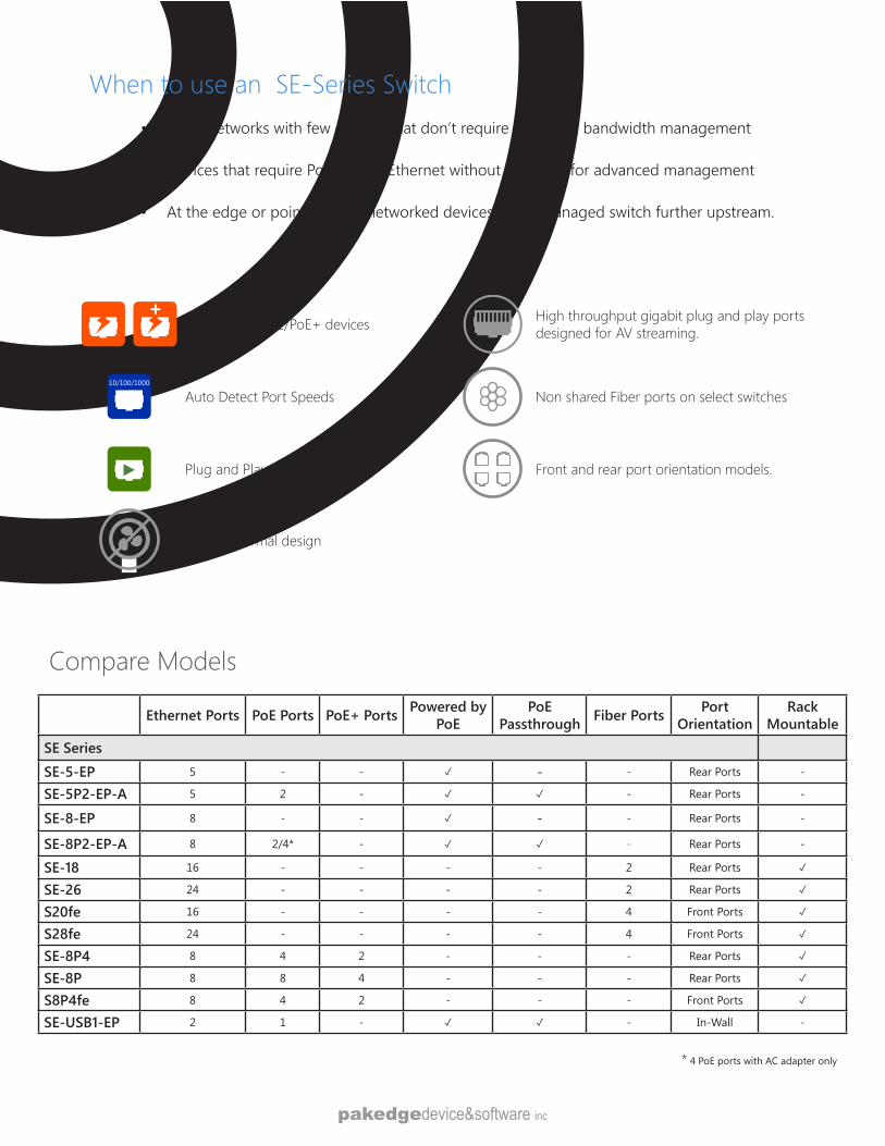
When to use an SE-Series Switch• Small networks with few devices that don’t require advanced bandwidth management
• Devices that require Power over Ethernet without the need for advanced management
• At the edge or point of use - networked devices and a managed switch further upstream.
Ethernet Ports PoE Ports PoE+ Ports Powered by PoE
PoE Passthrough Fiber Ports Port
OrientationRack
MountableSE SeriesSE-5-EP 5 - - - - Rear Ports -
SE-5P2-EP-A 5 2 - - Rear Ports -
SE-8-EP 8 - - - - Rear Ports -
SE-8P2-EP-A 8 2/4* - - Rear Ports -
SE-18 16 - - - - 2 Rear Ports
SE-26 24 - - - - 2 Rear Ports
S20fe 16 - - - - 4 Front Ports
S28fe 24 - - - - 4 Front Ports
SE-8P4 8 4 2 - - - Rear Ports
SE-8P 8 8 4 - - - Rear Ports
S8P4fe 8 4 2 - - - Front Ports
SE-USB1-EP 2 1 - - In-Wall -
High throughput gigabit plug and play ports designed for AV streaming.Auto Detect PoE/PoE+ devices
Non shared Fiber ports on select switches10/100/1000
Auto Detect Port Speeds
Front and rear port orientation models.Plug and Play Ports
Fanless thermal design
* 4 PoE ports with AC adapter only
Compare Models
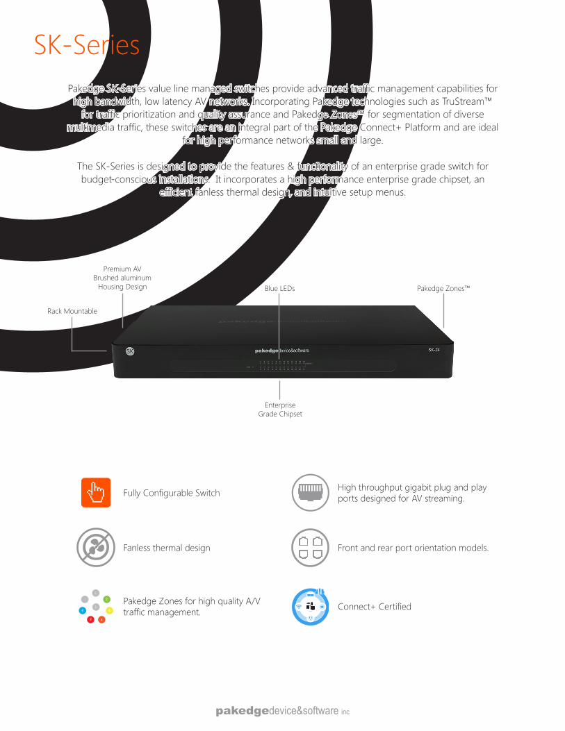
SK-SeriesPakedge SK-Series value line managed switches provide advanced traffic management capabilities for high bandwidth, low latency AV networks. Incorporating Pakedge technologies such as TruStream™
for traffic prioritization and quality assurance and Pakedge Zones™ for segmentation of diverse multimedia traffic, these switches are an integral part of the Pakedge Connect+ Platform and are ideal
for high performance networks small and large.
The SK-Series is designed to provide the features & functionality of an enterprise grade switch for budget-conscious installations. It incorporates a high performance enterprise grade chipset, an
efficient fanless thermal design, and intuitive setup menus.
Rack Mountable
Premium AV Brushed aluminum
Housing Design Pakedge Zones™Blue LEDs
Enterprise Grade Chipset
High throughput gigabit plug and play ports designed for AV streaming.
Front and rear port orientation models.
Fully Configurable Switch
1
2
3
45
6
1
Pakedge Zones for high quality A/V traffic management.
Fanless thermal design
Devices
Connect+ Certified
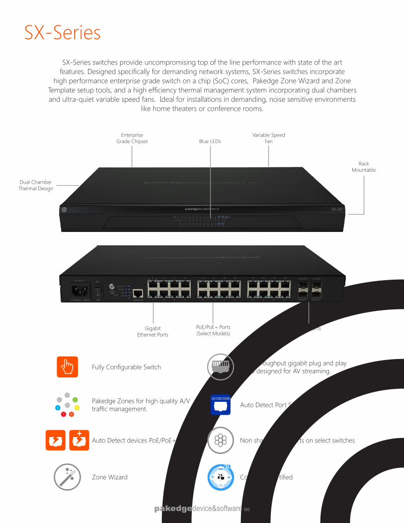
SX-Series
High throughput gigabit plug and play ports designed for AV streaming.Fully Configurable Switch
1
2
3
45
6
1
Pakedge Zones for high quality A/V traffic management.
10/100/1000
Auto Detect Port Speeds
Auto Detect devices PoE/PoE+ Non shared Fiber ports on select switches
SX-Series switches provide uncompromising top of the line performance with state of the art features. Designed specifically for demanding network systems, SX-Series switches incorporate
high performance enterprise grade switch on a chip (SoC) cores, Pakedge Zone Wizard and Zone Template setup tools, and a high efficiency thermal management system incorporating dual chambers and ultra-quiet variable speed fans. Ideal for installations in demanding, noise sensitive environments
like home theaters or conference rooms.
Enterprise Grade Chipset
Rack Mountable
Dual Chamber Thermal Design
Variable Speed FanBlue LEDs
Gigabit Ethernet Ports
Fiber PortsPoE/PoE+ Ports (Select Models)
Zone WizardDevices
Connect+ Certified
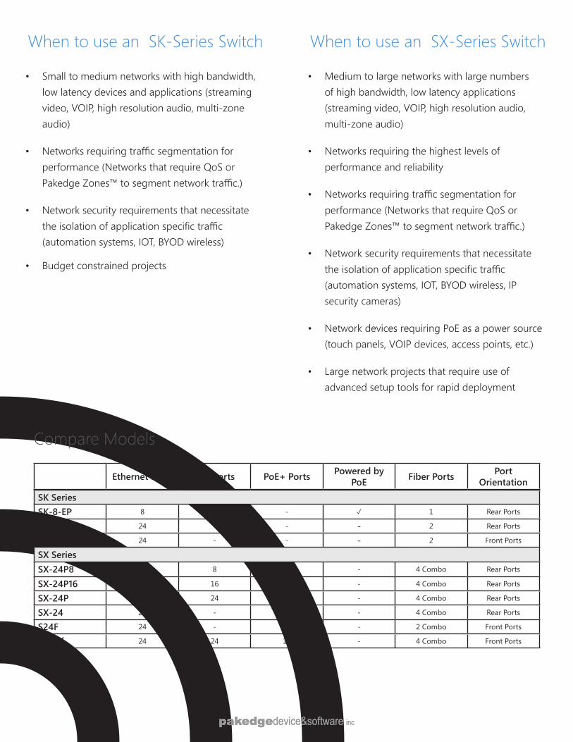
When to use an SX-Series Switch
• Medium to large networks with large numbers of high bandwidth, low latency applications (streaming video, VOIP, high resolution audio, multi-zone audio)
• Networks requiring the highest levels of performance and reliability
• Networks requiring traffic segmentation for performance (Networks that require QoS or Pakedge Zones™ to segment network traffic.)
• Network security requirements that necessitate the isolation of application specific traffic (automation systems, IOT, BYOD wireless, IP security cameras)
• Network devices requiring PoE as a power source (touch panels, VOIP devices, access points, etc.)
• Large network projects that require use of advanced setup tools for rapid deployment
When to use an SK-Series Switch
• Small to medium networks with high bandwidth, low latency devices and applications (streaming video, VOIP, high resolution audio, multi-zone audio)
• Networks requiring traffic segmentation for performance (Networks that require QoS or Pakedge Zones™ to segment network traffic.)
• Network security requirements that necessitate the isolation of application specific traffic (automation systems, IOT, BYOD wireless)
• Budget constrained projects
Ethernet Ports PoE Ports PoE+ Ports Powered by PoE Fiber Ports Port
OrientationSK SeriesSK-8-EP 8 - - 1 Rear Ports
SK-24 24 - - - 2 Rear Ports
SK-24F 24 - - - 2 Front Ports
SX SeriesSX-24P8 24 8 4 - 4 Combo Rear Ports
SX-24P16 24 16 12 - 4 Combo Rear Ports
SX-24P 24 24 12 - 4 Combo Rear Ports
SX-24 24 - - - 4 Combo Rear Ports
S24F 24 - - - 2 Combo Front Ports
S24Hf 24 24 12 - 4 Combo Front Ports
Compare Models
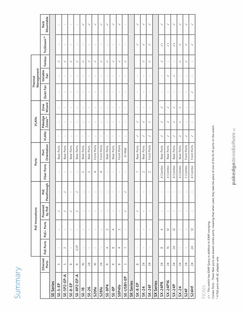
Sum
mar
y
Not
es
+ -
This
switc
h ha
s IG
MP
Que
ry in
add
ition
to IG
MP
snoo
ping
. Co
mbo
Por
ts -
Thes
e fib
er p
orts
are
sha
red
com
bo p
orts
, mea
ning
that
whe
n us
ed, t
hey
take
the
plac
e of
one
of t
he R
J-45
por
ts o
n th
e sw
itch.
* 4
PoE
port
s w
ith A
C ad
apte
r onl
y
Ethe
rnet
Po
rts
PoE
Port
sPo
E+ P
orts
Pow
ered
by
PoE
PoE
Pass
thro
ugh
Fibe
r Por
tsPo
rt
Orie
ntat
ion
VLAN
sPa
kedg
e Zo
nes™
Zone
W
izar
dQ
uiet
Fan
Varia
ble
Fan
Fanl
ess
TruS
trea
m™
Rack
M
ount
able
SE S
erie
sSE
-5-E
P5
--
-
-Re
ar P
orts
--
--
-
--
SE-5
P2-E
P-A
52
-
-
Rear
Por
ts-
--
--
-
-
SE-8
-EP
8-
-
--
Rear
Por
ts-
--
--
-
-
SE-8
P2-E
P-A
82/
4*-
-Re
ar P
orts
--
--
-
--
SE-1
816
--
--
2Re
ar P
orts
--
--
-
-
SE-2
624
--
--
2Re
ar P
orts
--
--
-
-
S20f
e16
--
--
4Fr
ont P
orts
--
--
-
-
S28f
e24
--
--
4Fr
ont P
orts
--
--
-
-
SE-8
P48
42
--
-Re
ar P
orts
--
--
-
-
SE-8
P8
84
--
-Re
ar P
orts
--
--
-
-
S8P4
fe8
42
--
-Fr
ont P
orts
--
--
-
-
SE-U
SB1-
EP3
1-
-In
-Wal
l-
--
--
-
-
SK S
erie
sSK
-8-E
P8
--
-
1Re
ar P
orts
--
-
SK-2
424
--
--
2Re
ar P
orts
--
-
SK-2
4F24
--
--
2Fr
ont P
orts
--
-
SX S
erie
sSX
-24P
824
84
--
4 Co
mbo
Rear
Por
ts
--
+
SX-2
4P16
2416
12-
-4
Com
boRe
ar P
orts
-
-
+
SX-2
4P24
2412
--
4 Co
mbo
Rear
Por
ts
-
-
+
SX-2
424
--
--
4 Co
mbo
Rear
Por
ts
--
S24F
24-
--
-2
Com
boFr
ont P
orts
-
--
-
S24H
f24
2412
--
4 Co
mbo
Fron
t Por
ts
--
-
-
PoE
Inno
vatio
nsPo
rts
VLAN
sTh
erm
alM
anag
emen
t
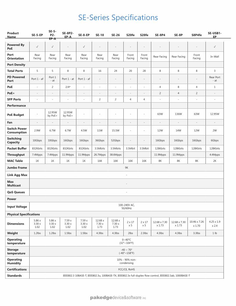
SE-Series Specifications
Product Name SE-5-EP
SE-5-P2-
EP-A
SE-8P2-EP-A SE-8-EP SE-18 SE-26 S20fe S28fe SE-8P4 SE-8P S8P4fe SE-USB1-
EP
Powered By PoE - - - - - - - -
Port Orientation
Rear Facing
Rear Facing
Rear Facing
Rear Facing
Rear Facing
Rear Facing
Front Facing
Front Facing Rear Facing Rear Facing Front
Facing In-Wall
Port Density
Total Ports 5 5 8 8 16 24 20 28 8 8 8 3
PD Powered Port Port 1 - af Port 1
- at Port 1 - at Port 1 - af - - - - - - - Rear Port - at
PoE - 2 2/4* - - - - - 4 8 4 1
PoE+ - - - - - - - - 2 4 2 -
SFP Ports - - - - 2 2 4 4 - - - -
Performance
PoE Budget - 12.95W by PoE+
12.95W by PoE+ - - - - - 63W 136W 63W 12.95W
Fan - - - - - - - - - - - -
Switch Power Consumption 2.9W 6.7W 6.7W 4.5W 11W 15.5W - - 12W 14W 12W 2W
Switching Capacity 10Gbps 10Gbps 16Gbps 16Gbps 36Gbps 52Gbps - - 16Gbps 16Gbps 16Gbps 6Gbps
Packet Buffer 832Kbits 832Kbits 832Kbits 832Kbits 3.5Mbits 3.5Mbits 3.5Mbit 3.5Mbit 128Kbits 128Kbits 128Kbits 128Kbits
Throughput 7.4Mpps 7.4Mpps 11.9Mpps 11.9Mpps 26.7Mpps 38.6Mpps 11.9Mpps 11.9Mpps 4.4Mpps
MAC Table 1K 1K 1K 1K 16K 16K 16K 16K 8K 8K 8K 2K
Jumbo Frame 9K
Link Agg Max -
Max Multicast -
QoS Queues -
Power
Input Voltage 100-240V AC,50/60Hz
Physical Specifications
Dimensions 5.86 x 3.30 x 1.02
5.86 x 3.30 x 1.02
7.59 x 3.30 x 1.02
7.59 x 3.30 x 1.02
12.68 x 7.30 x 1.73
12.68 x 7.30 x 1.73
2 x 17 x 5
2 x 17 x 5
12.68 x 7.30 x 1.73
12.68 x 7.30 x 1.73
10.46 x 7.26 x 1.70
4.25 x 1.9 x 2.4
Weight 1.2lbs 1.2lbs 1.5lbs 1.5lbs 4.3lbs 4.3lbs 2lbs 2.3lbs 4.3lbs 4.3lbs 3.3lbs 1 lb
Operating temperature
0~40°C (32°~104°F)
Storage temperature
-40 ~ 70°(-40°~158°F)
Operating Humidity
10% - 90% non-condensing
Certifications FCC/CE, RoHS
Standards IEEE802.3 10BASE-T, IEEE802.3u, 100BASE-TX, IEEE802.3x full-duplex flow control, IEEE802.3ab, 1000BASE-T
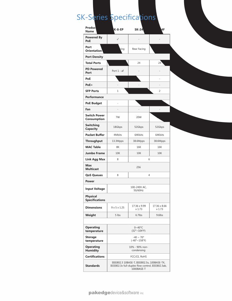
SK-Series SpecificationsProduct Name SK-8-EP SK-24 SK-24F
Powered By PoE - -
Port Orientation Rear Facing Rear Facing Front Facing
Port Density
Total Ports 8 24 24
PD Powered Port Port 1 - af - -
PoE - - -
PoE+ - - -
SFP Ports 1 2 2
Performance
PoE Budget - - -
Fan - - -
Switch Power Consumption 7W 20W 20W
Switching Capacity 18Gbps 52Gbps 52Gbps
Packet Buffer 4Mbits 64Kbits 64Kbits
Throughput 13.3Mpps 38.6Mpps 38.6Mpps
MAC Table 8K 16K 16K
Jumbo Frame 10K 10K 10K
Link Agg Max 8 6
Max Multicast 256
QoS Queues 8 4
Power
Input Voltage 100-240V AC,50/60Hz
Physical Specifications
Dimensions 9 x 5 x 1.25 17.36 x 9.99 x 1.73
17.36 x 8.66 x 1.73
Weight 5 lbs 6.7lbs 9.6lbs
Operating temperature
0~40°C (32°~104°F)
Storage temperature
-40 ~ 70°(-40°~158°F)
Operating Humidity
10% - 90% non-condensing
Certifications FCC/CE, RoHS
StandardsIEEE802.3 10BASE-T, IEEE802.3u, 100BASE-TX,
IEEE802.3x full-duplex flow control, IEEE802.3ab, 1000BASE-T
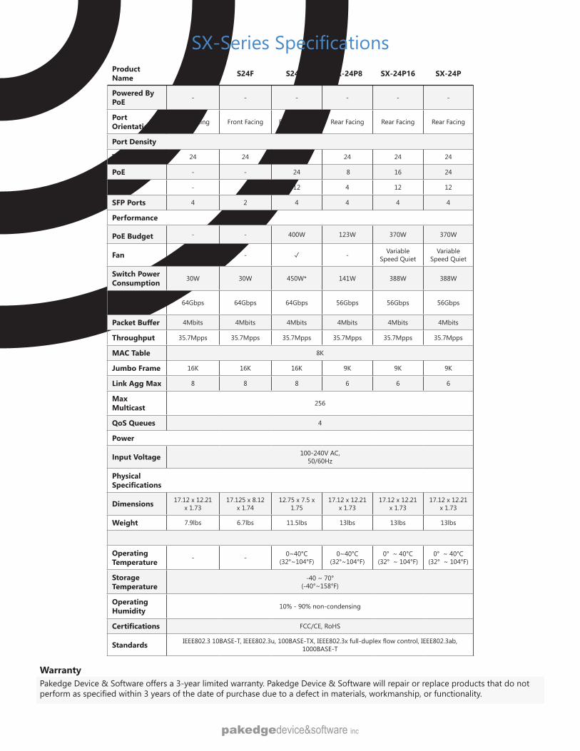
Product Name SX-24 S24F S24Hf SX-24P8 SX-24P16 SX-24P
Powered By PoE - - - - - -
Port Orientation Rear Facing Front Facing Front Facing Rear Facing Rear Facing Rear Facing
Port Density
Total Ports 24 24 24 24 24 24
PoE - - 24 8 16 24
PoE+ - - 12 4 12 12
SFP Ports 4 2 4 4 4 4
Performance
PoE Budget - - 400W 123W 370W 370W
Fan - - - Variable Speed Quiet
Variable Speed Quiet
Switch Power Consumption 30W 30W 450W* 141W 388W 388W
Switching Capacity 64Gbps 64Gbps 64Gbps 56Gbps 56Gbps 56Gbps
Packet Buffer 4Mbits 4Mbits 4Mbits 4Mbits 4Mbits 4Mbits
Throughput 35.7Mpps 35.7Mpps 35.7Mpps 35.7Mpps 35.7Mpps 35.7Mpps
MAC Table 8K
Jumbo Frame 16K 16K 16K 9K 9K 9K
Link Agg Max 8 8 8 6 6 6
Max Multicast 256
QoS Queues 4
Power
Input Voltage 100-240V AC,50/60Hz
Physical Specifications
Dimensions 17.12 x 12.21 x 1.73
17.125 x 8.12 x 1.74
12.75 x 7.5 x 1.75
17.12 x 12.21 x 1.73
17.12 x 12.21 x 1.73
17.12 x 12.21 x 1.73
Weight 7.9lbs 6.7lbs 11.5lbs 13lbs 13lbs 13lbs
Operating Temperature - - 0~40°C
(32°~104°F)0~40°C
(32°~104°F)0° ~ 40°C
(32° ~ 104°F)0° ~ 40°C
(32° ~ 104°F)
Storage Temperature
-40 ~ 70°(-40°~158°F)
Operating Humidity 10% - 90% non-condensing
Certifications FCC/CE, RoHS
Standards IEEE802.3 10BASE-T, IEEE802.3u, 100BASE-TX, IEEE802.3x full-duplex flow control, IEEE802.3ab, 1000BASE-T
SX-Series Specifications
WarrantyPakedge Device & Software offers a 3-year limited warranty. Pakedge Device & Software will repair or replace products that do not perform as specified within 3 years of the date of purchase due to a defect in materials, workmanship, or functionality.
Pakedge unmanaged SE-Series switches are “plug and play” switches that require no configuration setup. They auto-discover connected devices, auto-detect network speeds and communication modes, and integrate into the network in seconds. Unmanaged switches are ideal for use in small networks with a limited number of devices that don’t require a lot of bandwidth management, in a segment of a network downstream of a managed switch, or at the “edge” near the point of use of the device. Key benefits of unmanaged switches include ease of installation, and simple network expansion.
Switch Types
Key Switch Features
Pakedge managed SK and SX-Series switches are fully configurable to meet the unique needs of a specific network for maximum performance. These settings include bandwidth management settings, port settings, and security settings. Managed switches are ideal for networks, large or small, that have high bandwidth, low latency devices that compete against each other and require active bandwidth management for best performance. Key benefits include optimized performance tailored specifically to your network and the ability to scale and meet your network needs today and tomorrow.
Enterprise ChipsetHigh performance switches start with the core. The engines powering Pakedge switches are enterprise grade high performance processors using switch on a chip (SoC) technology. Network processors are optimized to process AV network traffic flows at high speeds. They reduce the load on other system components by taking on many of the packet-based communications maintenance tasks such as general TCP processing, network address translation and some encryption/decryption tasks. AV Traffic management is a key function of the switch and the chipset is the heart of that functionality. A high performance chipset is critical to fast and accurate switching capabilities.
Pakedge switches are available in two types - Unmanaged & Managed
SXSKSE
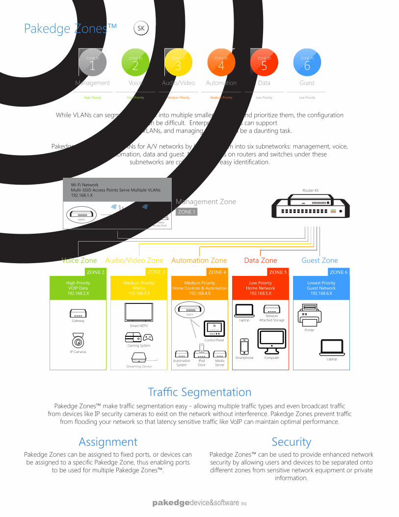
Pakedge Zones™
While VLANs can segment a network into multiple smaller networks and prioritize them, the configuration process can be difficult. Enterprise networks can support
hundreds of VLANs, and managing them all can be a daunting task.
Pakedge Zones simplify VLANs for A/V networks by breaking them into six subnetworks: management, voice, audio/video, automation, data and guest. Network ports on routers and switches under these
subnetworks are color-coded for easy identification.
ZONE ID
1Management
High Priority
ZONE ID
2Voice
High Priority
ZONE ID
3Audio/Video
Medium Priority
ZONE ID
4Automation
Medium Priority
ZONE ID
5Data
Low Priority
ZONE ID
6Guest
Low Priority
Pakedge Zones™ make traffic segmentation easy - allowing multiple traffic types and even broadcast traffic from devices like IP security cameras to exist on the network without interference. Pakedge Zones prevent traffic
from flooding your network so that latency sensitive traffic like VoIP can maintain optimal performance.
Traffic Segmentation
Pakedge Zones can be assigned to fixed ports, or devices can be assigned to a specific Pakedge Zone, thus enabling ports
to be used for multiple Pakedge Zones™.
AssignmentPakedge Zones™ can be used to provide enhanced network security by allowing users and devices to be separated onto different zones from sensitive network equipment or private
information.
Security
SXSK
Wi-Fi Network Multi-SSID Access Points Serve Multiple VLANs 192.168.1.X
Pakedge Zones Diagram
Lowest PriorityGuest Network
192.168.6.X
Laptop
Printer
Low PriorityHome Network
192.168.5.X
Laptop
Smartphone Computer
NetworkAttached Storage
Medium PriorityMedia
192.168.3.X
High PriorityVOIP Data192.168.2.X
ZONE 2
Gateway
Medium PriorityHome Controls & Automation
192.168.4.X
Control Panel
AutomationSystem
MediaServer
iPodDock
Switch
Management Zone
Smart HDTV
Streaming Device
IP Cameras
Voice Zone Audio/Video Zone Automation Zone Data Zone Guest Zone
Gaming System
Router Kit
ZONE 3 ZONE 4 ZONE 5 ZONE 6
WirelessAccess Point
SwitchWireless
Access Point
ZONE 1
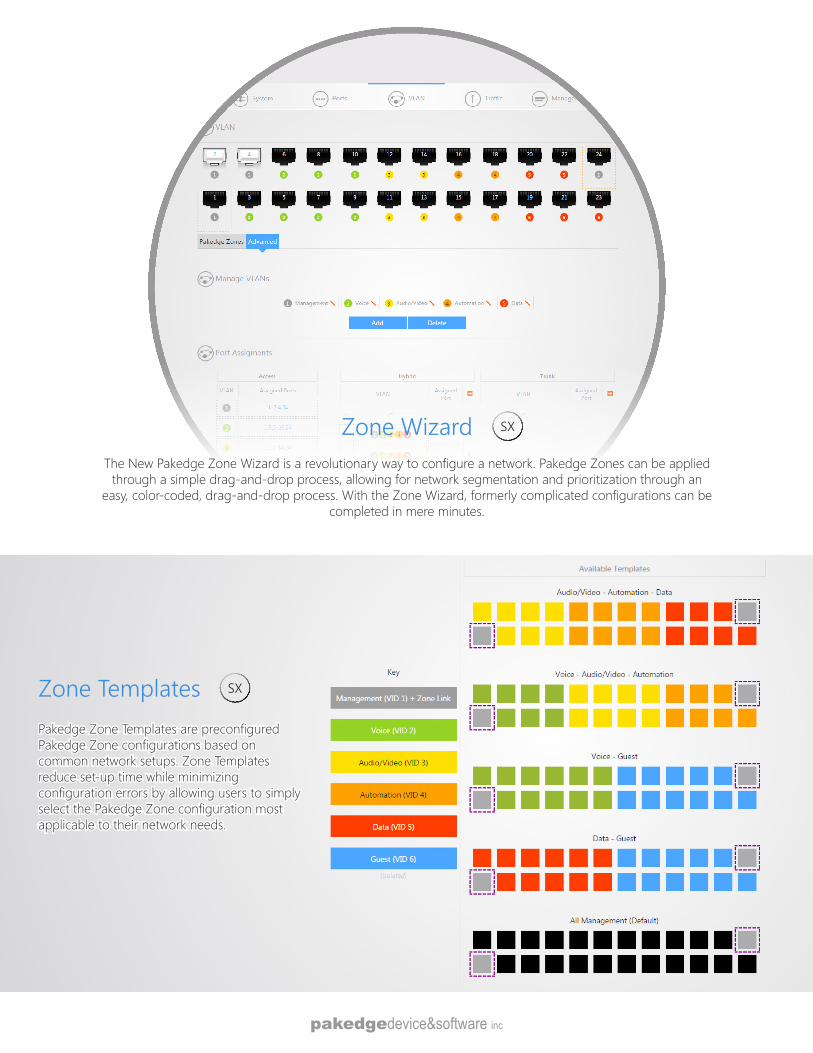
Zone WizardThe New Pakedge Zone Wizard is a revolutionary way to configure a network. Pakedge Zones can be applied
through a simple drag-and-drop process, allowing for network segmentation and prioritization through an easy, color-coded, drag-and-drop process. With the Zone Wizard, formerly complicated configurations can be
completed in mere minutes.
Zone TemplatesPakedge Zone Templates are preconfigured Pakedge Zone configurations based on common network setups. Zone Templates reduce set-up time while minimizing configuration errors by allowing users to simply select the Pakedge Zone configuration most applicable to their network needs.
SX
SX
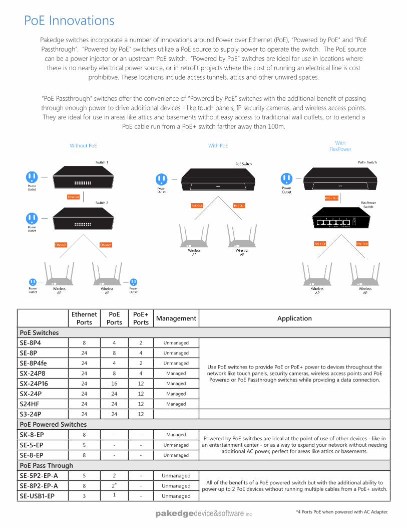
PoE InnovationsPakedge switches incorporate a number of innovations around Power over Ethernet (PoE), “Powered by PoE” and “PoE Passthrough”. “Powered by PoE” switches utilize a PoE source to supply power to operate the switch. The PoE source can be a power injector or an upstream PoE switch. “Powered by PoE” switches are ideal for use in locations where there is no nearby electrical power source, or in retrofit projects where the cost of running an electrical line is cost
prohibitive. These locations include access tunnels, attics and other unwired spaces.
“PoE Passthrough” switches offer the convenience of “Powered by PoE” switches with the additional benefit of passing through enough power to drive additional devices - like touch panels, IP security cameras, and wireless access points. They are ideal for use in areas like attics and basements without easy access to traditional wall outlets, or to extend a
PoE cable run from a PoE+ switch farther away than 100m.
Ethernet Ports
PoE Ports
PoE+ Ports Management Application
PoE SwitchesSE-8P4 8 4 2 Unmanaged
Use PoE switches to provide PoE or PoE+ power to devices throughout the network like touch panels, security cameras, wireless access points and PoE Powered or PoE Passthrough switches while providing a data connection.
SE-8P 24 8 4 Unmanaged
SE-8P4fe 24 4 2 Unmanaged
SX-24P8 24 8 4 Managed
SX-24P16 24 16 12 Managed
SX-24P 24 24 12 Managed
S24HF 24 24 12 Managed
S3-24P 24 24 12
PoE Powered SwitchesSK-8-EP 8 - - Managed
Powered by PoE switches are ideal at the point of use of other devices - like in an entertainment center - or as a way to expand your network without needing
additional AC power, perfect for areas like attics or basements. SE-5-EP 5 - - Unmanaged
SE-8-EP 8 - - Unmanaged
PoE Pass ThroughSE-5P2-EP-A 5 2 - Unmanaged
All of the benefits of a PoE powered switch but with the additional ability to power up to 2 PoE devices without running multiple cables from a PoE+ switch.SE-8P2-EP-A 8 2* - Unmanaged
SE-USB1-EP 3 1 - Unmanaged
*4 Ports PoE when powered with AC Adapter.
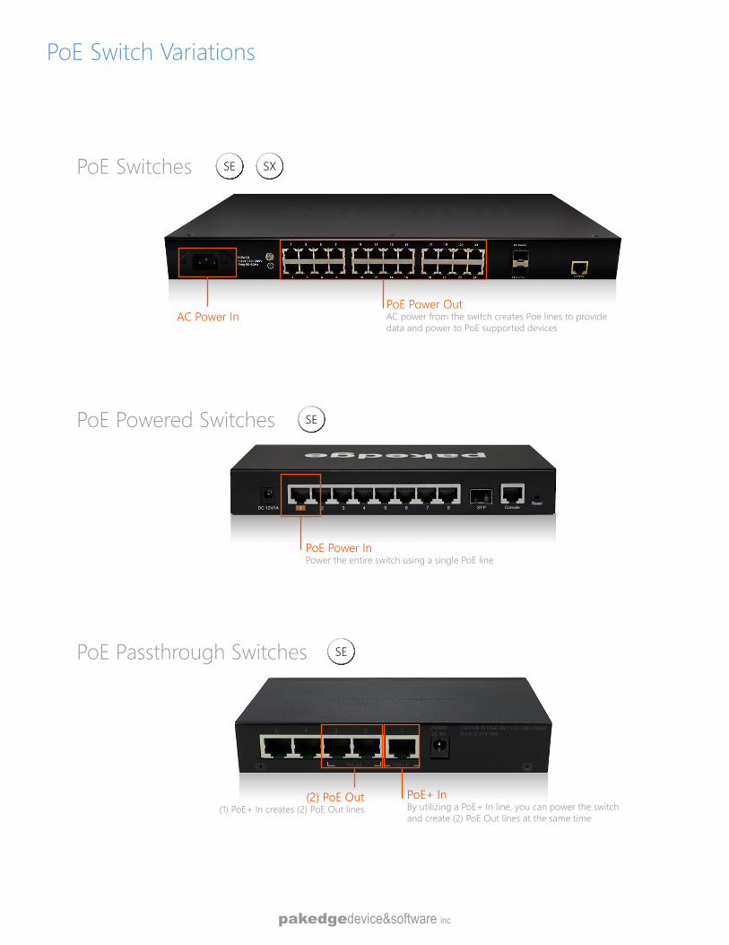
PoE Switch Variations
AC Power InPoE Power OutAC power from the switch creates Poe lines to provide data and power to PoE supported devices
PoE Switches SXSE
PoE Powered Switches
PoE Power InPower the entire switch using a single PoE line
SE
PoE+ InBy utilizing a PoE+ In line, you can power the switch and create (2) PoE Out lines at the same time
(2) PoE Out(1) PoE+ In creates (2) PoE Out lines
PoE Passthrough Switches SE
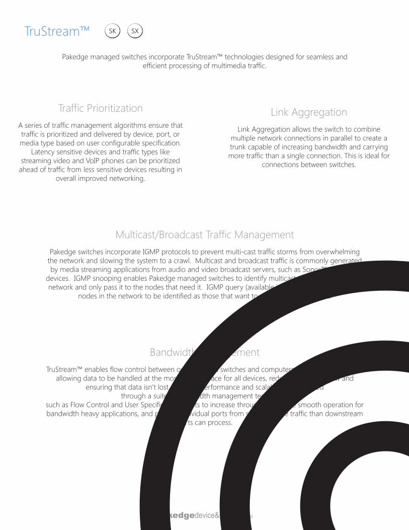
TruStream™
Link AggregationLink Aggregation allows the switch to combine
multiple network connections in parallel to create a trunk capable of increasing bandwidth and carrying more traffic than a single connection. This is ideal for
connections between switches.
Traffic PrioritizationA series of traffic management algorithms ensure that traffic is prioritized and delivered by device, port, or media type based on user configurable specification.
Latency sensitive devices and traffic types like streaming video and VoIP phones can be prioritized
ahead of traffic from less sensitive devices resulting in overall improved networking.
Bandwidth ManagementTruStream™ enables flow control between our managed switches and computers/devices on a network,
allowing data to be handled at the most efficient pace for all devices, reducing data overflow and ensuring that data isn’t lost. Network performance and scalability is optimized
through a suite of bandwidth management techniquessuch as Flow Control and User Specified rate limits to increase throughput, ensure smooth operation for bandwidth heavy applications, and prevent individual ports from sending more traffic than downstream
ports can process.
Pakedge managed switches incorporate TruStream™ technologies designed for seamless and efficient processing of multimedia traffic.
Multicast/Broadcast Traffic ManagementPakedge switches incorporate IGMP protocols to prevent multi-cast traffic storms from overwhelming
the network and slowing the system to a crawl. Multicast and broadcast traffic is commonly generated by media streaming applications from audio and video broadcast servers, such as Sonos™ and other
devices. IGMP snooping enables Pakedge managed switches to identify multicast traffic throughout the network and only pass it to the nodes that need it. IGMP query (available in SX switches) only enables
nodes in the network to be identified as those that want to receive multicast traffic.
SXSK
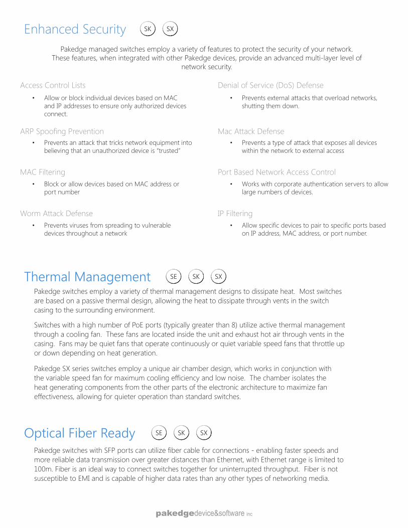
Thermal ManagementPakedge switches employ a variety of thermal management designs to dissipate heat. Most switches are based on a passive thermal design, allowing the heat to dissipate through vents in the switch casing to the surrounding environment.
Switches with a high number of PoE ports (typically greater than 8) utilize active thermal management through a cooling fan. These fans are located inside the unit and exhaust hot air through vents in the casing. Fans may be quiet fans that operate continuously or quiet variable speed fans that throttle up or down depending on heat generation.
Pakedge SX series switches employ a unique air chamber design, which works in conjunction with the variable speed fan for maximum cooling efficiency and low noise. The chamber isolates the heat generating components from the other parts of the electronic architecture to maximize fan effectiveness, allowing for quieter operation than standard switches.
Optical Fiber ReadyPakedge switches with SFP ports can utilize fiber cable for connections - enabling faster speeds and more reliable data transmission over greater distances than Ethernet, with Ethernet range is limited to 100m. Fiber is an ideal way to connect switches together for uninterrupted throughput. Fiber is not susceptible to EMI and is capable of higher data rates than any other types of networking media.
Enhanced SecurityPakedge managed switches employ a variety of features to protect the security of your network.
These features, when integrated with other Pakedge devices, provide an advanced multi-layer level of network security.
Access Control Lists• Allow or block individual devices based on MAC
and IP addresses to ensure only authorized devices connect.
Denial of Service (DoS) Defense• Prevents external attacks that overload networks,
shutting them down.
ARP Spoofing Prevention• Prevents an attack that tricks network equipment into
believing that an unauthorized device is “trusted”
Mac Attack Defense• Prevents a type of attack that exposes all devices
within the network to external access
MAC Filtering• Block or allow devices based on MAC address or
port number
Port Based Network Access Control• Works with corporate authentication servers to allow
large numbers of devices.
Worm Attack Defense• Prevents viruses from spreading to vulnerable
devices throughout a network
IP Filtering• Allow specific devices to pair to specific ports based
on IP address, MAC address, or port number.
SXSK
SXSKSE
SXSKSE
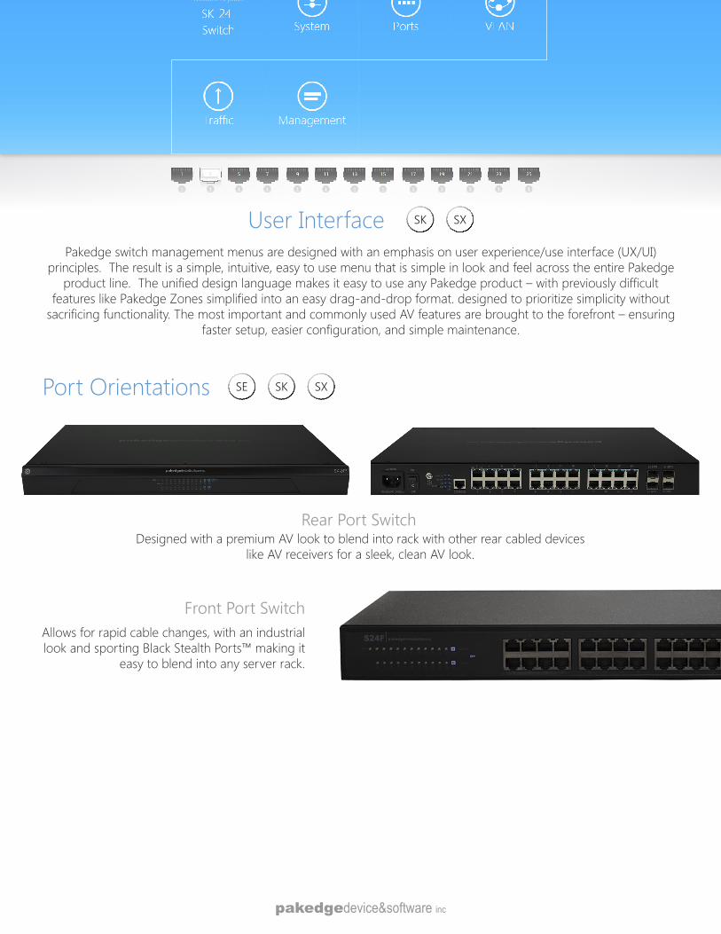
Pakedge switch management menus are designed with an emphasis on user experience/use interface (UX/UI) principles. The result is a simple, intuitive, easy to use menu that is simple in look and feel across the entire Pakedge
product line. The unified design language makes it easy to use any Pakedge product – with previously difficult features like Pakedge Zones simplified into an easy drag-and-drop format. designed to prioritize simplicity without
sacrificing functionality. The most important and commonly used AV features are brought to the forefront – ensuring faster setup, easier configuration, and simple maintenance.
Port Orientations
User Interface SXSK
SXSKSE
Rear Port SwitchDesigned with a premium AV look to blend into rack with other rear cabled devices
like AV receivers for a sleek, clean AV look.
Front Port SwitchAllows for rapid cable changes, with an industrial look and sporting Black Stealth Ports™ making it
easy to blend into any server rack.
Switch Accessories
The Fiber Modules plug into SFP or SFP+ ports on select Pakedge switches and routers, allowing the insertion of fiber-optic cables for the interconnecting of routers and switches.
SFPFiber Modules
Pakedge single mode fiber cables can transmit signals long distances without data loss or emitting interference. Constructed with extra durable cable jackets and a transparent glass cores, fiber cables are ideal for connecting switches to other switches without deterioration in quality. Available in lengths of 1, 2, 3, 4, 5, 10, 25, 75, 100, 200, 300, and 400 meters.
Fiber CablesFC-LC-LC-SM
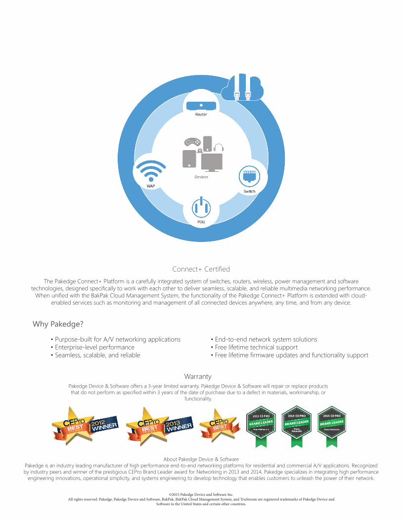
©2015 Pakedge Device and Software Inc.All rights reserved. Pakedge, Pakedge Device and Software, BakPak, BakPak Cloud Management System, and TruStream are registered trademarks of Pakedge Device and
Software in the United States and certain other countries.
About Pakedge Device & Software Pakedge is an industry leading manufacturer of high performance end-to-end networking platforms for residential and commercial A/V applications. Recognized by industry peers and winner of the prestigious CEPro Brand Leader award for Networking in 2013 and 2014, Pakedge specializes in integrating high performance
engineering innovations, operational simplicity, and systems engineering to develop technology that enables customers to unleash the power of their network.
• Purpose-built for A/V networking applications• Enterprise-level performance• Seamless, scalable, and reliable
• End-to-end network system solutions• Free lifetime technical support• Free lifetime firmware updates and functionality support
Why Pakedge?
The Pakedge Connect+ Platform is a carefully integrated system of switches, routers, wireless, power management and software technologies, designed specifically to work with each other to deliver seamless, scalable, and reliable multimedia networking performance.
When unified with the BakPak Cloud Management System, the functionality of the Pakedge Connect+ Platform is extended with cloud-enabled services such as monitoring and management of all connected devices anywhere, any time, and from any device.
Connect+ Certified
Pakedge Device & Software offers a 3-year limited warranty. Pakedge Device & Software will repair or replace products that do not perform as specified within 3 years of the date of purchase due to a defect in materials, workmanship, or
functionality.
Warranty

3847 Breakwater Avenue, Hayward, CA 94545
17011 Beach Blvd. Suite 600 Huntington Beach, CA 92647
www.pakedge.com
1 (650) 385-8702
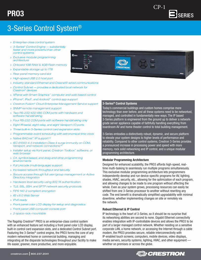
PRO3
3-Series Control System®
crestron.com | 800.237.2041
> Enterprise-class control system
> 3-Series® Control Engine — substantiallyfaster and more powerful than othercontrol systems
> Exclusive modular programmingarchitecture
> Onboard 1GB RAM & 4GB Flash memory
> Expandable storage up to 1TB
> Rear panel memory card slot
> High-speed USB 2.0 host port
> Industry-standard Ethernet and Cresnet® wired communications
> Control Subnet — provides a dedicated local network forCrestron® devices
> XPanel with Smart Graphics™ computer and web based control
> iPhone®, iPad®, and Android™ control app support
> Crestron Fusion® Cloud Enterprise Management Service support
> SNMP remote management support
> Two RS-232/422/485 COM ports with hardware andsoftware handshaking
> Four RS-232 COM ports with software handshaking only
> Eight IR/serial, eight relay, and eight Versiport I/O ports
> Three built-in 3-Series control card expansion slots
> Programmable event scheduling with astronomical time clock
> Native BACnet™/IP support [2]
> IEC 61000-4-5 Installation Class 4 surge immunity on COM,Versiport, and network connections [3]
> Installer setup via front panel, Crestron Toolbox™ software, orweb browser
> C#, symbol based, and drag-and-drop programmingenvironments
> Full Unicode (multi-language) support
> Increased network throughput and security
> Secure access through full user/group management or ActiveDirectory integration
> Hardware level security using 802.1X authentication
> TLS, SSL, SSH, and SFTP network security protocols
> FIPS 140-2 compliant encryption
> IIS v.6.0 Web Server
> IPv6 ready
> Front panel color LCD display for setup and diagnostics
> Front panel USB computer console port
> 2-space rack-mountable
The flagship Crestron® PRO3 is an enterprise-class control system with an enhanced feature set including a front panel color LCD display, built-in control card expansion slots, and a dedicated Control Subnet port. Featuring the 3-Series® control engine, the PRO3 forms the core of any modern networked home or commercial building, managing and integrating all the disparate technologies throughout your facility to make life easier, greener, more productive, and more enjoyable.
3-Series® Control SystemsToday’s commercial buildings and custom homes comprise moretechnology than ever before, and all these systems need to be networked,managed, and controlled in fundamentally new ways. The IP based3-Series platform is engineered from the ground up to deliver a network- grade server appliance capable of faithfully handling everything fromboardroom AV and home theater control to total building management.
3-Series embodies a distinctively robust, dynamic, and secure platformto elevate your system designs to higher levels of performance andreliability. Compared to other control systems, Crestron 3-Series providesa pronounced increase in processing power and speed with morememory, rock solid networking and IP control, and a unique modularprogramming architecture.
Modular Programming ArchitectureDesigned for enhanced scalability, the PRO3 affords high-speed, real- time multi-tasking to seamlessly run multiple programs simultaneously. This exclusive modular programming architecture lets programmers independently develop and run device-specific programs for AV, lighting, shades, HVAC, security, etc., allowing for the optimization of each program, and allowing changes to be made to one program without affecting the whole. Even as your system grows, processing resources can easily be shifted from one 3-Series processor to another without rewriting any code. The end benefit is dramatically simplified upgradability with minimal downtime, whether implementing changes on site or remotely via the network.
Robust Ethernet & IP ControlIP technology is the heart of 3-Series, so it should be no surprise that its networking abilities are second to none. Gigabit Ethernet connectivity enables integration with IP-controllable devices and allows the PRO3 to be part of a larger managed control network. Whether residing on a sensitive corporate LAN, a home network, or accessing the Internet through a cable modem, the PRO3 provides secure, reliable interconnectivity with IP-enabled touch screens, computers, mobile devices, video displays, media servers, security systems, lighting, HVAC, and other equipment — whether on premises or across the globe.
CP-1
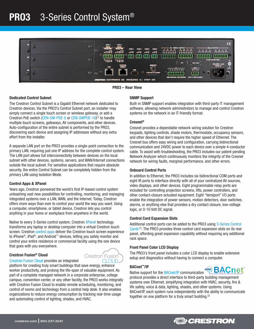
PRO3 3-Series Control System®
crestron.com | 800.237.2041
Dedicated Control SubnetThe Crestron Control Subnet is a Gigabit Ethernet network dedicated to Crestron devices. Via the PRO3’s Control Subnet port, an installer may simply connect a single touch screen or wireless gateway, or add a Crestron PoE switch (CEN-SW-POE-5 or CEN-SWPOE-16)[1] to handle multiple touch screens, gateways, AV components, and other devices. Auto-configuration of the entire subnet is performed by the PRO3, discovering each device and assigning IP addresses without any extra effort from the installer.
A separate LAN port on the PRO3 provides a single-point connection to the primary LAN, requiring just one IP address for the complete control system. The LAN port allows full interconnectivity between devices on the local subnet with other devices, systems, servers, and WAN/Internet connections outside the local subnet. For sensitive applications that require absolute security, the entire Control Subnet can be completely hidden from the primary LAN using Isolation Mode.
Control Apps & XPanelYears ago, Crestron pioneered the world’s first IP-based control system unleashing vast new possibilities for controlling, monitoring, and managing integrated systems over a LAN, WAN, and the Internet. Today, Crestron offers more ways than ever to control your world the way you want. Using a computer, smartphone, or tablet device, Crestron lets you control anything in your home or workplace from anywhere in the world.
Native to every 3-Series control system, Crestron XPanel technology transforms any laptop or desktop computer into a virtual Crestron touch screen. Crestron control apps deliver the Crestron touch screen experience to iPhone®, iPad®, and Android™ devices, letting you safely monitor and control your entire residence or commercial facility using the one device that goes with you everywhere.
Crestron Fusion® CloudCrestron Fusion Cloud provides an integrated platform for creating truly smart buildings that save energy, enhance worker productivity, and prolong the life-span of valuable equipment. As part of a complete managed network in a corporate enterprise, college campus, convention center, or any other facility, the PRO3 works integrally with Crestron Fusion Cloud to enable remote scheduling, monitoring, and control of rooms and technology from a central help desk. It also enables organizations to reduce energy consumption by tracking real-time usage and automating control of lighting, shades, and HVAC.
SNMP SupportBuilt-in SNMP support enables integration with third-party IT management software, allowing network administrators to manage and control Crestron systems on the network in an IT-friendly format.
Cresnet®
Cresnet provides a dependable network wiring solution for Crestron keypads, lighting controls, shade motors, thermostats, occupancy sensors, and other devices that don’t require the higher speed of Ethernet. The Cresnet bus offers easy wiring and configuration, carrying bidirectional communication and 24VDC power to each device over a simple 4-conductor cable. To assist with troubleshooting, the PRO3 includes our patent-pending Network Analyzer which continuously monitors the integrity of the Cresnet network for wiring faults, marginal performance, and other errors.
Onboard Control PortsIn addition to Ethernet, the PRO3 includes six bidirectional COM ports and eight IR ports to interface directly with all of your centralized AV sources, video displays, and other devices. Eight programmable relay ports are included for controlling projection screens, lifts, power controllers, and other contact-closure actuated equipment. Eight “Versiport” I/O ports enable the integration of power sensors, motion detectors, door switches, alarms, or anything else that provides a dry contact closure, low-voltage logic, or 0-10 Volt DC signal.
Control Card Expansion SlotsAdditional control ports can be added to the PRO3 using 3-Series Control Cards [1]. The PRO3 provides three control card expansion slots on its rear panel, affording great expansion capability without requiring any additional rack space.
Front Panel Color LCD DisplayThe PRO3’s front panel includes a color LCD display to enable extensive setup and diagnostics without having to connect a computer.
BACnet™/IPNative support for the BACnet/IP communication protocol provides a direct interface to third-party building management systems over Ethernet, simplifying integration with HVAC, security, fire & life safety, voice & data, lighting, shades, and other systems. Using BACnet/IP, each system runs independently with the ability to communicate together on one platform for a truly smart building.[2]
PRO3 – Rear View
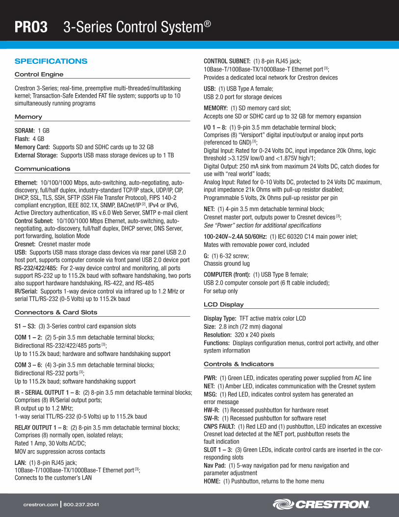
PRO3 3-Series Control System®
crestron.com | 800.237.2041
SPECIFICATIONS
Control Engine
Crestron 3-Series; real-time, preemptive multi-threaded/multitasking kernel; Transaction-Safe Extended FAT file system; supports up to 10 simultaneously running programs
Memory
SDRAM: 1 GBFlash: 4 GBMemory Card: Supports SD and SDHC cards up to 32 GBExternal Storage: Supports USB mass storage devices up to 1 TB
Communications
Ethernet: 10/100/1000 Mbps, auto-switching, auto-negotiating, auto- discovery, full/half duplex, industry-standard TCP/IP stack, UDP/IP, CIP, DHCP, SSL, TLS, SSH, SFTP (SSH File Transfer Protocol), FIPS 140-2 compliant encryption, IEEE 802.1X, SNMP, BACnet/IP [2], IPv4 or IPv6, Active Directory authentication, IIS v.6.0 Web Server, SMTP e-mail clientControl Subnet: 10/100/1000 Mbps Ethernet, auto-switching, auto- negotiating, auto-discovery, full/half duplex, DHCP server, DNS Server, port forwarding, Isolation ModeCresnet: Cresnet master modeUSB: Supports USB mass storage class devices via rear panel USB 2.0 host port, supports computer console via front panel USB 2.0 device portRS-232/422/485: For 2-way device control and monitoring, all ports support RS-232 up to 115.2k baud with software handshaking, two ports also support hardware handshaking, RS-422, and RS-485IR/Serial: Supports 1-way device control via infrared up to 1.2 MHz or serial TTL/RS-232 (0-5 Volts) up to 115.2k baud
Connectors & Card Slots
S1 – S3: (3) 3-Series control card expansion slots
COM 1 – 2: (2) 5-pin 3.5 mm detachable terminal blocks;Bidirectional RS-232/422/485 ports [3];Up to 115.2k baud; hardware and software handshaking support
COM 3 – 6: (4) 3-pin 3.5 mm detachable terminal blocks;Bidirectional RS-232 ports [3];Up to 115.2k baud; software handshaking support
IR - SERIAL OUTPUT 1 – 8: (2) 8-pin 3.5 mm detachable terminal blocks; Comprises (8) IR/Serial output ports;IR output up to 1.2 MHz;1-way serial TTL/RS-232 (0-5 Volts) up to 115.2k baud
RELAY OUTPUT 1 – 8: (2) 8-pin 3.5 mm detachable terminal blocks; Comprises (8) normally open, isolated relays;Rated 1 Amp, 30 Volts AC/DC;MOV arc suppression across contacts
LAN: (1) 8-pin RJ45 jack; 10Base-T/100Base-TX/1000Base-T Ethernet port [3]; Connects to the customer’s LAN
CONTROL SUBNET: (1) 8-pin RJ45 jack;10Base-T/100Base-TX/1000Base-T Ethernet port [3];Provides a dedicated local network for Crestron devices
USB: (1) USB Type A female;USB 2.0 port for storage devices
MEMORY: (1) SD memory card slot;Accepts one SD or SDHC card up to 32 GB for memory expansion
I/O 1 – 8: (1) 9-pin 3.5 mm detachable terminal block; Comprises (8) “Versiport” digital input/output or analog input ports (referenced to GND) [3];Digital Input: Rated for 0-24 Volts DC, input impedance 20k Ohms, logic threshold >3.125V low/0 and <1.875V high/1;Digital Output: 250 mA sink from maximum 24 Volts DC, catch diodes for use with “real world” loads;Analog Input: Rated for 0-10 Volts DC, protected to 24 Volts DC maximum, input impedance 21k Ohms with pull-up resistor disabled;Programmable 5 Volts, 2k Ohms pull-up resistor per pin
NET: (1) 4-pin 3.5 mm detachable terminal block;Cresnet master port, outputs power to Cresnet devices [3];See “Power” section for additional specifications
100-240V~2.4A 50/60Hz: (1) IEC 60320 C14 main power inlet;Mates with removable power cord, included
G: (1) 6-32 screw; Chassis ground lug
COMPUTER (front): (1) USB Type B female;USB 2.0 computer console port (6 ft cable included);For setup only
LCD Display
Display Type: TFT active matrix color LCDSize: 2.8 inch (72 mm) diagonalResolution: 320 x 240 pixelsFunctions: Displays configuration menus, control port activity, and other system information
Controls & Indicators
PWR: (1) Green LED, indicates operating power supplied from AC lineNET: (1) Amber LED, indicates communication with the Cresnet systemMSG: (1) Red LED, indicates control system has generated an error messageHW-R: (1) Recessed pushbutton for hardware resetSW-R: (1) Recessed pushbutton for software resetCNPS FAULT: (1) Red LED and (1) pushbutton, LED indicates an excessive Cresnet load detected at the NET port, pushbutton resets the fault indicationSLOT 1 – 3: (3) Green LEDs, indicate control cards are inserted in the cor-responding slotsNav Pad: (1) 5-way navigation pad for menu navigation and parameter adjustmentHOME: (1) Pushbutton, returns to the home menu
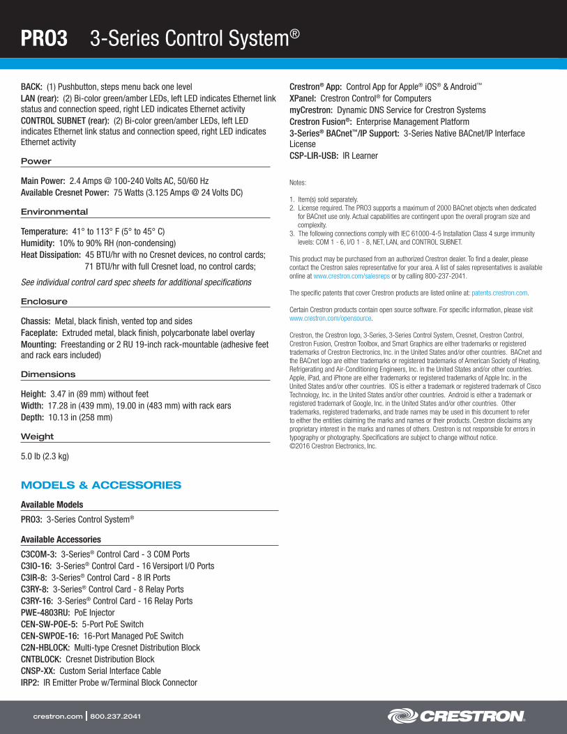
PRO3 3-Series Control System®
crestron.com | 800.237.2041
BACK: (1) Pushbutton, steps menu back one levelLAN (rear): (2) Bi-color green/amber LEDs, left LED indicates Ethernet link status and connection speed, right LED indicates Ethernet activityCONTROL SUBNET (rear): (2) Bi-color green/amber LEDs, left LED indicates Ethernet link status and connection speed, right LED indicates Ethernet activity
Power
Main Power: 2.4 Amps @ 100-240 Volts AC, 50/60 HzAvailable Cresnet Power: 75 Watts (3.125 Amps @ 24 Volts DC)
Environmental
Temperature: 41° to 113° F (5° to 45° C)Humidity: 10% to 90% RH (non-condensing)Heat Dissipation: 45 BTU/hr with no Cresnet devices, no control cards;
71 BTU/hr with full Cresnet load, no control cards;
See individual control card spec sheets for additional specifications
Enclosure
Chassis: Metal, black finish, vented top and sidesFaceplate: Extruded metal, black finish, polycarbonate label overlayMounting: Freestanding or 2 RU 19-inch rack-mountable (adhesive feet and rack ears included)
Dimensions
Height: 3.47 in (89 mm) without feetWidth: 17.28 in (439 mm), 19.00 in (483 mm) with rack earsDepth: 10.13 in (258 mm)
Weight
5.0 lb (2.3 kg)
MODELS & ACCESSORIES
Available Models
PRO3: 3-Series Control System®
Available Accessories
C3COM-3: 3-Series® Control Card - 3 COM PortsC3IO-16: 3-Series® Control Card - 16 Versiport I/O PortsC3IR-8: 3-Series® Control Card - 8 IR PortsC3RY-8: 3-Series® Control Card - 8 Relay PortsC3RY-16: 3-Series® Control Card - 16 Relay PortsPWE-4803RU: PoE InjectorCEN-SW-POE-5: 5-Port PoE SwitchCEN-SWPOE-16: 16-Port Managed PoE SwitchC2N-HBLOCK: Multi-type Cresnet Distribution BlockCNTBLOCK: Cresnet Distribution BlockCNSP-XX: Custom Serial Interface CableIRP2: IR Emitter Probe w/Terminal Block Connector
Crestron® App: Control App for Apple® iOS® & Android™
XPanel: Crestron Control® for ComputersmyCrestron: Dynamic DNS Service for Crestron SystemsCrestron Fusion®: Enterprise Management Platform3-Series® BACnet™/IP Support: 3-Series Native BACnet/IP InterfaceLicenseCSP-LIR-USB: IR Learner
Notes:
1. Item(s) sold separately.2. License required. The PRO3 supports a maximum of 2000 BACnet objects when dedicated
for BACnet use only. Actual capabilities are contingent upon the overall program size and complexity.
3. The following connections comply with IEC 61000-4-5 Installation Class 4 surge immunity levels: COM 1 - 6, I/O 1 - 8, NET, LAN, and CONTROL SUBNET.
This product may be purchased from an authorized Crestron dealer. To find a dealer, please contact the Crestron sales representative for your area. A list of sales representatives is available online at www.crestron.com/salesreps or by calling 800-237-2041.
The specific patents that cover Crestron products are listed online at: patents.crestron.com.
Certain Crestron products contain open source software. For specific information, please visit www.crestron.com/opensource.
Crestron, the Crestron logo, 3-Series, 3-Series Control System, Cresnet, Crestron Control, Crestron Fusion, Crestron Toolbox, and Smart Graphics are either trademarks or registered trademarks of Crestron Electronics, Inc. in the United States and/or other countries. BACnet and the BACnet logo are either trademarks or registered trademarks of American Society of Heating, Refrigerating and Air-Conditioning Engineers, Inc. in the United States and/or other countries. Apple, iPad, and iPhone are either trademarks or registered trademarks of Apple Inc. in the United States and/or other countries. IOS is either a trademark or registered trademark of Cisco Technology, Inc. in the United States and/or other countries. Android is either a trademark or registered trademark of Google, Inc. in the United States and/or other countries. Other trademarks, registered trademarks, and trade names may be used in this document to refer to either the entities claiming the marks and names or their products. Crestron disclaims any proprietary interest in the marks and names of others. Crestron is not responsible for errors in typography or photography. Specifications are subject to change without notice. ©2016 Crestron Electronics, Inc.
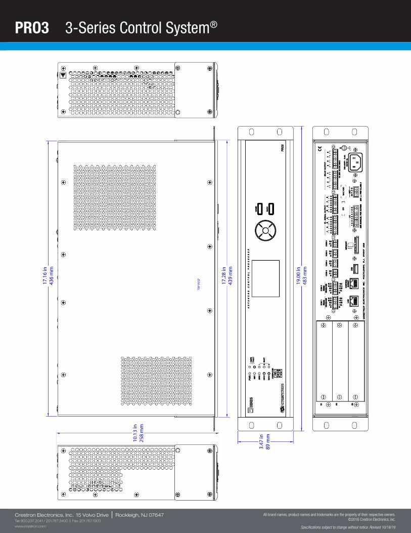
PRO3 3-Series Control System®
Crestron Electronics, Inc. 15 Volvo Drive | Rockleigh, NJ 07647Tel: 800.237.2041 / 201.767.3400 | Fax: 201.767.1903
www.crestron.com
All brand names, product names and trademarks are the property of their respective owners. ©2016 Crestron Electronics, Inc.
Specifications subject to change without notice. Revised 10/18/16
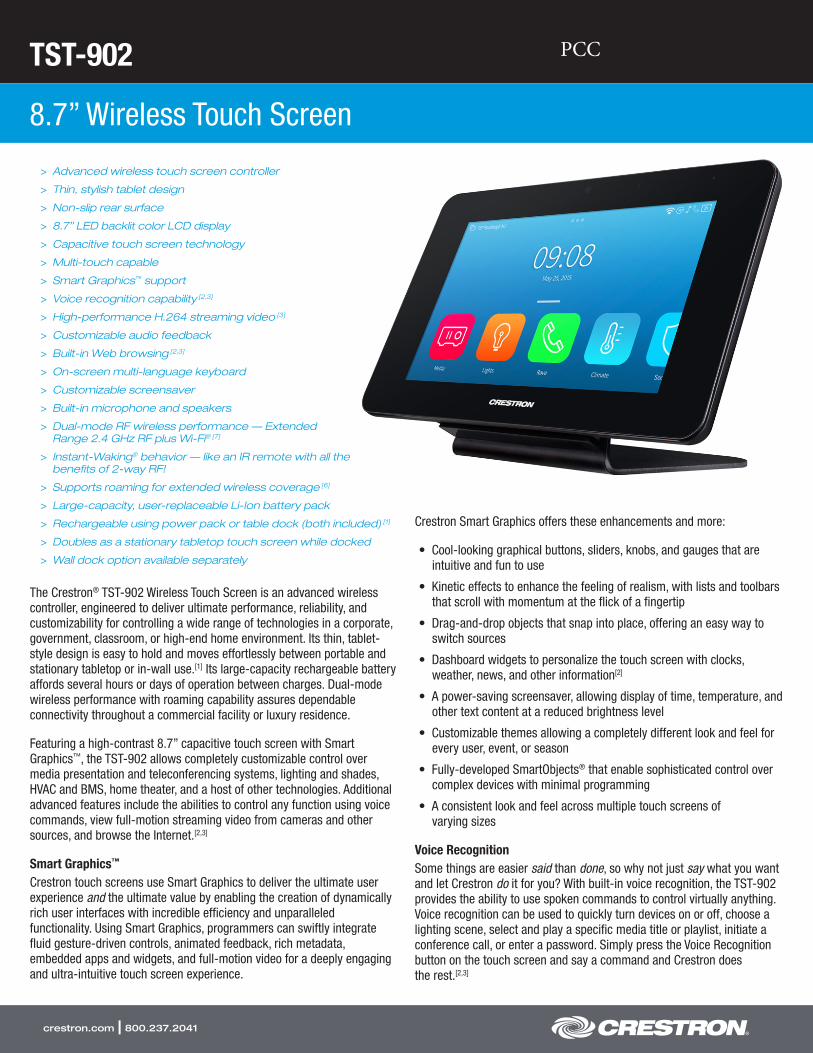
TST-902
8.7” Wireless Touch Screen
crestron.com | 800.237.2041
> Advanced wireless touch screen controller
> Thin, stylish tablet design
> Non-slip rear surface
> 8.7” LED backlit color LCD display
> Capacitive touch screen technology
> Multi-touch capable
> Smart Graphics™ support
> Voice recognition capability [2,3]
> High-performance H.264 streaming video [3]
> Customizable audio feedback
> Built-in Web browsing [2,3]
> On-screen multi-language keyboard
> Customizable screensaver
> Built-in microphone and speakers
> Dual-mode RF wireless performance — ExtendedRange 2.4 GHz RF plus Wi-Fi® [7]
> Instant-Waking® behavior — like an IR remote with all thebenefits of 2-way RF!
> Supports roaming for extended wireless coverage [6]
> Large-capacity, user-replaceable Li-Ion battery pack
> Rechargeable using power pack or table dock (both included) [1]
> Doubles as a stationary tabletop touch screen while docked
> Wall dock option available separately
The Crestron® TST-902 Wireless Touch Screen is an advanced wireless controller, engineered to deliver ultimate performance, reliability, and customizability for controlling a wide range of technologies in a corporate, government, classroom, or high-end home environment. Its thin, tablet-style design is easy to hold and moves effortlessly between portable and stationary tabletop or in-wall use.[1] Its large-capacity rechargeable battery affords several hours or days of operation between charges. Dual-mode wireless performance with roaming capability assures dependable connectivity throughout a commercial facility or luxury residence.
Featuring a high-contrast 8.7” capacitive touch screen with Smart Graphics™, the TST-902 allows completely customizable control over media presentation and teleconferencing systems, lighting and shades, HVAC and BMS, home theater, and a host of other technologies. Additional advanced features include the abilities to control any function using voice commands, view full-motion streaming video from cameras and other sources, and browse the Internet.[2,3]
Smart Graphics™
Crestron touch screens use Smart Graphics to deliver the ultimate user experience and the ultimate value by enabling the creation of dynamically rich user interfaces with incredible efficiency and unparalleled functionality. Using Smart Graphics, programmers can swiftly integrate fluid gesture-driven controls, animated feedback, rich metadata, embedded apps and widgets, and full-motion video for a deeply engaging and ultra-intuitive touch screen experience.
Crestron Smart Graphics offers these enhancements and more:
• Cool-looking graphical buttons, sliders, knobs, and gauges that areintuitive and fun to use
• Kinetic effects to enhance the feeling of realism, with lists and toolbarsthat scroll with momentum at the flick of a fingertip
• Drag-and-drop objects that snap into place, offering an easy way toswitch sources
• Dashboard widgets to personalize the touch screen with clocks,weather, news, and other information[2]
• A power-saving screensaver, allowing display of time, temperature, andother text content at a reduced brightness level
• Customizable themes allowing a completely different look and feel forevery user, event, or season
• Fully-developed SmartObjects® that enable sophisticated control overcomplex devices with minimal programming
• A consistent look and feel across multiple touch screens ofvarying sizes
Voice RecognitionSome things are easier said than done, so why not just say what you want and let Crestron do it for you? With built-in voice recognition, the TST-902 provides the ability to use spoken commands to control virtually anything. Voice recognition can be used to quickly turn devices on or off, choose a lighting scene, select and play a specific media title or playlist, initiate a conference call, or enter a password. Simply press the Voice Recognition button on the touch screen and say a command and Crestron does the rest.[2,3]
PCC

TST-902 8.7” Wireless Touch Screen
crestron.com | 800.237.2041
Streaming VideoHigh-performance streaming video capability makes it possible to view security cameras and other video sources right on the touch screen. Native support for H.264 and MJPEG formats allows the TST-902 to display live streaming video from an IP camera, a streaming encoder (Crestron CEN-NVS200, DM-TXRX-100-STR, or similar[4]), or a DigitalMedia™ switcher.[3]
Web BrowsingUsing its built-in Web browser, the TST-902 provides quick access to online program guides and other Web-based services at the touch of a button, allowing enhanced touch screen control of DVRs and other appliances without having to pick up a separate tablet or smartphone. If a device can be controlled or managed through a Web browser, it can be integrated into the Crestron system through the TST-902. Of course, the Web browser may also be used to simply browse the Internet, watch online videos, and check up on social media.[2,3]
Multi-Touch SupportThe TST-902’s capacitive touch screen affords enhanced capabilities for browsing Web pages using multi-touch gestures.
On-Screen KeyboardAn on-screen multi-language keyboard allows for quick entry of passwords, URLs, and text searches.
Audio FeedbackCustomized audio files can be loaded on the TST-902 to add another dimension to the touch screen graphics using personalized sounds, button feedback, and voice prompts.
Dual-Mode WirelessTo deliver the ultimate in wireless touch screen performance and functionality, the TST-902 employs a combination of Crestron Extended Range 2.4 GHz RF (ER) and Wi-Fi® wireless technologies.
• Extended Range RF (Required) — Primary functionality is supported via Crestron ER (Extended Range) wireless communications, providing seamless touch screen control with true feedback. A single ER gateway [4] enables ultra dependable wireless performance at a range of up to 200 feet (60 m) indoors.[5] Roaming capability allows for even greater coverage using up to eight ER gateways.
• Wi-Fi (Optional) — While the TST-902 can be operated using only ER wireless, advanced wireless capabilities such as streaming video, voice recognition, Web browsing, and dynamic graphics can only be supported using both ER and Wi-Fi together (dual-mode). Crestron enhanced Wi-Fi wireless performance achieves a remarkable 50 feet (15 m) omnidirectional coverage indoors.[5] For Wi-Fi networks with multiple access points, the TST-902 supports the ability to hand off communication from one access point to another if the active connection is lost.[6] The choice of 802.11 b, g, and n protocols affords reliable, high-speed wireless performance in virtually any RF environment. For optimal Wi-Fi performance, Crestron offers the CEN-WAP-1500 High Power Dual-Band Wireless Access Point [4].
IMPORTANT: EVERY INSTALLATION OF THE TST-902 REQUIRES A CRESTRON ER WIRELESS GATEWAY TO ENABLE ESSENTIAL WIRELESS CAPABILITY. THE TST-902 WILL NOT WORK WITH WI-FI ALONE.[7]
Instant-Waking®
To ensure the most transparent user experience possible, the TST-902 has been engineered to wake instantly upon touching the touch screen. Commands are sent immediately — just like an IR remote but with none of IR’s limitations. So spontaneous actions like muting the audio, pausing the video, or changing the channel can be executed on-the-fly without any waiting.
Extended Battery LifeThe TST-902 features a large-capacity, user-replaceable Li-Ion battery pack to enable up to 9 hours of continuous operation and several days of typical use between charges. Intelligent power management and Lithium Ion battery technology afford a perfect balance of long battery life, light weight, and compact size.
Table Dock ChargerThe TST-902 includes a stylish table dock for charging its internal battery while simultaneously allowing it to be used as a stationary tabletop touch screen. The table dock holds the TST-902 firmly at a fixed upright angle while docked, and allows it to be simply lifted off at any time for portable use. Its sleek appearance achieves a look befitting the most contemporary boardroom or luxury living room.[1]
Wall Dock OptionAvailable separately, the TST-902-DSW provides a flush mount, in-wall docking solution, allowing the TST-902 to be used as a stationary wall mount touch screen with the ability to go wireless at any time.
SPECIFICATIONS
Note: See also TST-902-DS for additional specifications.[1]
Touch Screen Display
Display Type: TFT Active matrix color LCDSize: 8.74 inch (222 mm) diagonalResolution: 1008 x 588 pixelsBrightness: 300 nits (cd/m²)Contrast: 700:1Color Depth: 24-bit, 16.7M colorsIllumination: LED BacklitViewing Angle: ±88° horizontal, ±88° verticalTouch Screen: Projected Capacitive, multi-touch capable
Buttons & Indicators
Battery LED: (1) White LED, indicates battery condition and charging status when dockedReset: (1) Pinhole recessed button on rear for hardware reset and setup initiation
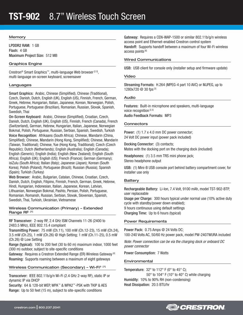
TST-902 8.7” Wireless Touch Screen
crestron.com | 800.237.2041
Memory
LPDDR2 RAM: 1 GBFlash: 4 GBMaximum Project Size: 512 MB
Graphics Engine
Crestron® Smart Graphics™, multi-language Web browser [2,3], multi-language on-screen keyboard, screensaver
Languages
Smart Graphics: Arabic, Chinese (Simplified), Chinese (Traditional), Czech, Danish, Dutch, English (UK), English (US), Finnish, French, German, Greek, Hebrew, Hungarian, Italian, Japanese, Korean, Norwegian, Polish, Portuguese, Portuguese (Brazilian), Romanian, Russian, Slovak, Spanish, Swedish, ThaiOn-Screen Keyboard: Arabic, Chinese (Simplified), Croatian, Czech, Danish, Dutch, English (UK), English (US), Finnish, French (Canada), French (Switzerland), German, Hebrew, Hungarian, Italian, Japanese, Norwegian Bokmal, Polish, Portuguese, Russian, Serbian, Spanish, Swedish, TurkishVoice Recognition: Afrikaans (South Africa); Chinese, Mandarin (China, Simplified); Chinese, Mandarin (Hong Kong, Simplified); Chinese, Mandarin (Taiwan, Traditional); Chinese, Yue (Hong Kong, Traditional); Czech (Czech Republic); Dutch (Netherlands); English (Australia); English (Canada); English (Generic); English (India); English (New Zealand); English (South Africa); English (UK); English (US); French (France); German (Germany); isiZulu (South Africa); Italian (Italy); Japanese (Japan); Korean (South Korea); Polish (Poland); Portuguese (Brazil); Russian (Russia); Spanish (Spain); Turkish (Turkey)Web Browser: Arabic, Bulgarian, Catalan, Chinese, Croatian, Czech, Danish, Dutch, English, Filipino, Finnish, French, German, Greek, Hebrew, Hindi, Hungarian, Indonesian, Italian, Japanese, Korean, Latvian, Lithuanian, Norwegian Bokmal, Pashto, Persian, Polish, Portuguese, Romanian, Romansh, Russian, Serbian, Slovak, Slovenian, Spanish, Swedish, Thai, Turkish, Ukrainian, Vietnamese
Wireless Communication (Primary) – Extended Range RF [7]
RF Transceiver: 2-way RF, 2.4 GHz ISM Channels 11-26 (2400 to 2483.5 MHz), IEEE 802.15.4 compliantTransmitting Power: 75 mW (Ch.11), 100 mW (Ch.12-23), 15 mW (Ch.24), 3.5 mW (Ch.25), 1 mW (Ch.26) @ High Setting; 1 mW (Ch.11-25), 0.5 mW (Ch.26) @ Low SettingRange (typical): 100 to 200 feet (30 to 60 m) maximum indoor, 1000 feet (300 m) outdoor, subject to site-specific conditionsGateway: Requires a Crestron Extended Range (ER) Wireless Gateway [4]
Roaming: Supports roaming between a maximum of eight gateways
Wireless Communication (Secondary) – Wi-Fi® [7]
Transceiver: IEEE 802.11b/g/n Wi-Fi (2.4 GHz 2-way RF), static IP or dynamic IP via DHCPSecurity: 64 & 128-bit WEP, WPA™ & WPA2™-PSK with TKIP & AESRange: Up to 50 feet (15 m), subject to site-specific conditions
Gateway: Requires a CEN-WAP-1500 or similar 802.11b/g/n wireless access point and Ethernet-enabled Crestron control systemHandoff: Supports handoff between a maximum of four Wi-Fi wireless access points [6]
Wired Communications
USB: USB client for console only (installer setup and firmware update)
Video
Streaming Formats: H.264 (MPEG-4 part 10 AVC) or MJPEG, up to 1280x720 @ 30 fps [3]
Audio
Features: Built-in microphone and speakers, multi-language voice recognition [2,3]
Audio Feedback Formats: MP3
Connectors
Power: (1) 1.7 x 4.0 mm DC power connector;24 Volt DC power input (power pack included)
Docking Connector: (3) contacts;Mates with the docking port on the charging dock (included)
Headphones: (1) 3.5 mm TRS mini phone jack;Stereo headphone output
USB: (1) Mini-B USB console port behind battery compartment cover, for installer use only
Battery
Rechargeable Battery: Li-Ion, 7.4 Volt, 9100 mAh, model TST-902-BTP, user replaceableUsage per Charge: 300 hours typical under normal use (10% active duty cycle with standby/power down enabled);9 hours continuous using default settingsCharging Time: Up to 6 hours (typical)
Power Requirements
Power Pack: 0.75 Amps @ 24 Volts DC;100-240 Volts AC, 50/60 Hz power pack, model PW-2407WURA included
Note: Power connection can be via the charging dock or onboard DC power connector
Power Consumption: 7 Watts
Environmental
Temperature: 32° to 112° F (0° to 45° C);50° to 104° F (10° to 40° C) while charging
Humidity: 10% to 90% RH (non-condensing)Heat Dissipation: 20.5 BTU/hr
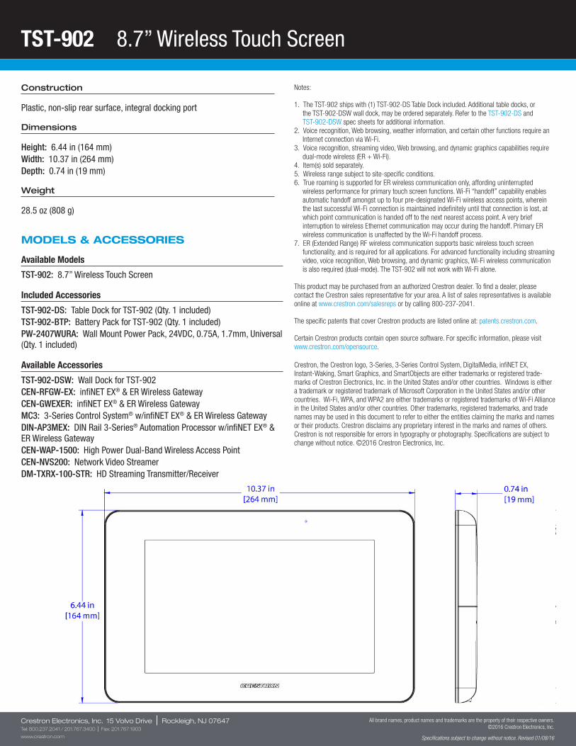
TST-902 8.7” Wireless Touch Screen
Crestron Electronics, Inc. 15 Volvo Drive | Rockleigh, NJ 07647Tel: 800.237.2041 / 201.767.3400 | Fax: 201.767.1903
www.crestron.com
All brand names, product names and trademarks are the property of their respective owners. ©2016 Crestron Electronics, Inc.
Specifications subject to change without notice. Revised 01/08/16
Construction
Plastic, non-slip rear surface, integral docking port
Dimensions
Height: 6.44 in (164 mm)Width: 10.37 in (264 mm)Depth: 0.74 in (19 mm)
Weight
28.5 oz (808 g)
MODELS & ACCESSORIES
Available Models
TST-902: 8.7” Wireless Touch Screen
Included Accessories
TST-902-DS: Table Dock for TST-902 (Qty. 1 included)TST-902-BTP: Battery Pack for TST-902 (Qty. 1 included)PW-2407WURA: Wall Mount Power Pack, 24VDC, 0.75A, 1.7mm, Universal (Qty. 1 included)
Available Accessories
TST-902-DSW: Wall Dock for TST-902CEN-RFGW-EX: infiNET EX® & ER Wireless GatewayCEN-GWEXER: infiNET EX® & ER Wireless GatewayMC3: 3-Series Control System® w/infiNET EX® & ER Wireless GatewayDIN-AP3MEX: DIN Rail 3-Series® Automation Processor w/infiNET EX® & ER Wireless GatewayCEN-WAP-1500: High Power Dual-Band Wireless Access PointCEN-NVS200: Network Video StreamerDM-TXRX-100-STR: HD Streaming Transmitter/Receiver
Notes:
1. The TST-902 ships with (1) TST-902-DS Table Dock included. Additional table docks, or the TST-902-DSW wall dock, may be ordered separately. Refer to the TST-902-DS and TST-902-DSW spec sheets for additional information.
2. Voice recognition, Web browsing, weather information, and certain other functions require an Internet connection via Wi-Fi.
3. Voice recognition, streaming video, Web browsing, and dynamic graphics capabilities require dual-mode wireless (ER + Wi-Fi).
4. Item(s) sold separately.5. Wireless range subject to site-specific conditions.6. True roaming is supported for ER wireless communication only, affording uninterrupted
wireless performance for primary touch screen functions. Wi-Fi “handoff” capability enables automatic handoff amongst up to four pre-designated Wi-Fi wireless access points, wherein the last successful Wi-Fi connection is maintained indefinitely until that connection is lost, at which point communication is handed off to the next nearest access point. A very brief interruption to wireless Ethernet communication may occur during the handoff. Primary ER wireless communication is unaffected by the Wi-Fi handoff process.
7. ER (Extended Range) RF wireless communication supports basic wireless touch screen functionality, and is required for all applications. For advanced functionality including streaming video, voice recognition, Web browsing, and dynamic graphics, Wi-Fi wireless communication is also required (dual-mode). The TST-902 will not work with Wi-Fi alone.
This product may be purchased from an authorized Crestron dealer. To find a dealer, please contact the Crestron sales representative for your area. A list of sales representatives is available online at www.crestron.com/salesreps or by calling 800-237-2041.
The specific patents that cover Crestron products are listed online at: patents.crestron.com.
Certain Crestron products contain open source software. For specific information, please visit www.crestron.com/opensource.
Crestron, the Crestron logo, 3-Series, 3-Series Control System, DigitalMedia, infiNET EX, Instant-Waking, Smart Graphics, and SmartObjects are either trademarks or registered trade-marks of Crestron Electronics, Inc. in the United States and/or other countries. Windows is either a trademark or registered trademark of Microsoft Corporation in the United States and/or other countries. Wi-Fi, WPA, and WPA2 are either trademarks or registered trademarks of Wi-Fi Alliance in the United States and/or other countries. Other trademarks, registered trademarks, and trade names may be used in this document to refer to either the entities claiming the marks and names or their products. Crestron disclaims any proprietary interest in the marks and names of others. Crestron is not responsible for errors in typography or photography. Specifications are subject to change without notice. ©2016 Crestron Electronics, Inc.
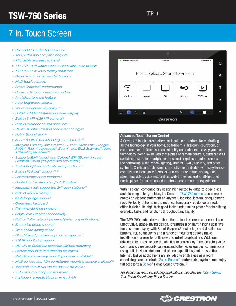
TSW-760 Series
7 in. Touch Screen
crestron.com | 800.237.2041
> Ultra clean, modern appearance
> Thin profile and compact footprint
> Affordable and easy to install
> 7 in. (178 mm) widescreen active-matrix color display
> 1024 x 600 WSVGA display resolution
> Capacitive touch screen technology
> Multi-touch capable
> Smart Graphics® performance
> Backlit soft-touch capacitive buttons
> Any/all button hide feature
> Auto-brightness control
> Voice recognition capability [2,3]
> H.264 or MJPEG streaming video display
> Built-in 5 MP H.264 IP camera [3]
> Built-in microphone and speakers [3]
> Rava® SIP intercom and phone technology [3]
> Native Sonos® app [2]
> Zoom Rooms™ conferencing control mode [9]
> Integrates directly with Crestron Fusion®, Microsoft®, Google®,Robin®, Teem®, Appspace®, Zoom™, and EMS Software™ roomscheduling services [1,6]
> Supports IBM® Notes® and CollegeNET® 25Live® throughCrestron Fusion (on-premises server only)
> Available light bar and hallway sign options [8]
> Built-in PinPoint™ beacon [3,10]
> Customizable audio feedback
> Control for Crestron Pyng® OS 2 system
> Integration with supported 2N® door stations [11]
> Built-in web browsing [2]
> Multi-language support
> On-screen keyboard
> Customizable screensaver
> Single-wire Ethernet connectivity
> PoE or PoE+ network powered (refer to specifications)
> Enterprise grade security
> Web based configuration
> Cloud-based provisioning and management
> SNMP monitoring support
> US, UK, or European electrical wall box mounting
> Lectern mount over a rectangular cutout
> Retrofit and masonry mounting options available [12]
> Multi-surface and ADA compliance mounting options available [4]
> Tabletop and swivel mount options available [4]
> 3 RU rack mount option available [4]
> Available in smooth black or white finish
Advanced Touch Screen ControlA Crestron® touch screen offers an ideal user interface for controlling all the technology in your home, boardroom, classroom, courtroom, or command center. Touch screens simplify and enhance the way you use technology, doing away with those piles of remote controls, cluttered wall switches, disparate smartphone apps, and cryptic computer screens. For controlling audio, video, lighting, shades, HVAC, security, and other systems, Crestron touch screens are fully-customizable with easy-to-use controls and icons, true feedback and real-time status display, live streaming video, voice recognition, web browsing, and a full-featured media player for an enhanced multiroom entertainment experience.
With its clean, contemporary design highlighted by edge-to-edge glass and stunning color graphics, the Crestron TSW-760 series touch screen makes an elegant statement on any wall, tabletop, lectern, or equipment rack. Perfectly at home in the most contemporary residence or modern office building, its high-tech good looks underline its power for simplifying everyday tasks and functions throughout any facility.
The TSW-760 series delivers the ultimate touch screen experience in an unobtrusive, space-saving design. It features a brilliant 7 inch capacitive touch screen display with Smart Graphics® technology and 5 soft-touch buttons. PoE connectivity and a range of mounting options make installation a breeze for both new and retrofit applications. Additional advanced features include the abilities to control any function using voice commands, view security cameras and other video sources, communicate using built-in video intercom and phone capabilities, and browse the Internet. Native applications are included to enable use as a room scheduling panel, control a Zoom Rooms™ conferencing system, and enjoy full access to a Sonos® Home Sound System.[2]
For dedicated room scheduling applications, see also the TSS-7 Series 7 in. Room Scheduling Touch Screen.
TP-1
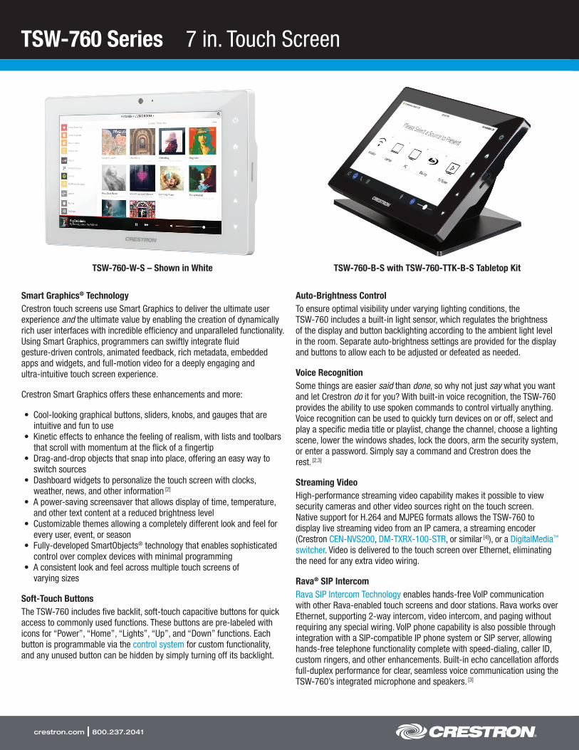
TSW-760 Series 7 in. Touch Screen
crestron.com | 800.237.2041
Smart Graphics® TechnologyCrestron touch screens use Smart Graphics to deliver the ultimate user experience and the ultimate value by enabling the creation of dynamically rich user interfaces with incredible efficiency and unparalleled functionality. Using Smart Graphics, programmers can swiftly integrate fluid gesture-driven controls, animated feedback, rich metadata, embedded apps and widgets, and full-motion video for a deeply engaging and ultra-intuitive touch screen experience.
Crestron Smart Graphics offers these enhancements and more:
• Cool-looking graphical buttons, sliders, knobs, and gauges that are intuitive and fun to use
• Kinetic effects to enhance the feeling of realism, with lists and toolbars that scroll with momentum at the flick of a fingertip
• Drag-and-drop objects that snap into place, offering an easy way to switch sources
• Dashboard widgets to personalize the touch screen with clocks, weather, news, and other information [2]
• A power-saving screensaver that allows display of time, temperature, and other text content at a reduced brightness level
• Customizable themes allowing a completely different look and feel for every user, event, or season
• Fully-developed SmartObjects® technology that enables sophisticated control over complex devices with minimal programming
• A consistent look and feel across multiple touch screens of varying sizes
Soft-Touch ButtonsThe TSW-760 includes five backlit, soft-touch capacitive buttons for quick access to commonly used functions. These buttons are pre-labeled with icons for “Power”, “Home”, “Lights”, “Up”, and “Down” functions. Each button is programmable via the control system for custom functionality, and any unused button can be hidden by simply turning off its backlight.
Auto-Brightness ControlTo ensure optimal visibility under varying lighting conditions, the TSW-760 includes a built-in light sensor, which regulates the brightness of the display and button backlighting according to the ambient light level in the room. Separate auto-brightness settings are provided for the display and buttons to allow each to be adjusted or defeated as needed.
Voice RecognitionSome things are easier said than done, so why not just say what you want and let Crestron do it for you? With built-in voice recognition, the TSW-760 provides the ability to use spoken commands to control virtually anything. Voice recognition can be used to quickly turn devices on or off, select and play a specific media title or playlist, change the channel, choose a lighting scene, lower the windows shades, lock the doors, arm the security system, or enter a password. Simply say a command and Crestron does the rest. [2,3]
Streaming VideoHigh-performance streaming video capability makes it possible to view security cameras and other video sources right on the touch screen. Native support for H.264 and MJPEG formats allows the TSW-760 to display live streaming video from an IP camera, a streaming encoder (Crestron CEN-NVS200, DM-TXRX-100-STR, or similar [4]), or a DigitalMedia™ switcher. Video is delivered to the touch screen over Ethernet, eliminating the need for any extra video wiring.
Rava® SIP IntercomRava SIP Intercom Technology enables hands-free VoIP communication with other Rava-enabled touch screens and door stations. Rava works over Ethernet, supporting 2-way intercom, video intercom, and paging without requiring any special wiring. VoIP phone capability is also possible through integration with a SIP-compatible IP phone system or SIP server, allowing hands-free telephone functionality complete with speed-dialing, caller ID, custom ringers, and other enhancements. Built-in echo cancellation affords full-duplex performance for clear, seamless voice communication using the TSW-760’s integrated microphone and speakers. [3]
TSW-760-B-S with TSW-760-TTK-B-S Tabletop Kit TSW-760-W-S – Shown in White
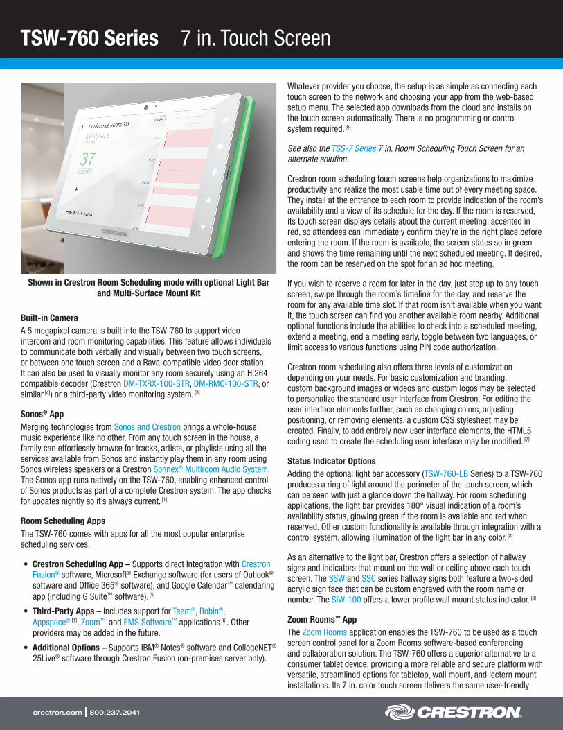
TSW-760 Series 7 in. Touch Screen
crestron.com | 800.237.2041
Built-in CameraA 5 megapixel camera is built into the TSW-760 to support video intercom and room monitoring capabilities. This feature allows individuals to communicate both verbally and visually between two touch screens, or between one touch screen and a Rava-compatible video door station. It can also be used to visually monitor any room securely using an H.264 compatible decoder (Crestron DM-TXRX-100-STR, DM-RMC-100-STR, or similar [4]) or a third-party video monitoring system. [3]
Sonos® AppMerging technologies from Sonos and Crestron brings a whole-house music experience like no other. From any touch screen in the house, a family can effortlessly browse for tracks, artists, or playlists using all the services available from Sonos and instantly play them in any room using Sonos wireless speakers or a Crestron Sonnex® Multiroom Audio System. The Sonos app runs natively on the TSW-760, enabling enhanced control of Sonos products as part of a complete Crestron system. The app checks for updates nightly so it’s always current. [1]
Room Scheduling AppsThe TSW-760 comes with apps for all the most popular enterprise scheduling services.
• Crestron Scheduling App – Supports direct integration with Crestron Fusion® software, Microsoft® Exchange software (for users of Outlook® software and Office 365® software), and Google Calendar™ calendaring app (including G Suite™ software). [5]
• Third-Party Apps – Includes support for Teem®, Robin®, Appspace® [1], Zoom™ and EMS Software™ applications [6]. Other providers may be added in the future.
• Additional Options – Supports IBM® Notes® software and CollegeNET® 25Live® software through Crestron Fusion (on-premises server only).
Whatever provider you choose, the setup is as simple as connecting each touch screen to the network and choosing your app from the web-based setup menu. The selected app downloads from the cloud and installs on the touch screen automatically. There is no programming or control system required. [6]
See also the TSS-7 Series 7 in. Room Scheduling Touch Screen for an alternate solution.
Crestron room scheduling touch screens help organizations to maximize productivity and realize the most usable time out of every meeting space. They install at the entrance to each room to provide indication of the room’s availability and a view of its schedule for the day. If the room is reserved, its touch screen displays details about the current meeting, accented in red, so attendees can immediately confirm they’re in the right place before entering the room. If the room is available, the screen states so in green and shows the time remaining until the next scheduled meeting. If desired, the room can be reserved on the spot for an ad hoc meeting.
If you wish to reserve a room for later in the day, just step up to any touch screen, swipe through the room’s timeline for the day, and reserve the room for any available time slot. If that room isn’t available when you want it, the touch screen can find you another available room nearby. Additional optional functions include the abilities to check into a scheduled meeting, extend a meeting, end a meeting early, toggle between two languages, or limit access to various functions using PIN code authorization.
Crestron room scheduling also offers three levels of customization depending on your needs. For basic customization and branding, custom background images or videos and custom logos may be selected to personalize the standard user interface from Crestron. For editing the user interface elements further, such as changing colors, adjusting positioning, or removing elements, a custom CSS stylesheet may be created. Finally, to add entirely new user interface elements, the HTML5 coding used to create the scheduling user interface may be modified. [7]
Status Indicator OptionsAdding the optional light bar accessory (TSW-760-LB Series) to a TSW-760 produces a ring of light around the perimeter of the touch screen, which can be seen with just a glance down the hallway. For room scheduling applications, the light bar provides 180° visual indication of a room’s availability status, glowing green if the room is available and red when reserved. Other custom functionality is available through integration with a control system, allowing illumination of the light bar in any color. [8]
As an alternative to the light bar, Crestron offers a selection of hallway signs and indicators that mount on the wall or ceiling above each touch screen. The SSW and SSC series hallway signs both feature a two-sided acrylic sign face that can be custom engraved with the room name or number. The SIW-100 offers a lower profile wall mount status indicator. [8]
Zoom Rooms™ AppThe Zoom Rooms application enables the TSW-760 to be used as a touch screen control panel for a Zoom Rooms software-based conferencing and collaboration solution. The TSW-760 offers a superior alternative to a consumer tablet device, providing a more reliable and secure platform with versatile, streamlined options for tabletop, wall mount, and lectern mount installations. Its 7 in. color touch screen delivers the same user-friendly
Shown in Crestron Room Scheduling mode with optional Light Bar and Multi-Surface Mount Kit
TSW-760 Series 7 in. Touch Screen
crestron.com | 800.237.2041
Zoom Rooms experience as a typical tablet, but without the risk of misplacing the device. Instead of Wi-Fi® communications, the TSW-760 uses a wired Ethernet connection to ensure reliable connectivity. [9]
The TSW-760 may be configured to run the Zoom Rooms app exclusively, or to allow toggling between the Zoom Rooms app and regular Smart Graphics touch screen control mode. The latter allows for integrating Zoom Rooms conferencing into a larger AV system while providing control for both through one touch screen device.
Note: Zoom Ultrasonic is supported up to an average of 3 feet (1 m) from the TSW-760 touch screen to an end user device. The range will vary based on environmental noise, the sensitivity of the end user device, and the orientation to the touch screen.
PinPoint™ Beacon (Coming Soon)The built-in PinPoint proximity detection beacon enhances the intelligence and personalization of a Crestron system by enabling a smartphone or tablet device to always know what room it’s in. It works with the Crestron App or Crestron PinPoint App, using Bluetooth® technology to determine when the mobile device is in or near the same room as the beacon, and signals the mobile app to automatically display the appropriate controls and information for that location. [3,10]
Web BrowsingUsing its built-in web browser, the TSW-760 provides access to online program guides and other web-based services at the touch of a button, allowing enhanced touch screen control of DVRs and other appliances without having to pick up a separate tablet or smartphone. The web browser may also be used to simply browse the Internet, check traffic conditions, or look up a recipe. [2]
On-Screen KeyboardTyping in passwords, URLs, and text searches is facilitated using the on-screen multi-language keyboard.
Multi-Touch SupportThe TSW-760’s capacitive touch screen affords enhanced capabilities for browsing web pages using multi-touch gestures.
Audio FeedbackCustomized audio files can be loaded to add another dimension to the touch screen graphics using personalized sounds, button feedback, and voice prompts.
Single-Wire ConnectivityA simple Ethernet LAN connection is all that is required to wire the TSW-760, containing all control, video, intercom, and power signals within a single wire.
Power over EthernetUsing PoE technology, the TSW-760 gets its operating power right through the network cable. PoE (Power over Ethernet) eliminates the need for a local power supply or any dedicated power wiring. Crestron PoE switches (CEN-SW-POE-5 or CEN-SWPOE-16 [4]) offer a total networking solution with built-in PoE for multiple touch screens. A PoE Injector (PWE-4803RU [4]) is also available to support a single touch screen.
Note: Refer to the “Power” specifications for additional details.
Enterprise Grade SecurityCrestron touch screens employ enterprise-grade networking with robust security features such as 802.1X authentication, TLS encryption, HTTPS connectivity, and Active Directory® software integration. These features are imperative to protect your network against service interruptions and malicious intrusions, and to ensure compliance with your organization’s stringent network policies. Cloud-based provisioning and management streamlines the process of configuring and monitoring every touch screen on the network and keeping them updated. Additional support for SNMP allows every touch screen to be monitored by your IT administrator alongside every other device on the network.
Crestron XiO Cloud™ ServiceCrestron XiO Cloud is Crestron’s unifying cloud-based platform for remotely provisioning, monitoring, and managing Crestron devices across an enterprise or an entire client base. Crestron XiO Cloud enables installers and IT managers to deploy and manage thousands of devices in the amount of time it would ordinarily take to manage just one. It provides a zero-touch solution that allows complete configuration of device settings without any hardware in hand, then simply connect each device on site and let Crestron XiO Cloud push out the settings, licenses, drivers, and firmware updates – automatically and securely – for a quick and painless, ready-to-use deployment.
Ongoing Crestron XiO Cloud services facilitate daily management and monitoring of every device through a single dashboard with comprehensive reporting and logging, live status viewing and alerts, performance metrics and analytics, scheduled actions and updates, and more. As requirements grow and evolve, new features and functionality can be added easily to one or many devices at any time without ever going on site. Crestron XiO Cloud is a subscription-based service offering an adaptable SaaS (Software as a Service) solution with graduated levels of functionality and unlimited scalability. For more information about Crestron XiO Cloud, please visit https://www.crestron.com/xiocloud.
Crestron Pyng® OS 2 ControlThe TSW-760 may be used to control a Crestron Pyng® OS 2 whole home solution. After a TSW-760 is added to a room in Crestron Pyng, a home control project is loaded directly to the touch screen. From there, the TSW-760 allows for control over lighting, shades, climate, media, security, and cameras, including the ability to create and recall scenes that create a desired ambiance within certain rooms or for the entire home. A TSW-760 may be installed in each room in the home to provide easy access to the room’s environmental and media subsystems.
2N® Door Station IntegrationThe TSW-760 may be integrated with a supported 2N® door station [11] via the touch screen’s built-in Rava® SIP intercom to provide a door station solution for Crestron Pyng. When a call is initiated on the 2N door station, the video and audio feed is displayed on the TSW-760. Controls are provided on the touch screen to answer or decline the call, and Crestron Pyng quick actions (such as “Open Gate”) may be performed while the call is in progress. A “do not disturb” option is also provided in Crestron Pyng to prevent calls from appearing on the TSW-760.

TSW-760 Series 7 in. Touch Screen
crestron.com | 800.237.2041
Wall or Lectern Mounting OptionsUsing the bracket provided, the TSW-760 is easily installed over a 2-gang or 3-gang US electrical box, or a 2-gang European or UK electrical box. The same bracket allows for installation in a wooden lectern or podium over a rectangular cutout. When installed, the touch screen protrudes just 1/2 inch from the mounting surface and latches firmly into its mounting bracket leaving no visible screws for an ultra clean appearance. A security latch option is included to deter unauthorized removal of the touch screen.
Additional mounting options are afforded using the TSW-UMB-60 Universal Mounting Bracket. By itself, the TSW-UMB-60 provides a post-construction solution for retrofitting the TSW-760 into existing drywall. For pre- construction applications that don’t require a back box, the TSW-UMB-60 can be used along with a TSW-UMB-60-PMK Pre-Construction Mounting Kit. Masonry and concrete applications are accommodated using the TSW-UMB-60 along with a TSW-UMB-60-BBI back box. The TSW-UMB-60 is compatible with TSW-560, TSW-760, TSW-1060, TSS-7, and TSS-10 series touch screens, making it easy to swap out devices at any time. [12]
For impenetrable surfaces, such as glass, granite, or marble, or for applications requiring ADA compliance, Crestron offers the Multi-Surface Mount Kit (TSW-760/1060-MSMK [4]). This option allows for attaching securely to virtually any smooth, flat surface without screws, providing an ideal solution for modern offices with glass walls or historically significant spaces where cutting and drilling is prohibited. It can also be mounted over a conventional electrical box. When installed, the touch screen is angled upwards at a 20° tilt to allow for mounting at an ADA approved height.
When installing the TSW-760 in place of an older Crestron touch screen (APAD, CT-1000, LC-1000, TPS-4L, or TPS-2000L), Crestron offers Retrofit Mounting Brackets (TSW-60-RMB series [4]), which facilitate replacement without having to tear out the old mounting hardware or patch the wall.
Tabletop OptionUsing the optional Tabletop Kit (TSW-760-TTK [4]), the TSW-760 becomes a stylish, freestanding touch screen that fits perfectly on a table, desk, or countertop. It can even be permanently attached to the surface using the optional Swivel Mount Kit (TSW-560/760/1060-SMK [4]).
Rack Mount OptionThe TSW-760 can be mounted in a 19 in. EIA equipment rack using the optional Rack Mount Kit (TSW-560/760-RMK-1 [4]). When rack mounted, the touch screen occupies three rack spaces.
SPECIFICATIONS
Touch Screen Display
Display Type: TFT active matrix color LCDSize: 7 inch (178 mm) diagonalAspect Ratio: 17:10 WSVGAResolution: 1024 x 600 pixelsBrightness: 350 nits (cd/m²)Contrast: 1100:1Color Depth: 24-bit, 16.7M colors
Illumination: Edgelit LED w/auto-brightness controlViewing Angle: ±80° horizontal, ±80° verticalTouch Screen: Projected capacitive, 5-point multi-touch capable
Buttons
Hard Keys: (5) Projected capacitive pushbuttons, backlit w/auto-brightness control, per-button show/hide (backlight enable/disable), pre-labeled with icons for “Power”, “Home”, “Lights”, “Up”, and “Down”Reset: (1) Miniature pushbutton on rear panel for hardware reset
Graphics Engine
Crestron Smart Graphics, multi-language web browser [2], multi-language on-screen keyboard, screensaver, single scalable streaming video window, native Sonos app [2], native room scheduling applications [6], native Zoom Rooms app, setup and diagnostics via web browser or onscreen UI
Room Scheduling Support
Crestron Scheduling App: Crestron Fusion, Microsoft Exchange & Office 365, Google Calendar & G Suite (IBM Notes and CollegeNET 25Live are also supported through Crestron Fusion On-premises only) [5]
Third-Party Apps: Teem, Robin, Appspace [1], Zoom, EMS Software [6]
Languages
Smart Graphics: Arabic, Chinese (Simplified), Chinese (Traditional), Czech, Danish, Dutch, English (UK), English (US), Finnish, French, German, Greek, Hebrew, Hungarian, Italian, Japanese, Korean, Norwegian, Polish, Portuguese, Portuguese (Brazilian), Romanian, Russian, Slovak, Spanish, Swedish, ThaiOn-Screen Keyboard: Arabic, Chinese (Simplified), Croatian, Czech, Danish, Dutch, English (UK), English (US), Finnish, French (Canada), French (Switzerland), German, Hebrew, Hungarian, Italian, Japanese, Norwegian Bokmal, Polish, Portuguese, Russian, Serbian, Spanish, Swedish, TurkishVoice Recognition: Afrikaans (South Africa); Chinese, Mandarin (China, Simplified); Chinese, Mandarin (Hong Kong, Simplified); Chinese, Mandarin (Taiwan, Traditional); Chinese, Yue (Hong Kong, Traditional); Czech (Czech Republic); Dutch (Netherlands); English (Australia); English (Canada); English (Generic); English (India); English (New Zealand); English (South Africa); English (UK); English (US); French (France); German (Germany); isiZulu (South Africa); Italian (Italy); Japanese (Japan); Korean (South Korea); Polish (Poland); Portuguese (Brazil); Russian (Russia); Spanish (Spain); Turkish (Turkey)Web Browser: Arabic, Bulgarian, Catalan, Chinese, Croatian, Czech, Danish, Dutch, English, Filipino, Finnish, French, German, Greek, Hebrew, Hindi, Hungarian, Indonesian, Italian, Japanese, Korean, Latvian, Lithuanian, Norwegian Bokmal, Pashto, Persian, Polish, Portuguese, Romanian, Romansh, Russian, Serbian, Slovak, Slovenian, Spanish, Swedish, Thai, Turkish, Ukrainian, VietnameseRoom Scheduling: Chinese (Simplified), Chinese (Traditional), Danish, Dutch (Netherlands), English (US), English (UK), French, German, Hebrew, Italian, Japanese, Korean, Norwegian, Portuguese (Brazil), Portuguese (Portugal), Russian, Spanish, Swedish
TSW-760 Series 7 in. Touch Screen
crestron.com | 800.237.2041
Memory
RAM: 2 GB DDR3LStorage: Firmware/Application: 4 GB Class 10 microSD card;
System: 4 GB eMMCMaximum Project Size: 600 MB
Communications
Ethernet: 10/100 Mbps, auto-switching, auto-negotiating, auto-discovery, full/half duplex, TCP/IP, UDP/IP, CIP, DHCP, SSL, TLS, SSH, SFTP (SSH File Transfer Protocol), IEEE 802.1X, SNMP, IPv4 or IPv6, Active Directory authentication, HTTPS web browser setup, Crestron XiO Cloud client, IEEE 802.3at compliantUSB: USB 2.0 host for room availability light bar or hallway sign [8]
Bluetooth: Crestron PinPoint proximity detection beacon [3,10]
Streaming Decoder
Video Formats: H.264 (MPEG-4 part 10 AVC), MJPEGAudio Formats: AAC stereoBitrates: Up to 25 Mbps (20 Mbps maximum recommended)Streaming Input Resolutions: Up to 1920x1080@30fpsStreaming Protocol: RTSP
Streaming Encoder & Camera [3]
Camera Resolution: 5.0 MPField of View: 50º horizontalVideo Format: H.264 (MPEG-4 part 10 AVC)Streaming Output Resolution: 1280x720Streaming Protocol: RTSP, ONVIF discovery
Audio
Features: Built-in microphone and speakers, Rava SIP Intercom, multi-language voice recognition [2,3]
Audio Feedback Formats: MP3
Connectors
LAN PoE: (1) 8-pin RJ45 connector, female, with 2 LED indicators;10Base-T/100Base-TX Ethernet port & PoE+ PD port;Green and yellow LEDs indicate Ethernet port status
USB: (1) USB Type A connector, female; USB 2.0 host port; For optional room availability light bar or hallway sign [8]
Power
Power over Ethernet: IEEE 802.3at Type 2 compliant PoE+ PD (Powered Device);- Requests 15 Watts from an 802.3at Type 2 PSE with LLDP advanced
power management;- Requests 30 Watts (PoE+ Class 4) from an 802.3at Type 2 PSE
without LLDP;- Requests 15.4 Watts (PoE Class 0) from an 802.3af (or 802.3at
Type 1) PSE
Environmental
Temperature: 32° to 112° F (0° to 45° C)Humidity: 10% to 90% RH (non-condensing)Heat Dissipation: 44 BTU/hr
Construction
Housing: Plastic, smooth black or white finish, edge-to-edge glass with black or white surroundMounting: Surface mount over a 2 or 3-gang US electrical box, 2-gang European (DIN 49073) electrical box, or 2-gang UK (BS 4662) electrical box; lectern mount over a 2-1/5 in. H x 3-3/4 in. W (56 mm H x 96 mm W) cutout; 1-3/8 in. (35 mm) minimum mounting depth; additional wall mount, surface mount, rack mount, and tabletop options available separately
Dimensions
Height: 4.79 in. (122 mm)Width: 7.61 in. (194 mm)Depth: 1.52 in. (39 mm)Dimensions do not include the mounting bracket or add-on accessories
Weight
14.1 oz (400 g)
Compliance
UL Listed for US & Canada, IC, CE, FCC Part 15 Class B digital device
Notes:
1. Appspace functionality is currently limited to their Room Management feature (aka, room cards or meeting cards) only.
2. Voice recognition, web browsing, weather information, Sonos app, and certain other functions require an Internet connection.
3. The camera, microphone, and Bluetooth transceiver may each be defeated programmatically at any time. For applications demanding an extra measure of privacy, Crestron offers models TSW-760-NC-B-S and TSW-760-NC-W-S, which have no physical camera, microphone, or Bluetooth transceiver installed.
4. Item(s) sold separately. Refer to each product’s spec sheet for complete information.5. Room Scheduling Mode requires the TSW-760 to be designated exclusively for room
scheduling use, which precludes use of certain features and functions described in this spec sheet. For design assistance, contact the Crestron True Blue support team at https://www.crestron.com/support.
TSW-760 Series 7 in. Touch Screen
crestron.com | 800.237.2041
6. Additional subscriptions and/or licenses may be required. Refer to each provider’s website for details about the capabilities and requirements of its scheduling application and services. Third-party apps typically run on the TSW-760 as they do on a tablet device. The TSW-760 runs only one app, which is selected at setup. Only the apps approved and delivered by Crestron can run on the TSW-760.
7. For more information on custom programming for the Crestron room scheduling app, refer to the Crestron Room Scheduling Panels Programming Guide (Doc. 8213) at www.crestron.com/manuals.
8. The light bar and hallway sign accessories are sold separately. Only one light bar or hallway sign may be connected to the TSW-760. Use of either accessory precludes use of the other without the addition of a custom-programmed control system and Cresnet wiring for the hallway sign. Refer to the Accessories section for a list of all available options. Refer to each accessory’s spec sheet for further information.
9. A complete Zoom Rooms solution requires a mini PC or Mac computer running Zoom software, a Zoom Rooms subscription, plus additional peripherals and cables. Visit https://zoom.us/zoomrooms for more information about Zoom Rooms capabilities, hardware requirements, and subscription plans. For design assistance, contact the Crestron True Blue support team at https://www.crestron.com/support.
10. Onboard PinPoint beacon functionality is not currently supported and will be enabled through a future update. When enabled, the TSW-760 will provide an integrated, equivalent alternative to the standalone PP-100-W beacon. For more details, refer to the PP-100-W spec sheet. Bluetooth technology is used solely for proximity detection and does not transmit or receive any control, multimedia, or personal data. PinPoint beacons are only visible to Bluetooth enabled devices that are specifically programmed and configured to work with them.
11. Supported 2N door stations include the 2N IP Audio Kit, 2N IP Audio Kit Lite, 2N IP Base, 2N IP Force, 2N IP Safety, 2N IP Solo, 2N IP Uni, 2N IP Vario, 2N IP Verso, and 2N IP Video Kit. For pairing instructions, refer to the Crestron Pyng OS 2 for CP3-R Product Manual (Doc. 8356) and the TSW-560/TSW-760/TSW-1060 Supplemental Guide (Doc. 7927) at www.crestron.com/manuals.
12. The TSW-UMB-60, TSW-UMB-60-PMK, and TSW-UMB-60-BBI are all sold separately. The TSW-UMB-60 is also compatible with older TSW-UMB-PMK preconstruction mounting kits and TSW-550-BBI back boxes, allowing the TSW-760 touch screen to be installed in place of a previous generation TSW-5xx series touch screen, or any other device that was originally installed using a TSW-UMB-PMK or TSW-550-BBI, without modification to the wall. If replac-ing another older Crestron device, use the appropriate TSW-60-RMB series retrofit mounting bracket (sold separately).
This product may be purchased from an authorized Crestron dealer. To find a dealer, please contact the Crestron sales representative for your area. A list of sales representatives is available online at https://www.crestron.com/How-To-Buy/Find-a-Representative or by calling 855-263-8754.
The specific patents that cover this and other Crestron products are listed online at https://www.crestron.com/legal/patents.
Certain Crestron products contain open source software. For specific information, visit https://www.crestron.com/opensource.
Crestron, the Crestron logo, Crestron Fusion, Crestron Pyng, Crestron XiO Cloud, DigitalMedia, PinPoint, Rava, Smart Graphics, SmartObjects, and Sonnex are either trademarks or registered trademarks of Crestron Electronics, Inc. in the United States and/or other countries. 2N is either a trademark or a registered trademark of 2N Telekomunikace in the United States and/or other countries. Appspace is either a trademark or registered trademark of AppSpace, Inc. in the United States and/or other countries. Bluetooth is either a trademark or registered trademark of Bluetooth SIG, Inc. in the United States and/or other countries. CollegeNET and 25Live are either trademarks or registered trademarks of CollegeNET, Inc. in the United States and/or other countries. EMS Software is either a trademark or registered trademark of EMS Software LLC in the United States and/or other countries. Google, G Suite, and Google Calendar are either trademarks or registered trademarks of Google LLC in the United States and/or other countries. IBM and Notes are either trademarks or registered trademarks of International Business Machines Corporation in the United States and/or other countries. Microsoft, Active Directory, Office 365, and Outlook are either trademarks or registered trademarks of Microsoft Corporation in the United States and/or other countries. Robin is either a trademark or registered trademark of Robin Powered, Inc. in the United States and/or other countries. Sonos is either a trademark or registered trademark of Sonos, Inc. in the United States and/or other countries. Teem is either a trademark or registered trademark of Teem Technologies, Inc. in the United States and/or other countries. Wi-Fi is either a trademark or registered trademark of Wi-Fi Alliance in the United States and/or other countries. Zoom and Zoom Rooms are either trademarks or registered trademarks of Zoom Video Communications, Inc. in the United States and/or other countries.
Other trademarks, registered trademarks, and trade names may be used in this document to refer to either the entities claiming the marks and names or their products. Crestron disclaims any proprietary interest in the marks and names of others. Crestron is not responsible for errors in typography or photography. Specifications are subject to change without notice. ©2018 Crestron Electronics, Inc.
MODELS & ACCESSORIES
Available Models
TSW-760-B-S: 7” Touch Screen, Black SmoothTSW-760-W-S: 7” Touch Screen, White Smooth
Available Accessories
TSW-760-TTK Series: Tabletop KitTSW-560/760/1060-SMK: Swivel Mount Kit for TSW-760-TTK SeriesTSW-UMB-60: Universal Mounting Bracket for TSW-x60 SeriesTSW-UMB-60-PMK: Pre-Construction Mounting Kit for TSW-UMB-60 TSW-UMB-60-BBI: Wall Mount Back Box for TSW-UMB-60TSW-760/1060-RMB-1: Retrofit Mounting Bracket – Converts APAD, CT/LC-1000, or TPS-2000L to TSW-760TSW-760/1060-RMB-2: Retrofit Mounting Bracket – Converts TPS-4L to TSW-760TSW-760/1060-MSMK Series: Multi-Surface Mount KitTSW-560/760-RMK-1: Rack Mount KitPWE-4803RU: PoE InjectorCEN-SW-POE-5: 5-Port PoE SwitchCEN-SWPOE-16: 16-Port Managed PoE SwitchCEN-NVS200: Network Video StreamerDM-TXRX-100-STR: HD Streaming Transmitter/ReceiverDM-RMC-100-STR: HD Streaming Receiver & Room Controller 100SW-XIOC-S Series: Crestron XiO Cloud™ Standard Provisioning and Management Service for one deviceSW-XIOC-P Series: Crestron XiO Cloud™ Premium Provisioning and Management Service for one deviceSW-FUSION-C-3: Crestron Fusion® Cloud; 250 rooms; 3-year service, support, and updatesSW-FUSION-P-L: Crestron Fusion® On-premises; Unlimited rooms; lifetime service, support, and updatesSW-HS-x-C Series: Crestron Fusion® Cloud Room Scheduling for one touch screenSW-HS-x-P Series: Crestron Fusion® On-premises Room Scheduling for one touch screenTSW-760-LB Series: Room Availability Light BarSSC Series: Room Availability Hallway Sign, Ceiling MountSSW Series: Room Availability Hallway Sign, Wall MountSIW-100: Room Availability Status Indicator, Wall Mount
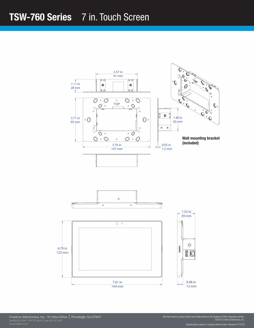
TSW-760 Series 7 in. Touch Screen
Crestron Electronics, Inc. 15 Volvo Drive | Rockleigh, NJ 07647Tel: 800.237.2041 / 201.767.3400 | Fax: 201.767.1903
www.crestron.com
All brand names, product names and trademarks are the property of their respective owners. ©2019 Crestron Electronics, Inc.
Specifications subject to change without notice. Revised 01/10/19
3.71 in95 mm
5.76 in147 mm
1.96 in50 mm
3.57 in91 mm
0.05 in1.2 mm
1.11 in28 mm
7.61 in194 mm
0.48 in13 mm
1.52 in39 mm
4.79 in122 mm
Wall mounting bracket (included)
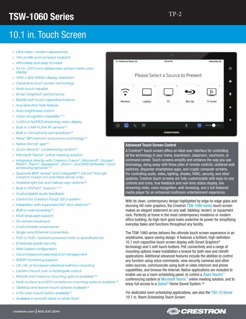
TSW-1060 Series
10.1 in. Touch Screen
crestron.com | 800.237.2041
> Ultra clean, modern appearance
> Thin profile and compact footprint
> Affordable and easy to install
> 10.1 in. (257 mm) widescreen active-matrix colordisplay
> 1280 x 800 WXGA display resolution
> Capacitive touch screen technology
> Multi-touch capable
> Smart Graphics® performance
> Backlit soft-touch capacitive buttons
> Any/all button hide feature
> Auto-brightness control
> Voice recognition capability [2,3]
> H.264 or MJPEG streaming video display
> Built-in 5 MP H.264 IP camera [3]
> Built-in microphone and speakers [3]
> Rava® SIP intercom and phone technology [3]
> Native Sonos® app [2]
> Zoom Rooms™ conferencing control [9]
> Microsoft Teams™ online meeting solution
> Integrates directly with Crestron Fusion®, Microsoft®, Google®,Robin®, Teem®, Appspace®, Zoom™, and EMS Software™ roomscheduling services [1,6]
> Supports IBM® Notes® and CollegeNET® 25Live® throughCrestron Fusion (on-premises server only)
> Available light bar and hallway sign options [8]
> Built-in PinPoint™ beacon [3,10]
> Customizable audio feedback
> Control for Crestron Pyng® OS 2 system
> Integration with supported 2N® door stations [11]
> Built-in web browsing [2]
> Multi-language support
> On-screen keyboard
> Customizable screensaver
> Single-wire Ethernet connectivity
> PoE or PoE+ network powered (refer to specifications)
> Enterprise grade security
> Web based configuration
> Cloud-based provisioning and management
> SNMP monitoring support
> US, UK, or European electrical wall box mounting
> Lectern mount over a rectangular cutout
> Retrofit and masonry mounting options available [12]
> Multi-surface and ADA compliance mounting options available [4]
> Tabletop and swivel mount options available [4]
> 4 RU rack mount option available [4]
> Available in smooth black or white finish
Advanced Touch Screen ControlA Crestron® touch screen offers an ideal user interface for controlling all the technology in your home, boardroom, classroom, courtroom, or command center. Touch screens simplify and enhance the way you use technology, doing away with those piles of remote controls, cluttered wall switches, disparate smartphone apps, and cryptic computer screens. For controlling audio, video, lighting, shades, HVAC, security, and other systems, Crestron touch screens are fully-customizable with easy-to-use controls and icons, true feedback and real-time status display, live streaming video, voice recognition, web browsing, and a full-featured media player for an enhanced multiroom entertainment experience.
With its clean, contemporary design highlighted by edge-to-edge glass and stunning HD color graphics, the Crestron TSW-1060 series touch screen makes an elegant statement on any wall, tabletop, lectern, or equipment rack. Perfectly at home in the most contemporary residence or modern office building, its high-tech good looks underline its power for simplifying everyday tasks and functions throughout any facility.
The TSW-1060 series delivers the ultimate touch screen experience in an unobtrusive, space-saving design. It features a brilliant, high-definition 10.1 inch capacitive touch screen display with Smart Graphics® technology and 5 soft-touch buttons. PoE connectivity and a range of mounting options make installation a breeze for both new and retrofit applications. Additional advanced features include the abilities to control any function using voice commands, view security cameras and other video sources, communicate using built-in video intercom and phone capabilities, and browse the Internet. Native applications are included to enable use as a room scheduling panel, to control a Zoom Rooms™ conferencing system or Microsoft Teams™ online meeting solution, and to enjoy full access to a Sonos® Home Sound System. [2]
For dedicated room scheduling applications, see also the TSS-10 Series 10.1 in. Room Scheduling Touch Screen.
TP-2
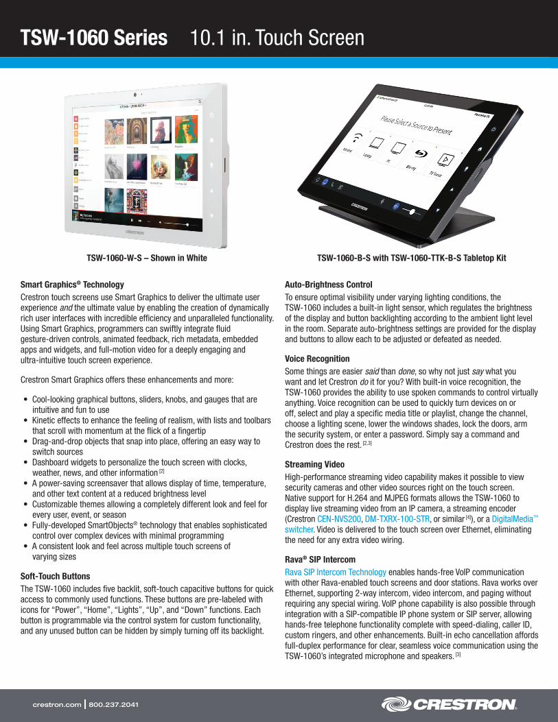
TSW-1060 Series 10.1 in. Touch Screen
crestron.com | 800.237.2041
Smart Graphics® TechnologyCrestron touch screens use Smart Graphics to deliver the ultimate user experience and the ultimate value by enabling the creation of dynamically rich user interfaces with incredible efficiency and unparalleled functionality. Using Smart Graphics, programmers can swiftly integrate fluid gesture-driven controls, animated feedback, rich metadata, embedded apps and widgets, and full-motion video for a deeply engaging and ultra-intuitive touch screen experience.
Crestron Smart Graphics offers these enhancements and more:
• Cool-looking graphical buttons, sliders, knobs, and gauges that are intuitive and fun to use
• Kinetic effects to enhance the feeling of realism, with lists and toolbars that scroll with momentum at the flick of a fingertip
• Drag-and-drop objects that snap into place, offering an easy way to switch sources
• Dashboard widgets to personalize the touch screen with clocks, weather, news, and other information [2]
• A power-saving screensaver that allows display of time, temperature, and other text content at a reduced brightness level
• Customizable themes allowing a completely different look and feel for every user, event, or season
• Fully-developed SmartObjects® technology that enables sophisticated control over complex devices with minimal programming
• A consistent look and feel across multiple touch screens of varying sizes
Soft-Touch ButtonsThe TSW-1060 includes five backlit, soft-touch capacitive buttons for quick access to commonly used functions. These buttons are pre-labeled with icons for “Power”, “Home”, “Lights”, “Up”, and “Down” functions. Each button is programmable via the control system for custom functionality, and any unused button can be hidden by simply turning off its backlight.
Auto-Brightness ControlTo ensure optimal visibility under varying lighting conditions, the TSW-1060 includes a built-in light sensor, which regulates the brightness of the display and button backlighting according to the ambient light level in the room. Separate auto-brightness settings are provided for the display and buttons to allow each to be adjusted or defeated as needed.
Voice RecognitionSome things are easier said than done, so why not just say what you want and let Crestron do it for you? With built-in voice recognition, the TSW-1060 provides the ability to use spoken commands to control virtually anything. Voice recognition can be used to quickly turn devices on or off, select and play a specific media title or playlist, change the channel, choose a lighting scene, lower the windows shades, lock the doors, arm the security system, or enter a password. Simply say a command and Crestron does the rest. [2,3]
Streaming VideoHigh-performance streaming video capability makes it possible to view security cameras and other video sources right on the touch screen. Native support for H.264 and MJPEG formats allows the TSW-1060 to display live streaming video from an IP camera, a streaming encoder (Crestron CEN-NVS200, DM-TXRX-100-STR, or similar [4]), or a DigitalMedia™ switcher. Video is delivered to the touch screen over Ethernet, eliminating the need for any extra video wiring.
Rava® SIP IntercomRava SIP Intercom Technology enables hands-free VoIP communication with other Rava-enabled touch screens and door stations. Rava works over Ethernet, supporting 2-way intercom, video intercom, and paging without requiring any special wiring. VoIP phone capability is also possible through integration with a SIP-compatible IP phone system or SIP server, allowing hands-free telephone functionality complete with speed-dialing, caller ID, custom ringers, and other enhancements. Built-in echo cancellation affords full-duplex performance for clear, seamless voice communication using the TSW-1060’s integrated microphone and speakers. [3]
TSW-1060-B-S with TSW-1060-TTK-B-S Tabletop Kit TSW-1060-W-S – Shown in White
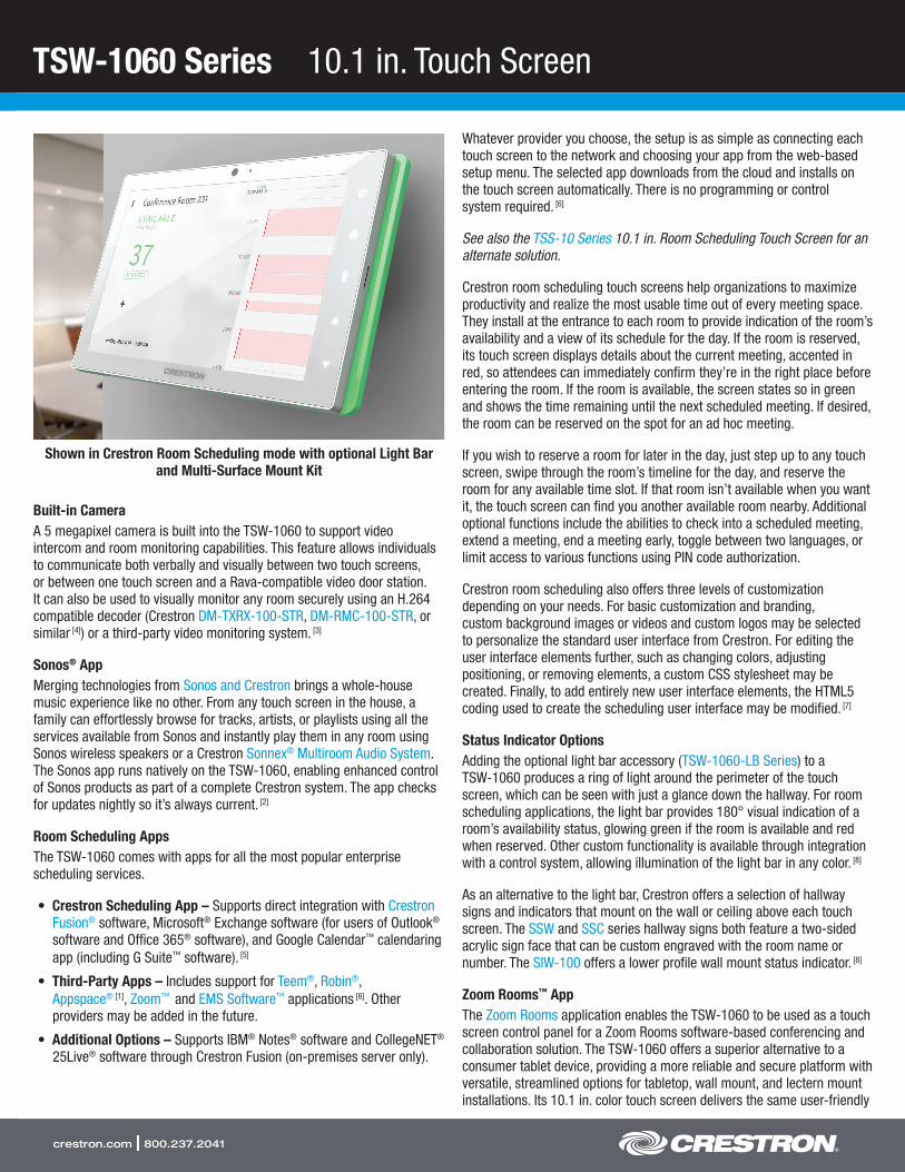
TSW-1060 Series 10.1 in. Touch Screen
crestron.com | 800.237.2041
Built-in CameraA 5 megapixel camera is built into the TSW-1060 to support video intercom and room monitoring capabilities. This feature allows individuals to communicate both verbally and visually between two touch screens, or between one touch screen and a Rava-compatible video door station. It can also be used to visually monitor any room securely using an H.264 compatible decoder (Crestron DM-TXRX-100-STR, DM-RMC-100-STR, or similar [4]) or a third-party video monitoring system. [3]
Sonos® AppMerging technologies from Sonos and Crestron brings a whole-house music experience like no other. From any touch screen in the house, a family can effortlessly browse for tracks, artists, or playlists using all the services available from Sonos and instantly play them in any room using Sonos wireless speakers or a Crestron Sonnex® Multiroom Audio System. The Sonos app runs natively on the TSW-1060, enabling enhanced control of Sonos products as part of a complete Crestron system. The app checks for updates nightly so it’s always current. [2]
Room Scheduling AppsThe TSW-1060 comes with apps for all the most popular enterprise scheduling services.
• Crestron Scheduling App – Supports direct integration with Crestron Fusion® software, Microsoft® Exchange software (for users of Outlook® software and Office 365® software), and Google Calendar™ calendaring app (including G Suite™ software). [5]
• Third-Party Apps – Includes support for Teem®, Robin®, Appspace® [1], Zoom™ and EMS Software™ applications [6]. Other providers may be added in the future.
• Additional Options – Supports IBM® Notes® software and CollegeNET® 25Live® software through Crestron Fusion (on-premises server only).
Whatever provider you choose, the setup is as simple as connecting each touch screen to the network and choosing your app from the web-based setup menu. The selected app downloads from the cloud and installs on the touch screen automatically. There is no programming or control system required. [6]
See also the TSS-10 Series 10.1 in. Room Scheduling Touch Screen for an alternate solution.
Crestron room scheduling touch screens help organizations to maximize productivity and realize the most usable time out of every meeting space. They install at the entrance to each room to provide indication of the room’s availability and a view of its schedule for the day. If the room is reserved, its touch screen displays details about the current meeting, accented in red, so attendees can immediately confirm they’re in the right place before entering the room. If the room is available, the screen states so in green and shows the time remaining until the next scheduled meeting. If desired, the room can be reserved on the spot for an ad hoc meeting.
If you wish to reserve a room for later in the day, just step up to any touch screen, swipe through the room’s timeline for the day, and reserve the room for any available time slot. If that room isn’t available when you want it, the touch screen can find you another available room nearby. Additional optional functions include the abilities to check into a scheduled meeting, extend a meeting, end a meeting early, toggle between two languages, or limit access to various functions using PIN code authorization.
Crestron room scheduling also offers three levels of customization depending on your needs. For basic customization and branding, custom background images or videos and custom logos may be selected to personalize the standard user interface from Crestron. For editing the user interface elements further, such as changing colors, adjusting positioning, or removing elements, a custom CSS stylesheet may be created. Finally, to add entirely new user interface elements, the HTML5 coding used to create the scheduling user interface may be modified. [7]
Status Indicator OptionsAdding the optional light bar accessory (TSW-1060-LB Series) to a TSW-1060 produces a ring of light around the perimeter of the touch screen, which can be seen with just a glance down the hallway. For room scheduling applications, the light bar provides 180° visual indication of a room’s availability status, glowing green if the room is available and red when reserved. Other custom functionality is available through integration with a control system, allowing illumination of the light bar in any color. [8]
As an alternative to the light bar, Crestron offers a selection of hallway signs and indicators that mount on the wall or ceiling above each touch screen. The SSW and SSC series hallway signs both feature a two-sided acrylic sign face that can be custom engraved with the room name or number. The SIW-100 offers a lower profile wall mount status indicator. [8]
Zoom Rooms™ AppThe Zoom Rooms application enables the TSW-1060 to be used as a touch screen control panel for a Zoom Rooms software-based conferencing and collaboration solution. The TSW-1060 offers a superior alternative to a consumer tablet device, providing a more reliable and secure platform with versatile, streamlined options for tabletop, wall mount, and lectern mount installations. Its 10.1 in. color touch screen delivers the same user-friendly
Shown in Crestron Room Scheduling mode with optional Light Bar and Multi-Surface Mount Kit
TSW-1060 Series 10.1 in. Touch Screen
crestron.com | 800.237.2041
Zoom Rooms experience as a typical tablet, but without the risk of misplacing the device. Instead of Wi-Fi® communications, the TSW-1060 uses a wired Ethernet connection to ensure reliable connectivity. [9]
The TSW-1060 may be configured to run the Zoom Rooms app exclusively, or to allow toggling between the Zoom Rooms app and regular Smart Graphics touch screen control mode. The latter allows for integrating Zoom Rooms conferencing into a larger AV system while providing control for both through one touch screen device.
Note: Zoom Ultrasonic is supported up to an average of 3 feet (1 m) from the TSW-1060 touch screen to an end user device. The range will vary based on environmental noise, the sensitivity of the end user device, and the orientation to the touch screen.
Microsoft Teams™ AppMicrosoft Teams is the hub for teamwork in Office 365® software, engaging people and bringing them together through messaging, voice over IP, online meetings, conferencing, content sharing, and collaboration. The Microsoft Teams application on the TSW-1060 enables presentation, calling, conferencing, and collaboration — all through a single touch screen console, with exceptional full-duplex wideband audio and HD video. A consistent user experience in every meeting space is provided via the familiar and intuitive Microsoft Teams UI, affording simple operation, built-in calendaring, and one-touch meeting joins.
PinPoint™ Beacon (Coming Soon)The built-in PinPoint proximity detection beacon enhances the intelligence and personalization of a Crestron system by enabling a smartphone or tablet device to always know what room it’s in. It works with the Crestron App or Crestron PinPoint App, using Bluetooth® technology to determine when the mobile device is in or near the same room as the beacon, and signals the mobile app to automatically display the appropriate controls and information for that location. [3,10]
Web BrowsingUsing its built-in web browser, the TSW-1060 provides access to online program guides and other web-based services at the touch of a button, allowing enhanced touch screen control of DVRs and other appliances without having to pick up a separate tablet or smartphone. The web browser may also be used to simply browse the Internet, check traffic conditions, or look up a recipe. [2]
On-Screen KeyboardTyping in passwords, URLs, and text searches is facilitated using the on-screen multi-language keyboard.
Multi-Touch SupportThe TSW-1060’s capacitive touch screen affords enhanced capabilities for browsing web pages using multi-touch gestures.
Audio FeedbackCustomized audio files can be loaded to add another dimension to the touch screen graphics using personalized sounds, button feedback, and voice prompts.
Single-Wire ConnectivityA simple Ethernet LAN connection is all that is required to wire the TSW-1060, containing all control, video, intercom, and power signals within a single wire.
Power over EthernetUsing PoE technology, the TSW-1060 gets its operating power right through the network cable. PoE (Power over Ethernet) eliminates the need for a local power supply or any dedicated power wiring. Crestron PoE switches (CEN-SW-POE-5 or CEN-SWPOE-16 [4]) offer a total networking solution with built-in PoE for multiple touch screens. A PoE Injector (PWE-4803RU [4]) is also available to support a single touch screen.
Note: PoE+ is required when connecting a light bar or hallways sign via USB. Refer to the “Power” specifications for additional details.
Enterprise Grade SecurityCrestron touch screens employ enterprise-grade networking with robust security features such as 802.1X authentication, TLS encryption, HTTPS connectivity, and Active Directory® software integration. These features are imperative to protect your network against service interruptions and malicious intrusions, and to ensure compliance with your organization’s stringent network policies. Cloud-based provisioning and management streamlines the process of configuring and monitoring every touch screen on the network and keeping them updated. Additional support for SNMP allows every touch screen to be monitored by your IT administrator alongside every other device on the network.
Crestron XiO Cloud™ ServiceCrestron XiO Cloud is Crestron’s unifying cloud-based platform for remotely provisioning, monitoring, and managing Crestron devices across an enterprise or an entire client base. Crestron XiO Cloud enables installers and IT managers to deploy and manage thousands of devices in the amount of time it would ordinarily take to manage just one. It provides a zero-touch solution that allows complete configuration of device settings without any hardware in hand, then simply connect each device on site and let Crestron XiO Cloud push out the settings, licenses, drivers, and firmware updates – automatically and securely – for a quick and painless, ready-to-use deployment.
Ongoing Crestron XiO Cloud services facilitate daily management and monitoring of every device through a single dashboard with comprehensive reporting and logging, live status viewing and alerts, performance metrics and analytics, scheduled actions and updates, and more. As requirements grow and evolve, new features and functionality can be added easily to one or many devices at any time without ever going on site. Crestron XiO Cloud is a subscription-based service offering an adaptable SaaS (Software as a Service) solution with graduated levels of functionality and unlimited scalability. For more information about Crestron XiO Cloud, please visit https://www.crestron.com/xiocloud.
Crestron Pyng® OS 2 ControlThe TSW-1060 may be used to control a Crestron Pyng® OS 2 whole home solution. After a TSW-1060 is added to a room in Crestron Pyng, a home control project is loaded directly to the touch screen. From there, the TSW-1060 allows for control over lighting, shades, climate, media, security,

TSW-1060 Series 10.1 in. Touch Screen
crestron.com | 800.237.2041
and cameras, including the ability to create and recall scenes that create a desired ambiance within certain rooms or for the entire home. A TSW-1060 may be installed in each room in the home to provide easy access to the room’s environmental and media subsystems.
2N® Door Station IntegrationThe TSW-1060 may be integrated with a supported 2N® door station [11] via the touch screen’s built-in Rava® SIP intercom to provide a door station solution for Crestron Pyng. When a call is initiated on the 2N door station, the video and audio feed is displayed on the TSW-1060. Controls are provided on the touch screen to answer or decline the call, and Crestron Pyng quick actions (such as “Open Gate”) may be performed while the call is in progress. A “do not disturb” option is also provided in Crestron Pyng to prevent calls from appearing on the TSW-1060.
Wall or Lectern Mounting OptionsUsing the bracket provided, the TSW-1060 is easily installed over a 2-gang or 3-gang US electrical box, or a 2-gang European or UK electrical box. The same bracket allows for installation in a wooden lectern or podium over a rectangular cutout. When installed, the touch screen protrudes just 1/2 inch from the mounting surface and latches firmly into its mounting bracket leaving no visible screws for an ultra clean appearance. A security latch option is included to deter unauthorized removal of the touch screen.
Additional mounting options are afforded using the TSW-UMB-60 Universal Mounting Bracket. By itself, the TSW-UMB-60 provides a post-construction solution for retrofitting the TSW-1060 into existing drywall. For pre- construction applications that don’t require a back box, the TSW-UMB-60 can be used along with a TSW-UMB-60-PMK Pre-Construction Mounting Kit. Masonry and concrete applications are accommodated using the TSW-UMB-60 along with a TSW-UMB-60-BBI back box. The TSW-UMB-60 is compatible with TSW-560, TSW-760, TSW-1060, TSS-7, and TSS-10 series touch screens, making it easy to swap out devices at any time. [12]
For impenetrable surfaces, such as glass, granite, or marble, or for applications requiring ADA compliance, Crestron offers the Multi-Surface Mount Kit (TSW-760/1060-MSMK [4]). This option allows for attaching securely to virtually any smooth, flat surface without screws, providing an ideal solution for modern offices with glass walls or historically significant spaces where cutting and drilling is prohibited. It can also be mounted over a conventional electrical box. When installed, the touch screen is angled upwards at a 20° tilt to allow for mounting at an ADA approved height.
When installing the TSW-1060 in place of an older Crestron touch screen (APAD, CT-1000, LC-1000, TPS-4L, TPS-6L, TPS-2000L, or TPS-3100L), Crestron offers Retrofit Mounting Brackets (TSW-60-RMB series [4]), which facilitate replacement without having to tear out the old mounting hardware or patch the wall.
Tabletop OptionUsing the optional Tabletop Kit (TSW-1060-TTK [4]), the TSW-1060 becomes a stylish, freestanding touch screen that fits perfectly on a table, desk, or countertop. It can even be permanently attached to the surface using the optional Swivel Mount Kit (TSW-560/760/1060-SMK [4]).
Rack Mount OptionThe TSW-1060 can be mounted in a 19 in. EIA equipment rack using the optional Rack Mount Kit (TSW-1060-RMK-2 [4]). When rack mounted, the touch screen occupies four rack spaces.
SPECIFICATIONS
Touch Screen Display
Display Type: TFT active matrix color LCDSize: 10.1 inch (257 mm) diagonalAspect Ratio: 16:10 WXGAResolution: 1280 x 800 pixelsBrightness: 400 nits (cd/m²)Contrast: 950:1Color Depth: 24-bit, 16.7M colorsIllumination: Edgelit LED w/auto-brightness controlViewing Angle: ±80° horizontal, ±80° verticalTouch Screen: Projected capacitive, 5-point multi-touch capable
Buttons
Hard Keys: (5) Projected capacitive pushbuttons, backlit w/auto-brightness control, per-button show/hide (backlight enable/disable), pre-labeled with icons for “Power”, “Home”, “Lights”, “Up”, and “Down”Reset: (1) Miniature pushbutton on rear panel for hardware reset
Graphics Engine
Crestron Smart Graphics, multi-language web browser [2], multi-language on-screen keyboard, screensaver, single scalable streaming video window, native Sonos app [2], native room scheduling applications [6], native Zoom Rooms app, native Microsoft Teams app, setup and diagnostics via web browser or onscreen UI
Room Scheduling Support
Crestron Scheduling App: Crestron Fusion, Microsoft Exchange & Office 365, Google Calendar & G Suite (IBM Notes and CollegeNET 25Live are also supported through Crestron Fusion On-premises only) [5]
Third-Party Apps: Teem, Robin, Appspace [1], Zoom, EMS Software [6]
Languages
Smart Graphics: Arabic, Chinese (Simplified), Chinese (Traditional), Czech, Danish, Dutch, English (UK), English (US), Finnish, French, German, Greek, Hebrew, Hungarian, Italian, Japanese, Korean, Norwegian, Polish, Portuguese, Portuguese (Brazilian), Romanian, Russian, Slovak, Spanish, Swedish, ThaiOn-Screen Keyboard: Arabic, Chinese (Simplified), Croatian, Czech, Danish, Dutch, English (UK), English (US), Finnish, French (Canada), French (Switzerland), German, Hebrew, Hungarian, Italian, Japanese, Norwegian Bokmal, Polish, Portuguese, Russian, Serbian, Spanish, Swedish, TurkishVoice Recognition: Afrikaans (South Africa); Chinese, Mandarin (China, Simplified); Chinese, Mandarin (Hong Kong, Simplified); Chinese, Mandarin (Taiwan, Traditional); Chinese, Yue (Hong Kong, Traditional); Czech (Czech Republic); Dutch (Netherlands); English (Australia); English (Canada); English
TSW-1060 Series 10.1 in. Touch Screen
crestron.com | 800.237.2041
(Generic); English (India); English (New Zealand); English (South Africa); English (UK); English (US); French (France); German (Germany); isiZulu (South Africa); Italian (Italy); Japanese (Japan); Korean (South Korea); Polish (Poland); Portuguese (Brazil); Russian (Russia); Spanish (Spain); Turkish (Turkey)Web Browser: Arabic, Bulgarian, Catalan, Chinese, Croatian, Czech, Danish, Dutch, English, Filipino, Finnish, French, German, Greek, Hebrew, Hindi, Hungarian, Indonesian, Italian, Japanese, Korean, Latvian, Lithuanian, Norwegian Bokmal, Pashto, Persian, Polish, Portuguese, Romanian, Romansh, Russian, Serbian, Slovak, Slovenian, Spanish, Swedish, Thai, Turkish, Ukrainian, VietnameseRoom Scheduling: Chinese (Simplified), Chinese (Traditional), Danish, Dutch (Netherlands), English (US), English (UK), French, German, Hebrew, Italian, Japanese, Korean, Norwegian, Portuguese (Brazil), Portuguese (Portugal), Russian, Spanish, Swedish
Memory
RAM: 2 GB DDR3LStorage: Firmware/Application: 4 GB Class 10 microSD card;
System: 4 GB eMMCMaximum Project Size: 600 MB
Communications
Ethernet: 10/100 Mbps, auto-switching, auto-negotiating, auto-discovery, full/half duplex, TCP/IP, UDP/IP, CIP, DHCP, SSL, TLS, SSH, SFTP (SSH File Transfer Protocol), IEEE 802.1X, SNMP, IPv4 or IPv6, Active Directory authentication, HTTPS web browser setup, Crestron XiO Cloud client, IEEE 802.3at compliantUSB: USB 2.0 host for room availability light bar or hallway sign [8]
Bluetooth: Crestron PinPoint proximity detection beacon [3,10]
Streaming Decoder
Video Formats: H.264 (MPEG-4 part 10 AVC), MJPEGAudio Formats: AAC stereoBitrates: Up to 25 Mbps (20 Mbps maximum recommended)Streaming Input Resolutions: Up to 1920x1080@30fpsStreaming Protocol: RTSP
Streaming Encoder & Camera [3]
Camera Resolution: 5.0 MPField of View: 50º horizontalVideo Format: H.264 (MPEG-4 part 10 AVC)Streaming Output Resolution: 1280x720Streaming Protocol: RTSP, ONVIF discovery
Audio
Features: Built-in microphone and speakers, Rava SIP Intercom, multi-language voice recognition [2,3]
Audio Feedback Formats: MP3
Connectors
LAN PoE: (1) 8-pin RJ45 connector, female, with 2 LED indicators;10Base-T/100Base-TX Ethernet port and PoE+ PD port;
Green and yellow LEDs indicate Ethernet port status
USB: (1) USB Type A connector, female; USB 2.0 host port; For optional room availability light bar or hallway sign [8]
Power
Power over Ethernet: IEEE 802.3at Type 2 compliant PoE+ PD (Powered Device);- Normally requests 15 Watts from an 802.3at Type 2 PSE with LLDP
advanced power management;- With room scheduling and USB enabled, requests 18 Watts from an
802.3at Type 2 PSE with LLDP;- Requests 30 Watts (PoE+ Class 4) from an 802.3at Type 2 PSE
without LLDP;- Requests 15.4 Watts (PoE Class 0) from an 802.3af (or 802.3at
Type 1) PSENote: Enabling the USB port requires use of an 802.3at Type 2 PoE+ PSE.
Environmental
Temperature: 32° to 112° F (0° to 45° C)Humidity: 10% to 90% RH (non-condensing)Heat Dissipation: 44 BTU/hr
Construction
Housing: Plastic, smooth black or white finish, edge-to-edge glass with black or white surroundMounting: Surface mount over a 2 or 3-gang US electrical box, 2-gang European (DIN 49073) electrical box, or 2-gang UK (BS 4662) electrical box; Lectern mount over a 2-1/5 in. H x 3-3/4 in. W (56 mm H x 96 mm W) cutout; 1-3/8 in. (35 mm) minimum mounting depth; Additional wall mount, surface mount, rack mount, and tabletop options available separately
Dimensions
Height: 6.59 in. (168 mm)Width: 10.23 in. (260 mm)Depth: 1.52 in. (39 mm)Dimensions do not include the mounting bracket or add-on accessories
Weight
23.9 oz (675 g)
Compliance
UL Listed for US & Canada, IC, CE, FCC Part 15 Class B digital device
Notes:
1. Appspace functionality is currently limited to their Room Management feature (aka, room cards or meeting cards) only.
2. Voice recognition, web browsing, weather information, Sonos app, and certain other functions require an Internet connection.

TSW-1060 Series 10.1 in. Touch Screen
crestron.com | 800.237.2041
3. The camera, microphone, and Bluetooth transceiver may each be defeated programmatically at any time. For applications demanding an extra measure of privacy, Crestron offers models TSW-1060-NC-B-S and TSW-1060-NC-W-S, which have no physical camera, microphone, or Bluetooth transceiver installed.
4. Item(s) sold separately. Refer to each product’s spec sheet for complete information.5. Room Scheduling Mode requires the TSW-1060 to be designated exclusively for room
scheduling use, which precludes use of certain features and functions described in this spec sheet. For design assistance, contact the Crestron True Blue support team at https://www.crestron.com/support.
6. Additional subscriptions and/or licenses may be required. Refer to each provider’s website for details about the capabilities and requirements of its scheduling application and services. Third-party apps typically run on the TSW-1060 as they do on a tablet device. The TSW-1060 runs only one app, which is selected at setup. Only the apps approved and delivered by Crestron can run on the TSW-1060.
7. For more information on custom programming for the Crestron room scheduling app, refer to the Crestron Room Scheduling Panels Programming Guide (Doc. 8213) at www.crestron.com/manuals.
8. The light bar and hallway sign accessories are sold separately. The TSW-1060 must be powered by a PoE+ power source when a light bar or hallway sign is connected. Only one light bar or hallway sign may be connected to the TSW-1060. Use of either accessory precludes use of the other without the addition of a custom-programmed control system and Cresnet wiring for the hallway sign. Refer to the Accessories section for a list of all available options. Refer to each accessory’s spec sheet for further information.
9. A complete Zoom Rooms solution requires a mini PC or Mac computer running Zoom software, a Zoom Rooms subscription, plus additional peripherals and cables. Visit https://zoom.us/zoomrooms for more information about Zoom Rooms capabilities, hardware requirements, and subscription plans. For design assistance, contact the Crestron True Blue support team at https://www.crestron.com/support.
10. Onboard PinPoint beacon functionality is not currently supported and will be enabled through a future update. When enabled, the TSW-1060 will provide an integrated, equivalent alternative to the standalone PP-100-W beacon. For more details, refer to the PP-100-W spec sheet. Bluetooth technology is used solely for proximity detection and does not transmit or receive any control, multimedia, or personal data. PinPoint beacons are only visible to Bluetooth enabled devices that are specifically programmed and configured to work with them.
11. Supported 2N door stations include the 2N IP Audio Kit, 2N IP Audio Kit Lite, 2N IP Base, 2N IP Force, 2N IP Safety, 2N IP Solo, 2N IP Uni, 2N IP Vario, 2N IP Verso, and 2N IP Video Kit. For pairing instructions, refer to the Crestron Pyng OS 2 for CP3-R Product Manual (Doc. 8356) and the TSW-560/TSW-760/TSW-1060 Supplemental Guide (Doc. 7927) at www.crestron.com/manuals.
12. The TSW-UMB-60, TSW-UMB-60-PMK, and TSW-UMB-60-BBI are all sold separately. The TSW-UMB-60 is also compatible with older TSW-UMB-PMK preconstruction mounting kits and TSW-550-BBI back boxes, allowing the TSW-1060 touch screen to be installed in place of a previous generation TSW-5xx series touch screen, or any other device that was originally installed using a TSW-UMB-PMK or TSW-550-BBI, without modification to the wall. If replacing another older Crestron device, use the appropriate TSW-60-RMB retrofit mounting bracket (sold separately).
This product may be purchased from an authorized Crestron dealer. To find a dealer, please contact the Crestron sales representative for your area. A list of sales representatives is available online at https://www.crestron.com/How-To-Buy/Find-a-Representative or by calling 855-263-8754.
The specific patents that cover this and other Crestron products are listed online at https://www.crestron.com/legal/patents.
Certain Crestron products contain open source software. For specific information, visit https://www.crestron.com/opensource.
Crestron, the Crestron logo, Crestron Fusion, Crestron Pyng, Crestron XiO Cloud, DigitalMedia, PinPoint, Rava, Smart Graphics, SmartObjects, and Sonnex are either trademarks or registered trademarks of Crestron Electronics, Inc. in the United States and/or other countries. 2N is either a trademark or a registered trademark of 2N Telekomunikace in the United States and/or other countries. Appspace is either a trademark or registered trademark of AppSpace, Inc. in the United States and/or other countries. Bluetooth is either a trademark or registered trademark of Bluetooth SIG, Inc. in the United States and/or other countries. CollegeNET and 25Live are either trademarks or registered trademarks of CollegeNET, Inc. in the United States and/or other countries. EMS Software is either a trademark or registered trademark of EMS Software LLC in the United States and/or other countries. Google, G Suite, and Google Calendar are either trademarks or registered trademarks of Google LLC in the United States and/or other countries. IBM and Notes are either trademarks or registered trademarks of International Business Machines Corporation in the United States and/or other countries. Microsoft, Active Directory, Microsoft Teams, Office 365, and Outlook are either trademarks or registered trademarks of Microsoft Corporation in the United States and/or other countries. Robin is either a trademark or registered trademark of Robin
Powered, Inc. in the United States and/or other countries. Sonos is either a trademark or registered trademark of Sonos, Inc. in the United States and/or other countries. Teem is either a trademark or registered trademark of Teem Technologies, Inc. in the United States and/or other countries. Wi-Fi is either a trademark or registered trademark of Wi-Fi Alliance in the United States and/or other countries. Zoom and Zoom Rooms are either trademarks or registered trademarks of Zoom Video Communications, Inc. in the United States and/or other countries. Other trademarks, registered trademarks, and trade names may be used in this document to refer to either the entities claiming the marks and names or their products. Crestron disclaims any proprietary interest in the marks and names of others. Crestron is not responsible for errors in typography or photography. Specifications are subject to change without notice. ©2018 Crestron Electronics, Inc.
MODELS & ACCESSORIES
Available Models
TSW-1060-B-S: 10.1 in. Touch Screen, Black SmoothTSW-1060-W-S: 10.1 in. Touch Screen, White Smooth
Available Accessories
TSW-1060-TTK Series: Tabletop KitTSW-560/760/1060-SMK: Swivel Mount Kit for TSW-1060-TTK SeriesTSW-UMB-60: Universal Mounting Bracket for TSW-x60 SeriesTSW-UMB-60-PMK: Pre-Construction Mounting Kit for TSW-UMB-60 TSW-UMB-60-BBI: Wall Mount Back Box for TSW-UMB-60TSW-760/1060-RMB-1: Retrofit Mounting Bracket – Converts APAD, CT/LC-1000, or TPS-2000L to TSW-1060TSW-760/1060-RMB-2: Retrofit Mounting Bracket – Converts TPS-4L to TSW-1060TSW-1060-RMB-3: Retrofit Mounting Bracket – Converts TPS-6L to TSW-1060TSW-1060-RMB-4: Retrofit Mounting Bracket – Converts TPS-3100L to TSW-1060TSW-760/1060-MSMK Series: Multi-Surface Mount KitTSW-560/760-RMK-2: Rack Mount KitPWE-4803RU: PoE InjectorCEN-SW-POE-5: 5-Port PoE SwitchCEN-SWPOE-16: 16-Port Managed PoE SwitchCEN-NVS200: Network Video StreamerDM-TXRX-100-STR: HD Streaming Transmitter/ReceiverDM-RMC-100-STR: HD Streaming Receiver & Room Controller 100SW-XIOC-S Series: Crestron XiO Cloud™ Standard Provisioning and Management Service for one deviceSW-XIOC-P Series: Crestron XiO Cloud™ Premium Provisioning and Management Service for one deviceSW-FUSION-C-3: Crestron Fusion® Cloud; 250 rooms; 3-year service, support, and updatesSW-FUSION-P-L: Crestron Fusion® On-premises; Unlimited rooms; lifetime service, support, and updatesSW-HS-x-C Series: Crestron Fusion® Cloud Room Scheduling for one touch screenSW-HS-x-P Series: Crestron Fusion® On-premises Room Scheduling for one touch screenTSW-1060-LB Series: Room Availability Light BarSSC Series: Room Availability Hallway Sign, Ceiling MountSSW Series: Room Availability Hallway Sign, Wall MountSIW-100: Room Availability Status Indicator, Wall Mount
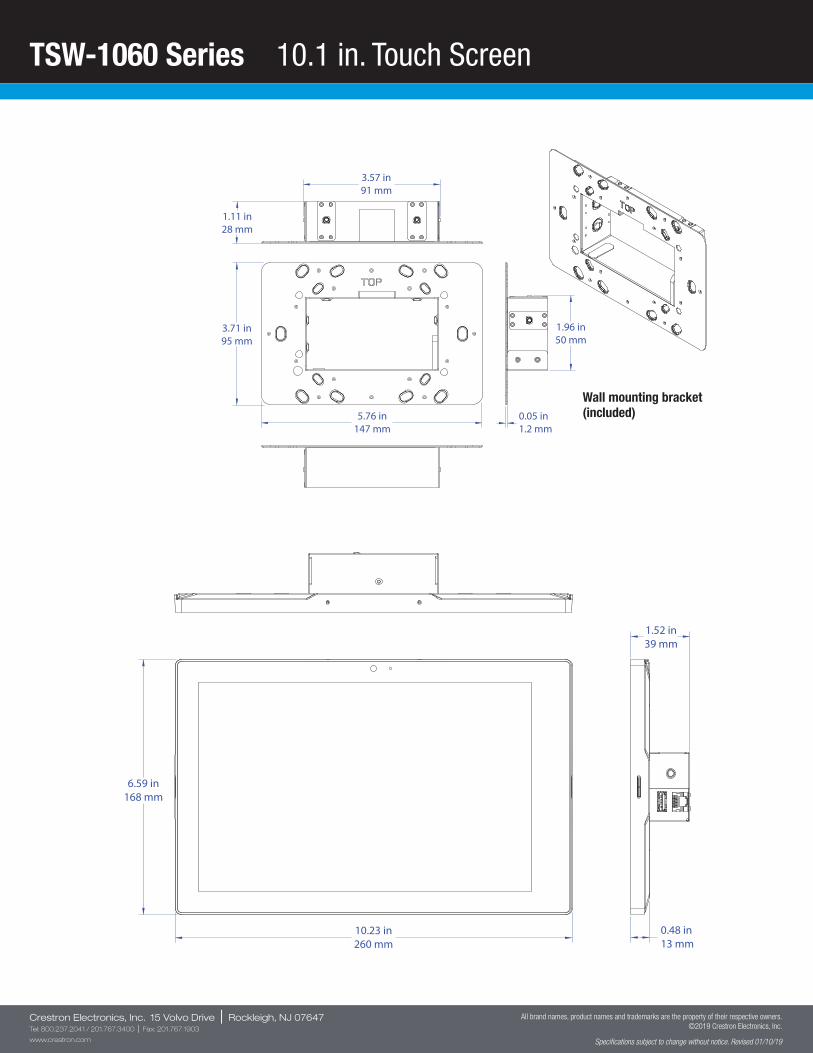
TSW-1060 Series 10.1 in. Touch Screen
Crestron Electronics, Inc. 15 Volvo Drive | Rockleigh, NJ 07647Tel: 800.237.2041 / 201.767.3400 | Fax: 201.767.1903
www.crestron.com
All brand names, product names and trademarks are the property of their respective owners. ©2019 Crestron Electronics, Inc.
Specifications subject to change without notice. Revised 01/10/19
10.23 in260 mm
6.59 in168 mm
0.48 in13 mm
1.52 in39 mm
3.71 in95 mm
5.76 in147 mm
1.96 in50 mm
3.57 in91 mm
0.05 in1.2 mm
1.11 in28 mm
Wall mounting bracket (included)
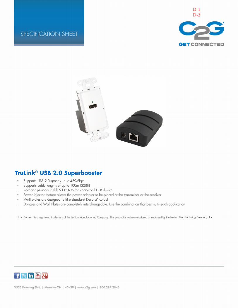
D-1D-2
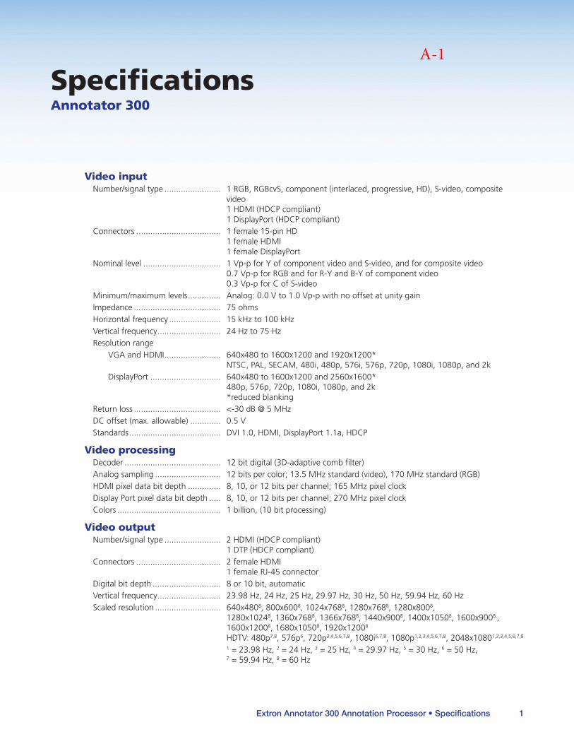
Extron Annotator 300 Annotation Processor • Specifications 1
SpecificationsAnnotator 300
Video inputNumber/signal type 1 RGB, RGBcvS, component (interlaced, progressive, HD), S-video, composite
video 1 HDMI (HDCP compliant) 1 DisplayPort (HDCP compliant)
Connectors 1 female 15-pin HD 1 female HDMI 1 female DisplayPort
Nominal level 1 Vp-p for Y of component video and S-video, and for composite video 07 Vp-p for RGB and for R-Y and B-Y of component video 03 Vp-p for C of S-video
Minimum/maximum levels Analog: 00 V to 10 Vp-p with no offset at unity gainImpedance 75 ohmsHorizontal frequency 15 kHz to 100 kHzVertical frequency 24 Hz to 75 HzResolution range
VGA and HDMI 640x480 to 1600x1200 and 1920x1200* NTSC, PAL, SECAM, 480i, 480p, 576i, 576p, 720p, 1080i, 1080p, and 2k
DisplayPort 640x480 to 1600x1200 and 2560x1600* 480p, 576p, 720p, 1080i, 1080p, and 2k *reduced blanking
Return loss <-30 dB @ 5 MHzDC offset (max allowable) 05 VStandards DVI 10, HDMI, DisplayPort 11a, HDCP
Video processingDecoder 12 bit digital (3D-adaptive comb filter)Analog sampling 12 bits per color; 135 MHz standard (video), 170 MHz standard (RGB)HDMI pixel data bit depth 8, 10, or 12 bits per channel; 165 MHz pixel clockDisplay Port pixel data bit depth 8, 10, or 12 bits per channel; 270 MHz pixel clockColors 1 billion, (10 bit processing)
Video outputNumber/signal type 2 HDMI (HDCP compliant)
1 DTP (HDCP compliant)Connectors 2 female HDMI
1 female RJ-45 connectorDigital bit depth 8 or 10 bit, automaticVertical frequency 2398 Hz, 24 Hz, 25 Hz, 2997 Hz, 30 Hz, 50 Hz, 5994 Hz, 60 HzScaled resolution 640x4808, 800x6008, 1024x7688, 1280x7688, 1280x8008,
1280x10248, 1360x7688, 1366x7688, 1440x9008, 1400x10508, 1600x9008,, 1600x12008, 1680x10508, 1920x12008 HDTV: 480p7,8, 576p6, 720p3,4,5,6,7,8, 1080i6,7,8, 1080p1,2,3,4,5,6,7,8, 2048x10801,2,3,4,5,6,7,8
1 = 2398 Hz, 2 = 24 Hz, 3 = 25 Hz, 4 = 2997 Hz, 5 = 30 Hz, 6 = 50 Hz, 7 = 5994 Hz, 8 = 60 Hz
zz For manuals, use the standard Section style instead of Chapter title, specs sheet or Heading 1, specs stand-alone; and use Heading 1 as usual for “Specifications” if the specs are part of a multitopic chapter
zz Click the text tool where you want to insert the specs table, select the specs table container paragraph style, then paste in the specs table from the stand-alone master specs sheet
zz For specifications from template v76 or earlier, use this guide to which new paragraph style replaces which old style:
zz Specs8_Heading 2 replaces SpecsSubHdr
zz Specs8_L1 “ Specs7
zz Specs8_L1 cont’d “ Specs7A
zz Specs8_L2 “ Specs7 subcategory
zz Specs8_L3 “ Specs7 sub-subcategory
zz Specs8_Note “ SpecsNote7
zz Specs8_Warning/Caution “ Specs7Warning/caution
zz Specs8_ Revision code “ Revision code
zz The other new styles are required for proper table placement/formatting (one for the entire specs table as placed within a manual section [specs table conteiner], two others [Specs8_Note L1 table and Specs8_Note L2 table] for the note/caution cells within the specs table)
zz At this time, the notes, cautions, and warnings boxes/tables within specs have to be hand inserted and merged and formatted Use the existing table styles (NOTE, Caution, and Warning1) for the table boxes
zz Apply the Specs8_Note L1 table or Specs8_Note L2 table paragraph style (depending on the content to which the note, caution, or warning applies) to the nested note, caution, or warning table Also apply the Specs8_Note cell insetscell style to the cell containing the note, caution, or warning nested table
zz Apply the Specs8_Note or Specs8_Warning/Caution paragraph style to the text within the nested note, caution, or warning table
zz Apply the Specs8_note cell inset cell style to the specs table cell containing the nested table
For use with user guides (manuals) only (but NOT for stand-alone specs sheets), two bulleted note styles are available to use when you combine a series of notes into one note table:
zz Specs8_Note_bulleted — This is for the first paragaph, and you have to manually insert the bullet character and second tab
zz Specs8_Note_bulleted, cont'd — This is for susequent paragaphs within a note box The bullet character is automatically inserted
Here is an example of how those two styles are used:
NOTES: • This is just test text to show the style You wouldn't normally put completely unrelated topics together in a shared noteAll nominal levels are at ±10% UL rated for use in plenum airspaces: meets UL 2043 for heat and smoke release, excluding the power supply; meets UL 60950 for safety UL rated for use in plenum airspaces: meets UL 2043 for heat and smoke release, excluding the power supply; meets UL 60950 for safety
• Specifications are subject to change without notice UL rated for use in plenum airspaces: meets UL 2043 for heat and smoke release, excluding the power supply; meets UL 60950 for safety
• The 5-pole port supports both hardware and software flow controlThe 3-pole ports support software flow control
A-1
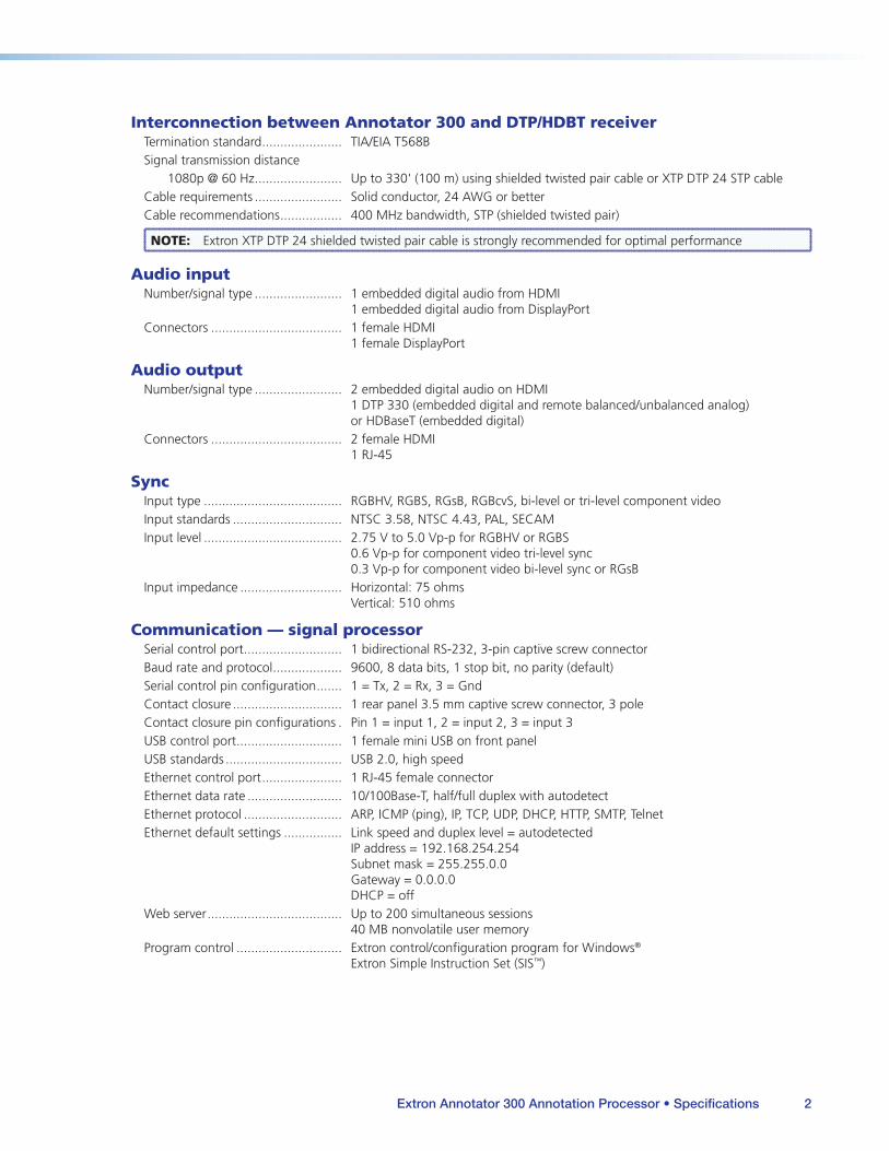
Extron Annotator 300 Annotation Processor • Specifications 2
Interconnection between Annotator 300 and DTP/HDBT receiverTermination standard TIA/EIA T568BSignal transmission distance
1080p @ 60 Hz Up to 330' (100 m) using shielded twisted pair cable or XTP DTP 24 STP cableCable requirements Solid conductor, 24 AWG or betterCable recommendations 400 MHz bandwidth, STP (shielded twisted pair)
NOTE: Extron XTP DTP 24 shielded twisted pair cable is strongly recommended for optimal performance
Audio inputNumber/signal type 1 embedded digital audio from HDMI
1 embedded digital audio from DisplayPortConnectors 1 female HDMI
1 female DisplayPort
Audio outputNumber/signal type 2 embedded digital audio on HDMI
1 DTP 330 (embedded digital and remote balanced/unbalanced analog) or HDBaseT (embedded digital)
Connectors 2 female HDMI 1 RJ-45
SyncInput type RGBHV, RGBS, RGsB, RGBcvS, bi-level or tri-level component videoInput standards NTSC 358, NTSC 443, PAL, SECAMInput level 275 V to 50 Vp-p for RGBHV or RGBS
06 Vp-p for component video tri-level sync 03 Vp-p for component video bi-level sync or RGsB
Input impedance Horizontal: 75 ohms Vertical: 510 ohms
Communication — signal processorSerial control port 1 bidirectional RS-232, 3-pin captive screw connectorBaud rate and protocol 9600, 8 data bits, 1 stop bit, no parity (default)Serial control pin configuration 1 = Tx, 2 = Rx, 3 = GndContact closure 1 rear panel 35 mm captive screw connector, 3 poleContact closure pin configurations Pin 1 = input 1, 2 = input 2, 3 = input 3USB control port 1 female mini USB on front panelUSB standards USB 20, high speedEthernet control port 1 RJ-45 female connectorEthernet data rate 10/100Base-T, half/full duplex with autodetectEthernet protocol ARP, ICMP (ping), IP, TCP, UDP, DHCP, HTTP, SMTP, TelnetEthernet default settings Link speed and duplex level = autodetected
IP address = 192168254254 Subnet mask = 25525500 Gateway = 0000 DHCP = off
Web server Up to 200 simultaneous sessions 40 MB nonvolatile user memory
Program control Extron control/configuration program for Windows® Extron Simple Instruction Set (SIS™)
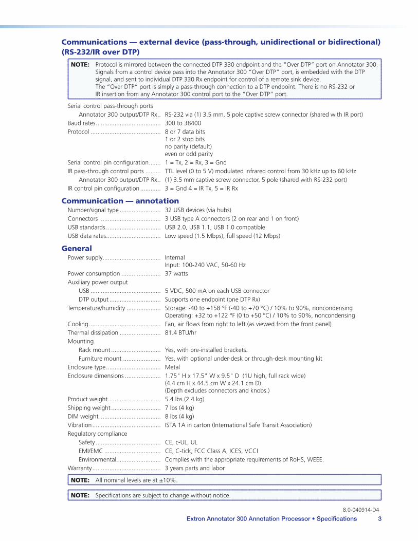
Extron Annotator 300 Annotation Processor • Specifications 3
Communications — external device (pass-through, unidirectional or bidirectional) (RS-232/IR over DTP)
NOTE: Protocol is mirrored between the connected DTP 330 endpoint and the “Over DTP” port on Annotator 300 Signals from a control device pass into the Annotator 300 “Over DTP” port, is embedded with the DTP signal, and sent to individual DTP 330 Rx endpoint for control of a remote sink device The “Over DTP” port is simply a pass-through connection to a DTP endpoint There is no RS-232 or IR insertion from any Annotator 300 control port to the “Over DTP” port
Serial control pass-through portsAnnotator 300 output/DTP Rx RS-232 via (1) 35 mm, 5 pole captive screw connector (shared with IR port)
Baud rates 300 to 38400Protocol 8 or 7 data bits
1 or 2 stop bits no parity (default) even or odd parity
Serial control pin configuration 1 = Tx, 2 = Rx, 3 = GndIR pass-through control ports TTL level (0 to 5 V) modulated infrared control from 30 kHz up to 60 kHz
Annotator 300 output/DTP Rx (1) 35 mm captive screw connector, 5 pole (shared with RS-232 port)IR control pin configuration 3 = Gnd 4 = IR Tx, 5 = IR Rx
Communication — annotationNumber/signal type 32 USB devices (via hubs)Connectors 3 USB type A connectors (2 on rear and 1 on front)USB standards USB 20, USB 11, USB 10 compatibleUSB data rates Low speed (15 Mbps), full speed (12 Mbps)
GeneralPower supply Internal
Input: 100-240 VAC, 50-60 HzPower consumption 37 wattsAuxiliary power output
USB 5 VDC, 500 mA on each USB connectorDTP output Supports one endpoint (one DTP Rx)
Temperature/humidity Storage: -40 to +158 °F (-40 to +70 °C) / 10% to 90%, noncondensing Operating: +32 to +122 °F (0 to +50 °C) / 10% to 90%, noncondensing
Cooling Fan, air flows from right to left (as viewed from the front panel)Thermal dissipation 814 BTU/hrMounting
Rack mount Yes, with pre-installed bracketsFurniture mount Yes, with optional under-desk or through-desk mounting kit
Enclosure type MetalEnclosure dimensions 175" H x 175" W x 95" D (1U high, full rack wide)
(44 cm H x 445 cm W x 241 cm D) (Depth excludes connectors and knobs)
Product weight 54 lbs (24 kg)Shipping weight 7 lbs (4 kg)DIM weight 8 lbs (4 kg)Vibration ISTA 1A in carton (International Safe Transit Association)Regulatory compliance
Safety CE, c-UL, ULEMI/EMC CE, C-tick, FCC Class A, ICES, VCCIEnvironmental Complies with the appropriate requirements of RoHS, WEEE
Warranty 3 years parts and labor
NOTE: All nominal levels are at ±10%
NOTE: Specifications are subject to change without notice
80-040914-D4
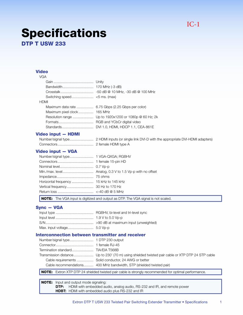
Extron DTP T USW 233 Twisted Pair Switching Extender Transmitter • Specifications 1
SpecificationsDTP T USW 233
VideoVGA
Gain UnityBandwidth 170 MHz (-3 dB)Crosstalk -50 dB @ 10 MHz, -30 dB @ 100 MHzSwitching speed <5 ms (max)
HDMIMaximum data rate 675 Gbps (225 Gbps per color)Maximum pixel clock 165 MHzResolution range Up to 1920x1200 or 1080p @ 60 Hz; 2kFormats RGB and YCbCr digital videoStandards DVI 10, HDMI, HDCP 11, CEA-861E
Video input — HDMINumber/signal type 2 HDMI inputs (or single link DVI-D with the appropriate DVI-HDMI adapters)Connectors 2 female HDMI type A
Video input — VGANumber/signal type 1 VGA-QXGA; RGBHVConnectors 1 female 15-pin HDNominal level 07 Vp-pMin/max level Analog, 03 V to 15 Vp-p with no offsetImpedance 75 ohmsHorizontal frequency 15 kHz to 145 kHzVertical frequency 30 Hz to 170 HzReturn loss <-40 dB @ 5 MHz
NOTE: The VGA input is digitized and output as DTP The VGA signal is not scaled
Sync — VGAInput type RGBHV, bi-level and tri-level syncInput level 19 V to 50 Vp-pS/N >90 dB at maximum input (unweighted)Max input voltage 50 Vp-p
Interconnection between transmitter and receiverNumber/signal type 1 DTP 230 outputConnector 1 female RJ-45Termination standard TIA/EIA T568BTransmission distance Up to 230' (70 m) using shielded twisted pair cable or XTP DTP 24 STP cable
Cable requirements Solid conductor, 24 AWG or betterCable recommendations 400 MHz bandwidth, STP (shielded twisted pair)
NOTE: Extron XTP DTP 24 shielded twisted pair cable is strongly recommended for optimal performance
NOTE: Input and output mode signaling: DTP: HDMI with embedded audio, analog audio, RS-232 and IR, and remote power HDBT: HDMI with embedded audio plus RS-232 and IR
IC-1
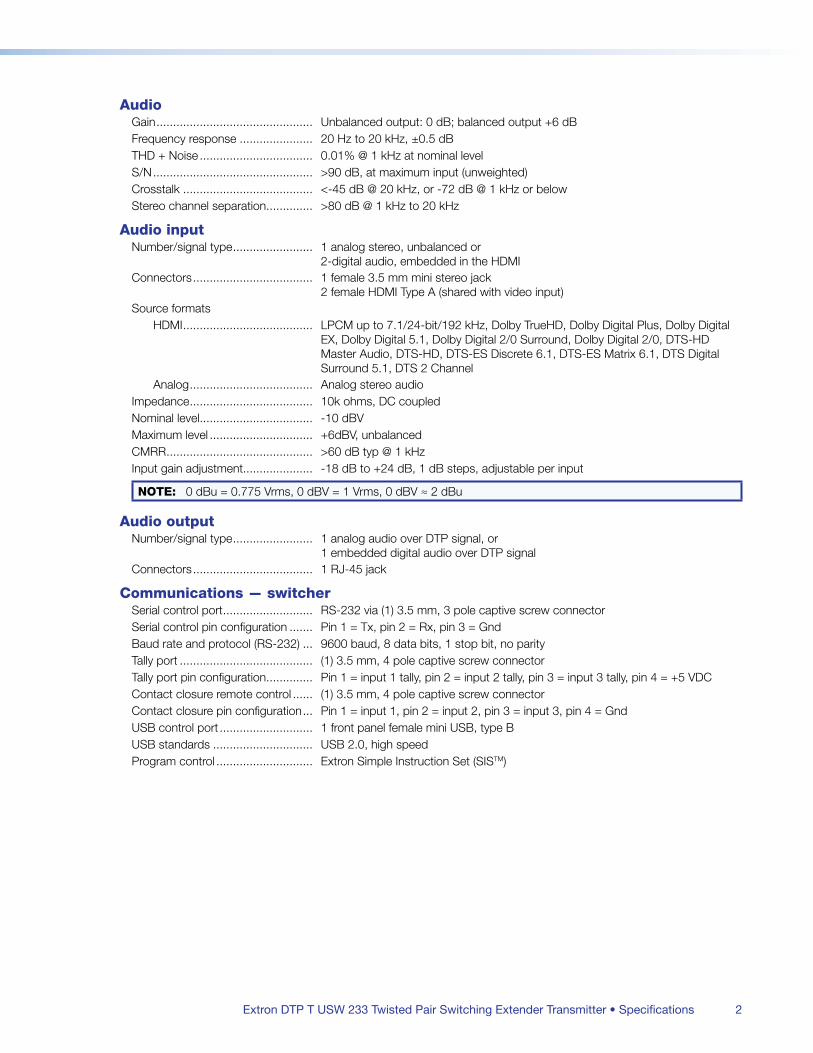
Extron DTP T USW 233 Twisted Pair Switching Extender Transmitter • Specifications 2
AudioGain Unbalanced output: 0 dB; balanced output +6 dBFrequency response 20 Hz to 20 kHz, ±05 dBTHD + Noise 001% @ 1 kHz at nominal levelS/N >90 dB, at maximum input (unweighted)Crosstalk <-45 dB @ 20 kHz, or -72 dB @ 1 kHz or belowStereo channel separation >80 dB @ 1 kHz to 20 kHz
Audio inputNumber/signal type 1 analog stereo, unbalanced or
2-digital audio, embedded in the HDMIConnectors 1 female 35 mm mini stereo jack
2 female HDMI Type A (shared with video input)Source formats
HDMI LPCM up to 71/24-bit/192 kHz, Dolby TrueHD, Dolby Digital Plus, Dolby Digital EX, Dolby Digital 51, Dolby Digital 2/0 Surround, Dolby Digital 2/0, DTS-HD Master Audio, DTS-HD, DTS-ES Discrete 61, DTS-ES Matrix 61, DTS Digital Surround 51, DTS 2 Channel
Analog Analog stereo audioImpedance 10k ohms, DC coupledNominal level -10 dBVMaximum level +6dBV, unbalancedCMRR >60 dB typ @ 1 kHzInput gain adjustment -18 dB to +24 dB, 1 dB steps, adjustable per input
NOTE: 0 dBu = 0775 Vrms, 0 dBV = 1 Vrms, 0 dBV ≈ 2 dBu
Audio outputNumber/signal type 1 analog audio over DTP signal, or
1 embedded digital audio over DTP signalConnectors 1 RJ-45 jack
Communications — switcherSerial control port RS-232 via (1) 35 mm, 3 pole captive screw connectorSerial control pin configuration Pin 1 = Tx, pin 2 = Rx, pin 3 = GndBaud rate and protocol (RS-232) 9600 baud, 8 data bits, 1 stop bit, no parityTally port (1) 35 mm, 4 pole captive screw connectorTally port pin configuration Pin 1 = input 1 tally, pin 2 = input 2 tally, pin 3 = input 3 tally, pin 4 = +5 VDCContact closure remote control (1) 35 mm, 4 pole captive screw connectorContact closure pin configuration Pin 1 = input 1, pin 2 = input 2, pin 3 = input 3, pin 4 = GndUSB control port 1 front panel female mini USB, type BUSB standards USB 20, high speedProgram control Extron Simple Instruction Set (SISTM)
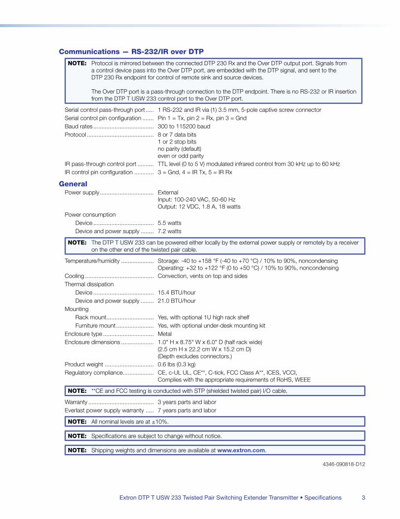
Extron DTP T USW 233 Twisted Pair Switching Extender Transmitter • Specifications 3
Communications — RS-232/IR over DTP
NOTE: Protocol is mirrored between the connected DTP 230 Rx and the Over DTP output port Signals from a control device pass into the Over DTP port, are embedded with the DTP signal, and sent to the DTP 230 Rx endpoint for control of remote sink and source devices
The Over DTP port is a pass-through connection to the DTP endpoint There is no RS-232 or IR insertion from the DTP T USW 233 control port to the Over DTP port
Serial control pass-through port 1 RS-232 and IR via (1) 35 mm, 5-pole captive screw connectorSerial control pin configuration Pin 1 = Tx, pin 2 = Rx, pin 3 = GndBaud rates 300 to 115200 baudProtocol 8 or 7 data bits
1 or 2 stop bits no parity (default) even or odd parity
IR pass-through control port TTL level (0 to 5 V) modulated infrared control from 30 kHz up to 60 kHzIR control pin configuration 3 = Gnd, 4 = IR Tx, 5 = IR Rx
GeneralPower supply External
Input: 100-240 VAC, 50-60 Hz Output: 12 VDC, 18 A, 18 watts
Power consumptionDevice 55 wattsDevice and power supply 72 watts
NOTE: The DTP T USW 233 can be powered either locally by the external power supply or remotely by a receiver on the other end of the twisted pair cable
Temperature/humidity Storage: -40 to +158 °F (-40 to +70 °C) / 10% to 90%, noncondensing Operating: +32 to +122 °F (0 to +50 °C) / 10% to 90%, noncondensing
Cooling Convection, vents on top and sidesThermal dissipation
Device 154 BTU/hourDevice and power supply 210 BTU/hour
MountingRack mount Yes, with optional 1U high rack shelfFurniture mount Yes, with optional under-desk mounting kit
Enclosure type MetalEnclosure dimensions 10" H x 875" W x 60" D (half rack wide)
(25 cm H x 222 cm W x 152 cm D) (Depth excludes connectors)
Product weight 06 lbs (03 kg)Regulatory compliance CE, c-UL UL, CE**, C-tick, FCC Class A**, ICES, VCCI,
Complies with the appropriate requirements of RoHS, WEEE
NOTE: **CE and FCC testing is conducted with STP (shielded twisted pair) I/O cable
Warranty 3 years parts and laborEverlast power supply warranty 7 years parts and labor
NOTE: All nominal levels are at ±10%
NOTE: Specifications are subject to change without notice
NOTE: Shipping weights and dimensions are available at www.extron.com
4346-090818-D12
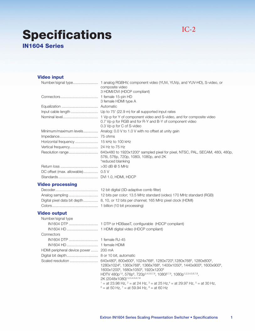
Extron IN1604 Series Scaling Presentation Switcher • Specifications 1
SpecificationsIN1604 Series
Video inputNumber/signal type 1 analog RGBHV, component video (YUVi, YUVp, and YUV-HD), S-video, or
composite video 3 HDMI/DVI (HDCP compliant)
Connectors 1 female 15-pin HD 3 female HDMI type A
Equalization AutomaticInput cable length Up to 75' (229 m) for all supported input ratesNominal level 1 Vp-p for Y of component video and S-video, and for composite video
07 Vp-p for RGB and for R-Y and B-Y of component video 03 Vp-p for C of S-video
Minimum/maximum levels Analog: 00 V to 10 V with no offset at unity gainImpedance 75 ohmsHorizontal frequency 15 kHz to 100 kHzVertical frequency 24 Hz to 75 HzResolution range 640x480 to 1920x1200* sampled pixel for pixel, NTSC, PAL, SECAM, 480i, 480p,
576i, 576p, 720p, 1080i, 1080p, and 2K *reduced blanking
Return loss >30 dB @ 5 MHzDC offset (max allowable) 05 VStandards DVI 10, HDMI, HDCP
Video processingDecoder 12 bit digital (3D-adaptive comb filter)Analog sampling 12 bits per color; 135 MHz standard (video) 170 MHz standard (RGB)Digital pixel data bit depth 8, 10, or 12 bits per channel; 165 MHz pixel clock (HDMI)Colors 1 billion (10 bit processing)
Video outputNumber/signal type
IN1604 DTP 1 DTP or HDBaseT, configurable (HDCP compliant)IN1604 HD 1 HDMI digital video (HDCP compliant)
ConnectorsIN1604 DTP 1 female RJ-45IN1604 HD 1 female HDMI
HDMI peripheral device power 200 mADigital bit depth 8 or 10 bit, automaticScaled resolution 640x4808, 800x6008, 1024x7688, 1280x7208,1280x7688, 1280x8008,
1280x10248, 1360x7688, 1366x7688, 1400x10508, 1440x9008, 1600x9008, 1600x12008, 1680x10508, 1920x12008 HDTV 480p7,8, 576p6, 720p3,4,5,6,7,8, 1080i6,7,8, 1080p1,2,3,4,5,6,7,8, 2K (2048x1080)1,2,3,4,5,6,7,8 1 = at 2398 Hz, 2 = at 24 Hz, 3 = at 25 Hz,4 = at 2997 Hz, 5 = at 30 Hz, 6 = at 50 Hz, 7 = at 5994 Hz, 8 = at 60 Hz
IC-2
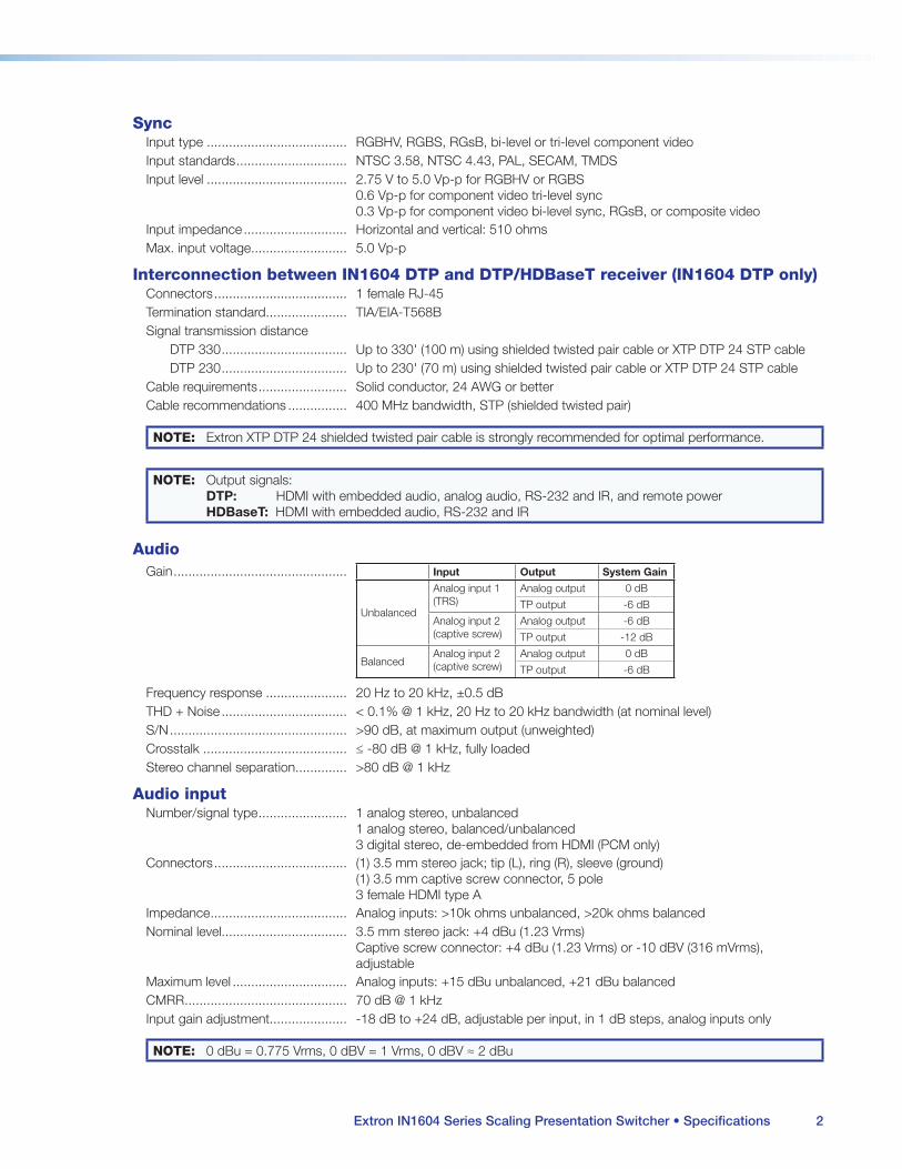
Extron IN1604 Series Scaling Presentation Switcher • Specifications 2
SyncInput type RGBHV, RGBS, RGsB, bi-level or tri-level component videoInput standards NTSC 358, NTSC 443, PAL, SECAM, TMDSInput level 275 V to 50 Vp-p for RGBHV or RGBS
06 Vp-p for component video tri-level sync 03 Vp-p for component video bi-level sync, RGsB, or composite video
Input impedance Horizontal and vertical: 510 ohmsMax input voltage 50 Vp-p
Interconnection between IN1604 DTP and DTP/HDBaseT receiver (IN1604 DTP only)Connectors 1 female RJ-45Termination standard TIA/EIA-T568BSignal transmission distance
DTP 330 Up to 330' (100 m) using shielded twisted pair cable or XTP DTP 24 STP cableDTP 230 Up to 230' (70 m) using shielded twisted pair cable or XTP DTP 24 STP cable
Cable requirements Solid conductor, 24 AWG or betterCable recommendations 400 MHz bandwidth, STP (shielded twisted pair)
NOTE: Extron XTP DTP 24 shielded twisted pair cable is strongly recommended for optimal performance
NOTE: Output signals: DTP: HDMI with embedded audio, analog audio, RS-232 and IR, and remote power HDBaseT: HDMI with embedded audio, RS-232 and IR
AudioGain Input Output System Gain
Unbalanced
Analog input 1 (TRS)
Analog output 0 dB
TP output -6 dB
Analog input 2 (captive screw)
Analog output -6 dB
TP output -12 dB
BalancedAnalog input 2 (captive screw)
Analog output 0 dB
TP output -6 dB
Frequency response 20 Hz to 20 kHz, ±05 dBTHD + Noise < 01% @ 1 kHz, 20 Hz to 20 kHz bandwidth (at nominal level)S/N >90 dB, at maximum output (unweighted)Crosstalk ≤ -80 dB @ 1 kHz, fully loadedStereo channel separation >80 dB @ 1 kHz
Audio inputNumber/signal type 1 analog stereo, unbalanced
1 analog stereo, balanced/unbalanced 3 digital stereo, de-embedded from HDMI (PCM only)
Connectors (1) 35 mm stereo jack; tip (L), ring (R), sleeve (ground) (1) 35 mm captive screw connector, 5 pole 3 female HDMI type A
Impedance Analog inputs: >10k ohms unbalanced, >20k ohms balancedNominal level 35 mm stereo jack: +4 dBu (123 Vrms)
Captive screw connector: +4 dBu (123 Vrms) or -10 dBV (316 mVrms), adjustable
Maximum level Analog inputs: +15 dBu unbalanced, +21 dBu balancedCMRR 70 dB @ 1 kHzInput gain adjustment -18 dB to +24 dB, adjustable per input, in 1 dB steps, analog inputs only
NOTE: 0 dBu = 0775 Vrms, 0 dBV = 1 Vrms, 0 dBV ≈ 2 dBu
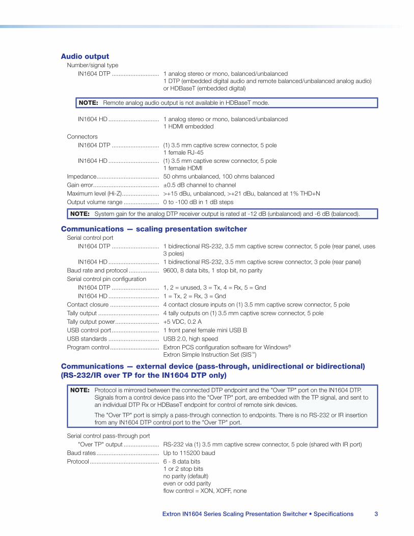
Extron IN1604 Series Scaling Presentation Switcher • Specifications 3
Audio outputNumber/signal type
IN1604 DTP 1 analog stereo or mono, balanced/unbalanced 1 DTP (embedded digital audio and remote balanced/unbalanced analog audio) or HDBaseT (embedded digital)
NOTE: Remote analog audio output is not available in HDBaseT mode
IN1604 HD 1 analog stereo or mono, balanced/unbalanced 1 HDMI embedded
ConnectorsIN1604 DTP (1) 35 mm captive screw connector, 5 pole
1 female RJ-45IN1604 HD (1) 35 mm captive screw connector, 5 pole
1 female HDMIImpedance 50 ohms unbalanced, 100 ohms balancedGain error ±05 dB channel to channelMaximum level (Hi-Z) >+15 dBu, unbalanced, >+21 dBu, balanced at 1% THD+NOutput volume range 0 to -100 dB in 1 dB steps
NOTE: System gain for the analog DTP receiver output is rated at -12 dB (unbalanced) and -6 dB (balanced)
Communications — scaling presentation switcherSerial control port
IN1604 DTP 1 bidirectional RS-232, 35 mm captive screw connector, 5 pole (rear panel, uses 3 poles)
IN1604 HD 1 bidirectional RS-232, 35 mm captive screw connector, 3 pole (rear panel)Baud rate and protocol 9600, 8 data bits, 1 stop bit, no paritySerial control pin configuration
IN1604 DTP 1, 2 = unused, 3 = Tx, 4 = Rx, 5 = GndIN1604 HD 1 = Tx, 2 = Rx, 3 = Gnd
Contact closure 4 contact closure inputs on (1) 35 mm captive screw connector, 5 poleTally output 4 tally outputs on (1) 35 mm captive screw connector, 5 poleTally output power +5 VDC, 02 AUSB control port 1 front panel female mini USB BUSB standards USB 20, high speedProgram control Extron PCS configuration software for Windows®
Extron Simple Instruction Set (SIS™)
Communications — external device (pass-through, unidirectional or bidirectional) (RS-232/IR over TP for the IN1604 DTP only)
NOTE: Protocol is mirrored between the connected DTP endpoint and the "Over TP" port on the IN1604 DTP Signals from a control device pass into the "Over TP" port, are embedded with the TP signal, and sent to an individual DTP Rx or HDBaseT endpoint for control of remote sink devices
The "Over TP" port is simply a pass-through connection to endpoints There is no RS-232 or IR insertion from any IN1604 DTP control port to the "Over TP" port
Serial control pass-through port"Over TP" output RS-232 via (1) 35 mm captive screw connector, 5 pole (shared with IR port)
Baud rates Up to 115200 baudProtocol 6 - 8 data bits
1 or 2 stop bits no parity (default) even or odd parity flow control = XON, XOFF, none
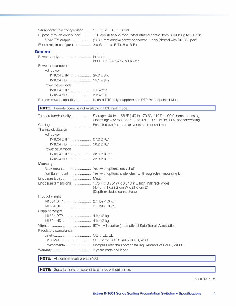
Extron IN1604 Series Scaling Presentation Switcher • Specifications 4
Serial control pin configuration 1 = Tx, 2 = Rx, 3 = GndIR pass-through control port TTL level (0 to 5 V) modulated infrared control from 30 kHz up to 60 kHz
"Over TP" output (1) 35 mm captive screw connector, 5 pole (shared with RS-232 port)IR control pin configuration 3 = Gnd, 4 = IR Tx, 5 = IR Rx
GeneralPower supply Internal
Input: 100-240 VAC, 50-60 HzPower consumption
Full powerIN1604 DTP 250 wattsIN1604 HD 151 watts
Power save modeIN1604 DTP 90 wattsIN1604 HD 66 watts
Remote power capability IN1604 DTP only: supports one DTP Rx endpoint device
NOTE: Remote power is not available in HDBaseT mode
Temperature/humidity Storage: -40 to +158 °F (-40 to +70 °C) / 10% to 90%, noncondensing Operating: +32 to +122 °F (0 to +50 °C) / 10% to 90%, noncondensing
Cooling Fan, air flows front to rear, vents on front and rearThermal dissipation
Full powerIN1604 DTP 670 BTU/hrIN1604 HD 502 BTU/hr
Power save modeIN1604 DTP 280 BTU/hrIN1604 HD 223 BTU/hr
MountingRack mount Yes, with optional rack shelfFurniture mount Yes, with optional under-desk or through-desk mounting kit
Enclosure type MetalEnclosure dimensions 175 H x 875" W x 85" D (1U high, half rack wide)
(44 cm H x 222 cm W x 216 cm D) (Depth excludes connectors)
Product weightIN1604 DTP 21 lbs (10 kg)IN1604 HD 21 lbs (10 kg)
Shipping weightIN1604 DTP 4 lbs (2 kg)IN1604 HD 4 lbs (2 kg)
Vibration ISTA 1A in carton (International Safe Transit Association)Regulatory compliance
Safety CE, c-UL, ULEMI/EMC CE, C-tick, FCC Class A, ICES, VCCIEnvironmental Complies with the appropriate requirements of RoHS, WEEE
Warranty 3 years parts and labor
NOTE: All nominal levels are at ±10%
NOTE: Specifications are subject to change without notice
81-011515-D5
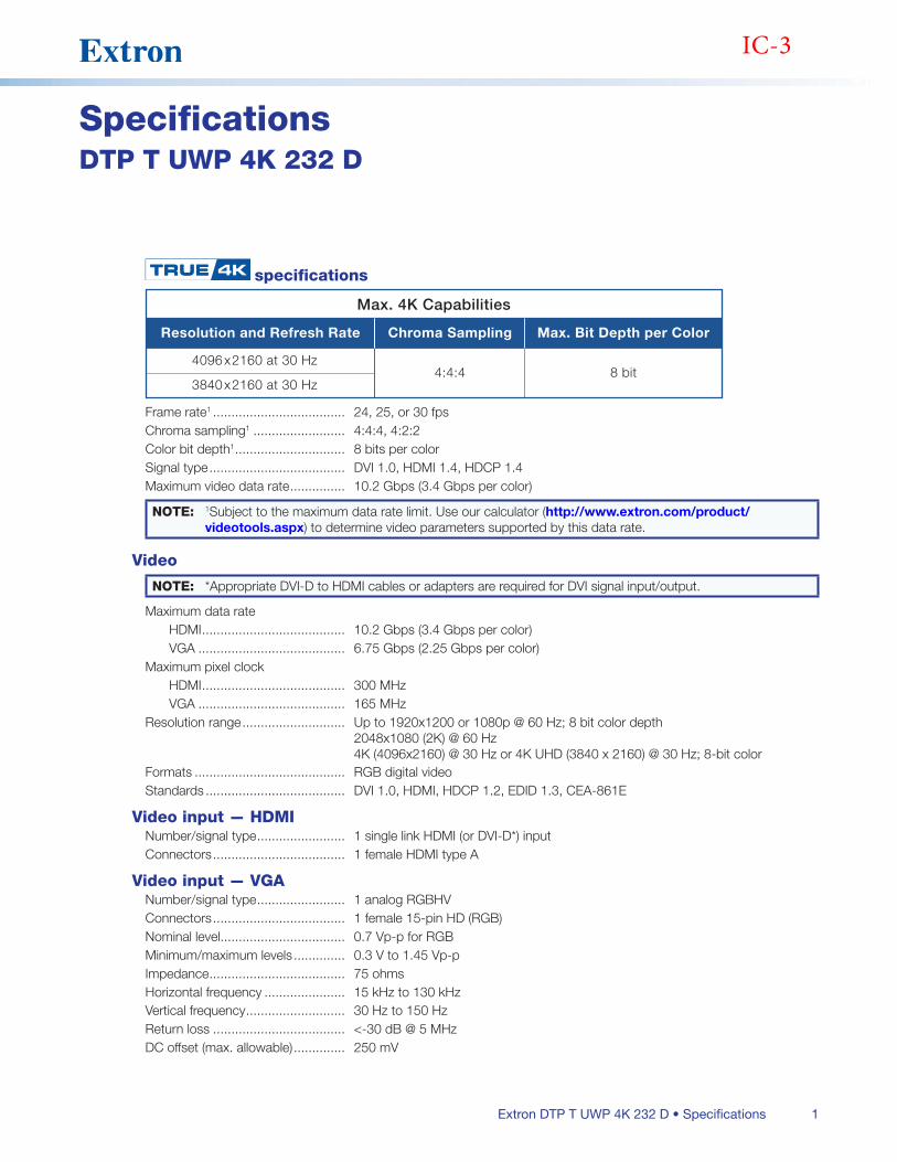
1Extron DTP T UWP 4K 232 D • Specifications
SpecificationsDTP T UWP 4K 232 D
specifications
Max. 4K Capabilities
Resolution and Refresh Rate
4096 x 2160 at 30 Hz
Chroma Sampling
4:4:4
Max. Bit Depth per Color
8 bit3840 x 2160 at 30 Hz
Frame rate1 24, 25, or 30 fpsChroma sampling1 4:4:4, 4:2:2Color bit depth1 8 bits per colorSignal type DVI 10, HDMI 14, HDCP 14Maximum video data rate 102 Gbps (34 Gbps per color)
NOTE: 1Subject to the maximum data rate limit Use our calculator (http://www.extron.com/product/videotools.aspx) to determine video parameters supported by this data rate
Video
NOTE: *Appropriate DVI-D to HDMI cables or adapters are required for DVI signal input/output
Maximum data rateHDMI 102 Gbps (34 Gbps per color)VGA 675 Gbps (225 Gbps per color)
Maximum pixel clockHDMI 300 MHzVGA 165 MHz
Resolution range Up to 1920x1200 or 1080p @ 60 Hz; 8 bit color depth 2048x1080 (2K) @ 60 Hz 4K (4096x2160) @ 30 Hz or 4K UHD (3840 x 2160) @ 30 Hz; 8-bit color
Formats RGB digital videoStandards DVI 10, HDMI, HDCP 12, EDID 13, CEA-861E
Video input — HDMINumber/signal type 1 single link HDMI (or DVI-D*) inputConnectors 1 female HDMI type A
Video input — VGANumber/signal type 1 analog RGBHVConnectors 1 female 15-pin HD (RGB)Nominal level 07 Vp-p for RGBMinimum/maximum levels 03 V to 145 Vp-pImpedance 75 ohmsHorizontal frequency 15 kHz to 130 kHzVertical frequency 30 Hz to 150 HzReturn loss <-30 dB @ 5 MHzDC offset (max allowable) 250 mV
IC-3
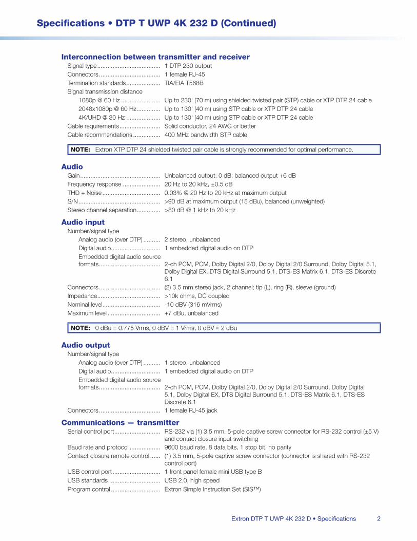
2
Specifications • DTP T UWP 4K 232 D (Continued)
Extron DTP T UWP 4K 232 D • Specifications
Interconnection between transmitter and receiverSignal type 1 DTP 230 outputConnectors 1 female RJ-45Termination standards TIA/EIA T568BSignal transmission distance
1080p @ 60 Hz Up to 230' (70 m) using shielded twisted pair (STP) cable or XTP DTP 24 cable2048x1080p @ 60 Hz Up to 130' (40 m) using STP cable or XTP DTP 24 cable4K/UHD @ 30 Hz Up to 130' (40 m) using STP cable or XTP DTP 24 cable
Cable requirements Solid conductor, 24 AWG or betterCable recommendations 400 MHz bandwidth STP cable
NOTE: Extron XTP DTP 24 shielded twisted pair cable is strongly recommended for optimal performance
AudioGain Unbalanced output: 0 dB; balanced output +6 dBFrequency response 20 Hz to 20 kHz, ±05 dBTHD + Noise 003% @ 20 Hz to 20 kHz at maximum outputS/N >90 dB at maximum output (15 dBu), balanced (unweighted)Stereo channel separation >80 dB @ 1 kHz to 20 kHz
Audio inputNumber/signal type
Analog audio (over DTP) 2 stereo, unbalancedDigital audio 1 embedded digital audio on DTPEmbedded digital audio sourceformats 2-ch PCM, PCM, Dolby Digital 2/0, Dolby Digital 2/0 Surround, Dolby Digital 51,
Dolby Digital EX, DTS Digital Surround 51, DTS-ES Matrix 61, DTS-ES Discrete 61
Connectors (2) 35 mm stereo jack, 2 channel; tip (L), ring (R), sleeve (ground)Impedance >10k ohms, DC coupledNominal level -10 dBV (316 mVrms)Maximum level +7 dBu, unbalanced
NOTE: 0 dBu = 0775 Vrms, 0 dBV = 1 Vrms, 0 dBV ≈ 2 dBu
Audio outputNumber/signal type
Analog audio (over DTP) 1 stereo, unbalancedDigital audio 1 embedded digital audio on DTPEmbedded digital audio sourceformats 2-ch PCM, PCM, Dolby Digital 2/0, Dolby Digital 2/0 Surround, Dolby Digital
51, Dolby Digital EX, DTS Digital Surround 51, DTS-ES Matrix 61, DTS-ES Discrete 61
Connectors 1 female RJ-45 jack
Communications — transmitterSerial control port RS-232 via (1) 35 mm, 5-pole captive screw connector for RS-232 control (±5 V)
and contact closure input switchingBaud rate and protocol 9600 baud rate, 8 data bits, 1 stop bit, no parityContact closure remote control (1) 35 mm, 5-pole captive screw connector (connector is shared with RS-232
control port)USB control port 1 front panel female mini USB type BUSB standards USB 20, high speedProgram control Extron Simple Instruction Set (SIS™)
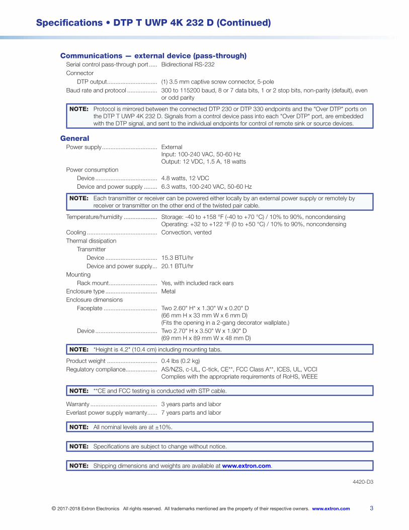
3
Specifications • DTP T UWP 4K 232 D (Continued)
© 2017-2018 Extron Electronics All rights reserved. All trademarks mentioned are the property of their respective owners. www.extron.com
Communications — external device (pass-through)Serial control pass-through port Bidirectional RS-232Connector
DTP output (1) 35 mm captive screw connector, 5-poleBaud rate and protocol 300 to 115200 baud, 8 or 7 data bits, 1 or 2 stop bits, non-parity (default), even
or odd parity
NOTE: Protocol is mirrored between the connected DTP 230 or DTP 330 endpoints and the "Over DTP" ports on the DTP T UWP 4K 232 D Signals from a control device pass into each "Over DTP" port, are embedded with the DTP signal, and sent to the individual endpoints for control of remote sink or source devices
GeneralPower supply External
Input: 100-240 VAC, 50-60 Hz Output: 12 VDC, 15 A, 18 watts
Power consumptionDevice 48 watts, 12 VDCDevice and power supply 63 watts, 100-240 VAC, 50-60 Hz
NOTE: Each transmitter or receiver can be powered either locally by an external power supply or remotely by receiver or transmitter on the other end of the twisted pair cable
Temperature/humidity Storage: -40 to +158 °F (-40 to +70 °C) / 10% to 90%, noncondensing Operating: +32 to +122 °F (0 to +50 °C) / 10% to 90%, noncondensing
Cooling Convection, ventedThermal dissipation
TransmitterDevice 153 BTU/hrDevice and power supply 201 BTU/hr
MountingRack mount Yes, with included rack ears
Enclosure type MetalEnclosure dimensions
Faceplate Two 260" H* x 130" W x 020" D (66 mm H x 33 mm W x 6 mm D) (Fits the opening in a 2-gang decorator wallplate)
Device Two 270" H x 350" W x 190" D (69 mm H x 89 mm W x 48 mm D)
NOTE: *Height is 42" (104 cm) including mounting tabs
Product weight 04 lbs (02 kg)Regulatory compliance AS/NZS, c-UL, C-tick, CE**, FCC Class A**, ICES, UL, VCCI
Complies with the appropriate requirements of RoHS, WEEE
NOTE: **CE and FCC testing is conducted with STP cable
Warranty 3 years parts and laborEverlast power supply warranty 7 years parts and labor
NOTE: All nominal levels are at ±10%
NOTE: Specifications are subject to change without notice
NOTE: Shipping dimensions and weights are available at www.extron.com
4420-D3
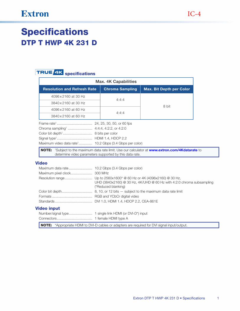
1Extron DTP T HWP 4K 231 D • Specifications
SpecificationsDTP T HWP 4K 231 D
specifications
Max. 4K Capabilities
Resolution and Refresh Rate
4096 x 2160 at 30 Hz
Chroma Sampling
4:4:4
4:4:4
Max. Bit Depth per Color
8 bit3840 x 2160 at 30 Hz
4096 x 2160 at 60 Hz
3840 x 2160 at 60 Hz
Frame rate1 24, 25, 30, 50, or 60 fpsChroma sampling1 4:4:4, 4:2:2, or 4:2:0Color bit depth1 8 bits per colorSignal type1 HDMI 14, HDCP 22Maximum video data rate1 102 Gbps (34 Gbps per color)
NOTE: 1Subject to the maximum data rate limit Use our calculator at www.extron.com/4Kdatarate to determine video parameters supported by this data rate
VideoMaximum data rate 102 Gbps (34 Gbps per color)Maximum pixel clock 300 MHzResolution range Up to 2560x1600* @ 60 Hz or 4K (4096x2160) @ 30 Hz,
UHD (3840x2160) @ 30 Hz, 4K/UHD @ 60 Hz with 4:2:0 chroma subsampling (*Reduced blanking)
Color bit depth 8, 10, or 12 bits — subject to the maximum data rate limitFormats RGB and YCbCr digital videoStandards DVI 10, HDMI 14, HDCP 22, CEA-861E
Video inputNumber/signal type 1 single link HDMI (or DVI-D*) inputConnectors 1 female HDMI type A
NOTE: *Appropriate HDMI to DVI-D cables or adapters are required for DVI signal input/output
IC-4
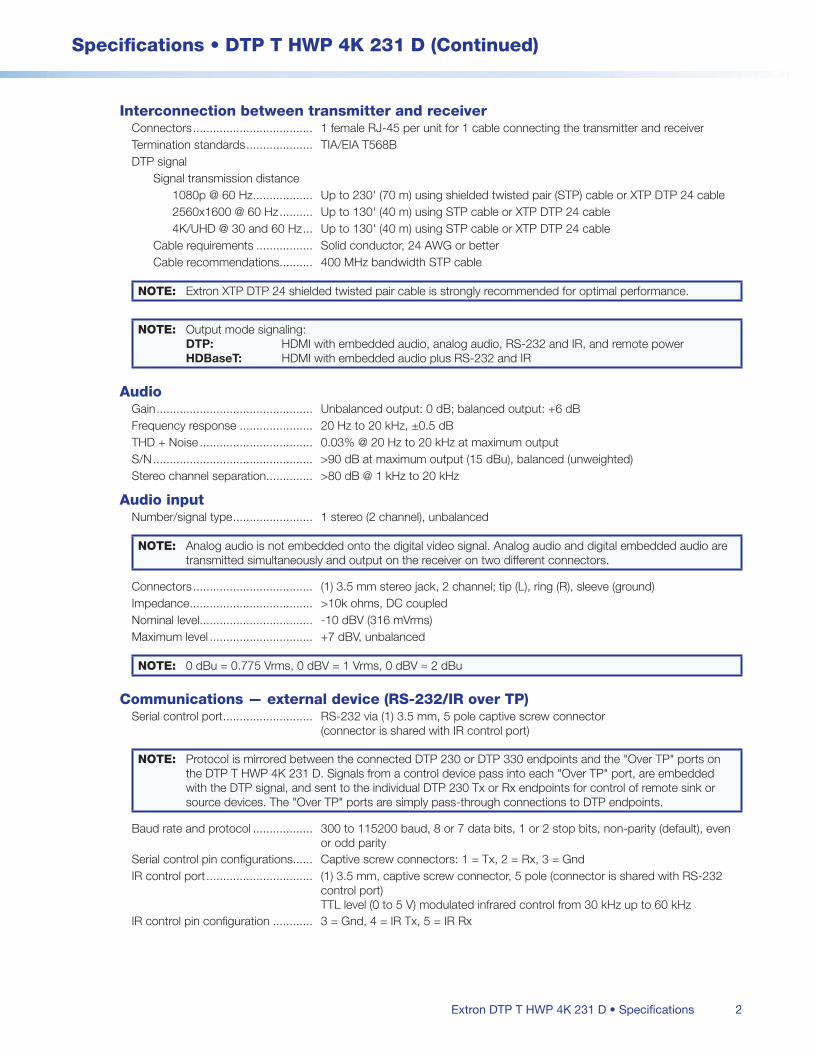
2
Specifications • DTP T HWP 4K 231 D (Continued)
Extron DTP T HWP 4K 231 D • Specifications
Interconnection between transmitter and receiverConnectors 1 female RJ-45 per unit for 1 cable connecting the transmitter and receiverTermination standards TIA/EIA T568BDTP signal
Signal transmission distance1080p @ 60 Hz Up to 230' (70 m) using shielded twisted pair (STP) cable or XTP DTP 24 cable2560x1600 @ 60 Hz Up to 130' (40 m) using STP cable or XTP DTP 24 cable4K/UHD @ 30 and 60 Hz Up to 130' (40 m) using STP cable or XTP DTP 24 cable
Cable requirements Solid conductor, 24 AWG or betterCable recommendations 400 MHz bandwidth STP cable
NOTE: Extron XTP DTP 24 shielded twisted pair cable is strongly recommended for optimal performance
NOTE: Output mode signaling: DTP: HDMI with embedded audio, analog audio, RS-232 and IR, and remote power HDBaseT: HDMI with embedded audio plus RS-232 and IR
AudioGain Unbalanced output: 0 dB; balanced output: +6 dBFrequency response 20 Hz to 20 kHz, ±05 dBTHD + Noise 003% @ 20 Hz to 20 kHz at maximum outputS/N >90 dB at maximum output (15 dBu), balanced (unweighted)Stereo channel separation >80 dB @ 1 kHz to 20 kHz
Audio inputNumber/signal type 1 stereo (2 channel), unbalanced
NOTE: Analog audio is not embedded onto the digital video signal Analog audio and digital embedded audio are transmitted simultaneously and output on the receiver on two different connectors
Connectors (1) 35 mm stereo jack, 2 channel; tip (L), ring (R), sleeve (ground)Impedance >10k ohms, DC coupledNominal level -10 dBV (316 mVrms)Maximum level +7 dBV, unbalanced
NOTE: 0 dBu = 0775 Vrms, 0 dBV = 1 Vrms, 0 dBV ≈ 2 dBu
Communications — external device (RS-232/IR over TP)Serial control port RS-232 via (1) 35 mm, 5 pole captive screw connector
(connector is shared with IR control port)
NOTE: Protocol is mirrored between the connected DTP 230 or DTP 330 endpoints and the "Over TP" ports on the DTP T HWP 4K 231 D Signals from a control device pass into each "Over TP" port, are embedded with the DTP signal, and sent to the individual DTP 230 Tx or Rx endpoints for control of remote sink or source devices The "Over TP" ports are simply pass-through connections to DTP endpoints
Baud rate and protocol 300 to 115200 baud, 8 or 7 data bits, 1 or 2 stop bits, non-parity (default), even or odd parity
Serial control pin configurations Captive screw connectors: 1 = Tx, 2 = Rx, 3 = GndIR control port (1) 35 mm, captive screw connector, 5 pole (connector is shared with RS-232
control port) TTL level (0 to 5 V) modulated infrared control from 30 kHz up to 60 kHz
IR control pin configuration 3 = Gnd, 4 = IR Tx, 5 = IR Rx

3
Specifications • DTP T HWP 4K 231 D (Continued)
© 2014-2018 Extron Electronics All rights reserved. All trademarks mentioned are the property of their respective owners. www.extron.com
GeneralPower supply External
Input: 100-240 VAC, 50-60 Hz Output: 12 VDC, 15 A, 18 watts
Power consumptionDevice 46 watts, 12 VDCDevice and power supply 61 watts, 100-240 VAC, 50-60 Hz
NOTE: Each transmitter or receiver can be powered either locally by an external power supply or remotely by receiver or transmitter on the other end of the twisted pair cable
Temperature/humidity Storage: -40 to +158 °F (-40 to +70 °C) / 10% to 90%, noncondensing Operating: +32 to +122 °F (0 to +50 °C) / 10% to 90%, noncondensing
Cooling Convection, no ventsThermal dissipation
Device 143 BTU/hrDevice and power supply 197 BTU/hr
MountingFurniture or wall mount Yes, with a 1-gang wall box or mud ring
Enclosure type MetalEnclosure dimensions
Faceplate 26" H x 13" W x 03" D (66 cm H x 33 cm W x 06 cm D)
Device 28" H x 17" W x 19" D (71 cm H x 43 cm W x 48 cm D)
NOTES:
• Overall height is 42" (107 cm), including mounting tabs Mounting holes are 32"(82 cm) apart on center
• Depth excludes connectors Fits the opening in a 1 gang decorator wallplate)
Product weight 02 lbs (01 kg)Regulatory compliance AS/NZS, C-tick, c-UL, CE**, FCC Class A**, ICES, UL
NOTE: **CE and FCC testing is conducted with STP cable
Warranty 3 years parts and laborEverlast power supply warranty 7 years parts and labor
NOTE: All nominal levels are at ±10%
NOTE: Specifications are subject to change without notice
NOTE: Shipping dimensions and weights are available at www.extron.com
4455-D7

1Extron DTP HDMI 230 4K Tx/Rx Twisted Pair Extender Transmitter/Receiver • Specifications
SpecificationsDTP HDMI 230 4K Tx/Rx
specification
Max. 4K Capabilities
Resolution and Refresh Rate
4096 x 2160 at 30 Hz
Chroma Sampling
4:4:4
4:2:0
Max. Bit Depth per Color
8 bit3840 x 2160 at 30 Hz
4096 x 2160 at 60 Hz
3840 x 2160 at 60 Hz
Frame rate1 24, 25, 30, 50, or 60 fpsChroma sampling1 4:4:4, 4:2:2, or 4:2:0Color bit depth1 8 bits per colorSignal type HDMI 14, HDCP 22Max video data rate 102 Gbps (34 Gbps per color)
NOTE: 1Subject to the maximum data rate limit Use our calculator (http://www.extron.com/product/videotools.aspx) to determine video parameters supported by this data rate
NOTE: This product consists of a transmitter (DTP HDMI 4K 230 Tx) and a receiver (DTP HDMI 4K 230 Rx), sold separately, with twisted pair cables linking the transmitter and receiver
NOTE: *Appropriate HDMI to DVI-D cables or adapters are required for DVI signal input/output
VideoMaximum data rate 102 Gbps (34 Gbps per color)Maximum pixel clock 300 MHzResolution range Up to 2560x1600* @ 60 Hz or
4K (4096x2160) @ 30 Hz, UHD (3840x2160) @ 30 Hz, 4K/UHD @ 60 Hz with 4:2:0 chroma subsampling (* reduced blanking)
Color bit depth 8, 10, or 12 bits — subject to the maximum data rate limitFormats RGB and YCbCr digital videoStandards DVI 10, HDMI 14, HDCP 22, CEA-861E
Video input — transmitterNumber/signal type 1 single link HDMI (or DVI-D*)Connectors 1 female HDMI type A
Interconnection between transmitter and receiverConnectors 1 female RJ-45 per unitTermination standard TIA/EIA T568B
IR-1

2
Specifications • DTP HDMI 230 4K Tx/Rx (Continued)
Extron DTP HDMI 230 4K Tx/Rx Twisted Pair Extender Transmitter/Receiver • Specifications
Signal transmission distance1080p @ 60 Hz Up to 230' (70 m) using shielded twisted pair (STP) cable or XTP DTP 24 STP
cable2560x1600 @ 60 Hz Up to 130' (40 m) using shielded twisted pair (STP) cable or XTP DTP 24 STP
cable4K/UHD @ 30Hz and 60 Hz Up to 130' (40 m) using shielded twisted pair (STP) cable or XTP DTP 24 STP
cableCable requirements Solid conductor, 24 AWG or betterCable recommendations 400 MHz bandwidth, STP (shielded twisted pair)
NOTE: Extron XTP DTP 24 shielded twisted pair cable is strongly recommended for optimal performance
Video output — receiverNumber/signal type 1 single link HDMI (or DVI-D*)Connectors 1 female HDMI type A
AudioGain Unbalanced output: 0 dB; balanced output +6 dBFrequency response 20 Hz to 20 kHz, ±05 dBTHD + Noise 003% @ 20 Hz to 20 kHz at maximum outputS/N >90 dB, at maximum output (15 dBu), balanced (unweighted)Stereo channel separation >80 dB @ 1 kHz to 20 kHz
Audio inputNumber/signal type 1 PC level stereo, unbalanced
NOTE: Analog audio is not embedded onto the digital video signal Embedded digital audio is not de-embedded from the digital video signal
Connectors (1) 35 mm stereo jack, 2 channel; tip (L), ring (R), sleeve (ground)Impedance >10k ohms, DC coupledNominal level -10 dBV (316 mVrms)Maximum level +7 dBV (unbalanced)
NOTE: 0 dBu = 0775 Vrms, 0 dBV = 1 Vrms, 0 dBV ≈ 2 dBu
Audio outputNumber/signal type 1 stereo (2 channel), balanced/unbalancedConnectors (1) 35 mm captive screw connector, 5 poleImpedance 50 ohms unbalanced, 100 ohms balancedGain error ±01 dB channel to channelMaximum level (600 ohm) >+11 dBu, balanced
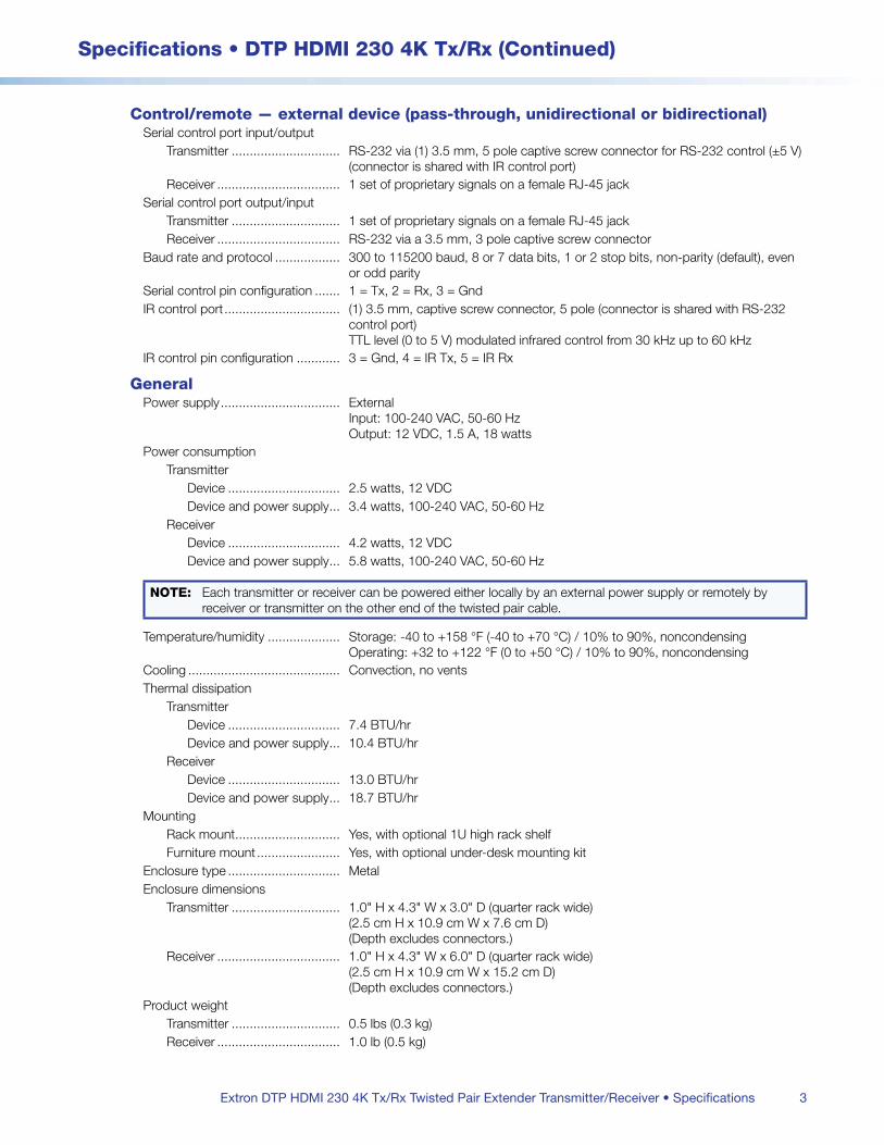
3
Specifications • DTP HDMI 230 4K Tx/Rx (Continued)
Extron DTP HDMI 230 4K Tx/Rx Twisted Pair Extender Transmitter/Receiver • Specifications
Control/remote — external device (pass-through, unidirectional or bidirectional)Serial control port input/output
Transmitter RS-232 via (1) 35 mm, 5 pole captive screw connector for RS-232 control (±5 V) (connector is shared with IR control port)
Receiver 1 set of proprietary signals on a female RJ-45 jackSerial control port output/input
Transmitter 1 set of proprietary signals on a female RJ-45 jackReceiver RS-232 via a 35 mm, 3 pole captive screw connector
Baud rate and protocol 300 to 115200 baud, 8 or 7 data bits, 1 or 2 stop bits, non-parity (default), even or odd parity
Serial control pin configuration 1 = Tx, 2 = Rx, 3 = GndIR control port (1) 35 mm, captive screw connector, 5 pole (connector is shared with RS-232
control port) TTL level (0 to 5 V) modulated infrared control from 30 kHz up to 60 kHz
IR control pin configuration 3 = Gnd, 4 = IR Tx, 5 = IR Rx
GeneralPower supply External
Input: 100-240 VAC, 50-60 Hz Output: 12 VDC, 15 A, 18 watts
Power consumptionTransmitter
Device 25 watts, 12 VDCDevice and power supply 34 watts, 100-240 VAC, 50-60 Hz
ReceiverDevice 42 watts, 12 VDCDevice and power supply 58 watts, 100-240 VAC, 50-60 Hz
NOTE: Each transmitter or receiver can be powered either locally by an external power supply or remotely by receiver or transmitter on the other end of the twisted pair cable
Temperature/humidity Storage: -40 to +158 °F (-40 to +70 °C) / 10% to 90%, noncondensing Operating: +32 to +122 °F (0 to +50 °C) / 10% to 90%, noncondensing
Cooling Convection, no ventsThermal dissipation
TransmitterDevice 74 BTU/hrDevice and power supply 104 BTU/hr
ReceiverDevice 130 BTU/hrDevice and power supply 187 BTU/hr
MountingRack mount Yes, with optional 1U high rack shelfFurniture mount Yes, with optional under-desk mounting kit
Enclosure type MetalEnclosure dimensions
Transmitter 10" H x 43" W x 30" D (quarter rack wide) (25 cm H x 109 cm W x 76 cm D) (Depth excludes connectors)
Receiver 10" H x 43" W x 60" D (quarter rack wide) (25 cm H x 109 cm W x 152 cm D) (Depth excludes connectors)
Product weightTransmitter 05 lbs (03 kg)Receiver 10 lb (05 kg)
4
Specifications • DTP HDMI 230 4K Tx/Rx (Continued)
© 2018 Extron Electronics All rights reserved. All trademarks mentioned are the property of their respective owners. www.extron.com
Regulatory compliance CE, c-UL UL, CE**, C-tick, FCC Class A**, ICES, VCCI, Complies with the appropriate requirements of RoHS, WEEE UL rated for use in plenum airspaces: meets UL 2043 for heat and smoke release, excluding the power supply
NOTE: **CE and FCC testing is conducted with STP (shielded twisted pair) I/O cable
Product warranty 3 years parts and labor
Everlast power supply warranty 7 years parts and labor
NOTE: All nominal levels are at ±10%
NOTE: Specifications are subject to change without notice
NOTE: Shipping weights and dimensions are available at www.extron.com
4482-101618-D18
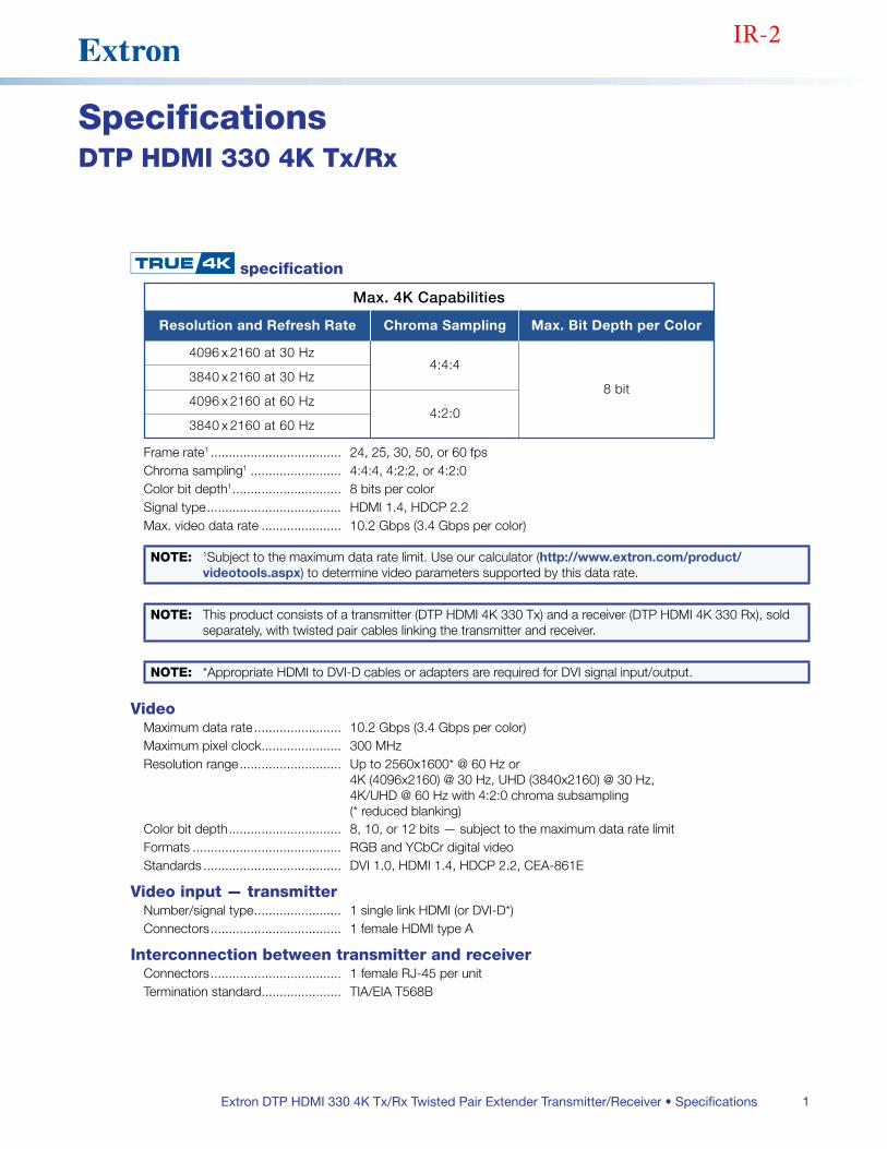
1Extron DTP HDMI 330 4K Tx/Rx Twisted Pair Extender Transmitter/Receiver • Specifications
SpecificationsDTP HDMI 330 4K Tx/Rx
specification
Max. 4K Capabilities
Resolution and Refresh Rate
4096 x 2160 at 30 Hz
Chroma Sampling
4:4:4
4:2:0
Max. Bit Depth per Color
8 bit3840 x 2160 at 30 Hz
4096 x 2160 at 60 Hz
3840 x 2160 at 60 Hz
Frame rate1 24, 25, 30, 50, or 60 fpsChroma sampling1 4:4:4, 4:2:2, or 4:2:0Color bit depth1 8 bits per colorSignal type HDMI 14, HDCP 22Max video data rate 102 Gbps (34 Gbps per color)
NOTE: 1Subject to the maximum data rate limit Use our calculator (http://www.extron.com/product/videotools.aspx) to determine video parameters supported by this data rate
NOTE: This product consists of a transmitter (DTP HDMI 4K 330 Tx) and a receiver (DTP HDMI 4K 330 Rx), sold separately, with twisted pair cables linking the transmitter and receiver
NOTE: *Appropriate HDMI to DVI-D cables or adapters are required for DVI signal input/output
VideoMaximum data rate 102 Gbps (34 Gbps per color)Maximum pixel clock 300 MHzResolution range Up to 2560x1600* @ 60 Hz or
4K (4096x2160) @ 30 Hz, UHD (3840x2160) @ 30 Hz, 4K/UHD @ 60 Hz with 4:2:0 chroma subsampling (* reduced blanking)
Color bit depth 8, 10, or 12 bits — subject to the maximum data rate limitFormats RGB and YCbCr digital videoStandards DVI 10, HDMI 14, HDCP 22, CEA-861E
Video input — transmitterNumber/signal type 1 single link HDMI (or DVI-D*)Connectors 1 female HDMI type A
Interconnection between transmitter and receiverConnectors 1 female RJ-45 per unitTermination standard TIA/EIA T568B
IR-2
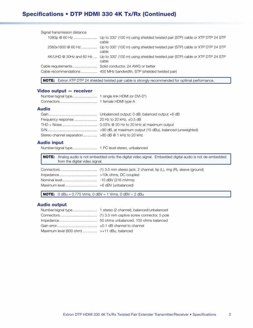
2
Specifications • DTP HDMI 330 4K Tx/Rx (Continued)
Extron DTP HDMI 330 4K Tx/Rx Twisted Pair Extender Transmitter/Receiver • Specifications
Signal transmission distance1080p @ 60 Hz Up to 330' (100 m) using shielded twisted pair (STP) cable or XTP DTP 24 STP
cable2560x1600 @ 60 Hz Up to 330' (100 m) using shielded twisted pair (STP) cable or XTP DTP 24 STP
cable4K/UHD @ 30Hz and 60 Hz Up to 330' (100 m) using shielded twisted pair (STP) cable or XTP DTP 24 STP
cableCable requirements Solid conductor, 24 AWG or betterCable recommendations 400 MHz bandwidth, STP (shielded twisted pair)
NOTE: Extron XTP DTP 24 shielded twisted pair cable is strongly recommended for optimal performance
Video output — receiverNumber/signal type 1 single link HDMI (or DVI-D*)Connectors 1 female HDMI type A
AudioGain Unbalanced output: 0 dB; balanced output +6 dBFrequency response 20 Hz to 20 kHz, ±05 dBTHD + Noise 003% @ 20 Hz to 20 kHz at maximum outputS/N >90 dB, at maximum output (15 dBu), balanced (unweighted)Stereo channel separation >80 dB @ 1 kHz to 20 kHz
Audio inputNumber/signal type 1 PC level stereo, unbalanced
NOTE: Analog audio is not embedded onto the digital video signal Embedded digital audio is not de-embedded from the digital video signal
Connectors (1) 35 mm stereo jack, 2 channel; tip (L), ring (R), sleeve (ground)Impedance >10k ohms, DC coupledNominal level -10 dBV (316 mVrms)Maximum level +6 dBV (unbalanced)
NOTE: 0 dBu = 0775 Vrms, 0 dBV = 1 Vrms, 0 dBV ≈ 2 dBu
Audio outputNumber/signal type 1 stereo (2 channel), balanced/unbalancedConnectors (1) 35 mm captive screw connector, 5 poleImpedance 50 ohms unbalanced, 100 ohms balancedGain error ±01 dB channel to channelMaximum level (600 ohm) >+11 dBu, balanced

3
Specifications • DTP HDMI 330 4K Tx/Rx (Continued)
Extron DTP HDMI 330 4K Tx/Rx Twisted Pair Extender Transmitter/Receiver • Specifications
Communications — external device (pass-through, unidirectional or bidirectional)Serial control port input/output
Transmitter RS-232 via (1) 35 mm, 5 pole captive screw connector for RS-232 control (±5 V) (connector is shared with IR control port)
Receiver 1 set of proprietary signals on a female RJ-45 jackSerial control port output/input
Transmitter 1 set of proprietary signals on a female RJ-45 jackReceiver RS-232 via a 35 mm, 3 pole captive screw connector
Baud rate and protocol 300 to 115200 baud, 8 or 7 data bits, 1 or 2 stop bits, non-parity (default), even or odd parity
Serial control pin configuration 1 = Tx, 2 = Rx, 3 = GndIR control port (1) 35 mm, captive screw connector, 5 pole (connector is shared with RS-232
control port) TTL level (0 to 5 V) modulated infrared control from 30 kHz up to 60 kHz
IR control pin configuration 3 = Gnd, 4 = IR Tx, 5 = IR Rx
GeneralPower supply External
Input: 100-240 VAC, 50-60 Hz Output: 12 VDC, 15 A, 18 watts
Power consumptionTransmitter
Device 25 watts, 12 VDCDevice and power supply 34 watts, 100-240 VAC, 50-60 Hz
ReceiverDevice 42 watts, 12 VDCDevice and power supply 58 watts, 100-240 VAC, 50-60 Hz
NOTE: Each transmitter or receiver can be powered either locally by an external power supply or remotely by receiver or transmitter on the other end of the twisted pair cable
Temperature/humidity Storage: -40 to +158 °F (-40 to +70 °C) / 10% to 90%, noncondensing Operating: +32 to +122 °F (0 to +50 °C) / 10% to 90%, noncondensing
Cooling Convection, no ventsThermal dissipation
TransmitterDevice 74 BTU/hrDevice and power supply 104 BTU/hr
ReceiverDevice 130 BTU/hrDevice and power supply 187 BTU/hr
MountingRack mount Yes, with optional 1U high rack shelfFurniture mount Yes, with optional under-desk mounting kit
Enclosure type MetalEnclosure dimensions
Transmitter 10" H x 43" W x 30" D (quarter rack wide) (25 cm H x 109 cm W x 76 cm D) (Depth excludes connectors)
Receiver 10" H x 43" W x 60" D (quarter rack wide) (25 cm H x 109 cm W x 152 cm D) (Depth excludes connectors)
Product weightTransmitter 05 lbs (03 kg)Receiver 10 lb (05 kg)
4
Specifications • DTP HDMI 330 4K Tx/Rx (Continued)
© 2018 Extron Electronics All rights reserved. All trademarks mentioned are the property of their respective owners. www.extron.com
Regulatory compliance CE, c-UL UL, CE**, C-tick, FCC Class A**, ICES, VCCI, Complies with the appropriate requirements of RoHS, WEEE UL rated for use in plenum airspaces: meets UL 2043 for heat and smoke release, excluding the power supply
NOTE: **CE and FCC testing is conducted with STP (shielded twisted pair) I/O cable
Product warranty 3 years parts and laborEverlast power supply warranty 7 years parts and labor
NOTE: All nominal levels are at ±10%
NOTE: Specifications are subject to change without notice
NOTE: Shipping weights and dimensions are available at www.extron.com
4483-101618-D17
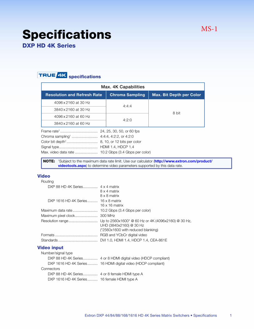
Extron DXP 44/84/88/168/1616 HD 4K Series Matrix Switchers • Specifications 1
SpecificationsDXP HD 4K Series
specifications
Max. 4K Capabilities
Resolution and Refresh Rate
4096 x 2160 at 30 Hz
Chroma Sampling
4:4:4
4:2:0
Max. Bit Depth per Color
8 bit3840 x 2160 at 30 Hz
4096 x 2160 at 60 Hz
3840 x 2160 at 60 Hz
Frame rate1 24, 25, 30, 50, or 60 fpsChroma sampling1 4:4:4, 4:2:2, or 4:2:0Color bit depth1 8, 10, or 12 bits per colorSignal type HDMI 14, HDCP 14Max video data rate 102 Gbps (34 Gbps per color)
NOTE: 1Subject to the maximum data rate limit Use our calculator (http://www.extron.com/product/videotools.aspx) to determine video parameters supported by this data rate
VideoRouting
DXP 88 HD 4K Series 4 x 4 matrix 8 x 4 matrix 8 x 8 matrix
DXP 1616 HD 4K Series 16 x 8 matrix 16 x 16 matrix
Maximum data rate 102 Gbps (34 Gbps per color)Maximum pixel clock 300 MHzResolution range Up to 2560x1600* @ 60 Hz or 4K (4096x2160) @ 30 Hz,
UHD (3840x2160) @ 30 Hz (*2560x1600 with reduced blanking)
Formats RGB and YCbCr digital videoStandards DVI 10, HDMI 14, HDCP 14, CEA-861E
Video inputNumber/signal type
DXP 88 HD 4K Series 4 or 8 HDMI digital video (HDCP compliant)DXP 1616 HD 4K Series 16 HDMI digital video (HDCP compliant)
ConnectorsDXP 88 HD 4K Series 4 or 8 female HDMI type ADXP 1616 HD 4K Series 16 female HDMI type A
MS-1
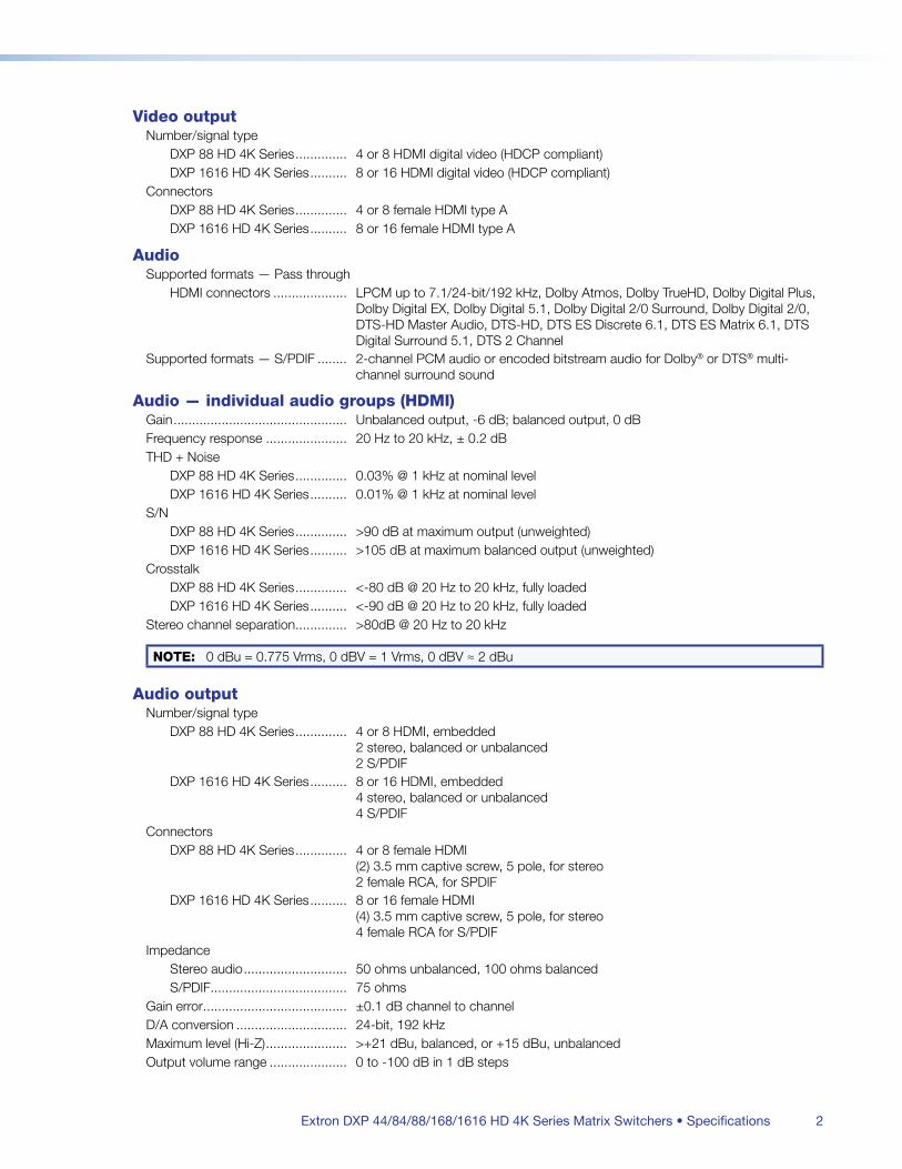
Extron DXP 44/84/88/168/1616 HD 4K Series Matrix Switchers • Specifications 2
Video outputNumber/signal type
DXP 88 HD 4K Series 4 or 8 HDMI digital video (HDCP compliant)DXP 1616 HD 4K Series 8 or 16 HDMI digital video (HDCP compliant)
ConnectorsDXP 88 HD 4K Series 4 or 8 female HDMI type ADXP 1616 HD 4K Series 8 or 16 female HDMI type A
AudioSupported formats — Pass through
HDMI connectors LPCM up to 71/24-bit/192 kHz, Dolby Atmos, Dolby TrueHD, Dolby Digital Plus, Dolby Digital EX, Dolby Digital 51, Dolby Digital 2/0 Surround, Dolby Digital 2/0, DTS-HD Master Audio, DTS-HD, DTS ES Discrete 61, DTS ES Matrix 61, DTS Digital Surround 51, DTS 2 Channel
Supported formats — S/PDIF 2-channel PCM audio or encoded bitstream audio for Dolby® or DTS® multi-channel surround sound
Audio — individual audio groups (HDMI)Gain Unbalanced output, -6 dB; balanced output, 0 dBFrequency response 20 Hz to 20 kHz, ± 02 dBTHD + Noise
DXP 88 HD 4K Series 003% @ 1 kHz at nominal levelDXP 1616 HD 4K Series 001% @ 1 kHz at nominal level
S/NDXP 88 HD 4K Series >90 dB at maximum output (unweighted)DXP 1616 HD 4K Series >105 dB at maximum balanced output (unweighted)
CrosstalkDXP 88 HD 4K Series <-80 dB @ 20 Hz to 20 kHz, fully loadedDXP 1616 HD 4K Series <-90 dB @ 20 Hz to 20 kHz, fully loaded
Stereo channel separation >80dB @ 20 Hz to 20 kHz
NOTE: 0 dBu = 0775 Vrms, 0 dBV = 1 Vrms, 0 dBV ≈ 2 dBu
Audio outputNumber/signal type
DXP 88 HD 4K Series 4 or 8 HDMI, embedded 2 stereo, balanced or unbalanced 2 S/PDIF
DXP 1616 HD 4K Series 8 or 16 HDMI, embedded 4 stereo, balanced or unbalanced 4 S/PDIF
ConnectorsDXP 88 HD 4K Series 4 or 8 female HDMI
(2) 35 mm captive screw, 5 pole, for stereo2 female RCA, for SPDIF
DXP 1616 HD 4K Series 8 or 16 female HDMI (4) 35 mm captive screw, 5 pole, for stereo4 female RCA for S/PDIF
ImpedanceStereo audio 50 ohms unbalanced, 100 ohms balancedS/PDIF 75 ohms
Gain error ±01 dB channel to channelD/A conversion 24-bit, 192 kHzMaximum level (Hi-Z) >+21 dBu, balanced, or +15 dBu, unbalancedOutput volume range 0 to -100 dB in 1 dB steps
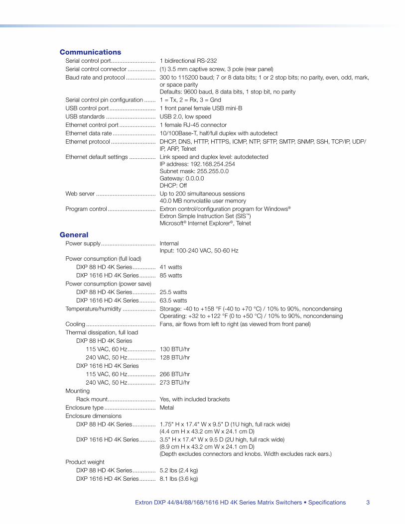
Extron DXP 44/84/88/168/1616 HD 4K Series Matrix Switchers • Specifications 3
CommunicationsSerial control port 1 bidirectional RS-232Serial control connector (1) 35 mm captive screw, 3 pole (rear panel)Baud rate and protocol 300 to 115200 baud; 7 or 8 data bits; 1 or 2 stop bits; no parity, even, odd, mark,
or space parity Defaults: 9600 baud, 8 data bits, 1 stop bit, no parity
Serial control pin configuration 1 = Tx, 2 = Rx, 3 = GndUSB control port 1 front panel female USB mini-BUSB standards USB 20, low speedEthernet control port 1 female RJ-45 connectorEthernet data rate 10/100Base-T, half/full duplex with autodetectEthernet protocol DHCP, DNS, HTTP, HTTPS, ICMP, NTP, SFTP, SMTP, SNMP, SSH, TCP/IP, UDP/
IP, ARP, TelnetEthernet default settings Link speed and duplex level: autodetected
IP address: 192168254254 Subnet mask: 25525500 Gateway: 0000 DHCP: Off
Web server Up to 200 simultaneous sessions 400 MB nonvolatile user memory
Program control Extron control/configuration program for Windows® Extron Simple Instruction Set (SIS™) Microsoft® Internet Explorer®, Telnet
GeneralPower supply Internal
Input: 100-240 VAC, 50-60 HzPower consumption (full load)
DXP 88 HD 4K Series 41 wattsDXP 1616 HD 4K Series 85 watts
Power consumption (power save)DXP 88 HD 4K Series 255 wattsDXP 1616 HD 4K Series 635 watts
Temperature/humidity Storage: -40 to +158 °F (-40 to +70 °C) / 10% to 90%, noncondensing Operating: +32 to +122 °F (0 to +50 °C) / 10% to 90%, noncondensing
Cooling Fans, air flows from left to right (as viewed from front panel)Thermal dissipation, full load
DXP 88 HD 4K Series115 VAC, 60 Hz 130 BTU/hr240 VAC, 50 Hz 128 BTU/hr
DXP 1616 HD 4K Series115 VAC, 60 Hz 266 BTU/hr240 VAC, 50 Hz 273 BTU/hr
MountingRack mount Yes, with included brackets
Enclosure type MetalEnclosure dimensions
DXP 88 HD 4K Series 175" H x 174" W x 95" D (1U high, full rack wide) (44 cm H x 432 cm W x 241 cm D)
DXP 1616 HD 4K Series 35" H x 174" W x 95 D (2U high, full rack wide) (89 cm H x 432 cm W x 241 cm D) (Depth excludes connectors and knobs Width excludes rack ears)
Product weightDXP 88 HD 4K Series 52 lbs (24 kg)DXP 1616 HD 4K Series 81 lbs (36 kg)
Extron DXP 44/84/88/168/1616 HD 4K Series Matrix Switchers • Specifications 4
Vibration ISTA 1A in carton (International Safe Transit Association)Regulatory compliance
Safety CE, c-UL, ULCompliances CE, C-Tick, FCC Class A, ICES, VCCIEnvironmental Complies with the appropriate requirements of RoHS, WEEE
Warranty 3 years parts and labor
NOTE: Specifications are subject to change without notice
NOTE: All nominal levels are at ±10%
NOTE: Shipping weights and dimensions are available at www.extron.com
CMS-090617-D7
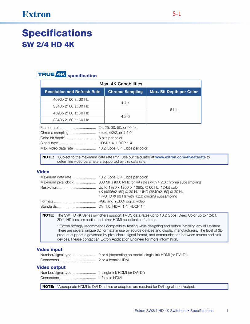
1Extron SW2/4 HD 4K Switchers • Specifications
SpecificationsSW 2/4 HD 4K
specification
Max. 4K Capabilities
Resolution and Refresh Rate
4096 x 2160 at 30 Hz
Chroma Sampling
4:4:4
4:2:0
Max. Bit Depth per Color
8 bit3840 x 2160 at 30 Hz
4096 x 2160 at 60 Hz
3840 x 2160 at 60 Hz
Frame rate1 24, 25, 30, 50, or 60 fpsChroma sampling1 4:4:4, 4:2:2, or 4:2:0Color bit depth1 8 bits per colorSignal type HDMI 14, HDCP 14Max video data rate 102 Gbps (34 Gbps per color)
NOTE: 1Subject to the maximum data rate limit Use our calculator at www.extron.com/4Kdatarate to determine video parameters supported by this data rate
VideoMaximum data rate 102 Gbps (34 Gbps per color)Maximum pixel clock 300 MHz (600 MHz for 4K rates with 4:2:0 chroma subsampling)Resolution Up to 1920 x 1200 or 1080p @ 60 Hz, 12-bit color
4K (4096x2160) @ 30 Hz, UHD (3840x2160) @ 30 Hz 4K/UHD @ 60 Hz with 4:2:0 chroma subsampling
Formats RGB and YCbCr digital videoStandards DVI 10, HDMI 14, HDCP 14
NOTE: The SW HD 4K Series switchers support TMDS data rates up to 102 Gbps, Deep Color up to 12-bit, 3D**, HD lossless audio, and other HDMI specification features
**Extron strongly recommends compatibility testing while designing and before installing any 3D system There are several unique 3D formats in use by source devices and display manufacturers The level of 3D product support is governed by pixel clock, signal format, and communication between source and sink devices Please contact an Extron Application Engineer for more information
Video inputNumber/signal type 2 or 4 (depending on model) single link HDMI (or DVI-D*)Connectors 2 or 4 female HDMI
Video outputNumber/signal type 1 single link HDMI (or DVI-D*)Connectors 1 female HDMI
NOTE: *Appropriate HDMI to DVI-D cables or adapters are required for DVI signal input/output
S-1
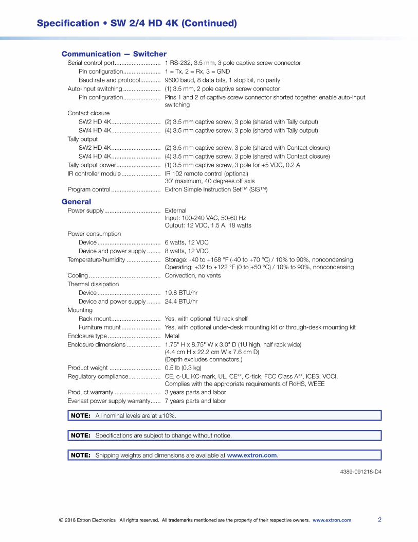
2
Specification • SW 2/4 HD 4K (Continued)
© 2018 Extron Electronics All rights reserved. All trademarks mentioned are the property of their respective owners. www.extron.com
Communication — SwitcherSerial control port 1 RS-232, 35 mm, 3 pole captive screw connector
Pin configuration 1 = Tx, 2 = Rx, 3 = GNDBaud rate and protocol 9600 baud, 8 data bits, 1 stop bit, no parity
Auto-input switching (1) 35 mm, 2 pole captive screw connectorPin configuration Pins 1 and 2 of captive screw connector shorted together enable auto-input
switchingContact closure
SW2 HD 4K (2) 35 mm captive screw, 3 pole (shared with Tally output)SW4 HD 4K (4) 35 mm captive screw, 3 pole (shared with Tally output)
Tally outputSW2 HD 4K (2) 35 mm captive screw, 3 pole (shared with Contact closure)SW4 HD 4K (4) 35 mm captive screw, 3 pole (shared with Contact closure)
Tally output power (1) 35 mm captive screw, 3 pole for +5 VDC, 02 AIR controller module IR 102 remote control (optional)
30' maximum, 40 degrees off axisProgram control Extron Simple Instruction Set™ (SIS™)
GeneralPower supply External
Input: 100-240 VAC, 50-60 Hz Output: 12 VDC, 15 A, 18 watts
Power consumptionDevice 6 watts, 12 VDCDevice and power supply 8 watts, 12 VDC
Temperature/humidity Storage: -40 to +158 °F (-40 to +70 °C) / 10% to 90%, noncondensing Operating: +32 to +122 °F (0 to +50 °C) / 10% to 90%, noncondensing
Cooling Convection, no ventsThermal dissipation
Device 198 BTU/hrDevice and power supply 244 BTU/hr
MountingRack mount Yes, with optional 1U rack shelfFurniture mount Yes, with optional under-desk mounting kit or through-desk mounting kit
Enclosure type MetalEnclosure dimensions 175" H x 875" W x 30" D (1U high, half rack wide)
(44 cm H x 222 cm W x 76 cm D) (Depth excludes connectors)
Product weight 05 lb (03 kg)Regulatory compliance CE, c-UL KC-mark, UL, CE**, C-tick, FCC Class A**, ICES, VCCI,
Complies with the appropriate requirements of RoHS, WEEEProduct warranty 3 years parts and laborEverlast power supply warranty 7 years parts and labor
NOTE: All nominal levels are at ±10%
NOTE: Specifications are subject to change without notice
NOTE: Shipping weights and dimensions are available at www.extron.com
4389-091218-D4
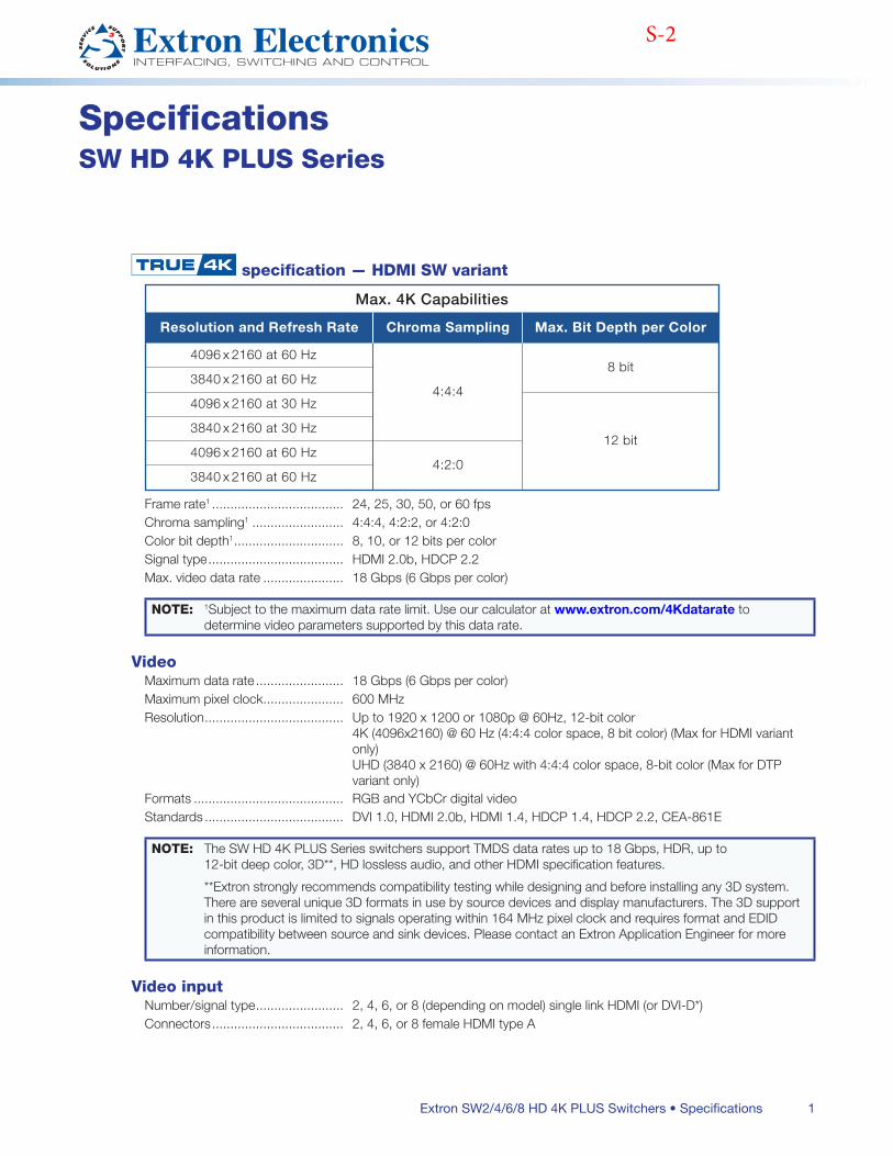
1Extron SW2/4/6/8 HD 4K PLUS Switchers • Specifications
SpecificationsSW HD 4K PLUS Series
specification — HDMI SW variant
Max. 4K Capabilities
Resolution and Refresh Rate
4096 x 2160 at 60 Hz
Chroma Sampling
4:4:4
4:2:0
Max. Bit Depth per Color
8 bit
12 bit
3840 x 2160 at 60 Hz
4096 x 2160 at 30 Hz
3840 x 2160 at 30 Hz
4096 x 2160 at 60 Hz
3840 x 2160 at 60 Hz
Frame rate1 24, 25, 30, 50, or 60 fpsChroma sampling1 4:4:4, 4:2:2, or 4:2:0Color bit depth1 8, 10, or 12 bits per colorSignal type HDMI 20b, HDCP 22Max video data rate 18 Gbps (6 Gbps per color)
NOTE: 1Subject to the maximum data rate limit Use our calculator at www.extron.com/4Kdatarate to determine video parameters supported by this data rate
VideoMaximum data rate 18 Gbps (6 Gbps per color)Maximum pixel clock 600 MHzResolution Up to 1920 x 1200 or 1080p @ 60Hz, 12-bit color
4K (4096x2160) @ 60 Hz (4:4:4 color space, 8 bit color) (Max for HDMI variant only) UHD (3840 x 2160) @ 60Hz with 4:4:4 color space, 8-bit color (Max for DTP variant only)
Formats RGB and YCbCr digital videoStandards DVI 10, HDMI 20b, HDMI 14, HDCP 14, HDCP 22, CEA-861E
NOTE: The SW HD 4K PLUS Series switchers support TMDS data rates up to 18 Gbps, HDR, up to 12-bit deep color, 3D**, HD lossless audio, and other HDMI specification features
**Extron strongly recommends compatibility testing while designing and before installing any 3D system There are several unique 3D formats in use by source devices and display manufacturers The 3D support in this product is limited to signals operating within 164 MHz pixel clock and requires format and EDID compatibility between source and sink devices Please contact an Extron Application Engineer for more information
Video inputNumber/signal type 2, 4, 6, or 8 (depending on model) single link HDMI (or DVI-D*)Connectors 2, 4, 6, or 8 female HDMI type A
THIS TEXT WINDOW and its contents are for reference only Delete this material before finishing and releasing the specs sheet
zz Styles are required for proper table placement/formatting (one for the entire specs table as placed within a page [specs table conteiner], two others [Specs8_Note L1 tableand Specs8_Note L2 table] for the note/caution cells within the specs table)
zz Notes, cautions, and warnings boxes/tables within specs have to be hand inserted and merged and formatted Use the existing table styles (NOTE, Caution, and Warning1) for the table boxes
zz Apply the Specs8_Note L1 table or Specs8_Note L2 table paragraph style (depending on the content to which the note, caution, or warning applies) to the nested note, caution, or warning table Also apply the Specs8_Note cell insetscell style to the cell containing the note, caution, or warning nested table
zz Apply the Specs8_Note or Specs8_Warning/Caution paragraph style to the text within the nested note, caution, or warning table
zz Apply the Specs8_note cell inset cell style to the specs table cell containing the nested table
S-2
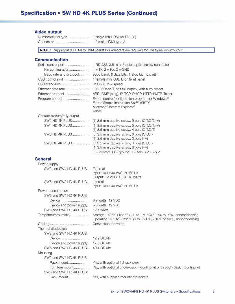
2
Specification • SW HD 4K PLUS Series (Continued)
Extron SW2/4/6/8 HD 4K PLUS Switchers • Specifications
Video outputNumber/signal type 1 single link HDMI (or DVI-D*)Connectors 1 female HDMI type A
NOTE: *Appropriate HDMI to DVI-D cables or adapters are required for DVI signal input/output
CommunicationSerial control port 1 RS-232, 35 mm, 3 pole captive screw connector
Pin configuration 1 = Tx, 2 = Rx, 3 = GNDBaud rate and protocol 9600 baud, 8 data bits, 1 stop bit, no parity
USB control port 1 female mini USB B on front panel USB standards USB 20, low speedEthernet data rate 10/100Base-T, half/full duplex, with auto detectEthernet protocol ARP, ICMP (ping), IP, TCP, DHCP, HTTP, SMTP, TelnetProgram control Extron control/configuration program for Windows®
Extron Simple Instruction Set™ (SIS™) Microsoft® Internet Explorer® Telnet
Contact closure/tally outputSW2 HD 4K PLUS (1) 35 mm captive screw, 5 pole (C,T,C,T,+V)SW4 HD 4K PLUS (1) 35 mm captive screw, 5 pole (C,T,C,T,+V)
(1) 35 mm captive screw, 4 pole (C,T,C,T)SW6 HD 4K PLUS (6) 35 mm captive screw, 3 pole (C,G,T)
(1) 35 mm captive screw, 3 pole (+V)SW8 HD 4K PLUS (8) 35 mm captive screw, 3 pole (C,G,T)
(1) 35 mm captive screw, 3 pole (+V) C = contact, G = ground, T = tally, +V = +5 V
GeneralPower supply
SW2 and SW4 HD 4K PLUS External Input: 100-240 VAC, 50-60 Hz Output: 12 VDC, 15 A, 18 watts
SW6 and SW8 HD 4K PLUS Internal Input: 100-240 VAC, 50-60 Hz
Power consumptionSW2 and SW4 HD 4K PLUS
Device 39 watts, 12 VDCDevice and power supply 55 watts, 12 VDC
SW6 and SW8 HD 4K PLUS 121 wattsTemperature/humidity Storage: -40 to +158 °F (-40 to +70 °C) / 10% to 90%, noncondensing
Operating: +32 to +122 °F (0 to +50 °C) / 10% to 90%, noncondensingCooling Convection, no ventsThermal dissipation
SW2 and SW4 HD 4K PLUSDevice 122 BTU/hrDevice and power supply 178 BTU/hr
SW6 and SW8 HD 4K PLUS 404 BTU/hrMounting
SW2 and SW4 HD 4K PLUSRack mount Yes, with optional 1U rack shelfFurniture mount Yes, with optional under-desk mounting kit or through-desk mounting kit
SW6 and SW8 HD 4K PLUSRack mount Yes, with supplied mounting brackets
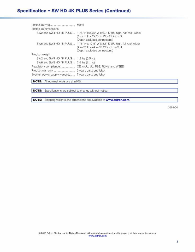
3
Specification • SW HD 4K PLUS Series (Continued)
© 2018 Extron Electronics, All Rights Reserved. All trademarks mentioned are the property of their respective owners. www.extron.com
Enclosure type MetalEnclosure dimensions
SW2 and SW4 HD 4K PLUS 175" H x 875" W x 60" D (1U high, half rack wide) (44 cm H x 222 cm W x 152 cm D) (Depth excludes connectors)
SW6 and SW8 HD 4K PLUS 175" H x 175" W x 85" D (1U high, full rack wide) (44 cm H x 444 cm W x 216 cm D) (Depth excludes connectors)
Product weightSW2 and SW4 HD 4K PLUS 12 lbs (05 kg)SW6 and SW8 HD 4K PLUS 25 lbs (11 kg)
Regulatory compliance CE, c-UL, UL, PSE, RoHs, and WEEEProduct warranty 3 years parts and laborEverlast power supply warranty 7 years parts and labor
NOTE: All nominal levels are at ±10%
NOTE: Specifications are subject to change without notice
NOTE: Shipping weights and dimensions are available at www.extron.com
3888-D1

TP-573HDMI HDCP 2.2 Transmitter with RS−232 &IR over PoC Long−Reach DGKat
| HDMI | HDCP Compliant | DGKat | Kramer Core | HDCP 2.2 Compatible
The TP−573 is a DGKat™ twisted pair transmitter forHDMI, bidirectional RS−232 and infrared signals. TheTP−573 converts the input signals to a twisted pairsignal and the TP−574 converts it back to HDMI,RS−232 and infrared signals
FEATURES
Max. Data Rate - 4.95Gbps (1.65Gbps per graphic channel)HDTV CompatibleHDCP CompliantDGKat™ Signal Integration - Kramer’s unique technology for converting TMDS as well as control andcommunication to signals that run over twisted pair cablesHDMI Support - x.v.Color™, Lip Sync, HDMI Uncompressed Audio Channels, Dolby TrueHD,DTS−HD3D Pass-ThroughEDID PassThru - Passes EDID signals between the source and displayBidirectional RS-232 & IR Interface - 38400 max baud rateSystem Range - Up to 90m (295ft) at 1080i @60hz or up to 70m (230ft) at 1080p @ 60hz when usingKramer DGKat cables. Note: Transmission range depends on the signal resolution, graphics card anddisplay used. If using third–party shielded CAT cables, both ends of the shield must be soldered tothe connectors for the products to function properlyPower Connect System™ - A single connection to the transmitter powers both unitsCompact DigiTOOLS® - 3 units can be rack mounted side−by−side in a 1U rack space with therecommended rack adapter
OR-1
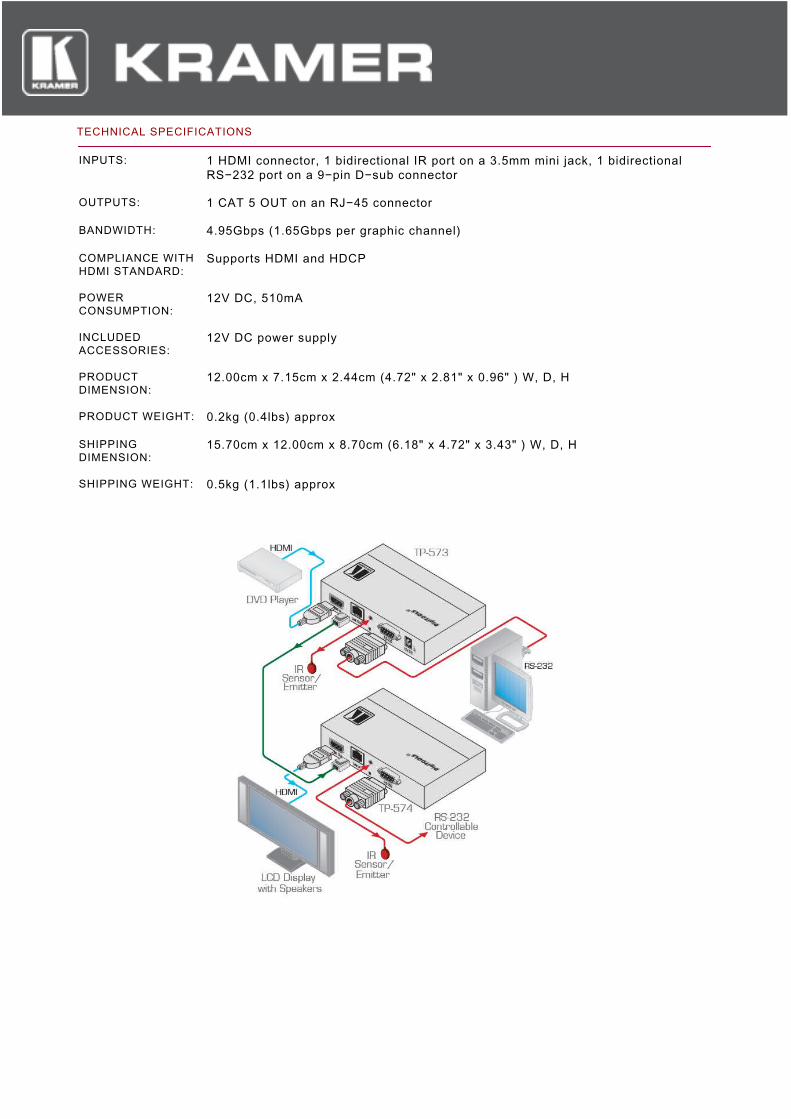
TECHNICAL SPECIFICATIONS
INPUTS: 1 HDMI connector, 1 bidirectional IR port on a 3.5mm mini jack, 1 bidirectionalRS−232 port on a 9−pin D−sub connector
OUTPUTS: 1 CAT 5 OUT on an RJ−45 connector
BANDWIDTH: 4.95Gbps (1.65Gbps per graphic channel)
COMPLIANCE WITHHDMI STANDARD:
Supports HDMI and HDCP
POWERCONSUMPTION:
12V DC, 510mA
INCLUDEDACCESSORIES:
12V DC power supply
PRODUCTDIMENSION:
12.00cm x 7.15cm x 2.44cm (4.72" x 2.81" x 0.96" ) W, D, H
PRODUCT WEIGHT: 0.2kg (0.4lbs) approx
SHIPPINGDIMENSION:
15.70cm x 12.00cm x 8.70cm (6.18" x 4.72" x 3.43" ) W, D, H
SHIPPING WEIGHT: 0.5kg (1.1lbs) approx
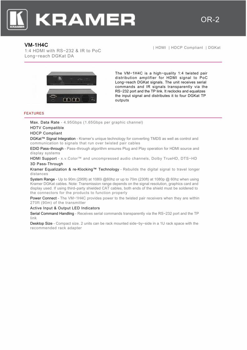
VM-1H4C1:4 HDMI with RS−232 & IR to PoCLong−reach DGKat DA
| HDMI | HDCP Compliant | DGKat
The VM−1H4C is a high−quality 1:4 twisted pairdistr ibution ampli f ier for HDMI signal to PoCLong−reach DGKat signals. The unit receives serialcommands and IR signals transparently via theRS−232 port and the TP link. It reclocks and equalizesthe input signal and distributes it to four DGKat TPoutputs
FEATURES
Max. Data Rate - 4.95Gbps (1.65Gbps per graphic channel)HDTV CompatibleHDCP CompliantDGKat™ Signal Integration - Kramer’s unique technology for converting TMDS as well as control andcommunication to signals that run over twisted pair cablesEDID Pass–through - Pass–through algorithm ensures Plug and Play operation for HDMI source anddisplay systemsHDMI Support - x.v.Color™ and uncompressed audio channels, Dolby TrueHD, DTS−HD3D Pass-ThroughKramer Equalization & re-Klocking™ Technology - Rebuilds the digital signal to travel longerdistancesSystem Range - Up to 90m (295ft) at 1080i @60hz or up to 70m (230ft) at 1080p @ 60hz when usingKramer DGKat cables. Note: Transmission range depends on the signal resolution, graphics card anddisplay used. If using third–party shielded CAT cables, both ends of the shield must be soldered tothe connectors for the products to function properlyPower Connect - The VM−1H4C provides power to the twisted pair receivers when they are within270ft (90m) of the transmitterActive Input & Output LED IndicatorsSerial Command Handling - Receives serial commands transparently via the RS−232 port and the TPlinkDesktop Size - Compact size. 2 units can be rack mounted side−by−side in a 1U rack space with therecommended rack adapter
OR-2
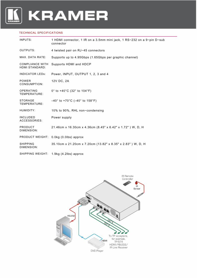
TECHNICAL SPECIFICATIONS
INPUTS: 1 HDMI connector, 1 IR on a 3.5mm mini jack, 1 RS−232 on a 9−pin D−subconnector
OUTPUTS: 4 twisted pair on RJ−45 connectors
MAX. DATA RATE: Supports up to 4.95Gbps (1.65Gbps per graphic channel)
COMPLIANCE WITHHDMI STANDARD:
Supports HDMI and HDCP
INDICATOR LEDs: Power, INPUT, OUTPUT 1, 2, 3 and 4
POWERCONSUMPTION:
12V DC, 2A
OPERATINGTEMPERATURE:
0° to +40°C (32° to 104°F)
STORAGETEMPERATURE:
–40° to +70°C (–40° to 158°F)
HUMIDITY: 10% to 90%, RHL non−condensing
INCLUDEDACCESSORIES:
Power supply
PRODUCTDIMENSION:
21.46cm x 16.30cm x 4.36cm (8.45" x 6.42" x 1.72" ) W, D, H
PRODUCT WEIGHT: 0.0kg (0.0lbs) approx
SHIPPINGDIMENSION:
35.10cm x 21.20cm x 7.20cm (13.82" x 8.35" x 2.83" ) W, D, H
SHIPPING WEIGHT: 1.9kg (4.2lbs) approx
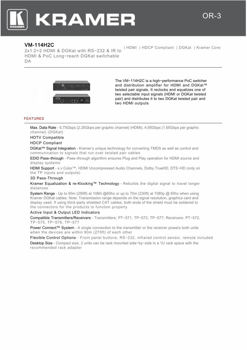
VM-114H2C2x1:2+2 HDMI & DGKat with RS−232 & IR toHDMI & PoC Long−reach DGKat switchableDA
| HDMI | HDCP Compliant | DGKat | Kramer Core
The VM−114H2C is a high−performance PoC switcherand distribution amplifier for HDMI and DGKat™twisted pair signals. It reclocks and equalizes one oftwo selectable input signals (HDMI or DGKat twistedpair) and distributes it to two DGKat twisted pair andtwo HDMI outputs
FEATURES
Max. Data Rate - 6.75Gbps (2.25Gbps per graphic channel) (HDMI), 4.95Gbps (1.65Gbps per graphicchannel) (DGKat)HDTV CompatibleHDCP CompliantDGKat™ Signal Integration - Kramer’s unique technology for converting TMDS as well as control andcommunication to signals that run over twisted pair cablesEDID Pass–through - Pass–through algorithm ensures Plug and Play operation for HDMI source anddisplay systemsHDMI Support - x.v.Color™, HDMI Uncompressed Audio Channels, Dolby TrueHD, DTS−HD (only onthe TP inputs and outputs)3D Pass-ThroughKramer Equalization & re-Klocking™ Technology - Rebuilds the digital signal to travel longerdistancesSystem Range - Up to 90m (295ft) at 1080i @60hz or up to 70m (230ft) at 1080p @ 60hz when usingKramer DGKat cables. Note: Transmission range depends on the signal resolution, graphics card anddisplay used. If using third–party shielded CAT cables, both ends of the shield must be soldered tothe connectors for the products to function properlyActive Input & Output LED IndicatorsCompatible Transmitters/Receivers - Transmitters: PT−571, TP−573, TP−577; Receivers: PT−572,TP−575, TP−576, TP−577Power Connect™ System - A single connection to the transmitter or the receiver powers both unitswhen the devices are within 90m (270ft) of each otherFlexible Control Options - Front panel buttons, RS−232, infrared control sensor, remote includedDesktop Size - Compact size. 2 units can be rack mounted side−by−side in a 1U rack space with therecommended rack adapter
OR-3
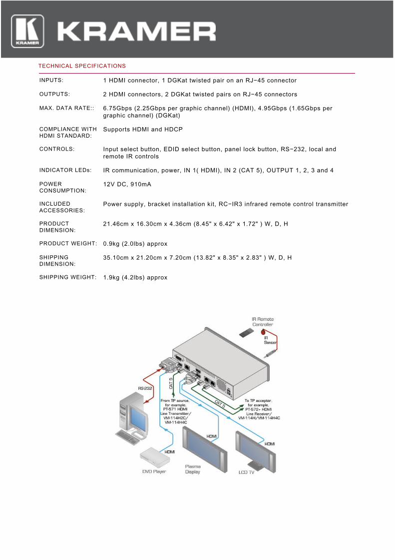
TECHNICAL SPECIFICATIONS
INPUTS: 1 HDMI connector, 1 DGKat twisted pair on an RJ−45 connector
OUTPUTS: 2 HDMI connectors, 2 DGKat twisted pairs on RJ−45 connectors
MAX. DATA RATE:: 6.75Gbps (2.25Gbps per graphic channel) (HDMI), 4.95Gbps (1.65Gbps pergraphic channel) (DGKat)
COMPLIANCE WITHHDMI STANDARD:
Supports HDMI and HDCP
CONTROLS: Input select button, EDID select button, panel lock button, RS−232, local andremote IR controls
INDICATOR LEDs: IR communication, power, IN 1( HDMI), IN 2 (CAT 5), OUTPUT 1, 2, 3 and 4
POWERCONSUMPTION:
12V DC, 910mA
INCLUDEDACCESSORIES:
Power supply, bracket installation kit, RC−IR3 infrared remote control transmitter
PRODUCTDIMENSION:
21.46cm x 16.30cm x 4.36cm (8.45" x 6.42" x 1.72" ) W, D, H
PRODUCT WEIGHT: 0.9kg (2.0lbs) approx
SHIPPINGDIMENSION:
35.10cm x 21.20cm x 7.20cm (13.82" x 8.35" x 2.83" ) W, D, H
SHIPPING WEIGHT: 1.9kg (4.2lbs) approx
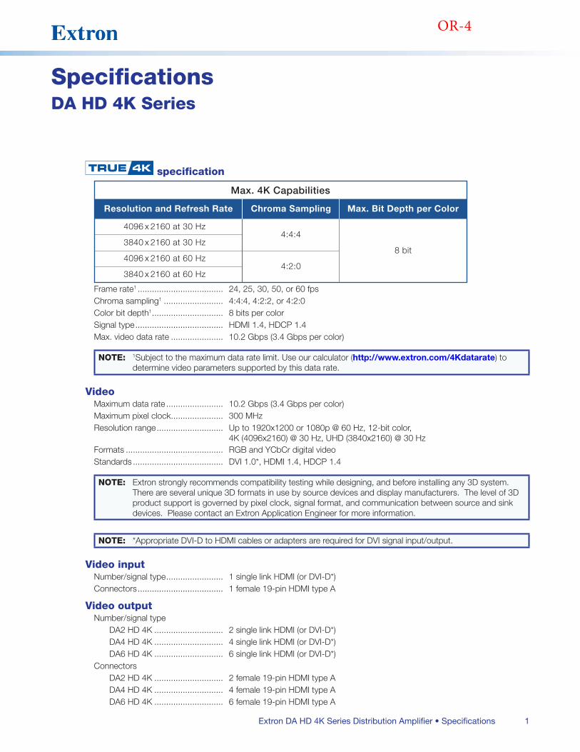
1Extron DA HD 4K Series Distribution Amplifier • Specifications
SpecificationsDA HD 4K Series
specification
Max. 4K Capabilities
Resolution and Refresh Rate
4096 x 2160 at 30 Hz
Chroma Sampling
4:4:4
4:2:0
Max. Bit Depth per Color
8 bit3840 x 2160 at 30 Hz
4096 x 2160 at 60 Hz
3840 x 2160 at 60 Hz
Frame rate1 24, 25, 30, 50, or 60 fpsChroma sampling1 4:4:4, 4:2:2, or 4:2:0Color bit depth1 8 bits per colorSignal type HDMI 14, HDCP 14Max video data rate 102 Gbps (34 Gbps per color)
NOTE: 1Subject to the maximum data rate limit Use our calculator (http://www.extron.com/4Kdatarate) to determine video parameters supported by this data rate
VideoMaximum data rate 102 Gbps (34 Gbps per color)Maximum pixel clock 300 MHzResolution range Up to 1920x1200 or 1080p @ 60 Hz, 12-bit color,
4K (4096x2160) @ 30 Hz, UHD (3840x2160) @ 30 HzFormats RGB and YCbCr digital videoStandards DVI 10*, HDMI 14, HDCP 14
NOTE: Extron strongly recommends compatibility testing while designing, and before installing any 3D system There are several unique 3D formats in use by source devices and display manufacturers The level of 3D product support is governed by pixel clock, signal format, and communication between source and sink devices Please contact an Extron Application Engineer for more information
NOTE: *Appropriate DVI-D to HDMI cables or adapters are required for DVI signal input/output
Video inputNumber/signal type 1 single link HDMI (or DVI-D*)Connectors 1 female 19-pin HDMI type A
Video outputNumber/signal type
DA2 HD 4K 2 single link HDMI (or DVI-D*)DA4 HD 4K 4 single link HDMI (or DVI-D*)DA6 HD 4K 6 single link HDMI (or DVI-D*)
ConnectorsDA2 HD 4K 2 female 19-pin HDMI type ADA4 HD 4K 4 female 19-pin HDMI type ADA6 HD 4K 6 female 19-pin HDMI type A
OR-4
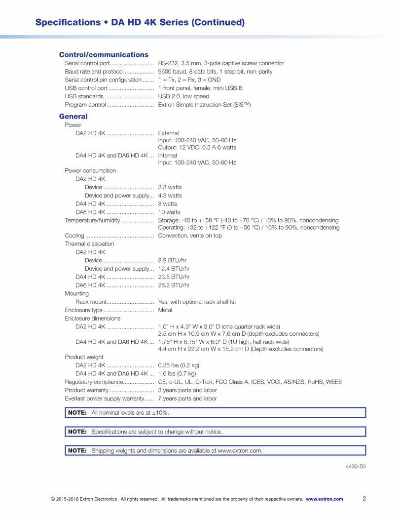
2
Specifications • DA HD 4K Series (Continued)
© 2015-2018 Extron Electronics All rights reserved. All trademarks mentioned are the property of their respective owners. www.extron.com
Control/communicationsSerial control port RS-232, 35 mm, 3-pole captive screw connectorBaud rate and protocol 9600 baud, 8 data bits, 1 stop bit, non-paritySerial control pin configuration 1 = Tx, 2 = Rx, 3 = GNDUSB control port 1 front panel, female, mini USB BUSB standards USB 20, low speedProgram control Extron Simple Instruction Set (SIS™)
GeneralPower
DA2 HD 4K External Input: 100-240 VAC, 50-60 Hz Output: 12 VDC, 05 A 6 watts
DA4 HD 4K and DA6 HD 4K Internal Input: 100-240 VAC, 50-60 Hz
Power consumptionDA2 HD 4K
Device 33 wattsDevice and power supply 43 watts
DA4 HD 4K 8 wattsDA6 HD 4K 10 watts
Temperature/humidity Storage: -40 to +158 °F (-40 to +70 °C) / 10% to 90%, noncondensing Operating: +32 to +122 °F (0 to +50 °C) / 10% to 90%, noncondensing
Cooling Convection, vents on topThermal dissipation
DA2 HD 4KDevice 89 BTU/hrDevice and power supply 124 BTU/hr
DA4 HD 4K 235 BTU/hrDA6 HD 4K 282 BTU/hr
MountingRack mount Yes, with optional rack shelf kit
Enclosure type MetalEnclosure dimensions
DA2 HD 4K 10" H x 43" W x 30" D (one quarter rack wide) 25 cm H x 109 cm W x 76 cm D (depth excludes connectors)
DA4 HD 4K and DA6 HD 4K 175" H x 875" W x 60" D (1U high, half rack wide) 44 cm H x 222 cm W x 152 cm D (Depth excludes connectors)
Product weightDA2 HD 4K 035 lbs (02 kg)DA4 HD 4K and DA6 HD 4K 16 lbs (07 kg)
Regulatory compliance CE, c-UL, UL, C-Tick, FCC Class A, ICES, VCCI, AS/NZS, RoHS, WEEEProduct warranty 3 years parts and laborEverlast power supply warranty 7 years parts and labor
NOTE: All nominal levels are at ±10%
NOTE: Specifications are subject to change without notice
NOTE: Shipping weights and dimensions are available at wwwextroncom
4430-D5
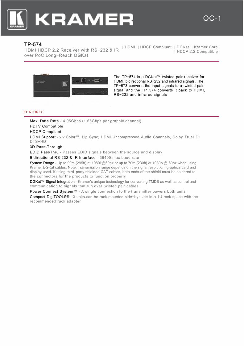
TP-574HDMI HDCP 2.2 Receiver with RS−232 & IRover PoC Long−Reach DGKat
| HDMI | HDCP Compliant | DGKat | Kramer Core | HDCP 2.2 Compatible
The TP−574 is a DGKat™ twisted pair receiver forHDMI, bidirectional RS−232 and infrared signals. TheTP−573 converts the input signals to a twisted pairsignal and the TP−574 converts it back to HDMI,RS−232 and infrared signals
FEATURES
Max. Data Rate - 4.95Gbps (1.65Gbps per graphic channel)HDTV CompatibleHDCP CompliantHDMI Support - x.v.Color™, Lip Sync, HDMI Uncompressed Audio Channels, Dolby TrueHD,DTS−HD3D Pass-ThroughEDID PassThru - Passes EDID signals between the source and displayBidirectional RS-232 & IR Interface - 38400 max baud rateSystem Range - Up to 90m (295ft) at 1080i @60hz or up to 70m (230ft) at 1080p @ 60hz when usingKramer DGKat cables. Note: Transmission range depends on the signal resolution, graphics card anddisplay used. If using third–party shielded CAT cables, both ends of the shield must be soldered tothe connectors for the products to function properlyDGKat™ Signal Integration - Kramer’s unique technology for converting TMDS as well as control andcommunication to signals that run over twisted pair cablesPower Connect System™ - A single connection to the transmitter powers both unitsCompact DigiTOOLS® - 3 units can be rack mounted side−by−side in a 1U rack space with therecommended rack adapter
OC-1
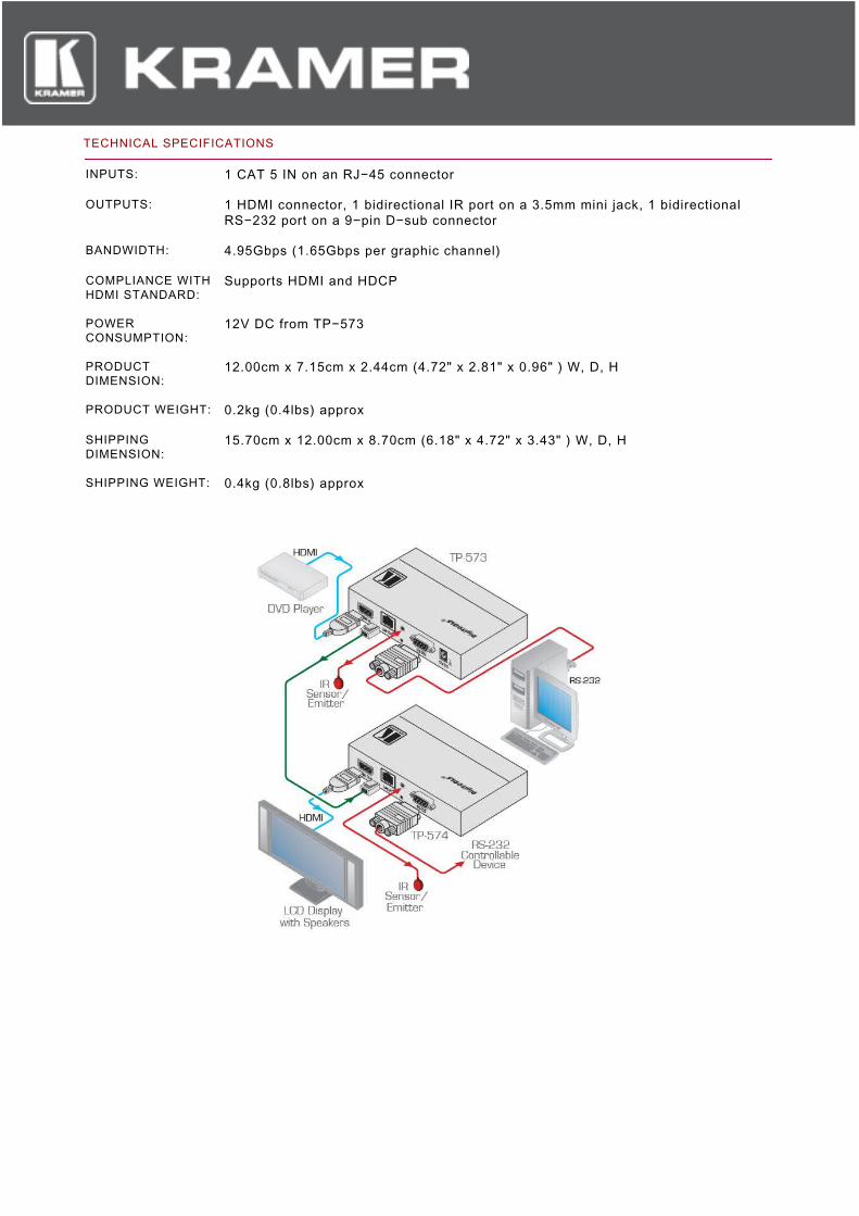
TECHNICAL SPECIFICATIONS
INPUTS: 1 CAT 5 IN on an RJ−45 connector
OUTPUTS: 1 HDMI connector, 1 bidirectional IR port on a 3.5mm mini jack, 1 bidirectionalRS−232 port on a 9−pin D−sub connector
BANDWIDTH: 4.95Gbps (1.65Gbps per graphic channel)
COMPLIANCE WITHHDMI STANDARD:
Supports HDMI and HDCP
POWERCONSUMPTION:
12V DC from TP−573
PRODUCTDIMENSION:
12.00cm x 7.15cm x 2.44cm (4.72" x 2.81" x 0.96" ) W, D, H
PRODUCT WEIGHT: 0.2kg (0.4lbs) approx
SHIPPINGDIMENSION:
15.70cm x 12.00cm x 8.70cm (6.18" x 4.72" x 3.43" ) W, D, H
SHIPPING WEIGHT: 0.4kg (0.8lbs) approx
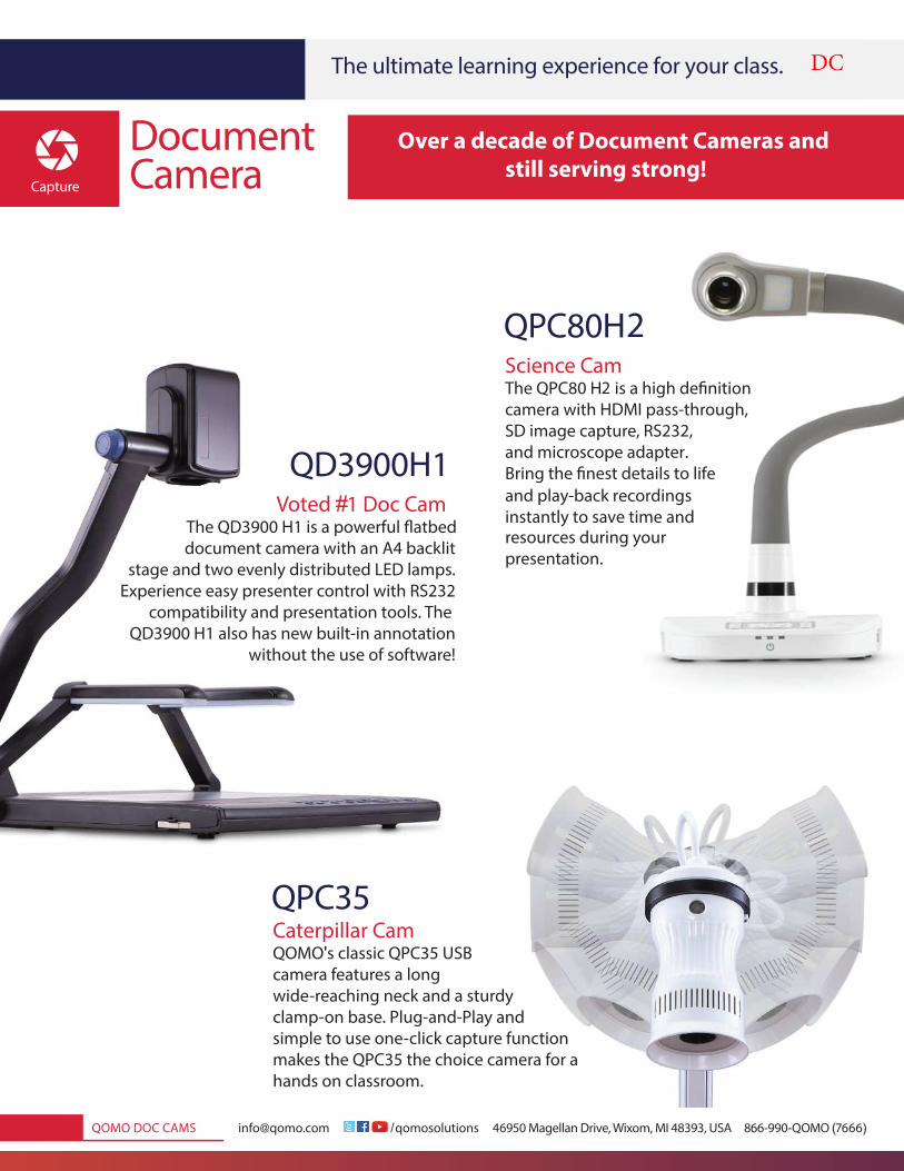
@ / ( )
|
'
#
2
DC
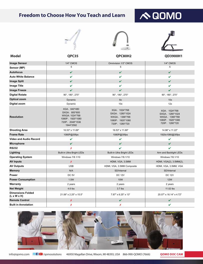
!"#$@%$&$'($&))))) ! ! !/!"#"$"%&'(")$***** *+,-.)/012330")45!627)8!9$&7)/:)*;<,<7)=>?)))));++@,,.@AB/B)(C+++)))))) "#$#!%#&!&'$
()*+,-!.+/0,1+2+34!5,--,346!|!789888!:;<-!=>?+@-++A;2!4;!&B;;C+!:;D!*;<!E+,1B!,3A!=+,-3
Image Sensor 1/4" CMOS Omnivision 1/3" CMOS 1/4" CMOS
Sensor (MP) 555
10x6xDynamic
12x10xDynamic
Autofocus
Auto White BalanceImage SplitImage TitleImage FreezeDigital Rotate 90°, 180°, 270° 90°, 180°, 270 9° 0°, 180°, 270°
Optical zoomDigital zoom
Resolution
XGA 640*480SXGA 800*600WXGA: 1024*768
1080P 1920*1080720P 2048*1536
1944*2592
XGA 1024*768SXGA 1280*1024WXGA 1366*7681080P 1920*1080720P 1280*720
XGA 1024*768SXGA 1280*1024WXGA 1366*7681080P 1920*1080720P 1280*720
Shooting Area 16.53" x 11.69" 16.53" x 11.69" 14.96" x 11.22"
Frame Rate 1080P@30fps 1080P@30fp s 1920x1080@30fps
Video and Audio RecordMicrophoneRS232Lighting Built-in Ultra Bright LEDs Arm and Backlight LEDs
Operating System Windows 7/8.1/10
Built-in Ultra Bright LEDs
Windows 7/8.1/10 Windows 7/8.1/10
AV Inputs HDMI, VGA, 3.5M HM DMI, VGA(2), 3.5MM(2),
AV Outputs USB HDMI, VGA, 3.5MM Composite HDMI, VGA, 3.5MM, VGA
Memory N/ SA D/Internal SD/Internal
Power DC 5V DC 12V DC 12V
Power Consumption 1.5W 10 1W 2W
Warranty 2 year 2s year 2s years
Net Weight 4.6 lb 3s .7 lbs 11.02 lbs
Dimensions Folded (L x W x H) 21.06" x 2.25" x 15.5 7" .87" x 6.25" x 13 2" 0.07" x 16.14" x 4.72"
Remote ControlBuilt in Annotation
$;A+0!!!!!!!!!!!!!!!!!!!!!!!!!!!!!!!!!!!!!!!!!!!!!!!!!!!!!!!!!!! "F&(7!!!!!!!!!!!!!!!!!!!!!!!!!!!!!!!!!!!!!!!!!!!!!!!!!!!"F&G8:H!!!!!!!!!!!!!!!!!!!!!!!!!!!!!!!!!!!!!!!!!!!!!"%(I88:J
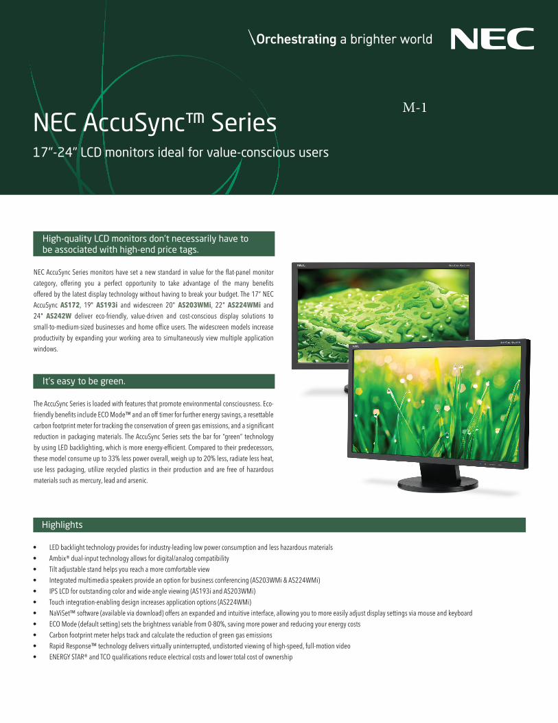
Highlights
• LED backlight technology provides for industry-leading low power consumption and less hazardous materials• Ambix® dual-input technology allows for digital/analog compatibility• Tilt adjustable stand helps you reach a more comfortable view • Integrated multimedia speakers provide an option for business conferencing (AS203WMi & AS224WMi) • IPS LCD for outstanding color and wide-angle viewing (AS193i and AS203WMi)• Touch integration-enabling design increases application options (AS224WMi)• NaViSet™ software (available via download) offers an expanded and intuitive interface, allowing you to more easily adjust display settings via mouse and keyboard• ECO Mode (default setting) sets the brightness variable from 0-80%, saving more power and reducing your energy costs • Carbon footprint meter helps track and calculate the reduction of green gas emissions• Rapid Response™ technology delivers virtually uninterrupted, undistorted viewing of high-speed, full-motion video• ENERGY STAR® and TCO qualifications reduce electrical costs and lower total cost of ownership
High-quality LCD monitors don’t necessarily have to be associated with high-end price tags.
NEC AccuSync Series monitors have set a new standard in value for the flat-panel monitor category, offering you a perfect opportunity to take advantage of the many benefits offered by the latest display technology without having to break your budget. The 17” NEC AccuSync AS172, 19" AS193i and widescreen 20" AS203WMi, 22" AS224WMi and 24" AS242W deliver eco-friendly, value-driven and cost-conscious display solutions to small-to-medium-sized businesses and home office users. The widescreen models increase productivity by expanding your working area to simultaneously view multiple application windows.
It’s easy to be green.
The AccuSync Series is loaded with features that promote environmental consciousness. Eco-friendly benefits include ECO Mode™ and an off timer for further energy savings, a resettable carbon footprint meter for tracking the conservation of green gas emissions, and a significant reduction in packaging materials. The AccuSync Series sets the bar for “green” technology by using LED backlighting, which is more energy-efficient. Compared to their predecessors, these model consume up to 33% less power overall, weigh up to 20% less, radiate less heat, use less packaging, utilize recycled plastics in their production and are free of hazardous materials such as mercury, lead and arsenic.
NEC AccuSync™ Series17"-24" LCD monitors ideal for value-conscious users
M-1
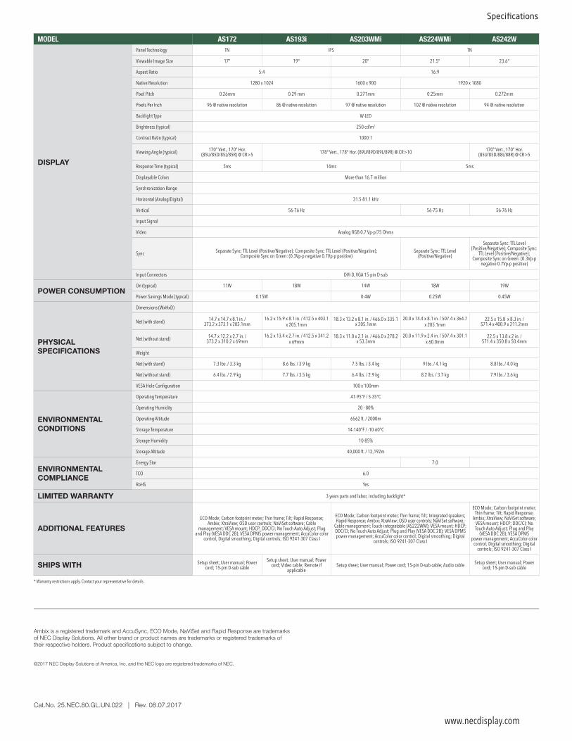
MODEL AS172 AS193i AS203WMi AS224WMi AS242W
DISPLAY
Panel Technology TN IPS TN
Viewable Image Size 17" 19" 20" 21.5" 23.6"
Aspect Ratio 5:4 16:9
Native Resolution 1280 x 1024 1600 x 900 1920 x 1080
Pixel Pitch 0.26mm 0.29 mm 0.271mm 0.25mm 0.272mm
Pixels Per Inch 96 @ native resolution 86 @ native resolution 97 @ native resolution 102 @ native resolution 94 @ native resolution
Backlight Type W-LED
Brightness (typical) 250 cd/m2
Contrast Ratio (typical) 1000:1
Viewing Angle (typical) 170° Vert., 170° Hor. (85U/85D/85L/85R) @ CR>5 178° Vert., 178° Hor. (89U/89D/89L/89R) @ CR>10 170° Vert., 170° Hor.
(85U/85D/88L/88R) @ CR>5
Response Time (typical) 5ms 14ms 5ms
Displayable Colors More than 16.7 million
Synchronization Range
Horizontal (Analog/Digital) 31.5-81.1 kHz
Vertical 56-76 Hz 56-75 Hz 56-76 Hz
Input Signal
Video Analog RGB 0.7 Vp-p/75 Ohms
Sync Separate Sync: TTL Level (Positive/Negative); Composite Sync: TTL Level (Positive/Negative); Composite Sync on Green: (0.3Vp-p negative 0.7Vp-p positive)
Separate Sync: TTL Level (Positive/Negative)
Separate Sync: TTL Level (Positive/Negative); Composite Sync:
TTL Level (Positive/Negative); Composite Sync on Green: (0.3Vp-p
negative 0.7Vp-p positive)
Input Connectors DVI-D, VGA 15-pin D-sub
POWER CONSUMPTIONOn (typical) 11W 18W 14W 18W 19W
Power Savings Mode (typical) 0.15W 0.4W 0.25W 0.45W
PHYSICAL SPECIFICATIONS
Dimensions (WxHxD)
Net (with stand) 14.7 x 14.7 x 8.1 in. / 373.2 x 373.1 x 205.1mm
16.2 x 15.9 x 8.1 in. / 412.5 x 403.1 x 205.1mm
18.3 x 13.2 x 8.1 in. / 466.0 x 335.1 x 205.1mm
20.0 x 14.4 x 8.1 in. / 507.4 x 364.7 x 205.1mm
22.5 x 15.8 x 8.3 in. / 571.4 x 400.9 x 211.2mm
Net (without stand) 14.7 x 12.2 x 2.7 in. / 373.2 x 310.2 x 69mm
16.2 x 13.4 x 2.7 in. / 412.5 x 341.2 x 69mm
18.3 x 11.0 x 2.1 in. / 466.0 x 278.2 x 53.3mm
20.0 x 11.9 x 2.4 in. / 507.4 x 301.1 x 60.0mm
22.5 x 13.8 x 2 in. / 571.4 x 350.8 x 50.4mm
Weight
Net (with stand) 7.3 lbs. / 3.3 kg 8.6 lbs. / 3.9 kg 7.5 lbs. / 3.4 kg 9 lbs. / 4.1 kg 8.8 lbs. / 4.0 kg
Net (without stand) 6.4 lbs. / 2.9 kg 7.7 lbs. / 3.5 kg 6.4 lbs. / 2.9 kg 8.2 lbs. / 3.7 kg 7.9 lbs. / 3.6 kg
VESA Hole Configuration 100 x 100mm
ENVIRONMENTAL CONDITIONS
Operating Temperature 41-95°F / 5-35°C
Operating Humidity 20 - 80%
Operating Altitude 6562 ft. / 2000m
Storage Temperature 14-140°F / -10-60°C
Storage Humidity 10-85%
Storage Altitude 40,000 ft. / 12,192m
ENVIRONMENTAL COMPLIANCE
Energy Star 7.0
TCO 6.0
RoHS Yes
LIMITED WARRANTY 3 years parts and labor, including backlight*
ADDITIONAL FEATURESECO Mode; Carbon footprint meter; Thin frame; Tilt; Rapid Response;
Ambix; XtraView; OSD user controls; NaViSet software; Cable management; VESA mount; HDCP; DDC/CI; No Touch Auto Adjust; Plug
and Play (VESA DDC 2B); VESA DPMS power management; AccuColor color control; Digital smoothing; Digital controls; ISO 9241-307 Class I
ECO Mode; Carbon footprint meter; Thin frame; Tilt; Integrated speakers; Rapid Response; Ambix; XtraView; OSD user controls; NaViSet software;
Cable management; Touch-integratable (AS222WM); VESA mount; HDCP; DDC/CI; No Touch Auto Adjust; Plug and Play (VESA DDC 2B); VESA DPMS power management; AccuColor color control; Digital smoothing; Digital
controls; ISO 9241-307 Class I
ECO Mode; Carbon footprint meter; Thin frame; Tilt; Rapid Response;
Ambix; XtraView; NaViSet software; VESA mount; HDCP; DDC/CI; No Touch Auto Adjust; Plug and Play
(VESA DDC 2B); VESA DPMS power management; AccuColor color
control; Digital smoothing; Digital controls; ISO 9241-307 Class I
SHIPS WITH Setup sheet; User manual; Power cord; 15-pin D-sub cable
Setup sheet; User manual; Power cord; Video cable; Remote if
applicableSetup sheet; User manual; Power cord; 15-pin D-sub cable; Audio cable Setup sheet; User manual; Power
cord; 15-pin D-sub cable
* Warranty restrictions apply. Contact your representative for details.
www.necdisplay.com
Ambix is a registered trademark and AccuSync, ECO Mode, NaViSet and Rapid Response are trademarks of NEC Display Solutions. All other brand or product names are trademarks or registered trademarks of their respective holders. Product specifications subject to change.
©2017 NEC Display Solutions of America, Inc. and the NEC logo are registered trademarks of NEC.
Cat.No. 25.NEC.80.GL.UN.022 | Rev. 08.07.2017
Specifications

NEC Ultra High Definition Large Format Displays 65", 75", 86" and 98" Commercial Displays Ideal for Digital Signage Applications
D-1: C651QD-2 : C861QD-3 : C751Q

Brand new UHD displays in an aesthetically-focused design allows for seamless integration into any digital signage environment while maintaining the commercial ruggedness necessary for the retail, educational and corporate environments
Advanced Heat Management
Monitoring and managing the temperature of each display is crucial to secure reliability and
longevity. An industrial-strength, premium-grade panel with additional thermal protection, internal
temperature sensors with self-diagnostics, and fan-based technology allows for 24/7 operation,
and protects your display investment. Without thermal management, displays can be prone to
damaging heat over time. This damaging heat will lower the picture quality and life expectancy
of the product. Integrated cooling fans automatically turn on and stay on when high internal
temperatures are detected. These will stay on until the heat is properly dissipated and the display
remains under proper temperature thresholds.
2
Beyond Standard Signage
With industry leading experience in superior design and customer focus, the NEC large C series
allow for clear, detailed imagery for unobtrusive digital messaging. New contemporary and slim
mechanical design with focused aesthetics allows for the smooth and stylistic integration into any
type of environment. Their full metal chassis coupled with real-time temperature sensors and
integrated cooling fans maintain the professional quality necessary for commercial environments.
With an anti-glare screen and ultra high definition panel, customers can enjoy the perfect image
in any circumstance. These displays come equipped with a wide range of the latest connectivity
interfaces including three separate HDMI 2.0 interfaces, two separate DisplayPort interfaces and a
DisplayPort Out connection to complement the native Ultra High Definition at 60Hz panel. These
displays also include expandability options such as the Open Pluggable Specification (OPS) and
Raspberry Pi Compute Module slots for source integration directly into the display. The NEC C
series boasts 350 - 400 cd/m2 brightness that allows for efficient readability in higher ambient light
situations and is ideal for 24/7 signage in airports, quick-serve restaurants, and retail.
Scalable Computing Power
Integrated computing options allow for cable free signage for any type of situation. The on-board
multimedia player can be utilized for simple signage applications by allowing auto-play off of USB
or SD card and content transfer via LAN. For more advanced signage systems, these displays contain
an industry first ability to integrate a Raspberry Pi Compute
module for near limitless potential and application. Finally,
each display adheres to the Open Pluggable Specification that
gives the ability to seamlessly integrate a full PC, HDBaseT
receiver or other options directly into the unit.
Location of Thermal Management Cooling Fans
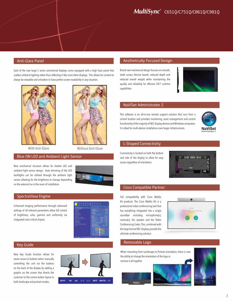
SpectraView Engine
Enhanced imaging performance through advanced
settings of all relevant parameters allow full control
of brightness, color, gamma and uniformity via
integrated color-critical chipset.
Key Guide
New Key Guide function allows for
easier access to buttons when manually
controlling the unit via the buttons
on the back of the display by adding a
graphic on the screen that directs the
customer to the correct button layout in
both landscape and portrait modes.
NaViSet Administrator 2
This software is an all-in-one remote support solution that runs from a
central location and provides monitoring, asset management and control
functionality of the majority of NEC display devices and Windows computers.
It is ideal for multi-device installations over larger infrastructures.
Aesthetically Focused Design
Brand new mechanical design focuses on smooth,
sleek curves, thinner bezels, reduced depth and
reduced overall weight while maintaining the
quality and reliability for efficient 24/7 runtime
capabilities.
Blue ON LED and Ambient Light Sensor
New mechanical structure allows for sleeker LED and
ambient light sensor design. Auto dimming of the LED
backlights can be utilized through the ambient light
sensor allowing for the brightness to change depending
on the external lux in the room of installation.
Anti-Glare Panel
Each of the new large C series commercial displays come equipped with a high haze panel that
scatters ambient lighting rather than reflecting it like most other displays. This allows for content to
always be viewable and onlookers to have perfect screen readability in any situation.
C651Q/C751Q/C861Q/C981Q
3
L-Shaped Connectivity
Connectivity is located on both the bottom
and side of the display to allow for easy
access regardless of orientation.
(EXIT) (SET) (MUTE) ( | )( )( ) ( ) ( )+
With Anti-Glare Without Anti-Glare
Cisco Compatible Partner:
Full compatibility with Cisco WebEx
Kit products. The Cisco WebEx Kit is a
professional video conferencing tool that
has everything integrated into a single
soundbar including microphone(s),
camera(s), the speaker and the Video
Conferencing Codec. This, combined with
the large format NEC displays provide the
ultimate conferencing solution.
Removable Logo
When mounting from Landscape to Portrait orientation, there is now
the ability to change the orientation of the logo or
remove it all together
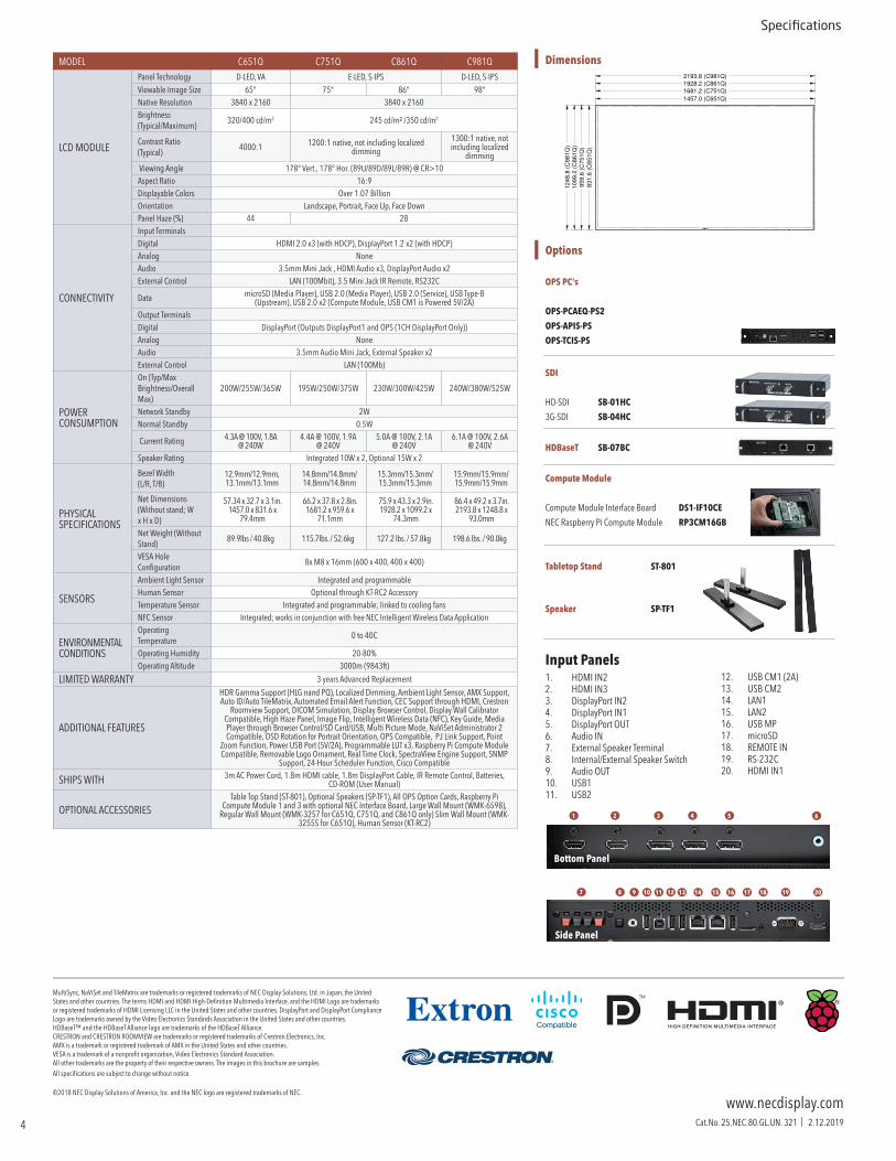
Input Panels 1. HDMI IN22. HDMI IN33. DisplayPort IN24. DisplayPort IN15. DisplayPort OUT6. Audio IN7. External Speaker Terminal8. Internal/External Speaker Switch9. Audio OUT10. USB111. USB2
www.necdisplay.comCat.No. 25.NEC.80.GL.UN. 321 | 2.12.2019
Specifications
Options
OPS PC's
OPS-PCAEQ-PS2
OPS-APIS-PS
OPS-TCIS-PS
SDI
HD-SDI SB-01HC
3G-SDI SB-04HC
HDBaseT SB-07BC
Compute Module
Compute Module Interface Board DS1-IF10CE
NEC Raspberry Pi Compute Module RP3CM16GB
Tabletop Stand ST-801
Speaker SP-TF1
Dimensions
12. USB CM1 (2A)13. USB CM214. LAN115. LAN216. USB MP17. microSD18. REMOTE IN19. RS-232C 20. HDMI IN1
MultiSync, NaViSet and TileMatrix are trademarks or registered trademarks of NEC Display Solutions, Ltd. in Japan, the United States and other countries. The terms HDMI and HDMI High-Definition Multimedia Interface, and the HDMI Logo are trademarks or registered trademarks of HDMI Licensing LLC in the United States and other countries. DisplayPort and DisplayPort Compliance Logo are trademarks owned by the Video Electronics Standards Association in the United States and other countries.HDBaseT™ and the HDBaseT Alliance logo are trademarks of the HDBaseT Alliance.CRESTRON and CRESTRON ROOMVIEW are trademarks or registered trademarks of Crestron Electronics, Inc.AMX is a trademark or registered trademark of AMX in the United States and other countries.VESA is a trademark of a nonprofit organization, Video Electronics Standard Association.All other trademarks are the property of their respective owners. The images in this brochure are samples.All specifications are subject to change without notice.
©2018 NEC Display Solutions of America, Inc. and the NEC logo are registered trademarks of NEC.
1928.2 (C861Q)
2193.8 (C981Q)
95
9.6
(C
75
1Q
)
10
99
.2 (
C8
61
Q)
12
48
.8 (
C9
81
Q)
1681.2 (C751Q)
83
1.6
(C
65
1Q
)
1457.0 (C651Q)
1
1211109 13 14 15 16 17 18 19 20
2 3 4 5 6
7 8
Bottom Panel
Side Panel
4
MODEL C651Q C751Q C861Q C981Q
LCD MODULE
Panel Technology D-LED, VA E-LED, S-IPS D-LED, S-IPSViewable Image Size 65" 75" 86" 98"Native Resolution 3840 x 2160 3840 x 2160Brightness (Typical/Maximum)
320/400 cd/m2 245 cd/m² /350 cd/m2
Contrast Ratio (Typical)
4000:1 1200:1 native, not including localized dimming
1300:1 native, not including localized
dimming Viewing Angle 178° Vert., 178° Hor. (89U/89D/89L/89R) @ CR>10Aspect Ratio 16:9Displayable Colors Over 1.07 BillionOrientation Landscape, Portrait, Face Up, Face DownPanel Haze (%) 44 28
CONNECTIVITY
Input TerminalsDigital HDMI 2.0 x3 (with HDCP), DisplayPort 1.2 x2 (with HDCP)Analog NoneAudio 3.5mm Mini Jack , HDMI Audio x3, DisplayPort Audio x2External Control LAN (100Mbit), 3.5 Mini Jack IR Remote, RS232C
Data microSD (Media Player), USB 2.0 (Media Player), USB 2.0 (Service), USB Type-B (Upstream), USB 2.0 x2 (Compute Module, USB CM1 is Powered 5V/2A)
Output TerminalsDigital DisplayPort (Outputs DisplayPort1 and OPS (1CH DisplayPort Only))Analog NoneAudio 3.5mm Audio Mini Jack, External Speaker x2External Control LAN (100Mb)
POWER CONSUMPTION
On (Typ/Max Brightness/Overall Max)
200W/255W/365W 195W/250W/375W 230W/300W/425W 240W/380W/525W
Network Standby 2WNormal Standby 0.5W
Current Rating 4.3A @ 100V, 1.8A @ 240W
4.4A @ 100V, 1.9A @ 240V
5.0A @ 100V, 2.1A @ 240V
6.1A @ 100V, 2.6A @ 240V
Speaker Rating Integrated 10W x 2, Optional 15W x 2
PHYSICAL SPECIFICATIONS
Bezel Width (L/R, T/B)
12.9mm/12.9mm, 13.1mm/13.1mm
14.8mm/14.8mm/14.8mm/14.8mm
15.3mm/15.3mm/15.3mm/15.3mm
15.9mm/15.9mm/15.9mm/15.9mm
Net Dimensions (Without stand; W x H x D)
57.34 x 32.7 x 3.1in. 1457.0 x 831.6 x
79.4mm
66.2 x 37.8 x 2.8in. 1681.2 x 959.6 x
71.1mm
75.9 x 43.3 x 2.9in. 1928.2 x 1099.2 x
74.3mm
86.4 x 49.2 x 3.7in. 2193.8 x 1248.8 x
93.0mm
Net Weight (Without Stand)
89.9lbs / 40.8kg 115.7lbs. / 52.6kg 127.2 lbs. / 57.8kg 198.6 lbs. / 90.0kg
VESA Hole Configuration
8x M8 x 16mm (600 x 400, 400 x 400)
SENSORS
Ambient Light Sensor Integrated and programmableHuman Sensor Optional through KT-RC2 AccessoryTemperature Sensor Integrated and programmable; linked to cooling fansNFC Sensor Integrated; works in conjunction with free NEC Intelligent Wireless Data Application
ENVIRONMENTAL CONDITIONS
Operating Temperature
0 to 40C
Operating Humidity 20-80%Operating Altitude 3000m (9843ft)
LIMITED WARRANTY 3 years Advanced Replacement
ADDITIONAL FEATURES
HDR Gamma Support (HLG nand PQ), Localized Dimming, Ambient Light Sensor, AMX Support, Auto ID/Auto TileMatrix, Automated Email Alert Function, CEC Support through HDMI, Crestron
Roomview Support, DICOM Simulation, Display Browser Control, Display Wall Calibrator Compatible, High Haze Panel, Image Flip, Intelligent Wireless Data (NFC), Key Guide, Media Player through Browser Control/SD Card/USB, Multi Picture Mode, NaViSet Administrator 2 Compatible, OSD Rotation for Portrait Orientation, OPS Compatible, PJ Link Support, Point
Zoom Function, Power USB Port (5V/2A), Programmable LUT x3, Raspberry Pi Compute Module Compatible, Removable Logo Ornament, Real Time Clock, SpectraView Engine Support, SNMP
Support, 24-Hour Scheduler Function, Cisco Compatible
SHIPS WITH 3m AC Power Cord, 1.8m HDMI cable, 1.8m DisplayPort Cable, IR Remote Control, Batteries, CD-ROM (User Manual)
OPTIONAL ACCESSORIESTable Top Stand (ST-801), Optional Speakers (SP-TF1), All OPS Option Cards, Raspberry Pi
Compute Module 1 and 3 with optional NEC Interface Board, Large Wall Mount (WMK-6598), Regular Wall Mount (WMK-3257 for C651Q, C751Q, and C861Q only) Slim Wall Mount (WMK-
3255S for C651Q), Human Sensor (KT-RC2)
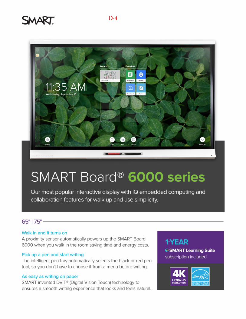
Our most popular interactive display with iQ embedded computing and collaboration features for walk up and use simplicity.
Walk in and it turns onA proximity sensor automatically powers up the SMART Board 6000 when you walk in the room saving time and energy costs.
Pick up a pen and start writingThe intelligent pen tray automatically selects the black or red pen tool, so you don’t have to choose it from a menu before writing.
As easy as writing on paperSMART invented DViT® (Digital Vision Touch) technology to ensures a smooth writing experience that looks and feels natural.
1-YEAR SMART Learning Suite
subscription included
ULTRA HDRESOLUTION
4K
SMART Board® 6000 series
65" | 75"
D-4

SMART Board® 6000 series
Multiple students, tools and colors at the same time
Simultaneous Tool Differentiation frees multiple students to write, erase and move notes at the same time. Pen ID™ recognition and Object awareness™ detection automatically make pens write in different colors, fingers move and palms erase.
Write and save notes directly into applications
SMART Ink® software lets teachers write over videos and into PDFs, Microsoft Office® files and websites, then save notes in almost any file type. Automatically convert notes to text and access tools, such as spotlight, magnifier and screen shade.
Unparalleled Collaborative Experience With 30 years of experience in education technology, SMART interactive displays are designed to support teaching approaches that affect learning outcomes.
Built to use. Built to last.
SMART Remote Management lets you efficiently maintain, secure and support all your devices – including SMART Board displays with iQ.
4K Ultra HD resolution
Accelerated Life Testing
LED rated for 50,000 hours
Fully heat-tempered, anti-glare glass
Silktouch™ frictionless surface
ENERGY STAR® certification
Conflict-free materials and sourcing
Regulatory and environmental certifications*
3-year standard warranty** (1-year on pens)
Durable and commercial-grade, SMART Board displays have received many safety, regulatory and environmental certifications, giving you peace of mind that they adhere to government or other regulatory requirements.
*See specification chart for detailed certifications.**1- or 2-year extended options available. 5-year standard in UK.

SMART Board® 6000 series
© 2019 SMART Technologies. All rights reserved. SMART Board, SMART Notebook, SMART Ink, DViT, Object Awareness, Pen ID, Silktouch, the SMART logo and all SMART taglines and product logos are trademarks or registered trademarks of SMART Technologies in the U.S. and/or other countries. All third-party product and company names are for identification purposes only and may be trademarks of their respective owners. 010719
Get the most out of your SMART solution Your purchase is just the beginning. Our implementation services, professional development and technical support resources help educators learn to use their SMART solutions, hone their technology skills and improve student learning outcomes.
Professional DevelopmentSMART provides complimentary professional development plans, and online courses and webinars that cover both functional and pedagogical topics.
Teachers can connect their Windows or Mac® computer and deliver interactive SMART Notebook® lessons at the display. Time-saving activity and assessment templates are easy to customize for all grades and subjects.
Education ConsultingSMART has a team of former educators dedicated to supporting implementation, as well as publications and research demonstrating improved outcomes.
Technical SupportSo much more than downloads and guides, SMART support has tons of training resources to get you started and a thriving community of educators to tap into.
Teachers can add game-based and collaborative activities to SMART Notebook, PDF and PowerPoint files, and send lessons to student devices to complete individual handouts or work together in collaborative workspaces.
Engage students. Empower teachers. Together with SMART Learning Suite software and iQ embedded computing options, SMART Board displays give teachers endless ways to quickly and easily create and deliver dynamic lessons.
Desktop experience
Give teachers access to Microsoft Office files and applications on a full Windows 10 Pro computer right at the display by adding an Intel® Compute Card to iQ.
Android™ experience Windows® experience
iQ provides teachers one-touch access to SMART Notebook lessons and collaboration tools including a whiteboard, web browser, apps library and native, wireless screen sharing.
Online experience
SMART Learning Suite transforms static content into interactive lessons including collaborative workspaces, game-based activities and formative assessments – all in one ultimate education suite.
iQ embedded computing puts everything teachers need to seamlessly transition lessons in one place at the touch of a finger – without extra hardware or apps.
Authorized reseller: SMART Technologiessmarttech.com/contact
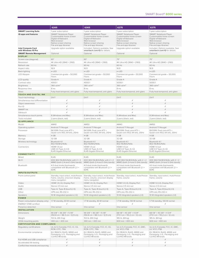
SMART Board® 6000 series
6265 6365 6275 6375
SMART Learning Suite 1-year subscription 1-year subscription 1-year subscription 1-year subscription
iQ apps and features SMART Notebook Player Customizable home screen Digital whiteboard Web browser Native screen sharing File and app libraries
SMART Notebook Player Customizable home screen Digital whiteboard Web browser Native screen sharing File and app libraries
SMART Notebook Player Customizable home screen Digital whiteboard Web browser Native screen sharing File and app libraries
SMART Notebook Player Customizable home screen Digital whiteboard Web browser Native screen sharing File and app libraries
Intel Compute Card with Windows 10 Pro
Upgrade option available Included. Options available. See smarttech.com/iQ for details.
Upgrade option available Included. Options available. See smarttech.com/iQ for details.
SMART Remote Management Optional Optional Optional OptionalD I S P L AY
Screen size (diagonal) 65” 65” 75” 75”
Resolution 4K Ultra HD (3840 × 2160) 4K Ultra HD (3840 × 2160) 4K Ultra HD (3840 × 2160) 4K Ultra HD (3840 × 2160)
Refresh rate 60 Hz 60 Hz 60 Hz 60 Hz
Aspect ratio 16:9 16:9 16:9 16:9
Back lighting e-LED e-LED e-LED e-LED
LED lifespan Commercial-grade – 50,000 hours
Commercial-grade – 50,000 hours
Commercial-grade – 50,000 hours
Commercial-grade – 50,000 hours
LCD quality Grade A Grade A Grade A Grade A
Contrast ratio 4000:1 4000:1 5000:1 5000:1
Brightness 360 cd/m² 360 cd/m² 360 cd/m² 360 cd/m²
Response time 8 ms 8 ms 8 ms 8 ms
Glass Fully heat-tempered, anti-glare Fully heat-tempered, anti-glare Fully heat-tempered, anti-glare Fully heat-tempered, anti-glareTO U C H A N D D I G ITA L I N K
Touch technology DViT DViT DViT DViT
Simultaneous tool differentiation Object awareness Pen ID SMART Ink Silktouch Simultaneous touch points 8 (Windows and Mac) 8 (Windows and Mac) 8 (Windows and Mac) 8 (Windows and Mac)
Tools included 2 pens (black, red) 2 pens (black, red) 2 pens (black, red) 2 pens (black, red)I Q A P P L I A N C E
Model AM40 AM50 AM40 AM50
Operating system Android 7.1 Nougat Android 7.1 Nougat Android 7.1 Nougat Android 7.1 Nougat
Processor RK3399, Dual-core A72 + Quad-core A53, 64 bits, 2GHz
RK3399, Dual-core A72 + Quad-core A53, 64 bits, 2GHz
RK3399, Dual-core A72 + Quad-core A53, 64 bits, 2GHz
RK3399, Dual-core A72 + Quad-core A53, 64 bits, 2GHz
Memory 4 GB 4 GB 4 GB 4 GB
Storage 32 GB 32 GB 32 GB 32 GB
Wireless technology Bluetooth 4.1 802.11A/B/G/N/Ac
Bluetooth 4.1 802.11A/B/G/N/Ac
Bluetooth 4.1 802.11A/B/G/N/Ac
Bluetooth 4.1 802.11A/B/G/N/Ac
Connectors HDMI 1.4 out USB 3.0 Type-A (×2) RJ45 Gigabit Ethernet
HDMI 1.4 out USB 3.0 Type-A (×2) RJ45 Gigabit Ethernet
HDMI 1.4 out USB 3.0 Type-A (×2) RJ45 Gigabit Ethernet
HDMI 1.4 out USB 3.0 Type-A (×2) RJ45 Gigabit Ethernet
CO N N E C TI V IT Y
Wired RJ45 RJ45 RJ45 RJ45
Wi-Fi IEEE 802.11A/B/G/N/Ac with 2 × 2 MIMO (both 2.4 and 5 GHz bands)
IEEE 802.11A/B/G/N/Ac with 2 × 2 MIMO (both 2.4 and 5 GHz bands)
IEEE 802.11A/B/G/N/Ac with 2 × 2 MIMO (both 2.4 and 5 GHz bands)
IEEE 802.11A/B/G/N/Ac with 2 × 2 MIMO (both 2.4 and 5 GHz bands)
Bluetooth 4.0 dual mode (backwards compatible with Bluetooth 2.1 + EDR)
4.0 dual mode (backwards compatible with Bluetooth 2.1 + EDR)
4.0 dual mode (backwards compatible with Bluetooth 2.1 + EDR)
4.0 dual mode (backwards compatible with Bluetooth 2.1 + EDR)
I N PUT S /O UTPUT S
Front control panel Standby, input select, mute/freeze frame, volume, onscreen display menu navigation
Standby, input select, mute/freeze frame, volume, onscreen display menu navigation
Standby, input select, mute/freeze frame, volume
Standby, input select, mute/freeze frame, volume
Video HDMI 1.4 (×2), Display Port HDMI 1.4 (×2), Display Port HDMI 1.4 (×2), Display Port HDMI 1.4 (×2), Display Port
Audio Stereo 3.5 mm out Stereo 3.5 mm out Stereo 3.5 mm out Stereo 3.5 mm out
USB Type-A, Type-B (touch) (×3) Type-A, Type-B (touch) (×3) Type-A, Type-B (touch) (×3) Type-A, Type-B (touch) (×3)
Other OPS slot, RS-232 in OPS slot, RS-232 in OPS slot, RS-232 in OPS slot, RS-232 in
Speakers 10 W integrated speakers (×2) 10 W integrated speakers (×2) 10 W integrated speakers (×2) 10 W integrated speakers (×2)P OW E R
Power consumption (display only) 1.7 W standby, 83 W normal 1.7 W standby, 83 W normal 1.7 W standby, 130 W normal 1.7 W standby, 130 W normal
ENERGY STAR certified Presence detection One sensor One sensor One sensor One sensorI N S TA LL ATI O N
Dimensions 59 3/8” × 36 3/8” × 5 1/8” (150.8 cm × 98.3 cm × 12.9 cm)
59 3/8” × 36 3/8” × 5 1/8” (150.8 cm × 98.3 cm × 12.9 cm)
68 1/8” × 43 3/8” × 4 3/4” (173.1 cm × 110.2 cm × 12 cm)
68 1/8” × 43 3/8” × 4 3/4” (173.1 cm × 110.2 cm × 12 cm)
Weight 153 lb. (69.3 kg) 153 lb. (69.3 kg) 185 lb. (84 kg) 185 lb. (84 kg)
VESA mounting points 300 mm × 400 mm 300 mm × 400 mm 600 mm × 400 mm 600 mm × 400 mmC E R TI F I C ATI O N A N D CO M P LI A N C E
Regulatory certifications UL (U.S./Canada), FCC, IC, CE, RCM, CITC, TRA
UL (U.S./Canada), FCC, IC, CE, RCM, CITC, TRA
UL (U.S./Canada), FCC, IC, EMC, LV, VCCI, PSE
UL (U.S./Canada), FCC, IC, EMC, LV, VCCI, PSE
Environmental compliance EU: REACH, RoHS, WEEE and Packaging; U.S.: Packaging and Conflict Minerals
EU: REACH, RoHS, WEEE and Packaging; U.S.: Packaging and Conflict Minerals
EU: REACH, RoHS, WEEE and Packaging; U.S.: Packaging and Conflict Minerals
EU: REACH, RoHS, WEEE and Packaging; U.S.: Packaging and Conflict Minerals
Full HDMI and USB compliance Accelerated life testing Conflict-free minerals and sourcing

LED-Backlit, Commercial-Grade LCD DisplaysIdeal for Education, Corporate and Digital Signage Applications
The Essentials
With a brilliant panel and simplified controls, the NEC E Series delivers everything you need
for captivating digital signage
• Integrated USB Media Player allows for playback of video, audio and picture files
• High-definition and high contrast ratio displays provide stunning images
• Built-in tuner allows for high-definition broadcast capabilities
• Additional energy options include a Power Savings Mode to further reduce energy
consumption
• 3-year warranty protects your investment
The Extras
Delivering more than just the basics, the NEC E Series has integrated features that will leave
no head unturned
• LED backlighting enables eco-friendly digital signage
• Simple 24-hour scheduler feature allows for programmable on/off times
• Reduced bezel width creates seamless digital signage
• Multiple HDMI ports enhance best-in-class connectivity
• Internal, 5W - 10W down-firing stereo speakers enhance the experience with
superior sound
• Ability to wake the display simply by plugging HDMI or VGA into the unit
Large Screen LED-backlit LCD 32" | 43" | 50" | 55" | 65"
Essential performance. Enticingly priced.
NEC E Series
QM-1
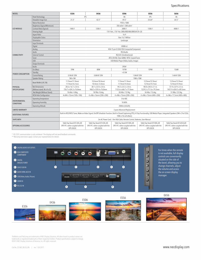
* RS-232C communication is only unilateral. The displays will not send feedback commands.** Warranty restrictions apply. Contact your representative for details.
For times when the remote is not available, full display controls are conveniently situated on the side of the bezel, allowing you to change channels, adjust the volume and access the on-screen display manager.
TileMatrix and TileComp are trademarks of NEC Display Solutions. All other brand or product names are trademarks or registered trademarks of their respective holders. Product specifications subject to change. ©2015 NEC Display Solutions of America, Inc. All rights reserved.
Cat.No. 25.NEC.80.GL.UN. | rev. 1.30.2017
DIGITAL AUDIO OUT (SPDIF)
RCA COMPOSITE/COMPONENT
DIGITAL ANALOG TUNER
VGA D-SUB IN
AUDIO MINI JACK IN
USB (Video, Audio, Picture)
HDMI IN
RS-232 IN
1
1
2
2
88
3
34 4
5
5
6
6
7
7
MODEL E326 E436 E506 E556 E656
LCD MODULE
Panel Technology IPS VA IPS VA
Viewable Image Size 31.5" 42.5" 49.5" 54.64" 64.5"
Native Resolution 1920 x 1080
Brightness (Typical/Minimum) 350 cd/m2 / 300 cd/m2
Contrast Ratio (Typical) 1400:1 1200:1 3000:1 1200:1 4000:1
Viewing Angle 176° Vert., 176° Hor. (88U/88D/88L/88R) @ CR>20
Aspect Ratio 16:9Displayable Colors Over 16.7 MillionOrientation Landscape
CONNECTIVITY
Input TerminalsDigital HDMI x3Analog VGA 15-pin D-SUB, RCA Composite/ComponentAudio RCA AudioExternal Control RS232C (Unidirectional)Tuner ATSC (8-VSB, Clear-QAM) / NTSC Coaxial TunerUSB USB Media Player (Video, Audio, Image)Output TerminalsAudio SPDIF
POWER CONSUMPTION
On (Max) 59W 80W 107W 109W 156WStandby <0.5W
Current Rating 0.9A @ 120V 0.8A @ 120V 1.0A @ 120V 1.4A @ 120V
Speaker Rating 5W x 5W 10W x 10W
PHYSICAL SPECIFICATIONS
Bezel Width (L/R, T/B)11.9mm/11.9mm/11.9mm/16.1mm
10.4mm/10.4mm/10.4mm.13.4mm
11.9mm/11.9mm/11.9mm/14.4mm
12.9mm/12.9mm/12.9mm/14.7mm
13.9mm/13.9mm/13.9mm/14.9mm
Net Dimensions (Without stand; W x H x D)
28.6 x 16.7 x 3.0 in. 726.7 x 424.3 x 76.8mm
38.1 x 22.0 x 3.0 in. 968.2 x 559.4 x 76.8mm
44.2 x 25.5 x 3.0 in. 1123.6 x 646.7 x 77.0mm
48.8 x 28.0 x 3.1 in. 1239.2 x 711.6 x 79.2mm
57.4 x 32.9 x 3.5 in. 1457.9 x 834.5 x 89.5mm
Net Weight (Without Stand) 10.6lbs / 4.8kg 18.9lbs / 8.6kg 28.4lbs / 12.9kg 34.4lbs / 15.6kg 51.8lbs / 23.5kgVESA Hole Configuration 4x M4 x 12mm (100 x 100) 4 x M6 x 16mm (200 x 200) 4 x M6 x 15mm (200 x 200) 4 x M6 x 15mm (400 x 200) 4 x M6 x 17.5mm (400 x 400)
ENVIRONMENTAL CONDITIONS
Operating Temperature 0 to 40C
Operating Humidity 10-80%
Operating Altitude 2000m (6562ft)
LIMITED WARRANTY 3 years Advanced Replacement
ADDITIONAL FEATURESBuilt-In ATSC/NTSC Tuner, Wake on Video Signal, On/Off Scheduler Function, Built-In Closed-Captioning (TTS), V-Chip Functionality, USB Media Player, Integrated Speakers (5W x 2 for E326,
10W x 2 for all others)
SHIPS WITH 3m AC Power Cord, 1.8m VGA Cable, Remote Control, Batteries, User Manual
OPTIONAL ACCESSORIESTable Top Stand (ST-32E), All
OPS PC's when coupled with the OPS-DOCK
Table Top Stand (ST-43E), All OPS PC's when coupled with the
OPS-DOCK
Table Top Stand (ST-50E), All OPS PC's when coupled with the
OPS-DOCK
Table Top Stand (ST-50E), All OPS PC's when coupled with the
OPS-DOCK
Table Top Stand (ST-65E2),All OPS PC's when coupled with the
OPS-DOCK
Specifications
www.necdisplay.com
E326E436
E506E556
E656
40", 48" and 55" Professional Displays Ideal for Digital Signage Applications
NEC Professional Large Format Displays
QM-2
Brand new aesthetically-focused design allows for seamless integration into any digital signage environment while maintaining the professional ruggedness necessary for the transportation, restaurant and financial industries.
Advanced Heat Management
Monitoring and managing the temperature of each display is crucial to secure reliability and
longevity. An industrial-strength, premium-grade panel with additional thermal protection, internal
temperature sensors with self-diagnostics, and fan-based technology allows for 24/7 operation, and
protects your display investment. Without thermal management, displays can be prone to damaging
heat over time. This damaging heat will lower the picture quality and life expectancy of the product.
Integrated cooling fans automatically turn on and stay on when high internal temperatures are detected.
These will stay on until the heat is properly dissipated and the display remains under proper temperature
thresholds.
2
Beyond Standard Signage
Create maximum visual impact through seamless simplicity with the new professional NEC P series
products. New contemporary and slim mechanical design with focused aesthetics allows for the
smooth and stylistic integration into any type of environment. Their full metal chassis coupled
with real-time temperature sensors and integrated cooling fans maintain the professional quality
necessary for commercial environments. With a wide range of the latest connectivity interfaces
including resolution support up to Ultra High Definition at 60Hz, these displays offer the future-
proofing necessary for the investment. These displays also include expandability options such as the
Open Pluggable Specification (OPS) and Raspberry Pi Compute Module slots for source integration
directly into the display. The NEC P series boasts 700 cd/m2 brightness along with a new anti-glare
surface that allows for efficient readability in higher ambient light situations and is ideal for 24/7
signage in airports, quick-serve restaurants, financial institutions and command and control.
L-Shaped Connectivity
Connectivity is located on
both the bottom and side
of the display to allow for
easy access regardless of
orientation
Scalable Computing Power
Integrated computing options allow for cable free signage for any type of situation. The on-board
multimedia player can be utilized for simple signage applications by allowing auto-play off of USB
or SD card and content transfer via LAN. For more advanced
signage systems, these displays contain an industry first
ability to integrate a Raspberry Pi Compute module for near
limitless potential and application. Finally, each display
adheres to the Open Pluggable Specification that gives the
ability to seamlessly integrate a full PC, HDBaseT receiver or
other options directly into the unit.
Dedicated Color Calibration Software
As the brightness and color temperature of the LCD change with time, colors may not match across
multiple screens. The NEC Display Wall Calibrator software ensures color uniformity and fidelity
across multiple screens, creating a perfectly matched image in tiled environments.
SpectraView Engine
Enhanced imaging performance through advanced settings of all relevant parameters allow full
control of brightness, color, gamma and uniformity via integrated color-critical chipset.
Intelligent Wireless Data Function
The built-in near field communication (NFC) chip allows data to be read and written via a mobile
phone or tablet PC. Users can significantly reduce installation costs as displays can be easily
configured and serviced using the NEC NFC Android app. This is extremely useful for larger rollouts
as it can be utilized even when the display is powered off.
Removable Logo
When mounting from Landscape to Portrait orientation, there is now the ability to change the
orientation of the logo or remove it all together
Key Guide
New Key Guide function allows for easier access to buttons when manually controlling the unit via
the buttons on the back of the display by adding a graphic on the screen that directs the customer to
the correct button layout in both landscape and portrait modes.
NaViSet Administrator 2
This software is an all-in-one remote support solution that runs from a
central location and provides monitoring, asset management and control
functionality of the majority of NEC display devices and Windows computers.
It is ideal for multi-device installations over larger infrastructures.
Proof of Play
This function provides accurate proof that displays are working as established when checking from
an external location. Information regarding video source, time on, audio source and more can be
pulled through the display when coupled with NaViSet Administrator 2.
Blue ON LED and Ambient Light Sensor
New mechanical structure allows for sleeker LED and ambient light sensor design. Auto dimming
of the LED backlights can be utilized through the ambient light sensor allowing for the brightness
to change depending on the external lux in the room of installation.
P404/P484/P554
3
Auto TileMatrix, Auto ID and Auto IP Address Technologies
Auto IP Address simplifies control setup by setting the static IP address on the first display then
initiating the feature so that the IP Addresses of consecutive displays follow the LAN daisy chain.
These displays also have Auto TileMatrix and Auto ID that can, in the case of a video wall, automatically
scale up to a UHD signal across the entirety of the wall through DisplayPort 1.2 while individually
IDing each screen, saving time and overall cost of installation.
(EXIT) (SET) (MUTE) ( | )( )( ) ( ) ( )+
P404 P484 P554
LCD MODULEPanel Technology SPVA SPVA S-IPSViewable Image Size 40" 48" 55"Native Resolution 1920 x 1080Brightness (Typical/Minimum) 550 cd/m2 / 700 cd/m2
Contrast Ratio (Typical) 4000:1 1300:1Viewing Angle 178° Vert., 178° Hor. (89U/89D/89L/89R) @ CR>10Aspect Ratio 16:9Displayable Colors Over 1.07 BillionOrientation Landscape, Portrait, Face Up, Face DownPanel Haze (%) 25 44CONNECTIVITY
Input Terminals
Digital HDMI 2.0 x2 (with HDCP), DVI-D (with HDCP), DisplayPort x2 (with HDCP)Analog VGA 15-pin D-SUB, RCA CompositeAudio 3.5mm Audio Mini Jack x2, DisplayPort Audio x2, HDMI Audio x3External Control LAN (100Mbit), 3.5 Mini Jack IR Remote, RS232C
Data microSD (Media Player), USB 2.0 (Media Player), USB 2.0 (Service), USB Type-B (Upstream), USB 2.0 x2 (Compute Module, Powered 5V/2A)
Output Terminals
Digital DisplayPort (Outputs DisplayPort) Audio 3.5mm Audio Mini JackExternal Control LAN (100Mb)
POWER CONSUMPTION
On (Typ/Max) 92W/115W 115W/140W 125W/175W
Network Standby 3W
Normal Standby <0.5W
Current Rating 2.9A - 1.2A @ 100V - 240V 3.1A - 1.2A @ 100V - 240V 3.6A - 1.5A @ 100V - 240V
Speaker Rating Integrated 10W x 10W, Optional 15W x 3
PHYSICAL SPECIFICATIONS
Bezel Width (L/R, T/B) 13.2mm/13.2mm/13.2mm/13.2mm
13.2mm/13.2mm/13.2mm/13.2mm
14.2mm/14.2mm/14.2mm/14.2mm
Net Dimensions (Without stand; W x H x D)
36.1 x 20.9 x 2.2 in. 918.0 x 530.6 x 54.7mm
42.8 x 24.6 x 2.2 in. 1086.5 x 625.3 x 54.7mm
49.0 x 28.1 x 2.5 in. 1244.0 x 714.8 x 62.9mm
Net Weight (Without Stand) 31.5lbs / 14.3kg 38.8lbs / 17.6kg 54.2lbs / 24.6kgVESA Hole Configuration 4x M6 x 12mm (300 x 300)
SENSORS
Ambient Light Sensor Integrated and programmable
Human Sensor Optional through KT-RC2 Accessory
Temperature Sensor Integrated and programmable; linked to cooling fans
NFC Sensor Integrated; works in conjunction with free NEC Intelligent Wireless Data Application
ENVIRONMENTAL CONDITIONS
Operating Temperature 0 to 40C
Operating Humidity 20-80%
Operating Altitude 3000m (9843ft)
LIMITED WARRANTY 5 years Advanced Replacement
ADDITIONAL FEATURES
Ambient Light Sensor, AMX Support, Auto ID/Auto TileMatrix, Automated Email Alert Function, CEC Support through HDMI, Crestron Roomview Support, DICOM Simulation, Display Browser Control, Display Wall Calibrator Compatible, Factory Uniformity Correction, High Haze Panel, Image Flip, Intelligent Wireless
Data (NFC), Key Guide, Media Player through Browser Control/SD Card/USB, Multi Picture Mode, NaViSet Administrator 2 Compatible, OSD Rotation for Portrait Orientation, OPS Compatible, PJ Link Support, Point
Zoom Function, Power USB Port (5V/2A), Programmable LUT x3, Raspberry Pi Compute Module Compat-ible, Removeable Logo Ornament, Real Time Clock, SpectraView Engine Support, SNMP Support (with
Uniformity Control), 24-Hour Scheduler Function, UHD Support through HDMI/DisplayPort
SHIPS WITH 3m AC Power Cord, 1.8m DVI Cable, IR Remote Control, Batteries, CD-ROM (User Manual)
OPTIONAL ACCESSORIESTable Top Stand (ST-401), Optional Speakers (SP-TF1), All OPS Option Cards, NEC Raspberry Pi Compute
Module (RP3CM16GB) with optional Compute Module Interface Board (DS1-IF10CE), Wall Mount (WMK-3257), Slim Wall Mount (WMK-3255S), Human Sensor (KT-RC2)
Input Panels 1. DVI-D2. HDMI IN23. DisplayPort IN24. DisplayPort IN15. DisplayPort OUT6. VGA (RGB, YPbPr)7. Audio IN18. Audio IN29. External Speaker Terminal10. Internal/External Speaker Switch11. Audio OUT12. USB1
www.necdisplay.comCat.No. 25.NEC.80.GL.UN.288 08.8.2017
Specifications
Options
OPS PC's
OPS-APIC-PS OPS-PCAEQ-PS
OPS-PCIB-PS OPS-APIS-PS
OPS-TCIS-PS
SDI
HD-SDI SB-01HC
3G-SDI SB-04HC
HDBaseT SB-07BC
Compute Module
Compute Module Interface Board DS1-IF10CE
NEC Raspberry Pi Compute Module RP3CM16GB
Tabletop Stand ST-401
Speaker SP-TF1
Dimensions
13. USB214. USB CM1 (2A)15. USB CM216. LAN117. LAN218. VIDEO IN19. USB MP20. microSD21. REMOTE IN22. RS-232C 23. HDMI IN1
MultiSync, NaViSet and TileMatrix are trademarks or registered trademarks of NEC Display Solutions, Ltd. in Japan, the United States and other countries. The terms HDMI and HDMI High-Definition Multimedia Interface, and the HDMI Logo are trademarks or registered trademarks of HDMI Licensing LLC in the United States and other countries. DisplayPort and DisplayPort Compliance Logo are trademarks owned by the Video Electronics Standards Association in the United States and other countries.HDBaseT™ and the HDBaseT Alliance logo are trademarks of the HDBaseT Alliance.CRESTRON and CRESTRON ROOMVIEW are trademarks or registered trademarks of Crestron Electronics, Inc.AMX is a trademark or registered trademark of AMX in the United States and other countries.VESA is a trademark of a nonprofit organization, Video Electronics Standard Association.All other trademarks are the property of their respective owners. The images in this brochure are samples.All specications are subject to change without notice.
©2017 NEC Display Solutions of America, Inc. and the NEC logo are registered trademarks of NEC.
1244.0 (P554)1086.5 (P484)
918.0 (P404)
62.9 (P554) 54.7 (P484)
54.7 (P404)
714.8
(P
554)
625.3
(P
484)
530.6
(P
404)
1
1211109 13 14 15 16 17 18 19 20 21 22 23
2 3 4 5 6 7 8
Bottom Panel
Side Panel
4
PCT2265 - Multi-Touch22" Touch Screen Monitor
The Planar® Helium™ PCT2265 is a 22" full HD
touch screen LCD monitor optimized with multi-touch
interactivity. With its integrated USB 3.0 hub and dual-
hinge desk stand, the Planar Helium Series PCT2265
provides the ultimate touch on the desktop
experience.
SPECIFICATION DETAIL
Product Name PCT2265
Planar Part Number 997-7251-00
Viewable Size 21.5" diagonal (18.77" horizontal x 10.56" vertical)
Touchscreen Type Projected Capacitive
Number of Touch Points 10
Touchscreen Interface USB
Contrast Ratio (typ) 3000:1
Viewing Angle (typ) 178° H,V
Response Time (typ) 18 ms
Brightness(w/touchscreen)
225 cd/m²
Brightness (w/otouchscreen)
250 cd/m²
Display Type Edge-Lit LED LCD
Display Resolution 1920 x 1080
Aspect Ratio 16:9
Tilt Range -5° to +90°
Palette 16.7 million colors
Pixel Pitch 0.2482
Refresh Rate 50-76 Hz
Panel Depth 2.49" (63.2 mm)
TM
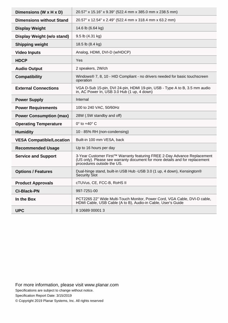
Dimensions (W x H x D) 20.57" x 15.16" x 9.39" (522.4 mm x 385.0 mm x 238.5 mm)
Dimensions without Stand 20.57" x 12.54" x 2.49" (522.4 mm x 318.4 mm x 63.2 mm)
Display Weight 14.6 lb (6.64 kg)
Display Weight (w/o stand) 9.5 lb (4.31 kg)
Shipping weight 18.5 lb (8.4 kg)
Video Inputs Analog, HDMI, DVI-D (w/HDCP)
HDCP Yes
Audio Output 2 speakers, 2W/ch
Compatibility Windows® 7, 8, 10 - HID Compliant - no drivers needed for basic touchscreenoperation
External Connections VGA D-Sub 15-pin, DVI 24-pin, HDMI 19-pin, USB - Type A to B, 3.5 mm audioin, AC Power In, USB 3.0 Hub (1 up, 4 down)
Power Supply Internal
Power Requirements 100 to 240 VAC, 50/60Hz
Power Consumption (max) 28W (.5W standby and off)
Operating Temperature 0° to +40° C
Humidity 10 - 85% RH (non-condensing)
VESA Compatible/Location Built-in 100 mm VESA, back
Recommended Usage Up to 16 hours per day
Service and Support 3-Year Customer First™ Warranty featuring FREE 2-Day Advance Replacement(US only). Please see warranty document for more details and for replacementprocedures outside the US.
Options / Features Dual-hinge stand, built-in USB Hub -USB 3.0 (1 up, 4 down), Kensington®Security Slot
Product Approvals cTUVus, CE, FCC-B, RoHS II
CI-Black-PN 997-7251-00
In the Box PCT2265 22" Wide Multi-Touch Monitor, Power Cord, VGA Cable, DVI-D cable,HDMI Cable, USB Cable (A to B), Audio-in Cable, User’s Guide
UPC 8 10689 00001 3
For more information, please visit www.planar.comSpecifications are subject to change without notice.
Specification Report Date: 3/15/2019
© Copyright 2019 Planar Systems, Inc. All rights reserved
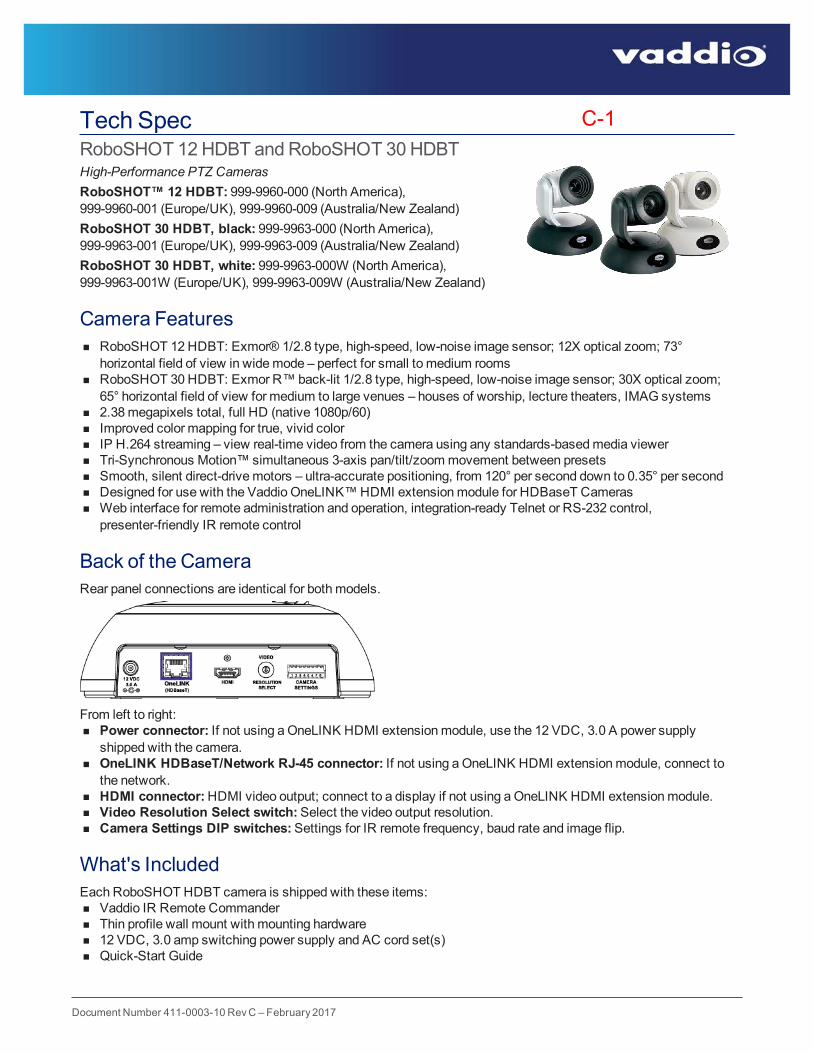
Document Number 411-0003-10 RevC – February 2017
Tech SpecRoboSHOT 12HDBT and RoboSHOT 30HDBTHigh-Performance PTZ CamerasRoboSHOT™ 12 HDBT: 999-9960-000 (North America),999-9960-001 (Europe/UK), 999-9960-009 (Australia/New Zealand)RoboSHOT 30 HDBT, black: 999-9963-000 (North America),999-9963-001 (Europe/UK), 999-9963-009 (Australia/New Zealand)RoboSHOT 30 HDBT, white: 999-9963-000W (North America),999-9963-001W (Europe/UK), 999-9963-009W (Australia/New Zealand)
Camera Featuresn RoboSHOT 12HDBT: Exmor® 1/2.8 type, high-speed, low-noise image sensor; 12X optical zoom; 73°
horizontal field of view in widemode – perfect for small to medium roomsn RoboSHOT 30HDBT: Exmor R™back-lit 1/2.8 type, high-speed, low-noise image sensor; 30X optical zoom;
65° horizontal field of view for medium to large venues – houses of worship, lecture theaters, IMAG systemsn 2.38megapixels total, full HD (native 1080p/60)n Improved color mapping for true, vivid colorn IP H.264 streaming – view real-time video from the camera using any standards-basedmedia viewern Tri-Synchronous Motion™ simultaneous 3-axis pan/tilt/zoommovement between presetsn Smooth, silent direct-drivemotors – ultra-accurate positioning, from 120° per second down to 0.35° per secondn Designed for use with the Vaddio OneLINK™HDMI extensionmodule for HDBaseT Camerasn Web interface for remote administration and operation, integration-ready Telnet or RS-232 control,
presenter-friendly IR remote control
Back of the CameraRear panel connections are identical for bothmodels.
From left to right:n Power connector: If not using aOneLINK HDMI extensionmodule, use the 12 VDC, 3.0 A power supply
shipped with the camera.n OneLINK HDBaseT/Network RJ-45 connector: If not using aOneLINK HDMI extensionmodule, connect to
the network.n HDMI connector:HDMI video output; connect to a display if not using aOneLINK HDMI extensionmodule.n Video Resolution Select switch:Select the video output resolution.n Camera Settings DIP switches:Settings for IR remote frequency, baud rate and image flip.
What's IncludedEach RoboSHOT HDBT camera is shipped with these items:n Vaddio IR Remote Commandern Thin profile wall mount with mounting hardwaren 12 VDC, 3.0 amp switching power supply and AC cord set(s)n Quick-Start Guide
C-1
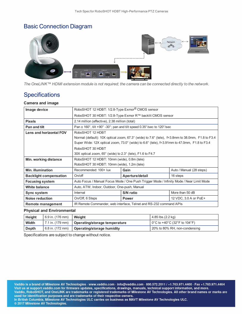
Basic Connection Diagram
TheOneLINK™HDMI extensionmodule is not required; the camera can be connected directly to the network.
SpecificationsCamera and imageImage device RoboSHOT 12 HDBT: 1/2.8-Type Exmor® CMOS sensor
RoboSHOT 30 HDBT: 1/2.8-Type Exmor R™ backlit CMOS sensor
Pixels 2.14 million (effective), 2.38 million (total)
Pan and tilt Pan ± 160°, tilt +90° -30°; pan and tilt speed 0.35°/sec to 120°/sec
Lens and horizontal FOV RoboSHOT 12 HDBTNormal (default): 10X optical zoom, 67.3° (wide) to 7.6° (tele), f=3.8mm to 38.0mm, F1.8 to F3.4Super Wide: 12X optical zoom, 73.0° (wide) to 6.6° (tele), f=3.91mm to 47.0mm, F1.8 to F3.4
RoboSHOT 30 HDBT30X optical zoom, 65° (wide) to 2.3° (tele), F1.6 to F4.7
Min. working distance RoboSHOT 12 HDBT: 10mm (wide), 0.8m (tele)RoboSHOT 30 HDBT: 10mm (wide), 1.2m (tele)
Min. illumination Recommended: 100+ lux Gain Auto / Manual (28 steps)
Backlight compensation On/off Aperture/detail 16 steps
Focusing system Auto Focus / Manual Focus Mode / One Push Trigger Mode / Infinity Mode / Near Limit Mode
White balance Auto, ATW, Indoor, Outdoor, One-push, Manual
Sync system Internal S/N ratio More than 50 dB
Noise reduction On/Off, 6 Steps Power 12 VDC, 3.0 A or PoE+
Remote management IR Remote Commander, web interface, Telnet and RS-232 command APIs
Physical and EnvironmentalHeight 6.9 in. (176 mm) Weight 4.85 lbs.(2.2 kg)
Width 7.1 in. (179 mm) Operating/storage temperature 0°C to +40°C (32°F to 104°F)
Depth 6.8 in. (172 mm) Operating/storage humidity 20% to 80% RH, non-condensing
Specifications are subject to change without notice.
Tech Spec for RoboSHOT HDBT High-Performance PTZ Cameras
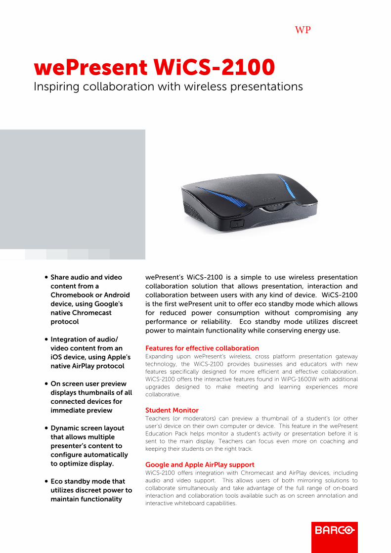
wePresent WiCS-2100Inspiring collaboration with wireless presentations
b Share audio and videocontent from aChromebook or Androiddevice, using Google'snative Chromecastprotocol
b Integration of audio/video content from aniOS device, using Apple'snative AirPlay protocol
b On screen user previewdisplays thumbnails of allconnected devices forimmediate preview
b Dynamic screen layoutthat allows multiplepresenter’s content toconfigure automaticallyto optimize display.
b Eco standby mode thatutilizes discreet power tomaintain functionality
wePresent’s WiCS-2100 is a simple to use wireless presentationcollaboration solution that allows presentation, interaction andcollaboration between users with any kind of device. WiCS-2100is the first wePresent unit to offer eco standby mode which allowsfor reduced power consumption without compromising anyperformance or reliability. Eco standby mode utilizes discreetpower to maintain functionality while conserving energy use.
Features for effective collaborationExpanding upon wePresent’s wireless, cross platform presentation gatewaytechnology, the WiCS-2100 provides businesses and educators with newfeatures specifically designed for more efficient and effective collaboration.WiCS-2100 offers the interactive features found in WiPG-1600W with additionalupgrades designed to make meeting and learning experiences morecollaborative.
Student MonitorTeachers (or moderators) can preview a thumbnail of a student's (or otheruser's) device on their own computer or device. This feature in the wePresentEducation Pack helps monitor a student's activity or presentation before it issent to the main display. Teachers can focus even more on coaching andkeeping their students on the right track.
Google and Apple AirPlay supportWiCS-2100 offers integration with Chromecast and AirPlay devices, includingaudio and video support. This allows users of both mirroring solutions tocollaborate simultaneously and take advantage of the full range of on-boardinteraction and collaboration tools available such as on screen annotation andinteractive whiteboard capabilities.
WP

wePresent WiCS-2100 Barco
02
Improved multi user Layout & conference controls
With dynamic screen layout, on screen collaboration becomes quicker andmore flexible. WiCS-2100 adapts to multiple presenters by automaticallyconfiguring the presentation content to optimize display.
For environments where moderator control is crucial, WiCS-2100 offers theconference controller an on screen user preview for up to 32 logged in users aswell as the ability to lock down the presentation from others.
WiCS-2100 brings effective wireless collaboration to boardrooms, classroomsand anywhere people work together.
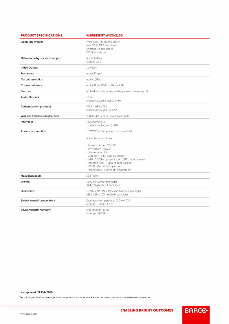
PRODUCT SPECIFICATIONS WEPRESENT WICS-2100
Operating system Windows 7, 8, 10 and abovemacOS X, 10.9 and aboveAndroid 4.1 and aboveiOS 9 and above
Native industry standard support Apple AirPlayGoogle Cast
Video Output 1 x HDMI
Frame rate up to 30 fps
Output resolution up to 1080p
Connected users up to 32 via Wi-Fi or 64 via LAN
Sources up to 4 simultaneously with dynamic screen layout
Audio Outputs HDMIanalog via audio jack 3.5mm
Authentication protocol WPA / WPA2 PSKStation mode 802.1x EAP
Wireless transmission protocol 2.4G(b/g/n) / 5G(a/n/ac) switchable
Interfaces 1 x Ethernet LAN1 x (back) + 1 x (front) USB
Power consumption 11.79W full load power consumption
under test conditions:
· Power source : DC 12V· SW version : RC217· HW version : ER· USB port : 0.5A load (each port)· WiFi : 5G/11ac (project four 1080p video stream)· Ethernet port : Transfer iperf packet· HDMI : Output four picture· Phone Jack : Connect to earphone
Heat dissipation 19 BTU/hr
Weight 1000±5%g with package344±5%g without package
Dimensions 169.87 x 129.19 x 45.52mm without package215 x 218 x 103mm with package
Environmental temperature Operation temperature: 0°C -+40°CStorage : -20°C -+70°C
Environmental humidity Operational : 85%Storage : 90%RH
ENABLING BRIGHT OUTCOMES
Last updated: 22 Feb 2019
Technical specifications are subject to change without prior notice. Please check www.barco.com for the latest information.
www.barco.com
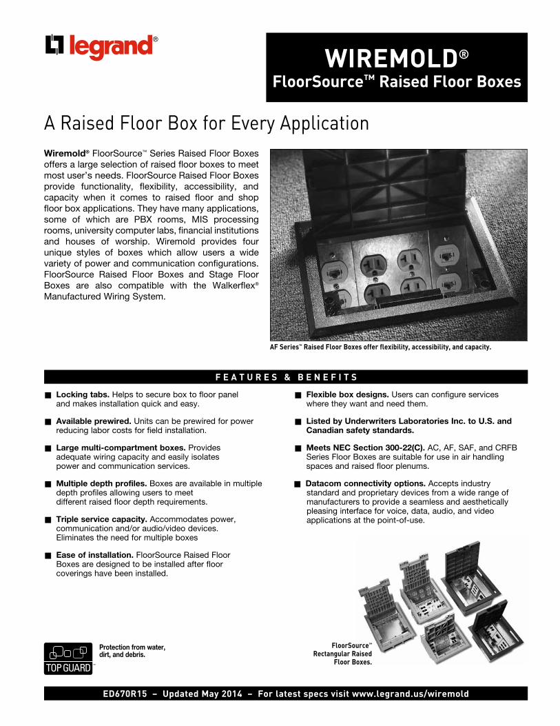
Wiremold® FloorSource™ raised Floor Boxes
A Raised Floor Box for Every ApplicationWiremold® FloorSource™ Series Raised Floor Boxes offers a large selection of raised floor boxes to meet most user’s needs. FloorSource Raised Floor Boxes provide functionality, flexibility, accessibility, and capacity when it comes to raised floor and shop floor box applications. They have many applications, some of which are PBX rooms, MIS processing rooms, university computer labs, financial institutions and houses of worship. Wiremold provides four unique styles of boxes which allow users a wide variety of power and communication configurations. FloorSource Raised Floor Boxes and Stage Floor Boxes are also compatible with the Walkerflex®
Manufactured Wiring System.
n Locking tabs. Helps to secure box to floor paneland makes installation quick and easy.
n Available prewired. Units can be prewired for powerreducing labor costs for field installation.
n Large multi-compartment boxes. Providesadequate wiring capacity and easily isolatespower and communication services.
n Multiple depth profiles. Boxes are available in multipledepth profiles allowing users to meetdifferent raised floor depth requirements.
n Triple service capacity. Accommodates power,communication and/or audio/video devices.Eliminates the need for multiple boxes
n Ease of installation. FloorSource Raised FloorBoxes are designed to be installed after floorcoverings have been installed.
n Flexible box designs. Users can configure serviceswhere they want and need them.
n Listed by Underwriters Laboratories Inc. to U.S. andCanadian safety standards.
n Meets NEC Section 300-22(C). AC, AF, SAF, and CRFBSeries Floor Boxes are suitable for use in air handlingspaces and raised floor plenums.
n Datacom connectivity options. Accepts industrystandard and proprietary devices from a wide range ofmanufacturers to provide a seamless and aestheticallypleasing interface for voice, data, audio, and videoapplications at the point-of-use.
F e a t u r e S & B e n e F i t S
aF Series™ raised Floor Boxes offer flexibility, accessibility, and capacity.
ed670r15 – updated may 2014 – For latest specs visit www.legrand.us/wiremold
FloorSource™ rectangular raised
Floor Boxes.
Protection from water, dirt, and debris.
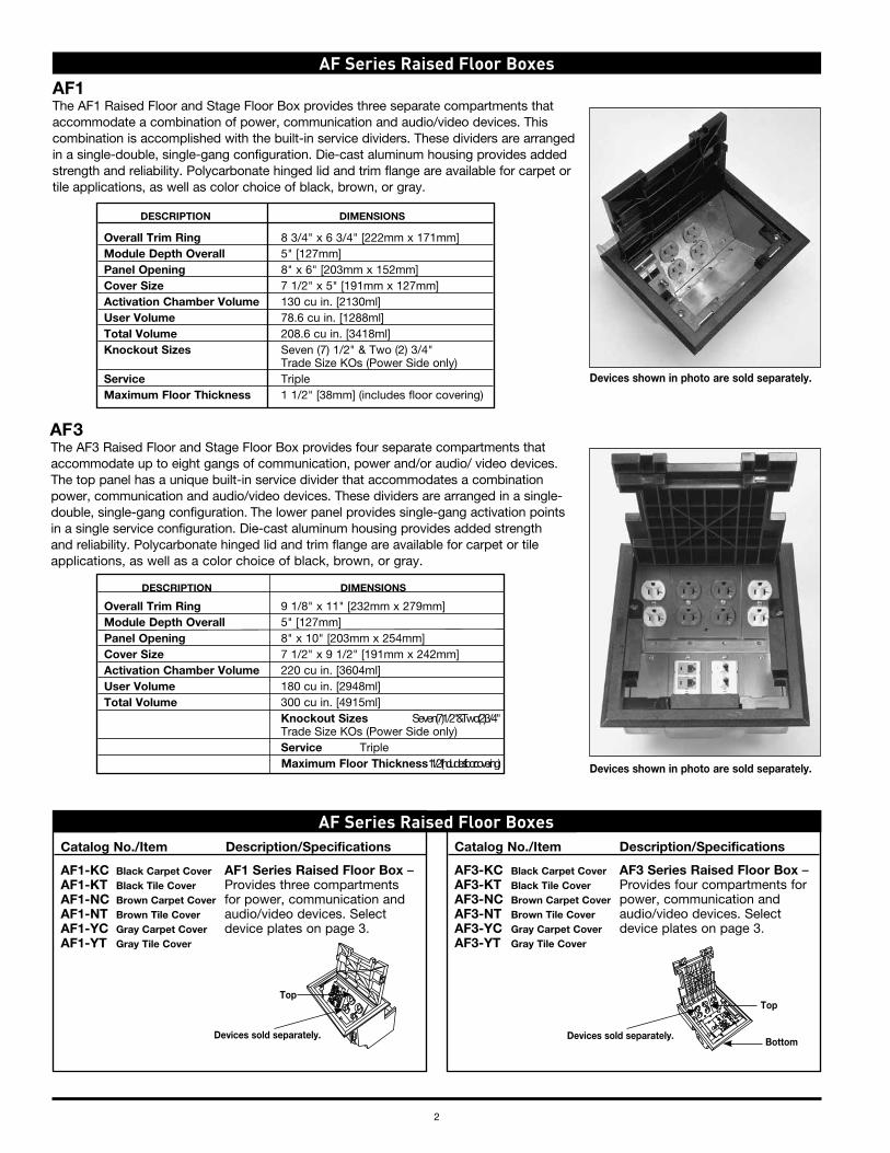
2
aF Series raised Floor Boxes
AF 3The AF3 Raised Floor and Stage Floor Box provides four separate compartments that accommodate up to eight gangs of communication, power and/or audio/ video devices. The top panel has a unique built-in service divider that accommodates a combination power, communication and audio/video devices. These dividers are arranged in a single-double, single-gang configuration. The lower panel provides single-gang activation points in a single service configuration. Die-cast aluminum housing provides added strength and reliability. Polycarbonate hinged lid and trim flange are available for carpet or tile applications, as well as a color choice of black, brown, or gray.
Devices shown in photo are sold separately.
Catalog No./Item Description/Specifications
AF1-KC Black Carpet Cover AF1 Series Raised Floor Box – AF1-KT Black Tile Cover Provides three compartments AF1-NC Brown Carpet Cover for power, communication and AF1-NT Brown Tile Cover audio/video devices. Select AF1-YC Gray Carpet Cover device plates on page 3. AF1-YT Gray Tile Cover
Catalog No./Item Description/Specifications
AF3-KC Black Carpet Cover AF3 Series Raised Floor Box – AF3-KT Black Tile Cover Provides four compartments for AF3-NC Brown Carpet Cover power, communication and AF3-NT Brown Tile Cover audio/video devices. Select AF3-YC Gray Carpet Cover device plates on page 3. AF3-YT Gray Tile Cover
aF Series raised Floor Boxes
Devices sold separately.
TopTop
Bottom
DESCRIPTIoN DIMENSIoNS
overall Trim Ring 9 1/8" x 11" [232mm x 279mm] Module Depth overall 5" [127mm] Panel opening 8" x 10" [203mm x 254mm] Cover Size 7 1/2" x 9 1/2" [191mm x 242mm] Activation Chamber Volume 220 cu in. [3604ml] User Volume 180 cu in. [2948ml] Total Volume 300 cu in. [4915ml] Knockout Sizes Seven (7) 1/2" & Two (2) 3/4" Trade Size KOs (Power Side only) Service Triple Maximum Floor Thickness 1 1/2" (includes floor covering)
DESCRIPTIoN DIMENSIoNS
overall Trim Ring 8 3/4" x 6 3/4" [222mm x 171mm] Module Depth overall 5" [127mm] Panel opening 8" x 6" [203mm x 152mm] Cover Size 7 1/2" x 5" [191mm x 127mm] Activation Chamber Volume 130 cu in. [2130ml] User Volume 78.6 cu in. [1288ml] Total Volume 208.6 cu in. [3418ml] Knockout Sizes Seven (7) 1/2" & Two (2) 3/4" Trade Size KOs (Power Side only) Service Triple Maximum Floor Thickness 1 1/2" [38mm] (includes floor covering)
Devices shown in photo are sold separately.
AF1The AF1 Raised Floor and Stage Floor Box provides three separate compartments that accommodate a combination of power, communication and audio/video devices. This combination is accomplished with the built-in service dividers. These dividers are arranged in a single-double, single-gang configuration. Die-cast aluminum housing provides added strength and reliability. Polycarbonate hinged lid and trim flange are available for carpet or tile applications, as well as color choice of black, brown, or gray.
Devices sold separately.
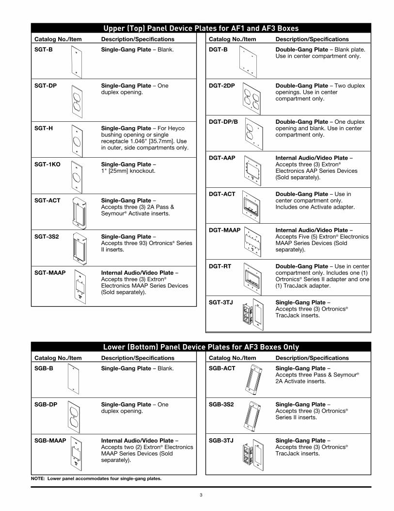
3
Catalog No./Item Description/Specifications
DGT-B Double-Gang Plate – Blank plate. Use in center compartment only.
DGT-2DP Double-Gang Plate – Two duplex openings. Use in center compartment only.
DGT-DP/B Double-Gang Plate – One duplex opening and blank. Use in center compartment only.
DGT-AAP Internal Audio/Video Plate – Accepts three (3) Extron® Electronics AAP Series Devices (Sold separately).
DGT-ACT Double-Gang Plate – Use in center compartment only. Includes one Activate adapter.
DGT-MAAP Internal Audio/Video Plate – Accepts Five (5) Extron® Electronics MAAP Series Devices (Sold separately).
DGT-RT Double-Gang Plate – Use in center compartment only. Includes one (1) Ortronics® Series II adapter and one (1) TracJack adapter.
SGT-3TJ Single-Gang Plate – Accepts three (3) Ortronics® TracJack inserts.
Catalog No./Item Description/Specifications
SGT-B Single-Gang Plate – Blank.
SGT-DP Single-Gang Plate – One duplex opening.
SGT-H Single-Gang Plate – For Heyco bushing opening or single receptacle 1.046" [35.7mm]. Use in outer, side compartments only.
SGT-1Ko Single-Gang Plate – 1" [25mm] knockout.
SGT-ACT Single-Gang Plate – Accepts three (3) 2A Pass & Seymour® Activate inserts.
SGT-3S2 Single-Gang Plate – Accepts three 93) Ortronics® Series II inserts.
SGT-MAAP Internal Audio/Video Plate – Accepts three (3) Extron® Electronics MAAP Series Devices (Sold separately).
Catalog No./Item Description/Specifications
SGB-B Single-Gang Plate – Blank.
SGB-DP Single-Gang Plate – One duplex opening.
SGB-MAAP Internal Audio/Video Plate – Accepts two (2) Extron® Electronics MAAP Series Devices (Sold separately).
Catalog No./Item Description/Specifications
SGB-ACT Single-Gang Plate – Accepts three Pass & Seymour® 2A Activate inserts.
SGB-3S2 Single-Gang Plate – Accepts three (3) Ortronics® Series II inserts.
SGB-3TJ Single-Gang Plate – Accepts three (3) Ortronics® TracJack inserts.
upper (top) Panel device Plates for aF1 and aF3 Boxes
lower (Bottom) Panel device Plates for aF3 Boxes only
NoTE: Lower panel accommodates four single-gang plates.
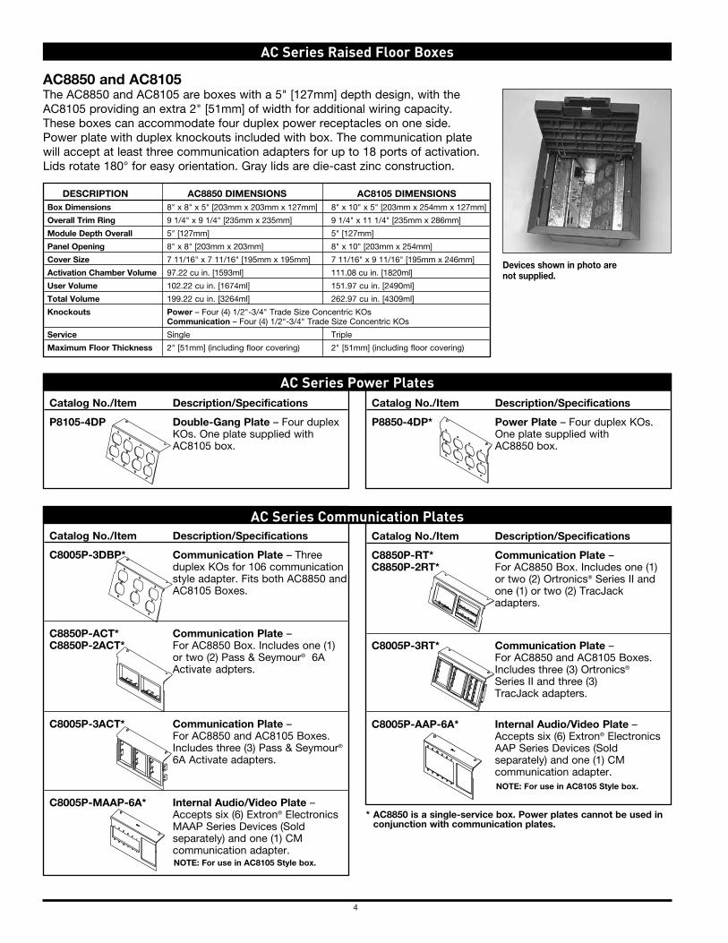
4
Catalog No./Item Description/Specifications
C8005P-3DBP* Communication Plate – Three duplex KOs for 106 communication style adapter. Fits both AC8850 and AC8105 Boxes.
C8850P-ACT* Communication Plate – C8850P-2ACT* For AC8850 Box. Includes one (1)
or two (2) Pass & Seymour® 6A Activate adpters.
C8005P-3ACT* Communication Plate – For AC8850 and AC8105 Boxes. Includes three (3) Pass & Seymour® 6A Activate adapters.
C8005P-MAAP-6A* Internal Audio/Video Plate – Accepts six (6) Extron® Electronics MAAP Series Devices (Sold separately) and one (1) CM communication adapter.
Catalog No./Item Description/Specifications
P8105-4DP Double-Gang Plate – Four duplex KOs. One plate supplied with AC8105 box.
AC8850 and AC8105 The AC8850 and AC8105 are boxes with a 5" [127mm] depth design, with the AC8105 providing an extra 2" [51mm] of width for additional wiring capacity. These boxes can accommodate four duplex power receptacles on one side. Power plate with duplex knockouts included with box. The communication plate will accept at least three communication adapters for up to 18 ports of activation. Lids rotate 180° for easy orientation. Gray lids are die-cast zinc construction.
DESCRIPTIoN AC8850 DIMENSIoNS AC8105 DIMENSIoNS Box Dimensions 8" x 8" x 5" [203mm x 203mm x 127mm] 8" x 10" x 5" [203mm x 254mm x 127mm]
overall Trim Ring 9 1/4" x 9 1/4" [235mm x 235mm] 9 1/4" x 11 1/4" [235mm x 286mm]
Module Depth overall 5" [127mm] 5" [127mm]
Panel opening 8" x 8" [203mm x 203mm] 8" x 10" [203mm x 254mm]
Cover Size 7 11/16" x 7 11/16" [195mm x 195mm] 7 11/16" x 9 11/16" [195mm x 246mm]
Activation Chamber Volume 97.22 cu in. [1593ml] 111.08 cu in. [1820ml]
User Volume 102.22 cu in. [1674ml] 151.97 cu in. [2490ml]
Total Volume 199.22 cu in. [3264ml] 262.97 cu in. [4309ml]
Knockouts Power – Four (4) 1/2"-3/4" Trade Size Concentric KOs Communication – Four (4) 1/2"-3/4" Trade Size Concentric KOs
Service Single Triple
Maximum Floor Thickness 2" [51mm] (including floor covering) 2" [51mm] (including floor covering)
aC Series raised Floor Boxes
Devices shown in photo are not supplied.
Catalog No./Item Description/Specifications
P8850-4DP* Power Plate – Four duplex KOs. One plate supplied with AC8850 box.
aC Series Power Plates
Catalog No./Item Description/Specifications
C8850P-RT* Communication Plate – C8850P-2RT* For AC8850 Box. Includes one (1)
or two (2) Ortronics® Series II and one (1) or two (2) TracJack adapters.
C8005P-3RT* Communication Plate – For AC8850 and AC8105 Boxes. Includes three (3) Ortronics® Series II and three (3) TracJack adapters.
C8005P-AAP-6A* Internal Audio/Video Plate – Accepts six (6) Extron® Electronics AAP Series Devices (Sold separately) and one (1) CM communication adapter.
aC Series Communication Plates
* AC8850 is a single-service box. Power plates cannot be used inconjunction with communication plates.
NoTE: For use in AC8105 Style box.
NoTE: For use in AC8105 Style box.
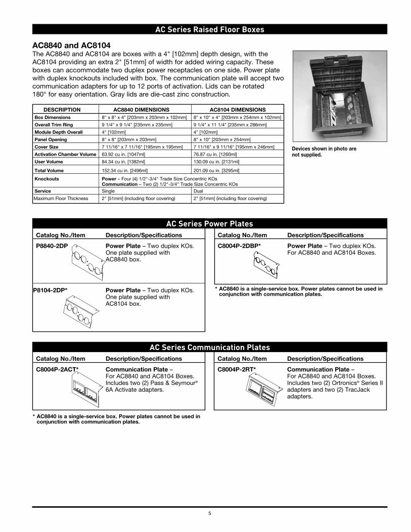
Catalog No./Item Description/Specifications
P8840-2DP Power Plate – Two duplex KOs. One plate supplied with AC8840 box.
P8104-2DP* Power Plate – Two duplex KOs. One plate supplied with AC8104 box.
5
Catalog No./Item Description/Specifications
C8004P-2ACT* Communication Plate – For AC8840 and AC8104 Boxes. Includes two (2) Pass & Seymour® 6A Activate adapters.
Catalog No./Item Description/Specifications
C8004P-2DBP* Power Plate – Two duplex KOs. For AC8840 and AC8104 Boxes.
AC8840 and AC8104The AC8840 and AC8104 are boxes with a 4" [102mm] depth design, with the AC8104 providing an extra 2" [51mm] of width for added wiring capacity. These boxes can accommodate two duplex power receptacles on one side. Power plate with duplex knockouts included with box. The communication plate will accept two communication adapters for up to 12 ports of activation. Lids can be rotated 180° for easy orientation. Gray lids are die-cast zinc construction.
DESCRIPTIoN AC8840 DIMENSIoNS AC8104 DIMENSIoNS Box Dimensions 8" x 8" x 4" [203mm x 203mm x 102mm] 8" x 10" x 4" [203mm x 254mm x 102mm]
overall Trim Ring 9 1/4" x 9 1/4" [235mm x 235mm] 9 1/4" x 11 1/4" [235mm x 286mm]
Module Depth overall 4" [102mm] 4" [102mm]
Panel opening 8" x 8" [203mm x 203mm] 8" x 10" [203mm x 254mm]
Cover Size 7 11/16" x 7 11/16" [195mm x 195mm] 7 11/16" x 9 11/16" [195mm x 246mm]
Activation Chamber Volume 63.92 cu in. [1047ml] 76.87 cu in. [1260ml]
User Volume 84.34 cu in. [1382ml] 130.09 cu in. [2131ml]
Total Volume 152.34 cu in. [2496ml] 201.09 cu in. [3295ml]
Knockouts Power – Four (4) 1/2"-3/4" Trade Size Concentric KOs Communication – Two (2) 1/2"-3/4" Trade Size Concentric KOs Service Single Dual
Maximum Floor Thickness 2" [51mm] (including floor covering) 2" [51mm] (including floor covering)
aC Series raised Floor Boxes
Devices shown in photo are not supplied.
aC Series Power Plates
Catalog No./Item Description/Specifications
C8004P-2RT* Communication Plate – For AC8840 and AC8104 Boxes.
Includes two (2) Ortronics® Series II adapters and two (2) TracJack adapters.
aC Series Communication Plates
* AC8840 is a single-service box. Power plates cannot be used in conjunction with communication plates.
* AC8840 is a single-service box. Power plates cannot be used in conjunction with communication plates.
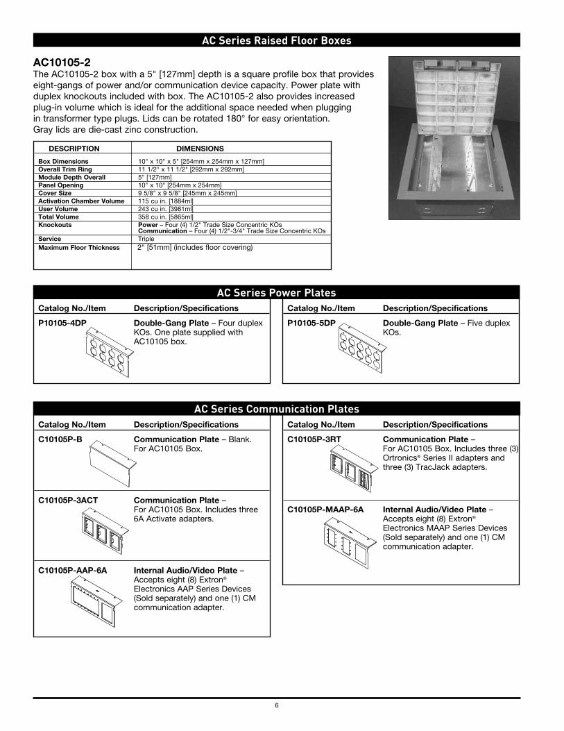
6
Catalog No./Item Description/Specifications
P10105-4DP Double-Gang Plate – Four duplex KOs. One plate supplied with AC10105 box.
Catalog No./Item Description/Specifications
C10105P-B Communication Plate – Blank. For AC10105 Box.
C10105P-3ACT Communication Plate – For AC10105 Box. Includes three 6A Activate adapters.
C10105P-AAP-6A Internal Audio/Video Plate – Accepts eight (8) Extron® Electronics AAP Series Devices (Sold separately) and one (1) CM communication adapter.
Catalog No./Item Description/Specifications
P10105-5DP Double-Gang Plate – Five duplex KOs.
AC10105-2 The AC10105-2 box with a 5" [127mm] depth is a square profile box that provides eight-gangs of power and/or communication device capacity. Power plate with duplex knockouts included with box. The AC10105-2 also provides increased plug-in volume which is ideal for the additional space needed when plugging in transformer type plugs. Lids can be rotated 180° for easy orientation. Gray lids are die-cast zinc construction.
aC Series raised Floor Boxes
DESCRIPTIoN DIMENSIoNS
Box Dimensions 10" x 10" x 5" [254mm x 254mm x 127mm] overall Trim Ring 11 1/2" x 11 1/2" [292mm x 292mm] Module Depth overall 5" [127mm]Panel opening 10" x 10" [254mm x 254mm]Cover Size 9 5/8" x 9 5/8" [245mm x 245mm]Activation Chamber Volume 115 cu in. [1884ml]User Volume 243 cu in. [3981ml]Total Volume 358 cu in. [5865ml]Knockouts Power – Four (4) 1/2" Trade Size Concentric KOs
Communication – Four (4) 1/2"-3/4" Trade Size Concentric KOsService Triple
Maximum Floor Thickness 2" [51mm] (includes floor covering)
Catalog No./Item Description/Specifications
C10105P-3RT Communication Plate – For AC10105 Box. Includes three (3) Ortronics® Series II adapters and three (3) TracJack adapters.
C10105P-MAAP-6A Internal Audio/Video Plate – Accepts eight (8) Extron® Electronics MAAP Series Devices (Sold separately) and one (1) CM communication adapter.
aC Series Power Plates
aC Series Communication Plates
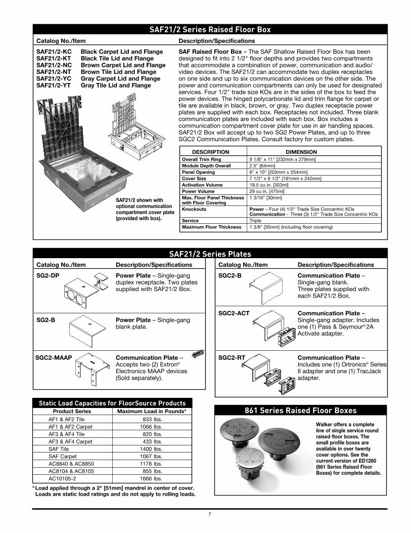
7
Catalog No./Item Description/Specifications
SAF21/2-KC Black Carpet Lid and Flange SAF Raised Floor Box – The SAF Shallow Raised Floor Box has been SAF21/2-KT Black Tile Lid and Flange designed to fit into 2 1/2" floor depths and provides two compartments SAF21/2-NC Brown Carpet Lid and Flange that accommodate a combination of power, communication and audio/ SAF21/2-NT Brown Tile Lid and Flange video devices. The SAF21/2 can accommodate two duplex receptacles SAF21/2-YC Gray Carpet Lid and Flange on one side and up to six communication devices on the other side. The SAF21/2-YT Gray Tile Lid and Flange power and communication compartments can only be used for designated services. Four 1/2" trade size KOs are in the sides of the box to feed the power devices. The hinged polycarbonate lid and trim flange for carpet or tile are available in black, brown, or gray. Two duplex receptacle power plates are supplied with each box. Receptacles not included. Three blank communication plates are included with each box. Box includes a communication compartment cover plate for use in air handling spaces. SAF21/2 Box will accept up to two SG2 Power Plates, and up to three SGC2 Communication Plates. Consult factory for custom plates.
DESCRIPTIoN DIMENSIoN overall Trim Ring 9 1/8" x 11" [232mm x 279mm] Module Depth overall 2.5" [64mm] Panel opening 8" x 10" [203mm x 254mm] Cover Size 7 1/2" x 9 1/2" [191mm x 242mm] Activation Volume 18.5 cu in. [303ml] Power Volume 29 cu in. [475ml] Max. Floor Panel Thickness 1 3/16" [30mm] with Floor Covering Knockouts Power – Four (4) 1/2" Trade Size Concentric KOs Communication – Three (3) 1/2" Trade Size Concentric KOs Service Triple Maximum Floor Thickness 1 3/8" [35mm] (including floor covering)
Catalog No./Item Description/Specifications
SGC2-B Communication Plate – Single-gang blank. Three plates supplied with each SAF21/2 Box.
SGC2-ACT Communication Plate – Single-gang adapter. Includes one (1) Pass & Seymour® 2A Activate adapter.
SGC2-RT Communication Plate – Includes one (1) Ortronics® Series II adapter and one (1) TracJack adapter.
Catalog No./Item Description/Specifications
SG2-DP Power Plate – Single-gang duplex receptacle. Two plates supplied with SAF21/2 Box.
SG2-B Power Plate – Single-gang blank plate.
SGC2-MAAP Communication Plate – Accepts two (2) Extron® Electronics MAAP devices (Sold separately).
SaF21/2 Series raised Floor Box
SaF21/2 Series Plates
SAF21/2 shown with optional communication compartment cover plate (provided with box).
861 Series raised Floor Boxes
* Load applied through a 2" [51mm] mandrel in center of cover. Loads are static load ratings and do not apply to rolling loads.
Product Series Maximum Load in Pounds*
AF1 & AF2 Tile 833 lbs. AF1 & AF2 Carpet 1066 lbs. AF3 & AF4 Tile 820 lbs. AF3 & AF4 Carpet 433 lbs. SAF Tile 1400 lbs. SAF Carpet 1067 lbs. AC8840 & AC8850 1178 lbs. AC8104 & AC8105 855 lbs. AC10105-2 1666 lbs.
Static load Capacities for FloorSource Products
Walker offers a complete line of single service round raised floor boxes. The small profile boxes are available in over twenty cover options. See the current version of ED1260 (861 Series Raised Floor Boxes) for complete details.

ED670R15 – Updated May 2014 – For latest specs visit www.legrand.us/wiremold© Copyright 2014 Legrand All Rights Reserved
electrical Wiring Systems60 Woodlawn Street West Hartford, CT 06110Phone: 1.877.BY.LEgRAnd (295-3472) www.legrand.us570 Applewood CrescentVaughan, Ontario L4K 4B4Phone:905.738.9195www.legrand.ca
n o t e S

LEONARD L. WILLIAMS JUSTICE CENTER APRIL 10, 2019
7th FLOOR FIT-OUT #MJ0217000001
DEDC, LLC AUDIO AND VIDEO COMMUNICATIONDEDC PROJECT NO. 18P015 27 40 00-3
PART 3 EXECUTION3.01 INSTALLATION - GENERAL
A. Comply with Delaware Sate-Wide Information Techanology and Architecture Standards(NE-Cabling-002)
B. Comply with Communication Service Provider requirements.C. Grounding and Bonding: Perform in accordance with TIA-607 and NFPA 70.D. Install firestopping to preserve fire resistance rating of partitions and other elements, using
materials and methods specified in Section 07 84 13.3.02 INSTALLATION OF PATHWAYS
A. Install pathways with the following minimum clearances:1. 48 inches from motors, generators, frequency converters, transformers, x-ray equipment,
and uninterruptible power systems.2. 12 inches from power conduits and cables and panelboards.3. 5 inches from fluorescent and high frequency lighting fixtures.4. 6 inches from flues, hot water pipes, and steam pipes.
B. Grounding and Bonding: Perform in accordance with ANSI/J-STD-607 and NFPA 70.C. Firestopping: Seal openings around pathway penetrations through fire-rated walls, partitions,
floors, and ceilings in accordance with Section 07 84 00.END OF SECTION
7TH FLOOR FIT-OUT #MJ0217000001
LEONARD L. WILLIAMS JUSTICE CENTER APRIL 10, 2019
AUDIO AND VIDEO COMMUNICATION DEDC, LLC27 40 00-4 DEDC PROJECT NO. 18P015
THIS PAGE INTENTIONALLY LEFT BLANK

DRAWINGS REDACTED