LED-ID SYSTEM: COVERAGE AND FAST LINK RECOVERY TECHNIQUE
13
International Journal of Computer Science & Engineering Survey (IJCSES) Vol.3, No.5, October 2012 DOI : 10.5121/ijcses.2012.3501 1 LED-ID SYSTEM: COVERAGE AND FAST LINK RECOVERY TECHNIQUE Muhammad Shahin Uddin 1 , Mst. Nargis Aktar 1 , Yeong Min Jang 2 1 Department of Information and Communication Technology Mawlana Bhashani Science and Technology University, Bangladesh [email protected], [email protected] 2 School of Electrical Engineering, Kookmin University, Seoul, South Korea [email protected] ABSTRACT Recently Light Emitting Diodes (LEDs) are considered to represent the next generation of lighting and communication technology. LED-ID (Light Emitting Diode – Identification) is one of the key technologies for identification, data transmission and illumination simultaneously. This is the new paradigm in the identification technology environment. LED-ID system typically needs line of sight (LOS) to support narrow FOV transceivers links to achieve high data rate but reduced the coverage, increase the disconnection rate of the link. Also when the receiver moves horizontally or vertically, in that case coverage also varied and LOS relies upon direct link between transmitter and receiver. Link recovery is a new challenge for reliable LED-ID system. Fast link recovery techniques are essential for the making the system robust. In this paper we discuss about the horizontal and vertical coverage variation in terms of received power and fast link recovery technique for the LED-ID system considering both LOS and NLOS reflection. KEYWORDS LED-ID system, vertical coverage, horizontal coverage, and FOV, Fast link recovery, LED-ID Tag and Reader 1. INTRODUCTION LED lights have been emerging as a new growth technology which is expected to replace existing illumination infrastructure for its long life expectancy, low cost, hasty response time high tolerance to humidity, low power consumption, and small size. Another important property that distinguishes it from traditional lights is that LEDs can be modulated in high speed, indicating it can not only be used to illuminate, but also play an important part in communication as a signal emitter. LED-ID technology based on the LED communication is ubiquitous information communication service that is used to supply variable information at museum, supermarket, and restaurant etc. Due to some tremendous features of LED, it is used as a transmitter, photo-detector is used as receiver and visible light is used as transmission medium in LED-ID system. Actually LED-ID system has two main components, LED-ID tag and LED-ID reader. Each reader and tag has at least one LED and photo-detector. Compared with radio wave wireless communication, the use of visible light is not harmless to humans, provides high security and license free. For high data transmission LED-ID tag and reader has narrow coverage area in LED-ID system. LEDs can be used as tags in LED-ID system without losing their main functionality as illumination sources [1-2]. LED-ID system commonly classified according to two criteria, namely, degree of directionality of the transmitter and receiver and whether the link relies upon the existence of a line-of-sight (LOS) path between them. Directed links employ narrow field-of view (FOV) transceivers that must be aimed in order to establish a communication link, while non-LOS links employ wide FOV transceivers
-
Upload
independent -
Category
Documents
-
view
1 -
download
0
Transcript of LED-ID SYSTEM: COVERAGE AND FAST LINK RECOVERY TECHNIQUE
International Journal of Computer Science & Engineering Survey (IJCSES) Vol.3, No.5, October 2012
DOI : 10.5121/ijcses.2012.3501 1
LED-ID SYSTEM: COVERAGE AND FAST LINK
RECOVERY TECHNIQUE
Muhammad Shahin Uddin1, Mst. Nargis Aktar
1, Yeong Min Jang
2
1Department of Information and Communication Technology
Mawlana Bhashani Science and Technology University, Bangladesh [email protected], [email protected]
2School of Electrical Engineering, Kookmin University, Seoul, South Korea
ABSTRACT
Recently Light Emitting Diodes (LEDs) are considered to represent the next generation of lighting and
communication technology. LED-ID (Light Emitting Diode – Identification) is one of the key technologies
for identification, data transmission and illumination simultaneously. This is the new paradigm in the
identification technology environment. LED-ID system typically needs line of sight (LOS) to support
narrow FOV transceivers links to achieve high data rate but reduced the coverage, increase the
disconnection rate of the link. Also when the receiver moves horizontally or vertically, in that case
coverage also varied and LOS relies upon direct link between transmitter and receiver. Link recovery is a
new challenge for reliable LED-ID system. Fast link recovery techniques are essential for the making the
system robust. In this paper we discuss about the horizontal and vertical coverage variation in terms of
received power and fast link recovery technique for the LED-ID system considering both LOS and NLOS
reflection.
KEYWORDS
LED-ID system, vertical coverage, horizontal coverage, and FOV, Fast link recovery, LED-ID Tag and
Reader
1. INTRODUCTION
LED lights have been emerging as a new growth technology which is expected to replace
existing illumination infrastructure for its long life expectancy, low cost, hasty response time
high tolerance to humidity, low power consumption, and small size. Another important property
that distinguishes it from traditional lights is that LEDs can be modulated in high speed,
indicating it can not only be used to illuminate, but also play an important part in
communication as a signal emitter. LED-ID technology based on the LED communication is
ubiquitous information communication service that is used to supply variable information at
museum, supermarket, and restaurant etc. Due to some tremendous features of LED, it is used
as a transmitter, photo-detector is used as receiver and visible light is used as transmission
medium in LED-ID system. Actually LED-ID system has two main components, LED-ID tag
and LED-ID reader. Each reader and tag has at least one LED and photo-detector. Compared
with radio wave wireless communication, the use of visible light is not harmless to humans,
provides high security and license free. For high data transmission LED-ID tag and reader has
narrow coverage area in LED-ID system. LEDs can be used as tags in LED-ID system without
losing their main functionality as illumination sources [1-2]. LED-ID system commonly
classified according to two criteria, namely, degree of directionality of the transmitter and
receiver and whether the link relies upon the existence of a line-of-sight (LOS) path between
them. Directed links employ narrow field-of view (FOV) transceivers that must be aimed in
order to establish a communication link, while non-LOS links employ wide FOV transceivers
International Journal of Computer Science & Engineering Survey (IJCSES) Vol.3, No.5, October 2012
2
that alleviate the need for such positioning. LOS links rely upon a direct path between the
transmitter and receiver for communication, whereas non-LOS links usually rely upon reflection
of the light from the ceiling or some other diffusely reflecting surface. In general, LOS links
minimize path loss and maximize power efficiency, and they can achieve higher transmission
rates [10]. However, they are less robust and less convenient to use. While suffering from lower
transmission rates, non-LOS links increase robustness and ease of use, allowing high user
mobility and the links to operate even when there are barriers between the LED-ID tag and
reader. In this paper we discuss about horizontal coverage due to movement of the receiver
along the horizontal direction and vertical coverage due to the movement along the vertical
direction and fast link recovery scheme. We also show some simulation results are this paper considering both LOS and NLOS reflection.
The rest of the paper is organized as follow. In section 2, Overview of the new identification
technique, LED-ID system, in section 3, Wireless link model for LED-ID system, in section 4
system model for horizontal and vertical coverage of LED-ID system including simulation
result. Fast link recovery technique in section 5. Finally, we conclude our work in section 6.
2. OVERVIEW OF LED-ID
2.1. Definition of LED-ID
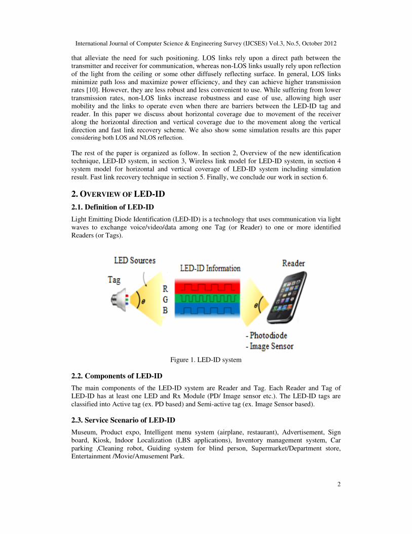
Light Emitting Diode Identification (LED-ID) is a technology that uses communication via light
waves to exchange voice/video/data among one Tag (or Reader) to one or more identified
Readers (or Tags).
Figure 1. LED-ID system
2.2. Components of LED-ID
The main components of the LED-ID system are Reader and Tag. Each Reader and Tag of
LED-ID has at least one LED and Rx Module (PD/ Image sensor etc.). The LED-ID tags are
classified into Active tag (ex. PD based) and Semi-active tag (ex. Image Sensor based).
2.3. Service Scenario of LED-ID
Museum, Product expo, Intelligent menu system (airplane, restaurant), Advertisement, Sign
board, Kiosk, Indoor Localization (LBS applications), Inventory management system, Car
parking ,Cleaning robot, Guiding system for blind person, Supermarket/Department store,
Entertainment /Movie/Amusement Park.
International Journal of Computer Science & Engineering Survey (IJCSES) Vol.3, No.5, October 2012
3
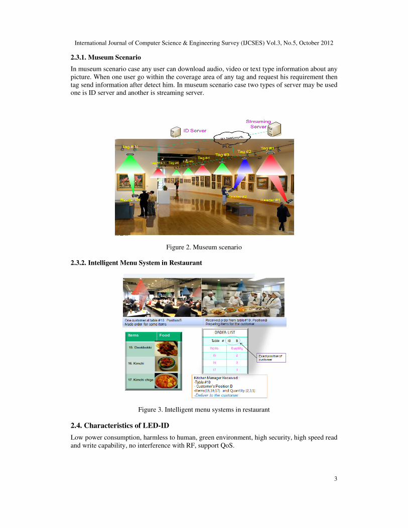
2.3.1. Museum Scenario
In museum scenario case any user can download audio, video or text type information about any
picture. When one user go within the coverage area of any tag and request his requirement then
tag send information after detect him. In museum scenario case two types of server may be used
one is ID server and another is streaming server.
Figure 2. Museum scenario
2.3.2. Intelligent Menu System in Restaurant
Figure 3. Intelligent menu systems in restaurant
2.4. Characteristics of LED-ID
Low power consumption, harmless to human, green environment, high security, high speed read
and write capability, no interference with RF, support QoS.

International Journal of Computer Science & Engineering Survey (IJCSES) Vol.3, No.5, October 2012
4
2.5. Comparison of ID Technologies
Bar Code RFID (Passive) LED-ID
Signal Format
(Transmission
medium)
Printed image RF
LED light (Visible
Light Infra-red Light
Ultra Violet Light
etc.
Reliability Wrinkled or smeared
labels will not be read
Nearly flawless
read rate Flawless read rate
Readable through
objects
No, must be line of
sight Yes
Depend on FOV
Read speed Slow Fast Variable Speed
Multiple tags No Yes (10-1000
tags per second)
Yes
Updateable No Yes Yes
Data type Non real-time Non real-time Non real-time and
real-time
Tag and reader
position
Scanner needs to see
the bar code to read it
No need to bring
the tag near the
reader
Need to bring within
the FOV
QoS No need Not support QoS Support QoS
Communication Half-duplex Duplex Duplex
Possibility to use
Existing Infrastructure No, New setup No, New setup
Yes, Existing
infrastructure may
be used
3. WIRELESS LINK MODEL FOR LED-ID SYSTEM
For a low cost LED-ID system, the most viable modulation is the intensity modulation (IM), in
which the desired waveform is modulated onto the instantaneous power of the carrier. On the
other hand, the most practical down-conversion technique is the direct detection (DD), in which
a photo-detector produces current proportional to the received instantaneous power [5-8]. Figure
4 shows the modelling of LED-ID system channels with IM/DD.
)( thη
Figure 4. Modeling of LED-ID System channel with IM/DD
International Journal of Computer Science & Engineering Survey (IJCSES) Vol.3, No.5, October 2012
5
Modeling a LED-ID link as a baseband linear, time-invariant system having impulse response
h�t�, with signal-independent additive noise ����.The visible-light channel is modeled as a
linear optical additive white Gaussian noise (AWGN) channel and summarized by the following
expression [10]. ���� � ���� � ��� � ���� �1� where I�t� is the photo-detector current, η represents the photo sensitivity of the photo-detector
(in A/W), ����is the instantaneous input power, the symbol “�” denotes convolution,
h�t�resembles the impulse response and N�t�is the AWGN. The time average transmitted
optical power P� is given by [3-7] [10]
� � ������ 12� �������� � �2�
where ���� ! 0 since the channel input power must be nonnegative.
The average received optical power P# generally can then be determined by $ � %�0�� �3� where %�0� � ' ��� ���� is the channel DC gain.
Here we consider line-of-sight (LOS) and non line-of-sight (NLOS) links.
3.1. LOS Case
In line of sight case the received power is determined by $()* � %()*�0� � �4� The channel dc gain H-./ can be determined by the following expression [10]
%()*�0� � 0�� � 1�12234 5678�9��:�;�<�;� 567�;� 0 = ; = ;>0 ?�7?@ ?A? B
where m is the order of Lambertian emission, A is the photo-detector area, D is the distance
between transmitter and receiver, φ is the angle of irradiance, ; is the angle of incidence, �:�;� is the signal transmission coefficient of an optical filter, <�;� is the gain of an optical
concentrator, and ψF is the receiver field-of-view (FOV). The order of Lambertian emission m
can be found from the equation, � � G HI 4HI�>J:K� where α is the transmitter beam angle. The gain
can be determined from the following expression [10]
<�;� � L M47�M4;> 0 = ; = ;>0 ?�7?@ ?A? B
where M denotes the internal refractive index of the optical concentrator.
3.2. NLOS Case with LOS
In NLOS case, let us consider the effect of reflective light by walls or other obstacles. The
received power is given by the channel DC gain on LOS and reflected path and reflected
path H#NO�0�.
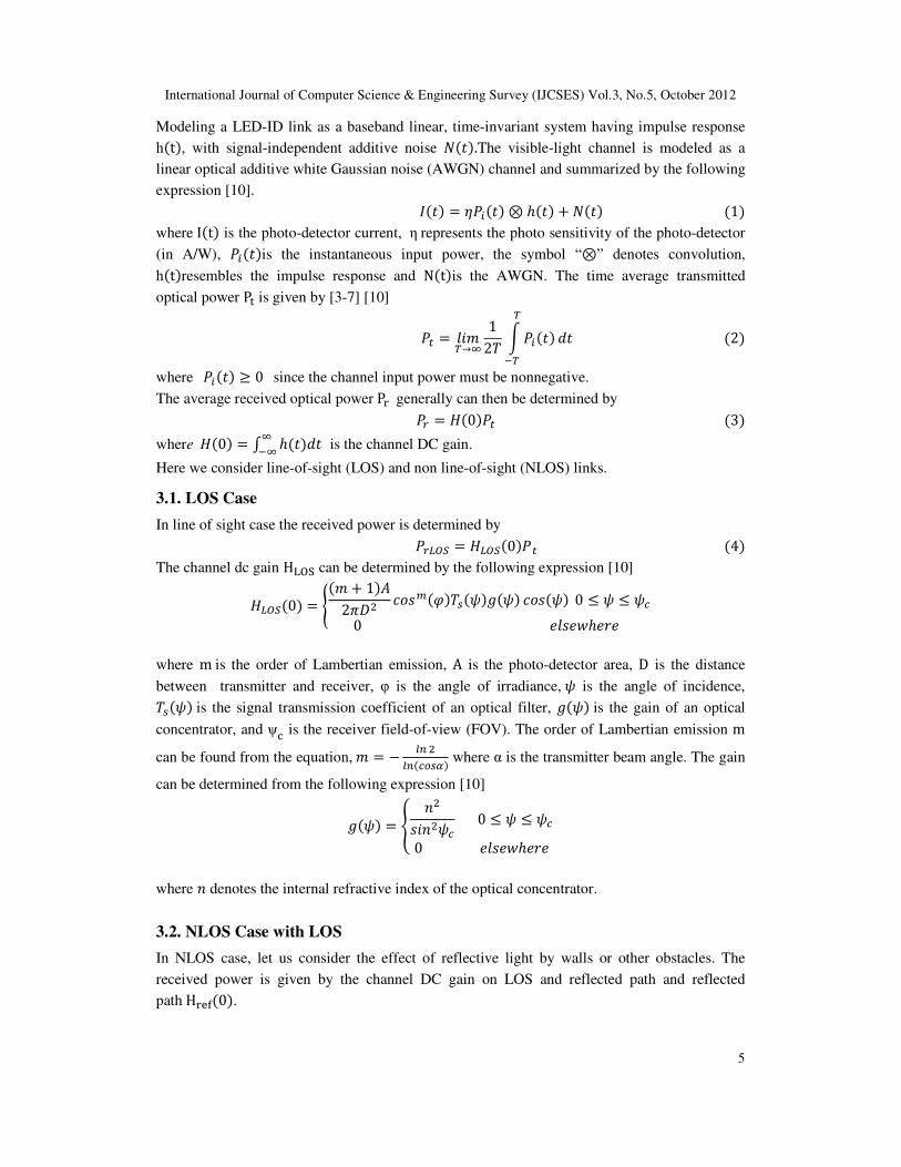
International Journal of Computer Science & Engineering Survey (IJCSES) Vol.3, No.5, October 2012
6
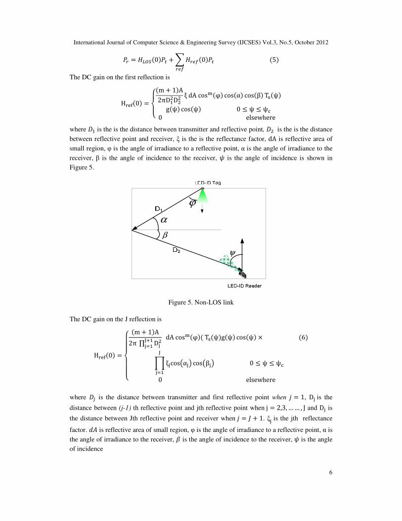
$ � %()*�0�� �P%$QR�0�� �5�$QR
The DC gain on the first reflection is
H#NO�0� � TUV�m � 1�A2πDX4D44 ξ dA cos^�φ� cos�α� cos�β� Tc�ψ�g�ψ� cos�ψ� 0 = ψ = ψF0 elsewhere
B where 3X is the is the distance between transmitter and reflective point, 34 is the is the distance
between reflective point and receiver, ξ is the is the reflectance factor, dA is reflective area of
small region, φ is the angle of irradiance to a reflective point, α is the angle of irradiance to the
receiver, β is the angle of incidence to the receiver, ; is the angle of incidence is shown in
Figure 5.
α
β
ψ
ϕ
Figure 5. Non-LOS link
The DC gain on the J reflection is
H#NO�0� �TjjUjjV�m� 1�A2π ∏ Dl4mnXloX dA cos^�φ�� Tc�ψ�g�ψ� cos�ψ� p �6�
rξlcossαlt cossβltmloX 0 = ψ = ψF0 elsewhere
B
where 3u is the distance between transmitter and first reflective point when v � 1, Dl is the
distance between (j-1) th reflective point and jth reflective point when j � 2,3,…… , J and Dl is
the distance between Jth reflective point and receiver when v � { � 1. ξl is the jth reflectance
factor. 1 is reflective area of small region, φ is the angle of irradiance to a reflective point, α is
the angle of irradiance to the receiver, | is the angle of incidence to the receiver, ; is the angle
of incidence
International Journal of Computer Science & Engineering Survey (IJCSES) Vol.3, No.5, October 2012
7
4. COVERAGE ANALYSIS OF LED-ID SYSTEM
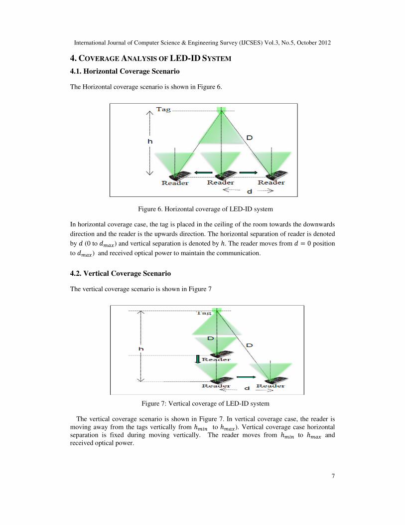
4.1. Horizontal Coverage Scenario
The Horizontal coverage scenario is shown in Figure 6.
Figure 6. Horizontal coverage of LED-ID system
In horizontal coverage case, the tag is placed in the ceiling of the room towards the downwards
direction and the reader is the upwards direction. The horizontal separation of reader is denoted
by (0 to 8}~) and vertical separation is denoted by . The reader moves from � 0 position
to 8}~) and received optical power to maintain the communication.
4.2. Vertical Coverage Scenario
The vertical coverage scenario is shown in Figure 7
Figure 7: Vertical coverage of LED-ID system
The vertical coverage scenario is shown in Figure 7. In vertical coverage case, the reader is
moving away from the tags vertically from 8�I to 8}~). Vertical coverage case horizontal
separation is fixed during moving vertically. The reader moves from 8�I to 8}~ and
received optical power.
International Journal of Computer Science & Engineering Survey (IJCSES) Vol.3, No.5, October 2012
8
4.3. Simulation and Performance
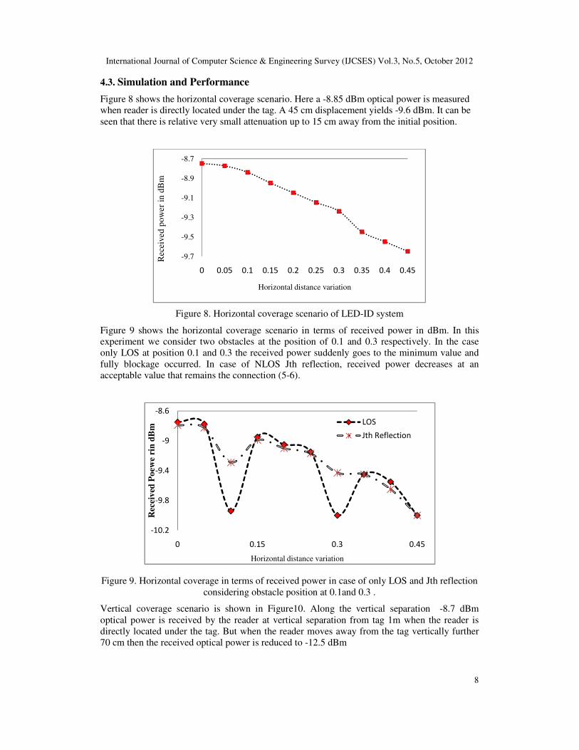
Figure 8 shows the horizontal coverage scenario. Here a -8.85 dBm optical power is measured
when reader is directly located under the tag. A 45 cm displacement yields -9.6 dBm. It can be
seen that there is relative very small attenuation up to 15 cm away from the initial position.
Figure 8. Horizontal coverage scenario of LED-ID system
Figure 9 shows the horizontal coverage scenario in terms of received power in dBm. In this
experiment we consider two obstacles at the position of 0.1 and 0.3 respectively. In the case
only LOS at position 0.1 and 0.3 the received power suddenly goes to the minimum value and
fully blockage occurred. In case of NLOS Jth reflection, received power decreases at an
acceptable value that remains the connection (5-6).
Figure 9. Horizontal coverage in terms of received power in case of only LOS and Jth reflection
considering obstacle position at 0.1and 0.3 .
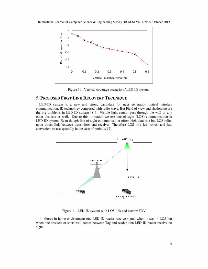
Vertical coverage scenario is shown in Figure10. Along the vertical separation -8.7 dBm
optical power is received by the reader at vertical separation from tag 1m when the reader is
directly located under the tag. But when the reader moves away from the tag vertically further
70 cm then the received optical power is reduced to -12.5 dBm
-9.7
-9.5
-9.3
-9.1
-8.9
-8.7
0 0.05 0.1 0.15 0.2 0.25 0.3 0.35 0.4 0.45
Rec
eived
pow
er i
n d
Bm
Horizontal distance variation
-10.2
-9.8
-9.4
-9
-8.6
0 0.15 0.3 0.45
Rec
eiv
ed P
oew
e ri
n d
Bm
Horizontal distance variation
LOS
Jth Reflection
International Journal of Computer Science & Engineering Survey (IJCSES) Vol.3, No.5, October 2012
9
Figure 10. Vertical coverage scenario of LED-ID system
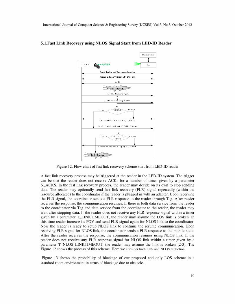
5. PROPOSED FIRST LINK RECOVERY TECHNIQUE
LED-ID system is a new and strong candidate for next generation optical wireless
communication, ID technology compared with radio wave. But Field of view and shadowing are
the big problems in LED-ID system [8-9]. Visible light cannot pass through the wall or any
other obstacle as well. Due to this limitation we use line of sight (LOS) communication in
LED-ID system. Even though line of sight communication offers high data rate but LOS relies
upon direct link between transmitter and receiver. Therefore LOS link less robust and less
convenient to use specially in the case of mobility [2].
Figure 11. LED-ID system with LOS link and narrow FOV
11 shows in home environment one LED-ID reader receive signal when it was in LOS but
when one obstacle or short wall comes between Tag and reader then LED-ID reader receive no
signal.
-12
-11
-10
-9
-8
-7
0 0.1 0.2 0.3 0.4 0.5 0.6
Rec
eiv
ed p
ow
er i
n d
Bm
Vertical distance variation
International Journal of Computer Science & Engineering Survey (IJCSES) Vol.3, No.5, October 2012
10
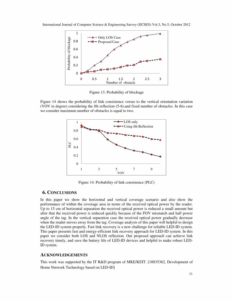
5.1.Fast Link Recovery using NLOS Signal Start from LED-ID Reader
Figure 12. Flow chart of fast link recovery scheme start from LED-ID reader
A fast link recovery process may be triggered at the reader in the LED-ID system. The trigger
can be that the reader does not receive ACKs for a number of times given by a parameter
N_ACKS. In the fast link recovery process, the reader may decide on its own to stop sending
data. The reader may optionally send fast link recovery (FLR) signal repeatedly (within the
resource allocated) to the coordinator if the reader is plugged in with an adapter. Upon receiving
the FLR signal, the coordinator sends a FLR response to the reader through Tag. After reader
receives the response, the communication resumes. If there is both data service from the reader
to the coordinator via Tag and data service from the coordinator to the reader, the reader may
wait after stopping data. If the reader does not receive any FLR response signal within a timer
given by a parameter T_LINKTIMEOUT, the reader may assume the LOS link is broken. In
this time reader increase its FOV and send FLR signal again for NLOS link to the coordinator.
Now the reader is ready to setup NLOS link to continue the resume communication. Upon
receiving FLR signal for NLOS link, the coordinator sends a FLR response to the mobile node.
After the reader receives the response, the communication resumes using NLOS link. If the
reader does not receive any FLR response signal for NLOS link within a timer given by a
parameter T_NLOS_LINKTIMEOUT, the reader may assume the link is broken [2-3]. The
Figure 12 shows the process of this scheme. Here we consider both LOS and NLOS reflection.
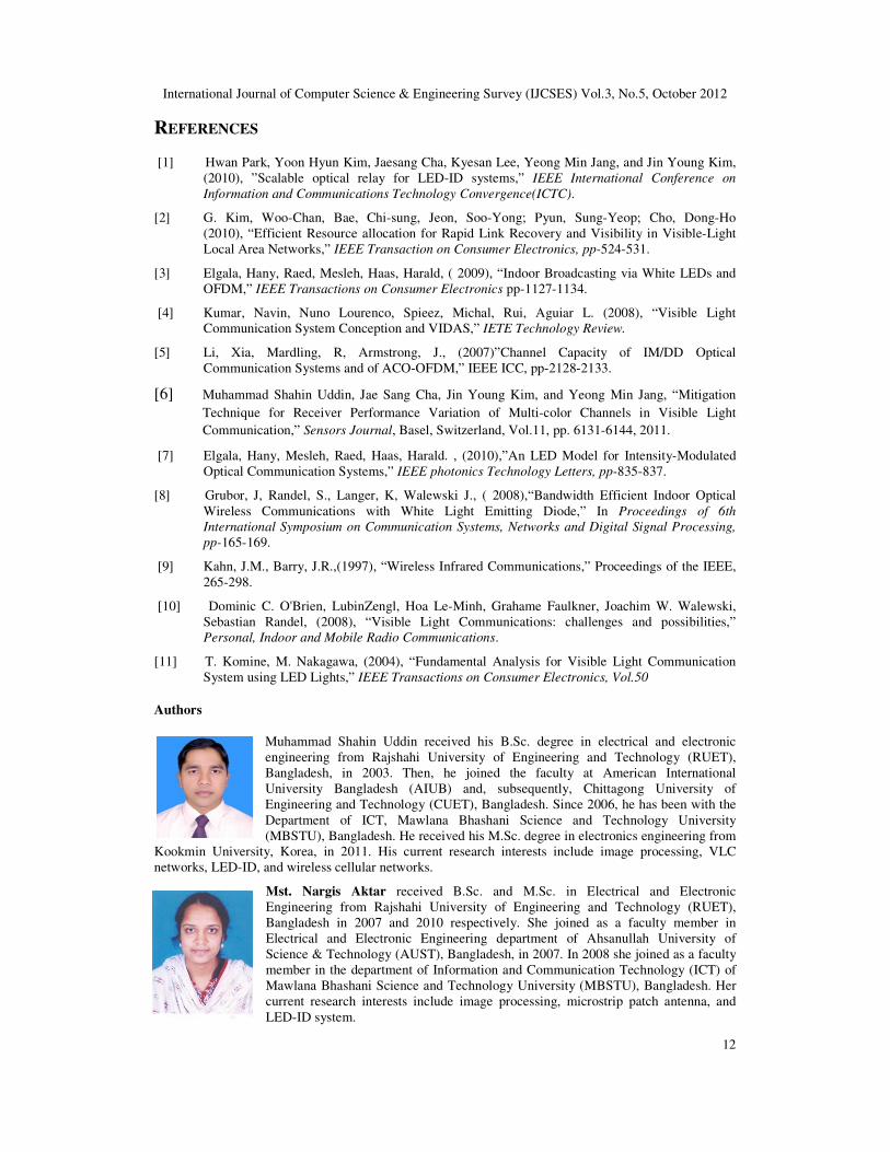
Figure 13 shows the probability of blockage of our proposed and only LOS scheme in a
standard room environment in terms of blockage due to obstacle.
International Journal of Computer Science & Engineering Survey (IJCSES) Vol.3, No.5, October 2012
11
Figure 13. Probability of blockage
Figure 14 shows the probability of link consistence versus to the vertical orientation variation
(VOV in degree) considering the Jth reflection (5-6).and fixed number of obstacles. In this case
we consider maximum number of obstacles is equal to two.
Figure 14. Probability of link consistence (PLC)
6. CONCLUSIONS
In this paper we show the horizontal and vertical coverage scenario and also show the
performance of within the coverage area in terms of the received optical power by the reader.
Up to 15 cm of horizontal separation the received optical power is reduced a small amount but
after that the received power is reduced quickly because of the FOV mismatch and half power
angle of the tag. In the vertical separation case the received optical power gradually decrease
when the reader moves away from the tag. Coverage analysis of this paper will helpful to design
the LED-ID system properly. Fast link recovery is a new challenge for reliable LED-ID system.
This paper presents fast and energy-efficient link recovery approach for LED-ID system. In this
paper we consider both LOS and NLOS reflection. Our proposed approach can achieve link
recovery timely, and save the battery life of LED-ID devices and helpful to make robust LED-
ID system.
ACKNOWLEDGEMENTS
This work was supported by the IT R&D program of MKE/KEIT. [10035362, Development of
Home Network Technology based on LED-ID]
0
0.2
0.4
0.6
0.8
1
0 0.5 1 1.5 2 2.5 3
Pro
bab
ilit
y o
f b
lock
age
Number of obstacle
Only LOS Case
Proposed Case
0
0.2
0.4
0.6
0.8
1
1 3 5 7 9
PL
C
VOV
LOS only
Using Jth Reflection
International Journal of Computer Science & Engineering Survey (IJCSES) Vol.3, No.5, October 2012
12
REFERENCES
[1] Hwan Park, Yoon Hyun Kim, Jaesang Cha, Kyesan Lee, Yeong Min Jang, and Jin Young Kim,
(2010), ”Scalable optical relay for LED-ID systems,” IEEE International Conference on
Information and Communications Technology Convergence(ICTC).
[2] G. Kim, Woo-Chan, Bae, Chi-sung, Jeon, Soo-Yong; Pyun, Sung-Yeop; Cho, Dong-Ho
(2010), “Efficient Resource allocation for Rapid Link Recovery and Visibility in Visible-Light
Local Area Networks,” IEEE Transaction on Consumer Electronics, pp-524-531.
[3] Elgala, Hany, Raed, Mesleh, Haas, Harald, ( 2009), “Indoor Broadcasting via White LEDs and
OFDM,” IEEE Transactions on Consumer Electronics pp-1127-1134.
[4] Kumar, Navin, Nuno Lourenco, Spieez, Michal, Rui, Aguiar L. (2008), “Visible Light
Communication System Conception and VIDAS,” IETE Technology Review.
[5] Li, Xia, Mardling, R, Armstrong, J., (2007)”Channel Capacity of IM/DD Optical
Communication Systems and of ACO-OFDM,” IEEE ICC, pp-2128-2133.
[6] Muhammad Shahin Uddin, Jae Sang Cha, Jin Young Kim, and Yeong Min Jang, “Mitigation
Technique for Receiver Performance Variation of Multi-color Channels in Visible Light
Communication,” Sensors Journal, Basel, Switzerland, Vol.11, pp. 6131-6144, 2011.
[7] Elgala, Hany, Mesleh, Raed, Haas, Harald. , (2010),”An LED Model for Intensity-Modulated
Optical Communication Systems,” IEEE photonics Technology Letters, pp-835-837.
[8] Grubor, J, Randel, S., Langer, K, Walewski J., ( 2008),“Bandwidth Efficient Indoor Optical
Wireless Communications with White Light Emitting Diode,” In Proceedings of 6th
International Symposium on Communication Systems, Networks and Digital Signal Processing,
pp-165-169.
[9] Kahn, J.M., Barry, J.R.,(1997), “Wireless Infrared Communications,” Proceedings of the IEEE,
265-298.
[10] Dominic C. O'Brien, LubinZengl, Hoa Le-Minh, Grahame Faulkner, Joachim W. Walewski,
Sebastian Randel, (2008), “Visible Light Communications: challenges and possibilities,”
Personal, Indoor and Mobile Radio Communications.
[11] T. Komine, M. Nakagawa, (2004), “Fundamental Analysis for Visible Light Communication
System using LED Lights,” IEEE Transactions on Consumer Electronics, Vol.50
Authors
Muhammad Shahin Uddin received his B.Sc. degree in electrical and electronic
engineering from Rajshahi University of Engineering and Technology (RUET),
Bangladesh, in 2003. Then, he joined the faculty at American International
University Bangladesh (AIUB) and, subsequently, Chittagong University of
Engineering and Technology (CUET), Bangladesh. Since 2006, he has been with the
Department of ICT, Mawlana Bhashani Science and Technology University
(MBSTU), Bangladesh. He received his M.Sc. degree in electronics engineering from
Kookmin University, Korea, in 2011. His current research interests include image processing, VLC
networks, LED-ID, and wireless cellular networks.
Mst. Nargis Aktar received B.Sc. and M.Sc. in Electrical and Electronic
Engineering from Rajshahi University of Engineering and Technology (RUET),
Bangladesh in 2007 and 2010 respectively. She joined as a faculty member in
Electrical and Electronic Engineering department of Ahsanullah University of
Science & Technology (AUST), Bangladesh, in 2007. In 2008 she joined as a faculty
member in the department of Information and Communication Technology (ICT) of
Mawlana Bhashani Science and Technology University (MBSTU), Bangladesh. Her
current research interests include image processing, microstrip patch antenna, and
LED-ID system.
International Journal of Computer Science & Engineering Survey (IJCSES) Vol.3, No.5, October 2012
13
Yeong Min Jang received the B.E. and M.E. degrees in electronics engineering from
Kyungpook National University, Korea, in 1985 and 1987, respectively. He received
the doctoral degree in computer science from the University of Massachusetts, USA, in
1999. He worked for ETRI between 1987 and 2000. Since 2002, he has been with the
School of Electrical Engineering, Kookmin University, Seoul, Korea. He has
organized several conferences such as ICUFN2009, ICUFN2010, and ICUFN2011 .
He is currently a member of the IEEE and Korea Information and Communications
Society (KICS). He received the Young Science Award from the Korean Government (2003–2006). He
had been the director of the Ubiquitous IT Convergence Center at Kookmin University since 2005. He
has served as the executive director of KICS since 2006. He has served as a founding chair of the KICS
Technical Committee on Communication Networks in 2007 and 2008. His research interests include,
RRM, femtocell networks, multi-screen convergence networks, VLC WPANs, and LED-ID system.