Lecture: Lagrangian Mechanics 1 1 Lecture: Lagrangian Mechanics
Upload
khangminh22Category
view
0download
0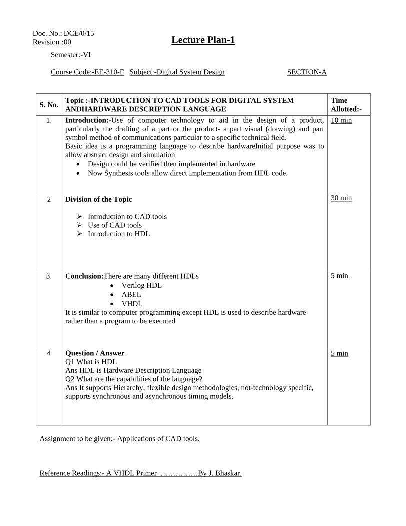
Lecture Plan-1
Semester:-VI Course Code:-EE-310-F Subject:-Digital System Design SECTION-A
S. No. Topic :-INTRODUCTION TO CAD TOOLS FOR DIGITAL SYSTEM ANDHARDWARE DESCRIPTION LANGUAGE
Time Allotted:-
1. Introduction:-Use of computer technology to aid in the design of a product, particularly the drafting of a part or the product- a part visual (drawing) and part symbol method of communications particular to a specific technical field. Basic idea is a programming language to describe hardwareInitial purpose was to allow abstract design and simulation
• Design could be verified then implemented in hardware • Now Synthesis tools allow direct implementation from HDL code.
10 min 30 min 5 min 5 min
2 Division of the Topic
Introduction to CAD tools Use of CAD tools Introduction to HDL
3. Conclusion:There are many different HDLs • Verilog HDL • ABEL • VHDL
It is similar to computer programming except HDL is used to describe hardware rather than a program to be executed
4 Question / Answer Q1 What is HDL Ans HDL is Hardware Description Language Q2 What are the capabilities of the language? Ans It supports Hierarchy, flexible design methodologies, not-technology specific, supports synchronous and asynchronous timing models.
Assignment to be given:- Applications of CAD tools. Reference Readings:- A VHDL Primer ……………By J. Bhaskar.
Doc. No.: DCE/0/15 Revision : 00
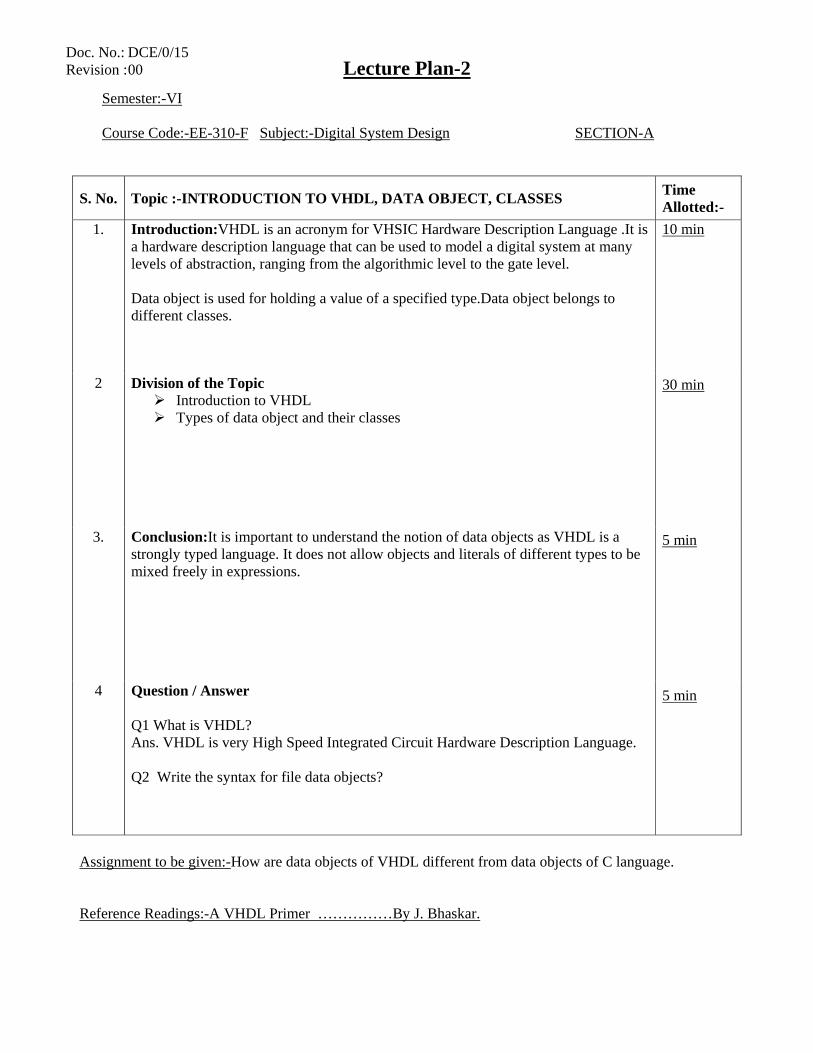
Lecture Plan-2
Semester:-VI Course Code:-EE-310-F Subject:-Digital System Design SECTION-A
S. No. Topic :-INTRODUCTION TO VHDL, DATA OBJECT, CLASSES Time Allotted:-
1. Introduction:VHDL is an acronym for VHSIC Hardware Description Language .It is a hardware description language that can be used to model a digital system at many levels of abstraction, ranging from the algorithmic level to the gate level. Data object is used for holding a value of a specified type.Data object belongs to different classes.
10 min 30 min 5 min 5 min
2 Division of the Topic Introduction to VHDL Types of data object and their classes
3. Conclusion:It is important to understand the notion of data objects as VHDL is a strongly typed language. It does not allow objects and literals of different types to be mixed freely in expressions.
4 Question / Answer Q1 What is VHDL? Ans. VHDL is very High Speed Integrated Circuit Hardware Description Language. Q2 Write the syntax for file data objects?
Assignment to be given:-How are data objects of VHDL different from data objects of C language. Reference Readings:-A VHDL Primer ……………By J. Bhaskar.
Doc. No.: DCE/0/15 Revision : 00
Lecture Plan-3
Semester:-VI Course Code:-EE-310-F Subject:-Digital System Design SECTION-A
S. No. Topic :-DATA TYPES Time Allotted:-
1. Introduction:VHDL object must be classified as being of a specific data type. Type has to be fixed when signal is declared, either as entity part or an internal architecture signal and cannot be changed during runtime
10 min 30 min 5 min 5 min
2 Division of the Topic Predefined Scalar Data Types IEEE standard 1164 Types of data type
3. Conclusion:. Data type is a name which is associated with a set of values and a set of operations.
4 Question / Answer Q1 Differentiate between sub and scalar types of data types? Q2 Enumerate the difference between data Objects and Data Types?
Assignment to be given:-What are identifiers and define types of identifier? Reference Readings:-A VHDL Primer ……………By J. Bhaskar.
Doc. No.: DCE/0/15 Revision : 00
Lecture Plan-4
Semester:-VI Course Code:-EE-310-F Subject:-Digital System Design SECTION-A
S. No. Topic :-OPERATORS AND LOGICAL OPERATORS Time Allotted:-
1. Introduction:- The predefined operators in the language are classified into the following six categories:
Logical Operators Relational Operators Shift Operators Adding Operators Multiplying Operators Miscellaneous Operators
10 min 30 min 5 min 5 min
2 Division of the Topic Operators:
Logical operators Relational Operators Shift Operators Adding Operators
3. Conclusion: The operators have increasing precedence going from category 1 to 6. Operators in the same category have the same precedence, and evaluation is done left to right.
4 Question / Answer Q1 Use shift left logical for 1001010 Ans 0101000 Q2 Use shift right logical for 1001010 Ans 0001001
Assignment to be given:- What do u mean by sign operators? Reference Readings:-A VHDL Primer ……………By J. Bhaskar.
Doc. No.: DCE/0/15 Revision : 00
Lecture Plan-5
Semester:-VI Course Code:-EE-310-F Subject:-Digital System Design SECTION-A
S. No. Topic :-OVERLOADING Time Allotted:-
1. Introduction: The multiplication and division operators are predefined for both operands being of the same integer or floating point type. The result is also of the same type. This leads to the concept of overloading
10 min 30 min 5 min 5 min
2 Division of the Topic
Types of Overloading Literal Overloading Subprogram Overloading Operator Overloading
3. Conclusion:- Overloading is not distinguished by subtypes and parameter modes These are very important in digital system design.
4 Question / Answer Q1 Explain the difference between operator Overloading and subprogramOverloading Q2 Give an example of lieral overloading.
Assignment to be given:- What is function overloading? Reference Readings:-A VHDL Primer ……………By J. Bhaskar.
Doc. No.: DCE/0/15 Revision : 00
Lecture Plan-6
Semester:-VI Course Code:-EE-310-F Subject:-Digital System Design SECTION-A
S. No. Topic :-Types of Delays-INERTIAL AND TRANSPORT DELAYS Time Allotted:-
1. Introduction:-Signal Assignment statement used inside a process illustrates the delta delay model. Aside from delta delay model, there are two other types of delay models that can be used with signal assignment :
Inertial Transport
10 min 30 min 5 min 5 min
2 Division of the Topic
Inertial and Transport Delays Syntax of Statement using Inertial Delay Syntax of Statement usingTransport Delay Examples and Waveforms
3. Conclusion: Inertial delay models the delays often used in switching circuits. Transport Delay models the delays in hardware that do not exhibit any inertial delay. This delay represents pure propagation delay.
4 Question / Answer Q1 Write the syntax and draw the waveform for inertial delay model. Q2 Draw the waveform for Z<= transport A after 10 ns
Assignment to be given:- In behavioral modeling, what are signal drivers? What is the effect of transport delay on signal drivers?
Doc. No.: DCE/0/15 Revision : 00
Lecture Plan-7
Semester:-VI Course Code:-EE-310-F Subject:-Digital System Design SECTION-A
S. No. Topic :-ENTITY AND ARCHITECTURE DECLARATION Time Allotted:-
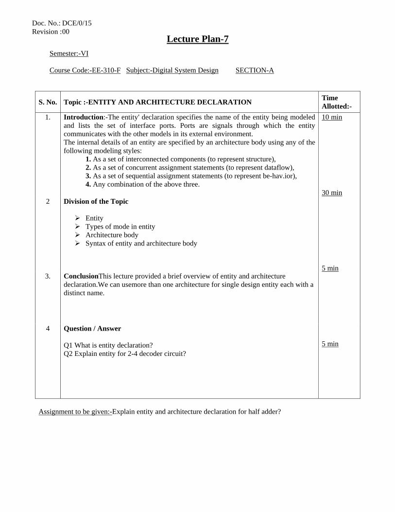
1. Introduction:-The entity' declaration specifies the name of the entity being modeled and lists the set of interface ports. Ports are signals through which the entity communicates with the other models in its external environment. The internal details of an entity are specified by an architecture body using any of the following modeling styles:
1. As a set of interconnected components (to represent structure), 2. As a set of concurrent assignment statements (to represent dataflow), 3. As a set of sequential assignment statements (to represent be-hav.ior), 4. Any combination of the above three.
10 min 30 min 5 min 5 min
2 Division of the Topic
Entity Types of mode in entity Architecture body Syntax of entity and architecture body
3. ConclusionThis lecture provided a brief overview of entity and architecture declaration.We can usemore than one architecture for single design entity each with a distinct name.
4 Question / Answer Q1 What is entity declaration? Q2 Explain entity for 2-4 decoder circuit?
Assignment to be given:-Explain entity and architecture declaration for half adder?
Doc. No.: DCE/0/15 Revision : 00
Lecture Plan-8
Semester:-VI Course Code:-EE-310-F Subject:-Digital System Design SECTION-A
S. No. Topic :-INTRODUCTION TO BEHAVIORAL , DATA FLOW AND STRUCTURALMODELS
Time Allotted:-
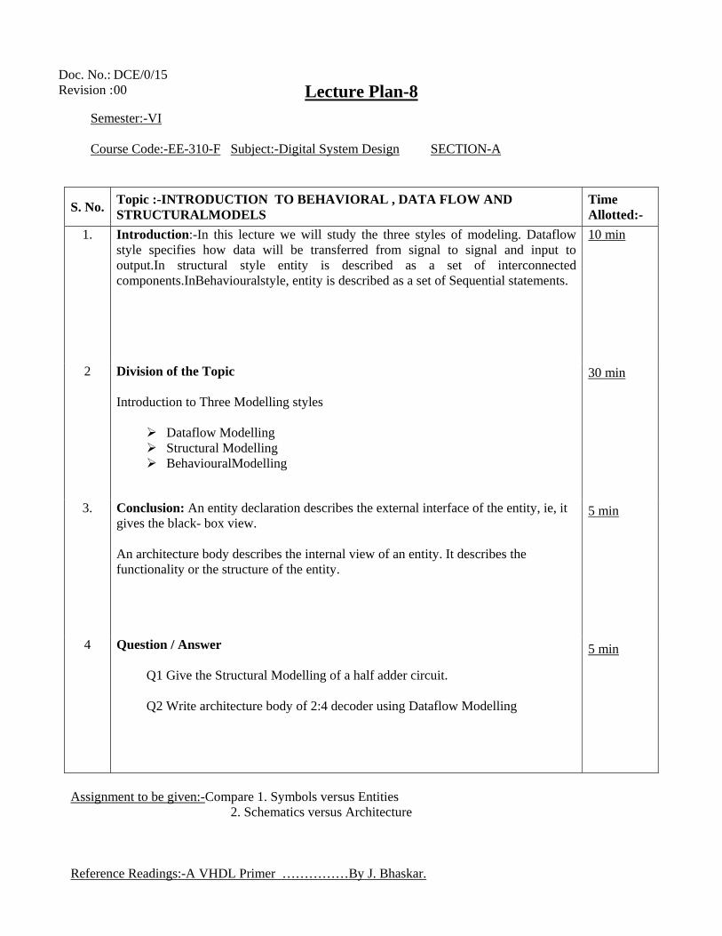
1. Introduction:-In this lecture we will study the three styles of modeling. Dataflow style specifies how data will be transferred from signal to signal and input to output.In structural style entity is described as a set of interconnected components.InBehaviouralstyle, entity is described as a set of Sequential statements.
10 min 30 min 5 min 5 min
2 Division of the Topic Introduction to Three Modelling styles
Dataflow Modelling Structural Modelling BehaviouralModelling
3. Conclusion: An entity declaration describes the external interface of the entity, ie, it gives the black- box view. An architecture body describes the internal view of an entity. It describes the functionality or the structure of the entity.
4 Question / Answer
Q1 Give the Structural Modelling of a half adder circuit. Q2 Write architecture body of 2:4 decoder using Dataflow Modelling
Assignment to be given:-Compare 1. Symbols versus Entities 2. Schematics versus Architecture Reference Readings:-A VHDL Primer ……………By J. Bhaskar.
Doc. No.: DCE/0/15 Revision : 00
Lecture Plan-9
Semester:-VI Course Code:-EE-310-F Subject:-Digital System Design SECTION-B
S. No. Topic :-ASSIGNMENT STATEMENTS AND SEQUENTIAL STATEMENTS Time Allotted:-
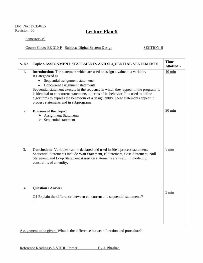
1. Introduction:-The statement which are used to assign a value to a variable. It Categorized as
• Sequential assignment statements • Concurrent assignment statements
Sequential statement execute in the sequence in which they appear in the program. It is identical to concurrent statements in terms of its behavior. It is used to define algorithms to express the behaviour of a design entity.These statements appear in process statements and in subprograms
10 min 30 min 5 min 5 min
2 Division of the Topic: Assignment Statements Sequential statement
3. Conclusion:- Variables can be declared and used inside a process statement. Sequential Statements include Wait Statement, If Statement, Case Statement, Null Statement, and Loop Statement.Assertion statements are useful in modeling constraints of an entity.
4 Question / Answer Q1 Explain the difference between concurrent and sequential statements? .
Assignment to be given:-What is the difference between function and procedure? Reference Readings:-A VHDL Primer ……………By J. Bhaskar.
Doc. No.: DCE/0/15 Revision : 00
Lecture Plan-10
Semester:-VI Course Code:-EE-310-F Subject:-Digital System Design SECTION-B
S. No. Topic :-PROCESS STATEMENTS Time Allotted:-
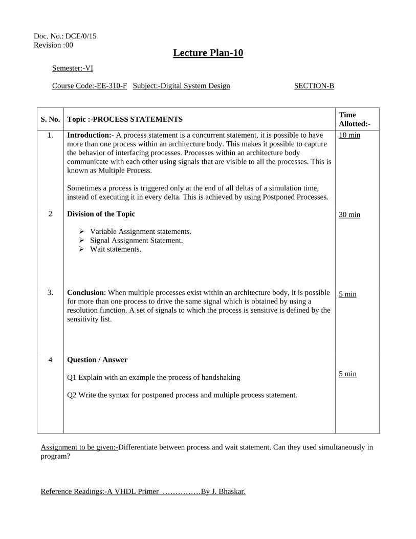
1. Introduction:- A process statement is a concurrent statement, it is possible to have more than one process within an architecture body. This makes it possible to capture the behavior of interfacing processes. Processes within an architecture body communicate with each other using signals that are visible to all the processes. This is known as Multiple Process. Sometimes a process is triggered only at the end of all deltas of a simulation time, instead of executing it in every delta. This is achieved by using Postponed Processes.
10 min 30 min 5 min 5 min
2 Division of the Topic
Variable Assignment statements. Signal Assignment Statement. Wait statements.
3. Conclusion: When multiple processes exist within an architecture body, it is possible for more than one process to drive the same signal which is obtained by using a resolution function. A set of signals to which the process is sensitive is defined by the sensitivity list.
4 Question / Answer Q1 Explain with an example the process of handshaking Q2 Write the syntax for postponed process and multiple process statement.
Assignment to be given:-Differentiate between process and wait statement. Can they used simultaneously in program? Reference Readings:-A VHDL Primer ……………By J. Bhaskar.
Doc. No.: DCE/0/15 Revision : 00
Lecture Plan-11
Semester:-VI Course Code:-EE-310-F Subject:-Digital System Design SECTION-B
S. No. Topic :-CONDITIONAL AND CASE STEATEMENTS Time Allotted:-
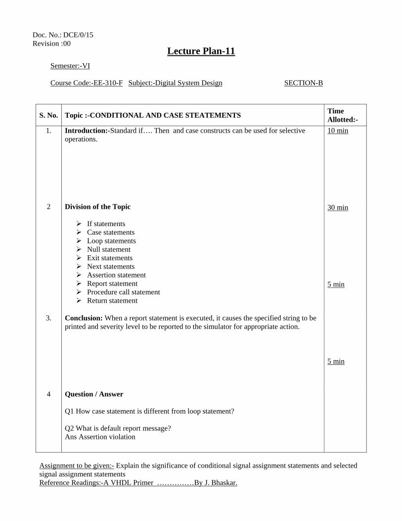
1. Introduction:-Standard if…. Then and case constructs can be used for selective operations.
10 min 30 min 5 min 5 min
2 Division of the Topic
If statements Case statements Loop statements Null statement Exit statements Next statements Assertion statement Report statement Procedure call statement Return statement
3. Conclusion: When a report statement is executed, it causes the specified string to be
printed and severity level to be reported to the simulator for appropriate action.
4 Question / Answer Q1 How case statement is different from loop statement? Q2 What is default report message? Ans Assertion violation
Assignment to be given:- Explain the significance of conditional signal assignment statements and selected signal assignment statements Reference Readings:-A VHDL Primer ……………By J. Bhaskar.
Doc. No.: DCE/0/15 Revision : 00
Lecture Plan-12
Semester:-VI Course Code:-EE-310-F Subject:-Digital System Design SECTION-B
S. No. Topic :-ARRAY AND LOOPS Time Allotted:-
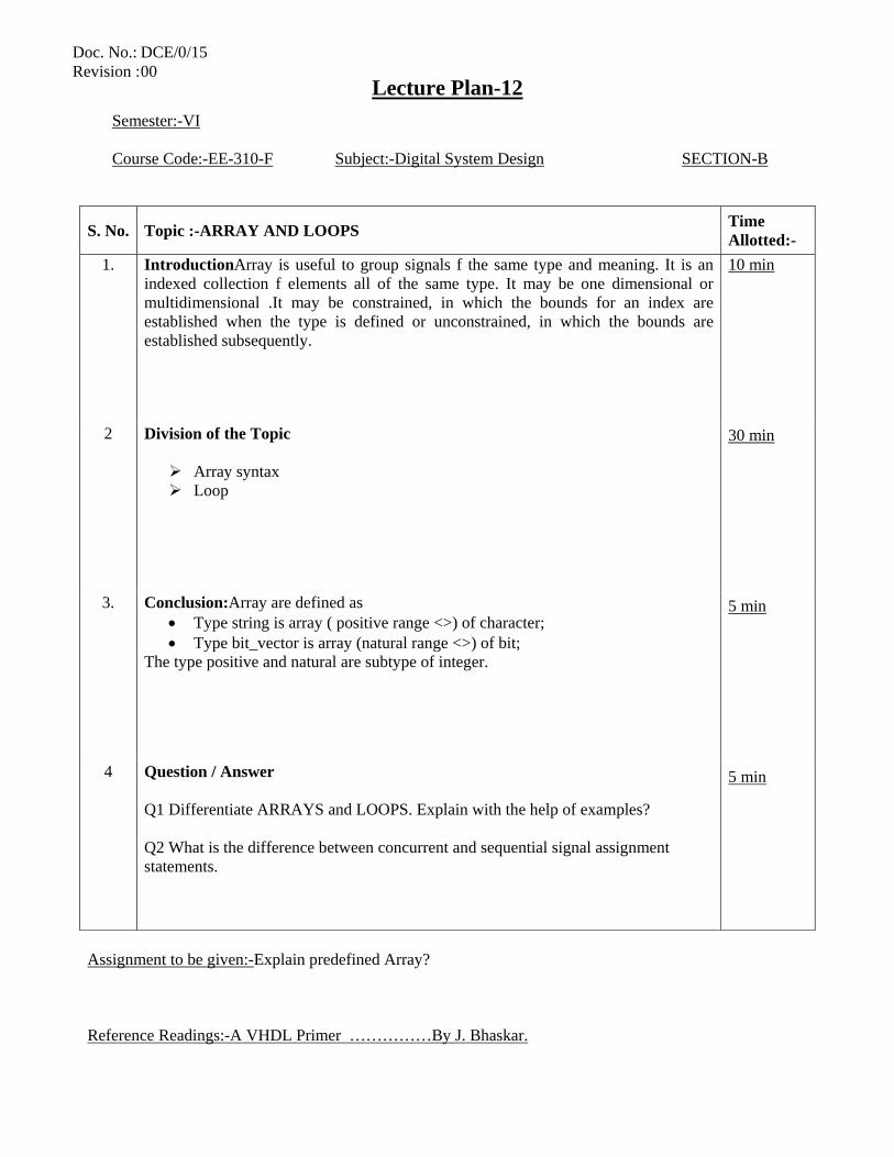
1. IntroductionArray is useful to group signals f the same type and meaning. It is an indexed collection f elements all of the same type. It may be one dimensional or multidimensional .It may be constrained, in which the bounds for an index are established when the type is defined or unconstrained, in which the bounds are established subsequently.
10 min 30 min 5 min 5 min
2 Division of the Topic
Array syntax Loop
3. Conclusion:Array are defined as • Type string is array ( positive range <>) of character; • Type bit_vector is array (natural range <>) of bit;
The type positive and natural are subtype of integer.
4 Question / Answer Q1 Differentiate ARRAYS and LOOPS. Explain with the help of examples? Q2 What is the difference between concurrent and sequential signal assignment statements.
Assignment to be given:-Explain predefined Array? Reference Readings:-A VHDL Primer ……………By J. Bhaskar.
Doc. No.: DCE/0/15 Revision : 00
Lecture Plan-13
Semester:-VI Course Code:-EE-310-F Subject:-Digital System Design SECTION-B
S. No. Topic :-RESOLUTION FUNCTION Time Allotted:-
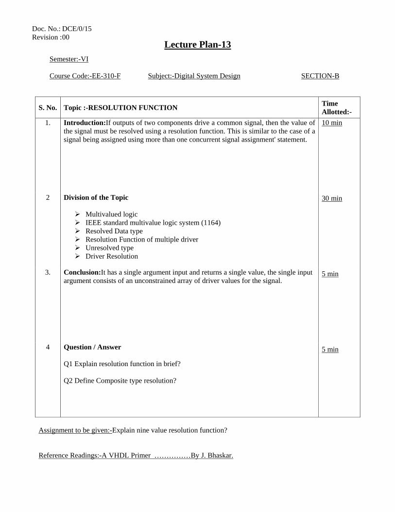
1. Introduction:If outputs of two components drive a common signal, then the value of the signal must be resolved using a resolution function. This is similar to the case of a signal being assigned using more than one concurrent signal assignment' statement.
10 min 30 min 5 min 5 min
2 Division of the Topic
Multivalued logic IEEE standard multivalue logic system (1164) Resolved Data type Resolution Function of multiple driver Unresolved type Driver Resolution
3. Conclusion:It has a single argument input and returns a single value, the single input argument consists of an unconstrained array of driver values for the signal.
4 Question / Answer Q1 Explain resolution function in brief? Q2 Define Composite type resolution?
Assignment to be given:-Explain nine value resolution function? Reference Readings:-A VHDL Primer ……………By J. Bhaskar.
Doc. No.: DCE/0/15 Revision : 00
Lecture Plan-14
Semester:-VI Course Code:-EE-310-F Subject:-Digital System Design SECTION-B
S. No. Topic :-PACKAGES AND LIBRARIES Time Allotted:-
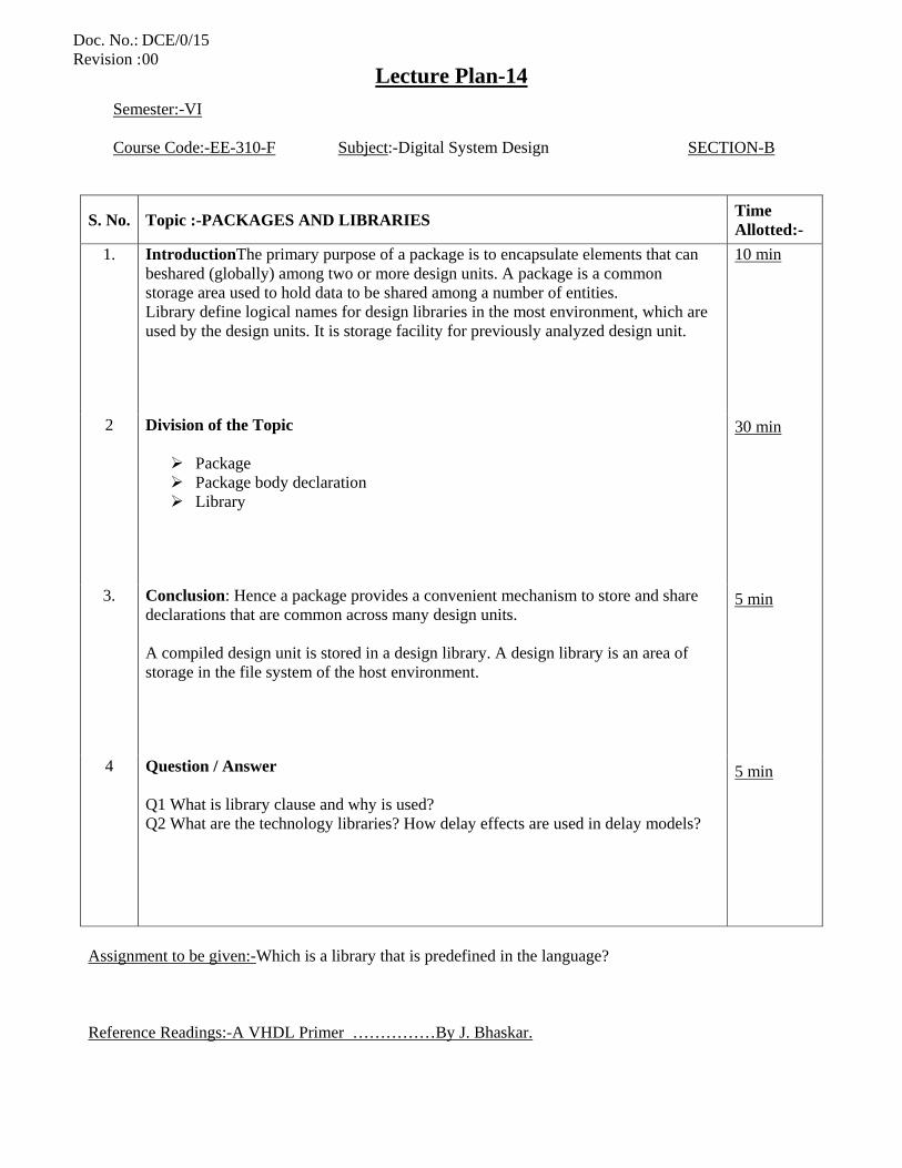
1. IntroductionThe primary purpose of a package is to encapsulate elements that can beshared (globally) among two or more design units. A package is a common storage area used to hold data to be shared among a number of entities. Library define logical names for design libraries in the most environment, which are used by the design units. It is storage facility for previously analyzed design unit.
10 min 30 min 5 min 5 min
2 Division of the Topic
Package Package body declaration Library
3. Conclusion: Hence a package provides a convenient mechanism to store and share declarations that are common across many design units. A compiled design unit is stored in a design library. A design library is an area of storage in the file system of the host environment.
4 Question / Answer Q1 What is library clause and why is used? Q2 What are the technology libraries? How delay effects are used in delay models?
Assignment to be given:-Which is a library that is predefined in the language? Reference Readings:-A VHDL Primer ……………By J. Bhaskar.
Doc. No.: DCE/0/15 Revision : 00
Lecture Plan-15
Semester:-VI Course Code:-EE-310-F Subject:-Digital System Design SECTION-B
S. No. Topic :-CONCURRENT STATEMENTS Time Allotted:-
1. Introduction Data flow modeling specifies the functionality of the entity without explicitly specifying its structure. This functionality shows the flow of information through the entity, which is expressed using concurrent signal assignment statements and block statements.
10 min 30 min 5 min 5 min
2 Division of the Topic
Data Flow Modeling- Concurrent Signal Assignment Statements Concurrent versus Sequential Signal Assignment Statements
3. Conclusion: Hence signal assignment statements can also appear within the body of a process statement. Such statements are called sequential signal assignment statements, while signal assignment statements that appear outside of a process are called concurrent signal assignment statements.
4 Question / Answer Q1 Do the data flow modeling for OR gate. Q2 What is the difference between concurrent and sequential signal assignment statements.
Assignment to be given:-NIL Reference Readings:-A VHDL Primer ……………By J. Bhaskar.
Doc. No.: DCE/0/15 Revision : 00
Lecture Plan-16
Semester:-VI Course Code:-EE-310-F Subject:-Digital System Design SECTION-B
S. No. Topic :-SUBPROGRAMS: APPLICATION OF FUNCTIONS AND PROCEDURES
Time Allotted:-
1. IntroductionA subprogram defines a sequential algorithm that performs a certain computation and executes in zero simulation time. There are two kinds of subprograms:
1. Functions: These are usually used for computing a single value. 2. Procedures: These are used to partition large behavioral descriptions.
Procedures can return zero or more values.A subprogram is defined using a subprogram body.
10 min 30 min 5 min 5 min
2 Division of the Topic
Syntax of Subprogram Application of function Application of procedures
3. Conclusion:Thesubprogram-specification specifies the name of a subprogram and defines its interface, that is, it defines the formal parameter names, their class (i.e., signal, variable, or constant), their type, and their mode (whether they are in, out, or inout). Parameters of mode in are read-only parameters; these cannot be updated within a subprogram body. Parameters of mode out are write-only parameters; their values cannot be used but can only be updated within a subprogram body. Parameters of mode inout can be read as well as updated. .
4 Question / Answer Q1 What is the difference between function and procedures?
Assignment to be given:-Define subprogram body declaration? Reference Readings:-A VHDL Primer ……………By J. Bhaskar.
Doc. No.: DCE/0/15 Revision : 00
Lecture Plan-17
Semester:-VI Course Code:-EE-310-F Subject:-Digital System Design SECTION-B
S. No. Topic :-STRUCTURAL MODELLING AND STRUCTURAL LAYOUT Time Allotted:-
1. Introduction In Structural style of modeling an entity is modeled as a set of components connected by signals. The behavior of the entity is not explicitly apparent from its model. The component instantiation statement is the primary mechanism used for describing such a model of an entity.
10 min 30 min 5 min 5 min
2 Division of the Topic
Structural Modeling- Component Declaration Component Instantiation
3. Conclusion: A component declaration declares the name and the interface of a component. The interface specifies the mode and the type of ports. A component instantiation statement defines a subcomponent of the entity in which it appears. It associates the signals in the entity with the ports of that subcomponent.
4 Question / Answer Q1 Do the structural modeling of D flip flop.
Assignment to be given:-NIL Reference Readings:-A VHDL Primer ……………By J. Bhaskar.
Doc. No.: DCE/0/15 Revision : 00
Lecture Plan-18
Semester:-VI Course Code:-EE-310-F Subject:-Digital System Design SECTION-B
S. No. Topic :-COMPONENT DECLARATION Time Allotted:-
1. Introduction: The component declaration declares the interface of the component to the architecture.It is necessary if the component interface is not declared elsewhere (package, library).
10 min 30 min 5 min 5 min
2 Division of the Topic
Component Declaration Component instantiate
3. Conclusion: A component instantiated in a structural description must first be declared using a component declaration. A component declaration declares the name and the interface of a component. The interface specifies the mode and the type of ports.
4 Question / Answer Q1 How you will compare components declaration and component instantiation?
Assignment to be given:-NIL Reference Readings:-A VHDL Primer ……………By J. Bhaskar.
Doc. No.: DCE/0/15 Revision : 00
Lecture Plan-19
Semester:-VI Course Code:-EE-310-F Subject:-Digital System Design SECTION -B
S. No. Topic :-GENERICS Time Allotted:-
1. Introduction: In this lecture we will discuss about generics and how certain types of information can be passed into an entity using generics. Information is of the type rise and fall delays and the size of interface ports. Generics of an entity are declared along with its ports in the entity declaration.
10 min 30 min 5 min 5 min
2 Division of the Topic
Generics
3. Conclusion: Hence the value for a generic may be specified in the entity declaration for an entity or it may also be specified in a configuration specification or in a configuration declaration. Generics can also be used to control the number of instantiations of a component in a generate statement.
4 Question / Answer Q1 Where the value of generic can be specified? Ans Entity declaration, Component Declaration, Component Instantiation. Q2 How the default value of generic can be overridden? Ans It can be overridden by specifying it again at component instantiation.
Assignment to be given:-NIL Reference Readings:-A VHDL Primer ……………By J. Bhaskar.
Doc. No.: DCE/0/15 Revision : 00
Lecture Plan-20
Semester:-VI Course Code:-EE-310-F Subject:-Digital System Design SECTION- C
S. No. Topic :-VHDL MODELS AND SIMULATION OF COMBINATIONAL CIRCUITS SUCH AS MULTIPLEXER,DEMULTIPLEXER,ENCODER
Time Allotted:-
1. Introduction: In the combinational logic circuit the no of o/ps are more than no of i/ps. The o/p at any time depends only on the i/p at that very time.
10 min 30 min 5 min 5 min
2 Division of the Topic
Combinational Circuit Design- Minimization of State Table
3. Conclusion: Combinational circuits which consists of i/p variable, logic gates & o/p variables. On receiving i/p signals the logic gates generate the o/p.
4 Question / Answer Q1 Draw the circuit for 8:1 multiplexer. Q2 How a decoder circuit can be converted to a demultiplexer.
Assignment to be given:-NIL
Doc. No.: DCE/0/15 Revision : 00
Lecture Plan-21
Semester:-VI Course Code:-EE-310-F Subject:-Digital System Design SECTION-C
S. No. Topic :- VHDL MODELS AND SIMULATION OF COMBINATIONAL CIRCUITS SUCH AS DECODER, CODE CONVERTERS, COMPARATORS
Time Allotted:-
1. Introduction: The combinational logic circuit the no of o/ps are more than no of i/ps. The o/p at any time depends only i/p at that very time.
10 min 30 min 5 min 5 min
2 Division of the Topic
State Diagram s of Combinational Circuits and VHDL Code of Combinational Circuits
3. Conclusion: Combinational circuits which consists of i/p variable, logic gates & o/p variables. On receiving i/p signals the logic gates generate the o/p.
4 Question / Answer Q1 Write the VHDL Code for decoder Q2 Write the VHDL Code for code convertor.
Assignment to be given:-NIL Reference Readings:-A VHDL Primer ……………By J. Bhaskar.
Doc. No.: DCE/0/15 Revision : 00
Lecture Plan-22
Semester:-VI Course Code:-EE-310-F Subject:-Digital System Design SECTION-C
S. No. Topic :-IMPLEMENTATION OF BOOLEAN FUNCTION AND SIMULATION OF SEQUENTIAL CIRCUITS –SHIFT REGISTERS
Time Allotted:-
1. Introduction: In sequential logic circuit O/Ps are directly or indirectly fed to I/P. Here O/P is delayed & there is feedback of O/P to I/P , hence at any instant O/P depends on past & present I/Ps.
10 min 30 min 5 min 5 min
2 Division of the Topic
Sequential Circuit Design- Study of Sequential circuits
3. Conclusion: These sequential circuits are designed by concept of combinational logic ckt& Boolean algebra. The delayed o/ps which are connected to i/ps act as memories.
4 Question / Answer Q1-For transmitting whole data at the same time which mode you will use? A1-parallel data transmission mode. Q2-what is the difference b/w synchronous & asynchronous operation? A2-Synchronous circuits work only on the arrival of clock pulse, asynchronous do not need clock for its working.
Assignment to be given:-Model and simulate 4-bit bidirectional shift register.Assume the counter is
1. SIPO 2. PISO mode Reference Readings:-Morismano, R P Jain
Doc. No.: DCE/0/15 Revision : 00
Lecture Plan-23
Semester:-VI Course Code:-EE-310-F Subject:-Digital System Design SECTION-C
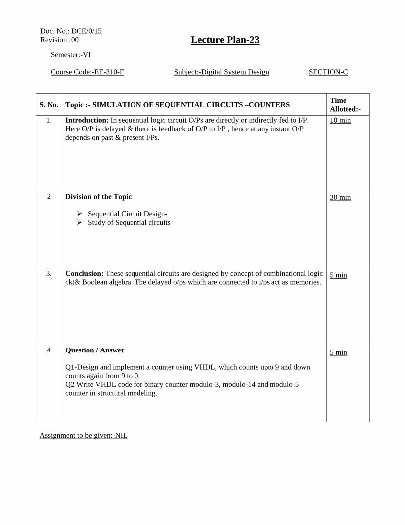
S. No. Topic :- SIMULATION OF SEQUENTIAL CIRCUITS –COUNTERS Time Allotted:-
1. Introduction: In sequential logic circuit O/Ps are directly or indirectly fed to I/P. Here O/P is delayed & there is feedback of O/P to I/P , hence at any instant O/P depends on past & present I/Ps.
10 min 30 min 5 min 5 min
2 Division of the Topic
Sequential Circuit Design- Study of Sequential circuits
3. Conclusion: These sequential circuits are designed by concept of combinational logic ckt& Boolean algebra. The delayed o/ps which are connected to i/ps act as memories.
4 Question / Answer Q1-Design and implement a counter using VHDL, which counts upto 9 and down counts again from 9 to 0. Q2 Write VHDL code for binary counter modulo-3, modulo-14 and modulo-5 counter in structural modeling.
Assignment to be given:-NIL
Doc. No.: DCE/0/15 Revision : 00
Lecture Plan-24
Semester:-VI Course Code:-EE-310-F Subject:-Digital System Design SECTION-D
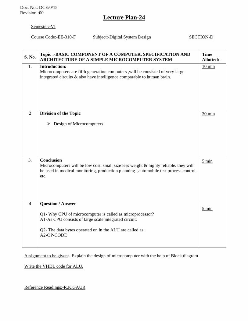
S. No. Topic :-BASIC COMPONENT OF A COMPUTER, SPECIFICATION AND ARCHITECTURE OF A SIMPLE MICROCOMPUTER SYSTEM
Time Allotted:-
1. Introduction: Microcomputers are fifth generation computers ,will be consisted of very large integrated circuits & also have intelligence comparable to human brain.
10 min 30 min 5 min 5 min
2 Division of the Topic
Design of Microcomputers
3. Conclusion Microcomputers will be low cost, small size less weight & highly reliable. they will be used in medical monitoring, production planning ,automobile test process control etc.
4 Question / Answer Q1- Why CPU of microcomputer is called as microprocessor? A1-As CPU consists of large scale integrated circuit. Q2- The data bytes operated on in the ALU are called as: A2-OP-CODE
Assignment to be given:- Explain the design of microcomputer with the help of Block diagram. Write the VHDL code for ALU. Reference Readings:-R.K.GAUR
Doc. No.: DCE/0/15 Revision : 00
Lecture Plan-25
Semester:-VI Course Code:-EE-310-F Subject:-Digital System Design SECTION-D
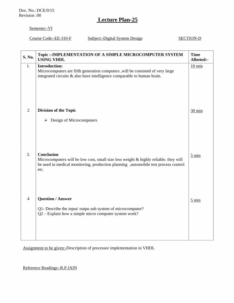
S. No. Topic :-IMPLEMENTATION OF A SIMPLE MICROCOMPUTER SYSTEM USING VHDL
Time Allotted:-
1. Introduction: Microcomputers are fifth generation computers ,will be consisted of very large integrated circuits & also have intelligence comparable to human brain.
10 min 30 min 5 min 5 min
2 Division of the Topic
Design of Microcomputers
3. Conclusion Microcomputers will be low cost, small size less weight & highly reliable. they will be used in medical monitoring, production planning ,automobile test process control etc.
4 Question / Answer Q1- Describe the input/ outpu sub system of microcomputer? Q2 – Explain how a simple micro computer system work?
Assignment to be given:-Description of processor implementation in VHDL Reference Readings:-R.P.JAIN
Doc. No.: DCE/0/15 Revision : 00
Lecture Plan-26
Semester:-VI Course Code:-EE-310-F Subject:-Digital System Design SECTION-D
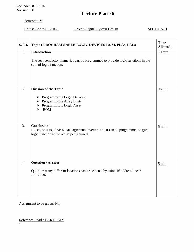
S. No. Topic :-PROGRAMMABLE LOGIC DEVICES-ROM, PLAs, PALs Time Allotted:-
1. Introduction The semiconductor memories can be programmed to provide logic functions in the sum of logic function.
10 min 30 min 5 min 5 min
2 Division of the Topic
Programmable Logic Devices. Programmable Array Logic Programmable Logic Array ROM
3. Conclusion PLDs consists of AND-OR logic with inverters and it can be programmed to give logic function at the o/p as per required.
4 Question / Answer Q1- how many different locations can be selected by using 16 address lines? A1-65536
Assignment to be given:-Nil Reference Readings:-R.P.JAIN \
Doc. No.: DCE/0/15 Revision : 00
Lecture Plan-27
Semester:-VI Course Code:-EE-310-F Subject:-Digital System Design SECTION-D
S. No. Topic :-PROGRAMMABLE LOGIC DEVICES- GAL, PEEL Time Allotted:-
1. Introduction The semiconductor memories can be programmed to provide logic functions in the sum of logic function.
10 min 30 min 5 min 5 min
2 Division of the Topic
GAL PEEL
3. Conclusion PLDs consists of AND-OR logic with inverters and it can be programmed to give logic function at the o/p as per required.
4 Question / Answer Q1- Collect the comparative and contrasting statement between PAL, PLA and GAL
Assignment to be given:-Nil Reference Readings:-R.P.JAIN
Doc. No.: DCE/0/15 Revision : 00
Lecture Plan-28
Semester:-VI Course Code:-EE-310-F Subject:-Digital System Design SECTION-D
S. No. Topic :- CPLDs, FPGAs, AND DESIGN IMPLEMENTATION USING CPLDs AND FPGAs
Time Allotted:-
1. Introduction In System Programming method is used
• LUTs contain volatile storage cells • None of the other PLD technologies are volatile • FPGA storage cells are loaded via a PROM when power is first applied
10 min 30 min 5 min 5 min
2 Division of the Topic
FPGA CPLD
3. Conclusion: CPLDs contain multiple circuit blocks on a single chip • Each block is like a PAL: PAL-like block • Connections are provided between PAL-like blocks via an
interconnection network that is programmable
4 Question / Answer Q1- Short notes on FPGA
Assignment to be given:-Nil Reference Readings:-R.P.JAIN
Doc. No.: DCE/0/15 Revision : 00
Copyright © 2022 FDOKUMEN