Lecture 4 – Finite State Machines
35
Lecture 4 – Finite State Machines 1 1/4/2021
-
Upload
khangminh22 -
Category
Documents
-
view
0 -
download
0
Transcript of Lecture 4 – Finite State Machines

Lecture 4 – Finite State Machines
1 1/4/2021

Modeling Finite State Machines (FSMs) “Manual” FSM design & synthesis process:
1. Design state diagram (behavior)2. Derive state table3. Reduce state table4. Choose a state assignment5. Derive output equations6. Derive flip-flop excitation equations
Steps 2-6 can be automated, given a state diagram1. Model states as enumerated type2. Model output function (Mealy or Moore model)3. Model state transitions (functions of current state and inputs)4. Consider how initial state will be forced
2 1/4/2021

FSM structure
CombinationalCircuit
Memory Elements
InputsX
OutputsY
Next State(NS)
Present State(PS)
Clock
3 1/4/2021

Mealy Machine and Moore Machine
1/4/20214
Next StateCombinational
Logic
Inputs StateRegister
OutputsOutput
CombinationalLogic
clock
Moore Machine
Next StateCombinational
Logic
InputsState
Register
OutputsOutput
CombinationalLogic
clock
Mealy Machine

FSM example – Mealy model
B/0 C/1 A/1
0/0
1/1 1/0
1/1
0/0
0/0X/Z Present
stateInput x
0 1
Next state/output
A/0 A/0 C/0
A B C
A
BC
entity seqckt isport ( x: in std_logic; -- FSM input
z: out std_logic; -- FSM outputclk: in std_logic ); -- clock
end seqckt;5 1/4/2021

FSM example - behavioral modelarchitecture behave of seqckt is
type states is (A,B,C); -- symbolic state names (enumerate)signal state: states; --state variable
begin
-- Output function (combinational logic)z <= ‘1’ when ((state = B) and (x = ‘1’)) --all conditions
or ((state = C) and (x = ‘1’)) --for which z=1.else ‘0’; --otherwise z=0
-- State transitions on next slide
6 1/4/2021

FSM example – state transitionsprocess (clk) – trigger state change on clock transition
beginif rising_edge(clk) then -- change state on rising clock edge
case state is -- change state according to xwhen A => if (x = ‘0’) then
state <= A;else -- if (x = ‘1’)
state <= B;end if;
when B => if (x=‘0’) thenstate <= A;
else -- if (x = ‘1’)state <= C;
end if;when C => if (x=‘0’) then
state <= C;else -- if (x = ‘1’)
state <= A;end if;
end case;end if;
end process;7 1/4/2021
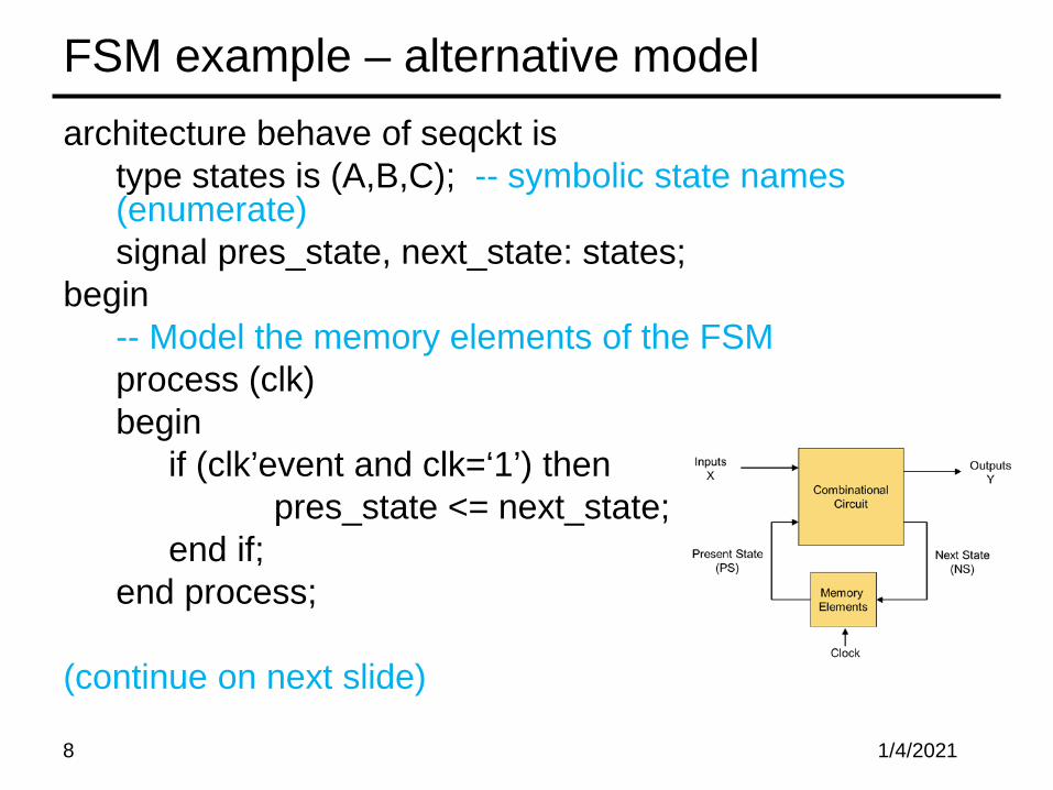
FSM example – alternative modelarchitecture behave of seqckt is
type states is (A,B,C); -- symbolic state names (enumerate)signal pres_state, next_state: states;
begin-- Model the memory elements of the FSMprocess (clk)begin
if (clk’event and clk=‘1’) thenpres_state <= next_state;
end if;end process;
(continue on next slide)
8 1/4/2021

FSM example (alternate model, continued)-- Model next-state and output functions of the FSM
-- as combinational logicprocess (x, pres_state) -- function inputsbegin
case pres_state is -- describe each statewhen A => if (x = ‘0’) then
z <= ‘0’;next_state <= A;
else -- if (x = ‘1’)z <= ‘0’;next_state <= B;
end if;
(continue on next slide for pres_state = B and C)9 1/4/2021

FSM example (alternate model, continued)
when B => if (x=‘0’) thenz <= ‘0’;next_state <= A;
elsez <= ‘1’;next_state <= C;
end if;when C => if (x=‘0’) then
z <= ‘0’;next_state <= C;
elsez <= ‘1’;next_state <= A;
end if;end case;
end process;10 1/4/2021

Alternative form for output and next state functions (combinational logic)
-- Next state function (combinational logic)next_state <= A when ((curr_state = A) and (x = ‘0’))
or ((curr_state = B) and (x = ‘0’)) or ((curr_state = C) and (x = ‘1’)) else
B when ((curr_state = 1) and (x = ‘1’)) elseC;
-- Output function (combinational logic)z <= ‘1’ when ((curr_state = B) and (x = ‘1’)) --all conditions
or ((curr_state = C) and (x = ‘1’)) --for which z=1.else ‘0’; --otherwise z=0
11 1/4/2021

Moore model FSM
entity FSM is port (CLK, EN, TDI: in bit;
RST, SHIFT: out bit); end entity FSM;
12 1/4/2021

Write a VHDL code using three process blocks!
13 1/4/2021

How Verilog Explicit FSM Works The nonblocking and blocking assignments are scheduled
in the same time step of the simulation in a particular order1. The nonblocking assignments in the edge-sensitive behavior are
sampled first at the beginning of the time step (i.e. before any assignments are made)
2. The blocking assignments in level-sensitive behavior are then executed (with the previous register value because there is no assignment done in Step 1)
3. After Step 2, the nonblocking assignments are completed by assigning LHS variables with the values that were sampled at Step 1

Verilog Explicit FSM Design and Synthesis Tips Use 2 cyclic behaviors for an explicit state machine
• One level-sensitive behavior for combinational logic to describe the next state and output logic
• One edge-sensitive behavior for state flip-flops to synchronize state transition
In the level-sensitive behavior for N/S and O/P• Use blocked assignments/procedural assignments “=“• Completely specify all outputsCan be achieved by initializing all outputs in the beginning
In the edge-sensitive behavior for state transition• Use nonblocking assignments “<=“ For state transition For register transfer of a data path
Always decode all possible states in the level sensitive behavior
• To avoid unnecessary latches

Decode All Possible States! Matching simulation results between behavioral model and a
synthesized circuit does NOT guarantee that an implementation is correct !
• Unless exercising all possible input sequences Which is almost impossible to do
• Because, if the testbench exercises the circuit only allowable input sequences, then it is not sufficient to verify the circuit’s behaviors that are not covered by the exercise of the testbench

Verilog: Mealy Machine
1/4/202117

Verilog: Mealy Machine– Cont.
1/4/202118
always @(state or x) begin
parity = 1'b0;case(state)
S0: if(x)begin
parity = 1; nextstate = S1;endelse
nextstate = S0;S1: if(x)
nextstate = S0;elsebegin
parity = 1; nextstate = S1;end
default:nextstate = S0;
endcaseendendmodule
module mealy_2processes(input clk, input reset, input x, output reg parity);reg state, nextstate;parameter S0=0, S1=1;
always @(posedge clk or posedgereset)if (reset)
state <= S0;else
state <= nextstate;
*Xilinx Documentation

Verilog: Mealy Machine– Cont.
1/4/202119
*Xilinx Documentation
module mealy_3processes(input clk, input reset, input x, output reg parity); reg state, nextstate;
parameter S0=0, S1=1;
always @(state or x) //Output Logicbegin
parity = 1'b0; case(state) S0: if(x)
parity = 1; S1: if(!x)
parity = 1; endcase
end
always @(state or x) // Nextstate Logicbegin
nextstate = S0; case(state) S0: if(x) nextstate = S1; S1: if(!x) nextstate = S1; endcase
end endmodule
always @(posedge clk or posedge reset) if (reset)
state <= S0; else state <= nextstate;

Verilog: Moore Machine
1/4/202120
*Xilinx Documentation
module mealy_3processes(input clk, input reset, input x, output reg parity); reg state, nextstate;
parameter S0=0, S1=1;
always @(state) // Output Logicbegincase(state)
S0: parity = 0;S1: parity = 1;
endcaseend
always @(state or x) // Nextstate Logicbegin
nextstate = S0; case(state) S0: if(x) nextstate = S1; S1: if(!x) nextstate = S1; endcase
end endmodule
always @(posedge clk or posedge reset) if (reset)
state <= S0; else state <= nextstate;

FSM Example: BCD-to-Excess-3 Code Converter (Mealy)
BCD-to-Excess-3 Code Converter for manual design• A serially-transmitted BCD (8421 code) word is to be converted into an
Excess-3 code Bin transmitted in sequence, LSB first
• An Excess-3 code word is obtained by adding 3 to the decimal value and taking the binary equivalent. Excess-3 code is self-complementing
Decimal 8-4-2-1 Excess-3Digit Code Code
(BCD)
0 0000 00111 0001 01002 0010 01013 0011 01104 0100 01115 0101 10006 0110 10017 0111 10108 1000 10119 1001 1100
9’s complement can be obtained by inverting

BCD-to-Excess-3 Code Converter (cont.)
Excess-3Code
Converter
clk
Bout = 8Excess-3
1 0 0 0+
1 1 10
Bin = 8 bcd
Bout
0 0 1 11 0 1 1
LSBMSB
0 0 0 1t
LSB MSB
t
MSBBin
S_5
S_0
input / output
1/00/1
0/1
0/0, 1/1
1/0
0/11/0
0/10/0, 1/1
0/0, 1/1
S_1 S_2
S_4S_3
S_6
reset
Bin(0)
Bin(1)
Bin(2)
Bin(3)

BCD-to-Excess-3 Code Converter (cont.)
module BCD_to_Excess_3b (B_out, B_in, clk, reset_b);output B_out;input B_in, clk, reset_b;parameter S_0 = 3'b000, // State assignment, which may be omitted
S_1 = 3'b001, // If omitted, allow synthesis tool to assignS_2 = 3'b101, S_3 = 3'b111,S_4 = 3'b011, S_5 = 3'b110, S_6 = 3'b010,dont_care_state = 3'bx,dont_care_out = 1'bx;
reg[2: 0] state, next_state;reg B_out;

BCD-to-Excess-3 Code Converter (cont.)always @ (posedge clk or negedge reset_b) // edge-sensitive behavior with NBAs
if (reset_b == 0) state <= S_0; else state <= next_state;
always @ (state or B_in) begin // level-sensitive behavior with blocking assignmentsB_out = 0; // initialize all outputs herecase (state) // explicit states
S_0: if (B_in == 0) begin next_state = S_1; B_out = 1; endelse if (B_in == 1) begin next_state = S_2; end // Mealy machine
S_1: if (B_in == 0) begin next_state = S_3; B_out = 1; endelse if (B_in == 1) begin next_state = S_4; end
S_2: begin next_state = S_4; B_out = B_in; endS_3: begin next_state = S_5; B_out = B_in; endS_4: if (B_in == 0) begin next_state = S_5; B_out = 1; end
else if (B_in == 1) begin next_state = S_6; endS_5: begin next_state = S_0; B_out = B_in; endS_6: begin next_state = S_0; B_out = 1; end/* default: begin next_state = dont_care_state;
B_out = dont_care_out; end */ endcase
endendmodule

State Encoding The task of assigning a code to the states of an FSM
• Also described as “state assignment” Number of flip-flops that are required to represent a
state• Influence the complexity of the combinational logic for the
next state and outputs

General Guidelines for State Encoding If two states have the same next state for a given
input• Give them logically adjacent state assignments Assign logically adjacent state codes to the next
state of a given state Assign logically adjacent state codes to the states
that have the same outputs for a given input Designers can choose state assignments or allow
synthesis tool to determine state encoding

State Assignment Codes
0 0000 0000000000000001 0000 000000001 0001 0000000000000010 0001 000000012 0010 0000000000000100 0011 000000113 0011 0000000000001000 0010 000001114 0100 0000000000010000 0110 000011115 0101 0000000000100000 0111 000111116 0110 0000000001000000 0101 001111117 0111 0000000010000000 0100 011111118 1000 0000000100000000 1100 111111119 1001 0000001000000000 1101 1111111010 1010 0000010000000000 1111 1111110011 1011 0000100000000000 1110 1111100012 1100 0001000000000000 1010 1111000013 1101 0010000000000000 1011 1110000014 1110 0100000000000000 1001 1100000015 1111 1000000000000000 1000 10000000
# Binary One-Hot Gray Johnson

State Assignment Codes (cont.) Binary coded decimal (BCD) format
• Uses the minimal number of flip-flops• Does not necessarily lead to an optimal realization of the combinational logic used
to decode the next state and output of the machine. Example: If a machine has more than 16 states, a binary code will result in a relatively large
amount of next-state logic The machine's speed will also be slower than alternative encoding.
Gray code • Uses the same number of bits as a binary code• Has the feature that two adjacent codes differ by only one bit
Can reduce the electrical noise in a circuit. Gray encoding is recommended for machines having more than 32 states because it
requires fewer flip-flops than one-hot encoding, and is more reliable than binary encoding because fewer bits change simultaneously
Johnson code • Has the same property as Gray code
Two adjacent codes differ by only one bit• Uses more bits.
A code that changes by only one bit between adjacent codes will reduce the simultaneous switching of adjacent physical signal lines in a circuit, thereby minimizing the possibility of electrical crosstalk.
• These codes also minimize transitions through intermediate states.

One-Hot Encoding (or One-Cold) One flip-flop for each state
• Usually more than minimum numbers of flip-flops• Reduces the decoding logic for next state and outputHence offset the extra flip-flops
• One-hot encoding usually does not correspond to the optimal state assignmentCombination usage of FF and decoding logic
Complexity does not increase as states are added to the machine
• Tradeoff: speed is not compromised by the time required to decode the state
Cost: area of the additional flip flops and signal routing

One-Hot Encoding (or One-Cold) (cont.) A one-hot encoding with an “if” statement that tests individual bits
might provide simpler decoding logic than decoding with a “case”statement
• Because “case” implicitly references all bits• While “if” only references to individual bits
In FPGA, saving flip-flops may not beneficial • Because FF already built inside FPGA Even don’t use them, you do not save FF
• If decoding logic requires more logic that are more than on a configurable logic block (CLB) Then on-hot is preferred Because no interconnection required between CLBs
• Hence, use one-hots in FPGAs to reduce the use of CLBs Note: in large machines, one-hot encoding will have several
unused states, in addition to requiring more registers than alternative encoding
Caution: if a state assignment does not exhaust the possibilities of a code, then additional logic will be required to detect and recover from transitions into unused states.

Zero Detector Asserting its output when a 0 is detected in a
stream of 1s.
1/4/202131

Zero Detector: Mealy Machine
1/4/202132

Zero Detector: Mealy Machine
1/4/202133
//Verilog 2001, 2005 syntaxmodule Mealy_Zero_Detector (output reg y_out,input x_in, clock, reset);reg [1: 0] state, next_state;parameter S0 = 2'b00, S1 = 2'b01, S2 = 2'b10, S3 = 2'b11;
always @ ( posedge clock, negedge reset)if (reset == 0) state <= S0;else state <= next_state;
always @ (state, x_in) // Next statecase (state)S0: if (x_in) next_state = S1; else next_state = S0;S1: if (x_in) next_state = S3; else next_state = S0;S2: if (~x_in) next_state = S0; else next_state = S2;S3: if (x_in) next_state = S2; else next_state = S0;endcase
always @ (state, x_in) // Mealy outputcase (state)S0: y_out = 0;S1, S2, S3: y_out = ~x_in;endcase
endmodule

Binary Counter: Moore Machine
1/4/202134

Binary Counter: Moore Machine Write a Verilog code for Binary Counter (Moore
Machine).
1/4/202135