Learning Materials Template - iLearn
62
3D COMPUTER ANIMATION: INTRODUCION TO 3DS MAX.2 Department of Computing, Multimedia & Network Technologies © Adam Smith College 1 3D COMPUTER ANIMATION HD3DCA/F2 INTRODUCTION TO 3DS MAX .2 Department of Computing, Multimedia & Networking Technologies
-
Upload
khangminh22 -
Category
Documents
-
view
1 -
download
0
Transcript of Learning Materials Template - iLearn
3D COMPUTER ANIMATION: INTRODUCION TO 3DS MAX.2 Department of Computing, Multimedia & Network Technologies
© Adam Smith College 1
3D COMPUTER ANIMATION
HD3DCA/F2
INTRODUCTION TO 3DS MAX .2
Department of Computing, Multimedia & Networking Technologies
3D COMPUTER ANIMATION: INTRODUCION TO 3DS MAX.2 Department of Computing, Multimedia & Network Technologies
2
3D COMPUTER ANIMATION
HD3DCA/F2
INTRODUCTION TO 3DS MAX .2
Table of Contents
Basic tools/techniques .............................................................................................................. 5 Key frames Time slider Track bar Animation with key frames Auto key mode Set key mode Setting key frame Time configuration Track view Dope sheet Curve editor The track view Motion panel
Modelling ................................................................................................................................... 14 Edit Mesh modifier Extrude modifier NURBS Modelling Patch modelling
Materials and Textures .......................................................................................................... 16 Material Editor Material editor controls Sample shots Creating a simple material Shader type Blinn shader Hue/Blackness/Whiteness (HBW) Red/Blue/Green (RGB) Hue/Saturation/Value (HSV) Self illumination Opacity Diffuse level Roughness Maps Map rollout Material/Map browser
3D COMPUTER ANIMATION: INTRODUCION TO 3DS MAX.2 Department of Computing, Multimedia & Network Technologies
3
UVW Mapping coordinates UVW Map Modifier Unwrap UVW Modiier
Lighting ....................................................................................................................................... 23 Default light Ambient light Free lights and target lights Spot light Omni light Skylight Transforming lights Placing lights Light parameters General parameters Intensity/colour/attenuation rollout Shadow parameters Spot light or directional parameters Light cone Show cone Overshoot Hotspot/beam Falloff/field Circle/Rectangle Aspect Bitmap fit Advanced effects
Cameras ...................................................................................................................................... 33 Free Camera Target Camera Creating a Free Camera Creating a Target Camera Camera Viewport Creating Cameras from View Creating parameters rollout Lens and FOV Orthographic Projection Stock Lenses Camera types and display options Environment ranges and clipping Multi-pass camera effects Camera matching Camera tracker
Rendering .................................................................................................................................. 39 Rendering Menu Common Rendering Parameters Time Output
3D COMPUTER ANIMATION: INTRODUCION TO 3DS MAX.2 Department of Computing, Multimedia & Network Technologies
4
Output Size Options Advanced Lighting Render Output Email Notification Assign Renderer Final Options Default Scan-line Renderer Options Antialising Global Super-sampling Object Motion Blur Image Motion Blur Auto Reflect/Refract Maps Colour Range Limiting Memory Management
Scene Creation .......................................................................................................................... 47
3D COMPUTER ANIMATION: INTRODUCION TO 3DS MAX.2 Department of Computing, Multimedia & Network Technologies
5
3DS Max – tutorial – Basic Tools/Techniques
Animation is used throughout 3ds max. It is possible to animate the position, rotation, and scale of an object, and almost any parameter setting that effects the object’s shape and surface. It is possible link objects for hierarchical animation, using both forward and reverse kinematics, and to edit the animation in Track View.
This section discusses the basics of creating animation. It looks briefly at a comparison between computer animation and classic hand-drawn animation, and then describes the creation of “Key Framed” animation, using the “Animate” Button.
Key Frames
Key Frames are the ones, where you define the animation for a parameter by specifying its exact value at a given set of times. The computer can then work out by interpolating what the value should be between the keys.
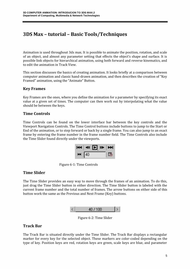
Time Controls
Time Controls can be found on the lower interface bar between the key controls and the Viewport Navigation Controls. The Time Control buttons include buttons to jump to the Start or End of the animation, or to step forward or back by a single frame. You can also jump to an exact frame by entering the frame number in the frame number field. The Time Controls also include the Time Slider found directly under the viewports.
Figure 6-1: Time Controls
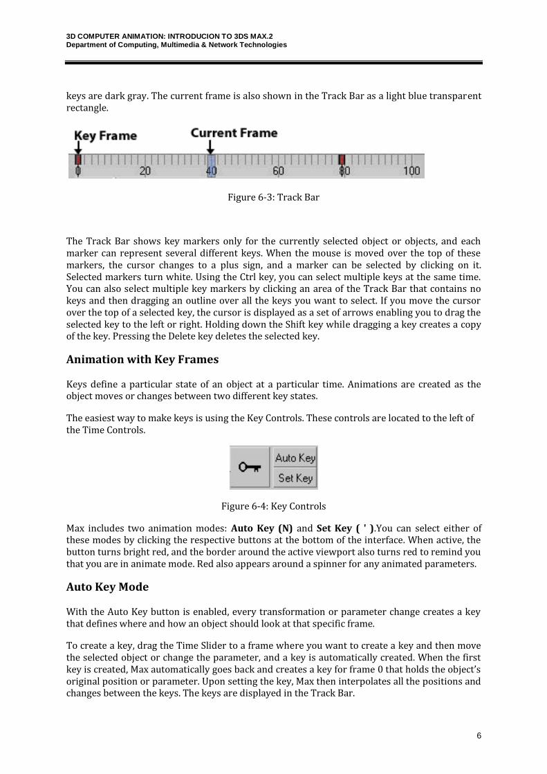
Time Slider
The Time Slider provides an easy way to move through the frames of an animation. To do this, just drag the Time Slider button in either direction. The Time Slider button is labeled with the current frame number and the total number of frames. The arrow buttons on either side of this button work the same as the Previous and Next Frame (Key) buttons.
Figure 6-2: Time Slider
Track Bar
The Track Bar is situated directly under the Time Slider. The Track Bar displays a rectangular marker for every key for the selected object. These markers are color-coded depending on the type of key. Position keys are red, rotation keys are green, scale keys are blue, and parameter
3D COMPUTER ANIMATION: INTRODUCION TO 3DS MAX.2 Department of Computing, Multimedia & Network Technologies
6
keys are dark gray. The current frame is also shown in the Track Bar as a light blue transparent rectangle.
Figure 6-3: Track Bar
The Track Bar shows key markers only for the currently selected object or objects, and each marker can represent several different keys. When the mouse is moved over the top of these markers, the cursor changes to a plus sign, and a marker can be selected by clicking on it. Selected markers turn white. Using the Ctrl key, you can select multiple keys at the same time. You can also select multiple key markers by clicking an area of the Track Bar that contains no keys and then dragging an outline over all the keys you want to select. If you move the cursor over the top of a selected key, the cursor is displayed as a set of arrows enabling you to drag the selected key to the left or right. Holding down the Shift key while dragging a key creates a copy of the key. Pressing the Delete key deletes the selected key.
Animation with Key Frames
Keys define a particular state of an object at a particular time. Animations are created as the object moves or changes between two different key states.
The easiest way to make keys is using the Key Controls. These controls are located to the left of the Time Controls.
Figure 6-4: Key Controls
Max includes two animation modes: Auto Key (N) and Set Key ( ' ).You can select either of these modes by clicking the respective buttons at the bottom of the interface. When active, the button turns bright red, and the border around the active viewport also turns red to remind you that you are in animate mode. Red also appears around a spinner for any animated parameters.
Auto Key Mode
With the Auto Key button is enabled, every transformation or parameter change creates a key that defines where and how an object should look at that specific frame.
To create a key, drag the Time Slider to a frame where you want to create a key and then move the selected object or change the parameter, and a key is automatically created. When the first key is created, Max automatically goes back and creates a key for frame 0 that holds the object’s original position or parameter. Upon setting the key, Max then interpolates all the positions and changes between the keys. The keys are displayed in the Track Bar.
3D COMPUTER ANIMATION: INTRODUCION TO 3DS MAX.2 Department of Computing, Multimedia & Network Technologies
7
Each frame can hold several different keys, but only one for each type of transform and each parameter. For example, if you move, rotate, scale, and change the Radius parameter for a sphere object with the Auto Key mode enabled, then separate keys are created for position, rotation, scaling, and a parameter change.
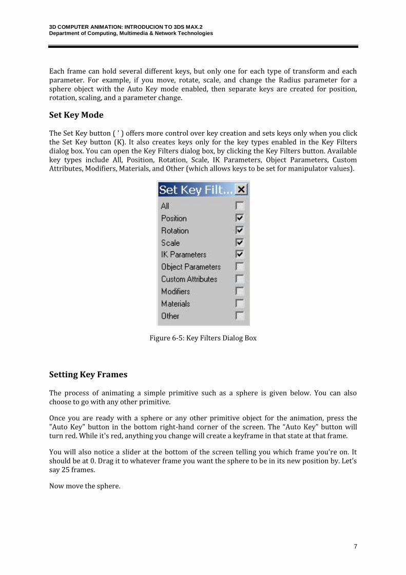
Set Key Mode
The Set Key button ( ' ) offers more control over key creation and sets keys only when you click the Set Key button (K). It also creates keys only for the key types enabled in the Key Filters dialog box. You can open the Key Filters dialog box, by clicking the Key Filters button. Available key types include All, Position, Rotation, Scale, IK Parameters, Object Parameters, Custom Attributes, Modifiers, Materials, and Other (which allows keys to be set for manipulator values).
Figure 6-5: Key Filters Dialog Box
Setting Key Frames
The process of animating a simple primitive such as a sphere is given below. You can also choose to go with any other primitive.
Once you are ready with a sphere or any other primitive object for the animation, press the "Auto Key" button in the bottom right-hand corner of the screen. The “Auto Key” button will turn red. While it's red, anything you change will create a keyframe in that state at that frame.
You will also notice a slider at the bottom of the screen telling you which frame you're on. It should be at 0. Drag it to whatever frame you want the sphere to be in its new position by. Let’s say 25 frames.
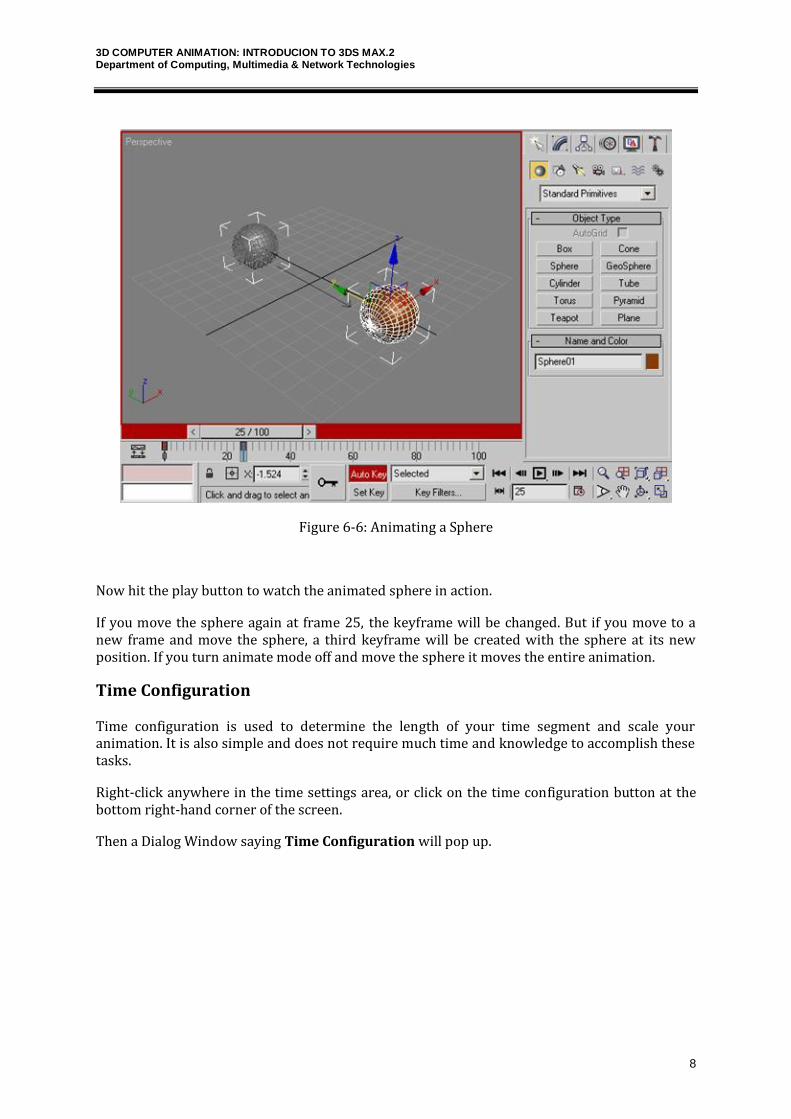
Now move the sphere.
3D COMPUTER ANIMATION: INTRODUCION TO 3DS MAX.2 Department of Computing, Multimedia & Network Technologies
8
Figure 6-6: Animating a Sphere
Now hit the play button to watch the animated sphere in action.
If you move the sphere again at frame 25, the keyframe will be changed. But if you move to a new frame and move the sphere, a third keyframe will be created with the sphere at its new position. If you turn animate mode off and move the sphere it moves the entire animation.
Time Configuration
Time configuration is used to determine the length of your time segment and scale your animation. It is also simple and does not require much time and knowledge to accomplish these tasks.
Right-click anywhere in the time settings area, or click on the time configuration button at the bottom right-hand corner of the screen.
Then a Dialog Window saying Time Configuration will pop up.
3D COMPUTER ANIMATION: INTRODUCION TO 3DS MAX.2 Department of Computing, Multimedia & Network Technologies
9
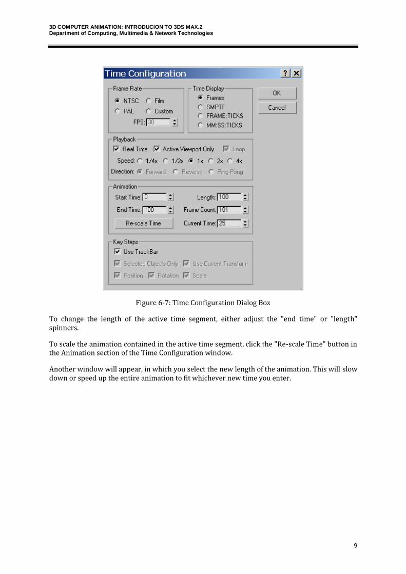
Figure 6-7: Time Configuration Dialog Box
To change the length of the active time segment, either adjust the "end time" or "length" spinners.
To scale the animation contained in the active time segment, click the "Re-scale Time" button in the Animation section of the Time Configuration window.
Another window will appear, in which you select the new length of the animation. This will slow down or speed up the entire animation to fit whichever new time you enter.
3D COMPUTER ANIMATION: INTRODUCION TO 3DS MAX.2 Department of Computing, Multimedia & Network Technologies
10
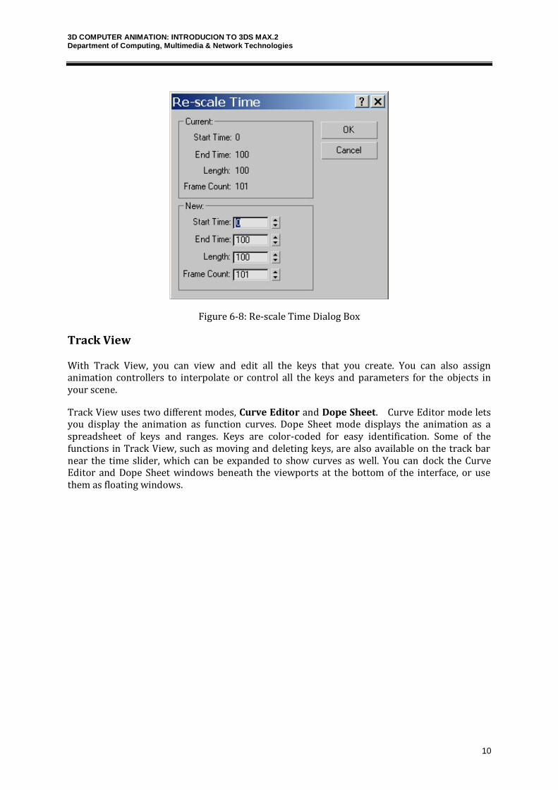
Figure 6-8: Re-scale Time Dialog Box
Track View
With Track View, you can view and edit all the keys that you create. You can also assign animation controllers to interpolate or control all the keys and parameters for the objects in your scene.
Track View uses two different modes, Curve Editor and Dope Sheet. Curve Editor mode lets you display the animation as function curves. Dope Sheet mode displays the animation as a spreadsheet of keys and ranges. Keys are color-coded for easy identification. Some of the functions in Track View, such as moving and deleting keys, are also available on the track bar near the time slider, which can be expanded to show curves as well. You can dock the Curve Editor and Dope Sheet windows beneath the viewports at the bottom of the interface, or use them as floating windows.
3D COMPUTER ANIMATION: INTRODUCION TO 3DS MAX.2 Department of Computing, Multimedia & Network Technologies
11
Dope Sheet
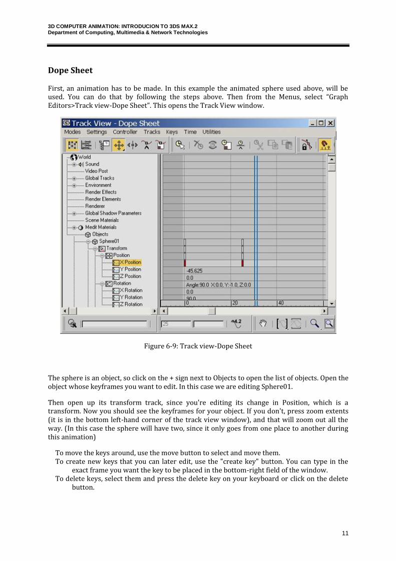
First, an animation has to be made. In this example the animated sphere used above, will be used. You can do that by following the steps above. Then from the Menus, select “Graph Editors>Track view-Dope Sheet”. This opens the Track View window.
Figure 6-9: Track view-Dope Sheet
The sphere is an object, so click on the + sign next to Objects to open the list of objects. Open the object whose keyframes you want to edit. In this case we are editing Sphere01.
Then open up its transform track, since you're editing its change in Position, which is a transform. Now you should see the keyframes for your object. If you don't, press zoom extents (it is in the bottom left-hand corner of the track view window), and that will zoom out all the way. (In this case the sphere will have two, since it only goes from one place to another during this animation)
To move the keys around, use the move button to select and move them. To create new keys that you can later edit, use the "create key" button. You can type in the
exact frame you want the key to be placed in the bottom-right field of the window. To delete keys, select them and press the delete key on your keyboard or click on the delete
button.
3D COMPUTER ANIMATION: INTRODUCION TO 3DS MAX.2 Department of Computing, Multimedia & Network Technologies
12
Curve Editor
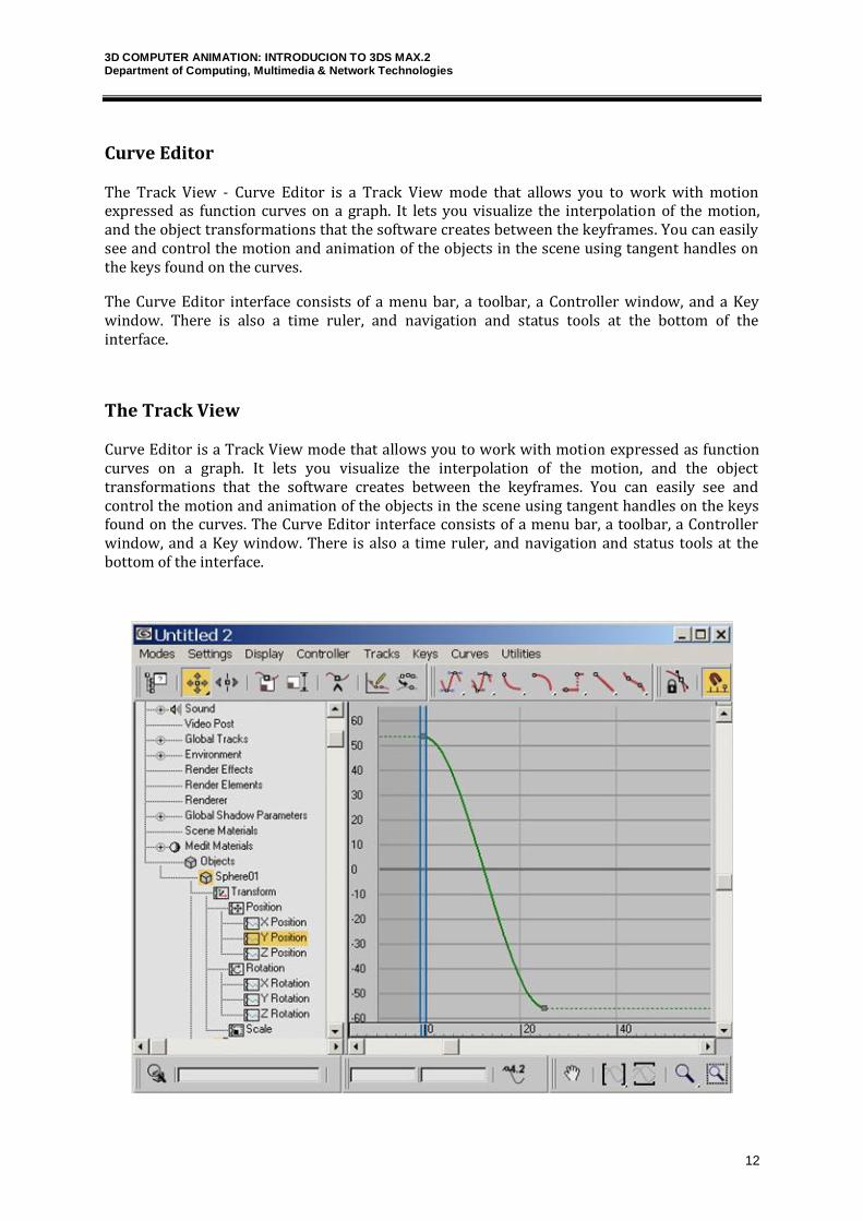
The Track View - Curve Editor is a Track View mode that allows you to work with motion expressed as function curves on a graph. It lets you visualize the interpolation of the motion, and the object transformations that the software creates between the keyframes. You can easily see and control the motion and animation of the objects in the scene using tangent handles on the keys found on the curves.
The Curve Editor interface consists of a menu bar, a toolbar, a Controller window, and a Key window. There is also a time ruler, and navigation and status tools at the bottom of the interface.
The Track View
Curve Editor is a Track View mode that allows you to work with motion expressed as function curves on a graph. It lets you visualize the interpolation of the motion, and the object transformations that the software creates between the keyframes. You can easily see and control the motion and animation of the objects in the scene using tangent handles on the keys found on the curves. The Curve Editor interface consists of a menu bar, a toolbar, a Controller window, and a Key window. There is also a time ruler, and navigation and status tools at the bottom of the interface.
3D COMPUTER ANIMATION: INTRODUCION TO 3DS MAX.2 Department of Computing, Multimedia & Network Technologies
13
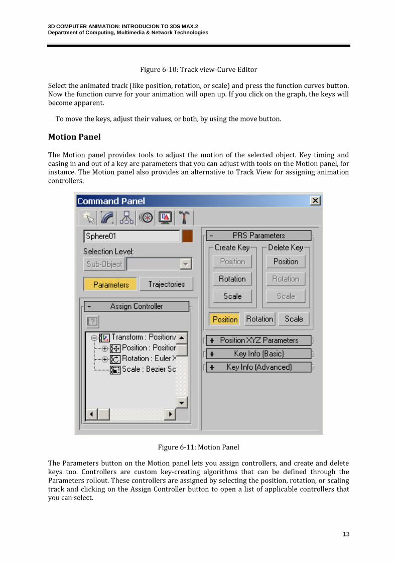
Figure 6-10: Track view-Curve Editor
Select the animated track (like position, rotation, or scale) and press the function curves button. Now the function curve for your animation will open up. If you click on the graph, the keys will become apparent.
To move the keys, adjust their values, or both, by using the move button.
Motion Panel
The Motion panel provides tools to adjust the motion of the selected object. Key timing and easing in and out of a key are parameters that you can adjust with tools on the Motion panel, for instance. The Motion panel also provides an alternative to Track View for assigning animation controllers.
Figure 6-11: Motion Panel
The Parameters button on the Motion panel lets you assign controllers, and create and delete keys too. Controllers are custom key-creating algorithms that can be defined through the Parameters rollout. These controllers are assigned by selecting the position, rotation, or scaling track and clicking on the Assign Controller button to open a list of applicable controllers that you can select.
3D COMPUTER ANIMATION: INTRODUCION TO 3DS MAX.2 Department of Computing, Multimedia & Network Technologies
14
3DS Max – tutorial – Modelling
When the user interface lists modifiers, it lists them typically by sets. The modifiers are classified into different types or sets on the basis of their functionality. Following is a list of modifier sets in Max.
Selection Modifiers Path/Spline Editing Mesh Editing Animation Modifiers UV Coordinate Modifiers Cache Tools Subdivision Surfaces Free Form Deformations Parametric Modifiers Surface Modifiers Conversion Modifiers Two commonly used Mesh Editing Modifiers, Edit Mesh Modifier and Extrude Modifier are discussed below.
Edit Mesh Modifier
When an object is converted to an Editable Mesh, its parametric nature is eliminated. However, if you use the Edit Mesh modifier, you can still retain the same object type and its parametric nature while having access to all the Editable Mesh features.
For example, if you create a sphere and apply the Edit Mesh modifier and then extrude several faces, you can still change the radius of the sphere by selecting the Sphere object in the Modifier Stack, and changing the Radius value in the Parameters rollout.
The Edit Mesh modifier provides explicit editing tools for different sub-object levels of the selected object: vertex, edge, and face/polygon/element.
The Edit Mesh modifier is similar in its capabilities of the base Editable Mesh object, except that you cannot animate sub-objects in Edit Mesh.
Extrude modiier
The Extrude modifier can be applied only to spline or shape objects. This modifier adds depth to a shape and makes it a parametric object.
This modifier copies the spline, moves it a given distance, and connects the two splines to form a 3D shape.
Parameters for this modifier include an Amount value, which is the distance to extrude, and the number of segments to use to define the height. The Capping options let you select a Start Cap and/or an End Cap using either a Morph or Grid option. The Morph option divides the caps into long, thin polygons suitable for morph targets, and the Grid option divides the caps into a tight grid of polygons suitable for deformation operations. The Cap fills the spline area and can be made as a Patch, Mesh, or NURBS object.
Only closed splines that are extruded can be capped. You can also have mapping coordinates and Material IDs generated automatically. The Smooth option smoothes the extrusion.
NURBS Modeling
NURBS is an acronym for Non-Uniform Rational B-Splines. They are the ideal modeling tool for creating
3D COMPUTER ANIMATION: INTRODUCION TO 3DS MAX.2 Department of Computing, Multimedia & Network Technologies
15
organic characters because they have a number of advantages. They are easy to work with, they give you good interactive control, they blend together seamlessly, and their surfaces remain smooth even when distorted. NURBS are superior to polygonal modeling methods when building models with smooth flowing contours such as plants, flowers, animals, and skin.
A NURBS model can be an assemblage of multiple NURBS sub-objects. For example, a NURBS object might contain two surfaces that are separate in space. NURBS curves and NURBS surfaces are controlled by either point or control vertex (CV) sub-objects. Points and CVs behave somewhat like the vertices of spline objects, but there are differences.
Patch Modeling
A patch is a type of skewable object. A patch object is useful for creating gently curved surfaces, and provides very detailed control for manipulating complex geometry.
When you apply an Edit Patch modifier to an object or convert it to an editable patch object, the software converts the object's geometry into a collection of separate Bezier patches. Each patch is made up of three or four vertices connected by edges, defining a surface. Patches also have interior vertices that you can control, or let the software control for you.
You can also create a patch by applying the “Surface” Modifier on a closed shape object containing 3 or 4 vertices along its perimeter.
You control a patch surface's shape by manipulating the vertices and edges. The surface is the renderable geometry of the object.
3D COMPUTER ANIMATION: INTRODUCION TO 3DS MAX.2 Department of Computing, Multimedia & Network Technologies
16
3DS Max – tutorial – Materials andTextures
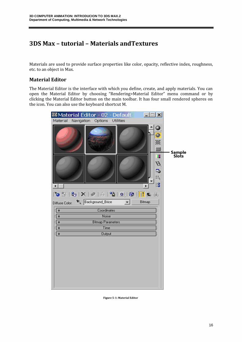
Materials are used to provide surface properties like color, opacity, reflective index, roughness, etc. to an object in Max.
Material Editor
The Material Editor is the interface with which you define, create, and apply materials. You can open the Material Editor by choosing “Rendering>Material Editor” menu command or by clicking the Material Editor button on the main toolbar. It has four small rendered spheres on the icon. You can also use the keyboard shortcut M.
Figure 5-1: Material Editor
3D COMPUTER ANIMATION: INTRODUCION TO 3DS MAX.2 Department of Computing, Multimedia & Network Technologies
17
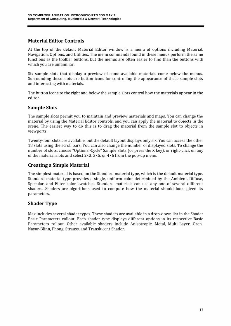
Material Editor Controls
At the top of the default Material Editor window is a menu of options including Material, Navigation, Options, and Utilities. The menu commands found in these menus perform the same functions as the toolbar buttons, but the menus are often easier to find than the buttons with which you are unfamiliar.
Six sample slots that display a preview of some available materials come below the menus. Surrounding these slots are button icons for controlling the appearance of these sample slots and interacting with materials.
The button icons to the right and below the sample slots control how the materials appear in the editor.
Sample Slots
The sample slots permit you to maintain and preview materials and maps. You can change the material by using the Material Editor controls, and you can apply the material to objects in the scene. The easiest way to do this is to drag the material from the sample slot to objects in viewports.
Twenty-four slots are available, but the default layout displays only six. You can access the other 18 slots using the scroll bars. You can also change the number of displayed slots. To change the number of slots, choose “Options>Cycle” Sample Slots (or press the X key), or right-click on any of the material slots and select 2×3, 3×5, or 4×6 from the pop-up menu.
Creating a Simple Material
The simplest material is based on the Standard material type, which is the default material type. Standard material type provides a single, uniform color determined by the Ambient, Diffuse, Specular, and Filter color swatches. Standard materials can use any one of several different shaders. Shaders are algorithms used to compute how the material should look, given its parameters.
Shader Type
Max includes several shader types. These shaders are available in a drop-down list in the Shader Basic Parameters rollout. Each shader type displays different options in its respective Basic Parameters rollout. Other available shaders include Anisotropic, Metal, Multi-Layer, Oren-Nayar-Blinn, Phong, Strauss, and Translucent Shader.
3D COMPUTER ANIMATION: INTRODUCION TO 3DS MAX.2 Department of Computing, Multimedia & Network Technologies
18
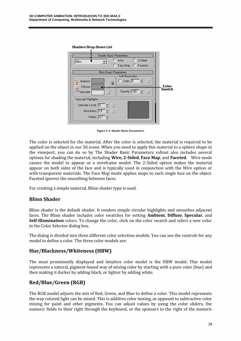
Figure 5-2: Shader Basic Parameters
The color is selected for the material. After the color is selected, the material is required to be applied on the object in our 3d scene. When you need to apply this material to a sphere shape in the viewport, you can do so by The Shader Basic Parameters rollout also includes several options for shading the material, including Wire, 2-Sided, Face Map, and Faceted. Wire mode causes the model to appear as a wireframe model. The 2-Sided option makes the material appear on both sides of the face and is typically used in conjunction with the Wire option or with transparent materials. The Face Map mode applies maps to each single face on the object. Faceted ignores the smoothing between faces.
For creating a simple material, Blinn shader type is used.
Blinn Shader
Blinn shader is the default shader. It renders simple circular highlights and smoothes adjacent faces. The Blinn shader includes color swatches for setting Ambient, Diffuse, Specular, and Self-Illumination colors. To change the color, click on the color swatch and select a new color in the Color Selector dialog box.
The dialog is divided into three different color selection models. You can use the controls for any model to define a color. The three color models are:
Hue/Blackness/Whiteness (HBW)
The most prominently displayed and intuitive color model is the HBW model. This model represents a natural, pigment-based way of mixing color by starting with a pure color (hue) and then making it darker by adding black, or lighter by adding white.
Red/Blue/Green (RGB)
The RGB model adjusts the mix of Red, Green, and Blue to define a color. This model represents the way colored light can be mixed. This is additive color mixing, as opposed to subtractive color mixing for paint and other pigments. You can adjust values by using the color sliders, the numeric fields to their right through the keyboard, or the spinners to the right of the numeric
3D COMPUTER ANIMATION: INTRODUCION TO 3DS MAX.2 Department of Computing, Multimedia & Network Technologies
19
fields.
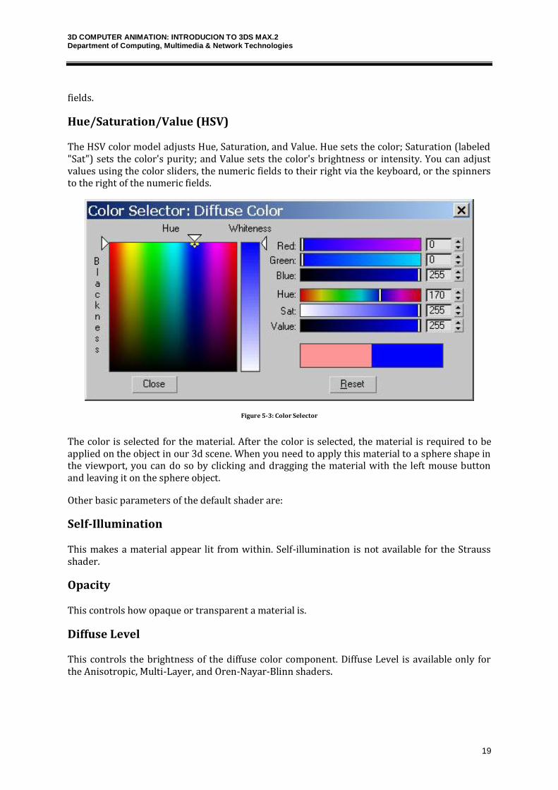
Hue/Saturation/Value (HSV)
The HSV color model adjusts Hue, Saturation, and Value. Hue sets the color; Saturation (labeled "Sat") sets the color's purity; and Value sets the color's brightness or intensity. You can adjust values using the color sliders, the numeric fields to their right via the keyboard, or the spinners to the right of the numeric fields.
Figure 5-3: Color Selector
The color is selected for the material. After the color is selected, the material is required to be applied on the object in our 3d scene. When you need to apply this material to a sphere shape in the viewport, you can do so by clicking and dragging the material with the left mouse button and leaving it on the sphere object.
Other basic parameters of the default shader are:
Self-Illumination
This makes a material appear lit from within. Self-illumination is not available for the Strauss shader.
Opacity
This controls how opaque or transparent a material is.
Diffuse Level
This controls the brightness of the diffuse color component. Diffuse Level is available only for the Anisotropic, Multi-Layer, and Oren-Nayar-Blinn shaders.
3D COMPUTER ANIMATION: INTRODUCION TO 3DS MAX.2 Department of Computing, Multimedia & Network Technologies
20
Roughness
This controls how quickly the diffuse component blends into the ambient component. Roughness is available only for the Multi-Layer and Oren-Nayar-Blinn shaders.
Maps
Maps are bitmaps or procedural textures that are used to give color and other apparent surface characteristics ("textures") to 3D objects in Max.
There can be different types of maps. Some maps wrap images about objects, while others define areas to be modified by comparing the intensity of the pixels in the map. An example of this is a bump map. A standard bump map would be a grayscale image. When mapped onto an object, lighter colored sections would be raised to a maximum of pure white and darker sections would be indented to a minimum of black. This enables you to easily create surface textures, such as an orange rind, without having to model them.
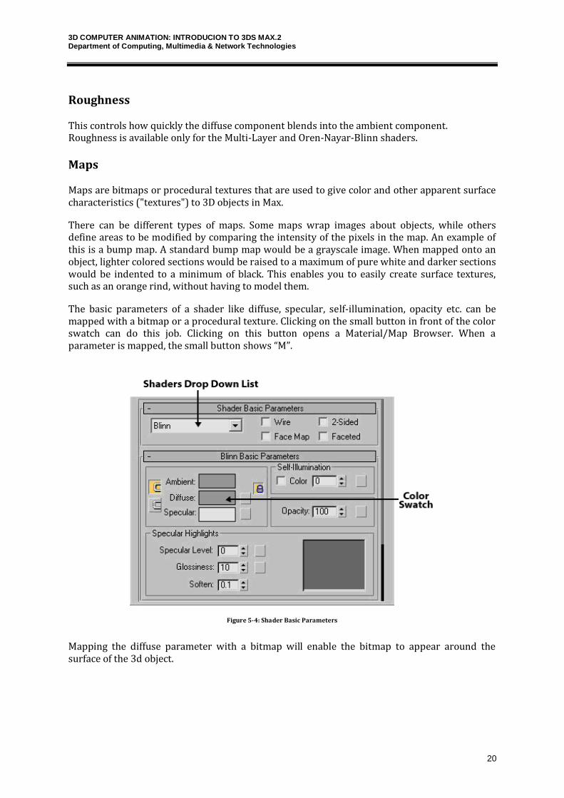
The basic parameters of a shader like diffuse, specular, self-illumination, opacity etc. can be mapped with a bitmap or a procedural texture. Clicking on the small button in front of the color swatch can do this job. Clicking on this button opens a Material/Map Browser. When a parameter is mapped, the small button shows “M”.
Figure 5-4: Shader Basic Parameters
Mapping the diffuse parameter with a bitmap will enable the bitmap to appear around the surface of the 3d object.
3D COMPUTER ANIMATION: INTRODUCION TO 3DS MAX.2 Department of Computing, Multimedia & Network Technologies
21
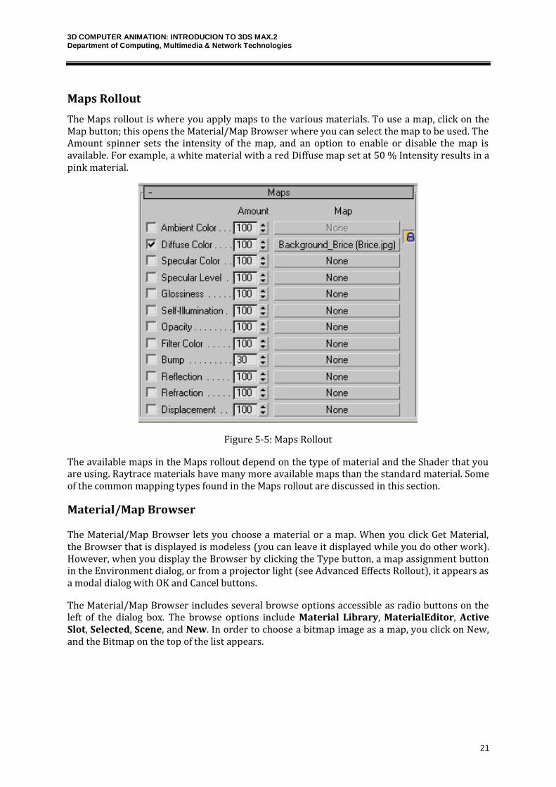
Maps Rollout
The Maps rollout is where you apply maps to the various materials. To use a map, click on the Map button; this opens the Material/Map Browser where you can select the map to be used. The Amount spinner sets the intensity of the map, and an option to enable or disable the map is available. For example, a white material with a red Diffuse map set at 50 % Intensity results in a pink material.
Figure 5-5: Maps Rollout
The available maps in the Maps rollout depend on the type of material and the Shader that you are using. Raytrace materials have many more available maps than the standard material. Some of the common mapping types found in the Maps rollout are discussed in this section.
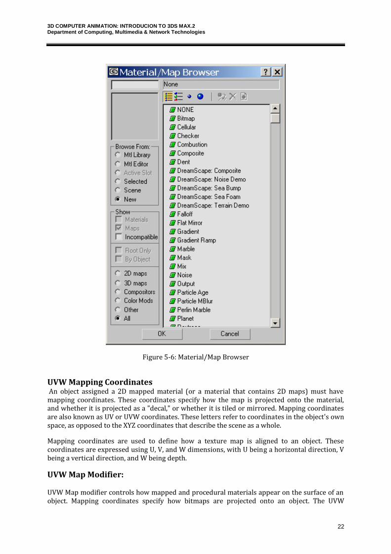
Material/Map Browser
The Material/Map Browser lets you choose a material or a map. When you click Get Material, the Browser that is displayed is modeless (you can leave it displayed while you do other work). However, when you display the Browser by clicking the Type button, a map assignment button in the Environment dialog, or from a projector light (see Advanced Effects Rollout), it appears as a modal dialog with OK and Cancel buttons.
The Material/Map Browser includes several browse options accessible as radio buttons on the left of the dialog box. The browse options include Material Library, MaterialEditor, Active Slot, Selected, Scene, and New. In order to choose a bitmap image as a map, you click on New, and the Bitmap on the top of the list appears.
3D COMPUTER ANIMATION: INTRODUCION TO 3DS MAX.2 Department of Computing, Multimedia & Network Technologies
22
Figure 5-6: Material/Map Browser
UVW Mapping Coordinates An object assigned a 2D mapped material (or a material that contains 2D maps) must have mapping coordinates. These coordinates specify how the map is projected onto the material, and whether it is projected as a "decal," or whether it is tiled or mirrored. Mapping coordinates are also known as UV or UVW coordinates. These letters refer to coordinates in the object's own space, as opposed to the XYZ coordinates that describe the scene as a whole.
Mapping coordinates are used to define how a texture map is aligned to an object. These coordinates are expressed using U, V, and W dimensions, with U being a horizontal direction, V being a vertical direction, and W being depth.
UVW Map Modifier:
UVW Map modifier controls how mapped and procedural materials appear on the surface of an object. Mapping coordinates specify how bitmaps are projected onto an object. The UVW
3D COMPUTER ANIMATION: INTRODUCION TO 3DS MAX.2 Department of Computing, Multimedia & Network Technologies
23
coordinate system is similar to the XYZ coordinate system. The U and V axes of a bitmap correspond to the X and Y axes. The W axis, which corresponds to the Z axis, is generally only used for procedural maps. A bitmap's coordinate system can be switched in the Material Editor to VW or WU, in which case the bitmap is rotated and projected so that it is perpendicular to the surface.
UVW Map Modifier projects the UVW coordinates on the surface of the 3d object. This projection can be done in the following available ways.
Planar Cylindrical Spherical Shrink Wrap Box Face XYZ to UVW Primitives, Loft Objects, and NURBS can generate their own mapping coordinates, but you need to use this modifier to apply mapping coordinates to mesh objects and patches.
Unwrap UVW Modifier
The Unwrap UVW modifier lets you control how a map is applied to a subobject selection. It can also be used to unwrap the existing mapping coordinates of an object. You can then edit these coordinates as needed. You can also use the Unwrap UVW modifier to apply multiple planar maps to an object. You accomplish this task by creating planar maps for various sides of an object and then editing the mapping coordinates in the Edit UVWs interface.
The Unwrap UVW modifier can be used as a self-contained UVW mapper and UVW coordinate editor, or in conjunction with the UVW Map modifier. If you use Unwrap UVW in conjunction with the UVW Map modifier, it is usually because you want to map the model with a method other than planar mapping, such as cylindrical or spherical mapping. You can animate UVW
coordinates by turning on the Auto Key button and transforming the coordinates at different frames.
3DS Max – tutorial – Lighting
3D COMPUTER ANIMATION: INTRODUCION TO 3DS MAX.2 Department of Computing, Multimedia & Network Technologies
24
Lights are objects that simulate real lights such as household or office lamps, the light instruments used in stage and film work, and the sun itself. Different kinds of light objects cast light in different ways, emulating different kinds of real-world light sources.
Lighting plays a critical part of any Max scene. Understanding the basics of lighting can make a big difference in the overall feeling and mood of your rendered scenes. Most Max scenes typically use one of two types of lighting: natural light or artificial light. Natural light is used for outside scenes and uses the sun and moon for its light source. Artificial light is usually reserved for indoor scenes where light bulbs provide the light. However, when working with lights, you’ll sometimes use natural light indoors, such as sunlight streaming through a window, or artificial light outdoors, such as a streetlight.
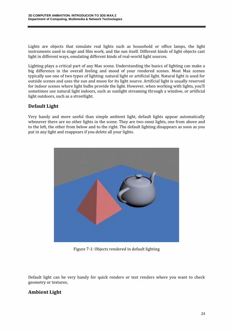
Default Light
Very handy and more useful than simple ambient light, default lights appear automatically whenever there are no other lights in the scene. They are two omni lights, one from above and to the left, the other from below and to the right. The default lighting disappears as soon as you put in any light and reappears if you delete all your lights.
Figure 7-1: Objects rendered in default lighting
Default light can be very handy for quick renders or test renders where you want to check geometry or textures,
Ambient Light
3D COMPUTER ANIMATION: INTRODUCION TO 3DS MAX.2 Department of Computing, Multimedia & Network Technologies
25
Ambient light is the general light that illuminates the entire scene. It has a uniform intensity and is uniformly diffused. It has no discernible source and no discernible direction. In the real world, light reflects from one surface to the next over and over, perhaps millions of times, until all the light energy has been absorbed.
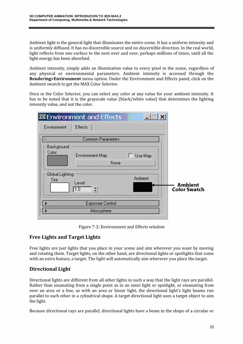
Ambient intensity, simply adds an illumination value to every pixel in the scene, regardless of any physical or environmental parameters. Ambient intensity is accessed through the Rendering>Environment menu option. Under the Environment and Effects panel, click on the Ambient swatch to get the MAX Color Selector.
Once in the Color Selector, you can select any color at any value for your ambient intensity. It has to be noted that it is the grayscale value (black/white value) that determines the lighting intensity value, and not the color.
Figure 7-2: Environment and Effects window
Free Lights and Target Lights
Free lights are just lights that you place in your scene and aim wherever you want by moving and rotating them. Target lights, on the other hand, are directional lights or spotlights that come with an extra feature, a target. The light will automatically aim wherever you place the target.
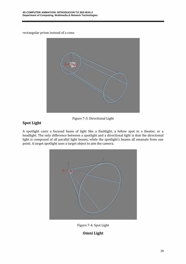
Directional Light
Directional lights are different from all other lights in such a way that the light rays are parallel. Rather than emanating from a single point as in an omni light or spotlight, or emanating from over an area or a line, as with an area or linear light, the directional light’s light beams run parallel to each other in a cylindrical shape. A target directional light uses a target object to aim the light.
Because directional rays are parallel, directional lights have a beam in the shape of a circular or
3D COMPUTER ANIMATION: INTRODUCION TO 3DS MAX.2 Department of Computing, Multimedia & Network Technologies
26
rectangular prism instead of a cone.
Figure 7-3: Directional Light
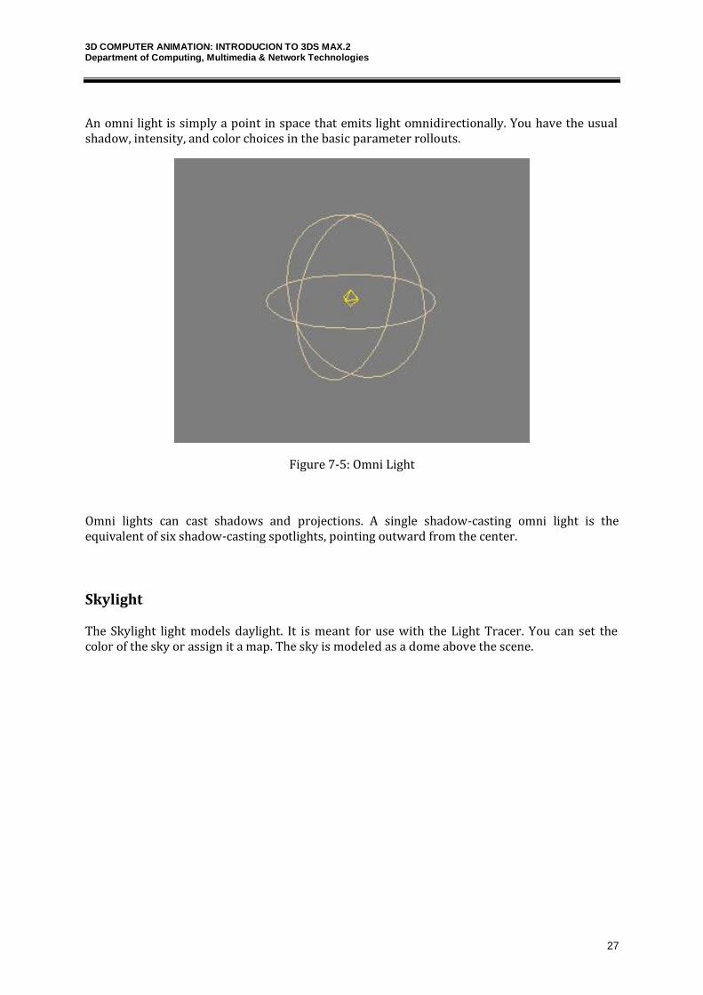
Spot Light
A spotlight casts a focused beam of light like a flashlight, a follow spot in a theater, or a headlight. The only difference between a spotlight and a directional light is that the directional light is composed of all parallel light beams, while the spotlight’s beams all emanate from one point. A target spotlight uses a target object to aim the camera.
Figure 7-4: Spot Light
Omni Light
3D COMPUTER ANIMATION: INTRODUCION TO 3DS MAX.2 Department of Computing, Multimedia & Network Technologies
27
An omni light is simply a point in space that emits light omnidirectionally. You have the usual shadow, intensity, and color choices in the basic parameter rollouts.
Figure 7-5: Omni Light
Omni lights can cast shadows and projections. A single shadow-casting omni light is the equivalent of six shadow-casting spotlights, pointing outward from the center.
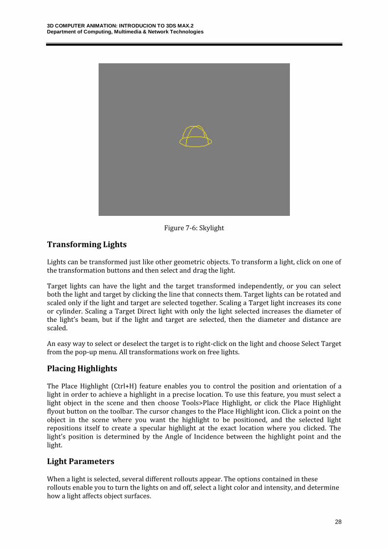
Skylight
The Skylight light models daylight. It is meant for use with the Light Tracer. You can set the color of the sky or assign it a map. The sky is modeled as a dome above the scene.
3D COMPUTER ANIMATION: INTRODUCION TO 3DS MAX.2 Department of Computing, Multimedia & Network Technologies
28
Figure 7-6: Skylight
Transforming Lights
Lights can be transformed just like other geometric objects. To transform a light, click on one of the transformation buttons and then select and drag the light.
Target lights can have the light and the target transformed independently, or you can select both the light and target by clicking the line that connects them. Target lights can be rotated and scaled only if the light and target are selected together. Scaling a Target light increases its cone or cylinder. Scaling a Target Direct light with only the light selected increases the diameter of the light’s beam, but if the light and target are selected, then the diameter and distance are scaled.
An easy way to select or deselect the target is to right-click on the light and choose Select Target from the pop-up menu. All transformations work on free lights.
Placing Highlights
The Place Highlight (Ctrl+H) feature enables you to control the position and orientation of a light in order to achieve a highlight in a precise location. To use this feature, you must select a light object in the scene and then choose Tools>Place Highlight, or click the Place Highlight flyout button on the toolbar. The cursor changes to the Place Highlight icon. Click a point on the object in the scene where you want the highlight to be positioned, and the selected light repositions itself to create a specular highlight at the exact location where you clicked. The light’s position is determined by the Angle of Incidence between the highlight point and the light.
Light Parameters
When a light is selected, several different rollouts appear. The options contained in these rollouts enable you to turn the lights on and off, select a light color and intensity, and determine how a light affects object surfaces.
3D COMPUTER ANIMATION: INTRODUCION TO 3DS MAX.2 Department of Computing, Multimedia & Network Technologies
29
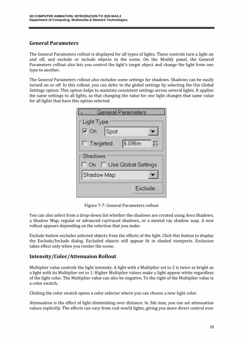
General Parameters
The General Parameters rollout is displayed for all types of lights. These controls turn a light on and off, and exclude or include objects in the scene. On the Modify panel, the General Parameters rollout also lets you control the light’s target object and change the light from one type to another.
The General Parameters rollout also includes some settings for shadows. Shadows can be easily turned on or off. In this rollout, you can defer to the global settings by selecting the Use Global Settings option. This option helps to maintain consistent settings across several lights. It applies the same settings to all lights, so that changing the value for one light changes that same value for all lights that have this option selected.
Figure 7-7: General Parameters rollout
You can also select from a drop-down list whether the shadows are created using Area Shadows, a Shadow Map, regular or advanced raytraced shadows, or a mental ray shadow map. A new rollout appears depending on the selection that you make.
Exclude button excludes selected objects from the effects of the light. Click this button to display the Exclude/Include dialog. Excluded objects still appear lit in shaded viewports. Exclusion takes effect only when you render the scene.
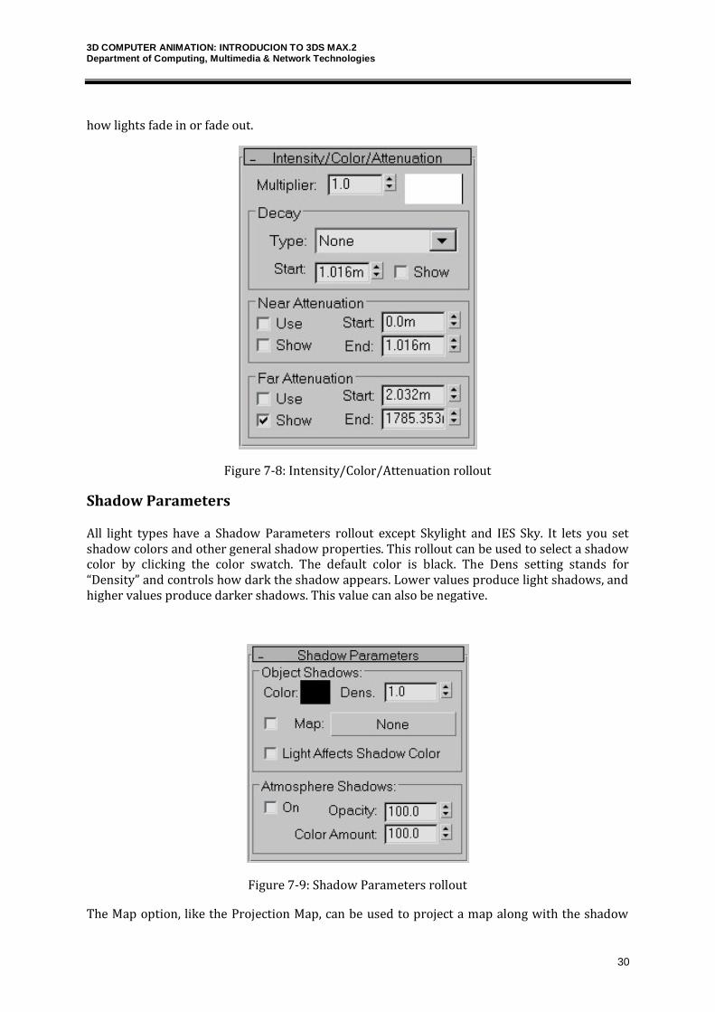
Intensity/Color/Attenuaion Rollout
Multiplier value controls the light intensity. A light with a Multiplier set to 2 is twice as bright as a light with its Multiplier set to 1. Higher Multiplier values make a light appear white regardless of the light color. The Multiplier value can also be negative. To the right of the Multiplier value is a color swatch.
Clicking the color swatch opens a color selector where you can choose a new light color.
Attenuation is the effect of light diminishing over distance. In 3ds max, you can set attenuation values explicitly. The effects can vary from real-world lights, giving you more direct control over
3D COMPUTER ANIMATION: INTRODUCION TO 3DS MAX.2 Department of Computing, Multimedia & Network Technologies
30
how lights fade in or fade out.
Figure 7-8: Intensity/Color/Attenuation rollout
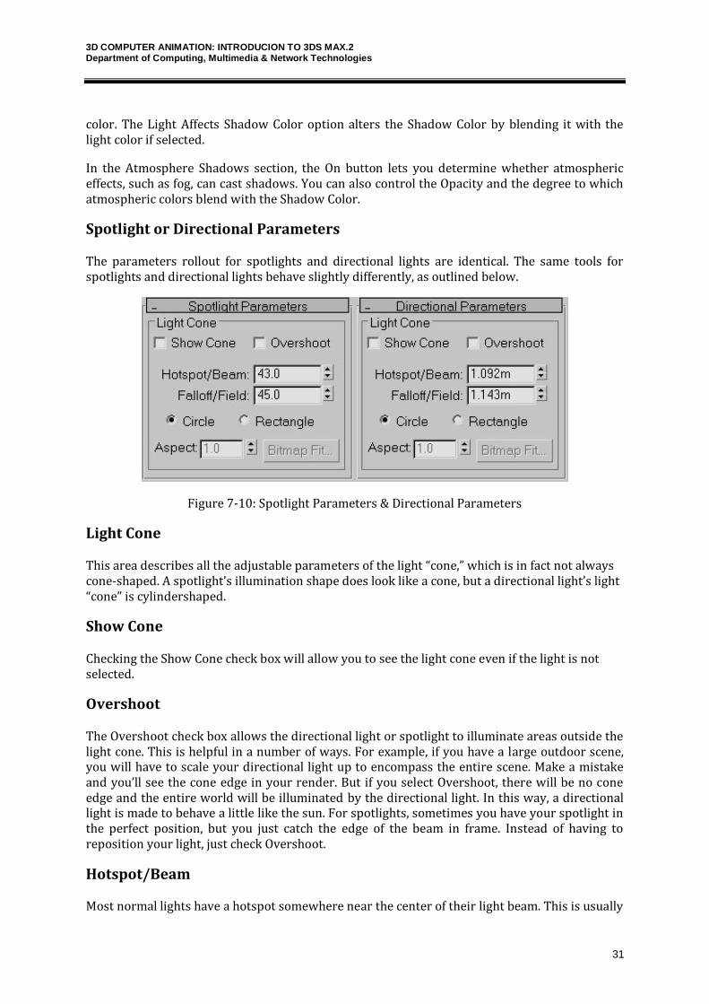
Shadow Parameters
All light types have a Shadow Parameters rollout except Skylight and IES Sky. It lets you set shadow colors and other general shadow properties. This rollout can be used to select a shadow color by clicking the color swatch. The default color is black. The Dens setting stands for “Density” and controls how dark the shadow appears. Lower values produce light shadows, and higher values produce darker shadows. This value can also be negative.
Figure 7-9: Shadow Parameters rollout
The Map option, like the Projection Map, can be used to project a map along with the shadow
3D COMPUTER ANIMATION: INTRODUCION TO 3DS MAX.2 Department of Computing, Multimedia & Network Technologies
31
color. The Light Affects Shadow Color option alters the Shadow Color by blending it with the light color if selected.
In the Atmosphere Shadows section, the On button lets you determine whether atmospheric effects, such as fog, can cast shadows. You can also control the Opacity and the degree to which atmospheric colors blend with the Shadow Color.
Spotlight or Directional Parameters
The parameters rollout for spotlights and directional lights are identical. The same tools for spotlights and directional lights behave slightly differently, as outlined below.
Figure 7-10: Spotlight Parameters & Directional Parameters
Light Cone
This area describes all the adjustable parameters of the light “cone,” which is in fact not always cone-shaped. A spotlight’s illumination shape does look like a cone, but a directional light’s light “cone” is cylindershaped.
Show Cone
Checking the Show Cone check box will allow you to see the light cone even if the light is not selected.
Overshoot
The Overshoot check box allows the directional light or spotlight to illuminate areas outside the light cone. This is helpful in a number of ways. For example, if you have a large outdoor scene, you will have to scale your directional light up to encompass the entire scene. Make a mistake and you’ll see the cone edge in your render. But if you select Overshoot, there will be no cone edge and the entire world will be illuminated by the directional light. In this way, a directional light is made to behave a little like the sun. For spotlights, sometimes you have your spotlight in the perfect position, but you just catch the edge of the beam in frame. Instead of having to reposition your light, just check Overshoot.
Hotspot/Beam
Most normal lights have a hotspot somewhere near the center of their light beam. This is usually
3D COMPUTER ANIMATION: INTRODUCION TO 3DS MAX.2 Department of Computing, Multimedia & Network Technologies
32
because directed light, like that from a stage spotlight, uses imperfect optics, and either the reflective mirror behind the lamp or the lenses are causing imperfect light focus to concentrate some light in one area and less in another.
Falloff/Field
Falloff/Field is the area of illumination falling outside of the hotspot and going as far as the edge of illumination. Using combinations of Hotspot/Beam and Falloff/Field, you can create very hard-edged theatrical spotlights, very soft-edged light, or anything in between.
Circle/Rectangle
You can easily switch your beam shape from a cone to a rectangle with the Circle and Rectangle buttons.
Aspect
The Aspect numeric input and spinner controls how rectangular in shape a Rectangle beam is. For example, if you enter an aspect of 1.0, the light beam will be perfectly square. If you enter an aspect of 2.0, the beam will be twice as wide as it is high, and so forth.
Bitmap Fit
If you choose a rectangular beam, you can automatically set the aspect with the Bitmap Fit button. Selecting this button brings up a file dialog. When you select a valid image file, the light’s aspect will automatically be adjusted to match that of the selected image.
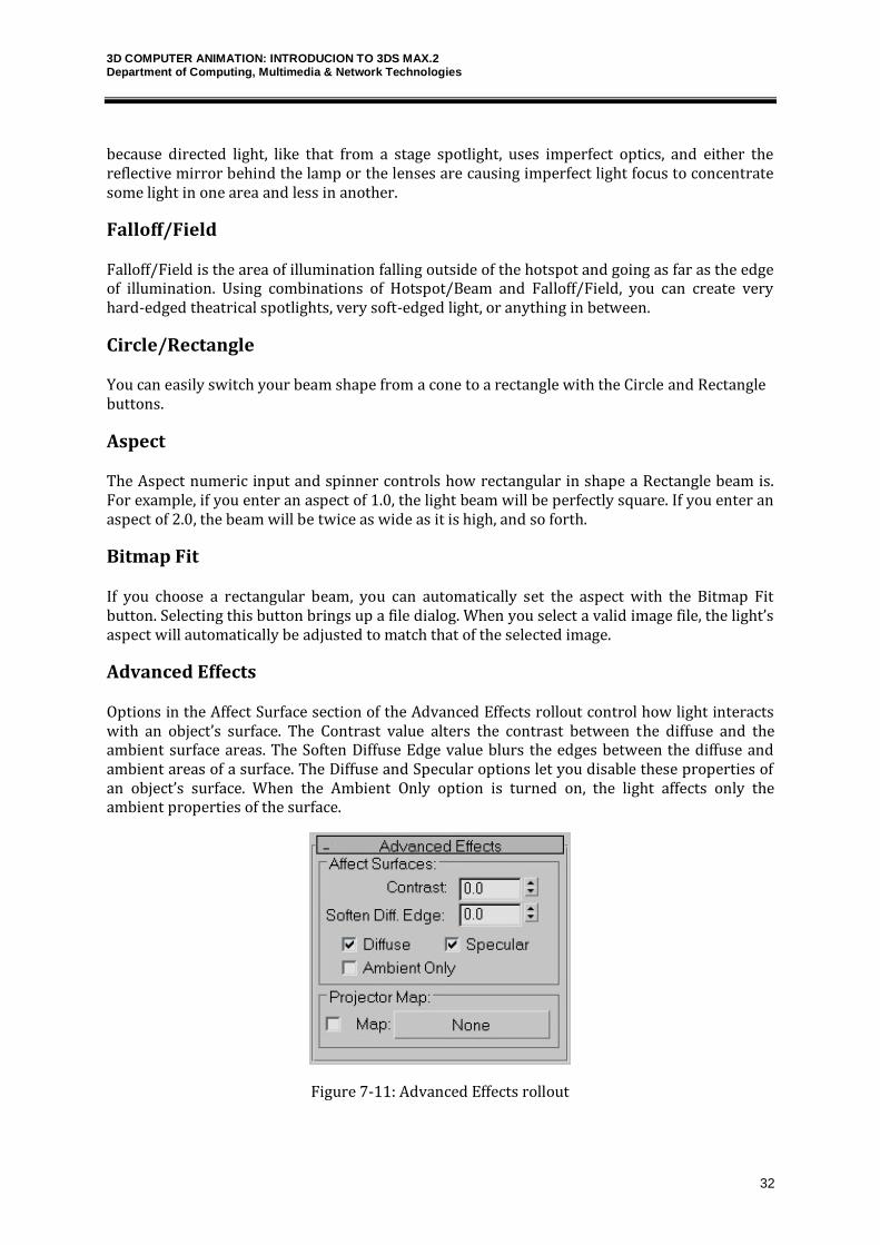
Advanced Effects
Options in the Affect Surface section of the Advanced Effects rollout control how light interacts with an object’s surface. The Contrast value alters the contrast between the diffuse and the ambient surface areas. The Soften Diffuse Edge value blurs the edges between the diffuse and ambient areas of a surface. The Diffuse and Specular options let you disable these properties of an object’s surface. When the Ambient Only option is turned on, the light affects only the ambient properties of the surface.
Figure 7-11: Advanced Effects rollout
3D COMPUTER ANIMATION: INTRODUCION TO 3DS MAX.2 Department of Computing, Multimedia & Network Technologies
33
You can use any light as a projector; you find this option in the Advance Effects rollouts. Selecting the Map option enables you to use the light as a projector. You can select a map to project by clicking the button to the right of the map option. You can drag a material map directly from the Material/Map Browser onto the Projector Map button.
3DS Max – tutorial – Cameras
Cameras present a scene from a particular point of view. Camera objects simulate still-image, motion picture, or video cameras in the real world.
The benefit of cameras is that you can position them anywhere within a scene to offer a custom view. You can open camera views in a view port, and you can also use them to render images or animated sequences.
Cameras in Max can also be. If you want to animate the point of view, you can create a camera and animate its position. For example, you might want to fly over a landscape or walk through a building. You can animate other camera parameters as well. For example, you can animate the camera's field of view to give the effect of zooming in on a scene.
There are two types of cameras in Max. They are Free camera and Target camera.
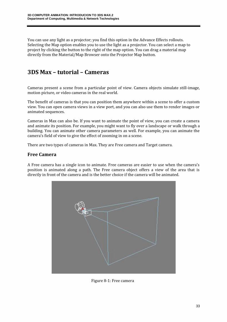
Free Camera
A Free camera has a single icon to animate. Free cameras are easier to use when the camera's position is animated along a path. The Free camera object offers a view of the area that is directly in front of the camera and is the better choice if the camera will be animated.
Figure 8-1: Free camera
3D COMPUTER ANIMATION: INTRODUCION TO 3DS MAX.2 Department of Computing, Multimedia & Network Technologies
34
When a Free camera is initially created, it points at the negative Z-axis of the active viewport. The single parameter for Free cameras defines a Target Distance—the distance to an invisible target about which the camera can orbit.
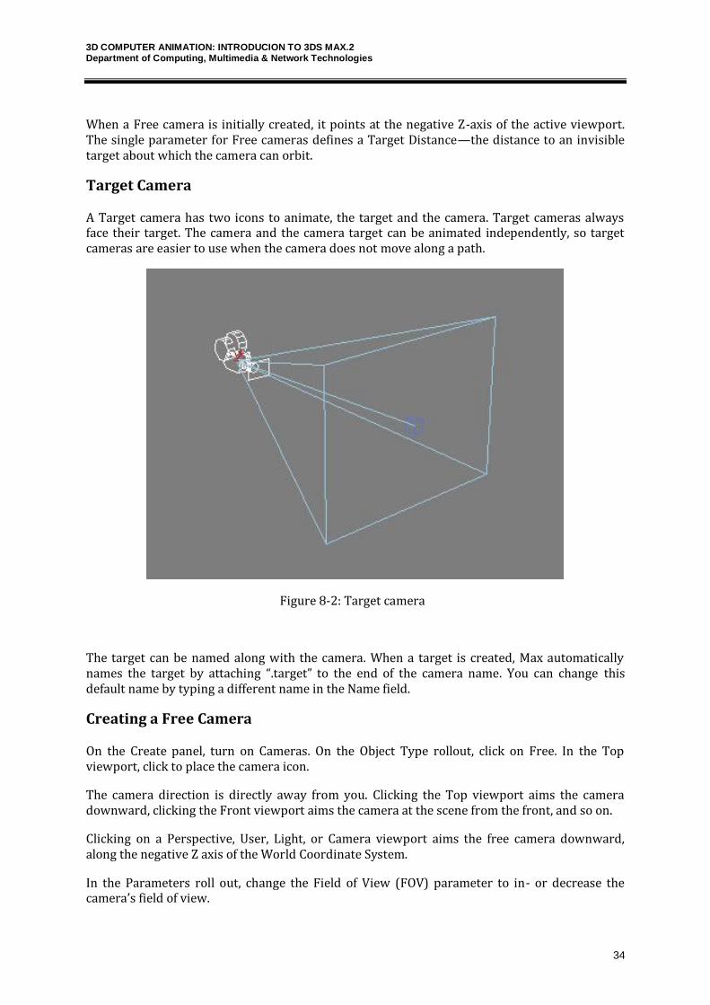
Target Camera
A Target camera has two icons to animate, the target and the camera. Target cameras always face their target. The camera and the camera target can be animated independently, so target cameras are easier to use when the camera does not move along a path.
Figure 8-2: Target camera
The target can be named along with the camera. When a target is created, Max automatically names the target by attaching “.target” to the end of the camera name. You can change this default name by typing a different name in the Name field.
Creating a Free Camera
On the Create panel, turn on Cameras. On the Object Type rollout, click on Free. In the Top viewport, click to place the camera icon.
The camera direction is directly away from you. Clicking the Top viewport aims the camera downward, clicking the Front viewport aims the camera at the scene from the front, and so on.
Clicking on a Perspective, User, Light, or Camera viewport aims the free camera downward, along the negative Z axis of the World Coordinate System.
In the Parameters roll out, change the Field of View (FOV) parameter to in- or decrease the camera’s field of view.
3D COMPUTER ANIMATION: INTRODUCION TO 3DS MAX.2 Department of Computing, Multimedia & Network Technologies
35
Creating a Target Camera
On the Create panel, turn on Cameras. On the Object Type rollout, click on Target.
In the Top viewport, click to place the camera icon, then drag toward the center of the object. Release the mouse button to set the target point.
Right-click on the Perspective viewport to make it active, then press the C key on the keyboard. This is a keyboard shortcut for Camera View. The Perspective viewport is replaced with the Camera Viewport. Notice in the bottom right that the Viewport navigation controls have changed. There are different controls for cameras than for the Perspective viewport. The viewport now shows what the camera "sees".
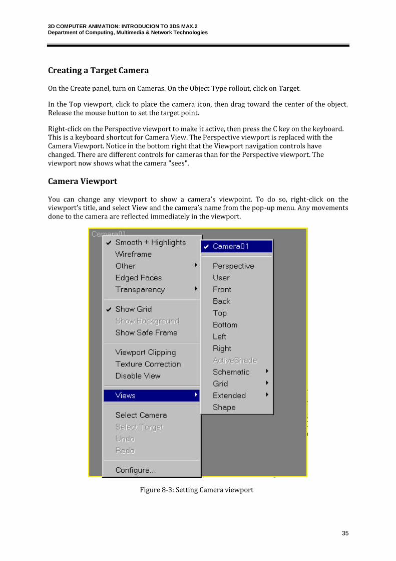
Camera Viewport
You can change any viewport to show a camera’s viewpoint. To do so, right-click on the viewport’s title, and select View and the camera’s name from the pop-up menu. Any movements done to the camera are reflected immediately in the viewport.
Figure 8-3: Setting Camera viewport
3D COMPUTER ANIMATION: INTRODUCION TO 3DS MAX.2 Department of Computing, Multimedia & Network Technologies
36
Another way to select a camera for a viewport is to press the C key. This keyboard shortcut makes the active viewport into a camera view. If several cameras exist in a scene, then the Select Camera dialog box appears, from which you can select a camera to use.
You can turn off the camera object icons using the Display panel. In the Display panel, under the Hide by Category rollout, select the Cameras option. When selected, the camera icons are not visible in the viewports.
Creating Camera from View
Create Camera From View creates a free camera whose field of view matches the current viewport. At the same time, it changes the viewport to a camera viewport for the new camera object, and makes the new camera the current selection.
To create a camera from a view, activate a perspective viewport.Adjust the perspective viewport using Pan, Zoom and Arc Rotate until you have view you like. Leaving the viewport active, on the Views menu choose Create Camera from View. The Perspective viewport label now reads Camera.
If there is already a camera in the scene and the camera is selected, then Create Camera from View will not create a new camera from the view. It will match the selected camera to the view instead, and switch the viewport to display what the selected camera sees.
Creating Parameters Rollout
When a camera is first created, you can modify the camera parameters directly in the Create panel as long as the new camera is selected. After the camera object has been deselected, you can make modifications in the Modify panel’s Parameters rollout for the camera.
3D COMPUTER ANIMATION: INTRODUCION TO 3DS MAX.2 Department of Computing, Multimedia & Network Technologies
37
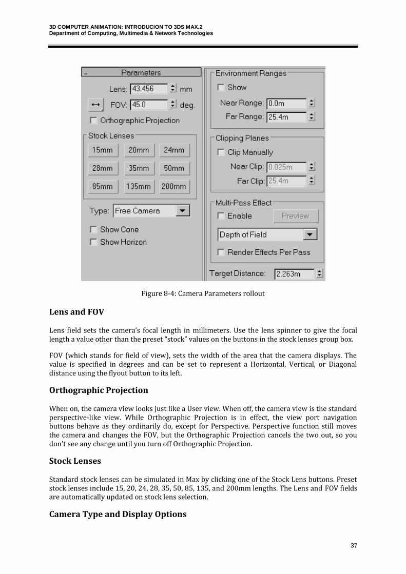
Figure 8-4: Camera Parameters rollout
Lens and FOV
Lens field sets the camera’s focal length in millimeters. Use the lens spinner to give the focal length a value other than the preset “stock” values on the buttons in the stock lenses group box.
FOV (which stands for field of view), sets the width of the area that the camera displays. The value is specified in degrees and can be set to represent a Horizontal, Vertical, or Diagonal distance using the flyout button to its left.
Orthographic Projection
When on, the camera view looks just like a User view. When off, the camera view is the standard perspective-like view. While Orthographic Projection is in effect, the view port navigation buttons behave as they ordinarily do, except for Perspective. Perspective function still moves the camera and changes the FOV, but the Orthographic Projection cancels the two out, so you don’t see any change until you turn off Orthographic Projection.
Stock Lenses
Standard stock lenses can be simulated in Max by clicking one of the Stock Lens buttons. Preset stock lenses include 15, 20, 24, 28, 35, 50, 85, 135, and 200mm lengths. The Lens and FOV fields are automatically updated on stock lens selection.
Camera Type and Display Options
3D COMPUTER ANIMATION: INTRODUCION TO 3DS MAX.2 Department of Computing, Multimedia & Network Technologies
38
Camera type changes the camera’s type from a Target Camera to a Free Camera, and vice versa.
The Show Cone option enables you to display the camera’s cone, showing the boundaries of the camera view when the camera isn’t selected. The Show Horizon option displays the horizon line. A dark gray line appears at the level of the horizon in the camera’s viewport.
Enviroment Ranges and Clipping
Environment ranges determine the near and far range limits for atmospheric effects you set in the Environment dialog.
Clipping planes let you exclude some of the scene´s geometry to view or render only certain portions of the scene. Objects closer than the near clipping plane or farther than the far clipping plane are invisible to the camera. The location of each clipping plane is measured along the camera's line of sight (its local Z axis) in the current units for the scene. In viewports, clipping planes are displayed as red rectangles (with diagonals) within the camera’s cone.
Multi-Pass Camera Effects
All cameras have the option to enable them to become multi-pass cameras. You can find these settings in the Parameters rollout when a camera object is selected. Checking the Enable button and selecting the effect from the drop-down list creates multi-pass cameras.
The available effects include Depth of Field (mental ray), Depth of Field, and Motion Blur. For each, an associated rollout of parameters opens.
The Multi-Pass Effect section of the Parameters rollout also includes a Preview button. This button makes the effect visible in the viewports. This feature can save you a significant amount of time that normally would be spent test-rendering the scene. The Preview button is worth its weight in render speed. Using this button, you can preview the effect without having to render the entire sequence.
The Render Effect Per Pass option causes any applied Render Effect to be applied at each pass. If disabled, then any of the applied Render Effect is applied after the passes are completed.
Camera Matching
The Camera Match tool is used to align a camera’s position to the background image. After you align the camera to the position that was used to take the image, you can place 3D objects within your scene and be assured that they will line up correctly with the objects within the image. For example, if you take a picture of a street scene and align the camera with the background image, then any cars or buildings that you digitally add to the scene are correctly aligned.

3D COMPUTER ANIMATION: INTRODUCION TO 3DS MAX.2 Department of Computing, Multimedia & Network Technologies
39
Figure 8-5: Camera Match utility
You can find the Camera Match tool in the Utilities panel. Before you can use this tool, you need to load a bitmap image as a background.
Camera Tracker
The Camera Tracker utility recreates the movements of a camera that was used to create an animated background. As with the Camera Match utility, you access the Camera Tracker utility from the Utilities panel. Click on the More button to open the Utilities dialog box, and select the Camera Tracker from the list of additional utilities.
3DS Max – tutorial – Rendering
Rendering creates a 2D image or animation based on your 3D scene. It shades the scene's geometry using the lighting you've set up, the materials you've applied, and environment settings such as background and atmosphere.
Max includes a Scanline Renderer that is optimized to speed up this process, and several settings exist that you can use to make this process even faster. Understanding the Render Scene dialog box and its functions can save you many headaches and computer cycles.
3D COMPUTER ANIMATION: INTRODUCION TO 3DS MAX.2 Department of Computing, Multimedia & Network Technologies
40
Rendering Menu
The Rendering menu contains commands for rendering scenes, setting up environmental and render effects, composing scenes with Video Post, and accessing the RAM Player.
The Render command opens the Render Scene dialog box where you can set output options such as which frames to render and the final image size.
Environment displays the Environment panel, which is used for setting up atmospheric and background effects such as a background color or image, global lighting settings, and atmospheric effects such as Combustion, Fog, and Volume Lights.
The Effects command opens the Rendering Effects dialog box. You use the Rendering Effects dialog box to add rendered effects to an image without having to use the Video Post dialog box.
The Advanced Lighting command opens a control panel where the settings for the Light Tracer, Radiosity, Exposure Control, and Lighting Analysis tools are located.
Rendering to texture, or "texture baking,” allows you to create texture maps based on an object's appearance in the rendered scene. The textures are then “baked” into the object: that is, they become part of the object via mapping, and can be used to display the textured object rapidly on Direct3D devices such as graphics display cards or game engines.
The Raytracer Settings command opens a dialog box for enabling raytracing options, and the Raytrace Global Include/Exclude command opens a dialog box where you can specify which objects are rendered using raytracing and which are not.
The Mental ray Messages Window displays log messages (other than debug messages) generated by the mental ray renderer.
The ActiveShade Floater opens the ActiveShade window, where you can get immediate rendered results. The ActiveShade Viewport command displays the immediate rendered results in the active viewport.
The Material Editor provides functions to create and edit materials and maps. The Material Editor (keyboard shortcut, M) and Material/Map Browser commands open their respective dialog boxes for creating, defining, and applying materials.
The Video Post command opens a dialog box for scheduling and controlling any post-processing work. The dialog box manages events for compositing images and including special effects such as glows, lens effects, and blurs. The Show Last Rendering command immediately recalls the last rendered image produced by the Render command.
The Panorama Exporter command allows you to render a panoramic scene. The Print Size Wizard is a godsend for anyone who is printing images from Max. It relates the current scene to the common paper sizes that printers use. The RAM Player can display images and animations in memory and includes two channels for overlaying images and comparing animations side by side.
Common Rendering Parameters
The Render Scene dialog's Common panel contains controls that apply to any rendering, regardless of which renderer you have chosen, and that lets you choose renderers.
3D COMPUTER ANIMATION: INTRODUCION TO 3DS MAX.2 Department of Computing, Multimedia & Network Technologies
41
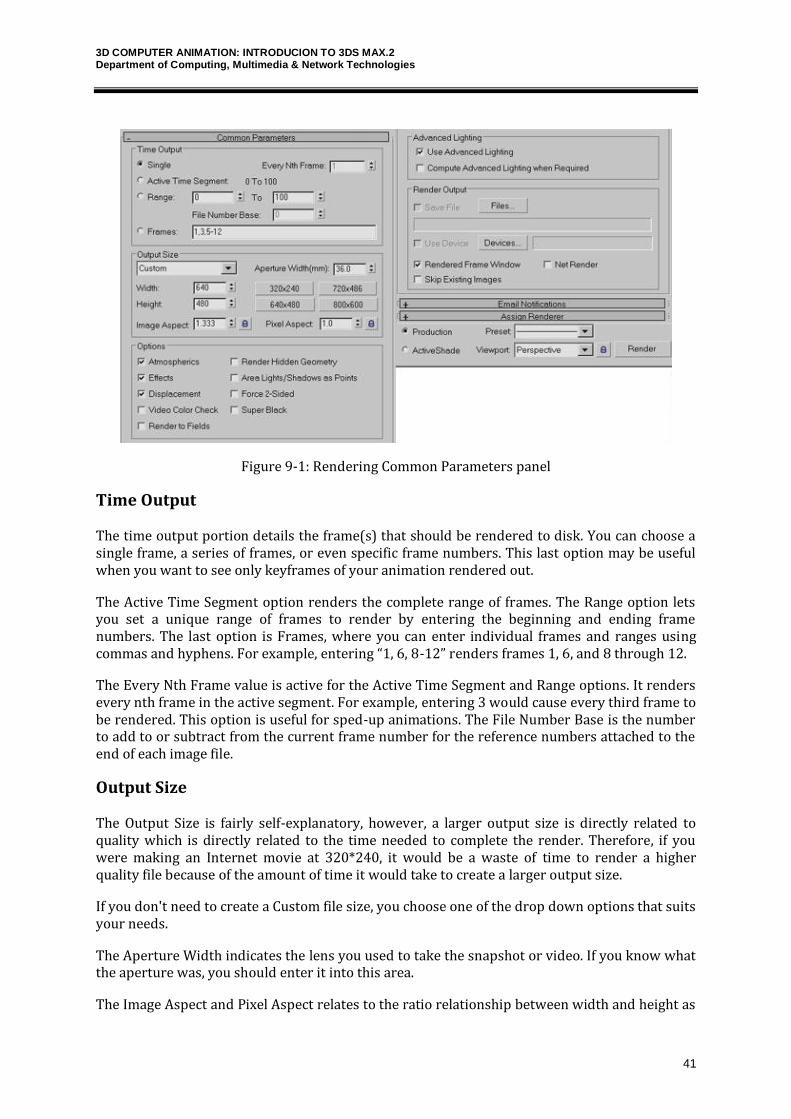
Figure 9-1: Rendering Common Parameters panel
Time Output
The time output portion details the frame(s) that should be rendered to disk. You can choose a single frame, a series of frames, or even specific frame numbers. This last option may be useful when you want to see only keyframes of your animation rendered out.
The Active Time Segment option renders the complete range of frames. The Range option lets you set a unique range of frames to render by entering the beginning and ending frame numbers. The last option is Frames, where you can enter individual frames and ranges using commas and hyphens. For example, entering “1, 6, 8-12” renders frames 1, 6, and 8 through 12.
The Every Nth Frame value is active for the Active Time Segment and Range options. It renders every nth frame in the active segment. For example, entering 3 would cause every third frame to be rendered. This option is useful for sped-up animations. The File Number Base is the number to add to or subtract from the current frame number for the reference numbers attached to the end of each image file.
Output Size
The Output Size is fairly self-explanatory, however, a larger output size is directly related to quality which is directly related to the time needed to complete the render. Therefore, if you were making an Internet movie at 320*240, it would be a waste of time to render a higher quality file because of the amount of time it would take to create a larger output size.
If you don't need to create a Custom file size, you choose one of the drop down options that suits your needs.
The Aperture Width indicates the lens you used to take the snapshot or video. If you know what the aperture was, you should enter it into this area.
The Image Aspect and Pixel Aspect relates to the ratio relationship between width and height as
3D COMPUTER ANIMATION: INTRODUCION TO 3DS MAX.2 Department of Computing, Multimedia & Network Technologies
42
well as how the pixels are drawn onto the screen respectively. A Pixel Aspect of 1.0 looks great on a computer screen, but DV uses 0.9. This often looks a bit distorted on a computer screen, but looks great on a TV source.
Options
The Options menu allows additional control over how the file will be rendered.
Atmospherics, Effects, and Displacement are rendered out by default, however, they can take a long time to render. If you want to speed up the render time and render out a quick test, atmospherics can be turned off in the renderer.
On the other hand, items like Force 2-Sided is unselected by default. When a basic shape like a box or a sphere are created, they only have an outside. If you zoom towards one of these shapes to the point that you are inside of it, the inside lacks any color or material. There are ways to modify the shape, and the way the colors and materials affect it to show both the inside and outside. However, forcing a 2-sided render will accomplish this task.
If you completed the box explosion tutorial, you will have noticed that when the box's pieces flip in the air, they disappear. This is a result of the box having only one side. By rendering both sides, a more realistic tumble through the air will be created.
Advanced Lighting
The Advanced Lighting panel offers options to use Advanced Lighting or Computer Advanced Lighting when Required. Advanced lighting can take a long time to compute, so these two options give you the ability to turn advanced lighting on or off.
The Render Output section enables you to output the image or animations to a file, a device, or the Rendered Frame Window. To save the output to a file, click the Files button and select a location in the Render Output File dialog box. Supported formats include .AVI, .BMP, .DDS, Postscript (.EPS), JPEG, Kodak Cineon (.CIN), .FLC, Radiance Image File (.HDRI), QuickTime (.MOV), .PNG, .RLA, .RPF, SGI’s Format (.RGB), Targa (.TGA), and .TIF. The Device button can output to a device such as a video recorder. If the Rendered Frame Window option is selected, then both the Files and Devices buttons are disabled.
Render Output
The Render Output menu is as important as choosing which frames to render. If you do not complete this step, clicking on render will create nothing at all. You must select the Files button in order to decide the name of the output file, where it will be saved, and in what format. This may include a series of still images, or it may be an avi file using the DiVX codec.
When you choose to render a particular output type for the first time, you will be provided with the specific options for the chosen codec.
The Use Device option is related to an external video device that you may want to record to.
The Virtual Frame Buffer, if selected, will allow you to see each frame as it is rendered.
Net Render, if selected, will check to see if you have a network render farm setup and will request which frames it should render while other computers on your network are working
3D COMPUTER ANIMATION: INTRODUCION TO 3DS MAX.2 Department of Computing, Multimedia & Network Technologies
43
hard to complete other frames.
Finally, Skip Existing Images refers to the possibility that you rendered using individual images rather than an AVI file and that for some reason the rendering was interrupted. You can resume the rendering without having to re-render existing images. Unfortunately, an AVI will need to be re-rendered rather than being appended too.
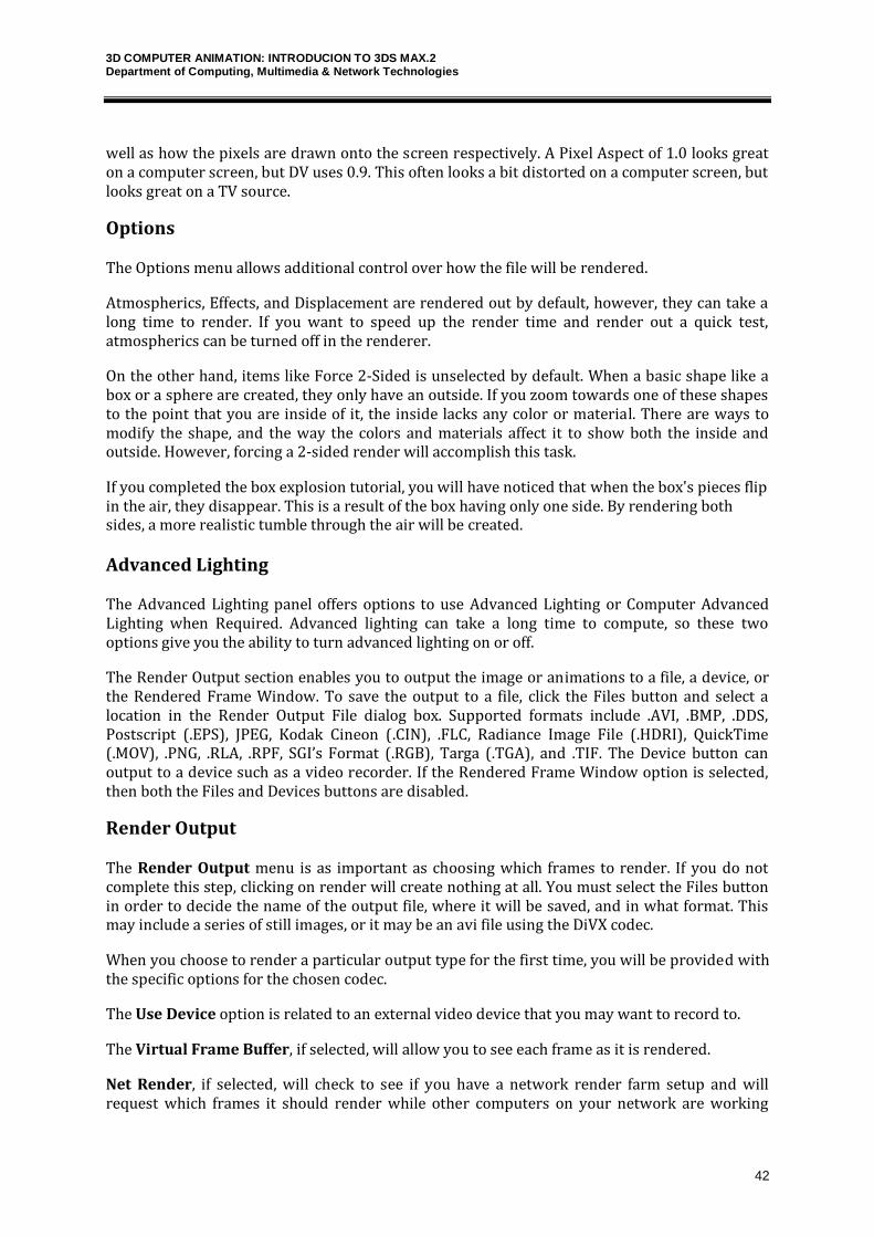
E-Mail Notifications
The process of rendering animation (or even a single frame) can be brief or it can take several days, depending on the complexity of the scene. For complex scenes that will take a while to render, you can configure Max to send you an e-mail message when your rendering is complete or if it fails. These options are in the Email Notifications rollout.
In addition to the options, you can enter whom the e-mail is from, whom it is to be sent to, and an SMTP Server.
Figure 9-2: Email Notifications rollout
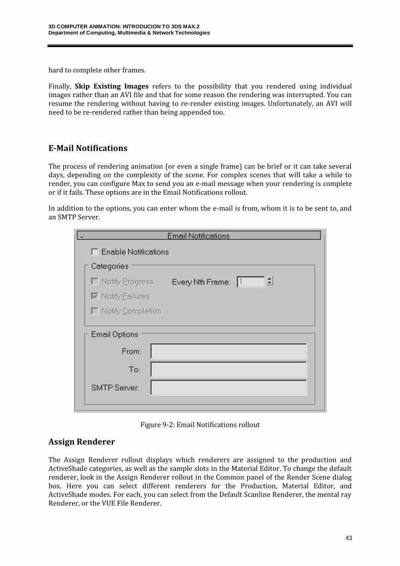
Assign Renderer
The Assign Renderer rollout displays which renderers are assigned to the production and ActiveShade categories, as well as the sample slots in the Material Editor. To change the default renderer, look in the Assign Renderer rollout in the Common panel of the Render Scene dialog box. Here you can select different renderers for the Production, Material Editor, and ActiveShade modes. For each, you can select from the Default Scanline Renderer, the mental ray Renderer, or the VUE File Renderer.
3D COMPUTER ANIMATION: INTRODUCION TO 3DS MAX.2 Department of Computing, Multimedia & Network Technologies
44
Figure 9-3: Assign Renderer rollout
Final Options
The Final Options provide some basic, but important features. The first permits you to choose between a Production and an Active Shade. The Production shade is the highest in quality, while Active Shade is a lower quality that renders much faster.
Figure 9-4: Final options
The Viewport option is also quite significant. Of the four possible views that are displayed on your screen at one time, you can choose which to render out. The perspective view, for example, will provide a 3D view whereas a front, right, and left view will be a 2D view.
Finally, by clicking on Render you confirm all the options and it will render out your still or video.
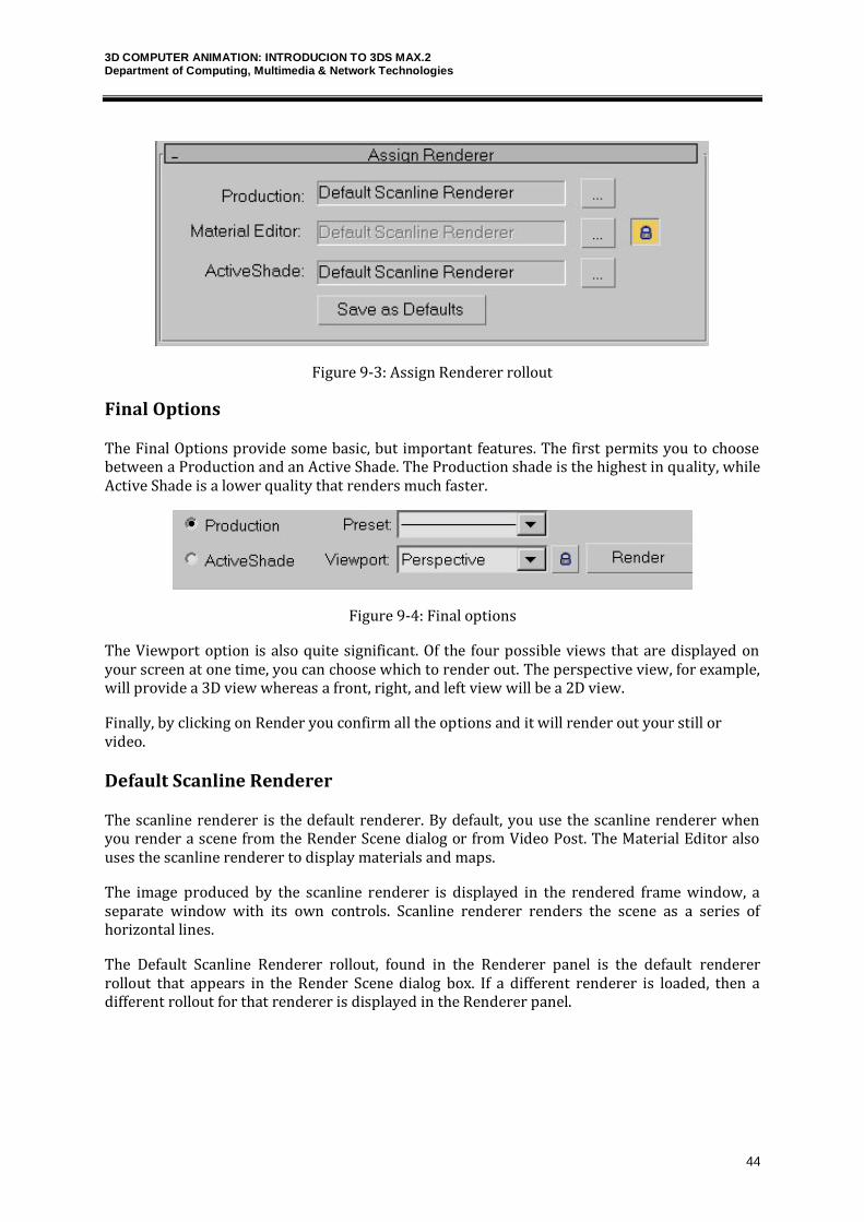
Default Scanline Renderer
The scanline renderer is the default renderer. By default, you use the scanline renderer when you render a scene from the Render Scene dialog or from Video Post. The Material Editor also uses the scanline renderer to display materials and maps.
The image produced by the scanline renderer is displayed in the rendered frame window, a separate window with its own controls. Scanline renderer renders the scene as a series of horizontal lines.
The Default Scanline Renderer rollout, found in the Renderer panel is the default renderer rollout that appears in the Render Scene dialog box. If a different renderer is loaded, then a different rollout for that renderer is displayed in the Renderer panel.
3D COMPUTER ANIMATION: INTRODUCION TO 3DS MAX.2 Department of Computing, Multimedia & Network Technologies
45
Figure 9-5: Default Scanline Renderer rollout
Options
Options section furnishes the control for toggling on-off features like mapping, shadows and reflections in order to speed up rendering for performing test renders.
Mapping is turned off to ignore all mapping information. It affects automatic reflections and environment maps, as well as material mapping. Turning off the shadows speeds up the test rendering. Auto Reflect/Refract and Mirrors when turned off, ignores automatic reflection/refraction maps to speed up rendering for tests.
Force Wireframe is used to render all surfaces in the scene as wireframes. You can choose the thickness of the wireframe in pixels.
Turning on Enable SSE uses Streaming SIMD Extensions (SSE). SIMD stands for Single Instruction, Multiple Data. Depending on the CPU (or CPUs) of your system, SSE can improve render time.
Antialiasing
Antialiasing smoothes the jagged edges along the border lines when rendering. Filter drop-down list lets you choose the filter that works at the sub-pixel level to perform the antialiasing. The Filter Maps option allows you to disable the computationally expensive process of filtering material maps. The Filter Size value applies only to the Soften filter.
Global Supersampling
Global Supersampling is an additional antialiasing process that you can apply to materials. This
3D COMPUTER ANIMATION: INTRODUCION TO 3DS MAX.2 Department of Computing, Multimedia & Network Technologies
46
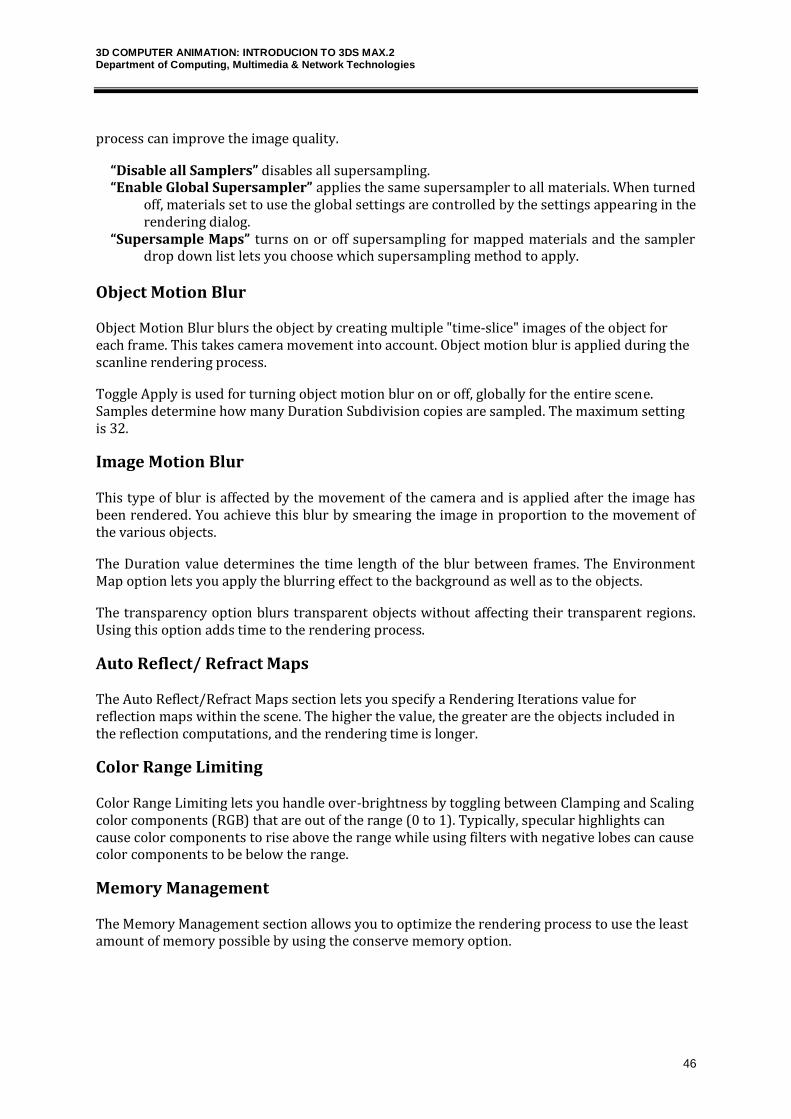
process can improve the image quality.
“Disable all Samplers” disables all supersampling. “Enable Global Supersampler” applies the same supersampler to all materials. When turned
off, materials set to use the global settings are controlled by the settings appearing in the rendering dialog.
“Supersample Maps” turns on or off supersampling for mapped materials and the sampler drop down list lets you choose which supersampling method to apply.
Object Motion Blur
Object Motion Blur blurs the object by creating multiple "time-slice" images of the object for each frame. This takes camera movement into account. Object motion blur is applied during the scanline rendering process.
Toggle Apply is used for turning object motion blur on or off, globally for the entire scene. Samples determine how many Duration Subdivision copies are sampled. The maximum setting is 32.
Image Motion Blur
This type of blur is affected by the movement of the camera and is applied after the image has been rendered. You achieve this blur by smearing the image in proportion to the movement of the various objects.
The Duration value determines the time length of the blur between frames. The Environment Map option lets you apply the blurring effect to the background as well as to the objects.
The transparency option blurs transparent objects without affecting their transparent regions. Using this option adds time to the rendering process.
Auto Reflect/ Refract Maps
The Auto Reflect/Refract Maps section lets you specify a Rendering Iterations value for reflection maps within the scene. The higher the value, the greater are the objects included in the reflection computations, and the rendering time is longer.
Color Range Limiting
Color Range Limiting lets you handle over-brightness by toggling between Clamping and Scaling color components (RGB) that are out of the range (0 to 1). Typically, specular highlights can cause color components to rise above the range while using filters with negative lobes can cause color components to be below the range.
Memory Management
The Memory Management section allows you to optimize the rendering process to use the least amount of memory possible by using the conserve memory option.
3D COMPUTER ANIMATION: INTRODUCION TO 3DS MAX.2 Department of Computing, Multimedia & Network Technologies
47
3DS Max – tutorial – Scene Creation
Scene Creation
You have read and perceived various aspects of scene creation in the previous chapters. In this chapter, some exercises related to the concepts of modeling, texturing, animation and lighting setup, to create an indoor room scene are elucidated.
To create a new scene, choose “File>New” Menu command or use “Ctrl+N” Keyboard shortcut. On the new scene dialog box, select “New All” and click on OK. This will create a new workspace with default setup.
Modeling
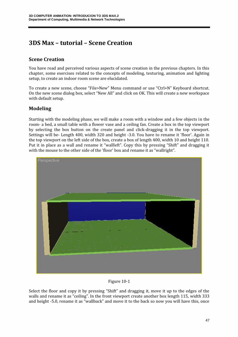
Starting with the modeling phase, we will make a room with a window and a few objects in the room- a bed, a small table with a flower vase and a ceiling fan. Create a box in the top viewport by selecting the box button on the create panel and click-dragging it in the top viewport. Settings will be- Length 400, width 320 and height -3.0. You have to rename it 'floor'. Again in the top viewport on the left side of the box, create a box of length 400, width 10 and height 110. Put it in place as a wall and rename it “wallleft”. Copy this by pressing “Shift” and dragging it with the mouse to the other side of the 'floor' box and rename it as “wallright”.
Figure 10-1
Select the floor and copy it by pressing “Shift” and dragging it, move it up to the edges of the walls and rename it as “ceiling”. In the front viewport create another box length 115, width 333 and height -5.0, rename it as “wallback” and move it to the back so now you will have this, once
3D COMPUTER ANIMATION: INTRODUCION TO 3DS MAX.2 Department of Computing, Multimedia & Network Technologies
48
you move your perspective viewport correctly in the figure given above.
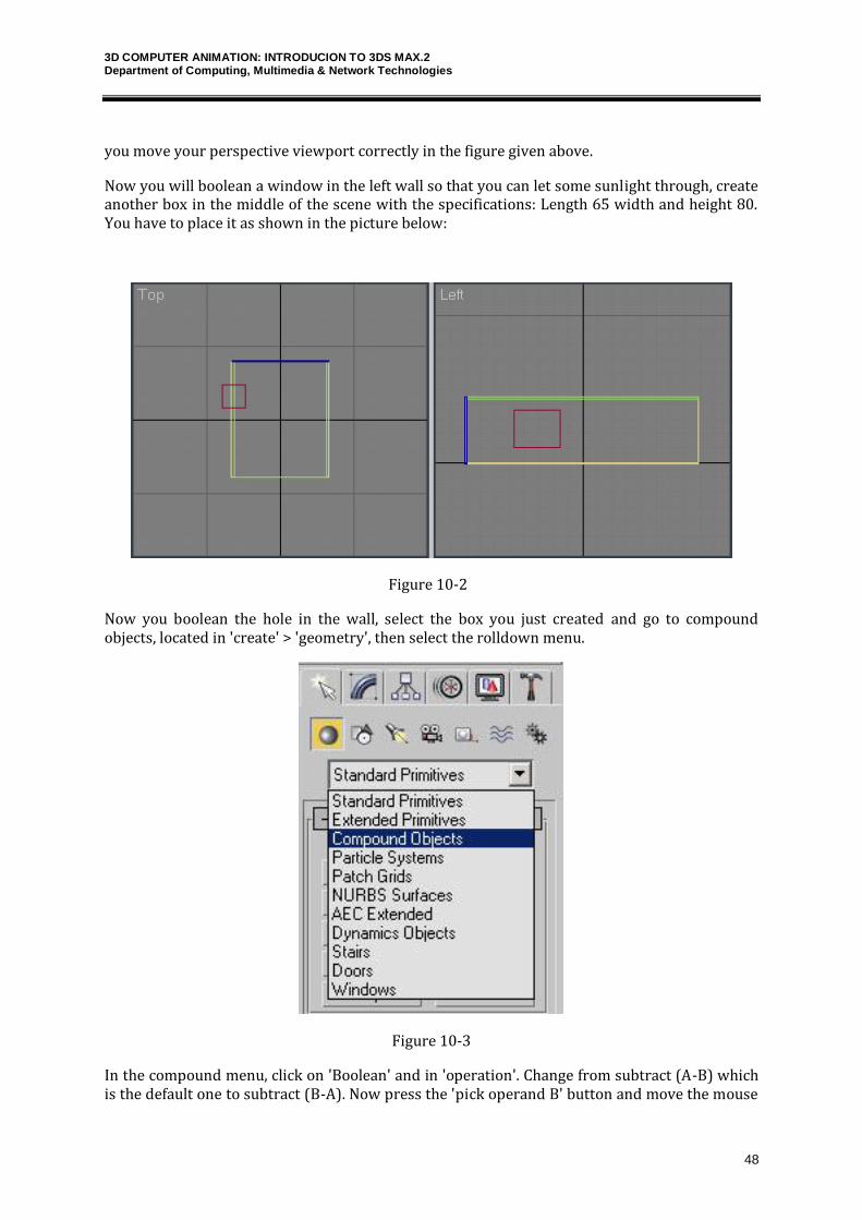
Now you will boolean a window in the left wall so that you can let some sunlight through, create another box in the middle of the scene with the specifications: Length 65 width and height 80. You have to place it as shown in the picture below:
Figure 10-2
Now you boolean the hole in the wall, select the box you just created and go to compound objects, located in 'create' > 'geometry', then select the rolldown menu.
Figure 10-3
In the compound menu, click on 'Boolean' and in 'operation'. Change from subtract (A-B) which is the default one to subtract (B-A). Now press the 'pick operand B' button and move the mouse

3D COMPUTER ANIMATION: INTRODUCION TO 3DS MAX.2 Department of Computing, Multimedia & Network Technologies
49
over to the front viewport and click on 'leftwall' where the window will be. So now you have a 'window'.
Figure 10-4
Now you have to create a small table at the right corner of the room. Start by making a box in the top view with the specifications: length, width 35 and height 3. Position the box as shown in the figure below.
Figure 10-5
To create the legs for the table, create a box with length, width 4 and height 25. Make three more copies of the box and place the 4 legs as shown in the given figure.
3D COMPUTER ANIMATION: INTRODUCION TO 3DS MAX.2 Department of Computing, Multimedia & Network Technologies
50
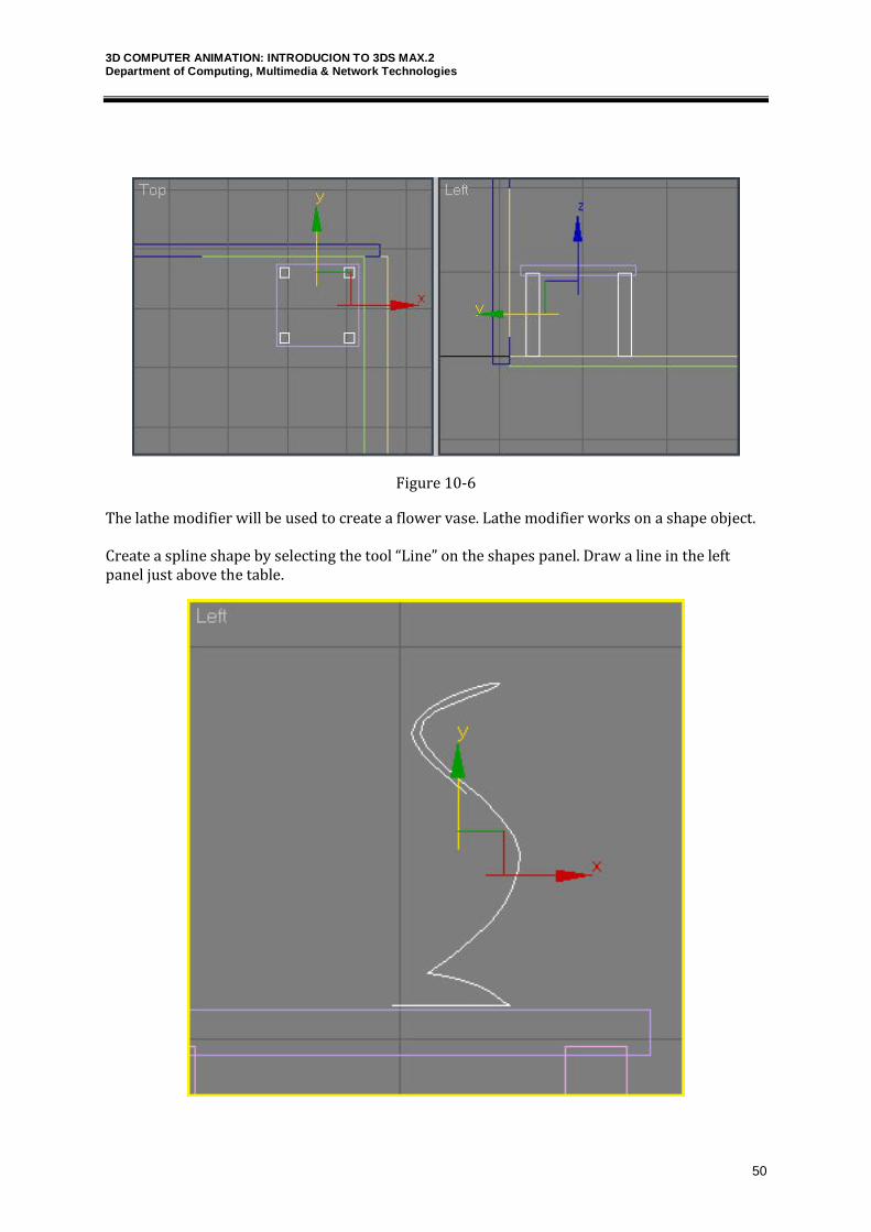
Figure 10-6
The lathe modifier will be used to create a flower vase. Lathe modifier works on a shape object. Create a spline shape by selecting the tool “Line” on the shapes panel. Draw a line in the left panel just above the table.
3D COMPUTER ANIMATION: INTRODUCION TO 3DS MAX.2 Department of Computing, Multimedia & Network Technologies
51
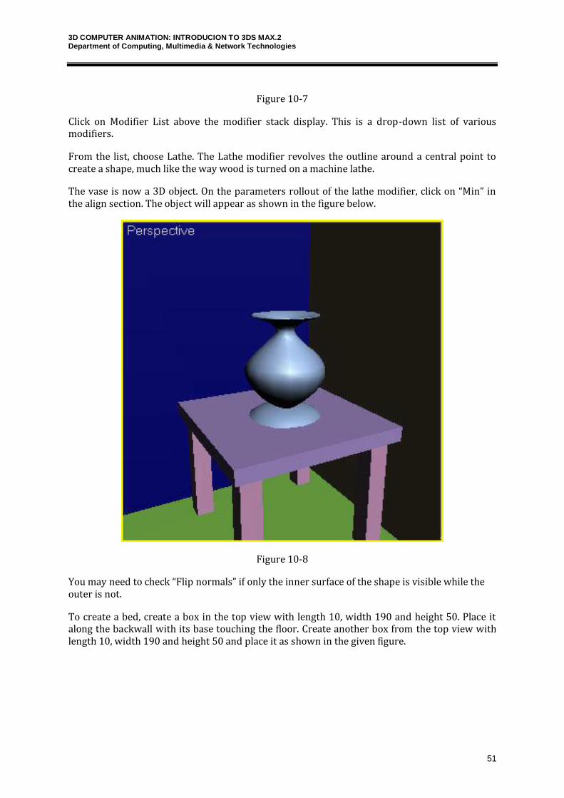
Figure 10-7
Click on Modifier List above the modifier stack display. This is a drop-down list of various modifiers.
From the list, choose Lathe. The Lathe modifier revolves the outline around a central point to create a shape, much like the way wood is turned on a machine lathe.
The vase is now a 3D object. On the parameters rollout of the lathe modifier, click on “Min” in the align section. The object will appear as shown in the figure below.
Figure 10-8
You may need to check “Flip normals” if only the inner surface of the shape is visible while the outer is not.
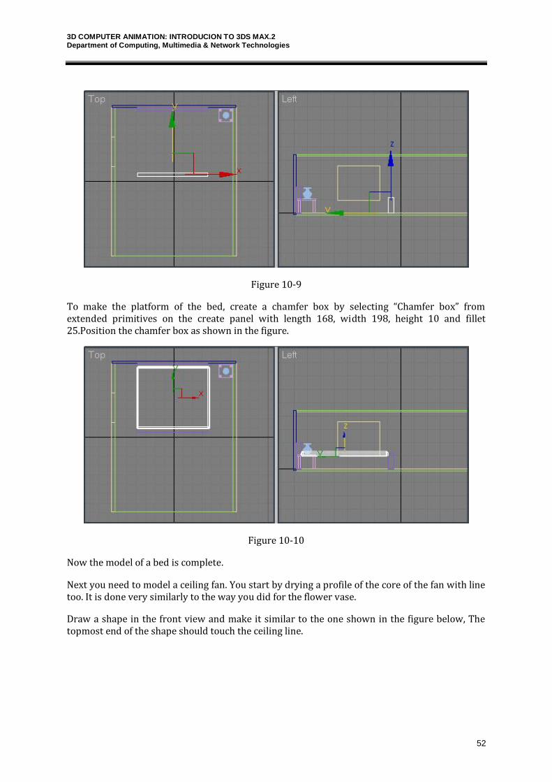
To create a bed, create a box in the top view with length 10, width 190 and height 50. Place it along the backwall with its base touching the floor. Create another box from the top view with length 10, width 190 and height 50 and place it as shown in the given figure.
3D COMPUTER ANIMATION: INTRODUCION TO 3DS MAX.2 Department of Computing, Multimedia & Network Technologies
52
Figure 10-9
To make the platform of the bed, create a chamfer box by selecting “Chamfer box” from extended primitives on the create panel with length 168, width 198, height 10 and fillet 25.Position the chamfer box as shown in the figure.
Figure 10-10
Now the model of a bed is complete.
Next you need to model a ceiling fan. You start by drying a profile of the core of the fan with line too. It is done very similarly to the way you did for the flower vase.
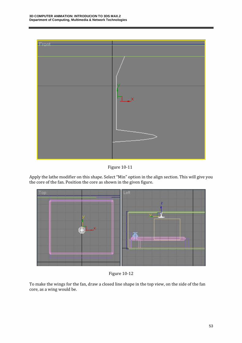
Draw a shape in the front view and make it similar to the one shown in the figure below, The topmost end of the shape should touch the ceiling line.
3D COMPUTER ANIMATION: INTRODUCION TO 3DS MAX.2 Department of Computing, Multimedia & Network Technologies
53
Figure 10-11
Apply the lathe modifier on this shape. Select “Min” option in the align section. This will give you the core of the fan. Position the core as shown in the given figure.
Figure 10-12
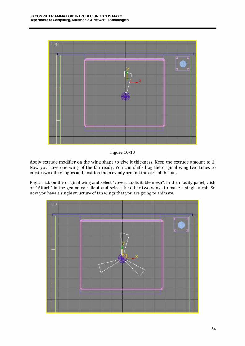
To make the wings for the fan, draw a closed line shape in the top view, on the side of the fan core, as a wing would be.
3D COMPUTER ANIMATION: INTRODUCION TO 3DS MAX.2 Department of Computing, Multimedia & Network Technologies
54
Figure 10-13
Apply extrude modifier on the wing shape to give it thickness. Keep the extrude amount to 1. Now you have one wing of the fan ready. You can shift-drag the original wing two times to create two other copies and position them evenly around the core of the fan.
Right click on the original wing and select “covert to>Editable mesh”. In the modify panel, click on “Attach” in the geometry rollout and select the other two wings to make a single mesh. So now you have a single structure of fan wings that you are going to animate.
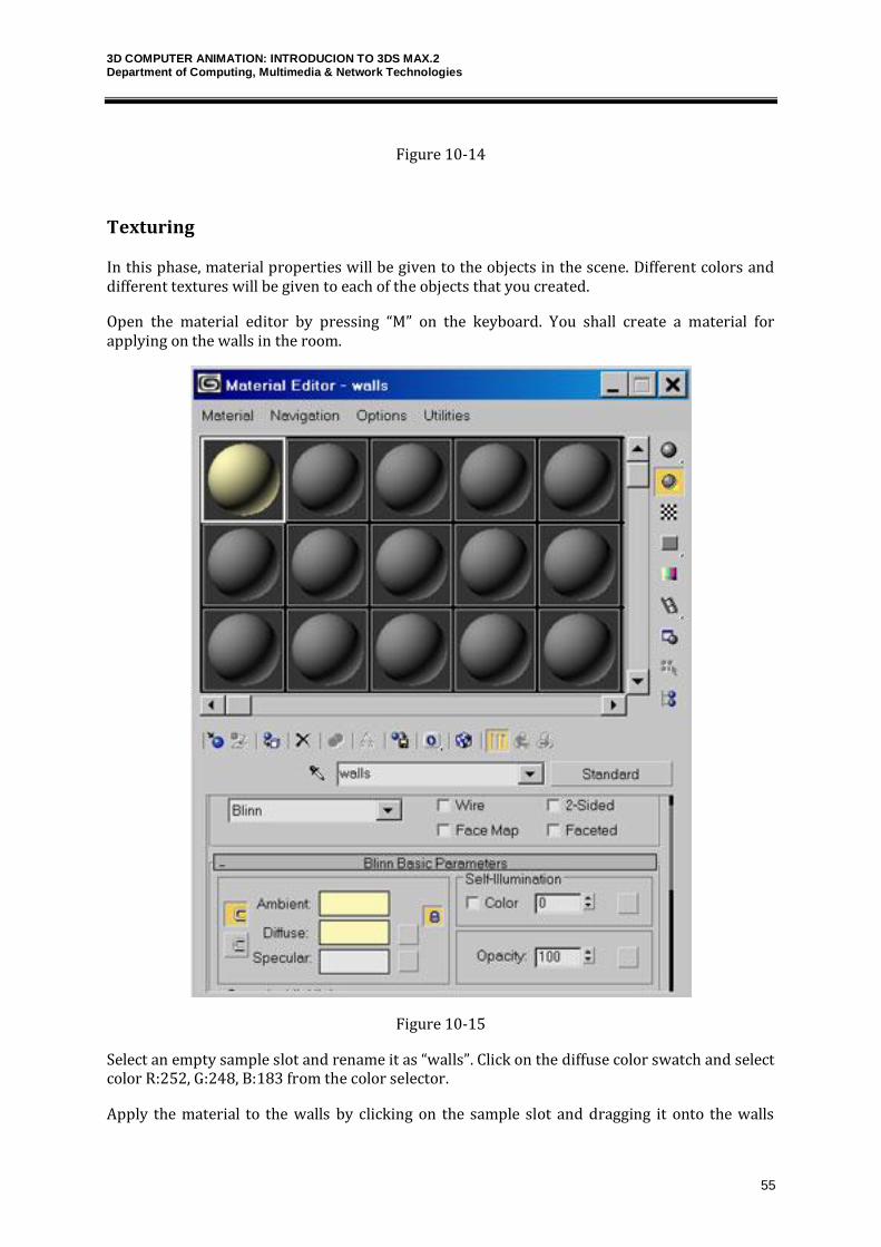
3D COMPUTER ANIMATION: INTRODUCION TO 3DS MAX.2 Department of Computing, Multimedia & Network Technologies
55
Figure 10-14
Texturing
In this phase, material properties will be given to the objects in the scene. Different colors and different textures will be given to each of the objects that you created.
Open the material editor by pressing “M” on the keyboard. You shall create a material for applying on the walls in the room.
Figure 10-15
Select an empty sample slot and rename it as “walls”. Click on the diffuse color swatch and select color R:252, G:248, B:183 from the color selector.
Apply the material to the walls by clicking on the sample slot and dragging it onto the walls
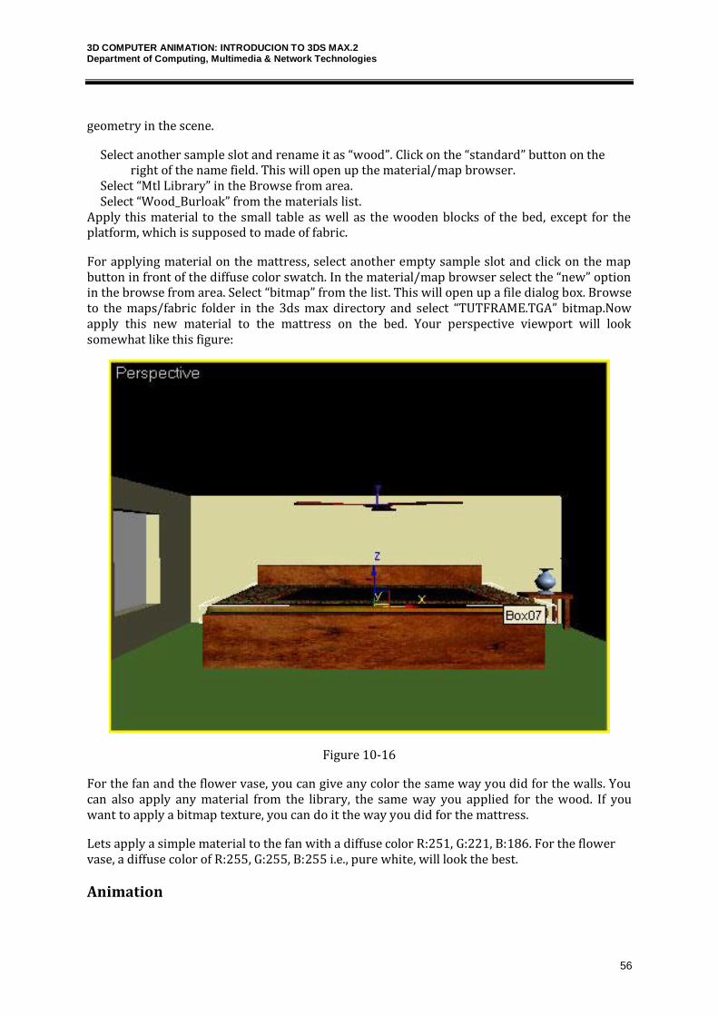
3D COMPUTER ANIMATION: INTRODUCION TO 3DS MAX.2 Department of Computing, Multimedia & Network Technologies
56
geometry in the scene.
Select another sample slot and rename it as “wood”. Click on the “standard” button on the right of the name field. This will open up the material/map browser.
Select “Mtl Library” in the Browse from area. Select “Wood_Burloak” from the materials list. Apply this material to the small table as well as the wooden blocks of the bed, except for the platform, which is supposed to made of fabric.
For applying material on the mattress, select another empty sample slot and click on the map button in front of the diffuse color swatch. In the material/map browser select the “new” option in the browse from area. Select “bitmap” from the list. This will open up a file dialog box. Browse to the maps/fabric folder in the 3ds max directory and select “TUTFRAME.TGA” bitmap.Now apply this new material to the mattress on the bed. Your perspective viewport will look somewhat like this figure:
Figure 10-16
For the fan and the flower vase, you can give any color the same way you did for the walls. You can also apply any material from the library, the same way you applied for the wood. If you want to apply a bitmap texture, you can do it the way you did for the mattress.
Lets apply a simple material to the fan with a diffuse color R:251, G:221, B:186. For the flower vase, a diffuse color of R:255, G:255, B:255 i.e., pure white, will look the best.
Animation
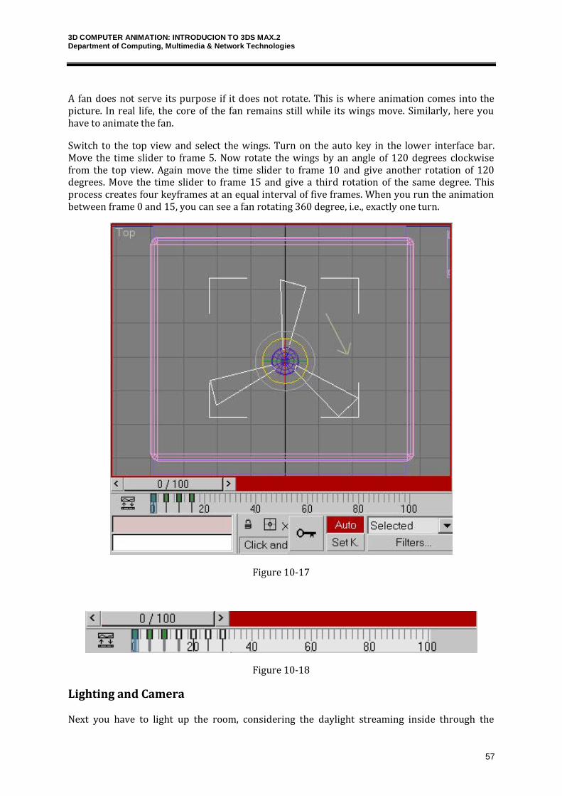
3D COMPUTER ANIMATION: INTRODUCION TO 3DS MAX.2 Department of Computing, Multimedia & Network Technologies
57
A fan does not serve its purpose if it does not rotate. This is where animation comes into the picture. In real life, the core of the fan remains still while its wings move. Similarly, here you have to animate the fan.
Switch to the top view and select the wings. Turn on the auto key in the lower interface bar. Move the time slider to frame 5. Now rotate the wings by an angle of 120 degrees clockwise from the top view. Again move the time slider to frame 10 and give another rotation of 120 degrees. Move the time slider to frame 15 and give a third rotation of the same degree. This process creates four keyframes at an equal interval of five frames. When you run the animation between frame 0 and 15, you can see a fan rotating 360 degree, i.e., exactly one turn.
Figure 10-17
Figure 10-18
Lighting and Camera
Next you have to light up the room, considering the daylight streaming inside through the
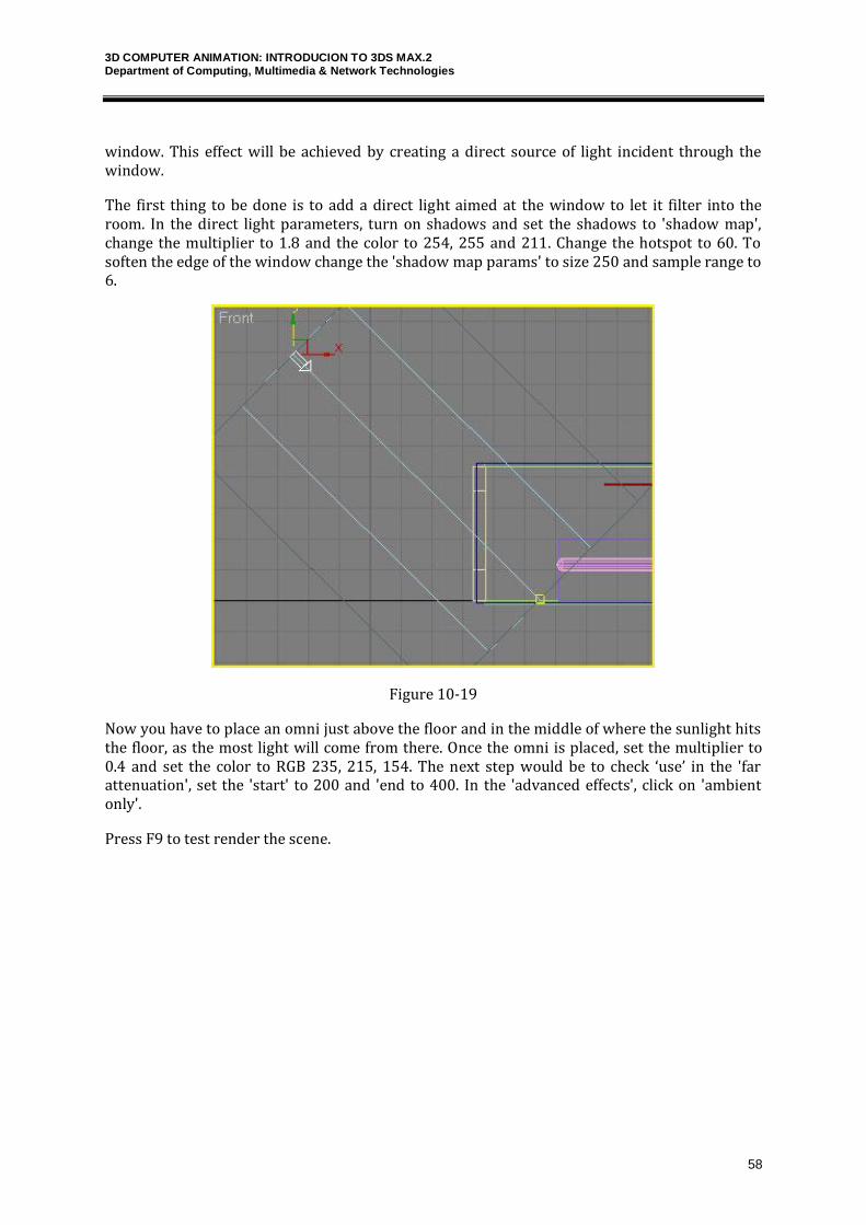
3D COMPUTER ANIMATION: INTRODUCION TO 3DS MAX.2 Department of Computing, Multimedia & Network Technologies
58
window. This effect will be achieved by creating a direct source of light incident through the window.
The first thing to be done is to add a direct light aimed at the window to let it filter into the room. In the direct light parameters, turn on shadows and set the shadows to 'shadow map', change the multiplier to 1.8 and the color to 254, 255 and 211. Change the hotspot to 60. To soften the edge of the window change the 'shadow map params' to size 250 and sample range to 6.
Figure 10-19
Now you have to place an omni just above the floor and in the middle of where the sunlight hits the floor, as the most light will come from there. Once the omni is placed, set the multiplier to 0.4 and set the color to RGB 235, 215, 154. The next step would be to check ‘use’ in the 'far attenuation', set the 'start' to 200 and 'end to 400. In the 'advanced effects', click on 'ambient only'.
Press F9 to test render the scene.
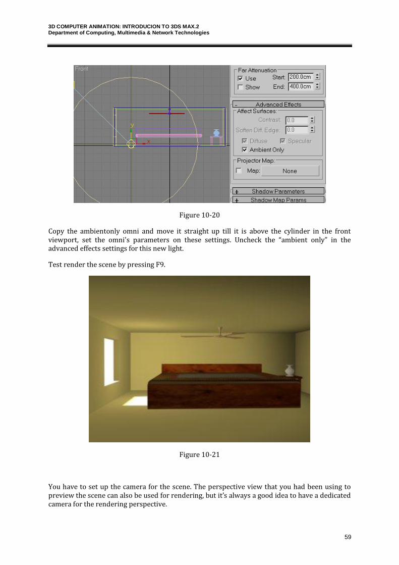
3D COMPUTER ANIMATION: INTRODUCION TO 3DS MAX.2 Department of Computing, Multimedia & Network Technologies
59
Figure 10-20
Copy the ambientonly omni and move it straight up till it is above the cylinder in the front viewport, set the omni's parameters on these settings. Uncheck the “ambient only” in the advanced effects settings for this new light.
Test render the scene by pressing F9.
Figure 10-21
You have to set up the camera for the scene. The perspective view that you had been using to preview the scene can also be used for rendering, but it’s always a good idea to have a dedicated camera for the rendering perspective.
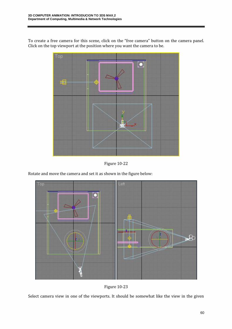
3D COMPUTER ANIMATION: INTRODUCION TO 3DS MAX.2 Department of Computing, Multimedia & Network Technologies
60
To create a free camera for this scene, click on the “free camera” button on the camera panel. Click on the top viewport at the position where you want the camera to be.
Figure 10-22
Rotate and move the camera and set it as shown in the figure below:
Figure 10-23
Select camera view in one of the viewports. It should be somewhat like the view in the given
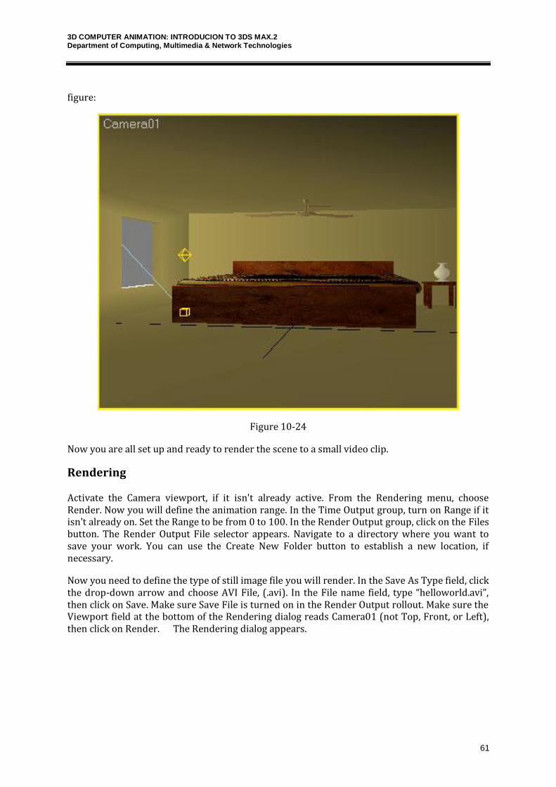
3D COMPUTER ANIMATION: INTRODUCION TO 3DS MAX.2 Department of Computing, Multimedia & Network Technologies
61
figure:
Figure 10-24
Now you are all set up and ready to render the scene to a small video clip.
Rendering
Activate the Camera viewport, if it isn't already active. From the Rendering menu, choose Render. Now you will define the animation range. In the Time Output group, turn on Range if it isn't already on. Set the Range to be from 0 to 100. In the Render Output group, click on the Files button. The Render Output File selector appears. Navigate to a directory where you want to save your work. You can use the Create New Folder button to establish a new location, if necessary.
Now you need to define the type of still image file you will render. In the Save As Type field, click the drop-down arrow and choose AVI File, (.avi). In the File name field, type “helloworld.avi”, then click on Save. Make sure Save File is turned on in the Render Output rollout. Make sure the Viewport field at the bottom of the Rendering dialog reads Camera01 (not Top, Front, or Left), then click on Render. The Rendering dialog appears.
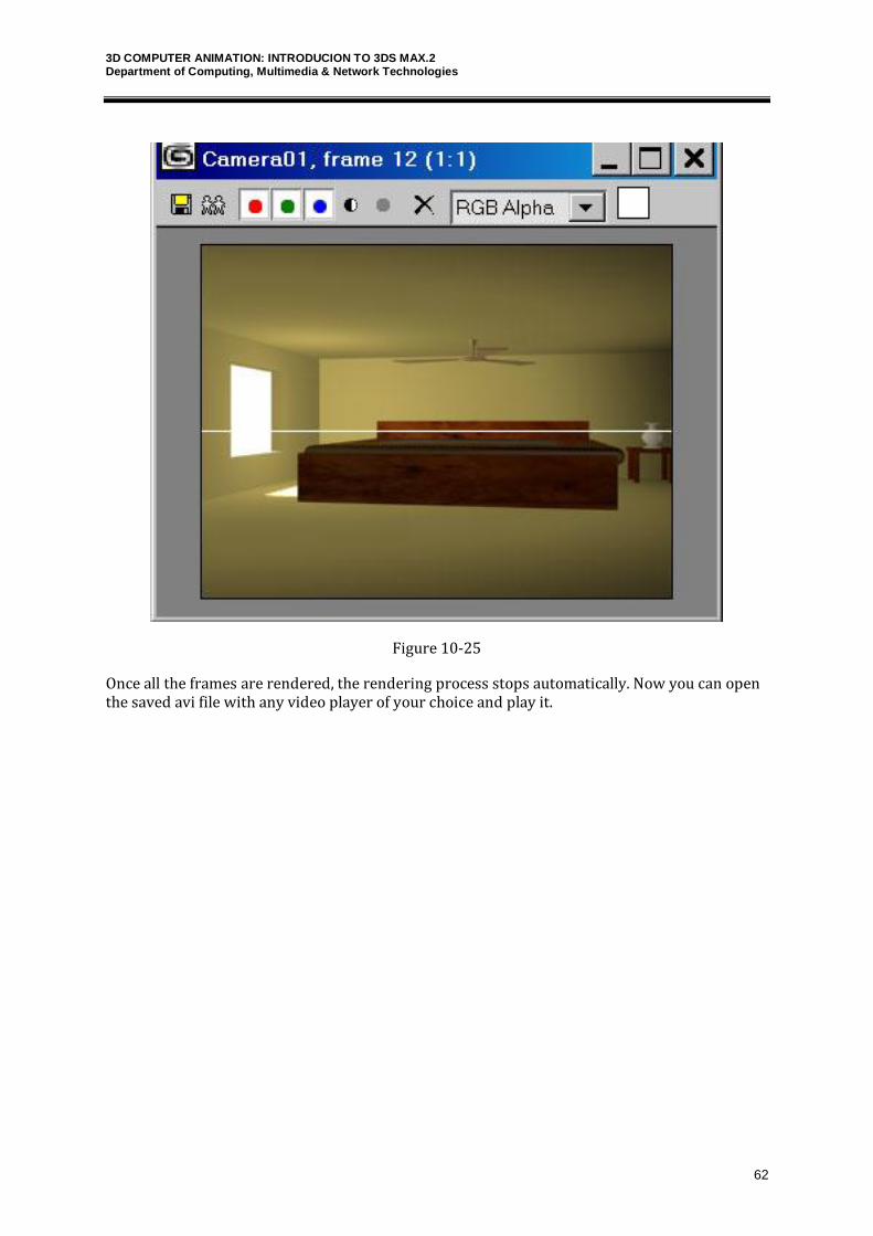
3D COMPUTER ANIMATION: INTRODUCION TO 3DS MAX.2 Department of Computing, Multimedia & Network Technologies
62
Figure 10-25
Once all the frames are rendered, the rendering process stops automatically. Now you can open the saved avi file with any video player of your choice and play it.