Latitude 7420 Service Manual - CNET Content Solutions
85
Latitude 7420 Service Manual Regulatory Model: P135G/P136G Regulatory Type: P135G001/P136G001 January 2021 Rev. A00
-
Upload
khangminh22 -
Category
Documents
-
view
8 -
download
0
Transcript of Latitude 7420 Service Manual - CNET Content Solutions

Latitude 7420Service Manual
Regulatory Model: P135G/P136GRegulatory Type: P135G001/P136G001January 2021Rev. A00

Notes, cautions, and warnings
NOTE: A NOTE indicates important information that helps you make better use of your product.
CAUTION: A CAUTION indicates either potential damage to hardware or loss of data and tells you how to avoid
the problem.
WARNING: A WARNING indicates a potential for property damage, personal injury, or death.
© 2021 Dell Inc. or its subsidiaries. All rights reserved. Dell, EMC, and other trademarks are trademarks of Dell Inc. or its subsidiaries. Othertrademarks may be trademarks of their respective owners.

Chapter 1: Working on your computer........................................................................................... 6Safety instructions.............................................................................................................................................................. 6
Service mode.................................................................................................................................................................. 6Before working inside your computer.......................................................................................................................8Safety precautions........................................................................................................................................................ 9Electrostatic discharge—ESD protection............................................................................................................... 9ESD field service kit ................................................................................................................................................... 10
Chapter 2: Removing and installing components...........................................................................11Recommended tools...........................................................................................................................................................11Screw List............................................................................................................................................................................. 11Major components of your system................................................................................................................................ 14micro-SD card.....................................................................................................................................................................15
Removing the micro-SD card.................................................................................................................................... 15Installing the micro-SD card...................................................................................................................................... 16
SIM card tray...................................................................................................................................................................... 16Removing the SIM card tray......................................................................................................................................16Installing the SIM card tray........................................................................................................................................ 17
Base cover........................................................................................................................................................................... 18Removing the base cover...........................................................................................................................................18Installing the base cover............................................................................................................................................ 20
Solid-state drive................................................................................................................................................................ 22Removing the solid-state drive................................................................................................................................ 22Installing the solid-state drive.................................................................................................................................. 23
WWAN card........................................................................................................................................................................ 24Removing the WWAN card....................................................................................................................................... 24
Installing the WWAN card......................................................................................................................................... 26Battery................................................................................................................................................................................. 27
Lithium-ion battery precautions...............................................................................................................................27Removing the 3-cell battery..................................................................................................................................... 27Installing the 3-cell battery....................................................................................................................................... 28Removing the 4-cell battery..................................................................................................................................... 30Installing the 4-cell battery........................................................................................................................................ 31
Heatsink assembly.............................................................................................................................................................32Removing the heatsink assembly.............................................................................................................................32Installing the heatsink assembly...............................................................................................................................33
Palmrest antenna module................................................................................................................................................34Removing the palmrest antenna module............................................................................................................... 34Installing the palmrest antenna module..................................................................................................................34
Display assembly................................................................................................................................................................35Removing the display assembly............................................................................................................................... 35Installing the display assembly..................................................................................................................................38
Audio board.........................................................................................................................................................................40Removing the audio board........................................................................................................................................ 40
Contents
Contents 3

Installing the audio board........................................................................................................................................... 41Speakers.............................................................................................................................................................................. 42
Removing the speakers..............................................................................................................................................42Installing the speaker.................................................................................................................................................. 43
SmartCard reader..............................................................................................................................................................44Removing the smart card reader............................................................................................................................. 44Installing the smart card reader............................................................................................................................... 46
System board......................................................................................................................................................................47Removing the system board..................................................................................................................................... 47Installing the system board....................................................................................................................................... 49
I/O board.............................................................................................................................................................................52Removing the I/O board............................................................................................................................................52Installing the I/O board.............................................................................................................................................. 52
Power button with fingerprint reader.......................................................................................................................... 53Removing the power button with fingerprint reader..........................................................................................53Installing the power button with fingerprint reader............................................................................................54
Keyboard............................................................................................................................................................................. 55Removing the keyboard............................................................................................................................................. 55Installing the keyboard............................................................................................................................................... 57
Palmrest assembly............................................................................................................................................................ 59Removing the palmrest assembly............................................................................................................................59Installing the palmrest assembly..............................................................................................................................60
Chapter 3: Software....................................................................................................................62Downloading Windows drivers....................................................................................................................................... 62
Chapter 4: System setup............................................................................................................. 63BIOS overview................................................................................................................................................................... 63Entering BIOS setup program........................................................................................................................................ 63
Boot menu.....................................................................................................................................................................63Navigation keys..................................................................................................................................................................64Boot Sequence...................................................................................................................................................................64System setup options.......................................................................................................................................................64Updating the BIOS in Windows .....................................................................................................................................74
Updating BIOS on systems with BitLocker enabled............................................................................................75Updating your system BIOS using a USB flash drive..........................................................................................75
System and setup password...........................................................................................................................................76Assigning a system setup password....................................................................................................................... 76Deleting or changing an existing system setup password................................................................................. 77
Clearing BIOS (System Setup) and System passwords...........................................................................................77
Chapter 5: Troubleshooting......................................................................................................... 78Recovering the operating system..................................................................................................................................78Backup media and recovery options............................................................................................................................. 78Dell SupportAssist Pre-boot System Performance Check diagnostics................................................................78
Running the SupportAssist Pre-Boot System Performance Check................................................................ 79Diagnostic LED behavior..................................................................................................................................................79Real-Time Clock (RTC Reset)........................................................................................................................................80Flashing BIOS (USB key)................................................................................................................................................. 81
4 Contents

Flashing the BIOS...............................................................................................................................................................81WiFi power cycle................................................................................................................................................................ 81BIOS recovery.................................................................................................................................................................... 82
BIOS recovery using hard drive............................................................................................................................... 82BIOS recovery using USB drive............................................................................................................................... 83
M-BIST.................................................................................................................................................................................83LCD Built-in Self Test (BIST)......................................................................................................................................... 84
Chapter 6: Getting help...............................................................................................................85Contacting Dell.................................................................................................................................................................. 85
Contents 5

Working on your computer
Topics:
• Safety instructions
Safety instructions
Prerequisites
Use the following safety guidelines to protect your computer from potential damage and to ensure your personal safety. Unlessotherwise noted, each procedure included in this document assumes that the following conditions exist:● You have read the safety information that shipped with your computer.● A component can be replaced or, if purchased separately, installed by performing the removal procedure in reverse order.
About this task
NOTE: Disconnect all power sources before opening the computer cover or panels. After you finish working inside the
computer, replace all covers, panels, and screws before connecting to the power source.
WARNING: Before working inside your computer, read the safety information that shipped with your computer.
For additional safety best practices information, see the Regulatory Compliance Homepage
CAUTION: Many repairs may only be done by a certified service technician. You should only perform
troubleshooting and simple repairs as authorized in your product documentation, or as directed by the online or
telephone service and support team. Damage due to servicing that is not authorized by Dell is not covered by
your warranty. Read and follow the safety instructions that came with the product.
CAUTION: To avoid electrostatic discharge, ground yourself by using a wrist grounding strap or by periodically
touching an unpainted metal surface at the same time as touching a connector on the back of the computer.
CAUTION: Handle components and cards with care. Do not touch the components or contacts on a card. Hold a
card by its edges or by its metal mounting bracket. Hold a component such as a processor by its edges, not by
its pins.
CAUTION: When you disconnect a cable, pull on its connector or on its pull-tab, not on the cable itself. Some
cables have connectors with locking tabs; if you are disconnecting this type of cable, press in on the locking
tabs before you disconnect the cable. As you pull connectors apart, keep them evenly aligned to avoid bending
any connector pins. Also, before you connect a cable, ensure that both connectors are correctly oriented and
aligned.
NOTE: The color of your computer and certain components may appear differently than shown in this document.
Service mode
Service Mode allows users to immediately cut off power from the system and conduct repairs without disconnecting thebattery cable from the system board:1. Shut down the system and disconnect the AC adapter.2. Press and hold the <B> key on the keyboard and then press the power button. The system boots.
1
6 Working on your computer

3. [For models configured with an Owner Tag] When the Owner Tag information appears on the screen, press any key toproceed.
NOTE: The Service Mode procedure will automatically skip this step if the Owner Tag of the system is not set up in
advance by the manufacturer.
4. Ensure that the AC adapter has been disconnected and press any key to proceed.
Working on your computer 7

5. When the ready-to-proceed message appears on the screen, press any key to proceed. The system emits three short beepsand shuts down immediately.
Once the system shuts down, you can perform replacement procedures without disconnecting the battery cable from thesystem board.
To exit Service Mode, connect AC adapter and press the power button to power on the system. The system will automaticallyreturn to normal functioning mode.
Before working inside your computer
About this task
NOTE: The images in this document may differ from your computer depending on the configuration you ordered.
Steps
1. Save and close all open files and exit all open applications.
2. Shut down your computer. Click Start > Power > Shut down.
NOTE: If you are using a different operating system, see the documentation of your operating system for shut-down
instructions.
3. Disconnect your computer and all attached devices from their electrical outlets.
8 Working on your computer
4. Disconnect all attached network devices and peripherals, such as keyboard, mouse, and monitor from your computer.
CAUTION: To disconnect a network cable, first unplug the cable from your computer and then unplug the
cable from the network device.
5. Remove any media card and optical disc from your computer, if applicable.
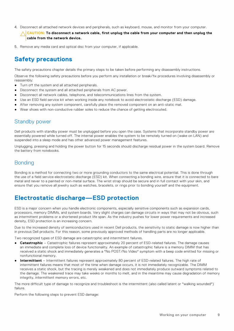
Safety precautions
The safety precautions chapter details the primary steps to be taken before performing any disassembly instructions.
Observe the following safety precautions before you perform any installation or break/fix procedures involving disassembly orreassembly:● Turn off the system and all attached peripherals.● Disconnect the system and all attached peripherals from AC power.● Disconnect all network cables, telephone, and telecommunications lines from the system.● Use an ESD field service kit when working inside any notebook to avoid electrostatic discharge (ESD) damage.● After removing any system component, carefully place the removed component on an anti-static mat.● Wear shoes with non-conductive rubber soles to reduce the chance of getting electrocuted.
Standby power
Dell products with standby power must be unplugged before you open the case. Systems that incorporate standby power areessentially powered while turned off. The internal power enables the system to be remotely turned on (wake on LAN) andsuspended into a sleep mode and has other advanced power management features.
Unplugging, pressing and holding the power button for 15 seconds should discharge residual power in the system board. Removethe battery from notebooks.
Bonding
Bonding is a method for connecting two or more grounding conductors to the same electrical potential. This is done throughthe use of a field service electrostatic discharge (ESD) kit. When connecting a bonding wire, ensure that it is connected to baremetal and never to a painted or non-metal surface. The wrist strap should be secure and in full contact with your skin, andensure that you remove all jewelry such as watches, bracelets, or rings prior to bonding yourself and the equipment.
Electrostatic discharge—ESD protection
ESD is a major concern when you handle electronic components, especially sensitive components such as expansion cards,processors, memory DIMMs, and system boards. Very slight charges can damage circuits in ways that may not be obvious, suchas intermittent problems or a shortened product life span. As the industry pushes for lower power requirements and increaseddensity, ESD protection is an increasing concern.
Due to the increased density of semiconductors used in recent Dell products, the sensitivity to static damage is now higher thanin previous Dell products. For this reason, some previously approved methods of handling parts are no longer applicable.
Two recognized types of ESD damage are catastrophic and intermittent failures.● Catastrophic – Catastrophic failures represent approximately 20 percent of ESD-related failures. The damage causes
an immediate and complete loss of device functionality. An example of catastrophic failure is a memory DIMM that hasreceived a static shock and immediately generates a "No POST/No Video" symptom with a beep code emitted for missing ornonfunctional memory.
● Intermittent – Intermittent failures represent approximately 80 percent of ESD-related failures. The high rate ofintermittent failures means that most of the time when damage occurs, it is not immediately recognizable. The DIMMreceives a static shock, but the tracing is merely weakened and does not immediately produce outward symptoms related tothe damage. The weakened trace may take weeks or months to melt, and in the meantime may cause degradation of memoryintegrity, intermittent memory errors, etc.
The more difficult type of damage to recognize and troubleshoot is the intermittent (also called latent or "walking wounded")failure.
Perform the following steps to prevent ESD damage:
Working on your computer 9

● Use a wired ESD wrist strap that is properly grounded. The use of wireless anti-static straps is no longer allowed; they do notprovide adequate protection. Touching the chassis before handling parts does not ensure adequate ESD protection on partswith increased sensitivity to ESD damage.
● Handle all static-sensitive components in a static-safe area. If possible, use anti-static floor pads and workbench pads.● When unpacking a static-sensitive component from its shipping carton, do not remove the component from the anti-static
packing material until you are ready to install the component. Before unwrapping the anti-static packaging, ensure that youdischarge static electricity from your body.
● Before transporting a static-sensitive component, place it in an anti-static container or packaging.
ESD field service kit
The unmonitored Field Service kit is the most commonly used service kit. Each Field Service kit includes three main components:anti-static mat, wrist strap, and bonding wire.
Components of an ESD field service kit
The components of an ESD field service kit are:● Anti-Static Mat – The anti-static mat is dissipative and parts can be placed on it during service procedures. When using an
anti-static mat, your wrist strap should be snug and the bonding wire should be connected to the mat and to any bare metalon the system being worked on. Once deployed properly, service parts can be removed from the ESD bag and placed directlyon the mat. ESD-sensitive items are safe in your hand, on the ESD mat, in the system, or inside a bag.
● Wrist Strap and Bonding Wire – The wrist strap and bonding wire can be either directly connected between your wristand bare metal on the hardware if the ESD mat is not required, or connected to the anti-static mat to protect hardware thatis temporarily placed on the mat. The physical connection of the wrist strap and bonding wire between your skin, the ESDmat, and the hardware is known as bonding. Use only Field Service kits with a wrist strap, mat, and bonding wire. Neveruse wireless wrist straps. Always be aware that the internal wires of a wrist strap are prone to damage from normal wearand tear, and must be checked regularly with a wrist strap tester in order to avoid accidental ESD hardware damage. It isrecommended to test the wrist strap and bonding wire at least once per week.
● ESD Wrist Strap Tester – The wires inside of an ESD strap are prone to damage over time. When using an unmonitoredkit, it is a best practice to regularly test the strap prior to each service call, and at a minimum, test once per week. Awrist strap tester is the best method for doing this test. If you do not have your own wrist strap tester, check with yourregional office to find out if they have one. To perform the test, plug the wrist-strap's bonding-wire into the tester while it isstrapped to your wrist and push the button to test. A green LED is lit if the test is successful; a red LED is lit and an alarmsounds if the test fails.
● Insulator Elements – It is critical to keep ESD sensitive devices, such as plastic heat sink casings, away from internal partsthat are insulators and often highly charged.
● Working Environment – Before deploying the ESD Field Service kit, assess the situation at the customer location. Forexample, deploying the kit for a server environment is different than for a desktop or portable environment. Servers aretypically installed in a rack within a data center; desktops or portables are typically placed on office desks or cubicles. Alwayslook for a large open flat work area that is free of clutter and large enough to deploy the ESD kit with additional space toaccommodate the type of system that is being repaired. The workspace should also be free of insulators that can cause anESD event. On the work area, insulators such as Styrofoam and other plastics should always be moved at least 12 inches or30 centimeters away from sensitive parts before physically handling any hardware components
● ESD Packaging – All ESD-sensitive devices must be shipped and received in static-safe packaging. Metal, static-shieldedbags are preferred. However, you should always return the damaged part using the same ESD bag and packaging that thenew part arrived in. The ESD bag should be folded over and taped shut and all the same foam packing material should beused in the original box that the new part arrived in. ESD-sensitive devices should be removed from packaging only at anESD-protected work surface, and parts should never be placed on top of the ESD bag because only the inside of the bag isshielded. Always place parts in your hand, on the ESD mat, in the system, or inside an anti-static bag.
● Transporting Sensitive Components – When transporting ESD sensitive components such as replacement parts or partsto be returned to Dell, it is critical to place these parts in anti-static bags for safe transport.
ESD protection summary
It is recommended that all field service technicians use the traditional wired ESD grounding wrist strap and protective anti-staticmat at all times when servicing Dell products. In addition, it is critical that technicians keep sensitive parts separate from allinsulator parts while performing service and that they use anti-static bags for transporting sensitive components.
10 Working on your computer

Removing and installing components
NOTE: The images in this document may differ from your computer depending on the configuration you ordered.
Topics:
• Recommended tools• Screw List• Major components of your system• micro-SD card• SIM card tray• Base cover• Solid-state drive• WWAN card• Battery• Heatsink assembly• Palmrest antenna module• Display assembly• Audio board• Speakers• SmartCard reader• System board• I/O board• Power button with fingerprint reader• Keyboard• Palmrest assembly
Recommended tools
The procedures in this document require the following tools:● Phillips #0 screwdriver● Plastic scribe: Recommended for field technicians.
Screw ListThe following table shows the screw list and the image of the screws.
Table 1. Screw list
Component Screw type Quantity Image
Base cover Captive screws 8
2
Removing and installing components 11

Table 1. Screw list (continued)
Component Screw type Quantity Image
NOTE: Screws arepart of the basecover.
Solid-state drive M2x2 2
WWAN M2x2.5 1
3-cell Battery M2.5x4
Captive screws
1
4
4-cell Battery M2x4
Captive screws
1
4
Heatsink assembly M2x2.5 6
Palmrest antenna M2x2
M2x2.5
1
2
Display assembly M2x2
M2.5x5
3
4
Audio board M2x2.5 1
SmartCard reader M2x2.5 4
System board M2x2
M2x2.5
M2x3
M2x4
3
4
2
2
I/O board M2x4 2
Power button with fingerprint reader M1.6x1.7 2
12 Removing and installing components

Table 1. Screw list (continued)
Component Screw type Quantity Image
Keyboard M1.6x1.7
M2x2
26
2
Removing and installing components 13

Major components of your system
1. Base cover
14 Removing and installing components

2. Battery3. I/O board4. Heatsink5. Solid-state drive cover6. System board7. Speakers8. Audio board9. Palmrest assembly10. Display assembly11. Keyboard assembly12. Power button with fingerprint reader13. SmartCard reader14. Palmrest antenna15. WWAN card shield16. Solid-state drive17. Solid-state drive shield18. WWAN card
NOTE: Dell provides a list of components and their part numbers for the original system configuration purchased. These
parts are available according to warranty coverages purchased by the customer. Contact your Dell sales representative for
purchase options.
micro-SD card
Removing the micro-SD card
About this task
The following images indicate the location of the micro-SD card reader slot and provide a visual representation of the removalprocedure.
Steps
1. Push the micro-SD card to eject it from the slot.
2. Remove the micro-SD card from the computer.
Removing and installing components 15

Installing the micro-SD card
Prerequisites
If you are replacing a component, remove the existing component before performing the installation procedure.
About this task
The following image indicates the location of the micro-SD card reader slot and provides a visual representation of theinstallation procedure.
Steps
Insert the micro-SD card into its slot until it clicks into place.
SIM card tray
Removing the SIM card tray
Prerequisites
Follow the procedure in before working inside your computer.
About this task
The following image provides a visual representation of the SIM card tray removal procedure.
16 Removing and installing components

Steps
1. Insert a pin into the release hole to release the SIM card tray.
2. Push the pin to disengage the lock, and eject the SIM card tray.
3. Slide the SIM card tray out of the slot on the system.
4. Remove the SIM card from the SIM card tray.
5. Slide and push the SIM card tray back into the slot.
Installing the SIM card tray
Prerequisites
If you are replacing a component, remove the necessary component before the installation procedure.
About this task
The following image provides a visual representation of the SIM card tray installation procedure.
Removing and installing components 17

Steps
1. Align and place the SIM card in the dedicated slot on the SIM card tray.
2. Slide the SIM card tray into the slot in the system [6], and push it to lock in place.
Next steps
Follow the procedure in After working on your computer.
Base cover
Removing the base cover
Prerequisites
1. Follow the procedure in before working inside your computer.2. Remove the microSD card.3. Enter the service mode.
18 Removing and installing components

About this task
Removing and installing components 19

Steps
1. Loosen the eight captive screws that secure the base cover to the computer.
2. Use a plastic scribe to pry open the base cover, starting from the U-shaped recesses near the hinges at the top edge of thebase cover.
CAUTION: Do not slide the scribe through the edge of the top side of the base cover as it damages the
latches inside the base cover.
3. Pry open the left and right sides of the base cover.
4. Pry open the bottom side of the base cover.
5. Hold the left and right sides of the base cover and remove it from the computer.
6. Disconnect the battery cable.
Installing the base cover
Prerequisites
If you are replacing a component, remove the existing component before performing the installation procedure.
About this task
The following image indicates the location of the base cover and provides a visual representation of the installation procedure.
20 Removing and installing components

Removing and installing components 21

Steps
1. Connect the battery cable.
2. Align and place the base cover on the computer, and snap the base cover latches into place.
3. Tighten the eight captive screws to secure the base cover to the computer.
Next steps
1. Install the microSD card.2. NOTE: Plug-in AC before powering up your computer.
Follow the procedure in after working inside your computer.
Solid-state drive
Removing the solid-state drive
Prerequisites
1. Follow the procedure in before working inside your computer.2. Remove the microSD card.3. Enter the service mode.4. Remove the base cover.
About this task
The following images indicate the location of the solid-state drive and provide a visual representation of the removal procedure.
22 Removing and installing components

Steps
1. Remove the screw (M2x2) that secures the SSD shield and remove the shield from the SSD.
2. Remove the screw (M2x2) that secures the SSD to the system board.
3. Slide and remove the solid-state drive from the M.2 slot on the system board.
NOTE: A thermal pad is included with the SSD plate and must always be adhered to the plate. If the thermal pad gets
separated from the plate or is adhered to the SSD, stick back the thermal pad to the SSD plate before reinstalling the
plate to the SSD.
Installing the solid-state drive
Prerequisites
If you are replacing a component, remove the existing component before performing the installation procedure.
About this task
The following image indicates the location of the solid-state drive and provides a visual representation of the installationprocedure.
Removing and installing components 23

Steps
1. Align the notch on the SSD with the tab on the M.2 slot and slide the SSD into the M.2 card slot on the system board.
2. Replace the screw (M2x2) that secures the SSD to the system board.
3. Replace the SSD shield, press to fit it firmly to cover the SSD, securing it with (M2x2) screw.
Next steps
1. Install the base cover.2. Install the microSD card.3. NOTE: Plug-in AC before powering up your computer.
Follow the procedure in after working inside your computer.
WWAN card
Removing the WWAN card
Prerequisites
1. Follow the procedure in before working inside your computer.2. Remove the microSD card.3. Enter the service mode.4. Remove the base cover.
About this task
The following images indicate the location of the WWAN card and provide a visual representation of the removal procedure.
24 Removing and installing components

Steps
1. Using a plastic scribe, pry and remove the WWAN card shield covering the WWAN card.
NOTE: Pry open the WWAN card shield from the recess on the top left corner.
2. Loosen the single (M2x2.5) screw and remove the WWAN-card bracket.
3. Disconnect the antenna cables from the connectors on the WWAN card.
4. Slide and remove the WWAN card out from the M.2 slot on the system board.
Removing and installing components 25

Installing the WWAN card
Prerequisites
If you are replacing a component, remove the existing component before performing the installation procedure.
About this task
The following image indicates the location of the WWAN card and provides a visual representation of the installation procedure.
Steps
1. Align the notch on the WWAN card with the tab on the WWAN-card slot and slide the WWAN into the M.2 slot on thesystem board.
2. Connect the antenna cables to the connectors on the WWAN card.
3. Align and place the WWAN-card bracket and tighten the single (M2x2.5) screw securing it to the system board.
4. Replace the WWAN-card shield over the WWAN card.
NOTE: Insert the edges of the WWAN-card shield into the clips on the system board to secure it in place.
26 Removing and installing components

Next steps
1. Install the base cover.2. Install the microSD card.3. NOTE: Plug-in AC before powering up your computer.
Follow the procedure in after working inside your computer.
Battery
Lithium-ion battery precautions
CAUTION:
● Exercise caution when handling Lithium-ion batteries.
● Discharge the battery completely before removing it. Disconnect the AC power adapter from the system and
operate the computer solely on battery power—the battery is fully discharged when the computer no longer
turns on when the power button is pressed.
● Do not crush, drop, mutilate, or penetrate the battery with foreign objects.
● Do not expose the battery to high temperatures, or disassemble battery packs and cells.
● Do not apply pressure to the surface of the battery.
● Do not bend the battery.
● Do not use tools of any kind to pry on or against the battery.
● Ensure any screws during the servicing of this product are not lost or misplaced, to prevent accidental
puncture or damage to the battery and other system components.
● If the battery gets stuck inside your computer as a result of swelling, do not try to release it as puncturing,
bending, or crushing a lithium-ion battery can be dangerous. In such an instance, contact Dell technical
support for assistance. See www.dell.com/contactdell.
● Always purchase genuine batteries from www.dell.com or authorized Dell partners and resellers.
Removing the 3-cell battery
Prerequisites
1. Follow the procedure in before working inside your computer.2. Remove the microSD card.3. Remove the base cover.
NOTE: If the battery is disconnected from system board, there is delay during computer boot as the computer undergoes
RTC (Real Time Clock) reset.
Removing and installing components 27

About this task
The following images indicate the location of the battery and provide a visual representation of the removal procedure.
Steps
1. Disconnect the battery cable from the system board.
2. Disconnect the speaker cable from the speaker board and release the speaker cable from the routing guides over the upperright side of the battery.
3. Remove the single (M2.5x4) screw and the four captive screws that secure the battery to the computer.
4. Lift and remove the battery from the computer.
Installing the 3-cell battery
Prerequisites
If you are replacing a component, remove the existing component before performing the installation procedure.
28 Removing and installing components

About this task
The following image indicates the location of the battery and provides a visual representation of the installation procedure.
NOTE: If the battery is disconnected from system board, there is delay during computer boot as the computer undergoes
RTC reset.
Steps
1. Align and place the battery into the computer.
2. Install the single (M2.5x4) screw and four captive screws to secure the battery in place.
3. Connect the speaker cable to the speaker board and reroute the speaker cable into its routing channel over the upper rightside of the battery
4. Connect the battery cable to the system board.
Next steps
1. Install the base cover.2. Install the microSD card.3. Follow the procedure in after working inside your computer.
Removing and installing components 29

Removing the 4-cell battery
Prerequisites
1. Follow the procedure in before working inside your computer.2. Remove the microSD card.3. Remove the base cover.
NOTE: If the battery is disconnected from system board, there is delay during computer boot as the computer undergoes
RTC reset.
About this task
The following images indicate the location of the battery and provide a visual representation of the removal procedure.
Steps
1. Disconnect the battery cable from the system board.
2. Disconnect the speaker cable from the speaker board and unroute the speaker cable from its routing channel over the upperright side of the battery.
3. Remove the single (M2x4) screw and the four captive screws that secure the battery to the computer.
30 Removing and installing components
4. Lift the battery and remove the battery from the computer.
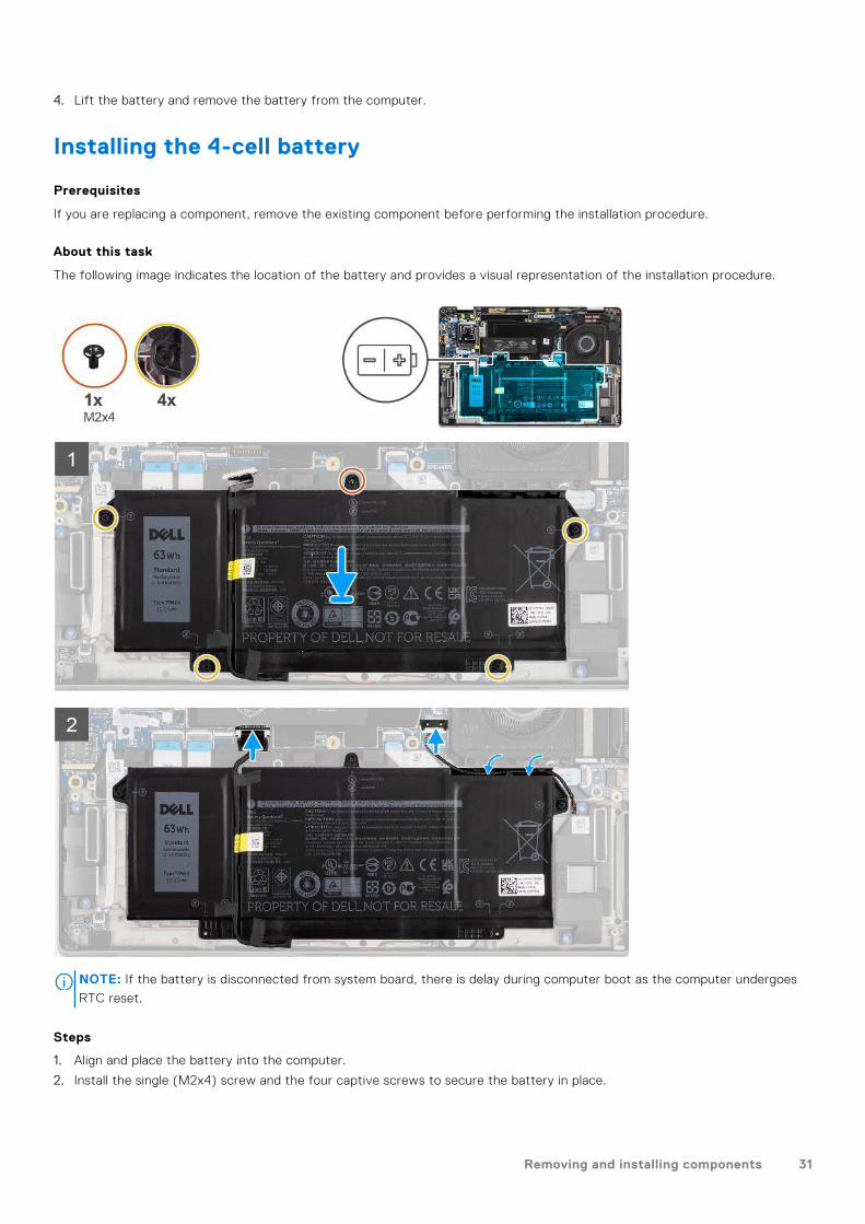
Installing the 4-cell battery
Prerequisites
If you are replacing a component, remove the existing component before performing the installation procedure.
About this task
The following image indicates the location of the battery and provides a visual representation of the installation procedure.
NOTE: If the battery is disconnected from system board, there is delay during computer boot as the computer undergoes
RTC reset.
Steps
1. Align and place the battery into the computer.
2. Install the single (M2x4) screw and the four captive screws to secure the battery in place.
Removing and installing components 31

3. Connect the speaker cable to the speaker board and reroute the speaker cable into its routing channel over the upper rightside of the battery.
4. Connect the battery cable to the system board.
Next steps
1. Install the base cover.2. Install the microSD card.3. Follow the procedure in after working inside your computer.
Heatsink assembly
Removing the heatsink assembly
Prerequisites
1. Follow the procedure in before working inside your computer.2. Remove the microSD card.3. Enter the service mode.4. Remove the base cover.
About this task
The following images indicate the location of the heatsink assembly and provide a visual representation of the removalprocedure.
Steps
1. Disconnect the fan cable from the system board.
2. Remove the two (M2x2.5) screws on the fan case and the four (M2x2.5) screws (in reverse order, 4->3->2->1) that securethe heatsink to the computer.
3. Lift the heatsink assembly from the computer.
32 Removing and installing components
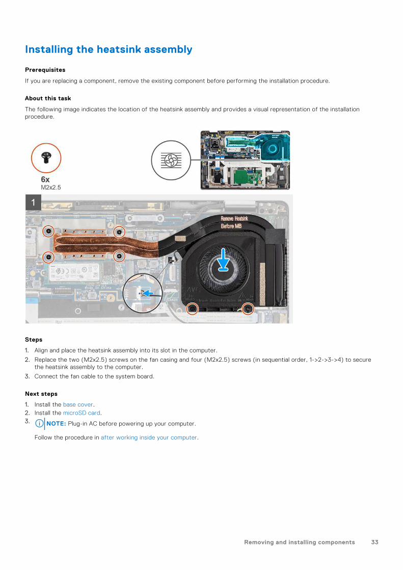
Installing the heatsink assembly
Prerequisites
If you are replacing a component, remove the existing component before performing the installation procedure.
About this task
The following image indicates the location of the heatsink assembly and provides a visual representation of the installationprocedure.
Steps
1. Align and place the heatsink assembly into its slot in the computer.
2. Replace the two (M2x2.5) screws on the fan casing and four (M2x2.5) screws (in sequential order, 1->2->3->4) to securethe heatsink assembly to the computer.
3. Connect the fan cable to the system board.
Next steps
1. Install the base cover.2. Install the microSD card.3. NOTE: Plug-in AC before powering up your computer.
Follow the procedure in after working inside your computer.
Removing and installing components 33

Palmrest antenna module
Removing the palmrest antenna module
Prerequisites
1. Follow the procedure in before working inside your computer.2. Remove the microSD card.3. Remove the base cover.
About this task
The following images indicate the location of the palmrest antenna module and provide a visual representation of the removalprocedure.
Steps
1. Remove the (M2x2) screw that secures the palmrest bracket to the system board.
2. Disconnect and unroute the antenna cables connected to the WLAN module on the system board.
3. Remove the two (M2x2.5) screws that secure the palmrest antenna module to the system.
4. Lift the palmrest antenna module away from the system.
Installing the palmrest antenna module
Prerequisites
If you are replacing a component, remove the existing component before performing the installation procedure.
34 Removing and installing components
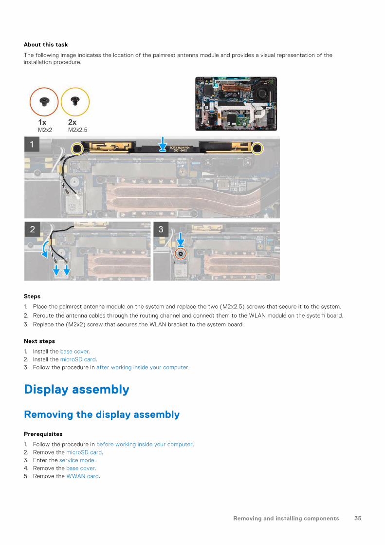
About this task
The following image indicates the location of the palmrest antenna module and provides a visual representation of theinstallation procedure.
Steps
1. Place the palmrest antenna module on the system and replace the two (M2x2.5) screws that secure it to the system.
2. Reroute the antenna cables through the routing channel and connect them to the WLAN module on the system board.
3. Replace the (M2x2) screw that secures the WLAN bracket to the system board.
Next steps
1. Install the base cover.2. Install the microSD card.3. Follow the procedure in after working inside your computer.
Display assembly
Removing the display assembly
Prerequisites
1. Follow the procedure in before working inside your computer.2. Remove the microSD card.3. Enter the service mode.4. Remove the base cover.5. Remove the WWAN card.
Removing and installing components 35

About this task
The following images indicate the location of the display assembly and provide a visual representation of the removal procedure.
36 Removing and installing components

Steps
1. Remove the single (M2x2) securing the WLAN card bracket to the antenna cables.
2. Lift the bracket from the WLAN card module on the system board.
3. Disconnect the WLAN antenna cables from the WLAN module.
4. Disconnect the WWAN antenna cable and release the cable from the rubber guides on the system board.
5. Remove the two (M2x2) securing the display cable bracket to the system board.
6. Lift to remove the display cable bracket from the computer.
7. Disconnect the display, camera, touch screen, sensor board cables from the system board and release them from cableguiding tabs.
Removing and installing components 37

8. Open the display lid to 90º angle and remove the four (M2.5x5) screws securing the hinges to the palmrest assembly.
9. Remove the display assembly from the computer.
NOTE: NOTE: The display assembly is a Hinge-Up Design (HUD) assembly and cannot be further disassembled once it is
removed from the bottom chassis. If any components in the display assembly are malfunctioning and must be replaced,
replace the entire display assembly.
Figure 1. Display assembly with antennae cables
Installing the display assembly
Prerequisites
If you are replacing a component, remove the existing component before performing the installation procedure.
About this task
The following image indicates the location of the display assembly and provides a visual representation of the installationprocedure.
38 Removing and installing components

Removing and installing components 39

Steps
1. Align and place the display assembly at a convenient angle to the bottom chassis.
2. Replace the four (M2.5x5) screws securing the hinges to the bottom chassis.
3. Route the display cable along the guiding tabs and connect the display, camera, touch screen, sensor board cables to thesystem board.
4. Connect the antenna cable to the WLAN module on the system board.
5. Replace the WLAN bracket on the antenna connector of the WLAN module on the system board.
6. Connect the WWAN antenna cables and route the antenna cables along the rubber guides on the system board.
7. Replace the single (M2x2) screw securing the WLAN card bracket to the system board.
8. Align and place the display cable bracket on the connector on the system board.
9. Install the two (M2x2) screws securing the display cable bracket to the system board.
Next steps
1. Install the WWAN card.2. Install the base cover.3. Install the microSD card.4. NOTE: Plug-in AC before powering up your computer.
Follow the procedure in after working inside your computer.
Audio board
Removing the audio board
Prerequisites
1. Follow the procedure in before working inside your computer.2. Enter the service mode.3. Remove the microSD card.
40 Removing and installing components

4. Remove the base cover.5. Remove the battery.
About this task
The following images indicate the location of the audio board and provide a visual representation of the removal procedure.
Steps
1. Disconnect and peel the audio board FFC from the system board.
2. Remove the M2x2.5 screw that secures the audio board to the computer.
3. Lift and remove the audio board from the computer.
Installing the audio board
Prerequisites
If you are replacing a component, remove the existing component before performing the installation procedure.
About this task
The following image indicates the location of the audio board and provides a visual representation of the installation procedure.
Removing and installing components 41

Steps
1. Align and replace the audio board into its slot in the computer.
2. Replace the M2x2.5 screw to secure the audio board to the computer.
3. Connect the audio board FFC to the system board.
Next steps
1. Install the battery.2. Install the base cover.3. Follow the procedure in after working inside your computer.
Speakers
Removing the speakers
Prerequisites
1. Follow the procedure in before working inside your computer.2. Remove the microSD card.3. Remove the base cover.4. Remove the battery.
42 Removing and installing components

About this task
The following images indicate the location of the speakers and provide a visual representation of the removal procedure.
Steps
1. Release the cable from the tabs on the palmrest assembly.
2. Lift and remove the speakers from the computer chassis.
Installing the speaker
Prerequisites
If you are replacing a component, remove the existing component before performing the installation procedure.
About this task
The following image indicates the location of the speaker and provides a visual representation of the installation procedure.
Removing and installing components 43

Steps
1. Replace the speaker into the slot in the computer.
2. Route the speaker cable along the cable guides on the palmrest assembly.
NOTE: While replacing the speakers, route the speaker cable into the routing channels along the bottom side of the
palmrest assembly.
Route the speaker cable underneath the LED board FFC.
Next steps
1. Install the battery.2. Install the base cover.3. Install the microSD card.4. Follow the procedure in after working inside your computer.
SmartCard reader
Removing the smart card reader
Prerequisites
1. Follow the procedure in before working inside your computer.
44 Removing and installing components

2. Remove the microSD card.3. Remove the base cover.4. Remove the battery.5. Remove the speaker.
About this task
The following images indicate the location of the smart card reader and provide a visual representation of the removalprocedure.
Removing and installing components 45
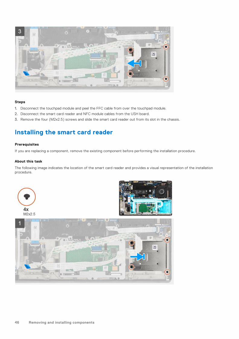
Steps
1. Disconnect the touchpad module and peel the FFC cable from over the touchpad module.
2. Disconnect the smart card reader and NFC module cables from the USH board.
3. Remove the four (M2x2.5) screws and slide the smart card reader out from its slot in the chassis.
Installing the smart card reader
Prerequisites
If you are replacing a component, remove the existing component before performing the installation procedure.
About this task
The following image indicates the location of the smart card reader and provides a visual representation of the installationprocedure.
46 Removing and installing components

Steps
1. Slide the smart card reader into its slot in the computer chassis and secure it using the four (M2x2.5) screws.
2. Adhere the smart card reader and NFC module cable and connect it to the USH board.
3. Adhere the touchpad FFC cable along the sides of the touchpad module and connect it to the system board.
Next steps
1. Install the speaker.2. Install the battery.3. Install the base cover.4. Install the microSD card.5. Follow the procedure in after working inside your computer.
System board
Removing the system board
Prerequisites
1. Follow the procedure in before working inside your computer.2. Enter the service mode.3. Remove the microSD card.4. Remove the SIM card.5. Remove the base cover.6. Remove the solid-state drive.7. Remove the battery.8. Remove the WWAN card.
Removing and installing components 47

9. Remove the heatsink assembly.CAUTION: Remove the heatsink assembly before removing the system board as there are two (M2x3) screws
underneath the heatsink that secures the system board to the computer.
NOTE: For configurations shipped with a carbon fiber palmrest and without WWAN antennas, the dummy SIM card tray
must removed from the system before removing the system board.
To remove the dummy SIM card tray, push the release latch inwards and then slide dummy card tray out of the computer.
NOTE: For non-WWAN configurations, remove the WWAN card shield and WWAN card bracket before removing the
system board.
About this task
The following images indicate the location of the system board and provide a visual representation of the removal procedure.
48 Removing and installing components

Steps
1. Remove the single (M2x2.5) screw from the finger print reader bracket and remove the bracket from the computer.
2. Disconnect the fingerprint reader FPC from the system board.
3. Remove the single (M2x2) screw and lift the bracket from the antenna cables.
4. Disconnect the WLAN antenna cables from the WLAN module on the system board.
5. Remove the single (M2x2) screw and lift the bracket from the WWAN card.
6. Disconnect the WWAN antenna cable and release the cable from the rubber guides on the system board.
7. Remove the two (M2x2) screws securing the display cable bracket to the system board.
8. Lift to remove the display cable bracket from the computer.
9. Disconnect the display, camera, touch screen, sensor board cables from the system board and unroute them from guidingtabs.
10. Disconnect the speakers board FPC, audio board FFC, touchpad FFC, USH board FFC and, LED board FFC from the systemboard.
11. Remove the single (M2x2.5) screw (For computer configuration with fingerprint reader on power button) or four (M2x2.5)screws (For computer configuration without fingerprint reader), two (M2x4) screws, and two (M2x3) screws securing thesystem board in place.
12. Carefully slide the system board out of the computer.
Installing the system board
Prerequisites
If you are replacing a component, remove the existing component before performing the installation procedure.
About this task
The following image indicates the location of the system board and provides a visual representation of the installation procedure.
Removing and installing components 49
50 Removing and installing components

Steps
1. Replace the system board into the computer chassis and tighten it using the single (M2x2.5) screw (for computerconfiguration with fingerprint reader on power button) or four (M2x2.5) screws (for computer configuration withoutfingerprint reader), two (M2x4) screws, and two (M2x3) screws securing the system board in place.
2. Connect the speakers board FPC, tweeter cable, audio board FFC, touchpad FFC, USH board FFC and, LED board FFC tothe system board.
3. Connect the display, camera, touch screen and, sensor board cables to the system board and route them along the guidingtabs.
4. Replace the display cable bracket on the system board and secure it using the two (M2x2) screws.
5. Route the WWAN antenna cables along the rubber guides on the system board and connect it to the WWAN card.
6. Connect the WLAN antenna cables to the WLAN module on the system board.
7. Replace the WLAN antenna bracket and secure it to the system board using the single (M2x2) screw.
8. Connect the fingerprint reader FPC to the system board.
9. Replace the finger print reader bracket and secure to the system board using the single (M2x2.5) screw.
10. Place the WWAN antenna cable bracket and replace the M2x2.5 screw.
Next steps
1. Install the heatsink assembly.2. Install the battery.3. Install the WWAN card.4. Install the solid-state drive.5. Install the base cover.6. Install the SIM card.7. Install the microSD card.8. NOTE: Plug-in AC before powering up your computer.
Follow the procedure in after working inside your computer.
Removing and installing components 51

I/O board
Removing the I/O board
Prerequisites
1. Follow the procedure in before working inside your computer.2. Enter the service mode.3. Remove the microSD card.4. Remove the SIM card.5. Remove the base cover.6. Remove the solid-state drive.7. Remove the WWAN card.8. Remove the battery.9. Remove the heatsink assembly.10. Remove the system board.
About this task
The following images indicate the location of the I/O board and provide a visual representation of the removal procedure.
Steps
1. Remove the two (M2x4) screws that secure the I/O board to the computer.
2. Lift and remove the I/O board from the computer.
Installing the I/O board
Prerequisites
If you are replacing a component, remove the existing component before performing the installation procedure.
52 Removing and installing components

About this task
The following image indicates the location of the I/O board and provides a visual representation of the installation procedure.
Steps
1. Replace the I/O board into its slot in the computer.
2. Secure the I/O board to the computer using two (M2x4) screws.
Next steps
1. Install the system board.2. Install the heatsink assembly.3. Install the battery.4. Install the WWAN card.5. Install the solid-state drive.6. Install the base cover.7. Install the SIM card.8. Install the microSD card.9. NOTE: Plug-in AC before powering up your computer.
Follow the procedure in after working inside your computer.
Power button with fingerprint reader
Removing the power button with fingerprint reader
Prerequisites
1. Follow the procedure in before working inside your computer.2. Enter the service mode.3. Remove the microSD card.
Removing and installing components 53

4. Remove the SIM card.5. Remove the base cover.6. Remove the solid-state drive.7. Remove the WWAN card.8. Remove the battery.9. Remove the heatsink assembly.10. Remove the system board.
About this task
The following images indicate the location of the power button with fingerprint reader and provide a visual representation of theremoval procedure.
Steps
1. Remove the two (M1.6x1.7) screws securing the power button with fingerprint reader to the computer.
2. Lift and remove the power button with fingerprint reader from the computer.
Installing the power button with fingerprint reader
Prerequisites
If you are replacing a component, remove the existing component before performing the installation procedure.
About this task
The following image indicates the location of the power button with fingerprint reader and provides a visual representation ofthe installation procedure.
54 Removing and installing components

Steps
1. Replace the power button with fingerprint reader into its slot in the computer.
2. Secure the power button with fingerprint reader to the computer using the two (M1.6x1.7) screws.
Next steps
1. Install the system board.2. Install the heatsink assembly.3. Install the battery.4. Install the WWAN card.5. Install the solid-state drive.6. Install the base cover.7. Install the SIM card.8. Install the microSD card.9. NOTE: Plug-in AC before powering up your computer.
Follow the procedure in after working inside your computer.
Keyboard
Removing the keyboard
Prerequisites
1. Follow the procedure in before working inside your computer.2. Remove the microSD card.3. Remove the base cover.4. Remove the solid-state drive.5. Remove the WWAN card.6. Remove the battery.
Removing and installing components 55

7. Remove the heatsink assembly.8. Remove the audio board.9. Remove the system board.10. Remove the I/O board.
About this task
The following images indicate the location of the keyboard and provide a visual representation of the removal procedure.
56 Removing and installing components

Steps
1. Peel the LED board FFC, USH board FFC, touchpad FFC and SmartCard reader FFC from the back of the keyboard.
2. Disconnect the keyboard FPC and keyboard backlight FPC from the touchpad module.
3. Remove the 26 (M1.6x1.7) screws that secure the keyboard assembly to the computer.
4. Carefully lift the keyboard assembly to remove it from the computer.
5. Remove the two (M2x2) screws securing the keyboard to the keyboard support plate.
6. Separate the keyboard from the keyboard support plate.
Installing the keyboard
Prerequisites
If you are replacing a component, remove the existing component before performing the installation procedure.
About this task
The following image indicates the location of the keyboard and provides a visual representation of the installation procedure.
Removing and installing components 57

58 Removing and installing components
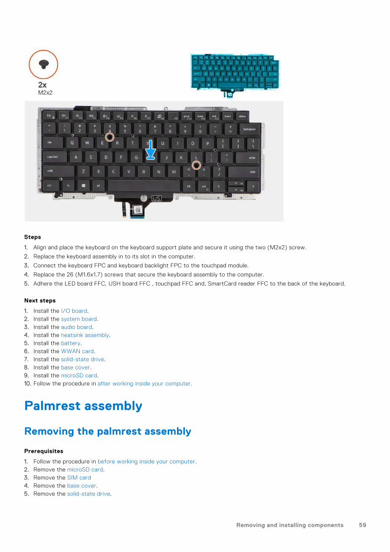
Steps
1. Align and place the keyboard on the keyboard support plate and secure it using the two (M2x2) screw.
2. Replace the keyboard assembly in to its slot in the computer.
3. Connect the keyboard FPC and keyboard backlight FPC to the touchpad module.
4. Replace the 26 (M1.6x1.7) screws that secure the keyboard assembly to the computer.
5. Adhere the LED board FFC, USH board FFC , touchpad FFC and, SmartCard reader FFC to the back of the keyboard.
Next steps
1. Install the I/O board.2. Install the system board.3. Install the audio board.4. Install the heatsink assembly.5. Install the battery.6. Install the WWAN card.7. Install the solid-state drive.8. Install the base cover.9. Install the microSD card.10. Follow the procedure in after working inside your computer.
Palmrest assembly
Removing the palmrest assembly
Prerequisites
1. Follow the procedure in before working inside your computer.2. Remove the microSD card.3. Remove the SIM card4. Remove the base cover.5. Remove the solid-state drive.
Removing and installing components 59

6. Remove the WWAN card.7. Remove the battery.8. Remove the heatsink assembly.9. Remove the display assembly.10. Remove the speaker.11. Remove the smart card reader.12. Remove the audio board.13. Remove the system board.14. Remove the I/O board.15. Remove the power button with finger print reader.16. Remove the keyboard.
Steps
After performing the pre-requisite steps, you are left with the palmrest assembly.
Installing the palmrest assembly
Prerequisites
If you are replacing a component, remove the existing component before performing the installation procedure.
About this task
The following image indicates the location of the palmrest assembly and provides a visual representation of the installationprocedure.
Steps
1. Place the palmrest assembly on a flat surface.
2. Transfer over the components to the new palmrest assembly.
Next steps
1. Install the keyboard.2. Install the power button with finger print reader.
60 Removing and installing components

3. Install the I/O board.4. Install the system board.5. Install the audio board.6. Install the smart card reader.7. Install the speaker.8. Install the display assembly.9. Install the heatsink assembly.10. Install the battery.11. Install the WWAN card.12. Install the solid-state drive.13. Install the base cover.14. Install the SIM card15. Install the microSD card.16. Follow the procedure in after working inside your computer.
Removing and installing components 61

SoftwareThis chapter details the supported operating systems along with instructions on how to install the drivers.
Topics:
• Downloading Windows drivers
Downloading Windows drivers
Steps
1. Turn on the notebook.
2. Go to Dell.com/support.
3. Click Product Support, enter the Service Tag of your notebook, and then click Submit.
NOTE: If you do not have the Service Tag, use the auto detect feature or manually browse for your notebook model.
4. Click Drivers and Downloads.
5. Select the operating system installed on your notebook.
6. Scroll down the page and select the driver to install.
7. Click Download File to download the driver for your notebook.
8. After the download is complete, navigate to the folder where you saved the driver file.
9. Double-click the driver file icon and follow the instructions on the screen.
3
62 Software

System setupCAUTION: Unless you are an expert computer user, do not change the settings in the BIOS Setup program.
Certain changes can make your computer work incorrectly.
NOTE: Before you change BIOS Setup program, it is recommended that you write down the BIOS Setup program screen
information for future reference.
Use the BIOS Setup program for the following purposes:● Get information about the hardware installed in your computer, such as the amount of RAM and the size of the hard drive.● Change the system configuration information.● Set or change a user-selectable option, such as the user password, type of hard drive installed, and enabling or disabling
base devices.
Topics:
• BIOS overview• Entering BIOS setup program• Navigation keys• Boot Sequence• System setup options• Updating the BIOS in Windows• System and setup password• Clearing BIOS (System Setup) and System passwords
BIOS overviewThe BIOS manages data flow between the computer's operating system and attached devices such as hard disk, video adapter,keyboard, mouse, and printer.
Entering BIOS setup program
About this task
Turn on (or restart) your computer and press F2 immediately.
Boot menu
Press <F12> when the Dell logo appears to initiate a one-time boot menu with a list of the valid boot devices for the system.Diagnostics and BIOS Setup options are also included in this menu. The devices listed on the boot menu depend on the bootabledevices in the system. This menu is useful when you are attempting to boot to a particular device or to bring up the diagnosticsfor the system. Using the boot menu does not make any changes to the boot order stored in the BIOS.
The options are:● UEFI Boot:
○ Windows Boot Manager● Other Options:
○ BIOS Setup○ BIOS Flash Update○ Diagnostics○ Change Boot Mode Settings
4
System setup 63
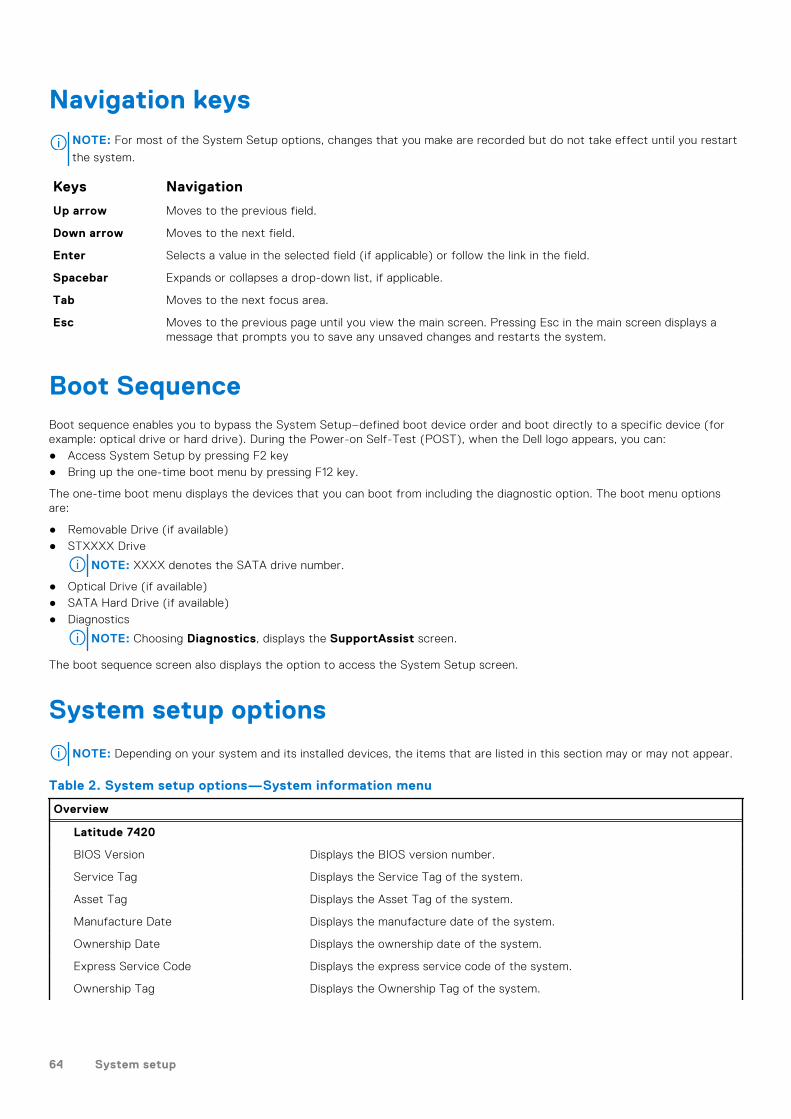
Navigation keysNOTE: For most of the System Setup options, changes that you make are recorded but do not take effect until you restart
the system.
Keys Navigation
Up arrow Moves to the previous field.
Down arrow Moves to the next field.
Enter Selects a value in the selected field (if applicable) or follow the link in the field.
Spacebar Expands or collapses a drop-down list, if applicable.
Tab Moves to the next focus area.
Esc Moves to the previous page until you view the main screen. Pressing Esc in the main screen displays amessage that prompts you to save any unsaved changes and restarts the system.
Boot SequenceBoot sequence enables you to bypass the System Setup–defined boot device order and boot directly to a specific device (forexample: optical drive or hard drive). During the Power-on Self-Test (POST), when the Dell logo appears, you can:● Access System Setup by pressing F2 key● Bring up the one-time boot menu by pressing F12 key.
The one-time boot menu displays the devices that you can boot from including the diagnostic option. The boot menu optionsare:
● Removable Drive (if available)● STXXXX Drive
NOTE: XXXX denotes the SATA drive number.
● Optical Drive (if available)● SATA Hard Drive (if available)● Diagnostics
NOTE: Choosing Diagnostics, displays the SupportAssist screen.
The boot sequence screen also displays the option to access the System Setup screen.
System setup options
NOTE: Depending on your system and its installed devices, the items that are listed in this section may or may not appear.
Table 2. System setup options—System information menu
Overview
Latitude 7420
BIOS Version Displays the BIOS version number.
Service Tag Displays the Service Tag of the system.
Asset Tag Displays the Asset Tag of the system.
Manufacture Date Displays the manufacture date of the system.
Ownership Date Displays the ownership date of the system.
Express Service Code Displays the express service code of the system.
Ownership Tag Displays the Ownership Tag of the system.
64 System setup
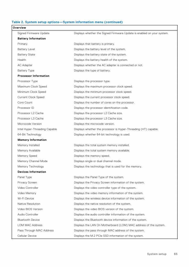
Table 2. System setup options—System information menu (continued)
Overview
Signed Firmware Update Displays whether the Signed Firmware Update is enabled on your system.
Battery Information
Primary Displays that battery is primary.
Battery Level Displays the battery level of the system.
Battery State Displays the battery state of the system.
Health Displays the battery health of the system.
AC Adapter Displays whether the AC adapter is connected or not.
Battery Type Displays the type of battery.
Processor Information
Processor Type Displays the processor type.
Maximum Clock Speed Displays the maximum processor clock speed.
Minimum Clock Speed Displays the minimum processor clock speed.
Current Clock Speed Displays the current processor clock speed.
Core Count Displays the number of cores on the processor.
Processor ID Displays the processor identification code.
Processor L2 Cache Displays the processor L2 Cache size.
Processor L3 Cache Displays the processor L3 Cache size.
Microcode Version Displays the microcode version.
Intel Hyper-Threading Capable Displays whether the processor is Hyper-Threading (HT) capable.
64-Bit Technology Displays whether 64-bit technology is used.
Memory Information
Memory Installed Displays the total system memory installed.
Memory Available Displays the total system memory available.
Memory Speed Displays the memory speed.
Memory Channel Mode Displays single or dual channel mode.
Memory Technology Displays the technology that is used for the memory.
Devices Information
Panel Type Displays the Panel Type of the system.
Privacy Screen Displays the Privacy Screen information of the system.
Video Controller Displays the video controller type of the system.
Video Memory Displays the video memory information of the system.
Wi-Fi Device Displays the wireless device information of the system.
Native Resolution Displays the native resolution of the system.
Video BIOS Version Displays the video BIOS version of the system.
Audio Controller Displays the audio controller information of the system.
Bluetooth Device Displays the Bluetooth device information of the system.
LOM MAC Address Displays the LAN On Motherboard (LOM) MAC address of the system.
Pass Through MAC Address Displays the pass through MAC address of the system.
Cellular Device Displays the M.2 PCIe SSD information of the system.
System setup 65

Table 3. System setup options—Boot Configuration menu
Boot Configuration
Boot Sequence
Boot mode Displays the boot mode.
Boot Sequence Displays the boot sequence.
Secure Digital (SD) Card Boot Enable or disable the SD card read-only boot.
By default, the Secure Digital (SD) Card Boot option is not enabled.
Secure Boot
Enable Secure Boot Enable or disable the secure boot feature.
By default, the option is not enabled.
Secure Boot Mode Enable or disable to change the secure boot mode options.
By default, the Deployed Mode is enabled.
Expert Key Management
Enable Custom Mode Enable or disable custom mode.
By default, the custom mode option is not enabled.
Custom Mode Key Management Select the custom values for expert key management.
Table 4. System setup options—Integrated Devices menu
Integrated Devices
Date/Time Displays the current date in MM/DD/YYYY format and current time inHH:MM:SS AM/PM format.
Camera Enables or disable the camera.
By default, the Enable Camera option is selected
Audio
Enable Audio Enable or disable the integrated audio controller.
By default, all the options are enabled.
USB/Thunderbolt Configuration ● Enable or disable booting from USB mass storage devices that areconnected to external USB ports.
By default, the Enable External USB Ports option is enabled.
● Enable or disable booting from USB mass storage devices such as externalhard drive, optical drive, and USB drive.
By default, the Enable USB Boot Support option is enabled.
Enable Thunderbolt TechnologySupport
Enable or disable the associated ports and adapters.
By default, the Enable Thunderbolt Technology Support option is selected.
Enable Thunderbolt Boot Support Enable or disable the Thunderbolt adapter peripheral device and USB devicesthat are connected to the Thunderbolt adapter to be used during BIOS Pre-boot.
By default, the Enable Thunderbolt Boot Support option is disabled.
Enable Thunderbolt (and PCIe behindTBT) pre-boot modules
Enable or disable the PCIe devices that are connected through a Thunderboltadapter to execute the PCIe devices UEFI Option ROM (if present) duringpre-boot.
By default, the Enable Thunderbolt (and PCIe behind TBT) pre-bootmodules option is disabled.
66 System setup

Table 4. System setup options—Integrated Devices menu (continued)
Integrated Devices
Disable USB4 PCIE Tunneling Disable the USB4 PCIE Tunneling option.
By default, the option is disabled.
Video/Power only on Type-C Ports Enable or disable the Type-C port functionality to video or only power.
By default, the Video/Power only on Type-C Ports option is disabled.
Type-C Dock Override Enables to use connected Type-C Dell Dock to provide data stream withexternal USB ports disabled. When Type-C Dock override is enabled, theVideo/Audio/Lan submenu is activated.
By default, the Type-C Dock Override option is enabled.
Video Enable or disable the usage of video on Dell Dock external ports.
By default, the Video option is disabled.
Audio Enable or disable the usage of audio on Dell Dock external ports.
By default, the Audio option is enabled.
Lan Enable or disable the usage of LAN on Dell Dock external ports.
By default, the Lan option is enabled.
Miscellaneous Devices Enable or disable Fingerprint Reader device.
By default, the Enable Fingerprint Reader Device option is enabled.
Unobtrusive Mode
Enable Unobtrusive Mode Enable or disable all the system light and sound.
By default, the Enable Unobtrusive Mode option is disabled.
Table 5. System setup options—Storage menu
Storage
SATA/NVMe Operation
SATA/NVMe Operation Set the operating mode of the integrated storage device controller.
By default, the RAID On option is enabled.
Storage interface
Port Enablement This page allows you to enable the onboard drives.
By default, the M.2 PCIe SSD option is enabled.
SMART Reporting
Enable SMART Reporting Enable or disable Self-Monitoring, Analysis, and Reporting Technology(SMART) during system startup.
By default, the Enable SMART Reporting option is not enabled.
Drive Information
M.2 PCIe SSD
Type Displays the M.2 PCIe SSD type information of the system.
Device Displays the M.2 PCIe SSD device information of the system.
Enable MediaCard
Secure Digital (SD) Card Enable or disable the SD card.
By default, the Secure Digital (SD) Card option is enabled.
Secure Digital (SD) Card Read-Only Mode Enable or disable the SD card read-only mode.
System setup 67
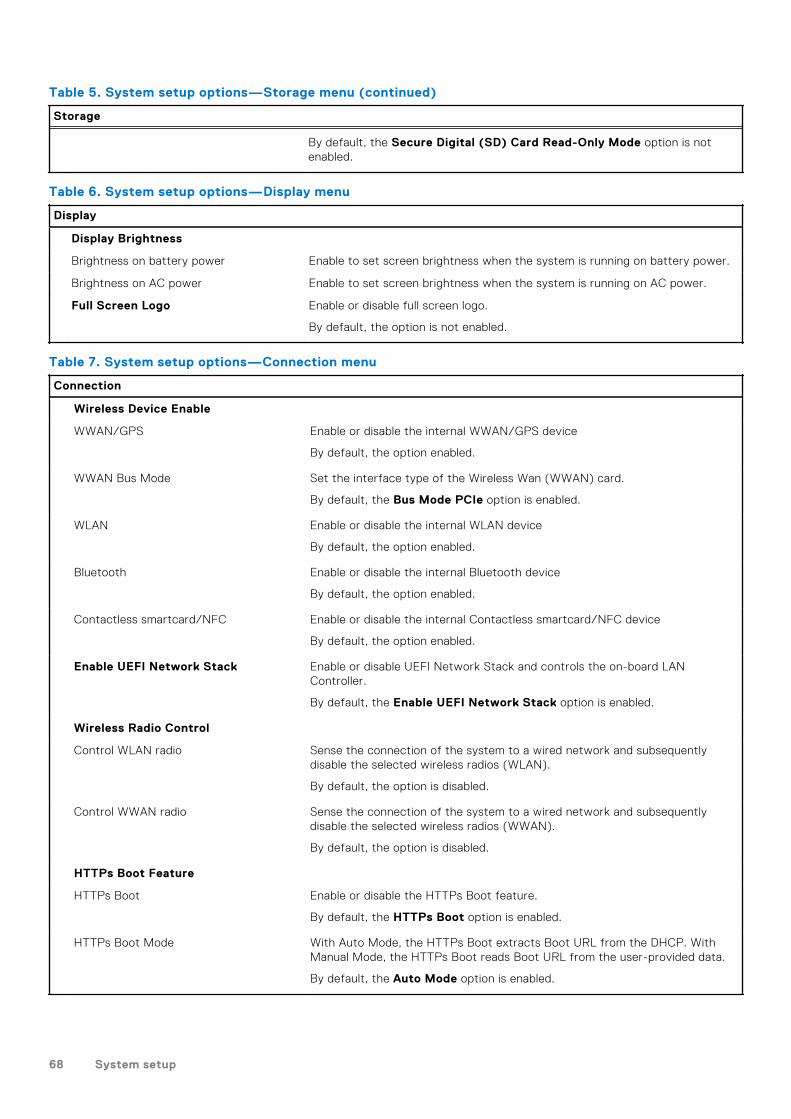
Table 5. System setup options—Storage menu (continued)
Storage
By default, the Secure Digital (SD) Card Read-Only Mode option is notenabled.
Table 6. System setup options—Display menu
Display
Display Brightness
Brightness on battery power Enable to set screen brightness when the system is running on battery power.
Brightness on AC power Enable to set screen brightness when the system is running on AC power.
Full Screen Logo Enable or disable full screen logo.
By default, the option is not enabled.
Table 7. System setup options—Connection menu
Connection
Wireless Device Enable
WWAN/GPS Enable or disable the internal WWAN/GPS device
By default, the option enabled.
WWAN Bus Mode Set the interface type of the Wireless Wan (WWAN) card.
By default, the Bus Mode PCIe option is enabled.
WLAN Enable or disable the internal WLAN device
By default, the option enabled.
Bluetooth Enable or disable the internal Bluetooth device
By default, the option enabled.
Contactless smartcard/NFC Enable or disable the internal Contactless smartcard/NFC device
By default, the option enabled.
Enable UEFI Network Stack Enable or disable UEFI Network Stack and controls the on-board LANController.
By default, the Enable UEFI Network Stack option is enabled.
Wireless Radio Control
Control WLAN radio Sense the connection of the system to a wired network and subsequentlydisable the selected wireless radios (WLAN).
By default, the option is disabled.
Control WWAN radio Sense the connection of the system to a wired network and subsequentlydisable the selected wireless radios (WWAN).
By default, the option is disabled.
HTTPs Boot Feature
HTTPs Boot Enable or disable the HTTPs Boot feature.
By default, the HTTPs Boot option is enabled.
HTTPs Boot Mode With Auto Mode, the HTTPs Boot extracts Boot URL from the DHCP. WithManual Mode, the HTTPs Boot reads Boot URL from the user-provided data.
By default, the Auto Mode option is enabled.
68 System setup

Table 8. System setup options—Power menu
Power
Battery configuration Enables the system to run on battery during peak power usage hours. Use thetable Custom Charge Start and Custom Charge Stop, to prevent AC powerusage between certain times of each day.
By default, the Adaptive option is enabled.
Advanced Configuration
Enable Advanced Battery ChargeConfiguration
Enable or disable the advanced battery charge configuration.
By default, the Enable Advanced Battery Charge Configuration option isdisabled.
Peak Shift Enables the system to run on battery during peak power usage hours.
Enable Peak Shift By default, the Enable Peak Shift option is disabled.
USB PowerShare
Enable USB PowerShare Enable or disable the USB PowerShare.
By default, the Enable USB PowerShare option is disabled
Thermal Management Enables to cool the fan and processor heat management to adjust the systemperformance, noise, and temperature.
By default, the Optimized option is enabled.
USB Wake Support
Wake on Dell USB-C Dock When enabled, connecting a Dell USB-C Dock will wake the system fromstandby.
By default, the Wake on Dell USB-C Dock option is enabled.
Block Sleep Enables to block entering sleep (S3) mode in the operating system.
By default, the Block Sleep option is disabled.
Lid Switch Enable or disable the lid switch.
By default, the Lid Switch option is enabled.
Intel Speed Shift Technology Enable or disable the Intel speed shift technology support.
By default, the Intel Speed Shift Technology option is enabled.
Table 9. System setup options—Security menu
Security
TPM 2.0 Security
TPM 2.0 Security On Enable or disable TPM 2.0 security options.
By default, the TPM 2.0 Security On option is enabled.
Attestation Enable Enables to control whether the Trusted Platform Module (TPM) EndorsementHierarchy is available to the operating system.
By default, the Attestation Enable option is enabled.
Key Storage Enable Enables to control whether the Trusted Platform Module (TPM) StorageHierarchy is available to the operating system.
By default, the Key Storage Enable option is enabled.
SHA-256 BIOS and the TPM will use the SHA-256 hash algorithm to extendmeasurements into the TPM PCRs during BIOS boot.
By default, the SHA-256 option is enabled.
System setup 69

Table 9. System setup options—Security menu (continued)
Security
Clear Enables to clear the TPM owner information and returns the TPM to thedefault state.
By default, the Clear option is disabled.
PPI ByPass for Clear Commands Controls the TPM Physical Presence Interface (PPI).
By default, the PPI ByPass for clear Commands option is disabled.
Intel Total Memory Encryption
Total Memory Encryption Enable or disable you to protect memory from physical attacks including freezespray, probing DDR to read the cycles, and others.
By default, the Total Memory Encryption option is disabled.
Chassis intrusion Controls the chassis intrusion feature.
By default, the On-Silent option is enabled.
Clear Intrusion Warning By default, the option is disabled.
SMM Security Mitigation Enable or disable SMM Security Mitigation.
By default, the option is enabled.
Data Wipe on Next Boot
Start Data Wipe Enable or disable the data wipe on next boot.
By default, the option is disabled.
Absolute Enable or disable or permanently disable the BIOS module interface of theoptional Absolute Persistence Module service from Absolute software.
By default, the option is enabled.
UEFI Boot Path Security Controls whether the system will prompt the user to enter the admin password(if set) when booting to a UEFI boot device from the F12 boot menu.
By default, the Always Except Internal HDD option is enabled.
Table 10. System setup options—Passwords menu
Passwords
Admin Password Set, change, or delete the administrator password.
System Password Set, change, or delete the system password.
NVMe SSD0 Set, change, or delete the NVMe SSD0 password.
Password Configuration
Upper Case Letter Reinforces password must have at least one upper case letter.
By default, the option is enabled.
Lower Case Letter Reinforces password must have at least one lower case letter.
By default, the option is enabled.
Digit Reinforces password must have at least one digit.
By default, the option is enabled.
Special Character Reinforces password must have at least one special character.
By default, the option is enabled.
Minimum Characters Set the minimum characters allowed for password.
70 System setup

Table 10. System setup options—Passwords menu (continued)
Passwords
Password Bypass When enabled, this always prompts for system and internal hard drivepasswords when powered on from the off state.
By default, the Disabled option is selected.
Password Changes
Enable Non-Admin Password Changes Enable or disable to change system and hard drive password without the needfor admin password.
By default, the option is disabled.
Admin Setup Lockout
Enable Admin Setup Lockout Enables administrators control over how their users can or cannot access BIOSsetup.
By default, the option is disabled.
Master Password Lockout
Enable Master Password Lockout When enabled, this disables the master password support.
By default, the option is disabled.
Allow Non-Admin PSID Revert
Enable Allow Non-Admin PSID Revert Controls access to the Physical Security ID (PSID) revert of NVMe hard-drivesfrom the Dell Security Manager prompt.
By default, the option is disabled.
Table 11. System setup options—Update, Recovery menu
Update, Recovery
UEFI Capsule Firmware Updates Enable or disable BIOS updates through UEFI capsule update packages.
By default, the option is enabled.
BIOS Recovery from Hard Drive Enables the user to recover from certain corrupted BIOS conditions from arecovery file on the user primary hard drive or an external USB key.
By default, the option is enabled.
BIOS Downgrade
Allow BIOS Downgrade Enable or disable the flashing of the system firmware to previous revision isblocked.
By default, the option is enabled.
SupportAssist OS Recovery Enable or disable the boot flow for SupportAssist OS Recovery tool in theevent of certain system errors.
By default, the option is enabled.
BIOSConnect Enable or disable cloud Service operating system recovery if the main operatingsystem fails to boot with the number of failures equal to or greater than thevalue specified by the Auto operating system Recovery Threshold setup optionand local Service operating system does not boot or is not installed.
By default, the option is enabled.
Dell Auto operating system RecoveryThreshold
Controls the automatic boot flow for SupportAssist System Resolution Consoleand for Dell operating system Recovery Tool.
By default, the threshold value is set to 2.
System setup 71
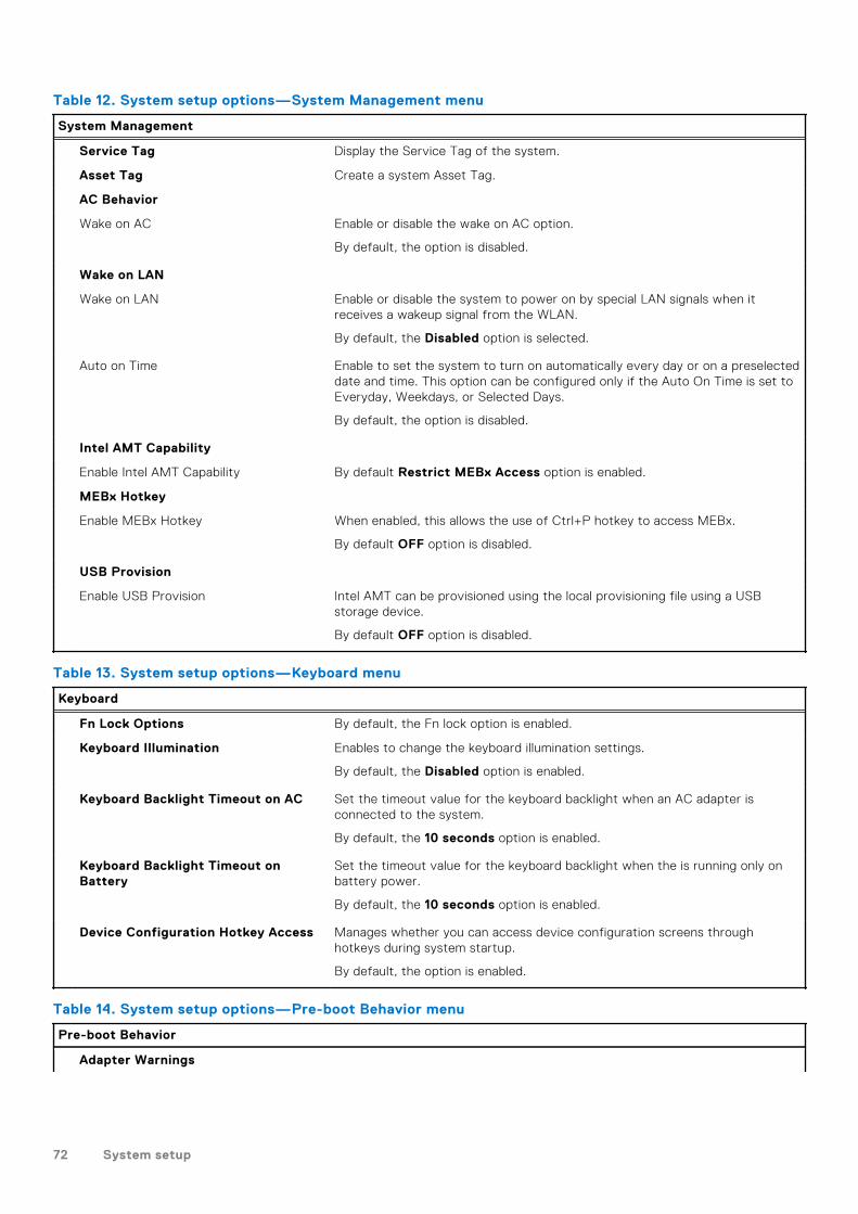
Table 12. System setup options—System Management menu
System Management
Service Tag Display the Service Tag of the system.
Asset Tag Create a system Asset Tag.
AC Behavior
Wake on AC Enable or disable the wake on AC option.
By default, the option is disabled.
Wake on LAN
Wake on LAN Enable or disable the system to power on by special LAN signals when itreceives a wakeup signal from the WLAN.
By default, the Disabled option is selected.
Auto on Time Enable to set the system to turn on automatically every day or on a preselecteddate and time. This option can be configured only if the Auto On Time is set toEveryday, Weekdays, or Selected Days.
By default, the option is disabled.
Intel AMT Capability
Enable Intel AMT Capability By default Restrict MEBx Access option is enabled.
MEBx Hotkey
Enable MEBx Hotkey When enabled, this allows the use of Ctrl+P hotkey to access MEBx.
By default OFF option is disabled.
USB Provision
Enable USB Provision Intel AMT can be provisioned using the local provisioning file using a USBstorage device.
By default OFF option is disabled.
Table 13. System setup options—Keyboard menu
Keyboard
Fn Lock Options By default, the Fn lock option is enabled.
Keyboard Illumination Enables to change the keyboard illumination settings.
By default, the Disabled option is enabled.
Keyboard Backlight Timeout on AC Set the timeout value for the keyboard backlight when an AC adapter isconnected to the system.
By default, the 10 seconds option is enabled.
Keyboard Backlight Timeout onBattery
Set the timeout value for the keyboard backlight when the is running only onbattery power.
By default, the 10 seconds option is enabled.
Device Configuration Hotkey Access Manages whether you can access device configuration screens throughhotkeys during system startup.
By default, the option is enabled.
Table 14. System setup options—Pre-boot Behavior menu
Pre-boot Behavior
Adapter Warnings
72 System setup

Table 14. System setup options—Pre-boot Behavior menu (continued)
Pre-boot Behavior
Enable Adapter Warnings Enable or disable the warning messages during boot when the adapters withless power capacity are detected.
By default, the option is enabled.
Warning and Errors Enable or disable the action to be done when a warning or error is encountered.
By default, the Prompt on Warnings and Errors option is enabled.
USB-C Warnings
Enable Dock Warning Messages By default, the option is enabled.
Fastboot Enable to set the speed of the boot process.
By default, the Minimal option is enabled.
Extend BIOS POST Time Set the BIOS POST time.
By default, the 0 seconds option is enabled.
MAC Address Pass-Through Replaces the external NIC MAC address with the selected MAC address fromthe system.
By default, the System Unique MAC Address option is enabled.
Mouse/Touchpad By default, the Touchpad and PS/2 Mouse option is enabled.
Table 15. System setup options—Virtualization menu
Virtualization
Intel Virtualization Technology
Enable Intel Virtualization Technology(VT)
Specify whether a Virtual Machine Monitor (VMM) can use the additionalhardware capabilities that are provided by Intel Virtualization Technology.
By default, the option is enabled.
VT for Direct I/O Specify whether a Virtual Machine Monitor (VMM) can use the additionalhardware capabilities that are provided by Intel Virtualization Technology forDirect I/O.
By default, the option is enabled.
Intel Trusted Execution Technology(TXT)
Enable Intel Trusted ExecutionTechnology (TXT)
Specifies whether a measured Virtual Machine Monitor (MVMM) can use theadditional hardware capabilities that are provided by Intel Trusted ExecutionTechnology.
By default, the option is disabled.
Table 16. System setup options—Performance menu
Performance
Multi Core Support
Active Cores Enables to change the number of CPU cores available to the operating system.
By default, the All Cores option is enabled.
Intel SpeedStep
Enable Intel SpeedStep Technology Enables the system to dynamically adjust processor voltage and corefrequency, decreasing average power consumption and heat production.
By default, the option is enabled.
System setup 73

Table 16. System setup options—Performance menu (continued)
Performance
C-States Control
Enable C-State Control Enable or disable additional processor sleep states.
By default, the option is enabled.
Intel TurbocBoost Technology
Enable Intel Turbo Boost Technology Enable or disable Intel TurboBoost mode of the processor.
By default, the option is enabled.
Intel Hyper-Threading Technology
Enable Intel Hyper-Threading Technology Enable or disable Hyper-Threading in the processor.
By default, the option is enabled.
Dynamic Tuning:Machine Learning
Enable Dynamic Tuning:Machine Learning Enables the operating system capability to enhance dynamic power tuningcapabilities based on detected workloads.
By default, the option is disabled.
Table 17. System setup options—System Logs menu
System Logs
BIOS Event Log
Clear Bios Event Log Display BIOS events.
By default, the Keep option is enabled.
Thermal Event Log
Clear Thermal Event Log Display Thermal events.
By default, the Keep option is enabled.
Power Event Log
Clear Power Event Log Display power events.
By default, the Keep option is enabled.
License Information Displays the license information of the system.
Updating the BIOS in Windows
Prerequisites
It is recommended to update your BIOS (System Setup) when you replace the system board or if an update is available. Forlaptops, ensure that your computer battery is fully charged and connected to a power before initiating a BIOS update.
About this task
NOTE: If BitLocker is enabled, it must be suspended prior to updating the system BIOS, and then re enabled after the BIOS
update is completed.
Steps
1. Restart the computer.
2. Go to Dell.com/support.● Enter the Service Tag or Express Service Code and click Submit.● Click Detect Product and follow the instructions on screen.
74 System setup

3. If you are unable to detect or find the Service Tag, click Choose from all products.
4. Choose the Products category from the list.
NOTE: Choose the appropriate category to reach the product page.
5. Select your computer model and the Product Support page of your computer appears.
6. Click Get drivers and click Drivers and Downloads.The Drivers and Downloads section opens.
7. Click Find it myself.
8. Click BIOS to view the BIOS versions.
9. Identify the latest BIOS file and click Download.
10. Select your preferred download method in the Please select your download method below window, click Download File.The File Download window appears.
11. Click Save to save the file on your computer.
12. Click Run to install the updated BIOS settings on your computer.
Follow the instructions on the screen.
Updating BIOS on systems with BitLocker enabled
CAUTION: If BitLocker is not suspended before updating the BIOS, the next time you reboot the system it
will not recognize the BitLocker key. You will then be prompted to enter the recovery key to progress and the
system will ask for this on each reboot. If the recovery key is not known this can result in data loss or an
unnecessary operating system re-install. For more information on this subject, see Knowledge Article: https://
www.dell.com/support/article/sln153694
Updating your system BIOS using a USB flash drive
About this task
If the computer cannot load into Windows but there is still a need to update the BIOS, download the BIOS file using anothercomputer and save it to a bootable USB flash drive.
NOTE: You must use a bootable USB flash drive. For more information, see the knowledge base article SLN143196.
Steps
1. Download the BIOS update .exe file to another computer.
2. Copy the .exe file onto the bootable USB flash drive.
3. Insert the USB flash drive into the computer that requires the BIOS update.
4. Restart the computer and press F12 when the Dell logo appears to display the One Time Boot Menu.
5. Using arrow keys, select USB Storage Device and press Enter.
6. The computer restarts to a Diag C:\> prompt.
7. Run the file by typing the complete filename and press Enter.
8. The BIOS Update Utility is displayed. Follow the on-screen instructions.
System setup 75

Figure 2. DOS BIOS Update Screen
System and setup passwordTable 18. System and setup password
Password type Description
System password Password that you must enter to log on to your system.
Setup password Password that you must enter to access and make changes tothe BIOS settings of your computer.
You can create a system password and a setup password to secure your computer.
CAUTION: The password features provide a basic level of security for the data on your computer.
CAUTION: Anyone can access the data stored on your computer if it is not locked and left unattended.
NOTE: System and setup password feature is disabled.
Assigning a system setup password
Prerequisites
You can assign a new System or Admin Password only when the status is in Not Set.
About this task
To enter the system setup, press F2 immediately after a power-on or reboot.
Steps
1. In the System BIOS or System Setup screen, select Security and press Enter.The Security screen is displayed.
2. Select System/Admin Password and create a password in the Enter the new password field.
Use the following guidelines to assign the system password:● A password can have up to 32 characters.● The password can contain the numbers 0 through 9.
76 System setup

● Only lower case letters are valid, upper case letters are not allowed.● Only the following special characters are allowed: space, (”), (+), (,), (-), (.), (/), (;), ([), (\), (]), (`).
3. Type the system password that you entered earlier in the Confirm new password field and click OK.
4. Press Esc and a message prompts you to save the changes.
5. Press Y to save the changes.The computer reboots.
Deleting or changing an existing system setup password
Prerequisites
Ensure that the Password Status is Unlocked (in the System Setup) before attempting to delete or change the existingSystem and Setup password. You cannot delete or change an existing System or Setup password, if the Password Status isLocked.
About this task
To enter the System Setup, press F2 immediately after a power-on or reboot.
Steps
1. In the System BIOS or System Setup screen, select System Security and press Enter.The System Security screen is displayed.
2. In the System Security screen, verify that Password Status is Unlocked.
3. Select System Password, alter or delete the existing system password and press Enter or Tab.
4. Select Setup Password, alter or delete the existing setup password and press Enter or Tab.
NOTE: If you change the System and/or Setup password, re enter the new password when prompted. If you delete the
System and Setup password, confirm the deletion when prompted.
5. Press Esc and a message prompts you to save the changes.
6. Press Y to save the changes and exit from System Setup.The computer restarts.
Clearing BIOS (System Setup) and System passwords
About this task
NOTE: To conduct a BIOS and System password reset, you must call the Dell Tech Support number in your region.
Steps
1. Key in your computer's service tag number into the locked BIOS/system setup screen.
2. Convey the code generated to the Dell Tech Support agent.
3. The Dell Tech Support agent will provide a 32 character Master System Password that can be used to access the lockedBIO/system setup.
System setup 77
Troubleshooting
Topics:
• Recovering the operating system• Backup media and recovery options• Dell SupportAssist Pre-boot System Performance Check diagnostics• Diagnostic LED behavior• Real-Time Clock (RTC Reset)• Flashing BIOS (USB key)• Flashing the BIOS• WiFi power cycle• BIOS recovery• M-BIST• LCD Built-in Self Test (BIST)
Recovering the operating systemWhen your computer is unable to boot to the operating system even after repeated attempts, it automatically starts DellSupportAssist OS Recovery.
Dell SupportAssist OS Recovery is a standalone tool that is preinstalled in all Dell computers installed with Windows 10 operatingsystem. It consists of tools to diagnose and troubleshoot issues that may occur before your computer boots to the operatingsystem. It enables you to diagnose hardware issues, repair your computer, back up your files, or restore your computer to itsfactory state.
You can also download it from the Dell Support website to troubleshoot and fix your computer when it fails to boot into theirprimary operating system due to software or hardware failures.
For more information about the Dell SupportAssist OS Recovery, see Dell SupportAssist OS Recovery User's Guide atwww.dell.com/support.
Backup media and recovery optionsIt is recommended to create a recovery drive to troubleshoot and fix problems that may occur with Windows. Dell proposesmultiple options for recovering Windows operating system on your Dell PC. For more information. see Dell Windows BackupMedia and Recovery Options.
Dell SupportAssist Pre-boot System PerformanceCheck diagnostics
About this task
SupportAssist diagnostics (also known as system diagnostics) performs a complete check of your hardware. The DellSupportAssist Pre-boot System Performance Check diagnostics is embedded with the BIOS and is launched by the BIOSinternally. The embedded system diagnostics provides a set of options for particular devices or device groups allowing you to:● Run tests automatically or in an interactive mode● Repeat tests● Display or save test results● Run thorough tests to introduce additional test options to provide extra information about the failed device(s)● View status messages that inform you if tests are completed successfully
5
78 Troubleshooting

● View error messages that inform you of problems encountered during testing
NOTE: Some tests for specific devices require user interaction. Always ensure that you are present at the computer
terminal when the diagnostic tests are performed.
For more information, see Resolve Hardware Issues With Built-in and Online Diagnostics (SupportAssist ePSA, ePSA or PSAError Codes) .
Running the SupportAssist Pre-Boot System Performance Check
Steps
1. Turn on your computer.
2. As the computer boots, press the F12 key as the Dell logo appears.
3. On the boot menu screen, select the Diagnostics option.
4. Click the arrow at the bottom left corner.Diagnostics front page is displayed.
5. Click the arrow in the lower-right corner to go to the page listing.The items detected are listed.
6. To run a diagnostic test on a specific device, press Esc and click Yes to stop the diagnostic test.
7. Select the device from the left pane and click Run Tests.
8. If there are any issues, error codes are displayed.Note the error code and validation number and contact Dell.
Diagnostic LED behaviorTable 19. Diagnostic LED behavior
Blinking pattern
Problem description Suggested resolutionAmber White
1 1 TPM detection failure Replace the system board.
1 2 Unrecoverable SPI FlashFailure
Replace the system board.
1 5 EC unable to program i-Fuse Replace the system board.
1 6 Generic catch-all forungraceful EC code flow
errors
Disconnect all power source(AC, battery, coin cell) and
drain flea power by pressing &holding down power button.
2 1 CPU failure ● Run the Dell SupportAssist/Dell Diagnostics
tool.● If problem persists,
replace the system board.
2 2 System board failure (includedBIOS corruption or ROM
error)
● Flash latest BIOS version● If problem persists,
replace the system board.
2 3 No memory/RAM detected ● Confirm that the memorymodule is installed
properly.● If problem persists,
replace the memorymodule.
Troubleshooting 79

Table 19. Diagnostic LED behavior (continued)
Blinking pattern
Problem description Suggested resolutionAmber White
2 4 Memory/RAM failure ● Reset and swap memorymodules amongst the
slots.● If problem persists,
replace the memorymodule.
2 5 Invalid memory installed ● Reset and swap memorymodules amongst the
slots.● If problem persists,
replace the memorymodule.
2 6 System board/Chipset Error Replace the system board.
2 7 LCD failure (SBIOS message) Replace the LCD module.
2 8 LCD failure (EC detection ofpower rail failure)
Replace the system board.
3 1 CMOS battery failure ● Reset the CMOS batteryconnection.
● If problem persists,replace the RTS battery.
3 2 PCI or Video card/chip failure Replace the system board.
3 3 BIOS Recovery image notfound
● Flash latest BIOS version● If problem persists,
replace the system board.
3 4 BIOS Recovery image foundbut invalid
● Flash latest BIOS version● If problem persists,
replace the system board.
3 5 Power rail failure Replace the system board.
3 6 Flash corruption detected bySBIOS.
Replace the system board.
3 7 Timeout waiting on ME toreply to HECI message.
Replace the system board.
NOTE: Blinking 3-3-3 LEDs on Lock LED (Caps-Lock or Nums-Lock), Power button LED (without Fingerprint reader), and
Diagnostic LED indicates failure to provide input during LCD panel test on Dell SupportAssist Pre-boot System Performance
Check diagnostics.
Real-Time Clock (RTC Reset)The Real Time Clock (RTC) reset function allows you or the service technician to recover Dell Latitude, systems from NoPOST/No Power/No Boot situations. The legacy jumper enabled RTC reset has been retired on these models.
Start the RTC reset with the system powered off and connected to AC power. Press and hold the power button for thirty (30)seconds. The system RTC Reset occurs after you release the power button.
80 Troubleshooting

Flashing BIOS (USB key)
Steps
1. Follow the procedure from step 1 to step 7 in "Flashing the BIOS" to download the latest BIOS setup program file.
2. Create a bootable USB drive. For more information see the knowledge base article SLN143196 at www.dell.com/support.
3. Copy the BIOS setup program file to the bootable USB drive.
4. Connect the bootable USB drive to the computer that needs the BIOS update.
5. Restart the computer and press F12 when the Dell logo is displayed on the screen.
6. Boot to the USB drive from the One Time Boot Menu.
7. Type the BIOS setup program filename and press Enter.
8. The BIOS Update Utility appears. Follow the instructions on the screen to complete the BIOS update.
Flashing the BIOS
About this task
You may need to flash (update) the BIOS when an update is available or when you replace the system board.
Follow these steps to flash the BIOS:
Steps
1. Turn on your computer.
2. Go to www.dell.com/support.
3. Click Product support, enter the Service Tag of your computer, and then click Submit.
NOTE: If you do not have the Service Tag, use the auto-detect feature or manually browse for your computer model.
4. Click Drivers & downloads > Find it myself.
5. Select the operating system installed on your computer.
6. Scroll down the page and expand BIOS.
7. Click Download to download the latest version of the BIOS for your computer.
8. After the download is complete, navigate to the folder where you saved the BIOS update file.
9. Double-click the BIOS update file icon and follow the instructions on the screen.
WiFi power cycle
About this task
If your computer is unable to access the internet due to WiFi connectivity issues a WiFi power cycle procedure may beperformed. The following procedure provides the instructions on how to conduct a WiFi power cycle:
NOTE: Some ISPs (Internet Service Providers) provide a modem/router combo device.
Steps
1. Turn off your computer.
2. Turn off the modem.
3. Turn off the wireless router.
4. Wait for 30 seconds.
5. Turn on the wireless router.
6. Turn on the modem.
7. Turn on your computer.
Troubleshooting 81
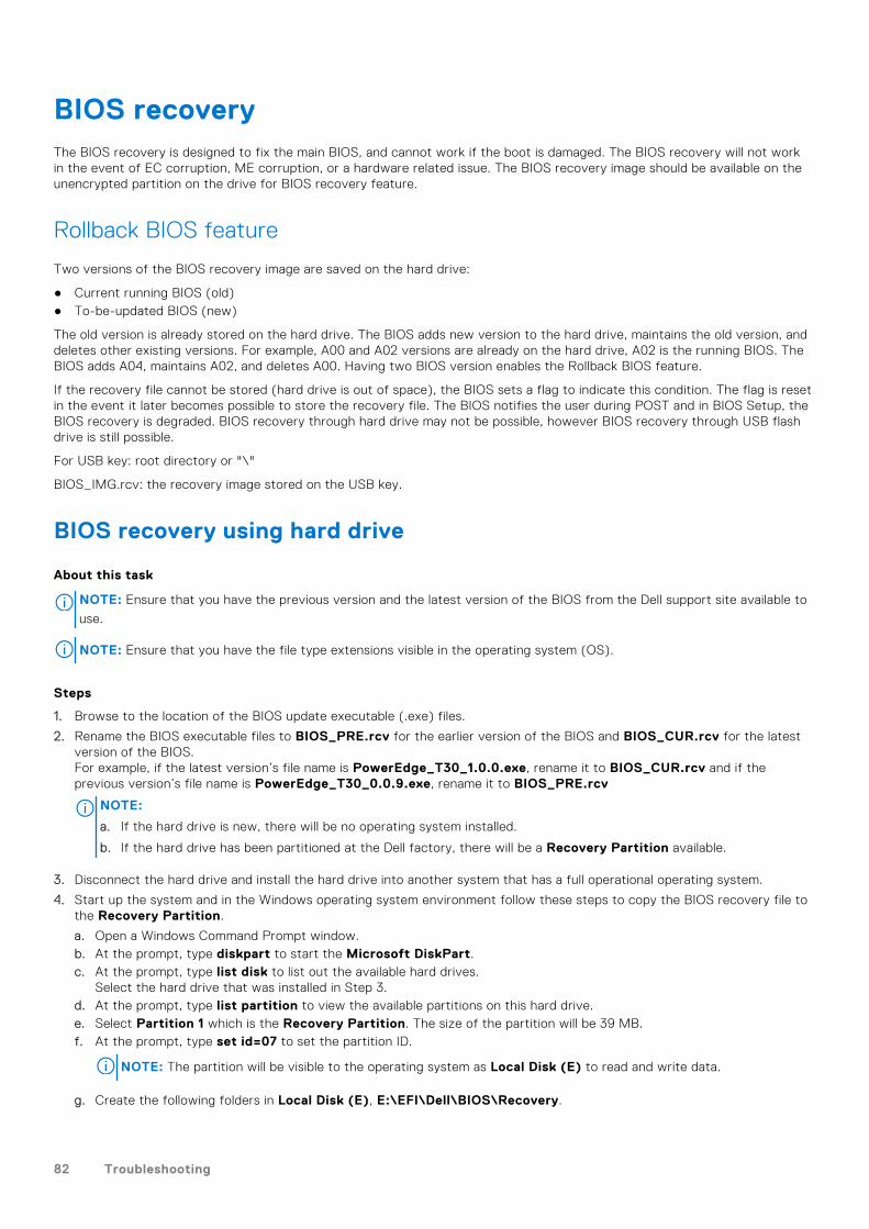
BIOS recoveryThe BIOS recovery is designed to fix the main BIOS, and cannot work if the boot is damaged. The BIOS recovery will not workin the event of EC corruption, ME corruption, or a hardware related issue. The BIOS recovery image should be available on theunencrypted partition on the drive for BIOS recovery feature.
Rollback BIOS feature
Two versions of the BIOS recovery image are saved on the hard drive:
● Current running BIOS (old)● To-be-updated BIOS (new)
The old version is already stored on the hard drive. The BIOS adds new version to the hard drive, maintains the old version, anddeletes other existing versions. For example, A00 and A02 versions are already on the hard drive, A02 is the running BIOS. TheBIOS adds A04, maintains A02, and deletes A00. Having two BIOS version enables the Rollback BIOS feature.
If the recovery file cannot be stored (hard drive is out of space), the BIOS sets a flag to indicate this condition. The flag is resetin the event it later becomes possible to store the recovery file. The BIOS notifies the user during POST and in BIOS Setup, theBIOS recovery is degraded. BIOS recovery through hard drive may not be possible, however BIOS recovery through USB flashdrive is still possible.
For USB key: root directory or "\"
BIOS_IMG.rcv: the recovery image stored on the USB key.
BIOS recovery using hard drive
About this task
NOTE: Ensure that you have the previous version and the latest version of the BIOS from the Dell support site available to
use.
NOTE: Ensure that you have the file type extensions visible in the operating system (OS).
Steps
1. Browse to the location of the BIOS update executable (.exe) files.
2. Rename the BIOS executable files to BIOS_PRE.rcv for the earlier version of the BIOS and BIOS_CUR.rcv for the latestversion of the BIOS.For example, if the latest version’s file name is PowerEdge_T30_1.0.0.exe, rename it to BIOS_CUR.rcv and if theprevious version’s file name is PowerEdge_T30_0.0.9.exe, rename it to BIOS_PRE.rcv
NOTE:
a. If the hard drive is new, there will be no operating system installed.
b. If the hard drive has been partitioned at the Dell factory, there will be a Recovery Partition available.
3. Disconnect the hard drive and install the hard drive into another system that has a full operational operating system.
4. Start up the system and in the Windows operating system environment follow these steps to copy the BIOS recovery file tothe Recovery Partition.
a. Open a Windows Command Prompt window.b. At the prompt, type diskpart to start the Microsoft DiskPart.c. At the prompt, type list disk to list out the available hard drives.
Select the hard drive that was installed in Step 3.d. At the prompt, type list partition to view the available partitions on this hard drive.e. Select Partition 1 which is the Recovery Partition. The size of the partition will be 39 MB.f. At the prompt, type set id=07 to set the partition ID.
NOTE: The partition will be visible to the operating system as Local Disk (E) to read and write data.
g. Create the following folders in Local Disk (E), E:\EFI\Dell\BIOS\Recovery.
82 Troubleshooting
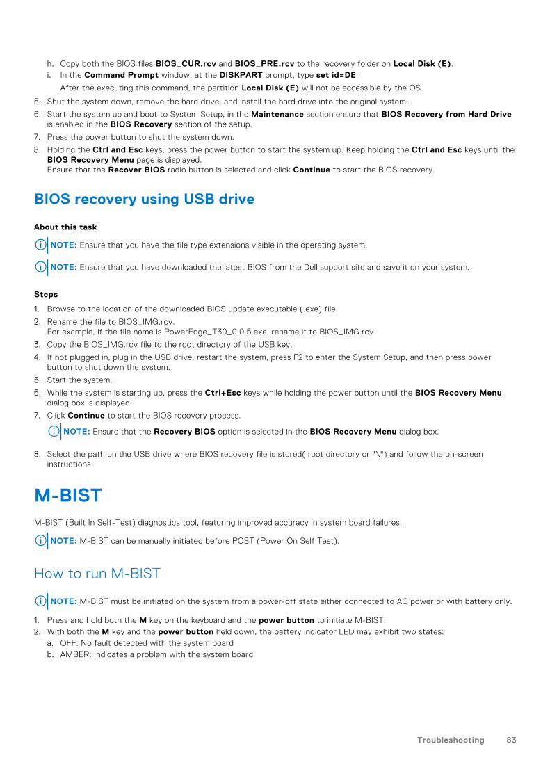
h. Copy both the BIOS files BIOS_CUR.rcv and BIOS_PRE.rcv to the recovery folder on Local Disk (E).i. In the Command Prompt window, at the DISKPART prompt, type set id=DE.
After the executing this command, the partition Local Disk (E) will not be accessible by the OS.
5. Shut the system down, remove the hard drive, and install the hard drive into the original system.
6. Start the system up and boot to System Setup, in the Maintenance section ensure that BIOS Recovery from Hard Driveis enabled in the BIOS Recovery section of the setup.
7. Press the power button to shut the system down.
8. Holding the Ctrl and Esc keys, press the power button to start the system up. Keep holding the Ctrl and Esc keys until theBIOS Recovery Menu page is displayed.Ensure that the Recover BIOS radio button is selected and click Continue to start the BIOS recovery.
BIOS recovery using USB drive
About this task
NOTE: Ensure that you have the file type extensions visible in the operating system.
NOTE: Ensure that you have downloaded the latest BIOS from the Dell support site and save it on your system.
Steps
1. Browse to the location of the downloaded BIOS update executable (.exe) file.
2. Rename the file to BIOS_IMG.rcv.For example, if the file name is PowerEdge_T30_0.0.5.exe, rename it to BIOS_IMG.rcv
3. Copy the BIOS_IMG.rcv file to the root directory of the USB key.
4. If not plugged in, plug in the USB drive, restart the system, press F2 to enter the System Setup, and then press powerbutton to shut down the system.
5. Start the system.
6. While the system is starting up, press the Ctrl+Esc keys while holding the power button until the BIOS Recovery Menudialog box is displayed.
7. Click Continue to start the BIOS recovery process.
NOTE: Ensure that the Recovery BIOS option is selected in the BIOS Recovery Menu dialog box.
8. Select the path on the USB drive where BIOS recovery file is stored( root directory or "\") and follow the on-screeninstructions.
M-BISTM-BIST (Built In Self-Test) diagnostics tool, featuring improved accuracy in system board failures.
NOTE: M-BIST can be manually initiated before POST (Power On Self Test).
How to run M-BIST
NOTE: M-BIST must be initiated on the system from a power-off state either connected to AC power or with battery only.
1. Press and hold both the M key on the keyboard and the power button to initiate M-BIST.2. With both the M key and the power button held down, the battery indicator LED may exhibit two states:
a. OFF: No fault detected with the system boardb. AMBER: Indicates a problem with the system board
Troubleshooting 83

LCD Built-in Self Test (BIST)Dell laptops have a built-in diagnostic tool that helps you determine if the screen abnormality you are experiencing is an inherentproblem with the LCD (screen) of the Dell laptop or with the video card (GPU) and PC settings.
When you notice screen abnormalities like flickering, distortion, clarity issues, fuzzy or blurry image, horizontal or vertical lines,color fade etc., it is always a good practice to isolate the LCD (screen) by running the Built-In Self Test (BIST).
How to invoke LCD BIST Test
1. Power off the Dell laptop.2. Disconnect any peripherals that are connected to the laptop. Connect only the AC adapter (charger) to the laptop.3. Ensure that the LCD (screen) is clean (no dust particles on the surface of the screen).4. Press and hold D key and Power on the laptop to enter LCD built-in self test (BIST) mode. Continue to hold the D key, until
you see color bars on the LCD (screen).5. The screen will display multiple color bars and change colors on the entire screen to red, green, and blue.6. Carefully inspect the screen for abnormalities.7. Press Esc key to exit.
NOTE: Dell SupportAssist Pre-boot diagnostics upon launch, initiates an LCD BIST first, expecting a user intervention
confirm functionality of the LCD.
84 Troubleshooting

Getting help
Topics:
• Contacting Dell
Contacting Dell
Prerequisites
NOTE: If you do not have an active Internet connection, you can find contact information on your purchase invoice, packing
slip, bill, or Dell product catalog.
About this task
Dell provides several online and telephone-based support and service options. Availability varies by country and product, andsome services may not be available in your area. To contact Dell for sales, technical support, or customer service issues:
Steps
1. Go to Dell.com/support.
2. Select your support category.
3. Verify your country or region in the Choose a Country/Region drop-down list at the bottom of the page.
4. Select the appropriate service or support link based on your need.
6
Getting help 85