Large scale antenna for Mobile Communication
13
Turkish Journal of Computer and Mathematics Education Vol.11 No.02 (2020), 816- 828 816 Research Article Next Generation Antenna: Large scale antenna for Mobile Communication Inderpreet Kaur 1 , Hari Kumar Singh 2 , Pooja Singh 3 Sanjeev Sharma 4 1,2,4 Department of Electronics and Communication Engineering 1,2 M.J.P. Rohilkhand University, Bareilly, U.P. (INDIA) 3 Reasearch Scholar, Delhi Technological University, Delhi 4 R.D. Engineering College, Ghaziabad, Uttar Pradesh, [email protected] 1 , [email protected] 2 Abstract: Cellular Communication technology is stepping towards the 6G and particularly in the context of antennas, 6G will demand a revolution, since they are going to be designed for short wavelength (mm-waves), which easily fit in handsets. There are many practical challenges of 6G requirement, millimeter waves suffer from high attenuation due to rain, to overcome all these challenges as well as free space attenuation, high efficiency, all space coverage antenna; researching configurable, large scale array antenna and radio frequency technology, breaking through the multiband and high integrated radio frequency circuit, including low power consumption, low noise and non-linearity. The crucial challenges include the theory and implementation method of high integration RF circuit optimization design, different antenna types have been exploited for 6G networks. For device-to-device communication, we have demonstrated that is possible to reach multi-Gbps throughput using spatial multiplexing and a simple RF architecture. a new spectrum at 140 GHz that may play a major role for 6G wireless communication. Terahertz wave has high frequency and wide bandwidth which can meet the requirements of spectrum bandwidth for wireless broadband transmission also terahertz waves are having strong penetration. Terahertz wave is easily absorbed by moisture in the air, which is more suitable for high speed, short distance wireless communication. The constraints include physical barriers to sub-THz wave propagation, which can be blocked or strongly attenuated by walls, trees or even windows. Even in a clear propagation path, high-gain antennas are required Multi antenna technology, especially very large-scale antenna technology is one of the key technologies to improve the spectrum efficiency of wireless mobile communication system. The large-scale antenna system aims to offer an increased number of antenna module and alters the way in which signals are sent to device by arranging and tuning them in different ways The more antenna modules that are deployed, the higher the concentration of beams and therefore the lower the beam that each antenna needs to send information. In order to obtain large scale antenna gain, channel status information (CSI) is needed at both transmitter and receiver. Keywords: The fifth-generation mobile communication, large-scale distributed antenna systems, spectral efficiency, channel state information acquisition, resource allocation. 1. Large Scale Antenna System The main aim of early mobile systems was to achieve a large coverage area by using a single, high-powered transmitter with an antenna mounted on a tall tower. While this approach achieved very good coverage, it was impossible to reuse same frequencies throughout the system. Any attempts to achieve frequency reuse. The improvement of antenna system performance will inevitably lead to improvement of the overall performance of wireless communication systems result interference. The cellular concept was a major breakthrough in solving the problem of spectral congestion and user capacity. It offered very high capacity in a limited allocation without any major technological changes. [1,3] In recent years, mobile data traffic has been increasing exponentially. At the same time, as the energy consumption of information and communication technology becomes large, it is very urgent to reduce the energy consumption of mobile communication systems. To meet the future demand for huge traffic volume of wireless data service, the research on sixth generation mobile communication system has been undertaken. [2,3] Comparison between 4G, 5G and 6G Android Authority takes a closer look at 4G, 5G and 6G wireless realms as they exist today and show where the worlds intersect and where they have clear distinctions. It ’s is also important to define 4G, 5G and 6G because the wireless tribe is an industry in a hurry when it comes to the generation. [5,7,11]
-
Upload
khangminh22 -
Category
Documents
-
view
2 -
download
0
Transcript of Large scale antenna for Mobile Communication
Turkish Journal of Computer and Mathematics Education Vol.11 No.02 (2020), 816- 828
816
Research Article
Next Generation Antenna: Large scale antenna for Mobile
Communication
Inderpreet Kaur1, Hari Kumar Singh
2, Pooja Singh
3 Sanjeev Sharma
4
1,2,4Department of Electronics and Communication Engineering
1,2M.J.P. Rohilkhand University, Bareilly, U.P. (INDIA)
3Reasearch Scholar, Delhi Technological University, Delhi
4R.D. Engineering College, Ghaziabad, Uttar Pradesh,
[email protected], [email protected]
2
Abstract: Cellular Communication technology is stepping towards the 6G and particularly in the context of antennas,
6G will demand a revolution, since they are going to be designed for short wavelength (mm-waves), which easily fit in
handsets. There are many practical challenges of 6G requirement, millimeter waves suffer from high attenuation due to
rain, to overcome all these challenges as well as free space attenuation, high efficiency, all space coverage antenna;
researching configurable, large scale array antenna and radio frequency technology, breaking through the multiband and
high integrated radio frequency circuit, including low power consumption, low noise and non-linearity. The crucial
challenges include the theory and implementation method of high integration RF circuit optimization design, different
antenna types have been exploited for 6G networks.
For device-to-device communication, we have demonstrated that is possible to reach multi-Gbps throughput using
spatial multiplexing and a simple RF architecture. a new spectrum at 140 GHz that may play a major role for 6G
wireless communication. Terahertz wave has high frequency and wide bandwidth which can meet the requirements of
spectrum bandwidth for wireless broadband transmission also terahertz waves are having strong penetration. Terahertz
wave is easily absorbed by moisture in the air, which is more suitable for high speed, short distance wireless
communication. The constraints include physical barriers to sub-THz wave propagation, which can be blocked or
strongly attenuated by walls, trees or even windows. Even in a clear propagation path, high-gain antennas are required
Multi antenna technology, especially very large-scale antenna technology is one of the key technologies to improve the
spectrum efficiency of wireless mobile communication system. The large-scale antenna system aims to offer an
increased number of antenna module and alters the way in which signals are sent to device by arranging and tuning
them in different ways
The more antenna modules that are deployed, the higher the concentration of beams and therefore the lower the beam
that each antenna needs to send information. In order to obtain large scale antenna gain, channel status information
(CSI) is needed at both transmitter and receiver.
Keywords: The fifth-generation mobile communication, large-scale distributed antenna systems, spectral efficiency,
channel state information acquisition, resource allocation.
1. Large Scale Antenna System
The main aim of early mobile systems was to achieve a large coverage area by using a single, high-powered transmitter
with an antenna mounted on a tall tower. While this approach achieved very good coverage, it was impossible to reuse
same frequencies throughout the system. Any attempts to achieve frequency reuse. The improvement of antenna system
performance will inevitably lead to improvement of the overall performance of wireless communication systems result
interference. The cellular concept was a major breakthrough in solving the problem of spectral congestion and user
capacity. It offered very high capacity in a limited allocation without any major technological changes. [1,3]
In recent years, mobile data traffic has been increasing exponentially. At the same time, as the energy consumption of
information and communication technology becomes large, it is very urgent to reduce the energy consumption of
mobile communication systems. To meet the future demand for huge traffic volume of wireless data service, the
research on sixth generation mobile communication system has been undertaken. [2,3]
Comparison between 4G, 5G and 6G
Android Authority takes a closer look at 4G, 5G and 6G wireless realms as they exist today and show where the worlds
intersect and where they have clear distinctions. It’s is also important to define 4G, 5G and 6G because the wireless
tribe is an industry in a hurry when it comes to the generation. [5,7,11]

Turkish Journal of Computer and Mathematics Education Vol.11 No.02 (2020), 816- 828
817
Research Article
4G is synonymous with Long Term Evolution (LTE) technology, there are two key technologies that enable LTE to
achieve higher data throughput than predecessor 3G networks: MIMO and OFDM. Orthogonal frequency division
multiplex (OFDM) is a transmission technique that uses a large number of closely-spaced carriers that are modulated
with low data rates. It’s a spectral efficiency scheme that enables high data rates and permits multiple users to share a
common channel. Multiple-input multiple-output (MIMO) technique further improves data throughput and spectral
efficiency by using multiple antennas at the transmitter and receiver. It uses complex digital signal processing to set up
multiple data streams on the same channel. The early LTE networks support 2×2 MIMO in both the downlink and
uplink. [8,9]
The LTE standard uses both forms of duplex operations: Frequency division duplex (FDD) and time division duplex
(TDD). 5G is an end-to-end ecosystem to enable a fully mobile and connected society. It empowers value creation
toward customers and partners, through existing and emerging use cases delivered with consistent experience and
enabled by sustainable business models. [10,12]
Essentially, LTE-A is the foundation of the 5G radio access network (RAN) below 6 GHz while the frequencies from 6
GHz to 100 GHz will explore new technologies in parallel. Take MIMO, for instance, where 5G raises the bar to
Massive MIMO technology, a large array of radiating elements that extends the antenna matrix to a new level—16×16
to 256×256 MIMO—and takes a leap of faith in wireless network speed and coverage. [4,9]
The early blueprint of 5G pilot networks mostly comprises of beamforming technology and small cell base stations. The
companies like Ericsson, Nokia and Samsung have launched pilot projects using these two technology building blocks
and so far results have been encouraging. [5,12]
How 4G and 5G differs while working
1. First and foremost, while the LTE-based 4G networks are going through a rapid deployment, 5G networks mostly
comprise of research papers and pilot projects. The wireless industry is broadly targeting 2020 for the widespread
deployment of 5G networks. [3,11]
2. Wireless networks till 4G mostly focused on the availability of raw bandwidth, while 5G is aiming on providing
pervasive connectivity to lay grounds for fast and resilient access to the Internet users, whether they are on a top of a
skyscraper or down under a subway station. Although LTE standard is incorporating a variant called machine type
communications (MTC) for the IoT traffic, 5G technologies are being designed from grounds up to support MTC-
like devices. [4,17]
3. The 5G networks are not going to be a monolithic network entity and will be built around a combination of
technologies: 2G, 3G, LTE, LTE-A, Wi-Fi, M2M, etc. In other words, 5G will be designed to support a variety of
applications such as the IoT, connected wearables, augmented reality and immersive gaming.
Unlike its 4G counterpart, 5G network will offer the ability to handle a plethora of connected devices and a myriad
of traffic types. For example, 5G will provide ultra-high-speed links for HD video streaming as well as low-data-rate
speeds for sensor networks. [13,15]
4. The 5G networks will pioneer new architectures like cloud RAN and virtual RAN to facilitate a more centralized
network establishment and make the best use of server farms through localized data centers at the network edges. [9]
5. Finally, 5G will spearhead the use of cognitive radio techniques to allow the infrastructure to automatically decide
about the type of channel to be offered, differentiate between mobile and fixed objects, and adapt to conditions at a
given time. In other words, 5G networks will be able to serve the industrial Internet and Facebook apps at the same
time. [16,20]
In simple words, 6G is widely believed to be smarter, faster and more efficient than 5G. It promises mobile data speeds
100 times faster than 5G network currently available in limited countries. With speeds of up to 100 times of 100
gigabits per second, 6G is set to be as much as 100 times faster than 5G.
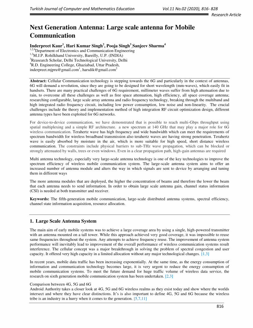
Features 5G Technology 6G Technology
Frequency Bands Sub 6 GHz,
mmwave for fixed access
Sub 6 GHz,
mmwave for mobile access exploration of
THz bands (above 140 GHz),
Non-RF bands (e.g. optical, VLC) etc.
Data rate Downlink Data Rate - 20 Gbps,
Uplink Data Rate - 10 Gbps)
1 Tbps
Latency 5 ms (Radio : 1 msec) < 1 ms (Radio : 0.1 msec)
Turkish Journal of Computer and Mathematics Education Vol.11 No.02 (2020), 816- 828
818
Research Article
Architecture Dense sub 6 GHz smaller BSs with
umbrella macro BSs
Mmwave small cells of about 100
meters (for fixed access)
Cell free smart surfaces at high frequencies
Temporary hotspots served by drone
mounted BSs or tethered Balloons.
Trials of tiny THz cells (under progress)
Application types eMBB (Enhanced Mobile
Broadband)
URLLC (Ultra Reliable Low
Latency Communications)
mMTC (Massive Machine Type
Communications)
MBRLLC
mURLLC
HCS
MPS
Device types Smartphones
Sensors
Drones
Sensors and DLT devices
CRAS
XR and BCI equipment
Smart implants
Spectral and energy
efficiency gain
10 x in bps/Hz/m2 1000 x in bps/Hz/m3
Traffic Capacity 10 Mbps/m2 1 to 10 Gbps/m2
Reliability 10-5 10-9
Localization precision 10 cm on 2D 1 cm on 3D
User experience 50 Mbps 2D everywhere 10 Gbps 3D everywhere
Table-1 Showing the comparison between 5G and 6G Technology
2. 6G Concept and Technology
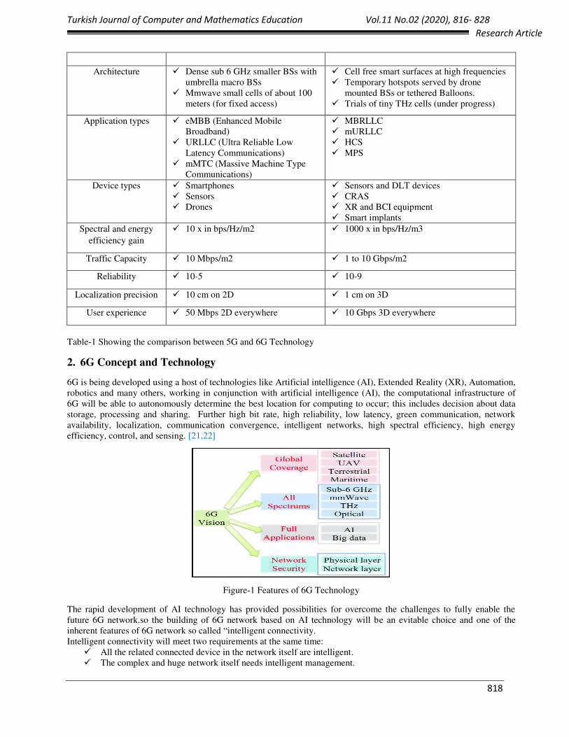
6G is being developed using a host of technologies like Artificial intelligence (AI), Extended Reality (XR), Automation,
robotics and many others, working in conjunction with artificial intelligence (AI), the computational infrastructure of
6G will be able to autonomously determine the best location for computing to occur; this includes decision about data
storage, processing and sharing. Further high bit rate, high reliability, low latency, green communication, network
availability, localization, communication convergence, intelligent networks, high spectral efficiency, high energy
efficiency, control, and sensing. [21,22]
Figure-1 Features of 6G Technology
The rapid development of AI technology has provided possibilities for overcome the challenges to fully enable the
future 6G network.so the building of 6G network based on AI technology will be an evitable choice and one of the
inherent features of 6G network so called “intelligent connectivity.
Intelligent connectivity will meet two requirements at the same time:
All the related connected device in the network itself are intelligent.
The complex and huge network itself needs intelligent management.

Turkish Journal of Computer and Mathematics Education Vol.11 No.02 (2020), 816- 828
819
Research Article
Information exchange demand are becoming more and more complex with the expansion of human production and
living space, Previous generation cellular network aimed at people centered communication needs, evolution of 6G, the
object of communication has expanded from human centered communication to the simultaneous communication of
things. So, the future wireless communication networks need to take in to account both the deep coverage requirement
of people and objects. [21,22]
1) The deep expansion of the connecting object activity space.
2) Deeper perceptual interaction.
3) Deep data mining in the physical network world.
4) In depth nerve interaction.
AR/VR (virtual and Augmented Reality) is considered to be one of the most important requirements of future cellular
network, the media interaction will be mainly planar multimedia, high fidelity AR/VR interaction, wireless holographic
communication and display can also be carried out at anytime and anywhere .to achieve all these we will face many
challenges and this can be summarized as Holographic connectivity.
A vast world will become more and more accessible, three- dimensional coverage and connection to all types of terrain
and space, which means deep connectivity emphasizes the depth of the connected objects, while ubiquitous connectivity
emphasizes the breadth of the distributed area of the connected objects. [6]
3. Terahertz Communication
Terahertz radiation is typically understood to be electromagnetic radiation in the frequency range from roughly
0.1 THz to 10 THz, corresponding to wavelengths from 3 mm down to 30 μm. Such frequencies are higher than those of
radio waves and microwaves, but lower than those of infrared light. The energy of terahertz waves is too low to knock
the electrons from atoms, i.e. they do not have the potential to ionize materials, and therefore won't damage living
tissue. This makes them very attractive for medical uses, but also for security application, such as scanning airline
passengers. [23]
Increasing the carrier frequencies from millimeter wave to THz is a potential solution to guarantee the transmission rate
and channel capacity. Due to the large transmission loss of Low-THz wave in free space, it is particularly urgent to
design high-gain antennas to compensate the additional path loss, and to overcome the power limitation of Low-THz
source. Recently, with the continuous updating and progress of additive manufacturing (AM) and 3D printing (3DP)
technology, antennas with complicated structures. [16]
Terahertz radiation is strongly absorbed by the gases of the atmosphere, and in air attenuated to zero within a few
meters, so it is not usable for terrestrial radio communication.it can penetrate thin layers of Materials but is blocked by
thicker objects.
Terahertz 6G Communication
The THz spectrum is sandwiched between the mm wave and the far infrared bands and has for long, been the least
investigated electromagnetic spectrum. The THz band offers much higher transmission bandwidth compared to the mm
wave band and more favorable propagation settings compared to the IR band. [19]
THz transmission incur very high propagation losses, which significantly limit the communication distances. Hence,
while in aerial, satellite, and vehicular network, THz frequencies can provide low latency communication, the
propagation losses can hinder the gains.
Because of its unique characteristics, terahertz communication has many advantages over microwave and wireless
optical communication, which determines that terahertz wave has broad application prospects in highspeed short
distance broadband wireless communication, broadband wireless secure access, space communication and so on. [13]
Terahertz wave is easily absorbed by moisture in the air when it propagates in the air, which is more suitable for
high speed, short distance wireless communication
Narrower beam, better directivity, stronger anti jamming ability, and can achieve secure communication within 2-
5 km
Terahertz wave has high frequency and wide bandwidth, which can meet the requirement of spectrum bandwidth
for wireless broadband transmission.
Space communication, in outer space, terahertz wave has relatively transparent atmospheric windows. it can
transmit without loss and achieve long distance communication with very low power.
Turkish Journal of Computer and Mathematics Education Vol.11 No.02 (2020), 816- 828
820
Research Article
The terahertz band has short wavelength and is suitable for Massive MIMO with more antenna arrays, literature
review show that the beam configuration and spatial multiplexing gain provided by Masssive MIMO can
overcome the rain and atmospheric degradation of terahertz propagation.
Terahertz wave has low photon energy, about10-3ev, only 1/40 of visible light. it can be used as an information
carrier to achieve high energy efficiency.
Terahertz wave can penetrate the material with a small attenuation, which is suitable for the communication.
4. Evolution and Innovation of antenna system for 6G
The 6G mobile communication system has become an important area with both academic and industrial concerns. 6G
will achieve higher access rate, wider communication range with better energy and spectrum efficiency, lower access
delay. Faced with the challenge of 6G requirement, large scale antenna technology needs to study and break through the
following problems solving the problems of theory and technology realization in the field of cross-band, high efficiency
all space coverage antenna ;researching configurable, large scale array antenna and radio frequency technology,
breaking through the multiband and high integrated radio frequency circuit, including low power consumption ,high
efficiency, low noise and non-linearity. [23,24]
In addition, in order to obtain large scale antenna gain, channel status information (CSI) is needed at both transmitter
and receiver, assuming TDD duplex mode, the upstream link pilot sequences from different cells interfere with each
other. These problems are very challenging for very large antennas. The number of arrays are more also the number of
channels to be estimated will be very large. In Massive MIMO system, transmitters and receivers are equipped with
large scale antenna arrays. Terahertz signal arrival consists of a small number of path clusters, and each cluster has only
a small angle expansion. [19,21,24]
There are several important factors in the development of antenna and RF system.
The internet of space, which is one of the possible evolution directions of 6G, also needs a variety of antenna
system that work in Ka and other bands to achieve wider coverage at all time and locations.
FSS technique, meta-material, features that are difficult to obtain naturally will enable antennas to be much
smaller, more immune to interferences, and much better in performances.
For considering antenna performance in the presence of different channel characteristics in different scenarios
and applications, antennas with a new configuration are employed.
The improvement of antenna system performance will inevitably lead to improvement of the overall
performance of wireless communication systems.
5. Terahertz band has irreplaceable advantages for mobile communication
Coverage and directional communication: Terahertz have larger free space fading than low-frequency band. Terahertz
propagation characteristics and huge antenna array means that Terahertz communication is highly directional. [16]
Large scale fading characteristics: Terahertz signal is very sensitive to shadows and has a great influence on coverage,
the effect of rainfall fading on terahertz communication is very small. [9]
Fast channel fluctuation and intermittent connection: Terahertz system mainly consists of microcells with small
coverage and high spatial orientation, it means that path fading, service beam and cell correlation will change rapidly.
Also, the coherence time of terahertz band is very small and Doppler spread is large. From the system point of view, it
means that the connection of terahertz communication system will be highly intermittent, and a fast adaptive
mechanism is needed to overcome this fast-changing intermittent connection problem. [24,25]
Processing power consumption: A major challenge in utilizing very large antennas is the power consumption of
broadband terahertz system (A/D) conversion. Power consumption is generally linear with sampling rate, and
exponential with sampling number per bit. Large bandwidth and huge antennas in terahertz band need high resolution
quantization. [22]

Turkish Journal of Computer and Mathematics Education Vol.11 No.02 (2020), 816- 828
821
Research Article
6. Literature Review
A Differential Dual-
band Dual-polarized
Antenna for 5G mm
Wave Communication
System
2020 IEEE
Inner length is an additional
parameter offered by the ring
geometry to control its resonant
frequency, impedance and bandwidth.
For resonance, the outer length
remains between quarter to half-
effective wavelength for an antenna
array, spacing between the element
plays a fundamental role in its far-
field performance, particularly gain
and grating lobe free scan range. The
differential feed has an added
advantage in the form of
enhancement in radiation
performance. The out of phase
current on the two probes, cancel
their effect on the radiation pattern.
A Review of
Broadband Low-Cost
and High-Gain Low-
Terahertz Antennas
for Wireless
Communications
Applications
IEEE
Access
April 1,
2020.
The proposed unit cell is composed
of a pair of wideband magneto-
electric dipoles, together with a
substrate-integrated waveguide (SIW)
aperture-coupling transmission
structure for independent phase
adjustability. This element provides a
full 360◦ phase coverage and realizes nearly parallel phase response in a
wide frequency range. A 40 × 32
array is fabricated by LTCC
technology. The measured peak gain
of the TA prototype is 33.45 dBi at
150 GHz with the aperture efficiency
of 44.03%, and the measured 3-dB
gain bandwidth is 124–158 GHz
(24.29%)
A Compact Shared-
Aperture Hybrid-
Mode Antenna for
Sub-6G
Communication
2019 IEEE
The slot acts as an inductive load for
the size reduction. Also, the slotting
in the center of the patch may help to
suppress the cross polarization level.
The slot mode has a large magnitude
and it determines the radiation at 4.0
GHz. Apparently, the dipole mode
arises at 5.0 GHz and it influences the
radiation. The slotted rectangular
patch is used to enhance the
impedance bandwidth through
sequentially exciting multiple
resonances in the interested band

Turkish Journal of Computer and Mathematics Education Vol.11 No.02 (2020), 816- 828
822
Research Article
Sub-THz Circularly
Polarized Horn
Antenna Using Wire
Electrical Discharge
Machining for 6G
Wireless
Communications
IEEE Access
July 6, 2020
The conical horn element is a smooth
walled conical horn antenna which is
easier to manufacture at high
frequencies (i.e. 300 GHz) compared
to a corrugated walled which
becomes complicated in terms of
manufacturing process. The aperture
‘‘ao’’ and throat ‘‘ai’’ radii of the
conical horn plays a very important
role in the performance of the
antenna such as directivity
Plasmonic
Nanoantennas for 6G
Intra/Inter-Chip
Optical-Wireless
Communications
IEEE 2020
The nano-antennas separated by a
distance of 1 µm. We must remark
here the high electric-field amplitudes
at the gold nanorod-tips in Fig. 3,
which are due to the excitation of
localized surface plasmon
resonances. These strongly confined
and enhanced optical fields amplify
the received signal and then re-
radiates it to the neighboring dipole
nanoantenna, which in turns excite
the fundamental mode of the
plasmonic transmission line for
communication with an optical
nanocircuit. This ability of plasmonic
nanorods to capture, enhance, and
redirect light make the plantenna
design an ideal candidate to work as
an optical receiver nanolink
A New Gridded
Parasitic Patch
Stacked Microstrip
Antenna for Enhanced
Wide Bandwidth in 60
GHz Band
IEEE 2017
Layer 1 at the bottom is use for
feeding microstrip line
electromagnetically coupled to the
patch and two slots under it. At layer
2 in the middle serve as radiating
element with rectangular patch shape
for gain the radiating electro-
magnetically to the nine gridded
patches at the top layer 3. At the layer
3, there are nine patches to reach the
maximal bandwidth
A 60 GHz PCB
Wideband Antenna-
in-Package for 5G/6G
Applications
IEEE
Antennas
and
Wireless
Propagatio
n Letters
As compared with C1 I , the choking
current C2 I , the common-mode
current on the EW and also co-
polarized, has more effect on the
radiation, and is much more crucial.
To suppress C2 I , a structure
composed of the EW, CW, and
ground is introduced, the cross
section of which is shown in Fig. 2c,
also the region A in Fig. 2a. In the
structure, one end of the EW and CW
is short circuited by the ground with
the other end open circuited.

Turkish Journal of Computer and Mathematics Education Vol.11 No.02 (2020), 816- 828
823
Research Article
A millimeter-wave
Fabry–Pérot cavity
antenna using fresnel
zone plate integrated
PRS,’’
IEEE
Trans.
Antennas
Propag.,
vol. 68, no.
1, pp. 564–568, Jan.
2020
This work introduces a new structure
of PRS to realize gain enhancement.
It is the first attempt to apply a
fresnel zone plate (FZP) to a single-
layer PRS this antenna uses a
substrate-integrated quasi-curve
reflector and a FZP integrated PRS to
form a FPC. With the quasi-curve
reflector, multiple resonate modes are
excited, providing a wide 3-dB gain
bandwidth. This antenna is processed
by low-cost and mature PCB
technology. The antenna illustrates
17.8% impedance bandwidth from 54
to 64.5 GHz, and the 3-dB gain
bandwidth is about 13.3 % (56-64
GHz). The measured peak gain is
21.0 dBi at broadside direction.
A Miniaturized
Design of Shared-
aperture Antenna with
High Aperture Reuse
Ratio for 5G
Applications
2019
Photonics
and
Electroma
gnetics
Research
Symposiu
m
The SIW cavity-backed slot array has
a multilayer structure, which
increases the metal thickness of the
shorted patch antenna Due to the
fringing field at the radiation edge of
the folded patch antenna, an
additional extended length ∆L will appear to change the resonant
frequency The cross polarization of
the shorted patch is relatively high
due to the magnetic current along the
non-radiating side cannot be
counteracted after folding the patch
antenna. However, the cross
polarization can be counteracted by
arrays.
High Gain Terahertz
Microstrip Array
Antenna for Future
Generation Cellular
Communication
September
05,2020
IEEE
EXPLORE
The width of each radiant element
(Wx)should be smaller than a half
wavelength to reduce SLL and
grating lobes. in hybrid feed, a wider
BW can be obtained.

Turkish Journal of Computer and Mathematics Education Vol.11 No.02 (2020), 816- 828
824
Research Article
Figure-2a Feeding structure of
the proposed antenna
Figure- 2b Two layer of the
proposed Antenna
Antenna Parameter Dimension
Substrate length ( l) 16 mm
Substrate width (w) 16 mm
Substrate FR4 (permittivity) Ɛr = 4.4
Upper layer radius via (a) 9.8mm
Inner layer radius via (b) 5mm
Radius of via ( Rvia ) 1mm
Slot length (ssx) 15 degree
Slot width (ssy) 1mm
Antenna Geometry
Proposed antenna is consisting of two-layer FR4 substrate along with ridge waveguide to provide good gain. The lower
layer of the proposed antenna is the feeding structure, and the upper layer of FR4 consists of superstrate along with
metallic via to enhance the gain and to maintain the directivity of antenna. Figure 1. Shows the configuration of the
proposed antenna which includes the overall three-dimensional view of the proposed antenna. The dielectric constant of
the material is 4.4 and surface area size of l x w and height h1 are 16 mm x 16 mm and 1.6 mm respectively. The radius
of a metallic vias (via) and pitch (p) are refined in such a manner that it offers minimal leakage of power. SIW aperture
coupled feeding is applied to improve the transmission efficiency and achieve a stable radiation pattern. The other end
of the microstrip line is connected to the SMA connector.
Antenna has the advantages of low profile, lightweight, conformability to planar or curved surfaces, and
easy integration with planar circuits. An astonishing problem arising in the MSA is the appearance of surface waves that
generally decrease the antenna efficiency.
Figure 3: Variation of return loss with frequency for different radius of upper layer via
Effect of radius of upper layer via
Slot between the SIW at lower layer acts as a feeding element element and variation of return loss with resonant
frequency for the different value of upper layer via from 0.8mm - 1.2mm exhibit in Figure 3. The radius of upper layer
via effects the impedance matching. The upper layer via along with slot of dimension ssx*ssy enhances the gain of the
proposed antenna.

Turkish Journal of Computer and Mathematics Education Vol.11 No.02 (2020), 816- 828
825
Research Article
Figure 4: Variation of return loss with frequency for different radius of lower layer via
Effect of radius of lower layer via
Slot between the SIW at Upper layer acts as a superstrate and variation of return loss with resonant frequency for the
different value of lower layer via1 from 0.5mm – 0.9mm exhibit in Figure 4. The radius of lower layer via effects the
impedance matching as well as the directional pattern of an antenna. The lower layer via along with slot effects the
return loss of the antenna.
Figure 5: Variation of Gain with frequency at different radius of lower layer via.
Effect of dimensions of upper layer slot
Figure6: Variation of return loss with frequency for different length of superstrate slot
Turkish Journal of Computer and Mathematics Education Vol.11 No.02 (2020), 816- 828
826
Research Article
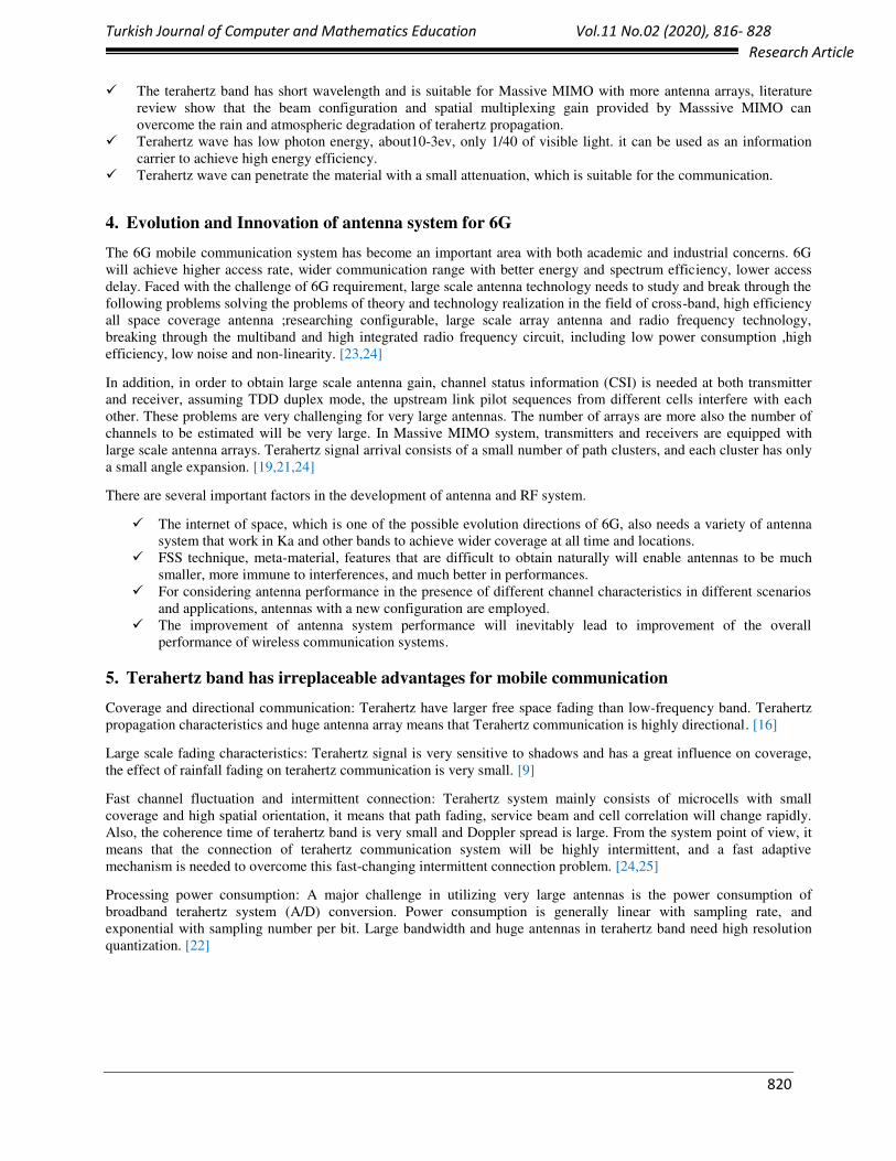
Figure 7: Variation of return loss with frequency for different length of superstrate width
The effect of dimensions of slot at the upper layer, effects the gain, radiation efficiency and front to back ratio of an
antenna. Figure 6 and Figure 7shows the variation in ssx and ssy varies the gain of an antenna. Radiation efficiency of
an antenna without upper layer 66% and front to back ratio 94.1and along with upper layer the radiation efficiency
enhances to 75% but FBR reduces to 34.6
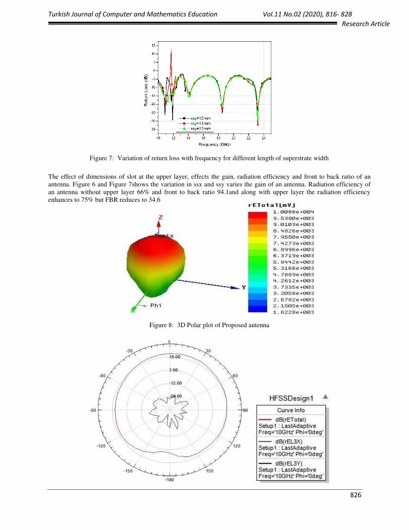
Figure 8: 3D Polar plot of Proposed antenna

Turkish Journal of Computer and Mathematics Education Vol.11 No.02 (2020), 816- 828
827
Research Article
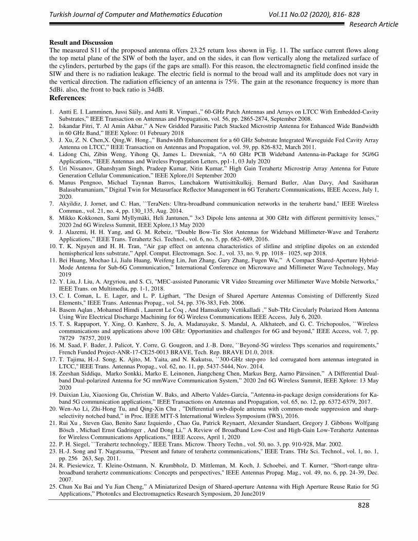
Figure 9: a) YZ-plane radiation pattern at resonance frequency at 15GHz
b) XZ- plane radiation pattern at resonance frequency at 15 GHz
Figure 10: Surface Electric field distribution of proposed antenna (Double Layer)
Figure 11: Surface Electric field distribution of proposed antenna (Single Layer)
Turkish Journal of Computer and Mathematics Education Vol.11 No.02 (2020), 816- 828
828
Research Article
Result and Discussion
The measured S11 of the proposed antenna offers 23.25 return loss shown in Fig. 11. The surface current flows along
the top metal plane of the SIW of both the layer, and on the sides, it can flow vertically along the metalized surface of
the cylinders, perturbed by the gaps (if the gaps are small). For this reason, the electromagnetic field confined inside the
SIW and there is no radiation leakage. The electric field is normal to the broad wall and its amplitude does not vary in
the vertical direction. The radiation efficiency of an antenna is 75%. The gain at the resonance frequency is more than
5dBi. also, the front to back ratio is 34dB.
References:
1. Antti E. I. Lamminen, Jussi Säily, and Antti R. Vimpari.,” 60-GHz Patch Antennas and Arrays on LTCC With Embedded-Cavity
Substrates,” IEEE Transaction on Antennas and Propagation, vol. 56, pp. 2865-2874, September 2008.
2. Iskandar Fitri, T. Al Amin Akbar,” A New Gridded Parasitic Patch Stacked Microstrip Antenna for Enhanced Wide Bandwidth
in 60 GHz Band,” IEEE Xplore: 01 February 2018
3. J. Xu, Z. N. Chen,X. Qing,W. Hong.,” Bandwidth Enhancement for a 60 GHz Substrate Integrated Waveguide Fed Cavity Array
Antenna on LTCC,” IEEE Transaction on Antennas and Propagation, vol. 59, pp. 826-832, March 2011.
4. Lidong Chi, Zibin Weng, Yihong Qi, James L. Drewniak, “A 60 GHz PCB Wideband Antenna-in-Package for 5G/6G
Applications, “IEEE Antennas and Wireless Propagation Letters, pp1-1, 03 July 2020
5. Uri Nissanov, Ghanshyam Singh, Pradeep Kumar, Nitin Kumar,” High Gain Terahertz Microstrip Array Antenna for Future
Generation Cellular Communication,” IEEE Xplore,01 September 2020
6. Manus Pengnoo, Michael Taynnan Barros, Lunchakorn Wuttisittikulkij, Bernard Butler, Alan Davy, And Sasitharan
Balasubramaniam,” Digital Twin for Metasurface Reflector Management in 6G Terahertz Communications, IEEE Access, July 1,
2020.
7. Akyildiz, J. Jornet, and C. Han, ``TeraNets: Ultra-broadband communication networks in the terahertz band,'' IEEE Wireless
Commun., vol. 21, no. 4, pp. 130_135, Aug. 2014.
8. Mikko Kokkonen, Sami Myllymäki, Heli Jantunen,” 3×3 Dipole lens antenna at 300 GHz with different permittivity lenses,”
2020 2nd 6G Wireless Summit, IEEE Xplore,13 May 2020
9. J. Alazemi, H. H. Yang, and G. M. Rebeiz, “Double Bow-Tie Slot Antennas for Wideband Millimeter-Wave and Terahertz
Applications,” IEEE Trans. Terahertz Sci. Technol., vol. 6, no. 5, pp. 682–689, 2016.
10. T. K. Nguyen and H. H. Tran, “Air gap effect on antenna characteristics of slitline and stripline dipoles on an extended
hemispherical lens substrate,” Appl. Comput. Electromagn. Soc. J., vol. 33, no. 9, pp. 1018– 1025, sep 2018.
11. Bei Huang, Mochao Li, Jialu Huang, Weifeng Lin, Jun Zhang, Gary Zhang, Fugen Wu,” A Compact Shared-Aperture Hybrid-
Mode Antenna for Sub-6G Communication,” International Conference on Microwave and Millimeter Wave Technology, May
2019
12. Y. Liu, J. Liu, A. Argyriou, and S. Ci, "MEC-assisted Panoramic VR Video Streaming over Millimeter Wave Mobile Networks,"
IEEE Trans. on Multimedia, pp. 1-1, 2018.
13. C. I. Coman, L. E. Lager, and L. P. Ligthart, "The Design of Shared Aperture Antennas Consisting of Differently Sized
Elements," IEEE Trans. Antennas Propag., vol. 54, pp. 376-383, Feb. 2006.
14. Basem Aqlan , Mohamed Himdi , Laurent Le Coq , And Hamsakutty Vettikalladi ,” Sub-THz Circularly Polarized Horn Antenna
Using Wire Electrical Discharge Machining for 6G Wireless Communications IEEE Access, July 6, 2020.
15. T. S. Rappaport, Y. Xing, O. Kanhere, S. Ju, A. Madanayake, S. Mandal, A. Alkhateeb, and G. C. Trichopoulos, ``Wireless
communications and applications above 100 GHz: Opportunities and challenges for 6G and beyond,'' IEEE Access, vol. 7, pp.
78729 78757, 2019.
16. M. Saad, F. Bader, J. Palicot, Y. Corre, G. Gougeon, and J.-B. Dore, ``Beyond-5G wireless Tbps scenarios and requirements,''
French Funded Project-ANR-17-CE25-0013 BRAVE, Tech. Rep. BRAVE D1.0, 2018.
17. T. Tajima, H.-J. Song, K. Ajito, M. Yaita, and N. Kukutsu, ``300-GHz step-pro led corrugated horn antennas integrated in
LTCC,'' IEEE Trans. Antennas Propag., vol. 62, no. 11, pp. 5437-5444, Nov. 2014.
18. Zeeshan Siddiqu, Marko Sonkki, Marko E. Leinonen, Jiangcheng Chen, Markus Berg, Aarno Pärssinen,” A Differential Dual-
band Dual-polarized Antenna for 5G mmWave Communication System,” 2020 2nd 6G Wireless Summit, IEEE Xplore: 13 May
2020
19. Duixian Liu, Xiaoxiong Gu, Christian W. Baks, and Alberto Valdes-Garcia, ”Antenna-in-package design considerations for Ka-
band 5G communication applications,” IEEE Transactions on Antennas and Propagation, vol. 65, no. 12, pp. 6372-6379, 2017.
20. Wen-Ao Li, Zhi-Hong Tu, and Qing-Xin Chu , ”Differential uwb-dipole antenna with common-mode suppression and sharp-
selectivity notched band,” in Proc. IEEE MTT-S International Wireless Symposium (IWS), 2016.
21. Rui Xu , Steven Gao, Benito Sanz Izquierdo , Chao Gu, Patrick Reynaert, Alexander Standaert, Gregory J. Gibbons Wolfgang
Bösch , Michael Ernst Gadringer , And Dong Li,” A Review of Broadband Low-Cost and High-Gain Low-Terahertz Antennas
for Wireless Communications Applications,” IEEE Access, April 1, 2020
22. P. H. Siegel, ``Terahertz technology,'' IEEE Trans. Microw. Theory Techn., vol. 50, no. 3, pp. 910-928, Mar. 2002.
23. H.-J. Song and T. Nagatsuma, ``Present and future of terahertz communications,'' IEEE Trans. THz Sci. Technol., vol. 1, no. 1,
pp. 256 263, Sep. 2011.
24. R. Piesiewicz, T. Kleine-Ostmann, N. Krumbholz, D. Mittleman, M. Koch, J. Schoebei, and T. Kurner, “Short-range ultra-
broadband terahertz communications: Concepts and perspectives,'' IEEE Antennas Propag. Mag., vol. 49, no. 6, pp. 24-39, Dec.
2007.
25. Chun Xu Bai and Yu Jian Cheng,” A Miniaturized Design of Shared-aperture Antenna with High Aperture Reuse Ratio for 5G
Applications,” PhotonIcs and Electromagnetics Research Symposium, 20 June2019