LADY LADY 5 | Beninca
72
L854300143 04/2019 rev 1 LADY LADY 5 UNIONE NAZIONALE COSTRUTTORI AUTOMATISMI PER CANCELLI, PORTE SERRANDE ED AFFINI IT EN DE FR ES PL
-
Upload
khangminh22 -
Category
Documents
-
view
1 -
download
0
Transcript of LADY LADY 5 | Beninca

L85430014304/2019 rev 1
LADYLADY 5
UNIONE NAZIONALE COSTRUTTORIAUTOMATISMI PER CANCELLI, PORTE
SERRANDE ED AFFINI
IT
EN
DE
FR
ES
PL

2
222
40
324
1008
LADY: MAX. 4,0m - LADY 5: MAX. 5.0m
LADY:MIN. 2,0m - LADY 5: MIN.3,5m
LADY: MAX. 4,2m - LADY 5: MAX. 5.2m
LADY:MIN. 2,2m - LADY 5: MIN.3,7m
1
2
C
B
A

3
3
320
135
222
200
E
D
F
F
A
VE.PS
VE.PS KitVE.PS KitVE.PS KitVE.PS KitVE.PS KitVE.PS Kit
B
C
4
M14x30
V ring (V 60A)

4
6
Sblocco di emergenza Emergency releaseNotentriegelungDéblocage de secoursDesbloqueo de emergenciaRozsprzęglanie awaryjne
Ripristino automatismoReset automationReset des AutomatismusRéinitialisation automatismeReactivación del automatismoPrzywrócenie działania automatyzmu
5
Barriera destraRight barrierSchranke rechtsBarrière droiteBarrera derechaBariera prawa
Barriera sinistraLeft barrier
Schrank linksBarrière gaucheBarrera izquierda
Bariera lewa
L L

5
8
G
F
G
F
D
T
7

6
2
3
3x1
2x1
2x1
4
6
7
1
2x1
4x1
2x1.5230 V
5
8
Mod. VE.AF / VE.AFS (Optional)
11
Slow-downClose (SLDC)
Slow-downOpen (SLDo)
O
C
O
C
9 10

7
RA
DIO
BLINKAUX2
J1
COM
SWO
SWC
STO
P
PHO
T
OPE
N
SHLD
ANT
CLOS
E
P.P.
U5
F3
MOTAUX - 24V +
BLINKAUX2
COM
SWO
SWC
STO
P
PHO
T
OPE
N
SHLD
ANT
CLOS
E
P.P.
MOTAUX
- +- +
AN
T
M
LAMP.24Vdc
24Vdc500 mA
CP.LADY
BARLIGHT24Vdc
L
LED 1
LED 2
F1
N
+-
SA.24V
100÷250 Vac
+ -
- +
2xDA.BT2(Optional)
SIS (Optional)
Adva
ntou
ch
- 24V +
+ B
AT
- BA
T
+-
M3
M1
M2
12

8
Schema menu di programmazione - Menu programming layoutDiagramm Programmiermenü - Menu de programmation
Menú de la carta de programación - Układ menu programowania
v1.05
8888 Inst Boom
POS
3-5 ok 7-8
ok ---00---
Mode ok ParcNorm
PRG
PRG
PRG
PRG
PRG
PRG
PRG
PRG
PRG
PRG
PRG
PRG
PRG
PRG
PRG
PRG
on PRG
OFF PRG
OFF PRG
OFF PRG
OFF PRG
OFF PRG
OFF PRG
off PRG
off PRG
OFF PRG
ON PRG
off PRG
off PRG
off PRG
PUSH OK
PUSH OK
0012
PUSH OK
rtr PRG OK
PUSH OK
PUSH OK
tca
fsts
sldo
sldc
tsmo
pmo
pmc
pso
psc
seav
sear
20
99
50
50
20
tsmc
20
20
20
20
0
0
TLS 60
saso 0
sasc 0
0AUX1
20
LOG
RADI
TCA
tca
IBL
IBCA
SCL
PP
PRE
htr
ltca
tst1
tstm
cvar
lbar
aopf
rem
pp
2ch
n TX
clr
rtr
OPen
Clse
0000 conf OK
res PRG
OFF PRG
0012 3456Nman
MACI
RES
CODE
Inst id
9000 9C5a
BUS
AUTO OK
0
OFF
PUSH
ID
Loc
TCA
LOG nman
PAR
Power ON
Display OFF
RE-ENTERCODE
Display OFF
2 CycleOPEN/CLOSE
PRG
PRG
Firmware Ver. (3s)
Diagnostic
9
v1.05
8888 Inst Boom
POS
3-5 ok 7-8
ok ---00---
Mode ok ParcNorm
PRG
PRG
PRG
PRG
PRG
PRG
PRG
PRG
PRG
PRG
PRG
PRG
PRG
PRG
PRG
PRG
on PRG
OFF PRG
OFF PRG
OFF PRG
OFF PRG
OFF PRG
OFF PRG
off PRG
off PRG
OFF PRG
ON PRG
off PRG
off PRG
off PRG
PUSH OK
PUSH OK
0012
PUSH OK
rtr PRG OK
PUSH OK
PUSH OK
tca
fsts
sldo
sldc
tsmo
pmo
pmc
pso
psc
seav
sear
20
99
50
50
20
tsmc
20
20
20
20
0
0
TLS 60
saso 0
sasc 0
0AUX1
20
LOG
RADI
TCA
tca
IBL
IBCA
SCL
PP
PRE
htr
ltca
tst1
tstm
cvar
lbar
aopf
rem
pp
2ch
n TX
clr
rtr
OPen
Clse
0000 conf OK
res PRG
OFF PRG
0012 3456Nman
MACI
RES
CODE
Inst id
9000 9C5a
BUS
AUTO OK
0
OFF
PUSH
ID
Loc
TCA
LOG nman
PAR
Power ON
Display OFF
RE-ENTERCODE
Display OFF
2 CycleOPEN/CLOSE
PRG
PRG
Firmware Ver. (3s)
Diagnostic
Legenda
Premere il tasto (-) / Press key (-) / Die Taste (-) drückenAppuyez sur la touche (-) / Presionar la tecla (-) / Wcisnąć przycisk (-)
Premere il tasto (+) / Press key (+) / Die Taste (+) drückenAppuyez sur la touche (+) / Presionar la tecla (+) / Wcisnąć przycisk (+)
Premere il tasto (PG) / Press key (PG) / Die Taste (PG) drückenAppuyez sur la touche (PG) / Presionar la tecla (PG )/ Wcisnąć przycisk (PG)
Premere simultaneamente (+) e (-) / Press simultaneously keys (+) and (-)Gleichzeitig (+) und (-) drücken / Presser simultanément (+) et (-)Presionar simultáneamente (+) y (-) / Naciskać jednocześnie (+) i (-)
Selezionare il valore desiderato con i pulsanti (+) e (-)Increase/decrease the value with keys (+) and (-)Mit den Tasten (+) und (-) kann man eingerichtete Werte ändernRégler la valeur désirée avec les touches (+) et (-)Establecer con las teclas (+) y (-) el valor deseadoNastawia przyciskami (+) i (-) obraną wartoś
Selezionare il pulsante del trasmettitore da associare alla funzione Press the transmitter key, which is to be assigned to functionTaste des Sendegeräts drücken, dem diese Funktion zugeteilt werden soll.Appuyer sur la touche du transmetteur qu’e l’on désire affecter à cette fonction.Presionar la tecla del transmisor que se desea asignar a esta función.Wcisnąć przycisk nadajnika, który zamierza się skojarzyć z tą funkcją.

10
SIS
GND B A GND B A
SIS
24Vac 24VacCOMNC NO
RXTX
-24Vdc COM
AUX1PHOT
+
-24Vdc
AUX1+
AUX1:0004
tst1:on
SCAPHOTOTESTAUX1:0000
AUX1:0003
-24Vdc
AUX1+
SERVICE LIGHT
L N
230VacLAMP
24VacLAMP
Relè24Vdc
MASTER
Menu BUS
ID=0
SLAVE
Menu BUS
ID=13x0,5mm
13
14
11
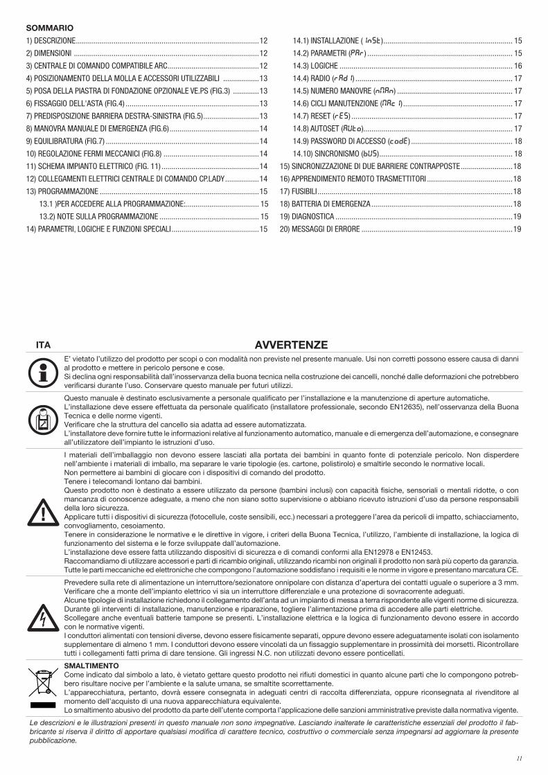
ITA AVVERTENZEE’ vietato l’utilizzo del prodotto per scopi o con modalità non previste nel presente manuale. Usi non corretti possono essere causa di danni al prodotto e mettere in pericolo persone e cose. Si declina ogni responsabilità dall’inosservanza della buona tecnica nella costruzione dei cancelli, nonché dalle deformazioni che potrebbero verificarsi durante l’uso. Conservare questo manuale per futuri utilizzi.
Questo manuale è destinato esclusivamente a personale qualificato per l’installazione e la manutenzione di aperture automatiche.L’installazione deve essere effettuata da personale qualificato (installatore professionale, secondo EN12635), nell’osservanza della Buona Tecnica e delle norme vigenti. Verificare che la struttura del cancello sia adatta ad essere automatizzata.L’installatore deve fornire tutte le informazioni relative al funzionamento automatico, manuale e di emergenza dell’automazione, e consegnare all’utilizzatore dell’impianto le istruzioni d’uso.
I materiali dell’imballaggio non devono essere lasciati alla portata dei bambini in quanto fonte di potenziale pericolo. Non disperdere nell’ambiente i materiali di imballo, ma separare le varie tipologie (es. cartone, polistirolo) e smaltirle secondo le normative locali.Non permettere ai bambini di giocare con i dispositivi di comando del prodotto. Tenere i telecomandi lontano dai bambini.Questo prodotto non è destinato a essere utilizzato da persone (bambini inclusi) con capacità fisiche, sensoriali o mentali ridotte, o con mancanza di conoscenze adeguate, a meno che non siano sotto supervisione o abbiano ricevuto istruzioni d’uso da persone responsabili della loro sicurezza. Applicare tutti i dispositivi di sicurezza (fotocellule, coste sensibili, ecc.) necessari a proteggere l’area da pericoli di impatto, schiacciamento, convogliamento, cesoiamento. Tenere in considerazione le normative e le direttive in vigore, i criteri della Buona Tecnica, l’utilizzo, l’ambiente di installazione, la logica di funzionamento del sistema e le forze sviluppate dall’automazione.L’installazione deve essere fatta utilizzando dispositivi di sicurezza e di comandi conformi alla EN12978 e EN12453.Raccomandiamo di utilizzare accessori e parti di ricambio originali, utilizzando ricambi non originali il prodotto non sarà più coperto da garanzia.Tutte le parti meccaniche ed elettroniche che compongono l'automazione soddisfano i requisiti e le norme in vigore e presentano marcatura CE.
Prevedere sulla rete di alimentazione un interruttore/sezionatore onnipolare con distanza d’apertura dei contatti uguale o superiore a 3 mm.Verificare che a monte dell’impianto elettrico vi sia un interruttore differenziale e una protezione di sovracorrente adeguati.Alcune tipologie di installazione richiedono il collegamento dell’anta ad un impianto di messa a terra rispondente alle vigenti norme di sicurezza.Durante gli interventi di installazione, manutenzione e riparazione, togliere l’alimentazione prima di accedere alle parti elettriche.Scollegare anche eventuali batterie tampone se presenti. L’installazione elettrica e la logica di funzionamento devono essere in accordo con le normative vigenti. I conduttori alimentati con tensioni diverse, devono essere fisicamente separati, oppure devono essere adeguatamente isolati con isolamento supplementare di almeno 1 mm. I conduttori devono essere vincolati da un fissaggio supplementare in prossimità dei morsetti. Ricontrollare tutti i collegamenti fatti prima di dare tensione. Gli ingressi N.C. non utilizzati devono essere ponticellati.
SMALTIMENTOCome indicato dal simbolo a lato, è vietato gettare questo prodotto nei rifiuti domestici in quanto alcune parti che lo compongono potreb-bero risultare nocive per l’ambiente e la salute umana, se smaltite scorrettamente. L’apparecchiatura, pertanto, dovrà essere consegnata in adeguati centri di raccolta differenziata, oppure riconsegnata al rivenditore al momento dell’acquisto di una nuova apparecchiatura equivalente. Lo smaltimento abusivo del prodotto da parte dell’utente comporta l’applicazione delle sanzioni amministrative previste dalla normativa vigente.
Le descrizioni e le illustrazioni presenti in questo manuale non sono impegnative. Lasciando inalterate le caratteristiche essenziali del prodotto il fab-bricante si riserva il diritto di apportare qualsiasi modifica di carattere tecnico, costruttivo o commerciale senza impegnarsi ad aggiornare la presente pubblicazione.
SOMMARIO
1) DESCRIZIONE ............................................................................................12
2) DIMENSIONI .............................................................................................12
3) CENTRALE DI COMANDO COMPATIBILE ARC ..............................................12
4) POSIZIONAMENTO DELLA MOLLA E ACCESSORI UTILIZZABILI ..................13
5) POSA DELLA PIASTRA DI FONDAZIONE OPZIONALE VE.PS (FIG.3) .............13
6) FISSAGGIO DELL'ASTA (FIG.4) ...................................................................13
7) PREDISPOSIZIONE BARRIERA DESTRA-SINISTRA (FIG.5) ............................13
8) MANOVRA MANUALE DI EMERGENZA (FIG.6) .............................................14
9) EQUILIBRATURA (FIG.7) .............................................................................14
10) REGOLAZIONE FERMI MECCANICI (FIG.8) ................................................14
11) SCHEMA IMPIANTO ELETTRICO (FIG. 11) .................................................14
12) COLLEGAMENTI ELETTRICI CENTRALE DI COMANDO CP.LADY .................14
13) PROGRAMMAZIONE ................................................................................15
13.1 )PER ACCEDERE ALLA PROGRAMMAZIONE:..................................... 15
13.2) NOTE SULLA PROGRAMMAZIONE .................................................. 15
14) PARAMETRI, LOGICHE E FUNZIONI SPECIALI ............................................15
14.1) INSTALLAZIONE (INST) ................................................................. 15
14.2) PARAMETRI (PAR) ......................................................................... 15
14.3) LOGICHE ....................................................................................... 16
14.4) RADIO (RADI) ............................................................................... 17
14.5) NUMERO MANOVRE (NMAN) .......................................................... 17
14.6) CICLI MANUTENZIONE (MACI) ....................................................... 17
14.7) RESET (RES) ................................................................................. 17
14.8) AUTOSET (AUTO)........................................................................... 17
14.9) PASSWORD DI ACCESSO (CODE) ................................................... 18
14.10) SINCRONISMO (BUS) ................................................................... 18
15) SINCRONIZZAZIONE DI DUE BARRIERE CONTRAPPOSTE ..........................18
16) APPRENDIMENTO REMOTO TRASMETTITORI ...........................................18
17) FUSIBILI ..................................................................................................18
18) BATTERIA DI EMERGENZA .......................................................................18
19) DIAGNOSTICA .........................................................................................19
20) MESSAGGI DI ERRORE ............................................................................19

12
PROGRAMMAZIONE RAPIDA- Premere il pulsante <PG>, il display si porta nel primo menu Installazione “INST”
- Entrare nel menu INST
- Verificare che il parametro BOOM sia corretto: 3-5 per tutti i modelli LADY/LADY 5 (configurazione di fabbrica)
- Impostare la posizione della barriera nel menu POS, di default è impostata come barriera RIGHT
- Entrare nel menu AUTO, confermare con OK ed eseguire l'acquisizione dei parametri ottimali di funzionamento
- Selezionare nei menu PAR e LOG i parametri e le logiche di funzionamento richieste in base alla tipologia di installazione.
IMPORTANTE: Dopo ogni variazione dei parametri FSTS. SLDO, SLDC, TSMO, TSMC, la barriera esegue una manovra di apertura e chiusura completa per acquisire i nuovi valori di corrente e coppia, sul display compare il messaggio "PRG".
1) DESCRIZIONEBarriera stradale dotata di centrale incorporata CP.LADY e di sblocco rapido esterno per la movimentazione manuale.E’ possibile la sincronizzazione di 2 motori per comandare due barriere contrapposte, in questo caso è necessario utilizzare la scheda di sincronizzazione SIS (opzionale), collegare tra di loro le due centrali come indicato in figura 14 e configurare le centrali come indicato nel paragrafo "Sincronizzazione di due barriere contrapposte".E' inoltre possibile l'alimentazione di emergenza tramite il semplice collegamento di due batterie 12V 2,1Ah (art. DA.BT2), come indicato in Fig.12, oppure la barriera può funzionare in completa assenza di rete utilizzando l'accessorio KSUN (pannelo fotovoltaico con batterie tampone).Ogni utilizzo diverso da quello indicato nelle presenti istruzioni non è consentito ed invalida la garanzia del costruttore.
Vi ricordiamo che registrandovi sul sito www.beninca.com avrete accesso a tutta la documentazione tecnica aggiornata per tutti prodotti e gli accessori ed alla guida per compilazione del fascicolo tecnico e dei documenti previsti dall'allegato V della Direttiva Macchine, obbligatorio ai sensi delle normative vigenti in materia.
IMPORTANTE: se la barriera viene utilizzata anche per passaggio pedonale è indispensabile verificare le forze di impatto misurate secondo quanto indicato dalla norma EN12445 (vedi limiti previsti da norma EN 12453).Nel caso il passaggio sia esclusivamente veicolare è indispensabile prevedere l'apposita segnaletica di divieto pedonale.
2) DIMENSIONI Nella figura 1 sono indicate i principali ingombri della barriera LADY/LADY 5 .Dimensioni di ingombro espresse in mm. LADY La lunghezza dell'asta può variare da un minimo di 2,2m ad un massimo di 4,2m.Poiché circa 20cm sono necessari al fissaggio dell'asta sulla barriera ne risulta un passaggio utile variabile da 2,0m a 4,0m come evidenziato in Fig.1LADY 5La lunghezza dell'asta può variare da un minimo di 3,7m ad un massimo di 5,2m.Poiché circa 20cm sono necessari al fissaggio dell'asta sulla barriera ne risulta un passaggio utile variabile da 3,5m a 5,0m come evidenziato in Fig.1Sulla barriera sono previste delle predisposizioni per accessori opzionali (fotocellule, selettori, ecc), applicare le apposite mascherine di copertura fornite in dotazione (Rif. A).
DATI TECNICI LADY/LADY 5
Alimentazione
Alimentazione motore
Assorbimento massimo da rete
Assorbimento in stand-by
Coppia
Tempo di apertura
Intermittenza di lavoro
Grado di protezione
Temp. funzionamento
Rumorosità
Lubrificazione
Peso
100-250 Vac 50/60Hz
24Vdc
1,5 A
40 mA (230Vac) - 50 mA (115 Vac)
195 Nm
min. 3,6"
Uso Intensivo
IP44
-20°C / +50°C
<70 dB (A)
Grasso permanente
50,8 kg
3) CENTRALE DI COMANDO COMPATIBILE ARCIMPORTANTE, LEGGERE CON ATTENZIONE:Il ricevitore radio presente in questo prodotto è compatibile con i nuovi trasmettitori ARC (Advanced Rolling Code) i quali, grazie alla codifica a 128 bit, garantiscono una superiore sicurezza anticopiatura. La memorizzazione dei nuovi trasmettitori ARC è del tutto analoga a quella dei normali trasmettitori Rolling Code con codifica HCS, ma occorre tenere presente che:1) Trasmettitori ARC e Rolling Code HCS non possono essere memorizzati in una singola ricevente.2) Il primo trasmettitore memorizzato stabilisce la tipologia di trasmettitori da utilizzare in seguito. Se il primo trasmettitore memorizzato è ARC, non sarà possibile memorizzare trasmettitori Rolling Code HCS, e viceversa.3) I trasmettitori a codice fisso possono essere utilizzati solo in abbinamento ai trasmettitori Rolling Code HCS, portando la logica CVAR in OFF. Non sono quindi utilizzabili in abbinamento ai trasmettitori ARC. Se il primo trasmettitore Rolling Code memorizzato è un ARC la logica CVAR è inifluente.4) Se si desidera cambiare tipologia di trasmettitori è necessario procedere con un reset della ricevente.

13
4) POSIZIONAMENTO DELLA MOLLA E ACCESSORI UTILIZZABILI In base alla lunghezza dell'asta ed al tipo di accessori installati, prima di procedere al tensionamento della molla, è necessario scegliere il corretto punto di aggancio della molla stessa alla leva.Il punto di aggancio corretto, ("A", "B" e "C" - Fig. 2), deve essere scelto nella tabella 1 in base alla lunghezza dell'asta ed al tipo di accessori che si intende installare.
LADY - TABELLA 1 Lunghezza asta (m)
Accessori utilizzabili 2,2 2,7 3,2 3,7 4,2NA C C C B A
LADY.P(1) C C B B ALADY.P(2) C C B B AVE.RAST C B B A
LADY.P(1) + VE.RAST C B B ALADY.P(1) + VE.AM C B B A ALADY.P(2) + VE.AM C B B A
LADY.P(1) + VE.RAST + VE.AM C B ASC.RES C B B A
LADY.P (1) + SC.RES C B A ASC.RES + VE.AM C B A A
LADY.P(1)+ SC.RES + VE.AM C B A
LADY 5 - TABELLA 1 Lunghezza asta (m)
Accessori utilizzabili 3,7 4,2 4,7 5,2NA C C
LADY.P(1) C B BLADY.P(2) C C B BVE.RAST C B B A
LADY.P(1) + VE.RAST C B A ALADY.P(1) + VE.AM C C B BLADY.P(2) + VE.AM C B B A
LADY.P(1) + VE.RAST + VE.AM B B A ASC.RES C B B A
LADY.P (1) + SC.RES C B A ASC.RES + VE.AM B B A A
LADY.P(1)+ SC.RES + VE.AM B B A AVE.RAST + VE.AM B B A A
LegendaNA Nessun accessorioLADY.P(1) Profilo di protezione (solo superiore).LADY.P(2) Profili di protezione (superiore e inferiore).VE.RAST Rastrelliera in alluminio.VE.AM Appoggio mobile per asta.SC.RES Bordo sensibile resistivo (conforme EN12878).Attenzione: L'installazione della VE.RAST pregiudica l'uso della SC.RES e viceversa.L'installazione del kit luci LADY.L non influenza il bilanciamento dell'asta
5) POSA DELLA PIASTRA DI FONDAZIONE OPZIONALE VE.PS (FIG.3) Dopo aver predisposto il passaggio dei cavi (alimentazione di rete, accessori, ecc), posizionare la piastra di fondazione facendo riferimento alle quote indicate.In dotazione con la piastra VE.PS sono fornite delle staffe a cementare (rif.A) da fissare alla piastra di fondazione mediante 4 dadi (B) e relative rondelle (C).Verificare che la piastra di fondazione sia perfettamente a livello (rif F), quindi fissare la barriera per mezzo dei dadi D e relative rondelle E.Note: la particolare forma delle asole sul fondo della cassa della barriera consentono piccoli aggiustamenti della posizione.Si consiglia di lasciare circa 30mm di barra filettata fuori dalla piastra di fondazione, un valore eccessivo potrebbe andare ad interferire con il fissaggio della molla, un valore inferiore non consente un buon fissaggio delle viti.
6) FISSAGGIO DELL'ASTA (FIG.4)Il fissaggio dell'asta alla piastra avviene utilizzando il supporto e le viti fornite in dotazione come illustrato in Fig.4. Si consiglia di installare eventuali accessori per l'sta (profili di protezione, luci, costa, rastrelliera, ecc.) prima di fissare la stessa alla piastra.
7) PREDISPOSIZIONE BARRIERA DESTRA-SINISTRA (FIG.5)Nel caso si renda necessario invertire il senso di apertura, procedere come segue, in caso contrario passare al paragrafo successivo:• scaricare completamente la molla, svitandola, e sganciarla dalla leva di ancoraggio "L"

14
• sbloccare il motoriduttore (vedi "Manovra manuale") in modo da rendere libero il movimento della leva di aggancio L.• a seconda della lunghezza dell'asta e degli accessori utilizzati, scegliere il punto di aggancio corretto, come inidcato nel paragrafo Posizionamento della molla e accessori utilizzabili. • agganciare la molla nella nuova posizione, in Fig. 5 sono evidenziate le differenze tra una barriera destra e una barriera sinistra.
8) MANOVRA MANUALE DI EMERGENZA (FIG.6)In caso di assenza di alimentazione di rete o di funzionamento anomalo, è possibile sbloccare l'asta e manovrarla manualmente (Fig. 6).Utilizzando la chiave fornita in dotazione:• Girare la chiave in senso orario fino ad avvertire una certa resistenza per sbloccare l'asta.• Girare la chiave in senso antiorario fino al blocco per ripristinare il movimento automatico dell'asta.
9) EQUILIBRATURA (FIG.7)Per un buon funzionamento della barriera è fondamentale che l’asta sia opportunamente equilibrata dall’azione della molla concorrente. Per verificare ciò agire come segue:• Verificare che la molla sia agganciata nel punto corretto alla leva (vedere paragrafo 2).• Sbloccare meccanicamente la barriera tramite la chiave di sblocco.• L'asta correttamente bilanciata deve restare ferma in qualsiasi punto venga posizionata: - se tende ad aprire diminuire la tensione della molla - se tende a chiudere aumentare la tensione della molla La tensione della molla può essere regolata, avvitando (rotazione antioraria) o svitando (rotazione oraria) manualmente la molla stessa. Una volta regolata la tensione della molla, bloccarla portando il dado "D" in battuta sul tappo T.
10) REGOLAZIONE FERMI MECCANICI (FIG.8)Facendo riferimento alla Fig.8:• Allentare il grano di blocco G • Avvitare/svitare il fermo meccanico F fino ad ottenere la posizione di intervento desiderata• Fissare il grano di blocco G
11) SCHEMA IMPIANTO ELETTRICO (FIG. 11)1 Centrale di comando CP.LADY2 Fotocellula trasmettitore FTC3 Fotocellula ricevente FTC4 Lampeggianti LADY.L5 Colonnina fotocellula per barriera LADY.COL6 Gomma di protezione inferiore/superiore LADY.P7 Costa resistiva SC.RES8 Accessorio mod. VE.AF/VE.AFI
12) COLLEGAMENTI ELETTRICI CENTRALE DI COMANDO CP.LADYNella seguente tabella sono descritti i collegamenti elettrici rappresentati in Fig. 12:
SA.24V
Morsetti Funzione Descrizione
L-N-GND Alimentazione Ingresso alimentazione di rete 100÷250Vac 50/60Hz
+ - Uscita 24Vdc Uscita 24 Vdc alimentazione centrale di comando CP.LADY.
+ BAT-BAT Batterie Ingresso Morsetto per il collegamento delle batterie tampone (accessorio)
CP.LADY
MORSETTIERA M1
M1 Ingresso 24VdcIngresso 24Vdc di alimentazione della scheda CP.LADY. Nel caso di utilizzo di sistema fotovoltaico SUN SYSTEM collegare l'uscita 24Vdc della scheda SUN.SY, (vedi istruzioni KSUN)
MORSETTIERA M2
P.P Passo-Passo Ingresso pulsante passo-passo (contatto N.O.) .
CLOSE Chiudi Ingresso pulsante chiude (contatto N.O.) .
OPEN Apre Ingresso pulsante apre (contatto N.O.), è possibile collegare un temporizzatore per aperture a fasce orarie.
PHOT Fotocellula Ingresso fotocellula attiva in apertura e chiusura (contatto N.C.).
STOP STOP Ingresso pulsante STOP (contatto N.C.).
SWC Finecorsa chiude Ingresso finecorsa CHIUDE (contatto N.C.).
SWO Finecorsa apre Ingresso finecorsa APRE (contatto N.C.).
COM Comune Ingressi Comune per finecorsa e tutti gli ingressi di comando.
AUX2 Uscita 24Vdc luci astaUscita 24Vdc per il collegamento delle luci lampeggianti da installare sull'asta (art. LADY.L), la modalità di lampeggio può essere impostata dalla logica LBAR.
BLINK Lampeggiante Uscita 24Vdc 15W max. per collegamento alla luce lampeggiante.
MORSETTIERA M3
ANT-SHIELD AntennaCollegamento antenna scheda radioricevitore integrato (ANT-segnale/SHIELD-schermo).Nel caso di utilizzo di antenna ricevente esterna rimuovere il cavo precablato nella morsettiera ANT.
AUX Uscita ausiliaria AUX 1 Uscita con contatto N.O. configurabile dalla logica di funzionamento AUX1
24V 24 Vdc Uscita alimentazione accessori 24Vdc 500 mA max.
MOT Motore Collegamento motore precablato: 24Vdc.

15
13) PROGRAMMAZIONELa programmazione delle varie funzionalità della centrale viene effettuata utilizzando il display LCD presente a bordo della centrale ed impostando i valori desiderati nei menu di programmazione descritti di seguito. Il menu parametri consente di impostare un valore numerico ad una funzione, in modo analogo ad un trimmer di regolazione.Il menu logiche consente di attivare o disattivare una funzione, in modo analogo al settaggio di un dip-switch.
13.1 )PER ACCEDERE ALLA PROGRAMMAZIONE:1 - Premere il pulsante <PG>, il display si porta nel primo menu Installazione “INST”. 2 - Scegliere con il pulsante <+> o <-> il menu che si intende selezionare.3 - Premere il pulsante <PG>, il display mostra la prima funzione disponibile nel menu.4 - Scegliere con il pulsante <+> o <-> la funzione che si intende modificare.5 - Premere il pulsante <PG>, il display mostra il valore attualmente impostato per la funzione selezionata.6 - Selezionare con il pulsante <+> o <-> il valore che si intende assegnare alla funzione.7 - Premere il pulsante <PG>, il display mostra il segnale “PRG” che indica l’avvenuta programmazione.
13.2) NOTE SULLA PROGRAMMAZIONELa pressione simultanea di <+> e <-> effettuata all’interno di un menu funzione consente di tornare al menu superiore senza apportare modifiche. Mantenere la pressione sul tasto <+> o sul tasto <-> per accelerare l’incremento/decremento dei valori.Dopo un’attesa di 120s la centrale esce dalla modalità programmazione e spegne il display.La pressione del pulsante <-> a display spento equivale ad un comando passo-passo.All’accensione della scheda viene visualizzata per circa 5s la versione software.Le logiche ed i parametri preconfigurati di fabbrica tengono conto di una installazione tipica.
14) PARAMETRI, LOGICHE E FUNZIONI SPECIALINelle tabelle di seguito vengono descritte le singole funzioni disponibili nella centrale.
14.1) INSTALLAZIONE (INST)
MENU FUNZIONE MIN-MAX-(Default) MEMO
BOOMSelezionare la lunghezza del'asta installata sulla barriera. Valore espresso in metri impostabile da 3m a 5m (per tutti i modelli LADY/LADY 5) o da 7m a 8m (per altri modelli)In base alla lunghezza dell'asta selezionata verranno impostati i valori ottimali di velocità.
3/5 -7/8 (3-5)
Pos
Impostare il senso di apertura della barriera.Il simbolo 0--- indica la barriera DESTRA (DX/RIGHT) DEFAULTIl simbolo ---0 indica la barriera SINISTRA (SX/LEFT)Verificare sempre il verso di apertura della barriera e nel caso modificare il senso di apertura. Ogni modifica apportata in questo menu comporta automaticamente l'avvio di una procedura AUTOSET.
0--- = RIGHT---0 = LEFT
( RIGHT )
RIGHT(STANDARD)
LEFT
14.2) PARAMETRI (PAR)
MENU FUNZIONE MIN-MAX-(Default) MEMO
TCATempo di chiusura automatica. Attivo solo con logica “TCA”=ON.Al termine del tempo impostato la centrale comanda una manovra di chiusura.
1-240-(20s)
FSTS Regola la velocità di apertura e chiusura della barriera (velocità standard, prima della fase di rallentamento). 50-99-(99)
sldo Regola la velocità della barriera durante la fase di rallentamento in apertura* (Fig.9 -slow Open). 20-70-(50)
sldc Regola la velocità della barriera durante la fase di rallentamento in chiusura* (Fig.10 -slow Close). 20-70-(50)
tsmoImposta il punto di inizio della fase di rallentamento in apertura (Fig.9- inizio slow Open). Il valore è espresso in percentuale sull'intera corsa.
1-99-(20)
tsmcImposta il punto di inizio della fase di rallentamento in chiusura (Fig.10- inizio slow Close). Il valore è espresso in percentuale sull'intera corsa.
1-99-(20)
PMO Regola la coppia motore applicata alla barriera durante la fase di apertura.* 1-99-(20)
PMC Regola la coppia motore applicata alla barriera durante la fase di chiusura.* 1-99-(20)
PSO Regola la coppia motore applicata alla barriera durante la fase di rallentamento in apertura* (Fig.9 - Slow Open). 1-99-(20)
PSC Regola la coppia motore applicata alla barriera durante la fase di rallentamento in chiusura* (Fig.10 - Slow Close). 1-99-(20)
SeaU Non utilizzato
SEAR Non utilizzato
tlsTempo di attivazione del contatto luce di cortesia. Valore espresso in secondi. Ad ogni manovra il contatto viene chiuso per il tempo impostato.Vedi descrizione parametro AUX1.
1-240 (60)

16
sasoImposta una breve inversione una volta raggiunto il punto di finecorsa di apertura. Può essere utile per facilitare la manovra manuale della barriera.
0-5 (0)
sascImposta una breve inversione una volta raggiunto il punto di finecorsa di chiusura. Può essere utile per facilitare la manovra manuale della barriera.
0-5 (0)
aux1
Seleziona la modalità di funzionamento dell'uscita ausiliaria 1 (contatto pulito N.O.)0: Spia barriera aperta, contatto chiuso a barriera aperta, aperto a barriera chiuso, intermittente durante la manovra (fig. 13, rif.SCA)1: Secondo canale radio della ricevente incorporata2: Luce Barriera, per il controllo delle luci LED installate sull'ASTA (vedi LADY.L), vedi anche parametro LBAR.3: Luce di cortesia, la durata della chiusura del contatto è regolabile dal parametro TLS (fig.13 rif SERVICE LIGHT) 4: Alimentazione fotocellule verificate, vedi schema di collegamento Fig.13 (rif. PHOTOTEST)5: Contatto chiuso con barriera aperta6: Contatto chiuso con barriera chiusa
0-6-(0)
* ATTENZIONE: UN’ERRATA IMPOSTAZIONE DI QUESTI PARAMETRI PUÒ RISULTARE PERICOLOSA. RISPETTARE LE NORMATIVE VIGENTI!
14.3) LOGICHE (LOG)
MENU FUNZIONE ON-OFF-(Default) MEMO
TCAAbilita o disabilita la chiusura automaticaOn: chiusura automatica abilitataOff: chiusura automatica disabilitata
(ON)
IbL
Abilita o disabilita la funzione condominiale. On: funzione condominiale abilitata. L’impulso P.P. o del trasmettitore non ha effetto durante la fase di apertura.Off: funzione condominiale disabilitata.
(OFF)
ibca
Abilita o disabilita la funzione condominiale durante il conteggio TCA. On: funzione condominiale abilitata. L’impulso P.P. o del trasmettitore non ha effetto durante il conteggio del TCA.Off: funzione condominiale -disabilitata.
(OFF)
SCL
Abilita o disabilita la chiusura rapidaOn: chiusura rapida abilitata. Con barriera aperto o in fase di apertura l’intervento della fotocellula provoca la chiusura automatica dopo 3 s dopo la completa apertura. Attiva solo con TCA:ON Off: chiusura rapida disabilitata.
(OFF)
PPSeleziona la modalità di funzionamento del ”Pulsante P.P.” e del trasmettitore.On: Funzionamento: APRE > CHIUDE > APRE >Off: Funzionamento: APRE > STOP > CHIUDE > STOP >
(OFF)
PREAbilita o disabilita il pre-lampeggio.On: Pre-lampeggio abilitato. Il lampeggiante si attiva 3s prima della partenza del motore.Off: Pre-lampeggio disabilitato.
(OFF)
htr
Abilita o disabilita la funzione Uomo presente. On: Funzionamento Uomo Presente. La pressione dei pulsanti APRE/CHIUDE deve essere mantenuta durante tutta la manovra. L’apertura dell’ingresso STOP arresta il motore. Tutti gli ingressi di sicurezza sono disattivati.Off: Funzionamento automatico.
(OFF)
ltcaSelezione la modalità di funzionamento del lampeggiante durante il tempo TCAOn: Lampeggiante acceso durante TCAOff: Lampeggiante spento durante TCA
(OFF)
TST1
Abilita o disabilita la verifica delle fotocellule sull’ingresso PHOTO, attivo sia in chiusura, sia in apertura.On: Verifica abilitata. Se la verifica ha esito negativo non viene comandata nessun a manovra. Vedi Fig.16 - “PHOTO TEST”.Off: Verifica delle fotocellule ad ogni manovra disabilitata.
(OFF)
TSTmAbilita o disabilita la verifica motori.On: Verifica abilitata. Se la verifica ha esito negativo non viene comandata nessuna manovra.Off: Verifica disabilitata.
(OFF)
Cvar
Abilita o disabilita i trasmettitori a codice programmabile. On: Ricevitore radio abilitato esclusivamente ai trasmettitori a codice variabile (rolling-code). Off: Ricevitore abilitato a trasmettitori codice variabile (rolling-code) e programmabile (autoap-prendimento e dip/switch) .
(ON)
lBAR
Seleziona la modalità di funzionamento delle luci barriera (uscita 24Vdc AUX2 o contatto N.O. dell'uscita AUX 1 configurato con logica 2) .On: Le luci barriera sono spente a barriera chiusa, si accendono a barriera in movimento e durante la fase di apertura.On: Le luci barriera lampeggiano lentamente (1s pausa) a barriera chiusa, lampeggiano veloce-mente (0,5s pausa) o a barriera in movimento e durante la fase di apertura.
(OFF)

17
aopf
Attiva o disattiva la funzione di “Apertura forzata in assenza di rete” (attivabile solo con batterie di emergenza collegate e funzionanti).On: Funzione attiva. In caso di mancanza di alimentazione di rete, la centrale forza una manovra di apertura.La barriera rimane aperta fino al ripristino dell'alimentazione di rete.Off: Funzione non attiva.
(OFF)
rem
Abilita o disabilita l’apprendimento remoto dei radiotrasmettitori, come indicato nel paragrafo “Apprendimento remoto trasmettitori”.On: Apprendimento remoto abilitato.Off: Apprendimento remoto non abilitato.
(OFF)
14.4) RADIO (RADI)
MENU FUNZIONE
PP
Selezionando questa funzione la ricevente si pone in attesa (Push) di un codice trasmettitore da assegnare alla funzione passo-passo.Premere il tasto del trasmettitore che si intende assegnare a questa funzione.Se il codice è valido, viene memorizzato e viene visualizzato il messaggio OKSe il codice non è valido, viene visualizzato il messaggio Err.
OPen
Selezionando questa funzione la ricevente si pone in attesa (Push) di un codice trasmettitore da assegnare alla funzione OPEN.Premere il tasto del trasmettitore che si intende assegnare a questa funzione.Se il codice è valido, viene memorizzato e viene visualizzato il messaggio OKSe il codice non è valido, viene visualizzato il messaggio Err.
close
Selezionando questa funzione la ricevente si pone in attesa (Push) di un codice trasmettitore da assegnare alla funzione CLOSE.Premere il tasto del trasmettitore che si intende assegnare a questa funzione.Se il codice è valido, viene memorizzato e viene visualizzato il messaggio OKSe il codice non è valido, viene visualizzato il messaggio Err.
2Ch
Selezionando questa funzione la ricevente si pone in attesa (Push) di un codice trasmettitore da assegnare al secondo canale radio.Premere il tasto del trasmettitore che si intende assegnare a questa funzione.Se il codice è valido, viene memorizzato e viene visualizzato il messaggio OKSe il codice non è valido, viene visualizzato il messaggio Err.
ntx Selezionando questa funzione il display LCD visualizza il numero di trasmettitori attualmente memorizzati nella ricevente.
CLRSelezionando questa funzione la ricevente si pone in attesa (Push) di un codice trasmettitore da cancellare dalla memoria.Se il codice è valido, viene cancellato e viene visualizzato il messaggio OKSe il codice non è valido o non è presente in memoria, viene visualizzato il messaggio Err
RTRCancella completamente la memoria della ricevente. Viene richiesta conferma dell’operazione.Selezionando questa funzione la ricevente si pone in attesa (Push) di un una nuova pressione di PGM a conferma dell’operazione.A fine cancellazione viene visualizzato il messaggio OK
14.5) NUMERO MANOVRE (NMAN)
Visualizza il numero di cicli completi (apre+chiude) effettuate dall’automazione. La prima pressione del pulsante <PG>, visualizza le prime 4 cifre, la seconda pressione le ultime 4. Es. <PG> 0012 >>> <PG> 3456: effettuati 123.456 cicli.
14.6) CICLI MANUTENZIONE (MACI)
Questa funzione consente di attivare la segnalazione di richiesta manutenzione dopo un numero di manovre stabilito dall’installatore. Per attivare e selezionare il numero di manovre, procedere come segue: Premere il pulsante <PG>, il display visualizza OFF, che indica che la funzione è disabilitata (valore di default). Con i pulsanti <+> e <-> selezionare uno dei valori numerici proposti (da OFF a 100). I valori vanno intesi come centinaia di cicli di manovre (ad es.: il valore 50 sta ad indicare 5000 manovre). Premere il pulsante OK per attivare la funzione. Il display visualizza il messaggio PROG. La richiesta di manutenzione viene segnalata all’utente mantenendo il lampeggiante acceso per altri 10s dopo la conclusione della manovra di apertura o chiusura.
14.7) RESET (RES)
RESET della centrale. ATTENZIONE!: Riporta la centrale ai valori di default.La prima pressione del pulsante <PG> provoca il lampeggio della scritta RES, una ulteriore pressione del pulsante <PG> effettua il reset della centrale. Nota: Non vengono cancellati i trasmettitori dalla ricevente ne la password di accesso. Vengono riportati ai valori di default tutte le logiche e tutti i parametri, è pertanto necessario ripetere la procedura di autoset.
14.8) AUTOSET (AUTO)
Questa funzione permette di impostare i valori ottimali di funzionamento dell’automazione, e al termine della procedura, setta dei valori medi di COPPIA (PMO/PMC e PSO/PSC).Per effettuare l’autoset, procedere come segue:a) Accertarsi che nell’area di manovra non siano presenti ostacoli di nessuna natura, se necessario, transennare l’area in modo da impedire l’accesso a persone, animali, auto, ecc. Durante la fase di autoset, la funzione di antischiacciamento non è attiva.b) Selezionare la funzione AUTO e premere PG.c) la centrale si pone in attesa di conferma di inizio procedura "PUSH"c) premere PG per dare inizio alla fase di autoset.La centrale esegue una serie di manovre per l’apprendimento della corsa e per la configurazione dei parametri.Nel caso l’operazione non abbia esito positivo viene visualizzato il messaggio ERR. Ripetere l’operazione dopo aver ricontrollato i cablaggi e l’even-tuale presenza di ostacoli.

18
14.9) PASSWORD DI ACCESSO (CODE)
Consente di inserire un codice di protezione di accesso alla programmazione della centrale.E’ possibile inserire un codice alfanumerico di quattro caratteri utilizzando i numeri da 0 a 9 e le lettere A-B-C-D-E-F.Il valore di default è 0000 (quattro zeri) e indica l’assenza di codice di protezione. In qualsiasi momento è possibile annullare l’operazione di inserimento del codice, premendo contemporaneamente i tasti + e -. Una volta inserita la password è possibile operare sulla centrale, entrando ed uscendo dalla programmazione per un tempo di circa 10 minuti, in modo da consentire le operazioni di regolazione e test delle funzioni.Sostituendo il codice 0000 con qualsiasi altro codice si abilita la protezione della centrale, impedendo l’accesso a tutti i menu. Se si desidera inserire un codice di protezione, procedere come segue:- selezionare il menu Code e premere OK.- viene visualizzato il codice 0000, anche nel caso sia già stato inserito in precedenza un codice di protezione.- con i tasti + e - si può variare il valore del carattere lampeggiante.- con il tasto OK si conferma il carattere lampeggiante e si passa al successivo.- dopo aver inserito i 4 caratteri compera un messaggio di conferma “CONF”.- dopo alcuni secondi viene ri-visualizzato il codice 0000- è necessario riconfermare il codice di protezione precedentemente inserito, in modo da evitare inserimenti involontari.Se il codice corrisponde al precedente, viene visualizzato un messaggio di conferma “OK”La centrale esce automaticamente dalla fase di programmazione, e per accedere nuovamente ai menu sarà necessario inserire il codice di protezione memorizzato.IMPORTANTE: ANNOTARE il codice di protezione e CONSERVARLO IN LUOGO SICURO per future manutenzioni. Per rimuovere un codice da una centrale protetta è necessario entrare in programmazione con la password e riportare il codice al valore di default 0000. IN CASO DI SMARRIMENTO DEL CODICE È NECESSARIO RIVOLGERSI ALL’ASSISTENZA TECNICA AUTORIZZATA, PER IL RESET TOTALE DELLA CENTRALE.
14.10) SINCRONISMO (BUS)
MENU FUNZIONE
idImposta il numero id di sincronismo. E' possibile impostare un valore numerico da 0 a 16.Se impostata con il valore 0 la centrale viene configurata come MASTER, tutti gli altri valori la configurano come SLAVE.
locConsente ad una centrale configurata come SLAVE di accettare comandi locali.Vedi paragrafo 12.4 "SINCRONIZZAZIONE DI DUE BARRIERE CONTRAPPOSTE"
15) SINCRONIZZAZIONE DI DUE BARRIERE CONTRAPPOSTEE' possibile gestire un sistema formato da due barriere utilizzando su ogni scheda CP.LADY l'apposita scheda opzionale di sincronismo SIS, da innestare nell'apposito connettore come indicato in Fig.12.Ogni scheda deve essere interconnessa utilizzando 3 fili da 0,5mmq, come indicato in Fig.14.Una delle due schede deve essere impostata come MASTER (ID=0), l'altra come SLAVE (ID>0).Tutti i comandi (sia da radiotrasmettitori, sia da ingressi di comando e sicurezze) ricevuti dalla barriera MASTER verranno quindi trasmessi alla barriera SLAVE, che replicherà istantaneamente il comportamento della barriera MASTER.La logica LOC può essere settata in due modi:ON: la barriera SLAVE può accettare un comando locale e di conseguenza può effettuare una manovra di apertura e/o chiusura senza che ci sia un effetto sulla barriera MASTER. OFF: la barriera SLAVE non accetta comandi locali, replicherà quindi sempre e comunque lo stato della barriera MASTER.
Una barriera SLAVE con LOC impostato in ON può ad esempio essere utile nel caso sia occasionalmente necessaria l'apertura parziale di un passaggio che normalmente viene gestita da due barriere sincronizzate, dato che un pulsante Passo-Passo (o OPEN/CLOSE) collegato alla barriera SLAVE avrà effetto solo su quest'ultima, mentre tutti i comandi alla MASTER saranno replicati dalla SLAVE.
I collegamenti dei dispositivi di sicurezza (fotocellule, bordi sensibili, ecc) possono essere collegati indifferentemente sulla scheda MASTER o SLAVE.
16) APPRENDIMENTO REMOTO TRASMETTITORISe si dispone di un trasmettitore già memorizzato nella ricevente è possibile effettuare l’apprendimento radio remoto (senza necessità di accedere alla centrale). IMPORTANTE: La procedura deve essere eseguita con asta in posizione di apertura. La logica REM deve essere ON.Procedere come segue:1 Premere il tasto nascosto del trasmettitore già memorizzato.2 Premere, entro 5s, il tasto del trasmettitore già memorizzato corrispondente al canale da associare al nuovo trasmettitore. Il lampeggiante si accende.3 Premere entro 10s il tasto nascosto del nuovo trasmettitore.4 Premere, entro 5s, il tasto del nuovo trasmettitore da associare al canale scelto al punto 2. Il lampeggiante si spegne.5 La ricevente memorizza il nuovo trasmettitore ed esce immediatamente dalla programmazione.
17) FUSIBILIF3 CP.LADY : T1A - Fusibile di protezione alimentazione accessori.F1 SA24V : T4A - Fusibile di protezione generale
18) BATTERIA DI EMERGENZALa centrale CP.LADY comprende la scheda di alimentazione SA.24V predisposta al collegamento di due batterie 12V 2,1Ah DA.BT2 (opzionali) che consentono il funzionamento dell'automazione anche nel caso di temporanea assenza dell'alimentazione di rete.Durante il normale funzionamento di rete la scheda SA.24V provvede alla ricarica delle batterie (Fig.12).La corrente di carica massima è di 1A, la corrente di carica media è di 300mA.

19
19) DIAGNOSTICA
PHOT
SW Close
STOP
SW OpenP.P. OPEN CLOSE
LED 1 : Presenza alimentazione di reteLED 2 : Centrale di comando CP.LADY alimentata correttamenteAd ogni ingresso è associato un segmento del display che in caso di attivazione si accende, secondo il seguente schema.Gli ingressi N.C. sono rappresentati dai segmenti verticali. Gli ingressi N.O. sono rappresentati dai segmenti orizzontali.La modalità di lampeggio dei segmenti SW Open (a barriera aperta) e SW Close (a barriera chiusa)
20) MESSAGGI DI ERROREDi seguito sono elencati alcuni messaggi che vengono visualizzati dal display in caso di anomalie di funzionamento:
Err Errore generico Errore inserimento password, memorizzazione trasmettitori.
Err1 Errore motoreVerificare collegamenti motore, motore scollegato o non funzionante, problema su centrale di comando.
Err2 Errore fotocellule verificare collegamenti, allineamento fotocellula o presenza ostacoli.
err3 Errore Encoder assoluto Verificare collegamenti Encoder, verificare funzionamento Encoder.
AMP Intervento sensore amperometrico Verificare presenza ostacoli o attriti.
THRM Intervento sensore termico Surriscaldamento per funzionamento continuo eccessivo, attendere ripristino.
OVLD Sovraccarico Superamento della potenza massima. Verificare motore o presenza attriti.
Enc Encoder Intervento soglia Encoder.

20
ENG WARNINGGENERAL INFORMATIONSThe product shall not be used for purposes or in ways other than those for which the product is intended for and as described in this manual. Incorrect uses can damage the product and cause injuries and damages.The company shall not be deemed responsible for the non-compliance with a good manufacture technique of gates as well as for any de-formation, which might occur during use. Keep this manual for further use.
INSTALLER GUIDEThis manual has been especially written to be use by qualified fitters. Installation must be carried out by qualified personnel (professional installer, according to EN 12635), in compliance with Good Practice and current code. Make sure that the structure of the gate is suitable for automation. The installer must supply all information on the automatic, manual and emergency operation of the automatic system and supply the end user with instructions for use.
GENERAL WARNINGSPackaging must be kept out of reach of children, as it can be hazardous. For disposal, packaging must be divided the various types of waste (e.g. carton board, polystyrene) in compliance with regulations in force. Do not allow children to play with the fixed control devices of the product. Keep the remote controls out of reach of children. This product is not to be used by persons (including children) with reduced physical, sensory or mental capacity, or who are unfamiliar with such equipment, unless under the supervision of or following training by persons responsible for their safety. Apply all safety devices (photocells, safety edges, etc.) required to keep the area free of impact, crush-ing, dragging and shearing hazard. Bear in mind the standards and directives in force, Good Practice criteria, intended use, the installation environment, the operating logic of the system and forces generated by the automated system. Installation must be carried out using safety devices and controls that meet standards EN 12978 and EN 12453. Only use original accessories and spare parts, use of non-original spare parts will cause the warranty planned to cover the products to become null and void. All the mechanical and electrical parts composing automation must meet the requirements of the standards in force and outlined by CE marking.
ELECTRICAL SAFETYThe box containing the control unit is secured to barrier case with two screws to avoid damage during transport. Once the barrier has been positioned it possible to remove the screws and to unhook the box from the case so as to facilitate wiring operations and the preparation of the control unit. On completing installation, secure the box to the barrier case again.An omnipolar switch/section switch with remote contact opening equal to, or higher than 3mm must be provided on the power supply mains.Make sure that before wiring an adequate differential switch and an overcurrent protection is provided.Pursuant to safety regulations in force, some types of installation require that the gate connection be earthed. During installation, maintenance and repair, cut off power supply before accessing to live parts. Also disconnect buffer batteries, if any are connected. The electrical installation and the operating logic must comply with the regulations in force. The leads fed with different voltages must be physically separate, or they must be suitably insulated with additional insulation of at least 1 mm. The leads must be secured with an additional fixture near the terminals.During installation, maintenance and repair, interrupt the power supply before opening the lid to access the electrical partsCheck all the connections again before switching on the power. The unused N.C. inputs must be bridged.Consult the control unit instructions manual as regards the regulation of the operating times and logic, the connection of the accessories and of the safety devices, etc.
WASTE DISPOSALAs indicated by the symbol shown, it is forbidden to dispose this product as normal urban waste as some parts might be harmful for en-vironment and human health, if they are disposed of incorrectly. Therefore, the device should be disposed in special collection platforms or given back to the reseller if a new and similar device is purchased. An incorrect disposal of the device will result in fines applied to the user, as provided for by regulations in force.
Descriptions and figures in this manual are not binding. While leaving the essential characteristics of the product unchanged, the manufacturer reserves the right to modify the same under the technical, design or commercial point of view without necessarily update this manual.
INDEX
1) DESCRIPTION ............................................................................................21
2) DIMENSIONS.............................................................................................21
3) ARC COMPATIBLE CONTROL UNIT .............................................................21
4) POSITIONING THE SPRING AND THE ACCESSORIES FOR USE ....................22
5) INSTALLATION OF THE OPTIONAL FOUNDATION PLATE VE.PS (FIG.3) ........22
6) FIXING THE BAR (FIG.4) .............................................................................22
7) PREPARING THE BARRIER FOR RIGHT OR LEFT (FIG.5) ...............................22
8) MANUAL AND EMERGENCY MANOEUVRES (FIG. 6) ...................................23
9) BALANCING (FIG. 7) ...................................................................................23
10) REGULATING THE MECHANICAL STOPS (FIG.8) ........................................23
11) WIRE DIAGRAM (FIG.11) ..........................................................................23
12) CP.LADY CONTROL UNIT WIRE DIAGRAM .................................................23
13) PROGRAMMING ......................................................................................24
13.1) TO ACCESS PROGRAMMING .......................................................... 24
13.2) PROGRAMMING NOTES ................................................................. 24
14) PARAMETERS, LOGICS AND SPECIAL FUNCTIONS....................................24
14.1) INSTALLATION (INST) ................................................................... 24
14.2) PARAMETERS (PAR) ...................................................................... 24
14.3) LOGICS (LOG) ................................................................................ 25
14.4) RADIO (RADI) ............................................................................... 26
14.5) CYCLES NUMBER (NMAN) .............................................................. 26
14.6) MAINTENANCE CYCLES (MACI) ..................................................... 26
14.7) RESET (RES) ................................................................................. 26
14.8) AUTOSET (AUTO)........................................................................... 26
14.9) PASSWORD (CODE) ....................................................................... 27
14.10) SYNCHRONIZATION (BUS)............................................................ 27
15) SYNCHRONIZATION OF TWO OPPOSED BARRIERS ...................................27
16) TRANSMITTERS REMOTE LEARNING .......................................................27
17) FUSES ....................................................................................................27
18) BACK UP BATTERIES ...............................................................................27
19) DIAGNOSTICS .........................................................................................28
20) ERROR MESSAGES .................................................................................28

21
QUICK PROGRAMMING- Press the <PG> button, the display goes to the "INST" menu
- Enter the INST menu
- Verify that the parameter BOOM is correct: 3-5 for all LADY/LADY 5 models (factory settings).
- Set the barrier position by means of the menu POS, by default the barrier is set as RIGHT BARRIER
- Enter the menu AUTO, confirm with <PG> and wait until the barrier has carried out the autoset of the parameters
- By means of the menus PAR and LOG, select the parameters and the logic functions wanted according to the type of installation in object
IMPORTANT: After every change of the parameters FSTS. SLDO, SLDC, TSMO, TSMC, the barrier executes an opening maneuver followed by a closing one in order to acquire the new values of current and torque, on the screen will appear the message <PRG>
1) DESCRIPTIONRoad barrier provided with built in control unit CP.LADY and quick external release for manual maneuver.It is possible the synchronization of 2 motors for controlling 2 opposed barriers, to do this it is necessary to use the synchronization control unit SIS (optional). Wire each other the two control units as shown in figure 14 and configure them as described in the paragraph “Synchronization of two opposed barriers”.In addition to this it is possible the connection of two backup batteries by 12V 2,1Ah (DA.BT2), as shown in figure 12.The barrier can work also in absolute absence of power supply by means of the accessory KSUN (sun system composed by solar panel, backup bat-teries and control unit). Every utilization different from the one described in this instruction manual is not allowed and voids the manufacturer warranty.We would like to remind you that if you register on the site www.beninca.com you will have access to the technical documentation updated for all the Benincà products and accessories and the guide for compiling the technical file and documents required under Annex V of the Machinery Directive, mandatory under the regulations in force.IMPORTANT: whether the barrier is used even for pedestrian passage it is compulsory to carry out the force test as indicated by the European standard EN12445 (see the limitations as per the standard EN12453).In case the passage is for vehicular use only, it is necessary to foresee appropriate signs of pedestrian prohibition.
2) DIMENSIONSIn figure 1 are shown the main dimensions of the LADY barrier.Overall dimensions are expressed in mm. LADY The road barrier length ranges from 2,2m minimum to 4,2m maximum.As about 20cm are required to fix a road barrier, a useful opening of passage, ranging from 2.0m to 4.00m, will be available, as shown in Fig.1LADY 5The road barrier length ranges from 3,7m minimum to 5,2m maximum.As about 20cm are required to fix a road barrier, a useful opening of passage, ranging from 3,5m to 5,0m, will be available, as shown in Fig.1Optional accessories can be fitted onto be barrier (photocells, selector, etc.). For assembly, apply the special covers supplied (Rif. A).
SPECIFICATION LADY
Power supply
Motor power supply
Current absorption
Stand by current absorption
Torque
Opening time
Jogging
Protection class
Operating temperature
Noise
Lubrication
Weight
100-250 Vac 50/60Hz
24Vdc
1,5 A
40 mA (230 Vac - 50 mA (115 Vac)
195 Nm
min. 3,6"
Continuous use
IP44
-20°C / +50°C
<70 dB
Grease
50,8 kg
3) ARC COMPATIBLE CONTROL UNITIMPORTANT, PLEASE READ CAREFULLY:The radio receiver in this product is compatible with the new ARC (Advanced Rolling Code) transmitters which, thanks to 128-bit encryption ensure superior copy-security.Storing new ARC transmitters is quite similar to that of normal rolling code transmitters with HCS coding, but be aware that:1) ARC transmitters and Rolling Code HCS can not be stored in a single receiver.2) The first transmitter memorized determines the type of transmitters to be used later. If the first transmitter memorized is ARC, you can not store Roll-ing code HCS transmitters, and vice versa.3) Fixed code transmitters may only be used in conjunction with Rolling code HCS transmitters, bringing the logic CVAR OFF. They are, therefore, not usable in combination with the ARC transmitters. If the first rolling code transmitter stored is an ARC CVAR the logic is inoperative.4) If you want to change the type of transmitters it is necessary to proceed with a receiver reset.

22
4) POSITIONING THE SPRING AND THE ACCESSORIES FOR USE Depending on the length of the bar and on the type of accessories installed, before putting the spring under tension it is necessary to choose the correct point in which to attach the spring to the lever.The correct fastening point (“A”, “B” or “C” - Fig.2), must be chosen in table 1, depending on the length of the bar and on the type of accessories you intend to install.
LADY - TAB. 1 Bar lenght (m)
Accessories for use 2,2 2,7 3,2 3,7 4,2
NA C C C B A
LADY.P(1) C C B B A
LADY.P(2) C C B B A
VE.RAST C B B A
LADY.P(1) + VE.RAST C B B A
LADY.P(1) + VE.AM C B B A A
LADY.P(2) + VE.AM C B B A
LADY.P(1) + VE.RAST + VE.AM C B A
SC.RES C B B A
LADY.P (1) + SC.RES C B A A
SC.RES + VE.AM C B A A
LADY.P(1)+ SC.RES + VE.AM C B A
LADY 5 - TAB. 1 Bar lenght (m)
Accessories for use 3,7 4,2 4,7 5,2NA C C
LADY.P(1) C B BLADY.P(2) C C B BVE.RAST C B B A
LADY.P(1) + VE.RAST C B A ALADY.P(1) + VE.AM C C B BLADY.P(2) + VE.AM C B B A
LADY.P(1) + VE.RAST + VE.AM B B A ASC.RES C B B A
LADY.P (1) + SC.RES C B A ASC.RES + VE.AM B B A A
LADY.P(1)+ SC.RES + VE.AM B B A AVE.RAST + VE.AM B B A A
KeyNA No accessoriesLADY.P(1) Protection profile (only upper).LADY.P(2) Protection profiles (upper and lower).VE.RAST Aluminium skirt.VE.AM Mobile support for bar.SC.RES Sensitive resistive edge (complying EN12878).Attention: The installation of the VE.RAST interferes with the use of the SC.RES and vice versa.The installation of the LADY.L lights kit does not influence the balancing of the bar
5) INSTALLATION OF THE OPTIONAL FOUNDATION PLATE VE.PS (FIG.3) After preparing the cable laying (mains power supply, accessories, etc.), place the foundation plate keeping to dimensions indicated.Brackets to be cemented are supplied with the system (ref. A). The brackets must be fitted to the foundation plate by means of nuts (B) and corresponding washers C.Check that the foundation plate is perfectly flat (ref. F), then fix the road barrier by means of nuts D and corresponding washers E.Notes: the special shape of the slots on the bottom of the barrier cabinet, allow to adjust finely the position of the barrier.It is suggested to leave 30 mm of threaded bar out from the foundation plate, a bigger length could generate an interference with the spring, a smaller length does not ensure the proper fixing of the barrier.
6) FIXING THE BAR (FIG.4)The bar is fixed to the plate using the support and the screws provided, as illustrated in Fig.4. We recommend installing any accessories for the bar (protective profiles, lights, edge, skirt, etc.) before fixing it to the plate.
7) PREPARING THE BARRIER FOR RIGHT OR LEFT (FIG.5)If the opening direction reversion is required, proceed as follows. If it is not necessary, go to the next section:• Entirely unload the spring by loosening it and unhooking it from the “L” anchoring lever• unlock the geared motor (see “Manual Operation”) insofar as to render the L hooking lever idle.

23
• according to the length of the road barrier arm and accessories used, choose the correct hooking position, as indicated in paragraph “Positioning of the spring and accessories”.
• hook the spring in the new position. Fig. 5 shows the differences between a right-hand road barrier and a left-hand one.
8) MANUAL AND EMERGENCY MANOEUVRES (FIG. 6) In the event of a power cut or of abnormal operation, it is possible to release the bar and move it by hand (Fig. 6).Using the key provided:• To release the bar, turn the key in a clockwise direction until you fell a certain resistance.• To restore the automatic movement of the bar, turn the key in an anti-clockwise direction until it is blocked.
9) BALANCING (FIG. 7)For good operation of the barrier it is fundamental for the bar to be suitably balanced by the action of the spring. To check this, proceed as follows: • Ensure that the spring is fixed to the correct point of the lever (see paragraph 2).• Mechanically release the barrier using the release key.• The correctly balanced bar must stay still in whichever point it is positioned: - if it tends to open, decrease the tension of the spring - if it tends to close, increase the tension of the spring The tension of the spring may be regulated by manually screwing (anti-clockwise rotation) or unscrewing (clockwise rotation) the spring itself. Once
you have regulated the spring tension, block it, screwing down the nut “D” until it makes contact with the cap T.
10) REGULATING THE MECHANICAL STOPS (FIG.8)With reference to Fig.8:• Slacken the blocking dowel G• Tighten /unscrew the mechanical stop F until the desired position of intervention is obtained• Tighten the blocking dowel G
11) WIRE DIAGRAM (FIG.11)1 Control unit CP.LADY2 Transmitting photocell FTC3 Receiving photocell FTC4 Blinking lights LADY.L6 Bottom/top rubber protection LADY.P7 Resistive edge SC.RES8 Mod. VE.AF / VE.AFI accessory
12) CP.LADY CONTROL UNIT WIRE DIAGRAMWire connections shown in Fig. 12 are described hereunder:
SA.24V
TERMINALS Function Description
L-N-GND Power supply Mains input 100÷250Vac 50/60Hz
+ - Output 24Vdc Controller CP.1524 power supply output 24 Vdc
+ BAT-BAT Batteries Clamp input for connection of back-up batteries (accessory).
CP.LADY
TERMINAL BLOCK M1
M1 24Vdc INPUT24Vdc input for powering the CP.LADY. In case of use of the SUN SYSTEM it is necessary to connect the 24Vdc output of the SUN.SY to M1 (see the KSUN instructions)
TERMINAL BLOCK M2
P.P. Step by step Input for step by step command (N.O. contact) .
CLOSE Close Input for close command (N.O. contact) .
OPEN Open Input for open command (N.O. contact), It is possible to connect a timer for programmed openings.
PHOT Photocell Input for photocells enabled during opening and closing phase (N.C. contact).
STOP STOP Input for STOP command (N.C. contact).
SWC Closing limit switch CLOSED limit switch input (NO contact)
SWO Opening limit switch OPEN limit switch input (NO contact)
COM Common Common for all the input commands and the limit switches .
AUX2 24Vdc output for bar light 24Vdc output for the bar flashing light LADY.L (max 2), the flashing mode can be set by means of the logic LBAR.
BLINK Blinker Output 24Vdc 15W max. for flashing light connection.
TERMINAL BLOCK M3
ANT-SHIELD AntennaConnection for the antenna of the built in receiver (ANT-signal/SHIELD-shield).In case of use of an external antenna it is necessary to remove the pre-cabled cable from the terminal ANT
AUX Auxiliary output AUX 1 Output with N.O. contact configurable by means of the logic AUX 1
24V 24 Vdc Accessory power supply 24Vdc 500 mA maximum
MOT Motor Motor connection: 24Vdc.

24
13) PROGRAMMINGThe programming of the various functions of the control unit is carried out using the LCD display on the control unit and setting the desired values in the programming menus described below.The parameters menu allows you to assign a numerical value to a function, in the same way as a regulating trimmer.The logic menu allows you to activate or deactivate a function, in the same way as setting a dip-switch.
13.1) TO ACCESS PROGRAMMING1 -Press the <PG> button to enter the first Installation menu “INST”.2 -Choose with <+> or <-> button the menu you want to select3 - Press the button <PG>, the display shows the first function available on the menu.4 - With the <+> or <-> button, select the function you want.5 - Press the button <PG>, the display shows the value currently set for the function selected.6 - With the <+> or <-> button, select the value you intend to assign to the function.7 - Press the button <PG>, the display shows the signal “PRG” which indicates that programming has been completed.
13.2) PROGRAMMING NOTESSimultaneously pressing <+> and <-> from inside a function menu allows you to return to the previous menu without making any changes. Hold down the <+> key or the <-> key to accelerate the increase/decrease of the values.Hold down the <+> key or the <-> key to accelerate the increase/decrease of the values.After waiting 120s the control unit quits programming mode and switches off the display.When the board is switched on, the software version is displayed for around 5 sec The pre-set logic functions and parameters are made taking account of a typical installation.
14) PARAMETERS, LOGICS AND SPECIAL FUNCTIONSThe following tables describe the functions available on the control unit
14.1) INSTALLATION (INST)
MENU FUNCTION MIN-MAX-(Default) MEMO
BOOM
Select the length of the boom installed on the barrier.Value expressed in meter from 3m to 5m (all LADY/LADY 5 models) or from 7m to 8m (other models)According to the selected boom length, the optimal value of speed will be set.
3/5 -7/8 (7-8)
Pos
Set the closing direction of the barrier.The symbol 0--- indicates right barrier (R/RIGHT) DEFAULTThe symbol ---0 indicates left barrier (L/LEFT)Verify the opening direction of the boom and in case reverse it. Every change of this func-tion automatically implies the starting of a new AUTOSET procedure.
RIGHT(STANDARD)
LEFT
0--- = RIGHT---0 = LEFT
( RIGHT )
14.2) PARAMETERS (PAR)
MENU FUNCTION MIN-MAX-(Default) MEMO
TCAAutomatic closing time. Enabled only with logic “TCA”=ON.At the end of the set time, the control unit commands a closing maneuver .
1-240-(20s)
FSTS Adjusts the opening and closing speed of the barrier (standard speed, before the slowdown phase). 50-99-(99)
sldo Adjusts the slowdown speed of the barrier during the opening phase* (Fig.9 -slow Open). 20-70-(50)
sldc Adjusts the slowdown speed of the barrier during the closing phase * (Fig.10 -slow Close). 20-70-(50)
tsmoSets the starting point of the slowdown during the opening phase (Fig.9- beginning of the slow Open). The value is expressed in seconds.
1-99-(20)
tsmcSets the starting point of the slowdown during the closing phase (Fig.10- beginning of the slow Close). The value is expressed in seconds.
1-99-(20)
PMO Adjusts the motor torque applied to the barrier during the opening phase.* 1-99-(20)
PMC Adjusts the motor torque applied to the barrier during the closing phase.* 1-99-(20)
PSO Adjusts the motor torque applied to the barrier during the slowdown in opening phase * (Fig.9 - Slow Open). 1-99-(20)
PSC Adjusts the motor torque applied to the barrier during the slowdown in closing phase * (Fig.10- Slow Close). 1-99-(20)
SeaU Not used
SEAR Not used
tlsActivation time of the courtesy light contact. Value expressed in seconds. At the beginning of each maneuver the contact latches for the set time.See the description of AUX1 parameter.
1-240 (60)

25
sasoSets a short reversion after reaching the limit switch in open position. Can be useful for facilitat-ing the manual release.
0-5 (0)
sascSets a short reversion after reaching the limit switch in close position. Can be useful for facilitat-ing the manual release.
0-5 (0)
aux1
Selects the functioning mode of the auxiliary output 1 (N.O. clean contact)0: Open barrier light, close contact when the barrier is open, open contact when the barrier is close, intermittent during the maneuver (fig. 13, SCA)1: Second radio cannel of the built in receiver2: Boom light, for controlling the LED light installed on the BOOM (LADY.L), see also the pa-rameter LBAR.3: Courtesy light, the contact remains close according to the parameter TLS (fig.13 SERVICE LIGHT) 4: Photocells test, see wiring diagram in Fig.13 (PHOTOTEST)5: Close contact with open barrier6: Close contact with close barrier
0-6-(0)
* ATTENTION: A WRONG SETTING OF THESE PARAMETERS CAN BE DANGEROUS. RESPECT THE REGULATION IN FORCE!
14.3) LOGICS (LOG)
MENU FUNZIONE ON-OFF-(Default) MEMO
TCAEnables or disables automatic closingOn: automatic closing enabledOff: automatic closing disabled
(ON)
IbL
Enables or disables condominium function. On: condominium function enabled. The step-by-step impulse or transmitter impulse has no effect during the opening phase.Off: condominium function disabled.
(OFF)
ibca
The multi-flat function is enabled or disabled during the TCA counting. On: the bloc of flat function is enabled. The Step-by-Step signal or the transmitter signal has no effect during the TCA counting.Off: the bloc of flat function is disabled.
(OFF)
SCL
Enables or disables rapid closingOn: rapid closure is enabled. With open bar, or in the opening phase, the activation of the photocell causes the automatic closure 3sec after the total opening of the gate. It is activated only with TCA:ON Off: rapid closing disabled.
(OFF)
PPSelects the operating mode of the ”Step by step button” and of the transmitter.On: Operation: OPEN > CLOSE > OPEN >Off: Operation: OPEN > STOP > CLOSE > STOP >
(OFF)
PREEnables or disables pre-blinking.On: Pre-blinking enabled. Blinking is activated 3s before the motor starts.Off: Pre-blinking disabled.
(OFF)
htr
Enabled or disables HOLD-TO-RUN functionOn: HOLD-TO-RUN function.The pressure of the OPENS/CLOSES button must be maintained throughout the entire manoeuvre. The opening of the STOP input stops the motor. All the safety inputs are deactivated.Off: Automatic/semiautomatic function
(OFF)
ltcaSelects the operating mode of the blinking light during the time TCAOn: Blinking light on during TCAOff: Blinking light off during TCA
(OFF)
TST1
Enables or disables checking of photocells on PHOT input, active both in closing and in opening.On: Check enabled. If the check has a negative result, no manoeuvre is commanded. See Fig.13 - “PHOTO TEST”.Off: Checking of photocells disabled at each manoeuvre.
(OFF)
TSTmEnables or disables motors check.On: Check enabled. If the check has a negative result, no manoeuvre is commanded. Off: Check disabled.
(OFF)
Cvar
The code programmable transmitters is enabled or disabled. On: Radio receiver enabled only for rolling-code transmitters. Off: Receiver enabled for rolling-code and programmable code transmitters (self-learning and Dip Switch).
(ON)
lBAR
Selects the functioning mode of the boom light (24Vdc output on AUX2 or N.O. contact on the output AUX 1 when configured at 2).On: The boom light is off when the barrier is close, it turns on when the barrier is in movement or open.On: The boom light flashes slowly when the barrier is close (1s pause), it flashes quickly (0,5s pause) when the barrier is in movement or open.
(OFF)
aopf
The “forced opening in case of power cut-off” function is activated or deactivated (it can be activated only with connected and operating emergency batteries). On: Activated function. In the event of power failure, the control unit causes an opening operation.The barrier remains open until the power supply is back.Off: Deactivated function.
(OFF)

26
rem
Enables or disables remote radiotransmitters learning, as indicated in the paragraph “Remote transmitters learning”. On: Remote learning enabled.Off: Remote learning not enabled.
(OFF)
14.4) RADIO (RADI)
MENU FUNZIONE
PP
By selecting this function, the receiver goes in waiting (Push) for a transmitter code to assign to the step-step function. Press the key of the transmitter to assign to this function. If the code is valid, it is memorised and the message OK is displayedIf the code is not valid, the message Err is displayed
OPen
By selecting this function, the receiver goes in waiting (Push) for a transmitter code to assign to the OPEN function. Press the key of the transmitter to assign to this function. If the code is valid, it is memorised and the message OK is displayedIf the code is not valid, the message Err is displayed
close
By selecting this function, the receiver goes in waiting (Push) for a transmitter code to assign to the CLOSE function. Press the key of the transmitter to assign to this function. If the code is valid, it is memorised and the message OK is displayedIf the code is not valid, the message Err is displayed
2Ch
By selecting this function, the receiver goes into waiting (Push) for a transmitter code to assign to the second radio channel. Press the key of the transmitter to assign to this function. If the code is valid, it is memorised ad the OK message is displayedIf the code is not valid, the message Err is displayed.
ntx By selecting this function the LCD screen shows the number of transmitters memorized into the receiver.
CLRBy selecting this function, the receiver goes into waiting (Push) for a transmitter code to erase from the memory. If the code is valid, it is erased and the message OK is displayedIf the code is not valid or not present in memory, the message Err is displayed
RTRCompletely erases memory of the receiver. Confirmation of the operation is requested. By selecting this function the receiver goes into waiting (Push) for a new PGM pressure to confirm the operation. At end of erasing the OK message is displayed
14.5) CYCLES NUMBER (NMAN)
Displays the number of complete cycles (open+close) carried out by the automation. When the <PG> button is pressed for the first time, it displays the first 4 figures, the second time it shows the last 4. Example <PG> 0012 >>> <PG> 3456: made 123.456 cycles.
14.6) MAINTENANCE CYCLES (MACI)
This function enables to activate the maintenance request notice after a number of manoeuvres determined by the installer. To activate and select the number of manoeuvres, proceed as follows: Press button <PG>, the display will show OFF, which indicated that the function is disabled (default value). With the buttons <+> and <-> select one of the numeric values proposed (from OFF to 100). The values are intended as hundreds of cycles of ma-noeuvres (for example: the value 50 indicates 5000 manoeuvres). Press the OK button to activate the function. The display will show the message PROG. The maintenance request is indicated to the user by keeping the indicator lamp lit up for other 10 sec after the conclusion of the opening or closing operation.
14.7) RESET (RES)
RESET of the control unit. ATTENTION!: Returns the control unit to the default values.Pressing the <PG> button for the first time causes blinking of the letters RES, pressing the <PG> button again resets the control unit. Note: The trans-mitters are not erased from the receiver nor is the access password. All the logics and all the parameters are brought back to default values, it is therefore necessary to repeat the autoset procedure.
14.8) AUTOSET (AUTO)
This function sets the optimal functioning values of the installation, at the end of the procedure, it sets the average values of torque (PMO/PMC and PSO/PSC).To carry out the AUTOSET, proceed as follow:a) Make sure that during the autoset there is no obstacle is in the maneuver area, if necessary, fence off the area so that persons, animals, cars, etc., cannot interrupt the procedure. During the AUTOSET procedure, the anti crushing feature is not enabled.b) select the function AUTO and press PG.c) the control unit waits the confirmation to start the procedure “PUSH”d) press PG to start the AUTOSET procedure.The control unit performs few maneuvers for the stroke learning and the configuration of the parameters.In case that the procedure is not successful the message ERR will be shown. Repeat the procedure after checking the wirings and the possible presence of obstacles.

27
14.9) PASSWORD (CODE)
It allows to type in an access protection code to the programming of the control unit.A four-character alphanumeric code can be typed in by using the numbers from 0 to 9 and the letters A-B-C-D-E-F.The default value is 0000 (four zeros) and shows the absence of a protection code.While typing in the code, this operation can be cancelled at any moment by pressing keys + and – simultaneously. Once the password is typed in, it is possible to act on the control unit by entering and exiting the programming mode for around 10 minutes in order to allow adjustments and tests on functions.By replacing the 0000 code with any other code, the protection of the control unit is enabled, thus preventing the access to any other menu. If a protection code is to be typed in, proceed as follows:- select the Code menu and press OK.- the code 0000 is shown, also in the case a protection code has been previously typed in.- the value of the flashing character can be changed with keys + and -.- press OK to confirm the flashing character, then confirm the following one. - after typing in the 4 characters, a confirmation message “CONF” appears.- after a few seconds, the code 0000 appears again- the previously stored protection code must be reconfirmed in order to avoid any accidental typing in.If the code corresponds to the previous one, a confirmation message “OK” appears.The control unit automatically exits the programming phase. To gain access to the Menus again, the stored protection code must be typed in.IMPORTANT: TAKE NOTE of the protection code and KEEP IT IN A SAFE PLACE for future maintenance operations. To remove a code from a protected control unit it is necessary to enter into programming with the password and bring the code back to the 0000 default value. IF YOU LOOSE THE CODE, PLEASE CONTACT THE AUTHORISED SERVICE CENTER FOR THE TOTAL RESET OF THE CONTROL UNIT.
14.10) SYNCHRONIZATION (BUS)
MENU FUNZIONE
idSets the synchronizing number. It is possible to set a numeric value from 0 to 16.If the ID parameter is to 0 the control unit is set as MASTER, all the other values set the barrier as SLAVE.
locAllows a barrier set as SLAVE to receive local commands.See paragraph 12.4 “SYNCHRONIZATION OF TWO OPPOSED BARRIERS”
15) SYNCHRONIZATION OF TWO OPPOSED BARRIERSIt is possible to manage a system composed of two barriers by using for each CP.LADY the specific optional control unit SIS, which must be plugged into the appropriate connector as shown in Fig. 12.Each SIS unit must be connected to the other one by means of 3 wires by 0,5 sq.mm each, as shown in Fig.12.One of the control unit must be set as MASTER (ID=0) and the other one as SLAVE (ID>0).All the commands (commands given by transmitters, push buttons or safety devices) received by the MASTER barrier are sent to the SLAVE barrier, which will replicate instantaneously the behavior of the MASTER.The logic LOC can be set in two ways:ON: the SLAVE barrier can accept a local command and execute an opening/closing maneuver with no effect on the MASTER barrier.OFF: the SLAVE barrier do not accept any local command and so it will replicate exclusively the behavior of the MASTER barrier.A SLAVE barrier with LOC set to ON can be useful in case it is occasionally necessary the partial opening of a passage which is usually managed by two synchronized barriers, since that a step by step command (or OPEN/CLOSE) given to the SLAVE will have effect only on this last one, while all the other commands given to the MASTER will be replicated by the SLAVE.The connection of the safety devices (photocells, safety edges, etc.) can be done indifferently to the MASTER unit or to the SLAVE.
16) TRANSMITTERS REMOTE LEARNINGIf an already memorised transmitter is available in the receiver it is possible to carry out remote radio learning (without needing to access the control unit).IMPORTANT: the procedure must be carried out with barrier open.The logic REM must be ON.Proceed as follows:1 Press the hidden key of the transmitter which is already memorised. 2 Press, within 5s, the key of the corresponding transmitter which is already memorised to associate to the new transmitter. The flashing light will turn on. 3 Press within 10s the hidden key of the new transmitter. 4 Press, within 5s, the key of the new transmitter to associate to the channel chosen at point 2. The flashing light will turn off. 5 The receiver memorised the new transmitter and immediately exits from programming.
17) FUSESF3 CP.LADY: T1A - Fuse for the protection of the accessories power supplyF1 SA.24V: T4A - Fuse for general protection
18) BACK UP BATTERIESThe control unit CP.LADY includes the power pack SA.24V predisposed for the connection of two batteries by 12Vdc 2,1Ah DA.BT2 (optional) which guarantee the regular functioning of the automation in case of temporary power failure.When the barrier is working with mains voltage the power pack SA.24V charges the batteries (Fig. 12).The maximum charging current is 1A, the average charging current is 300 mA.

28
19) DIAGNOSTICS
PHOT
SW Close
STOP
SW OpenP.P. OPEN CLOSE
LED 1 : Presence of mains voltageLED 2 : Control unit CP.LADY correctly poweredTo each input is associated a line of the LCD screen which in case of activation it turns on according to the following diagram.The N.C. inputs are represented by vertical lines. The N.O. inputs are represented by horizontal lines.The flashing mode of the lines SW Open (when the barrier is open) and SW Close (when the barrier is close)
20) ERROR MESSAGESSome messages that are displayed in case of function anomalies are listed as follows:
Err Generic error Error inserting password or memorizing transmitter..
Err1 Motor error Verify the motor wirings, faulty motor or not connected, problem on the control unit.
Err2 Photocells error Verify connections, photocells alignment and presence of obstacles.
err3 Absolute encoder error Verify encoder connections, verify the good functioning of the Encoder.
AMP Amperometric sensor intervention Verify the presence of obstacles or friction points.
THRM Thermal sensor intervention Overheating due to a too intensive use, wait the restoring.
OVLD Overload Exceeding of the maximum power. Verify the motor and presence of friction points..
Enc Encoder Encoder threshold intervention.

29
DEU HINWEISEALLGEMEINE INFORMATIONENDas Produkt darf nicht für andere Zwecke oder auf andere Weise verwendet werden, als in der vorliegenden Anleitung beschrieben. Ein ungeeigneter Gebrauch kann das Produkt beschädigen und eine Gefahr für Personen und Sachen darstellen.Wir übernehmen keinerlei Haftung für Schäden, die sich aus einer unsachgerechten Montage der Tore und aus daraus folgenden Verfor-mungen ergeben können. Bewahren Sie dieses Handbuch für Nachschlagzwecke auf.
ERRICHTER GUIDEDieses Handbuch ist ausschließlich qualifiziertem Personal für die Installation und Wartung von automatischen Öffnungsvorrichtungen bestimmt.Die Installation muss vonFachpersonal(professioneller Installateur gemäß EN12635) unter Beachtung der Regeln der guten Technik sowie der geltenden Normen vorgenommen werden. Prüfen, dass die Struktur des Tors so ist, dass es automatisiert werden kann. Der Installateur hat dem Benutzer alle Informationen über den automatischen, manuellen Betrieb sowie den Not-Betrieb der Automatik zusammen mit der Bedienungsanleitung zu liefern.
HINWEISEDas Verpackungsmaterial fern von Kindern halten, da es eine potentielle Gefahr darstellt. Das Verpackungsmaterial nicht ins Freie werfen, sondern je nach Sorte (z.B. Pappe, Polystyrol) und laut den örtlich geltenden Vorschriften entsorgen. Erlauben Sie es Kindern nicht, mit den Steuervorrichtungen dieses Produkts zu spielen. Halten Sie die Fernbedienungen von Kindern fern. Dieses Produkt eignet sich nicht für den Gebrauch durch Personen (einschließlich Kindern) mit eingeschränkten körperlichen, sensorischen oder geistigen Fähigkeiten oder ohne die nötigen Kenntnisse, es sei denn, sie werden von für ihre Sicherheit verantwortlichen Personen beaufsichtigt oder angeleitet. Wenden Sie alle Sicherheitsvorrichtungen (Fotozellen, Sensoren usw.) an, die zum Schutz desGefahrenbereiches gegen Aufprall, Quetschung, Erfas-sung und Abtrennung von Gliedmaßen erforderlich sind. Berücksichtigen Sie die geltenden Normen und Richtlinien, die Regeln der guten Technik, die Einsatzweise, die Installationsumgebung, die Betriebsweise sowie die vom System entwickelten Kräfte. Die Installation muss unter Verwedung von Sicherheits- und Steuerungsvorrichtungen vorgenommen werden, die der Norm EN 12978 und EN 12453 entsprechen.Verwenden Sie ausschließlich Originalzubehör und Originalersatzteile, die Verwendung von nicht originalen Teilen zieht einen Verfall der vom Garantiezertifikat vorgesehenen Gewährleistungen nach sich. Alle mechanischen und elektrischen Teile der Automatisierung müssen den Vorgaben der gültigen Normen entsprechen und mit der CE-Kennzeichnung versehen sein.
ELEKTRISCHE SICHERHEITDas Gehäuse der Steuerzentrale ist mit zwei Schrauben am Kasten der Schranke befestigt, damit Transportschäden vermieden werden. Nachdem die Schranke angebracht wurde, können diese Schrauben entfernt und das Gehäuse kann vom Kasten getrennt werden, so dass Verkablung und Einstellung der Zentrale erleichtert werden. Nach abgeschlossener Installation das Gehäuse wieder am Kasten der Schranke fixieren.Das Stromnetz muss mit einem allpoligen Schalter bzw. Trennschalter ausgestattet sein, dessen Kontakte einen Öffnungsabstand gleich oder größer als 3 aufweisen. Kontrollieren, ob der elektrischen Anlage ein geeigneter Differentialschalter und ein Überspannungsschutzschalter vorgeschaltet sind. Einige Installationstypologien verlangen den Anschluss des Flügels an eine Erdungsanlage laut den geltenden Sicherhe-itsnormen. Während der Installation, der Wartung und der Reparatur, die Anlage stromlos machen bevor an den elektrischen Teilen gearbeitet wird. Klemmen Sie falls vorhanden auch die eventuellen Pufferbatterien ab. Die elektrische Installation und die Betriebslogik müssen den geltenden Vorschriften entsprechen. Die Leiter die mit unterschiedlichen Spannungen gespeist werden, müssen physisch getrennt oder sachgerecht mit einer zusätzlichen Isolierung von mindestens 1 mm isoliert werden. Die Leiter müssen in der Nähe der Klemmen zusätzlich befestigt werden. Während der Installation, der Wartung und der Reparatur, die Anlage stromlos machen bevor an den elektrischen Teilen gearbeitet wird. Alle Anschlüsse nochmals prüfen, bevor die Zentrale mit Strom versorgt wird. Die nicht verwendeten N.C. Eingänge müssen überbrückt werden.Zur Einstellung der Intervalle und der Funktionslogiken, den Anschluss der Zubehörteile und der Sicherheitsvorrichtungen usw. die Gebr-auchsanweisung der Zentrale beachten.
ENTSORGUNGDas seitlich abgebildete Symbol weißt darauf hin, dass das Produkt nicht als Hausmüll entsorgt werden darf, da einige Bestandteile für die Umwelt und die menschliche Gesundheit gefährlich sind. Das Gerät muss daher zu einer zugelassenen Entsorgungsstelle gebracht oder einem Händler beim Kauf eines neuen Geräts zurückerstattet werden. Eine nicht ordnungsgemäße Entsorgung ist laut Gesetz strafbar.
Die in diesem Handbuch enthaltenen Beschreibungen und Abbildungen sind nicht verbindlich. Ausgenommen der Haupteigenschaften des Produkts, behält sich der Hersteller das Recht vor eventuelle technische, konstruktive oder kommerzielle Änderungen vorzunehmen ohne dass er vorliegende Veröffentlichung auf den letzten Stand bringen muss.
INHALT
1) BESCHREIBUNG ........................................................................................30
2) ABMESSUNGEN .......................................................................................30
3) ARC-KOMPATIBLE STEUEREINHEIT ............................................................30
4) POSITIONIEREN DER FEDER UND VERWENDBARES ZUBEHÖR ..................31
5) VERLEGEN DER FUNDAMENTPLATTE VE.PS (OPTION) (ABB.3) ....................31
6) BEFESTIGUNG DER STANGE (ABB.4) ..........................................................31
7) VORBEREITUNG FÜR RECHTS- ODER LINKSSEITIGE SCHRANKE (ABB.4) ....31
8) MANUELLE NOTBEDIENUNG (FIG.6) ...........................................................32
9) AUSWUCHTEN (ABB. 7) .............................................................................32
10) EINSTELLUNG DER MECHANISCHEN FESTSTELLVORRICHTUNGEN ...........32
11) SCHALTPLAN .........................................................................................32
12) STEUEREINHEIT CP.LADY ELEKTRISCHE ANSCHLÜSSE .............................32
13) PROGRAMMIERUNG ................................................................................33
13.1) GEBRAUCH DER PROGRAMMIERUNGSTASTEN ............................... 33
13.2) BEMERKUNGEN ............................................................................. 33
14) PARAMETER, LOGIKEN UND SONDERFUNKTIONEN ..................................33
14.1) INSTALLIERUNG (INST) ................................................................ 33
14.2) PARAMETER (PAR) ........................................................................ 33
14.3) LOGIKEN (LOG).............................................................................. 34
14.4) RADIO (RAD) ................................................................................. 35
14.5) ZYKLEN (NMAN) ............................................................................. 35
14.6) WARTUNGSZYKLEN (MACI) ........................................................... 35
14.7) RESET (RES) ................................................................................. 35
14.8) AUTOSET (AUTO)........................................................................... 36
14.9) SCHÜSSELCODE (CODE) ............................................................... 36
14.10) SYNCHRONISMUS (BUS) ............................................................. 36
15) SYNCHRONISIERUNG ZWEIER GEGENÜBERLIEGENDER SCHRANKEN ........36
16) FERNÜBERNAHME FUNKGERÄTE .............................................................36
17) SICHERUNGEN ........................................................................................36
18) NOTSTROMBATTERIE ..............................................................................37
19) DIAGNOSE ..............................................................................................37
20) FEHLERMELDUNGEN ...............................................................................37

30
SCHNELLPROGRAMMIERUNG- Das Menü INST einblenden.
- Überprüfen, ob der Parameter BOOM richtig ist: 3-5 für alle LADY/LADY 5-Modelle.
- Die Schrankenposition im Menü POS einstellen, die Standard-Einstellung ist Schranke RIGHT.
- Das Menü AUTO einblenden, mit OK bestätigen und die optimalen Betriebsparameter eingeben.
- In den Menüs PAR und LOG die Betriebsparameter und -logiken auswählen, die im Hinblick auf die Art der Installierung nötig sind.
WICHTIG: Die Schranke führt nach jeder Parameteränderung FSTS. SLDO, SLDC, TSMO, TSMC eine komplette Öffnung und Schließung durch, um die neuen Strom- und Drehmomentwerte zu erfassen. Auf dem Display erscheint die Meldung „PRG“.
1) BESCHREIBUNGStraßenschranke mit integriertem Steuergerät CP.LADY und externer Schnellentriegelung für die manuelle Bedienung.Es ist ein Synchronbetrieb von 2 Motoren möglich, um zwei gegenüberliegende Schranken zu steuern. In diesem Fall ist die Synchronisationskarte SIS (Optional) einzusetzen, es müssen wie in Abb. 14 die zwei Steuergeräte miteinander verbunden und wie im Absatz „Synchronisation von zwei gegen-überliegenden Schranken“ entsprechend konfiguriert werden.Darüber hinaus ist die Notstromversorgung anhand des einfachen Anschlusses zweier Batterien 12V 2,1 Ah (Art. DA.BT2) möglich - siehe Abb. 12 - oder die Schranke funktioniert ganz ohne Netzstrom unter Einsatz des Zubehörs KSUN (Solarzellen mit Pufferbatterien).Jeder andere Einsatz als in dieser Anleitung angegeben ist unzulässig und hebt die Herstellergarantie auf.
Wir möchten Sie daran erinnern, dass Sie durch Ihre Anmeldung auf der Website www.beninca.com Zugang zu allen aktualisierten technischen Unterlagen der Produkte und Zubehörteile erhalten. Dies schließt auch den Leitfaden für die Ausfüllung der technischen Dokumentation und Unterlagen mit ein, die vom Anhang V der Maschinenrichtlinie vorgesehen und gemäß den einschlägig geltenden Normen bindend sind.
WICHTIG: Wird die Schranke auch als Fußgängerdurchgang benutzt, muss unbedingt die gemessene Aufprallkraft gemäß der Norm EN 12445 überprüft werden (siehe die gemäß der Norm EN 12453 vorgesehenen Grenzwerte).Ist es ausschließlich ein Fahrzeugdurchgang, sind Schilder für das Fußgängerverbot vorzusehen.
2) ABMESSUNGEN Abbildung 1 zeigt die Hauptabmessungen der Schranke LADY/LADY 5 . Außenmaße in mm. LADY Die Schrankenarmlänge beträgt mindestens 2,2 m und maximal 4,2 m.Da zur Befestigung des Arms an der Schranke 20 cm benötigt werden, beträgt die nützliche Länge 2,0 m bis 4,0 m, wie in Abb. 1 gezeigt.LADY 5Die Schrankenarmlänge beträgt mindestens 3,7 m und maximal 5,2 m.Da zur Befestigung des Arms an der Schranke 20 cm benötigt werden, beträgt die nützliche Länge 3,5 m bis 5,0 m, wie in Abb. 1 gezeigt.Die Schranke ist zudem zur Montage von anderen, auf Wunsch erhältlichen Zubehörteilen (Fotozelle, Wahlschalter usw.) vorbereitet. Diese Verbindungs-stellen werden, falls nicht verwendet, mit den mitgelieferten Abdeckungen (Ref. A) verschlossen.
TECHNISCHE DATEN LADY/LADY 5
Speisung
Motorenspeisung
Stromaufnahme
Leistungsaufnahme im Standby-Modus
Drehmoment
Öffnungsgeschwindigkeit
Intermittierender Betrieb
Schutzklasse
Betriebstemperatur
Geräuschpegel
Schmierung
Gewicht
100-250 Vac 50/60Hz
24Vdc
1,5 A
40 mA (230 Vac - 50 mA (115 Vac)
195 Nm
min. 3,6"
Intensive Nutzung
IP44
-20°C / +50°C
<70 dB
Fett
50,8 kg
3) ARC-KOMPATIBLE STEUEREINHEITWICHTIG, AUFMERKSAM LESEN:Der Funkempfänger in diesem Produkt ist mit den neuen ARC-Sendern (Advanced Rolling Code) kompatibel, die dank der Kodierungmit128 Bit einen höheren Kopierschutz gewährleisten.Die Speicherung der neuen ARC-Sender funktioniert genauso, wie bei den normalen Rolling-Code-Sendern mit HCS-Kodierung, zu beachten ist jedoch:1) ARC-Sender und Rolling Code HCS-Sender können nicht in einem Empfänger gleichzeitig gespeichert werden.2) Der erste gespeicherte Sender bestimmt die Art der Sender, die später verwendet werden können. Wenn der erste gespeicherteSender ein ARC-Sender ist, können keine Rolling Code HCS-Sender verwendet werden und umgekehrt.3) Sender mit festem Code können nur in Verbindung mit Rolling Code HCS-Sendern verwendet werden, wobei die Logik CVAR auf AUS stehen muss. Sie können daher nicht in Verbindung mit ARC-Sendern eingesetzt werden. Wenn es sich bei dem ersten gespeicherten Rolling Code Sender um einen ARC-Sender handelt, hat die CVAR-Logik keinen Einfluss.4) Wenn Sie die Art des Senders ändern möchten, müssen Sie einen Reset des Empfängers durchführen.

31
4) POSITIONIEREN DER FEDER UND VERWENDBARES ZUBEHÖR Je nach Länge der Stange und Typ der installierten Zubehöre muss vor dem Spannen der Feder der korrekte Punkt bestimmt werden, an dem die Feder am Hebel angehängt werden soll.Der korrekte Kupplungspunkt („A“, „B“ und „C“ - Abb.1) wird je nach Länge der Stange und Typ der gewünschten Zubehöre aus der Tabelle 1 ausgesucht.
LADY -TAB. 1 Stangenlänge (m)
Verwendbares Zubehör 2,2 2,7 3,2 3,7 4,2
NA C C C B A
LADY.P(1) C C B B A
LADY.P(2) C C B B A
VE.RAST C B B A
LADY.P(1) + VE.RAST C B B A
LADY.P(1) + VE.AM C B B A A
LADY.P(2) + VE.AM C B B A
LADY.P(1) + VE.RAST + VE.AM C B A
SC.RES C B B A
LADY.P (1) + SC.RES C B A A
SC.RES + VE.AM C B A A
LADY.P(1)+ SC.RES + VE.AM C B A
LADY 5 - TAB. 1 Stangenlänge (m)
Verwendbares Zubehör 3,7 4,2 4,7 5,2NA C C
LADY.P(1) C B BLADY.P(2) C C B BVE.RAST C B B A
LADY.P(1) + VE.RAST C B A ALADY.P(1) + VE.AM C C B BLADY.P(2) + VE.AM C B B A
LADY.P(1) + VE.RAST + VE.AM B B A ASC.RES C B B A
LADY.P (1) + SC.RES C B A ASC.RES + VE.AM B B A A
LADY.P(1)+ SC.RES + VE.AM B B A AVE.RAST + VE.AM B B A A
LegendeNA Kein ZubehörLADY.P(1) Schutzprofil (nur oben).LADY.P(2) Schutzprofile (oben und unten).VE.RAST Unterfahrsperre aus AluminiumVE.AM Bewegliche Stangenauflage.SC.RES Resistive Kontaktleiste (gemäß EN12878).Achtung: Die Installation der VE.RAST beeinträchtigt den Einsatz der SC.RES und umgekehrt.Die Installation des Beleuchtungskits LADY.L beeinflusst nicht die Auswuchtung der Stange
5) VERLEGEN DER FUNDAMENTPLATTE VE.PS (OPTION) (ABB.3)Nachdem die Kabelverlegung vorbereitet worden ist (Stromversorgung, Zubehör usw.), die Fundamentplatte laut den angegebenen Maßen positionieren. Die mitgelieferten Bügel mit den 4 Schrauben M12x50 (Ref. A) an die Fundamentplatte befestigen und mit mit den Muttern B und den Unterlegscheiben C befestigen.Sicherstellen, dass die Fundamentplatte einwandfrei ausgerichtet ist (Ref.F) und die Schranke mit den Muttern D und den Unterlegscheiben E befestigen.Hinweis: Durch die besondere Form der Schlitze auf dem Schrankenkastenboden kann die Position berichtigt werden. Es empfiehlt sich, etwa 30 mm Gewindestange außerhalb der Fundamentplatte zu lassen. Ein zu hoher Wert könnte mit der Federbefestigung interferieren, ein geringerer Wert behindert die einwandfreie Schraubenfixierung.
6) BEFESTIGUNG DER STANGE (ABB.4)Die Stange wird unter Verwendung der Auflage und der mitgelieferten Schauben an der Platte befestigt, wie in Abb.3 gezeigt. Eventuelle Zubehörteile der Stange (Schutzprofile, Beleuchtung, Kontaktleiste, Unterfahrsperre, usw.) installieren, bevor diese an der Platte befestigt wird.
7) VORBEREITUNG FÜR RECHTS- ODER LINKSSEITIGE SCHRANKE (ABB.4)Falls die Öffnungsrichtung geändert werden muss, folgendermaßen vorgehen, anderenfalls die Anweisungen des nachfolgenden Paragraphen befolgen.• Die Feder vollständig durch Abschrauben entlasten und aus der Verankerung „L“ am Hebel herausnehmen.• Den Getriebemotor entsichern (siehe „Handbetrieb“), so dass der Befestigungshebel L frei bewegt werden kann.• Die richtige Befestigungsposition je nach Armlänge und gewähltem Zubehör wählen. Siehe Paragraph „Position der Feder und verwendbares Zubehör“.

32
• Die Feder an der neuen Position einhaken. Die Abb. 4zeigt den Unterschied zwischen der rechtsseitigen und linksseitigen Schranke.• An der Steuereinheit die Anschlüsse des Motors und der Endschalter SWC (Endschalter für das Schließen) und SWC-R (Endschalter für
die Geschwindigkeitsabnahme beim Schließen) umkehren.
8) MANUELLE NOTBEDIENUNG (FIG.6)Bei Netzausfall oder im Falle von Funktionsstörungen kann die Stange entriegelt und von Hand bedient werden (Abb. 5).Dazu den mitgelieferten Schlüssel wie folgt verwenden:• Um die Stange zu entriegeln, den Schlüssel nach rechts drehen, bis ein gewisser Widerstand spürbar wird.• Um den automatischen Betrieb der Stange wiederherzustellen, den Schlüssel bis zum Blockieren nach links drehen.
9) AUSWUCHTEN (ABB. 7)Für die einwandfreie Funktion der Schranke muss die Stange unbedingt durch die Auswirkung der betreffenden Feder entsprechend ausgewuchtet sein. Um diese zu kontrollieren, wie folgt vorgehen:• Sicherstellen, dass die Feder an der korrekten Stelle am Hebel eingehängt ist (siehe Absatz 2).• Mit Hilfe des Entriegelungsschlüssels die Schranke mechanisch entriegeln.• Eine perfekt ausgewuchtete Stange muss vollkommen still stehen, egal, an welchem Punkt sie sich befindet: - Falls sie dazu neigt, zu öffnen, die Spannung der Feder vermindern. - Falls sie dazu neigt, zu schließen, die Spannung der Feder erhöhen. Die Spannung der Feder kann durch manuelles Einschrauben (im Gegenuhrzeigersinn) oder Aufschrauben (im Uhrzeigersinn) verstellt werden. Nachdem
die Federspannung eingestellt wurde, die Einstellung fixieren, indem die Mutter „D“ in Anschlag an die Kappe T gebracht wird.
10) EINSTELLUNG DER MECHANISCHEN FESTSTELLVORRICHTUNGENUnter Bezugnahme auf die Abb.9 wie folgt vorgehen:• Den Arretierstift lockern G. • Die mechanische Feststellvorrichtung ein-/ausschrauben F, bis der erwünschte Auslösepunkt erhalten ist.• Den Arretierstift fixieren G.
11) SCHALTPLAN 1 Steuerzentrale CP.LADY2 Photozelle Sender FTC3 Photozelle Empfänger FTC4 Blinkleuchten LADY.L5 Photozellensäule für Schranke LADY.COL5 unterer/oberer Schutzgummi LADY.P7 resistive Kontaktleiste SC.RES8 VE .AF / VE.AFI zubehör
12) STEUEREINHEIT CP.LADY ELEKTRISCHE ANSCHLÜSSEIn der nachstehenden Tabelle sind die elektrischen und in Abb. 13 dargestellten Anschlüsse beschrieben:
SA.24V
Klemmen Funktion Beschreibung
L-N-GND Versorgung Eingang Netzversorgung 100÷250Vac 50/60Hz
+ - Ausgang 24 Vdc Ausgang 24 Vdc Versorgung Steuerzentraleinheit CP.1524
+ BAT-BAT Akkusatz Klemme eingang zum Anschluss der Akkubatterien (Zubehör)
CP.LADY
KLEMMLEISTE M1
M1 Eingang 24 VDCEingang 24 VDC zur Versorgungsspannung der Karte CP.LADY. Wird die Solarstromanlage SUN SYSTEM benutzt, ist der Ausgang 24 VDC der Karte SUN.SY anzuschließen (siehe Anleitung KSUN)
KLEMMLEISTE M2
P.P Schrittbetrieb Eingang Taste Schrittbetrieb (N.O. Kontakt) .
CLOSE Schließen Eingang Taste Schließen (N.O. Kontakt) .
OPEN Öffnen Eingang Taste Öffnen (N.O. Kontakt), es ist eine Schaltuhr für die Öffnung zu bestimmten Uhrzeiten anschließbar.
PHOT Lichtschranke Eingang Lichtschranke aktiv bei Öffnung und Schließung (N.C. Kontakt)
STOP STOP Eingang Taste STOPP (N.C. Kontakt)
SWC Endschalter Schließen ZU-Endschalter-Eingang (Schließer)
SWO Endschalter Öffnen Endschalter-Eingang AUF (Schließer)
COM Gemeinsamer Eingang Gemeinsam für Endschalter und alle Steuereingänge.
AUX2Ausgang 24 VDC Baumlichter
Ausgang 24 VDC für den Anschluss der Blinklichter, die es am Baum einzubauen gilt Art. LADY.L (max 2), der Blinkmodus ist auf der LBAR-Logik einstellbar.
BLINK Blinklicht Ausgang 24 VDC 15W max. für den Anschluss an das Blinklicht.
KLEMMLEISTE M3
ANT-SHIELD AntenneAnschluss Antenne/Karte integrierter Funkempfänger (ANT-Signal/SHIELD-Schirm).Wird eine externe Empfangsantenne benutzt, ist das vorverdrahtete Kabel in der Klemmleiste ANT zu entfernen.
AUX Zusatzausgang AUX 1 Ausgang mit N.O. Kontakt, konfigurierbar durch Funktionslogik AUX1
24 V 24 VDC Ausgang Versorgungsspannung Zubehör 24 VDC 500 mA max.
MOT Motor Anschluss Motor: 24 VDC.

33
13) PROGRAMMIERUNGDie Programmierung der verschiedenen Funktionen der Zentrale erfolgt über das LCD Display an Bord der Zentrale indem die gewünschten Werte im Programmie-rungsmenü, wie nachstehend beschrieben eingerichtet werden. Das Menü Parameter ermöglicht es einer Funktion einen numerischen Wert zuzuordnen, wie es bei einem Trimmer der Fall ist. Das Menü der Logik ermöglicht es eine Funktion zu aktivieren oder deaktivieren, ähnlich wie bei der Einstellung eines Dip-Schalters. In den Menüs Parameter und Logik können zudem noch andere Sonderfunktionen eingestellt werden, die je nach Modell oder Software-Version unterschiedlich sind.
13.1) GEBRAUCH DER PROGRAMMIERUNGSTASTEN1 - Die Taste <PG> drücken, das Display blendet das erste Menü Installierung „INST“ ein. 2 - Mit der Taste <+> oder <-> das gewünschte Menü auswählen.3 – Die Taste <PG> drücken, am Display wird die erste Funktion des Menüs sichtbar.4 – Mit der Taste <+> oder <-> die gewünschte Funktion selektieren.5 – Die Taste <PG> drücken, am Display wird der derzeitig für die selektierte Funktion eingestellte Wert sichtbar.6 – Mit der Taste <+> oder <-> den für die Funktion gewünschten Wert selektieren.7 – Die Taste <PG> drücken, am Display wird das Signal “PRG” sichtbar, welches die erfolgte Programmierung anzeigt.
13.2) BEMERKUNGENDurch gleichzeitiges Drücken von <+> und <->, innerhalb eines Funktionen-Menüs, wird zum vorherigen Menü zurückgekehrt, ohne Änderungen durchzuführen. Durch gedrückt halten der Taste <+> oder der Taste <-> wird das zunehmende oder abnehmende Ablaufen der Werte beschleunigt.Nach einer Wartezeit von 120s verlässt die Steuerzentrale den Programmiermodus und das Display schaltet sich aus.Das Drücken der Taste <-> bei ausgeschaltetem Display entspricht einer Schritt-Schritt Steuerung.Beim Einschalten der Karte wird ca. 5 s lang die Softwareversion angezeigt. Die im Werk vorkonfigurierten Parameter und Logiken sehen eine typische Installierung vor.
14) PARAMETER, LOGIKEN UND SONDERFUNKTIONENIn den nachstehenden Tabellen sind die einzelnen Funktionen der Steuerung beschrieben.
14.1) INSTALLIERUNG (INST)
MENU FUNKTION MIN-MAX-(Default) MEMO
BOOM
Die an der Schranke installierte Baumlänge auswählen.Wert in Meter, von 3 bis 5 m (für alle LADY/LADY 5-Modelle) oder 7 bis 8 m (für andere Modelle) einstellbar.Die Einstellung der optimalen Geschwindigkeitswerte richtet sich nach der ausgewählten Baumlänge.
3/5 -7/8 (7-8*)
Pos
Die Richtung der Schrankenöffnung einstellen (siehe Abb. 2).Das Zeichen 0--- zeigt die Schranke RECHTS (DX/RIGHT) DEFAULT-WERT an.Das Zeichen ---0 zeigt die Schranke LINKS (SX/RIGHT) an.Stets die Richtung der Schrankenöffnung überprüfen; bei Bedarf die Richtung ändern. Jede Änderung in diesem Menü schaltet automatisch eine AUTOSET-Prozedur ein.
RIGHT(STANDARD)
LEFT
0--- = RIGHT---0 = LEFT
( RIGHT )
14.2) PARAMETER (PAR)
MENU FUNKTIONMIN-MAX-(Default)
MEMO
TCAZeit für automatisches Schließen. Aktiv nur mit Logik „TCA“=ON.Wenn die eingestellte Zeit abgelaufen ist, aktiviert die Steuerung einen Schließvorgang.
1-240-(20 s)
FSTSRegelt die Öffnungs- und Schließgeschwindigkeit der Schranke (Standardgeschwindigkeit, vor der Verlangsamung).
50-99-(99)
sldo Regelt die Schrankengeschwindigkeit in der verlangsamten Phase des Öffnens* (Abb. 11 -slow Open). 20-70-(50)
sldc Regelt die Schrankengeschwindigkeitin der verlangsamten Phase des Schließens* (Abb. 12 -slow Close). 20-70-(50)
tsmoStellt den Startpunkt in der verlangsamten Phase des Öffnens ein (Abb. 11-Start slow Open). Der Wert ist auf Sekunden ausgedrückt.
1-99-(20)
tsmcStellt den Startpunkt in der verlangsamten Phase des Schließens ein (Abb. 12-Start slow Close). Der Wert ist auf Sekunden ausgedrückt.
1-99-(20)
PMO Regelt das Motordrehmoment, das beim Öffnen auf die Schranke einwirkt.* 1-99-(20)
PMC Regelt das Motordrehmoment, das beim Schließen auf die Schranke einwirkt.* 1-99-(20)
PSORegelt das Motordrehmoment, das beim verlangsamten Öffnen auf die Schranke einwirkt* (Abb. 10 - Slow Open).
1-99-(20)
PSCRegelt das Motordrehmoment, das beim verlangsamten Schließen auf die Schranke einwirkt* (Abb. 11 - Slow Close).
1-99-(20)
SeaU Nicht benutzt
SEAR Nicht benutzt

34
tlsAktivierungsdauer des Kontakts der Hilfsbeleuchtung. Wert in Sekunden. Bei jeder Bedienung wird der Kontakt für die eingestellte Dauer geschlossen.Siehe Beschreibung Parameter AUX1.
1-240 (60)
sasoStellt eine kurze Umdrehung ein, sobald der Endlaufpunkt beim Öffnen erreicht wird. Ist für eine mühelosere manuelle Bedienung der Schranke von Nutzen.
0-5 (0)
sascStellt eine kurze Umdrehung ein, sobald der Endlaufpunkt beim Schließen erreicht wird. Ist für eine mühelosere manuelle Bedienung der Schranke von Nutzen.
0-5 (0)
aux1
Wählt den Betriebsmodus des Zusatzausgangs 1 aus (potentialfreier N.O. Kontakt)0: Meldeleuchte Schranke offen, Kontakt bei offener Schranke geschlossen, bei geschlossener Schranke offen, blinkend während der Bewegung (Abb. 14, Bez. SCA)1: Zweiter Funkkanal des eingebauten Funkempfängers2: Schrankenlicht, für die Steuerung der am BAUM eingebauten LED-Lichter (Art. LADY.L), siehe auch Parameter LBAR3: Innenleuchte, die Schließzeit des Kontakts ist über den Parameter TLS einstellbar (Abb. 14 Bez. SERVICE LIGHT) 4: Versorgungsspannung Lichtschranken überprüft, siehe Anschlussplan Abb. 14 (Bez. PHOTOTEST)5: Kontakt bei offener Schranke geschlossen6: Kontakt bei geschlossener Schranke geschlossen
0-6-(0)
* ACHTUNG: EINE FALSCHE EINSTELLUNG DIESER PARAMETER KANN GEFÄHRLICH SEIN. DIE GELTENDEN NORMEN EINHALTEN!
14.3) LOGIKEN (LOG)
MENÜ FUNKTION MEMO
TCAAktiviert oder deaktiviert das automatische SchließenOn: Automatisches Schließen aktiviertOff: Automatisches Schließen deaktiviert
(ON)
IbL
Aktiviert oder deaktiviert die Mehrbenutzerfunktion. On: Mehrbenutzerfunktion deaktiviert. Der Impuls „Schrittschaltung“ oder des Senders hat während des Öffnens keine Auswirkung.Off: Mehrbenutzerfunktion aktiviert.
(OFF)
ibca
Aktiviert oder deaktiviert die Funktion Wohngemeinschaft während der Zeit TCA. On: Mehrbenutzerfunktion deaktiviert. Der Impuls „Schrittschaltung“ oder des Senders hat während des Öffnens keine der Zeit TCA.Off: Mehrbenutzerfunktion aktiviert.
(OFF)
SCL
Aktiviert oder deaktiviert das schnelle SchließenOn: Schnelles Schließen aktiviert. Bei offenem Tor oder während des Öffnens verursacht das Aus-lösen der Photozelle nach 3 s ein automatisches Schließen. Aktiv nur bei TCA:ON Off: Schnelles Schließen deaktiviert
(OFF)
PPSelektiert den Funktionsmodus ”Taste Schrittschaltung” und des Senders.On: Funktion: ÖFFNEN > SCHLIESSEN > ÖFFNEN >Off: Funktion: ÖFFNEN > STOPP > SCHLIESSEN > STOPP >
(OFF)
PRE
Aktiviert oder deaktiviert das Vorwarnblinken.On: Vorwarnblinken aktiviert. Die Blinkleuchte schaltet sich 3s vor Anlaufen des Motors ein.Off: Vorwarnblinken deaktiviert.
(OFF)
htr
Freischaltung oder Ausschaltung der Funktion Person vorhanden. On: Arbeitsweise der Funktionen Person vorhanden. Der Druck auf die Knöpfe Öffnen/Schließen muss während des gesamten Vorgangs beibehalten werden. Die öffnung des Einganges STOPP hält den Motor an. Alle Sicherheitseingänge sind ausgeschaltet.Off: Automatik-/Halbautomatikbetrieb.
(OFF)
LTCASelektiert den Funktionsmodus der Blinkleuchte während der Zeit TCAOff: Blinkleuchte ausgeschaltet während TCAOn: Blinkleuchte eingeschaltet während TCA
(OFF)
TST1
Freischaltung oder Ausschaltung der Fotozellenprüfung am Eingang PHOT, aktiv sowohl bei der Schließung als auch bei der Öffnung.On: Überprüfung freigeschaltet. Ist das Ergebnis der Überprüfung negativ, wird keinerlei Bewegung gesteuert. Siehe Abb.14 - „PHOTOTEST“.Off: Überprüfung der Fotozellen bei jedem ausgeschalteten Vorgang.
(OFF)
TSTm
Freischaltung oder Ausschaltung der Motorenprüfung.On: Überprüfung freigeschaltet. Ist das Ergebnis der Überprüfung negativ, wird keinerlei Bewegung gesteuert.Off: Überprüfung ausgeschaltet.
(OFF)
Cvar
Aktiviert oder deaktiviert die Sendegeräte mit programmierbarem Code. On: Funkempfänger ist nur für Sendegeräte mit variablem Code aktiviert (Rolling-Code). Off: Funkempfänger ist für Sendegeräte mit variablem Code (Rolling-Code) und programmierbare (Selbstlernfunktion und Dip-Schalter) Sendegeräte aktiviert.
(ON)

35
lBAR
Wählt den Betriebsmodus der Schrankenlichter aus (Ausgang 24 VDC AUX2 oder N.O. Kontakt des Ausgangs AUX 1 mit Logik 2 konfiguriert).On: Die Schrankenlichter sind bei geschlossener Schranke ausgeschaltet und schalten sich ein, sobald man die Schranke bedient und sie sich öffnet. On: Die Schrankenlichter blinken bei geschlossener Schranke langsam (1 s Pause). Sie blinken schnell (0,5 s Pause), sobald man die Schranke bedient und sie sich öffnet.
(OFF)
aopf
Aktiviert oder deaktiviert die Funktion „Öffnung bei Stromausfall forcieren“ (nur bei angeschlossenen und funktionstüchtigen Batterien aktivierbar).On: Funktion aktiviert. Im Falle eines Stromausfalls, forciert die Zentrale den Öffnungsvorgang. Die Schranke bleibt bis zur Wiederherstellung der Netzversorgung offen.Off: Funktion nicht aktiviert.
(OFF)
rem
Freischaltung oder Ausschaltung des Fernübernahme der Funkgeräte, wie im Abschnitt „Fernüber-nahme Funkgeräte“.On: Fernübernahme freigeschaltet.Off: Fernübernahme nicht freigeschaltet.
(OFF)
14.4) RADIO (RAD)
MENÜ FUNKTION
PP
Bei Wahl dieser Funktion setzt sich der Empfänger in Wartemodus (Push) eines Sendercodes, der dem Schritt-Betrieb zuzuweisen ist. Drücken der Sendertaste, der für die Zuweisung dieser Funktion gedacht ist.Wenn der Code gültig ist, wird er gespeichert und es erscheint die Meldung OKWenn der Code nicht gültig ist, erscheint die Meldung ERR.
OPen
Bei Wahl dieser Funktion setzt sich der Empfänger in Wartemodus (Push) eines Sendercodes, der dem OPEN-Betrieb zuzuweisen ist. Drücken der Sendertaste, der für die Zuweisung dieser Funktion gedacht ist.Wenn der Code gültig ist, wird er gespeichert und es erscheint die Meldung OKWenn der Code nicht gültig ist, erscheint die Meldung ERR.
CLOS
Bei Wahl dieser Funktion setzt sich der Empfänger in Wartemodus (Push) eines Sendercodes, der dem CLOSE-Betrieb zuzuweisen ist.Drücken der Sendertaste, der für die Zuweisung dieser Funktion gedacht ist.Wenn der Code gültig ist, wird er gespeichert und es erscheint die Meldung OKWenn der Code nicht gültig ist, erscheint die Meldung ERR.
2Ch
Bei Wahl dieser Funktion setzt sich der Empfänger in Wartemodus (Push) eines Sendercodes, der dem zweiten Funkkanal zuzuweisen ist.Drücken der Sendertaste, der für die Zuweisung dieser Funktion gedacht ist.Wenn der Code gültig ist, wird er gespeichert und es erscheint die Meldung OKWenn der Code nicht gültig ist, erscheint die Meldung ERR.
ntx Wählt man diese Funktion, blendet das LCD-Display die Anzahl der derzeit im Funkempfänger gespeicherten Sendegeräte ein.
ped
Bei Wahl dieser Funktion setzt sich der Empfänger in Wartemodus (Push) eines Sendercodes, der der der Funktion Fußgängeröffnung zuzuweisen ist.Drücken der Sendertaste, der für die Zuweisung dieser Funktion gedacht ist.Wenn der Code gültig ist, wird er gespeichert und es erscheint die Meldung OKWenn der Code nicht gültig ist, erscheint die Meldung ERR.
CLRBei Wahl dieser Funktion setzt sich der Empfänger in Wartemodus (Push) eines Sendercodes, der aus dem Speicher zu löschen ist.Wenn der Code gültig ist, wird er gelöscht und es erscheint die Meldung OKWenn der Code nicht gültig ist oder wenn er nicht im Speicher vorhanden ist, erscheint die Meldung ERR.
RTRLöscht vollständig den Empfängerspeicher. Es wird eine Bestätigung des Vorgangs abgefragt.Bei Wahl dieser Funktion setzt sich der Empfänger in Wartemodus (Push) eines neuen Drucks des PGM zur Bestätigung des Vorgangs. Am Ende des Löschvorgangs wird die Meldzng OK ausgegeben
14.5) ZYKLEN (NMAN)
Zeigt die Zahl der von der Automatisierung ausgeführten kompletten Zyklen (Öffnen+Schließen) an. Beim erstmaligen Drücken der Taste <PG> erscheinen die ersten 4 Ziffern, beim zweiten Drücken die letzten 4. Beispiel <PG> 0012 >>> <PG> 3456: es wurden 123.456 Zyklen ausgeführt.
14.6) WARTUNGSZYKLEN (MACI)
Diese Funktion ermöglicht es, nach einer Anzahl von stattgefundenen Manövern, die vom Installateur festgelegt werden, die erforderliche Wartungren. Zur Aktivierung und zur Auswahl der Manöver, gehen Sie wie folgt vor:Drücken der Taste <PG>, das Display zeigt OFF an, was heißt, dass die Funktion nicht zur Verfügung steht (Voreinstellung). Mit den Tasten <+> und <-> wählen Sie einen der vorgeschlagenen Werte (von OFF bis 100). Die Werte zeigen das Hundertfache der Manöverdurch-gänge an (z.B.: steht der Wert 50 für 5000 Manöver).Drücken der Taste OK, um die Funktion zu aktivieren. Das Display zeigt die Meldung PROG an. Die Wartungsnachfrage wird dem Benutzer durch das 10 Sekunden lange Blinken nach beendeter Öffnung- oder Schließbewegung gemeldet.
14.7) RESET (RES)
RESET der Steuerzentrale. ACHTUNG!: Bringt die Zentrale auf die Default-Werte zurück.Beim erstmaligen Drücken der Taste <PG> blinkt die Schrift RES, beim weiteren Drücken der Taste <PG> erfolgt das Reset der Steuerzentrale. Anb-merkung: Es werden weder die Sender vom Empfänger noch das Zugangspasswort gelöscht. Alle Logikschalter und alle Parameter werden auf ihre Vorgabewerte gesetzt, daher muss der Autoset-Vorgang wiederholt werden.

36
14.8) AUTOSET (AUTO)
Mit dieser Funktion sind die optimalen Betriebswerte der Automation einstellbar. Nach dieser Prozedur werden die Durchschnittswerte des DREHMO-MENTS (PMO/PMC und PSO/PSC) eingesetzt.Für die Autoset-Prozedur wie folgt vorgehen:a) Sicherstellen, dass im Bedienungsbereich keinerlei Hindernisse vorhanden sind. Bei Bedarf den Bereich absperren, so dass Personen, Tiere, Fahr-zeuge, usw. keinen Zugang mehr haben. Beim Autoset ist die Quetschschutz-Funktion deaktiviert.b) Die Funktion AUTO wählen und PG drücken.c) Die Steuerung wartet auf die Bestätigung für den Start von „PUSH“.d) PG drücken, um Autoset einzuleiten.Die Steuerung führt eine Reihe von Bedienabläufen durch, um den Hub zu erfassen und die Parameter zu konfigurieren.Sollte der Vorgang negativ ausfallen, erscheint die Meldung ERR. Die Verkabelungen und das eventuelle Vorhandensein von Hindernissen prüfen. Anschließend den Vorgang wiederholen.
14.9) SCHÜSSELCODE (CODE)
Gestattet es einen Schüsselcode einzugeben, um den Zugriff auf die Programmierung der Einheit zu schützen.Der Code muss aus vier alphanumerischen Zeichen bestehen (0 bis 9 und/oder A-B-C-D-E-F).Man kann jederzeit den Vorgang der Code-Eingabe durch das gleichzeitige Drücken der Tasten + und – unterbrechen. Nachdem das Passwort eingegeben worden ist, kann die Programmierung nur noch für ungefähr 10 Minuten abgerufen werden, um eventuelle Einstellungen vorzunehmen und Tests durchzuführen.Der Default-Wert lautet 0000 (vier Mal Null) und bedeutet, dass kein Schlüsselcode eingegeben worden ist.Wird der Code 0000 durch irgend einen anderen Code ersetzt, so wird der Zugriff auf alle Menüs der Einheit verhindert. Um einen Schlüsselcode einzugeben, folgendermaßen vorgehen:- Das Menü CODE abrufen und die Taste OK drücken.- Es wird der Code 0000 auch dann angezeigt, wenn zuvor ein Schlüsselcode eingegeben wurde.- Über die Tasten + und – kann der Wert des blinkenden Zeichens geändert werden.- Durch Drücken der Taste OK, wird das blinkende Zeichen bestätigt und es kann das nächste Zeichen eingegeben werden.- Nachdem alle vier Zeichen eingegeben worden sind, erscheint zur Bestätigung die Meldung “CONF”.- Nach einigen Sekunden wird der Code 0000 nochmals angezeigt.- An dieser Stelle muss der soeben neu eingegebene Schlüsselcode bestätigt werden, um versehentliche Eingaben zu vermeiden.Stimmt der Code mit dem zuvor eingegebenen ein, so wird zur Bestätigung die Meldung OK angezeigt.Die Einheit beendet den Programmierungsvorgang automatisch. Um das Menü erneut abrufen zu können, ist von nun an die Eingabe des gespeicherten Schlüsselcodes erforderlich.WICHTIG: Notieren Sie sich den Schlüsselcode und BEWAHREN SIE IHN für zukünftige Wartungszwecke AN EINEM SICHEREN Ort auf. Um einen Code von einer geschützten Zentrale zu entfernen, ist es nötig, dass mit dem Passwort in den Programmiermodus gegangen wird und dort der Code auf den Defaultwert von 0000 gestellt wird.SOLLTE DER SCHLÜSSELCODE VERLOREN GEHEN, WENDEN SIE SICH BITTE AN DIE KUNDENDIENSTSTELLE, DIE EIN RESET DER GE-SAMTEN EINHEIT VORNEHMEN WIRD.
14.10) SYNCHRONISMUS (BUS)
MENÜ FUNKTION
idStellt die id-Zahl der Synchronisierung ein. Es ist ein Zahlenwert zwischen 0 und 16 einstellbar.Bei der Werteinstellung 0 wird die Steuerung als MASTER konfiguriert, alle anderen Werte konfigurieren sie als SLAVE (untergeordnet).
locDadurch kann eine als SLAVE konfigurierte Steuerung lokale Steuerbefehle annehmen.Siehe Absatz 12.4 „SYNCHRONISIERUNG ZWEIER GEGENÜBERLIEGENDER SCHRANKEN“
15) SYNCHRONISIERUNG ZWEIER GEGENÜBERLIEGENDER SCHRANKENEs besteht die Möglichkeit, eine aus zwei Schranken bestehende Anlage zu steuern. Hierzu wird auf jeder Karte CP.LADY die entsprechende optionale Synchronisationskarte SIS eingesetzt, die man der Abb. 14 entsprechend in die jeweilige Steckvorrichtung einzuführen hat.Jede Karte muss gemäß Abb. 15 über 3 Drähte zu 0,5 qmm verbunden werden.Eine der beiden Karten ist als MASTER (ID=0), die andere als SLAVE (ID>0) einzustellen.Alle von der Schranke MASTER erhaltenen Steuerbefehle (sowohl über die Funkgeräte als auch über die Steuer- und Sicherheitseingänge) werden somit zur Schranke SLAVE weitergeleitet, die die Abläufe der Schranke MASTER umgehend nachahmt.Die Logik LOC ist auf zweierlei Arten einsetzbar:ON: Die Schranke SLAVE kann einen lokalen Steuerbefehl annehmen und folglich ein Öffnen bzw. Schließen betätigen, ohne dass sich dies auf die Schranke MASTER auswirkt. OFF: Die Schranke SLAVE nimmt keine lokalen Steuerbefehle an; sie wiederholt somit immer den Status der Schranke MASTER.Eine Schranke SLAVE mit auf ON eingestellter LOC kann zum Beispiel nützlich sein, wenn gelegentlich nur die teilweise Öffnung eines Durchgangs nötig ist, die gewöhnlich durch zwei synchronisierte Schranken gesteuert wird, da eine an die Schranke SLAVE angeschlossene Taste Schrittbetrieb (oder OPEN/CLOSE) sich nur auf letztere auswirkt, während alle Steuerbefehle an MASTER von SLAVE wiederholt werden.Die Anschlüsse der Sicherheitsvorrichtungen (Lichtschranken, Sicherheitskontaktleisten, usw.) können an die Karte MASTER oder SLAVE angeschlossen werden.
16) FERNÜBERNAHME FUNKGERÄTEWenn ein Sender bereits im Empfänger gespeichert ist, kann die Fernübernahme (ohne auf die Zentrale zuzugreifen) durchgeführt werden. WICHTIG: Der Vorgang ist bei sich öffnendem Schrankenbaum durchzuführen. Die Logik REM muss auf ON sein.Gehen Sie wie folgt vor:1 Drücken Sie die versteckte Taste des bereits gespeicherten Senders.2 Drücken Sie innerhalb von 5s die Taste des bereits gespeicherten Senders, der dem Kanal entspricht, der dem neuen Sender zugewiesen werden soll. Die Blinkleute geht an.3 Drücken Sie innerhalb 10s die versteckte Taste des neuen Senders.4 innerhalb von 5s die Taste des neuen Senders, der dem unter Punkt 2 gewählten Kanal zugewiesen werden soll. Die Blinkleuchte geht aus.5 Der Empfänger speichert den neuen Sender und steigt sofort aus dem Programmiermodus aus.
17) SICHERUNGENF3 CP.LADY: T1A - Schutzsicherung Versorgungsspannung Zubehör.F1 SA24V: T4A - Allgemeine Schutzsicherung

37
18) NOTSTROMBATTERIEDas Steuergerät CP.LADY umfasst die Netzteilkarte SA.24V, die den eventuellen Anschluss zweier Batterien 12V 2,1 Ah DA.BT2 (Optional) vorsieht. Dadurch ist der Betrieb der Automation auch bei zeitweiligem Stromnetzausfall möglich.Beim normalen Netzbetrieb lädt die Karte SA.24V die Batterien wieder auf (Abb. 13).Der maximale Ladestrom beträgt 1 A, der durchschnittliche Wert 300 mA.
19) DIAGNOSE
PHOT
SW Close
STOP
SW OpenP.P. OPEN CLOSE
LED 1: Netzstrom vorhandenLED 2: Steuergerät CP.LADY korrekt mit Strom versorgtJedem Eingang ist ein Displaysegment zugeordnet, das sich bei einer Aktivierung einschaltet und dabei nachstehendem Schema folgt.Die senkrechten Segmente stellen die N.C. Eingänge dar. Die waagrechten Segmente stellen die N.O. Eingänge dar.Der Blinkmodus der Segmente SW Open (bei offener Schranke) und SW Close (bei geschlossener Schranke)
20) FEHLERMELDUNGENIm Folgenden werden einige Meldungen aufgelistet, die auf dem Display bei Betriebsstörungen angezeigt werden:
Err Allgemeiner Fehler Fehler Passworteingabe, Speicherung Sendegeräte.
Err1 Fehler MotorDie Motoranschlüsse überprüfen, Motor nicht angeschlossen oder nicht funktions-tüchtig, Problem an der Steuerung.
Err2 Fehler LichtschrankenAnschlüsse und Ausrichtung der Lichtschranke überprüfen oder Hindernisse vor-handen.
err3 Fehler Absolut-Encoder Anschlüsse des Encoders überprüfen, seinen Betrieb prüfen.
AMP Sensor Kraftabschaltung ausgelöst Das Vorhandensein von Hindernissen oder Reibung prüfen.
THRM Temperatursensor ausgelöst Überhitzung bei übertriebenem Dauerbetrieb, Rückstellung abwarten.
OVLD ÜberlastÜberschreitung der Höchstleistung. Motor prüfen oder nachsehen, ob Reibungen vorliegen.
Enc Encoder Empfindlichkeit des Encoders.

38
FRA AVERTISSEMENTSINFORMATIONS GÉNÉRALES Il est interdit d’utiliser ce produit pour l’utilisation du produit ou avec des finalités ou modalités non prévues par le présent manuel. Toute autre utilisation pourrait compromettre l’intégrité du produit et présenter un danger pour les personnes ou pour les biens.Le fabricant décline toute responsabilité en cas d’utilisation impropre ou d’inobservation de la bonne technique dans la construction des portails, ainsi que de toute déformation qui pourrait avoir lieu lors de son utilisation. Toujours conserver la notice pour toute autre consultation future.
GUIDE INSTALLATEURCe manuel est destiné exclusivement au personnel qualifié pour l’installation et la maintenance des ouvertures automatiques.Le montage doit être accompli par du personnel qualifié (monteur professionnel, conformément à EN12635), dans le respect del la bonne technique et des normes en vigueur. Vérifier que la structure du portail est adaptée pour être équipée d’un automatisme. L’installateur doit fournir toutes les informations relatives au fonctionnement automatique, au déverrouillage d’urgence de l’automatisme, et livrer à l’utilisateur les modes d’emploi.
AVERTISSEMENTS GÉNÉRAUX Tenir à l’écart des enfants tous les matériaux d’emballage car ils représentent une source potentielle de danger. Ne pas disperser les matériaux d’emballage dans l’environnement, mais trier selon les différentes typologies (i.e. carton, polystyrène) et les traiter selon les normes locales.Ne pas laisser les enfants jouer avec les dispositifs de commande du produit. Conserver les télécommandes hors de la portée des enfants. Ce produit n’est pas prévu pour être utilisé par des personnes (dont les enfants) dont les capacités physiques, sensorielles ou mentales sont limitées, ou ne disposant pas des connaissances adéquates, sauf sous surveillance ou après avoir reçu les consignes des personnes responsables de leur sécurité. Appliquer tous les dispositifs de sécurité (photocellules, linteaux sensibles, etc..) nécessaires pour protéger la zone contre les risques de choc, d’écrasement, d’entraînement ou de cisaillement. Tenir compte des réglements et des directives en vigueur, des critéres de bonne technique, de l’utilisation, de l’environnement de l’installation, de la logique de functionnement du système et des forces développées par l’automatisation.L’installation doit être équipée de dispositifs de sécurité et de commandes conformes aux normes EN 12978 et EN 12453.Utiliser exclusivement des accessoires et des pièces de rechange originales, l’utilisation de composants non originaux comporte l’exclusion du produit des couvertures prévues par le certificat de Garantie.Toutes la parties, mécaniques et électriques, qui composent l'automation doivent correspondre aux conditions requises des réglementations en vigueur et reporter le marquage CE.
SÉCURITÉ ÉLECTRIQUE Le boîtier contenant la logique de commande est fixé au fût de la barrière au moyen de deux vis pour éviter tout dommage au cours du transport. Une fois que la barrière a été positionnée, on peut enlever les vis et séparer le boîtier du fût de manière à faciliter les opérations de câblage et de mise au point de la logique de commande. Quand l’installation est terminée, monter de nouveau le boîtier dans le fût de la barrière.Prévoir sur le réseau de l’alimentation un interrupteur / sectionneur omnipolaire avec distance d’ouverture des contacts égale ou supérieure à 3 mm. Vérifier la présence en amont de l’installation électrique d’un interrupteur différentiel et d’une protection de surcourant adéquats.Certains types d’installation requièrent le branchement du vantail à une installation de mise à terre satisfaisant les normes de sécurité e vigueur.Avant toute intervention, d’installation, réparation et maintien, couper l’alimentation avant d’accéder aux parties électriques. Déconnecter également les batteries tempon éventuellement présentes. L’installation électrique et la logique de fonctionnement doivent être conformes aux normes en vigueur. Les conducteurs alimentés à des tensions différentes doivent être séparés physiquement ou bien, ils doivent être isolés en manière appropriée avec une gaine supplémentaire d’au moins 1 mm. Les conducteurs doivent être assurés par une fixation sup-plémentaire à proximité des bornes. Pendant toute intervention d’installation, maintenance et réparation, couper l’alimentation avant de procéder à toucher les parties électriques. Recontrôler toutes les connexions faites avant d’alimenter la logique de commande. Les entrées N.F. non utilisées doivent être shuntéesConsultez le manuel d’instructions de la logique de commande pour le réglage des temps et des logiques de fonctionnement, la connexion des accessoires et des dispositifs de sécurité, etc.
DÉMOLITIONComme indiqué par le symbole à coté, il est interdit de jeter ce produit dans les ordures ménagères car les parties qui le composent pour-raient nuire à l’environnent et à la santé des hommes, si traitées et évacuées de manière incorrecte. L’appareillage devra, par conséquent, être livré dans les spéciaux point de collecte et de triage, ou bien remis au revendeur lorsqu’on décide d’acheter un appareillage équivalent. L’évacuation abusive du produit de la part de l’usager comporte l’application de sanctions administratives comme prévu par les normes en vigueur.
Les descriptions et les illustrations présentées dans ce manuel ne sont pas contraignantes. En laissant inaltérées les caractéristiques essentielles du produit, le fabricant se réserve le droit d’apporter toute modification à caractère technique, de construction ou commerciale sans s’engager à revoir la cette publication.
INDEX
1) DESCRIPTION ............................................................................................39
2) DIMENSIONS ............................................................................................39
3) CENTRALE DE COMMANDE COMPATIBLE ARC ...........................................39
4) POSITIONNEMENT DU RESSORT ET ACCESSOIRES UTILISABLES ...............40
5) POSE DE LA PLAQUE D’ANCRAGE VE.PS (OPTIONELLE) (FIG.3) ..................40
6) FIXATION DE LA LISSE (FIG. 4) ...................................................................40
7) RÉGLAGE BARRIÈRE DROITE-GAUCHE (FIG. 5) ...........................................40
8) MANŒUVRE MANUELLE DE SECOURS (FIG. 6) ...........................................41
9) ÉQUILIBRAGE (FIG. 7) ................................................................................41
10) RÉGLAGE DES BUTÉES MÉCANIQUES (FIG. 9) ..........................................41
11) SCHÉMA INSTALLATION ELECTRIQUE (FIG.11) .........................................41
12) CP.LADY BRANCHEMENTS ELECTRIQUES ELETTRICI ................................41
13) PROGRAMMATION ..................................................................................42
13.1) POUR ACCÉDER À LA PROGRAMMATION: ....................................... 42
13.2) NOTES ......................................................................................... 42
14) PARAMÈTRES, LOGIQUES ET FONCTIONS SPÉCIALES ..............................42
14.1) INSTALLATION (INST) ................................................................... 42
14.2) PARAMETRES (PAR) ...................................................................... 42
14.3) LOGIQUES (LOG) ........................................................................... 43
14.4) RADIO (RAD) ................................................................................. 44
14.5) NOMBRE DE CYCLES (NMAN) ......................................................... 44
14.6) CYCLES MAINTENANCE (MACI) ..................................................... 44
14.7) RESET (RES) ................................................................................. 44
14.8) AUTOSET (AUTO)........................................................................... 44
14.9) PROTECTION D’ACCÈS (CODE) ...................................................... 45
14.10) SYNCHRONISME (BUS) ................................................................ 45
15) SYNCHRONISATION DE DEUX BARRIÈRES OPPOSÉES ..............................45
16) APPRENTISSAGE ELOIGNE DES EMETTEURS ...........................................45
17) FUSIBLES ................................................................................................45
18) BATTERIE D’URGENCE .............................................................................45
19) DIAGNOSTIC ...........................................................................................46
20) MESSAGES D’ERREUR ...........................................................................46

39
1) DESCRIPTIONBarrière levante équipée d’une centrale incorporée CP.LADY et d’un déverrouillage rapide extérieur pour la manutention manuelle.La synchronisation de 2 moteurs est possible pour commander deux barrières opposées ; dans ce cas, il faut utiliser la carte de synchronisation SIS (en option), relier les deux centrales entre elles, comme indiqué à la figure 14, et configurer les centrales comme mentionné au paragraphe « Synchronisation de deux barrières opposées ».En outre, l’alimentation d’urgence est possible par le biais d’un simple branchement de deux batteries 12V 2,1Ah (art. DA.BT2), comme indiqué à la Fig.12, la barrière peut aussi fonctionner en l’absence totale de réseau grâce à l’accessoire KSUN (panneau photovoltaïque avec batteries tampon).Toute utilisation différente de celle mentionnée dans les présentes instructions n’est pas autorisée et annule la garantie du fabricant.Nous tenons à vous rappeler qu’en vous enregistrant sur le site www.beninca.com, vous avez accès à toute la documentation mise à jour pour tous les produits et les accessoires ainsi qu’au guide pour remplir le fascicule technique et les documents prévus par l’annexe V de la Directive Machines, obliga-toire en vertu des législations en vigueur en la matière.IMPORTANT : si la barrière est aussi utilisée pour le passage piéton, il est nécessaire de vérifier les forces d’impact, mesurées conformément aux pres-criptions de la norme EN12445 (voir limites prévues par la norme EN 12453).S’il y a uniquement le passage de véhicules, il est indispensable d’apposer la signalisation de défense de passage aux piétons.
2) DIMENSIONS Les principaux encombrements de la barrière LADY/LADY 5 sont indiqués à la figure 1.Dimensions d’encombrement exprimées en mm. LADYLa longueur de la lisse peut varier d’un minimum de 2,2m à un maximum de 4,2m.Vu que 20cm environ sont nécessaires pour l’encrage de la lisse sur la barrière l en résulte que le passage utile varie de 2,00m à 4,00 comme illustré dans la Fig.1LADY 5La longueur de la lisse peut varier d’un minimum de 3,7m à un maximum de 5,2m.Vu que 20cm environ sont nécessaires pour l’encrage de la lisse sur la barrière l en résulte que le passage utile varie de 3,50m à 5,00 comme illustré dans la Fig.1Sur la lisse on a prévu les prédispositions pour les accessoires optionnels (photocellules, sélecteurs, etc.), appliquer les caches de couverture fournies en dotation (Réf. A).
INFORMATIONS TECHNINQUES LADY/LADY 5
Alimentation
Alimentation moteur
Absorption
Absorption en stand-by
Couple
Temps d’ouverture
Intermittence travail
Degré de protection
Temp. de fonctionnement
Bruit
Lubrification
Poids
100-250 Vac 50/60Hz
24 Vdc
1,5 A
40 mA (230 Vac - 50 mA (115 Vac)
195 Nm
min. 3,6"
Usage intensif
IP44
-20°C / +50°C
<70 dB
Graisse permanente
50,8 kg
3) CENTRALE DE COMMANDE COMPATIBLE ARCIMPORTANT, LIRE AVEC ATTENTION:Le récepteur radio présent dans ce produit est compatible avec les nouveaux émetteurs ARC (Advanced Rolling Code) qui garantissent,grâce à la codification en 128 bits, une sécurité anti-copiage supérieure. La mémorisation des nouveaux émetteurs ARC est complètement analogue à celle des émetteurs Rolling Code avec codification HCS mais il faut garder à l’esprit que :1) Les émetteurs ARC et Rolling Code HCS ne peuvent pas être mémorisés dans un récepteur simple.2) Le premier émetteur mémorisé établit la typologie d’émetteurs à utiliser par la suite. Si le premier émetteur mémorisé est ARC, il ne sera pas possible de mémoriser des émetteurs Rolling Code HCS et vice-versa.3) Les émetteurs à code fixe ne peuvent être utilisés qu’en association avec ceux Rolling Code HCS, en réglant la logique CVAR sur OFF. Ils ne sont donc pas utilisables en association avec les émetteurs ARC. Si le premier émetteur Rolling Code mémorisé est un ARC, la logique CVAR n’a pas d’influence.4) Si on souhaite changer de typologie d’émetteurs, il est nécessaire de réinitialiser le récepteur .
PROGRAMMATION RAPIDE- Entrer dans le menu INST
- Vérifier que le paramètre BOOM soit correct : 3-5 pour tous les modèles LADY/LADY 5 (réglage d'usine).
- Régler la position de la barrière dans le menu POS, elle est configurée par défaut comme barrière RIGHT [droite]
- Entrer dans le menu AUTO, confirmer en appuyant sur OK et exécuter l’acquisition des paramètres optimaux de fonctionnement
- Sélectionner dans les menus PAR et LOG les paramètres et les logiques de fonctionnement requis selon le type d’installation.
IMPORTANT: Après chaque variation des paramètres FSTS. SLDO, SLDC, TSMO, TSMC, la barrière exécute une manoeuvre d’ouver-ture et de fermeture complète pour acquérir les nouvelles valeurs de courant et de couple, le message « PRG » s’affiche à l’écran.

40
4) POSITIONNEMENT DU RESSORT ET ACCESSOIRES UTILISABLESSuivant la longueur de la lisse et le type d’accessoires installés, avant de mettre le ressort en tension il faut choisir le point d’accrochage correct du ressort au levier.Le point d’accrochage correct, («A», «B» et «C» - Fig. 1), doit être choisi dans le tableau 1 suivant la longueur de la lisse et le type d’accessoires que l’on compte installer.
LADY - TAB. 1 Longueur lisse (m)
Accessoires utilisables 2,2 2,7 3,2 3,7 4,2NA C C C B A
LADY.P(1) C C B B ALADY.P(2) C C B B AVE.RAST C B B A
LADY.P(1) + VE.RAST C B B ALADY.P(1) + VE.AM C B B A ALADY.P(2) + VE.AM C B B A
LADY.P(1) + VE.RAST + VE.AM C B ASC.RES C B B A
LADY.P (1) + SC.RES C B A ASC.RES + VE.AM C B A A
LADY.P(1)+ SC.RES + VE.AM C B A
LADY 5 - TAB. 1 Longueur lisse (m)
Accessoires utilisables 3,7 4,2 4,7 5,2NA C C
LADY.P(1) C B BLADY.P(2) C C B BVE.RAST C B B A
LADY.P(1) + VE.RAST C B A ALADY.P(1) + VE.AM C C B BLADY.P(2) + VE.AM C B B A
LADY.P(1) + VE.RAST + VE.AM B B A ASC.RES C B B A
LADY.P (1) + SC.RES C B A ASC.RES + VE.AM B B A A
LADY.P(1)+ SC.RES + VE.AM B B A AVE.RAST + VE.AM B B A A
LégendeNA Aucun accessoireLADY.P(1) Profil de protection (supérieur).LADY.P(2) Profils de protection (supérieur et inférieur).VE.RAST Filet de lisse en aluminium.VE.AM Appui mobile pour lisse.SC.RES Barre palpeuse (bord sensible de sécurité à variation de résistance conforme à EN12878).Attention: L’installation de la VE.RAST empêche l’emploi de la SC.RES et vice-versa. L’installation du kit lumières LADY.L n’influence pas l’équilibrage de la lisse
5) POSE DE LA PLAQUE D’ANCRAGE VE.PS (OPTIONELLE) (FIG.3)Après avoir prédisposé le passage des câbles (alimentation secteur, accessoires, etc.), placez la plaque d’encrage en se référant aux cotes indiquées.Dans l’équipement sont aussi fournies les brides à cimenter (réf. A) à fixer à la plaque d’encrage à l’aide des écrous B et leurs rondelles C.Vérifiez que la plaque d’encrage soit parfaitement nivelée (réf. F), donc fixez la barrière à l’aide des écrous D et leurs rondelles E.Remarques : la forme particulière des fentes au fond du caisson de la barrière permet de petits ajustements de la position.On conseille de laisser environ 30 mm de barre filetée hors de la plaque de fondation, une valeur supérieure pourrait interférer avec la fixation du ressort, une valeur inférieure ne permet pas une bonne fixation des vis.
6) FIXATION DE LA LISSE (FIG. 4)La fixation de la lisse à la platine s’effectue en utilisant le support et les vis fournies comme l’indique la Fig. 3. Il est conseillé d’installer les éventuels acces-soires pour la lisse (profils de protection, lumières, barre palpeuse, filet de lisse, etc.) avant de fixer la lisse à la platine.
7) RÉGLAGE BARRIÈRE DROITE-GAUCHE (FIG. 5)En cas de nécessité, pour invertir le sens d’ouverture, procéder comme il suit, au cas contraire, passer au paragraphe suivant:• décharger complètement le ressort, en le dévissant, et l’accrocher au levier d’accrochage «L»• débloquer le motoréducteur (voir «Manœuvre manuelle «) de manière à rendre libre le mouvement du levier d’accrochage L.• selon la longueur de la tige et des accessoires utilisés, choisir le point d’ancrage correct, comme indiqué dans le paragraphe Placement du ressort
et des accessoires utilisables.

41
• accrochez le ressort dans la nouvelle position, dans la Fig. 4 sont mises en évidence les différences entre une barrière droite et une barrière gauche.• dans la centrale de commande invertissez les branchements moteur et les fin de course SWC (fin de course fermeture) et SWC-R (fin de
course ralentissement fermeture).
8) MANŒUVRE MANUELLE DE SECOURS (FIG. 6)En cas d’interruption de l’alimentation de secteur ou en cas de fonctionnement anormal, il est possible de débloquer la lisse et de la manœuvrer manuelle-ment (Fig. 4). En utilisant la clé fournie:• Tourner la clé dans le sens des aiguilles d’une montre jusqu’à ce qu’on sente une certaine résistance pour débloquer la lisse.• Tourner la clé dans le sens inverse des aiguilles d’une montre pour rétablir le mouvement automatique de la lisse.
9) ÉQUILIBRAGE (FIG. 7)Pour un bon fonctionnement de la barrière, il est fondamental que la lisse soit correctement équilibrée par l’action du ressort. Pour le vérifier, agir de la façon suivante :• Vérifier que le ressort est accroché au bon endroit sur le levier (voir paragraphe 2).• Débloquer mécaniquement la barrière avec la clé de déblocage.• La lisse correctement équilibrée ne doit pas bouger quel que soit le point où elle est positionnée : - si elle a tendance à s’abaisser, augmenter la tension du ressort - si elle a tendance à se lever, diminuer la tension du ressort La tension du ressort peut être réglée en vissant (rotation dans le sens inverse des aiguilles d’une montre) ou en dévissant (rotation dans le sens des
aiguilles d’une montre) manuellement le ressort. Quand la tension du ressort a été réglée, la bloquer en mettant l’écrou «D» en butée sur le bouchon T.
10) RÉGLAGE DES BUTÉES MÉCANIQUES (FIG. 9)En se référant à la Fig. 9 :• Desserrer le goujon de blocage G.• Visser/dévisser la butée mécanique F jusqu’à l’obtention de la position d’intervention désirée.• Serrer le goujon de blocage G.
11) SCHÉMA INSTALLATION ELECTRIQUE (FIG.11)1 Logique de commande CP.LADY2 Photocellule émetteur FTC3 Photocellule récepteur FTC4 Clignotants LADY.L5 Colonne photocellule pour barrière LADY.COL6 Profil de protection inférieur/supérieur en caoutchouc LADY.P7 Barre résistif SC.RES8 Mod. VE.AF / VE.AFI accessoire
12) CENTRALE DE COMMANDE CP.LADY BRANCHEMENTS ELECTRIQUES ELETTRICIDans la table ci-dessous il y a la description des branchements électriques illustrés dans la Fig. 13:
SA.24V
Bornes Fonction Description
L-N-GND Alimentation Entrée alimentation de réseau 100÷250 Vac 50/60 Hz
+ - Sortie 24Vdc Sortie 24 Vdc alimentation centrale de commande CP.LADY
+ BAT-BAT Batteries Entrée pince pour le raccordement des batteries d'appoint (accessoire)
CP.LADY
BORNIER M1
M1 Entrée 24VdcEntrée 24Vdc d’alimentation de la carte CP.LADY. Dans le cas d’utilisation d’un système photovol-taïque SUN SYSTEM, brancher la sortie 24Vdc de la carte SUN.SY, (voir instructions KSUN)
BORNIER M2
P.P Pas à pas Entrée bouton pas à pas (contact N.O.) .
CLOSE Fermer Entrée bouton ferme (contact N.O.) .
OPEN Ouvre Entrée bouton ouvre (contact N.O.), il est possible de raccorder un temporisateur pour des ouvertures à plage horaire.
PHOT Photocellule Entrée photocellule attive à l’ouverture et à la fermeture (contact N.C.).
STOP STOP Entrée bouton STOP (contact N.C.).
SWC Fin de course ferme Entrée de fin de course FERMETURE (contact N.C.)
SWO Fin de course ouvre Entrée de fin de course OUVERT (contact N.C.)
COM Entrées en mode commun Mode commun pour fin de course et toutes les entrées de commande.
AUX2 Sortie 24Vdc éclairages lisseSortie 24Vdc pour le branchement des lumières clignotantes à installer sur la lisse art. LADY.L (max 2), le mode clignotant peut être réglé par la logique LBAR.
BLINK Clignotant Sortie 24Vdc 15W max. pour le branchement à la lumière clignotante.
BORNIER M3
ANT-SHIELD AntenneRaccordement antenne carte radiorécepteur intégré (ANT-signal/SHIELD-écran).En cas d’utilisation d’une antenne de réception externe, retirer le fil pré-câblé dans le bornier ANT.
AUX Sortie auxiliaire AUX 1 Sortie avec contact N.O. configurable par la logique de fonctionnement AUX1
24V 24 Vdc Sortie alimentation accessoires 24Vdc 500 mA max.
MOT Moteur Raccordement moteur : 24Vdc.

42
13) PROGRAMMATIONLa programmation des différentes fonctions de la logique de commande est effectuée en utilisant l’afficheur à cristaux liquides présent sur le tableau de la logique et en programmant les valeurs désirées dans les menus de programmation décrits ci-après. Le menu paramètres permet d’associer une valeur numérique à une fonction, comme pour un trimmer de réglage. Le menu des logiques permet d’activer ou de désactiver une fonction, comme pour le réglage d’un dip-switch.
13.1) POUR ACCÉDER À LA PROGRAMMATION:1 - Appuyer sur le bouton <PG>, l’écran affiche le premier menu Installation « INST ». 2 - Avec le bouton <+> ou <->, choisir le menu que l’on veut sélectionner.3 - Presser la touche <PG>, l’afficheur présente la première fonction disponible dans le menu.4 - Choisir avec la touche <+> ou <-> la fonction que l’on souhaite sélectionner.5 - Presser la touche <PG>, l’afficheur montre la valeur actuellement programmée pour la fonction sélectionnée.6 - Choisir avec la touche <+> ou <-> la valeur que l’on souhaite attribuer à la fonction.7 - Presser la touche <PG>, l’afficheur montre le signal “PRG” qui indique que la programmation a eu lieu.
13.2) NOTES La pression simultanée de <+> et <-> effectuée à l’intérieur d’un menu fonction permet de revenir au menu supérieur sans apporter de modification. Maintenir la pression sur la touche <+> ou sur la touche <-> pour accélérer l’incrémentation/décrémentation des valeurs. Après une attente de 120 s, la logique de commande sort du mode programmation et éteint l’afficheur. La pression sur la touche <-> avec afficheur éteint signifie un impulsion P.P.À l’allumage de la fiche, la version logicielle est affichée pendant environ 5 s. Les logiques et les paramètres réglés en usine tiennent compte d’une installation typique.
14) PARAMÈTRES, LOGIQUES ET FONCTIONS SPÉCIALESChaque fonction disponible dans la centrale est décrite dans le tableau suivant.
14.1) INSTALLATION (INST)
MENU FONCTION MIN-MAX-(Default) MEMO
BOOM
Sélectionner la longueur de la lisse installée sur la barrière.Valeur exprimée en mètres réglable de 3 m à 5 m (pour tous les modèles LADY/LADY 5) ou de 7m à 8 m (pour d'autres modèles)En fonction de la longueur de la lisse sélectionnée, les valeurs optimales de vitesse seront configurées.
3/5 -7/8 (7-8*)
Pos
Régler le sens d’ouverture de la barrière (voir Fig.2)Le symbole 0--- indique la barrière DROITE (D/RIGHT) DEFAULTLe symbole ---0 indique la barrière GAUCHE (L/LEFT)Toujours vérifier le sens d’ouverture de la barrière et, le cas échéant, modifier le sens d’ouverture. Toute modification apportée dans ce menu implique automatiquement le démarrage d’une procédure AUTOSET [Autoréglage].
RIGHT(STANDARD)
LEFT
0--- = RIGHT---0 = LEFT
( RIGHT )
14.2) PARAMETRES (PAR)
MENU FONCTION MIN-MAX-(Default) MEMO
TCATemps de fermeture automatique. Actif uniquement avec la logique « TCA »=ON.À la fin de la durée définie, la centrale commande une manoeuvre de fermeture.
1-240-(20 s)
FSTSRègle la vitesse d’ouverture et de fermeture de la barrière (vitesse standard, avant la phase de ralentissement).
50-99-(99)
sldo Règle la vitesse de la barrière lors de la phase de ralentissement à l’ouverture * (Fig.11 -slow Open). 20-70-(50)
sldcRègle la vitesse de la barrière lors de la phase de ralentissement à la fermeture * (Fig.12 -slow Close).
20-70-(50)
tsmoRègle le point de départ de la phase de ralentissement à l’ouverture (Fig.11- début slow Open). La valeur est exprimée en secondes.
1-99-(20)
tsmcRègle le point de départ de la phase de ralentissement à la fermeture (Fig.12- début slow Close). La valeur est exprimée en secondes.
1-99-(20)
PMO Règle le couple moteur appliqué à la barrière lors de la phase d’ouverture.* 1-99-(20)
PMC Règle le couple moteur appliqué à la barrière lors de la phase de fermeture.* 1-99-(20)
PSORègle le couple moteur appliqué à la barrière lors de la phase de ralentissement à l’ouverture* (Fig.10 - Slow Open).
1-99-(20)
PSCRègle le couple moteur appliqué à la barrière lors de la phase de ralentissement à la fermeture* (Fig.11 - Slow Close).
1-99-(20)
SeaU Non utilisé
SEAR Non utilisé
tlsTemps d’activation du contact éclairage de courtoisie. Valeur exprimée en secondes. À chaque manoeuvre, le contact est fermé pendant la durée définie. Voir description paramètre AUX1.
1-240 (60)

43
sasoDéfinit une brève inversion après que le point de fin de course d’ouverture ait été atteint. Peut être utile pour faciliter la manoeuvre manuelle de la barrière.
0-5 (0)
sascDéfinit une brève inversion après que le point de fin de course de fermeture ait été atteint. Peut être utile pour faciliter la manoeuvre manuelle de la barrière.
0-5 (0)
aux1
Sélectionne le mode de fonctionnement de la sortie auxiliaire 1 (contact sec N.O.)0: Voyant lumineux barrière ouverte, contact fermé quand la barrière est ouverte, ouvert quand la barrière est fermée, intermittent lors de la manoeuvre (fig. 14, réf.SCA)1: Deuxième canal radio de l’antenne réceptrice incorporée2: Éclairage Barrière pour le contrôle des lampes LED installées sur la LISSE (art. LADY.L), voir aussi paramètre LBAR.3: Éclairage de courtoisie, la durée de la fermeture du contact est réglable par le paramètre TLS (fig.14 réf. SERVICE LIGHT) 4: Alimentation photocellules vérifiées, voir schéma de raccordement Fig.14 (réf. PHOTOTEST)5: Contact fermé avec barrière ouverte6: Contact fermé avec barrière fermée
0-6-(0)
* ATTENTION: UN RÉGLAGE ERRONÉ DE CES PARAMÈTRES PEUT S’AVÉRER DANGEREUX. RESPECTEZ LES NORMES EN VIGUEUR!
14.3) LOGIQUES (LOG)
MENU FONCTION ON-OFF-(Default) MEMO
TCAActive ou désactive la fermeture automatiqueOn: fermeture automatique activéeOff: fermeture automatique désactivée
(ON)
IbL
Active ou désactive le fonctionnement collectif On: fonctionnement collectif activé. L’impulsion P.P. ou de l’émetteur n’a pas d’effet durant la phase d’ouverture.Off: fonctionnement collectif désactivé.
(OFF)
ibca
Active ou désactive la fonction collectif durant le comptage TCA. On: fonctionnement collectif désactivé. L’impulsion P.P. ou de l’émetteur n’a pas d’effet durant le comptage TCA.Off: fonctionnement collectif désactivé.
(OFF)
SCL
Active ou désactive la fermeture rapide.On: fermeture rapide activée. Avec barriere ouvert ou en phase d’ouverture, l’intervention de la photocellule provoque la fermeture automatique au bout de 3 s. Active seulement avec TCA: ON.Off: fermeture rapide désactivée.
(OFF)
PPSélectionne le mode de fonctionnement de la “Touche P.P.” et de l’émetteur.On: Fonctionnement: OUVERTURE > FERMETURE > OUVERTURE >Off: Fonctionnement: OUVERTURE > STOP > FERMETURE > STOP >
(OFF)
PREActive ou désactive le préclignotement.On: Préclignotement activé. Le clignotant s’active 3 s avant le démarrage du moteur.Off: Préclignotement désactivé.
(OFF)
htr
Active ou désactive la fonction à Action maintenue. On: Fonctionnement à Action maintenue. La pression des boutons OUVRIR/FERMER doit être maintenue durant toute la manœuvre. L’ouverture de l’entrée STOP arrête le moteur. Toutes les entrées de sécurité sont désactivées.Off: Fonctionnement automatique /semi-automatique.
(OFF)
LTCASélectionne le mode de fonctionnement du clignotant durant le temps TCA.On: Clignotant allumé durant TCAOff: Clignotant éteint durant TCA
(OFF)
TST1
Active ou désactive la vérification des photocellules sur l’entrée PHOT, active aussi bien à la fermeture qu’à l’ouverture.On: Vérification activée. Si la vérification produit un résultat négatif aucune manœuvre n’est commandée. Voir Fig.14- “PHOTO TEST”.Off: Vérification des photocellules à chaque manœuvre désactivée.
(OFF)
TSTm
Active ou désactive la vérification des moteurs.On: Vérification activée. Si la vérification produit un résultat négatif aucune manœuvre n’est commandée.Off: Vérification désactivée.
(OFF)
Cvar
Valide ou invalide les transmetteurs à code programmable. On: Récepteur radio habilité exclusivement pour les transmetteurs à code variable (rolling-code). Off: Récepteur habilité pour les transmetteurs à code variable (rolling-code) et programmable (auto apprentissage et dip/switch) .
(ON)
lBAR
Sélectionne le mode de fonctionnement des lampes de la barrière (sortie 24Vdc AUX2 ou contact N.O. de la sortie AUX 1 réglé par la logique 2).On : Les lampes sont éteintes lorsque la barrière est fermée, elles s’allument quand la barrière est en mouvement et lors de la phase d’ouverture.On : Les lampes de la barrière clignotent lentement (1 s de pause) lorsque la barrière est fermée, elles clignotent plus rapidement (0,5 s de pause) quand la barrière est en mouvement et lors de la phase d’ouverture.
(OFF)

44
aopf
Activer ou désactiver la fonction d’ “Ouverture forcée en l’absence de courant ” (activable uni-quement avec batteries de secours branchées et fonctionnantes).On: Fonction active. En cas de panne électrique, la centrale force une manœuvre d’ouverture..La barrière reste ouverte jusqu’au rétablissement de l’alimentation de réseau. Off: Fonction inactive.
(OFF)
rem
Active ou désactive l’apprentissage éloigné des émetteurs radio, comme il est indiqué au para-graphe “Apprentissage éloigné des émetteurs”.On: Apprentissage éloigné activé.Off: Apprentissage éloigné non activé.
(OFF)
14.4) RADIO (RAD)
MENU FONCTION
PP
En sélectionnant cette fonction la réceptrice se met en attente (Push) d’un code émetteur à attribuer à la fonction pas à pas.Presser la touche de l’émetteur que l’on veut attribuer à cette fonction.Si le code est valide, il est mémorisé et le message OK s’afficheSi le code n’est pas valide, le message ERR s’affiche.
OPEN
En sélectionnant cette fonction la réceptrice se met en attente (Push) d’un code émetteur à attribuer à la fonction OPEN.Presser la touche de l’émetteur que l’on veut attribuer à cette fonction.Si le code est valide, il est mémorisé et le message OK s’afficheSi le code n’est pas valide, le message ERR s’affiche.
CLOSE
En sélectionnant cette fonction la réceptrice se met en attente (Push) d’un code émetteur à attribuer à la fonction CLOSE.Presser la touche de l’émetteur que l’on veut attribuer à cette fonction.Si le code est valide, il est mémorisé et le message OK s’afficheSi le code n’est pas valide, le message ERR s’affiche.
2Ch
En sélectionnant cette fonction la réceptrice se met en attente (Push) d’un code émetteur à attribuer au second canal radioélectrique.Presser la touche de l’émetteur que l’on veut attribuer à cette fonction.Si le code est valide, il est mémorisé et le message OK s’affiche Si le code n’est pas valide, le message ERR s’affiche.
ntx Si on sélectionne cette fonction, l’écran LCD affiche le nombre de transmetteurs actuellement mémorisés dans l’antenne de réception.
CLREn sélectionnant cette fonction la réceptrice se met en attente (Push) d’un code émetteur à effacer de la mémoire.Si le code est valide, il est annulé et le message OK s’affiche.Si le code n’est pas valide ou ne se trouve pas dans la mémoire, le message ERR s’affiche.
RTRAnnule complètement la mémoire de la réceptrice. La confirmation de l’opération est requise.En sélectionnant cette fonction la réceptrice se met en attente (Push) d’une nouvelle pression de PGM pour confirmer l’opération.A la fin de l’annulation le message OK s’affiche.
14.5) NOMBRE DE CYCLES (NMAN)
Affiche le nombre de cycles complets (ouverture+fermeture effectués par l’automatisme. La première pression de la touche <PG> affiche les 4 premiers chiffres, la deuxième pression les 4 derniers. Ex. <PG> 0012 >>> <PG> 3456: 123.456 cycles effectués.
14.6) CYCLES MAINTENANCE (MACI)
Cette fonction permet d’activer la signalisation d’une demande de maintenance après un nombre de manœuvres établi par l’installateur. Pour activer et sélectionner le nombre de manœuvres, procéder de la façon suivante:Presser le bouton <PG>, l’écran visualise OFF, qui indique que la fonction est désactivée (valeur par défaut). A l’aide des boutons <+> et <-> sélectionner une des valeurs numériques proposées (de OFF à 100). Les valeurs doivent être considérées comme des centaines de cycles de manœuvres (par ex.: la valeur 50 indique 5000 manœuvres).Presser le bouton OK pour activer la fonction. L’écran visualise le message PROG. La demande de maintenance est signalée à l’utilisateur en gardant le clignotant allumé durant encore 10 s après la conclusion de la manœuvre d’ouverture ou de fermeture.
14.7) RESET (RES)
Réinitialisation de la logique de commande ATTENTION! Reprogramme la logique de commande avec les valeurs par défaut. La première pression de la touche <PG> provoque le clignotement du mot RES, une autre pression de la touche <PG> réinitialise la logique de commande. Remarque: Les émetteurs ne sont pas annulés par la réceptrice ni le mot de passe d’accès. Toutes les logiques et tous les paramètres sont indiqués aux valeurs par défaut, il est donc nécessaire de répéter la procédure d’autoset.
14.8) AUTOSET (AUTO)
Cette fonction permet de configurer les valeurs optimales de fonctionnement de l’automatisme et, à la fin de la procédure,elle règle les valeurs moyennes de COUPLE (PMO/PMC et PSO/PSC).Pour effectuer l’autoréglage, procéder comme suit :a) S’assurer qu’aucun obstacle ne soit présent dans la zone de manoeuvre, si nécessaire, isoler la zone afin d’empêcher l’accès aux personnes, aux animaux, aux véhicules, etc. Durant la phase d’autoréglage, la fonction d’anti-écrasement n’est pas active.b) Sélectionner la fonction AUTO et enfoncer PG.c) la centrale se met en attente de confirmation du début de la procédure “PUSH”d) enfoncer PG pour faire démarrer la phase d’autoréglage.La centrale effectue une série de manoeuvres pour l’acquisition de la course et pour la configuration des paramètres.Si l’opération n’est pas fructueuse, le message ERR. est affiché. Répéter l’opération après avoir recontrôler les câblages et la présence d’obstacles éventuels.

45
14.9) PROTECTION D’ACCÈS (CODE)
Permet de saisir un code de protection d’accès à la programmation de la centrale.Le système permet de saisir un code alphanumérique de quatre caractères en utilisant des chiffres de 0 a 9 et les lettres A-B-C-D-E-F.A’ tout moment il est possible d’ annuler l’opération de saisie du code, en appuyant simultanément sur les touches + et -. Une fois le mot d passe saisi on peut opérer sur la centrale, en entrant et en sortant de la programmation pendant un temps de 10 minutes environ, de manière à permettre les opération de réglage et test des fonctions.La valeur de défaut est 0000 (quatre fois zéro) et indique l’absence du code de protection.En remplaçant le code 0000 avec n’importe quel autre code on active la protection de la centrale, en empêchant l’accès à tous les menus. Si l’on désire saisir un code de protection, procéder comme il suit:- sélectionner le menu Code et appuyer sur OK.- le système affiche le code 0000, même si un code de protection à été précédemment saisi.- avec les touches + e – on peut varier la valeur du caractère clignotant.- avec la touche OK on confirme le caractère clignotant et l’on passe au suivant.- après avoir saisi les 4 caractères le système affichera un message de confirmation “CONF”.- après quelques secondes le code 0000 est affiché à nouveau - il faut confirmer à nouveau le code de protection précédemment saisi, à fin d’éviter tout saisie involontaire.Si le code correspond au précédent, le système affiche un message de confirmation “OK”La centrale sort automatiquement de la phase de programmation et pour accéder à nouveau aux menus il faudra saisir le code de protection mémorisé.IMPORTANT: NOTER le code de protection et le GARDER EN LIEU SÛR pour futures opérations d’entretien. Pour enlever un code d’une armoire protégée, entrer dans la programmation grâce à un mot de passe et ramener le code à la valeur par défaut 0000.EN CAS DE PERTE DU CODE IL FAUT S’ADRESSER À L’ASSISTANCE TECHNIQUE AUTORISÉE, POUR LE REDÉMARRAGE TOATL DE LA CENTRALE.
14.10) SYNCHRONISME (BUS)
MENU FONCTION
idConfigure le nombre id de synchronisme. Il est possible de définir une valeur numérique de 0 à 16.Si la centrale est réglée avec la valeur 0, elle est définie comme MASTER, toutes les autres valeurs la définissent comme SLAVE.
locPermet à une centrale définie comme SLAVE d’accepter les commandes locales.Voir paragraphe 12.4 « SYNCHRONISATION DE DEUX BARRIÈRES OPPOSÉES »
15) SYNCHRONISATION DE DEUX BARRIÈRES OPPOSÉESOn peut gérer un système formé par deux barrières en utilisant sur chaque carte CP.LADY la carte, en option, spécifique de synchronisme SIS, à brancher dans le connecteur prévu à cet effet, comme indiqué à la Fig.14.Chaque carte doit être interconnectée en utilisant 3 fils de 0,5 mmq, comme indiqué à la Fig.15.Une des deux cartes doit être configurée comme MASTER (ID=0), l’autre comme SLAVE (ID>0).Toutes les commandes (soit des radiotransmetteurs, soit des entrées de commandes et de sécurités) reçues par la barrière MASTER seront ensuite transmises à la barrière SLAVE, qui reproduira instantanément le comportement de la barrière MASTER.La logique LOC peut être réglée selon deux modes :ON : la barrière SLAVE peut accepter une commande locale et, donc, peut effectuer une manoeuvre d’ouverture et/ou de fermeture sans qu’il y ait un effet sur la barrière MASTER. OFF : la barrière SLAVE n’accepte pas de commandes locales et reproduira donc toujours et en tous cas l’état de la barrière MASTER.Une barrière SLAVE avec LOC réglé sur ON peut être utile, par exemple, si parfois est nécessaire l’ouverture partielle d’un passage, qui normalement est gérée par deux barrières synchronisées, vu qu’un bouton Pas à Pas (ou OPEN/CLOSE) raccordé à la barrière SLAVE aura un effet uniquement sur celle-ci, tandis que toutes les commandes à la barrière MASTER seront répétées par la barrière SLAVE.Les raccordements des dispositifs de sécurité (photocellules, profils sensibles, etc.) peuvent être effectués sans distinction sur la carte MASTER ou SLAVE.
16) APPRENTISSAGE ELOIGNE DES EMETTEURSSi l’on dispose d’un émetteur déjà mémorisé dans la réceptrice il est possible d’effectuer l’apprentissage radio éloigné (sans besoin d’accéder à l’armoire). IMPORTANT : La procédure doit être exécutée avec la lisse en ouverture. La logique REM doit être sur ON.Procéder de la manière suivante:1 Presser la touche cachée de l’émetteur déjà mémorisé.2 Presser, dans les 5s, la touche de l’émetteur déjà mémorisé correspondant au canal à associer au nouvel émetteur. Le clignotant s’allume.3 Presser, dans les 10s la touche cachée du nouvel émetteur.4 Presser, dans les 5s, la touche du nouvel émetteur à associer au canal choisi au point 2. Le clignotant s’éteint.5 La réceptrice mémorise le nouvel émetteur et sort immédiatement de la programmation.
17) FUSIBLESF3 CP.LADY : T1A - Fusible de protection alimentation accessoires.F1 SA24V : T4A - Fusible de protection générale
18) BATTERIE D’URGENCELa centrale CP.LADY comprend la carte d’alimentation SA.24V, prédisposée au raccordement de deux batteries 12V 2, 1Ah DA.BT2 (en option) qui permettent le fonctionnement de l’automatisme mȇme en cas d’absence momentanée d’alimentation de réseau.Lors du fonctionnement normal de réseau, la carte SA.24V procède à la recharge des batteries (Fig.13).Le courant de charge maximal est de 1 A, le courant de charge moyen est de 300 mA.

46
19) DIAGNOSTIC
PHOT
SW Close
STOP
SW OpenP.P. OPEN CLOSE
LED 1 : Présence alimentation de réseauLED 2 : Centrale de commande CP.LADY alimentée correctementÀ chaque entrée, un segment de l’écran est associé, lequel s’allume en cas d’activation, selon le schéma suivant.Les entrées N.C. sont représentées par des segments verticaux. Les entrées N.O. sont représentées par des segments horizontaux.Le mode de clignotement des segments SW Open (quand la barrière est ouverte) et SW Close (quand la barrière est fermée)
20) MESSAGES D’ERREUR Ci-après certains messages qui sont visualisés par l’écran en cas d’anomalies de fonctionnement:
Err Erreur générique Erreur saisie du mot de passe, mémorisation des transmetteurs.
Err1 Erreur moteurVérifier les raccordements moteur, moteur débranché ou qui ne fonctionne pas, problème de la centrale de commande.
Err2 Erreur photocellules vérifier les raccordements, l’alignement de la photocellule ou la présence d’obstacles.
err3 Erreur Encodeur absolu Vérifier les raccordements de l’Encodeur, contrôler le fonctionnement de l’encodeur.
AMP Intervention de capteur ampérométrique Vérifier la présence d’obstacles ou de frottements.
THRM Intervention du capteur thermique Surchauffe pour fonctionnement continu excessive, attendre le rétablissement.
OVLD SurchargeDépassement de la puissance maximale. Vérifier le moteur ou la présence de frot-tements.
Enc Encodeur Intervention du seuil Encodeur.

47
ESP ADVERTENCIASINFORMACIÓN GENERAL Está prohibido utilizar el producto para finalidades o con modalidades no previstas en el presente manual. Usos incorrectos pueden causar daños al producto y poner en peligro personas y cosas.Se rehúsa cualquier responsabilidad en caso de incumplimiento de la buena técnica en la construcción de las cancelas, así como en cuanto a las deformaciones que pudieran producirse durante el uso. Guardar este manual para futuras consultas.
GUÍA DEL INSTALADOR Este manual está destinado exclusivamente a personal cualificado para la instalación y el mantenimiento de aperturas automáticas.La instalación debe ser realizada por personal cualificado (instalador profesional, conforme a EN12635), en cumplimiento del la Buena Técnica y de las normas vigentes. Controle que la estructura de la puerta sea adecuada para su automatización. El instalador debe propor-cionar todas las informaciones relativas al funcionamiento automático, manual y de emergencia de la automatización y entregar al usuario del equipo las instrucciones de uso.
ADVERTENCIAS GENERALES Los elementos del embalaje no se deben dejar al alcance de los niños ya que son potenciales fuentes de peligro. No tirar al medio ambiente los elementos del embalaje, sino que se deben separar según los varios tipos (por ej. cartón, poliestireno) y evacuarlos de conformidad con las normas locales. No permitir que los niños jueguen con los dispositivos de mando del producto. Mantener los mandos a distancia fueradel alcance de los niños. Este producto no está destinado al uso por parte de niños ni de personas con capacidades físicas, sensoriales o mentales reducidas, o carentes de los conocimientos necesarios, salvo bajo las instrucciones y la vigilancia de una persona que se haga responsable de su seguridad. Aplicar todos los dispositivos de seguridad (fotocélulas, cantos sensibles, etc.) necesarios para proteger el área de peligros de impacto, aplastamiento, arrastre, corte. Tener en cuenta las normativas y nlas directivas vigentes, los criterios de la Buena Técnica, el uso, el entorno de instalación, la lógica de funcionamiento del sistema y las fuerzas desarrolladas por la automatización. La instalación se debe realizar utilizando dispositivos de seguridad y de mandos conformes a la EN 12978 y EN12453. Usar exclusivamente accesorios y repuestos originales, el uso de componentes no originales implica la exclusión del producto de las coberturas previstas por el certificado de Garantía. Todas las partes, mecánicas y eléctricas, que componen la automatización deben cumplir con los requisitos de las normativas vigentes y que se muestran en la marca CE.
SEGURIDAD ELECTRICALa caja de la centralita de comando está fijada a la caja de la barrera con dos tornillos para impedir que se estropee durante el transporte. Una vez montada la barrera, se extraen los tornillos y se desengancha la caja para facilitar las operaciones de cableo y puesta a punto de la centralita. Una vez terminada la instalación, volver a fijar la caja de la centralita en la caja de la barrera. Prever en la red de alimentación un interruptor/cortacircuitos omnipolar con distancia de apertura de los contactos igual o mayor que 3 mm.Comprobar que entre el aparato y la red eléctrica general haya un interruptor diferencial y una protección contra sobrecorriente adecuados. Algunos tipos de instalación requieren que se conecte la hoja con una instalación de puesta a tierra conforme a las vigentes normas de se-guridad. Durante las operaciones de instalación, mantenimiento y reparación, cortar la alimentación antes de acceder a las partes eléctricas.Desconectar tambiEn eventuales baterías compensadoras si estuvieran presentes. La instalación eléctrica y la lógica de funcionamiento deben cumplir las normas vigentes. Los conductores alimentados con tensiones distintas deben estar físicamente separados, o bien deben estar adecuadamente aislados con aislamiento suplementario de por lo menos 1 mm. Los conductores deben estar vinculados por una fijación suplementaria cerca de los bornes. Durante las operaciones de instalación, mantenimiento y reparación, cortar la alimentación antes de acceder a las partes eléctricas. Comprobar todas las conexiones efectuadas antes de dar la tensión. Las entradas N.C. no utilizadas deben estar puenteadas. Consultar el manual de instrucciones de la centralita para la puesta a punto de los tiempos y lógicas de funcionamiento, montaje de los accesorios y de las protecciones, etc
ELIMINACIÓNComo indicado por el símbolo de al lado, está prohibido tirar este producto a la basura doméstica ya que algunas partes que lo componen podrías ser nocivas para el medio ambiente y la salud human si se eliminan de manera errada. Por lo tanto el aparato se deberá entregar a idóneos centro de recogida selectiva o bien se deberá devolver al revendedor en el momento de comprar un nuevo aparato equivalente. La eliminación ilegal del producto por parte del usuario conlleva la aplicación de las sanciones administrativas previstas por las normas vigentes.
Las descripciones y las ilustraciones presentadas en este manual no son vinculantes. Sin cambiar las características esenciales del producto, el fabricante se reserva el derecho de aportar cualquier modificación de carácter técnico, constructivo o comercial sin obligación de actualizar la presente publicación.
TABLA DE CONTENIDO
1) DESCRIPCIÓN ...........................................................................................48
2) MEDIDAS .................................................................................................48
3) CENTRALE DE COMMANDE COMPATIBLE ARC ...........................................48
4) POSICIONAMIENTO DEL MUELLE Y ACCESORIOS UTILIZABLES ..................49
5) APLICACIÓN DE LA PLACA DE FUNDACIÓN VE.PS (OPCIONAL) (FIG. 3)........49
6) FIJACIÓN DEL ASTA (FIG.4) .......................................................................49
7) DISPOSICIÓN DE LA BARRERA DERECHA-IZQUIERDA (FIG. 5) .....................49
8) MANIOBRA MANUAL DE EMERGENCIA (FIG. 6) ...........................................50
9) EQUILIBRADO (FIG. 7) ................................................................................50
10) REGULACIÓN DE LOS TOPES MECÁNICOS (FIG. 9) ...................................50
11) ESQUEMA DE INSTALACIÓN ELÉCTRICA (FIG. 11) ....................................50
12) CENTRAL DE MANDO CP.LADY CONEXIONES ELÉCTRICAS .......................50
13) PROGRAMACIÓN .....................................................................................51
13.1) PARA ACCEDER A LA PROGRAMACIÓN ........................................... 51
13.2) NOTAS .......................................................................................... 51
14) PARÁMETROS, LÓGICAS Y FUNCIONES ESPECIALES ................................51
14.1) INSTALACIÓN (INST) ...................................................................... 51
14.2) PARAMETROS (PAR) ...................................................................... 51
14.3) LÓGICAS (LOG) .............................................................................. 52
14.4) RADIO (RAD) .................................................................................. 53
14.5) NÚMERO DE CICLOS (NMAN) ......................................................... 53
14.6) CICLOS DE MANTENIMIENTO (MACI) .............................................. 53
14.7) RESET (RES) .................................................................................. 53
14.8) AUTOSET (AUTO) ........................................................................... 53
14.9) CÓDIGO DE PROTECCIÓN (CODE) ................................................... 54
14.10) SINCRONIZACIÓN (BUS) ............................................................... 54
15) SINCRONIZACIÓN DE DOS BARRERAS CONTRAPUESTAS .........................54
16) MEMORIZACIÓN A DISTANCIA DE LOS TRANSMISORES ...........................54
17) FUSIBLES ................................................................................................54
18) BATERÍA DE EMERGENCIA .......................................................................54
19) DIAGNÓSTICO .........................................................................................55
20) MENSAJES DE ERROR ............................................................................55

48
1) DESCRIPCIÓNBarrera de circulación equipada con centralita incorporada CP.LADY y desbloqueo rápido externo para el movimiento manual.Es posible sincronizar 2 motores para controlar dos barreras contrapuestas; en este caso, es necesario utilizar la ficha de sincronización SIS (opcional), conectar entre sí las dos centralitas tal y como se indica en la figura 14 y configurar las centralitas como se indica en el apartado “Sincronización de dos barreras contrapuestas”.Además, es posible la alimentación de emergencia conectando simplemente dos baterías de 12 V 2,1Ah (art. DA.BT2), tal y como se indica en la Fig. 12, o bien la barrera puede funcionar en ausencia total de red utilizando el accesorio KSUN (panel fotovoltaico con baterías tampón).No está permitido ningún uso distinto del indicado en estas instrucciones, anulándose la garantía del fabricante en caso contrario.Le recordamos que registrándose en la página www.beninca.com tendrá acceso a toda la documentación técnica actualizada de todos los productos y accesorios, así como a la guía de elaboración del expediente técnico y de los documentos previstos por el anexo V de la Directiva de máquina, obligatorio en virtud de la legislación vigente.IMPORTANTE: si la barrera se utiliza también para el paso de peatones, será fundamental comprobar las fuerzas de impacto medidas según lo indicado por la norma EN12445 (consultar límites establecidos por la norma EN 12453).En caso de que el paso sea exclusivamente para vehículos, será fundamental colocar las señales adecuadas para impedir el tránsito de peatones.
2) MEDIDAS En la figura 1 se indican las medidas principales de la barrera LADY/LADY 5 .Medidas máximas expresadas en mm. LADYLa longitud de la barra puede variar entre un mínimo de 2,2m y un máximo de 4,2m.Ya que se necesitan aproximadamente 20cm para la fijación de la barra en la barrera, resulta que el paso útil puede variar entre 2,0m y 4,0m, como destacado en la Fig. 1LADY 5La longitud de la barra puede variar entre un mínimo de 3,7m y un máximo de 5,2m.Ya que se necesitan aproximadamente 20cm para la fijación de la barra en la barrera, resulta que el paso útil puede variar entre 3,5m y 5,0m, como destacado en la Fig. 1En la barrera están previstas unas predisposiciones para accesorios opcionales (fotocélulas, selectores, etc.), cubiertas con correspondientes tapas suministradas (Ref. A).
DATOS TÉCNICOS LADY/LADY 5
Alimentación eléctrica
Alimentación motor
Absorción
Consumo en stand-by
Par
Tiempo de apertura
Clase de servicio
Grado de protección
Temp. de funcionamiento
Ruidosidad
Lubricación
Peso
100-250Vac 50/60Hz
24Vdc
1,5 A
40 mA (230 Vac - 50 mA (115 Vac)
195 Nm
min. 3,6"
Uso intensivo
IP44
-20°C / +50°C
<70 dB
Grasa permanente
50,8 kg
3) CENTRALE DE COMMANDE COMPATIBLE ARCIMPORTANT, LIRE AVEC ATTENTION:Le récepteur radio présent dans ce produit est compatible avec les nouveaux émetteurs ARC (Advanced Rolling Code) qui garantissent, grâce à la codification en 128 bits, une sécurité anti-copiage supérieure. La mémorisation des nouveaux émetteurs ARC est complètement analogue à celle des émetteurs Rolling Code avec codification HCS mais il faut garder à l’esprit que:1) Les émetteurs ARC et Rolling Code HCS ne peuvent pas être mémorisés dans un récepteur simple.2) Le premier émetteur mémorisé établit la typologie d’émetteurs à utiliser par la suite. Si le premier émetteur mémorisé est ARC, il ne sera pas possible de mémoriser des émetteurs Rolling Code HCS et vice-versa.3) Les émetteurs à code fixe ne peuvent être utilisés qu’en association avec ceux Rolling Code HCS, en réglant la logique CVAR sur OFF. Ils ne sont donc pas utilisables en association avec les émetteurs ARC. Si le premier émetteur Rolling Code mémorisé est un ARC, la logique CVAR n’a pas d’influence.4) Si on souhaite changer de typologie d’émetteurs, il est nécessaire de réinitialiser le récepteur .
PROGRAMACIÓN RÁPIDA- Entre en el menú INST
- Compruebe que el parámetro BOOM sea correcto: 3-5 para todos los modelos LADY/LADY 5 (configuración de fábrica).
- Ajuste la posición de la barrera en el menú POS; por defecto, está configurada como barrera RIGHT.
- Entre en el menú AUTO, confirme con OK y realice la adquisición de los parámetros óptimos de funcionamiento.
- Seleccione en los menús PAR y LOG los parámetros y las lógicas de funcionamiento solicitadas en función del tipo de instalación.
IMPORTANTE: después de cualquier variación de los parámetros FSTS, SLDO, SLDC, TSMO y TSMC, la barrera realiza una ma-niobra de apertura y cierre completa para grabar los nuevos valores de corriente y par; en la pantalla aparecerá el mensaje “PRG”.

49
4) POSICIONAMIENTO DEL MUELLE Y ACCESORIOS UTILIZABLESSegún la largura del asta y del tipo de accesorios instalados, antes de tensar el muelle hay que elegir el correcto punto de enganche de éste a la palanca.Se elegirá el punto de enganche correcto, (“A”, “B” y “C” - Fig.1) en la tabla 1, con arreglo a la largura del asta y al tipo de accesorios que se desea instalar.
LADY - TAB. 1 Largura del asta (m)
Accesorios utilizables 2,2 2,7 3,2 3,7 4,2NA C C C B A
LADY.P(1) C C B B ALADY.P(2) C C B B AVE.RAST C B B A
LADY.P(1) + VE.RAST C B B ALADY.P(1) + VE.AM C B B A ALADY.P(2) + VE.AM C B B A
LADY.P(1) + VE.RAST + VE.AM C B ASC.RES C B B A
LADY.P (1) + SC.RES C B A ASC.RES + VE.AM C B A A
LADY.P(1)+ SC.RES + VE.AM C B A
LADY 5 - TAB. 1 Largura del asta (m)
Accesorios utilizables 3,7 4,2 4,7 5,2NA C C
LADY.P(1) C B BLADY.P(2) C C B BVE.RAST C B B A
LADY.P(1) + VE.RAST C B A ALADY.P(1) + VE.AM C C B BLADY.P(2) + VE.AM C B B A
LADY.P(1) + VE.RAST + VE.AM B B A ASC.RES C B B A
LADY.P (1) + SC.RES C B A ASC.RES + VE.AM B B A A
LADY.P(1)+ SC.RES + VE.AM B B A AVE.RAST + VE.AM B B A A
LeyendaNA Ningún accesorioLADY.P(1) Perfil de protección (sólo superior).LADY.P(2) Perfiles de protección (superior e inferior).VE.RAST Faldilla en aluminio.VE.AM Apoyo móvil para asta.SC.RES Bordo sensible resistivo (conforme EN12878).Atención: Si se instala el VE.RAST no se podrá utilizar el SC.RES, y viceversa. La instalación del kit luces LADY.L no afecta al equilibrado del asta
5) APLICACIÓN DE LA PLACA DE FUNDACIÓN VE.PS (OPCIONAL) (FIG. 3)Después de haber preparado el pasaje de los cables (alimentación de red, accesorios, etc.), posicionar la placa de fundación haciendo referencia a las cotas indicadas.Se suministran unos estribos a cementar (Ref. A) que se fijan a la placa de fundaciónmediante las tuercas B y correspondientes arandelas C.Comprobar que la placa de fundación esté perfectamente a nivel (Ref. F) y seguidamente fijar la barrera mediante las tuercas D y correspondientes arandelas E.Nota: la forma particular de las ranuras en el fondo de la caja de la barrera permite pequeños ajustes de posición. Se recomienda dejar unos 30 mm de barra roscada fuera de la placa de cimentación, ya que un valor excesivo podría interferir con la sujeción del muelle y un valor inferior no permitiría una buena fijación de los tornillos.
6) FIJACIÓN DEL ASTA (FIG.4)Para fijar el asta a la placa se utilizan el soporte y los tornillos en equipamiento como se muestra en la Fig.3. Es conveniente montar en el asta los posibles accesorios (perfiles de protección, luces, banda, faldilla, etc.) antes de fijarla en la placa.
7) DISPOSICIÓN DE LA BARRERA DERECHA-IZQUIERDA (FIG. 5)Si fuese necesario invertir la dirección de apertura, proceder como sigue; en caso contrario pasar al párrafo siguiente:• descargar completamente el muelle, desenroscándolo, y desengancharlo de la palanca de anclaje “L”• desbloquear el motorreductor (véase “Maniobra manual”) para dejar libre el movimiento de la palanca de enganche L.• según la longitud de la barra y de los accesorios utilizados, elegir el punto de enganche correcto, como indicado en el párrafo Posicionamiento del
muelle y accesorios utilizables. • enganchar el muelle en la nueva posición; en la Fig. 4 se destacan las diferencias entre una barrera derecha y una barrera izquierda.• en la central de mando invertir las conexiones de motor y los finales de carrera SWC (final de carrera cierre) y SWC-R (final de carrera ralentización cierre).

50
8) MANIOBRA MANUAL DE EMERGENCIA (FIG. 6)En caso de fallo de suministro de energía eléctrica o de funcionamiento anómalo, es posible desbloquear el asta y maniobrarla manualmente (Fig. 6).Con la llave en equipamiento:• para desbloquear el asta, girar la llave en sentido horario hasta que se note cierta resistencia;• para reactivar el movimiento automático del asta, girar la llave en sentido anti-horario hasta su bloqueo.
9) EQUILIBRADO (FIG. 7)Para el buen funcionamiento de la barrera es fundamental que el asta esté equilibrada correctamente con la acción del muelle concurrente. Para veri-ficarlo, hay que hacer lo siguiente:• comprobar que el muelle esté enganchado a la palanca en el punto correcto (véase el párrafo 2).• Desbloquear mecánicamente la barrera con la llave de desbloqueo.• Un asta bien equilibrada deberá permanecer parada en cualquier posición: - si tiende a abrirse, disminuir la tensión del muelle - si tiende a cerrarse, aumentar la tensión del muelle Se regula la tensión del muelle atornillándolo (rotación anti-horaria) o desatornillando (rotación horaria) manualmente. Una vez regulada la tensión del
muelle, bloquearlo enroscando la tuerca “D” hasta el fondo del tapón T.
10) REGULACIÓN DE LOS TOPES MECÁNICOS (FIG. 9)Teniendo como referencia la Fig.9:• Aflojar el tornillo sin cabeza de bloqueo G.• Atornillar/desatornillar el tope mecánico F hasta conseguir la posición de intervención deseada.• Fijar el tornillo sin cabeza de bloqueo G.
11) ESQUEMA DE INSTALACIÓN ELÉCTRICA (FIG. 11)1 Central de comando CP.LADY2 Fotocélula del transmisor FTC3 Fotocélula del receptor FTC4 Lámparas destellantes LADY.L5 Columna fotocélula para barrera LADY.COL6 Goma de protección inferior/superior LADY.P7 Banda resistente SC.RES8 Accesorio mod. VE.AF / VE.AFI
12) CENTRAL DE MANDO CP.LADY CONEXIONES ELÉCTRICASEn el cuadro siguiente se describen las conexiones eléctricas representadas en la Fig. 13:
SA.24VBornes Función Descripción
L-N-GND Alimentación Ingreso de alimentación de red 100÷250Vac 50/60Hz
+ - Salida 24Vdc Salida 24 Vdc alimentación central de mando CP.LADY
BAT-BAT Baterías Ingreso abrazadera para la conexión de las baterías tampón (accesorio)
CP.LADYREGLETA DE BORNES M1
M1 Entrada 24 VccEntrada 24 Vcc de alimentación de la tarjeta CP.LADY. En caso de utilizar un sistema fotovoltaico SUN SYSTEM, conecte la salida 24 Vcc de la tarjeta SUN.SY (ver instrucciones KSUN).
REGLETA DE BORNES M2
P.P Paso a paso Entrada pulsador “paso a paso” (contacto N.O.).
CLOSE Cierre Entrada pulsador de cierre (contacto N.O.).
OPEN AperturaEntrada pulsador apertura (contacto N.O.); es posible conectar un temporizador para aperturas con franjas horarias.
PHOT Fotocélula Entrada fotocélula activa en apertura y cierre (contacto N.O.).
STOP Parada Entrada pulsador STOP (contacto N.C.).
SWC Final de carrera cierre Entrada de interruptor de límite CERRADA (sin contacto)
SWO Final de carrera apertura Interruptor de límite de entrada APRE (contacto N.C.)
COM Entrada común Común para final de carrera y todas las entradas de control.
AUX2Salida 24 Vcc luces poste
Salida 24 Vcc para la conexión de las luces parpadeantes que deben colocarse en el poste art. LADY.L (max 2); la modalidad de parpadeo puede configurarse desde la lógica LBAR.
BLINK Parpadeo Salida 24 Vcc 15W máx. para conexión con la luz parpadeante.
REGLETA DE BORNES M3
ANT-SHIELD AntenaConexión con la antena de la tarjeta del radiorreceptor integrado (ANT-señal/SHIELD-pantalla).En caso de uso de antena receptora externa, retire el cable precableado en la regleta de bornes ANT.
AUX Salida auxiliar AUX1 Salida con contacto N.O. configurable desde la lógica AUX1
24V 24 Vcc Salida alimentación accesorios 24 Vcc 500 mA máx.
MOT Motor Conexión motor: 24 Vcc

51
13) PROGRAMACIÓNLa programación de las diferentes funciones de la centralita se efectúa utilizando el display LCD incorporado en la centralita y se programan los valores deseados en los menús de programación descritos a continuación. El menú de parámetros permite programar un valor numérico a una función, en modo análogo a un trimmer de regulación. Con el menú de lógicas se activa o se desactiva una función, en modo análogo a la configuración de un dip-switch.
13.1) PARA ACCEDER A LA PROGRAMACIÓN1 - Pulse el botón <PG>; la pantalla se sitúa en el primer menú de instalación “INST”. 2 - Escoja con los botones <+> o <-> el menú que quiere seleccionarse.3 - Presionar el pulsador <PG>, el display muestra la primera función disponible en el menú.4 - Seleccionar con el pulsador <+> o <-> la función que se desea seleccionar.5 - Presionar el pulsador <PG>, el display muestra el valor actualmente programado para la función seleccionada.6 - Seleccionar con el pulsador <+> o <-> el valor que se desea dar a la función.7 - Presionar el pulsador <PG>, el display muestra la señal “PRG” que indica que se ha realizado la programación.
13.2) NOTASPresionando simultáneamente <+> y <-> dentro de un menú función se vuelve al menú superior sin aportar modificaciones. Mantener presionada la tecla <+> o la tecla <-> para acelerar el aumento/disminución de los valores. Al cabo de 120 segs., la centralita sale de la modalidad programación y apaga el display. La presión del pulsador <-> con el display apagado equivale a un mando paso-paso.Al encendido de la tarjetas durante aproximadamente 5 segundos se muestra la versión software Las lógicas y los parámetros preconfigurados de fábrica funcionan con una instalación típica.
14) PARÁMETROS, LÓGICAS Y FUNCIONES ESPECIALESEn las tablas que aparecen a continuación se describen las funciones individuales disponibles en la centralita.
14.1) INSTALACIÓN (INST)
MENU FUNCIÓN MIN-MAX-(Default) MEMO
BOOM
Seleccionar la longitud del poste instalado en la barrera.Valor expresado en metros, puede configurarse desde 3 a 5 m (para todos los modelos LADY/LADY 5) o desde 7 a 8 m (para otros modelos).Los valores óptimos de velocidad se configurarán en función de la longitud del poste seleccionado.
3/5 -7/8 (7-8*)
Pos
Configurar el sentido de apertura de la barrera (ver Fig. 2).El símbolo 0--- indica la barrera DERECHA (DER/RIGHT) POR DEFECTOEl símbolo ---0 indica la barrera IZQUIERDA (IZQ/LEFT)Comprobar siempre el sentido de apertura de la barrera y, si fuese necesario, cambiar el sentido de esta. Cada modificación realizada en este menú conlleva el arranque automático de un procedimiento de AUTOSET.
RIGHT(STANDARD)
LEFT
0--- = RIGHT---0 = LEFT
( RIGHT )
14.2) PARAMETROS (PAR)
MENU FUNCIÓN MIN-MAX-(Default) MEMO
TCATiempo de cierre automático. Activo solo con lógica “TCA”=ON.Al finalizar el tiempo definido, la centralita manda una maniobra de cierre.
1-240-(20 seg)
FSTS Ajuste la velocidad de apertura y cierre de la barrera (velocidad estándar, antes de la fase de desaceleración). 50-99-(99)
sldo Ajusta la velocidad de la barrera durante la fase de desaceleración en apertura* (Fig.11 -slow Open). 20-70-(50)
sldc Ajusta la velocidad de la barrera durante la fase de desaceleración en cierre* (Fig.12 -slow Close). 20-70-(50)
tsmoAjusta el punto de inicio de la fase de desaceleración en apertura g.11- inicio slow Open). El valor se expresa en segundos.
1-99-(20)
tsmcAjusta el punto de inicio de la fase de desaceleración en cierre (Fig.12- inicio slow Close). El valor se expresa en segundos.
1-99-(20)
PMO Regula el par motor aplicado a la barrera durante la fase de apertura*. 1-99-(20)
PMC Regula el par motor aplicado a la barrera durante la fase de cierre*. 1-99-(20)
PSO Regula el par motor aplicado a la barrera durante la fase de desaceleración en apertura* (Fig.10 - Slow Open). 1-99-(20)
PSC Regula el par motor aplicado a la barrera durante la fase de desaceleración en cierre* (Fig.11 - Slow Close). 1-99-(20)
SeaU No utilizado
SEAR No utilizado
tlsTiempo de activación del contacto de luz de cortesía. Valor expresado en segundos. Con cada maniobra, el contacto se cierre durante el tiempo definido. Ver descripción del parámetro aUX1.
1-240 (60)

52
sasoAjusta una breve inversión una vez que se ha alcanzado el punto de final de carrera de apertura. Puede ser útil para facilitar la maniobra manual de la barrera.
0-5 (0)
sascAjusta una breve inversión una vez que se ha alcanzado el punto de final de carrera de cierre. Puede ser útil para facilitar la maniobra manual de la barrera.
0-5 (0)
aux1
Selecciona la modalidad de funcionamiento de la salida auxiliar 1 (contacto limpio N.O.).0: Piloto luminoso barrera abierta, contacto cerrado con barrera abierta, abierto con barrera cerrada, intermitente durante la maniobra (fig. 14, ref. SCA).1: Según el canal de radio del receptor incorporado.2: Luz de barrera para el control de las luces LED instaladas en el POSTE (art LADY.L); ver también el parámetro LBAR.3: Luz de cortesía; la duración del cierre del contacto puede ajustarse desde el parámetro TLS (fig.14 ref. SERVICE LIGHT). 4: Alimentación fotocélulas verificadas; ver esquema de conexión Fig.14 (ref. PHOTOTEST).5: Contacto cerrado con barrera abierta.6: Contacto cerrado con barrera cerrada.
0-6-(0)
* ATENCIÓN: UN AJUSTE ERRÓNEO DE ESTOS PARÁMETROS PODRÍA RESULTAR PELIGROSO. RESPETE LA NORMATIVA VIGENTE.
14.3) LÓGICAS (LOG)
MENU FUNCIÓN ON-OFF-(Default) MEMO
TCAHabilita o deshabilita el cierre automáticoOn: cierre automático habilitadoOff: cierre automático deshabilitado
(ON)
IbL
Habilita o deshabilita la función de comunidad. On: función de comunidad habilitada. El impulso P.P. o del transmisor no tiene efecto durante la fase de apertura.Off: función de comunidad deshabilitada.
(OFF)
ibca
Habilita o inhabilita la función de comunidad durante el conteo TCA. On: función de comunidad habilitada. El impulso P.P. o del transmisor no tiene efecto durante la fase durante el conteo TCA.Off: función de comunidad deshabilitada.
(OFF)
SCL
Habilita o deshabilita el cierre rápidoOn: cierre rápido habilitado. Con verja abierta o en fase de apertura la actuación de la fotocélula pro-voca el cierre automático al cabo de 3 s después de completar la apertura. Activa sólo con TCA: ON Off: cierre rápido deshabilitado.
(OFF)
PPSelecciona la modalidad de funcionamiento del ”Pulsador P.P.” y del transmisor.On: Funcionamiento: ABRE > CIERRA > ABRE >Off: Funcionamiento: ABRE > STOP > CIERRA > STOP >
(OFF)
PREHabilita o deshabilita el pre-destello.Off: Pre-destello deshabilitado.On: Pre-destello habilitado. La lámpara destellante se activa 3 segundos antes de que arranque el motor.
(OFF)
HAM
Habilita o deshabilita la función golpe de inversiónOn: Función habilitada. Antes de cualquier maniobra de apertura, la centralita comanda una ma-niobra de 2 segundos en dirección contraria, a fin de facilitar el desenganche de la electrocerradura.Off: Función deshabilitada.
(OFF)
htr
Habilita y deshabilita la función “Hombre presente”. On: Funcionamiento “Hombre presente”. Presione los botones APERTURA/CIERRE y manténgalos presionados durante toda la opera-ción. La apertura de la entrada STOP detiene el motor. Todas las entradas de seguridad están desactivadas.Off: Funcionamiento automático/semiautomático.
(OFF)
LTCASelecciona la modalidad de funcionamiento de la lámpara destellante durante el tiempo TCAOn: Lámpara destellante encendida durante TCAOff: Lámpara destellante apagada durante TCA
(OFF)
TST1
Habilita o deshabilita el control de las fotocélulas en entrada PHOT, activa en cierre y en apertura.On: Control habilitado. Si el control no se realiza con éxito, no se controla ninguna operación. Consulte la Fig.14 - “PHOTO TEST”.Off: Control de las fotocélulas con cada operación deshabilitada.
(OFF)
TSTmHabilita o deshabilita el control de los motores.On: Control habilitado. Si el control no se realiza con éxito, no se controla ninguna operación.Off: Control deshabilitado.
(ON)
Cvar
Habilita o inhabilita los transmisores con código programable. On: Receptor radio habilitado exclusivamente para los transmisores de código variable (rolling-code). Off: Receptor habilitado para transmisores de código variable (rolling-code) y programable (auto-aprendizaje y dip/switch) .
(OFF)
lBAR
Selecciona la modalidad de funcionamiento de las luces de la barrera (salida 24 Vcc AUX2 o contacto N.O. de la salida AUX1, configurado con lógica 2).On: las luces de la barrera están apagadas con la barrera cerrada y se encienden cuando la barrera está en movimiento y durante la fase de apertura.On: las luces de la barrera parpadean lentamente (1 seg pausa) con la barrera cerrada, parpadean rápido (0,5 seg pausa) con la barrera en movimiento y durante la fase de apertura.
(OFF)

53
aopf
Activa o desactiva la función de “Apertura forzada a falta de red” (activable sólo con baterías de emergencia conectadas y en marcha).On: Función activa. En caso de falta de alimentación de red, la central fuerza una maniobra de apertura.La barrera permanece abierta hasta que se restablece la alimentación de red.Off: Función no activa.
(OFF)
rem
Habilita o deshabilita la memorización a distancia de los radiotransmisores, tal como se indica en el apartado “Memorización a distancia transmisores”.On: Memorización a distancia habilitada.Off: Memorización a distancia no habilitada.
(OFF)
14.4) RADIO (RAD)
MENU FUNZIONE
PPAl seleccionar esta función, el receptor queda a la espera () de un código transmisor que se asigna a la función paso-paso.Presione la tecla del transmisor que se trata de asignar a esta función.Si el código es válido, se almacena y aparece el mensaje Si el código no es válido, se muestra el mensaje
OPENAl seleccionar esta función, el receptor queda a la espera () de un código transmisor que se asigna a la función OPEN.Presione la tecla del transmisor que se trata de asignar a esta función.Si el código es válido, se almacena y aparece el mensaje Si el código no es válido, se muestra el mensaje
CLOSAl seleccionar esta función, el receptor queda a la espera () de un código transmisor que se asigna a la función CLOSE.Presione la tecla del transmisor que se trata de asignar a esta función.Si el código es válido, se almacena y aparece el mensaje Si el código no es válido, se muestra el mensaje
2ChAl seleccionar esta función, el receptor queda a la espera () de un código transmisor que se asigna al segundo canal de radio.Presione la tecla del transmisor que se trata de asignar a esta función.Si el código es válido, se almacena y aparece el mensaje Si el código no es válido, se muestra el mensaje
NTX Seleccionando esta función, la pantalla LCD muestra el número de transmisores memorizados actualmente en el receptor.
CLRAl seleccionar esta función, el receptor queda a la espera () de un código transmisor para borrar de la memoria.Si el código es válido, se borra y aparece el mensaje Si el código no es válido o no está presente en memoria, se muestra el mensaje
RTRBorra completamente la memoria del receptor. Se solicita la confirmación de la operación.Al seleccionar esta función, el receptor queda a la espera () de que se presione nuevamente el PGM para confirmar la operación. Una vez que se termina de borrar, se muestra el mensaje .
14.5) NÚMERO DE CICLOS (NMAN)
Visualiza el número de ciclos completos (abre+cierra) efectuados por la automatización. Al presionar el pulsador <PG> por primera vez, se visualizan las primeras 4 cifras, y presionándolo otra vez, las últimas 4. Ej. <PG> >>> <PG> : efectuados 123.456 ciclos.
14.6) CICLOS DE MANTENIMIENTO (MACI)
Esta función permite activar la indicación de solicitud de mantenimiento después de un número de operaciones establecido por el instalador. Para activar y seleccionar el número de operaciones, proceda de la siguiente manera:Presione el botón <PG>, la pantalla muestra el mensaje OFF, lo cual indica que la función queda deshabilitada (valor por defecto). Con los botones <+> y <->, seleccione uno de los valores numéricos propuestos (de OFF a 100). Los valores se deben tomar como centenares de ciclos de operaciones (por ej.: el valor 50 indica 5000 operaciones).Presione el botón OK para activar la función. La pantalla muestra el mensaje .La solicitud de mantenimiento es comunicada al usuario manteniendo el intermitente encendido por otros 10s después de terminada la maniobra de apertura o de cierre.
14.7) RESET (RES)
REACTIVACIÓN de la centralita. ¡CUIDADO!: Restablece los valores de default de la centralita.Al apretar el pulsador <PG> por primera vez, destella la sigla , presionando el pulsador <PG> otra vez, se reactiva la centralita.Nota: No se borran los transmisores del receptor ni la contraseña de acceso. Se indican los valores por defecto de todas las lógicas y todos los parámetros; por lo tanto, será necesario repetir el procedimiento de autoset.
14.8) AUTOSET (AUTO)
Esta función permite configurar los valores óptimos de funcionamiento de la automatización y, al finalizar el procedimiento, ajusta los valores medios de PAR (PMO/PMC y PSO/PSC). Para realizar el autoset (autorestablecimiento), realice los siguientes pasos:a) Asegúrese de que no haya obstáculos de ningún tipo en la zona de maniobra y, si fuese necesario, cerque la zona para impedir el acceso a per-sonas, animales, vehículos, etc. Durante la fase de autoset, la función de antiaplastamiento no está activa.b) Seleccione la función AUTO y pulse PG.c) La centralita se pone en modo de espera de confirmación del inicio del procedimiento “PUSH”.d) Pulse PG para dar inicio a la fase de autoset.La centralita realiza una serie de maniobras para memorizar el recorrido y para la configuración de los parámetros.En caso de que la operación no haya podido realizarse con éxito, en la pantalla aparecerá el mensaje ERR. Repita la operación después de haber comprobado los cableados y la posible presencia de obstáculos.

54
14.9) CÓDIGO DE PROTECCIÓN (CODE)
Permite introducir un código de protección de acceso a la programación de la central.Se puede introducir un código alfanumérico de cuatro caracteres utilizando los de 0 a 9 y las letras A-B-C-D-E-F.En cualquier momento es posible anular la operación de introducción del código, pulsando simultáneamente las teclas + y -. Una vez insertada la contraseña se puede actuar sobre la central, en entrada y en salida de la programación, para un tiempo de aproximadamente 10 minutos, a fin de consentir la ejecución de las operaciones de ajuste y test de las funciones.El valor por omisión es 0000 (cuatro ceros) e indica la ausencia de un código de protección.Sustituyendo el código 0000 por cualquier otro código se habilita la protección de la central, impidiendo el acceso a todos los menús. Si se desea introducir un código de protección, proceder como sigue:
- seleccionar el menú Code y pulsar OK.- se muestra el código 0000, también si ya se ha ingresado precedentemente un código de protección.- con las teclas + y - se puede modificar el valor del carácter intermitente.- con la tecla OK se confirma el carácter intermitente y se pasa al siguiente.- después de haber ingresado los 4 caracteres aparece un mensaje de confirmación “CONF”.- al cabo de unos segundos se vuelve a mostrar el código 0000- es necesario volver a confirmar el código de protección precedentemente ingresado, a fin de evitar ingresos involuntarios.Si el código corresponde al precedente, se muestra un mensaje de confirmación “”La central sale automáticamente de la fase de programación y, para acceder de nuevo a los menús, será necesario ingresar el código de protección memorizado.IMPORTANTE: APUNTAR el código de protección y GUARDARLO EN UN SITIO SEGURO para futuros mantenimientos. Para quitar un código de una central protegida, bastará con entrar a la programación con la contraseña y asignar el código al valor por defecto 0000.SI SE EXTRAVÍA EL CÓDIGO ES NECESARIO DIRIGIRSE AL SERVICIO TÉCNICO AUTORIZADO PARA QUE EFECTÚE EL RESTABLECIMIENTO TOTAL DE LA CENTRAL.
14.10) SINCRONIZACIÓN (BUS)
MENU FUNZIONE
idAjusta el número id de sincronización. Puede definirse un valor numérico de 0 a 16.Si se ajusta con el valor 0, la centralita se configurará como MASTER; para todos los demás valores, se configurará como SLAVE.
locPermite a una centralita configurada como SLAVE aceptar comandos locales.Ver párrafo 12.4 “SINCRONIZACIÓN DE DOS BARRERAS CONTRAPUESTAS”.
15) SINCRONIZACIÓN DE DOS BARRERAS CONTRAPUESTASPuede gestionarse un sistema formado por dos barreras utilizando en cada tarjeta CP.LADY la correspondiente tarjeta opcional de sincronización SIS, que tendrá que introducirse en su conector específico, como se indica en la Fig. 14.Cada tarjeta tiene que estar interconectada utilizando 3 cables de 0,5 mm2, como se indica en la Fig. 15.Una de las dos tarjetas tiene que configurarse como MASTER (ID=0) y la otra como SLAVE (ID>0).Todos los controles (ya sea desde radiotransmisores o desde entradas de control y protecciones) recibidos por la barrera MASTER se transmitirán a la barrera SLAVE, que replicará al instante el comportamiento de la barrera MASTER.La lógica LOC puede ajustarse de dos maneras:ON: la barrera SLAVE puede aceptar un comando local y, por lo tanto, puede realizar una maniobra de apertura y/o cierre sin que se produzca ningún efecto en la barrera MASTER. OFF: la barrera SLAVE no acepta comandos locales, sino que replicará siempre el estado de la barrera MASTER.
Una barrera SLAVE con LOC ajustada en ON puede ser útil, por ejemplo, en caso de que de vez en cuando sea necesario abrir parcialmente un paso que normalmente se gestionaría desde dos barreras sincronizadas, ya que el pulsador “paso a paso” (o OPEN/CLOSE) conectado a la barrera SLAVE tendrá efecto únicamente sobre esta última, mientras que todos los comandos enviados a la barrera MASTER los replicará la SLAVE.Las conexiones de los dispositivos de seguridad (fotocélulas, bordes sensibles, etc.) pueden conectar indiferentemente a la tarjeta MASTER o SLAVE.
16) MEMORIZACIÓN A DISTANCIA DE LOS TRANSMISORESSi se dispone de un transmisor ya almacenado en el receptor, se podrá realiza la memorización de radio a distancia (sin necesidad de acceder a la central). IMPORTANTE: el procedimiento debe realizarse con el poste en fase de apertura. La lógica REM debe estar en ON.Actúe de la siguiente manera:1 Presione la tecla escondida del transmisor ya memorizado.2 Presione, durante 5 s, la tecla del transmisor ya almacenado correspondiente al canal que se asocia al nuevo transmisor. El indicador intermitente se enciende.3 Presione la tecla escondida del nuevo transmisor durante 10 s.4 Presione, durante 5 s, la tecla del nuevo transmisor que se debe asociar al canal seleccionado en el punto 2. El indicador intermitente se apaga.5 El receptor almacena el nuevo transmisor y sale inmediatamente de la programación.
17) FUSIBLESF3 CP.LADY: T1A - Fusible de protección alimentación accesorios.F1 SA24V: T4A - Fusible de protección general
18) BATERÍA DE EMERGENCIALa centralita CP.LADY incluye la tarjeta de alimentación SA.24V preparada para la conexión de dos baterías 12V 2,1Ah DA.BT2 (opcionales) que permiten el funcionamiento de la automatización, incluso en caso de falta temporal de alimentación de red.Durante el funcionamiento normal de red, la tarjeta SA.24V recarga las baterías (Fig.13).La corriente de carga máxima es de 1A y la corriente de carga media es de 300mA.

55
19) DIAGNÓSTICO
PHOT
SW Close
STOP
SW OpenP.P. OPEN CLOSE
LED 1: presencia de alimentación de red.LED 2: centralita de control CP.LADY alimentada correctamente.A cada entrada se asocia un segmento de la pantalla que se enciende en caso de activación, de acuerdo con el siguiente esquema.Las entradas N.C. están representadas por los segmentos verticales. Las entradas N.O. están representadas por los segmentos horizontales.La modalidad de parpadeo de los segmentos SW Open (con barrera abierta) y SW Close (con barrera cerrada)
20) MENSAJES DE ERRORA continuación, se muestran algunos mensajes que se visualizan en la pantalla en caso de que se presenten anomalías en el funcionamiento:
Err Error genérico Error de introducción de la contraseña, memorización transmisores.
Err1 Error del motorComprobar las conexiones del motor, motor desconectado o no funciona, problema en la centralita de control.
Err2 Error de las fotocélulas Comprobar las conexiones, alineación fotocélula o presencia de obstáculos.
err3 Error del codificador absoluto Comprobar las conexiones del codificador, comprobar el funcionamiento del codificador.
AMP Intervención sensor amperométrico. Comprobar la presencia de obstáculos o posibles rozamientos.
THRM Intervención del sensor térmico. Sobrecalentamiento por excesivo funcionamiento continuado; espere a que se restablezca.
OVLD Sobrecarga Se ha excedido la potencia máxima. Comprobar el motor o posibles rozamientos.
Enc Codificador Intervención del umbral del codificador.

56
POL OSTRZEŻENIAINFORMACJE OGÓLNE Zabrania się używania produktu do celów i w sposób inny niż przewidziane w niniejszym podręczniku. Nieprawidłowe używanie może spowodować uszkodzenie produktu i stanowić zagrożenie dla osób i rzeczy. Nie bierze się na siebie żadnej odpowiedzialności za nieprzestrzeganie reguł dobrej techniki budowlanej przy realizacji bram, a także w przypadku odkształceń, które mogłyby powstać w trakcie użytkowania. Przechowywać niniejszy podręcznik do przyszłego użytku.
INSTRUKCJA INSTALATORA Niniejszy podręcznik przeznaczony jest wyłącznie dla wykwalifikowanego personelu w celu instalacji I konserwacji bram automatycznych. Montaż należy powierzyć osobom o odpowiednich umiejętnościach (zawodowy monter, zgodnie z wymogami normy EN12635), które stosują się do Zasad Technicznych oraz do obowiązujących przepisów. Sprawdzić, czy konstrukcja bramy jest odpowiednia do zautomatyzowania.Instalator zobowiązany jest do udzielenia wszelkich informacji dotyczących działania w trybie automatycznym, ręcznym i w przypadku zaistnienia stanu alarmowego automatyzacji i wręczyć użytkownikowi instalacji instrukcję użytkowania.
UWAGI OGÓLNE Nie można pozostawiać opakowania w miejscach dostępnych dla dieci, ponieważ może to być niebezpieczne. Nie pozostawiać opakowania w środowisku, tylko podzielić na poszczególne kategorie odpadów (n.p. karton, polistyrol) i zlikwidować je zgodnie z obowiązującymi przepisami miejs-cowymi. Nie zezwalać dzieciom na zabawę urządzeniami sterującymi produktu. Przechowywać piloty w miejscu niedostępnym dla dzieci.Ten produkt nie jest przeznaczony do użytkowania przez osoby (w tym dzieci) o ograniczonych zdolnościach fizycznych, zmysłowych lub umysłowych, lub też nieposiadające odpowiedniej wiedzy, z wyjątkiem sytuacji, gdy znajdują się one pod nadzorem osób odpowiedzialnych za ich bezpieczeństwo lub zostały przez nie poinstruowane na temat użycia produktu. Zastosować wszystkie zabezpieczenia (fotokomórki, czułe listwy, itp.) niezbędne do ochrony danego obszaru przed uderzeniem, przygnieceniem, wciągnięciem, przecięciem. Należy uwzglednić obowiązujące przepisy i dyrektywy, zasady techniczne, sposób eksploatacji, otoczenie montażowe, zasadę działania urządzenia oraz siły wytwarzane przez automatyke. Podczas instalacji należy wykorzystać zabezpieczenia i sterowniki spełniające wymogi norm EN 12978 i EN12453. Używać wyłącznie oryginalnych akcesoriów i części zamien-nych; stosowanie nieoryginalnych części powoduje wykluczenie produktu z gwarancji przewidzianej w certyfikacie Gwarancyjnym. Wszystkie części, mechaniczne i elektryczne, wchodzące w skład mechanizmu muszą odpowiadać wymogom obowiązujących przepisów i posiadać oznakowanie CE.
BEZPIECZEŃSTWO ELEKTRYCZNESkrzynka z centralką sterowania przytwierdzona jest do obudowy bariery za pomocą dwóch śrub by niedopuścić w ten sposób do uszkodzeń podczas transportu. Po ustawieniu bariery można wykręcić śruby i odłączyć skrzynkę od obudowy w sposób ułatwiający wykonanie okablowania i nastawienie centralki. Po wykonaniu instalacji ponownie przymocować skrzynkę do obudowy bariery. Należy przewidzieć w sieci wyłącznik/odłącznik sekcyjny wielobiegunowy, gdzie odległość rozwarcia między stykami będzie równa lub większa 3 mm. Sprawdzić, czy przed instalacją elektryczną jest odpowiedni wyłącznik dyferencjalny i zabezpieczenie przed przetężeniem.Niektóre typologie instalacji wymagają podłączenia skrzydła do uziemienia zgodnego z obowiązującymi normami bezpieczeństwa. Podczas prac instalacyjnych, konserwacji i naprawy, przed przystąpieniem do prac na częściach elektrycznych należy odciąć zasilanie.Wyjąć również ewentualne baterie zapasowe, jeżeli są. Instalacja elektryczna i tryb funkcjonowania musza być zgodne z obowiązującymi normami. Przewody zasilane różnym napięciem muszą być materialnie oddzielone, albo odpowiednio izolowane dodatkową izolacją o grubości co najmniej 1 mm. W pobliżu zacisków przewody musza być umocowane dodatkowym zaciskiem.Podczas prac instalacyjnych, konserwacji i naprawy, przed przystąpieniem do prac na częściach elektrycznych należy odciąć zasilanie.Przed przywróceniem napięcia należy dokładnie sprawdzić wszystkie połączenia elektryczne. Nieużywane wejścia N.C. należy zmostkować.Zapoznać się z instrukcją obsługi centralki odnośnie nastawiania czasów i logiki funkcjonowania, podłączania akcesoriów i zabezpieczeń, itd.
ELIMINACJA I DEMOLOWANIEJak wskazuje znajdujący się obok symbol, zabrania się wyrzucania niniejszego wyrobu razem z odpadami gospodarstw domowych, gdyż niektóre komponenty składowe mogłyby okazać się szkodliwe dla środowiska naturalnego i zdrowia ludzkiego, jeżeli nie zostałyby prawidłowo usunięte. Zużyte urządzenie powinno być, zatem, dostarczone do odpowiednich ośrodków zajmujących się selektywną zbiórką odpadów lub do sklepu w chwili zakupu nowego, równoważnego urządzenia. Nielegalne usunięcie odpadów przez użytkownika powoduje zastosowanie sankcji administracyjnych przewidzianych przez obowiązujące przepisy.
Opisy i ilustracje znajdujące się w niniejszym podręczniku podane są wyłącznie przykładowo. Pozostawiając niezmienione istotne charakterystyki techniczne produktu, producent zastrzega sobie prawo do wprowadzania każdej zmiany o charakterze technicznym, konstrukcyjnym lub handlowym, bez konieczności modyfikowania niniejszej publikacji.
STRESZCZENIE
1) OPIS ....................................................................................................57
2) WYMIARY .................................................................................................57
3) CENTRALA STERUJĄCA KOMPATYBILNA Z ARC .........................................57
4) USTAWIANIE SPRĘŻYNY I STOSOWANYCH AKCESORIÓW ..........................58
5) WYKONANIE PŁYTY FUNDAMENTOWEJ VE.PS (OPCJONALMA) (RYS. 3) ......58
6) MONTOWANIE RAMIENIA (RYS.4) ..............................................................58
7) PRZYGOTOWANIE BARIERY PRAWEJ-LEWEJ (RYS.5) .................................58
8) MANEWR RĘCZNY AWARYJNY (RYS. 6) ......................................................59
9) WYWAŻANIE (RYS. 7) .................................................................................59
10) REGULACJA BLOKAD MECHANICZNYCH (FIG.8) .......................................59
11) SCHEMAT INSTALACJI ELEKTRYCZNEJ (RYS. 11) .....................................59
12) CENTRALKA STEROWANIA CP.LADY POŁĄCZENIA ELEKTRYCZNE .............59
13) PROGRAMOWANIE ..................................................................................60
13.1) UŻYWANIE PRZYCISKÓW PROGRAMOWANIA .................................. 60
13.2) UWAGI ........................................................................................... 60
14) PARAMETRY, UKŁADY LOGICZNE I FUNKCJE SPECJALNE .........................60
14.1) INSTALACJA (INST) ........................................................................ 60
14.2) PARAMETRY (PAR) ......................................................................... 60
14.3) LOGIKA (LOG) ................................................................................ 61
14.4) RADIO (RAD) .................................................................................. 62
14.5) LICZBĘ CAŁKOWITYCH CYKLI (NMAN) ............................................ 62
14.6) CZĘSTOTLIWOŚĆ SERWISOWANIA (MACI) ...................................... 62
14.7) RESET (RES) .................................................................................. 62
14.8) AUTOSET (AUTO) ........................................................................... 62
14.9) KODU ZABEZPIECZAJĄCEGO (CODE) .............................................. 63
14.10) RADIO (RAD) ................................................................................ 63
15) SYNCHRONIZACJA DWÓCH PRZECIWSTAWNYCH SZLABANÓW ................63
16) ZDALNE ZAPAMIĘTYWANIE NADAJNIKÓW ...............................................63
17) BEZPIECZNIKI..........................................................................................63
18) BATERIA AWARYJNA................................................................................63
19) DIAGNOSTYKA ........................................................................................64
20) KOMUNIKATY O BŁĘDZIE .........................................................................64

57
PROGRAMOWANIE SZYBKIE- Wejść do menu INST
- Sprawdzić, czy parametr BOOM jest prawidłowy: 3-5 dla wszystkich modeli LADY/LADY 5 (ustawienie fabryczne).
- Ustawić położenie szlabanu w menu POS, domyślnie jest ustawiony jako szlaban RIGHT
- Wejść do menu AUTO, potwierdzić OK i wykonać akwizycję optymalnych parametrów działania
- W menu PAR i LOG wybrać parametry i układy logiczne działania wymagane dla typu instalacji.
WAŻNE: Po każdej zmianie parametrów FSTS, SLDO, SLDC, TSMO, TSMC szlaban wykonuje pełny ruch otwarcia i zamknięcia, aby dokonać akwizycji nowych wartości prądu i momentu obrotowego, na wyświetlaczy wyświetli się komunikat „PRG”.
1) OPIS Szlaban drogowy z wbudowaną jednostką sterującą CP.LADY do szybkiego odblokowywania zewnętrznego do przemieszczania ręcznego.Można zsynchronizować 2 silnik do sterowania dwoma przeciwstawnymi szlabanami; w takim przypadku należy się oprzeć na karcie do synchronizacji SIS (opcja), połączyć z sobą dwie jednostki sterujące, jak pokazano na rysunku 14 i skonfigurować jednostki sterujące, jak pokazano w paragrafie „Syn-chronizacja dwóch przeciwstawnych szlabanów”. Ponadto dostępne jest zasilanie awaryjne przez zastosowanie prostego połączenia dwóch baterii 12V 2,1Ah (art. DA.BT2), jak pokazano na Rys. 12 lub szlaban może działać pozbawiony sieci przy pomocy urządzenia KSUN (panel fotowoltaiczny z bateriami buforowymi). Każde zastosowanie inne od wskazanego w niniejszej instrukcji jest niedozwolone i unieważnia gwarancję producenta.Przypominamy, że po zarejestrowaniu się w witrynie www.beninca.com uzyskuje się dostęp do całej najnowszej dokumentacji technicznej dla wszystkich produktów i akcesoriów i możliwość uzyskania pomocy przy wypełnianiu broszury technicznej oraz dokumentów przewidzianych w załączniku V do Dy-rektywy maszynowej, która jest obowiązkowa zgodnie z obowiązującymi przepisami prawa.WAŻNE: jeśli szlaban jest używany również do przejścia dla pieszych należy bezwzględnie sprawdzić siłę uderzenia zmierzoną zgodnie z normą EN12445 (patrz limity dyktowane normą EN 12453).Jeżeli przejście jest jedynie przeznaczone dla pojazdów istotne jest, aby zapewnić odpowiednie znaki zakazujące dla pieszych.
2) WYMIARY Na rysunku 1 pokazano główne wymiary gabarytowe szlabanu LADY/LADY 5 .Wymiary gabarytowe wyrażone w mm. LADYDługość ramienia może wynosić od minimum 2,2 m do maksymalnie 4,2 m.Ponieważ około 25 cm potrzebne jest do zamocowania ramienia na barierze, rzeczywista długość użytkowa wynosi od 2,0 m do 4,0 m, tak jak wskazane na Rys.1.LADY 5Długość ramienia może wynosić od minimum 3,7 m do maksymalnie 5,2 m.Ponieważ około 25 cm potrzebne jest do zamocowania ramienia na barierze, rzeczywista długość użytkowa wynosi od 3,5 m do 5,0 m, tak jak wskazane na Rys.1.Bariera przystosowana jest do zamontowania akcesoriów opcjonalnych (fotokomórki, przełączniki i t.p.); założyć odpowiednie osłony dostarczone w wyposażeniu (Odniesienie A).
DANE TECHNICZNE LADY/LADY 5
Zasilanie
Zasilanie silnika
Pobór prądu
Pobór w stanie czuwania
Moment napędowy
Czas otwierania
Intensywność prac
Standard ochrony
Temperatura pracy
Hałaśliwoś
Smarowanie
Ciężar
100-250 Vac 50/60Hz
24Vdc
1,5 A
40 mA (230 Vac - 50 mA (115 Vac)
195 Nm
min. 3,6"
Użytkowanie intensywne
IP44
-20°C / +50°C
<70 dB
Smar trwały
50,8 kg
3) CENTRALA STERUJĄCA KOMPATYBILNA Z ARCWAŻNE! PRZECZYTAJ UWAŻNIE PONIŻSZĄ INSTRUKCJĘ:Znajdujący się w opisanym produkcie odbiornik radiowy jest kompatybiln y z nowymi nadajnikami ARC (Advanced Rolling Code), które dzięki 128-bito-wego kodowaniu zapewniają większe zabezpieczenie przed klonowaniem. Programowanie kodów w nowych nadajnikach ARC jest podobne do progra-mowania zwykłych nadajników Rolling Code z układem HCS, ale warto przypomnieć, że:1) Nadajniki ARC i Rolling Code HCS nie mogą być zaprogramowane dla tego samego odbiornika.2) Pierwszy zaprogramowany dla odbiornika nadajnik określa rodzaj nadajników, które będą mogły być użyte później. Jeśli na przykład pierwszy zapro-gramowany nadajnik jest typu ARC, wówczas nie będzie możliwe późniejsze zakodowanie nadajników typu Rolling Code HCS i odwrotnie.3) Nadajniki z kodem stałym mogą być użyte tylko w połączeniu z nadajnikami Rolling Code HCS, ustawiając logikę CVAR w położeniu OFF. Nie mogą więc być wykorzystane w połączeniu z nadajnikami ARC. Jeśli pierwszy zaprogramowany nadajnik Rolling Code jest rodzaju ARC, wówczas logika CVAR nie będzie istotna.4) Jeżeli chcemy zmienić rodzaj nadajników, należy zresetować odbiornik.

58
4) USTAWIANIE SPRĘŻYNY I STOSOWANYCH AKCESORIÓW W zależności od długości ramienia i od rodzaju zainstalowanych akcesoriów, przed przystąpieniem do napinania sprężyny, należy koniecznie ustalić właściwy punkt przyczepienia sprężyny do uchwytu zaczepowego. Właściwy punkt zaczepienia, („A”, „B” i „C” - Rys.2), musi zostać wybrany w/g tab.1 w zależności od długości ramienia i od rodzaju akcesoriów do zainstalowania.
LADY - TAB. 1 Długość ramienia (m)
Stosowane akcesoria 2,2 2,7 3,2 3,7 4,2NA C C C B A
LADY.P(1) C C B B ALADY.P(2) C C B B AVE.RAST C B B A
LADY.P(1) + VE.RAST C B B ALADY.P(1) + VE.AM C B B A ALADY.P(2) + VE.AM C B B A
LADY.P(1) + VE.RAST + VE.AM C B ASC.RES C B B A
LADY.P (1) + SC.RES C B A ASC.RES + VE.AM C B A A
LADY.P(1)+ SC.RES + VE.AM C B A
LADY 5 - TAB. 1 Długość ramienia (m)
Stosowane akcesoria 3,7 4,2 4,7 5,2NA C C
LADY.P(1) C B BLADY.P(2) C C B BVE.RAST C B B A
LADY.P(1) + VE.RAST C B A ALADY.P(1) + VE.AM C C B BLADY.P(2) + VE.AM C B B A
LADY.P(1) + VE.RAST + VE.AM B B A ASC.RES C B B A
LADY.P (1) + SC.RES C B A ASC.RES + VE.AM B B A A
LADY.P(1)+ SC.RES + VE.AM B B A AVE.RAST + VE.AM B B A A
OpisNA Bez akcesoriówLADY.P(1) Odbojnica ochronna (tylko górna).LADY.P(2) Odbojnice ochronne (górna i dolna).VE.RAST Drabinka aluminiowa.VE.AM Słupek podpierający ramię, ruchomy.SC.RES Obrzeże czujnikowe rezystywne (zgodne z wytycznymi EN12978).Uwaga: Instalacja drabinki VE.RAST uniemożliwia stosowanie obrzeża SC.RES i odwrotnie. Instalacja zestawu świateł LADY.L nie wpływa na wyważenie ramienia szlabanu
5) WYKONANIE PŁYTY FUNDAMENTOWEJ VE.PS (OPCJONALMA) (RYS. 3)Po przygotowaniu przejścia na przewody (zasilanie sieciowe, akcesoria I t.p.), umieścić płytę fundamentową zgodnie ze wskazanymi wymiarami.W wyposażeniu dostarczone są zaciski do zabetonowania (odniesienie A), które należy przymocować do płyty fundamentowej przy pomocy nakrętek (B) i odpowiednich podkładek (C). Sprawdzić czy płyta fundamentowa jest dokładnie uliniowana (odniesienie F), a następnie przymocować barierę przy pomocy nakrętek (D) i odpowiednich podkładek (E). Uwaga: szczególny kształt szczelin na spodzie obudowy szlabanu pozwalają na małe korekcje pozycji.Zaleca się, aby zostawić około 30 mm gwintowanego pręta poza płytą bazową; nadmierna wartość może zakłócać mocowaniu sprężyny, wartość niższa nie pozwala na dobre przymocowanie śrub.
6) MONTOWANIE RAMIENIA (RYS.4)By przymocować ramię do płyty należy zastosować podporę i śruby dostarczone w wyposażeniu, jak ilustruje to Rys. 4. Zaleca się zainstalowanie ewentualnych akcesoriów do ramienia (odbojnic, świateł, skuwka, drabinka, itd.) jeszcze przed jego przymocowaniem do płyty.
7) PRZYGOTOWANIE BARIERY PRAWEJ-LEWEJ (RYS.5)W razie konieczności zmiany kierunku otwierania, należy postępować w sposób następujący, w innym razie przejść do kolejnego podrozdziału:• całkowicie poluzować sprężynę, odkręcając ją i wyjmując z gniazda „L”• odblokować motoreduktor (zobacz „Zabieg ręczny”) tak, aby dźwignia zaczepowa L mogła się swobodnie poruszać.• w zależności od długości drążka i stosowanego osprzętu, wybrać prawidłowy punkt zaczepienia, jak opisano w podrozdziale Pozycjonowanie sprężyny
i stosowanego osprzętu. • zahaczyć sprężynę w nowym położeniu, na Rys. 5 pokazane są różnice między barierą prawostronną I lewostronną

59
8) MANEWR RĘCZNY AWARYJNY (RYS. 6)W przypadku braku prądu sieciowego lub w przypadku nieprawidłowego funkcjonowania, istnieje możliwość rozsprzęglenia ramienia i wykonywanie manewru ręcznie (Rys. 6).Stosując pilot kluczowy z wyposażenia należy:• Przekręcać klucz w kierunku ruchu wskazuwek zagara aż do momentu wyczucia pewnego oporu, w celu rozsprzęglenia ramienia.• Przekręcać klucz w kierunku odwrotnym do ruchu wskazówek zegara aż do momentu zablokowania, w celu przywrócenia automatycznego działania ramienia.
9) WYWAŻANIE (RYS. 7)By zapewnić należyte funkcjonowanie bariery istotnym jest odpowiednie równoważenie ramienia przez sprężynę odciągającą. W celu weryfikacji należy wykonać następujące czynności:• Sprawdzić czy sprężyna została przyczepiona do uchwytu zaczepowego we właściwym punkcie (zobacz paragraf 2).• Odblokować mechanicznie barierę za pomocą pilota kluczowego.• Ramię dokładnie wyważone powinno pozostawać w bezruchu w każdym z punktów ustawienia: - jeśli ramię wykazuje tendencję do otwierania się należy zmniejszyć napięcie sprężyny - jeśli wykazuje ono tendencję do zamykania się należy zwiększyć napięcie sprężyny Napięcie sprężyny może być regulowane, dokręcając (obroty odwrotne do ruchu wskazówek zegara) lub odkręcając (obroty zgodne z ruchem wskazówek
zegara) ręcznie samą sprężynę. Po wyregulowaniu napięcia sprężyny, należy zablokować ją nakładając przez wciśnięcie nakrętkę „D” na zatyczkę T.
10) REGULACJA BLOKAD MECHANICZNYCH (FIG.8)Odnośnie Rys.8:• Poluzować kołek blokujący G • Zakręcić/odkręcić blokadę mechaniczną F aż do osiągnięcia pozycji obranego działania• Zamocować kołek blokujący G
11) SCHEMAT INSTALACJI ELEKTRYCZNEJ (RYS. 11)1 Centralka sterowania CP.LADY2 Fotokomórka przekaźnikowa FTC3 Fotokomórka odbiornikowa FTC4 Światła migające LADY.L5 Kolumienka fotokomórki dla ramienia LADY.COL6 Ochrona gumowa dolna/górna LADY.P7 Skuwka rezystancyjne SC.RES8 Akcesoria VE.AF / VE.AFI
12) CENTRALKA STEROWANIA CP.LADY POŁĄCZENIA ELEKTRYCZNEW poniższej tabeli przedstawione są połączenia elektryczne zilustrowane na Rys. 12:
SA.24V
Zaciski Funkcja Opis
L-N-GND Zasilanie Wejście do zasilania sieciowego 100÷250Vac 50/60Hz
+ - Wyjście 24Vdc Wyjście 24 Vdc zasilania centrali sterującej CP.LADY
BAT-BAT Baterie Wejście zacisk do podłączenia baterii zasilania awaryjnego (opcjonalnych)
CP.LADY
TABLICZKA ZACISKOWA M1
M1 Wejście 24 VdcWejście 24 Vdc do zasilania karty CP.LADY. Jeśli używa się systemu fotowoltaicznego SUN SYSTEM, połączyć wyjście 24 Vdc karty SUN.SY (patrz instrukcje KSUN)
TABLICZKA ZACISKOWA M2
P.P Krokowy Wejście przycisku krokowego (styk N.O.) .
CLOSE Zamknij Wejście przycisku zamykania (styk N.O.) .
OPEN OtwieraWejście przycisku otwierania (styk N.O.), można przyłączyć regulator czasowy do otwierania w określonych przedziałach czasowych.
PHOT Fotokomórka Wejście fotokomórki aktywnej przy otwieraniu i zamykaniu (styk N.Z.).
STOP STOP Wejście przycisku STOP (styk N.Z).
SWC Wyłącznik krańcowy zamykania ZAMKNIĘTY wejście wyłącznika krańcowego (styk NO)
SWO Wyłącznik krańcowy otwierania Wejściowy wyłącznik krańcowy APRE (skontaktuj się z N.C.)
COM Przewód wspólny wejść Przewód wspólny do wyłącznika krańcowego i wszystkich wejść sterowania.
AUX 2 Wyjście 24 Vdc świateł ramieniaWyjście 24 Vdc do przyłączenia świateł migających do zainstalowania na ramieniu art. LADY.L (max 2), tryb migania można ustawić w układzie logicznym LBAR.
BLINK Miga Wyjście 24 Vdc 15W maks. do przyłączenia światła migającego.
TABLICZKA ZACISKOWA M3
ANT-SHIELD
AntenaPołączenie anteny karty wbudowanego odbiornika radiowego (ANT-sygnał/SHIELD-ekran).W przypadku zewnętrznej anteny odbiorczej odłączyć kabel przyłączony do tabliczki zaciskowej ANT.
AUX Wyjście pomocnicze AUX 1 Wyjście ze stykiem N.O. konfigurowalne z układu logicznego działania AUX1
24V 24 Vdc Wyjście zasilania akcesoriów 24 Vdc 500 mA maks.
MOT Silnik Połączenie silnika: 24 Vdc.

60
13) PROGRAMOWANIEProgramowania różnych funkcji centralki dokonuje się na wyświetlaczu cyfrowym LCD, w wyposażeniu centralki, poprzez ustalenie żądanych wartości w menu programowania opisanym poniżej. Menu parametrów pozwala na przypisanie wartości numerycznej do danej funkci, w sposób analogiczny do regulacji przez trymer. Menu trybu działania pozwala na aktywację lub wyłączenia danej funkcji, w sposób analogiczny do wyznaczenia przez dip-switch.
13.1) UŻYWANIE PRZYCISKÓW PROGRAMOWANIA1 – Wcisnąć przycisk <PG>, wyświetlacz przechodzi do pierwszego menu Instalacji “INST”. 2 – Przyciskiem <+> lub <-> wybrać menu, które zamierza się wybrać.3 – Nacisnąć przycisk <PG>, display wyświetla pierwszą dostępną w menu funkcję.4 – Wybrać za pomocą przycisku <+> lub <-> funkcję do zaprogramowania.5 – Nacisnąć przycisk <PG>, display wyświetla aktua lną nastawioną wartość dla wyselekcjonowanej funkcji.6 – Wyselekcjonować za pomocą przycisku <+> lub <-> wartość którą zamierza się przydzielić funkcji.7 – Nacisnąć <PG>, display wyświetla skrót “PRG” sygnalizujący wykonanie zaprogramowania.
13.2) UWAGIJednoczesne wciśnięcie i <+> i <-> w obrębie danego menu funkcji pozwala na powrót do nadrzędnego menu bez wprowadzania modyfikacji. Naciśnięcie przycisku <-> na wyłączonym wyświetlaczu jest równoważne z poleceniem ruchu krokowego.W celu zwiększania/zmniejszania wartości należy trzymać wciśnięty przycisk <+> lub przycisk <->.Po upływie 30 s centralka wychodzi z trybu programowania i gasi wyświetlacz cyfrowy.Układy logiczne i wstępnie skonfigurowane parametry fabryczne uwzględniają instalację standardową.
14) PARAMETRY, UKŁADY LOGICZNE I FUNKCJE SPECJALNEW poniższych tabelach opisano poszczególne funkcje dostępne w jednostce sterującej.
14.1) INSTALACJA (INST)
MENU FUNKCJA MIN-MAX-(Default) MEMO
BOOMWybrać długość zainstalowanego na szlabanie ramienia. Wartość wyrażona w metrach, ustawiana od 3 m do 5 m (dla wszystkich modeli LADY/LADY 5) lub od 7 m do 8 m (dla innych modeli).W zależności od długości wybranego ramienia ustawione zostaną optymalne wartości prędkości.
3/5 -7/8 (7-8)
Pos
Ustawić kierunek otwierania szlabanu (patrz Rys. 2)Symbol 0--- wskazuje szlaban PRAWOSTRONNY (DX/RIGHT) DEFAULTSymbol ---0 wskazuje szlaban LEWOSTRONNY (SX/LEFT)Należy zawsze sprawdzić kierunek otwierania szlabanu i ewentualnie go zmienić. Wszelkie zmiany w tym menu automatycznie powodują uruchomienie procedury AUTOSET.
RIGHT(STANDARD)
LEFT
0--- = RIGHT---0 = LEFT
( RIGHT )
14.2) PARAMETRY (PAR)
MENU FUNKCJA MIN-MAX-(Default) MEMO
TCACzas zamykania automatycznego. Aktywny tylko z układem logicznym “TCA”=ON.Pod koniec ustawionego czasu jednostka sterownicza wydaje polecenie ruchu zamykania.
1-240-(20s)
FSTSDostosowuje prędkość otwierania i zamykania szlabanu (prędkość standardowa, przed etapem zwalniania).
50-99-(99)
sldo Dostosowuje prędkość szlabanu podczas etapu zwalniania przy otwieraniu* (Rys. 11 -slow Open). 20-70-(50)
sldc Dostosowuje prędkość szlabanu podczas etapu zwalniania przy zamykaniu* (Rys. 12 -slow Close). 20-70-(50)
tsmoUstawia początek etapu zwalniania przy otwieraniu (Rys. 11- początek slow Open). Wartość ta jest wyrażana w sekundach.
1-99-(20)
tsmcUstawia początek etapu zwalniania przy otwieraniu (Rys. 11- początek slow Open). Wartość ta jest wyrażana w sekundach.
1-99-(20)
PMO Dostosowuje moment obrotowy szlabanu podczas etapu otwierania.* 1-99-(20)
PMC Dostosowuje moment obrotowy szlabanu podczas etapu zamykania.* 1-99-(20)
PSODostosowuje moment obrotowy szlabanu podczas etapu zwalniania przy otwieraniu* (Rys. 10 - Slow Open).
1-99-(20)
PSCDostosowuje moment obrotowy szlabanu podczas etapu zwalniania przy otwieraniu* (Rys. 11 - Slow Close).
1-99-(20)
SeaU Nie używane
SEAR Nie używane
tlsCzas aktywacji styku światła działania. Wartość wyrażona w sekundach. Przy każdym ruchu styk jest zamykany na ustawiony czas. Patrz opis parametru AUX1.
1-240 (60)
sasoUstawia krótki nawrót po osiągnięciu punktu wyłącznika krańcowego otwierania. Może być użyteczny, ułatwiając ruch ręczny szlabanu.
0-5 (0)

61
sascUstawia krótki nawrót po osiągnięciu punktu wyłącznika krańcowego zamykania. Może być użyteczny, ułatwiając ruch ręczny szlabanu.
0-5 (0)
aux1
Wybiera tryb pracy wyjścia pomocniczego 1 (styk bezpotencjałowy N.O.)0: Kontrolka otwartego szlabanu, styk zamknięty przy otwartym szlabanie, otwarty przy zamknię-tym, z przerwami podczas ruchu (Rys. 14, odn. SCA)1: Drugi kanał radiowy wbudowanego odbiornika2: Światło szlabanu, do kontroli świateł LED zainstalowanych na RAMIENIU (art. LADY.L), patrz również parametr LBAR.3: Światło działania, czas trwania zamykania styku reguluje się w parametrze TLS (Rys. 14 odn. SERVICE LIGHT) 4: Zasilanie sprawdzonych fotokomórek, patrz schemat połączeń Rys. 14 (odn. PHOTOTEST)5: Styk zamknięty przy otwartym szlabanie6: Styk zamknięty przy zamkniętym szlabanie
0-6-(0)
*UWAGA: BŁĘDNE USTAWIENIE TYCH PARAMETRÓW MOŻE BYĆ NIEBEZPIECZNE. PRZESTRZEGAĆ OBOWIĄZUJĄCYCH PRZEPISÓW!
14.3) LOGIKA (LOG)
MENU FUNKCJA ON-OFF-(Default) MEMO
TCAWłącza lub wyłącza samozamykanie.On: samozamykanie włączoneOff: samozamykanie wyłączone
(ON)
IbL
Włącza lub wyłącza funkcję zbiorczą. On: funkcja zbiorcza włączona. Impuls P.P. lub przekaźnikowy nie ma wpływu podczas fazy otwierania.Off: funkcja zbiorcza wyłączona.
(OFF)
ibca
Włącza lub wyłącza funkcję wspólnoty mieszkaniowej podczas zliczania TCA. On: funkcja zbiorcza włączona. Impuls P.P. lub przekaźnikowy nie ma wpływu podczas fazy zliczania TCA.Off: funkcja zbiorcza wyłączona.
(OFF)
SCL
Włącza lub wyłącza zamykanie z wyprzedzeniem.On: szybkie zamykanie aktywne. Przy otwartej bramce lub podczas fazy otwierania, włączenie się fotokomůrki powoduje automatyczne zamknięcie po upływie 3 s i po całkowitym otwarciu. Jest aktywna tylko przy TCA:ON Off: zamykanie z wyprzedzeniem wyłączone.
(OFF)
PPWybiera sposób funkcjonowania ”Przycisku P.P.” i przekaźnika.On: Funkcjonowanie: OTWIERA > ZAMYKA > OTWIERA>Off: Funkcjonowanie: OTWIERA > STOP > ZAMYKA > STOP >
(OFF)
PRE
Włącza lub wyłącza wstępne miganie.On: Wsteppe miganie włączone. Światło migające włącza się o 3s wcześniej przed ruszeniem silnika.Off: Wstępne miganie wyłączone.
(OFF)
htr
Załącza lub wyłącza funkcję Obecność człowieka. On: Działanie funkcji Obecność człowieka. Przyciski APRE/CHIUDE [OTWÓRZ/ZAMKNIJ] muszą być wciśnięte w czasie całego manewru. Otwarcie wejścia STOP zatrzymuje silnik. Wszystkie wejścia bezpieczeństwa są wyłączone.Off: Działanie w trybie automatycznym/półautomatycznym.
(OFF)
LTCAWybiera sposób działania światła migającego dla czasu TCAOn: Światło migające zapalone podczas TCA.Off: Światło migające zgaszone podczas TCA.
(OFF)
TST1
Załącza lub wyłącza sprawdzanie fotokomórek na wejściu PHOT, jest aktywne zarówno przy zamykaniu, jak i przy otwieraniu.On: Sprawdzanie załączone. Jeśli sprawdzanie daje wynik negatywny, nie zostaje wydane żadne polecenie manewru. Patrz Rys.14 - “PHOTO TEST”.Off: Sprawdzanie fotokomórek przy każdym wyłączonym manewrze.
(OFF)
TSTm
Włącza lub wyłącza funkcję sprawdzania silników.On: Sprawdzanie załączone. Jeśli sprawdzanie daje wynik negatywny, nie zostaje wydane żadne polecenie manewru.Off: Sprawdzanie wyłączone.
(OFF)
Cvar
Uaktywnia lub wyklucza nadajniki o kodzie programowanym. On: Radioodbiornik odbiera wyłącznie sygnały nadajników na kod zmienny (rolling-code). Off: Radioodbiornik odbiera sygnały nadajników na kod zmienny (rolling-code) i na kod progra-mowany (samouczenie i dip/switch) .
(OFF)
lBAR
Wybiera tryb działania świateł szlabanu (wyjście 24Vdc AUX3 lub styk N.O. wyjścia AUX 1 skon-figurowanego z układem logicznym 2) .On: Światła szlabanu są wyłączone, gdy szlaban jest zamknięty, włączają się, gdy szlaban jest w ruchu i podczas otwierania.On: Światła szlabanu migają powoli (1s przerwa) przy zamkniętym szlabanie, migają szybko (0,5 s przerwa) gdy szlaban jest w ruchu lub podczas otwierania.
(OFF)

62
aopf
Włącza lub wyłącza funkcję “Wymuszonego otwierania w razie nieobecności sieci” (możliwa do włączenia tylko przy podłączonych i funkcjonujących bateriach alarmowych).On: Funkcja aktywna. W razie braku zasilania sieciowego, centralka wymusza zabieg otwierania.Szlaban jest otwarty do czasu przywrócenia zasilania sieciowego.Off: Funkcja nieaktywna.
(OFF)
rem
Załącza lub wyłącza zdalne zapamiętywanie nadajników radiowych, zgodnie z opisem w paragrafie „Zdalne zapamiętywanie nadajników”.On: Zdalne zapamiętywanie nadajników załączoneOff: Zdalne zapamiętywanie nadajników niezałączone
(OFF)
14.4) RADIO (RAD)
MENU FUNZIONE
PP
Po wybraniu tej funkcji odbiornik przechodzi w tryb oczekiwania (Push) na kod nadajnika, który będzie przypisany do funkcji krok-krok.Nacisnąć klawisz nadajnika, który ma być przypisany do tej funkcji.Jeśli kod jest prawidłowy, zostaje on zapamiętany i pojawia się komunikat OK.Jeśli kod nie jest prawidłowy, pojawia się komunikat ERR.
OPEN
Po wybraniu tej funkcji odbiornik przechodzi w tryb oczekiwania (Push) na kod nadajnika, który będzie przypisany do funkcji OPEN.Nacisnąć klawisz nadajnika, który ma być przypisany do tej funkcji.Jeśli kod jest prawidłowy, zostaje on zapamiętany i pojawia się komunikat OK.Jeśli kod nie jest prawidłowy, pojawia się komunikat ERR.
CLOS
Po wybraniu tej funkcji odbiornik przechodzi w tryb oczekiwania (Push) na kod nadajnika, który będzie przypisany do funkcji CLOSE.Nacisnąć klawisz nadajnika, który ma być przypisany do tej funkcji.Jeśli kod jest prawidłowy, zostaje on zapamiętany i pojawia się komunikat OK.Jeśli kod nie jest prawidłowy, pojawia się komunikat ERR.
ntx Po wybraniu tej funkcji, ekran LCD wyświetla liczbę nadajników obecnie zapisanych w odbiorniku.
2Ch
Po wybraniu tej funkcji odbiornik przechodzi w tryb oczekiwania (Push) na kod nadajnika, który będzie przypisany do drugiego kanału radiowego.Nacisnąć klawisz nadajnika, który ma być przypisany do tej funkcji.Jeśli kod jest prawidłowy, zostaje on zapamiętany i pojawia się komunikat OK.Jeśli kod nie jest prawidłowy, pojawia się komunikat ERR.
ped
Po wybraniu tej funkcji odbiornik przechodzi w tryb oczekiwania (Push) na kod nadajnika, który będzie przypisany do funkcji otwierania nożnego (patrz parametr TPED). Nacisnąć klawisz nadajnika, który ma być przypisany do tej funkcji.Jeśli kod jest prawidłowy, zostaje on zapamiętany i pojawia się komunikat OK.Jeśli kod nie jest prawidłowy, pojawia się komunikat ERR.
CLRPo wybraniu tej funkcji odbiornik przechodzi w tryb oczekiwania (Push) na kod nadajnika, który ma być usunięty z pamięci.Jeśli kod jest prawidłowy, zostaje on usunięty i pojawia się komunikat OK.Jeśli kod nie jest prawidłowy lub nie ma go w pamięci, pojawia się komunikat ERR.
RTRCałkowicie kasuje pamięć odbiornika. Operacja wymaga potwierdzenia.Po wybraniu tej funkcji odbiornik przechodzi w tryb oczekiwania (Push) na ponowne przyciśnięcie PGM, które jest potwierdzeniem operacji.Po zakończeniu usuwania pojawia się komunikat OK.
14.5) LICZBĘ CAŁKOWITYCH CYKLI (NMAN)
Ukazuje liczbę całkowitych cykli (otwiera+zamyka) wykonanych przez automatyzm. Pierwsze naciśnięcie przycisku <PG>, ukazuje pierwsze 4 cyfry, drugie naciśnięcie ostatnie 4 cyfry. Np. <PG> 0012 >>> <PG> 3456: wykonanych zostało 123.456 cykli.
14.6) CZĘSTOTLIWOŚĆ SERWISOWANIA (MACI)
Dzięki tej funkcji, po wykonaniu ilości manewrów określonych przez instalatora, włącza się sygnalizacja żądania przeprowadzenia czynności serwiso-wych. Aby aktywować i wybrać ilość manewrów, należy wykonać następujące czynności:Nacisnąć przycisk <PG>, na wyświetlaczu pokaże się napis OFF, oznaczający, że funkcja jest wyłączona (wartość domyślna). Przy pomocy przycisków <+> i <-> należy wybrać wybraną wartość numeryczną (od OFF do 100). Jednostka to sto cyklów manewrów (np. wartość 50 oznacza 5000 manewrów). Nacisnąć przycisk “OK”, aby aktywować funkcję. Na wyświetlaczu pokazuje się komunikat PROG.Polecenie wykonania konserwacji jest sygnalizowane użytkownikowi przez miganie kontrolki przez 10s po zakończeniu manewru otwierania i zamykania.
14.7) RESET (RES)
ZEROWANIE centrali. UWAGA!: Przywraca dla centrali wartości default.Pierwszy nacisk przycisku <PG> włącza światełko migające z napisem RES, powtórne naciśnięcie przycisku <PG> wykonuje zerowanie centrali. UWAGA: Nie są usuwane nadajniki z odbiornika ani hasło dostępu. Dla wszystkich logik i dla wszystkich parametrów zostają przywrócone wartości domyślne, w związku z tym należy powtórzyć procedurę autoset.
14.8) AUTOSET (AUTO)
Ta funkcja pozwala ustawić optymalne wartości działania automatu i na koniec procedury ustawia wartości średnie MOMENTU (PMO/PMC i PSO/PSC).Aby przeprowadzić autoset, wykonać, co następuje:a) Upewnić się, że w obszarze manewrowania nie ma żadnych przeszkód i w razie konieczności ogrodzić obszar, aby uniemożliwić dostęp ludzi, zwierząt, samochodów itp. Podczas autoset funkcja zapobiegająca zgnieceniu nie jest aktywna.b) Wybrać funkcję AUTO i wcisnąć PG.c) jednostka sterująca czeka na potwierdzenie rozpoczęcia procedury “PUSH”d) wcisnąć PG, aby rozpocząć fazę autoset.Jednostka sterująca wykonuje szereg ruchów, aby nauczyć się biegu i celem skonfigurowania parametrów.Jeśli operacja nie zakończy się pomyślnie, wyświetlany jest komunikat ERR. Powtórzyć operację po sprawdzeniu kabli i ewentualnej obecności przeszkód.

63
14.9) KODU ZABEZPIECZAJĄCEGO (CODE)
Umożliwia wpisanie kodu zabezpieczającego przed dostępem do funkcji programowania centralki. Można wpisać kod alfanumeryczny obejmujący cztery znaki posługując się numerami od 0 do 9 i literami A-B-C-D-E-F. Wartość fabryczna wynosi 0000 (cztery zera) i wskazuje na brak kodu zabezpieczającego.W każdym momencie można anulować czynność wpisywania kodu poprzez równoczesne naciśnięcie klawiszy + i -. Po wpisaniu hasła można wyko-nywać czynności na centralce, wchodząc i wychodząc z trybu programowania przez okres około 10 minut tak, aby umożliwić wykonanie czynności regulacyjnych i testu funkcjonowania. Zastępując kod 0000 jakimkolwiek innym kodem, włącza się zabezpieczenie centralki, uniemożliwiając dostęp do całego menu. Jeżeli chce się wpisać kod bezpieczeństwa, należy postępować, jak poniżej:- zaznaczyć menu Code i nacisnąć OK.- jest wyświetlany kod 0000, nawet jeżeli inny kod bezpieczeństwa został uprzednio wprowadzony.- za pomocą klawiszy + i - można zmienić wartość migającego znaku.- za pomocą klawisza OK potwierdza się migający znak i przechodzi się do kolejnego znaku.- po wpisaniu 4 znaków pojawi się komunikat potwierdzający “CONF”.- po kilku sekundach jest ponownie wyświetlany kod 0000- należy potwierdzić wprowadzony kod bezpieczeństwa tak, aby zapobiec przypadkowemu wpisaniu danych.Jeżeli kod pokrywa się z kodem uprzednio wpisanym, zostanie wyświetlony komunikat potwierdzający “OK”Centralka automatycznie opuszcza tryb programowania i aby ponownie uzyskać dostęp do menu będzie konieczne wpisanie zapisanego kodu bezpieczeństwa.UWAGA WAŻNE: ODNOTOWAĆ kod bezpieczeństwa i PRZECHOWYWAĆ GO W BEZPIECZNYM MIEJSCU do celów kolejnych konserwacji. Aby usunąć kod z zabezpieczonej centralki, należy wprowadzić kod dostępu, przejść do programowania i ustawić dla kodu wartość domyślną 0000. W RAZIE ZGUBIENIA KODU NALEŻY ZWRÓCIĆ SIĘ DO AUTORYZOWANEGO SERWISANTA W CELU PRZEPROWADZENIA CAŁKOWITEGO SKASOWANIA CENTRALKI.
14.10) RADIO (RAD)
MENU FUNZIONE
idUstawia numer id systemu synchronizacji. Dostępna wartość numeryczna mieści się w przedziale od 0 do 16. Po ustawieniu 0, jednostka sterująca jest konfigurowana jako MASTER, wszystkie pozostałe wartości prowadzą do jej konfiguracji jako SLAVE.
locPozwala, żeby jednostka sterująca skonfigurowana jako SLAVE przyjmowała polecenia lokalne.Patrz paragraf 12.4 “SYNCHRONIZACJA DWÓCH PRZECIWSTAWNYCH SZLABANÓW”
15) SYNCHRONIZACJA DWÓCH PRZECIWSTAWNYCH SZLABANÓWMożna sterować systemem z dwoma szlabanami przez zastosowanie na każdej karcie CP.LADY odpowiedniej karty opcjonalnej do synchronizacji SIS, do włożenia w specjalny łącznik, jak pokazano na Rys. 14.Każda karta powinna być połączona 3 przewodami 0,5mm2, jak pokazano na Rys. 15.Jedną z dwóch kart należy ustawić jako MASTER (ID=0), drugą jako SLAVE (ID>0).Wszystkie polecenia (zarówno z radionadajników jak i wejść sterowania i zabezpieczeń) odebrane przez szlaban MASTER zostaną przekazane do szlabanu SLAVE, która natychmiast odtworzy zachowanie szlabanu MASTER.Układ logiczny LOC można ustawić na dwa sposoby:ON: szlaban SLAVE może przyjąć polecenie lokalne, czyli może wykonać ruch otwierania i/lub zamykania bez oddziaływania na szlaban MASTER. OFF: szlaban SLAVE nie przyjmuje poleceń lokalnych, więc zawsze będzie odtwarzał stan szlabanu MASTER.Szlaban SLAVE z LOC ustawionym na ON może na przykład być przydatny okazjonalnie przy konieczności częściowego otwarcia przejazdu lub przejścia, którym zazwyczaj sterują dwa zsynchronizowane szlabany, uwzględniając fakt, że przycisk krokowy (lub OPEN/CLOSE) połączony ze szlabanem SLAVE będzie oddziaływał tylko na niego, natomiast wszystkie polecenia dla MASTER zostaną odtworzone przez SLAVE.Połączenia urządzeń zabezpieczających (fotokomórki, czułe krawędzie itd.) można przyłączyć albo na karcie MASTER albo na SLAVE.
16) ZDALNE ZAPAMIĘTYWANIE NADAJNIKÓWJeżeli użytkownik posiada już nadajnik wpisany do pamięci odbiornika, można przeprowadzić zdalne zapamiętywanie (bez konieczności wchodzenia do centralki). WAŻNE: Procedurę należy wykonać przy otwartym ramieniu. Układ logiczny REM powinie być włączony (ON).Należy postępować w następujący sposób:1. Nacisnąć ukryty przycisk zapamiętanego już nadajnika.2 Przytrzymać wciśnięty przez 5s klawisz już zapamiętanego nadajnika, odpowiadającego kanałowi, który ma być przypisany do nowego nadajnika. Lampka migająca zapala się.3. Przytrzymać wciśnięty przez 10s ukryty przycisk nowego nadajnika.4 Przytrzymać wciśnięty przez 5s klawisz nowego nadajnika, który ma być przypisany do kanału wybranego w punkcie 2. Lampka migająca powinna się wyłączyć.5 Odbiornik zapamiętuje nowy nadajnik i natychmiast wychodzi z programowania.
17) BEZPIECZNIKIF3 CP.LADY: T1A - Bezpiecznik do ochrony zasilania akcesoriów.F1 SA24V: T4A - Główny bezpiecznik ochronny
18) BATERIA AWARYJNAJednostka sterująca CP.LADY zawiera kartę zasilania SA.24V przystosowaną do połączenia z dwoma bateriami 12V 2,1Ah DA.BT2 (opcja), które umoż-liwiają działanie automatu nawet w przypadku czasowego braku zasilania sieciowego.Podczas normalnej pracy sieci karta SA.24V doładowuje baterie (Rys. 13).Maksymalny prąd ładowania to 1 A, średni prąd ładowania to 300 mA.
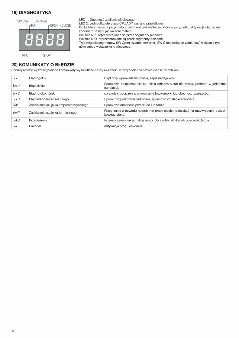
64
19) DIAGNOSTYKA
PHOT
SW Close
STOP
SW OpenP.P. OPEN CLOSE
LED 1: Obecność zasilania sieciowegoLED 2: Jednostka sterująca CP.LADY zasilana prawidłowoDo każdego wejścia przydzielono segment wyświetlacza, który w przypadku aktywacji włącza się zgodnie z następującym schematem.Wejścia N.Z. reprezentowane są przez segmenty pionowe. Wejścia N.O. reprezentowane są przez segmenty poziome.Tryb migania segmentów SW Open (szlaban otwarty) i SW Close (szlaban zamknięty) wskazuje typ używanego wyłącznika krańcowego.
20) KOMUNIKATY O BŁĘDZIEPoniżej zostały wyszczególnione komunikaty wyświetlane na wyświetlaczu w przypadku nieprawidłowości w działaniu.
Err Błąd ogólny Błąd przy wprowadzaniu hasła, zapis nadajników.
Err1 Błąd silnikaSprawdzić połączenia silnika, silnik odłączony lub nie działa, problem w jednostce sterującej.
Err2 Błąd fotokomórek sprawdzić połączenia, wyrównanie fotokomórki lub obecność przeszkód.
err3 Błąd enkodera absolutnego Sprawdzić połączenia enkodera, sprawdzić działanie enkodera.
AMP Zadziałanie czujnika amperometrycznego Sprawdzić obecność przeszkód lub tarcia.
THRM Zadziałanie czujnika termicznegoPrzegrzanie z powodu nadmiernej pracy ciągłej, poczekać na przywrócenie począt-kowego stanu.
OVLD Przeciążenie Przekroczenie maksymalnej mocy. Sprawdzić silnika lub obecność tarcia.
Enc Enkoder Aktywacja progu enkodera.

65
Norme di sicurezza
• Non sostare nella zona di movimento delle ante.• Non lasciare che i bambini giochino con i comandi o in prossimità delle
ante.• In caso di anomalie di funzionamento non tentare di riparare il guasto ma
avvertire un tecnico specializzato.
Manovra manuale di emergenza
In caso di assenza di alimentazione di rete o di funzionamento anomalo, è possibile sbloccare l'asta e manovrarla manualmente.Utilizzando la chiave fornita in dotazione:• Girare la chiave in senso orario fino ad avvertire una certa resistenza per
sbloccare l'asta.• Girare la chiave in senso antiorario fino al blocco per ripristinare il movi-
mento automatico dell'asta.
Manutenzione
• Controllare periodicamente l’efficienza dello sblocco manuale di emer-genza.
• Astenersi assolutamente dal tentativo di effettuare riparazioni, potreste incorrere in incidenti; per queste operazioni contattare un tecnico spe-cializzato.
• L’attuatore non richiede manutenzioni ordinarie, tuttavia è necessario verificare periodicamente l’efficienza dei dispositivi di sicurezza e le altre parti dell’impianto che potrebbero creare pericoli in seguito ad usura.
Smaltimento
Qualora il prodotto venga posto fuori servizio, è necessario seguire le dispo-sizioni legislative in vigore al momento per quanto riguarda lo smaltimento differenziato ed il riciclaggio dei vari componenti (metalli, plastiche, cavi elettrici, ecc.); è consigliabile contattare il vostro installatore o una ditta specializzata ed abilitata allo scopo.
Safety rules
• Do not stand in the movement area of the gate.• Do not let children play with controls and near the gate.• Should operating faults occur, do not attempt to repair the fault but call a
qualified technician.
Manual and emergency manoeuvres
In the event of a power cut or of abnormal operation, it is possible to release the bar and move it by hand.Using the key provided:• To release the bar, turn the key in a clockwise direction until you fell a
certain resistance.• To restore the automatic movement of the bar, turn the key in an anti-
clockwise direction until it is blocked.
Maintenance
• Every month check the good operation of the emergency manual release.• It is mandatory not to carry out extraordinary maintenance or repairs as
accidents may be caused. These operations must be carried out by qualified personnel only.• The operator is maintenance free but it is necessary to check periodically
if the safety devices and the other components of the automation system work properly. Wear and tear of some components could cause dangers.
Waste disposal
If the product must be dismantled, it must be disposed according to regula-tions in force regarding the differentiated waste disposal and the recycling of components (metals, plastics, electric cables, etc..). For this operation it is advisable to call your installer or a specialised company.
LADY/LADY 5 Libro istruzioni per l’utilizzatore User’s handbook
Sblocco di emergenza Emergency release
Ripristino automatismoReset automation

66
Handbuch für den Verbraucher Manuel d’instructions pour l’utilisateur
Sicherheitsvorschriften
• Nicht im Öffnungsbereich verweilen.• Kinder nicht mit den Steuerungen oder in der Nähe des Tores spielen
lassen.• Bei Funktionsausfällen nicht versuchen, den Schaden selber zu beheben,
sondern den Techniker rufen.
Manuelle Notbedienung
Bei Netzausfall oder im Falle von Funktionsstörungen kann die Stange entriegelt und von Hand bedient werden.Dazu den mitgelieferten Schlüssel wie folgt verwenden:• Um die Stange zu entriegeln, den Schlüssel nach rechts drehen, bis ein
gewisser Widerstand spürbar wird.• Um den automatischen Betrieb der Stange wiederherzustellen, den
Schlüssel bis zum Blockieren nach links drehen.
Wartung
• Monatliche Kontrolle der manuellen Notentriegelung• Es ist absolut untersagt, selbstständig Sonderwartung oder Reparaturen
vorzunehmen, da Unfälle die Folge sein können; wenden Sie sich an den Techniker.
• Der Antrieb braucht keine ordentliche Unterhaltung aber es ist periodisch notwendig die Leistungsfähigkeit der Sicherheitsvorrichtungen und die andere Teile des Anlages zu prüfen. Sie könnten durch Abnutzung Gefaht hervorbringen.
Entsorgung
Wird das Gerät außer Betrieb gesetzt, müssen die gültigen Gesetzesvor-schriften zur differenzierten Entsorgung und Wiederverwendung der Ein-zelkomponenten, wie Metall, Plastik, Elektrokabel, usw., beachtet werden. Rufen Sie Ihren Installateur oder eine Entsorgungsfirma.
Normes de sécurité
• Ne vous arrêtez jamais dans la zone de mouvement des portes.• Ne laissez pas les enfants jouer avec les commandes ou à proximité des
portes.• En cas d’anomalies de fonctionnement, n’essayez pas de réparer la panne
mais contactez un technicien spécialisé.
Manœuvre manuelle de secours
En cas d’interruption de l’alimentation de secteur ou en cas de fonctionnement anormal, il est possible de débloquer la lisse et de la manœuvrer manuellement. En utilisant la clé fournie:• Tourner la clé dans le sens des aiguilles d’une montre jusqu’à ce qu’on sente
une certaine résistance pour débloquer la lisse.• Tourner la clé dans le sens inverse des aiguilles d’une montre pour rétablir le
mouvement automatique de la lisse.
Maintenance
• Contrôler tous les mois le bon état du déverrouilleur manuel d’urgence.• S’abstenir impérativement de toute tentative d’effectuer des maintenances
extraordinaires ou des réparations, sous risque d’accident. Contactez un technicien spécialisé pour ces opérations.
• L’actuateur ne demande pas de manutention ordinaire mais il faut verifier periodiquement l’efficience des dispositifs de sécurité et les autres parties de l’installation qui puissent créer dangers à cause d’usure.
Démolition
Au cas où le produit serait mis hors service, il est impératif de se conformer aux lois en vigueur pour ce qui concerne l’élimination différenciée et le recyclage des différents composants (métaux, matières plastiques câbles électriques, etc...) contactez votre installateur ou une firme spécialisée autorisée à cet effet.
LADY/LADY 5
NotentriegelungDéblocage de secours
Reset des AutomatismusRéinitialisation automatisme

67
Libro de instrucciones para el usuario Książeczka z instrukcjami dla użytkownika
Normas de seguridad
• No pararse en la zona de movimiento de las hojas.• No dejar que los niños jueguen con los mando o en proximidad de las hojas.• En caso de anomalías de funcionamiento no intentar reparar la avería sino
que avisar a un técnico especializado.
Maniobra manual de emergencia
En caso de fallo de suministro de energía eléctrica o de funcionamiento anómalo, es posible desbloquear el asta y maniobrarla manualmente.Con la llave en equipamiento:• para desbloquear el asta, girar la llave en sentido horario hasta que se note
cierta resistencia;• para reactivar el movimiento automático del asta, girar la llave en sentido
anti-horario hasta su bloqueo.
Mantenimiento
• Controlar periódicamente la eficiencia del desbloqueo manual de emer-gencia.
• Abstenerse absolutamente de intentar efectuar reparaciones, podrían incurrir en accidentes; para estas operaciones contactar con un técnico especializado.
• El operador no requiere mantenimiento habitual, no obstante es necesario verificar periódicamente la eficiencia de los dispositivos de seguridad y las otras partes de la instalación que pudiesen crear peligros a causa del desgaste.
Eliminación
Cada vez que el producto esté fuera de servicio, es necesario seguir las disposiciones legislativas en vigor en ese momento en cuanto concierne a la eliminación de suciedad y al reciclaje de varios componentes (metales, plásticos, cables eléctricos, etc.), es aconsejable contactar con su instalador o con una empresa especializada y habilitada para tal fin.
Normy bezpieczeństwa
• Starać się nie przebywać w obszarze posuwu skrzydeł.• Niedopuścić aby dzieci bawiły się sterownikami lub w pobliżu skrzydeł
bramy.• W przypadku niewłaściwego funkcjonowania nie starać się samemu do-
konywać naprawy a powiadomić o fakcie technika wyspecjalizowanego.Manewr ręczny awaryjny
W przypadku braku prądu sieciowego lub w przypadku nieprawidłowego funkcjonowania, istnieje możliwość rozsprzęglenia ramienia i wykonywanie manewru ręcznie. Stosując pilot kluczowy z wyposażenia należy:• Przekręcać klucz w kierunku ruchu wskazuwek zagara aż do momentu
wyczucia pewnego oporu, w celu rozsprzęglenia ramienia.• Przekręcać klucz w kierunku odwrotnym do ruchu wskazówek zegara
aż do momentu zablokowania, w celu przywrócenia automatycznego działania ramienia.
Konserwacja
• Sprawdzać okresowo sprawność działania ręcznego mechanizmu odblo-kowującego i bezpieczeństwa.
• Nie starać się w żadnym wypadku dokonywać napraw samemu z racji na możliwość ulegnięcia wypadkowi, w celu naprawy należy skontaktować się z technikiem wyspecjalizowanym.
• Siłownik nie wymaga normalnej konserwacji, tym niemniej wskazane jest okresowe sprawdzanie sprawności działania elementów bezpieczeństwa i pozostałych części instalacji, mogących stanowić zagrożenie z racji na stan zużycia.
Eliminacja i demolowanie
W przypadku gdy urządzenie nie nadaje się już do dalszego użytkowania, w celu pozbycia się go należy ściśle przestrzegać obowiązujących w danym momencie norm prawnych regulujących zróżnicowany rozkład na części i odzyskiwanie niektórych elementów składowych (metale, plastyk, kable elektryczne, itp.); wskazane jest skontaktowanie się z instalatorem lub wy-specjalizowaną firmą, autoryzowaną do tego rodzaju prac.
LADY/LADY 5
Desbloqueo de emergenciaRozsprzęglanie awaryjne
Reactivación del automatismoPrzywrócenie działania automatyzmu

68
1
6
76
3
2
4
5
Ref.LADY / LADY 5
CodeNote
1 9686110
2 9686112
3 9686111
4 968601407
5 9686109
6 9686555
7 968601408

69
11
8
14 15
16
17
18
10
12
13
19
9
20
Ref.LADYCode
LADY 5 Code
Note
8 9686183 968600647
9 9686248 9686248
10 968600915 968600915
11 9686181 9686181
12 6986184 6986184
13 9686666 9686666
14 9686190 9686190
15 9686191 9686191
16 9686192 9686192
17 9686193 9686193
18 968601410 968601410 CP.LADY
19 968601409 968601409 nr. 2 microsw..20 9686160 9686160

70
Dichiarazione di Conformità UE (DoC)
Nome del produttore: Automatismi Benincà SpA Indirizzo: Via Capitello, 45 - 36066 Sandrigo (VI) - ItaliaTelefono: +39 0444 751030 . Indirizzo e-mail: [email protected] autorizzata a costruire la documentazione tecnica: Automatismi Benincà SpA
Dichiara che il documento è rilasciato sotto la propria responsabilità e appartiene al seguente prodotto:Tipo di prodotto: automazione per barriere stradaliModello/Tipo: LADY/LADY 5 Accessori: N/A
Il prodotto sopraindicato risulta conforme alle disposizioni imposte dale seguenti direttive:Direttiva 2014/53/EUDirettiva 2011/65/EUDirettiva 2006/42/CE
Sono state applicate le norme armonizzate e le specifiche tecniche descritte di seguito:ETSI EN 300 220-1 V3.1.1ETSI EN 300 220-2 V3.1.1ETSI EN 301 489-1 V2.1.1ETSI EN 301 489-3 V2.1.1EN 60950-1:2006 + A11:2009 + A1:2010 + A12:2011 + AC:2011 + A2:2013EN 61000-6-2:2005, EN 61000-6-3:2007 + A1:2011EN 60335-1:2012 + A11:2014; EN 60335-2-103:201550581:2012EN 13241-1:2003EN 12445:2002, EN 12453:2002, EN 12978:2003 (se applicabile)
Il Certificato di Conformità di questo documento cor-risponde all'ultima revisione disponibile al momento della stampa e può risultare differente per esigenze editoriali dall'originale disponibile presso il produttore.
Benincà Luigi, Responsabile legale.Sandrigo, 16/01/2019.
UE Declaration of Conformity (DoC)
Manufacturer's name: Automatismi Benincà SpA Address: Via Capitello, 45 - 36066 Sandrigo (VI) - ItaliaTelephone: +39 0444 751030 . Email address: [email protected] authorised to draft the technical documentation: Automatismi Benincà SpA
Declare that the DOC is issued under our sole responsi-bility and belongs to the following product:Product type: operator for road gatesModel/type: LADY/LADY 5 Accessories: N/A
The object of the declaration described above is in conformity with the relevant Union harmonization legislation:Directive 2014/53/EUDirective 2011/65/EUDirective 2006/42/CE
The following harmonized standards and technical specifications have been applied:ETSI EN 300 220-1 V3.1.1ETSI EN 300 220-2 V3.1.1ETSI EN 301 489-1 V2.1.1ETSI EN 301 489-3 V2.1.1EN 60950-1:2006 + A11:2009 + A1:2010 + A12:2011 + AC:2011 + A2:2013EN 61000-6-2:2005, EN 61000-6-3:2007 + A1:2011EN 60335-1:2012 + A11:2014; EN 60335-2-103:201550581:2012EN 13241-1:2003EN 12445:2002, EN 12453:2002, EN 12978:2003 (as applicable)
The certificate of conformity in this document corre-sponds to the last review available at the time of print-ing and could differ for editorial requirements from the original available from the manufacturer.
Benincà Luigi, Legal Officer.Sandrigo, 16/01/2019.
EG-Konformitätserklärung (DoC)
Name des Herstellers: Automatismi Benincà SpAAdresse: Via Capitello, 45 - 36066 Sandrigo (VI) - Italia Telefon: +39 0444 751030 E-Mail-Adresse: [email protected] Erstellung der technischen Dokumentation berechtigte Person: Automatismi Benincà SpA
Erklärt, dass das Dokument unter alleiniger Verant-wortung herausgegeben wurde und zu dem folgenden Produkt ge-hört:Produkttypus: Antriebe für StraßensperrenModell/Typus: LADY/LADY 5 Zubehör: N/ADas oben genannte Produkt stimmt mit den Vorschriften der folgenden Richtlinien überein:Richtlinie 2014/53/EURichtlinie 2011/65/EURichtlinie 2006/42/CE
Die harmonisierten Normen und technischen Spezi-fikationen, die unten beschrieben werden, wurden angewandt:ETSI EN 300 220-1 V3.1.1ETSI EN 300 220-2 V3.1.1ETSI EN 301 489-1 V2.1.1ETSI EN 301 489-3 V2.1.1EN 60950-1:2006 + A11:2009 + A1:2010 + A12:2011 + AC:2011 + A2:2013EN 61000-6-2:2005, EN 61000-6-3:2007 + A1:2011EN 60335-1:2012 + A11:2014; EN 60335-2-103:201550581:2012EN 13241-1:2003EN 12445:2002, EN 12453:2002, EN 12978:2003(falls anwendbar)
Die in diesem Dokument vorliegende Konformitätserk-lärung entspricht der neuesten zum Druckzeitpunkt erhältlichen Revision und könnte aufgrund von ver-legerischen Gründen vom beim Hersteller erhältlichen Original abweichen.
Benincà Luigi, Rechtsvertreter.Sandrigo, 16/01/2019.
71
Déclaration CE de conformité (DoC)
Nom du producteur: Automatismi Benincà SpAAdresse: Via Capitello, 45 - 36066 Sandrigo (VI) - Italia Téléphone : +39 0444 751030 Adresse e-mail: [email protected] Personne autorisée à construire la documentation tech-nique : Automatismi Benincà SpA
Nous déclarons que le document est délivré sous notre propre responsabilité et qu'il appartient au produit suivant :Type de produit :automatisme pour barrières routièresModèle/Type: LADY/LADY 5 Accessoires : N/A
Le produit mentionné ci-dessus est conforme aux disposi-tions établies par les directives suivantes :Directive 2014/53/EUDirective 2011/65/EUDirective 2006/42/CE
Les normes harmonisées et les spécifications techniques décrites ci-dessous ont été appliquées:ETSI EN 300 220-1 V3.1.1ETSI EN 300 220-2 V3.1.1ETSI EN 301 489-1 V2.1.1ETSI EN 301 489-3 V2.1.1EN 60950-1:2006 + A11:2009 + A1:2010 + A12:2011 + AC:2011 + A2:2013EN 61000-6-2:2005, EN 61000-6-3:2007 + A1:2011EN 60335-1:2012 + A11:2014; EN 60335-2-103:201550581:2012EN 13241-1:2003EN 12445:2002, EN 12453:2002, EN 12978:2003 (si applicable)
Le certificat de conformité présent dans ce document correspond à la dernière révision disponible au moment de l’impression et pourrait différer pour des exigences éditoriales de l’original disponible chez le constructeur.
Benincà Luigi, Représentant LégalSandrigo, 16/01/2019.
Declaración CE de conformidad (DoC)
Nombre del productor: Automatismi Benincà SpADirección: Via Capitello, 45 - 36066 Sandrigo (VI) - Italia Teléfono: +39 0444 751030 Dirección de correo electrónico: [email protected] autorizada a producir la documentación técnica: Automatismi Benincà SpA
Declara que el documento ha sido emitido bajo la propia responsabilidad y pertenece al siguiente producto:Tipo de producto: automatización para barreras de callesModelo/Tipo: LADY/LADY 5 Accesorios: N/A
El producto indicado arriba cumple con las disposiciones establecidas por las siguientes directivas:Directiva 2014/53/EUDirectiva 2011/65/EUDirectiva 2006/42/CE
Han sido aplicadas las normas armonizadas y las es-pecificaciones técnicas que se describen a continuación:ETSI EN 300 220-1 V3.1.1ETSI EN 300 220-2 V3.1.1ETSI EN 301 489-1 V2.1.1ETSI EN 301 489-3 V2.1.1EN 60950-1:2006 + A11:2009 + A1:2010 + A12:2011 + AC:2011 + A2:2013EN 61000-6-2:2005, EN 61000-6-3:2007 + A1:2011EN 60335-1:2012 + A11:2014; EN 60335-2-103:201550581:2012EN 13241-1:2003EN 12445:2002, EN 12453:2002, EN 12978:2003 (si es aplicable)
El certificado de conformidad presente en este docu-mento corresponde a la última revisión disponible en el momento de la impresión y podría diferir por exi-gencias editoriales del original disponible en la sede del fabricante.
Benincà Luigi, Representante Legal.Sandrigo, 16/01/2019.
Deklaracja zgodności CE (DoC)
Nazwa producenta: Automatismi Benincà SpAAdres: Via Capitello, 45 - 36066 Sandrigo (VI) - Italia Telefon: +39 0444 751030 Adres e-mail: [email protected] upoważniona do stworzenia dokumentacji tech-nicznej: Automatismi Benincà SpA
Oświadcza, że dokument został wydany na własną odpowiedzialność i dotyczy produktu:Rodzaj produktu: Automatyzm do szlabanów dro-gowychModel/Typ: LADY/LADY 5 Akcesoria: N/A
Wyżej wskazany produkt spełnia wymagania dyrektyw:Dyrektywy 2014/53/EUDyrektywy 2011/65/EUDyrektywy 2006/42/CE
Uwzględniono normy zharmonizowane i zastosowano niżej wskazane specyfikacje techniczne:ETSI EN 300 220-1 V3.1.1ETSI EN 300 220-2 V3.1.1ETSI EN 301 489-1 V2.1.1ETSI EN 301 489-3 V2.1.1EN 60950-1:2006 + A11:2009 + A1:2010 + A12:2011 + AC:2011 + A2:2013EN 61000-6-2:2005, EN 61000-6-3:2007 + A1:2011EN 60335-1:2012 + A11:2014; EN 60335-2-103:201550581:2012EN 13241-1:2003EN 12445:2002, EN 12453:2002, EN 12978:2003 (jeśli ma zastosowanie)
Certyfikat zgodności znajdujący się w niniejszym do-kumencie odpowiada ostatniej aktualizacji dostępnej w momencie wydruku i może się różnić ze względów wydawniczych od oryginału dostępnego u producenta.
Benincà Luigi, Przedstawiciel prawny.Sandrigo, 16/01/2019.

AUTOMATISMI BENINCÀ SpA - Via Capitello, 45 - 36066 Sandrigo (VI) - Tel. 0444 751030 r.a. - Fax 0444 759728