LABORATORY MANUAL - Dev Bhoomi Institute of Technology ...
30
LABORATORY MANUAL B.TECH. VII SEMESTER Department of Mechanical Engineering Dev Bhoomi Institute of Technology Dehradun www.dbit.ac.in Affiliated to Uttrakhand Technical University,Dehradun
-
Upload
khangminh22 -
Category
Documents
-
view
0 -
download
0
Transcript of LABORATORY MANUAL - Dev Bhoomi Institute of Technology ...
LABORATORY MANUAL
B.TECH. VII SEMESTER
Department of Mechanical Engineering
Dev Bhoomi Institute of Technology Dehradun www.dbit.ac.in
Affiliated to
Uttrakhand Technical University,Dehradun
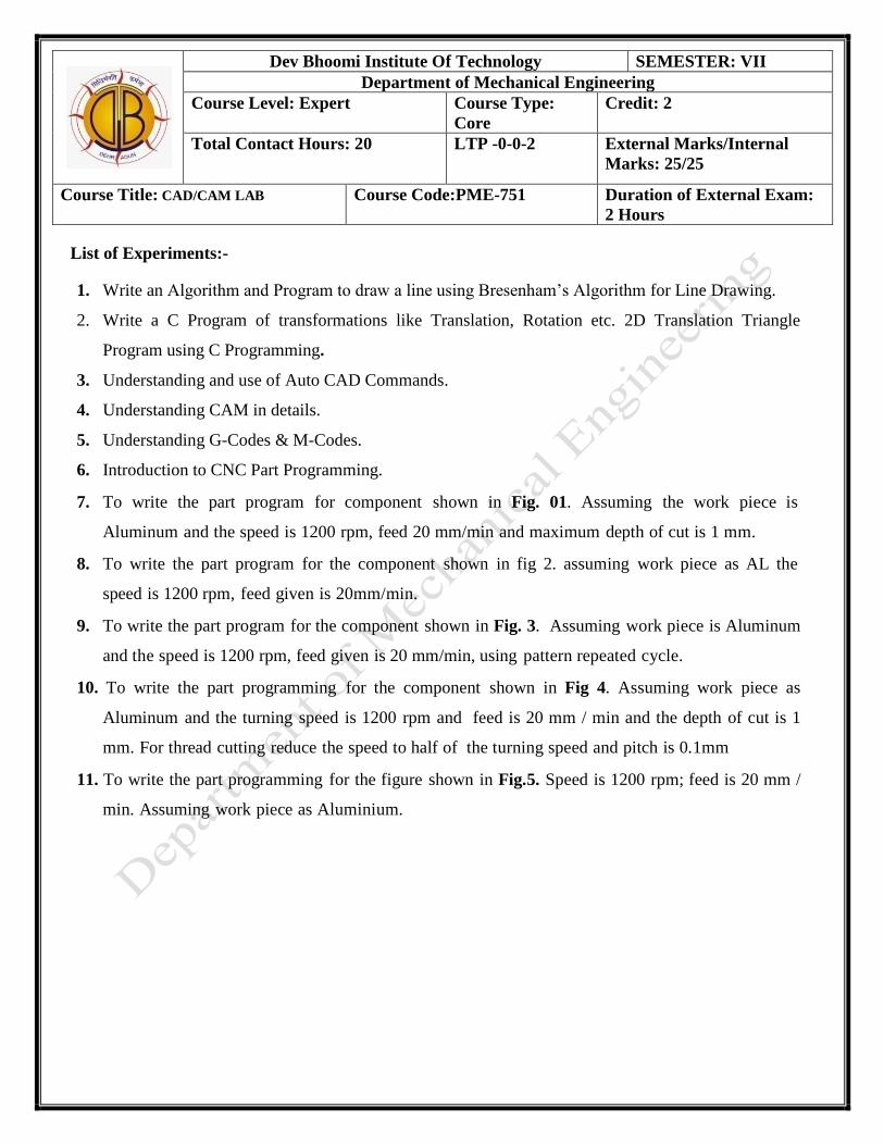
List of Experiments:-
1. Write an Algorithm and Program to draw a line using Bresenham’s Algorithm for Line Drawing.
2. Write a C Program of transformations like Translation, Rotation etc. 2D Translation Triangle
Program using C Programming.
3. Understanding and use of Auto CAD Commands.
4. Understanding CAM in details.
5. Understanding G-Codes & M-Codes.
6. Introduction to CNC Part Programming.
7. To write the part program for component shown in Fig. 01. Assuming the work piece is
Aluminum and the speed is 1200 rpm, feed 20 mm/min and maximum depth of cut is 1 mm.
8. To write the part program for the component shown in fig 2. assuming work piece as AL the
speed is 1200 rpm, feed given is 20mm/min.
9. To write the part program for the component shown in Fig. 3. Assuming work piece is Aluminum
and the speed is 1200 rpm, feed given is 20 mm/min, using pattern repeated cycle.
10. To write the part programming for the component shown in Fig 4. Assuming work piece as
Aluminum and the turning speed is 1200 rpm and feed is 20 mm / min and the depth of cut is 1
mm. For thread cutting reduce the speed to half of the turning speed and pitch is 0.1mm
11. To write the part programming for the figure shown in Fig.5. Speed is 1200 rpm; feed is 20 mm /
min. Assuming work piece as Aluminium.
Dev Bhoomi Institute Of Technology SEMESTER: VII
Department of Mechanical Engineering
Course Level: Expert Course Type:
Core
Credit: 2
Total Contact Hours: 20 LTP -0-0-2 External Marks/Internal
Marks: 25/25
Course Title: CAD/CAM LAB Course Code:PME-751 Duration of External Exam:
2 Hours
OBJECTIVE: Write an Algorithm and Program to draw a line using Bresenham’s Algorithm for Line
Drawing
DEV BHOOMI INSTITUTE OF TECHNOLOGY
DEPARTMENT OF MECHANICAL
ENGINEERING
LABORATORY
MANUAL
PRACTICAL INSTRUCTION SHEET
EXPERIMENT NO. 1 ISSUE NO. : ISSUE DATE:
REV. NO. : 5 REV. DATE : 20 July
2017
PAGE:
Laboratory Name & Code: CAD/CAM LAB (PME-751 ) SEMESTER: VII
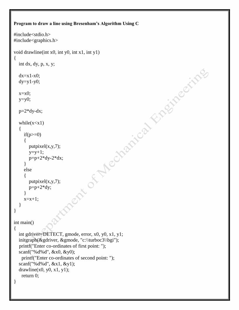
Program to draw a line using Bresenham’s Algorithm Using C
#include<stdio.h> #include<graphics.h> void drawline(int x0, int y0, int x1, int y1) { int dx, dy, p, x, y; dx=x1-x0; dy=y1-y0; x=x0; y=y0; p=2*dy-dx; while(x<x1) { if(p>=0) { putpixel(x,y,7); y=y+1; p=p+2*dy-2*dx; } else { putpixel(x,y,7); p=p+2*dy; } x=x+1; } } int main() { int gdriver=DETECT, gmode, error, x0, y0, x1, y1; initgraph(&gdriver, &gmode, "c:\\turboc3\\bgi"); printf("Enter co-ordinates of first point: "); scanf("%d%d", &x0, &y0); printf("Enter co-ordinates of second point: "); scanf("%d%d", &x1, &y1); drawline(x0, y0, x1, y1); return 0; }
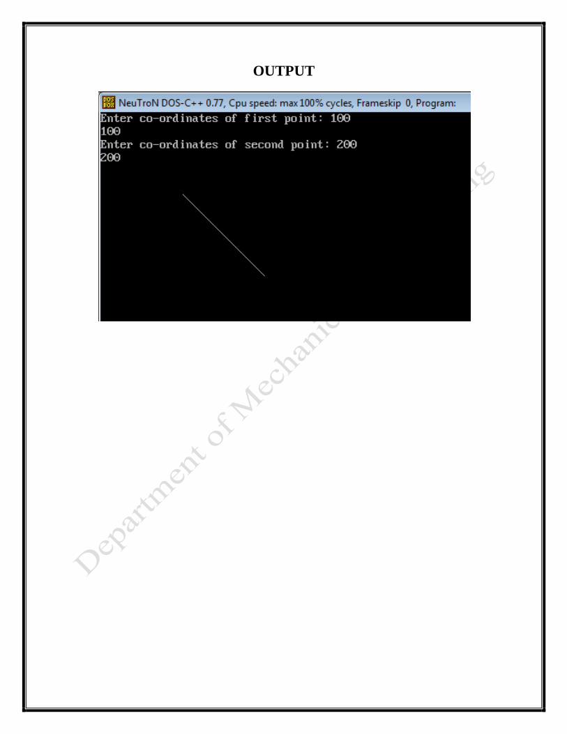
OUTPUT
OBJECTIVE: Write a C Program of transformations like Translation, Rotation etc. 2D Translation
Triangle Program using C Programming
ALGORITHM: 1. Start
2. Initialize the graphics mode.
3. Construct a 2D object (use Drawpoly()) e.g. (x,y)
4. A) Translation
a. Get the translation value tx, ty
b. Move the 2d object with tx, ty (x’=x+tx,y’=y+ty)
c. Plot (x’,y’)
5. B) Scaling
a. Get the scaling value Sx,Sy
b. Resize the object with Sx,Sy (x’=x*Sx,y’=y*Sy)
c. Plot (x’,y’)
6. C) Rotation
a. Get the Rotation angle
b. Rotate the object by the angle ф
x’=x cos ф - y sin ф
y’=x sin ф - y cosф
c. Plot (x’,y’)
PROGRAM:
#include <graphics.h>
#include <stdlib.h>
#include <stdio.h>
#include <conio.h>
#include<math.h>
void main()
{
int gm;
DEV BHOOMI INSTITUTE OF TECHNOLOGY
DEPARTMENT OF MECHANICAL
ENGINEERING
LABORATORY
MANUAL
PRACTICAL INSTRUCTION SHEET
EXPERIMENT NO. 2 ISSUE NO. : ISSUE DATE:
REV. NO. : 5 REV. DATE : 20 July
2017
PAGE:
Laboratory Name & Code: CAD/CAM LAB (PME-751 ) SEMESTER: VII
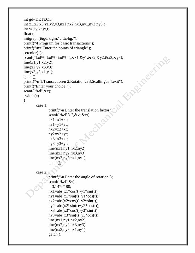
int gd=DETECT;
int x1,x2,x3,y1,y2,y3,nx1,nx2,nx3,ny1,ny2,ny3,c;
int sx,sy,xt,yt,r;
float t;
initgraph(&gd,&gm,"c:\tc\bg:");
printf("\t Program for basic transactions");
printf("\n\t Enter the points of triangle");
setcolor(1);
scanf("%d%d%d%d%d%d",&x1,&y1,&x2,&y2,&x3,&y3);
line(x1,y1,x2,y2);
line(x2,y2,x3,y3);
line(x3,y3,x1,y1);
getch();
printf("\n 1.Transaction\n 2.Rotation\n 3.Scalling\n 4.exit");
printf("Enter your choice:");
scanf("%d",&c);
switch(c)
{
case 1:
printf("\n Enter the translation factor");
scanf("%d%d",&xt,&yt);
nx1=x1+xt;
ny1=y1+yt;
nx2=x2+xt;
ny2=y2+yt;
nx3=x3+xt;
ny3=y3+yt;
line(nx1,ny1,nx2,ny2);
line(nx2,ny2,nx3,ny3);
line(nx3,ny3,nx1,ny1);
getch();
case 2:
printf("\n Enter the angle of rotation");
scanf("%d",&r);
t=3.14*r/180;
nx1=abs(x1*cos(t)-y1*sin(t));
ny1=abs(x1*sin(t)+y1*cos(t));
nx2=abs(x2*cos(t)-y2*sin(t));
ny2=abs(x2*sin(t)+y2*cos(t));
nx3=abs(x3*cos(t)-y3*sin(t));
ny3=abs(x3*sin(t)+y3*cos(t));
line(nx1,ny1,nx2,ny2);
line(nx2,ny2,nx3,ny3);
line(nx3,ny3,nx1,ny1);
getch();
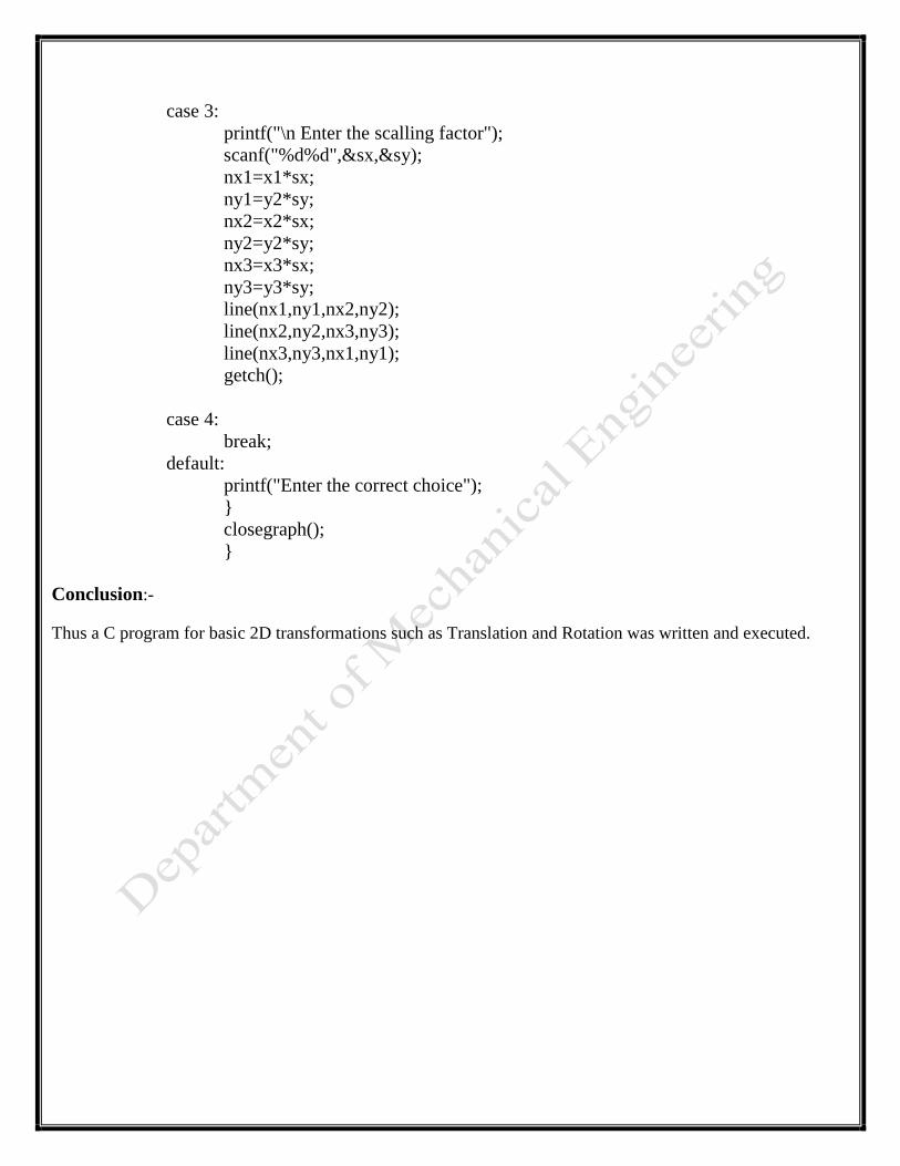
case 3:
printf("\n Enter the scalling factor");
scanf("%d%d",&sx,&sy);
nx1=x1*sx;
ny1=y2*sy;
nx2=x2*sx;
ny2=y2*sy;
nx3=x3*sx;
ny3=y3*sy;
line(nx1,ny1,nx2,ny2);
line(nx2,ny2,nx3,ny3);
line(nx3,ny3,nx1,ny1);
getch();
case 4:
break;
default:
printf("Enter the correct choice");
}
closegraph();
}
Conclusion:-
Thus a C program for basic 2D transformations such as Translation and Rotation was written and executed.

OBJECTIVE: Understanding and use of Auto CAD Commands.
AutoCAD is the engineer’s and architects best friend. It is a Computer Aided Design (CAD) program created by
Autodesk, and first released way back in 1982.
The most basic building blocks of AutoCAD are called “entities”, and they are created within the program with
the purpose of being manipulated and changed to meet the needs of the user and to help them create the designs
they see in their head. These entities are manipulated through the use of commands. Some commands can be
used at any time, others, only at specific junctures in the creation process.
Commands for Setting the Drawing Environment
These commands may be used at any time, but are mainly called upon more during the beginning of the drawing
process.
Units: Specifies the display format and precision. This command dictates whether the units are displayed
as decimals or as a fraction, as well as how many decimal places the number will go. Also specifies how
angles will be represented, either as decimal degrees, radians, etc., as well as how angles will be
measured, i.e. clockwise vs. counterclockwise.
Limits: Sets limits to the boundary and size of the current drawing. The user must specify the lower left-
hand corner and the upper right-hand corner. This setting may be turned on or off – when on, points may
not be specified outside the currently set limits.
Viewers: Performs two functions: first, it lets the user disable fast zoom, which makes sense when
conforming a more modern version of AutoCAD to an earlier one that lacks the fast zoom capability.
Second, Viewres allows the user to control the smoothness and speed of circles and arcs drawn in the
display. The user does this by choosing the number of sides circles will have. It is recommended this
value be set at 2000.
Blipmode: Blips are small crosses used to mark screen positions that the user has pointed to. They can
be useful reference points, but too many of them can crowd the screen, making it difficult for the user to
see. Engaging Blipmode allows the small crosses to stay up in the wake of the pointer, and turning it off
makes them disappear. Blips are not part of the final drawing and are removed when the drawing is
complete.
Fill: When this command is engaged, solids, traces, wide polylines, and donuts that are drawn are then
filled in with color, as opposed to just being outlines. This command does not affect the drawing’s
plotted output, and, when using this command, there is a trade-off between regeneration time and the
image’s quality.
DEV BHOOMI INSTITUTE OF TECHNOLOGY
DEPARTMENT OF MECHANICAL
ENGINEERING
LABORATORY
MANUAL
PRACTICAL INSTRUCTION SHEET
EXPERIMENT NO. 3 ISSUE NO. : ISSUE DATE:
REV. NO. : 5 REV. DATE : 20 July
2017
PAGE:
Laboratory Name & Code: CAD/CAM LAB (PME-751 ) SEMESTER: VII
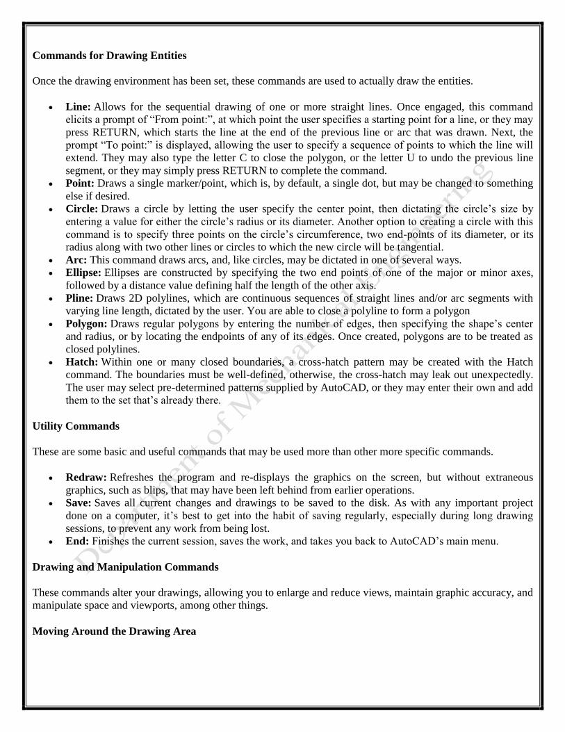
Commands for Drawing Entities
Once the drawing environment has been set, these commands are used to actually draw the entities.
Line: Allows for the sequential drawing of one or more straight lines. Once engaged, this command
elicits a prompt of “From point:”, at which point the user specifies a starting point for a line, or they may
press RETURN, which starts the line at the end of the previous line or arc that was drawn. Next, the
prompt “To point:” is displayed, allowing the user to specify a sequence of points to which the line will
extend. They may also type the letter C to close the polygon, or the letter U to undo the previous line
segment, or they may simply press RETURN to complete the command.
Point: Draws a single marker/point, which is, by default, a single dot, but may be changed to something
else if desired.
Circle: Draws a circle by letting the user specify the center point, then dictating the circle’s size by
entering a value for either the circle’s radius or its diameter. Another option to creating a circle with this
command is to specify three points on the circle’s circumference, two end-points of its diameter, or its
radius along with two other lines or circles to which the new circle will be tangential.
Arc: This command draws arcs, and, like circles, may be dictated in one of several ways.
Ellipse: Ellipses are constructed by specifying the two end points of one of the major or minor axes,
followed by a distance value defining half the length of the other axis.
Pline: Draws 2D polylines, which are continuous sequences of straight lines and/or arc segments with
varying line length, dictated by the user. You are able to close a polyline to form a polygon
Polygon: Draws regular polygons by entering the number of edges, then specifying the shape’s center
and radius, or by locating the endpoints of any of its edges. Once created, polygons are to be treated as
closed polylines.
Hatch: Within one or many closed boundaries, a cross-hatch pattern may be created with the Hatch
command. The boundaries must be well-defined, otherwise, the cross-hatch may leak out unexpectedly.
The user may select pre-determined patterns supplied by AutoCAD, or they may enter their own and add
them to the set that’s already there.
Utility Commands
These are some basic and useful commands that may be used more than other more specific commands.
Redraw: Refreshes the program and re-displays the graphics on the screen, but without extraneous
graphics, such as blips, that may have been left behind from earlier operations.
Save: Saves all current changes and drawings to be saved to the disk. As with any important project
done on a computer, it’s best to get into the habit of saving regularly, especially during long drawing
sessions, to prevent any work from being lost.
End: Finishes the current session, saves the work, and takes you back to AutoCAD’s main menu.
Drawing and Manipulation Commands
These commands alter your drawings, allowing you to enlarge and reduce views, maintain graphic accuracy, and
manipulate space and viewports, among other things.
Moving Around the Drawing Area
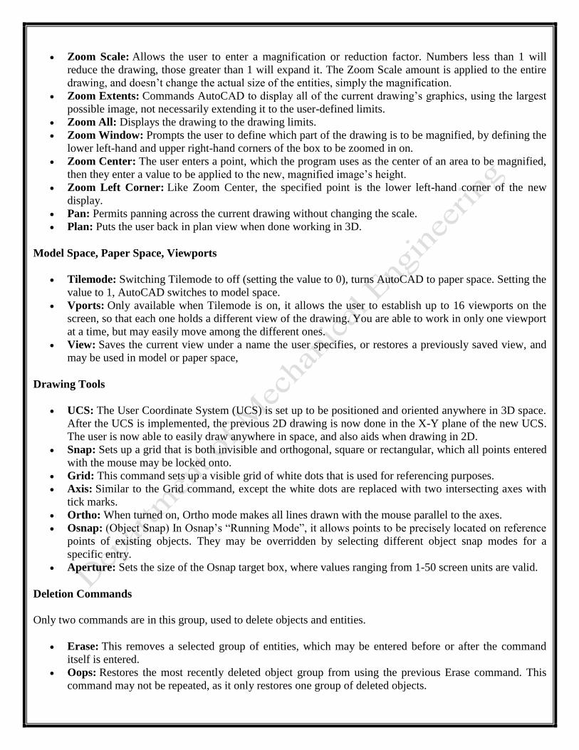
Zoom Scale: Allows the user to enter a magnification or reduction factor. Numbers less than 1 will
reduce the drawing, those greater than 1 will expand it. The Zoom Scale amount is applied to the entire
drawing, and doesn’t change the actual size of the entities, simply the magnification.
Zoom Extents: Commands AutoCAD to display all of the current drawing’s graphics, using the largest
possible image, not necessarily extending it to the user-defined limits.
Zoom All: Displays the drawing to the drawing limits.
Zoom Window: Prompts the user to define which part of the drawing is to be magnified, by defining the
lower left-hand and upper right-hand corners of the box to be zoomed in on.
Zoom Center: The user enters a point, which the program uses as the center of an area to be magnified,
then they enter a value to be applied to the new, magnified image’s height.
Zoom Left Corner: Like Zoom Center, the specified point is the lower left-hand corner of the new
display.
Pan: Permits panning across the current drawing without changing the scale.
Plan: Puts the user back in plan view when done working in 3D.
Model Space, Paper Space, Viewports
Tilemode: Switching Tilemode to off (setting the value to 0), turns AutoCAD to paper space. Setting the
value to 1, AutoCAD switches to model space.
Vports: Only available when Tilemode is on, it allows the user to establish up to 16 viewports on the
screen, so that each one holds a different view of the drawing. You are able to work in only one viewport
at a time, but may easily move among the different ones.
View: Saves the current view under a name the user specifies, or restores a previously saved view, and
may be used in model or paper space,
Drawing Tools
UCS: The User Coordinate System (UCS) is set up to be positioned and oriented anywhere in 3D space.
After the UCS is implemented, the previous 2D drawing is now done in the X-Y plane of the new UCS.
The user is now able to easily draw anywhere in space, and also aids when drawing in 2D.
Snap: Sets up a grid that is both invisible and orthogonal, square or rectangular, which all points entered
with the mouse may be locked onto.
Grid: This command sets up a visible grid of white dots that is used for referencing purposes.
Axis: Similar to the Grid command, except the white dots are replaced with two intersecting axes with
tick marks.
Ortho: When turned on, Ortho mode makes all lines drawn with the mouse parallel to the axes.
Osnap: (Object Snap) In Osnap’s “Running Mode”, it allows points to be precisely located on reference
points of existing objects. They may be overridden by selecting different object snap modes for a
specific entry.
Aperture: Sets the size of the Osnap target box, where values ranging from 1-50 screen units are valid.
Deletion Commands
Only two commands are in this group, used to delete objects and entities.
Erase: This removes a selected group of entities, which may be entered before or after the command
itself is entered.
Oops: Restores the most recently deleted object group from using the previous Erase command. This
command may not be repeated, as it only restores one group of deleted objects.
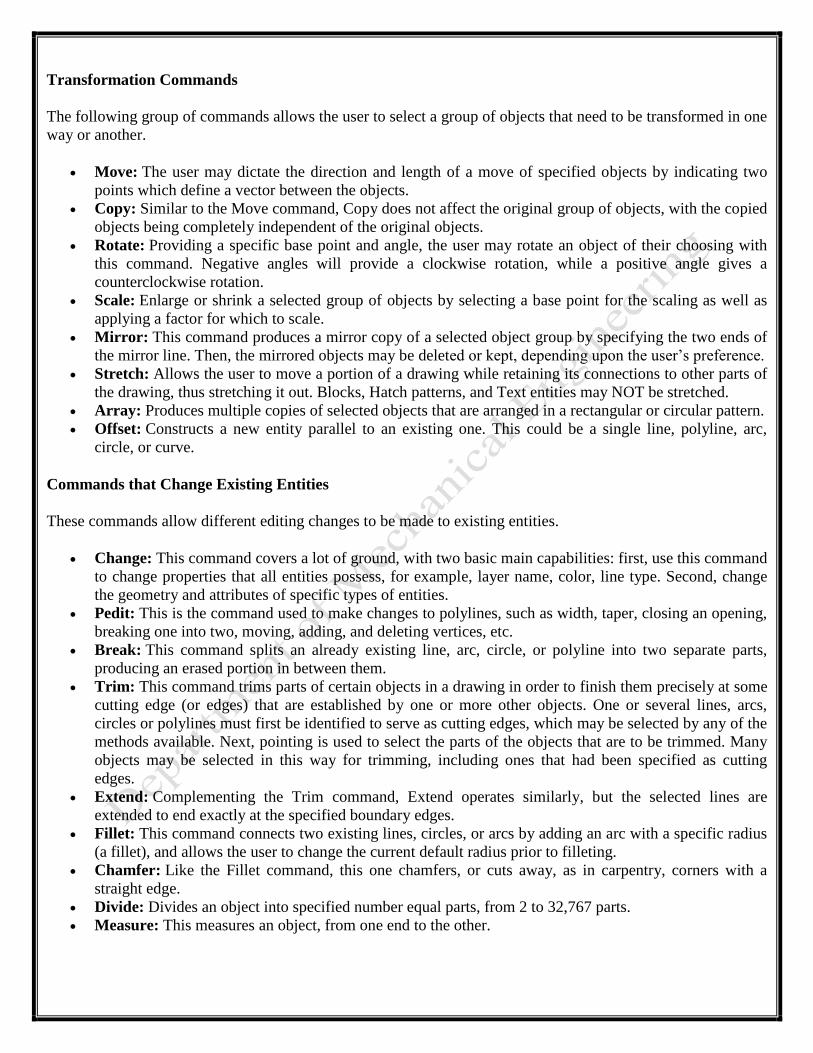
Transformation Commands
The following group of commands allows the user to select a group of objects that need to be transformed in one
way or another.
Move: The user may dictate the direction and length of a move of specified objects by indicating two
points which define a vector between the objects.
Copy: Similar to the Move command, Copy does not affect the original group of objects, with the copied
objects being completely independent of the original objects.
Rotate: Providing a specific base point and angle, the user may rotate an object of their choosing with
this command. Negative angles will provide a clockwise rotation, while a positive angle gives a
counterclockwise rotation.
Scale: Enlarge or shrink a selected group of objects by selecting a base point for the scaling as well as
applying a factor for which to scale.
Mirror: This command produces a mirror copy of a selected object group by specifying the two ends of
the mirror line. Then, the mirrored objects may be deleted or kept, depending upon the user’s preference.
Stretch: Allows the user to move a portion of a drawing while retaining its connections to other parts of
the drawing, thus stretching it out. Blocks, Hatch patterns, and Text entities may NOT be stretched.
Array: Produces multiple copies of selected objects that are arranged in a rectangular or circular pattern.
Offset: Constructs a new entity parallel to an existing one. This could be a single line, polyline, arc,
circle, or curve.
Commands that Change Existing Entities
These commands allow different editing changes to be made to existing entities.
Change: This command covers a lot of ground, with two basic main capabilities: first, use this command
to change properties that all entities possess, for example, layer name, color, line type. Second, change
the geometry and attributes of specific types of entities.
Pedit: This is the command used to make changes to polylines, such as width, taper, closing an opening,
breaking one into two, moving, adding, and deleting vertices, etc.
Break: This command splits an already existing line, arc, circle, or polyline into two separate parts,
producing an erased portion in between them.
Trim: This command trims parts of certain objects in a drawing in order to finish them precisely at some
cutting edge (or edges) that are established by one or more other objects. One or several lines, arcs,
circles or polylines must first be identified to serve as cutting edges, which may be selected by any of the
methods available. Next, pointing is used to select the parts of the objects that are to be trimmed. Many
objects may be selected in this way for trimming, including ones that had been specified as cutting
edges.
Extend: Complementing the Trim command, Extend operates similarly, but the selected lines are
extended to end exactly at the specified boundary edges.
Fillet: This command connects two existing lines, circles, or arcs by adding an arc with a specific radius
(a fillet), and allows the user to change the current default radius prior to filleting.
Chamfer: Like the Fillet command, this one chamfers, or cuts away, as in carpentry, corners with a
straight edge.
Divide: Divides an object into specified number equal parts, from 2 to 32,767 parts.
Measure: This measures an object, from one end to the other.
Objective:- Understanding CAM in details.
Theory:-
CAM Computer-aided manufacturing
Computer-aided manufacturing (CAM) is the use of computer-based software tools that assist engineers
and machinists in manufacturing or prototyping product components. Its primary purpose is to create a faster
production process and components with more precise dimensions and material consistency, which in some
cases, uses only the required amount of raw material (thus minimizing waste), while simultaneously reducing
energy consumption. CAM is a programming tool that makes it possible to manufacture physical models using
computer-aided design (CAD) programs. CAM creates real life versions of components designed within a
software package
CNC Technology Numerical Control (NC) is a software-based machine tool control technique developed at Massachusetts
Institute of Technology (MIT) in early 1960s. It has now evolved into a mature technology known as
Computer Numerical Control (CNC). Although major applications of CNC even today continue to be
in machining, it finds applications in other processes such as sheet metal working, non-traditional
machining and inspection. Robots and Rapid Prototyping machines are also CNC controlled. In fact, any
process that can be visualized as a sequence of motions and switching functions can be controlled by
CNC. These motions and switching functions are input in the form of alphanumeric instructions. CNC is
the basis of flexible automation which helps industries cut down time-to-market and enables launch of
even low volume products. Unlimited muscle power, unmanned operation, independent axes coordinated
through software, simplified generic tooling even for the most complex jobs and accurate construction are
DEV BHOOMI INSTITUTE OF TECHNOLOGY
DEPARTMENT OF MECHANICAL
ENGINEERING
LABORATORY
MANUAL
PRACTICAL INSTRUCTION SHEET
EXPERIMENT NO. 4 ISSUE NO. : ISSUE DATE:
REV. NO. : 5 REV. DATE : 20 July
2017
PAGE:
Laboratory Name & Code: CAD/CAM LAB (PME-751 ) SEMESTER: VII
some of the salient features of CNC.
CNC Machining
Automats and Special Purpose Machines (SPMs) require special cams/ templates and clutch settings for each
part. Manufacture of these cams/ templates is costly and slow.
Furthermore, changing over from one part to the other on these machines also consumes considerable
time. The high cost and long time of these hard automated machines to produce parts can be justified only
in mass production. With the advent of fast, rigid and accurate CNC machines and sophisticated CAM
packages, generation of NC programs and change over from one product to the other are easy and fast as it
does not require any mechanical change. These in conjunction with advanced cutting tools have made High
Speed Cutting (HSC) of hard materials a reality. Therefore, CNC machining has become a standard means
to produce dies and molds; tool makers today require EDM only for producing inaccessible regions, sharp
corners, tiny features and desired surface quality. Intricate aerospace parts are realized through 5 axis
CNC machining. Internet technology in a global village enables designing in one place, NC programming and
verification in another place and actual machining in yet another place.
ADVANTAGES OF CNC:
Flexibility
Accuracy
Speed
Simplified fixturing and generic cutting tools Storage of machining skill in NC programs Less skilled
operators will do
Less fatigue to the operators
Objective:- Understanding G-Codes & M-Codes.
Theory:-
G-CODES
G-Code, or preparatory code or function, are functions in the Numerical control programming language. The G-
codes are the codes that position the tool and do the actual work, as opposed to M-codes, that manages the
machine; T for tool-related codes. S and F are tool-Speed and tool-Feed, and finally D-codes for tool
compensation. The programming language of Numerical Control (NC) is sometimes informally called G- code.
But in actuality, G-codes are only a part of the NC-programming language that controls NC and CNC machine
tools.
A basic list of `G' operation codes is given below. These direct motion of the tool.
1. G00 - Rapid move (not cutting)
2. G01 - Linear move
3. G02 - Clockwise circular motion
4. G03 - Counterclockwise circular motion
5. G04 - Dwell
6. G05 - Pause (for operator intervention)
7. G08 - Acceleration
8. G09 - Deceleration
9. G17 - x-y plane for circular interpolation
10. G18 - z-x plane for circular interpolation
11. G19 - y-z plane for circular interpolation
12. G20 - turning cycle or inch data specification
13. G21 - thread cutting cycle or metric data specification
14. G24 - face turning cycle
15. G25 - wait for input #1 to go low (Prolight Mill)
16. G26 - wait for input #1 to go high (Prolight Mill)
17. G28 - return to reference point
18. G29 - return from reference point
19. G31 - Stop on input (INROB1 is high) (Prolight Mill)
20. G33-35 - thread cutting functions (Emco Lathe)
21. G35 - wait for input #2 to go low (Prolight Mill)
22. G36 - wait for input #2 to go high (Prolight Mill)
23. G40 - cutter compensation cancel
24. G41 - cutter compensation to the left
DEV BHOOMI INSTITUTE OF TECHNOLOGY
DEPARTMENT OF MECHANICAL
ENGINEERING
LABORATORY
MANUAL
PRACTICAL INSTRUCTION SHEET
EXPERIMENT NO. 5 ISSUE NO. : ISSUE DATE:
REV. NO. : 5 REV. DATE : 20 July
2017
PAGE:
Laboratory Name & Code: CAD/CAM LAB (PME-751 ) SEMESTER: VII
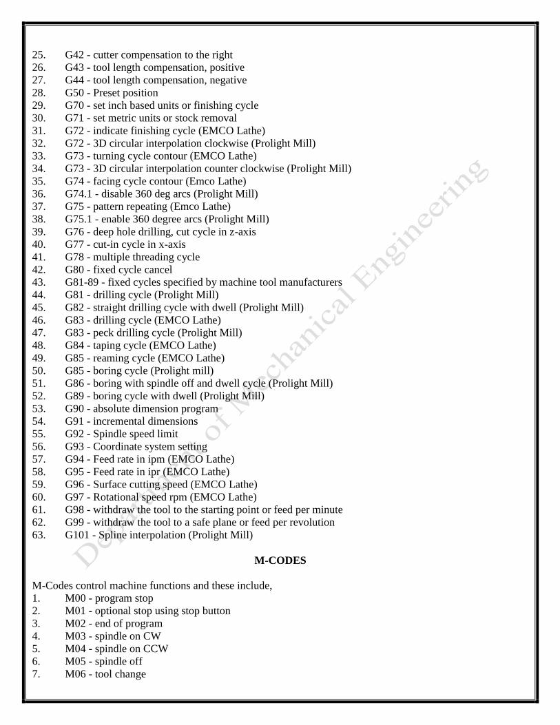
25. G42 - cutter compensation to the right
26. G43 - tool length compensation, positive
27. G44 - tool length compensation, negative
28. G50 - Preset position
29. G70 - set inch based units or finishing cycle
30. G71 - set metric units or stock removal
31. G72 - indicate finishing cycle (EMCO Lathe)
32. G72 - 3D circular interpolation clockwise (Prolight Mill)
33. G73 - turning cycle contour (EMCO Lathe)
34. G73 - 3D circular interpolation counter clockwise (Prolight Mill)
35. G74 - facing cycle contour (Emco Lathe)
36. G74.1 - disable 360 deg arcs (Prolight Mill)
37. G75 - pattern repeating (Emco Lathe)
38. G75.1 - enable 360 degree arcs (Prolight Mill)
39. G76 - deep hole drilling, cut cycle in z-axis
40. G77 - cut-in cycle in x-axis
41. G78 - multiple threading cycle
42. G80 - fixed cycle cancel
43. G81-89 - fixed cycles specified by machine tool manufacturers
44. G81 - drilling cycle (Prolight Mill)
45. G82 - straight drilling cycle with dwell (Prolight Mill)
46. G83 - drilling cycle (EMCO Lathe)
47. G83 - peck drilling cycle (Prolight Mill)
48. G84 - taping cycle (EMCO Lathe)
49. G85 - reaming cycle (EMCO Lathe)
50. G85 - boring cycle (Prolight mill)
51. G86 - boring with spindle off and dwell cycle (Prolight Mill)
52. G89 - boring cycle with dwell (Prolight Mill)
53. G90 - absolute dimension program
54. G91 - incremental dimensions
55. G92 - Spindle speed limit
56. G93 - Coordinate system setting
57. G94 - Feed rate in ipm (EMCO Lathe)
58. G95 - Feed rate in ipr (EMCO Lathe)
59. G96 - Surface cutting speed (EMCO Lathe)
60. G97 - Rotational speed rpm (EMCO Lathe)
61. G98 - withdraw the tool to the starting point or feed per minute
62. G99 - withdraw the tool to a safe plane or feed per revolution
63. G101 - Spline interpolation (Prolight Mill)
M-CODES
M-Codes control machine functions and these include,
1. M00 - program stop
2. M01 - optional stop using stop button
3. M02 - end of program
4. M03 - spindle on CW
5. M04 - spindle on CCW
6. M05 - spindle off
7. M06 - tool change
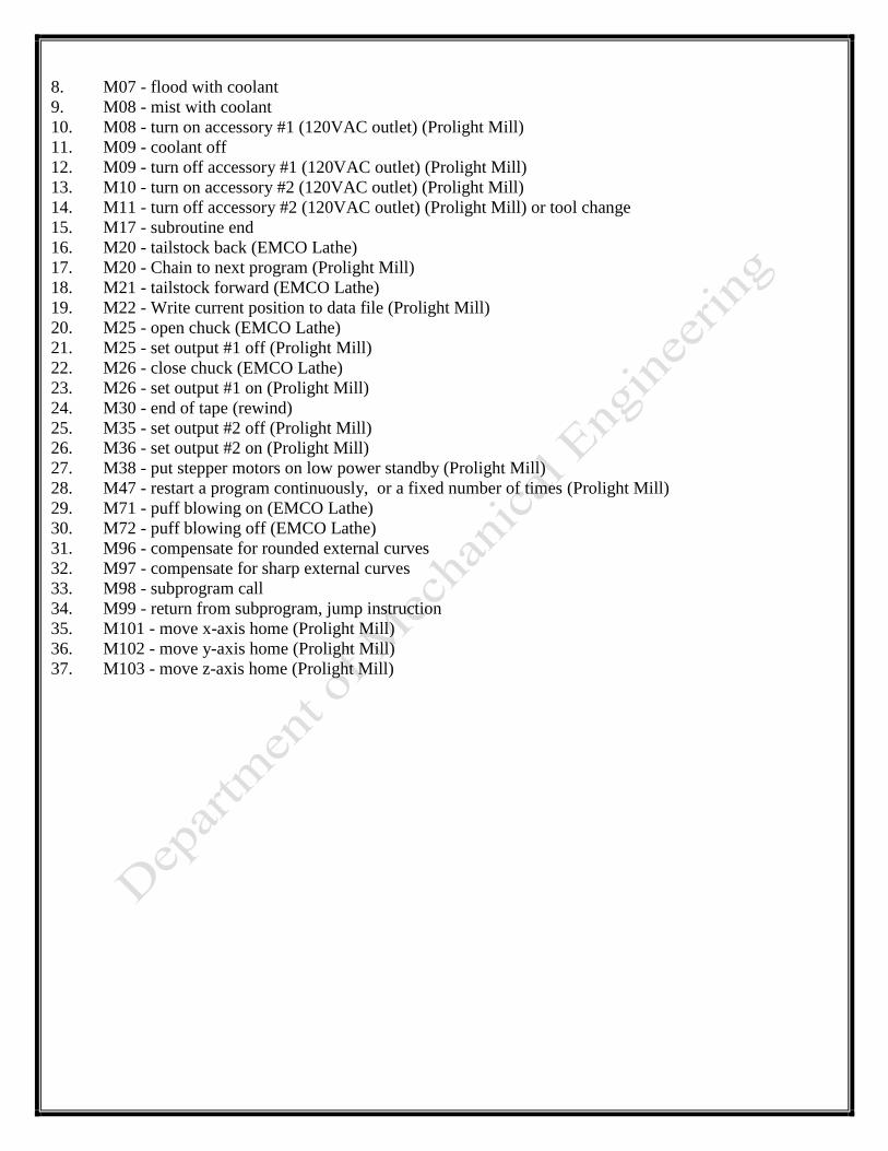
8. M07 - flood with coolant
9. M08 - mist with coolant
10. M08 - turn on accessory #1 (120VAC outlet) (Prolight Mill)
11. M09 - coolant off
12. M09 - turn off accessory #1 (120VAC outlet) (Prolight Mill)
13. M10 - turn on accessory #2 (120VAC outlet) (Prolight Mill)
14. M11 - turn off accessory #2 (120VAC outlet) (Prolight Mill) or tool change
15. M17 - subroutine end
16. M20 - tailstock back (EMCO Lathe)
17. M20 - Chain to next program (Prolight Mill)
18. M21 - tailstock forward (EMCO Lathe)
19. M22 - Write current position to data file (Prolight Mill)
20. M25 - open chuck (EMCO Lathe)
21. M25 - set output #1 off (Prolight Mill)
22. M26 - close chuck (EMCO Lathe)
23. M26 - set output #1 on (Prolight Mill)
24. M30 - end of tape (rewind)
25. M35 - set output #2 off (Prolight Mill)
26. M36 - set output #2 on (Prolight Mill)
27. M38 - put stepper motors on low power standby (Prolight Mill)
28. M47 - restart a program continuously, or a fixed number of times (Prolight Mill)
29. M71 - puff blowing on (EMCO Lathe)
30. M72 - puff blowing off (EMCO Lathe)
31. M96 - compensate for rounded external curves
32. M97 - compensate for sharp external curves
33. M98 - subprogram call
34. M99 - return from subprogram, jump instruction
35. M101 - move x-axis home (Prolight Mill)
36. M102 - move y-axis home (Prolight Mill)
37. M103 - move z-axis home (Prolight Mill)
Objective:- Introduction to CNC Part Programming.
Theory:-
CNC PROGRAMMING
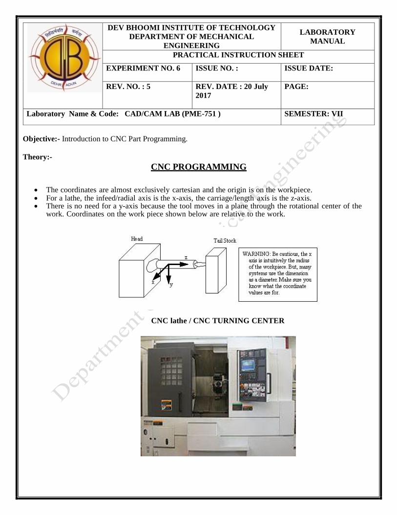
The coordinates are almost exclusively cartesian and the origin is on the workpiece. For a lathe, the infeed/radial axis is the x-axis, the carriage/length axis is the z-axis. There is no need for a y-axis because the tool moves in a plane through the rotational center of the
work. Coordinates on the work piece shown below are relative to the work.
CNC lathe / CNC TURNING CENTER
DEV BHOOMI INSTITUTE OF TECHNOLOGY
DEPARTMENT OF MECHANICAL
ENGINEERING
LABORATORY
MANUAL
PRACTICAL INSTRUCTION SHEET
EXPERIMENT NO. 6 ISSUE NO. : ISSUE DATE:
REV. NO. : 5 REV. DATE : 20 July
2017
PAGE:
Laboratory Name & Code: CAD/CAM LAB (PME-751 ) SEMESTER: VII
CNC lathes are rapidly replacing the older production lathes (multispindle, etc) due to their ease of setting
and operation. They are designed to use modern carbide tooling and fully utilize modern processes. The
part may be designed and the tool paths programmed by the CAD/CAM process, and the resulting file
uploaded to the machine, and once set and trailed the machine will continue to turn out parts under
the occasional supervision of an operator. The machine is controlled electronically via a computer menu
style interface; the program may be modified and displayed at the machine, along with a simulated view of
the process. The setter/operator needs a high level of skill to perform the process, however the knowledge base
is broader compared to the older production machines where intimate knowledge of each machine was
considered essential. These machines are often set and operated by the same person, where the operator will
supervise a small number of machines (cell).
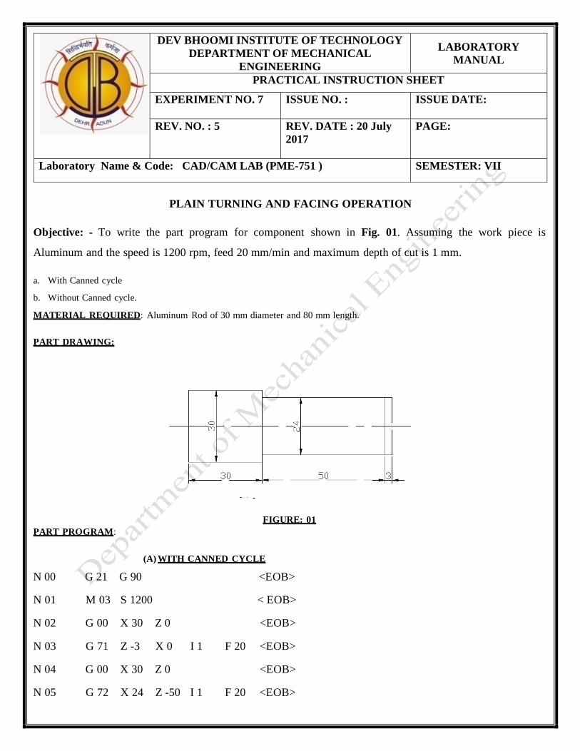
PLAIN TURNING AND FACING OPERATION
Objective: - To write the part program for component shown in Fig. 01. Assuming the work piece is
Aluminum and the speed is 1200 rpm, feed 20 mm/min and maximum depth of cut is 1 mm.
a. With Canned cycle
b. Without Canned cycle.
MATERIAL REQUIRED: Aluminum Rod of 30 mm diameter and 80 mm length.
PART DRAWING:
FIGURE: 01
PART PROGRAM:
(A) WITH CANNED CYCLE
N 00 G 21 G 90 <EOB>
N 01 M 03 S 1200 < EOB>
N 02 G 00 X 30 Z 0 <EOB>
N 03 G 71 Z -3 X 0 I 1 F 20 <EOB>
N 04 G 00 X 30 Z 0 <EOB>
N 05 G 72 X 24 Z -50 I 1 F 20 <EOB>
DEV BHOOMI INSTITUTE OF TECHNOLOGY
DEPARTMENT OF MECHANICAL
ENGINEERING
LABORATORY
MANUAL
PRACTICAL INSTRUCTION SHEET
EXPERIMENT NO. 7 ISSUE NO. : ISSUE DATE:
REV. NO. : 5 REV. DATE : 20 July
2017
PAGE:
Laboratory Name & Code: CAD/CAM LAB (PME-751 ) SEMESTER: VII
N 06 G 00 X 50 Z 10 <EOB>
N 07 M 30 <EOB>
(B) WITHOUT CANNED CYCLE N 00 G 21 G 90 <EOB> N 01 M 03 S 1200 <EOB>
N 02 G 00 X 30 Z 1 <EOB>
N 03 G 01 Z –1 F 20 <EOB>
N 04 G 01 X 00 F 20 <EOB>
N 05 G 00 X 30 Z 00 <EOB>
N 06 G 01 Z –2 F 20 <EOB>
N 07 G 01 X 00 F 20 <EOB>
N 08 G 00 X 30 Z 00 <EOB>
N 09 G 01 Z –3 F 20 <EOB>
N 10 G 01 X 00 F 20 <EOB>
N 11 G 00 X 30 Z 00 <EOB>
N 12 G 01 Z -50 F 20 <EOB>
N 13 G 01 X 28 F 20 <EOB>
N 14 G 00 X 30 Z 00 <EOB>
N 15 G 01 Z -50 F 20 <EOB>
N 16 G 01 X 26 F 20 <EOB>
N 17 G 00 X 30 Z 00 <EOB
N 18 G 01 Z -50 F 20 <EOB>
N 19 G 01 X 24 F 20 <EOB>
N 20 G 00 X 50 Z 10 <EOB
N 21 M 30 <EOB>
RESULT:
The program is written and simulated and stored in System No…and file name as…
Ø3
0
Ø2
4
Ø1
8
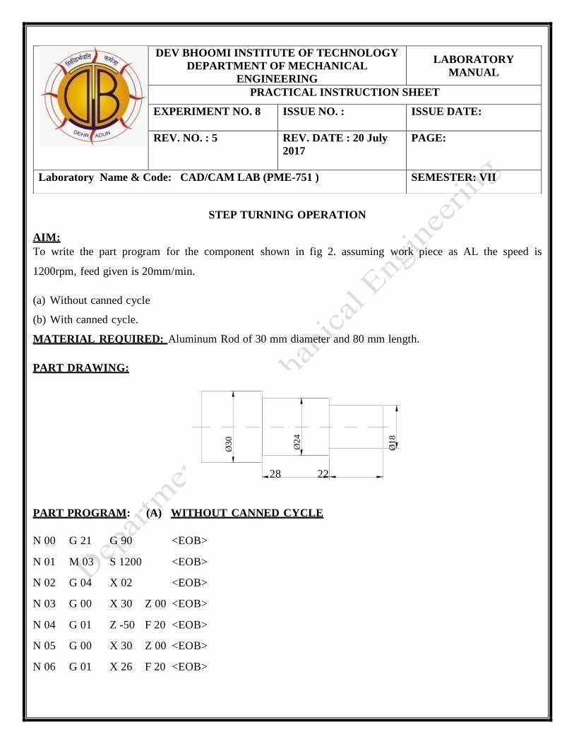
STEP TURNING OPERATION
AIM:
To write the part program for the component shown in fig 2. assuming work piece as AL the speed is
1200rpm, feed given is 20mm/min.
(a) Without canned cycle (b) With canned cycle. MATERIAL REQUIRED: Aluminum Rod of 30 mm diameter and 80 mm length. PART DRAWING:
28 22
PART PROGRAM: (A) WITHOUT CANNED CYCLE
N 00 G 21 G 90 <EOB>
N 01 M 03 S 1200 <EOB>
N 02 G 04 X 02 <EOB>
N 03 G 00 X 30 Z 00 <EOB>
N 04 G 01 Z -50 F 20 <EOB>
N 05 G 00 X 30 Z 00 <EOB>
N 06 G 01 X 26 F 20 <EOB>
DEV BHOOMI INSTITUTE OF TECHNOLOGY
DEPARTMENT OF MECHANICAL
ENGINEERING
LABORATORY
MANUAL
PRACTICAL INSTRUCTION SHEET
EXPERIMENT NO. 8 ISSUE NO. : ISSUE DATE:
REV. NO. : 5 REV. DATE : 20 July
2017
PAGE:
Laboratory Name & Code: CAD/CAM LAB (PME-751 ) SEMESTER: VII
N 07 G 01 Z -50 F 20 <EOB>
N 08 G 00 X 30 Z 00 <EOB>
N 09 G 01 X 24 F 20 <EOB>
N 10 G 01 Z -50 F 20 <EOB>
N 11 G 00 X 30 Z 00 <EOB>
N 12 G 01 X 22 F 20 <EOB>
N 13 G 01 Z -22 F 20 <EOB>
N 14 G 00 X 30 Z 00 <EOB>
N 15 G 01 X 20 F 20 <EOB>
N 16 G 01 Z -22 F 20 <EOB>
N 17 G 00 X 30 Z 00 <EOB>
N 19 G 00 X 50 Z 10 <EOB>
N 20 M 30 <EOB>
(B) WITH CANNED CYCLE:
N 00 G 21 G 90 <EOB>
N 01
M 03
S 1200
<EOB>
N 02
G 04
X 03
<EOB>
N O3
G 00
X 30
Z 00
<EOB>
N 04
G 72
X 24
Z -50
I 01
F 20
<EOB>
N 05
G 72
X 20
Z -22
I 01
F20
<EOB>
N 06
G 00
X 30
Z 00
<EOB>
N 08
X 50
Z 10
<EOB>
N 09
M 30
<EOB>
RESULT:
The program is written and simulated and stored in System No…and file name as…
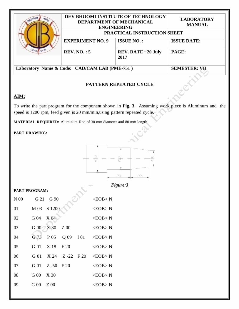
PATTERN REPEATED CYCLE
AIM:
To write the part program for the component shown in Fig. 3. Assuming work piece is Aluminum and the
speed is 1200 rpm, feed given is 20 mm/min,using pattern repeated cycle.
MATERIAL REQUIRED: Aluminum Rod of 30 mm diameter and 80 mm length.
PART DRAWING:
Figure:3 PART PROGRAM:
N 00 G 21 G 90 <EOB> N
01 M 03 S 1200 <EOB> N
02 G 04 X 04 <EOB> N
03 G 00 X 30 Z 00 <EOB> N
04 G 73 P 05 Q 09 I 01 <EOB> N
05 G 01 X 18 F 20 <EOB> N
06 G 01 X 24 Z -22 F 20 <EOB> N
07 G 01 Z -50 F 20 <EOB> N
08 G 00 X 30 <EOB> N
09 G 00 Z 00 <EOB> N
DEV BHOOMI INSTITUTE OF TECHNOLOGY
DEPARTMENT OF MECHANICAL
ENGINEERING
LABORATORY
MANUAL
PRACTICAL INSTRUCTION SHEET
EXPERIMENT NO. 9 ISSUE NO. : ISSUE DATE:
REV. NO. : 5 REV. DATE : 20 July
2017
PAGE:
Laboratory Name & Code: CAD/CAM LAB (PME-751 ) SEMESTER: VII
10 G 00 X 50 Z 05 <EOB> N
11 M 30 <EOB>
RESULT: The program is written and simulated and stored in System No…and file name as…
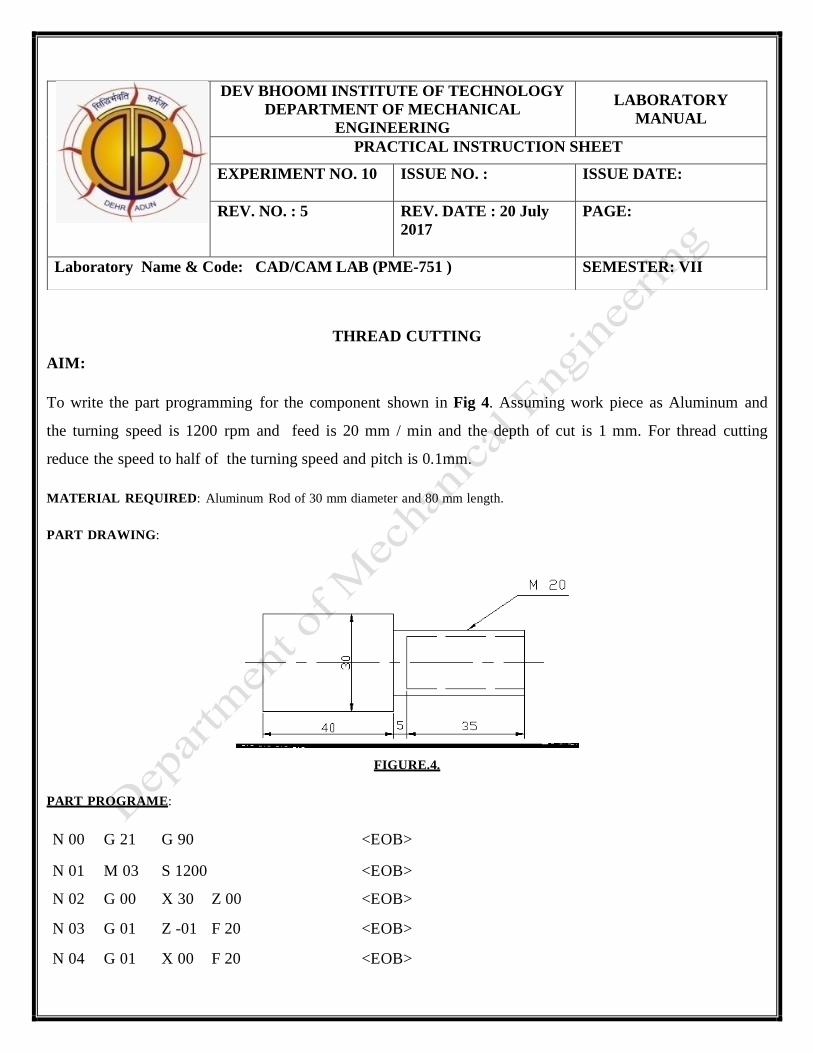
THREAD CUTTING
AIM:
To write the part programming for the component shown in Fig 4. Assuming work piece as Aluminum and
the turning speed is 1200 rpm and feed is 20 mm / min and the depth of cut is 1 mm. For thread cutting
reduce the speed to half of the turning speed and pitch is 0.1mm.
MATERIAL REQUIRED: Aluminum Rod of 30 mm diameter and 80 mm length.
PART DRAWING:
FIGURE.4.
PART PROGRAME:
N 00 N 01
G 21 M 03
G 90 S 1200
<EOB> <EOB>
N 02 G 00 X 30 Z 00 <EOB>
N 03 G 01 Z -01 F 20 <EOB>
N 04 G 01 X 00 F 20 <EOB>
DEV BHOOMI INSTITUTE OF TECHNOLOGY
DEPARTMENT OF MECHANICAL
ENGINEERING
LABORATORY
MANUAL
PRACTICAL INSTRUCTION SHEET
EXPERIMENT NO. 10 ISSUE NO. : ISSUE DATE:
REV. NO. : 5 REV. DATE : 20 July
2017
PAGE:
Laboratory Name & Code: CAD/CAM LAB (PME-751 ) SEMESTER: VII
N 05 G 00 X 30 Z 00 <EOB>
N 06 G 72 X 20 Z -40 I 01 F 20 <EOB>
N 07 G 00 X 30 Z 05 <EOB>
N 08 M 05 <EOB>
N 09 T 0202 <EOB>
N 09 M 03 S 600 <EOB>
N 10 G 04 X 02 <EOB>
N 11 G 01 X 20 Z 00 F 20 <EOB>
N 12 G 93 (or) 92 X 20 Z -35 I 0.1 F 01 <EOB>
N 13 G 00 X 30 Z 01 <EOB>
N 14 RESULT:
M 30 <EOB>
The program is written and simulated and stored in System No…and file name as…
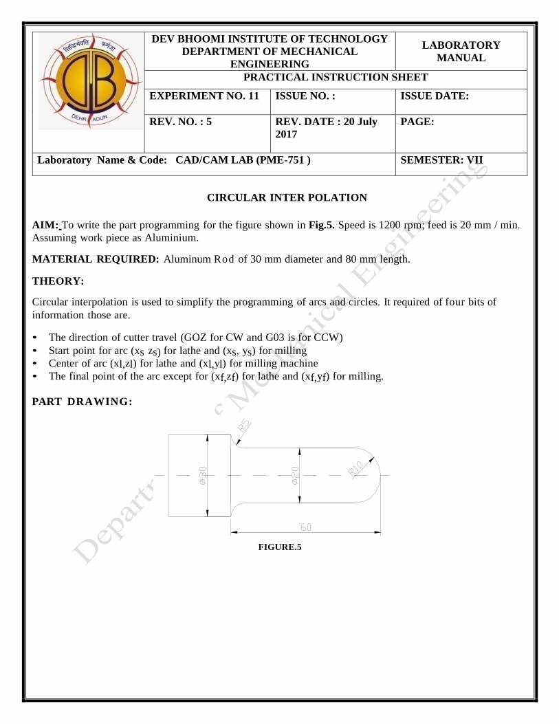
CIRCULAR INTER POLATION
AIM: To write the part programming for the figure shown in Fig.5. Speed is 1200 rpm; feed is 20 mm / min.
Assuming work piece as Aluminium.
MATERIAL REQUIRED: Aluminum Rod of 30 mm diameter and 80 mm length.
THEORY: Circular interpolation is used to simplify the programming of arcs and circles. It required of four bits of
information those are. • The direction of cutter travel (GOZ for CW and G03 is for CCW)
• Start point for arc (xs zs) for lathe and (xs, ys) for milling
• Center of arc (xl,zl) for lathe and (xl,yl) for milling machine
• The final point of the arc except for (xf,zf) for lathe and (xf,yf) for milling.
PART DRAWING:
FIGURE.5
DEV BHOOMI INSTITUTE OF TECHNOLOGY
DEPARTMENT OF MECHANICAL
ENGINEERING
LABORATORY
MANUAL
PRACTICAL INSTRUCTION SHEET
EXPERIMENT NO. 11 ISSUE NO. : ISSUE DATE:
REV. NO. : 5 REV. DATE : 20 July
2017
PAGE:
Laboratory Name & Code: CAD/CAM LAB (PME-751 ) SEMESTER: VII
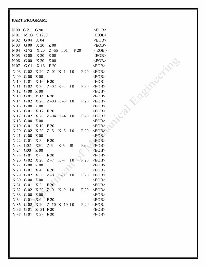
PART PROGRAM:
N 00 G 21 G 90 <EOB>
N 01 M 03 S 1200 <EOB>
N 02 G 04 X 04 <EOB>
N 03 G 00 X 30 Z 00 <EOB>
N 04 G 72 X 20 Z -55 I 01 F 20 <EOB>
N 05 G 00 X 30 Z 00 <EOB>
N 06 G 00 X 20 Z 00 <EOB>
N 07 G 01 X 18 F 20 <EOB>
N 08 G 02 X 20 Z -01 K -1 I 0 F 20 <EOB>
N 09 G 00 Z 00 <EOB>
N 10 G 01 X 16 F 20 <EOB>
N 11 G 02 X 20 Z -02 K -2 I 0 F 20 <EOB>
N 12 G 00 Z 00 <EOB>
N 13 G 01 X 14 F 20 <EOB>
N 14 G 02 X 20 Z -03 K -3 I 0 F 20 <EOB>
N 15 G 00 Z 00 <EOB>
N 16 G 01 X 12 F 20 <EOB>
N 17 G 02 X 20 Z -04 K -4 I 0 F 20 <EOB>
N 18 G 00 Z 00 <EOB>
N 19 G 01 X 10 F 20 <EOB>
N 20 G 02 X 20 Z -5 K -5 I 0 F 20 <EOB>
N 21 G 00 Z 00 <EOB>
N 22 G 01 X 8 F 20 <EOB>
N 23 G02 X20 Z-6 K-6 I0 F20 <EOB>
N 24 G00 Z 00 <EOB>
N 25 G 01 X 6 F 20 <EOB>
N 26 G 02 X 20 Z -7 K -7 I 0 F 20 <EOB>
N 27 G 00 Z 00 <EOB>
N 28 G 01 X 4 F 20 <EOB>
N 29 G 02 X 30 Z -8 K-8 I 0 F 20 <EOB>
N 30 G 00 Z 00 <EOB>
N 31 G 01 X 2 F 20 <EOB>
N 32 G 02 X 20 Z -9 K -9 I 0 F 20 <EOB>
N 33 G 00 Z 00 <EOB>
N 34 G 01 X 0 F 20 <EOB>
N 35 G 02 X 20 Z -10 K -10 I 0 F 20 <EOB>
N 36 G 01 Z -31 F 20 <EOB>
N 37 G 01 X 28 F 20 <EOB>
3030
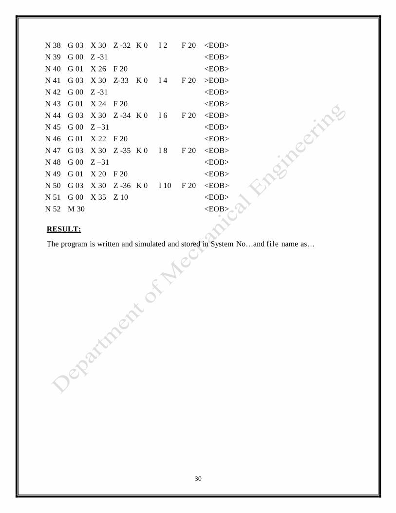
N 38 G 03 X 30 Z -32 K 0 I 2 F 20 <EOB>
N 39 G 00 Z -31 <EOB>
N 40 G 01 X 26 F 20 <EOB>
N 41 G 03 X 30 Z-33 K 0 I 4 F 20 >EOB>
N 42 G 00 Z -31 <EOB>
N 43 G 01 X 24 F 20 <EOB>
N 44 G 03 X 30 Z -34 K 0 I 6 F 20 <EOB>
N 45 G 00 Z –31 <EOB>
N 46 G 01 X 22 F 20 <EOB>
N 47 G 03 X 30 Z -35 K 0 I 8 F 20 <EOB>
N 48 G 00 Z –31 <EOB>
N 49 G 01 X 20 F 20 <EOB>
N 50 G 03 X 30 Z -36 K 0 I 10 F 20 <EOB>
N 51 G 00 X 35 Z 10 <EOB>
N 52 M 30 <EOB>
RESULT:
The program is written and simulated and stored in System No…and file name as…