BG to consider modifications to C-TRAN bus route - The Reflector
Upload
independentCategory
view
4download
0
Radio Science, Volume 27, Number 6, Pages 851-865, November-December 1992
Laboratory chamber experiments exploring the potential use of artificially ionized layers of gas as a Bragg reflector for over-the-horizon signals
S. P. Kuo 1, Y. S. Zhang 2, M. C. Lee 3, Paul Kossey 4, and Robert J. Barker 5
(Received September 17, 1991; revised March 10, 1992; accepted March 18, 1992.)
A set of parallel plasma layers is generated by two intersecting microwave pulses in a chamber containing dry air at a pressure comparable to the upper atmosphere. The dependence of breakdown conditions on the pressure and pulse length is examined. The results are shown to be consistent with the appearance of tail erosion of microwave pulse caused by air breakdown. Bragg scattering experiments, using the plasma layers as a Bragg reflector are then performed. Both time domain and frequency domain measurements of wave scattering are conducted. The experimental results are found to agree very well with the theory. Moreover, the time domain measurement of wave scattering provides an unambiguous way for determining the temporal evolution of electron density during the first 100 gs period. A Langmuir double probe is then used to determine the decay rate of electron density during a later time interval (1 to 1.1 ms). The propagation of high-power microwave pulses through the air is also studied experimentally. The mechanisms responsible for two different degrees of tail erosion have been identified. The optimum amplitude of an 1.1 gs pulse for maximum energy transfer through the air has been determined.
1. INTRODUCTION
It is a well-known fact that the conventional line of sight radars are limited by their range of detection. This lilnitation is removed, however, by over-the-horizon (OTH) radars [Headrick and Skolnik, 1974]. OTH radars use ionospheric plasma to reflect the obliquely incident radar pulses back to the ground at a distance away from the radar site. The range of detection is, in general, from 1000 to 4000 km which is far outside the range of the line of sight (about 400 km). Since the radar pulses are reflected from the ionosphere, moving targets can be detected, in principle, at any altitude. The extended range of detection of OTH radars can be used to monitor ships and oceans from a land base. Moreover, OTH radar can also be used
1 Weber Research Institute, Polytechnic University, Farmingdale, New York.
2 University of Wisconsin, Madison, Wisconsin. 3 Plasma Fusion Center, Massachusetts Institute of
Technology, Cambridge, Massachusetts. 4 Air Force Phillips Laboratory, Hanscom Air Force Base,
Massachusetts.
5 Air Force Office of Scientific Research, Bolling Air Force Base, Washington, D.C.
Copyright 1992 by the American Geophysical Union. Paper number 92RS00965. 0048-6604/92/92RS-00965508.00
for air traffic control in areas where the simple line of sight radars cannot reach. The above mentioned attractive
applications of the OTH radar in turn generate a great deal of concern about how to improve the capability of the OTH radar.
It is believed that the performance of the OTH radar has to be extended in three major areas. The first one regards the range of the radar. In order to avoid cluttering in the radar return, a large clearance region which is proportional to the height of the ionospheric reflector is required. Thus OTH radar is, in general, blind in a zone from 400 to 1000 Km. In principle, this region can still be covered by operating the radar with the _surface wave. The surface wave is a wave diffracted around the surface of the Earth or guided by the ground-air interface. Unfortunately, this wave attenuates rapidly while propagating away from the radar [MIT Radar School Staff, 1952]. Therefore, it requires the radar to operate with a much higher power level in order to use the surface wave for target detection at a distance over the horizon. It is thus realized that this is a
very ineffective approach. The second one concerns the resolution of the radar which depends strongly on the radar frequency. The third one involves the stability of the ionosphere, which varies from day to night. This variation will affect the performance and reliability of the radar.
These concerns may be resolved if an artificial ionospheric mirror (AIM) can be produced at a much lower altitude and is able to reflect radar pulses of much higher frequency. Its stability and location are controllable. Two schemes have been proposed. Both schemes use a high power RF breakdown approach for plasma generation [Gurevich, 1979, 1980; Borisov and Gurevich, 1980]. The RF pulses used for air breakdown and plasma maintenance will be transmitted by
851
852 KUO ET AL.: OVER-THE-HORIZON RADAR USING BRAGG REFLECTION
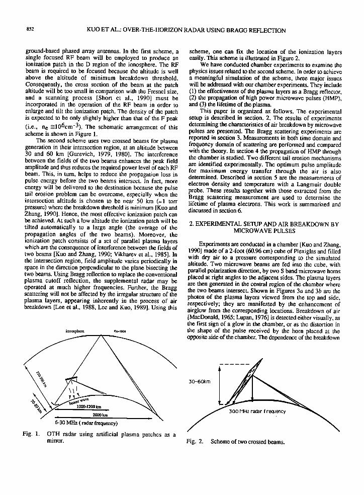
ground-based phased array antennas. In the first scheme, a single focused RF beam will be employed to produce an ionization patch in the D region of the ionosphere. The RF beam is required to be focused because the altitude is well above the altitude of minimum breakdown threshold.
Consequently, the cross section of the beam at the patch altitude will be too small in comparison with the Fresnel size, and a scanning process [Short et al., 1990] must be incorporated in the operation of the RF beam in order to enlarge and tilt the ionization patch. The density of the patch is expected to be only slightly higher than that of the F peak (i.e., n e _--106cm-3). The schematic arrangement of this scheme is shown in Figure 1.
The second scheme uses two crossed beams for plasma generation in their intersection region, at an altitude between 30 and 60 km [Gurevich, 1979, 1980]. The interference between the fields of the two beams enhances the peak field amplitude and thus reduces the required power level of each RF beam. This, in turn, helps to reduce the propagation loss in pulse energy before the two beams intersect. In fact, more energy will be delivered to the destination because the pulse tail erosion problem can be overcome, especially when the intersection altitude is chosen to be near 50 km (--1 tort pressure) where the breakdown threshold is minimum [Kuo and Zhang, 1990]. Hence, the most effective ionization patch can be achieved. At such a low altitude the ionization patch will be tilted automatically to a large angle (the average of the propagation angles of the two beams). Moreover, the ionization patch consists of a set of parallel plasma layers which are the consequence of interference between the fields of two beams [Kuo and Zhang, 1990; Vikharev et al., 1985]. In the intersection region, field amplitude varies periodically in space in the direction perpendicular to the plane bisecting the two beams. Using Bragg reflection to replace the conventional plasma cutoff reflection, the supplemental radar may be operated at much higher frequencies. Further, the Bragg scattering will not be affected by the irregular structure of the plasma layers, appearing inherently in the process of air breakdown [Lee et al., 1988, Lee and Kuo, 1989]. Using this
ionosphere n,.•oE6
6-30 MHz ( radar frequency)
Fig. 1. OTH radar using artificial plasma patches as a mirror.
scheme, one can fix the location of the ionization layers easily. This scheme is illustrated in Figure 2.
We have conducted chamber experiments to examine the physics issues related to the second scheme. In order to achieve a meaningful simulation of the scheme, three major issues will be addressed with our chamber experiments. They include (1) the effectiveness of the plasma layers as a Bragg reflector, (2) the propagation of high power microwave pulses (HMP), and (3) the lifetime of the plasma.
This paper is organized as follows. The experimental setup is described in section. 2. The results of experiments determining the characteristics of air breakdown by microwave pulses are presented. The Bragg scattering experiments are reported in section 3. Measurements in both time domain and frequency domain of scattering are performed and compared with the theory. In section 4 the propagation of HMP through the chamber is studied. Two different tail erosion mechanisms are identified experimentally. The optimum pulse amplitude for maximum energy transfer through the air is also determined. Described in section 5 are the measurements of electron density and temperature with a Langmuir double probe. These results together with those extracted from the Bragg scattering measurement are used to determine the lifetime of plasma electrons. This work is summarized and discussed in section 6.
2. EXPERIMENTAL SETUP AND AIR BREAKDOWN BY MICROWAVE PULSES
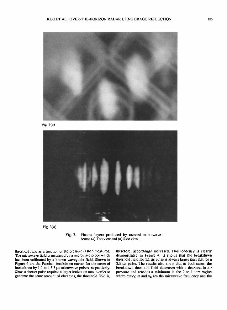
Experiments are conducted in a chamber [Kuo and Zhang, 1990] made of a 2-foot (60.96 cm) cube of Plexiglas and filled with dry air to a pressure corresponding to the simulated altitude. Two microwave beams are fed into the cube, with parallel polarization direction, by two S band microwave horns placed at right angles to the adjacent sides. The plasma layers are then generated in the central region of the chamber where the two beams intersect. Shown in Figures 3a and 3b are the photos of the plasma layers viewed from the top and side, respectively; they are manifested by the enhancement of airglow from the corresponding locations. Breakdown of air [MacDonald, 1965; Lupan, 1976] is detected either visually, as the first sign of a glow in the chamber, or as the distortion in the shape of the pulse received by the horn placed at the opposite side of the chamber. The dependence of the breakdown
30-60kin
300 MHz radar frequency
Fig. 2. Scheme of two crossed beams.
KUO ET AL.: OVER-THE-HORIZON RADAR USING BRAGG REFLECTION 853
Fig. 3(a)
Fig. 3(b)
Fig. 3. Plasma layers produced by crossed microwave beams.(a) Top view and (b) Side view.
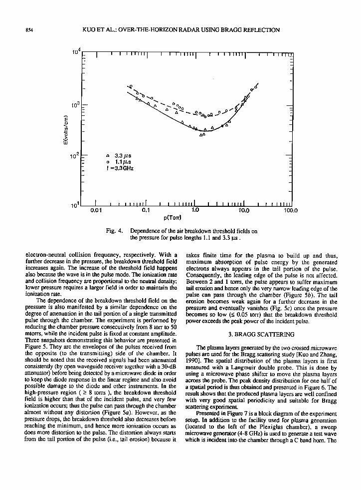
threshold field as a function of the pressure is then measured. The microwave field is measured by a microwave probe which has been calibrated by a known waveguide field. Shown in Figure 4 are the Paschen breakdown curves for the cases of breakdown by 1.1 and 3.3 gs microwave pulses, respectively. Since a shorter pulse requires a larger ionization rate in order to generate the same amount of electrons, the threshold field is,
therefore, accordingly increased. This tendency is clearly demonstrated in Figure 4. It shows that the breakdown threshold field for 1.1 gs pulse is always larger than that for a 3.3 gs pulse. The results also show that in both cases, the breakdown threshold field decreases with a decrease in air
pressure and reaches a minimum in the 2 to I torr region where to=-Ve; to and Ve are the microwave frequency and the
854 KUO ET AL.: OVER-THE-HORIZON RADAR USING BRAGG REFLECTION
104
103
2
lO 1
- I , I [ ['][[I ] ] [ [[[t,[ [ , ,
- a"" • Oo ., o,...P 5x
I 0.01
a 3.3½s o 1.1p, s f =3.3GHz
, , I , ,,,[[ [ ! I ] [[[[[ [ o.1 1.o
p(Torr) 10.o
[ i I Ill[
I I I!lll
100.0
Fig. 4. Dependence of the air breakdown threshold fields on the pressure for pulse lengths 1.1 and 3.3 ItS.
electron-neutral collision frequency, respectively. With a further decrease in the pressure, the breakdown threshold field increases again. The increase of the threshold field happens also because the wave is in the pulse mode. The ionization rate and collision frequency are proportional to the neutral density; lower pressure requires a larger field in order to maintain the ionization rate.
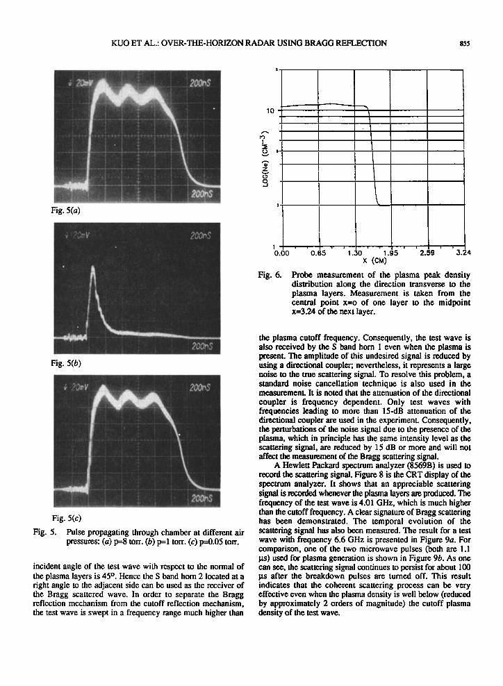
The dependence of the breakdown threshold field on the pressure is also manifested by a similar dependence on the degree of attenuation in the tail portion of a single transmitted pulse through the chamber. The experiment is performed by reducing the chamber pressure consecutively from 8 torr to 50 mtorrs, while the incident pulse is fixed at constant amplitude. Three snapshots demonstrating this behavior are presented in Figure 5. They are the envelopes of the pulses received t¾om the opposite (to the transmitting) side of the chamber. It should be noted that the received signals had been attenuated consistently (by open waveguide receiver together with a 30-dB attenuator) before being detected by a microwave diode in order to keep the diode response in the linear regime and also avoid possible damage to the diode and other instruments. In the high-pressure region ( > 8 torrs ), the breakdown threshold field is higher than that of the incident pulse, and very few ionization occurs; thus the pulse can pass through the chamber almost without any distortion (Figure 5a). However, as the pressure drops, the breakdown threshold also decreases before reaching the minimum, and hence more ionization occurs as does more distortion to the pulse. The distortion always starts from the tail portion of the pulse (i.e., tail erosion) because it
takes finite time for the plasma to build up and thus, maximum absorption of pulse energy by the generated electrons always appears in the tail portion of the pulse. Consequently, the leading edge of the pulse is not affected. Between 2 and 1 torts, the pulse appears to suffer maximum tail erosion and hence only the very narrow leading edge of the pulse can pass through the chamber (Figure 5b). The tail erosion becomes weak again for a further decrease in the pressure and eventually vanishes (Fig. 5c) once the pressure becomes so low (< 0.05 tort) that the breakdown threshold power exceeds the peak power of the incident pulse.
3. BRAGG SCATI'ERING
The plasma layers generated by the two crossed microwave pulses are used for the Bragg scattering study [Kuo and Zhang, 1990]. The spatial distribution of the plasma layers is first measured with a Langmuir double probe. This is done by using a microwave phase shifter to move the plasma layers across the probe. The peak density distribution for one half of a spatial period is thus obtained and presented in Figure 6. The result shows that the produced plasma layers are well confined with very good spatial periodicity and suitable for Bragg scattering experiment.
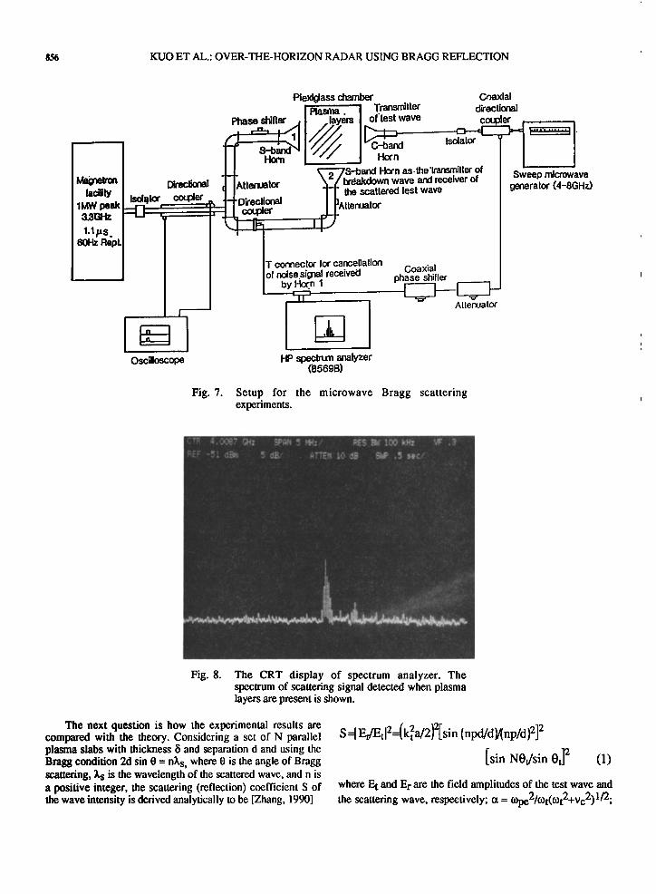
Presented in Figure 7 is a block diagram of the experiment setup. In addition to the facility used for plasma generation (located to the left of the Plexiglas chamber), a sweep microwave generator (4-8 GHz) is used to generate a test wave which is incident into the chamber through a C band horn. The
KUO ET AL.: OVER-THE-HORIZON RADAR USING BRAGG REFLECTION 855
ß ß .
Fig. 5(a)
..: ..
...
;
::.
ß
..
200r,$
Fig. 5(b)
v
....
' •-•'•;'"- S ...
Fig. 5(c)
Fig. 5. Pulse propagating through chamber at different air pressures: (a) p=8 torr. (b) p=l torr. (c) p=0.05 torr.
incident angle of the test wave with respect to the normal of the plasma layers is 45 ø. Hence the S band horn 2 located at a right angle to the adjacent side can be used as the receiver of the Bragg scattered wave. In order to separate the Bragg reflection mechanism from the cutoff reflection mechanism, the test wave is swept in a frequency range much higher than
lO
1 0.00 0.65 2.59 3.24
i
1.30 1.95
x
Fig. 6. Probe measurement of the plasma peak density distribution along the direction transverse to the plasma layers. Measurement is taken from the central point x=o of one layer to the midpoint x=3.24 of the next layer.
the plasma cutoff frequency. Consequently, the test wave is also received by the S band horn 1 even when the plasma is present. The amplitude of this undesired signal is reduced by using a directional coupler; nevertheless, it represents a large noise to the true scattering signal. To resolve this problem, a standard noise cancellation technique is also used in the measurement. It is noted that the attenuation of the directional
coupler is frequency dependent. Only test waves with frequencies leading to more than 15-dB attenuation of the directional coupler are used in the experiment. Consequently, the perturbations of the noise signal due to the presence of the plasma, which in principle has the same intensity level as the scattering signal, are reduced by 15 dB or more and will not affect the measurement of the Bragg scattering signal.
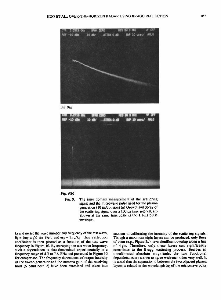
A Hewleu Packard spectrum analyzer (8569B) is used to record the scattering signal. Figure 8 is the CRT display of the spectrum analyzer. It shows that an appreciable scattering signal is recorded whenever the plasma layers are produced. The frequency of the test wave is 4.01 GHz, which is much higher than the cutoff frequency. A clear signature of Bragg scattering has been demonstrated. The temporal evolution of the scattering signal has also been measured. The result for a test wave with frequency 6.6 GHz is presented in Figure 9a. For comparison, one of the two microwave pulses (both are 1.1 !.rs) used for plasma generation is shown in Figure 9b. As one can see, the scattering signal continues to persist for about 100 gs after the breakdown pulses are turned off. This result indicates that the coherent scattering process can be very effective even when the plasma density is well below (reduced by approximately 2 orders of magnitude) the cutoff plasma density of the test wave.
856 KUO ET AL.: OVER-THE-HORIZON RADAR USING BRAGG REFLECTION
MagiIron lacilily
1MW peak 3.3GHz
1.1p.s_ 60Hz RepL
ß P!exi[Jass ch•_mber Coaxial Pl•s•--i Trans. tier d•ectional
Phase shifter--" !ay•s I of'test wave coupler . -
• Hot'n // J Horn .LL - •--'•'•S•• Horn as.lhe'l/•iller ot e......• .. ,,., I I ̂ tte13uator \ / Dfdal•oowrl wave ar• [ec;• u ........ Dieaoa I*'
Isolator,• coupler ,L ]'-t'Directional I •]a,,,.mator
T ½onae½lor lot ½ancellalion .. . , Iof noise sig3al receivei::l I by I-•.n I •' ..............
Aller'uator
Oscilloscope HP spec• analyzer (8569B)
Fig. 7. Setup for the microwave Bragg scattering experiments.
Fig. 8. The CRT display of spectrum analyzer. The spectrum of scattering signal detected when plasma layers are present is shown.
The next question is how the experimental results are compared with the theory. Considering a set of N parallel plasma slabs with thickness 8 and separation d and using the Bragg condition 2d sin 0 = n•s, where 0 is the angle of Bragg scattering, •,s is the wavelength of the scattered wave, and n is a positive integer, the scattering (reflection) coefficient S of the wave intensity is derived analytically to be [Zhang, 1990]
S q /Etl==(kfa/2)2[sin (npd/d }/(np/d [sin NOt/sin Ot] 2 (1)
where E t and Er are the field amplitudes of the test wave and
the scattering wave, respectively; (x = COpe2/Cot(cot2+Vc2)l/2;
KUO ET AL.: OVER-THE-HORIZON RADAR USING BRAGG REFLECTION 857
. .
..
.
Fig. 9(a)
Fig. 9(b)
Fig. 9. The time domain measurement of the scattering signal and the microwave pulse used for the plasma generation (10 gs/division) (a) Growth and decay of the scattering signal over a 100 gs time interval. (b) Shown at the same time scale is the 1.1-gs pulse envelope.
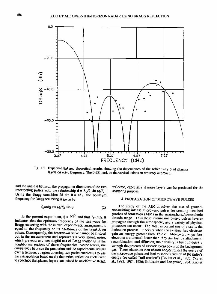
kt and tot are the wave number and frequency of the test wave, 0t = (tot-tos)d sin 0/c , and tos = 2nC/Xs. This reflection coefficient is then plotted as a function of the test wave frequency in Figure 10. By sweeping the test wave frequency, such a dependence is also determined experimentally in a frequency range of 4.3 to 7.8 GHz and presented in Figure 10 for comparison. The frequency dependence of output intensity of the sweep generator and the antenna gain of the receiving horn (S band horn 2) have been examined and taken into
account in cal!brating the intensity of the scattering signals. Though a maximum eight layers can be produced, only three of them (e.g., Figure 3a) have significant overlap along a line of sight. Therefore, only these layers can significantly contribute to the Bragg scattering process. Besides an uncalibrated absolute magnitude, the two functional dependencies are shown to agree with each other very well. It is noted that the separation d between the two adjacent plasma layers is related to the wavelength X0 of the microwave pulse
858 KUO ET AL.: OVER-THE-HORIZON RADAR USING BRAGG REFLECTION
0.0
-20.0
CfJ -40.0
0
-60.0 ,
I I I I I i I i i I I , 'I i i I i i i I i I I i i i I
4..27 5.27 6.27
FFr_QUr_qC¾ (Hz)
I -80.0 • • i • I J • 3.27 7.27
Fig. 10. Experimental and theoretical results showing the dependence of the reflectivity S of plasma layers on wave frequency. The 0-dB mark on the vertical axis is an arbitrary reference.
and the angle $ between the propagation directions of the two intersecting pulses with the relationship d = 3,0/2 sin ($/2). Using the Bragg condition 2d sin 0 = n•k s, the optimum frequency for Bragg scattering is given by
fs=nfo sin (•/2)/sin O (2)
In the present experiment, $ = 90 ø, and thus fs=nf0 . It indicates that the optimum frequency of the test wave for Bragg scattering with the current experimental arrangement is equal to the frequency or its harmonics of the breakdown pulses. Consequently, the breakdown wave cannot be filtered out in the measurement and represents a very strong noise, which prevents any meaningful test of Bragg scattering in the neighboring regions of those frequencies. Nevertheless, the consistency between the prediction and the experimental results over a frequency region covering two peaks enables us to use the extrapolation based on the theoretical reflection coefficient to conclude that plasma layers can indeed be an effective Bragg
reflector, especially if more layers can be produced for the scattering purpose.
4. PROPAGATION OF MICROWAVE PULSES
The study of the AIM involves the use of ground- transmitting intense microwave pulses for creating localized patches of ionization (AIM) in the stratospheric/m½sospheric altitude range. Thus these intense microwave pulses have to propagate through the atmosphere, and a variety of physical processes can occur. The most important one of these is the ionization process. It occurs when the existing free electrons gain an energy greater then 12 eV. Moreover, when free electrons are created faster than they are lost by attachment, recombination, and diffusion, their density is built up quickly through the process of cascade breakdown of the background gas. These electrons then absorb and/or reflect the energy of the microwave pulses and lead to serious erosion of the pulse's energy (so-called "tail erosion") [Bollen et al., 1983; Yee et al., 1983, 1984, 1986; Goldstein and Longmire, 1984; Kuo et
KUO ET AL.: OVER-THE-HORIZON RADAR USING BRAGG REFLECTION 859
al.,. 1990a]. Hence the available pulse's energy delivered to the destination is reduced considerably. Consequently, the ionization at the destined altitude may become inadequate for the applications of AIM. Therefore, a thorough study of microwave pulse propagation through the atmosphere is needed.
The propagation of intense electromagnetic pulses through the atmosphere has been investigated theoretically and experimentally for many years [Bollen et al., 1983; Yee et al., 1983, 1986; Woo and DeGroot, 1984; Mulbrandon et al., 1989; Kuo et al., 1990a,b, Kuo and Zhang, 1991]. Basically, there are two fundamental issues to be addressed. One concerns
the optimum pulse characteristics for maximum energy transfer through the atmosphere by the pulse. The second concern is how to prevent the ionizations in the trail following the pulse from exceeding a critical level. Apparently, these two concerns are interrelated and must be considered together. In order to minimize the energy loss in the pulse before reaching the destination, one has to prevent the occurrence of excessive ionization at any location along the propagation path. Otherwise, the overdense plasma can cut off the propagation of the remaining part of the pulse and can cause the tail of the pulse to be eroded via the reflection process. This process is believed to be far more severe in causing tail erosion than the conventional process attributed to ionization and heating.
The purpose of our experimental effort is to understand the fundamental behavior of tail erosion and to address the
question of how energy loss depends on basic parameters such as pulse intensity and background pressure. The experiments are conducted in the same chamber as that for a Bragg scattering study. The experimental data can then be incorporated for the development of an useful theoretical model for a self-consistent description of pulse propagation in an air breakdown situation [Kuo and Zhang, 1991].
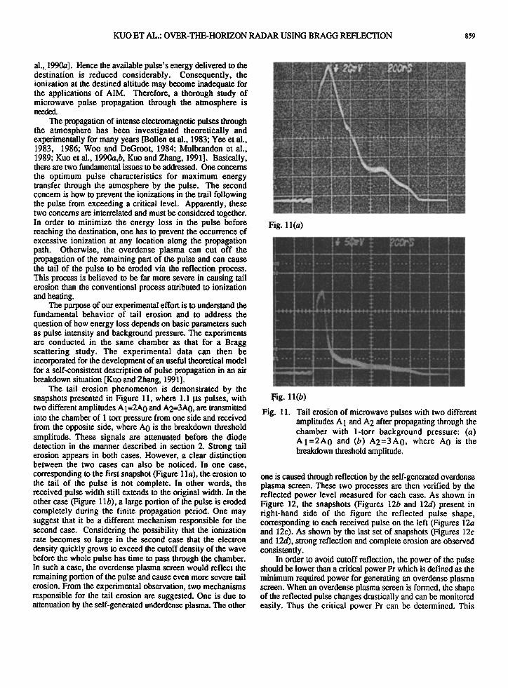
The tail erosion phenomenon is demonstrated by the snapshots presented in Figure 11, where 1.1 !.rs pulses, with two different amplitudes A I=2A0 and A2=3A0, are transmitted into the chamber of 1 torr pressure from one side and received from the opposite side, where A 0 is the breakdown threshold amplitude. These signals are attenuated before the diode detection in the manner described in section 2. Strong tail erosion appears in both cases. However, a clear distinction between the two cases can also be noticed. In one case, corresponding to the first snapshot (Figure 1 la), the erosion to the tail of the pulse is not complete. In other words, the received pulse width still extends to the original width. In the other case (Figure 1 lb), a large portion of the pulse is eroded completely during the finite propagation period. One may suggest that it be a different mechanism responsible for the second case. Considering the possibility that the ionization rate becomes so large in the second case that the electron density quickly grows to exceed the cutoff density of the wave before the whole pulse has time to pass through the chamber. In such a case, the overdense plasma screen would reflect the remaining portion of the pulse and cause even more severe tail erosion. From the experimental observation, two mechanisms responsible for the tail erosion are suggested. One is due to attenuation by the self-generated underdense plasma. The other
Fig. 1 l(a)
.Fig. 11(b)
Fig. 11. Tail erosion of microwave pulses with two different amplitudes A 1 and A 2 after propagating through the chamber with 1-torr background pressure: (a) AI=2A0 and (b) A2=3A0, where A0 is the breakdown threshold amplitude.
one is caused through reflection by the self-generated overdense plasma screen. These two processes are then verified by the reflected power level measured for each case. As shown in Figure 12, the snapshots (Figures 12b and 12d) present in right-hand side of the figure the reflected pulse shape, corresponding to each received pulse on the left (Figures 12a and 12c). As shown by the last set of snapshots (Figures 12c and 12d), strong reflection and complete erosion are observed consistently.
In order to avoid cutoff reflection, the power of the pulse should be lower than a critical power Pr which is defined as the minimum required power for generating an overdense plasma screen. When an overdense plasma screen is formed, the shape of the reflected pulse changes drastically and can be monitored easily. Thus the critical power Pr can be determined. This
860 KUO ET AL.: OVER-THE-HORIZON RADAR USING BRAGG REFLECTION
Fig. 12(a) Fig. 12(b)
Fig. 12(c) Fig. 12(d)
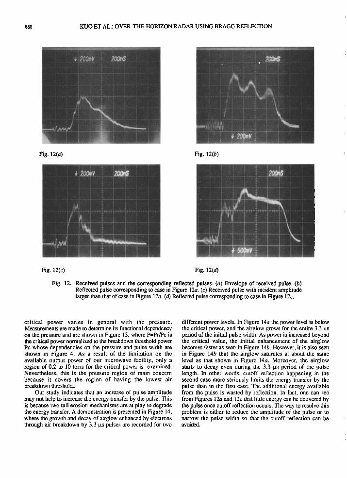
Fig. 12. Received pulses and the corresponding reflected pulses. (a) Envelope of received pulse. (b) Reflected pulse corresponding to case in Figure 12a. (c) Received pulse with incident amplitude larger than that of case in Figure 12a. (d) Reflected pulse corresponding to case in Figure 12c.
critical power varies in general with the pressure. Measurements are made to determine its functional dependency on the pressure and are shown in Figure 13, where P=Pr/Pc is the critical power normalized to the breakdown threshold power Pc whose dependencies on the pressure and pulse width are shown in Figure 4. As a result of the limitation on the available output power of our microwave facility, only a region of 0.2 to 10 torrs for the critical power is examined. Nevertheless, this is the pressure region of main concern because it covers the region of having the lowest air breakdown threshold..
Our study indicates that an increase of pulse amplitude may not help to increase the energy transfer by the pulse. This is because two tail erosion mechanisms are at play m degrade the energy transfer. A demonstration is presented in Figure 14, where the growth and decay of airglow enhanced by electrons through air breakdown by 3.3 ps pulses are recorded for two
different power levels. In Figure 14a the power level is below the critical power, and the airglow grows for the entire 3.3 gs period of the initial pulse width. As power is increased beyond the critical value, the initial enhancement of the airglow becomes faster as seen in Figure 14b. However, it is also seen in Figure 14b that the airglow saturates at about the same level as that shown in Figure 14a. Moreover, the airglow starts to decay even during the 3.3 ps period of the pulse length. In other words, cutoff reflection happening in the second case more seriously limits the energy transfer by the pulse than in the first case. The additional energy available from the pulse is wasted by reflection. In fact, one can see from Figures 12a and 12c that little energy can be delivered by the pulse once cutoff reflection occurs. The way to resolve this problem is either to reduce the amplitude of the pulse or to narrow the pulse width so that the cutoff reflection can be avoided.
KUO ET AL.: OVER-THE-HORIZON RADAR USING BRAGG REFLECTION 861
3.50
illlJllll Illilllll I'lll'lllll I'l'111llJi i!1illlll
3.00
2.00
'1.50
•2.50.
0.00 2.00 4.00 6.00 8.00 10.00
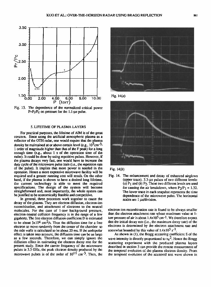
P (torr) Fig. 13. The dependence of the normalized critical power
P=Pr/P c on pressure for the 1.1-ps pulse.
5. LIFETIME OF PLASMA LAYERS
For practical purposes, the lifetime of AIM is of the great concern. Since using the artificial atmospheric plasma as a reflector of the OTH radar, one would require that the plasma density be maintained at or above certain level (e.g., 107cm -3, 1 order of magnitude higher than that of the F peak) for a long enough time (e.g., about 1 s of the operation time of the radar). It could be done by using repetitive pulses. However, if the plasma decays very fast, one would have to increase the duty cycle of the microwave pulse train (i.e., the repetition rate of the pulse). It implies that more power is needed in the operation. Hence a more expensive microwave facility will be required and a greater running cost will result. On the other hand, if the plasma is shown to have a desired long lifetime, the current technology is able to meet the required specifications. The design of the system will become straightforward and, most importantly, the whole system can be justified to be economically feasible and competitive.
In general, three processes work together to cause the decay of the plasma. They are electron diffusion, electron-ion recombination, and attachment of electrons to the neutral molecules. For the case of l-tort background pressure, electron-neutral collision frequency is in the range of a few gigahertz. The free electron diffusion coefficient D is estimated to be about 3x104 cm2/s. Thus the diffusion time for a free electron to move randomly from the center of the chamber to the side walls is calculated to be about 20 ms. If the ambipohtr effect is taken into account, the diffusion time can be as large as a few seconds. Therefore, we can simply ignore the diffusion effect in estimating the electron decay rate for the present study. Since the carrier frequency of the microwave pulses is 3.3 GHz, the peak electron density produced by the microwave pulses is of the order of 1011 cm-3. Then, the
Fig. 14(a)
i
Fig. 14(b)
Fig. 14. The enhancement and decay of enhanced airglows (upper trace). 3.3-ps pulses of two different levels: (a) PI and (b) P2. These two different levels are used for causing the air breakdown, where P2•I = 1.32. The lower trace in each snapshot represents the time dependence of the microwave pulse. The horizontal scales are 1 ps/division.
electron-ion recombination rate is found to be always smaller than the electron attachment rate whose maximum value at l-
tort pressure of air is about 1.4x 1.05 cm-1. We therefore expect that the initial decay rate (i.e., the maximum decay rate) of the electrons is determined by the electron attachment rate and somewhat bounded by this value of 1.4x10⁵ s -1.
As shown in (1), the Bragg scattering coefficient S of the wave intensity is directly proportional to ne 2. Hence the Bragg scattering experiment with the produced plasma layers described in section 3 can provide the remote measurement of the temporal evolution of the plasma electron density. From the temporal evolution of the scattered test wave shown in
862 KUO ET AL.: OVER-THE-HORIZON RADAR USING BRAGG REFLECTION
Figure 9A, the electron decay rate after the breakdown pulses have passed through the chamber (i.e., the initial decay rate) is estimated to be 6x10⁴ s -1, which is consistent with the dissociative attachment rate. It is also seen that 70 gs later the electron density is reduced by a factor of about 30. Similarly, the electron decay rate is also reduced over a factor of 10 from the initial decay rate. In this density level (•3x109cm -3) the measured decay rate becomes consistent with the recombination loss rate. This surprising result is understandable from the fact that when enough negative molecule .ions are produced through the electron attachment process, the detachment rate for electron regeneration is increased and eventually balances the electron attachment loss rate. The detachment rate is determined to be Vd = 2x10³ s -1. It is obtained by the best fit of the numerical result of the theoretical model [Zhang and Kuo, 1991] evaluated with Vd as a free parameter to the measured temporal evolution of electron density. Thus the dominant electron loss mechanism is shifted to the recombination process. On the other hand, the attachment process also serves to reduce the recombination and diffusion losses of electrons. It helps the excess of free electrons to be stored in the plasma by attachment of the free electrons to the neutral molecules with low mobility. These attached electrons, subsequently, become the source of free electrons of the system. The detachment process plays an important role in balancing all the loss processes. When such a balance is reached (e.g., 70 gs marked in Figure 9a), the density of free electrons begins to decay at a relatively slow rate determined by the recombination process and the ambipolar diffusion process.
With the available power (= 10mW) of sweep microwave generator and the detecting facility (HP spectrum analyzer 8569B), the Bragg scattering measurements are no longer sensitive to the electron density after decay from its peak value for a period of 100 gs (see Figure 9a). The evolution of an electron density at a later time is then determined by a Langmuir double probe. The main purpose of Langmuir probe measurement is to confirm that the decay of electron density after reaching the balance of processes is indeed caused mainly by the recombination process. In addition, the probe measurement can provide the information on the electron temperature. The difficulty with the Langmuir probe measurements lies with the presence of negatively charged molecules since the ion density is not quite the same as the electron density. The presence of negatively charged molecules also complicates the relationships among the electron density, electron temperature, and ion density etc. inside a sheath. For instance, the sheath potential changes its sign when the density of negatively charged molecules becomes much larger than that of free electrons. This can be monitored
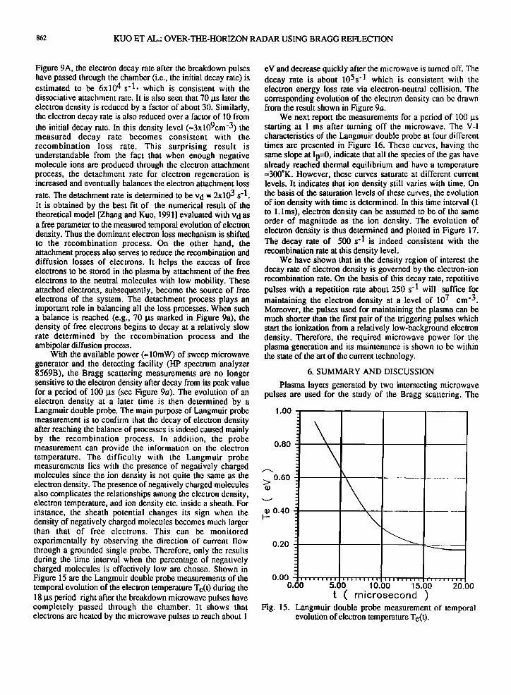
experimentally by observing the direction of current flow through a grounded single probe. Therefore, only the results during the time interval when the percentage of negatively charged molecules is effectively low are chosen. Shown in Figure 15 are the Langmuir double probe measurements of the temporal evolution of the electron temperature Te(t ) during the 18 gs period right after the breakdown microwave pulses have completely passed through the chamber. It shows that electrons are heated by the microwave pulses to reach about 1
eV and decrease quickly after the microwave is turned off. The decay rate is about 105s -1 which is consistent with the electron energy loss rate via electron-neutral collision. The corresponding evolution of the electron density can be drawn from the result shown in Figure 9a.
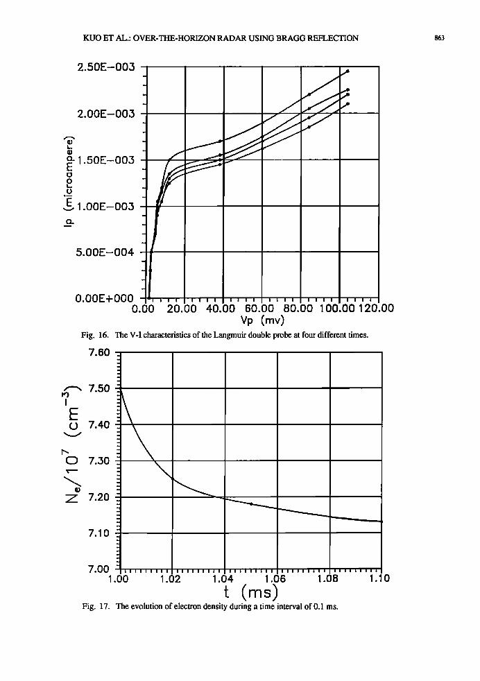
We next report the measurements for a period of 100 gs starting at 1 ms after turning off the microwave. The V-I characteristics of the Langmuir double probe at four different times are presented in Figure 16. These curves, having the same slope at Ip=0, indicate that all the species of the gas have already reached thermal equilibrium and have a temperature =300øK. However, these curves saturate at different current levels. It indicates that ion density still varies with time. On the basis of the saturation levels of these curves, the evolution of ion density with time is determined. In this time interval (1 to 1.1ms), electron density can be assumed to be of the same order of magnitude as the ion density. The evolution of electron density is thus determined and plotted in Figure 17. The decay rate of 500 s -1 is indeed consistent with the recombination rate at this density level.
We have shown that in the density region of interest the decay rate of electron density is governed by the electron-ion recombination rate. On the basis of this decay rate, repetitive pulses with a repetition rate about 250 s'l will suffice for maintaining the electron density at a level of 107 cm -3. Moreover, the pulses used for maintaining the plasma can be much shorter than the first pair of the triggering pulses which start the ionization from a relatively low-background electron density. Therefore, the required microwave power for the plasma generation and its maintenance is shown to be within the state of the art of the current technology.
6. SUMMARY AND DISCUSSION
Plasma layers generated by two intersecting microwave pulses are used for the study of the Bragg scattering. The
1.00
iiiiiiiii iIiiiiill iiiiiiiii iiiiiiiil _ _
0.80
0.60
0.40
0.20
0.00 0.00 5.00 10.00 15.00 20.00
t ( microsecond ) Fig. 15. Langmuir double probe measurement of temporal
evolution of electron temperature Te(t).
KUO ET AL.: OVER-THE-HORIZON RADAR USING BRAGG REFLECTION 863
2.50E-003
2.00E-003
o. 1 50E-003 E ' o
E 1 00E-003
5.00E-004
O.00E+000 0.00
• "I i I I I '1 I I I [ I I I i I [ I I ! I 'ili i I -
20.00 4-0.00 60.00 80.00 100.00 120.00
Vp (mv) Fig. 16. The V-I characteristics of the Langmuir double probe at four different times.
7.60
7.50
E 7.40
7.30
7.20
7.10
7.00 1.00 1.02 1.04 1.06 1.08
Fig. 17. The evolution of electron density during a time interval of 0.1 ms.
IIii11111 ii1111111 IIIIIIiii i11111111 i11111111
1.10
864 KUO ET AL.: OVER-THE-HORIZON RADAR USING BRAGG REFLECTION
experiment is conducted in a chamber covered with microwave absorbers so that the microwave reflection from the wall can be minimized. Hence the experiments can be considered to be a laboratory simulation of the conceptualized plasma layers generated by high-power microwaves in the upper atmosphere.
We first determine the characteristics of air breakdown by powerful microwave pulses. We have observed that it is very difficult to generate plasma at the center of the chamber with a single pulse. This is mainly because the plasma generated near the wall adjacent to the microwave horn causes erosion of the incident pulse. Thus the pulse becomes too short by the time it reaches the central region of the chamber to cause an appreciable ionization. However, this problem is easily overcome when the scheme of two intersecting pulses is used for the plasma generation. In this approach, each pulse has its amplitude below a critical level to avoid the significant plasma generation near the chamber wall. However, the fields in the intersecting region add up and well exceed the breakdown threshold. This scheme is most effective when the two pulses have the same polarization and are coherent. In this case, the wave fields form a standing wave pattern in the intersecting region in the direction perpendicular to the line bisecting the angle { between the intersecting pulses. Thus parallel plasma layers with a separation d=)•0/2 sin (q•/2) can be generated as shown in Figure 3.
Since there are no electrodes involved in the current
experiments of air breakdown, we can determine the breakdown threshold field as a function of the air pressure within the accuracy of the microwave probe measurements. Two Paschen breakdown curves for the cases using the 1.1- and 3.3-!.ts pulses are determined and shown in Figure 4. The appearance of a Paschen minimum can be explained as the result of breakdown by a short pulse which is equivalent to a dc discharge with short separation between electrodes (i.e. short electron transit time). The result that the breakdown threshold for a longer pulse (3.3 !.rs) is lower than that for a shorter pulse (1.1 gs) agrees with this explanation. The characteristics of the curves are confirmed experimentally by the various degrees of tail erosion of the same pulse passing through the chamber at different pressures displayed in Figure 5.
We then conducted the Bragg scattering experiment with the produced plasma layers. Both temporal evolution of the scattering signal from a test wave and the spectral dependence of the scattering coefficient have been examined. Good agreement between theoretical and experimental results on the spectral dependence of the scattering coefficient has been found and is shown in Figure 10. It should be noted that, because of the dimension of the chamber and microwave beams, only three plasma layers have significant overlap along a central line of sight for the incident path of the test wave for Bragg scattering. Nevertheless, a remarkable effectiveness of Bragg scattering has been demonstrated by the present chamber experiment. It is further realized that more layers and a much larger cross sectional area for each layer would be produced in the actual envisioned installation. One could expect that many more plasma layers would be incorporated for Bragg scattering. Since the scattering coefficient is proportional to the square of the number of layers at play, one can expect that effective Bragg scattering can still be achieved even at much lower
plasma density (=107cm '3 for possible practical application) than that for the current experiments (= 109cm-3). Especially, the operating radar frequency is expected to be at least I order of magnitude lower than that of the test wave used in the present experiments.
An experiment investigating the propagation of high- power microwave pulses through the air is also performed. We have identified two mechanisms which are responsible for two different degrees of tail erosion. One is attributed to the absorption by the self-generated underdense plasma. The other one is caused by reflection by the self-generated overdense plasma screen. Our study indicates that an increase of pulse amplitude may, in fact, degrade the energy delivery capability of the pulse. This is because the cutoff reflection mechanism causes even more severe tail erosion to the pulse. The demonstration of these effects is presented in Figures 12a and 12c and 14. The way to solve the problem is either to lower the amplitude of the pulse or to narrow the pulse width so that cutoff reflection by self-generated plasma can be avoided. The optimum amplitude of the 1.1 !.rs pulse for the maximum energy transfer through the air has also been determined in this experiment. Since the effects of the pressure gradient and large propagation distance cannot be incorporated in this chamber experiment, the optimum parameters of the pulses for achieving the most effective plasma generation remain to be determined.
A practical physics issue concerning the applicability of the present study to the OTH radar is the lifetime of plasma electrons generated by the microwave pulses. The theoretical results show that the scattering coefficient is proportional to the square of the electron density and insensitive to the electron temperature. Therefore, the electron decay rate after the breakdown pulses have passed through the chamber can be evaluated from Figure 9a. It shows that the initial decay rate is about 6x10⁴ s '1 which is consistent with the dissociative attachment rate. It also shows that 70 !.rs later the electron density is reduced by a factor of about 30. Similarly, the electron decay rate is reduced over a factor of 10 from its initial decay rate. In this region the decay rate is consistent with the recombination loss rate. This arises from the fact that when
enough negative molecule ions are produced through the electron attachment process, the detachment rate for electron regeneration is increased and eventually balances the electron attachment loss rate. Thus the electron loss mechanism is
dominated by the recombination process. The evolution of electron density can be measured only up to 100 !.rs by the Bragg scattering. Beyond that the signal becomes too weak to be detected by our available instruments. In order to be sure that the loss of electrons is indeed caused mainly by the recombination process which has an acceptably low rate, a Langmuir double probe is used to measure the evolution of electron density at much later time (i.e. 1 to 1.1 ms). The results of the probe measurement confirm those of the Bragg scattering measurements.
In summary, our chamber experiments have investigated all the major physics issues related to the implementation of a Bragg reflector in the upper atmosphere (=50 km) by two intersecting microwave pulses transmitted from the ground with potential applications to OTH radars and
KUO ET AL.: OVER-THE-HORIZON RADAR USING BRAGG REFLECTION 865
telecommunication links. The results show that the required microwave power for the plasma generation and its maintenance are within the state of art of the current
technology.
Acknowledgments. The authors gratefully acknowledge the referees' comments and suggestions that helped us improve this work. This work was supported by the Air Force Phillips Laboratory through NASA grant NAG 5-1051 and by the Air Force Office of Scientific Research under the grant AFOSR- 91-0002.
REFERENCES
Bollen, W. M., C. L. Yee, A. W. A!i, M. J. Nagurney, and M. E. Read, High-power microwave energy coupling to ni- trogen during breakdown, J. Appl. Phys. 5.•.4, 101-106, 1983
Borisov, N. D., and A. V. Gurevich, High frequency pulsed air breakdown in intersecting radio beams, Geomagn. Aeronom, 2._0_0, 841-845, 1980.
Goldstein, B. and C. Longmire, Microwave absorption and plasma heating due to microwave breakdown in the atmo- sphere, J. Radiation Effects Res. and Eng., 3, 1626-1628, 1984.
Gurevich, A. V., Ionization of the lower ionosphere under the effect of strong radio pulses, Geomagn. Aeronom., 1_.•9,428- 432, 1979.
Gurevich, A. V., An ionized layer in a gas, Soy. Phys. Usp,, Engl. Transl., 23, 862-865, 1980.
Headrick, J. M., and M. I. Skolnik, Over-the-horizon radar in the I-IF band, Proc. IEEE, 6:2(6), 664-673, 1974.
Kuo, S. P., and Y. S. Zhang, Bragg scattering of electromag- netic wave by microwave produced plasma layers, Phys, Fluids B, 2(3), 667-673, 1990.
Kuo, S. P., and Y. S. Zhang, A theoretical model for intense microwave pulse propagation in an air breakdown environ- ment, Phys. Fluids B, 3(10), 2906-2912, 1991.
Kuo, S. P., Y. S. Zhang, and P. Kossey, Propagation of high power microwave pulses in air breakdown environment, J. Applied Phys., 67(6), 2762-2766, 1990a.
Kuo, S. P., Y. S. Zhang, and A. Ren, Observation of fre- quency up-conversion in the propagation of a high power microwave pulse in a self-generated plasma, Phys, Lett. A, 150, 92-96, 1990b.
Lee, M. C., D Thuranatnam, and E. R. Williams, Radio wave scattering from artificial plasma layers, paper presented at the URSI/National Radio Science Meeting, Boulder, Colorado, January 5-8, 1988.
Lee, M. C. and S. P. Kuo, Structure and radio reflectivity of artificial plasma, paper presented at the IV International Workshop on Nonlinear and Turbulent Processes in Physics, Kiev, Ukraine, U.S.S.R., October 9-22, 1989.
Lupan, Yu. A., Refined theory for an RF discharge in air, Soy. Phys. Tech. Phys., 21(11), 1367-1370, 1976.
MacDonald, A.D., Microwave Breakdown in Gas, John Wiley, New York, 1965.
MIT Radar School Staff, Principles of Radar 3rd ed., McGraw-Hill, New York, 1952.
Mulbrandon, M. J., J. Chen, P. J. Palmadesso, C. A. Sullivan, and A.M. Ali, A numerical solution of the Boltzmann equation for high-power short pulse microwave breakdown in nitrogen, Phys. Fluids B, 1, 2507-2515, 1989.
Short, R. et al., Physics study in artificial ionospheric mirror (AIM) related phenomena, Technical Final Report, GL-TR- 90-0038, Air Force Phillips Laboratory, Hanscorn Air Force Base, Massachusetts, 1990.
Vikharev, A. L., V. B. Gil'denburg, O. A. Ivanov, and A. N. Stepanov, Microwave discharge in intersecting electromag- netic wave beams, Soy. J. Plasma Phys., 10, 460-464, 1985.
Woo, Wee and J. S. DeGroot, Microwave absorption and plasma heating due to microwave breakdown in the atmo- sphere, Phys. Fluids, 27,475-487, 1984.
Yee, C. L., A. W. Ali, and W. M. Bollen, Microwave cou- pling in a nitrogen-breakdown plasma, J. Appl. Phys., 54, 1278-1283, 1983.
Yee, J. H., R. A. Alvarez, D. J. Mayhall, N. K. Madsen, and H. S. Cabayan, Dynamic characteristics of intense short mi- crowave propagation in an atmosphere, J. Radiation Effects Res. and Eng., 3, 152-160, 1984.
Yee, J. H., R. A. Alverez, D. J. Mayhall, D. P. Byrne, and J. DeGroot, Theory of intense electromagnetic pulse propaga- tion through the atmosphere, Phys. Fluids, 29, 1238-1244, 1986.
Zhang, Y. S., Bragg Scattering of electromagnetic wave by microwave produced periodic plasma layers, Ph.D. disserta- tion, Polytechnic University, Brooklyn, New York, 1990.
Zhang, Y. S., and S. P. Kuo Bragg Scattering measurement of atmospheric plasma decay, Int. J. Infrared Millimeter Waves, 12, 335-343, 1991.
Robert J. Barker, Air Force of Scientific Research, Bolling Air Force Base, Washington, D.C. 20332-6448.
Paul Kossey, Air Force Phillips Laboratory, Hanscom Air Force Base, Massachusetts 01731
S. P. Kuo, Weber Research Institute, Polytechnic University, Route 110, Farmingdale, New York 11735
M. C. Lee, Plasma Fusion Center, Massachusetts Institute of Technology, Cambridge, Massachusetts 02139
Y.S. Zhang, University of Wisconsin-Madison, 1500 Johnson Drive, Madison, Wisconsin 53706-1687
Copyright © 2022 FDOKUMEN