Use of parabolic reflector to amplify in-air signals generated during impact-echo testing
Upload
independentCategory
view
3download
0
JOURNAL OF DISPLAY TECHNOLOGY, VOL. 8, NO. 6, JUNE 2012 321
LED Backlight Module by a Lightguide-DiffusiveComponent With Tetrahedron Reflector Array
Jang-Zern Tsai, Rong-Seng Chang, Tung-Yen Li, and Thomas Chiang Chuang
Abstract—In our previous work, IEEE/OSA JOURNAL OF DISPLAYTECHNOLOGY, February 2012, we examined the luminance anduniformity characteristics of a newly invented secondary opticallens with a wide emission angle called a “lightguide–diffusivecomponent”. The lightguide-diffusive component is designed forthin direct LED backlighting applications. The LED backlightmodule is composed of at least an LED light source, a secondarylightguide–diffusive component with a micro-structure reflectivebottom surface, and a flexible printed circuit (FPC) for LEDlighting without a brightness-enhanced film (BEF). Throughthis lightguide–diffusive component, the emission profile of asingle LED is modified to provide better illumination and moreuniformity. In this work, the micro-structure reflective bottom isredesigned to be shaped like a Tetrahedron Reflector StructureArray instead of a triangle cylinder structured array, resulting ina more uniform spatial light energy distribution on the emissionplane of the LED backlight. The simulation results show anincrease in the uniformity ratio with the new design from 72% to76%, a 4% improvement, the angle of the luminous intensity is in-creased from 98 deg to 112 deg, a 14 deg improvement, a decreasein the luminance is from 9024 nits to 8551 nits, an impairment of5%, and a decrease in the volume of the micro-structure reflectorfrom 1.154 mm� to 0.767 mm�, a 33.5% volume reduction (costsaving).
Index Terms—LED, secondary lightguide-diffusive, backlightmodule, tetrahedron.
I. INTRODUCTION
L IQUID-CRYSTAL displays (LCDs) have been widely ap-plied in everything from mobile devices to large-size tele-
visions. Recently, LCDs have demonstrated many advantagesover other flat display types. With the increasing usage of largeLCD TVs, the reliability requirements for the backlight unithave become more critical.
The primary backlight unit designs are the edge-in backlightmodel and direct illumination-type backlight model. Due to theincrease in the dimensions of LCD TVs, and the increased im-portance of saving energy, the direct illumination type backlightmodel is now considered of greater importance.
Manuscript received September 22, 2011; revised December 11, 2011, Jan-uary 06, 2012; accepted January 06, 2012. Date of current version April 25,2012. This paper is supported by the National Science Council, Executive Yuan,R.O.C. (Taiwan) under Grant NSC100-2116-M-008-016.
J.-Z. Tsai and T.-Y. Li are with the Department of Electrical Engineering,National Central University, Jhong -Li, 32001 Taiwan.
R.-S. Chang is with the Department of Optics and Photonics, National CentralUniversity, Jhong-Li, 32001 Taiwan (e-mail: [email protected]).
T. C. Chuang is with the Department of Computer Science and InformationEngineering, Van Nung University, Chung-Li, 32045 Taiwan.
Color versions of one or more of the figures are available online at http://ieeexplore.ieee.org.
Digital Object Identifier 10.1109/JDT.2012.2184077
Fig. 1. Structure of the direct illumination-type LED Backlight module.
The main light sources used in the direct illumination-typebacklight model are cold cathode fluorescent lamps (CCFL) [1]and LEDs [2]. The advantages of LEDs over other light sourcesare their faster drive speed, full color availability without colorfilters, less image blurring, and ever increasing efficiency. TheLED has been widely accepted and applied in the field of back-light module design. Recently, the study of LED backlight unitdesign has developed rapidly and its achievements have drawna lot of attention.
The general direct illumination type of LED backlightmodule (see Fig. 1) consists of a light source (LED), reflector,diffuser sheet, prisms and so on. For a review of the high bright-ness direct LED backlight for LCD TVs please see the workof West [3]. Past studies have shown that a target luminanceof 50%–60% uniformity [3], [4], and 10 000 nits have beenachieved in LED backlight designs.
In [5], we presented a new type of backlight module design.The uniformity ratio and luminance were improved by usingan LED backlight module with secondary lightguide diffusivecomponents. In order to obtain better performance, and reducethe volume of the micro-structure reflector and save costs, anovel micro-structure reflector is designed to replace the Tri-angle Cylinder Structured Array commonly used in other back-light modules. An LED source is utilized in the secondary light-guide-diffusive component to improve the uniformity ratio ofthe LCD display. We also need to maintain the performanceof both the luminance and uniformity ratio, and decrease thevolume of the micro reflectors used in the module.
We design a Tetrahedron Reflector Structured Array to im-prove the performance of the backlight module. In this study theCAE software (TracePro.) is used to simulate the TetrahedronReflector Structured Array and the Triangle Cylinder StructuredArray. In the simulation process, a light source is set up with2 2 Lambertian type LED Array. The material from which itfabricated is Polymethylmethacrylate (PMMA). These findingsare of great practical importance for the design of a backlightmodule.
1551-319X/$31.00 © 2012 IEEE

322 JOURNAL OF DISPLAY TECHNOLOGY, VOL. 8, NO. 6, JUNE 2012
Fig. 2. Secondary lightguide-diffusive component model.
Fig. 3. Illustration of the backlight module with four secondary lightguide–dif-fusive components.
II. MATERIAL AND METHODOLOGY
A. Preliminary Design
Preliminary Design of the LED Backlight Module: Fig. 2shows an illustration of the proposed secondary lightguide-dif-fusive component model [5]. The original design contains asecondary lightguide-diffusive component, several LED lightsources, a Printed Circuit Board (PCB), and a reflector surface.The LEDs (Part No.: LW G6SG) chosen are made by the OsramCompany. In this work, PMMA (index of refraction )is chosen as the material to be used in both the design and thesimulation. The secondary lightguide-diffusive component con-tains an incident surface and an exit surface with several concavestructures on both surfaces.
To enhance the performance and brightness of the backlightmodule, the structure of the exit surface is designed to be con-cave in shape with a curvature of mm. At the sametime, there are four small concave-shaped structures on the in-cident surface ( mm).
The dimensions of this model are as follows: 86.14 mm inlength, 71.8 mm in width, and 19.5 mm in thickness. To sim-ulate the luminance and uniformity characteristic of the light-guide-diffusive component, four models are combined into thebackinglight module. Fig. 3 shows an illustration of the back-light module. The module has a length of 172.28 mm, a widthof 143.6 mm, and a thickness of 19.5 mm.
The other simulation conditions are as follows: the reflectanceof the reflectors is set as for a perfect mirror (i.e., 100% re-flectance, no scatter). The refractive index of the lightguide-dif-fusive component is 1.4935 (PMMA from Plastic). The absorp-
Fig. 4. Positions of points P1–P16.
Fig. 5. Simulation results for the flat reflector.
tion of the LEDs is set to be zero, and the angular distributionof the LEDs is set as the Lambertian type.
Evaluation of the Simulated Results of the Backlight Module:A mathematical model is developed to evaluate the luminanceproperties and the viewing angle in the simulation results. First,the “View Area” is defined (consisting of P1–P16; see Fig. 4).The viewing area is located 30 mm away from bottom of theLED backlight module.
In the simulation, we set a parameter to indicate the “Unifor-mity Ratio” which is expressed as the uniformity in the simula-tion results as follows:
% % (1)
where is the maximum luminance value in the View Area;is the minimum luminance value in the View Area; and and
are in units of nits (nt).
Angle of the luminous intensity (degree)
2 angle of (half of the maximum luminous intensity)
TSAI et al.: LED BACKLIGHT MODULE WITH TETRAHEDRON REFLECTOR ARRAY 323
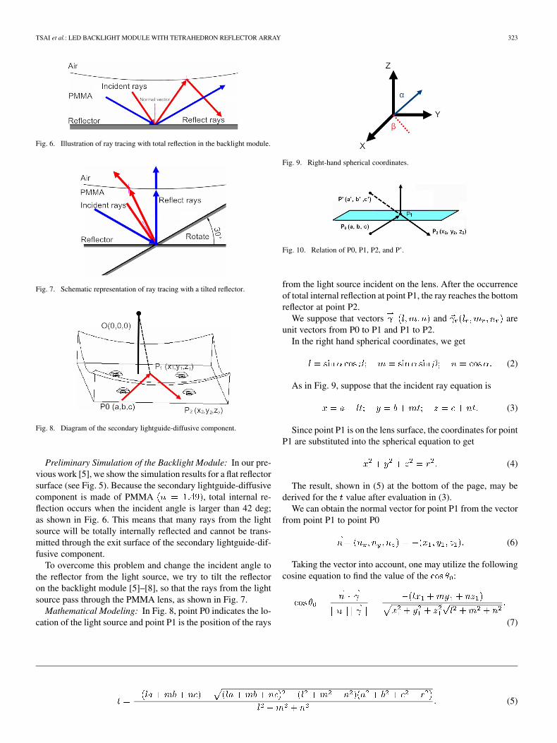
Fig. 6. Illustration of ray tracing with total reflection in the backlight module.
Fig. 7. Schematic representation of ray tracing with a tilted reflector.
Fig. 8. Diagram of the secondary lightguide-diffusive component.
Preliminary Simulation of the Backlight Module: In our pre-vious work [5], we show the simulation results for a flat reflectorsurface (see Fig. 5). Because the secondary lightguide-diffusivecomponent is made of PMMA , total internal re-flection occurs when the incident angle is larger than 42 deg;as shown in Fig. 6. This means that many rays from the lightsource will be totally internally reflected and cannot be trans-mitted through the exit surface of the secondary lightguide-dif-fusive component.
To overcome this problem and change the incident angle tothe reflector from the light source, we try to tilt the reflectoron the backlight module [5]–[8], so that the rays from the lightsource pass through the PMMA lens, as shown in Fig. 7.
Mathematical Modeling: In Fig. 8, point P0 indicates the lo-cation of the light source and point P1 is the position of the rays
Fig. 9. Right-hand spherical coordinates.
Fig. 10. Relation of P0, P1, P2, and P’.
from the light source incident on the lens. After the occurrenceof total internal reflection at point P1, the ray reaches the bottomreflector at point P2.
We suppose that vectors and areunit vectors from P0 to P1 and P1 to P2.
In the right hand spherical coordinates, we get
(2)
As in Fig. 9, suppose that the incident ray equation is
(3)
Since point P1 is on the lens surface, the coordinates for pointP1 are substituted into the spherical equation to get
(4)
The result, shown in (5) at the bottom of the page, may bederived for the value after evaluation in (3).
We can obtain the normal vector for point P1 from the vectorfrom point P1 to point P0
(6)
Taking the vector into account, one may utilize the followingcosine equation to find the value of the :
(7)
(5)

324 JOURNAL OF DISPLAY TECHNOLOGY, VOL. 8, NO. 6, JUNE 2012
Fig. 11. Structures and locations of the Triangle Cylinder Structured Array (units: mm).
We can find the critical angle whenlight travels from the PMMA to air
. When the incident angle is largerthan the critical angle, there is total internal reflection.
Equations (6) and (7) clarify the reflection and refraction con-ditions. Thus, we get from (6), where
. In Fig. 10, the point on the planeis , and the normal vector on the plane is
. One can say that the mirror point of the point canbe described as follows:
(8)
(9)
We can find the vectors from P1 to P2, which are
(10)
Equation (5) is used to obtain the vector and the angle ,which is between vector and vector (0, 0, 1). We can find theincident angle of the ray reflected from the bottom by settingthe light source P0, angle , and angle into the model. Therays will be entirely reflected within the PMMA material whenthe incident angles are from 34.31 to 59.83 [5]–[8].
To modify the incident angle from the light source, we rotatethe bottom reflector about 30 deg, so that the rays from the lightsource pass through the PMMA lens.
Simulation of the Preliminary Design of the LED BacklightModule-Triangle Cylinder Structure Array: In reference to ourwork [5] and to ensure that the rays are transmitted through thesecondary lightguide-diffusive component, a micro reflector inthe shape of a Triangle cylinder is placed on the bottom of thebacklight module.
The shape of the Triangle Cylinder Structured Array and thelocation where it is placed are shown in Fig. 11. The dimen-sions were as follows; 2 mm in length, 2 mm in width, and0.577 mm in height. The volume of the Triangle Cylinder Struc-ture is 1.154 mm . For ease of understanding, we separate thebottom of the backlight module into six sections labeled section
Fig. 12. Schematic representation of the six sections (sections N1–N6).
N1 through section N6 (see Fig. 12). The number of micro-re-flectors placed in these sections is defined as a function N (N1,N2, N3, N4, N5, N6). The quantity and position of the Trianglecylinder in each section is adjusted and the simulations run. Thesimulation results are shown in Figs. 13 and 14.
B. Advanced Design
Simulation of the Advanced Design of the LED BacklightModule-Tetrahedron Reflector Structured Array: To obtainbetter performance and reduce the volume of the reflector,we look further at other proposed models. We designed theTetrahedron Reflector Structured Array as a substitute for theTriangle Cylinder Structured Array.
The light source of an LED is incident into the lightguide-dif-fusive component. As specified in Snell’s Law, the rays are re-flected and refracted in the lightguide-diffusive component andthey are diffused and transmitted between the micro reflectorstructure located at the bottom of the backlight module and thelightguide-diffusive component. Finally, the rays are guided outof the backlight module to provide a light source for the LCDpanel.
The Tetrahedron Reflector Structured Array has two more re-flective surfaces than the Triangle Cylinder Structured Array sothat the directions of reflected rays can be increased. After re-flection, the light is transmitted in different directions equally,which enhances the uniformity of the backlight module.

TSAI et al.: LED BACKLIGHT MODULE WITH TETRAHEDRON REFLECTOR ARRAY 325
TABLE ISIMULATED RESULT OF THE TRIANGLE CYLINDER STRUCTURE ARRAY AND TETRAHEDRON REFLECTOR STRUCTURE ARRAY
Fig. 13. Triangle Cylinder Structured Array simulation results: (a) N (5,10,5,6,6,6); (b) N (5,10,5,6,8,6); and (c) N (5,10,5,8,8,8).
Fig. 14. Triangle Cylinder Structured Array polar candela plot: Blue line-N(5,10,5,6,6,6); Red line-N (5,10,5,6,8,6); Black line-N (5,10,5,8,8,8).
The Tetrahedron Reflector Structure is shown in Fig. 15. Thedimensions are as follows: 2 mm in length, 2 mm in width and0.577 mm in height. The volume of the Tetrahedron ReflectorStructure is 0.767 mm . We utilize them in the x/y direction onthe bottom of the backlight module. Experiments are conductedunder the same conditions, and the experimental parameters andtheir range are indicated in Figs. 16 and 17.
III. RESULTS
Given the above results, one may look further into theTracePro software simulation data. In the simulation results,the uniformity ratio, angle of luminance and volume saving ofthe micro reflector were better with the Tetrahedron ReflectorStructured Array than with the Triangle Cylinder StructuredArray.
There is a decrease in the volume of the micro structurefrom 1.154 mm (Triangle Cylinder Structure) to 0.767 mm(Tetrahedron Reflector Structure), a 33.5% reduction in volume.
Table I presents the simulation results for the uniformity ratio,maximum luminance, minimum luminance and the ranges forthe design parameters of the micro reflector structure.
Compared with the design of the Triangle Cylinder Struc-tured Array, the uniformity ratio of our Tetrahedron ReflectorStructured Array design showed an increase of 1.9% (from73.3% to 75.2 %) in case N (5, 10, 5, 6, 6, 6), 4% (from 72% to76%) in case N (5, 10, 5, 6, 8, 6) and 3.9% (from 72.4% to 76.3)in case N (5, 10, 5, 8, 8, 8). Also, the maximum luminance ofour Tetrahedron Reflector Structure Array design decreased by

326 JOURNAL OF DISPLAY TECHNOLOGY, VOL. 8, NO. 6, JUNE 2012
Fig. 15. Structures and locations of the Tetrahedron Reflector Structured Array (units: mm).
Fig. 16. Tetrahedron Reflector Structured Array simulation results: (a) N (5,10,5,6,6,6); (b) N (5,10,5,6,8,6); (c) N (5,10,5,8,8,8).
Fig. 17. Tetrahedron Reflector Structure Array polar candela plot: Blue line-N(5,10,5,6,6,6); Red line-N (5,10,5,6,8,6); Black line-N (5,10,5,8,8,8).
2.4% (from 8867 nits to 8646 nits) in case N (5, 10, 5, 6, 6, 6),5% (from 9024 nits to 8551 nits) in case N (5, 10, 5, 6, 8, 6)and 5% (from 8977 nits to 8514 nit) in case N (5, 10, 5, 8, 8,
8). The results of the uniformity ratio simulation are presentedin Fig. 18.
Table II shows the angle of luminous intensity, maximum lu-minous intensity and the ranges of the design parameters of themicro reflector structure.
Compared with the design of the Triangle Cylinder StructuredArray, the angle of luminous intensity of our Tetrahedron Re-flector Structure Array design showed an increase of 8 deg (from92 ot 100 deg) in case N (5, 10, 5, 6, 6, 6), 8 deg (from 100 to108 deg) in case N (5, 10, 5, 6, 8, 6) and 14 degrees (from 98 to112 deg) in case N (5, 10, 5, 8, 8, 8). The results of the simula-tion are presented in Fig. 19.
The Tetrahedron Reflector Structured Array has two more re-flective surfaces than the Triangle Cylinder Structured Array al-lowing the directions in which rays could be reflected to increase.

TSAI et al.: LED BACKLIGHT MODULE WITH TETRAHEDRON REFLECTOR ARRAY 327
Fig. 18. Simulation results of the uniformity ratio.
Fig. 19. Simulation results of the angle of the luminous intensity.
TABLE IICANDELA PLOT RESULTS OF THE TRIANGLE CYLINDER STRUCTURE ARRAY AND TETRAHEDRON REFLECTOR STRUCTURE ARRAY
After reflection and refraction, the light was transmitted equallyin different directions, which enhanced the uniformity ratio andluminous intensity angle of the Tetrahedron Reflector backlightmodule.
IV. CONCLUSION
Improving LCD backlighting efficiency is one of the criticalareas of research for improving LCD TV performance. In thiswork, the uniformity ratio, angle of luminous intensity and thevolume of the micro-structure in the new design are shown tohave improved by 4% [in cases N (5,10,5,6,6,6)], 14 deg [incases N (5,10,5,8,8,8)] and the volume has been reduced by33.5% (in all cases). The luminance in the new design showsan decrease of 5% [in cases N (5,10,5,8,8,8)].
The simulation results are summarized above along witha discussion of previous work [5]. We obtain a brightnessforecast of 12329 (nits) 95% 11713 (nits) when utilizingthe Tetrahedron Reflector Structured Array in the backlight
module. This data still meets the luminance target (10000 nits)[3], [4].
The above results indicate the efficiency of the new design(Tetrahedron Reflector Structured Array) which could improvethe competitiveness, cost and balance for better performance be-tween the uniformity ratio and the luminance of the LED back-light module with a lightguide diffusive component.
The design is applicable to large size display applications andother commercial displays. In large size display applications,direct illumination-type backlight models have better perfor-mance than the edge-in backlight models since the luminanceof the direct illumination-type backlight models is superior tothat of the edge-in backlight models.
Compared with the thickness and weight of commer-cially-available backlights for LED TV, our design is heavierand thicker, but it is suitable for large size display applicationswhich would have enough space to contain our LED backlightmodule with its lightguide-diffusive component and Tetrahe-dron Reflector Structured Array.
328 JOURNAL OF DISPLAY TECHNOLOGY, VOL. 8, NO. 6, JUNE 2012
REFERENCES
[1] M. Doshi, R. Zane, and F. J. Azcondo, “Low frequency architecturefor multi-lamp CCFL systems with capacitive ignition,” J. DisplayTechnol., vol. 5, no. 5, pp. 152–161, May 2009.
[2] C. F. Lin, C. C. Wu, P. H. Yang, and T. Y. Kuo, “Application of Taguchimethod in light-emitting diode backlight design for wide color gamutdisplays,” J. Display Technol., vol. 5, no. 8, pp. 323–330, Aug. 2009.
[3] R. S. West, H. Konijn, W. S. Smitt, S. Kuppens, N. Pfeffer, Y. Martnov,T. Yagi, S. Eberle, G. Harbers, T. WeiTan, and C. E. Chan, “Highbrightness direct LED backlight for LCD-TV,” in SID Int. Symp. Dig.Tech. Papers Book II, 2003, pp. 1262–1265.
[4] R. S. West, H. Konijn, S. Kuppens, N. Pfeffer, Q. V. Vader, Y. Martnov,T. Heemstra, J. Sanders, T. Yagi, and G. Harbers, “LED backlight forlarge area LCD TV’s,” in Proc. Int. Disp. Workshops, 2003, vol. 10, pp.657–660.
[5] R. S. Chang, J. Z. Tsai, T. Y. Li, and S. L. Liao, “LED backlight moduleby lightguide diffusive component,” J. Display Technol., vol. 8, no. 2,pp. 79–86, Feb. 2012.
[6] E. Hecht, Optics, 4th ed. Reading, MA: Addison-Wesley, 2002, ch. 5.[7] W. J. Smith, Modern Optical Engineering, the Design of Optical
System, 3rd ed. New York: McGraw Hill, 2000, ch. 4.[8] J. M. Geary, Introduction to Lens Design with practical Zemax Exam-
ples. Richmond, VA: Willmann-Bell, 2002, ch. 3.
Jang-Zern Tsai received the B.S. degree in electrical engineering from NationalCentral University, Taiwan, in 1984, the M.S. degree in electrical engineeringfrom National Tsing Hua University, Taiwan, in 1986, and the Ph.D. degree inelectrical engineering from the University of Wisconsin-Madison, in 2001.
He is currently an assistant professor of Electrical Engineering in NationalCentral University, Jhong-Li City, Taiwan. His current research interests includebiochip design, biomedical instrumentation, biomedical signal processing, andwireless sensor networking. His current research interests include biochip de-sign, biomedical image processing, and biooptics.
Rong-Seng Chang received the B.S. degree from the Department of Physics,Chung Cheng Institute of Technology, Daxi Township, Taiwan, in 1967, theM.S. degree from the Department of Applied Physics, the Hebrew Universityof Jerusalem, in 1972, and the Ph.D. degree from the Optical Sciences Center,University of Arizona, Tempe, in 1980.
He is currently a professor of the Department of Optics and Photonics in Na-tional Central University, Jhong-Li City, Taiwan. His current research interestsinclude pattern recognition, optical systems, bio MEMS, nanotechnology, fuzzysystems and biochip design.
Tung-Yen Li received the B.S. degree from National Taiwan Ocean University,Taiwan, in 1999, the M.S. degree from National Central University, Taiwan, in2002, and is currently working toward the Ph.D. degree in electrical engineeringfrom the same university.
His current research work has mainly been focused on electro-optics, andmagnetic devices.
Thomas Chiang Chuang was born in Taiwan. He received the Ph.D. degree inelectrical engineering from the University of California, Los Angeles in 1981.
He has worked for many internationally well-known companies such asEastman Kodak, DuPont, and Raytheon. He joined the Van Nung Instituteof Technology, Chung-Li, Taiwan, in 2002, as an associate professor in theDepartment of Computer Science and Information Engineering, and waspromoted to full professor in 2005. His current research interests include laserelectro optics, image processing, natural language processing, and patternrecognition.
Copyright © 2022 FDOKUMEN