L-858D L-858D-U
223
Light Meter SPEEDMASTER L-858D L-858D-U Operating Manual Thank you for purchasing our product. Please read this operating manual so that you will fully understand the features and operation of this product. Then keep the operating manual in a safe place for future use. Please see the Startup Guide for information about the basic operations.
-
Upload
khangminh22 -
Category
Documents
-
view
0 -
download
0
Transcript of L-858D L-858D-U

Light Meter
SPEEDMASTERL-858DL-858D-UOperating Manual
Thank you for purchasing our product.Please read this operating manual so that you will fully understand the features and operation of this product. Then keep the operating manual in a safe place for future use.Please see the Startup Guide for information about the basic operations.

Please read this operating manual thoroughly to gain a full understanding of the contents and ensure safe and correct use of this product.
The SPEEDMASTER L-858D is a photographic light meter with the following features;
● World's first*1 HSS (High Speed Sync) flash measurement ● Flash duration measurement ● Multi-brand wireless triggering & control (with optional transmitter)
The multi-function SPEEDMASTER L-858D is the flagship of the Sekonic family of light meters. Offering reflected-spot and incident light measurement of ambient and flash light sources, the L-858D features a host of new functions and operations to make it the perfect tool for all light measurement needs.The color touch-screen panel is the control center of the ergonomic, rubber-cushioned body. Weatherproofing seals enable using the L-858D in all shooting conditions. Increased sensitivity and wide measuring range provide the high level of accuracy demanded for today's digital imaging.
Using the Sekonic-developed Data Transfer Software*2 enables mapping your camera's exposure profile and tuning the L-858D to your shooting style. Up to 10 Exposure Profiles*3 can be stored in the meter and called up anytime you need them. Precision tuning of the L-858D enables instant check scene and subject brightness against dynamic range of your camera for the very best exposure decisions. The Data Transfer Software also allows customizing the L-858D to your operating preferences.
*1 World's first as a hand-held light meter (As of September, 2016, Investigated by SEKONIC.)*2 Download the Data Transfer Software from www.sekonic.com, and install it on your
computer. URL: www.sekonic.com/support/downloads/dtssoftwareformacandwindows.aspx To use this software, connect your computer to the L-858D using a USB cable (micro-B type, available commercially).
*3 An exposure profile contains information that indicates each characteristic feature (exposure compensation amount between the camera and light meter, clipping point, and dynamic range) of the digital camera you are using. To create the exposure profile, it is necessary to do shooting in advance, and use the Data Transfer Software.
©2017 All Rights Reserved.

i
■ Terms and Trademarks ● Windows is a registered trademark of Microsoft Corporation in the United States and/or other countries.
● The official name of Windows is "Microsoft® Windows® Operating System". ● Macintosh and Mac OS are registered trademarks of Apple Computer, Inc. in the United States and/or other countries.
● Adobe Reader is a registered trademark of Adobe Systems Inc. ● Elinchrom is the registered trademark of Elinchrom SA. ● Phottix® is the registered trademark and Strato™ is the trademark of Phottix Hong Kong Ltd.
NOTICE
● The reproduction of all or any part of this document without permission is strictly forbidden.
● The product concerned and/or this manual may be subject to changes without prior notification
● The screens in this operating manual may differ from the actual displays of the meter you are using. (Colors, letters, etc.)

ii
■ Safety PrecautionsBefore using this product, please read this "Safety Precautions" for proper operation.
WARNING The WARNING symbol indicates the possibility of death or serious injury if the product is not used properly.
CAUTION The CAUTION symbol indicates the possibility of minor to moderate personal injury or product damage if the product is not used properly.
NOTICE The NOTICE symbol indicates cautions or restrictions when using the product. Please read all notes to avoid errors in operation.
NOTEThe reference symbol indicates additional information about the controls or related functions.Reading these is recommended.
The arrow indicates reference pages.
WARNING ● Infants or toddlers may accidentally wrap the strap around their neck, so please place it in a location out of their reach. There is a danger of suffocation. ● Infants or toddlers may accidentally swallow the lens cap, so please place it in a location out of their reach. There is a danger of suffocation. ● Do not look directly at the sun or an intense light source via the viewfinder. Doing so may damage your eyesight. ● Do not place batteries in open flames, attempt to short, disassemble or apply heat to them, use unspecified batteries, or recharge them (except rechargeable batteries). They may burst and cause fires, serious injury, or damage to the environment.
Polyvinyl Chloride (PVC) cable and cord notice ● Handling the cord on this product or cords associated with accessories sold with this product will expose you to lead, a chemical known to the State of California to cause cancer, and birth defects or other reproductive harm. Wash hands after handling.

iii
CAUTION ● Do not handle this product with wet hands, or leave it in the rain or in a location where it may be splashed with water, submerged, or come into contact with moisture. There is a danger of electric shock if the "Cord Flash Mode" is used. This may also result in damage to the product. ● Make sure the Synchro terminal cover c and USB connector cover a are firmly in place when not using the meter in Cord Flash Mode or it is not connected to a computer. If not sealed by the covers, the meter is no longer water-resistant and moisture could damage the circuitry of the meter. ● Do not under any circumstances remodel or disassemble this product for modification or part replacement purposes. Refer any servicing to qualified and authorized personnel if the product has malfunctioned. Otherwise, measuring results may be affected and/or the product may be damaged. ● Gently tap the meter's LED panel when changing modes or making selections. Using pointed pens or pencils may scratch the LCD screen or damage the product. ● Infants or toddlers may accidentally grab the strap and swing the product, so please place it in a location out of their reach, as the meter may be damaged by impacts. ● Be careful that the neck strap does not come loose when carrying the product, as the meter may be damaged when dropped. ● This neck strap is made of polyester fiber. Please refrain from using the product if synthetic fibers cause your skin to become irritated, inflamed or itchy in order to prevent worsening your symptoms.

iv
NOTICE
● A protective sheet is attached to the LCD. Peel it off before use. ● Although the LCD monitor is manufactured to very high standards, it is possible to observe a few dead pixels on the screen. This is normal and not a malfunction of the meter.
● Do not use at altitudes above 2,000m (6,561 feet). ● Our company shall not be liable for any data loss caused by, but not limited to, malicious acts and control errors.
● Be sure not to drop the meter or subject it to sudden impacts, as the meter will be damaged.
● Do not store the meter in areas of high temperature of high humidity, as the meter will be damaged.
● Be careful not to transport the meter from cold to warm moist conditions as condensation will form on the meter and may damage it.
● If the meter is operated in temperatures below -10°C, the response of the LCD will greatly slow down and the display may be difficult to view and read. This will not harm the meter. Also, if the temperature exceeds 50°C, the liquid crystal display will darken and become difficult to read, but when it returns to room temperature it will return to its normal condition.
● If the meter is left in direct sunlight, a vehicle, or near a heater, the unit's temperature will rise and may result in damage. Please be careful when using the meter in these types of locations.
● If the meter is left where corrosive gases may be generated, the gases may affect the product and may result in damage. Please be careful when using the meter in these types of locations.
● In case of disposing the meter, follow the rules of disposal in your area.
Maintenance Notes ● Be careful not to let the Light Receptor become dusty, dirty, or scratched as this may affect the precision of the measurement.
● If the meter becomes dirty, wipe it with a dry, soft cloth. Never use organic solvents such as thinner or benzine.
NOTE
● For used batteries, dispose of them according to the rules of your area, or bring them to a battery recycling shop near you.
● Insulate plus and minus terminals with tape or other insulation material. ● Do not disassemble the batteries.

v
■ Intended UsageThe meter is designed for:
● Measurement of artificial light sources or natural light for photo, video, or movie ● Display of latitude (dynamic range) from the shadow to the highlight of a digital camera
● Measurement of the flash high-speed synchro exposure or flash duration time for diversifying flash shooting
● Flash unit triggering and power control functions with the transmitter (sold separately)
● High-level measurement accuracy and a wide measurement range in all shooting situations from outdoor to indoor with all weather design
■ Features of the L-858D[Basic functions and performance]1 Model with incident light and reflected light (spot photometry 1 degree) systems2 One-touch switching between extended lumisphere and retracted lumisphere (Light
receiving part up-down mechanism)3 Flash Analyzing Function which provides the percentage of flash in total exposure as
well as ambient and flash components.4 Exposure Profile Function (using the Data Transfer Software application software)5 Simplified luminance measurement (cd/m2, Foot-lambert) and simplified illuminance
measurement (Lux, Foot-candle)
[New functions and performance]1 2.7-inch liquid-crystal color touch panel
The operability is enhanced by assigning frequently used functions to Function Buttons at the bottom of the screen.
2 Flash duration analysis (1/40 to 1/55,500 sec., t0.1 to t0.9, which can be changed in 0.1 steps)
3 Exposure measurement in HSS (High Speed Synchro) Mode4 Improvement of lower light measurement performance (from -5 EV in incident light
measuring, from -1 EV in reflected light measuring) (based on ISO100).5 Flash units triggering and power control functions with multi-brands of the transmitter
(sold separately)6 Enhancement of video/cine functions such as frame rate setting (1 to 1,000 f/s), shutter
angle setting (1 to 358 degrees), and filter compensation is possible. (+/-12 EV value, or select the desired option from the registered filter names.)

vi
■ Intended UsersThe intended users of this product are the following.
Those working in the areas of photography, filming, etc. such as photographers, videographers, and movie camera operators, gaffers, and cinematographers
■ RestrictionsThere are some cautions and restrictions regarding the use of this product.Please read and understand the following before using the meter.
NOTE
● The contents of this manual may be subject to change for the product's specification modifications and other reasons without prior notice.We recommend that you download the latest operating manual from our website and use this product.URL: www.sekonic.com/support/instructionmanualuserguidedownload.aspx
● The safety-related precautions such as "Safety Guide and Maintenance" and "Safety Precautions" conform to the legal and industry standards that were applicable at the time this operating manual was created. Therefore, this manual may not contain the latest information. If you are using the previous operating manual, please download and refer to the latest operating manual.
● The product may contain printing materials such as cautions related to safety and/or printing errors as a supplement to the operating manual.
● The contents of this operating manual may be reproduced for non-commercial purposes and for personal use only. However, the reproduced material must contain the copyright notice of our company.
● The screens in this operating manual may differ from the actual displays of the meter you are using. (Colors, letters, etc.)

vii
■ Accompanying AccessoriesThe following items are included with the meter in the package. Please be sure to check that all noted items are included.* If any items are missing, please contact the distributor or the reseller you purchased the
meter from.* The USB cable (that has the A connector and Micro-B connector) is not included in the
package. Please obtain this separately.* Batteries (two AA) are not included in the package. Please obtain these separately.
Meter Lens cap(Attached to the meter)
Soft case
Anti-glare sheet for LCD screen Strap
Startup Guide Safety Precaution
Safety Precaution
For Proper OperationBefore using this product, please read this "Safety Precautions" for proper operation.
WARNINGThe WARNING symbol indicates the possibility of death or serious injury if the product is not used properly.
CAUTIONThe CAUTION symbol indicates the possibility of minor to moderate personal injury or product damage if the product is not used properly.
NOTICEThe NOTICE symbol indicates cautions or restrictions when using the product. Please read all notes to avoid errors in operation.
General Safety Information• Read the Operating Manual before use.• Keep the Operating Manual on hand for reference at any
time.• Stop using this product when there are any abnormalities.• The modification or disassembly of this product is prohibited.• Do not attempt to repair this product by yourself.• This product is intended only for persons with expert
knowledge.• Monitor children so that they do not touch this product.• Use this product in a usage environment described in the
Operating Manual.• This product is not waterproof.
WARNINGThere is a danger of electrical shock when using high voltage strobes.Avoid contacting the terminals.This product emits electromagnetic waves. Do not bring this product close to persons with pacemakers.
Do not use this product in an explosive atmosphere.
Use of devices emitting electromagnetic waves is prohibited in hospitals.
CAUTION• Check the material of the neck strap to see if there is any
risk of allergy.• Be careful of sudden emission of lights from strobes.
NOTICE
• Do not leave this product on car dashboards in hot weather. This may damage the product.
• Remove the batteries when this product is not in use for a long period of time.
• When the desired performance is not achieved, stop using this product and contact the service center.
Information for Users on Collection and Disposal of Old Equipment
To protect environment, do not through this device and batteries away with the normal household waste at the end of those life, but bring them in at an official collection point of your country for recycling.
English

viii
1. Names and Functions of Parts ................................................................................................. 1
1-1 Names of Parts ......................................................................................................................... 1
1-2 Functions of Parts .................................................................................................................... 2
2. Before Use ................................................................................................................................................ 3
2-1 Attaching the Strap .................................................................................................................. 3
2-2 Inserting the Batteries ............................................................................................................. 4
2-3 Power ON/OFF ......................................................................................................................... 5
2-4 Auto Power Off Function ......................................................................................................... 7
2-5 Checking the Battery Capacity .............................................................................................. 8
2-6 Replacing Batteries .................................................................................................................. 8
3. Screen Operations.............................................................................................................................. 9
3-1 Basic Operations ...................................................................................................................... 9
3-2 Locking and Unlocking the Screen .................................................................................... 13
3-3 Screen Transition ................................................................................................................... 14
3-4 Screen Display ........................................................................................................................ 15
3-4-1 Measuring Screen .................................................................................................................. 15
3-4-2 Measuring Operation/Display Area ..................................................................................... 18
3-4-3 USB Connection Screen ....................................................................................................... 23
3-4-4 Viewfinder Display .................................................................................................................. 24
3-4-5 Tool Box Screen ..................................................................................................................... 26
3-4-6 Menu Screen ........................................................................................................................... 29
Table of Contents
■ Terms and Trademarks ...............................................................................................................................i
■ Safety Precautions ....................................................................................................................................... ii
WARNING .................................................................................................................................................... ii
CAUTION .................................................................................................................................................... iii
NOTICE .............................................................................................................................................................iv
■ Intended Usage .............................................................................................................................................v
■ Features of the L-858D ..............................................................................................................................v
■ Intended Users .............................................................................................................................................vi
■ Restrictions.....................................................................................................................................................vi
■ Accompanying Accessories ...................................................................................................................vii

ix
4. Basic Operations ............................................................................................................................... 31
4-1 Basic Measurement Workflow ............................................................................................. 31
4-2 Switch the Light Receiving Method .................................................................................... 32
4-2-1 Incident Light System ............................................................................................................ 32
1) Using the Function Button for Setting ......................................................................... 32
2) Setting on the Tool Box Screen .................................................................................... 34
3) Interchanging the Extended Lumisphere and Retracted Lumisphere.................. 35
4-2-2 Reflected Light System ......................................................................................................... 37
1) Using the Function Button for Setting ......................................................................... 37
2) Setting on the Tool Box Screen .................................................................................... 39
3) Measuring Area ............................................................................................................... 40
4) Diopter Scale Compensation ........................................................................................ 40
4-2-3 Setting the Measuring Button 6 and Memory Button 7 .............................................. 41
4-3 Selecting the Measuring Mode ............................................................................................ 43
5. Measuring................................................................................................................................................ 47
5-1 Measuring in Ambient Light Mode ...................................................................................... 47
5-1-1 T (shutter speed) Priority Mode ........................................................................................... 48
5-1-2 F (F-stop) Priority Mode ........................................................................................................ 50
5-1-3 T+F (Shutter Speed/F-stop) Priority Mode ........................................................................ 52
5-1-4 HD CINE Mode ....................................................................................................................... 54
1) Measuring ......................................................................................................................... 54
2) Frame Rate Editing ......................................................................................................... 57
5-1-5 CINE Mode .............................................................................................................................. 60
1) Measuring ......................................................................................................................... 60
2) Frame Rate Editing ......................................................................................................... 63
3) Shutter Angle Editing ...................................................................................................... 66
5-1-6 Illuminance/Luminance Mode .............................................................................................. 69
1) Illumination Measuring ................................................................................................... 69
2) Luminance Measuring .................................................................................................... 71
5-2 Measuring in Flash Light Mode ........................................................................................... 73
5-2-1 Cordless Flash Mode............................................................................................................. 74
1) Measuring ......................................................................................................................... 74
2) Number of Pre-flash ....................................................................................................... 77
5-2-2 Cordless Multi (Cumulative) Flash Mode .......................................................................... 79
1) Measuring ......................................................................................................................... 79

x
2) Multi Clear ........................................................................................................................ 82
3) Number of Pre-flash ....................................................................................................... 83
5-2-3 Cord Flash Mode .................................................................................................................... 85
5-2-4 Cord Multi (Cumulative) Flash Mode .................................................................................. 87
1) Measuring ......................................................................................................................... 87
2) Multi Clear ........................................................................................................................ 89
5-2-5 Radio Triggering Flash Mode ............................................................................................... 90
5-3 HSS (High Speed Synchro) Flash Cordless Mode ......................................................... 91
5-3-1 HSS (High Speed Synchro) Flash Cordless Mode ......................................................... 91
1) Measuring ......................................................................................................................... 91
2) Number of Pre-flash ....................................................................................................... 93
5-4 Measuring in Flash Duration Analysis Mode .................................................................... 95
5-4-1 Flash Duration Analysis Cordless Mode ............................................................................ 95
1) Measuring ......................................................................................................................... 95
2) Number of Pre-flash ....................................................................................................... 98
3) Flash Duration Analysis t Value .................................................................................100
5-4-2 Flash Duration Analysis Code Mode ................................................................................102
1) Measuring .......................................................................................................................102
2) Flash Duration Analysis t Value .................................................................................105
5-4-3 Flash Duration Analysis Radio Triggering Mode ............................................................107
5-5 Out of Displayed Range or Measuring Range ...............................................................108
5-5-1 When Displayed Range Is Exceeded ..............................................................................108
1) When Under Exposure "Under" Is Displayed:.........................................................108
2) When Over Exposure "Over" Is Displayed: .............................................................108
5-5-2 When Measuring Range Is Exceeded .............................................................................109
6. Functions ............................................................................................................................................... 110
6-1 Memory Function .................................................................................................................. 110
6-1-1 How to Save Values in the Memory ................................................................................. 111
6-1-2 Memory Clear ........................................................................................................................ 113
1) Individual Clear .............................................................................................................. 114
2) Collective Clear ............................................................................................................. 115
6-1-3 Memory Recall ...................................................................................................................... 116
6-2 Average/Contrast Function................................................................................................. 118
1) Average Function .......................................................................................................... 118
2) Contrast Function ..........................................................................................................121

xi
3) Average/Contrast Function Setting on the Tool Box Screen ................................124
6-3 Exposure Compensation Function ...................................................................................125 ■Minus Compensation ......................................................................................................125
■Plus Compensation .........................................................................................................125
6-4 Filter Compensation Function ............................................................................................127
6-4-1 Input Filter Comp. Value .....................................................................................................128
6-4-2 Selecting a Filter ...................................................................................................................130
6-4-3 User-defined Filter Compensation Settings ....................................................................133
6-4-4 Deselecting a Filter ..............................................................................................................138
6-5 Mid. Tone Function ...............................................................................................................139
6-5-1 Mid. Tone Setting ..................................................................................................................139
1) Set from Current Measurement .................................................................................139
2) Set from Memory ...........................................................................................................140
3) Modify Current Mid. Tone ............................................................................................142
6-5-2 Mid. Tone Recall ...................................................................................................................144
6-5-3 Mid. Tone Clear .....................................................................................................................145
6-6 Exposure Profile Function ..................................................................................................146
6-6-1 Overview of Exposure Profile Function ...........................................................................146
6-6-2 Set Exposure Profile ............................................................................................................147
6-6-3 Edit Exposure Profile ...........................................................................................................148
1) Display or not on the Set Exposure Profile Screen (Tool Box) ............................149
2) Edit Exposure Profile ....................................................................................................151
6-7 Custom Setting .....................................................................................................................156
6-7-1 Custom Setting List ..............................................................................................................157
6-7-2 Custom Setting Procedure .................................................................................................159
1) Function Button -1 Setting...........................................................................................160
2) Function Button -2 Setting...........................................................................................162
3) "Increments of T+F" Setting ........................................................................................163
4) "Display of 1/10 Step Increments" Setting ...............................................................165
5) Compensation +/- Preference ....................................................................................166
6) Setting for Switching the Measuring Button 6 and Memory Button 7 ............168
7) Ambient Mode Setting ..................................................................................................170
8) Flash Mode Setting .......................................................................................................172
9) HSS Flash Mode Setting .............................................................................................174
10) Flash Duration Analysis Mode Setting .............................................................176

xii
11) Additional Data Setting ....................................................................................178
12) Color Theme Setting ........................................................................................180
13) Auto Power Off Time Setting ...........................................................................182
14) Backlight Brightness Setting ............................................................................183
15) Auto Dimmer Setting .......................................................................................184
16) Radio System Preference Setting ...................................................................186
17) Reset Custom Setting ......................................................................................186
7. Hardware Setting .............................................................................................................................188
7-1 Hardware Setting Screen ...................................................................................................188
7-1-1 User Calibration ....................................................................................................................189
7-1-2 Adjust Touch Panel ..............................................................................................................191
7-1-3 Factory Setting ......................................................................................................................193
7-1-4 Edit User Information ...........................................................................................................194
8. Optional Accessories ...................................................................................................................195 ■Synchro Cord ...................................................................................................................195
■Standard Gray Card .......................................................................................................195
■Exposure Profile Target II ..............................................................................................195
■Exposure Profile Target ..................................................................................................195
■Step-up Ring ....................................................................................................................196
■RT-EL/PX Transmitter ....................................................................................................196
■RT-20PW...........................................................................................................................196
■RT-3PW .............................................................................................................................196
9. Various Setting Values ................................................................................................................197
9-1 ISO Sensitivity .......................................................................................................................197
9-2 Shutter Speed .......................................................................................................................197
9-3 F-stop (Aperture) ..................................................................................................................198
9-4 Frame Rate ............................................................................................................................198
9-5 Shutter Angle .........................................................................................................................198
9-6 Filter Names and Compensation Values .........................................................................199
10. Specifications ....................................................................................................................................200
11. Legal Requirement .........................................................................................................................203
12. Troubleshooting ...............................................................................................................................204
13. After-sales Services ......................................................................................................................207

1
1. Names and Functions of Parts
1. Names and Functions of Parts
1-1 Names of Parts
Bottom View, Battery Cover Top View
Rear ViewFront View
Tabs (Three)
Retracted Mark
Extended Mark
Lumisphere (Switchover between Extended/Retracted)
k Lumisphere Lock Lever
2 Lumisphere
1 Lumisphere Retracting Ring
6 Measuring Button*1
3 Objective Lens
4 Viewfinder Eyepiece (with diopter adjustment)
5 Power Button
7 Memory Button*1
0 USB Connector
b Synchro Terminal
c Synchro Terminal Cover
a USB Connector Cover
d Battery Cover
e Battery Cover Latch
f Strap Eyelet
8 Touch Panel LCD
9 Menu Button <<MENU>>
g Tripod Socket Hole
h Transmitter (sold separately) Compartment
i Transmitter Connector Cover
j Battery Compartment

2
1. Names and Functions of Parts
1-2 Functions of Parts
The following table lists the functions of each part.
No. Part Name Function
1Lumisphere Retracting Ring
Turn this to switch between the extended lumisphere and retracted lumisphere. (P35)
2 LumispherePosition the meter at subject with Lumisphere facing toward camera or light source during measurement. Can be freely rotated through 270° to receive light. (P32)
3 Objective Lens For viewing reflected-light spot measurements of subjects or scenes.Attach the Step-up ring (sold separately) to mount a filter. (P196)
4Viewfinder Eyepiece (with diopter adjustment)
Turn the viewfinder eyepiece to adjust the diopter scale. (P40)
5 Power Button Press to turn ON/OFF. (P5)
6 Measuring Button*1 Press for measurement.
7 Memory Button*1Press after measuring to record the measured value.Press in Multi (Cumulative) Flash Mode to clear the number of cumulative flashes.
8 Touch Panel LCDDisplays the setting screens and measurement screens. The built-in touch panel function enables setting, selection or operation by touching the displayed screens. (P9)
9 Menu Button Press to enter the Menu list from any of the screens. Press again to return to the previous screen. (P29)
0 USB ConnectorThe USB connector for connecting to the computer with the installed Data Transfer Software.(Terminal shape: Micro B type)
a USB Connector Cover Protects USB terminal when not in use.
b Synchro Terminal Accepts an optional synchro cord when using meter in Cord Flash Mode.
c Synchro Terminal Cover Protects synchro terminal when not in use.
d Battery Cover Secures the batteries.
e Battery Cover Latch Pull out and rotate down to open battery cover.
f Strap Eyelet Attach the accessory strap here. (P3)
g Tripod Socket Hole Used to attach the meter to a tripod. (1/4 inch, 20 threads)
hTransmitter (sold separately) Compartment
Install radio transmitter (sold separately) for the radio triggering of flash units. (P90)
i Transmitter Connector Cover Protect the transmitter connector.*2
j Battery Compartment Hold 2x AA batteries. Insert as indicated in compartment. (P4)
k Lumisphere Lock Lever Use this lever to replace the lumisphere (when it is damaged or contaminated).
*1 The function of the Measuring Button 6 and that of the Memory Button 7 can be interchanged using Custom Setting. (P41, P168)
*2 Be sure to reattach the Transmitter Connector Cover i if the Transmitter is removed.

3
2. Before Use
2. Before Use
2-1 Attaching the Strap
1. Pass the strap (included) through the outer hole of the Strap Eyelet f.
2. Pass the opposite end of the strap through the loop at the end of the strap.
Strap Eyelet f
Strap
WARNINGInfants or toddlers may accidentally wrap the strap around their neck, so please place it in a location out of their reach. There is a danger of suffocation.
CAUTION ● Infants or toddlers may accidentally grasp and swing the strap, so please place it in a location out of their reach. Otherwise, the meter may be damaged due to an impact shock. ● Be careful not to let the strap become entangled when carrying the meter. Otherwise, the meter may be damaged due to an impact shock that may occur when the meter is dropped, etc. ● This strap is made of polyester fiber.The synthetic fabric has caused skin irritation, redness, or itching. If you experience this, discontinue using strap.

4
2. Before Use
2-2 Inserting the Batteries
1. Prepare two AA batteries.
2. Unlock the Battery Cover Latch e, and remove the Battery Cover d.
3. Insert the batteries according to the "+" and "–" symbols in the Battery Compartment j.
4. Align the tabs (three locations) of the Battery Cover d to the holes of the meter. While pressing down the Battery Cover d, use the Battery Cover Latch e to lock the Battery Cover d.
Tabs (Three)
Battery Cover Latch e
Battery Cover d
Battery Compartment j
WARNINGDo not place batteries in open flames, attempt to short, disassemble, apply heat to, or recharge them (except rechargeable batteries). They may burst and cause fires, serious injury, or damage to the environment.
CAUTION ● Use the manganese or alkaline batteries. ● Do not use batteries with any other rating than the one specified. Also, do not mix old and new batteries. ● To prevent corrosion of battery contact pieces or deterioration of the waterproof feature, exercise care to ensure that the rubber packing of the Battery Cover d is not contaminated with dust or sand. ● Please insert the batteries minus "-" side first. When removing the batteries, remove them plus "+" side first. ● lf the meter will not be used for an extended period of time, it is recommended to remove the batteries to avoid possible damage caused by battery leaking.

5
2. Before Use
2-3 Power ON/OFF
Power ON
1. Press the Power Button 5.The meter turns on.The Startup Screen appears on the LCD for one second.Then operating assignment for the Measuring Button 6 (MEASURE) and Memory Button 7 (MEMORY) are displayed on the Measuring Screen for two seconds.
Startup Screen
Startup Screen that appears if a transmitter (sold
separately) is installed
Measuring ScreenMeasuring Screen
Power Button 5
Memory Button 7 Measuring Button 6

6
2. Before Use
NOTICE ● The blue lettered "SEKONIC" Logo Screen is displayed after battery replacement and 24 hours after power OFF.
● The L-858D is executing a memory check while the blue progress bar is moving on the Logo Screen, so please do not turn OFF the power, as doing so may lead to damage.
● If the specifications of the transmitter (sold separately) are not compatible, the "Radio transmitter installed cannot be used in this meter." message is displayed. Check that the specifications of the transmitter are compatible with the meter before turning the power ON. See the manual for the transmitter (sold separately) for details.
NOTE ● If the LCD screen shows no display, check if the batteries are installed properly (Pos/Neg positioning) and have enough capacity.
● The Startup display can be skipped by touching the screen when it appears.
Power OFF
1. Press the Power Button 5.The meter will turn off and the display disappears.The meter power turns off after the display disappears.
NOTICE ● Please wait 3 seconds between repeated power on and power off sessions. ● If the power is turned off, graphs displayed during the Flash Duration Analysis Mode will be erased.
NOTE
All settings that are made and measured values that are obtained during use are saved in the memory even after the meter has been powered off.Saved data is re-displayed as soon as the meter is turned on.When the batteries are removed, the stored settings and measured values are saved in the memory and will be displayed when batteries are installed and the meter is switched ON.
Progress Bar
Power Button 5

7
2. Before Use
2-4 Auto Power Off Function
To save battery capacity, the meter will automatically turn off 5 minutes after the last button is pressed.
NOTE ● All settings and measurements are saved in memory even after the meter has automatically turned off. When the power is turned ON, they will be displayed again.
● The graph displayed during the Flash Duration Analysis Mode will be erased at Auto power off or when the Power Button 5 is used to turn the power off.
● Default Auto Power OFF is 5 minutes. Select longer time in Custom Setting. (P182)
● If, while in transport, the Power Button 5 is inadvertently and continually pressed in, the meter will turn ON for about 1 minute and then automatically turn OFF to save battery power.
Power Button 5

8
2. Before Use
2-5 Checking the Battery Capacity
When the power is turned ON, the LCD screen will show the battery capacity indicator.
Sufficient battery life remaining.
Adequate battery life remaining.
Have a spare battery ready.
Replace the battery immediately.
NOTE ● When battery power is low and the meter is turned ON, the LCD screen will appear, then turn off immediately. This is an indication that the batteries have been depleted and they should be replaced immediately.It is recommended that spare batteries be kept on hand.
● When the meter is continuously used at room temperature, the battery should last 15 hours (based on Sekonic testing methods).
2-6 Replacing Batteries ● Always turn off the power before replacing batteries.If you replace batteries while the power is turned on, the measured values that are obtained during operations are not saved. Also, this may cause a failure.
● If an unexpected display appears on the LCD during battery replacement or measurement, i.e. settings other than selected, or if the meter does not respond when a button is pressed, remove the batteries, wait at least 10 seconds, and then re-install them.
Measuring ScreenBattery Capacity Indicator

9
3. Screen Operations
3. Screen Operations
3-1 Basic Operations
The screen, which is based on the touch panel system, allows you to select a target menu or item by touching the icon with your fingertip.
● The LCD backlight is lit when the meter is turned on. ● The screen dims during measuring or cordless flash standby to eliminate its influence on measured values, with the exception of the case when measuring is carried out by the Contrast Function.
● The brightness of the LCD backlight is set to "Bright" by factory default to enhance the visibility for outdoor use. To reduce power consumption, specify "Standard" or "Dark" in Custom Setting. (P183)
● By factory default, the screen dims if the touch panel is not operated for approximately 20 seconds. (time can be adjusted in Custom Functions. (P184))
Touch operationsTouch each icon to change the display to a desired screen. (P43)
Measuring Screen Measuring Mode Screen
* The examples above show the screens that are displayed when all Measuring Modes are enabled in Custom Setting.
If you touch the arrow icon ( ), you can increase the setting value or change to an item above.If you touch the arrow icon ( ), you can decrease the setting value or change to an item below. Continuing touch of Setting Icon will successively change the setting value.
Measuring Screen

10
3. Screen Operations
Slide operationsSlide a finger up or down on the setting value areas at any time to change setting values.
If a scroll bar is displayed on the screen, you can slide it to change the setting value.
Touch and move the slider to change the setting value on the scale.
Radio button operationsTouching a Radio button selects the item to the right of it.Only one selection can be made at one time.
Check box operationsCheck boxes are displayed when multiple selections are available.Touch the boxes for the desired items to select them.
Flash Mode Screen Ambient Mode Screen
Setting Value Areas
Scroll Bar
Slider
Set Filter Compensation Screen

11
3. Screen Operations
Numeric Value Input Screen
Numeric Value Input Screen
2
3 4
1
The input value is displayed in this area.
* The Filter Compensation Value Input Screen is used as an example.
How to input a numeric value (Numeric Value Input Screen)No. Key Description
10-9, Decimal point, Sign (+/-)
Inputs a numeric value. When a key is touched, the input value is displayed at the top of the screen.
2 DEL Deletes the input value.
3 OK Confirms the input value, and returns to the previous screen.
4 Cancel Cancels the input value, and returns to the previous screen.

12
3. Screen Operations
Character Input Screen
Lower Case Input Screen Numeric Value Input Screen
Upper Case Input Screen
5
6 7
2
1
3
4
How to input characters and numbers (Alphabet Input Screen and Number Input Screen)No. Key Description
1 ■ The cursor indicates the location at which to input a value.
2
ABC, abc, 0-9, Decimal point, Space, Hyphen
When touched, the input value is displayed at the top of the screen.Repeated touching of the same button for alphabet (ABC/abc) will change the alphabet character in order.
3 1/A/a Shifts between numbers/upper case letters/lower case letters.
4 ← → Moves input position.
5 DEL Deletes the character at the cursored position.
6 OK Confirms the input value, and returns to the previous screen.
7 Cancel Cancels the input value, and returns to the previous screen.

13
3. Screen Operations
3-2 Locking and Unlocking the Screen
You can lock the screen to prevent misoperation.When the screen is locked, touch operation is disabled.However, the Power Button 5, Measuring Button 6, and Memory Button 7 are still operational.The screen will stay locked even when power is turned OFF and ON.
Measuring Screen (For screen operations in locked state)
Measuring Screen(Unlock)
Measuring Screen(Lock)
LockPress and hold down the Menu Button 9 on the Measuring Screen to lock the screen (the [Locked] Icon will be displayed at the top right of the LCD screen).
Buttons and icons on the LCD (touch panel) cannot be operated while the lock is ON. If you touch the screen, the Screen Locked Icon appears. (at the center of screen)Moreover, it is not possible to open the Menu Function by pressing the Menu Button 9.
UnlockPress and hold down the Menu Button 9 again to release the locked screen (the [Locked] Icon will disappear).
Menu Button 9

14
3. Screen Operations
3-3 Screen Transition
The basic screen transition is as follows.A change in the Measuring Mode or settings can be made on the Measuring Screen.
Power ON
Startup Screen
Measuring Screen
Menu
Menu Button 9
Hardware Setting
Menu Button 9
Power Button 5
Set the Measuring Mode that matches your intended use.
● Ambient light ● Flash light ● HSS flash ● Flash duration analysis
Measuring Mode* The modes displayed can be selected in Custom Setting. (P170)
Set, recall and clear meter/measuring functions to fit your needs.● Set Average/Contrast Function ● Select Incident/Spot● Set Exposure Compensation ● Set Filter Compensation● Set Mid. Tone ● Mid. Tone Clear● Mid. Tone Recall ● Set Exposure Profile● Memory Clear ● Memory Recall● Number of Pre-flash ● Multi Clear● Flash Duration Analysis t Value ● Radio CH/Zone
Tool Box
Select, edit, and customize meter operations and displayed measuring functions.
● Set Analog Scale ● Custom Setting ● Edit Exposure Profile ● Edit Frame Rate ● Edit Shutter Angle ● Edit Filter
View information about your meter. ● Product Information ● Regulation
Menu Function
While the meter's power is off, hold down the Menu Button 9, then press the Power Button 5 to display the Hardware Setting Screen.
● User calibration of measured value ● Touch panel display position adjustment ● Reset to Factory settings (default settings) ● User information editing
Hardware Setting
15
3. Screen Operations
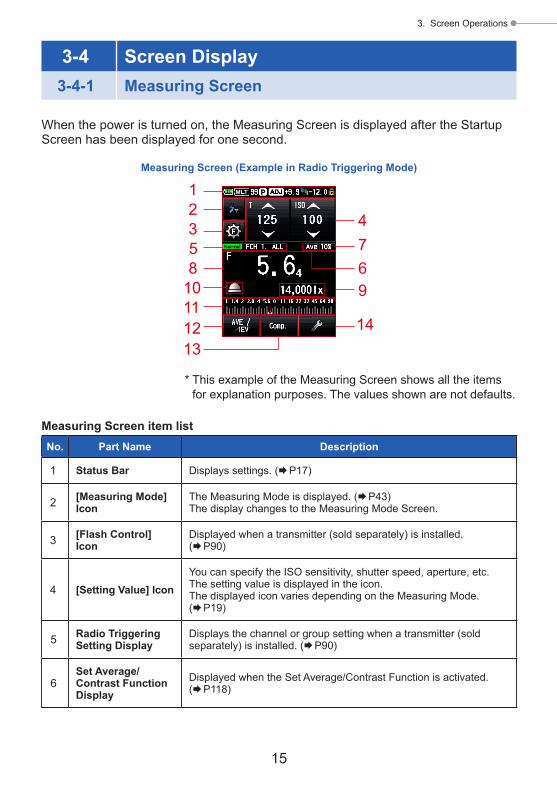
3-4 Screen Display3-4-1 Measuring Screen
When the power is turned on, the Measuring Screen is displayed after the Startup Screen has been displayed for one second.
Measuring Screen (Example in Radio Triggering Mode)
1
4769
14
2358
10111213
* This example of the Measuring Screen shows all the items for explanation purposes. The values shown are not defaults.
Measuring Screen item listNo. Part Name Description
1 Status Bar Displays settings. (P17)
2 [Measuring Mode] Icon
The Measuring Mode is displayed. (P43)The display changes to the Measuring Mode Screen.
3 [Flash Control] Icon
Displayed when a transmitter (sold separately) is installed. (P90)
4 [Setting Value] IconYou can specify the ISO sensitivity, shutter speed, aperture, etc.The setting value is displayed in the icon.The displayed icon varies depending on the Measuring Mode. (P19)
5 Radio Triggering Setting Display
Displays the channel or group setting when a transmitter (sold separately) is installed. (P90)
6Set Average/Contrast Function Display
Displayed when the Set Average/Contrast Function is activated. (P118)

16
3. Screen Operations
No. Part Name Description
7 Flash Component The percentage of flash light in the total exposure is displayed (in steps of 10%) (P73)
8Measured Value/Measuring Unit Display Area
Displays information such as measured values and measuring units. (P20)
9 Measured Value (Additional Data) Displays the additional data for the measured value. (P178)
10 Display Incident/Spot
Displayed when "Select Incident/Spot" is not assigned to Function Button -1 or -2. (P33)
11 Analog ScaleDisplays various information such as measured values, exposure profiles, and flash or ambient light components for flash analyzing, depending on the Measuring Mode. (P22)
12 Function Button -1Set the desired function to this Function Button. (P160)
13 Function Button -2
14 [Tool Box] Icon To make various settings for the current measurement, touch the [Tool Box] Icon on the Measuring Screen. (P26)
Function Button [Selectable in Custom Setting Menu]Part Name Icon Description
[Set Average/Contrast Function] Button
Set the Average/Contrast Function.Used with the Memory Function, displays the average of up to nine measured values. (P118)The Contrast Function displays a difference between current value and memorized/averaged value when Measuring Button 6 is pressed.(Excluding the Multiple (Cumu.) Flash Mode)
[Select Incident/Spot] Button
Set the light receiving method. (P32)Touch to switch between the Incident light (extended lumisphere or retracted lumisphere) and the reflected light (spot) measuring system.
[Set Exposure Compensation] Button
Toggling In/Out set exposure compensation for measured value. (P125)
[Filter Compensation] Button
Toggling In/Out set filter compensation for measured value. (P127)
[Mid. Tone] Button Activate to set current value as Mid-Tone for comparison on Analog Scale. (P139)

17
3. Screen Operations
Status bar1 2 3 4 5 6 7
8 9
* This example shows all the items for explanation purposes. The displayed information vary depending on settings.
Displayed item listNo. Part Name Description
1Battery Capacity Indicator Display
Full battery power remaining.
Sufficient battery power remaining.
Low battery power remaining. Have spare batteries ready.
Replace the batteries immediately.
2 Memory CountDisplays the number of measurement data items saved in the memory.The total number of data items in the memory is displayed up to "9" on the right of the M symbol.
3 Exposure Profile Appears when the exposure profile is set.
4 Exposure Compensation
Appears when Exposure compensation (adjustment) is set for the measured value.The numeric value indicates the compensation value (+/-9.9 EV).
5 Filter Compensation
Appears when filter compensation is set for the measured value.The numeric value indicates the compensation value (+/-12.0 EV).
6 Key Locked Status Display
Appears when the Screen Lock Function is active.No touch panel operations are available when the screen is locked.
7
Multiple (Cumu.) Flash Mode/Cumulative Count
Indicates that the Multi (Cumulative) Flash Mode is selected. ● Cordless Multi (Cumulative) Flash Mode ● Cord Multi (Cumulative) Flash Mode ● Radio Triggering Multi (Cumulative) Flash Mode
This item is displayed on each Measuring Screen of the modes above.Cumulative count (up to 99) is displayed on the right of the MLT symbol. When the cumulative count exceeds the maximum, the value begins from "00" again.
8 Menu Title - Displays the screen title.(The title is displayed, excluding the Measuring Screen.)
9 Page Number Displays the page number when there are multiple screens.
* The displayed information vary depending on the specified Measuring Mode.

18
3. Screen Operations
3-4-2 Measuring Operation/Display Area
The measuring operation/display area consists of the following components: ● Measuring Mode Icon ● Setting Value Icon ● Measured value/measuring unit display area ● Analog scale
Measuring Screen (Ambient T Priority Mode)
Measuring Screen (Ambient CINE Mode)
Setting Value IconMeasuring Mode Icon(Ambient Mode)
Measuring Mode Icon (CINE Mode)
Measured Value/Measuring Unit Display Area
Analog Scale
Measuring Mode Icon Touch the Measuring Mode Icon ( ) at the top left of the Measuring Screen to display the Measuring Mode Screen. Select any Measuring Mode on the Measuring Mode Screen. (P43)

19
3. Screen Operations
Setting Value IconYou can set the shutter speed, aperture, etc.The setting value is displayed in the icon. The displayed icon varies depending on the Measuring Mode.
Measuring ScreenT (shutter speed) Priority
Mode, Flash Measuring Mode
HD Cine Camera Mode
Cine Camera Mode
T+F (Shutter Speed/Aperture) Priority Mode
F (Aperture) Priority Mode
* The character on the upper-left side of the Setting Value Icon indicates the setting.
SettingsCharacter Description
TShutter speed Shutter speed is displayed in the following way.30m (30 minutes), 8s (8 seconds), 125 (1/125 of a second)
ISO ISO sensitivity
F Aperture
Ang Shutter angle
f/s Frames per second (Frame rate)
Operating the Setting Value Icon If you touch the arrow icon ( ), the setting value increases. If you touch the arrow icon ( ), the setting value decreases. Slide the icon number up or down with your fingertip to increase or decrease the setting value.
Setting Value Icon

20
3. Screen Operations
* If you touch the Setting Value Icon while the HD Cine Mode or Cine Mode is enabled, the display is enlarged.
[Example] CINE Mode
Measured value/measuring unit display area Displays information such as measured values and measuring units.
Measuring Screen
Measured Value
Measured Value (Additional data display)
Unit of Measured Value: ISO (ISO sensitivity)
Measured Value/Measuring Unit Display Area
Measuring Mode information display ● lx : Ambient light illuminance lx independent display ● cd/m2 : Ambient light luminance (cd/m2) independent display
Measuring Screen Incident light system
Measuring Screen Reflected light system
Viewfinder Display
Measured Values
* If the light receiving method is changed from the incident light system to the reflected light system, the display is automatically changed from the Ambient Light Illuminance (lx or fc) Mode to the Ambient Light Luminance (cd/m2 or fl) Mode.

21
3. Screen Operations
Viewfinder Display
Measuring Screen
Flash Component ● Flash component: The ratio of flash light to the total exposure is displayed as a percentage (in steps of 10%)
Measured Value
Unit of Measured Value: F (aperture)
Measured Value/Measuring Unit Display Area
NOTE
Fractions of a measured value can be displayed or hidden using the "Increments of T+F" in Custom Setting. (P165)
Display in Measuring Screen
Fraction hidden
Viewfinder Display
Fraction hidden
Fraction displayed
Fraction displayed

22
3. Screen Operations
Analog scale The analog scale displays the exposure setting for a current measurement and value relationships between two or more memorized measurements.
Memory PointerMeasured Value PointerMemory Pointer
Measured value scaleDepending on the Measuring Mode, the following values will be displayed on the scale.F value, T value, illuminance lx, luminance cd/m2
Shutter speed scale
Luminance (cd/m2) scale
Aperture scale
Illuminance (lx) scale
EV scaleThis scale has two modes that can be selected: measured value scale and EV scale. You can switch between these two modes using the Menu Function.
Menu Screen, Page 1 Analog Scale Selection Screen
EV scale display
Measured Value Scale
EV Scale
[Close] Button

23
3. Screen Operations
Flash analyzing scaleThe ambient light and flash light components are displayed on the analog scale when a flash light measurement is made. You can touch the scale to switch whether to display components or not. (P73)
No component displayedComponent displayedAmbient Light (Orange)
Flash Light (Blue)
Mid tone scaleThe scale color is changed when the Mid-Tone Mode is selected, and the clipping point and dynamic range are displayed. (P139)
Measuring display (with Mid-Tone specified)
Measuring display (with no Mid-Tone specified)
Dynamic Range [-]
Clipping Point
Dynamic Range [+]
3-4-3 USB Connection Screen
The USB symbol is displayed on the screen whenever meter is connected to a computer via USB cable.Button and touch panel operations are disabled, excluding the Power Button 5.
Screen displayed when a USB storage drive is connected

24
3. Screen Operations
3-4-4 Viewfinder Display
12 3
54
Viewfinder Display
Viewfinder item listNo. Part Name Description
1Measured value display Displays the measured value.
2 Additional display Displays the flash component ratio and the Illuminance/luminance symbol.
3Exposure compensation
Displays only the plus or minus sign when exposure compensation is set for the actually measured exposure value.
4 Unit display
The ratio of flash light to the total exposure is displayed as a percentage (in steps of 10%)
Appears when the shutter speed is set in minutes. Appears when the shutter speed is set in seconds.
Appears when the shutter speed is set with the cine frame rate.
5Monitor value/average value display area
Appears when the monitor measurement is active. Appears when the average measurement is active or the
standard value is specified for monitor measurement.
NOTICE
The viewfinder displays only measured values. The additional data cannot be displayed.

25
3. Screen Operations
Special Viewfinder display examples ● Shutter speeds higher that 1/1600s are abbreviated to the first digit and "k" multiplier symbol.Example: 1/2,000s = 2K
● In T+F priority, ISO numbers higher than ISO 160,000 as the first 3 digits and k multiplier symbol.Example: ISO 204,800 = 204K
Viewfinder Display
2Units: k (x 1,000)
Viewfinder Display
204Units: k (x 1,000)

26
3. Screen Operations
3-4-5 Tool Box Screen
Touch the [Tool Box] Icon ( ) on the Measuring Screen to make the following settings.
Filter Compensation Screen
Mid. Tone RecallScreen
Mid. Tone ClearScreen
Set Mid. Tone Screen
Select Incident/Spot Screen
Set Exposure ProfileScreen
Set Average/Contrast Function Screen Tool Box Screen
Exposure Compensation Value Screen
Measuring Screen
1
7
8
42
35
6
To next page
[Close] Button

27
3. Screen Operations
* When the Multiple (Cumu.) Flash Mode is selected, page 2 of the Tool Box Screen displays contents that are different from those shown above.
* The contents are displayed on page 2 of the Tool Box Screen if a transmitter (sold separately) is installed.
Multi Clear
Number of Pre-flash Screen
Radio CH/Zone Setting Screen with Transmitter (sold separately)
Flash Duration Analysis t Value Screen
Tool Box ScreenPage 2
Memory Recall Screen
Tool Box ScreenPage 2
Memory Clear Screen
9 10
11
12
13
14
* The contents displayed on page 2 of the Tool Box Screen vary depending on the meter setting or whether optional accessories are attached.

28
3. Screen Operations
Tool Box item listNo. Part Name Description
1 Set Average/Contrast Function Select ON or OFF. (P118)
2 Select Incident/Spot Select the light receiving method (Incident/Spot). (P32)
3 Set Exposure Compensation
Input an Exposure compensation value. The allowable exposure compensation range is -9.9 EV to +9.9 EV. (P125)
4 Filter CompensationSet filter compensation (you can input the filter compensation value or select the filter name).The allowable filter compensation range is -12.0 to +12.0. (P127)
5 Set Mid. Tone Set the mid-tone (from the current measured value or memorized value) or edit the mid tone value. (P139)
6 Mid. Tone Clear Delete the mid-tone value. (P145)
7 Mid. Tone Recall Recall the set mid-tone value. (P144)
8 Set Exposure Profile Select an exposure profile. (P147)
9 Memory Clear*1Delete the measured value that is saved in the memory.(Not displayed in the Multiple (Cumu.) Flash Mode.) (P113)
10 Memory Recall*1Recall the measured value that is saved in the memory.(Not displayed in the Multiple (Cumu.) Flash Mode.) (P116)
11 Multi Clear*1Clear the multiple flash reading.(Displayed in the Multiple (Cumu.) Flash Mode only.) (P82, P89)
12 Number of Pre-flash Select the number of pre-flash cancellation times. (P77, P83, P93, P98)
13 Flash Duration Analysis t Value
Select the analysis t value of the flash duration time. (P100, P105)
14 Radio CH/Zone (Group)*2 Select Radio channel and Zone (or Group). (P90)
*1 When the Multiple (Cumu.) Flash Mode is selected, the displayed information are different from those shown above.
*2 Displayed if a transmitter (sold separately) is installed.

29
3. Screen Operations
3-4-6 Menu Screen
Touch the Menu Button 9 to make the following settings.
Menu Button <<MENU>> 9
Analog Scale Screen
Edit Exposure ProfileScreen
Product Information Screen
Menu ScreenPage 2
Edit Shutter AngleScreen
Custom Setting Menu Screen
Menu ScreenPage 1
Edit Filter Screen
Edit Frame RateScreen
12
34
65
[Close] Button
* The contents on the Regulation Screen vary depending on the destination or whether a transmitter (sold separately) is installed.
7
8

30
3. Screen Operations
Menu item listNo. Part Name Description
1 Analog Scale Set the display of the analog scale. (P22)
2 Custom Setting Menu Select a function or set and edit the displayed information. (P156)
3 Edit Exposure Profile Edit exposure files created by Data Transfer Software on the meter side (about setting values and names). (P148)
4 Edit Frame Rate Create up to 20 frame rates in addition to the standard frame rates. (P57, P63)
5 Edit Shutter Angle Create up to 20 shutter angles in addition to the standard shutter angles. (P66)
6 Edit FilterSet filter compensation up to 30 sheets (No. 1 to No. 30).The specified filter compensation values can be freely edited. (P127)
7 Product Information Displays information such as the meter version.
8 Regulation Displays the compatibility symbol (institutions) for the legal restrictions according to which the meter is licensed.

31
4. Basic Operations
4. Basic Operations
4-1 Basic Measurement Workflow
[Hardware Setting]• User calibration (P189)• Touch panel adjustment (P191)• Factory setting (P193)• User information editing (P194)
Power ON (P5)
Switch the light receiving method (P32)
Select a Measuring Mode (P43)
Exposure compensation (P125)
Filter compensation (P127)
Exposure profile (P146)
Input setting values(See each Measuring Mode.)
Advanced functions
Measuring exposure(See each Measuring Mode.)
Display the measured values
Advanced functions
Mid. Tone (P139)
Set Average/Contrast Function (P118)
Memory, Clear, Recall (P111, P113, P116)
Power OFF (P6)
Extended lumisphere (P35)Retracted lumisphere (P35)
• T (shutter speed) Priority Mode (P48)
• F (Aperture) Priority Mode (P50)• T+F (Shutter Speed/Aperture)
Priority Mode (P52)• HD Cine camera (P54)• Cine camera (P60)
Incident light (P32)
Reflected light (P37)
Ambient light (P47)
Flash light(P73, P90)
Multiple (Cumulative)(P79, P87)
Cordless (P74, P79)
Cord connection (P85, P102)
Cordless (P91) HSS flash (P91)
Flash duration analysis (P95)
Radio Triggering (P90, P107) When a transmitter (sold separately) is installed
Shooting

32
4. Basic Operations
4-2 Switch the Light Receiving Method4-2-1 Incident Light System
The incident light system measures the light that is falling on the subject using the Extended lumisphere or Retracted Lumisphere Function. Point the lumisphere at the camera lens (lens optical axis) from a location close to the subject, then make a measurement.
1) Using the Function Button for Setting
* This section describes how to switch the light receiving method from the reflected light system to the incident light system.
1. Touch the [Function Button] Icon ( ) on the Measuring Screen.This changes the screen to the Select Incident/Spot Screen.
2. Touch the [Incident Light] Radio Button.This changes the system to the incident light system, and the display returns to the Measuring Screen.
Measuring Screen Measuring ScreenSelect Incident/Spot Screen
Function Button Specified light receiving method's Function Button

33
4. Basic Operations
NOTICE
If you used Custom Functions to change the Function Button assignment, sellect Incident/Spot using the Tool Box Screen. (P34)
NOTE
Icon Description
Displayed when the extended lumisphere is selected for incident light.
Displayed when the retracted lumisphere is selected for incident light.
Displayed when reflected light is selected.
Measuring Screen

34
4. Basic Operations
2) Setting on the Tool Box Screen
1. Touch the [Tool Box] Icon ( ) on the Measuring Screen.The Tool Box Screen is displayed.
2. Touch the [Select Incident/Spot] Button on the Tool Box Screen.The Select Incident/Spot Screen is displayed.
3. Touch the [Incident Light] Radio Button.This changes the system to the incident light system, and the display returns to the Measuring Screen.If you do not want to make any changes, touch the [Close] Button to return to the Measuring Screen.
Tool Box Screen
Measuring ScreenSelect Incident/Spot Screen
Measuring Screen
Specified light receiving method
NOTICE
Measurement values for the current Measuring Mode will be cleared when going to the Select Incident/Spot Screen.

35
4. Basic Operations
3) Interchanging the Extended Lumisphere and Retracted Lumisphere
1. Extending Lumisphere Extend the Lumisphere to measure the illumination of people, buildings, and other three dimensional subjects.Rotate the top of the Lumisphere Retracting Ring 1 to securely align the mark on the ring with the lumisphere mark ( ).
2. Retracting Lumisphere Retract the Lumisphere to measure the illumination of flat subjects such as manuscripts, books, or paintings, measure the illumination ratio (Contrast Function), and simply measure the illuminance.Rotate the Lumisphere Retracting Ring 1 to securely align the mark on the ring with the retracted lumisphere mark ( ).
Lumisphere Retracting Ring 1
Lumisphere Aligning Mark
Extended Mark Retracted Mark
Lumisphere 2
NOTICE
● Try to minimize your influence on the light measurement. Do not block the light falling on the subject with your hand or body. Do not allow light toned clothing to reflect light into the meter.
● Do not set the Lumisphere Retracting Ring 1 to an intermediate position. This will change the quality of the light and produce an incorrect measurement.
● Do not push down the Lumisphere 2 with your hand. ● Because it may affect the precision of the measurements, be careful not to damage or contaminate the Lumisphere 2. If the Lumisphere 2 becomes dirty, wipe it with a dry soft cloth. Never use organic solvent such as thinner or benzene.

36
4. Basic Operations
NOTE
If the Lumisphere 2 is damaged or stains cannot be removed, purchase a replacement of lumisphere for L-858 separately, and replace the defective lumisphere with the new one.1) How to replace the Lumisphere 2
Push down the Lumisphere Lock Lever k. While holding both the upper and lower parts of Lumisphere Retracting Ring 1, turn the ring counterclockwise to remove the lumisphere unit.
2) How to attach the Lumisphere 2 Align the mark on the Lumisphere Retracting Ring 1 with the mark on the meter head, and press the lumisphere unit in the meter head. Then, turn the ring clockwise until it clicks into place.
* Check to see that the Lumisphere Lock Lever k is engaged.* When attaching/detaching the Lumisphere 2, be sure not to
touch the light receiving element inside the meter head.
Lumisphere Retracting Ring 1
Lumisphere Lock Lever k
Light Receiving Element

37
4. Basic Operations
4-2-2 Reflected Light System
Switch the light receiving method to the reflected light system to make a measurement. The reflected light system measures the brightness (luminance) of the light reflected from the subject. It is useful to meter distant objects such as landscapes, if you cannot go to the location of the subject, or to meter subjects that generate light (neon signs, etc.), highly reflective surfaces, or translucent subjects (stained glass, etc.). Although the reflected measurement is useful to see from the highlight to shadow, the measured value should be compensated to use as the proper exposure depending on the reflectance ratio. Reflected light measurements are made by aligning the circle in the viewfinder with the subject area to be measured at the camera position or in the camera direction.
1) Using the Function Button for Setting
* This section describes how to switch the light receiving method from the incident light system to the reflected light system.
1. Touch the [Function Button] Icon ( ) on the Measuring Screen.This changes the screen to the Select Incident/Spot Screen.
2. Touch the [Reflected Light (Spot)] Radio Button.This changes the reflected light system, and the display returns to the Measuring Screen.
Measuring ScreenSelect Incident/Spot ScreenMeasuring Screen
Function Button Specified light receiving method's Function Button

38
4. Basic Operations
NOTICE
If you used Custom Functions to change the Function Button assignment, sellect Incident/Spot using the Tool Box Screen. (P39)
NOTE
Icon Description
Displayed when the extended lumisphere is selected for incident light.
Displayed when the retracted lumisphere is selected for incident light.
Displayed when reflected light is selected.
Measuring Screen

39
4. Basic Operations
2) Setting on the Tool Box Screen
1. Touch the [Tool Box] Icon ( ) on the Measuring Screen.The Tool Box Screen is displayed.
2. Touch the [Select Incident/Spot] Button on the Tool Box Screen.The Select Incident/Spot Screen is displayed.
3. Touch the [Reflected Light (Spot)] Radio Button.This changes the reflected light system, and the display returns to the Measuring Screen.If you do not want to make any changes, touch the [Close] Button to return to the Measuring Screen.
Tool Box Screen
Select Incident/Spot Screen Measuring Screen
Measuring Screen
Specified light receiving method
NOTICE
Measurement values for the current Measuring Mode will be cleared when going to the Select Incident/Spot Screen.

40
4. Basic Operations
3) Measuring Area
The measuring area is the inside of circle in the viewfinder.The light receiving angle is 1 degree.
4) Diopter Scale Compensation
While looking through the viewfinder, adjust the diopter by rotating the Viewfinder Eyepiece 4 so that the circle and digital display can be seen clearly.(The setting range is -2.5 to 1.0 D.)
WARNINGBe careful not to directly look at the sun or bright light sources during measurement.This may cause a serious eye injury or lead to blindness.
NOTE
<<Step-up ring>> (Accessory sold separately)You can attach a filter to the objective lens side using the step-up ring (30.5 mm → 40.5 mm). This allows you to determine the exposure without specifying the filter compensation value of the PL filter, etc., which is a burdensome task.The step-up ring can also be used as a hood to protect the lens part from damage or dirt and prevent an incorrect measurement due to lens flare or glare. (P196)
Viewfinder Display
Circle
Viewfinder Eyepiece 4

41
4. Basic Operations
4-2-3 Setting the Measuring Button 6 and Memory Button 7
You can interchange the Measuring Button 6 and Memory Button 7 using Custom Setting. (P168)
1. When mainly using the incident light system"Switching Measure / Memory Buttons" is set to "Standard" in the Custom Setting menu. (P157)
NOTE
Each time the meter is powered on, the assignment of the Memory and Measurement Buttons will be displayed for two seconds.
2. When mainly using the reflected light system (spot)If it is inconvenient to operate the Measuring Button in the reflected light system (spot), you can interchange the Measuring Button 6 and Memory Button 7.Select "Reverse" in "Switching Measure / Memory Buttons" on the Custom Setting menu. (P168)
Power Button 5
Memory Button 7
Measuring Button 6
Measuring Screen
Measuring Button 6
Memory Button 7

42
4. Basic Operations
NOTE
Each time the meter is powered on, the assignment of the Memory and Measurement Buttons will be displayed for two seconds.
3. When frequently using both the incident light and reflected light systemsIn the incident light system, the button position can be changed automatically to the standard configuration. In the reflected light system, it can be changed automatically to the reverse configuration.Select "Auto (Incident:Standard, Spot:Reverse)" in "Switching Measure / Memory Buttons" on the Custom Setting menu. (P168)
In Incident Light System In Reflected Light System
Memory Button
Memory Button
Measuring Button
Measuring Button
Auto (Incident: Standard,
Spot: Reverse)
Measuring Screen

43
4. Basic Operations
4-3 Selecting the Measuring Mode
Select the desired Measuring Mode.
NOTICE
If you change the Measuring Mode, the measured value is cleared.
Touch the Measuring Mode Icon ( ) on the Measuring Screen to display the Measuring Mode Screen. Here you can select any Measuring Mode to suit your light measuring needs.
* The Measuring Modes displayed on the Measuring Mode Screen vary depending on the details of Custom Setting. (P157)
Measuring Screen Measuring Mode Screen
1 7 c
2 8 d
3 9 e
4 0 f
5 a
6 b
* This example shows all the items for explanation.
Icons on the Measuring Mode Screen
Measuring Mode: Ambient Mode (P170)
No. Icon Description
1Ambient Light T (shutter speed) Priority ModeDisplays F-stop value (aperture) for input shutter speed and ISO sensitivity. (P48)
2Ambient Light F-stop (Aperture) Priority ModeDisplays shutter speed value for input F-stop and ISO sensitivity. (P50)
3Ambient Light T+F (Shutter Speed and Aperture) Priority ModeDisplays ISO sensitivity for input shutter speed and F-stop value. (P52)
4Ambient Light HD Cine ModeDisplays F-stop value for input shutter speed, frame rate and ISO sensitivity. (P54)

44
4. Basic Operations
5Ambient Light CINE ModeDisplays F-stop value for input frame rate, ISO sensitivity, and shutter angle values. (P60)
6
Ambient Light Illuminance lux Mode (Incident light measurement)Displays brightness value in lux (lx) unit. (P69)
Ambient Light Illuminance fc Mode (Incident light measurement)Displays brightness value in foot-candle (fc) unit. (P69)
Ambient Light Luminance cd/m2 Mode (Reflected light measurement)Displays brightness values in cd/m2 unit. (P71)
Ambient Light Luminance fl Mode (Reflected light measurement)Displays brightness value in foot-lambert (fl) unit. (P71)
NOTE
Ambient Light refers to natural light (sunlight) as well as continuous light like tungsten lamps and fluorescent lamps.
Measuring Mode: Flash Mode (P172)
No. Icon Description
7
Cordless Flash ModeDetects flash brightness without meter-flash connection after Measuring Button pressed to arm meter for 90 seconds and flash fired separately, and displays F-stop value for input shutter speed and ISO sensitivity. (P74)
8
Cordless Multiple (Cumulative) (MLT) Flash ModeDetects and accumulates flash brightness without meter-flash connection after Measuring Button pressed to arm meter for 90 seconds and flash fired separately, and displays F-stop value for input shutter speed and ISO sensitivity. (P79)
9Cord Flash ModeDetects flash brightness with synchro cord meter- flash connection, and displays F-stop value for input shutter speed and ISO sensitivity. (P85)
0
Cord Multi (Cumulative) Flash ModeDetects and accumulate flash brightness with synchro cord meter- flash connection, and displays F-stop value for input shutter speed and ISO sensitivity. (P87)
a
Radio Triggering Flash ModeDetects flash brightness after Measuring Button is pressed to send radio transmitted signal to radio receiver connected to flash. Displays F-stop value for input shutter speed and ISO sensitivity (When a transmitter sold separately is installed). (P90)

45
4. Basic Operations
b
Radio Triggering Multi (Cumulative) Flash ModeDetects and accumulate flash brightness after Measuring Button is pressed to send radio transmitted signal to radio receiver connected to flash. Displays F-stop value for input shutter speed and ISO sensitivity (When a transmitter sold separately is installed). (P90)
Measuring Mode: HSS Mode (P174)
No. Icon Description
c
HSS (High Speed Synchro) Flash Cordless ModeSelect this mode to measure the brightness of a flash activated in HSS (High Speed Synchro) Flash Mode. Detects flash brightness without meter-flash connection after Measuring Button pressed to arm meter for 90 seconds and flash fired separately, and displays F-stop value for input shutter speed and ISO sensitivity. (P91)
Measuring Mode: Flash Duration Analysis Mode (P176)
No. Icon Description
d
Flash Duration Analysis Cordless ModeDetects flash brightness without meter-flash connection after Measuring Button pressed to arm meter for 90 seconds and flash fired separately, and displays flash duration time, graph of flash waveform and F-stop value for input shutter speed and ISO sensitivity. (P95)
e
Flash Duration Analysis Cord ModeDetects flash brightness with synchro cord meter- flash connection, and displays flash duration time, graph of flash waveform and F-stop value for input shutter speed and ISO sensitivity. (P102)
f
Flash Duration Analysis Radio Triggering ModeDetects flash brightness after Measuring Button is pressed to send radio transmitted signal to radio receiver connected to flash. Displays flash duration time, graph of flash waveform and F-stop value for input shutter speed and ISO sensitivity (When a transmitter sold separately is installed). (P107)
NOTE
Flash refers to momentary light such as that produced by a flashlight or flash bulb.

46
4. Basic Operations
Operation
* This section describes how to switch from the Ambient T Priority Mode to the Ambient CINE Mode.
1. Touch the Measuring Mode Icon on the upper left of the screen.The Measuring Mode Screen is displayed.
Measuring Mode ScreenMeasuring Screen
Measuring Mode Icon
2. Touch the desired icon on the Measuring Mode Screen.Select the desired Measuring Mode. Then, the screen changes.
Measuring Mode Screen Measuring Screen

47
5. Measuring
5. Measuring
5-1 Measuring in Ambient Light Mode
Continuous light like natural light (sunlight) as well as tungsten lamps and fluorescent lamps are measured in Ambient Light Mode.The following measuring methods are available in Ambient Light Mode.
● T (shutter speed) priority ● F (f-stop) priority ● T+F (EV) priority ● Illuminance Mode (Lux or Foot-candle) (in incident light measurement) ● Luminance Mode (cd/m2 or Foot-lambert) (in reflected light measurement)
NOTE
● Shutter speed and f-stop (aperture) values can be displayed in 1, 1/2 and 1/3 stop increments in Custom Setting. (P163)
● After taking a measurement, changing a setting value (ISO sensitivity, shutter speed, aperture, frame rate, or shutter angle) will display the corresponding measured value.
● Touching the Average Icon ( ) at the bottom of the screen activates the Average Function. (P118)
● The Analog Scale display will change according to Measuring Mode, Incident/Reflected and Mid-Tone Mode selected as well as "Set Analog Scale" (Measurement Scale or EV Scale) in Menu list. (P22)
● If the reading is outside the display range or beyond the measuring range, change the aperture or adjust the brightness. (P108)

48
5. Measuring
5-1-1 T (shutter speed) Priority Mode
Displays aperture (F) for input ISO sensitivity and shutter speed values.
Operation
1. Touch the Measuring Mode Icon on the Measuring Screen.The Measuring Mode Screen is displayed.
2. Touch the icon ( ) on the Measuring Mode Screen.When it is selected, the display changes to the Measuring Screen.
Measuring Screen Measuring Screen
Measuring Mode Icon
Measuring Mode Screen
3. Set the light receiving method.Switch to the Incident light, extended lumisphere ( )/retracted lumisphere ( ), or reflected light. (P32, P37)

49
5. Measuring
4. Set the ISO sensitivity value on the [ISO] Icon. (P197)
5. Set the shutter speed on the [T] Icon. (P197)
Measuring Screen
Setting Value
6. Press the Measuring Button 6 on the side of the meter to measure the light.The measured value (F-stop) will be displayed.While the Measuring Button 6 is being pressed, the meter measures continuously until the button is released. When the Measuring Button 6 is released, the measurement is completed. The measured value at that time will be displayed in the measured value/measuring unit display area and on the analog scale. (P22, P24)
Measuring Screen
Viewfinder Display(in reflected light measurement)
Measured Value (F-stop)

50
5. Measuring
Operation
1. Touch the Measuring Mode Icon on the Measuring Screen.The Measuring Mode Screen is displayed.
2. Touch the icon ( ) on the Measuring Mode Screen.When it is selected, the display changes to the Measuring Screen.
Measuring Screen Measuring Screen
Measuring Mode Icon
Measuring Mode Screen
3. Set the light receiving method.Switch to the Incident light, extended lumisphere ( )/retracted lumisphere ( ), or reflected light. (P32, P37)
5-1-2 F (F-stop) Priority Mode
Displays shutter speed (T) for input ISO sensitivity and f-stop values.

51
5. Measuring
4. Set the ISO sensitivity value on the [ISO] Icon. (P197)
5. Set the aperture on the [F (f-stop)] Icon. (P198)
Measuring Screen
Setting Value
6. Press the Measuring Button 6 on the side of the meter to measure the light.The measured value (shutter speed) will be displayed.While the Measuring Button 6 is being pressed, the meter measures continuously until the button is released. When the Measuring Button 6 is released, the measurement is completed. The measured value at that time will be displayed in the measured value/measuring unit display area and on the analog scale. (P22, P24)
Measuring Screen
Viewfinder Display(in reflected light measurement)
Measured Value (Shutter Speed)

52
5. Measuring
Operation
1. Touch the Measuring Mode Icon on the Measuring Screen.The Measuring Mode Screen is displayed.
2. Touch the icon ( ) on the Measuring Mode Screen.When it is selected, the display changes to the Measuring Screen.
Measuring Screen Measuring Screen
Measuring Mode Icon
Measuring Mode Screen
3. Set the light receiving method.Switch to the Incident light, extended lumisphere ( )/retracted lumisphere ( ), or reflected light. (P32, P37)
5-1-3 T+F (Shutter Speed/F-stop) Priority Mode
Displays ISO sensitivity for input shutter speed and f-stop values.The T+F (Shutter Speed/F-stop) Priority Mode is useful for today's digital cameras when a fixed speed and aperture are desired and the ISO can be adjusted for appropriate exposure.

53
5. Measuring
4. Set the shutter speed on the [T] Icon. (P197)
5. Set the aperture on the [F (f-stop)] Icon. (P198)
Measuring Screen
Setting Value
6. Press the Measuring Button 6 to measure the light on the side of the meter.The measured ISO sensitivity value will be displayed.While the Measuring Button 6 is being pressed, the meter measures continuously until the button is released. When the Measuring Button 6 is released, the measurement is completed. The measured value at that time will be displayed in the measured value/measuring unit display area and on the analog scale. (P22, P24)
Measuring Screen
Viewfinder Display(in reflected light measurement)
Measured Value (ISO Sensitivity)
NOTICE
In the T+F (Shutter Speed/F-stop) Priority Mode, the ISO sensitivity (measured value) can be stored in the memory, but cannot be displayed on the scale.

54
5. Measuring
Operation
1. Touch the Measuring Mode Icon on the Measuring Screen.The Measuring Mode Screen is displayed.
2. Touch the icon ( ) on the Measuring Mode Screen.When it is selected, the display changes to the Measuring Screen.
Measuring Screen Measuring Screen
Measuring Mode Icon
Measuring Mode Screen
3. Set the light receiving method.Switch to the Incident light, extended lumisphere ( )/retracted lumisphere ( ), or reflected light. (P32, P37)
5-1-4 HD CINE Mode
Displays f-stop value for input shutter speed, ISO sensitivity and frame rate (f/s).
1) Measuring

55
5. Measuring
4. Set the ISO sensitivity value on the [ISO] Icon. (P197)Touch the [ISO] Icon to expand it. Slide the icon number up or down using your fingertip to set the measured value. The icon will return to its reduced size after the icon is not touched for a short time.
Measuring Screen Close-up
5. Set the frame rate on [f/s] Icon.Touch the [f/s] Icon to expand it. Slide the icon number up or down using your fingertip to set the frame rate. The icon will return to its reduced size after the icon is not touched for a short time.
Close-upMeasuring Screen
6. Set the shutter speed on the [T] Icon. (P197)
Measuring Screen

56
5. Measuring
7. Press the Measuring Button 6 on the side of the meter to measure the light.The measured value (F-stop) will be displayed.While the Measuring Button 6 is being pressed, the meter measures continuously until the button is released. When the Measuring Button 6 is released, the measurement is completed. The measured value at that time will be displayed in the measured value/measuring unit display area and on the analog scale. (P22, P24)
Measuring Screen
Viewfinder Display(in reflected light measurement)
Measured Value (F-stop)
NOTE
● There are 20 preset of frame rates that can be customized. (P57) ● The T value cannot be set lower than the selected frame rate.

57
5. Measuring
2) Frame Rate Editing
In addition to the standard frame rates available in the meter, up to 20 frame rates can be customized and displayed in the Meter Screen. The stored frame rates can be edited as desired. (P198)
Page 3 Page 4Page 2Page 1
Menu Screen, Page 1
Edit Frame Rate Screen
Edit Frame Rate
To previous pageTo previous page
To next pageTo next pageTo next page [Close] Button
Operation
1. Press the Menu Button 9 on the meter to open the Menu Screen.
Menu Button 9

58
5. Measuring
2. Touch [Edit Frame Rate] Button to display the Edit Frame Rate Screen.
3. Touch [Frame Rate] Button to display the Frame Rate Screen.
Menu ScreenPage 1
Edit Frame Rate Screen
[Frame Rate] Button
Frame Rate Screen
4. Input a numeric value in the Input Frame Rate Screen. (P11)
5. Touch [OK] Button.The display will return to the Edit Frame Rate Screen.Touch the [Cancel] Button to return to the Edit Frame Rate Screen without changing the value.
Frame Rate Screen
The input numeric value is displayed.
[OK] Button [Cancel] Button
NOTICE ● The frame rate is set in steps of 0.001 (f/s) within a range from 0.001 to 99,999.999 (f/s). (P198)
● The frame rate is not displayed if its box is unchecked.

59
5. Measuring
6. Check the box of the desired frame rate.Touch the box () to check it (check mark ). The checked frame rate is displayed after 1,000f/s on the Measured Screen. When the box is unchecked, it is deselected.
Edit Frame Rate Screen
The input numeric value is displayed.
[Close] Button
Check Box
To next page
Measuring Screen Measuring Screen
7. Touch [Close] Button on the Edit Frame Rate Screen.The display returns to the Menu Screen.
8. Touch [Close] Button on the Menu Screen.The display returns to the Measuring Screen.
Edit Frame Rate Screen Menu Screen, Page 1
[Close] Button
[Close] Button

60
5. Measuring
5-1-5 CINE Mode
This mode measures the aperture for input frame rate (f/s), ISO sensitivity and shutter angle.
1) Measuring
Operation
1. Touch the Measuring Mode Icon on the Measuring Screen.The Measuring Mode Screen is displayed.
2. Touch the icon ( ) on the Measuring Mode Screen.When it is selected, the display changes to the Measuring Screen.
Measuring Screen Measuring Screen
Measuring Mode Icon
Measuring Mode Screen
3. Set the light receiving method.Switch to the Incident light, extended lumisphere ( )/retracted lumisphere ( ), or reflected light. (P32, P37)

61
5. Measuring
4. Set the ISO sensitivity value on the [ISO] Icon. (P197)Touch the [ISO] Icon to expand it. Slide the icon number up or down using your fingertip to set the measured value. The icon will return to its reduced size after the icon is not touched for a short time.
Measuring ScreenClose-up
5. Set the shutter angle on the [Ang] Icon.Touch the [Ang] Icon to expand it. Set the shutter angle under this condition. The icon will return to its reduced size after the icon is not touched for a short time. The icon will return to its reduced size after the icon is not touched for a short time.
Close-upMeasuring Screen
6. Set the frame rate on the [f/s] Icon. (P198)Slide the icon number up or down using your fingertip to set the frame rate.
Measuring Screen

62
5. Measuring
7. Press the Measuring Button 6 on the side of the meter to measure the light.The measured value (F-stop) will be displayed.While the Measuring Button 6 is being pressed, the meter measures continuously until the button is released. When the Measuring Button 6 is released, the measurement is completed. The measured value at that time will be displayed in the measured value/measuring unit display area and on the analog scale. (P22, P24)
Measuring Screen
Viewfinder Display (in reflected light measurement)
Measured Value (F-stop)
NOTE
● There are 20 preset of frame rates that can be set at "Edit Frame Rate" in the MENU list. (P63)
● There are 20 preset of shutter angles that can be set at "Edit Shutter Angle" in the MENU list. (P66)
● The T value cannot be set lower than the selected frame rate.

63
5. Measuring
2) Frame Rate Editing
In addition to the standard frame rates available in the meter, up to 20 frame rates can be customized and displayed in the Meter Screen. The stored frame rates can be edited as desired.
Page 3 Page 4Page 2Page 1
Menu Screen, Page 1
Edit Frame Rate Screen
Edit Frame Rate
To previous page To next page[Close] Button
Operation
1. Press the Menu Button 9 on the meter to open the Menu Screen.
Menu Button 9

64
5. Measuring
2. Touch [Edit Frame Rate] Button to display the Edit Frame Rate Screen.
3. Touch [Frame Rate] Button to display the Frame Rate Screen.
Menu ScreenPage 1
Edit Frame Rate Screen
[Frame Rate] Button
Frame Rate Screen
4. Input a numeric value in the Input Frame Rate Screen. (P11)
5. Touch [OK] Button.The display will return to the Edit Frame Rate Screen.Touch the [Cancel] Button to return to the Edit Frame Rate Screen without changing the value.
Frame Rate Screen
The input numeric value is displayed.
[OK] Button [Cancel] Button
NOTICE ● The frame rate is set in steps of 0.001 (f/s) within a range from 0.001 to 99,999.999 (f/s). (P198)
● The frame rate is not displayed if its box is unchecked.

65
5. Measuring
6. Check the box of the desired frame rate.Touch the box () to check it (check mark ). The checked frame rate is displayed after 1000f/s on the Measured Screen. When the box is unchecked, it is deselected.
Edit Frame Rate Screen
The input numeric value is displayed.
[Close] Button
Check Box
To next page
Measuring Screen Measuring Screen
7. Touch [Close] Button on the Edit Frame Rate Screen.The display returns to the Menu Screen.
8. Touch [Close] Button on the Menu Screen.The display returns to the Measuring Screen.
Edit Frame Rate Screen Menu Screen, Page 1
[Close] Button
[Close] Button

66
5. Measuring
3) Shutter Angle Editing
In addition to the standard shutter angles available in the meter, up to 20 shutter angles can be customized and displayed in the Meter Screen. The input shutter angle can be edited as desired.
Page 3 Page 4Page 2Page 1
Menu Screen, Page 1
Edit Shutter Angle Screen
Edit Shutter Angle
To previous page To next page[Close] Button
Operation
1. Press the Menu Button 9 on the meter to open the Menu Screen.
Menu Button 9

67
5. Measuring
2. Touch the [Edit Shutter Angle] Button.The Edit Shutter Angle Screen is displayed.
3. Touch the [Shutter Angle] Button.The Input Shutter Angle Screen is displayed.
Menu ScreenPage 1
Edit Shutter Angle Screen
[Shutter Angle] Button
Shutter Angle Screen
4. Input a numeric value on the Input Shutter Angle Screen. (P11)
5. Touch [OK] Button.The display will return to the Edit Shutter Angle Screen.Touch the [Cancel] Button to return to the Edit Shutter Angle Screen without changing the value.
Shutter Angle Screen
The input numeric value is displayed.
[OK] Button [Cancel] Button
NOTICE
● Shutter angle is set in steps of 0.001° within a range from 0.001 to 360°. ● The frame rate is not displayed if its box is unchecked.

68
5. Measuring
6. Check the box corresponding to the desired shutter angle.Touch the box () to check it (check mark ). The checked shutter angle is displayed after Ang 358 on the Measuring Screen. When the box is unchecked, it is deselected. When checked (check mark ), an arrow is displayed above Ang 358.
Edit Shutter Angle Screen
The input numeric value is displayed.
[Close] Button
Check Box
To next page
Measuring Screen Measuring Screen
7. Touch the [Close] Button on the Edit Shutter Angle Screen.The display returns to the Menu Screen.The added shutter angle is displayed at the end of the sequence on the Measuring Screen.
8. Touch [Close] Button on the Menu Screen.The display returns to the Measuring Screen.
Edit Shutter Angle Screen Menu Screen, Page 1
[Close] Button
[Close] Button

69
5. Measuring
5-1-6 Illuminance/Luminance Mode
Illuminance is measured using the Incident Light Mode, and luminance is measured using the Reflected Light (Spot) Mode.The following are the units that can be set. Select the Illuminance/Luminance Unit in the Custom Setting. (P156)
Incident light measurement (Illuminance)
Lux (Unit: lx)(P69)
Foot-candle (Unit: fc)
Reflected light measurement (Luminance) cd/m2
Candela per square meter (Unit: cd/m2) (P71)
Foot-lambert (Unit: fl)
NOTE
Any calibration or exposure compensation will not be in effect when measuring illuminance or luminance.
1) Illumination Measuring
Operation
1. Switch the light receiving method to incident light. (P32)
2. Touch the Measuring Mode Icon on the Measuring Screen.The Measuring Mode Screen is displayed.
3. Touch the icon ( or ) on the Measuring Mode Screen.When it is selected, the display changes to the Measuring Screen.
Measuring Screen Measuring Screen
[Measuring Mode] Icon
Measuring Mode Screen

70
5. Measuring
4. Switch to the retracted lumisphere.If extended lumisphere is selected, rotate the Lumisphere Retracting Ring 1 to switch to the retracted lumisphere ( ) position.
Lumisphere Retracting Ring 1
Retracted Mark ( )
Measuring Screen
5. Point the light receptor directly toward the light source.
6. Press the Measuring Button 6 on the side of the meter to measure the light.The measured illuminance will be displayed in lux (measured value).While the Measuring Button 6 is being pressed, the meter measures continuously until the button is released. When the Measuring Button 6 is released, the measurement is completed. The measured value at that time will be displayed in the measured value/measuring unit display area and on the analog scale. (P22)
Measuring Screen
Measured Value (lx)
Measuring Screen
Measured Value (fc)

71
5. Measuring
2) Luminance Measuring
Operation
1. Switch the light receiving method to reflected light. (P37)
2. Touch the Measuring Mode Icon on the Measuring Screen.The Measuring Mode Screen is displayed.
3. Touch the icon ( or ) on the Measuring Mode Screen.When it is selected, the display changes to the Measuring Screen.
Measuring Screen Measuring Screen
[Measuring Mode] Icon
Measuring Mode Screen

72
5. Measuring
4. While looking through the viewfinder, press the Measuring Button 6 on the side of the meter to measure the light.While looking through the viewfinder, locate the subject area to be measured within the finder circle.
Press the Measuring Button 6, and the luminance will be displayed in Candelas square meter (measured value). While the Measuring Button 6 is being pressed, the meter measures continuously until the button is released. When the Measuring Button 6 is released, the measurement is completed. The measured value at that time will be displayed in the measured value/measuring unit display area and on the analog scale. (P22, P24)
Measuring ScreenViewfinder Display
Measured Value (cd/m2) Measured Value (fl)
Viewfinder DisplayMeasuring Screen
WARNINGDo not look directly at the sun or an intense light source via the viewfinder. Doing so may damage your eyesight.
NOTE
While looking through the viewfinder, adjust the diopter by rotating the Viewfinder Eyepiece (with diopter adjustment) 4 so that the circle can be seen clearly.
Viewfinder Eyepiece 4

73
5. Measuring
5-2 Measuring in Flash Light Mode
Flash illumination is light that is produced by the very brief light pulse of an electronic flash unit or flash bulb. Flash measurement is available in the following modes:
● Cordless Flash Mode ● Cordless Multi (Cumulative) Flash Mode ● Cord (PC) Flash Mode ● Cord Multi (Cumulative) Flash Mode ● Radio Triggering Flash Mode *Available when a transmitter (sold separately) is installed
● Radio Triggering Multi (Cumulative) Flash Mode *Available when a transmitter (sold separately) is installed
Screen Display Details When flash light is measured, f-stop (Ambient brightness + Flash brightness = total exposure) is displayed on the screen.The ratio of flash light to the total exposure is displayed in steps of 10%.The analog scale displays the ambient component (orange line) and flash component (blue line).Example: As shown in the screen below, if the shutter speed is 1/125s and ISO
sensitivity is 100, the flash component and ambient light component will be 50%, respectively. The analog scale displays the measured value of both the flash component (blue) and the ambient component (orange), and the photo becomes a little yellowish if the tungsten light is used as the ambient light.
Measuring Screen example in Cordless Flash Mode
Viewfinder Display (in reflected light
measurement)
Setting Value
Flash ComponentMeasured ValuesAnalog Scale
Ambient Light(Orange)
Flash Light(Blue)

74
5. Measuring
NOTE ● Shutter speed and f-stop (aperture) values can be displayed in 1, 1/2 and 1/3 stop increments in Custom Setting. (P163)
● After taking a measurement, changing a setting value (ISO value or shutter speed) will display the corresponding aperture.
● Touching the Average Icon ( ) at the bottom of the screen activates the Average or Contrast Function. (P118)
● The Analog Scale display will change according to Measuring Mode, Incident/Reflected and Mid-Tone Mode selected as well as "Set Analog Scale" (Measurement Scale or EV Scale) in Menu list. (P22)
● If the reading is outside the display range or beyond the measuring range, change the aperture or adjust the brightness. (P108)
5-2-1 Cordless Flash Mode
In this Measuring Mode, the meter detects flash brightness without meter-flash connection after Measuring Button 6 pressed to arm meter for 90 seconds and flash fired separately. It displays F-stop value for input shutter speed and ISO sensitiity. It is used when the synchro cord will not reach because of the distance between the flash and meter, or when use of synchro cord is inconvenient.
1) Measuring
Operation
1. Touch the Measuring Mode Icon on the Measuring Screen.The Measuring Mode Screen is displayed.
2. Touch the icon ( ) on the Measuring Mode Screen.When it is selected, the display changes to the Measuring Screen.
Measuring Screen Measuring Screen
[Measuring Mode] Icon
Measuring Mode Screen

75
5. Measuring
3. Set the light receiving method.Switch to the Incident light, extended lumisphere ( )/retracted lumisphere ( ), or reflected light. (P32, P37)
4. Set the ISO sensitivity value on the [ISO] Icon. (P197)
5. Set the shutter speed on the [T] Icon. (P197)
Measuring Screen
Setting Value
NOTICE
Make sure that the settings are within the specifications of the camera and flash system.
6. Press the Measuring Button 6. The meter will enter the Measuring Standby Mode, and the Measuring Mode Icon ( ) will blink for 90 seconds.The LCD screen dims and stands by.
Measuring Screen

76
5. Measuring
NOTICE
In case of the following, please follow "5-2-3 Cord Flash Mode". (P85) ● When firing the flash, if the flash brightness is lower than the ambient light, the meter may fail to detect the light.
● Rapid start fluorescent lamps and special lighting are sometimes mistaken for flash and accidentally measured.
● Even if the flash is not fired, when a sudden light change occurs in the light receptor, measurement may be made.
● The waveform of a flash bulb has a slight slope and there is a possibility that the light meter cannot recognize the flash bulb in Cordless Flash Mode.
NOTE
● In the Cordless Flash Mode, the backlight of the LCD screen dims and is only illuminated for three seconds after measurement.
● After the measurement, the meter enters the 90-second Standby Mode again. If you need to measure again, fire the flash during this time.
● If the measured values are stored in the memory, the Measurement Standby Mode is canceled.
● If the icon stops blinking before the flash fires, repeat Steps 6 and 7. ● To stop the Standby Mode, just touch the screen. ● It is convenient to set the light meter in a fixed position during the measuring time. This can be accomplished by mounting the meter on a tripod or stand using the tripod socket on the bottom of the meter.
7. Trigger the flash unit manually while the Measuring Mode Icon ( ) is blinking.When the flash light is detected, the measurement is made automatically and the measured value (F-stop) is displayed.
Measuring Screen
Flash Component
Measured Value (F-stop)

77
5. Measuring
2) Number of Pre-flash
For red-eye prevention and auto-flash light adjustment, some devices can pre-flash before main flash burst.With the normal setting, the light meter will measure the pre-flash bursts and not the main flash burst. To take a successful reading, activate the pre-flash feature in the Tool Box.
Operation
1. Touch the [Tool Box] Icon ( ) on the Measuring Screen.The Tool Box Screen is displayed.
2. Touch the [Next Page] Icon ( ) of the Tool Box to display the Tool Box showing "Number of Pre-flash".This button is enabled if Flash Mode is selected. If it is grayed out, check the Measuring Mode.
3. Touch the [Number of Pre-flash] Button of the Tool Box.The Number of Pre-flash Screen is displayed.If you do not change this number, touch the [Close] Button.
Measuring Screen Tool Box ScreenPage 1
[Close] ButtonTo next page
Tool Box ScreenPage 2

78
5. Measuring
4. Touch the radio button of the Number of Pre-flash Button.Set the number of pre-flash on the Number of Pre-flash Screen. The display returns to the Measuring Screen.
If you do not change this number, touch the [Close] Button to return to the Measuring Screen.
Number of Pre-flash Screen
[Close] Button
NOTE
The amount of pre-flashes fired by a flash unit can be different for different camera brands. Check the camera manual for number fired by your camera system.

79
5. Measuring
5-2-2 Cordless Multi (Cumulative) Flash Mode
This Measuring Mode is used when the light generated by the flash at one time is inadequate for the desired F-stop setting. Repeated flash pops can be accumulated until the desired F-stop value is displayed.When the Measuring Button 6 is pressed, the light meter is set to the Standby Mode (90 seconds) and makes a measurement by activating the flash. The measured value (F-stop) is displayed for each trigger of the flash.The cumulative count is infinite. Up to 99 times is displayed in the Status/Title field, however, the cumulative count returns to 0(zero) for more than 100 times (0=100, 1=101, 2=102, etc.).
1) Measuring
Operation
1. Touch the Measuring Mode Icon on the Measuring Screen.The Measuring Mode Screen is displayed.
2. Touch the icon ( ) on the Measuring Mode Screen.When it is selected, the display changes to the Measuring Screen.
Measuring Screen Measuring Screen
[Measuring Mode] Icon
Measuring Mode Screen
3. Set the light receiving method.Switch to the Incident light, extended lumisphere ( )/retracted lumisphere ( ), or reflected light. (P32, P37)

80
5. Measuring
4. Set the ISO sensitivity value on the [ISO] Icon. (P197)
5. Set the shutter speed on the [T] Icon. (P197)
Measuring Screen
Setting Value
NOTICE
Make sure that the settings are within the specifications of the camera and flash system.
6. Press the Measuring Button 6.The meter will enter the Measuring Standby Mode, and the Measuring Mode Icon ( ) will blink for 90 seconds.The LCD screen dims and stands by.
Measuring Screen

81
5. Measuring
7. Trigger the flash unit manually while the Measuring Mode Icon ( ) is blinking. When the flash light is detected, the measurement is made automatically and the measured value (F-stop) is displayed. Repeat triggering the flash unit until the desired F-stop is displayed during the Standby Mode.
Measuring Screen
Flash Component
Measured Value (F-stop)
NOTICE
● In case of the following, please follow "5-2-4 Cord Multi (Cumulative) Flash Mode". (P87) - When firing the flash, if the flash brightness is significantly lower than the
ambient light, the meter may fail to detect the light. - Rapid start fluorescent lamps and special lighting are sometimes mistaken for
flash and accidentally measured. - Even if the flash is not fired, when a sudden light change occurs in the light
receptor, measurement may be made. - The waveform of a flash bulb has a slight slope and there is a possibility that the
light meter cannot recognize the flash bulb in Cordless Flash Mode ● The EV scale cannot be displayed in this Measuring Mode.
NOTE
● In the Cordless Multiple (Cumulative) Flash Mode, the backlight of the LCD screen dims and is only illuminated for three seconds after measurement.
● After the measurement, the meter enters the 90-second Standby Mode again. If you need to measure again, fire the flash during this time.
● If the measured values are stored in the memory, the Measurement Standby Mode is canceled.
● If the icon stops blinking before the flash fires, repeat Steps 6 and 7. ● To stop the Standby Mode, just touch the screen. ● It is convenient to set the light meter in a fixed position during the measuring time. This can be accomplished by mounting the meter on a tripod or stand using the tripod socket on the bottom of the meter.

82
5. Measuring
2) Multi Clear
Clears the cumulative count.
Operation
1. Touch the [Tool Box] Icon ( ) on the Measuring Screen.The Tool Box Screen is displayed.
2. Touch the [Next Page] Icon ( ) of the Tool Box to display the Tool Box showing "Multi Clear".This button is only enabled during measurement. If the button is grayed out, the cumulative measurement is not made and the count cannot be cleared.
3. Touch the [Multi Clear] Button of the Tool Box.The cumulate value is cleared, and the display returns to the Measuring Screen.If you do not change the value, touch the [Close] Button. The display returns to the Measuring Screen.
Measuring Screen Tool Box ScreenPage 1
[Close] ButtonTo next page
Tool Box ScreenPage 2
Cumulative CountMeasuring Screen
Cumulative Count
Cumulative Count

83
5. Measuring
3) Number of Pre-flash
For red-eye prevention and auto-flash light adjustment, some devices can pre-flash before main flash burst.With the normal setting, the light meter will measure the pre-flash bursts and not the main flash burst. To take a successful reading, activate the pre-flash feature in the Tool Box.
Operation
1. Touch the [Tool Box] Icon ( ) on the Measuring Screen.The Tool Box Screen is displayed.
2. Touch the [Next Page] Icon ( ) of the Tool Box to display the Tool Box showing "Number of Pre-flash".This button is enabled if Flash Mode is selected. If it is grayed out, check the Measuring Mode.
3. Touch the [Number of Pre-flash] Button of the Tool Box.The Number of Pre-flash Screen is displayed.If you do not change this number, touch the [Close] Button.
Measuring Screen Tool Box ScreenPage 1
[Close] ButtonTo next page
Tool Box ScreenPage 2
NOTE
When the standby state is released and when the Measuring Button 6 is pressed again, the measuring will start with a cumulative count of "0".

84
5. Measuring
4. Touch the radio button of the Number of Pre-flash Button.Set the number of pre-flash on the Number of Pre-flash Screen. The display returns to the Measuring Screen.
If you do not change this number, touch the [Close] Button to return to the Measuring Screen.
Number of Pre-flash Screen
[Close] Button
NOTE
The amount of pre-flashes fired by a flash unit can be different for different camera brands. Check the camera manual for number fired by your camera system.

85
5. Measuring
5-2-3 Cord Flash Mode
In this Measuring Mode, a synchro cord (sold separately) is used to connect the flash to the meter. Use this Cord Flash Mode when you need to ensure synchronization with the flash or use a flash bulb. After pressing the Measuring Button 6, the meter trigger the flash unit and displays F-stop value.
Operation
1. Connect the synchro cord (sold separately), which is connected to the flash, to the meter. (P195)Connect the synchro cord (sold separately) to the meter's Synchro Terminal b.
2. Touch the Measuring Mode Icon on the Measuring Screen.The Measuring Mode Screen is displayed.
3. Touch the icon ( ) on the Measuring Mode Screen.When it is selected, the display changes to the Measuring Screen.
Measuring Screen Measuring Screen
[Measuring Mode] Icon
Measuring Mode Screen
4. Set the light receiving method.Switch to the Incident light, extended lumisphere ( )/retracted lumisphere ( ), or reflected light. (P32, P37)
Synchro Terminal b
Synchro Cord (sold separately)

86
5. Measuring
NOTICE
● When the synchro cord is connected to the Synchro Terminal b or when the meter's Power Button 5 is operated, the flash may fire.
● Also, the flash may not fire when the trigger voltage is very low. In such a case, follow "5-2-1 Cordless Flash Mode". (P74)
5. Set the ISO sensitivity value on the [ISO] Icon. (P197)
6. Set the shutter speed on the [T] Icon. (P197)
Measuring Screen
Setting Value
NOTICE
Make sure that the settings are within the specifications of the camera and flash system.
7. Press the Measuring Button 6. The flash will fire and the measured value (F-stop) will be displayed.
Measuring Screen
Flash Component
Measured Value (F-stop)

87
5. Measuring
5-2-4 Cord Multi (Cumulative) Flash Mode
This Measuring Mode is used when the light generated by the flash at one time is inadequate for the desired F-stop setting. Repeated flash pops can be accumulated until the desired F-stop value is displayed. The measured value (F-stop) is displayed for each trigger of the flash. The cumulative count is displayed in the Status/Title field. The cumulative count is infinite. Up to 99 times is displayed in the Status/Title field, however, the cumulative count returns to 0(zero) for more than 100 times (0=100, 1=101, 2=102, etc.).
1) Measuring
Operation
1. Connect the synchro cord (sold separately), which is connected to the flash, to the meter. (P195)Connect the synchro cord (sold separately) to the meter's Synchro Terminal b.
2. Touch the Measuring Mode Icon on the Measuring Screen.The Measuring Mode Screen is displayed.
3. Touch the icon ( ) on the Measuring Mode Screen.When it is selected, the display changes to the Measuring Screen.
Measuring Screen Measuring Screen
Measuring Mode Icon
Measuring Mode Screen
4. Set the light receiving method.Switch to the Incident light, extended lumisphere ( )/retracted lumisphere ( ), or reflected light. (P32, P37)
Synchro Terminal b
Synchro Cord (sold separately)

88
5. Measuring
5. Set the ISO sensitivity value on the [ISO] Icon. (P197)
6. Set the shutter speed on the [T] Icon. (P197)
Measuring Screen
Setting Value
NOTICE
Make sure that the settings are within the specifications of the camera and flash system.
7. Press the Measuring Button 6. The accumulated measured value (F-stop) and the number of cumulative flashes will be displayed. Press the Measuring Button 6 until the desired F-stop is displayed.
Measuring Screen
Flash Component
Measured Value (F-stop)
Cumulative count
NOTICE
● When the synchro cord is connected to the Synchro Terminal b or when the meter's Power Button 5 is operated, the flash may fire.
● Also, the flash may not fire when the trigger voltage is very low. In such a case, follow "5-2-2 Cordless Multi (Cumulative) Flash Mode". (P79)
● The EV scale cannot be displayed in this Measuring Mode.

89
5. Measuring
2) Multi Clear
Clears the cumulative count.
Operation
1. Touch the [Tool Box] Icon ( ) on the Measuring Screen.The Tool Box Screen is displayed.
2. Touch the [Next Page] Icon ( ) of the Tool Box to display the Tool Box showing "Multi Clear".This button is only enabled during measurement. If the button is grayed out, the cumulative measurement is not made and the count cannot be cleared.
3. Touch the [Multi Clear] Button of the Tool Box.The cumulate value is cleared, and the display returns to the Measuring Screen.If you do not change the value, touch the [Close] Button. The display returns to the Measuring Screen.
Measuring Screen Tool Box ScreenPage 1
[Close] ButtonTo next page
Tool Box ScreenPage 2
Cumulative CountMeasuring Screen
Cumulative Count
Cumulative Count

90
5. Measuring
5-2-5 Radio Triggering Flash Mode
(Available when a transmitter sold separately is installed)The meter detects flash brightness after Measuring Button 6 is pressed to send radio transmitted signal to radio receiver connected to flash. Displays F-stop value for input ISO sensitivity and shutter speed. Depending on the radio system in use, the meter controls the output power of flash units and the modeling lamps with turning ON/OFF.For details, see the operating manual of the transmitter (sold separately). (P196)
Measuring Screen Measuring Screen
[Measuring Mode] Icon
Measuring Mode Screen
NOTE
It may not be possible to adjust the light quantity of the modeling lamp depending on the flash unit or EL-Skyport receiver used.

91
5. Measuring
5-3 HSS (High Speed Synchro) Flash Cordless Mode
Measures the HSS (High Speed Synchro) or FP flash.
NOTICE
The HSS flash can be measured in Cordless Mode only.
5-3-1 HSS (High Speed Synchro) Flash Cordless Mode
Select this mode to measure the brightness of a flash activated in HSS (High Speed Synchro) Mode. Press the Measuring Button 6 without a meter-flash connection. When the flash brightness is detected, the F-stop is measured for input shutter speed and ISO sensitivity.
1) Measuring
Operation
1. Touch the Measuring Mode Icon on the Measuring Screen.The Measuring Mode Screen is displayed.
2. Touch the icon ( ) on the Measuring Mode Screen.When it is selected, the display changes to the Measuring Screen.
Measuring Screen Measuring Screen
[Measuring Mode] Icon
Measuring Mode Screen

92
5. Measuring
3. Set the light receiving method.Switch to the Incident light, extended lumisphere ( )/retracted lumisphere ( ), or reflected light. (P32, P37)
4. Set the ISO sensitivity value on the [ISO] Icon. (P197)
5. Set the shutter speed on the [T] Icon. (P197)
Measuring Screen
Setting Value
NOTICE
Make sure that the settings are within the specifications of the camera and flash system.
6. Press the Measuring Button 6. The meter will enter the Measuring Standby Mode, and the Measuring Mode Icon ( ) will blink for 90 seconds.The LCD screen dims and stands by.
Measuring Screen

93
5. Measuring
NOTE
● In the HSS Cordless Flash Mode, the backlight of the LCD screen dims and is only illuminated for three seconds after measurement.
● After the measurement, the meter enters the 90-second Standby Mode again. If you need to measure again, fire the flash during this time.
● If the measured values are stored in the memory, the Measurement Standby Mode is canceled. ● If the icon stops blinking before the flash fires, repeat Steps 6 and 7. ● To stop the Standby Mode, just touch the screen. ● It is convenient to set the light meter in a fixed position during the measuring time. This can be accomplished by mounting the meter on a tripod or stand using the tripod socket on the bottom of the meter.
2) Number of Pre-flash
For red-eye prevention and auto-flash light adjustment, some devices can pre-flash before main flash burst.With the normal setting, the light meter will measure the pre-flash bursts and not the main flash burst. To take a successful reading, activate the pre-flash feature in the Tool Box.
Operation
1. Touch the [Tool Box] Icon ( ) on the Measuring Screen.The Tool Box Screen is displayed.
7. When the Measuring Mode Icon ( ) is blinking, release the shutter button of the camera that is set to HSS Flash Mode to fire the flash unit.When the flash light is detected, the measurement is made automatically and the measured value (F-stop) is displayed.
Measuring Screen
Flash Component
Measured Value (F-stop)

94
5. Measuring
NOTE
The amount of pre-flashes fired by a flash unit can be different for different camera brands. Check the camera manual for number fired by your camera system.
2. Touch the [Next Page] Icon ( ) of the Tool Box to display the Tool Box showing "Number of Pre-flash".This button is enabled if Flash Mode is selected. If it is grayed out, check the Measuring Mode. (P44)
3. Touch the [Number of Pre-flash] Button of the Tool Box.The Number of Pre-flash Screen is displayed.If you do not change this number, touch the [Close] Button.
Measuring Screen Tool Box ScreenPage 1
[Close] ButtonTo next page
Tool Box ScreenPage 2
4. Touch the radio button of the Number of Pre-flash Button.Set the number of pre-flash on the Number of Pre-flash Screen. The display returns to the Measuring Screen.
If you do not change this number, touch the [Close] Button to return to the Measuring Screen.Number of Pre-flash Screen
[Close] Button
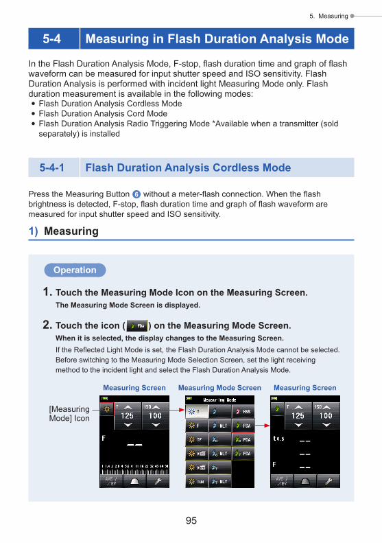
95
5. Measuring
5-4 Measuring in Flash Duration Analysis Mode
In the Flash Duration Analysis Mode, F-stop, flash duration time and graph of flash waveform can be measured for input shutter speed and ISO sensitivity. Flash Duration Analysis is performed with incident light Measuring Mode only. Flash duration measurement is available in the following modes:
● Flash Duration Analysis Cordless Mode ● Flash Duration Analysis Cord Mode ● Flash Duration Analysis Radio Triggering Mode *Available when a transmitter (sold separately) is installed
5-4-1 Flash Duration Analysis Cordless Mode
Press the Measuring Button 6 without a meter-flash connection. When the flash brightness is detected, F-stop, flash duration time and graph of flash waveform are measured for input shutter speed and ISO sensitivity.
1) Measuring
Operation
1. Touch the Measuring Mode Icon on the Measuring Screen.The Measuring Mode Screen is displayed.
2. Touch the icon ( ) on the Measuring Mode Screen.When it is selected, the display changes to the Measuring Screen.If the Reflected Light Mode is set, the Flash Duration Analysis Mode cannot be selected. Before switching to the Measuring Mode Selection Screen, set the light receiving method to the incident light and select the Flash Duration Analysis Mode.
Measuring Screen Measuring Screen
[Measuring Mode] Icon
Measuring Mode Screen

96
5. Measuring
3. Set the light receiving method.Incident light system Switch to the extended lumisphere ( )/retracted lumisphere ( ). (P32)
4. Set the ISO sensitivity value on the [ISO] Icon. (P197)
5. Set the shutter speed on the [T] Icon. (P197)
Measuring Screen
Setting Value
NOTICE
● Make sure that the settings are within the specifications of the camera and flash system.
● If the measured flash duration time is longer than the input shutter speed, an appropriate F-stop cannot be measured. The yellow "Under" indication appears. In this case, slower the shutter speed than the flash duration time and measure again.
6. Set the Flash Duration Analysis t value. (P100)
7. Press the Measuring Button 6. The meter will enter the Measuring Standby Mode, and the Measuring Mode Icon ( ) will blink for 90 seconds. The LCD screen dims and stands by.
Measuring Screen

97
5. Measuring
8. Trigger the flash unit manually while the Measuring Mode Icon ( ) is blinking.When the flash light is detected, the measurement is made automatically and the measured value (F-stop) will be displayed.
Measuring Screen
Flash Duration Time
Flash Component
Measured Value (F-stop)
NOTICE
● The flash duration time and graph are displayed in the Flash Duration Analysis Mode, however, they cannot be stored in the memory.They are cleared if the Measuring Mode is changed or the POWER switch is turned OFF.
● The incident light measurement can only be used in Flash Duration Analysis Mode. ● During 90 Seconds Standby Mode, the meter receives and measure the flash light only once, and does not enter the Standby Mode. Repeat the procedure 7. and 8. above to measure again and manually trigger the flash units.
● In case of the following, please follow "5-4-2 Flash Duration Analysis Code Mode". (P102) - When firing the flash, if the flash brightness is lower than the ambient light, the
meter may fail to detect the light. - Rapid start fluorescent lamps and special lighting are sometimes mistaken for
flash and accidentally measured. - Even if the flash is not fired, when a sudden light change occurs in the light
receptor, measurement may be made. - The waveform of a flash bulb has a slight slope and there is a possibility that the
light meter cannot recognize the flash bulb in Cordless Flash Mode.

98
5. Measuring
2) Number of Pre-flash
For red-eye prevention and auto-flash light adjustment, some devices can pre-flash before main flash burst.With the normal setting, the light meter will measure the pre-flash bursts and not the main flash burst. To take a successful reading, activate the pre-flash feature in the Tool Box.
Operation
1. Touch the [Tool Box] Icon ( ) on the Measuring Screen.The Tool Box Screen is displayed.
2. Touch the [Next Page] Icon ( ) of the Tool Box to display the Tool Box showing "Number of Pre-flash".This button is enabled if Flash Mode is selected. If it is grayed out, check the Measuring Mode.
NOTE
● When the measured value display area is touched, both flash waveform graph and measured value are displayed. When it is touched again, the display returns to the previous screen.
Measuring ScreenFlash Duration Analysis Cordless
Mode Flash Waveform Graph Screen
Touching the Measured value area changes the display.
* The Graph Screen cannot be used to make measurements. ● Measure the flash light characteristics in a darkroom without ambient light. ● When using a pre-flashing light, set the "Number of Pre-flash" of the Tool Box. (P98) ● It is convenient to set the light meter in a fixed position during the measuring time. This can be accomplished by mounting the meter on a tripod or stand using the tripod socket on the bottom of the meter.

99
5. Measuring
3. Touch the [Number of Pre-flash] Button of the Tool Box.The Number of Pre-flash Screen is displayed.If you do not change this number, touch the [Close] Button.
Measuring Screen Tool Box ScreenPage 1
[Close] ButtonTo next page
Tool Box ScreenPage 2
4. Touch the radio button of the Number of Pre-flash Button.Set the number of pre-flash on the Number of Pre-flash Screen. The display returns to the Measuring Screen.
If you do not change this number, touch the [Close] Button to return to the Measuring Screen.
Number of Pre-flash Screen
[Close] Button
NOTE
The amount of pre-flashes fired by a flash unit can be different for different camera brands. Check the camera manual for number fired by your camera system.

100
5. Measuring
3) Flash Duration Analysis t Value
The t value can be set in steps of 0.1 at a range of 0.1 to 0.9.The flash duration time varies depending on the input t value.
Operation
1. Touch the [Tool Box] Icon ( ) on the Measuring Screen.The Tool Box Screen is displayed.
2. Touch the [Next Page] Icon ( ) of the Tool Box to display the Tool Box showing "Flash Duration Analysis t Value".This button is enabled if Flash Duration Analysis Mode is selected. If it is not grayed out, check the Measuring Mode.
3. Touch the [Flash Duration Analysis t Value] Button of the Tool Box.The Flash Duration Analysis t Value Screen is displayed.If you do not change this number, touch the [Close] Button.
Measuring Screen Tool Box ScreenPage 1
[Close] ButtonTo next page
Tool Box ScreenPage 2

101
5. Measuring
4. Input the "Reference" of 0.1 to 0.9 by touching the numeric value.The t value can be set in steps of 0.1 at a range of 0.1 to 0.9. The first "0." is fixed. Input the first digit decimal only. (To set "0.1", input "1".)
Flash Duration Analysis t Value Screen
The input numeric value is displayed.
[OK] Button [Cancel] Button
Flash Duration Analysis t Value Screen
5. Touch [OK] Button.The setting is input, and the display returns to the Measuring Screen.Touch the [Cancel] Button to return to the Measuring Screen without making the modification.
Measuring Screen
NOTE
Two rules apply to the reference flash duration time.t0.5 = Effective flash duration timet0.1 = Total flash duration time
After flash firing, the time at which the maximum intensity drops by half is called "t0.5". The time at which the maximum intensity drops to 1/10 is called "t0.1".Generally, "t0.5" is called the flash duration time.
t 0.1
t 0.2
t 0.3
t 0.4
t 0.5
t 0.6
t 0.7
t 0.8
t 0.9

102
5. Measuring
5-4-2 Flash Duration Analysis Code Mode
Press the Measuring Button 6 with a meter-flash connection. When the flash brightness is detected, F-stop, flash duration time and graph of flash waveform are measured for input shutter speed and ISO sensitivity.
1) Measuring
Operation
1. Connect the synchro cord (sold separately), which is connected to the flash, to the meter. (P195)Connect the synchro cord (sold separately) to the meter's synchro terminal b.
2. Touch the Measuring Mode Icon on the Measuring Screen.The Measuring Mode Screen is displayed.
3. Touch the icon ( ) on the Measuring Mode Screen.When it is selected, the display changes to the Measuring Screen.If the Reflected Light Mode is set, the Flash Duration Analysis Mode cannot be selected. Before switching to the Measuring Mode Selection Screen, set the light receiving method to the incident light and select the Flash Duration Analysis Mode.
Measuring Screen Measuring Screen
[Measuring Mode] Icon
Set the incident light
Measuring Mode Screen
4. Set the light receiving method.Incident light system Switch to the extended lumisphere ( )/retracted lumisphere ( ). (P32)
Synchro Terminal b
Synchro Cord (sold separately)

103
5. Measuring
5. Set the ISO sensitivity value on the [ISO] Icon. (P197)
6. Set the shutter speed on the [T] Icon. (P197)
Measuring Screen
Setting Value
NOTICE
● Make sure that the settings are within the specifications of the camera and flash system.
● If the measured flash duration time is longer than the input shutter speed, an appropriate F-stop cannot be measured. The yellow "Under" indication appears.In this case, slower the shutter speed than the flash duration time and measure again.
7. Set the Flash Duration Analysis t value. (P105)
8. Press the Measuring Button 6. The flash will fire and the measured value (F-stop) will be displayed.
Measuring Screen
Flash Duration Time
Flash Component
Measured Value (F-stop)
Measuring Screen

104
5. Measuring
NOTICE
● The flash duration time and graph are displayed in the Flash Duration Analysis Mode, however, they cannot be stored in the memory.They are cleared if the Measuring Mode is changed or the POWER switch is turned OFF.
● The incident light measurement can only be used in Flash Duration Analysis Mode. ● When the synchro cord is connected to the Synchro Terminal b or when the meter's Power Button 5 is pressed, the flash may fire.
● Also, the flash may not fire when the trigger voltage is very low. In such a case, follow "5-4-1 Flash Duration Analysis Cordless Mode". (P95)
NOTE
● When the measured value display area is touched, both flash waveform graph and measured value are displayed. When it is touched again, the display returns to the previous screen.
Measuring ScreenFlash Duration Analysis Cordless Mode
Flash Waveform Graph Screen
Touching the Measured value area changes the display.
* The Graph Screen cannot be used to make measurements. ● Measure the flash light characteristics in a darkroom without ambient light.

105
5. Measuring
2) Flash Duration Analysis t Value
The t value can be set in steps of 0.1 at a range of 0.1 to 0.9.The flash duration time varies depending on the input t value.
Operation
1. Touch the [Tool Box] Icon ( ) on the Measuring Screen.The Tool Box Screen is displayed.
2. Touch the [Next Page] Icon ( ) of the Tool Box to display the Tool Box showing "Flash Duration Analysis t Value".This button is enabled if Flash Duration Analysis Mode is selected. If it is not grayed out, check the Measuring Mode.
3. Touch the [Flash Duration Analysis t Value] Button of the Tool Box.The Flash Duration Analysis t Value Screen is displayed.If you do not change this number, touch the [Close] Button.
Measuring Screen Tool Box ScreenPage 1
[Close] ButtonTo next page
Tool Box ScreenPage 2
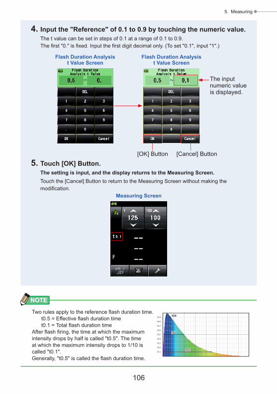
106
5. Measuring
NOTE
Two rules apply to the reference flash duration time.t0.5 = Effective flash duration timet0.1 = Total flash duration time
After flash firing, the time at which the maximum intensity drops by half is called "t0.5". The time at which the maximum intensity drops to 1/10 is called "t0.1".Generally, "t0.5" is called the flash duration time.
t 0.1
t 0.2
t 0.3
t 0.4
t 0.5
t 0.6
t 0.7
t 0.8
t 0.9
4. Input the "Reference" of 0.1 to 0.9 by touching the numeric value.The t value can be set in steps of 0.1 at a range of 0.1 to 0.9. The first "0." is fixed. Input the first digit decimal only. (To set "0.1", input "1".)
Flash Duration Analysis t Value Screen
The input numeric value is displayed.
[OK] Button [Cancel] Button
Flash Duration Analysis t Value Screen
5. Touch [OK] Button.The setting is input, and the display returns to the Measuring Screen.Touch the [Cancel] Button to return to the Measuring Screen without making the modification.
Measuring Screen

107
5. Measuring
5-4-3 Flash Duration Analysis Radio Triggering Mode
(Available when a transmitter sold separately is installed)The meter detects flash brightness after Measuring Button 6 is pressed to send radio transmitted signal to radio receiver connected to flash. F-stop, flash duration time and graph of flash waveform are displayed for input ISO sensitivity and shutter speed. Depending on the radio system in use, the meter controls the output power of flash units and the modeling lamps with turning ON/OFF.For details, see the operating manual of the transmitter (sold separately). (P196)
Measuring Screen Measuring Screen
[Measuring Mode] Icon
Measuring Mode Screen
NOTE
It may not be possible to adjust the light quantity of the modeling lamp depending on the flash unit or EL-Skyport receiver used.

108
5. Measuring
5-5 Out of Displayed Range or Measuring Range
(* This example explains what needs to be done in Cord Flash Mode.)
5-5-1 When Displayed Range Is Exceeded
For any given shutter speed and ISO setting, "Under" or "Over" is displayed if the measured value (F-stop) exceeds the display range even if it is within measuring range. In these cases, take the following actions.
Over Exposure displayUnder Exposure display
Viewfinder DisplayViewfinder Display
1) When Under Exposure "Under" Is Displayed:
If "Under" is displayed when the measured value (F-stop) is lower than the minimum f-stop (F0.5), slower the shutter speed on the [T] Icon, set higher ISO sensitivity or increase the flash brightness to measure it again.The correct F-stop will be displayed for input values.
2) When Over Exposure "Over" Is Displayed:
If "Over" is displayed when the measured value (F-stop) is higher than the maximum f-stop (F128.9), faster the shutter speed on the [T] Icon, set lower ISO sensitivity or reduce the flash brightness to measure it again.The correct F-stop will be displayed for input values.

109
5. Measuring
5-5-2 When Measuring Range Is Exceeded
When the amount of light is outside the measuring range of the meter, "Over" and "Under" will appear and blink.When this occurs, adjust the brightness level to obtain a measurement.
When brightness is over the measuring range
When brightness is under the measuring range
Viewfinder DisplayViewfinder Display
NOTE
Display RangeISO sensitivity ISO 3 to ISO 13,107,200 (in 1/3 steps)Shutter speed Ambient light 30 min to 1/64,000 sec, 1/200, 1/400
(in 1, 1/2, 1/3 steps) Flash light 30 min to 1/16,000 sec, 1/75, 1/80, 1/90, 1/100,
1/200, 1/400 (in 1, 1/2, 1/3 steps)Aperture F0.5 to F128.9 (in 1 steps) F0.5 to F152.4 (in 1/2 steps) F0.5 to F161.2 (in 1/3 steps)Flash duration time 1/40 to 1/55,500 sec (25 ms to 18 us)
Measuring Range (ISO100)Ambient light Incident light system -5EV to EV22.9 Reflected light system -1EV to EV24.4 Flash light Incident light system F0.5 to F128.9 Reflected light system F1.0 to F128.9 Illuminance 0.1 to 2,000,000 lx Luminance 0.1 to 980,000 cd/m2

110
6. Functions
6. Functions
6-1 Memory Function
This meter can save measured values in the memory. This function is available in the following Measuring Modes.
Ambient Mode ● T Priority Mode ● F Priority Mode ● TF Priority Mode ● HD Cine Mode ● Cine Mode
Flash Mode ● Cord in (PC) Mode ● Cordless Mode ● Radio Triggering Mode
HSS Flash Mode ● HSS Flash Cordless Mode
You can save (in the memory) and recall up to nine measured values regardless of whether the incident light system or reflected light system is selected.
NOTE
● When you have used the incident light system to save measured values in the memory and then changed the system to the reflected light system, the measured values that are saved in the memory using the incident light system are maintained. Then, you can newly display measured values saved in the memory using the reflected light system.
● In Ambient Mode, the measured values saved in the memory are maintained even if the mode is switched. In Flash Mode, the measured values saved in the memory are not maintained if the mode is switched.

111
6. Functions
6-1-1 How to Save Values in the Memory
Operation
1. Press the Measuring Button 6. The measured value at that time will be displayed.In Ambient Mode, while the Measuring Button 6 is held down, the meter continues to make measurements. When the Measuring Button 6 is released, the measurement ends. The measured value at that time will be displayed in the measured value/measuring unit display area and on the analog scale. (P22, P24)
2. Press the Memory Button 7.The measured value is saved in the memory. The measured value saved in the memory is displayed as a dot on the analog scale.
3. Repeat Steps 1 and 2.This meter can store up to nine measured values in the memory.
Measuring Button 6 Memory Button 7
Measuring Screen Measuring Screen
Measured Value (F-stop)
Measured Value (F-stop)
Memory Count
Each measured value (F-stop) saved in the memory

112
6. Functions
NOTICE
The Memory Function cannot be used in the following Measuring Modes. ● Cord Multi (Cumulative) Flash Mode ● Cordless Multiple (Cumulative) Flash Mode ● Illuminance/Luminance Measuring Mode ● Flash Duration Analysis Mode
NOTE
Memory count warningUp to nine measured values can be saved in the memory. If you attempt to save a 10th or subsequent measured value, the "Memory Full" warning message will be displayed, and the measured value cannot be saved in the memory.
Measuring Screen

113
6. Functions
6-1-2 Memory Clear
This function individually or collectively clears measured values that are saved in the memory. The Memory Clear Screen displays memory information (memory count, incident light ( ) or reflected light ( ), and measured value) in the order in which they are saved in the memory.Measured values that are saved in the memory are displayed as dots ( ) on the analog scale.
Operation
1. Touch the [Tool Box] Icon ( ) on the Measuring Screen.The Tool Box Screen is displayed.
2. Touch the [Next Page] Icon ( ) on the Tool Box Screen.This displays the Tool Box Screen that shows "Memory Clear".
3. Touch the [Memory Clear] Button on the Tool Box Screen.The Memory Clear Screen is displayed.
Memory Clear ScreenTool Box Screen
Page 2
Measuring ScreenTool Box Screen
Page 1
To next page

114
6. Functions
1) Individual Clear
Operation
1. Select the memory value to be deleted on the Memory Clear Screen.Multiple memory values are selectable.
2. Touch [Clear] Button.This changes the display to the Selected Memory Clear Confirmation Screen, and the "Selected memory is cleared. Are you sure?" message is displayed.When you touch [Close] Button, the display returns to the Measuring Screen without clearing the memory value.
3. Touch [OK] Button.The selected item is cleared, and the display returns to the Memory Clear Screen. The contents are displayed without a space.When you touch [Cancel] Button, the display returns to the Memory Clear Screen without clearing the memory value.
4. Touch [Close] Button on the Memory Clear Screen.The display returns to the Measuring Screen.
Memory Clear Screen Selected Memory Clear Confirmation Screen
Memory Clear Screen
[Close] Button[Cancel] Button
[OK] Button
[Clear] Button
[Close] Button
Selected Item
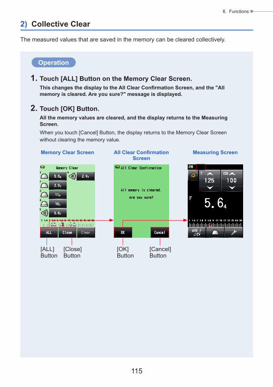
115
6. Functions
2) Collective Clear
The measured values that are saved in the memory can be cleared collectively.
Operation
1. Touch [ALL] Button on the Memory Clear Screen.This changes the display to the All Clear Confirmation Screen, and the "All memory is cleared. Are you sure?" message is displayed.
2. Touch [OK] Button.All the memory values are cleared, and the display returns to the Measuring Screen.When you touch [Cancel] Button, the display returns to the Memory Clear Screen without clearing the memory value.
Memory Clear Screen All Clear Confirmation Screen
[Cancel] Button
[OK] Button
[ALL] Button
[Close] Button
Measuring Screen

116
6. Functions
6-1-3 Memory Recall
This function recalls the measured values that are saved in the memory to enable the user to view details. This screen displays memory information (memory count, incident light ( ) or reflected light ( ), and measured value) in the order in which they are saved in the memory. Measured values that are saved in the memory are displayed as dots ( ) on the analog scale.
Operation
1. Touch the [Tool Box] Icon ( ) on the Measuring Screen.The Tool Box Screen is displayed.
2. Touch the [Next Page] Icon ( ) on the Tool Box Screen.This displays the Tool Box Screen that shows "Memory Recall".
3. Touch the [Memory Recall] Button on the Tool Box Screen.The Memory Recall Screen is displayed. (Up to nine measured values in the memory)
Measuring Screen Tool Box ScreenPage 2
Tool Box ScreenPage 1
To next page

117
6. Functions
4. Touch the item to be recalled.Contents saved in the memory are displayed on the Measuring Screen. (Green background)
Memory Recall Screen Recall Screen
[Memory Recall] Button
Currently Recalled Memory No.
[Close] Button
NOTE
● In Ambient Mode, the measured values saved in the memory are maintained even if the mode is switched. Values saved in the memory in each Measuring Mode are displayed in the value type corresponding to the measurement mode in which memory recall was carried out.Example: When an ISO value is saved in the memory in TF Priority Mode, if it is
recalled in T Priority Mode, the f-stop value is displayed. ● As the setting value is changed on the Memory Recall Screen, the measured value (memory recall value) is also changed.
Recall Screen
Setting Value

118
6. Functions
6-2 Average/Contrast Function
1) Average Function
This function averages up to nine measured values that are saved in the memory, and displays the result. This function is available in Ambient Mode (T Priority, F Priority, TF Priority, HD Cine, and Cine Mode), Flash Mode (Cord, Cordless, and Radio Triggering), and HSS Flash Mode.
5. Touch [Memory Recall] Button.If you touch [Memory Recall] Button on the Recall Screen to display another memory value, the display returns to the Memory Recall Screen.If you touch [Close] Button, the display returns to the Measuring Screen instead of returning to the Memory Recall Screen.
6. Touch [Close] Button.If you touch [Close] Button, the display returns to the Measuring Screen instead of returning to the Memory Recall Screen.
7. Touch [Close] Button on the Memory Recall Screen.The display returns to the Measuring Screen.
Measuring ScreenMemory Recall ScreenRecall Screen
[Memory Recall] Button[Close] Button

119
6. Functions
Operation
1. Press the Measuring Button 6.Press this button to make a measurement.
2. Press the Memory Button 7.The measured value is saved in the memory. Each measured value that is saved in the memory is displayed as a dot ( ) on the analog scale.
3. Repeat Steps 1 and 2.Up to nine measurements can be stored in the memory. The memory count is displayed on the status bar.
4. Touch the Set Average/Contrast Function Icon ( ).The "Ave" symbol appears on the screen. The average of all memory values is displayed.When the Average Function is active, the Set Average/Contrast Function Icon ( ) is highlighted ( ).
EnlargeAnalog Scale
EnlargeAnalog Scale
Measuring Screen Measuring Screen
Memory Count
The Average Function is active.
Measured Value
"Ave" Symbol
Memory Value
Average Value
Memory Value
Average Value(bigger indicator)
Last Measured Value
Memory Value
Measuring Button 6
Memory Button 7

120
6. Functions
NOTE
The Set Average/Contrast Function Icon is set to Function Button -1 Button in Factory Setting. When the Set Average/Contrast Function Icon is not displayed, set the Function Button in Custom Setting (P160), or set the Set Average/Contrast Function on the Tool Box Screen (P124).
5. Touch the Icon ( ) again.The Average Function is released, and the highlighted icon ( ) returns to the normal state ( ). Then, the "Ave" symbol disappears from the screen.The last measured value is displayed.
Measuring Screen
NOTE
In case that the Average/Contrast Function is assigned to Function Button -1 or -2. (P160)
Icon Description
Displayed when no measured or memorized values are registered.
Displayed when the Set Average/Contrast Function is disabled.
Displayed when the Set Average/Contrast Function is enabled.

121
6. Functions
Operation
1. Rotate the Lumisphere Retracting Ring 1.Turn the Lumisphere Retracting Ring 1 to aligh the dot to the retracted mark ( ) position. Only the light source can be measured by setting the light receptor to the retracted lumisphere.
2. Turn ON the main light source only. Turn OFF the second light source.
3. Press the Measuring Button 6.Point the light receptor at the main light source from the subject position to make a measurement.
Lumisphere Retracting Ring 1
Retracted ( )
2) Contrast Function
This function is useful for checking studio lighting or illumination unevenness. This function is also convenient when you check the difference in luminance between the intermediate value and the highlight and/or shadow value for landscape shooting.While you are holding down the Measuring Button 6 at the comparison position after defining the measured value at a specific point as the standard value, a difference between the standard value and the value at the comparison position is displayed with an EV value (difference in stops), and the current measured value is displayed on the analog scale.* If there are no values in the memory, the standard value will be the last measured value.
If there are values in the memory, the standard value will be the average of all the values saved in the memory.
The example of lighting ratio using the Contrast Function(In T Priority Mode in the incident light system)When you want to measure the lighting ratio between the main and second light sources, lower the lumisphere to use the Retracted Lumisphere Function.

122
6. Functions
4. Touch the Set Average/Contrast Function Icon ( ).The "Ave" symbol appears on the screen.When the Contrast Function is active, the Set Average/Contrast Function Icon ( ) is highlighted ( ).
The measured value of the main light source is saved in the memory as the standard value.
Measuring Screen Measuring Screen
Measured Value
Set Average/Contrast Function Icon
The Contrast Function is active.
Memory Count
"Ave" Symbol
Reference Value
5. Turn ON the second light source only. Turn OFF the main light source.
6. Hold down the Measuring Button 6.Point the light receptor at the second light source from the subject position to make a measurement. While holding down the Measuring Button 6, the difference between the standard value of the main light source and the second light source being measured is displayed in terms of an EV value. Then, the standard value and the measured value at the compared position are displayed, and you will be able to obtain the contrast ratio.
7. Release the Measuring Button 6.The Contrast Function is released. And the standard value is displayed at the position of the measured value area.
8. Touch the Set Average/Contrast Function Icon ( ) again.The Contrast Function is cleared, and the "Ave" symbol disappears from the screen. The last measured value when the Measuring Button 6 is released is displayed.The standard value is saved in the memory as " 1". Clear the memory when you want to use the Contrast Function with a new standard value. (P113)

123
6. Functions
Reflected-light measurement example
Viewfinder Display
EnlargeAnalog Scale
Measuring ScreenMeasuring Screen
" EV" Symbol
The Average Function is active.
Measured Value
Reference Value
Set Average/Contrast Function Icon
EV Difference of Measured Value Illumination Ratio
1 2:1
1.5 3:1
2 4:1
3 8:1
4 16:1
NOTE
● To determine the final exposure in the incident light system, turn on the main and sub light sources, and set the right receptor to the extended lumisphere. Then, point it at the optical axis of the camera to make a measurement.
● The Set Average/Contrast Function Icon is set to Function Button -1 in Factory Setting. When the Set Average/Contrast Function Icon is not displayed, set the Function Button in Custom Setting (P160), or set the Set Average/Contrast Function on the Tool Box Screen (P124).
● The Set Average/Contrast Function is only available in a mode in which the Memory Function is valid. (P110)
● When measuring the contrast ratio, use the EV scale to make it more visible. ● "Measurement" or "EV Scale" on the analog scale can be changed in Custom Setting. (P22)

124
6. Functions
3) Average/Contrast Function Setting on the Tool Box Screen
Operation
1. Touch the [Tool Box] Icon ( ) on the Measuring Screen.The Tool Box Screen is displayed.
2. Touch the [Set Average/Contrast Function] Button on the Tool Box Screen.The Set Average/Contrast Function Screen is displayed.
3. Touch the "ON" or "OFF" radio button or an area around an item name.You can set the Set Average/Contrast Function to "ON" or "OFF".When you touch either one, the display returns to the Measuring Screen.
Measuring Screen Tool Box Screen Set Average/Contrast Function Screen
Measuring Screen
Case in which Set Average/Contrast Function is set to "ON"
Case in which Set Average/Contrast Function is set to "OFF"
Measuring Screen

125
6. Functions
6-3 Exposure Compensation Function
This function is useful when compensation is necessary for highlight and/or shadow in reflected-light measurements.The input value range is -9.9 EV to +9.9 EV in 0.1 step increments.To use the Set Exposure Compensation Function, first specify the Measuring Mode (incident light system or reflected light system). Exposure Compensation can be set individually in the incident light system and the reflected light system.
■ Minus CompensationIf a lighter image is obtained when shooting was carried out based on the measured values of this meter, you can use the minus compensation to adjust the exposure to a darker value.
■ Plus CompensationIf a darker image is obtained when shooting was carried out based on the measured values of this meter, you can use the plus compensation to adjust the exposure to a more positive value.
NOTICE ● Compensation of the measured value must be performed based on a sufficient number of test shooting results.
● Note that the individual compensation is possible in the incident light system and reflected light system while uniform compensation is applied in Ambient Mode and Flash Mode.
NOTEIn Factory Setting, the light intensity can be adjusted using the minus or plus compensation. However, to adjust the exposure value (exposure decrease by plus compensation and exposure increase by minus compensation), select "Measured Value (+ is dark, - is bright)" in "Compensation +/- Preference" of Custom Setting. (P166)
NOTEIn case that the Exposure Compensation is assigned to Function Button -1 or -2. (P160)
Icon Description
Disabled when Exposure compensation is not set.
Displayed when Exposure compensation is OFF.
Displayed when Exposure compensation is ON.

126
6. Functions
Operation
1. Touch the [Tool Box] Icon ( ) on the Measuring Screen.The Tool Box Screen is displayed.
2. Touch the [Set Exposure Compensation] Button on the Tool Box Screen.The Exposure Comp. Value Screen is displayed.
3. Set the compensation value.Set the compensation value on the Exposure Comp. Value Screen that is displayed. The input value range is +/-9.9 EV in 0.1 step increments. (See P11 for details about how to input the value.)
4. Touch [OK] Button.The display returns to the Measuring Screen, and the icon and the compensation value are displayed on the status bar.When you touch [Cancel] Button, the display returns to the Measuring Screen without setting the Exposure compensation.
Exposure Comp. Value Screen
Viewfinder Display
Measuring Screen
Measuring Screen Exposure Comp. Value ScreenTool Box Screen, Page 1
Input Value
Compensation Value
Compensation Value
[Cancel] Button[OK] Button

127
6. Functions
6-4 Filter Compensation Function
This function registers a filter compensation value in the light meter. Setting this value enables you to obtain the measurement result to which the filter compensation value is applied.If the filter is used in front of camera lens, the light coming into the camera is decreased, so this "decreased" light value should be compensated for the exposure value measured with the light meter.The input value range is +/-12 EV in 0.1 EV step increments.
You can select the desired Filter Compensation Mode from the following three options:1. Input Filter Comp. Value
Enter the numeric value. Filter Compensation ( ) is displayed on the status bar.2. Filter Pack in Use
You can select up to four pre-registered filter names. Filter Compensation ( ) is displayed on the status bar.
3. No Filter Filter Compensation ( ) disappears from the status bar.
NOTICE
Note that this Filter compensation is applied in the incident light system and the reflected light system, and also in Ambient Mode and Flash Mode at the same time.
NOTE
● Selecting the plus compensation decerases the exposure (the meter displays a higher shutter speed or F-stop). Selecting the minus compensation increases the exposure (the meter displays a lower value of shutter speed or F-stop).
● Enter a minus value for filter compensation. Pre-registered filter names and values can be customized in Edit Filter in Menu list. (Up to 30 filter names can be registered.)
NOTE
In case that the Filter Compensation is assigned to Function Button -1 or -2. (P160)
Icon Description
Disabled when Filter compensation is not set.
Displayed when Filter compensation is OFF.
Displayed when Filter compensation is ON.

128
6. Functions
6-4-1 Input Filter Comp. Value
Directly enter a filter compensation value using a numeric value.The input value range is +/-12 EV in 0.1 EV step increments.
Operation
1. Touch the [Tool Box] Icon ( ) on the Measuring Screen.The Tool Box Screen is displayed.
2. Touch the [Set Filter Compensation] Button on the Tool Box Screen.The Filter Compensation Screen is displayed.
3. Touch "Input Filter Comp. Value".The Filter Comp. Value Screen is displayed.
Filter Compensation Screen
Measuring Screen Tool Box ScreenPage 1

129
6. Functions
4. Input the compensation value on the Filter Comp. Value Screen. (See P11 for details about how to input the value.)
5. Touch [OK] Button.The value is applied, and the display returns to the Filter Compensation Screen. Then, the entered filter compensation value is displayed.To return to the Filter Compensation Screen without changing the value, touch [Cancel] Button.
6. Touch [OK] Button on the Filter Compensation Screen.The value is applied, and the display returns to the Measuring Screen. Then, the Filter Compensation Icon ( ) and the compensation value are displayed on the status bar.
Filter Compensation Screen
Filter Comp. Value Screen
[Cancel] Button
[OK] Button
Input Value
Filter Compensation Screen
[Cancel] Button
[OK] Button
Measuring ScreenFilter Compensation Display

130
6. Functions
6-4-2 Selecting a Filter
You can select up to four pre-registered filter name (P199).
Operation
1. Touch the [Tool Box] Icon ( ) on the Measuring Screen.The Tool Box Screen is displayed.
2. Touch the [Set Filter Compensation] Button on the Tool Box Screen.The Filter Compensation Screen is displayed.
3. Touch "Filter Pack in Use".The Filter Pack in Use Screen is displayed.
Filter Compensation Screen
Measuring Screen Tool Box ScreenPage 1

131
6. Functions
4. Touch any of four [Filter Name] Buttons on the Filter Pack in Use Screen.The Select User Filter Screen is displayed.When there are multiple pages, press the [Next Page] Icon ( ) to display different pages. (P199)
5. Touch the radio button on the Filter Pack in Use Screen to select the desired filter.The selected filter is registered, and the display returns to the Filter Pack in Use Screen.
Filter Pack in Use Screen
Filter Pack in Use Screen
Select User Filter Screen
[Close] ButtonTo next page
6. Repeat Steps 4 and 5 to register other filters.Up to four filters listed on the Filter Pack in Use Screen are compensated all at once.
NOTE
● In this Filter Pack in Use, you can select the same filter more than once. ● To deselect the listed in Filter Pack in Use, select "No Filter".
7. Touch [Close] Button.The display returns to the Filter Compensation Screen.

132
6. Functions
8. Check that the selected filter name is displayed.Check that the selected filter name is registered.
9. Touch [OK] Button on the Filter Compensation Screen.The value is applied, and the display returns to the Measuring Screen. Then, the Filter Compensation Icon ( ) and the compensation value are displayed on the status bar.To return to the Measuring Screen without changing the value, touch [Cancel] Button.
Filter Compensation Screen Measuring Screen
[Cancel] Button[OK] Button
Filter Name
Filter Compensation Display
NOTE
● See "9-6 Filter Names and Compensation Values" for details about the filters that are pre-registered in Factory Setting. (P199)
● The pre-registered filter name can be customized in Edit Filter in Menu list. (Up to 30 filter names can be registered.)

133
6. Functions
6-4-3 User-defined Filter Compensation Settings
You can register up to 30 user-defined filter compensation values in addition to the standard filter compensation values. The registered filter compensation values can be edited freely.
Edit FilterPage 3
Edit FilterPage 4
Edit FilterPage 5
Menu ScreenPage 1
Edit FilterPage 1
Edit FilterPage 2
Edit Filter
[Close] Button
To next pageTo next page
To next page To next pageTo previous page

134
6. Functions
Operation
1. Press the Menu Button 9 on the meter. The Menu Screen is displayed.
2. Touch the [Edit Filter] Button.The Edit Filter Screen is displayed.
3. Touch [Filter Name] Button of the desired filter.The Edit Filter Screen is displayed.
Edit Filter Screen Edit Filter ScreenMenu ScreenPage 1
4. Touch the [Filter Name] Button on the Edit Filter Screen.The Filter Name Screen is displayed.
Filter Name ScreenEdit Filter Screen
[Filter Name] Button
Menu Button 9

135
6. Functions
5. Input the filter name. (P12)You can input the filter name using up to 31 characters.
6. Touch [OK] Button.The display returns to the Edit Filter Screen.To return to the Edit Filter Screen without changing the name, touch the [Cancel] Button.
Filter Name Screen
[OK] Button [Cancel] Button
Displays the alphanumeric characters you entered.
7. Touch the [Filter Comp. Value] Button on the Edit Filter Screen.The Filter Comp. Value Screen is displayed.
Filter Comp. Value ScreenEdit Filter Screen
[Filter Comp. Value] Button

136
6. Functions
8. Input the filter compensation value. (P11)The input value range is +/-12 EV in 0.1 EV step increments.
9. Touch [OK] Button.The display returns to the Edit Filter Screen.To return to the Edit Filter Screen without changing the value, touch [Cancel] Button.
Filter Comp. Value Screen
[OK] Button [Cancel] Button
Displays the numeric value you entered.
NOTICE
Selecting the plus compensation decreases the exposure (the meter displays a higher value of shutter speed or F-stop). Selecting the minus compensation increases the exposure (the meter displays a lower value of shutter speed or F-stop).
10. Touch [Close] Button on the Edit Filter Screen.The display returns to the Edit Filter Screen.
Edit Filter Screen
[Close] Button

137
6. Functions
11. Touch the check box of the filter name.Touch the box () to check (check mark ) to display the filter name in the Select User Filter Screen on the Tool Box. (P130) When the box is unchecked, it is not listed.
Select User Filter Screen(Tool Box)
Edit Filter Screen
[Filter Name] ButtonCheck Box
12. Touch [Close] Button on the Edit Filter Screen.The display returns to the Menu Screen.
13. Touch [Close] Button on the Menu Screen.The display returns to the Measuring Screen.
Menu ScreenEdit Filter Screen
[Close] Button
NOTE
● Filter compensation No. 1 to 24 have preset values. (P199) ● User settings can be added to filter compensation No. 25 to 30, and if necessary, No. 1 to 24 can be edited.

138
6. Functions
6-4-4 Deselecting a Filter
If "No Filter" is selected, any filter compensation is not applied to the measured value.
Operation
1. Touch the [Tool Box] Icon ( ) on the Measuring Screen.The Tool Box Screen is displayed.
2. Touch the [Set Filter Compensation] Button on the Tool Box Screen.The Filter Compensation Screen is displayed.
3. Touch "No Filter"."No Filter" is selected.
Filter Compensation ScreenMeasuring Screen Tool Box Screen, Page 1
4. Touch [OK] Button on the Filter Compensation Screen.The filter compensation is released, and the display returns to the Measuring Screen. Then, the Filter Compensation Icon on the status bar disappears.
Filter Compensation Screen Measuring Screen
[Cancel] Button[OK] Button
No display of Filter Comp. Icon

139
6. Functions
6-5 Mid. Tone Function
This function is used to specify a measured value as the standard of light measurements and put it at the center of EV scale.
The Mid. Tone Function has four modes:
Setting name Description
Set from Current Measurement Specify the measured value as the Mid. Tone value.
Set from Memory Select the desired one from up to nine measured values saved in the memory, and set it as the Mid. Tone value.
Modify Current Mid. Tone Modify the specified Mid. Tone value.
Mid. Tone Recall Allows you to check the Mid. Tone value on the Mid. Tone Recall Screen.
NOTE
In case that the Mid. Tone is assigned to Function Button -1 or -2. (P160)
Icon Description
Disabled when no measured value is taken.
Displayed when the Mid. Tone setting is OFF.
Displayed when the Mid. Tone setting is ON.
6-5-1 Mid. Tone Setting
1) Set from Current Measurement
Set the measured value as the Mid. Tone value.
Operation
1. Press the Measuring Button 6.Press this button to make a measurement.

140
6. Functions
2. Touch the [Tool Box] Icon ( ) on the Measuring Screen.The Tool Box Screen is displayed.
3. Touch the [Set Mid. Tone] Button on the Tool Box Screen.The Set Mid. Tone Screen is displayed.
4. Touch the [Set from Current Measurement] Button on the Set Mid. Tone Screen.Set the current measured value as the Mid. Tone value, and return to the Measuring Screen. The newly set Mid. Tone value is then displayed on the analog scale.
Measuring Screen Set Mid. Tone ScreenTool Box Screen, Page 1
EnlargeAnalog Scale
Mid. Tone Value
Measuring Screen (Set Mid. Tone)
(Set from the measured value.)
2) Set from Memory
Set the memorized value as the Mid. Tone value.

141
6. Functions
Operation
1. Touch the [Tool Box] Icon ( ) on the Measuring Screen.The Tool Box Screen is displayed.
2. Touch the [Set Mid. Tone] Button on the Tool Box Screen.The Set Mid. Tone Screen is displayed.
3. Touch the [Set from Memory] Button on the Set Mid. Tone Screen.This displays the Mid. Tone Set from Memory Screen, which shows memory information (memory number, incident light ( ) or reflected light ( ), and measured value). Measured values that are saved in the memory are displayed as dots on the analog scale.
4. Touch one of the memorized values to set as the Mid. Tone value.The selected value is registered, and the display returns to the Measuring Screen. The newly set Mid. Tone value is then displayed on the analog scale.
EnlargeAnalog Scale
Mid. Tone Value
Mid. Tone Set from Memory Screen
Measuring Screen (Set Mid. Tone) Screen
Tool Box Screen, Page 1 Set Mid. Tone ScreenMeasuring Screen
(Select the Mid. Tone value from memory.)

142
6. Functions
3) Modify Current Mid. Tone
Fine-tune the currently set Mid. Tone value.
Operation
1. Touch the [Tool Box] Icon ( ) on the Measuring Screen.The Tool Box Screen is displayed.
2. Touch the [Set Mid. Tone] Button on the Tool Box Screen.The Set Mid. Tone Screen is displayed.
3. Touch the [Modify Current Mid. Tone] Button on the Set Mid. Tone Screen.The Modify Current Mid. Tone Screen is displayed.
Tool Box ScreenPage 1
Measuring Screen Set Mid. Tone Screen

143
6. Functions
4. Touch the arrow icon ( or ) or slide the number on the Modify Current Mid. Tone Screen.Select the desired Mid. Tone value.
5. Touch [OK] Button.The change is applied and the displays to the Measuring Screen.To return to the Measuring Screen without changing the value, touch [Cancel] Button. The newly set Mid. Tone value is then displayed on the analog scale.
EnlargeAnalog Scale
Modify Current Mid. Tone Screen
Modify Current Mid. Tone Screen
Measuring Screen
[Cancel] Button
Mid. Tone Value (After selected from the memory and edited)
(Select the Mid. Tone value from memory.)
[OK] Button
NOTICE
You cannot make a change if no Mid. Tone value is set.

144
6. Functions
6-5-2 Mid. Tone Recall
This function recalls the set Mid. Tone value to view details.
Operation
1. Touch the [Tool Box] Icon ( ) on the Measuring Screen on which the Mid. Tone value is specified.The Tool Box Screen is displayed.
2. Touch the [Mid. Tone Recall] Button on the Tool Box Screen.The current Mid. Tone setting is displayed on the Measuring Screen.
3. Touch [Close] Button.The display returns to the Measuring Screen.
Measuring Screen
Mid. ToneRecall Screen
Measuring Screen Tool Box Screen, Page 1
[Close] Button
NOTE
If the setting value is changed, the measured value is also changed.
Setting Value
Measured Value

145
6. Functions
Operation
1. Touch the [Tool Box] Icon ( ) on the Measuring Screen on which the Mid. Tone value is set.The Tool Box Screen is displayed.
2. Touch the [Mid. Tone Clear] Button on the Tool Box Screen.The Mid. Tone Clear Screen is displayed, and the message of "A Mid. Tone value is cleared. Are you sure?" is displayed.
3. Touch [OK] Button.The Mid. Tone value is cleared, and the analog scale that shows the Mid. Tone value is also cleared. Then, the display returns to the Measuring Screen.To return to the Measuring Screen without clearing the Mid. Tone, touch [Cancel] Button.
EnlargeAnalog Scale Display
The Mid. Tone value is cleared.
Measuring Screen
Measuring Screen Tool Box ScreenPage 1
Mid. Tone Clear Screen
Measured Value
[Cancel] Button
[OK] Button
6-5-3 Mid. Tone Clear
This function clears the set Mid. Tone value.

146
6. Functions
6-6 Exposure Profile Function6-6-1 Overview of Exposure Profile Function
1. What is a Exposure Profile?1) It can be used to display on a light meter the unique dynamic range and clipping
point of the digital camera you are using.
� Transfers the unique sensor characteristics of the digital camera to the light meter.The dynamic range and clipping point differ depending on the camera you are using, so it is necessary to pay careful attention to how well the color and detail are captured in the highlight and shadow areas when you take a picture. By creating a camera exposure profile in Data Transfer Software and transferring it to the light meter, you can display the unique sensor characteristics as the dynamic range and clipping point, which makes it possible to instantly check whether or not a subject falls within the exposure range.
2) To display more accurate exposure values on the light meter, it records unique variations in the camera, lens shutter speed, aperture, etc. that you are using and reflects them in the exposure display.
�Achieves more accurate exposure by matching the camera you are using with the light meter display
Even if you set exposure values measured on a light meter in the camera, you may not obtain the standard exposure due to variations in the camera, lens shutter speed and aperture you are using. If this happens, you can use Data Transfer Software to match the values on the light meter with the camera variations by correcting the display in the light meter so that it is possible to obtain the standard.* This function takes the characteristics of the camera you are using into account and achieves better
correction compared to prescribed correction functions that correct the measured results uniformly.
2. Main functions of Data Transfer SoftwareData Transfer Software is application software for creating and editing camera exposure profiles, editing light meter settings (custom setting and user setting, etc.) and updating light meter firmware, transferring camera exposure profiles to the light meter unit as well as for implementing all other related settings.
Measuring Screen (Set Mid. Tone)
-7.0
500
100
150
200
250
-6.0 -5.0 -4.0 -3.0 -2.0 -1.0 0 +1.0 +2.0 +3.0 +4.0 +5.0
Out
put l
evel
(8bi
t)
Exposure area (wide)Exposure area (intermediate)
Exposure area (narrow)
Deviation from intermediate concentration (ΔEV)
Sensitivity characteristic curve
Exposure Profile Target
Exposure Profile Target II
For details, refer to the Software Guide of Data Transfer Software. (downloadable from the website, www.sekonic.com)

147
6. Functions
6-6-2 Set Exposure Profile
Operation
1. Touch the [Tool Box] Icon ( ) on the Measuring Screen.The Tool Box Screen is displayed.
2. Touch the [Set Exposure Profile] Button on the Tool Box Screen.The Set Exposure Profile Screen is displayed.
Measuring Screen Tool Box ScreenPage 1
3. Touch the exposure profile name to select it.Touch the exposure profile name to select it. The display returns to the Measuring Screen and the Exposure Profile Icon ( ) is displayed on the status bar.
Page 2Page 1Set Exposure Profile Screen
To previous pageTo next page
NOTICE
You can display only the items for which you have selected in the check boxes on the Edit Exposure Profile Screen. (P148)

148
6. Functions
6-6-3 Edit Exposure Profile
You can specify whether to display or not in the list on the "Set Exposure Profile" Screen of the Tool Box Screen.You can also edit exposure profiles created using Data Transfer Software on the meter side (about setting values and names) or create exposure profiles manually using this meter only. (The meter can store up to 10 exposure profiles.)
Edit Exposure ProfilePage 1
Edit Exposure ProfilePage 2
Menu Screen, Page 1
To previous page
To next page
Edit Exposure Profile
[Close] Button

149
6. Functions
Operation
1. Press the Menu Button 9 on the meter. The Menu Screen is displayed.
2. Touch the [Edit Exposure Profile] Button.The Edit Exposure Profile Screen is displayed.
Menu Screen, Page 1
3. Touch the check box of the exposure profile name.Touch the box () to check it (check mark ). The selected item can be displayed (registered) on the screen as an option on the Set Exposure Profile Screen. If the check mark () is cleared, the option on the Set Exposure Profile Screen is disabled, and is not displayed on the screen.
* Only the check box () of "Default Profile" is selected by default.
Edit Exposure Profile Screen
To next page[Close] Button
Check Box
[Exposure Profile Name] Button
Menu Button 9
1) Display or not on the Set Exposure Profile Screen (Tool Box)

150
6. Functions
4. Touch [Close] Button.The display returns to the Menu Screen.
Menu Screen
[Close] Button
5. Touch [Close] Button on the Menu Screen.The display returns to the Measuring Screen.

151
6. Functions
2) Edit Exposure Profile
Although you can create an exposure profile using Data Transfer Software and transfer it to the meter, you can edit the stored exposure profil or directly enter an exposure profile into the meter manually.
Operation
1. Touch the [Edit Exposure Profile] Button.The Edit Exposure Profile Screen is displayed.* To always display the selected item as an option on the Set Exposure Profile Screen,
touch the check box () to mark (check mark ).
2. Touch the [Exposure Profile Name] Button you want to select.The Edit Exposure Profile Screen is displayed.
Edit Exposure Profile Screen
To next page
[Exposure Profile Name] Button

152
6. Functions
3. Touch the [Exposure Profile Name] Button on the Edit Exposure Profile Screen.The Exposure Profile Name Screen is displayed.
4. Input the name.Input the name on the Exposure Profile Name Screen. (P12)
Edit Exposure Profile Screen Exposure Profile Name Screen
[Cancel] Button[OK] Button
Input the name here.
5. Touch [OK] Button.The display returns to the Edit Exposure Profile Screen, and the profile name you input is displayed.Touch [Cancel] Button to return to the Edit Exposure Profile Screen without applying the edit made to the exposure profile name.
Edit Exposure Profile Screen
[Exposure Profile Name] Button

153
6. Functions
6. Touch the icon for the desired light receiving method and light source in "Edit Exposure Profile Data" on the Edit Exposure Profile Screen.The ISO Sensitivity of Edit Exposure Profile Data Screen is displayed.
Edit Exposure Profile Screen
[Light Receiving Method / Light Source] Icon
[Close] Button
NOTE
Incident light system, Ambient Mode
Incident light system, Flash Mode
Reflected light system, Ambient Mode
Reflected light system, Flash Mode
7. Touch the [ISO Sensitivity] Button of the Exposure Profile Data to edit.Touch the arrow icon ( or ) on the screen, or slide the scroll bar upward or downward using fingers to select the ISO sensitivity. Three buttons of ISO sensitivity that are able to be selected are displayed.
Edit Screen
Scroll Bar[ISO Sensitivity] Button

154
6. Functions
8. Edit the camera sensitivity characteristics.Set Camera Sensitivity Characteristic Screen
Compensation Value Cursor
Compensation Value(Synchronized with the cursor)
Clipping Point (-)
Dynamic Range (-) Dynamic Range (+)
Clipping Point (+)
[Cancel] Button[Default] Button
[OK] Button
1 Compensation value cursorThe compensation value can be set between -5 EV and +5 EV in 0.1 EV step increments.
While touching the compensation value cursor, slide the cursor to set the compensation value.
You can also touch the Minus or Plus Icon ( or ) to change the value in 0.1 EV step increments each time it is clicked.
2 Dynamic range and clipping pointThe dynamic range and clipping point can be set between -10 EV and +10 EV in 0.1 EV step increments. However, the clipping point cannot be set over the dynamic range.
Dynamic range (-) ≤ Clipping point (-) ≤ Clipping point (+) ≤ Dynamic range (+)While touching each cursor, slide the cursor to set the dynamic range (-), clipping point (-), clipping point (+), and dynamic range (+).
To edit the dynamic range, touch the Minus or Plus Icon ( or ).
To edit the clipping point, touch the Minus or Plus Icon ( or ).
3 DefaultIf you touch [Default] Button, the profile of the selected ISO sensitivity is reset to the default. To reset all the profiles to their defaults, use "Data Transfer Software", which is a convenient tool.
9. Touch [OK] Button.The display returns to the ISO sensitivity selection on Edit Exposure Profile Data Screen. Touch [Cancel] Button to return to the ISO sensitivity selection on Edit Exposure Profile Data Screen without changing any data.

155
6. Functions
10. Touch [Close] Button on the ISO sensitivity selection on Edit Exposure Profile Data Screen.The display returns to the Edit Exposure Profile Screen.
11. Repeat Steps 6 to 9.Edit another light receiving method and light source as needed.
Edit Exposure Profile ScreenEdit Screen
[Light Receiving Method / Light Source] Icon
[Close] Button
[Close] Button
12. Touch [Close] Button on the Edit Exposure Profile Screen.The display returns to the profile name selection on the Edit Exposure Profile Screen.
13. Touch [Close] Button on the Edit Exposure Profile Screen.The display returns to the Menu Screen.
14. Touch [Close] Button on the Menu Screen.The display returns to the Measuring Screen.
Edit Exposure Profile Screen Menu Screen
[Close] Button
[Close] Button

156
6. Functions
6-7 Custom Setting
The meter can be customized to desired measuring and display preferences.
Menu Screen, Page 1
Custom Setting MenuPage 2
Custom Setting MenuPage 1
To next pageTo previous page
[Custom Setting] Button
[Close] Button
Custom Setting MenuPage 3
*1
*1 "Radio System Preference" in Custom Setting is only displayed when a transmitter (sold separately) is installed.

157
6. Functions
6-7-1 Custom Setting List
Setting No.
Custom Setting Name Item Default
Setting
1 Function Button -1
Average/Contrast Function ON/OFF
Incident/Spot Selection
Exposure Compensation
ON/OFF
Filter Compensation
ON/OFF
Mid. Tone ON/OFF
Average/Contrast Function ON/OFF
2 Function Button -2
Average/Contrast Function ON/OFF
Incident/Spot Selection
Exposure Compensation
ON/OFF
Filter Compensation
ON/OFF
Mid. Tone ON/OFF
Incident/Spot Selection
3 Increments of T+F 1 step*1 1/3 (0.3) step 1/2 (0.5) step - - 1 step*1
4Display of 1/10 Step Increments*2
ON OFF - - - ON
5 Compensation +/- Preference
Exposure Level
(+: Brighter, -: Darker)
Measured Value
(+: Darker, -: Brighter)
- - -
Exposure Level
(+: Brighter, -: Darker)
6
Switching Measure / Memory Buttons*3
Standard Reverse
Auto (Incident: Standard,
Spot: Reverse) *3
- - Standard
7 Ambient Mode*4, *5 ON OFF - - - ON
a) T Priority Mode*4 ON OFF - - - ON
b) F Priority Mode*4 ON OFF - - - ON
c) TF Priority Mode*4 ON OFF - - - ON
d) HD Cine Mode*4 ON OFF - - - ON
e) Cine Mode*4 ON OFF - - - ON
f)Illuminance / Luminance Mode*4
ON OFF - - - ON
8 Flash Mode*4, *5 ON OFF - - - ON
a) Cordless Mode*4 ON OFF - - - ON
b) Cord Mode*4 ON OFF - - - ON
c)Radio Triggering Mode*4, *7
ON OFF - - - ON
d) Multi Mode*4, *6 ON OFF - - - ON

158
6. Functions
Setting No.
Custom Setting Name Item Default
Setting
9 HSS Flash Mode*5 ON OFF - - - ON
10Flash Duration Analysis Mode*5
ON OFF - - - ON
a) Cordless Mode*4 ON OFF - - - ON
b) Cord Mode*4 ON OFF - - - ON
c)Radio Triggering Mode*4, *7
ON OFF - - - ON
11 Additional Data None EV Illuminance / Luminance - - None
12Illuminance / Luminance Unit
Lux or cd/m2Foot-candle
or Foot-lambert
- - -
13 Color Theme Black White Rose Blue - Black
14 Auto Power Off 5 min 10 min 20 min No auto power off - 5 min
15 Backlight Brightness Bright Normal Dark - - Bright
16 Auto Dimmer 20 sec 40 sec 60 sec No dimmer - 20 sec
17 Radio System Preference*7
Elinchrom: EL-skyport
Normal
Elinchrom: EL-skyport
Speed
Phottix: Strato II - -
Elinchrom: EL-skyport
Normal
ControlTL Standard ControlTL + Standard - - ControlTL +
Standard
18 Reset Custom Setting*8 Select [OK] Button or [Cancel] Button to apply or cancel reset processing. -
*1 The fraction is indicated in 1/10 steps in all modes.*2 The fraction display can only be set to ON or OFF in 1/3 or 1/2 step.*3 Auto: The Measuring Button 6 and Memory Button 7 are placed in the standard
configuration in the incident light system, and they are automatically switched to the reverse configuration in the reflected light system.
*4 When all the Measuring Modes are set to "OFF", the Ambient T Priority Mode is selected.
*5 When the Ambient Mode, Flash Mode and Flash Duration Analysis Mode are set to OFF, the alphabet items that follow the modes are hidden.
*6 When the Multi Mode is set to "ON", the Cordless Multi (Cumulative) Flash Mode, Cord Multi (Cumulative) Flash Mode, and Radio Triggering Multi (Cumulative) Flash Mode are available on the Measuring Mode Screen.
*7 Displayed if a transmitter (sold separately) is installed. See the Transmitter operating manual for details.
*8 All the items in Custom Setting are reset to the factory settings.

159
6. Functions
6-7-2 Custom Setting Procedure
Operation
1. Press the Menu Button 9 on the meter. The Menu Screen is displayed.
2. Touch the [Custom Setting] Button.The Custom Setting Menu Screen is displayed.
Menu Screen, Page 1
Custom Setting MenuPage 2
Custom Setting MenuPage 1
Custom Setting MenuPage 3
To next pageTo previous page
[Custom Setting] Button
[Close] Button
Menu Button 9

160
6. Functions
1) Function Button -1 Setting
Assign the Function Button -1 on the Measuring Screen.
Function Button -1 ScreenMeasuring Screen
Function Button -1
3. Select the page to display the desired item to set.Touch the [Next Page] / [Previous Page] Icon ( / ) to display the target page.
4. Touch the desired item name.The Item Setting Screen is displayed. Touch the radio button to select the desired item.When you touch [Close] Button, the display returns to the Menu Screen.
Custom Setting MenuPage 1
Function Button -1
[Close] Button

161
6. Functions
Operation
1. Touch the [Function Button -1] Button on page 1 of the Custom Setting Menu Screen.The Function Button -1 Screen is displayed.
2. Touch the desired item.Touch the desired radio button or an area around the item name to select.
3. Touch [Close] Button.The display returns to the Custom Setting Menu Screen.
Custom Setting Menu Screen Function Button -1 Screen
[Close] Button
4. Touch [Close] Button on the Custom Setting Menu Screen.The display returns to the Menu Screen.
5. Touch [Close] Button on the Menu Screen.The display returns to the Measuring Screen.The selected item (Exposure Compensation ON/OFF) has been set to Function Button -1 on the Measuring Screen.
Custom Setting Menu Screen Measuring ScreenMenu Screen
Function Button -1[Close] Button [Close] Button

162
6. Functions
2) Function Button -2 Setting
Assign the Function Button -2 on the Measuring Screen.Items are common to Function Button -1.
Measuring Screen
Function Button -2
Operation
1. Touch the [Function Button -2] Button on page 1 of the Custom Setting Menu Screen.The Function Button -2 Screen is displayed.
2. Touch the desired item.Touch the desired radio button or an area around the item name to select.
3. Touch [Close] Button.The display returns to the Custom Setting Menu Screen.
Custom Setting Menu Screen Function Button -2 Screen
[Close] Button

163
6. Functions
4. Touch [Close] Button on the Custom Setting Menu Screen.The display returns to the Menu Screen.
5. Touch [Close] Button on the Menu Screen.The display returns to the Measuring Screen.The selected item (Filter Compensation ON/OFF) has been set to Function Button -2 on the Measuring Screen.
Custom Setting Menu Screen Measuring ScreenMenu Screen
Function Button -2[Close] Button [Close] Button
3) "Increments of T+F" Setting
Set the increments of T+F for the shutter speed and f-stop value. See "9. Various Setting Values" for the increments of T+F setting. (P197)
Operation
1. Touch the [Increments of T+F] Button on page 1 of the Custom Setting Menu Screen.The Increments of T+F Screen is displayed.

164
6. Functions
2. Touch the desired item.Touch the desired radio button or an area around the item name to select.
3. Touch [Close] Button.The display returns to the Custom Setting Menu Screen.
Increments of T+F ScreenCustom Setting Menu Screen
Default
[Close] Button
4. Touch [Close] Button on the Custom Setting Menu Screen.The display returns to the Menu Screen.
5. Touch [Close] Button on the Menu Screen.The display returns to the Measuring Screen.
Custom Setting Menu Screen Menu Screen
[Close] Button
[Close] Button

165
6. Functions
4) "Display of 1/10 Step Increments" Setting
Set the display of 1/10 step increments of the measured value.
Viewfinder DisplayViewfinder Display
Measuring ScreenDisplay of 1/3 step with 1/10 increments OFF
Measuring ScreenDisplay of 1/3 step with 1/10 increments ON
Display of 1/10 Step Increments
Operation
1. Touch the [Display of 1/10 Step Increments] Button on page 1 of the Custom Setting Menu Screen.The Display of 1/10 Step Increments Screen is displayed.
2. Touch the desired item.Touch the desired radio button or an area around the item name to select.
3. Touch [Close] Button.The display returns to the Custom Setting Menu Screen.
Custom Setting Menu Screen Display of 1/10 Step Increments Screen
Default
[Close] Button

166
6. Functions
4. Touch [Close] Button on the Custom Setting Menu Screen.The display returns to the Menu Screen.
5. Touch [Close] Button on the Menu Screen.The display returns to the Measuring Screen, and the updated content is applied to the Measuring Screen.
Custom Setting Menu Screen Menu Screen
[Close] Button
[Close] Button
5) Compensation +/- Preference
Set the plus or minus direction of Exposure Compensation Value Function.
Operation
1. Touch the [Compensation +/- Preference] Button on page 1 of the Custom Setting Menu Screen.The Compensation +/- Preference Screen is displayed.
2. Touch the desired item.Touch the desired radio button or an area around the item name to select.

167
6. Functions
3. Touch [Close] Button.The display returns to the Custom Setting Menu Screen.
Custom Setting Menu Screen Compensation +/- Preference Screen
Default
[Close] Button
4. Touch [Close] Button on the Custom Setting Menu Screen.The display returns to the Menu Screen.
5. Touch [Close] Button on the Menu Screen.The display returns to the Measuring Screen.
Custom Setting Menu Screen Menu Screen
[Close] Button
[Close] Button
NOTE
Exposure Level: Selecting the plus (+) sign carries out compensation so that the exposure is increased (the image becomes brighter). Selecting the minus (-) sign carries out compensation so that the exposure is decreased (the image becomes darker).
Measured Value: Selecting the plus (+) sign carries out compensation so that the measured value is increased (the exposure is reduced, which means that the image becomes darker). Selecting the minus (-) sign carries out compensation so that the measured value is decreased (the exposure is increased, which means that the image becomes brighter).

168
6. Functions
6) Setting for Switching the Measuring Button 6 and Memory Button 7
To improve the operability, you can interchange the button functions between the incident light system and reflected light system.
NOTE
● Standard: Used for measurement in the incident light system.
Memory Button
Measuring Button
Measuring Screen
● Reverse: Used for measurement in the reflected light system.
Measuring Button
Memory Button
Measuring Screen
● Auto: The button arrangement is set to "Standard" when the incident light system is selected, and to "Reverse" when the reflected light system is selected.
The positions of the Measuring Button and Memory Button are displayed for two seconds on the Measuring Screen just after Custom Setting has been changed and also just after the power has been turned on.

169
6. Functions
Operation
1. Touch the [Switching Measure / Memory Buttons] Button on page 1 of the Custom Setting Menu Screen.The Switching Measure / Memory Buttons Screen is displayed.
2. Touch the desired item.Touch the desired radio button or an area around the item name to select.
3. Touch [Close] Button.The display returns to the Custom Setting Menu Screen.
Custom Setting Menu Screen
Switching Measure / Memory Buttons Screen
Default
[Close] Button
4. Touch [Close] Button on the Custom Setting Menu Screen.The display returns to the Menu Screen.
5. Touch [Close] Button on the Menu Screen.The display returns to the Measuring Screen.
Custom Setting Menu Screen Menu Screen
[Close] Button
[Close] Button

170
6. Functions
7) Ambient Mode Setting
You can select Measuring Modes to be displayed on the Measuring Mode Screen.Display of all of Ambient Modes can be switched ON or OFF collectively, or Measuring Mode can be switched ON/OFF individually.
Measuring Mode ScreenDefault (All ON)
Measuring Mode ScreenAll OFF in Ambient Mode
Measuring Mode ScreenIndividually OFF in Ambient Mode
Operation
1. Touch the [Ambient Mode] Button on page 2 of the Custom Setting Menu Screen.The Ambient Mode Screen is displayed.
Custom Setting Menu Screen Ambient Mode Screen
Default(All ON)
[Close] Button

171
6. Functions
2. Touch the check boxes of the Measuring Modes to display or not.To display, select their check boxes (). To hide, clear the check boxes ().
If you clear the "Ambient Mode" check box, all the Ambient Modes are hidden collectively, and you will not be able to select any Measuring Mode under "Ambient Mode". To individually display or hide each Measuring Mode, select the desired modes under "Ambient Mode" without clearing the "Ambient Mode" check box.
Measuring Mode ScreenAll OFF in Ambient Mode
Measuring Mode ScreenIndividually OFF in Ambient Mode
[Close] Button
3. Touch [Close] Button.The display returns to the Custom Setting Menu Screen.
4. Touch [Close] Button on the Custom Setting Menu Screen.The display returns to the Menu Screen.
5. Touch [Close] Button on the Menu Screen.The display returns to the Measuring Screen.
Custom Setting Menu Screen Menu Screen
[Close] Button
[Close] Button

172
6. Functions
8) Flash Mode Setting
You can select Measuring Modes to be displayed on the Measuring Mode Screen.Display of all Flash Modes can be switched ON or OFF collectively, or Measuring Mode can be switched ON/OFF individually.
Measuring Mode ScreenDefault (All ON)
Measuring Mode ScreenAll OFF in Flash Mode
Measuring Mode ScreenIndividually OFF in Flash Mode
Operation
1. Touch the [Flash Mode] Button on page 2 of the Custom Setting Menu Screen.The Flash Mode Screen is displayed.
Custom Setting Menu Screen Flash Mode Screen
Default(All ON)
[Close] Button

173
6. Functions
2. Touch the check boxes of the Measuring Modes to display or not.To display, select their check boxes (). To hide, clear the check boxes ().
If you clear the "Flash Mode" check box, all the Flash Modes are hidden collectively, and you will not be able to select any Measuring Mode under "Flash Mode". To individually display or hide each Measuring Mode, select the desired modes under "Flash Mode" without clearing the "Flash Mode" check box.
Measuring Mode ScreenAll OFF in Flash Mode
Measuring Mode ScreenIndividually OFF in Flash Mode
[Close] Button
3. Touch [Close] Button.The display returns to the Custom Setting Menu Screen.
4. Touch [Close] Button on the Custom Setting Menu Screen.The display returns to the Menu Screen.
5. Touch [Close] Button on the Menu Screen.The display returns to the Measuring Screen.
Custom Setting Menu Screen Menu Screen
[Close] Button
[Close] Button

174
6. Functions
9) HSS Flash Mode Setting
You can select Measuring Modes to be displayed on the Measuring Mode Screen.Set the HSS (High Speed Synchro) Mode to ON or OFF.
Measuring Mode ScreenDefault (All ON)
Measuring Mode ScreenHSS Flash Mode OFF
Operation
1. Touch the [HSS Flash Mode] Button on page 2 of the Custom Setting Menu Screen.The HSS Flash Mode Screen is displayed.
HSS Flash Mode ScreenCustom Setting Menu Screen
Default(All ON)
[Close] Button

175
6. Functions
2. Check the HSS Flash Mode check box.To display, select their check boxes (). To hide, clear the check boxes ().
The HSS Flash Mode is only available in the Cordless Mode. Therefore, all modes are displayed or hidden regardless of whether "HSS Flash Mode" or "Cordless Mode" is selected.
HSS Flash Mode Screen
[Close] Button
3. Touch [Close] Button.The display returns to the Custom Setting Menu Screen.
4. Touch [Close] Button on the Custom Setting Menu Screen.The display returns to the Menu Screen.
5. Touch [Close] Button on the Menu Screen.The display returns to the Measuring Screen.
Custom Setting Menu Screen Menu Screen
[Close] Button
[Close] Button

176
6. Functions
10) Flash Duration Analysis Mode Setting
You can select Measuring Modes to be displayed on the Measuring Mode Screen.Display of all Flash Duration Analysis Modes can be switched ON or OFF collectively, or Measuring Mode can be switched ON/OFF individually.
Measuring Mode ScreenDefault (All ON)
Measuring Mode ScreenFlash Duration Analysis Mode
All OFF
Measuring Mode ScreenEach Flash Duration Analysis Mode
OFF individually
Operation
1. Touch the [Flash Duration Analysis Mode] Button on page 2 of the Custom Setting Menu Screen.The Flash Duration Analysis Mode Screen is displayed.
Flash Duration Analysis Mode Screen
Custom Setting Menu Screen
Default(All ON)
[Close] Button

177
6. Functions
2. Touch the check boxes of the Measuring Modes you want to display or hide.To display, select their check boxes (). To hide, clear the check boxes ().
If you clear the "Flash Duration Analysis Mode" check box, all the Flash Duration Analysis Modes are hidden collectively, and you will not be able to select any Measuring Mode under "Flash Duration Analysis Mode". To individually display or hide each Measuring Mode, select the desired modes under "Flash Duration Analysis Mode" without clearing the "Flash Duration Analysis Mode" check box.
[Close] Button
Flash Duration Analysis Mode Screen
3. Touch [Close] Button.The display returns to the Custom Setting Menu Screen.
4. Touch [Close] Button on the Custom Setting Menu Screen.The display returns to the Menu Screen.
5. Touch [Close] Button on the Menu Screen.The display returns to the Measuring Screen.
Custom Setting Menu Screen Menu Screen
[Close] Button
[Close] Button

178
6. Functions
11) Additional Data Setting
Set the contents of additional data to be displayed on the lower right of the measurement value on the Measuring Screen.
Measuring ScreenDefault
(No additional data)
Measuring ScreenAdditional data for
illuminance / luminance
Measuring ScreenAdditional data for
EV value
Operation
1. Touch the [Additional Data] Button on page 2 of the Custom Setting Menu Screen.The Additional Data Screen is displayed.
2. Touch the desired item.Touch the desired radio button or an area around the item name to select.
3. Touch [Close] Button.The display returns to the Custom Setting Menu Screen.
Custom Setting Menu Screen Additional Data Screen
Default
[Close] Button

179
6. Functions
4. Touch [Close] Button on the Custom Setting Menu Screen.The display returns to the Menu Screen.
5. Touch [Close] Button on the Menu Screen.The display returns to the Measuring Screen, and the updated content is applied to the Measuring Screen.
Custom Setting Menu Screen Menu Screen
[Close] Button
[Close] Button
NOTICE
The additional data is not displayed in the viewfinder in the reflected light system.

180
6. Functions
12) Color Theme Setting
Set the color theme of the Measuring Screen.You can select the screen background color from black, white, rose, and blue.
Black (Default) White Rose Blue
NOTICE
The viewfinder background color in the reflected light system cannot be changed.
Operation
1. Touch the [Color Theme] Button on page 3 of the Custom Setting Menu Screen.The Color Theme Screen is displayed.
2. Touch the desired item.Touch the desired radio button or an area around the item name to select.

181
6. Functions
3. Touch [Close] Button.The display returns to the Custom Setting Menu Screen.
Color Theme ScreenCustom Setting Menu Screen
Default
[Close] Button
4. Touch [Close] Button on the Custom Setting Menu Screen.The display returns to the Menu Screen.
5. Touch [Close] Button on the Menu Screen.The setting is applied, and the display returns to the Measuring Screen.
Custom Setting Menu Screen Menu Screen
[Close] Button
[Close] Button

182
6. Functions
13) Auto Power Off Time Setting
Set the auto power off time.You can select "5 min", "10 min", "20 min", or "No auto power off" as the length of the period from the time when the last operation on the meter was carried out to the time when the Auto Power Off Function is activated. When "No auto power off" is selected, the power is not turned off automatically.
Operation
1. Touch the [Auto Power Off] Button on page 3 of the Custom Setting Menu Screen.The Auto Power Off Screen is displayed.
2. Touch the desired item.Touch the desired radio button or an area around the item name to select.
3. Touch [Close] Button.The display returns to the Custom Setting Menu Screen.
Auto Power Off ScreenCustom Setting Menu Screen
Default
[Close] Button
4. Touch [Close] Button on the Custom Setting Menu Screen.The display returns to the Menu Screen.

183
6. Functions
5. Touch [Close] Button on the Menu Screen.The display returns to the Measuring Screen.
Custom Setting Menu Screen Menu Screen
[Close] Button
[Close] Button
14) Backlight Brightness Setting
Set the backlight brightness.You can select "Bright", "Normal", or "Dark" as the backlight brightness of the screen."Bright" is set as the default. For longer battery life, set this item to "Normal" or "Dark".
Operation
1. Touch the [Backlight Brightness] Button on page 3 of the Custom Setting Menu Screen.The Backlight Brightness Screen is displayed.
2. Touch the desired item.Touch the desired radio button or an area around the item name to select.

184
6. Functions
15) Auto Dimmer Setting
Set the time to dim the LCD backlight.You can select "20 sec", "40 sec", "60 sec", or "No dimmer" as the length of the period from the time when the last operation on the meter was carried out to the time when the backlight dims.
3. Touch [Close] Button.The display returns to the Custom Setting Menu Screen.
Custom Setting Menu Screen Backlight Brightness Screen
Default
[Close] Button
4. Touch [Close] Button on the Custom Setting Menu Screen.The display returns to the Menu Screen.
5. Touch [Close] Button on the Menu Screen.The display returns to the Measuring Screen.
Custom Setting Menu Screen Menu Screen
[Close] Button
[Close] Button

185
6. Functions
Operation
1. Touch the [Auto Dimmer] Button on page 3 of the Custom Setting Menu Screen.The Auto Dimmer Screen is displayed.
2. Touch the desired item.Touch the desired radio button or an area around the item name to select.
3. Touch [Close] Button.The display returns to the Custom Setting Menu Screen.
Custom Setting Menu Screen Auto Dimmer Screen
Default
[Close] Button
4. Touch [Close] Button on the Custom Setting Menu Screen.The display returns to the Menu Screen.
5. Touch [Close] Button on the Menu Screen.The display returns to the Measuring Screen.
Custom Setting Menu Screen Menu Screen
[Close] Button
[Close] Button

186
6. Functions
16) Radio System Preference Setting
Select the radio system used in Radio Triggering Flash Mode and Flash Duration Analysis Radio Triggering Mode.This Custom Setting menu is only displayed when a transmitter (sold separately) is installed on the meter.For details, see the manual of the transmitter (sold separately).
Custom Setting Menu Screen
Operation
1. Touch the [Reset custom setting] Button on page 3 of the Custom Setting Menu Screen.The Reset Custom Setting Screen is displayed. The "Reset the contents of Custom Setting. Are you sure?" message is displayed.
17) Reset Custom Setting
Reset each setting value in Custom Setting to the default value.You can only reset the "custom setting item" in the meter setting. To reset all the meter settings to the factory settings, perform the procedure from the hardware setting. (P193)

187
6. Functions
2. Touch [Yes] Button.All of the custom setting items are reset to the default, and the display returns to the Custom Setting Menu Screen.Touch [No] Button to return to the Custom Setting Menu Screen without reset of all custom setting items.
Reset Custom Setting ScreenCustom Setting Menu Screen
[Yes] Button [No] Button
3. Touch [Close] Button on the Custom Setting Menu Screen.The display returns to the Menu Screen.
4. Touch [Close] Button on the Menu Screen.The display returns to the Measuring Screen.
Custom Setting Menu Screen Menu Screen
[Close] Button
[Close] Button

188
7. Hardware Setting
7. Hardware Setting
7-1 Hardware Setting Screen
The following settings can be made on the Hardware Setting Screen. ● User calibration of measured value ● Adjustment of touch panel display position ● Reset to factory settings (default settings) ● User information editing
Operation
1. Ensure that the power is turned off, press the Power Button 5 while holding down the Menu Button 9 of the meter.The Hardware Setting Screen is displayed.
NOTICE
Do not release the Menu Button 9 until the Hardware Screen is displayed.
2. Touch the item on the Hardware Setting Screen.
No. Item Description
1User Calibration
Allows you to preset a compensation value for a measured value and apply it to the measurement result. (Setting range: -1.0 EV to 1.0 EV)
2Adjust Touch Panel
Touch the white cross cursor displayed on the screen, and adjust the touch panel position.
3Factory Setting
Allows you to reset various parameters and settings in the meter to their factory settings.
4Edit User Information
Allows you to edit user information.
Menu Button 9
Power Button 5
Hardware Setting Screen
1
2
3
4

189
7. Hardware Setting
Operation
<When you know the compensation value in advance>
1. Touch the [User Calibration] Button.The User Calibration Screen is displayed.
User Calibration Screen
[Close] Button
Calibration Value
Adjustment Button(+)
Adjustment Button(-)
2. Adjust the calibration value.Use the Adjustment Button ( ) or ( ) to adjust the calibration value in increments of +/-0.1 EV.
3. Touch [Close] Button.Finish the setting, and return to the Hardware Setting Screen.
7-1-1 User Calibration
The meter is calibrated to Sekonic standards. However, if necessary, you can change the measurement standard using the User Calibration Function. The compensation value can be set +/- 1.0 EV in 0.1 EV step increments.If you know the compensation value in advance, you can directly enter the value.Also, you can adjust the meter based on a measured value obtained using another light meter.

190
7. Hardware Setting
<When adjusting the meter based on a measured value obtained using another light meter>
1. Touch the [User Calibration] Button.The User Calibration Screen is displayed.
User Calibration Screen
[Close] Button
Calibration Value
Adjustment Button(+)
Adjustment Button(-)
2. Press the Measuring Button 6.The User Calibration Screen allows you to make measurements, thus you can equalize measured values obtained using another light meter under the same light source.
3. Adjust the calibration value.Touch the Adjustment Button ( ) or ( ) to adjust the calibration value in increments of +/-0.1 EV.
4. Touch [Close] Button.Finish the setting, and return to the Hardware Setting Screen.
NOTICE
● User calibration carried out in Hardware Setting is not displayed on the status bar.
● Calibration of the measured value must be performed based on a sufficient number of test shooting results.
● Note that the individual compensation is possible in the incident light system and reflected light system while uniform compensation is applied in Ambient Mode and Flash Mode.

191
7. Hardware Setting
7-1-2 Adjust Touch Panel
This function allows you to adjust the coordinate position that is recognized by the touch sensor of the touch panel.
Operation
1. Touch the [Adjust Touch Panel] Button.The Adjust Touch Panel Screen is displayed.The white cross cursor appears on the screen.The "Touch center of the cursor." message is displayed.
2. Touch the white cross cursor.A red cross cursor is displayed at the position you touched.
After touching
Adjust Touch Panel Screen

192
7. Hardware Setting
3. Perform this procedure twice at each of four positions.After being touched, the white cross cursor is displayed at another position.The cursor is displayed twice in four corners in the following order: top left → bottom right → top right → bottom left → top left → bottom right → top right → bottom left. Repeat this procedure in sequence.
Adjust Touch Panel Screen
4. Check the adjustment result.When you have touched the cursor in all the corners, the "Data is determined by pressing the "OK"." message is displayed.
Adjust Touch Panel Screen
[Cancel] Button[OK] Button
5. Touch [OK] Button.Finish the setting, and the display returns to the Hardware Setting Screen.Touch [Cancel] Button to return to the Hardware Setting Screen without applying the touch panel adjustment.

193
7. Hardware Setting
Operation
1. Touch the [Factory Setting] Button.The "Reset to factory default settings. Are you sure?" message is displayed on the Factory setting Screen.
2. Touch [Yes] Button.To perform this operation, touch the [Yes] Button.
The "All measurements will be lost when you perform this operation. Are you sure?" message is displayed on the Factory Setting Confirmation Screen.Touch [No] Button to return to the Hardware Setting Screen without performing the factory setting.
Factory Setting Confirmation Screen
[No] Button [Yes] Button
Factory Setting Screen
[Yes] Button [No] Button
3. Touch [Yes] Button.The factory settings are initialized, and the display returns to the Hardware Setting Screen.Touch [No] Button to return to the Hardware Setting Screen without performing the factory setting.
7-1-3 Factory Setting
This function resets all the parameters and settings related to measured values, setting values, custom settings, user information, etc. to the factory settings. See "6-7 Custom Setting" for the factory default custom settings. ( P156)

194
7. Hardware Setting
7-1-4 Edit User Information
This function allows you to edit user information. The input user information is displayed on the Product Information Screen of the Menu.
Operation
1. Touch the [Edit User Information] Button.The User Information Screen is displayed.
User Information Screen
[OK] Button [Cancel] Button
Displays the text you input.
2. Input user information.User information can be input using up to 31 characters. (See P12 for details about how to input the value.)
3. Touch [OK] Button.After inputing user information, touch the [OK] Button.
The display returns to the Hardware Setting Screen.Touch [Cancel] Button to return to the Hardware Setting Screen without changing the User information.
4. Touch [Close] Button on the Hardware Setting Screen.Finish the setting, and return to the Measuring Screen.

195
8. Optional Accessories
■ Synchro CordThis is a five-meter (16.4 feet) long cord with three plugs. An exposure meter, a camera and a flash can all be connected at the same time without having to plug or unplug the cord during shooting. Also, the connection terminal (male) on the light meter side of the synchro cord has a locking mechanism to ensure it remains connected to the meter.(1 male terminal on the light meter side, 1 male terminal and 1 female terminal)
■ Standard Gray CardThis gray card has a reflection ratio of 18%. Shooting this card enables you to check the standard measured values. If this standard gray card is measured in advance using the reflected light system of the light meter, you can obtain the standard exposure value. (Size: 125mm x 123mm = 4.9" x 4.8" when in use, 72mm x 123mm = 2.8" x 4.8" when folded)
■ Exposure Profile Target IISimpler to use, this is the test target used to create camera exposure profiles. One side consists of a central 18% gray patch that is surrounded by 24 patches arranged in 1/6th stop values that are successively brighter and darker, while the other side is 18% gray card, so it can be used to determine digital camera white balancing and spot metering.(Size: 350 mm × 210 mm = 13.8" x 8.3")
■ Exposure Profile TargetThis is more economical test target used to create camera exposure profiles. One side is nine gray patches including black and white, and the other side is an 18% gray card for digital camera white balancing and spot metering.(Size: 280 mm x 180 mm = 11" x 7.1")
8. Optional Accessories

196
8. Optional Accessories
■ Step-up RingYou can attach the step-up ring (30.5 mm → 40.5 mm) to the objective lens side to use a commercially available filter. This allows you to determine the exposure without troublesome correction calculation of the PL filter. PL filters have the circular polarized light and polarized light types, however, only the circular polarized light type can be used. The step-up ring can also be used as a lens hood to protect the spot lens from damage or dirt and avoid lens glare which could cause incorrect light measurements etc.
■ RT-EL/PX TransmitterThis transmitter, compatible with 2.4Ghz Elinchrom radio system (EL-Skyport) and Phottix radio system (Strato II protocol), separately requires a receiver for the relevant system on the flash side. Installing the transmitter in the L-858D enables to trigger the electronic flash units wirelessly with radio signal for measurement. With EL-Skyport system, it allows you to control the power of flash units and modeling lamps as well as turn the power ON/OFF of modeling lamps.
■ RT-20PWThis transmitter, compatible with 344Mhz frequency of PocketWizard radio system, separately requires a receiver for the relevant system on the flash side.Installing the transmitter in the L-858D enables to trigger the electronic flash units wirelessly with radio signal for measurement. With ControlTL system, it allows you to control the power of flash units and turn the power ON/OFF of modeling lamps.
■ RT-3PWThis transmitter, compatible with 433Mhz frequency of PocketWizard radio system, separately requires a receiver for the relevant system on the flash side.Installing the transmitter in the L-858D enables to trigger the electronic flash units wirelessly with radio signal for measurement. With ControlTL system, it allows you to control the power of flash units and turn the power ON/OFF of modeling lamps.

197
9. Various Setting Values
9. Various Setting Values
9-1 ISO Sensitivity
Setting values are basically defined in 1/3 step increments. However, ISO850 used in Cine camera is displayed between ISO800 and ISO1000.
3, 4, 5, 6, 8, 10, 12, 16, 20, 25, 32, 40, 50, 64, 80, 100, 125, 160, 200, 250, 320, 400, 500, 640, 800, 850, 1,000, 1,250, 1,600, 2,000, 2,500, 3,200, 4,000, 5,000, 6,400, 8,000, 10,000, 12,800, 16,000, 20,000, 25,600, 32,000, 40,000, 51,200, 64,000, 80,000, 102,400, 128,000, 160,000, 204,800, 256,000, 320,000, 409,600, 512,000, 640,000, 819,200, 1,024,000, 1,280,000, 1,638,400, 2,048,000, 2,560,000, 3,276,800, 4,096,000, 5,120,000, 6,553,600, 8,192,000, 10,240,000, 13,107,200
9-2 Shutter Speed
"m" denotes "minutes", and "s" denotes "seconds". Numbers without a unit are in "second" units. You can select the desired value in Custom Setting to suit the camera settings.In Ambient Mode, the fastest shutter speed setting is 1/64,000 sec. In Flash Mode, the fastest shutter speed setting is 1/16,000 sec. The shutter speed from 1/75 which appears after the fastest shutter speed is old shutter speed. The displayed old shutter speeds differ between ambient light and flash light.
1 step increments(Default)
30m, 15m, 8m, 4m, 2m, 1m, 30s, 15s, 8s, 4s, 2s, 1s, 1/2, 1/4, 1/8, 1/15, 1/30, 1/60, 1/125, 1/250, 1/500, 1/1,000, 1/2,000, 1/4,000, 1/8,000, 1/16,000, 1/32,000, 1/64,000, 1/75, 1/80, 1/90, 1/100, 1/200, 1/400
1/2 step increments
30m, 20m, 15m, 10m, 8m, 6m, 4m, 3m, 2m, 1.5m, 1m, 45s, 30s, 20s, 15s, 10s, 8s, 6s, 4s, 3s, 2s, 1.5s, 1s, 0.7s, 1/2, 1/3, 1/4, 1/6, 1/8, 1/10, 1/15, 1/20, 1/30, 1/45, 1/60, 1/90, 1/125, 1/180, 1/250, 1/350, 1/500, 1/750, 1/1,000, 1/1,500, 1/2,000, 1/3,000, 1/4,000, 1/6,000, 1/8,000, 1/12,000, 1/16,000, 1/24,000, 1/32,000, 1/50,000, 1/64,000, 1/75, 1/80, 1/90, 1/100, 1/200, 1/400
1/3 step increments
30m, 25m, 20m, 15m, 13m, 10m, 8m, 6m, 5m, 4m, 3.2m, 2.5m, 2m, 1.6m, 1.3m, 1m, 50s, 40s, 30s, 25s, 20s, 15s, 13s, 10s, 8s, 6s, 5s, 4s, 3.2s, 2.5s, 2s, 1.6s, 1.3s, 1s, 0.8s, 0.6s, 0.5s, 0.4s, 0.3s, 1/4, 1/5, 1/6, 1/8, 1/10, 1/13, 1/15, 1/20, 1/25, 1/30, 1/40, 1/50, 1/60, 1/80, 1/100, 1/125, 1/160, 1/200, 1/250, 1/320, 1/400, 1/500, 1/640, 1/800, 1/1,000, 1/1,250, 1/1,600, 1/2,000, 1/2,500, 1/3,200, 1/4,000, 1/5,000, 1/6,400, 1/8,000, 1/10,000, 1/13,000, 1/16,000, 1/20,000, 1/26,000, 1/32,000, 1/40,000, 1/50,000, 1/64,000, 1/75, 1/80, 1/90, 1/100, 1/200, 1/400
HD Cine Mode only
The following special shutter speeds appear after the fastest shutter speed setting.1/6, 1/6.25, 1/7.5, 1/12, 1/12.5, 1/15, 1/24, 1/25, 1/30, 1/48, 1/50, 1/60, 1/96, 1/100, 1/120, 1/192, 1/200, 1/240

198
9. Various Setting Values
9-3 F-stop (Aperture)
You can select the desired value in Custom Setting to suit the camera settings.
<Incident light system>
1 step increments(Default)
0.5, 0.7, 1.0, 1.4, 2.0, 2.8, 4.0, 5.6, 8.0, 11, 16, 22, 32, 45, 64, 90, 128
1/2 step increments
0.5, 0.6, 0.7, 0.8, 1.0, 1.2, 1.4, 1.7, 2.0, 2.4, 2.8, 3.4, 4.0, 4.8, 5.6, 6.7, 8.0, 9.5, 11, 13, 16, 19, 22, 27, 32, 38, 45, 54, 64, 76, 90, 108, 128, 152
1/3 step increments
0.5, 0.56, 0.63, 0.7, 0.8, 0.9, 1.0, 1.1, 1.3, 1.4, 1.6, 1.8, 2.0, 2.2, 2.5, 2.8, 3.2, 3.6, 4.0, 4.5, 5.0, 5.6, 6.3, 7.0, 8.0, 9.0, 10, 11, 12.7, 14, 16, 18, 20, 22, 25, 28, 32, 35, 40, 45, 51, 57, 64, 72, 81, 90, 102, 114, 128, 144, 161
9-4 Frame Rate
The available frame rate (f/s) settings are as follows. In addition to these values, you can register up to 20 frame rates.
1, 2, 3, 4, 6, 8, 10, 12, 14, 15, 16, 18, 20, 23.976, 24, 25, 29.97, 30, 32, 36, 40, 47.952, 48, 50, 59.94, 60, 64, 72, 75, 90, 96, 100, 120, 125, 128, 150, 180, 200, 240, 250, 256, 300, 360, 375, 500, 625, 750, 1,000
9-5 Shutter Angle
The available shutter angle settings are as follows. In addition to these values, you can register up to 20 shutter angles.
1, 2, 3, 4, 5, 6, 7, 8, 9, 10, 11, 11.25, 12, 15, 17, 20, 22, 22.5, 25, 30, 35, 40, 43.2, 45, 50, 55, 60, 65, 69, 70, 72, 75, 80, 85, 86.4, 90, 95, 100, 105, 108, 110, 115, 120, 125, 130, 135, 140, 144, 145, 150, 155, 160, 165, 170, 172, 172.8, 175, 180, 185, 190, 195, 200, 205, 210, 215, 216, 220, 225, 230, 235, 240, 245, 250, 255, 260, 262, 265, 270, 288, 316, 358

199
9. Various Setting Values
9-6 Filter Names and Compensation Values
The following table shows the L-858D's default filter names and compensation values that are displayed when a filter name is selected. In addition to these values, you can register up to 30 filter names.
No. Filter Name Compensation value (EV value)
1 ND0.3 -1.0
2 ND0.6 -2.0
3 ND0.9 -3.0
4 CTO Double -2.1
5 CTO Full -1.1
6 CTO Three-Quarter -0.8
7 CTO Half -0.5
8 CTO Quarter -0.3
9 CTO Eighth -0.1
10 No.85 -0.8
11 CTB Double -3.3
12 CTB Full -1.5
13 CTB Three-Quarter -1.3
14 CTB Half -0.9
15 CTB Quarter -0.4
16 CTB Eighth -0.3
17 Minusgreen Full -0.9
18 Minusgreen Half -0.5
19 Minusgreen Quarter -0.3
20 Minusgreen Eighth -0.2
21 Plusgreen Full -0.4
22 Plusgreen Half -0.2
23 Plusgreen Quarter -0.1
24 Plusgreen Eighth -0.2

200
10. Specifications
10. SpecificationsType ● Digital light meter for flash and ambient light
Light Receiving Method ● Incident light and reflected light
Light Receptor ● Incident light Extended lumisphere convertible to retracted lumisphere
(The lumisphere also functions as a retracted lumisphere when it is retracted into the meter.)
● Reflected light Single-eye spot with in-viewfinder indicators (light receiving angle: 1 degree)Measuring distance: 1 m to ∞
Light Receptor Element ● Silicon photo diodes
Measuring Mode ● Ambient light T (shutter speed) priority
F (f-stop) priorityTF (shutter speed and aperture) priorityHD CineCineIlluminance (lux or foot-candle) Luminance (cd/m2 or foot-lambert)
● Flash light Cord Mode (with/without multi cumulative) Cordless Mode (with/without multi cumulative)Radio Triggering (with/without multi cumulative) * Available when a transmitter (sold separately) is installed
● HSS flash Cordless Mode (without multi cumulative) ● Flash duration analysis (for incident light only)
Cord Mode (without multi cumulative) Cordless Mode (without multi cumulative)Radio Triggering (without multi cumulative)* Available when a transmitter (sold separately) is installed
Repeat Accuracy ● 0.1EV or less (Incident light: from EV-2, Reflected light : from EV1) ● 0.2EV or less (Incident light: under EV-2, Reflected light : under EV1)
Measuring Range (ISO100) ● Ambient light Incident light
Reflected lightEV-5 to EV+22.9 EV-1 to EV+24.4
● Flash light Incident lightReflected light
F0.5 to F128.9 (= F161.2) F1.0 to F128.9 (= F161.2)
● Illuminance (in two significant digits)
Incident light 0.10 lx to 2,000,000 lx 0.01 to 180,000 fc

201
10. Specifications
● Luminance (in two significant digits)
Reflected light 0.10 cd/m2 to 980,000 cd/m2 0.03 to 290,000 fl
Calibration Constant ● Incident light Lumisphere C = 340 Flat diffuser (retracted lumisphere)
C = 250 ● Reflected light K = 12.5
Display Range ● ISO ISO 3 to ISO 13,107,200 (in 1/3 steps), ISO 850 ● Shutter speed Ambient light 30 min to 1/64,000 sec, 1/200, 1/400
(in 1, 1/2, and 1/3 steps)Flash light 30 min to 1/16,000 sec, 1/75, 1/80,
1/90, 1/100, 1/200, 1/400(in 1, 1/2, and 1/3 steps)
● Flash duration time 1/40s to 1/55,500 sec (25 ms to 18 us)t0.1 to t0.9 (in 0.1 steps)
● Aperture F0.5 to F128.9 (in 1 steps)F0.5 to F152.4 (in 1/2 steps)F0.5 to F161.2 (in 1/3 steps)
● EV Incident lightReflected light
EV-73.9 to EV+103.8EV-69.9 to EV+105.3
● Frame rate (f/s) 1f/s to 1,000f/sPlus 20 other user settings from 0.001f/s to 99,999.999f/s
● Shutter angle 1° to 358° Plus 20 other user settings from 0.001° to 360°
● Analog display T scale 4s to 1/2000s (in 1/3 steps) F scale F1.0 to F90 (in 1/3 steps) EV scale -3EV to +3EV (incident light, in 1/3 steps) -7EV to +7EV (reflected light, in 1/3 steps)Illuminance lux 0 to 50,000 lxLuminance cd/m2 0 to 2,500 cd/m2
(candela per square meter) ● Contrast Function -9.9EV to +9.9EV (in 0.1 steps) ● Cumulative count 0 to 99 times (Maximum of 99 times for display, the
number of measurement is infinite) ● Filter compensation value -12.0EV to +12.0EV (in 0.1 steps) ● Filter name compensation selection
Up to four types can be used simultaneously. Plus 30 user settings
● Exposure compensation -9.9EV to +9.9EV (in 0.1 steps) ● User calibration -1.0EV to +1.0EV (in 0.1 steps)

202
10. Specifications
Other Functions ● Exposure profile Up to 10 profiles can be displayed. ● Flash Analyzing Function 0 to 100% (in 10% steps) ● Memory Function Up to 9 measurements can be memorized ● Memory Clear and Memory Recall Functions ● Average Function Calculates an average of up to nine memorized values ● Out of display or measurement range
Under, Over warning display
● Battery power indicator display
Four levels
● Auto Power OFF Function Can be selected in Custom Setting ● LCD backlight Backlight brightness and dimmer time can be selected in the
Custom Setting. ● Touch Panel Lock Function ● Custom settings 16 items (17 items when a transmitter (sold separately) is
installed) + Reset ● Tripod socket 1/4 in, 20 threads
LCD ● LCD panel 2.7-inch color dot matrix LCD with Touch panel function
Power Supply ● Two 1.5V AA batteries (Alkaline and manganese batteries are recommended.)
Operating Ambient Temperature ● -10°C to 50°C (no condensation)
Operating Ambient Humidity ● 85% RH or less (at 35°C) (no condensation)
Transportation and Storage Conditions ● Ambient temperature -20°C to 60°C (no condensation)
* Depends on the specification of batteries in use. ● Ambient humidity 85% RH or less (at 35°C) (no condensation)
Dimensions ● Approx. 94 (W) × 176 (H) × 49 (D) mm (excluding light receptor)* Excluding the buttons and other protrusions
Weight ● Approx. 240 g (without batteries)
Standard Accessories ● Soft case, strap, lens cap (installed on the meter), anti-glare sheet for LCD screen Startup Guide, Safety Precautions
For improvement reasons the specifications and external appearance in this manual may be subject to future changes without prior notification.

203
11. Legal Requirement
11. Legal RequirementThis product complies with the following legal requirements.
Destination Standard Details
Europe CE SAFETY EN 60950-1:2006 + A1:2010 + A2:2013
EMC EMS: EN55024:2010EMI: EN55032:2012/AC:2013
Wireless EN300 220-2 V2.4.1EN301 489-1 V1.9.2EN301 489-3 V1.6.1EN300 440-2 V1.4.1 EN62479:2010
Environmental WEEE, RoHS
North America
FCC(US)
EMC FCC Part15 SubpartB ClassB
Wireless FCC Part15 SubpartC
IC(Canada)
EMC ICES-003
Wireless RSS-210 Issue8
Japan EnvironmentalStandard
Containers and Packaging Recycling Act
Radio Act Certification of construction type prescribed in Article 38-24paragraph (1) of the Radio Act

204
12. Troubleshooting
12. TroubleshootingIf your meter is not operating properly, as you expect, please consult the following conditions and attempt the suggested solutions before contacting Sekonic. Non-operation can be due to incorrect, mis-setting of the meter or battery condition. Should your meter be malfunctioning, please contact place where meter was purchased or Sekonic for service and repair.
Condition Possible reasons What to do
The power does not turn on. (No display)
Was the Power Button 5 pressed and held in for more than one second?
Hold the Power Button 5 down for more than one second.
Batteries installed properly (+/-)? Check the display (+/-). (P4)
Batteries dead? Replace the batteries. (P8)
Battery terminals dirty? Wipe them with a dry cloth.
Correct batteries being used? Check the batteries. (P4)
The LCD screen doesn't respond.
Is the screen locked? Hold down the Menu Button 9 to release the screen lock. (P13)
The viewfinder does not show the measured value.
Is the light receiving method Incident Light Mode? (The display of measurement in the viewfinder is available in Reflected Light Mode only.)
Set the meter to Reflected Light Mode with Function Button or Tool Box Screen. (P37, P39)
Can not measure. Is it connected to a PC with the USB cable?
Remove- the USB cable. (P23)
Have Measuring Button and Memory Button Functions been switched?
Check the Custom Setting Function and switch the buttons if necessary. (P5, P41, P157)
Is the measured flash duration time longer than the input shutter speed?
Slower the shutter speed than the flash duration time and measure again. (P96)

205
12. Troubleshooting
Condition Possible reasons What to do
Measured value does not look correct.
Is the lumisphere retracting ring at an intermediate position?
Rotate the lumisphere retracting ring until it clicks into place. (P35)
Is the light receiving method between Incident light and reflected light wrong?
Make sure if the light receiving method (incident or reflected) is correct, and set it with Function Button or Tool Box to take a measurement correctly.
+/- values in ADJ (Exposure Compensation) or Filter area of Information Screen in use?
Check the exposure compensation (P125) or filter compensation (P127) are set correctly in Tool Box.
Exposure Profile in use? Check if correct exposure profile is selected in Tool Box, or properly created (P147)
Is a user calibration set with the Hardware Setting Function?
Check the user calibration (P189), and check whether the set value is correct or not.
Measuring Mode set for type of light being measured?
Check Measuring Mode Icon. To change, touch Icon to go to Measuring Mode Selection Screen.
Flash being measured in Cordless Mode set for TTL or Auto? (Pre-flash being measured instead of exposure flash.)
Select manual modes for flash in use. Exposure meters cannot measure TTL flash.Set the number of pre-flash in Tool Box to measure the exposure flash correctly.
Does the flash unit being used have the Pre-flash Function?
Set the number of pre-flash in Tool Box to measure the exposure flash correctly. (P93)
In HD Cine Mode, cannot set lower shutter speed.
Normal function. Shutter speeds cannot be set lower than the selected frame rate. (For example, if the frame rate is set to 15 f/s, the shutter speed can only be set up to 1/15 s.)
Select lower frame rate. Increase brightness to get desired F-number.
Displayed shutter speed and aperture values do not look like camera's settings.
Are display steps set for full or 1/2 or 1/3 equal to your camera?
Press Menu Button 9. Select 3. Custom Setting. Select Increments of T+F to set display properly.

206
12. Troubleshooting
Condition Possible reasons What to do
Can not use the memory The Memory Function can't be used in the following Measuring Modes.- Cord Multiple (Cumulative)
Flash Mode- Cordless Multiple (Cumulative)
Flash Mode- Radio Triggering Multiple
(Cumulative) Flash Mode- Illuminance/Luminance
Measuring Mode
Use the Memory Function in modes other than those on the left.
Is "Memory Full" displayed when you press the Memory Button 7? The memory can be used 9 times.
If you can't put the 10th or later measured value into the memory, clear unnecessary memory values on the Memory Clear Screen, and then measure and store the value again.
The EV is not displayed. The EV value is displayed in the following Measuring Modes.- Ambient T Priority Mode- Ambient F Priority Mode- Ambient TF Priority Mode- Ambient HD Cine Mode- Ambient Cine Mode
Use a Measuring Mode which displays the EV value.
The EV scale is not displayed even though it is selected.
The EV scale can't be displayed in the following Measuring Modes.- Cord Multiple (Cumulative)
Flash Mode- Cordless Multiple (Cumulative)
Flash Mode- Radio Triggering Multiple
(Cumulative) Flash Mode
Use the EV scale in a Flash Mode other than a Cumulative Mode. The measuring value scale (f-stop value) can be used in Cumulative Modes.
Can not trigger the flash in HSS Mode.
Is the synchro cord used to connect and measure?
HSS measurement is only available with Cordless Flash Mode. Set the meter to this mode, and manually trigger the flash to read.
Error 10 is displayed. Did you turn the power supply off or remove the USB cable while updating the firmware on the data transfer software "Update" screen?
Overwrite the firmware on the data transfer software "Update" screen.

207
13. After-sales Services
13. After-sales Services �Contact your local distributor or camera store that you purchased from for warranty and service.
�Even within the warranty period, repair services may be provided on a paid basis. Check the conditions of warranty provided by local distributor or retailer.
� The warranty is not valid unless the copy of proof of purchase with the date of purchase and the retailer name. Be sure to store such information (bill of purchase or receipt) in a safe location.
�We will retain performance parts for repairs for approximately seven years after production is discontinued. Therefore, we may not be able to carry out repairs after this period has elapsed.
�When requesting repairs, please provide us with as much detail as possible about the failure or specific failure locations that you are able to identify. In certain cases, some products that are returned to us for repairs are not malfunctioning, and begin to operate normally again when we simply replace the batteries. Before requesting repairs, please confirm that the batteries are installed in the correct polarities, contain sufficient charge, and that they match the rating.


7-24-14, Oizumi-Gakuen-Cho, Nerima-Ku, Tokyo178-8686 Japan Tel +81-3-3978-2335 Fax +81-3-3978-5229 http://www.sekonic.com
JY1L97630January 2017