KHB - Lennox International -
75
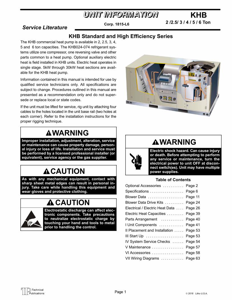
© 2018 Litho U.S.A. Page 1 KHB Service Literature 2 /2.5/ 3 / 4 / 5 / 6 Ton Corp. 1815-L6 KHB Standard and High Efficiency Series The KHB commercial heat pump is available in 2, 2.5, 3, 4, 5 and 6 ton capacities. The KHB024-074 refrigerant sys- tems utilize one compressor, one reversing valve and other parts common to a heat pump. Optional auxiliary electric heat is field installed in KHB units. Electric heat operates in single stage. 5kW through 30kW heat sections are avail- able for the KHB heat pump. Information contained in this manual is intended for use by qualified service technicians only. All specifications are subject to change. Procedures outlined in this manual are presented as a recommendation only and do not super- sede or replace local or state codes. If the unit must be lifted for service, rig unit by attaching four cables to the holes located in the unit base rail (two holes at each corner). Refer to the installation instructions for the proper rigging technique. WARNING Improper installation, adjustment, alteration, service or maintenance can cause property damage, person- al injury or loss of life. Installation and service must be performed by a licensed professional installer (or equivalent), service agency or the gas supplier. CAUTION As with any mechanical equipment, contact with sharp sheet metal edges can result in personal in- jury. Take care while handling this equipment and wear gloves and protective clothing. CAUTION Electrostatic discharge can affect elec- tronic components. Take precautions to neutralize electrostatic charge by touching your hand and tools to metal prior to handling the control. WARNING Electric shock hazard. Can cause injury or death. Before attempting to perform any service or maintenance, turn the electrical power to unit OFF at discon- nect switch(es). Unit may have multiple power supplies. Table of Contents Optional Accessories Page 2 ........... Specifications Page 6 .................. Blower Data Page 11 ................... Blower Data Drive Kits Page 24 .......... Electrical / Electric Heat Data Page 26 .... Electric Heat Capacities Page 39 ......... Parts Arrangement Page 40 ............ I Unit Components Page 41 ............. II Placement and Installation Page 53 ..... III Start Up Page 53 .................... IV System Service Checks Page 54 ...... V Maintenance Page 57 ................. VI Accessories Page 58 ................. VII Wiring Diagrams Page 63 ............
-
Upload
khangminh22 -
Category
Documents
-
view
3 -
download
0
Transcript of KHB - Lennox International -
© 2018 Litho U.S.A.Page 1
KHB
Service Literature2 /2.5/ 3 / 4 / 5 / 6 TonCorp. 1815-L6
KHB Standard and High Efficiency SeriesThe KHB commercial heat pump is available in 2, 2.5, 3, 4,
5 and 6 ton capacities. The KHB024-074 refrigerant sys
tems utilize one compressor, one reversing valve and other
parts common to a heat pump. Optional auxiliary electric
heat is field installed in KHB units. Electric heat operates in
single stage. 5kW through 30kW heat sections are avail
able for the KHB heat pump.
Information contained in this manual is intended for use by
qualified service technicians only. All specifications are
subject to change. Procedures outlined in this manual are
presented as a recommendation only and do not super
sede or replace local or state codes.
If the unit must be lifted for service, rig unit by attaching four
cables to the holes located in the unit base rail (two holes at
each corner). Refer to the installation instructions for the
proper rigging technique.
WARNINGImproper installation, adjustment, alteration, serviceor maintenance can cause property damage, personal injury or loss of life. Installation and service mustbe performed by a licensed professional installer (orequivalent), service agency or the gas supplier.
CAUTIONAs with any mechanical equipment, contact withsharp sheet metal edges can result in personal injury. Take care while handling this equipment andwear gloves and protective clothing.
CAUTIONElectrostatic discharge can affect electronic components. Take precautionsto neutralize electrostatic charge bytouching your hand and tools to metalprior to handling the control.
WARNINGElectric shock hazard. Can cause injuryor death. Before attempting to performany service or maintenance, turn theelectrical power to unit OFF at disconnect switch(es). Unit may have multiplepower supplies.
Table of Contents
Optional Accessories Page 2. . . . . . . . . . .
Specifications Page 6. . . . . . . . . . . . . . . . . .
Blower Data Page 11. . . . . . . . . . . . . . . . . . .
Blower Data Drive Kits Page 24. . . . . . . . . .
Electrical / Electric Heat Data Page 26. . . .
Electric Heat Capacities Page 39. . . . . . . . .
Parts Arrangement Page 40. . . . . . . . . . . .
I Unit Components Page 41. . . . . . . . . . . . .
II Placement and Installation Page 53. . . . .
III Start Up Page 53. . . . . . . . . . . . . . . . . . . .
IV System Service Checks Page 54. . . . . .
V Maintenance Page 57. . . . . . . . . . . . . . . . .
VI Accessories Page 58. . . . . . . . . . . . . . . . .
VII Wiring Diagrams Page 63. . . . . . . . . . . .
Page 2
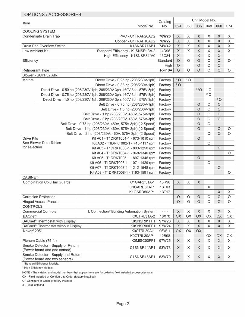
OPTIONS / ACCESSORIES
ItemModel No.
Catalog No.
Unit Model No. 024 030 036 048 060 074
COOLING SYSTEMCondensate Drain Trap PVC - C1TRAP20AD2 76W26 X X X X X X
Copper - C1TRAP10AD2 76W27 X X X X X XDrain Pan Overflow Switch K1SNSR71AB1 74W42 X X X X X XLow Ambient Kit Standard Efficiency - K1SNSR13A-2 14D96 X X X X X X
High Efficiency - K1SNSR34*A0 15C84 X X X XEfficiency Standard O O O O O O
High O O O ORefrigerant Type R-410A O O O O O OBlower - SUPPLY AIRMotors Direct Drive - 0.25 hp (208/230V-1ph) Factory 1 O 1 O
Direct Drive - 0.33 hp (208/230V-1ph) Factory 2 ODirect Drive - 0.50 hp (208/230V-1ph, 208/230V-3ph, 460V-3ph, 575V-3ph) Factory 1, 2O 1 ODirect Drive - 0.75 hp (208/230V-1ph, 208/230V-3ph, 460V-3ph, 575V-3ph) Factory 2 ODirect Drive - 1.0 hp (208/230V-1ph, 208/230V-3ph, 460V-3ph, 575V-3ph) Factory 2 O
Belt Drive - 0.75 hp (208/230V-1ph) Factory O O OBelt Drive - 1.5 hp (208/230V-1ph) Factory O O O
Belt Drive - 1 hp (208/230V, 460V, 575V-3ph) Factory O O OBelt Drive - 2 hp (208/230V, 460V, 575V-3ph) Factory O O O
Belt Drive - 0.75 hp (208/230V, 460V, 575V-3ph) ( 2 Speed) Factory O OBelt Drive - 1 hp (208/230V, 460V, 575V-3ph) ( 2 Speed) Factory O O OBelt Drive - 2 hp (208/230V, 460V, 575V-3ph) (2 Speed) Factory O O O
Drive Kits See Blower Data Tables for selection
Kit A01 - T1DRKT001-1 - 673-1010 rpm Factory OKit A02 - T1DRKT002-1 - 745-1117 rpm Factory OKit A03 - T1DRKT003-1 - 833-1250 rpm Factory OKit A04 - T1DRKT004-1 - 968-1340 rpm Factory OKit A05 - T1DRKT005-1 - 897-1346 rpm Factory O
Kit A06 - T1DRKT006-1 - 1071-1429 rpm Factory OKit A07 - T1DRKT007-1 - 1212-1548 rpm Factory OKit A08 - T1DRKT008-1 - 1193-1591 rpm Factory O
CABINETCombination Coil/Hail Guards C1GARD51A-1 13R98 X X X
C1GARD51AT1 13T03 XK1GARD50AP1 13T17 X X
Corrosion Protection O O O O O OHinged Access Panels O O O O O OCONTROLSCommercial Controls L Connection® Building Automation System - - - X X X X X XBACnet® K0CTRL31A-2 16X70 OX OX OX OX OX OXBACnet® Thermostat with Display K0SNSR01FF1 97W23 X X X X X XBACnet® Thermostat without Display K0SNSR00FF1 97W24 X X X X X XNovar® 2051 K0CTRL30A-1 96W11 OX OX OX
K0CTRL30AP1 12B98 OX OX OXPlenum Cable (75 ft.) K0MISC00FF1 97W25 X X X X X XSmoke Detector - Supply or Return (Power board and one sensor) C1SNSR44AP1 53W78 X X X X X X
Smoke Detector - Supply and Return (Power board and two sensors) C1SNSR43AP1 53W79 X X X X X X1 Standard Efficiency Models.2 High Efficiency Models.
NOTE - The catalog and model numbers that appear here are for ordering field installed accessories only.OX - Field Installed or Configure to Order (factory installed)O - Configure to Order (Factory Installed)X - Field Installed
Page 3
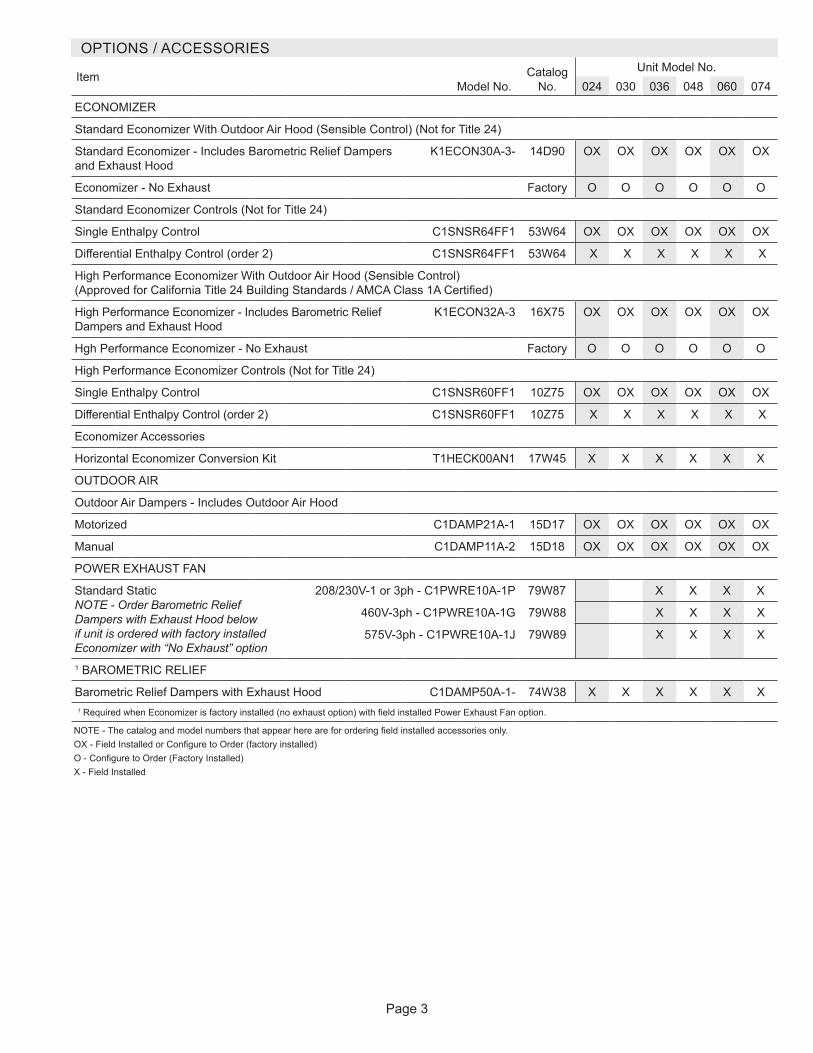
OPTIONS / ACCESSORIES
ItemModel No.
Catalog No.
Unit Model No. 024 030 036 048 060 074
ECONOMIZER
Standard Economizer With Outdoor Air Hood (Sensible Control) (Not for Title 24)
Standard Economizer - Includes Barometric Relief Dampers and Exhaust Hood
K1ECON30A-3- 14D90 OX OX OX OX OX OX
Economizer - No Exhaust Factory O O O O O O
Standard Economizer Controls (Not for Title 24)
Single Enthalpy Control C1SNSR64FF1 53W64 OX OX OX OX OX OX
Differential Enthalpy Control (order 2) C1SNSR64FF1 53W64 X X X X X X
High Performance Economizer With Outdoor Air Hood (Sensible Control) (Approved for California Title 24 Building Standards / AMCA Class 1A Certified)
High Performance Economizer - Includes Barometric Relief Dampers and Exhaust Hood
K1ECON32A-3 16X75 OX OX OX OX OX OX
Hgh Performance Economizer - No Exhaust Factory O O O O O O
High Performance Economizer Controls (Not for Title 24)
Single Enthalpy Control C1SNSR60FF1 10Z75 OX OX OX OX OX OX
Differential Enthalpy Control (order 2) C1SNSR60FF1 10Z75 X X X X X X
Economizer Accessories
Horizontal Economizer Conversion Kit T1HECK00AN1 17W45 X X X X X X
OUTDOOR AIR
Outdoor Air Dampers - Includes Outdoor Air Hood
Motorized C1DAMP21A-1 15D17 OX OX OX OX OX OX
Manual C1DAMP11A-2 15D18 OX OX OX OX OX OX
POWER EXHAUST FAN
Standard Static NOTE - Order Barometric Relief Dampers with Exhaust Hood below if unit is ordered with factory installed Economizer with “No Exhaust” option
208/230V-1 or 3ph - C1PWRE10A-1P 79W87 X X X X
460V-3ph - C1PWRE10A-1G 79W88 X X X X
575V-3ph - C1PWRE10A-1J 79W89 X X X X
1 BAROMETRIC RELIEF
Barometric Relief Dampers with Exhaust Hood C1DAMP50A-1- 74W38 X X X X X X1 Required when Economizer is factory installed (no exhaust option) with field installed Power Exhaust Fan option.
NOTE - The catalog and model numbers that appear here are for ordering field installed accessories only.OX - Field Installed or Configure to Order (factory installed)O - Configure to Order (Factory Installed)X - Field Installed

Page 4
OPTIONS / ACCESSORIES
ItemModel No.
Catalog No.
Unit Model No. 024 030 036 048 060 074
ELECTRICAL
Disconnect See Electrical/Electric Heat Tables for selection OX OX OX OX OX OX
Voltage 60 hz
208/230V - 1 phase O O O O O
208/230V - 3 phase O O O O
460V - 3 phase O O O O
575V - 3 phase O O O O
GFI Service Outlets
15 amp non-powered, field-wired (208/230V, 460V only) LTAGFIK10/15 74M70 OX OX OX OX OX OX
20 amp non-powered, field-wired (575V only) C1GFCI20FF1 67E01 X X X X X X
Weatherproof Cover for GFI C1GFCI99FF1 10C89 X X X X X X
ELECTRIC HEAT
5 kW 208/230V- 1ph - K1EH0050A-1P 12F06 X X
7.5 kW 208/230V-1ph - T1EH0075AN1P 14W32 X X X X X
208/230V-3ph - T1EH0075AN1Y 14W35 X X X X
460V-3ph - T1EH0075AN1G 14W39 X X X X
575V-3ph - T1EH0075AN1J 14W43 X X X X
10 kW 208/230V-1ph - T1EH0100A1P 30W26 X X
15 kW 208/230V-1ph - T1EH0150AN1P 14W33 X X X
208/230V-3ph - T1EH0150AN1Y 14W36 X X X X
460V-3ph - T1EH0150AN1G 14W40 X X X X
575V-3ph - T1EH0150AN1J 14W44 X X X X
22.5 kW 208/230V-1ph - T1EH0225AN1P 14W34 X
208/230V-3ph - T1EH0225AN1Y 14W37 X X
460V-3ph - T1EH0225AN1G 14W41 X X
575V-3ph - T1EH0225AN1J 14W45 X X
30 kW 208/230V-3ph - T1EH0300N-1Y 14W38 X
460V-3ph - T1EH0300N-1G 14W42 X
575V-3ph - T1EH0300N-1J 14W46 XNOTE - The catalog and model numbers that appear here are for ordering field installed accessories only.OX - Field Installed or Configure to Order (factory installed)O - Configure to Order (Factory Installed)X - Field Installed

Page 5
OPTIONS / ACCESSORIES
ItemModel No.
Catalog No.
Unit Model No. 024 030 036 048 060 074
Indoor Air QualityAir FiltersHealthy Climate® High Efficiency Air FiltersOrder 4 per unit
MERV 8 (16 x 20 x 2) - C1FLTR15A-1- 54W20 X X XMERV 13 (16 x 20 x 2) - T1FLTR40A-1- 52W37 X X XMERV 8 (20 x 20 x 2) - C1FLTR15D-1- 54W21 X X X
MERV 13 (20 x 20 x 2) - C1FLTR40D-1- 52W39 X X XIndoor Air Quality (Co2) SensorsSensor - Wall-mount, off-white plastic cover with LCD display C0SNSR50AS1L 77N39 X X X X X XSensor - Wall-mount, black plastic case, no display, rated for plenum mounting
C0SNSR53AE1L 87N54 X X X X X X
CO2 Sensor Duct Mounting Kit - for downflow applications 85L43 X X X X X XAspiration Box - for duct mounting non-plenum rated CO2 sensor (77N39)
90N43 X X X X X X
UVC Germicidal Lamps1 Healthy Climate® UVC Light Kit (208/230v-1ph) E1UVCL10AN1 50W90 X X X X X XROOF CURBSHybrid Roof Curbs, Downflow8 in. height C1CURB70A-1 11F50 X X X X 2 X 2 X14 in. height C1CURB71A-1 11F51 X X X X 2 X 2 X18 in. height C1CURB72A-1 11F52 X X X X 2 X 2 X24 in. height C1CURB73A-1 11F53 X X X X 2 X 2 XHybrid Roof Curbs, Full Perimeter, Downflow8 in. height K1CURB70AP1 11S47 X X14 in. height K1CURB71AP1 11S48 X X18 in. height K1CURB72AP1 11T01 X X24 in. height K1CURB73AP1 11T06 X XAdjustable Pitch Curb, Downflow14 in. height C1CURB55AT1 43W27 X X X X X XCEILING DIFFUSERSStep-Down - Order one RTD9-65S 13K60 X X X X
RTD11-95S 13K61 X XFlush - Order one FD9-65S 13K55 X X X X
FD11-95S 13K56 X XTransitions (Supply and Return) - Order one T1TRAN10AN1 17W53 X X X X
T1TRAN20N-1 17W54 X X1 Lamps operate on 110-230V single-phase power supply. Step-down transformer may be ordered separately for 460V and 575V units. Alternately, 110V power supply
may be used to directly power the UVC ballast(s).2 060H and 074 models will fit smaller roof curbs with overhang. See dimension drawing.
NOTE - The catalog and model numbers that appear here are for ordering field installed accessories only.OX - Field Installed or Configure to Order (factory installed)O - Configure to Order (Factory Installed)X - Field Installed
Page 6
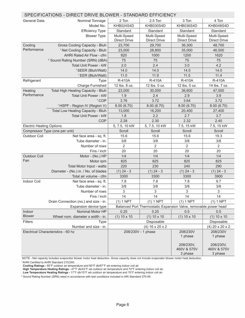
SPECIFICATIONS - DIRECT DRIVE BLOWER - STANDARD EFFICIENCYGeneral Data Nominal Tonnage 2 Ton 2.5 Ton 3 Ton 4 Ton
Model No. KHB024S4D KHB030S4D KHB036S4D KHB048S4DEfficiency Type Standard Standard Standard Standard
Blower Type Multi-Speed Direct Drive
Multi-Speed Direct Drive
Multi-Speed Direct Drive
Multi-Speed Direct Drive
Cooling Performance
Gross Cooling Capacity - Btuh 23,700 29,700 36,300 48,7001 Net Cooling Capacity - Btuh 23,000 28,800 35,000 46,500
AHRI Rated Air Flow - cfm 820 1000 1200 16202 Sound Rating Number (SRN) (dBA) 75 75 75 75
Total Unit Power - kW 2.0 2.4 3.0 4.21 SEER (Btuh/Watt) 14.0 14.0 14.0 14.0
1 EER (Btuh/Watt) 11.0 11.9 11.5 11.4Refrigerant Type R-410A R-410A R-410A R-410A
Charge Furnished 12 lbs. 8 oz. 12 lbs. 0 oz. 12 lbs. 0 oz. 14 lbs. 7 oz.Heating Performance
Total High Heating Capacity - Btuh 23,000 30,000 36,600 47,500Total Unit Power - kW 1.9 2.4 2.9 3.9
1 COP 3.76 3.72 3.64 3.721 HSPF - Region IV (Region V) 8.00 (6.70) 8.00 (6.70) 8.00 (6.70) 8.00 (6.70)
Total Low Heating Capacity - Btuh 13,000 16,200 20,400 27,400Total Unit Power - kW 1.8 2.2 2.7 3.7
COP 2.28 2.30 2.32 2.40Electric Heating Options 5, 7.5, 10 kW 5, 7.5, 10 kW 7.5, 15 kW 7.5, 15 kWCompressor Type (one per unit) Scroll Scroll Scroll ScrollOutdoor Coil Net face area - sq. ft. 15.6 15.6 15.6 19.3
Tube diameter - in. 3/8 3/8 3/8 3/8Number of rows 2 2 2 2
Fins / inch 20 20 20 20Outdoor Coil Fan
Motor - (No.) HP 1/4 1/4 1/4 1/4Motor rpm 825 825 825 825
Total Motor Input - watts 220 230 240 290Diameter - (No.) in. / No. of blades (1) 24 - 3 (1) 24 - 3 (1) 24 - 3 (1) 24 - 3
Total air volume - cfm 3300 3300 3300 3900Indoor Coil
Net face area - sq. ft. 7.8 7.8 7.8 9.7Tube diameter - in. 3/8 3/8 3/8 3/8
Number of rows 3 3 3 3Fins / inch 14 14 14 14
Drain Connection (no.) and size - in. (1) 1 NPT (1) 1 NPT (1) 1 NPT (1) 1 NPTExpansion device type Balanced Port Thermostatic Expansion Valve, removable power head
Indoor Blower
Nominal Motor HP 0.25 0.25 0.5 0.5Wheel nom. diameter x width - in. (1) 10 x 10 (1) 10 x 10 (1) 10 x 10 (1) 10 x 10
Filters Type Disposable DisposableNumber and size - in. (4) 16 x 20 x 2 (4) 20 x 20 x 2
Electrical Characteristics - 60 hz 208/230V - 1 phase 208/230V 1 phase
208/230V,
460V & 575V 3 phase
208/230V 1 phase
208/230V,
460V & 575V 3 phase
NOTE - Net capacity includes evaporator blower motor heat deduction. Gross capacity does not include evaporator blower motor heat deduction.1 AHRI Certified to AHRI Standard 210/240: Cooling Ratings - 95°F outdoor air temperature and 80°F db/67°F wb entering indoor coil air. High Temperature Heating Ratings - 47°F db/43°F wb outdoor air temperature and 70°F entering indoor coil air. Low Temperature Heating Ratings - 17°F db/15°F wb outdoor air temperature and 70°F entering indoor coil air.2 Sound Rating Number (SRN) rated in accordance with test conditions included in ARI Standard 270-95.
Page 7
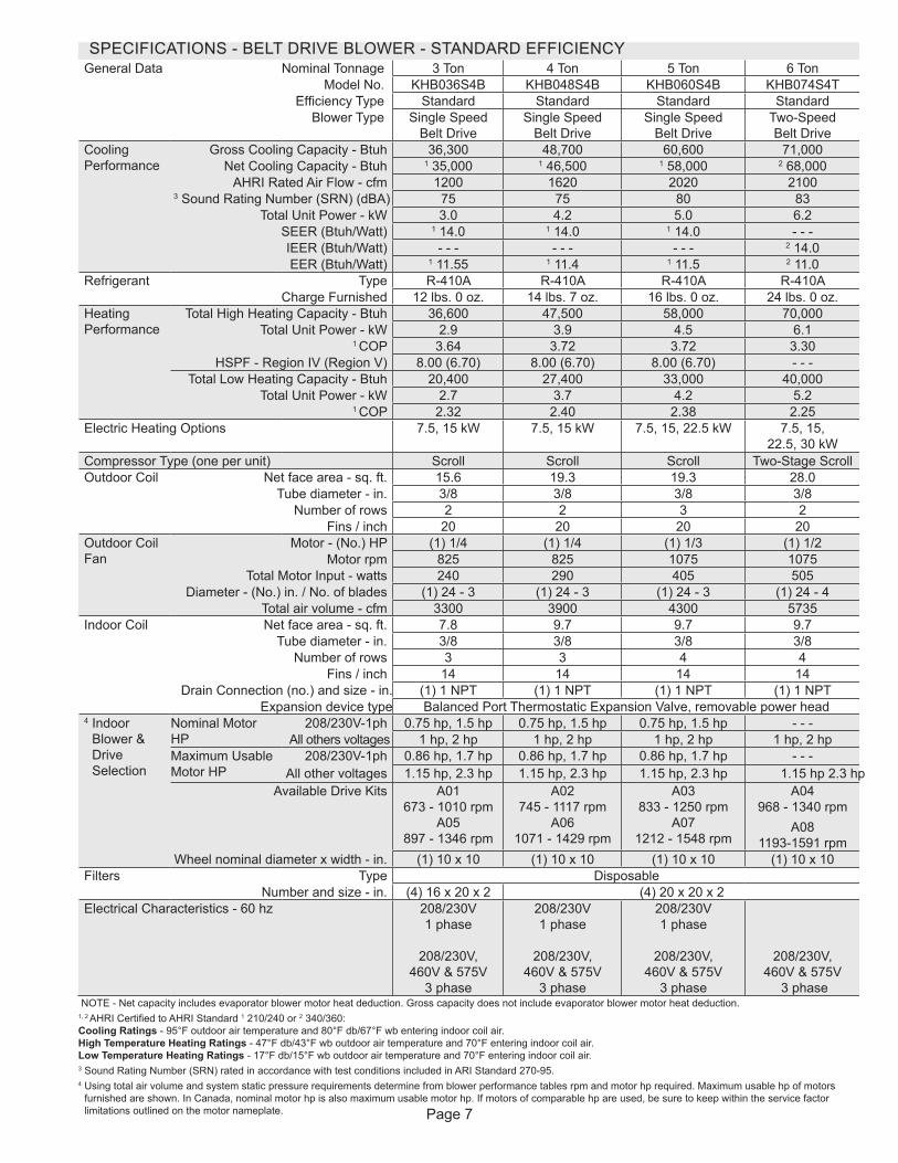
SPECIFICATIONS - BELT DRIVE BLOWER - STANDARD EFFICIENCYGeneral Data Nominal Tonnage 3 Ton 4 Ton 5 Ton 6 Ton
Model No. KHB036S4B KHB048S4B KHB060S4B KHB074S4TEfficiency Type Standard Standard Standard Standard
Blower Type Single Speed Belt Drive
Single Speed Belt Drive
Single Speed Belt Drive
Two-Speed Belt Drive
Cooling Performance
Gross Cooling Capacity - Btuh 36,300 48,700 60,600 71,000 Net Cooling Capacity - Btuh 1 35,000 1 46,500 1 58,000 2 68,000
AHRI Rated Air Flow - cfm 1200 1620 2020 21003 Sound Rating Number (SRN) (dBA) 75 75 80 83
Total Unit Power - kW 3.0 4.2 5.0 6.2SEER (Btuh/Watt) 1 14.0 1 14.0 1 14.0 - - -IEER (Btuh/Watt) - - - - - - - - - 2 14.0EER (Btuh/Watt) 1 11.55 1 11.4 1 11.5 2 11.0
Refrigerant Type R-410A R-410A R-410A R-410ACharge Furnished 12 lbs. 0 oz. 14 lbs. 7 oz. 16 lbs. 0 oz. 24 lbs. 0 oz.
Heating Performance
Total High Heating Capacity - Btuh 36,600 47,500 58,000 70,000Total Unit Power - kW 2.9 3.9 4.5 6.1
1 COP 3.64 3.72 3.72 3.30HSPF - Region IV (Region V) 8.00 (6.70) 8.00 (6.70) 8.00 (6.70) - - -
Total Low Heating Capacity - Btuh 20,400 27,400 33,000 40,000Total Unit Power - kW 2.7 3.7 4.2 5.2
1 COP 2.32 2.40 2.38 2.25Electric Heating Options 7.5, 15 kW 7.5, 15 kW 7.5, 15, 22.5 kW 7.5, 15,
22.5, 30 kWCompressor Type (one per unit) Scroll Scroll Scroll Two-Stage ScrollOutdoor Coil Net face area - sq. ft. 15.6 19.3 19.3 28.0
Tube diameter - in. 3/8 3/8 3/8 3/8Number of rows 2 2 3 2
Fins / inch 20 20 20 20Outdoor Coil Fan
Motor - (No.) HP (1) 1/4 (1) 1/4 (1) 1/3 (1) 1/2Motor rpm 825 825 1075 1075
Total Motor Input - watts 240 290 405 505Diameter - (No.) in. / No. of blades (1) 24 - 3 (1) 24 - 3 (1) 24 - 3 (1) 24 - 4
Total air volume - cfm 3300 3900 4300 5735Indoor Coil Net face area - sq. ft. 7.8 9.7 9.7 9.7
Tube diameter - in. 3/8 3/8 3/8 3/8Number of rows 3 3 4 4
Fins / inch 14 14 14 14Drain Connection (no.) and size - in. (1) 1 NPT (1) 1 NPT (1) 1 NPT (1) 1 NPT
Expansion device type Balanced Port Thermostatic Expansion Valve, removable power head4 Indoor
Blower & Drive Selection
Nominal Motor HP
208/230V-1ph 0.75 hp, 1.5 hp 0.75 hp, 1.5 hp 0.75 hp, 1.5 hp - - -All others voltages 1 hp, 2 hp 1 hp, 2 hp 1 hp, 2 hp 1 hp, 2 hp
Maximum Usable Motor HP
208/230V-1ph 0.86 hp, 1.7 hp 0.86 hp, 1.7 hp 0.86 hp, 1.7 hp - - -All other voltages 1.15 hp, 2.3 hp 1.15 hp, 2.3 hp 1.15 hp, 2.3 hp 1.15 hp 2.3 hp
Available Drive Kits A01 673 - 1010 rpm
A05 897 - 1346 rpm
A02 745 - 1117 rpm
A06 1071 - 1429 rpm
A03 833 - 1250 rpm
A07 1212 - 1548 rpm
A04 968 - 1340 rpm
A08 1193-1591 rpm
Wheel nominal diameter x width - in. (1) 10 x 10 (1) 10 x 10 (1) 10 x 10 (1) 10 x 10Filters Type Disposable Number and size - in. (4) 16 x 20 x 2 (4) 20 x 20 x 2Electrical Characteristics - 60 hz 208/230V
1 phase
208/230V, 460V & 575V
3 phase
208/230V 1 phase
208/230V,
460V & 575V 3 phase
208/230V 1 phase
208/230V,
460V & 575V 3 phase
208/230V, 460V & 575V
3 phaseNOTE - Net capacity includes evaporator blower motor heat deduction. Gross capacity does not include evaporator blower motor heat deduction.
1, 2 AHRI Certified to AHRI Standard 1 210/240 or 2 340/360: Cooling Ratings - 95°F outdoor air temperature and 80°F db/67°F wb entering indoor coil air. High Temperature Heating Ratings - 47°F db/43°F wb outdoor air temperature and 70°F entering indoor coil air. Low Temperature Heating Ratings - 17°F db/15°F wb outdoor air temperature and 70°F entering indoor coil air.3 Sound Rating Number (SRN) rated in accordance with test conditions included in ARI Standard 270-95.4 Using total air volume and system static pressure requirements determine from blower performance tables rpm and motor hp required. Maximum usable hp of motors
furnished are shown. In Canada, nominal motor hp is also maximum usable motor hp. If motors of comparable hp are used, be sure to keep within the service factor limitations outlined on the motor nameplate.

Page 8
SPECIFICATIONS - DIRECT DRIVE BLOWER - HIGH EFFICIENCYGeneral Data Nominal Tonnage 2 Ton 3 Ton 4 Ton 5 Ton
Model No. KHB024H4E KHB036H4E KHB048H4E KHB060H4EEfficiency Type High High High High
Blower Type Direct Drive-ECM Direct Drive-ECM Direct Drive-ECM Direct Drive-ECMCooling Performance
Gross Cooling Capacity - Btuh 23,800 35,700 46,800 59,4001 Net Cooling Capacity - Btuh 23,600 35,200 46,000 58,000
AHRI Rated Air Flow - cfm 800/560 1200/800 1430/1120 1650/12102 Sound Rating Number (SRN) (dBA) 74 75 77 77
Total Unit Power - kW 1.8 2.8 3.6 4.71 SEER (Btuh/Watt) 16.5 16.0 16.0 16.0
1 EER (Btuh/Watt) - 208/230V 13.0 12.7 12.8 12.51 EER (Btuh/Watt) - 460V/575V 13.0 12.4 12.8 12.5
Refrigerant Type R-410A R-410A R-410A R-410ACharge Furnished 13 lbs. 0 oz. 12 lbs. 13 oz. 14 lbs. 0 oz. 20 lbs. 0 oz.
Heating Performance
Total High Heating Capacity - Btuh 24,000 35,000 46,000 59,000Total Unit Power - kW 1.8 2.6 3.4 4.7
1 COP 3.88 3.90 3.90 3.761 HSPF - Region IV (Region V) 8.30 8.50 8.50 8.50
Total Low Heating Capacity - Btuh 13,000 19,200 26,000 34,000Total Unit Power - kW 1.6 2.3 3.0 4.0
COP 2.34 2.40 2.46 2.46Electric Heating Options - 5, 7.5, 10 kW 7.5, 15 kW 7.5, 15 kW 7.5, 15 kWCompressor Type (one per unit) Two-Stage Scroll Two-Stage Scroll Two-Stage Scroll Two-Stage ScrollOutdoor Coil Net face area - sq. ft. 15.6 15.6 19.3 28.0
Tube diameter - in. 3/8 3/8 3/8 3/8Number of rows 2 2 2 2
Fins / inch 20 20 20 20Outdoor Coil Fan
Motor - (No.) HP (1) 1/3 (1) 1/3 (1) 1/3 (1) 1/3Motor rpm 725/500 775/650 850/700 930/785
Total Motor Input - watts 165/60 193/125 251/140 236/145Diameter - (No.) in. / No. of blades 24 - 3 24 - 3 24 - 3 24 - 3
Total air volume - cfm 3340/2240 3500/2970 4060/3330 4135/3385Indoor Coil
Net face area - sq. ft. 7.8 7.8 9.7 9.7Tube diameter - in. 3/8 3/8 3/8 3/8
Number of rows 3 3 3 4Fins / inch 14 14 14 14
Drain Connection (no.) and size - in. (1) 1 NPT (1) 1 NPT (1) 1 NPT (1) 1 NPTExpansion device type Balanced Port Thermostatic Expansion Valve, removable power head
Indoor Blower
Nominal Motor HPWheel nominal diameter x width - in.
0.33 0.5 0.75 1(1) 10 x 10 (1) 10 x 10 (1) 10 x 10 (1) 11 x 10
Filters Type Disposable DisposableNumber and size - in. (4) 16 x 20 x 2 (4) 20 x 20 x 2
Electrical Characteristics - 60 hz 208/230V 1 phase
208/230V 1 phase
208/230V,
460V & 575V 3 phase
208/230V 1 phase
208/230V,
460V & 575V 3 phase
208/230V 1 phase
208/230V,
460V & 575V 3 phase
NOTE - Net capacity includes evaporator blower motor heat deduction. Gross capacity does not include evaporator blower motor heat deduction.1 AHRI Certified to AHRI Standard 210/240: Cooling Ratings - 95°F outdoor air temperature and 80°F db/67°F wb entering indoor coil air. High Temperature Heating Ratings - 47°F db/43°F wb outdoor air temperature and 70°F entering indoor coil air. Low Temperature Heating Ratings - 17°F db/15°F wb outdoor air temperature and 70°F entering indoor coil air.2 Sound Rating Number (SRN) rated in accordance with test conditions included in ARI Standard 270-95.
Page 9
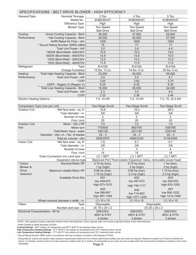
SPECIFICATIONS - BELT DRIVE BLOWER - HIGH EFFICIENCYGeneral Data Nominal Tonnage 3 Ton 4 Ton 5 Ton
Model No. KHB036H4T KHB048H4T KHB060H4TEfficiency Type High High High
Blower Type Two Speed Belt Drive
Two Speed Belt Drive
Two Speed Belt Drive
Cooling Performance
Gross Cooling Capacity - Btuh 36,200 47,600 59,6001 Net Cooling Capacity - Btuh 35,000 46,000 57,500
AHRI Rated Air Flow - cfm 1200 1600 18002 Sound Rating Number (SRN) (dBA) 75 77 77
Total Unit Power - kW 3.0 3.8 4.91 SEER (Btuh/Watt)- 208/230V 15.0 15.0 15.0
1 SEER (Btuh/Watt) - 460/575V 14.8 14.8 15.01 EER (Btuh/Watt) - 208/230V 12.0 12.0 12.01 EER (Btuh/Watt) - 460/575V 11.8 11.9 11.8
Refrigerant Type R-410A R-410A R-410ACharge Furnished 12 lbs. 13 oz. 14 lbs. 0 oz. 20 lbs. 0 oz.
Heating Performance
Total High Heating Capacity - Btuh 35,000 46,000 59,000Total Unit Power - kW 2.8 3.5 4.7
1 COP 3.64 3.82 3.70HSPF - Region IV (Region V) 8.30 8.30 8.30
Total Low Heating Capacity - Btuh 19,200 26,000 34,000Total Unit Power - kW 2.3 3.0 4.0
1 COP 2.22 2.38 2.46Electric Heating Options - 7.5, 15 kW 7.5, 15 kW 7.5, 15, 22.5 kW
Compressor Type (one per unit) Two-Stage Scroll Two-Stage Scroll Two-Stage ScrollOutdoor Coil Net face area - sq. ft. 15.6 19.3 28.0
Tube diameter - in. 3/8 3/8 3/8Number of rows 2 2 2
Fins / inch 20 20 20Outdoor Coil Fan
Motor - (No.) HP 1/3 1/3 1/3Motor rpm 775/650 850/700 930/785
Total Motor Input - watts 195/125 251/140 235/145Diameter - (No.) in. / No. of blades 24 - 3 24 - 3 24 - 3
Total air volume - cfm 3500/2970 4060/3330 4135/3385Indoor Coil Net face area - sq. ft. 7.8 9.7 9.7
Tube diameter - in. 3/8 3/8 3/8Number of rows 3 3 4
Fins / inch 14 14 14Drain Connection (no.) and size - in. (1) 1 NPT (1) 1 NPT (1) 1 NPT
Expansion device type Balanced Port Thermostatic Expansion Valve, removable power head3 Indoor
Blower & Drive Selection
Nominal Motor HP 0.75 hp (low), 1 hp (high)
0.75 hp (low), 2 hp (high)
1 hp (low), 2 hp (high)
Maximum Usable Motor HP 0.86 hp (low), 1.15 hp (high)
0.86 hp (low), 2.3 hp (high)
1.15 hp (low), 2.3 hp (high)
Available Drive Kits A01 low 449-673
high 673-1010A05
low 598-897 high 897-1346
A02 low 497-673
high 745-1117A06
low 714-953 high 1071-1429
A03 low 555-833
high 833-1250A07
low 808-1032 high 1212-1548
Wheel nominal diameter x width - in. (1) 10 x 10 (1) 10 x 10 (1) 10 x 10Filters Type Disposable Disposable Number and size - in. (4) 16 x 20 x 2 (4) 20 x 20 x 2Electrical Characteristics - 60 hz 208/230V,
460V & 575V 3 phase
208/230V, 460V & 575V
3 phase
208/230V, 460V & 575V
3 phaseNOTE - Net capacity includes evaporator blower motor heat deduction. Gross capacity does not include evaporator blower motor heat deduction.
1 AHRI Certified to AHRI Standard 210/240: Cooling Ratings - 95°F outdoor air temperature and 80°F db/67°F wb entering indoor coil air. High Temperature Heating Ratings - 47°F db/43°F wb outdoor air temperature and 70°F entering indoor coil air. Low Temperature Heating Ratings - 17°F db/15°F wb outdoor air temperature and 70°F entering indoor coil air.2 Sound Rating Number (SRN) rated in accordance with test conditions included in ARI Standard 270-95.3 Using total air volume and system static pressure requirements determine from blower performance tables rpm and motor hp required. Maximum usable hp of motors furnished are
shown. In Canada, nominal motor hp is also maximum usable motor hp. If motors of comparable hp are used, be sure to keep within the service factor limitations outlined on the motor nameplate.
Page 10
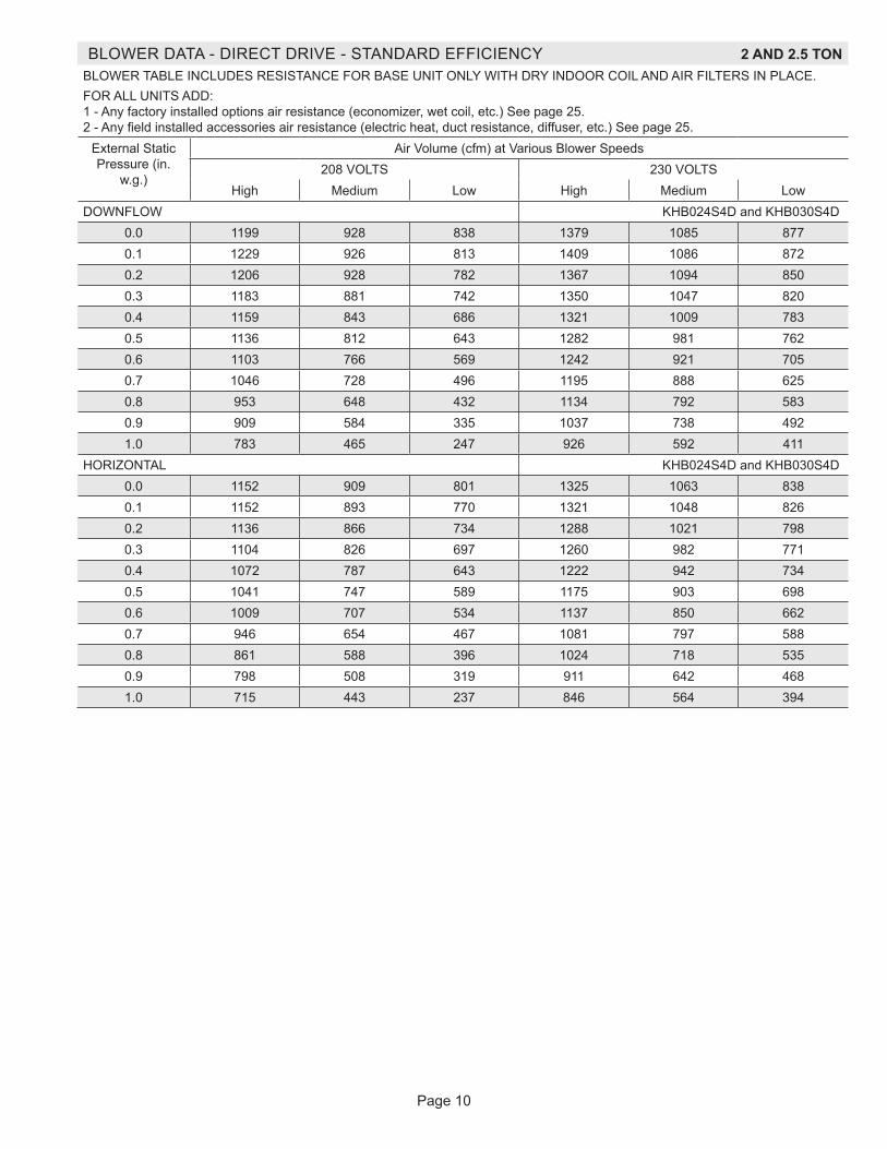
BLOWER DATA - DIRECT DRIVE - STANDARD EFFICIENCY 2 AND 2.5 TONBLOWER TABLE INCLUDES RESISTANCE FOR BASE UNIT ONLY WITH DRY INDOOR COIL AND AIR FILTERS IN PLACE.FOR ALL UNITS ADD: 1 - Any factory installed options air resistance (economizer, wet coil, etc.) See page 25. 2 - Any field installed accessories air resistance (electric heat, duct resistance, diffuser, etc.) See page 25.
External Static Pressure (in.
w.g.)
Air Volume (cfm) at Various Blower Speeds208 VOLTS 230 VOLTS
High Medium Low High Medium LowDOWNFLOW KHB024S4D and KHB030S4D
0.0 1199 928 838 1379 1085 8770.1 1229 926 813 1409 1086 8720.2 1206 928 782 1367 1094 8500.3 1183 881 742 1350 1047 8200.4 1159 843 686 1321 1009 7830.5 1136 812 643 1282 981 7620.6 1103 766 569 1242 921 7050.7 1046 728 496 1195 888 6250.8 953 648 432 1134 792 5830.9 909 584 335 1037 738 4921.0 783 465 247 926 592 411
HORIZONTAL KHB024S4D and KHB030S4D0.0 1152 909 801 1325 1063 8380.1 1152 893 770 1321 1048 8260.2 1136 866 734 1288 1021 7980.3 1104 826 697 1260 982 7710.4 1072 787 643 1222 942 7340.5 1041 747 589 1175 903 6980.6 1009 707 534 1137 850 6620.7 946 654 467 1081 797 5880.8 861 588 396 1024 718 5350.9 798 508 319 911 642 4681.0 715 443 237 846 564 394
Page 11
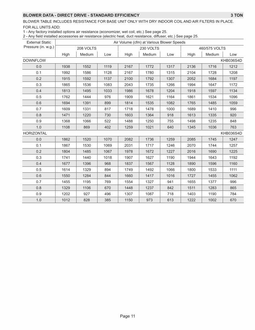
BLOWER DATA - DIRECT DRIVE - STANDARD EFFICIENCY 3 TONBLOWER TABLE INCLUDES RESISTANCE FOR BASE UNIT ONLY WITH DRY INDOOR COIL AND AIR FILTERS IN PLACE.FOR ALL UNITS ADD: 1 - Any factory installed options air resistance (economizer, wet coil, etc.) See page 25. 2 - Any field installed accessories air resistance (electric heat, duct resistance, diffuser, etc.) See page 25.
External Static Pressure (in. w.g.)
Air Volume (cfm) at Various Blower Speeds208 VOLTS 230 VOLTS 460/575 VOLTS
High Medium Low High Medium Low High Medium LowDOWNFLOW KHB036S4D
0.0 1938 1552 1119 2167 1772 1317 2136 1716 12120.1 1992 1586 1128 2167 1780 1315 2104 1728 12080.2 1915 1592 1137 2100 1792 1307 2052 1684 11970.3 1865 1536 1083 2043 1735 1266 1994 1647 11720.4 1813 1495 1033 1986 1678 1204 1918 1597 11340.5 1762 1444 976 1909 1621 1164 1861 1534 10960.6 1694 1391 899 1814 1535 1082 1765 1485 10590.7 1609 1331 817 1718 1478 1000 1689 1410 9960.8 1471 1220 730 1603 1364 918 1613 1335 9200.9 1368 1066 522 1488 1250 755 1498 1235 8481.0 1108 869 402 1259 1021 640 1345 1036 763
HORIZONTAL KHB036S4D0.0 1862 1520 1070 2082 1736 1259 2085 1745 12470.1 1867 1530 1069 2031 1717 1246 2070 1744 12570.2 1804 1485 1067 1978 1672 1227 2016 1690 12250.3 1741 1440 1018 1907 1627 1190 1944 1643 11920.4 1677 1396 968 1837 1567 1128 1890 1596 11600.5 1614 1329 894 1749 1492 1066 1800 1533 11110.6 1550 1284 844 1660 1417 1016 1727 1455 10620.7 1455 1195 769 1554 1327 941 1655 1377 9960.8 1329 1106 670 1448 1237 842 1511 1283 8650.9 1202 927 496 1307 1087 718 1403 1190 7841.0 1012 828 385 1150 973 613 1222 1002 670
Page 12
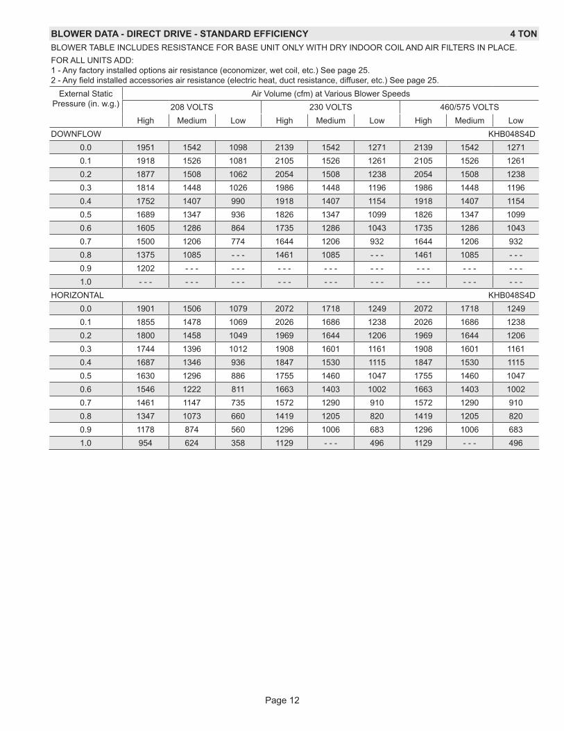
BLOWER DATA - DIRECT DRIVE - STANDARD EFFICIENCY 4 TONBLOWER TABLE INCLUDES RESISTANCE FOR BASE UNIT ONLY WITH DRY INDOOR COIL AND AIR FILTERS IN PLACE.FOR ALL UNITS ADD: 1 - Any factory installed options air resistance (economizer, wet coil, etc.) See page 25. 2 - Any field installed accessories air resistance (electric heat, duct resistance, diffuser, etc.) See page 25.
External Static Pressure (in. w.g.)
Air Volume (cfm) at Various Blower Speeds208 VOLTS 230 VOLTS 460/575 VOLTS
High Medium Low High Medium Low High Medium LowDOWNFLOW KHB048S4D
0.0 1951 1542 1098 2139 1542 1271 2139 1542 12710.1 1918 1526 1081 2105 1526 1261 2105 1526 12610.2 1877 1508 1062 2054 1508 1238 2054 1508 12380.3 1814 1448 1026 1986 1448 1196 1986 1448 11960.4 1752 1407 990 1918 1407 1154 1918 1407 11540.5 1689 1347 936 1826 1347 1099 1826 1347 10990.6 1605 1286 864 1735 1286 1043 1735 1286 10430.7 1500 1206 774 1644 1206 932 1644 1206 9320.8 1375 1085 - - - 1461 1085 - - - 1461 1085 - - -0.9 1202 - - - - - - - - - - - - - - - - - - - - - - - -1.0 - - - - - - - - - - - - - - - - - - - - - - - - - - -
HORIZONTAL KHB048S4D0.0 1901 1506 1079 2072 1718 1249 2072 1718 12490.1 1855 1478 1069 2026 1686 1238 2026 1686 12380.2 1800 1458 1049 1969 1644 1206 1969 1644 12060.3 1744 1396 1012 1908 1601 1161 1908 1601 11610.4 1687 1346 936 1847 1530 1115 1847 1530 11150.5 1630 1296 886 1755 1460 1047 1755 1460 10470.6 1546 1222 811 1663 1403 1002 1663 1403 10020.7 1461 1147 735 1572 1290 910 1572 1290 9100.8 1347 1073 660 1419 1205 820 1419 1205 8200.9 1178 874 560 1296 1006 683 1296 1006 6831.0 954 624 358 1129 - - - 496 1129 - - - 496

Page 13
BLOWER DATA - DIRECT DRIVE - HIGH EFFICIENCY 2 TONBLOWER TABLE INCLUDES RESISTANCE FOR BASE UNIT ONLY WITH DRY INDOOR COIL AND AIR FILTERS IN PLACE.FOR ALL UNITS ADD: 1 - Any factory installed options air resistance (economizer, wet coil, etc.) See page 25. 2 - Any field installed accessories air resistance (electric heat, duct resistance, diffuser, etc.) See page 25.
External Static Pressure in. w.g.
Air Volume at Specific Blower Taps (cfm)Tap 1 Tap 2 Tap 3 Tap 4 Tap 5
DOWNFLOW KHB024H4E0.0 635 728 918 1121 13360.1 547 689 861 1071 12900.2 433 607 806 1031 12530.3 371 528 749 986 12120.4 280 460 677 927 11660.5 217 380 605 868 11200.6 - - - - - - 548 819 10710.7 - - - - - - 491 773 10290.8 - - - - - - 442 714 9830.9 - - - - - - 393 653 9291.0 - - - - - - - - - 604 879
HORIZONTAL KHB024H4E0.0 602 715 908 1096 13020.1 509 663 852 1057 12630.2 413 588 793 1007 12270.3 340 507 736 964 11890.4 266 438 679 918 11420.5 220 355 620 864 11000.6 - - - - - - 560 809 10610.7 - - - - - - 500 752 10150.8 - - - - - - 444 706 9640.9 - - - - - - 390 661 9131.0 - - - - - - 352 612 872

Page 14
BLOWER DATA - DIRECT DRIVE - HIGH EFFICIENCY 3 TONBLOWER TABLE INCLUDES RESISTANCE FOR BASE UNIT ONLY WITH DRY INDOOR COIL AND AIR FILTERS IN PLACE.FOR ALL UNITS ADD: 1 - Any factory installed options air resistance (economizer, wet coil, etc.) See page 25. 2 - Any field installed accessories air resistance (electric heat, duct resistance, diffuser, etc.) See page 25.
External Static Pressure in. w.g.
Air Volume at Specific Blower Taps (cfm)Tap 1 Tap 2 Tap 3 Tap 4 Tap 5
DOWNFLOW KHB036H4E0.0 893 1035 1375 1600 18400.1 838 965 1330 1574 17800.2 768 895 1277 1543 17480.3 705 800 1253 1505 17120.4 645 750 1200 1473 16770.5 575 690 1150 1435 16380.6 - - - - - - 1095 1390 16080.7 - - - - - - 1052 1345 15770.8 - - - - - - 1004 1302 15280.9 - - - - - - 950 1260 14911.0 - - - - - - 900 1218 1455
HORIZONTAL KHB036H4E0.0 900 1045 1379 1599 18100.1 828 970 1305 1549 17490.2 777 900 1264 1504 17180.3 702 800 1216 1479 16770.4 635 750 1173 1434 16490.5 553 685 1131 1399 16220.6 - - - - - - 1078 1359 15770.7 - - - - - - 1038 1315 15440.8 - - - - - - 986 1280 15090.9 - - - - - - 933 1236 14711.0 - - - - - - 885 1196 1438
Page 15
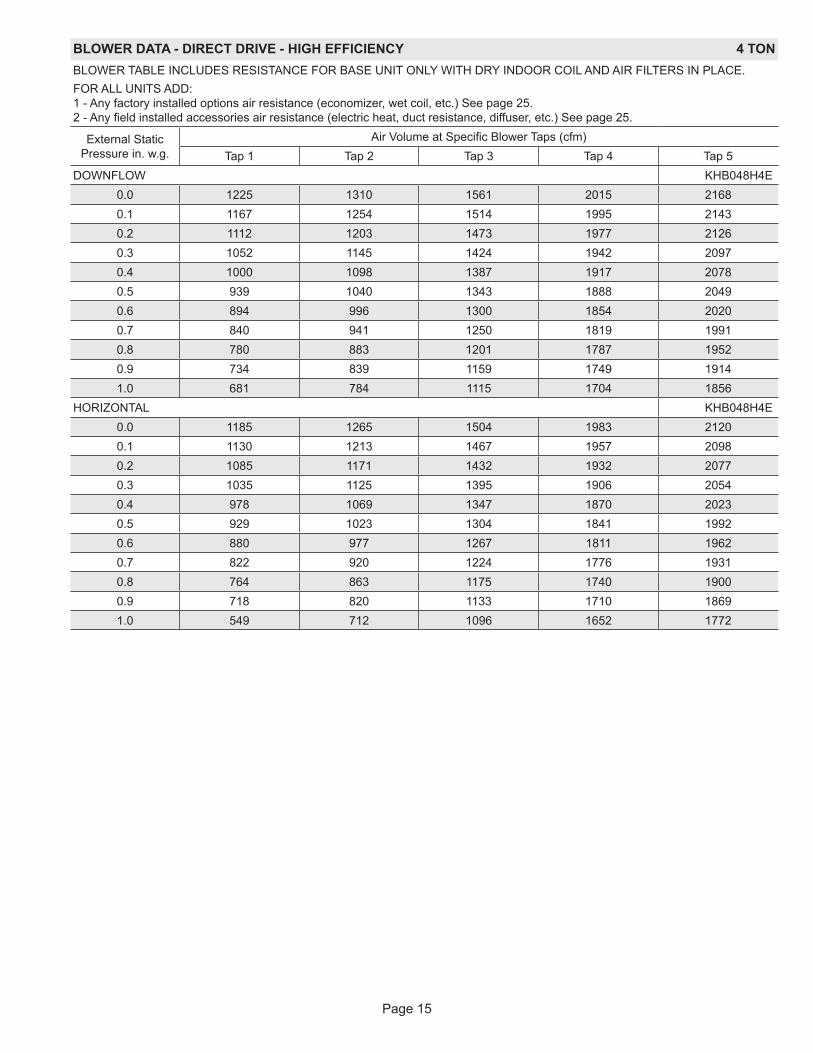
BLOWER DATA - DIRECT DRIVE - HIGH EFFICIENCY 4 TONBLOWER TABLE INCLUDES RESISTANCE FOR BASE UNIT ONLY WITH DRY INDOOR COIL AND AIR FILTERS IN PLACE.FOR ALL UNITS ADD: 1 - Any factory installed options air resistance (economizer, wet coil, etc.) See page 25. 2 - Any field installed accessories air resistance (electric heat, duct resistance, diffuser, etc.) See page 25.
External Static Pressure in. w.g.
Air Volume at Specific Blower Taps (cfm)Tap 1 Tap 2 Tap 3 Tap 4 Tap 5
DOWNFLOW KHB048H4E0.0 1225 1310 1561 2015 21680.1 1167 1254 1514 1995 21430.2 1112 1203 1473 1977 21260.3 1052 1145 1424 1942 20970.4 1000 1098 1387 1917 20780.5 939 1040 1343 1888 20490.6 894 996 1300 1854 20200.7 840 941 1250 1819 19910.8 780 883 1201 1787 19520.9 734 839 1159 1749 19141.0 681 784 1115 1704 1856
HORIZONTAL KHB048H4E0.0 1185 1265 1504 1983 21200.1 1130 1213 1467 1957 20980.2 1085 1171 1432 1932 20770.3 1035 1125 1395 1906 20540.4 978 1069 1347 1870 20230.5 929 1023 1304 1841 19920.6 880 977 1267 1811 19620.7 822 920 1224 1776 19310.8 764 863 1175 1740 19000.9 718 820 1133 1710 18691.0 549 712 1096 1652 1772
Page 16
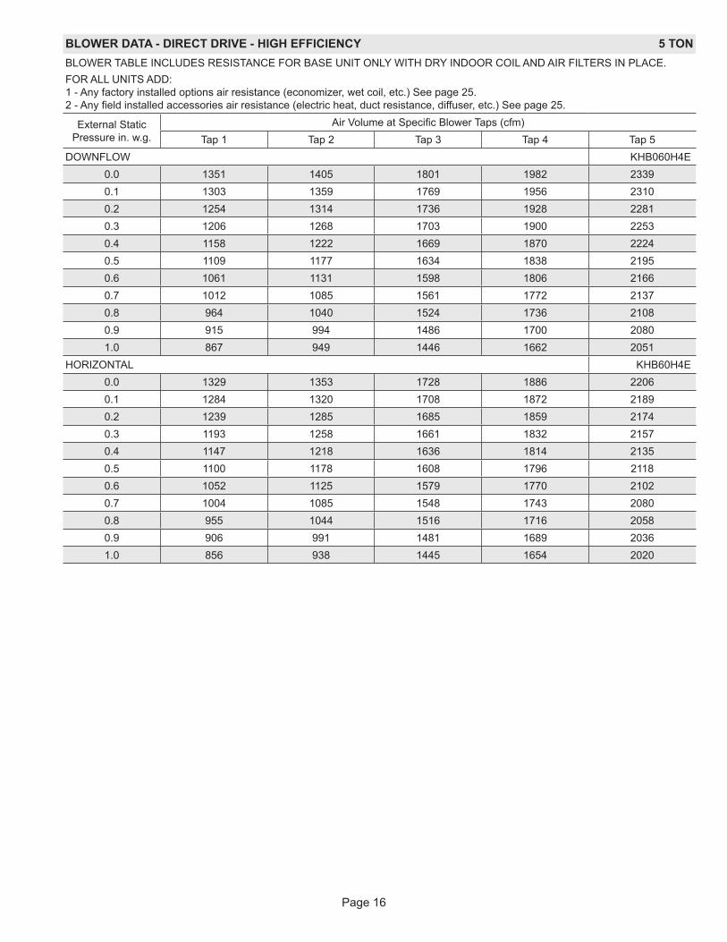
BLOWER DATA - DIRECT DRIVE - HIGH EFFICIENCY 5 TONBLOWER TABLE INCLUDES RESISTANCE FOR BASE UNIT ONLY WITH DRY INDOOR COIL AND AIR FILTERS IN PLACE.FOR ALL UNITS ADD: 1 - Any factory installed options air resistance (economizer, wet coil, etc.) See page 25. 2 - Any field installed accessories air resistance (electric heat, duct resistance, diffuser, etc.) See page 25.
External Static Pressure in. w.g.
Air Volume at Specific Blower Taps (cfm)Tap 1 Tap 2 Tap 3 Tap 4 Tap 5
DOWNFLOW KHB060H4E0.0 1351 1405 1801 1982 23390.1 1303 1359 1769 1956 23100.2 1254 1314 1736 1928 22810.3 1206 1268 1703 1900 22530.4 1158 1222 1669 1870 22240.5 1109 1177 1634 1838 21950.6 1061 1131 1598 1806 21660.7 1012 1085 1561 1772 21370.8 964 1040 1524 1736 21080.9 915 994 1486 1700 20801.0 867 949 1446 1662 2051
HORIZONTAL KHB60H4E0.0 1329 1353 1728 1886 22060.1 1284 1320 1708 1872 21890.2 1239 1285 1685 1859 21740.3 1193 1258 1661 1832 21570.4 1147 1218 1636 1814 21350.5 1100 1178 1608 1796 21180.6 1052 1125 1579 1770 21020.7 1004 1085 1548 1743 20800.8 955 1044 1516 1716 20580.9 906 991 1481 1689 20361.0 856 938 1445 1654 2020
Page 17
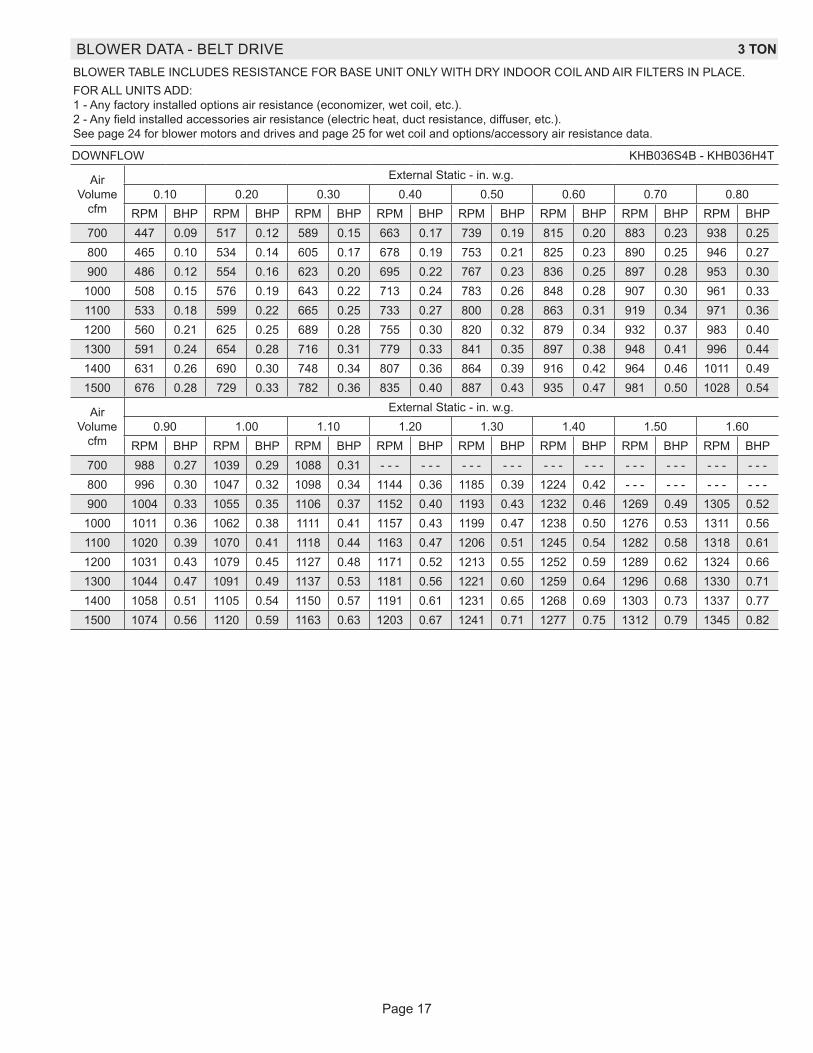
BLOWER DATA - BELT DRIVE 3 TONBLOWER TABLE INCLUDES RESISTANCE FOR BASE UNIT ONLY WITH DRY INDOOR COIL AND AIR FILTERS IN PLACE.FOR ALL UNITS ADD: 1 - Any factory installed options air resistance (economizer, wet coil, etc.). 2 - Any field installed accessories air resistance (electric heat, duct resistance, diffuser, etc.). See page 24 for blower motors and drives and page 25 for wet coil and options/accessory air resistance data.
DOWNFLOW KHB036S4B - KHB036H4T
Air Volume
cfm
External Static - in. w.g.0.10 0.20 0.30 0.40 0.50 0.60 0.70 0.80
RPM BHP RPM BHP RPM BHP RPM BHP RPM BHP RPM BHP RPM BHP RPM BHP700 447 0.09 517 0.12 589 0.15 663 0.17 739 0.19 815 0.20 883 0.23 938 0.25800 465 0.10 534 0.14 605 0.17 678 0.19 753 0.21 825 0.23 890 0.25 946 0.27900 486 0.12 554 0.16 623 0.20 695 0.22 767 0.23 836 0.25 897 0.28 953 0.30
1000 508 0.15 576 0.19 643 0.22 713 0.24 783 0.26 848 0.28 907 0.30 961 0.331100 533 0.18 599 0.22 665 0.25 733 0.27 800 0.28 863 0.31 919 0.34 971 0.361200 560 0.21 625 0.25 689 0.28 755 0.30 820 0.32 879 0.34 932 0.37 983 0.401300 591 0.24 654 0.28 716 0.31 779 0.33 841 0.35 897 0.38 948 0.41 996 0.441400 631 0.26 690 0.30 748 0.34 807 0.36 864 0.39 916 0.42 964 0.46 1011 0.491500 676 0.28 729 0.33 782 0.36 835 0.40 887 0.43 935 0.47 981 0.50 1028 0.54
Air Volume
cfm
External Static - in. w.g.0.90 1.00 1.10 1.20 1.30 1.40 1.50 1.60
RPM BHP RPM BHP RPM BHP RPM BHP RPM BHP RPM BHP RPM BHP RPM BHP700 988 0.27 1039 0.29 1088 0.31 - - - - - - - - - - - - - - - - - - - - - - - - - - - - - -800 996 0.30 1047 0.32 1098 0.34 1144 0.36 1185 0.39 1224 0.42 - - - - - - - - - - - -900 1004 0.33 1055 0.35 1106 0.37 1152 0.40 1193 0.43 1232 0.46 1269 0.49 1305 0.521000 1011 0.36 1062 0.38 1111 0.41 1157 0.43 1199 0.47 1238 0.50 1276 0.53 1311 0.561100 1020 0.39 1070 0.41 1118 0.44 1163 0.47 1206 0.51 1245 0.54 1282 0.58 1318 0.611200 1031 0.43 1079 0.45 1127 0.48 1171 0.52 1213 0.55 1252 0.59 1289 0.62 1324 0.661300 1044 0.47 1091 0.49 1137 0.53 1181 0.56 1221 0.60 1259 0.64 1296 0.68 1330 0.711400 1058 0.51 1105 0.54 1150 0.57 1191 0.61 1231 0.65 1268 0.69 1303 0.73 1337 0.771500 1074 0.56 1120 0.59 1163 0.63 1203 0.67 1241 0.71 1277 0.75 1312 0.79 1345 0.82
Page 18
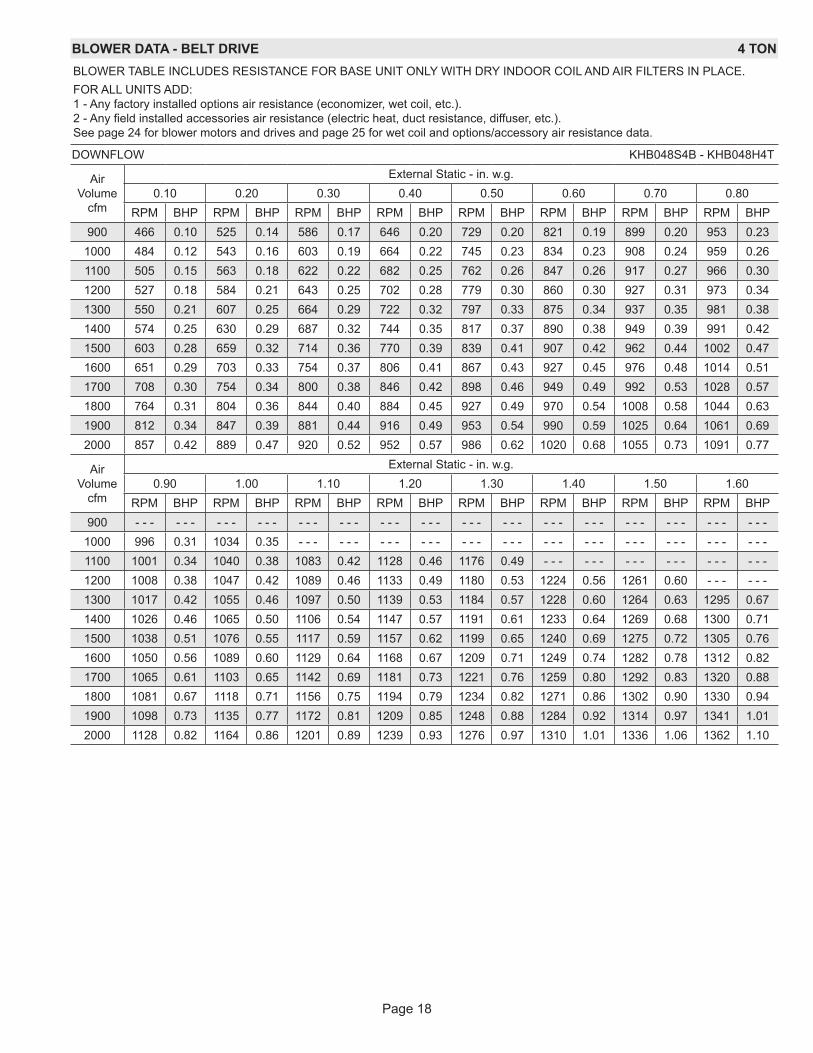
BLOWER DATA - BELT DRIVE 4 TONBLOWER TABLE INCLUDES RESISTANCE FOR BASE UNIT ONLY WITH DRY INDOOR COIL AND AIR FILTERS IN PLACE.FOR ALL UNITS ADD: 1 - Any factory installed options air resistance (economizer, wet coil, etc.). 2 - Any field installed accessories air resistance (electric heat, duct resistance, diffuser, etc.). See page 24 for blower motors and drives and page 25 for wet coil and options/accessory air resistance data.
DOWNFLOW KHB048S4B - KHB048H4T
Air Volume
cfm
External Static - in. w.g.0.10 0.20 0.30 0.40 0.50 0.60 0.70 0.80
RPM BHP RPM BHP RPM BHP RPM BHP RPM BHP RPM BHP RPM BHP RPM BHP900 466 0.10 525 0.14 586 0.17 646 0.20 729 0.20 821 0.19 899 0.20 953 0.23
1000 484 0.12 543 0.16 603 0.19 664 0.22 745 0.23 834 0.23 908 0.24 959 0.261100 505 0.15 563 0.18 622 0.22 682 0.25 762 0.26 847 0.26 917 0.27 966 0.301200 527 0.18 584 0.21 643 0.25 702 0.28 779 0.30 860 0.30 927 0.31 973 0.341300 550 0.21 607 0.25 664 0.29 722 0.32 797 0.33 875 0.34 937 0.35 981 0.381400 574 0.25 630 0.29 687 0.32 744 0.35 817 0.37 890 0.38 949 0.39 991 0.421500 603 0.28 659 0.32 714 0.36 770 0.39 839 0.41 907 0.42 962 0.44 1002 0.471600 651 0.29 703 0.33 754 0.37 806 0.41 867 0.43 927 0.45 976 0.48 1014 0.511700 708 0.30 754 0.34 800 0.38 846 0.42 898 0.46 949 0.49 992 0.53 1028 0.571800 764 0.31 804 0.36 844 0.40 884 0.45 927 0.49 970 0.54 1008 0.58 1044 0.631900 812 0.34 847 0.39 881 0.44 916 0.49 953 0.54 990 0.59 1025 0.64 1061 0.692000 857 0.42 889 0.47 920 0.52 952 0.57 986 0.62 1020 0.68 1055 0.73 1091 0.77
Air Volume
cfm
External Static - in. w.g.0.90 1.00 1.10 1.20 1.30 1.40 1.50 1.60
RPM BHP RPM BHP RPM BHP RPM BHP RPM BHP RPM BHP RPM BHP RPM BHP900 - - - - - - - - - - - - - - - - - - - - - - - - - - - - - - - - - - - - - - - - - - - - - - - -
1000 996 0.31 1034 0.35 - - - - - - - - - - - - - - - - - - - - - - - - - - - - - - - - - - - -1100 1001 0.34 1040 0.38 1083 0.42 1128 0.46 1176 0.49 - - - - - - - - - - - - - - - - - -1200 1008 0.38 1047 0.42 1089 0.46 1133 0.49 1180 0.53 1224 0.56 1261 0.60 - - - - - -1300 1017 0.42 1055 0.46 1097 0.50 1139 0.53 1184 0.57 1228 0.60 1264 0.63 1295 0.671400 1026 0.46 1065 0.50 1106 0.54 1147 0.57 1191 0.61 1233 0.64 1269 0.68 1300 0.711500 1038 0.51 1076 0.55 1117 0.59 1157 0.62 1199 0.65 1240 0.69 1275 0.72 1305 0.761600 1050 0.56 1089 0.60 1129 0.64 1168 0.67 1209 0.71 1249 0.74 1282 0.78 1312 0.821700 1065 0.61 1103 0.65 1142 0.69 1181 0.73 1221 0.76 1259 0.80 1292 0.83 1320 0.881800 1081 0.67 1118 0.71 1156 0.75 1194 0.79 1234 0.82 1271 0.86 1302 0.90 1330 0.941900 1098 0.73 1135 0.77 1172 0.81 1209 0.85 1248 0.88 1284 0.92 1314 0.97 1341 1.012000 1128 0.82 1164 0.86 1201 0.89 1239 0.93 1276 0.97 1310 1.01 1336 1.06 1362 1.10
Page 19
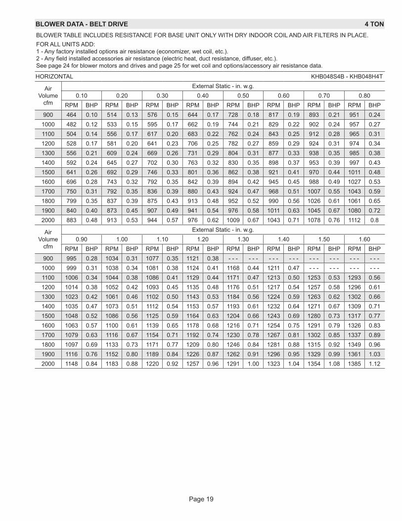
BLOWER DATA - BELT DRIVE 4 TONBLOWER TABLE INCLUDES RESISTANCE FOR BASE UNIT ONLY WITH DRY INDOOR COIL AND AIR FILTERS IN PLACE.FOR ALL UNITS ADD: 1 - Any factory installed options air resistance (economizer, wet coil, etc.). 2 - Any field installed accessories air resistance (electric heat, duct resistance, diffuser, etc.). See page 24 for blower motors and drives and page 25 for wet coil and options/accessory air resistance data.
HORIZONTAL KHB048S4B - KHB048H4T
Air Volume
cfm
External Static - in. w.g.0.10 0.20 0.30 0.40 0.50 0.60 0.70 0.80
RPM BHP RPM BHP RPM BHP RPM BHP RPM BHP RPM BHP RPM BHP RPM BHP900 464 0.10 514 0.13 576 0.15 644 0.17 728 0.18 817 0.19 893 0.21 951 0.24
1000 482 0.12 533 0.15 595 0.17 662 0.19 744 0.21 829 0.22 902 0.24 957 0.271100 504 0.14 556 0.17 617 0.20 683 0.22 762 0.24 843 0.25 912 0.28 965 0.311200 528 0.17 581 0.20 641 0.23 706 0.25 782 0.27 859 0.29 924 0.31 974 0.341300 556 0.21 609 0.24 669 0.26 731 0.29 804 0.31 877 0.33 938 0.35 985 0.381400 592 0.24 645 0.27 702 0.30 763 0.32 830 0.35 898 0.37 953 0.39 997 0.431500 641 0.26 692 0.29 746 0.33 801 0.36 862 0.38 921 0.41 970 0.44 1011 0.481600 696 0.28 743 0.32 792 0.35 842 0.39 894 0.42 945 0.45 988 0.49 1027 0.531700 750 0.31 792 0.35 836 0.39 880 0.43 924 0.47 968 0.51 1007 0.55 1043 0.591800 799 0.35 837 0.39 875 0.43 913 0.48 952 0.52 990 0.56 1026 0.61 1061 0.651900 840 0.40 873 0.45 907 0.49 941 0.54 976 0.58 1011 0.63 1045 0.67 1080 0.722000 883 0.48 913 0.53 944 0.57 976 0.62 1009 0.67 1043 0.71 1078 0.76 1112 0.8
Air Volume
cfm
External Static - in. w.g.0.90 1.00 1.10 1.20 1.30 1.40 1.50 1.60
RPM BHP RPM BHP RPM BHP RPM BHP RPM BHP RPM BHP RPM BHP RPM BHP900 995 0.28 1034 0.31 1077 0.35 1121 0.38 - - - - - - - - - - - - - - - - - - - - - - - -
1000 999 0.31 1038 0.34 1081 0.38 1124 0.41 1168 0.44 1211 0.47 - - - - - - - - - - - -1100 1006 0.34 1044 0.38 1086 0.41 1129 0.44 1171 0.47 1213 0.50 1253 0.53 1293 0.561200 1014 0.38 1052 0.42 1093 0.45 1135 0.48 1176 0.51 1217 0.54 1257 0.58 1296 0.611300 1023 0.42 1061 0.46 1102 0.50 1143 0.53 1184 0.56 1224 0.59 1263 0.62 1302 0.661400 1035 0.47 1073 0.51 1112 0.54 1153 0.57 1193 0.61 1232 0.64 1271 0.67 1309 0.711500 1048 0.52 1086 0.56 1125 0.59 1164 0.63 1204 0.66 1243 0.69 1280 0.73 1317 0.771600 1063 0.57 1100 0.61 1139 0.65 1178 0.68 1216 0.71 1254 0.75 1291 0.79 1326 0.831700 1079 0.63 1116 0.67 1154 0.71 1192 0.74 1230 0.78 1267 0.81 1302 0.85 1337 0.891800 1097 0.69 1133 0.73 1171 0.77 1209 0.80 1246 0.84 1281 0.88 1315 0.92 1349 0.961900 1116 0.76 1152 0.80 1189 0.84 1226 0.87 1262 0.91 1296 0.95 1329 0.99 1361 1.032000 1148 0.84 1183 0.88 1220 0.92 1257 0.96 1291 1.00 1323 1.04 1354 1.08 1385 1.12

Page 20
BLOWER DATA - BELT DRIVE 5 TONBLOWER TABLE INCLUDES RESISTANCE FOR BASE UNIT ONLY WITH DRY INDOOR COIL AND AIR FILTERS IN PLACE.FOR ALL UNITS ADD: 1 - Any factory installed options air resistance (economizer, wet coil, etc.). 2 - Any field installed accessories air resistance (electric heat, duct resistance, diffuser, etc.). See page 24 for blower motors and drives and page 25 for wet coil and options/accessory air resistance data.
DOWNFLOW KHB060S4B - KHB060H4T
Air Volume
cfm
External Static - in. w.g.0.10 0.20 0.30 0.40 0.50 0.60 0.70 0.80
RPM BHP RPM BHP RPM BHP RPM BHP RPM BHP RPM BHP RPM BHP RPM BHP1100 512 0.15 571 0.19 630 0.23 690 0.26 770 0.26 854 0.26 922 0.27 970 0.301200 535 0.18 593 0.22 651 0.26 710 0.30 788 0.30 868 0.30 933 0.31 978 0.341300 559 0.22 616 0.26 674 0.29 732 0.34 807 0.34 883 0.34 944 0.35 987 0.381400 584 0.26 641 0.29 698 0.33 755 0.37 827 0.37 899 0.38 956 0.40 997 0.431500 615 0.29 671 0.33 726 0.36 782 0.41 850 0.41 917 0.42 970 0.44 1009 0.471600 665 0.30 716 0.34 768 0.38 819 0.44 879 0.44 937 0.46 985 0.49 1022 0.521700 723 0.31 768 0.35 814 0.39 860 0.47 910 0.47 959 0.50 1001 0.54 1037 0.581800 779 0.32 818 0.37 857 0.41 897 0.50 939 0.50 980 0.55 1018 0.59 1054 0.641900 826 0.36 859 0.41 894 0.45 928 0.56 964 0.56 1000 0.61 1036 0.66 1072 0.702000 857 0.42 889 0.47 920 0.52 952 0.62 986 0.62 1020 0.68 1055 0.73 1091 0.772100 878 0.49 909 0.54 940 0.59 973 0.70 1006 0.70 1041 0.75 1076 0.80 1112 0.852200 897 0.55 929 0.61 961 0.66 994 0.78 1028 0.78 1063 0.83 1099 0.89 1134 0.932300 918 0.62 950 0.68 983 0.74 1017 0.86 1052 0.86 1087 0.92 1122 0.97 1157 1.022400 941 0.70 974 0.77 1008 0.83 1042 0.96 1077 0.96 1111 1.01 1146 1.06 1181 1.11
Air Volume
cfm
External Static - in. w.g.0.90 1.00 1.10 1.20 1.30 1.40 1.50 1.60
RPM BHP RPM BHP RPM BHP RPM BHP RPM BHP RPM BHP RPM BHP RPM BHP1100 1006 0.35 1045 0.39 1089 0.43 1134 0.46 - - - - - - - - - - - - - - - - - - - - - - - -1200 1013 0.38 1053 0.42 1095 0.46 1139 0.50 1186 0.53 1230 0.57 1266 0.60 - - - - - -1300 1022 0.42 1062 0.46 1104 0.50 1146 0.54 1192 0.57 1234 0.60 1269 0.64 1301 0.681400 1033 0.47 1072 0.51 1114 0.55 1155 0.58 1199 0.61 1240 0.65 1275 0.68 1305 0.721500 1045 0.52 1085 0.56 1125 0.60 1165 0.63 1208 0.66 1248 0.69 1281 0.73 1311 0.771600 1059 0.57 1098 0.61 1138 0.65 1177 0.68 1218 0.71 1257 0.75 1290 0.79 1319 0.831700 1074 0.62 1113 0.66 1152 0.70 1190 0.74 1231 0.77 1268 0.80 1299 0.84 1328 0.891800 1091 0.68 1129 0.72 1167 0.76 1205 0.80 1244 0.83 1280 0.87 1310 0.91 1338 0.951900 1109 0.75 1146 0.79 1183 0.82 1221 0.86 1260 0.90 1294 0.94 1323 0.98 1349 1.022000 1128 0.82 1164 0.86 1201 0.89 1239 0.93 1276 0.97 1310 1.01 1336 1.06 1362 1.102100 1148 0.89 1185 0.93 1221 0.97 1258 1.01 1294 1.05 1325 1.09 1351 1.14 1376 1.192200 1170 0.97 1206 1.01 1242 1.05 1277 1.09 1311 1.14 1341 1.18 1365 1.23 1390 1.282300 1193 1.06 1228 1.09 1262 1.14 1295 1.19 1327 1.24 1355 1.29 1380 1.33 1406 1.372400 1216 1.15 1250 1.19 1282 1.24 1313 1.30 1343 1.36 1371 1.40 1396 1.44 1423 1.48
Page 21
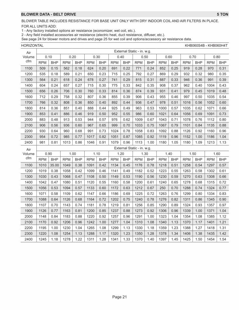
BLOWER DATA - BELT DRIVE 5 TONBLOWER TABLE INCLUDES RESISTANCE FOR BASE UNIT ONLY WITH DRY INDOOR COIL AND AIR FILTERS IN PLACE.FOR ALL UNITS ADD: 1 - Any factory installed options air resistance (economizer, wet coil, etc.). 2 - Any field installed accessories air resistance (electric heat, duct resistance, diffuser, etc.). See page 24 for blower motors and drives and page 25 for wet coil and options/accessory air resistance data.
HORIZONTAL KHB060S4B - KHB060H4T
Air Volume
cfm
External Static - in. w.g.0.10 0.20 0.30 0.40 0.50 0.60 0.70 0.80
RPM BHP RPM BHP RPM BHP RPM BHP RPM BHP RPM BHP RPM BHP RPM BHP1100 509 0.15 562 0.18 624 0.20 691 0.22 771 0.24 852 0.25 919 0.28 970 0.311200 535 0.18 589 0.21 650 0.23 715 0.25 792 0.27 869 0.29 932 0.32 980 0.351300 564 0.21 618 0.24 678 0.27 741 0.29 815 0.31 887 0.33 946 0.36 991 0.391400 604 0.24 657 0.27 715 0.30 775 0.33 842 0.35 908 0.37 962 0.40 1004 0.431500 656 0.26 706 0.30 760 0.33 814 0.36 874 0.39 931 0.41 979 0.45 1019 0.481600 712 0.29 758 0.32 807 0.36 855 0.39 906 0.43 955 0.46 997 0.50 1035 0.541700 766 0.32 808 0.36 850 0.40 892 0.44 936 0.47 978 0.51 1016 0.56 1052 0.601800 814 0.36 851 0.40 888 0.44 925 0.49 963 0.53 1000 0.57 1035 0.62 1071 0.661900 853 0.41 886 0.46 919 0.50 952 0.55 986 0.60 1021 0.64 1056 0.69 1091 0.732000 883 0.48 913 0.53 944 0.57 976 0.62 1009 0.67 1043 0.71 1078 0.76 1112 0.802100 906 0.56 936 0.60 967 0.65 999 0.70 1033 0.75 1067 0.79 1101 0.84 1135 0.882200 930 0.64 960 0.68 991 0.73 1024 0.78 1058 0.83 1092 0.88 1126 0.92 1160 0.962300 954 0.72 985 0.77 1017 0.82 1051 0.87 1085 0.92 1119 0.96 1152 1.00 1186 1.042400 981 0.81 1013 0.86 1046 0.91 1079 0.96 1113 1.00 1180 1.05 1180 1.09 1213 1.13
Air Volume
cfm
External Static - in. w.g.0.90 1.00 1.10 1.20 1.30 1.40 1.50 1.60
RPM BHP RPM BHP RPM BHP RPM BHP RPM BHP RPM BHP RPM BHP RPM BHP1100 1010 35.00 1049 0.38 1091 0.42 1134 0.45 1176 0.78 1218 0.51 1258 0.54 1297 0.571200 1019 0.38 1058 0.42 1099 0.46 1141 0.49 1182 0.52 1223 0.55 1263 0.58 1302 0.611300 1030 0.43 1068 0.47 1108 0.50 1149 0.53 1190 0.56 1230 0.59 1270 0.63 1308 0.661400 1042 0.47 1080 0.51 1120 0.55 1160 0.58 1200 0.61 1240 0.65 1278 0.68 1315 0.721500 1056 0.53 1094 0.57 1133 0.60 1172 0.63 1212 0.67 250 0.70 1288 0.74 1324 0.771600 1071 0.58 1109 0.62 1147 0.66 1186 0.69 1225 0.72 1263 0.76 1299 0.80 1334 0.831700 1088 0.64 1126 0.68 1164 0.72 1202 0.75 1240 0.78 1276 0.82 1311 0.86 1345 0.901800 1107 0.70 1143 0.74 1181 0.78 1219 0.81 1256 0.85 1290 0.89 1324 0.93 1357 0.971900 1126 0.77 1163 0.81 1200 0.85 1237 0.88 1273 0.92 1306 0.96 1339 1.00 1371 1.042000 1148 0.84 1183 0.88 1220 0.92 1257 0.96 1291 1.00 1323 1.04 1354 1.08 1385 1.122100 1170 0.92 1206 0.96 1242 1.00 1277 1.04 1310 1.08 1340 1.13 1370 1.17 1401 1.212200 1195 1.00 1230 1.04 1265 1.08 1299 1.13 1330 1.18 1359 1.23 1388 1.27 1418 1.312300 1220 1.08 1254 1.13 1288 1.17 1320 1.23 1350 1.28 1378 1.34 1406 1.38 1435 1.422400 1245 1.18 1278 1.22 1311 1.28 1341 1.33 1370 1.40 1397 1.45 1425 1.50 1454 1.54
Page 22
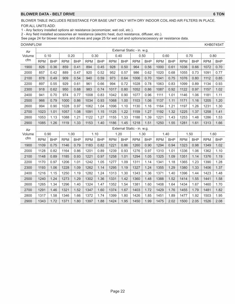
BLOWER DATA - BELT DRIVE 6 TONBLOWER TABLE INCLUDES RESISTANCE FOR BASE UNIT ONLY WITH DRY INDOOR COIL AND AIR FILTERS IN PLACE.FOR ALL UNITS ADD: 1 - Any factory installed options air resistance (economizer, wet coil, etc.). 2 - Any field installed accessories air resistance (electric heat, duct resistance, diffuser, etc.). See page 24 for blower motors and drives and page 25 for wet coil and options/accessory air resistance data.
DOWNFLOW KHB074S4T
Air Volume
cfm
External Static - in. w.g.0.10 0.20 0.30 0.40 0.50 0.60 0.70 0.80
RPM BHP RPM BHP RPM BHP RPM BHP RPM BHP RPM BHP RPM BHP RPM BHP1900 826 0.36 859 0.41 894 0.45 928 0.50 964 0.56 1000 0.61 1036 0.66 1072 0.702000 857 0.42 889 0.47 920 0.52 952 0.57 986 0.62 1020 0.68 1055 0.73 1091 0.772100 878 0.49 909 0.54 940 0.59 973 0.64 1006 0.70 1041 0.75 1076 0.80 1112 0.852200 897 0.55 929 0.61 961 0.66 994 0.72 1028 0.78 1063 0.83 1099 0.89 1134 0.932300 918 0.62 950 0.68 983 0.74 1017 0.80 1052 0.86 1087 0.92 1122 0.97 1157 1.022400 941 0.70 974 0.77 1008 0.83 1042 0.90 1077 0.96 1111 1.01 1146 1.06 1181 1.112500 966 0.79 1000 0.86 1034 0.93 1068 1.00 1103 1.06 1137 1.11 1171 1.16 1205 1.202600 994 0.90 1028 0.97 1062 1.04 1096 1.10 1130 1.16 1164 1.21 1197 1.26 1231 1.302700 1023 1.01 1057 1.08 1091 1.15 1125 1.22 1159 1.27 1192 1.32 1225 1.37 1258 1.412800 1053 1.13 1088 1.21 1122 1.27 1155 1.33 1188 1.39 1221 1.43 1253 1.48 1286 1.532900 1085 1.26 1119 1.33 1153 1.40 1186 1.45 1218 1.51 1250 1.55 1281 1.61 1313 1.66
Air Volume
cfm
External Static - in. w.g.0.90 1.00 1.10 1.20 1.30 1.40 1.50 1.60
RPM BHP RPM BHP RPM BHP RPM BHP RPM BHP RPM BHP RPM BHP RPM BHP1900 1109 0.75 1146 0.79 1183 0.82 1221 0.86 1260 0.90 1294 0.94 1323 0.98 1349 1.022000 1128 0.82 1164 0.86 1201 0.89 1239 0.93 1276 0.97 1310 1.01 1336 1.06 1362 1.102100 1148 0.89 1185 0.93 1221 0.97 1258 1.01 1294 1.05 1325 1.09 1351 1.14 1376 1.192200 1170 0.97 1206 1.01 1242 1.05 1277 1.09 1311 1.14 1341 1.18 1365 1.23 1390 1.282300 1193 1.06 1228 1.09 1262 1.14 1295 1.19 1327 1.24 1355 1.29 1380 1.33 1406 1.372400 1216 1.15 1250 1.19 1282 1.24 1313 1.30 1343 1.36 1371 1.40 1396 1.44 1423 1.482500 1240 1.24 1273 1.29 1302 1.36 1331 1.42 1360 1.48 1388 1.52 1414 1.55 1441 1.582600 1265 1.34 1296 1.40 1324 1.47 1352 1.54 1381 1.60 1408 1.64 1434 1.67 1460 1.702700 1291 1.46 1321 1.52 1347 1.60 1374 1.67 1403 1.72 1429 1.76 1455 1.79 1481 1.822800 1317 1.58 1346 1.66 1372 1.74 1399 1.80 1426 1.85 1451 1.89 1477 1.92 1503 1.952900 1343 1.72 1371 1.80 1397 1.88 1424 1.95 1450 1.99 1475 2.02 1500 2.05 1526 2.08
Page 23
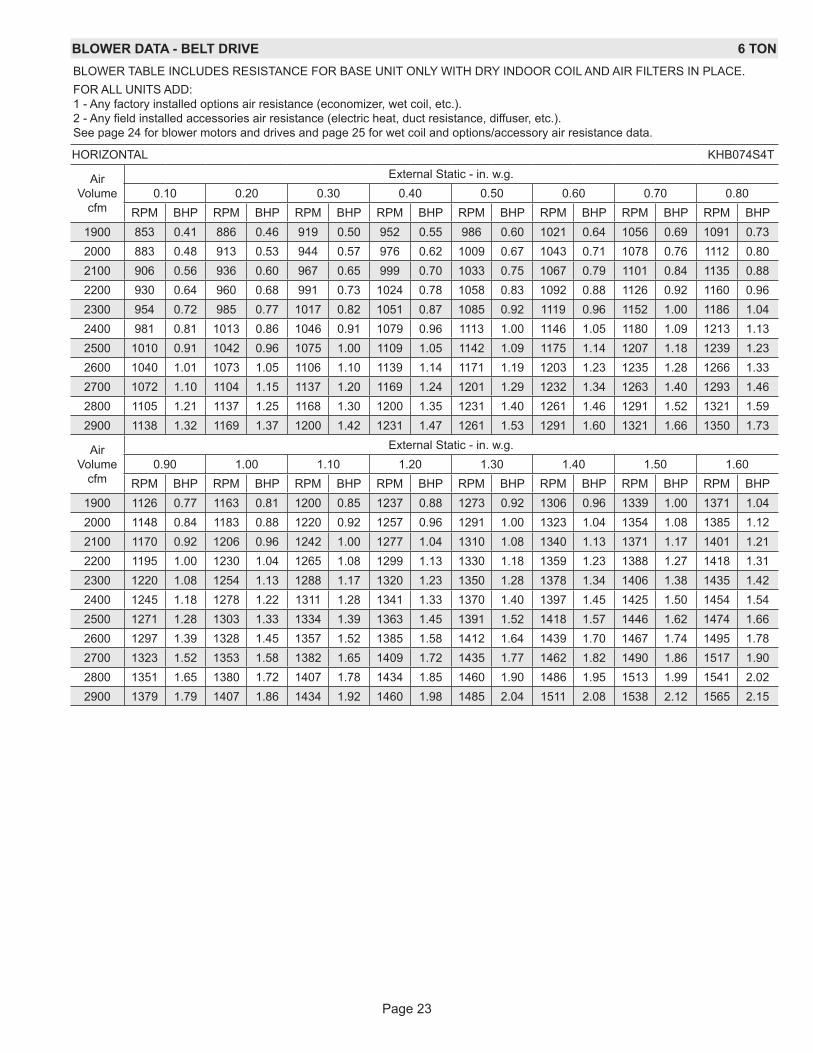
BLOWER DATA - BELT DRIVE 6 TONBLOWER TABLE INCLUDES RESISTANCE FOR BASE UNIT ONLY WITH DRY INDOOR COIL AND AIR FILTERS IN PLACE.FOR ALL UNITS ADD: 1 - Any factory installed options air resistance (economizer, wet coil, etc.). 2 - Any field installed accessories air resistance (electric heat, duct resistance, diffuser, etc.). See page 24 for blower motors and drives and page 25 for wet coil and options/accessory air resistance data.
HORIZONTAL KHB074S4T
Air Volume
cfm
External Static - in. w.g.0.10 0.20 0.30 0.40 0.50 0.60 0.70 0.80
RPM BHP RPM BHP RPM BHP RPM BHP RPM BHP RPM BHP RPM BHP RPM BHP1900 853 0.41 886 0.46 919 0.50 952 0.55 986 0.60 1021 0.64 1056 0.69 1091 0.732000 883 0.48 913 0.53 944 0.57 976 0.62 1009 0.67 1043 0.71 1078 0.76 1112 0.802100 906 0.56 936 0.60 967 0.65 999 0.70 1033 0.75 1067 0.79 1101 0.84 1135 0.882200 930 0.64 960 0.68 991 0.73 1024 0.78 1058 0.83 1092 0.88 1126 0.92 1160 0.962300 954 0.72 985 0.77 1017 0.82 1051 0.87 1085 0.92 1119 0.96 1152 1.00 1186 1.042400 981 0.81 1013 0.86 1046 0.91 1079 0.96 1113 1.00 1146 1.05 1180 1.09 1213 1.132500 1010 0.91 1042 0.96 1075 1.00 1109 1.05 1142 1.09 1175 1.14 1207 1.18 1239 1.232600 1040 1.01 1073 1.05 1106 1.10 1139 1.14 1171 1.19 1203 1.23 1235 1.28 1266 1.332700 1072 1.10 1104 1.15 1137 1.20 1169 1.24 1201 1.29 1232 1.34 1263 1.40 1293 1.462800 1105 1.21 1137 1.25 1168 1.30 1200 1.35 1231 1.40 1261 1.46 1291 1.52 1321 1.592900 1138 1.32 1169 1.37 1200 1.42 1231 1.47 1261 1.53 1291 1.60 1321 1.66 1350 1.73
Air Volume
cfm
External Static - in. w.g.0.90 1.00 1.10 1.20 1.30 1.40 1.50 1.60
RPM BHP RPM BHP RPM BHP RPM BHP RPM BHP RPM BHP RPM BHP RPM BHP1900 1126 0.77 1163 0.81 1200 0.85 1237 0.88 1273 0.92 1306 0.96 1339 1.00 1371 1.042000 1148 0.84 1183 0.88 1220 0.92 1257 0.96 1291 1.00 1323 1.04 1354 1.08 1385 1.122100 1170 0.92 1206 0.96 1242 1.00 1277 1.04 1310 1.08 1340 1.13 1371 1.17 1401 1.212200 1195 1.00 1230 1.04 1265 1.08 1299 1.13 1330 1.18 1359 1.23 1388 1.27 1418 1.312300 1220 1.08 1254 1.13 1288 1.17 1320 1.23 1350 1.28 1378 1.34 1406 1.38 1435 1.422400 1245 1.18 1278 1.22 1311 1.28 1341 1.33 1370 1.40 1397 1.45 1425 1.50 1454 1.542500 1271 1.28 1303 1.33 1334 1.39 1363 1.45 1391 1.52 1418 1.57 1446 1.62 1474 1.662600 1297 1.39 1328 1.45 1357 1.52 1385 1.58 1412 1.64 1439 1.70 1467 1.74 1495 1.782700 1323 1.52 1353 1.58 1382 1.65 1409 1.72 1435 1.77 1462 1.82 1490 1.86 1517 1.902800 1351 1.65 1380 1.72 1407 1.78 1434 1.85 1460 1.90 1486 1.95 1513 1.99 1541 2.022900 1379 1.79 1407 1.86 1434 1.92 1460 1.98 1485 2.04 1511 2.08 1538 2.12 1565 2.15
Page 24
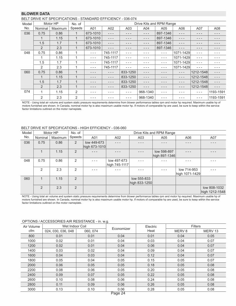
OPTIONS / ACCESSORIES AIR RESISTANCE - in. w.g. Air Volume
cfmWet Indoor Coil
Economizer Electric Heat
Filters024, 030, 036, 048 060, 074 MERV 8 MERV 13
800 0.01 0.01 0.04 0.01 0.04 0.051000 0.02 0.01 0.04 0.03 0.04 0.071200 0.02 0.01 0.04 0.06 0.04 0.071400 0.03 0.02 0.04 0.09 0.04 0.071600 0.04 0.03 0.04 0.12 0.04 0.071800 0.05 0.04 0.05 0.15 0.05 0.072000 0.06 0.05 0.05 0.18 0.05 0.082200 0.08 0.06 0.05 0.20 0.05 0.082400 0.09 0.07 0.05 0.22 0.05 0.082600 0.10 0.08 0.06 0.24 0.05 0.082800 0.11 0.09 0.06 0.26 0.05 0.083000 0.13 0.10 0.06 0.28 0.05 0.08
BLOWER DATABELT DRIVE KIT SPECIFICATIONS - STANDARD EFFICIENCY - 036-074Model
No.Motor HP No. of
SpeedsDrive Kits and RPM Range
Nominal Maximum A01 A02 A03 A04 A05 A06 A07 A08036 0.75 0.86 1 673-1010 - - - - - - - - - 897-1346 - - - - - - - - -
1 1.15 1 673-1010 - - - - - - - - - 897-1346 - - - - - - - - -1.5 1.7 1 673-1010 - - - - - - - - - 897-1346 - - - - - - - - -2 2.3 1 673-1010 - - - - - - - - - 897-1346 - - - - - - - - -
048 0.75 0.86 1 - - - 745-1117 - - - - - - - - - 1071-1429 - - - - - -1 1.15 1 - - - 745-1117 - - - - - - - - - 1071-1429 - - - - - -
1.5 1.7 1 - - - 745-1117 - - - - - - - - - 1071-1429 - - - - - -2 2.3 1 - - - 745-1117 - - - - - - - - - 1071-1429 - - - - - -
060 0.75 0.86 1 - - - - - - 833-1250 - - - - - - - - - 1212-1548 - - -1 1.15 1 - - - - - - 833-1250 - - - - - - - - - 1212-1548 - - -
1.5 1.7 1 - - - - - - 833-1250 - - - - - - - - - 1212-1548 - - -2 2.3 1 - - - - - - 833-1250 - - - - - - - - - 1212-1548 - - -
074 1 1.15 2 - - - - - - - - - 968-1340 - - - - - - - - - 1193-15912 2.3 2 - - - - - - - - - 968-1340 - - - - - - - - - 1193-1591
NOTE - Using total air volume and system static pressure requirements determine from blower performance tables rpm and motor hp required. Maximum usable hp of motors furnished are shown. In Canada, nominal motor hp is also maximum usable motor hp. If motors of comparable hp are used, be sure to keep within the service factor limitations outlined on the motor nameplate.
BELT DRIVE KIT SPECIFICATIONS - HIGH EFFICIENCY - 036-060Model
No.Motor HP No. of
SpeedsDrive Kits and RPM Range
Nominal Maximum A01 A02 A03 A05 A06 A07036 0.75 0.86 2 low 449-673
high 673-1010- - - - - - - - - - - - - - -
1 1.15 2 - - - - - - - - - low 598-897 high 897-1346
- - - - - -
048 0.75 0.86 2 - - - low 497-673 high 745-1117
- - - - - - - - - - - -
2 2.3 2 - - - - - - - - - - - - low 714-953 high 1071-1429
- - -
060 1 1.15 2 low 555-833 high 833-1250
2 2.3 2 low 808-1032 high 1212-1548
NOTE - Using total air volume and system static pressure requirements determine from blower performance tables rpm and motor hp required. Maximum usable hp of motors furnished are shown. In Canada, nominal motor hp is also maximum usable motor hp. If motors of comparable hp are used, be sure to keep within the service factor limitations outlined on the motor nameplate.
Page 25
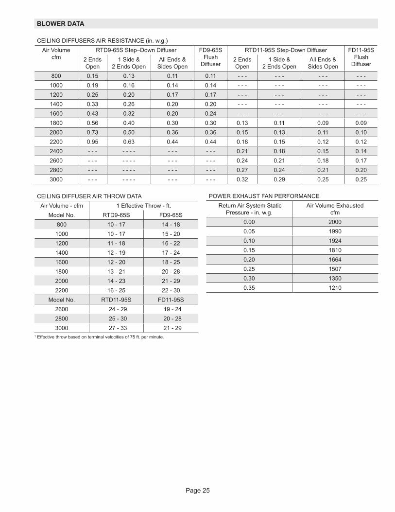
BLOWER DATA
CEILING DIFFUSER AIR THROW DATAAir Volume - cfm 1 Effective Throw - ft.
Model No. RTD9-65S FD9-65S800 10 - 17 14 - 18
1000 10 - 17 15 - 201200 11 - 18 16 - 221400 12 - 19 17 - 241600 12 - 20 18 - 251800 13 - 21 20 - 282000 14 - 23 21 - 292200 16 - 25 22 - 30
Model No. RTD11-95S FD11-95S2600 24 - 29 19 - 242800 25 - 30 20 - 283000 27 - 33 21 - 29
1 Effective throw based on terminal velocities of 75 ft. per minute.
CEILING DIFFUSERS AIR RESISTANCE (in. w.g.)Air Volume
cfmRTD9-65S Step–Down Diffuser FD9-65S
Flush Diffuser
RTD11-95S Step-Down Diffuser FD11-95S Flush
Diffuser2 Ends Open
1 Side & 2 Ends Open
All Ends & Sides Open
2 Ends Open
1 Side & 2 Ends Open
All Ends & Sides Open
800 0.15 0.13 0.11 0.11 - - - - - - - - - - - -1000 0.19 0.16 0.14 0.14 - - - - - - - - - - - -1200 0.25 0.20 0.17 0.17 - - - - - - - - - - - -1400 0.33 0.26 0.20 0.20 - - - - - - - - - - - -1600 0.43 0.32 0.20 0.24 - - - - - - - - - - - -1800 0.56 0.40 0.30 0.30 0.13 0.11 0.09 0.092000 0.73 0.50 0.36 0.36 0.15 0.13 0.11 0.102200 0.95 0.63 0.44 0.44 0.18 0.15 0.12 0.122400 - - - - - - - - - - - - - 0.21 0.18 0.15 0.142600 - - - - - - - - - - - - - 0.24 0.21 0.18 0.172800 - - - - - - - - - - - - - 0.27 0.24 0.21 0.203000 - - - - - - - - - - - - - 0.32 0.29 0.25 0.25
POWER EXHAUST FAN PERFORMANCE Return Air System Static
Pressure - in. w.g. Air Volume Exhausted
cfm0.00 20000.05 19900.10 19240.15 18100.20 16640.25 15070.30 13500.35 1210
Page 26
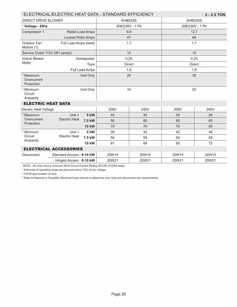
ELECTRICAL/ELECTRIC HEAT DATA - STANDARD EFFICIENCY 2 - 2.5 TONDIRECT DRIVE BLOWER KHB024S KHB030S1 Voltage - 60hz 208/230V - 1 Ph 208/230V - 1 PhCompressor 1 Rated Load Amps 9.8 12.7
Locked Rotor Amps 47 64Outdoor Fan Motors (1)
Full Load Amps (total) 1.7 1.7
Service Outlet 115V GFI (amps) 15 15Indoor Blower Motor
Horsepower 0.25 0.25Type Direct Direct
Full Load Amps 1.8 1.82 Maximum
Overcurrent Protection
Unit Only 25 30
3 Minimum Circuit Ampacity
Unit Only 16 20
ELECTRIC HEAT DATAElectric Heat Voltage 208V 240V 208V 240V2 Maximum
Overcurrent Protection
Unit + Electric Heat
5 kW 40 45 50 507.5 kW 50 60 60 6010 kW 70 70 70 80
3 Minimum Circuit Ampacity
Unit + Electric Heat
5 kW 39 42 42 467.5 kW 50 55 54 5910 kW 61 68 65 72
ELECTRICAL ACCESSORIESDisconnect Standard Access - 0-10 kW 20W15 20W15 20W15 20W15
Hinged Access - 0-10 kW 20W21 20W21 20W21 20W21NOTE - All units have a minimum Short Circuit Current Rating (SCCR) of 5000 amps.
1 Extremes of operating range are plus and minus 10% of line voltage.2 HACR type breaker or fuse.3 Refer to National or Canadian Electrical Code manual to determine wire, fuse and disconnect size requirements.

Page 27
ELECTRICAL/ELECTRIC HEAT DATA - STANDARD EFFICIENCY 3 TONDIRECT DRIVE BOWER - KHB036S
1 Voltage - 60hz 208/230V - 1 Ph 208/230V - 3 Ph 460V - 3 Ph 575V - 3 PhCompressor Rated Load Amps 15.3 8.7 4 3.6
Locked Rotor Amps 70 70 31 27Outdoor Fan Motors (1)
Full Load Amps (total) 1.7 1.7 1.1 0.7
Power Exhaust (1) 0.33 HP
Full Load Amps (total) 2.4 2.4 1.3 1
Service Outlet 115V GFI (amps) 15 15 15 20Indoor Blower Motor
Horsepower 0.5 0.5 0.5 0.5Type Direct Direct Direct Direct
Full Load Amps 3.9 3.9 2 22 Maximum
Overcurrent Protection
Unit Only 40 25 15 15with (1) 0.33 HP Power Exhaust
40 25 15 15
3 Minimum Circuit Ampacity
Unit Only 25 17 9 8with (1) 0.33 HP Power Exhaust
28 19 10 9
ELECTRIC HEAT DATAElectric Heat Voltage 208V 240V 208V 240V 480V 600V2 Maximum
Overcurrent Protection
Unit + Electric Heat
7.5 kW 60 70 40 40 20 2015 kW 100 110 60 70 35 30
3 Minimum Circuit Ampacity
Unit + Electric Heat
7.5 kW 59 64 37 40 20 1715 kW 93 103 56 62 31 26
2 Maximum Overcurrent Protection
Unit + Electric Heat + Power Exhaust
7.5 kW 70 70 40 45 25 2015 kW 100 110 60 70 35 30
3 Minimum Circuit Ampacity
Unit + Electric Heat + Power Exhaust
7.5 kW 61 67 39 42 21 1815 kW 95 106 58 64 32 27
ELECTRICAL ACCESSORIESDisconnect Standard Access - 0-7.5 kW 20W15 20W15 20W15 20W15
15 kW 20W16 20W15 20W15 20W15Hinged Access - 0-7.5 kW 20W21 20W21 20W21 20W21
15 kW 20W22 20W21 20W21 20W21NOTE - All units have a minimum Short Circuit Current Rating (SCCR) of 5000 amps.
1 Extremes of operating range are plus and minus 10% of line voltage.2 HACR type breaker or fuse.3 Refer to National or Canadian Electrical Code manual to determine wire, fuse and disconnect size requirements.

Page 28
ELECTRICAL/ELECTRIC HEAT DATA - STANDARD EFFICIENCY 4 TONDIRECT DRIVE BOWER - KHB048S
1 Voltage - 60hz 208/230V - 1 Ph 208/230V - 3 Ph 460V - 3 Ph 575V - 3 PhCompressor Rated Load Amps 20 11 5.5 4.7
Locked Rotor Amps 99 86 37 34Outdoor Fan Motors (1)
Full Load Amps (total) 1.7 1.7 1.1 0.7
Power Exhaust (1) 0.33 HP
Full Load Amps (total) 2.4 2.4 1.3 1
Service Outlet 115V GFI (amps) 15 15 15 20Indoor Blower Motor
Horsepower 0.5 0.5 0.5 0.5Type Direct Direct Direct Direct
Full Load Amps 3.9 3.9 2 22 Maximum
Overcurrent Protection
Unit Only 50 30 15 15with (1) 0.33 HP Power Exhaust
50 30 15 15
3 Minimum Circuit Ampacity
Unit Only 31 20 10 9with (1) 0.33 HP Power Exhaust
33 22 12 10
ELECTRIC HEAT DATAElectric Heat Voltage 208V 240V 208V 240V 480V 600V2 Maximum
Overcurrent Protection
Unit + Electric Heat
7.5 kW 70 80 45 45 25 2015 kW 100 110 60 70 35 30
3 Minimum Circuit Ampacity
Unit + Electric Heat
7.5 kW 65 70 39 42 22 1815 kW 99 109 59 65 33 27
2 Maximum Overcurrent Protection
Unit + Electric Heat + Power Exhaust
7.5 kW 80 80 45 50 25 2015 kW 110 125 70 70 35 30
3 Minimum Circuit Ampacity
Unit + Electric Heat + Power Exhaust
7.5 kW 67 73 42 45 23 1915 kW 101 112 61 67 34 28
ELECTRICAL ACCESSORIESDisconnect Standard Access - 0-7.5 kW 20W18 20W18 20W18 20W18
15 kW 20W19 20W18 20W18 20W18Hinged Access - 0-7.5 kW 20W24 20W24 20W24 20W24
15 kW 20W25 20W24 20W24 20W24NOTE - All units have a minimum Short Circuit Current Rating (SCCR) of 5000 amps.
1 Extremes of operating range are plus and minus 10% of line voltage.2 HACR type breaker or fuse.3 Refer to National or Canadian Electrical Code manual to determine wire, fuse and disconnect size requirements.
Page 29
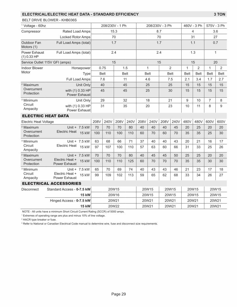
ELECTRICAL/ELECTRIC HEAT DATA - STANDARD EFFICIENCY 3 TONBELT DRIVE BLOWER - KHB036S
1 Voltage - 60hz 208/230V - 1 Ph 208/230V - 3 Ph 460V - 3 Ph 575V - 3 PhCompressor Rated Load Amps 15.3 8.7 4 3.6
Locked Rotor Amps 70 70 31 27Outdoor Fan Motors (1)
Full Load Amps (total) 1.7 1.7 1.1 0.7
Power Exhaust (1) 0.33 HP
Full Load Amps (total) 2.4 2.4 1.3 1
Service Outlet 115V GFI (amps) 15 15 15 20Indoor Blower Motor
Horsepower 0.75 1.5 1 2 1 2 1 2Type Belt Belt Belt Belt Belt Belt Belt Belt
Full Load Amps 7.6 11 4.6 7.5 2.1 3.4 1.7 2.72 Maximum
Overcurrent Protection
Unit Only 40 45 25 25 15 15 15 15with (1) 0.33 HP Power Exhaust
45 45 25 30 15 15 15 15
3 Minimum Circuit Ampacity
Unit Only 29 32 18 21 9 10 7 8with (1) 0.33 HP Power Exhaust
31 35 20 23 10 11 8 9
ELECTRIC HEAT DATAElectric Heat Voltage 208V 240V 208V 240V 208V 240V 208V 240V 480V 480V 600V 600V2 Maximum
Overcurrent Protection
Unit + Electric Heat
7.5 kW 70 70 70 80 40 40 40 45 20 25 20 2015 kW 100 110 100 110 60 70 60 70 35 35 25 30
3 Minimum Circuit Ampacity
Unit + Electric Heat
7.5 kW 63 68 66 71 37 40 40 43 20 21 16 1715 kW 97 107 100 110 57 63 60 66 31 33 25 26
2 Maximum Overcurrent Protection
Unit + Electric Heat + Power Exhaust
7.5 kW 70 70 70 80 40 45 45 50 25 25 20 2015 kW 100 110 110 125 60 70 70 70 35 35 30 30
3 Minimum Circuit Ampacity
Unit + Electric Heat + Power Exhaust
7.5 kW 65 70 69 74 40 43 43 46 21 23 17 1815 kW 99 109 102 113 59 65 62 68 33 34 26 27
ELECTRICAL ACCESSORIESDisconnect Standard Access - 0-7.5 kW 20W15 20W15 20W15 20W15 20W15
15 kW 20W16 20W15 20W15 20W15 20W15Hinged Access - 0-7.5 kW 20W21 20W21 20W21 20W21 20W21
15 kW 20W22 20W21 20W21 20W21 20W21NOTE - All units have a minimum Short Circuit Current Rating (SCCR) of 5000 amps.
1 Extremes of operating range are plus and minus 10% of line voltage.2 HACR type breaker or fuse.3 Refer to National or Canadian Electrical Code manual to determine wire, fuse and disconnect size requirements.

Page 30
ELECTRICAL/ELECTRIC HEAT DATA - STANDARD EFFICIENCY 4 TONBELT DRIVE BLOWER - KHB048S
1 Voltage - 60hz 208/230V - 1 Ph 208/230V - 3 Ph 460V - 3 Ph 575V - 3 PhCompressor Rated Load Amps 20 11 5.5 4.7
Locked Rotor Amps 99 86 37 34Outdoor Fan Motors (1)
Full Load Amps (total) 1.7 1.7 1.1 0.7
Power Exhaust (1) 0.33 HP
Full Load Amps (total) 2.4 2.4 1.3 1
Service Outlet 115V GFI (amps) 15 15 15 20Indoor Blower Motor
Horsepower 0.75 1.5 1 2 1 2 1 2Type Belt Belt Belt Belt Belt Belt Belt Belt
Full Load Amps 7.6 11 4.6 7.5 2.1 3.4 1.7 2.72 Maximum
Overcurrent Protection
Unit Only 50 50 30 30 15 15 15 15with (1) 0.33 HP Power Exhaust
50 60 30 35 15 15 15 15
3 Minimum Circuit Ampacity
Unit Only 35 38 21 23 11 12 9 10with (1) 0.33 HP Power Exhaust
37 41 23 26 12 13 10 11
ELECTRIC HEAT DATAElectric Heat Voltage 208V 240V 208V 240V 208V 240V 208V 240V 480V 480V 600V 600V2 Maximum
Overcurrent Protection
Unit + Electric Heat
7.5 kW 80 80 80 80 45 45 45 50 25 25 20 2015 kW 110 125 110 125 60 70 70 70 35 35 30 30
3 Minimum Circuit Ampacity
Unit + Electric Heat
7.5 kW 69 74 72 77 40 43 43 46 22 23 18 1915 kW 103 113 106 116 60 66 63 69 33 34 27 28
2 Maximum Overcurrent Protection
Unit + Electric Heat + Power Exhaust
7.5 kW 80 80 80 90 45 50 50 50 25 25 20 2015 kW 100 110 110 125 70 70 70 80 35 40 30 30
3 Minimum Circuit Ampacity
Unit + Electric Heat + Power Exhaust
7.5 kW 71 76 74 80 42 46 45 48 23 24 19 2015 kW 105 115 108 119 62 68 65 71 34 36 28 29
ELECTRICAL ACCESSORIESDisconnect Standard Access - 0-7.5 kW 20W18 20W18 20W18 20W18 20W18
15 kW 20W19 20W18 20W18 20W18 20W18Hinged Access - 0-7.5 kW 20W24 20W24 20W24 20W24 20W24
15 kW 20W25 20W24 20W24 20W24 20W24NOTE - All units have a minimum Short Circuit Current Rating (SCCR) of 5000 amps.
1 Extremes of operating range are plus and minus 10% of line voltage.2 HACR type breaker or fuse.3 Refer to National or Canadian Electrical Code manual to determine wire, fuse and disconnect size requirements.
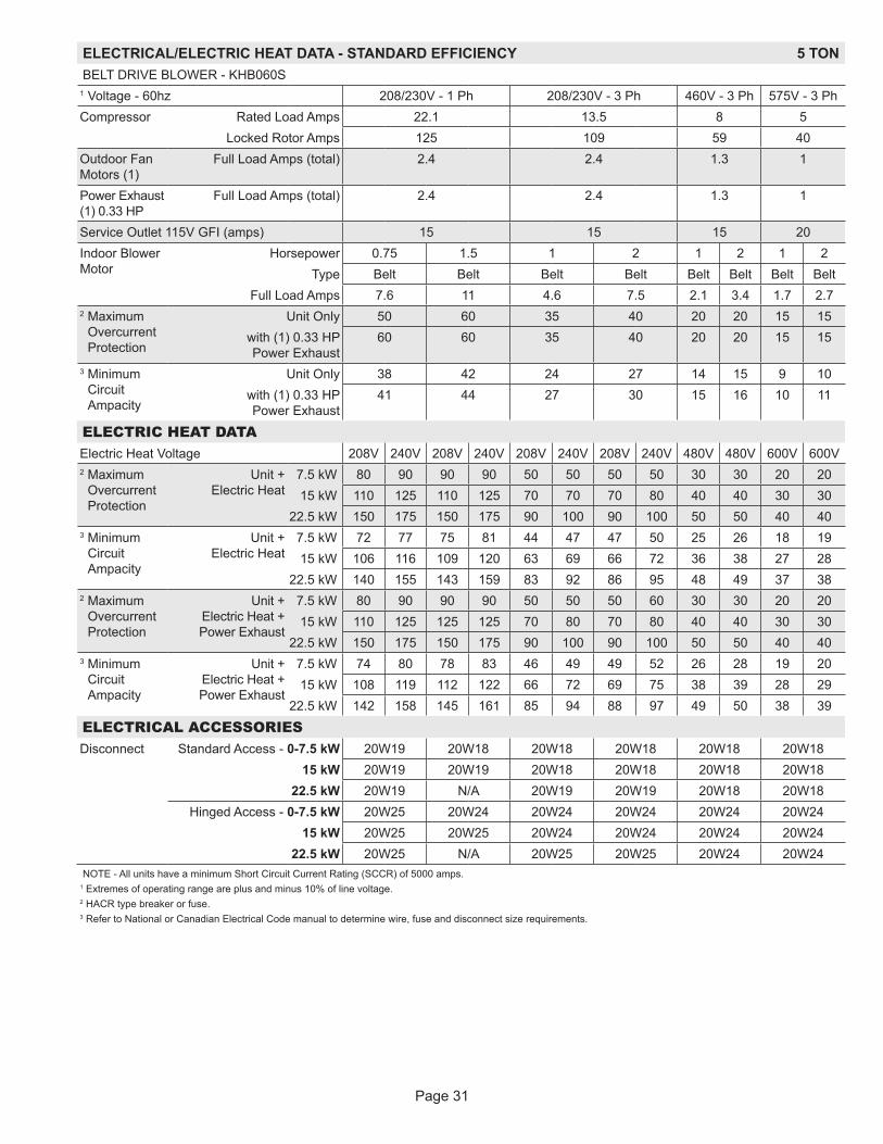
Page 31
ELECTRICAL/ELECTRIC HEAT DATA - STANDARD EFFICIENCY 5 TONBELT DRIVE BLOWER - KHB060S
1 Voltage - 60hz 208/230V - 1 Ph 208/230V - 3 Ph 460V - 3 Ph 575V - 3 PhCompressor Rated Load Amps 22.1 13.5 8 5
Locked Rotor Amps 125 109 59 40Outdoor Fan Motors (1)
Full Load Amps (total) 2.4 2.4 1.3 1
Power Exhaust (1) 0.33 HP
Full Load Amps (total) 2.4 2.4 1.3 1
Service Outlet 115V GFI (amps) 15 15 15 20Indoor Blower Motor
Horsepower 0.75 1.5 1 2 1 2 1 2Type Belt Belt Belt Belt Belt Belt Belt Belt
Full Load Amps 7.6 11 4.6 7.5 2.1 3.4 1.7 2.72 Maximum
Overcurrent Protection
Unit Only 50 60 35 40 20 20 15 15with (1) 0.33 HP Power Exhaust
60 60 35 40 20 20 15 15
3 Minimum Circuit Ampacity
Unit Only 38 42 24 27 14 15 9 10with (1) 0.33 HP Power Exhaust
41 44 27 30 15 16 10 11
ELECTRIC HEAT DATAElectric Heat Voltage 208V 240V 208V 240V 208V 240V 208V 240V 480V 480V 600V 600V2 Maximum
Overcurrent Protection
Unit + Electric Heat
7.5 kW 80 90 90 90 50 50 50 50 30 30 20 2015 kW 110 125 110 125 70 70 70 80 40 40 30 30
22.5 kW 150 175 150 175 90 100 90 100 50 50 40 403 Minimum
Circuit Ampacity
Unit + Electric Heat
7.5 kW 72 77 75 81 44 47 47 50 25 26 18 1915 kW 106 116 109 120 63 69 66 72 36 38 27 28
22.5 kW 140 155 143 159 83 92 86 95 48 49 37 382 Maximum
Overcurrent Protection
Unit + Electric Heat + Power Exhaust
7.5 kW 80 90 90 90 50 50 50 60 30 30 20 2015 kW 110 125 125 125 70 80 70 80 40 40 30 30
22.5 kW 150 175 150 175 90 100 90 100 50 50 40 403 Minimum
Circuit Ampacity
Unit + Electric Heat + Power Exhaust
7.5 kW 74 80 78 83 46 49 49 52 26 28 19 2015 kW 108 119 112 122 66 72 69 75 38 39 28 29
22.5 kW 142 158 145 161 85 94 88 97 49 50 38 39
ELECTRICAL ACCESSORIESDisconnect Standard Access - 0-7.5 kW 20W19 20W18 20W18 20W18 20W18 20W18
15 kW 20W19 20W19 20W18 20W18 20W18 20W1822.5 kW 20W19 N/A 20W19 20W19 20W18 20W18
Hinged Access - 0-7.5 kW 20W25 20W24 20W24 20W24 20W24 20W2415 kW 20W25 20W25 20W24 20W24 20W24 20W24
22.5 kW 20W25 N/A 20W25 20W25 20W24 20W24NOTE - All units have a minimum Short Circuit Current Rating (SCCR) of 5000 amps.
1 Extremes of operating range are plus and minus 10% of line voltage.2 HACR type breaker or fuse.3 Refer to National or Canadian Electrical Code manual to determine wire, fuse and disconnect size requirements.

Page 32
ELECTRICAL/ELECTRIC HEAT DATA - STANDARD EFFICIENCY 6 TONBELT DRIVE BLOWER - KHB074S1 Voltage - 60hz 208/230V - 3 Ph 460V - 3 Ph 575V - 3 PhCompressor Rated Load Amps 17.6 8.5 6.3
Locked Rotor Amps 136 66.1 55.3Outdoor Fan Motor
Full Load Amps 3 1.5 1.2
Power Exhaust (1) 0.33 HP
Full Load Amps 2.4 1.3 1
Service Outlet 115V GFI (amps) 15 15 20Indoor Blower Motor
Horsepower 1 2 1 2 1 2Type Belt Belt Belt Belt Belt Belt
Full Load Amps 4.6 7.5 2.1 3.4 1.7 2.72 Maximum
Overcurrent Protection
Unit Only 45 50 20 20 15 15With (1) 0.33 HP
Power Exhaust45 50 20 25 15 15
3 Minimum Circuit Ampacity
Unit Only 30 33 15 16 11 12With (1) 0.33 HP
Power Exhaust32 35 16 17 12 13
ELECTRIC HEAT DATAElectric Heat Voltage 208 240 208 240 480 480 600 6002 Maximum Overcurrent Protection
Unit+ Electric Heat
7.5 kW 60 60 60 60 30 30 20 2515 kW 70 80 80 80 40 40 30 30
22.5 kW 90 100 100 110 50 50 40 4030 kW 110 125 125 125 60 70 50 50
3 Minimum Circuit Ampacity
Unit+ Electric Heat
7.5 kW 50 53 53 56 26 27 20 2115 kW 69 75 72 78 37 39 29 30
22.5 kW 89 98 92 101 49 50 38 3930 kW 108 120 111 123 60 61 47 48
2 Maximum Overcurrent Protection
Unit+ Electric Heat
and (1) 0.33 HP Power Exhaust
7.5 kW 60 60 60 70 30 30 25 2515 kW 80 80 80 90 40 40 30 35
22.5 kW 100 100 100 110 50 60 40 4030 kW 125 125 125 150 70 70 50 50
3 Minimum Circuit Ampacity
Unit+ Electric Heat
and (1) 0.33 HP Power Exhaust
7.5 kW 52 55 55 58 27 29 21 2215 kW 72 78 74 81 39 40 30 31
22.5 kW 91 100 94 103 50 51 39 4030 kW 111 123 114 126 61 62 48 49
ELECTRICAL ACCESSORIESDisconnect Kit
Standard Access - 0-15 kW 20W18 20W18 20W18 20W1822.5-30 kW 20W19 20W19 20W18 20W18
Hinged Access - 0-15 kW 20W24 20W24 20W24 20W2422.5-30 kW 20W25 20W25 20W24 20W24
NOTE - All units have a minimum Short Circuit Current Rating (SCCR) of 5000 amps. 1 Extremes of operating range are plus and minus 10% of line voltage.2 HACR type breaker or fuse.3 Refer to National or Canadian Electrical Code manual to determine wire, fuse and disconnect size requirements.
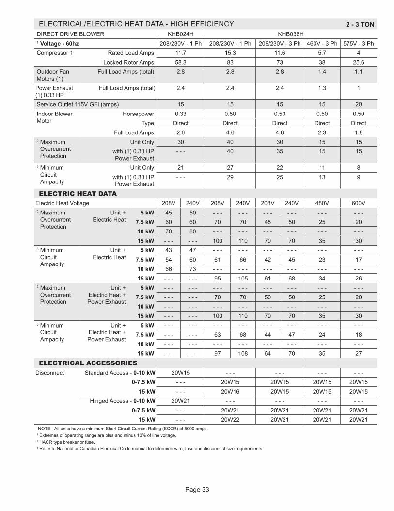
Page 33
ELECTRICAL/ELECTRIC HEAT DATA - HIGH EFFICIENCY 2 - 3 TONDIRECT DRIVE BLOWER KHB024H KHB036H1 Voltage - 60hz 208/230V - 1 Ph 208/230V - 1 Ph 208/230V - 3 Ph 460V - 3 Ph 575V - 3 PhCompressor 1 Rated Load Amps 11.7 15.3 11.6 5.7 4
Locked Rotor Amps 58.3 83 73 38 25.6Outdoor Fan Motors (1)
Full Load Amps (total) 2.8 2.8 2.8 1.4 1.1
Power Exhaust (1) 0.33 HP
Full Load Amps (total) 2.4 2.4 2.4 1.3 1
Service Outlet 115V GFI (amps) 15 15 15 15 20Indoor Blower Motor
Horsepower 0.33 0.50 0.50 0.50 0.50Type Direct Direct Direct Direct Direct
Full Load Amps 2.6 4.6 4.6 2.3 1.82 Maximum
Overcurrent Protection
Unit Only 30 40 30 15 15with (1) 0.33 HP Power Exhaust
- - - 40 35 15 15
3 Minimum Circuit Ampacity
Unit Only 21 27 22 11 8with (1) 0.33 HP Power Exhaust
- - - 29 25 13 9
ELECTRIC HEAT DATAElectric Heat Voltage 208V 240V 208V 240V 208V 240V 480V 600V2 Maximum
Overcurrent Protection
Unit + Electric Heat
5 kW 45 50 - - - - - - - - - - - - - - - - - -7.5 kW 60 60 70 70 45 50 25 2010 kW 70 80 - - - - - - - - - - - - - - - - - -15 kW - - - - - - 100 110 70 70 35 30
3 Minimum Circuit Ampacity
Unit + Electric Heat
5 kW 43 47 - - - - - - - - - - - - - - - - - -7.5 kW 54 60 61 66 42 45 23 1710 kW 66 73 - - - - - - - - - - - - - - - - - -15 kW - - - - - - 95 105 61 68 34 26
2 Maximum Overcurrent Protection
Unit + Electric Heat + Power Exhaust
5 kW - - - - - - - - - - - - - - - - - - - - - - - -7.5 kW - - - - - - 70 70 50 50 25 2010 kW - - - - - - - - - - - - - - - - - - - - - - - -15 kW - - - - - - 100 110 70 70 35 30
3 Minimum Circuit Ampacity
Unit + Electric Heat + Power Exhaust
5 kW - - - - - - - - - - - - - - - - - - - - - - - -7.5 kW - - - - - - 63 68 44 47 24 1810 kW - - - - - - - - - - - - - - - - - - - - - - - -15 kW - - - - - - 97 108 64 70 35 27
ELECTRICAL ACCESSORIESDisconnect Standard Access - 0-10 kW 20W15 - - - - - - - - - - - -
0-7.5 kW - - - 20W15 20W15 20W15 20W1515 kW - - - 20W16 20W15 20W15 20W15
Hinged Access - 0-10 kW 20W21 - - - - - - - - - - - -0-7.5 kW - - - 20W21 20W21 20W21 20W21
15 kW - - - 20W22 20W21 20W21 20W21NOTE - All units have a minimum Short Circuit Current Rating (SCCR) of 5000 amps.
1 Extremes of operating range are plus and minus 10% of line voltage.2 HACR type breaker or fuse.3 Refer to National or Canadian Electrical Code manual to determine wire, fuse and disconnect size requirements.
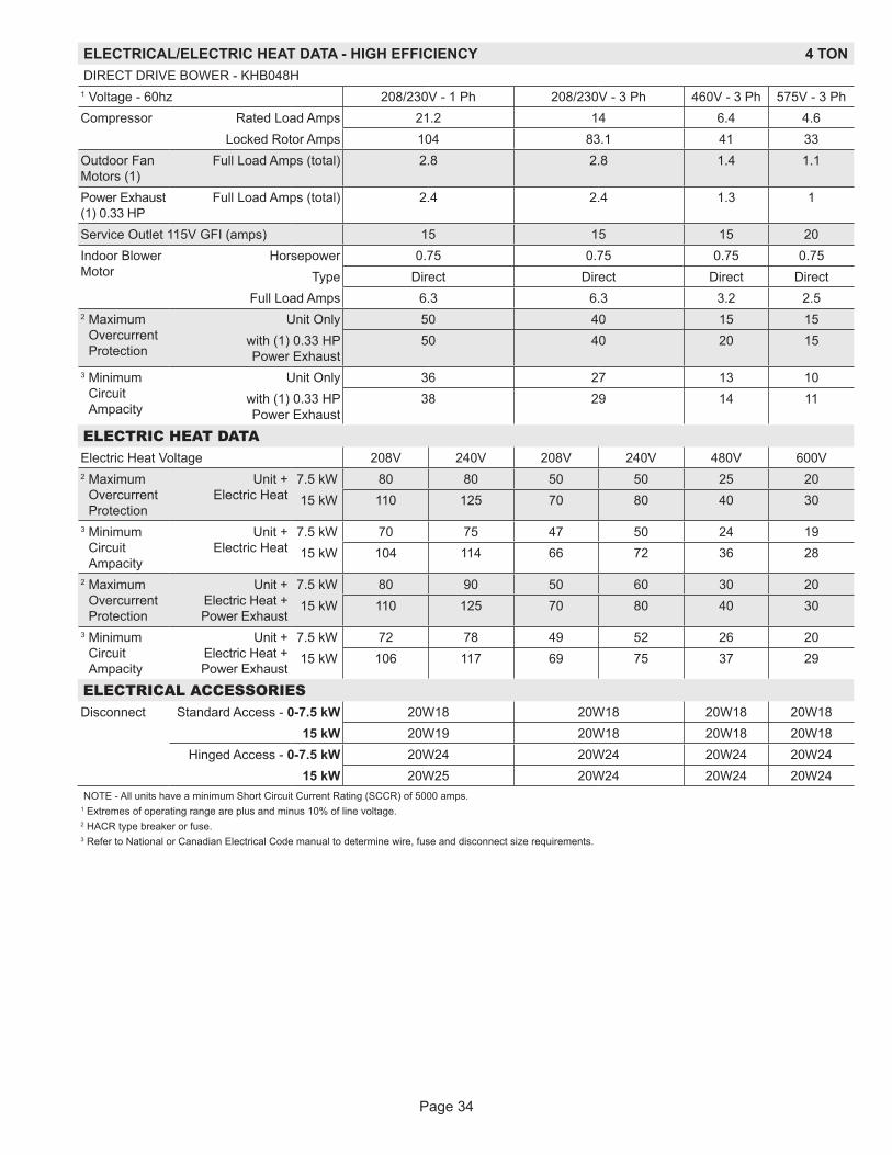
Page 34
ELECTRICAL/ELECTRIC HEAT DATA - HIGH EFFICIENCY 4 TONDIRECT DRIVE BOWER - KHB048H
1 Voltage - 60hz 208/230V - 1 Ph 208/230V - 3 Ph 460V - 3 Ph 575V - 3 PhCompressor Rated Load Amps 21.2 14 6.4 4.6
Locked Rotor Amps 104 83.1 41 33Outdoor Fan Motors (1)
Full Load Amps (total) 2.8 2.8 1.4 1.1
Power Exhaust (1) 0.33 HP
Full Load Amps (total) 2.4 2.4 1.3 1
Service Outlet 115V GFI (amps) 15 15 15 20Indoor Blower Motor
Horsepower 0.75 0.75 0.75 0.75Type Direct Direct Direct Direct
Full Load Amps 6.3 6.3 3.2 2.52 Maximum
Overcurrent Protection
Unit Only 50 40 15 15with (1) 0.33 HP Power Exhaust
50 40 20 15
3 Minimum Circuit Ampacity
Unit Only 36 27 13 10with (1) 0.33 HP Power Exhaust
38 29 14 11
ELECTRIC HEAT DATAElectric Heat Voltage 208V 240V 208V 240V 480V 600V2 Maximum
Overcurrent Protection
Unit + Electric Heat
7.5 kW 80 80 50 50 25 2015 kW 110 125 70 80 40 30
3 Minimum Circuit Ampacity
Unit + Electric Heat
7.5 kW 70 75 47 50 24 1915 kW 104 114 66 72 36 28
2 Maximum Overcurrent Protection
Unit + Electric Heat + Power Exhaust
7.5 kW 80 90 50 60 30 2015 kW 110 125 70 80 40 30
3 Minimum Circuit Ampacity
Unit + Electric Heat + Power Exhaust
7.5 kW 72 78 49 52 26 2015 kW 106 117 69 75 37 29
ELECTRICAL ACCESSORIESDisconnect Standard Access - 0-7.5 kW 20W18 20W18 20W18 20W18
15 kW 20W19 20W18 20W18 20W18Hinged Access - 0-7.5 kW 20W24 20W24 20W24 20W24
15 kW 20W25 20W24 20W24 20W24NOTE - All units have a minimum Short Circuit Current Rating (SCCR) of 5000 amps.
1 Extremes of operating range are plus and minus 10% of line voltage.2 HACR type breaker or fuse.3 Refer to National or Canadian Electrical Code manual to determine wire, fuse and disconnect size requirements.
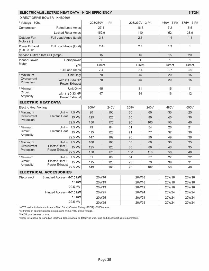
Page 35
ELECTRICAL/ELECTRIC HEAT DATA - HIGH EFFICIENCY 5 TONDIRECT DRIVE BOWER - KHB060H
1 Voltage - 60hz 208/230V - 1 Ph 208/230V - 3 Ph 460V - 3 Ph 575V - 3 PhCompressor Rated Load Amps 27.1 16.5 7.2 5.5
Locked Rotor Amps 152.9 110 52 38.9Outdoor Fan Motors (1)
Full Load Amps (total) 2.8 2.8 1.4 1.1
Power Exhaust (1) 0.33 HP
Full Load Amps (total) 2.4 2.4 1.3 1
Service Outlet 115V GFI (amps) 15 15 15 20Indoor Blower Motor
Horsepower 1 1 1 1Type Direct Direct Direct Direct
Full Load Amps 7.4 7.4 3.7 3.02 Maximum
Overcurrent Protection
Unit Only 70 45 20 15with (1) 0.33 HP Power Exhaust
70 45 20 15
3 Minimum Circuit Ampacity
Unit Only 45 31 15 11with (1) 0.33 HP Power Exhaust
47 34 16 12
ELECTRIC HEAT DATAElectric Heat Voltage 208V 240V 208V 240V 480V 600V2 Maximum
Overcurrent Protection
Unit + Electric Heat
7.5 kW 90 100 60 60 30 2515 kW 125 125 80 80 40 30
22.5 kW 150 175 90 100 50 403 Minimum
Circuit Ampacity
Unit + Electric Heat
7.5 kW 79 84 51 54 26 2115 kW 113 123 71 77 37 30
22.5 kW 147 162 90 99 49 392 Maximum
Overcurrent Protection
Unit + Electric Heat + Power Exhaust
7.5 kW 100 100 60 60 30 2515 kW 125 125 80 80 40 35
22.5 kW 150 175 100 110 50 403 Minimum
Circuit Ampacity
Unit + Electric Heat + Power Exhaust
7.5 kW 81 86 54 57 27 2215 kW 115 125 73 79 39 31
22.5 kW 149 165 93 102 50 40
ELECTRICAL ACCESSORIESDisconnect Standard Access - 0-7.5 kW
15 kW22.5 kW
20W18 20W18 20W18 20W1820W19 20W18 20W18 20W1820W19 20W19 20W18 20W18
Hinged Access - 0-7.5 kW15 kW
22.5 kW
20W25 20W24 20W24 20W24
20W25 20W24 20W24 20W2420W25 20W25 20W24 20W24
NOTE - All units have a minimum Short Circuit Current Rating (SCCR) of 5000 amps. 1 Extremes of operating range are plus and minus 10% of line voltage.2 HACR type breaker or fuse.3 Refer to National or Canadian Electrical Code manual to determine wire, fuse and disconnect size requirements.
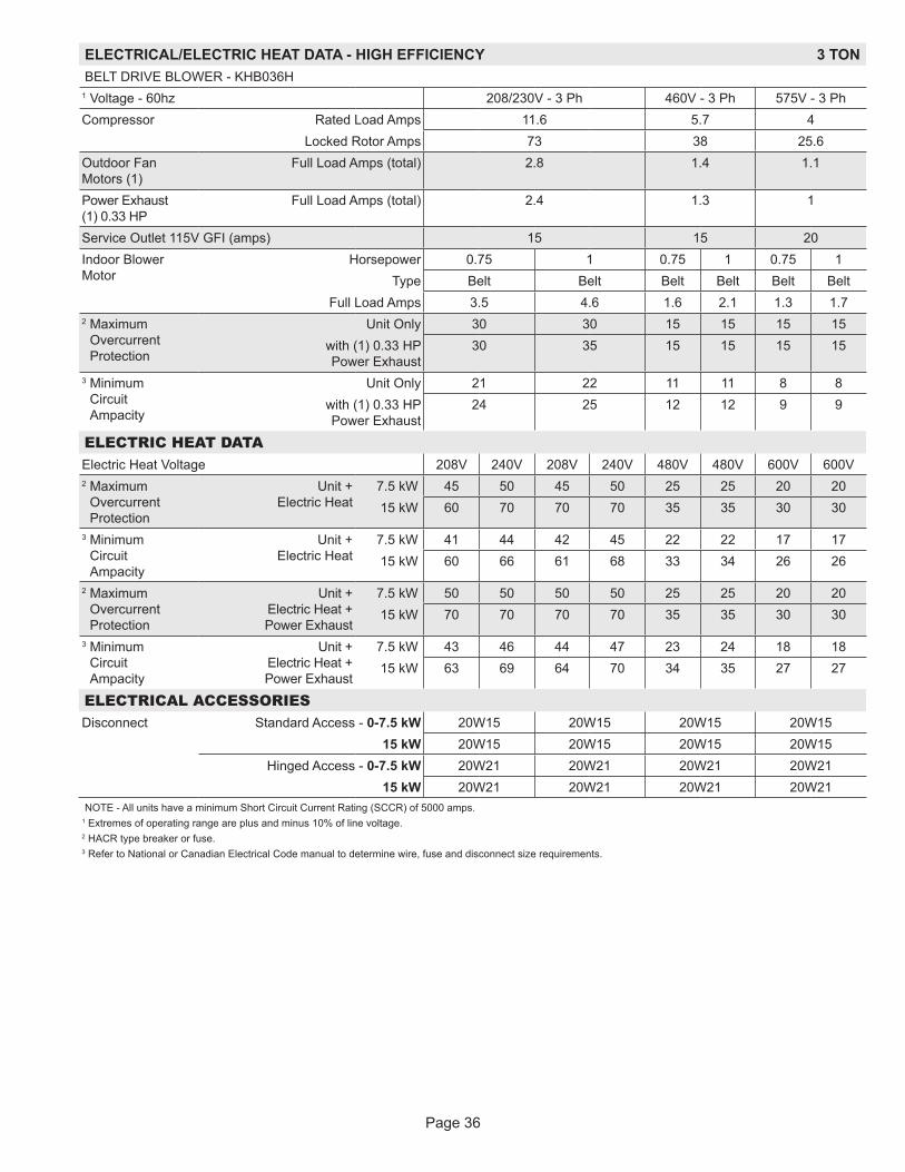
Page 36
ELECTRICAL/ELECTRIC HEAT DATA - HIGH EFFICIENCY 3 TONBELT DRIVE BLOWER - KHB036H
1 Voltage - 60hz 208/230V - 3 Ph 460V - 3 Ph 575V - 3 PhCompressor Rated Load Amps 11.6 5.7 4
Locked Rotor Amps 73 38 25.6Outdoor Fan Motors (1)
Full Load Amps (total) 2.8 1.4 1.1
Power Exhaust (1) 0.33 HP
Full Load Amps (total) 2.4 1.3 1
Service Outlet 115V GFI (amps) 15 15 20Indoor Blower Motor
Horsepower 0.75 1 0.75 1 0.75 1Type Belt Belt Belt Belt Belt Belt
Full Load Amps 3.5 4.6 1.6 2.1 1.3 1.72 Maximum
Overcurrent Protection
Unit Only 30 30 15 15 15 15with (1) 0.33 HP Power Exhaust
30 35 15 15 15 15
3 Minimum Circuit Ampacity
Unit Only 21 22 11 11 8 8with (1) 0.33 HP Power Exhaust
24 25 12 12 9 9
ELECTRIC HEAT DATAElectric Heat Voltage 208V 240V 208V 240V 480V 480V 600V 600V2 Maximum
Overcurrent Protection
Unit + Electric Heat
7.5 kW 45 50 45 50 25 25 20 2015 kW 60 70 70 70 35 35 30 30
3 Minimum Circuit Ampacity
Unit + Electric Heat
7.5 kW 41 44 42 45 22 22 17 1715 kW 60 66 61 68 33 34 26 26
2 Maximum Overcurrent Protection
Unit + Electric Heat + Power Exhaust
7.5 kW 50 50 50 50 25 25 20 2015 kW 70 70 70 70 35 35 30 30
3 Minimum Circuit Ampacity
Unit + Electric Heat + Power Exhaust
7.5 kW 43 46 44 47 23 24 18 1815 kW 63 69 64 70 34 35 27 27
ELECTRICAL ACCESSORIESDisconnect Standard Access - 0-7.5 kW 20W15 20W15 20W15 20W15
15 kW 20W15 20W15 20W15 20W15Hinged Access - 0-7.5 kW 20W21 20W21 20W21 20W21
15 kW 20W21 20W21 20W21 20W21NOTE - All units have a minimum Short Circuit Current Rating (SCCR) of 5000 amps.
1 Extremes of operating range are plus and minus 10% of line voltage.2 HACR type breaker or fuse.3 Refer to National or Canadian Electrical Code manual to determine wire, fuse and disconnect size requirements.

Page 37
ELECTRICAL/ELECTRIC HEAT DATA - HIGH EFFICIENCY 4 TONBELT DRIVE BLOWER - KHB048H
1 Voltage - 60hz 208/230V - 3 Ph 460V - 3 Ph 575V - 3 PhCompressor Rated Load Amps 14 6.4 4.6
Locked Rotor Amps 83.1 41 33Outdoor Fan Motors (1)
Full Load Amps (total) 2.8 1.4 1.1
Power Exhaust (1) 0.33 HP
Full Load Amps (total) 2.4 1.3 1
Service Outlet 115V GFI (amps) 15 15 20Indoor Blower Motor
Horsepower 0.80 2 0.75 2 0.75 2Type Belt Belt Belt Belt Belt Belt
Full Load Amps 3.5 7.5 1.6 3.4 1.3 2.72 Maximum
Overcurrent Protection
Unit Only 35 40 15 15 15 15with (1) 0.33 HP Power Exhaust
40 40 15 20 15 15
3 Minimum Circuit Ampacity
Unit Only 24 28 11 13 9 10with (1) 0.33 HP Power Exhaust
27 31 13 15 10 11
ELECTRIC HEAT DATAElectric Heat Voltage 208V 240V 208V 240V 480V 480V 600V 600V2 Maximum
Overcurrent Protection
Unit + Electric Heat
7.5 kW 50 50 50 60 25 25 20 2015 kW 70 70 70 80 35 40 30 30
3 Minimum Circuit Ampacity
Unit + Electric Heat
7.5 kW 44 47 48 51 23 25 18 1915 kW 63 69 67 73 34 36 27 28
2 Maximum Overcurrent Protection
Unit + Electric Heat + Power Exhaust
7.5 kW 50 50 50 60 25 30 20 2015 kW 70 80 70 80 35 40 30 30
3 Minimum Circuit Ampacity
Unit + Electric Heat + Power Exhaust
7.5 kW 46 49 50 53 24 26 19 2015 kW 66 72 70 76 35 37 28 29
ELECTRICAL ACCESSORIESDisconnect Standard Access - 0-7.5 kW 20W18 20W18 20W18 20W18
15 kW 20W18 20W18 20W18 20W18Hinged Access - 0-7.5 kW 20W24 20W24 20W24 20W24
15 kW 20W24 20W24 20W24 20W24NOTE - All units have a minimum Short Circuit Current Rating (SCCR) of 5000 amps.
1 Extremes of operating range are plus and minus 10% of line voltage.2 HACR type breaker or fuse.3 Refer to National or Canadian Electrical Code manual to determine wire, fuse and disconnect size requirements.

Page 38
ELECTRICAL/ELECTRIC HEAT DATA - HIGH EFFICIENCY 5 TONBELT DRIVE BLOWER - KHB060H
1 Voltage - 60hz 208/230V - 3 Ph 460V - 3 Ph 575V - 3 PhCompressor Rated Load Amps 16.5 7.2 5.5
Locked Rotor Amps 110 52 38.9Outdoor Fan Motors (1)
Full Load Amps (total) 2.8 1.4 1.1
Power Exhaust (1) 0.33 HP
Full Load Amps (total) 2.4 1.3 1
Service Outlet 115V GFI (amps) 15 15 20Indoor Blower Motor
Horsepower 1 2 1 2 1 2Type Belt Belt Belt Belt Belt Belt
Full Load Amps 4.6 7.5 2.1 3.4 1.7 2.72 Maximum
Overcurrent Protection
Unit Only 40 45 15 20 15 15with (1) 0.33 HP Power Exhaust
45 45 20 20 15 15
3 Minimum Circuit Ampacity
Unit Only 29 31 13 14 10 11with (1) 0.33 HP Power Exhaust
31 34 14 16 11 12
ELECTRIC HEAT DATAElectric Heat Voltage 208V 240V 208V 240V 480V 480V 600V 600V2 Maximum
Overcurrent Protection
Unit + Electric Heat
7.5 kW 60 60 60 60 25 30 20 2015 kW 70 80 80 80 40 40 30 30
22.5 kW 90 100 90 100 50 50 40 403 Minimum
Circuit Ampacity
Unit + Electric Heat
7.5 kW 48 51 51 54 24 26 19 2015 kW 68 74 71 77 36 37 28 29
22.5 kW 87 96 90 99 47 48 37 382 Maximum
Overcurrent Protection
Unit + Electric Heat + Power Exhaust
7.5 kW 60 60 60 60 30 30 20 2515 kW 70 80 80 80 40 40 30 30
22.5 kW 90 100 100 110 50 50 40 403 Minimum
Circuit Ampacity
Unit + Electric Heat + Power Exhaust
7.5 kW 50 53 53 56 26 27 20 2115 kW 70 76 73 79 37 38 29 30
22.5 kW 90 99 92 101 48 49 38 39
ELECTRICAL ACCESSORIESDisconnect Standard Access - 0-7.5 kW 20W18 20W18 20W18 20W18
15 kW 20W18 20W18 20W18 20W1822.5 kW 20W19 20W19 20W18 20W18
Hinged Access - 0-7.5 kW 20W24 20W24 20W24 20W2415 kW 20W24 20W24 20W24 20W24
22.5 kW 20W25 20W25 20W24 20W24NOTE - All units have a minimum Short Circuit Current Rating (SCCR) of 5000 amps.
1 Extremes of operating range are plus and minus 10% of line voltage.2 HACR type breaker or fuse.3 Refer to National or Canadian Electrical Code manual to determine wire, fuse and disconnect size requirements.
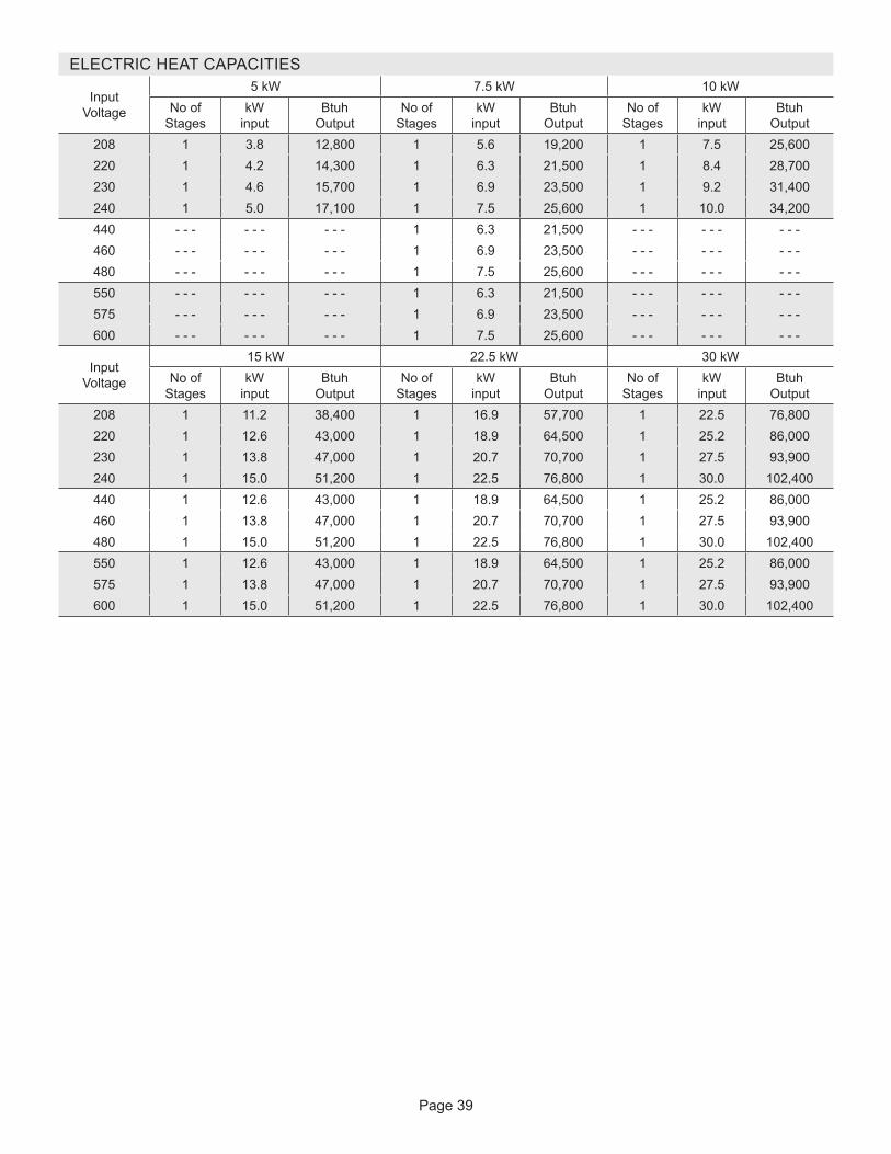
Page 39
ELECTRIC HEAT CAPACITIES
Input Voltage
5 kW 7.5 kW 10 kWNo of
StageskW
inputBtuh
OutputNo of
StageskW
inputBtuh
OutputNo of
StageskW
inputBtuh
Output208 1 3.8 12,800 1 5.6 19,200 1 7.5 25,600220 1 4.2 14,300 1 6.3 21,500 1 8.4 28,700230 1 4.6 15,700 1 6.9 23,500 1 9.2 31,400240 1 5.0 17,100 1 7.5 25,600 1 10.0 34,200440 - - - - - - - - - 1 6.3 21,500 - - - - - - - - -460 - - - - - - - - - 1 6.9 23,500 - - - - - - - - -480 - - - - - - - - - 1 7.5 25,600 - - - - - - - - -550 - - - - - - - - - 1 6.3 21,500 - - - - - - - - -575 - - - - - - - - - 1 6.9 23,500 - - - - - - - - -600 - - - - - - - - - 1 7.5 25,600 - - - - - - - - -
Input Voltage
15 kW 22.5 kW 30 kWNo of
StageskW
inputBtuh
OutputNo of
StageskW
inputBtuh
OutputNo of
StageskW
inputBtuh
Output208 1 11.2 38,400 1 16.9 57,700 1 22.5 76,800220 1 12.6 43,000 1 18.9 64,500 1 25.2 86,000230 1 13.8 47,000 1 20.7 70,700 1 27.5 93,900240 1 15.0 51,200 1 22.5 76,800 1 30.0 102,400440 1 12.6 43,000 1 18.9 64,500 1 25.2 86,000460 1 13.8 47,000 1 20.7 70,700 1 27.5 93,900480 1 15.0 51,200 1 22.5 76,800 1 30.0 102,400550 1 12.6 43,000 1 18.9 64,500 1 25.2 86,000575 1 13.8 47,000 1 20.7 70,700 1 27.5 93,900600 1 15.0 51,200 1 22.5 76,800 1 30.0 102,400
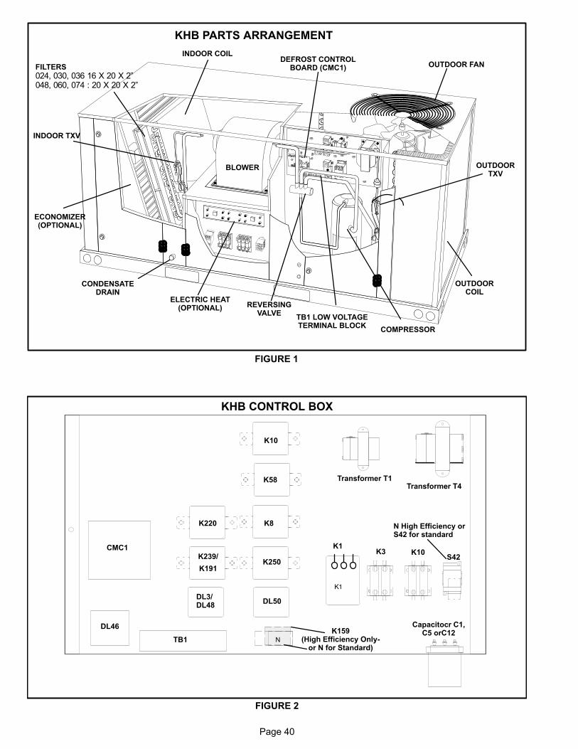
Page 40
KHB PARTS ARRANGEMENT
FIGURE 1
INDOOR COIL
OUTDOOR FAN
OUTDOORCOIL
CONDENSATEDRAIN
ECONOMIZER(OPTIONAL)
ELECTRIC HEAT(OPTIONAL)
COMPRESSOR
BLOWER
REVERSINGVALVE
DEFROST CONTROLBOARD (CMC1)FILTERS
024, 030, 036 16 X 20 X 2”048, 060, 074 : 20 X 20 X 2”
TB1 LOW VOLTAGETERMINAL BLOCK
INDOOR TXV
OUTDOORTXV
KHB CONTROL BOX
FIGURE 2
K1
CMC1 K1
Capacitocr C1,C5 orC12
DL46
Transformer T1Transformer T4
K159(High Efficiency Only
or N for Standard)
K220 N High Efficiency orS42 for standard
S42K239/
K191
K8
K250
K58
K10
TB1
DL3/DL48
DL50
N
K10K3
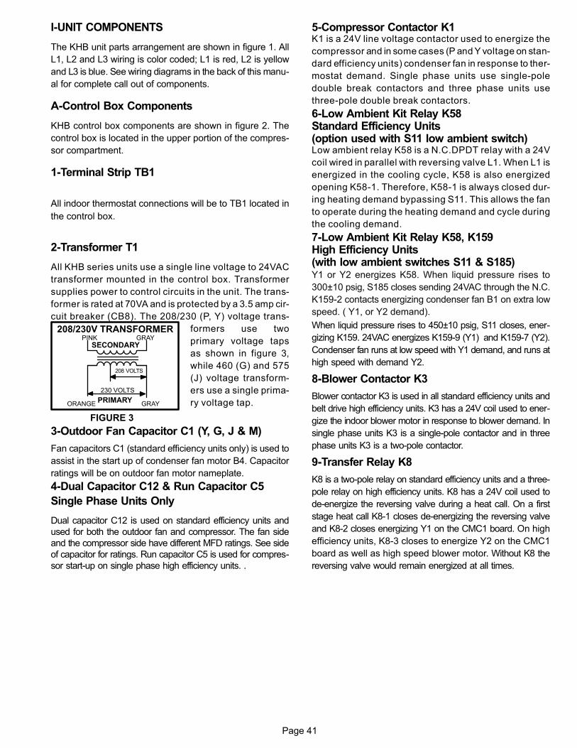
Page 41
I-UNIT COMPONENTS
The KHB unit parts arrangement are shown in figure 1. All
L1, L2 and L3 wiring is color coded; L1 is red, L2 is yellow
and L3 is blue. See wiring diagrams in the back of this manu
al for complete call out of components.
A-Control Box Components
KHB control box components are shown in figure 2. The
control box is located in the upper portion of the compres
sor compartment.
1-Terminal Strip TB1
All indoor thermostat connections will be to TB1 located in
the control box.
2-Transformer T1
All KHB series units use a single line voltage to 24VAC
transformer mounted in the control box. Transformer
supplies power to control circuits in the unit. The trans
former is rated at 70VA and is protected by a 3.5 amp cir
cuit breaker (CB8). The 208/230 (P, Y) voltage trans
formers use two
primary voltage taps
as shown in figure 3,
while 460 (G) and 575
(J) voltage transform
ers use a single prima
ry voltage tap.
3-Outdoor Fan Capacitor C1 (Y, G, J & M)
Fan capacitors C1 (standard efficiency units only) is used to
assist in the start up of condenser fan motor B4. Capacitor
ratings will be on outdoor fan motor nameplate.
4-Dual Capacitor C12 & Run Capacitor C5
Single Phase Units Only
Dual capacitor C12 is used on standard efficiency units and
used for both the outdoor fan and compressor. The fan side
and the compressor side have different MFD ratings. See side
of capacitor for ratings. Run capacitor C5 is used for compres
sor start-up on single phase high efficiency units. .
5-Compressor Contactor K1K1 is a 24V line voltage contactor used to energize the
compressor and in some cases (P and Y voltage on stan
dard efficiency units) condenser fan in response to ther
mostat demand. Single phase units use single-pole
double break contactors and three phase units use
three-pole double break contactors.
6-Low Ambient Kit Relay K58Standard Efficiency Units(option used with S11 low ambient switch)Low ambient relay K58 is a N.C.DPDT relay with a 24V
coil wired in parallel with reversing valve L1. When L1 is
energized in the cooling cycle, K58 is also energized
opening K58-1. Therefore, K58-1 is always closed dur
ing heating demand bypassing S11. This allows the fan
to operate during the heating demand and cycle during
the cooling demand.
7-Low Ambient Kit Relay K58, K159High Efficiency Units(with low ambient switches S11 & S185)Y1 or Y2 energizes K58. When liquid pressure rises to
300±10 psig, S185 closes sending 24VAC through the N.C.
K159-2 contacts energizing condenser fan B1 on extra low
speed. ( Y1, or Y2 demand).
When liquid pressure rises to 450±10 psig, S11 closes, ener
gizing K159. 24VAC energizes K159-9 (Y1) and K159-7 (Y2).
Condenser fan runs at low speed with Y1 demand, and runs at
high speed with demand Y2.
8-Blower Contactor K3
Blower contactor K3 is used in all standard efficiency units and
belt drive high efficiency units. K3 has a 24V coil used to ener
gize the indoor blower motor in response to blower demand. In
single phase units K3 is a single-pole contactor and in three
phase units K3 is a two-pole contactor.
9-Transfer Relay K8
K8 is a two-pole relay on standard efficiency units and a three-
pole relay on high efficiency units. K8 has a 24V coil used to
de-energize the reversing valve during a heat call. On a first
stage heat call K8-1 closes de-energizing the reversing valve
and K8-2 closes energizing Y1 on the CMC1 board. On high
efficiency units, K8-3 closes to energize Y2 on the CMC1
board as well as high speed blower motor. Without K8 the
reversing valve would remain energized at all times.
FIGURE 3
PINK GRAY
ORANGE GRAY
230 VOLTS
208 VOLTS
PRIMARY
SECONDARY
208/230V TRANSFORMER
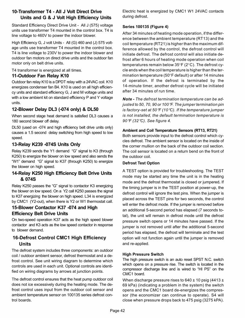
Page 42
10-Transformer T4 - All J Volt Direct Drive
Units and G & J Volt High Efficiency Units
Standard Efficiency Direct Drive Unit - All J (575) voltage
units use transformer T4 mounted in the control box. T4 is
line voltage to 460V to power the indoor blower.
High Efficiency G, J volt Units - All (G) 460 and (J) 575 volt
age units use transformer T4 mounted in the control box.
T4 is line voltage to 230V to power the indoor blower and
outdoor fan motors on direct drive units and the outdoor fan
motor only on belt drive units.
T4 transformer is energized at all times.
11-Outdoor Fan Relay K10
Outdoor fan relay K10 is a DPDT relay with a 24VAC coil. K10
energizes condenser fan B4. K10 is used on all high efficien
cy units and standard efficiency G, J and M voltage units and
with a low ambient kit on standard efficiency P and Y voltage
units.
12-Blower Delay DL3 (-074 only) & DL50
When second stage heat demand is satisfied DL3 causes a
180 second blower off delay.
DL50 (used on -074 and high efficiency belt drive units only)
causes a 1.5 second delay switching from high speed to low
speed.
13-Relay K239 -074S Units Only
Relay K239 sends the Y1 demand “G” signal to K3 (through
K250) to energize the blower on low speed and also sends the
“W1” demand “G” signal to K37 (through K250) to energize
the blower on high speed.
14-Relay K250 High Efficiency Belt Drive Units
& 074S
Relay K250 passes the “G” signal to contactor K3 energizing
the blower on low speed. On a Y2 call K250 passes the signal
to K37 energizing the blower on high speed. L34 is energized
by CMC1 (Y2-out), when there is Y2 or W1 thermostat call.
15-Blower Contactor K37 -074 and High
Efficiency Belt Drive Units
On two-speed operation K37 acts as the high speed blower
contactor and K3 acts as the low speed contactor in response
to blower demand.
16-Defrost Control CMC1 High Efficiency
Units
The defrost system includes three components: an outdoor
coil / outdoor ambient sensor, defrost thermostat and a de
frost control. See unit wiring diagram to determine which
controls are used in each unit. Optional controls are identi
fied on wiring diagrams by arrows at junction points.
The defrost control ensures that the heat pump outdoor coil
does not ice excessively during the heating mode. The de
frost control uses input from the outdoor coil sensor and
ambient temperature sensor on 100135 series defrost con
trol boards.
Electric heat is energized by CMC1 W1 24VAC contacts
during defrost.
Series 100135 (Figure 4)
After 34 minutes of heating mode operation, if the differ
ence between the ambient temperature (RT13) and the
coil temperature (RT21) is higher than the maximum dif
ference allowed by the control, the defrost control will
initiate defrost. The defrost control will also initiate de
frost after 6 hours of heating mode operation when coil
temperatures remain below 35°F (2°C). The defrost cy
cle ends when the coil temperature is higher than the ter
mination temperature (50°F default) or after 14 minutes
of operation. If the defrost is terminated by the
14-minute timer, another defrost cycle will be initiated
after 34 minutes of run time.
Note - The defrost termination temperature can be ad
justed to 50, 70, 90 or 100�F. The jumper termination pin
is factory-set at 50�F (10�C). If the temperature jumper
is not installed, the default termination temperature is
90�F (32�C). See figure 4.
Ambient and Coil Temperature Sensors (RT13, RT21)
Both sensors provide input to the defrost control which cy
cles defrost. The ambient sensor is located on the inside of
the corner mullion on the back of the outdoor coil section.
The coil sensor is located on a return bend on the front of
the outdoor coil.
Defrost Test Option
A TEST option is provided for troubleshooting. The TEST
mode may be started any time the unit is in the heating
mode and the defrost thermostat is closed or jumpered. If
the timing jumper is in the TEST position at power‐up, the
defrost control will ignore the test pins. When the jumper is
placed across the TEST pins for two seconds, the control
will enter the defrost mode. If the jumper is removed before
an additional 5-second period has elapsed (7 seconds to
tal), the unit will remain in defrost mode until the defrost
pressure switch opens or 14 minutes have passed. If the
jumper is not removed until after the additional 5-second
period has elapsed, the defrost will terminate and the test
option will not function again until the jumper is removed
and re-applied.
High Pressure Switch
The high pressure switch is an auto reset SPST N.C. switch
which opens on a pressure rise. The switch is located in the
compressor discharge line and is wired to “HI PS” on the
CMC1 board.
When discharge pressure rises to 640 ± 10 psig (4413 ±
69 kPa) (indicating a problem in the system) the switch
opens and the CMC1 board de-energizes the compres
sor (the economizer can continue to operate). S4 will
close when pressure drops back to 475 psig (3275 kPA).
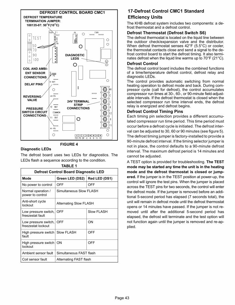
Page 43
DEFROST CONTROL BOARD CMC1DEFROST TEMPERATURE
TERMINATION JUMPER:
100135-07: 50�F(10�C)
24V TERMINALSTRIP
CONNECTIONS
DIAGNOSTICLEDS
PRESSURESWITCH CIRCUITCONNECTIONS
COIL AND AMBI
ENT SENSOR
CONNECTIONS
REVERSINGVALVE
DELAY PINS
FIGURE 4
Diagnostic LEDs
The defrost board uses two LEDs for diagnostics. The
LEDs flash a sequence according to the condition.
TABLE 1
Defrost Control Board Diagnostic LED
Mode Green LED (DS2) Red LED (DS1)
No power to control OFF OFF
Normal operation /power to control
Simultaneous Slow FLASH
Anti‐short cyclelockout
Alternating Slow FLASH
Low pressure switch,freezestat fault
OFF Slow FLASH
Low pressure switch,freezestat lockout
OFF ON
High pressure switchfault
Slow FLASH OFF
High pressure switchlockout
ON OFF
Ambient sensor fault Simultaneous FAST flash
Coil sensor fault Alternating FAST flash
17-Defrost Control CMC1 Standard
Efficiency Units
The KHB defrost system includes two components: a defrost thermostat and a defrost control.
Defrost Thermostat (Defrost Switch S6)The defrost thermostat is located on the liquid line betweenthe outdoor check/expansion valve and the distributor.When defrost thermostat senses 42°F (5.5°C) or cooler,the thermostat contacts close and send a signal to the defrost control board to start the defrost timing. It also terminates defrost when the liquid line warms up to 70°F (21°C).
Defrost ControlThe defrost control board includes the combined functionsof a time/temperature defrost control, defrost relay anddiagnostic LEDs.
The control provides automatic switching from normalheating operation to defrost mode and back. During compressor cycle (call for defrost), the control accumulatescompressor run times at 30‐, 60‐, or 90‐minute field-adjustable intervals. If the defrost thermostat is closed when theselected compressor run time interval ends, the defrostrelay is energized and defrost begins.
Defrost Control Timing PinsEach timing pin selection provides a different accumu
lated compressor run time period. This time period must
occur before a defrost cycle is initiated. The defrost inter
val can be adjusted to 30, 60 or 90 minutes (see figure 5).
The defrost timing jumper is factory-installed to provide a
90-minute defrost interval. If the timing selector jumper is
not in place, the control defaults to a 90-minute defrost
interval. The maximum defrost period is 14 minutes and
cannot be adjusted.
A TEST option is provided for troubleshooting. The TEST
mode may be started any time the unit is in the heating
mode and the defrost thermostat is closed or jump
ered. If the jumper is in the TEST position at power‐up, the
control will ignore the test pins. When the jumper is placed
across the TEST pins for two seconds, the control will enter
the defrost mode. If the jumper is removed before an addi
tional 5-second period has elapsed (7 seconds total), the
unit will remain in defrost mode until the defrost thermostat
opens or 14 minutes have passed. If the jumper is not re
moved until after the additional 5-second period has
elapsed, the defrost will terminate and the test option will
not function again until the jumper is removed and re-ap
plied.
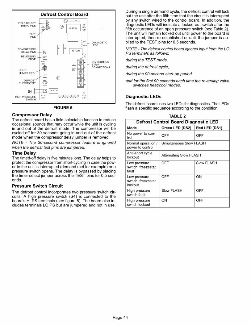
Page 44
Defrost Control Board
24V TERMINALSTRIPCONNECTIONS
DIAGNOSTICLEDS
HIGH PRESSURESWITCH
TESTPINS
FIELD SELECTTIMING PINS
REVERSINGVALVE
DEFROSTTHERMOSTAT
COMPRESSORDELAY PINS
S4
FIGURE 5
LOLO
LO-PSJUMPERED
Compressor DelayThe defrost board has a field-selectable function to reduceoccasional sounds that may occur while the unit is cyclingin and out of the defrost mode. The compressor will becycled off for 30 seconds going in and out of the defrostmode when the compressor delay jumper is removed.
NOTE - The 30‐second compressor feature is ignored
when the defrost test pins are jumpered.
Time DelayThe timed‐off delay is five minutes long. The delay helps toprotect the compressor from short‐cycling in case the power to the unit is interrupted (demand met for example) or apressure switch opens. The delay is bypassed by placingthe timer select jumper across the TEST pins for 0.5 seconds.
Pressure Switch Circuit
The defrost control incorporates two pressure switch circuits. A high pressure switch (S4) is connected to theboard's HI PS terminals (see figure 5). The board also includes terminals LO PS but are jumpered and not in use.
During a single demand cycle, the defrost control will lockout the unit after the fifth time that the circuit is interruptedby any switch wired to the control board. In addition, thediagnostic LEDs will indicate a locked‐out switch after thefifth occurrence of an open pressure switch (see Table 2).The unit will remain locked out until power to the board isinterrupted, then re‐established or until the jumper is applied to the TEST pins for 0.5 seconds.
NOTE - The defrost control board ignores input from the LOPS terminals as follows:
during the TEST mode,
during the defrost cycle,
during the 90‐second start‐up period,
and for the first 90 seconds each time the reversing valveswitches heat/cool modes.
Diagnostic LEDs
The defrost board uses two LEDs for diagnostics. The LEDsflash a specific sequence according to the condition.
TABLE 2
Defrost Control Board Diagnostic LED
Mode Green LED (DS2) Red LED (DS1)
No power to control
OFF OFF
Normal operation /power to control
Simultaneous Slow FLASH
Anti‐short cyclelockout
Alternating Slow FLASH
Low pressureswitch, freezestatfault
OFF Slow FLASH
Low pressureswitch, freezestatlockout
OFF ON
High pressureswitch fault
Slow FLASH OFF
High pressureswitch lockout
ON OFF
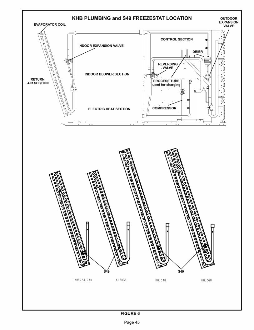
Page 45
KHB PLUMBING and S49 FREEZESTAT LOCATION
FIGURE 6
EVAPORATOR COIL
RETURN AIR SECTION
INDOOR BLOWER SECTION
ELECTRIC HEAT SECTION
INDOOR EXPANSION VALVE
REVERSINGVALVE
CONTROL SECTION
COMPRESSOR
DRIER
PROCESS TUBEused for charging
OUTDOOREXPANSION
VALVE
S49 S49
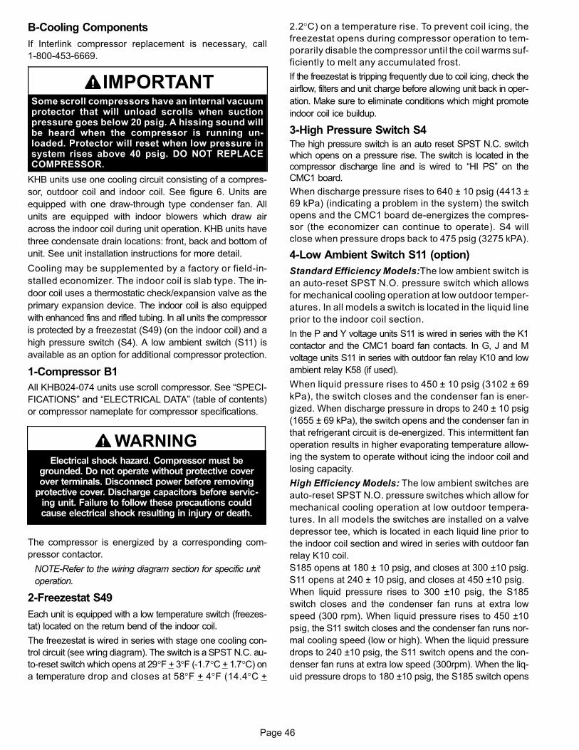
Page 46
B-Cooling Components
If Interlink compressor replacement is necessary, call
1-800-453-6669.
IMPORTANTSome scroll compressors have an internal vacuumprotector that will unload scrolls when suctionpressure goes below 20 psig. A hissing sound willbe heard when the compressor is running unloaded. Protector will reset when low pressure insystem rises above 40 psig. DO NOT REPLACECOMPRESSOR.
KHB units use one cooling circuit consisting of a compres
sor, outdoor coil and indoor coil. See figure 6. Units are
equipped with one draw-through type condenser fan. All
units are equipped with indoor blowers which draw air
across the indoor coil during unit operation. KHB units have
three condensate drain locations: front, back and bottom of
unit. See unit installation instructions for more detail.
Cooling may be supplemented by a factory or field‐in
stalled economizer. The indoor coil is slab type. The in
door coil uses a thermostatic check/expansion valve as the
primary expansion device. The indoor coil is also equipped
with enhanced fins and rifled tubing. In all units the compressor
is protected by a freezestat (S49) (on the indoor coil) and a
high pressure switch (S4). A low ambient switch (S11) is
available as an option for additional compressor protection.
1-Compressor B1
All KHB024-074 units use scroll compressor. See “SPECI
FICATIONS” and “ELECTRICAL DATA” (table of contents)
or compressor nameplate for compressor specifications.
WARNINGElectrical shock hazard. Compressor must be
grounded. Do not operate without protective coverover terminals. Disconnect power before removing
protective cover. Discharge capacitors before servicing unit. Failure to follow these precautions couldcause electrical shock resulting in injury or death.
The compressor is energized by a corresponding com
pressor contactor.
NOTE-Refer to the wiring diagram section for specific unit
operation.
2-Freezestat S49
Each unit is equipped with a low temperature switch (freezes
tat) located on the return bend of the indoor coil.
The freezestat is wired in series with stage one cooling con
trol circuit (see wring diagram). The switch is a SPST N.C. au
to-reset switch which opens at 29°F + 3°F (‐1.7°C + 1.7°C) on
a temperature drop and closes at 58°F + 4°F (14.4°C +
2.2°C) on a temperature rise. To prevent coil icing, the
freezestat opens during compressor operation to tem
porarily disable the compressor until the coil warms suf
ficiently to melt any accumulated frost.
If the freezestat is tripping frequently due to coil icing, check the
airflow, filters and unit charge before allowing unit back in oper
ation. Make sure to eliminate conditions which might promote
indoor coil ice buildup.
3-High Pressure Switch S4
The high pressure switch is an auto reset SPST N.C. switch
which opens on a pressure rise. The switch is located in the
compressor discharge line and is wired to “HI PS” on the
CMC1 board.
When discharge pressure rises to 640 ± 10 psig (4413 ±
69 kPa) (indicating a problem in the system) the switch
opens and the CMC1 board de-energizes the compres
sor (the economizer can continue to operate). S4 will
close when pressure drops back to 475 psig (3275 kPA).
4-Low Ambient Switch S11 (option)
Standard Efficiency Models:The low ambient switch is
an auto‐reset SPST N.O. pressure switch which allows
for mechanical cooling operation at low outdoor temper
atures. In all models a switch is located in the liquid line
prior to the indoor coil section.
In the P and Y voltage units S11 is wired in series with the K1
contactor and the CMC1 board fan contacts. In G, J and M
voltage units S11 in series with outdoor fan relay K10 and low
ambient relay K58 (if used).
When liquid pressure rises to 450 ± 10 psig (3102 ± 69
kPa), the switch closes and the condenser fan is ener
gized. When discharge pressure in drops to 240 ± 10 psig
(1655 ± 69 kPa), the switch opens and the condenser fan in
that refrigerant circuit is de-energized. This intermittent fan
operation results in higher evaporating temperature allow
ing the system to operate without icing the indoor coil and
losing capacity.
High Efficiency Models: The low ambient switches are
auto‐reset SPST N.O. pressure switches which allow for
mechanical cooling operation at low outdoor tempera
tures. In all models the switches are installed on a valve
depressor tee, which is located in each liquid line prior to
the indoor coil section and wired in series with outdoor fan
relay K10 coil.
S185 opens at 180 ± 10 psig, and closes at 300 ±10 psig.
S11 opens at 240 ± 10 psig, and closes at 450 ±10 psig.
When liquid pressure rises to 300 ±10 psig, the S185
switch closes and the condenser fan runs at extra low
speed (300 rpm). When liquid pressure rises to 450 ±10
psig, the S11 switch closes and the condenser fan runs nor
mal cooling speed (low or high). When the liquid pressure
drops to 240 ±10 psig, the S11 switch opens and the con
denser fan runs at extra low speed (300rpm). When the liq
uid pressure drops to 180 ±10 psig, the S185 switch opens
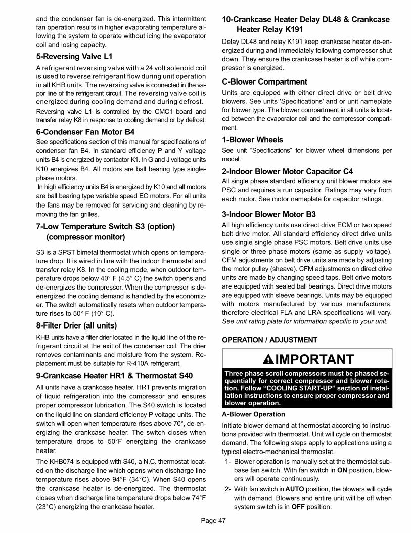
Page 47
and the condenser fan is de-energized. This intermittent
fan operation results in higher evaporating temperature al
lowing the system to operate without icing the evaporator
coil and losing capacity.
5-Reversing Valve L1
A refrigerant reversing valve with a 24 volt solenoid coil
is used to reverse refrigerant flow during unit operation
in all KHB units. The reversing valve is connected in the va
por line of the refrigerant circuit. The reversing valve coil is
energized during cooling demand and during defrost.
Reversing valve L1 is controlled by the CMC1 board and
transfer relay K8 in response to cooling demand or by defrost.
6-Condenser Fan Motor B4
See specifications section of this manual for specifications of
condenser fan B4. In standard efficiency P and Y voltage
units B4 is energized by contactor K1. In G and J voltage units
K10 energizes B4. All motors are ball bearing type single-
phase motors.
In high efficiency units B4 is energized by K10 and all motors
are ball bearing type variable speed EC motors. For all units
the fans may be removed for servicing and cleaning by re
moving the fan grilles.
7-Low Temperature Switch S3 (option)
(compressor monitor)
S3 is a SPST bimetal thermostat which opens on tempera
ture drop. It is wired in line with the indoor thermostat and
transfer relay K8. In the cooling mode, when outdoor tem
perature drops below 40° F (4.5° C) the switch opens and
de-energizes the compressor. When the compressor is de-
energized the cooling demand is handled by the economiz
er. The switch automatically resets when outdoor tempera
ture rises to 50° F (10° C).
8-Filter Drier (all units)
KHB units have a filter drier located in the liquid line of the re
frigerant circuit at the exit of the condenser coil. The drier
removes contaminants and moisture from the system. Re
placement must be suitable for R-410A refrigerant.
9-Crankcase Heater HR1 & Thermostat S40
All units have a crankcase heater. HR1 prevents migration
of liquid refrigeration into the compressor and ensures
proper compressor lubrication. The S40 switch is located
on the liquid line on standard efficiency P voltage units. The
switch will open when temperature rises above 70°, de-en
ergizing the crankcase heater. The switch closes when
temperature drops to 50°F energizing the crankcase
heater.
The KHB074 is equipped with S40, a N.C. thermostat locat
ed on the discharge line which opens when discharge line
temperature rises above 94°F (34°C). When S40 opens
the crankcase heater is de-energized. The thermostat
closes when discharge line temperature drops below 74°F
(23°C) energizing the crankcase heater.
10-Crankcase Heater Delay DL48 & Crankcase
Heater Relay K191
Delay DL48 and relay K191 keep crankcase heater de-en
ergized during and immediately following compressor shut
down. They ensure the crankcase heater is off while com
pressor is energized.
C-Blower Compartment
Units are equipped with either direct drive or belt drive
blowers. See units 'Specifications' and or unit nameplate
for blower type. The blower compartment in all units is locat
ed between the evaporator coil and the compressor compart
ment.
1-Blower Wheels
See unit “Specifications” for blower wheel dimensions per
model.
2-Indoor Blower Motor Capacitor C4All single phase standard efficiency unit blower motors are
PSC and requires a run capacitor. Ratings may vary from
each motor. See motor nameplate for capacitor ratings.
3-Indoor Blower Motor B3
All high efficiency units use direct drive ECM or two speed
belt drive motor. All standard efficiency direct drive units
use single single phase PSC motors. Belt drive units use
single or three phase motors (same as supply voltage).
CFM adjustments on belt drive units are made by adjusting
the motor pulley (sheave). CFM adjustments on direct drive
units are made by changing speed taps. Belt drive motors
are equipped with sealed ball bearings. Direct drive motors
are equipped with sleeve bearings. Units may be equipped
with motors manufactured by various manufacturers,
therefore electrical FLA and LRA specifications will vary.
See unit rating plate for information specific to your unit.
OPERATION / ADJUSTMENT
IMPORTANTThree phase scroll compressors must be phased sequentially for correct compressor and blower rotation. Follow “COOLING START-UP” section of installation instructions to ensure proper compressor andblower operation.
A-Blower Operation
Initiate blower demand at thermostat according to instruc
tions provided with thermostat. Unit will cycle on thermostat
demand. The following steps apply to applications using a
typical electro-mechanical thermostat.
1- Blower operation is manually set at the thermostat sub
base fan switch. With fan switch in ON position, blow
ers will operate continuously.
2- With fan switch in AUTO position, the blowers will cycle
with demand. Blowers and entire unit will be off when
system switch is in OFF position.
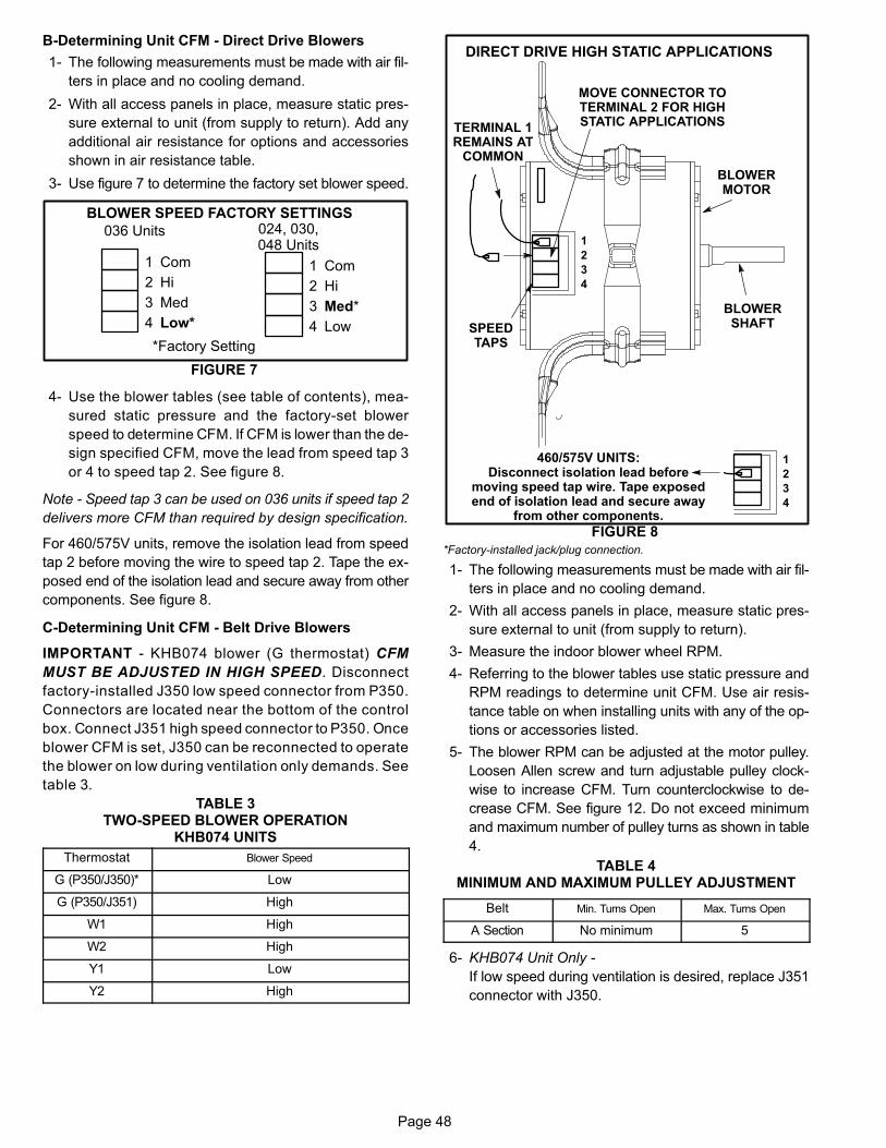
Page 48
B-Determining Unit CFM - Direct Drive Blowers
1- The following measurements must be made with air fil
ters in place and no cooling demand.
2- With all access panels in place, measure static pres
sure external to unit (from supply to return). Add any
additional air resistance for options and accessories
shown in air resistance table.
3- Use figure 7 to determine the factory set blower speed.
BLOWER SPEED FACTORY SETTINGS
FIGURE 7
1
2
3
4
Com
Hi
Med
Low*
1
2
3
4
Com
Hi
Med*
Low
*Factory Setting
036 Units 024, 030,048 Units
4- Use the blower tables (see table of contents), mea
sured static pressure and the factory-set blower
speed to determine CFM. If CFM is lower than the de
sign specified CFM, move the lead from speed tap 3
or 4 to speed tap 2. See figure 8.
Note - Speed tap 3 can be used on 036 units if speed tap 2
delivers more CFM than required by design specification.
For 460/575V units, remove the isolation lead from speed
tap 2 before moving the wire to speed tap 2. Tape the ex
posed end of the isolation lead and secure away from other
components. See figure 8.
C-Determining Unit CFM - Belt Drive Blowers
IMPORTANT - KHB074 blower (G thermostat) CFM
MUST BE ADJUSTED IN HIGH SPEED. Disconnect
factory-installed J350 low speed connector from P350.
Connectors are located near the bottom of the control
box. Connect J351 high speed connector to P350. Once
blower CFM is set, J350 can be reconnected to operate
the blower on low during ventilation only demands. See
table 3.
TABLE 3TWO-SPEED BLOWER OPERATION
KHB074 UNITS
Thermostat Blower Speed
G (P350/J350)* Low
G (P350/J351) High
W1 High
W2 High
Y1 Low
Y2 High
FIGURE 8
MOVE CONNECTOR TOTERMINAL 2 FOR HIGHSTATIC APPLICATIONS
1
2
3
4
BLOWERMOTOR
SPEEDTAPS
BLOWERSHAFT
DIRECT DRIVE HIGH STATIC APPLICATIONS
TERMINAL 1REMAINS AT
COMMON
1
2
3
4
460/575V UNITS:Disconnect isolation lead before
moving speed tap wire. Tape exposedend of isolation lead and secure away
from other components.
*Factory-installed jack/plug connection.
1- The following measurements must be made with air fil
ters in place and no cooling demand.
2- With all access panels in place, measure static pres
sure external to unit (from supply to return).
3- Measure the indoor blower wheel RPM.
4- Referring to the blower tables use static pressure and
RPM readings to determine unit CFM. Use air resis
tance table on when installing units with any of the op
tions or accessories listed.
5- The blower RPM can be adjusted at the motor pulley.
Loosen Allen screw and turn adjustable pulley clock
wise to increase CFM. Turn counterclockwise to de
crease CFM. See figure 12. Do not exceed minimum
and maximum number of pulley turns as shown in table
4.
TABLE 4MINIMUM AND MAXIMUM PULLEY ADJUSTMENT
Belt Min. Turns Open Max. Turns Open
A Section No minimum 5
6- KHB074 Unit Only -
If low speed during ventilation is desired, replace J351
connector with J350.
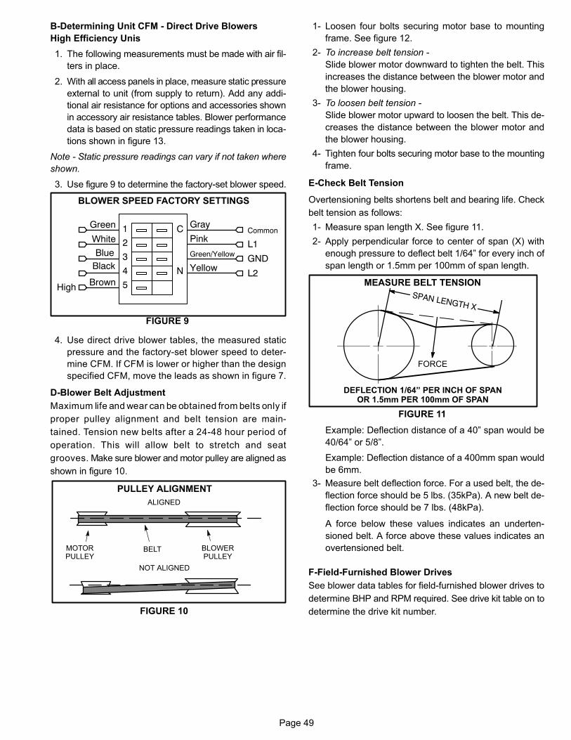
Page 49
B-Determining Unit CFM - Direct Drive Blowers
High Efficiency Unis
1. The following measurements must be made with air fil
ters in place.
2. With all access panels in place, measure static pressure
external to unit (from supply to return). Add any addi
tional air resistance for options and accessories shown
in accessory air resistance tables. Blower performance
data is based on static pressure readings taken in loca
tions shown in figure 13.
Note - Static pressure readings can vary if not taken where
shown.
3. Use figure 9 to determine the factory-set blower speed.
BLOWER SPEED FACTORY SETTINGS
FIGURE 9
Gray
Pink
Green/Yellow
Yellow
1
2
3
4
5
C
N
Green
White
BrownHigh
Common
L1
GND
L2
BlueBlack
4. Use direct drive blower tables, the measured static
pressure and the factory-set blower speed to deter
mine CFM. If CFM is lower or higher than the design
specified CFM, move the leads as shown in figure 7.
D-Blower Belt Adjustment
Maximum life and wear can be obtained from belts only if
proper pulley alignment and belt tension are main
tained. Tension new belts after a 24-48 hour period of
operation. This will allow belt to stretch and seat
grooves. Make sure blower and motor pulley are aligned as
shown in figure 10.
FIGURE 10
PULLEY ALIGNMENT
BELT BLOWERPULLEY
MOTORPULLEY
NOT ALIGNED
ALIGNED
1- Loosen four bolts securing motor base to mounting
frame. See figure 12.
2- To increase belt tension -
Slide blower motor downward to tighten the belt. This
increases the distance between the blower motor and
the blower housing.
3- To loosen belt tension -
Slide blower motor upward to loosen the belt. This de
creases the distance between the blower motor and
the blower housing.
4- Tighten four bolts securing motor base to the mounting
frame.
E-Check Belt Tension
Overtensioning belts shortens belt and bearing life. Check
belt tension as follows:
1- Measure span length X. See figure 11.
2- Apply perpendicular force to center of span (X) with
enough pressure to deflect belt 1/64” for every inch of
span length or 1.5mm per 100mm of span length.
MEASURE BELT TENSION
FIGURE 11
DEFLECTION 1/64” PER INCH OF SPANOR 1.5mm PER 100mm OF SPAN
FORCE
Example: Deflection distance of a 40” span would be
40/64” or 5/8”.
Example: Deflection distance of a 400mm span would
be 6mm.
3- Measure belt deflection force. For a used belt, the de
flection force should be 5 lbs. (35kPa). A new belt de
flection force should be 7 lbs. (48kPa).
A force below these values indicates an underten
sioned belt. A force above these values indicates an
overtensioned belt.
F-Field-Furnished Blower Drives
See blower data tables for field-furnished blower drives to
determine BHP and RPM required. See drive kit table on to
determine the drive kit number.
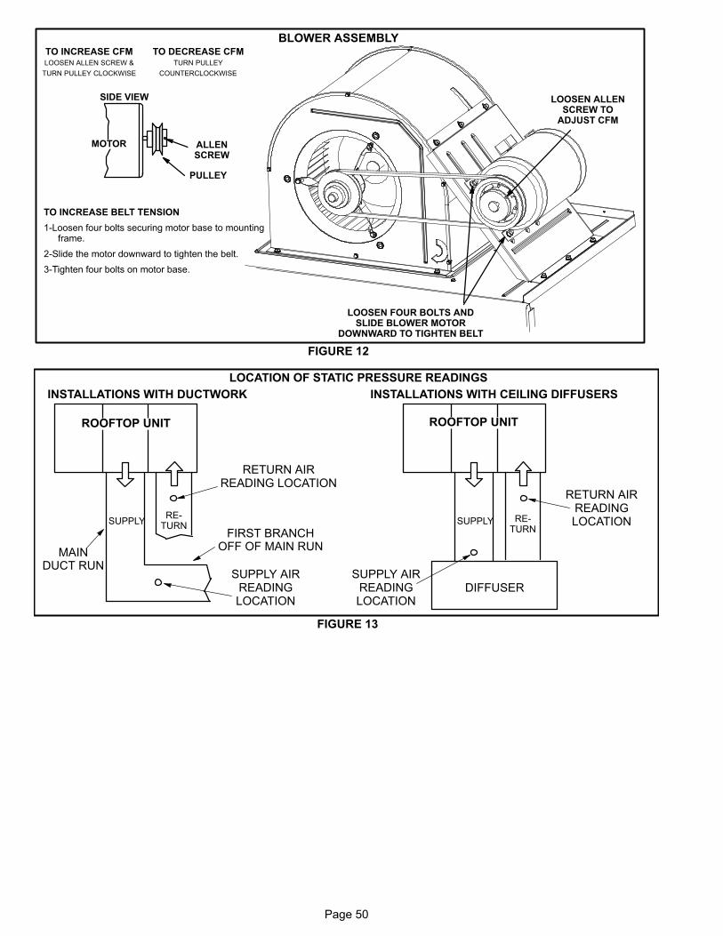
Page 50
BLOWER ASSEMBLY
TO INCREASE BELT TENSION
1-Loosen four bolts securing motor base to mountingframe.
2-Slide the motor downward to tighten the belt.
3-Tighten four bolts on motor base.
TO INCREASE CFMLOOSEN ALLEN SCREW &
TURN PULLEY CLOCKWISE
TO DECREASE CFMTURN PULLEY
COUNTERCLOCKWISE
FIGURE 12
PULLEY
MOTOR
SIDE VIEW
ALLENSCREW
LOOSEN FOUR BOLTS ANDSLIDE BLOWER MOTOR
DOWNWARD TO TIGHTEN BELT
LOOSEN ALLENSCREW TO
ADJUST CFM
FIGURE 13
LOCATION OF STATIC PRESSURE READINGS
SUPPLY AIRREADINGLOCATION
SUPPLYRE
TURN
INSTALLATIONS WITH DUCTWORK
SUPPLY RETURN
INSTALLATIONS WITH CEILING DIFFUSERS
MAINDUCT RUN
FIRST BRANCHOFF OF MAIN RUN
DIFFUSER
ROOFTOP UNIT ROOFTOP UNIT
SUPPLY AIRREADINGLOCATION
RETURN AIRREADING LOCATION
RETURN AIRREADINGLOCATION

Page 51
D-Optional Electric Heat Components
Electric heat matchups are found in the ELECTRICAL DA
TA tables. See table of contents.
All electric heat sections consist of electric heating ele
ments exposed directly to the airstream. See figure 14.
See figure 15 for vestibule parts arrangement.
1-Contactors K15, K16
All contactors are double break and either single, dou
ble or three pole (see diagram) and equipped with a
24VAC coil. The coils in the K15 and K16 contactors
are energized by the indoor thermostat. In all units
K15 energizes the heating elements, while in the 22.5
kW units, K15 and K16 energize the heating elements
simultaneously.
2-High Temperature Limits S15 (Primary)
S15 is a SPST N.C. auto‐reset thermostat located on the
back panel of the electric heat section above the heating
elements. S15 is the high temperature limit for the electric
heat section. When S15 opens, indicating a problem in the
system, contactor K15 is de‐energized (including K16 in
22.5 kW units). When K15 is de‐energized, all stages of
heat are de‐energized. See table 5 for S15 set points. Set
points are factory set and not adjustable.
TABLE 5
Unit kW (Voltage) S15 Opens ° F S15 Closes ° F
7.5 (Y, G, J, P) 160 120
10 (P) 170 130
15 (Y) 170 130
15 (G, J, P) 160 120
22.5 (Y, G, J) 160 120
22.5 (P) 150 110
30 (Y, G, J) 150 110
3-High Temperature Limit S20 and S157 (Secondary)
S20 and S157 are SPST N.C. manual‐reset ther
mostats. S20 and S157 are wired in series with the
heating elements. See T1EH wiring diagrams. When
either limit opens K15 and K16 are de‐energized.
When the contactors are de‐energized, all stages of
heat are de‐energized. The thermostat is factory set to
open at 220�F + 6�F (104�C + 3.3�C) on a tempera
ture rise and can be manually reset when temperature
falls below 160�F (71.0�C). See figure 15 for location.
4-Terminal Strip TB2
Terminal strip TB2 is used for single point power instal
lations only. TB2 distributes power to TB3. Units with
multi-point power connections will not use TB2.
5-Terminal Strip TB3
P and Y voltage units are equipped with terminal strip
TB3. Electric heat line voltage connections are made
to TB3, which distributes power to the electric heat
components and is located on the vestibule. See fig
ure 15.
6-Heating Elements HE1 through HE6
Heating elements are composed of helix wound bare
nichrome wire exposed directly to the airstream. Three el
ements are connected in a three‐phase arrange
ment. The elements in 208/230V units are connected
in a “Delta” arrangement. Elements in 460 and 575V
units are connected in “Wye” arrangement. Each stage
is energized independently by the corresponding contac
tors located on the electric heat vestibule panel. Once
energized, heat transfer is instantaneous. High temper
ature protection is provided by primary and redundant
high temperature limits and overcurrent protection is
provided by fuses.
FIGURE 14
ELECTRIC HEAT ELEMENTS
7-Fuse F3 and F42
Fuse F3 and F42 are housed in a fuse block which holds
two or three fuses. Each F3 fuse is connected in series
with each leg of electric heat. Figure 15 and table 6 show
the fuses used with each electric heat section.
8-Unit Fuse Block & Fuse F4
Unit fuses F4 provide short circuit and ground fault pro
tection to all cooling components in the KHB units with
electric heat. The fuses are rated in accordance with
the amperage of the cooling components. The F 4 fuse
block is located inside a sheetmetal enclosure.
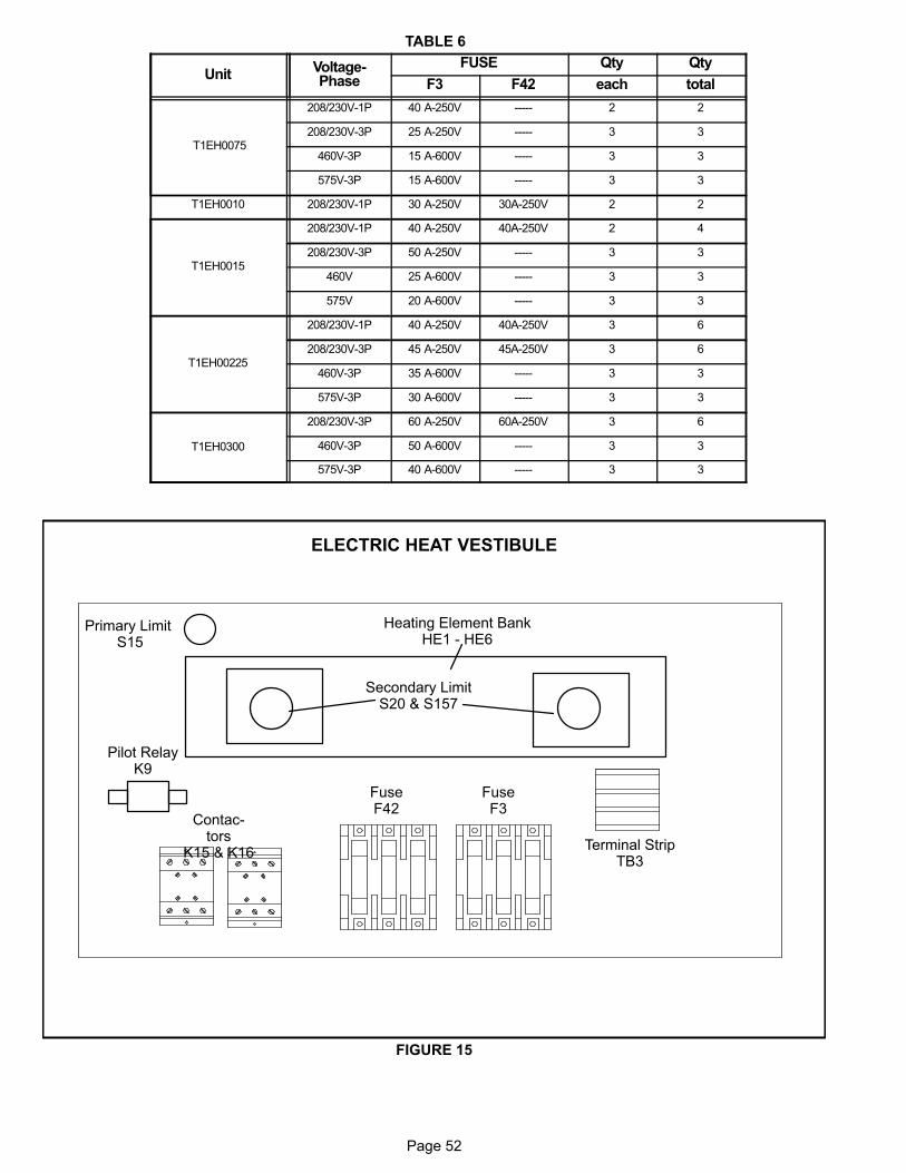
Page 52
TABLE 6
UnitVoltage-Phase
FUSE Qty Qty
F3 F42 each total
T1EH0075
208/230V-1P 40 A-250V ----- 2 2
208/230V-3P 25 A-250V ----- 3 3
460V-3P 15 A-600V ----- 3 3
575V-3P 15 A-600V ----- 3 3
T1EH0010 208/230V-1P 30 A-250V 30A-250V 2 2
T1EH0015
208/230V-1P 40 A-250V 40A-250V 2 4
208/230V-3P 50 A-250V ----- 3 3
460V 25 A-600V ----- 3 3
575V 20 A-600V ----- 3 3
T1EH00225
208/230V-1P 40 A-250V 40A-250V 3 6
208/230V-3P 45 A-250V 45A-250V 3 6
460V-3P 35 A-600V ----- 3 3
575V-3P 30 A-600V ----- 3 3
T1EH0300
208/230V-3P 60 A-250V 60A-250V 3 6
460V-3P 50 A-600V ----- 3 3
575V-3P 40 A-600V ----- 3 3
FIGURE 15
ELECTRIC HEAT VESTIBULE
Secondary LimitS20 & S157
Pilot RelayK9
Primary Limit S15
Heating Element BankHE1 - HE6
Contactors
K15 & K16
FuseF42
Terminal StripTB3
FuseF3
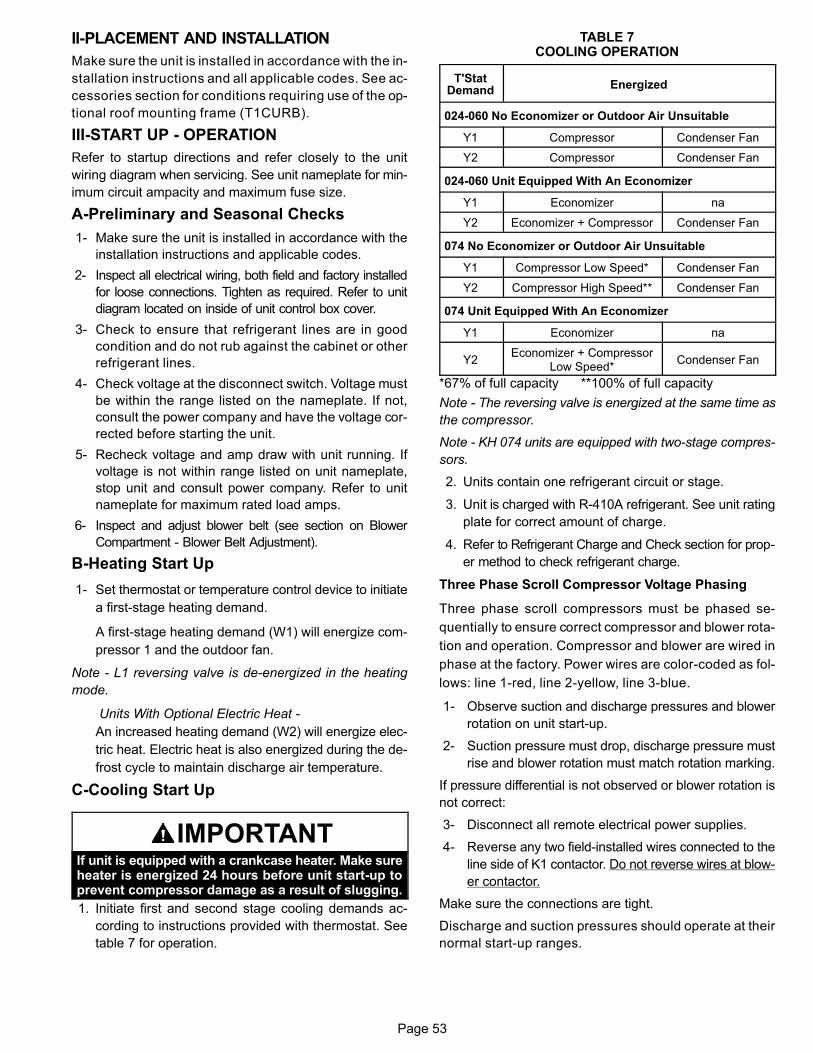
Page 53
II-PLACEMENT AND INSTALLATION
Make sure the unit is installed in accordance with the in
stallation instructions and all applicable codes. See ac
cessories section for conditions requiring use of the op
tional roof mounting frame (T1CURB).
III-START UP - OPERATION
Refer to startup directions and refer closely to the unit
wiring diagram when servicing. See unit nameplate for min
imum circuit ampacity and maximum fuse size.
A-Preliminary and Seasonal Checks
1- Make sure the unit is installed in accordance with the
installation instructions and applicable codes.
2- Inspect all electrical wiring, both field and factory installed
for loose connections. Tighten as required. Refer to unit
diagram located on inside of unit control box cover.
3- Check to ensure that refrigerant lines are in good
condition and do not rub against the cabinet or other
refrigerant lines.
4- Check voltage at the disconnect switch. Voltage must
be within the range listed on the nameplate. If not,
consult the power company and have the voltage cor
rected before starting the unit.
5- Recheck voltage and amp draw with unit running. If
voltage is not within range listed on unit nameplate,
stop unit and consult power company. Refer to unit
nameplate for maximum rated load amps.
6- Inspect and adjust blower belt (see section on Blower
Compartment - Blower Belt Adjustment).
B-Heating Start Up
1- Set thermostat or temperature control device to initiate
a first-stage heating demand.
A first-stage heating demand (W1) will energize com
pressor 1 and the outdoor fan.
Note - L1 reversing valve is de-energized in the heating
mode.
Units With Optional Electric Heat -
An increased heating demand (W2) will energize elec
tric heat. Electric heat is also energized during the de
frost cycle to maintain discharge air temperature.
C-Cooling Start Up
IMPORTANTIf unit is equipped with a crankcase heater. Make sureheater is energized 24 hours before unit start-up toprevent compressor damage as a result of slugging.
1. Initiate first and second stage cooling demands ac
cording to instructions provided with thermostat. See
table 7 for operation.
TABLE 7COOLING OPERATION
T'StatDemand
Energized
024-060 No Economizer or Outdoor Air Unsuitable
Y1 Compressor Condenser Fan
Y2 Compressor Condenser Fan
024-060 Unit Equipped With An Economizer
Y1 Economizer na
Y2 Economizer + Compressor Condenser Fan
074 No Economizer or Outdoor Air Unsuitable
Y1 Compressor Low Speed* Condenser Fan
Y2 Compressor High Speed** Condenser Fan
074 Unit Equipped With An Economizer
Y1 Economizer na
Y2Economizer + Compressor
Low Speed*Condenser Fan
*67% of full capacity **100% of full capacity
Note - The reversing valve is energized at the same time as
the compressor.
Note - KH 074 units are equipped with two-stage compres
sors.
2. Units contain one refrigerant circuit or stage.
3. Unit is charged with R-410A refrigerant. See unit rating
plate for correct amount of charge.
4. Refer to Refrigerant Charge and Check section for prop
er method to check refrigerant charge.
Three Phase Scroll Compressor Voltage Phasing
Three phase scroll compressors must be phased se
quentially to ensure correct compressor and blower rota
tion and operation. Compressor and blower are wired in
phase at the factory. Power wires are color-coded as fol
lows: line 1-red, line 2-yellow, line 3-blue.
1- Observe suction and discharge pressures and blower
rotation on unit start-up.
2- Suction pressure must drop, discharge pressure must
rise and blower rotation must match rotation marking.
If pressure differential is not observed or blower rotation is
not correct:
3- Disconnect all remote electrical power supplies.
4- Reverse any two field-installed wires connected to the
line side of K1 contactor. Do not reverse wires at blow
er contactor.
Make sure the connections are tight.
Discharge and suction pressures should operate at their
normal start‐up ranges.
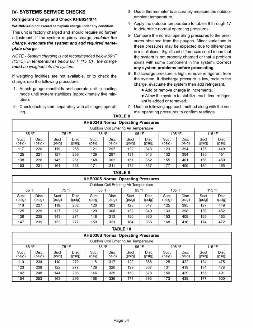
Page 54
IV- SYSTEMS SERVICE CHECKS
Refrigerant Charge and Check KHB024/074
WARNING-Do not exceed nameplate charge under any condition.
This unit is factory charged and should require no further
adjustment. If the system requires charge, reclaim the
charge, evacuate the system and add required name
plate charge.
NOTE - System charging is not recommended below 60�F
(15�C). In temperatures below 60�F (15�C) , the charge
must be weighed into the system.
If weighing facilities are not available, or to check the
charge, use the following procedure:
1- Attach gauge manifolds and operate unit in cooling
mode until system stabilizes (approximately five min
utes).
2- Check each system separately with all stages operat
ing.
3- Use a thermometer to accurately measure the outdoor
ambient temperature.
4- Apply the outdoor temperature to tables 8 through 17
to determine normal operating pressures.
5- Compare the normal operating pressures to the pres
sures obtained from the gauges. Minor variations in
these pressures may be expected due to differences
in installations. Significant differences could mean that
the system is not properly charged or that a problem
exists with some component in the system. Correct
any system problems before proceeding.
6- If discharge pressure is high, remove refrigerant from
the system. If discharge pressure is low, reclaim the
charge, evacuate the system then add refrigerant.
� Add or remove charge in increments.
� Allow the system to stabilize each time refriger
ant is added or removed.
7- Use the following approach method along with the nor
mal operating pressures to confirm readings.TABLE 8
KHB024S Normal Operating Pressures
Outdoor Coil Entering Air Temperature
65 °F 75 °F 85 °F 95 °F 105 °F 115 °FSuct(psig)
Disc(psig)
Suct(psig)
Disc(psig)
Suct(psig)
Disc(psig)
Suct(psig)
Disc(psig)
Suct(psig)
Disc(psig)
Suct(psig)
Disc(psig)
117 220 119 255 121 297 122 343 123 394 125 449
125 221 127 256 129 297 131 343 132 394 135 451
138 226 145 261 148 302 151 352 155 401 156 459
153 231 164 268 171 311 174 357 177 409 180 465
TABLE 9
KHB030S Normal Operating Pressures
Outdoor Coil Entering Air Temperature
65 °F 75 °F 85 °F 95 °F 105 °F 115 °FSuct(psig)
Disc(psig)
Suct(psig)
Disc(psig)
Suct(psig)
Disc(psig)
Suct(psig)
Disc(psig)
Suct(psig)
Disc(psig)
Suct(psig)
Disc(psig)
116 227 118 262 120 303 123 347 125 395 127 449
125 229 127 267 129 308 132 349 133 398 136 452
139 235 143 271 146 313 150 360 153 409 155 463
147 239 153 277 159 321 164 366 168 416 174 472
TABLE 10
KHB036S Normal Operating Pressures
Outdoor Coil Entering Air Temperature
65 °F 75 °F 85 °F 95 °F 105 °F 115 °FSuct(psig)
Disc(psig)
Suct(psig)
Disc(psig)
Suct(psig)
Disc(psig)
Suct(psig)
Disc(psig)
Suct(psig)
Disc(psig)
Suct(psig)
Disc(psig)
110 234 110 272 118 317 122 366 125 422 124 475
123 238 122 277 126 320 129 367 131 419 134 478
142 248 144 286 146 329 150 378 150 429 155 491
154 253 163 295 168 336 171 393 173 439 177 500

Page 55
TABLE 11
KHB048S Normal Operating Pressures
Outdoor Coil Entering Air Temperature
65 °F 75 °F 85 °F 95 °F 105 °F 115 °FSuct(psig)
Disc(psig)
Suct(psig)
Disc(psig)
Suct(psig)
Disc(psig)
Suct(psig)
Disc(psig)
Suct(psig)
Disc(psig)
Suct(psig)
Disc(psig)
112 239 113 277 115 319 117 363 120 411 120 464
119 244 121 282 123 323 126 368 128 416 130 471
140 253 141 291 142 333 144 377 147 426 149 481
158 264 162 301 165 343 167 389 169 439 170 493
TABLE 12
KHB060S Normal Operating Pressures
Outdoor Coil Entering Air Temperature
65 °F 75 °F 85 °F 95 °F 105 °F 115 °FSuct(psig)
Disc(psig)
Suct(psig)
Disc(psig)
Suct(psig)
Disc(psig)
Suct(psig)
Disc(psig)
Suct(psig)
Disc(psig)
Suct(psig)
Disc(psig)
115 246 116 284 118 326 120 372 122 423 124 478
123 250 125 288 127 331 129 377 130 428 133 484
139 259 143 299 146 342 147 388 149 440 153 495
149 266 159 308 163 352 167 400 170 452 173 509
TABLE 13
KHB024H Normal Operating Pressures
Outdoor Coil Entering Air Temperature
65 °F 75 °F 85 °F 95 °F 105 °F 115 °FSuct(psig)
Disc(psig)
Suct(psig)
Disc(psig)
Suct(psig)
Disc(psig)
Suct(psig)
Disc(psig)
Suct(psig)
Disc(psig)
Suct(psig)
Disc(psig)
113 217 114 254 117 295 119 342 121 395 124 455
120 222 125 259 123 304 128 349 130 401 133 459
141 226 143 262 142 303 145 353 148 404 154 465
154 233 162 270 167 312 170 358 171 410 175 466
TABLE 14
KHB036H Normal Operating Pressures
Outdoor Coil Entering Air Temperature
65 °F 75 °F 85 °F 95 °F 105 °F 115 °FSuct(psig)
Disc(psig)
Suct(psig)
Disc(psig)
Suct(psig)
Disc(psig)
Suct(psig)
Disc(psig)
Suct(psig)
Disc(psig)
Suct(psig)
Disc(psig)
113 230 115 268 117 310 119 358 121 412 121 471
121 233 123 273 125 314 128 364 130 417 130 476
142 240 142 278 144 321 146 370 149 425 151 483
157 247 163 286 165 330 168 378 170 431 173 491
TABLE 15
KHB048H Normal Operating Pressures
Outdoor Coil Entering Air Temperature
65 °F 75 °F 85 °F 95 °F 105 °F 115 °FSuct(psig)
Disc(psig)
Suct(psig)
Disc(psig)
Suct(psig)
Disc(psig)
Suct(psig)
Disc(psig)
Suct(psig)
Disc(psig)
Suct(psig)
Disc(psig)
107 234 109 272 110 314 112 363 116 409 117 462
115 242 117 279 119 321 121 366 123 415 123 470
129 247 134 284 137 328 140 375 143 425 144 480
134 251 145 292 154 335 159 382 162 432 164 489
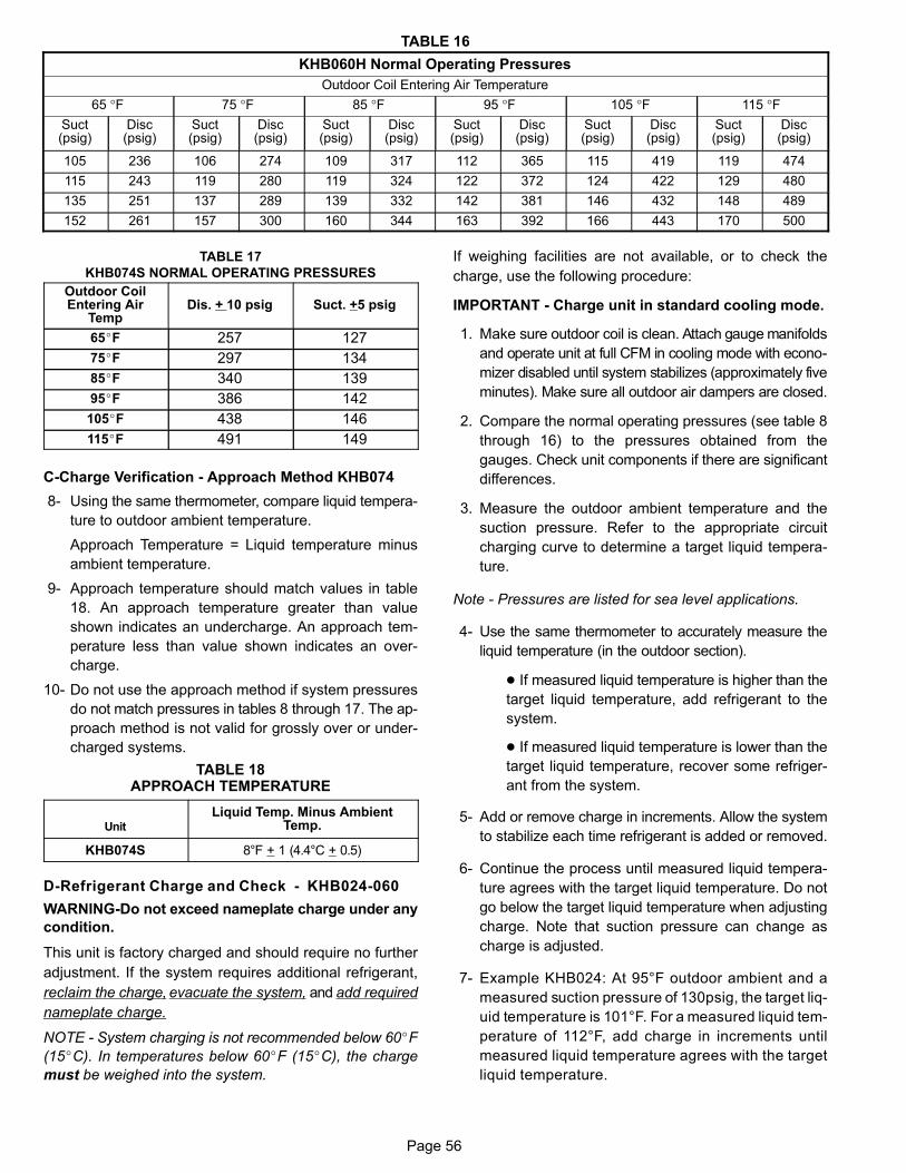
Page 56
TABLE 16
KHB060H Normal Operating Pressures
Outdoor Coil Entering Air Temperature
65 °F 75 °F 85 °F 95 °F 105 °F 115 °FSuct(psig)
Disc(psig)
Suct(psig)
Disc(psig)
Suct(psig)
Disc(psig)
Suct(psig)
Disc(psig)
Suct(psig)
Disc(psig)
Suct(psig)
Disc(psig)
105 236 106 274 109 317 112 365 115 419 119 474
115 243 119 280 119 324 122 372 124 422 129 480
135 251 137 289 139 332 142 381 146 432 148 489
152 261 157 300 160 344 163 392 166 443 170 500
TABLE 17
KHB074S NORMAL OPERATING PRESSURES
Outdoor CoilEntering Air
TempDis. + 10 psig Suct. +5 psig
65�F 257 127
75�F 297 134
85�F 340 139
95�F 386 142
105�F 438 146
115�F 491 149
C-Charge Verification - Approach Method KHB074
8- Using the same thermometer, compare liquid tempera
ture to outdoor ambient temperature.
Approach Temperature = Liquid temperature minus
ambient temperature.
9- Approach temperature should match values in table
18. An approach temperature greater than value
shown indicates an undercharge. An approach tem
perature less than value shown indicates an over
charge.
10- Do not use the approach method if system pressures
do not match pressures in tables 8 through 17. The ap
proach method is not valid for grossly over or under
charged systems.
TABLE 18APPROACH TEMPERATURE
Unit
Liquid Temp. Minus AmbientTemp.
KHB074S 8°F + 1 (4.4°C + 0.5)
D-Refrigerant Charge and Check - KHB024-060
WARNING-Do not exceed nameplate charge under any
condition.
This unit is factory charged and should require no further
adjustment. If the system requires additional refrigerant,
reclaim the charge, evacuate the system, and add required
nameplate charge.
NOTE - System charging is not recommended below 60�F
(15�C). In temperatures below 60�F (15�C), the charge
must be weighed into the system.
If weighing facilities are not available, or to check the
charge, use the following procedure:
IMPORTANT - Charge unit in standard cooling mode.
1. Make sure outdoor coil is clean. Attach gauge manifolds
and operate unit at full CFM in cooling mode with econo
mizer disabled until system stabilizes (approximately five
minutes). Make sure all outdoor air dampers are closed.
2. Compare the normal operating pressures (see table 8
through 16) to the pressures obtained from the
gauges. Check unit components if there are significant
differences.
3. Measure the outdoor ambient temperature and the
suction pressure. Refer to the appropriate circuit
charging curve to determine a target liquid tempera
ture.
Note - Pressures are listed for sea level applications.
4- Use the same thermometer to accurately measure the
liquid temperature (in the outdoor section).
� If measured liquid temperature is higher than the
target liquid temperature, add refrigerant to the
system.
� If measured liquid temperature is lower than the
target liquid temperature, recover some refriger
ant from the system.
5- Add or remove charge in increments. Allow the system
to stabilize each time refrigerant is added or removed.
6- Continue the process until measured liquid tempera
ture agrees with the target liquid temperature. Do not
go below the target liquid temperature when adjusting
charge. Note that suction pressure can change as
charge is adjusted.
7- Example KHB024: At 95°F outdoor ambient and a
measured suction pressure of 130psig, the target liq
uid temperature is 101°F. For a measured liquid tem
perature of 112°F, add charge in increments until
measured liquid temperature agrees with the target
liquid temperature.
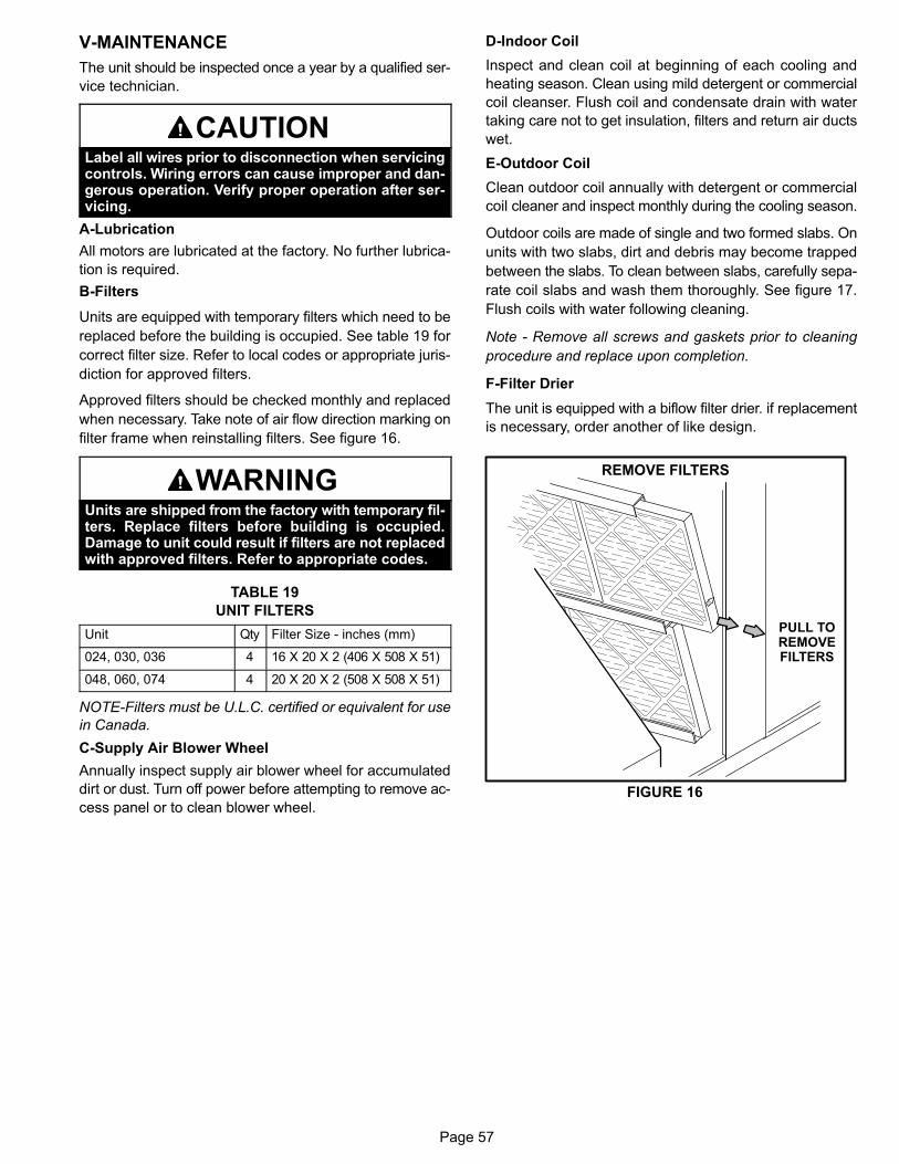
Page 57
V-MAINTENANCE
The unit should be inspected once a year by a qualified ser
vice technician.
CAUTIONLabel all wires prior to disconnection when servicingcontrols. Wiring errors can cause improper and dangerous operation. Verify proper operation after servicing.
A-Lubrication
All motors are lubricated at the factory. No further lubrica
tion is required.
B-Filters
Units are equipped with temporary filters which need to be
replaced before the building is occupied. See table 19 for
correct filter size. Refer to local codes or appropriate juris
diction for approved filters.
Approved filters should be checked monthly and replaced
when necessary. Take note of air flow direction marking on
filter frame when reinstalling filters. See figure 16.
WARNINGUnits are shipped from the factory with temporary filters. Replace filters before building is occupied.Damage to unit could result if filters are not replacedwith approved filters. Refer to appropriate codes.
TABLE 19
UNIT FILTERS
Unit Qty Filter Size - inches (mm)
024, 030, 036 4 16 X 20 X 2 (406 X 508 X 51)
048, 060, 074 4 20 X 20 X 2 (508 X 508 X 51)
NOTE-Filters must be U.L.C. certified or equivalent for use
in Canada.
C-Supply Air Blower Wheel
Annually inspect supply air blower wheel for accumulated
dirt or dust. Turn off power before attempting to remove ac
cess panel or to clean blower wheel.
D-Indoor Coil
Inspect and clean coil at beginning of each cooling and
heating season. Clean using mild detergent or commercial
coil cleanser. Flush coil and condensate drain with water
taking care not to get insulation, filters and return air ducts
wet.
E-Outdoor Coil
Clean outdoor coil annually with detergent or commercial
coil cleaner and inspect monthly during the cooling season.
Outdoor coils are made of single and two formed slabs. On
units with two slabs, dirt and debris may become trapped
between the slabs. To clean between slabs, carefully sepa
rate coil slabs and wash them thoroughly. See figure 17.
Flush coils with water following cleaning.
Note - Remove all screws and gaskets prior to cleaning
procedure and replace upon completion.
F-Filter Drier
The unit is equipped with a biflow filter drier. if replacement
is necessary, order another of like design.
FIGURE 16
REMOVE FILTERS
PULL TOREMOVEFILTERS
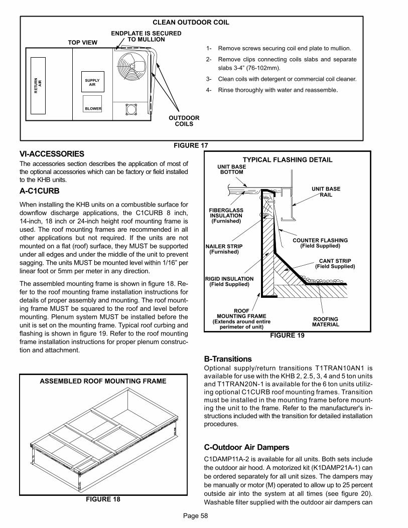
Page 58
TOP VIEW
OUTDOORCOILS
BLOWER
FIGURE 17
ENDPLATE IS SECUREDTO MULLION
1- Remove screws securing coil end plate to mullion.
2- Remove clips connecting coils slabs and separate
slabs 3-4” (76-102mm).
3- Clean coils with detergent or commercial coil cleaner.
4- Rinse thoroughly with water and reassemble.
CLEAN OUTDOOR COIL
SUPPLYAIR
VI-ACCESSORIESThe accessories section describes the application of most of
the optional accessories which can be factory or field installed
to the KHB units.
A-C1CURB
When installing the KHB units on a combustible surface for
downflow discharge applications, the C1CURB 8 inch,
14‐inch, 18 inch or 24‐inch height roof mounting frame is
used. The roof mounting frames are recommended in all
other applications but not required. If the units are not
mounted on a flat (roof) surface, they MUST be supported
under all edges and under the middle of the unit to prevent
sagging. The units MUST be mounted level within 1/16” per
linear foot or 5mm per meter in any direction.
The assembled mounting frame is shown in figure 18. Re
fer to the roof mounting frame installation instructions for
details of proper assembly and mounting. The roof mount
ing frame MUST be squared to the roof and level before
mounting. Plenum system MUST be installed before the
unit is set on the mounting frame. Typical roof curbing and
flashing is shown in figure 19. Refer to the roof mounting
frame installation instructions for proper plenum construc
tion and attachment.
FIGURE 18
ASSEMBLED ROOF MOUNTING FRAME
FIGURE 19
ROOFMOUNTING FRAME
(Extends around entireperimeter of unit)
FIBERGLASSINSULATION(Furnished)
COUNTER FLASHING(Field Supplied)
UNIT BASEBOTTOM
RIGID INSULATION(Field Supplied)
ROOFINGMATERIAL
CANT STRIP(Field Supplied)
NAILER STRIP(Furnished)
UNIT BASERAIL
TYPICAL FLASHING DETAIL
B-TransitionsOptional supply/return transitions T1TRAN10AN1 is
available for use with the KHB 2, 2.5, 3, 4 and 5 ton units
and T1TRAN20N-1 is available for the 6 ton units utiliz
ing optional C1CURB roof mounting frames. Transition
must be installed in the mounting frame before mount
ing the unit to the frame. Refer to the manufacturer's in
structions included with the transition for detailed installation
procedures.
C-Outdoor Air Dampers
C1DAMP11A-2 is available for all units. Both sets include
the outdoor air hood. A motorized kit (K1DAMP21A-1) can
be ordered separately for all unit sizes. The dampers may
be manually or motor (M) operated to allow up to 25 percent
outside air into the system at all times (see figure 20).
Washable filter supplied with the outdoor air dampers can
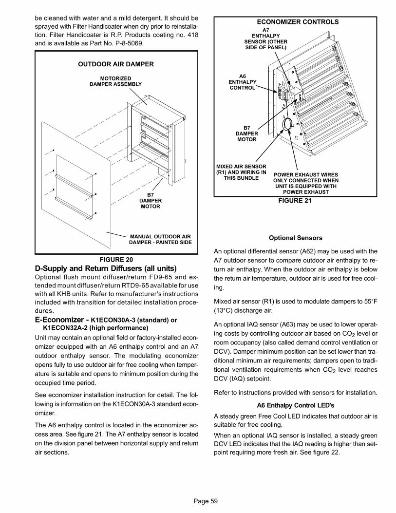
Page 59
be cleaned with water and a mild detergent. It should be
sprayed with Filter Handicoater when dry prior to reinstalla
tion. Filter Handicoater is R.P. Products coating no. 418
and is available as Part No. P-8-5069.
FIGURE 20
MOTORIZEDDAMPER ASSEMBLY
MANUAL OUTDOOR AIRDAMPER - PAINTED SIDE
B7DAMPERMOTOR
OUTDOOR AIR DAMPER
D-Supply and Return Diffusers (all units)Optional flush mount diffuser/return FD9-65 and ex
tended mount diffuser/return RTD9-65 available for use
with all KHB units. Refer to manufacturer's instructions
included with transition for detailed installation proce
dures.
E-Economizer - K1ECON30A-3 (standard) or
K1ECON32A-2 (high performance)
Unit may contain an optional field or factory-installed econ
omizer equipped with an A6 enthalpy control and an A7
outdoor enthalpy sensor. The modulating economizer
opens fully to use outdoor air for free cooling when temper
ature is suitable and opens to minimum position during the
occupied time period.
See economizer installation instruction for detail. The fol
lowing is information on the K1ECON30A-3 standard econ
omizer.
The A6 enthalpy control is located in the economizer ac
cess area. See figure 21. The A7 enthalpy sensor is located
on the division panel between horizontal supply and return
air sections.
FIGURE 21
ECONOMIZER CONTROLS
A6ENTHALPYCONTROL
B7DAMPERMOTOR
A7ENTHALPY
SENSOR (OTHERSIDE OF PANEL)
POWER EXHAUST WIRESONLY CONNECTED WHENUNIT IS EQUIPPED WITH
POWER EXHAUST
MIXED AIR SENSOR(R1) AND WIRING IN
THIS BUNDLE
Optional Sensors
An optional differential sensor (A62) may be used with the
A7 outdoor sensor to compare outdoor air enthalpy to re
turn air enthalpy. When the outdoor air enthalpy is below
the return air temperature, outdoor air is used for free cool
ing.
Mixed air sensor (R1) is used to modulate dampers to 55°F
(13°C) discharge air.
An optional IAQ sensor (A63) may be used to lower operat
ing costs by controlling outdoor air based on CO2 level or
room occupancy (also called demand control ventilation or
DCV). Damper minimum position can be set lower than tra
ditional minimum air requirements; dampers open to tradi
tional ventilation requirements when CO2 level reaches
DCV (IAQ) setpoint.
Refer to instructions provided with sensors for installation.
A6 Enthalpy Control LED's
A steady green Free Cool LED indicates that outdoor air is
suitable for free cooling.
When an optional IAQ sensor is installed, a steady green
DCV LED indicates that the IAQ reading is higher than set
point requiring more fresh air. See figure 22.
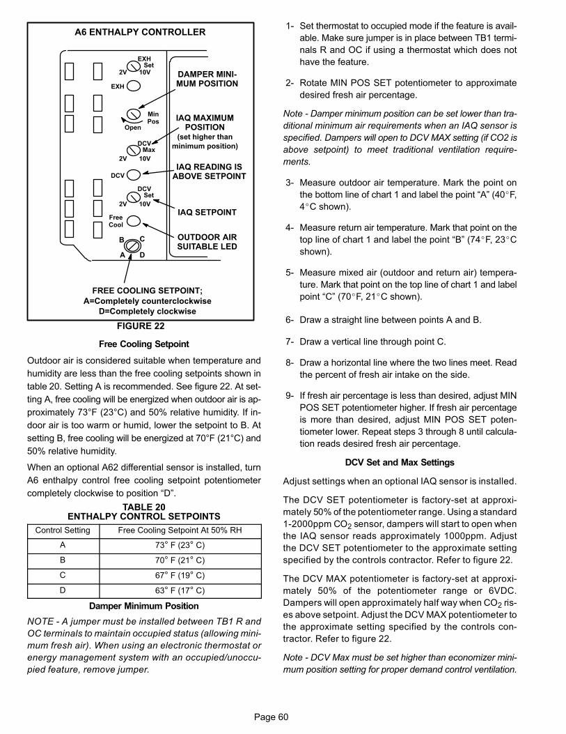
Page 60
FIGURE 22
A6 ENTHALPY CONTROLLER
A
B C
D
Open
MinPos
FREE COOLING SETPOINT;
A=Completely counterclockwise
D=Completely clockwise
OUTDOOR AIRSUITABLE LED
FreeCool
DCV
EXH
EXHSet
2V 10V
DCVMax
2V 10V
DCVSet
2V 10V
IAQ SETPOINT
IAQ READING ISABOVE SETPOINT
DAMPER MINIMUM POSITION
IAQ MAXIMUMPOSITION
(set higher than
minimum position)
Free Cooling Setpoint
Outdoor air is considered suitable when temperature and
humidity are less than the free cooling setpoints shown in
table 20. Setting A is recommended. See figure 22. At set
ting A, free cooling will be energized when outdoor air is ap
proximately 73°F (23°C) and 50% relative humidity. If in
door air is too warm or humid, lower the setpoint to B. At
setting B, free cooling will be energized at 70°F (21°C) and
50% relative humidity.
When an optional A62 differential sensor is installed, turn
A6 enthalpy control free cooling setpoint potentiometer
completely clockwise to position “D”.
TABLE 20ENTHALPY CONTROL SETPOINTS
Control Setting Free Cooling Setpoint At 50% RH
A 73° F (23° C)
B 70° F (21° C)
C 67° F (19° C)
D 63° F (17° C)
Damper Minimum Position
NOTE - A jumper must be installed between TB1 R and
OC terminals to maintain occupied status (allowing mini
mum fresh air). When using an electronic thermostat or
energy management system with an occupied/unoccu
pied feature, remove jumper.
1- Set thermostat to occupied mode if the feature is avail
able. Make sure jumper is in place between TB1 termi
nals R and OC if using a thermostat which does not
have the feature.
2- Rotate MIN POS SET potentiometer to approximate
desired fresh air percentage.
Note - Damper minimum position can be set lower than tra
ditional minimum air requirements when an IAQ sensor is
specified. Dampers will open to DCV MAX setting (if CO2 is
above setpoint) to meet traditional ventilation require
ments.
3- Measure outdoor air temperature. Mark the point on
the bottom line of chart 1 and label the point “A” (40�F,
4�C shown).
4- Measure return air temperature. Mark that point on the
top line of chart 1 and label the point “B” (74�F, 23�C
shown).
5- Measure mixed air (outdoor and return air) tempera
ture. Mark that point on the top line of chart 1 and label
point “C” (70�F, 21�C shown).
6- Draw a straight line between points A and B.
7- Draw a vertical line through point C.
8- Draw a horizontal line where the two lines meet. Read
the percent of fresh air intake on the side.
9- If fresh air percentage is less than desired, adjust MIN
POS SET potentiometer higher. If fresh air percentage
is more than desired, adjust MIN POS SET poten
tiometer lower. Repeat steps 3 through 8 until calcula
tion reads desired fresh air percentage.
DCV Set and Max Settings
Adjust settings when an optional IAQ sensor is installed.
The DCV SET potentiometer is factory-set at approxi
mately 50% of the potentiometer range. Using a standard
1-2000ppm CO2 sensor, dampers will start to open when
the IAQ sensor reads approximately 1000ppm. Adjust
the DCV SET potentiometer to the approximate setting
specified by the controls contractor. Refer to figure 22.
The DCV MAX potentiometer is factory-set at approxi
mately 50% of the potentiometer range or 6VDC.
Dampers will open approximately half way when CO2 ris
es above setpoint. Adjust the DCV MAX potentiometer to
the approximate setting specified by the controls con
tractor. Refer to figure 22.
Note - DCV Max must be set higher than economizer mini
mum position setting for proper demand control ventilation.
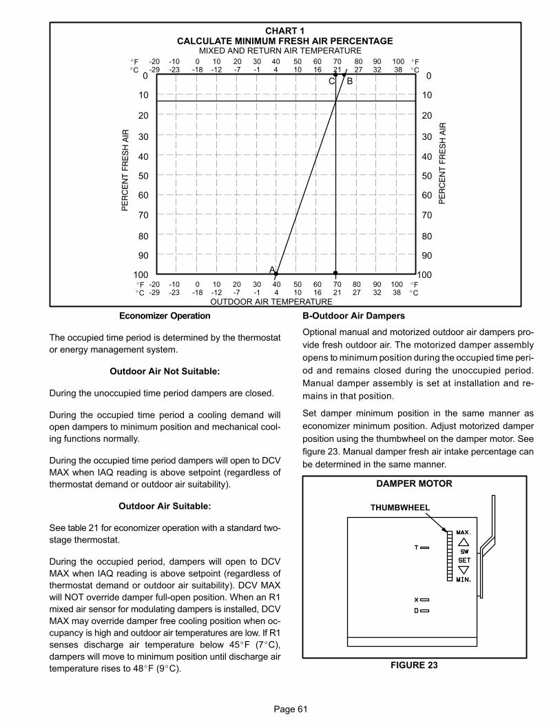
Page 61
-20-29
-10-23
0-18
10-12
20-7
30-1
404
5010
6016
7021
8027
9032
10038
0
10
30
40
50
60
70
80
90
100
20
OUTDOOR AIR TEMPERATURE
0
10
30
40
50
60
70
80
90
100
20
MIXED AND RETURN AIR TEMPERATURE
CHART 1CALCULATE MINIMUM FRESH AIR PERCENTAGE
A
BC
�F�C
�F�C
-20-29
-10-23
0-18
10-12
20-7
30-1
404
5010
6016
7021
8027
9032
10038
�F�C
�F�C
Economizer Operation
The occupied time period is determined by the thermostat
or energy management system.
Outdoor Air Not Suitable:
During the unoccupied time period dampers are closed.
During the occupied time period a cooling demand will
open dampers to minimum position and mechanical cool
ing functions normally.
During the occupied time period dampers will open to DCV
MAX when IAQ reading is above setpoint (regardless of
thermostat demand or outdoor air suitability).
Outdoor Air Suitable:
See table 21 for economizer operation with a standard two-
stage thermostat.
During the occupied period, dampers will open to DCV
MAX when IAQ reading is above setpoint (regardless of
thermostat demand or outdoor air suitability). DCV MAX
will NOT override damper full-open position. When an R1
mixed air sensor for modulating dampers is installed, DCV
MAX may override damper free cooling position when oc
cupancy is high and outdoor air temperatures are low. If R1
senses discharge air temperature below 45�F (7�C),
dampers will move to minimum position until discharge air
temperature rises to 48�F (9�C).
B-Outdoor Air Dampers
Optional manual and motorized outdoor air dampers pro
vide fresh outdoor air. The motorized damper assembly
opens to minimum position during the occupied time peri
od and remains closed during the unoccupied period.
Manual damper assembly is set at installation and re
mains in that position.
Set damper minimum position in the same manner as
economizer minimum position. Adjust motorized damper
position using the thumbwheel on the damper motor. See
figure 23. Manual damper fresh air intake percentage can
be determined in the same manner.
FIGURE 23
DAMPER MOTOR
THUMBWHEEL
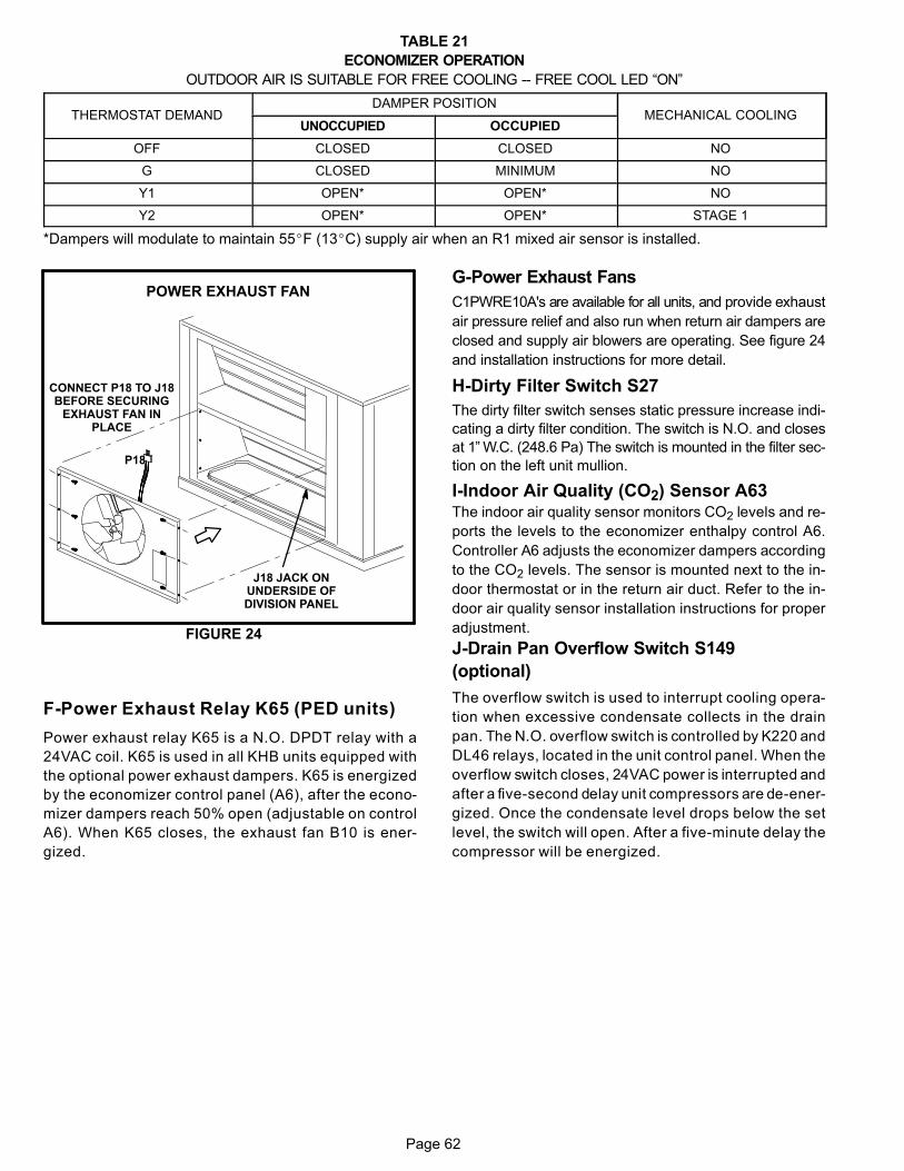
Page 62
TABLE 21
ECONOMIZER OPERATION
OUTDOOR AIR IS SUITABLE FOR FREE COOLING -- FREE COOL LED “ON”
ÁÁÁÁÁÁÁÁÁÁÁÁÁÁÁÁÁÁÁÁÁÁÁÁÁÁÁÁÁÁÁÁÁ
THERMOSTAT DEMANDÁÁÁÁÁÁÁÁÁÁÁÁÁÁÁÁÁÁÁÁÁÁÁÁÁÁÁÁÁÁÁÁÁÁ
DAMPER POSITION ÁÁÁÁÁÁÁÁÁÁÁÁÁÁÁÁÁÁÁÁÁÁÁÁÁÁÁÁÁÁ
MECHANICAL COOLING
ÁÁÁÁÁÁÁÁÁÁÁÁÁÁÁÁÁÁ
UNOCCUPIED ÁÁÁÁÁÁÁÁÁÁÁÁÁÁÁÁÁÁ
OCCUPIED
ÁÁÁÁÁÁÁÁÁÁÁÁÁÁÁÁÁÁÁÁÁÁ
OFF ÁÁÁÁÁÁÁÁÁÁÁÁÁÁÁÁÁÁ
CLOSED ÁÁÁÁÁÁÁÁÁÁÁÁÁÁÁÁÁÁ
CLOSED ÁÁÁÁÁÁÁÁÁÁÁÁÁÁÁÁÁÁÁÁ
NO
ÁÁÁÁÁÁÁÁÁÁÁÁÁÁÁÁÁÁÁÁÁÁ
G ÁÁÁÁÁÁÁÁÁÁÁÁÁÁÁÁÁÁ
CLOSED ÁÁÁÁÁÁÁÁÁÁÁÁÁÁÁÁÁÁ
MINIMUM ÁÁÁÁÁÁÁÁÁÁÁÁÁÁÁÁÁÁÁÁ
NO
ÁÁÁÁÁÁÁÁÁÁÁÁÁÁÁÁÁÁÁÁÁÁ
Y1 ÁÁÁÁÁÁÁÁÁÁÁÁÁÁÁÁÁÁ
OPEN* ÁÁÁÁÁÁÁÁÁÁÁÁÁÁÁÁÁÁ
OPEN* ÁÁÁÁÁÁÁÁÁÁÁÁÁÁÁÁÁÁÁÁ
NO
ÁÁÁÁÁÁÁÁÁÁÁÁÁÁÁÁÁÁÁÁÁÁ
Y2 ÁÁÁÁÁÁÁÁÁÁÁÁÁÁÁÁÁÁ
OPEN* ÁÁÁÁÁÁÁÁÁÁÁÁÁÁÁÁÁÁ
OPEN* ÁÁÁÁÁÁÁÁÁÁÁÁÁÁÁÁÁÁÁÁ
STAGE 1
*Dampers will modulate to maintain 55�F (13�C) supply air when an R1 mixed air sensor is installed.
FIGURE 24
POWER EXHAUST FAN
P18
J18 JACK ONUNDERSIDE OFDIVISION PANEL
CONNECT P18 TO J18BEFORE SECURING
EXHAUST FAN INPLACE
F-Power Exhaust Relay K65 (PED units)
Power exhaust relay K65 is a N.O. DPDT relay with a
24VAC coil. K65 is used in all KHB units equipped with
the optional power exhaust dampers. K65 is energized
by the economizer control panel (A6), after the econo
mizer dampers reach 50% open (adjustable on control
A6). When K65 closes, the exhaust fan B10 is ener
gized.
G-Power Exhaust Fans
C1PWRE10A's are available for all units, and provide exhaust
air pressure relief and also run when return air dampers are
closed and supply air blowers are operating. See figure 24
and installation instructions for more detail.
H-Dirty Filter Switch S27
The dirty filter switch senses static pressure increase indi
cating a dirty filter condition. The switch is N.O. and closes
at 1” W.C. (248.6 Pa) The switch is mounted in the filter sec
tion on the left unit mullion.
I-Indoor Air Quality (CO2) Sensor A63The indoor air quality sensor monitors CO2 levels and re
ports the levels to the economizer enthalpy control A6.
Controller A6 adjusts the economizer dampers according
to the CO2 levels. The sensor is mounted next to the in
door thermostat or in the return air duct. Refer to the in
door air quality sensor installation instructions for proper
adjustment.
J-Drain Pan Overflow Switch S149
(optional)
The overflow switch is used to interrupt cooling opera
tion when excessive condensate collects in the drain
pan. The N.O. overflow switch is controlled by K220 and
DL46 relays, located in the unit control panel. When the
overflow switch closes, 24VAC power is interrupted and
after a five-second delay unit compressors are de-ener
gized. Once the condensate level drops below the set
level, the switch will open. After a five-minute delay the
compressor will be energized.
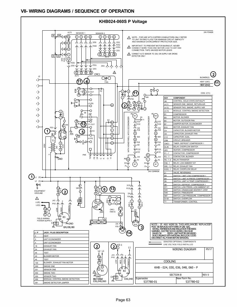
Page 63
VII- WIRING DIAGRAMS / SEQUENCE OF OPERATION
KHB024-060S P Voltage
1
2
3
11
6
4
51
2
2 2
2
1111
12
13
14
COOLING
REV 0
L2(S)
L1(R)
24V COMMON
COOL 1(Y1)
HEAT 1(W1)
BLOWER(G)
24V POWER
(S)
(R)L1
L2
HR1
24V
GND
240V
C
024, 030, 060
K3-1L1
L1L2
HEAT 2(W2)
GND
T1
GND
K1-1
L2
CK3-1
L2
X
B3
C4
GND
B1
S11
B4
C12
K3-1
L2
C
B3B3
NOTE - IF ANY WIRE IN THIS APPLIANCEIS REPLACEDITMUST BE REPLACED WITH WIRE OF LIKE SIZE, RATING, TERMINATION AND INSULATION THICKNESSWARNING - ELECTRIC SHOCK HAZARD, CAN CAUSE INJURY OR DEATH . UNIT MUST BE GROUNDED IN ACCORDANCE WITH NATIONAL AND LOCAL CODESDISCONNECT ALL POWER BEFORE SERVICING.
K1-1
L2
C
C4036,048BELT DRIVE
036,048,060
CB8
DF
J353
4
CMC1
K1B
AK8-1
K3
A
B
K8
A
B
K8-2
S4
K58 A
B
S87
L1
CMC1
FAN K1
K58-1
7
2
S49
S3
DL46
K220
A
B
S149
K220-1
2
7
K220-1
P35
S6
J255
J35
P35
A173
P255P255
J250 J252
A171
J251
A171
J251
P250
P251
P252
P253
J255
J261
CONNECT A172 SENSOR TO J261 ON SUPPLY AIR SMOKE
DETECTOR ONLY
C6
J132
P132
K65-2
9
6
K65-1
7
4
B10
J24
P24
KEY COMPONENT
A6 CONTROL, SOLID STATE ENTHALPY
A171 SENSOR ONE, SMOKE, RETURN AIR
A172 SENSOR TWO, SMOKE, SUPPLY AIR
A173 MODULE, CONTROL SMOKE DETECTION
B1 COMPRESSOR
B3 MOTOR, BLOWER
B4 MOTOR, OUTDOOR FAN
B10 MOTOR, EXHAUST FAN
C4 CAPACITOR, BLOWER MOTOR
C6 CAPACITOR, EXHAUST FAN
CB8 CIRCUIT, BREAKER
DL46 DELAY, OVERFLOW SWITCH
HR1 HEATER, COMPRESSOR
K1,−1 CONTACTOR, COMPRESSOR
K3, −1 CONTACTOR, BLOWER
K65,−1,2 RELAY, EXHAUST FAN
K220,−1 RELAY, OVERFLOW DELAY
S3 SWITCH, LIMIT LOW COMPRESSOR 1
S4 SWITCH, LIMIT HI PRESS COMPRESSOR 1
S11 SWITCH, LOW PRESS, LOW AMBIENT KIT
S49 SWITCH, FREEZESTAT
S149 SWITCH, OVERFLOW
B7 DAMPER MOTOR, ECONOMIZER
CMC1 TIMER, DEFROST COMPRESSOR 1
K8,−1−2 RELAY,TRANSFER
L1 VALVE, REVERSING
S6 SWITCH, DEFROST, COMPRESSOR 1
S87 SWITCH, LOW PRESSURE, COMPRESSOR 1
K58,−1 RELAY, LOW AMBIENT KIT
2 HEAT
3 UNIT ECONOMIZER
18 EXHAUST FAN
35 TEST
43 BLOWER MOTOR
132 BLOWER , EXHAUST FAN MOTOR
250 SMOKE ONE
251 SENSOR ONE
252 SMOKE TWO
253 SENSOR TWO
24 EXHAUST FAN
255 MODULE, CONTROL SMOKE DETECTION
261 SMOKE DETECTOR JUMPER
J / P JACK / PLUG DESCRIPTION
4 UNIT ECONOMIZER
TEST 45
P4
J3
CA6
B7
J10
P3
P132
J132
P18
J18
J18P18
ACT
COM
J132
P132
EXH1
A6
WIT
H H
ON
EY
WE
LL W
7220
EC
ON
OM
IZE
R
WIT
H H
ON
EY
WE
LL W
7212
EC
ON
OM
IZE
R
P4
J3
TR1A6
B7
J10
P3
P132
J132
P18
J18
J18P18
J132
P132
EF1
A6
P4
K65
A
B
K65
A
B
96 96
9595
S5
S5 SWITCH, LIMIT HI TEMP COMPRESSOR 1
C12 CAPACITOR, DUAL
T1 TRANSFORMER, CONTROL
S40 SWITCH, CRANKCASE HEATER T−STAT
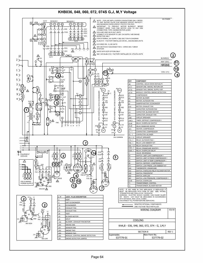
Page 64
KHB036, 048, 060, 072, 074S G,J, M,Y Voltage
1
2
3
11
6
7
4
5
8
9 10
2
2
2
7
11
12
13
14
15
New Form No.Supersedes
WIRING DIAGRAM
KHA,B - 036, 048, 060, 072, 074 - G, J,M,Y
03/18
COOLING
SECTION B REV 1
537779-01 537779-02
24V COMMON
COOL 1(Y1)
HEAT 1(W1)
BLOWER(G)
24V POWER
24V
C
J2
2
7
1
6
5
3
4
8
9
1
HEAT 2(W2)
GND
S3
CB8
DEF
J353
CMC1
K1
B
A
S49
K8-1
K3
A
B
K8
A
BK8-2
K58
A
B
L1
L2
L1
L1
L2
K3-1
L1X
GND
K3-1
L2
X
GND
C4
060 LOW
060 HIGH
T4
B1
L1 L2 L3
T1 T2 T3
K1-1
B3
L1 L2
T1 T2
K3-1
L1 L2 L3
T1 T2 T3
K1-1
S42
3
B3
LO
W HIG
H
CO
M
ORG
K3-1 L1
X
C4
BELT DRIVE
B3
LO
W
CO
MM
ON
ORAN
GE
K10
A
B
S11
S42,N ARE USED ON M VOLT UNITS
L3
K58-1
7
2
DL46
K220A
B
S149
K220-1
2
7
32
1
B4
K10-1
7
5
C1
C4
J35
P35
A173
P255
P255
J250 J252
A171
J251
A172
J253
P251
P252
P253
J255
J261
L3
J132
P132
K65−2
9
6
K65−1
7
4
B10
J24
P24
KEY COMPONENT
A6 CONTROL, SOLID STATE ENTHALPY
A171 SENSOR ONE, SMOKE, RETURN AIR
A172 SENSOR TWO, SMOKE, SUPPLY AIR
A173 MODULE, CONTROL SMOKE DETECTION
B1 COMPRESSOR
B3 MOTOR, BLOWER
B4 MOTOR, OUTDOOR FAN
B10 MOTOR, EXHAUST FAN
C1 CAPACITOR, OUTDOOR FAN
C4 CAPACITOR, BLOWER MOTOR
C6 CAPACITOR, EXHAUST FAN
CB8 CIRCUIT, BREAKER
DL46 DELAY, OVERFLOW SWITCH
HR1 HEATER, COMPRESSOR
K1,−1 CONTACTOR, COMPRESSOR
K3, −1 CONTACTOR, BLOWER
K10,−1 RELAY, OUTDOOR FAN 1
K65,−1,2 RELAY, EXHAUST FAN
K220,−1 RELAY, OVERFLOW DELAY
S3 SWITCH, LIMIT LOW COMPRESSOR 1
S4 SWITCH, LIMIT HI PRESS COMPRESSOR 1
S5 SWITCH, LIMIT HI TEMP COMPRESSOR 1
S11 SWITCH, LOW PRESS, LOW AMBIENT KIT
S40 THERMOSTAT, CRANKCASE
S42 SWITCH, OVERLOAD RELAY BLOWER MOTOR
S49 SWITCH, FREEZESTAT
S149 SWITCH, OVERFLOW
T1 TRANSFORMER, CONTROL
B7 DAMPER MOTOR, ECONOMIZER
CMC1 TIMER, DEFROST COMPRESSOR 1
K8,−1−2 CIRCUIT, BREAKER
L1 VALVE, REVERSING
S6 SWITCH, DEFROST, COMPRESSOR 1
S87 SWITCH, LOW PRESSURE, COMPRESSOR 1
K58,−1 RELAY, LOW AMBIENT KIT
2 HEAT
3 UNIT ECONOMIZER
18 EXHAUST FAN
35 TEST
43 BLOWER MOTOR
132 BLOWER , EXHAUST FAN MOTOR
250 SMOKE ONE
251 SENSOR ONE
252 SMOKE TWO
253 SENSOR TWO
24 EXHAUST FAN
255 MODULE, CONTROL SMOKE DETECTION
261 SMOKE DETECTOR JUMPER
J / P JACK / PLUG DESCRIPTION
INPUT 45
T4 TRANSFORMER, BLOWER MOTOR
P4
J3
CA6
B7
J10
P3
P132
J132
P18
J18
K65
A
B
J181P18
ACT
COM
J132
P132
EXH1
A6
WIT
H H
ON
EY
WE
LL W
7220
EC
ON
OM
IZE
R
WIT
H H
ON
EY
WE
LL W
7212
EC
ON
OM
IZE
R
P4
J3
TR1A6
B7
J10
P3
P132
J132
P18
J18
K65
A
B
J181P18
J132
P132
EF1
A6
P4
96 96
9595
K191
A
B
DL48
N
DL48
S5
K191-1
9
3
K191,−1
DL48 DELAY,CRANKCASE HEATER
RELAY, CRANKCASE HEATER 1
S11
K58-1
CMC1
FAN K1
10 ECONOMIZER
S52
S52 SWITCH, AIRFLOW
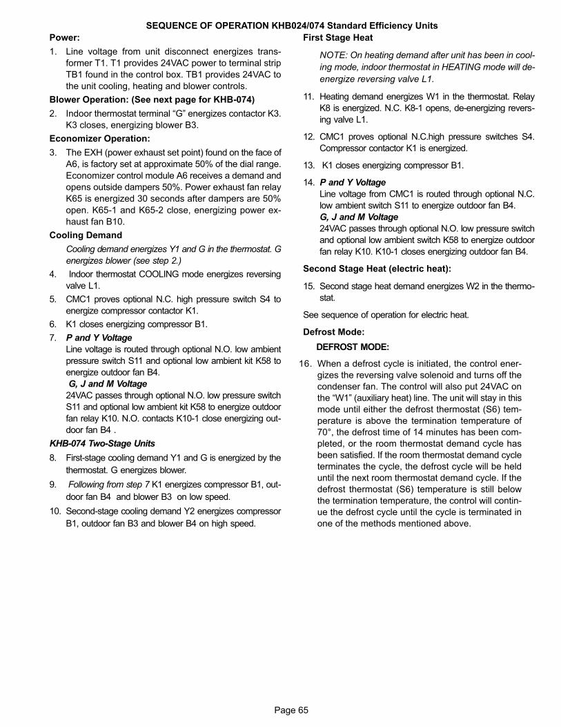
Page 65
SEQUENCE OF OPERATION KHB024/074 Standard Efficiency Units
Power:
1. Line voltage from unit disconnect energizes trans
former T1. T1 provides 24VAC power to terminal strip
TB1 found in the control box. TB1 provides 24VAC to
the unit cooling, heating and blower controls.
Blower Operation: (See next page for KHB-074)
2. Indoor thermostat terminal “G” energizes contactor K3.
K3 closes, energizing blower B3.
Economizer Operation:
3. The EXH (power exhaust set point) found on the face of
A6, is factory set at approximate 50% of the dial range.
Economizer control module A6 receives a demand and
opens outside dampers 50%. Power exhaust fan relay
K65 is energized 30 seconds after dampers are 50%
open. K65-1 and K65-2 close, energizing power ex
haust fan B10.
Cooling Demand
Cooling demand energizes Y1 and G in the thermostat. G
energizes blower (see step 2.)
4. Indoor thermostat COOLING mode energizes reversing
valve L1.
5. CMC1 proves optional N.C. high pressure switch S4 to
energize compressor contactor K1.
6. K1 closes energizing compressor B1.
7. P and Y Voltage
Line voltage is routed through optional N.O. low ambient
pressure switch S11 and optional low ambient kit K58 to
energize outdoor fan B4.
G, J and M Voltage
24VAC passes through optional N.O. low pressure switch
S11 and optional low ambient kit K58 to energize outdoor
fan relay K10. N.O. contacts K10-1 close energizing out
door fan B4 .
KHB-074 Two-Stage Units
8. First-stage cooling demand Y1 and G is energized by the
thermostat. G energizes blower.
9. Following from step 7 K1 energizes compressor B1, out
door fan B4 and blower B3 on low speed.
10. Second-stage cooling demand Y2 energizes compressor
B1, outdoor fan B3 and blower B4 on high speed.
First Stage Heat
NOTE: On heating demand after unit has been in cool
ing mode, indoor thermostat in HEATING mode will de-
energize reversing valve L1.
11. Heating demand energizes W1 in the thermostat. Relay
K8 is energized. N.C. K8-1 opens, de-energizing revers
ing valve L1.
12. CMC1 proves optional N.C.high pressure switches S4.
Compressor contactor K1 is energized.
13. K1 closes energizing compressor B1.
14. P and Y Voltage
Line voltage from CMC1 is routed through optional N.C.
low ambient switch S11 to energize outdoor fan B4.
G, J and M Voltage
24VAC passes through optional N.O. low pressure switch
and optional low ambient switch K58 to energize outdoor
fan relay K10. K10-1 closes energizing outdoor fan B4.
Second Stage Heat (electric heat):
15. Second stage heat demand energizes W2 in the thermo
stat.
See sequence of operation for electric heat.
Defrost Mode:
DEFROST MODE:
16. When a defrost cycle is initiated, the control ener
gizes the reversing valve solenoid and turns off the
condenser fan. The control will also put 24VAC on
the “W1” (auxiliary heat) line. The unit will stay in this
mode until either the defrost thermostat (S6) tem
perature is above the termination temperature of
70°, the defrost time of 14 minutes has been com
pleted, or the room thermostat demand cycle has
been satisfied. If the room thermostat demand cycle
terminates the cycle, the defrost cycle will be held
until the next room thermostat demand cycle. If the
defrost thermostat (S6) temperature is still below
the termination temperature, the control will contin
ue the defrost cycle until the cycle is terminated in
one of the methods mentioned above.
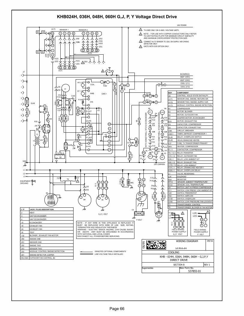
Page 66
KHB024H, 036H, 048H, 060H G,J, P, Y Voltage Direct Drive
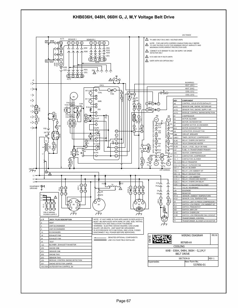
Page 67
KHB036H, 048H, 060H G, J, M,Y Voltage Belt Drive
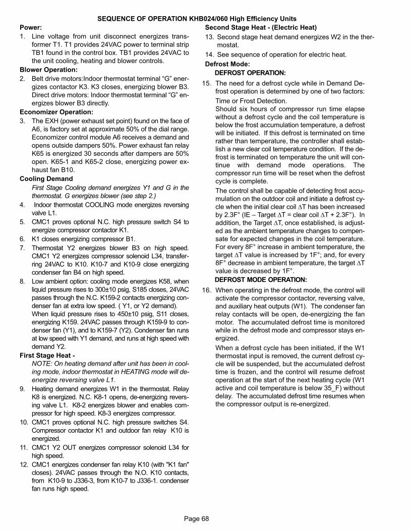
Page 68
SEQUENCE OF OPERATION KHB024/060 High Efficiency Units
Power:
1. Line voltage from unit disconnect energizes trans
former T1. T1 provides 24VAC power to terminal strip
TB1 found in the control box. TB1 provides 24VAC to
the unit cooling, heating and blower controls.
Blower Operation:
2. Belt drive motors:Indoor thermostat terminal “G” ener
gizes contactor K3. K3 closes, energizing blower B3.
Direct drive motors: Indoor thermostat terminal “G” en
ergizes blower B3 directly.
Economizer Operation:
3. The EXH (power exhaust set point) found on the face of
A6, is factory set at approximate 50% of the dial range.
Economizer control module A6 receives a demand and
opens outside dampers 50%. Power exhaust fan relay
K65 is energized 30 seconds after dampers are 50%
open. K65-1 and K65-2 close, energizing power ex
haust fan B10.
Cooling Demand
First Stage Cooling demand energizes Y1 and G in the
thermostat. G energizes blower (see step 2.)
4. Indoor thermostat COOLING mode energizes reversing
valve L1.
5. CMC1 proves optional N.C. high pressure switch S4 to
energize compressor contactor K1.
6. K1 closes energizing compressor B1.
7. Thermostat Y2 energizes blower B3 on high speed.
CMC1 Y2 energizes compressor solenoid L34, transfer
ring 24VAC to K10. K10-7 and K10-9 close energizing
condenser fan B4 on high speed.
8. Low ambient option: cooling mode energizes K58, when
liquid pressure rises to 300±10 psig, S185 closes, 24VAC
passes through the N.C. K159-2 contacts energizing con
denser fan at extra low speed. ( Y1, or Y2 demand).
When liquid pressure rises to 450±10 psig, S11 closes,
energizing K159. 24VAC passes through K159-9 to con
denser fan (Y1), and to K159-7 (Y2). Condenser fan runs
at low speed with Y1 demand, and runs at high speed with
demand Y2.
First Stage Heat -
NOTE: On heating demand after unit has been in cool
ing mode, indoor thermostat in HEATING mode will de-
energize reversing valve L1.
9. Heating demand energizes W1 in the thermostat. Relay
K8 is energized. N.C. K8-1 opens, de-energizing revers
ing valve L1. K8-2 energizes blower and enables com
pressor for high speed. K8-3 energizes compressor.
10. CMC1 proves optional N.C. high pressure switches S4.
Compressor contactor K1 and outdoor fan relay K10 is
energized.
11. CMC1 Y2 OUT energizes compressor solenoid L34 for
high speed.
12. CMC1 energizes condenser fan relay K10 (with "K1 fan"
closes). 24VAC passes through the N.O. K10 contacts,
from K10-9 to J336-3, from K10-7 to J336-1. condenser
fan runs high speed.
Second Stage Heat - (Electric Heat)
13. Second stage heat demand energizes W2 in the ther
mostat.
14. See sequence of operation for electric heat.
Defrost Mode:
DEFROST OPERATION:
15. The need for a defrost cycle while in Demand De
frost operation is determined by one of two factors:
Time or Frost Detection.
Should six hours of compressor run time elapse
without a defrost cycle and the coil temperature is
below the frost accumulation temperature, a defrost
will be initiated. If this defrost is terminated on time
rather than temperature, the controller shall estab
lish a new clear coil temperature condition. If the de
frost is terminated on temperature the unit will con
tinue with demand mode operations. The
compressor run time will be reset when the defrost
cycle is complete.
The control shall be capable of detecting frost accu
mulation on the outdoor coil and initiate a defrost cy
cle when the initial clear coil ΔT has been increased
by 2.3F° (IE – Target ΔT = clear coil ΔT + 2.3F°). In
addition, the Target ΔT, once established, is adjust
ed as the ambient temperature changes to compen
sate for expected changes in the coil temperature.
For every 8F° increase in ambient temperature, the
target ΔT value is increased by 1F°; and, for every
8F° decrease in ambient temperature, the target ΔT
value is decreased by 1F°.
DEFROST MODE OPERATION:
16. When operating in the defrost mode, the control will
activate the compressor contactor, reversing valve,
and auxiliary heat outputs (W1). The condenser fan
relay contacts will be open, de-energizing the fan
motor. The accumulated defrost time is monitored
while in the defrost mode and compressor stays en
ergized.
When a defrost cycle has been initiated, if the W1
thermostat input is removed, the current defrost cy
cle will be suspended, but the accumulated defrost
time is frozen, and the control will resume defrost
operation at the start of the next heating cycle (W1
active and coil temperature is below 35_F) without
delay. The accumulated defrost time resumes when
the compressor output is re-energized.
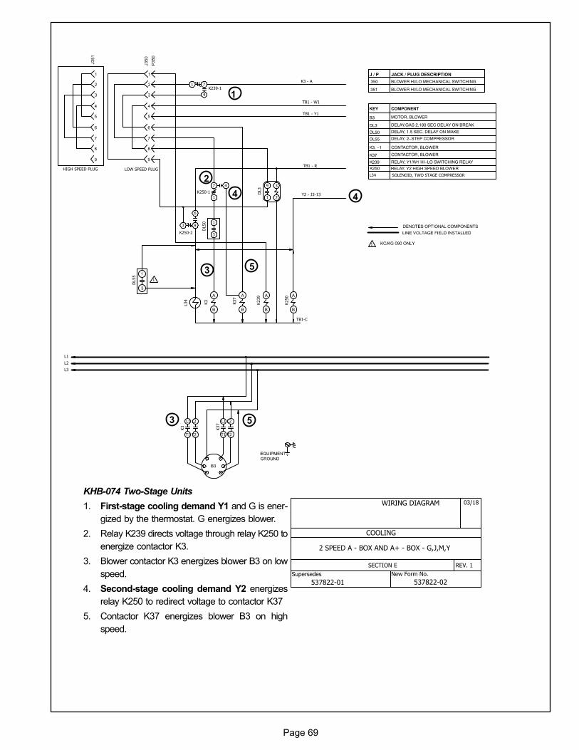
Page 69
KHB-074 Two-Stage Units
1. First-stage cooling demand Y1 and G is ener
gized by the thermostat. G energizes blower.
2. Relay K239 directs voltage through relay K250 to
energize contactor K3.
3. Blower contactor K3 energizes blower B3 on low
speed.
4. Second-stage cooling demand Y2 energizes
relay K250 to redirect voltage to contactor K37
5. Contactor K37 energizes blower B3 on high
speed.
1
2
3
4
5
3
4
5
New Form No.Supersedes
WIRING DIAGRAM
2 SPEED A - BOX AND A+ - BOX - G,J,M,Y
03/18
COOLING
SECTION E REV. 1
537822-01 537822-02
KEY COMPONENT
B3 MOTOR, BLOWER
K3, −1 CONTACTOR, BLOWER
J / P JACK / PLUG DESCRIPTION
HIGH SPEED PLUG
K250 A
B
K239 A
B
K37
A
B
K3
A
B
L34
9
1
3
2
7
1
4
1
3
3
6
9
1
4
7
DL50
DL3
K250-1
K250-2
K239-1
K3 - A
TB1 - W1
TB1 - Y1
TB1 - R
Y2 - J3-13
DL50 DELAY, 1.5 SEC. DELAY ON MAKE
K37 CONTACTOR, BLOWER
K239 RELAY, Y1/W1 HI−LO SWITCHING RELAY
K250 RELAY, Y2 HIGH SPEED BLOWER
L34 SOLENOID, TWO STAGE COMPRESSOR
350 BLOWER HI/LO MECHANICAL SWITCHING
351 BLOWER HI/LO MECHANICAL SWITCHING
DL3 DELAY,GAS 2,180 SEC DELAY ON BREAK
TB1-C
L2
L1
L3
LOW SPEED PLUG
DL55
1
1
L1 L2
T1 T2
K3
L1 L2
T1 T2
K37
DL55 DELAY, 2−STEP COMPRESSOR
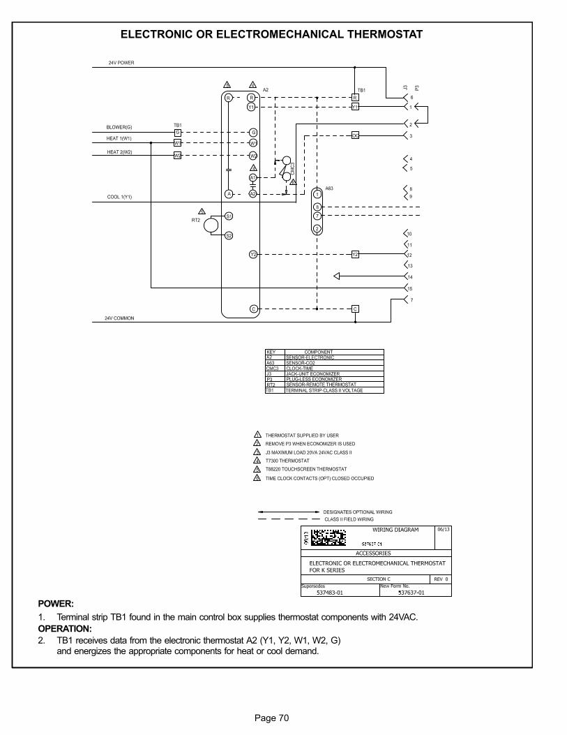
Page 70
ELECTRONIC OR ELECTROMECHANICAL THERMOSTAT
POWER:
1. Terminal strip TB1 found in the main control box supplies thermostat components with 24VAC.
OPERATION:
2. TB1 receives data from the electronic thermostat A2 (Y1, Y2, W1, W2, G)and energizes the appropriate components for heat or cool demand.
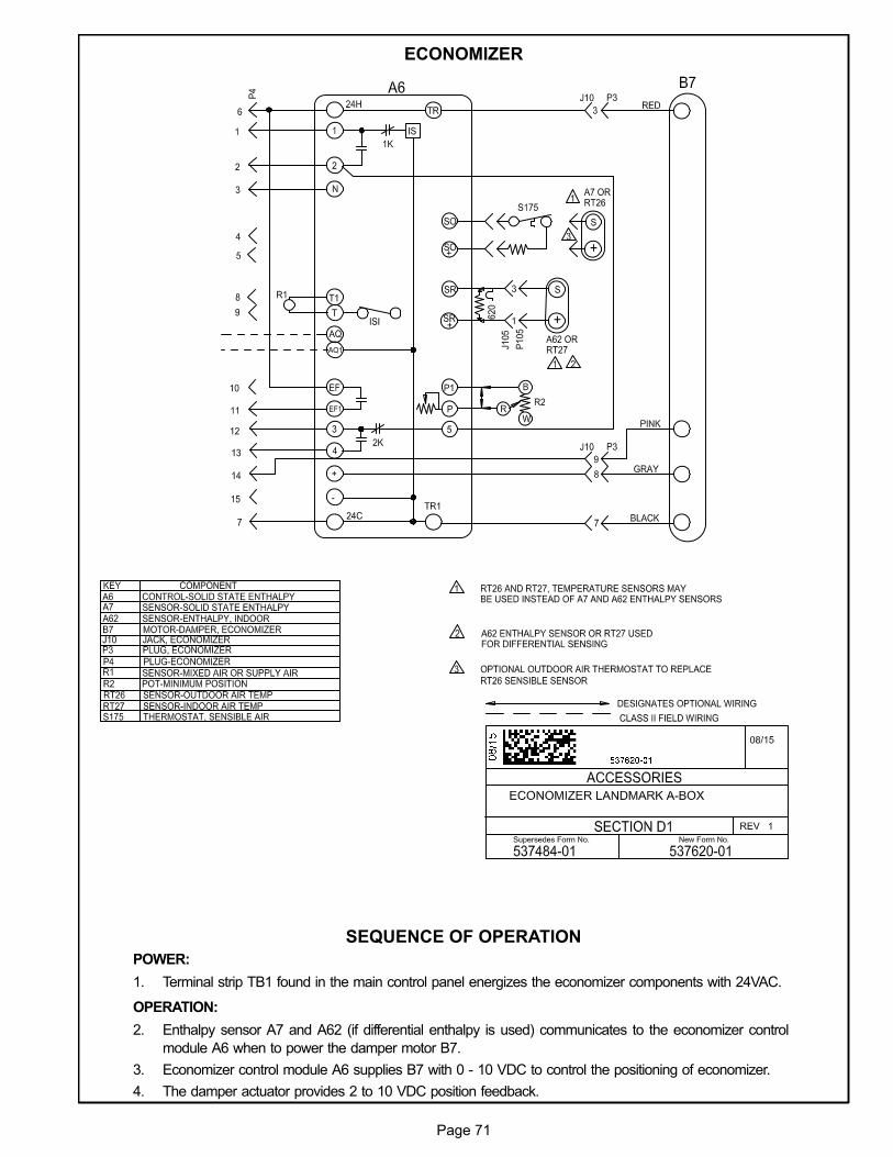
Page 71
ECONOMIZER
SEQUENCE OF OPERATION
POWER:
1. Terminal strip TB1 found in the main control panel energizes the economizer components with 24VAC.
OPERATION:
2. Enthalpy sensor A7 and A62 (if differential enthalpy is used) communicates to the economizer control
module A6 when to power the damper motor B7.
3. Economizer control module A6 supplies B7 with 0 - 10 VDC to control the positioning of economizer.
4. The damper actuator provides 2 to 10 VDC position feedback.

Page 72
T1EH-7.5, 10, 15, 22.5 kW P VOLTAGE
1
3
4
5
6
7
2
44
4
7
7 4
4 4 4
4
7
7
77
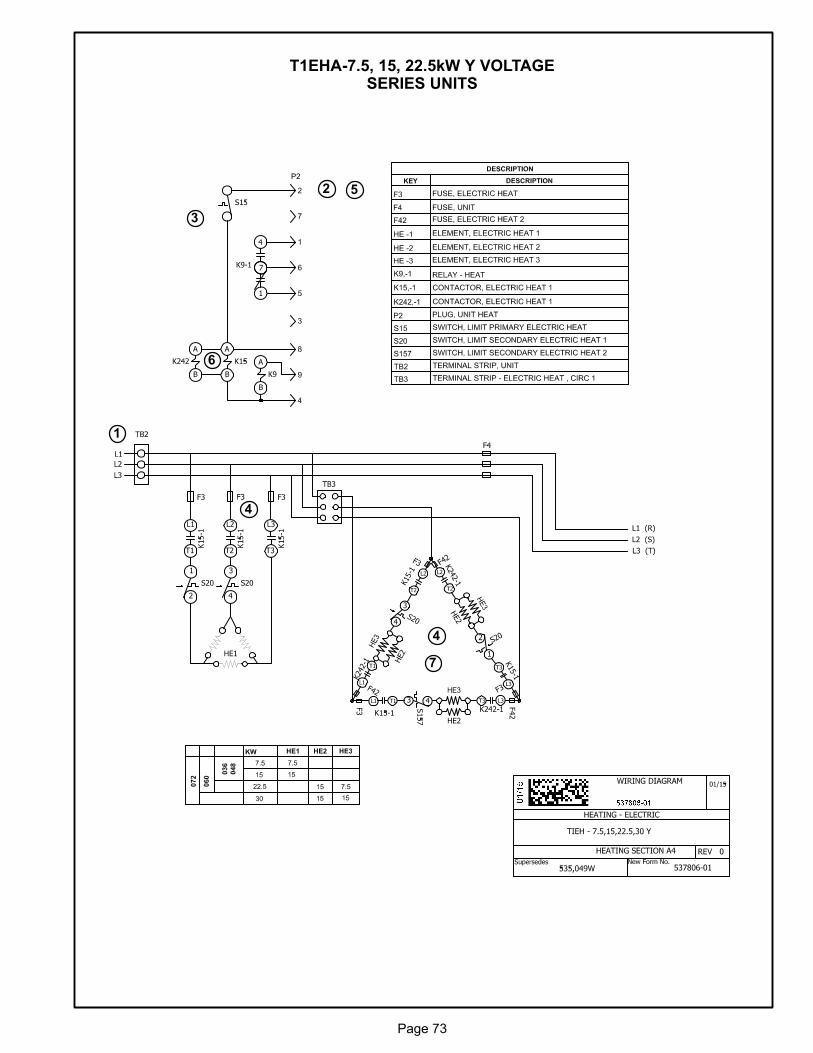
Page 73
T1EHA-7.5, 15, 22.5kW Y VOLTAGESERIES UNITS
1
3
4
5
6
7
2
4
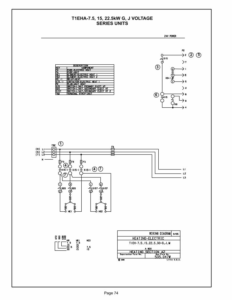
Page 74
T1EHA-7.5, 15, 22.5kW G, J VOLTAGESERIES UNITS
1
3
4
5
6
7
2
4 7
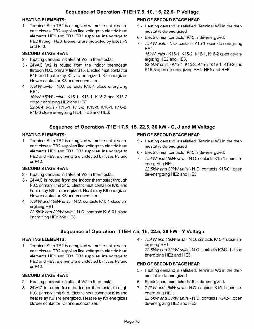
Page 75
Sequence of Operation -T1EH 7.5, 10, 15, 22.5- P Voltage
HEATING ELEMENTS:
1 - Terminal Strip TB2 is energized when the unit discon
nect closes. TB2 supplies line voltage to electric heat
elements HE1 and TB3. TB3 supplies line voltage to
HE2 through HE6. Elements are protected by fuses F3
and F42.
SECOND STAGE HEAT:
2 - Heating demand initiates at W2 in thermostat.
3 - 24VAC W2 is routed from the indoor thermostat
through N.C. primary limit S15. Electric heat contactor
K15 and heat relay K9 are energized. K9 energizes
blower contactor K3 and economizer.
4 - 7.5kW units - N.O. contacts K15-1 close energizing
HE1.
10kW 15kW units - K15-1, K16-1, K15-2 and K16-2
close energizing HE2 and HE3.
22.5kW units - K15-1, K15-2, K15-3, K16-1, K16-2,
K16-3 close energizing HE4, HE5 and HE6.
END OF SECOND STAGE HEAT:
5 - Heating demand is satisfied. Terminal W2 in the ther
mostat is de-energized.
6 - Electric heat contactor K15 is de-energized.
7 - 7.5kW units - N.O. contacts K15-1, open de-energizing
HE1.
15kW units - K15-1, K15-2, K16-1, K16-2 open de-en
ergizing HE2 and HE3.
22.5kW units - K15-1, K15-2, K15-3, K16-1, K16-2 and
K16-3 open de-energizing HE4, HE5 and HE6.
Sequence of Operation -T1EH 7.5, 15, 22.5, 30 kW - G, J and M Voltage
HEATING ELEMENTS:
1 - Terminal Strip TB2 is energized when the unit discon
nect closes. TB2 supplies line voltage to electric heat
elements HE1 and TB3. TB3 supplies line voltage to
HE2 and HE3. Elements are protected by fuses F3 and
or F42.
SECOND STAGE HEAT:
2 - Heating demand initiates at W2 in thermostat.
3 - 24VAC is routed from the indoor thermostat through
N.C. primary limit S15. Electric heat contactor K15 and
heat relay K9 are energized. Heat relay K9 energizes
blower contactor K3 and economizer.
4 - 7.5kW and 15kW units - N.O. contacts K15-1 close en
ergizing HE1.
22.5kW and 30kW units - N.O. contacts K15-01 close
energizing HE2 and HE3.
END OF SECOND STAGE HEAT:
5 - Heating demand is satisfied. Terminal W2 in the ther
mostat is de-energized.
6 - Electric heat contactor K15 is de-energized.
7 - 7.5kW and 15kW units - N.O. contacts K15-1 open de-
energizing HE1.
22.5kW and 30kW units - N.O. contacts K15-01 open
de-energizing HE2 and HE3.
Sequence of Operation -T1EH 7.5, 15, 22.5, 30 kW - Y Voltage
HEATING ELEMENTS:
1 - Terminal Strip TB2 is energized when the unit discon
nect closes. TB2 supplies line voltage to electric heat
elements HE1 and TB3. TB3 supplies line voltage to
HE2 and HE3. Elements are protected by fuses F3 and
or F42.
SECOND STAGE HEAT:
2 - Heating demand initiates at W2 in thermostat.
3 - 24VAC is routed from the indoor thermostat through
N.C. primary limit S15. Electric heat contactor K15 and
heat relay K9 are energized. Heat relay K9 energizes
blower contactor K3 and economizer.
4 - 7.5kW and 15kW units - N.O. contacts K15-1 close en
ergizing HE1.
22.5kW and 30kW units - N.O. contacts K242-1 close
energizing HE2 and HE3.
END OF SECOND STAGE HEAT:
5 - Heating demand is satisfied. Terminal W2 in the ther
mostat is de-energized.
6 - Electric heat contactor K15 is de-energized.
7 - 7.5kW and 15kW units - N.O. contacts K15-1 open de-
energizing HE1.
22.5kW and 30kW units - N.O. contacts K242-1 open
de-energizing HE2 and HE3.