KAUNAS UNIVERSITY OF TECHNOLOGY - KTU ePubl
56
KAUNAS UNIVERSITY OF TECHNOLOGY MECHANICAL ENGINEERING AND DESIGN FACULTY Thillai Balaji Sankaravel DESIGN CONSIDERATIONS AND PERFORMANCE MODELING OF PELLETIZED BIO-FUEL SCREW FEEDERS Final project for Master degree Supervisor Assoc. Prof. Dr. Evaldas Narvydas KAUNAS, 2015
-
Upload
khangminh22 -
Category
Documents
-
view
1 -
download
0
Transcript of KAUNAS UNIVERSITY OF TECHNOLOGY - KTU ePubl

KAUNAS UNIVERSITY OF TECHNOLOGY
MECHANICAL ENGINEERING AND DESIGN FACULTY
Thillai Balaji Sankaravel
DESIGN CONSIDERATIONS AND PERFORMANCE MODELING
OF PELLETIZED BIO-FUEL SCREW FEEDERS
Final project for Master degree
Supervisor
Assoc. Prof. Dr. Evaldas Narvydas
KAUNAS, 2015

KAUNAS UNIVERSITY OF TECHNOLOGY
MECHANICAL ENGINEERING AND DESIGN FACULTY
MECHANICAL ENGINEERING DEPARTMENT
I APPROVE
Head of Department
(signature) Prof. Dr. Vytautas Grigas
(date)
DESIGN CONSIDERATION AND PERFORMANCE MODELING
PELLETIZED BIO-FUEL SCREW FEEDERS.
Final project for Master degree
Study programme: Mechanical Engineering (621H30001)
Supervisor
(signature) Assoc. Prof. Dr. Evaldas Narvydas
(date)
Reviewer
(signature) Assoc. Prof. Dr. Kęstutis Pilkauskas
(date)
Project made by
(signature) Thillai Balaji Sankaravel
(date)
KAUNAS, 2015

KAUNAS UNIVERSITY OF TECHNOLOGY
Mechanical Engineering and Design Faculty (Faculty)
Thillai Balaji Sankaravel (Student's name, surname)
Master of Mechanical Engineering, Study programme: Mechanical Engineering (621H30001) (Title and code of study programme)
DESIGN CONSIDERATIONS AND PERFORMANCE MODELING
OF PELLETIZED BIO-FUEL SCREW FEEDERS
Final project
DECLARATION OF ACADEMIC HONESTY
2015
Kaunas
I confirm that a final project by me, Thillai Balaji Sankaravel, on the subject "Design
Considerations and Performance modelling of Bio-fuel Screw Feeders" is written completely by
myself; all provided data and research results are correct and obtained honestly. None of the parts of
this thesis have been plagiarized from any printed or Internet sources, all direct and indirect quotations
from other resources are indicated in literature references. No monetary amounts not provided for by
law have been paid to anyone for this thesis.
I understand that in case of a resurfaced fact of dishonesty penalties will be applied to me
according to the procedure effective at Kaunas University of Technology.
(name and surname filled in by hand) (signature)

KAUNAS UNIVERSITY OF TECHNOLOGY
FACULTY OF MECHANICAL ENGINEERING AND DESIGN
Approved: Head of Mechanical
Engineering
Department
(Signature, date)
Vytautas Grigas
(Name, Surname)
MASTER STUDIES FINAL PROJECT TASK ASSIGNMENT
Study programme MECHANICAL ENGINERING
The final project of Master studies to gain the master qualification degree , is research or applied type
project, for completion and defence of which 30 credits are assigned. The final project of the student must
demonstrate the deepened and enlarged knowledge acquired in the main studies, also gained skills to formulate
and solve an actual problem having limited and (or) contradictory information, independently conduct scientific
or applied analysis and properly interpret data. By completing and defending the final project Master studies
student must demonstrate the creativity, ability to apply fundamental knowledge, understanding of social and
commercial environment, Legal Acts and financial possibilities, show the information search skills, ability to
carry out the qualified analysis, use numerical methods, applied software, common information technologies and
correct language, ability to formulate proper conclusions.
1. Title of the Project
Approved by the Dean 2015 y. _May_m.11 d. Order No. _ ST17-F-11-2__
2. Aim of the project
3. Structure of the project
4. Requirements and conditions
5. This task assignment is an integral part of the final project
6. Project submission deadline: 2015 June 1st.
Given to the student
Thillai Balaji Sankaravel__________________________ _____
Task Assignment received Thillai Balaji Sankaravel _____________________ (Name, Surname of the Student) (Signature, date)
Supervisor Assoc. Prof. Dr. Evaldas Narvydas _____________________ (Position, Name, Surname) (Signature, date)
To prepare final project according to KTU regulations and requirements. Conditions: to analyze the
presented screw feeder and to perform modifications with two filling conditions of the hopper: 0.3
m and 0.45 m and mass flow rate according to the screw rotational speed from 5 rpm to 30 rpm
The final project consists of: summary in Lithuanian and English; introduction with emphasized aim
and topicality of the project; literature survey; presentation of the research methods; research results;
conclusions and list of references.
To review the designs of the screw feeders used for bio-fuel supply, to model the performance of
most sufficient feeders by means of finite element analysis, to perform a parametric analysis and to
suggest improvements for design
Design considerations and performance modeling of pelletized bio-fuel screw feeders

Sankaravel, T B. Biokuro granulių sraigtinių tiektuvų konstrukcijų analizė ir veikimo modeliavimas.
Magistro baigiamasis projektas / vadovas doc. dr. Evaldas Narvydas; Kauno technologijos universitetas,
Mechanikos inžinerijos ir dizaino fakultetas, Mechanikos inžinerijos katedra.
Kaunas, 2015. 45 psl.
SANTRAUKA
Projekto tikslas yra sukurti sraigtinio tiektuvo modelį, ištirti jo deformacijas, įtempius,
išnagrinėti granulinio bio-kuro kamščių susidarymo galimybes ir jo veikimą, esant užduotam tiekiamo
kuro masės srautui. Darbe pristatomi trys variantai naujo dizaino sraigtinių tiektuvų, kuriuose sraigtas
yra be ašies ir jų deformacijos bei įtempiai palyginti su įprastu sraigtiniu tiektuvu su ašimi. Panaudoti
du variantai tiektuvo bunkerio dizaino tiriant granulių kamščių susidarymą tiektuve, kuriame sraigtas
yra su ašimi. Bunkerio variantas, kuriame kuro strigimas yra mažesnis, toliau naudojamas tiektuvų,
kurių sraigtas neturi ašies, tyrimuose. Granulinių dalelių masės srautas yra apskaičiuotas visais
nagrinėtais tiektuvo variantais. Iš apskaičiuotų rezultatų matyti, kad du iš trijų naujo dizaino tiektuvų
veikia efektyviai, o jų deformacijų ir įtempių vertės yra mažesnės lyginant su įprastais tiektuvais, kurių
sraigtai turi ašis.

Sankaravel, Thillai Balaji Sankaravel. Design considerations and performance modeling of pelletized
bio-fuel screw feeders. Master of Mechanical Engineering final project / supervisor Assoc. Prof. Dr.
Evaldas Narvydas; Kaunas University of Technology, Mechanical Engineering and design faculty,
Mechanical Engineering department.
Kaunas, 2015. 45 p.
SUMMARY
The goal of project is to design the active shafted screw feeder model to analysis its
deformation, stress, possibilities of pelletized bio-fuel jamming in its hopper and performance using its
mass flow rate. The implementation of new design three different axle free screw feeder used in this
project in order to reduce its deformation and stress values when compared active shafted screw
feeder. Two hopper designs are used for analysis of pellets jamming with initial active shafted screw
feeder. The hopper with less jamming is considered for further research by assembling the rest three
different axle free screw feeder and jamming analysis are done. The mass flow rate of the pelletized
particle is calculated for all screws used in this project. From results it shown that the two out of three
newly designed screw feeder are efficient in performance, less deformation and stress values are
reduced when compared to the existing shafted screw feeder.

Table of Contents
INTRODUCTION ..................................................................................................................................... 1
1. LITERATURE SURVEY...................................................................................................................... 2
1.1 Screw feeder in biomass industries ................................................................................................. 3
1.2 Study of screw feeder ...................................................................................................................... 4
1.3 Challenges in existing screw feeders ............................................................................................... 6
1.3.1 Operational parameter stresses .............................................................................................................. 6
1.3.2 Different load conditions ........................................................................................................................ 6
1.3.3 Operator faults ........................................................................................................................................ 7
1.3.4 Shape of shaft .......................................................................................................................................... 7
1.4.1 Major advantage of shafted screw feeder .............................................................................................. 7
1.4.2 Major disadvantage of shafted screw feeder ......................................................................................... 8
1.5 Axle-free screw feeder and its advantages ...................................................................................... 8
1.5.1 Advantage of using Axle-free screw feeder ............................................................................................ 8
1.6 Schematic diagram of research work............................................................................................... 9
2. EXPERIMENTAL SETUP & ANALYSIS ........................................................................................ 10
2.1 Parameters of screw feeder and hopper ......................................................................................... 11
2.2 Wooden pellets .............................................................................................................................. 14
2.3 Analysis of hopper-feeder ............................................................................................................. 14
2.3.1 Capacity of Screw Feeder ...................................................................................................................... 14
2.3.2 The Filling Condition .............................................................................................................................. 15
2.4 FORCES ACTING ON SCREW FEEDER .................................................................................. 17
2.4.1 Force on driving slide of flight ............................................................................................................... 18
2.5 Simulations for shafted screw feeder, screw 1 .............................................................................. 20
2.5.1 Total deformation for screw 1 .............................................................................................................. 20
2.5.2 Maximum Principal Stress for screw-1 .................................................................................................. 22
2.6 Simulation for axial free screw feeder , Screw-2 .......................................................................... 23
2.6.1 Total deformation for axial free screw feeder SCREW-2 ...................................................................... 23
2.6.2 Maximum principal stress for screw 2 .................................................................................................. 24
2.7 Axial free screw feeder with standard diameter, Screw 3 ............................................................. 25
2.7.1 Total deformation of axial free screw feeder with 90mm diameter, SCREW-3:................................... 26
2.7.2 Maximum Principal Stress for hopper level for Screw 3: ...................................................................... 27

2.8 Axial free screw feeder with 80 mm diameter, Screw 4 ............................................................... 28
2.8.1 Total deformation of axial free screw feeder with 80 mm diameter ................................................... 29
2.8.2 Maximum principal stress for axial free screw feeder with 80mm ...................................................... 30
3.9. Analysis of jamming using CFD .................................................................................................. 31
3.10 Analysis of mass flow rate using CFD ........................................................................................ 35
3. RESULT .............................................................................................................................................. 38
3.1 Result analysis on Total deformation of the screw feeders for all the screws: ............................. 38
3.2 Result analysis on Maximum principal stress for all the screws ................................................... 39
3.3 Result on pressure analysis of pelletized particle in hopper .......................................................... 40
3.4 Result on analysis of Mass flow rate in all four screws ................................................................ 42
CONCLUSIONS ..................................................................................................................................... 44
LIST OF REFERENCES ........................................................................................................................ 45

List of Figures
Figure 1.1. Archimedes screw, reference [16].......................................................................................... 2
Figure 1.2 Layout of biomass plant, reference [17] .................................................................................. 3
Figure 1.3 Screw feeders in Bio-mass gasification industry, reference [15] ............................................. 4
Figure 1.4 Shows the excessive loads conditions frequently result in fatigue failures in the shaft,
reference [9] ............................................................................................................................................... 6
Figure 1.5 Shows the crack development at the end of shaft or weld section due to the stress and
deflection, reference [9] ............................................................................................................................. 7
Figure 1.6 Axle-free screw feeder, reference [10] & [13] ......................................................................... 8
Figure 2.1 Full assembly side view with screw feeder ............................................................................ 10
Figure 2.2 Wireframe view of screw feeder-hopper complete assembly ................................................ 10
Figure 2.3 Isometric view of Designed Screw Feeder............................................................................. 11
Figure 2.4 Screw feeder with dimensional parameters, reference [6] ..................................................... 12
Figure 2.5 Front view and Side view of hopper, reference [6] ................................................................ 12
Figure 2.5 (b) Shows drawing of constructed model............................................................................... 13
Figure 2.6 Stress Field, reference [12] .................................................................................................... 16
Figure 2.7 Force acting on the flight, reference [6] ................................................................................. 17
Figure 2.8 Resisting force acting on the pelletized material ................................................................... 18
Figure 2.9 Driving force acting on the pelletized material ...................................................................... 18
Figure 2.10 Screw 1 with trough in ANSYS workbench ........................................................................ 20
Figure 2.11 Wireframe view of hopper level 0.3m ................................................................................. 21
Figure 2.12 Wireframe view of Total deformation for hopper level 0.45 ............................................... 21
Figure2.13 Wireframe view of Maximum Principal Stress for 0.3m ...................................................... 22
Figure 2.14 Wireframe view of Maximum Principal Stress 0.45 ............................................................ 22
Figure 2.15 Axial free Screw Feeder with different diameter ................................................................. 23
Figure 2.16 Wireframe view of axial free screw feeder with different diameter SCREW 2, 0.3m ........ 23
Figure 2.17 Wireframe view of axial free screw feeder with different diameter SCREW 2, 0.45m ...... 24
Figure.2.18 Wireframe view of Maximum Principal Stress for filling condition 0.3m .......................... 24
Figure 2.19 Wireframe view of Maximum Principal Stress for filling condition 0.45m ........................ 25
Figure 2.20 Axial-Free screw feeder with 90 mm diameter, SCREW-3. ................................................ 26
Figure.2.21 Wireframe model hopper level 0.3m, Screw-3 .................................................................... 26
Figure 2.22 Wireframe view of total deformation for hopper level 0.45m, Screw-3 .............................. 27
Figure 2.23 Wireframe view of Maximum Principal Stress with hopper level 0.3m, Screw-3 .............. 27
Figure 2.24 Wire frame view of Maximum Principal Stress with hopper level 0.45m, Screw-3 ........... 28
Figure 2.25 Axial-Free screw feeder with 80 mm diameter, SCREW- 4. ............................................... 29
Figure 2.26 Wireframe model for hopper level 0.3m, Screw- 4 ............................................................. 29
Figure.2.27 Wireframe view of total deformation hopper level, 0.45m .................................................. 30
Figure 2.28 Wireframe view of Maximum principal stress for 0.3m, Screw-4 ...................................... 30
Figure 2.29 shows the Wireframe model Maximum principal stress for 0.45m, Screw-4 ...................... 31
Figure 2.30 Pressure of particles in hopper 1 with Screw 1 Assembly ................................................... 32
Figure 2.31 Pressure of particles in hopper 2 with screw 1 Assembly .................................................... 32
Figure 2.32 Jamming in the hopper-2 ...................................................................................................... 33

Figure 2.33 Jamming-Free hopper-1 ....................................................................................................... 33
Figure 2.34 Pressure of particles in Screw 2 Assembly .......................................................................... 34
Figure 2.35 Pressure of particles in Screw 3 Assembly .......................................................................... 34
Figure 2.36 Pressure of particles in Screw 4 Assembly .......................................................................... 35
Figure 2.37 shows the velocity of the particles in the screw 1 and hopper 1 assembly. ......................... 36
Figure 2.38 shows the velocity of the particles in the screw 2 and hopper 1 assembly. ......................... 36
Figure 2.39 shows the velocity of the particle in the screw 3 and hopper 1 assembly. ........................... 37
Figure 2.40 shows the velocity of the particle in the screw 4 and hopper 1 assembly. ........................... 37
Figure 3.1 Total deformations of all screw feeders for filling level 0.3m ............................................... 38
Figure 3.2 Total deformations of all screw feeders for filling level 0.45m ............................................. 39
Figure 3.3 Maximum Principle stresses of all screw feeders for filling level 0.3m ................................ 39
Figure 3.4 Maximum Principle stresses of all screw feeders for filling level 0.3m ................................ 40
Figure 3.5 Pressure comparison of pelletized particle (wooden pellet) in Hopper 1 and Hopper 2........ 41
Figure 3.6 Pressure comparison of pelletized particle (wooden pellet) in all four assemblies ............. 41
Figure 3.7 Mass flow rates of Screw 1 .................................................................................................... 42
Figure 3.8 Mass flow rate of Screw 2 ...................................................................................................... 42
Figure 3.9 Mass flow rate of Screw 3 ...................................................................................................... 43
Figure 3.10 Mass flow rate of Screw 4 .................................................................................................... 43

List of Tables
Table 1.1 Properties of pelletized particle ................................................................................................. 5
Table 2.1 Screw dimensions .................................................................................................................... 11
Table 2.2 Hopper dimensions .................................................................................................................. 13
Table 2.3 Trough dimensions .................................................................................................................. 13
Table 2.4 Property of Wooden pellets ..................................................................................................... 14
Table 2.5 Flow ability of material ........................................................................................................... 15
Table 2.6 Vertical stresses ....................................................................................................................... 17
Table 2.7 Force on flights of all four screws ........................................................................................... 19
Table 2.8 Total deformation of SCREW 1 .............................................................................................. 21
Table 2.8 (a) Maximum Principal Stress for SCREW 1.......................................................................... 22
Table 2.9 Total deformation of SCREW 2 .............................................................................................. 24
Table 2.9 (a) Maximum Principal Stress for SCREW 2.......................................................................... 25
Table 2.10 Total deformation of SCREW 3 ............................................................................................ 27
Table 2.10 (a) Maximum Principal Stress for SCREW 3........................................................................ 28
Table 2.11 Total deformation of SCREW 4 ............................................................................................ 30
Table 2.11 (a) Maximum Principal Stress for SCREW 4........................................................................ 31

1
INTRODUCTION
A screw feeder can be defined as “A mechanism for handling bulk (pulverized or granulated
solids) materials, in which a rotating helicoids screw moves the material forward, toward and into a
process unit” based on McGraw-Hill Dictionary of Scientific & Technical Terms, 6E, Copyright ©
2003 by The McGraw-Hill Companies. In this research project the screw feeder used as material
handling equipment which used to standardize the flow of pelletized particle from hopper to the
Fluidized bed combustion boiler of the bio-mass Industries.
Screw feeder has wide range of application with conveying of pelletized materials in
Industries. The aim of this research project is to develop 3D model of existing design of screw feeder
and to analysis of design consideration by using three different axle-free screw feeders with
performance of all four screws analysis using mass flow rate. This aim is divided into several
objectives:
1. To identify the deformation occurring at existing screw feeder and comparing its results with
modified axle free screw feeders.
2. To recognize the maximum stress occurring at existing screw feeder and to do result
comparison with modified axle free screw feeders.
3. To classify the jamming occurring at two different hoppers and selecting the hopper with less
jamming which is further assembled with all four screws. The jamming comparison of all four
assemblies is done.
4. Mass flow rate for all the four screws are calculated for tool check.
In this research project four type of screw feeder is constructed using SOLIDWORKS with
different dimension according to the design specifications and its CFD used for jamming analysis.
ANSYS workbench used for stress and deformation simulation which uses the finite element method
approach to both the designed screw feeders with which one can find whether the design suitable for
industrial utilization.
This project consists of four different sections; names are followed by literature review,
Analytical & simulation, result comparisons and conclusion. In literature review previous works on
screw feeder is discussed based on the reference journals and the schematic diagram of research work
is described. In Analytical & simulation section of thesis, the deformation and stress on the 4 different
type of screw is been obtained using ANSYS workbench. The next sections are results comparisons
and conclusion in which the obtained results are explained with the graphs. The ultimate statements are
given at the end.

2
1. LITERATURE SURVEY
Screw feeder or conveyor is a component that uses a rotating helical screw blade called flights
usually within a round and hollow tube, to move pelletized particle or fluids. The principle sort of
screw conveyor was the Archimedes' screw, used since ancient times to pump irrigation water.
Archimedes' screw, also called the Archimedean screw or screw pump, is a machine truly utilized for
transferring water from a low-lying body of water into irrigation trench. Water is pumped by turning a
screw-shaped surface inside a hollow pipe, from reference [16]
Figure 1.1. Archimedes screw, reference [16]
The screw is turned usually by a windmill or by manual labor. As the shaft turns, the bottom
ends flights up a volume of water. This water will slide up in the spiral tube, until it finally pours out
from the top of the tube and feeds the irrigation systems. The screw was used mostly for draining water
out of mines or other areas of low lying water, from reference [16].

3
1.1 Screw feeder in biomass industries
The biomass in general refers to organic material from plants and animals including agriculture
and civil waste products excluding food products. The biomass can be changed into distinctive forms of
bio energy in variety of ways, from low tech to high.
Bio energy technologies are the processes and mechanisms that convert plant and animal matter
into energy source. The energy generated from biomass is less harmful to environment and which can
be transformed to gas & oil to generate electricity and heat. It can be converted into liquid fuels and
used for transportation. The layout of bio mass industry is given below.
Figure 1.2 Layout of biomass plant, reference [17]
The screw feeders are used to transport the biomass products to Fuel blending and preparation
which is further transferred fluidized bed combustion boiler by another screw feeder. The Fluidized bed
combustion (FDC) is the combustion technology used burn solid fuels. FBC are capable for burning a
variety of low-grade solid fuels, including most type of coal and wooden bio mass in a high efficiency
without any expensive fuel separation, from reference [18].

4
Figure 1.3 Screw feeders in Bio-mass gasification industry, reference [15]
1.2 Study of screw feeder
Jianjun Dai, John R. Grace developed a model for bio-mass screw feeder in which the bulk
solid mechanics of a material element within the pocket surface is clearly stated out, reference [6]. The
vertical stress exerted on the outlet of the hopper by the bulk material in the hopper is proportional to
required torque. In their experiment they have used two screws with different screw diameter as screw-
1 and different shaft diameter with constant screw diameter screw-2. The vertical stress and force
acting on the flights of the screw feeder is compared. The interaction between the bulk solid materials
is also explained using Mohr circle.
In biomass screw feeding with tapered and extended sections by Jianjun Dai, John R. Grace A
methodology is presented to analyze the tapered and extended sections which are employed to improve
plug seal to reactors in the biomass industry, reference [7]. The wall friction angle and internal friction
angle is diffused in this part which is used as reference of calculation of force on the flights.
Roberts and Manjunath [8] have analyzed the volumetric characteristics and mechanics of
screw feeders in relation to the bulk solid draw-down characteristics of the feed hopper. Distribution of
throughput along screw and uniform draw-down patterns was investigated. Yu and Arnold proposed a
theoretical model for torque requirements for single screw feeders. They assumed that the load imposed
on a screw feeder by the bulk solids in the hopper is determined by the major consolidation stress.

5
Alan W. Roberts were carried out experimental investigation of Design and Performance
evolution of screw conveyor, based on reference [5]. Screw conveyors with fully enclosed in
cylindrical casings were used in experiment. The throughput, torque and power are significantly
influenced by the vortex motion of the bulk solid being conveyed. The vortex motion, together with the
degree of fill, govern the volumetric efficiency and, hence, the throughput. This, in turn, influences the
torque, power and conveying efficiency. A theory is presented to predict the performance of screw
conveyors of any specified geometry. The influence of the flow properties of the bulk material on the
conveyor performance is given. Performance of screw conveyors is significantly influenced by the
vortex motion of the bulk solid being conveyed. The flow properties of the bulk material being
conveyed are shown to have a significant influence on the performance.
From Jianjun Dai, John R. Grace journals the properties of pelletized particle are tabulated.
Table 1.1 Properties of pelletized particle
Name of the
specimen
Particle size
Range, mm
Bulk density
Kg/m3
Wall friction
angle,(o)
Internal
friction,(o)
Shape
Wooden
shavings
0.09 to 6.73 188 31.4 38 Irregular
Wood pellets 8 - 11 630 31.4 32 Cylinder
Ground hog
fuel
0.09 – 2.8 150 31.8 45 Irregular

6
1.3 Challenges in existing screw feeders
Commonly faced problems by screw conveyors are pelletized particle density combined with
the speed of the drive which causes screw to fail in shaft journals.
1.3.1 Operational parameter stresses
Frequently, certain methods of operating the screw feeder cause oddly high stresses in the
screw. These stresses are primarily influenced by the following operating parameters
1.3.2 Different load conditions
Different stress magnitudes occur as a result of different load applications. Impact loads causes
stresses that are two to three times higher than the "steady state" stresses that are present in the screw
when it is operated at a slow, constant speed in a pelletized particle comprised of a homogenous
material mixture as illustrated by reference journal by Improved conveyor performance by adjusting
operating parameters to avoid loads and adhering to more rigorous inspections, conveyor downtime
from wood screw failures becomes avoidable by Monica Shaw [9].
For example, a 20% increase in density results in a 20% increase in stress. Furthermore,
changes in two or more operating parameters, such as filling conditions and material density, have an
increasing effect as the stresses are added together, from reference journal [9].
Figure 1.4 Shows the excessive loads conditions frequently result in fatigue failures in the shaft,
reference [9]

7
Figure 1.5 Shows the crack development at the end of shaft or weld section due to the stress and
deflection, reference [9]
1.3.3 Operator faults
When the screw does not function as required, the first reaction by some personnel is to enlarge
some of the screw's parts to improve performance and prevent future failures. Although increasing the
applied horsepower or torque by increasing the motor size, gear ratio, shear pin diameter, or coupling
bolt size may solve the problem, it decreases the screw's expected life by relocating the stress to a more
crucial portion of the equipment based on the reference [9].
1.3.4 Shape of shaft
Stress magnitudes can be altered by changing the thickness or diameter of the shaft, but mostly
do not change these dimensions because it requires a change in the unit's design and an alteration of the
original equipment supplied by the manufacturer based on the reference [9].
1.4.1 Major advantage of shafted screw feeder
The screw feeders are very compact and adaptable to congested locations. It does not have
any return to similar to a belt or drag conveyor.
Screw feeders are capable of handling a great variety of bulk material from slow-moving to
free- flowing.

8
1.4.2 Major disadvantage of shafted screw feeder
During the transportation of stick, wet and slow moving material in the screw feeder there will
be loss in flow of pelletized particle at feeder outlet which happens due to pelletized particle
sticking at the centre shaft of screw feeder which leads to jamming in the transportation.
The most of screw feeder in the biomass industries is fixed only at one end and other is open to
the furnace which causes the maximum stress at the end of the shafts and deformations occurs
periodically. This happens due to weight of the screw feeder.
1.5 Axle-free screw feeder and its advantages
The present drawback in the screw feeder is overcome in this project by using axle-free screw
feeder (shaft less). The bulk material discharge from hopper or filter presses can easily be metered or
conveyed by Axle-free (shaft less) screw feeder based on the reference [10].
Figure 1.6 Axle-free screw feeder, reference [10] & [13]
1.5.1 Advantage of using Axle-free screw feeder
Ideal for handling sticky and sluggish bulk material.
Conveying efficiency is improved when compared to shafted screw feeder.
Less wear
Maintenance is little bit less when compared to shafted screw feeder
Handling of large objects up to trough diameter

9
1.6 Schematic diagram of research work
Literature review
Drawback analysis
Present design Solution by adapted
design
Construction of 3D
model of screw 1
Construction of 3D
model of screw 2
Construction of 3D
model of screw 3
Construction of 3D
model of screw 4
Deformation and Stress
analysis
Jamming and Mass flow
rate analysis
Result analysis

10
2. EXPERIMENTAL SETUP & ANALYSIS
The experimental design and complete setup is based on the reference of the journal “A Modal
for biomass screw feeding” by Jianjun Dai and John R Grace [6]. The complete design of experiment
setup is done on using SOLIDWORKS. The DC motor with 0.56 kW is constructed using
SOLIDWORKS based on the reference journal [6]. Flange is constructed by SOLIDWORKS which is
used coupling device to connect shafts in this machinery. Two connections are made by flange in this
project, one is Motor-Speed reducer and another one is Speed reducer-screw feeder shaft. Flange is
based on design standards [11]. A bearing is a machine element that constrains relative motion to only
the desired motion and reduces friction between moving parts based on bearing definitions. The tapered
bearing is used at the end of the shaft of screw feeder which construed based on design standards. ISO
355-2CD30-16, DE,NC,16.
Figure 2.1 Full assembly side view with screw feeder
Figure 2.2 Wireframe view of screw feeder-hopper complete assembly

11
Different screw feeders are used in this project one of the screw feeder is with shaft based on
the reading of pervious reference and others is axial free (shaft less) screw feeder, it is the new concept
of implementing into the machinery.
2.1 Parameters of screw feeder and hopper
The Screw feeder is designed in SOLIDWORKS and the dimensions are tabulated in Table 1.
Figure 2.3 Isometric view of Designed Screw Feeder
Table 2.1 Screw dimensions
Parameter of Screw Feeder Dimensions
Screw length In Hopper length = 910mm
In choke section= 610mm
Total length of Screw= 1520 mm
Screw diameter, Do 100;90;80 (*1)
Shaft diameter, Ds 30 mm
Pitch,P 100
Flight Thickness 6.35
Clearance, c 1;6;11 (*1)
Material 316 SS

12
*1- For the length of first 800 mm of screw is 100 mm diameter with clearance as 1 mm. Next
300 mm of screw is 90 mm dia with clearance 6 mm. The last 420 of screw is 80 mm diameter with
clearance 11mm.
Figure 2.4 Screw feeder with dimensional parameters, reference [6]
The schematic diagram of Hopper
Figure 2.5 Front view and Side view of hopper, reference [6]

13
Figure 2.5 (b) Shows drawing of constructed model.
The hopper and Trough dimensions are given in Table 2.2 & Table 2.3.
Table 2.2 Hopper dimensions
Parameters of Hopper Dimensions
Type Wedge-shaped
Length 910 mm
Height 610 mm
Angle with horizontal axis 70o
Material Carbon steel
Table 2.3 Trough dimensions
Parameter of trough Dimensions
Diameter, Dt 102 mm
Material Carbon Steel

14
2.2 Wooden pellets
The analysis of the screw feeder is done based on the material to be transported. In this project
the wood is consider to be transported in the screw feeder. The wood pellets are the one of the most
common material used to transport biomass product. The property of screw feeder is given below.
Table 2.4 Property of Wooden pellets
Property of wood Values
Bulk Density 630 Kg/m3
Young Modulus 1.1E+09 Pa
Poisson Ratio 0.3
Bulk Modulus 9.1667E+08 Pa
Shear Modulus 4.2308E+08 Pa
2.3 Analysis of hopper-feeder
The analysis below consider on hopper, feeder and choke section. The capacity of screw feeder,
stresses and forces calculations are done.
2.3.1 Capacity of Screw Feeder
The capacity of screw feeder can be determined by the formula derived by Siddhartha ray 2008
[2], Introduction to Material Handling. The screw diameter, pitch of screw, screw speed as a major role
in the calculation of capacity of screw.
Eqn (1)
Q= Tonnage capacity, ton/hr
V= Volumetric capacity, m3/hr.
D= Screw diameter, m
n = Speed, rpm

15
S= Screw pitch, m
= Bulk density, kg/m3
C= Factor depending upon inclination of feeder.
= Flow ability of material, it depends upon the material.
Table 2.5 Flow ability of material
Material characteristics Value of
Slow flowing abrasive 0.125
Slow flowing Mild abrasive 0.25
Free flowing mild abrasive 0.32
Free flowing non-abrasive 0.4
Therefore the capacity of shafted screw = 0.609 t/hr = 0.16 kg/s.
2.3.2 The Filling Condition
The filling condition in hopper ho as show in Figure 2.5, is given as 0.3 m and 0.45 m it was formerly
employed by the precious journals by “A Modal for biomass screw feeding” by Jianjun Dai and John R
Grace. To find stress and force acting on screw feeder inside hopper can be calculated by the formula
derived from the previous journals.
Eqn (2)
v = Vertical stress, N/m2
, Bulk density
q = Surcharge factor = 1.04
B = hopper outlet width, mm
= Length the particle filled in Hopper condition.
G= Standard earth gravity, m/s2

16
Under filling condition, once the flow is initiated the stress field is generated in the hopper. This stress
field is generated throughout the hopper. The surcharge factor is involved in the calculation of vertical
stress acting on the screw feeder due to stress on the upper part of the pelletized material. The
surcharge factor (qf) can be calculated by the formula which is given below based on the reference [1].
Where X and Y,
m, Hopper factor=1 (for axis symmetric flow)
, Effective angle of internal friction
Hopper angle.
Figure 2.6 Stress Field, reference [12]
The vertical stress calculation are made according to the equation (2) for the both filling condition and
the results are tabulated

17
Table 2.6 Vertical stresses
Vertical stress inside
hopper, v
Hopper Level Values
0.3 1683.5 N/m2
0.45
2195 N/m2
The vertical stress acts only the shaft part which is inside the hopper. The remaining part in
trough will be subjected to have only axial stress.
2.4 FORCES ACTING ON SCREW FEEDER
The force acting on the screw feeder is illustrated by Figure given below.
Figure 2.7 Force acting on the flight, reference [6]
The Force acting on flight of screw feeder is product of equivalent friction co-efficient of bulk
solids it is taken from reference journal, A modal of biomass screw feeding by Jianjun Dai, John R
Grace.

18
2.4.1 Force on driving slide of flight
To calculate the force on driving slide of flight additional factor such as force on trailing surface
and trough surface is taken into account. The friction force on the trailing side resists the forward
motion of pelletized particle but it helps to rotate material inside the pocket section. Pelletized particle
moves forward due to connect on the driving slide of the screw feeder. The Figure 2.8 shows the
resisting force acting on the trailing side of the screw flights. Figure 2.9 shows driving force on the
material. The force acting trailing flight are derived in equation (6) & (7)
Figure 2.8 Resisting force acting on the pelletized material
Figure 2.9 Driving force acting on the pelletized material
(6)

19
(7)
The pelletized particle subjected to have frictional force on the inside surface of trough. The axial
resisting on the screw flight is given by equation (12) & (13).
(8)
Where
, Ratio of trough to screw diameter
, Ratio of core shaft diameter to screw diameter
, Ratio of pitch to screw diameter
Therefore the force acting on the driving flight of screw feeder is given by equation (10) & (11).
(10)
Table 2.7 Force on flights of all four screws
Hopper Level, m Force acting on
flights of
screw 1, N
Force acting on
flight of
screw 2, N
Force acting on
flights of
screw 3, N
Force acting on
flights of
screw 4, N
0.3 173.5 89.2 79.46 70.14
0.45 269.1 178.4 144.9 127.68
The deformation of the screw feeder is simulated using workbench. The results of Maximum stress,
total deformation and deflection through Y- axis are taken

20
2.5 Simulations for shafted screw feeder, screw 1
The simulation is done using ANSYS workbench. Only screw and trough part is taken into
account. At first the shafted screw feeder (SCREW 1) taken deformation and stress analysis.
2.5.1 Total deformation for screw 1
The vertical stress and pressure on driving side of the flights is applied on the shafts of the
Screw-1 with fixed support at one end. The simulated results and values are tabulated below.
Figure 2.10 Screw 1 with trough in ANSYS workbench
With respect to two filling condition 0.3m and 0.45m of hopper the pressure values are given. At first
the total deformation of about the filling condition is given below. The total deformation of screw 1 is
shown in next page.

21
Figure 2.11 Wireframe view of hopper level 0.3m
The Figure 2.11 shows the result of total deformation for screw 1 with filling level 0.3m. The below
image 2.12 shows the total deformation for filling level 0.45m.
Figure 2.12 Wireframe view of Total deformation for hopper level 0.45
The values from the above simulated results are tabulated.
Table 2.8 Total deformation of SCREW 1
Shafted
screw feeder
Total Deformation
Hopper level, mm Maximum, mm
300 3.9
450 5.2

22
2.5.2 Maximum Principal Stress for screw-1
Figure2.13 Wireframe view of Maximum Principal Stress for 0.3m
The Figure 2.13 shows the result of Maximum principal stress for screw 1 with filling level 0.3m. The
below image 2.14 shows the Maximum principal stress for filling level 0.45m.
Figure 2.14 Wireframe view of Maximum Principal Stress 0.45
Table 2.8 (a) Maximum Principal Stress for SCREW 1
Shafted
screw feeder
Maximum principal
stress
Hopper level, m Maximum, MPa
0.3 49.214
0.45 64.095

23
2.6 Simulation for axial free screw feeder , Screw-2
The Axial free screw feeder SCREW-2 as same diameter with respect to SCREW 1 but it is
shaft free connected to one end as show in the Figure.
Figure 2.15 Axial free Screw Feeder with different diameter
2.6.1 Total deformation for axial free screw feeder SCREW-2
Based on design of existing shafted screw feeder proposed by John Dai, Same screw diameter is
used but without the centre shaft is created.
Figure 2.16 Wireframe view of axial free screw feeder with different diameter SCREW 2, 0.3m
The Figure 2.16 shows the result of total deformation for screw 2 with filling level 0.3m. The below
image 2.17 shows the total deformation for filling level 0.45m.

24
Figure 2.17 Wireframe view of axial free screw feeder with different diameter SCREW 2, 0.45m
Table 2.9 Total deformation of SCREW 2
Axial free
screw feeder,
SCREW-2
Total deformation
Hopper level, mm Maximum, mm
300 2.5
450 5.1
2.6.2 Maximum principal stress for screw 2
Figure.2.18 Wireframe view of Maximum Principal Stress for filling condition 0.3m

25
The Figure 2.18 shows the result of Maximum principal stress for screw 2 with filling level
0.3m. The below image 2.19 shows the Maximum principal stress for filling level 0.45m
Figure 2.19 Wireframe view of Maximum Principal Stress for filling condition 0.45m
Table 2.9 (a) Maximum Principal Stress for SCREW 2
Axial free
screw feeder with
different diameter
(SCREW-2)
Maximum Principal
Stress
Hopper level, m Maximum, MPa
0.3 4.202
0.45 8.411
2.7 Axial free screw feeder with standard diameter, Screw 3
Now the research is carried out by applying standard diameter of axial free screw feeder to
existing assembly. Two screws with 90 mm and 80 mm are used, Screw 3 is with diameter of 90 mm
and Screw 4 is with of diameter 80 mm. At first, SCREW- 3 is analyzed with two filling conditions
0.3m and 0.45m.

26
Figure 2.20 Axial-Free screw feeder with 90 mm diameter, SCREW-3.
2.7.1 Total deformation of axial free screw feeder with 90mm diameter, SCREW-3:
Figure.2.21 Wireframe model hopper level 0.3m, Screw-3
The Figure 2.21 shows the simulated result of total deformation for screw 3 with filling level 0.3m. The
below image 2.22 shows the total deformation for filling level 0.45m.

27
Figure 2.22 Wireframe view of total deformation for hopper level 0.45m, Screw-3
Table 2.10 Total deformation of SCREW 3
Axial free
screw feeder ,
SCREW-3
Total deformation
Hopper level, mm Maximum, mm
300 5.82
450 10.77
2.7.2 Maximum Principal Stress for hopper level for Screw 3:
Figure 2.23 Wireframe view of Maximum Principal Stress with hopper level 0.3m, Screw-3

28
The Figure 2.23 shows the simulated result of Maximum principal stress for screw 3 with filling level
0.3m. The below image 2.24 shows the Maximum principal stress for filling level 0.45m.
Figure 2.24 Wire frame view of Maximum Principal Stress with hopper level 0.45m, Screw-3
Table 2.10 (a) Maximum Principal Stress for SCREW 3
Axial free
screw feeder ,
SCREW-3
Maximum Principal
Stress
Hopper level, mm Maximum, MPa
0.3 6.634
0.45 12.27
2.8 Axial free screw feeder with 80 mm diameter, Screw 4
Now the research is carried out with another screw feeder with screw diameter 80mm based on
standard diameter specifications.

29
Figure 2.25 Axial-Free screw feeder with 80 mm diameter, SCREW- 4.
2.8.1 Total deformation of axial free screw feeder with 80 mm diameter
The Figure below Figure 2.26 shows the total deformation of axial free screw feeder with 80 mm
diameter with hopper level 0.3m.
Figure 2.26 Wireframe model for hopper level 0.3m, Screw- 4
The Figure below 2.27 shows the directional deformation of axial free screw feeder with 80 mm
diameter with hopper level 0.45m.

30
Figure.2.27 Wireframe view of total deformation hopper level, 0.45m
Table 2.11 Total deformation of SCREW 4
Axial free
screw feeder 80mm dia
Total deformation
Hopper level, mm Maximum, mm
300 2.47
450 4.48
2.8.2 Maximum principal stress for axial free screw feeder with 80mm
Figure 2.28 Wireframe view of Maximum principal stress for 0.3m, Screw-4

31
The Figure 2.28 shows the simulated result of Maximum principal stress for screw 3 with filling level
0.3m. The below image 2.29 shows the Maximum principal stress for filling level 0.45m.
Figure 2.29 shows the Wireframe model Maximum principal stress for 0.45m, Screw-4
Table 2.11 (a) Maximum Principal Stress for SCREW 4
Axial free
screw feeder 80mm dia
Maximum principal
Hopper level, m Maximum, MPa
0.3 5.389
0.45 11.425
3.9. Analysis of jamming using CFD
The jamming occurs in the place where the trough part and hopper part is joined. If trough part
is higher and if base of the hopper part is lower to it then the jamming of pelletized particle occurs. The
design change of hopper is done after analyzing in both motion analysis and CFD of SOLIDWORKS.
Using CFD of SOLIDWORKS the jamming found in the hopper design by analyzing the
pressure of the pelletized particle in the hopper. The images of the analysis are given below.

32
Figure 2.30 Pressure of particles in hopper 1 with Screw 1 Assembly
The above Figure 2.30 shows the pressure on pelletized particles in hopper. For hopper 2, the
same assembly is made with Screw 1 which is shown in Figure 2.31 and pressure values are simulated
using CFD of SOLIDWORKS.
Figure 2.31 Pressure of particles in hopper 2 with screw 1 Assembly
The hopper 1 pressure values are high in hopper 2 when compared to hopper 1 which means the
jamming is occurring at hopper 2.
Now, the two different hoppers are analyzed with motion analysis of SOLIDWORKS. The
images of analysis are given below.

33
Figure 2.32 Jamming in the hopper-2
The Figure 2.32 shows the jamming occurring at the hopper which is highlighted in red border.
This is rectified by design solution of having trough and hopper bases at same height which show in the
below image.
Figure 2.33 Jamming-Free hopper-1
The Figure 2.33 shows the free flow of pelletized particle at the point where trough and hopper
is connected.
Now the research carried out with particle analysis of all four screw feeders with hopper 1
(jamming-free hopper). The screw feeders are assembled in hopper 1 designed using SOLIDWORKS.
Flow analysis of SOLIDWORKS helps to find velocity and pressure of pelletized particle transported.
Since the screw 1 with hopper 1 is already analyzed in the above section of this research
project. Now for rest of the screws such as SCREW-2, SCREW-3 and SCREW-4 the pressure values
are analyzed using CFD.

34
For shaft less screw with different diameter (SCREW 2) the obtained velocity and pressure are
show in Figure 2.34.
Figure 2.34 Pressure of particles in Screw 2 Assembly
For shaft less screw with diameter of 90 mm (SCREW 3) the obtained pressure are show in
Figure 2.35.
Figure 2.35 Pressure of particles in Screw 3 Assembly

35
For shaft less screw with diameter of 80 mm (SCREW 4) the obtained velocity and pressure are
show in Figure 2.36
Figure 2.36 Pressure of particles in Screw 4 Assembly
3.10 Analysis of mass flow rate using CFD
The mass flow rate of the feeder can be easily found by finding out velocity of the particles
transported in the equipment and implementing it on equation (12).
= Buk density kg/m3
V= Velocity of the particles, m/s
A = Flow area, m2
The existing mass flow rate from the screw feeder through the trough section is 0.16 kg/s which
are obtained from the equation (1). Now the velocity of the pelletized particle inside the assembly of all
four screws with hopper 1 is analyzed using CFD. The Screw 1 and hopper assembly is taken at first;
the velocity of pelletized particle in it is given in Figure 2.37 only the trough part is show in the Figure
for clear appearance.
36
Figure 2.37 shows the velocity of the particles in the screw 1 and hopper 1 assembly.
From the simulation, the velocity of particles at outlet of trough surface is 0.0011 m/s by
substituting the value of velocity in equation (12) the obtained mass flow rate is 0.15 kg/s which is
closer to the calculated value.
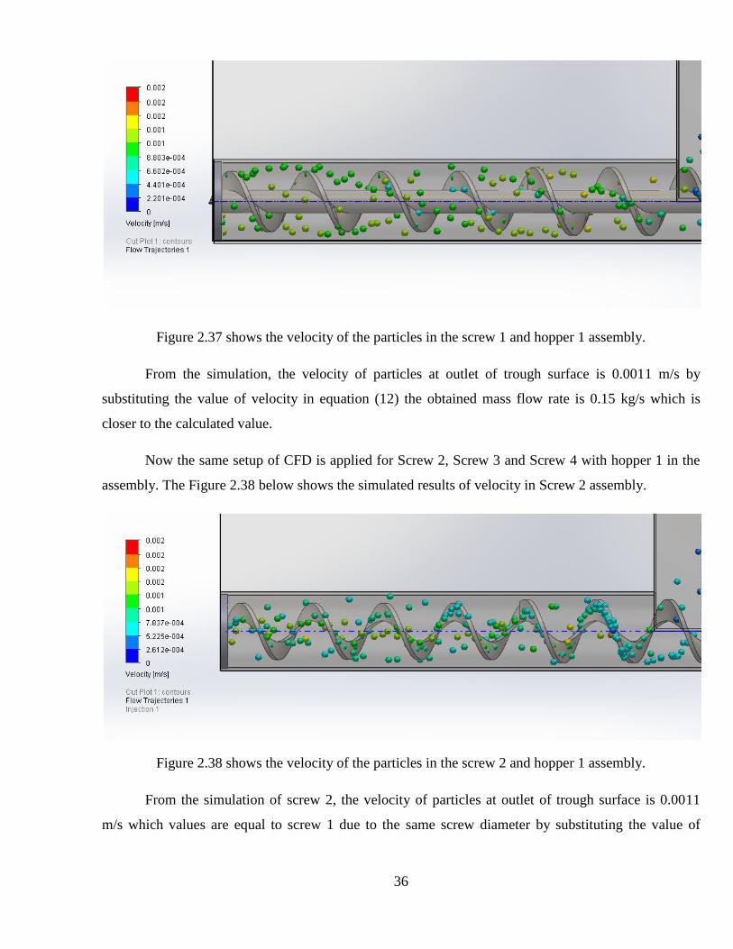
Now the same setup of CFD is applied for Screw 2, Screw 3 and Screw 4 with hopper 1 in the
assembly. The Figure 2.38 below shows the simulated results of velocity in Screw 2 assembly.
Figure 2.38 shows the velocity of the particles in the screw 2 and hopper 1 assembly.
From the simulation of screw 2, the velocity of particles at outlet of trough surface is 0.0011
m/s which values are equal to screw 1 due to the same screw diameter by substituting the value of

37
velocity in equation (12) the obtained mass flow rate is 0.15 kg/s which is closer to the calculated value
0.16 kg/s.
Figure 2.39 shows the velocity of the particle in the screw 3 and hopper 1 assembly.
From the simulation of screw 3 shown in Figure 2.39, the velocity of particles at outlet of
trough surface is 9.644e-004 m/s by substituting the value of velocity in equation (12) the obtained
mass flow rate is 0.12 kg/s which is not closer to the calculated value 0.16 kg/s. Therefore the Screw 3
will not convey required amount of mass flow.
Figure 2.40 shows the velocity of the particle in the screw 4 and hopper 1 assembly.
From the simulation of screw 4 shown in Figure 2.40, the velocity of particles at outlet of
trough surface is 0.00102 m/s by substituting the value of velocity in equation (12) the obtained mass
flow rate is 0.14 kg/s which is closer to the calculated value 0.16 kg/s.

38
3. RESULT
The simulated results from ANSYS WORKBENCH are tabulated and variations are found
through the graph. There four different types of Screw feeders are used in this project. The names of
each screw are listed out below.
SCREW 1 - Shafted screw feeder with different screw diameter.
SCREW 2 – Axial free (shaft less screw feeder with different screw diameter),
SCREW 3 – Axial free screw feeder with standard diameter 90mm.
SCREW 4- Axial free screw feeder with standard diameter 80mm.
3.1 Result analysis on Total deformation of the screw feeders for all the screws:
This section denotes the total deformation of screw feeders. From the table 2.8, 2.9, 2.10 and
2.11 the Figure 3.1 & Figure 3.2 is plotted.
Figure 3.1 Total deformations of all screw feeders for filling level 0.3m
From the Figure 3.1, it shows that screw 2 and screw 4 have lesser deformation value when
compared to screw 1. In screw 2 the deformation of screw 1 is reduced by 1.4 mm and in screw 4
deformations is reduced by 1.43 mm.
3.9 3.9 3.9
2.5
5.82
2.47
0
1
2
3
4
5
6
7
SCREW 1 vs SCREW 2 SCREW 1 vs SCREW 3 SCREW 1 vs SCREW 4
De
form
atio
n S
cale
, mm
Total deformation comparision of Screw 1 vs rest of the screws for filling level 0.3m
SCREW 1 SCREW 2 SCREW 3 SCREW 4

39
Figure 3.2 Total deformations of all screw feeders for filling level 0.45m
From the Figure 3.2, the screw 2 has 1 mm lesser deformation when compared to screw 1. The
screw 4 has same level deformation with screw 1.
3.2 Result analysis on Maximum principal stress for all the screws
This section denotes the Maximum principal stress on all screw feeders. From the tables 2.8 (b),
2.9 (b), 2.10 (b) and 2.11 (b) the Figure 3.3 and 3.4 are plotted.
Figure 3.3 Maximum Principle stresses of all screw feeders for filling level 0.3m
5.2 5.2 5.2 5.1
10.77
4.5
0
2
4
6
8
10
12
SCREW 1 vs SCREW 2 SCREW 1 vs SCREW 3 SCREW 1 vs SCREW 4
De
form
atio
n S
cale
, mm
Total deformation comparison of screw 1 vs rest of the screws for filling level 0.45m
SCREW 1 SCREW 2 SCREW 3 SCREW 4
49.214 49.214 49.214
4.202 6.634 5.389
0
10
20
30
40
50
60
SCREW 1 vs SCREW 2 SCREW 1 vs SCREW 3 SCREW 1 vs SCREW 4
Stre
ss V
alu
es,
MP
a
Comparision of Maximum principal stress on screw 1 vs rest of screws for filling condition 0.3 m
SCREW 1 SCREW 2 SCREW 3 SCREW 4

40
The yield strength of stainless steel (SS 316) is 172.37 MPa. From the figure 3.3, all the four
screw are below the yield strength of stainless steel. The stress value of SCREW- 2 is minimum when
compared to all other screws.
Figure 3.4 Maximum Principle stresses of all screw feeders for filling level 0.3m
From Figure 3.4, the maximum stress for hopper level 0.45 is denoted. All the four screws are
below the yield strength of stainless steel. The stress value of SCREW- 2 is minimum when compared
to all other screws.
3.3 Result on pressure analysis of pelletized particle in hopper
As discussed pressure analysis of pelletized particle (wooden pellet) is done in with two
different hoppers with assembly Screw 1 the existing design. From simulated results of analysis of
jamming using CFD the Figure 3.5 is plotted.
64.095 64.095 64.095
8.411 12.27 11.46
0
10
20
30
40
50
60
70
SCREW 1 vs SCREW 2 SCREW 1 vsSCREW 3 SCREW 1 vsSCREW 4
Stre
ss V
alu
es,
MP
a
Comparision of Maximum prinicipal stress on screw 1 vs rest of the screws for filling condition 0.45 m
SCREW 1 SCREW 2 SCREW 3 SCREW 4

41
Figure 3.5 Pressure comparison of pelletized particle (wooden pellet) in Hopper 1 and Hopper 2
From Figure 3.5, the pressure in pelletized particle is high on Hopper 2 therefore Hopper 1
design is used to analysis of pressure in pelletized particles using all fours in hoper 1 as assembly. From
the simulation results all four assembly the Figure 3.6 is plotted.
Figure 3.6 Pressure comparison of pelletized particle (wooden pellet) in all four assemblies
From Figure 3.6, the pressure in pelletized particle is low on screw 2 and very high on screw 3
assemblies. Pressure on pelletized particles on screw 4 is little high when compared screw 1 assembly.
97936.56
98667.04
97400
97600
97800
98000
98200
98400
98600
98800
Hopper 1 Hopper 2
Pre
ssu
re, P
a
Pressure comparision of granular particle (Wooden pellet) in Hopper 1 and Hopper 2
Hopper 1 Hopper 2
97936.56 97633.86
101411.41
98727.9
95000 96000 97000 98000 99000
100000 101000 102000
Hopper 1 & Screw 1
assembly
Hopper 1 & Screw 2
assembly
Hopper 1 & Screw 3
assembly
Hopper 1 & screw 4
assembly
Pre
ssu
re, P
a
Pressure comparision of granular material (wooden pellet) in all four assembly
Hopper 1 & Screw 1 assembly Hopper 1 & Screw 2 assembly
Hopper 1 & Screw 3 assembly Hopper 1 & screw 4 assembly

42
3.4 Result on analysis of Mass flow rate in all four screws
The Mass flow rate analysis on all screws is done by using three different pelletized particles
with different bulk density at varying speeds. The Figure 3.7 shows the mass flow rate of screw 1 and
the Figure 3.8 shows the mass flow rate of screw 2.
Figure 3.7 Mass flow rates of Screw 1
Figure 3.8 Mass flow rate of Screw 2
0.08 0.10
0.12 0.13
0.15 0.16
0.07 0.08 0.08 0.09 0.09
0.09
0.07 0.08 0.08 0.08 0.09 0.09
0.00
0.05
0.10
0.15
0.20
5 10 15 20 25 30
Mas
s fl
ow
rat
e, K
g/s
Speed, rpm
Mass flow rate of screw 1
Wooden pellets Wooden Shaving Ground Hog fuel
0.09 0.10
0.11 0.12
0.14 0.15
0.07 0.08 0.08 0.09 0.09 0.09
0.07 0.08 0.08 0.08 0.09 0.09
0
0.02
0.04
0.06
0.08
0.1
0.12
0.14
0.16
5 10 15 20 25 30
Mas
s fl
ow
rat
e, K
g/s
Speed, rpm
Mass flow rate of screw 2
Wooden pellets Wooden shavings Ground hog fuel

43
Now the mass flow rate of screw 3 is shown in the figure 3.9 with same three pelletized
materials such as wooden pellets, wooden shaving and Ground hog fuel.
Figure 3.9 Mass flow rate of Screw 3
The final part of the research shows the mass flow rate of screw 4 in figure 3.10.
Figure 3.10 Mass flow rate of Screw 4
0.019
0.039
0.058
0.077
0.097
0.116
0.006 0.011
0.017 0.022 0.028 0.033
0.005 0.009 0.014 0.018 0.023 0.028
0.000
0.020
0.040
0.060
0.080
0.100
0.120
0.140
5 10 15 20 25 30
Mas
s fl
ow
rat
e, K
g/s
Speed, rpm
Mass flow rate of screw 3
Wooden Pellets Wooden Shaving Ground hog fuel
0.02
0.05
0.07
0.09
0.12
0.14
0.01 0.01
0.02 0.03
0.03 0.04
0.01 0.01 0.02 0.02 0.03 0.03
0.00
0.02
0.04
0.06
0.08
0.10
0.12
0.14
0.16
5 10 15 20 25 30
Mas
s fl
ow
rat
e, K
g/s
Speed, rpm
Mass flow rate of screw 4
Wooden Pellets Wooden Shaving Ground Hog fuel

44
CONCLUSIONS
The design calculations, modeling and analysis were done for all the four screw feeders. The
modeling of the screw feeders are constructed using SOLIDWORKS 2013. The stress and deformation
analysis are done using ANSYS workbench 14.5. The Jamming analyses are done using
SOLIDWORKS computational fluid dynamics and mass flow rate is checked for all four screws.
1. The Screw-1 is constructed with the typical specifications and its simulation values are
perfectly satisfying the model conditions. From the deformation result of the research, the total
deformation occurring at Screw-1 is in permissible limit to the hopper. The total deformation
occurred in screw-2 is 1.4mm less when compared to Screw 1. The Screw- 3 as higher
deformation values than screw 1 which will be unsuitable for existing hopper design. The
Screw-4 also has similar less deformation when compared to Screw 1.
2. From the result of Maximum principle stress, the maximum stress occurring at all four screws
are below the yield strength therefore the design is safe. In comparison, the stress value in
Screw- 2 is 56MPa less when compared to screw-1. The Screw-4 also has less stress value
which is reduced up to 53MPa.
3. From the result of jamming analysis, the pressure of pelletized particles in hopper 1 is lesser
than hopper 2 therefore the possibility of jamming is less in hopper 1. The chances of jamming
with all four screws with hopper 1 assembly are analyzed. From the results of the assembly, it
shows that Screw 2 assembly has lesser pressure values of pelletized particle in the hopper 1
when compared to Screw 1 – hopper 1 assembly. The screw 4 has little high pressure in
pelletized particle with hopper 1 assembly when compared to Screw 1- Hopper 1 assembly.
4. The mass flow rate are calculated and plotted for all four screws when comparing the result,
Screw 2 have equal mass flow rate to screw 1. The Screw 4 have closer mass flow rate to
Screw 1.
From this research, the modified design Screw 4 will be suitable for existing hopper with some
tapered design at trough part and the modified design Screw 2 will be directly suitable for existing
hopper 1 which has 7.3 Kg lesser weight when compared to Screw 1, less deformation, less stress
values and similar performance to the screw 1.

45
LIST OF REFERENCES
1. McGraw-Hill Dictionary of Scientific & Technical Terms, 6E, Copyright © 2003 by The
McGraw-Hill Companies, Inc.
2. Introduction to Material Handling, New age international publication by Siddhartha Ray 2008.
3. Handbook of Conveying and Handling of Particulate Solids by A. Levy, Christopher J Kalman.
4. A review on numerical and experimental study of screw conveyor by Jigar patel, sumant patel
and snehal patel.
5. Design and performance evaluation of screw conveyors by Alan W. Roberts
6. A modal of biomass screw feeding by Jianjun Dai, John R Grace
7. Biomass screw feeding with tapered and extended sections by Jianjun Dai, John R Grace
8. A.W Roberts, K.S Manjunath volumetric and torque characteristics if screw feeders.
9. Improved conveyor performance by adjusting operating parameters to avoid loads and adhering
to more rigorous inspections, conveyor downtime from wood screw failures becomes avoidable
by Monica Shaw.
10. KWS Design Engineering Manufacture, Access via internet: http://mdcreps.com/newspace/kws-
manufacturing/, Access on: 10th
May 2015
11. A textbook of Machine Design by R.S Khurmi and J.K Gupta.
12. Hand book of conveying and Handling of Particulate solids by A. Levy, Christopher J kalman.
13. Axle-free spiral conveyor by spirac, Access via internet :
http://www.spirac.com/products/shaftless-screw-conveyor, Accessed on: 10th
May 2015
14. K.S Manjunath, A.W. Roberts, Wall pressure-feeder load interactions in mass flow
hopper/feeder combinations.
15. Book on 1st World Conference on Biomass for Energy and Industry by Spyros Kyritsis
16. Archimedes Screw wiki, Internet source: http://en.wikipedia.org/wiki/Archimedes%27_screw
Accessed on: 9th
May 2015
17. Lesson learnt from existing biomass plants by G. Wiltsee.
18. FBC wiki, Internet source: http://en.wikipedia.org/wiki/Fluidized_bed_combustion
Accessed on: 15th
May 2015