Kaleido Software Users Manual - Grass Valley
536
User’s Manual M770-2800-144 2018-09-07 KALEIDO SOFTWARE UNMATCHED PICTURE QUALITY AND LAYOUT FLEXIBILITY
-
Upload
khangminh22 -
Category
Documents
-
view
3 -
download
0
Transcript of Kaleido Software Users Manual - Grass Valley

User’s ManualM770-2800-144
2018-09-07
KALEIDO SOFTWAREUNMATCHED PICTURE QUALITY AND LAYOUT FLEXIBILITY

2
Notices
Copyright & Trademark NoticeCopyright © 2007–2018, Grass Valley Canada. All rights reserved.
Belden, Belden Sending All The Right Signals, and the Belden logo are trademarks or registered trademarks of Belden Inc. or its affiliated companies in the United States and other jurisdictions. Grass Valley, Kaleido, Kaleido-X, iControl, NVISION, and Densité are trademarks or registered trademarks of Grass Valley Canada. Belden Inc., Grass Valley Canada, and other parties may also have trademark rights in other terms used herein.
Terms and ConditionsPlease read the following terms and conditions carefully. By using Kaleido multiviewer documentation, you agree to the following terms and conditions.
Grass Valley hereby grants permission and license to owners of Kaleido multiviewers to use their product manuals for their own internal business use. Manuals for Grass Valley products may not be reproduced or transmitted in any form or by any means, electronic or mechanical, including photocopying and recording, for any purpose unless specifically authorized in writing by Grass Valley.
A Grass Valley manual may have been revised to reflect changes made to the product during its manufacturing life. Thus, different versions of a manual may exist for any given product. Care should be taken to ensure that one obtains the proper manual version for a specific product serial number.
Information in this document is subject to change without notice and does not represent a commitment on the part of Grass Valley.
Warranty information is available from the Legal Terms and Conditions section of Grass Valley’s website (www.grassvalley.com).
Title Kaleido Software User’s Manual
Part Number M770-2800-144
Revision 2018-09-07, 13:12

Table of Contents
1 Introduction . . . . . . . . . . . . . . . . . . . . . . . . . . . . . . . . . . . . . . . . . . . . . . . . . . . . . . 13Introduction. . . . . . . . . . . . . . . . . . . . . . . . . . . . . . . . . . . . . . . . . . . . . . . . . . . . . . . . . . . . . . . . . . . . . . . . . . . . . . . . . . . . . . . 13About this Document. . . . . . . . . . . . . . . . . . . . . . . . . . . . . . . . . . . . . . . . . . . . . . . . . . . . . . . . . . . . . . . . . . . . . . . . . . . . . . 13Related Documentation . . . . . . . . . . . . . . . . . . . . . . . . . . . . . . . . . . . . . . . . . . . . . . . . . . . . . . . . . . . . . . . . . . . . . . . . . . . 13Software and Firmware Updates . . . . . . . . . . . . . . . . . . . . . . . . . . . . . . . . . . . . . . . . . . . . . . . . . . . . . . . . . . . . . . . . . . . 14Feature Availability and Multiviewer Specifications . . . . . . . . . . . . . . . . . . . . . . . . . . . . . . . . . . . . . . . . . . . . . . . . . 14XEdit Application Shortcuts . . . . . . . . . . . . . . . . . . . . . . . . . . . . . . . . . . . . . . . . . . . . . . . . . . . . . . . . . . . . . . . . . . . . . . . . 15
2 Getting Started. . . . . . . . . . . . . . . . . . . . . . . . . . . . . . . . . . . . . . . . . . . . . . . . . . . . 17Introduction. . . . . . . . . . . . . . . . . . . . . . . . . . . . . . . . . . . . . . . . . . . . . . . . . . . . . . . . . . . . . . . . . . . . . . . . . . . . . . . . . . . . . . . 17Multiviewer Signal Flow Overview . . . . . . . . . . . . . . . . . . . . . . . . . . . . . . . . . . . . . . . . . . . . . . . . . . . . . . . . . . . . . . . . . 18
Multiviewer Sources . . . . . . . . . . . . . . . . . . . . . . . . . . . . . . . . . . . . . . . . . . . . . . . . . . . . . . . . . . . . . . . . . . . . . . . . . . . 19Logical Sources. . . . . . . . . . . . . . . . . . . . . . . . . . . . . . . . . . . . . . . . . . . . . . . . . . . . . . . . . . . . . . . . . . . . . . . . . . . . . . . . 20Monitors . . . . . . . . . . . . . . . . . . . . . . . . . . . . . . . . . . . . . . . . . . . . . . . . . . . . . . . . . . . . . . . . . . . . . . . . . . . . . . . . . . . . . . 20Layouts . . . . . . . . . . . . . . . . . . . . . . . . . . . . . . . . . . . . . . . . . . . . . . . . . . . . . . . . . . . . . . . . . . . . . . . . . . . . . . . . . . . . . . . 20Rooms and Displays . . . . . . . . . . . . . . . . . . . . . . . . . . . . . . . . . . . . . . . . . . . . . . . . . . . . . . . . . . . . . . . . . . . . . . . . . . . 21
3 Managing Kaleido Multiviewer Systems. . . . . . . . . . . . . . . . . . . . . . . . . . . . . 23Introduction. . . . . . . . . . . . . . . . . . . . . . . . . . . . . . . . . . . . . . . . . . . . . . . . . . . . . . . . . . . . . . . . . . . . . . . . . . . . . . . . . . . . . . . 23Key Concepts. . . . . . . . . . . . . . . . . . . . . . . . . . . . . . . . . . . . . . . . . . . . . . . . . . . . . . . . . . . . . . . . . . . . . . . . . . . . . . . . . . . . . . 23Representation of Multiviewer Models in Kaleido Software. . . . . . . . . . . . . . . . . . . . . . . . . . . . . . . . . . . . . . . . . . 27Opening XEdit Software . . . . . . . . . . . . . . . . . . . . . . . . . . . . . . . . . . . . . . . . . . . . . . . . . . . . . . . . . . . . . . . . . . . . . . . . . . . 28Difference between Online and Offline Modes . . . . . . . . . . . . . . . . . . . . . . . . . . . . . . . . . . . . . . . . . . . . . . . . . . . . . 31Using XEdit in Online Mode . . . . . . . . . . . . . . . . . . . . . . . . . . . . . . . . . . . . . . . . . . . . . . . . . . . . . . . . . . . . . . . . . . . . . . . . 32
Connecting to a Multiviewer . . . . . . . . . . . . . . . . . . . . . . . . . . . . . . . . . . . . . . . . . . . . . . . . . . . . . . . . . . . . . . . . . . . 32Disconnecting from a Multiviewer . . . . . . . . . . . . . . . . . . . . . . . . . . . . . . . . . . . . . . . . . . . . . . . . . . . . . . . . . . . . . 33Enabling Access Control in XEdit . . . . . . . . . . . . . . . . . . . . . . . . . . . . . . . . . . . . . . . . . . . . . . . . . . . . . . . . . . . . . . . 34Disabling Access Control in XEdit . . . . . . . . . . . . . . . . . . . . . . . . . . . . . . . . . . . . . . . . . . . . . . . . . . . . . . . . . . . . . . 34
Importing a Database. . . . . . . . . . . . . . . . . . . . . . . . . . . . . . . . . . . . . . . . . . . . . . . . . . . . . . . . . . . . . . . . . . . . . . . . . . . . . . 35Exporting a Database . . . . . . . . . . . . . . . . . . . . . . . . . . . . . . . . . . . . . . . . . . . . . . . . . . . . . . . . . . . . . . . . . . . . . . . . . . . . . . 37
Exporting a Single-Multiviewer Database. . . . . . . . . . . . . . . . . . . . . . . . . . . . . . . . . . . . . . . . . . . . . . . . . . . . . . . 37Exporting a Cluster Database . . . . . . . . . . . . . . . . . . . . . . . . . . . . . . . . . . . . . . . . . . . . . . . . . . . . . . . . . . . . . . . . . . 37
Creating a Backup . . . . . . . . . . . . . . . . . . . . . . . . . . . . . . . . . . . . . . . . . . . . . . . . . . . . . . . . . . . . . . . . . . . . . . . . . . . . . . . . . 40Backing Up the Current Database . . . . . . . . . . . . . . . . . . . . . . . . . . . . . . . . . . . . . . . . . . . . . . . . . . . . . . . . . . . . . . 40Backing Up Resolutions. . . . . . . . . . . . . . . . . . . . . . . . . . . . . . . . . . . . . . . . . . . . . . . . . . . . . . . . . . . . . . . . . . . . . . . . 40Backing Up Audio Scales. . . . . . . . . . . . . . . . . . . . . . . . . . . . . . . . . . . . . . . . . . . . . . . . . . . . . . . . . . . . . . . . . . . . . . . 40
Restoring a Backup . . . . . . . . . . . . . . . . . . . . . . . . . . . . . . . . . . . . . . . . . . . . . . . . . . . . . . . . . . . . . . . . . . . . . . . . . . . . . . . . 41Restoring a Database from a Backup . . . . . . . . . . . . . . . . . . . . . . . . . . . . . . . . . . . . . . . . . . . . . . . . . . . . . . . . . . . 41Restoring Resolutions or Audio Scales from a Backup . . . . . . . . . . . . . . . . . . . . . . . . . . . . . . . . . . . . . . . . . . . 41
Creating a Single Multiviewer System . . . . . . . . . . . . . . . . . . . . . . . . . . . . . . . . . . . . . . . . . . . . . . . . . . . . . . . . . . . . . . 42
3

Table of Contents
Cluster . . . . . . . . . . . . . . . . . . . . . . . . . . . . . . . . . . . . . . . . . . . . . . . . . . . . . . . . . . . . . . . . . . . . . . . . . . . . . . . . . . . . . . . . . . . . 45Creating a Cluster . . . . . . . . . . . . . . . . . . . . . . . . . . . . . . . . . . . . . . . . . . . . . . . . . . . . . . . . . . . . . . . . . . . . . . . . . . . . . 45
Cascade . . . . . . . . . . . . . . . . . . . . . . . . . . . . . . . . . . . . . . . . . . . . . . . . . . . . . . . . . . . . . . . . . . . . . . . . . . . . . . . . . . . . . . . . . . . 52Configuring the System Representation . . . . . . . . . . . . . . . . . . . . . . . . . . . . . . . . . . . . . . . . . . . . . . . . . . . . . . . . . . . . 53Managing Cards in a Kaleido-X or KMX-3901 System Representation . . . . . . . . . . . . . . . . . . . . . . . . . . . . . . . . 54
Emptying card slots . . . . . . . . . . . . . . . . . . . . . . . . . . . . . . . . . . . . . . . . . . . . . . . . . . . . . . . . . . . . . . . . . . . . . . . . . . . 55Populating card slots . . . . . . . . . . . . . . . . . . . . . . . . . . . . . . . . . . . . . . . . . . . . . . . . . . . . . . . . . . . . . . . . . . . . . . . . . . 55
Restoring the Factory-Default Configuration . . . . . . . . . . . . . . . . . . . . . . . . . . . . . . . . . . . . . . . . . . . . . . . . . . . . . . . 57To restore the XEdit factory defaults for a multiviewer model . . . . . . . . . . . . . . . . . . . . . . . . . . . . . . . . . . . 57To restore the XEdit factory defaults for a multiviewer cluster . . . . . . . . . . . . . . . . . . . . . . . . . . . . . . . . . . . 58
Managing Multiple Databases Efficiently . . . . . . . . . . . . . . . . . . . . . . . . . . . . . . . . . . . . . . . . . . . . . . . . . . . . . . . . . . . 60Working online. . . . . . . . . . . . . . . . . . . . . . . . . . . . . . . . . . . . . . . . . . . . . . . . . . . . . . . . . . . . . . . . . . . . . . . . . . . . . . . . 60Working offline. . . . . . . . . . . . . . . . . . . . . . . . . . . . . . . . . . . . . . . . . . . . . . . . . . . . . . . . . . . . . . . . . . . . . . . . . . . . . . . . 60Applying a backup database to the multiviewer . . . . . . . . . . . . . . . . . . . . . . . . . . . . . . . . . . . . . . . . . . . . . . . . 61
4 Managing Sources in a Kaleido-IP System . . . . . . . . . . . . . . . . . . . . . . . . . . . 63Introduction. . . . . . . . . . . . . . . . . . . . . . . . . . . . . . . . . . . . . . . . . . . . . . . . . . . . . . . . . . . . . . . . . . . . . . . . . . . . . . . . . . . . . . . 63
Input Types - Network Sources Versus Virtual Inputs Explained. . . . . . . . . . . . . . . . . . . . . . . . . . . . . . . . . . 63Kaleido-IP Multiviewer Ethernet Port Usage . . . . . . . . . . . . . . . . . . . . . . . . . . . . . . . . . . . . . . . . . . . . . . . . . . . . 65Default Kaleido-IP Network Source Configuration in XEdit . . . . . . . . . . . . . . . . . . . . . . . . . . . . . . . . . . . . . . 65Configuration Prerequisites . . . . . . . . . . . . . . . . . . . . . . . . . . . . . . . . . . . . . . . . . . . . . . . . . . . . . . . . . . . . . . . . . . . . 65
Configuring Network Sources . . . . . . . . . . . . . . . . . . . . . . . . . . . . . . . . . . . . . . . . . . . . . . . . . . . . . . . . . . . . . . . . . . . . . . 66Adding Any-Source Multicast Transport Stream Sources . . . . . . . . . . . . . . . . . . . . . . . . . . . . . . . . . . . . . . . . 66Adding Source-Specific or Source-Filtered Multicast Transport Stream Sources . . . . . . . . . . . . . . . . . . 68Adding Unicast Transport Stream Sources. . . . . . . . . . . . . . . . . . . . . . . . . . . . . . . . . . . . . . . . . . . . . . . . . . . . . . 70Adding HLS Playlist Sources . . . . . . . . . . . . . . . . . . . . . . . . . . . . . . . . . . . . . . . . . . . . . . . . . . . . . . . . . . . . . . . . . . . 71Adding RTSP Transport Stream Sources . . . . . . . . . . . . . . . . . . . . . . . . . . . . . . . . . . . . . . . . . . . . . . . . . . . . . . . . 73Adding RTMP Transport Stream Sources . . . . . . . . . . . . . . . . . . . . . . . . . . . . . . . . . . . . . . . . . . . . . . . . . . . . . . . 74Modifying transport streams and HLS playlists. . . . . . . . . . . . . . . . . . . . . . . . . . . . . . . . . . . . . . . . . . . . . . . . . . 75Removing transport streams and HLS playlists. . . . . . . . . . . . . . . . . . . . . . . . . . . . . . . . . . . . . . . . . . . . . . . . . . 77Importing an Input Configuration from a Spreadsheet . . . . . . . . . . . . . . . . . . . . . . . . . . . . . . . . . . . . . . . . . . 78
Configuring Virtual Inputs . . . . . . . . . . . . . . . . . . . . . . . . . . . . . . . . . . . . . . . . . . . . . . . . . . . . . . . . . . . . . . . . . . . . . . . . . 84Adding Virtual Inputs . . . . . . . . . . . . . . . . . . . . . . . . . . . . . . . . . . . . . . . . . . . . . . . . . . . . . . . . . . . . . . . . . . . . . . . . . . 84Modifying Virtual Inputs . . . . . . . . . . . . . . . . . . . . . . . . . . . . . . . . . . . . . . . . . . . . . . . . . . . . . . . . . . . . . . . . . . . . . . . 86Removing Virtual Inputs . . . . . . . . . . . . . . . . . . . . . . . . . . . . . . . . . . . . . . . . . . . . . . . . . . . . . . . . . . . . . . . . . . . . . . . 87
5 Logical Sources. . . . . . . . . . . . . . . . . . . . . . . . . . . . . . . . . . . . . . . . . . . . . . . . . . . . 89Introduction. . . . . . . . . . . . . . . . . . . . . . . . . . . . . . . . . . . . . . . . . . . . . . . . . . . . . . . . . . . . . . . . . . . . . . . . . . . . . . . . . . . . . . . 89Key Concepts. . . . . . . . . . . . . . . . . . . . . . . . . . . . . . . . . . . . . . . . . . . . . . . . . . . . . . . . . . . . . . . . . . . . . . . . . . . . . . . . . . . . . . 89Creating and Configuring Logical Sources . . . . . . . . . . . . . . . . . . . . . . . . . . . . . . . . . . . . . . . . . . . . . . . . . . . . . . . . . . 90
Automatically Adding Logical Sources . . . . . . . . . . . . . . . . . . . . . . . . . . . . . . . . . . . . . . . . . . . . . . . . . . . . . . . . . 90Managing Logical Sources Associated with Programs in a Transport Stream . . . . . . . . . . . . . . . . . . . . . 92Adding logical sources for new programs in a transport stream . . . . . . . . . . . . . . . . . . . . . . . . . . . . . . . . . 92Manually adding a Logical Source. . . . . . . . . . . . . . . . . . . . . . . . . . . . . . . . . . . . . . . . . . . . . . . . . . . . . . . . . . . . . . 94Managing Levels . . . . . . . . . . . . . . . . . . . . . . . . . . . . . . . . . . . . . . . . . . . . . . . . . . . . . . . . . . . . . . . . . . . . . . . . . . . . . . 95Managing Logical Source Count Prompts . . . . . . . . . . . . . . . . . . . . . . . . . . . . . . . . . . . . . . . . . . . . . . . . . . . . . . 97Defining Physical Assignments. . . . . . . . . . . . . . . . . . . . . . . . . . . . . . . . . . . . . . . . . . . . . . . . . . . . . . . . . . . . . . . . . 98Making Further Assignments by Incremental Copy . . . . . . . . . . . . . . . . . . . . . . . . . . . . . . . . . . . . . . . . . . . . 102
4

Kaleido SoftwareUser’s Manual
Sorting the Sources Table. . . . . . . . . . . . . . . . . . . . . . . . . . . . . . . . . . . . . . . . . . . . . . . . . . . . . . . . . . . . . . . . . . . . . 104Filtering the Sources Table. . . . . . . . . . . . . . . . . . . . . . . . . . . . . . . . . . . . . . . . . . . . . . . . . . . . . . . . . . . . . . . . . . . . 104Resizing the Sources Table’s Columns . . . . . . . . . . . . . . . . . . . . . . . . . . . . . . . . . . . . . . . . . . . . . . . . . . . . . . . . . 105
Monitoring Internal-Router Outputs on the Monitor Wall (Sample Scenario) . . . . . . . . . . . . . . . . . . . . . . . . 106
6 Calibrating the Kaleido Software . . . . . . . . . . . . . . . . . . . . . . . . . . . . . . . . . . 107Introduction. . . . . . . . . . . . . . . . . . . . . . . . . . . . . . . . . . . . . . . . . . . . . . . . . . . . . . . . . . . . . . . . . . . . . . . . . . . . . . . . . . . . . . 107Key Concepts. . . . . . . . . . . . . . . . . . . . . . . . . . . . . . . . . . . . . . . . . . . . . . . . . . . . . . . . . . . . . . . . . . . . . . . . . . . . . . . . . . . . . 107
Profiles. . . . . . . . . . . . . . . . . . . . . . . . . . . . . . . . . . . . . . . . . . . . . . . . . . . . . . . . . . . . . . . . . . . . . . . . . . . . . . . . . . . . . . . 107Multiviewer Output Calibrations . . . . . . . . . . . . . . . . . . . . . . . . . . . . . . . . . . . . . . . . . . . . . . . . . . . . . . . . . . . . . . 108Multiviewer Input Calibrations . . . . . . . . . . . . . . . . . . . . . . . . . . . . . . . . . . . . . . . . . . . . . . . . . . . . . . . . . . . . . . . . 109Router Output Calibrations . . . . . . . . . . . . . . . . . . . . . . . . . . . . . . . . . . . . . . . . . . . . . . . . . . . . . . . . . . . . . . . . . . . 111GPI/Genlock Calibrations . . . . . . . . . . . . . . . . . . . . . . . . . . . . . . . . . . . . . . . . . . . . . . . . . . . . . . . . . . . . . . . . . . . . . 111Alarm Debouncing . . . . . . . . . . . . . . . . . . . . . . . . . . . . . . . . . . . . . . . . . . . . . . . . . . . . . . . . . . . . . . . . . . . . . . . . . . . 111
Managing Calibration Profiles. . . . . . . . . . . . . . . . . . . . . . . . . . . . . . . . . . . . . . . . . . . . . . . . . . . . . . . . . . . . . . . . . . . . . 113Creating Calibration Profiles . . . . . . . . . . . . . . . . . . . . . . . . . . . . . . . . . . . . . . . . . . . . . . . . . . . . . . . . . . . . . . . . . . 113Deleting Calibration Profiles . . . . . . . . . . . . . . . . . . . . . . . . . . . . . . . . . . . . . . . . . . . . . . . . . . . . . . . . . . . . . . . . . . 113Configuring Calibration Profiles . . . . . . . . . . . . . . . . . . . . . . . . . . . . . . . . . . . . . . . . . . . . . . . . . . . . . . . . . . . . . . . 113Assigning Calibration Profiles . . . . . . . . . . . . . . . . . . . . . . . . . . . . . . . . . . . . . . . . . . . . . . . . . . . . . . . . . . . . . . . . . 114
Configuring Alarm Thresholds . . . . . . . . . . . . . . . . . . . . . . . . . . . . . . . . . . . . . . . . . . . . . . . . . . . . . . . . . . . . . . . . . . . . 116Configuring Alarm Debouncing . . . . . . . . . . . . . . . . . . . . . . . . . . . . . . . . . . . . . . . . . . . . . . . . . . . . . . . . . . . . . . . . . . . 121Multiviewer Input Calibrations . . . . . . . . . . . . . . . . . . . . . . . . . . . . . . . . . . . . . . . . . . . . . . . . . . . . . . . . . . . . . . . . . . . . 123
Configuring Audio Programs . . . . . . . . . . . . . . . . . . . . . . . . . . . . . . . . . . . . . . . . . . . . . . . . . . . . . . . . . . . . . . . . . 123Calibrating Loudness Measurement. . . . . . . . . . . . . . . . . . . . . . . . . . . . . . . . . . . . . . . . . . . . . . . . . . . . . . . . . . . 124Calibrating Loudness Probe Assignments . . . . . . . . . . . . . . . . . . . . . . . . . . . . . . . . . . . . . . . . . . . . . . . . . . . . . 127Calibrating Dolby Dialog Loudness Measurement . . . . . . . . . . . . . . . . . . . . . . . . . . . . . . . . . . . . . . . . . . . . . 128Configuring Sources for Dolby E Audio Metadata . . . . . . . . . . . . . . . . . . . . . . . . . . . . . . . . . . . . . . . . . . . . . . 130Calibrating Zero VU Reference Levels for Embedded Audio Sources . . . . . . . . . . . . . . . . . . . . . . . . . . . . 131Calibrating Zero VU Reference Level for an ABT Audio Source . . . . . . . . . . . . . . . . . . . . . . . . . . . . . . . . . . 132Calibrating Aspect Ratio Decoding . . . . . . . . . . . . . . . . . . . . . . . . . . . . . . . . . . . . . . . . . . . . . . . . . . . . . . . . . . . . 133Calibrating Detail Enhancement . . . . . . . . . . . . . . . . . . . . . . . . . . . . . . . . . . . . . . . . . . . . . . . . . . . . . . . . . . . . . . 134Calibrating HDR . . . . . . . . . . . . . . . . . . . . . . . . . . . . . . . . . . . . . . . . . . . . . . . . . . . . . . . . . . . . . . . . . . . . . . . . . . . . . . 135Calibrating Dynamic Range . . . . . . . . . . . . . . . . . . . . . . . . . . . . . . . . . . . . . . . . . . . . . . . . . . . . . . . . . . . . . . . . . . . 137Calibrating Subtitling/Closed Captioning. . . . . . . . . . . . . . . . . . . . . . . . . . . . . . . . . . . . . . . . . . . . . . . . . . . . . . 138Calibrating Metadata Holding Time . . . . . . . . . . . . . . . . . . . . . . . . . . . . . . . . . . . . . . . . . . . . . . . . . . . . . . . . . . . 140Calibrating DTMF Tone Sequences . . . . . . . . . . . . . . . . . . . . . . . . . . . . . . . . . . . . . . . . . . . . . . . . . . . . . . . . . . . . 143Calibrating SCTE 35 Event Reporting Duration. . . . . . . . . . . . . . . . . . . . . . . . . . . . . . . . . . . . . . . . . . . . . . . . . 144
Calibrating SCTE 104 Message Events . . . . . . . . . . . . . . . . . . . . . . . . . . . . . . . . . . . . . . . . . . . . . . . . . . . . . . . . . . . . . 146Multiviewer Output Calibrations . . . . . . . . . . . . . . . . . . . . . . . . . . . . . . . . . . . . . . . . . . . . . . . . . . . . . . . . . . . . . . . . . . 148
Calibrating the Brightness and Contrast . . . . . . . . . . . . . . . . . . . . . . . . . . . . . . . . . . . . . . . . . . . . . . . . . . . . . . . 148Calibrating Color Saturation . . . . . . . . . . . . . . . . . . . . . . . . . . . . . . . . . . . . . . . . . . . . . . . . . . . . . . . . . . . . . . . . . . 149Calibrating the DVI Keying Mode. . . . . . . . . . . . . . . . . . . . . . . . . . . . . . . . . . . . . . . . . . . . . . . . . . . . . . . . . . . . . . 151Calibrating the Audio Monitoring Delay . . . . . . . . . . . . . . . . . . . . . . . . . . . . . . . . . . . . . . . . . . . . . . . . . . . . . . . 152Calibrating the Audio Monitoring Color . . . . . . . . . . . . . . . . . . . . . . . . . . . . . . . . . . . . . . . . . . . . . . . . . . . . . . . 154
Router Output Calibrations . . . . . . . . . . . . . . . . . . . . . . . . . . . . . . . . . . . . . . . . . . . . . . . . . . . . . . . . . . . . . . . . . . . . . . . 156Calibrating Switch Field Selection . . . . . . . . . . . . . . . . . . . . . . . . . . . . . . . . . . . . . . . . . . . . . . . . . . . . . . . . . . . . . 156Calibrating SDI Signal Reclocking . . . . . . . . . . . . . . . . . . . . . . . . . . . . . . . . . . . . . . . . . . . . . . . . . . . . . . . . . . . . . 156
GPI/Genlock Calibrations . . . . . . . . . . . . . . . . . . . . . . . . . . . . . . . . . . . . . . . . . . . . . . . . . . . . . . . . . . . . . . . . . . . . . . . . . 158
5

Table of Contents
7 Configuring Alarms . . . . . . . . . . . . . . . . . . . . . . . . . . . . . . . . . . . . . . . . . . . . . . . 159Introduction. . . . . . . . . . . . . . . . . . . . . . . . . . . . . . . . . . . . . . . . . . . . . . . . . . . . . . . . . . . . . . . . . . . . . . . . . . . . . . . . . . . . . . 159Key Concepts. . . . . . . . . . . . . . . . . . . . . . . . . . . . . . . . . . . . . . . . . . . . . . . . . . . . . . . . . . . . . . . . . . . . . . . . . . . . . . . . . . . . . 159
Alarm . . . . . . . . . . . . . . . . . . . . . . . . . . . . . . . . . . . . . . . . . . . . . . . . . . . . . . . . . . . . . . . . . . . . . . . . . . . . . . . . . . . . . . . . 159General Status Manager (GSM). . . . . . . . . . . . . . . . . . . . . . . . . . . . . . . . . . . . . . . . . . . . . . . . . . . . . . . . . . . . . . . . 159Alarm Logging . . . . . . . . . . . . . . . . . . . . . . . . . . . . . . . . . . . . . . . . . . . . . . . . . . . . . . . . . . . . . . . . . . . . . . . . . . . . . . . 160Alarm Browser . . . . . . . . . . . . . . . . . . . . . . . . . . . . . . . . . . . . . . . . . . . . . . . . . . . . . . . . . . . . . . . . . . . . . . . . . . . . . . . 160Alarm Status . . . . . . . . . . . . . . . . . . . . . . . . . . . . . . . . . . . . . . . . . . . . . . . . . . . . . . . . . . . . . . . . . . . . . . . . . . . . . . . . . 160External Alarm Provider. . . . . . . . . . . . . . . . . . . . . . . . . . . . . . . . . . . . . . . . . . . . . . . . . . . . . . . . . . . . . . . . . . . . . . . 162Lookup Service . . . . . . . . . . . . . . . . . . . . . . . . . . . . . . . . . . . . . . . . . . . . . . . . . . . . . . . . . . . . . . . . . . . . . . . . . . . . . . . 162Alarm Suppression . . . . . . . . . . . . . . . . . . . . . . . . . . . . . . . . . . . . . . . . . . . . . . . . . . . . . . . . . . . . . . . . . . . . . . . . . . . 162Global Alarms . . . . . . . . . . . . . . . . . . . . . . . . . . . . . . . . . . . . . . . . . . . . . . . . . . . . . . . . . . . . . . . . . . . . . . . . . . . . . . . . 162Virtual Alarm . . . . . . . . . . . . . . . . . . . . . . . . . . . . . . . . . . . . . . . . . . . . . . . . . . . . . . . . . . . . . . . . . . . . . . . . . . . . . . . . . 163Sub-Alarm . . . . . . . . . . . . . . . . . . . . . . . . . . . . . . . . . . . . . . . . . . . . . . . . . . . . . . . . . . . . . . . . . . . . . . . . . . . . . . . . . . . 164Alarm Monitor. . . . . . . . . . . . . . . . . . . . . . . . . . . . . . . . . . . . . . . . . . . . . . . . . . . . . . . . . . . . . . . . . . . . . . . . . . . . . . . . 164Simple Network Management Protocol (SNMP) . . . . . . . . . . . . . . . . . . . . . . . . . . . . . . . . . . . . . . . . . . . . . . . 164Teletext, Subtitles, and Closed Captions . . . . . . . . . . . . . . . . . . . . . . . . . . . . . . . . . . . . . . . . . . . . . . . . . . . . . . . 166Dolby E/AC-3 Metadata. . . . . . . . . . . . . . . . . . . . . . . . . . . . . . . . . . . . . . . . . . . . . . . . . . . . . . . . . . . . . . . . . . . . . . . 168Microphone Loudness Measurement . . . . . . . . . . . . . . . . . . . . . . . . . . . . . . . . . . . . . . . . . . . . . . . . . . . . . . . . . 170SCTE 35 Digital Program Insertion (DPI) Signaling . . . . . . . . . . . . . . . . . . . . . . . . . . . . . . . . . . . . . . . . . . . . . 170Bit Rate Measurement . . . . . . . . . . . . . . . . . . . . . . . . . . . . . . . . . . . . . . . . . . . . . . . . . . . . . . . . . . . . . . . . . . . . . . . . 170Transport Stream Monitoring . . . . . . . . . . . . . . . . . . . . . . . . . . . . . . . . . . . . . . . . . . . . . . . . . . . . . . . . . . . . . . . . . 170
Managing Alarm Providers. . . . . . . . . . . . . . . . . . . . . . . . . . . . . . . . . . . . . . . . . . . . . . . . . . . . . . . . . . . . . . . . . . . . . . . . 172Managing Virtual Alarms. . . . . . . . . . . . . . . . . . . . . . . . . . . . . . . . . . . . . . . . . . . . . . . . . . . . . . . . . . . . . . . . . . . . . . . . . . 174
Creating Virtual Alarms . . . . . . . . . . . . . . . . . . . . . . . . . . . . . . . . . . . . . . . . . . . . . . . . . . . . . . . . . . . . . . . . . . . . . . . 174Modifying Virtual Alarms . . . . . . . . . . . . . . . . . . . . . . . . . . . . . . . . . . . . . . . . . . . . . . . . . . . . . . . . . . . . . . . . . . . . . 179Deleting Virtual Alarms . . . . . . . . . . . . . . . . . . . . . . . . . . . . . . . . . . . . . . . . . . . . . . . . . . . . . . . . . . . . . . . . . . . . . . . 180
Managing Alarm Logging. . . . . . . . . . . . . . . . . . . . . . . . . . . . . . . . . . . . . . . . . . . . . . . . . . . . . . . . . . . . . . . . . . . . . . . . . 182Adding a GSM log plug-in . . . . . . . . . . . . . . . . . . . . . . . . . . . . . . . . . . . . . . . . . . . . . . . . . . . . . . . . . . . . . . . . . . . . 182Specifying your multiviewer as a lookup server for iControl . . . . . . . . . . . . . . . . . . . . . . . . . . . . . . . . . . . . 183Enabling logging for a native alarm . . . . . . . . . . . . . . . . . . . . . . . . . . . . . . . . . . . . . . . . . . . . . . . . . . . . . . . . . . . 185Disabling logging for a virtual alarm . . . . . . . . . . . . . . . . . . . . . . . . . . . . . . . . . . . . . . . . . . . . . . . . . . . . . . . . . . 186
Publishing Alarms to SNMP Managers . . . . . . . . . . . . . . . . . . . . . . . . . . . . . . . . . . . . . . . . . . . . . . . . . . . . . . . . . . . . . 187Identifying Target SNMP Managers . . . . . . . . . . . . . . . . . . . . . . . . . . . . . . . . . . . . . . . . . . . . . . . . . . . . . . . . . . . 187Enabling SNMP Traps . . . . . . . . . . . . . . . . . . . . . . . . . . . . . . . . . . . . . . . . . . . . . . . . . . . . . . . . . . . . . . . . . . . . . . . . . 188
8 Setting Up Rooms . . . . . . . . . . . . . . . . . . . . . . . . . . . . . . . . . . . . . . . . . . . . . . . . 191Introduction. . . . . . . . . . . . . . . . . . . . . . . . . . . . . . . . . . . . . . . . . . . . . . . . . . . . . . . . . . . . . . . . . . . . . . . . . . . . . . . . . . . . . . 191Key Concepts. . . . . . . . . . . . . . . . . . . . . . . . . . . . . . . . . . . . . . . . . . . . . . . . . . . . . . . . . . . . . . . . . . . . . . . . . . . . . . . . . . . . . 191Managing Rooms. . . . . . . . . . . . . . . . . . . . . . . . . . . . . . . . . . . . . . . . . . . . . . . . . . . . . . . . . . . . . . . . . . . . . . . . . . . . . . . . . 192
Creating a Room . . . . . . . . . . . . . . . . . . . . . . . . . . . . . . . . . . . . . . . . . . . . . . . . . . . . . . . . . . . . . . . . . . . . . . . . . . . . . 192Creating a 4K UHD Room . . . . . . . . . . . . . . . . . . . . . . . . . . . . . . . . . . . . . . . . . . . . . . . . . . . . . . . . . . . . . . . . . . . . . 193Opening Rooms . . . . . . . . . . . . . . . . . . . . . . . . . . . . . . . . . . . . . . . . . . . . . . . . . . . . . . . . . . . . . . . . . . . . . . . . . . . . . . 195Closing Rooms . . . . . . . . . . . . . . . . . . . . . . . . . . . . . . . . . . . . . . . . . . . . . . . . . . . . . . . . . . . . . . . . . . . . . . . . . . . . . . . 196Deleting Rooms . . . . . . . . . . . . . . . . . . . . . . . . . . . . . . . . . . . . . . . . . . . . . . . . . . . . . . . . . . . . . . . . . . . . . . . . . . . . . . 196Adding Displays . . . . . . . . . . . . . . . . . . . . . . . . . . . . . . . . . . . . . . . . . . . . . . . . . . . . . . . . . . . . . . . . . . . . . . . . . . . . . . 197Removing Displays . . . . . . . . . . . . . . . . . . . . . . . . . . . . . . . . . . . . . . . . . . . . . . . . . . . . . . . . . . . . . . . . . . . . . . . . . . . 199Adding Full Screen Zones. . . . . . . . . . . . . . . . . . . . . . . . . . . . . . . . . . . . . . . . . . . . . . . . . . . . . . . . . . . . . . . . . . . . . 200
6

Kaleido SoftwareUser’s Manual
Removing Full Screen Zones . . . . . . . . . . . . . . . . . . . . . . . . . . . . . . . . . . . . . . . . . . . . . . . . . . . . . . . . . . . . . . . . . . 200Configuring Displays . . . . . . . . . . . . . . . . . . . . . . . . . . . . . . . . . . . . . . . . . . . . . . . . . . . . . . . . . . . . . . . . . . . . . . . . . . . . . 201
Viewing Room Display Properties . . . . . . . . . . . . . . . . . . . . . . . . . . . . . . . . . . . . . . . . . . . . . . . . . . . . . . . . . . . . . 201Enabling EDID Auto-Detection in XEdit. . . . . . . . . . . . . . . . . . . . . . . . . . . . . . . . . . . . . . . . . . . . . . . . . . . . . . . . 202Configuring Custom Resolutions from the Tools Menu. . . . . . . . . . . . . . . . . . . . . . . . . . . . . . . . . . . . . . . . . 202Configuring a Custom Resolution from a Specific Display in a Room. . . . . . . . . . . . . . . . . . . . . . . . . . . . 205Changing Room Display Resolutions . . . . . . . . . . . . . . . . . . . . . . . . . . . . . . . . . . . . . . . . . . . . . . . . . . . . . . . . . . 207Configuring the Primary and Secondary Multiviewer Outputs . . . . . . . . . . . . . . . . . . . . . . . . . . . . . . . . . . 208Scan Format. . . . . . . . . . . . . . . . . . . . . . . . . . . . . . . . . . . . . . . . . . . . . . . . . . . . . . . . . . . . . . . . . . . . . . . . . . . . . . . . . . 209Enabling HDR or WCG Monitoring Output for a Display . . . . . . . . . . . . . . . . . . . . . . . . . . . . . . . . . . . . . . . . 209Enabling Phase Locking at the Monitoring Output. . . . . . . . . . . . . . . . . . . . . . . . . . . . . . . . . . . . . . . . . . . . . 210Disabling the Dashboard . . . . . . . . . . . . . . . . . . . . . . . . . . . . . . . . . . . . . . . . . . . . . . . . . . . . . . . . . . . . . . . . . . . . . 210Changing a Display’s Aspect Ratio . . . . . . . . . . . . . . . . . . . . . . . . . . . . . . . . . . . . . . . . . . . . . . . . . . . . . . . . . . . . 211Changing a Display’s Diagonal Size . . . . . . . . . . . . . . . . . . . . . . . . . . . . . . . . . . . . . . . . . . . . . . . . . . . . . . . . . . . 211Changing a Display’s Height . . . . . . . . . . . . . . . . . . . . . . . . . . . . . . . . . . . . . . . . . . . . . . . . . . . . . . . . . . . . . . . . . . 211Changing a Display’s Width . . . . . . . . . . . . . . . . . . . . . . . . . . . . . . . . . . . . . . . . . . . . . . . . . . . . . . . . . . . . . . . . . . . 212Changing a Display’s Rotation . . . . . . . . . . . . . . . . . . . . . . . . . . . . . . . . . . . . . . . . . . . . . . . . . . . . . . . . . . . . . . . . 212Changing a Display’s Position . . . . . . . . . . . . . . . . . . . . . . . . . . . . . . . . . . . . . . . . . . . . . . . . . . . . . . . . . . . . . . . . . 213
Managing Display Libraries . . . . . . . . . . . . . . . . . . . . . . . . . . . . . . . . . . . . . . . . . . . . . . . . . . . . . . . . . . . . . . . . . . . . . . . 214Creating Custom Display Libraries . . . . . . . . . . . . . . . . . . . . . . . . . . . . . . . . . . . . . . . . . . . . . . . . . . . . . . . . . . . . 214Adding Displays to Custom Libraries . . . . . . . . . . . . . . . . . . . . . . . . . . . . . . . . . . . . . . . . . . . . . . . . . . . . . . . . . . 215Removing Displays from Custom Libraries. . . . . . . . . . . . . . . . . . . . . . . . . . . . . . . . . . . . . . . . . . . . . . . . . . . . . 215Closing Display Libraries . . . . . . . . . . . . . . . . . . . . . . . . . . . . . . . . . . . . . . . . . . . . . . . . . . . . . . . . . . . . . . . . . . . . . . 216Opening Display Libraries . . . . . . . . . . . . . . . . . . . . . . . . . . . . . . . . . . . . . . . . . . . . . . . . . . . . . . . . . . . . . . . . . . . . 216
9 Creating Layouts . . . . . . . . . . . . . . . . . . . . . . . . . . . . . . . . . . . . . . . . . . . . . . . . . 217Introduction. . . . . . . . . . . . . . . . . . . . . . . . . . . . . . . . . . . . . . . . . . . . . . . . . . . . . . . . . . . . . . . . . . . . . . . . . . . . . . . . . . . . . . 217Key Concepts. . . . . . . . . . . . . . . . . . . . . . . . . . . . . . . . . . . . . . . . . . . . . . . . . . . . . . . . . . . . . . . . . . . . . . . . . . . . . . . . . . . . . 217
Layouts and Layout Elements . . . . . . . . . . . . . . . . . . . . . . . . . . . . . . . . . . . . . . . . . . . . . . . . . . . . . . . . . . . . . . . . . 217Aspect Ratio. . . . . . . . . . . . . . . . . . . . . . . . . . . . . . . . . . . . . . . . . . . . . . . . . . . . . . . . . . . . . . . . . . . . . . . . . . . . . . . . . . 219Cropping Mode . . . . . . . . . . . . . . . . . . . . . . . . . . . . . . . . . . . . . . . . . . . . . . . . . . . . . . . . . . . . . . . . . . . . . . . . . . . . . . 220Spanning . . . . . . . . . . . . . . . . . . . . . . . . . . . . . . . . . . . . . . . . . . . . . . . . . . . . . . . . . . . . . . . . . . . . . . . . . . . . . . . . . . . . 2224K UHD Spanning . . . . . . . . . . . . . . . . . . . . . . . . . . . . . . . . . . . . . . . . . . . . . . . . . . . . . . . . . . . . . . . . . . . . . . . . . . . . 224
Managing Layouts . . . . . . . . . . . . . . . . . . . . . . . . . . . . . . . . . . . . . . . . . . . . . . . . . . . . . . . . . . . . . . . . . . . . . . . . . . . . . . . 225Opening Layouts . . . . . . . . . . . . . . . . . . . . . . . . . . . . . . . . . . . . . . . . . . . . . . . . . . . . . . . . . . . . . . . . . . . . . . . . . . . . . 225Loading a Layout on the Monitor Wall. . . . . . . . . . . . . . . . . . . . . . . . . . . . . . . . . . . . . . . . . . . . . . . . . . . . . . . . . 227Closing Layouts . . . . . . . . . . . . . . . . . . . . . . . . . . . . . . . . . . . . . . . . . . . . . . . . . . . . . . . . . . . . . . . . . . . . . . . . . . . . . . 227Creating Room Layouts . . . . . . . . . . . . . . . . . . . . . . . . . . . . . . . . . . . . . . . . . . . . . . . . . . . . . . . . . . . . . . . . . . . . . . . 227Creating 4K UHD Upscale Layouts. . . . . . . . . . . . . . . . . . . . . . . . . . . . . . . . . . . . . . . . . . . . . . . . . . . . . . . . . . . . . 229Creating Layouts to Monitor 4K UHD Quad Link Sources . . . . . . . . . . . . . . . . . . . . . . . . . . . . . . . . . . . . . . . 230Creating Full Screen Layouts . . . . . . . . . . . . . . . . . . . . . . . . . . . . . . . . . . . . . . . . . . . . . . . . . . . . . . . . . . . . . . . . . . 233Deleting Layouts . . . . . . . . . . . . . . . . . . . . . . . . . . . . . . . . . . . . . . . . . . . . . . . . . . . . . . . . . . . . . . . . . . . . . . . . . . . . . 234Copying Layouts . . . . . . . . . . . . . . . . . . . . . . . . . . . . . . . . . . . . . . . . . . . . . . . . . . . . . . . . . . . . . . . . . . . . . . . . . . . . . 236Rearranging Layouts Across Displays. . . . . . . . . . . . . . . . . . . . . . . . . . . . . . . . . . . . . . . . . . . . . . . . . . . . . . . . . . 237Exporting Layouts . . . . . . . . . . . . . . . . . . . . . . . . . . . . . . . . . . . . . . . . . . . . . . . . . . . . . . . . . . . . . . . . . . . . . . . . . . . . 239Importing Layouts. . . . . . . . . . . . . . . . . . . . . . . . . . . . . . . . . . . . . . . . . . . . . . . . . . . . . . . . . . . . . . . . . . . . . . . . . . . . 239Adding Monitors to a Layout. . . . . . . . . . . . . . . . . . . . . . . . . . . . . . . . . . . . . . . . . . . . . . . . . . . . . . . . . . . . . . . . . . 240Removing Monitors . . . . . . . . . . . . . . . . . . . . . . . . . . . . . . . . . . . . . . . . . . . . . . . . . . . . . . . . . . . . . . . . . . . . . . . . . . 242Duplicating Monitors . . . . . . . . . . . . . . . . . . . . . . . . . . . . . . . . . . . . . . . . . . . . . . . . . . . . . . . . . . . . . . . . . . . . . . . . . 242
7

Table of Contents
Assigning Logical Sources or Monitor Wall Destinations to Monitors . . . . . . . . . . . . . . . . . . . . . . . . . . . 242Automatically Populating a Grid-Type Layout . . . . . . . . . . . . . . . . . . . . . . . . . . . . . . . . . . . . . . . . . . . . . . . . . 244Selecting a Background Image for a Layout. . . . . . . . . . . . . . . . . . . . . . . . . . . . . . . . . . . . . . . . . . . . . . . . . . . . 245Setting up a Layout for Background Keying from the DVI Input . . . . . . . . . . . . . . . . . . . . . . . . . . . . . . . . 246Zooming and Panning a View. . . . . . . . . . . . . . . . . . . . . . . . . . . . . . . . . . . . . . . . . . . . . . . . . . . . . . . . . . . . . . . . . 247Showing and Hiding the Layout Navigator . . . . . . . . . . . . . . . . . . . . . . . . . . . . . . . . . . . . . . . . . . . . . . . . . . . . 248
Configuring Video Monitors . . . . . . . . . . . . . . . . . . . . . . . . . . . . . . . . . . . . . . . . . . . . . . . . . . . . . . . . . . . . . . . . . . . . . . 249Setting Monitored Levels for a Video Monitor . . . . . . . . . . . . . . . . . . . . . . . . . . . . . . . . . . . . . . . . . . . . . . . . . 249Resizing a Video Monitor . . . . . . . . . . . . . . . . . . . . . . . . . . . . . . . . . . . . . . . . . . . . . . . . . . . . . . . . . . . . . . . . . . . . . 250Setting a Video Monitor’s Aspect Ratio . . . . . . . . . . . . . . . . . . . . . . . . . . . . . . . . . . . . . . . . . . . . . . . . . . . . . . . . 250Adding Safe Area Markers . . . . . . . . . . . . . . . . . . . . . . . . . . . . . . . . . . . . . . . . . . . . . . . . . . . . . . . . . . . . . . . . . . . . 251Adding a Custom Safe Area Image . . . . . . . . . . . . . . . . . . . . . . . . . . . . . . . . . . . . . . . . . . . . . . . . . . . . . . . . . . . . 251Video Cropping/Zooming . . . . . . . . . . . . . . . . . . . . . . . . . . . . . . . . . . . . . . . . . . . . . . . . . . . . . . . . . . . . . . . . . . . . 254Configuring Automatic Aspect Ratios . . . . . . . . . . . . . . . . . . . . . . . . . . . . . . . . . . . . . . . . . . . . . . . . . . . . . . . . . 256Configuring a Video Monitor’s Alarm Reporting Behavior . . . . . . . . . . . . . . . . . . . . . . . . . . . . . . . . . . . . . . 257Configuring a Video Monitor’s Source Reporting Behavior . . . . . . . . . . . . . . . . . . . . . . . . . . . . . . . . . . . . . 258Setting a Video Monitor’s Text Mode . . . . . . . . . . . . . . . . . . . . . . . . . . . . . . . . . . . . . . . . . . . . . . . . . . . . . . . . . . 260
Configuring Audio Monitors . . . . . . . . . . . . . . . . . . . . . . . . . . . . . . . . . . . . . . . . . . . . . . . . . . . . . . . . . . . . . . . . . . . . . . 265Configuring Loudness Monitors. . . . . . . . . . . . . . . . . . . . . . . . . . . . . . . . . . . . . . . . . . . . . . . . . . . . . . . . . . . . . . . . . . . 268Configuring Audio Scales . . . . . . . . . . . . . . . . . . . . . . . . . . . . . . . . . . . . . . . . . . . . . . . . . . . . . . . . . . . . . . . . . . . . . . . . . 270
Configuring Audio Scales from the Tools Menu. . . . . . . . . . . . . . . . . . . . . . . . . . . . . . . . . . . . . . . . . . . . . . . . 270Configuring Time Code Monitors . . . . . . . . . . . . . . . . . . . . . . . . . . . . . . . . . . . . . . . . . . . . . . . . . . . . . . . . . . . . . . . . . 274Configuring Timers . . . . . . . . . . . . . . . . . . . . . . . . . . . . . . . . . . . . . . . . . . . . . . . . . . . . . . . . . . . . . . . . . . . . . . . . . . . . . . . 276
Adding Timers to the System . . . . . . . . . . . . . . . . . . . . . . . . . . . . . . . . . . . . . . . . . . . . . . . . . . . . . . . . . . . . . . . . . 276Adding a Timer Monitor to a Layout. . . . . . . . . . . . . . . . . . . . . . . . . . . . . . . . . . . . . . . . . . . . . . . . . . . . . . . . . . . 279
Configuring UMDs . . . . . . . . . . . . . . . . . . . . . . . . . . . . . . . . . . . . . . . . . . . . . . . . . . . . . . . . . . . . . . . . . . . . . . . . . . . . . . . 282Setting Monitored Alarm and Text Levels for a UMD . . . . . . . . . . . . . . . . . . . . . . . . . . . . . . . . . . . . . . . . . . . 282Configuring a UMD’s Alarm Reporting Behavior . . . . . . . . . . . . . . . . . . . . . . . . . . . . . . . . . . . . . . . . . . . . . . . 283Configuring a UMD’s Source Reporting Behavior . . . . . . . . . . . . . . . . . . . . . . . . . . . . . . . . . . . . . . . . . . . . . . 285Configuring Static UMD Text. . . . . . . . . . . . . . . . . . . . . . . . . . . . . . . . . . . . . . . . . . . . . . . . . . . . . . . . . . . . . . . . . . 286Configuring Dynamic UMD Text . . . . . . . . . . . . . . . . . . . . . . . . . . . . . . . . . . . . . . . . . . . . . . . . . . . . . . . . . . . . . . 287Setting the Text Font . . . . . . . . . . . . . . . . . . . . . . . . . . . . . . . . . . . . . . . . . . . . . . . . . . . . . . . . . . . . . . . . . . . . . . . . . 288
Configuring Alarm Monitors . . . . . . . . . . . . . . . . . . . . . . . . . . . . . . . . . . . . . . . . . . . . . . . . . . . . . . . . . . . . . . . . . . . . . . 290Configuring an Alarm Monitor’s Source Reporting Behavior. . . . . . . . . . . . . . . . . . . . . . . . . . . . . . . . . . . . 291
Configuring Subtitling Monitors . . . . . . . . . . . . . . . . . . . . . . . . . . . . . . . . . . . . . . . . . . . . . . . . . . . . . . . . . . . . . . . . . . 294Configuring Metadata Monitors. . . . . . . . . . . . . . . . . . . . . . . . . . . . . . . . . . . . . . . . . . . . . . . . . . . . . . . . . . . . . . . . . . . 299Configuring V-Chip Monitors . . . . . . . . . . . . . . . . . . . . . . . . . . . . . . . . . . . . . . . . . . . . . . . . . . . . . . . . . . . . . . . . . . . . . 301Configuring Clocks . . . . . . . . . . . . . . . . . . . . . . . . . . . . . . . . . . . . . . . . . . . . . . . . . . . . . . . . . . . . . . . . . . . . . . . . . . . . . . . 303
Inserting a Clock Logo . . . . . . . . . . . . . . . . . . . . . . . . . . . . . . . . . . . . . . . . . . . . . . . . . . . . . . . . . . . . . . . . . . . . . . . . 306Working with Composite Monitors . . . . . . . . . . . . . . . . . . . . . . . . . . . . . . . . . . . . . . . . . . . . . . . . . . . . . . . . . . . . . . . . 308
Creating a Composite Monitor . . . . . . . . . . . . . . . . . . . . . . . . . . . . . . . . . . . . . . . . . . . . . . . . . . . . . . . . . . . . . . . . 308Resizing a Composite Monitor . . . . . . . . . . . . . . . . . . . . . . . . . . . . . . . . . . . . . . . . . . . . . . . . . . . . . . . . . . . . . . . . 312Unlocking a Composite Monitor . . . . . . . . . . . . . . . . . . . . . . . . . . . . . . . . . . . . . . . . . . . . . . . . . . . . . . . . . . . . . . 313
Using the Region Editor. . . . . . . . . . . . . . . . . . . . . . . . . . . . . . . . . . . . . . . . . . . . . . . . . . . . . . . . . . . . . . . . . . . . . . . . . . . 314Opening the Region Editor . . . . . . . . . . . . . . . . . . . . . . . . . . . . . . . . . . . . . . . . . . . . . . . . . . . . . . . . . . . . . . . . . . . 314Configuring a Monitor’s Position Using the Region Editor . . . . . . . . . . . . . . . . . . . . . . . . . . . . . . . . . . . . . . 314Configuring a Monitor’s Dimensions Using the Region Editor . . . . . . . . . . . . . . . . . . . . . . . . . . . . . . . . . . 315
Format Painting . . . . . . . . . . . . . . . . . . . . . . . . . . . . . . . . . . . . . . . . . . . . . . . . . . . . . . . . . . . . . . . . . . . . . . . . . . . . . . . . . . 316Copying Properties from one Monitor to Another . . . . . . . . . . . . . . . . . . . . . . . . . . . . . . . . . . . . . . . . . . . . . 316Copying Size from one Monitor to Another. . . . . . . . . . . . . . . . . . . . . . . . . . . . . . . . . . . . . . . . . . . . . . . . . . . . 316
8

Kaleido SoftwareUser’s Manual
Copying Actions from one Monitor to Another . . . . . . . . . . . . . . . . . . . . . . . . . . . . . . . . . . . . . . . . . . . . . . . . 317Managing Monitor Libraries . . . . . . . . . . . . . . . . . . . . . . . . . . . . . . . . . . . . . . . . . . . . . . . . . . . . . . . . . . . . . . . . . . . . . . 318
Creating Monitor Libraries . . . . . . . . . . . . . . . . . . . . . . . . . . . . . . . . . . . . . . . . . . . . . . . . . . . . . . . . . . . . . . . . . . . . 318Closing a Monitor Library . . . . . . . . . . . . . . . . . . . . . . . . . . . . . . . . . . . . . . . . . . . . . . . . . . . . . . . . . . . . . . . . . . . . . 318Opening a Monitor Library. . . . . . . . . . . . . . . . . . . . . . . . . . . . . . . . . . . . . . . . . . . . . . . . . . . . . . . . . . . . . . . . . . . . 318
10 Creating Actions. . . . . . . . . . . . . . . . . . . . . . . . . . . . . . . . . . . . . . . . . . . . . . . . . . 321Introduction. . . . . . . . . . . . . . . . . . . . . . . . . . . . . . . . . . . . . . . . . . . . . . . . . . . . . . . . . . . . . . . . . . . . . . . . . . . . . . . . . . . . . . 321Overview. . . . . . . . . . . . . . . . . . . . . . . . . . . . . . . . . . . . . . . . . . . . . . . . . . . . . . . . . . . . . . . . . . . . . . . . . . . . . . . . . . . . . . . . . 321Key Concepts. . . . . . . . . . . . . . . . . . . . . . . . . . . . . . . . . . . . . . . . . . . . . . . . . . . . . . . . . . . . . . . . . . . . . . . . . . . . . . . . . . . . . 321Creating Monitor Wall Actions . . . . . . . . . . . . . . . . . . . . . . . . . . . . . . . . . . . . . . . . . . . . . . . . . . . . . . . . . . . . . . . . . . . . 324
Assigning a monitor wall action to a monitor . . . . . . . . . . . . . . . . . . . . . . . . . . . . . . . . . . . . . . . . . . . . . . . . . . 324Assigning a monitor wall action to a layout. . . . . . . . . . . . . . . . . . . . . . . . . . . . . . . . . . . . . . . . . . . . . . . . . . . . 325
Creating Background Actions . . . . . . . . . . . . . . . . . . . . . . . . . . . . . . . . . . . . . . . . . . . . . . . . . . . . . . . . . . . . . . . . . . . . . 327Creating a Background Action from the Actions Tab . . . . . . . . . . . . . . . . . . . . . . . . . . . . . . . . . . . . . . . . . . . 327Creating a Background Action from the System List . . . . . . . . . . . . . . . . . . . . . . . . . . . . . . . . . . . . . . . . . . . 329Creating an Action that can be Triggered through a Gateway Command . . . . . . . . . . . . . . . . . . . . . . . 330Editing an Action . . . . . . . . . . . . . . . . . . . . . . . . . . . . . . . . . . . . . . . . . . . . . . . . . . . . . . . . . . . . . . . . . . . . . . . . . . . . . 331Removing Action Items from an Action. . . . . . . . . . . . . . . . . . . . . . . . . . . . . . . . . . . . . . . . . . . . . . . . . . . . . . . . 331Deleting an Action . . . . . . . . . . . . . . . . . . . . . . . . . . . . . . . . . . . . . . . . . . . . . . . . . . . . . . . . . . . . . . . . . . . . . . . . . . . 332
11 Managing RCP Users . . . . . . . . . . . . . . . . . . . . . . . . . . . . . . . . . . . . . . . . . . . . . . 333Introduction. . . . . . . . . . . . . . . . . . . . . . . . . . . . . . . . . . . . . . . . . . . . . . . . . . . . . . . . . . . . . . . . . . . . . . . . . . . . . . . . . . . . . . 333XEdit Quick Start Task List. . . . . . . . . . . . . . . . . . . . . . . . . . . . . . . . . . . . . . . . . . . . . . . . . . . . . . . . . . . . . . . . . . . . . . . . . 333Key Concepts. . . . . . . . . . . . . . . . . . . . . . . . . . . . . . . . . . . . . . . . . . . . . . . . . . . . . . . . . . . . . . . . . . . . . . . . . . . . . . . . . . . . . 333Managing RCP Users. . . . . . . . . . . . . . . . . . . . . . . . . . . . . . . . . . . . . . . . . . . . . . . . . . . . . . . . . . . . . . . . . . . . . . . . . . . . . . 334
Adding RCP Users . . . . . . . . . . . . . . . . . . . . . . . . . . . . . . . . . . . . . . . . . . . . . . . . . . . . . . . . . . . . . . . . . . . . . . . . . . . . 334Removing RCP Users from the System. . . . . . . . . . . . . . . . . . . . . . . . . . . . . . . . . . . . . . . . . . . . . . . . . . . . . . . . . 334
Managing Room Access . . . . . . . . . . . . . . . . . . . . . . . . . . . . . . . . . . . . . . . . . . . . . . . . . . . . . . . . . . . . . . . . . . . . . . . . . . 336Granting Room Access to RCP Users. . . . . . . . . . . . . . . . . . . . . . . . . . . . . . . . . . . . . . . . . . . . . . . . . . . . . . . . . . . 336Removing RCP Users from Rooms . . . . . . . . . . . . . . . . . . . . . . . . . . . . . . . . . . . . . . . . . . . . . . . . . . . . . . . . . . . . . 336
Setting Room Preferences . . . . . . . . . . . . . . . . . . . . . . . . . . . . . . . . . . . . . . . . . . . . . . . . . . . . . . . . . . . . . . . . . . . . . . . . 337Assigning Room Layouts to the Kaleido-RCP2 Preset buttons . . . . . . . . . . . . . . . . . . . . . . . . . . . . . . . . . . 337Assigning an Audio Output to the Remote Control Panel’s AUDIO MONITORING Button . . . . . . . . 338Enabling the Large Mouse Pointer for a Room . . . . . . . . . . . . . . . . . . . . . . . . . . . . . . . . . . . . . . . . . . . . . . . . . 338Assigning a Timer to a Room. . . . . . . . . . . . . . . . . . . . . . . . . . . . . . . . . . . . . . . . . . . . . . . . . . . . . . . . . . . . . . . . . . 339Setting RCP User Preferences . . . . . . . . . . . . . . . . . . . . . . . . . . . . . . . . . . . . . . . . . . . . . . . . . . . . . . . . . . . . . . . . . 339Assigning Room Layouts to a Kaleido-RCP2 User’s Presets . . . . . . . . . . . . . . . . . . . . . . . . . . . . . . . . . . . . . 341Assigning a Full Screen Layout to an RCP User . . . . . . . . . . . . . . . . . . . . . . . . . . . . . . . . . . . . . . . . . . . . . . . . . 341Assigning Audio Output to an RCP User . . . . . . . . . . . . . . . . . . . . . . . . . . . . . . . . . . . . . . . . . . . . . . . . . . . . . . . 342Setting the Keyboard Language . . . . . . . . . . . . . . . . . . . . . . . . . . . . . . . . . . . . . . . . . . . . . . . . . . . . . . . . . . . . . . 343Assigning a Timer to an RCP User . . . . . . . . . . . . . . . . . . . . . . . . . . . . . . . . . . . . . . . . . . . . . . . . . . . . . . . . . . . . . 344Changing an RCP User’s Name or Password . . . . . . . . . . . . . . . . . . . . . . . . . . . . . . . . . . . . . . . . . . . . . . . . . . . 345
12 Routers & Kaleido Multiviewers . . . . . . . . . . . . . . . . . . . . . . . . . . . . . . . . . . . 347Introduction. . . . . . . . . . . . . . . . . . . . . . . . . . . . . . . . . . . . . . . . . . . . . . . . . . . . . . . . . . . . . . . . . . . . . . . . . . . . . . . . . . . . . . 347
9

Table of Contents
Overview. . . . . . . . . . . . . . . . . . . . . . . . . . . . . . . . . . . . . . . . . . . . . . . . . . . . . . . . . . . . . . . . . . . . . . . . . . . . . . . . . . . . . . . . . 347Key Concepts. . . . . . . . . . . . . . . . . . . . . . . . . . . . . . . . . . . . . . . . . . . . . . . . . . . . . . . . . . . . . . . . . . . . . . . . . . . . . . . . . . . . . 348
Router Control Configurations . . . . . . . . . . . . . . . . . . . . . . . . . . . . . . . . . . . . . . . . . . . . . . . . . . . . . . . . . . . . . . . . 350Router Configuration Scenarios . . . . . . . . . . . . . . . . . . . . . . . . . . . . . . . . . . . . . . . . . . . . . . . . . . . . . . . . . . . . . . . 351Router Connections . . . . . . . . . . . . . . . . . . . . . . . . . . . . . . . . . . . . . . . . . . . . . . . . . . . . . . . . . . . . . . . . . . . . . . . . . . 354Signal Path Viewer . . . . . . . . . . . . . . . . . . . . . . . . . . . . . . . . . . . . . . . . . . . . . . . . . . . . . . . . . . . . . . . . . . . . . . . . . . . 356Router Protocols . . . . . . . . . . . . . . . . . . . . . . . . . . . . . . . . . . . . . . . . . . . . . . . . . . . . . . . . . . . . . . . . . . . . . . . . . . . . . 357Optional Drivers for Controlling Routing Devices from the Multiviewer. . . . . . . . . . . . . . . . . . . . . . . . . 357Built-in Communications Protocols . . . . . . . . . . . . . . . . . . . . . . . . . . . . . . . . . . . . . . . . . . . . . . . . . . . . . . . . . . . 358Serial Connections . . . . . . . . . . . . . . . . . . . . . . . . . . . . . . . . . . . . . . . . . . . . . . . . . . . . . . . . . . . . . . . . . . . . . . . . . . . 359Q & A . . . . . . . . . . . . . . . . . . . . . . . . . . . . . . . . . . . . . . . . . . . . . . . . . . . . . . . . . . . . . . . . . . . . . . . . . . . . . . . . . . . . . . . . 361
Importing Router Configurations from an NV9000 System Controller . . . . . . . . . . . . . . . . . . . . . . . . . . . . . . . 363Renaming Physical Routers . . . . . . . . . . . . . . . . . . . . . . . . . . . . . . . . . . . . . . . . . . . . . . . . . . . . . . . . . . . . . . . . . . . . . . . 370Configuring an External Router . . . . . . . . . . . . . . . . . . . . . . . . . . . . . . . . . . . . . . . . . . . . . . . . . . . . . . . . . . . . . . . . . . . 371
Step 1 – Defining a Physical Router. . . . . . . . . . . . . . . . . . . . . . . . . . . . . . . . . . . . . . . . . . . . . . . . . . . . . . . . . . . . 371Step 2 – Adding Physical Levels . . . . . . . . . . . . . . . . . . . . . . . . . . . . . . . . . . . . . . . . . . . . . . . . . . . . . . . . . . . . . . . 374Step 3 – Adding Logical Routers . . . . . . . . . . . . . . . . . . . . . . . . . . . . . . . . . . . . . . . . . . . . . . . . . . . . . . . . . . . . . . 376
Configuring a Router Controller . . . . . . . . . . . . . . . . . . . . . . . . . . . . . . . . . . . . . . . . . . . . . . . . . . . . . . . . . . . . . . . . . . . 384Adding a Simple Router Controller . . . . . . . . . . . . . . . . . . . . . . . . . . . . . . . . . . . . . . . . . . . . . . . . . . . . . . . . . . . . 384Adding an Intelligent Router Controller . . . . . . . . . . . . . . . . . . . . . . . . . . . . . . . . . . . . . . . . . . . . . . . . . . . . . . . 386
Configuring a Multiviewer’s Internal Router . . . . . . . . . . . . . . . . . . . . . . . . . . . . . . . . . . . . . . . . . . . . . . . . . . . . . . . 390Configuring the Internal Router in a Kaleido-X16 . . . . . . . . . . . . . . . . . . . . . . . . . . . . . . . . . . . . . . . . . . . . . . 390Configuring the Internal Router in a Kaleido-X (7RU) . . . . . . . . . . . . . . . . . . . . . . . . . . . . . . . . . . . . . . . . . . . 392Configuring the Internal Router in a Kaleido-X (14RU). . . . . . . . . . . . . . . . . . . . . . . . . . . . . . . . . . . . . . . . . . 396
Configuring Router Connections . . . . . . . . . . . . . . . . . . . . . . . . . . . . . . . . . . . . . . . . . . . . . . . . . . . . . . . . . . . . . . . . . . 398
13 Tally Interface Devices &Timer Systems . . . . . . . . . . . . . . . . . . . . . . . . . . . . 401Introduction. . . . . . . . . . . . . . . . . . . . . . . . . . . . . . . . . . . . . . . . . . . . . . . . . . . . . . . . . . . . . . . . . . . . . . . . . . . . . . . . . . . . . . 401Overview. . . . . . . . . . . . . . . . . . . . . . . . . . . . . . . . . . . . . . . . . . . . . . . . . . . . . . . . . . . . . . . . . . . . . . . . . . . . . . . . . . . . . . . . . 401Key Concepts. . . . . . . . . . . . . . . . . . . . . . . . . . . . . . . . . . . . . . . . . . . . . . . . . . . . . . . . . . . . . . . . . . . . . . . . . . . . . . . . . . . . . 401
Drivers for Controlling Tally Interface Devices from the Multiviewer . . . . . . . . . . . . . . . . . . . . . . . . . . . . 401Drivers for Scoreboards and Timers . . . . . . . . . . . . . . . . . . . . . . . . . . . . . . . . . . . . . . . . . . . . . . . . . . . . . . . . . . . 402
Plura (Alpermann+Velte) Studio Production Timer. . . . . . . . . . . . . . . . . . . . . . . . . . . . . . . . . . . . . . . . . . . . . . . . . 404Adding a Timer System to your Multiviewer Configuration. . . . . . . . . . . . . . . . . . . . . . . . . . . . . . . . . . . . . 404Assigning Timer System Information to Logical Sources . . . . . . . . . . . . . . . . . . . . . . . . . . . . . . . . . . . . . . . 406Configuring Layout Elements . . . . . . . . . . . . . . . . . . . . . . . . . . . . . . . . . . . . . . . . . . . . . . . . . . . . . . . . . . . . . . . . . 407
GPI-1501 General Purpose Interface I/O Module . . . . . . . . . . . . . . . . . . . . . . . . . . . . . . . . . . . . . . . . . . . . . . . . . . . 410Adding a GPI-1501 Module to your Multiviewer Configuration . . . . . . . . . . . . . . . . . . . . . . . . . . . . . . . . . 410Configuring Layout Elements . . . . . . . . . . . . . . . . . . . . . . . . . . . . . . . . . . . . . . . . . . . . . . . . . . . . . . . . . . . . . . . . . 414
Configuring Serial Tally Systems . . . . . . . . . . . . . . . . . . . . . . . . . . . . . . . . . . . . . . . . . . . . . . . . . . . . . . . . . . . . . . . . . . 416TSL IP UMD Controller . . . . . . . . . . . . . . . . . . . . . . . . . . . . . . . . . . . . . . . . . . . . . . . . . . . . . . . . . . . . . . . . . . . . . . . . . . . . 418Ross Video Production Switcher. . . . . . . . . . . . . . . . . . . . . . . . . . . . . . . . . . . . . . . . . . . . . . . . . . . . . . . . . . . . . . . . . . . 419Sony Production Switcher . . . . . . . . . . . . . . . . . . . . . . . . . . . . . . . . . . . . . . . . . . . . . . . . . . . . . . . . . . . . . . . . . . . . . . . . 424
Setting Up a Sony Switcher . . . . . . . . . . . . . . . . . . . . . . . . . . . . . . . . . . . . . . . . . . . . . . . . . . . . . . . . . . . . . . . . . . . 424Setting Up a Multiviewer to Interface with a Sony Production Switcher . . . . . . . . . . . . . . . . . . . . . . . . . 425
Kahuna Production Switcher . . . . . . . . . . . . . . . . . . . . . . . . . . . . . . . . . . . . . . . . . . . . . . . . . . . . . . . . . . . . . . . . . . . . . . 428Kayak Production Switcher . . . . . . . . . . . . . . . . . . . . . . . . . . . . . . . . . . . . . . . . . . . . . . . . . . . . . . . . . . . . . . . . . . . . . . . 434
Configuring the Kayak Switcher. . . . . . . . . . . . . . . . . . . . . . . . . . . . . . . . . . . . . . . . . . . . . . . . . . . . . . . . . . . . . . . 434Configuring the Multiviewer . . . . . . . . . . . . . . . . . . . . . . . . . . . . . . . . . . . . . . . . . . . . . . . . . . . . . . . . . . . . . . . . . . 435
10

Kaleido SoftwareUser’s Manual
Kayenne Production Switcher. . . . . . . . . . . . . . . . . . . . . . . . . . . . . . . . . . . . . . . . . . . . . . . . . . . . . . . . . . . . . . . . . . . . . 442Configuring the Kayenne Switcher . . . . . . . . . . . . . . . . . . . . . . . . . . . . . . . . . . . . . . . . . . . . . . . . . . . . . . . . . . . . 442Configuring the Multiviewer . . . . . . . . . . . . . . . . . . . . . . . . . . . . . . . . . . . . . . . . . . . . . . . . . . . . . . . . . . . . . . . . . . 443
K-Frame Switchers. . . . . . . . . . . . . . . . . . . . . . . . . . . . . . . . . . . . . . . . . . . . . . . . . . . . . . . . . . . . . . . . . . . . . . . . . . . . . . . . 451Configuring the K-Frame Switcher . . . . . . . . . . . . . . . . . . . . . . . . . . . . . . . . . . . . . . . . . . . . . . . . . . . . . . . . . . . . 451Configuring the Multiviewer . . . . . . . . . . . . . . . . . . . . . . . . . . . . . . . . . . . . . . . . . . . . . . . . . . . . . . . . . . . . . . . . . . 451
Zodiak Production Switcher . . . . . . . . . . . . . . . . . . . . . . . . . . . . . . . . . . . . . . . . . . . . . . . . . . . . . . . . . . . . . . . . . . . . . . 459Configuring the Zodiak Switcher . . . . . . . . . . . . . . . . . . . . . . . . . . . . . . . . . . . . . . . . . . . . . . . . . . . . . . . . . . . . . . 459Configuring the Multiviewer . . . . . . . . . . . . . . . . . . . . . . . . . . . . . . . . . . . . . . . . . . . . . . . . . . . . . . . . . . . . . . . . . . 460
Daktronics Scoreboards . . . . . . . . . . . . . . . . . . . . . . . . . . . . . . . . . . . . . . . . . . . . . . . . . . . . . . . . . . . . . . . . . . . . . . . . . . 467Adding a Daktronics Scoreboard to your Multiviewer Configuration. . . . . . . . . . . . . . . . . . . . . . . . . . . . 467Assigning Scoreboard Information to Logical Sources . . . . . . . . . . . . . . . . . . . . . . . . . . . . . . . . . . . . . . . . . 469Configuring Layout Elements . . . . . . . . . . . . . . . . . . . . . . . . . . . . . . . . . . . . . . . . . . . . . . . . . . . . . . . . . . . . . . . . . 470
Serial Port Test Agent. . . . . . . . . . . . . . . . . . . . . . . . . . . . . . . . . . . . . . . . . . . . . . . . . . . . . . . . . . . . . . . . . . . . . . . . . . . . . 473
14 Operation of the Monitor Wall . . . . . . . . . . . . . . . . . . . . . . . . . . . . . . . . . . . . . 475Introduction. . . . . . . . . . . . . . . . . . . . . . . . . . . . . . . . . . . . . . . . . . . . . . . . . . . . . . . . . . . . . . . . . . . . . . . . . . . . . . . . . . . . . . 475Key Concepts. . . . . . . . . . . . . . . . . . . . . . . . . . . . . . . . . . . . . . . . . . . . . . . . . . . . . . . . . . . . . . . . . . . . . . . . . . . . . . . . . . . . . 475Logging on to the Monitor Wall Using a Remote Control Panel . . . . . . . . . . . . . . . . . . . . . . . . . . . . . . . . . . . . . 480
Logging on to the Monitor Wall Using the Kaleido-RCP2 . . . . . . . . . . . . . . . . . . . . . . . . . . . . . . . . . . . . . . . 480Logging on to the Monitor Wall Using the RCP-200 . . . . . . . . . . . . . . . . . . . . . . . . . . . . . . . . . . . . . . . . . . . . 481
Using On-Screen Wall Control. . . . . . . . . . . . . . . . . . . . . . . . . . . . . . . . . . . . . . . . . . . . . . . . . . . . . . . . . . . . . . . . . . . . . 483Locating the Mouse Pointer on the Monitor Wall . . . . . . . . . . . . . . . . . . . . . . . . . . . . . . . . . . . . . . . . . . . . . . 483Using On-Screen Wall Control from the RCP-200. . . . . . . . . . . . . . . . . . . . . . . . . . . . . . . . . . . . . . . . . . . . . . . 483Synchronizing the RCP-200’s Head View with the Monitor Wall . . . . . . . . . . . . . . . . . . . . . . . . . . . . . . . . 483
Displaying the Dashboard . . . . . . . . . . . . . . . . . . . . . . . . . . . . . . . . . . . . . . . . . . . . . . . . . . . . . . . . . . . . . . . . . . . . . . . . 484Hiding the Dashboard . . . . . . . . . . . . . . . . . . . . . . . . . . . . . . . . . . . . . . . . . . . . . . . . . . . . . . . . . . . . . . . . . . . . . . . . . . . . 485Loading Layouts. . . . . . . . . . . . . . . . . . . . . . . . . . . . . . . . . . . . . . . . . . . . . . . . . . . . . . . . . . . . . . . . . . . . . . . . . . . . . . . . . . 486
Loading a Layout by Using the Mouse. . . . . . . . . . . . . . . . . . . . . . . . . . . . . . . . . . . . . . . . . . . . . . . . . . . . . . . . . 486Loading a Layout by Using the Kaleido-RCP2 . . . . . . . . . . . . . . . . . . . . . . . . . . . . . . . . . . . . . . . . . . . . . . . . . . 486Using Layouts Presets . . . . . . . . . . . . . . . . . . . . . . . . . . . . . . . . . . . . . . . . . . . . . . . . . . . . . . . . . . . . . . . . . . . . . . . . 487Loading a Layout by Using the RCP-200 . . . . . . . . . . . . . . . . . . . . . . . . . . . . . . . . . . . . . . . . . . . . . . . . . . . . . . . 487Refreshing a Layout . . . . . . . . . . . . . . . . . . . . . . . . . . . . . . . . . . . . . . . . . . . . . . . . . . . . . . . . . . . . . . . . . . . . . . . . . . 487
Displaying a Source in Full Screen Mode . . . . . . . . . . . . . . . . . . . . . . . . . . . . . . . . . . . . . . . . . . . . . . . . . . . . . . . . . . 489Changing a Source’s Aspect Ratio . . . . . . . . . . . . . . . . . . . . . . . . . . . . . . . . . . . . . . . . . . . . . . . . . . . . . . . . . . . . . . . . . 490Video Cropping/Zooming . . . . . . . . . . . . . . . . . . . . . . . . . . . . . . . . . . . . . . . . . . . . . . . . . . . . . . . . . . . . . . . . . . . . . . . . 491Toggling Safe Area Markers . . . . . . . . . . . . . . . . . . . . . . . . . . . . . . . . . . . . . . . . . . . . . . . . . . . . . . . . . . . . . . . . . . . . . . . 493Displaying Subtitles and Closed Caption Text. . . . . . . . . . . . . . . . . . . . . . . . . . . . . . . . . . . . . . . . . . . . . . . . . . . . . . 494
Setting the Text Mode . . . . . . . . . . . . . . . . . . . . . . . . . . . . . . . . . . . . . . . . . . . . . . . . . . . . . . . . . . . . . . . . . . . . . . . . 494Switching Closed Captioning On/Off . . . . . . . . . . . . . . . . . . . . . . . . . . . . . . . . . . . . . . . . . . . . . . . . . . . . . . . . . . 496Setting the DVB Subtitling Language from the Monitor Wall . . . . . . . . . . . . . . . . . . . . . . . . . . . . . . . . . . . 496Setting the SCTE 27 Subtitling Language from the Monitor Wall . . . . . . . . . . . . . . . . . . . . . . . . . . . . . . . 497Selecting a Teletext/Subtitling Page from the Monitor Wall . . . . . . . . . . . . . . . . . . . . . . . . . . . . . . . . . . . . 497
Editing UMD Text. . . . . . . . . . . . . . . . . . . . . . . . . . . . . . . . . . . . . . . . . . . . . . . . . . . . . . . . . . . . . . . . . . . . . . . . . . . . . . . . . 499Selecting an Input Method. . . . . . . . . . . . . . . . . . . . . . . . . . . . . . . . . . . . . . . . . . . . . . . . . . . . . . . . . . . . . . . . . . . . . . . . 500Assigning Sources to Monitors . . . . . . . . . . . . . . . . . . . . . . . . . . . . . . . . . . . . . . . . . . . . . . . . . . . . . . . . . . . . . . . . . . . . 501
Assigning a Logical Source to a Monitor by Using the Kaleido-RCP2 . . . . . . . . . . . . . . . . . . . . . . . . . . . . 501Assigning a Logical Source to a Monitor by Using the RCP-200 . . . . . . . . . . . . . . . . . . . . . . . . . . . . . . . . . 501Assigning a Logical Source to a Monitor by Using the Mouse. . . . . . . . . . . . . . . . . . . . . . . . . . . . . . . . . . . 503
11

Table of Contents
Changing Crosspoints . . . . . . . . . . . . . . . . . . . . . . . . . . . . . . . . . . . . . . . . . . . . . . . . . . . . . . . . . . . . . . . . . . . . . . . . . . . . 505Changing Logical Sources Assignments on a Kaleido-X Configured as a Router . . . . . . . . . . . . . . . . . 505Viewing Assignment Information . . . . . . . . . . . . . . . . . . . . . . . . . . . . . . . . . . . . . . . . . . . . . . . . . . . . . . . . . . . . . 505Changing an Internal Router Crosspoint. . . . . . . . . . . . . . . . . . . . . . . . . . . . . . . . . . . . . . . . . . . . . . . . . . . . . . . 506Changing an External Router Crosspoint . . . . . . . . . . . . . . . . . . . . . . . . . . . . . . . . . . . . . . . . . . . . . . . . . . . . . . 507
Using Timers . . . . . . . . . . . . . . . . . . . . . . . . . . . . . . . . . . . . . . . . . . . . . . . . . . . . . . . . . . . . . . . . . . . . . . . . . . . . . . . . . . . . . 509Controlling a Timer by Using the Timer Monitor’s Buttons and the Menu . . . . . . . . . . . . . . . . . . . . . . . 509Controlling a Timer by Using an External Numeric Keypad . . . . . . . . . . . . . . . . . . . . . . . . . . . . . . . . . . . . . 511
Triggering Actions. . . . . . . . . . . . . . . . . . . . . . . . . . . . . . . . . . . . . . . . . . . . . . . . . . . . . . . . . . . . . . . . . . . . . . . . . . . . . . . . 512Triggering an Action from the RCP-200. . . . . . . . . . . . . . . . . . . . . . . . . . . . . . . . . . . . . . . . . . . . . . . . . . . . . . . . 512
Triggering GPI Output Events . . . . . . . . . . . . . . . . . . . . . . . . . . . . . . . . . . . . . . . . . . . . . . . . . . . . . . . . . . . . . . . . . . . . . 513Acknowledging Alarms . . . . . . . . . . . . . . . . . . . . . . . . . . . . . . . . . . . . . . . . . . . . . . . . . . . . . . . . . . . . . . . . . . . . . . . . . . . 514
Acknowledging Alarms on the Monitor Wall. . . . . . . . . . . . . . . . . . . . . . . . . . . . . . . . . . . . . . . . . . . . . . . . . . . 514Acknowledging Alarms by Using an Action. . . . . . . . . . . . . . . . . . . . . . . . . . . . . . . . . . . . . . . . . . . . . . . . . . . . 515
Monitoring Audio . . . . . . . . . . . . . . . . . . . . . . . . . . . . . . . . . . . . . . . . . . . . . . . . . . . . . . . . . . . . . . . . . . . . . . . . . . . . . . . . 516Triggering Audio Monitoring by Using the mouse, the RCP-200, or the Kaleido-RCP2 . . . . . . . . . . . 516Controlling the Volume at the Audio Monitoring Output . . . . . . . . . . . . . . . . . . . . . . . . . . . . . . . . . . . . . . 517
15 Maintenance & Troubleshooting . . . . . . . . . . . . . . . . . . . . . . . . . . . . . . . . . . 519Introduction. . . . . . . . . . . . . . . . . . . . . . . . . . . . . . . . . . . . . . . . . . . . . . . . . . . . . . . . . . . . . . . . . . . . . . . . . . . . . . . . . . . . . . 519Troubleshooting Common Issues . . . . . . . . . . . . . . . . . . . . . . . . . . . . . . . . . . . . . . . . . . . . . . . . . . . . . . . . . . . . . . . . . 519
16 Acronyms Used in this Document . . . . . . . . . . . . . . . . . . . . . . . . . . . . . . . . . . 521
Index . . . . . . . . . . . . . . . . . . . . . . . . . . . . . . . . . . . . . . . . . . . . . . . . . . . . . . . . . . . . . . . 527
Contact Us . . . . . . . . . . . . . . . . . . . . . . . . . . . . . . . . . . . . . . . . . . . . . . . . . . . . . . . . . . 536
12

Introduction
IntroductionThis chapter provides an overview of the different Kaleido multiviewer models.
About this DocumentThe Kaleido Software User’s Manual is intended to help you leverage the full working potential of the Kaleido Software and XEdit application for controlling and monitoring audio, and video broadcast signal paths for interfacing, routing distribution and other peripheral devices.
For specific installation instructions for your multiviewer model, refer to the multiviewer’s Installation & Service Manual. The Installation & Service Manual document lists all related documentation for the multiviewer model. This document presumes that you have made the multiviewer functional according to the Installation & Service Manual document. Then use this document to complete your system configuration until it meets your monitoring requirements.
Related DocumentationUse the following related documentation to configure the multiviewer and to better understand the features available with this multiviewer. You can obtain the latest product documentation from the Documentation Library section of Grass Valley’s website (www.grassvalley.com/docs/multiviewers). The multiviewer’s Installation & Service Manual lists the specific documentation set for a given multiviewer model. The Kaleido Multiviewers Documentation Resource Guide (part number M770-9905) provides an overview of available documentation and explains how to access it from the Grass Valley website.
Document Number / Documentation Library Title
M770-2800 Kaleido Software User’s Manual
M770-2103 Kaleido Software Release Notes
M770-9904 Kaleido Software Product Comparison Charts
See www.grassvalley.com/docs/multiviewers
Kaleido multiviewer Documentation Library
M735-9902 Kaleido-RCP2 Guide to Installation and Operation
M876-9900 RCP-200 Guide to Installation and Operation
M770-0900 Kaleido Remote Control Protocol (Gateway) User’s Guide
13

IntroductionSoftware and Firmware Updates
Software and Firmware UpdatesYou can obtain the latest software, drivers, and sample databases from the Downloads section of the Grass Valley’s website (www.grassvalley.com/dl/multiviewers).
Feature Availability and Multiviewer SpecificationsThis user manual shows features and capacities that are not supported by all multiviewer models. To better understand the features that are available for your multiviewer, see the Kaleido Multiviewer Product Comparison Guide (part number M770-9904). The multiviewer’s Installation & Service Manual has the full specifications for a given multiviewer model.
Feature AvailabilityWhen a feature shown in this document does not apply to all multiviewer models, a table is used to identify the multiviewer models that do support the feature. An example of such a table is shown below that indicates that the feature applies to the Kaleido-MX series, Kaleido-Modular-X, KMX-3921, and the KMX-49N1 multiviewers only.
M796-9902 Audio Bridge Terminal Guide to Installation and Operation
M407-9900 iControl Router User Guide
Published online iControl Online HelpiControl Solo Online Help
See https://www.grassvalley.com/products/nv9000/
NV9000 Control System Documentation Library
Document Number / Documentation Library Title
Kaleido-MX SeriesKaleido-Modular-X
Kaleido-XQUADKaleido-Modular
Kaleido-XKaleido-X16 Kaleido-IP Series
KMX-3921KMX-4921KMX-4911
14

Kaleido SoftwareUser’s Manual
XEdit Application ShortcutsThe following is a list of shortcut keys available in XEdit to execute specific actions.
Action Shortcut key
Save Ctrl+S
Import sources from spreadsheeta
a. Available for Kaleido-IP only (see Importing an Input Configuration from a Spreadsheet on page 78).
Ctrl+I
Toggle the status bar Ctrl+Shift+B
Toggle the layout navigator Ctrl+Shift+N
Toggle the grid Ctrl+Shift+G
Toggle the Tools pane Ctrl+Shift+T
Toggle the Properties pane Ctrl+Shift+P
Toggle the Tips pane Ctrl+Shift+H
Undo last operation Ctrl+Z
Redo last operation Ctrl+Y
Cut Ctrl+X
Copy Ctrl+C
Paste Ctrl+V
Delete selection Delete
Duplicate Ctrl+D
New Ctrl+N
Open Ctrl+O
Save as Ctrl+Shift+S
Close Ctrl+W
Create grid-type layout based on selection (Auto-layout) Ctrl+M
Select all Ctrl+A
Send to back Ctrl+B
Send to front Ctrl+R
Unlock composite F2
Zoom in Ctrl+plus sign
Zoom out Ctrl+minus sign
15

IntroductionXEdit Application Shortcuts
16

Getting Started
IntroductionThis chapter provides an overview of how to configure a Kaleido multiviewer.
Once the multiviewer has been connected and powered up, according to the multiviewer’s Installation & Service Manual, you must use XEdit to configure the multiviewer to make the monitoring output functional. To start XEdit, refer to the multiviewer’s Installation & Service Manual.
17

Getting StartedMultiviewer Signal Flow Overview
Multiviewer Signal Flow OverviewThe following diagrams shows how a signal proceeds through the multiviewer. However, note that the order in which you configure the multiviewer is different from the way the signal flows through the multiviewer.
Logi
cal
Sour
ces
Sour
ces
Mon
itors
Layo
uts
Calibrations
∙ “On Demand” Router Sources (non-Kaleido-IP models)
∙ “On Demand” Network Sources (Kaleido-IP models)
∙ Physical Inputs (non-Kaleido-IP models)∙ Virtual Inputs (Kaleido-IP models)
Dis
play
s Active sources
Selected SourcesAlarms
18

Kaleido SoftwareUser’s Manual
Multiviewer SourcesDepending on the multiviewer model, the source signal type and how it arrives at the multiviewer varies.
SourceMultiviewer Models Description
“On Demand” Network Sources
Kaleido-IP series
These sources represent streams that are available to the multiviewer but are only used when they are displayed through a logical source. When these streams are not currently being displayed, the multiviewer will still periodically inspect these sources to determine their content.
Virtual Inputs Kaleido-IP series
Virtual inputs aren't actual sources but instead represent multiviewer resources that are actively receiving streams from the moment they are configured with a valid stream IP address or URL. As a result, these streams will continuously use network bandwidth, and your network link must be scaled appropriately to handle the number of simultaneous streams you want to make available to the multiviewer.
“On Demand” Router Sources
Non-Kaleido-IP These sources represent Router Sources available to the multiviewer through the available cabling between the multiviewer and the router (See Router Connections, on page 354). These sources are routed to the multiviewer only when they are put on a display through a logical source. Even if they are not currently used, the multiviewer will periodically poll the router control system to determine the source names (if the protocol allows it).
Physical Inputs Non-Kaleido-IP These sources represent physical inputs that are actively receiving SDI or analog signals.
19

Getting StartedLogical Sources
Logical SourcesA logical source organizes a group of audio, video, or metadata sources, as well as alarms generated by these sources, into a series of levels. See Logical Sources, on page 89.
MonitorsA monitor is an element that is part of a layout and displays a level from a logical source. The Kaleido Software supports several types of layout elements (for example, clocks, video monitors, audio monitors, UMDs, time code monitors, etc.), as well as composite monitors. See Adding Monitors to a Layout, on page 240.
LayoutsA layout is a visual grouping of monitors that appear on displays within a room. A layout includes different types of monitors in a variety of placements and sizes. There are two
20

Kaleido SoftwareUser’s Manual
types of layouts: room layouts, and full screen layouts. See Managing Layouts, on page 225.
Rooms and DisplaysEach Display forms one of the multiviewer’s monitoring outputs. Add two or more Displays to a Room, to represent a physical display monitor’s orientation (portrait / landscape), to establish the display’s location with respect to other displays, to integrate mouse cursor movement between the displays, and so on. See Setting Up Rooms, on page 191.
Room Configuration
21

Getting StartedRooms and Displays
22

Managing Kaleido Multiviewer Systems
IntroductionThis section explains what constitutes a Kaleido multiviewer system, and the related workflow.
Creating and maintaining a Kaleido multiviewer system involves a number of file management tasks, including backup and restore operations. The XEdit software is used to perform these tasks. Some tasks are done in online mode, others in offline mode. Most are available in both modes.
A local database is used as a workspace to save layouts and related configuration data temporarily while you are building your Kaleido multiviewer system in offline mode. If you need to build more than one system, you can keep working with the same database, and use the backup tool to save the data for each system separately. To further work on a specific system you would then use the restore backup tool. See Managing Multiple Databases Efficiently on page 60 for an overview of the recommended workflow.
Key ConceptsThe name used in the Kaleido Software to represent a multiviewer model is shown in Representation of Multiviewer Models in Kaleido Software, on page 27. See the Kaleido Multiviewer Product Comparison Guide for detailed information about the capacities of each multiviewer model. See the multiviewer’s Installation & Service Guide for the multiviewer’s specifications. See Related Documentation, on page 13.
Term Description
System A Kaleido-X system represents a grouping of equipment, including one or more multiviewers that use the Kaleido Software, and a number of peripheral devices such as routers, production switchers, UMD controllers, or automation systems. In XEdit, you work on one multiviewer at a time. Each multiviewer is stored as a separate database.
Kaleido-X The compact Kaleido-X (4RU) multiviewer supports 32 inputs and 4 multi-image outputs. The Kaleido-X (7RU) multiviewer can display 96 inputs over up to 8 displays of any resolution and orientation. The Kaleido-X (7RU) built-in routing capability offers switching of 96 unprocessed inputs to 48 HD/SD outputs for feeding monitors, test equipment, master control or production switchers, ISO recorders, or other multi-image processors.
Expansion system By using a mid-plane expansion module, two Kaleido-X (7RU) frames can be connected to display up to 192 video inputs over up to 12 displays. In XEdit, an expansion system is identified as Kaleido-X (14RU).
23

Managing Kaleido Multiviewer SystemsKey Concepts
KMX-3921 Each KMX-3921 card can display up to nine 3Gbps, HD, or SD inputs in up to nine video windows across one or two high-resolution outputs. For certain frame models, combine up to six KMX-3921 cards, to configure a dual- or quad-output system supporting up to 54 inputs. In XEdit, system presets are available for KMX-3921 9 × 2, KMX-3921 18 × 4, KMX-3921 27 × 4, KMX-3921 36 × 4, and KMX-3921 54 × 4.
KMX-49N1 Each KMX-4911 or KMX-4921 card can display up to nine SMPTE ST 2022-6, ST 2110, 3Gbps, HD, or SD inputs in up to nine video windows across one or two high-resolution outputs. Combine up to six KMX-49N1 cards, to configure a dual- or quad-output system supporting up to 54 inputs. In XEdit, system presets are available for KMX-49N1 9 × 2, KMX-49N1 18 × 4, KMX-49N1 27 × 4, KMX-49N1 36 × 4, and KMX-49N1 54 × 4.
Kaleido-MX The Kaleido-MX is available in two form factors (1 RU, and 3 RU), the Kaleido-MX supports up to 64 video inputs, and up to four multiviewer outputs.
Kaleido-MX 4K Available in two form factors (1 RU, and 3 RU), and four configurations, the Kaleido-MX 4K ultra high-definition multiviewer can monitor up to 64 video inputs, on a 4K UHD display, without visible quadrants.
Kaleido-Modular-X The Kaleido-Modular-X can use FlexBridge coax cable bridging between the input and output modules which allows for the installation of the input stage next to the router or sources, and the output stage next to displays, for simpler, cost-effective cabling with none of the risk associated with HDMI extenders. The Kaleido-Modular-X supports up to 64 video inputs, and up to four multiviewer outputs.
Kaleido-X16 The Kaleido-X16 is a compact, ultra-quiet multiviewer in a 1RU frame, with 16 inputs and two outputs. It provides a subset of the features of the Kaleido-X 4RU and 7RU models. There are two types of Kaleido-X16: Kaleido-X16-S (single head) and Kaleido-X16-D (dual head).
KMV-3901/3911 The KMV-3901, the first member of the Kaleido-Modular series, is a multiviewer on a single Densité card, with eight inputs and two outputs. Designed to address production-type applications, it supports a subset of the features offered by the other Kaleido multiviewer models:• Processing: Video scaling, Video cropping, 3Gbps (level A only)
support, KXI-DVI-Bridge support.• Probing: Display of audio levels (up to 16 audio signals per head), time
codes (based on URS signal from a REF-1801 Densité card, or on embedded reference signal), video format and audio format.
• GPIO interface: Support for 8 GPI inputs and 2 GPI outputs.The KMV-3911 multiviewer also supports up to two monitoring outputs.
Kaleido-IP The Kaleido-IP can monitor and display 4K, HD and SD television programs distributed over IP, across two 4K or HDTV displays — or, in the case of a Kaleido-IP VM, through one streaming output. It supports a variety of compressed and uncompressed video and audio formats over IP.
Term Description
24

Kaleido SoftwareUser’s Manual
Kaleido-XQUAD The Kaleido-XQUAD is available in two versions: the Kaleido-XQUAD features four 3Gbps/HD inputs and a single multiviewer output (HDMI/HD-SDI), and the Kaleido-XQUAD-DUAL offers eight 3Gbps/HD inputs and two multiviewer outputs. Both versions offer exceptional display flexibility and outstanding space and energy efficiency, using a 1RU half width frame with silent ventilation for installation within studios. The multiviewer can be used for small installations with one or two displays, and in much larger configurations using multiple Kaleido-XQUADs.
XEdit XEdit is the Kaleido Software’s layout editor, a software that is run on a remote computer. Its purpose is to define your Kaleido multiviewer system components, including external devices, create rooms, logical sources, layouts, and RCP user definitions, and perform all the configurations required for successful operation of the multiviewer. XEdit has two modes of operation: you can work offline in a local workspace and then apply your changes by exporting them to the multiviewer, or you can connect to a multiviewer and work in online mode, directly on the system. Changes made in online mode take effect immediately on the monitor wall.
Database Layouts and related configurations for your Kaleido multiviewer system are created in XEdit. All this information is stored in a database. When you work in offline mode, you load the appropriate database in a local workspace on the PC where XEdit is used. XEdit can export this database to a multiviewer, or import the current layouts and configurations from a multiviewer into the local workspace on your PC. For changes you make in offline mode to take effect on the monitor wall, you must export the database to a multiviewer. Conversely, any configuration change you make in online mode must be imported from the multiviewer into your local workspace if you want to be able to make further changes in offline mode.
Cluster A cluster refers to multiple multiviewers, configured so that they can be operated as a single system from a room comprising up to 48 displays fed by the different multiviewers’ outputs. The complete cluster system can include up to 128 displays. See Creating a Cluster on page 45.
Cascade A cascade refers to up to three Kaleido-X16 or up to three KMV-3901/3911 multiviewers, configured so that they can be operated as a single system from a room. The cascade makes it possible to monitor up to 48 video inputs for a Kaleido-X16 cascade, or up to 24 video inputs for a KMV-3901/3911 cascade, on a single monitor wall display. Depending on your purposes, you may want to monitor both baseband and IP sources at once, on the same monitor wall display. This can be achieved by configuring a hybrid cascade system, involving one Kaleido-IP multiviewer and one Kaleido-X or Kaleido-X16 multiviewer. Refer to the Kaleido-X or Kaleido-X16 Installation & Service manual for more information. See Related Documentation, on page 13.
Term Description
25

Managing Kaleido Multiviewer SystemsKey Concepts
Logical source A logical source (called a channel, in earlier versions of the software and documentation) refers to a group of physical audio, video, or metadata sources, and text attributes. A logical source can be used as a whole, and assigned to a virtual monitor. See Logical Sources on page 89, for details.
Cards Cards are added to, and removed from a Kaleido-X, Kaleido-MX, Kaleido-MX 4K, or Kaleido-Modular-X multiviewer (see Managing Cards in a Kaleido-X or KMX-3901 System Representation on page 54). There are different, specialized types of cards: input cards, output cards, a GPI/genlock card, expansion cards and internal router cards. Refer to the appropriate Installation & Service Manual, for more information. See Related Documentation, on page 13.
Virtual card slots Certain cards now integrate features that previously would have been implemented on two or more physically separate cards. From a software point of view, these integrated cards still exist as separate cards that are located in virtual card slots. For example, in XEdit, the Kaleido-X16 virtual card slots contain representations of GPI/genlock, input, output, and internal router cards that are equivalent to their physical counterparts on the Kaleido-X (4RU) and Kaleido-X (7RU) models. Likewise, the KMV-3901/3911 multiviewers have virtual card slots with representations of GPI/genlock, input, and output cards.
There are, however, some differences in how the Kaleido-X16 and KMV-3901/3911 multiviewer models are presented in XEdit, compared to the Kaleido-X models:• Cards in virtual slots are always present by default, and cannot be
removed in XEdit.• There are no status icons next to a virtual card slot (e.g., inserted or
empty card slot icon).
In XAdmin the virtual slot/card concept is represented as follows:• Cards in virtual slots have no name.• There is no reset button associated with each card. Instead, there is a
single multiviewer reset button that sends a reboot command to the multiviewer.
• Cards in virtual slots have no serial number. Instead, there is one serial number for the multiviewer.
• Cards in virtual slots do not have individual IP addresses. There is only one IP address, which is associated with the multiviewer.
Calibration Calibration refers to the configuration of different card attributes. For example, an output card’s Brightness and Contrast attributes can be calibrated, or an input card’s Silence threshold attribute. See Calibrating the Kaleido Software on page 107, for details.
Peripheral devices A peripheral device is an external piece of equipment, such as a router or production switcher, that can be connected to the multiviewer.
Term Description
26

Kaleido SoftwareUser’s Manual
Representation of Multiviewer Models in Kaleido SoftwareThe name used in Kaleido Software to represent a multiviewer model is shown in the table below.
In XEdit Select In XAdmin Select To represent
Kaleido-X16-S Kaleido-X16-S A Kaleido-X16 (single output) frame
Kaleido-X16-D Kaleido-X16-D A Kaleido-X16 (dual output) frame
Kaleido-X (4RU) Kaleido-X (4RU) A Kaleido-X (4RU) frame
Kaleido-X (7RU) Kaleido-X (7RU) A Kaleido-X (7RU) frame
Kaleido-X (14RU) Kaleido-X (14RU) Two Kaleido-X (7RU) frames, with expansion cards
KMV-3911 KMV-3911 Any Kaleido-XQUAD, or Kaleido-XQUAD-DUAL system
KMX-3901 / KMV-3911
KMX-3901 A KMV-3901 system
KMX-3901 / KMV-3911
KMX-3901 / KMV-3911
KMX-3901 / KMV-3911 system
KMX-3901 KMX-3901 Any Kaleido-Modular-X system, Kaleido-MX, or Kaleido-MX 4K system
KMX-3921-9x2 KMX-3921-9x2 A KMX-3921 9 × 2 or 9 × 1 system
KMX-3921-18x4 KMX-3921-18x4 A KMX-3921 18 × 4, 18 × 3, 18 × 2, or 18 × 1 system
KMX-3921-27x4 KMX-3921-27x4 A KMX-3921 27 × 4, 27 × 3, 27 × 2, or 27 × 1 system
KMX-3921-36x4 KMX-3921-36x4 A KMX-3921 36 × 4, 36 × 3, 36 × 2, or 36 × 1 system
KMX-3921-54x4 KMX-3921-54x4 A KMX-3921 54 × 4, 54 × 3, 54 × 2, or 54 × 1 system
KMX-49N1-9x2 KMX-49N1-9x2 A KMX-49N1 9 × 2 or 9 × 1 system
KMX-49N1-18x4 KMX-49N1-18x4 A KMX-49N1 18 × 4, 18 × 3, 18 × 2, or 18 × 1 system
KMX-49N1-27x4 KMX-49N1-27x4 A KMX-49N1 27 × 4, 27 × 3, 27 × 2, or 27 × 1 system
KMX-49N1-36x4 KMX-49N1-36x4 A KMX-49N1 36 × 4, 36 × 3, 36 × 2, or 36 × 1 system
KMX-49N1-54x4 KMX-49N1-54x4 A KMX-49N1 54 × 4, 54 × 3, 54 × 2, or 54 × 1 system
Kaleido-IP-2 Kaleido-IP-2 A Kaleido-IP X300, or X100 frame with two LAN connections
Kaleido-IP-4 Kaleido-IP-4 A Kaleido-IP X120, X110, X320, X310, or X300 frame with four LAN connections
Kaleido-IP-6 Kaleido-IP-6 A Kaleido-IP X320, X310, or X300 frame with six LAN connections
27

Managing Kaleido Multiviewer SystemsOpening XEdit Software
Opening XEdit SoftwareWhen using XEdit offline, you work inside a workspace located on your client PC. When you first open XEdit, a window will prompt you for the location for this workspace. It is recommended to consider this workspace as a sandbox into which you will always first import the database you want to work on during the current session, and from which you will export the database at the end of the session.
To open XEdit1 Double-click the XEdit icon on your desktop: .
A startup screen appears, followed by the Database Location window.
2 When prompted to specify the database location, click Browse.
Note: If you have installed multiple versions of XEdit, the launcher icon on your desktop opens the last version you installed. To open a specific version of XEdit, use the launcher icon on the Start menu (under All Programs).
28

Kaleido SoftwareUser’s Manual
3 In Select the database location, locate an appropriate directory for your workspace, and then click Open.
If this is not the first time you open XEdit, and you are satisfied with the location of your local workspace, then select the Don’t ask next time check box, to avoid being prompted every time you open XEdit.
4 Click OK to close the Database Location window.XEdit’s main application window appears. This may take a few seconds.
29

Managing Kaleido Multiviewer SystemsOpening XEdit Software
When first opening XEdit in offline mode, the database contains the default configuration for a Kaleido-X (7RU) system, including a fully-populated frame (all cards present) and a set of predefined logical sources.
To customize the layout of the XEdit application window• Resize the window, and its three panes, by dragging the window’s borders, corners, and
pane splitters.• Move the Tips, Tools, and Properties panes between the left and right panes, and
reorder them, by clicking their handle and dragging them to their final location.• Close the Tips, Tools, and Properties panes by clicking their × button.• Undock the Tips, Tools, and Properties panes from the main window, by clicking their
square button.
To restore the default application layout1 Dock the Tips, Tools, and Properties panes, if they are undocked, by clicking their ×
button.2 On the View menu, point to Panes and tabs, and then click Restore default window
settings.
To close XEdit• On the File menu, click Exit. Alternatively, click the × button in the upper right corner of
the main application window.
× button Handle Square button
Splitter
30

Kaleido SoftwareUser’s Manual
Difference between Online and Offline Modes When using XEdit in online mode, any changes made are applied and stored directly on the multiviewer and any change you make to your multiviewer’s configuration takes effect immediately on the multiviewer itself; your local database is not involved. The online mode is not limited to basic system configuration; changes can also be made to existing logical sources, rooms, layouts, RCP users, etc.
When using XEdit in offline mode, all changes are stored locally on your PC, and the database must be exported to the multiviewer for the changes to take effect.
Note: In the case of a Kaleido-IP, you must work in online mode at least once, to obtain the list of programs and elementary streams under each transport stream.
31

Managing Kaleido Multiviewer SystemsUsing XEdit in Online Mode
Using XEdit in Online ModeOnce XEdit is open, proceed as follows.
Connecting to a MultiviewerTo connect to a multiviewer
1 On the Configure menu, click Connect.
2 In Connect to Multiviewer, Enter the management IP address for the multiviewer you want to configure or select a multiviewer from the drop-down list, and then click OK.Your recent connections, and all the multiviewers that are on the same subnet as your PC are automatically included in the list.
3 If access control is enabled for this multiviewer, then XEdit prompts you for a password. Type the password associated with the RCP user “Admin”, and then click Log on.
The selected system’s hierarchical list appears in XEdit’s main pane, showing the multiviewer model, system name and IP address, and the status bar shows the connection status.
Connection status Multiviewer model System name System IP address
32

Kaleido SoftwareUser’s Manual
It is also possible to verify which version of the Kaleido Software is installed on this multiviewer, by moving to pointer to the system name in the System list. A tip appears, showing this information.
In the case of a cluster system, cluster members are listed in alphabetical order based on the system name, which appears first, and the multiviewer you are currently connected to is highlighted.
Disconnecting from a MultiviewerTo disconnect from a multiviewer
• On the Configure menu, click Disconnect.XEdit switches to its local workspace, and displays the OFFLINE status on the status bar.
Notes
• When using XEdit in online mode, some database functions, such as Export, Import, and Restore backup, are not available. Any changes made by the user are not kept locally on the user’s PC, but applied directly on the multiviewer. To retrieve the data set from the multiviewer, either disconnect from the multiviewer, and then use the Import function, or use the Create backup function to save a copy of the database. A database can be restored from a backup repository to your local workspace later. See Managing Multiple Databases Efficiently on page 60 for a description of the recommended workflow.
• It is not recommended to have two or more users simultaneously connected online to the same multiviewer system for editing.
Bold text indicates thecluster member to whichXEdit is currently connected.
Connection status MultiviewerSystem name System IP addressmodel
33

Managing Kaleido Multiviewer SystemsEnabling Access Control in XEdit
Enabling Access Control in XEditXEdit supports a simple authentication mechanism to prevent unauthorized users from connecting or exporting to a multiviewer. When access control is enabled, the password associated with the RCP user Admin (see Changing an RCP User’s Name or Password on page 345) is enforced.
To enable access control in XEdit1 Connect to the multiviewer you want to protect (see Connecting to a Multiviewer on
page 32).2 On the Configure menu, select the Access control check box.
XEdit prompts you for a password.
3 Type the password associated with the RCP user Admin, and then click Log on.Access control is now enabled for this multiviewer.
Disabling Access Control in XEditTo disable access control in XEdit
1 Connect to the multiviewer you want to unprotect (see Connecting to a Multiviewer on page 32).XEdit prompts you for a password.
2 Type the password associated with the RCP user Admin, and then click Log on.3 On the Configure menu, clear the Access control check box.
Access control is now disabled for this multiviewer.
34

Kaleido SoftwareUser’s Manual
Importing a DatabaseTo import a database
1 On the Configure menu, point to Database, and then click Import.The Import from Multiviewer window appears, prompting you for the IP address of the multiviewer whose database you want to import.Your recent connections, and all the multiviewers that are on the same subnet as your PC are automatically included in the list.
2 Select the multiviewer from the list (if present), or type the appropriate IP address in the box, and then click OK.A window appears, prompting you to confirm that you really want to import the database from the multiviewer.
3 Click Yes.A progress window appears, followed by a message stating whether the import succeeded or not.
4 Click OK.The imported data has replaced the former content in your local workspace. The originating system’s multiviewer model and IP address now appear in the System list.
Multiviewer model IP address
35

Managing Kaleido Multiviewer SystemsImporting a Database
In the case of a cluster system, the System list shows cluster members in alphabetical order based on their system name, which appears first and is followed by the multiviewer model and IP address.
Bold text indicates thecluster member to whichXEdit is currently connected.
Connection status MultiviewerSystem name System IP addressmodel
36

Kaleido SoftwareUser’s Manual
Exporting a Database
Exporting a Single-Multiviewer DatabaseTo export a single-multiviewer database
1 On the Configure menu, point to Database, and then click Export.The Export to Multiviewer window appears, prompting you for the IP address of the multiviewer to which you want to transfer the database.Your recent connections, and all the multiviewers that are on the same subnet as your PC are automatically included in the list.
2 Select the multiviewer from the list (if present), or type the appropriate IP address in the box, and then click OK.A window appears, prompting you to confirm that you really want to export data to the multiviewer.
3 Click Yes.4 If access control is enabled for this multiviewer, then XEdit prompts you for a password.
Type the password associated with the RCP user “Admin”, and then click Log on.
A progress window appears, followed by a message stating whether the export succeeded or not.
5 Click OK.All data on the remote system is now replaced with content from the local workspace.
Exporting a Cluster DatabaseTo export a cluster database
1 On the Configure menu, point to Database, and then click Export.
37

Managing Kaleido Multiviewer SystemsExporting a Cluster Database
The Export Cluster window appears, prompting you to confirm the set of multiviewers to which you want to transfer the database.
If you were working in offline mode on a database imported from your existing cluster system, and all cluster members are currently available, then click OK to proceed.On the other hand, if a cluster member happens to be unavailable, or if you are cloning a cluster configuration to a different set of multiviewers, you may need to remove members from the selection and change IP addresses.
a To change an IP address, double-click an IP address, and then type the IP address of the actual multiviewer that is to receive the corresponding database shown under Name.
b When a cluster member is not currently online, clear the corresponding check box.Similarly, you may remove members if your target cluster does not have as many members as the current database does, or if you wish to update members that were previously unavailable with the same database you already exported to the other cluster members.
c Once the selected IP addresses match the actual multiviewers that are set to receive the database, click OK.In the case of a partial export, a warning appears prompting you to confirm your choice; click OK to proceed.
A window appears, prompting you to confirm that you really want to export the database.
2 Click Yes.
IMPORTANTPartial exports should be limited to cases where you had to replace a defective cluster member and need to bring its replacement into service without disrupting operations.Before performing a partial export, you must verify that the cluster configuration has remained unchanged between your local version and the online version currently on the system. See below.
38

Kaleido SoftwareUser’s Manual
3 If access control is enabled for a multiviewer, then XEdit prompts you for a password. Type the password associated with the RCP user “Admin”, and then click Log on.
A progress window appears, followed by a message stating whether the export succeeded or not.
4 Click OK.All selected cluster members now have the latest configuration from the local workspace.
39

Managing Kaleido Multiviewer SystemsCreating a Backup
Creating a BackupUse the Create backup and Restore backup functions to manage copies of your system database on your PC. This is equivalent to the usual Save as and Open functions, and is useful not only for data recovery purposes but also on sites where more than one system must be maintained.
Backing Up the Current DatabaseTo back up the current system database
1 On the Configure menu, point to Database, then to Create backup and click All.The Create Backup window appears.
2 In Create Backup, select the location on your PC where you want to save a backup copy of the current database content, and then click Save.The database is saved as a ZIP file.
Backing Up ResolutionsTo back up resolutions from the current system
1 On the Configure menu, point to Database, then to Create backup and click Resolutions.The Create Backup window appears.
2 In Create Backup, select the location on your PC where you want to save a backup copy of the resolutions from the current database, and then click Save.The resolutions are saved as an XEdit collection file, with a .xcol extension.
Backing Up Audio ScalesTo back up audio scales from the current system
1 On the Configure menu, point to Database, then to Create backup and click Audio scales.The Create Backup window appears.
2 In Create Backup, select the location on your PC where you want to save a backup copy of the audio scales from the current database, and then click Save.The audio scales are saved as an XEdit collection file, with a .xcol extension.
40

Kaleido SoftwareUser’s Manual
Restoring a Backup
Restoring a Database from a Backup
To restore a backup database1 On the Configure menu, point to Database, and then click Restore backup.
The Select Backup window appears.2 In Select Backup, navigate to the appropriate backup file on your PC (a ZIP archive, in
the case of a full database backup), select it, and then click Open.A message appears prompting you to confirm your choice.
3 Click Yes.4 Once the operation has completed, click OK to continue.
The former content of the local workspace is entirely replaced with data from the backup.
Restoring Resolutions or Audio Scales from a BackupTo restore resolutions or audio scales from a backup
1 On the Configure menu, point to Database, and then click Restore backup.The Select Backup window appears.
2 In Select Backup, navigate to the appropriate backup file on your PC (an XEdit collection file, with a .xcol extension), select it, and then click Open.The content of the local workspace is updated with data from the backup.
Note: When XEdit restores a database backup, it replaces the content of the local workspace with data from the backup (saved as a file on your PC). This cannot be undone. Always create a backup of the current data before restoring data from a different source. See Managing Multiple Databases Efficiently on page 60 for an overview of the recommended workflow.
Note: XEdit will not prompt for confirmation.
41

Managing Kaleido Multiviewer SystemsCreating a Single Multiviewer System
Creating a Single Multiviewer SystemWhen first opening XEdit in offline mode, the database contains the default configuration for a Kaleido-X (7RU) system, including a fully-populated frame (all cards present) as a starting point. If you have a different multiviewer model that is not a Kaleido-X (7RU) system, then you must replace this initial configuration with one that matches your actual system with the following procedure.
To create a system with a single multiviewer1 Open XEdit.2 In the main window, click the System tab, and then click Description/Calibrations on
the second-level tab bar.The main pane displays the System hierarchical list, and the Tools pane displays the equipment library when the root of the System list is selected.
3 Right-click the current multiviewer in the System list, and then select the appropriate multiviewer model, from the replace with options on the menu.
Notes
• The name used in Kaleido Software to represent a multiviewer model is shown in Representation of Multiviewer Models in Kaleido Software, on page 27.
• For the purpose of creating a Kaleido-X (14RU) expansion system, this model is considered as a single multiviewer.
• For instructions on creating a cluster system, see Creating a Cluster, on page 45.
• For instructions on creating a cascade system, refer to the appropriate Cascade Step-by-Step Configuration guide. See Related Documentation, on page 13.
42

Kaleido SoftwareUser’s Manual
The name used in Kaleido Software to represent a multiviewer model is shown in Representation of Multiviewer Models in Kaleido Software, on page 27.A message appears, prompting you to confirm your choice.
4 Click Yes.The next message prompts you about populating the database with a factory-default configuration for the selected multiviewer model.
5 Click Yes to have the system populated with factory defaults for the selected multiviewer model. See Restoring the Factory-Default Configuration on page 57 for more information.Click No, if you want to reuse the current room and layout configuration with the new multiviewer model. For instance, you may want to convert two 7RU multiviewers into an expansion system. Refer to the “Kaleido-X (7RU) Expansion” chapter in the
Notes
If you are working in the online mode, the available multiviewer models shown in the menu varies according to the current model. If the current model is a Kaleido-IP, then only other Kaleido-IP models can be selected.
Conversely, if the current model is not a Kaleido-IP, then none of the Kaleido-IP models can be selected.
See Using XEdit in Online Mode, on page 32 and Managing Multiple Databases Efficiently, on page 60 for more information about the online and offline modes.
43

Managing Kaleido Multiviewer SystemsCreating a Single Multiviewer System
Kaleido-X (7RU) Installation & Service Manual for more information. See Related Documentation, on page 13.
6 Select the relevant peripheral devices in the equipment library and drag them onto the root of the System hierarchical list in the main window. Alternatively, right-click the list root, and then select the appropriate peripheral device from the “insert...” options on the menu.All peripheral devices added to the system appear in the System list.
7 If you are going to control the multiviewer, from a device using one of the supported TCP/IP router protocols — SW-P-02, SW-P-08, Network Modular, or NVEP Router (NP0016) —, then configure the router level to be controlled: click the multiviewer in the System list, and then, in the Properties pane, specify the logical router and level you want to control, by selecting the appropriate values in the Router and Router level lists under TCP/IP Router control.
8 On the File menu, click Save. Alternatively, click the toolbar’s Save button.Changes to the system are saved.
IMPORTANTDatabases created for different multiviewer models are incompatible with each other. It is important to select the proper model at this stage for the actual hardware you are using.
Notes
• As of version 5.00 of the Kaleido Software, the router selected by default for TCP/IP control is the KX Router logical router
• To control the KX Router logical router from an external device or application, this device or application must support the NVEP Router (NP0016) protocol (see Built-in Communications Protocols on page 358, for more information).
44
Kaleido SoftwareUser’s Manual
ClusterAs of version 4.00 of the Kaleido Software, it is possible to configure a cluster system, allowing operation of layouts sharing output signals from multiple multiviewers fed by a router, while using only one mouse, and one Kaleido-RCP2 or RCP-200. See Creating a Cluster, on page 45, for more information.
Cluster system overview
Creating a ClusterClusters can be created and configured in both online and offline modes. Creating a cluster involves the following steps:
1 add multiviewers to your system2 configure new rooms that include displays fed by the different multiviewers3 create layouts for the new rooms4 replicate RCP users from one multiviewer to all other systems that are part of the cluster5 replicate custom display resolutions from one multiviewer to all others6 make a backup of your cluster configuration
IMPORTANTIt is important to follow the indicated sequence: first add the multiviewers to your system, then create new rooms, and only then create the layouts. Although first copying the same single-multiviewer database to the multiviewers you wish to join in a cluster may look like an option, this method is not supported.
45

Managing Kaleido Multiviewer SystemsCreating a Cluster
Adding Multiviewers to a Cluster
Creating a cluster in online mode
To create a system with multiple multiviewers in online mode1 Open XEdit, and then click Connect on the Configure menu, to access one of the
multiviewers you want to be part of the cluster system. See Connecting to a Multiviewer on page 32.You are now ready to add more multiviewers to the system.
2 In the equipment library, select any multiviewer model, and then drag it onto the root of the System hierarchical list.
Notes
• Any multiviewer you want to add to a cluster must have the Kaleido Software version 4.00 or later, and all members of a cluster must have the same Kaleido Software version.
• Each multiviewer you want to add to a cluster must have a unique name.
• If you change the system name or IP address of a cluster member while another cluster member is offline or otherwise unavailable, the cluster’s integrity will be broken. If you attempt to make such a change, XAdmin will alert you of the situation, prompting you to cancel the operation and try again later, when all cluster members are available. If you choose to force the change, then you will need to repair the cluster (see Repairing a Cluster System on page 50).
• Changing the system name or IP address of a KMV-3901/3911 multiviewer associated with a cluster, by using the card’s control panel on the Densité housing frame, or by using the KMV-3901/3911 control panel in iControl, is not supported. If this happens, then you will need to repair the cluster (see Repairing a Cluster System on page 50).
• A multiviewer can only be part of one cluster system at any time. XEdit will not let you add a multiviewer that is already included in a different cluster system.
• The name used in Kaleido Software to represent a multiviewer model is shown in Representation of Multiviewer Models in Kaleido Software, on page 27.
46

Kaleido SoftwareUser’s Manual
The Add Multiviewer to Cluster window appears.
Your recent connections, and all the multiviewers that are on the same subnet as your PC are automatically included in the list.
3 Select the multiviewer you want to add from the list (if present), or type the appropriate IP address in the box, and then click OK.The multiviewer is added to the System list.
4 Repeat from step 2 until you have added all the required devices to the cluster.5 If further system configuration is required on the individual members of the cluster,
start with the current system (i.e., the one you are connected to). See Configuring the System Representation on page 53, for detailed instructions on adding cards to a Kaleido-X (4RU, 7RU, or 14RU), or on adding streams to a Kaleido-IP configuration. See Routers & Kaleido Multiviewers, on page 347, and Tally Interface Devices &Timer Systems, on page 401, for instructions on adding other routing and control devices.
6 Once you have completed the current system’s specific configuration, save it, and then connect to the next cluster member you need to configure: right-click the appropriate multiviewer node and then click Connect to this system.
Note: The appropriate multiviewer model is automatically selected, based on the actual target system.
Note: Each member of a cluster has its own database where both common information about the cluster and information local to the individual cluster member are stored. Room and layout definitions are automatically replicated to all cluster members, whereas the logical sources and the configuration of devices connected to a specific cluster member are only stored in this member’s database.
47

Managing Kaleido Multiviewer SystemsCreating a Cluster
Once the connection is established, the selected system becomes highlighted in the System list, and the message “Connected to...” appears in the status bar.
7 Repeat from step 5 until all cluster members are configured.
Creating a cluster in offline mode
To create a system with multiple multiviewers in offline mode1 Open XEdit, and load the database for one of the multiviewers you want to be part of
the cluster system, if it is not already in your local workspace (see Restoring a Database from a Backup on page 41, or Importing a Database, on page 35).You are now ready to add more multiviewers to the system.
2 In the equipment library, select the appropriate multiviewer model and drag it onto the root of the System hierarchical list.Alternatively, right-click the list root, and then click the appropriate multiviewer model on the “insert...” menu.
Note: In the hierarchical list for a cluster, an unavailable system is indicated by a dimmed icon and cannot be expanded. It can take up to 15 seconds before a multiviewer’s status icon is updated in the System list.
48

Kaleido SoftwareUser’s Manual
A multiviewer of the selected model is added to the System list.
3 On the File menu, click Save.A progress window appears while XEdit applies default settings to your new cluster configuration.
4 Repeat from step 2 until you have added all the required devices to the cluster.
5 If further system configuration is required on the individual members of the cluster, start with the current system (i.e., the one that is highlighted). See Configuring the System Representation on page 53, for detailed instructions on adding cards to a Kaleido-X (4RU, 7RU, or 14RU), or on adding streams to a Kaleido-IP configuration. See Routers & Kaleido Multiviewers, on page 347, and Tally Interface Devices &Timer Systems, on page 401, for instructions on adding other routing and control devices.
6 Once you have completed the current system’s specific configuration, save it, and then switch to the next cluster member you need to configure: right-click the appropriate multiviewer node and then click Switch to this system.
The selected cluster member becomes highlighted in the System list.
7 Repeat from step 5 until all cluster members are configured.8 On the File menu, click Save.
Eventually, you will want to export this cluster configuration to the appropriate set of multiviewers. See Exporting a Cluster Database on page 37 for details.
Note: Each member of a cluster has its own database where both common information about the cluster and information local to the individual cluster member are stored. Room and layout definitions are automatically replicated to all cluster members, whereas the logical sources and the configuration of devices connected to a specific cluster member are only stored in this system’s database.
49

Managing Kaleido Multiviewer SystemsCreating a Cluster
Creating Rooms for a Cluster SystemCreate rooms for the cluster system, by adding displays associated with the different multiviewers as appropriate. See Setting Up Rooms on page 191, for details.
Creating Layouts for a Cluster SystemIt is possible to create a partial layout for a cluster system in offline mode, and then export it to the appropriate multiviewer for further online configuration. When configuring a layout for a room that is associated with a cluster system, you only work on one part at a time: the part that is associated with the current multiviewer’s output heads. See Creating Layouts on page 217 for detailed instructions.
Replicating RCP Users Across a Cluster SystemRCP Users are not automatically propagated to all multiviewers. Before a user can log on to a room associated with a cluster system, the corresponding RCP user configuration must be manually replicated on all member multiviewers across the cluster. See Managing RCP Users, on page 334.
Repairing a Cluster System
To repair the cluster configuration1 In XEdit, connect to System B, the multiviewer that was unavailable when the change
was made, once it is available again.2 In the Description/Calibrations tab, remove System A from the cluster, and then add it
back to the cluster.
Notes
• Each room must have a unique name across the cluster system. XEdit will not let you use a name if there is already a room with this name associated with one of the multiviewers within the cluster.
• All multiviewers associated with the cluster system must be available. If one of the member multiviewers becomes unavailable while you were configuring a room for the cluster system, then XEdit will not let you save the room. If you want to save the room anyway, first remove any unavailable system from the cluster.
Note: Each layout must have a unique name across the cluster system. XEdit will not let you export a layout to a cluster system if there is already a layout with this name associated with one of the multiviewers within the cluster. As a workaround, you could make a copy of one of the conflicting layouts under a different name, and then delete the original before proceeding with the export (see Copying Layouts, on page 236, Deleting Layouts, on page 234).
Note: In the procedure below, System A refers to the system whose name or IP address was changed while another cluster member, referred to as System B, was unavailable.
50

Kaleido SoftwareUser’s Manual
3 If other cluster members were unavailable when the change was made (e.g., if System A is a KMV-3901/3911 whose name or IP address was changed from the Densité frame’s control panel, or from the KMV-3901/3911 control panel in iControl, then repeat the previous steps for each.If only the IP address was changed then no further action is required. Otherwise, if the system name was changed, then proceed as follows.
4 Connect to System A.5 Change something in every room (e.g., move a display and then bring it back to its
initial position) to enable the Save button.6 Save the room.
This will replicate the proper room configuration to the other members of the cluster. (At the same time, the layouts will also be updated on all multiviewers in the cluster.)
51
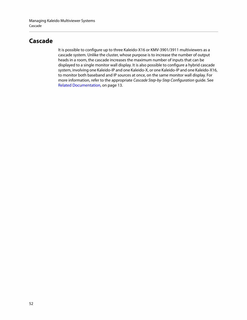
Managing Kaleido Multiviewer SystemsCascade
CascadeIt is possible to configure up to three Kaleido-X16 or KMV-3901/3911 multiviewers as a cascade system. Unlike the cluster, whose purpose is to increase the number of output heads in a room, the cascade increases the maximum number of inputs that can be displayed to a single monitor wall display. It is also possible to configure a hybrid cascade system, involving one Kaleido-IP and one Kaleido-X, or one Kaleido-IP and one Kaleido-X16, to monitor both baseband and IP sources at once, on the same monitor wall display. For more information, refer to the appropriate Cascade Step-by-Step Configuration guide. See Related Documentation, on page 13.
52

Kaleido SoftwareUser’s Manual
Configuring the System Representation• The Kaleido-IP has two, four, or six LAN connections, depending on the model, and two
multiviewer outputs. The multiviewer’s output can optionally be output over IP streaming. Configuring your Kaleido-IP’s system representation in XEdit involves adding or removing transport streams until the representation matches the set of transport streams you want to monitor. See Managing Sources in a Kaleido-IP System on page 63, for details.
• The Kaleido-IP VM has a single multiviewer output over IP streaming, associated with output Head 1, in the system representation. Configuring your Kaleido-IP VM’s system representation in XEdit involves adding or removing transport streams until the representation matches the set of transport streams you want to monitor. See Managing Sources in a Kaleido-IP System on page 63, for details.
• In the case of a Kaleido-MX, Kaleido-MX 4K, Kaleido-Modular-X, Kaleido-X (4RU), Kaleido-X (7RU), or Kaleido-X (14RU) expansion system, configuring your system’s representation in XEdit involves adding or removing cards until the representation matches the hardware configuration of your actual multiviewer. The name used in Kaleido Software to represent a multiviewer model is shown in Representation of Multiviewer Models in Kaleido Software, on page 27. See Managing Cards in a Kaleido-X or KMX-3901 System Representation on page 54, for details.
• This section does not apply to the KMX-3921, KMX-49N1, Kaleido-X16, Kaleido-XQUAD, and KMV-3901/3911, which have a set number of card slots. In the case of the Kaleido-X16, Kaleido-XQUAD, and KMV-3901/3911, these slots are virtual card slots that represent hardware features integrated within their main board. In XEdit, the virtual card slots are, for the most part, equivalent to their physical counterparts on the Kaleido-X models (See Virtual card slots on page 26).
53

Managing Kaleido Multiviewer SystemsManaging Cards in a Kaleido-X or KMX-3901 System Representation
Managing Cards in a Kaleido-X or KMX-3901 System Representation
To configure a Kaleido-X or KMX-3901 system1 In the main window, click the System tab, and then click Description/Calibrations on
the second-level tab bar.The main pane displays the System hierarchical list, and the Tools pane displays the equipment library when the root of the System list is selected.
2 Expand the System root, and the multiviewer you want to configure.
The card slots appear in the hierarchical list.
If you used the XEdit factory default configuration or the sample database for your multiviewer model (see Restoring the Factory-Default Configuration on page 57), then the appropriate slots may already be populated with cards.
3 Add or remove cards until the system’s card slots are populated with cards that match the hardware configuration of your multiviewer. See Emptying card slots, on page 55, and Populating card slots, on page 55, for details.
4 On the File menu, click Save.You new system configuration is saved.
Note: In the case of a Kaleido-X (14RU) expansion system, then you need to first expand the dual frame element, under which both frames A and B are listed. You can then configure each of the two frames as described below.
Empty slots
Populated slots
54

Kaleido SoftwareUser’s Manual
Emptying card slotsTo empty card slots in a Kaleido-X or Kaleido-MX system representation
1 In the System list, right-click the populated slot you want to empty.2 If you want to empty multiple slots in a single operation, extend your selection by using
the multi-selection Shift+click or Ctrl+click keyboard shortcuts. In this case, XEdit will prompt you to confirm your choice.
3 Right-click your selection and then click Remove on the menu.
Alternatively click the populated card slot, and then press Delete on your keyboard.
The slots are now empty and the card type does not appear any more next to the slot name.
Populating card slotsTo populate slots with cards in a Kaleido-X or Kaleido-MX system representation
1 In the System list, right-click the slot you want to populate.2 If you want to populate multiple slots in a single operation, extend your selection to
other slots of the same type by using the multi-selection Shift+click or Ctrl+click keyboard shortcuts. In this case, XEdit will prompt you to confirm your choice.
Note: Pressing Delete to empty card slots is only supported in the case of a single-card selection.
Empty slots
55
Managing Kaleido Multiviewer SystemsPopulating card slots
3 Right-click your selection and then click Insert [card type] on the menu.
Alternatively drag the card from the equipment library onto the empty card slot.
The slot name is now appended with the card type. For example: INPUT D - KXI-16, or INPUT B - KMX-3901-IN.
Note: Dragging a card from the equipment library is only supported in the case of a single-card selection.
Populated slots
56

Kaleido SoftwareUser’s Manual
Restoring the Factory-Default ConfigurationA number of predefined rooms and layouts are available on the multiviewer when you first receive your system. This is the factory-default configuration. If after modifying the multiviewer’s configuration, you are not satisfied with the results, there are the following methods to revert the multiviewer’s configuration back to the factory-default configuration in order to start over.
• A menu option allows you to directly restore the multiviewer’s factory-default configuration. See To restore the XEdit factory defaults for a multiviewer model, on page 57.
• If the current multiviewer is a cluster then you can directly restore the multiviewer cluster to its factory-default configuration. See To restore the XEdit factory defaults for a multiviewer cluster, on page 58.
Restoring the factory database does not modify the multiviewer's current IP addresses and system name. If these parameters need to be changed, it must be done using XAdmin. See the multiviewer’s Installation & Service Manual. See Related Documentation, on page 13.
In the case of a KMX-3921 / KMX-49N1 system, you can also reset some card settings to their factory-default values, by using the KMX-3921 / KMX-49N1 service panel, in iControl or iControl Solo. See the KMX-3921 Installation & Service Manual or KMX-49N1 Installation & Service Manual.
To restore the XEdit factory defaults for a multiviewer model
For this procedure, XEdit can be online with the multiviewer or offline from the multiviewer. 1 In the main window, click the System tab, and then click Description/Calibrations on
the second level tab bar.2 Expand the System hierarchical list, and then select the multiviewer that you want to
restore to its factory-default configuration.
IMPORTANTIf you already have layouts that you want to keep, make sure to back up the XEdit database or export the layout before restoring the factory defaults. See Creating a Backup, on page 40 and Exporting Layouts, on page 239.
Note: If XEdit is offline from the multiviewer and the current model of multiviewer in XEdit does not match the actual multiviewer model, then you can replace the current configuration with one that matches your actual system and restore the multiviewer’s factory-default configuration at the same time using the replace with option. See Creating a Single Multiviewer System, on page 42.
57

Managing Kaleido Multiviewer SystemsTo restore the XEdit factory defaults for a multiviewer cluster
3 On the Configure menu, click Database and then Restore factory default.
XEdit then prompts you to confirm that you want to restore the factory defaults for the selected multiviewer model.
4 Click Yes.The configuration of the selected multiviewer model is reset to the factory default.
5 The local layout must be refreshed on the multiviewer’s wall. See Refreshing a Layout, on page 487.
The multiviewer’s wall is now showing the factory-default configuration.
To restore the XEdit factory defaults for a multiviewer clusterFor this procedure, XEdit can be online with the multiviewer or offline from the multiviewer. Each multiviewer member that forms the cluster must be restored to its factory default for this procedure to be successful. Otherwise, the layouts will come back from any cluster member that has not been reset to factory defaults and you save the multiviewer’s configuration.
1 In the main window, click the System tab, and then click Description/Calibrations on the second level tab bar.
2 Expand the System hierarchical list, and then select a member of the multiviewer cluster to restore to its factory-default configuration.
If the multiviewer you want to restore to factory defaults is a member of a cluster that is greyed-out, right-click the appropriate multiviewer node and then click Switch to this system.
The selected cluster member becomes highlighted in the System list.
58

Kaleido SoftwareUser’s Manual
3 On the Configure menu, click Database and then Restore factory default.
XEdit then prompts you to confirm that you want to restore the factory defaults for the selected multiviewer model.
4 Click Yes.The configuration of the selected multiviewer model is reset to the factory default.
5 Repeat steps 2 to 4 on each member of the multiviewer cluster.6 Create a clustered room. See Creating a Cluster, on page 45.7 The local layout must be refreshed on the multiviewer’s wall. See Refreshing a Layout,
on page 487.
The multiviewer’s wall is now showing the factory-default configuration.
59

Managing Kaleido Multiviewer SystemsManaging Multiple Databases Efficiently
Managing Multiple Databases EfficientlyTo avoid mistakes in managing databases, especially when multiple multiviewers are involved, it is recommended to follow the rules below:
• Back up the database for each system to a central repository, separate from the local workspace you use when working in XEdit offline.
• When using XEdit, limit yourself to a single workspace. When working online, the local workspace is not used. When working offline, first either import the database from the appropriate multiviewer into your XEdit workspace, or restore the latest backup for the system you want to work on.
• When your work session in XEdit is complete, always create a new backup of the database, regardless of whether you were working online or offline.
The next sections describe three typical situations, summarized below:
Working onlineIf you are connected to a multiviewer, and working online in XEdit, you are actually editing the database that is located inside the multiviewer’s file system. There is one database per multiviewer. An expansion system, comprising two Kaleido-X (7RU) frames, is also managed through a single database. A cluster system includes one database for each multiviewer in the cluster, which are backed up or restored as a single operation. When you have completed your changes, create a backup of the current system and store it in a secure location on your PC.
To back up the current Kaleido multiviewer system1 On the Configure menu, point to Database, to Create backup, and then click All.2 Browse to the secure location on your PC where you store all your database backups
(e.g., multiviewerDatabaseBackups), and type a name for the new backup, preferably a name that includes the multiviewer name and the date (e.g., KX_A&B_08_12_02.zip).
Working offlineWhen using XEdit offline, you work inside a workspace located on your client PC. You set the location for this workspace when you first opened XEdit. It is recommended to consider this workspace as a “sandbox” into which you import the database you want to work on during this session, and from which you export the database at the end of the session.
Online Offline System restore from backup (offline)
1 Work in XEdit. 1 Import database from multiviewer into local workspace.
1 Restore backup from central repository into local workspace.
2 Back up database from multiviewer to central repository.
2 Work in XEdit. 2 Work in XEdit, if needed......and then back up database from local workspace to central repository.
3 Back up database from local workspace to central repository.
4 Export database from local workspace to multiviewer.
3 Export database from local workspace to multiviewer.
60

Kaleido SoftwareUser’s Manual
See Importing a Database on page 35, for instructions on how to import the database from a specific multiviewer into your workspace. Once the import is completed, you can work locally, in your XEdit workspace. When you have completed your changes, export the database from the workspace, back to the multiviewer.
Applying a backup database to the multiviewerTo restore a backup database, you must use XEdit in offline mode. A backup database must first be restored to your local workspace before it can be exported back to the appropriate multiviewer.
To restore a backup database1 On the Configure menu, point to Database, and then click Restore backup.
A window appears, prompting you to locate a backup database.2 Navigate to your central backup storage area, select the backup database you want to
restore, and then click Open.A message appears prompting you to confirm your choice.
3 Click Yes.
Once the operation completes, your XEdit workspace area will contain the restored database. You can now work on this database in offline mode, or export it back to the multiviewer.
TIPOnce you are satisfied with the location of your local workspace, on the Configure menu, point to Database, and then select the Do not prompt for the database path check box, to avoid being prompted every time you open XEdit.
61

Managing Kaleido Multiviewer SystemsApplying a backup database to the multiviewer
62

Managing Sources in a Kaleido-IP System
IntroductionIn order to obtain the list of programs and elementary streams under each transport stream, you must connect to your Kaleido-IP / Kaleido-IP VM in online mode (see Using XEdit in Online Mode on page 32).
The supported stream types are:• Any-Source Multicast (ASM)• Source-specific multicast• Source-filtered multicast (filtering limited to a single source IP in include mode only)• Unicast• RTSP• RTMP• HTTP Live Streaming (HLS)• Uncompressed 2022-6
Input Types - Network Sources Versus Virtual Inputs ExplainedAs of Kaleido Software version 9.20, Virtual Inputs are a new concept that has been added to Kaleido-IP multiviewers that differs from the traditional network Sources concept in a few ways.
In XEdit, both network Sources and virtual inputs are found in the main window, under the System tab, and then the Description/Calibrations on the second level tab bar as shown below.
The differences between network Sources and virtual inputs are described below.
What is a Network Source?Sources are representations of streams that are available to the Kaleido-IP multiviewer. In XEdit, sources are placed into folders labelled LAN1 to LAN6. Each of these folders corresponds to one of the multiviewer’s physical network adapter interfaces. Each physical network adapter interface is connected to an independent LAN (Local Area Network or IP switch) on which the source stream is made available.
Network SourcesVirtual Inputs
63

Managing Sources in a Kaleido-IP SystemInput Types - Network Sources Versus Virtual Inputs Explained
Once a stream has been added to a LAN, the Kaleido-IP multiviewer will periodically join the stream to analyze its structure (for example, to determine the amount and type of elementary streams and their associated PIDs) to make the information available in XEdit to allow users to make logical sources out of them. Typically, there is one monitoring logical source per video program, so a stream consisting in a Multi-Program Transport Stream (MPTS) with four video programs will need to be spread over four logical sources. Another example is a HLS stream consisting in four compression profiles. Each profile can be monitored by associating it with its own logical source.
Note that the Kaleido-IP multiviewer cannot discover the existence of a stream. The multicast address, unicast receiving port or HTTP URL must be manually specified or imported through a spreadsheet (for more information, see Importing an Input Configuration from a Spreadsheet, on page 78).
When a source is associated with a logical source, and that logical source is assigned to a monitor on the monitor wall, the stream becomes active. The transport stream is joined or HTTP downloads begin (depending on the type of source) and alarms like TS Loss are valid. Individual elementary streams composing the transport stream are only decoded if a corresponding monitor is present on the wall, in which case associated alarms are also valid. If an elementary stream is not displayed on the wall through a monitor, its alarms are in the pending state (unknown).
A network Source does not support uncompressed streams.
Adding Network Source Streams to the Multiviewer - OverviewIf you have connected your Kaleido-IP to more than one Media Network, or you want to monitor sources from Unicast streams or from other types of transport streams, or more sources from Multicast streams, then you need to add transport streams to the basic system configuration. See:
• To add Any-Source Multicast (ASM) transport streams, see Adding Any-Source Multicast Transport Stream Sources on page 66.
• To add Source-Specific Multicast or Source-Filtered Multicast (SSM or SFM) transport streams, see Adding Source-Specific or Source-Filtered Multicast Transport Stream Sources on page 68.
• To add unicast transport streams, see Adding Unicast Transport Stream Sources on page 70.
• To add HTTP Live Streaming (HLS) playlists, see Adding HLS Playlist Sources on page 71.• To add RTSP streams, see Adding RTSP Transport Stream Sources on page 73.• To add RTMP streams, see Adding RTMP Transport Stream Sources on page 74.
What is a Virtual Input?A virtual input is like a physical input of traditional SDI multiviewers. It represents a port that receives a stream and decodes it.
A virtual input must be associated with a logical source to be able to view it on the wall. Typically, there is one logical source per virtual input.
When using virtual inputs, the Kaleido-IP multiviewer does not know the existence of a stream until it has been instructed to join it, at which point it becomes immediately active (joined immediately) whether the logical source is viewed on the wall through a monitor or
64

Kaleido SoftwareUser’s Manual
not (this behavior is different from a Network Source). Some alarms like stream presence are immediately valid, whereas other alarms are pending until the stream is displayed on the wall.
To add uncompressed 2022-6 stream Inputs, see Adding Virtual Inputs on page 84.
Migration from Software Versions prior to Kaleido Software Version 9.20.Virtual inputs were first introduced in Kaleido Software version 8.40. Prior to Kaleido Software version 9.20, they were configured in XEdit as NMOS DEVICES, found in the main window, under the System tab, and then the Description/Calibrations on the second level tab bar. When upgrading to Kaleido Software version 9.20 or higher, any NMOS DEVICES are converted into INPUTS. Such an upgrade will bring changes that are not backwards compatible with Kaleido Software versions earlier than 9.20. If a user installs Kaleido Software version 9.20 or higher and then decides to downgrade to a Kaleido Software version earlier than 9.20, the INPUTS folder will be empty and you will have to recreate the inputs or see Workaround below. The same applies to a user that exports a database from Kaleido Software version 9.20 (or higher) to a Kaleido Software version earlier than 9.20.
Workaround: Before upgrading to Kaleido Software version 9.20 (or higher), make a database backup. When downgrading to a Kaleido Software version earlier than 9.20, restore this database backup to the multiviewer.
Kaleido-IP Multiviewer Ethernet Port UsageFor non-virtual machine (VM) Kaleido-IP multiviewers, refer to the multiviewer’s Installation & Service Manual for the correct multiviewer Ethernet port wiring connections. See Related Documentation, on page 13.
Default Kaleido-IP Network Source Configuration in XEditThe default configuration for a Kaleido-IP system includes eight predefined any-source multicast (ASM) streams, located under LAN2. Before you can use these streams, you must adjust their settings to match the actual transport streams you want to monitor. To modify previously configured streams and playlists, see Modifying transport streams and HLS playlists on page 75.
To remove streams from your system configuration, see Removing transport streams and HLS playlists on page 77.
Configuration PrerequisitesA URL path can be used to identify a source located on a remoter server to access HTTP, RTSP, RTMP, or Input streams. When using a URL, the multiviewer’s DNS server configuration must have been previously configured in XAdmin to allow the multiviewer to be able to resolve the URL to the stream server’s current network IP address.
To configure the multiviewer’s DNS setting, open XAdmin, and navigate to DNS and proxy configuration under System configuration. Refer to Configuring a Multiviewer’s IP, Date, and Time Settings with XAdmin in the multiviewer’s Installation & Service Manual. See Related Documentation, on page 13.
65

Managing Sources in a Kaleido-IP SystemConfiguring Network Sources
Configuring Network SourcesFor more information about a Virtual Input, see What is a Network Source?, on page 63.
Adding Any-Source Multicast Transport Stream SourcesTo add an Any-Source Multicast (ASM) Transport Stream
1 In the main window, click the System tab, and then click Description/Calibrations on the second level tab bar.
2 Expand the System hierarchical list, and then click the appropriate LAN element, for the stream you want to add. See also Kaleido-IP Multiviewer Ethernet Port Usage, on page 65.The supported stream types (Multicast, Unicast, HTTP, RTSP, RTMP) are listed on the Tools pane.
3 Drag Multicast from the Tools pane onto the LAN adapter.
The Multicast Stream Configuration window appears.4 In Multicast Stream Configuration, to replace the default stream name if necessary,
select the appropriate protocol (RTP, UDP), and type the multicast group address and port number associated with the transport stream you want to add.
Notes
• The Kaleido Software supports UTF-8 encoded stream names. The only characters, which cannot be used in a stream name are: @ / \ ' and ".
• Verify the protocol you selected. Registering an RTP stream as UDP instead of RTP may result in the decoded video appearing jerky or accelerated on the monitor wall.
66

Kaleido SoftwareUser’s Manual
5 If the stream you want to add is constrained to a virtual LAN, select Virtual LAN tagging, and then type the appropriate VLAN identifier.
6 Click OK.The Kaleido-IP establishes a connection with the selected stream. All programs that are part of the stream, and the elementary streams included in these programs, automatically appear under the transport stream element in the System list.
7 Repeat this procedure until you have added all required ASM transport streams to your system configuration.
8 On the File menu, click Save. Alternatively, click the toolbar’s Save button.Changes to the system are saved.
Note: VLAN adapter settings must have been previously configured in XAdmin. See Configuring Virtual LAN Adapters on a Kaleido-IP in the Kaleido-IP’s Installation & Service Manual for more information. See see Related Documentation on page 13.
Note: Under the LAN elements, transport streams are listed in alphabetical order.
Transport streamProgram 1Elementary streams (audio)
Elementary stream (video)
Group address
ProtocolPort number (or range)
Program 2Elementary stream (video)
Elementary streams (audio)
67

Managing Sources in a Kaleido-IP SystemAdding Source-Specific or Source-Filtered Multicast Transport Stream Sources
Adding Source-Specific or Source-Filtered Multicast Transport Stream Sources
To add a source-specific, or source-filtered multicast (SSM/SFM) transport stream1 In the main window, click the System tab, and then click Description/Calibrations on
the second level tab bar.2 Expand the System hierarchical list, and then click the appropriate LAN element, for the
stream you want to add. See also Kaleido-IP Multiviewer Ethernet Port Usage, on page 65.The supported stream types (Multicast, Unicast, HTTP, RTSP, RTMP) are listed on the Tools pane.
3 Drag Multicast from the Tools pane onto the LAN adapter.
The Multicast Stream Configuration window appears.
4 In Multicast Stream Configuration, to replace the default stream name if necessary, select the appropriate protocol (RTP, UDP), and type the multicast group address and port number associated with the transport stream you want to add.
Notes
• The Kaleido Software supports UTF-8 encoded stream names. The only characters, which cannot be used in a stream name are: @ / \ ' and ".
• Verify the protocol you selected. Registering an RTP stream as UDP instead of RTP may result in the decoded video appearing jerky or accelerated on the monitor wall.
68

Kaleido SoftwareUser’s Manual
5 Select the Source specific multicast (SSM) check box, and then type the IP address associated with the specific source you want to monitor in the Source IP address box.
6 If the stream you want to add is constrained to a virtual LAN, select Virtual LAN tagging, and then type the appropriate VLAN identifier.
7 Click OK.The Kaleido-IP establishes a connection with the selected SSM/SFM stream. All programs that are part of the selected stream, and the elementary streams included in
Note: In the case of streams that are available from the same multicast group address and port number, you must enter the source IP address associated with a stream before you can add the next one.
Note: VLAN adapter settings must have been previously configured in XAdmin. See Configuring Virtual LAN Adapters on a Kaleido-IP in the multiviewer’s Installation & Service Manual for more information. See see Related Documentation on page 13.
69

Managing Sources in a Kaleido-IP SystemAdding Unicast Transport Stream Sources
these programs, automatically appear under the transport stream element in the System list.
8 Repeat this procedure until you have added all required SSM/SFM transport streams to your system configuration.
9 On the File menu, click Save. Alternatively, click the toolbar’s Save button.Changes to the system are saved.
Adding Unicast Transport Stream SourcesTo add a unicast transport stream
1 In the main window, click the System tab, and then click Description/Calibrations on the second level tab bar.
2 Expand the System hierarchical list, and then click the appropriate LAN element, for the stream you want to add. See also Kaleido-IP Multiviewer Ethernet Port Usage, on page 65.The supported stream types (Multicast, Unicast, HTTP, RTSP, RTMP) are listed on the Tools pane.
3 Drag Unicast from the Tools pane onto the LAN element.
The Unicast Stream Configuration window appears.
Note: Under the LAN elements, transport streams are listed in alphabetical order.
Transport streamProgram 1Elementary streams (audio)
Elementary stream (video)
Group address
ProtocolPort number (or range)
Program 2Elementary stream (video)
Elementary streams (audio)
Source IP address
70

Kaleido SoftwareUser’s Manual
4 In Unicast Stream Configuration, to replace the default stream name if necessary, select the appropriate protocol (RTP, UDP), type the port number associated with the transport stream you want to add, and then click OK.
The Kaleido-IP establishes a connection with the selected stream. All programs that are part of the stream, and the elementary streams included in these programs, automatically appear under the transport stream element in the System list.
5 Repeat this procedure until you have added all required unicast transport streams to your system configuration.
6 On the File menu, click Save. Alternatively, click the toolbar’s Save button.Changes to the system are saved.
Adding HLS Playlist Sources
To add an HLS playlist1 In the main window, click the System tab, and then click Description/Calibrations on
the second level tab bar.2 Expand the System hierarchical list, and then click the appropriate LAN element, for the
stream you want to add. See also Kaleido-IP Multiviewer Ethernet Port Usage, on page 65.The supported stream types (Multicast, Unicast, HTTP, RTSP, RTMP) are listed on the Tools pane.
Notes
• The Kaleido Software supports UTF-8 encoded stream names. The only characters, which cannot be used in a stream name are: @ / \ ' and ".
• Verify the protocol you selected. Registering an RTP stream as UDP instead of RTP may result in the decoded video appearing jerky or accelerated on the monitor wall.
• Under the LAN elements, transport streams are listed in alphabetical order.
Note: Make sure the multiviewer’s DNS and proxy settings are properly configured for your network, and that NTP synchronization is enabled. Refer to the Kaleido-IP Installation & Service Manual for more information. See Related Documentation, on page 13.
71

Managing Sources in a Kaleido-IP SystemAdding HLS Playlist Sources
3 Drag HTTP from the Tools pane onto the LAN element.
The HTTP Stream Configuration window appears.
4 In HTTP Stream Configuration, to replace the default stream name if necessary, type the URL of the playlist you want to monitor, provide the appropriate authentication key if required, and then click OK.In the URL, include the HTTP prefix: http://, for example: http://example.com/stream
The Kaleido-IP establishes a connection with the stream provider. In the System list, a master playlist element including all media playlists specified in the master playlist automatically appears under the LAN elements. All programs that are part of a media playlist, and the elementary streams included in these programs, automatically appear under the media playlist element.
5 Repeat this procedure until you have added all required HLS playlists to your system configuration.
Notes
• The Kaleido Software supports UTF-8 encoded stream names. The only characters, which cannot be used in a stream name are: @ / \ ' and ".
• Both HTTP and HTTPS protocols are supported. If HTTPS is used, there must be a valid certificate for the connection to be established.
• Under the LAN elements, HLS master playlists and media playlists are listed in alphabetical order.
ProgramElementary stream (audio)Elementary stream (video)
Source URL
MediaMaster playlist element
playlists
72

Kaleido SoftwareUser’s Manual
6 On the File menu, click Save. Alternatively, click the toolbar’s Save button.Changes to the system are saved.
Adding RTSP Transport Stream Sources
To add an RTSP transport stream1 In the main window, click the System tab, and then click Description/Calibrations on
the second level tab bar.2 Expand the System hierarchical list, and then click the appropriate LAN element, for the
stream you want to add. See also Kaleido-IP Multiviewer Ethernet Port Usage, on page 65.The supported stream types (Multicast, Unicast, HTTP, RTSP, RTMP) are listed on the Tools pane.
3 Drag RTSP from the Tools pane onto the LAN element.
The RTSP Stream Configuration window appears.
4 In RTSP Stream Configuration, to replace the default stream name if necessary, type the URL of the stream you want to monitor, select the appropriate protocol (RTP, UDP), and then click OK.In the URL, include the RTSP prefix: rtsp://, for example: rtsp://example.com/stream
The Kaleido-IP establishes a connection with the selected stream. All programs that are part of the stream, and the elementary streams included in these programs, automatically appear under the transport stream element.
Note: Make sure the multiviewer’s DNS and proxy settings are properly configured for your network. Refer to the Kaleido-IP Installation & Service Manual for more information. See Related Documentation, on page 13.
Notes
• The Kaleido Software supports UTF-8 encoded stream names. The only characters, which cannot be used in a stream name are: @ / \ ' and ".
73

Managing Sources in a Kaleido-IP SystemAdding RTMP Transport Stream Sources
5 Repeat this procedure until you have added all required RTSP transport streams to your system configuration.
6 On the File menu, click Save. Alternatively, click the toolbar’s Save button.Changes to the system are saved.
Adding RTMP Transport Stream Sources
To add an RTMP transport stream1 In the main window, click the System tab, and then click Description/Calibrations on
the second level tab bar.2 Expand the System hierarchical list, and then click the appropriate LAN element, for the
stream you want to add. See also Kaleido-IP Multiviewer Ethernet Port Usage, on page 65.The supported stream types (Multicast, Unicast, HTTP, RTSP, RTMP) are listed on the Tools pane.
3 Drag RTMP from the Tools pane onto the LAN element.
The RTMP Stream Configuration window appears.
4 In RTMP Stream Configuration, to replace the default stream name if necessary, type the URL of the stream you want to monitor, and then click OK.In the URL, include the RTMP prefix: rtmp://, for example: rtmp://example.com/stream
• Verify the protocol you selected. Registering an RTP stream as UDP instead of RTP may result in the decoded video appearing jerky or accelerated on the monitor wall.
• Under the LAN elements, transport streams are listed in alphabetical order.
Notes (continued)
Note: Make sure the multiviewer’s DNS and proxy settings are properly configured for your network. Refer to the Kaleido-IP Installation & Service Manual for more information. See Related Documentation, on page 13.
74

Kaleido SoftwareUser’s Manual
The Kaleido-IP establishes a connection with the selected stream. All programs that are part of the stream, and the elementary streams included in these programs, automatically appear under the transport stream element.
5 Repeat this procedure until you have added all required RTMP transport streams to your system configuration.
6 On the File menu, click Save. Alternatively, click the toolbar’s Save button.Changes to the system are saved.
Modifying transport streams and HLS playlistsYou may need to modify previously created stream information:
• One or more transport streams or HLS playlists have been added to a LAN element.• The default configuration for a Kaleido-IP system includes eight predefined any-source
multicast (ASM) streams, under LAN2. Before you can use these streams, you must adjust their settings to match the actual transport streams you want to monitor.
To modify transport stream or HLS playlist settings 1 In the main window, click the System tab, and then click Description/Calibrations on
the second level tab bar.2 Expand the System hierarchical list, and then navigate to the transport stream or
master playlist you want to modify found under a LAN network interface. For example, a default multicast transport stream found under LAN2. See also Kaleido-IP Multiviewer Ethernet Port Usage, on page 65.
Notes
• The Kaleido Software supports UTF-8 encoded stream names. The only characters, which cannot be used in a stream name are: @ / \ ' and ".
• Under the LAN elements, transport streams are listed in alphabetical order.
75

Managing Sources in a Kaleido-IP SystemModifying transport streams and HLS playlists
The settings for the selected stream or master playlist appear in the Properties pane.
Source settings (example showing settings for an any-source multicast stream)
Source settings (example showing settings for an HLS master playlist)
3 Replace the stream name if necessary and then, depending on the stream type:• Select the appropriate protocol (RTP, UDP).• Enter the multicast group IP address (in the case of a multicast stream) and port
number associated with the actual transport stream you want to monitor.• In the case of an SSM (or SFM) stream, enter the IP address associated with the
specific source you want to monitor in the SSM source IP address box.• In the case of a multicast stream constrained to a virtual LAN, enter the appropriate
VLAN identifier.
• In the case of an HLS master playlist, RTSP stream, or RTMP stream, enter the new URL.
Note: VLAN adapter settings must have been previously configured in XAdmin. Refer to Configuring Virtual LAN Adapters on a Kaleido-IP in the Kaleido-IP Installation & Service Manual for more information. See Related Documentation, on page 13.
Notes
• The Kaleido Software supports UTF-8 encoded stream names. The only characters, which cannot be used in a stream name are: @ / \ ' and ".
• Verify the protocol you selected. Registering an RTP stream as UDP instead of RTP may result in the decoded video appearing jerky or accelerated on the monitor wall.
• For HLS playlists, both HTTP and HTTPS protocols are supported.
76

Kaleido SoftwareUser’s Manual
The Kaleido-IP establishes a connection with the stream provider. In the case of an HLS playlist, a master playlist element including all media playlists specified in the master playlist automatically appears under the LAN elements, in the System list. All programs that are part of a transport stream or specified in a media playlist, and the elementary streams included in these programs, automatically appear under the transport stream or media playlist element.
Example showing programs and elementary streams for a single-source multicast stream
4 Repeat this until you have completed the required configuration changes to match the set of transport streams you want to monitor.
5 If there are default transport streams left, which you will not use, see Removing transport streams and HLS playlists, on page 77.
6 On the File menu, click Save. Alternatively, click the Save button on the toolbar.Changes to the system are saved.
Removing transport streams and HLS playlistsTo remove transport streams or HLS playlists from your system configuration
1 In the main window, click the System tab, and then click Description/Calibrations on the second level tab bar.
2 Expand the System hierarchical list, and then navigate to the master playlist or transport stream you want to remove.
3 If you want to remove multiple transport streams and master playlists in a single operation, then extend your selection by using the multi-selection Shift+click or Ctrl+click keyboard shortcuts.
77

Managing Sources in a Kaleido-IP SystemImporting an Input Configuration from a Spreadsheet
4 Right-click the selection, and then click Remove.
5 When prompted to confirm, click Yes.6 On the File menu, click Save.
Changes to the system are saved. If you are not planning on adding the removed streams back to your system, then you might now want to remove logical sources that were based on them: see Removing logical sources for removed programs in a transport stream on page 93.
Importing an Input Configuration from a SpreadsheetThis feature only applies to creating Network Sources.
If you need to monitor a large number of programs, you may find it convenient to import related configuration information from a spreadsheet in XLS or XLSX format. Once this file has been imported, the logical sources associated with the programs specified in the spreadsheet will be automatically added to the sources table. A sample spreadsheet is available. See Software and Firmware Updates, on page 14.
Preparing a spreadsheet with stream lineup informationThe spreadsheet file must contain the following:
• information about the programs you want to monitor, and the transport streams to which they belong,
• information about the logical sources that will be added to the sources table for these programs, including any static text levels you may want to add.
WARNINGGrass Valley recommends making a backup of your system before importing stream configuration information from a spreadsheet. When you import streams from a spreadsheet, this erases all previously imported streams and associated logical sources. It may also overwrite streams that you had manually added (and logical sources) if they have the same name or index as a stream whose configuration is being imported.
Notes
• Kaleido-IP X320, X310, X120 and X110 multiviewers support 6000 logical sources.
78

Kaleido SoftwareUser’s Manual
The spreadsheet is organized as follows:• Two heading rows. The first heading row divides the spreadsheet into four main areas:
• Programs. This area occupies the first column (A).• Transport streams. This area spans columns B – G.• Logical sources. This area spans columns H – J.• Additional static text levels (optional). This area starts at column K, and can extend
to as many columns as you need. Text you enter on the second heading row in this area will be imported.
• One row for every program you want to monitor.
To prepare the spreadsheet file1 Using your spreadsheet software, either open a copy of the sample spreadsheet file or
create a new spreadsheet.2 Enter the information about a program, and the transport stream to which it belongs:
• In the case of the Kaleido-IP X300, to support more than 1500 sources, or to be able to use Kaleido Software version 7.90 or higher, the multiviewer’s RAM must be upgraded to 24 GB. To order an upgrade kit, contact Grass Valley Technical Support, on page 536 and order part number KIP-X300-MEMORY-UPGRADE. The document Kaleido-IP X300 Memory Upgrade (M926-9907) procedure is supplied with the kit.
• The Kaleido-IP X100 is limited to 1500 sources. To be able to use Kaleido Software version 7.90 or higher, the multiviewer’s RAM must be upgraded to 16 GB. To order an upgrade kit, contact Grass Valley Technical Support, on page 536 and order part number KIP-X100-MEMORY-UPGRADE. The document Kaleido-IP X100 Memory Upgrade (M926-9807) procedure is supplied with the kit.
• RTSP, RTMP, HTTP or HTTPS streams cannot be imported from a spreadsheet.
In this column... Enter this information...
A Program number The program number (MPEG ID), for the program you want to monitor.
B Stream name A name to identify the transport stream that includes this program. Alternatively, you can leave this cell blank, in which case a default name will be created. Stream names that only contain digits and have decimal positions that are all zeros must be preceded with an apostrophe in the spreadsheet.
C Multicast group IP address
The multicast group IP address. In the case of a unicast stream, leave the cell blank.
D Port number The appropriate port number.
E SSM/SFM source IP address
In the case of a source-specific multicast (SSM) or source-filtered multicast (SFM) transport stream, enter the source IP address.
Notes (continued)
79

Managing Sources in a Kaleido-IP SystemImporting an Input Configuration from a Spreadsheet
Sample spreadsheet: Programs, and Transport streams areas
3 Enter the information that will be used to create the logical source associated with this program:
F Protocol RTP or UDP.
G NIC The LAN identifier: see Kaleido-IP Multiviewer Ethernet Port Usage, on page 65 for Ethernet port usage information. The number of LANs varies depending on the Kaleido-IP model (see Representation of Multiviewer Models in Kaleido Software on page 27).
In this column... Enter this information...
80

Kaleido SoftwareUser’s Manual
Sample spreadsheet: Logical sources area
In this column... Enter this information...
H Index If your system involves a control panel from which you control your multiviewer as a router, set a source number for the logical source associated with this program to be available through the KX Router logical router, by entering the appropriate number in this column. Source numbers must be unique.
I Category Text in this column can be used to group related logical sources together, when you sort the sources table in XEdit (see Sorting the Sources Table on page 104). The category text can have up to 200 characters.
J Name The name of the logical source. Names are limited to 48 characters. Logical source names that only contain digits and have decimal positions that are all zeros must be preceded with an apostrophe in the spreadsheet.
81

Managing Sources in a Kaleido-IP SystemImporting an Input Configuration from a Spreadsheet
4 Optionally, use the columns, starting at column K, to add static text levels. Enter the level name on the second heading row.
Sample spreadsheet: Additional static text levels area
Static text level names and data that only contain digits and have decimal positions that are all zeros must be preceded with an apostrophe in the spreadsheet.
5 Repeat this procedure until you have added the required information for all the programs you want to monitor.
To import a set of streams from a spreadsheet file1 In the main window, click the System tab, and then click Description/Calibrations on
the second level tab bar.2 On the File menu, click Import.
XEdit prompts you for confirmation.
3 Click OK to continue, if you are confident that you have a backup so that you can restore your system if needed - see Creating a Backup, on page 40.
4 Navigate to the spreadsheet file you want to import, select it, and then click Open.XEdit validates the following: IP address range, LAN number, protocol, consistency of stream name vs. stream information (group and source IP addresses + port), duplicate stream names, duplicate logical source information (category + name), duplicate logical source index, and will report any error. If no errors were found, then the following message appears.
82

Kaleido SoftwareUser’s Manual
5 Click OK to continue.The streams appear under the specified LANs.
Example showing streams imported from the sample spreadsheet file.
After a few minutes, if XEdit is connected to the multiviewer, all programs included in the transport streams are discovered.
In addition, logical sources for the programs listed in the spreadsheet you imported are automatically added to the sources table. If XEdit is not connected to the multiviewer, then the new sources’ video levels appear in red in the sources table. In such case, the sources table will be updated when you work in online mode once you have exported the database to the multiviewer.
Should you want to add audio, dynamic text, alarm and time code levels to these logical sources, you may complete all physical assignments for one logical source, which you can then designate as the template. By applying the template, you will be able to populate the remaining levels in a single operation. See Defining Physical Assignments on page 98, for more information.
Note: The set of discovered programs does not necessarily match the programs listed in the spreadsheet. The discovery being a dynamic process, it may find more (or less) programs.
Imported streamsImported streams
Logical sources createdfrom imported programs
83

Managing Sources in a Kaleido-IP SystemConfiguring Virtual Inputs
Configuring Virtual InputsFor more information about a Virtual Input, see What is a Virtual Input?, on page 64.
Adding Virtual Inputs To add an Input device
1 In the main window, click the System tab, and then click Description/Calibrations on the second level tab bar.
2 Expand the System hierarchical list, and then click the INPUTS element.3 Drag Input Device from the Tools pane onto the INPUTS element.
4 In Insert virtual input(s), set the quantity of virtual inputs to create, and then click OK.
A predefined Input device skeleton appears under INPUTS, in the System list. The source stream must be configured for each individual INPUT.
5 Expand the System hierarchical list and select a numbered input.
The settings for the selected input appear in the Properties pane.
6 Click Edit in the Properties pane.
84

Kaleido SoftwareUser’s Manual
The Virtual Input Configuration screen opens.7 Configure the input stream’s source.
Virtual Input Configuration settings
8 Click OK. The configuration information for this input is shown in the Properties pane.The Kaleido-IP starts receiving the stream. Stream elements that are present will be shown in black. Unavailable elements will be grayed out.
Example showing the programs and elementary streams of a Virtual Input
Once an input has been created for each source, you can assign these logical sources to monitors in a layout.
Parameter Description
URL Enter the Real-time Transport Protocol (RTP) URL (In the form rtp://<ip_address>:<port>) associated with the transport stream you want to monitor.
Label Optionally enter a descriptive label for the stream.
LAN Select the LAN port (and the network) that has IP connectivity to the stream’s source. See also Kaleido-IP Multiviewer Ethernet Port Usage, on page 65.
Media type The transport standard used by the stream:• ST2022-6: Standard to transport video over IP network.
Clear Click to deallocate this virtual input. This stops the currently-configured stream from using network bandwidth.
Stream elements
Stream
85

Managing Sources in a Kaleido-IP SystemModifying Virtual Inputs
Modifying Virtual InputsYou may need to modify previously created virtual inputs that have been added to an INPUT element.
To modify virtual inputs settings 1 In the main window, click the System tab, and then click Description/Calibrations on
the second level tab bar.2 Expand the System hierarchical list, and under INPUTS, navigate to the virtual input
you want to modify.
The settings for the selected virtual input appears in the Properties pane.
3 Click Edit in the Properties pane.The Virtual Input Configuration screen opens.
4 Configure the input stream’s source.
Virtual Input Configuration settings
Parameter Description
URL Enter the Real-time Transport Protocol (RTP) URL (In the form rtp://<ip_address>:<port>) associated with the transport stream you want to monitor.
Label Optionally enter a descriptive label for the stream.
LAN Select the LAN port (and the network) that has IP connectivity to the stream’s source. See also Kaleido-IP Multiviewer Ethernet Port Usage, on page 65.
86

Kaleido SoftwareUser’s Manual
5 Click OK. The configuration information for this input is shown in the Properties pane.The Kaleido-IP starts receiving the stream. Stream elements that are present will be shown in black. Unavailable elements will be grayed out.
Example showing the programs and elementary streams of a Virtual Input
6 Repeat this until you have completed the required configuration changes to match the set of virtual inputs you want to monitor.
7 If there are virtual inputs left which you will not use, see Removing Virtual Inputs, on page 87.
8 On the File menu, click Save. Alternatively, click the Save button on the toolbar.Changes to the system are saved.
Removing Virtual InputsTo remove virtual inputs from your system configuration
1 In the main window, click the System tab, and then click Description/Calibrations on the second level tab bar.
2 Expand the System hierarchical list, and then navigate to the virtual input you want to remove.
3 If you want to remove multiple virtual inputs in a single operation, then extend your selection by using the multi-selection Shift+click or Ctrl+click keyboard shortcuts.
Media type The transport standard used by the stream:• ST2022-6: Standard to transport video over IP network.
Clear Click to deallocate this virtual input. This stops the currently-configured stream from using network bandwidth.
Parameter Description
Stream elements
Stream
87

Managing Sources in a Kaleido-IP SystemRemoving Virtual Inputs
4 Right-click the selection, and then click Remove.
5 When prompted to confirm, click Yes.6 On the File menu, click Save.
Changes to the system are saved. If you are not planning on adding the removed streams back to your system, then you might now want to remove logical sources that were based on them: see Removing logical sources for removed programs in a transport stream on page 93.
88

Logical Sources
IntroductionThis chapter explain how to configure logical sources for your multiviewer system.
Key Concepts
Term Description
Logical source A logical source (called a channel, in earlier versions of the Kaleido Software user interface, and related documentation) refers to a group of physical audio, video, or metadata sources, and text attributes. A logical source can be used as a whole, and assigned to a virtual monitor. The Kaleido Software supports up 7000 logical sources.Notes:• The KMV-3901/3911, Kaleido-MX, Kaleido-MX 4K, Kaleido-IP X100,
KMX-49N1, KMX-3921, and Kaleido-Modular-X support up to 1500 logical sources.
• Kaleido-IP X320, X310, X120, X110, Kaleido-X, and Kaleido-X16 multiviewers support up to 6000 logical sources. In the case of the Kaleido-IP X300, to support more than 1500 sources, or to be able to use Kaleido Software version 7.90 or higher, the multiviewer’s RAM must be upgraded to 24 GB. To order an upgrade kit, contact Grass Valley Technical Support, on page 536 and order part number KIP-X300-MEMORY-UPGRADE. The document Kaleido-IP X300 Memory Upgrade (M926-9907) procedure is supplied with the kit.
• If you choose to configure your multiviewer system with a large number of logical sources (i.e., more than 1500), you should disable global alarm contribution for all alarm levels in the sources table (see Global Alarms on page 162), to improve the system performance. When you save the sources table, if there are more than 1500 sources, XEdit prompts you to let it disable these contributions for you (see Managing Logical Source Count Prompts on page 97).
Level Within a logical source, attributes are organized by levels belonging to either of the following categories: Source info, Video, Audio, Text, Alarm, Time code, and Color. For example, the video level category may comprise multiple levels, each representing a specific physical part of a video signal.
89

Logical SourcesCreating and Configuring Logical Sources
Creating and Configuring Logical SourcesWhen opening XEdit in offline mode, the initial database is populated with the default configuration for a Kaleido-X (7RU) system, including a fully-populated frame (all cards present) and a set of predefined logical sources. The KX Router logical router is also created as a 96 × 80 router where the 96 inputs are the multiviewer’s logical sources, the first 48 outputs are those from the two router cards, and the last 32 outputs are monitor wall destinations.
Likewise, when you replace the initial Kaleido-X (7RU) with the appropriate multiviewer model that matches your actual system, you can choose to have your local database populated with a default set of logical sources and a preconfigured KX Router logical router.
Automatically Adding Logical SourcesA set of logical sources based on external video router sources or on multiviewer inputs can be added to the sources table, as a single operation, by clicking Create logical sources on the menu that appears when you right-click supported elements in the filtered system list.
Alternatively, in the case of a Kaleido-IP, a set of logical sources is also automatically created if you import the stream lineup from a spreadsheet file (see Importing an Input Configuration from a Spreadsheet on page 78).
About Automatic Sources CreationFrom the same menu, you can also set Activate automatic sources creation if you want the multiviewer to create new logical sources automatically with the same settings as existing programs when the multiviewer detects new program elements as they become available in the transport stream. Similarly, when sources are added or modified in a router’s own configuration environment, logical sources will be added or updated automatically in the multiviewer’s sources table.
The Activate automatic sources creation option only creates new logical sources from newly detected program streams. When a program stream is no longer present, or when a router source is no longer present, this feature does not automatically remove the corresponding
Incremental copy Once a logical source (channel) is configured, it is possible to use incremental copy to automatically propagate appropriate physical assignments to other adjacent logical sources. For instance, if the current logical source’s levels are assigned from Video 1, then the incremental copy tool will automatically assign corresponding physical elements from Video 2 to the next logical source’s levels, and so on. Alternatively, if only one or a few specific levels are to be similarly configured, it is possible to use incremental copy on the corresponding level column only.
Incremental copy handle
In the sources table, the incremental copy handle is indicated by a small square at the bottom right of the selected cell.
Term Description
90

Kaleido SoftwareUser’s Manual
logical source that was automatically created. You must do this manually. See Removing logical sources for removed programs in a transport stream, on page 93. Only remove logical sources for programs that you know will never return, as a rediscovered program stream will be created with a new internal ID that will not match up with the ID of the first instance. This means that you will have to reassign the channel/sources to the monitors.
To define logical sources for a transport stream
This procedure shows how to add “On Demand” Network Sources and “On Demand” Router Sources which are activated only when they are displayed through a logical source. See also Logical Sources, on page 20
A Kaleido-IP multiviewer is used to illustrate the following procedure, however, the same procedure applies to all types of multiviewer inputs, including inputs from “On Demand” Router Sources.
1 In the main window, click the Channels/Sources tab.
2 On the Tools pane, expand the multiviewer, and navigate to the transport stream for which you want to define logical sources.
3 Right-click the transport stream, and then click Create logical sources on the menu. See also About Automatic Sources Creation, on page 90.
Logical sources are automatically created for every program signal found in the selected transport stream.
91

Logical SourcesManaging Logical Sources Associated with Programs in a Transport Stream
4 Repeat until you have added logical sources for every stream you want to monitor.5 If your system involves a control panel from which you will control your multiviewer as
a router, then configure source numbers for the KX Router logical router, by typing the appropriate numbers in the first column (#) under Source info, and using the incremental copy tool as needed.
6 On the File menu, click Save.
Managing Logical Sources Associated with Programs in a Transport StreamIn the case of a Kaleido-IP system, you may need to add or remove sources, from time to time, when programs are added or removed from a transport stream.
Adding logical sources for new programs in a transport streamTo add a logical source for a new program in a transport stream
1 Connect XEdit to the Kaleido-IP (see Using XEdit in Online Mode on page 32), and then click the Channels/Sources tab.
2 On the Tools pane, navigate to the transport stream that includes the new program.3 Right-click the program, and then click Create logical sources on the menu.
Notes• Under Source info, dynamic and static names resulting from the Name
level assignments are limited to 48 characters and automatically truncated as needed.
• If the case of router sources, if the router is subject to frequent dimension changes, then you may want to select Activate automatic sources creation.
• Auto detected Level assignments follow reference “template” channel, identified by a “T” icon.
92

Kaleido SoftwareUser’s Manual
A new entry appears in the sources table, with all assignments based on the logical source template (see Defining Physical Assignments on page 98).
4 On the File menu, click Save.
Removing logical sources for removed programs in a transport stream
To remove logical sources associated with programs that are not present anymore1 Connect XEdit to the Kaleido-IP (see Using XEdit in Online Mode on page 32) and then
click the Channels/Sources tab.Logical sources associated with programs that have been removed from a transport stream will have elements marked in red.
2 Select these sources (using the multi-selection Shift+click or Ctrl+click keyboard shortcuts to extend your selection as needed).
3 Right-click the selection, and then click Delete selected sources on the menu.
Note: Under Source info, dynamic and static names resulting from the Name level assignments are limited to 48 characters and automatically truncated as needed.
93

Logical SourcesManually adding a Logical Source
4 On the File menu, click Save.5 Click the Layouts tab, open the appropriate layouts, locate any monitors that included
assignments based on the sources you just deleted, and update their configuration as required (see Assigning Logical Sources or Monitor Wall Destinations to Monitors on page 242).
Manually adding a Logical SourceTo add a logical source
1 Click the Channels/Sources tab in the main window.The sources table appears.
Note: The sources table is preconfigured with a set of default assignments, including at least one level under each level category. A symbol indicates the physical source for each assignment: for example, “A16” indicates input signal 16 on input card A. In the case of an expansion system, the symbol is prefixed with a frame identifier: either “FRA-” or “FRB-”. On the Kaleido-X16, only the input numbers 01 to 16 appear. On a KMV-3901/3911, the input numbers 1 to 8 (or 1 to 4, in the case of the 4 × 1 and 4 × 2 models) appear.
94

Kaleido SoftwareUser’s Manual
2 On the File menu, click New.Alternatively right-click the Channels/Sources column heading, and then click Add source on the menu.
A logical source is added at the bottom of the sources table.
3 On the File menu, click Save.The sources table is saved.
Managing Levels
Adding a level
Notes• Under Source info, you can change the logical source name and path,
resulting from the Name and Cat. level assignments. For example, “Channel 1” can be renamed “Cam 1” or assigned a dynamic name. You can group related logical sources together, by adding static or dynamic text elements to the Cat. level, and then sorting the table as needed, to suit your purposes (see Sorting the Sources Table on page 104). You can also apply a filter to the table, so that sources that do not match the filter be hidden from view (see Filtering the Sources Table on page 104).
• When a logical source’s name or category changes, the row header is updated accordingly.
• When applying an overall incremental copy (from the row header), the Source info columns and the Video levels are excluded. These columns must be incremented individually. The overall incremental copy features relies on a video level having been populated first.
Note: To be able to monitor a 3D stereoscopic signal, you must first add a second video level to your logical sources (so you have a level for each eye), and then for each video monitor or composite you want to use for 3D monitoring, you must assign the left-eye and right-eye levels.
95

Logical SourcesManaging Levels
To add a level1 Click the Channels/Sources tab in the main window.
The level categories Video, Audio, Text, Alarm, Time code, and Color appear as main column headings in the sources table.
2 Right-click the appropriate level category, and then click Add level on the menu.
A new level appears under the selected category.
3 If you want to change the level name, click the level header, and then, in the Properties pane, type the new name in the Level name box.In the case of an alarm level, you may also set its contribution to your system’s global alarms. See Configuring an alarm level’s contribution below.
4 On the File menu, click Save.The sources table is saved.
Configuring an alarm level’s contributionYou can select which alarm levels contribute to the global alarm associated with every logical source (see Global Alarms on page 162), and rank their individual contribution.
To configure an alarm level’s contribution to your system’s global alarms• In the sources table, click the column header for the level you want to configure.
The Properties pane shows the name of the selected alarm level, and its current contribution settings.
Levelcategories
Add level
96

Kaleido SoftwareUser’s Manual
• If you want to exclude alarms in this level from the global alarm calculation, then clear the Include in global alarm check box.
• To rank this level’s contribution to your system’s global alarms, click the Global alarm contribution box, and then select the appropriate value from the list.
• Passthrough: This is the default value. Alarms in this level will pass their status unaltered to the global alarms.
• Critical, Major, Minor, Disabled: It is possible to override the error status of alarms when they are triggered. This is useful when, for example, a device is only able to report a status of either normal or error, but you want the error condition to be considered as minor in the global alarm calculation.
• Invert: Alarms in this level will pass the opposite of their status to the global alarms. This can be used, for example, to report alarms from GPI inputs, or to handle cases where an error is expected, and not seeing an error is a sign that something probably went wrong. See Inverting an alarm, on page 174.
• Faults only: Alarms in this level will be mapped to normal unless their status is one of the fault statuses—usually critical, major, and minor.1
Managing Logical Source Count Prompts
1.The list of fault status can be modified by scripting.
Selected alarm level
Note: This section applies to KMX-49N1, Kaleido-IP (except Kaleido-IP X100), Kaleido-X, and Kaleido-X16. All other multiviewer models are limited to 1500 logical sources.
97

Logical SourcesDefining Physical Assignments
When you save the sources table, if there are more than 1500 sources, XEdit prompts you to let it disable global alarm contributions, for you (see Logical source on page 89).
• Regardless of whether you clicked Yes or No, XEdit will not prompt you again, unless the number of logical sources or the global alarm contribution settings changed.
• If you select the Do not ask me again check box, XEdit will no longer prompt you.
To restore logical source count prompting• On the Configure menu, clear the Do not warn about channel count check box.
To disable logical source count prompting• On the Configure menu, select the Do not warn about channel count check box.
Defining Physical AssignmentsOnce you have created a logical source, you must make the physical assignments. This is required before you can create a layout.
To make the physical assignments for a logical source1 In the sources table, click the cell that corresponds to the level you want to define for
this logical source.2 On the Tools pane, expand the filtered System list, and then drag the appropriate
element from the list, to the selected level in the sources table.For a typical logical source, you will normally start by making a video assignment, set the appropriate category and source ID (under Source info) if you want to control your multiviewer system as a router, and then proceed with the audio, text, alarm, time code, and color levels. See, for example, Configuring text level assignments, on page 99, Configuring alarm level assignments, on page 100, Configuring logical sources based on external alarm providers, on page 100, and Configuring color level assignments, on page 101.
Sources table with a selected cell in the Video level category for Channel1
3 Repeat this procedure until all required physical assignments are completed for this logical source.
98

Kaleido SoftwareUser’s Manual
4 If you want to be able to use this logical source as a template, right-click the source header and then click Set source as template on the menu.
Once you have added the required number of logical sources, and made appropriate video assignments, you will be able to populate remaining levels in a single operation by applying the template. If you have enabled automatic sources creation for an external router, then automatically-created logical sources will be based on the template.
Configuring text level assignments
To assign a text element to a logical source’s text level1 Click the Channels/Sources tab in the main window.2 In the sources table, click the cell that corresponds to the logical source and text level
you want to configure.3 Expand the filtered System list on the Tools pane, locate the text element, and then
drag it onto the selected cell in the sources table.
4 On the File menu, click Save.The sources table is saved.
Note: Under Source info, dynamic and static names resulting from the Name level assignments are limited to 48 characters and automatically truncated as needed.
Note: Under Source info, dynamic and static names resulting from the Name level assignments are limited to 48 characters and automatically truncated as needed.
99

Logical SourcesDefining Physical Assignments
Configuring alarm level assignments
To assign an alarm to a logical source’s alarm level1 Click the Channels/Sources tab in the main window.2 In the sources table, click the cell that corresponds to the logical source and alarm level
you want to configure.3 Expand the filtered System list on the Tools pane, locate the alarm, and drag it onto the
selected cell in the sources table.
4 On the File menu, click Save.The sources table is saved.
Configuring logical sources based on external alarm providersTo have access to alarms and text elements from an external alarm provider, you must have specified this provider in your multiviewer system configuration (see Managing Alarm Providers on page 172).
To assign an alarm or a text element from an external provider1 Open a GSM alarm browser associated with the alarm provider you want to use.
For example, after opening iControl Navigator, click General status managers on the View menu. Refer to the iControl User Guide for more information. See Related Documentation, on page 13.
2 In XEdit, click the Channels/Sources tab in the main window.3 In the GSM alarm browser, navigate to the element you want to assign, and then drag it
onto the cell that corresponds to the alarm or text level you want to configure in the sources table.In the selected cell, the prefix “EXT” indicates that the assignment is from an external source and is followed with information such as the device class and a name.
100

Kaleido SoftwareUser’s Manual
4 On the File menu, click Save.The sources table is saved.
Configuring color level assignmentsYou may configure sources with color levels so that you can distinguish them at a glance on the monitor wall. For example, your sources could have three color levels: one that you would apply to a monitor’s border color, one to a UMD’s background, and one to the UMD text.
To configure a logical source’s color levels1 Click the Channels/Sources tab in the main window.2 In the sources table, double-click the cell that corresponds to the logical source and
color level you want to configure.The color picker window opens.
3 In Colors, click the tab that corresponds to the color space you want to use, and then choose the color that will be associated with the selected source and color level.
Notes• You can select multiple elements in the GSM alarm browser (by pressing
Shift+click or Ctrl+click as needed) and assign them to consecutive logical sources at once, by dragging the multiple selection to the appropriate level for the first logical source you want to configure. The elements are inserted in the same order you selected them.
• Drag an alarm folder to an alarm level to monitor the folder’s status. Dragging an alarm folder to a text level is not supported.
• GSM alarms are not available as triggers for background actions (see Creating Background Actions on page 327).
• Incremental copy is not supported in the case of assignments from external providers (see Making Further Assignments by Incremental Copy on page 102).
101

Logical SourcesMaking Further Assignments by Incremental Copy
4 Click OK to close the color picker window.The color you chose appears in the sources table.
5 Repeat from step 2 until you have configured all color levels for this source.6 On the File menu, click Save.
The sources table is saved.
Making Further Assignments by Incremental CopyOnce done with a first logical source, if the next logical source is to be similar to the first one, it is possible to use incremental copy to automatically create it. Alternatively, if only one or a few specific levels are to be similarly configured, it is possible to use incremental copy on the corresponding level column only.
To use the incremental copy tool to propagate physical assignments to adjacent logical sources
1 Click the row header for the logical source whose assignments you want to propagate.A small square, the incremental copy handle, appears in the bottom right corner of the header cell.
Note: Color levels are not subject to incremental copy.
102

Kaleido SoftwareUser’s Manual
2 Move the pointer to the incremental copy handle. The pointer changes to crosshairs.
3 Click and drag to propagate the selected logical source’s physical assignments to the next logical sources’ levels.The source cells are highlighted with a green border and the target cells with a red border.
4 Release the mouse button once you have reached the last logical source to be configured.The level cells are now populated with “incremented” physical assignments.
Note: It is possible to drag the incremental copy handle up, or down. The physical assignments will be decremented or incremented accordingly.
Incremental copy handle
103

Logical SourcesSorting the Sources Table
Sorting the Sources TableTo sort the sources table
• Right-click the heading of the column you want to sort by (i.e., either Source ID, or any of the level headings), and then click Sort on the menu.
The sources table is sorted, based on the elements in the selected level.
Filtering the Sources TableTo filter the sources table
• Type in the Cat./Name filter box, located above the sources table.
Logical sources with categories and names that do not match the text or regular expression are hidden as you type.
Notes
• The filter is not applied to new logical sources that have yet to be saved. They will remain visible, until you saved the sources table.
Cat./Namefilter
Filter text
Example: Type “input f” to view only the sources that belong to Input F.
104

Kaleido SoftwareUser’s Manual
Resizing the Sources Table’s ColumnsTo resize a column manually
• In the category or level heading row, point the column boundary you want to move until the pointer becomes a resize pointer ( ), and then drag the boundary to resize.
To resize a column to the width of its content• In the category or level heading row, point either boundary for the column you want to
resize to fit, until the pointer becomes a resize pointer ( ), and then double-click.The column width is adjusted to fit the content.
To resize all columns to the width of their content• In the category or level heading row, point any column boundary until the pointer
becomes a resize pointer ( ), and then triple-click.All columns are resized to fit their content.
• It is always possible to apply the template source to other logical sources, even when this specific source is hidden.
• Apply template to all sources affects all logical sources, regardless of filtering.
• The incremental copy tool affects visible sources only.
Notes (continued)
Note: If there are more than 250 rows in the sources tables, when you double- or triple-click, the columns are adjusted to fit the content of the currently visible rows only.
105

Logical SourcesMonitoring Internal-Router Outputs on the Monitor Wall (Sample Scenario)
Monitoring Internal-Router Outputs on the Monitor Wall (Sample Scenario)
It is possible, for specific monitoring purposes, to configure a video monitor so that it displays the current signal at a physical output from the multiviewer's internal router, by assigning this router output to a logical source’s video level.
To configure a monitor to follow an internal-router output on the monitor wall1 Click the Channels/Sources tab in the main window.2 Add a logical source to the table (see Manually adding a Logical Source, on page 94).3 In the new logical source row, click the cell that corresponds to the first video level.4 Expand the filtered System list on the Tools pane, locate the router output you want to
monitor, and then drag it onto the selected cell in the sources table.5 On the File menu, click Save.
The sources table is saved.6 Click the Layouts tab, and open the appropriate layout.7 From the Channel/Sources list on the Tools pane, drag the new logical source onto the
monitor you want to configure, and then save the layout.
Once such a logical source is available, you can also assign it to other composite or video monitors, directly on the monitor wall, and their video window will dynamically follow the video signal sent to that router output.
Note: The current version of the Kaleido Software does not support monitoring of the associated audio signal.
106

Calibrating the Kaleido Software
IntroductionA Kaleido multiviewer system includes a number of cards or modules that process a variety of signal types. This section explains how to calibrate features related with the different signal types.
Key Concepts
Profiles
IMPORTANT
Calibration changes are applied immediatelyUnlike other elements in a multiviewer configuration, system calibrations do not need to be saved.• When using XEdit in online mode, calibration changes become
immediately effective.• When using XEdit in offline mode, calibration changes are applied to the
system representation in your local workspace.
Calibration changes are synchronizedWhen you export a database to a multiviewer, the latest calibrations prevail (i.e., if the database you export is from a backup that included earlier calibration changes, or if calibrations were changed by using XEdit in offline mode, then any calibrations that were also changed in the meantime on the multiviewer itself, by using XEdit in online mode, will remain effective after the export).
Profile With the current version of the Kaleido Software, profiles are available for Kaleido-IP multiviewers only. A profile is a group of calibrations that you configure for a specific purpose, and then apply to specific elementary streams, or transport streams, as needed. A default audio profile, a default video profile, a default teletext profile, a default SCTE 35 profile, and a default transport stream profile are available with set calibrations. You may add custom profiles to your system, and configure them as needed. See Managing Calibration Profiles on page 113.
Video profile Video profiles include video input calibrations: alarm debouncing, metadata holding time, and presence timeout parameters.
Audio profile Audio profiles include audio input calibrations: a zero VU reference level calibration, alarm threshold calibrations, alarm debouncing, and loudness calibrations.
107

Calibrating the Kaleido SoftwareMultiviewer Output Calibrations
Multiviewer Output Calibrations
Teletext profile Teletext profiles include calibrations for page selection, subtitling holding time, alarm debouncing, and text presence timeout parameters.
SCTE 35 profile SCTE 35 profiles include calibrations for digital program insertion (DPI) signaling (e.g., splice events, DTMF break sequences, timing information), and a signaling timeout calibration.
Transport stream profile
Transport stream (TS) profiles include calibrations for TR 101 290 first- and second-priority fault-reporting indicators.
Brightness The green, red, and blue brightness parameters determine the black level of the RGB output signals shown on the corresponding display. See Calibrating the Brightness and Contrast on page 148.
Contrast The green, red, and blue contrast parameters determine the white level of the RGB output signals shown on the corresponding display. See Calibrating the Brightness and Contrast on page 148.
Color saturation The color saturation of an RGB output signal can be adjusted so that colors in the video windows will match the surrounding graphical elements on the corresponding display. See Calibrating Color Saturation on page 149.
DVI keying mode Kaleido-X and Kaleido-X16 multiviewers have a DVI input connector for every output head. Using these connectors, it is possible to feed keying material to the multiviewer. Depending on your purposes, the content provided through the DVI input can be set either as a background or as a foreground for the layout shown on the monitor wall. See Calibrating the DVI Keying Mode, on page 151, and Setting up a Layout for Background Keying from the DVI Input, on page 246.
Audio monitoring delay
Each of the output heads in a Kaleido-X, or Kaleido-X16 multiviewer is associated with two audio output channels. The monitoring output is simultaneously available on one AES and two analog connections. For each head, output parameters can be adjusted to optimize the relative timing of the audio and video signals on the monitor wall display. The Audio monitoring delay calibration provides this function. See Calibrating the Audio Monitoring Delay on page 152.
Audio monitoring color
Audio monitors can have an indicator that changes color depending on the output display where audio monitoring of the associated audio level is taking place. The default color is a shade of blue. See Calibrating the Audio Monitoring Color on page 154.
108

Kaleido SoftwareUser’s Manual
Multiviewer Input Calibrations
Detail enhancer The purpose of the detail enhancer parameter is to recover sharpness that may have been lost in the de-interlacing and scaling process. See Calibrating Detail Enhancement on page 134.
HDR (and Wide Color Gamut)
The HDR parameter determines which HDR and WCG standard should be used to interpret the input signal’s format. This supports a mix of multiviewer signal input types (SDR, HDR, color gamut) to be viewed in the multiviewer’s monitoring output at the same time in a coherent manner, consistent with the limits of the current monitoring output’s SDR, HDR, and color gamut display settings. See Calibrating HDR, on page 135 and see Configuring Displays, on page 201.
Dynamic range The dynamic range parameter determines the color model to be applied: either full-range RGB (0-255) or video RGB (16-235). Full-range RGB is also called computer RGB; video RGB is also called studio RGB. See Calibrating Dynamic Range on page 137.
Aspect ratio Unlike HD signals where aspect ratio information, when available, always follows the SMPTE ST 2016 standard, there are different standards for encoding aspect ratio information in SD signals. The AFD & WSS calibrations determine which standard will be applied by default to SD signals feeding the selected multiviewer input. The aspect ratio of video windows on the monitor wall can then be automatically adjusted, based on the current source assignment. See Calibrating Aspect Ratio Decoding on page 133.
Note: In the case of the Kaleido-IP, aspect ratio information can be extracted and monitored. No calibration is needed for the Kaleido-IP, since it supports decoding of a signal’s aspect ratio from AFD metadata only. However, the Kaleido Software does not support automatic aspect ratio adjustment based on the decoded information for signals originating from these multiviewers.
NTSC standard The NTSC and NTSC-J standards are different with regard to their black level. This parameter determines which standard is to be applied to the selected analog input signal. Available for Kaleido-X, and Kaleido-X16 only.
Subtitling/closed captioning
Presence alarms can be configured for up to four preset Teletext (WST) subtitle pages for each input signal. There are also subtitling calibrations for the CEA-608 CC and the DTVCC alarms. See Calibrating Subtitling/Closed Captioning on page 138.
Metadata holding time
The holding time parameters determine the delay after which decoded metadata such as closed captions, teletext subtitles, or XDS metadata will be cleared. This requires the CC/XDS option to be enabled (see the multiviewer’s Installation & Service Manual for more information). See Calibrating Metadata Holding Time, on page 140 for details.
109

Calibrating the Kaleido SoftwareMultiviewer Input Calibrations
Zero VU (dBu) The Zero VU (dBu) parameters determine the reference level to be applied to the selected analog input signal, from an Audio Bridge Terminal (ABT). Its default value is 4 dBu, on a range of -24 dBu to 8 dBu. See Calibrating Zero VU Reference Level for an ABT Audio Source on page 132.
Zero VU (dBFS) The Zero VU (dBFS) parameters determine the reference level to be applied to the selected digital (embedded, or from ABT) audio signal. dBFS stands for decibels full scale. Zero dBFS corresponds to the maximum possible level. By default the reference level for it is set to -20 dBFS, on a range of -24 dBFS to -8 dBFS. The extraction of digital audio This requires the KXS-HD-EMB or KXS-SD-EMB option to be enabled (see the multiviewer’s Installation & Service Manual for more information). See Calibrating Zero VU Reference Levels for Embedded Audio Sources, on page 131 for details.
Audio program Loudness measurement is based on audio program calibrations for certain multiviewer models. See Configuring Audio Programs on page 123.
Audio loudness A measure of the perceived loudness of a group of audio channels (an audio program). Various measurement modes are available depending on the hardware being used. It is possible to configure an alarm that will be triggered when the measured loudness deviates too far from a target specified either by a standard or by your organization.
In the case of the Kaleido-X, and Kaleido-X16 multiviewers, an alarm can also be triggered when the measured loudness deviates too far from the dialnorm value found in the VANC audio metadata (SMPTE ST 2020-A).
Depending on the hardware, the loudness measurement mode will either be:
• Compliant with recommendations from Dolby regarding dialog loudness measurement (ATSC A/53) and provide a short term value referred to as loudness, with a limit of one measurement per video channel. This applies to Kaleido-X with first-generation input cards (KXI-16SV rev. 599 and earlier, KXI-16HS, and KXI-16HSV), only. See Calibrating Dolby Dialog Loudness Measurement on page 128.
OR,
110

Kaleido SoftwareUser’s Manual
Router Output Calibrations
GPI/Genlock Calibrations
Alarm DebouncingAlarm debouncing allows the filtering of false alarms. Two parameters can be calibrated: the time required for an alarm event to be present before the system considers it to be valid (to avoid false triggering of alarms), and the time required for an alarm state to be normal before the system actually clears the alarm (to avoid false releasing of alarms).
An alarm is triggered when a probe is in a continuous error state for the number of seconds specified in the Set duration debouncing parameter. In most cases, the alarm status will
• Compliant with recent standards (EBU R128, ATSC A/85, ARIB TR-B32) and provide two measures (short term, and momentary) per audio program. This applies to Kaleido-IP, KMX-39N1, KMX-49N1, Kaleido-X16, and Kaleido-X with second-generation input cards (KXI-16SV rev. 600 and later, KXI-16HS3, and KXI-16HSV3). See Calibrating Loudness Measurement on page 124.• The Kaleido-IP supports loudness probing of audio streams with a
sampling rate of 48 kHz only.• For the Kaleido-X and Kaleido-X16, although two audio programs
can be defined per video input, there is a limitation on the number of concurrent measurements that can be made. See Calibrating Loudness Probe Assignments on page 127.
Dolby E selection Decoding support for Dolby E. See Configuring Sources for Dolby E Audio Metadata, on page 130 for details.• Dolby E decoding requires the Dolby E option to be enabled. See the
multiviewer’s Installation & Service Manual for more information.• Dolby E decoding is not supported on the Audio Bridge Terminal (ABT).
Switch field selection
The switch field parameter determines whether the router module will perform clean crosspoint changes on the odd (field 1) on the even (field 2) field, or on any field. See Calibrating Switch Field Selection on page 156.
SDI output reclocking
The SDI output reclocking parameter determine whether digital video signals will have their timing restored at the selected output, to eliminate jitter. Reclocking is typically used in installations with large routing devices or long cables in the signal path. See Calibrating SDI Signal Reclocking on page 156.
GPI line direction The GPI line direction can be set on certain multiviewer models.The state of any GPI output can be set manually for test purposes, by using their ON/OFF calibration. See GPI/Genlock Calibrations on page 158.
111

Calibrating the Kaleido SoftwareAlarm Debouncing
revert to normal by default, as soon as the probe returns a normal state. To delay the releasing of an alarm, you can change its Clear duration parameter.
• For TR 101 290 fault-reporting indicators, the default debouncing parameters are as follows:
• For all other alarms, the default debouncing parameters are as follows:
See Configuring Alarm Debouncing on page 121, for more information.
Attribute Default value Range Description
Set duration 0 seconds 0 s – 300 s By default, TR 101 290 faults are reported as soon as they are detected.
Clear duration 5 seconds 0 s – 90 s Once the fault condition is no longer detected, this is the time interval to wait before resetting the alarm.
Attribute Default value Range Description
Set duration 15 seconds 0 s – 300 s This is the time interval to wait before triggering an alarm once a probe has been in a continuous error state.
Clear duration 0 seconds 0 s – 90 s Once a probe has returned to a normal state (the alarm condition is no longer detected), this is the time interval to wait before resetting the alarm.
Notes
• In the case of video freeze alarms, the default debouncing settings are appropriate for most purposes, when the intention is to detect a freeze. Note, however, that it may take up to one second (two seconds, in the case of a Kaleido-IP) more than the value of the Set duration parameter to trigger a video freeze alarm. On the other hand, if your situation requires detecting movement (e.g, to detect that nothing is put on air during an off-air period) then you may need to set an appropriate reset delay for this alarm (e.g., 5 seconds) by using the Clear Duration parameter.
• In the case of video black, video luma too high, and teletext presence alarms, it may take up to one second more than the value of the Set duration parameter to trigger these alarms, and it may take up to one second more than the value of the Clear duration parameter before the system clears them.
• In the case of V-chip loss alarms, the Set duration parameter should be at least 3 seconds, in order to avoid false alarms.
• As of version 6.60 of the Kaleido Software, the former Occurrences and Detection window debouncing parameters have been removed. You may need to revise your system’s alarm debouncing calibrations when you upgrade to version 6.60 (or later) from version 6.50 (or earlier). Refer to the upgrade instructions in the Installation & Service Manual, for details. See Related Documentation, on page 13.
112

Kaleido SoftwareUser’s Manual
Managing Calibration Profiles
Creating Calibration ProfilesTo create a calibration profile
1 In XEdit’s main window, click the System tab, and then click Calibrations (Kaleido-IP) on the second-level tab bar.
2 On the File menu, click Add TS profile, Add video profile, Add audio profile, Add teletext profile, or Add SCTE 35 profile depending on the type of calibration profile you want to create.The new profile appears on the Tools pane.
3 Click the profile to rename it as necessary.
Deleting Calibration ProfilesTo delete a calibration profile
1 In XEdit’s main window, click the System tab, and then click Calibrations (Kaleido-IP) on the second-level tab bar.
2 On the Tools pane, click the profile you want to delete.3 On the File menu, click Delete profile.
Configuring Calibration ProfilesTo configure a calibration profile
1 In XEdit’s main window, click the System tab, and then click Calibrations (Kaleido-IP) on the second-level tab bar.
2 On the Tools pane, click the profile you want to configure.A hierarchical list representing all applicable calibrations appears in the main window.
3 Navigate to the element you want to calibrate, and select it.The related attributes appear in the Properties pane.
• See Configuring Alarm Debouncing on page 121, if you need to change debouncing parameters for teletext, audio, video, or transport stream alarms, and see Configuring Alarm Thresholds on page 116, to adjust alarm thresholds.
• For a TS profile:• See Transport Calibration, on page 120, if you need to change alarm thresholds
for TR 101 290 fault indicators.• For an audio profile:
• See Audio Calibrations, on page 119, if you need to change audio alarm thresholds.
• See Calibrating Loudness Measurement on page 124, for detailed instructions on calibrating loudness measurement.
• See Calibrating Zero VU Reference Levels for Embedded Audio Sources on page 131, if you need to change the Zero Vu reference level for all sources associated with the current profile.
113

Calibrating the Kaleido SoftwareAssigning Calibration Profiles
• For a video profile:• See Calibrating Metadata Holding Time on page 140, if you need to change the
holding time for XDS metadata, CC or DTVCC captions.• See Metadata Calibration, on page 120, if you need to change the presence
timeout value for DTVCC services and text.• For a teletext profile:
• See Calibrating Metadata Holding Time on page 140, if you need to change the holding time for teletext subtitles.
• See Calibrating Subtitling/Closed Captioning on page 138, to configure the teletext page selection parameters.
• For a SCTE 35 profile:• See Metadata Calibration, on page 120, if you need to change the presence
timeout value for SCTE 35 signaling.• See Calibrating DTMF Tone Sequences on page 143, to register the out-of-
network, and in-network DTMF sequences you need to monitor.• See Calibrating SCTE 35 Event Reporting Duration on page 144, if you want to
adjust the delay after which alarms triggered when SCTE 35 commands are detected return to normal.
4 Repeat step 3 until the profile is properly configured for your purposes.
Assigning Calibration ProfilesTo assign a calibration profile
1 In the main window, click the System tab, and then click Description/Calibrations on the second-level tab bar. The main pane displays the System hierarchical list.
2 Navigate to the elementary stream, or transport stream you want to calibrate and select it.
3 In the Properties pane, click Profile, and then select the calibration profile you want to apply to this stream.
Elementary stream profile assignment example
Transport stream profile assignment example
114

Kaleido SoftwareUser’s Manual
4 To apply the same profile to all elementary streams of a compatible type (e.g., all audio elementary streams), click Apply to all.Alternatively, you can drag a profile from the Tools pane, onto an elementary stream, or transport stream in the System list.
115

Calibrating the Kaleido SoftwareConfiguring Alarm Thresholds
Configuring Alarm Thresholds
To configure the threshold for an alarm1 Connect to the multiviewer you want to configure, if you want to apply the changes in
real time (see Connecting to a Multiviewer on page 32).
2 In the main window, click the System tab, and then:• In the case of a Kaleido-IP, click Calibrations (Kaleido-IP) on the second-level tab
bar, select the appropriate calibration profile on the Tools pane, and then click the alarm whose threshold you want to calibrate in the main pane.
A transport stream profile
Elementary stream profiles
Note: With the current version of the Kaleido Software, the KMV-3901/3911, and Kaleido-XQUAD support audio alarm threshold calibrations only. The Kaleido-IP supports threshold calibrations for audio, teletext, SCTE 35, and TR 101 290 alarms.
Note: If this step is omitted, then you will need to export the database to apply the calibration changes.
116

Kaleido SoftwareUser’s Manual
• For all other multiviewer models, click Description/Calibrations on the second-level tab bar, navigate to the alarm whose threshold you want to calibrate, by expanding the appropriate multiviewer input, one of its Video elements, and then the alarm-related elements (or the ABT element, and then one of the ABT’s audio elements).
Example of alarms related to video and embedded audio input signals,for Kaleido-X, Kaleido-X16, and KMV-3901/3911 multiviewers.
3 In the Properties pane, set the relevant values under Calibration.
117

Calibrating the Kaleido SoftwareConfiguring Alarm Thresholds
Video Calibrations
Black detection threshold
Set the level (in IRE, sample values, or mV) below which the signal will be considered to be black. By default the threshold is set at 8 IRE, or 0 mV, depending on the multiviewer model.
Note: The IRE scale assumes a 7.5 IRE setup.
Freeze sensitivity Freeze detection is done by comparing successive frames. Noise in the signal could disrupt this process, so filtering is added to remove it. Adjust the sensitivity according to the signal being monitored, on a range of 0 (for a noisy signal) to 16 (for a clean signal). By default the sensitivity is set at 8, and the alarm will be triggered after at least 15 seconds of continuous freeze. Once the alarm is triggered it will only be released if no other freeze condition is detected over the period determined by the Clear duration parameter (by default, there is no delay), to avoid unwanted alarm flickering that could be caused by glitches on the signal.
Note that when setting the Clear duration parameter to any value other than 0, it may happen that the freeze alarm will only be released after a long time (longer than the value of the period determined by the Clear duration parameter) if the video has short-duration freezes during this period.
SD/HD detection zone
Determine the video window area to be monitored for Freeze and Black detection. Two detection zones can be configured: one for SD signals, one for HD signals.
Luma too high detection threshold
Set the level (in IRE, sample values, or mV) above which Luma too high will be reported. By default the threshold is set at 100 IRE, or 700 mV, depending on the multiviewer model.
Note: The IRE scale assumes a 7.5 IRE setup.
118

Kaleido SoftwareUser’s Manual
Audio Calibrations
Silence left/right/center
Select the level (in dB or dBFS for digital audio sources, in dB or dBu for analog audio sources) below which the audio signal will be considered silenced. The default value is –55 dBFS, on a range of -63 to 0.
All silent / All silent program 2
Select the level (in dB or dBFS for digital audio sources, in dB or dBu for analog audio sources) below which an audio signal will be considered silenced. An alarm is raised if all available channels are below the threshold. The default value is –55 dBFS, on a range of -63 to 0.
Overload left/right Select the level (in dB or dBFS for digital audio sources, in dB or dBu for analog audio sources) above which the audio signal will be considered overloaded. The default value is –5 dBFS, on a range of -63 to 0.
Overall audio overload
Select the level (in dB or dBFS) above which an audio signal will be considered overloaded. An alarm is raised if any available speaker is above the threshold. The default value is –5 dBFS, on a range of -63 to 0. Available for Kaleido-IP only.
Out of phase Select the sensitivity level below which the audio signal will be considered out of phase. The sensitivity is a value between -1 and +1, where -1 means completely out of phase and +1 means perfectly in phase. The default value is 0.
Mono An audio source is considered to be mono if the left and right signals are perfectly in phase (i.e., more likely to be the same). Select the sensitivity level above which audio will be considered mono. The sensitivity is a value between -1 and +1, where -1 means that everything is considered to be mono, and +1 means that only perfectly in phase audio will be considered mono. The default value is 1 (Perfectly in phase).
119

Calibrating the Kaleido SoftwareConfiguring Alarm Thresholds
Metadata Calibration
Transport Calibration
DTVCC service presence timeout
Set the delay (in seconds) after which a Service loss alarm will be triggered, if the multiviewer has not received any DTVCC data blocks for the given service. This calibration applies to the six standard services. The default value is 30 seconds, on a range of 1 to 360.
DTVCC text presence timeout
Set the delay (in seconds) after which a Text loss alarm will be triggered, if the multiviewer has not received any characters for the given service. This calibration applies to the six standard services. The default value is 30 seconds, on a range of 1 to 360.
Teletext/subtitling text loss
Set the delay (in seconds) after which a Text loss alarm will be triggered for the configured WST subtitling page. The default value is 30 seconds, on a range of 1 to 360.
SCTE 35 loss Set the delay (in minutes) after which a SCTE 35 loss alarm will be triggered to report that no new SCTE 35 messages were detected during this much time. The default value is 60 minutes, on a range of 1 to 360.
1.3a PAT timeout Set the delay (in millisecond) after which a timeout alarm will be triggered to report that no Program Association Table (PAT) was found in the transport stream during this much time. The default value is 500 ms, on a range of 10 to 2500.
1.5a PMT timeout Set the delay (in millisecond) after which a timeout alarm will be triggered to report that no Program Map Table (PMT) was found on the Packet Identifier (PID) specified in the PAT during this much time. The default value is 500 ms, on a range of 10 to 2500.
1.6 PID error Set the delay (in millisecond) after which an alarm will be triggered to report that the data stream associated with a PID has not occurred in the transport stream during this much time. The default value is 5000 ms, on a range of 10 to 25000.
120

Kaleido SoftwareUser’s Manual
Configuring Alarm DebouncingTo configure alarm debouncing
1 Connect to the multiviewer you want to configure, if you want to apply the changes in real time (see Connecting to a Multiviewer on page 32).
2 In the main window, click the System tab, and then:• In the case of a Kaleido-IP, click Calibrations (Kaleido-IP) on the second-level tab
bar, select the appropriate calibration profile on the Tools pane, and then click the alarm whose debouncing you want to calibrate in the main pane.
A transport stream profile
2.3a PCR repetition error
Set the delay (in millisecond) after which an alarm will be triggered to report that the interval between two consecutive Primary Clock Reference (PCR) values has exceeded the specified time. The default value is 40 ms, on a range of 10 to 200.
2.5 PTS error Set the delay (in millisecond) after which an alarm will be triggered to report that no Presentation Time Stamp (PTS) was found in the transport stream during this much time. The default value is 700 ms, on a range of 10 to 3500.
Note: If this step is omitted, then you will need to export the database to apply the new calibrations to the multiviewer.
121

Calibrating the Kaleido SoftwareConfiguring Alarm Debouncing
Elementary stream profiles
• For all other multiviewer models, click Description/Calibrations on the second-level tab bar, navigate to the alarm whose debouncing you want to calibrate, by expanding the appropriate multiviewer input, one of its Video elements, and then the alarm-related elements (or the ABT element, and then one of the ABT’s audio elements).
3 In the Properties pane, under Debouncing, set appropriate values (see page 111) for the Set duration and Clear duration attributes.
122

Kaleido SoftwareUser’s Manual
Multiviewer Input CalibrationsTo calibrate your multiviewer inputs, you navigate a hierarchical representation of your system in XEdit, and set parameters to match your monitoring purposes.
• In the case of a Kaleido-IP, default audio, video, teletext, SCTE 35, and transport stream profiles are available with preset calibrations, which cannot be modified. You can add custom profiles, and configure them as needed, from XEdit’s Calibrations (Kaleido-IP) tab. You can apply a profile to an elementary stream in the Description/Calibrations tab. See Profiles on page 107.
• For all other multiviewer models, you can modify calibrations for every multiviewer input, from the System list in XEdit’s Description/Calibrations tab. To apply a specific calibration to all inputs at once, click the corresponding Apply to all button.
Configuring Audio ProgramsThis feature applies to:
To configure an audio program1 In the main window, click the System tab, and then click Description/Calibrations on
the second-level tab bar.A hierarchical list representing the current system appears.
2 In the list, expand the multiviewer whose inputs you want to calibrate.3 Expand the appropriate input.4 Expand Audio programs & loudness, and then click Program 1.
Kaleido-MX SeriesKaleido-Modular-X
Kaleido-XQUADKaleido-Modular
Kaleido-XKaleido-X16 Kaleido-IP Series
KMX-39N1KMX-4921KMX-4911
1
1.Applies to the Kaleido-X16, and to Kaleido-X multiviewers with second-generation input cards (KXI-16SV rev. 600 and later, KXI-16HS3, and KXI-16HSV3), only. You can define up to two groups of audio channels, for each video input—each group, itself, constituting an audio program.
2
2.You can define up to four group of audio channels, for each video source.
Note: If you have a Kaleido-X with first-generation input cards (KXI-16HSV, KXI-16HS, or KXI-16SV rev. 599 and earlier), see Calibrating Dolby Dialog Loudness Measurement, on page 128.
123

Calibrating the Kaleido SoftwareCalibrating Loudness Measurement
5 In the Properties pane, select the embedded audio channels that you want to be part of the audio program.
Each channel is assigned a specific role in the program (left, right, center, etc).6 Repeat this procedure to define a second audio program (Program 2) if necessary.
Audio channels can be reused to define the second program or they can be made mutually exclusive as required.
Calibrating Loudness MeasurementThis feature applies to:
To calibrate loudness measurement1 Navigate to the appropriate input’s Loudness element in the System list or audio
profile, and select it.• In the case of a Kaleido-IP, see Navigating to the loudness calibration in a
Kaleido-IP calibration profile, on page 126.
Kaleido-MX SeriesKaleido-Modular-X
Kaleido-XQUADKaleido-Modular Kaleido-X Kaleido-X16 Kaleido-IP Series
KMX-39N1KMX-4921KMX-4911
1
1.With second-generation input cards (KXI-16SV rev. 600 and later, KXI-16HS3, and KXI-16HSV3)
124

Kaleido SoftwareUser’s Manual
• For a Kaleido-X16 or a Kaleido-X, see Navigating to the loudness calibration in a Kaleido-X16 or Kaleido-X System list, on page 126.
2 In the Properties pane, set the appropriate values for your installation.
The following values are involved:
Parameter Description
Mode Select the loudness standard you want to apply: EBU R128, ATSC A/85, or ARIB TR-B32. Alternatively, you can define a custom mode to gain more control.
Short term window This parameter determines the integration time of the short term loudness measurement. It is configurable when using ATSC A/85 or a custom measurement mode, with a value on a scale ranging between 1 and 15 seconds.
Max. lower deviation
The Max. lower deviation parameter determines the tolerated excursion range of the short term loudness below the target value. The measured short term loudness and the encoded dialnorm can be compared against each other and against a standard or your organization's target value, and alarms will be triggered in case of too much deviation. In custom mode, possible values range from -70 dB to 0 dB.1
1.Setting this parameter to its lowest value (-70 dB) will prevent the short term/Target alarm from being triggered when silence is detected.
Max. upper deviation
The Max. upper deviation parameter determines the tolerated excursion range of the short term loudness above the target value. The measured short term loudness and the encoded dialnorm can be compared against each other and against a standard or your organization’s target value, and alarms will be triggered in case of too much deviation. In custom mode, the possible values range from 0 dB to 15 dB.
Target Type the appropriate loudness value for your custom standard, in the box, or set it using the slider. The default value is -24, on a scale of -70 LUFS/LKFS to 0 LUFS/LKFS.2 This value can then be compared against the measured loudness, and against the encoded dialnorm found in the VANC audio metadata (SMPTE ST 2020-A).
2.On the monitor wall, loudness monitors using a custom measurement mode have their scale labeled LU, or LUFS. There is no functional difference between the LU vs. LK, or LUFS vs. LKFS scales.
125

Calibrating the Kaleido SoftwareCalibrating Loudness Measurement
Navigating to the loudness calibration in a Kaleido-IP calibration profile
To navigate to the loudness calibration in a Kaleido-IP calibration profile1 In XEdit’s main window, click the System tab, and then click Calibrations (Kaleido-IP)
on the second-level tab bar.2 On the Tools tab, select the audio profile whose loudness measurement you would like
to calibrate.A hierarchical list representing all applicable calibrations for this profile appears in the main window.
3 Expand the list, and then click Loudness.
Navigating to the loudness calibration in a Kaleido-X16 or Kaleido-X System list
To navigate to the loudness calibration in a Kaleido-X16 or Kaleido-X System list1 In the main window, click the System tab, and then click the Description/Calibrations
second-level tab.2 Expand the appropriate input module, then the video input you want to calibrate, the
Audio programs & loudness element, the Program element you want to configure (Program 1, or Program 2), and then click Loudness.
126

Kaleido SoftwareUser’s Manual
Calibrating Loudness Probe AssignmentsThis feature applies to:
To calibrate loudness probe assignments1 In the main window, click the System tab, and then click Description/Calibrations on
the second-level tab bar.A hierarchical list representing the current system appears.
2 In the list, expand the multiviewer whose inputs you want to calibrate.3 Expand the appropriate input, and then click Loudness probe assignment.
4 In the Properties pane, assign an audio program to one of the 16 available probes.The default is Program 1 for all video inputs.
Kaleido-MX SeriesKaleido-Modular-X
Kaleido-XQUADKaleido-Modular Kaleido-X Kaleido-X16 Kaleido-IP Series
KMX-39N1KMX-4921KMX-4911
1
1.With second-generation input cards (KXI-16SV rev. 600 and later, KXI-16HS3, and KXI-16HSV3)
Note: If you choose to measure the second program for a specific video input, you will not be able to measure audio programs on all inputs.
127

Calibrating the Kaleido SoftwareCalibrating Dolby Dialog Loudness Measurement
Calibrating Dolby Dialog Loudness MeasurementThis feature applies to:
To calibrate loudness measurement for an audio source1 In the main window, click the System tab, and then click Description/Calibrations on
the second-level tab bar.A hierarchical list representing the current system appears.
2 In the list, expand the multiviewer whose inputs you want to calibrate.3 Expand the appropriate input, and then click Loudness - dialnorm (legacy).
4 In the Properties pane, set the appropriate values for your installation.
Kaleido-MX SeriesKaleido-Modular-X
Kaleido-XQUADKaleido-Modular Kaleido-X Kaleido-X16 Kaleido-IP Series
KMX-39N1KMX-4921KMX-4911
1
1.With first-generation input cards (KXI-16SV rev. 599 and earlier, KXI-16HS, and KXI-16HSV)
Note: If you have a Kaleido-X16, and to Kaleido-X multiviewers with second-generation input cards (KXI-16SV rev. 600 and later, KXI-16HS3, and KXI-16HSV3), see Configuring Audio Programs, on page 123.
128

Kaleido SoftwareUser’s Manual
The following values are involved:
Configuring Sources for Dolby E Audio MetadataThis feature applies to:
Parameter Description
Loudness standard Select the standard you want to apply: either the A-weighted LEQ (LEQ(A)) or the ITU-R BS.1770 filter.Note: Mixing standards for different inputs is not supported.
Loudness channel selection
Select the check boxes corresponding to the audio channels that should contribute to the loudness measurement.Note: The Kaleido Software can measure loudness against a maximum of 8 channels. If you select more than 8 channels, only the first 8 will be used.
Target Type your organization’s reference dialnorm value in the box, or set it using the slider. The default value is -27 dB, on a scale of -60 dB to 0 dB. This value can then be compared against the measured loudness, and against the encoded dialnorm found in the VANC audio metadata (SMPTE ST 2020-A).
Max. lower deviation
The Max. lower deviation parameter determines the tolerated excursion range below the reference value. The measured levels and the encoded dialnorm can be compared against each other and against your organization's target, and alarms triggered in case of too much deviation. The default value is -5.4 dB, on a scale of -64 dB to 0 dB.Note: Setting this parameter to its lowest value (-64 dB) will prevent the Loudness/Target alarm from being triggered when silence is detected.
Max. upper deviation
The Max. upper deviation parameter determines the tolerated excursion range above the reference value. The measured levels and the encoded dialnorm can be compared against each other and against your organization's target, and alarms triggered in case of too much deviation.The default value is 2.4 dB, on a scale of 0 dB to 15 dB.
Kaleido-MX Series Kaleido-Modular-XKaleido-XQUAD
Kaleido-ModularKaleido-X
Kaleido-X16 Kaleido-IP Series
KMX-39N1KMX-4921KMX-4911
1
1.Dolby E metadata can be decoded from all eight embedded pairs within a video source.
2
2.Dolby E audio can be decoded from two of eight AES pairs within a signal’s embedded audio stream. The Dolby E selection parameters determine which AES pairs will be used.
129

Calibrating the Kaleido SoftwareCalibrating Zero VU Reference Levels for Embedded Audio Sources
To configure sources for Dolby E audio metadata1 In the main window, click the System tab, and then click Description/Calibrations on
the second-level tab bar.A hierarchical list representing the current system appears.
2 In the list, expand the multiviewer whose inputs you want to calibrate.3 Expand the appropriate input, and then click Dolby E selection.
4 In the Properties pane, select the AES pairs (among Embedded audio 1 to Embedded audio 8) associated with the two Dolby E programs to be decoded, from the two lists: Dolby E selection 1 and Dolby E selection 2.
Calibrating Zero VU Reference Levels for Embedded Audio SourcesThis feature applies to:
Notes• Dolby E decoding requires the Dolby E option to be enabled. See the
multiviewer’s Installation & Service Manual for more information.• Dolby E decoding is not supported on the Audio Bridge Terminal
(ABT).
Kaleido-MX Series Kaleido-Modular-XKaleido-XQUAD
Kaleido-ModularKaleido-X
Kaleido-X16 Kaleido-IP Series
KMX-39N1KMX-4921KMX-4911
130

Kaleido SoftwareUser’s Manual
To calibrate a Zero VU reference level1 In the main window, click the System tab, and then:
• In the case of a Kaleido-IP, click the Calibrations (Kaleido-IP) tab, select the audio profile you want to configure, and then click Zero VU.
• For all other multiviewer models, click Description/Calibrations on the second-level tab bar, expand the appropriate input, then one of its embedded audio elements, and select Zero VU.
2 In the Properties pane, set the reference level to the appropriate value (in dBFS), using the Zero VU slider, under Calibration.Alternatively, type the value directly in the Zero VU box.
131

Calibrating the Kaleido SoftwareCalibrating Zero VU Reference Level for an ABT Audio Source
Calibrating Zero VU Reference Level for an ABT Audio SourceThis feature applies to:
To calibrate an ABT audio source1 In the main window, click the System tab, and then click Description/Calibrations on
the second-level tab bar.A hierarchical list representing the current system appears.
2 In the list, expand the multiviewer whose inputs you want to calibrate.3 Expand the appropriate input, its ABT element, and then one of the ABT’s audio
elements. Select Zero VU.
4 In the Properties pane, set the reference levels to the appropriate values (in dBFS, and in dBu), using the Zero VU sliders, under Calibration. Alternatively, type the values directly in the Zero VU boxes.
Calibrating Aspect Ratio Decoding
Aspect ratio information can be encoded following different standards: AFD 2016, AFD VI, or WSS. The following table shows the different standards and their availability according to the signal type:
Kaleido-MX SeriesKaleido-Modular-X
Kaleido-XQUADKaleido-Modular
Kaleido-XKaleido-X16 Kaleido-IP Series
KMX-39N1KMX-4921KMX-4911
Notes
• The KMV-3901/3911 only supports embedded audio, not discrete audio sources from an ABT.
Note: This section applies to multiviewers that are used to monitor SD signals. In the case of HD signals, since the AFD information always follows AFD 2016, no calibration is needed. No calibration is needed for the Kaleido-IP either, since it supports decoding of a signal’s aspect ratio from AFD metadata only. See Aspect ratio, on page 109 for more information.
132

Kaleido SoftwareUser’s Manual
AFD VI information can be encoded as 4 bits or 3 bits (legacy).
To select the AFD source for an SD signal1 In the main window, click the System tab, and then click Description/Calibrations on
the second-level tab bar.A hierarchical list representing the current system appears.
2 In the list, expand the multiviewer whose inputs you want to calibrate.3 Expand the appropriate input, and then click AFD & WSS.
4 In the Properties pane, select Legacy AFD 3 bits to support the legacy AFD 3-bit format for the video index, if appropriate.
5 Select the appropriate value from the SD AFD source list.
The default value is Auto, which means that the multiviewer will automatically detect what is present in the signal and use it to report AFD. If more than one AFD type is present in the signal, and SD AFD source is set to Auto, then the AFD type is selected in this order: (1) AFD 2016, (2) AFD VI, or (3) WSS.
Signal type AFD 2016 Video index (AFD VI) Wide screen signaling (WSS)
HD Yes — —
SD 525 Yes Yes —
SD 625 Yes Yes Yes
133

Calibrating the Kaleido SoftwareCalibrating Detail Enhancement
Calibrating Detail EnhancementThis feature applies to:
To configure detail enhancement for a video input1 In the main window, click the System tab, and then click Description/Calibrations on
the second-level tab bar.A hierarchical list representing the current system appears.
2 In the list, expand the multiviewer whose inputs you want to calibrate.3 Expand the appropriate input, then one of its Video elements.4 Under Video calibrations, click Detail enhancer.
5 In the Properties pane, set the appropriate value (between 0 and 15).
6 Click Apply to all to apply the associated setting to all video inputs on your multiviewer.
Calibrating HDRThis feature applies to:
Kaleido-MX SeriesKaleido-Modular-X
Kaleido-XQUADKaleido-Modular
Kaleido-XKaleido-X16 Kaleido-IP Series
KMX-39N1KMX-4921KMX-4911
Notes
• KMX-39N1, KMX-49N1, Kaleido-MX and Kaleido-Modular-X configured for 4K UHD output, and Kaleido-MX 4K do not support detail enhancement for video windows spanned across multiple heads (see 4K UHD Spanning on page 224). Make sure the corresponding multiviewer inputs are calibrated with the Detail Enhancer parameter set to 0, which is the default value.
Kaleido-MX SeriesKaleido-Modular-X
Kaleido-XQUADKaleido-Modular
Kaleido-XKaleido-X16 Kaleido-IP Series KMX-4911
KMX-39N1KMX-4921
134

Kaleido SoftwareUser’s Manual
The HDR parameter determines which HDR and WCG standard should be used to interpret the input signal’s format. This supports a mix of multiviewer signal input types (SDR, HDR, color gamut) to be viewed in the monitoring output at the same time in a coherent manner, consistent with the limits of the current monitoring output’s SDR, HDR, color gamut display settings; see Configuring Displays, on page 201.
To configure HDR and WCG for a video input1 In the main window, click the System tab, and then click Description/Calibrations on
the second-level tab bar.A hierarchical list representing the current system appears.
2 In the list, expand the multiviewer whose inputs you want to calibrate.3 Expand the appropriate input, then one of its Video elements.4 Under Video calibrations, click HDR.
5 In the Properties pane, click ....
6 Set the values in HDR Options.
The following values need to be configured:
135

Calibrating the Kaleido SoftwareCalibrating HDR
7 Click Apply. 8 Click Apply to all to apply the associated setting to all video inputs on your
multiviewer.
Parameter Description
Mode Pass Through (default): the input signal is passed through the multiviewer without any HDR or WCG processing. This mode is used under the following situations:
• when there is a need to display the input signal without any processing (as-is)
• for any KMX-4911 multiviewer card which does not support HDR
• any KMX-39N1 / KMX-4921 multiviewer card that is not currently licensed for the HDR option internally uses the Pass Through mode even when Mode is set to another option setting
In Pass Through, none of the parameters shown below can be set.Auto: automatically detect the input video signal’s HDR and WCG format and adjust the input settings accordingly. The Nits (MaxCLL) parameter must be set below if you expect that any PQ video stream may be received.Preset: manually set a number of fixed parameters needed to process the HDR and WCG input signal.
Transfer function SDR-TV: the HD input video signal meets the Rec. 709 standard.HLG: the Hybrid Log-Gamma input video signal meets the BT.2100 standard.PQ: the Perceptual Quantizer input video signal meets the SMPTE ST 2084 standard.S-Log3: the input video signal is in S-Log3 format.
Gamut Rec. 709: the input video signal’s color gamut meets the Rec. 709 standard.Rec. 2020: the input video signal’s color gamut meets the Rec. 2020 standard.S-Gamut3: the input video signal’s color gamut is in S-Gamut3 format.
Bit depth 10-bit Full Range: 0 to 1023 image mapping range according to SMPTE RP. 2077. This is also called computer RGB.10-bit (narrow range): the standard 64 to 940 image mapping range. This is also called studio RGB.
Nits (MaxCLL) The MaxCLL corresponds to the brightest pixel to be expected in the stream. This is represented in nits. The value 0 is internally interpreted as 1000.
136

Kaleido SoftwareUser’s Manual
Calibrating Dynamic RangeFull-range RGB (0-255) is also called computer RGB. Video RGB (16-235) is also called studio RGB.
This feature applies to:
To configure dynamic range for a video input1 In the main window, click the System tab, and then click Description/Calibrations on
the second-level tab bar.A hierarchical list representing the current system appears.
2 In the list, expand the multiviewer whose inputs you want to calibrate.3 Expand the appropriate input, then one of its Video elements.4 Under Video calibrations, click Dynamic range.
5 In the Properties pane, set the appropriate value (either Full range or Video range).
6 Click Apply to all to apply the associated setting to all video inputs on your multiviewer.
Calibrating Subtitling/Closed CaptioningThis feature applies to:
In the case of a Kaleido-IP, presence alarms can be configured for up to eight preset Teletext (WST) subtitle pages for each input signal and all eight teletext pages (page A to page H) can be decoded.
Kaleido-MX SeriesKaleido-Modular-X
Kaleido-XQUADKaleido-Modular
Kaleido-XKaleido-X16 Kaleido-IP Series
KMX-39N1KMX-4921KMX-4911
Kaleido-MX SeriesKaleido-Modular-X
Kaleido-XQUADKaleido-Modular
Kaleido-XKaleido-X16 Kaleido-IP Series
KMX-39N1KMX-4921KMX-4911
137

Calibrating the Kaleido SoftwareCalibrating Subtitling/Closed Captioning
The subtitling page selection parameters determine which pages will be monitored. In the case of the KMX-39N1, KMX-49N1, Kaleido-MX, Kaleido-MX 4K, Kaleido-Modular-X, Kaleido-X, and Kaleido-X16 multiviewers, the teletext page set as page A will also be decoded, and its content can be displayed in a video window.
This requires the CC/XDS option to be enabled (see the multiviewer’s Installation & Service Manual for more information).
For a Kaleido-IP, see Configuring Teletext/Subtitling Page Selection for a Kaleido-IP below. For other multiviewer models, see Configuring Teletext/Subtitling Page Selection for a KMX-39N1, KMX-49N1, Kaleido-X, Kaleido-X16, Kaleido-MX, Kaleido-MX 4K, or Kaleido-Modular-X, on page 139.
Configuring Teletext/Subtitling Page Selection for a Kaleido-IP
To configure Teletext/Subtitling page selection for a Kaleido-IP1 In the main window, click the System tab, and then click the Calibrations (Kaleido-IP)
tab.2 Select the teletext profile you want to configure, expand the Page A element, and then
click Page selection.
3 In the Properties pane, type the page number you want to be the default selection for Page A, in the Teletext page A selection box. Alternatively, use the slider to set the page number.
4 If you want to enable or disable teletext decoding for this page, then select or clear the Enabled check box accordingly.Only decoding of Page A is enabled by default.
5 Repeat this procedure for the Page B, to Page H elements.
Note: Alarms can be configured for all eight preset pages (see Configuring Alarm Debouncing on page 121 for instructions on how to configure the alarms).
138

Kaleido SoftwareUser’s Manual
Configuring Teletext/Subtitling Page Selection for a KMX-39N1, KMX-49N1, Kaleido-X, Kaleido-X16, Kaleido-MX, Kaleido-MX 4K, or Kaleido-Modular-X
To configure Teletext/Subtitling page selection for a KMX-39N1, KMX-49N1, Kaleido-X, Kaleido-X16, Kaleido-MX, Kaleido-MX 4K, or Kaleido-Modular-X
1 In the main window, click the System tab, and then click Description/Calibrations on the second-level tab bar.A hierarchical list representing the current system appears.
2 In the list, expand the multiviewer whose inputs you want to calibrate.3 Expand the appropriate input, then one of its Video elements.4 Under Teletext & subtitling alarms, expand the Page A element, and then click Page
selection.
5 In the Properties pane, type the page number you want to be the default selection for Page A, in the Teletext page A selection box. Alternatively, use the slider to set the page number.
6 Click Apply to all if you want this setting to be the default Page A selection for every video signal on your system.
7 Repeat this procedure for the Page B, C, and D elements.
Note: Alarms can be configured for all four preset pages (see Configuring Alarm Debouncing on page 121 for instructions on how to configure the alarms). The Teletext page set as Page A will also be decoded, and its content can be displayed in a video window.
139

Calibrating the Kaleido SoftwareCalibrating Metadata Holding Time
Calibrating Metadata Holding TimeThis feature applies to:
To calibrate metadata holding time1 In the main window, click the System tab, and then:
• In the case of a Kaleido-IP, click the Calibrations (Kaleido-IP) tab, select the video or teletext profile you want to configure, and then click CC Caption holding time, XDS filtering, DTVCC holding time (for a video profile), or Subtitling holding time (for a teletext profile).
• For all other multiviewer models, click Description/Calibrations on the second-level tab bar, expand the appropriate input module, then the video input you want to calibrate, and select the metadata element whose holding time you want to configure.
2 In the Properties pane, set the value by typing it directly in the box, or by using the slider (refer to the table below as needed).
Kaleido-MX SeriesKaleido-Modular-X
Kaleido-XQUADKaleido-Modular
Kaleido-XKaleido-X16 Kaleido-IP Series
KMX-39N1KMX-4921KMX-4911
140

Kaleido SoftwareUser’s Manual
Subtitling holding time Set the delay (between 5 and 360 seconds, default value is 16 seconds) after which subtitles are cleared.
XDS filtering Set the holding time (between 5 and 360 seconds, default value is 30 seconds) for each XDS metadata element (APS, ASB, CGMS-A; channel number; elapsed time; network name; program description, ID, name, length, and type; station ID; TSID name; time of day; time zone; V-chip rating).
141

Calibrating the Kaleido SoftwareCalibrating DTMF Tone Sequences
Calibrating DTMF Tone SequencesThis feature applies to:
The Kaleido-IP can detect 16 specific DTMF sequences in a SCTE 35 stream, to trigger up to 8 DTMF break alarms and to return their status to normal. Define the sequences, matching those used in the actual programs you want to monitor.
To calibrate out-of-network, and in-network DTMF tone sequences1 In the main window, click the System tab, and then click the Calibrations (Kaleido-IP)
tab on the second-level tab bar.
CC holding time Set the delay (between 5 and 360 seconds, default value is 16 seconds) after which closed captions (608) are cleared.
DTVCC holding time Set the amount of time (between 15 and 360 seconds, default value is 30 seconds) during which DTVCC closed captions (708) should persist on the monitor wall, if the multiviewer has not received a clear message block for the corresponding DTVCC service. When this delay expires the text is forcibly cleared on the monitor wall.
Kaleido-MX SeriesKaleido-Modular-X
Kaleido-XQUADKaleido-Modular
Kaleido-XKaleido-X16 Kaleido-IP Series
KMX-39N1KMX-4921KMX-4911
142

Kaleido SoftwareUser’s Manual
2 On the Tools pane, select the SCTE 35 profile you want to configure, and then click DTMF break 1 sequences.
3 In the Properties pane, set the appropriate values for the out-of-network, and in-network DTMF sequences.
Allowed characters: 0–9, A–D, *, and #.4 Proceed in the same fashion with DTMF break 2 sequences to DTMF break 8
sequences, as needed, to define the remaining DTMF sequences you want to monitor.
Calibrating SCTE 35 Event Reporting DurationThis feature applies to:
When the Kaleido-IP detects a SCTE 35 command in a transport stream, it momentarily triggers the corresponding alarm. The alarm status returns to normal after a delay, which you can configure for your specific purposes if needed.
To calibrate SCTE 35 event reporting duration1 In the main window, click the System tab, and then click the Calibrations (Kaleido-IP)
tab on the second-level tab bar.2 On the Tools pane, select the SCTE 35 profile you want to configure.3 In the main pane, click Splice received, Splice null received, Time signal received, or
Unsupported command received.
Kaleido-MX SeriesKaleido-Modular-X
Kaleido-XQUADKaleido-Modular
Kaleido-XKaleido-X16 Kaleido-IP Series
KMX-39N1KMX-4921KMX-4911
143

Calibrating the Kaleido SoftwareCalibrating SCTE 35 Event Reporting Duration
4 In the Properties pane, set the relevant values under Calibration.
Splice received timeout
Set the delay (in seconds) after which the splice received alarm will be cleared. The splice received alarm is triggered immediately whenever the Kaleido-IP detects a splice insert command. The default value is 120 seconds, on a range of 1 to 3600.
Splice null received timeout
Set the delay (in seconds) after which the splice null received alarm will be cleared. The splice null received alarm is triggered immediately whenever the Kaleido-IP detects a splice null command. The default value is 60 seconds, on a range of 1 to 3600.
Time signal received timeout
Set the delay (in seconds) after which the time signal received alarm will be cleared. The time signal received alarm is triggered immediately whenever the Kaleido-IP detects a time signal command. The default value is 60 seconds, on a range of 1 to 3600.
Unsupported command received timeout
Set the delay (in seconds) after which the unsupported command received alarm will be cleared. The unsupported command received alarm is triggered immediately whenever the Kaleido-IP detects a command that does not belong to the set of supported commands. The default value is 60 seconds, on a range of 1 to 3600.
144

Kaleido SoftwareUser’s Manual
Calibrating SCTE 104 Message EventsThis feature applies to:
When the Kaleido-IP detects a SCTE 104 command in a transport stream, it momentarily triggers the corresponding alarm. The alarm status returns to normal after a delay, which you can configure for your specific purposes if needed.
To calibrate SCTE 104 event reporting duration1 In the main window, click the System tab, and then click the Descriptions/Calibrations
tab on the second-level tab bar. 2 On the Tools pane, select the SCTE 104 profile you want to configure.3 In the main pane, click Insertion Line, SCTE 104 loss, Splice received, Splice null
received, Time signal received, or Unsupported command received.
4 In the Properties pane, set the relevant values under Calibration.
Kaleido-MX SeriesKaleido-Modular-X
Kaleido-XQUADKaleido-Modular
Kaleido-XKaleido-X16 Kaleido-IP Series
KMX-39N1KMX-4921KMX-4911
Insertion Line Set the VANC line to use for SCTE 104 data transmission detection. Any detects SCTE 104 data on any VANC line from 9 to 21.
SCTE 104 loss Calibration, SCTE 104 loss timeout: Set the delay (in seconds) after which the SCTE 104 loss alarm will be cleared. The splice received alarm is triggered immediately whenever the Kaleido-IP detects a splice insert command. The default value is 60 seconds, on a range of 1 to 360.
145

Calibrating the Kaleido SoftwareCalibrating SCTE 104 Message Events
5 In the Properties pane, select the Trap enabled check box to have the multiviewer issue an SNMP trap each time this alarm is triggered. See Simple Network Management Protocol (SNMP), on page 164. The default is disabled.
6 In the Properties pane, select the Logging enabled check box to have the multiviewer publish this alarm to the application server’s log, each time this alarm is triggered. The default is disabled. See Enabling logging for a native alarm, on page 185.
7 When Apply to all is available, click it if you want to apply the corresponding setting to every video signal on your system.
Splice received timeout
Set the delay (in seconds) after which the splice received alarm will be cleared. The splice received alarm is triggered immediately whenever the Kaleido-IP detects a splice insert command. The default value is 120 seconds, on a range of 1 to 300.
Splice null received timeout
Set the delay (in seconds) after which the splice null received alarm will be cleared. The splice null received alarm is triggered immediately whenever the Kaleido-IP detects a splice null command. The default value is 60 seconds, on a range of 1 to 3600.
Time signal received timeout
Set the delay (in seconds) after which the time signal received alarm will be cleared. The time signal received alarm is triggered immediately whenever the Kaleido-IP detects a time signal command. The default value is 60 seconds, on a range of 1 to 3600.
Unsupported command received timeout
Set the delay (in seconds) after which the unsupported command received alarm will be cleared. The unsupported command received alarm is triggered immediately whenever the Kaleido-IP detects a command that does not belong to the set of supported commands. The default value is 60 seconds, on a range of 1 to 3600.
146

Kaleido SoftwareUser’s Manual
Multiviewer Output Calibrations
Calibrating the Brightness and ContrastThis feature applies to:
Each of the output heads in the multiviewer can drive a monitor wall display. For each head, output parameters can be adjusted to optimize the image on the monitor wall display: the brightness parameters set the black offsets of the RGB output signals; and the contrast parameters set the gain offsets of these signals.
To calibrate the brightness and contrast parameters1 In the main window, click the System tab, and then click Description/Calibrations on
the second-level tab bar.A hierarchical list representing the current system appears.
2 In the list, expand the multiviewer whose output heads you want to calibrate.
3 Expand the appropriate output module.The expanded module will show the output heads. Depending on the multiviewer model, other items may also appear.
4 Select the head you want to calibrate.The brightness and contrast adjustment controls appear in the Properties pane.
Kaleido-MX SeriesKaleido-Modular-X
Kaleido-XQUADKaleido-Modular
Kaleido-XKaleido-X16 Kaleido-IP Series
KMX-39N1KMX-4921KMX-4911
Output heads 1 and 2
147

Calibrating the Kaleido SoftwareCalibrating Color Saturation
5 Expand the headings to show the controls if they are not visible.
6 Use the sliders to adjust the brightness and contrast until you obtain a pleasing presentation of the video elements on the monitor wall display driven by the selected head.Alternatively, type values directly in the Red, Green (master), and Blue boxes.
7 If appropriate, you may copy settings from this head to every output head in the system. For each value you want to apply globally throughout your system, click the corresponding Apply to all button.This has the same effect as selecting every output head one by one, and adjusting the sliders to the same value for the selected parameter.
Calibrating Color SaturationThis feature applies to:
Each of the output heads in the multiviewer can drive a monitor wall display. The image on the monitor wall contains both graphical elements created by the Kaleido multiviewer system, and video signals that are passed through the system. It is often useful to be able to modify the color saturation of the video so that its appearance within the graphical environment is pleasing. The Color saturation calibration control provides this function.
The color saturation calibration does not affect the graphical elements within the monitor wall display.
Note: Moving the Green (master) slider will move the Red and the Blue sliders by the same amount.The values must be between 0 and 100.A good approach is to set all values the same using the Red and Blue sliders, then to adjust for the best overall presentation using the Green (master) slider, and finally to fine-tune the color balance using the Red and the Blue sliders.
Note: If you want to apply the same values to all the other output heads in your system, you must click the Apply to all button for Green (master) FIRST, and then the Apply to all buttons for blue and red in any order. Otherwise the values for blue and red would be modified following the application of the value for green.
Kaleido-MX SeriesKaleido-Modular-X
Kaleido-XQUADKaleido-Modular
Kaleido-XKaleido-X16 Kaleido-IP Series
KMX-39N1KMX-4921KMX-4911
148

Kaleido SoftwareUser’s Manual
To calibrate the color saturation1 In the main window, click the System tab, and then click Description/Calibrations on
the second-level tab bar.A hierarchical list representing the current system appears.
2 In the list, expand the multiviewer whose output heads you want to calibrate.
3 Expand the appropriate output module.The expanded module will show the output heads. (Depending on the multiviewer model, other items may also appear.)
4 Select the head you want to calibrate.The color saturation adjustment control appears in the Properties pane.
5 Expand the Calibration heading to show the control if it is not visible.
6 Use the slider to adjust the color saturation until you obtain a pleasing presentation of the video elements on the monitor wall display driven by the selected head. Alternatively, type a value (between 0 and 100) directly in the Color saturation box.
7 If appropriate, you may copy the settings from this head to every output head in the system. To apply the color saturation settings globally throughout your system, click Apply to all.
Note: All videos on the monitor wall display controlled by the selected head are adjusted simultaneously.
149

Calibrating the Kaleido SoftwareCalibrating the DVI Keying Mode
This has the same effect as selecting every output head one by one, and adjusting the Color saturation slider to the same value.
Calibrating the DVI Keying ModeThis feature applies to:
To calibrate the DVI keying mode1 In the main window, click the System tab, and then click Description/Calibrations on
the second-level tab bar.A hierarchical list representing the current system appears.
2 In the list, expand the multiviewer whose output heads you want to calibrate.
3 Expand the appropriate output module.The expanded module will show the output heads. (Depending on the multiviewer model, other items may also appear.)
Kaleido-MX SeriesKaleido-Modular-X
Kaleido-XQUADKaleido-Modular
Kaleido-XKaleido-X16 Kaleido-IP Series
KMX-39N1KMX-4921KMX-4911
Notes
• Background keying is enabled by default, and should remain enabled when no actual keying is involved. Enabling the foreground keying mode when there is no signal at the associated DVI input is not supported.
• For more information about using content from the DVI input as background, see Setting up a Layout for Background Keying from the DVI Input, on page 246.
150

Kaleido SoftwareUser’s Manual
4 Select the head you want to calibrate.5 In the Properties pane, select the appropriate value from the DVI Input Keying Mode
list.
6 If appropriate, you may copy the settings from this head to every output head in the system: to apply the selected DVI input keying mode globally throughout your system, click Apply to all.This has the same effect as configuring every output head one by one, and selecting the same keying mode for each.
Calibrating the Audio Monitoring DelayThis feature applies to:
To calibrate the audio monitoring delay for a head1 In the main window, click the System tab, and then click Description/Calibrations on
the second-level tab bar.A hierarchical list representing the current system appears.
2 In the list, expand the multiviewer whose output heads you want to calibrate.
Kaleido-MX SeriesKaleido-Modular-X
Kaleido-XQUADKaleido-Modular
Kaleido-XKaleido-X16 Kaleido-IP Series
KMX-39N1KMX-4921KMX-4911
Notes
• By design, the audio signal is approximately 37 ms ahead of the video.
151

Calibrating the Kaleido SoftwareCalibrating the Audio Monitoring Delay
3 Expand the appropriate output module.The expanded module will show the output heads. (Depending on the multiviewer model, other items may also appear.)
4 Select the head you want to calibrate.The audio monitoring delay adjustment control appears in the Properties pane. Expand the Calibration heading to show the control if it is not visible.
5 Select the appropriate unit (milliseconds or AES samples), and then use the slider to adjust the audio monitoring delay until the audio and video are well synchronized on the monitor wall display driven by the selected head.Alternatively, type a value (between 0 and 100 ms, or between 4 and 4800 AES samples) directly in the Audio monitoring delay box.
Note: All videos on the monitor wall display controlled by the selected head are adjusted simultaneously.
152

Kaleido SoftwareUser’s Manual
6 If appropriate, you may copy the settings from this head to every output head in the system. To apply the audio monitoring delay calibration globally throughout your system, click Apply to all.This has the same effect as selecting every output head one by one, and adjusting the audio monitoring delay settings to the same values.
Calibrating the Audio Monitoring ColorWhen the Monitoring indicator check box is selected (see Configuring Audio Monitors, on page 265), a color-keyed rectangle is shown below the VU meter that is the same color set below in Audio Monitoring Color when that display head is being monitored. See also Triggering Audio Monitoring by Using the mouse, the RCP-200, or the Kaleido-RCP2, on page 516.
To calibrate the audio monitoring color1 In the main window, click the System tab, and then click Description/Calibrations on
the second-level tab bar.A hierarchical list representing the current system appears.
2 In the list, expand the multiviewer whose output heads you want to calibrate.
3 Expand the appropriate output module.The expanded module will show the output heads. (Depending on the multiviewer model, other items may also appear.)
4 Select the head you want to calibrate.5 In the Properties pane, click the Audio Monitoring Color box, and then click the
button that appears at the end of the line.
153

Calibrating the Kaleido SoftwareCalibrating the Audio Monitoring Color
The color picker window opens.
6 In Colors, click the tab that corresponds to the color space you want to use, and then choose the color that will be associated with the selected output head.
7 Click OK to close the color picker window.
Click to open thecolor picker window
154

Kaleido SoftwareUser’s Manual
Router Output CalibrationsThis feature applies to:
Calibrating Switch Field SelectionTo calibrate switch field selection for a router module
1 In the main window, click the System tab, and then click Description/Calibrations on the second-level tab bar.A hierarchical list representing the current system appears.
2 In the list, expand the multiviewer you want to calibrate.3 Expand the appropriate router module, and then click Switch field selection.
4 In the Properties pane, click the Switch field selection box, and then select the appropriate field value from the list.
Calibrating SDI Signal ReclockingThis feature applies to:
To calibrate reclocking of a router module’s output signal1 In the main window, click the System tab, and then click Description/Calibrations on
the second-level tab bar.
Kaleido-MX SeriesKaleido-Modular-X
Kaleido-XQUADKaleido-Modular Kaleido-X 4RU Kaleido-X 7RU & 14RU Kaleido-X16 Kaleido-IP Series
KMX-39N1KMX-4921KMX-4911
Kaleido-MX SeriesKaleido-Modular-X
Kaleido-XQUADKaleido-Modular Kaleido-X 4RU Kaleido-X 7RU & 14RU Kaleido-X16 Kaleido-IP Series
KMX-39N1KMX-4921KMX-4911
155

Calibrating the Kaleido SoftwareCalibrating SDI Signal Reclocking
A hierarchical list representing the current system appears.2 In the list, expand the multiviewer you want to calibrate.3 Expand the appropriate router output, and then click SDI output reclocking.
4 In the Properties pane, click the SDI output reclocking box, and then select ON or OFF from the list.
5 Click Apply to all to apply the chosen value throughout the system.
156

Kaleido SoftwareUser’s Manual
GPI/Genlock CalibrationsThis feature applies to:
You can define actions that change the state of a GPI output line, and assign them to a monitor. In all cases, the state of any GPI output can be set manually for test purposes, by using their ON/OFF calibration.
To configure a GPI line’s direction as an output1 In the main window, click the System tab, and then click Description/Calibrations on
the second-level tab bar.A hierarchical list representing the current system appears.
2 In the list, expand the multiviewer you want to calibrate.3 Expand the GPI/GENLOCK module, and then click a GPI line element.
4 In the Properties pane, click the GPI direction box, and then select output from the list.
5 Click Apply to all, if every GPI line in your system is to be configured as an output.6 To set this GPI output line’s ON/OFF state set manually for test purposes, click the GPI
output box, and then select either ON or OFF from the list.
Kaleido-MX SeriesKaleido-Modular-X
Kaleido-XQUADKaleido-Modular Kaleido-X Kaleido-X16 Kaleido-IP Series
KMX-39N1KMX-4921KMX-4911
1
1.the GPI lines are unidirectional (2 out and 8 in).2
2.On Kaleido-X systems with a GPI/genlock module, GPI lines can be configured as inputs or outputs.
3
3.the GPI lines are unidirectional (4 out and 32 in).
157

Calibrating the Kaleido SoftwareGPI/Genlock Calibrations
158

Configuring Alarms
IntroductionYour Kaleido multiviewer system can help you monitor alarm conditions efficiently. This section describes how to configure alarm detection and alarm sharing parameters for your system. This configuration is made in XEdit.
Key Concepts
AlarmAn alarm is a report on a single, defined condition (generated by a device or service) within a multiviewer system. A multiviewer analyses the signals that pass through it, and can detect and flag problems by raising alarms. Each alarm can be individually configured. Most alarm definitions specify detection thresholds, a set duration, and a clear duration, in order to exclude transient events. See Configuring Alarm Thresholds on page 116, and Configuring Alarm Debouncing, on page 121.
When XEdit is connected to a multiviewer in online mode, alarms generated by the current multiviewer are displayed in the System list and you can review their status in real time. You can manage additional alarms, including health monitoring alarms, or alarms generated by external devices, by using an alarm browser such as iControl’s GSM alarm browser or the alarm browser pane in XEdit’s Build Virtual Alarm window (see Virtual Alarm on page 163).
As part of the alarm calibration process, you can specify that an alarm, when triggered, be sent as an SNMP trap. See Simple Network Management Protocol (SNMP) on page 164.
General Status Manager (GSM)The general status manager (GSM) is the service responsible for central management of all alarm conditions within a monitoring and control system. Every Kaleido multiviewer has a GSM and can be configured to share GSM information with other multiviewers and iControl systems. For example:
• Display alarm status information from Densité cards on the monitor wall.• Display alarms detected within a Kaleido multiviewer system on an iControl Web page.• Display EdgeVision alarms along with the stream coming from the EdgeVision on a
Kaleido-IP multiviewer.• Display alarm status information in XEdit (online mode).• Create virtual alarms that combine a number of alarm statuses, not only within a single
system, but also from different devices within multiple Kaleido multiviewers and iControl systems. See Creating Virtual Alarms on page 174.
159

Configuring AlarmsAlarm Logging
In addition, as of version 6.40 of the Kaleido Software, it is possible to assign elements from any GSM alarm browser to alarm levels in the sources table, directly, by a drag-and-drop operation (see Configuring logical sources based on external alarm providers on page 100).
Alarm LoggingAs part of the alarm calibration process, you can specify that an alarm, when triggered, be logged to an iControl application server. This requires adding a log plug-in to your multiviewer’s GSM configuration (see Adding a GSM log plug-in on page 182). As of version 6.50 of the Kaleido Software, alarms logged to an iControl application server include time code information from the corresponding video signal (ATC or VITC, depending on the signal format).
• By default, native alarms are not logged. See Enabling logging for a native alarm on page 185.
• Virtual alarms are logged by default. See Disabling logging for a virtual alarm on page 186. When a virtual alarm status changes, then the native sub-alarms that triggered the change are logged even if logging is disabled for these sub-alarms.
• Global alarms are always logged. It is possible, however, to disable alarm logging for a global alarm, by editing the corresponding plug-in from the iControl application server’s GSM alarm browser. Refer to the iControl User Guide, for more information. See Related Documentation, on page 13.
Alarm BrowserThe alarm browser is a window, accessible from within iControl Navigator and other iControl applications. XEdit’s Build Virtual Alarm window features an alarm browser pane. The information that appears in the Alarm Browser is generated by a specific GSM. The alarm browser displays a hierarchical view of all the alarms that have been discovered by the GSM. The alarms may be related to Grass Valley devices, or other supported third-party devices, and are organized into folders. The current status of each alarm is shown as an icon next to its name. These status are dynamically updated.
Alarm StatusThe current status of an alarm determines the color of the LED-like icon to the left of its name, in XEdit, in GSM alarm browsers, and in iControl log viewers. Video monitors, UMDs and alarm monitors have alarm reporting features (e.g., border color and thickness, blink mode, latch) that can be customized in XEdit, when you create a layout.
Each possible alarm status is represented by a color. Alarm statuses are dynamically updated. The following alarm status values are supported as described in the table below: pending, normal (or OK), warning (or minor), major, critical, unknown, nonexistent, and disabled. In a multiviewer’s System list and on the monitor wall, nonexistent and unknown alarms are considered disabled.
160

Kaleido SoftwareUser’s Manual
A multiviewer alarm status is only visible in iControl’s GSM alarm browser when at least one of the following conditions apply:
• The alarm is already monitored on the monitor wall.• Someone navigated to this alarm by expanding the System list in iControl or XEdit.• The alarm is associated with a background action.• The alarm contributes to a virtual alarm.
When navigating a multiviewer’s GSM, by using the alarm browser in iControl, some alarm folders may show a disabled (black) status, until you expand them to reveal the alarms they contain, at which point the folder color will be updated to reflect the status of the alarms.
In the case of a Kaleido-IP, alarm status and text information for a source is available only when the corresponding source is being monitored on the wall. For SCTE 35 alarm status and text information to be available (and logged to iControl, if applicable), make sure to assign at least one text or alarm level from every SCTE 35 stream you want to monitor, to UMD components (tally or text) on the monitor wall layout. Alarms associated with sources that are currently not assigned to any layout element on the monitor wall appear with a pending (white) status in a Kaleido-IP System list or GSM alarm browser.
Status Color Description
Pending White Alarm exists but was not reported yet: The software is waiting for the hardware or driver to update the alarm.
Normal (or OK) Green No error detected.
Warning (or Minor)
Yellow Supported for Gateway alarms only (see Gateway on page 323).
Major Orange Supported for Gateway alarms only (see Gateway on page 323).
Critical Red Error detected.
Unknown Gray Could not get status: Failed to communicate with device to get status. It could happen for example, if the network connection is lost. Another example is a loss of signal that would trigger a critical alarm for signal presence while the alarm state for all other parameters would become unknown. The freeze or black status is disabled if the signal is not present.
Nonexistent Blue Alarm that has been removed (or was never added): It can happen if the alarm reference in XEdit does not exist on the multiviewer — for example, if an input card is removed from a Kaleido-X multiviewer. All associated alarms will disappear from the GSM and become disabled on the multiviewer.
Disabled Black No alarm assigned to the status indicator: Alarm exists but is disabled at the source by the user. The Kaleido Software has the ability to deactivate some alarms on the multiviewer hardware itself.
TIPCreate a virtual alarm, based on the alarms whose status you want to be able to monitor in real time. See Virtual Alarm on page 163.
161

Configuring AlarmsExternal Alarm Provider
External Alarm ProviderOnce you have declared a device (e.g., an iControl application server, an EdgeVision quality of experience monitoring system, another multiviewer) as an external alarm provider to your multiviewer system, any alarms registered with this device’s GSM, in addition to the alarms generated by the current multiviewer system, can contribute to your monitoring and control purposes. See Managing Alarm Providers on page 172.
Lookup ServiceGrass Valley’s monitoring and control products implement a lookup service for discovery and information sharing over a network. A program on one device can use a lookup service to obtain information from remote applications or devices, including alarm-related information from a device’s GSM. By default, every multiviewer has a lookup service and can therefore be considered a lookup server. For example, before you can use an RCP-200 control panel to operate your monitor wall, the multiviewer must be specified as a lookup server in the RCP-200’s configuration (see Specifying lookup servers for the RCP-200 in the multiviewer’s Installation & Service Manual for more information).
Alarm SuppressionAlarms that are not relevant—momentarily or on a recurrent basis—can be squelched, either manually or by defining schedules, so that only meaningful alarm information remains to be monitored. A schedule can put an alarm in either of the following operational modes: offline, in maintenance, or inverted.
Global AlarmsA logical source comprises different level categories, including alarms (see Logical source on page 89). Each logical source can include multiple alarm levels: one for each alarm state that can be reported to the Kaleido multiviewer system. In many cases, a single, combined status, based on all the alarms in every alarm level for a logical source, is more useful than having to individually assess each and every alarm condition detected. Such a global alarm combines all the individual alarm statuses into an overall status, where the most critical events take precedence.
IMPORTANTiControl application server requirementIn the case of an iControl system involving multiple application servers, there will typically be only one or two of the servers with a lookup service enabled. To qualify as an external alarm provider, an iControl application server must have its lookup service enabled (i.e., it must be a lookup server). Refer to the iControl User Guide for more information. See Related Documentation, on page 13.
Note: A background action triggered by an alarm is executed, regardless of the alarm’s operational mode (see Creating Background Actions on page 327).
162

Kaleido SoftwareUser’s Manual
Example: Three alarms occur, two of which can be acknowledged without further action, while the other one is considered an Error. In such a case, the overall alarm status would be Error.
The Kaleido Software creates one global alarm for every logical source. The global alarms are not directly exposed in the Channels/Sources tab, but you can configure which alarm levels contribute to them (see Configuring an alarm level’s contribution on page 96). If you have disabled global alarm contribution for all alarm levels, then the global alarms are not generated.
In the Layouts tab, you can assign a global alarm to a layout element that supports alarm reporting, like a UMD or an alarm monitor: in the Properties pane, the lists of alarm levels that can be assigned to a monitor include the item GlobalAlarm, along with all the individual alarm levels.
You can select this global alarm not only as an alarm status, but also as a text label. When an individual alarm is in Error, its friendly name will contribute to the global alarm text value. When the global alarm level is assigned to an alarm monitor, the text values for all contributing alarms currently in Error will be visible.
See Configuring Video Monitors, on page 249, Configuring UMDs, on page 282, Configuring Alarm Monitors, on page 290, and Configuring Subtitling Monitors, on page 294), for detailed instructions.
Virtual AlarmA virtual alarm allows you to derive a result from the status of one or more existing alarms. Any alarms — including other virtual alarms — can be combined together to form a new, higher-level virtual alarm. Since a virtual alarm can be composed of virtual alarms other than itself, there can be many levels of virtual alarms within a particular virtual alarm. At this time there is no limit to the number of levels that a virtual alarm can have. See Creating Virtual Alarms on page 174.
Note: If you choose to configure your multiviewer system with a large number of logical sources (i.e., more than 1500), you should disable global alarm contribution for all alarm levels in the sources table, to improve the system performance.
Notes
• Do not include the reserved text GlobalAlarm in a virtual alarm name.
• Creating a virtual alarm that includes itself as a sub-alarm, directly or indirectly, creates a circular reference. XEdit does not automatically check for this dependency. Your multiviewer will, however, perform cycle validation and will record an error in vroom.log if such a condition is detected.
163

Configuring AlarmsSub-Alarm
Sub-AlarmA sub-alarm is an alarm that contributes to the status of a higher-level virtual alarm. The effect of a sub-alarm’s contribution is determined by the way in which the higher-level alarm is configured.
Alarm MonitorAlarm monitors help you see the status of global and virtual alarms, but their use is not limited to this type of alarms. When any alarm level is assigned to an alarm monitor, the status of this alarm will be shown. When using the global alarm at the text label level, it will display the text value of the alarm, which is a readable name. See Configuring Alarm Monitors on page 290, for more information.
Simple Network Management Protocol (SNMP)This feature applies to:
Certain multiviewers support at least one SNMP agent, which is capable of sending SNMP traps to notify external SNMP managers of significant events. Within your multiviewer system, these significant events are reported as alarms (see Alarm on page 159).
Some text status data (e.g., AFD/WSS format, Dolby E or Dolby VANC encoded dialnorm or program configuration, etc.) only become available to SNMP managers once they have been displayed on the monitor wall. In the case of a Kaleido-IP multiviewer, the SNMP status for an alarm is only valid, if the corresponding source is monitored on the monitor wall.
SNMP trapsSetting up your multiviewer’s SNMP trap process involves the following actions:
• Identify the targets (SNMP managers) to which SNMP traps will be sent (see Identifying Target SNMP Managers on page 187).
• Choose the traps that will be sent to the selected SNMP managers (see Enabling SNMP Traps on page 188). Not available for Kaleido-IP.
Traps are automatically sent for all logical sources’ global alarms (see Global Alarms on page 162), and for virtual alarms (see Virtual Alarm on page 163). Each trap contains a cause, and the name of the logical source. Health-related traps for Kaleido-X, Kaleido-X16,
Kaleido-MX SeriesKaleido-Modular-X
Kaleido-XQUADKaleido-Modular
Kaleido-XKaleido-X16 Kaleido-IP Series
KMX-3921KMX-4921KMX-4911
TIPTo make text status available to SNMP managers1 In XEdit, add the text status element from the appropriate source signal to
a logical source (channel).2 Assign the logical source to a UMD.3 Load the layout that includes this UMD on the monitor wall.
164

Kaleido SoftwareUser’s Manual
Kaleido-MX, Kaleido-MX 4K, and Kaleido-Modular-X are also automatically sent. Kaleido-IP X100 and Kaleido-IP X300 multiviewers cannot send health-related SNMP traps. To send health-related traps, a Kaleido-IP X120, X110, X320, or X310 requires advanced server configuration, for which you might need assistance from Technical Support (Grass Valley Technical Support, on page 536).
MIB documentsBefore you can use a network management system (NMS) to send SNMP requests (e.g., Get, GetNext, Set) to your multiviewer, and to process the multiviewer’s responses and traps, you need to download the appropriate MIBs from your multiviewer, and then load them into the NMS.
To obtain MIBs from your multiviewer, point your browser to the URLs indicated below.
Kaleido-X, Kaleido-X16, Kaleido-MX, Kaleido-MX 4K, Kaleido-Modular-X
To manage these multiviewers (through port 161), or process any SNMP traps they might send, NMSs require both KALEIDO-KX-MIB, and MIRANDA-MIB.
• http://<your multiviewer’s IP address>/pub/KALEIDO-KX-MIB.mib• http://<your multiviewer’s IP address>/pub/MIRANDA-MIB.mib
Kaleido-IP
To manage these multiviewers (through port 161), or process any SNMP traps they might send, NMSs require both Kaleido-IP-MIB, and MIRANDA-MIB.
• http://<your multiviewer’s IP address>/pub/Kaleido-IP-MIB.mib• http://<your multiviewer’s IP address>/pub/MIRANDA-MIB.mib
TIP
Create virtual alarms based on health-related alarms from your Kaleido-IP to make this information automatically available to your target SNMP managers.
To make Kaleido-IP health-related status available to SNMP managers
1 Connect XEdit to the Kaleido-IP.
2 On the Tools menu, click New virtual alarm.
3 In Build Virtual Alarm, select your Kaleido-IP from the list in the left-hand part of the GSM alarm browser pane.
4 In the right-hand part of the alarm browser pane, expand the MULTIVIEWER OUTPUTS element to navigate to the health-related alarms you want to monitor.
5 Proceed with the creation of the new virtual alarm (see Creating Virtual Alarms on page 174, for detailed instructions).
Note: The Kaleido Software does not support the SNMP v2 GetBulk command. Performing a GetBulk on kxVideoTable returns “There is no such instance in this MIB” instead of the data for the table.
165

Configuring AlarmsTeletext, Subtitles, and Closed Captions
In addition, health-related status information from a Kaleido-IP X320, Kaleido-IP X310, Kaleido-IP X120, or Kaleido-IP X110 multiviewer is available through port 1161, for which your NMS will need the basebrd7_v5.mib MIB.
• http://<your multiviewer’s IP address>/pub/basebrd7_v5.mib
Health-related status information from a Kaleido-IP X300, or Kaleido-IP X100 multiviewer is available through port 1161, for which your NMS will need the SUPERMICRO-HEALTH-MIB, and SUPERMICRO-SMI MIBs.
• http://<your multiviewer’s IP address>/pub/SUPERMICRO-HEALTH-MIB.my• http://<your multiviewer’s IP address>/pub/SUPERMICRO-SMI.my
In the case of a Kaleido-IP, publishing signal/service probing alarms to SNMP managers is not fully supported. Kaleido-IP-MIB is a subset of KALEIDO-KX-MIB. The Kaleido-IP can report service/signal status to an SNMP manager through the Kaleido-IP-MIB file's kxVirtualAlarmTable. This table includes entries for all virtual alarms and logical sources created in XEdit for your multiviewer. For each logical source, the global alarm and associated text information is available. Refer to the MIB-embedded descriptions for exceptions.
Teletext, Subtitles, and Closed CaptionsThis feature applies to:
TIPIf an iControl Application Server is available to your system, configure it to relay your Kaleido-IP alarm status information to the target devices. See General Status Manager (GSM) on page 159, and refer to iControl and SNMP in the iControl User Guide, for more information. See Related Documentation, on page 13.
Kaleido-MX SeriesKaleido-Modular-X
Kaleido-XQUADKaleido-Modular Kaleido-X Kaleido-X16 Kaleido-IP Series
KMX-3921KMX-4921KMX-4911
a
a. With second-generation input cards (KXI-16SV rev. 600 and later, KXI-16HS3, and KXI-16HSV3)
Multiviewer Supports
Kaleido-MXKaleido-MX 4KKaleido-Modular-XKaleido-XKaleido-X16KMX-49N1KMX-3921
Can monitor teletext subtitling (compliant with WST, or SMPTE RDD 8 / Free TV Australia OP-47), NTSC closed captioning (CEA-608), and ATSC Digital Television Closed Captioning (CEA-708 DTVCC) can be displayed on the monitor wall, allowing visual monitoring of decoded text from an analog or SDI video source. The lines of text extracted from the video source metadata are displayed within the corresponding video window.
166

Kaleido SoftwareUser’s Manual
Teletext may comprise up to 799 pages of displayable data (numbered from page 100 to 899). Teletext subtitles are decoded as described by the ETSI EN 300 472 V1.3.1 (2003-05) standard (for Kaleido-IP) or ETSI ETS 300 706 (for other multiviewer models). The Kaleido-IP can decode up to eight pages from a DVB teletext stream, and monitor teletext, subtitle, and text presence for each of the selected pages. In the case of the Kaleido-X, Kaleido-X16, KMX-3921, KMX-49N1, Kaleido-MX, Kaleido-MX 4K, and Kaleido-Modular-X, only one page can be decoded per video monitor and only one page can be decoded per video source, for monitoring purposes. However, these multiviewers can monitor the presence of up to four pages. See Setting a Video Monitor’s Text Mode, on page 260, and Displaying Subtitles and Closed Caption Text, on page 494, for more information.
Decoding PrecedenceThe CEA-708 standard supports legacy CEA-608 data. In the case of an HD-SDI source carrying both 708 captions and 608 legacy caption data, the multiviewer will display the 708 captions, and automatically fall back to displaying the 608 captions only if the 708 data becomes unavailable.
In the case of a Kaleido-IP, when a video or subtitling monitor’s text mode is set to Auto sense, and the associated source carries more than one type of captioning, teletext or subtitling data, decoding precedence is a follows: DVB subtitling, SCTE 27 subtitling, DVB teletext (WST), CC (608). For example, DVB teletext is only decoded if there is no DVB subtitling, and no SCTE 27 subtitling available.
For the other multiviewer models, the following table shows which of captioning, teletext, or subtitling data is decoded by default for each supported video format, when a video monitor’s text mode is set to Auto sense: DTVCC (708), CC (608), teletext (RDD 8/OP-47, ST 2031, or WST).
Kaleido-XaKaleido-X16KMX-49N1KMX-3921
Can monitor teletext subtitling compliant with SMPTE ST 2031
Kaleido-IP Can monitor teletext and subtitling from DVB streams, and subtitling from SCTE 27 streams. The lines of text extracted from a DVB subtitling stream compliant with ETSI EN 300 743 V 1.2.1 (2002-10), or from a SCTE 27 subtitling stream can be displayed within the corresponding video window, or in a subtitling monitor. In the case of DVB teletext streams, the lines of text are displayed within the corresponding video window.
a. With second-generation input cards (KXI-16SV rev. 600 and later, KXI-16HS3, and KXI-16HSV3)
Video format Decoded data Video format Decoded data
SDI 525 CC (608) 1080i59.94 DTVCC (708)
SDI 625 Teletext 1080PsF23.98 N/A
NTSCa CC (608) 1080PsF24 N/A
PALb Teletext 1080PsF25 Teletext
Multiviewer Supports
167

Configuring AlarmsDolby E/AC-3 Metadata
CEA-608 CC Alarm Definitions
CEA-708 DTVCC Alarm Definitions
Dolby E/AC-3 MetadataIn the case of a KMX-3921, KMX-49N1, Kaleido-MX, Kaleido-MX 4K, Kaleido-Modular-X, Kaleido-X, or Kaleido-X16 multiviewer, metadata contained in a Dolby E audio stream can be exposed on the monitor wall in text form. Dolby E and PCM audio levels can be displayed through audio monitors. The Kaleido-X and Kaleido-X16 also support decoding of audio metadata embedded as ancillary data (VANC) compliant with SMPTE ST 2020-A, in the video stream.
• If multichannel audio (up to 8 channels) is coded in a Dolby E stream and transported over a single AES channel, metadata and audio levels are extracted from the Dolby E stream:
• in the case of Kaleido-X and Kaleido-X16, extraction is limited to two embedded audio sources, selectable
• KMX-3921, KMX-49N1, Kaleido-MX, Kaleido-MX 4K, and Kaleido-Modular-X support extraction of Dolby E metadata from all 8 embedded audio source
• no ABT support• VU and Peak meters (8 channels), for each source• Program configuration, for each source• Dialnorm for program 1, for each source
SECAM Teletext 1080PsF29.97 DTVCC (708)
720p24 N/A 1080p23.98 N/A
720p25 N/A 1080p24 N/A
720p29.97 DTVCC (708) 1080p25 N/A
720p50 Teletext 1080p29.97 DTVCC (708)
720p59.94 DTVCC (708) 1080p50 Teletext
1080i50 Teletext 1080p59.94 DTVCC (708)
a. All supported NTSC formats.b.All supported PAL formats.
Line 21 loss CEA-608 preamble presence indicator
CC1 loss – CC3 loss Closed caption data presence indicators
Service loss Reports, after a configurable amount of time (see DTVCC service presence timeout on page 120), the absence of DTVCC data blocks in the video signal for the given DTVCC service
Text loss Reports, after a configurable amount of time (see DTVCC text presence timeout on page 120), the absence of characters for the given DTVCC service
Video format Decoded data Video format Decoded data
168

Kaleido SoftwareUser’s Manual
• If multichannel audio (up to 16 channels) is transported as regular AES channels (up to 8) in the SDI embedded audio, metadata is extracted from VANC packets:
• Program configuration• Dialnorm for program 1• VU and Peak meters come from the AES in PCM
Definitions
Audio FormatThe format of each audio channel (PCM, Dolby AC-3, Dolby E, other or Unavailable) is reported as a text attribute, that can be assigned to a text level within a logical source.
Audio MetadataThe metadata extracted from the VANC and from the Dolby E is available as text in the XEdit hierarchical system list, and therefore can be exposed through any layout element capable of displaying text levels from logical sources (currently only UMDs).
Dialnorm is displayed as a numeric value between -31 and -1 dB. Program Config is displayed as the Dolby E Program Config description. Unavailable is displayed if the source is not being decoded, or is not Dolby E.
Logical Source AssignmentLogical source assignment is performed by dragging an AES pair onto a logical source’s audio level.
If the AES pair is calibrated as a Dolby E source, then the 8 channels are available to be displayed by an audio monitor. The channel displayed by the audio monitor depends on how the monitor was configured.
For Dolby VANC, if the audio monitor is set to Auto or Dolby VANC, the VANC metadata from the video of the assigned AES will be decoded. The audio monitor will have access to all amended audio peaks depending on VANC program configuration (regardless of which AES pair was assigned to the logical source).
Term Definition
Dolby E stream A coded (compressed) 8-channel digital stream that fits inside an AES channel (L/R)
Dolby E metadata Metadata such as dialnorm and program config extracted from a Dolby E stream. Includes audio level data from encoded audio data
VANC metadata Audio metadata extracted from SMPTE ST 2020-A VANC packets. Audio level data is probed directly from the PCM AES signal
Embedded audio source or channel
Any of the 8 SDI or HD-SDI embedded audio AES signals
AES signal or source A bitstream for audio service
Multichannel audio Audio service or essence composed of more than 2 channels of audio (more than Left and Right)
169

Configuring AlarmsMicrophone Loudness Measurement
Microphone Loudness MeasurementKaleido-X and Kaleido-X16 multiviewers are capable of providing microphone loudness measurement as dynamic text values, for Audio Bridge Terminal (ABT) sources. Values are available for every ABT channel, and can be displayed in a UMD (or in an alarm status monitor), provided you configured logical sources with the appropriate text levels (see Configuring Dynamic UMD Text on page 287, for example). Support is limited to one ABT per multiviewer. Playout is assumed to be mono. The measurement is optimized for voice content. The values (in dBFS) are updated every second, and have a precision of 0.5 dB.
SCTE 35 Digital Program Insertion (DPI) SignalingThe Kaleido-IP can monitor digital program insertion (DPI) signaling from SCTE 35 streams. It supports a splice break alarm, eight DTMF break alarms, and text information for logging purposes.
Bit Rate MeasurementThe Kaleido-IP reports bit rate measurements as text values, for every type of elementary streams. Measurements are performed based on guidelines from ETSI TR 101 290. A 188-byte packet format is assumed. (With the current version of the Kaleido Software, bit rate values reported for streams encoded with a 204-byte packet format are therefore not accurate.)
Transport Stream MonitoringThe Kaleido-IP reports TR 101 290 first- and second-priority faults, as alarms and text values, for every type of transport streams. Measurements are performed based on guidelines from ETSI TR 101 290. Second-priority indicator 2.5 (PTS_error) is available for video and audio
Note: Do not confuse the video bit rate (measured value) with the bit rate reported under Video encoder metadata (extracted information).
Measured bit rate
Encoded bit rate
170

Kaleido SoftwareUser’s Manual
elementary streams, only. Second-priority indicator 2.4 (PCR_accuracy_error) is not available.
Note: Text values are not persisted and should not be displayed in monitor wall layouts. They are suitable for logging purposes only.
171

Configuring AlarmsManaging Alarm Providers
Managing Alarm ProvidersTo add alarm providers to your Kaleido multiviewer system
1 In the main window, click the System tab, and then click Description/Calibrations on the second-level tab bar.A hierarchical list representing the current system appears.
2 Click the multiviewer whose alarm providers you want to define.3 In the Properties pane, click the Alarm providers list box.
4 Click the button that appeared at the end of the box to open the External Alarm Providers Configuration window.
5 In External Alarm Providers Configuration, review the alarm providers list, and then add or remove devices, as required.
• To add a device to the providers list, select the device from the Host address list, or type the appropriate IP address in the box, and then click Add.
• To remove a device from the alarm providers list, select it, and then click Remove.
172

Kaleido SoftwareUser’s Manual
6 Once you have added all devices required for your purposes, click OK to close the window.
7 On the File menu, click Save.
Note: To qualify as an external alarm provider, an iControl application server must have its lookup service enabled. See External Alarm Provider on page 162.
173

Configuring AlarmsManaging Virtual Alarms
Managing Virtual Alarms
Creating Virtual Alarms
Inverting an alarmThe Invert contribution allows performing a logical “NOT” calculation on sub-alarms. This feature can be used, for example, to report alarms from GPI inputs. It can also be used to handle cases where an error is expected, and not seeing an error is a sign that something probably went wrong. The table below describes the result of inverting sub-alarms:
To create a virtual alarm1 Connect XEdit to the multiviewer (see Using XEdit in Online Mode on page 32).2 On the Tools menu, click New virtual alarm.
Alternatively, after clicking the Actions tab, or while a text or alarm level is selected in the sources table you can:
• Right-click Virtual alarms in the filtered System list, point to Virtual alarm, and then click New.
Sub-alarm status Inverted contribution
NORMAL ERROR
MINOR NORMAL
MAJOR NORMAL
CRITICAL NORMAL
NON-EXISTENT NON-EXISTENT
PENDING PENDING
DISABLED DISABLED
UNKNOWN UNKNOWN
174

Kaleido SoftwareUser’s Manual
• Expand Virtual alarms in the filtered System list, right-click any existing virtual alarm, point to Virtual alarm, and then click New.
The Build Virtual Alarm window appears.
3 In the Status logic section, select one of the following three options:Virtual alarm status is best status among selected alarms (AND) — Choose this option to have the contribution of the sub-alarms calculated using the optimistic version of the alarm logic tables.Virtual alarm status is worst status among selected alarms (OR) — Choose this option to have the contribution of the sub-alarms calculated using the pessimistic version of the alarm logic tables. This is the most common option, since it brings changes in the status of any sub-alarms to the attention of the operators.Virtual alarm status is critical if selected alarms differ (XOR) — Choose this option to have the contribution of the sub-alarms calculated using the XOR version of the alarm
Alarm providers Alarm browser
175

Configuring AlarmsCreating Virtual Alarms
logic tables. This causes the virtual alarm to reflect whether or not all of its sub-alarms have the same status. If all sub-alarms are the same, the virtual alarm will be green. Otherwise, it will be red.For a more detailed description of the difference between these options, refer to “Understanding the Alarm Logic Tables” in the iControl User Guide. See Related Documentation, on page 13.
4 In the Text logic section, determine what to include in this virtual alarm’s text attribute by selecting one of the following three options:Ignore texts — No text logic (default).Concatenate texts — Concatenate the text attributes from all sub-alarms.List errors — List the text attributes from the sub-alarms that are in error.
5 Select the alarm provider you want to use from the list in the left-hand part of the GSM alarm browser pane.
6 In the right-hand part of the alarm browser, select the alarms that are to be sub-alarms of the new virtual alarm, and then click the large down arrow button to transfer them to the table in the bottom half of the window.
7 The table displays various details about the sub-alarms you have selected, including their contribution, which defines how a sub-alarm will pass its status on to the virtual alarm. The default contribution value is Passthrough, which means the sub-alarm will pass its status unaltered to the overall calculation of the virtual alarm.It is possible to override the error status of sub-alarms when they are triggered. This is useful when, for example, a device is only able to report a status of either normal (green) or error (red), but you want the error condition to be considered as minor (yellow) in the virtual alarm calculation. To change a sub-alarm’s contribution, click in
176

Kaleido SoftwareUser’s Manual
the Contribution column, and then select the status you want the virtual alarm to use when an error occurs.
For example, if a sub-alarm goes from green to orange or red, but the selected contribution is yellow, the virtual alarm will “see” yellow (the virtual alarm’s overall status may still depend on other sub-alarms).The Invert contribution allows performing a logical “NOT” calculation on sub-alarms. This feature can be used, for example, to report alarms from GPI inputs. It can also be used to handle cases where an error is expected, and not seeing an error is a sign that something probably went wrong. See Inverting an alarm, on page 174.Selecting the Faults only contribution causes a sub-alarm to be mapped to NORMAL unless it is in one of the fault statuses—usually CRITICAL, MAJOR, and MINOR. Refer to the iControl User Guide for more information. See Related Documentation, on page 13.
8 Repeat from step 5, until you have added all the required sub-alarms.9 Specify a name for the new virtual alarm in the Name box.
10 Optionally, change the default path as needed in order to logically group alarms together.
11 Configure logging behavior as required (see Alarm Logging on page 160):• If you want to disable logging for this virtual alarm, then select Not logged.• If you want to have occurrences of this virtual alarm logged as incidents, select This
virtual alarm is an incident template. Refer to the iControl User Guide for more information. See Related Documentation, on page 13.
• To add relevant information for your logging purposes, click Edit metadata.The Virtual Alarm Metadata window appears.
Note: If the sub-alarm’s fault condition is cleared, its contribution will always be green (NORMAL), unless the value specified in the Contribution column is black (DISABLED).
Note: Do not include the reserved text GlobalAlarm in a virtual alarm name.
177

Configuring AlarmsCreating Virtual Alarms
The information you provide for this virtual alarm can be used to sort and locate events and incidents in the iControl log viewers. For example, a meaningful Source ID may help you distinguish this virtual alarm’s sub-alarms from other alarms. Click OK to close the window.
12 Click OK.The Build Virtual Alarm window closes and the newly created alarm appears at the specified path, under Virtual alarms, in your multiviewer’s filtered System list (e.g., when a text or alarm level is selected in the sources table).
If the multiviewer’s IP address was added to an iControl applications server’s Service and alarm discovery table2 you will also be able to manage your multiviewer’s virtual alarms from the multiviewer’s GSM, by using the iControl GSM alarm browser.
2.To access the iControl Lookup locations page, where you can review and update the Service and alarm discovery table, click System tools on the Startup page, and then click Edit service locations.
178

Kaleido SoftwareUser’s Manual
Modifying Virtual AlarmsTo modify a virtual alarm
1 In the sources table, select a text or alarm level.Alternatively, click the Actions tab.
2 Expand the filtered System list, and navigate to the virtual alarm you want to modify.3 Right-click the alarm, point to Virtual alarm, and then click Edit.
The Build Virtual Alarm window appears.
179

Configuring AlarmsDeleting Virtual Alarms
4 Modify your virtual alarm, by adding or removing sub-alarms, changing their contribution, the alarm name or path, etc. See Creating Virtual Alarms, on page 174, as needed. For example:
• after selecting the sub-alarms you want to remove from the table in the bottom half of the window, click the large up arrow button.
• after selecting the appropriate alarm provider from the list in the left-hand part of the GSM alarm browser pane, select the sub-alarms you want to add, from the right-hand part of the alarm browser, and then click the large down arrow button to transfer them to the table in the bottom half of the window.
5 Once you have completed your changes, click OK to close the Build Virtual Alarm window.
Deleting Virtual AlarmsTo delete a virtual alarm
1 In the sources table, select a text or alarm level.Alternatively, click the Actions tab.
2 Expand the filtered System list, and navigate to the virtual alarm you want to delete.3 Right-click the alarm, point to Virtual alarm, and then click Delete.
180

Kaleido SoftwareUser’s Manual
XEdit prompts you to confirm.
4 Click Yes to proceed.The selected virtual alarm is removed from your configuration.
181

Configuring AlarmsManaging Alarm Logging
Managing Alarm Logging
Adding a GSM log plug-inTo add a log plug-in to your multiviewer’s GSM
1 Make sure your multiviewer is specified as a lookup server in the iControl application server’s configuration. See Specifying your multiviewer as a lookup server for iControl, below.
2 Open iC Navigator. Refer to Starting iC Navigator, in the iControl User Guide, if needed. See Related Documentation, on page 13.
3 On the View menu, click General status managers.The General Status Managers window appears.
4 In the left pane, click your multiviewer’s GSM.5 In the main pane, click the Admin tab, and then click Actions on the second-level tab
bar.
6 Click Add global.The New Action window appears.
7 Click Event and Incident log, and then click New.The Event and Incident Log Configuration window appears.
8 In Host name (or IP address), type the iControl application server’s IP address.9 Under Advanced options, clear Enable incident log.
182

Kaleido SoftwareUser’s Manual
10 Click OK.Your new log plug-in appears under Global actions.
11 Close General Status Managers.In iControl Navigator, you may now open Event Log Viewer, and search the application server’s event log database for any relevant alarm information logged by your multiviewer. Refer to the iControl User Guide for more information. See Related Documentation, on page 13.
Specifying your multiviewer as a lookup server for iControlTo specify your multiviewer as a lookup server for iControl
1 Open a Web browser window, and enter the IP address or host name of the iControl application server whose event log you want to use, in the address bar.iControl’s Startup page appears.
183

Configuring AlarmsSpecifying your multiviewer as a lookup server for iControl
2 Click iControl admin.3 If the iControl admin login page appears, type the appropriate user name and
password, and then click Log In.The iControl admin page appears.
4 Click Lookup locations.
The Lookup location page appears.5 In the Service and alarm discovery area, type your multiviewer’s IP address, and then
click Add lookup.
Your multiviewer’s IP address appears as a lookup entry, at the bottom of the Service and alarm discovery area.
Lookuplocations
184

Kaleido SoftwareUser’s Manual
Enabling logging for a native alarmTo allow an alarm to be logged to the GSM log plug-in configured for this system
1 In the main window, click the System tab, and then click Description/Calibrations on the second-level tab bar.A hierarchical list representing the current system appears.
2 Expand the multiviewer whose alarms you want to log, navigate to the appropriate alarm, and then click the alarm to select it.
3 In the Properties pane, select the Logging enabled check box to have the multiviewer publish this alarm to the application server’s log, each time this alarm is triggered.
4 Click Apply to all if you want to apply this setting to all other alarms with the same name, throughout the system.In the example, clicking Apply to all will enable logging for the Video Loss alarm on every multiviewer input in your system.
5 Repeat this procedure until logging is enabled for all alarms that require it.6 On the File menu, click Save.
185

Configuring AlarmsDisabling logging for a virtual alarm
Disabling logging for a virtual alarmTo prevent a virtual alarm from being logged to the GSM log plug-in
1 In the sources table, select a text or alarm level.Alternatively, click the Actions tab.
2 Expand the filtered System list, and navigate to the virtual alarm you want to modify.3 Right-click the alarm, point to Virtual alarm, and then click Edit.
The Build Virtual Alarm window appears.4 In the bottom area of the window, select Not logged.5 Click OK to close the Build Virtual Alarm window.
186

Kaleido SoftwareUser’s Manual
Publishing Alarms to SNMP Managers
Identifying Target SNMP ManagersThis feature applies to:
To identify the target SNMP managers1 In the main window, click the System tab, and then click Description/Calibrations on
the second-level tab bar.A hierarchical list representing the current system appears.
2 Click the multiviewer whose SNMP trap targets you want to identify.3 If your target SNMP managers filter traps based on a specific community string, then
the Properties pane, click the Community box (which contains “public” by default), and type the appropriate string.
4 Click the Trap targets box.
5 Click the button that appeared at the end of the box to open the SNMP Configuration window.The trap targets list shows all trap targets currently identified for the selected multiviewer.SNMP Managers that are trap targets for this multiviewer are identified by their host address and port number.
6 Add, remove, or modify trap targets as needed, and then click OK to confirm and apply the changes, or click Cancel to close the SNMP Configuration window without saving your changes to the trap targets list.
Kaleido-MX SeriesKaleido-Modular-X
Kaleido-XQUADKaleido-Modular
Kaleido-XKaleido-X16 Kaleido-IP Series
KMX-3921KMX-4921KMX-4911
187

Configuring AlarmsEnabling SNMP Traps
To add a trap target to the list1 In the Host address box, type the IP address of the device that has the target SNMP
manager.2 In the Port box, type the port number through which the SNMP manager will be
accessed.3 Click Add.
The new trap target is added to the list.
To modify an existing trap target1 Click the trap target you want to modify in the list.
It becomes highlighted and its host address and port number appear in the data boxes, and the Edit button is available.
2 Type new or revised data in the data boxes.3 Click Edit.
The revised data appears in the target list.
To remove a trap target from the list1 Click the trap target you want to remove in the list.
It becomes highlighted and its host address and port number appear in the data boxes.2 Click Delete.
The trap target is removed from the list.
Enabling SNMP TrapsThis feature applies to:
TIPThe host address and port number remain in the data boxes. Hence the trap target can easily be added back to the list, by clicking Add, if it was removed in error.
Kaleido-MX SeriesKaleido-Modular-X
Kaleido-XQUADKaleido-Modular
Kaleido-XKaleido-X16 Kaleido-IP Series
KMX-3921KMX-4921KMX-4911
Notes
• Kaleido-X: Traps for individual physical inputs are disabled by default. These traps only provide physical input information, with no correlation to a logical source. Enabling a large number of SNMP traps can degrade the performance of a Kaleido-X multiviewer system. If you must monitor a large number of traps, then avoid setting the related alarm thresholds to short durations—for example, 1 second for a freeze detection is too low; 10 seconds is adequate (see Alarm Debouncing on page 111).
188

Kaleido SoftwareUser’s Manual
To choose the traps that will be sent to the selected trap targets for this system1 In the main window, click the System tab, and then click Description/Calibrations on
the second-level tab bar.A hierarchical list representing the current system appears.
2 Expand the multiviewer whose traps you want to enable, navigate to the appropriate alarm, and then click the alarm to select it.
3 In the Properties pane, select the Trap enabled check box to have the multiviewer issue an SNMP trap each time this alarm is triggered.
4 Click Apply to all to apply this setting to all other alarms with the same name, throughout the system.In the example, clicking Apply to all will enable Video Loss SNMP traps for every input in your system. This is particularly useful for audio input errors, because of the large number of channels arriving at the multiviewer.
5 Repeat this procedure until all required SNMP traps have been enabled.6 On the File menu, click Save.
189

Configuring AlarmsEnabling SNMP Traps
190

Setting Up Rooms
IntroductionThis section describes Kaleido multiviewer rooms and their configuration.
Key Concepts
Term Description
Room A room is a visual grouping of displays that represent the physical displays positioned and sized as they are installed in an actual room. Multiple operators can share the same room. Display grouping creates a large virtual monitor wall that operators see as a single large display. The room definition specifies display resolutions and sizes, as well as zones that are used to display full screen layouts. See Managing Rooms, on page 192.
4K UHD room 4K UHD output is available with Kaleido-Modular-X 4K, Kaleido-MX 4K, KMX-3921, and KMX-49N1 multiviewers. A 4K UHD room is a visual grouping of displays that represents one of the following:• four 1080p borderless displays positioned as a 2 × 2 grid• a single quad link 4K UHD displaySee Creating a 4K UHD Room on page 193.A Kaleido-IP X320 / X120 uses displays to output one or two 4K UHDTV mosaic images. See Creating a Room, on page 192.
HDR (and Wide Color Gamut)
The High Dynamic Range (HDR) parameter determines which SDR, HDR, color gamut standard should be used to generate the multiviewer’s monitoring output signal format. The HDR setting includes options for Wide Color Gamut (WCG), which permits an extended color space gama range of an image. See Enabling HDR or WCG Monitoring Output for a Display, on page 209.
Display versus monitor
Within the XEdit workflow, a display refers to the representation of a physical display monitor (such as a flat screen display) within a room, whereas a monitor represents a physical signal within a layout: for example, a video monitor displaying a specific video signal.
Full screen zone A full screen zone is a sub-section of a room. It can be any size and it can be positioned on any of the displays in the room. A full screen zone can be associated with one or more full screen layouts assigned to specific users.
Display library A display library contains a collection of predefined displays that can be conveniently reused to configure your system’s rooms. More than one display library can exist.
191

Setting Up RoomsManaging Rooms
Managing RoomsIn XEdit, a room represents a grouping of displays on the monitor wall driven by your Kaleido multiviewer system. When creating a room, you add displays, and assign each of them an output head. You can also define full screen zones.
To configure non-4K UHD rooms, proceed with Creating a Room, below. To configure a 4K UHD room, different procedures apply according to the multiviewer’s model shown in the following table.
Creating a RoomThis feature applies to:
When the multiviewer feeds one or more individual displays, use the following procedure to configure each output head individually. Each display can have different resolutions and orientations.
When configuring a Kaleido-IP X320 / X120 4K multiviewer, configure it to use one or two displays that are later set to use the 4K display resolution parameter (UHDTV-1), which is available for this model’s HDMI outputs. See Changing Room Display Resolutions, on page 207.
To create a room1 Click the Rooms tab in the main window.2 On the File menu, click New.
An empty room with a black background appears in the main window.3 Add the appropriate number of displays, and configure them to match your actual
installation. See Adding Displays, on page 197, and Configuring Displays, on page 201.4 Optionally add full screen zones (see Adding Full Screen Zones on page 200).5 On the File menu, click Save.
The Save Room window appears.
Kaleido-MX Series 4KKaleido-Modular-X 4K
KMX-3921a
KMX-4921a
KMX-4911a
a. For multiviewers to be configured for a 4K UHD room only.
Kaleido-IP SeriesSee Creating a 4K UHD Room, on page 193 See Creating a Room, below
Note: In the case of a cluster system, it is possible to view a room configuration in offline mode. However, to create and configure a room, XEdit must be connected to one of the cluster members (for more information, see Using XEdit in Online Mode on page 32).
Kaleido-MX SeriesKaleido-Modular-X
Kaleido-MX Series 4KKaleido-Modular-X 4K
Kaleido-XQUADKaleido-Modular
Kaleido-XKaleido-X16 Kaleido-IP Series
KMX-3921KMX-4921KMX-4911
a
a. For multiviewers to be configured for a non-4K UHD room only.
192

Kaleido SoftwareUser’s Manual
6 Type a name for the new room, and then click Save.
Creating a 4K UHD RoomThis feature applies to:
When the multiviewer feeds 4K UHD output to four 1080p borderless displays, to a single quad link 4K UHD display, the room you configure in XEdit requires four output heads assigned to four 1080p displays: one for each quadrant.
Notes• A room name cannot exceed 7 characters.• A room can only be saved once every display has been assigned an output
head (see Adding Displays on page 197).• In a cluster system, each room must have a unique name across the whole
system. XEdit will not let you use a name if there is already a room with this name associated with one of the multiviewers within the cluster.
• In a cluster system, if one of the member multiviewers becomes unavailable while you were configuring a room, then XEdit will not let you save the room. If you want to save the room anyway, first remove any unavailable multiviewer from the cluster.
Kaleido-MX SeriesKaleido-Modular-X
Kaleido-MX Series 4KKaleido-Modular-X 4K
Kaleido-XQUADKaleido-Modular
Kaleido-XKaleido-X16 Kaleido-IP Series
KMX-3921KMX-4921KMX-4911
a
a. For multiviewers to be configured for a 4K UHD room only.
Notes
• On the monitor wall, you may notice a lack of fluidity in the mouse pointer movement at the junctions between quadrants.
193

Setting Up RoomsCreating a 4K UHD Room
To create a 4K UHD room1 Click the Rooms tab in the main window.2 On the File menu, click New.
An empty room with a black background appears in the main window.3 Add four displays, and assign your system’s four output heads as illustrated below.
See Adding Displays on page 197, for more information. See also the multiviewer’s Installation & Service Manual for more information about how to make the multiviewer cable connections to the displays.
Kaleido-Modular-X, Kaleido-MX, Kaleido-MX 4K
KMX-3921, KMX-49N1
4K UHD room example (with a KMX-3921 or KMX-49N1 system, CARD A and CARD B would appear, instead of OUTPUT A and OUTPUT B)
4 Make sure all four displays are configured with the same 1080p output resolution (see Changing Room Display Resolutions, on page 207, and Configuring the Primary and Secondary Multiviewer Outputs, on page 208).
• If you are configuring this room for a single quad link 4K UHD display, you may want to disable the dashboard for the displays associated with the top-left, top-right and bottom-left quadrants in XEdit, and leave it enabled for the display associated with the bottom-right quadrant only (see Disabling the Dashboard on page 210).
Top left OUTPUT A, Head 1 Top right OUTPUT B, Head 1
Bottom left OUTPUT A, Head 2 Bottom right OUTPUT B, Head 2
Top left CARD A, Head 1 Top right CARD B, Head 1
Bottom left CARD A, Head 2 Bottom right CARD B, Head 2
Notes (continued)
194

Kaleido SoftwareUser’s Manual
5 Position the four displays as a tight 2 × 2 grid: select the four displays and use the Remove horizontal space, Remove vertical space, and the appropriate Align toolbar buttons as needed, to make sure there is no gap between the displays (see also: Changing a Display’s Position, on page 213).
6 On the File menu, click Save.The Save Room window appears.
7 Type a name for the new room (maximum 7 characters), and then click Save.
Opening RoomsTo open an existing room
1 Click the Rooms tab in the main window.2 On the File menu, click Open.
The Open Room window appears.
3 Select the room you want to open, and then click Open.The selected room appears in the Rooms tab.
Note: For multiviewers equipped with SDI outputs, a seamless output is only supported at the SDI monitoring outputs, which must be configured for a progressive scan format (see Configuring the Primary and Secondary Multiviewer Outputs, on page 208). If you connect a 4K UHD monitor to the multiviewer’s HDMI outputs instead, you might notice a discontinuity in the image at the junctions between the quadrants.
195

Setting Up RoomsClosing Rooms
Closing RoomsTo close a room
• On the File menu, click Close. Alternatively, click the toolbar’s Close button .
Deleting RoomsBefore deleting a room, make sure you have exported any layouts you might want to save from that room (see Exporting Layouts on page 239), or that you have copied them to another room (see Copying Layouts on page 236).
To delete a room1 Open the room you want to delete (see Opening Rooms on page 195).2 On the File menu, click Delete. Alternatively, click the toolbar’s Delete button .
The system prompts you to confirm.
Notes
• When you have more than one room open, you can switch from one to another by clicking the tabs at the bottom of the window.
• In the case of a cluster system, it is possible to view a room configuration in offline mode, but any changes must be made in online mode.
196

Kaleido SoftwareUser’s Manual
3 Click Yes to proceed.The room and all the layouts that were associated with it are removed from your system configuration.
Adding DisplaysTo add a display to a room
1 Select a display from the display library and drag it onto the room area.Alternatively, click the toolbar’s Display button , and then click the room area to add a custom display.
2 Expand the filtered System list on the Tools pane, and then drag the appropriate output head onto the display in the Rooms tab.
Note: All currently open display libraries appear on the Tools pane. Custom display libraries are stored separately from the XEdit workspace. See Managing Display Libraries on page 214 for details.
Filtered Display Room Selectedselected displaySystem list library area displayProperties of the
197

Setting Up RoomsAdding Displays
The name of the output head is indicated on the display. In the case of a Kaleido-X (4RU) or Kaleido-X (7RU), the card slot is also indicated. In the case of a cluster system, the name of the originating multiviewer also appears.
One output head cannot be assigned to more than one display at a time. When different displays are assigned the same output head, if the displays are part of the same room, then XEdit will issue an error message and prevent you from saving the room until the head assignment is corrected.However, to facilitate room management — for example, in a cluster system where rooms and layouts have been created based on configurations from earlier standalone systems — XEdit will let you assign the same head to displays that are located in different rooms, but such conflicting assignments will be marked in red in the filtered System list displayed on the Tools pane, and should be resolved by removing a conflicting display (see Removing Displays on page 199), or by deleting the conflicting room (see Deleting Rooms on page 196).
Card slot letter (A, B, etc.)Output head (1, or 2)
System name (cluster systems only)
198

Kaleido SoftwareUser’s Manual
3 On the File menu, click Save.The updated room configuration is saved.
Removing DisplaysBefore removing a display, you might consider copying layout parts associated with this display to other display areas (see Display layout on page 217).
To remove a display from a room1 Open the room that contains the display you want to remove (see Opening Rooms on
page 195).2 If there is a full screen zone associated with this display, click it, and then press Delete
on your keyboard to remove it.3 Click the display and then press Delete on your keyboard.
IMPORTANTConflicting head assignmentsNeglecting to resolve conflicting head assignments could result in distorted layout elements on the monitor wall (which would happen, for example, if the same output head is assigned to two displays with different resolutions), or, in the case of a cluster, in the dashboard showing the wrong room name (from one of the earlier standalone configurations you may have used to create the cluster).To prevent this from happening, open the old room configuration, and look for red Head elements in the filtered System list that appears at the bottom of the Tools pane. Clear the unwanted head assignments, either by removing the corresponding displays from the room layout (see Removing Displays on page 199), or by completely deleting the old room configuration if you do not need it anymore (see Deleting Rooms on page 196).
Conf
licts
are
sho
wn
in re
d
199

Setting Up RoomsAdding Full Screen Zones
4 On the File menu, click Save.The updated room configuration is saved.
Adding Full Screen Zones
To add a full screen zone to a room1 Click the Full screen zone button i5n the toolbar, and then click the room area to
create the full screen zone.2 Position and resize the zone as appropriate.3 In the Properties pane, click the Friendly name box, and then type a name for the
zone.
4 Press Enter on your keyboard to validate the new name, and then click Save on the File menu.The room configuration is saved.
Removing Full Screen ZonesBefore removing a full screen zone, make sure there are no full screen layouts associated with this zone in your system configuration. If there are still full screen layouts for this zone, then XEdit will issue an error message and prevent you from saving the room. See Deleting Layouts on page 234.
To remove a full screen zone from a room1 Open the room that contains the full screen zone you want to remove (see Opening
Rooms on page 195).2 Click the full screen zone, and then press Delete on your keyboard.3 On the File menu, click Save.
The updated room configuration is saved.
Notes• Adding full screen zones to a room is optional.• Do not span a full screen zone across more than one display; use spanned
video monitors instead. See Spanning on page 222 for more information.
200

Kaleido SoftwareUser’s Manual
Configuring DisplaysThe monitor wall driven by your Kaleido multiviewer system may include displays of various shapes and sizes, each with its specific characteristics. The displays you add to your rooms in XEdit must be configured to match the attributes of their physical counterparts. The Kaleido Software includes a set of predefined resolutions that cover most standard displays. Any custom resolutions you add to this set will be available throughout the system, and can be reused when configuring any display in any room.
You can manually configure display resolutions in two ways: either globally, from the Tools menu, or by clicking a specific display in a room.
In addition to monitor wall displays, your system can include other monitors connected to the multiviewer’s monitoring outputs (one for each output head). The monitoring output format on a given head depends on the resolution configured for the corresponding multiviewer output, and, in the case of a 1080-line resolution, on the selected scan format (interlaced, progressive) for this output head. In the case of a KMV-3911 or Kaleido-X16 multiviewer, you can enable phase-locking at the output head level, to support production switchers (or other equipment) connected to the multiviewer’s SDI monitoring outputs.
Viewing Room Display PropertiesTo view the properties for one of the displays in a room
1 Click the display whose properties you want to view.2 Review the attributes and values that appear in the Properties pane.
201

Setting Up RoomsEnabling EDID Auto-Detection in XEdit
Enabling EDID Auto-Detection in XEditThis feature applies to:
The monitor EDID auto-detection feature is enabled by default in order to facilitate the initial setup of a Kaleido system. Setting an output head to a specific resolution, from a multiviewer service panel in iControl (if available), from the monitor wall (Kaleido-X, Kaleido-X16), or from a Densité controller’s local control panel (Kaleido-MX, Kaleido-MX 4K, Kaleido-Modular-X, KMV-3901/3911, Kaleido-XQUAD) disables the EDID auto-detection for this head.
To enable EDID auto-detection for a display1 In the Rooms tab, click the display you want to configure.2 In the Properties pane, select the Override with native display resolution check box.
3 On the File menu, click Save.
Configuring Custom Resolutions from the Tools MenuThis feature applies to:
To create a custom display resolution from the Tools menu1 On the Tools menu, click Edit resolutions.
The Edit Resolution Settings window appears.
Kaleido-MX SeriesKaleido-Modular-X
Kaleido-XQUADKaleido-Modular
Kaleido-XKaleido-X16 Kaleido-IP X320 / X120 Kaleido-IP VM
KMX-3921KMX-4921KMX-4911
Select to enable automatic detection of EDID information
Kaleido-MX SeriesKaleido-Modular-X
Kaleido-XQUADKaleido-Modular Kaleido-X Kaleido-X16 Kaleido-IP Series
KMX-3921KMX-4921KMX-4911
202

Kaleido SoftwareUser’s Manual
2 Select the resolution you want to customize (or the one on which you want to base a new resolution), from the list at the bottom of the window.
3 Under either the Porch or the Modeline section—depending on whether you prefer to specify front porch, back porch, sync, and active values, or blank start, sync start, sync end and blank end—, set the refresh rate and other timing parameters so that they match those of the physical display you need to configure.
Note: When you modify one of the default resolutions, you can only save your changes as a new resolution. On the other hand, custom resolutions can be tweaked and saved repeatedly until the final configuration is achieved. However, make sure that the active width and active height values you specify match those of one of the default resolutions, otherwise your custom resolution will be ignored.
203

Setting Up RoomsConfiguring Custom Resolutions from the Tools Menu
Example: Suppose you want to configure the display that is connected to head 1 of a Kaleido-X multiviewer’s OUTPUT A card. The image below shows the relevant data you need to copy to the Modeline section of the Edit Resolution Settings window.
Note: In XAdmin’s Status and Options page, these parameters are listed under the corresponding output card information, according to the blank/sync start/end modeline system, and with the sync polarity expressed as a number between 0 and 3. See Viewing a Multiviewer’s Status Information in the multiviewer’s Installation & Service Manual for more information.
204

Kaleido SoftwareUser’s Manual
4 Type a name for the new resolution in the Friendly name box, and then click Save as to close the Edit Resolution Settings window. Alternatively, if you are modifying an existing custom resolution, you can click the Save button.
Configuring a Custom Resolution from a Specific Display in a RoomThis feature applies to:
To configure a custom resolution from a specific display in a room1 Click the display whose resolution you want to configure.2 Click the Display resolution box in the Properties pane, and then click the button that
appeared on the right side of the resolution presets.
Frequency and timing information
Type a name
Kaleido-MX SeriesKaleido-Modular-X
Kaleido-XQUADKaleido-Modular
Kaleido-XKaleido-X16 Kaleido-IP Series
KMX-3921KMX-4921KMX-4911
Edit resolution settings button
205

Setting Up RoomsConfiguring a Custom Resolution from a Specific Display in a Room
The Edit Resolution Settings window appears.
3 Under either the Porch or the Modeline section, depending on whether you prefer to specify front porch, back porch, sync, and active values; or blank start, sync start, sync end and blank end, set the refresh rate and other timing parameters so that they match those of the physical display you need to configure.
Example: Suppose you want to configure the display that is connected to head 1 of a Kaleido-X multiviewer’s OUTPUT A card. The image below shows the relevant data you need to copy to the Modeline section of the Edit Resolution Settings window.
Frequency and timing information, as listed in XAdmin
Note: In XAdmin’s Status and Options page, these parameters are listed under the corresponding output card information, according to the blank/sync start/end modeline system, and with the sync polarity expressed as a number between 0 and 3. Refer to Viewing a Multiviewer’s Status Information in the multiviewer’s Installation & Service Manual for more information. See Related Documentation, on page 13.
206

Kaleido SoftwareUser’s Manual
4 Type a name for the new resolution in the Friendly name box, and then click Save as to close the Edit Resolution Settings window. Alternatively, if you are modifying an existing custom resolution, you can click the Save button.
5 On the File menu, click Save.
Changing Room Display ResolutionsTo change the resolution for a display in a room
1 Click the display you want to configure.2 In the Properties pane, expand the Display resolution list, and then select the
appropriate resolution from the list.
For example, to configure a Kaleido-IP X320 / X120 multiviewer’s display for a 4K display DVI / HDMI output, select UHDTV-1 from the Display resolution list.
3 On the File menu, click Save.
Note: Even when a Kaleido-IP X320 / X120 multiviewer’s display output is set to 4K output resolution, the maximum streaming output resolution is HD (1920 × 1080p).
Note: In the case of a KMX-3921 / KMX-49N1 multiviewer, the refresh rates indicated in the names of the available display resolutions are ignored — the frame reference signal's refresh rate is always used.
207

Setting Up RoomsConfiguring the Primary and Secondary Multiviewer Outputs
Configuring the Primary and Secondary Multiviewer OutputsThis feature applies to:
These multiviewer models have two or more sets of physical output connectors on their rear panels. The following shows the difference in behavior between these primary and secondary output types:
• the HDMI / DVI / RGBHV are the multiviewer’s primary output connectors. • the display resolution can be set to any available resolution. See Changing Room
Display Resolutions, on page 207. However, only specific display resolutions can be used (listed below) if the secondary output connectors are to be used.
• the scan format is always progressive (the setting of the Scan format parameter has no effect on the primary output connectors).
• the SFP / SDI are the multiviewer’s secondary output connectors. These outputs are only enabled when one of the following display resolutions is used (see the Display resolution parameter in Changing Room Display Resolutions, on page 207):
• 1280×720 @50Hz (HDTV): the scan format is always progressive (the setting of the Scan format parameter has no effect).
• 1280×720 @60Hz (HDTV): the scan format is always progressive (the setting of the Scan format parameter has no effect).
• 1920×1080 @50Hz (HDTV): the scan format can be either interlaced or progressive as set in the following procedure.
• 1920×1080 @60Hz (HDTV): the scan format can be either interlaced or progressive as set in the following procedure.
To configure the scan format for a 1080-line signal at the secondary output1 In the Room area, click the display associated with the multiviewer output head whose
properties you want to configure.2 In the Properties pane, verify that the selected display resolution for the multiviewer
output head is one of the HDTV resolutions listed above, and make sure that the Override with native display resolution option is disabled.
3 Click the Scan format box, and then select the appropriate scan format: Progressive or Interlaced.
4 On the File menu, click Save.
Kaleido-MX SeriesKaleido-Modular-X
Kaleido-XQUADKaleido-Modular
Kaleido-XKaleido-X16 Kaleido-IP Series
KMX-3921KMX-4921KMX-4911
EDID auto-detection disabled
Scan format for a 1080-line signalat the monitoring output
208

Kaleido SoftwareUser’s Manual
Scan FormatThis feature applies to:
The scan format parameter determines if the video output is to be in interlaced or progressive scan format.
To configure the scan format 1 In the Room area, click the display associated with the multiviewer output head whose
properties you want to configure.2 Click the Scan format box, and then select the appropriate scan format: Progressive or
Interlaced.
3 On the File menu, click Save.
Enabling HDR or WCG Monitoring Output for a DisplayThis feature applies to:
The HDR Mode parameter determines which Standard Dynamic Range (SDR or Rec. 709), High Dynamic Range (HDR), color gamut standard should be used to generate the multiviewer’s monitoring output signal format. Internally, the multiviewer cross-maps the SDR, HDR, and color gamut format of each multiviewer input signal to the current mosaic’s output format set below in the room configuration for a display.
According to the signal input types supported by the currently-connected monitor for the multiviewer’s monitoring output, set the appropriate SDR, HDR, color gamut mode of operation.
For HDR and WCG operation, the display’s scan format must be set to Progressive as shown below.
To enable HDR and WCG for a Monitor Output1 In the Rooms tab, click the display you want to configure for HDR / WCG.2 In the Properties pane, set the Scan format to Progressive.
Kaleido-MX SeriesKaleido-Modular-X
Kaleido-XQUADKaleido-Modular
Kaleido-XKaleido-X16 Kaleido-IP Series
KMX-3921KMX-4921KMX-4911
Scan format
Kaleido-MX SeriesKaleido-Modular-X
Kaleido-XQUADKaleido-Modular
Kaleido-XKaleido-X16 Kaleido-IP Series KMX-4911
KMX-3921KMX-4921
Select Progressive to enable HDR / WCG modeSelect the Monitor output’s HDR / WCG mode
209

Setting Up RoomsEnabling Phase Locking at the Monitoring Output
3 In HDR Mode, select the appropriate SDR, HDR, color gamut mode of operation supported by the currently-connected monitor for this monitoring output.
4 For the PQ HDR mode, set the Diffuse White (PQ/HLG) level (brightness) in nits. Consult your display manufacturer’s documentation for more information about this parameter. This parameter also sets the brightness of the white used for on-screen multiviewer-generated graphics such as clocks, borders, and so on.
5 On the File menu, click Save.
Enabling Phase Locking at the Monitoring OutputThis feature applies to:
These multiviewers can feed production switchers (or other equipment) through their monitoring output. If your downstream equipment requires input signals that are in phase with the facility’s genlock reference, then you need to enable phase locking at the corresponding output head. This increases the processing delay equally at the monitoring output and corresponding HDMI output.
To enable phase locking at the monitoring output for a specific output head1 Click the display associated with the head whose monitoring output you want to
configure, and then select the Phase locking check box in the Properties pane.
2 On the File menu, click Save.
Disabling the DashboardA room can be configured to prevent the dashboard from appearing on specific displays. For instance, in a production control room, or if the multiviewer is used in the studio backdrop you may not want the dashboard to pop up, regardless of alarm conditions.
To disable the dashboard for a specific display1 Click the display on which you do not want the dashboard to appear, and then clear the
Allow dashboard display check box in the Properties pane.
Kaleido-MX SeriesKaleido-Modular-X
Kaleido-XQUADKaleido-Modular
Kaleido-ModularKMV-3911 Kaleido-X Kaleido-X16 Kaleido-IP Series
KMX-3921KMX-4921KMX-4911
Note: Phase locking is disabled by default, to allow for a minimal processing delay. Leave it disabled for all other multiviewer models, or if your system does not involve downstream equipment requiring phase-locked signals.
Note: Make sure the dashboard remains enabled on a least one display, in a room where alarm conditions can be monitored, since it is your only way to be notified in case of a card booting in offline mode, a duplicate IP address, a defective fan, a power supply alarm, etc.
210

Kaleido SoftwareUser’s Manual
2 On the File menu, click Save.
Changing a Display’s Aspect Ratio
To change the aspect ratio of a display in a room1 Click the display whose aspect ratio you want to set.2 In the Properties pane, expand the Aspect ratio list, and then select the appropriate
aspect ratio preset from the list.
Alternatively, type the ratio directly in the box.3 On the File menu, click Save.
Changing a Display’s Diagonal SizeTo change the diagonal size of a display in a room
1 Click the display whose size you want to configure.2 Click the Diagonal size box in the Properties pane.
3 Select the appropriate unit of measurement from the list that appears inside the Diagonal size box, and type the size.
4 On the File menu, click Save.
Changing a Display’s HeightTo change the height of a display in a room
1 Click the display whose height you want to configure.2 Click the Height box in the Properties pane.
Notes• It is important to properly set the aspect ratio of a display, since this will
affect the proportions of every component you will use to create layouts for this room. For instance, if the aspect ratio of a display does not match the aspect ratio of the actual display in the physical room, then a video window inside a layout will show distorted images.
• If you change the display aspect ratio later in the process, layouts created before the change will be broken.
211

Setting Up RoomsChanging a Display’s Width
3 Select the appropriate unit of measurement from the list that appears inside the Height box and type the height.
4 On the File menu, click Save.
Changing a Display’s WidthTo change the width of a display in a room
1 Click the display whose width you want to configure.2 Click the Width box in the Properties pane.
3 Select the appropriate unit of measurement from the list that appears inside the Width box and type the width.
4 On the File menu, click Save.
Changing a Display’s RotationThis feature applies to:
To change the rotation setting for a display in a room1 Click the display you want to configure.2 In the Properties pane, expand the Rotation list, and then select the configuration that
matches the way the actual display is mounted in the physical room:• normal• rotated 90 degrees clockwise
Kaleido-MX SeriesKaleido-Modular-X
Kaleido-XQUADKaleido-Modular
Kaleido-XKaleido-X16 Kaleido-IP Series
KMX-3921KMX-4921KMX-4911
Notes
• For rotation to work properly on the monitor wall, the Display Rotation option must be enabled on the corresponding output card (in the case of a Kaleido-X, Kaleido-MX, Kaleido-MX 4K, or Kaleido-Modular-X multiviewer) or HDMI output port (in the case of a Kaleido-X16). This option must be enabled (see the multiviewer’s Installation & Service Manual for more information).
212

Kaleido SoftwareUser’s Manual
• rotated 90 degrees counterclockwise
3 On the File menu, click Save.If you already had created layouts for the room associated with the display whose rotation setting you just changed, you may need to adjust layout elements in these layouts (see Creating Layouts on page 217).
Changing a Display’s PositionTo change position of a display in a room
1 Click the display whose position you want to configure.2 Click the Position box in the Properties pane, then click the button that appears inside
the box.
The Specify Position window appears.
3 Type the appropriate values in the X (mm), and Y (mm) boxes, and then click OK.The values appear in the Position box.
4 On the File menu, click Save.
213

Setting Up RoomsManaging Display Libraries
Managing Display LibrariesThe default display library includes configurations for the most popular display models. You can also create your own display configurations, and add them to custom display libraries. All open display libraries appear on the Tools pane. The default display library is always open. Custom display libraries are stored separately from the XEdit workspace, and must be opened explicitly.
Creating Custom Display LibrariesTo create a custom display library
1 Click the Rooms tab in the main window.2 On the File menu, click New. Alternatively, click Open to open an existing room.3 On the File menu, click New display library.
Alternatively, right-click anywhere inside the Tools pane’s display library area, and then click New display library on the menu.
The new display library appears below the default display library area on the Tools pane.
4 Right-click anywhere in the display library area, and then click Save Display Library on the menu.The Save Display Library window appears.
5 Type a name for the new custom display library, and then click Save.Custom display libraries are stored separately from the XEdit workspace. They have a.dlib extension.
New (empty) display library
214

Kaleido SoftwareUser’s Manual
Adding Displays to Custom LibrariesTo add a display to a custom display library
1 Click the Display button on the toolbar, and then click the room background to add a display. Alternatively drag a display from a display library onto the room, or choose a display within an existing room.
2 Customize the display as needed, and then drag it onto the display library while holding the Ctrl key.
Removing Displays from Custom LibrariesTo remove a display from a custom library
• Click the display you want to remove and then press Delete.• Alternatively, right-click its icon and then click Delete entry on the menu.
Note: It is not possible to further customize a display once it is inside a library. Should you need to do so, drag the display to the room area, apply the required changes, and then Ctrl+drag the modified display to the display library. You can then remove the obsolete display from the library.
Ctrl+click to drag displayto custom library
215

Setting Up RoomsClosing Display Libraries
Closing Display LibrariesTo close a display library
• Once the custom library is saved, you can right-click in the library area, and then click Close display library on the menu.
• Alternatively, click Close display library, on the File menu.
Opening Display LibrariesTo open a custom display library
• On the Tools pane, right-click anywhere in the display library area, and then click Open display library on the menu.
• Alternatively, click Open display library, on the File menu.
Note: It is possible to have multiple custom libraries open at the same time.
216

Creating Layouts
IntroductionThis section describes layout elements and their purposes, and provides detailed configuration instructions.
Key Concepts
Layouts and Layout ElementsLayout elements
Term Description
Layout A layout is a visual grouping of monitors that appear on displays within a room. A layout includes different types of monitors in a variety of placements and sizes. There are two types of layouts: room layouts, and full screen layouts. See Managing Layouts on page 225.Note: Before creating layouts, you may want to review your room configurations. Should a display be rotated in a room (see Changing a Display’s Rotation on page 212), some layout elements in your existing room layouts may require adjustments.
Display layout In a room layout, the parts that cover the room displays can be managed separately. You can consider each of these parts as a display layout. You can duplicate a display layout to another display area within the same layout, or to any other layout, in any room within your system. You can mix and match individual display layouts to create a new room layout.Use the Copy layout to feature, to build a display layout library from your most useful display layouts. See Copying Layouts on page 236. If your system does not include a single-display room, you might consider momentarily creating one for this purpose. Alternatively, copy your display layouts, one by one, to Display 1, in separate room layouts. Once you have isolated a display layout to a separate room layout, consider exporting this room layout as a file, so you can reuse it in other multiviewer systems. See Exporting Layouts on page 239, Importing Layouts, on page 239, and Rearranging Layouts Across Displays, on page 237.
Monitor A monitor is an element that is part of a layout. The Kaleido Software supports several types of layout elements (e.g., clocks, video monitors, audio monitors, UMDs, time code monitors, etc.), as well as composite monitors. All layout elements, except for the video monitors and subtitling monitors are graphical layout elements. See Adding Monitors to a Layout on page 240.
217

Creating LayoutsLayouts and Layout Elements
Video monitor A video monitor is a layout element used to define an area for displaying a video signal. It is represented in XEdit by the boundary box made visible by clicking the element.Within a video monitor, the video window is the active area where the video signal is displayed, possibly including closed captions or teletext. The video window is represented in XEdit by the blue rectangle inside a video monitor. The video window does not necessarily cover the complete video monitor’s area. See Configuring Video Monitors on page 249.
Composite monitor
A composite monitor is a group of primary elements that can be seen as a single object within a layout. Composite monitors typically include a video window, one or more audio level meters, and a UMD with two tallies.
Time code monitor
A time code monitor displays the Ancillary Time Code (ATC) from an HD video signal, or the time code found in an embedded SDI video signal, part of the vertical interval of an analog signal (VITC), or other external Linear Time Code (LTC). This monitor also supports time code information from external providers (see Configuring logical sources based on external alarm providers on page 100). Time code monitors can be used for monitoring the duration of programs. See Configuring Time Code Monitors on page 274.
Timer A timer can be slaved to a production timer, controlled from the Kaleido-RCP2 (with start, stop and reset control through GPI inputs), and/or used for monitoring the duration of programs.Three timer modes are available: (1) UP: timer counts up starting from zero up to a preset time, (2) DOWN: timer counts down from a preset time to zero, and (3) REMAINING: timer counts down from the current time until it reaches a preset time.A timer monitor is based on a timer defined within the Kaleido Software. Timers are defined and configured in XEdit. Timer monitors can be configured directly on the monitor wall. See Configuring Timers on page 276.
Audio monitor An audio monitor (also called audio level meter or ALM) is a graphical layout element that provides a visual representation of sound. See Configuring Audio Monitors, on page 265, and Configuring Audio Scales, on page 270.
Loudness monitor
A loudness monitor is a graphical layout element that provides a visual representation of the perceived loudness of an audio program. It provides two measures (short-term, and momentary loudness) per audio program. See Configuring Loudness Monitors on page 268.
UMD An under monitor display (UMD) has a text label that can be static or dynamically updated by a peripheral device. It can also have left and right tally indicators. The UMD typically indicates the name of the video source seen in a video monitor. See Configuring UMDs on page 282.
Alarm monitor Alarm monitors help you see the status of global and virtual alarms, but their use is not limited to this type of alarms. When any alarm level is assigned to an alarm monitor, the status of this alarm is shown. When using the global alarm at the text label level, the alarm monitor displays the text value of the alarm, which is a readable name. See Configuring Alarm Monitors, on page 290 and Alarm latch, on page 477 for more information.
Term Description
218

Kaleido SoftwareUser’s Manual
Aspect RatioAspect ratio information can be encoded within a video signal following different standards: AFD 2016, AFD VI, or WSS. The Kaleido Software may use this information to render the video raster in the target video window on the monitor wall.
Subtitling monitor
A subtitling monitor defines an area for displaying subtitles extracted from a video signal. By using a subtitling monitor you can monitor subtitling from a specific DVB or SCTE 27 stream, independently from the associated video stream. This requires the CC/XDS option to be enabled (see the multiviewer’s Installation & Service Manual for more information). See Configuring Subtitling Monitors on page 294.Note: With the current version of the Kaleido Software, the subtitling monitor supports DVB and SCTE 27 subtitles, from Kaleido-IP sources only.
Metadata monitor
A metadata monitor defines an area for displaying XDS, or digital content advisory descriptor (CAD) information compliant with CEA-766-D, extracted from a video signal. This requires the CC/XDS option to be enabled (see the multiviewer’s Installation & Service Manual for more information). See Configuring Metadata Monitors on page 299.
V-chip monitor The V-chip monitor provides a visual indication of the V-chip rating from the CC (608) metadata in an SD video signal, or from the CC (608) legacy caption data, when such data is present within an HD video signal. This requires the CC/XDS option to be enabled (see the multiviewer’s Installation & Service Manual for more information). See Configuring V-Chip Monitors, on page 301.
Clock A clock is the visual representation of time in a video or display. It can be based on a reference LTC signal or on the multiviewer system time. See Configuring Clocks on page 303.
Monitor library A monitor library is a collection of predefined layout elements. Monitors from a library can be used to help construct a layout. Default monitor libraries are available from XEdit’s Tools pane. You can also create your own libraries. See Managing Monitor Libraries on page 318.Note: As of version 7.40 of the Kaleido Software, two new 16:9, and 4:3 composite monitor libraries with proportional elements are available. In these libraries, the primary monitors within each composite have all their dimensions defined as a percentage, which allows intuitive resizing, whereas, in the legacy maximum video area libraries, some primary monitors have fixed height or width, to allow more space for the video window. The new composite monitors with proportional elements suit most purposes. It is preferable to always use them, unless you specifically require monitors with fixed dimensions.
Term Description
Term Description
AFD VI Active format description encoded in the video index.
AFD 2016 Active format description encoded in the ancillary data (according to the SMPTE ST 2016 standard).
219

Creating LayoutsCropping Mode
The aspect ratio of video displayed on the monitor wall can be automatically adjusted. With multiple video players (monitors) on a monitor wall, in multiple formats/aspect ratios, this makes it easy to switch from one format to another in the same player. Automatic adjustment can be accomplished in two ways:
• Video monitor slaved to input: A video monitor can be slaved to the input format such that the video monitor will change its aspect ratio according to the input signal type (e.g., SD, HD, DVI).
• Video raster follows AFD/WSS: A video monitor can be configured so that WSS, AFD VI, or AFD 2016 metadata is used to crop (and/or add black bars to) the video signal, giving the video raster the correct aspect ratio.
This metadata can be reported as text inside a UMD. Its presence can also be made available in alarms as well as through SNMP traps.
See Configuring Automatic Aspect Ratios on page 256, for more information.
Cropping ModeThis feature applies to:
The display of a video signal can be cropped to remove unwanted portions, or to zoom in on a specific portion of the image. In XEdit, you can configure a video monitor to display signals in underscan or overscan mode (see Video Cropping/Zooming on page 254).
Underscan: When a video window is in underscan mode, it displays the full signal without cropping any of the image.
Overscan: When a video window is in overscan mode, it displays a selected area of the image, typically zoomed and cropped to fit the window. By default, the overscan mode crops the left, right, top and bottom margins by 5% each.
WSS Wide Screen Signaling.
Video raster Video signal that is displayed inside the video monitor on a monitor wall.
Note: The Kaleido Software does not support automatic aspect ratio adjustment based on decoded AFD/WSS information for signals originating from Kaleido-IP multiviewers.
Note: Aspect ratio decoding can also be configured for each multiviewer input, based on decoded AFD or WSS metadata when such information is available within the input signal (see Calibrating Aspect Ratio Decoding on page 132).
Term Description
Kaleido-MX SeriesKaleido-Modular-X
Kaleido-XQUADKaleido-Modular
Kaleido-XKaleido-X16 Kaleido-IP X320 / X120 Kaleido-IP VM
KMX-3921KMX-4921KMX-4911
220

Kaleido SoftwareUser’s Manual
Changing the underscan/overscan mode dynamicallyIt is possible to dynamically change the overscan/underscan mode based on the current feed assigned to a video monitor. For example, you can change logical sources in a video monitor using Gateway commands, where a video source requires the monitor to be in overscan mode but a graphics source requires the monitor to be in underscan mode to avoid cropping the image. A custom action script can make the monitor change its scan mode depending on the format detected. For information on how to create such a script, contact Technical Support (Grass Valley Technical Support, on page 536).
Custom overscanThe amount of overscan applied can be customized to some extent, which will depend on the original signal resolution, relative to the size of the video window where the image is displayed. Excessive cropping may result in a loss of video image on the monitor wall. Likewise, when a layout has several monitors with heavy cropping settings on the same display head, some video windows may turn blank.
The examples listed below may be used as guidelines. Unless specified otherwise, these are based on a 1080p display resolution. Displays with a lower resolution can afford more cropping.
• In the case of a full screen video window:• The KMV-3901/3911 supports cropping up to 6% in both directions (i.e., 6%
vertically, and 6% horizontally).• The Kaleido-X and Kaleido-X16 support cropping up to 18% in both directions.• Kaleido-MX, Kaleido-MX 4K, and Kaleido-Modular-X support cropping up to 40% in
both directions, for SD 525 sources in a 1920 × 1200 monitor.• In the case of a video window occupying 1/16th of the display area:
• The KMV-3901/3911 supports cropping up to 17% in both directions for a 1080i HD source, or up to 38% for an SD source.
• The Kaleido-X and Kaleido-X16 support cropping up to 42% in both directions.
Note: Kaleido-MX, and Kaleido-Modular-X configured for 4K UHD output, and Kaleido-MX 4K do not support the overscan mode for video windows spanned across multiple heads (see 4K UHD Spanning on page 224).
221

Creating LayoutsSpanning
SpanningThis feature applies to:
Graphical layout elements (UMDs, audio monitors, etc.) and video monitors can be made to span across multiple heads, on up to 4 displays, portrait or landscape, in any combination. On displays that fit perfectly side by side, this gives the impression of having one large screen. When any layout element is spanned across displays, an icon automatically appears in the top right corner.
To avoid pixel cropping on spanned monitors, you must position room displays so that there is no gap between them. Use XEdit’s Remove horizontal space and/or Remove vertical space buttons to make sure your displays are perfectly positioned for spanning.
You must also ensure that each display has the same pixel-per-inch (or -per-mm) ratio, calculated as horizontal resolution (pixels) divided by display width (inches or mm) and vertical resolution divided by display height. Ideally, you should use displays that have the same physical size and resolution.
The figure below shows two displays properly sized and positioned for monitor spanning.
Kaleido-MX SeriesKaleido-Modular-X
Kaleido-XQUADKaleido-Modular
Kaleido-XKaleido-X16 Kaleido-IP X320 / X120 Kaleido-IP VM
KMX-3921KMX-4921KMX-4911
Warning icon appears even if monitoris one pixel over the edge
Video monitor spanned over two displayswith warning icon in top right corner
Horizontal: 1600 pixels ÷ 800 mm = 2 pixels/mmVertical: 1200 pixels ÷ 600 mm = 2 pixels/mm
Horizontal: 1366 pixels ÷ 683 mm = 2 pixels/mmVertical: 768 pixels ÷ 384 mm = 2 pixels/mm
222

Kaleido SoftwareUser’s Manual
Notes
• In the case of KMV-3901/3911 and Kaleido-XQUAD multiviewers, which support a maximum of eight video monitors over two displays, a spanned video monitor counts as two (i.e., if you have one spanned video monitor, you can only add six other video monitors to your layout; if you span two video monitors, you can add only four other video monitors.
• Monitors can extend outside the edge of a display, but not completely.
• The use of a mouse is not completely supported with spanned video monitors.
• Do not span a layout element beyond a maximum of 3000 × 1800 pixels. When spanning or scaling video monitors in a layout, avoid heavy cropping settings (generally avoid exceeding 15% in any direction).
Maximum size of spanned video element = 3000 × 1800 pixels
Maximum horizontal cropping = 15%
Maximum vertical cropping = 15%
223

Creating Layouts4K UHD Spanning
4K UHD SpanningThis feature applies to:
Kaleido-MX, and Kaleido-Modular-X multiviewers support seamless 4K UHD output, to either four 1080p borderless displays, or a single quad link 4K UHD display. Kaleido-MX 4K, KMX-3921, and KMX-49N1 multiviewers support seamless 4K UHD output to a single HDMI 2.0 4K UHD display. For best results, avoid spanning layout elements across multiple heads. For example, a layout with 9 or 25 monitors positioned as a 3 × 3 or 5 × 5 grid will require more processing.
If you must use a layout with composite monitors spanning multiple heads, make sure that graphical elements such as time code monitors and audio monitors, within the composites, are placed in a way that they do not straddle head boundaries.
In the case of a Kaleido-MX, Kaleido-MX 4K, or Kaleido-Modular-X, you should also make sure that any video windows horizontally straddling head boundaries have at least ¼ of their width on either side.
See Creating a 4K UHD Room on page 193, Creating 4K UHD Upscale Layouts, on page 229, and Creating Layouts to Monitor 4K UHD Quad Link Sources, on page 230.
Kaleido-MX SeriesKaleido-Modular-X
Kaleido-MX Series 4KKaleido-Modular-X 4K
Kaleido-XQUADKaleido-Modular
Kaleido-XKaleido-X16 Kaleido-IP Series
KMX-3921KMX-4921KMX-4911
a
a. Multiviewers to be configured for a 4K UHD room only.
Notes
• Kaleido-MX and Kaleido-Modular-X configured for 4K UHD output, and Kaleido-MX 4K do not support the overscan mode for video windows spanned across multiple heads (see Cropping Mode on page 220).
• KMX-3921, KMX-49N1, Kaleido-MX and Kaleido-Modular-X configured for 4K UHD output, and Kaleido-MX 4K do not support detail enhancement for video windows spanned across multiple heads (see Detail enhancer on page 109).
• Kaleido-MX and Kaleido-Modular-X configured for 4K UHD output to a single quad link 4K UHD display, and Kaleido-MX 4K do not support spanning SD or 720p sources across multiple heads.
• 4K UHD spanning is not supported for sources that are not referenced within the multiviewer system.
224

Kaleido SoftwareUser’s Manual
Managing Layouts
Opening LayoutsTo open an existing layout
1 Click the Layouts tab.2 On the File menu, click Open. Alternatively, click the toolbar’s Open button .
The Open Layout window appears.
• Double-click Full screen layout, to open a full screen layout.• Double-click Multihead layout, to open a room layout.
3 Double-click the appropriate room.
4 Click the layout you want to open.
Note: Before creating or modifying a layout for a Kaleido-IP system, review the guidelines listed in Network Considerations in the multiviewer’s Installation & Service Manual for more information.
225

Creating LayoutsOpening Layouts
5 If you want to open multiple layouts in a single operation, extend your selection by using the multi-selection Shift+click or Ctrl+click keyboard shortcuts.
6 Click Open.The selected layouts appear in the Layouts tab.
226

Kaleido SoftwareUser’s Manual
Loading a Layout on the Monitor WallTo load the current layout on the monitor wall, directly from XEdit, in online mode
• Click LOAD button on the toolbar.
The current layout appears on the monitor wall.
Closing LayoutsTo close the current layout
• On the File menu, click Close. Alternatively, click the toolbar’s Close button .
Creating Room LayoutsTo create a room layout
1 Click the Layouts tab in the main window.2 On the File menu, click New.
TIPWhen you have opened more than one layout, you can switch from one to another by clicking the tabs at the bottom of the window.
227

Creating LayoutsCreating 4K UHD Upscale Layouts
The Create a New Layout window appears. It lists all the existing rooms and full screen zones in your system.
3 Click the name of the room where this layout will be displayed.
An empty layout appears.4 Add at least one monitor to the layout (see Adding Monitors to a Layout on page 240).5 Assign every monitor a logical source (see Assigning Logical Sources or Monitor Wall
Destinations to Monitors on page 242).6 On the File menu, click Save.
The Save Layout window appears.
7 Type a name for the layout, and then click Save.
Creating 4K UHD Upscale LayoutsThis feature applies to:
Kaleido-MX SeriesKaleido-Modular-X
Kaleido-XQUADKaleido-Modular
Kaleido-XKaleido-X16 Kaleido-IP Series
KMX-3921KMX-4921KMX-4911
228

Kaleido SoftwareUser’s Manual
This section explains how to create a layout, to monitor an HD source (1080i, 1080p, or 720p) upscaled to 4K UHD. You must have first created your 4K UHD room (see Creating a 4K UHD Room on page 193).
• To configure a layout you might use to monitor a 4K UHD quad link (square division) source in a 4K UHD room, see Creating Layouts to Monitor 4K UHD Quad Link Sources, on page 230.
• To configure a regular layout, see Creating Room Layouts, on page 227.• To configure a layout for a full screen zone, see Creating Full Screen Layouts, on
page 233.
To create a 4K UHD upscale layout1 Click the Layouts tab in the main window.2 On the File menu, click New.
The Create a New Layout window appears. It lists all the existing rooms and full screen zones in your system.
3 Click the name of the 4K UHD room where this layout will be displayed.
An empty layout appears.4 Add a single video monitor to the layout (see Adding Monitors to a Layout on page 240),
and make it span the entire area of the four room displays.5 Verify the dimensions and position of the monitor by switching to the expert view:
a Click the View filters button at the top of the Properties pane, and then select the Expert view check box.
b Open the region editor, and set the monitor’s position to Left = 0, Right = 0, and its dimensions to Width = 200%, Height = 200% (see Using the Region Editor on page 314).
229

Creating LayoutsCreating Layouts to Monitor 4K UHD Quad Link Sources
c Click OK to close the region editor.6 Assign the monitor a logical source (see Assigning Logical Sources or Monitor Wall
Destinations to Monitors on page 242).7 On the File menu, click Save.
The Save Layout window appears.8 Type a name for the layout, and then click Save.
Creating Layouts to Monitor 4K UHD Quad Link SourcesThis feature applies to:
This section explains how to create a layout, to monitor a 4K UHD quad link (square division) source in a 4K UHD room. You must have first created your 4K UHD room (see Creating a 4K UHD Room on page 193). If there are two 4K UHD quad link sources connected to your multiviewer’s inputs, you will need to use a router control application or device configured with salvos to change the source assignments.
• To configure a layout you might use to monitor an HD source (1080i, 1080p, or 720p) upscaled to 4K UHD, see Creating 4K UHD Upscale Layouts, on page 229.
• To configure a regular layout, see Creating Room Layouts, on page 227.• To configure a layout for a full screen zone, see Creating Full Screen Layouts, on
page 233.
Kaleido-MX SeriesKaleido-Modular-X
Kaleido-XQUADKaleido-Modular
Kaleido-XKaleido-X16 Kaleido-IP Series
KMX-3921KMX-4921KMX-4911
230

Kaleido SoftwareUser’s Manual
To create a layout to monitor a 4K UHD quad link source1 Click the Layouts tab in the main window.2 On the File menu, click New.
The Create a New Layout window appears. It lists all the existing rooms and full screen zones in your system.
3 Click the name of the 4K UHD room where this layout will be displayed.
An empty layout appears.4 Add a video monitor to the layout (see Adding Monitors to a Layout on page 240), and
make it span the entire area of one room display, by switching to the expert view:a Click the View filters button at the top of the Properties pane, and then select the
Expert view check box.
b Open the region editor, and set the monitor’s position to Left = 0, Right = 0, and its dimensions to Width = 100%, Height = 100% (see Using the Region Editor on page 314).
231

Creating LayoutsCreating Layouts to Monitor 4K UHD Quad Link Sources
c Click OK to close the region editor.d With the monitor still selected in the main pane, remove the preconfigured
borders, at least for the Normal/OK alarm state, by clicking the Border thickness – Normal/OK thickness box, and then selecting “0” from the list.
5 Add three more video monitors to the layout in the same fashion.
6 Assign each monitor the logical source associated with the matching quadrant (see Assigning Logical Sources or Monitor Wall Destinations to Monitors on page 242).
Note: Each video monitor must span an entire room display. This is the only supported configuration for monitoring 4K UHD sources on a 4K UHD display.
232

Kaleido SoftwareUser’s Manual
7 Also assign each monitor the monitor wall destination you will use when making crosspoint changes, if needed.
8 On the File menu, click Save.The Save Layout window appears.
9 Type a name for the layout, and then click Save.
Creating Full Screen LayoutsTo create a full screen layout
1 Click the Layouts tab in the main window.2 On the File menu, click New.
The Create a New Layout window appears. It lists all the existing rooms and full screen zones in your system.
3 Click the name of the full screen zone in which this layout will be displayed.
An empty layout area appears.4 Add at least one monitor to the layout (see Adding Monitors to a Layout on page 240).
If the full screen layout includes more than one composite monitor, you can designate one of them who will receive its source assignments from the monitor under the mouse pointer on the monitor wall, by selecting the Full screen layout monitor option in the Properties pane.
Make the appropriate assignments for the other elements in the layout (see Assigning Logical Sources or Monitor Wall Destinations to Monitors on page 242).
5 On the File menu, click Save.The Save Layout window appears.
6 Type a name for the full screen layout, and then click Save.
233

Creating LayoutsDeleting Layouts
Deleting Layouts
Deleting an open layout
To delete an open layout1 If you have opened more than one layout (see Opening Layouts on page 225), select
the layout you want to delete by clicking the appropriate tab at the bottom of the window.
2 On the File menu, click Delete.The system prompts you to confirm.
3 Click Yes to proceed.The layout is removed from your system configuration.
Deleting layouts from the Open Layout window
To delete layouts from the Open Layout window1 Click the Layouts tab.2 On the File menu, click Open. Alternatively, click the toolbar’s Open button .
The Open Layout window appears.
234

Kaleido SoftwareUser’s Manual
• Double-click Full screen layout, to delete a full screen layout.• Double-click Multihead layout, to delete a room layout.
3 Double-click the appropriate room.
The layouts associated with the selected room appear.4 Click the layout you want to delete.
235

Creating LayoutsCopying Layouts
5 If you want to delete multiple layouts in a single operation, extend your selection by using the multi-selection Shift+click or Ctrl+click keyboard shortcuts.
6 Click the Delete button on the toolbar.The system prompts you to confirm.
7 Click Yes to proceed.The selected layouts are removed from your system configuration.
8 Click Cancel to close the Open Layout window.
Copying LayoutsTo copy a layout
1 Open the layout you want to duplicate.2 On the File menu, click Copy layout to, point to the appropriate room, and then either
select an existing layout from the list, or click Empty layout.
A two-pane window appears. The left pane represents the source layout, and the right pane represents the destination layout.
236

Kaleido SoftwareUser’s Manual
3 Drag one head from the source pane to the destination pane.
4 Repeat until every part of the source layout you want to copy has been dragged onto the appropriate head in the destination pane, and then click Copy layout.
• If you selected an existing layout as your destination layout, the updated destination layout is automatically saved, and appears in the Layouts tab.
• If you selected Empty layout as your destination layout, the Save Layout window appears.
• In Save Layout, type a name for the new layout, and then click Save.Alternatively, you can replace an existing layout with the new layout.
Rearranging Layouts Across DisplaysIn a room layout, the parts that cover the room displays can be managed separately. You can consider each of these parts as a display layout (see Display layout on page 217). In some situations, you might want to move these parts around, within a room layout, or from one room layout to another. The following procedure describes how to swap two display layouts.
To rearrange a layout1 Open the layout you want to rearrange (see Opening Layouts on page 225).2 On the File menu, click Copy layout to, point to the appropriate room, and then click
the name of the current layout (i.e., the layout you want to rearrange).
237

Creating LayoutsRearranging Layouts Across Displays
A two-pane window appears. The left pane represents the source layout, and the right pane represents the destination layout.
3 Drag one head from the source pane to a head in the destination pane.
4 Repeat until every part of the source layout you want to copy has been dragged to the appropriate head in the destination pane, and then click Copy layout.
238

Kaleido SoftwareUser’s Manual
Your rearranged layout is automatically saved, and appears in the Layouts tab.
Exporting LayoutsTo export a room layout
1 Open the room layout you want to export (see Opening Layouts on page 225).
If you have opened more than one layout, select the layout you want to export by clicking the appropriate tab at the bottom of the window.
2 On the File menu, click Export to file.
The Export to File window opens.3 Navigate to the location where you want to save the layout file, change the file name, if
necessary, and then click Save.The layout is saved to your file system as a Kaleido Room Layout (KRL) file. You can use this file as a backup, or reuse it by importing it to another room or to another system.
Importing LayoutsTo import a layout
1 On the File menu, point to Import from file, and then click the room into which you want to import the layout.
Note: XEdit does not support exporting full screen layouts.
Note: Logical source and monitor wall destination assignment are not exported.
239

Creating LayoutsAdding Monitors to a Layout
The Import from File to Room window opens.2 Navigate to the Kaleido Room Layout (KRL) file you want to import, click it, and then
click Open.The layout appears in the Layouts tab.If the number of displays in the target room (or their position), does not match the original room configuration, the imported layout is mapped to the target room’s display areas, on a best effort basis. Layout elements associated with Display 1 in the originating room, appear on Display 1 in the target room, elements from Display 2 appear on the target room’s Display 2 area, and so on.
3 Rearrange the different parts of your layout across the display areas, if needed (see Rearranging Layouts Across Displays on page 237).
4 Assign logical sources and monitor wall destinations to the monitors, if necessary (see Assigning Logical Sources or Monitor Wall Destinations to Monitors on page 242).
5 On the File menu, click Save to add the layout to the selected room.Alternatively, use Save as, to save the layout under a different name.
Adding Monitors to a Layout
Monitor Limitations in a Layout
Notes
• When adding monitors to a layout, avoid overlapping graphical layout elements with one another. For example, making sure that there be no overlap between UMDs and audio monitors in a layout will ensure optimal performance.
• Before creating or modifying a layout for a Kaleido-IP system, review the guidelines listed in Network Considerations in the multiviewer’s Installation & Service Manual for more information.
240

Kaleido SoftwareUser’s Manual
To add monitors to a layout1 Drag components from the monitor libraries onto the layout, or create custom
components, using the toolbar buttons ( ).
2 Resize, move and configure the monitors until you achieve the layout you want.For detailed configuration instructions on the different monitor types, see:
• Configuring Video Monitors, on page 249• Configuring Audio Monitors, on page 265• Configuring Loudness Monitors, on page 268• Configuring Time Code Monitors, on page 274• Configuring Timers, on page 276
• In the case of a KMV-3901/3911 or Kaleido-XQUAD multiviewer, layouts are subject to the following limitations:• up to eight video monitors over two displays (overlapping is not
supported),• up to four stereo audio level meters per video monitor,• one time code per video monitor,• only digital clocks are supported,• XDS metadata monitors are not supported.
• In the case of the Kaleido-X, Kaleido-X16, and Kaleido-IP multiviewers, every output head supports up to 64 video monitors, across both the current layout and a full screen layout when used.
• In the case of a Kaleido-X or Kaleido-X16, the minimum width supported for a video window is 1/16th of the original signal’s horizontal resolution.
• In the case of a Kaleido-X, the minimum height supported for a video window is 91 pixels.
• In the case of a Kaleido-MX, Kaleido-MX 4K, or Kaleido-Modular-X multiviewer, every output head supports up to 64 video monitors. However, if every monitor is associated with audio meters and a time code monitor, then the maximum is 24 video windows per output head. If a layout is used to monitor color teletext, then it should be limited to 16 windows per output head. The image can be scaled down to 1/8 of the original signal’s resolution. The minimum width supported for a video window is 128 pixels.
• In the case of a KMX-3921 / KMX-49N1 multiviewer, the maximum number of video monitors supported in a layout is the number of physical inputs of the specific KMX-3921 / KMX-49N1 model. Video windows must not exceed 1920 × 1080 pixels.Best practice: For full flexibility, assign your logical sources to no more than one monitor each, in a layout. On the monitor wall, manage source assignments through the GV Node’s built-in router.
Note: All open monitor libraries appear on the Tools pane. See Monitor library on page 219.
Notes (continued)
241

Creating LayoutsRemoving Monitors
• Configuring UMDs, on page 282• Configuring Alarm Monitors, on page 290• Configuring Subtitling Monitors, on page 294• Configuring Metadata Monitors, on page 299• Configuring V-Chip Monitors, on page 301• Configuring Clocks, on page 303• Working with Composite Monitors, on page 308• Managing Monitor Libraries, on page 318
Removing MonitorsTo remove a monitor from a layout
• Click the monitor you want to remove, and then press Delete on your keyboard.
Duplicating MonitorsTo duplicate a monitor within a layout
1 Click the monitor you want to duplicate.2 On the Edit menu, click Duplicate. Alternatively, press Ctrl+D.
A copy of the monitor is added to the layout.3 Move the new monitor to the appropriate position on the layout.4 Press Ctrl+D again, and repeat until the number of copies of the monitor are added to
the layout.The new copies are automatically positioned at intervals matching the relative positions of the original monitor and its first duplicate.
Assigning Logical Sources or Monitor Wall Destinations to Monitors When you load a layout to the monitor wall, monitors that are not configured with a logical source assignment may be blank (until you manually set the assignment) but, if a monitor was configured as a monitor wall destination, then it will remember its last source assignment (if any). Keep in mind that, if two monitors are assigned the same monitor wall destination, they will both reflect source assignments made to any of them during operation. You may want to keep track of already assigned monitor wall destinations, if this is something you want to avoid, and carefully review any layouts you create or modify based on elements from other layouts.
The Tools pane includes lists from which you can make assignments by dragging logical sources and monitor wall destinations onto monitors (you do not need to select the monitor first).
TIPTo remove multiple monitors in a single operation, extend your selection by using the standard Ctrl+click keyboard shortcut.
242

Kaleido SoftwareUser’s Manual
To assign a logical source to a monitor• Select a logical source from the Channels/Sources list, on the Tools pane, and then
drag it onto the appropriate monitor.
To assign a monitor wall destination to a monitor• Select a destination from the Monitor wall destinations list, on the Tools pane, and
then drag it onto the appropriate monitor.
Type in the filter box located above the Channels/Sources, and Monitor wall destinations lists, to hide sources or destinations that do not match the filter text or regular expression.
When assigning logical sources or monitor wall destinations to monitors in a layout, it may happen that the selection migrates to an adjacent element from the Channels/Sources or Monitor wall destinations list during the drag-and-drop operation. Once you selected a logical source or monitor wall destination from the corresponding list, dragging the selected element horizontally until the pointer exits the Tools pane, or performing a slower drag-and-drop may help.
To assign different monitor wall destinations to individual components within a composite monitor
1 Click the composite monitor.The current assignments for this composite appear in the Properties pane.
2 Make sure Monitor wall destination is set to None.
Filter text
Example: Type “f” to view only the sources that belong to Input F.
243

Creating LayoutsAutomatically Populating a Grid-Type Layout
3 Double-click the composite monitor to unlock it.4 Click a component you want to configure as a monitor wall destination, within the
unlocked composite. 5 In the Properties pane, click the Monitor wall destination box, and then select the
appropriate destination from the list.6 Repeat from step 4 until you have made the required assignments for this composite.7 Click outside the composite monitor to lock it.
Automatically Populating a Grid-Type LayoutUse the Auto-layout tool to quickly create a layout containing a grid of up to 256 identical composites. To use the Auto-layout tool, you first add a monitor to the layout. This first monitor is resized and replicated until the grid area is populated with the specified number of monitors, spread over the area delimited by the upper left corner of the current monitor and the bottom right corner of the current head.
By assigning a channel or a Monitor Wall Destination to the first monitor, the channel number or monitor wall destination number will automatically increment as each monitor is added to the layout. If the current number of channels (as set in the Channels/Sources tab, see Creating and Configuring Logical Sources, on page 90) is insufficient for the number of monitors to be created by auto-layout, the remaining monitors will use the last available channel in the list.
To automatically populate a grid-type layout1 Add a first monitor to the layout (see Adding Monitors to a Layout, on page 240, and
Working with Composite Monitors, on page 308). Assign a channel number or a Monitor Wall Destination to the first monitor. See Assigning Logical Sources or Monitor Wall Destinations to Monitors, on page 242.
2 Position the monitor so that its upper left corner marks the location where you want to start populating the grid.
3 Click the monitor, and then click the Auto-layout button on the toolbar.4 In the Auto-Layout window, type the total number of monitors you want to add to the
layout, and then click OK.
Note: To undo this action, you will need to press Ctrl+Z twice: once to remove the copies, and then once more to restore the first monitor’s initial size.
244

Kaleido SoftwareUser’s Manual
Selecting a Background Image for a LayoutFor some purposes, you may want to display a layout’s elements layered over a specific static image.
To select a background image for a layout1 Click the Layouts tab, and open the layout whose background you want to set.2 Click the display background on the layout.3 In the Properties pane, click the Background image box, under Appearance, and then
click the button that appeared at the end of the box.The Select Image window appears.
4 If the image you want to use is not already listed in Select Image, then click the Open button to open the Browse Image window. Locate the image, select it, and then click Open.
The image is imported into the database.
245

Creating LayoutsSetting up a Layout for Background Keying from the DVI Input
5 In Select image, select the image from the Image selection list, and then click OK.
The image appears in the layout background.
Setting up a Layout for Background Keying from the DVI InputThis section explains how to set up a layout’s background to be keyed out and replaced with content from the DVI input (see DVI keying mode on page 108).
Notes
• The maximum size for each image is 256 KB, and the maximum overall size for all images is 10 MB. The image can be in PNG, GIF, or JPEG format. Images can be used on multiple layouts and only need to be imported to the database once.
• With a KMV-3901/3911 multiviewer, a layout background image in a PNG format that includes embedded metadata may fail to appear on the monitor wall. Workaround: Remove the metadata from the PNG image file, recreate the image without metadata, or convert the PNG file to another format such as JPEG. Freeware tools can be downloaded from the Web to remove metadata from an image.
Notes
• The Kaleido-IP, Kaleido-MX, Kaleido-MX 4K, Kaleido-Modular-X, KMV-3901/3911, and Kaleido-XQUAD multiviewers do not support DVI keying.
• Since the DVI input cannot be resized, the resolution on the PC that feeds this input is best set to match the selected display’s (head) resolution. The DVI background is always positioned from the top-left corner of the display and is drawn pixel for pixel. If the resolutions do not match, some part of the DVI input might be missing or noise might be displayed.
246

Kaleido SoftwareUser’s Manual
To use the DVI input as the background in a layout1 Click the background of the layout.2 In the Properties pane, click the Background color box, and then click the button that
appears inside the box to open the color picker window.
3 In Colors, click the RGB tab, and then set the Red to 254, Green to 0 and Blue to 254.
4 Click OK.5 If the area you want to configure for background keying covers more than one head,
repeat this procedure for the remaining heads, by clicking the corresponding areas in the layout.
6 On the File menu, click Save.
Zooming and Panning a ViewTo adjust the portion of a layout or room that is shown in the main window
• Press and hold the Ctrl key, then press the plus key (+) to zoom in or the minus key (–) to zoom out.
• Press and hold the Ctrl key, then rotate the mouse wheel to zoom in or out.• Type the zoom factor you want to apply (in the range of 2% to 1600%) directly in the
zoom box.
Note: Since bright pink colors matching the RGB values listed below are considered pass-through colors, and since background keying is always enabled, if a layout's background color (or any monitor's color attribute) is set to any of these RGB values, the DVI input will be displayed in the corresponding areas on the monitor wall. If there is no signal at the associated DVI input (or the multiviewer does not support DVI keying), residual data may be visible in such areas.• Pass-through colors: RGB (254,0,254), (254,0,255), (254,1,254),
(254,1,255), (255,0,254), (255,0,255), (255,1,254), (255,1,255)Do not use these colors for any monitor's color attributes. A layout's background should only be set to such a color if a DVI input will be contributing the actual background for this layout on the monitor wall.
247

Creating LayoutsShowing and Hiding the Layout Navigator
• Press and hold the spacebar, then click and drag to pan.• Use the scroll bars at the right side and bottom of the Layouts or Rooms tab.• In the case of a layout view, click and drag the layout navigator’s red rectangle on the
Tools pane.
Showing and Hiding the Layout NavigatorTo show or hide the layout navigator
• On the View menu, click Navigator. Alternatively, press Ctrl+Shift+N.The layout navigator will appear on the Tools pane if it was hidden, and vice versa.
Layout navigator
248

Kaleido SoftwareUser’s Manual
Configuring Video MonitorsIn XEdit, you can configure several properties for a video monitor in a layout.
To configure a video monitor1 In XEdit, click the Layouts tab, and then open a layout.2 Unlock the appropriate composite monitor if applicable (see Unlocking a Composite
Monitor on page 313).3 Click the video monitor you want to configure.4 To pre-assign a logical source to be monitored by default, to configure a video monitor
as a monitor wall destination, or to configure reporting behaviors, see:• Assigning Logical Sources or Monitor Wall Destinations to Monitors, on page 242.• Setting Monitored Levels for a Video Monitor, on page 249.• Setting a Video Monitor’s Text Mode, on page 260.• Configuring a Video Monitor’s Alarm Reporting Behavior, on page 257.• Configuring a Video Monitor’s Source Reporting Behavior, on page 258.
5 To configure dimensions, and resizing behavior, see:• Resizing a Video Monitor, on page 250.• Setting a Video Monitor’s Aspect Ratio, on page 250.• Adding Safe Area Markers, on page 251.• Adding a Custom Safe Area Image, on page 251.• Video Cropping/Zooming, on page 254.• Configuring Automatic Aspect Ratios, on page 256.
6 Click outside the composite monitor to lock it, if applicable.7 On the File menu, click Save.
Setting Monitored Levels for a Video MonitorWhen a system’s logical sources include more than one level under a given category, the first level is selected by default for monitoring. In the case of a video monitor, you may change the default assignments for video, audio, and alarm levels.
To change the default levels selected for a video monitor1 If your system’s logical sources include more than one video level (e.g., to monitor 3D
stereoscopic signals), select the ones you want to monitor from the Video level (left/mono), and Video level (right) lists.
249

Creating LayoutsResizing a Video Monitor
2 To monitor a different alarm level, or the source’s global alarm, select the appropriate level from the Border alarm level list.
3 If you want the default Monitor audio action associated with this video monitor to use a different audio level, select a level from the Audio level list.
Resizing a Video MonitorTo resize a video monitor
• Drag any of the corner handles, inwards or outwards.The video monitor, and the associated video window, will become smaller or larger, and they will both keep their aspect ratio.
• Drag any of the side handles, inwards or outwards.The bounds of the video monitor will change, while the video window will still keep its aspect ratio.
• Change the aspect ratio property of the video monitor. See Setting a Video Monitor’s Aspect Ratio below.The video monitor will keep its bounds, and the video window will be resized to fill as much of the video monitor area as possible, given the new aspect ratio. Certain multiviewer models have limitations as to the minimum allowed monitor size. See Monitor Limitations in a Layout, on page 240.
Setting a Video Monitor’s Aspect RatioTo set a video monitor’s aspect ratio
1 Click the video monitor whose aspect ratio you want to configure.
Video monitor with an aspect ratio of 16:9
250

Kaleido SoftwareUser’s Manual
2 In the Properties pane, click the Current aspect ratio box, and then select the appropriate aspect ratio from the list.
The selected aspect ratio is applied to the video window, within the video monitor.
Video window’s aspect ratio changed to 4:3, within a 16:9 video monitor
To set a custom aspect ratio for a video monitor1 In the Properties pane, click the Custom aspect ratio box.
The box becomes editable.2 Type the appropriate aspect ratio, and then press Enter.
The new aspect ratio is applied to the video window, within the video monitor, and it is added to both the Current aspect ratio, and Custom aspect ratio lists.
Adding Safe Area MarkersTo add safe area markers for a video monitor in a layout
• In the Properties pane, select the appropriate options, under Safe area markers.
Adding a Custom Safe Area ImageXEdit allows you to superimpose an image, e.g., a brand graphics, on top of a video monitor in such a way that a video signal will show through the transparent areas in the graphics.
Note: Double-click the video monitor, if it is part of a composite monitor.
Note: The custom values are appended to the Custom aspect ratio list on an ongoing basis. They can then be applied to other monitors in other layouts. Current aspect ratio only lists the current custom ratio, if any, in addition to the default 16:9, and 4:3 values.
251

Creating LayoutsAdding a Custom Safe Area Image
This is accomplished by adding a free-form safe area image to the video monitor. The image can be in PNG, GIF, or JPEG format.
To add a free-form safe area image to a video monitor1 In the Properties pane, select the Show markers check box, under Safe area markers.
2 Click the Custom safe zone image box.A button appears inside the box.
3 Click the button to open the Select Image window.
Notes
• The maximum size for each image is 256 KB, and the maximum overall size for all images is 10 MB. Images can be used on multiple layouts and only need to be imported to the database once.
• To ensure that the aspect ratio of the imported image is preserved, you should position the graphics on a fully transparent background with the same aspect ratio as the video monitor on which it is to appear.
• In the case of a cascade system, XEdit must be connected to the multiviewer that will provide the source for the corresponding video monitor. A monitor that is not associated with a specific source is displayed by the system closest to the display.
Select imagebutton
252

Kaleido SoftwareUser’s Manual
4 If the image you want to use is not already listed in Select Image, then click the Open button to open the Browse Image window. Locate the image, select it, and then click Open.
The image is imported into the database.5 In Select image, select the image from the Image selection list, and then click OK.
6 The image appears on the video monitor.
253

Creating LayoutsVideo Cropping/Zooming
7 To adjust the transparency level of the image, click the Unsafe zone transparency box, then move the slider or type a transparency value directly in the box. At 0% the portions of the image that correspond to the unsafe area are opaque; at 100% the entire image is transparent.
Video Cropping/Zooming
To set the underscan/overscan properties of a video monitor1 In the Properties pane, scroll down to the Underscan/Overscan section.
Note: When a custom safe zone image is selected, the following attributes are not available: Marker color, Safe title offsets, Safe zone aspect ratio, and Unsafe zone color.
Kaleido-MX SeriesKaleido-Modular-X
Kaleido-XQUADKaleido-Modular
Kaleido-XKaleido-X16 Kaleido-IP X320 / X120 Kaleido-IP VM
KMX-3921KMX-4921KMX-4911
Note: The Kaleido-IP VM does not support cropping and zooming.
254

Kaleido SoftwareUser’s Manual
2 In the Mode list, select Underscan (to display the entire video signal) or Overscan (to display a cropped video signal).
3 To specify custom crop settings, click in the white area to the right of Custom overscan, then click the button that appears.
4 In the Custom Overscan window, specify new percentage values for Left, Right, Top, and Bottom overscan margins, then click OK.
255

Creating LayoutsConfiguring Automatic Aspect Ratios
When the layout is loaded on the monitor wall, the updated overscan/underscan properties become available.
Configuring Automatic Aspect RatiosTo slave a video monitor to the input signal aspect ratio
• In the Properties pane, select the appropriate value from the Automatic Aspect Ratio list.
• The default value is OFF.• If the Automatic Aspect Ratio property is set to Follow Input Format, then the
video monitor will change its aspect ratio based on the input feed’s format.• If the Automatic Aspect Ratio property is set to Follow Input Format and AFD
Coded Frame, then the video monitor will change its aspect ratio according to the AFD coded frame. If there is no AFD present, the default value for the current format will be used (see Configuring the default aspect ratio for HD and SD signals on page 257):
• the default HD AFD value, if the input is HD;• the default SD AFD/WSS value if the input is not HD;• if the default value for the current input format is None, then the video
monitor will change its aspect ratio based on the input feed’s format.
Note: Generally avoid exceeding 15% in any direction. You can click Restore defaults to enter the default overscan values (left, right, top and bottom = 5%). Safe title area and aspect ratio markers follow the video signal (e.g., if the safe title is within 5% of top, left, right and bottom, then when the video is in default overscan mode, the safe title will not appear).
Note: In the case of the Kaleido-IP, aspect ratio information can be extracted and monitored. However, the Kaleido Software does not support automatic aspect ratio adjustment based on the decoded information for signals originating from these multiviewers.
256

Kaleido SoftwareUser’s Manual
Configuring the default aspect ratio for HD and SD signals
To have a video raster follow a video signal’s AFD/WSS metadata1 Click to put a check mark in the box labeled Follow AFD/WSS.
2 In the Default SD AFD/WSS value list, select the aspect ratio to use when there is no AFD or WSS in an SD signal. Select Keep Last to have the video window maintain the last decoded AFD or WSS value if the signal is paused.
3 In the Default HD AFD value list, select the aspect ratio to use when there is no AFD or WSS in an SD signal. Select Keep Last to have the video window maintain the last decoded AFD value if the signal is paused.
Configuring a Video Monitor’s Alarm Reporting BehaviorTo prevent users from missing temporary alarms on the monitor wall, monitors that are capable of displaying an alarm status (e.g., video monitors, subtitling monitors, UMDs, alarm monitors) can be configured with a latching mechanism. An alarm latch will keep the error state visible until someone acknowledges the associated alarm. Video monitors can provide alarm status information through their borders’ color and blinking behavior, and show the latched state as small indicators in each corner of the video window. See also: Configuring a Video Monitor’s Source Reporting Behavior, on page 258.
257

Creating LayoutsConfiguring a Video Monitor’s Source Reporting Behavior
To set the alarm reporting features for a video monitor1 In the Properties pane, scroll down to the Alarms/Tallies section.
2 Set the appropriate border color scheme and associated thickness attributes.3 Click the Blink mode box, and then select the appropriate blinking behavior, for your
purposes.
4 The Kaleido multiviewer supports the following blinking modes:
5 Select the Display alarm latch check box to enable the latched status indicators in each corner of the video window.
Configuring a Video Monitor’s Source Reporting BehaviorTo help you distinguish which sources are currently active on the monitor wall, monitors that are capable of displaying an alarm status (e.g., video monitors, subtitling monitors, UMDs, alarm monitors) can have their borders, background or text configured to appear in a specific color, based on their current source. Video monitors can provide this information through their borders’ color. See also: Configuring a Video Monitor’s Alarm Reporting Behavior, on page 257.
Blink mode Description
Off The status indicator will never blink.
Follow Latch The status indicator’s blinking will follow the latch status. The indicator will blink until someone unlatches the alarm.
Critical The status indicator will blink when the current status is critical.
Critical or Major The status indicator will blink when the current status is critical or major.
Critical, Major and Minor
The status indicator will blink when the current status is critical, major or minor.
Blink mode selectionDisplay alarm latch check box
258

Kaleido SoftwareUser’s Manual
To configure a video monitor’s border colors for source reporting1 In the Properties pane, scroll down to the Alarms/Tallies section.
2 Set the border thickness attributes as necessary.3 Click the border color box for an alarm state you want associated with a distinctive
color, based on the monitor’s current source.4 Click the button that appeared at the end of the box.
5 In Colors, select the appropriate level from the Source color level list. See Configuring color level assignments on page 101, for more information.
6 Set the color’s transparency as necessary.7 Set the color to be used for sources whose color levels might not be defined, by clicking
the tab that corresponds to the color space you want to use, and then choose a color (see Configuring a Video Monitor’s Alarm Reporting Behavior on page 257, for more information).
259

Creating LayoutsSetting a Video Monitor’s Text Mode
8 Click OK to close the color picker window.In the Properties pane, the name of the selected source-based color level appears next to the fallback color (and transparency, if used).
9 Repeat from step 3 for the remaining colors you want to set.
Setting a Video Monitor’s Text ModeThis feature applies to:
To set the subtitling properties of a video monitor1 In the Properties pane, scroll down to the CC/Subtitling section.
2 Select the Text enabled check box.
Kaleido-MX SeriesKaleido-Modular-X
Kaleido-XQUADKaleido-Modular
Kaleido-XKaleido-X16 Kaleido-IP Series
KMX-3921KMX-4921KMX-4911
Notes
• Closed captioning/subtitling text services can be enabled by purchasing the CC/XDS option. This requires the CC/XDS option to be enabled (see the multiviewer’s Installation & Service Manual for more information).
• The Kaleido-IP supports extraction of CC/subtitling and XDS data (1 license/program). It is not possible to enable or verify the CC/XDS option in XAdmin’s Status and Options page, for this multiviewer model. Contact Technical Support for activation and configuration instructions (Grass Valley Technical Support, on page 536).
260

Kaleido SoftwareUser’s Manual
3 Select a value from the Text mode list.
4 Select the appropriate option from the Text colors list.
• Auto: To display text in colors, as defined in the signal.• Black & white: To display white characters against a black background, regardless
of what is specified in the signal.5 To adjust the transparency level of the text background, click the Text background
transparency box, and then move the slider, or type a transparency value directly in the box.
At 0% the text will appear against an opaque background; at 100% the fully transparent background will let the text appear directly against the video. This applies to CEA-608, CEA-708 captions, WST, ST 2031, and RDD 8/OP-47 text.
6 Specify a CEA-708 service value, if necessary, and then click Apply.
7 In the case of a Kaleido-IP, if you want to pre-select a specific DVB teletext subtitling language for this monitor, select a page from the Subtitling page list.Make sure the selected page is configured (see Configuring Teletext/Subtitling Page Selection for a Kaleido-IP on page 138). For other multiviewer models, make sure page A remains selected.
261

Creating LayoutsSetting a Video Monitor’s Text Mode
8 If you want to pre-select a specific DVB subtitling language for this monitor, click to expand the DVB subtitling language list and then select the appropriate language or DVB stream you want to monitor.
The list of subtitling streams and languages contains the following:• A series of DVB streams identified by their relative number: DVB stream 1 to DVB
stream 12. Choose from this series if you want to always monitor the third available subtitling stream, for example.
• A list of all supported languages, in alphabetical order based on the English name, which is followed with the corresponding ISO 639-2 alpha-3 code. Choose from this series if you want to monitor subtitling in a specific language.
When XEdit is connected to the multiviewer, the available languages are indicated in bold text. The ISO 639-2 alpha-3 code for each available language, and the corresponding PID appear in the list of relative subtitling streams.
262

Kaleido SoftwareUser’s Manual
Then, following DVB stream 12, for each of the currently available languages, the name, the 3-letter code, and the corresponding PID appear in bold text before the list of all supported languages.
9 If you want to pre-select a specific SCTE 27 subtitling language for this monitor, click to expand the SCTE 27 subtitling language list and then select the appropriate language or SCTE 27 stream you want to monitor.
The list of subtitling streams and languages contains the following:• A series of SCTE 27 streams identified by their relative number: SCTE 27 stream 1
to SCTE 27 stream 12. Choose from this series if you want to always monitor the third available subtitling stream, for example.
• A list of all supported languages, in alphabetical order based on the English name, which is followed with the corresponding ISO 639-2 alpha-3 code. Choose from this series if you want to monitor subtitling in a specific language.
When XEdit is connected to the multiviewer, the available languages are indicated in bold text. The ISO 639-2 alpha-3 code for each available language, and the corresponding PID appear in the list of relative subtitling streams.Then, following SCTE 27 stream 12, for each of the currently available languages, the name, the 3-letter code, and the corresponding PID appear in bold text before the list of all supported languages.
Notes
• The current version of the Kaleido Software supports foreground colors for teletext (WST, OP-47) only. Closed captions (CC, DTVCC) will appear in white against a black background.
263

Creating LayoutsSetting a Video Monitor’s Text Mode
10 If you want to see CC/subtitling text in a larger, more readable font size, select the Large font (experimental) check box.
• If you do not need teletext to be displayed in colors, then you may find that selecting Black & white will improve your system’s performance.
• In the case of the Subtitling (WST) text services, the Kaleido-IP supports decoding of up to eight preset pages (page A to page H) per video signal on the monitor wall. The other multiviewer models support decoding of a single preset page (i.e., page A) per video signal.
• In the case of CEA-608, only CC1 subtitles can be decoded.
• The current version of the Kaleido Software supports DVB and SCTE 27 subtitles, from Kaleido-IP sources only.
Note: The large font option is in a beta stage, and works best with an aspect ratio of 16:9.
Notes (continued)
264

Kaleido SoftwareUser’s Manual
Configuring Audio Monitors
To configure an audio monitor1 In the Layouts tab, click the audio monitor you want to configure.2 In the Properties pane, click the Audio scale box, under Appearance, and then select
the appropriate audio scale from the list.
3 The Monitoring indicator check box is selected by default. When enabled, a color-keyed rectangle is shown below the VU meter that is the same color set for the display from which the audio is being monitored. To set a display’s color, see Calibrating the Audio Monitoring Color, on page 153. See also Triggering Audio Monitoring by Using the mouse, the RCP-200, or the Kaleido-RCP2, on page 516. Clear the check box to remove this rectangle.
4 If you want your audio monitor to include a stereo phase meter: under Phase meter, select the Meter check box, and then configure the threshold and colors as needed.
5 Under Assignments, click the Audio format box, and then select the appropriate format from the list: Auto, PCM, Dolby E or Dolby VANC.
Note: To decode Dolby E audio metadata, the Dolby E option is required. This requires this option to be enabled (see the multiviewer’s Installation & Service Manual for more information).
Note: See Configuring Audio Scales on page 270 for more information.
Monitoring indicator check box
Meter check box
265

Creating LayoutsConfiguring Audio Monitors
By default, audio monitors added to a layout by using the toolbar button have this attribute set to Auto.
6 Choose an Audio level.
7 Choose a value from the Channels list to indicate which channel to display.
• If the Audio format is set to PCM, then the available choices are (L) Left, (R) Right, and Stereo.
• If the Audio format is set to Auto, Dolby E or Dolby VANC, then the available choices are (L) Left, (R) Right, Stereo, (S) Surround, (Ls) Left surround, (Rs) Right surround, (LFE) Low-frequency effects, (C) Center, (Bsl) Back surround left, (Bsr) Back surround right, (Le) Left extra, and (Re) Right extra.
8 If your monitoring purposes may involve decoding Dolby E audio metadata, then select the appropriate program number (1–8) from the Dolby program list.
9 Make the appropriate assignments (see Assigning Logical Sources or Monitor Wall Destinations to Monitors on page 242).
10 Set the other attributes, as needed (see Creating Actions on page 321 for more information).
Notes• If the actual audio source assigned to this audio monitor is not of the same
format configured here, then the audio data will not be shown.• In the case of a Kaleido-IP, the current version of the Kaleido Software
does not support audio monitors configured to monitor PCM audio signals. For every audio monitor in your layout, the Audio format property should be set to Auto.
Note: The number of programs included in a Dolby E metadata bitstream depends on the program configuration. For example, a Dolby E stream with the 7.1 program configuration only has one program available for selection in its metadata bitstream; a 5.1+2 stream has two programs; a 8x1stream has eight program selections possible.
266

Kaleido SoftwareUser’s Manual
11 On the File menu, click Save.
267

Creating LayoutsConfiguring Loudness Monitors
Configuring Loudness MonitorsTo configure a loudness monitor
1 In XEdit, click the Layouts tab, and then open a layout.2 Unlock the appropriate composite monitor if applicable (see Unlocking a Composite
Monitor on page 313).3 Click the loudness monitor you want to configure.
4 In the Properties pane, click the Audio scale box, under Appearance, and then select the appropriate audio scale from the list.
Three predefined audio scales are available for loudness monitors:• Full scale (default)• EBU +9• EBU +18
5 Choose the Audio level you want to monitor.
Note: The audio scales applicable to loudness monitors have fixed upper and lower limits. Only the colors can be changed (see Configuring Audio Scales on page 270).
Note: The selected audio level must be associated with an audio program (not with an embedded audio pair). See Audio program on page 110.
268

Kaleido SoftwareUser’s Manual
6 Make the appropriate source and destination assignments (see Assigning Logical Sources or Monitor Wall Destinations to Monitors on page 242).
7 Set other attributes, as needed (see Creating Actions on page 321 for more information).
8 On the File menu, click Save.
269

Creating LayoutsConfiguring Audio Scales
Configuring Audio ScalesYou can configure audio scales in two ways: either globally, from the Tools menu, or by clicking a specific audio monitor in a layout.
Configuring Audio Scales from the Tools MenuTo configure an audio scale from the Tools menu
1 On the Tools menu, click Edit audio scales:
The Edit Audio Scale window appears.
2 Select the audio scale you want to customize (or the one on which you want to base a new audio scale), from the list at the bottom of the window.
3 Click one of the Top color, Middle color, or Bottom color buttons, depending on the part of the audio scale you want to configure.The color picker window appears.
Note: When you modify one of the default audio scales, you can only save your changes as a new audio scale. On the other hand, custom audio scales can be tweaked and saved repeatedly until the required configuration is achieved.
270

Kaleido SoftwareUser’s Manual
4 In Colors, click the tab that corresponds to the color space you want to use, and then choose a color.Swatches in the selected color appear under Preview.
5 Click OK to close the color picker window.In Edit Audio Scale, the corresponding button and the corresponding part of the audio monitor preview show the selected color.
6 Repeat this procedure until all three colors are set.7 Enter the audio thresholds in Upper limit and Lower limit.8 Type a name for the new audio scale in the box at the bottom, and then click the Save
as button. Alternatively, if you are modifying an existing custom audio scale, you can click the Save button.
Configuring an Audio Scale from a Specific Audio Monitor
To configure an audio scale from a specific audio monitor1 In the Layouts tab, click the audio monitor you want to configure.2 In the Properties pane, click the Audio scale box, under Appearance, and then click
the button that appeared at the end of the box.The Edit Audio Scale window appears.
271

Creating LayoutsConfiguring Audio Scales from the Tools Menu
3 Click one of the Top color, Middle color, or Bottom color buttons, depending on the part of the audio scale you want to configure.The color picker window appears.
4 In Colors, click the tab that corresponds to the color space you want to use, and then choose a color.Swatches in the selected color appear under Preview.
5 Click OK to close the color picker window.In Edit Audio Scale, the corresponding button and the corresponding part of the audio monitor preview show the selected color.
6 Repeat this procedure until all three colors are set.7 Enter the audio thresholds in Upper limit and Lower limit.8 Type a name for the new audio scale in the box at the bottom, and then click the Save
as button.
Note: When you modify one of the default audio scales, you can only save your changes as a new audio scale. On the other hand, custom audio scales can be tweaked and saved repeatedly until the required configuration is achieved.
272

Kaleido SoftwareUser’s Manual
Removing Audio Scales from the System
To remove a custom audio scale from the system1 On the Tools menu, click Edit audio scales.
The Edit Audio Scale window appears.2 In Edit Audio Scale, select the custom scale you want to remove, from the list at the
bottom of the window, and then click Delete.
Note: The default audio scales cannot be removed from the system.
273

Creating LayoutsConfiguring Time Code Monitors
Configuring Time Code MonitorsTo configure a time code monitor in a layout
1 To add a time code monitor to a layout, click the “Time code monitor” button on the toolbar, and then click and drag to draw a time code monitor on the layout.Alternatively, you can drag a time code monitor from a monitor library to the layout.
2 Click the time code monitor you want to configure.The time code’s attributes appear in the Properties pane.
• To replace the default name, type a new name in the Name box.
• If you want to assign a logical source, drag the appropriate element from the Channels/Sources list that appears on the Tools pane, to the time code monitor.
The selected logical source’s name appears in the Source box.
Note: The first time code level applies by default. If your system’s logical sources include more than one time code level, select the one you want to apply from the Time code level list.
274

Kaleido SoftwareUser’s Manual
• If you want to assign time code information from an external provider (see Configuring logical sources based on external alarm providers on page 100), then select the appropriate text level from the Time code text level list.
If the time code monitor is configured with both a time code level and a text level, it will show the most recently updated value (i.e., if the multiviewer received time code data, followed by a text update from the GSM, then the monitor will display the GSM alarm text). If a text value from the GSM does not meet the supported formats, then the value is ignored. The supported formats are:
• HH:MM:SS (showing the hours, minutes, and seconds, as 2-digit values)• HH:MM:SS:FF (showing the hours, minutes, seconds, and frames, as 2-digit
values)• HH:MM:SS;FF (showing the hours, minutes, seconds, and drop frames, as 2-
digit values)
Note: With the current implementation of this feature, you may observe a 200-270 ms delay, depending on your multiviewer system topology, and on the network load.
275

Creating LayoutsConfiguring Timers
Configuring TimersBuilding a countdown timer involves defining the timer itself (name, behavior, time reference, etc.), and then creating one or more timer monitors to display the timer on a monitor wall. Timers can be created, modified, deleted, added to a layout, assigned to logical sources, rooms or individual RCP users, and controlled from the Kaleido-RCP2.
Adding Timers to the SystemTo define a timer
1 On the Tools menu, click Edit timers.
2 In Timer Editor, click New.
3 Type a name for your new timer in the Timer name box.
4 Choose the appropriate mode, from the Timer mode list.
Note: In addition to timer monitors, Gateway commands (see Gateway on page 323) can be used to interact with timers. Refer to the Kaleido Remote Control Protocol (Gateway) User’s guide. See Related Documentation, on page 13.
276

Kaleido SoftwareUser’s Manual
• Up: The timer counts up starting from zero up to the Preset time.• Down: The timer counts down from the Preset time to zero.• Remaining: The timer counts down from the current time until it reaches the Preset
time. This mode is a one-shot mode—the timer will not automatically restart the next day at the same start time. To restart it, you must either reset the timer monitor on the monitor wall, or set and specify a new start time.
5 Choose what happens when the timer reaches the end of its countdown period, from the Timer end list.
• Loop: The timer restarts and repeats its cycle (not available with the Remaining timer mode).
• Stop: The timer stops.• Overrun: The timer counts through its specified end point, and then continues
(when Overrun is specified, the timer always counts up).6 If you chose Loop as a timer end mode, specify the number of times the loop should
repeat.
7 Specify a Preset duration.
8 Specify a Start time.
277

Creating LayoutsAdding Timers to the System
9 Choose a synchronization source from the Time code reference list— either an embedded time code signal from a video source, an LTC input (if available), or the internal clock time (default).
10 Click Save to save your new timer and close the Timer Editor window.11 Under the Channels/Sources tab, create a new logical source to associate with the
timer, and name it.
IMPORTANTBefore setting a timer’s start time in XEdit, review the following:
• If the selected time code reference includes time zone information, then make sure that the PC that has XEdit is configured for the same time zone.
• If the selected time code reference does not include time zone information, or you chose to bind the timer to the multiviewer’s internal clock, then the multiviewer's system time will apply. • In the case of a Kaleido-X or Kaleido-X16 multiviewer model,
make sure the time zone settings are the same, on the multiviewer, and on the PC that has XEdit.
• In the case of a KMV-3901/3911, when you save or export the timer to the multiviewer, XEdit automatically converts the start time you specified to UTC, based on your computer’s time zone settings.
Note: In the case of a Kaleido-X or Kaleido-X16 multiviewer model, the system's time zone is configured in XAdmin. In the case of a KMV-3901/3911, time is always based on UTC. On a Windows PC, the time zone is configured in the Date and Time control panel.
278

Kaleido SoftwareUser’s Manual
12 Click a cell in the time code level of the new logical source, and drag the timer you want to assign to this logical source from the filtered System list that appears on the Tools pane, to the selected cell in the sources table.
13 Click Save.
Adding a Timer Monitor to a LayoutTo create a timer monitor
1 In XEdit, open a layout and click the Timer button .2 Click and drag to draw a timer monitor on the layout.
Alternatively, you can drag a timer monitor from the Timers library to the layout.The timer’s attributes appear in the Properties pane.
3 Replace the default name, by typing a new name in the Name box.
279

Creating LayoutsAdding a Timer Monitor to a Layout
4 If you want to assign a logical source, drag the appropriate element from the Channels/Sources list that appears on the Tools pane, to the timer monitor.
The selected logical source’s name appears in the Source box, and the Timer source box shows the value of the corresponding time code level.
5 Click the button beside Timer source.
The Timer Editor window appears.6 Choose a timer (see Configuring Timers on page 276) from the Timer List.
It is also possible to assign a timer to a timer monitor by dragging an existing logical source (containing a timer assignment) to the monitor.
Note: The first time code level applies by default. If your system’s logical sources include more than one time code level, select the one you want to apply from the Time code level list.
Assigned logical source name
Time code level value from assignedlogical source
280

Kaleido SoftwareUser’s Manual
7 Click Save.8 Modify the timer’s Appearance properties as needed.
9 To attach an action to the timer, click the button beside Mouse click.
The Action Editor window appears.10 Drag an action from the left pane to the middle pane, then specify the action’s behavior
in the right pane.
For more information on creating actions, see Creating Actions, on page 321.11 Click OK to save the action assignment and close the Action Editor window.12 Click Save to save the layout with the new timer monitor.13 Export the database to a Kaleido-X, and load the layout.
The interactive timer monitor appears on the monitor wall. See Using Timers, on page 509, Assigning a Timer to a Room, on page 339, and Assigning a Timer to an RCP User, on page 344, for more information.
Note: Each timer monitor is assigned to exactly one timer. Multiple timer monitors can be assigned to the same timer. Start/stop/reset or mode changes applied to one monitor affect all other monitors assigned to the same timer.
281

Creating LayoutsConfiguring UMDs
Configuring UMDs UMDs can serve various purposes: in addition to displaying the name of the video source seen in a video monitor, they can report operational status and error conditions in real time, by showing dynamic alarm and text attributes associated with a source.
To configure a UMD1 In XEdit, click the Layouts tab, and then open a layout.2 Unlock the appropriate composite monitor if applicable (see Unlocking a Composite
Monitor on page 313).3 Click the UMD you want to configure.4 To pre-assign a logical source to be monitored by default, to configure the selected
UMD as a monitor wall destination, or to configure its reporting behaviors, see:• Assigning Logical Sources or Monitor Wall Destinations to Monitors, on page 242.• Setting Monitored Alarm and Text Levels for a UMD, on page 282.• Configuring a UMD’s Alarm Reporting Behavior, on page 283.• Configuring a UMD’s Source Reporting Behavior, on page 285.
5 To configure UMD text properties, see:• Configuring Static UMD Text, on page 286.• Configuring Dynamic UMD Text, on page 287.• Setting the Text Font, on page 288.
6 Click outside the composite monitor to lock it, if applicable.7 On the File menu, click Save.
Setting Monitored Alarm and Text Levels for a UMDWhen a system’s logical sources include more than one level under a given category, the first level is selected by default for monitoring. In the case of a UMD, you may change the alarm levels associated with the UMD itself, and with its left and right tallies, and the text level from which the UMD label will be retrieved.
To change the default alarm and text levels selected for a UMD1 To monitor a different alarm level, or the source’s global alarm, select the appropriate
level from the UMD alarm level list.
Note: UMDs configured to show static text are editable in XEdit, and on the monitor wall, whereas UMDs configured to show dynamic text are not editable.
282

Kaleido SoftwareUser’s Manual
2 To have the UMD report alarm text (or other dynamic text), select the level from the Text label level list.
See Configuring Dynamic UMD Text on page 287, for more information.3 If you want to monitor tallies, select the levels from the Left tally source level, and
Right tally source level lists.See Tally Interface Devices &Timer Systems on page 401, for examples of such configurations.
Configuring a UMD’s Alarm Reporting BehaviorTo prevent users from missing temporary alarms on the monitor wall, monitors that are capable of displaying an alarm status (e.g., video monitors, subtitling monitors, UMDs, alarm monitors) can be configured with a latching mechanism. An alarm latch will keep the error state visible until someone acknowledges the associated alarm. For UMDs, the latch color can be set to follow the background or the text color configuration. See also: Configuring a UMD’s Source Reporting Behavior, on page 285.
To set the alarm reporting features for a UMD (text and tallies)1 In XEdit, open a layout, and click the UMD whose alarm reporting behavior you want to
configure.
2 If you want to use the UMD’s alarm latching mechanism, make sure the UMD is configured with a bevel.In the Properties pane, the UMD bevel attribute should be set to either lowered, or raised.
Note: Double-click the UMD, if it is part of a composite monitor.
283

Creating LayoutsConfiguring a UMD’s Alarm Reporting Behavior
3 Scroll down to the Alarms/Tallies section, in the Properties pane, to set the appropriate text and background color scheme.
4 Click the Blink mode boxes, and then select the appropriate blinking behavior, for your purposes:
Blink mode Description
Off The status indicator will never blink.
Follow latch The status indicator’s blinking will follow the latch status. The indicator will blink until someone unlatches the alarm.
Critical The status indicator will blink when the current status is critical.
Critical and major The status indicator will blink when the current status is critical or major.
Critical, major and minor
The status indicator will blink when the current status is critical, major or minor.
Blink mode selection
Display alarm latch check box
Display alarm latch check box
Display alarm latch check box
Blink mode selection
Blink mode selection
Latch colors selection
284

Kaleido SoftwareUser’s Manual
5 Select the Display alarm latch check box to enable the latched status indicators.
Configuring a UMD’s Source Reporting BehaviorTo help you distinguish which sources are currently active on the monitor wall, monitors that are capable of displaying an alarm status (e.g., video monitors, subtitling monitors, UMDs, alarm monitors) can have their borders, background or text configured to appear in a specific color, based on their current source. UMDs can provide this information through their text and background colors. See also: Configuring a UMD’s Alarm Reporting Behavior, on page 283.
To configure a UMD’s background or text colors for source reporting1 In XEdit, open a layout, and click the UMD whose source reporting behavior you want
to configure.
2 In the Properties pane, scroll down to the Alarms/Tallies section.
3 Click the text or background color box for a state you want associated with a distinctive color, based on the monitor’s current source.
4 Click the button that appeared at the end of the box.
Note: Double-click the UMD, if it is part of a composite monitor.
285

Creating LayoutsConfiguring Static UMD Text
5 In Colors, select the appropriate level from the Source color level list. See Configuring color level assignments on page 101, for more information.
6 Set the color’s transparency as necessary.7 Set the color to be used for sources whose color levels might not be defined, by clicking
the tab that corresponds to the color space you want to use, and then choosing a color (see Configuring a UMD’s Alarm Reporting Behavior on page 283, for more information).
8 Click OK to close the color picker window.In the Properties pane, the name of the selected source-based color level appears next to the fallback color (and transparency, if used).
9 Repeat from step 3 for the remaining colors you want to set.
Configuring Static UMD TextA UMD can show two types of static text:
• static text that you typed directly on a layout, in XEdit (see below), or on the monitor wall (see Editing UMD Text on page 499);
• static text associated with the current logical source assigned to the UMD, which you entered in the sources table.
286

Kaleido SoftwareUser’s Manual
In the first case, the static text is tied to a specific layout whereas, in the other case, the text is tied to a specific input signal.
To configure static text for a specific UMD in a layout1 In the Layouts tab, double-click the UMD whose static text you want to set.2 Make sure the appropriate input language and method are set in your operating
system.3 Type some text.
To configure static UMD text from the sources table1 In the Channels/Sources tab, click the cell that corresponds to the appropriate text
level of the logical source that is assigned to the UMD whose static text you want to set.2 Type the new static text.
Configuring Dynamic UMD TextAssuming you have created logical sources (see Creating and Configuring Logical Sources on page 90) and a layout in XEdit, you can further configure UMDs in your layout to report dynamic text labels, associated with the sources you want to monitor.
To configure dynamic UMD text1 In the Channels/Sources tab, click a cell that corresponds to the appropriate text level
of a logical source.2 In the filtered System list, navigate to the text element you want to monitor, and drag it
onto the selected cell.
3 Make corresponding assignments to other logical sources by incremental copy, if necessary (see Making Further Assignments by Incremental Copy on page 102).
4 On the File menu, click Save.Changes to the sources table are saved.
5 Click the Layouts tab, and then open the layout you want to configure.6 Unlock the appropriate composite monitor if applicable (see Unlocking a Composite
Monitor on page 313), and then click the UMD whose dynamic text reporting behavior you want to set.
7 In the Properties pane, click the Text label level box, and then select the text level you configured in step 2.
287

Creating LayoutsSetting the Text Font
8 Click outside the composite to lock it, if applicable.9 Repeat step 6 – step 8 until you have configured all UMDs that are to display dynamic
text when this layout is loaded on the monitor wall.10 On the File menu, click Save.
Setting the Text FontTo set the text font for a UMD in a layout
1 In the Layouts tab, click the UMD whose text font you want to set.2 In the Properties pane, click the Text font box, under Appearance, then click the
button that appeared at the end of the box.The Select a Font window appears.
3 Select the appropriate values from the Font, Font Style and Size lists.
Note: On a monitor wall display connected to a KMV-3901/3911 multiviewer output, there is no difference in the rendering between bold and regular text.
288

Kaleido SoftwareUser’s Manual
4 Click OK.
289

Creating LayoutsConfiguring Alarm Monitors
Configuring Alarm MonitorsTo add an alarm monitor to a layout
1 Click the Alarm monitor button on the toolbar, click the layout, and then move or resize the monitor as needed.You may choose to layer this monitor on top of the video window within a composite. See Working with Composite Monitors on page 308, for instructions on how to add elements to a composite.
2 In the Properties pane, set the transparency attribute to the appropriate value for your purposes, by clicking the Transparency box, and then using the slider or typing a value directly into the box.
Set the other appearance attributes as necessary.3 In the Alarms/Tallies section, set the appropriate color and video transparency scheme
for the text and background, to achieve the required alarm reporting and source reporting behaviors (see Configuring an Alarm Monitor’s Source Reporting Behavior, on page 291, for details).
Note: On the monitor wall, an alarm monitor positioned over a video window has the following default behavior:• If the source assigned to the alarm monitor is an active alarm (red), the
alarm monitor is visible. The video transparency settings configured in XEdit for this alarm monitor apply to the part of the monitor that overlaps the video window.
• If the source assigned to the alarm monitor is an inactive alarm (green), the alarm monitor is not visible on the monitor wall. If the alarm monitor partially overlaps the video window, then the part of the monitor that does not cover the video window remains visible (green).
Alarm monitor
290

Kaleido SoftwareUser’s Manual
4 Click the Blink mode box, and then select the appropriate blinking behavior, for your purposes:
5 To enable the latched status indicators, select the Display alarm latch check box, click the Latch colors box, and then select the appropriate color scheme for your purposes: either Same as text colors, or Same as background colors.
6 Choose from two display modes: Cycle and Marquee.In cycle mode, the alarm monitor displays text from each alarm, one after the other. In marquee mode, the alarm text scrolls across the monitor. In addition, you can control the cycling speed and the scroll rate by setting the cycling period, in milliseconds.
7 Make the appropriate assignments (see Assigning Logical Sources or Monitor Wall Destinations to Monitors on page 242), and select the required alarm and text label levels, if necessary.
8 On the File menu, click Save.
Configuring an Alarm Monitor’s Source Reporting BehaviorTo help you distinguish which sources are currently active on the monitor wall, monitors that are capable of displaying an alarm status (e.g., video monitors, subtitling monitors, UMDs, alarm monitors) can have their borders, background or text configured to appear in
Blink mode Description
Off The status indicator will never blink.
Follow latch The status indicator’s blinking will follow the latch status. The indicator will blink until someone unlatches the alarm.
Critical The status indicator will blink when the current status is critical.
Critical and major The status indicator will blink when the current status is critical or major.
Critical, major and minor
The status indicator will blink when the current status is critical, major or minor.
Display alarm latch check box
Blink mode selectionLatch colors selection
100% video transparency to keep the statusindicator hidden when there is no alarm.
291

Creating LayoutsConfiguring an Alarm Monitor’s Source Reporting Behavior
a specific color, based on their current source. Alarm monitors can provide this information through their text and background colors.
To configure an alarm monitor’s background or text colors for source reporting1 In XEdit, open a layout, and click the alarm monitor whose source reporting behavior
you want to configure.
2 In the Properties pane, scroll down to the Alarms/Tallies section.
3 Click the text or background color box for a state you want associated with a distinctive color, based on the monitor’s current source.
4 Click the button that appeared at the end of the box.
5 In Colors, select the appropriate level from the Source color level list. See Configuring color level assignments on page 101, for more information.
Note: Double-click the alarm monitor, if it is part of a composite monitor.
292

Kaleido SoftwareUser’s Manual
6 Set the color’s transparency as required.7 Set the color to be used for sources whose color levels might not be defined, by clicking
the tab that corresponds to the color space you want to use, and then choosing a color.8 Click OK to close the color picker window.
In the Properties pane, the name of the selected source-based color level appears next to the fallback color (and transparency, if used).
9 Repeat from step 3 for the remaining colors you want to set.
293

Creating LayoutsConfiguring Subtitling Monitors
Configuring Subtitling MonitorsTo monitor subtitling from a DVB or SCTE 27 stream
1 To add a subtitling monitor, click the Subtitling monitor button on the toolbar, click the layout, and then move or resize the monitor as needed.
2 Click the subtitling monitor you want to configure.
The subtitling monitor’s attributes appear in the Properties pane.
The first alarm level is selected by default for alarm reporting.3 If you want to monitor a different alarm level, or the source’s global alarm, select the
appropriate level from the Border alarm level list.
The first video level applies by default.4 If your system’s logical sources include more than one video level, select the one you
want to monitor from the Video level list.
294

Kaleido SoftwareUser’s Manual
5 If you want to replace the default name, type a new name in the Name box.
6 If you want to assign a logical source, drag the appropriate element from the Channels/Sources list that appears on the Tools pane, to the subtitling monitor.
The selected logical source’s name appears in the Source box.
7 If you want to pre-select a specific text mode for this monitor, select a value from the Text mode list (see Teletext, Subtitles, and Closed Captions on page 166).
8 If you want to pre-select a specific DVB subtitling language for this monitor, click to expand the DVB subtitling language list, and then select the appropriate language or DVB stream you want to monitor.
The list of subtitling streams and languages contains the following:
295

Creating LayoutsConfiguring Subtitling Monitors
• A series of DVB streams identified by their relative number: DVB stream 1 to DVB stream 12. Choose from this series if you want to always monitor the third available subtitling stream, for example.
• A list of all supported languages, in alphabetical order based on the English name, which is followed with the corresponding ISO 639-2 alpha-3 code. Choose from this series if you want to monitor subtitling in a specific language.
When XEdit is connected to the multiviewer, the available languages are indicated in bold text. The ISO 639-2 alpha-3 code for each available language, and the corresponding PID appear in the list of relative subtitling streams.
Then, following DVB stream 12, for each of the currently available languages, the name, the 3-letter code, and the corresponding PID appear in bold text before the list of all supported languages.
9 If you want to pre-select a specific SCTE 27 subtitling language for this monitor, click to expand the SCTE 27 subtitling language list, and then select the appropriate language or SCTE 27 stream you want to monitor.
The list of subtitling streams and languages contains the following:• A series of SCTE 27 streams identified by their relative number: SCTE 27 stream 1
to SCTE 27 stream 12. Choose from this series if you want to always monitor the third available subtitling stream, for example.
• A list of all supported languages, in alphabetical order based on the English name, which is followed with the corresponding ISO 639-2 alpha-3 code. Choose from this series if you want to monitor subtitling in a specific language.
296

Kaleido SoftwareUser’s Manual
When XEdit is connected to the multiviewer, the available languages are indicated in bold text. The ISO 639-2 alpha-3 code for each available language, and the corresponding PID appear in the list of relative subtitling streams.Then, following SCTE 27 stream 12, for each of the currently available languages, the name, the 3-letter code, and the corresponding PID appear in bold text before the list of all supported languages.
10 Modify the subtitling monitor’s Appearance properties as needed.
11 If you want to use the subtitling monitor’s background color for source reporting:a Click the Background color box, and then click the button that appeared at the
end of the box.
b In Colors, select the appropriate level from the Source color level list. See Configuring color level assignments on page 101, for more information.
c Set the color’s transparency as required.d Set the color to be used for sources whose color levels might not be defined, by
clicking the tab that corresponds to the color space you want to use, and then choosing a color.
e Click OK to close the color picker window.f In the Properties pane, the name of the selected source-based color level appears
next to the fallback color (and transparency, if used).
297

Creating LayoutsConfiguring Subtitling Monitors
12 Change the Default aspect ratio as needed.
This value is used in the absence of aspect ratio information in the DVB or SCTE 27 subtitling stream, when the associated video stream is not decoded. When the video is decoded, the video signal’s aspect ratio is used, in the absence of aspect ratio information in the subtitling stream. See Setting a Video Monitor’s Aspect Ratio on page 250 for more information, including on selecting a custom aspect ratio.
13 See Configuring a Video Monitor’s Alarm Reporting Behavior, on page 257, and to Configuring a Video Monitor’s Source Reporting Behavior, on page 258, to configure the subtitling monitor’s other alarm reporting, and source reporting features.
14 See Creating Monitor Wall Actions, on page 324 to configure mouse-click actions for this subtitling monitor.
15 On the File menu, click Save.
298

Kaleido SoftwareUser’s Manual
Configuring Metadata MonitorsTo monitor XDS data, or digital content advisory descriptor (CAD) information
1 Click the Metadata monitor button on the toolbar, click the layout, and then move or resize the monitor as needed.
Alternatively, you may choose to layer this monitor on top of the video window within a composite. See Working with Composite Monitors on page 308, for instructions on how to add elements to a composite.
2 In the Properties pane, select the check boxes that correspond to the data elements you want the monitor to display.
• XDS data: APS, ASB, CGMS-A; channel number; elapsed time; network name; program description, ID, name, length, and type; station ID; TSID; time/date; time zone; V-chip rating
• CAD information: US rating, Canadian rating
3 You can also set appearance properties, including the font and size of the text labels, or choose not to display the labels by clearing the Display legend check box.
299

Creating LayoutsConfiguring Metadata Monitors
The selected monitor is updated accordingly in the layout.4 Make the appropriate assignments (see Assigning Logical Sources or Monitor Wall
Destinations to Monitors on page 242), and select a video level, if necessary.
5 Click the Save button on the toolbar.
300

Kaleido SoftwareUser’s Manual
Configuring V-Chip MonitorsA V-chip monitor provides a visual indication of the V-chip rating from the CC (608) metadata in an SD video signal, or from the CC (608) legacy caption data when such data is present within an HD video signal.
To add a V-chip monitor to a layout1 Click the V-chip monitor button on the toolbar, click the layout, and then move or
resize the monitor as needed.You may choose to layer this monitor on top of the video window within a composite. See Working with Composite Monitors on page 308, for instructions on how to add elements to a composite.
2 In the Properties pane, set the transparency attribute to the appropriate value for your purposes, by clicking the V-chip transparency box, and then using the slider or typing a value directly into the box.
3 If you want to preview the logo associated with a specific V-chip rating, select it from the V-chip rating preview list. For example:
4 Make the appropriate assignments (see Assigning Logical Sources or Monitor Wall Destinations to Monitors on page 242), and select a video level if necessary.
Note: Extraction of CC (608) captions and CC (608) legacy captions is available with the Extraction of CC, Subtitling and XDS metadata option (CC/XDS). This requires this option to be enabled (see the multiviewer’s Installation & Service Manual for more information).
Note: As its name implies, the V-chip rating preview is only a preview, and its value is not saved with the layout.
301

Creating LayoutsConfiguring V-Chip Monitors
5 On the File menu, click Save.
Notes
• Unlike alarms, the V-chip rating associated with a video signal that is currently monitored on the monitor wall is not relayed to the XEdit user interface, when working in online mode.
• The V-chip monitor uses the holding time configured with the XDS filtering calibrations for the associated video source (see Calibrating Metadata Holding Time on page 140). Once the specified holding time has expired, the V-chip monitor displays the N/A logo ( ).
• When V-chip data cannot be extracted from the current video signal, the V-chip monitor displays the N/A logo ( ).
302

Kaleido SoftwareUser’s Manual
Configuring ClocksIn addition to the default combo-type clock that can be added to a layout by using the Clock button on the toolbar, the predefined monitor library includes a selection of analog and digital clocks.
To configure a clock1 In the Layouts tab, click the clock you want to configure.
2 In the Properties pane, make the appropriate assignments:• Determine the time source (see Assigning Logical Sources or Monitor Wall
Destinations to Monitors on page 242), and select a time code level if necessary.
• Select the appropriate time zone for your purposes.
Notes• The KMV-3901/3911 and Kaleido-XQUAD do not support analog clocks.• In the case of a KMV-3901/3911, Kaleido-XQUAD, Kaleido-MX,
Kaleido-MX 4K, or Kaleido-Modular-X, the system time is always based on UTC. However, if you want to see the time from different time zones on the monitor wall, you can configure different clocks accordingly.
303

Creating LayoutsConfiguring Clocks
If you select Autodetect, then the clock will use the time zone from the assigned source, based on the following rules:
• If the clock is bound to an LTC or DVITC time code that includes time zone information, then the time zone is decoded from the time code.
• If the clock is bound to the system time, or to an LTC or DVITC time code that does not include time zone information, then:– in the case of a Kaleido-X or Kaleido-X16 multiviewer model, the time zone
configured in XAdmin applies;– in the case of a KMV-3901/3911 or Kaleido-MX, the system time is always
based on UTC.3 If the clock is bound to an LTC or DVITC time code, and you want it to momentarily use
the multiviewer’s internal clock for reference should the assigned time code become unavailable, then select Fall back to internal pulse.
When a clock configured with this option loses its time reference, it will not stop but keep working to the beat of the multiviewer internal clock instead.
Notes
• When a clock switches between the LTC or DVITC signal, and the multiviewer’s internal clock reference, you may notice a one-second offset on the monitor wall.
304

Kaleido SoftwareUser’s Manual
4 Modify the clock’s Appearance properties as needed:• From the Clock type list, select between a digital, an analog or a combo-type clock.
• Resize the clock as needed, set color attributes, and select the appropriate date and time formats.
• In the case of a digital or combo-type clock, select the Display leading zero check box, if you want to see the time with a leading zero when it is before 10:00 a.m. or 10:00 p.m.
• In the case of an analog or combo-type clock, you can also add a clock logo (see Inserting a Clock Logo on page 306).
• In the case of an analog or combo clock, if the clock is to be displayed against a pink background— RGB (255, 0, 255) or similar—, or if the current layout belongs to a cascade room (see page 25), then make sure to clear the Border antialiasing check box.
• Refreshing the current layout (or switching to another layout and then back) cancels the fallback mechanism. When this happens, the clock that had lost its time reference halts, showing the time it was at the moment the layout was refreshed (or loaded again), based on the multiviewer system clock.
Notes (continued)
305

Creating LayoutsInserting a Clock Logo
In such cases, if border antialiasing remains enabled, the clock will have a pink outline on the monitor wall.
5 Define actions associated to this layout element (see Creating Monitor Wall Actions on page 324).
6 On the File menu, click Save.
Inserting a Clock Logo
To insert a clock logo1 In the Properties pane, click the Logo box, under Appearance.2 Click the button that appeared at the end of the box.
The Select Image window appears.3 If the logo you want to use is not already listed in Select Image, then click the Open
button to open the Browse Image window. Locate the image, select it, and then click Open.
Notes
• The maximum size for each image is 256 KB, and the maximum overall size for all images is 10 MB. The image can be in PNG, GIF, or JPEG format. Images can be used on multiple layouts and only need to be imported to the database once.
• In the case of a cascade system, XEdit must be connected to the multiviewer that will provide the source for the corresponding clock. A clock that is not associated with a specific source is displayed by the system closest to the display.
306

Kaleido SoftwareUser’s Manual
The image is imported into the database.4 In Select image, select the logo you want to use from the Image selection list, and
then click OK.
The logo appears on the clock background.
307

Creating LayoutsWorking with Composite Monitors
Working with Composite Monitors
Creating a Composite MonitorComposite monitors encapsulate a number of primary elements (e.g., a video monitor, one or two audio monitors, a UMD, and a time code) that can then be managed as a single object. The following example outlines the basic rules to follow, in order to create composite monitors that can be resized elegantly.
To create a composite monitor1 Open an existing layout or create a new one.2 Click the Composite button on the toolbar, and then click the layout. Resize the
empty composite box approximately, to a size that will be appropriate for the display where it is to appear.
Empty composite
3 Right-click the empty box, and then click Unlock on the menu.Notice that the handles around the box boundary line become orange.
Unlocked empty composite
4 Add a monitor to the composite, either using a button on the toolbar or dragging an element from a monitor library. For example, click the Video monitor button on the toolbar, and then click inside the composite to add a video monitor.
Note: If you double-click a composite monitor, the handles also become orange. However, in such a case, you cannot move or resize individual components within the composite (see Unlocking a Composite Monitor on page 313).
308

Kaleido SoftwareUser’s Manual
Video monitor within unlocked composite
5 Click the Audio monitor button on the toolbar, and then click inside the composite to add an audio level meter.
Audio level meter within unlocked composite
6 Click the UMD button on the toolbar, and then click inside the composite to add a UMD.
UMD within unlocked composite
7 Move the audio level meter to the very edge of the composite, using the mouse and then finishing with the arrow keys, and resize it as appropriate.
Note: Only primary monitors (not composite) can be part of a composite.
309

Creating LayoutsCreating a Composite Monitor
Audio level meter resized and moved to the side
8 Move the UMD to the very bottom of the composite, using the mouse and then finishing with the arrow keys, and resize it if needed.
UMD resized and moved to the bottom, with its upper right handle matching the audio level meter’s lower left handle
9 Move the video monitor to the top-left corner of the composite, then click its bottom-right corner handle, and drag it to stretch the video until one of its dimensions completely fills the empty area (vertically or horizontally).
Notes
• Making sure that UMDs and audio monitors do not overlap one another in a composite monitor will ensure optimal performance of any layout where several copies of this composite might appear. As a rule, avoid overlapping graphical elements in a layout.
• To align a monitor more precisely against another, select one of them, and then click the second one while holding the Shift key. It is then possible to drag any of the sizing handles (the larger gray dots) to resize any of the selected monitors, while their relative position remains visible. Whenever appropriate, matching adjacent monitors’ corner or center handles together will help achieve a composite that can be resized elegantly.
310

Kaleido SoftwareUser’s Manual
Video monitor stretched to fill the remaining horizontal area
10 Drag the video monitor’s bottom-center handle until it meets the UMD’s bounds.
Video monitor stretched vertically with its bounds matching the UMD’s
11 Adjust the size and position of the components some more if needed, making sure to keep the peripheral monitors at the very edges of the composite’s boundary box, while minimizing empty space within the composite.
12 Click outside the composite to lock it.
Locked composite
13 Drag the composite’s top or bottom center handle inwards, until there is no more empty space above and below the video monitor.
Note: Resizing the video monitor is easier with the UMD’s bounds visible: first click the video monitor, and then click the UMD while holding the Shift key.
311

Creating LayoutsResizing a Composite Monitor
Composite resized to remove remaining empty space around video monitor
14 To be able to reuse the new composite in other layouts, drag it onto the appropriate monitor library while holding the Ctrl key. See Creating Monitor Libraries on page 318 for more information.
15 On the File menu, click Save.
Resizing a Composite MonitorTo resize a composite
• Click the composite monitor, and drag any of its corner handles outwards or inwards.The composite expands or shrinks while its individual elements maintain their relative position and aspect ratio. Certain multiviewer models have limitations as to the minimum allowed monitor size. See Monitor Limitations in a Layout, on page 240.
Larger and smaller copies of the original composite
Composite monitors configured for maximum video areaIn the case of composite monitors from the legacy maximum video area monitor libraries, or that were created with a version of XEdit earlier than 7.40, individual monitors within a composite are resized according to the following rules:
312

Kaleido SoftwareUser’s Manual
• Video monitors are scaled proportionally, in both width and height.• Vertical audio monitors are scaled vertically, but their width does not change.• Horizontal audio monitors, time codes, timers, and UMDs are scaled horizontally, but
their height does not change.• Clocks are not resized.
The following table summarizes these rules:
Unlocking a Composite MonitorSince a composite monitor functions as a single entity, its individual components are locked together. If you want to configure individual components within a composite monitor, you need to first unlock the monitor. There are two ways in which a composite monitor can be unlocked, one of which prevents you from moving or resizing individual components. An unlocked composite monitor has orange handles around its boundary line.
If you want to configure properties for individual components within a composite monitor
• Double-click the composite monitor whose primary elements you want to configure.Notice that the handles around the boundary line become orange. When using this method, you cannot move or resize the monitor’s individual components.
If you want to add, move, or resize individual components within a composite monitor• Right-click the composite monitor you want to modify, and then click Unlock on the
menu. Alternatively, click the monitor, and then press F2.Notice that the handles around the boundary line become orange.
Monitor type Height Width
Video Scalable Scalable
Vertical audio monitor Scalable Fixed
Horizontal audio monitor, UMD, time code, timer
Fixed Scalable
Clock Fixed Fixed
Orange handles
313

Creating LayoutsUsing the Region Editor
Using the Region Editor
Opening the Region Editor
To open the region editor1 Click the monitor whose properties you want to see.2 In the Properties pane, click the Bounds box, under Size & Position.
Click the button that appeared inside the box to open the Region Editor window.
Configuring a Monitor’s Position Using the Region EditorTo set a monitor’s position on the layout
1 For each position, first select the appropriate unit.
Note: The region editor is part of the expert view. To show the expert view, click the View filters button on the Properties pane’s toolbar, and then select the Expert view check box. Using the region editor is not recommended. To accomplish most configurations, the standard tools available in the layout editor are sufficient.
314

Kaleido SoftwareUser’s Manual
2 Type values in the Left, Top, Right, and Bottom boxes, relative to the upper-left corner of the display.
3 Click OK to close the editor.4 On the File menu, click Save.
Configuring a Monitor’s Dimensions Using the Region EditorTo configure a monitor’s dimensions
1 For each dimension, first select the appropriate unit.
2 Type values in the Width and Height boxes.3 Click OK to close the editor.4 On the File menu, click Save.
315

Creating LayoutsFormat Painting
Format Painting
Copying Properties from one Monitor to AnotherEvery monitor in a layout has properties related to its appearance that you can configure in the Properties pane. The Copy properties tool copies most of these properties from one monitor to another of the same type (e.g., audio monitor to audio monitor, clock to clock, etc.). Assignments, and actions are not copied. Size is not copied by default (see TIP, below). To copy actions, use the Copy actions tool (see Copying Actions from one Monitor to Another on page 317). To copy size only, use the Copy size tool (see Copying Size from one Monitor to Another on page 316).
To use the Copy properties tool1 In the Layouts tab, click the monitor whose properties you want to copy to another
monitor of the same type.The monitor’s boundary box appears.The Copy properties button becomes available on the toolbar.
2 Click the Copy Properties button to switch to format-painting mode.3 Point to another monitor of the same type in the layout.
The pointer changes to a hand with the index finger pointing , indicating that the properties of the first monitor (whose boundary box is still shown) can be copied onto the monitor beneath the pointer.
4 Click the monitor beneath the pointer to copy the properties onto that monitor.The monitor’s appearance changes to reflect the new properties.
5 Repeat this for every monitor whose properties you want to change.6 Click the Select button on the toolbar to exit format-painting mode when you have
finished.
Copying Size from one Monitor to AnotherThe size of every monitor in a layout can be adjusted by the user, by dragging handles on the boundary box that appears when the monitor is selected. The Copy size tool copies the size from one monitor to another monitor of the same type. The Copy size tool does not copy any other properties from one monitor to another.
To use the Copy size tool1 In the Layouts tab, click the monitor whose size you want to copy to another monitor
of the same type.The monitor’s boundary box appears.The Copy size button becomes available on the toolbar.
2 Click the Copy size button to switch to size-painting mode.
TIPTo have the width and height copied as well, press and hold the Ctrl key while clicking the monitor.
316

Kaleido SoftwareUser’s Manual
3 Point to another monitor of the same type in the layout.The pointer changes to a hand with the index finger pointing , indicating that the size of the first monitor (whose boundary box is still shown) can be copied onto the monitor beneath the pointer.
4 Click the monitor beneath the pointer to copy the size onto that monitor.The monitor’s size changes to match that of the first monitor.
5 Repeat this for every monitor whose size you want to change.6 Click the Select button on the toolbar to exit size-painting mode when you have
finished.
Copying Actions from one Monitor to AnotherThe Copy actions tool copies the single-click and double-click actions from one monitor to another monitor of the same type. The Copy actions tool does not copy any other properties from one monitor to another.
To use the Copy actions tool1 In the Layouts tab, click the monitor whose actions you want to copy to another
monitor of the same type.The monitor’s boundary box appears.The Copy actions button becomes available on the toolbar.
2 Click the Copy actions button to switch to action-painting mode.3 Point to another monitor of the same type in the layout.
The pointer changes to a hand with the index finger pointing , indicating that the actions of the first monitor (whose boundary box is still shown) can be copied onto the monitor beneath the pointer.
4 Click the monitor beneath the pointer to copy the actions onto that monitor. The monitor’s actions change to match that of the first monitor.
5 Repeat this for every monitor whose actions you want to change.6 Click the Select button on the toolbar to exit action-painting mode when you have
finished.
317

Creating LayoutsManaging Monitor Libraries
Managing Monitor Libraries
Creating Monitor LibrariesTo create a monitor library
1 Click the Layouts tab.2 On the Tools pane, click My monitors.3 Right-click inside the custom monitor libraries area, and then click New monitor library
on the menu. Alternatively, click New monitor library on the File menu.
The new monitor library appears in the custom monitor libraries area on the Tools pane.
4 On the File menu, click New. Alternatively, click Open to open an existing layout. 5 Click the appropriate toolbar button, then click the layout to add a monitor of the
selected type. Alternatively drag a monitor from one of the existing libraries onto the layout, or choose an existing monitor within the layout.
6 Customize the monitor if necessary, and then drag it onto the new monitor library while holding the Ctrl key.
7 Right-click anywhere inside the monitor library, and then click Save monitor library on the menu.The Save Monitor Library window appears.
8 Type a name for the new custom monitor library, and then click Save.
Closing a Monitor LibraryTo close a monitor library
• Once the custom library is saved, you can right-click in the library area, and then click Close monitor library on the menu. Alternatively, on the File menu, click Close monitor library.
Opening a Monitor LibraryTo open a custom library
• Right-click inside the custom monitor libraries area, on the Tools pane, and then click Open monitor library on the menu.
• On the File menu, click Open monitor library.• On the File menu, point to Open recent, and then select from the list of recently used
monitor libraries.
Note: It is not possible to customize a monitor once it is inside a library.
318

Kaleido SoftwareUser’s Manual
Note: It is possible to have multiple custom libraries open at the same time.
319

Creating LayoutsOpening a Monitor Library
320

Creating Actions
IntroductionThis chapter describes how to configure and trigger monitor wall actions, and background actions.
OverviewAn action is an operation automatically performed in response to a specific trigger. A monitor wall action is associated with a monitor belonging to a specific layout, or directly with a specific layout. It can only be activated when that layout is loaded on the monitor wall, whereas a background action can be triggered at any time by any alarm on the multiviewer. Unlike monitor wall actions, background actions are always available within a multiviewer system, regardless of what layouts are currently loaded.
Key Concepts
Note: Version 5.30 of the Kaleido Software fixed a bug fix that required changes to the JavaScript code associated with all predefined actions elements in XEdit. For the fix to be applied to actions created with an earlier version of XEdit, open them with version 5.30 or later, and view the underlying JavaScript code by selecting every action element in turn, and then clicking the View source button in the Properties pane. XEdit will automatically update the JavaScript code. Verify that the first lines in the code start with var param_<xxx> = <value>, before saving the action.
Term Description
Layout A group of monitors (or composite monitors) arranged for display on a monitor wall.
Composite monitor A group of primary monitors.
Monitor A graphical component used in the creation of a layout. Typical monitors include UMDs, time code monitors, audio monitors, video monitors, and clocks.
System list Refers to the hierarchical list visible under XEdit’s System tab, which gives a virtual representation of the system hardware (i.e., multiviewers and peripheral devices).
321

Creating ActionsKey Concepts
Action item Action elements are associated with a specific action. When defining an action for a monitor, you could specify, for instance, that a specific full screen layout be displayed on the monitor wall in response to the trigger. Multiple action items can be combined as a single action. The following action items are available:• Toggle destination overlay• Unlatch / Acknowledge all• Reset a timer• Pause a timer• Start a timer• Load layout• Monitor audio• Switch router crosspoint• Set GPI output• Show full screen layout• Hide full screen layout• Assign source• Custom (JavaScript)
Trigger Refers to the event that causes an action to be invoked.For a monitor wall action, a trigger could be a single click or a double click on a monitor, the loading of a layout to the monitor wall, or the unloading of a layout.Background actions are triggered by alarms, or by Gateway commands:• On Disabled: background action is triggered when an alarm is disabled• On Normal/OK: background action is triggered when an alarm reverts
to normal• On Minor/Warning: supported for Gateway alarms only• On Major: supported for Gateway alarms only• On Critical/Error: background action is triggered by a critical alarm• On Change / Gateway: background action is triggered by any change
in alarms status, or by the setKFireAction Gateway command
Triggering of background actions
Any multiviewer alarm can be used as a trigger to invoke a background action.The end event of any countdown timer can be used as a trigger to invoke a background action.Any GPI input from the multiviewer can trigger a background action.Gateway commands sent by an external device can be used to trigger actions created in XEdit.The system verifies alarm states after a multiviewer has restarted, and every time you create or modify a background action. Consequently, if—for example—an alarm’s Normal state was selected as the trigger for a background action, and this alarm’s state is Normal, when the action is created, or when the multiviewer has restarted, the action will be executed.Note: A background action triggered by an alarm is always executed, regardless of the alarm’s operational mode (see Alarm Suppression on page 162).
Term Description
322

Kaleido SoftwareUser’s Manual
Triggering of GPI outputs
Any multiviewer alarm can be used to trigger a GPI output change.
Gateway Kaleido multiviewers can execute commands received through the Kaleido Remote Control Protocol (Gateway) interface, allowing third-party developers and individual users remote access to some Kaleido functions. Refer to the Kaleido Remote Control Protocol (Gateway) User’s Guide, for more information. See Related Documentation, on page 13.
Term Description
323

Creating ActionsCreating Monitor Wall Actions
Creating Monitor Wall ActionsMonitor wall actions can be assigned to a specific monitor on a layout, or to the layout itself. Actions associated with a monitor on a layout can only be triggered when the layout is loaded on the monitor wall. Actions associated with a layout, are triggered either upon loading the layout to the monitor wall, or when the layout is being replaced with another one.
Assigning a monitor wall action to a monitorTo assign a monitor wall action to a monitor
1 Open the layout that contains the monitor to which you want to assign an action, or create a new layout.
2 In the Layouts tab, unlock the appropriate composite monitor if applicable (see Unlocking a Composite Monitor on page 313), and then click the monitor you want to configure.
3 In the Properties pane, click the Mouse click box, under Actions/Scripts.
4 Click the button that appeared at the end of the box you clicked.The Action Editor window appears.
5 In Action Editor, drag the appropriate action item from the Action List pane to the middle pane under either the Single Click or Double Click tab.
6 Select the action in the middle pane.7 In the right pane, specify the attributes of the action.
Note: For a UMD, three action types can be set, and there is a box for each under Actions/Scripts: Left tally - Mouse click, Right tally - Mouse click, and UMD click.
324

Kaleido SoftwareUser’s Manual
8 Repeat this procedure if you want to add action items. If multiple actions are specified, the trigger (e.g., single click on UMD) will cause all of these actions to be executed in order.
9 When finished, click OK to close the window, and then click the Save toolbar button.The next time the layout is loaded on the monitor wall, the actions will be available.
Assigning a monitor wall action to a layoutTo assign a monitor wall action to a layout
1 Open the layout to which you want to assign an action, or create a new layout.2 In the Layouts tab, click the layout background.3 In the Properties pane, click the box that matches the type of action you want to set:
• On layout exiting — to define an action to be executed when the layout is unloaded (i.e., when it is about to be replaced with another one, on the monitor wall), or
• On layout loading — to define an action to be executed when the layout is loaded to the monitor wall.
4 Click the button that appeared at the end of the box you clicked.
The Action Editor window appears.5 In Action Editor, drag the appropriate action item from the Action List pane to the
middle pane (named either On Unload or On Load depending on the type of action you have selected at step 3).
Note: When you click a monitor on the monitor wall, all the actions associated with the single-click event are triggered. When you double-click a monitor, all the actions associated with the single-click AND the double-click events are triggered.
325

Creating ActionsAssigning a monitor wall action to a layout
6 Select the action in the middle pane.7 In the right pane, specify the attributes of the action.
8 Repeat this procedure, if you want to add action items.If multiple actions are specified, the trigger (i.e., the loading or unloading of the layout) will cause all of these actions to be executed in order.
9 When finished, click OK to close the window, and then click the Save toolbar button.
326

Kaleido SoftwareUser’s Manual
Creating Background Actions
Creating a Background Action from the Actions TabTo create a background action
1 Open XEdit and load the database associated with the multiviewer for which you want to create a background action. Alternatively, click Connect on the Configure menu, to work online (see Using XEdit in Online Mode on page 32).
2 Click the Actions tab.
3 Click the New toolbar button.
4 On the Tools pane, click and drag an alarm from the filtered System list onto the new action. This defines the alarm as the trigger for the action.
New
327

Creating ActionsCreating a Background Action from the Actions Tab
5 From the Action list area of the Tools pane, drag one of the available action items onto one of the six columns at the bottom of the Actions tab.
6 Configure the action’s properties in the Properties pane.
Note: You do not have to perform this step for actions triggered by Gateway commands, because the Gateway alarm itself acts as the trigger. See Creating an Action that can be Triggered through a Gateway Command, on page 330.
328

Kaleido SoftwareUser’s Manual
7 Repeat step 5 and step 6 as necessary.
8 Click the Save toolbar button.
Creating a Background Action from the System ListTo create a background action from the System list
1 In the Description/Calibration tab (or in any other tab that shows a filtered System list with alarms), right-click the alarm you want to associate with an action.
2 On the Set action menu, select the appropriate trigger condition:• On Change• On Disabled• On Normal/OK• On Critical/Error
The Action Editor window appears.
Note: If you assign multiple action items to a trigger, you can change the order of execution by dragging items to higher or lower positions in the list. When the background action is triggered, its associated action items are executed in order from top to bottom.
Note: The trigger conditions on Minor/Warning and on Major are supported for Gateway alarms only.
329

Creating ActionsCreating an Action that can be Triggered through a Gateway Command
3 From the Action list pane, drag one of the available action items to the middle column, and then set the action item’s properties in the Properties pane.
4 Repeat step 3 as needed.5 Click OK to close the window, and then click the Save toolbar button, to save the action.
Creating an Action that can be Triggered through a Gateway CommandTo create an action that can be triggered through the Gateway
1 Perform step 1 to step 3 from Creating Background Actions, on page 327.2 From the Action list area of the Tools pane, drag one of the available action items onto
the On Change / Gateway column at the bottom of the Actions pane.
3 Under Properties > General, type a Friendly name for the Action.
330

Kaleido SoftwareUser’s Manual
Editing an ActionTo edit an action
1 Select an action under the Actions tab, or in the middle pane of the Action Editor window.
2 Under the Properties pane, modify the action item’s parameters3 Click Save on the toolbar if you modified the action under the Actions tab, or click OK if
you modified the action in the Action Editor window.
Removing Action Items from an ActionTo remove an action item from an action
1 Select an action under the Actions tab, or in the middle pane of the Action Editor window.
2 Select one or more action items associated with the action.3 Press the Delete key.4 Click Save on the toolbar if you modified the action under the Actions tab, or click OK if
you modified the action in the Action Editor window.
Note: The Friendly name is used with the setKFireAction command to trigger the action. Refer to the Kaleido Remote Control Protocol (Gateway) User’s Guide, for details. See Related Documentation, on page 13.
331

Creating ActionsDeleting an Action
Deleting an ActionTo delete an action
1 Select the action you want to delete under the Actions tab.2 Click the Delete toolbar button.3 Click Save on the toolbar if you modified the action under the Actions tab, or click OK if
you modified the action in the Action Editor window.
332

Managing RCP Users
IntroductionA user uses either the Kaleido-RCP2 and RCP-200 panels to connect to the multiviewer using a username/password combination. This chapter explains the configuration of a Kaleido multiviewer for use with a Kaleido-RCP2, an RCP-200 Remote Control Panel, or from the Gateway.
XEdit Quick Start Task ListFollow these steps in XEdit, to set up your RCP users’ profiles:
1 Create an RCP user. See Managing RCP Users on page 334.2 Grant room access to the RCP user. See Managing Room Access on page 336.3 Select the configuration of the external keyboard for this user. See Setting the
Keyboard Language on page 343.
Key Concepts
Term Description
Kaleido-RCP2 The Kaleido-RCP2 is a multi-function remote control panel designed for use with Grass Valley's Kaleido multiviewers. Ethernet connectivity allows multiple RCP users to access multiple Kaleido systems, allowing convenient access to their real-time operating features.The XEdit application is used to manage certain aspects of the Kaleido-RCP2 such as layout presets and audio monitoring destination
RCP-200 The RCP-200 advanced remote control panel for Densité cards, Kaleido multiviewers, and NVISION/third party routers. It provides a highly intuitive graphical interface and it simplifies video/audio signal processing and control in both single and multi-user environments.The XEdit application is used to manage certain aspects of the RCP-200 such as layout presets and audio monitoring destination.
Gateway Kaleido multiviewers can execute commands received through the Kaleido Remote Control Protocol (Gateway) interface, allowing third-party developers and individual users remote access to some Kaleido functions. Refer to the Kaleido Remote Control Protocol (Gateway) User’s Guide, for more information. See Related Documentation, on page 13.
333

Managing RCP UsersManaging RCP Users
Managing RCP Users
Adding RCP UsersTo add an RCP user to the system
1 In the main window, click the RCP users tab.2 On the Tools pane, right-click anywhere in the RCP users area, and then click New user
on the menu.
A new user is added to the RCP users list.
Removing RCP Users from the SystemTo remove an RCP user from the system
1 In the main window, click the RCP users tab.2 On the Tools pane, select the user you want to remove from the system’s RCP users list.3 Right-click the selection, and then click Delete user on the menu.
A confirmation window appears.
Notes• New users are called UserN, where N = 1, 2, 3 etc.• RCP users can be renamed. See Changing an RCP User’s Name or Password
on page 345.• New users are saved automatically; it is not necessary to click the Save
button after adding a user to the system.
334

Kaleido SoftwareUser’s Manual
4 Click Yes.5 On the File menu, click Save.
Note: The user Admin cannot be removed.
335

Managing RCP UsersManaging Room Access
Managing Room Access
Granting Room Access to RCP UsersTo grant RCP users access to a room
1 In the main window, click the RCP users tab.2 On the Tools pane, select the appropriate users from the RCP users list.
3 Drag the selected users onto the appropriate room in the RCP users tab.4 Expand the room (if it is not expanded already) to verify that the users were added.
RCP user “User2” has been granted access to Room2
5 On the File menu, click Save.
Removing RCP Users from RoomsTo remove RCP users from rooms
1 In the main window, click the RCP users tab, expand the appropriate rooms if needed, and then select the users you want to remove.
2 On the File menu, click Remove user from room. Alternatively, click the toolbar’s Remove button , or right-click and then click Remove user from room on the menu.
The selected user is removed access to the room.3 On the File menu, click Save.
Note: Use Shift+click or Ctrl+click to select multiple users.
Note: Use Shift+click or Ctrl+click to select multiple users.
Note: The user Admin cannot be removed.
336

Kaleido SoftwareUser’s Manual
Setting Room PreferencesRoom preferences will apply by default for any user who log on to the room from a Kaleido-RCP2, or RCP-200 control panel. See Setting RCP User Preferences on page 339, to learn how to configure preferences for a specific user.
To set default preferences for a room1 In the main window, click the RCP users tab, and then select the appropriate room.
The selected room’s preferences (layout presets, audio monitoring output, mouse pointer size, and timer) are listed in the Properties pane.
2 Modify the room preferences as needed.
3 On the File menu, click Save.
Assigning Room Layouts to the Kaleido-RCP2 Preset buttonsTo assign room layouts to the Kaleido-RCP2 preset buttons
1 In the main window, click the RCP users tab, and then select the room for which you want to configure layout presets.
2 For each Kaleido-RCP2 preset button, click the corresponding box in the Properties pane, and then select the appropriate layout from the list.
Note: An asterisk (*) will appear beside the room in the main pane, if any of its properties are modified. The asterisk will disappear when the changes are saved.
337

Managing RCP UsersAssigning an Audio Output to the Remote Control Panel’s AUDIO MONITORING Button
Assigning an Audio Output to the Remote Control Panel’s AUDIO MONITORING Button
To assign an audio output to the Remote Control Panel’s AUDIO MONITORING button for a room
1 In the main window, click the RCP users tab, and then select the room for which you want to configure the remote control panel’s AUDIO MONITORING button.
2 In the Properties pane, click the Audio monitoring output box, and then select the output used to monitor audio signals, from the list.
Enabling the Large Mouse Pointer for a RoomTo display a larger pointer on the monitor wall for a room
1 In the main window, click the RCP users tab, and then select the room where you want to use a large pointer on the monitor wall.
2 In the Properties pane, select the Use large mouse pointer check box.
338

Kaleido SoftwareUser’s Manual
.
Assigning a Timer to a RoomTo assign a default timer for all RCP users in a room
1 In the main window, click the RCP users tab, and then select the room to be assigned a timer.
2 In the Properties pane, click the Timer box, and then select the appropriate timer to be controlled by default from this room.
Setting RCP User PreferencesTo modify the preferences for an RCP user
1 In the main window, click the RCP users tab, and then select the user whose preferences you want to set, from under the appropriate room.The selected RCP user’s preferences (layout presets, full screen assignment, audio monitoring output, external keyboard configuration, and timer) are listed in the Properties pane.
Note: When the large mouse pointer option is enabled for a room, the menus also appear in a larger font size on the monitor wall displays associated with this room.
339

Managing RCP UsersSetting RCP User Preferences
2 Modify the preferences as needed. See:• Assigning Room Layouts to a Kaleido-RCP2 User’s Presets, on page 341,• Assigning a Full Screen Layout to an RCP User, on page 341,• Assigning Audio Output to an RCP User, on page 342, and• Setting the Keyboard Language, on page 343.
3 Modify the system-level attributes for this user (user name, description, password) as needed. See Changing an RCP User’s Name or Password on page 345.
4 On the File menu, click Save.
Note: User preferences are specific to an RCP user in a specific room. If no preferences have been specified for an RCP user, then the corresponding room preferences apply. They appear in gray in the Properties pane.
Note: These system-level attributes are specific to a user, independent of the room to which the user is assigned.
Notes
• The Admin user name cannot be modified.
• An asterisk (*) will appear beside the RCP user in the main window if any of the user properties are modified. The asterisk will disappear when the changes are saved.
• The message “Cannot find reference” indicates that a full screen layout, full screen zone, or layout associated with a Room or RCP user has been deleted.
340

Kaleido SoftwareUser’s Manual
Assigning Room Layouts to a Kaleido-RCP2 User’s PresetsTo assign a room layout to a Kaleido-RCP2 user’s preset button
1 In the main window, click the RCP users tab, and then select the user for whom you want to configure the remote control panel’s preset buttons, from under the appropriate room.
2 For each Kaleido-RCP2 preset button, click the corresponding box in the Properties pane, and then select the appropriate layout from the list.
Assigning a Full Screen Layout to an RCP UserTo assign a full screen layout to an RCP user
1 In the main window, click the RCP users tab, and then select the user for whom you want to configure the remote control panel’s FULL SCREEN button, from under the appropriate room.
2 In the Properties pane, click the Full screen settings box, and then click the button that appeared at the end of the box.
Note: If no layout is specified for this user preset, the layout that has been selected for this preset in the room’s preferences will apply. It will appear in gray in the Preset [n] box. See Setting Room Preferences on page 337.
341

Managing RCP UsersAssigning Audio Output to an RCP User
The Full Screen Settings window appears.3 In Full Screen Settings, select the appropriate full screen layout, and then click OK.
Assigning Audio Output to an RCP UserTo assign an audio output to an RCP User
1 In the main window, click the RCP users tab, and then select the user for whom you want to configure the remote control panel’s AUDIO MONITORING button, from under the appropriate room.
2 In the Properties pane, click the Audio monitoring output box, and then select the output used to monitor audio signals by this user in this room, from the list of available outputs.
Note: Before XEdit 2.00, full screen layouts were not associated with a specific full screen zone. In the case of such legacy layouts, you must also select the appropriate full screen zone from the Zone list.
Full screen settings button
342

Kaleido SoftwareUser’s Manual
Setting the Keyboard LanguageTo set the input language for an external keyboard connected to the Kaleido-RCP2 or RCP-200
1 In the main window, click the RCP users tab, and then select the user for whom you want to set the keyboard, from under the appropriate room.
2 In the Properties pane, click the Keyboard box, and then select the keyboard to be used by this user in this room, from the list of available keyboard configurations.
Note: If no audio monitoring output is specified for this user, the output signal that has been selected in the room’s preferences will apply. It will appear in gray in the Audio monitoring output box. See Setting Room Preferences on page 337.
343

Managing RCP UsersAssigning a Timer to an RCP User
Assigning a Timer to an RCP UserTo assign a timer to an RCP User
1 In the main window, click the RCP users tab, and then select the user to whom you want to assign a timer, from under the appropriate room.
2 In the Properties pane, click the Timer box, and then select the appropriate timer to be controlled by this user in this room, from the list of available timers.
Note: This setting applies to the selected user, in the current room only. A keyboard configuration must be selected for each user, in every room, unless the system default is suitable.
344

Kaleido SoftwareUser’s Manual
Changing an RCP User’s Name or PasswordTo change an RCP user’s name and password
1 In the main window, click the RCP users tab, and then select the user whose user name or password you want to change, from under any of the rooms.
2 In the Properties pane, click the User name box, and then type the new name.
3 In the Properties pane, click the Password box, and then click the button that appeared at the end of the box.
The Password Modification window appears.
Note: If no timer is specified for this user, the timer that has been selected in the room’s preferences will apply. It will appear in gray in the Time box. See Setting Room Preferences on page 337.
Note: A user’s name or password cannot be changed from within the Tools pane. They can only be changed from within the rooms list, in the main pane. The user can be removed from the room after the name or password change. The change will be retained. See Granting Room Access to RCP Users on page 336.
Note: The name must be no more than 8 characters in length, and consist of only letters and numbers (no spaces or special characters).
Password modification button
345

Managing RCP UsersChanging an RCP User’s Name or Password
4 In Password Modification, type the new password (only numbers, up to 8 digits) and then type it again to confirm.
5 Click OK.
346

Routers & Kaleido Multiviewers
IntroductionThis chapter describes how a multiviewer can be configured to control external routers, to act as a router itself, and to be controlled from an upstream router control panel or software.
OverviewThe Kaleido-X, Kaleido-MX, Kaleido-MX 4K, Kaleido-X16, Kaleido-Modular-X, and Kaleido-Modular, KMV-3901/3911 multiviewers are designed for flexible integration with a variety of routing devices. A multiviewer can be configured to control, or to be controlled by a variety of routing devices. The Kaleido-X (7RU) and Kaleido-X16 have an internal router option, which offers switching of up to 192 unprocessed inputs to 96 HD/SD outputs (16 inputs to 2 outputs, in the case of the Kaleido-X16), for feeding monitors, test equipment and master control or production switchers. A multiviewer can also be configured as a router and provide switching of its logical sources to router card outputs (if available) or monitor wall destinations.
The Kaleido Software interfaces with most routing devices, through Ethernet or serial connection, for router control and dynamic text label tracking. The interface allows dynamic source updates from the router, and quick access to any router sources directly from the monitor wall user interface. The Kaleido Software can also save source assignments to the layout presets, and reconfigure the router by recalling a layout preset.
For quality control applications, the monitor wall pointer (controlled by a mouse connected through a Kaleido-RCP2 control panel) can be used to assign a selected source to a monitoring output bus. This creates a highly intuitive and rapid quality control capability. Grass Valley has been working closely with SAM (Snell/Pro-Bel), and NVISION, to provide a cost-reduced, multi-image/routing solution, with compelling integration and a direct download of sources text databases from routers and production switchers to the multiviewer system.
See Tally Interface Devices &Timer Systems on page 401 for more information on configuring supported production switchers to interact with the Kaleido Software.
347

Routers & Kaleido MultiviewersKey Concepts
Key Concepts
Term Description
External Router In XEdit’s Equipment library, External Router refers to an upstream router that will be controlled by the multiviewer. For example, the multiviewer can request a specific source from the external router to be routed to a specific video monitor on the monitor wall.
Physical router In XEdit, a physical router is a software representation of router equipment. Physical routers hold information on how to communicate with the equipment, as well as the number of physical levels associated with the router.
Physical level Some router equipment can have multiple physical levels, which are subsets of the physical router’s inputs and outputs.
Protocol The instruction set and parameters used to communicate with and control a device. The router protocols supported in iControl are also supported by Kaleido multiviewers, and vice-versa (although there might be a slight lag between the time the latest software versions are released).
Router controller
Router controller refers to any software or hardware that can request a crosspoint change on a router. The Router Control Software Single Bus and Matrix View applications (also part of the iRouter Router Control Software packaged with iControl Application Servers) are examples of router controllers. They are integrated with the Kaleido Software, and can be launched from the multiviewer’s home page.
Logical router A logical router is a software abstraction that permits the control of multiple physical routers/levels as a single entity. Logical routers have a unique matrix ID within a router manager.
Logical level A logical level defines the mapping between logical and physical inputs, and the mapping between the logical and physical outputs.
Matrix ID A unique identifier used by a router controller to identify which router is the target of a switching command.
KX Router logical router
Independent from the routing capabilities obtained by adding KXO-24Router cards to a Kaleido-X (7RU) multiviewer or by enabling the router output ports on a Kaleido-X16, any multiviewer can be used as a router of itself.The logical sources defined in XEdit’s Channels/Sources tab (see page 89) are considered sources for the KX Router logical router, whose destinations are either monitors on the monitor wall, or the multiviewer’s own router outputs (if applicable).a Source IDs to be used for routing purposes are assigned in XEdit’s Channels/Sources tab. These IDs can be used by external router control software or devices. The logical destinations for the KX Router logical router are configured in the Destinations tab.The KX Router logical router configuration is automatically shared between multiviewers and iControl systems, and also between multiviewers and RCP-200 devices with version 1.70 or later.
Router service The Kaleido router service is the software component responsible for communicating with physical routers, and for managing crosspoint change requests coming from router controllers.
348

Kaleido SoftwareUser’s Manual
Internal Router The Kaleido-X (7RU / 14RU) and Kaleido-X16 multiviewers feature built-in routing which eliminates the need for separate routing in control rooms, and provides a significant cost saving. Up to 48 unprocessed, baseband outputs can be provided from any of the 96 HD / SD-SDI inputs to each Kaleido-X (7RU) processor. In the case of a Kaleido-X16, up to 2 baseband outputs can be provided from any of the 16 inputs. These outputs can be used to feed high quality monitors, test equipment such as waveform scopes, as well as ISO recorders. The outputs can even feed other multiviewers.
The router outputs can be controlled from the monitor wall menu, by a Nevion (Network Electronics) remote control panel through a serial connection, by a Grass Valley (Miranda/NVISION) system controller through a TCP/IP connection, or by a production switcher’s auxiliary bus controls. The router outputs can be controlled by external controllers through the following protocols: VikinX Compact (serial), VikinX Modular (TCP/IP), Grass Valley (Miranda/NVISION) NVEP NP0016 (TCP/IP), SAM (Snell/Pro-Bel) SW-P-08 (serial, TCP/IP) or manually from the Router Control Matrix application available from the multiviewer’s Web page.
The built-in router improves integration, and reduces cabling and equipment costs. The routing capability eliminates the need for a separate router for the following applications:• feeding baseband high quality monitors anywhere in a facility• feeding test equipment for quality control monitoring• feeding a secondary multiviewer for output expansion• feeding an ISO recorder in production studios
Profile A logical view of an NV9000 routing system represented as a single flat matrix of sources and destinations, regardless of where in the routing system the actual sources and destination may be.
a. i.e., the 24 BNC outputs on a KXO-24Router card for a Kaleido-X (7RU) or Kaleido-X (14RU), or the two RT OUT ports on a Kaleido-X16. The other multiviewer models do not have router outputs.
Term Description
349

Routers & Kaleido MultiviewersRouter Control Configurations
Router Control ConfigurationsMultiviewers can be configured for router control in five ways:
1 Kaleido-X (7RU), Kaleido-X (14RU), and Kaleido-X16 multiviewers allow direct control over their own internal router module.
2 All multiviewers allow direct control over an external router through a serial or TCP/IP connection.
3 All multiviewers allow control over a series of external routers in a cascade configuration: the Kaleido Software sends a router command to one of the routers through a serial or TCP/IP connection, which then broadcasts it to the other routers in the cascade using an internal communications mechanism (e.g., MIDI). The router command contains an ID that causes it to be accepted by one router in the cascade, and ignored by the rest.
4 All multiviewers can be controlled by an external (push-button) control panel, through a serial or TCP/IP connection. Usually, such a panel is used to control either a simple external router (case 2, above) connected to the multiviewer, or the internal router module (case 1, above).
5 All multiviewers can be controlled by an intelligent router controller, through a serial or TCP/IP connection. The controller can issue commands to the multiviewer internal router module (if available), or to any external router connected to the multiviewer. The Kaleido Software directs the commands to the designated device, and, as needed, translates the command to the required protocol.
350

Kaleido SoftwareUser’s Manual
Router Configuration Scenarios
Controlling an external router
1 An operator chooses an assignment option on the monitor wall menu (e.g., “switch output 2 of external router A to QC monitor”).
2 The Kaleido Software interprets the command, and sends it to the designated router over a serial or TCP/IP connection, using the appropriate router protocol.
3 The router receives the command and executes a crosspoint switch, either changing the signal on one of its connections to a multiviewer input, or…
4 …sending the signal to another device (e.g., vector scope, QC monitor, ISO recorder).
Note: In the same way, from the monitor wall, it is possible to change crosspoints on the multiviewer’s internal router (if available), when its physical levels are configured in the context of the KX Router logical router’s first level.
351

Routers & Kaleido MultiviewersRouter Configuration Scenarios
Controlling external routers in a cascade
1 An operator chooses an assignment option on the monitor wall menu (e.g., “switch output 23 of external router A, Level 2 to QC monitor”).
2 The Kaleido Software interprets the command, and sends it to the designated router over a serial or TCP/IP connection, using the appropriate router protocol.
3 The physical router receives the command, and then relays it to the other physical routers in the cascade using an internal communications mechanism (e.g., MIDI).
4 When the targeted Level receives the command, it executes a crosspoint switch, either changing the signal on one of its connections to a multiviewer input, or…
5 …sending the signal to another device (e.g., vector scope, QC monitor, ISO recorder).
352

Kaleido SoftwareUser’s Manual
Translating commands from external router controllers
1 A system controller—e.g., Grass Valley (Miranda/NVISION) NV9000, SAM (Snell/Pro-Bel) Aurora, Nevion (Network Electronics) VikinX—sends a router command to an external router connected to the multiviewer.
2 The Kaleido Software detects the command, translates it to the appropriate router protocol and, then sends it to the designated router over a serial or TCP/IP connection.
3 The router (or “Level” in a cascade) receives the command and executes a crosspoint switch, either changing the signal on one of its connections to a multiviewer input, or…
4 …sending the signal to another device (e.g., vector scope, QC monitor, ISO recorder).
Controlling the internal router by using a router control device or application
1 An external router control device or application—e.g., SAM (Snell/Pro-Bel) Aurora, Nevion (Network Electronics) VikinX—or an automation system—e.g., Sundance Digital Titan—sends a command, over a serial or TCP/IP connection, to the multiviewer.
353

Routers & Kaleido MultiviewersRouter Connections
2 The Kaleido Software detects the command, and executes a crosspoint switch on its internal router or…
3 …sending the selected signal from the corresponding multiviewer input to another device (e.g., vector scope, QC monitor, ISO recorder).
Router ConnectionsTo be able to control an upstream router from the monitor wall, or to control your multiviewer as a router from an external control panel, you must specify physical connections between a number of multiviewer inputs and external router outputs that feed them (see Configuring Router Connections on page 398). This is equivalent to defining the tie lines between two routers: your upstream router and your multiviewer’s KX Router logical router. When two routers are interconnected, a tie-line manager module allows sources from the upstream router to be routed transparently to the selected destinations. For example, when you want to assign a source from the upstream router to a video monitor on the monitor wall, the Kaleido Software uses this information to allocate a tie line (i.e. one of the multiviewer’s physical input connectors that you reserved for this purpose, and the upstream router’s output it is connected to), and initiate the appropriate crosspoint change on the upstream router.
Note: Tie lines between the multiviewer and an upstream router are meant to be used exclusively by the Kaleido Software. You must not enable features such as destination lock at the router end of a tie line.
354

Kaleido SoftwareUser’s Manual
1 An operator right-clicks a monitor, and either• assigns a logical source by using the Assign Source window, or• assigns a router source by using the Assign Router Input window.
2 The Router connections tab in XEdit allows you to map physical connections between a number of INPUT connectors on the multiviewer and the upstream router’s OUTPUTs that feed them, which allows the Kaleido Software to determine the crosspoint switch needed. See Configuring Router Connections on page 398 for details.
3 The multiviewer sends this command to the external router, over a serial or TCP/IP connection, using the appropriate protocol.
4 The external router redirects the specified source signal.5 The new signal follows the physical connection to one of the multiviewer inputs
reserved for this purpose, is processed, and appears on the monitor wall.
Assign Source window on the monitor wall
DVI outputs to monitor wall
INPUTs 1 to 96 entering KXI cards
OUTPUTs 1 to N exiting router, some of which are physically
connected to KXI INPUTs
SOURCES (e.g. CAM_1, SAT_1) entering router
355

Routers & Kaleido MultiviewersSignal Path Viewer
Signal Path ViewerSignal Path Viewer is a standalone panel, updated in real time, showing assignment information between router sources and multiviewer inputs. This information might help you validate your system configuration, or troubleshoot configuration or router control issues. Signal Path Viewer is not used with Kaleido-IP. See Installing Signal Path Viewer in the multiviewer’s Installation & Service Manual for more information.
For each tie line (i.e., for each multiviewer input that was assigned a router output—see Router Connections on page 354), the panel displays, in real time, the current router source assignment, the corresponding router destination, as well as router status information. In the case of a KMX-3921, KMX+49N1, or Kaleido-X multiviewer system, it also indicates whether an input card has been removed.
The table below describes what each column of the Signal Path Viewer panel represents.
Column Description
KX Input Identifies the physical multiviewer input end of the tie line.
RT Name The name of the logical router connected to this multiviewer input.
RT Level Level ID of the logical router connected to this multiviewer input.
RT Dest Destination label of the output port of the logical router connected to this multiviewer input.
RT Src Label of the logical router source.
Tie Line Status Label of the logical router source routed to the tie line. Usually the same as RT Src. Free means that the tie line is not used.
CP Confirmed Reports whether the router confirmed the crosspoint take.
RT Ready Reports the router level readiness.
KXI Card Present Reports the multiviewer input card presence.
RT Dest Conflict Reports a crosspoint control fight for the multiviewer input (e.g., multiple controllers trying to switch different sources to the same destination.
356

Kaleido SoftwareUser’s Manual
Router ProtocolsCertain multiviewers models are equipped with an RS-232 serial port for use with other systems and equipment while others only allow equipment integration to be made using an IP connection. Refer to your multiviewer’s Installation & Service Manual. See Related Documentation, on page 13.
Optional Drivers for Controlling Routing Devices from the MultiviewerOptional drivers are available to extend your Kaleido system with the ability to control routing devices that comply with the protocols listed in the following table. Contact your sales representative for details.
Note: This multiviewer does not have an RS-232 serial port for use with other systems and equipment. Any equipment integration must be made using an IP connection. Only use drivers that are IP capable before considering the use of the driver for a solution.
Company Protocol
Text database download Routers/Controllers
Datatek D-2815 Control Module Protocol
No
ETL ETL Matrix Yes ETL Matrix
Evertz Quartz Type 1 Yes EQX
Grass Valley (Miranda)
Densité Yes HRS-1801
No HCO-1821, HCO-1822
Grass Valley (Miranda/NVISION)
NVEP NV9000 – Deprecated (NP0017)a
Yes NV9000 system controllers
NVEP NV9000 – Port Takes (NP0017)b
Yes
NVEP NV9000 – Device Takes (NP0017)c
Yes
NVEP Router (NP0016) No Compact router series
Grass Valley GVG-NP Emulation No Jupiter CM-4000 and CM-4400 system controllers
GVG 7000 Native Protocold Yes Concerto-series routers, Encore-series control panels
Grass Valley (Thomson/Philips)e
Jupiter ASCII communications protocol
No Venus-series and Trinix-series routers
Imagine Communications (Harris/Leitch)
Harris XY Passthrough Protocol
No Platinum, Xplus, Integrator, Via-32, Panacea, Xpress
Lantronix (Lightwave) Matrix-Hub Protocol
No Matrix-Hub 1000
357

Routers & Kaleido MultiviewersBuilt-in Communications Protocols
Built-in Communications ProtocolsThe multiviewer itself can be controlled by external devices (e.g. Kaleido-RCP2, router control panels) or applications (e.g. router control software application, Remote Control Gateway) via built-in communications protocols. Such devices or applications can be used to command monitor wall operations (e.g. source assignment) or routing operations.
A router control device or application can control a Kaleido-X (7RU) or Kaleido-X16 multiviewer’s internal router module, or any multiviewer’s logical sources and monitor wall destinations, via the KX Router logical router. It can also control other logical routers configured within your multiviewer system. In the case of the KX Router logical router, the device or application must support the NVEP Router (NP0016) protocol.
The supported communications protocols are listed in the following table, with an indication of the supported connection types (TCP/IP), and the dedicated port number on the multiviewer, for TCP/IP connections.
Nevion (Network Electronics)
Network Modular (Ethernet) No VikinX Modular
PESA USP (Unsolicited Status Protocol)
No Cheetah, Tiger, Jaguar, Cougar, Ocelot, Bobcat, TDM3000, PERC2000 system controller
Grass Valley (SAM / Snell / Pro-Bel)
General Switcher Protocol (SW-P-02)
No
Sony Sony HKSPC (GVGNP Emulator)
No Sony routers (requires HKSPC card); GVG routers (Ethernet)
Utah Scientific PL-160/PL-320 No AVS-1B
RCP-1 No SC-1, SC-2, SC-3 series
RCP-3 Yes SC-4 series (Ethernet only)
a. Deprecated. To be used with legacy configurations only.b.To be used in most cases. Supports native locks, and aliases from router (provided system controller
has NV9000 router control system version 6.0.6 or later)c. To be used in very specific scenarios involving physical router interconnects with tie lines, or with
hybrid router configurations. Contact Technical Support for more information (see Grass Valley Technical Support, on page 536).
d.For Thomson / Grass Valley Series 7000 devices, our current implementation of the Series 7000 Native Protocol supports some Encore system controller models, which are supported by Ethernet connection. For other Series 7000 devices you wish to control by Ethernet connection, use the Sony HKSPC (GVGNP Emulator).
e. Our current implementations of the protocols listed above for Grass Valley (Thomson/Philips) routers and controllers support neither the CM-4400 nor the CM-4000 system controllers.
Company Protocol
Text database download Routers/Controllers
358

Kaleido SoftwareUser’s Manual
Serial ConnectionsThe physical cabling required to connect a multiviewer to an external serial device (such as a router, production switcher, or router controller) can vary from one device to another. It is important to check the manufacturer’s documentation to get the proper pin-out so it matches up with the multiviewer.
The RS-422 ports at the back of a Kaleido-X16 multiviewer or at the back of a KXO-Dual or KXO-Dual3 card (in the case of the Kaleido-X multiviewer models) use an RJ45 connector. Grass Valley provides two adapters, which map the RS-422 signals to the more common DE-9 form factor:
• To connect a serial device whose RS-422 port is wired to the SMPTE slave wiring specifications, use the straight adapter (Grass Valley part number 1737-3000-102).
• To connect a serial device whose RS-422 port is wired to the SMPTE master wiring specifications, use the crossover adapter (Grass Valley part number 1792-3700-100).
The DE-9S pinouts for these two adapters are as follows:
Company Protocol TCP/IP (port) Serial
Grass Valley (Miranda) Kaleido Remote Control Protocol Yes (13000) No
Grass Valley (Miranda/NVISION)
NVEP Router (NP0016) Yes (5194) No
Nevion (Network Electronics)
Network Modular Yes (4381) No
Grass Valley (SAM/Snell/Pro-Bel)
SW-P-08 Yes (14000) No
SW-P-02 Yes (2000) No
PinStraight adapter (1737-3000-102)
Crossover adapter (1792-3700-100)
1 Not connected Not connected
2 RX– TX–
3 TX+ RX+
4 Not connected Not connected
5 Not connected Not connected
6 Not connected Not connected
7 RX+ TX+
8 TX– RX–
9 Not connected Not connected
359

Routers & Kaleido MultiviewersSerial Connections
Sample Third-Party Serial Pin-outsExample #1: Ross Synergy100 (RS-422)
The Grass Valley 1737-3000-102 (straight) adapter can be connected directly to the Ross Synergy 100:
Standard wiring between multiviewer and devices wired to SMPTE “slave” specification (e.g. most routers, Ross Synergy switchers, Nevion ETH-CON)
Example #2: Philips VM-3000 (RS-422)
The Grass Valley 1792-3700-100 (crossover) adapter can be connected directly to the Philips controller:
Standard wiring between multiviewer and devices wired to SMPTE “master” specification (e.g. Philips Jupiter router control system, Grass Valley Presmaster PCS)
Note: Some routers have RS-232 ports, which will require the use of a RS-232 to RS-422 converter (externally powered ones work best).
1 Not connected 4 Ground 7 TX+
2 TX– 5 Ground 8 RX–
3 RX+ 6 Not connected 9 Not connected
1 Ground 4 Not connected 7 RX+
2 RX– 5 Not connected 8 TX–
3 TX+ 6 Not connected 9 Not connected
Pinout of an RS-422 port’s RJ45 connector
on the multiviewer
Pinout of straight adapter (Grass Valley part no. 1737-3000-102)
RJ45 DE-9 male DE-9 femalePinout of RS-422
connector on SMPTE slave device
Pinout of an RS-422 port’s RJ45 connector
on the multiviewer
RJ45 DE-9 male DE-9 femalePinout of crossover adapter (Grass
Valley part no. 1792-3700-100)Pinout of RS-422
connector on SMPTE master device
360

Kaleido SoftwareUser’s Manual
Alternatively, use the Grass Valley 1737-3000-102 (straight) adapter but with a crossover cable between the multiviewer and the adapter.
Q & A
Q: Is the internal router used to change inputs to the multiviewer in order to direct signals to the monitor wall?
A: No, an internal router card is not needed to display video on the monitor wall. The outputs of the internal router do not feed into the multiviewer’s inputs—they come from the multiviewer’s inputs through the midplane.
Q: What is the main purpose of having an internal router?
A: The internal router allows you to share the inputs connected to a Kaleido-X or Kaleido-X16 multiviewer with other equipment (e.g., QA monitors, vectorscopes), reducing or eliminating the need to have an expensive standalone external router. The internal router allows you to have one piece of equipment (the multiviewer) that serves two integrated purposes: displaying video inputs on the monitor wall, and sharing them with other equipment. For example, instead of having a router in front of the multiviewer to split feeds between the multiviewer and a vectorscope monitor, you can use the multiviewer as a router. Your feeds enter at a single point, and one of the outputs can go to a vectorscope or quality control (QC) monitor, so that instead of a large, expensive station router in front you can have a smaller one—you don’t lose outputs for QC.
Q: Is there a matrix GUI available for controlling routers through the multiviewer?
A: Yes. The Kaleido Software (version 4.00 and later) incorporates the single bus and matrix view from iControl Router Control Software.
Q: Is the “External Router” item in the Equipment library always used to add a router?
A: Yes. This is done for consistency with iControl. Other types of equipment (production switchers, controllers, tally boxes) have their own specific entries in the Equipment library.
Q: Can there be more than one external router?
A: Yes. Every router or router control panel that is connected to a serial port on the multiviewer corresponds to an External Router in XEdit. Similarly, every router with a unique IP address connected through TCP/IP to the multiviewer is considered a unique External Router. If the multiviewer is connected to a series of physical routers in a cascade configuration, the cascade corresponds to a single External Router in XEdit, where each router is a Level.
Q: Why was the iControl Router Manager integrated into XEdit version 3.00?
A: Previously, a version of the iControl Router Manager appeared as a separate application within XEdit. This could lead to some issues, such as two devices being configured on the same serial port. Since Router Manager is now integrated, XEdit is more “aware” of the router configuration information, and can prevent such misconfigurations.
361

Routers & Kaleido MultiviewersQ & A
Q: Is router management backward compatible?
A: Yes. Router configurations made in version 2.20 will be preserved when upgrading to version 3.00 (or later). However, even though this has been tested on a large number of configurations, it is recommended that the router settings be reviewed before and after the upgrade in order to ensure that there are no errors.
Q: What is a “Network router”?
A: The phrase “Network router” has the obvious connotation of a router available on a network. However, in the context of Grass Valley’s Monitoring and Control applications, it can also refer to a device now manufactured by Nevion (www.nevion.com)—formerly Network Electronics Ltd.—such as a VikinX router.
Q: What are the three different Router Controller items (i.e. Network Compact and the two Pro-Bel items) in the Equipment library?
A: They are all used for controlling either the multiviewer’s internal router, or any logical router.3 The only difference is the protocol used to communicate with the multiviewer.
Q: My internal router card shows up in the Routers list in XEdit as “OPTION A (Video 120 × 48)”. Does this mean it has 120 inputs and 48 outputs?
A: No. Each card can route up to 96 inputs to 24 physical outputs, and so has an actual size of 96 × 24. “120 × 48 “refers to the size of the router card when including other internal connections that are used for router expansion.
3.Controlling a logical router from an upstream router control device or application is supported since version 3.00 of the Kaleido Software.
362

Kaleido SoftwareUser’s Manual
Importing Router Configurations from an NV9000 System Controller
XEdit can import router configurations from an NV9000 system controller and share its KX Router logical router’s configuration with iControl Application Servers and RCP-200 Advanced Remote Control Panels. Refer to the “Component Compatibility” section of the Kaleido Software Release Notes for related version information. See Related Documentation, on page 13.
Although it is possible to partly configure your system by using XEdit in offline mode, you must work in online mode, to import NV9000 router configurations (see Using XEdit in Online Mode on page 32).
To import external router configurations from an NV9000 system controller1 In XEdit’s main window, click the System tab, and then click Router configurations on
the second-level tab bar.2 On the Tools pane, click the Physical routers folder.
3 Click Import NVISION config.The Import Configuration window appears.
Note: The Kaleido Software does not officially support aliases. If you want to include aliases from an NV9000 router configuration within your multiviewer configuration, contact Technical Support (Grass Valley Technical Support, on page 536).
363

Routers & Kaleido MultiviewersImporting Router Configurations from an NV9000 System Controller
4 In Import Configuration, type the host name or IP address of the NV9000 system controller, click Show only router profiles if appropriate, and then click Get router list.
All physical levels and profiles known to this NV9000 system controller appear under Import preview.
The name of every NV9000 physical level or profile is followed with an ID, and dimensions. For example, in the case of NV32X8_PL1 (ID 6) [32x8] above, the part
IMPORTANTThe number of outputs on a physical router may impact performance, both on the multiviewer and on the NV9000. If your physical routers have more than a few hundred outputs, Grass Valley recommends that you create profiles (see Profile on page 349), limited to the necessary outputs for your monitoring purposes, in NV9000-SE Utilities, and then import those profile configurations instead of the full router configuration into your multiviewer system configuration.
364

Kaleido SoftwareUser’s Manual
NV32X8_PL1 is the name of an NV9000 physical level, whose ID (internal to the NV9000 system) is 6, and which has 32 sources and 8 destinations.
5 Select the router creation mode that best suits your purposes.• By default, Create several routers with one level per router is selected, which
means that XEdit will create one single-level physical router and one single-level logical router, for every selected router or profile. This is appropriate from most use cases.
• If you want to have only one router with several levels instead, select Create one router with multiple levels.
6 Select the NV9000 physical levels or profiles you want to control from your multiviewer, by clicking the corresponding check boxes. For more information about the NV9000 physical levels, see Related Documentation, on page 13.
Example: Three routers will be created.
7 Click OK.The selected router configurations are imported into your multiviewer system.
• If you selected Create several routers with one level per router, then, once the import has completed, your multiviewer’s configuration includes new external routers whose names are based on the NV9000 system controller’s IP address prefixed with N9000, and followed with the ID of the NV9000 physical level (e.g., “N9000 10.5.1.92 6,” where “10.5.1.92” is the controller’s IP address, and “6” is the NV9000 physical level ID).
Note: You can see these NV9000 physical level names and IDs in NV9000-SE Utilities PhysLevels table. Refer to the NV9000-SE Utilities User’s Guide, for more information. See Related Documentation, on page 13.
Example: One router with two levels will be created.
365

Routers & Kaleido MultiviewersImporting Router Configurations from an NV9000 System Controller
Three external routers were added to the system.
The Routers list includes new physical, and logical routers with the same names. The new physical routers and associated logical routers have one level for every router you imported from the NV9000 system controller.
Three physical routers, and three logical routers were added, each with a single level whose name matches the name of the corresponding NV9000 physical level.
• If you selected Create one router with multiple levels, then, once the import has completed, your multiviewer’s configuration includes one new external router whose name is based on the NV9000 system controller’s IP address prefixed with N9000 (e.g., “N9000 10.6.0.81”).
One external router was added to the system.
New external routers
NV9000 physical level IDNV9000 system controller IP address
Prefix
New physical router imported from NV9000
New logical routerLogical level
Physical level
New external router
NV9000 system controller IP addressPrefix
366

Kaleido SoftwareUser’s Manual
The Routers list includes one new physical router, and one new logical router with the same name. The new physical router and associated logical router have one level for every router you imported from the NV9000 system controller.
One physical router, and one logical router were added, each with two levels whose names match the names of the corresponding NV9000 physical levels.
If you intend to import other router configurations from the same NV9000 system controller, separately, then you must rename the physical router associated with the configuration you just imported. Otherwise, if you use the Create one router with multiple levels option again, then any configuration you import next will replace the current one. See Renaming Physical Routers below.
8 On the File menu, click Save.9 Click the Channels/Sources tab.
10 In the filtered System list, right-click the external router you just imported, and then click Create logical sources on the menu.
The sources table now includes entries for your router sources.
New physical router
New logical routerLogical levels
Physical levels
367

Routers & Kaleido MultiviewersImporting Router Configurations from an NV9000 System Controller
11 Optionally sort the sources table as appropriate for your needs and then define IDs for the new sources, using the incremental copy tool as needed. You can also set a category.
12 On the File menu, click Save, and then click the Destinations tab.
Note: If this router is subject to frequent dimension changes, then you may want to select Activate automatic sources creation (see step 10). When the router is reconfigured with larger dimensions in NV9000-SE Utilities, you will need to import the router configuration from the NV9000 again, but the appropriate number of sources will be automatically added to the sources table, at the same time, with their assignments based on the current template (see Defining Physical Assignments on page 98). On the other hand, if the number of sources for this router becomes smaller, then you will need to delete the unnecessary entries from the sources table manually.
Source IDs Category
368

Kaleido SoftwareUser’s Manual
13 Optionally, in the Destinations tab, adjust the number of destinations by typing the number in the Size box, and then click Auto map if needed to configure all KX Router destinations as monitor wall destinations.
14 Click the System tab, and then click Router connections on the second-level tab bar.15 Specify the appropriate physical connections between your multiviewer inputs and the
external router outputs that feed them. See Configuring Router Connections on page 398, for details.
16 Click the Layouts tab.17 Open the layout you want to use, and then assign monitor wall destinations to
monitors in your layout, as required. See Assigning Logical Sources or Monitor Wall Destinations to Monitors on page 242 for details.Optionally, you may also assign a logical source to each monitor for increased clarity.
18 For every monitor to be used as a monitor wall destination, specify the appropriate text level, based on the information you want the UMDs to display. See Configuring Dynamic UMD Text on page 287, for details.
19 On the File menu, click Save, and then click the LOAD toolbar button.The layout appears on the monitor wall.
369

Routers & Kaleido MultiviewersRenaming Physical Routers
Renaming Physical RoutersTo rename a physical router
1 In the Routers list, click the physical router you want to rename.
2 In the Router configuration tab, type the new name in the Router name box, and then press Enter.You may rename the associated logical router, for consistency.
370

Kaleido SoftwareUser’s Manual
Configuring an External RouterThe process of creating and configuring an external router (e.g., a third-party router or router control panel) for use with your Kaleido multiviewer system consists of 4 steps:
• defining the physical router• adding one or more physical levels• creating one or more logical routers• adding one or more logical levels
Step 1 – Defining a Physical RouterTo configure an external router
1 Open XEdit and load the database associated with the multiviewer for which you want to configure an external router.
2 Drag External Router from the Equipment library onto the root of the System hierarchical list in the Description/Calibrations pane.
3 Enter a descriptive name to act as a device identifier for the external (physical) router.
A new physical router appears in the System list.
371

Routers & Kaleido MultiviewersStep 1 – Defining a Physical Router
4 Click the Interconnects tab, draw a line between the multiviewer and the External Router icons to establish a connection (i.e. add a connection properties entry to the database), and then click the line.
5 In the Properties pane, select the appropriate element from the Connect to list.This can be a serial connection, or a network (TCP/IP or UDP/IP) connection.
Depending on the multiviewer model (for example, on a Kaleido-X, each output card has one RS-422 port, a Kaleido-X16 has one or two RS-422 ports), the available RS-422 ports are designated as follows:
At this point, there are still no properties associated with the new physical router.
KMV-3901/3911 RS-422
Kaleido-X16 Port 1, and Port 2
Kaleido-X (14RU) Frame A – Output A, B, and C; Frame B – Output A, B, and C
Kaleido-X (7RU) Output A, B, C, and D
Kaleido-X (4RU) Output A, and B
Kaleido-MX, Kaleido-MX 4K
Output A, and BNote: The Kaleido-MX (1RU) 16 × 4, and the Kaleido-MX 4K 16 × 1 models have only one RS-422 port, which is physically connected to output card A.
Kaleido-Modular-X Output A, and BNote: KMX-3901-OUT output cards with a single rear connector panel (KMX-3901-OUT-D-3+SRP) do not have RS-422 ports. To support a serial device, your Kaleido-Modular-X system must have at least one output card with a double rear connector panel (KMX-3901-OUT-D-3DRP).
Click the line to configurethe connection properties
372

Kaleido SoftwareUser’s Manual
6 Click the Router configurations tab.Notice that, in the Routers list, under Physical routers, XEdit has added the new physical router.
7 Select the appropriate protocol in the Router protocol list.
Once you have chosen a protocol, you can click Help to view tips on its use.
• In the case of a serial connection, you can specify serial communication parameters: the bit rate (bps), the number of data bits, parity, stop bits and flow control.
Note: A physical router associated with the multiviewer’s own internal router module is also predefined. In the case of a multiviewer that does not have any router card, there will be no entries in the Levels list for this physical router).
Note: The connection type and serial port specified earlier (see step 5), if any, appear here automatically. These values can be changed, if necessary. Any changes will also appear in the Properties pane.
373

Routers & Kaleido MultiviewersStep 2 – Adding Physical Levels
• If the connection type is TCP/IP or UDP/IP, you must specify the router’s IP address and port number.
8 Click Use protocol defaults to specify the default parameters for the selected protocol (this can be useful to begin if you do not have access to your specific router’s documentation).At this point, you have created a new physical router.
Step 2 – Adding Physical LevelsThere is not always just one connection per router. Sometimes, the connection is to one of several routers in a cascade configuration. For example, in the case of Nevion (Network Electronics) VikinX routers, the multiviewer sends commands to one router in the cascade, which passes it on to the other routers through an internal communications mechanism (MIDI in this case). Each router in the cascade has an ID. To represent this arrangement in XEdit, the router connected to the multiviewer is considered the physical router, with all of the routers in the cascade represented by a physical level.
Even if the multiviewer is connected directly to a router (i.e. no intermediary device), you still use the mechanism of defining a physical level. The distinction here is that there would only be one physical level.
To add one or more physical levels1 In the Router configurations tab, click Add level.
374

Kaleido SoftwareUser’s Manual
2 In the Physical Level Configuration window, type a name in the Level name box (e.g., “Video”).
3 Type the appropriate value in the Level or frame ID box (whether a level ID or a frame ID is relevant depends on the protocol in use).
4 Click Edit.5 In the Edit Level Size window, type the appropriate number of sources and
destinations for this physical router.
6 Click OK, and then click OK again in the Physical Level Configuration window.
Note: This value identifies and must match the ID of the physical router in a cascade (there is sometimes a jumper on the router that is used to set its ID, or it may be done by changing a configuration setting using software that comes with the router). The Kaleido Software uses this ID to issue a command through the serial port (e.g., “Change this crosspoint on router ID 2”). When the command is sent to routers on a MIDI bus, each router will examine the command, check its ID, and ignore it unless the ID matches its own.
Note: The three option buttons labeled Video, Audio and Other are used for Nevion (Network Electronics) routers only, for which levels must be classified as either Video or Audio. These settings are ignored by routers from other manufacturers.
375

Routers & Kaleido MultiviewersStep 3 – Adding Logical Routers
At this point, you have added a level to a physical router, which appears in the Levels list under the Router configurations tab, and in the Routers list on the Tools pane.
For example, if the physical router is a controller talking to a cascade of routers using a specified protocol, you might have defined one of these, a video router, as Level 0 in the cascade, with 16 sources and 16 destinations (16 × 16).
7 You can continue to add levels for other routers in the cascade. The screens below, for example, show how to define a 32 × 32 level for a Nevion (Network Electronics) audio router.
It is fairly typical to have an audio and a video router connected to the same serial port. When a crosspoint switch is sent out over the serial port, it addresses both routers, so that the audio follows the video switch.
Step 3 – Adding Logical RoutersLogical routers add another layer of refinement over the control of a router. In a typical situation, a very large router (e.g., 1024 × 1024) might be used to control a TV station. The station manager does not want just anyone to be able to change any source to any destination, because some of these destinations go straight to air. If someone accidentally changes a crosspoint on the monitor wall, and the feed goes live, the error could have
New physical level
376

Kaleido SoftwareUser’s Manual
serious consequences. To avoid such problems, it is desirable to give operators access only to those crosspoints they need, by creating logical routers.
To add a logical router1 In the Routers list, click the Logical routers folder, and then click Add router under the
Router configurations tab.
A new sub-folder is added to the Logical routers folder. This new folder is automatically selected, and a third-level tab bar appears under Router configurations, with the Configuration tab selected.
2 Type a name (e.g., “SmallLogicalRouter”) in the Logical router name box. This is the name that will appear on monitor wall in the Assign [router] input menu. Ignore the Logical router matrix ID box for now. Type the required number of sources and destinations (e.g., 16 × 4).
IMPORTANTOnce you have configured the logical router, it is important not to change its name.Doing so will disable any settings that refer to the existing router name, including:• logical source assignments for source or destination label,• external router connection configurations,• monitors and background actions associated with the logical
router,• automatic crosspoint changes on video monitors (router source
property).If you change the name back to the original, everything should work as before.
New logical router
377

Routers & Kaleido MultiviewersStep 3 – Adding Logical Routers
The subfolder that represents the new logical router is renamed automatically, reflecting your changes.
3 Click Add level.4 In the Logical Level Configuration window, type a Logical level name (e.g., “Video”).
The Logical level ID is not important at this point.
5 The logical level must be associated with a physical router level. Click Add, and then select the appropriate physical level from the list that appears.
6 Click OK, and then click OK again in the Logical Level Configuration window.The new logical level appears in the Levels list, and also under the new sub-folder that represents the logical router in the Routers list.
Updated logical router
378

Kaleido SoftwareUser’s Manual
Next, you must specify the relationship between the logical level destinations (4 in this example) and the physical destinations (16 in this example).
7 Click the Destination mapping tab.The Destination mapping table includes rows for each of the logical destinations (4 in this example), with columns for entering a text label (e.g., “Main Out”, “Preview”, etc.) and the corresponding physical router destination (this column’s heading corresponds to the logical router level specified earlier–“[0] Video” in this example).
8 Click in a row in the physical level column.A menu appears listing all of the available outputs associated with that physical level.
9 Choose a physical output for this logical destination, and then proceed in the same fashion for the other destinations, or click Auto map to automatically enter physical outputs, in sequential order, starting from the first one in the list.
New logical level
379

Routers & Kaleido MultiviewersStep 3 – Adding Logical Routers
• If you have already specified a physical output, the sequence starts from that one, then autofills from there.
• If the one you specified is in a row part way down the table, auto-mapping fills in the rows below, then continues the sequence starting at the top of the table.
This feature is particularly useful when mapping a large number of destinations.
10 To import labels from a CSV file (i.e. a comma-delimited file such as might be exported from an Excel spreadsheet), click Import labels, navigate to the CSV file that contains the labels you want to import, select it, and then click Open.
Alternatively, select the Get labels from physical level check box, to import labels directly from a router at runtime.
Note: If you make a mistake, click Clear mapping, and then click Yes in the confirmation message that appears to delete the entries in the physical output column of the table. This does not affect the Labels column.
Note: The file must be formatted as three columns with no heading row. Column 1 should contain numbers from 1 to N (the number of sources), column 2 should contain the source labels, and column 3 should contain the destination labels. Columns are delimited by commas, without spaces. Sample label file:
1,VTR 1,OUT 12,VTR 2,OUT 23,CAM 1,OUT 34,CAM 2,OUT 45,SAT 1,PGM6,SAT 2,PVW
Note: Labels are imported at runtime (i.e. they only appear on the monitor wall, not in XEdit). This feature applies to the following router protocols only:• ETL Matrix• Evertz Quartz Type 1• HRS-1801• NVEP NV9000 (NP0017)• SAM (Snell/Pro-Bel) General Remote Control Protocol (SW-P-08)• Thomson / Grass Valley GVG 7000 Native Protocol• Utah Scientific RCP-3 ProtocolThe list of supported protocols appears at the bottom of the Source mapping and Destination mapping tabs.
Auto map button Physical outputs are automatically populated
380

Kaleido SoftwareUser’s Manual
As with destinations, the sources of the logical level must be associated with sources on the physical router.
11 Click the Source mapping tab. The table works in the same way as for destinations, except that the number of rows is determined by the number of sources specified when the logical level was created.Auto mapping example: Specify Input 4 in Row 2, then click Auto map. The auto mapper starts by putting Input 1 in Row 1, detects the entry in Row 2, so picks up the sequence by putting Input 5 in Row 3, Input 6 in Row 4, etc.
At this point, you have completed the source and destination mapping for a logical level (e.g., “[0] Video”). Additional levels can be created. For example, it is often necessary to switch the audio at the same time as the video. If you have a video router and an audio router, and you select Video 2 on the former, you probably want the associated audio to switch as well. To accomplish this, define a new logical level for the audio.
12 Create a new logical level (e.g., “[1] Audio”), and associate it with a physical router Audio level.
IMPORTANTYou can have the same physical sources and destinations mapped to multiple logical routers. The software does not prevent this. In the case of destinations, care must be taken to avoid conflicts when using auto mapping.
381

Routers & Kaleido MultiviewersStep 3 – Adding Logical Routers
The new level appears under the logical router in the Routers list.
13 Click the Destination mapping tab.A new column appears, corresponding to the new logical Audio level. The audio destinations can be mapped to correspond to the video destinations. Use the Auto map button as needed.
14 Proceed in the same fashion with the source mapping.
382

Kaleido SoftwareUser’s Manual
If the audio mapping mirrors the video mapping, then, when a video switch is made (e.g., from Video 1 to Video 2), the corresponding audio will follow (i.e. the same command will switch a crosspoint in both the physical video router and the physical audio router).
At this point, you have completed the definition of an external router.
Note: Grass Valley’s Router Control Software includes applications for controlling routers (single bus and matrix) where you can operate in all follow mode (change all levels), or in breakaway mode.The all follow mode is more typically used. An example of a breakaway would be switching Video 4 with Audio 5 instead of Audio 4 because Audio 5 is in another language.When you make a crosspoint change in a logical router, you can change all of the logical levels, or just specific ones. When controlling the monitor wall, only the “all follow” mode is supported. If you need to set up breakaway switches, you must use other software—e.g., Grass Valley’s Router Control Software—, or a router controller—e.g., a device that supports the SAM (Snell/Pro-Bel) SW-P-08 protocol.
383

Routers & Kaleido MultiviewersConfiguring a Router Controller
Configuring a Router ControllerThere are two categories of router controllers that can be used to control the routers connected to (controlled by) a multiviewer:
• Simple router controllers, such as the Nevion (Network Electronics) VikinX Compact, or devices that support the SAM (Snell/Pro-Bel) SW-P-02 protocol.
• Intelligent router controllers that support the SAM (Snell/Pro-Bel) SW-P-08 protocol.
Adding a Simple Router ControllerA VikinX Compact router controller, on any control panel that supports the SAM (Snell/Pro-Bel) SW-P-02 protocol, can issue switching commands to a specific router connected to (controlled by) the multiviewer, which will act as a protocol translator.
Adding a VikinX Compact router controller
To add a VikinX Compact (or equivalent) router controller 1 Click and drag Router controller (VikinX Compact) from the Equipment library to the
System hierarchical list.
2 When prompted, type a name, and then click OK.
3 Click the Interconnects tab, draw a line between the multiviewer and the new router controller, and then click the line.
384

Kaleido SoftwareUser’s Manual
4 In the Properties pane, select the appropriate element from the RS-422 communication port list.
Depending on the multiviewer model, the available RS-422 ports are designated as follows:
KMV-3901/3911 RS-422
Kaleido-X16 Port 1 and Port 2
Kaleido-X (14RU) Frame A – Output A, B, and C; Frame B – Output A, B, and C
Kaleido-X (7RU) Output A, B, C, and D
Kaleido-X (4RU) Output A and B
Kaleido-MX, Kaleido-MX 4K
Output A, and BNote: The Kaleido-MX (1RU) 16 × 4, and the Kaleido-MX 4K 16 × 1 models have only one RS-422 port, which is physically connected to output card A.
Kaleido-Modular-X Output A, and BNote: KMX-3901-OUT output cards with a single rear connector panel (KMX-3901-OUT-D-3+SRP) do not have RS-422 ports. To support a serial device, your Kaleido-Modular-X system must have at least one output card with a double rear connector panel (KMX-3901-OUT-D-3DRP).
Note: Simple router controllers can also communicate with a Kaleido multiviewer through TCP/IP. This type of connection is enabled automatically, and allows such controllers to issue commands to the multiviewer’s internal router module.
Click the line to configurethe connection properties
385

Routers & Kaleido MultiviewersAdding an Intelligent Router Controller
5 In the Interconnects tab, click the router controller icon.In the Properties pane, a list of settings appears, with default values for the serial communication parameters: the bit rate (bps), the number of data bits, parity, stop bits and flow control.
6 Select a logical router (e.g., SmallLogicalRouter) from the Router list.
This is the logical router that will be controlled by the router control panel. When the multiviewer receives commands over the serial port on the output card selected in step 4, it will know these are destined for the logical router corresponding to “SmallLogicalRouter”.
Adding a SAM (Snell/Pro-Bel) SW-P-02 router controller
To add a control panel that uses the SW-P-02 protocol• See the above procedure but, at step 1, select Router controller (SW-P-02) from the
Equipment library instead of Router controller (VikinX Compact).
Adding an Intelligent Router ControllerAn intelligent router controller is one that can issue switching commands to any router connected to (controlled by) the multiviewer. In order to be able to do this, it must attach a unique identifier to each command that will allow the Kaleido Software to direct the command to the appropriate device. This unique identifier is the “Logical router matrix ID”, which is similar to the “Level or frame ID” for a physical router, but identifies a logical router.
So, for example, if you press a button on the external panel that is set up to make a crosspoint change on logical router matrix ID 0, the Kaleido Software will receive this command, look up matrix ID 0 to find the physical router it is mapped to, and then forward the crosspoint change to the physical router using the appropriate protocol. In such cases, the Kaleido Software acts as a “protocol translator” for the control panel.
To add a SAM (Snell/Pro-Bel) SW-P-08 (or equivalent) router controller 1 Click and drag Router controller (SW-P-08) from the Equipment library to the System
hierarchical list.
Note: The VikinX Compact protocol allows you to specify one logical router only (it is a one-to-one controller protocol).
386

Kaleido SoftwareUser’s Manual
2 When prompted, type a name for the router controller, and then click OK.
3 Click the Interconnects tab, draw a line between the multiviewer and the new router controller, and then click the line.
4 In the Properties pane, select the appropriate element from the RS-422 communication port list.
Click the line to configurethe connection properties
387

Routers & Kaleido MultiviewersAdding an Intelligent Router Controller
Depending on the multiviewer model, the available RS-422 ports are designated as follows:
5 In the Interconnects tab, click the router controller icon.In the Properties pane, a list of settings appears, with default values for the serial communication parameters: the bit rate (bps), the number of data bits, parity, stop bits and flow control.
However, in this case, there is no Router box for specifying which logical router is to be controlled. This is because the SW-P-08 protocol allows the controller to pass the identifier for the logical router with a command (i.e. it tells the multiviewer to make a crosspoint change for logical router X). The ID that it passes is the logical router matrix ID (see Step 3 – Adding Logical Routers, on page 376).
6 Click the Router configurations tab to view (or set) the logical matrix ID.
KMV-3901/3911 RS-422
Kaleido-X16 Port 1, and Port 2
Kaleido-X (14RU) Frame A – Output A, B, and C; Frame B – Output A, B, and C
Kaleido-X (7RU) Output A, B, C, and D
Kaleido-X (4RU) Output A, and B
Kaleido-MX, Kaleido-MX 4K
Output A, and BNote: The Kaleido-MX (1RU) 16 × 4, and the Kaleido-MX 4K 16 × 1 models have only one RS-422 port, which is physically connected to output card A.
Kaleido-Modular-X Output A, and BNote: KMX-3901-OUT output cards with a single rear connector panel (KMX-3901-OUT-D-3+SRP) do not have RS-422 ports. To support a serial device, your Kaleido-Modular-X system must have at least one output card with a double rear connector panel (KMX-3901-OUT-D-3DRP).
388

Kaleido SoftwareUser’s Manual
Notes
• The logical router matrix ID must be manually entered on the SAM (Snell/Pro-Bel) controller—this is usually done through a Web interface, but is sometimes done over a serial connection. Some controllers allow you to program individual buttons, or groups of buttons.
• The SAM (Snell/Pro-Bel) controller can also use the logical router level IDs (e.g., [0] Video, [1] Audio) when it sends commands, allowing you to target just video crosspoints, just audio crosspoints, or both.
IMPORTANTYou must always configure a logical router for a physical external router. There is no way to control a physical external router directly.
389

Routers & Kaleido MultiviewersConfiguring a Multiviewer’s Internal Router
Configuring a Multiviewer’s Internal RouterTo control your multiviewer’s internal router, it must be configured in the context of the KX Router logical router.
Configuring the Internal Router in a Kaleido-X16To configure a Kaleido-X16 multiviewer’s internal router
1 Click the Router configurations tab, and then navigate to the Kaleido-X16-D (Internal Router) or Kaleido-X16-S (Internal Router) folder under Physical routers, in the Routers list.
The router protocol, connection type, host name and levels are predefined (and cannot be modified). Under Kaleido-X16-D (or S) (Internal Router), the physical level ROUTER OUTPUTS (Video 16 × 2) or ROUTER OUTPUTS (Video 16 × 1) was automatically created and configured to the right size.
2 Navigate to the KX Router folder, under Logical routers, and then click the [0] Video level.
Notes
• The following ports are always active and can be used for controlling a Kaleido multiviewer over TCP/IP, through the associated protocols:• port 14000 — SW-P-08• port 2000 — SW-P-02• port 4381 — VikinX Modular• port 5194 — NVEP Router (NP0016)
• When controlling a multiviewer, by using one of the TCP/IP router protocols, the router level to be controlled must be configured in XEdit (see step 6 under Creating a Single Multiviewer System, on page 42). No other communication configuration is required in XEdit.
390

Kaleido SoftwareUser’s Manual
In a factory-default configuration, the physical level ROUTER OUTPUTS is automatically included in the KX Router logical level [0] Video.
3 If the physical level is not included—for example, someone may have removed it from your configuration—, then you must add it to this logical level. In the Router configurations tab, click Add.
The Select Levels window appears, listing all available physical levels.
4 Select the physical levels you want to add to KX Router’s first logical level, and then click OK.The selected levels appear in the Physical levels list.
5 Click the [1] KX Router (16 × 34) folder under Logical routers in the Routers list.The third-level tab bar appears under Router configurations, with the Configuration tab selected.
IMPORTANTControlling the multiviewer’s internal router by using any other logical router than KX Router is not supported. The ROUTER OUTPUT physical level must be added to the first level (i.e. [0] Video), under KX Router.
391

Routers & Kaleido MultiviewersConfiguring the Internal Router in a Kaleido-X (7RU)
6 Source and destination mapping is not done automatically. Click the Source mapping tab, click a cell in the [0] Video logical level column, and then choose an input from the list.
7 To import labels from a CSV file (i.e. a comma-delimited file such as might be exported from an Excel spreadsheet), click Import labels, navigate to the CSV file that contains the labels you want to import, select it, and then click Open.
Auto map works as described in Step 3 – Adding Logical Routers, on page 376.
KX Router also has a Logical router matrix ID, which can be used by an external router control device or application to control the internal router modules.
Configuring the Internal Router in a Kaleido-X (7RU)To configure a Kaleido-X (7RU) multiviewer’s internal router cards
1 Make sure that the System list reflects your multiviewer’s router card configuration. To add an internal router card, right-click OPTION A or OPTION B in the System list, and then click Insert KXO-24Router on the menu.
Note: The file must be formatted as three columns with no heading row. Column 1 should contain numbers from 1 to N (the number of sources), column 2 should contain the source labels, and column 3 should contain the destination labels. Columns are delimited by commas, without spaces. Sample label file:
1,VTR 1,OUT 12,VTR 2,OUT 23,CAM 1,OUT 34,CAM 2,OUT 45,SAT 1,PGM6,SAT 2,PVW
Note: The Get labels from physical level feature is not supported for internal router cards.
Logical router matrix ID
392

Kaleido SoftwareUser’s Manual
A KXO-24Router card fills the selected slot.
2 Click the Router configurations tab, and then navigate to the Kaleido-X (7RU) (Internal Router) folder under Physical routers, in the Routers list.The router protocol, connection type, host name and levels are predefined (and cannot be modified).
393

Routers & Kaleido MultiviewersConfiguring the Internal Router in a Kaleido-X (7RU)
3 Click OPTION A (or B) under Kaleido-X (7RU) (Internal Router) in the physical routers list. Note that the physical levels are automatically created—OPTION A (Video 120 × 48) and OPTION B (Video 120 × 48)—and configured to the right size.
4 Navigate to the KX Router folder, under Logical routers, and then click the [0] Video level.
In a factory-default configuration, the physical levels OPTION A and OPTION B are automatically included in the KX Router logical level [0] Video. If the physical levels
Notes
• The following ports are always active and can be used for controlling a Kaleido multiviewer over TCP/IP, through the associated protocols:• port 14000 — SW-P-08• port 2000 — SW-P-02• port 4381 — VikinX Modular• port 5194 — NVEP Router (NP0016)
• When controlling a multiviewer, by using one of the TCP/IP router protocols, the router level to be controlled must be configured in XEdit (see step 6 under Creating a Single Multiviewer System, on page 42). No other communication configuration is required in XEdit.
Note: “120 × 48” refers to the physical router size including internal connections used for router expansion. The actual size of each router card is 96 × 24. Refer to Configuring Router Card Expansion in the Kaleido-X (7RU) Installation & Service Manual, for more information. See Related Documentation, on page 13.
394

Kaleido SoftwareUser’s Manual
(OPTION A, or B) for your actual router cards are not included—for example, this would be the case if you just added a router card to your system configuration—, then you must add them to this logical level.
5 In the Router configurations tab, click Add.
The Select Levels window appears, listing all available physical levels.
6 Select the physical levels you want to add to KX Router’s first logical level, and then click OK.The selected levels appear in the Physical levels list.
7 Click the [1] KX Router (96 × 80) folder under Logical routers in the Routers list.The third-level tab bar appears under Router configurations, with the Configuration tab selected.
8 Source and destination mapping is not done automatically. Click the Source mapping tab, click a cell in the [0] Video logical level column, and then choose an input from the list.
9 To import labels from a CSV file (i.e. a comma-delimited file such as might be exported from an Excel spreadsheet), click Import labels, navigate to the CSV file that contains the labels you want to import, select it, and then click Open.
IMPORTANTControlling the multiviewer’s internal router by using any other logical router than KX Router is not supported. The physical levels OPTION A and OPTION B must be added to the first level (i.e. [0] Video), under KX Router.
395

Routers & Kaleido MultiviewersConfiguring the Internal Router in a Kaleido-X (14RU)
Auto map works as described in Step 3 – Adding Logical Routers, on page 376.It is also useful to have manual control over the source/destination mapping in the event a router card is removed.
KX Router also has a Logical router matrix ID, which can be used by an external router control device or application to control the internal router modules.
Configuring the Internal Router in a Kaleido-X (14RU)Once two Kaleido-X (7RU) systems are in a Kaleido-X (14RU) expansion configuration, thereby giving you access to any source from either frame in your layouts, their respective router cards are not automatically shared between the system’s Frame A and Frame B. To be able to choose a source from one frame and send it to a router output on the other frame, you must have connected the router cards of one frame to those of the other using special cables plugged into the expansion ports on the router cards themselves, and then, in XEdit, you must have specified how the cards are connected. Refer to “Configuring Router Card Expansion” in the Kaleido-X (7RU) Installation & Service Manual, for details. See Related
Note: The file must be formatted as three columns with no heading row. Column 1 should contain numbers from 1 to N (the number of sources), column 2 should contain the source labels, and column 3 should contain the destination labels. Columns are delimited by commas, without spaces. Sample label file:
1,VTR 1,OUT 12,VTR 2,OUT 23,CAM 1,OUT 34,CAM 2,OUT 45,SAT 1,PGM6,SAT 2,PVW
Note: The Get labels from physical level feature is not supported for internal router cards.
Note: In the case of a Kaleido-X (7RU), signals entering the input cards are made available to the internal router cards through the midplane (i.e. there is no cabling between the BNC outputs on the router cards and the BNC inputs on the KXI cards).
Logical router matrix ID
396

Kaleido SoftwareUser’s Manual
Documentation, on page 13.
397

Routers & Kaleido MultiviewersConfiguring Router Connections
Configuring Router ConnectionsTo configure router connections
1 Click the Router connections tab, which lists all multiviewer inputs and, for each, the associated output connector from a router. For each multiviewer input you want to connect to an external router (e.g., INPUT A – Video 01), click the first menu (under Router) and choose a physical router level (e.g., “MyRouter” – Video).
2 Click the second menu and choose the appropriate output (e.g., “Output 1 [1]”).
In this example, the Kaleido Software registers that Output 1 from the router has a cable that connects to the BNC connector corresponding to Video 1 on the multiviewer’s INPUT A module. This means that when you select a router source to be assigned to a monitor on the monitor wall, the Kaleido Software will be able to determine whether the multiviewer’s INPUT A – Video 01 connector is available, and, if so, request the appropriate crosspoint change for “Output 1” of “MyRouter”.
3 Use the incremental copy tool to assign the next router outputs to contiguous multiviewer inputs.
Note: Unconnected means that this multiviewer input is not connected to a router output. For example, the input might be directly connected to a source signal.
Maps to BNC connectors on the
multiviewer
The name of the physical
router
Maps to OUTPUT BNC connectors on the physical router
398

Kaleido SoftwareUser’s Manual
Notes
• Using the incremental copy tool in the Router column only copies the selected router to the next rows.
• Using the incremental copy tool in the Port column inserts the next output ports from the selected router in sequence, based on their Destination ID, until the last output port has been mapped, at which point using the incremental copy tool further will clear the subsequent cells.
• When using the tool in the Port column, the Router column is populated accordingly.
• It is possible to select the same output port more than once.
• You can resize the router connections table by dragging column boundaries, or by using the double or triple click features described in the Logical Sources chapter. See Resizing the Sources Table’s Columns on page 105, for details.
• In the case of a Kaleido-Modular-X multiviewer connected to an NV8576 router that has M3 output cards, if an M3 output card is installed in the lower output bays of the NV8576 router frame, its backplane is upside down and the ordering of its ports differs from when the backplane is installed in the upper bays (right side up) of an NV8576 frame. Refer to NV8500 M3 Backplane Connections, in the Kaleido-Modular-X Installation & Service Manual to determine the correct mapping between router outputs and multiviewer inputs, when using the M3 cable. See Related Documentation, on page 13.
399

Routers & Kaleido MultiviewersConfiguring Router Connections
400

Tally Interface Devices &Timer Systems
IntroductionThis chapter describes how multiviewers can be configured to receive dynamic labels and status from tally interface devices, timer, time code and status information from a timer system, or status from a GPI module.
OverviewKaleido multiviewer systems support most production switchers and other tally interface devices such as UMD controllers and automation systems, through a serial or network connection. Some timer systems and GPI I/O modules are also supported through a network connection. The multiviewer can dynamically update monitor wall elements to reflect text and status updates from the devices.
Key Concepts
Drivers for Controlling Tally Interface Devices from the MultiviewerDrivers are available to extend your Kaleido-X system with the ability to control tally interface devices such as the ones listed in the tables below. Contact your sales representative for more information.
Production Switchers
Company Device/System
Grass Valley (Thomson) Kayenne K-Frame, Karrera K-Frame, Kayenne, Kalypso, Zodiak, KayakDD, Kayak SD/HD, DD35, XtenDD HD/SD series
Ross Acuity, Synergy, and Vision Tritium series (via the Kalypso Serial Tally Protocol)
Grass Valley (SAM / Snell & Wilcox)
Kahuna
Sony DVS-9000, MVS-8000, MFS-2000
401

Tally Interface Devices &Timer SystemsDrivers for Scoreboards and Timers
Drivers for Scoreboards and Timers
UMD controllers
Company Protocol Device/System
TSL TSL UMD protocol V5.0 UMD Controller (TCP/IP or UDP/IP)IP Limitation: only one screen index can be received per unicast port.
TSL UMD protocol V3.1 UMD Controller (serial)
Grass Valley (Thomson)
Andromeda protocol Andromeda UMD Controller
Image Video TSI-1000 Tally System Interface (requires option from Image Video)
Automation systems
Company Device/System
Imagine Communications (Harris/Encoda)
D-Series Playout Automation, A7500 Dual Master Automation
Sundance Digital Fastbreak NXT Automation (requires option from Sundance Digital)
Scoreboards
Company Device/System Sport Protocol version
Daktronics All Sport scoreboard controllers Basketball ED-16593, Rev 0–1
Football ED-16098, Rev 0–1
Baseball DD1492305, Rev 0
Soccer ED-16804, Rev 0–1
Volleyball ED-19266, Rev 0
Hockey ED-16092, Rev 0
Pitch timer (requires All Sport 5000, with All Sport CG version 2.6 or later)
Baseball DD3030549, Rev 1
Timer systems
Company Device/System
Plura (Alpermann+Velte) Studio Production Timer (SPT)
402

Kaleido SoftwareUser’s Manual
Serial-to-TCP/IP DispatcherThe Serial-to-TCP/IP Dispatcher is a piece of software designed to run on a separate PC or embedded into a product (e.g., a Kaleido multiviewer) and act as a bridge between a serial device and the TCP/IP network.
Note: For more information, refer to the Serial-to-TCP/IP Dispatcher Protocol guide, available from Grass Valley’s Technical Support (Grass Valley Technical Support, on page 536).
403

Tally Interface Devices &Timer SystemsPlura (Alpermann+Velte) Studio Production Timer
Plura (Alpermann+Velte) Studio Production Timer
For your multiviewer to receive time code information from a Plura (Alpermann+Velte) Studio Production Timer (SPT) system, and to display the system’s contribution on the monitor wall, you need to configure your multiviewer’s Plura SPT service, by performing the following tasks in XEdit:
1 Add the Plura (Alpermann+Velte) SPT timer system to your multiviewer system configuration, and set up the communication parameters (see Adding a Timer System to your Multiviewer Configuration on page 404).
2 Add logical sources and configure them by assigning alarms (or text elements) from the SPT system to the logical sources’ alarm (or text) levels (see Assigning Timer System Information to Logical Sources on page 406).
3 Assign the appropriate alarm and text levels from logical sources, to layout elements such as time code monitors, UMDs or alarm monitors (see Configuring Layout Elements on page 407).
Adding a Timer System to your Multiviewer ConfigurationTo add a Plura (Alpermann+Velte) SPT system to your multiviewer configuration
1 Open XEdit.2 Connect to the multiviewer, if you want to apply your changes in real time
(see Connecting to a Multiviewer on page 32).
3 In the main window, click the System tab, and then click Description/Calibrations on the second-level tab bar. The main pane displays the System hierarchical list, and the Tools pane displays the equipment library when the root of the System list is selected.
4 Drag the Plura (Alpermann+Velte) SPT device from the equipment library onto the root of the System hierarchical list.
Alternatively, right-click the list root, and then click Insert Plura (Alpermann+Velte) SPT on the menu.
Note: The Kaleido Software supports Plura (Alpermann+Velte) Studio Production Timer (SPT) systems that comprise a Rubidium series IE module with firmware version 2.14.24 or later, and option R (Timer Request Protocol) enabled. Only the Basic timer format mode is available.
Note: If this step is omitted, then you will need to export the database to apply the changes.
404

Kaleido SoftwareUser’s Manual
A window appears, prompting you for a device identifier.5 In Device Identifier, type a name for the timer system, and then click OK.
The timer system is added to the system list.
6 Click the Interconnects tab.7 Position the pointer over the multiviewer icon, then click and drag towards the timer
system icon.A line representing the connection between the multiviewer and the device appears.
8 Click the connection line between multiviewer and device.9 In the Properties pane, select Network (TCP/IP) from the Transport type list.
10 In the Interconnects tab, click the timer system icon.11 In the Properties pane, type the IP address of your timer system.
You are now ready to add information from the timer system to logical sources.
405

Tally Interface Devices &Timer SystemsAssigning Timer System Information to Logical Sources
Assigning Timer System Information to Logical SourcesTo configure your logical sources
1 In the Channels/Sources tab, add the required number of logical sources for your purposes (see Manually adding a Logical Source on page 94).
2 Add the required number of text and alarm levels for your purposes (see Adding a level on page 95).For example, you might add one text level named Timer, and one alarm level named Timer status.
3 Click a cell that corresponds to the appropriate text level of a logical source you want to configure.
4 In the filtered System list, navigate to the text element you want to monitor, and drag it onto the selected cell.
5 If your logical sources include more text levels to be associated with the timer system, then repeat step 3 and step 4 for the current logical source’s remaining text levels.
6 Click a cell that corresponds to the appropriate alarm level of a logical source you want to configure.
7 In the filtered System list, navigate to the alarm element you want to monitor, and drag it onto the selected cell.
406

Kaleido SoftwareUser’s Manual
8 If your logical sources include more alarm levels to be associated with the timer system, then repeat step 6 and step 7 for the current logical source’s remaining alarm levels.
9 Repeat step 3–step 8 for any remaining logical sources you want to configure with information from the timer system.
10 On the File menu, click Save.Changes to the sources table are saved.
Configuring Layout ElementsYou can now assign the logical sources you previously configured (see Assigning Timer System Information to Logical Sources on page 406) to UMDs or other monitors that can display text or alarms (e.g., time code monitors, alarm monitors) in a layout. Depending on your purposes, you will assign the appropriate text or alarm levels to specific components within the monitors.
For example, you might configure the assignments for an alarm monitor, by replacing the default alarm level and text label level assignments (both set to GlobalAlarm, by default) with an alarm level associated with the timer system, and the corresponding text level, respectively.
The procedure below explains how to configure a UMD to report timer text and status.
407

Tally Interface Devices &Timer SystemsConfiguring Layout Elements
To configure a UMD for dynamic reporting of text and status from a timer system1 Click the Layouts tab, and then open a layout.2 Add a UMD from the set of predefined UMDs available on the Tools pane (e.g., umd2),
or use the UMD toolbar button (see Configuring UMDs, on page 282, and Working with Composite Monitors, on page 308, if needed).
3 On the Tools pane, select one of the logical sources you previously configured (see Assigning Timer System Information to Logical Sources on page 406) from the filtered Channels/Sources list, and then drag it onto the UMD.
4 In the Properties pane, click the Text label level box, and then select the text level you want to monitor (e.g., the Timer level you previously configured).
5 Click the UMD alarm level box, and then select the alarm level you want to monitor (e.g., the Timer status level you previously configured).
6 Select a monospace font for the text:a Click the Text font box, and then click the button that appears inside the box to
open the font picker window.b In Select a Font, click a monospace font (e.g., Lucida Sans Typewriter), and then
click OK to close the window.Alternatively, set the text to be left-aligned by clicking the Text horizontal alignment box, and then selecting Left from the list.
7 Click outside the composite to lock it, if applicable.8 On the File menu, click Save.9 If you have been working in offline mode, then export the database to your
multiviewer (see Exporting a Database on page 37).
408

Kaleido SoftwareUser’s Manual
On the monitor wall, you can now load the layout containing the monitors that were assigned information from the Plura (Alpermann+Velte) SPT system. Text and status information from the device will be visible on the monitor wall. Any changes made by the device’s operator will be immediately reflected on the monitor wall.
409

Tally Interface Devices &Timer SystemsGPI-1501 General Purpose Interface I/O Module
GPI-1501 General Purpose Interface I/O ModuleThe GPI-1501 is a 2RU Densité card that provides 20 dedicated GPI (General Purpose Interface) inputs plus eight terminals that can be individually configured as either a GPI input or GPI output. You may add one or more GPI-1501 modules to your multiviewer configuration to supplement the multiviewer’s existing GPI interface or, in the case of a Kaleido-Modular-X system, to provide such an interface. Kaleido-MX, and Kaleido-MX 4K multiviewers ship with a pre-configured GPI-1501 card.
For example, you may resort to the GPI interface to receive tally information from a switcher whose specific protocol the multiviewer does not support, assuming the switcher is capable of communicating through GPI.
For your multiviewer to receive status information from a GPI-1501 module, and to display the module’s contribution on the monitor wall as visual tally information, you need to configure your multiviewer’s GPI-1501 service, by performing the following tasks in XEdit:
1 Add the GPI-1501 module to your multiviewer system configuration, and set up the communication parameters (see Adding a GPI-1501 Module to your Multiviewer Configuration on page 410).
2 Configure logical sources by assigning GPI alarms from the GPI-1501 module to the logical sources’ alarm levels (see Assigning GPI Status Information to Logical Sources on page 413).
3 Assign alarm levels from logical sources, to layout elements such as UMDs or alarm monitors (see Configuring Layout Elements on page 414).
Adding a GPI-1501 Module to your Multiviewer ConfigurationTo add a GPI-1501 module to your multiviewer system configuration
1 Open XEdit.2 Connect to the multiviewer, if you want to apply your changes in real time
(see Connecting to a Multiviewer on page 32).
3 In the main window, click the System tab, and then click Description/Calibrations on the second-level tab bar. The main pane displays the System hierarchical list, and the Tools pane displays the equipment library when the root of the System list is selected.
4 Drag the GPI-1501 device from the equipment library onto the root of the System hierarchical list. Alternatively, right-click the list root, and then click Insert GPI-1501 on the menu.
Note: If this step is omitted, then you will need to export the database to apply the changes.
410

Kaleido SoftwareUser’s Manual
A window appears, prompting you for a device identifier.5 In Device Identifier, type a name for the GPI-1501, and then click OK.
The GPI-1501 is added to the system list.
6 Click the Interconnects tab.7 Position the pointer over the multiviewer icon, then click and drag towards the
GPI-1501 icon.A line representing the connection between the multiviewer and the device appears.
8 Click the connection line between multiviewer and device.9 In the Properties pane, select Network (TCP/IP) from the Transport type list.
10 In the Interconnects tab, click the GPI-1501 icon.11 In the Properties pane, type the number of the slot where your GPI-1501 card is located
in its housing frame, directly in the Slot number box, or use the slider to set it.
Note: In the case of a system with several GPI-1501 modules, some of which you do not necessarily use all the time, you may choose to momentarily disconnect those that are not in use, when you need to reduce network traffic, by selecting Disconnected from the Transport type list.
411

Tally Interface Devices &Timer SystemsAdding a GPI-1501 Module to your Multiviewer Configuration
• In the case of a Kaleido-Modular-X multiviewer, if the GPI-1501 card and your multiviewer’s output cards all share the same housing frame, then select the Single-frame system check box.
• Kaleido-MX, and Kaleido-MX 4K multiviewers being single-frame systems, with a GPI-1501 card included, keeping the Single-frame system check box selected allows you to change the CPU-ETH2 controller’s network settings, when needed, without having to revise communication parameters.
• In all other cases, enter the IP address of the Densité frame housing the GPI-1501 (use the IP address associated with the CPU-ETH2 controller card’s ETH1 port).
12 If you want to configure the GPI-1501 itself, click the Description/Calibrations tab, and then expand the appropriate GPI-1501 module in the System list.
a Click one of the eight configurable I/O terminals.
b In the Properties pane, select the appropriate value from the GPI IO direction list, to configure the GPI line’s direction (input or output).
c In the case of a GPI output line, if you want to set its ON/OFF state manually for test purposes, then select either ON or OFF from the GPI output control list.
Note: GPI-1501 configuration is only available when XEdit is connected to the multiviewer. If you were working in offline mode up to this point, you must now export the database to the multiviewer (see Exporting a Database on page 37), and then switch to online mode (see Connecting to a Multiviewer on page 32).
412

Kaleido SoftwareUser’s Manual
d To configure the source of timestamp information, click the Timestamp element in the System list, and then, in the Properties pane, select the appropriate value from the Timestamp source list.
• None: No timestamping.• CPU: Timestamping will be based on the Densité CPU-ETH2 controller card’s
real time clock.• LTC: Timestamping will be based on the LTC signal at GPI input 20 if available.
Selecting LTC as the timestamp source renders GPI input 20 unavailable for GPI purposes.
• URS: Timestamping will be based on the time information carried in the URS signal internal to the Densité housing frame. The URS is generated by a reference module (REF-1801) which must be installed in the frame for the URS to be available.
e If you selected LTC, then you may enable SMPTE ST 309 support.
You are now ready to add information from the GPI-1501 to logical sources.
Assigning GPI Status Information to Logical Sources
To configure your logical sources1 In the Channels/Sources tab, add the required number of alarm levels for your
purposes (see Creating and Configuring Logical Sources on page 90). For example, you might add one alarm level named On-air tally.
2 Click a cell that corresponds to the appropriate alarm level of a logical source you want to configure.
3 In the filtered System list, navigate to the GPI element you want to monitor, and drag it onto the selected cell.
New alarm level
413

Tally Interface Devices &Timer SystemsConfiguring Layout Elements
4 If your logical sources include more alarm levels to be associated with the GPI-1501, then repeat step 2 and step 3 for the current logical source’s remaining alarm levels.
5 Make corresponding assignments to other logical sources by incremental copy, if necessary (see Making Further Assignments by Incremental Copy on page 102).
6 On the File menu, click Save.Changes to the sources table are saved.
Configuring Layout ElementsYou can now assign the logical sources you previously configured (see Assigning GPI Status Information to Logical Sources on page 413) to monitors that can display text or alarms (e.g., UMD, video, text alarm status) in a layout. Depending on your purposes, you will assign the appropriate text or alarm levels to specific components within the monitors. For example, you might select an alarm level as the source for an alarm monitor, and the GlobalAlarm level (see Global Alarms on page 162) as the text label level. The procedure below explains how to configure a UMD to report the On-air tally status.
To configure layout elements for dynamic text and tally reporting1 Click the Layouts tab, and then open the layout you want to configure.2 On the Tools pane, select one of the logical sources you previously configured
(see Assigning GPI Status Information to Logical Sources on page 413) from the filtered Channels/Sources list, and then drag it onto the appropriate monitor.
3 Repeat step 2 until you have assigned all the sources you want to monitor to the appropriate monitors in your layout.
4 Click a UMD whose tally reporting behavior you want to set, after unlocking the composite monitor that contains it if applicable (see Unlocking a Composite Monitor on page 313).
5 In the Properties pane, click the Right tally source level box, and then select the alarm level you want to monitor (e.g., the On-air tally level you previously configured).
Alarm level based on status information from the GPI-1501
414

Kaleido SoftwareUser’s Manual
Alarm level selection for the right tally in a UMD
6 Click outside the composite to lock it, if applicable.7 Repeat step 4 and step 5 until you have configured all UMDs that are to display tally
status when this layout is loaded on the monitor wall.8 On the File menu, click Save.9 If you have been working in offline mode, then export the database to your
multiviewer (see Exporting a Database on page 37).
On the monitor wall, you can now load the layout containing the monitors that were assigned tally information provided by the GPI-1501. Tally status from the device (e.g., a switcher) feeding the GPI-1501 module will be visible on the monitor wall. Any changes made by the device’s operator will be immediately reflected on the monitor wall.
415

Tally Interface Devices &Timer SystemsConfiguring Serial Tally Systems
Configuring Serial Tally SystemsThis section covers the configuration of the Kalypso, Andromeda, Encoda, Serial to TCP/IP Dispatcher (see Serial-to-TCP/IP Dispatcher, on page 403), and TSL serial devices, which can be added to a multiviewer system to receive and interpret serial tally information from peripheral devices. The illustrations, options or properties shown below may vary, depending on your actual system.
To configure a serial tally system1 In the main window, click the System tab, and then click Description/Calibrations on
the second-level tab bar. The main pane displays the System hierarchical list, and the Tools pane displays the equipment library when the root of the System list is selected.
2 Drag the appropriate peripheral device from the equipment library onto the root of the System hierarchical list. Alternatively, right-click the list root, and then click the appropriate peripheral device on the menu.A window appears, prompting you for a device identifier.
3 Type a name for the peripheral device, and then click OK.4 Click the Interconnects tab.5 Click the multiviewer icon and hold the mouse button, while dragging the pointer
towards the peripheral device icon.A line representing the connection between the multiviewer and the device appears.
Connection between the multiviewer and the device (example using Kalypso, same for all devices)
6 Click the connection line between the multiviewer and the device.7 In the Properties pane, select the appropriate element from the RS-422
communication port list.
416

Kaleido SoftwareUser’s Manual
Depending on the multiviewer model, the available RS-422 ports are designated as follows:
8 Click the peripheral device icon in the Interconnects tab.9 In the Properties pane, set the serial communications properties for the device.
The set of properties will vary, depending on the device. Refer to the manufacturer’s documentation for your specific device as needed.
Serial communications properties examples
10 On the File menu, click Save.
KMV-3901/3911 RS-422
Kaleido-X16 Port 1, and Port 2
Kaleido-X (14RU) Frame A – Output A, B, and C; Frame B – Output A, B, and C
Kaleido-X (7RU) Output A, B, C, and D
Kaleido-X (4RU) Output A, and B
Kaleido-MX, Kaleido-MX 4K
Output A, and BNote: The Kaleido-MX (1RU) 16 × 4, and the Kaleido-MX 4K 16 × 1 models have only one RS-422 port, which is physically connected to output card A.
Kaleido-Modular-X Output A, and BNote: KMX-3901-OUT output cards with a single rear connector panel (KMX-3901-OUT-D-3+SRP) do not have RS-422 ports. To support a serial device, your Kaleido-Modular-X system must have at least one output card with a double rear connector panel (KMX-3901-OUT-D-3DRP).
Example showing the default properties for the Kalypso device
Example showing the properties for an Encoda device, configured to reflect the current settings on
an actual A7500 automation system
Example showing the default properties for the Andromeda
device (the Encoda device has thesame default properties)
417

Tally Interface Devices &Timer SystemsTSL IP UMD Controller
TSL IP UMD ControllerThe TSL IP Tally system can be added to a multiviewer system to receive and interpret UMD information from peripheral devices. TSL IP Limitation: only one screen index can be received per unicast port.Workaround: configure multiple unicast ports, each associated to a different screen index. Then in the multiviewer configure multiple TSL drivers (each configured with a different unicast port number) to receive each separate UMD stream index.
418

Kaleido SoftwareUser’s Manual
Ross Video Production SwitcherA multiviewer can receive dynamic source names and tally information from a Ross Video production switcher (Synergy 2, 3, 4 SD/MD and Vision models). The procedures below describe how to set up the multiviewer to interface with a Ross Video switcher.
To set up the Ross Video production switcher1 Enable the contribution serial tally interface on one of the switcher’s ports, by using the
switcher’s installation menu: from the HOME menu, press More > Setup > Installation > Comm Setup, and then configure the serial tally device as follows:
2 Physically connect one end of an RJ-45 straight-through cable to the multiviewer’s RS-422 port.
3 Using the straight DE-9S-to-RJ45 adapter (part no. 1737-3000-102), connect the other end of the cable to the enabled serial tally port on the switcher.Since the protocol is unidirectional, only the transmit pins are required from the switcher’s remote port. Refer to the multiviewer’s Installation & Service Manual for pin-outs on the multiviewer. See Related Documentation, on page 13.
To set up the multiviewer1 Open XEdit.
Menu Field Value Sub-value
Type Com Port [any REMOTE or PERIPH port (depending on device), or the EDITOR port (on a Synergy 100 panel)]
Device Serial Tally
SelectDevice Device Contrib
Comm Setting Baud 38 400-115 200
Parity NONE
Comm Type Type RS-422
Extra Option Option Rate 26
Option Data Txfr Complete
Option Start None
Option At Black All Off
Note: For more information on installing port devices, refer to your Ross switcher documentation. The communication parameters listed above are recommended values. Other values may also work, but remember that both the switcher and the multiviewer must be configured with the same values.
Required pins Signal
7 TX+
2 TX-
419

Tally Interface Devices &Timer SystemsRoss Video Production Switcher
2 In the main window, click the System tab, and then click Description/Calibrations on the second-level tab bar. The main pane displays the System hierarchical list, and the Tools pane displays the equipment library when the root of the System list is selected.
3 Drag the Kalypso device from the equipment library onto the root of the System hierarchical list. Alternatively, right-click the list root, and then click Insert Kalypso on the menu.
A window appears, prompting you for a device identifier.
4 Type a name for the Kalypso device, and then click OK.5 Click the Interconnects tab.6 Position the pointer over the multiviewer icon, then click and drag towards the Kalypso
device icon.A line representing the connection between the multiviewer and the device appears.
Connection between the multiviewer and the device
7 Click the connection line between the multiviewer and the device.8 In the Properties pane, select the appropriate element from the RS-422
communication port list.
Depending on the multiviewer model, the available RS-422 ports are designated as follows:
Note: On the multiviewer, Kalypso is the module that receives and interprets serial tally information from Ross Video production switchers.
420

Kaleido SoftwareUser’s Manual
9 In the Interconnects tab, click the Kalypso device icon.10 In the Properties pane, set the serial communications properties for the remote port
on the Ross Video switcher as follows:
11 In the Channels/Sources tab, configure logical sources using text sources and system tallies from the Kalypso serial tally device.
KMV-3901/3911 RS-422
Kaleido-X16 Port 1, and Port 2
Kaleido-X (14RU) Frame A – Output A, B, and C; Frame B – Output A, B, and C
Kaleido-X (7RU) Output A, B, C, and D
Kaleido-X (4RU) Output A, and B
Kaleido-MX, Kaleido-MX 4K
Output A, and BNote: The Kaleido-MX (1RU) 16 × 4, and the Kaleido-MX 4K 16 × 1 models have only one RS-422 port, which is physically connected to output card A.
Kaleido-Modular-X Output A, and BNote: KMX-3901-OUT output cards with a single rear connector panel (KMX-3901-OUT-D-3+SRP) do not have RS-422 ports. To support a serial device, your Kaleido-Modular-X system must have at least one output card with a double rear connector panel (KMX-3901-OUT-D-3DRP).
Baud rate 38 400-115 200
Data bits 8
Parity NONE
Stop bits 1
421

Tally Interface Devices &Timer SystemsRoss Video Production Switcher
Note: Refer to the table below for a list of valid source IDs and their meaning in the context of the Kalypso serial tally protocol.
Source IDs Kalypso
1 - 92 Inputs 1 - 92
93 M/E 1 PGM A
94 M/E 1 PGM B
95 M/E 1 PGM C
96 M/E 1 PGM D
97 M/E 1 PVW A
98 M/E 1 PVW 2
99* M/E 2 PGM A
100* M/E 2 PGM B
101* M/E 2 PGM C
102* M/E 2 PGM D
103* M/E 2 PVW A
104* M/E 2 PVW 2
105* M/E 3 PGM A
106* M/E 3 PGM B
107* M/E 3 PGM C
108* M/E 3 PGM D
109* M/E 3 PVW A
110* M/E 3 PVW 2
111 Pgm-Pst PGM A
112 Pgm-Pst PGM B
113 Pgm-Pst PGM C
114 Pgm-Pst PGM D
115 Pgm-Pst PVW A
116 Pgm-Pst PVW 2
117 Test Signal
118 Black
119 Background 1
120 Background 2
121 Still Store 1
122 Still Store 2
123 Still Store 3
422

Kaleido SoftwareUser’s Manual
* 2-M/E systems do not have these sources.12 In the Layouts tab, create layouts and assign logical sources created in step 11 to
monitors that can display text (e.g., UMD) and alarms (e.g., UMD, video, text alarm).13 On the File menu, click Save.14 If you have been working in offline mode, then export the database to your
multiviewer (see Exporting a Database on page 37).15 On the multiviewer, load the layout containing the monitors assigned to dynamic text
and tallies coming from the Ross Video switcher.You should see source names and tallies from the Ross Video switcher on the monitor wall.
124 Still Store 4
125 Still Store 5
126 Still Store 6
127 Still Store 7
128 Still Store 8
Source IDs Kalypso
423

Tally Interface Devices &Timer SystemsSony Production Switcher
Sony Production SwitcherA multiviewer can receive dynamic source names and tally information from a Sony switcher. The procedure below describes how to set up a multiviewer to interface with a Sony production switcher (DVS-9000 series, MVS-8000 series or MFS-2000 series).
Setting Up a Sony SwitcherTo set up a Sony switcher
1 Enable serial tally on one of the switcher’s ports (refer to your Sony Production Switcher System User’s Guide for details).
2 Physically connect one end of an RJ-45 straight cable to the multiviewer’s RS-422 port.3 Using a DE-9S-to-RJ45 crossover adapter (Grass Valley part no. 1792-3700-100),
connect the other end of the cable to the enabled serial tally port on the Sony switcher. Refer to the multiviewer’s Installation & Service Manual for pin-outs on the multiviewer. See Related Documentation, on page 13.
DVS-9000 switchersSince there are no serial tally connections on the DVS-9000 switcher, you will need an additional device—either a Device Control Unit (DCU) or a System Control Unit (SCU)—between this switcher model and the multiviewer. Use a DCU model MKS-8700 or DCU-8000, or an SCU model MKS-8010A or MKS-8010B.
• On a DCU (MKS-8700 or DCU-8000), use the connectors labeled Serial Tally 1 and Serial Tally 2.
Sony Device Control Unit Pack (DCU-8000)
• On an SCU (MKS-8010A or MKS-8010B), use the 15-pin connector labeled EDITOR PANEL, with an adapter.
Note: There are no serial tally connections on the Sony switcher model DVS-9000. See DVS-9000 switchers on page 424 for details.
Note: MKS-2700: The 1 RU DCU model MKS-2700 does not have a serial tally connection, so serial tally must come from a MKS-8010A or MKS-8010B SCU.
Serial Tally 2Serial Tally 1
424

Kaleido SoftwareUser’s Manual
Sony System Control Unit (MKS-8010A)
Sony System Control Unit (MKS-8010B)
To use a serial tally from an SCU model MKS-8010A or MKS-8010B, a 15-pin-to-9-pin adapter is required, with pinouts as follows:
No adapter is required for SCU model MKS-8010, which has a DE-9 connector with the following pinout:
In addition, on Sony menu page 7367, you must enable R and G serial tallies on the SCU port.
Setting Up a Multiviewer to Interface with a Sony Production SwitcherTo set up the multiviewer to interface with the Sony production switcher
1 Open XEdit.
MKS-8010A or MKS-8010B (15-pin) SCU (Signal) Serial tally device (9-pin)
2 RX- 2
3 TX+ 3
10 RX+ 7
11 TX- 8
4 GND 4
MKS-8010 (9-pin) SCU (Signal)
2 RX-
3 TX+
7 RX+
8 TX-
4 GND
Note: Refer to the multiviewer’s Installation & Service Manual for pin-outs on the multiviewer. See Related Documentation, on page 13.
EDITOR PANEL
EDITOR PANEL
425

Tally Interface Devices &Timer SystemsSetting Up a Multiviewer to Interface with a Sony Production Switcher
2 In the main window, click the System tab, and then click Description/Calibrations on the second-level tab bar. The main pane displays the System hierarchical list, and the Tools pane displays the equipment library when the root of the System list is selected.
3 Drag the Sony production switcher device from the equipment library onto the root of the System hierarchical list. Alternatively, right-click the list root, and then click Insert Sony serial tally on the menu.A window appears, prompting you for a device identifier.
4 Type the name of the Sony production switcher, and then click OK.5 Click the Interconnects tab.6 Position the pointer over the multiviewer icon, then click and drag towards the Sony
production switcher icon.A line representing the connection between the multiviewer and the device appears.
Connection between the multiviewer and the device
7 Click the connection line between the multiviewer and the device.8 In the Properties pane, select the appropriate element from the RS-422
communication port list.
Depending on the multiviewer model, the available RS-422 ports are designated as follows:
KMV-3901/3911 RS-422
Kaleido-X16 Port 1, and Port 2
Kaleido-X (14RU) Frame A – Output A, B, and C; Frame B – Output A, B, and C
426

Kaleido SoftwareUser’s Manual
9 In the Interconnects tab, click the Sony production switcher icon.10 In the Properties pane, set the serial
communications properties for the Sony device as follows:
11 In the Channels/Sources tab, create logical sources using text and alarms levels coming from the Sony serial tally device.
12 In the Layouts tab, create layouts and assign logical sources created in step 11 to monitors that can display text (e.g., UMD) and alarms (e.g., UMD, video, text alarm).
13 On the File menu, click Save.14 If you have been working in offline mode, then export the database to your
multiviewer (see Exporting a Database on page 37).15 On the multiviewer, load the layout containing the monitors assigned to dynamic text
and tallies coming from the Sony switcher.You should see source names and tallies from the Sony switcher on the monitor wall.
Kaleido-X (7RU) Output A, B, C, and D
Kaleido-X (4RU) Output A, and B
Kaleido-MX, Kaleido-MX 4K
Output A, and BNote: The Kaleido-MX (1RU) 16 × 4, and the Kaleido-MX 4K 16 × 1 models have only one RS-422 port, which is physically connected to output card A.
Kaleido-Modular-X Output A, and BNote: KMX-3901-OUT output cards with a single rear connector panel (KMX-3901-OUT-D-3+SRP) do not have RS-422 ports. To support a serial device, your Kaleido-Modular-X system must have at least one output card with a double rear connector panel (KMX-3901-OUT-D-3DRP).
Baud Rate 38 400
Data Bits 8
Parity ODD
Stop bits 1
427

Tally Interface Devices &Timer SystemsKahuna Production Switcher
Kahuna Production SwitcherA multiviewer can receive dynamic source names and tally information from a Kahuna production switcher. The procedures below describe how to set up a multiviewer to interface with a Kahuna switcher.
To set up the Kahuna switcher1 Physically connect one end of an RJ-45 straight cable to the multiviewer’s RS-422 port.2 Using a DE-9S-to-RJ45 crossover adapter (Grass Valley part no. 1792-3700-100),
connect the other end of the cable to the appropriate RS-422 control port on the Kahuna switcher. Refer to the multiviewer’s Installation & Service Manual for pin-outs on the multiviewer. See Related Documentation, on page 13. The illustration below shows the location of the RS-422 ports on an 11RU Kahuna switcher. The RS-422 ports (highlighted) are numbered 1 – 8, from right to left. Refer to the Kahuna Install Manual for more details on the RS-422 control ports.4
4.The Kahuna Install Manual is available here: https://kahuna.snellgroup.com/kahunaclub/kahunacare/documents.php
RS-422 ports (1 – 8)
428

Kaleido SoftwareUser’s Manual
The Kahuna has DE-9 connectors with the following pin-out:
3 On the Kahuna switcher’s GUI panel, press the ENG CONFIG button.The Engineering Config menu appears on the touch screen.
4 Touch the Protocols button on the screen to bring up the Engineering Config – Serial Port Protocols menu.
5 In the list of RS-422 ports, select the one to which you connected the crossover cable.6 Set the communications parameters for the selected port as follows, using the rotary
controls on the right side of the GUI panel:
7 On the Kahuna switcher’s GUI panel, press the PERIPH buttonThe Peripherals menu appears.
8 Touch the Tally Control button on the screen to bring up the Peripherals – Tally Protocol menu.
9 Select the RS-422 port that is connected to the multiviewer, and set its serial protocol options as follows:
9-pin Signal
2 RX-
3 TX+
7 RX+
8 TX-
4 GND
Note: Refer to the multiviewer’s Installation & Service Manual for pin-outs on the multiviewer. See Related Documentation, on page 13.
Protocol Serial Tally
Baud Rate 115 200
Parity NONE
Data Bits 8
Stop bits 1
Port Type Master
Extension Enable On
Full Table Enable On
Notes
• Refer to the Kahuna User Instruction Manual for further details on setting up the port protocols and tally protocol parameters (see https://kahuna.snellgroup.com/kahunaclub/kahunacare/documents.php).
429

Tally Interface Devices &Timer SystemsKahuna Production Switcher
To set up the multiviewer1 Open XEdit.2 In the main window, click the System tab, and then click Description/Calibrations on
the second-level tab bar. The main pane displays the System hierarchical list, and the Tools pane displays the equipment library when the root of the System list is selected.
3 Drag the Kahuna production switcher device from the equipment library onto the root of the System hierarchical list. Alternatively, right-click the list root, and then click Insert Kahuna on the menu.A window appears, prompting you for a device identifier.
4 Type a name for the Kahuna production switcher, and then click OK.5 Click the Interconnects tab.6 Position the pointer over the multiviewer icon, then click and drag towards the Kahuna
production switcher icon.A line representing the connection between the multiviewer and the device appears.
Connection between the multiviewer and the device
7 Click the connection line between multiviewer and device.8 In the Properties pane, select the appropriate element from the RS-422
communication port list.
• Although it is possible to define “user configuration” source names on the Kahuna switcher, these are not transmitted over the serial tally interface. The switcher only transmits the “engineering configuration” source names.
Notes (continued)
430

Kaleido SoftwareUser’s Manual
Depending on the multiviewer model, the available RS-422 ports are designated as follows:
9 In the Interconnects tab, click the Kahuna production switcher icon.10 In the Properties pane, set the serial
communications properties for the Kahuna device as follows:
11 In the Channels/Sources tab, create logical sources using Text and Alarm elements coming from the Kahuna’s serial tally information.
KMV-3901/3911 RS-422
Kaleido-X16 Port 1, and Port 2
Kaleido-X (14RU) Frame A – Output A, B, and C; Frame B – Output A, B, and C
Kaleido-X (7RU) Output A, B, C, and D
Kaleido-X (4RU) Output A, and B
Kaleido-MX, Kaleido-MX 4K
Output A, and BNote: The Kaleido-MX (1RU) 16 × 4, and the Kaleido-MX 4K 16 × 1 models have only one RS-422 port, which is physically connected to output card A.
Kaleido-Modular-X Output A, and BNote: KMX-3901-OUT output cards with a single rear connector panel (KMX-3901-OUT-D-3+SRP) do not have RS-422 ports. To support a serial device, your Kaleido-Modular-X system must have at least one output card with a double rear connector panel (KMX-3901-OUT-D-3DRP).
Baud Rate 115200
Data Bits 8
Parity NONE
Stop bits 1
Note: Refer to the table below for a list of valid source IDs and their meaning in the context of the Kahuna serial tally protocol.
431

Tally Interface Devices &Timer SystemsKahuna Production Switcher
Source IDs Kahuna
1 - 80 Inputs 1 - 80
81 Store 9
82 Store 10
83 Store 11
84 Store 12
85 Store 13
86 Store 14
87 Store 15
88 Store 16
89 DVE 1 Output 1
90 DVE 1 Output 2
91 DVE 1 Output 3
92 DVE 1 Output 4
93 M/E 1 Output 1
94 M/E 1 Output 2
95 M/E 1 Output 3
96 M/E 1 Output 4
97 Unused
98 Unused
99 M/E 2 Output 1
100 M/E 2 Output 2
101 M/E 2 Output 3
102 M/E 2 Output 4
103 Unused
104 Unused
105 M/E 3 Output 1
106 M/E 3 Output 2
107 M/E 3 Output 3
108 M/E 3 Output 4
109 Unused
110 Unused
111 Pgm-Pst Output 1
112 Pgm-Pst Output 2
113 Pgm-Pst Output 3
114 Pgm-Pst Output 4
432

Kaleido SoftwareUser’s Manual
12 In the Layouts tab, create layouts and assign logical sources created in step 11 to monitors that can display text (e.g., UMD) and alarms (e.g., UMD, video, text alarm).
13 On the File menu, click Save.14 If you have been working in offline mode, then export the database to your
multiviewer (see Exporting a Database on page 37).15 On the multiviewer, load the layout containing the monitors assigned to dynamic text
and tallies coming from the Kahuna switcher.You should see source names and tallies from the Kahuna switcher on the monitor wall.
115 Unused
116 Unused
117 DVE 2 Output 1
118 DVE 2 Output 2
119 DVE 2 Output 3
120 DVE 2 Output 4
121 Store 1
122 Store 2
123 Store 3
124 Store 4
125 Store 5
126 Store 6
127 Store 7
128 Store 8
Source IDs Kahuna
433

Tally Interface Devices &Timer SystemsKayak Production Switcher
Kayak Production SwitcherA multiviewer can receive dynamic source names and tally information from Thomson Grass Valley production switchers that support the ACOS protocol, including the KayakDD, Kayak HD/SD, DD35, and XtenDD HD/SD series. The procedures below describe how to set up a multiviewer to interface with these Thomson Grass Valley switchers, for which the generic name Kayak switcher will be used.
Configuring the Kayak SwitcherOnce you have established a serial connection between the switcher and your multiviewer, you will need to enable the ACOS protocol on the switcher’s serial port by using the Sidepanel software.ß
To set up the Kayak switcher1 Physically connect one end of an RJ-45 straight cable to the multiviewer’s RS-422 port.2 Using a DE-9S-to-RJ45 crossover adapter (Grass Valley part no. 1792-3700-100),
connect the other end of the cable to one of the RS-422 control ports on the Kayak switcher. The illustration below shows the location of the RS-422 ports on a 4RU Kayak HD switcher. The RS-422 ports (highlighted) are numbered 1 – 8, in reading order. Refer to your switcher’s Installation & Service Manual for more details.5 See Related Documentation, on page 13.
Note: The on-air tally feature was introduced in version 6.9.3 of the ACOS protocol, which is only available with the Kayak series of Grass Valley production switchers. Other features such as retrieving dynamic source or destination names, and changing crosspoints are available on all ACOS-enabled production switchers.
5.Manuals and Release Notes for all Grass Valley production switchers are available here:http://www.grassvalley.com/docs/all_switchers.html#manuals
434

Kaleido SoftwareUser’s Manual
The Kayak switcher’s 8 control ports have DE-9 female connectors with the following pinout:
3 Install the Sidepanel software (available on the Kayak Software CD) on a PC, if you have not already done so. Refer to your switcher’s Release Notes for installation instructions.
4 Launch the Sidepanel software, and navigate to the Install > E-Box menu.5 Click the Router tab.6 Under Automation Control 1, select the appropriate serial port (i.e., the one to which
the multiviewer is connected) and the protocol type (only “acos_vxxx” should be available).This completes the configuration required on the switcher. The ACOS protocol is now enabled on the serial port used for the connection between the switcher and the multiviewer. The multiviewer system will be able to send commands to the switcher, and the switcher will respond accordingly.
Configuring the MultiviewerFor your multiviewer to receive tally status, input names and output names from a Kayak switcher, and to display the switcher’s contribution on the monitor wall as visual tally and dynamic text information, you need to configure your multiviewer’s Kayak serial tally service, by performing the following tasks in XEdit:
• set up the communication parameters for the serial connection;• configure logical sources by assigning input names, output names, and tally status
from the switcher to the logical sources’ text or alarm levels;• assign alarm and text levels from logical sources to layout elements such as UMDs or
alarm monitors.
Establishing serial communication between the Kayak switcher and the multiviewer
To set up the multiviewer’s communication parameters1 Open XEdit.
Pin Signal
1 and 9 Chassis Ground
2 RX-
3 TX+
7 RX+
8 TX-
4 and 6 Signal Ground
Note: Refer to the multiviewer’s Installation & Service Manual for pin-outs on the multiviewer. See Related Documentation, on page 13.
435

Tally Interface Devices &Timer SystemsConfiguring the Multiviewer
2 In the main window, click the System tab, and then click Description/Calibrations on the second-level tab bar. The main pane displays the System hierarchical list, and the Tools pane displays the equipment library when the root of the System list is selected.
3 Drag the Kayak production switcher device from the equipment library onto the root of the System hierarchical list. Alternatively, right-click the list root, and then click Insert Kayak on the menu.A window appears, prompting you for a device identifier.
4 Type a name for the Kayak production switcher, and then click OK.5 Click the Interconnects tab.6 Position the pointer over the multiviewer icon, then click and drag towards the Kayak
production switcher icon.A line representing the connection between the multiviewer and the device appears.
Connection between the multiviewer and the device
7 Click the connection line between multiviewer and device.8 In the Properties pane, select the appropriate element from the RS-422
communication port list.
Depending on the multiviewer model, the available RS-422 ports are designated as follows:
436

Kaleido SoftwareUser’s Manual
9 In the Interconnects tab, click the Kayak production switcher icon.10 In the Properties pane, set the serial
communications properties for the Kayak device as follows:
Assigning Kayak tallies, input names, and output names to logical sources
To configure your logical sources• In the Channels/Sources tab, configure logical sources using text sources and system
tallies from the Kayak’s serial interface.
KMV-3901/3911 RS-422
Kaleido-X16 Port 1, and Port 2
Kaleido-X (14RU) Frame A – Output A, B, and C; Frame B – Output A, B, and C
Kaleido-X (7RU) Output A, B, C, and D
Kaleido-X (4RU) Output A, and B
Kaleido-MX, Kaleido-MX 4K
Output A, and BNote: The Kaleido-MX (1RU) 16 × 4, and the Kaleido-MX 4K 16 × 1 models have only one RS-422 port, which is physically connected to output card A.
Kaleido-Modular-X Output A, and BNote: KMX-3901-OUT output cards with a single rear connector panel (KMX-3901-OUT-D-3+SRP) do not have RS-422 ports. To support a serial device, your Kaleido-Modular-X system must have at least one output card with a double rear connector panel (KMX-3901-OUT-D-3DRP).
Baud Rate 38400
Data Bits 8
Parity NONE
Stop bits 1
437

Tally Interface Devices &Timer SystemsConfiguring the Multiviewer
Notes
• Kayak devices provide up to 512 text sources, and up to 256 × 5 system tally sources.
• The current version of the XtenDD HD/SD switchers software does not provide tally sources.
• DD35 and the Kayak series switchers only provide RED (On Air) tally sources. This is a limitation in the current version (6.9.3) of the ACOS protocol.
• Refer to the table below for a list of valid sources, depending on your switcher model, and their meaning in the context of the ACOS protocol.
Input Number DD35 XtenDD HD XtenDD SD KayakDD Kayak SD/HD
0x00 BLACK BLACK BLACK BLACK BLACK
0x01..0x60 Input1...62 (0x01..0x3E)
Input 1..90 (0x01..0x5A)
Input 1..90 (0x01..0x5A)
Input 1..32 (0x01..0x20)
Input 1..96 (0x01..0x60)
0x80 VideoStore
0x81 Montage processor 1
0x82 Montage processor 2
0x85 DVX1 DVX1 DVX1
0x86 DVX2 DVX2 DVX2
0x87 DVX3 DVX3 DVX3
0x88 DVX4 DVX4 DVX4
0x89 RamRec1 RamRec1 RamRec1 RamRec1
0x8A RamRec2 RamRec2 RamRec2 RamRec2
0x8B RamRec3 RamRec3 RamRec3 RamRec3
0x8C RamRec4 RamRec4 RamRec4 RamRec4
0x8D RamRec5
0x8E RamRec6
0x90 ColorBGD1 ColorBGD1 ColorBGD1 ColorBGD1 ColorBGD1
0x91 ColorBGD2 ColorBGD2 ColorBGD2 ColorBGD2
0x92 ColorBGD3 ColorBGD3 ColorBGD3
0x98 ColorBGD ME
0x99 ColorBGDTest
0xA0 PP-Main PP-Main PP-Main PP A PP A
0xA1 ME1-Main ME1-Main ME1-Main M1 A M1 A
438

Kaleido SoftwareUser’s Manual
0xA2 ME2-Main ME2-Main ME2-Main M2 A
0xA3 ME3-Main ME3-Main ME3-Main M3 A
0xA4 MEhA
0xA8 PP_UTIL_D
0xA9 PP_UTIL_E
0xAA ME1_UTIL_D
0xAB ME1_UTIL_E
0xAC ME2_UTIL_D
0xAD ME2_UTIL_E
0xAE ME3_UTIL_D
0xAF ME3_UTIL_E
0xB0 PP-PVW PP-PVW PP-PVW PPp1 PPp1
0xB1 ME1-PVW ME1-PVW ME1-PVW M1p1 M1p1
0xB2 ME2-PVW ME2-PVW ME2-PVW M2p1 M2p1
0xB3 ME3-PVW ME3-PVW ME3-PVW M3p1 M3p1
0xB4 Mhp1
0xB8 VideoStore1 VideoStore1
0xB9 VideoStore2 VideoStore2
0xBA VideoStore3 VideoStore3
0xBB VideoStore4 VideoStore4
0xBC VideoStore5 VideoStore5
0xBD VideoStore6 VideoStore6
0xC0 PP C
0xC1 Layer ME1 PP D
0xC2 Layer ME2 M1 C
0xC3 Layer ME3 M1 D
0xC4 M2 C
0xC5 M2 D
0xC6 M3 C
0xC7 M3 D
0xC8 PPKey PPKey
0xC9 ME1Key ME1Key
0xCA ME2Key ME2Key
0xCB ME3Key ME3Key
Input Number DD35 XtenDD HD XtenDD SD KayakDD Kayak SD/HD
439

Tally Interface Devices &Timer SystemsConfiguring the Multiviewer
Configuring layout elements
To configure layout elements 1 In the Layouts tab, create layouts and assign the logical sources you configured
(see Assigning Kayak tallies, input names, and output names to logical sources on page 437) to monitors that can display text (e.g., UMD) or alarms (e.g., UMD, video, text alarm status).
2 Depending on your purposes, assign the appropriate text or alarm levels to specific components within the monitors (e.g., assign an alarm level to a tally component in a UMD, or a text level to the UMD text component).
0xD0 PP Clean PP Clean PP Clean PP B (PP Clean)
PP B
0xD1 ME1 Clean ME1 Clean ME1 Clean M1 B (ME1 Clean)
M1 B
0xD2 ME2 Clean ME2 Clean ME2 Clean M2 B
0xD3 ME3 Clean ME3 Clean ME3 Clean M3 B
0xD4 PP UtilA PP UtilA PPp2 (PP Clean Preview)
MEh B
0xD5 PP UtilB PP UtilB
0xD6 PP UtilC PP UtilC
0xD7 ME1 UtilA ME2 UtilA M1p2 (ME1 Clean Preview)
0xD8 ME1 UtilB ME1 UtilB PPp2
0xD9 ME1 UtilC ME1 UtilC M1p2
0xDA ME2 UtilA ME2 UtilA M2p2
0xDB ME2 UtilB ME2 UtilB M3p2
0xDC ME2 UtilC ME2 UtilC Mhp2
0xDD ME3 UtilA ME3 UtilA
0xDE ME3 UtilB ME3 UtilB
0xDF ME3 UtilC ME3 UtilC
0xE0..0xEF Virtual Input 00...15
Virtual Input 00...15
Virtual Input 00...15
Virtual Input 00...15
Virtual Input 00...15
0xF0 WHITE WHITE WHITE WHITE WHITE
Input Number DD35 XtenDD HD XtenDD SD KayakDD Kayak SD/HD
440

Kaleido SoftwareUser’s Manual
3 On the File menu, click Save.4 If you have been working in offline mode, then export the database to your
multiviewer (see Exporting a Database on page 37).
On the monitor wall, you can now load the layout containing the monitors that were assigned dynamic text and tallies provided by the Kayak switcher. Input and output names, as well as tally status from the Kayak switcher will be visible on the wall. Any changes made by the switcher’s operator will be immediately reflected.
441

Tally Interface Devices &Timer SystemsKayenne Production Switcher
Kayenne Production SwitcherA multiviewer can receive dynamic source names and tally information from a Grass Valley Kayenne Video Production Center. The procedures below describe how to set up a multiviewer to interface with this family of production switchers.
Configuring the Kayenne SwitcherTo establish a serial connection between the switcher and your multiviewer, you need to identify the serial port you want to use for tally contribution in the switcher’s Engineering Setups, by using the Kayenne touch screen menu panel or the Kayenne Menu application.
To set up the Kayenne switcher1 Physically connect one end of an RJ-45 straight cable to the multiviewer’s RS-422 port.2 Using a DE-9S-to-RJ45 crossover adapter (Grass Valley part no. 1792-3700-100),
connect the other end of the cable to one of the 8 RS-422 control ports on the Kayenne Video Processor Frame. The illustration below shows the location of the RS-422 ports on a 4RU Kayenne frame. The RS-422 ports (highlighted) are numbered 1 – 8, from top to bottom.
The 8 RS-422 control ports at the back of a Kayenne Video Processor frame have DE-9 female connectors. When any of them is designated as the tally contribution port, it is automatically configured with the following pinout:Pin Signal
1 and 9 Chassis Ground
2 RX-
3 TX+
7 RX+
8 TX-
4 and 6 Signal Ground
442

Kaleido SoftwareUser’s Manual
3 On the Kayenne touch screen menu panel, touch the Eng Setup menu button, the Ports & Devices category button, and then the Serial Tally Ports tab.The Serial Tally Ports menu appears.
4 In the port selection area, touch the port you want to use as the tally contribution port.5 In the Baud Rate / Parity area, touch 115.2k, and None.
This sets the baud rate to 115,200 and the parity to None.
Assuming the required sources and outputs have been defined, this completes the configuration required on the switcher. The multiviewer system will be able to send commands to the switcher, and the switcher will respond accordingly. Refer to the Kayenne Installation & Service Manual for more details.6
Configuring the MultiviewerFor your multiviewer to receive tally status, source names and output names from a Kayenne switcher, and to display the switcher’s contribution on the monitor wall as visual tally and dynamic text information, you need to configure your multiviewer’s Kayenne serial tally service, by performing the following tasks in XEdit:
• set up the communication parameters for the serial connection;• configure logical sources by assigning input names, output names, and tally status
from the switcher to the logical sources’ text or alarm levels;• assign alarm and text levels from logical sources to layout elements such as UMDs or
alarm monitors.
Establishing serial communication between the switcher and the multiviewer
To set up the multiviewer’s communication parameters1 Open XEdit.2 In the main window, click the System tab, and then click Description/Calibrations on
the second-level tab bar. The main pane displays the System hierarchical list, and the Tools pane displays the equipment library when the root of the System list is selected.
3 Drag the Kayenne production switcher device from the equipment library onto the root of the System hierarchical list. Alternatively, right-click the list root, and then click Insert Kayenne on the menu.A window appears, prompting you for a device identifier.
Note: Refer to the multiviewer’s Installation & Service Manual for pin-outs on the multiviewer. See Related Documentation, on page 13.
6.Manuals and Release Notes for all Grass Valley production switchers are available here:http://www.grassvalley.com/apps/doc_prodlist?super=broadcast&set=switchers
443

Tally Interface Devices &Timer SystemsConfiguring the Multiviewer
4 Type a name for the Kayenne production switcher, and then click OK.5 Click the Interconnects tab.6 Position the pointer over the multiviewer icon, then click and drag towards the
Kayenne production switcher icon.A line representing the connection between the multiviewer and the device appears.
7 Click the connection line between multiviewer and device.8 In the Properties pane, select the appropriate serial port from the RS-422
communication port list.
Depending on the multiviewer model, the available RS-422 ports are designated as follows:
KMV-3901/3911 RS-422
Kaleido-X16 Port 1, and Port 2
Kaleido-X (14RU) Frame A – Output A, B, and C; Frame B – Output A, B, and C
Kaleido-X (7RU) Output A, B, C, and D
Kaleido-X (4RU) Output A, and B
444

Kaleido SoftwareUser’s Manual
9 In the Interconnects tab, click the Kayenne production switcher icon.10 In the Properties pane, set the serial
communications properties for the Kayenne device as follows:
11 Set the appropriate output numbers to use for tally calculation, based on your switcher’s configuration.The current version of the Kaleido Software supports monitoring of up to 6 tallies from a Kayenne Video Processor Frame. By default, in XEdit, Tally 1 corresponds to the Kayenne’s output 1 (which typically carries the Program signal), and Tally 2 corresponds to the Kayenne’s output 5 (typically the Preview signal). The following table lists the default output assignments on a Kayenne Video Processor Frame. Refer to the Kayenne Installation & Service Manual for more details.7
Kaleido-MX, Kaleido-MX 4K
Output A, and BNote: The Kaleido-MX (1RU) 16 × 4, and the Kaleido-MX 4K 16 × 1 models have only one RS-422 port, which is physically connected to output card A.
Kaleido-Modular-X Output A, and BNote: KMX-3901-OUT output cards with a single rear connector panel (KMX-3901-OUT-D-3+SRP) do not have RS-422 ports. To support a serial device, your Kaleido-Modular-X system must have at least one output card with a double rear connector panel (KMX-3901-OUT-D-3DRP).
Baud Rate 115200
Data Bits 8
Parity NONE
Stop bits 1
7.Manuals and Release Notes for all Grass Valley production switchers are available here:http://www.grassvalley.com/docs/all_switchers.html#manuals
ME A ME B ME C ME D
Output # Signal Output # Signal Output # Signal Output # Signal
1 Pgm A 13 ME1 A 25 ME2 A 37 ME3 A
2 Pgm B 14 ME1 B 26 ME2 B 38 ME3 B
3 Pgm C 15 ME1 C 27 ME2 C 39 ME3 C
4 Pgm D 16 ME1 D 28 ME2 D 40 ME3 D
5 Pgm pA 17 ME1 pA 29 ME2 pA 41 ME3 pA
6 Pgm p2 18 ME1 p2 30 ME2 p2 42 ME3 p2
7 Aux 1 19 Aux 4 31 Aux 8 43 Aux 14
8 Aux 1 20 Aux 4 32 Aux 9 44 Aux 15
9 Aux 2 21 Aux 5 33 Aux 10 45 Aux 16
445

Tally Interface Devices &Timer SystemsConfiguring the Multiviewer
Assigning Kayenne tallies, input names, and output names to logical sourcesThe Kayenne contribution tally protocol provides information on up to 96 external sources, up to 4 eDPM video/key pairs, up to 6 image store outputs, up to 48 programmable switcher outputs, up to 2 complete operator suites with the associated alternative source names, and a few more signals from the Kayenne Video Processor Frame. In XEdit’s Channels/Sources tab, configure logical sources using text sources and system tallies from the Kayenne’s serial interface. You will find these elements by expanding the filtered system list that appears on the Tools pane.
To configure your logical sources1 In the Channels/Sources tab, add the required number of text and alarm levels for your
purposes (see Creating and Configuring Logical Sources on page 90).You may, for example, add one text level to monitor source labels from the Kayenne switcher, and two alarm levels to monitor Program and Preview tallies.
2 Click a cell that corresponds to the appropriate text level of a logical source.3 In the filtered System list, navigate to the text element you want to monitor, and drag it
onto the selected cell.
10 Aux 2 22 Aux 6 34 Aux 11 46 Aux 17
11 Aux 3 23 Aux 7 35 Aux 12 47 Aux 18
12 Aux 3 24 Sw Pvw 36 Aux 13 48 Aux 19
ME A ME B ME C ME D
Output # Signal Output # Signal Output # Signal Output # Signal
446

Kaleido SoftwareUser’s Manual
Kayenne elements available from the filtered System list, for assignment to text levels in the sources table
In the case of the Kayenne Output 1 to Output 48, from which elements can be assigned to text levels in your multiviewer’s logical sources, the Kaleido Software supports 4 display modes for the labels:
All other Kayenne signals represented in the filtered System list, are associated with a single Input label.
4 If your logical sources include more text levels to be associated with the Kayenne switcher, then repeat step 2 – step 3 for the current logical source’s remaining text levels.
5 Click a cell that corresponds to the appropriate alarm level of the current logical source.6 In the filtered System list, navigate to the tally element you want to monitor, and drag it
onto the selected cell.
Level 1 The label represents the initial background feed.
Level 2 The label represents the initial and the previous background feed
Level 3 The label represents the previous background feed
Level 4 The label represents the current background feed (not supported)
447

Tally Interface Devices &Timer SystemsConfiguring the Multiviewer
Kayenne elements available from the filtered System list, for assignment to alarm levels in the sources table
7 If your logical sources include more alarm levels to be associated with the Kayenne switcher, then repeat step 5 – step 6 for the current logical source’s remaining alarm levels.
8 Make corresponding assignments to other logical sources by incremental copy, if necessary (see Making Further Assignments by Incremental Copy on page 102).
9 On the File menu, click Save.Changes to the sources table are saved.
Configuring layout elementsYou can now assign the logical sources you previously configured (see Assigning Kayenne tallies, input names, and output names to logical sources on page 446) to monitors that can display text (e.g., UMD) or alarms (e.g., UMD, video, text alarm status) in a layout. Depending on your purposes, you will assign the appropriate text or alarm levels to specific components within the monitors (e.g., assign an alarm level to tally components in a UMD, or a text level to the UMD text component).
Note: In the case of a Kayenne system involving ISO recorders controlled through GPI, when a GPI command is used to take a recorder off air, related tallies may not be updated on the multiviewer side. In addition, the following Kayenne features are not supported:• Pgm-Pst Look Ahead Preview (LAP) tallies (“Next On Air”)• Bus tallies• Tracing of upstream tally tributaries
Text level based on dynamic labels from Kayenne sources
Alarm levels based on tallies from the Kayenne device
448

Kaleido SoftwareUser’s Manual
To configure layout elements for dynamic text and tally reporting1 Click the Layouts tab, and then open the layout you want to configure.2 On the Tools pane, select one of the logical sources you previously configured
(see Assigning Kayenne tallies, input names, and output names to logical sources on page 446) from the filtered Channels/Sources list, and then drag it onto the appropriate monitor.
3 Repeat step 2 until you have assigned all the sources you want to monitor to the appropriate monitors in your layout.
4 Click the first UMD whose dynamic text and tally reporting behavior you want to set, after unlocking the composite monitor that contains it if applicable (see Unlocking a Composite Monitor on page 313).
5 In the Properties pane, click the Left tally source level box, and then select the alarm level you want to monitor.
Alarm level selection for the left tally in a UMD
6 Click the Right tally source level box, and then select the appropriate alarm level, if applicable.
7 Click the Text label level box, and then select the text level you want to monitor.
449

Tally Interface Devices &Timer SystemsConfiguring the Multiviewer
Text level selection for the text label in a UMD
8 Click outside the composite to lock it, if applicable.9 Repeat step 4 – step 8 until you have configured all UMDs that are to display dynamic
text and tally status when this layout is loaded on the monitor wall.10 On the File menu, click Save.11 If you have been working in offline mode, then export the database to your
multiviewer (see Exporting a Database on page 37).
On the monitor wall, you can now load the layout containing the monitors that were assigned dynamic text and tallies provided by the Kayenne switcher. Input or output names, as well as tally status from the Kayenne switcher will be visible on the monitor wall. Any changes made by the switcher’s operator will be immediately reflected on the monitor wall.
450

Kaleido SoftwareUser’s Manual
K-Frame SwitchersA multiviewer can receive dynamic source names and tally information from Grass Valley K-Frame production switchers, such as Kayenne K-Frame or Karrera K-Frame Video Production Center systems. The procedures below describe how to set up a multiviewer to interface with this family of production switchers.
Configuring the K-Frame SwitcherTo establish tally contribution from the switcher to your multiviewer, you need to identify the multiviewer as a tally client, by using the switcher’s touch screen menu panel or the K-Frame Menu application.
To set up the K-Frame switcher1 On the K-Frame touch screen menu panel, touch the Eng Setup menu button, the
Ports & Devices category button, and then the Tally Ports tab.The Tally Ports menu appears.
2 Enter your multiviewer’s IP address in one of the two tally ports, and then touch the Enable button for the selected port.The connection status indicator turns red, since the connection has yet to be established on the multiviewer side.
Assuming the required sources and outputs have been defined, this completes the configuration required on the switcher. The multiviewer system will be able to send commands to the switcher, and the switcher will respond accordingly. Refer to your switcher’s Installation & Service Manual for more information.8
Configuring the MultiviewerFor your multiviewer to receive tally status, and source names from a K-Frame switcher, and to display the switcher’s contribution on the monitor wall as visual tally and dynamic text information, you need to configure your multiviewer’s K-Frame tally service, by performing the following tasks in XEdit:
• set up the communication parameters;
8.Manuals and Release Notes for all Grass Valley production switchers are available here:http://www.grassvalley.com/apps/doc_prodlist?super=broadcast&set=switchers
451

Tally Interface Devices &Timer SystemsConfiguring the Multiviewer
• configure logical sources by assigning source names and tally status from the switcher, to the logical sources’ text or alarm levels;
• assign alarm and text levels from logical sources to layout elements such as UMDs or alarm monitors.
Establishing communication between the K-Frame switcher and the multiviewer
To set up the multiviewer’s communication parameters1 Open XEdit.2 In the main window, click the System tab, and then click Description/Calibrations on
the second-level tab bar. The main pane displays the System hierarchical list, and the Tools pane displays the equipment library when the root of the System list is selected.
3 Drag the K-Frame switcher device from the equipment library onto the root of the System hierarchical list. Alternatively, right-click the list root, and then click Insert K-Frame on the menu.A window appears, prompting you for a device identifier.
4 Type a name for the K-Frame production switcher, and then click OK.The device is added to your system configuration.
5 Click the Interconnects tab.6 Position the pointer over the multiviewer icon, then click and drag towards the K-Frame
production switcher icon.A line representing the connection between the multiviewer and the device appears.
7 Click the connection line between multiviewer and device.8 In the Properties pane, select Network (TCP/IP) from the Transport type list.
452

Kaleido SoftwareUser’s Manual
9 In the Interconnects tab, click the K-Frame production switcher icon.10 In the Properties pane, enter the K-Frame switcher’s IP address, and set the appropriate
output numbers to use for tally calculation, based on your switcher’s configuration.
By default, in XEdit, Tally 1 corresponds to the K-Frame switcher’s output 1 (which typically carries the Program signal), and Tally 2 corresponds to the K-Frame switcher’s output 5 (typically the Preview signal).
11 On the File menu, click Save.This establishes communication between the multiviewer and the switcher. On the touch screen menu panel (or in K-Frame Menu) you may notice that the status indicators turned green in the Tally Ports menu, and your multiviewer is now listed in the Tally Clients list.
Assigning K-Frame tallies and input names to logical sourcesThe K-Frame contribution tally protocol provides information on up to 192 inputs, up to 96 outputs, the full set of fixed sources internal to the K-Frame system, and up to 2 complete operator suites. In XEdit’s Channels/Sources tab, configure logical sources using input names and system tallies from the K-Frame. You will find these elements by expanding the filtered system list that appears on the Tools pane.
453

Tally Interface Devices &Timer SystemsConfiguring the Multiviewer
• For every input, 6 tallies, and 2 text labels (the engineering name and the OLED name) are available. When the OLED name is not defined for an input, both text labels contain the engineering name. A tally status indicates whether the input contributes to the output associated with the tally (see step 10, under Establishing communication between the K-Frame switcher and the multiviewer, on page 452). For example, if Tally 1 has been configured to match Output 1, then the Tally 1 status of an input indicates whether this input contributes to Output 1.
• For every physical output of the K-Frame, the (static) name of the output is available.
• Within the operator suites, 6 tally statuses are available for every video processing engine (VPE) output. The tally status indicates whether the VPE output contributes to the switcher output associated with the tally.
454
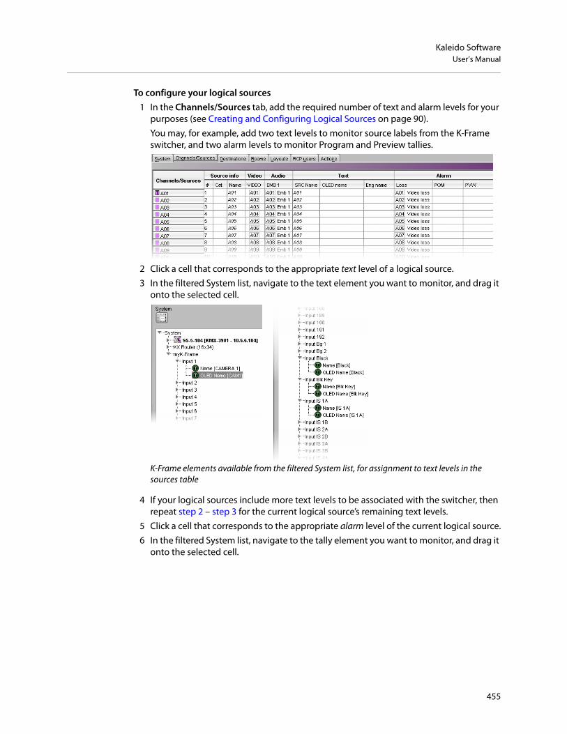
Kaleido SoftwareUser’s Manual
To configure your logical sources1 In the Channels/Sources tab, add the required number of text and alarm levels for your
purposes (see Creating and Configuring Logical Sources on page 90).You may, for example, add two text levels to monitor source labels from the K-Frame switcher, and two alarm levels to monitor Program and Preview tallies.
2 Click a cell that corresponds to the appropriate text level of a logical source.3 In the filtered System list, navigate to the text element you want to monitor, and drag it
onto the selected cell.
K-Frame elements available from the filtered System list, for assignment to text levels in the sources table
4 If your logical sources include more text levels to be associated with the switcher, then repeat step 2 – step 3 for the current logical source’s remaining text levels.
5 Click a cell that corresponds to the appropriate alarm level of the current logical source.6 In the filtered System list, navigate to the tally element you want to monitor, and drag it
onto the selected cell.
455

Tally Interface Devices &Timer SystemsConfiguring the Multiviewer
K-Frame elements available from the filtered System list, for assignment to alarm levels in the sources table
7 If your logical sources include more alarm levels to be associated with the K-Frame switcher, then repeat step 5 – step 6 for the current logical source’s remaining alarm levels.
8 Make corresponding assignments to other logical sources by incremental copy, if necessary (see Making Further Assignments by Incremental Copy on page 102).
9 On the File menu, click Save.Changes to the sources table are saved.
Configuring layout elementsYou can now assign the logical sources you previously configured (see Assigning K-Frame tallies and input names to logical sources on page 453) to monitors that can display text (e.g., UMD) or alarms (e.g., UMD, video, text alarm status) in a layout. Depending on your purposes, you will assign the appropriate text or alarm levels to specific components within the monitors (e.g., assign an alarm level to tally components in a UMD, or a text level to the UMD text component).
To configure layout elements for dynamic text and tally reporting1 Click the Layouts tab, and then open the layout you want to configure.
Text levels based on dynamic K-Frame source labels
Alarm levels based on tallies from the K-Frame switcher
456

Kaleido SoftwareUser’s Manual
2 On the Tools pane, select one of the logical sources you previously configured (see Assigning K-Frame tallies and input names to logical sources on page 453) from the filtered Channels/Sources list, and then drag it onto the appropriate monitor.
3 Repeat step 2 until you have assigned all the sources you want to monitor to the appropriate monitors in your layout.
4 Click the first UMD whose dynamic text and tally reporting behavior you want to set, after unlocking the composite monitor that contains it if applicable (see Unlocking a Composite Monitor on page 313).
5 In the Properties pane, click the Left tally source level box, and then select the alarm level you want to monitor.
Alarm level selection for the left tally in a UMD
6 Click the Right tally source level box, and then select the appropriate alarm level, if applicable.
7 Click the Text label level box, and then select the text level you want to monitor.
Text level selection for the text label in a UMD
8 Click outside the composite to lock it, if applicable.
457

Tally Interface Devices &Timer SystemsConfiguring the Multiviewer
9 Repeat step 4 – step 8 until you have configured all UMDs that are to display dynamic text and tally status when this layout is loaded on the monitor wall.
10 On the File menu, click Save.11 If you have been working in offline mode, then export the database to your
multiviewer (see Exporting a Database on page 37).
On the monitor wall, you can now load the layout containing the monitors that were assigned dynamic text and tallies provided by the K-Frame switcher. Input names, and tally status from the switcher will be visible on the monitor wall. Any changes made by the switcher’s operator will be immediately reflected on the monitor wall.
458

Kaleido SoftwareUser’s Manual
Zodiak Production SwitcherA multiviewer can receive dynamic source names and tally information from a Grass Valley Zodiak Digital Production Switcher. The procedures below describe how to set up a multiviewer to interface with this family of production switchers.
Configuring the Zodiak SwitcherTo establish a serial connection between the switcher and your multiviewer, you need to identify the serial port you want to use for tally contribution in the switcher’s Engineering Setups, by using the Zodiak touch screen menu panel or the Zodiak Menu application. You also need to configure or take note of the communications settings and use the same values on the multiviewer’s side. The procedure below is an example using the default values typically used on Grass Valley production switchers.
To set up the Zodiak switcher1 Physically connect one end of an RJ-45 straight cable to the multiviewer’s RS-422 port.2 Using a DE-9S-to-RJ45 crossover adapter (Grass Valley part no. 1792-3700-100),
connect the other end of the cable to one of the 4 RS-422 control ports on the Zodiak Video Processor Frame. The illustration below shows the location of the RS-422 ports on a Zodiak frame. The RS-422 ports (highlighted) are labeled Serial 1 – 4 (J4 – J7).
The 4 RS-422 control ports at the back of a Zodiak Video Processor frame have DE-9 female connectors with the following pinout:
Pin Signal
1, 4, 6, and 9 Chassis ground
2 RX-
3 TX+
7 RX+
8 TX-
Note: Refer to the multiviewer’s Installation & Service Manual for pin-outs on the multiviewer. See Related Documentation, on page 13.
459

Tally Interface Devices &Timer SystemsConfiguring the Multiviewer
3 From the Zodiak Home menu, touch the Eng Setup menu button, and then the Ports & Devices category button.The Physical Serial Port Assignment menu appears.
4 In the port selection area, touch the port you want to use as the tally contribution port.5 In the Baud Rate area, touch 38.4k.6 In the Parity area, touch None.
This sets the baud rate to 38,400 and the parity to None.
Assuming the required sources and outputs have been defined, this completes the configuration required on the switcher. The multiviewer system will be able to send commands to the switcher, and the switcher will respond accordingly. Refer to the Zodiak Installation & Service Manual for more details.9
Configuring the MultiviewerFor your multiviewer to receive tally status, source names and output names from a Zodiak switcher, and to display the switcher’s contribution on the monitor wall as visual tally and dynamic text information, you need to configure your multiviewer’s Zodiak serial tally service, by performing the following in XEdit:
• set up the communication parameters for the serial connection;• configure logical sources by assigning input names, output names, and tally status
from the switcher to the appropriate logical sources’ text and alarm levels;• assign alarm and text levels from logical sources to layout elements such as UMDs or
alarm monitors.
Establishing serial communication between the Zodiak switcher and the multiviewer
To set up the multiviewer’s communication parameters1 Open XEdit.2 In the main window, click the System tab, and then click Description/Calibrations on
the second-level tab bar. The main pane displays the System hierarchical list, and the Tools pane displays the equipment library when the root of the System list is selected.
3 Drag the Zodiak production switcher device from the equipment library onto the root of the System hierarchical list. Alternatively, right-click the list root, and then click Insert Zodiak on the menu.A window appears, prompting you for a device identifier.
4 Type a name for the Zodiak production switcher, and then click OK.
9.Manuals and Release Notes for all Grass Valley production switchers are available here:http://www.grassvalley.com/docs/all_switchers.html#manuals
460

Kaleido SoftwareUser’s Manual
5 Click the Interconnects tab.6 Position the pointer over the multiviewer icon, then click and drag towards the Zodiak
production switcher icon.A line representing the connection between the multiviewer and the device appears.
7 Click the connection line between multiviewer and device.8 In the Properties pane, select the appropriate serial port from the RS-422
communication port list.
Depending on the multiviewer model, the available RS-422 ports are designated as follows:
9 In the Interconnects tab, click the Zodiak production switcher icon.
KMV-3901/3911 RS-422
Kaleido-X16 Port 1, and Port 2
Kaleido-X (14RU) Frame A – Output A, B, and C; Frame B – Output A, B, and C
Kaleido-X (7RU) Output A, B, C, and D
Kaleido-X (4RU) Output A, and B
Kaleido-MX, Kaleido-MX 4K
Output A, and BNote: The Kaleido-MX (1RU) 16 × 4, and the Kaleido-MX 4K 16 × 1 models have only one RS-422 port, which is physically connected to output card A.
Kaleido-Modular-X Output A, and BNote: KMX-3901-OUT output cards with a single rear connector panel (KMX-3901-OUT-D-3+SRP) do not have RS-422 ports. To support a serial device, your Kaleido-Modular-X system must have at least one output card with a double rear connector panel (KMX-3901-OUT-D-3DRP).
461

Tally Interface Devices &Timer SystemsConfiguring the Multiviewer
In the Properties pane, the serial communications properties for the Zodiak device are the following, by default:
10 Set these properties to match the values used on the switcher.
11 Select the appropriate outputs to use for the Preview Out and Program Out tally calculation, based on your switcher’s configuration.
The current version of the Kaleido Software supports monitoring of one Preview output and one Program output from any of the Zodiak switcher’s physical or internal M/E units (Pgm-Pst PVW A, and B; M/E 1 PVW, M/E 2 PVW, M/E 3 PVW; Pgm-Pst PGM A, and B; M/E 1 PGM, M/E 2 PGM, M/E 3 PGM), from up to 13 Aux bus outputs, or from the additional switched preview output.
Assigning Zodiak tallies, input names, and output names to logical sourcesThe Zodiak contribution tally protocol provides information on up to 128 external sources, up to 13 Aux bus outputs, and the switched preview output from the Zodiak Video Processor Frame, in addition to the Preview and Program outputs you selected (see step 11 of Establishing serial communication between the Zodiak switcher and the multiviewer, on page 460). In XEdit’s Channels/Sources tab, configure logical sources using text sources and system tallies from the Zodiak’s serial interface. You will find these elements by expanding the filtered system list that appears on the Tools pane.
To configure your logical sources1 In the Channels/Sources tab, add the required number of text and alarm levels for your
purposes (see Creating and Configuring Logical Sources on page 90).You may, for example, add one text level to monitor source labels from the Zodiak switcher, and two alarm levels to monitor Program and Preview tallies.
Baud Rate 38400
Data Bits 8
Parity NONE
Stop bits 1
462

Kaleido SoftwareUser’s Manual
2 Click a cell that corresponds to the appropriate text level of a logical source.3 In the filtered System list, navigate to the text element you want to monitor, and drag it
onto the selected cell.
Zodiak elements available from the filtered System list, for assignment to text levels in the sources table
In the case of the Zodiak outputs (the Preview and Program Outputs you selected, Aux Output 1 to Aux Output 13, and the Switched Preview Output), from which elements can be assigned to text levels in your multiviewer’s logical sources, the Kaleido Software supports 4 display modes for the labels:
The Zodiak external sources represented in the filtered System list (Input 1 to Input 128), are associated with a single Input label.
4 If your logical sources include more text levels to be associated with the Zodiak switcher, then repeat step 2 – step 3 for the current logical source’s remaining text levels.
5 Click a cell that corresponds to the appropriate alarm level of the current logical source.6 In the filtered System list, navigate to the tally element you want to monitor, and drag it
onto the selected cell.
Level 1 The label represents the initial background feed.
Level 2 The label represents the initial and the previous background feed
Level 3 The label represents the previous background feed
Level 4 The label represents the current background feed (not supported)
463

Tally Interface Devices &Timer SystemsConfiguring the Multiviewer
7 If your logical sources include more alarm levels to be associated with the Zodiak switcher, then repeat step 5 – step 6 for the current logical source’s remaining alarm levels.
8 Make corresponding assignments to other logical sources by incremental copy, if necessary (see Making Further Assignments by Incremental Copy, on page 102).
9 On the File menu, click Save.Changes to the sources table are saved.
Configuring layout elementsYou can now assign the logical sources you previously configured to monitors that can display text (e.g., UMD) or alarms (e.g., UMD, video, text alarm status) in a layout. Depending on your purposes, you will assign the appropriate text or alarm levels to specific components within the monitors (e.g., assign an alarm level to tally components in a UMD, or a text level to the UMD text component).
To configure layout elements for dynamic text and tally reporting1 Click the Layouts tab, and then open the layout you want to configure.2 On the Tools pane, select one of the logical sources you previously configured
(see Assigning Zodiak tallies, input names, and output names to logical sources on page 462) from the filtered Channels/Sources list, and then drag it onto the appropriate monitor.
3 Repeat step 2 until you have assigned all the sources you want to monitor to the appropriate monitors in your layout.
Text level based on dynamic labels from Zodiak sources
Alarm levels based on tallies from the Zodiak device
464

Kaleido SoftwareUser’s Manual
4 Click the first UMD whose dynamic text and tally reporting behavior you want to set, after unlocking the composite monitor that contains it if applicable (see Unlocking a Composite Monitor on page 313).
5 In the Properties pane, click the Left tally source level box, and then select the alarm level you want to monitor.
Alarm level selection for the left tally in a UMD
6 Click the Right tally source level box, and then select the appropriate alarm level, if applicable.
7 Click the Text label level box, and then select the text level you want to monitor.
Text level selection for the text label in a UMD
8 Click outside the composite to lock it, if applicable.9 Repeat step 4 – step 8 until you have configured all UMDs that are to display dynamic
text and tally status when this layout is loaded on the monitor wall.10 On the File menu, click Save.
465

Tally Interface Devices &Timer SystemsConfiguring the Multiviewer
11 If you have been working in offline mode, then export the database to your multiviewer (see Exporting a Database on page 37).
On the monitor wall, you can now load the layout containing the monitors that were assigned dynamic text and tallies provided by the Zodiak switcher. Input or output names, as well as tally status from the Zodiak switcher will be visible on the monitor wall. Any changes made by the switcher’s operator will be immediately reflected on the monitor wall.
466

Kaleido SoftwareUser’s Manual
Daktronics ScoreboardsFor your multiviewer to receive scoreboard information from a Daktronics system, and to display the system’s contribution on the monitor wall, you need to configure your multiviewer by performing the following tasks in XEdit:
1 Add the Daktronics scoreboard to your multiviewer system configuration, and set up the communication parameters (see Adding a Daktronics Scoreboard to your Multiviewer Configuration on page 467).
2 Add logical sources and configure them by assigning text elements from the scoreboard system to the logical sources’ text levels (see Assigning Scoreboard Information to Logical Sources on page 469).
3 Assign the appropriate text levels from logical sources, to layout elements such as UMDs, or alarm monitors (see Configuring Layout Elements on page 470).
Adding a Daktronics Scoreboard to your Multiviewer ConfigurationTo add a Daktronics scoreboard to your multiviewer configuration
1 Open XEdit.2 Connect to the multiviewer, if you want to apply your changes in real time
(see Connecting to a Multiviewer on page 32).
3 In the main window, click the System tab, and then click Description/Calibrations on the second-level tab bar. The main pane displays the System hierarchical list, and the Tools pane displays the equipment library when the root of the System list is selected.
4 Drag the Daktronics device from the equipment library onto the root of the System hierarchical list.
Alternatively, right-click the list root, and then click Insert Daktronics on the menu.A window appears, prompting you for a device identifier.
5 In Device Identifier, type a name for the scoreboard, and then click OK.
Note: If this step is omitted, then you will need to export the database to apply the changes.
467

Tally Interface Devices &Timer SystemsAdding a Daktronics Scoreboard to your Multiviewer Configuration
The scoreboard is added to the system list.
6 Click the Interconnects tab.7 Position the pointer over the multiviewer icon, then click and drag towards the
scoreboard device icon.A line representing the connection between the multiviewer and the device appears.
8 Click the connection line between multiviewer and device.9 In the Properties pane, select the appropriate element from the RS-422
communication port list.
Depending on the multiviewer model, the available RS-422 ports are designated as follows:
KMV-3901/3911 RS-422
Kaleido-X16 Port 1, and Port 2
Kaleido-X (14RU) Frame A – Output A, B, and C; Frame B – Output A, B, and C
Kaleido-X (7RU) Output A, B, C, and D
Kaleido-X (4RU) Output A, and B
468

Kaleido SoftwareUser’s Manual
10 In the Interconnects tab, click the scoreboard device icon.11 In the Properties pane, set the serial communications
properties for the scoreboard device as follows:
You are now ready to add information from the Daktronics scoreboard system to logical sources.
Assigning Scoreboard Information to Logical SourcesTo configure your logical sources
1 In the Channels/Sources tab, add the required number of logical sources for your purposes (see Manually adding a Logical Source on page 94).If you plan to monitor scoreboard data during a hockey game, for example, you might add one logical source for every element you want to monitor (e.g., the game clock, the period number, the home and guest teams’ scores).
2 Add the required number of text levels for your purposes (see Adding a level on page 95).For example, you might add one text level named Scoreboard.
3 Click a cell that corresponds to the appropriate text level of a logical source you want to configure.
4 In the filtered System list, navigate to the text element you want to monitor, and drag it onto the selected cell.
5 If your logical sources include more text levels to be associated with the timer system, then repeat step 3 and step 4 for the current logical source’s remaining text levels.
6 Repeat step 3–step 5 for any remaining logical sources you want to configure with scoreboard information.
Kaleido-MX, Kaleido-MX 4K
Output A, and BNote: The Kaleido-MX (1RU) 16 × 4, and the Kaleido-MX 4K 16 × 1 models have only one RS-422 port, which is physically connected to output card A.
Kaleido-Modular-X Output A, and BNote: KMX-3901-OUT output cards with a single rear connector panel (KMX-3901-OUT-D-3+SRP) do not have RS-422 ports. To support a serial device, your Kaleido-Modular-X system must have at least one output card with a double rear connector panel (KMX-3901-OUT-D-3DRP).
Baud Rate 9600
Data Bits 8
Parity NONE
Stop bits 1
469

Tally Interface Devices &Timer SystemsConfiguring Layout Elements
Sample Daktronics configuration, to monitor scoreboard information for a hockey game
7 On the File menu, click Save.Changes to the sources table are saved.
Configuring Layout ElementsYou can now assign the logical sources you previously configured (see Assigning Scoreboard Information to Logical Sources on page 469) to UMDs or alarm monitors in a layout. The procedure below explains how to configure UMDs to report scoreboard information.
To configure UMDs for dynamic reporting of scoreboard text from a Daktronics system1 Click the Layouts tab, and then open a layout.2 Drag the third predefined UMD (umd2), from the set of predefined UMDs available on
the Tools pane, onto your layout, and then adjust its size and position as needed.
3 On the Tools pane, select one of the logical sources you previously configured (see Assigning Scoreboard Information to Logical Sources on page 469), from the filtered Channels/Sources list, and then drag it onto the UMD.
4 In the Layouts tab, click the UMD, if it is not already selected.5 In the Properties pane, click the Text label level box, and then select the text level you
want to monitor (e.g., the Scoreboard level you previously configured).
Note: The third predefined UMD (umd2) is configured not to show tallies or alarm latches, which makes it the convenient choice for displaying text information only.
470

Kaleido SoftwareUser’s Manual
6 Select a monospace font for the text:a Click the Text font box, and then click the button that appears inside the box to
open the font picker window.
b In Select a Font, click a monospace font (e.g., Lucida Sans Typewriter).c Set the font style and size, as needed.d Click OK to close the window.
7 Set the text alignment to match your scoreboard behavior by clicking the Text horizontal alignment box, and then selecting Left, or Right, for example, from the list.
8 If you want to add a text label for this information (e.g., GUEST, HOME, PERIOD, etc.), add another UMD (again, by using umd2 from the set of predefined UMDs), and type some text (see Configuring Static UMD Text on page 286, if needed).
9 Repeat step 2–step 8 until you have added UMDs for all the scoreboard data you want to monitor.
Click this button to open Select a Font
471

Tally Interface Devices &Timer SystemsConfiguring Layout Elements
10 On the File menu, click Save.11 If you have been working in offline mode, then export the database to your
multiviewer (see Exporting a Database on page 37).
On the monitor wall, you can now load the layout containing the monitors that were assigned information from the scoreboard system. Text information from the device will be visible on the monitor wall. Any changes made by the device’s operator will be immediately reflected on the monitor wall.
472

Kaleido SoftwareUser’s Manual
Serial Port Test AgentDuring a setup, it is sometime not clear if the wiring between the multiviewer and a peripheral device is correct or if the peripheral device sends the expected data. One can connect a serial-port test agent as a peripheral device in XEdit, export the database to the multiviewer, and then read, on a Web page, the data received on the serial port.
To use a serial port test agent1 Select the Serial port test device in the equipment library and drag it onto the root of
the System hierarchical list. Alternatively, right-click the list root, and then click Insert Serial port test on the menu.
2 Click the Interconnects tab in the main window.3 To connect the test device to the multiviewer, click the multiviewer’s icon, or the
device’s, and drag the pointer towards the other.4 Click the test device’s icon, and adjust the port settings to match those of the actual
peripheral device you want to test.5 Click the connection line between the device and the multiviewer.6 In the Properties pane, select the appropriate element from the RS-422
communication port list.Depending on the multiviewer model, the available RS-422 ports are designated as follows:
When connected, the serial-port test agent will log all data received from the serial port to a file that you can read using a Web browser.Once the database is exported to the multiviewer, the serial-port test agent starts. The agent opens the serial port and start writing to a log file the data that is received on the port. To access the log file, point your browser to http://[IP address]/logs/comm.log.
KMV-3901/3911 RS-422
Kaleido-X16 Port 1, and Port 2
Kaleido-X (14RU) Frame A – Output A, B, and C; Frame B – Output A, B, and C
Kaleido-X (7RU) Output A, B, C, and D
Kaleido-X (4RU) Output A, and B
Kaleido-MX, Kaleido-MX 4K
Output A, and BNote: The Kaleido-MX (1RU) 16 × 4, and the Kaleido-MX 4K 16 × 1 models have only one RS-422 port, which is physically connected to output card A.
Kaleido-Modular-X Output A, and BNote: KMX-3901-OUT output cards with a single rear connector panel (KMX-3901-OUT-D-3+SRP) do not have RS-422 ports. To support a serial device, your Kaleido-Modular-X system must have at least one output card with a double rear connector panel (KMX-3901-OUT-D-3DRP).
473

Tally Interface Devices &Timer SystemsSerial Port Test Agent
Note: The part [IP address] represents the IP address of the output card (or of the multiviewer itself, depending on the model) where the test agent is connected. You can find the IP address on XAdmin’s System Configuration page (see Configuring a Multiviewer’s IP Settings in the multiviewer’s Installation & Service Manual for more information).
474

Operation of the Monitor Wall
IntroductionThis section introduces the multiviewer monitor wall features and describes the actions you can perform on the multiviewer’s monitor wall.
Key Concepts
Monitor wall The monitor wall refers to the group of display screens that are connected to the output modules of a specific Kaleido system.
Room A room is a visual grouping of display screens. A room represents the physical displays, positioned and sized as viewed by the user in an actual room. Rooms can include full screen zones, and are defined and configured by using the XEdit application. See Logging on to the Monitor Wall Using a Remote Control Panel on page 480.
Automatic resolution detection
Automatic resolution detection eases the initial setup of a new display monitor by automatically determining the best resolution supported by the display. This ensures that the multiviewer will be configured for the best video quality. When a new display is connected, the multiviewer will detect the EDID of the display on boot-up, and will set the correct resolution accordingly. This means that displays can be hot-swapped. If an existing display is replaced by a new one, the multiviewer will automatically change the resolution without the need for a system restart. Note: The Kaleido-IP does not support automatic output resolution detection.
Layout A layout refers to a visual grouping of monitors on the monitor wall. Layouts are specific to a room, and created by using the XEdit application. Full screen layouts, also defined in XEdit, are specific to a full screen zone within a particular room. See Loading Layouts, on page 486, and Displaying a Source in Full Screen Mode, on page 489.
Dashboard The dashboard is a window that contains the system name, IP address and software build version. It also displays error messages. The dashboard is displayed at the bottom right of each display, on the monitor wall:
See Displaying the Dashboard, on page 484, and Hiding the Dashboard, on page 485.
475

Operation of the Monitor WallKey Concepts
Monitor A monitor is an element that is part of a layout. XEdit supports several types of primary elements (clocks, timers, video monitors, audio monitors, UMDs, time code monitors, alarm monitors, etc.), that can be grouped into composite monitors.
Logical source A logical source (called a channel, in earlier versions of the documentation) refers to a group of physical audio, video, or metadata sources, and text attributes. A logical source can be used as a whole, and assigned to a virtual monitor. See Assigning Sources to Monitors on page 501.
Video monitor A video monitor is a layout element used to define an area for displaying a video signal. Within a video monitor, the video window is the active area where the video signal is displayed, possibly including closed captions or teletext. See Displaying Subtitles and Closed Caption Text on page 494.
Composite monitor
A composite monitor (also referred to as a composite, a monitor or a tile) is a group of primary elements that can be seen as a single object within a layout. Composite monitors typically include a video window, one or more audio level meters, and a UMD with two tallies.
Safe area The safe area is a configurable region inside a video window. The safe area markers delimit this region (e.g., a 4:3 region inside a 16:9 window). See Toggling Safe Area Markers on page 493.
Audio monitor An audio monitor (also called audio level meter or ALM) is a layout element that provides a visual representation of sound. See Audio Monitoring on page 479.
UMD An under monitor display (UMD) has a text label that can be static or dynamically updated by a peripheral device. It can also have left and right tally indicators. The UMD typically indicates the name of the video source seen in a video monitor. You can edit static labels directly on the monitor wall: see Editing UMD Text, on page 499, and Selecting an Input Method, on page 500.
Time code monitor
A time code monitor displays the Ancillary Time Code (ATC) from an HD video signal, or the time code found in an embedded SDI video signal, part of the vertical interval of an analog signal (VITC), or other external Linear Time Code (LTC). This monitor also supports time code information from external providers. Time code monitors can be used for monitoring the duration of programs.
RCP User The advanced Remote Control Panel (RCP) simplifies video/audio signal processing and control in both single and multiuser environments. RCP User use the RCP to control connected equipment.
Timer A timer monitor is based on a timer defined within the multiviewer system.Three timer modes are available: (1) UP: timer counts up starting from zero up to a preset time, (2) DOWN: timer counts down from a preset time to zero, and (3) REMAINING: timer counts down from the current time until it reaches a preset time.Timers are defined and configured in XEdit. They can be slaved to production timers, assigned to logical sources, assigned to rooms or specific RCP users, and controlled from the Kaleido-RCP2. See Using Timers on page 509.
Clock A clock is the visual representation of time in a video or display. It can be based on a reference LTC signal or on the multiviewer’s system time.
476

Kaleido SoftwareUser’s Manual
Subtitling monitor
A subtitling monitor defines an area for displaying subtitles extracted from a video signal. By using a subtitling monitor you can monitor subtitling from a specific DVB or SCTE 27 stream, independently from the associated video stream. This requires the CC/XDS option to be enabled (see the multiviewer’s Installation & Service Manual for more information). See Setting the DVB Subtitling Language from the Monitor Wall, on page 496, and Setting the SCTE 27 Subtitling Language from the Monitor Wall, on page 497.Note: With the current version of the Kaleido Software, the subtitling monitor supports DVB subtitles and SCTE 27 subtitles, from Kaleido-IP sources only.
V-chip monitor The V-chip monitor provides a visual indication of the V-chip rating from the CC (608) metadata in an SD video signal, or from the CC (608) legacy caption data, when such data is present within an HD video signal. Requires the CC/XDS option to be enabled (see the multiviewer’s Installation & Service Manual for more information).
Metadata monitor
A metadata monitor defines an area for displaying XDS, or digital content advisory descriptor (CAD) information compliant with CEA-766-D, extracted from a video signal. This requires the CC/XDS option to be enabled (see the multiviewer’s Installation & Service Manual for more information).
Action An action is an operation automatically performed in response to a specific trigger. Monitor wall actions are directly associated with layout elements. Background (floating) actions are actions that are global to the multiviewer system. Unlike monitor wall actions, background actions are always available. See Triggering Actions on page 512.
Trigger A trigger is an event that triggers an action. An example of a trigger could be a double click on a monitor. Background actions are triggered by alarms or by Gateway commands. In XEdit, when defining an action for a layout element, you could specify, for instance, that a specific full screen layout be displayed on the monitor wall in response to the trigger.
Alarm monitor Alarm monitors help you see the status of global and virtual alarms, but their use is not limited to this type of alarms. When any alarm level is assigned to an alarm monitor, the status of this alarm will be shown. When using the global alarm at the text label level, it will display the text value of the alarm, which is a readable name.
Alarm latch To prevent operators from missing temporary alarms on the monitor wall, layout elements that are capable of displaying an alarm status (e.g., video monitors, subtitling monitors, UMDs, alarm monitors) can be configured with a latching mechanism. An alarm latch will keep the error state visible until someone acknowledges the associated alarm. See Acknowledging Alarms on page 514.
When you acknowledge an alarm, latched or current, the latched status is reset to normal (i.e., unlatched). If the alarm is acknowledged while its status indicates an error condition, the latched status is reset to normal, and will only go back to error if the alarm status returns to normal and then to error again.
477

Operation of the Monitor WallKey Concepts
Note: If you have an iControl application server, you may use its GSM alarm browser to configure an acknowledgement snooze duration, which defines the period during which alarm status changes detected by your multiviewer are ignored, immediately after an alarm is acknowledged. Such a snooze period is typically not desirable in the context of multiviewer alarms. Therefore, a multiviewer’s GSM has its acknowledgement snooze duration set to 0 ms, by default.
Video monitors can provide alarm status information through their borders’ color and blinking behavior, and show the latched state as small indicators in each corner of the video window. UMDs (text and tallies) and alarm monitors can change their text or background color and blinking behavior, to reflect the alarm status and show the latched state through their borders.
See Configuring a Video Monitor’s Alarm Reporting Behavior, on page 257, Configuring a UMD’s Alarm Reporting Behavior, on page 283, and Configuring Alarm Monitors, on page 290, for details on configuring the alarm reporting and latching attributes for these layout elements.
The multiviewer tracks the latched state of all alarm levels in a logical source at all times, even when alarms are not being monitored on the monitor wall, or through SNMP traps or background actions. It could thus happen that some layout elements will show a latched status indicator after a layout is loaded, even if the current state of the corresponding alarm is normal and the alarm was not monitored in the previous layout (the alarm occurred on the feed while the feed was not monitored).
• Latching only occurs when an alarm severity is above normal (i.e., minor, major, or critical). All other alarm states (unavailable, unassigned, pending, unknown, etc.) are not latched.
• Unlatching a global alarm unlatches all its contributing alarms. Unlatching the last alarm contributing to a global alarm unlatches the global alarm itself.
• The color of the latch indicator reflects the highest level of alarm received since the corresponding alarm was last unlatched.
Red border indicates
Red corners indicate
current alarm state
latched state
478

Kaleido SoftwareUser’s Manual
Audio MonitoringThe Kaleido-RCP2’s volume control, Mute, and -20dB buttons, their equivalent on the RCP-200, and the corresponding Gateway commands apply to analog audio monitoring outputs (where available). In the case of a Kaleido-X, or Kaleido-X16 multiviewer, the Mute button (and its equivalents) applies to digital (AES, HDMI, or SDI) audio outputs as well. See Monitoring Audio on page 516.
The following table summarizes support for muting the audio monitoring outputs, by multiviewer type, and audio output format.
Crosspoint A multiviewer can control upstream rou9ters, and it can also be controlled as a router itself. In addition, some multiviewer models—Kaleido-X16, Kaleido-X (7RU), and Kaleido-X (14RU)—can have optional router outputs. A crosspoint is the link inside a router between a source (input) and a destination (output). See Changing Crosspoints on page 505.Note: As of Kaleido Software version 5.20, the preferred method of controlling sources, regardless of whether they are sources from an upstream router or physical multiviewer inputs, is to configure logical sources.
Gateway Kaleido multiviewers can execute commands received through the Kaleido Remote Control Protocol (Gateway) interface, allowing third-party developers and individual users remote access to some Kaleido functions. Refer to the Kaleido Remote Control Protocol (Gateway) User’s Guide, for more information. See Related Documentation, on page 13.
Analog AES HDMI SDI (or SFP) Mosaic return (KMX-49N1)
KMX-3921 N/A N/A N/A No N/A
KMX-49N1 N/A N/A No No No
Kaleido-MXa
a. Also Kaleido-MX 4K, and Kaleido-Modular-X.
Yesb
b.Kaleido-MX 16 × 4, and Kaleido-MX 4K 16 × 1 do not have analog audio monitoring outputs.
N/A No No N/A
Kaleido-IP N/A N/A No N/A N/A
Kaleido-X Yes Yes N/A Yes N/A
Kaleido-X16 Yes Yes Yes Yes N/A
KMV-3911c
c. Also KMV-39N1, Kaleido-XQUAD, and Kaleido-XQUAD Dual
N/A N/A No No N/A
479

Operation of the Monitor WallLogging on to the Monitor Wall Using a Remote Control Panel
Logging on to the Monitor Wall Using a Remote Control PanelAs network devices, the RCP-200 advanced remote control panel, and the Kaleido-RCP2 control panel provides access to any room, from any Kaleido multiviewer system on the network. As a security measure, access is controlled by a login procedure. Multiple RCP-200 and Kaleido-RCP2 can be used by different users to access the same room concurrently. When multiple RCP users are active in the same room, they each control a separate pointer on the monitor wall, and can use the monitor wall menu independently, as long as they limit their actions to separate displays.
In a default system configuration, a multiviewer’s video outputs are assigned to specific rooms:
• On a Kaleido-X (7RU), the two DVI/VGA outputs from each of the dual-head output cards A, B, C and D are assigned to ROOM1, ROOM2, ROOM3 and ROOM4 respectively.
• On a Kaleido-X (4RU), the two DVI/VGA outputs from each of the dual-head output cards A and B are assigned to ROOM1 and ROOM2 respectively.
• On a Kaleido-X (14RU) expansion system, the two DVI/VGA outputs from each of the dual-head output cards A, B and C of each of Frame A and Frame B are assigned to ROOM1, ROOM2, ROOM3, ROOM4, ROOM5 and ROOM6 respectively.
• On a Kaleido-X16-D, the HDMI outputs from each of the output modules are assigned to ROOMX16.
• On a Kaleido-X16-S, the HDMI output is assigned to ROOMX16.• On a KMV-3901/3911, Kaleido-XQUAD, or Kaleido-XQUAD-DUAL, the HDMI outputs are
assigned to ROOM1.• On a Kaleido-IP, the multiviewer outputs are assigned to ROOM.• On a Kaleido-MX, Kaleido-MX 4K, or Kaleido-Modular-X, the outputs are assigned to
ROOM1.
Logging on to the Monitor Wall Using the Kaleido-RCP2To log on to a Kaleido multiviewer’s room from the Kaleido-RCP2
1 On a Kaleido-RCP2 with an active connection to the network, press and hold the ENTER button until the ESC button lights up. The Configuration menu appears, with the ROOM SELECTION option displayed.
2 Press ENTER again to obtain the list of rooms from the Kaleido multiviewer systems that are currently available on the network.The rooms are listed in the form [multiviewer name]/[room name]. If a room belongs to a cluster system, its name appears once for each of the member multiviewers (e.g., if two multiviewers, KX1 and KX2, are configured as a cluster, and ROOM1 includes displays fed by both multiviewers, then both KX1/ROOM1 and KX2/ROOM1 will be listed. You may select either one.
3 In the room list, select the room you want to access by pressing the 2 key (to move up in the list) or the 8 key (to move down the list).
4 When the appropriate room name is highlighted, press ENTER to accept the new selection, and then press ESC to exit the Configuration menu.
5 Press the LOGIN key.
480

Kaleido SoftwareUser’s Manual
The following message will appear on the LCD display:LOGIN PositionAdmin
6 Select your user name by pressing the 2 key (to move up in the list) or the 8 key (to move down the list).
7 When you user name is highlighted, press ENTER.8 When prompted, type the password for this user name, then press ENTER.
The message “Access granted” will appear on the LCD display if the login is successful. If a mouse is connected to the Kaleido-RCP2, then you should be able to see and move the mouse pointer on the monitor wall. Alternatively, use the Kaleido-RCP2’s mouse-function keys.
For more information on the Kaleido-RCP2, refer to the Kaleido-RCP2 Guide to Installation and Operation. See Related Documentation, on page 13.
Logging on to the Monitor Wall Using the RCP-200To log on to a Kaleido multiviewer room from the RCP-200
1 On an RCP-200 with an active connection to the network, press the LIST button.All devices, and Kaleido multiviewer rooms, detected by the RCP-200 appear on the left screen. Kaleido multiviewer rooms are listed in the form [multiviewer name]\[room name].If a room belongs to a cluster system, its name appears once for each of the member multiviewers (e.g., if two multiviewers, KX1 and KX2, are configured as a cluster, and ROOM1 includes displays fed by both multiviewers, then both KX1\ROOM1 and KX2\ROOM1 will be listed. To determine the one you should select, review the following:
• Has the RCP user configuration you want to use been replicated on every member of the cluster (see Replicating RCP Users Across a Cluster System on page 50)?
• Do you need to control an external router whose configuration is available only from one or some specific members of the cluster?
Note: By default, the user “Admin” has no password.
Notes
• If at any time the message “Target system is offline” or “No login list available” appears on the LCD display, press the ESC, ENTER and DEL keys simultaneously and go back to step 1.
• If the room you were logged on to is part of a cluster system, try accessing it from a different multiviewer (e.g., select KX2/ROOM1 instead of KX1/ROOM1, from the room list).
• The pointer may flicker when two RCP users access displays fed by the same multiviewer output.
• Two users accessing the same display will be limited to sharing a single pointer.
481

Operation of the Monitor WallLogging on to the Monitor Wall Using the RCP-200
• Does your system configuration include actions that were configured only on one or some specific members of the cluster?
• Do you need to control a timer from the monitor wall in a cascade room?If any of the above elements is available only from one or some specific members, then make sure you select the room name prefixed with the appropriate multiviewer name. In the case of a cascade room, unless you remember which multiviewer you were connected to when you added the timer you need to control, you will have to proceed by trial and error.
2 Touch the room you want to access (press the DOWN or UP soft keys to scroll the list as needed).
3 If the list of users assigned to this room appears on the right-hand screen, touch the user name under which you want to log on, enter your password, and then touch LOG IN.
The room’s monitor wall control panel appears on the right-hand screen, with the ASSIGN CHANNEL category selected. If a mouse is connected to the RCP-200, then after touching WALL MOUSE you should be able to see and move the mouse pointer on the monitor wall.
For more information on the RCP-200, refer to the RCP-200 Guide to Installation and Operation. See Related Documentation, on page 13.
Note: By default, the user “Admin” has no password.
Notes
• If the ROUTER SELECT category becomes selected instead of ASSIGN CHANNEL, showing the following message on the right-hand screen: “Please select a router from the left-hand screen,” then you still need to complete the correlation between some monitor wall destinations and the representation of the corresponding KX Router logical router. See Correlating Monitor Wall Destinations and KX Router Logical Routers for the RCP-200 in the multiviewer’s Installation & Service Manual for more information.
• The RCP-200 will remember your user credentials until you log out explicitly (by touching LOG OUT at the upper-right corner of the control panel).
• The pointer may flicker when two RCP users access displays fed by the same multiviewer output.
• Two users accessing the same display will be limited to sharing a single pointer.
482

Kaleido SoftwareUser’s Manual
Using On-Screen Wall Control
Locating the Mouse Pointer on the Monitor WallIf you have a cluster system, the monitor wall may comprise a large number of display screens, where the mouse pointer location is not always obvious.
To locate the mouse pointer on the monitor wall• Click the middle mouse button.
A more recognizable square shape appears around the pointer.
Using On-Screen Wall Control from the RCP-200Once you have logged on to a room from the RCP-200 control panel, a mouse connected to one of the panel’s USB port automatically switches to the monitor wall, while the RCP-200’s touch screen features remain available. You can alternate using the mouse between the RCP-200’s right-hand screen, and the monitor wall.
To use the mouse on the RCP-200’s right-hand screen• Touch the WALL MOUSE category.
The category’s background turns a darker shade (purple), and the mouse pointer appears on the RCP-200’s right-hand screen.
To use the mouse on the monitor wall• Touch the WALL MOUSE category.
The category’s background turns a lighter shade (mauve), and the mouse pointer appears on the monitor wall.
Synchronizing the RCP-200’s Head View with the Monitor WallThe RCP-200 control panel does not automatically reflect changes to the current layout that were not performed from the RCP-200—for example, someone may have loaded a different layout, or changed assignments, from another control panel, from XEdit, or by using the monitor wall mouse.
To synchronize the RCP-200’s head view with the monitor wall• Press the REFRESH knob.
Note: Configuring a larger pointer may also help. See Enabling the Large Mouse Pointer for a Room on page 338, for details.
483

Operation of the Monitor WallDisplaying the Dashboard
Displaying the DashboardWhenever the Kaleido Software detects an error, it will automatically display the dashboard on every monitor of the monitor wall. When all errors are resolved, then the system automatically closes the dashboard on every monitor. You can also display the dashboard as needed, to view your multiviewer’s system name, IP address, software version and current error messages. In such cases you must manually close the dashboard.
To display the dashboard1 Right-click a monitor. On the menu, point to Monitor wall, and then click Show
dashboard to display the dashboard associated with the current head.
Monitor wall menu (from composite monitor menu)
After a brief delay, the dashboard appears at the bottom-right corner of the display monitor, and the command Hide dashboard replaces Show dashboard on the menu.
Dashboard on the monitor wall
Note: It is possible to disable the automatic display of the dashboard on specific displays. See Disabling the Dashboard on page 210 for details on how to configure this option.
Note: If you right-click the monitor wall background directly, then the monitor wall menu appears immediately, and you can click Show dashboard directly:
i
Show dashboard
484

Kaleido SoftwareUser’s Manual
Hiding the DashboardTo hide the dashboard
• Click the × button at the bottom-right corner of the dashboard. Alternatively, right-click anywhere on the monitor wall, point to Monitor wall on the menu (if you clicked a layout element), and then click Hide dashboard to hide the dashboard on the current display.
To hide all the dashboards• Right-click anywhere on the monitor wall, point to Monitor wall on the menu (if you
clicked a layout element), and then click Hide all dashboards to hide the dashboard on every display in the room.
Note: Clicking the × button closes the dashboards on every display monitor in the room if they were displayed automatically.
Note: When a dashboard is closed while the system is in an error condition, it will automatically reappear after 60 minutes, or when a new error occurs.
Hide dashboard
Hide all dashboards
485

Operation of the Monitor WallLoading Layouts
Loading Layouts
Loading a Layout by Using the MouseTo load a layout on the monitor wall, by using the mouse
1 Right-click anywhere on the monitor wall, point to Monitor wall (if you clicked a layout element), and then click Load layout on the menu.
The layout chooser appears.
2 Select the layout you want to load, from the set of layouts defined for this room, and then click OK.The new layout appears on the monitor wall.
Loading a Layout by Using the Kaleido-RCP2To load a layout on the monitor wall, by using the Kaleido-RCP2
1 Press LOAD on the Kaleido-RCP2.The layout chooser appears.
Note: Due to a limitation in XEdit’s support for drag-and-drop operations, when you first load a new layout on the monitor wall, you may notice that a monitor’s source or destination assignment is incorrect. Open the layout in XEdit, click the corresponding monitor, verify the Source and Monitor wall destination attributes indicated in the Properties pane, and correct them as needed. See Assigning Logical Sources or Monitor Wall Destinations to Monitors on page 242.
Load layout
486

Kaleido SoftwareUser’s Manual
2 Select the layout you want to load, from the set of layouts defined for this room, and then click OK.The new layout appears on the monitor wall.
Using Layouts PresetsTo load a layout using the Kaleido-RCP2’s preset buttons
• Press the appropriate preset button (1-10) on the Kaleido-RCP2.The button you just pressed starts flashing (while the button associated with the currently loaded layout, if any, remains lit). Once the layout associated with the preset button for the current user appears on the monitor wall, the button stops flashing, and becomes lit (while the previously lit button is not lit anymore). See Assigning Room Layouts to the Kaleido-RCP2 Preset buttons on page 337, for more information.
Loading a Layout by Using the RCP-200To load a layout on the monitor wall, by using the RCP-200
1 Touch LAYOUT SELECT on the RCP-200’s right-hand screen.The layout chooser view appears.
2 Rotate the TAKE knob to locate the layout you want to load, scrolling the list as needed.3 Once you have selected the layout you want to load, press TAKE.
After a moment, the new layout appears on the monitor wall, and the RCP-200’s right-hand screen returns to the ASSIGN CHANNEL panel.
Refreshing a LayoutTo refresh a layout
• Right-click anywhere on the monitor wall, point to Monitor wall (if you clicked a layout element), and then click Refresh on the menu.
Note: Once the preset button has stopped flashing on the Kaleido-RCP2, if the new layout has source assignments from an upstream router, it may still take a moment before these sources appear on the monitor wall.
487

Operation of the Monitor WallRefreshing a Layout
Refresh
488

Kaleido SoftwareUser’s Manual
Displaying a Source in Full Screen ModeTo display a source in full screen mode from the Kaleido-RCP2
1 Move the pointer over the video source you want to display in full screen mode.2 Press FULL SCREEN on the Kaleido-RCP2.
The full screen layout assigned to the current user is loaded into the full screen zone.
To display a source in full screen mode from the RCP-2001 Touch the WALL MOUSE category if it is not already selected, and then move the
pointer over the video source you want to display in full screen mode on the monitor wall.
2 If you have yet to assign the FULL SCREEN wall function to one of the programmable knobs, rotate the knob you want to program until FULL SCREEN is selected, and then press the knob.FULL SCREEN appears above the programmed knob.
3 Press the FULL SCREEN knob.The full screen layout assigned to the current user is loaded into the full screen zone.
To close the full screen view• Move the pointer over the full screen zone, and then press FULL SCREEN again, on the
Kaleido-RCP2 or RCP-200.
Note: A full screen layout can also be loaded by configuring actions in XEdit. See Managing Layouts on page 225, for information on creating a full screen layout, and see Creating Actions, on page 321, for detailed instructions.
489

Operation of the Monitor WallChanging a Source’s Aspect Ratio
Changing a Source’s Aspect RatioTo change the aspect ratio using the Kaleido-RCP2
• Move the pointer over the video source whose aspect ratio you want to change, and then press ASPECT RATIO on the Kaleido-RCP2. Continue pressing ASPECT RATIO to alternate between the available aspect ratio options (4:3, 16:9, and possibly a third custom aspect ratio if one was defined in XEdit for the monitor).
To change the aspect ratio using the RCP-2001 Touch the WALL MOUSE category if it is not already selected, and then move the
pointer over the video source whose aspect ratio you want to change on the monitor wall.
2 If you have yet to assign the ASPECT RATIO wall function to one of the programmable knobs, rotate the knob you want to program until ASPECT RATIO is selected, and then press the knob.ASPECT RATIO appears above the programmed knob.
3 Press the ASPECT RATIO knob.The video source’s aspect ratio changes. Continue pressing ASPECT RATIO to alternate between the available aspect ratio options (4:3, 16:9, and possibly a third custom aspect ratio if one was defined in XEdit for the monitor).
To change the aspect ratio using the mouse1 Right-click the video source.2 On the menu, point to Aspect Ratio, and then click 4:3 or 16:9.
The video is resized accordingly within the layout.
Note: There may be one more choice on the menu if you set a custom aspect ratio in XEdit, for this monitor. See Setting a Video Monitor’s Aspect Ratio on page 250.
490

Kaleido SoftwareUser’s Manual
Video Cropping/ZoomingThis feature applies to:
To toggle the cropping mode using the Kaleido-RCP2• To change the current cropping mode, move the mouse pointer over the video source
whose cropping mode you want to change, and then press the UNDERSCAN button on the Kaleido-RCP2. Continue pressing UNDERSCAN to alternate between underscan and overscan mode.
To toggle the cropping mode using the RCP-2001 Touch the WALL MOUSE category if it is not already selected, and then move the
pointer over the video source whose cropping mode you want to change on the monitor wall.
2 If you have yet to assign the UNDERSCAN wall function to one of the programmable knobs, rotate the knob you want to program until UNDERSCAN is selected, and then press the knob.UNDERSCAN appears above the programmed knob.
3 Press the UNDERSCAN knob.The video source’s cropping mode changes. Continue pressing UNDERSCAN to alternate between underscan and overscan mode.
To toggle the cropping mode using the mouse• Right-click the video source.
If the video is in underscan mode, then the menu will allow you to change to overscan.
Kaleido-MX SeriesKaleido-Modular-X
Kaleido-XQUADKaleido-Modular
Kaleido-XKaleido-X16 Kaleido-IP X320 / X120 Kaleido-IP VM
KMX-3921KMX-4921KMX-4911
Notes
• The overscan margins are set to 5% by default. They can be customized in XEdit (see Cropping Mode on page 220).
• Kaleido-MX and Kaleido-Modular-X configured for 4K UHD output, and Kaleido-MX 4K do not support the overscan mode for video sources spanned across multiple heads (see 4K UHD Spanning on page 224).
• Safe title area and aspect ratio markers follow the video signal (e.g., if the safe title area is within 5% of top, left, right and bottom, then when the video is in default overscan mode, the safe title area markers will not appear).
• The KMX-3921 and KMX-49N1 can only crop horizontally (width).
491

Operation of the Monitor WallVideo Cropping/Zooming
If the video is in overscan mode, then the menu will allow you to change to underscan.
Overscan
Underscan
492

Kaleido SoftwareUser’s Manual
Toggling Safe Area MarkersTo toggle the safe area markers on a video using the Kaleido-RCP2
• Move the pointer over the video source, and then press SAFE AREA on the Kaleido-RCP2. Continue pressing SAFE AREA to toggle the markers.
To toggle the safe area markers on a video using the RCP-2001 Touch the WALL MOUSE category if it is not already selected, and then move the
pointer over the video source whose cropping mode you want to change on the monitor wall.
2 If you have yet to assign the SAFE AREA wall function to one of the programmable knobs, rotate the knob you want to program until SAFE AREA is selected, and then press the knob.SAFE AREA appears above the programmed knob.
3 Press the SAFE AREA knob.The safe area markers appear inside the video window. Continue pressing SAFE AREA to toggle the markers.
To toggle the safe area markers on a video using the mouse1 Right-click the video source, and then click Safe Area on the menu.
The safe area markers appear inside the video window.
2 Click Safe Area again on the menu, to hide the markers.
Safe area
493

Operation of the Monitor WallDisplaying Subtitles and Closed Caption Text
Displaying Subtitles and Closed Caption TextThis feature applies to:
Setting the Text ModeTo change the text mode for a video, or subtitling monitor
1 Right-click the appropriate video, or subtitling monitor, on the monitor wall.2 If the current text mode indicator is Text (CC/subtitling), then:
a Click Enable text on the menu, to first enable the display of subtitles and closed captions.
b Right-click the monitor again.3 On the menu, point to the text mode indicator —either Text (CC/subtitling), CC (608),
CC (708), Teletext & subtitling, DVB subtitling, or SCTE 27 subtitling, then point to Text mode, and click the text mode you want to apply.
Kaleido-MX SeriesKaleido-Modular-X
Kaleido-XQUADKaleido-Modular
Kaleido-XKaleido-X16 Kaleido-IP Series
KMX-3921KMX-4921KMX-4911
Notes
• Only the Kaleido-IP supports extraction of SCTE 27 subtitles, DVB subtitles, and DVB teletext.
494

Kaleido SoftwareUser’s Manual
To prevent the menu from being too crowded by CC (608), CC (708), DVB subtitling, SCTE 27 subtitling, and Teletext/subtitling options, its content (label, icon and available choice) changes, depending on the current video format:
Signal type Text Mode Indicator Label Available choices
SD-SDI/CVBS 525, MPEG-2, H.264
Auto CC (608) Off, CC1, Text mode sub-menu
Any CC (608)
SD-SDI/CVBS 625, MPEG-2, H.264
Auto Teletext & subtitling
For a Kaleido-IP: Off, Page A to Page H, Text mode sub-menuOther multiviewer models: Off, Page A, Edit pages, Text mode sub-menu
Any Teletext & subtitling
HD-SDI, MPEG-2, H.264
Auto CC (708) Off, Service 1 to Service 63, Text mode sub-menu
Any CC (708)
MPEG-2, H.264 Auto DVB subtitling Off, available language services, Text mode sub-menu
Any DVB subtitling
MPEG-2, H.264 Auto SCTE 27 subtitling
Off, available language services, Text mode sub-menu
Any SCTE 27 subtitling
Other / Unknown Auto Text (CC/subtitling)
Enable text, Auto sense, CC (608), CC (708), Teletext & subtitling, DVB subtitling, SCTE 27 subtitling.
495

Operation of the Monitor WallSwitching Closed Captioning On/Off
Switching Closed Captioning On/OffTo switch CC (608) closed captioning on/off
• Right-click the appropriate composite or video monitor on the monitor wall, point to CC (608), and then click either CC1 or Off.
To switch CC (708) closed captioning on/off• Right-click the appropriate composite or video monitor on the monitor wall, point to
CC (708), and then click either the appropriate service number or Off.
Setting the DVB Subtitling Language from the Monitor WallTo set the decoded DVB subtitling language for a monitor on the wall
• Right-click the appropriate composite, video, or subtitling monitor, point to DVB subtitling, and then click the language you want to monitor.
Note: The menu displays Service 1 to Service 6. Use the Extended services sub-menu to select from the Service 7 to Service 63 range. When an extended service is enabled it is added to the menu below Service 6.
496

Kaleido SoftwareUser’s Manual
To switch DVB subtitling off• Right-click the monitor, point to DVB subtitling, and then click Off.
Setting the SCTE 27 Subtitling Language from the Monitor WallTo set the decoded SCTE 27 subtitling language for a monitor on the monitor wall
• Right-click the appropriate composite, video, or subtitling monitor, point to SCTE 27 subtitling, and then click the language you want to monitor.
To switch SCTE 27 subtitling off• Right-click the monitor, point to SCTE 27 subtitling, and then click Off.
Selecting a Teletext/Subtitling Page from the Monitor WallTo change the decoded teletext/subtitling page for a Kaleido-IP
• Right-click the appropriate composite or video monitor, point to Teletext & Subtitling, and then click the page you want to decode on the menu.The menu displays Page A (###) to Page H (###) where “###” is the number of the actual page being monitored (from 100 to 899), or the word Disabled (if the page number associated with this page is not to be monitored).
Note: When monitoring a program that includes DVB subtitling based on a non-supported version of ETSI EN 300 743, the Kaleido-IP raises the DVB subtitle invalid alarm and no subtitling appears on the monitor wall.
497

Operation of the Monitor WallSelecting a Teletext/Subtitling Page from the Monitor Wall
The assignments of Page A to Page H are configured in XEdit.
To change the decoded teletext/subtitling page for a Kaleido-X, Kaleido-X16, KMX-3921, KMX-49N1, Kaleido-MX, Kaleido-MX 4K, or Kaleido-Modular-X
• Right-click the appropriate composite or video monitor, point to Teletext & Subtitling, and then click Page A ([page number]) on the menu.
The menu displays Page A (###) where “###” is the number of the actual page being monitored (from 100 to 899).It is possible to change the assignment using the Edit pages sub-menu. This menu allows you to configure the page selection for the current input.
To switch teletext/subtitling off• Right-click the monitor, point to Teletext & Subtitling, and then click Off.
498

Kaleido SoftwareUser’s Manual
Editing UMD Text
To edit the text on a UMD1 Right-click the UMD whose text label you want to modify, and then click Edit text on
the menu.
The UMD text area becomes editable.
2 Type the new text, and then press ENTER on the Kaleido-RCP2, RCP-200, or external keyboard.The UMD displays the new text.
Note: Only UMDs configured to show static text are editable on the monitor wall.
499

Operation of the Monitor WallSelecting an Input Method
Selecting an Input MethodThis feature applies to:
To select an input method1 Click the appropriate composite or video monitor on the monitor wall.2 Press left Alt+Shift+1 on the external keyboard.
The Select Input Method menu appears.3 On the Select Input Method menu, click the appropriate input method.
You can now type text in your language of choice, using an external keyboard connected to the Kaleido-RCP2.
Kaleido-MX SeriesKaleido-Modular-X Kaleido-XQUAD Kaleido-Modular
Kaleido-XKaleido-X16 Kaleido-IP Series
KMX-3921KMX-4921KMX-4911
Note: In the case of a KMV-3901/3911 multiviewer, the current version of the Kaleido Software does not support input methods on the monitor wall. As a workaround, use XEdit, open the layout that contains the text you want to modify (e.g., static UMD text, logical source text level), and then use the appropriate input method from your client PC.
500

Kaleido SoftwareUser’s Manual
Assigning Sources to MonitorsAny monitor in a layout can be assigned a logical source in XEdit. It is possible to change the logical source assignment directly on the monitor wall.
Assigning a Logical Source to a Monitor by Using the Kaleido-RCP2To assign a logical source to a monitor, by using the Kaleido-RCP2’s CHANNEL button
1 Move the pointer over the monitor that is to be assigned a logical source, and then press CHANNEL on the Kaleido-RCP2.The Assign Source window appears.
The label of each category/index button in Assign Source is based on recurring strings found in the logical source names available for your system. The Src box shows the current assignment.
2 Click through the categories until the Pst box shows the logical source you want to assign to the selected monitor. For example, if you want to assign the logical source named “/Input B/Channel 16” to the monitor, click Input B, 1, and then 6.
3 Click Take.The selected logical source is now assigned to the monitor.
4 Click the × button to close the Assign Source window.
Assigning a Logical Source to a Monitor by Using the RCP-200Although logical source assignments can be accomplished through the CHANNEL monitor wall function (see page 502), you may find the RCP-200’s category/index router view more convenient. To use the RCP-200’s category/index panel, your multiviewer system must have been configured to be controlled as a router. In a layout, the RCP-200 can only control monitors that have been assigned a monitor wall destination.
Note: Logical source assignments can also be changed by configuring actions in XEdit. See Creating Actions on page 321 for more information.
Current assignment
501

Operation of the Monitor WallAssigning a Logical Source to a Monitor by Using the RCP-200
To assign a logical source to a monitor, by using the RCP-200’s Category/Index panel1 Select the appropriate head from the room view, by rotating the HEAD knob (or by
touching the DISPLAY SELECT category, and then touching a room display), if needed.2 Touch the monitor whose source assignment you want to change.
The monitor’s border turns yellow, indicating that this monitor is a monitor wall destination, and the RCP-200’s category/index panel appears on the left-hand screen.The label of each category/index button is based on recurring strings found in the logical source names available for your system. The Src and Dst areas show the current source assignment and the monitor wall destination number for the selected monitor.
3 Touch through the categories until the Pst area shows the logical source you want to assign to the selected monitor. For example, if you want to assign the logical source named “/Input B/Channel 16” to the monitor, touch Input B, 1, and then 6.
4 Press Take.The selected logical source is now assigned to the monitor.
To assign a logical source to a monitor, by using the RCP-200’s CHANNEL knob1 Touch the WALL MOUSE category if it is not already selected, and then move the
pointer over the composite or video monitor whose source assignment you want to change.
2 If you have yet to assign the CHANNEL wall function to one of the programmable knobs, rotate the knob you want to program until CHANNEL is selected, and then press the knob.CHANNEL appears above the programmed knob.
3 Press the CHANNEL knob.The Assign Source window appears on the monitor wall.
The label of each category/index button in Assign Source is based on recurring strings found in the logical source names available for your system. The Src box shows the current assignment.
4 Click through the categories until the Pst box shows the logical source you want to assign to the selected monitor. For example, if you want to assign the logical source named “/Input B/Channel 16” to the monitor, click Input B, 1, and then 6.
Current assignment
502

Kaleido SoftwareUser’s Manual
5 Click Take.The selected logical source is now assigned to the monitor.
6 Click the × button to close the Assign Source window.
Assigning a Logical Source to a Monitor by Using the MouseTo assign a logical source to a monitor, by using the mouse
1 Right-click the monitor that is to be assigned a logical source.2 On the menu, point to Assign source to [component] (where [component] will be
monitor, video, UMD, tally, audio meter, status alarm, time code, metadata display, subtitling, or clock, depending on the monitor you clicked).
The Assign Source window appears.
The label of each category/index button in Assign Source is based on recurring strings found in the logical source names available for your system. The Src box shows the current assignment.
3 Click through the categories until the Pst box shows the logical source you want to assign to the selected monitor. For example, if you want to assign the logical source named “/Input B/Channel 16” to the monitor, click Input B, 1, and then 6.
4 Click Take.The selected logical source is now assigned to the monitor.
Current assignment
503

Operation of the Monitor WallAssigning a Logical Source to a Monitor by Using the Mouse
5 Click the × button to close the Assign Source window.
504

Kaleido SoftwareUser’s Manual
Changing Crosspoints
Changing Logical Sources Assignments on a Kaleido-X Configured as a Router
To change a monitor’s source assignment by using a router control device or application• Apply a crosspoint change to route a logical source to the video monitor whose source
assignment you want to change on the monitor wall, in the same way you would do for any router controlled by the device or application you have.The video from the first video level assignment within the selected logical source appears in the video window.When the current layout is reloaded, either of the following two situations may apply.
• No logical source: If there was no logical source associated with the monitor, then the multiviewer will remember the new source assignment.
• Not a monitor wall destination: If the monitor was not already configured as a monitor wall destination, then the layout will be reloaded in its initial state, as it was configured in XEdit.
Viewing Assignment InformationTo view the current assignment information for a video monitor
• Right-click the video monitor, and then point to Info on the menu.
The following information appears, as a submenu:
Dest Name associated with this monitor when considered as a destination in the context of the KX Router logical router
Src Name of the logical source currently assigned to this monitor.
Phy Identifier associated with the physical multiviewer input providing the current signal to this monitor.
Current logical sourcePhysical source ID
Monitor-wall destination
505

Operation of the Monitor WallChanging an Internal Router Crosspoint
Changing an Internal Router CrosspointThis feature applies to:
To change a crosspoint in the internal router1 Right-click the appropriate composite or video monitor on the monitor wall.2 On the menu, point to Send to [router] output (where [router] will be the name of the
first logical router mapped to your multiviewer’s router outputs), navigate to the appropriate logical output, and then select it.
Notes
• In the case of a Kaleido-IP, the physical input information (Phy) is not relevant.
• The information shown is not dynamic. To view the latest information, close the menu, and then open it again.
• The physical input information (Phy) indicates “Unassigned” when there are no logical source assigned to the monitor, or when the current logical source does not include any video level.
• The physical input information (Phy) may indicate “Unresolved” in situations such as the following:• the router that provides the current source to the multiviewer is not
configured properly;• the router interconnections are not configured properly;• there is no communication between the router and the multiviewer;• an input card was removed (in the case of a Kaleido-X, Kaleido-MX, or
Kaleido-MX 4K multiviewer model);• there are not enough multiviewer inputs connected to the router to
handle all the signals being routed to monitor wall destinations.
Kaleido-MX SeriesKaleido-Modular-X
Kaleido-XQUADKaleido-Modular Kaleido-X 4RU
Kaleido-X 7RU & 14RUKaleido-X16 Kaleido-IP Series
KMX-3921KMX-4921KMX-4911
Notes
• This feature is only available on Kaleido-X (7RU), Kaleido-X (14RU), and Kaleido-X16 multiviewers, with the SDI Router Output option, and whose internal router is properly configured within the first level of the KX Router logical router. See Configuring a Multiviewer’s Internal Router on page 390 for more details.
• In the case of a Kaleido-X (14RU) expansion system, to be able to send a video signal to a router output on either frame, the internal routers must be connected by expansion cables, and router expansion must have been properly configured in XEdit. Refer to “Configuring Router Card Expansion” in the Kaleido-X (7RU) Installation & Service Manual, for more information. See Related Documentation, on page 13.
506

Kaleido SoftwareUser’s Manual
The source signal displayed on the monitor is routed to the selected destination.
Changing an External Router CrosspointTo change an external router crosspoint
1 Right-click a composite or video monitor on the monitor wall.2 On the menu click Assign [router] input.
The Assign Router Input window appears.
Note: In Assign [router] input, [router] will be the name of the logical router associated with the physical router output that is connected to the multiviewer input currently feeding the monitor (see Configuring Router Connections on page 398).
507

Operation of the Monitor WallChanging an External Router Crosspoint
The label of each category/index button in Assign Router Input is based on recurring strings found in the router source labels available to your system. The Src box shows the current assignment.
3 Click through the categories until the Pst box shows the router source you want to assign to the selected monitor.For example, if you want to assign the router source named “AUX2” to the monitor, click AUX, and then 2.
4 Click Take.The multiviewer requests the specified source signal from the router, and assigns it to the monitor.
5 Click the × button to close the Assign Router Input window.
Notes
• The Assign Router Input category/index panel does not support duplicate names for the router sources. When using the panel to assign a router source to a monitor, if multiple router sources have the same name, only the source with the highest index number is available.Workaround: Update the configuration of your router, or router control system, so that every router source has a unique name. Alternatively, override the source labels for the appropriate physical router level in XEdit's Router Configurations tab.
• What you see on the monitor wall is not a list of physical inputs, but of logical inputs (labels). Once you have established your configuration in XEdit, you always work with logical devices/levels.
Current assignment
Current preset
508

Kaleido SoftwareUser’s Manual
Using TimersTimers can be assigned to timer monitors in a layout. Any user can control such timers by using the timer monitor’s buttons and menu. An RCP user can be assigned a specific timer. This allows using the numeric keypad on an external keyboard connected to the Kaleido-RCP2 to control the timer.
Controlling a Timer by Using the Timer Monitor’s Buttons and the Menu
.
To configure an interactive timer monitor on the monitor wall1 Right-click the timer you want to configure.
Notes
• Timer monitors display time in HH:MM:SS format. Even if the monitor is synchronized with an LTC source, frame count is not displayed.
• Using a timer monitor’s Reset, Timer mode or End behavior buttons will stop the timer, if it was running.
Reset Timer mode End behaviorStart/Stop
Stop
Remaining
Loop
Down
Overrun Up
509

Operation of the Monitor WallControlling a Timer by Using the Timer Monitor’s Buttons and the Menu
2 On the menu, point to Mode, navigate to the appropriate timer mode, and then click an end behavior.
Alternatively, you can set the mode and behavior directly, by clicking the timer monitor’s Timer mode, and End behavior buttons:
• Click the Timer mode button to select one of three modes: Overrun, Stop or Loop.• Click the End behavior button to select one of three modes: Down, Up or
Remaining.The timer monitor is updated accordingly.
3 Use the Preset controls to set a new preset time.
510

Kaleido SoftwareUser’s Manual
4 Click the Reset button to reset the timer to its initial value (based on timer mode and preset time).
5 Click the Start button to start the timer.
Controlling a Timer by Using an External Numeric KeypadIf a timer is assigned to the current RCP user, or else if a timer is assigned by default for the room, then the external keyboard’s numeric keypad controls this specific timer.
To configure your assigned timer, by using a numeric keypad• Press the slash key (“/”) to set the timer mode and end behavior. Keep pressing the key
to cycle through all the available options, until the buttons show the appropriate settings.
• Press the plus key (“+”) to reset the timer. (This will also stop the timer if it was running.)• Press the Enter key to start/pause the timer.• Use the number keys to set or modify the preset time.
Note: The reserved keys are always enabled, whether Num Lock is set or not.
511

Operation of the Monitor WallTriggering Actions
Triggering Actions
Triggering an Action from the RCP-200To trigger a background action from the RCP-200’s programmable knobs
1 If you have yet to assign the action you want to trigger to one of the programmable knobs, rotate the knob you want to program until the action is selected, and then press the knob.The action’s name appears above the programmed knob.
2 Press the knob to trigger the action.
Triggering an Action from the Monitor Wall
To trigger a monitor wall action1 Move the pointer over a monitor associated with the action you want to trigger.
The pointer changes to a hand icon.2 If the action is not triggered automatically, click or double-click the monitor.
Notes
• An Action’s trigger is determined when the Action is created in XEdit. See Creating Actions on page 321 for more information.
• To create background actions that can be triggered from the RCP-200’s programmable knobs, see Creating an Action that can be Triggered through a Gateway Command, on page 330.
512

Kaleido SoftwareUser’s Manual
Triggering GPI Output EventsThis feature applies to:
To trigger a GPI output event1 In XEdit, configure the appropriate GPI line’s direction as an output (system calibration).2 Create an action to toggle the GPI output on/off state, and assign it to a monitor.3 Export the database to the multiviewer.4 Trigger the action by clicking the monitor.
The GPI line’s state changes.
Kaleido-MX SeriesKaleido-Modular-X
Kaleido-XQUADKaleido-Modular
Kaleido-XKaleido-X16 Kaleido-IP Series
KMX-3921KMX-4921KMX-4911
Note: GPI lines configured as outputs can have their state set manually for test purposes in XEdit’s System tab:
513

Operation of the Monitor WallAcknowledging Alarms
Acknowledging Alarms
Acknowledging Alarms on the Monitor WallTo acknowledge an alarm, by using the Kaleido-RCP2
• Move the pointer over the monitor whose alarm state you want to acknowledge, and then press the UNLATCH STATUS button on the Kaleido-RCP2.
To acknowledge an alarm, by using the RCP-2001 Touch the WALL MOUSE category if it is not already selected, and then move the
pointer over the monitor whose alarm state you want to acknowledge on the monitor wall.
2 If you have yet to assign the UNLATCH STAT wall function to one of the programmable knobs, rotate the knob you want to program until UNLATCH STAT is selected, and then press the knob.UNLATCH STAT appears above the programmed knob.
3 Press the UNLATCH STAT knob.
To acknowledge an alarm, by using the mouse• Right-click the monitor whose alarm state you want to acknowledge, and then click
Unlatch/Acknowledge on the menu.
To acknowledge all current alarms in a room• Right-click the monitor wall, point to Monitor wall (if you clicked a monitor), and then
click Unlatch/Acknowledge all on the menu.
Unlatch/Acknowledge
Unlatch/Acknowledge all
514

Kaleido SoftwareUser’s Manual
This will acknowledge every alarm monitored in the current room.
Acknowledging Alarms by Using an ActionTo acknowledge alarms, by using an action
• Create a Unlatch/Acknowledge all action. This action can be assigned to a monitor on the monitor wall, it can be triggered by loading or unloading a layout, or it can be a background action. See Creating Actions on page 321 for details.
515
Operation of the Monitor WallMonitoring Audio
Monitoring Audio
Triggering Audio Monitoring by Using the mouse, the RCP-200, or the Kaleido-RCP2
To trigger audio monitoring, by using the mouse, the RCP-200, or the Kaleido-RCP2• Move the pointer over an audio monitor, and then
• click the monitor• press AUDIO MONITORING on the Kaleido-RCP2
• press the AUDIO MONITOR programmable knob on the RCP-200
This will route the monitor’s audio source to the monitoring output assigned to the current RCP user.
• Move the pointer over a video monitor, and then• click the monitor• press AUDIO MONITORING on the Kaleido-RCP2
• press the AUDIO MONITOR programmable knob on the RCP-200
This will route the specific audio level associated with the video monitor, based on the assigned logical source.
• Move the pointer over any other monitor, and then• click the monitor• press AUDIO MONITORING on the Kaleido-RCP2
• press the AUDIO MONITOR programmable knob on the RCP-200
Notes
• Before connecting a display to a Kaleido-IP multiviewer, make sure the multiviewer is powered off. In the event that you have connected such a device while the multiviewer is running, you must restart the multiviewer for audio monitoring to be functional. See Restarting and Shutting Down a Kaleido-IP Multiviewer in the multiviewer’s Installation & Service Manual for how to do this.
• KMV-3911 cascade systems do not support audio monitoring at the SDI monitoring output. As a workaround, you could convert the cascade system’s HDMI output to SDI, by using an ADVC G1 converter. This will make the audio from the HDMI output available for monitoring.
Notes
• All audio and video monitors are configured by default, with a Monitor audio action triggered by a single click.
• If you have yet to assign the AUDIO MONITOR wall function to one of the RCP-200’s programmable knobs, rotate the knob you want to program until AUDIO MONITOR is selected, and then press the knob. AUDIO MONITOR appears above the programmed knob.
516

Kaleido SoftwareUser’s Manual
This will route the first audio level of the associated logical source to the monitoring output.Audio monitors that have an audio monitoring indicator (see Configuring Audio Monitors on page 265) and that are currently assigned the same audio level, will turn the color associated with the current display (see Calibrating the Audio Monitoring Color on page 154), showing that is being sent to an audio monitoring output.
If multiple users are listening to the same audio source at the same time, then the indicator will show one color only: (1) the color associated with a display in the same room (2) the color associated with the display at the monitoring output that was enabled last in the room.
Controlling the Volume at the Audio Monitoring Output
Controlling the volume from the Kaleido-RCP2
To control the volume at the audio monitoring output, from the Kaleido-RCP2• Adjust the audio volume for your assigned monitoring output by using the up and
down volume buttons on the Kaleido-RCP2.• Mute the audio by pressing the Mute button on the Kaleido-RCP2.• Attenuate the volume by 20 dB by pressing the -20 dB button on the Kaleido-RCP2.
Controlling the volume from the RCP-200On the RCP-200, pressing the VOL knob repeatedly alternates between the normal, mute, and -20 dB audio output mode.
To control the volume at the audio monitoring output, from the RCP-200• Adjust the audio volume for your assigned monitoring output by rotating the VOL
knob.• Mute the audio by pressing the VOL knob until MUTE appears above the knob.• Attenuate the volume by 20 dB by pressing the VOL knob until -20 dB appears above
the knob.
Audio monitoring indicator
Note: The Kaleido-RCP2’s volume control, Mute, and -20dB buttons, their equivalent on the RCP-200, and the corresponding Gateway commands apply to analog audio monitoring outputs (where available). In the case of a Kaleido-X, or Kaleido-X16 multiviewer, the Mute button (and its equivalents) applies to digital (AES, HDMI, or SDI) audio outputs as well. See Audio Monitoring on page 479, for more details.
517

Operation of the Monitor WallControlling the Volume at the Audio Monitoring Output
518

Maintenance & Troubleshooting
IntroductionThis chapter shows you the various maintenance operations and corrective actions that maybe required to be performed when configuring the multiviewer system and over the multiviewer’s lifetime.
Troubleshooting Common IssuesTroubleshooting consists of identifying common configuration errors and to provide solutions to these issues. Use the following troubleshooting table to diagnose common issues and take corrective actions to restore operation.
Symptom Probable cause Test Corrective action
Mosaic layout is scrambled and has ghost images.
Head is assigned to two rooms.
Using XEdit, verify that each head is assigned only once.
In XEdit's room configuration pane, remove the extra displays or assign them to another system if the multiviewer is clustered. See Adding Displays, on page 197.
519

Maintenance & TroubleshootingTroubleshooting Common Issues
520

Acronyms Used in this Document
The acronyms used in this document are defined in the following table.
Acronym Definition
ABT Audio Bridge Terminal
ACOS Mnemonic, tally and control of crosspoints
AES Audio Engineering Society, specifically the AES3 standard
AFD Active Format Description
AFD VI AFD Video Index
ALM Audio Level Meter
APS Analogue Protection System
ARIB Association of Radio Industry and Businesses
ASB Analog Source Bit
ASCII American Standard Code for Information Interchange
ASM Any-Source Multicast
ATC Ancillary Time Code
ATSC Advanced Television Systems Committee
AUX Axillary
AV Audio-Video
BNC Bayonet Neill–Concelman
CAD Content Advisory Descriptor
CBR Constant Bit Rate
CC Closed Caption
CEA Consumer Electronics Association
CGMS-A Copy Generation Management System - Analog
CPU Central Processing Unit
CSV Comma Separated Values
CVBS Composite Video and Blanking Signal
dBFS Decibels Full Scale
dBu A logarithmic voltage ratio with a reference voltage of 0.7746 volt = 0 dBu
DCII Digicipher 2
DE-9 9-pin serial port connector
DHCP Dynamic Host Configuration Protocol
521

Glossary
DIN Deutsches Institut für Normung / German Institute for Standardization
DNS Domain Name System
DPI Digital Program Insertion
DTMF Dual-Tone Multi-Frequency signaling
DTVCC Digital Television Closed Captioning
DVB Digital Video Broadcasting
DVI Digital Visual Interface
EBU European Broadcasting Union
EDID Extended Display Identification Data
eDPM expansion Digital Picture Manipulator
ETH Ethernet
ETS European Telecommunication Standard
ETSI European Telecommunications Standards Institute
GB GigaBytes
GENLOCK Generator Locking
GPI General Purpose Interface
GPIO General-Purpose Input/Output
GPU Graphics Processing Unit
GSM General Status Manager
GUI Graphical user interface
HD High Definition
HD-SDI High Definition-Serial Digital Interface
HDMI High-Definition Multimedia Interface
HDR High Dynamic Range
HLG Hybrid Log-Gamma (BT.2100)
HLS HTTP Live Streaming
HTTP Hypertext Transfer Protocol
HTTPS HTTP Secure
IEC International Electrotechnical Commission
IEEE Institute of Electrical and Electronics Engineers
IP Internet Protocol
IRE Institute of Radio Engineers
ISO International Standards Organization
ITU International Telecommunication Union
KMV Kaleido Multiviewer
Acronym Definition
522

Kaleido SoftwareUser’s Manual
KX Kaleido-X
LAN Local Area Network
LAP Look Ahead Preview
LCD Liquid Crystal Display
LED Light Emitting Diode
LEQ A-weighted LEQ
LKFS Loudness, K-weighted, relative to Full Scale
LTC Linear Time Code
LUFS Loudness Units relative to Full Scale
LUT Look Up Table (also known as Look Profiles)
MIB Management Information Base
MIDI Musical Instrument Digital Interface
MPEG Moving Picture Experts Group
MPEG ID MPEG stream Identifier
msec millisecond
mV milliVolt
NIC Network Interface Card
NMOS Networked Media Open Specifications
NMS Network Management System
NTP Network Time Protocol
NTSC National Television System Committee
NTSC-J National Television System Committee-Japan
OLED Organic LED
PAL Phase Alternating Line
PAT Program Association Table
PCM Pulse-code modulation
PCR Primary Clock Reference
PGM Program
PID Packet Identifier
PMT Program Map Table
PQ Perceptual Quantizer (SMPTE ST 2084)
PST Preset
PSU Power Supply Unit
PTS Presentation Time Stamp
PVW Preview
Acronym Definition
523

Glossary
RAM Random Access Memory
RCP Remote Control Panel
RDD Registered Disclosure Document
Rec.2020BT.2020
The standard for Ultra-high-definition television (ITU-R BT.2020)
Rec.709BT.709709 Standard
The standard for high-definition television (ITU-R BT.709)
REST Representational State Transfer
RGB Red Blue Green, or a VGA connection
RMI Remote Method Invocation
RTMP Real-Time Messaging Protocol
RTP Real-time Transport Protocol
RTSP Real Time Streaming Protocol
RU Rack Unit
SCTE Society of Cable Telecommunications Engineers
SD Standard Definition
SDI Serial Digital Interface
SDR Standard Dynamic Range, Rec.709 (BT.709), as opposed to HDR
SECAM Séquentiel couleur à mémoire / Sequential Color with Memory
SFM Source-Filtered Multicast
SFP Small Form-factor Pluggable
S-Gamut3 One of Sony’s gamma curves for WCG
S-Log3 One of Sony’s transfer function curves for HDR
SMPTE Society of Motion Picture & Television Engineers
SMTP Simple Mail Transfer Protocol
SNMP Simple Network Management Protocol
SPT Studio Production Timer
SSH Secure Shell
SSM Source-Specific Multicast
TCP Transmission Control Protocol
TS Transport Stream
TSID MPEG Transport Stream identifier
TTF True Type Font
UDP User Datagram Protocol
UHD Ultra-High Definition
Acronym Definition
524

Kaleido SoftwareUser’s Manual
UMD Under Monitor Display
URL Uniform Resource Locator
URS Universal Reference Signal
USB Universal Serial Bus
UTF Unicode Transformation Format
VANC Vertical Ancillary Data
VESA Video Electronics Standards Association
VGA Video Graphics Array connector, a 640×480 screen resolution, or the DE-15 connector.
VITC Vertical Interval of an analog signal
VLAN Virtual Local Area Network
VPE Video Processing Engine
VU Volume Units
WCG Wide Color Gamut
WSS Wide screen signaling
WST World System Teletext
XDS Extended Data Services
XLSXLSX
Microsoft Office spreadsheet file format
ZIP Lossless file compression format
Acronym Definition
525

Glossary
526

IndexIndex
0–90 VU . . . . . . . . . . . . . . . . . . . . . . . . . . . . . . . . . . 131–1323D monitoring . . . . . . . . . . . . . . . . . . . . . . . . . . . . . . 954K . . . . . . . . . . . . . . . . . . . . . . . . . . . . . . . 191, 193, 224
AAC-3 metadata . . . . . . . . . . . . . . . . . . . . . . . . . . . . . 168Access control
XEdit . . . . . . . . . . . . . . . . . . . . . . . . . . . . . . . . . . . . 34Actions
assigned to monitors . . . . . . . . . . . . . . . . . . . . 324background actions . . . . . . . . . . . . . . . . . . . . . 327configuration . . . . . . . . . . . . . . . . . . . . . . . . . . . 321trigger . . . . . . . . . . . . . . . . . . . . . . . . . . . . . 322, 512trigger audio monitoring . . . . . . . . . . . 515–516
AFDabout . . . . . . . . . . . . . . . . . . . . . . . . . . . . . . . . . . . 219configuration . . . . . . . . . . . . . . . . . . . . . . . . . . . 256
Alarm monitorsabout . . . . . . . . . . . . . . . . . . . . . . . . . . . . . . . . . . . 218configuration . . . . . . . . . . . . . . . . . . . . . . . . . . . 290
Alarmsabout . . . . . . . . . . . . . . . . . . . . . . . . . . . . . . . . . . . 159browser . . . . . . . . . . . . . . . . . . . . . . . . . . . . . . . . 160debouncing, about . . . . . . . . . . . . . . . . . . . . . 111debouncing, configuration . . . . . . . . . . . . . . 121global . . . . . . . . . . . . . . . . . . . . . . . . . . . . . . . . . . 162GSM . . . . . . . . . . . . . . . . . . . . . . . . . . . . . . . . . . . . 159latch, about . . . . . . . . . . . . . . . . . . . . . . . . . . . . . 477levels, in logical source . . . . . . . . . . . . . . . . . . 100logging . . . . . . . . . . . . . . . . . . . . . . . . . . . . . . . . . 160lookup . . . . . . . . . . . . . . . . . . . . . . . . . . . . . . . . . . 162monitor . . . . . . . . . . . . . . . . . . . . . . . . . . . . . . . . 218providers . . . . . . . . . . . . . . . . . . . . . 100, 159, 162reporting behavior . . . . . . . . . . . . . . . . . . . . . . 290scheduling . . . . . . . . . . . . . . . . . . . . . . . . . . . . . . 162SNMP . . . . . . . . . . . . . . . . . . . . . . . . . . . . . . 164, 187status . . . . . . . . . . . . . . . . . . . . . . . . . . . . . . . . . . . 160status indicator . . . . . . . . . . . . . . . . . . . . . . . . . 164sub-alarms . . . . . . . . . . . . . . . . . . . . . . . . . . . . . . 164
threshold . . . . . . . . . . . . . . . . . . . . . . . . . . . . . . . 116virtual . . . . . . . . . . . . . . . . . . . . . . . . . . . . . 159, 163
ALM. See Audio monitors.Alpermann+Velte . . . . . . . . . . . . . . . . . . . . . . . . . . 404Andromeda . . . . . . . . . . . . . . . . . . . . . . . . . . . . . . . . 416Any-source multicast transport stream . . . . . . . 66ASM transport streams . . . . . . . . . . . . . . . . . . . . . . 66Aspect ratio
about . . . . . . . . . . . . . . . . . . . . . . . . . . . . . 109, 219AFD . . . . . . . . . . . . . . . . . . . . . . . . . . . . . . . . . . . . 256automatic . . . . . . . . . . . . . . . . . . . . . . . . . 220, 256calibration . . . . . . . . . . . . . . . . . . . . . . . . . . . . . . 133changing . . . . . . . . . . . . . . . . . . . . . . . . . . . . . . . 490of a room display . . . . . . . . . . . . . . . . . . . . . . . 211subtitling monitor . . . . . . . . . . . . . . . . . . . . . . 298WSS . . . . . . . . . . . . . . . . . . . . . . . . . . . . . . . . . . . . 256
Assigningalarms to logical sources . . . . . . . . . . . . . . . . 100audio outputs to RCP users . . . . . . . . . . . . . . 342colors to logical sources . . . . . . . . . . . . . . . . . 101full screen layouts to RCP users . . . . . . . . . . 341logical sources to monitors . . . . . . . . . . . . . . 501room layouts to RCP users . . . . . . . . . . . . . . 341timers to RCP users . . . . . . . . . . . . . . . . . . . . . 344timers to rooms . . . . . . . . . . . . . . . . . . . . . . . . . 339
Audiolevel meter . . . . . . . . . . . . . . . . . . . . . . . . . . . . . 218metadata . . . . . . . . . . . . . . . . . . . . . . . . . . . . . . . 130monitor . . . . . . . . . . . . . . . . . . . . . . . . . . . . . . . . 218monitoring delay . . . . . . . . . . . . . . . . . . . . . . . 152output, assigning to RCP users . . . . . . . . . . 342reference level . . . . . . . . . . . . . . . . . . . . . 131–132
Audio level meters, scale . . . . . . . . . . . . . . . . . . . 271Audio monitoring . . . . . . . . . . . . . . . . . . . . . . . . . . 516
triggered by actions . . . . . . . . . . . . . . . . . . . . 515Audio monitors
about . . . . . . . . . . . . . . . . . . . . . . . . . . . . . . . . . . 218scale . . . . . . . . . . . . . . . . . . . . . . . . . . . . . . . . . . . 271
Audio profilesabout . . . . . . . . . . . . . . . . . . . . . . . . . . . . . . . . . . 107calibrations . . . . . . . . . . . . . . . . . . . . . . . . . . . . . 113
Audio programsabout . . . . . . . . . . . . . . . . . . . . . . . . . . . . . . . . . . 110
527

Index
calibration . . . . . . . . . . . . . . . . . . . . . . . . . . . . . . 123Audio scales
backup . . . . . . . . . . . . . . . . . . . . . . . . . . . . . . . . . . 40configuration . . . . . . . . . . . . . . . . . . . . . . 270–271
Auto-layout . . . . . . . . . . . . . . . . . . . . . . . . . . . . . . . . 244Automatic aspect ratio . . . . . . . . . . . . . . . . . . . . . 256
BBackground actions . . . . . . . . . . . . . . . . . . . . . . . . 327Background images
clock logo . . . . . . . . . . . . . . . . . . . . . . . . . . . . . . 306custom safe area . . . . . . . . . . . . . . . . . . . . . . . . 251DVI input . . . . . . . . . . . . . . . . . . . . . . . . . . . . . . . 246on layouts . . . . . . . . . . . . . . . . . . . . . . . . . . . . . . 245
Backupaudio scales . . . . . . . . . . . . . . . . . . . . . . . . . . . . . 40creating . . . . . . . . . . . . . . . . . . . . . . . . . . . . . . . . . 40resolutions . . . . . . . . . . . . . . . . . . . . . . . . . . . . . . 40retrieving . . . . . . . . . . . . . . . . . . . . . . . . . . . . . . . . 41
CCAD. See Metadata monitors.Calibrating
0 VU . . . . . . . . . . . . . . . . . . . . . . . . . . . . . . . 131–132audio metadata . . . . . . . . . . . . . . . . . . . . . . . . . 130audio monitoring delay . . . . . . . . . . . . . . . . . 152audio programs . . . . . . . . . . . . . . . . . . . . . . . . . 123automatic aspect ratio . . . . . . . . . . . . . . . . . . 133brightness . . . . . . . . . . . . . . . . . . . . . . . . . . . . . . 148closed captioning . . . . . . . . . . . . . . . . . . . . . . . 138color saturation . . . . . . . . . . . . . . . . . . . . . . . . . 149contrast . . . . . . . . . . . . . . . . . . . . . . . . . . . . . . . . 148detail enhancement . . . . . . . . . . . . . . . . . . . . . 134DVI keying mode . . . . . . . . . . . . . . . . . . . . . . . . 151dynamic range . . . . . . . . . . . . . . . . . . . . . . . . . . 137GPI lines . . . . . . . . . . . . . . . . . . . . . . . . . . . . . . . . 158HDR . . . . . . . . . . . . . . . . . . . . . . . . . . . . . . . . . . . . 135High Dynamic Range . . . . . . . . . . . . . . . . . . . . 135loudness (audio programs) . . . . . . . . . . . . . . 124loudness (legacy) . . . . . . . . . . . . . . . . . . . . . . . 128metadata holding time . . . . . . . . . . . . . . . . . . 140router field selection switching . . . . . . . . . . 156router output signal reclocking . . . . . . . . . . 156subtitling . . . . . . . . . . . . . . . . . . . . . . . . . . . . . . . 138WCG . . . . . . . . . . . . . . . . . . . . . . . . . . . . . . . . . . . . 135Wide Color Gamut . . . . . . . . . . . . . . . . . . . . . . 135
Calibrationabout . . . . . . . . . . . . . . . . . . . . . . . . . . . . . . . . . . . 26profiles . . . . . . . . . . . . . . . . . . . . . . . . . . . . . . . . . 107
Cards . . . . . . . . . . . . . . . . . . . . . . . . . . . . . . . . . . . . . . . 26Cascade . . . . . . . . . . . . . . . . . . . . . . . . . . . . . . . . . 25, 52CC . . . . . . . . . . . . . . . . . . . . . . . . . . . . . . . . . . . . . . . . . 166Channels. See Sources.Clear duration . . . . . . . . . . . . . . . . . . . . . . . . . . . . . . 111Clocks
about . . . . . . . . . . . . . . . . . . . . . . . . . . . . . . . . . . 219configuration . . . . . . . . . . . . . . . . . . . . . . . . . . . 303logo . . . . . . . . . . . . . . . . . . . . . . . . . . . . . . . . . . . . 306
Closed captionscalibration . . . . . . . . . . . . . . . . . . . . . . . . . . . . . . 138configuration . . . . . . . . . . . . . . . . . . . . . . . . . . . 260holding time . . . . . . . . . . . . . . . . . . . . . . . . . . . 140standards . . . . . . . . . . . . . . . . . . . . . . . . . . . . . . . 166switching on/off . . . . . . . . . . . . . . . . . . . . . . . . 496text mode . . . . . . . . . . . . . . . . . . . . . . . . . . . . . . 494
Clusterabout . . . . . . . . . . . . . . . . . . . . . . . . . . . . . . . . 25, 45configuration . . . . . . . . . . . . . . . . . . . . . . . . . . . . 45rooms . . . . . . . . . . . . . . . . . . . . . . . . . . . . . . . . . . 198
Color levels, in logical source . . . . . . . . . . . . . . . 101Color saturation . . . . . . . . . . . . . . . . . . . . . . . . . . . . 149Composite monitors
about . . . . . . . . . . . . . . . . . . . . . . . . . . . . . . . . . . 218configuration . . . . . . . . . . . . . . . . . . . . . . . . . . . 308creating . . . . . . . . . . . . . . . . . . . . . . . . . . . . . . . . 308resizing . . . . . . . . . . . . . . . . . . . . . . . . . . . . . . . . . 312unlocking . . . . . . . . . . . . . . . . . . . . . . . . . . . . . . 313
Configuringalarm thresholds . . . . . . . . . . . . . . . . . . . . . . . . 116aspect ratio . . . . . . . . . . . . . . . . . . . . . . . . . . . . . 256audio scales . . . . . . . . . . . . . . . . . . . . . . . 270–271router output signal reclocking . . . . . . . . . . 156routers . . . . . . . . . . . . . . . . . . . . . . . . . . . . . . . . . 347serial devices . . . . . . . . . . . . . . . . . . . . . . . . . . . 416static UMD text . . . . . . . . . . . . . . . . . . . . . . . . . 282system . . . . . . . . . . . . . . . . . . . . . . . . . . . . . . . . . . 53TSL IP UMD Controller . . . . . . . . . . . . . . . . . . 418UMD text . . . . . . . . . . . . . . . . . . . . . . . . . . . . . . . 282
Content advisory descriptor. See Metadata monitors.
Countdown timers . . . . . . . . . . . . . . . . . . . . 276, 279Cropping
about . . . . . . . . . . . . . . . . . . . . . . . . . . . . . . . . . . 220configuration . . . . . . . . . . . . . . . . . . . . . . . . . . . 254custom . . . . . . . . . . . . . . . . . . . . . . . . . . . . . . . . . 221operation . . . . . . . . . . . . . . . . . . . . . . . . . . . . . . . 491
528

Kaleido SoftwareUser’s Manual
Crosspoints . . . . . . . . . . . . . . . . . . . . . . . . . . . 505–507
DDaktronics scoreboards . . . . . . . . . . . . . . . . . . . . . 467Dashboard
disabling . . . . . . . . . . . . . . . . . . . . . . . . . . . . . . . 210showing on wall . . . . . . . . . . . . . . . . . . . . . . . . 484
Databaseabout . . . . . . . . . . . . . . . . . . . . . . . . . . . . . . . . . . . . 25backup . . . . . . . . . . . . . . . . . . . . . . . . . . . . . . . . . . 40location . . . . . . . . . . . . . . . . . . . . . . . . . . . . . . . . . 42recommended workflow . . . . . . . . . . . . . . . . . 60retrieving backup . . . . . . . . . . . . . . . . . . . . . . . . 41
Debouncingabout . . . . . . . . . . . . . . . . . . . . . . . . . . . . . . . . . . . 111configuration . . . . . . . . . . . . . . . . . . . . . . . . . . . 121
Detail enhancementabout . . . . . . . . . . . . . . . . . . . . . . . . . . . . . . . . . . . 109calibration . . . . . . . . . . . . . . . . . . . . . . . . . . . . . . 134
Diagonal size . . . . . . . . . . . . . . . . . . . . . . . . . . . . . . . 211Dialnorm . . . . . . . . . . . . . . . . . . . . . . . . . . . . . . 128, 168Digital content advisory descriptor . . . . . 299, 477Display layouts . . . . . . . . . . . . . . . . . . . . . . . . . . . . . 217Display libraries
about . . . . . . . . . . . . . . . . . . . . . . . . . . . . . . . . . . . 191closing . . . . . . . . . . . . . . . . . . . . . . . . . . . . . . . . . 216managing . . . . . . . . . . . . . . . . . . . . . . . . . . . . . . 214opening . . . . . . . . . . . . . . . . . . . . . . . . . . . . . . . . 216
Displaysadding to room . . . . . . . . . . . . . . . . . . . . . . . . . 197aspect ratio . . . . . . . . . . . . . . . . . . . . . . . . . . . . . 211dashboard . . . . . . . . . . . . . . . . . . . . . . . . . . . . . . 210diagonal size . . . . . . . . . . . . . . . . . . . . . . . . . . . . 211full screen zone . . . . . . . . . . . . . . . . . . . . . . . . . 200height . . . . . . . . . . . . . . . . . . . . . . . . . . . . . . . . . . 211position . . . . . . . . . . . . . . . . . . . . . . . . . . . . . . . . 213properties . . . . . . . . . . . . . . . . . . . . . . . . . . . . . . 201removing from room . . . . . . . . . . . . . . . . . . . . 199resolution . . . . . . . . . . . . . . . . 202, 205, 207, 475rotation . . . . . . . . . . . . . . . . . . . . . . . . . . . . . . . . . 212width . . . . . . . . . . . . . . . . . . . . . . . . . . . . . . . . . . . 212
Dolby E metadata . . . . . . . . . . . . . . . . . . . . . . . . . . 168Dolby VANC
dialnorm . . . . . . . . . . . . . . . . . . . . . . . . . . . . . . . . 128loudness . . . . . . . . . . . . . . . . . . . . . . . . . . . . . . . . 128
DTVCC . . . . . . . . . . . . . . . . . . . . . . . . . . . . . . . . . . . . . 140DVB subtitling . . . . . . . . . . . . . . . . 219, 294, 477, 496DVI . . . . . . . . . . . . . . . . . . . . . . . . . . . . . . . . . . . . . . . . 246
DVI keying . . . . . . . . . . . . . . . . . . . . . . . . . . . . . . . . . 151DVTCC . . . . . . . . . . . . . . . . . . . . . . . . . . . . . . . . . . . . . 166Dynamic range
about . . . . . . . . . . . . . . . . . . . . . . . . . . . . . . . . . . 109calibration . . . . . . . . . . . . . . . . . . . . . . . . . . . . . . 137
EEDID . . . . . . . . . . . . . . . . . . . . . . . . . . . . . . . . . . . . . . . 475Encoda . . . . . . . . . . . . . . . . . . . . . . . . . . . . . . . . . . . . 416Expansion system . . . . . . . . . . . . . . . . . . . . . . . . . . . 23Extended Data Services. See Metadata monitors.
FFactory defaults . . . . . . . . . . . . . . . . . . . . . . . . . . . . . 57Floating actions . . . . . . . . . . . . . . . . . . . . . . . . . . . . 327Full screen layouts
assigning to RCP user . . . . . . . . . . . . . . . . . . . 341creating . . . . . . . . . . . . . . . . . . . . . . . . . . . . . . . . 233
Full screen zonesabout . . . . . . . . . . . . . . . . . . . . . . . . . . . . . . . . . . 191configuration . . . . . . . . . . . . . . . . . . . . . . . . . . . 200operation . . . . . . . . . . . . . . . . . . . . . . . . . . . . . . . 489
GGateway . . . . . . . . . . . . . . . . . . . . . . . . . . . . . . . . . . . 323General status managers. See GSM.Global alarms . . . . . . . . . . . . . . . . . . . . . . . . . . . . . . 162GPI . . . . . . . . . . . . . . . . . . . . . . . . . . . . . . . . . . . 158, 513GPI-1501 . . . . . . . . . . . . . . . . . . . . . . . . . . . . . . . . . . . 410Graphical layout elements . . . . . . . . . . . . . . . . . . 217GSM
about . . . . . . . . . . . . . . . . . . . . . . . . . . . . . . . . . . 159alarm browser . . . . . . . . . . . . . . . . . . . . . . . . . . 160alarm logging . . . . . . . . . . . . . . . . . . . . . . . . . . 160sources, from external provider . . . . . . . . . 100
HHD closed captions . . . . . . . . . . . . . . . . . . . . . . . . . 166HDR
about . . . . . . . . . . . . . . . . . . . . . . . . . . . . . 109, 191calibration . . . . . . . . . . . . . . . . . . . . . . . . . . . . . . 135
Height . . . . . . . . . . . . . . . . . . . . . . . . . . . . . . . . . . . . . 211
529

Index
High Dynamic Rangeabout . . . . . . . . . . . . . . . . . . . . . . . . . . . . . . 109, 191calibration . . . . . . . . . . . . . . . . . . . . . . . . . . . . . . 135
HLS streams . . . . . . . . . . . . . . . . . . . . . . . . . . . . . . . . . 71
IiControl application server
alarm consumer . . . . . . . . . . . . . . . . . . . . . . . . 160alarm provider . . . . . . . . . . . . . . . . . . . . . . . . . . 162
Incremental copyabout . . . . . . . . . . . . . . . . . . . . . . . . . . . . . . . . . . . . 90using . . . . . . . . . . . . . . . . . . . . . . . . . . . . . . . . . . . 102
Input Device . . . . . . . . . . . . . . . . . . . . . . . . . . . . . . . . 84Input method . . . . . . . . . . . . . . . . . . . . . . . . . . . . . . 500Inputs . . . . . . . . . . . . . . . . . . . . . . . . . . . . . . . . . . . . . . . 84Internal router . . . . . . . . . . . . . . . . . . . . . . . . . . . . . . 349
KKahuna . . . . . . . . . . . . . . . . . . . . . . . . . . . . . . . . . . . . 428Kaleido Remote Control Protocol (Gateway) . 323Kaleido-IP
about . . . . . . . . . . . . . . . . . . . . . . . . . . . . . . . . . . . . 24cascade . . . . . . . . . . . . . . . . . . . . . . . . . . . . . . .25, 52network source streams, removing . . . . . . . 77network sources streams, modifying . . . . . . 75NMOS devices . . . . . . . . . . . . . . . . . . . . . . . . . . . 84streams, ASM . . . . . . . . . . . . . . . . . . . . . . . . . . . . 66streams, HLS . . . . . . . . . . . . . . . . . . . . . . . . . . . . . 71streams, importing from spreadsheet . . . . . 78streams, preparing spreadsheet . . . . . . . . . . 78streams, RTMP . . . . . . . . . . . . . . . . . . . . . . . . . . . 74streams, RTSP . . . . . . . . . . . . . . . . . . . . . . . . . . . . 73streams, SSM/SFM . . . . . . . . . . . . . . . . . . . . . . . 68streams, unicast . . . . . . . . . . . . . . . . . . . . . . . . . . 70virtual input streams, modifying . . . . . . . . . . 86virtual input streams, removing . . . . . . . . . . 87
Kaleido-ModularKMV-3901/3911 . . . . . . . . . . . . . . . . . . . . . . . . . . 24
Kaleido-Modular-Xabout . . . . . . . . . . . . . . . . . . . . . . . . . . . . . . . . . . . . 24M3 module connections . . . . . . . . . . . . . . . . 398
Kaleido-MX 4K, about . . . . . . . . . . . . . . . . . . . . . . . . 24Kaleido-MX, about . . . . . . . . . . . . . . . . . . . . . . . . . . . 24Kaleido-RCP2
about . . . . . . . . . . . . . . . . . . . . . . . . . . . . . . . . . . . 333adding users . . . . . . . . . . . . . . . . . . . . . . . . . . . . 334
audio monitoring . . . . . . . . . . . . . . . . . . . . . . . 516layout presets . . . . . . . . . . . . . . . . . . . . . . . . . . 487login . . . . . . . . . . . . . . . . . . . . . . . . . . . . . . . . . . . 480removing users . . . . . . . . . . . . . . . . . . . . 334, 336user preferences . . . . . . . . . . . . . . . . . . . . . . . . 339
Kaleido-Xabout . . . . . . . . . . . . . . . . . . . . . . . . . . . . . . . . . . . 23cascade . . . . . . . . . . . . . . . . . . . . . . . . . . . . . . 25, 52cluster system . . . . . . . . . . . . . . . . . . . . . . . . . . . 25configuration . . . . . . . . . . . . . . . . . . . . . . . . . . . . 53expansion system . . . . . . . . . . . . . . . . . . . . . . . . 23internal router . . . . . . . . . . . . . . . . . . . . . . . . . . 349
Kaleido-X16about . . . . . . . . . . . . . . . . . . . . . . . . . . . . . . . . . . . 24cascade . . . . . . . . . . . . . . . . . . . . . . . . . . . . . . 25, 52internal router . . . . . . . . . . . . . . . . . . . . . . . . . . 349
Kaleido-XQUADabout . . . . . . . . . . . . . . . . . . . . . . . . . . . . . . . . . . . 25
Kalypso . . . . . . . . . . . . . . . . . . . . . . . . . . . . . . . 416, 419Kayak . . . . . . . . . . . . . . . . . . . . . . . . . . . . . . . . . . . . . . 434Kayenne . . . . . . . . . . . . . . . . . . . . . . . . . . . . . . . . . . . 442Keyboard input method . . . . . . . . . . . . . . . . . . . . 500Keying mode . . . . . . . . . . . . . . . . . . . . . . . . . . . . . . . 151K-Frame . . . . . . . . . . . . . . . . . . . . . . . . . . . . . . . . . . . 451KMV-3901/3911
about . . . . . . . . . . . . . . . . . . . . . . . . . . . . . . . . . . . 24cascade . . . . . . . . . . . . . . . . . . . . . . . . . . . . . . 25, 52
KMX-49n1, about . . . . . . . . . . . . . . . . . . . . . . . . . . . 24KX Router logical router . . . . . . . . . . . . . . . . . . . . 348
LLanguages, input method . . . . . . . . . . . . . . . . . . 500Layout
display layout . . . . . . . . . . . . . . . . . . . . . . . . . . 217Layouts
4K UHD upscale . . . . . . . . . . . . . . . . . . . . . . . . 229about . . . . . . . . . . . . . . . . . . . . . . . . . . . . . . . . . . 217assigning to RCP users . . . . . . . . . . . . . . . . . . 341automatically populated grid . . . . . . . . . . . 244background image . . . . . . . . . . . . . . . . . . . . . 245background keying . . . . . . . . . . . . . . . . . . . . . 151clocks . . . . . . . . . . . . . . . . . . . . . . . . . . . . . . . . . . 303closing . . . . . . . . . . . . . . . . . . . . . . . . . . . . . . . . . 227countdown timers . . . . . . . . . . . . . . . . . . . . . . 279deleting . . . . . . . . . . . . . . . . . . . . . . . . . . . . . . . . 234digital content advisory descriptor . . . . . . 299duplicating . . . . . . . . . . . . . . . . . . . . . . . . . . . . . 236DVI background input . . . . . . . . . . . . . . . . . . 246
530

Kaleido SoftwareUser’s Manual
exporting . . . . . . . . . . . . . . . . . . . . . . . . . . . . . . . 239foreground keying . . . . . . . . . . . . . . . . . . . . . . 151full screen . . . . . . . . . . . . . . . . . . . . . . . . . . . . . . 233importing . . . . . . . . . . . . . . . . . . . . . . . . . . . . . . . 239loading . . . . . . . . . . . . . . . . . . . . . . . . . . . . . . . . . 486management . . . . . . . . . . . . . . . . . . . . . . . . . . . 225Metadata monitor . . . . . . . . . . . . . . . . . . . . . . 219monitors, adding . . . . . . . . . . . . . . . . . . . . . . . 240opening . . . . . . . . . . . . . . . . . . . . . . . . . . . . . . . . 225pan view, in XEdit . . . . . . . . . . . . . . . . . . . . . . . 247presets . . . . . . . . . . . . . . . . . . . . . . . . . . . . . . . . . 487rearranging . . . . . . . . . . . . . . . . . . . . . . . . . . . . . 237refreshing . . . . . . . . . . . . . . . . . . . . . . . . . . . . . . 487room layout . . . . . . . . . . . . . . . . . . . . . . . . . . . . 227source assignment . . . . . . . . . . . . . . . . . . . . . . 242subtitling monitor . . . . . . . . . . . . . . . . . . . . . . 294timers . . . . . . . . . . . . . . . . . . . . . . . . . . . . . . . . . . 279V-chip monitor . . . . . . . . . . . . . . . . . . . . . . . . . . 301XDS metadata . . . . . . . . . . . . . . . . . . . . . 299, 477zoom, in XEdit . . . . . . . . . . . . . . . . . . . . . . . . . . 247
LevelsGlobalAlarm . . . . . . . . . . . . . . . . . . . . . . . . . . . . 162in logical source . . . . . . . . . . . . . . . . . . . . . . . . . 95in router . . . . . . . . . . . . . . . . . .348, 389–390, 394
Librariesdisplays . . . . . . . . . . . . . . . . . . . . . . . . . . . . . . . . . 214layout elements . . . . . . . . . . . . . . . . . . . . . . . . . 219
Loading layouts . . . . . . . . . . . . . . . . . . . . . . . . . . . . 486Logical sources. See Sources.Login, monitor wall . . . . . . . . . . . . . . . . . . . . . . . . . 480Lookup services . . . . . . . . . . . . . . . . . . . . . . . . . . . . 162Loudness
calibration (audio program) . . . . . . . . . . . . . 124calibration (legacy) . . . . . . . . . . . . . . . . . . . . . . 128microphone . . . . . . . . . . . . . . . . . . . . . . . . . . . . 170
Loudness monitorsabout . . . . . . . . . . . . . . . . . . . . . . . . . . . . . . . . . . . 218configuration . . . . . . . . . . . . . . . . . . . . . . . . . . . 268
LTC over IP . . . . . . . . . . . . . . . . . . . . . . . . . . . . . . . . . 274
MM3 modules . . . . . . . . . . . . . . . . . . . . . . . . . . . . . . . . 398Markers, safe area . . . . . . . . . . . . . . . . . . . . . . . . . . 493Matrix ID . . . . . . . . . . . . . . . . . . . . . . . . . . . . . . 348, 389Metadata
AC-3 . . . . . . . . . . . . . . . . . . . . . . . . . . . . . . . . . . . . 168closed captions . . . . . . . . . . . . . . . . . . . . . . . . . 166display . . . . . . . . . . . . . . . . . . . . . . . 219, 299, 477
Dolby E . . . . . . . . . . . . . . . . . . . . . . . . . . . . . . . . . 168holding time . . . . . . . . . . . . . . . . . . . . . . . . . . . 140SCTE 35 . . . . . . . . . . . . . . . . . . . . . . . . . . . . . . . . 170subtitles . . . . . . . . . . . . . . . . . . . . . . . . . . . . . . . . 166teletext . . . . . . . . . . . . . . . . . . . . . . . . . . . . . . . . . 166
Metadata monitorsabout . . . . . . . . . . . . . . . . . . . . . . . . . . . . . 219, 477configuration . . . . . . . . . . . . . . . . . . . . . . . . . . . 299
Microphone loudness measurement . . . . . . . . 170Monitor libraries
about . . . . . . . . . . . . . . . . . . . . . . . . . . . . . . . . . . 219configuration . . . . . . . . . . . . . . . . . . . . . . . . . . . 318
Monitor wallabout . . . . . . . . . . . . . . . . . . . . . . . . . . . . . . . . . . 475dashboard . . . . . . . . . . . . . . . . . . . . . . . . . . . . . . 484destinations . . . . . . . . . . . . . . . . . . .242, 501, 505disabling dashboard . . . . . . . . . . . . . . . . . . . . 210full screen zones . . . . . . . . . . . . . . . . . . . . . . . . 489login . . . . . . . . . . . . . . . . . . . . . . . . . . . . . . . . . . . 480menu font size . . . . . . . . . . . . . . . . . . . . . . . . . . 338mouse pointer, locating . . . . . . . . . . . . . . . . . 483mouse pointer. large . . . . . . . . . . . . . . . . . . . . 338timers . . . . . . . . . . . . . . . . . . . . . . . . . . . . . . . . . . 509
monitoring outputformat . . . . . . . . . . . . . . . . . . . . . . . . . . . . . . . . . . 208phase locking . . . . . . . . . . . . . . . . . . . . . . . . . . . 210
Monitorsabout . . . . . . . . . . . . . . . . . . . . . . . . . . . . . . . . . . 217alarm . . . . . . . . . . . . . . . . . . . . . . . . . .164, 218, 290audio . . . . . . . . . . . . . . . . . . . . . . . . . . . . . . . . . . . 218clock . . . . . . . . . . . . . . . . . . . . . . . . . . . . . . 219, 303composite . . . . . . . . . . . . . . . . . . . . .218, 308, 312duplicating . . . . . . . . . . . . . . . . . . . . . . . . . . . . . 242loudness . . . . . . . . . . . . . . . . . . . . . . . . . . 218, 268Metadata . . . . . . . . . . . . . . . . . . . . . . . . . . . . . . . 219monitor wall destination . . . . . . . . . . . . . . . . 242replication . . . . . . . . . . . . . . . . . . . . . . . . . . . . . . 244resizing . . . . . . . . . . . . . . . . . . . . . . . . . . . . . . . . . 312source assignment . . . . . . . . . . . . . . . . . 242, 501subtitling . . . . . . . . . . . . . . . . . . . . . .219, 294, 477time code . . . . . . . . . . . . . . . . . . . . . . . . . 218, 274timer . . . . . . . . . . . . . . . . . . . . . . . . . . . . . . 218, 279UMD . . . . . . . . . . . . . . . . . . . . . . . . . . . . . . . . . . . 218V-chip . . . . . . . . . . . . . . . . . . . . . . . . .219, 301, 477video . . . . . . . . . . . . . . . . . . . . . . . . . . . . . . 218, 249XDS metadata . . . . . . . . . . . . . . . . . . . . . 299, 477
Mouselarge pointer . . . . . . . . . . . . . . . . . . . . . . . . . . . 338locating on monitor wall . . . . . . . . . . . . . . . . 483RCP-200 . . . . . . . . . . . . . . . . . . . . . . . . . . . . . . . . 483
531

Index
Multicast transport streamany source . . . . . . . . . . . . . . . . . . . . . . . . . . . . . . . 66source filtered . . . . . . . . . . . . . . . . . . . . . . . . . . . 68specific source . . . . . . . . . . . . . . . . . . . . . . . . . . . 68
Multiviewercascade . . . . . . . . . . . . . . . . . . . . . . . . . . . . . . .25, 52cluster . . . . . . . . . . . . . . . . . . . . . . . . . . . . . . . .25, 45expansion system . . . . . . . . . . . . . . . . . . . . . . . . 23Kaleido-IP . . . . . . . . . . . . . . . . . . . . . . . . . . . . . . . . 24Kaleido-Modular . . . . . . . . . . . . . . . . . . . . . . . . . 24Kaleido-Modular-X . . . . . . . . . . . . . . . . . . . . . . . 24Kaleido-MX . . . . . . . . . . . . . . . . . . . . . . . . . . . . . . 24Kaleido-MX 4K . . . . . . . . . . . . . . . . . . . . . . . . . . . 24Kaleido-X (14RU) . . . . . . . . . . . . . . . . . . . . . . . . . 23Kaleido-X (4RU) . . . . . . . . . . . . . . . . . . . . . . . . . . 23Kaleido-X (7RU) . . . . . . . . . . . . . . . . . . . . . . . . . . 23Kaleido-X16 . . . . . . . . . . . . . . . . . . . . . . . . . . . . . . 24Kaleido-XQUAD . . . . . . . . . . . . . . . . . . . . . . . . . . 25KMV-3901/3911 . . . . . . . . . . . . . . . . . . . . . . . . . . 24KMX-49n1 . . . . . . . . . . . . . . . . . . . . . . . . . . . . . . . 24
Nnetwork source . . . . . . . . . . . . . . . . . . . . . . . . . . . . . . 63NMOS devices . . . . . . . . . . . . . . . . . . . . . . . . . . . . . . . 84Nominal level . . . . . . . . . . . . . . . . . . . . . . . . . 131–132NV8576 . . . . . . . . . . . . . . . . . . . . . . . . . . . . . . . . . . . . 398NV9000 router control system
importing configurations . . . . . . . . . . . . . . . . 363profile . . . . . . . . . . . . . . . . . . . . . . . . . . . . . . . . . . 349
OOP-47 . . . . . . . . . . . . . . . . . . . . . . . . . . . . . . . . . . . . . . 166Overscan
about . . . . . . . . . . . . . . . . . . . . . . . . . . . . . . . . . . . 220configuration . . . . . . . . . . . . . . . . . . . . . . . . . . . 254
PPanning . . . . . . . . . . . . . . . . . . . . . . . . . . . . . . . . . . . . 247Passthrough . . . . . . . . . . . . . . . . . . . . . . . . . . . . . . . 176Peripheral devices . . . . . . . . . . . . . . . . . . . . . . 26, 416Phase locking . . . . . . . . . . . . . . . . . . . . . . . . . . . . . . 210Plura SPT . . . . . . . . . . . . . . . . . . . . . . . . . . . . . . . . . . . 404Preferences, RCP user . . . . . . . . . . . . . . . . . . . . . . . 339Presets . . . . . . . . . . . . . . . . . . . . . . . . . . . . . . . . . . . . . 487
Processing delay . . . . . . . . . . . . . . . . . . . . . . . . . . . 210Production switchers . . . . . . . . . . . . . . . . . . . . . . . 401
Kahuna . . . . . . . . . . . . . . . . . . . . . . . . . . . . . . . . . 428Kalypso . . . . . . . . . . . . . . . . . . . . . . . . . . . . . . . . . 419Kayak . . . . . . . . . . . . . . . . . . . . . . . . . . . . . . . . . . 434Kayenne . . . . . . . . . . . . . . . . . . . . . . . . . . . . . . . . 442K-Frame . . . . . . . . . . . . . . . . . . . . . . . . . . . . . . . . 451Ross Video . . . . . . . . . . . . . . . . . . . . . . . . . . . . . . 419SAM . . . . . . . . . . . . . . . . . . . . . . . . . . . . . . . . . . . . 428Sony . . . . . . . . . . . . . . . . . . . . . . . . . . . . . . . . . . . 424Zodiak . . . . . . . . . . . . . . . . . . . . . . . . . . . . . . . . . 459
Profilesabout . . . . . . . . . . . . . . . . . . . . . . . . . . . . . . . . . . 107calibrations . . . . . . . . . . . . . . . . . . . . . . . . . . . . . 113creating . . . . . . . . . . . . . . . . . . . . . . . . . . . . . . . . 113deleting . . . . . . . . . . . . . . . . . . . . . . . . . . . . . . . . 113NV9000 . . . . . . . . . . . . . . . . . . . . . . . . . . . . . . . . 349
Program config . . . . . . . . . . . . . . . . . . . . . . . . . . . . 168Programs, audio . . . . . . . . . . . . . . . . . . . . . . . . . . . 110
RRCP2. See Kaleido-RCP2.RCP-200
audio monitoring . . . . . . . . . . . . . . . . . . . . . . . 516category/index panel . . . . . . . . . . . . . . . . . . . 501login . . . . . . . . . . . . . . . . . . . . . . . . . . . . . . . . . . . 480mouse . . . . . . . . . . . . . . . . . . . . . . . . . . . . . . . . . . 483
RDD 8 . . . . . . . . . . . . . . . . . . . . . . . . . . . . . . . . . . . . . . 166Reclocking . . . . . . . . . . . . . . . . . . . . . . . . . . . . . . . . . 156Reference levels . . . . . . . . . . . . . . . . . . . . . . . 131–132Refreshing layouts . . . . . . . . . . . . . . . . . . . . . . . . . 487Region editor . . . . . . . . . . . . . . . . . . . . . . . . . 314–315Resolutions
automatic detection . . . . . . . . . . . . . . . . . . . . 475backup . . . . . . . . . . . . . . . . . . . . . . . . . . . . . . . . . . 40changing . . . . . . . . . . . . . . . . . . . . . . . . . . . . . . . 207custom, creating . . . . . . . . . . . . . . . . . . . 202, 205
Restoringdatabase backup . . . . . . . . . . . . . . . . . . . . . . . . 41factory defaults . . . . . . . . . . . . . . . . . . . . . . . . . . 57
Rooms4K UHD . . . . . . . . . . . . . . . . . . . . . . . . . . . . 191, 1934K UHD upscale layouts . . . . . . . . . . . . . . . . . 229about . . . . . . . . . . . . . . . . . . . . . . . . . . . . . . . . . . 191assigning layouts to RCP users . . . . . . . . . . 341closing . . . . . . . . . . . . . . . . . . . . . . . . . . . . . . . . . 196cluster . . . . . . . . . . . . . . . . . . . . . . . . . . . . . . . . . . 198creating . . . . . . . . . . . . . . . . . . . . . . . . . . . . . . . . 192
532

Kaleido SoftwareUser’s Manual
dashboard . . . . . . . . . . . . . . . . . . . . . . . . . . . . . . 210deleting . . . . . . . . . . . . . . . . . . . . . . . . . . . . . . . . 196display aspect ratio . . . . . . . . . . . . . . . . . . . . . 211display diagonal size . . . . . . . . . . . . . . . . . . . . 211display height . . . . . . . . . . . . . . . . . . . . . . . . . . 211display position . . . . . . . . . . . . . . . . . . . . . . . . . 213display properties . . . . . . . . . . . . . . . . . . . . . . . 201display resolution . . . . . . . . . . . . . 202, 205, 207display rotation . . . . . . . . . . . . . . . . . . . . . . . . . 212display width . . . . . . . . . . . . . . . . . . . . . . . . . . . 212displays . . . . . . . . . . . . . . . . . . . . . . . . . . . . . . . . . 197full screen layouts . . . . . . . . . . . . . . . . . . . . . . . 233full screen zone . . . . . . . . . . . . . . . . . . . . . . . . . 200layouts . . . . . . . . . . . . . . . . . . . . . . . . . . . . . . . . . 227mouse pointer . . . . . . . . . . . . . . . . . . . . . . . . . . 338opening . . . . . . . . . . . . . . . . . . . . . . . . . . . . . . . . 195pan view, in XEdit . . . . . . . . . . . . . . . . . . . . . . . 247zoom view, in XEdit . . . . . . . . . . . . . . . . . . . . . 247
Ross Video production switchers . . . . . . . . . . . . 419Rotation . . . . . . . . . . . . . . . . . . . . . . . . . . . . . . . . . . . 212Router controllers . . . . . . . . . . . . . . . . . . . . . . . . . . 347Routers
cards, SDI signal reclocking . . . . . . . . . . . . . . 156configuration . . . . . . . . . . . . . . . . . . . . . . . . . . . 347connections . . . . . . . . . . . . . . . . . . . . . . . 354, 398crosspoints . . . . . . . . . . . . . . . . . . . . . . . . 505–507field selection switching . . . . . . . . . . . . . . . . . 156importing from NV9000 . . . . . . . . . . . . . . . . . 363internal . . . . . . . . . . . . . . . . . . . . . . . . . . . . . . . . . 349KX Router . . . . . . . . . . . . . . . . . . . . . . . . . . . . . . . 348levels . . . . . . . . . . . . . . . . . . . . . . . . . 389–390, 394logical levels . . . . . . . . . . . . . . . . . . . . . . . . . . . . 348M3 modules . . . . . . . . . . . . . . . . . . . . . . . . . . . . 398matrix ID . . . . . . . . . . . . . . . . . . . . . . . . . . 348, 389physical levels . . . . . . . . . . . . . . . . . . . . . . . . . . 348tie lines . . . . . . . . . . . . . . . . . . . . . . . . . . . . 354, 398
RTMP streams . . . . . . . . . . . . . . . . . . . . . . . . . . . . . . . 74RTSP streams . . . . . . . . . . . . . . . . . . . . . . . . . . . . . . . . 73
SSafe area
free-form . . . . . . . . . . . . . . . . . . . . . . . . . . . . . . . 251markers . . . . . . . . . . . . . . . . . . . . . . . . . . . . . . . . . 251markers, toggling . . . . . . . . . . . . . . . . . . . . . . . 493
Scoreboards . . . . . . . . . . . . . . . . . . . . . . . . . . . . . . . . 467SCTE 27 subtitling . . . . . . . . . . . . 219, 294, 477, 497SCTE 35
about . . . . . . . . . . . . . . . . . . . . . . . . . . . . . . . . . . . 170
profiles . . . . . . . . . . . . . . . . . . . . . . . . . . . . . . . . . 108Serial devices . . . . . . . . . . . . . . . . . . . . . . . . . . . . . . 416Serial port test agent . . . . . . . . . . . . . . . . . . . . . . . 473Serial to TCP/IP Dispatcher . . . . . . . . . . . . 403, 416Set duration . . . . . . . . . . . . . . . . . . . . . . . . . . . . . . . 111SFM transport streams . . . . . . . . . . . . . . . . . . . . . . 68Slots, virtual . . . . . . . . . . . . . . . . . . . . . . . . . . . . . . . . . 26SMPTE ST 2031 . . . . . . . . . . . . . . . . . . . . . . . . . . . . . 166Snell & Wilcox production switcher. See Kahuna.SNMP traps . . . . . . . . . . . . . . . . . . . . . . . . . . . 164, 187Sony production switchers . . . . . . . . . . . . . . . . . 424Source-filtered multicast transport streams . . 68Sources
about . . . . . . . . . . . . . . . . . . . . . . . . . . . . . . . . 26, 89alarm levels . . . . . . . . . . . . . . . . . . . . . . . . . . . . . 100assigning to monitors . . . . . . . . . . . . . . 242, 501color levels . . . . . . . . . . . . . . . . . . . . . . . . . . . . . 101configuration . . . . . . . . . . . . . . . . . . . . . . . . . . . . 90EXT . . . . . . . . . . . . . . . . . . . . . . . . . . . . . . . . . . . . . 100external providers . . . . . . . . . . . . . . . . . . . . . . 100full screen . . . . . . . . . . . . . . . . . . . . . . . . . . . . . . 489levels . . . . . . . . . . . . . . . . . . . . . . . . . . . . . . . . . . . . 95template . . . . . . . . . . . . . . . . . . . . . . . . . . . . . . . . 99
Sources tablefiltering . . . . . . . . . . . . . . . . . . . . . . . . . . . . . . . . 104resizing columns . . . . . . . . . . . . . . . . . . . . . . . . 105sorting . . . . . . . . . . . . . . . . . . . . . . . . . . . . . . . . . 104
Spanning4K UHD . . . . . . . . . . . . . . . . . . . . . . . . . . . . . . . . . 224layout elements . . . . . . . . . . . . . . . . . . . . . . . . 222
SSM transport streams . . . . . . . . . . . . . . . . . . . . . . 68Status
alarm . . . . . . . . . . . . . . . . . . . . . . . . . . . . . . . . . . . 160Subtitling
calibration . . . . . . . . . . . . . . . . . . . . . . . . . . . . . . 138configuration . . . . . . . . . . . . . . . . . . . . . . . . . . . 260holding time . . . . . . . . . . . . . . . . . . . . . . . . . . . 140standards . . . . . . . . . . . . . . . . . . . . . . . . . . . . . . . 166text mode . . . . . . . . . . . . . . . . . . . . . . . . . . . . . . 494
Subtitling monitorsabout . . . . . . . . . . . . . . . . . . . . . . . . . . . . . 219, 477aspect ratio . . . . . . . . . . . . . . . . . . . . . . . . . . . . . 298configuration . . . . . . . . . . . . . . . . . . . . . . . . . . . 294
Switchers. See Production switchers.System
about . . . . . . . . . . . . . . . . . . . . . . . . . . . . . . . . . . . 23backup . . . . . . . . . . . . . . . . . . . . . . . . . . . . . . . . . . 40cascade . . . . . . . . . . . . . . . . . . . . . . . . . . . . . . 25, 52cluster . . . . . . . . . . . . . . . . . . . . . . . . . . . . . . . . 25, 45configuration . . . . . . . . . . . . . . . . . . . . . . . . . . . . 53
533

Index
creation . . . . . . . . . . . . . . . . . . . . . . . . . . . . . . . . . 42expansion . . . . . . . . . . . . . . . . . . . . . . . . . . . . . . . 23phase locking . . . . . . . . . . . . . . . . . . . . . . . . . . . 210retrieving backup . . . . . . . . . . . . . . . . . . . . . . . . 41
TTally interface devices . . . . . . . . . . . . . . . . . . . . . . 401Teletext
about . . . . . . . . . . . . . . . . . . . . . . . . . . . . . . . . . . . 166Teletext profiles
about . . . . . . . . . . . . . . . . . . . . . . . . . . . . . . . . . . . 107calibrations . . . . . . . . . . . . . . . . . . . . . . . . . . . . . 113
Template . . . . . . . . . . . . . . . . . . . . . . . . . . . . . . . . . . . . 99Text mode . . . . . . . . . . . . . . . . . . . . . . . . . . . . 260, 494Third-party devices
serial port test . . . . . . . . . . . . . . . . . . . . . . . . . . 473TSL (serial) . . . . . . . . . . . . . . . . . . . . . . . . . . . . . . 416TSL UMD controller (IP) . . . . . . . . . . . . . . . . . . 418
Tie lines . . . . . . . . . . . . . . . . . . . . . . . . . . . . . . . 354, 398Time code monitors
about . . . . . . . . . . . . . . . . . . . . . . . . . . . . . . . . . . . 218configuration . . . . . . . . . . . . . . . . . . . . . . . . . . . 274
Timer systems . . . . . . . . . . . . . . . . . . . . . . . . . . . . . . 404Timers
about . . . . . . . . . . . . . . . . . . . . . . . . . . . . . . . . . . . 218assigning to RCP users . . . . . . . . . . . . . . . . . . 344assigning to rooms . . . . . . . . . . . . . . . . . . . . . . 339configuration . . . . . . . . . . . . . . . . . . . . . . . . . . . 276monitor . . . . . . . . . . . . . . . . . . . . . . . . . . . . . . . . 279operation . . . . . . . . . . . . . . . . . . . . . . . . . . . . . . . 509
Transport stream profilecalibrations . . . . . . . . . . . . . . . . . . . . . . . . . . . . . 113
Transport streamsASM . . . . . . . . . . . . . . . . . . . . . . . . . . . . . . . . . . . . . 66HLS . . . . . . . . . . . . . . . . . . . . . . . . . . . . . . . . . . . . . . 71RTMP . . . . . . . . . . . . . . . . . . . . . . . . . . . . . . . . . . . . 74RTSP . . . . . . . . . . . . . . . . . . . . . . . . . . . . . . . . . . . . . 73SFM . . . . . . . . . . . . . . . . . . . . . . . . . . . . . . . . . . . . . 68SSM . . . . . . . . . . . . . . . . . . . . . . . . . . . . . . . . . . . . . 68unicast . . . . . . . . . . . . . . . . . . . . . . . . . . . . . . . . . . 70
Traps, SNMP . . . . . . . . . . . . . . . . . . . . . . . . . . . 164, 187TSL
IP UMD Controller . . . . . . . . . . . . . . . . . . . . . . . 418serial devices . . . . . . . . . . . . . . . . . . . . . . . . . . . 416
UUHD . . . . . . . . . . . . . . . . . . . . . . . . . . . . . .191, 193, 224UMD
about . . . . . . . . . . . . . . . . . . . . . . . . . . . . . . . . . . 218editing text . . . . . . . . . . . . . . . . . . . . . . . . . . . . . 499static text . . . . . . . . . . . . . . . . . . . . . . . . . . . . . . . 282text font . . . . . . . . . . . . . . . . . . . . . . . . . . . . . . . . 282
Under monitor displays. See UMD.Underscan
about . . . . . . . . . . . . . . . . . . . . . . . . . . . . . . . . . . 220configuration . . . . . . . . . . . . . . . . . . . . . . . . . . . 254
VV-chip monitors
about . . . . . . . . . . . . . . . . . . . . . . . . . . . . . 219, 477configuration . . . . . . . . . . . . . . . . . . . . . . . . . . . 301
Video monitorsabout . . . . . . . . . . . . . . . . . . . . . . . . . . . . . . . . . . 218aspect ratio . . . . . . . . . . . . . . . . . . . . . . . . . . . . . 250configuration . . . . . . . . . . . . . . . . . . . . . . . . . . . 249cropping . . . . . . . . . . . . . . . . . . . . . . . . . . . . . . . 254full screen . . . . . . . . . . . . . . . . . . . . . . . . . . . . . . 489overscan . . . . . . . . . . . . . . . . . . . . . . . . . . 254, 491resizing . . . . . . . . . . . . . . . . . . . . . . . . . . . . . . . . . 250safe area . . . . . . . . . . . . . . . . . . . . . . . . . . . 251, 493underscan . . . . . . . . . . . . . . . . . . . . . . . . . 254, 491zooming . . . . . . . . . . . . . . . . . . . . . . . . . . . . . . . 254
Video profilesabout . . . . . . . . . . . . . . . . . . . . . . . . . . . . . . . . . . 107calibrations . . . . . . . . . . . . . . . . . . . . . . . . . . . . . 113
Video stream impact on network bandwidth . 19Virtual card slots . . . . . . . . . . . . . . . . . . . . . . . . . . . . 26Virtual input . . . . . . . . . . . . . . . . . . . . . . . . . . . . . . . . 64VLAN . . . . . . . . . . . . . . . . . . . . . . . . . . . . . . . . . . . . 66, 68
WWCG
about . . . . . . . . . . . . . . . . . . . . . . . . . . . . . 109, 191calibration . . . . . . . . . . . . . . . . . . . . . . . . . . . . . . 135
Wide Color Gamutabout . . . . . . . . . . . . . . . . . . . . . . . . . . . . . 109, 191calibration . . . . . . . . . . . . . . . . . . . . . . . . . . . . . . 135
Widgets. See Monitors.Width, display . . . . . . . . . . . . . . . . . . . . . . . . . . . . . . 212Workflow, database management . . . . . . . . . . . 60
534

Kaleido SoftwareUser’s Manual
WSSabout . . . . . . . . . . . . . . . . . . . . . . . . . . . . . . . . . . . 219configuration . . . . . . . . . . . . . . . . . . . . . . . . . . . 256
WST . . . . . . . . . . . . . . . . . . . . . . . . . . . . . . . . . . . . . . . . 166
XXAdmin
virtual card slots . . . . . . . . . . . . . . . . . . . . . . . . . 26XDS. See Metadata monitors.XEdit
about . . . . . . . . . . . . . . . . . . . . . . . . . . . . . . . . . . . . 25access control . . . . . . . . . . . . . . . . . . . . . . . . . . . 34opening . . . . . . . . . . . . . . . . . . . . . . . . . . . . . . . . . 28password . . . . . . . . . . . . . . . . . . . . . . . . . . . . . . . . 34virtual card slots . . . . . . . . . . . . . . . . . . . . . . . . . 26
ZZero VU . . . . . . . . . . . . . . . . . . . . . . . . . . . . . . . 131–132
analog . . . . . . . . . . . . . . . . . . . . . . . . . . . . . . . . . . 110digital . . . . . . . . . . . . . . . . . . . . . . . . . . . . . . . . . . 110
Zodiak . . . . . . . . . . . . . . . . . . . . . . . . . . . . . . . . . . . . . 459Zooming
configuration . . . . . . . . . . . . . . . . . . . . . . . . . . . 254layout, in XEdit . . . . . . . . . . . . . . . . . . . . . . . . . . 247operation . . . . . . . . . . . . . . . . . . . . . . . . . . . . . . . 491
535

Contact Us
Grass Valley Technical SupportFor technical assistance, contact our international support center, at1-800-547-8949 (US and Canada) or +1-530-478-4148.
To obtain a local phone number for the support center nearest you, consult the Contact Us section of Grass Valley’s website (www.grassvalley.com).
An online form for e-mail contact is also available from the website.
Corporate Head OfficeGrass Valley3499 Douglas-B.-FloreaniSt-Laurent, Quebec H4S 2C6CanadaTelephone: +1 514 333 1772Fax: +1 514 333 9828www.grassvalley.com