June 2019 - can-newsletter.org |
44
www.can-newsletter.org www.can-newsletter.org Adblue emulator: illegal and legal Adblue emulator: illegal and legal Mills of the European Mills of the European administration grind slowly administration grind slowly CAN security: how small can we go? CAN security: how small can we go? Security Hardware + Software + Tools + Engineering Hardware + Software + Tools + Engineering CAN CAN Newsletter Newsletter www.can-newsletter.org www.can-newsletter.org June 2019 June 2019
-
Upload
khangminh22 -
Category
Documents
-
view
2 -
download
0
Transcript of June 2019 - can-newsletter.org |

www.can-newsletter.orgwww.can-newsletter.org
Adblue emulator: illegal and legalAdblue emulator: illegal and legal
Mills of the EuropeanMills of the Europeanadministration grind slowlyadministration grind slowly
CAN security: how small can we go?CAN security: how small can we go?
Secu
rity
Hardware + Software + Tools + EngineeringHardware + Software + Tools + Engineering
CANCAN NewsletterNewsletter
www.can-newsletter.orgwww.can-newsletter.org
June 2019June 2019
PEAK-System Technik GmbH
Otto-Roehm-Str. 69, 64293 Darmstadt, Germany Phone: +49 6151 8173-20 - Fax: +49 6151 8173-29 E-mail: [email protected]
www.peak-system.com
Take a look at our website for the international sales partners. Scan the QR code on the left to open that page.
PCAN-Explorer 6Professional Windows® Software for Analysis and Observation of CAN & CAN FD buses
Simultaneous connections with multiple CAN interfaces independent of their hardware type
Easy manual and periodic message transmission Data logging with tracers and the 4-channel Line Writer
Optional functionality upgrades: Plotter Add-in: Recording and graphical representation of multiple signal sequences
Instruments Panel Add-in: Representation of digital and
of complex CAN applications J1939 Add-in: Support for functions of the SAE J1939 network protocol
CANdb Import Add-in: Direct use and optional import of
PCAN-USB X66-Channel CAN FD Interface for USB 2.0
CAN FD support for ISO and Non-ISO standards switchable
Time stamp resolution 1 μs
®
Version with M12 connectors: Increased Ingress Protection
Voltage supply from 8 to 30 V Extended operating temperature range
Measurement of bus load including error frames and
Induced error generation for incoming and outgoing CAN messages
Windows®
3CAN Newsletter 2/2019
Tabl
e of
con
tent
s
ImprintPublisherCAN in Automation GmbHKontumazgarten 3DE-90429 Nuremberg
Tel.: +49-911-928819-0Fax: +49-911-928819-79
CEO Reiner Zitzmann
AG Nürnberg 24338
Downloads March issue:(retrieved May 20, 2019)4798 full magazine
Cindy Weissmueller (cw)Holger Zeltwanger (hz)(responsible accordingto the press law)
LayoutNickel Plankermann
Media consultantGertraud Weber(responsible accordingto the press law)
Distribution managerGertraud Weber
© CopyrightCAN in Automation GmbH
Towards the sun: inclinometers in CSP 8
The low-cost hardware revolution 14
Electrified units for eco-friendlymunicipal vehicles 18
Easy migration with gateways 34
Hardware
Call for papers: 17th iCC in 2020CiA is going to organize the 17th international CAN Conference (iCC) in Baden-Baden, Germany. It will take place on March 17 and 18. The program committee calls for papers. Deadline is September 1, 2019. Conference language is English. As usual, all papers will be published in the conference proceedings.
Topics of the conference include CAN applications, CAN standardization, CAN-based higher-layer protocols, and CAN protocol implementations as well as tools and engineering. Papers on functional safety and security are also welcome, when the have some relations to CAN.
Besides Classical CAN, the conference addresses also CAN FD solutions. Additionally, the program committee expects some papers on CAN XL, the next CAN protocol generation.
For abstract submissions, please use this hyperlink.
Helping out on the race track 22
Future electric mobility with CAN in-wheel system 26
CAN IP core with DMU and TSU 38
J1939 for stage-V engines 42
Mills of the European administration grind slowly 4
Adblue emulator: illegal and legal 10
CAN security: how small can we go? 28
Engineering
Security
4 CAN Newsletter 2/2019
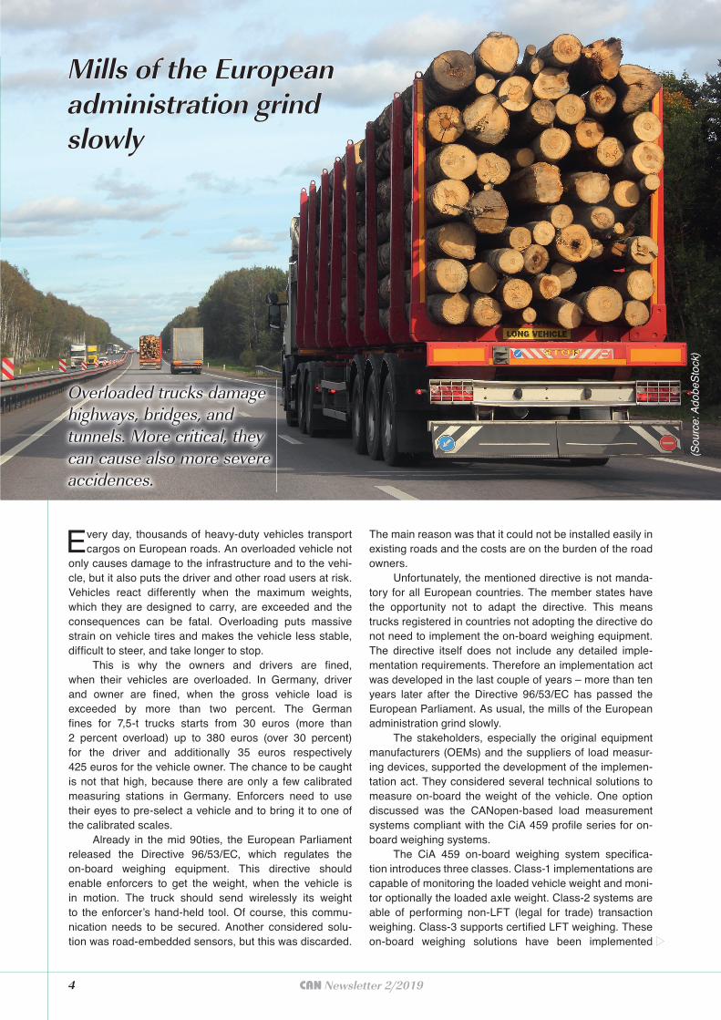
Every day, thousands of heavy-duty vehicles transport cargos on European roads. An overloaded vehicle not
only causes damage to the infrastructure and to the vehi-cle, but it also puts the driver and other road users at risk. Vehicles react differently when the maximum weights, which they are designed to carry, are exceeded and the consequences can be fatal. Overloading puts massive strain on vehicle tires and makes the vehicle less stable, difficult to steer, and take longer to stop.
This is why the owners and drivers are fined, when their vehicles are overloaded. In Germany, driver and owner are fined, when the gross vehicle load is exceeded by more than two percent. The German fines for 7,5-t trucks starts from 30 euros (more than 2 percent overload) up to 380 euros (over 30 percent) for the driver and additionally 35 euros respectively 425 euros for the vehicle owner. The chance to be caught is not that high, because there are only a few calibrated measuring stations in Germany. Enforcers need to use their eyes to pre-select a vehicle and to bring it to one of the calibrated scales.
Already in the mid 90ties, the European Parliament released the Directive 96/53/EC, which regulates the on-board weighing equipment. This directive should enable enforcers to get the weight, when the vehicle is in motion. The truck should send wirelessly its weight to the enforcer’s hand-held tool. Of course, this commu-nication needs to be secured. Another considered solu-tion was road-embedded sensors, but this was discarded.
The main reason was that it could not be installed easily in existing roads and the costs are on the burden of the road owners.
Unfortunately, the mentioned directive is not manda-tory for all European countries. The member states have the opportunity not to adapt the directive. This means trucks registered in countries not adopting the directive do not need to implement the on-board weighing equipment. The directive itself does not include any detailed imple-mentation requirements. Therefore an implementation act was developed in the last couple of years – more than ten years later after the Directive 96/53/EC has passed the European Parliament. As usual, the mills of the European administration grind slowly.
The stakeholders, especially the original equipment manufacturers (OEMs) and the suppliers of load measur-ing devices, supported the development of the implemen-tation act. They considered several technical solutions to measure on-board the weight of the vehicle. One option discussed was the CANopen-based load measurement systems compliant with the CiA 459 profile series for on-board weighing systems.
The CiA 459 on-board weighing system specifica-tion introduces three classes. Class-1 implementations are capable of monitoring the loaded vehicle weight and moni-tor optionally the loaded axle weight. Class-2 systems are able of performing non-LFT (legal for trade) transaction weighing. Class-3 supports certified LFT weighing. These on-board weighing solutions have been implemented
Overloaded trucks damage Overloaded trucks damage highways, bridges, and highways, bridges, and tunnels. More critical, they tunnels. More critical, they can cause also more severe can cause also more severe accidences.accidences.
Mills of the European Mills of the European administration grind administration grind slowlyslowly
(Sou
rce:
Ado
beS
tock
)
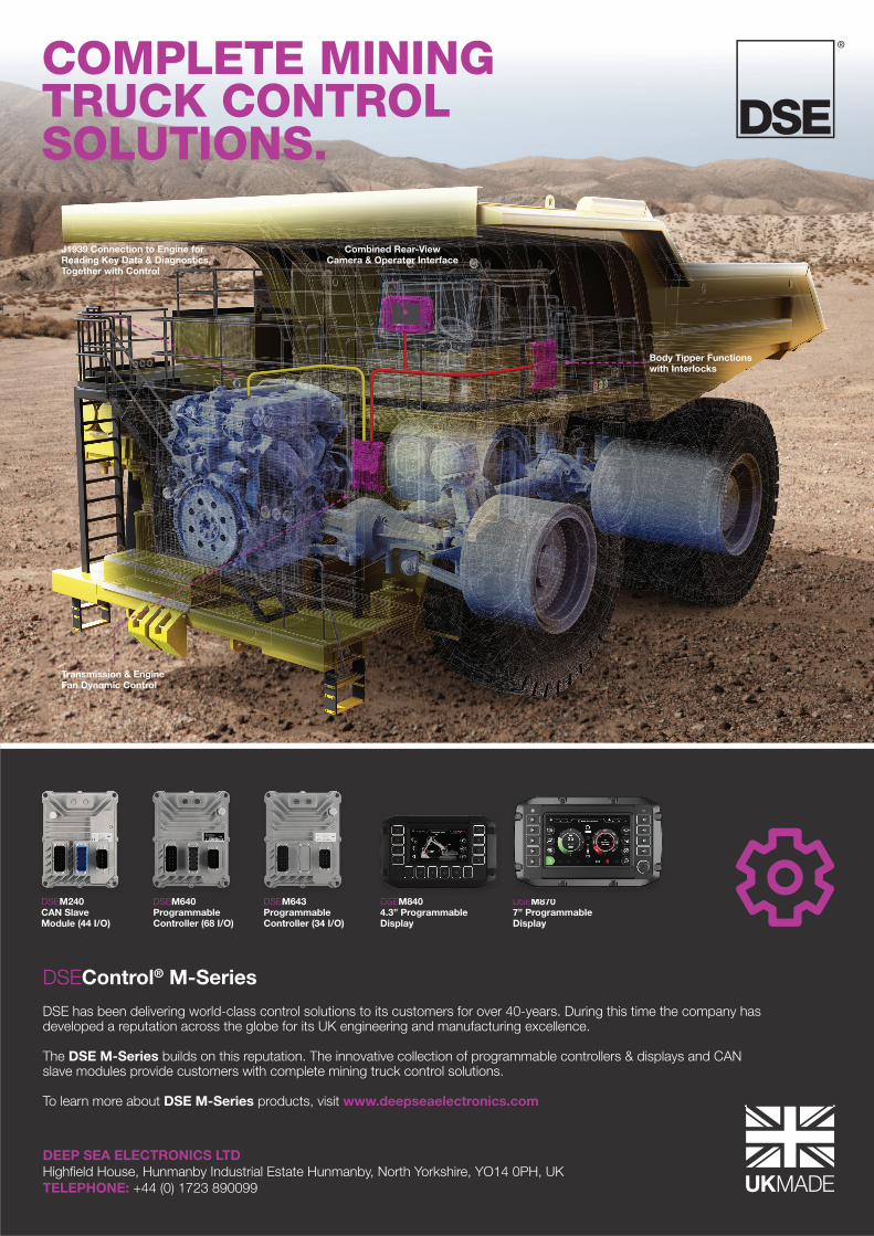
COMPLETE MININGTRUCK CONTROLSOLUTIONS.
DSEM8707” Programmable Display
DSEM8404.3” Programmable Display
DSEM240CAN SlaveModule (44 I/O)
DSEM640ProgrammableController (68 I/O)
DSEM643ProgrammableController (34 I/O)
DSEM240 DSEM640 DSEM643 DSEM840 DSEM870
DSEControl® M-Series
DSE has been delivering world-class control solutions to its customers for over 40-years. During this time the company has developed a reputation across the globe for its UK engineering and manufacturing excellence. The DSE M-Series builds on this reputation. The innovative collection of programmable controllers & displays and CAN slave modules provide customers with complete mining truck control solutions. To learn more about DSE M-Series products, visit www.deepseaelectronics.com
DEEP SEA ELECTRONICS LTDHighfield House, Hunmanby Industrial Estate Hunmanby, North Yorkshire, YO14 0PH, UKTELEPHONE: +44 (0) 1723 890099
Combined Rear-View Camera & Operator Interface
J1939 Connection to Engine for Reading Key Data & Diagnostics,Together with Control
Body Tipper Functionswith Interlocks
Transmission & Engine Fan Dynamic Control
6 CAN Newsletter 2/2019
especially in special-purpose vehicles. Some of them are used to charge customers on the transported weight. One of the implementers is the CiA member VPG situated in England.
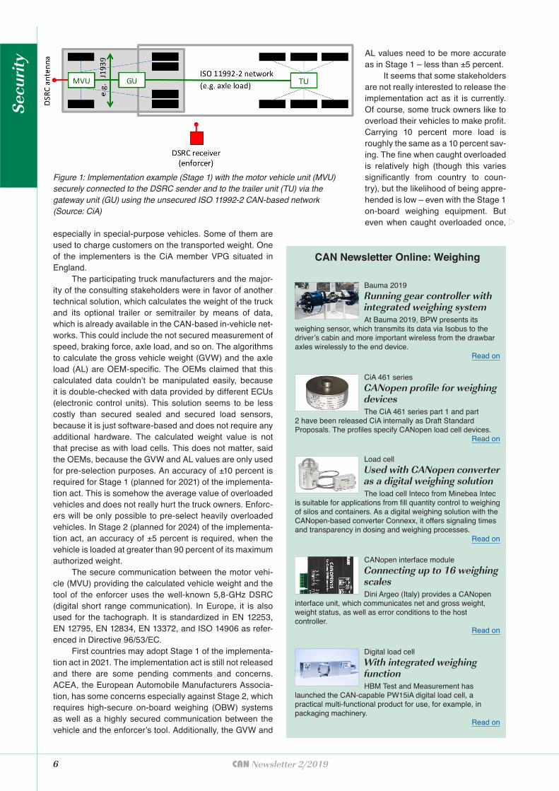
The participating truck manufacturers and the major-ity of the consulting stakeholders were in favor of another technical solution, which calculates the weight of the truck and its optional trailer or semitrailer by means of data, which is already available in the CAN-based in-vehicle net-works. This could include the not secured measurement of speed, braking force, axle load, and so on. The algorithms to calculate the gross vehicle weight (GVW) and the axle load (AL) are OEM-specific. The OEMs claimed that this calculated data couldn’t be manipulated easily, because it is double-checked with data provided by different ECUs (electronic control units). This solution seems to be less costly than secured sealed and secured load sensors, because it is just software-based and does not require any additional hardware. The calculated weight value is not that precise as with load cells. This does not matter, said the OEMs, because the GVW and AL values are only used for pre-selection purposes. An accuracy of ±10 percent is required for Stage 1 (planned for 2021) of the implementa-tion act. This is somehow the average value of overloaded vehicles and does not really hurt the truck owners. Enforc-ers will be only possible to pre-select heavily overloaded vehicles. In Stage 2 (planned for 2024) of the implementa-tion act, an accuracy of ±5 percent is required, when the vehicle is loaded at greater than 90 percent of its maximum authorized weight.
The secure communication between the motor vehi-cle (MVU) providing the calculated vehicle weight and the tool of the enforcer uses the well-known 5,8-GHz DSRC (digital short range communication). In Europe, it is also used for the tachograph. It is standardized in EN 12253, EN 12795, EN 12834, EN 13372, and ISO 14906 as refer-enced in Directive 96/53/EC.
First countries may adopt Stage 1 of the implementa-tion act in 2021. The implementation act is still not released and there are some pending comments and concerns. ACEA, the European Automobile Manufacturers Associa-tion, has some concerns especially against Stage 2, which requires high-secure on-board weighing (OBW) systems as well as a highly secured communication between the vehicle and the enforcer’s tool. Additionally, the GVW and
AL values need to be more accurate as in Stage 1 – less than ±5 percent.
It seems that some stakeholders are not really interested to release the implementation act as it is currently. Of course, some truck owners like to overload their vehicles to make profit. Carrying 10 percent more load is roughly the same as a 10 percent sav-ing. The fine when caught overloaded is relatively high (though this varies significantly from country to coun-try), but the likelihood of being appre-hended is low – even with the Stage 1 on-board weighing equipment. But even when caught overloaded once,
Figure 1: Implementation example (Stage 1) with the motor vehicle unit (MVU) securely connected to the DSRC sender and to the trailer unit (TU) via the gateway unit (GU) using the unsecured ISO 11992-2 CAN-based network (Source: CiA)
CAN Newsletter Online: Weighing
Bauma 2019
Running gear controller with integrated weighing systemAt Bauma 2019, BPW presents its
weighing sensor, which transmits its data via Isobus to the driver’s cabin and more important wireless from the drawbar axles wirelessly to the end device.
Read on
CiA 461 series
CANopen profi le for weighing devicesThe CiA 461 series part 1 and part
2 have been released CiA internally as Draft Standard Proposals. The profi les specify CANopen load cell devices.
Read on
Load cell
Used with CANopen converter as a digital weighing solutionThe load cell Inteco from Minebea Intec
is suitable for applications from fi ll quantity control to weighing of silos and containers. As a digital weighing solution with the CANopen-based converter Connexx, it offers signaling times and transparency in dosing and weighing processes.
Read on
CANopen interface module
Connecting up to 16 weighing scalesDini Argeo (Italy) provides a CANopen
interface unit, which communicates net and gross weight, weight status, as well as error conditions to the host controller.
Read on
Digital load cell
With integrated weighing functionHBM Test and Measurement has
launched the CAN-capable PW15iA digital load cell, a practical multi-functional product for use, for example, in packaging machinery.
Read on
Secu
rity
Author
Holger ZeltwangerCAN [email protected]
the cost of the penalty can be offset through additional overloaded runs. Road users like you and me are not rep-resented in the working group discussing and drafting the Directive 96/53/EC related implementation act. Some OEMs seem to be afraid to displease their potential cus-tomers by a more restricting implementation act.
According to the implementation act, the on-board weighing equipment shall be subject to a periodic inspec-tion by a dedicated workshop every two years following its installation in the vehicle or vehicle combination. This seems to be hard to achieve, if the GVW and AL values are OEM-specific calculated from different data sources. Euro-pean member states adapting the Directive 96/53/EC and the related implementation act need to approve, to audit regularly, and to certify the dedicated workshops allowed performing inspections of on-board weighing equipment. This is another hurdle to implement successfully the Direc-tive 96/53/EC. t
ROTARY ENCODER AND INCLINOMETER
Ideal for Construction Machinery
Static and Dynamic Inclinometers
High Precision Magnetic Rotary Encoder up to 16 Bits
Protection up to IP69K
High Shock and Vibration Resistance
Variety of Interfaces: CANopen, J1939, Analog, Modbus
Simple Diagnosis by Means of LED
Additional Versions: Safety Compliant and ExProof
www.posital.com
8 CAN Newsletter 2/2019
The recently by Pepperl + Fuchs introduced tilt sen-sor features CANopen connectivity and supports the
CiA 301 application layer and the CiA 410 profile for incli-nometer. The two-axes sensor measures angles from 0° to 360° with an accuracy smaller than ±0,15° in both axes — across the entire measuring range. The legacy inclina-tion sensors from the supplier are based on a two-piece mounting concept, which makes them sturdy. A metal mounting bracket provides the sensor module with impact protection. The F199 one-part inclination sensor supple-ments this existing portfolio. A corrosion-resistant alumi-num housing, encapsulated electronics, and 100-g shock resistance make it robust.
To suit CSP applications, the product comes in IP68/69-rated housing. The ingress protection (IP) rat-ing is standardized in IEC/EN 60529. The first indicates the degree of protection (of people) from moving parts, as well as the protection of enclosed equipment from foreign bodies: “6” is the protection against dust that may harm the sensor. The second digit defines the protection level that the enclosure enjoys from various forms of moisture (drips, sprays, submersion, etc.): “8” indicates a protection against temporary immersion and “9” against prolonged effects of immersion under pressure.
The F199 two-axes inclinometer is designed for precision measurements and comes in a robust housing suitable for concentrated solar power (CSP)
systems.
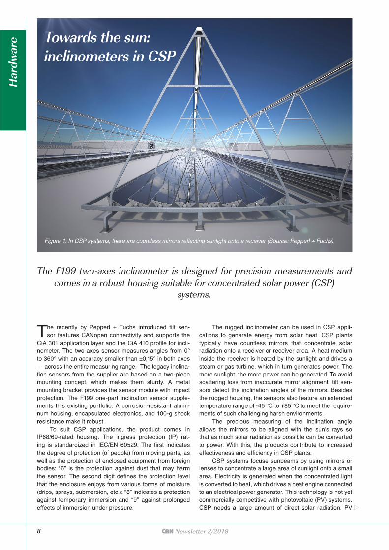
The rugged inclinometer can be used in CSP appli-cations to generate energy from solar heat. CSP plants typically have countless mirrors that concentrate solar radiation onto a receiver or receiver area. A heat medium inside the receiver is heated by the sunlight and drives a steam or gas turbine, which in turn generates power. The more sunlight, the more power can be generated. To avoid scattering loss from inaccurate mirror alignment, tilt sen-sors detect the inclination angles of the mirrors. Besides the rugged housing, the sensors also feature an extended temperature range of -45 °C to +85 °C to meet the require-ments of such challenging harsh environments.
The precious measuring of the inclination angle allows the mirrors to be aligned with the sun’s rays so that as much solar radiation as possible can be converted to power. With this, the products contribute to increased effectiveness and efficiency in CSP plants.
CSP systems focuse sunbeams by using mirrors or lenses to concentrate a large area of sunlight onto a small area. Electricity is generated when the concentrated light is converted to heat, which drives a heat engine connected to an electrical power generator. This technology is not yet commercially competitive with photovoltaic (PV) systems. CSP needs a large amount of direct solar radiation. PV
Figure 1: In CSP systems, there are countless mirrors reflecting sunlight onto a receiver (Source: Pepperl + Fuchs)
Towards the sun:inclinometers in CSP
Har
dwar
e
systems can be operated also in cloudy environments. The advantage of CSP over PV is the production of heat, which can be used running a conventional thermal power block. A CSP plant can store the heat of solar energy in molten salts, which enables these plants to continue to generate electricity whenever it is needed, whether day or night.
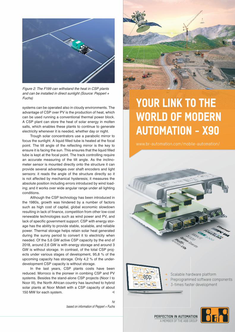
Trough solar concentrators use a parabolic mirror to focus the sunlight. A liquid filled tube is heated at the focal point. The tilt angle of the reflecting mirror is the key to ensure it is facing the sun. This ensures that the liquid filled tube is kept at the focal point. The track controlling require an accurate measuring of the tilt angle. As the inclino-meter sensor is mounted directly onto the structure it can provide several advantages over shaft encoders and light sensors: it reads the angle of the structure directly so it is not affected by mechanical hysteresis; it measures the absolute position including errors introduced by wind load-ing; and it works over wide angular range under all lighting conditions.
Although the CSP technology has been introduced in the 1980s, growth was hindered by a number of factors such as high cost of capital, global economic slowdown resulting in lack of finance, competition from other low-cost renewable technologies such as wind power and PV, and lack of specific government support. CSP with energy stor-age has the ability to provide stable, scalable, and reliable power. Thermal storage helps retain solar heat generated during the sunny period to convert it to electricity when needed. Of the 5,6 GW active CSP capacity by the end of 2018, around 2,6 GW is with energy storage and around 3 GW is without storage. In contrast, of the total CSP proj-ects under various stages of development, 95,8 % of the upcoming capacity has storage. Only 4,2 % of the under-development CSP capacity is without storage.
In the last years, CSP plants costs have been reduced. Morroco is the pioneer in combing CSP and PV systems. Besides the stand-alone CSP projects (Noor I to Noor III), the North African country has launched to hybrid solar plants at Noor Midelt with a CSP capacity of about 150 MW for each system. t
hzbased on information of Pepperl + Fuchs
Figure 2: The F199 can withstand the heat in CSP plants and can be installed in direct sunlight (Source: Pepperl + Fuchs)
YOUR LINK TO THE WORLD OF MODERN AUTOMATION - X90www.br-automation.com/mobile-automation/
< Scalable hardware platform < Preprogrammed software components < 3-times faster development

10 CAN Newsletter 2/2019
In most European countries, the use of Adblue emulators is forbidden or restricted. In other ones, they are allowed. An Adblue emulator simulates the Selective Catalytic
Reduction (SCR) system behavior and truck owners can save a lot of money.
The SCR system reduces the quantity of Mono-Nitro-gen Oxides (NOx) in engine exhaust gasses. The SCR
catalytic converter core is usually made from ceramic (ti-tanium oxide). It is coated with oxides of such metals as tungsten, vanadium, molybdenum, and other precious or rare metals. The reduction reaction is achieved by add-ing a solution of anhydrous ammonia, aqueous ammo-nia, or urea. This additive is called Diesel Exhaust Fluid (DEF). The most popular DEF solution on the market is Adblue; this is a registered trademark of the German As-sociation of the Automotive Industry (VDA). DEF is the re-ducing agent that reacts with NOx to convert the pollutants into nitrogen, water, and tiny amounts of CO2. The DEF can be rapidly broken down to produce the oxidizing am-monia in the exhaust stream. SCR technology alone can achieve NOx reductions up to 90 percent. Most of the SCR systems available on the market use CAN communication based on the J1939 higher-layer protocol and associated Parameter Groups.
The SCR catalytic converter works by injecting Adblue to the exhaust system. DEF is injected before the catalytic converter chamber, where its vapor is mixed with exhaust gasses. It is important that the temperature will
reach 360°C to 450 °C otherwise SCR effectiveness is rel-atively small. It means that it needs some time after the cold engine starts to arrive at the required temperature to start the NOx reduction process effectively. The SCR system has an exhaust tem-perature sensor, which sends temperature data to the SCR electronic control unit (ECU).
All Euro-V and Euro-IV type diesel engines are equipped with SCR systems. European regulation mandates this. All Euro-VI type engines provide a Diesel Particulate Fil-ter (DPF). This device removes any possible diesel particulate mat-ter (solid particles) or soot from the exhaust gasses before they are
Figure 1: Typical Adblue emulator (Source: Sail Technology Software)
Adblue emulator: illegal and legal
(Sou
rce:
Ado
beS
tock
)
�������������� �� ������������
������������ ������������
��� ���� �������� ������������ �� ! �� "#$�
# ���� �%�������
�� ���������� ������������������������������
�� ���� ���� �!��"��#�$�����#�%�&'()(�*�+��,�)-
�� $ !�����.����/+0
�� 1��������+��0��. ���
�� �2!�'�������� ������� !�
exhausted to the atmosphere. Particulate matter is a result of incomplete or improper diesel combustion cycle. There are several reasons, why particles could be produced: Cold engine starts, especially in the ultra low-temperature environment; lack of intake air pressure or flow due to dam-aged turbo charger or clogged intake channels; reduced compression in cylinders due to damaged engine parts; high engine load or sudden power demand on rapid accel-eration; clogged exhaust gas recirculation (EGR) system; or poor fuel quality, engine oil in the combustion chamber of cylinders and other factors.
SCR systems are also used in other countries. For example, in the USA to meet the EPA 2010 diesel engine emission standards for heavy-duty vehicles and the Tier-4 emissions standard for engines found in off-road equip-ment. Diesel particulate matter particles are considered as one of the most harmful pollutants. Therefore all Euro-IV type exhaust systems must have DPF systems. Some DPF filters are single use, and some of them are capa-ble of regenerating at certain conditions (DPF regenera-tion). Recovery is possible by burning more fuel and rising exhaust system temperature, which makes it possible to burn out any contamination from the filter. DPF regenera-tion controlled by a vehicle ECU and executed when nec-essary conditions are reached (exhaust temperature, fuel quantity in the tank, vehicle speed, and engine speed).
Failures in SCR or DPF systems
When the SCR or DPF systems fail, the truck driver is in trouble: In both cases, the central ECU activates the limp mode of the engine. This reduces the engine power to pro-tect the environment from possible highly polluted exhaust gasses. This is done independent, if the engine is capable to work properly. The ride to the next repair shop or garage can be time-consuming. Additionally, repair costs are high.
In some northern regions of Europe and Russia, envi-ronment temperatures can be low as -40 °C. These ultra-low temperatures are way beyond the freezing point of DEF; it freezes if its temperature falls below -11 °C. Injec-ting frozen Adblue to the SCR chamber is impossible. Also, it will damage the DEF pump, and the whole SCR system fails. This means, you need to switch-off the SCR sys-tem. This could be done by means of so-called Adblue
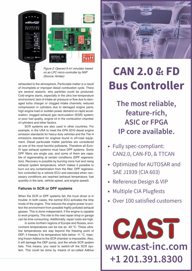
Figure 2: Opened 9-in1 emulator based on an LPC micro-controller by NXP (Source: Aimtec)
12 CAN Newsletter 2/2019
emulators. They can help to drive on the regular engine mode even if the SCR system is faulty. But the main reason why so many trucks equipped with Adblue emulators is the saving of money on a diesel exhaust fluid.
Such products were available shortly after introduc-tion of Euro-IV type diesel engines. The first of such CAN-connectable devices were designed for a dedicated truck. In the meantime, they can support multiple brands. Some of them are configurable by means of DIP-switches, while others implement an USB-to-CAN dongle. The price for such Adblue emulators has come down to 30 euros com-prising a USB dongle. This leads to another question: Why generic CAN-to-USB interfaces cost often more than 300 euros? Of course, some of them provide additional features and are tailored for sophisticated diagnostic purposes.
Installing an SCR emulator is easy
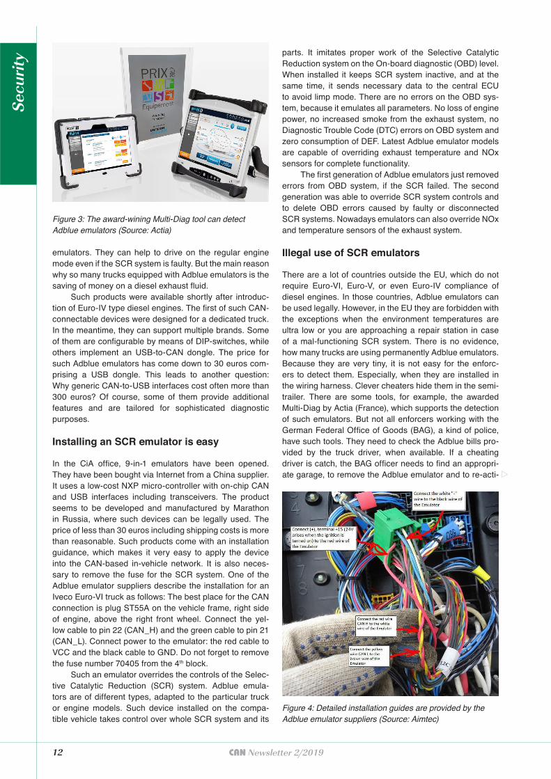
In the CiA office, 9-in-1 emulators have been opened. They have been bought via Internet from a China supplier. It uses a low-cost NXP micro-controller with on-chip CAN and USB interfaces including transceivers. The product seems to be developed and manufactured by Marathon in Russia, where such devices can be legally used. The price of less than 30 euros including shipping costs is more than reasonable. Such products come with an installation guidance, which makes it very easy to apply the device into the CAN-based in-vehicle network. It is also neces-sary to remove the fuse for the SCR system. One of the Adblue emulator suppliers describe the installation for an Iveco Euro-VI truck as follows: The best place for the CAN connection is plug ST55A on the vehicle frame, right side of engine, above the right front wheel. Connect the yel-low cable to pin 22 (CAN_H) and the green cable to pin 21 (CAN_L). Connect power to the emulator: the red cable to VCC and the black cable to GND. Do not forget to remove the fuse number 70405 from the 4th block.
Such an emulator overrides the controls of the Selec-tive Catalytic Reduction (SCR) system. Adblue emula-tors are of different types, adapted to the particular truck or engine models. Such device installed on the compa-tible vehicle takes control over whole SCR system and its
parts. It imitates proper work of the Selective Catalytic Reduction system on the On-board diagnostic (OBD) level. When installed it keeps SCR system inactive, and at the same time, it sends necessary data to the central ECU to avoid limp mode. There are no errors on the OBD sys-tem, because it emulates all parameters. No loss of engine power, no increased smoke from the exhaust system, no Diagnostic Trouble Code (DTC) errors on OBD system and zero consumption of DEF. Latest Adblue emulator models are capable of overriding exhaust temperature and NOx sensors for complete functionality.
The first generation of Adblue emulators just removed errors from OBD system, if the SCR failed. The second generation was able to override SCR system controls and to delete OBD errors caused by faulty or disconnected SCR systems. Nowadays emulators can also override NOx and temperature sensors of the exhaust system.
Illegal use of SCR emulators
There are a lot of countries outside the EU, which do not require Euro-VI, Euro-V, or even Euro-IV compliance of diesel engines. In those countries, Adblue emulators can be used legally. However, in the EU they are forbidden with the exceptions when the environment temperatures are ultra low or you are approaching a repair station in case of a mal-functioning SCR system. There is no evidence, how many trucks are using permanently Adblue emulators. Because they are very tiny, it is not easy for the enforc-ers to detect them. Especially, when they are installed in the wiring harness. Clever cheaters hide them in the semi-trailer. There are some tools, for example, the awarded Multi-Diag by Actia (France), which supports the detection of such emulators. But not all enforcers working with the German Federal Office of Goods (BAG), a kind of police, have such tools. They need to check the Adblue bills pro-vided by the truck driver, when available. If a cheating driver is catch, the BAG officer needs to find an appropri-ate garage, to remove the Adblue emulator and to re-acti-
Figure 3: The award-wining Multi-Diag tool can detect Adblue emulators (Source: Actia)
Figure 4: Detailed installation guides are provided by the Adblue emulator suppliers (Source: Aimtec)
Secu
rity
High-end connectivity and data management
Service 4.0 | IoT Applications | Updates-over-the-air
Sontheim Industrie Elektronik GmbHGeorg-Krug-Str. 2, 87437 Kempten
Tel: +49 831 57 59 00 -0 - Fax: [email protected]
DE
Telematics and Cloud SystemsContinuous digitization for smart vehicles
Modular on-board units with Linux - ready for condition monitoring. Including flash-over-the-air and embedded diagnostic functionality. Sontheim cloud portal based on standard interfaces. For a highly secure, comfortable and individual visualization of your data.
COMhawk xt - Modular on-board telematics series
Integrated flash-over-the-air
functionality
Compatible for embedded diagnostics
Ready for condition monitoring
Sontheim cloud portal and cloud portal light
Multi-protocol support (J1939, J2534,
UDS, KWP, ...)
D
CBM
vate the SCR system. This can take some time for the truck driver, but also for the enforcers.
Already in 2017, European truck OEM (original equip-ment manufacturer) requested actions to prevent aftermar-ket manipulation of emissions controls. “The European Automobile Manufacturers’ Association (ACEA) strongly condemns the advertising, sale, and use of any aftermar-ket device that can be used by truck operators to turn-off emission control systems,” stated ACEA Secretary Gen-eral Erik Jonnaert two years ago. The association already raised its concerns in 2012 with the European Commission and the member states, but no action was taken. The issue of aftermarket devices was also raised by Denmark several years earlier, but the general view at that time up to now was and is that this should be a matter for national enforce-ment. In 2017, the German Ministry of Traffic responded a question regarding the manipulation of emissions controls that it would appreciate banning of Adblue emulators. But nothing has happened: you can still buy them and adver-tise for them. It is not that the manipulated trucks causes a higher pollution of NOx, but there is also a lost of income regarding the toll on trucks. Trucks without SCR systems pay more money.
It is possible, that due to political reasons it is not that easy to forbid selling of Adblue emulators in Ger-many. Another option would be to make the integration of such devices more complicated by means of authentica-tion. The J1939 communication regarding emission con-trol between several ECUs could be protected by means
Author
Holger ZeltwangerCAN [email protected]
of authentication of messages. Even a simple authentica-tion mechanism is better than nothing. If the automotive industry, heavy-duty truck OEMs, and related associa-tions, would really like to support the EU emission regula-tion, there are several options to do so.
To summarize: for just a few euros a truck owner can save annually about 6000 euros and more said some sources. The achievable profit depends on the driven kilo-meters and the consumed Adblue. This does not consider possible repair costs for the SCR system. What is not used, does not need to be repaired. t

14 CAN Newsletter 2/2019
The inventiveness of the maker generation is finding its way into industry with cost-effective hardware, open
source platforms, and fresh ideas. The wave of low-cost hardware success is unstoppable. Anyone thinking of low-cost hardware has developer boards front of mind: Rasp-berry Pi, Arduino, or Beagle Bone. Since its launch in 2012, the Raspberry Pi has an amazing success story. With over 17 million devices sold worldwide, Raspberry Pi is the most popular single-board computer of all time. This mini-PC is the initiator of the low-cost trend.
But the Raspberry Pi has now found itself in a compet-itive market place as more developer boards try to emulate its success. From new one-board controls to accessories and extensions, the market is constantly seeing innova-tion. Shields, hats, power supplies, sensors, and the abil-ity to enable CAN support through converters has created a whole hardware ecosystem that is available with these mini-computers.
Developments in performance and computing power have opened up a host of new possibilities for mini-PCs. The Raspberry Pi initially had limited computing capa-city and was primarily used by students for study or hobby projects. But it quickly became apparent that more was needed from the small format. The latest model, the Rasp-berry Pi 3B+, now offers a 1,4-GHz quad-core processor with 1024 MiB of memory and gigabit Ethernet.
The active developer community provides guidance for fellow users to make it easier for people to get started in electronics. The Raspberry Pi is being used in an industrial environment more often than before, either as a controller in prototype development or as a fully-fledged industrial control system.
Raspberry Pis can also be of use for industrial purposes such as automotive as well, thanks to its ability to be connected to CAN through USB or SPI (serial peripheral interface) converters. For example, users can enhance a Raspberry Pi using the PiCAN2 board or a CAN network for the Revolution Pi. Micro-controllers and devices can communicate without a host computer in a low-cost, robust, and efficient way without complex wiring. It can be modified, too – great for problem solving engineers.
Speed, flexibility, cost reduction
The big advantage of a Raspberry Pi is, without question, the low-price, which keeps the barriers to entry particularly low. For around 29 euros, you can get a standard board
This article focuses on opportunities and challenges of low-cost developer boards in the industry.
The low-cost hardware revolution
and a wealth of possibilities. Any missing interfaces can now be added by a range of shields or hats.
In addition, developers are finding they can work much more independently with mini-PCs. Solutions like open source developer portals are available for reference. Most of the time, the systems are based on Linux but there are also freely available software libraries with helpful developer forums.
Working with low-cost hardware offers unimagined flexibility. Developers are able to find their own solutions to specific problems. When a new interface is needed, it is usually easier and faster to integrate it via an open source environment.
Paradigm shift in development
By contrast, a developer who relies on a proprietary con-trol system will have to wait until the right extension has been developed and launched by the appropriate com-pany. Here we see a clear paradigm shift: With low-cost hardware, developers can take their projects into their own hands, contribute ideas, and find solutions.
This saves valuable development time and money. In a market environment that is becoming more dynamic and relying on rapid innovation, this is a key advantage. Elec-tronics have developed rapidly in recent years. It is becom-ing increasingly clear that speed has become a decisive factor to be successful in this market.
Digitization opportunity for SMEs
The low-cost and ease of implementation make hardware like Raspberry Pi a great solution for SMEs (small and
Figure 1: A connected Raspberry Pi board (Source: Reichelt Elektronik)
Har
dwar
e

medium enterprise). To compete with the bigger compa-nies though SMEs face the challenge of digitization. But unlike the larger players, they lack the funds for costly investments. So where should these companies start?
Low-cost solutions with single-board computers offer small and medium-sized enterprises a great opportunity to tackle digital transformation. At Reichelt, we introduced a bundle of a Raspberry Pi and accessories for integration some time ago. This bundle became an instant success. This has shown us that medium-sized companies need simple and practical solutions in order to make successful use of digitization.
Developer boards like Raspberry Pi offer companies new innovative opportunities when it comes to industrial uses. By connecting a CAN network, automotive oppor-tunities are possible - even creating drones or prosthetics is possible. This is an important feature of the Raspberry Pi and will become even more important in the future as IoT (Internet-of-Things) and cloud technology continue to become prevalent in everyday life.
When used in harsh industrial environments, the Raspberry Pi can reach its limits, however. Due to the com-pact size of the computer it already has slightly elevated ambient temperatures. The core temperature can rise sharply, leading to significant performance losses.
Additionally, the microSD cards used as fixed storage allow only a very limited number of writing cycles and are not suitable as remnant storage, which is why they cannot meet industrial requirements. The 3B+ model does come with G-Ethernet and WiFi connectivity - essential prerequi-sites for industry 4.0 applications. But industrial interfaces such as EIA-485 or CAN are still missing. This means that using Raspberry Pi in industry is only possible if you add the right extensions. An interesting market has now formed for shields or hats for a range of functionalities.
Raspberry Pi in the control cabinet
The PiXtend is a professional extension board for the Raspberry Pi that can be used for control tasks as well as a learning environment for control, circuit, and software technology. On industrial-grade features, it brings serial interfaces (EIA-232, EIA-485, and CAN), remote storage, and the ability to monitor in real-time. In addition, it with-stands ambient temperatures of up to 50 degrees and can be used directly in the control cabinet thanks to hat rail casings.
The Andino X1 Kit combines the Raspberry Pi and Arduino to create an industrial solution for adapting digital inputs and outputs for a voltage of 24 V. Thanks to its own micro-controller, precise signal pre-processing and adap-tation of signaling devices, and actuators is possible. In addition, the Andino X1 protects all essential interfaces of the Raspberry Pi according to current industry standards. The supported digital entrances and outputs are separated and prevent overvoltage of the pis.
Full-fledged industrial PC
The Revolution Pi family offers a Raspberry Pi-based open and modular system for a low-cost industrial PC. The
CiACAN in Automation
CiA events
July 04, 2019, Paris (France)October 10, 2019, Krakow (Poland)
March 17 to 18, 2020Baden Baden (Germany)
June 17 to 21, 2019Beijing, Qingdao, Shanghai, Shenzhen
These events are intended to discuss latest trends and developments in CAN-based networking as well as to share practical experience with other CAN users.
CiA members participate free of charge.
Both events offer tabletop exhibitions.
These events aim to bring the latest trends and developments in the CAN FD technology and the practical experience to more engineers and system integrators.
CiA members participate free of charge.
The call for papers is available atwww.can-cia.org/icc.
CAN technology days
CAN FD roadshows in China
17th international CAN Conference (iCC)
For more details please contact the CiA offi ce at [email protected]
www.can-cia.org
16 CAN Newsletter 2/2019
three basic modules available are each equipped with a highly efficient DC-DC converter for the power supply and generate the 24 V of operating voltage common for con-trol cabinets. An elaborate protective housing guarantees unimpaired function, even in the event of massive distur-bances on the power supply system and complies with the EN61131-2 standard.
The RevPi Connect base module has been specially designed for use in the IIoT (Industrial-Internet-of-Things) sector and has more interfaces, including two Ethernet interfaces, each with its own MAC address. This means the module can be used simultaneously in the automation network, as well as be integrated into the IT network and transmit data.
Depending on your requirements, the Revolution Pi can be used through digital or analog I/O modules to build an industrial control system. There are also different ver-sions for these expansion modules. They each have 14 or 16 entrances and exits, which are separated from the logic part with the PiBridge. They are protected against distur-bances according to EN 61131-2 and temperatures of -40 °C to +50 °C, and up to 80 % relative humidity. In addi-tion, the system can be integrated into an industrial net-work through a field bus connection. In keeping with open source tradition, both the source code and all schematics
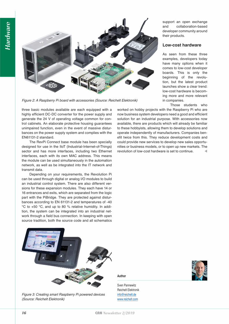
Figure 2: A Raspberry Pi board with accessories (Source: Reichelt Elektronik)
Figure 3: Creating smart Raspberry Pi powered devices (Source: Reichelt Elektronik)
support an open exchange and collaboration-based developer community around their products.
Low-cost hardware
As seen from these three examples, developers today have many options when it comes to low-cost developer boards. This is only the beginning of the revolu-tion, but the latest product launches show a clear trend: low-cost hardware is becom-ing more and more relevant in companies.
Those students who worked on hobby projects with the Raspberry Pi who are now business system developers need a good and efficient solution for an industrial purpose. With accessories now available, there are products which will already be familiar to these hobbyists, allowing them to develop solutions and operate independently of manufacturers. Companies ben-efit twice from this. They reduce development costs and could provide new services to develop new sales opportu-nities or business models, or to open up new markets. The revolution of low-cost hardware is set to continue. t
Author
Sven PannewitzReichelt Elektronik [email protected]
Har
dwar
e
CAN Newsletter Online: Raspberry Pi
Industrial computer
Raspberry Pi based controller supports CANopenKontron (Germany) has released the
KBox A-330-MX6 host controllers. It also can be used as IoT gateway.
Read on
Embedded World 2019
Motherboard for Raspberry PiAndino X2 from Clear Systems is, like the little brother the X1, a motherboard
for a Raspberry Pi 3 in a DIN rail housing. It is equipped with a built-in 15-W power supply (85 V to 230 V).
Read on
Raspberry Pi-based PLC
With Classical CAN and CANopenQube Solutions presented the latest
model of their Raspberry Pi-based controllers (PLC) called Pixtend V2 -L-. It is available in three variants. A Classical CAN interface has been added.
Read on
Embedded computers
Now also with long-term available Raspberry Pi module
The industrial computers with CAN interfaces from Janz Tec based on Raspberry Pi are now also available with the Raspberry Pi 3 B+ module with long-term availability.
Read on
Open-source
CAN-based IoT platformOmzlo has launched the Nocan Arduino-compatible wired IoT platform
for makers. It comprises one Pimaster board and several Canzero modules.
Read on
CANcrypt and CANopen module
For Raspberry Pi and other computing platformsEmsa (formerly Embedded Systems
Academy) offers the CANgine-Berry. It is an active CAN co-processor module that uses a regular UART communication channel towards the host system.
Read on
Scalable HMI system
With widescreen display and CAN interfaceSyslogic, manufacturer of industrial
control systems, announced another HMI system with widescreen display. It can be equipped with scalable processors and used as a control system or web terminal for industrial environments, depending on the model.
Read on
18 CAN Newsletter 2/2019
New Euro standards, stricter regulations regarding fine dust pollution and concern for citizens' health mean
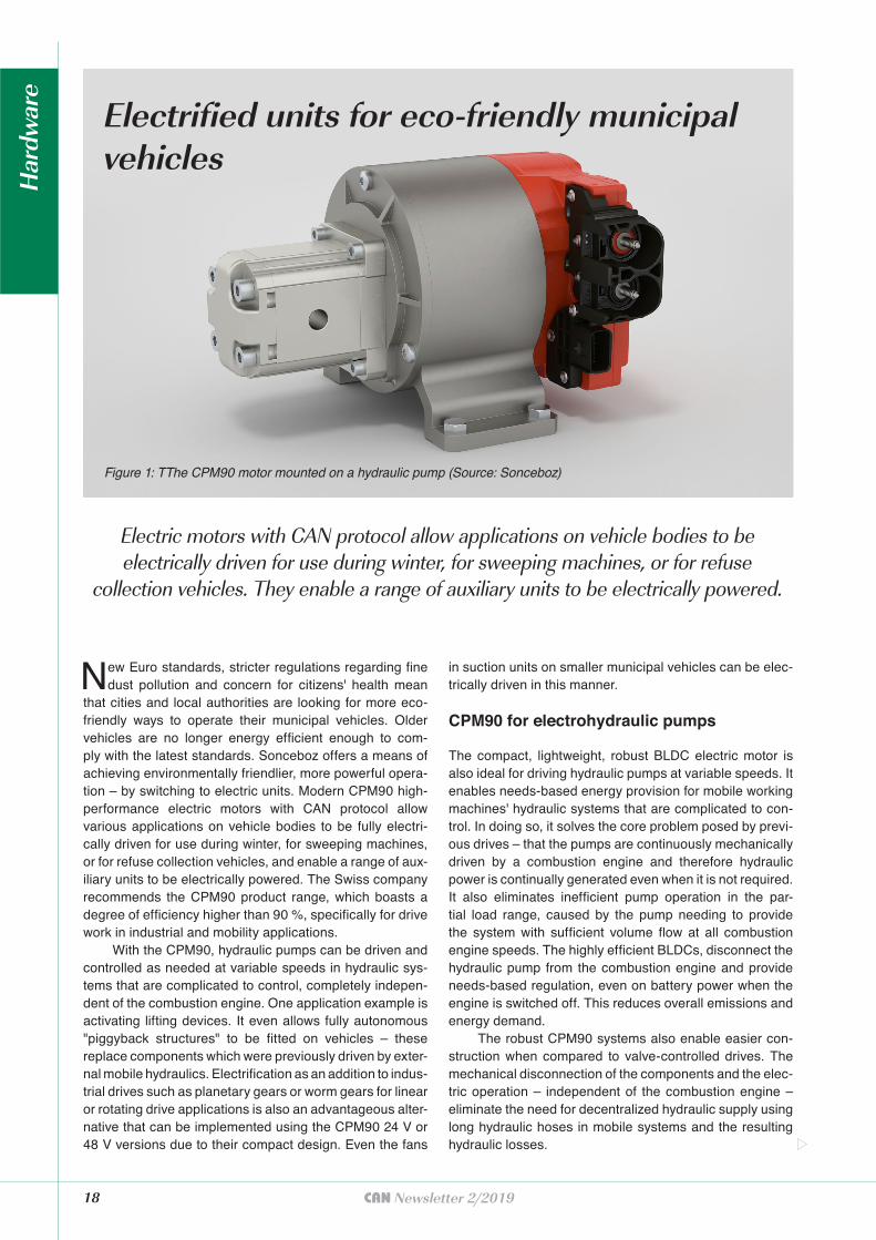
that cities and local authorities are looking for more eco-friendly ways to operate their municipal vehicles. Older vehicles are no longer energy efficient enough to com-ply with the latest standards. Sonceboz offers a means of achieving environmentally friendlier, more powerful opera-tion – by switching to electric units. Modern CPM90 high-performance electric motors with CAN protocol allow various applications on vehicle bodies to be fully electri-cally driven for use during winter, for sweeping machines, or for refuse collection vehicles, and enable a range of aux-iliary units to be electrically powered. The Swiss company recommends the CPM90 product range, which boasts a degree of efficiency higher than 90 %, specifically for drive work in industrial and mobility applications.
With the CPM90, hydraulic pumps can be driven and controlled as needed at variable speeds in hydraulic sys-tems that are complicated to control, completely indepen-dent of the combustion engine. One application example is activating lifting devices. It even allows fully autonomous "piggyback structures" to be fitted on vehicles – these replace components which were previously driven by exter-nal mobile hydraulics. Electrification as an addition to indus-trial drives such as planetary gears or worm gears for linear or rotating drive applications is also an advantageous alter-native that can be implemented using the CPM90 24 V or 48 V versions due to their compact design. Even the fans
in suction units on smaller municipal vehicles can be elec-trically driven in this manner.
CPM90 for electrohydraulic pumps
The compact, lightweight, robust BLDC electric motor is also ideal for driving hydraulic pumps at variable speeds. It enables needs-based energy provision for mobile working machines' hydraulic systems that are complicated to con-trol. In doing so, it solves the core problem posed by previ-ous drives – that the pumps are continuously mechanically driven by a combustion engine and therefore hydraulic power is continually generated even when it is not required. It also eliminates inefficient pump operation in the par-tial load range, caused by the pump needing to provide the system with sufficient volume flow at all combustion engine speeds. The highly efficient BLDCs, disconnect the hydraulic pump from the combustion engine and provide needs-based regulation, even on battery power when the engine is switched off. This reduces overall emissions and energy demand.
The robust CPM90 systems also enable easier con-struction when compared to valve-controlled drives. The mechanical disconnection of the components and the elec-tric operation – independent of the combustion engine – eliminate the need for decentralized hydraulic supply using long hydraulic hoses in mobile systems and the resulting hydraulic losses.
Figure 1: TThe CPM90 motor mounted on a hydraulic pump (Source: Sonceboz)
Electrifi ed units for eco-friendly municipal vehicles
Electric motors with CAN protocol allow applications on vehicle bodies to be electrically driven for use during winter, for sweeping machines, or for refuse
collection vehicles. They enable a range of auxiliary units to be electrically powered.
Har
dwar
e

CAN protocol for implementation
The CPM90 systems guarantee optimum energy efficiency thanks to their extremely high power density. They are based on a brushless DC motor with external rotors and an integrated CAN-capable controller. The CAN protocol features a configurable data transfer rate from 50 kbit/s to 1 Mbit/s. The standard is 500 Kbit/s. The CAN interface operates as CAN extended base frame format standard – with extended IDs – in Intel format. CPM90 is compatible with the J1939 network protocol for communication in commercial vehicles. It therefore makes it possible to read out and process information relating to engine control (speed, rotational speed, and position), to configure maximum or minimum limits and to perform diagnostics regarding the temperature, engine status, faults or warnings.
The CPM90 drive has an integrated controller with corresponding application and diagnostic software that enables simple implementation in existing systems and adaptation to customer-specific parameters. The power and control electronics make four-quadrant operation pos-sible. This enables a number of functions, such as demand-controlled bidirectional pump operation and generative recuperation. Due to its modular construction concept, customized highly efficient electric drives with integrated control electronics can be implemented in no time.
Powerful battery operation
The BLDC electric motors with embedded motor control and control electronics in an integrated design are the ideal solution for mobile applications and battery-operated machines. They are therefore particularly suitable for all areas that require high-power in low-voltage operation, with strict requirements when it comes to robustness. CPM90 can drive pumps, function as a drive motor, perform other drive and adjustment tasks, and contribute to electrification for the future. For use in mobile working machines with a 24-V or 48-V on-board network, Sonceboz offers, for example, motors with a peak output of up to 6 kW at a power density of up to 2 kW/kg and peak torque of up to 14 Nm. The hydraulic power corresponds to a pressure of up to 200 bar at 25 l/min.
Autonomous drive system for industrial applications
In combination with modern lithium batteries, the system can be operated fully autonomously and independent of the carrier vehicle's supply. Modifications to other suitable vehicles can be made quickly and easily because no hydraulic connections are present. By using the CPM90-48V, manufacturers also achieve highly efficient energy management. What's more, disconnecting the system from the vehicle eliminates additional adaptations to the carrier vehicle. The "piggyback structure" can be conveniently fitted on any commercial vehicle with sufficient capacity.
Additional subsystems such as supply systems and dosing units can also be electrified by adding a planetary
20 CAN Newsletter 2/2019
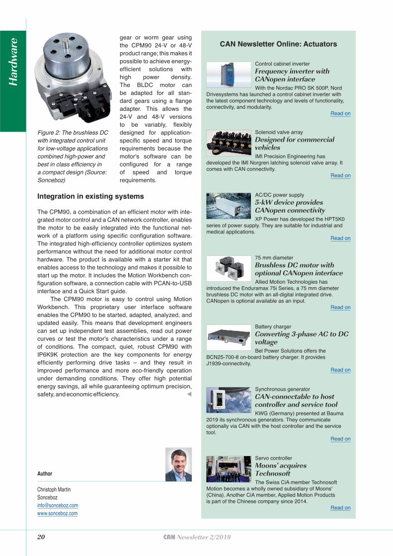
gear or worm gear using the CPM90 24-V or 48-V product range; this makes it possible to achieve energy-efficient solutions with high power density. The BLDC motor can be adapted for all stan-dard gears using a flange adapter. This allows the 24-V and 48-V versions to be variably, flexibly designed for application-specific speed and torque requirements because the motor's software can be configured for a range of speed and torque requirements.
Integration in existing systems
The CPM90, a combination of an efficient motor with inte-grated motor control and a CAN network controller, enables the motor to be easily integrated into the functional net-work of a platform using specific configuration software. The integrated high-efficiency controller optimizes system performance without the need for additional motor control hardware. The product is available with a starter kit that enables access to the technology and makes it possible to start up the motor. It includes the Motion Workbench con-figuration software, a connection cable with PCAN-to-USB interface and a Quick Start guide.
The CPM90 motor is easy to control using Motion Workbench. This proprietary user interface software enables the CPM90 to be started, adapted, analyzed, and updated easily. This means that development engineers can set up independent test assemblies, read out power curves or test the motor's characteristics under a range of conditions. The compact, quiet, robust CPM90 with IP6K9K protection are the key components for energy efficiently performing drive tasks – and they result in improved performance and more eco-friendly operation under demanding conditions. They offer high potential energy savings, all while guaranteeing optimum precision, safety, and economic efficiency. t
Author
Christoph MartinSonceboz [email protected]
CAN Newsletter Online: Actuators
Control cabinet inverter
Frequency inverter with CANopen interfaceWith the Nordac PRO SK 500P, Nord
Drivesystems has launched a control cabinet inverter with the latest component technology and levels of functionality, connectivity, and modularity.
Read on
Solenoid valve array
Designed for commercial vehiclesIMI Precision Engineering has
developed the IMI Norgren latching solenoid valve array. It comes with CAN connectivity.
Read on
AC/DC power supply
5-kW device provides CANopen connectivityXP Power has developed the HPT5K0
series of power supply. They are suitable for industrial and medical applications.
Read on
75 mm diameter
Brushless DC motor with optional CANopen interfaceAllied Motion Technologies has
introduced the Enduramax 75i Series, a 75 mm diameter brushless DC motor with an all-digital integrated drive. CANopen is optional available as an input.
Read on
Battery charger
Converting 3-phase AC to DC voltageBel Power Solutions offers the
BCN25-700-8 on-board battery charger. It provides J1939-connectivity.
Read on
Synchronous generator
CAN-connectable to host controller and service toolKWG (Germany) presented at Bauma
2019 its synchronous generators. They communicate optionally via CAN with the host controller and the servicetool.
Read on
Servo controller
Moons' acquires TechnosoftThe Swiss CiA member Technosoft
Motion becomes a wholly owned subsidiary of Moons' (China). Another CiA member, Applied Motion Products is part of the Chinese company since 2014.
Read on
Figure 2: The brushless DC with integrated control unit for low-voltage applications combined high-power and best in class efficiency in a compact design (Source: Sonceboz)
Har
dwar
e
Increase efficiency of your projects with the universal tool chain from Vector:
> High-professionial tools for testing, flashing and
calibrating ECUs
> Flexible network interfaces
> New all-in-one network disturbance interface
> Powerful logging solutions for test fleet operators
> High performance oscilloscope
> Proven design tools for network architectures
> Easy to configure AUTOSAR basic software
> Worldwide engineering services and trainings
More information: www.can-solutions.com
More CAN power by Vector: benefit from 30 years of networking experience.
First Class Solutions for Your CAN (FD) Projects
Your Universal Tool Chain
Vector Informatik GmbH | Germany · USA · Brazil · France · UK · Italy · Austria · Sweden · Japan · Korea · India · China | www.vector.com
22 CAN Newsletter 2/2019
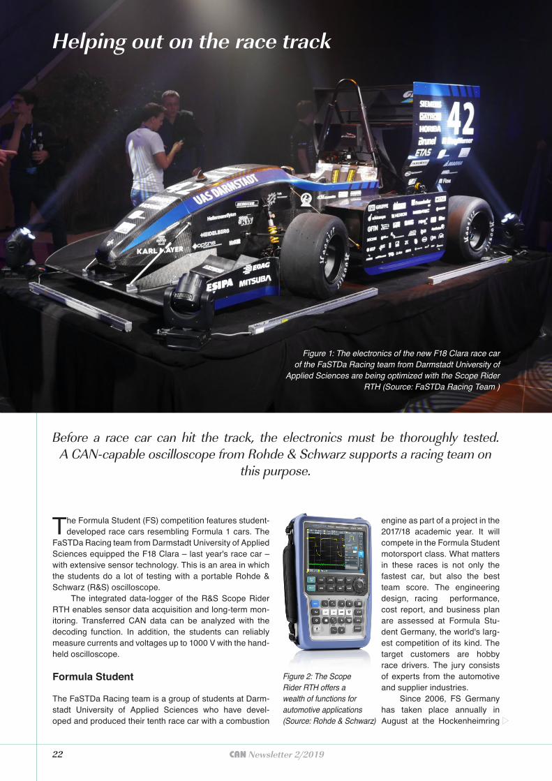
The Formula Student (FS) competition features student-developed race cars resembling Formula 1 cars. The
FaSTDa Racing team from Darmstadt University of Applied Sciences equipped the F18 Clara – last year's race car – with extensive sensor technology. This is an area in which the students do a lot of testing with a portable Rohde & Schwarz (R&S) oscilloscope.
The integrated data-logger of the R&S Scope Rider RTH enables sensor data acquisition and long-term mon-itoring. Transferred CAN data can be analyzed with the decoding function. In addition, the students can reliably measure currents and voltages up to 1000 V with the hand-held oscilloscope.
Formula Student
The FaSTDa Racing team is a group of students at Darm-stadt University of Applied Sciences who have devel-oped and produced their tenth race car with a combustion
engine as part of a project in the 2017/18 academic year. It will compete in the Formula Student
Figure 1: The electronics of the new F18 Clara race car of the FaSTDa Racing team from Darmstadt University of
Applied Sciences are being optimized with the Scope Rider RTH (Source: FaSTDa Racing Team )
Helping out on the race track
Before a race car can hit the track, the electronics must be thoroughly tested. A CAN-capable oscilloscope from Rohde & Schwarz supports a racing team on
this purpose.
Figure 2: The Scope Rider RTH offers a wealth of functions for automotive applications (Source: Rohde & Schwarz)
motorsport class. What matters in these races is not only the fastest car, but also the best team score. The engineering design, racing performance, cost report, and business plan are assessed at Formula Stu-dent Germany, the world's larg-est competition of its kind. The target customers are hobby race drivers. The jury consists of experts from the automotive and supplier industries.
Since 2006, FS Germany has taken place annually in August at the Hockenheimring
handling, acceleration, endurance, and fuel or energy con-sumption in autocross, skid pad, acceleration, and endur-ance races.
Measuring the engine control unit
They needed an instrument to measure the engine con-trol unit. The FaSTDa Racing team received the Efficien-cy Award in 2017 at the Formula Student East competi-tion in Hungary and wanted to build on this success with the F18. In order to further optimize efficiency, the F18
circuit and is sponsored by the VDI. There, the teams par-ticipate in three classes: driverless, electric, and combus-tion engine. Comparable competitions also take place at other internationally known race tracks. The Darmstadt team's F18 Clara was publicly unveiled in late May 2018. With a 59 hp modified one-cylinder KTM engine, it accel-erates from 0 km/h to 100 km/h in 4 s and has a top speed of around 130 km/h.
The budding engineers optimized their race cars up until the first races in late summer 2018. Racing per-formance includes attributes such as vehicle dynamics,
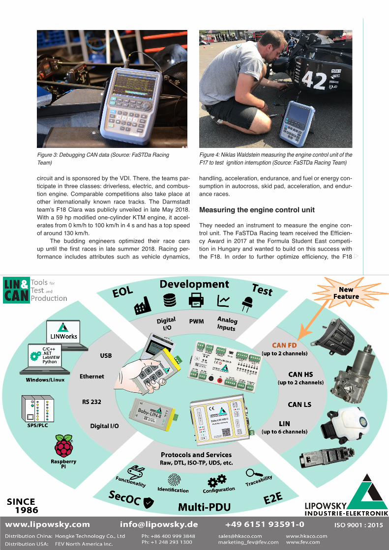
Figure 3: Debugging CAN data (Source: FaSTDa Racing Team)
Figure 4: Niklas Waldstein measuring the engine control unit of the F17 to test ignition interruption (Source: FaSTDa Racing Team)
24 CAN Newsletter 2/2019
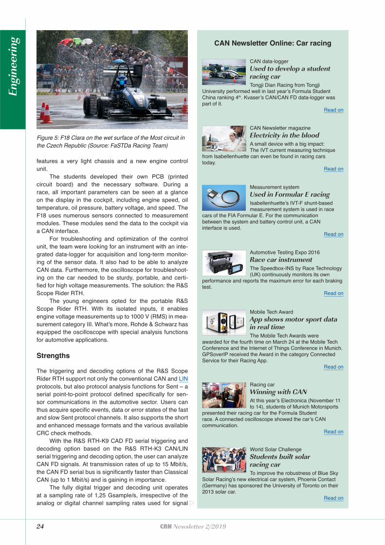
Figure 5: F18 Clara on the wet surface of the Most circuit in the Czech Republic (Source: FaSTDa Racing Team)
CAN Newsletter Online: Car racing
CAN data-logger
Used to develop a student racing carTongji Dian Racing from Tongji
University performed well in last year’s Formula Student China ranking 4th. Kvaser’s CAN/CAN FD data-logger was part of it.
Read on
CAN Newsletter magazine
Electricity in the bloodA small device with a big impact: The IVT current measuring technique
from Isabellenhuette can even be found in racing cars today.
Read on
Measurement system
Used in Formular E racingIsabellenhuette’s IVT-F shunt-based measurement system is used in race
cars of the FIA Formular E. For the communication between the system and battery control unit, a CAN interface is used.
Read on
Automotive Testing Expo 2016
Race car instrumentThe Speedbox-INS by Race Technology (UK) continuously monitors its own
performance and reports the maximum error for each braking test.
Read on
Mobile Tech Award
App shows motor sport data in real timeThe Mobile Tech Awards were
awarded for the fourth time on March 24 at the Mobile Tech Conference and the Internet of Things Conference in Munich. GPSoverIP received the Award in the category Connected Service for their Racing App.
Read on
Racing car
Winning with CANAt this year’s Electronica (November 11 to 14), students of Munich Motorsports
presented their racing car for the Formula Student race. A connected oscilloscope showed the car’s CAN communication.
Read on
World Solar Challenge
Students built solar racing carTo improve the robustness of Blue Sky
Solar Racing’s new electrical car system, Phoenix Contact (Germany) has sponsored the University of Toronto on their 2013 solar car.
Read on
features a very light chassis and a new engine control unit.
The students developed their own PCB (printed circuit board) and the necessary software. During a race, all important parameters can be seen at a glance on the display in the cockpit, including engine speed, oil temperature, oil pressure, battery voltage, and speed. The F18 uses numerous sensors connected to measurement modules. These modules send the data to the cockpit via a CAN interface.
For troubleshooting and optimization of the control unit, the team were looking for an instrument with an inte-grated data-logger for acquisition and long-term monitor-ing of the sensor data. It also had to be able to analyze CAN data. Furthermore, the oscilloscope for troubleshoot-ing on the car needed to be sturdy, portable, and certi-fied for high voltage measurements. The solution: the R&S Scope Rider RTH.
The young engineers opted for the portable R&S Scope Rider RTH. With its isolated inputs, it enables engine voltage measurements up to 1000 V (RMS) in mea-surement category III. What's more, Rohde & Schwarz has equipped the oscilloscope with special analysis functions for automotive applications.
Strengths
The triggering and decoding options of the R&S Scope Rider RTH support not only the conventional CAN and LIN protocols, but also protocol analysis functions for Sent – a serial point-to-point protocol defined specifically for sen-sor communications in the automotive sector. Users can thus acquire specific events, data or error states of the fast and slow Sent protocol channels. It also supports the short and enhanced message formats and the various available CRC check methods.
With the R&S RTH-K9 CAD FD serial triggering and decoding option based on the R&S RTH-K3 CAN/LIN serial triggering and decoding option, the user can analyze CAN FD signals. At transmission rates of up to 15 Mbit/s, the CAN FD serial bus is significantly faster than Classical CAN (up to 1 Mbit/s) and is gaining in importance.
The fully digital trigger and decoding unit operates at a sampling rate of 1,25 Gsample/s, irrespective of the analog or digital channel sampling rates used for signal
Engi
neer
ing

Author
Markus HerdinRohde & Schwarz [email protected]
acquisition. This makes it possible to easily decode serial protocols even when very slow time domain signals are displayed at the same time.
At the press of a button, the R&S Scope Rider RTH displays the currently analyzed protocol in table format together with additional protocol-specific information. Another benefit is support for symbolic labels. Decoded control signals are displayed in plain text, making it very easy to work with the instrument. Example measurements The R&S Scope Rider RTH was also used to debug the CAN data of the F17 last year. This ensured that all values were displayed correctly in the cockpit.
In addition, the portable oscilloscope is used to test and optimize ignition interruption in the engine control unit. For this task, it was especially important to Maximilian Kuhnert that the oscilloscope is portable. As well as being part of the electronics team, he is responsible for sensor technology and data-logging for the FaSTDa Racing team.
The optimization measures paid off with the F17. At the start of the 2017 season, the FaSTDa Racing team took first place in the efficiency category at Formula Stu-dent East, held at the Örkény Euroring in Hungary.
At the first race of the 2018 season in late July in Most (Czech Republic), F18 Clara came 12th out of 32 teams despite unfavorable circumstances. The race was stopped prematurely due to a thunderstorm. In early August 2018, the team achieved a very respectable 16th place with the F18 Clara at the Hockenheimring circuit in a field of 58 teams with combustion engines. In the last race of the
season at the end of August 2018 on the slippery pavement of the Circuit de Barcelona-Catalunya, the F18 managed to achieve 10th place overall. The car once again showed that it performs reliably even under adverse conditions. t

26 CAN Newsletter 2/2019
The playing field of the automotive industry has significantly changed with the arrival of electric vehicles
to the mainstream market. Today, electric vehicle design and production is not limited to only traditional players, but has become an open playing field for anyone with resources.There is a vast number of competing powertrain architectures and technologies - some simple adaptations of the traditional 100-year-old ICE concept, and others more advanced, which bring more radical changes to a car.
Since a lot of different technologies are possible and viable, and development of mass-production compati-ble electric powertrains is practically in its infancy, vehi-cle makers are scrambling to find the right formula for the future consumer demands.
Currently, electric vehicles are competing on accel-eration performance and range, but in the future, the dis-cussion will be less about cars and more about mobility, of which electric vehicles will be one of the main pillars. Vehicle makers are increasingly focusing on electric vehi-cles with autonomous driving functionalities and connec-tivity. The defining characteristic is that the new vehicles are not designed for the driver, but rather the user. The “form factor” is a rolling chassis with space allocated above the wheel for people and goods utility of mobility. It means that the powertrain will be much less in the spot-light; Instead, function, safety, and comfort, with high-level of autonomy and connectivity will become the main drivers for consumers.
There is a requirement for an efficient development process, which means effective and less time-consuming packaging of powertrain components, increased control of the vehicle and of course, more and more focus on soft-ware and related safety functions. Because of the many new possibilities and design freedoms they offer, (inwheel) wheel hub motors are a new favorite of the designers as the basic e-powertrain technology. Since the end of the 1980's, the development of such technology for the Euro-pean automotive industry has been the main focus of Elaphe Propulsion Technologies specialists. With many successful past and ongoing projects, and planned devel-opments, the industrialized in-wheel technology is finally being commercialized as the ultimate powertrain platform for the next generation of autonomous and connected electric vehicles.
From a future market standpoint, the powertrain will need to become invisible to the user as much as possible, and the software will likely be the main differentiator.
Currently, electric vehicles are competing on acceleration performance and range, but in the future, the discussion will be less about cars and more about mobility, of which electric vehicles will be one of the main pillars.
Future electric mobility with CAN in-wheel system
The depth of impact for software will greatly depend on the basic possibilities that the powertrain offers to exploit (functionality, power electronics, space, control-lability, etc.). This is where in-wheel powertrains provide enormous value and possibilities. The business model for use of vehicles will change, so considering the vehicle as a smart device, which can add functionalities and features as if adding apps on your phone, is a likely analogy.
One other thing is that the vehicles will begin to change exterior and interior form with increasing auto-nomy and different propulsion architectures. In line with the packaging requirements, the motors will likely need to take less and less space to enable low and flat floors, maximiz-ing spaciousness inside a vehicle while still keeping a min-imal outside size footprint. Another benefit will also be the increased battery capacity, which will still play a major role, but will come from three different facts - there will be more space available on a vehicle for a larger battery due to novel architectures; the vehicles will feature reduced pow-ertrain weight and increased efficiency; and we will have access to increased battery energy density that evolves with time.
In-wheel technology thus plays a significant role in the development of compact, transmission-free drive systems. Increased safety, improved handling, and unparalleled traction control are just some of the benefits of the decen-tralized in-wheel architecture. Having a lower powertrain
Figure 1: The automotive-grade ASIL-D-rated PCU 2.0enables use of four separate CAN networks and supportsFlexray; As an ECU, it is compatible for use on manydifferent levels of control within a vehicle – including servingas a powertrain controller for autonomous applications builton top of the stack (Source: Elaphe)
Engi
neer
ing
27CAN Newsletter 2/2019
weight, a lower vehicle center of mass and optimized bal-ance, the dynamic behavior of the vehicle changes dra-matically. The drive architecture with its weight distribution and contact pressure at precisely the point of traction allow greater control over the vehicle's behavior in comparison to standard drives. More so when you consider the possi-bilities of advanced systems such as brake blending. This greatly shortens emergency braking distances on lowad-hesion surfaces, active traction control that is constantly optimizing the grip between the wheel and the road, and torque vectoring, improving vehicle stability and keeping control over vehicle dynamic behavior in unstable, critical situations.
Elaphe recently launched the newest version of its L1500 motor, currently the highest-performance passen-ger car in-wheel motor in production. It generates more than 1500 Nm of torque and featuring the highest torque density of a direct-drive in-wheel motor in the world. The motor is designed for upper segment passenger cars, such as SUVs, large sedans, light delivery vehicles, and other electric vehicles in the given weight and performance class. The L1500 in-wheel motor features one of the most compact and torque-dense e-machines in the world. The unit is lightweight (less than 31 kg added weight) and the compact active part allows standard wheel bearings and disc brakes to be integrated within the e-machine enve-lope. The L1500 fits into a 19-inch or larger rims and is able to produce up to 110 kW of mechanical power in each driven wheel.
One of the key novelties of the in-wheel powertrain architecture is that it enables individual control of each wheel. While it comes as a benefit for vehicle control and behavior, it also requires an intelligent system to wholly control the vehicle propulsion system, and optimize the overall driving performance with advanced functionalities. The brain of the Elaphe in-wheel powertrain platform is the PCU – the propulsion control unit. It is the home for powertrain control and advanced features such as traction control, torque vectoring, brake blending, battery power control, data logging and drive analytics. Support for var-ious driving modes is developed and optimized for the system.
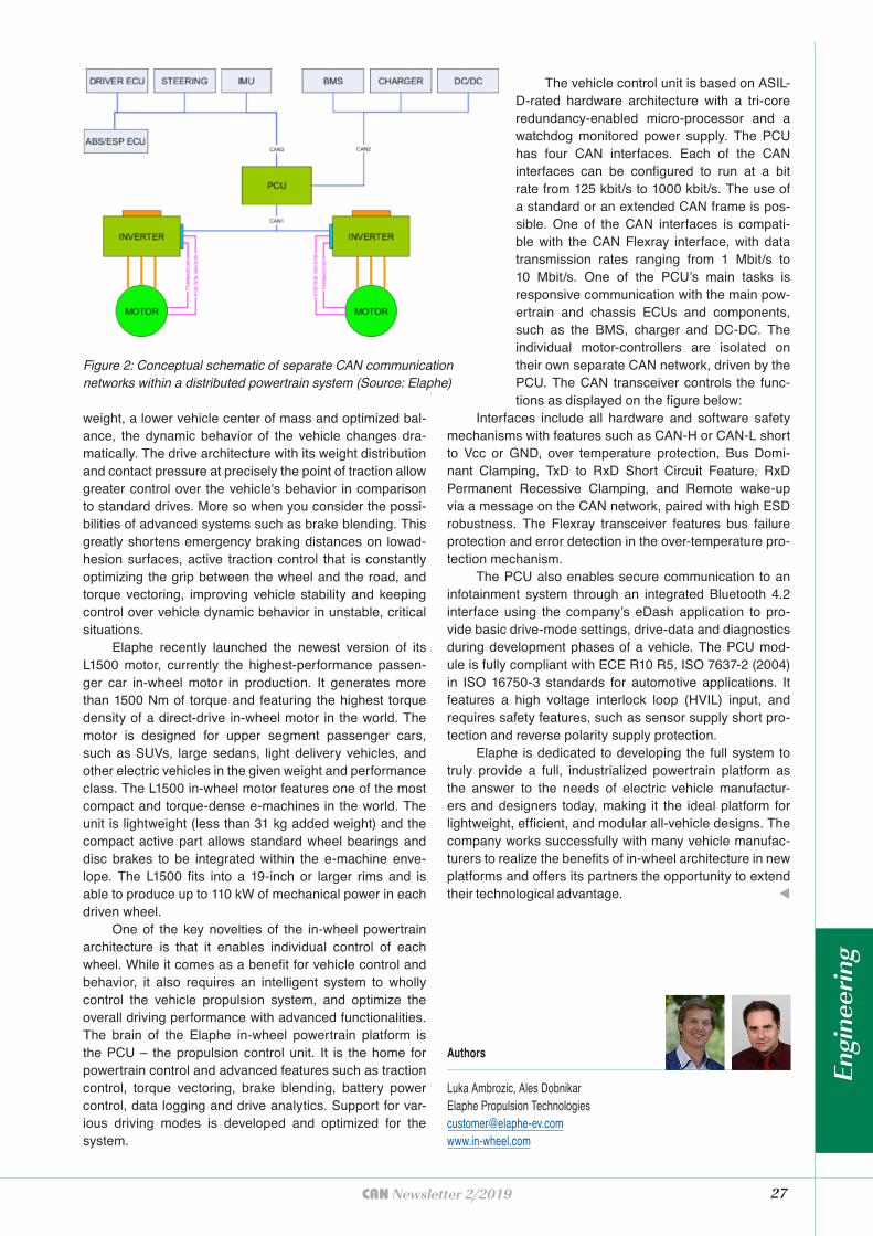
The vehicle control unit is based on ASIL-D-rated hardware architecture with a tri-core redundancy-enabled micro-processor and a watchdog monitored power supply. The PCU has four CAN interfaces. Each of the CAN interfaces can be configured to run at a bit rate from 125 kbit/s to 1000 kbit/s. The use of a standard or an extended CAN frame is pos-sible. One of the CAN interfaces is compati-ble with the CAN Flexray interface, with data transmission rates ranging from 1 Mbit/s to 10 Mbit/s. One of the PCU’s main tasks is responsive communication with the main pow-ertrain and chassis ECUs and components, such as the BMS, charger and DC-DC. The individual motor-controllers are isolated on their own separate CAN network, driven by the PCU. The CAN transceiver controls the func-tions as displayed on the figure below:
Interfaces include all hardware and software safety mechanisms with features such as CAN-H or CAN-L short to Vcc or GND, over temperature protection, Bus Domi-nant Clamping, TxD to RxD Short Circuit Feature, RxD Permanent Recessive Clamping, and Remote wake-up via a message on the CAN network, paired with high ESD robustness. The Flexray transceiver features bus failure protection and error detection in the over-temperature pro-tection mechanism.
The PCU also enables secure communication to an infotainment system through an integrated Bluetooth 4.2 interface using the company’s eDash application to pro-vide basic drive-mode settings, drive-data and diagnostics during development phases of a vehicle. The PCU mod-ule is fully compliant with ECE R10 R5, ISO 7637-2 (2004) in ISO 16750-3 standards for automotive applications. It features a high voltage interlock loop (HVIL) input, and requires safety features, such as sensor supply short pro-tection and reverse polarity supply protection.
Elaphe is dedicated to developing the full system to truly provide a full, industrialized powertrain platform as the answer to the needs of electric vehicle manufactur-ers and designers today, making it the ideal platform for lightweight, efficient, and modular all-vehicle designs. The company works successfully with many vehicle manufac-turers to realize the benefits of in-wheel architecture in new platforms and offers its partners the opportunity to extend their technological advantage. t
Figure 2: Conceptual schematic of separate CAN communication networks within a distributed powertrain system (Source: Elaphe)
Authors
Luka Ambrozic, Ales DobnikarElaphe Propulsion [email protected]
Engi
neer
ing
28 CAN Newsletter 2/2019
In past articles, the authors have introduced various security methods which all had in common to work for
systems and devices of all sizes and hardware capabilities. Along with the needed amount of flexibility, however, typically come higher resource requirements. A product that includes CAN and that has been sold for many years may not have the amount of resources needed for extra security features to spare. In this article we examine what kind of CAN security we can still add to a deployed CAN system if the processors have only medium performance and we can only add a few kilobytes of extra code.
Motivation
Some things appear to have not changed significantly in the past 20 years of Embedded Systems programming. Back then we would start developing minimal solutions for clients that wanted to add CANopen using “as few resources as possible”. Today, clients want to add CAN security to an already deployed system and again, often with only minimal resources available. Same situation, different technology.
We introduced the CANcrypt security framework in previous articles. The framework offers enough functionality and flexibility for a wide range of platforms and security needs. However, especially in applications where authentication for as many CAN frames as possible is the number one requirement but encryption is not needed, an alternative, cut-down Micro CANcrypt implementation targeting low-footprint environment can fit the bill much better.
At the same time, the authors thought of better ways to apply CANcrypt methods to classic CANopen and CANopen FD. In its original incarnation, securing CANopen messages with CANcrypt would always need either a second message or multiple reserved bytes in the data payload while Micro CANcrypt will attempt to stay as close to unencrypted CANopen as possible.
Micro CANcrypt optimizations
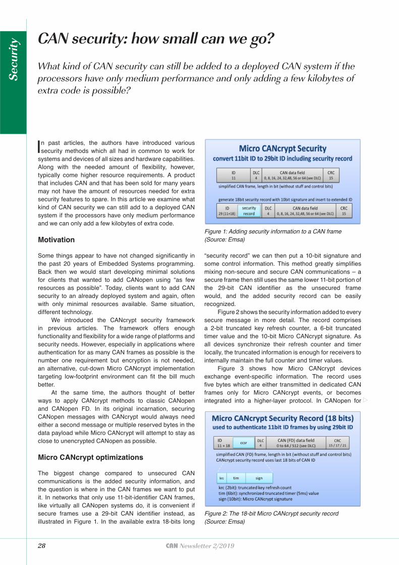
The biggest change compared to unsecured CAN communications is the added security information, and the question is where in the CAN frames we want to put it. In networks that only use 11-bit-identifier CAN frames, like virtually all CANopen systems do, it is convenient if secure frames use a 29-bit CAN identifier instead, as illustrated in Figure 1. In the available extra 18-bits long
What kind of CAN security can still be added to a deployed CAN system if the processors have only medium performance and only adding a few kilobytes of extra code is possible?
CAN security: how small can we go?
“security record” we can then put a 10-bit signature and some control information. This method greatly simplifies mixing non-secure and secure CAN communications – a secure frame then still uses the same lower 11-bit portion of the 29-bit CAN identifier as the unsecured frame would, and the added security record can be easily recognized.
Figure 2 shows the security information added to every secure message in more detail. The record comprises a 2-bit truncated key refresh counter, a 6-bit truncated timer value and the 10-bit Micro CANcrypt signature. As all devices synchronize their refresh counter and timer locally, the truncated information is enough for receivers to internally maintain the full counter and timer values.
Figure 3 shows how Micro CANcrypt devices exchange event-specific information. The record uses five bytes which are either transmitted in dedicated CAN frames only for Micro CANcrypt events, or becomes integrated into a higher-layer protocol. In CANopen for
Figure 1: Adding security information to a CAN frame (Source: Emsa)
Figure 2: The 18-bit Micro CANcrypt security record (Source: Emsa)
Secu
rity
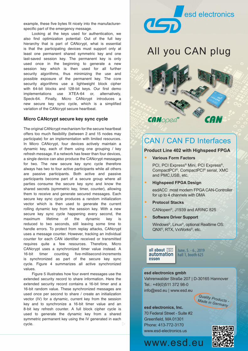
example, these five bytes fit nicely into the manufacturer-specific part of the emergency message.
Looking at the keys used for authentication, we also find optimization potential: Out of the full key hierarchy that is part of CANcrypt, what is essential is that the participating devices must support only at least one permanent shared symmetric key and one last-saved session key. The permanent key is only used once in the beginning to generate a new session key which is then used for all further security algorithms, thus minimizing the use and possible exposure of the permanent key. The core security algorithms use a lightweight block cipher with 64-bit blocks and 128-bit keys. Our first demo implementations use XTEA-64 or, alternatively, Speck-64. Finally, Micro CANcrypt introduces a new secure key sync cycle, which is a simplified variation of the CANcrypt secure heartbeat.
Micro CANcrypt secure key sync cycle
The original CANcrypt mechanism for the secure heartbeat offers too much flexibility (between 2 and 15 nodes may participate) for an implementation with limited resources. In Micro CANcrypt, four devices actively maintain a dynamic key, each of them using one grouping / key refresh message. If a network has fewer than four devices, a single device can also produce the CANcrypt messages for two. The new secure key sync cycle therefore always has two to four active participants while all others are passive participants. Both active and passive participants become part of a secure group where all parties consume the secure key sync and know the shared secrets (symmetric key, timer, counter), allowing them to receive and generate secured messages. Each secure key sync cycle produces a random initialization vector which is then used to generate the current rolling dynamic key from the session key. With a new secure key sync cycle happening every second, the maximum lifetime of the dynamic key is reduced to two seconds, still leaving some time to handle errors. To protect from replay attacks, CANcrypt uses a message counter. However, tracking an individual counter for each CAN identifier received or transmitted requires quite a few resources. Therefore, Micro CANcrypt uses a synchronized timer value instead. A 16-bit timer counting five-millisecond-increments is synchronized as part of the secure key sync cycle. Figure 4 summarizes all active synchronized values.
Figure 5 illustrates how four event messages use the extended security record to share information. Here the extended security record contains a 16-bit timer and a 16-bit random value. These synchronized messages are used once per second to share / create an initialization vector (IV) for a dynamic, current key from the session key and to synchronize a 16-bit timer value and an 8-bit key refresh counter. A full block cipher cycle is used to generate the dynamic key from a shared symmetric permanent key using the IV generated in each cycle.

30 CAN Newsletter 2/2019
Signature generation performancerequirements
One goal of Micro CANcrypt is to be able to perform a signature generation or verification for every CAN frame processed by a device. At a CAN bitrate of 125 Kbit/s, potential throughput is about one CAN frame per millisecond. At 500 Kbit/s, it can be four frames per millisecond.
A rough estimation: Let’s assume that a CPU may use 50 % of its CPU time for CAN processing and that for signature calculation a maximum of 10 % additional CPU time is allowed, then this translates to:
◆ 125 Kbit/s: 1 ms per CAN frame, CPU time 500 μs, 10 % translates to 50 μs available for signature calculation.
◆ 500 Kbit/s: 250 μs per frame, CPU time 125 μs, 10 % translates to 12,5 μs available for signature calculation.
These estimates already show that there is not always enough CPU time to execute a full lightweight block cipher with all rounds for every signature in every CAN frame, as not all micro-controllers in use will have the needed performance. However, when keeping in mind, that
◆ a pseudo one-time pad is used that changes every 5 ms
◆ the current dynamic key is based on a session key
◆ the current dynamic key is valid for a maximum of two seconds only, therefore the number of messages communicated in that time frame (= samples to attacker) is limited
◆ as shown below, attacker will never see all data, only portions of it (see method below)
It means that the method chosen to generate a digital signature does not need to be protected to the highest extent. The Micro CANcrypt method to generate a signature is illustrated in Figure 6. The steps to calculate the transmit-side signature are:1. Generate a 64-bit checksum of the CAN identifier,
DLC and data.2. Take the current 16-bit timer, counter and dynamic key
to create a pseudo one-time pad, using only a portion of the recommended rounds of the block cipher (default: one quarter).
Figure 3: The extended security record (Source: Emsa)
Figure 5: The secure key sync cycle (Source: Emsa)
Figure 4: Synchronized, shared parameters, and secrets (Source: Emsa)
Figure 6: Signature generation (Source: Emsa)
Secu
rity
3. Encrypt the buffer using only a portion of the recommended rounds of the block cipher (default: one quarter).
4. We now have a 64-bit signature buffer which needs to be reduced to 10 bits. The value of the lowest six bits of the buffer is taken as the bit position of the 10-bit slice from the buffer that is used as Micro CANcrypt Signature for this CAN frame.
To verify the signature during secure receive: ◆ First, verify that the key refresh counter received
matches the local key counter or is from previous cycle.
◆ Second, verify that the received timestamp is not older than 25 ms compared to the local timer.
Then perform the same steps as above to generate the receive-side Micro CANcrypt signature. For the generation of the one-time pad use a full timer value, comprising the lower-16-bit timer value received with the frame and the upper bits of the local timer. If it matches with the received transmit-side signature, the frame is authentic.
Overview of resources used
First prototype implementations of Micro CANcrypt are being done on an NXP LPC11Cxx (ARM Cortex-M0, 48 Mhz) for Classical CAN and an NXP LPC54xxx for CAN FD. For a full integration demo, we use the multilayer security demonstrator, adding Micro CANopen security not only to evaluation boards, but also to commercial CANopen
(FD) modules from Peak-System Technik and Embedded Systems Solutions.
Additional CAN traffic and bandwidth
The secure key sync cycle uses four extended security records, in CANopen integrated into the manufacturer-specific field of the emergency message and using an EMCY error code below 100h to indicate no error. These are used once per second normally or twice per second on failure / recovery. At 125 Kbit/s, the generated bus load for this mechanism is less than 0,01 %.
All existing 11-bit CAN identifier communication that requires security now uses a 29-bit CAN identifier which generates an overhead of about 20 bits per CAN frame, assuming an average of 2 stuffing bits. With CAN frames being some 60 bits to 125 bits long (incl. stuffing bits, assuming DLC between 1 and 8), the overhead calculates to between 16 % and 33 % for all secured messages.
Memory usage
Code size of the Micro CANcrypt specific secure grouping mechanism is below 2000 bytes for the Cortex-M0, using a Keil/ARM Realview compiler at its highest optimization level. Added to this is some “glue” code to interface with the driver level, the size of which highly depends on driver specifics. RAM and stack usage
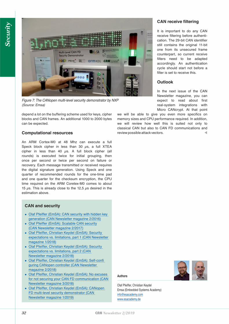
32 CAN Newsletter 2/2019
depend a lot on the buffering scheme used for keys, cipher blocks and CAN frames. An additional 1000 to 2000 bytes can be expected.
Computational resources
An ARM Cortex-M0 at 48 Mhz can execute a full Speck block cipher in less than 30 μs, a full XTEA cipher in less than 40 μs. A full block cipher (all rounds) is executed twice for initial grouping, then once per second or twice per second on failure or recovery. Each message transmitted or received requires the digital signature generation. Using Speck and one quarter of recommended rounds for the one-time pad and one quarter for the checksum encryption, the CPU time required on the ARM Coretex-M0 comes to about 15 μs. This is already close to the 12,5 μs desired in the estimation above.
Figure 7: The CANopen multi-level security demonstrator by NXP(Source: Emsa)
◆ Olaf Pfeiffer (EmSA): CAN security with hidden key generation (CAN Newsletter magazine 2/2016)
◆ Olaf Pfeiffer (EmSA): Scalable CAN security(CAN Newsletter magazine 2/2017)
◆ Olaf Pfeiffer, Christian Keydel (EmSA): Security expectations vs. limitations, part 1 (CAN Newsletter magazine 1/2018)
◆ Olaf Pfeiffer, Christian Keydel (EmSA): Security expectations vs. limitations, part 2 (CAN Newsletter magazine 2/2018)
◆ Olaf Pfeiffer, Christian Keydel (EmSA): Self-confi guring CANopen controller (CAN Newsletter magazine 2/2018)
◆ Olaf Pfeiffer, Christian Keydel (EmSA): No excuses for not securing your CAN FD communication (CAN Newsletter magazine 3/2018)
◆ Olaf Pfeiffer, Christian Keydel (EmSA): CANopen FD multi-level security demonstrator (CAN Newsletter magazine 1/2019)
CAN and security
Authors
Olaf Pfeiffer, Christian KeydelEmsa (Embedded Systems Academy)[email protected]
CAN receive filtering
It is important to do any CAN receive filtering before authenti-cation. The 29-bit CAN identifier still contains the original 11-bit one from its unsecured frame counterpart, so current receive filters need to be adapted accordingly. An authentication cycle should start not before a filter is set to receive this.
Outlook
In the next issue of the CAN Newsletter magazine, you can expect to read about first real-system integrations with Micro CANcrypt. At that point
we will be able to give you even more specifics on memory sizes and CPU performance required. In addition, we will review how well this is suited not only to classical CAN but also to CAN FD communications and review possible attack vectors. t
Secu
rity
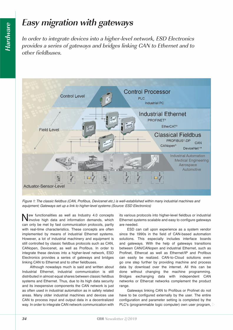
34 CAN Newsletter 2/2019
New functionalities as well as Industry 4.0 concepts involve high data and information demands, which
can only be met by fast communication protocols, partly with real-time characteristics. These concepts are often implemented by means of industrial Ethernet systems. However, a lot of industrial machinery and equipment is still controlled by classic fieldbus protocols such as CAN, CANopen, Devicenet, as well as Profibus. In order to integrate these devices into a higher-level network, ESD Electronics provides a series of gateways and bridges linking CAN to Ethernet and to other fieldbuses.
Although nowadays much is said and written about Industrial Ethernet, industrial communication is still distributed in almost equal shares between classic fieldbus systems and Ethernet. Thus, due to its high data security and its inexpensive components the CAN network is just as often used in industrial automation as in safety related areas. Many older industrial machines and devices use CAN to process input and output data in a decentralized way. In order to integrate CAN network communication with
In order to integrate devices into a higher-level network, ESD Electronics provides a series of gateways and bridges linking CAN to Ethernet and to other fieldbuses.
Easy migration with gateways
its various protocols into higher-level fieldbus or industrial Ethernet systems scalable and easy to configure gateways are needed.
ESD can call upon experience as a system vendor since the 1990s in the field of CAN-based automation solutions. This especially includes interface boards and gateways. With the help of gateways transitions between CAN/CANopen and industrial Ethernet, such as Profinet, Ethercat as well as Ethernet/IP and Profibus can easily be realized. CAN-to-Cloud solutions even go one step further by providing machine and process data by download over the internet. All this can be done without changing the machine programming. Bridges exchanging data with independent CAN networks or Ethercat networks complement the product range.
Gateways linking CAN to Profibus or Profinet do not have to be configured externally by the user. The entire configuration and parameter setting is completed by the PLC's (programmable logic computer) own user program,
Figure 1: The classic fieldbus (CAN, Profibus, Devicenet etc.) is well-established within many industrial machines and equipment; Gateways set up a link to higher-level systems (Source: ESD Electronics)
Har
dwar
e
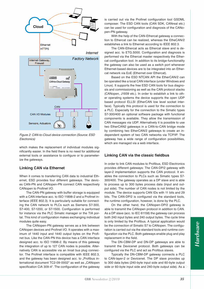
35CAN Newsletter 2/2019
which makes the replacement of individual modules sig-nificantly easier. In the field there is no need for additional external tools or assistance to configure or to parameter-ize the gateways.
Linking CAN via Ethernet
When it comes to transferring CAN data to industrial Eth-ernet, ESD provides four different gateways. The devic-es CAN-PN and CANopen-PN connect CAN respectively CANopen to Profinet I/O.
The CAN-PN gateway with buffer storage is equipped with a CAN interface acc. to ISO 11898-2 and a Profinet in-terface (IEEE 802.3). It is particularly suitable for connect-ing the CAN network to PLCs such as Siemens S7-300, S7-400, S7-1200, or S7-1500. Configuration is performed for instance via the PLC Simatic manager or the TIA por-tal. This kind of configuration makes exchanging individual modules quite easy.
The CANopen-PN gateway serves as a link between CANopen devices and Profinet I/O. It operates with a max-imum of 1440 input and 1440 output bytes on the Profi-net bus. Like the CAN-PN this device has a CAN interface designed acc. to ISO 11898-2. By means of this gateway the integration of up to 127 CAN nodes is possible. Alter-natively CAN is accessible via an Inrail bus plug connec-tor. The Profinet interface is compatible with IEEE 802.3, and the gateway has been designed acc. to „Profibus in-ternational document TC2-09-0002“ as well as „CANopen specification CiA 309-4“. The configuration of the gateway
is carried out via the Profinet configuration tool GSDML composer. The ESD CAN tools (CAN SDK, CANreal etc.) can be used for configuration and diagnosis of the CANo-pen-PN gateway.
With the help of the CAN-Ethercat gateway a connec-tion to Ethercat can be realized, whereas the EtheCAN/2 establishes a link to Ethernet according to IEEE 802.3.
The CAN-Ethercat acts as Ethercat slave and is de-signed acc. to ETG.5000. Configuration and diagnosis is performed via the Ethercat master respectively the Ether-cat configuration tool. In addition to its bridge-functionality the gateway can also be used as a switch port whenever Ethernet-based devices are to be integrated into an Ether-cat network via EoE (Ethernet over Ethercat).
Based on the ESD NTCAN API the EtherCAN/2 can be operated like a local CAN interface (under Windows and Linux). It supports the free ESD CAN tools for bus diagno-sis and commissioning as well as the CAN protocol stacks (CANopen, J1939 etc.). In order to establish a link to oth-er operating systems the device supports the open UDP based protocol ELLSI (EtherCAN low level socket inter-face). Typically this protocol is used for the connection to a PLC. Especially for the connection to the Simatic types S7-300/400 an optional software package with functional components is available. They allow the transmission of CAN messages via UDP. Alternatively it is possible to use two EtherCAN2 gateways in a CAN-to-CAN bridge mode by combining two EtherCAN/2 gateways to create an in-dependent system of two CAN networks via TCP/IP. The gateway has a wide range of configuration possibilities, which are managed via a web interface.
Linking CAN via the classic fieldbus
In order to link CAN modules to Profibus, ESD Electronics provides different gateways: The CAN-DP/2 gateway with layer-2 implementation supports the CAN protocol. It en-ables the connection to PLCs such as Simatic types S7-300/400. The gateway operates as a DP slave and is able to process up to 300 bytes process data (input and out-put side). The number of CAN nodes is not limited by the module. The device supports CAN IDs with 11 bits and 29 bits. The CAN-DP/2 is configured via the standard tools, the runtime configuration, however, is done by the PLC.
On the other hand, the CANopen-DP/2 gateway is able to transmit the CANopen protocol in addition to CAN. As a DP slave (acc. to IEC 61158) the gateway can process both 240 input bytes and 240 output bytes. The cycle time is only limited by the Profibus. A typical application would be the connection of Simatic S7 to CANopen. The configu-ration is carried out via the standard tools and runtime con-figuration via the PLC. Both gateways enable plug and play replacement in the field.
The DN-CBM-DP and DN-DP gateways are able to transmit the Devicenet protocol. Both gateways can be configured via the PLC and act as Profibus slaves.
Typically the DN-CBM-DP gateway connects a PLC to CAN-layer-2 or Devicenet. The DP slave provides up to 300 data bytes (240-byte input side and 60-byte output side or 60-byte input side and 240-byte output side). As a
Figure 2: CAN-to-Cloud device connection (Source: ESD Electronics)
Har
dwar
e

36 CAN Newsletter 2/2019
CAN master, the DN-CBM-DP gateway also operates with CAN-layer-2.
CAN-to-Cloud – making data available via the internet
With the help of an Azure-IoT-Hub the CAN-to-Cloud Gate-way allows a worldwide access to data of a certain CAN network. CAN data is sent to Microsoft Azure Cloud over a TLS/SSL encrypted secure connection. From there, data can be retrieved from anywhere in the world. The Micro-soft Azure Cloud offers many different software services for the gateway's operation: it allows storage, display, and analysis of data. Based on these data it is possible to gen-erate warnings that may be sent to computer systems or smartphones.
By means of a web browser interface the CAN-to-Cloud is very easy to handle. CAN data can be filtered via IDs or can be forwarded completely or partially. Moreover it is possible to process various data formats or to add appli-cation-specific information and time-stamps to messages. The cloud platform may be used for predictive mainte-nance so that on site monitoring can be omitted. Data host-ing can take place in German computer centers if explicitly required (Microsoft Azure Deutschland, trustee: Telekom).
Bridges – integrating independent networks
Whenever independent networks are to be connected bridges come into play.
The ECX-EC Ethercat bridge merges two Ethercat slave segments. In this way process data between two independent Ethercat networks can be exchanged. For the synchronization of different cycles (DC) the bridge uses the exact difference between two slave time stamps as CoE (CAN over Ethercat) object. Thus, one master is synchronized with the other. Within a redundant network the ECX-EC bridge uses the first and the last slave simultaneously which allows the master to keep all slave segments synchronous in
Figure 3: Gateways by ESD (Source: ESD Electronics)
Author
Renate Klebe-KlingemannESD [email protected]
both segments. The Ethercat implementation relies onEthernet ports according to IEEE 802.3, configuration is effected via CoE objects and the firmware update as well as the EoE support (switch port) is performed via FoE. The Ethercat process image can be configured by means of typical network configuration tools (i.e. ESD workbench, Twincat).
The CAN bridge CAN-CBM-Bridge/2 with data buffering establishes a link between two CAN networks. It is able to connect CAN networks with different data rates. The bridge supports 11-bit and 29-bit identifiers and is equipped with CAN interfaces accordingto ISO 11898-2. They are electrically isolated by means
of optocouplers and DC/DC converters. Configuration can be completed quite easily via the PC's serial interface (RS232). The device is designed for DIN EN rail mounting (T35). t
Har
dwar
e

38 CAN Newsletter 2/2019
The DMU add-on allows the reduction of the host con-troller load by off-loading the transport of CAN frames
to a DMA controller. The TSU expansion module enables hardware-based and Autosar-compatible time synchroni-zation.
When exchanging CAN data frames between the host controller and the M_CAN protocol controller, there are some issues to consider, especially for complex SoCs (system-on-chip). Due to the high complexity of modern SoC architectures, the on-chip communication paths are divided into several domains of different performance. The bridging between domains additionally slows down performance, e.g. due to clock-domain crossings.
The heat-map (red = fast, blue = slow) in Figure 1 illustrates the speed of data transfers initiated by the host controller in the processor domain. Thus, the connection of the host controller core to the dedicated caches is the fastest, followed by the TCM within the cluster. When creating the software, it must be ensured that these memories can be used efficiently.
In extreme contrast to this, single accesses to components in the peripheral domain can be up to 30 times slower. If, for example, the continuous exchange of CAN frames between the host controller and a M_CAN unit is considered, the following interactions are typically required:
◆ Check the status register of M_CAN when asserting an interrupt
◆ Optionally transfer the CAN data frames ◆ Optionally signal to the M_CAN the completion of
frame transfersIf the cores in the processor domain would perform
these interactions, they would be significantly slowed down by the NoC (network on chip). For example, such interactions can also be done via a processor core within the peripheral domain, if available. However, this article focuses on a different approach that does not allocate computational resources of any processor core.
DMU functionality
Bosch offers an add-on for the M_CAN called DMU. With this, the continuous exchange of CAN data frames can be completely outsourced to a DMA controller. The add-on unit is based on the concept of virtualizing the FIFO (first-in, first-out) head elements (Figure 2).
Bosch has improved its M-CAN. The added functions include a DMA interface unit (DMU) and a time stamping unit (TSU).
CAN IP core with DMU and TSU
The M_CAN has an associated message RAM (MRAM), which i.a. contains the elements (CAN data frames) organized in FIFOs. To access the memory segment of the current message (head element) within these FIFOs by the host controller, the respective pointers (read/write pointer) from the M_CAN must previously be queried. To avoid this, accesses to fixed address areas are virtualized. The DMU dynamically redirects these accesses to the head elements in the MRAM. The redirection is controlled invisibly within the DMU by the FIFO pointers in the M_CAN. The size of the reserved areas corresponds to the largest possible frame elements, which are 18 words (32-bit) for the TX, RX0, and RX1 elements and two words (32-bit) for the TX Event element (three words, if the TSU timestamp is also transferred). The transfer of a last element word activates a process in the DMU, in which for TX elements the transmit request is set in M_CAN, or for the other elements (RX0, RX1, TXE) the dedicated FIFO acknowledge is set in the M_CAN unit. Thus, writing or reading the CAN data frames via DMU elements completes the whole queuing/de-queuing process in the M_CAN unit. The DMU supports data frame transfers
Figure 1: Domains of a SoC (Source: Bosch)
Engi
neer
ing

39CAN Newsletter 2/2019
from the CRAM to the TX-FIFO/Queue and vice versa, from the RX-FIFOs respectively the TX-event FIFO to the CRAM. The block diagram in Figure 3 shows the M_CAN unit with the add-ons DMU and TSU. The host controller accesses to the M_CAN are routed through both add-on modules.
Figure 4 shows the memory map of the DMU. In the yellow marked memory area starting at address 0, the registers of the M_CAN unit and the TSU are memory-mapped. Afterwards, the purple coloured Virtual Buffers are shown, which are accessed by the DMA in order to transport the head elements of the M_CAN message FIFOs.
TX element
The CAN data frame elements are written by the DMA controller to be added in the TX-FIFO/Queue. When writing the last element word, the TX request is automatically set for this element, so that the M_CAN unit sends this. The DMU requests further CAN data frame elements from the DMA controller as long as the TX-FIFO/Queue is not full.
RX0 / RX1 elements
The CAN data frame elements are read by the DMA controller, which are located in the receive FIFO 0 or FIFO 1 of the M_CAN unit. When the last element word is read, the de-queuing is communicated to the M_
Figure 2: Functional block diagram of the DMU (Source: Bosch)
Figure 3: M_CAN unit with DMU and TSU (Source: Bosch)
CAN unit by setting the dedicated acknowledge index by the DMU. Optionally, the time-stamp of the TSU can also be transmitted. The DMU triggers the DMA to de-queue further CAN data frame elements as long as the RX-FIFO is not empty.
TX event element
Like the RX0 / RX1 elements, but here the TX events are read, optionally with the time stamp of the TSU.
DMU register
The DMU gets most of the configuration parameters from the M_CAN, only the transport of the hardware time-stamp of the TSU can be switched on/off. The status information provides feedback on whether the access to the virtual elements is correct or, if not, what problem occurred. This is particularly helpful when debugging the DMA routines, but should also be monitored during normal operation for reasons of functional safety.
DMU debug section
When debugging the software, the DMU elements can be accessed by reading without affecting the queuing or de-queuing of the DMA. For the TX element, the last element written is read, for the RX0, RX1, and TXE elements the current element is read. These accesses do not trigger automatisms of the DMU, like the acknowledgment in M_CAN core.
Data flow within the SoC
The following approach is recommended for the data flow within the SoC: A RAM has to be selected to which the desired processor core can access with the highest possible read/write performance and to which the DMA controller also has direct access. This CRAM is then used to exchange the CAN data frames, with the DMA controller taking over the slow transfers of the CAN data frames across large distances of the NoC and storing them in the CRAM close to the processor core, which then access without performance loss.
TSU add-on
For the Autosar-compatible (automotive open system architecture) synchronization of time bases between CAN nodes, only software implementations had been
Engi
neer
ing

40 CAN Newsletter 2/2019
used due to a lack of special hardware. To further increase the time accuracy, special hard-ware is required. The CiA 603 document speci-fies a hardware-based concept, which has been implemented in TSU. This approach is independent of interrupt response times and thus achieves the best possible accuracy. The TSU may operate on its own internal time-base, or uses an external time-base, e.g. a reference time base within the SoC.
Receipt of messages with timestamp
In order to receive a time-stamped message, a base or extended frame ID filter element must be configured accordingly, i.e. S0.SSYNC = 1 or F1.ESYNC = 1. Upon receipt of a valid data frame matching the filter, the time-stamp is stored in the TSU. Since the TSU stores several time-
stamps, a pointer is written into the CAN data frame (R1.RXTSP), which points to the corres ponding entry in the TSU. When reading out such an RX data frame with the DMU, the TSU time-stamp can be automatically attached.
Sending messages with timestamp
If a time stamp has to be generated when a CAN data frame is sent, the following bits must be set in the mes-sage: T1.TSCE = 1 and T1.EFC = 1. Upon successful trans-mission, a time-stamp is stored in the TSU and a TX-Event message is generated, which refers to the corresponding entry in the TSU, i.e. field TXTSP in event message word E1 (E1.TXTSP). When using DMU, the time-stamp of the TSU can also be automatically attached.
Synchronization process after Autosar
After successful configuration (see above) of all participat-ing CAN nodes, the timers of the time slaves can be cor-rected with a two-step synchronization process. In the first step, the current time T0 is latched in the time master, and the part of T0, which represents the seconds, is sent to the time slaves with the SYNC message. If the EoF is reached when sending this SYNC message, then timestamps are
Figure 4: DMU address map (Source: Bosch)
Authors
Stefan ThieleRobert [email protected]
[1] Time-stamping of CAN frames, CAN Newsletter 2/2017[2] CiA 603, CAN frame time-stamping – Requirements for network time management, Nuremberg 2017[2] CiA 603, CAN frame time-stamping – Requirements for network time management, Nuremberg 2017
Literature
stored in the TSUs of all nodes, i.e. in the Time Master and all Time Slaves. This is the common point of time ref-erence. In the second step, the time master adds its TSU time stamp to the nanosecond part of T0 and sends it to the time slaves via FollowUp message. From this, the time slaves can derive their own time base.
Saving time stamps at SoF
For non-Autosar applications, the TSU can also be config-ured to store time-stamps at the start of a CAN data frame (SoF bit). t
Engi
neer
ing

YOURTRUSTEDCANPARTNER
YOURTRUSTED
PARTNERwww.kvaser.com
Advanced CAN solutions built by engineers, for engineers.Kvaser CAN Interfaces & dataloggers are the reference for CAN and related bus protocol connection.Kvaser is committed to providing open solutions that ensure easy toolchain integration.
Combine Kvaser hardware with software from our Technical Associates for a powerful, tailored solution.Free software includes Kvaser CANlib SDK, a one-stop development environment for our CAN and LIN interfaces, andKvaser’s free CanKing bus monitor. Windows and Linux versions available, accessible through Python.Free global support. Our International Support Team provide timely email and phone support to Kvaser customersthroughout the world.Unique design: Lightweight, ergonomic, durable, and flexible.
#CAN FD
#LINUX
#LIN
#DATALOGGING
#MAGISYNC
#SCRIPTING
#RUGGED
#SILENTMODE #EMBEDDED
#ETHERNET
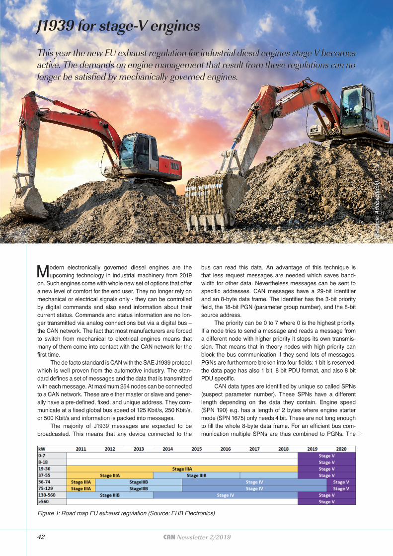
42 CAN Newsletter 2/2019
Modern electronically governed diesel engines are the upcoming technology in industrial machinery from 2019
on. Such engines come with whole new set of options that offer a new level of comfort for the end user. They no longer rely on mechanical or electrical signals only - they can be controlled by digital commands and also send information about their current status. Commands and status information are no lon-ger transmitted via analog connections but via a digital bus – the CAN network. The fact that most manufacturers are forced to switch from mechanical to electrical engines means that many of them come into contact with the CAN network for the first time.
The de facto standard is CAN with the SAE J1939 protocol which is well proven from the automotive industry. The stan-dard defines a set of messages and the data that is transmitted with each message. At maximum 254 nodes can be connected to a CAN network. These are either master or slave and gener-ally have a pre-defined, fixed, and unique address. They com-municate at a fixed global bus speed of 125 Kbit/s, 250 Kbit/s, or 500 Kbit/s and information is packed into messages.
The majority of J1939 messages are expected to be broadcasted. This means that any device connected to the
bus can read this data. An advantage of this technique is that less request messages are needed which saves band-width for other data. Nevertheless messages can be sent to specific addresses. CAN messages have a 29-bit identifier and an 8-byte data frame. The identifier has the 3-bit priority field, the 18-bit PGN (parameter group number), and the 8-bit source address.
The priority can be 0 to 7 where 0 is the highest priority. If a node tries to send a message and reads a message from a different node with higher priority it stops its own transmis-sion. That means that in theory nodes with high priority can block the bus communication if they send lots of messages. PGNs are furthermore broken into four fields: 1 bit is reserved, the data page has also 1 bit, 8 bit PDU format, and also 8 bit PDU specific.
CAN data types are identified by unique so called SPNs (suspect parameter number). These SPNs have a different length depending on the data they contain. Engine speed (SPN 190) e.g. has a length of 2 bytes where engine starter mode (SPN 1675) only needs 4 bit. These are not long enough to fill the whole 8-byte data frame. For an efficient bus com-munication multiple SPNs are thus combined to PGNs. The
Figure 1: Road map EU exhaust regulation (Source: EHB Electronics)
J1939 for stage-V engines
This year the new EU exhaust regulation for industrial diesel engines stage V becomes This year the new EU exhaust regulation for industrial diesel engines stage V becomes active. The demands on engine management that result from these regulations can no active. The demands on engine management that result from these regulations can no longer be satisfied by mechanically governed engines.longer be satisfied by mechanically governed engines.
(Sou
rce:
Ado
beS
tock
)
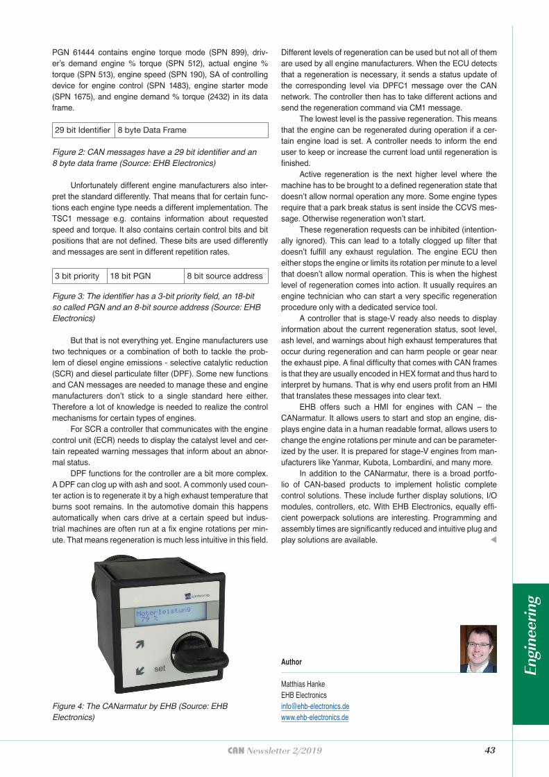
43CAN Newsletter 2/2019
PGN 61444 contains engine torque mode (SPN 899), driv-er’s demand engine % torque (SPN 512), actual engine % torque (SPN 513), engine speed (SPN 190), SA of controlling device for engine control (SPN 1483), engine starter mode (SPN 1675), and engine demand % torque (2432) in its data frame.
Unfortunately different engine manufacturers also inter-pret the standard differently. That means that for certain func-tions each engine type needs a different implementation. The TSC1 message e.g. contains information about requested speed and torque. It also contains certain control bits and bit positions that are not defined. These bits are used differently and messages are sent in different repetition rates.
But that is not everything yet. Engine manufacturers use two techniques or a combination of both to tackle the prob-lem of diesel engine emissions - selective catalytic reduction (SCR) and diesel particulate filter (DPF). Some new functions and CAN messages are needed to manage these and engine manufacturers don’t stick to a single standard here either. Therefore a lot of knowledge is needed to realize the control mechanisms for certain types of engines.
For SCR a controller that communicates with the engine control unit (ECR) needs to display the catalyst level and cer-tain repeated warning messages that inform about an abnor-mal status.
DPF functions for the controller are a bit more complex. A DPF can clog up with ash and soot. A commonly used coun-ter action is to regenerate it by a high exhaust temperature that burns soot remains. In the automotive domain this happens automatically when cars drive at a certain speed but indus-trial machines are often run at a fix engine rotations per min-ute. That means regeneration is much less intuitive in this field.
29 bit Identifi er 8 byte Data Frame
Figure 2: CAN messages have a 29 bit identifier and an 8 byte data frame (Source: EHB Electronics)
3 bit priority 18 bit PGN 8 bit source address
Figure 3: The identifier has a 3-bit priority field, an 18-bit so called PGN and an 8-bit source address (Source: EHB Electronics)
Figure 4: The CANarmatur by EHB (Source: EHB Electronics)
Different levels of regeneration can be used but not all of them are used by all engine manufacturers. When the ECU detects that a regeneration is necessary, it sends a status update of the corresponding level via DPFC1 message over the CAN network. The controller then has to take different actions and send the regeneration command via CM1 message.
The lowest level is the passive regeneration. This means that the engine can be regenerated during operation if a cer-tain engine load is set. A controller needs to inform the end user to keep or increase the current load until regeneration is finished.
Active regeneration is the next higher level where the machine has to be brought to a defined regeneration state that doesn’t allow normal operation any more. Some engine types require that a park break status is sent inside the CCVS mes-sage. Otherwise regeneration won’t start.
These regeneration requests can be inhibited (intention-ally ignored). This can lead to a totally clogged up filter that doesn’t fulfill any exhaust regulation. The engine ECU then either stops the engine or limits its rotation per minute to a level that doesn’t allow normal operation. This is when the highest level of regeneration comes into action. It usually requires an engine technician who can start a very specific regeneration procedure only with a dedicated service tool.
A controller that is stage-V ready also needs to display information about the current regeneration status, soot level, ash level, and warnings about high exhaust temperatures that occur during regeneration and can harm people or gear near the exhaust pipe. A final difficulty that comes with CAN frames is that they are usually encoded in HEX format and thus hard to interpret by humans. That is why end users profit from an HMI that translates these messages into clear text.
EHB offers such a HMI for engines with CAN – the CANarmatur. It allows users to start and stop an engine, dis-plays engine data in a human readable format, allows users to change the engine rotations per minute and can be parameter-ized by the user. It is prepared for stage-V engines from man-ufacturers like Yanmar, Kubota, Lombardini, and many more.
In addition to the CANarmatur, there is a broad portfo-lio of CAN-based products to implement holistic complete control solutions. These include further display solutions, I/O modules, controllers, etc. With EHB Electronics, equally effi-cient powerpack solutions are interesting. Programming and assembly times are significantly reduced and intuitive plug and play solutions are available. t
Author
Matthias HankeEHB [email protected]
Engi
neer
ing

The non-profi t CiA organization promotes CAN and CAN FD, develops CAN FD recommendations and CANopen specifi cations, and supports other CAN-based higher-layer protocols.
Join the community!u Initiate and infl uence CiA specifi cations
u Get credits on CiA training and education events
u Download CiA specifi cations, already in work draft status
u Get credits on some CiA publications
u Receive the exclusive, monthly CiA Member News (CMN) email service
u Get CANopen vendor-IDs free-of-charge
u Participate in plugfests and workshops
u Get the classic CANopen conformance test tool
u Participate in joint marketing activities
u Develop partnerships with other CiA members
u Get credits on CiA testing services
For more details please contact CiA offi ce at [email protected]
www.can-cia.org