Juki_DDL-555-4_Instruction_Manual.pdf - CCA Portal
40
BE5554S0B0A w MODEL DDL-555-4 High Speed, Single Needle. Lockstitch Industrial Sewing Machine Equipped with Automatic Thread Trimmer Instruction Book nJ U Kl TOKYO JUKI INDUSTRIAL CO..LTO From the library of: Superior Sewing Machine & Supply LLC
-
Upload
khangminh22 -
Category
Documents
-
view
4 -
download
0
Transcript of Juki_DDL-555-4_Instruction_Manual.pdf - CCA Portal

BE5554S0B0A
w
MODEL DDL-555-4High Speed, Single Needle. LockstitchIndustrial Sewing Machine Equipped withAutomatic Thread Trimmer
Instruction Book
nJ U Kl
TOKYO JUKI INDUSTRIAL CO..LTOFrom the library of: Superior Sewing Machine & Supply LLC
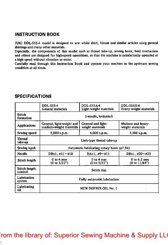
INSTRUCTION BOOK
JUKI DDL-SSS-4 model is designed to sew white shirt, blouse and similar articles using generalshirtings and many other materials.Especially, the components of this model such as thread take-up, sewing hook, feed mechanismand others are designed for high-speed operations, so that the machine is satisfactorily operated ata high speed without vibration or noise.Carefully read through this Instruction Book and operate your machine in the optimum sewingcondition at all times.
SPECIFICATIONS
DDL-555-4General materials
DDL-555A-4Light-weight materials
DDL-555H-4Heavy-weight materials
Stitchformation
1-needle, lockstitch
Applications General, light-weight andmedium-weight materials
General and lightweight materials
Medium and heavyweight materials
Sewing speed S,000 s.p.m. 4,000 s.p.m. 3,500 s.p.m.
Threadtake-up Link-type thread take-up
Sewing hpok Automatic lubricating rotary hook (07.94)
Needle DBxI,#ll~#I8 DAxl,#9~#Il DBxl, #20'-#23
Stitch length 0 to 4 mm(0 to 5/32")
0 to 4 mm(0 to 5/32")
0 to 4.5 mm(0 to 11/64")
Stitch lengthcontrol
Stitch dial
Lubricationsystem
Fully automatic lubrication
Lubricatingoil
NEW DEFRIX OIL No. 1
From the library of: Superior Sewing Machine & Supply LLC
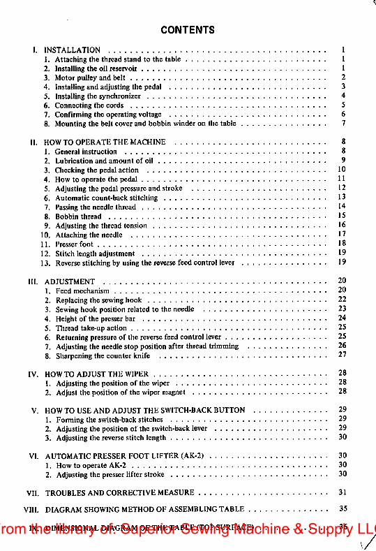
CONTENTS
I. INSTALLATION I
1. Attaching the thread stand to the table I2. Installing the oil reservoir 13. Motor pulley and belt 24. Installing and adjusting the pedal 35. Installing the synchronizer 46. Connecting the cords 57. Confirming the operating voltage 68. Mounting the belt cover and bobbin winder on the table 7
II. HOW TO OPERATE THE MACHINE 81. General instruction 82. Lubrication and amount of oil 93. Checking the pedal action 104. How to operate the pedal 115. Adjusting the pedal pressureand stroke 126. Automatic count-back stitching 137. Passing the needlethread 148. Bobbin thread 159. Adjusting the thread tension 16
10. Attaching the needle 1711. Presser foot 1812. Stitch lengthadjustment 1913. Reverse stitchingby using the reverse feedcontrol lever 19
HI. ADJUSTMENT 201. Feed mechanism 202. Replacingthe sewinghook 223. Sewinghook position related to the needle 234. Heightof the presserbar 245. Thread take-upaction 256. Returningpressureof the reverse feed control lever 257. Adjusting the needle stop position after thread trimming 268. Sharpening the counter knife 27
IV. HOWTO ADJUST THE WIPER 281. Adjusting the positionof the wiper 282. Adjust the position of the wiper magnet 28
V. HOW TO USE AND ADJUST THE SWITCH-BACK BUTTON 291. Formingthe switch-back stitches 292. Adjusting the position of the switch-backlever 293. Adjusting the reversestitch length 30
VI. AUTOMATIC PRESSER FOOT LIFTER (AK-2) 301. How to operate AK-2 302. Adjusting the presser lifter stroke 30
VII. TROUBLES AND CORRECTIVE MEASURE 31
VIII. DIAGRAM SHOWING METHOD OF ASSEMBLING TABLE 35
IX. DIMENSIONAL DIAGRAM OF THE TABLE (TOP SURFACE) 36From the library of: Superior Sewing Machine & Supply LLC

I. INSTALLATION
1. Attaching the thread stand to the table
Assemble the thread stand and set it up on the machine table by using the installation holes in thetable as illustrated.
Do not tighten the clamping nut too much. When power source is supplied by the overhead wires,pass the power supply cord through the spool rest rod.
2. Installing the oil reservoir
oi Rubber cushionj-vf-r
reservoir
Operator side Hinge side
Install the oil reservoir in such a manner that it
is supported by the 4 corners of an opening inthe table.
1. Nail in the 2 felt pads of 4 mm (5/32")thick to the 2 corners near the operator.
2. Nail in the 2 felt pads of 6 mm (15/64")thick to the remaining 2 corners (hingedside).
3. Place the oil reservoir on the felt pads.4. Insert the rubber cushions into 4 corners by
your finger.5. Put the round felt pads to 4 rubber cush
ions.
- 1 -From the library of: Superior Sewing Machine & Supply LLC
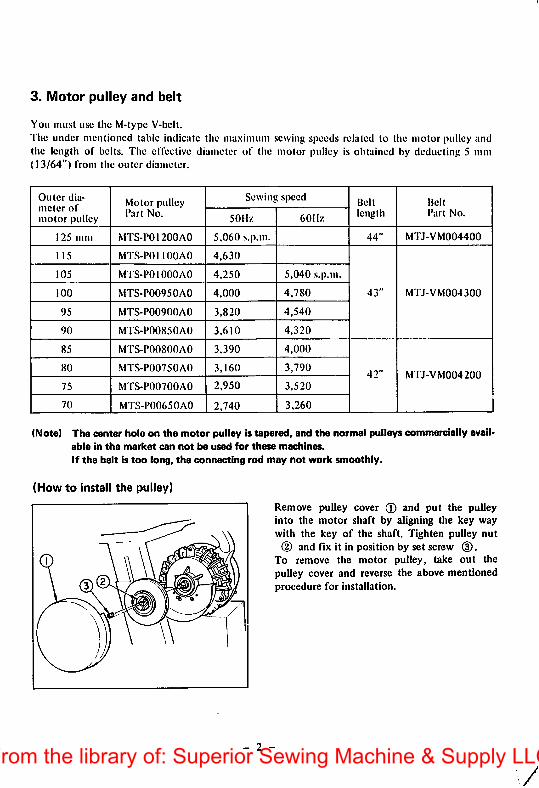
3. Motor pulley and belt
You must use the M-typc V-belt.The under mentioned table indicate tlie maximum sewing speeds related to tlie motor pulley andthe length of belts. The elTective diameter of the motor pulley is obtained by deducting 5 mm(13/64") from the outer diameter.
Ou ler diameter of
motor pulley
Motor pulleySewing speed
Belt Belt
Part No.50Hz 60Hz
length Part No.
125 mm MTS-P01200AO 5,060 s.p.m. 44" MTJ-VM004400
115 MTS-POl 100AO 4,630
105 MTS-POIOOOAO 4,250 5,040 s.p.m.
100 MTS-P00950AO 4,000 4,780 43" MTJ-VM004300
95 MTS-P00900A0 3,820 4,540
90 MTS-P00850A0 3,610 4,320
85 MTS-P00800A0 3,390 4,000
80 MTS-P00750A0 3,160 3,79042" MTJ-VM004200
75 MTS-P00700A0 2,950 3,520
70 MTS-P00650A0 2,740 3,260
(Note) The center hole on the motor pulley is tapered, and the normal pulleys commercially available in the market can not be used for these machines.
If the belt is too long, the connecting rod may not work smoothly.
(How to install the pulley)
Remove pulley cover 0 and put the pulleyinto the motor shaft by aligning the key waywith the key of the shaft. Tighten pulley nut
(D and fix it in position by set screw (3).To remove the motor pulley, take out thepulley cover and reverse the above mentionedprocedure for installation.
- 2 -From the library of: Superior Sewing Machine & Supply LLC
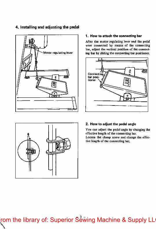
4. Installing and adjusting the pedal
Motor regulating lever
1. How to attach the connecting bar
After the motor regulating lever and the pedalwere connected by means of the connectingbar, adjust the vertical position of the connecting bar by sliding the connecting bar positioner.
Connectingbar positioner
2. How to adjust the pedal angle
You can adjust the pedal angle by changing theeffective length of the connecting bar.Loosen the clamp screw and change the effective length of the connecting bar.
- 3 -From the library of: Superior Sewing Machine & Supply LLC
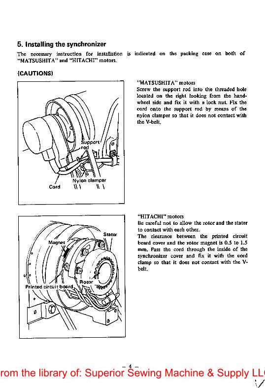
5. Installing the synchronizer
The necessary instruction for installation is indicated on the packing case on both of"MATSUSHITA" and "HITACHI" motors.
(CAUTIONS)
Supportrod
Nylon clamperCord \\\ \\ \
Stater
Magnet
RotorPrinted circuit board
"MATSUSHITA" motors
Screw the support rod into the threaded holelocated on the right looking from the hand-wheel side and fix it with a lock nut. Fix the
cord onto the support rod by means of thenylon clamper so that it does not contact withthe V-belt.
"HITACHI" motors
Be careful not to allow the rotor and the stater
to contact with each other.
The clearance between the printed circuitboard cover and the rotor magnet is 0.S to 1.5mm. Pass the cord through the inside of thesynchronizer cover and fix it with the cordclamp so that it does not contact with the V-belt.
- 4 -
1/From the library of: Superior Sewing Machine & Supply LLC
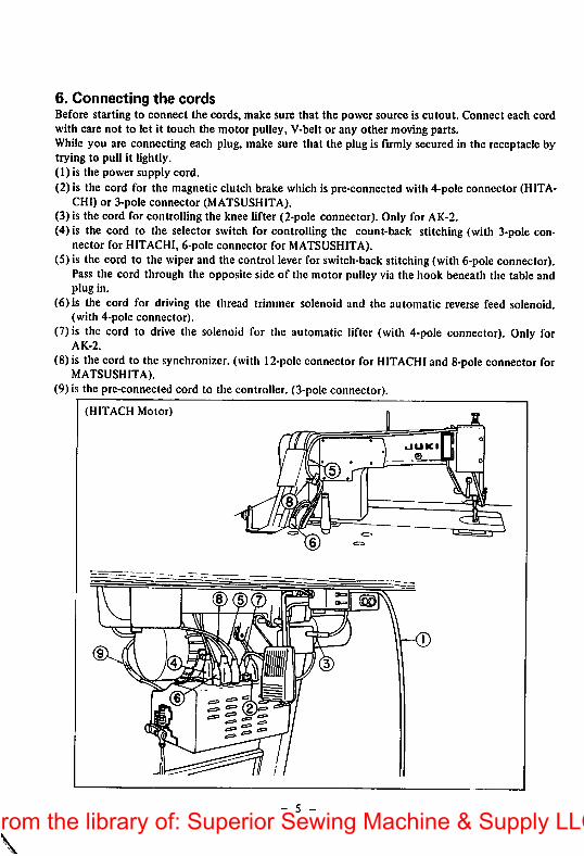
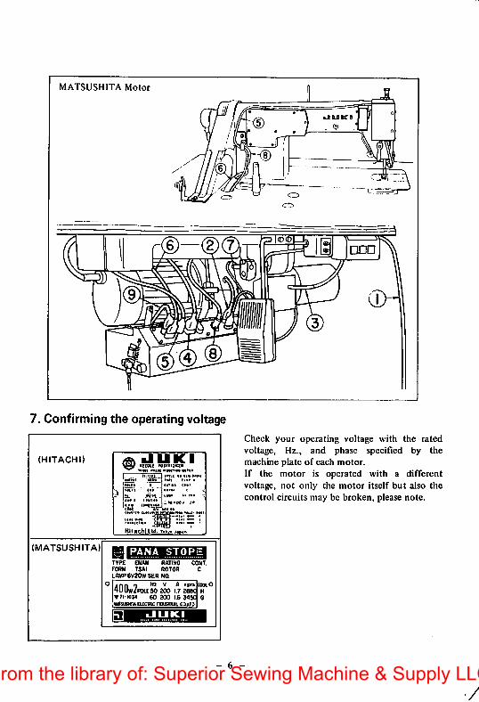
6. Connecting the cordsBefore starting to connect the cords, make sure that the power source is cutout. Connect each cordwith care not to let it touch the motor pulley, V-belt or any other moving parts.While you are connecting each plug, make sure that the plug is firmly secured in the receptacle bytrying to pull it lightly.(1) is the power supply cord.(2) is the cord for the magnetic clutch brake which is pre-connccted with 4-pole connector (HITA
CHI) or 3-pole connector (MATSUSHITA).(3) is the cord for controlling the knee lifter (2-pole connector). Only for AK-2.(4) is the cord to the selector switch for controlling the count-back stitching (with 3-pole con
nector for HITACHI, 6-pole connector for MATSUSHITA).(5) is the cord to the wiper and the control lever for switch-backstitching (with 6-pole connector).
Pass the cord through the opposite side of the motor pulley via the hook beneath the table andplug in.
(6) is the cord for driving the thread trimmer solenoid and the automatic reverse feed solenoid,(with 4-pole connector).
(7) is the cord to drive the solenoid for the automatic lifter (with 4-pole connector). Only forAK-2.
(8) is the cord to the synchronizer, (with 12-poIc connector for HITACHI and 8-poleconnector forMATSUSHITA).
(9) is the pre-connected cord to the controller. (3-pole connector).
(HITACH Motor)
- 5 -
From the library of: Superior Sewing Machine & Supply LLC
MATSUSHITA Motor
7. Confirming the operating voltage
(HITACHI)
(MATSUSHITA)
HlOchi.Ud. Totx j.Mi
PANA STORETYPE ENAM RATING CONT.FORM TSAI ROTOR CLAWP6V20WSER NO.jnn 0 V A rptnlcoocO4UUw/P0US0 200 17 2e8C H• n-i034 60 200 Ij6 34S0 GimsusTO Eiicwic rcusTittL cajjo
•JUKI
>JUKB
I®®
Clieck your operating voltage with the ratedvoltage, Hz., and phase specified by themachine plate of each motor.If the motor is operated with a differentvoltage, not only the motor itself but also thecontrol circuits may be broken, please note.
- 6 -
V
From the library of: Superior Sewing Machine & Supply LLC
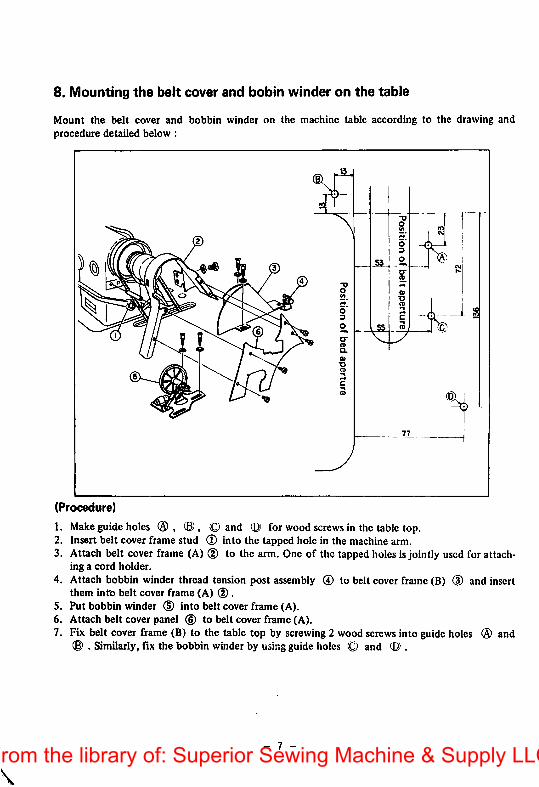
8. Mounting the belt cover and bobin winder on the table
Mount the belt cover and bobbin winder on the machine table according to the drawing andprocedure detailed below :
(Procedure)
1. Make guide holes ® ® , O and for wood screws in the table top.2. Insert belt cover frame stud (T) into the tapped hole in the machinearm.3. Attach belt cover frame (A) (D to the arm. One of the tappedholesisjointly usedfor attach
ing a cord holder.4. Attach bobbin winder thread tension post assembly ® to belt cover frame (B) (D and insert
them intb belt cover frame (A) (D.5. Put bobbin winder (D into belt cover frame (A).6. Attach belt cover panel (6) to belt cover frame (A).7. Fix belt cover frame (B) to the table top by screwing2 wood screwsinto guide holes ® and
(8) . Similarly, fix the bobbin winderby using guideholes (Q and .
- 7 -From the library of: Superior Sewing Machine & Supply LLC
II. HOW TO OPERATE THE MACHINE
1. General instruction
After the machine has been set up, bring down the needle by rotating the handwheel with yourhand, switch on the machine on trial and check that the motor rotates in the correct direction bywatching the rotation of the handwheel. The handwheel must rotate counterclockwise watchingfrom the open side of the handwheel.If you fail to judge it, you can repeat to switch on and off the machine until the direction is found,
o Clean up the installed machine.o Before starting to operate the machine, read through the separate INSTRUCTION BOOK,o Do not drive the machine before the oil reservoir is filled with the lubricating oil.o Do not replace the motor pulley with a larger one within first 1 month.
You may operate the machine at a higher speed depending on the necessity of sewing worksand operator's ability after the first 1 montli has passed,
o Keep away from the needle dropping place when you switch the machine on.o Do not fail to switch off the machine before you tilt the machine head backwards for lubrica
tion or cleaning or removing the V-belt.(If you mistakenly tread on the pedal, the motor puUey will be stopped immediately by meansof the built-in safety device in the case of "HITACHI" motor assembly.)
o Whan you move the machine to other places, do not hold it with the cover located on the rearof the handwheel.
o Even if you tread on the pedal backwards (heel-down) immediately after the machine is switched on or the thread is trimmed, the needle would not come down or the thread trimmer wouldnot work. Such thread trimming motion is performed only after the pedal has been trod onceforwards (toc-down).
- 8From the library of: Superior Sewing Machine & Supply LLC

Oil sight window
As long as the oil reservoir is properly filled upwith the lubricating oil, you will see the oilsplashing on the internal surface of the oU sightwindow while the machine is running. Since theoil sight window is used only to check if thelubricating oil is flowing or not, you do nothave to worry about the amount of oil appearing in it.
(Notes)
1. As soon as lubricating oil has become dirty, renew the oil.It can be drained by removing the oil drain cap screw.
2. In order to thoroughly lubricate the machine, provide it with an idle run for about 10 minutesat a sewing speed of 3,000 to 3,500 s.p.m. before using a newly installed machine or a machinewhich has not been operated for a long period of time.
2. Lubrication and amount of oil
HIGH markOil reservoir
LOW mark
Before driving the machine, fill the oil reservoirwith JUKI New Defrix Oil No. 1 up to "HIGH"level. Take care not to allow the oil level to
come down below the "LOW" mark duringoperation.
- 9 -From the library of: Superior Sewing Machine & Supply LLC

Oil adjustingpin
Mark
r\Oil amount
gets less
Crank
Mark
Crank
amount gets moreI I II
Adjustment of oil amount fed to the faceplate components-
When adjusting the amount of lubricating oilflowing into the face plate components such asthe thread take-up and needle bar crank,remove the face plate and the arm oil shield androtate the oil adjusting pin which is located onthe top end of the main shaft.To minimize the oil flow, bring the dot markon the adjusting pin close to the crank.To ma.\imize it, bring the dot mark to the farside of the crank.
(Note)
After this adjustment, let the machine run and confirm the result of adjustment.
Oil regulating valve
Adjustment of oil amount fed to the
sewing hook:
Adjust it by means of the oil adjusting screwwhich is located on the hook driving shaft frombushing. Amount of flowing oil is increased byturning clockwise and decreased by turningcounterclockwise.
More
3. Checking the pedal action
Firstly, check your machine without passing the threads.Switch on the machine, and the needle will be held at it's highest position without fail.Even the needle staying at a lower position will be brought up andheld at the highest positionby switching on the machine.
- 10 -From the library of: Superior Sewing Machine & Supply LLC
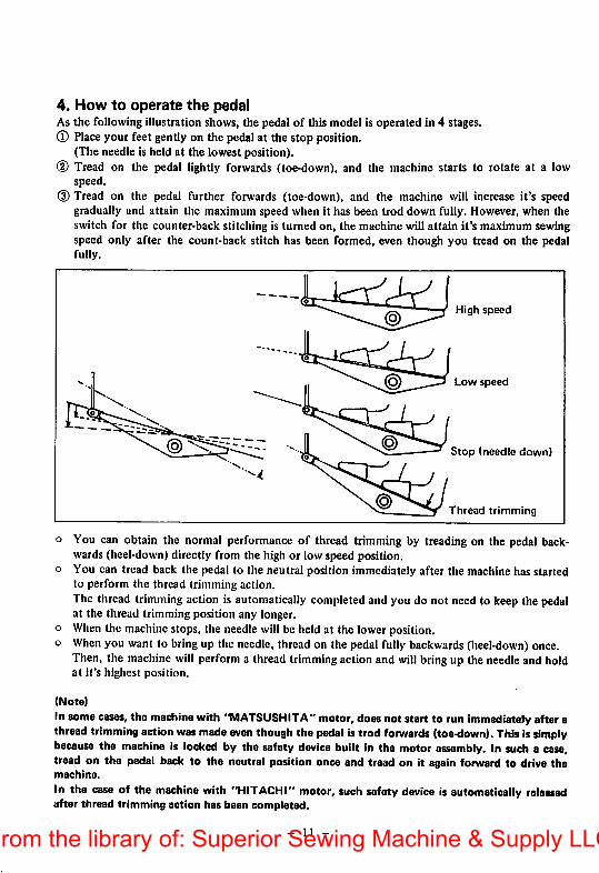
4. How to operate the pedalAs the following illustration shows, the pedal of this model is operated in 4 stages.® Place your feet gentlyon the pedalat the stop position.
(The needle is held at the lowest position).(D Tread on the pedal lightly forwards (toe-down), and the machine starts to rotate at a low
speed.(D Tread on the pedal further forwards (toe-down), and the machine will increase it's speed
gradually and attain the maximum speed when it has been trod down fully. However, when theswitch for the counter-back stitching is turned on, the machine will attain it's maximum sewingspeed only after the count-back stitch has been formed, even though you tread on the pedalfully.
High speed
Low speed
Stop (needle down)
Thread trimming
o You can obtain the normal performance of thread trimming by treading on the pedal backwards (heel-down) directly from the high or low speed position,
o You can tread back the pedal to the neutral position immediately after the machine has startedto perform the thread trimming action.The thread trimming action is automatically completed and you do not need to keep the pedalat the thread trimming position any longer,
o When the machine stops, the needle will be held at the lower position,o When you want to bringup the needle, thread on the pedal fully backwards (heel-down) once.
Then, the machine will perform a thread trimmingaction and willbring up the needleand holdat it's highest position.
(Note)
In some cases, the machine with "MATSUSHITA" motor, does not start to run immediately after athreadtrimming actionwas made even thoughthe pedal istrod forwards (toe-down). Thisissimplybecause the machine is locked by the safety device built in the motor assembly, in such a case,tread on the pedal back to the neutral position once and tread on it again forward to drive themachine.
In the case of the machine with "HITACHI" motor, such safetydevice is automatically releasedafter thread trimming action has been completed.
- 11 -From the library of: Superior Sewing Machine & Supply LLC
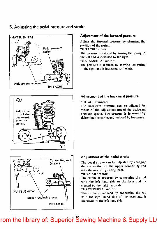
5. Adjusting the pedal pressure and stroke
(MATSUSHITA)
Adjustment grooves
Adjustmentnut of the
backwardpressure
spring.
C?
(MATSUSHITA)
Motor regulating lever
(HITACHI)
I Pedal pressure^spring
(HITACHI)
Connecting rod(u
Adjustment of the forward pressure
Adjust the forward pressure by changing theposition of the spring."HITACHI" motor:
The pressure is reduced by moving tiie spring tothe left and is increased to the right."MATSUSHITA" motor:
The pressure is reduced by moving the springto the right and is increased to the left.
Adjustment of the backward pressure
"HITACHI" motor;
The backward pressure can be adjusted bymeans of the adjustment nut of the backwardpressure spring. The pressure is increased bytightening the spring and reduced by loosening.
Adjustment of the pedal stroke
The pedal stroke can be adjusted by changingthe connection of the upper connecting rodwith the motor regulating lever."HITACHI" motor:
The stroke is reduced by connecting the rodwith the left hand side of the lever and in
creased by the right hand side."MATSUSHITA" motor:
The stroke is reduced by connecting the rodwith the right hand .side of the lever and isincreased by the left hand side.
- 12 -From the library of: Superior Sewing Machine & Supply LLC
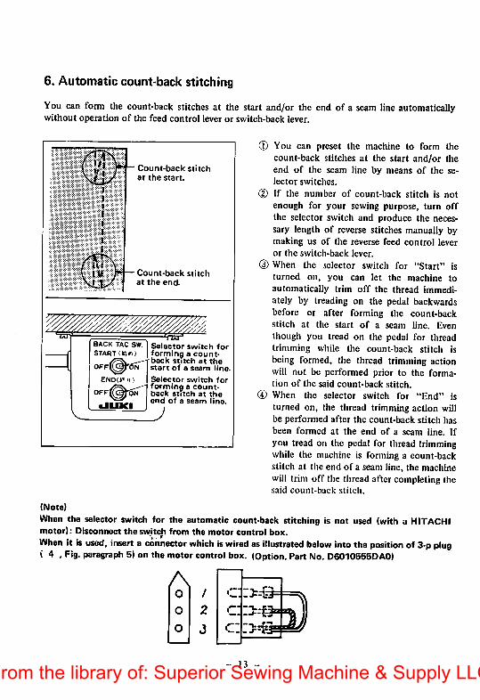
6. Automatic count-back stitching
You can form the count-back stitches at the start and/or the end of a seam line automaticallywithout operation of the feed control lever or switch-back lever.
Count-back stitchat the start.
Count-back stitchat the end.
BACK TAG SW.
START
0FF|̂ ^l6iAEND(»*') )
OFF^^-SiT•JUKI
Selector switch forforming a count-back stitch at thestart of a seam line.
Selector switch forforming a count-back stitch at theend of a seam line.
J
13
(T) You can preset the machine to form thecount-back stitches at the start and/or theend of the seam line by means of the selector switches.
(D If the number of count-back stitch is notenough for your sewing purpose, turn offthe selector switch and produce the necessary length of reverse stitches manually bymaking us of the reverse feed control leveror the switch-back lever.
(3) When the selector switch for "Start" isturned on, you can let the machine toautomatically trim off the thread immediately by treading on the pedal backwardsbefore or after forming the count-backstitch at the start of a seam line. Eventiiough you tread on the pedal for threadtrimming while the count-back stitch isbeing formed, the thread trimming actionwill not be performed prior to the formation of the said count-back stitch.
® When the selector switch for "End" isturned on, the thread trimming action willbe performed after the count-back stitch hasbeen formed at the end of a seam line. Ifyou tread on the pedal for thread trimmingwhile the machine is forming a count-backstitch at the end of a .seam line, the machinewill trim off the thread after completing thesaid count-back stitch.
(Note)
When the selector switch for the automatic count-back stitching is not used (with a HITACHImotor): Disconnect the swjtch from the motor control box.When it is used, insert a connector which iswired as illustrated below into the position of 3-pplug( 4 , Fig. paragraph 5) on the motorcontrolbox. (Option. Part No.D6010555DA0)
AO
o
o
From the library of: Superior Sewing Machine & Supply LLC
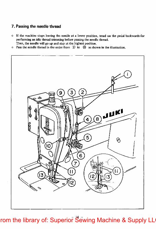
7. Passing the needle thread
o ir the machine stops leaving the needle at a lower position, tread on the pedal backwards forperforming an idle thread trimming before passing the needle thread.Then, the needle will go up and stay at the highest position,
o Pass the needle thread in the order from ® to ® as shown in the illustration.
I
- 14 -From the library of: Superior Sewing Machine & Supply LLC
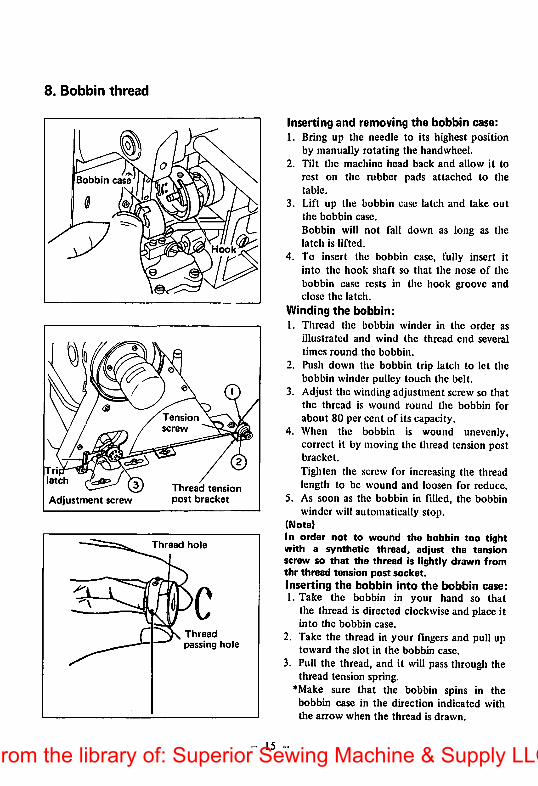
8. Bobbin thread
Bobbin case
Adjustment screw
Tensionscrew
Hook
Thread tensionpost bracket
—Thread hole
Threadpassing hole
- 15
Inserting and removing the bobbin case:1. Bring up the needle to its highest position
by manually rotating the handwheel.2. Tilt the machine head back and allow it to
rest on the rubber pads attached to thetable.
3. Lift up the bobbin case latch and take outthe bobbin case.
Bobbin will not fall down as long as thelatch is lifted.
4. To insert the bobbin case, fully insert itinto tiic hook shaft so that the nose of the
bobbin case rests in tlic hook groove andclose the latch.
Winding the bobbin:1. Thread the bobbin winder in the order as
illustrated and wind the thread end several
times round the bobbin.
2. Push down the bobbin trip latch to let thebobbin winder pulley touch the belt.
3. Adjust the winding adjustment screw so thatthe thread is wound round the bobbin for
about 80 per cent of its capacity.4. When the bobbin is wound unevenly,
correct it by moving the thread tension postbracket.
Tighten the screw for increasing the threadlength to be wound and loosen for reduce.
5. As soon as the bobbin in filled, the bobbinwinder will automatically stop.
(Note)In order not to wound the bobbin too tightwith a synthetic thread, adjust the tensionscrew so that the thread is lightly drawn fromthr thread tension post socket,inserting the bobbin into the bobbin case:1. Take the bobbin in your hand so that
the thread is directed clockwise and place itinto the bobbin case.
2. Take the thread in your fingers and pull uptoward the slot in the bobbin case.
3. Pull the thread, and it will pass through thethread tension spring.
""Make sure that the bobbin spins in thebobbin case in the direction indicated withthe arrow when the thread is drawn.
From the library of: Superior Sewing Machine & Supply LLC
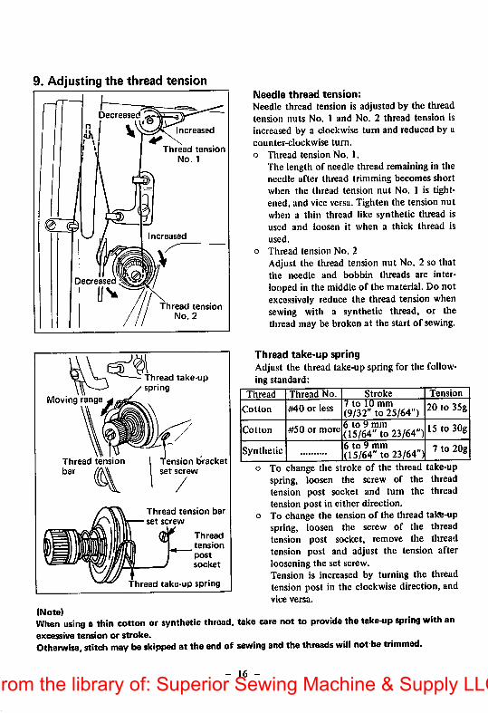
9. Adjusting the thread tension
Decreased
Decreased
Moving range
V\S—Increased
Thread tensionNo. 1
Thread tensionbar
Increased
Thread tensionNo. 2
thread take-upspring
Tension bracketset screw
Thread tension bar
set screw
Thread
tension
socket
Thread take-up spring
(Note)
When using a thin cotton or synthetic thread,excessive tension or stroke.
Otherwise, stitch may be skipped at the end of
Needle thread tension:Needle thread tension is adjusted by the threadtension nuts No. 1 and No, 2 thread tension isincreased by a clockwise turn and reduced by acounter-clockwise turn,
o Thread tension No. 1.
The length of needle thread remaining in theneedle after thread trimming becomes shortwhen the thread tension nut No. 1 is tightened, and vice versa. Tighten the tension nutwhen a thin thread like synthetic thread isused and loosen it when a thick thread isused.
o Thread tension No. 2
Adjust the thread tension nut No. 2 so thatthe needle and bobbin threads are inter-
looped in the middle of the material. Do notexcessively reduce the thread tension whensewing with a synthetic thread, or thethread may be broken at the start of sewing.
Thread take-up springAdjust the thread take-up spring for the following standard:
Thread Thread No. Stroke Tension
Cotton #40 or less7 to 10 mm(9/32" to 25/64")
20 to 35g
Cotton #50 or more6 to 9 mm(15/64" to 23/64") 15 to 30g
Synthetic6 to 9 mm(15/64" to 23/64")
7 to 20g
o To change the stroke of the thread take-upspring, loosen the screw of the threadtension post socket and turn the threadtension post in either direction,
o To change the tension of the thread tate-upspring, loosen the screw of the threadtension post socket, remove the threadtension post and adjust the tension afterloosening the set screw.Tension is increased by turning the threadtension post in the clockwise direction, andvice versa.
take care not to provide the take-up spring with an
sewing and the threads will not be trimmed.
- 16 -
From the library of: Superior Sewing Machine & Supply LLC
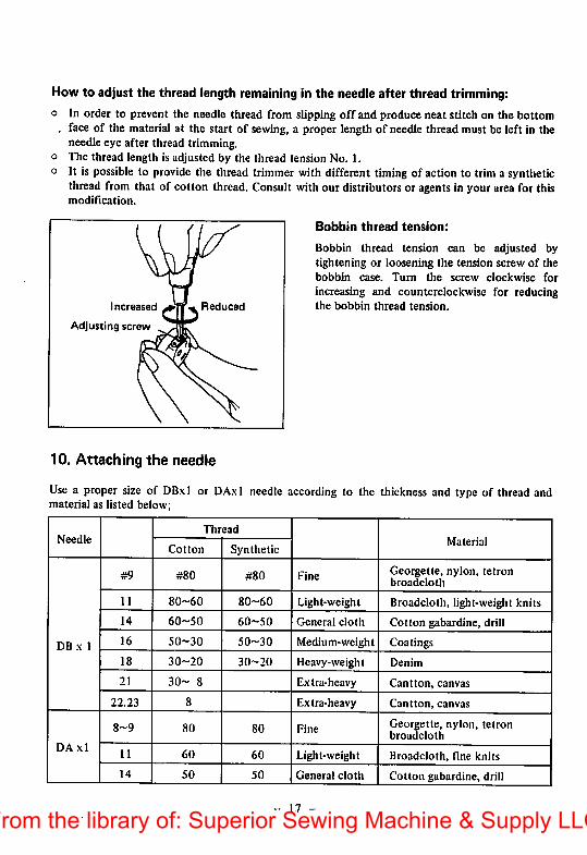
Howto adjust the thread length remaining in the needle after thread trimming:o In order to prevent the needle thread from slipping off and produce neat stitch on the bottom
. face of the material at the start of sewing, a proper length of needlethread must be left in theneedle eye after thread trimming.
o The thread length is adjusted by the thread tension No. 1.o It is possible to provide the thread trimmer with different timing of action to trim a synthetic
thread from that of cotton thread. Consult with our distributorsor agentsin your area for thismodification.
Increased
Adjusting screw
Reduced
10. Attaching the needle
Bobbin thread tension:
Bobbin thread tension can be adjusted bytightening or loosening the tension screw of thebobbin case. Turn the screw clockwise for
increasing and counterclockwise for reducingthe bobbin thread tension.
Use a proper size of DB,\1 or DAxl needle according to thematerial as listed below;
thickness and type of thread and
NeedleThread
MaterialCotlon Synthetic
DB X 1
#9 #80 #80 FineGeorgette, nylon, tetronbroadcloth
11 80-60 80-60 Light-weight Broadcloth, light-weight knits
14 60-50 60-50 General cloth Cotton gabardine, drill
16
01
o
50-30 Medium-weight Coatings
18 30-20 30-20 Heavy-weight Denim
21 30- 8 Extra-heavy Cantton, canvas
22.23 8 Extra-heavy Cantton, canvas
DA xl
8-9 80 80 FineGeorgette, nylon, tetronbroadcloth
11 60 60 Light-weight Broadcloth, fine knits
14 50 50 General cloth Cotton gabardine, drill
- 17 -
From the library of: Superior Sewing Machine & Supply LLC
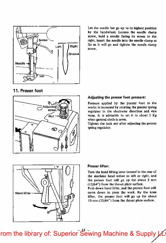
Screw
Needle
11. Presser foot
Adjusting!screw
Hand lifter
Groove
Let the needle bar go up to its highest positionby the handwheel. Loosen the needle clampscrew, hold a needle facing its recess to theright, insert the needle into the needle clamp asfar as it will go and tighten the needle clampscrew.
Adjusting the presser foot pressure:
Pressure applied by the presser foot to theworks is increased by rotating the presser springregulator in the clockwise direction and viceversa. It is advisable to set it to about 5 Kgwhen general cloth is sewn.Tighten the lock nut after adjusting the presserspring regulator.
Presser lifter:
Turn the hand lifting lever located in the rear ofthe machine head either to left or right, andthe presser foot will go up for about 5 mm(13/64") from the throat plate surface.Push down hand lifter, and the pre.sser foot willcome down to press the work. By the kneelifter, the presser foot will go up for about10 mm (25/64") from the throat plate surface.
- 18 -From the library of: Superior Sewing Machine & Supply LLC
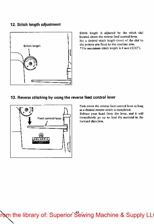
12. Stitch length adjustment
Stitch length
E
Stitch length is adjusted by the stitch diallocated above the reverse feed control lever.
Set a desired stitch length (mm) of the dial tothe pointer pin fi.xcd to the machine arm.*The ma.ximum stitch length is 4 mm (5/32").
13. Reverse stitching by using the reverse feed control lever
N
IFeed control lever
/
OOL-SBS-4
Push down the reverse feed control lever as longas a desired reverse stitch is completed.Release your hand from the lever, and it willimmediately go up to feed the material in theforward direction.
19 -From the library of: Superior Sewing Machine & Supply LLC
III. ADJUSTMENT
1. Feed mechanism
Set screw
n\Feed driveeccentric cam
w
Thrust collar \ II
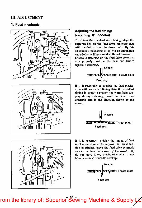
Adjusting the feed timing:(excepting DDL-555H-4):
To obtain the standard feed timing, align theengraved line on the feed drive eccentric camwith the dot mark on the thrust collar. By thisadjustment, puckering stitch will be eliminatedand stitches will have an ideal thread tension.
Loosen 2 setscrews on the feed drive eccentriccam properly position the cam and firmlytighten 2 setscrews.
Needle
mm mm( Throat plate
Feed dog
If it is preferable to provide the feed mechanism with an earlier timing than the standardtiming in order to prevent the work from slipping during stitching, move the feed driveeccentric cam in the direction shown by thearrow.
Needle
Throat plate
Feed dog
If it is necessary to delay the timing of feedmechanism in order to improve the thread tension in stitches, move the feed drive eccentriccam in the direction shown by the arrow. But,do not move it too much, otherwise it maybecome a cause of needle breakage.
Needle
Feed dog
Throat plate
- 20 -From the library of: Superior Sewing Machine & Supply LLC
Front up Standard Front down
DotL_^
Screw driver
Set screw
Feed driving fork
•
,^CIamp screw^
H ri"
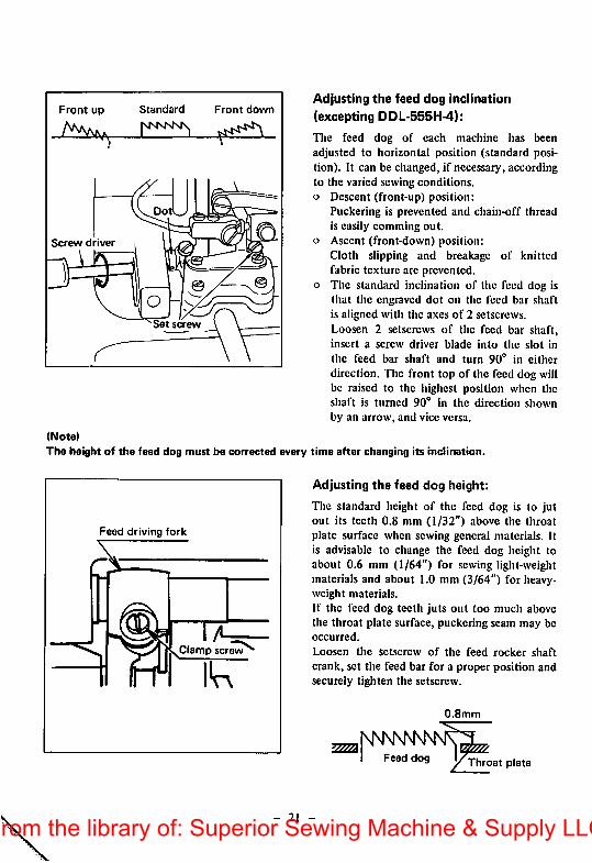
Adjusting the feed dog Inclination
(excepting DDL-555H-4):
The feed dog of each machine has beenadjusted to horizontal position (standard position). It can be changed, if necessary, accordingto the varied sewing conditions,o Descent (front-up) position:
Puckering is prevented and chain-off threadis easily comming out.
o Ascent (front-down) position:Cloth slipping and breakage of knittedfabric texture arc prevented,
o The standard inclination of the feed dog isthat the engraved dot on the feed bar shaftis aligned with the axes of 2 setscrews.Loosen 2 setscrews of the feed bar shaft,insert a screw driver blade into the slot in
the feed bar shaft and turn 90" in eitherdirection. The front top of the feed dog willbe raised to the highest position when theshaft is turned 90" in the direction shownby an arrow, and vice versa.
(Note)
The height of the feed dog must be corrected every time after changing its inclination.
Adjusting the feed dog height:
The standard height of the feed dog is to Jutout its teeth 0.8 mm (1/32") above the throatplate surface when sewing general materials. Itis advisable to change the feed dog height toabout 0.6 mm (1/64") for sewing light-weightmaterials and about 1.0 mm (3/64") for heavyweight materials.If the feed dog teeth Juts out too much abovethe throat plate surface, puckering seam may beoccurred.
Loosen the setscrew of the feed rocker shaft
crank, set the feed bar for a proper position andsecurely tighten the setscrew.
0.8mm
Feed dog j/^cThroat plate
- 21 -From the library of: Superior Sewing Machine & Supply LLC
2. Replacing the sewing hook
qpt «rrpw Bobbincase positioningbet screw f , ,.
Hook
Set screw
Feed base
lT0
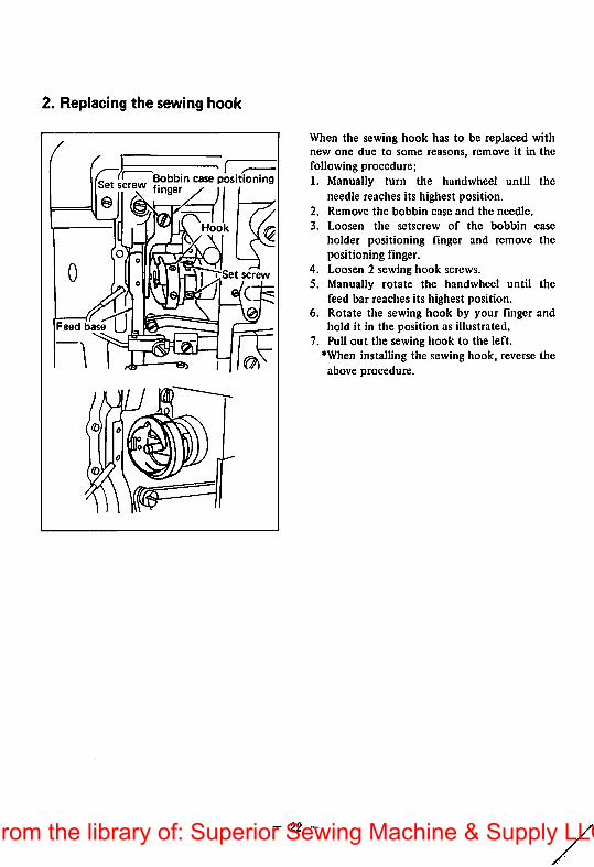
When the sewing hook has to be replaced withnew one due to some reasons, remove it in thefollowing procedure;1. Manually turn the handwheel until the
needle reaches its highest position.2. Remove the bobbin case and the needle.
3. Loosen the setscrew of the bobbin case
holder positioning finger and remove thepositioning finger.
4. Loosen 2 sewing hook screws.5. Manually rotate the handwheel until the
feed bar reaches its highest position.6. Rotate the sewing hook by your finger and
hold it in the position as illustrated.7. Pull out the sewing hook to the left.
"'When installing the sewing hook, reverse theabove procedure.
22From the library of: Superior Sewing Machine & Supply LLC
3. Sewing hook position related to the needle
Needle
Blade point ofthe sewinghook
Clamp screw
^ Needle bar^ lower bushing
Upper^ indicating line
• Lower indicatingline
>Needle bar
Lower
indicating line
(At this position, matchthe blade point of the
^ sewing hook withthe center of
the needle)
Sewing hook
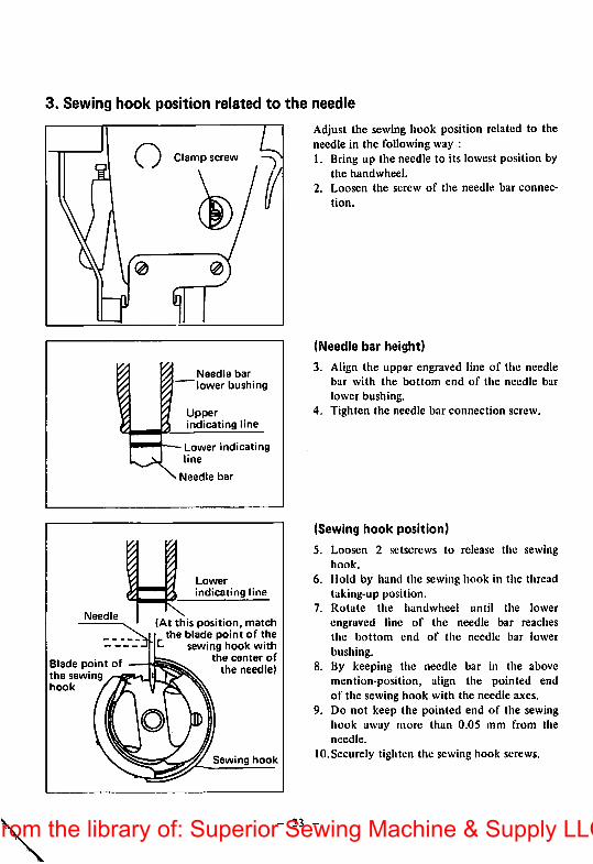
Adjust the sewing hook position related to theneedle in the following way :1. Bring up the needle to its lowest position by
the handwheel.
2. Loosen the screw of the needle bar connec
tion.
(Needle bar height)
3
4.
Align the upper engraved line of the needlebar with the bottom end of the needle bar
lower bushing.Tighten the needle bar connection screw.
(Sewing hook position)
5. Loosen 2 .setscrews to release the sewinghook.
6. Mold by hand the sewing hook in the threadtaking-up position.
7. Rotate the handwheel until the lower
engraved line of the needle bar reachesthe bottom end of the needle bar lower
bushing.8. By keeping the needle bar in the above
mention-position, align the pointed endof the sewing hook with the needle axes.
9. Do not keep the pointed end of the sewingliook away more than O.OS mm from theneedle.
10. Securely tighten the sewing hook screws.
- 23 -From the library of: Superior Sewing Machine & Supply LLC

4. Height of the presser bar
Presser bar clamp ^screw
When correcting the height or angle of thepresser bar after replacing the presser foot orsome other reasons, remove the rubber plugfrom the face plate and loosen the screw of thepresser bar guide bracket by inserting a screwdriver through the opening in the face plate.Securely tighten the screw after adjusting thepresser bar height.
How to use the pressure reducer:
It is possible to sliglitly reduce the pressureapplied by the presser foot when the pressurereducer is used. This system is quite usefulwhen a floating presser foot is used or a workhas to be turned round at an end of a seam to
continue to stitch in a different direction.
Loosen the lock nut (g) and properly tightenthe adjusting screw (g) , and the presser footwill be raised up from the throat plate surface,so that the material in the machine can be
easily turned round the needle.
- 24 -From the library of: Superior Sewing Machine & Supply LLC
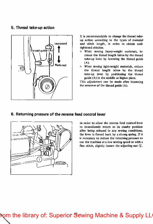
5. Thread take-up action
Increased
Thread guide (A)
Reduced
It is recommendable to change the thread take-up action according to the types of materialand stitch length, in order to obtain well-tightened stitches.o When sewing heavy-weight materials, in
crease the thread length taken by the threadtake-up lever by lowering the thread guide(A).
o When sewing light-weight materials, reducethe tliread length taken by the threadtake-up lever by positioning the threadguide (A) in the middle or higher place.
This adjustment can be made after looseningthe setscrew of the thread guide (A).
6. Returning pressure of the reverse feed control lever
In order to allow the reverse feed control lever
to immediately return to its stanby positionafter being released in any sewing conditions,the lever is forced back by a strong spring. If itis necessary to reduce the returning pressure touse the machine at a low sewing speed or with afine stitch, slightly loosen the adjusting nut ®.
- 25 -From the library of: Superior Sewing Machine & Supply LLC
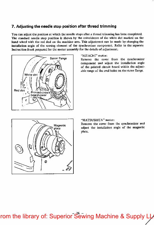
7. Adjusting the needle stop position after thread trimming
You can adjust Hie position at which the needle stops after a thread trimming has been completed.The standard needle stop position is shown by the coincidence of the white dot marked on thehand wheel with the red dod on the machine arm. This adjustment can be made by changing theinstallation angle of the sensing element of the synchronizer component. Refer to the separateInstruction Book prepared for the motor assembly for the details of adjustment.
"HITACHI" motor;
Remove the cover from the synchronizercomponent and adjust the installation angleof the printed circuit board within the adjustable range of the oval holes on the stater flange.
White
Red dotPrinted circuitboard cover
Stater flange\
Magnetic
"MATSUSHITA" motor:
Remove the cover from the synchronizer andadjust the installation angle of the magneticplate.
- 26 -From the library of: Superior Sewing Machine & Supply LLC

8. Sharpening the counter knife
Horn this corner
Sharpen this face-./ \
Blade tip"""^^ y^
N
1 /
"* Counter knife
Moving knife
Needle center- a
Shorter
I The remaining lengthof the thread becomes;
- 27 -
As soon as you noticed that the threadtrimmer has become dull, resharpen thecounter knife immediately.Put the resharpened counter knife back toit's correct position shown by the followingillustration.
If you move the installing position of thecounter knife to the right from the standardposition, the length of thread remaining onthe needle after trimming becomes longerand vice versa.
I .omm
Bottom face ofthe throat plate
— Stepped partof the bed
Counter knife
Longer*
From the library of: Superior Sewing Machine & Supply LLC
IV. HOW TO ADJUST THE WIPER
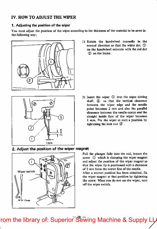
1. Adjusting the position of the wiper
You must adjust the position of the wiper according to the thickness of the material to be sewn inthe following way;
1) Rotate the handwheel manually in thenormal direction so that the white dot (Don the handwheel coincide with the red dot
(D on the frame.r
2) Insert the wiper (D into the wiper drivingshaft (2) so that the vertical clearancebetween the wiper edge and the needlepoint becomes 2 mm and also the parallelclearance between the needle center and the
straight inside face of the wiper becomes1 mm. Fix the wiper at such a position bytightening the lock nut (3) .
2. Adjust the position of the wiper magnetPull the plunger fully into the coil, loosen thescrew 0 which is clamping the wiper magnetand adjust the position of the wiper magnet sothat the wiper tip is positioned with a clearanceof 2 mm from the center line of the needle.
After a correct position has been obtained, fixthe wiper magnet at that position by tighteningthe screw. When you do not use the wiper, turnoff the wiper switch.
Wiper switch
28 —From the library of: Superior Sewing Machine & Supply LLC
V.HOW TO USE AND ADJUST THE SWITCH-BACK BUTTON
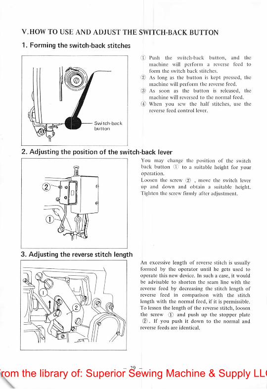
1. Forming the switch-back stitches
Swi tch-backbutton
Push tiie switch-back button, and the
machine will perform a reverse feed toform the switch back stitches.
As long as the button is kept pressed, themachine will perform the reverse feed.As soon as the button is released, the
machine will reversed to the normal feed.
When you sew the half stitches, use the
reverse feed control lever.
2. Adjusting the position of the switch-back leverI You may change the position of the switch
back button C1 to a suitable height for youroperation.
Loosen the screw (2) , move the switch lever
ij f up and down and obtain a suitable height.DK Tighten the screw firmly after adjustment.
3. Adjusting the reverse stitch lengthAn excessive length of reverse stitch is usuallyformed by the operator until he gets used tooperate this new device. In such a case, it wouldbe advisable to shorten the seam line with the
reverse feed by decreasing the stitch length ofreverse feed in comparison with the stitchlength with the normal feed, if it is permissible.To lessen the length of the reverse stitch, loosen
the screw (I) and push up the stopper plated). If you push it down to the normal and
reverse feeds are identical.
- 29 -From the library of: Superior Sewing Machine & Supply LLC
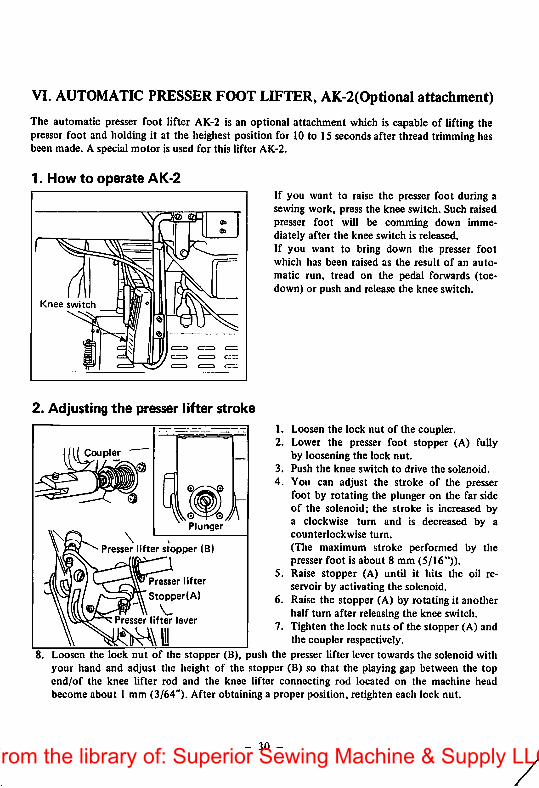
VI. AUTOMATIC PRESSER FOOT LIFTER, AK-2(Optional attachment)
The automatic presser foot lifter AK-2 is an optional attachment which is capable of lifting thepresser foot and holding it at the heighest position for 10 to 15 secondsafter thread trimming hasbeen made. A special motor is used for this lifter AK-2.
1. How to operate AK-2
Knee switch
If you want to raise the presser foot during asewing work, press the knee switch. Such raisedpresser foot will be comming down immediately after the knee switch is released.If you want to bring down the presser footwhich has been raised as the result of an auto
matic run, tread on the pedal forwards (toe-down) or push and release the knee switch.
2. Adjusting the presser lifter stroke
1. Loosen the lock nut of the coupler.2. Lower the presser foot stopper (A) fully
by loosening the lock nut.3. Push the knee switch to drive the solenoid.4. You can adjust the stroke of the presser
foot by rotating the plunger on the far sideof the solenoid; the stroke is increased bya clockwise turn and is decreased by acounterlockwise turn.
(The maximum stroke performed by thepresser foot is about 8 mm (5/16")).
5. Raise stopper (A) until it hits the oil reservoir by activating the solenoid.
6. Raise the stopper (A) by rotating it anotherhalf turn after releasing the knee switch.
7. Tighten the lock nuts of the stopper (A) andthe coupler respectively.
8. Loosen the lock nut of the stopper (B), push the presser lifter lever towards the solenoid withyour hand and adjust the height of the stopper (B) so that the playing gap between the topend/of the knee lifter rod and the knee lifter connecting rod located on the machine headbecome about 1 mm (3/64"). After obtaining a proper position, retighten each lock nut.
Coupler
Plunger
Presser lifter stopper (B)
Presser lifter
Stopper(A)
VPresser lifter lever
tM\li
- 30 -From the library of: Superior Sewing Machine & Supply LLC
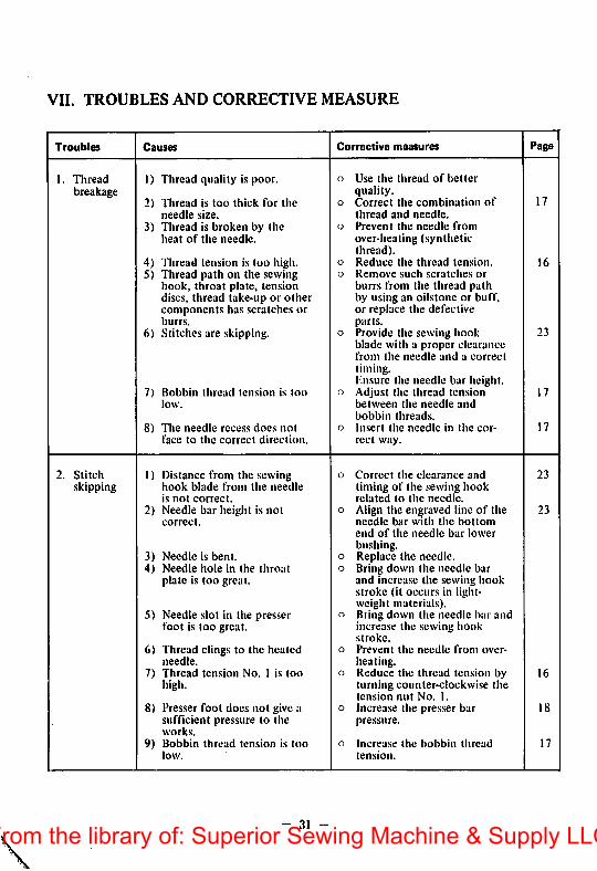
VII. TROUBLES AND CORRECTIVE MEASURE
Troubles Causes Corrective measures Page
1. Thread 1) Thread quality is poor. o Use the thread of better
breakage quality.172) Thread is too thick for the o Correct the combination of
needle size. thread and needle.
3) Thread is broken by the o Prevent the needle from
heat of the needle. over-heating (syntheticthread).
4) Thread tension is too high. o Reduce the thread tension. 165) Thread path on the sewing o Remove such scratches or
hook, throat plate, tension burrs from the thread pathdiscs, thread take-up or other by using an oilstone or buff.components has scratches or or replace the defectiveburrs. parts.
6) Stitches are skipping. o Provide the sewing hook 23blade with a proper clearancefrom the needle and a correcttiming.Hn.sure the needle bar height.
7) Bobbin thread tension is too o Adjust the thread tension 17low. between the needle and
bobbin threads.8) The needle recess does not o Insert the needle in the cor 17
face to the correct direction. rect way.
2. Stitch 1) Distance from the .sewing o Correct the clearance and 23skipping hook blade from the needle timing of the .sewing hook
is not correct. related to the needle.2) Needle bar height is not o Align the engraved line of the 23
correct. needle bar with the bottomend of the needle bar lowerbushing.
3) Needle is bent. o Replace the needle.4) Needle hole in the throat o Bring down the needle bar
plate is too great. and increa.sc the sewing hookstroke (it occurs in lightweight materials).
5) Needle slot in the presser n Bring down the needle bar andfoot is too great. increase the .sewing hook
stroke.6) Thread clings to the heated o Prevent the needle from over
needle. heating.7) Thread tension No. 1 is too o Reduce the thread ten.sion by 16
high. turning counter-clockwi.se thetension nut No. 1.
8) Presser foot does not give a o Increase the presser bar 18sufficient pressure to the pressure.works.
9) Bobbin thread tension is too o Increa.se the bobbin thread 17low. tension.
- 31 -From the library of: Superior Sewing Machine & Supply LLC
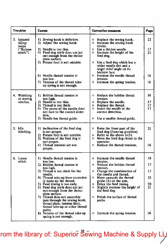
Troubles Causes Corrective measures Page
3. Isolated I) Sewing hook is defective. 0 Replace the sewing hook. 22idling- 2) Adjust the sewing hook. o Increase the sewing hookloops stroke.("Baloon- 3) Needle is too thin. o Use a thicker needle. 17stitch") 4) Feed dog teeth does not Jut o Increase the height of the 21
out enough from the throat feed dog.plate surface.
5) Presser foot is not suitable. o Use a feed dog which has awider needle slot and alarger relief angle on itsbottom face.
6) Needle thread tension is o Increase the needle thread 16too low. tension.
7) Tension of the thread take- o Increa.se the spring tension. 16up spring is not enough.
4, Wobbling 1) Bobbin thread tension is o Reduce the bobbin thread 16or waving too high. tension.stitches. 2) Needle is too thin. o Replace the needle. 17
3) Thread is too thick. o Replace the thread. 174) The recess of the needle does o Insert the needle in the 17
not face to the correct direc correct direction.tion.
5) Needle bar thread guide. o Use a .smaller thread guide.
S. Idle 1) Inclination of the feed dog o Raise the front part of the 21stitching. is not proper. feed dog (front-up position).
2) Presser foot is not suitable. o Refer to the above 3-(5).3) Position of the feed dog is o Move the feed dog closer to the
not proper. operator.4) Thread tensions are not o Reduce the thread tensions. 16
proper.
6. Loose 1) Needle thread tension is o Increase the needle thread 16stitch. too low. tension.
2) Bobbin thread tension is o Reduce the bobbin thread 17too high. tension.
3) Thread is too thick for the o Change the combination of 17needle. the needle and thread.
4) Thread take-up lever excessive o Move upwards the thread 25ly takes up the thread. guide (A) on the arm.
5) Feed timing is too early. o Delay the feed timing. 206) Feed dog teeth does not jut o Slightly increase the height of 21
out enough from the throat the feed dog.plate surface.
7) Thread does not smoothly o Polish the surface of threadpass through the sewing hook, paths.throat plate, tension discs.thread take-up or other threadpaths.
o Increase the spring tension. 168) Tension of the thread take-upspring is not enough.
- 32 -From the library of: Superior Sewing Machine & Supply LLC
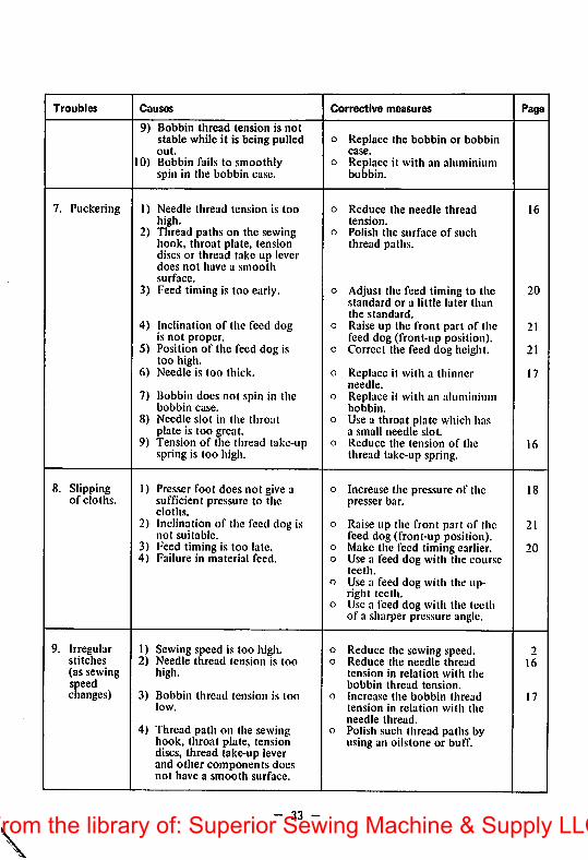
Troubles Causes Corrective measures Page
9) Bobbin thread tension is notstable while it is being pulled o Replace the bobbin or bobbinout. case.
10) Bobbin fails to smoothly o Replace it with an aluminiumspin in the bobbin case. bobbin.
7. Puckering 1) Needle thread tension is too o Reduce the needle thread 16high. tension.
2) Tliread paths on the sewing o Polish the surface of suchhook, throat plate, tension thread paths.discs or thread take up leverdoes not have a smoothsurface.
3) Feed timing is too early. o Adjust the feed timing to the 20standard or a little later thanthe standard.
4) Inclination of the feed dog o Raise up the front part of the 21is not proper. feed dog (front-up position).
5) Position of the feed dog is o Correct the feed dog height. 21too high.
6) Needle is too thick. 0 Replace it with a thinner 17needle.
7) Bobbin does not spin in the o Replace it with an aluminiumbobbin case. bobbin.
8) Needle slot in the throat o Use a throat plate which hasplate is too great. a small needle slot.
9) Tension of the thread take-up o Reduce the tension of the 16spring is too high. thread take-up spring.
8. Slipping 1) Presser foot does not give a o Increase the pressure of the 18of cloths. sufficient pressure to the presser bar.
cloths.2) Inclination of the feed dog is o Raise up the front part of the 21
not suitable. feed dog (front-up position).3) Feed timing is too late. o Make the feed timing earlier. 204) Failure in material feed. o Use a feed dog with the course
teeth.o Use a feed dog with the up
right teeth.o Use a feed dog with the teeth
of a sharper pressure angle.
9. Irregular 1) Sewing speed is too high. o Reduce the sewing speed. 2stitches 2) Needle thread tension is too o Reduce the needle thread 16(as sewing high. tension in relation with thespeed bobbin thread tension.changes) 3) Bobbin thread tension is too o Increase the bobbin thread 17
low. tension in relation with theneedle thread.
4) Thread path on the sewing o Polish such thread paths byhook, throat plate, tension using an oilstone or buff.discs, thread take-up leverand other components doesnot have a smooth surface.
33 -From the library of: Superior Sewing Machine & Supply LLC
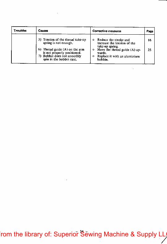
Troubles Causes Corrective measures Page
5) Tension of the thread take-upspring is not enough.
6) Thread guide (A) on the armis not properly positioned.
7) Bobbin docs not smoothlyspin in the bobbin case.
o Reduce the stroke andincrease the tension of thetake-up spring,
o Move the thread guide (A) upwards.
o Replace it with an aluminiumbobbin.
16
25
- 34 -
yFrom the library of: Superior Sewing Machine & Supply LLC
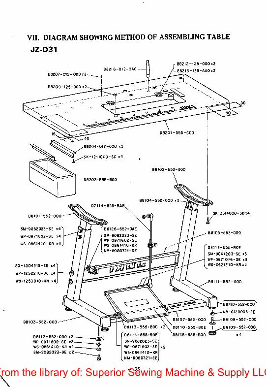
VII. DIAGRAM SHOWING METHOD OF ASSEMBLING TABLE
JZ-D31
08207-012-000x2
88209-125-000 x2
40
88204-012-000 x2
B8216-O12-0A0
88212-125-000 x2
B8213-125-AA0x2
D820I-555-C00
SK-1211000-SC x4
88101-552-000
SM-9082023-SE x4
WP-0871602-SE x4
WS-08614t0-KR x4
S0-1204215-SE x4l
WP-1252210-SC x4
WS-1253010-KN x4
88103-552-000
88112-552-000 x2
WP-0871602-SE x2
WS-08614I0-KR x2
SM-9082023-SE x2
88102-552-000
D8203-555-B00
88104-552-000 x2
D7114-555-BAB
88126-552
SM-9082023-SE
WP-0871602-SE
WS-0861410-KR
1 NM-6080721-SE
08113-555-800 x2
D8II4-555-80E
SM-9082023-SE
WP-0871602-SE
WS-0861410-KR
MM-6080721-SE
35 -
08115-555-800
SK-3514000-SDx4
B8105-552-000
D8112-555-80E
SM-9061203-SE x3
WP-0671016-SE x3
WS-0621210-KR x3
88111-552-000
88107-552-000 E 88108-552-000
D8110-555-80E I ^88109-552-000
88110-652-000
NM-6120003-SE
From the library of: Superior Sewing Machine & Supply LLC
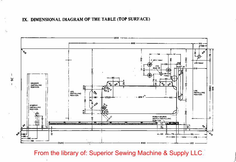
IX. DIMENSIONAL DIAGRAM OF THE TABLE (TOP SURFACE)
-40-'-50
106
DRAWER
INSTALLINGmiTION
STOPPERINSTALLINGPOSITION
LifU
•(525J-
LEG
INSTALLINGPOSlTiON
2
t—80
"il.s
3-^6 S (holetl
H—100- Cf •
'tX^35£asIhoio) •«. ^
sLTzfoi:'is 1^%
POWER SOURCE
SWITCH installingPOSITION \
jiTTfTr
-76-
-tl5-
-90-rSoH
♦18 Ihol*il
fzio
LEG
INSTALLINGPOSITION
From the library of: Superior Sewing Machine & Supply LLC
TOKYO JUKI
TOKYO JUKI INDUSTRIAL CO.. LTD.Head Office & Plant: 2-1, 8-chome, Kokuryo-cho, Chofu-shi, Tokyo, JapanBusiness Office: 23-3, Kabuki-cho 1-chome, Shinjuku-ku, Tokyo 16Q, JapanCable: JUKI TOKYO Telex: 22967; 232-2301 '
>. -ip
I
hfedinTapan(T)From the library of: Superior Sewing Machine & Supply LLC