Journal-Of-The-AIEE-1926-11.pdf - World Radio History
206
-11-112_17_177PLILT=L_FLIT_F=LJTIPL.P11-21-="r37.171-1 ra ra NOVEMBER 1926 F r` ®IDF FJ r` F F PUBLISHED MONTHLY BY THE r` AMERICAN INSTITUTE OF ELECTRICAL ENGINEERS 33 -WEST 39TH ST. NEW YORK CITY ._r_rLr_p_r,r-Lni_riu-LriLi-Lrarlp,rara-z_rosz_r_rer azra. J Jr. URN/XL OF THE
-
Upload
khangminh22 -
Category
Documents
-
view
0 -
download
0
Transcript of Journal-Of-The-AIEE-1926-11.pdf - World Radio History

-11-112_17_177PLILT=L_FLIT_F=LJTIPL.P11-21-="r37.171-1
ra
ra
NOVEMBER 1926
F
r`
®IDF
FJ
r`
F
F
PUBLISHED MONTHLY BY THE r`AMERICAN INSTITUTE OF ELECTRICAL ENGINEERS33 -WEST 39TH ST. NEW YORK CITY._r_rLr_p_r,r-Lni_riu-LriLi-Lrarlp,rara-z_rosz_r_rer azra. J
Jr. URN/XLOF THE

American Institute of Electrical Engineers
COMING MEETINGS
New York Regional Meeting, New York, N. 'i., No \ .1 I
Winter Convention, New York, N. Y., Feb. 7-10
MEETINGS OF OTHER SOCIETIES
American Welding Society, Buffalo, N. Y., Nov. 16-19
American Physical Society, Chicago, III., Nov. 26-27
The American Society of Mechanical Engineeers, New York, N. Y., Dec. 6-9
First National Exposition of Power and Mechanical Engineering, Grand CentralPalace, New York, N. Y., Dec. 6-11

American
JOURNAL
InstituteOF
ofTHE
Electrical EngineersPUBLISHED MONTHLY BY THE AMERICAN INSTITUTE OF ELECTRICAL ENGINEERS
33 West 39th Street, New York
Subscription. $10.00 per year to United States, Mexico, Cuba, Porto Rico, Hawaii and the Phillipines, $10.50to Canada and $11.00 to all other Countries. Single copies $1.00.
Entered as matter of the second class at the Post Office, New York, N. Y., May 10, 1905, under the Act of Congress, March 3, 1879.Acceptance for mailing at special rate of postage provided for in Section 1103, Act of October 3. 1917, authorized on August 3, 1918.
Vol. XLV NOVEMBER, 1926 Number 11
TABLE OF CONTENTSPapers, Discussions, Reports, Etc.
Nbtes and Announcements 1059 A New Cathode -Ray Tube 1143Transmission Features of Transcontinental Telephony, Unbalanced Conductor Tensions, by E. S. Healy and A. J.
by H. H. Nance and 0. B. Jacobs 1061 Wright 1144Surface Heat Transfer in Electric Machines with Forced
Air Flow (Abridged), by G. E. Luke 1070Variable -Voltage Equipment for Electric Power Shovels,
by R. W. McNeill 1151Some Graphical Solutions of A -C. Circuits Founded Upon Discussion at Midwinter Convention
. Non -Euclidian Geometry, by F. W. Lee 1078 Experimental Drmination of Losses in AlternatorsStandards for Measuring the Power Factor of Dielectrics (Roth) 1155
at High Voltage and Low Frequency, by Harvey L. Discussion at Madison MeetingCurtis 1084 The Quality Rating of High -Tension Cable with Im-Establishment of Radio Standards of Frequency by the pregnated Paper Insulation (Roper andUse of a Harmonic Amplifier 1086 Halperin) 1157
Mercury Arc Rectifiers, by D. C. Prince 1087 Papers on Rural Electrification (Neff and Post) .... 1166Multiplex Windings for D -C. Machines, by Carl C. Nelson 1094 Cooperation Between the Colleges and the IndustriesElectric Welds for Building Construction 1097 in Research (Wickenden, Potter, Bailey,New Copper Beds Discovered in Canada 1097 Bennett) 1171Report of Committee on Protective Devices 1098 Discussion at Annual ConventionElectric Cars for Steam Railroads 1114 Remotely -Controlled Substations (Blackwood) 1174Seminars for Practising Engineers 1114Report of Committee on Production and Application,
General Theory of the Auto -Transformer (Upson) .. 1175Production and Application of Light (Millar) 1176
of Light 1115 The High -Speed Circuit Breaker in Railway FeederFire Protection of Water -Wheel Type Generators, by J. Networks (McNairy) 1176
Allen Johnson and E. J. Burnham 1121 Mercury Arc Rectifiers (Prince) 1176Report of Committee on Power Generation 1130 Multiplex Windings for D -C. Machines (Nelson) ... 1178Why Good Headlighting is Difficult 1135 Report of Standards Committee (Osborne) 1181The Space Charge that Surrounds a Conductor in Corona Vibration Recorder (Mershon) 1181
at 60 Cycles, by Joseph S. Carroll and Harris J. Ryan 1136 England Has All -Electric Village 1182
Institute and Related ActivitiesNew York Regional Meeting 1183 History of Engineering 1187Award of John Fritz Medal for 1927 1184A. I. E. E. Directors' Meeting 1185 Personal Mention 1187Future Section Meetings 1185 Behind the Pyramids 1188New York Section Meeting 1185 Obituary 11882,000,000 -Volt Laboratory at Stanford University 1186Charles M. Schwab, President -Elect A. S. M. E. 1186 Addresses Wanted 1188Use of Safety Codes 1186 Engineering Societies Library 1189University of Pennsylvania Placement Bureau 1186 Past Sections and Branch Meetings 1191Tests of Welded Rail Joints 1186 Engineering Societies Employment ServiceEngineering Foundation Positions Open 1192Detroit Honors Engineering Foundation 1186 Men Available 1192New Offer for Muscle Shoals 1187 Membership -Applications, Elections and Transfers 1193American Engineering Council
Administrative Board Meets at Cornell 1187Participation in Highway Safety Conference 1187Officers of A. I. E. E. 1197List of Sections and Branches 1197Proposal for New Patent Office Building 1187 Digest and Current Industrial News 1198
A REQUEST FOR CHANGE OF ADDRESS must be received at Institute headquarters at least ten days before the date of issuewith which it is to take effect. Duplicate copies cannot be sent without charge to replace those issues undelivered through failure tosend such advance notice. With your new address be sure to mention the old one, indicating also any change in business connections.
Copyright 1926. By A. I. E. E.Printed In U. S. A.
Permission is given to reprint any article after its date of publication, provided proper credit is given.

Current Electrical Articles Publishedby Other Societies
Journal of Franklin Institute, September 1926
Inductance of Overhead Transmission Lines with Unequal Spacing of Wires,by A. Still
National Electric Light Ass'n. Bulletin, September 1926
A Proposed Set of Voltage Standards for A -C. Electrical Systems and Equip-ment, by the Electrical Apparatus Committee
Electric Power in Agriculture, by L. R. Nash
Rural Electrification and the Canadian Hydro, by E. A. Stewart
Safety Precautions in a 150,000-H. P. Hydroelectric Station, by R. D. Shaub

Journal of the A. I. E. E.Devoted to the advancement of the theory and practise of electrical engineering and the allied arts and sciences
Vol. XLV NOVEMBER, 1926 Number 11
Student Activitiesin the A. L E. E.
The prospects for better and more effective work bythe Student Branches have been greatly increased dur-ing the past year by the appointment of faculty mem-bers as official Counselors, authorized by the Board ofDirectors a year ago. The Counselors, /Tow eighty-seven in number, are ex -officio members of the StudentBranches Committee and as a consequence the workduring the year has centered chiefly on providingmachinery for coordinating the efforts of the enlargedmembership.
In general the plan in process of development may beoutlined as follows:
1. A committee of Student Activities consisting ofthe Counselors, District Vice-president and Secretaryto be organized in ;each District, with one of the Coun-selors as Chairman; the principal function of these com-mittees will be to coordinate student activities in theirrespective districts.
2. That each District Student Activities Committeeselect each year one of its Counselor members asofficial delegate to an annual meeting of the StudentBranches Committee during the Summer Conventionof the Institute.
As part of the above outlined plan for the purpose offostering and developing branch activity, the Sectionsdelegates conference in joint meeting with the Com-mittee on Student Branches at White Sulphur Springs,Va., during the Spring Convention of the Institute onMay 21, after full discussion, took favorable action onthe following recommendations to be submitted to theBoard of Directors:
(a) The payment from the Treasury of the Institutefor travel 'expenses (at the usual rate of 10 cents permile one way) for branch counselors and incoming chair-men of branches for one annual district meeting.
(b) Similar payment of travel expenses of one dis-trict branch representative, selected by the StudentActivities Committee of each district, to an annualnational meeting held in conjunction with the SectionsDelegates' Conference at the annual SummerConvention.
It is understood that the above is applicable only tothose districts where permanent Student ActivitiesCommittees of Counselors, district Vice-presidentand Secretary have been effected.
In accord with the above general plan very successfulmeetings have been held during the year at several
regional conventions. Student Activities Committeeshave been organized as follows:
District No. 1, Boston, May 7, A. H. Timbie, Chair-man. District No. 2, Cleveland, March 9, H. B. Dates,Chairman. District No. 5, Madison, May 7, C. M.Janskey, Chairman. District No. 8, Salt Lake City,Sept. 6, H. H. Henline, Chairman. District No. 9, SaltLake City, Sept. 6, J. A. Thaler, Chairman.
Three very successful conventions of electrical engi-neering students were also held last spring at Boston,New York and Swarthmore College, Pa.
While the organization of Student Activities Com-mittees and the meetings held during the severaldistrict conventions have received most attention, thegeneral problem of increasing the effectiveness of theStudent Branches has been approached from manydirections. Among the suggestions discussed at theWhite Sulphur Springs Convention the following maybe of special interest:
1. Recognition of Student Branch activities by thefaculty as an essential factor in the work of electricalengineering students.
2. More frequent visits from A. I. E. E. officials. 3. Better cooperation between Branches and nearby
Sections. Joint meetings, exchange of programs, etc.4. Presentation of papers by students at regional
meetings of the Institute.5. Printing of more student papers either as a special
section in the A. I. E. E. JOURNAL or otherwise.The several suggestions listed above, especially
numbers four and five, should .be fully discussed by allStudent Activities Committees in order that definiteaction may be taken at the meeting of the StudentBranches Committee during the next Summer Con-vention of the Institute.
Another part in the year's work has been to assistin the drafting of the revised set of By-laws forBranches recently submitted to and approved by theBoard of Directors.
During the past year the Student Branches Com-mittee has submitted to the Board of Directors favor-able recommendation on applications for the establish-ment of Student Branches at the following institutions:
1. Stevens Institute of Technology, 2. WorcesterPolytechnic Institute, 3. University of Wyoming,4. Washington and Lee University, 5. Ohio University,6. Princeton University, 7. University of New Hamp-shire, 8. Louisiana State University, 9. Akron MunicipalUniversity, 10. College of Engineering of the NewarkTechnical School, 11. University of Santa Clara.
1059

1060NOTES AND COMMENT.; Journal A. I. E. E.
The status of general student Engineering Societiesseeking affiliation with the Institute has been carefullyconsidered and on May 21 definitely determined by theBoard of Directors with the adoption of the followingBy-law:
"sEe. 59A. An established student engineering society in auniversity or technical school of recognized standing may, uponapplication of its officers and a member of the Institute connectedwith the school, and the approval of the Board of Directors,become associated with the Institute. Members of such associ-ated student engineering society may have the same privilegesas enrolled Students of the Institute and will be governed by thesame requirements."
In adopting this By-law, it was definitely understoodby the Board that in recognizing general student engi-neering societies in this way, no financial support fromthe Institute treasury is contemplated, but that stu-dents who are members of such societies and who desireto subscribe to the JOURNAL at $3.00 per year, which isthe same amount as paid by Enrolled Students of theInstitute, may have this privilege; and also, the namesof such affiliated organizations will be printed togetherwith the list of Student Branches. In other words, theprincipal purpose of the By-law is to indicate clearly thatthe Institute is ready to cooperate with general studentengineering societies in those institutions in which it isnot deemed desirable, for one reason or another, toorganize a separate Student Branch of the Institute.
C. E. MAGNUSSON,
Chairman, Student Branches Committee.
Some Leadersof the A. I E. E.
Arthur William Berresford, thirty-third president ofthe Institute (1920-1921), was born in Brooklyn, NewYork, in the year 1872. After the completion of hisgrade school education, he entered the Brooklyn Poly-technic Institute to prepare for his professional career andwas graduated with the class of 1892. He then enteredas Senior at Cornell University, graduating in 1893 withthe degree of M. E. in Electricity.
From 1893 to 1896 Mr. Berresford engaged in thevaried line of occupation inevitable to the beginner ofany profession, his preliminary experience ranging inscope from work in the car barns of the Brooklyn CityRailway Company-overhauling motors, and ground-hand on trolley -line construction work, drafting, wiringand installation-to the fields of sales and invention.In 1896 he was placed in charge of the testing and designwork of the Ward -Leonard Electric Company and fromthat time until 1923 he was closely identified withelectric motor control.
In 1898, in company with two associates, he boughtover the Iron Clad Rheostat Company which, under thenew name of the Iron Clad Resistance Company, theyrestored to a sound basis in two years time and sold it toThe Cutler -Hammer Mfg: Co., which is today one of therepresentative heads in the field of motor control.Entering this company's engineering department in1900, Mr. Berresford, within a period of 23 years, be-
came successively superintendent, general manager andvice-president. His contributions to the professionhave been largely from a managerial point of view, inencouraging and instructing many of the men who haveachieved great things for the advancement of the elec-trical science. During the period of his service withThe Cutler -Hammer Mfg. Co., many intricate deviceswere evolved, lending material betterment to modernsteel mill equipment and production, hoisting andconveying machinery, electrically operated printingpresses, modern electric elevator service and innumer-able special control problems requiring a high order ofengineering ability.
During the war period, Mr. Berresford was chairmanof the General War Service Committee of the ElectricalManufacturing Industry and is now past -president ofthe Electrical Manufacturers Club and AssociatedManufacturers of Electrical Supplies. He is also amember of the National Industrial Conference Board,The American' Society of Mechanical Engineers, theSociety of Naval Architects and Marine Engineers, theNational Electric Light Association, Society for thePromotion of Engineering Education, Sigma Psi,Milwaukee and University Clubs of Chicago and Mil-waukee, the Town Club, Country Club and MohawkClubs of Schenectady, the Engineers Club, New YorkAthletic Club and Chemists Club of New York. Mr.Berresford became an Associate of the Institute in 1894,was transferred to the grade of Member in 1906 and tothe grade of Fellow in 1914. He was a Manager of theInstitute from 1909-12, a Vice President from 1912-14and President from 1920-21. He also served uponnumerous important committees of the Institute,including the Executive, Sections, Public Policy,Meetings and Papers and Edison Medal Committees.He has represented the Institute upon the John FritzMedal Board of Award and the American EngineeringCouncil, and at the present time is a Vice -President ofthe latter organization.
He is now engaged in the field of electrical refrigera-tion as executive vice-president of the Nizer Corpora-tion, of Detroit, one of the three units recently mergedto form the Electric Refrigeration Corporation.
A system of ,budgeting the A. I. E. E. papers forthe coming year was inaugurated by the MeetingSand Papers Committee last year which has proved mostsatisfactory in limiting the amount of material acceptedfor JOURNAL publication to the number of pages avail-
. able, without exceeding the appropriation allowed forthis purpose. In previous years, in order to keepwithin the appropriation, it became necessary to abridgevery drastically quite a number of papers; this year, by
. virtue of the budget system, we are able to publish allaccepted papers either in full or with eight pageabridgements as prescribed by the Publication Com-mittee. A similar budget has been prepared fornext year.

Transmission Features of TranscontinentalTelephony
BY H. H. NANCE'Member, A. I. E. E.
Synopsis.-In this paper, the various steps in the establish-ment of the existing network of transcontinental type circuits and thetransmission design considerations are reviewed. The discussioncovers the communication channels obtained from transcontinentaltype facilities and the bands of frequencies employed, and includes
and 0. B. JACOBSIAssociate, A. I. E. E.
carrier -current systems, telephone repeaters and signaling systems.Mention is made of special uses of transcontinental telephonecircuits, such as the transmission of program material for broad-casting and the transmission of pictures. Finally, the maintenancemethods required to keep the system at full efficiency are outlined.
IN view of the fact that this convention is beingheld in Salt Lake City and that the original trans-continental telephone line connects this point with
Pacific Coast points and the eastern part of the countryincluding points on the Atlantic Coast, it wassuggested to the authors that it would be of interestto present a discussion of the transmission features oftranscontinental telephony at this time.
Since considerable information on this subject hasbeen covered by previous papers presented before theInstitute, this discussion will be confined to a resume ofthe transcontinental type facilities provided for coast -to -coast telephone service and some of the generaltransmission considerations which are important factorsin determining the design of these facilities.
The opening of the first transcontinental line in 1915,between New York and San Francisco, marked a newera in long distance telephony, as this was the firstachievement of successful telephone transmission overdistances materially in excess of 2000 mi. and demon-strated cleaily the practicability of meeting the trans-mission requirements for a nation-wide telephoneservice. Previous to that time, New York to Denverrepresented about the maximum distance for telephoneconnections and the transmission obtained would notbe considered any too good as judged by the standardsof today. The circuits for the New York -Denverservice had been constructed of copper wire, 165 mils indiameter (435 lb. per mile), and were loaded with 250-milhenry coils spaced about eight miles apart. Re-peaters, or amplifiers, however, were not used sincemethods for applying them to loaded lines, as wellas for their use at more than one point in a connnection,had not been developed to a practical extent at thattime.
By the time the new line west of Denver was con-structed, telephone repeaters of new design and improve-ments in their application to telephone circuits had beendeveloped so that the difficulty of operating in tandemand also over loaded lines had been overcome. In-cluded in these improvements, which were appliedto the new line and also to the existing line from New
1. Both of the American Telephone and Telegraph Co.,New York City.
Presented at the Pacific Coast Convention of the A. I. E. E.,Salt Lake City, Utah, Sept. 6-9, 1926.
York to Denver, were new loading coils of a more stabledesign, very accurately spaced, in order to provideuniform impedance characteristics and balancingnetworks of simple design for use at repeater points tomatch or simulate the impedance of the line. Therepeaters were located about 500 mi. apart so that on aNew York -San Francisco connection, six repeaters werenormally in the circuit. The transmission loss in aconnection of this kind was about half that in a formerNew York -Denver connection and about the same asthat in a former New York -Chicago connection.
Many new developments have been applied to thetranscontinental circuits since the first of these wereplaced in service and also to other similar circuitsthroughout the country, which have resulted in abetter quality of transmission, including increasedover-all volume efficiency2. Briefly, the outstandingfeatures of the improved circuits are that they arenon -loaded and that the repeaters and the associatedequipment have improved transmission characteristics.With the non -loaded circuits, increased speed of propa-gation and smoother lines are obtained and consequentlythey can be operated to give better volume withoutincreased echo effect. At the same time, transmissionis further improved due to the better attenuation-frequency characteristics. Variations in line attenua-tion with weather conditions also are considerablyreduced.
The transmission improvements in the repeatersand associated equipment consist chiefly of bettertransmission -frequency and impedance -frequency char-acteristic.s, which, together with improved balancingnetworks, contribute toward better quality of trans-mission not only from the standpoint of naturalnessbut also from that of volume efficiency. Due to thehigher attenuation of non -loaded lines as comparedwith loaded lines, a larger number of repeaters isrequired on a long non -loaded circuit than on a loadedcircuit of similar length and therefore the importanceof the improvements in the repeaters is correspondinglygreater.
Three telephone circuits were provided by the firsttranscontinental facilities, which consisted of four wires
2. Telephone Transmission Over Long Distances, by H. S.Osborne, TRANS. A. I. E. E., Vol. XLII, 1923, p. 984.
1061

1062 NANCE AND JACOBS: TRANSCONTINENTAL TELEPHONY Jouroul A. I. E,
arranged forl phantom operation. The circuit layoutwas planned to provide__direct circuits between strategicpoints along the line to facilitate connections to othertrunk routes as well as the handling of the messagetraffic between large cities on this route. The longestdirect circuit set up was a Chicago -San Franciscocircuit. There were also direct circuits from New Yorkto Chicago, Chicago to Denver, Denver to San Fran-cisco, Denver to Salt Lake City, Salt Lake City toSan Francisco, etc.
For several years these facilities were sufficient tohandle the long telephone message traffic connecting thecountry east of the Rocky Mountains with that to thewest, but by 1923 the increase in traffic requirementsmade it advisable to provide additional facilities. Aftercareful consideration of all factors, it was decided toprovide these partly over the direct route betweenChicago and Denver and thence over a new route tothe south through El Paso and west through Tucsonand Phoenix, Ariz. to Los Angeles. A second routefrom Chicago via Kansas City to Denver was alreadyin existence, so by providing a new route west of Denver,two separate routes were made available from easternpoints to the Pacific Coast. This was particularlydesirable from the standpoint of service protection, andfurthermore, there was an appreciable volume of trafficto Los Angeles and surrounding territory for which itwas desirable to provide direct circuits. Toll circuitswere already available between San Francisco and LosAngeles so that in times of trouble on either the centralor the southern route, the other could be used for con-nections to both the northern and southern sectionsof the Pacific Coast.
Following the construction of the line from Denver toLos Angeles, the next steps were to provide trunkroutes between New Orleans and Dallas and Dallasand El Paso which connect to other similar routes atNew Orleans and Dallas, and to the Denver -Los Angelesroute at El Paso. The line across Texas was completedin 1925 and at the present time transcontinentaltelephone connections may be established over an allsouthern route.
As a result of further increase in transcontinentaltraffic requirements, particularly to points in Wash-ington and Oregon now reached over the central routeby switching at San Francisco to circuits north alongthe coast, there is being constructed a direct northernroute from Chicago through Minneapolis, Fargo, Bis-marck, Billings, Helena, and Spokane, to Seattle.When completed, this will provide a third separateand distinct transcontinental route and will furtherinsure the continuity of telephone service between theeast and far west.
There are many other important routes throughoutthe country carrying circuits of the transcontinentaltype, as indicated on Fig. 1. Some of the longest directcircuits radiating from Chicago reach to San Francisco,Los Angeles, Denver, Pallas, Atlanta, Washington, New
York and Boston, while circuits of similar class radiatingfrom New York terminate in Minneapolis, Milwaukee,St. Louis, Kansas City, New Orleans, Atlanta, WestPalm Beach and Havana. Other circuits of corre-sponding type3 connect San Francisco with Portland,Salt Lake City, Denver and Los Angeles, while LosAngeles has direct circuits to El Paso and Dallas.
Telephone circuits having repeaters at severalintermediate points may be compared to a series ofpower transmission lines, each one of which receivespower from the originating point or a repeater and de-livers power to another repeater or to the terminal.In contrast to power transmission lines, however, thesections of a repeatered telephone circuit and the asso-ciated equipment are designed with the object of causingpower of a complicated nature to be reproduced in format a distant point, and the fact that none of the originalpower reaches the far terminal is of no concern sincein any event it would be useful only as a means oftransmitting intelligible sounds while it would have noappreciable value purely from the power standpoint.
While the application of telephone repeaters tolong telephone circuits improves their over-all trans-mission efficiency, the efficiency from a power trans-mission standpoint is zero, since none of the originalenergy passes through a repeater point. It is fortunatethat the energy losses do not involve large amounts ofpower and therefore do not represent an appreciableeconomic loss from the power standpoint.
In the early days of the telephone, the only methodof improving the volume efficiency of a telephone linewas to increase the amount of copper; that is, to usewires of larger diameter. The use of metals of higherconductivity than copper was clearly prohibitivebecause of the cost. But additional increments incopper result in less and less improvement in efficiencyso that wire larger than 165 mils in diameter was notused to any important extent.
With the invention and development of the loadingcoil and its application to open wire lines, it became pos-sible to operate at a higher voltage with a consequentreduction in line losses. With this method, however,leakage losses in wet weather are greatly increased,resulting in considerable variation in efficiency.
The development of efficient amplifying devices andof circuit arrangements for applying them to two-waycircuits provided the means for increasing the trans-mission volume efficiencies of long telephone circuits toa much greater extent than the older methods. With-out telephone repeaters but with other parts of a longtelephone circuit unchanged, the delivery at the re-ceiving end of the amount of power ordinarily obtainedwould require startlingly large amounts of power atother points in the circuit. For example, in the caseof a San Francisco -New York connection, the amount
3. Applications of Long Distance Telephony on the PacificCoast, by H. W. Hitchcock, TRANS. A. I. E. E., Vol. XLII, 1923,p. 1071.

Nov. 1926 NANCE AND JACOBS: TRANSCONTINENTAL TELEPHONY 1063
of power ordinarily applied at San Francisco would berequired near Harrisburg, Pa. All of the power intro-duced ordinarily at all points in the line would berequired at a point near Pittsburg. Power sufficient tolight two 20-c. p. incandescent lamps would be necessarynear Chicago, while the power of a five -kw. radiostation would be required near Omaha. The require-ments continue to rise rapidly until, near Rawlins,Wyo., a 50,000 -kw. generator would have to deliver itsentire rated capacity to the circuit, while at SanFrancisco, something in the order of the estimated
411A3MARINE C.Brt.
SEATTLE
S'0,A 4
OILNONT
,A*TBurr?...
_ _
POCBTEU0
-4 r
L
COS
EU4TIIRCIC
Tann PLATTE
SAN ANTONIO
NE
In the design of telephone circuits, it is necessaryto consider the three transmission essentials for easyand natural conversation. These are volume, accuratereproduction, and freedom from disturbance. Thefactors which tend to impair these qualities are attenua-tion, distortion and noise. In addition, cross -talkmust be so low as to preclude appreciable overhearingof speech over other circuits.
Fortunately it is not necessary, nor even desirable,that all of the energy reaching a telephone transmitterbe delivered by the receiver at the other end of the
PCO
L -
n. STa
aid
yr
OETWOrr
TLAPT
weir"'"
-
REPEATER STATIONS
-IRS MIL CIRCUITS- 104 MIL CIRCUITS
WADER CONSTRIBETIoN
IACKSOMBJ-E
EIWYTOHA
WEST PALM BEACH
Y WEST
..-SLIONAAINt. EARLE
HAvAI7'....A
FIG. 1-ROUTES OF TRANSCONTINENTAL -TYPE TELEPHONE CIRCUITS IN THE UNITED STATES
total world production of mechanical and electricalpower would be needed.
Let us suppose, however, that a 50,000 -kw. generatordelivered its entire output to the circuit at San Fran-cisco, and overlook, for the moment, what would happento the line if any such amount of energy were applied.The power received at New York would be of the orderof one five -hundredth of a microwatt, which would haveto flow for about 25,000 years in order to equal the en-ergy required to light a 25 -watt lamp for one minute.
From this it is evident that the economic solutionof the problem of very long distance telephony does notlie in the application of large amounts of power at thecircuit terminals, but rather in the use of amplifierslocated at suitable intervals along the line.
ITO
circuit, and the characteristics of the hearing mechanismof the human ear are such that very slight amounts ofdistortion and noise do not materially affect the in-telligibility of received speech energy when the latteris of reasonable magnitude. In designing long tele-phone circuits the engineer thus has a small range withinwhich to work as regards each of the essential factorsfor satisfactory transmission.
The attenuation losses in line conductors may beoffset largely by the use of repeaters applied at suitablepoints to give transmission gains. The extent to whichsuch losses can be counteracted in non -loaded open wirecircuits arranged for two-way operation is illustratedby the present transcontinental circuits between NewYork and San Francisco in which the total attenuation
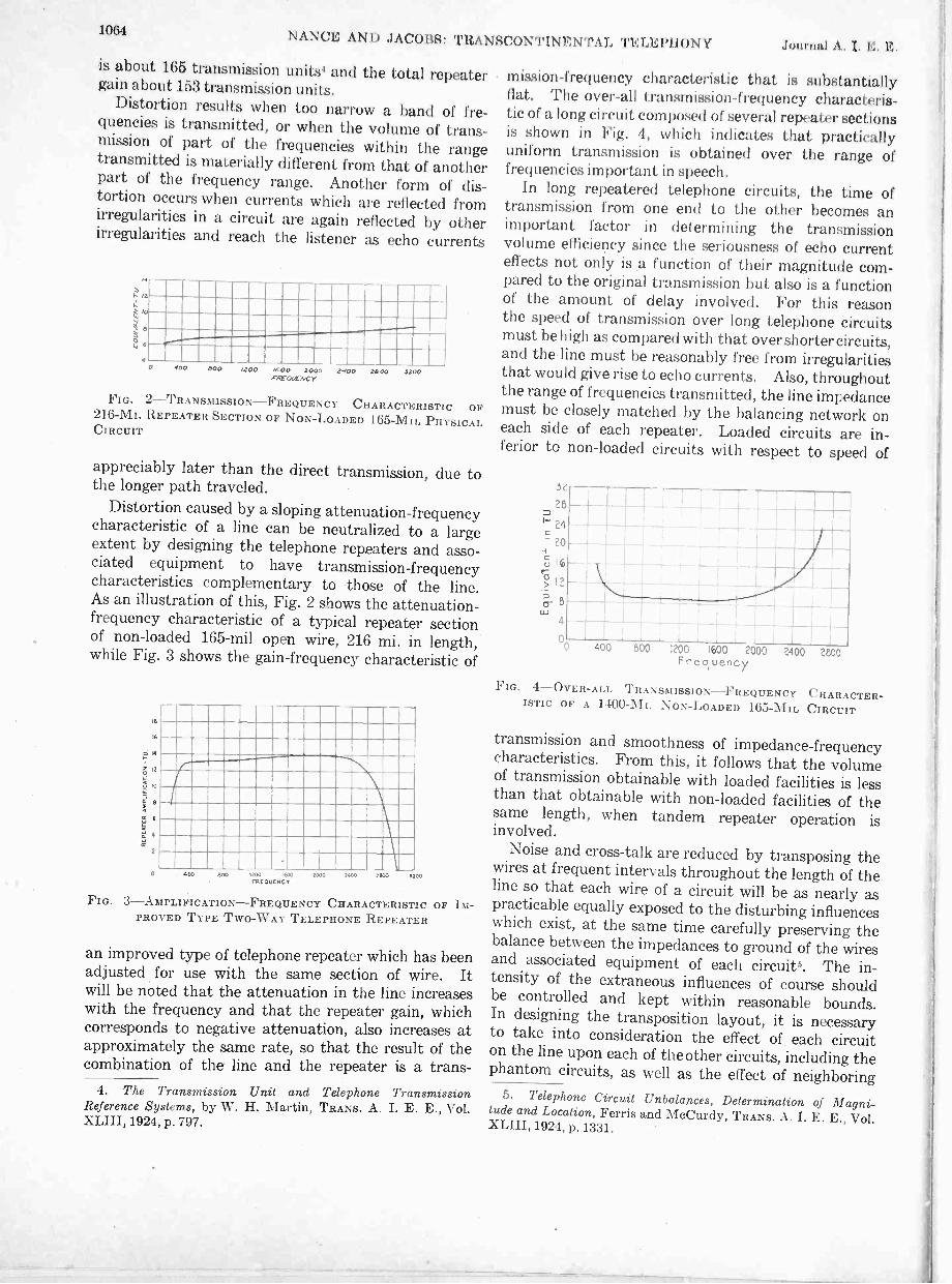
1064 NANCE AND JACOBS: TRANSCONTI N ENTAL TELEPHONY L E. I.
is about 165 transmission units1 and the total repeatergain about 153 transmission units.
Distortion results when too narrow a band of fre-quencies is transmitted, or when the volume of trans-mission of part of the frequencies within the rangetransmitted is materially different from that of anotherpart of the frequency range. Another form of dis-tortion occurs when currents which are reflected fromirregularities in a circuit are again reflected by otherirregularities and reach the listener as echo currents
14
a
4100 SOO /200 /600 2000 2100 2000 2200
PREOWNCY
FIG. 2-TRANSMISSION-FREQUENCY CHARACTERISTIC OF216 -MI. REPEATER SECTION OF NON -LOADED 165 -MIL PHYSICALCIRCUIT
appreciably later than the direct transmission, due tothe longer path traveled.
Distortion caused by a sloping attenuation -frequencycharacteristic of a line can be neutralized to a largeextent by designing the telephone repeaters and asso-ciated equipment to have transmission -frequencycharacteristics complementary to those of the line.As an illustration of this, Fig. 2 shows the attenuation -frequency characteristic of a typical repeater sectionof non -loaded 165 -mil open wire, 216 mi. in length,while Fig. 3 shows the gain-frequency characteristic of
16
1°
2
mom mum=mom mummomma =pm=prammammummommmimmummummammmummommommummommummommismmumummummummmummummummmmum mmommum
000 NCO 0000 0000 0000 3100FREQUENCY
FIG. 3-AMPLIFICATION-FREQUENCY CHARACTERISTIC OF IM-PROVED TYPE TWO-WAY TELEPHONE REPEATER
an improved type of telephone repeater which has beenadjusted for use with the same section of wire. Itwill be noted that the attenuation in the line increaseswith the frequency and that the repeater gain, whichcorresponds to negative attenuation, also increases atapproximately the same rate, so that the result of thecombination of the line and the repeater is a trans -
4. The Transmission Unit and Telephone TransmissionReference Systems, by W. H. Martin, TRANS. A. I. E. E., Vol.
XLIII, 1924, p. 797.
mission -frequency characteristic that is substantiallyflat. The over-all transmission -frequency characteris-tic of a long circuit composed of several repeater sectionsis shown in Fig. 4, which indicates that practicallyuniform transmission is obtained over the range offrequencies important in speech.
In long repeatered telephone circuits, the time oftransmission from one end to the other becomes animportant factor in determining the transmissionvolume efficiency since the seriousness of echo currenteffects not only is a function of their magnitude com-pared to the original transmission but also is a functionof the amount of delay involved. For this reasonthe speed of transmission over long telephone circuitsmust be high as compared with that overshorter circuits,and the.line must be reasonably free from irregularitiesthat would give rise to echo currents. Also, throughoutthe range of frequencies transmitted, the line impedancemust be closely matched by the balancing network oneach side of each repeater. Loaded circuits are in-ferior to non -loaded circuits with respect to speed of
..5.0
28
1
400 800 200 1600 2000Frequency
2400 2800
FIG. 4-OVER-ALL TRANSMISSION-FREQUENCY CHARACTER-ISTIC OF A 1400 -MI. NON -LOADED 165 -MIL CIRCUIT
transmission and smoothness of impedance -frequencycharacteristics. From this, it follows that the volumeof transmission obtainable with loaded facilities is lessthan that obtainable with non -loaded facilities of thesame length, when tandem repeater operation isinvolved.
Noise and cross -talk are reduced by transposing thewires at frequent intervals throughout the length of theline so that each wire of a circuit will be as nearly aspracticable equally exposed to the disturbing influenceswhich exist, at the same time carefully preserving thebalance between the impedances to ground of the wiresand associated equipment of each circuits. The in-tensity of the extraneous influences of course shouldbe controlled and kept within reasonable bounds.In designing the transposition layout, it is necessaryto take into consideration the effect of each circuiton the line upon each of the other circuits, including thephantom circuits, as well as the effect of neighboring
5. Telephone Circuit Unbalances, Determination of Magni-tude and Location, Ferris and McCurdy, TRANS. A. I. E. E., Vol.XLIII, 1924, p. 1331.

Nov. 1926 NANCE AND JACOBS: TRANSCONTINENTAL TELEPHONY 1065
power lines. A single series of transpositions whichresults in substantially equal exposures of each circuitto every other circuit on the line is called a transpositionsection. In general, one or more sections of this kindare required for each part of the line that is exposedto different outside influences. The phantom trans-positions involve interchanging the positions of thetwo pairs from which the phantom circuit is derived.
Fig. 5 shows the power at different points in a NewYork -San Francisco connection, when an arbitrarilyassumed power of 1000 microwatts is applied to theline at San Francisco. It will be seen that the poweris attenuated at the inputs of many of the repeaters toa value which is of about the same order as that whichreaches the New York end. Therefore, any noiseinduced in the circuit at such points may be as strongwhen it reaches a terminal of the circuit as it is at thepoints where it originates. In some places, the trans-mission level is even lower than at New York, as atBeaver Dam; so that noise introduced at such points
r
3.
Y
SO -
r !1aSTATUTE %ALES $0 100 IN 243 3071 277 071 121 1711 11 X0 Mil 207 11
LAX LOSS - TV 7u /02 120 /14 1LS 03 EIS=100 111~
1,11{
ATTACATTI 10.11 -TV 90 110 12.0 110 11.0 /SO 110 100 110 110 /09 110
FIG. 5-POWER LEVELS OF SAN FRANCISCO -NEW YORKCONNECTION AT 1000 CYCLES, WHEN POWER OF 1000 MICRO -WATTS IS APPLIED AT SAN FRANCISCO
may reach New York at greater than its originalstrength. Thus it is evident that from the noise stand-point, the relative transmission levels at a disturbedpoint and at the terminals are of particular importancerather than the distances from the disturbed point tothe terminals.
Besides providing voice -frequency telephone chan-nels, the open wires composing the network of "back-bone" telephone circuits are being used to a largeextent for superimposed carrier -current systems6 as wellas for providing ordinary grounded telegraph facilities.An example of this is covered by Fig. 6, which shows,schematically, the various communication channelsobtained from four wires of a group of transcontinentalfacilities between Denver and Sacramento. Altogether,
6. Carrier -Current Telephony and Telegraphy, by E. H. Col-pitts and 0. B. Blackwell, TRANS. A. I. E. E., Vol. XL, 1921,p. 205.
there are twenty two-way communication channelsoperating on fhese two pairs of conductors, six tele-phone circuits and fourteen telegraph circuits. Atelephone circuit is obtained from each of the two pairsof wires, and a third from the combination of these"side circuits," to form a phantom circuit. The otherthree telephone circuits are obtained from a carrier -current telephone system superimposed on one of thepairs of wires.
FIG. 6 -COM M UN IC ATI uN CH A NNF.LS ON FOUR WIRES OFROUP OF TRANSCONTINENTAL FACILITIES BETWEEN DENVER
AND SACRAMENTO
Ten of the telegraph circuits are obtained from acarrier -current telegraph system superimposed on theother pair of wires, and the other four telegraph circuitsare direct current channels derived by ordinary com-positing arrangements.
of four wires may havea second carrier telephone system superimposed inplace of the carrier telegraph system, while in othercases, a second carrier telegraph system is used in placeof the carrier telephone system, according to the re-quirements for these types of facilities.
'Fig. 7 shows the bands of frequencies used at presentfor communication purposes on typical long open wire
FIG.
!MI...1,
Imm issi mil Elio
9. ,1.0.35.0.1 .16 INC COCC.I.D.
__J
7-FREQUENCY ALLOCATIONS ON TYPICAL TRANSCONTI-NENTAL FACILITIES
circuits. The lowest, from zero to about 80 cycles, isemployed for the d -c. telegraph. Each telegraphcircuit employs a single wire with ground return, sothat two are obtained from each pair of wires.
The voice frequencies occupy the next higher bandof frequencies, extending to about 3000 cycles. Somecircuits of this type are made efficient at frequencies aslow as 135 cycles to permit the employment of a currentof this frequency for signaling purposes.

lonaN X( I Is : TR.% scriN \ \ T.11. TEI.El'iluN I I.
Ahove the voice rangy, each pair of wires may hearranged for superimposed carrier -current operation,either telegraph or telephone. The former utilizesfrequencies as high as 10,000 cycles; the latter, as highas 28,000 cycles.
'Ile general use of large wire and long repeater spac-ings is advantageous in the case of very long circuits,since this results in a smaller number of repeaters, and,in the case of voice frequency circuits, the lesser numberof echo current paths permits somewhat better over-allvolume efficiencies to be obtained. Carrier systemsinvolve, at the terminals, large investments in apparatusfor converting the voice frequencies or telegraph signals,as the case may be, to carrier frequencies, and viceversa. Thus, in general, the longer the distance tobe spanned, the lower is the cost of the carrier circuitsper mile. The longer or "back -bone" circuits areusually of 165 -mil diameter copper, with repeatersspaced from about 200 to 300 mi. apart, and, con-sequently, carrier systems have been applied to thesemuch more extensively than to wires of smaller gage.In a few of these circuits, however, 128 -mil or even104 -mil wire is used through some sections whererepeater spacings and other conditions are favorable.
In carrier -current telephone systems, the frequencyemployed for carrier purposes is modulated by the voicecurrents, and one of the resulting bands of frequenciesis filtered out from the others and transmitted over theline. At the terminals of the systems, the variousbands are separated from each other and from the voice-frequency channels by properly designed filters. Inthe latest systems, six bands of carrier frequencies areutilized, the lower three for transmission in one directionand the other three for transmission in the oppositedirection, these being combined at the terminals toform three two-way circuits. The use of separatechannels for the two directions of transmission of eachcircuit permits the use of one-way amplifiers thegains of which are not limited by balance conditions.At repeater points, the lower hands are kept separatefrom the upper ones by filters, and each one-way re-peater amplifies three carrier channels simultaneously.
In the carrier telegraph system, the fundamentalcarrier frequencies are under the control of telegraphrelays and are applied to the line as spurts of highfrequency currents. For a ten -channel system twentydifferent frequencies are employed, the lower ten fortransmission in one direction and the upper ten fortransmission in the opposite direction. As in thecase of the carrier telephone systems previously men-tioned, the group of frequencies transmitted in onedirection is kept separate from the opposite boundgroup at 'repeater points by means of filters and anentire one-way group of frequencies is amplified by asimilar method.
It is necessary, of course, to convert the receivedcarrier telephone or telegraph currents to voice fre-quencies or d -c. telegraph signals, as the case may be.
lii t ht ruse of h'il'11,1':1 I Ili ty$11,.111111.:11.111:rtitilgrrf:i.nli:
ure 11'1:0141 ill the fg wll 4i ordinarytelegraph iinpulse; ;-11 11:1i c11114RN 111;0' be von-neeted to telegraph circuits (If oilier types as desired.
The application Of carrier sy:,Iems employing fre-quencies as high as 28,00o cycles has brought with itspecially difficult problems from the standpoint ofcross -talk. With t hese high frequencies, the transposi-tion spacing requirements become quite stringentand the number of points at which transpositions arenecessary is greatly increased. In addition, in tollentrance and intermediate cables, it is necessaryusually to arrange the conductors in such a way thatthose used for carrier systems will not be adjacent toeach other.
Frequent reference has been made to telephonerepeaters' and repeater gains. The amplifying elementof a telephone repeater, the vacuum tube, is essentiallya one-way device, and for two-way operation it isnecessary that the output of the element be prevented
r
43.
,11.
Fu.. 8-SIMPLIFIEDREPEATER STATION
EQUI PM ENT LAYOUT AT INTERMEDIATEON TRANSCONTINENTAL -TYPE CIRCUITS
from getting back to the input side and thus setting upcontinuous oscillations known as singing or howling.This is accomplished by the use of two amplifyingelements, each with its input connected at a neutralpoint in the output circuit of the other. The neutralpoint is obtained in a manner very similar to that em-ployed in duplex telegraphy by dividing the outputof each vacuum tube between the line and an artificialline having similar characteristics so that the electricalcenter of the output circuit remains at a constantpotential unaffected by the changing currents in theoutput circuit itself.
Fig. 8 shows the equipment at an intermediaterepeater point on one pair of wires of the type used fortranscontinental service. The voice -frequency tele-phone repeater is shown connected to the line in thetwo directions. Each line, with its associated terminalequipment, is balanced by an artificial line with associ-ated balancing equipment. The hybrid coil located
7. Tele' hone Repeaters, by B. Gherardi and F. B. Jewett,TRANS. A. I. E. E., Vol. XXXVI I I, Part II, 1919, p. 1287.

Nov. 1926 NANCE AND JACOBS: TRANSCONTINENTAL TELEPHONY 1067
in the electrical center between the line and artificialline is the means by which the transmission in the twodirections is separated. Currents amplified by theupper one-way element pass through the so calledthird winding of the hybrid coil and set up voltages inthe line windings. These voltages are of exactly thesame magnitude on both sides of the electrical centerof the coil and cause equal currents to flow in theline and artificial lines if their impedances balanceeach other perfectly. In practise, it is impracticable toobtain an exact balance due to the presence of un-avoidable irregularities in the line and its associatedequipment, the effect of which is to reflect energy whichreaches the other amplifier. For successful operation,however, the average of the two transmission lossesrepresented by the ratio between the reflected energyand the applied energy on each side of the repeater,must be substantially greater than the averageof the transmission gains of the two amplifyingelements.
The line repeating coil is shown in the figure withthe mid -point of the line side indicated as the phantomcircuit tap. The composite set is essentially a filterwhich allows the voice currents to pass between theline and the telephone repeater, while direct currentsand the low frequency alternating currents involvedin d -c. telegraph operation pass between the line and thetelegraph repeaters. It will be noted that. the tele-graph repeaters, also, are arranged for two-wayoperation involving the employment of balancingnetworks.
The currents of carrier frequencies are prevented bya filter from reaching the low -frequency equipment butare transmitted easily through a high -frequency pathin the filter to the carrier repeater. In the latter, forseparating the two directions of transmission, advantageis taken of the fact that the currents in the two directionsare of different frequencies so that directional filterscan be used to separate them. The repeaters amplifythe three one-way channels of a carrier telephone systemor the ten one-way channels of a carrier telegraphsystem simultaneously. In order to avoid interactionor modulation between the various channels, it is essen-tial that the relatiqn between the output current and theinput voltage of the vacuum tubes be a straight linefunction over the energy range employed in the carriersystem.
Signal currents, also, must be relayed or amplifiedon long telephone circuits, just as voice and carrier fre-quencies are. On some short toll circuits, a signalingcurrent of about 20 -cycle frequency is used, the sameas that for ringing the bells of subscribers' telephones.On circuits arranged for d -c. telegraph operation, itis impracticable to employ such a low frequency; itis necessary to use a frequency that will be transmittedsatisfactorily by the circuit. In actual operation, thesignaling channels at the ends of the circuits arearranged usually for 20 -cycle operation by means
of relays which automatically apply higher frequencysignaling currents and receive the incoming signals.
The signaling frequency commonly used on tollcircuits of medium length is 135 cycles. With thissystem, the signals are relayed at least at every othervoice -frequency repeater point since the attenuationloss at 135 cycles is greater than that over the mainvoice -frequency range. In very long circuits, thisresults in the necessity for operating a train of relaysat successive points, which delays the transmissionof the signals. To overcome signaling difficultieson such circuits, a system of ringing, employing 1000 -cycle currents which are transmitted from end to endof the circuit with the same efficiency as speech currentsof that frequency, has been developed and applied.The signaling currents are supplied from a suitablesource and are controlled by 20 -cycle relays at the ter-minals. At the receiving end, circuits tuned to thesignaling frequency are employed to amplify and con-vert the signals to currents which operate relays.Interference from speech currents is avoided by inter-rupting the signaling current at the sending end about.twenty times per second, while at the receiving end,the signals pass through a circuit tuned to 20 cycles.
At some points in a long telephone circuit, it isnecessary to employ cable, as when passing througha large city. Because of this greater capacity betweenwires, cable circuits cause much greater attenuationper unit of length than open wire circuits, especiallyat carrier frequencies. In order to improve the effi-ciency of the cable circuits they are loaded by means ofinductances placed at intervals along the circuit.The inductances and spacing are so chosen as tocause the characteristic impedances of the cablecircuits to approximate closely those of the open wirecircuits over the range of frequencies transmitted.
Circuits of transcontinental type are used often forspecial services such as for the transmission of programmaterial to broadcasting station& or to points wheresuch material is desired in connection with a publicaddress system. As this is essentially a one-wayservice and the programs usually include music, forwhich the best results are obtained by using a widerrange of frequencies than ordinarily is employed forcommercial telephone communication, the two-wayrepeaters in the line are replaced by one-way repeatersand associated equipment for amplifying the currentsand equalizing the transmission throughout the widerrange of frequencies. Programs are transmitted dailyin this manner to a number of broadcasting stations inthe eastern half of the country.
Typical of the larger networks that have been setup is that for the inauguration of President Coolidge.Fig. 9 shows the layout arranged for that purpose, whicheffectively covered the entire country.
8. High Quality Transmission and Reproduction of Speechand Music, by W. H. Martin and H. Fletcher, TRANS. A. I. E. E.,Vol. XLIII, 1924, p. 384.

1008 NANCE AND JACOBS: TRANSCONTINENTAL TELEPHONY Journal A. I. E. E.On occasions, a speaker in one city addresses ameeting in a distant city, the loud speakers at the
receiving end being connected to the transmitting tele-phone by wire. In some cases, such speeches also arebroadcast from one or more radio broadcasting stations.Another use made of transcontinental type facilities
is the transmission of pictures or facsimiles of printedor written matter, fingerprints and similar material.The frequencies employed for this purpose are withinthe voice range and the currents are transmitted in thesame way as voice currents. Special apparatus is re-quired, of course, at the transmitting and receivingends.
The continuity of the many important services routedover the facilities used in making up these long circuitsis dependent upon continuous and efficient maintenancemethods and performance. Coordination of the work
SALTCITT
1.INNEAPOu
500
including a complete description of the 'types of equip-ment and transmission data, are prepared and furnishedto the terminal offices and intermediate repeaterstations. These records are made on cards of conve-nient size as illustrated by Table I, which is reproducedfrom one of three cards containing the data for aChicago -San Francisco circuit.
To insure satisfactory over-all transmission and properfunctioning of the circuit, various tests and inspectionsare made at frequent intervals9. Some of the moreimportant maintenance tests are as follows: insulationresistance, loop resistance and resistance balance of theline conductors; measurement of the gain-frequencycharacteristic as well as the gain at 1000 cycles, and tubetests on all repeaters to detect changes in amplificationdue to possible changes in the characteristics of thevacuum tubes or repeater equipment; balance tests at
4it \ . 1cwwvo DAvENPOITI, I 11\ I
;iint,.. _ 1-,..---_ .,..r
1 ....,,, ^', I sfr/
I 1----17,./P-,75.73-1. 1 ;
iii I
...o. I c"'llc."
LOSSAGELES
DENA
7-7-IF-VW.
et 'kr LEV0
,J ATe
c.c.)
I 1,0,10
ATLANTA
LOIENECTAEN
1
00.1LAJELPI.A
'Pa,. e:
"..5161.7
TC0
r -
0- -ywI crow
- LEGEND -
AMPLIFIER
CIPCLV TO RADIO STAMP.
pAc PUBLIC ADDRESS
FIG. 9-NETWORK OF CIRCUITS FOR TRANSMITTING PROGRAM MATERIAL TO BROADCASTING STATIONS-LAYOUT MADE AVAIL-ABLE FOR THE INAUGURATION OF PRESIDENT COOLIDGE
of, thefldifferent offices is most essential in order to obtainbest results especially on the longer direct circuitsand on those built up by connecting together severalcircuits, as there are many variable factors. Toassist in obtaining this coordination, one of the terminaloffices of each circuit is designated as the controllingoffice for that circuit and is responsible for the directionand supervision of tests and adjustments required onthe circuit as a whole. In addition to the duties inconnection with the maintenance of the completecircuit, each office along the circuit is responsible forthe proper physical maintenance of the plant in itsterritory. To assist in this maintenance work, ac -.curate records of the circuit make-up from end to end,
each repeater station to check the degree of balancebetween the line circuit and its balancing network;noise and cross -talk measurements; 1000 -cycle trans-mission measurements and transmission -frequencymeasurements on the over-all circuit to insure that thecircuit equivalent is maintained within proper limits;and finally, over all talking and signaling tests.
In making many of the measurements, it is necessaryto remove the circuit from service. This would resultin considerable lost circuit time if each of the stationsmade the measurements and tests independently. Inorder to minimize this lost circuit time, it has been found
9. Practises in Telephone Transmission Work, by W. H.Harden, TRANS. A. I. E. E., Vol. XLIII, 1924, p. 1320.

Nov. 1926 NANCE AND JACOBS: TRANSCONTINENTAL TELEPHONY 1069
TABLE I.TOLL -CIRCUIT LAYOUT RECORD
0 E-552Circuit No. 2 Chicago (E) San Francisco (W)
Control Meas. Noise
Office Chicago At Chicago Class Rat'g
order 5785 Item 42in service 6-1-26issue No. 1 Date 5-22-26
Equiv. in TUReq.Meas.
E to W1111
W to E1111
CircuitDateCard
From1
ToCable or
line3
Pair or pinnumbers
4
Size ofwire
5
Load-ing
6Length
7Equiv.
8
Toll line equipment
Ringer13
Misc.14
Loss(Columns)(9 to 14)
15
Onside
9
ForSX10
Forotheruse11
CX
12
C ChicagoDE Morl Park
Morl ParkMH 28
Chg-MP CA 5West TE CA
1511
1913
H-44N
7.62.2
3.61.1
75 A75 A75 A TS
3A
KX
0.80.71.1
F P 128 P 328 Chg-Omaha 9-10 165 N 3.8 0.1G P 328 P 7415 9-10 165 N 166.3 5.5HP 7415 P 7445 9-10 165 N 0.7 0.0J P 7445 Davenpt Aer Cable 9 13 N 0.1 0.0K Davenpt P 7445 5 13 N 0.1 0.0
L P 7445 P 7557 Chg-Omaha 35-36 165 N 2.1 0.1M P 7557 P 7741 25-26 165 N 4.5 0.1N P 12976P P 9047Q Burlington
P 9047BurlingtonP 9047
Stl-DavptAer Cable
5-65
15
1651013
N
N
83.40.51.0
2.80.20.5
75 A75 A
TSTS
KXKX
1.11.1
R P 9047 P 7930 Stl-Davpt 15-16 165 N 29.5 1.0S Total Total
Office16
T ChicagoU Morl PkV BurlingtonW Kans Cy.Z Newtn.
Telephone Repeater DataMileage 0. W.
CA. &0. W
Toward W Toward EThis 2002.3 2021.2
Gain or Singing point Gain or Singing point Misc. companyCC step CC step Other
Net Ring- Ring- Net company 644.3Type Imp. Req. Meas. Req. Meas. lug ing Req. Meas. Req. Meas.
17 18 19 20 21 22 23 24 25 26 27 . 28 29 30 31 Total 2665.5
C N 3 13 P 24 Net Equivalent2 A C N 7.1 17 E 24 7.1 13 P 14
21 P N 12 17 F 24 12 17 F 24 Four -wire section21 P N 12 17 F 24 12 17 F 24 Two -wire section21 P N 12 17 E 24 12 17 F 24 Carrier section
desirable in the case of long telephone circuits to setaside a definite time for making the periodic tests and tocoordinate the work of making the tests under the,direction of the controling office. This testing routinehas been perfected to such an extent that the circuitneed not be kept out of service for more than a fewminutes even in the case of the longest circuits.
The measurements of line resistance, insulationresistance, and resistance balance are made by means ofWheatstone Bridge arrangements in the testboardslocated at each repeater station and sometimes at inter-mediate points in a long repeater section. The ampli-fication, or gain, given by each repeater is measured bymeans of a visual reading instrument of the vacuumtube type located at each repeater station. Balancebetween the line and network circuits in each directionat the various repeater stations is roughly checkedby means of the repeater itself. This is done by dis-connecting the line and network from one side of therepeater and connecting the two amplifying elementsof th6 repeater in tandem, then increasing the amplifi-cation until the repeater circuit begins to oscillate.The sum of the calibrated gains of the two sides of therepeater is a rough measure of the degree of balanceexisting between the line and network circuits connectedto the repeater. Measurements of the over-all equiva-lent of a circuit are made from the terminal offices by
means of transmission measuring sets° provided withvariable frequency oscillators.
The long telephone circuits in the United Statesform a network by means of which many importantpoints are connected directly to each other, whilepractically all large centers may be connected by avery few switches which rarely involve more than threesuch links. Economic use is made of the wires by thelarge number of telephone and telegraph channels super-imposed on the voice -frequency circuits. The plantcomposing this network extends over the entire countryand close coordination is essential to insure the bestresults both from the technical and the economicstandpoints.
Main arteries of communication have been es-tablished in this way which bring the widely separatedparts of the country into close touch with one anotherand the network is being augmented and extended tomeet the growth in the traffic as it occurs. Thesearteries are being developed so that continuous servicecan be given by means of the protection afforded byalternate routes, and they are well maintained to giveefficient service under all the varying conditionsencountered.
10. Methods for Maintaining the Transmission Efficiency ofTelephone Circuits, by F. H. Best, TRANS. A. I. E. E., Vol. XLIII,1924, p. 423.

Abridgment ofSurface Heat Transfer in Electric Machines with
Forced Air FlowBY G. E. LUKE*
Associate, A. I. E. B.
Synopsis.-Since the insulation of windings in electric machineshas comparatively low temperature limits, the problem of coolingthese machines with the most economical use of material becomesone of major importance. The design of such machines from atemperature standpoint is usually based on tests of a previouslymade similar machine or else is of the "cut-and -try" type wheresuch tests are not available.
The predetermination of the operating temperature depends
a great deal upon the rate at which the heat losses can be liberatedfrom the ventilating .surface to some cooling fluid such as air,which is considered in this paper. Some data are available regard-ing this rate of heat dissipation with forced air convection currents;a comparison of the various results published, however, shows themto be inconsistent. The purpose of this paper is to submit additionalinformation that should be of value to the industry and that willalso explain some of the inconsistencies in the past tests.
INTRODUCTION
THE main factor that limits the capacity of electricmachines is the temperature of the windings. Thistemperature limit is comparatively low, ranging
from approximately 100 deg. cent. to 150 deg. cent.,depending upon the class of insulation and the type ofmachine. Air is used as a cooling medium in the greatmajority of rotating machines. The heat resultingfrom the iron and copper losses of the machine isconducted to the ventilating surfaces where it istransferred to the moving air. To conduct this heatthrough the solid material and to transfer it from asurface to a fluid requires a temperature gradient.Such a flow is shown on Fig. 1 with a radial duct.From the standpoint of heat transfer from a surface,air is one of the poprest of fluids. From 20 to 75 percent of the temperature rise in rotating machines is dueto the gradient necessary to transfer the heat from thesurface to the ventilating air. This factor is thereforeof considerable importance in the design of an econom-ical machine.
Considerable data in the past have been publishedconcerning heat liberated from surfaces with naturalconvection currents, but it has been just recently thatdata applicable to electrical machines with forced airflow have been available. To obtain information re-garding the rate at which heat is dissipated with highvelocity air flow is difficult since it will depend uponthe particular conditions of air flow as well as the meanvelocity. Experimental results published by variousworkers do not agree, therefore, in many cases. Thepurpose of this paper is to discuss some of the availabletests and to submit new tests covering conditions of airflow such as are found in electric machines. The newdata presented also will correlate some of the workwhich offhand seemed to be inconsistent.
*Research Department, Westinghouse Electric and Manu-facturing Co.
Presented at the Annual Convention of the A. I. E. E., WhiteSulphur Springs, W. Va., June 21-25, 19f6. Complete copiesavailable upon request.
COMPARISON OF PUBLISHED DATA
Throughout this paper the coefficient of surface heattransfer will be symbolized (Kr) or W/sq. in./deg.cent., which means watts transferred per square inch ofventilating surface per deg. cent. difference betweenthe surface and mean air temperature flowing in theduct. Thus, in Fig. 1, (Kr) for the particular air flowwould depend not upon the minimum air temperaturenor upon the mean temperature as yiven by the curvebut upon the integrated mean temperature taking intoaccount the total mass flow. This is the only practicalway of defining (Kr) since in any ventilating duct the
80 DEG. CENT.
-80-*- Iron7 ; 70
--
Air 6uFilm
50.
.Convection40r .
.
30Laminations
20 -1--
10
-..- 4;1 17.t--
FIG. 1-TEMPERATURE GRADIENT DUE TO HEAT FLOW TOAIR STREAM IN RADIAL DUCT
air temperatures and velocities vary greatly at anyparticular point.
This coefficient of surface heat transfer is often called"rate of surface heat flow", "dissipation constant" anderroneously, "the emissivity constant". It may also beexpressed in other units; the relation of some of these isapproximately as follows:
1 B. t. u. per sq. ft. per deg. fahr. per hr. = 0.00366watts per sq. in. per deg. cent.
1 Calorie per sq. cm. per deg. cent. per sec. = 27.0watts per sq. in. per deg. cent.
1 Kilo -calorie per sq. m. per deg. cent. per hr. =0.00075 watts per sq. in. per deg. cent.
1070

Nov. 1926 LUKE: SURFACE HEAT TRANSFER IN ELECTRIC MACHINES 1071
1 watt per sq. cm. per deg. cent. = 6.45 watts persq. in. per deg. cent.
A few of the experimental results published by Nusselt,1Dicksee,2 Rice,3 and the writer,' giving the rate of sur-face heat transfer for various air velocities, are plottedon Fig. 2. In all of these tests the air velocity referredto is the mean velocity in ft. per min. obtained bydividing the weight of air, in pounds, passing throughthe duct by the cross-sectional area of the duct insquare feet, and by the weight of air in pounds per cubic
0.36
0.34
0.32
0.30
0.28
le> 0.26
EP.; 0.24
W 0.220_
0.20
0,0.13
cc 0.16
0.14
< 0.12
z 0.10
0.06
0.04
0.02
1000 2000 3000 4000 5000 6000V AVERAGE AIR VELOCITY FT. PER MIN.
(BASIS OF 0.074 LBS. PER CU. FT.
FIG. 2 -SURFACE HEAT TRANSFER CONSTANT AGAINSTAVERAGE AIR VELOCITY FOR VARIOUS DUCTS OF ATMOSPHERICPRESSURE
Curve Author Type1 Luke' Smooth circular 114 in. Dia. 36 in. long.2 Luke' Rough circular 11 in. Dia. 36 in. long.3 Nusselt4 Smooth circular 0.866 in. dia.4 Luke' Smooth concentric 25 in. by 26 in. dia. 36 in. long.5 Dicksee2 Smooth concentric 3 in. by 5% in. dia. 7 in. long.6 Rice' Rough concentric 1.1 in. by 2 in. dia., 5.86 in. long.
feet (0.074). This factor (0.074) is the weight of dryair in pounds per cubic foot at 25 deg. cent. and at-mospheric pressure of 29.92 inches of mercury. Thusthe weight of air flowing will be proportional to thevelocity factor.
Curves 1, 2, and 4, given by the writer,4 were with airflowing through ducts such as are found in electricmachines and are called axial ducts. Curve 1 appliesto a smooth brass tube 1% in. in diameter and 36 in.long, with air flowing through it. Curve 2 is for aduct similar to Curve 1 except that the surfaces arerough, since the tube was made by stacking washersof 0.017 in. varnished iron with a 1h in. inside di-ameter. Since the punching and stacking varieda few thousandths of an inch, the inside bore was com-paratively rough. This increased the coefficient of
1, 2, 3, and 4. See Bibliography.
friction (f) at least 50 per cent and the heat transfer(K5) from 20 to 30 per cent. Curve 1 provides areasonably close check on the data given by Nusselt(Curve 3) which were obtained by using a smooth0.866 -in. diameter tube. Jordan5 also gives the resultsof surface heat transfer constants (K5) with air flowthrough smooth tubes which are slightly below Curve 1.
Curves 4, 5, and 6 were obtained with the air flowingaxially between two concentric cylinders. In the testsmade by the writer the cylinders were 25 and 26 inchesin diameter and 36 inches long. Due to the radiatiOnloss the values are slightly greater than those indicatedby Curve 1. This radiation loss is present in Curves4, 5, and 6, since the heated surface was the outersurface of the inner cylinder. This radiation loss isapproximately 0.003 to 0.005 W/sq. in./deg. cent. andwill be independent of the air velocity. Curve 5 byDicksee2 was obtained with a much smaller heatercylinder upon which were soldered various numbers ofradial copper fins with surfaces parallel to the air flow.The values of the heat liberated are about twice thosegiven for Curve 1. Curve 6 by Rice was plotted interms of mean velocity instead of maximum velocityby using the mean velocity ratio of 0.85. The values ofheat transfer are comparatively large, being about fivetimes as great as those of Curve 1 and about 2 timesas great as those of Curve 5.
From past experience in the cooling of electric ma-chines with free convection currents, values of heattransfer from the ventilating surfaces have been ob-tained that are considerably greater than those given by
Air Chamber
in.x231 in.x278 in.Outside
Cold Junction of_,..xAir rise couples
22 in.Two layers Magnesia
Soapstoneteel Plate
14 in.
Baffle Plateand Wire Screen
WdrAWIIMIOSIIIer
wwwwwwswitawasim....111131=1=1
Hot Junction oAir rise couples
§
1---23-6-
From
Blower
Magnesi
Wooden rEMIlliniciSpacer
W...
119111End Cross-section of Duct
22 in.
78 in.
Plan view of Bottom Plate showinglocation of Thermo -couples
FIG. 3 -APPARATUS FOR DETERMINING THE HEAT LOSS FROMFLAT PARALLEL PLATES
Curves 1 to 4. The writer has never obtained suchhigh values, however, as those given by Curve 6 andhence additional tests were planned and executed forthe purpose of giving more information concerningthe variation of this cooling constant (K5) as in-fluenced by varied air flow conditions.
EXPERIMENTAL
1. Air Flow Between Two Parallel Flat Plates.Electric machines are cooled more by radial ventilating

1072 LUKE SURFACE II EAT TRANSFER IN ELECTRIC MA( 711 1 N ES Jourrinl A. 1. E. E.
ducts in the iron core than by any other method. Theseducts range in width from Y.1 in. to 1 in., Y8 in. being themore common figure. The air flow through them isvery turbulent, due not only to the ventilating spacersor fingers and the coils but also to the changing cross-section for air flow. On large bore machines thechange in air velocity due to the radial flow may not begreat. The first test made was to imitate such condi-tions where a minimum rate of heat transfer is to beexpected.
A sketch of the apparatus is shown on Fig. 3. Theair was supplied by a centrifugal fan driven by anadjustable speed, d -c. shunt motor. This fan dischargedinto an expansion chamber. The air then passedthrough the ventilating duct formed by two hotplates 8 in. wide by 22 in. long, separated a definitedistance by proper spacers. The hot discharge airthen passed through an outlet duct where its averagetemperature was measured.
In all tests on heat transfer with forced air flow theaccuracy of the data depends upon the true mean airvelocity or volume. This volume may be obtained byusing the pilot tube, anemometer, orifice meter, andother similar methods, but in many tests of this naturethe writer has obtained the best and most accurateresults by using the specific heat method. The volumewas obtained after thermal equilibrium had beenreached from the watts input to the air and the re-sulting air temperature rise. The watts absorbed bythe air equals the total watts input minus the strayloss as given by the calibration curve corresponding tothat particular heater temperature. The temperaturerise of the air was obtained by five thermocouples withthe hot and cold junction distributed in the outlet andinlet air respectively. The accuracy of this methoddepended upon obtaining the true temperature rise,which necessitated a thorough mixing of the hot air.This is accomplished best as shown by allowing the airto expand on discharge with a baffle placed in thedirect path of the high velocity air, forcing the air tochange its path. This scheme functioned successfullyas shown by temperature traverses of the air witha single couple. The equation used was
1.765 Wa.V= 0.
whereV = cubic feet of air per minute (25 deg. cent.
temperature)W. = watts absorbed by the air0. = resulting air temperature rise deg. cent.The average air velocity (v) through the duct, then,
is
v=VA
wherev = average air velocity in feet per minute, and
A = cross-sectional area of duct in sq. ft.The rate of heat loss (K) from the surface for any
given velocity was determined from the equation
K WQ
S(0 02_)
whereK = surface heat transfer constant in W/ sq. in/deg.
cent.,Wa = watts dissipated to ventilating air,S = ventilating surface of duct in sq. in.,0, = average surface temperature rise of duct above
intake air deg. cent., andO. = temperature rise of the outlet air deg. cent.
A stray heat loss curve for each spacing was obtained
0.081
0.07
0.06zz
No 0.05coEEL
0.04
CYN0
I- w 0.03zct!
t.1§ 0.028
00 1000 2000 3000 4000 5000 6000V AVERAGE AIR VELOCITY IN FT. PER MIN.
(BASED ON AIR DENSITY OF 0.074 LBS. PER CU. FT.
FIG. 5-CURVES FOR FLAT PARALLEL PLATE DUCT
Size duct 8 by 22 in.Curve No. 1; (for !,.; -in. spacing)Curve No. 2; (for )-2-in. spacing).Curve No. 3; (for y8 -in. spacing).Curve No. 4; (for 1 -in. spacing.)
which gave the watts stray loss for any average platetemperature. This was made by completely closingthe ends of the duct so as to minimize loss by convection.The heater input, then, when steady conditions had beenreached, was the stray loss flowing through the heatinsulation. With forced convection the duct was givena definite spacing and air at a constant velocity wasforced through. The current through the heaters wasadjusted until an average plate temperature of about80 deg. cent. was reached. When the temperatures be-came stable all thermocouples and heat inputs weremeasured. Direct current was used as the heatersupply. The voltage dropped across the heater,across a fixed resistance in series with the heater, andthe potentials given by the couples were all measuredwith a Leeds & Northrup type K potentiometer. Inthis manner tests at various velocities were made for
Nov. 1926 LUKE: SURFACE HEAT TRANSFER IN ELECTRIC MACHINES 1073
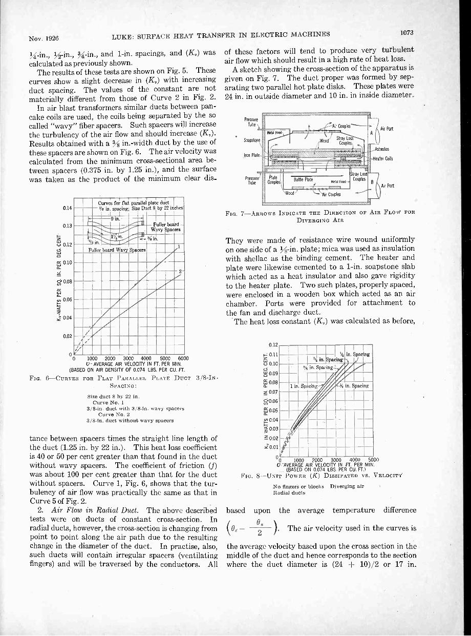
%2 -in., 34 -in., and 1 -in. spacings, and (K,) wascalculated as previously shown.
The results of these tests are shown on Fig. 5. Thesecurves show a slight decrease in (K,) with increasingduct spacing. The values of the constant are notmaterially different from those of Curve 2 in Fig. 2.
In air blast transformers similar ducts between pan-cake coils are used, the coils being separated by the socalled "wavy" fiber spacers. Such spacers will increasethe turbulency of the air flow and should increase (Kr).Results obtained with a in. -width duct by the use ofthese spacers are shown on Fig. 6. The air velocity wascalculated from the minimum cross-sectional area be-tween spacers (0.375 in. by 1.25 in.), and the surfacewas taken as the product of the minimum clear dis-
0.14
0.13
Lc:_i 0.12
L.6
ar, 0.10
Z
ci 0.08
cr,a _ 0.06
Y0.04
0.02
00 1000 2000 3000 4000 5000 6000
I i 1i
I I 1
Curves for flat paralle plate duct3/8 in. spacing,
L_L_Size Duct 8 by 22 inches
9 inMiller board -
. Wry Spacers
a/ in.17in.
-A k- 3/i in.
Fuller board Wavy Spacers /
1/
;/;777777-/
2
U - AVERAGE AIR VELOCITY IN FT. PER MIN.(BASED ON AIR DENSITY OF 0.074 LBS. PER CU. FT.
FIG. 6 -CURVES FOR FLAT PARALLEL PLATE DUCT 3/8 -INSPACING:
Size duct 8 by 22 in.Curve No. 1
3/8 -in. duct with 3/8 -in. wavy spacersCurve No. 2
3/8 -in. duct without wavy spacers
tance between spacers times the straight line length ofthe duct (1.25 in. by 22 in.). This heat loss coefficientis 40 or 50 per cent greater than that found in the ductwithout wavy spacers. The coefficient of friction (f)was about 100 per cent greater than that for the ductwithout spacers. Curve 1, Fig. 6, shows that the tur-bulency of air flow was practically the same as that inCurve 5 of Fig. 2.
2. Air Flow in Radial Duct. The above describedtests were on ducts of constant cross-section. Inradial ducts, however, the cross-section is changing frompoint to point along the air path due to the resultingchange in the diameter of the duct. In practise, also,such ducts will contain irregular spacers (ventilatingfingers) and will be traversed by the conductors. All
of these factors will tend to produce very turbulentair flow which should result in a high rate of heat loss.
A sketch showing the cross-section of the apparatus is
given on Fig. 7. The duct proper was formed by sep-arating two parallel hot plate disks. These plates were24 in. in outside diameter and 10 in. in inside diameter.
Pressure
Tube
Are/ /AV/
Soapstone
Iron Plate -
Metal Hood-ON
LIVAVo. INMOINI.Air Couples
Stray LossCouples
I Cr/MIA VZIZ/Z,
PressureTube
z zrz,rrrz.
Air Port
bestos
Heater Coils
Air Port
FIG. 7 -ARROWS INDICATE THE DIRECTION OF AIR FLOW FORDIVERGING AIR
They were made of resistance wire wound uniformlyon one side of a y -in. plate; mica was used as insulationwith shellac as the binding cement. The heater andplate were likewise cemented to a 1 -in soapstone slabwhich acted as a heat insulator and also gave rigidityto the heater plate. Two such plates, properly spaced,were enclosed in a wooden box which acted as an airchamber. Ports were provided for attachment tothe fan and discharge duct.
The heat loss constant (K) was calculated as before,
0.12
0.11
`610.10
0.09
w 0.08o_
Z 0.07
y 0.06
LI:5 0.05o_
,<L) 0.04
g 0.03
0.02
C/.01
00 1000 2000 3000 4000 5000V -AVERAGE AIR VELOCITY IN FT. PER MIN.
(BASED ON 0.074 LBS. PER CU. FT.)FIG. 8 -UNIT POWER (K) DISSIPATED VS. VELOCITY.
No fingers or blocks Diverging airRadial ducts
1/2 in. Spac ng343 in. Spacing
% in. Spacing
1 in. Spacing % in. Spacing
based upon the average temperature difference
(00 a
2). The air velocity used in the curves is
the average velocity based upon the cross section in themiddle of the duct and hence corresponds to the sectionwhere the duct diameter is (24 + 10)/2 or 17 in.

1074 1,11K : SURFACE 11 EAT TRANSFER IN E "I' RI( ! NI Ad 'II IN ES J11111/i I .\ I. 14:.
When ventilating fingers were used the surface of thefingers was also included.
The results of tests with diverging flow through theunobstructed radial duct are shown on Fig. 8. Theheat loss constant at a definite velocity is greater for the1 -in. ducts than for the i'1 -in. duct which is the reverseof the case given on Fig. 5. The values are also muchhigher due to greater turbulency of air flow. These
FIG.
0.10
1-4-1 0.09
LT, 0.08
cc 0.07
cl". 0.06
60.05
cc 0.04a
0.03
ti 0.02
z 0.01
4 001000 2000 3000 4000 5000
V AVERAGE AIR VELOCITY IN FT. PER MIN.BASED ON 0.074 LBS. PER CU. Fr:
I Average Cuive flor14in.1/4 in. and% in. Spacing-
35 Fingers & Blocks
'4 in. SpacingWith 35 Fingers only
9 -UNIT POWER (K) DISSIPATED VS. VELOCITY
35 lingers -35 blocks diverging airRadial duct
values are of the same approximate value as that repre-sented by Curve 5, Fig. 2. The curve of the 3/3 in. orin. duct, Fig. 8, seems to be out of place. The valuesgiven, however, were rechecked several times.
When ventilating fingers and conductors are placed inthe duct the curves are as shown on Fig. 9. Since thesurfaces of the spacers are also included, the results
0.10
ti 0.09
8 0.08
cc 0.07
Z13-0 06
6.0.05
Li 0.04
ci-u, 0.03
0.02
z 0.01
35 Fingers & locks% in. Spacing
PEN
Blocksti
42ipan3's in. Spacing
in.wailINPA:FTngeSpgionrg%iIrvAlt
15rill
giV AVERAGE AIR VELOCITY IN FT. PER MIN.
BASED ON 0.074 LBS. PER CU. FT.
FIG. 10 -UNIT POWER (K) DISSIPATED VS. VELOCITY35 fingers -35 blocks converging airRadial duct
show that they are almost as effective as the ductsurface.'Many machines are now ventilated with air flowradially inward (converging flow) through a portion ofthe ducts. The results of such a flow are shown onFig. 10. It should be noted that the values obtainedare lower than those obtained with diverging flow;Curvel2, particularly, is materially lower than the
similar curve on Fig. H. This fact is to be expectedsince it is known that diverging air flow will he moreirregular or turbulent than converging flow with thesame axial change in cross-section. Thus the tur-bulence obtained with Curve 2, Fig. 10, is about thesame as that found in Fig. 5 with a constant crosssection since the rate of heat loss is about the same.
3. Air Flow between Two Concentric Cylinders.Mr. C. B. Dicksee,2 working in this laboratory, in-vestigated the heat loss from an air cooled gasolineengine cylinder with numerous fins attached. Curve 5,Fig. 2, gives the average results of these tests on acylinder with 5 to 40 axial metal fins attached. Thesefins extended to the outer cylinder. The heat lossconstant (KO was independent of the number of finsused. At the time these tests were made the value of(Kr) was considered high and no reason could be sug-gested why the heat loss should be any greater than,let us say, Curve 2.
The writer at that time had tests made with thesmooth cylinder without fins as shown on Fig. 11.
5 3/8in.l. D. Micarta Tube
Baffle
Heater Leads1=3:.
Cold JunctionsAir Rise
Box 2ft.-Oin.x2ft.-6in
Outside
Hot Junctions Air Rise
--- 4 I/ O.D.
15 in.
Wood
Detachable
To Blower
Iron. Brass.;
Cross-section of Cylinder
3m. Dia. x iin. long
Soapstone
FIG. 11 -DIAGRAM OF EXPERIMENTAL APPARATUS FOR DETER-MINING HEAT Loss FROM A CYLINDER WITH AXIAL AIR FLOW
This test equipment was the same as used in the abovetest. The cylinder was supported as shown, with asquare orifice air intake. The average temperatureof the inner cylinder was obtained with thermocouplesas before; (Kt) was calculated as it had been donepreviously and the air velocity was calculated from thecross-sectional area of the duct.
Curve 2, Fig. 12, gives the results of these tests.The values of (Kr) are a little greater than those ob-tained on the finned cylinder, Curve 1. In comparingthis Curve 2, Fig. 12, with Curve 4, Fig. 2, a greatdifference is observed, although the types of air flowsystem are about the same; the main difference is thelength of duct (7 in. and 36 in.).
It has long been known that when air enters a duct ofconstant cross section from a larger chamber, a con-vergence or "vena contracta" of the air stream will takeplace, and later the effective air stream will expand andgradually assume a stable velocity condition. Thisconvergence near the entrance of the duct and theresulting change in velocity beyond the "vena con-tracta" will result in turbulence and an increase in heat

Nov. 1926 LUKE: SURFACE HEAT TRANSFER IN ELECTRIC MACHINES 1075
loss coefficient (K,). This is evidently the explanationfor the high value of (K,) shown on Curves 1 and 2,Fig. 12. Since the major part of this effect extendsover only a few inches, this explains why its influenceis small on Curve 4, Fig. 2, with a 36 in. length of duct.
About this time Rice3 published his Curve 6, Fig. 2.This curve, as previously mentioned, gives values of(K,) about 2% times as great as those of Curve 1 or 2,Fig. 12, and as Rice states, about five times those ofNusselt.' The explanations suggested were that theconditions of air flow and heater surface were different.
In order to investigate this inconsistency, the writer
0.14
0.13
0.12
0.11
c.6Lo 0.10(:)
icf, 0.09n_
0.08
6.0.07rnFE 0.06o_
j 0.05
a 0.04
z 0.03
0.02
0.01
00 1 2 3 4 5AVERAGE VELOCITY IN 1000's FT. PER MIN. V
(BASED ON 0.074 LBS. PER CU. FT.
FIG. 12-HEAT Loss FROM A CYLINDER WITH AXIAL AIR FLOW
No. 2
No. 3
made tests on the smooth cylinder with a convergingentrance simulating conditions as described by Rice.This was done by attaching extensions to the cylindersas shown in the dotted lines, Fig. 11. The results ofthis are given by Curve 3, Fig. 12, and show a decrease inheat transfer instead of an increase. This decrease wasexpected since a converging entrance will result in lessair turbulence than a square entrance.
To check the effect of roughness on the rate of heattransfer, the above 3 -in. cylinder was closely wound with0.0155 -in. diameter enamel copper wire (0.0394 cm.).This was insulated from the brass tube and the outerexposed enamel was removed with sand paper. Theresistance of this outer wire surface was obtained witha wheatstone bridge from which the temperature wascalculated. The results of these tests were practicallythe same as the results of tests made with the smoothcylinder and line up with Curve 3, Fig. 12, within theerror of test.
These test conditions, while not exactly the same asthose given by Rice,3 are nevertheless very similar.The dissimilarities due to size and other conditionsshould not be expected to give a value of (K,) ofmore than 20 to 30 per cent difference. The results asgiven for 4000 -ft. per min. air velocity are, however,0.09 for Curve 3, Fig. 12, and 0.28 Rice's value, Fig. 2.
. F. -9WFrom blower
Baffle plate
Such a discrepancy is enormous and the writer'sopinion is that Curve 6, Fig. 2, is incorrect since it is outof line with all other tests.RATE OF HEAT Loss AS INFLUENCED BY DUCT LENGTH
It was previously suggested that the rate of heat lossdue to air flowing through a duct will not be constant forall parts of the duct, even with a constant cross section.It has been observed in machine design that machineswith short duct lengths, both radial and axial, can dissi-pate more heat in proportion to the surface than canlarge machines with the same type and section of ductbut with longer air flow path. A part of this differencewas believed to be due to the conditions of air flow.The turbulence caused by the vena contracta at theduct entrance should cause an increase in heat losscomparable to that loss where the stream flow was moreuniform. This effect has been masked in many of thepast researches due to the difficulty in obtaining the rateof heat transfer over any part of the duct. Thus thework described by Nusselt,l Pohl,° Rice,3 Dicksee,2 andJordan5 was all based on an average heat transferconstant taken over the total length of the duct. Thewriter notices this increased heat loss near the ductentrance but was unable to determine its value ac-curately because of a variable stray end loss. TheCurves 1 and 2, Fig. 2, were; therefore, based upon theaverage heat loss in the middle M section of the duct.
Air rise couples at entrance Five layeri of corrugated cardboard
387/$'-i Air rise couples t--- - -at exit
Air temperature couple at entrance
Stray loss therm°. couples located between4th and Sth layers of cardboard
creen nd
baffle plate
0.057 D.C.C. advance
wire Mica rapebeheeen
core and wire
6 %Z.-- 13 ye'
01.1t 2 -.1- 3 -1.- 5'/e 5 VI
391/4*
End cross-section of core
13 ya f 6
5 5 3/e "t. 2 N 44,k
All1111111111111111111111111111111110111111111111111111111111111111
Thermocouples located
on surface of laminations
FIG. 14-APPARATUS FOR DETERMINING RATE OF HEAT DISSI-PATION FROM AXIAL DUCTS
NIIIIIIIIIIIIIII II 11111111 1111111111 Wllllllllllllllll
Crosssection of core and insulation Iron laminations
Curve 4 was based on the average loss over the totalduct.
This variation in rate of heat loss with length of ducthas been analytically considered by Latzko.7 Hedeveloped a theory of heat transfer as determined byform and dimension with reference to the turbulency offlow. His work was based upon the hydrodynamicalprinciples of fluid flow. No experimental work, how-ever, was available, and none was submitted to sub-stantiate the analysis.
The following work was planned in order to determinethis variation in the rate of surface heat transfer with

1076 LUKE: SURFACE IlEAT TRANSFKR IN 1.:1,1,;( "I'lt N1A( .14,11rnal A. I. K. E.
duct length and also to check Curve 2, Fig. 2, previouslysubmitted.
4. Air Flow in a Circular Axial Duct. This air duetused was practically a duplicate of that from whichCurve 2, Fig. 2, was obtained. It is called an axialduct since it was made to imitate such ducts found inthe punchings of electric machines. The duct was114 in. in diameter and 391.I in. long. The inside sur-face was rough since the duct was formed by stackingstampings in the form of washers made from 0.017 in.
0.18
0.16
0.14
0.12
a"Z 0.10
cicr)cc 0.08
E 0.06
0.04
0.02
0
Square
iminitimijEntrance
J
Round Entrance
41191111111111i-x
41114111111111111--
:,.
r -X-I,._,
\Average(On basis
Ve ocityof 0
5850074
ft.lbs.
per min.per u. ft.)
'.L*-----..,
ANWAR Velocity -3915 ft. per mm.
o ------.''V '-Average Velocity 1710
-5-ft. per
vi rimm.
.1
i
0 8 16 24 32 40X= LENGTH ALONG DUCT IN INCHES
FROM THE ENTRANCEFIG. 17 -RATE OF HEAT Loss FROM SURFACE
NATED AXIAL DUCTOF A ',ANIL-
1 in. diameter 39!, in. long°These dots are for duct with round entranceXThese dots are for duct with squar3 entrance
sheet steel (1 per cent silicon). These stampings werebolted together by three long bolts running the lengthof the duct. A sketch of the construction and detailsis given in Fig. 14.
Tests were made with a sharp or square entrance andwith a round entrance as shown on Fig. 17. Thesevalues of heat loss (K) are the actual values obtained atany particular point along the duct. They verify thepreviously given theory that the rate of heat loss againstduct length will be a variable and should be muchhigher near the entrance of the duct. For a constantvolume, the loss (K) is about twice as high for the firstinch of the duct as that found near the middle of theduct. It should be noted, also, that there is a slightincrease in (K) near the outlet of the duct. This showsan increased turbulence and is verified by static air pres-sure explorations in that region.
The influence of the entrance is shown by an increasein (K) with a square entrance over that given with asmooth entrance. Near the middle of the duct the twocurves are practically the same.
General Discussion awl Conclusions. (a). Express-ing the rate of surface heat transfer (Kr.) in terms of theaverage air velocity (v), the following constants for theequation
v \"K - A k moo/
are found
Type of Duct A
Axial szninoli surface ronst. I1I1S5 .'loon 0.0157* 0.85Axial Hough surface 1'011s1. (Toss SCITi011 0.0178* 0.93Axial Annular rtiersdh surfaci rl'OsS hill. Ion 0.0367 0.75Rectangular samoili rt.(,. section .0203 0.82Rectangular a a n. cou,t . (Trois section . .0298 0.77Radial , 111. (I1%. ruin note 110 linger. enable sect .0365 0.77Radial' t, iu. Ili% pi 111,%% 1% it 11 linger, variable sect .0367 0.72Radial 111. cow rging flow t its variable' sect .0310 0.70Radial in, con% ,',;1 jug How 110 fliwtrs %aria ble sect .0204 0.88
*This factor t iner4.ase as I lie duet length decreases.
These results show a wide deviation in values of (A)ranging from 0.0157 to 0.0367 and of (n) from 0.70 to0.93. In general the indications are that when (n) is lowthe coefficient (A) will be large. The value of (A) of0.0178 for the axial duct was based on uniform air flow
FIG.
0.17
0.16
0.15
0.14
)2: 0.13 ftw - x -0.12'
(.9
CI 0.11
Litcr0.10
0.09
in 0.08cc '
1:1 0.07
r0.06
ks 0 05Z0.04
0.03
0.02
0.01 -
0
1a,i, of (.574 lb. per cu. lii
vd,wity 400, ier min.
ft per min.-
Vel,Pot3 1(0 ft per min.
0 4 8 12 16 20 24X = DISTANCE FROM ENTRANCE OF DUCT IN IN.
18 -RATE OF HEAT LOSS FROM SURFACE OF A LAMINATEDAXIAL DUCT AT VARIOUS VELOCITIES
These curves are for duct with square entrance as shown1'4 in. diameter 39!. in. long
which would exist in very long ducts. As shown :inTest 4, Fig. 18, this constant may increase to aboutdouble this value for very short ducts. Test 3, Fig. 12,showed that for such short ducts where very turbulentair flow is obtained, the influence of friction upon(Ktil may be negligible. Test 2, Fig. 8, showed thatradial ducts with diverging flow and changing crosssection also gave irregular flow and hence high valuesfor (Kr). With converging flow, however, the valuesof (K,.), Fig. 10, were much lower, even approaching

qov. 1926 LUKE: SURFACE HEAT TRANSFER IN ELECTRIC MACHINES ' 1077
;he minimum values found in Curve 1, Fig. 2. The-ate of heat transfer (K5) for Test 1, Fig. 5, with a
-ectangular duct of constant cross section is also lowInd indicates a rather uniform air flow.
A general summary of the variation in (K5) is givenm Fig. 23. It shows that the minimum value is given)y the smooth 1 q -in. duct, Fig. 2, with regular flow.The maximum value of (K5) is found in the radial duct,Fig. 8, with a diverging air flow. This curve is closelyapproached by axial ducts, with a 1- to 2 -in. duct length.
(b) Test 4, Fig. 18, giving the variation in (K5) atmy point along the duct explains why many researchesLong this line have been inconsistent. The majority)f these tests have been expressed in terms of a (K5)weraged over the total duct length and since thisength varied greatly (K5) would also vary as shown byFig. 18. This variable factor of duct length is in)rinciple a check of Latzko's7 analysis. His equations,
0.14
0.13
0.12
0.1
ho, 0.1
rx 0.09
a: 0.08
60.07cc 0.06
i) 0.05
a 0.04
z 0.03
4.0.02
0.01
1611Is.
v --
V,/,'X_1
,v.,,.%
AOTh-4,
<,?AIIII774-`1v.;"
's4.
-,,
vo-""c7''Li.4%:cs
,0
,I,9,,gfr.
6000V AVERAGE AIR VELOCITY FT. PER MIN
(BASIS OF 0.074 LBS. PER CU. FT.)
23-SUMMARY OF SURFACE HEAT TRANSFER CONSTANTAGAINST AVERAGE AIR VELOCITY FOR VARIOUS DUCTS
Average air temperature intake 25 deg. cent.Average surface temperature 75 deg. cent.Atmospheric pressure
towever, do not agree in detail with the curves on Fig.8. According to his calculations, based purely ontydrodynamical relations, the curves on Fig. 18 shouldeach their minimum value in a length from the entrance;such less than shown.
(c) Over the range of temperatures used, 25 to 150leg. cent., the rate of heat transfer (K5) at a constantaass air flow decreases slightly with increasing tern-Perature; its approximate relation is: (K5) varies as
1
TaCelvin of the wall and air. This is in the directionadicated by Rice,3 Royds, and Campbell," but is op-posite to that given by Nusselt,1Poh1,6and Jordan.6
(d) When air flows through ducts of constant cross-ection and has reached a stable flow the heat transfer
where (Tang) is the average temperature
(K5) will tend to increase with the coefficient of surfacefriction. When the air flow is irregular, due to condi-tions such as entrance or irregular cross-section, (K5)will be large and may be practically unaffected by sur-face conditions. With the use of baffles the turbulencyof the air can be greatly increased with an increase inrate of heat transfer (KO. The increase in static airpressure drop, however, will be at a greater rate.
(e) A general analysis of surface heat flow con-stant for a wide range of fluids and gases has been madeby Davis,12 Rice,3. 8 Nusselt,1 Latzsko,7 McAdams,Frost,13 and many others. The equations, based uponthe physical properties of fluids and upon frictional andhydrodynamical relations, were solved mainly by di-mensional analysis. As a general solution, such work isvaluable. For specific information regarding the heattransfer covering a definite fluid with definite conditionsof flow, temperature, and the like, however, the abovegeneral solutions may be seriously in error. The workerslisted above have shown that this rate of heat transferis a function of the physical properties of the fluid suchas density, specific heat, viscosity, velocity, thermalconductivity and also a function of the shape andprincipal dimension of the surface. The tests sub-mitted by the writer have shown that this rate of heattransfer is also a function of the flow lines of the fluidand in this respect becomes a problem of more than asingle dimension and at least involves a ratio of princi-pal dimensions. To derive a general solution takinginto account the hydrodynamical conditions in addi-tion to the above physical properties seems visionary,at least as regards a practical solution. Thus, forspecific information, which is desired by designingengineers of electric machines, experimental resultssuch as submitted on Fig. 23 must be used.
It is also hoped that these specific tests may aid informing a basis for a better general solution of thissurface heat transfer problem covering, let us say,the more restricted field of gas flow which is of greatimportance in electrical industry.
The writer wishes to express his appreciation of thevaluable assistance given in the performance of thesetests by Messrs. L. W. Schad, R. R. Sirrs, J. H. Cone,C. G. Veinott, and E. Steinert.
BibliographyReferences are numbered as they appear in the paper.
1. Heat Transmission in Conduits, by Wilhelm Nusselt.Zeit. des Vereines deutscher Ing. Oct. 23, 1909.
2. How to Determine the Cooling Capacity of Fins onCrank -case or Engine, by C. B. Dicksee. Automotive Industries.July- 24, 1924.
3. Free and Forced Convection of Heat in Gases andLiquids, by Chester W. Rice. A. I. E. E., 1923.
4. The Cooling of Electric Machines, by George E. Luke.A. I. E. E., 1923.
5. On the Rate of Heat Transmission Between Fluids andMetal Surfaces, by H. P. Jordan. I. M. E., 1909.
6. Fundamentals of Heating Calculation of Electric Ma-chines, by R. Pohl, Archiv. fur Elek. June 30, 1923.

1078 LEE: GRAPHICAL SOLUTIONS OF ALTERNATING CURRENT CIRCUITS Journal A. I. E. E.
7. The Transfer of Heat to a Turbulent Flow of Liquid or(las, by II. Latzko. Zeit. fur AnycleamIte Math. und Mech.,August, 1921.
8. Forced Convection of Heat in (lases and Liquids-II,by Chester W. Rice. /ad. Eng. Cheinidry. May 1924.
9. On the Extent and Action of the Heating Surface forSteam Boilers, by Osborne Reynolds. Literary and Philo-sophical Society of Manchester, 1879.
10. Passage of Heat Between Metal Surfaces and Liquids in
Contract milli Them, by 'I'. E. Stanton. /fay. ,tier,, 1897.11. Heat Transmission by Radiation, Condnetion and Con-
vection, by It. Royds. Book published by Constable St. CoLondon.
12. Free and Forced Convection Papers by A. II. Davis.Phil. Mag., 1920, 1921, 1922.
13. Heat Transfer by ('onduct it nil yeetion, byW. 11. McAdans and T. 11. Front. /Ha. and key. Chemistry,1999.
Some Graphical Solutions of A -C. CircuitsFounded Upon Non -Euclidian Geometry
BY F. W. LEE'Associate. A. I. E. E.
Synopsis. -1. A graphical method for the solution of alternating -current circuits is developed and discussed.2. The application of these transformations is shown graphically by numerous examples.3. Certain characteristics of circuits are identified which greatly simplify the graphical solutions of circuits.
INTRODUCTION
THE purpose of this paper is to show how, with theaid of simple functional transformations, it ispossible to obtain a mental picture of the limita-
tions, as well as the influence, of each factor in an a -c.circuit upon the resultant voltages and currents.Steinmetz first explained how the influence of the indi-vidual factors of a circuit may be computed with theaid of his complex operator. Arnold also indicates howthey may be used for constructing loci diagrams. Theusual representation of an electric circuit is by theimpedance or the admittance diagram; these operateupon the current or voltage in question and alsodetermine the relative phase relations and magnitudesof the voltages and currents in the circuit. The methodof analysis now presented has the limitation of theadmittance or impedance diagrams for its objective.
Fundamentally, this idea embraces the operationcarried out upon a function instead of a particular value.The function has all particular values as special cases.Also, if the functional transformations are simple, theindividual operations may be traced after each func-tional change has been made. In this particular dis-cussion the functions are circles and each particularsolution may. be followed with great rapidity. Theeffect of each functional change may be seen and anyalteration of each particular factor visualized undervarious circuit conditions.
The nature of these solutions all have circles for theirfunctions, but the parts of the circle which are physic-ally operative may be greatly attenuated by circuitlimitations.. Nevertheless, the circle, has a very welldefined physical, and also a mathematical, relation to
1. The Johns Hopkins University, Baltimore, Maryland.Presented at the Annual Convention of the A. I. E. E.,
at White Sulphur Springs, W. Va., June 21-25, 1926.
the circuit in question. Although the following trans-formations transform into similar figures, the circle,as will be seen, is a natural consequence in alternatingcircuit modifications. This operation upon a circlemay take various forms; these are best understoodwhen the equation of a circle is considered.
OPERATIONAL CHANGES
The function for simplicity is taken as an impedanceand is represented by Z. It may also, however, takethe value of a voltage, a current, or an admittance, asconditions require. In Fig. 1, a circle of radius I r I isshown.
The equation of this circle is Z = Irleig. Every
Y
FIG. 1
point on this circle is uniquely defined; for example,= I r I em. The center of the circle coincides with
the X X and Y Y axis. Certain operational changesmay be made upon this function Z which will give riseto another function W; for example, a constant complexvalue a = lal may be added to every point uponthe circle shown in Fig. 2.
W = Z + aor
W = a+Irleje. (1)From Fig. 2, it is seen that the diameter of W is
the same but the center has been shifted for 0 to 0'.

Nov. 1926 LEE: GRAPHICAL SOLUTIONS OF ALTERNATING -CURRENT CIRCUITS 1079
Here it may also be seen that W is a more generalexpression for a circle.
Again consider the circle Z = Irl ele but let it bemultiplied by em. The new function W now is
W= Z = I r I ej° x el" = I r I egg "i). (2)
This is shown in Fig. 3, the circle has the same
FIG. 2
radius as in Fig. 1, but the points have all been dis-placed by 01 deg.; or the circle has been rotated in apositive sense.
Had Z been multiplied by I b I E' °b,
as demonstrated by Fig. 4,then
W =17.1 x Iblemb"). (3)The original circle Z, having a radius I r I, will change
x
Y
FIG. 3
into circle W, having a radius Irl X lb I, or the productof the radii. The circle W would also be rotated withreference to Z by an angle of Ob degrees. Point awill go into a', etc.
If a more general equation for a circle had been
FIG.
considered, as Z = a+ Irl E' °, where a is a complexnumber, as shown in Fig. 5, and had Z been multipliedby b = IbI E' °b, the circle Z would have gone into
W = Zlbi Hal cilia +irleioi[lbwoo]=IaI Ibl .00. +00 +IrlIbIe" +fib)
+Ir'ei(0+00. (4)Notice that the circle Z has been moved through an
radius
angle Ob and has also been revolved about its centerby Ob. Its new radius r' = IT' x Ibl and its newdistance from the origin c= lal X ib I.
To define a circle, three factors are necessary after atransformation, viz., (a) the radius or diameter, (b)the distance and direction from the origin, and (c) thevalue of Ob or its zero reference point.
Another equally important transformation is the
Y
FIG. 6
reciprocal of a circle presented by Fig. 6.is a circle about the origin.
Then1
r
Z= 171 Eje
(5)
From this equation a new circle arises, having a1
r with angles taken in the negative sense.
Circle Z will go into circle W and vice versa; point awould correspond to a', a circle inside of the unitcircle will fall outside, and a circle outside will fallinside, upon inversion. The unit circle will invertinto itself but the points on it will not coincide. Should,however, the center of the circle not coincide with the
FIG. 7
origin, Fig. 7, then the inversion will also transform thecircle into another circle.
HereZ = lalej'a +Mc"
=1
=1
Z = I a 'I --i°a + I el 01
(6)0 and 0' bear no linear functional relationship.
This transformation may be proved from similartriangles upon elemental portions of the two circles.The angles, however, do not transform uniformly as a

1082 LEE: ORAPIIICAL SOLUTIONS OF ALTERNATINO-CURItENT CIRCUITS Journal A. I. E. E.Before the reactance is added the current in the circuit
1 1is proportional to and afterwards toZ + ZL Z2 + ZLwhere, for example, ZL is taken as a 50 per cent powerfactor locus.
It is evident that there is a short-circuit current forZL = o, but from the diagram it is seen that this maynot be the maximum current possible in the circuit.For a definite range of power factors touching the cir-cles between a k c and b m c maximum currents greaterthan the short circuit current are possible. The inver-sion of the circles A and B indicates the locus of thesemaximum currents which are the straight lines a' c' andb' c'. These two lines intersect at c', corresponding tothe intersection at c of the two circles which is theresonant point in both instances. For this point the
1/ = [1 + Z
+ Y, E/0 . (10)
YL + Y2
The successive operations which are necessary areindicated in this equation. The variable Y1. is the loadadmittance; the other factors are constants which areindicated as per Fig. 17, (I). The graphical operationsare accomplished in the order in which equation (1)is derived and are indicated as follows:
YL and YL + Y, [Fig. 17, (II) j1
YL + Y2 and + Z [Fig. 17, (III) j+1
Y 2
1
1 1and
YL + Y2+ 1
YL ± Y2
+ Y1
1A
EL:7547071:j1.584(16127 Kv.T
Z 264+ne±3.
Y
4YL
T Lagging1
[Fig. 17, (IV) jy,.,2
I = EVO + Y1 [Fig. 17, (V) I(1)
1[
la f EIS? + Zz
YL + 172+
YitYz
Ens
FIG. 17
ratio of the short-circuit currents corresponding too c'
line impedance Z1 and Z2 is -0 = 1; for ZL = 0 the
o b'ratio is
o a, = 0.5; at 50 per cent power factor leading
o m'it is
o= 0.633. Here again the dotted portions of
the loci represent the mathematical possibilities andthe full lines the physical limitations. The points cand c' are the same for any reactances which may havebeen added to Z1; hence they may be called invariantpoints in the comparison.
Another example is the location of the generatorcurrent locus for a high-tension transmission line, inthis es se the 500 -mile line published in the JOURNALof the A. I. E. E. for September, 1924. Fig. 17 (I)shows the line reduced by the simple reduction formulasof Dr. Kennelly. It is loaded at a constant powerfactor of 80 per cent lagging current at the load. Theequation of the current at the generator is
It will be seen from Fig. 17, (V) that the current is aminimum at P. In order to determine the exact valueof load YL for this minimum current, this value of Pmay be traced through each transformation and isindicated by P on every locus.
From purely physical considerations of this circuitit is evident that the voltage at open circuit is the same,irrespective of the value of admittancedecreased to zero. Also, the voltage at a short circuitis zero irrespective of how YL was increased to infinity.Hence there are two invariant points in this systemcommon to any kind of loading, that for open circuitYL = Yo, and that for short circuit YL = Allof the current loci will intersect at these two invariantpoints.
DISCRIMINANT LOCICertain loci may have something common with
other loci which allow the rapid evaluation of a largenumberof loci by the use of this locus. A locus whichcan be used in this manner may be called a discriminantlocus. For example, suppose it were desired to com-pute all the generator current loci for all power factorsof loading Fig. (18) and of circuit Fig. 17 (I).
Here are shown various power factors of loadingY. = 50 per cent leading, Yb = 86 per cent leading,
= 86 per cent lagging, and Yd = 50 per cent lag-ging as illustrated. It would be, with the abovesimple method of current evaluation, rather tedious tocarry through each evaluation as per Fig. 17. FromFig. 18 (II) it is seen that YL + Y2 produces, for everypower factor, a circle locus 123056; this circle has onepoint in common for every power factor in addition tothe invariant points Yo and Y.; it is a discriminantlocus. Now by treating this circle as a special type of

Nov. 1926 LEE: GRAPHICAL SOLUTIONS OF ALTERNATING-CURRENT CIRCUITS 1083
load and carrying it through as per Fig. (17) a locus ofI is found, Fig. 18, III. All power factors, Y6,Yb,Ycy
and Yd, have the points 5, 6, 2 and 3 respectively, onthis circle. Since the current loci must also passthrough Yo and Yoo in addition to a point on this locus,it is possible to draw a new circle through these threepoints, for example, point 2, Fig. 18 (IV), to deter -
I Locus
6f
5
.1
M
.0
61
(IV)
2 Locus
86 'a p. f. lg.
E a
mine the current locus at 86 per cent power factor.The small shaded area shows the change from 80 percent power factor of Fig. 17 to 86 per cent powerfactor, or the range of generator current due to changeof power factor at the load. The phase angle of thecurrent I at the generator and the voltage E/0 can beobtained directly from the diagram. Because allcurrent loci have their centers in line M N, this lineis also a discriminant locus. It can be seen from Fig.18, (V), that a change of load power factor from 50
per cent to 80 per cent, leading, corresponding to lociY. and Yb, produces a much greater change of currentat the generator than a similar change from 50 per centto 86 per cent lagging, or circles Y, and Yd.
In order to determine the voltage EL at the load,the relation
EL = E/0 - [ IA E/0 Yi Z (10)
is used, and the transformations are followed as indi-cated in the equation, (see Fig. 19). All of the genera-tor current loci of Fig. 18 (V) were operated upon asindicated in equation (10). The discriminant lineM N of Fig. 18 (V) transforms into the line M' N' andallows a very rapid determination of the voltage at theload EL. This diagram shows what values of YL mustbe chosen if the system is to have a constant voltage atthe load end in conjunction with a constant voltage atthe receiving end of a transmission line.
The well-known asynchronous machine can begraphically visualized with these transformations.The standard circuit of the induction machine is shown,in Fig. 20 (I).
Remembering that the slip
s -
EIWg
W i - co 2
W1
21. r, +ix) Zs. r: +ix:
R
(I)
-jb
13" Z + +R L
_R. -ac
Induction Generator
(1)
Induction Motor
Induction Generator
(III)
FIG. 20
R +cc
Induction Motor
21+22+R
TM2R+ Yo
Brake
in which wi is the synchronous speed and w2 the speedof the rotor, in the equivalent circuit
or
r2
s= R r2
R=( r2r2
(12)
(13)
where r2 is the rotor circuit resistance and R is theresistance equivalent to the mechanical load on therotor.
The range of speed, for the induction motor is
0<w2<ohfor which R varies from 0 to cc resistance.
1084 CURTIS: STAN1)ARDS FOR 111.:ASUItIN(/ 1)11.;LI.;("I'ItIc Luss Joitriittl A. 1. H. K.
The range of speed for the induction generator isoo > > w
for which R varies from - r2 to - .
The range of the frequency converter or brake is- co < w2 < 0
for which R varies from - r2 to 0.Here the critical locus is R, which has all valuesf rom
ca to - 03 with singular points at 0 and - r2 asshown in Fig. 20 (II). The effect of adding the pri-mary and secondary impedance is shown in the lineK L. Upon inversion the circle through the origin isrealized and the points R = a) and R = - ao arethe same point at 0.
The current delivered to or from this circuit is shownin Fig. 20, (III)
1
Yo E/90Z -I- + R
The voltage is chosen at 90 deg. to make the diagram
similar to the conventiwi;t1 rcprosentation of theHeyland diagram.
Further application of tl wse methods to transformers,generators, filter circuits, vacuum tubes, etc., is obvious,once the view point is ascertained.
CoNcLusioNsThis analysis indicates how, with the aid of a few
elementary transformation theorems, the operation ofelectric circuits, machinery, and vibrations of all kindsmay be visualized and their limitations and possibilitiesdiscerned without the aid of extensive mathematicalformulas.
It indicates a method for the computation of chartsshowing changes upon individual units comprising thesystem. It will show, for example, how a system maybe operated with greatest efficiency or flexibility andwhat units added to this system will give best results.
The writer wishes to acknowledge the many kindsuggestions of Dr. Whitehead and the careful compari-sons of the proof by M. W. Pullen.
Standards for Measuring the Power Factor ofDielectrics at High Voltage and Low Frequency'
BY HARVEY L. CURTIS2Fellow. A. I. E. E.
Synopsis.-This paper points out the need which exists in theelectrical industry, particularly in connection with the testing ofhigh -voltage cables for convenient standards for use in the measure-ment of dielectric loss. At present most laboratories make use ofair condensers. In the paper these are classified and certain
sources of error which must be guarded against are mentioned.Condensers with solid dielectrics would be much more convenient,more portable, and cheaper, but so far none have been producedwhich have satisfactory constancy for use as standards at highvoltage.
IN any kind of measurement the need of standards isnot apparent until the importance of this kind ofmeasurement becomes evident. For example, stand-
ards of resistance were not needed so long as men wereinterested only in electrostatics. It was only whencurrent electricity became of importance that resistancestandards were developed. Likewise, the recent realiza-tion by industry of the importance of measuring thepower factor of dielectrics has raised the questionas to whether or not suitable standards can be preparedand maintained.
At the present time practically all laboratories whichmake measurements of the power factor at high voltagesuse an air or gas condenser as a standard. It is assumedthat there is a negligible loss in such a condenser.Descriptions of a number of these condensers have
1. Approved by the Director of the Bureau of Standardsof the U. S. Department of Commerce.
2. Senior Physicist, Bureau of Standards.Presented at the Regional Meeting of District No. 1, of the
A. I. E. E., Niagara Falls, N. Y., May 26-28, 1926.
appeared in print.3 Also a number of concerns, inresponse to a circular letter, have furnished the authorwith descriptions of the condensers which they areusing.4 Space does not permit a detailed description ofall of these condensers. However, it is possible toclassify them under certain general headings and thusindicate the important features of the condensers whichare now being used.
In all of these condensers, great care has been exer-cised to so design the condensers that no corona will
3. Shanklin, G. E. Review, Vol. 19, 1916, p. 844. Whitehead& Isshiki, TRANS. A. I. E. E., Vol. 30, 1920, p. 1076. Atkinson,Electric Jour., Vol. 22, 1925, p. 62. Rayner, Jour. Sc. Instru-ments, Vol. 3, 1925, p. 33. Dawes & Hoover, JOUR. A. I. E. E.,April, 1926, p. 337.
4. The following firms have furnished unpublished descrip-tions:American Steel & Wire Company.Electrical Testing Laboratories.Habirshaw Cable & Wire Corporation.Safety Cable Company. ,Simplex Wire & Cable Company.Westinghouse Electric & Manufacturing Company.

Nov. 1926 CURTIS: STANDARDS FOR MEASURING DIELECTRIC LOSS 1085
occur at the highest voltages at which they are to beused. This requires that the spacing between theplates shall be adequate and that the edges of theplates shall be finished by a curved surface having at allpoints a large radius of curvature. If a large room isavailable, these conditions are not difficult to meet.
The condensers may be classified either in regard tothe kind of dielectric or in regards to the shape of theelectrodes. When classified in regard to the kind ofdielectric, the condensers naturally fall into twoclasses, (1) condensers using air at normal pressure as adielectric and (2) condensers using a compressed gas as adielectric. As the dielectric strength of a gas increasesapproximately in the same ratio as the pressure of thegas, the plates of a compressed gas condenser can beplaced relatively close together, decreasing greatly thesize required for a given capacitance. With a pressureof only 10 atmospheres, the plate separation for anygiven voltage need be no greater than with an oil con-denser for that voltage. Moreover, there are no data toshow that there is any dielectric loss in a compressedgas. The advantages and disadvantages of a com-pressed gas condenser in comparison with one usingair at atmospheric pressure is shown in the followingstatement furnished by Mr. R. W. Atkinson:
Advantages
CompactnessPortabilityCheapnessConstancyComplete shielding
Disadvantages
Lack of adjustabilityNecessity of maintaining pressureInaccessibility of electrodesDifficulty of designing a gas-
tight, high-tension bushing
Air condensers for high voltage may also be put in twoclasses as regards the shape of electrodes, i. e., thoseusing flat plates and those using coaxial cylinders.Those using flat plates may again be divided into thosehaving a single high -voltage plate and those havingseveral high -voltage plates. When there is a singlehigh -voltage plate, most laboratories use two low -voltage plates, one on either side of the high -voltageplate. This doubles the capacitance with an increase inthe cost of only 50 per cent. Many laboratories use aguard plate to shield each of the low -voltage plates ofthe condenser.
In the condensers made of coaxial cylinders, two typesare used; those having the high voltage on the innercylinder and those having the high voltage on the outercylinder. In either case guard rings are generally usedat the ends of the low -voltage cylinder. If the low -voltage cylinder is outside, it is customary to surroundthe low -voltage plate by a metallic screen which isconnected to the guard rings at the end, thus completelyshielding the low -voltage plate. If the low -voltageplate is on the inside cylinder, the guards at the end ofthe cylinder form a complete shield for this plate.
Certain difficulties arise in the use of air condensersas standards for power -factor measurements. There is
often some uncertainty concerning the loss in the leadswhich go to the air condenser as well as those which goto the specimen. In case a substitution method is used,care must be exercised to see that the loss in the leads isthe same when the specimen is being measured as whenthe air condenser is substituted.
If the condenser does not have any guard plates,then it is important that all the lines of electrostaticforce passing from one plate to the other shall gothrough air. Such condensers should be kept wellaway from the walls of the room, and the solid insulatingmaterial used to support the low -voltage plate must beso arranged that the loss in it is negligible.
In condensers using a guard, there is frequently alarge capacitance between the guard and the shieldedplate. If the guard plate is at every instant kept at thesame potential as the shielded plate, then this largecapacitance has no deleterious effect. However, in
E
FIG.
very few of the published methods is any provisionmade for keeping the voltage of the guard plate thesame as that of the shielded plate.
The effect of a slight difference of potential betweenthe guard plate and low -voltage plate can easily beillustrated by reference to the Schering bridge., Thisbridge, arranged for use with a guarded condenser, isshown in Fig. 1. The capacitance C. between theshielded plate and the guard plate is in parallel with themeasuring capacitance C4. The power factor of thespecimen D is given by the equation
Power Factor = 2 r f R4 (C4 + C,)Hence, if the value of C. is omitted in computing thepower factor, an error is introduced, the magnitude ofwhich will depend on the relative values of C4 and C..For a given sample, the error will increase as R4 isincreased. A rough estimate of the value of the ca-pacitance C. that may be expected in types of condens-ers now in use indicates that if R4 is as much as 1000ohms, the error would be of the order of 0.01 per cent inthe power factor, whereas if R4 is 10000 ohms the errorwould be of the order of 0.1 per cent.
All other methods of measuring power factor with a
5. See description by Everett S. Lee, JOUR. A. I. E. E.,Feb. 1925, p. 160.

1086 CURTIS: STANDARDS FOR MEASURINO DIELECTRIC LOSS Journal A. I. E. E.
guarded condenser are subject to errors of the samemagnitude as those indicated for the Schering bridge.The current that flows through the capacitance from theshielded electrode to earth decreasesthe current throughthe measuring instrument. Unless special provision ismade to insure that the guard electrode is at the samepotential as the shielded electrode, the errors that mayresult in the power factor of the specimen under testmay be quite as large with a guarded condenser as withan unguarded condenser.
The problem of making power -factor measurementswould be considerably simplified if suitable condenserswith solid dielectric were available. These condenserscould be certified for power factor in a standardizinglaboratory. In order to be suitable, such condensersmust be small enough to be portable and should have alow power factor which is stable with time and which isnearly independent of voltage, frequency, and tempera-ture. No condenser which fulfills these requirementsat high voltages has been produced. A mica condenserserves admirably at low voltage, but as yet it has notbeen adapted to high voltage.
Paper condensers for use on voltages up to 3000 voltsare now a commercial article. Some unpublishedexperiments performed at the Bureau of Standardsindicate that their power factor may change with time.Hence such condensers cannot at present be consideredsuitable for standards.
Glass condensers have been used in some cases.While very stable, the loss with most kinds of glass ishigh and there is a large change with temperature.Such condensers are not suitable as standards.. Thereare unpublished data indicating that glass having amuch lower loss than ordinary glasses will soon beavailable. This offers interesting possibilities for usein standard condensers.
Clear -fused quartz, often called silica glass, has beensuggested as a suitable dielectric for high -voltage con-densers. It answers the requirements of stability andof low dielectric loss. However, the effect on the powerfactor of changes in voltage, frequency, and temperaturehas not yet been determined. Until a condenser ofthis type has been given a complete test, therewill be no certainty that fused -quartz condenserswill make satisfactory standards for power -factormeasurements.
The situation today in regard to power -factor stand-ards at high voltage in many ways resembles the voltagesituation forty years ago. Then if one wished to mea-sure a voltage he must himself set up a Daniell cellwhich he could use as a standard. Now, practicallyevery voltage measurement depends directly or in-directly on values maintained at a standardizing labora-tory. The change from the first condition to thesecond has taken place gradually as new methods ofmaintaining standards have been developed, and asstandardizing laboratories have been able to convince
industry that the standards which they furnish arereliable.
Now it is practically necessary for every laboratorythat wishes to measure power factor at high voltageeither to build an air condenser which is supposed tohave zero power factor or to resort to difficult absolutemeasurements. However, if there is sufficient demand,standards will be developed and standardizing labora-tories will put themselves in a position to certify to thevalue of the power factor under working conditions.
ESTABLISHMENT OF RADIOSTANDARDS OF FREQUENCY BY THE
USE OF A HARMONIC AMPLIFIERScientific Paper No. 530 of the Bureau of Standards,
by C. B. Jolliffe and Grace Hazen, bears the abovetitle, and describes a method for measuring the ratio ofa radio to an audio -frequency by the use of a harmonicamplifier. The harmonic. amplifier makes it possibleto use harmonics of a very high order from a knownlow -frequency source, such as a standard tuning fork.The method consists essentially of the production ofharmonics of the fundamental frequency of an alter-nating current by means of the nonlinear characteristicsof electron tubes, the selection of any desired harmonicby means of tuned circuits, and its amplification tosufficient power to operate a standard frequency meter(wave meter). Any harmonic of the source may beselected, and thus from a known audio -frequencysource a frequency meter may be standardized through-out its entire range.
The harmonic amplifier consists of two units, onehaving a range from 8 to 450 kc, the other from 400 to4000 kc. The first unit supplies a harmonic which isused as the fundamental for the second unit. Theharmonic amplifier is given a preliminary calibration,so that the harmonic multiples can be readilydetermined.
A fixed frequency generator, such as a piezo oscillator,may be standardized with the aid of an auxiliary deviceto determine the frequency of the beat note occurringbetween a harmonic of the amplifier and the fixedfrequency. The device used for this purpose is asonometer. It consists of a steel piano wire mountedhorizontally across two movable knife-edges with aknown tension applied. The beat -note frequency isapplied to the wire through a telephone receiver. Thewire vibrates when its frequency is equal to the appliedfrequency. The frequency of vibration may be compu-ted from the length, tension, and mass per unit lengthof the wire. Two audio -frequencies may be comparedvery accurately by the use of the harmonic amplifierand sonometer.
Copies of the complete paper may be obtained fromthe Superintendent of Documents, Government Print-ing office, Washington, D. C.

ercury Arc RectifiersBY D. C. PRINCE'
Fellow. A. I. E. E.
Synopsis.-Mercury rectifiers have been known for abouttwenty-four years, but until the last few years their principles ofoperation have not been understood with any certainty, and all arenot yet conclusively proved. In the first part of this paper, theprobable mechanism of the electron source or cathode spot is out-
lined, the source of the various losses is indicated, and the probablemechanism of arc back, that is, failure to rectify, is described.
The second part of the paper is devoted to the principles of simplerectifier circuits, while the third shows a variety of rectifiers ofdifferent kinds and sizes.
THE mercury arc rectifier has been known for abouttwenty-four years, but, in spite of the length of timewhich has elapsed, there are a great many things
about it which are not understood with any degree ofcertainty. A good deal has, however, been found out,especially in the last few years, and since interest inrectifiers is growing, it may be worth while to go oversome of the principal features so as to get a generalidea of the rectifier and its problems.
Fig. 1 represents a standard, 50 -ampere, 100 -voltmercury arc rectifier. This form is shown for pur-poses of explanation on account of its simplicity.It consists of an evacuated glass bulb containing, in thiscase, two main anodes composed of graphite located inthe anode arms projecting at either side of the bulb; two
FIG. 1 -50 -AMPERE LOW -VOLTAGE RECTIFIER
auxiliary anodes also made of graphite lower down andon the front of the bulb; a starting anode made ofmercury at the lower right; and a mercury cathode poolat the bottom.
The principle of operation in its barest essentialsis similar to that of the vacuum tubes used in radioreception, with which most people are now familiar.In a vacuum tube a filament is heated until the electronsin it have so much energy that they are able to breakthrough the metallic boundary into the surrounding
1. Research Laboratory, General Electric Co., Schenectady,N. Y.
Presented at the Annual Convention of the A. I. E. E.,White Sulphur Springs, W. Va., June 21-25, 1926.
space. If the anode (plate) is positive, these electronsare attracted toward it and current flows. If the anodeis negative with respect to the filament, the electronswill be drawn back upon the filament and no currentcan flow. Rectifier or check -valve action is thus es:tablished, since current can be carried in one directiononly. In the high -vacuum rectifier the electrons fillingthe space between anode and filament produce a chargeknown as the "space charge" which tends to drive theelectrons back. This causes a loss which becomes veryhigh if it is attempted to draw considerable current.
In the mercury rectifier in place of the filament wehave a small, bright, dancing spot called the "cathodespot" which is the source of the electrons. Electronsare drawn from this spot to the anodes when they arepositive just as in the high vacuum tube,. but when theanodes are negative they do not constitute a source ofelectrons, so that no current can flow and rectification isobtained. There is some difference of opinion as towhat occurs in this spot. The electrons proceedingfrom it strike neutral molecules of mercury .vapor andionize them; that is, one electron is removed from themolecule and the remainder of the molecule then has apositive charge. These positively charged molecules,called positive ions, are attracted toward the cathode,and, since they are quite heavy, their striking repre-sents considerable energy and the spot where theystrike is heated. There is thus some action analogousto the heating of a filament. In addition to this heating,the positive ions, being heavy, move slowly, and a largeaccumulation of them near the mercury surface pro-duces a high potential gradient which tends to drawelectrons from the mercury surface at a temperaturelower than that at which they would be able to leave itif there were no such strongly attractive force. Theelectrons drawn out ionize new molecules which heatthe surface of the mercury and draw electrons from it,so that the process once started is self -continuingprovided the potential necessary to make the currentflow is present. To start the spot in the first place, anarc is drawn by tilting the tube so that the mercury inthe cathode makes contact with the mercury in thestarting anode. The potential is impressed on thestarting anode through a small resistance. When thetube is returned to the vertical position, this circuit isbroken and the resulting arc initiates the cathode spot.
Measurements have been made of the current densityin the cathode spot, and it is believed to be of the order
1087
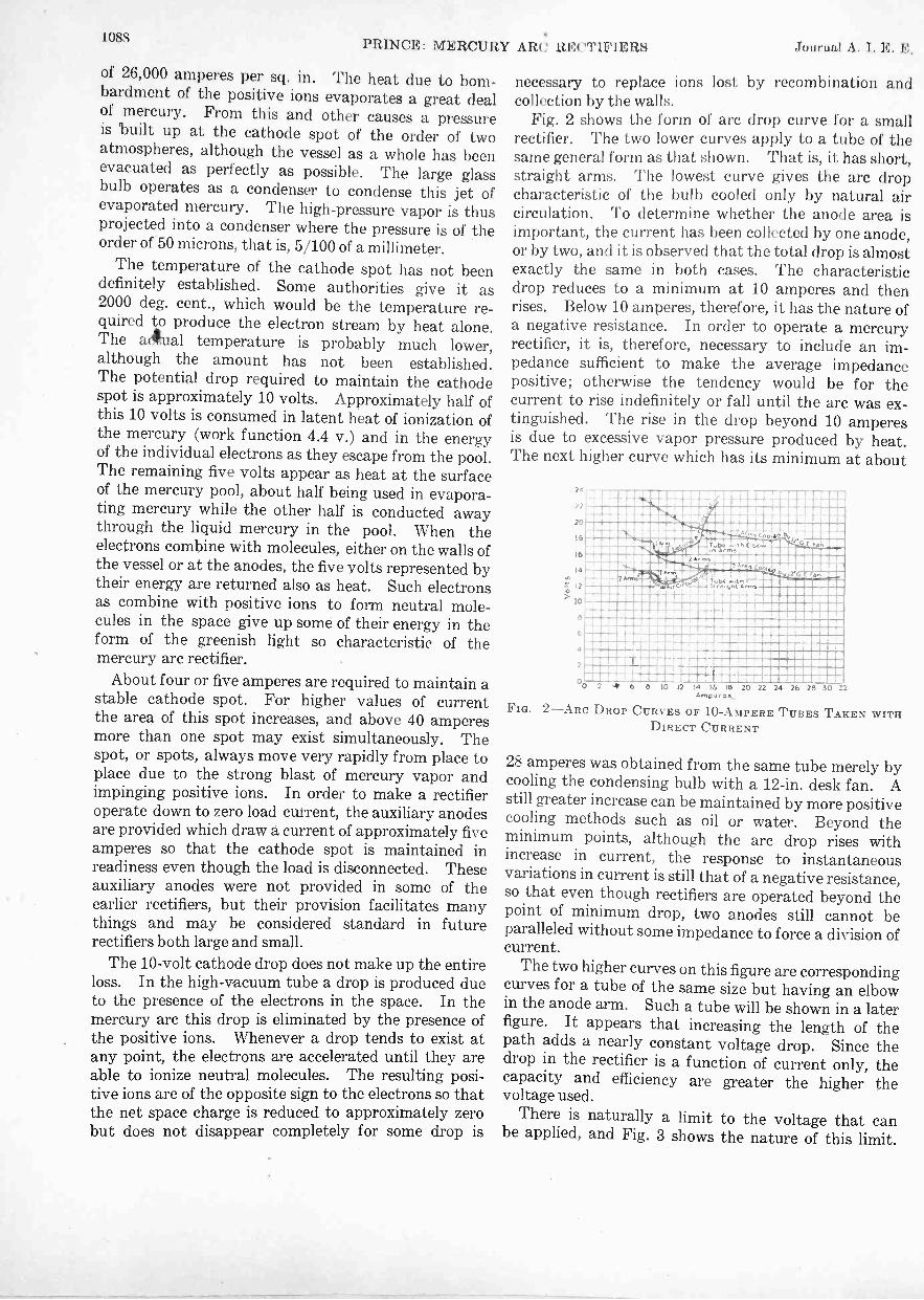
1088PRINCE: MERCURY ARC RECTIFIERS Jotirmi.,1 A. I. 10,. E,
of 26,000 amperes per sq. in. The heat due to bom-bardment of the positive ions evaporates a great dealof mercury. From this and other causes a pressureis built up at the cathode spot of the order of twoatmospheres, although the vessel as a whole has beenevacuated as perfectly as possible. The large glassbulb operates as a condenser to condense this jet ofevaporated mercury. The high-pressure vapor is thusprojected into a condenser where the pressure is of theorder of 50 microns, that is, 5/100 of a millimeter.
The temperature of the cathode spot has not beendefinitely established. Some authorities give it as2000 deg. cent., which would be the temperature re-quired to produce the electron stream by heat alone.The akal temperature is probably much lower,although the amount has not been established.The potential drop required to maintain the cathodespot is approximately 10 volts. Approximately half ofthis 10 volts is consumed in latent heat of ionization ofthe mercury (work function 4.4 v.) and in the energyof the individual electrons as they escape from the pool.The remaining five volts appear as heat at the surfaceof the mercury pool, about half being used in evapora-ting mercury while the other half is conducted awaythrough the liquid mercury in the pool. When theelectrons combine with molecules, either on the walls ofthe vessel or at the anodes, the five volts represented bytheir energy are returned also as heat. Such electronsas combine with positive ions to form neutral mole-cules in the space give up some of their energy in theform of the greenish light so characteristic of themercury arc rectifier.
About four or five amperes are required to maintain astable cathode spot. For higher values of currentthe area of this spot increases, and above 40 amperesmore than one spot may exist simultaneously. Thespot, or spots, always move very rapidly from place toplace due to the strong blast of mercury vapor andimpinging positive ions. In order to make a rectifieroperate down to zero load current, the auxiliary anodesare provided which draw a current of approximately fiveamperes so that the cathode spot is maintained inreadiness even though the load is disconnected. Theseauxiliary anodes were not provided in some of theearlier rectifiers, but their provision facilitates manythings and may be considered standard in futurerectifiers both large and small.
The 10 -volt cathode drop does not make up the entireloss. In the high -vacuum tube a drop is produced dueto the presence of the electrons in the space. In themercury arc this drop is eliminated by the presence ofthe positive ions. Whenever a drop tends to exist atany point, the electrons are accelerated until they areable to ionize neutral molecules. The resulting posi-tive ions are of the opposite sign to the electrons so thatthe net space charge is reduced to approximately zerobut does not disappear completely for some drop is
necessary to replace ions lost by recombination andcollection by the walls.
Fig. 2 shows the form of arc drop curve for a smallrectifier. The two lower curves apply to a tube of thesame general form as that shown. That is, it has short,straight arms. The lowest curve gives the arc dropcharacteristic of the bulb cooled only by natural aircirculation. To determine whether the anode area isimportant, the current has been collected by one anode,or by two, and it is observed that the total drop is almostexactly the same in both cases. The characteristicdrop reduces to a minimum at 10 amperes and thenrises. Below 10 amperes, therefore, it has the nature ofa negative resistance. In order to operate a mercuryrectifier, it is, therefore, necessary to include an im-pedance sufficient to make the average impedancepositive; otherwise the tendency would be for thecurrent to rise indefinitely or fall until the arc was ex-tinguished. The rise in the drop beyond 10 amperesis due to excessive vapor pressure produced by heat.The next higher curve which has its minimum at about
r .
..... -2 - Nismom.Nam0 0 2 4 6 8 10 12 14 18 20 22 24 26 28 30 32
Amp -as
FIG. 2-ARC DROP CURVES OF 10 -AMPERE TUBES TAKEN WITHDIRECT CURRENT
28 amperes was obtained from the same tube merely bycooling the condensing bulb with a 12 -in. desk fan. Astill greater increase can be maintained by more positivecooling methods such as oil or water. Beyond theminimum points, although the arc drop rises withincrease in current, the response to instantaneousvariations in current is still that of a negative resistance,so that even though rectifiers are operated beyond thepoint of minimum drop, two anodes still cannot beparalleled without some impedance to force a division ofcurrent.
The two higher curves on this figure are correspondingcurves for a tube of the same size but having an elbowin the anode arm. Such a tube will be shown in a laterfigure. It appears that increasing the length of thepath adds a nearly constant voltage drop. Since thedrop in the rectifier is a function of current only, thecapacity and efficiency are greater the higher thevoltage used.
There is naturally a limit to the voltage that canbe applied, and Fig. 3 shows the nature of this limit.

Nov. 1926 PRINCE: MERCURY ARC RECTIFIERS 1089
This figure shows what is known as the "arc backcharacteristic" of a 20 -ampere glass rectifier withnatural air circulation. It appears that for any current,there is a maximum voltage which the tube will rectify.Above this voltage one of the anodes becomes a cathode,so that the unidirectional conductivity of the deviceis lost.
Like the point of minimum arc drop, the current
FIG.
4600
4400
4200
4000
3800
3600
3400
3200
3000
2800
2600s02400
.0' 2200
2000
1800re
1600
1400
1200
1000
800
600
400
200
0
111111111'1 111 !!!!!!!!!!!!
1111111111111 111111111111ME= MEMRCIMMOMPMEMEMEMINIMEMMEMM EMMIIMMEMMEMMIIMMEMMOM
111111 111111111111111
ribl"1111111111111111111111 I Ilk
11111111111 11111111 Wig6 8 10 12 14 18 20 22 24 26 28Rectified Current avere9C
3-ARC BACK CURVE FOR 20 -AMPERE TUBES WITH BENTARMS
at which such a failure or arc back occurs can be in-creased by cooling. The probable mechanism issubstantially as follows. When the anode is negative,some of . the positive ions will be attracted toward itand will strike it with considerable velocity. Undernormal conditions very few of these collisions willproduce electrons from the anode. Some few willbe drawn out, however, and these will proceed toward
T T4
711tSupply
urrentdal
a c
a' c.
FIG. 4-IDEAL SINGLE-PHASE, FULL -WAVE RECTIFIER CIRCUIT
the cathode, ionizing further molecules as they go.The additional positive ions produced in the neighbor-hood of the anode will return toward it, and they alsowill produce a certain small number of electrons. Thehigher the negative voltage on the anode, the more ofthese electrons will be produced. The higher thevapor pressure, the more collisions each electron willmake and the more positive ions they will produce.Thus a point is reached where, by increasing vapor
pressure with temperature or by increasing voltage,so many electrons will be drawn from the anodethat it will become a cathode and rectification ceases.
Primary Voltage
Load voltage
FIG. 5-WAVE SHAPES OBTAINED WITH CIRCUIT OF FIG. 4
This covers in a general way the principal phenomenaof the rectifier. Under normal conditions it gives analmost perfect unidirectional action with a relativelysmall drop, so that in circuit determinations we mayneglect all but the unidirectional effects.
Fig. 4 shows the most elementary rectifier circuit.Power is supplied from any alternating current sourqto transformer primary T. The secondary T' isconnected at its terminals to anodes a and a'. Inthis case high -vacuum rectifiers are indicated. Thecathodes c and c' are connected together and to themidpoint of transformer secondary T' through theload R.
Fig. 5 shows the primary voltage and voltage andcurrent across load resistance R. During the half -cycle that anode a is positive, electrons flow from c to a;that is, current in the usual sense flows from a to c andreturns through R in the direction shown by the arrow.
A -C. PowerSource
FIG. 6-MERCURY ARC RECTIFIER CIRCUIT WITH SMOOTHINGINDUCTANCE IN OUTPUT CIRCUIT
During the other half -cycle, a' is positive and currentflows from a' to c' and returns through R in the directionshown by the arrow, that is, during both of thesehalf -cycles, current has flowed in the same direction
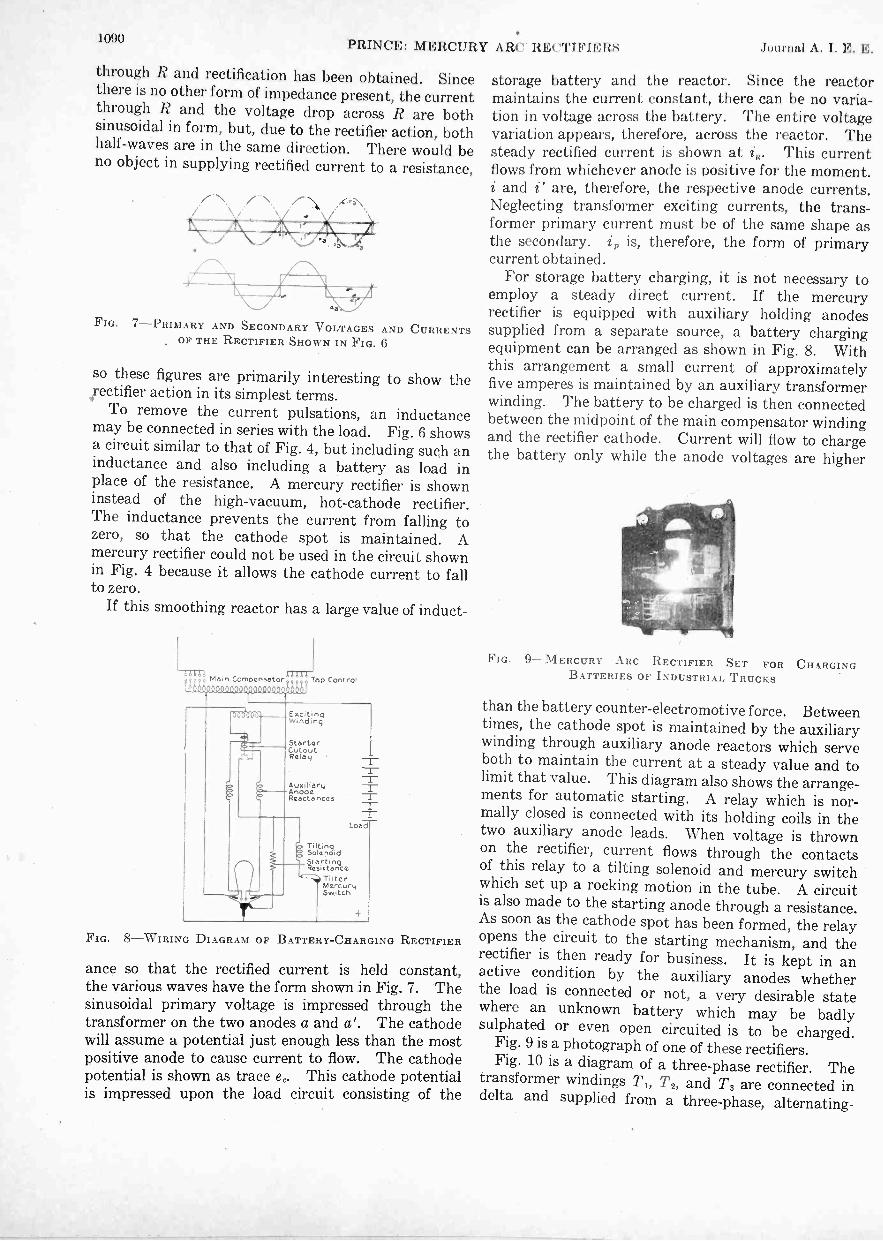
1090PRINCE: MERCURY ARC' RECTIFIERS Journal A. I. E. E.
through R and rectification has been obtained. Sincethere is no other form of impedance present, the currentthrough R and the voltage drop across R are bothsinusoidal in form, but, due to the rectifier action, bothhalf -waves are in the same direction. There would beno object in supplying rectified current to a resistance,
FIG. 7-PRIMARY AND SECONDARY VOLTAGES AND CURRENTSOF THE RECTIFIER SHOWN IN FIG. 6
so these figures are primarily interesting to show the,rectifier action in its simplest terms.
To remove the current pulsations, an inductancemay be connected in series with the load. Fig. 6 showsa circuit similar to that of Fig. 4, but including such aninductance and also including a battery as load inplace of the resistance. A mercury rectifier is showninstead of the high -vacuum, hot -cathode rectifier.The inductance prevents the current from falling tozero, so that the cathode spot is maintained. Amercury rectifier could not be used in the circuit shownin Fig. 4 because it allows the cathode current to fallto zero.
If this smoothing reactor has a large value of induct-
cdbdbin Compensatorf Teo Control
Exc.tingwinding
StarterCutoutRelay -
AuxiliaryAnodeReactances
TiltingSolenoid
tIstetirtar?ceTilterMerCurt4Switch
-1-1Loao
FIG. 8-WIRING DIAGRAM OF BATTERY -CHARGING RECTIFIER
ance so that the rectified current is held constant,the various waves have the form shown in Fig. 7. Thesinusoidal primary voltage is impressed through thetransformer on the two anodes a and a'. The cathodewill assume a potential just enough less than the mostpositive anode to cause current to flow. The cathodepotential is shown as trace ec. This cathode potentialis impressed upon the load circuit consisting of the
storage battery and the reactor. Since the reactormaintains the current constant, there can be no varia-tion in voltage across the battery. The entire voltagevariation appears, therefore, across the reactor. Thesteady rectified current is shown at i. This currentflows from whichever anode is positive for the moment.i and i' are, therefore, the respective anode currents.Neglecting transformer exciting currents, the trans-former primary current must be of the same shape asthe secondary. ip is, therefore, the form of primarycurrent obtained.
For storage battery charging, it is not necessary toemploy a steady direct current. If the mercuryrectifier is equipped with auxiliary holding anodessupplied from a separate source, a battery chargingequipment can be arranged as shown in Fig. 8. Withthis arrangement a small current of approximatelyfive amperes is maintained by an auxiliary transformerwinding. The battery to be charged is then connectedbetween the midpoint of the main compensator windingand the rectifier cathode. Current will flow to chargethe battery only while the anode voltages are higher
FIG. 9-MERCURY ARC RECTIFIER SET FOR CHARGINGBATTERIES OF INDUSTRIAL TRUCKS
than the battery counter -electromotive force. Betweentimes, the cathode spot is maintained by the auxiliarywinding through auxiliary anode reactors which serveboth to maintain the current at a steady value and tolimit that value. This diagram also shows the arrange-ments for automatic starting. A relay which is nor-mally closed is connected with its holding coils in thetwo auxiliary anode leads. When voltage is thrownon the rectifier, current flows through the contactsof this relay to a tilting solenoid and mercury switchwhich set up a rocking motion in the tube. A circuitis also made to the starting anode through a resistance.As soon as the cathode spot has been formed, the relayopens the circuit to the starting mechanism, and therectifier is then ready for business. It is kept in anactive condition by the auxiliary anodes whetherthe load is connected or not, a very desirable statewhere an unknown battery which may be badlysulphated or even open circuited is to be charged.
Fig. 9 is a photograph of one of these rectifiers.Fig. 10 is a diagram of a three-phase rectifier. The
transformer windings T,, T2, and T3 are connected indelta and supplied from a three-phase, alternating-

Nov. 1926 PRINCE: MERCURY ARC RECTIFIERS 1091
current source. The transformer secondary windingst1, t2, and t, are connected so as to form a Y. Theouter ends of the Y are connected to anodes al, a2, anda3. The cathodes are connected through an inductanceL, and the load R to the Y point of the transformer.Hot cathode rectifiers are indicated although no changewould be involved in inserting a mercury rectifier.
Fig. 11 shows the wave forms obtained by this
T3
FIG. 10-CIRCUIT DIAGRAM OF THREE-PHASE RECTIFIER
arrangement. The three-phase or anode voltages areshown as e,, e2, and e3. The cathode follows these insuccession, always assuming a potential sufficientlybelow the more positive anode to cause the current toflow. The total current is maintained constant by theinductance L so that the drop across the load is theaverage cathode potential and is shown at E. Since thetotal current is constant as shown at I and current flowsalways to the more positive anode, the three anodecurrents are as shown in ii", i2", and i3", each one havingfull value of the rectified current for M of a cycle.Since the transformer will not transform direct current,the transformer primary will carry only the alternating
J.; 12 13
a11 11
aihi.V" 'V Ve V
b
d
FIG. 11-PRIMARY AND SECONDARY VOLTAGES AND CURRENTSOF THE RECTIFIER SHOWN IN FIG. 10
component of these waves. These components areindicated as i ', i2', and is'. Combining these currentsin pairs at the corners of the delta gives the three linecurrents i i2, and i3. It is observed that both line anddelta currents are not symmetrical. This indicates thatwith this connection there are even harmonics of currentpresent. Even harmonics have an opposite phaserotation from the normal and so are still more objection -
from
able than odd harmonics. Two three-phase rectifiersmay be connected as shown in Fig. 12, however, to forma six -phase rectifier. With this arrangement, instead ofproviding two inductances L, a single compensator or
FIG. 12-DOUBLE THREE-PHASE RECTIFIER
"interphase transformer" can be used provided the twothree-phase rectifiers are connected 180 deg. out ofphase as shown. The resulting six -phase rectifier is theone which is usually used for power installations.
The foregoing wave diagrams are made on the as-sumption that there is no inductance in the alternatingcircuits. On this same assumption a mercury rectifierhas a perfectly definite voltage ratio. If we have arectifier of p phases, the cathode will follow the anode
2p
the pulsations are absorbed by the inductance L, thedirect voltage available is the average of a sine wave forthis interval. By referring to Fig. 13, the averagevoltage may be obtained by integrating a cosine wave
-7rp
to . This gives a value for the
direct -current voltage G = E sin . This
general expression gives the light load voltage for arectifier of any number of phases. The rectifier in
Fig. 13
Fig. 12 was made up of two three-phase units andtherefore has an output voltage corresponding to threephases.
The perfectly square current waves shown in thecurrent diagrams could only exist in an inductance less

1092PRIN(71!1: M ElICUItY Alt(' It TIFIE RS lunrnnl A
circuit, since otherwise it would require infinite voltage toproduce an instantaneous change of current. Actually,therefore, the current does not change instantaneously.Instead, when the point of the cycle is reached at whichtwo anodes have the same potential, the current beginsto shift from one to the other Since this shift isbrought about by a sinusoidal voltage difference be-tween the two anodes, the changing component of
\
//
,
1i
,,
/-- ------------ `." ---- - ---- - --- 4 -- i\
FIG. 14-GRAPHICAL REPRESENTATION OF CONDITION ARI:,-ING FROM THE SUPPOSITION THAT THE TRANSFORMER SHOWN INFIG. 6 HAS LEAKAGE REACTANCE
current will be sinusoidal, and, if the primary impedanceis nearly all inductive, as it usually is, the current willstart to change just as though an alternating voltagewere suddenly impressed on a circuit carrying a directcurrent. The condition is shown in Fig. 14. A steadycurrent is maintained at a value I by the inductanceL up to the time to, at which time there is no differenceof potential between the anodes a and a'. At this pointthe current will begin to change as though it were goingto follow the dotted curve i. This curve is exactly thecurve that would be obtained in impressing a voltageon a circuit of inductance and small resistance; thatis, it has an axis u which has the decrement factor
- r tL . The alternating component has a constant
tot'
FIG. 15-OUTPUT CURRENT AND VOLTAGE WAVES, SHOWINGEFFECT OF 26 -DEG. PERIOD OF SHORT CIRCUIT DURING WHICHCURRENTS ARE TRANSFERRED AND No VOLTAGE IS PRODUCEDBY THE RECTIFIER
amplitude. Of course, this current cannot continueto flow, as by the time t', the current to the anode a hasbeen reduced to zero, and it is prevented from reversingby the unidirectional conductivity of the rectifiertube. We are therefore interested in only a part ofthis transient curve which takes place between timesto and t'.
During the interval to and t' during which currentflows from two anodes, those two anodes must be at thesame potential. The transformer secondary is thus
in effect short circuited for this interval, and there is nooutput voltage. This relation is shown in Fig. 15.is and i.' represent the anode currents. a and a'
FIG. 16 -10 -AMPERE, 300 -VOLT GLASS RECTIFIER
FIG. 17-THREE-PHASE, 20 -AMPERE GLASS RECTIFIER
FIG. 18-30, 100 -AMPERE, THREE-PHASE RECTIFIER
represent the corresponding anode voltages. Thecathode now follows these lines, and it, therefore, has an

Nov. 1926 PRINCE: MERCURY ARC RECTIFIERS 1093
average value somewhat less than in the case where noinductance is present.
This is the mechanism which acts for rectifier voltageregulation. Elaborate equations have been worked outto give the amount of this regulation, but they will notbe dealt with at this time.
Leaving now the rectifier circuits, we shall review
FIG. 19 -250 -AMPERE GLASS RECTIFIER
FIG. 20 -100 -Kw. RECTIFIER USING Two 250 -AMPERE TUBES
FIG. 21-ANTERIOR OF A 100 -Kw. RECTIFIER
some of the forms of rectifiers which have been made.Fig. 16 shows the smallest mercury rectifier now made
by the General Electric Company. This rectifier has arating of 10 amperes and 300 volts. It' has an over-all height of approximately 8 in.
Fig. 17 shows a three-phase, 20 -ampere glass rectifier.Fig. 18 shows a 50/100 -ampere, three-phase rectifier.
This rectifier is approximately 30 in. high and is thelargest glass rectifier made by the company before1925. The two ratings given are one for natural air
FIG. 22-EARLY IRON RECTIFIER
FIG. 23-MODERN IRON RECTIFIER
700 'eldoWer-f actor i
I I II11-'Re ulation
ro i 1 li iLoad (Amperes)
FIG. 24-CHARACTERISTIC CURVES OF AN IRON RECTIFIER
cooling and the other for fan cooling. The currentratings apply to approximately 220 volts and must bereduced somewhat if higher voltages are used. It isquite feasible to use voltages as high as 3000 for thesetubes.
Fig. 19 shows the new 250 -ampere glass rectifier

109 4 NELSON: MULTI XLEX WINDINOS I) -t'. MACHINES Journal A. 1. E. E.
developed during the last year. The normal rating is250 amperes, 250 volts fan cooling. One of this typewas operated in oil at 200 amperes, 3000 volts andwithstood repeated short circuits opened by a high-speed breaker.
Fig. 20 shows a 100 -kw. rectifier now supplying a shopcircuit in the Schenectady works. This rectifieremploys two of the 250-ampere glass tubes. Theinterior of it is shown in Fig. 21. From the earliestdays, attempts were made to make rectifiers of iron in
FIG. 25-TYPICAL STREET RAILWAY LOAD
large sizes. Fig. 22 shows one of these early rectifierswhich was modeled quite closely in form after the glassrectifier. As iron is not subject to the same limitationsas to form, later rectifiers have been made similar toFig. 23, which is a photograph of the rectifier shown atthe Atlantic City convention during the fall of 1925.
Fig. 24 shows the characterisitc performance of such arectifier operating a street railway' load. The highefficiericy under light loads is particularly significant asthe load factor of street railways is notoriously poor.
Fig. 25 shows the kind of load factor met in thisservice.
One objection to the iron type of rectifier as usuallyconstructed is that some leakage always occurs withbolted joints, although the amount may be very small.For this reason, it is necessary to have a vacuum pumpattached to the rectifier, although it need not beoperated at all times. Attempts have been made to
FIG. 26-SMALL IRON RECTIFIER WITH ALL JOIN] WELDED
avoid the need for a vacuum pump by the use of sealsfused directly to the metal parts. The rectifier shownin Fig. 23 has no clamped joints between metal andinsulation, and, by the use of well fitted metal to metaljoints, the danger of leakage is greatly reduced. It ispossible to go still further and make rectifiers in whichthe sealing is complete. Fig. 26 is a small one of thiskind which showed no indications of impaired vacuumthree months after being evacuated and sealed.
ultiplex Windings for D -C. _MachinesBY CARL C. NELSON
Enrolled Student
Synopsis.-With the increase in capacity of d -c. machines, thequestion of their successful operation has become more and moreimportant. It is thought that multiplex windings offer creditableadvantages if they are designed so that cross connections can besuitably applied and the circuits thereby kept balanced, a featurewhich was not given thorough consideration when multiplex windingswere first tried.
This paper describes machines in .which the proper design maybe secured when standard construction is used. Both the lap andwave types of windings arc considered. The principles are appliedto duplex windings in this paper, but if so desired they may beapplied also to triplex and other multiplex windings.
A brief description of "frog leg windings," a recently developedtype of multiplex winding, is also given.
THE use of multiplex windings in large d -c. machinesoffers marked improvements provided the windingscan have 'armature cross connections properly
applied to them, so that the armature circuits can bekept balanced; that is, the currents in the circuits maybe kept equal. This result has been successfully ac-complished with multiplex windings on practicalmachines with the ordinary type of cross connections in
1. Massachusetts Institute of Technology.Presented at the Annual Convention of the A. 1. E. E.,
White Sulphur Springs, W. Va.. June 21-25, 1926.
a few cases (see references 6 and 7), and it seemsprobable that the same good results can be obtained inother cases.
Multiplex windings have, in general, more parallelpaths and, consequently, less current per coil than thecorresponding simplex windings which are usually used.Accordingly the current to be commutated is muchsmaller and therefore the amount of sparking is re-duced. The fact that an increase in the number ofparallel paths in an armature winding improves commu-tation, (other things being equal,) is exemplified by the

Nov. 1926 NELSON: MULTIPLEX WINDINGS FOR D -C. MACHINES 1095
well-known case of an armature which is of such ratingthat either a wave or lap winding could be used. Thelatter is distinguished by more paths in parallel, moreand narrower commutator bars and better commuta-tion, as is well known from practical experience. If,then, multiplex windings, having even more paths inparallel than the ordinary lap windings, can be safelyused and kept properly balanced, another step in theimprovement of commutation may be expected. Theadvantages to be obtained justify further study andtrial of multiplex windings.
The windings used in practise at the present timeare usually simplex wave, simplex lap, and, occasion-ally, an eight -pole, duplex wave winding. This is avery limited assortment.
A number of machines tried in the past with multiplexwindings were not designed properly and armaturecross connections could not be applied suitably. Thedesirable condition would be the interconnection ofequipotential points in one individual part of a multi-plex winding to equipotential points in another individ-ual part of the multiplex winding, and so on. In thisway all the individual parts would be joined together.In addition, the winding should be so arranged that theresulting potential distribution on the commutatorwould be uniform and the volts per bar would be of alow value. Arnold has advocated the use of crossconnections and has shown triplex wave windings'with the cross connections joining equipotential pointsof the three individual parts of the winding, which is thedesirable condition. In describing Fig. 12 (reference7), it is stated that triplex lap windings have beenmade with efficient cross connections on one end of thearmature and have operated successfully. Arnold,however, has not shown duplex lap and triplex lapwindings with simple cross connections joining the indivi-dual parts of the winding together. In his early work hehas shown duplex lap windings' so arranged thatequipotential points in the same part of the duplexwindings were joined, thereby giving a potential dis-tribution on the commutator such that bars in pairswere at the same potential. This has the same effectas using half the number of bars and therefore is notdesirable. In his later work, Arnold has shown duplexlap windings with equalizing rings4 both on the frontand back of the windings and with connections fromthe front to back joining these rings, thus intercon-necting the individual parts of the duplex winding.This method introduces the complication of crossconnections at both front and rear ends of the armature,and of connectors along the shaft. It would be moredesirable to use the arrangement proposed in this papet,
2. See p. 87, Die Gliechstrommaschine Arnold-la Cour,Third Edition, 1919, Julius Springer, Berlin.
3. See p. 177, Die Gleichstrommaschine, Arnold, SecondEdition, 1906, Julius Springer, Berlin.
4. See p. 82, Same reference as 1, and Fig. 14, p.604, Stand-ard Handbook for Electrical Engineers, Edition of 1922.
in which all the cross connections are at the rear end of
the armature.It is very desirable that multiplex windings be used
where they are successful, since by means of themd -c. machines can be designed to have as many and asnarrow commutator bars as possible. This results in acommutator bar in large machines from N to in.in width, which is considerably narrower than many inuse. The benefit of the smallest current per circuit aswell as a corresponding improvement in commutationwill thus be obtained.
A preliminary investigation as to the number ofslots and bars and their relations in certain machinesusing multiplex windings has been made by the authorin the Electrical Engineering Department of theMassachusetts Institute of Technology. It is hiswish to duly acknowledge a number of valuable sug-gestions made by Professor H. B. Dwight of thisdepartment.
The windings used in the figures for purposes ofillustration have been shown as applied to cores withextremely few slots and should therefore not be con-sidered as actually, usable windings. This has beendone so as to present clearly the principles which are tobe applied to practical windings. The naming of thetypes of windings herein is similar to that used in theStandard Handbook for Electrical Engineers.
Multiplex windings were proposed in the earlywritings on d -c. machines, but little or nothing was saidabout cross connections. Where there are four or moreparallel paths through the armature, these are usuallynecessary. The cross connections must be madebetween points having mathematically the samevoltage, the flux being the same in all poles. This isprovided for in the windings suggested in this paper.
The type of winding proposed is an ordinary multi-plex winding so arranged that a system of cross con-nections, all at one end of the armature, can be con-veniently applied to equipotential points, therebyjoining to one another the individual parts of thewinding' and producing a uniform distribution ofpotential on the commutator. These connectionsare shown on the diagrams of this article.
The shape of the coils of a duplex lap winding is thesame as that of the coils for a simplex lap winding andno departure is made from the usual construction. Allthe coils for any one machine are of the same size andshape. The ends of the coils in a duplex lap winding areconnected to bars 1, 3, 5, and so on to all theodd numbered bars. Another part of the windingplaced in the slots connects to bars 2, 4, 6, . . . .
and so on to all the even numbered bars. There aretwo cases to be considered. In Case I, when the totalnumber of commutator bars is even, the two parts of thewinding are separate and independent except as they
5. See p. 244, The Dynamo, C. C. Hawkins, Volume I, SixthEdition, 1922, Sir Isaac Pitman & Sons, Ltd., London.

1096 NELSON: MULTIPLEX WINDINOS FUR T) -C. MACHINES Journal A. I. E. E.
are joined by equipotential or cross connections. Atwo-part winding of this type is known as doubly re-entrant and will be referred to herein as such. It is rep-resented by the four -pole diagram, Fig. 1, and by thesymbol 0 0
In Case II when the number of commutator barsis odd and the coil ends are connected to every other bar,the first part of the winding goes around the armatureand leads into the second part of the winding, which,after going around the armature, connects to the first
FIG. 1 (CASE I)-DUPLEX LAP WINDING, DOUBLE RE-ENTRANTFour poles, 18 slots, 18 bars, 8 paths. Cross connections as shown
FIG. 2 (CASE ID-DUPLEX LAP WINDING, SINGLY RE-ENTRANTSix poles, 27 slots, 27 bars, 12 paths. Cross connections as shown
part, resulting in a continuous winding. This windingis referred to as singly re-entrant and is represented by
the six -pole diagram, Fig. 2, and by the symbol CD
The diagrams show the cross connections joining thetwo parts of the duplex lap winding, which is a de-sirable feature. The commutator potential is shown toprogress fairly uniformly around the commutator,which is also desirable. To arrange the cross connec-
tions properly and to secure these results cer-tain numbers of slots and bars must be used. Themethod of cross connecting,as shown, can be used withduplex lap windings on the following machines when thechoice of slots and bars is made as indicated in Table A.
TA B LE ADUPLEX LAP WINDINGS
N umber Slots per Total liars Total ite-of Pole. Pair of Poles No. Slots per Slot No. Mini entrancy- -
a. 4b. (I
Odd no.Odd no.
1,:vvo no.Odd no.
Odd no.Odd no.
Even no.Odd no.
DoubleSingle
0 0
c. 8 Odd no. Even no. Odd no. Even no. Double 0 0d. 10 Odd no. Odd no. Odd no. Odd no. Single CDe. 12 Odd no. Even no. Odd no. Even no. Double 0 0
There may be a cyclical change in the number ofslots per path but this is quite possibly not harmful, forit occurs with two -circuit windings which operatesuccessfully. The great improvement in commutating
om.aaamappomvaamm000-coo.<mnt110 naC 0,0np-i9ici
FULL LINE WINDINGur? m cv Ot ,:r1 al aN 4) rxi
NOA-DtVOTTED LINE WINING.,..mm4 c,, ."00
Cs,
0 no Na a er 0,
1:S1... LINE WINDINGr-. , o (s! O.
O. g Fes. g1 '41
DOTTED LINE WINDING
to
46
20
O
FIG. 3 (CASE I)-VOLTAGE DISTRIBUTION DIAGRAM FOR DUPLEXLAP WINDING, DOUBLY REENTRANT
Four poles, 18 slots, 18 bars, 8 paths, (same winding as Fig. 1)
characteristics obtained by having only half as muchcurrent per path to be reversed at one time would seemto be the important consideration in connection withthis type of winding.
In determining the voltage distribution (see Fig. 3)the developed winding is laid out and a field form asmight naturally be expected is plotted above thewinding. As the voltage in a conductor is proportionalto the flux it cuts, an excellent idea of the voltage dis-tribution may be secured by summing up the voltagesinduced throughout the winding. In doing this, it isassumed that any conductor in a slot generates a voltageproportional to the flux directly above the center lineof that slot.
Another type of winding is the duplex wave windinghaving four parallel paths through the armature. Thistype would give an intermediate step between the sim-plex wave and the simplex lap winding and although.

Nov. 1926 NELSON: MULTIPLEX WINDINGS FOR D -C. MACHINES 1097
the benefits to be derived from the use of this type arenot expected to be as great as those obtained with theduplex lap winding, certain cases may justify the use of
this type. An eight -pole, duplex wave winding is usedrather extensively at the present time and has provensatisfactory. Such a winding with cross connectionsjoining equipotential points of the individual parts of
the duplex winding is advocated and shown by Arnold.6
Cross connections joining the two parts of a duplexwave winding are possible in certain cases. Theseconnections should join points having mathematicallythe same voltage when all poles have an equal amount of
flux. They can be used on the following machineswhen the choice of slots and bars is made as indicatedin Table B.
TABLE BDUPLEX WAVE WINDINGS
Number ofPoles
TotalNo. Slots
Barsper Slot
TotalNo. Bars Re-entrancy
f. 8g. 12h. 16
Even no.Even no.Even no.
Odd no.Odd no.Odd no.
Even no.Even no.Even no.
Single or double ac -cording to whethercommutator pitch isodd or even.
Of course these windings must be such that thecommutator pitch, Y, is a whole number where
number of bars ± 2Y - pairs of poles
The cross connections in the windings of the abovetable will span half the number of poles, or in otherwords, they are diametral. When the number of pairsof poles is odd, such as in the six- or ten -pole machine,cross connections to equipotential points diametricallyopposite are not possible. This can be explained asfollows: Suppose that the choice of slots is made so thata point of one part of a duplex winding has a certainposition relative to a pole with one polarity; then acorresponding point in the other part of the duplexwinding has a position under the influence of a pole ofopposite polarity, a condition which does not lend tocross connections. It may be possible that six- and ten -pole, single re-entrant windings of the duplex wave typewould be successful even though they do not have crossconnections.
Triplex windings could be designed on the same basisas the duplex windings herein described, but onlyduplex windings have been treated in this paper, sincethey involve the least departure from simplex windings,and so should be the first to be tried out.
Since the preparation of this article was commenced,a very interesting paper' on Frog Leg Windings byW. H. Powell and G. M. Albrecht has appeared.This illustrates the general principles of using a multi-plex wave winding in the same slots with a lap windingeither simplex or multiplex to a less degree than the
6. See p. 86, Die Gleichatrommarichine Arnold-la Cour,Third Edition, 1919, Julius Springer, Berlin.
7. P. 345, Iron and Steel Engineer, September 1925.
wave winding, so that both windings produce the samevoltage at the brushes and are connected to the same setof commutator bars. The wave winding connects thecircuits of the lap winding and the lap-wound coilsconnect the circuits of the wave winding therebyproducing a thoroughly cross -connected winding. Thename frog leg is used because of the peculiar shape ofthe coils which consist of a lap -wound coil and a wave -wound coil taped together. The advantages obtainedby the authors are, first, better cross connections, andsecond, the use of multiplex windings.
In Part III of the above described paper, a triplexwinding with external cross connections as previouslymentioned, and not of the frog leg type, is mentioned ashaving been made and operated successfully. If triplexwindings, not of the frog leg type as ref erred to above,have been successful, then a duplex winding should alsooperate well when the choice of slots has been madeproperly and the cross connections applied efficientlyas outlined herein.
It is possible that duplex lap windings with or-dinary cross connections as shown will give some of theadvantages of the frog leg winding without the com-plication of having two complete windings in the slots.
ELECTRIC WELDS FOR BUILDINGCONSTRUCTION
A pressure machine capable of applying a load of10,000,000 lb. was used at the Bureau of Standards inWashington to determine whether steel girders weldedby electricity can stand stresses necessary in skyscraperconstruction. The welds made good. In order tomake the test some steel plates were fabricated byelectric welding into a plate girder 15 ft. long having aweb plate M in. thick and 24 in. deep. The flanges were12 in. wide, one was 1% in. thick and the other 1%in. thick. A 9 cover plate was used on the topand bottom flanges. Pressure was applied in themiddle of a 13% -ft. span. The web buckled and thegirder had deflected several inches . before the electricwelds connecting the web to the top flange failed at theends. The welds withstood a load of well over 410tons which was considered to be the full strength ofthe web.
NEW COPPER BEDS.DISCOVERED INCANADA
According to report received from the AmericanConsul at St. John, Canada, comparatively high gradecopper ore has been located from recent prospectingnear Elgin, Albert County, New Brunswick, the pre-liminary examination covering an area of approximatelytwo square miles. According to official assays the orevalue runs as high as $15 per ton.
Shafts have been sunk over the prospected area andcopper ore discovered in every instance, in most casesfrom within 16 inches of the surface and as far downas diggings were made.

Preseto 1)1.;Icties. i I l'ruh'cli()IIAnimal Report I (. AH11111.010, (Hi (' I )t.\ i(.('s*
E. (1. s'r()\1.:,
To the Board of Directors:
FOREWORD
Because of the many developments during the pastfew years within the scope of the Committee on Pro-tective Devices, it was held desirable to present, thisyear, a survey of the present state of the art in the fieldof protective devices for power systems, and the follow-ing annual report has been prepared with this purposein view. The Committee has also, during the pastyear, given careful attention to the possibilities offurther standardization in the field of protective devices,and has certain definite recommendations to make.
As heretofore, the work has been carried on by sub-committees, each under the direction of itsown chairman.The subjects covered and the chairmen in charge areas follows:
Automatic Substations. W. H. Millan, Union Elec.Lt. & Pwr. Co., St. Louis, Missouri.
Current Limiting Reactors. E. A. Hester, DuquesneLight Company, Pittsburgh, Pa.
Lightning Arresters. H. Halperin, CommonwealthEdison Co., Chicago, Illinois.
Oil Circuit Breakers. J. M. Oliver, Alabama PowerCompany, Birmingham, Alabama.
Protective Relays. J. A. Johnson, Niagara FallsPower Co., Niagara Falls, New York.
The Subcommittee on Grounding of Systems, whichreported last year, was not continued this year, as itwas felt that it had completed its work, for the timeat least.
Following are some of the more important subjectsdealt with in the report:
Full automatic stations of the folloWing types arein successful operation:
Hydroelectric generating stationsRailway substations for city and heavy traction,
as well as interurban serviceEdison d -c. substationsMining and steel mill substationsAlternating -current substations (reclosing breakers)Synchronous condenser stations.Mercury arc rectifiers for arc lighting and power*Committee on Protective Devices:
E. C. Stone, ChairmanF. L. Hunt, Vice -Chairman
George S. Humphrey,J. Allen Johnson,M. G. Lloyd,H. C. Louis,A. A. Meyer,
W. S. Edsall.H. Halperin.F. C. Hanker,S. E. M. Henderson.R. A. Hentz,E. A. Hester,
W. H. Milan,J. M. Oliver,N. L. Pollard,E. J. Rutan,E. R. Stauffacher.H. R. Summerhayes.
Presented at the Annual Convention of the A.White Sulphur Springs, W. Va., June 21-25, 1926.
I. E. E., at
sery Jct. alt. lam. 'wing, provided with automatic switch-ing equipmeni
Thor ough 1.(Hodie inspection and maintenance areessential to opei at kin of automaticstat ions.
There is a marked ti end toward the use of reactorswith insulated conductor s, in or der to obtain protectionfrom external inter fei (lee.
Lightning protection on low -voltage circuits (230-115)in 1,eneral appears to I e unnecessary. For distr itutioncircuits up to 6.6 kv., having numerous transformersconnected, satisfactory protection is tieing obtainedfrom available types of arresters in many cases.
On circuits rated at 73 kv. and telow, the generaltendency is to install arresters, usually of the highdischarge rate type. The installation of arresters oncircuits from 73 kv. to 154 kv. is debatable, but there isa growing tendency to provide some means to reduceover -voltages due to lightning. On circuits at 154kv. and higher, the tendency is to omit lightningarresters.
The Dufour oscillograph and klydonograph formeasuring transient phenomena are expected greatly toincrease our knowledge of lightning arrester performanceand requirements for lightning protection.
Relative interrupting capacity ratings for oil circuitbreakers under various operating duties have beenagreed upon by the N. E. L. A. and Electric PowerClub, and are presented herein.
Progress in the problem of short circuit interruptionis recorded in further short circuit tests on operatingsystems, additional testing facilities in manufacturer'splants, and improvement in details of design. Theproblem still remains one of outstanding importance,however, and seems far from satisfactory solution.
In relay practise, definite trends are reported asfollows:
a. Integration of entire system into one unit, sointerconnected and relayed that its integrity shall notbe broken by a fault.
b. Fault isolation by use of balanced relay systems orsystems responsive to location or specific nature of thefault.
c. Use of "back-up" protection, in the form of a secondsystem of relays to function in case of failure of thefirst system.
d. Use of devices for detection of approaching faultsbefore they actually occur.
The committee has given active attention to theobtaining of papers for Institute meetings. Referenceis made herein to a number of important subjects whichshould be covered by papers next year.
1098

Nov. 1926 PRESENT PRACTISES IN PROTECTION 1099
AUTOMATIC STATIONS
Survey. A brief survey of the present status of theautomatic station art seems desirable at this time. Forconvenience, this survey will be considered under severalpertinent topical headings.
Automatic hydroelectric generating stations havebeen the subject of extensive development during thepast three years. Stations containing two 9000-kv-a.units are now in successful operation, while manyranging from 100- to 5000-kv-a. are regularly being in-stalled and operated. Automatic synchronizing hasbeen perfected and is now used where large units areconnected to small systems. Governor design hasbeen improved to meet the rigid requirements of auto-matic station operation. In fact, practically all smallhydroelectric developments and many moderate sizedones are now designed for automatic operation anduniformly successful results are reported.
Railway substations now being purchased are in-variably automatic with rare exceptions due to localconditions. They are not only considered standard forinterurban service but also standard for heavy cityservice and electrified portions of steam railroads.All kinds of service find them economical and reliableand their use is now being rapidly extended not only bythe installation of new stations but also by the con-version of existing stations from manual to automaticoperation.
Automatic substations for Edison, three-wire net-works have now been in successful operation on smalland moderate size systems for over four years. Theirfirst application to two of the largest systems has justbeen completed. Their success for this class of serviceseems assured although more operating experienceis desirable before extensive installations are made onimportant projects.
Mining substations now being purchased are all eithercompletely or partially automatic as individual localconditions warrant. The various designs offered havebeen subjected to operating service for over five
years. As a result the automatic substation is todayconsidered standard by the electrical profession for themotor generators and synchronous converters used inthe coal and metal mining industries for electricitysupply.
Steel mills have been the latest industry to adoptautomatic stations. One small installation of partiallyautomatic -controlled synchronous motor -generatorshas been in successful operation over five years.Another extensive installation of completely auto-matically -controlled synchronous motor -generatorshas been in service almost two years. About eightadditional extensive installations are now in progress sothat it would seem as though steel mill electricalengineers have started toward adopting automaticstations as standard for their service.
Automatic feeders for alternating -current supplyconstitute by far the largest field for completely auto-
matic operation. In practical application, the artis still in an initial state of development. The equip-ments so far offered have simulated manual practisewith the only improvement of more prompt opera-tion. Successful a -c. motor -operated mechanismsare now being applied to the largest oil circuit breakers
thus eliminating solenoids and batteries for reclosingservice. Automatic reclosing relay and oil circuitbreaker combinations are now in operation whichpermit clearing transient feeder faults without appre-ciable service interruption. These so far, however,.
have been applied only to moderate sized, relativelylow pressure service, although in one particular case44,000 -volt feeders are being automatically reclosed ona relatively large capacity power system.
Synchronous condensers for power factor correctionwere first made automatic about ten years ago. Only
a few installations have been made but each has beenuniformly successful and the use of this type of auto-matic switching equipment is spreading with a relativedegree of rapidity.
Mercury arc rectifiers for arc lighting and powerservice are now being provided with automatic switch-ing equipment. The smaller sizes with glass tuberectifiers have been in service a sufficient length of timeto demonstrate their success. Those for larger unitsusing metal tanks are just being placed in service sothat next year's report may contain further data con-cerning their performance.
Railway signal and automatic train control sub-stations are the latest addition to the rapidly growinglist of automatic applications. Some of these have beenin successful operation for over three years. Manyare now being installed to furnish power for the opera-tion of track signals and train control circuits.
Symbols. Symbols for automatic station wiringdiagrams have been attracting increased attentionduring the past year. Data which will give the existingpractise are being collected by the subcommittee. Itis then planned to correlate the various symbols, adjustdifferences where they exist, and finally prepare a simple,agreeable set which may be submitted to the StandardsCommittee for approval and promulgation.
Nomenclature. Nomenclature for various types ofa -c. reclosing feeders was suggested in the 1925 report.These suggestions have been before the electricalengineering public for about a year and no unfavorablecomments have been heard or received by the committee.Instead, it has been found that many of the designersand purchasers of automatic d -c. feedeh have adoptedthe proposed nomenclature. It has, therefore, beenpresented to the Standards Committee for approvaland inclusion in the A. I. E. E. Standards.
Protection. Recommended protection for railwayand Edison automatic stations with synchronousconverters and synchronous motor generators, as wellas for automatic switching equipment in a -c. feederservice, was given in the 1925 report. These recommen-
1100Pia:SP:NT l'1111"I'ltil,:ti IN PIO )14:1. I I4).
dal ions have been adopted as standard by the principalmanor:Let m.o.,: and users t tl t Masses of automat wstat inns, This year there have been developed recom-mendations for the protection of mining and steelmill automatic stations usinv tichronous convertersand motor generators as well ;is synchronous condensersin voltage regulating substations :Ind hydroelectricgenerating stations using synchronous generators.
Steel mill substations are quite generally providedwith synchronous motor generators. Some are partialautomatic as when an attendant is constantly on dutyin the vicinity. Others are completely automatic aswhen the stations ,are non -attended and locked. Thepartial automatic stations are similar in design to thecompletely automatic ones except that certain protect-ive and re -starting features are omitted. The itemsto be omitted vary from installation to installation sothat it is difficult at this time to make any completerecommendation for the partial automatic. For thisyear's report, therefore, consideration will be givenonly to the completely automatic synchronous motor-generators in steel mill service. It is recommended thatthese be provided with protective features as follows:
A -c. undervoltageSevere a -c. overloadSingle-phase startingExcess temperature due to sustained moderate
overloadImperfect startLoss of field of a -c. machineLoss of field of d -c. machineReversed phase rotationD -c. reverse powerExcess bearing temperatureMachine overspeedingMine substations are usually equipped with synchro-
nous motor -generators although some stations havesynchronous converters and a few have inductionmotor generators, with mercury rectifiers beginning tobe used. The recommended protection for synchro-nous motor -generators in mine substations is the sameas that for synchronous motor -generators in steel millservice. Few induction motor -generators are nowbeing applied and only two or three mercury rectifiershave been installed in mine service so that recommen-dations for these are omitted for the time being. Forsynchronous converters in mine service it is recom-mended that protection be given as follows:
A -c. undervoltageSevere a -c. overloadSingle-phase startingExcess temperature due to sustained moderate
overloadImperfect startLoss of fieldD -c. overloadIncorrect polarityD -c. reverse power
EXCI II
111W
I'm. :00 onat it. IlydrOeleet Stliti.(;)n.Iin
With SY110111)11(ill }.'11111:11()US and for synchronousdenser stations i (pole similar. For synchronouxgenerators in automatic stations, 11w recommendedprotection is as follows:
A -c. undervoltageSevere a -c. overloadExcess tempetature due to sustained moderate
overloadSingle-phase operat ionImperfect startLoss of a -c. machine fieldExciter overvolt apeExcess bearing temperatureMachine overspeedingSynchronouscondensers usually have, in addition, a -c.
undervoltage and single-phase starting protection.They are usually provided with automatic voltageregulators so that the exciter over voltage protectionincluded for synchronous generators is in that caseomitted.
Storage Batteries. The majority of automatic sta-tions are not provided with storage batteries. If theyare automatic hydroelectric stations, a small turbineor waterwheel directly connected to a generator seemsto be the preferred source of control power. If theyare substations, then the source of power suitablytransformed is used to supply the operating current.
Some designs of automatic stations, particularly thoseused for certain classes of Edison service and for allclasses of remote supervision, require relatively smalloperating batteries. Practically all types of standardbatteries have been used with an equal measure ofsuccess although some are better adapted than othersfor this service. In general, the batteries are tricklecharged through rectifiers or motor generators. In afew unusual designs, a motor -generator is provided tocarry the operating load with a battery floated on it forstand-by purposes.
Oil Circuit Breakers. Oil circuit breakers are used inautomatic stations between incoming lines and thestation equipment and between the station equipmentand outgoing lines and feeders. The two applicationsrequire quite different treatment in the selection of theoil circuit breaker equipment if a maximum of re-liability is obtained.
When used between the incoming line and the stationequipment, the oil circuit breaker is closed each time themachine in the station is started and opened each timeit is stopped. Usually such an oil circuit breaker isoperated most frequently to make or break currents lessthan its normal continuous current carrying capacity.However, it may be required to operate from two to onehundred times each day depending upon the serviceconditions.
Oil circuit breakers used between the station equip-

Nov. 1926 PRESENT PRACTISES IN PROTECTION 1101
ment and outgoing feeders are normally closed. Theyare opened usually only in case of trouble or to permitof circuit maintenance. These oil circuit breakers willconsequently operate infrequently. Usually, however,when they do operate, they will be called upon tointerrupt currents approximating their circuit inter-rupting capacity.
In the first case, a so called "one-shot" breakersuffices if its mechanical parts permit the required fre-quent operation. In the second case, the circuit in-terrupting capacity on successive interruptions is themore important function with the mechanical life ofsecondary consideration.
To meet the frequent operating requirements of thebreaker located between the incoming line and the sta-tion equipment, there have been developed new designsof universal motor operating mechanisms. Some ofthese have been in service in excess of five years.They eliminate the difficulties experienced with theolder type of operating mechanisms and give a verymuch improved automatic station equipment.
For improving the requirement of successive circuitinterruption to clear feeder faults, various schemes havebeen approved and are being tried. Double tanks,slow release of gases, ventilating ducts, and explosionchambers are all in use with no marked preferenceconceded at this time.
Reclosing Cycle. The reclosing cycle used for oilcircuit breakers which protect feeder service in auto-matic stations varies from application to application.In one extreme case, each time a feeder breaker opens, itis held open until closed from a central operating point;i. e., it is closed under the supervision of an operator sothat in case the trouble persists the operator can im-mediately report the difficulty to a central load dis-patcher. At the other extreme is the application wherean oil circuit breaker may reclose on a fault five or sixtimes in rapid succession.
So far as is known by the committee, there are onlytwo installations where the operation of the breakers issupervised after each automatic opening and only oneinstallation where the breakers reclose five or six timesin rapid succession' on a circuit fault.'. By far themajority of automatic reclosing feeders in alternating-current service are reclosed two, three, or four times on afault before being locked out.
The reclosing cycle having three reclosures before lockout is almost universally standard. The time intervals,between reclosures, however, vary between relativelywide limits. One group of operators, which is rapidlygrowing, prefers to have the breakers reclose immediatelyafter the first or initial circuit interruption. They wantthis time made as short as practicably consistent withpositive relay and oil circuit breaker operation. Themajority of operating companies, however, appear to besatisfied with a time interval ranging from five to twentyseconds between the time the breaker opens initiallyand the time of the first reclosure. Practically all
classes of operators are content with automatic re -closing the second time from fifteen to thirty or fortyseconds after the second circuit breaker opening.Those who use third and fourth reclosures appear to besatisfied with a time interval between the second andthird and the third and fourth reclosures of about oneminute each. There are some unusual conditions,however, where the time intervals between the firstand second reclosure and the second and third re -closure are even longer, being as much as three minutesand five minutes respectively, but these are againunusual.
As a result, it is seen that there is a wide range ofoperating adjustments in the automatic reclosing ofalternating current feeder circuits indicating that theart has not yet become stabilized.
Relays. Relays of many varieties form the primarybasis on which successful operation of automatic sta-tions depends. The devices have been the subjectof much study, development and observation in auto-matic station practise. Relays are used not only forperforming protective functions, but are also used forcontrolling operating sequence and as preventativesagainst avoidable damage to service and apparatus.
The early designs of automatic stations includedrelays which had been developed for use in manualstations. Gradually, however, most of these have beenreplaced by relays or their equivalents specially de-signed to meet the arduous service and strict regulationrequired for automatic station operation. However,not all of the relays or other similar devices employed inautomatic stations today can be considered perfect.Service records indicate though, that as a result of relaydevelopment, automatic stations are today equally, ifnot more, reliable than the equivalent manual stations.
Inspection. Periodical inspection of automatic sta-tions is essential to their successful operation. Thefrequency and extent of such inspection depends uponservice requirements. Experience indicates that auto-matic stations provided with rotating machines andsupplying important service should be inspected daily.Such inspection rarely requires over an hour in thestation after the inspector has become proficient.For less important service, automatic stations with ro-tating machines may be inspected weekly while trans-former stations with reclosing feeders only are in-spected at even greater intervals. This class of in-spection serves to detect any tendency for the devicesin the station to change their adjustment or operatingcharacteristics and prevents unnecessary serviceinterruptions.
Inspection as thus outlined must not be confused withperiodical maintenance. Quite different personnels arerequired for the two sets of functions although wherethe automatic stations are small the same staff mayperform both duties.
Most of the systems having several or more auto-matic stations make it a rule 'for each inspector to file a

1102 PRESENT PRACTISES IN PROTECTION Journal A. I. E. E.
written report after each inspection of an automaticstation. This report summarizes the work done in thestation together with the observations which have beenmade. The reports differ from organization to or-ganization depending upon local conditions. In general,however, these reports contain the time and date of theinspection, together with a list of devices inspected andcomments on any device which requires attention.In some cases, the reports list the readings of thecounting devices in the station and indicate the numberof operations of the principal functions. Of course,reports are properly signed and dated and otherwiseidentified.
Maintenance. Periodical maintenance is equallyas important as periodical inspection. The frequencyof maintenance will depend upon the number ofoperations the automatic station is called upon to make.If only six or eight operations a day constitutes thecycle, thorough examination of the equipment withsuch cleaning of contacts and replacing of worn parts asis necessary ought to.be made bi-monthly. If severalhundred operations per day is the schedule, thenweekly examination with such maintenance as is neededis generally recommended.
Maintenance reports are usually prepared on themoderate size and large systems which use automaticstations. Their form follows, in general, the inspectionreports mentioned above, except that they mayelaborate on the details of devices which require morethan usual maintenance as well as list the renewalparts which are installed.
A clear distinction should be made between inspec-tion and maintenance. One reviews, casually, thecondition of each device or piece of apparatus in theautomatic station. The other should be a minute in-spection accompanied by such cleaning and adjustingand replacing of worn parts as the service may require.Every effort should be made not to confuse these two,and in many systems the distinction has been drawnso clearly that inspection is charged to the operatingaccount while maintenance is charged to the usualmaintenance account.
Records. Records of automatic station performanceare quite necessary for their efficient adjustment andoperation. These records may be divided into twoclasses as follows:
1. Records of device and functional performance.2. Records of station performance.Device and functional performance records are
usually made chronological and recorded in a logbook kept in the station. Here are listed the date andtime of the visits of inspectors, maintainers, and others,with their observations and the adjustments andchanges they may make from time to time in the stationequipment. Brief summaries of the station log may beprepared and forwarded to a central supervisor fromtime to time and from these may be prepared condensedoperating reports.
Station performance records are usually obtainedautomatically by curve drawing or recording instru-ments and meters. Sometimes the instruments andmeters form a permanent part of the automatic stationequipment. Ofttimes portable curve drawing instru-ments or meters are used at regular intervals to checkservice requirements and station operation. Thisportion of the automatic station art is just being devel-oped and not many definite data are available as a resultof service experience.
Fire Extinguishment. Automatic fire extinguishmentin automatic stations has been considered by the com-mittee for the past two years. Practically nothinghas been done in automatic stations along this line.The art of automatic or even partial automatic fireextinguishment in manual stations is even now just inthe experimental stage. The committee is watchingall installations quite carefully and expects to reportfurther progress next year.
Remote Supervision. Remote supervision of auto-matic stations is becoming more and more important.A number of systems are in the open market and some ofthe operating companies have manufactured their ownsystems. A general review of the situation was pre-sented by Mr. Chester Lichtenberg under the auspicesof the Protective Devices Committee at the MidwinterConvention in New York, February 1926, and referenceis made to his paper for an up-to-date survey of thesituation.
Telemetering. Telemetering is just now being de-veloped particularly for automatic station service.There are about one-half dozen installations in partialor complete service; but this, too, is a new developmentin the art which will probably serve as the subject offurther comments next year.
Ventilation. Ventilation of automatic stations formsa yery important part of the design of these stations.In general, automatic stations are smaller than theequivalent manual stations. Therefore, a less volumeof air is available for carrying off the heat generatedin the station. This means that there must be largeropenings provided for the air to enter and leave thestation if the apparatus is to be maintained at a reason-able temperature. Very thorough studies of thissubject are now being made by several members of theInstitute and at least one member has promised toprepare a paper on this important topic for presentationto the Institute in the near future.
Other Topics. Other topics not yet studied by theautomatic station subcommittee are as follows:
Nomenclature for types of automatic reclosinga -c. feeders.
Terminology for operations in automatic stations.Protection against failure of cooling mediums.Automatic warning of approach of apparatus failure.Dielectric failure of oil where used as an insulating
or cooling medium.Loss of oil in transformers.

Nov. 1926 PRESENT PRACTISES IN PROTECTION 1103
CURRENT LIMITING REACTORS
A review of the status of current limiting reactorsin the light and power industry during the past yearreveals nothing revolutionary either in application orin manufacture and design. Preceding reports haveindicated a general stabilization of both applicationand design practises and these tendencies have becomeeven stronger. The practise of sectionalizing gener-ating stations with reactors is on the increase and theiruse at other points on the system to localize faultsand reduce short-circuit currents is becoming quitegeneral.
The practise of insulatirig the coil conductors isincreasing in popularity, and tests have been madewhich show the efficacy of this method of preventingtrouble from external sources.
There is some activity in the development of oilimmersed, steel enclosed reactors, and it is expectedthat the next year will show considerable progress.There has been one installation of this type of reactoroperating successfully at 66,000 volts for some time.
The mechanical and electrical reliability of reactorsseems to be quite definitely established in the minds ofoperating engineers. Cases of failure due to inherentweakness continue to occur but with such infrequencythat they may be attributed to accidents of manu-facture. It is felt that with reasonable care in instal-lation and inspection for freedom from foreign objectsthe reactor may be counted among the most reliableof electrical equipment. Of the serious failures whichhave occurred recently the greater number may beattributed to the presence of something foreign to thereactor.
Out of a total of almost 5000 reactors installed duringthe past five years . only thirty-seven failures havebeen reported and only a few of these could not beattributed to something other than defective design ormanufacture. These results were reported by 43operating companies. Of these 43, 11 reported that noreactors had been installed during the last five years.
In presenting last year's report the subcommitteemade several recommendations of subjects requiringinvestigation.
The matter of thermal capacity and conductorcross-section continues to furnish material for discus-sion. Most operating companies appear to be speci-fying a thermal capacity of about five seconds andrequire a cross-section having the same carrying ca-pacity as the cables to which the reactor is connected.This is a somewhat more liberal allowance than wasusual some years ago where two seconds were allowedand a smaller cross-section used. It hardly seemslogical to make the reactor the weakest link in thesystem and the longer time is the result of the moregeneral use of the so called "back-up" protection.
The two -second idea seems to have grown out ofthe fact that this was the maximum allowable timefor relay settings. Should the circuit breaker fail, then
the reactor was as good a place as any for the shortcircuit to burn clear. Now, there is usually at leastone back-up circuit breaker and in the case of extremecontingency the time may run well above two seconds.
Attention has been given to the matter of providingreactors with taps and it is the general opinion of thesubcommittee that this is undesirable except in cases ofextreme necessity. It is recognized that occasions willarise when there is no alternative, as for instance, inthe balancing of feeders, but it is suggested that eachcase be made the subject of special treatment. Themanufacturers are willing to supply such reactors onspecial order but are unwilling to attempt to make thema standard product on account of manufacturingdifficulties. Finally there is the objection to havingmany dissimilar reactors on the system with resultingchances of confusion.
Under the subject of shielded reactors two generalclassifications may be made, first, those having eachindividual conductor insulated, and second, those whichare oil immersed and totally enclosed.
The insulated conductor reactor has proven quitepopular and effective and it is predicted that they willlargely replace the bare type on new installations,especially in generating stations. The number offailures due to the presence of foreign material is verylikely to show a marked reduction.
There is not a great amount of data available onoil -immersed, totally enclosed reactors although thereare some in operation. In order that the status ofthis type of apparatus may be put before the industryit is hoped to present a paper during the comingyear, covering operating experience and possibilities.
It has been suggested that your subcommittee considerthe use of current -limiting reactors with static condensersto aid in smoothing out surges, to limit the fuse current,and to increase the capacity of the condenser. Yoursubcommittee feels that, since a reactor consideredin this light becomes a part of a specific device, itshould be studied by the committee under whosejurisdiction static condensers are placed. The functionof this subcommittee is to study the reactor as anindividual piece of apparatus and its effect on thesystem as a whole.
There has been much discussion in the past fewyears as to whether the use of reactors actually increasesthe duty on oil circuit breakers. In the light of recentdevelopments and tendencies in practise it wouldappear that the duty is actually decreased rather thanotherwise. The fact that the installation of reactorsin a great number of cases makes it possible for the oilcircuit breaker to interrupt the short circuit currentis clear indication that the gain in smaller currentover -balances the disadvantage of a possible higherrecovery voltage.
There are still two schools on the question of theefficacy of resistance -shunted reactors. The one sidecontends that the resistance is quite effective in ab-

nut PRESENT PRACTISES IN PROTECTION .14)iirnal A. I. E. E.
sorbing the surge voltage while the other maintainsthat it has no appreciable effect. There are some ofboth types in service and a few tests have been made,but thus far the results have not been very conclusive.It is hoped that with the assistance of the Dufouroscillograph and the klydonograph, described inanother section of this report, some definite settlementof the question may be obtained. A paper coveringoperating experiences with the two types is alsorecommended.
Some tiouble has been experienced because of cir-culating currents in two -winding reactors due tounbalance in windings. Consideration of this broughtout the fact that it is purely a manufacturing problemand therefore the concern of the particular manufac-turer and the user experiencing the difficulty.
The effect of reactors on nearby magnetic materialshas been mentioned as a subject for investigation.Your subcommittee is of the opinion that this is a fairlydefinite thing and that it has been well taken care ofby the manufacturers in the printed specificationscovering each type of reactor. Special cases must besubject to special attention by the manufacturer.
The arrangement of single-phase reactors on three-phase circuits and the position of the reactor withrelation to the oil circuit breaker is sometimes broughtup for discussion. This, however, is so often subjectto local conditions that no set rules can be laid downwith reference to physical arrangement. Obviously,the reactor must be between the source of power andthe circuit breaker whose duty is to be limited butthis again is subject to a great many variable factorsand no standard can be applied.
The problem of standardization in reactors is arather difficult one as is obvious from the foregoingconsiderations.. Something may possibly be doneon thermal capacity and conductor cross-section andyour subcommittee is now considering this with themanufacturers.
The wide variety of reactance values and currentratings now in use is rather astonishing and it is sug-gested that the succeeding subcommittee look into thepossibility of reducing these to some standard basis.It would seem feasible to standardize certain sizeswith respect to current, voltage, and reactance values,as has been done with other types of equipment.
In reviewing papers which have been presentedduring the past few years a few points were found to berather incompletely covered. This suggests the de-sirability of a few additional papers and the followingare recommended :
1. Status and Operating Experience on Oil Im-mersed Reactors.
2. Effect of Shunting Resistance in ReducingSurge Voltages.
3. Further Operating Experience with InsulatedConductor Reactors.
LIGIITNINc Alt u:mi.:us
General. In general, (luring the past year there havebeen no radical changes in the fundamental principlesof lightning arrester design, and the efforts of manu-facturers and operating companies have been directedmainly to increase in reliability of the arrester andeconomy in its use. One modification is the develop-ment by a manufacturer of a liquid type of arresterwith an electrolyte, which is claimed to have a freezingtemperature of about minus 48 deg. cent.; this develop-ment has been also accompanied by some changes in theconstruction of the arrester. Other recent develop-ments have been more in the nature of increased rugged-ness, additional refinements, and increased attention tospecial features imposed by operating conditions. Thegeneral tendency is to install arresters outdoorswherever possible.
For high -voltage networks, it has been found that thetransient overvoltages which appear on the high-ten-sion side of a transformer may also be induced on thelow-tension side (and lines connected thereto) bymeans of electrostatic induction. This effect varieswith the physical dimensions of the transformers, andthere have been cases for transformers of large dimen-sions, that the induced voltage on the low tension sidehas been high as compared with normal overvoltageson that side; therefore, it appears that some considera-tion must be given to reducing such voltages.
Development and Practise. The A. I. E. E. Stand-ards state that "a lightning arrester is a device forprotecting circuits and apparatus against lightning orother abnormal potential rises of short duration."In operation the device must shunt or divert thetransient current in a sufficient amount so that theresulting rise in the voltage will not be above what theapparatus will withstand. Since maximum shuntingoccurs when the impedance of the circuit is zero, it isevident that the most effective protection during thetransient over -voltage will be secured when the im-pedance of the arrester and its connections to theground is minimum.
The earliest efforts in overvoltage protection con-sisted in providing air -gaps connected between line andground and so arranged that when the transient voltageappeared, the gap would break down and practicallyconnect the circuit directly to earth. Usually the arcthrough the arrester would not break until the genera-tor voltage and resulting system voltage became quitelow. Neglecting the effect of the voltage fluctuation,this might have been satisfactory on some of the smallsystems, especially some years ago when generators ofhigh impedance were used; but with the larger systemswhich have generators with lower impedance, the arcwould be maintained and furthermore there was thepossibility of accompanying high voltages due to whatwas in effect an arcing ground. The operating difficul-ties were so great that later some impedance, usuallyresistance, was introduced in the connection to ground

Nov. 1926 PRESENT PRACTISES IN PROTECTION 1105
in order to facilitate the breaking of the arc; but thisreduced the efficiency of the arrester as a protectivedevice.
The operation of systems with inadequate protectionwas found to be impractical on account of many inter-ruptions of the service, and, as the art developed and thecustomer grew to place more and more dependence uponcontinuity of electric power supply, greater and greaterefforts were exerted by the operating companies toeliminate interruptions and large voltage fluctuations.The persistance of this demand led to the developmentof arresters with characteristics which provided a com-paratively free path for flow of surge current at volt-ages above the operating voltage, but which did notpermit current in detrimental amounts to flow, exceptduring overvoltage. This important characteristichas been described as an "electric valve action" andarresters of these characteristics are known as "valvetype" arresters.
The earliest of these was the electrolytic arrester,which, after some modification made through serviceexperience, had very good protection characteristics.It had Certain mechanical disadvantages, such as theuse of oil and the use of an electrolyte which froze,and made the arrester practically inoperative atvery low temperatures. There was some expense tooperating these arresters on account of the periodicmaintenance and daily charging during the warmweather, and, if the arrester was remotely located, thenthe expense became considerable.
There is now almost a universal agreement that for ahigh degree of protection a lightning arrester should havea high discharge rate, a short dielectric spark lag, and theability to interrupt the dynamic current. This is borneout by theoretical considerations which have been pre-sented on several occasions and tests and operating datareported by manufacturing and operating companies.
According to Peek,' "an induced stroke of lightningmay produce a voltage on an overhead line equal toabout 100 kv. per foot of elevation of the wires aboveground. In the average case, this factor has been foundto be 30 kv. per foot." On the low voltage lines, theline insulation is a smaller portion of the probable usualvoltage induced by lightning than it is for the high volt-age lines, for instance, on a 220-kv. line without aground wire, the ratio of the usual highest lightningvoltage to the insulator spark over voltage is about1.1 while the corresponding ratio for a similarly designed70-kv. line would be over two and for still lower volt-ages, this ratio would become larger. Direct strokes ofstill greater severity may be expected occasionally.
The present practise is approximately as follows:1. Low -Voltage Circuits. Due to the fact that on
such systems lightning arresters are spaced ratherclosely, a high individual discharge rate is not as es-
1. Address by F. W. Peek, Jr., at meeting of N. E. L. A.,Overhead Systems Committee, February 11, 1926, Kansas City,Missouri.
sential for low -voltage circuits as for high -voltage lines.A variety of arresters are being used with comparativesuccess, and among other factors the simplicity of de-sign is of considerable importance.
Experience on one system has shown that where thewires of low -voltage secondaries are placed directlyunder the wires of higher -voltage primaries, say ratedat four kv. and the length of the secondaries are not,more than about 600 feet, it has been found unneces-sary to place arresters on secondaries when the primarywires are well protected from lightning by means ofarresters connected to them. In the experience onanother system it has been found that secondaries under1000 feet in length, whether under protected primariesor not, do not require arresters. Theoretically, there issome question as to the degree of protection offered tosecondaries by protected overstrung primaries, butthere is no doubt that the general practise of groundingone secondary wire affords effective protection to thesecondary circuit. Where the length of the secondariesis longer and there are no wires above them to protectthem, it has appeared necessary to put arresters on thesecondaries in order to obtain protection from lightning.
2. High -Voltage Circuits (0.6 to 154 Kv.). On high -voltage circuits, the lightning arresters are usuallyspaced a great distance apart so that the individualarrester, to be of any value, should have a large dis-charge rate which limits to a few types the number of ar-resters suitable for this purpose. The general tendencyis to install arresters on circuits rated at 73 kv. and less.The installation of arresters on circuits from 73 kv.to 154 kv. seems to be debatable, but there is a growingtendency among engineers to provide some means todiminish the over -voltages due to lightning. This isdone by either the rearrangement of the phase wiresinto a horizontal configuration in order to diminish thevalue of the induced voltage from lightning, or by theuse of the ground wires to further reduce the inducedvoltage, .or both, and also by the use of lightning ar-resters in order to protect the apparatus and circuits.
3. Extra High -Voltage Lines. There is a tendencyto omit lightning arresters from lines operating at 154kv. and higher, the main argument being that the lineinsulation is able to withstand the induced over -voltagesand' the direct strokes of lightning cannot be handledeffectively by existing arresters.
As no arrester will insure an absolute protectionagainst a direct stroke of lightning, a certain amount ofdamage to existing equipment is to be expected, itsamount being dependent upon the degree of protectionprovided by a given installation of arresters. Theinstallation of arresters by operating companies hasbeen shown by Roper, Atherton, and others to be war-ranted only on a basis of the improvement and re-liability of service to the customer, as the cost of in-stalling and operating an arrester is many times therevenue that would be lost by the operating com-panies during the time of interruptions.

1106 PItESENT PRA( "FINKS IN PROTECTION .14,urwil A. I. E. E.
The degree of protection to be selected for each casedepends primarily on the economic considerations, andthe problem can be treated in a manner similar to thatdescribed in an article by A. L. Atherton." As anexample, the Commonwealth Edison Company hasfound for business and residential sections with a highdensity of load, that on its 4000 -volt distribution system,there is slight advantage in having more than 135 ar-resters per square mile. The less expensive line types ofarresters are used on the lower voltages., except on im-portant installations where the larger station type isinstalled. Above '50 kv., only the station type ar-resters are used.
NEW DEVICES
The outstanding recent event in the field of lightningarresters has been the application in this country of twoexcellent tools for investigations, that is, the Dufourcathode ray oscillograph and the klydonograph.
The Dufour oscillograph, which is essentially alaboratory instrument, was constructed in Europeseveral years ago, but it was not used in this countryuntil recently. It will make records of voltage or cur-rent transients of a very much shorter duration than ispossible by the ordinary vibrating type of oscillograph.(For further details see Appendix 1.) In the work ofthe subcommittee in the past feyv years, the measure-ment of the voltage -time curve (see JOURNAL ofA. I. E. E., June 1924, p. 575) was recommended as abasis of comparing various lightning arresters. Untilrecent time, there have been no facilities available todetermine this curve experimentally, but now this canbe done with the Dufour oscillograph. This apparatusalso affords a means of determining the relative time lagof insulations which is also important in the study oflightning protection.
The klydonograph makes it possible to obtain recordsof transient voltages as they appear on the systems.It makes a record which gives a direct indication of thepolarity and the approximate magnitude of the over-voltage and an approximate indication of the wavefront of the surge. (Further details are given inAppendix II.)
Both of these devices will give more definite informa-tion as to the nature of the surges due to lightning andother sources, and also determine the effect of lightningarresters on reducing the surges.
FURTHER WORK
Some further work to be done is as follows:1. Standardization of technique for using lightning
generators for testing lightning arresters.2. Determination of voltage -time characteristics
of lightning arresters, including rate of discharge andthe dielectric spark lag.
3. Statistical data of operating experience on highvoltage lines, especially those ranging above about
2. Lightning Arrester Application from the Economics Stand-point, A. L. Atherton, TRANS. A. I. E. E., 1924, page 581.
73-kv., should be gathered and correlated for systemswhich have one or more of the following conditionsthat affect the amount of the over voltages due tolightning and the methods of coping with these voltages:
a. Wites of a given line in a horizontalarrangement.
b. Wires in other configurations.c. Lines with and without arresters.d. Line protected by ground wires (See Peek's3
article.)e. Lines constructed so that corona acts as
lightning arrester.'
DUFOUR CATHODE-RAY OSCILLOGRAPH
For the first time in the history of the art of light-ning arrester protection it is possible to secure oscillo-grams showing the voltage, current, and time relationsof an electrical transient which may occupy a time of1/100,000,000 of a second or less. This achievementhas been made possible through the application of theDufour cathode-ray oscillograph5 to the measurementof transient phenomena encountered in the art oflightning protection.
This oscillograph makes use of a beam of electronsmoving at high velocities which produce a . photo-graphic impression by impinging directly on thephotographic film located inside of the vacuum chamber.Since such a beam of electrons can be deflected by bothelectrical and magnetic fields, it is possible to takevolt-ampere curves of any device operating on atransient by super -imposing on the electron streamtwo fields at right angles, one proportional to the currentand the other proportional to the voltage. Suchcurves may be taken in a millionth of a second and giveinformation on the operating characteristics of ap-paratus subjected to transients which has not beenobtainable in the past.
If the volt -time or current -time curves are desired,it is necessary to supply time axis usually perpendicularto the direction of deflection of the transient. Forvery slow speeds this may be conveneintly done by theuse of a moving film. For high speeds the movingfilm is impracticable because of the tremendous per-ipheral velocities involved; therefore, means are pro-vided to move the electron stream at a uniform rateacross the stationery photographic film. This is doneby the use of a magnetic field whose change of intensityis suitably controlled. The upper limit of velocity,which is about Yi miles per second, is reached becauseof the increasing difficulty in timing the unknowntransient so as to get the record on the films while thespot moving at the 3/t miles per second rate is tra-
3. Lightning and Other Transients on Transmission Lines,F. W. Peek, Jr., JOURNAL A. I. E. E., August 1924, page 697.
4. The Corona as Lightning Arrester, J. B. Whitehead.JOURNAL A. I. E. E., October 1924, page 914.
5. Studies of Time Lag of Needle Gaps, K. B. McEachron andE. J. Wade, JOURNAL A. I. E. E., January 1926, page 46.
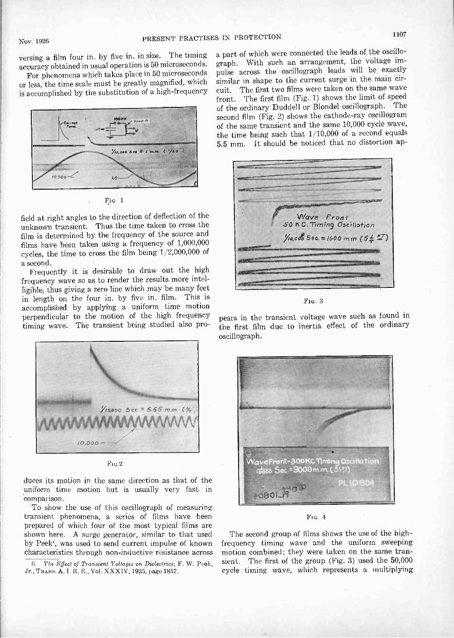
Nov. 1926PRESENT PRACTISES IN PROTECTION 1107
versing a film four in. by five in. in size. The timingaccuracy obtained in usual operation is 50 microseconds.
For phenomena which takes place in 50 microsecondsor less, the time scale must be greatly magnified, whichis accomplished by the substitution of a high -frequency
Fio.
field at right angles to the direction of deflection of theunknown transient. Thus the time taken to cross thefilm is determined by the frequency of the source andfilms have been taken using a frequency of 1,000,000cycles, the time to cross the film being 1/2,000,000 ofa second.
Frequently it is desirable to draw out the highfrequency wave so as to render the results more intel-ligible, thus giving a zero line which may be many feetin length on the four in. by five in. film. This isaccomplished by applying a uniform time motionperpendicular to the motion of the high frequencytiming wave. The transient being studied also pro-
FIG.2
duces its motion in the same direction as that of theuniform time motion but is usually very fast in'comparison.
To show the use of this oscillograph of measuringtransient phenomena, a series of films have beenprepared of which four of the most typical films areshown here. A surge generator, similar to that usedby Peek°, was used to send current impulse of knowncharacteristics through non -inductive resistance across
6. The Effect of Transient Voltages on Dielectrics, F. W. Peek,Jr., TRANS. A. I. E. E., Vol. XXXIV, 1925, page 1857.
a part of which were connected the leads of the oscillo-graph. With such an arrangement, the voltage im-pulse across the oscillograph leads will be exactlysimilar in shape to the current surge in the main cir-cuit. The first two films were taken on the same wavefront. The first film (Fig. 1) shows the limit of speedof the ordinary Duddell or Blondel oscillograph. Thesecond film (Fig. 2) shows the cathode-ray oscillogramof the same transient and the same 10,000 cycle wave,the time being such that 1/10,000 of a second equals5.5 mm. It should be noticed that no distortion ap-
VVove Front.50 Tarrari9 Oscillcvtiors
7io,00g Sec. = /600 rri n-1 (5:y.t FT)
FIG. 3
pears in the transient voltage wave such as found inthe first film due. to inertia effect of the ordinaryoscillograph.
Pm. 4
The second group of films shows the use of the high -frequency timing wave and the uniform sweepingmotion combined; they were taken on the same tran-sient. The first of the group (Fig. 3) used the 50,000cycle timing wave, which represents a multiplying

1108 PRESEN T PRACTISES IN RO' E( ;TION Journal A. I. E. K.
factor of 1600 compared with that of Fig. 2. Whentaking the oscillograms shown in Fig. 4, the timingfrequency was increased to 300,000 cycles and now itis possible to get an accurate picture of the wave frontitself. The transients shown on Figs. 3 and 4 can bereplotted on rectangular co-ordinates to eliminatethe distortion effect of the timing oscillation on theshape of the wave front; however, such error is usuallyso small that it is not necessary. It will be noticedthat there are high -frequency oscillations on the wavefront of the main impulse which are due to reflectionsin the connecting leads between the oscillographand the impulse circuit. However, in order to measurethese high -frequency oscillations on the wave front,a timing frequency of 1,000,000 cycles would be neces-sary and for such conditions, the time required to tra-verse the film once is but 1/2,000,000 of a second. Theoscillations on the wave front are of the order of 100,-000,000 cycles and with such timing frequency, it ispossible to get some idea of the wave shape of some ofthese oscillations. With Dufour oscillograph a mag-nification of 30,000 times that obtained with the or-dinary oscillograph is possible without disturbinginertia effects.
As may be readily appreciated, from a study of thesefilms, this oscillograph is destined to be of tremendousvalue in the study of transient phenomena since it isnow possible to depict accurately the operating charac-teristics of any device under the action of an impulse.Studies which are being made will lead to a determina-tion of the characteristics of all kinds of protectionequipment, will give information concerning the break-down of insulation with very short times of application,and will determine the nature of the overvoltages whichappear on transmission and distribution systems.
KLYDONOGRAPH
The klydonograph7 developed by J. F. Peters is asurge recorder which utilizes the principle of the Lich-tenburg figures. When a voltage impulse is impressedon a terminal in contact with the emulsion of a photo-graphic plate between it and a grounded metallic plate,upon development of the photographic plate there willbe a figure which by its size indicates the magnitudeof the voltage impressed and by its appearance indicatesthe nature of the voltage, that is, polarity and the ap-proximate steepness of wave front. This instrumentlends itself readily to application where a continuousgraphic record of transient voltages is desired.
Uses. 1. The use to which the klydonograph isbest adapted is the recording of surges on transmissionlines. Since the range of voltages which may beapplied directly to the klydonograph is from 2 kv. to20 kv. in order to apply it to high voltage lines, a po-tentiometer, or multiplier, is necessary. This may be
7. Klydonograph and Its Application to Surge Investigations,J. H. Cox and J. W. Legg, JOURNAL A: I. E. E., October 1925,page 1094.
conveniently accomplished by taking the klydonographpotential from the middle plate of two suitably adjustedair condensers connected between the high tensionconductor and ground.
2. A klydonograph connected as above to give thenature of the surge, and another connected to measurethe voltage across a non -inductive resistance inserted inthe ground lead of a lightning arrester will give thedischarge current of the arrester and the nature ofthe surge which caused it.
3. The klydonograph may be used to measureindirectly the abruptness of a disturbance. To do thison a transmission line the instrument is connected tomeasure the voltage induced in an antenna loop.In the laboratory, the klydonograph is connected tomeasure the potentials across a non -inductive resist-ance and a concentrated inductance. From thesethe frequency of the disturbance may be calculated.
4. By the speed of propagation of the figures on theplate it is possible to measure time intervals of the order10' of second. Thus it can be used to estimate thetime lags of spark gaps, insulators, etc.
5. Finally, the klydonograph lends convenience toall measurements where heretofore spark gaps havebeen used. This is for the reason that the klydono-graph will indicate the correct voltage with one trial,while a spark gap indicates only minimum values.
Results. 1. Extended field tests have added toinformation on the magnitudes of surges due to lightningswitching, arcing ground, etc. On three 120- and 140-kv. systems, three direct strokes of more than 1,000 kv.crest value were recorded in one season. Inducedlightning up to 650 kv. was recorded on a 140-kv. systemand exceeding 400 kv. on a 66-kv. line. In generalthey were single impulses, and the few oscillatoryrecords were highly damped. The latter were probablyline oscillations. On a 120-kv. system switchingsurges with a maximum voltage to ground of 390 kv.were recorded, and were rarely oscillatory.
Fig. 5 shows a section of film taken during an actualtest on a transmission line.
OIL CIRCUIT BREAKERS, SWITCHES, AND FUSESPapers. In 1918, at the Midwinter Convention of
the A. I. E. E., Messrs. Hewlett, Mahoney, and Burn-ham presented a paper on The Rating and Selectionof Oil Circuit Breakers. Since then much additionalexperience has been gained in the design and operationof oil circuit breakers. Factory and field tests havebeen conducted, methods of determining short-circuit'current have received further attention, and newdecrement curves have been prepared. Preparationof another paper bringing this information up-to-dateis very desirable. The three larger manufacturers ofoil circuit breakers have under consideration the prep-aration of such a paper and it is hoped that this paperwill be available within the next year.
Standardization. Revised sections of the A. I. E. E.

Nov. 1926 PRESENT PRACTISES IN PROTECTION 1109
Standards dealing with Oil Circuit Breakers (number19) and Disconnecting and Horn Gap Switches (number22) were adopted in June 1925 and are now available.The revised Standards cover these subjects morecompletely than ever.
As a result of its work during the present committeeyear, the Protective Devices Committee recommendsthe following additions to the above mentioned sectionof the Standards for Oil Circuit Breakers:
A. Rule No. 19-102. Add to present rule -"By ratedvoltage is meant the voltage from line to line as dis-tinguished from line to neutral."
b. Rule No. 19-104. Add to present rule -"Bynormal voltage is meant line to line voltage as dis-tinguished from to neutral."
c. In referring to interrupting capacity ratings, theterm "arc amperes" is often used, and should be de-fined as -"The r. m. s. value of the current taken during
FIG. 5
the first half cycle of arc between contacts during theopening stroke."
Definitions of Normal (or Working) Voltage, Nor-mal (or Working) Current, and kiterrupting (or Re-covery) Voltage should be adopted by the A. I. E. E.A tentative definition of Recovery Voltage, not ap-proved by the Protective Devices Committee, is givenhere as a matter of interest:
Recovery Voltage is defined as the maximum peak value,measured from normal zero, of the voltage divided by \/2 whichmay occur on the live side of the breaker after the interruptionof the arc and before normal voltage conditions are restored.
Attention is called to the following typographicalerrors in the revised Standards, Sections 19 and 22:
19 -63 -use "Isolating" instead' of "Isolated."22 -55 -use "Disconnecting" instead of "Dis-
connection."22 -59 --second line -incorrect reference to "oil cir-
cuit breaker."
22 -155 -second line -incorrect reference to "oil.circuit breaker."
Future revisions of the A. I. E. E. Standards shouldtake into account the factors which determine the in-terrupting duty which may be imposed upon oil circuitbreakers. .No reference to these factors, or so called"Prescribed Conditions," is made in the revised Stand-ards; however, the available fund of information uponthis subject is limited and much further study will benecessary before definite recommendations can beagreed upon. Factory and field tests should materi-ally assist in clearing up this matter. Particular at-tention is called to a paper by Mr. E. C. Stone on TheOil Circuit Breaker Situation from an Operator'sView Point, presented at the Annual Convention ofthe A. I. E. E. -at Saratoga Springs in June 1925 (seeA: I. E. E. JOURNAL, July 1925, page 756). In thispaper some of the factors affecting current to be inter-rupted and recovery voltage are set forth and discussed.
Standardization of interrupting ratings has progressedto the point where definite recommendations havebeen made for uniform standard interrupting capacityratings. The recommended steps of rating, based onthe standard operating duty (2-000), for power houseindoor oil circuit breakers at 15,000 volts and beloware given in the following tabulation:
Arc Amperes Rated Volts Arc Kv-a.
2,500 4,500 20,0002,000 7,500 26,0001,500 15,000 40,0002,500 15,000 65,0003,500 15,000 90,0005,000 15,000 125,0007,000 15,000 175,000
10,000 15,000 250,00014,000 15,000 350,00020,000 15,000 500,00030,000 15,000 750,00040,000 15,000 1,000,00060,000 15,000 1,500,000
100,000 15,000 2,500,000
Definite progress is being made toward recommen-dations of standard steps of interrupting rating on oilcircuit breakers rated from 15,000 to 220,000 volts.Standardization of this kind, it is believed, will ma-terially reduce the Present extensive lines of breakersand great variety of interrupting capacity and voltageratings which manufacturers are forced to carry,'ultimately leading to reduction in oil circuit breakercosts.
Progress is being made toward recommendations ofdefinition of high -voltage fuse ratings. Steps have alsobeen taken for preparation of a uniform test procedurefor testing the interrupting rating of high -voltage fuses,similar to the procedure recently prepared for testingoil circuit breakers.
Research is under way for the determination of rela-tive accuracy of current transformers and shunts to beused in connection with oscillop,Taphie records of short

1110 PRESENT PRACTISES IN PROTECT ION Jourmtl A. I. E. l;
circuit tests; results and recommendations will probablybe available within another year.
Interrupting Capacity Ratings. The following rela-tive interrupting capacity ratings for oil circuit breakershave been approved by the N. E. L. A. and the ElectricPower Club:
a. One -unit operating duty 100 per cent to 125 per centRating varies between limits given with de-sign of breaker.
b. Two -unit operating duty, two -minute interval(Standard operating duty) 100 per cent
c. Four -unit operating duty, two -minute in-tervals 70 per cent
d. Four -unit operating duty, one-half minuteintervals 60 per cent
e. Four -unit operating duty, no time intervals. . . 25 per centf. 300 -unit operating duty, 15 -minute intervals 30 per centg. Four -unit operating duty, successive intervals
of 0, 30, 75 seconds 30 per centh. Four -unit operating duty, successive intervals
of 15, 30, 75 seconds 40 per centi. Three -unit operating duty, one -minute in-
tervals 70 per cent1. With reference to operating duties (d), (e), (g) and (h),
while there are no known limitations which prevent the generalapplication of these operating cycles to all oil circuit breakers,still in view of lack of operating experience and possible hazard,it is recommended that these operating cycles be confined tobreakers having interrupting rating on operating cycle (b) of notover 250,000 kv-a. and having voltage ratings of 37,000 andlower.
2. Zero means no time delay between full open position andstart of closing.
3. The present factor which the operators are using forthe opinion of the
Power Club that 25 per cent is more suitable.
In the above tabulation a unit operating cycle isunderstood to consist of a closing of the circuit breakerfollowed immediately by its opening without purposelydelayed action.
Oil Circuit Breaker Tests. High capacity testingfacilities are now available at the plants of two largemanufacturing companies. Plans are also under wayfor several operating companies to undertake a series ofcooperative oil circuit breaker tests, interchanging resultsamong the companies participating, all tests to be madeaccording to recommendations of the uniform testprocedure. It is believed that much valuable data as tooil circuit breaker performance, and conditions affectinginterrupting duty, will be secured from such tests.
General. Improvements in the details of design havebeen made by the various manufacturers who arecontinuing the development of their oil circuit breakersonthe basis of different design features as follows:
High-speed contacts,Explosion chambers,Multiple contacts in series,Resistance introduced into breaker circuit to reduce
energy released by arc in the breaker,Various methods of relieving gas pressure.Armored, or metal clad, switch gear which has been
used extensively in Great Britain and Continental
Europe has been introduced in this country. The unitof metal clad switch gear is the three-phase circuitbreaker with mountings and all auxiliaries. Each unitcontains, within itself, the main oil breaker, bus bars,disconnecting devices, instrument transformers, cablepotheads, and necessary minor features. All of the liveconductors involved in this assembly are either im-mersed in oil or solidly imbedded in insulating com-pound and the whole is enclosed within grounded metalcasings which form the exterior covering. Discon-nection is provided by withdrawal, in a horizontaldirection, of the carriage type oil circuit breaker.
The field of truck mounted breakers has been ex-tended and high interrupting capacity outdoor breakers,up to circuit voltages of 154,000, are now being builtwith this type of mounting.
Working toward a better interchangeability of breakersof the smaller indoor type, single -pole elements are nowbeing mounted on trucks and arranged for installationin a uniformly constructed steel housing; this willserve in place of the usual cell construction and willallow a more liberal interchange of elements and, be-cause of the single- rather than triple -pole element,will permit a smaller stock of spare units to be carried.Each element may be controlled by a separate protec-tive relay, allowing one pole to trip while the other tworemain closed, continuing a single-phase supply over thecircuit which the switch controls.
Another step toward universality is being made byone manufacturer who is arranging to build certain high -
voltage breakers with provision for interchangingmanual, solenoid, and motor operating mechanisms.
The application of motor mechanisms has been con-siderably widened to cover a greater number of breakercapacities and to meet a larger diversity in controlcircuits as to a -c. voltage, and frequency, and varyingd -e. voltage.
Another manufacturer employs high-speed arcingcontacts in high -voltage oil breakers. In the 110,000-,132,000-, and 187,000 -volt breakers the arcing contactsare of the high-speed bayonet type. A cam in theguide mechanism of the arcing contacts provides for astraight line motion of the arcing contact latch untilthe main contacts have parted a pre -determined dis-tance, when the cam releases the arcing tips from thelatch of the moving contacts. The release of the arcingtip is followed by a quick return to the normal position.The 25,000-, 37,000-, 50,000- and 73,000 -volt breakersemploy finger type high speed arcing contacts. Themain contacts open at a moderate speed and when theyreach a pre -determined separation, the arcing contactsare released at a high rate of speed. The contact partsare so arranged as to take advantage of the magneticblow-out action of the current -carrying loop of thebreaker. Another class of breakers, used for centralstation service, employs the double tank feature, thepurpose being to prevent oil throwing and to provideadditional assurance that a tank will not be burned

Nov. 1926 PRESENT PRACTISES IN PROTECTION 1111
through. Breakers with interrupting ratings up to1,500,000 kv-a., of the indoor type, are being providedwith the resilient double tank and also each pole unitis designed in two sections so as to reduce the area whichmight be exposed to high gas pressures.
The multiple series break principle for 4, 6, 8, and 10breaks is being employed on breakers from 15,000 to220,000 volts.
Considerable interest has been manifested by anumber of companies in the interrupting capacity ofboth high- and low -voltage fuses. Several companieshave tested fuses in the 250- to 600 -volt class.
In one series of tests on open -link fuses in sizes from100 to 1000 amperes, with the fuses both initially hotand cold prior to test, it was found that in every casethe fuse operation was selective between two fuses ofadjacent current rating, the two fuses being in seriesfor each individual test.
A series of tests conducted on renewable and one-timeenclosed cartridge fuses indicated that the rupturingcapacity of the fuse is largely a function of the lengthof the fuse element and the volume of the cartridgefuse case. The time for interrupting a circuit wasfound to be very selective between fuses of differentsizes. The melting time of the fuse was a directfunction of the thermal capacity of the element andinversely to the heating effect of the short-circuitcurrent.
Tests have been made by a number of companies onhigh -voltage fuses for protection of transformer banks,sectionalizing lines, and similar service. Standardshave been fairly well established on the liquid types offuses. On the open link expulsion type fuses, a widevariety of results has been secured.
PROTECTIVE RELAYS
In view of the recent publication of the Relay Hand-book, this year's report of the relay subcommitteeconsists principally of a resume and analysis of the pres-ent status and trend of protective relay practise.
As the publication of the Relay Handbook has givento the industry a comprehensive picture of the relayart in detail, this report will refer in detail only todevelopments which have occurred since the Handbookwent to press, and only generally to developmentsoccuring prior to that date.
Present State of Protective Relay Practise. A "relay"in the electrical art is an automatic device whose func-tion is to receive information and initiate action inresponse thereto. It is estimated that the total numberof types of such devices used in the electric power andtelephone industries alone is in excess of 60,000. How-ever, this subcommittee, being a branch of the Com-mittee on Protective Devices, deals primarily withrelays for the protection of power circuits and ap-paratus. The function of the relay as a protectivedevice is to receive information of some abnormalcondition and initiate action to correct the abnormal
condition, or to disconnect the apparatus or circuitinvolved, from the source of energy.
Probably the oldest form of protection in use onelectrical circuits is the fuse. From this developed theso called "overload" relays designed to act in responseto excessive flow of current. At first these actedinstantaneously, but as power systems, protected by"overload" relays, grew in magnitude and complica-tion, it became necessary to differentiate between relaysin different parts of the circuit by introducing theelement of time. We therefore have today, as ourfundamental system of protection against faultsproducing abnormal currents, a system depending onovercurrent relays with differing time adjustments, suchtime adjustment, in general, becoming longer the closerthe generating station is approached. This has resulted,with the enormous and complicated power networks nowexisting, in the appearance of various limitations to theuse of this system, due to the fact that the time differ-entials between relay settings cannot be reduced belowa certain minimum on account of the inherent timerequired for relays and circuit breaking devices tofunction.
To meet this objection, a second general system ofprotection against abnormal current producing faultshas developed, based upon the principle of balancingout of relay circuits all current except the fault current,thereby causing the protective relays to function inresponse to the fault current alone.
This general idea has crystallized in the system ofprotecting individual pieces of apparatus by balancingout of the relay circuits all current except that resultingfrom a fault within the particular piece of apparatus.There are two methods of applying this principle,first, by means of a series differential connection inwhich the two ends of a circuit are balanced againsteach other, and second, a parallel differential systemwhich may be used where a circuit consists of parallelpaths which may be balanced against each other.
In addition to systems of protection using currentalone, we have a number of systems which dependupon the use of both current and voltage. Some ofthese systems, such as directional ground relayingsystems, use both the fault current and the fault voltage;others, such as directional current and directionalpower systems, utilize the circuit voltage and totalcurrent, and certain other devices, such as the impe-dance relay, utilize the total current and fault voltage.
It should be observed that we have in the above,in general, two systems of current relaying, one de-pending upon total current and time for selective action,the other depending upon. fault current and locationfor selective action.
In addition to protection against faults involvingcurrent, many other abnormal conditions are nowprotected against specifically by means of relays, suchas abnormal voltage, temperature, speed, etc., single-phase operation of motors and generators, cessation of

1112 PRESFAT l'It 1CTIsi.:', I \
flow of oil, water and air fur lubrication or coolingpurposes, and other comfit ions too numerous to mention.Development of many of these additional protectivedevices has been largely accelerated by the advent ofthe automatic slat ion, in which, there being no operatorto act in ease of trouble, it is necessary to provideautomatic devices.
Trend of Protectire Relay Practise. The aboveoutline of the types of protective relaying systemsnow in use, together with the chronological order oftheir development, indicates certain quite definitetrends in the protective relay art. These may be brieflystated as follows:
First: With the development of large interconnectedpower systems supplied from numerous generatingsources of varying efficiencies, there appears to be agrowing trend towards the integration of all such sourcesinto one comprehensive system so interconnected andrelayed that its integrity shall not be broken by theoccurrence of faults.
Second: Since the system of relaying which dependsupon differential timing for selective fault isolationhas not proved sufficiently flexible to promote themaintenance of the maximum integrity of such systems,there appears to be a strong trend towards obtainingsuch fault isolation through the use of balanced relaysystems, or systems responsive to the location or specificnature of the fault.
Third: There also seems to be a rather strong trendtowards the use of what may be called "back-up"protection, or a second line of defense, in the form of asecond system of relays to function in case of failureof the first system, applied either to the same circuitbreakers as the primary defense, or to others nearerthe sources of energy.
Fourth: There also seems to be a strongly developingtendency toward the development and use of devicesfor the detection of abnormal conditions and approach-ing faults before such faults actually occur.
Summarizing the apparent trend of relaying practisein general, therefore, it would appear that the tendencyis towards the maintenance of system integrity by thesetting up of three lines of defense:
1. Relays which will detect and give warning ofapproaching faults or conditions which may causefaults,
2. Relays which respond to the abnormal conditionsresulting from the occurrence of faults to isolate theparticular piece of apparatus or circuit at fault,
3. A back-up system (consisting in its commonestform of overcurrent relays) adjusted with such timedelay as to function only upon the failure of the firstand second lines of defense.
The relay art has played an important part in theevolution of the modern superpower system and hasitself evolved in sympathy therewith. This evolutionis still going on and must continue to do so. We are
confident that it will go on until every requirementfur cunt Mottos electric service has been met.
Developments but illy the Past Year. A number ofnew developments have occurred during the year, n,(: 1of which art' in the nature of detail improvt 'memdevised to keep abreast of the evolving art. The fol-lowing specific developments are noted fur the pulp,of recording the advances in I he art and as infoi mat ionAs to new devices available.
1. Speed indicating relay for application toautomatic stations. Makes separate contacts at defi-nite per cent under -speed, at synchronous speed and atdefinite per cent over -speed.
2. Automatic network relay. For the controlof alternating current network breakers. Connectstransformers to network when capable of supplyingload and disconnects them on reversal of energy flow.Will operate on magnetizing current of a transformer.
3. Ratio differential relay. For the differentialprotection of a -c. generators and transformers. Trip-ping current varies with load, allowing the relay to beset for close protection at normal loads. Does notrequire balancing auto -transformers for transformerprotection.
4. Direct -current polarized relay. Has inversedefinite minimum characteristics. A complete line isavailable including over -current, under -current, over -voltage, under -voltage, reverse power, polarized po-tential, and resistance measuring relays.
5. Duplex impedance relay. A combination of adirectional impedance relay and a ground relay in onecase.
6. Automatic reclosing relay. Has been modifiedto permit any desired duty cycle. Time intervals maybe varied between five seconds and two minutes.
7. Over- and under -voltage relays. Have beenmodified by the addition of a voltage adjusting re-sistor controlled by a pointer and scale. Permits relayto be adjusted for any voltage within a definite range.
8. An over -voltage relay. The same as existingover current' relay except that a voltage winding hasbeen substituted for the current winding and certainother minor alterations.
9. A power directional over -current relay, offeringpower directional protection against ground faults, andagainst phase -to -phase faults where for any reasonsingle-phase directional elements are preferred to apolyphase relay.
10. A network relay for protecting low -voltage a -c.networks against a faulty distributing transformer orfeeder.
11. Power directional relays for sensitive pro-tection against ground faults in grounded neutralcircuits.
.12. Differential frequency relay consisting of twoinduction frequency elements arranged in oppositionon a single shaft. For application in connection with

Nov. Mb PRESENT PRACTISES IN PROTECTION 1113
two circuits that are interlinked by means of a rotatingmachine.
13. A phase unbalance relay for use in a polyphasecircuit for protection against faults producing an un-balancing of currents in the several phases.
14. Synchronism indicating relay comprising aninduction type differential element for preventing in-terconnection of two systems at one point unless theyare already connected at some other point. -
15. Motor -operated timing -relay for controllingthe time elapsing between certain operations. In-tended primarily for use with automatic reclosing ofcircuit breakers.
16. Auxiliary relay. A plunger type relay particu-larly adapted to automatic switching for introducingtime in starting up and in shutting down machines.Can also be used in any a -c. or d -c. circuit where in-stantaneous pick-up and long time drop-ou tttre required.
17. Electrically -reset instantaneous over -currentand auxiliary relays. Equipped with a solenoid forresetting.
18. Flashing protective relay. Has a heavy wind-ing for connection from d -c. machine frame to ground toprotect against flashing or grounding of winding toframe. Instantaneous.
19. Plunger type trip free relay for use with elec-trically operated circuit breakers to prevent the breakerbeing held closed with over -current in the circuit;
20. Locking relay plunger type. Primarily for pre-venting a circuit breaker from opening on an exces-sively heavy over -current.
21. Locking relay. Primarily for preventing theopening of one circuit breaker due to surge conditionsresulting from the opening of another circuit breaker.
Recommendations. Since the efforts of InstituteTechnical Committees are directed towards research,standardization, and publicity, it is believed that thissubcommittee can be of most service this year by sug-gesting a few subjects on which research, standardiza-tion, or publicity appear desirable.
As to research, the following studies are recommended :A. Study of pilot wire transmission line relay
systems employed in Europe, to determine their properfield of usefulness. It is understood that many suc-cessful installations are in use and it is thought thatAmerican practise may benefit by the investigationthereof.
B. Study of characteristics of current transformersat very high overloads. The characteristics of currenttransformers at very high overloads are of importancein many relay applications, and the information atpresent available is somewhat meagre. It is recom-mended that the manufacturers be urged to investi-gate this matter and present the information to theindustry in the form of papers, or otherwise.
It is recommended that standards be formulated andadopted for the following:
1. Relay operation nomenclature. The selectionof terms to define the characteristics of relay operationare very chaotic at the present time, probably no twocompanies having the same. conception of what is re-quired, or using exactly the same terms. In order thatmaterial for publication regarding operating experiencemay have a common language of expression it is recom-mended that standard nomenclature for relay operationbe adopted.
2. Relay acceptance tests. At the present time thereare no Institute standards of overpotential tests,temperatures, etc., for relays. It is recommended thatsuch standards be established.
3. Relay designs and ratings. At the present timethere is no purposeful coordination of standard relaydesigns among the different manufacturers. Thisfact imposes considerable hardship upon the relay users,in view of the difficulty introduced thereby, of makingrelay applications involving relays of different manu-facturer. It is therefore recommended that, in so faras appears feasible, standard ratings and operatingcharacteristic curves be established for the morecommon types of relays.
4. Current transformer characteristics. A. Coordi-nation between transformers of different types andvoltages: Considerable difficulty arises in the ap-plication of balanced protection where transformersof more than one type or voltage rating are involved.It is recommended that in so far as possible the designsof transformers of different types and ratings be socoordinated that differing types can, without seriousdifficulty, be used for differential protection.
B. Coordination of characteristics as betweendifferent manufacturers: It is also recommended thatin so far as may be practicable, current and potentialtransformer designs of different manufacturers of thesame general type and voltage ratings, be so coordi-nated that like types will have like characteristics.
As to papers for publication, due perhaps to theabove noted confusion as to nomenclature for relayoperation, there has been little published informationregarding the operation, successful or otherwise, ofexisting relay systems. It is therefore recommendedthat at a future general Institute meeting, an appropri-ate amount of time be alloted for the presentation ofrelay operating experience. It is suggested that thispresentation might well be made under three generaldivisions:
Time differential systems, or systems in whichselectivity is obtained principally by timing.
Current differential systems, or systems employingvarious current balancing plans for selective operation.
Voltage differential systems in which the abnormalvoltage conditions resulting from a fault are utilizedto assist selective operation, such as impedance relayapplications.

1114 PRESENT PRACTISES IN PROTECTION .1(iiirnal A. I. H. E.
In the advancement of the above suggested programthe following sub -subcommittees have been appointed :
1. On Relay Operation Nomenclature andExperience.
2. On Relay Acceptance Test Specifications andStandards.
3. On Current and Potential TransformerCharacteristics.
These subsubcommittees have not had time to com-plete their work this year, but it is hoped that they willbe continued next year and continue their work to auseful conclusion.
AppendixREPORT OF SUBCOMMITTEE ON AUTOMATIC STATIONS
Since the presentation of the Automatic StationsSubcommittee Report this year, three points have
principal manufacturers and users and is now almostuniven,al. This idea has practically standardizeditself, but it is felt that these device function numbersshould be transmitted to the Committee on Standards,who should be urged to accept and incorporate them inthe Standards of the Institute.
Device Symbols. The subcommittee also submits aset of device symbols for use on automatic stationwiring diagrams. These have just been accepted bythe two principal manufacturers and will be used bythem in the future. It is urged that these wiringdiagram symbols be transmitted to the Committee onStandards for acceptance and incorporation in theStandards of the Institute.
MINIMUM PROTECTIONFOR POWER APPARATUS IN AUTOMATIC STATIONS
WALTER H. MILLAN,
Chairman.
Protection
Synchronous Converters Syn. Motor Gen. Gen. Cond.
Rwy.600 -volt
Edison250 -volt
Mining& indust.
Edison250 -volt
Mining& Indust.
Synch.hydro.
Synch.
A -C. Under -voltageA -C. Over -voltageIncorrect Polarity
x
x
x
x
x
x
x x xx
xx
Single -Phase StartingSingle -Phase Operation
x x x x xx
xxLoss of Field, A -C. Machine
Loss of Field, D -C. Machinex x x
xxx
x xD -C. Reverse Power x x x x xD -C. Overload x x x xExcess Temperature (Sustained Overload) x x x x x x xImperfect Start (Lock -out) x x x x x x xMachine Overspeeding (Lock -out) x x x x x xSevere A -C. Overload (Lock -out) x x x x x x xGrounding Protection (Lock -out) x x x x x xExcess Bearing Temp. (Lock -out) x x x x x x x
developed on which is submitted supplementaryinformation, including points as follows:
1. Minimum safe protection of power apparatus inautomatic stations.
2. Device function numbers for use in automaticstations.
3. Device symbols for use on automatic stationwiring diagrams.
Minimum Safe Protection. In its reports of 1925and 1926, the subcommittee presented its recommenda-tions for the protection of synchronous converters ofrailway, Edison, and industrial types; synchronousmotor generators of Edison and industrial types;synchronous generators (in automatic hydroelectricapplications) and synchronous condensers. Theserecommendations have been tabulated and are pre-sented herewith. It is urged that they be transmittedto the Committee on Standards with the recommenda-tion that they be accepted and incorporated in theStandards of the Institute.
Device Function Numbers. During the year 1924
the subcommittee submitted a set of device functionnumbers for use in automatic stations. Through theefforts of the subcommittee, this was accepted by the
ELECTRIC CARS FOR STEAM RAILROADSElectricity for local passenger service is going to the
aid of steam railways that are not yet ready to com-pletely electrify their systems. The Boston & Maine,after a summer's experience with seven passenger carsoperated by electricity generated on board by a gaso-line engine, is now installing seventeen more to makeruns of 250 and 300 miles a day covering most of themain line of the railroad and many of the branch lines.
The new cars are 73 feet long and can seat 88 peoplein passenger, smoking and baggage compartments.The generators on each car are rated at 275 horse power.Car warmth in winter is provided by water electricallyheated. Quick starting and high speed enable these carsto run on main lines to do local work between fastthrough trains. They reduce the cost of branch lineservice markedly.
SEMINARS FOR PRACTISING ENGINEERSIn the October JOURNAL a paper by Edward Bennett
bears the title "Excellent Seminars for PracticingEngineers." "Excellent" should be omitted. The wordwas inadvertently so affixed to the manuscript by areviewer that it appeared to be part of the title.

Status of Electric Lighting in 1926Report of Committee on Production and Application of Light*
PRESTON S. MILLAR, Chairman
To the Board of Directors:As required by provision of the By-laws, this report
constitutes a brief resume of of the progress of thelighting art, including recent developments in electriclighting which appear to have significance as indicatingan actual trend in the art.
ILLUMINANTS
In electric illuminants there have been no new de-velopments of a radical character during the past year.Among tungsten filament incandescent lamps there hasbeen developed a new standard line in which the gas -filled type has been introduced in the 50- and 60 -wattsizes heretofore generally of the vacuum type. Theselamps, standardized thus far from the 15- to the 100 -watt sizes of the 115 -volt range, are characterized by
FIG 1-NEW STANDARD LINE OF TUNGSTEN FILAMENTLAMPS
bulbs of a pleasing contour (Fig. 1), lightly frosted uponthe inner surface, providing a measure of diffusion oflight, while retaining the cleanly, smooth surface hereto-fore had only in the clear bulb and "natural glass"lamps. The adoption of this new standard line oflamps in place of a variety of types heretofore employedis a conspicuous example of the principle of simplifi-cation which the Department of Commerce hasurged successfully and constructively upon industryin this country.
Arc Lamps. The employment of arc lamps in thiscountry for general illumination is confined largely to themagnetite lamp which continues in successful operationin some localities, and which in its higher powered formhas been utilized in several recent installations wherehigh -intensity street lighting is desired.
For the projection of motion pictures in large houses,
*Committee on Production and Application of Light;Preston S. Millar. Chairman, Electrical Testing Laboratories,
80th Ht. & East End Ave., New YorkW. T. Blackwell, F. F. Fowls, F. II. Murphy,J. B. Bryant, 0. 0. Hall, Charles F. Scott,W. T. Dempsey, H. If. Higble, B. E. Shackelford,H. W. Hales, A. S. McAllister, C. J. Stahl,P. M. Felker, G. H. Mersin, 0. H. Stickney.
Presented at the Annual Convention of the A. I. E. E.at White Sulphur Springs, June E1-26, l926.
the high -intensity arc is quite generally used. Inmedium-sized theatres carbon arcs, both alternatingand d -c., operating at currents from 30 amperes to 80amperes, are quite generally in use. A 10- to 30 -ampere,horizontal carbon arc used with a reflector insteadof a lens as a condenser has entered into use recently.
Practically all interior motion picture photographyis now done with the aid of electric arcs for illumination.Four types of arc are used: the high -intensity arc (150amperes), the white -flame arc, the ordinary carbon arc,and the mercury vapor arc. There is steady improve-ment in all forms of studio arc -lighting apparatus.
The high -intensity arc has been brought to its highestdegree of perfection in military searchlight work andis now used universally by both the Army and Navy.
White -flame arcs are still quite generally used inphoto -lithography and color reproduction work.Improved units are occasionally appearing in this field.
The use of white -flame arcs in portrait photographyis increasing and several small, efficient arc mechanismsare now being used in this field.
Small Gaseous Conductor Lamps. A distinctly newdevelopment is the small gaseous conductor lampsdevised by Moore for indicator or marker purposesrather than for purposes of illumination. Theselamps operate at 115 volts alternating -current ordirect -current. They consume about one-half milli-ampere for the T-4 bulb size, and one milliamperefor the G-10 bulb size, and have an efficiency ofabout one-third lumen per watt. The life is saidto be 3000 to 5000 hours. One form of the lamp,fitted with a G-10 bulb, has an over-all length oftwo in. and a diameter of one to one-fourth in. Thisis provided with a wire resistance of about 35,000ohms in the base, which is of the medium screw type.Another form has a T-4 bulb, an over-all length of aboutone to one-fourth in., and a diameter of one-half in. Thisis fitted with a candelabra screw base in which thereis a composition paste resistance of about 70,000 ohms.The lamps are said to contain neon, helium, and argonin certain proportions. When excited by electricpressure at the electrodes, the gas becomes luminousat the cathode. On direct current, the gas aroundonly one electrode glows; on alternating current thegas glows near both electrodes at a frequency dependingupon the supply current.
The lighting and extinction of these lamps is practi-cally instantaneous. They thus have properties whichare peculiarly desirable for such instruments as strobo-
1. "Recent Developments of Moore Gaseous ConductorLamps" by Moore and Porter, Transactions, Illuminating Engi-neering Society, Feb. 1926, p. 176.
1115

STATUS OF ELECTRIC LIWITIN(I IN 1921; Journal A. I. I':.
scopes, synchroscopes, etc. If 230 volts be applied,they merely glow a little more brightly than on 116 volts.
The two forms of this lamp are illustrated in Fig. 2.Application of the lamp to an electric flat iron is shownin Fig. 3. The small power consumption makes itpracticable to use the lamp in a wide variety of serviceto indicate that the circuit is alive, or to indicate loca-
FIG. 2-GASEOUS CONDUCTOR LAMPS FOR 115 -VOLT CIRCUITS
tions of switches, polarity of d -c. circuits, etc. Forother applications see paper to which reference has beenmade.
Double Filament Automobile Lamp. The past yearhas witnessed the rather extensive introduction ofthe double filament automobile headlight lamps. Inordinary practise the lower filament provides theprincipal driving beam. When the upper filament is
FIG. 3-0 ASEOUS CONDUCTOR LAMP TO INDICATE CLOSEDCIRCUIT ON FLATIRON
switched into circuit the beam is depressed by two tothree degrees. A further discussion of this developmentin relation to headlight practise appears under a latersection of this report.
Prefocusing Lamp Socket. To meet the requirementsfor precise location of filaments of incandescent lampsused in motion picture machines, stereopticons, signals,etc., there has been developed a special type of base
and socket which insures correct operating positionfor the filament in such apparatus. Each lamp isbased in an optical jig to secure exact filament locationwith respect to both axial alignment and light centerlength once the projection apparatus is properly fitted.This device eliminates the necessity of refocusing onrenewing a lamp, and procures for users of projectorsmaximum screen illumination. While this equipmentis not regularly listed by manufacturers it is understoodthat it can be procured when desired.
LIGHTING EQUIPMENT
For Residence Lighting. The trend in luminariesfor home lighting in recent years has been largely inthe direction of the candelabra type of equipmentemploying frosted or coated incandescent lamps whichin large part have been without shades and wholly ex-posed to view. In illuminating engineering circles thistrend has been regarded as contrary to the public inter-est in that it has brought within the field of ordinary vis-ion sources of excessive brightness which have producedglare. With a view to correcting this condition mucheducational work is being done by central stationsand other branches of the industry to impress thepublicwith the desirability of properly shading light sources,and new types and finishes of shades are being madeavailable by some manufacturers to encourage thispractise.
For Street Lighting. In street lightirig equipmentthere has been a pronounced trend in the direction ofemployment of directive equipment, usually of pris-matic glass, surrounded by lightly diffusing outer glassenvelopes. The purpose has been to secure a consider-able measure of favorable redirection of light whilekeeping brightness and glare within bounds. Avariety of equipment of this kind has been placed inservice. In some cases effort is confined to redirectioninto the lower hemisphere of some of the light fluxwhich otherwise would be directed upward. In othercases this has been combined with a latitudinal redirec-tion along the street of some of the light flux whichotherwise would fall upon building fronts.
ORGANIZED STUDY OF ILLUMINATIONIllumination and Production. Under the aegis of
the National Research Council an effort is being madeto ascertain some of the relations between changes inillumination and changes in industrial production.Investigations to date' have indicated that improvedillumination has secured industrial advantage in theway of increased production, diminished shrinkage,and more favorable working conditions. The purpose'of the present investigation is, if possible, to ascertainunder independent auspices the. facts in certain repre-sentative industries. Thus far, the committee having
2. Report of Committee to Promote Central Station Illu-minating Engineering, Lighting Bureau, Commercial NationalSection, Presented at National Electric Light Association Con-vention, May, 1924. (Table III)

Nov. 1926 STATUS OF. ELECTRIC LIGHTING IN 1926 1117
this enterprise in charge, and operating under thechairmanship of Professor D. C. Jackson, has engagedlargely in developing methods with a view to the formu-lation of a procedure and the establishment of systemsof control which when applied to an industry which islargely dependent upon vision, may be expected todetermine the facts of relationship between illuminationand industrial production.
Street Lighting. A committee of the IlluminatingEngineering Society is endeavoring to develop a methodof appraising the effectiveness of street lighting whichwill make it practicable to determine, at least approxi-mately, the relative merits of two different streetlighting systems. It is an interesting and notablefact that despite the extensive attention which has beendevoted in recent years to the subject of street lighting,there is today nothing like consensus among theleaders of the art as to the best manner of locating andequipping street lamps and of distributing the lightfor purposes of street illumination. If the presentattempt fails in its ultimate object, it may at leastsucceed in diminishing the divergence of views amongstreet lighting engineers. There is included in theprogram a project for study of the elusive subject ofglare in street lighting.
ORGANIZED MOVEMENTS FOR THE IMPROVEMENT OFLIGHTING PRACTISE
Electric lighting is receiving proportionately moreattention at the hands of electric service companiesthroughout the country than has been the case inrecent years. The potentialities of revenue fromincreased lighting load and a growing sense of responsi-bility for making available to the public the benefitsof improved illumination have combined to commanda greater degree of specialized attention to illumination.
Training Course for Lighting Men. At the 1924Convention of the National Electric Light Association.a Committee to Promote Central Station IlluminatingEngineering reported upon the importance of theopportunity in the lighting field afforded centralstations, and described a training course forprospective central station illuminating engineersthen in course of preparatipn. This course, under thejoint auspices of the National Electric Light Associationand the Illuminating Engineering Society, was arrangedfor the autumn of 1924 and was carried through withsuccess. It made available to a training group thekind of instruction which in recent years had beengiven lighting students in training courses by the largermanufacturers of incandescent lamps, and supple-mented this by the experience of central station com-panies who have pioneered in the organization andoperation of lighting service departments and by acarefully chosen inspection trip.
Selection of Lighting Equipment. A further indicationof central station concern for the improvement ofelectric lighting is furnished by action of the Lamp
Committee of the Association of Edison IlluminatingCompanies, which heretofore has functioned success-fully in connection with incandescent lamps themselves,but has not concerned itself with lighting equipment.It is understood that this Committee has taken cog-nizance of unsatisfactory lighting conditions in
residences, and has requested the Illuminating Engi-neering Society to formulate a statement of principlesand perhaps some simple specifications which maybe looked to for the guidance of central stations whichdesire to select satisfactory lighting equipment for sale
to the public. It is further understood that theIlluminating Engineering Society is endeavoring tocomply with this request and has a committee at workformulating such a statement of principles which maygovern the selection of residence lighting equipment.
Central Station Lighting Departments. Whereas in thespring of 1924 only nine central station companies wereknown to have lighting service departments, todaythere are 42 central stations which have such depart-ments and the number is fast growing. The principallimitation is the unavailability of trained men com-petent to organize and operate such activities.
This awakening of central stations to their opportuni-ties and responsibilities in lighting is of large significanceto the country. Most classes of illumination, and par-ticularly residence, industrial, and street lighting,suffer needlessly from ineffective and inappropriatelighting which fails to take advantage of recent advancesin the art. The light and power industry can contributematerially to the welfare of the country by lending itsgreat influence to betterment of these conditions. Itis a matter of gratification to this Committee that defi-nite progress in this direction is indicated by thedevelopments of the past year.
I. E. S. and Central Station Lighting Men. During1925 the National Electric Light Association, in re-organizing its Commercial Section for greatereffectiveness, dispensed with its Lighting Sales Bureau.In September, 1925, on the day preceding the openingof the Illuminating Engineering Society's annual con-vention, there was a gathering of central stationlighting men out of which there was evolved a planfor greater activities in connection with central stationlighting under the auspices of the Illuminating Engi-neering Society. In this connection it is understoodthat there is in course of preparation a Lighting ServiceDepartment Manual which will make available theexperience of central stations which have assumed thelead itibsuch work. This will include a brief survey ofthe lighting field and chapters on the organization ofa lighting service department, its scope, needed equip-ment, and engineering and commercial features of itswork.
Lighting Demonstrations. Interest in electric lightinghas been enhanced and in all probability practise hasbeen much improved as a result of demonstrationsmade in the elaborate Lighting Educational Centers

STATUS 010 ELE("I'lill! LI(IIITIN(; IN 1926 Jouruul A. I. E. E.
of the incandescent lamp manufacturers at Nela Parkand Harrison. So successful have these been that lesselaborate demonstrations have been set up and operatedin a number of cities. Notable among these aredemonstrations in Boston, Chattanooga, Cincinnati,Detroit, Kansas City, Knoxville, Louisville, Nashville,Philadelphia, Pittsburgh, and Providence. Others areunderstood to be in preparation.
MOTOR VEHICLE LIGHTING
Specifications for automobile headlamp and rear-lamp performance have been prepared by the Illumina-ting Engineering Society and revised as of 1922. Theseheadlamp specifications cover laboratory tests forheadlamps and headlighting devices and prescribecandle power limits for different parts of the beam.The headlamp specifications were endorsed in 1922by the Society of Automotive Engineers, which organi-zation, however, supplemented its endorsement bypromulgating, within such limits, recommended practisecalling for a higher maximum beam candle power and ahigher candle power in the beam spread to the rightand to the left than is stipulated in the specifications.The I. E. S. headlamp specifications were approvedas a "Tentative American Standard" in 1922. Theyare in use by the Eastern Conference of Motor VehicleAdministrators in which are represented all the NewEngland States, (except Massachusetts) New York,New Jersey, Pennsylvania, Maryland, Delaware, Vir-ginia, District of Columbia, Ontario, and Quebec.The specifications are also in force, either wholly orin part, in Ohio, Wisconsin, Iowa, Utah, Nebraska,Texas, California, and Oregon. Also they are recom-mended in the "Uniform Act Regulating the Operationof Vehicles on the Highways" prepared under the di-rection of Secretary Hoover in the National Conferenceof Street and Highway Safety.
The rear lamp specifications developed by theIlluminating Engineering Society cover the generalrelation of the lamp and license plate holder and thequantity and uniformity of illumination upon thelicense plate. At the present time the rear lamp speci-fications used by the State of Massachusetts aresubstantially in accord with those prepared by theIlluminating Engineering Society.
During the past year the Automotive LightingAssociation has prepared specifications covering stopand direction signals and the depressed beam from con-trollable headlights or auxiliary driving lights. Sub-sequently somewhat different specifications fordepressed beam lighting have been formulated tenta-tively by the Illuminating Engineering Society'sCommittee on Motor Vehicle Lighting. The matteralso is understood to be under consideration by theEastern Conference of Motor Vehicle Administrators.
A further advance made in the practise of theEastern Conference of Motor Vehicle Administratorsis a requirement for excellence of headlamp construction
not formerly Unposed. Another forward step wastaken by the National Conference on Street and High-way Safety in formulating a Uniform Vehicle Codeintended to promote uniformity of regulatory actionin the several st ates.
The depressible beam, fast coming into use in motorcar lighting, is a step in the direction of securing theadvantages of the desirable headlighting characteristicrequired by the specifications now in general use withthe element of advantage otherwise secured throughdimming. It is a step further in the direction of doingaway with the disadvantage inherent in each practise,measurably avoiding the glare to which the approachingdriver is subjected under the first practise and thehazard of passing vehicles with lights dimmed involvedin the second.
The depressed beam has become a practicable devicethrough the development of a lamp having twinfilaments, one placed 9/64 in. above the other andsuitably coorditiated with lens or reflector elements.By switching from one filament to the other, the beamis depressed by from two to three deg. in a simple,positive, and easily applied manner.
Although but few of these devices as thus far de-veloped are understood to have been approved by theEastern Conference, more than 20 car manufacturershave adopted such equipments for their new cars.
Research. As a result of discussion following the1925 Conference on Street and Highway Safety, ajoint Steering Committee on Headlight Research hasbeen formed by the Society of Automotive Engineersand the Illuminating Engineering Society.
The first objective of the Committee is to stimulateand guide experimental research directed toward thedetermination of the most satisfactory methods ofautomobile headlighting and, in accordance with theresults of research, to formulate a code of recommendedpractise with respect to headlight equipment, adjust-ment, and use.
A program has been projected by the Committeeincluding collection of data on visibility of objectsunder various conditions, experimental studies ofvisibility under conditions of actual driving, collectionof data on quality and condition of lamps as used andthe possibilities of bettering them, and a demonstrationof the lighting which various automobile manufacturersconsider most satisfactory for all-around use.
Relation to Street Lighting. In this connection itmay be interesting to observe that the Committee onStreet Lighting of the Illuminating Engineering Societyis of the opinion that urban streets ought to be suffi-ciently well lighted to make it practicable to do awayentirely with powerful headlights on automobiles, as isthe practise in New York City, and to a limited extentin some other cities. It is held that streets whichsupport considerable traffic ought to be sufficientlylighted to make this practicable, and that where suchcondition exists, the safety and convenience of all

Nov. 1926 STATUS OF ELECTRIC LIGHTING IN 1926 1119
concerned will be promoted. The Committee is
engaged in establishing street lighting minimaabove which it can feel confident in recommending theabolition of headlights.
RESIDENCE LIGHTING
One of the serious obstacles to the provision of betterlighting in the home is the general lack of adequateoutlets and the apparent difficulty and expense of
making additions.In the 1925 report of this Committee, reference was
made to the Red Seal Campaign which undertakes toestablish a minimum limit of adequacy of wiring ac-cording to the needs of each community. This planhas been adopted by nineteen different local electricleagues operating in six hundred and seventy-sixcommunities and reaching nearly ten million people.One manufacturer is undertaking to establish a nation-wide standard of quality and adequacy, and it isprobable that others will follow along similar lines.It is therefore becoming the fashion to provide suitablewiring.
Although home -lighting equipment is still beingselected with the main emphasis on the artistic featuresof metal working, with inadequate attention to theartistic and utilitarian values of the illumination itself,there yet seems to be a slow but general progress towarda better understanding of the merits of good lighting.The more common use of such terms as "shaded lights"indicates the trend.
SCHOOL LIGHTING
Preliminary tests have been made for the city ofNewark, New Jersey, to secure an indication of thequantity and character of artificial light desirable forspecial public school classes of pupils having defectivevision.
Observations of reading and writing suggested 15 -ft.candles, or about 50 per cent more than ordinarily.recommended. Comparison seemed to show semi -indirect and direct lighting, with large diameterdiffusing glassware, to be equally acceptable, whensupplementing daylight.
RAILWAY LIGHTING
The first edition of a Manual of Lighting Practise forRailroads has been practically completed by the Asso-ciation of Railway Electrical Engineers.
The following topics have been covered: Funda-mentals of Illumination and General Design, DesignData, Railway Shop and Roundhouse Lighting, Officeand Drafting Room Lighting, Freight and PassengerStation Lighting, Warehouse and Pier Lighting, YardLighting, and Car Lighting.
BUS LIGHTING
The 12- to 16 -volt systems are rapidly displacingthe six- to eight -volt systems formerly used in buslighting. A 21-c. p. incandescent lamp in an S-11bulb designed for 300 hours of life has been standardizedparticularly for this purpose. It is interesting to note
that some of the modern double-deck motor coacheshave as many as 42 lamps for interior lighting. Specialtypes of enclosing units and opal glass reflectors havebeen developed for motor coach lighting. Enclosingunits are being used in the majority of new buses.
ILLUMINATION OF RAILROAD CLASSIFICATION YARDS
The employment of flood lights for illumination ofrailroad classification yards is becoming general. TheCommittee on Illumination of the Association ofRailway Electrical Engineers reported that in 1924,35 railroads had 90 yards equipped with an aggregateof about 2100 flood lighting units. Since that timethe practise has been extended, notable recent installa-tions being in the Selkirk Yard of the New YorkCentral Railroad and the Markham Yard of theIllinois Central Railroad.
The necessity for adequate and proper illumination isenhanced by the introduction of the so-called mechan-ical car -retarder system for controlling the speed ofcars in the gravity type of classification yard since theoperators of such equipment must have a good viewof the entire yard from their control towers.
The above mentioned Committee has received areport from one railroad covering operating recordsof yards for several months before and after equipmentwith flood lighting, there previously having beenno artificial illumination in the yard. This showedan increase of 15.5 per cent in number of cars handled atnight with a decrease of 21 per cent in the average costof damage suffered by cars and with entire eliminationof personal injuries attributable to inadequate illumina-tion during the months in which the records werestudied.
LIGHTING FOR ADVERTISEMENT
Electric signs and illuminated displays are aconstantly growing factor in the advertising field.There has been within the last year a noted increasein the diversity of form of such displays together witha more rational design of the illuminated pattern basedupon new engineering information.
SIGNAL LIGHTING
Traffic Signal Lighting. With the large increase inthe use of electric traffic signals, there has come fortun-ately an approach toward uniformity of practise intheir use. Red quite generally now means "Stop"and green means "Go". Amber signifying "Caution"is employed in many cities for the assistance of thepedestrian.
A lens, a glass reflector, and an incandescent lampare the usual equipment for each signal. Styles ofsignals are becoming more nearly uniform. Flexibilityof control for isolated units and for large interlockedinstallations is a feature of the latest developments.A centrally controlled progressive system of signaloperation has been developed and placed in operationin Chicago, which is greatly expediting the flow of trafficthrough the "Loop" district. Many of the signals
1120STATUS OF ELECTRIC LIGHTING IN 1926 Journal A. I. E. E.
installed in the past have not been sufficiently brightto have the necessary attention value when seen againstthe sky near the sun. Experience indicates that thisis a subject to which considerable attention must begiven to insure the efficacy of the signal under allconditions.
The proper solution of the traffic problem in anygiven case requires real engineering analysis.. With the multiplication of traffic signal lights, therecomes a possibility of confusion which merits furtherstudy. Red traffic signal lights are sometimes placedat elevations of not more than 10 ft. above the roadway;there are red tail lights; and sometimes red stop lightson street cars and port running lights on motor buses.In some districts there is also a red signal at fire alarmboxes. Police patrol stations and building exit markersfurther complicate the situation. This is a matterwhich clearly requires care and attention if we are toavoid complexity of signal lights which may result inconfusion and increase the accident hazard.
The 1926 Conference of Street and Highway Safety,taking cognizance of the abokre described situation inregard to traffic signals, adopted by majority vote a'recommendation that yellow be employed as a rearlamp signal for motor cars.
Railway Signal Lighting. Progress is reported inthe development of electric signals both to replace thekerosene lamp for night use and to serve as a full colorsignal both day and night. The development hasinvolved specialized design of lamp filament and bulb,of optical system, of a universal accurate focusingmechanism, and of means for directing the light asdesired.
Aviation Lighting. After much experimentation,particularly on the part of the United States Air MailService, it appears that the following is likely to becomegeneral practise in aviation lighting: a 500,000,000-c. p., high -intensity arc searchlight, visible in clearweather for 150 mi., is located every 250 mi. along theroute. Every 25 mi. between these beacons are located60 -ft. steel towers supporting a 24 -in. rotating beacon,employing a 30 -volt, 900 -watt, tungsten filament lamp.This beacon has a beam c. p. of approximately 7,500,000,and in clear weather is visible for 75 mi. The beam iselevated at an angle of one to one-half deg. abovethe horizon, and rotates at a speed that provides aflash every 10 seconds. In very hilly or mountainoussections, routes are marked with smaller beaconsconsisting of four automobile headlamps equipped with12- to 16 -volt, 21-c. p. tungsten filament lamps. Thesebeacons are rotated at a speed of 10 rev. per min.
The boundaries of the principal landing fields aremarked by 60-c. p. series lamps spaced 150 ft. apartaround the edge of the field. Emergency landing fieldboundaries are marked by two -c. p., three- to four -voltlamps, 28 of these being connected in series around theboundary of the field. They are operated from gasoline-electric equipments. Each fitting has a relay whichintroduces an equivalent resistance into the circuit
in case of a lamp failure. It is usual to place a numberof flood -lighting equipments along two sides of the fieldto illuminate it for landing purposes. These have 120-deg. Fresnel lenses and are equipped with 900 -watt,30 -volt, tungsten filament lamps. To some extent 10-kw. ribbon filament lamps are also used in very largeFresnel type lenses for flood lighting landing fields.
With the development of commercial flying it isprobable that there will arise requirement for welldefined routes and landing fields. The total lightingload at a typical air mail field is 38 kw.
A NEW APPLICATION OF LIGHT
The transmission by wire or wireless of actual scenesor so-called "television" is understood to have beenaccomplished experimentally. With the aid of thephotoelectric cell and the Moore gaseous conductorlamp it has been found possible to use relatively simpleapparatus for the transmission and reception of pictureswithin the interval imposed by the human eye as arequirement for sustained vision. It is expected thatthis new art will be brought to commercial developmentat a relatively early date.
ILLUMINATION NOMENCLATURE AND SYMBOLS
Nomenclature, abbreviations, and symbols in theillumination field are now fairly well fixed in thiscountry. The report of the Committee on Nomen-clature and Standards of the Illuminating EngineeringSociety, having been submitted some time ago to theprocedure of the American Engineering StandardsCommittee, was adopted as an "American Standard."
ILLUMINATION ITEMS IN THE PROCEEDINGSUnder the auspices of this Committee there have
appeared in the proceedings from time to time briefarticles designed to keep the membership posted as tosignificant developments in the lighting field. Evidencesof appreciation having been received, this practiseis being continued and 'may be recorded as a supple-mentary activity of this technical committee.
CONCLUSIONThe Committee on Production and Application of
Light, having thus reviewed the field of lighting withinits purview, is in a position to report to the Institutethat electric lighting is undergoing a sound and whole-some development under the influence of forces largelycommercial in character but greatly beneficial from apublic point of view.
The Illuminating Engineering Society is intent upondeveloping the science and the art of illumination andis making measurable progress in its activities. Asso-ciations of manufacturing and operating interests arecontributing notably through progressive engineeringand business development which derives adequatesanction from the fundamentally favorable considera-tion that every improvement in equipment and practisein the lighting field is mutually advantageous to thecommercial interests and to the public.

Fire Protection of Water -Wheel Type GeneratorsIll- J. ALLEN JOHNSON' and E. J. BURNHAM2
Associate, A. I. E. E.Associate, A. I. E. E.
Synopsis. --In recent years, much attention has been given tofire protection of turbo generators, resulting in a trend towardsclosed ventilating systems and the use of inert gas to smother com-
bustion. Water -wheel type generators are not so well adapted tothis method of protection. In water -power plants, water is themost readily available means for fire extinguishment, but its in-discriminate use through perforated pipes or nozzles may causedamage equal to that of the fire.
The present paper describes a system of fire protection for water-
wheel type generators which is designed to limit both fire and waterdamage to the section of the. generator immediately adjacent to thepoint of origin of the fire. This is accomplished, first, by airbaffles which control the flow of ventilating air around the armatureend projections, and second, by the use of fusible sprinkler headswhich permit the application of the water solely to the region of the
fire. The means for preventing and detecting fires in such generators
are also outlined. Tests made during design to establish the effective-ness of the scheme and devices used are also described.
THE problem of protecting generators against firesof internal origin is closely associated with that of
their ventilation. This is obvious from the factthat the cooling medium ordinarily employed, namely,air, contains the oxygen required to support combustion.This fact has been recognized in that one methodemployed for extinguishing fires in generators is tocontrol the composition of the atmosphere within theventilating system. In closed ventilating systems,such as are now becoming standard for steam turbogenerators, this may be accomplished in various ways.For instance, the fire may be permitted to burn untilenough of the oxygen contained in the closed ventilatingsystem is used up so that the remaining gases willno longer support combustion, or an inert gas such ascarbon dioxide may be admitted to the ventilatingsystem in sufficient concentration to lower the freeoxygen content to a point where combustion will stop.A third method which has been proposed is to maintainat all times in the closed ventilating system an inert gas,such as hydrogen, as a cooling medium instead of air.Methods of protection, however, which have beenworked out for steam -turbine -driven generators are notin general applicable without modification to water-wheel type generators.
The purpose of this paper, therefore, is to point outcertain factors involved in the problem of fire protectionof water -wheel type generators, and to record theprinciples and devices employed in the fire protectionof the 65,000-kv-a. Niagara generators.
Let us therefore first catalog some of the essentialpoints in which water -wheel type generators differ fromsteam turbo generators from the standpoint of fireprotection. .
1. Water -wheel type generators are of relativelylarge diameter. This means that the armature wind-ings occupy a considerable circumferential length.For instance, in the 65,000-kv-a. generators to which
1. Electrical Engineer, Niagara Falls PowerFalls, N. Y.
2. Central StationSchenectady, N. Y.
Presented at the Pacific Coast ConventionSalt Lake City, Utah, Sept. 6-9,1926.
Co., Niagara
Engg. Dept., General Electric Co.,
of the A. I. E. E.,
reference was made, the circumferential length of thearmature windings is approximately 75 ft., whereas inturbo generators the diameters are small and thewindings concentrated into a much smaller space.The significance of this fact is that it ought not to benecessary to burn up a whole winding, say 75 ft. long,on account of a fire starting at one point.
2. Water -wheel type generators are usually of openconstruction and employ an open system of ventilationas contrasted with the closed systems now usuallyemployed with turbo generators. It is, indeed, be-coming more common to employ semi -enclosed systemsof ventilation for water -wheel generators in whicheither the air inlet or air outlet is enclosed, but it isseldom that both inlet and outlet are enclosed, and nocase is known to the writer where a completely closedsystem of ventilation with air coolers is employed witha water -wheel generator, although such a case may exist.
3. In turbo generators it is now usual to employforced ventilation in which the air is moved by anexternal fan and directed in definite paths through thegenerator ventilating ducts. In water -wheel typegenerators, however, a natural system of ventilation isusually employed in.which the air is moved by means ofthe natural blower effect of the generator rotor, some-times assisted by fan blades attached to the rotor, andsometimes, also, by an external blower the only func-tion of which, however, is to bring the *air to, or removeit from, the generator. This method usually results ina considerable circumferential motion of the air aroundthe armature windings, particularly about those por-tions of them which project beyond the iron core.These end projections are frequently insulated withinflammable materials, and on account of this and theirextent and exposure to the whirling air currents, theyconstitute the principal element of fire hazard in thegenerator. In many cases of fires which have occurredin generators of this type, it has been the experience thata fire originating at one point of the circumference hasbeen communicated very quickly throughout the entirecircumference of the generator through the agency ofthese whirling currents of air. When this occurs, itusually results in the loss of the entire winding, if, in-deed, damage does not also result to other parts of the
1121
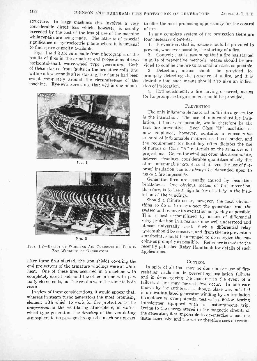
1122 JOH NtiON AND BURNHAM : FIRE PROTE( "NON OI O EN ERA TORS .1(Junin.1 A. I. E. E.
structure. In large machines this involves a veryconsiderable direct loss which, however, is usuallyexceeded by the cost of the loss of use of the machinewhile repairs are being made. The latter is of especialsignificance in hydroelectric plants where it is unusualto find spare capacity available.
Figs. 1 and 2 are cuts made from photographs of theresults of fires in the armature end projections of twohorizontal -shaft water -wheel type generators. Bothof these started from faults in the armature coils, andwithin a few seconds after starting, the flames had beenswept completely around the circumference of themachine. Eye -witnesses state that within one minute
FIG. 2
FIGS. 1-2-EFFECT OF WHIRI ING AIR CURRENTS ONEND WINDINGS OF GENERATORS
FIRE IN
after these fires started, the iron shields covering theend projections of the armature windings were at whiteheat. One of these .fires occurred in a machine withcompletely closed ends and the other in one with par-tially closed ends, but the results were the same in bothcases.
In view of these considerations, it would appear that,whereas in steam turbo generators the most promisingelement with which to work for fire protection is thecomposition of the ventilating atmosphere, in water-wheel type generators the directing of the ventilatingatmosphere in its passage through the machine appears
to offer the most promising opportunity for the controlof fire.
In any complete system of fire protection there arefour necessary elements:
1. Prevention; that is, means should be provided toprevent, whenever possible, the starting of a fire.
2. Control; that is, assuming that a fire has startedin spite of preventive methods, means should be pro-vided to confine the fire to as small an area as possible.
3. Detection; means should be provided forpromptly detecting the presence of a fire, and it isdesirable that such means should also give an indica-tion of its location.
4. Extinguishment; a fire having occurred, meansfor its prompt extinguishment should be provided.
PREVENTION
The only inflammable material built into a generatoris the insulation. The use of non-combustible insu-lation, if that were possible, would therefore be thebest fire preventive. Even Class "B" insulation asnow employed, however, contains a considerableamount of inflammable material used as a binder, andthe requirement for flexibility often dictates the useof fibrous or Class "A" materials on the armature endprojections. Generator windings often also accumulate,between cleanings, considerable quantities of oily dirtof an inflammable nature, so that even the use of fire-proof insulation cannot always be depended upon tomake a fire impossible.
Generator fires are usually caused by insulationbreakdown. One obvious means of fire prevention,therefore, is to use a high factor of safety in the insu-lation of the windings.
Should a failure occur, however, the next obviousthing to do is to disconnect the generator from thesystem and remove its excitation as quickly as possible.This is best accomplished by means of differentialrelay protection in a manner now well understood andalmost universally used. Such a differential relaysystem should be sensitive, and, from the fire preventionstandpoint, should be arranged to de -energize the ma-chine as promptly as possible. Reference is made to therecent'y published Relay Handbook for details of suchapplications.
CONTROLIn spite of all that may be done in the use of fire-
resisting nsulation, in preventing insulation failuresand in de -energizing the machine in the event of afailure, a fire may nevertheless occur. In one caseknown by the authors, a stubborn blaze was initiatedin a mica -insulated generator winding by an insulationbrEakdown on over -potential test with a 50 -kw. testingtransformer equipped with an instantaneous trip.Owing to the energy stored in the magnetic circuits ofthe generator, it is impossible to de -energize a machineinstantaneously, and the writer therefore sees no reason
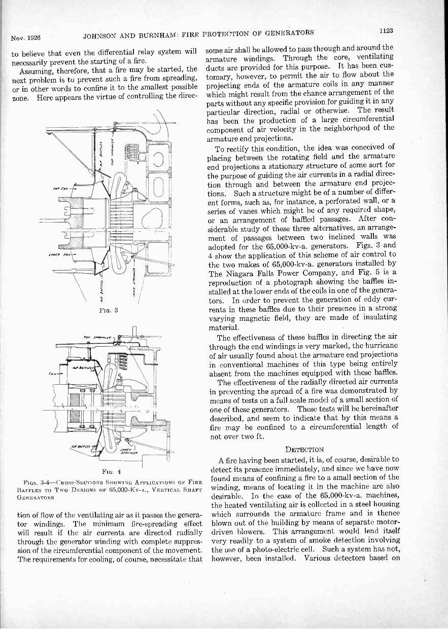
Nov. 1926 JOHNSON AND BURNHAM: FIRE PROTECTION OF GENERATORS 1123
to believe that even the differential relay system willnecessarily prevent the starting of a fire.
Assuming, therefore, that a fire may be started, thenext problem is to prevent such a fire from spreading,or in other words to confine it to the smallest possiblezone. Here appears the virtue of controlling the direc-
FIG. 4
FIGS. 3-4--CROSS-SECTIONS SHOWING APPLICATIONS OF FIREBAFFLES TO Two DESIGNS OF 65,000-Kv-A., VERTICAL SHAFTGENERATORS
tion of flow of the ventilating air as it passes the genera-tor windings. The minimum fire -spreading effectwill result if the air currents are directed radiallythrough the generator winding with complete suppres-sion of the circumferential component of the movement.The requirements for cooling, of course, necessitate that
some air shall be allowed to pass through and around thearmature windings. Through the core, ventilatingducts are provided for this purpose. It has been cus-tomary, however, to permit the air to flow about theprojecting ends of the armature coils in any mannerwhich might result from the chance arrangement of theparts without any specific provision for guiding it in anyparticular direction, radial or otherwise. The resulthas been the production of a large circumferentialcomponent of air velocity in the neighborhood of thearmature end projections.
To rectify this condition, the idea was conceived ofplacing between the rotating field and the armatureend projections a stationary structure of some sort forthe purpose of guiding the air currents in a radial direc-tion through and between the armature end projec-tions. Such a structure might be of a number of differ-ent forms, such as, for instance, a perforated wall, or aseries of vanes which might be of any required shape,or an arrangement of baffled passages. After con-siderable study of these three alternatives, an arrange-ment of passages between two inclined walls wasadopted for the 65,000-kv-a. generators. Figs. 3 and4 show the application of this scheme of air control tothe two makes of 65,000-kv-a. generators installed byThe Niagara Falls Power Company, and Fig. 5 is areproduction of a photograph showing the baffles in-stalled at the lower ends of the coils in one of the genera-tors. In order to prevent the generation of eddy cur-rents in these baffles due to their presence in a strongvarying magnetic field, they are made of insulatingmaterial.
The effectiveness of these baffles in directing the airthrough the end windings is very marked, the hurricaneof air usually found about the armature end projectionsin conventional machines of this type being entirelyabsent from the machines equipped with these baffles.
The effectiveness of the radially directed air currentsin preventing the spread of a fire was demonstrated bymeans of tests on a full scale model of a small section ofone of these generators. These tests will be hereinafterdescribed, and seem to indicate that by this means afire may be confined to a circumferential length ofnot over two ft.
DETECTION
A fire having been started, it is, of course, desirable todetect its presence immediately, and since we have nowfound means of confining a fire to a small section of thewinding, means of locating it in the machine are alsodesirable. In the case of the 65,000-kv-a. machines,the heated ventilating air is collected in a steel housingwhich surrounds the armature frame and is thenceblown out of the building by means of separate motor -driven blowers. This arrangement would lend itselfvery readily to a system of smoke detection involvingthe use of a photo -electric cell. Such a system has not,however, been installed. Various detectors based on

1124 JOHNSON AND BURNHAM: FIRE PROTECTION OF GENERATORS Journal A. I. E. E.
abnormal temperatures might also be employed; onedevice suggested consists of a fuse wire carried aroundthe generator and arranged to give an indication uponbeing fused at any point. Another possible devicewould be a vapor tension thermometer with its bulb inthe form of a long slender tube extending completelyaround the machine. This would indicate the maxi-mum temperatures at any point throughout the length
FIG. 5-FIRE BAFFLES INSTALLED AT LOWER END OF ARMA-TURE OF 65,000-liv-A. GENERATOR
of the tube. A third system of giving the indication ofthe presence of a fire is the use of sprinkler heads inwhich case the means of detection and of extinguish-ment are combined. With any system the provision ofhand holes at frequent intervals about the circumfer-ence of the machine is desirable both for the purpose oflocating the fire and for allowing access to it by means ofhand extinguishers or a fire hose. The combinationof sprinkler heads and hand holes was used in the 65,000-kv-a. generators (Fig. 6).
EXTINGUISHMENT
A number of mediums are now available for extin-guishing fires in electrical apparatus, the principal ones
FIG. 6-HAND HOLES AND SPRINKLER HEADS AT TOP OF 65,000-KV-A. GENERATOR
being water, steam, carbon dioxide, carbon tetra-chloride, "Fire Foam," and the well-known soda acidextinguisher. These may be applied in various ways;for instance, soda acid, "Fire Foam," and carbontetrachloride are usually applied by hand or portabletank extinguishers. Water or steam may be appliedthrough a hose; or water, steam, "Fire Foam," andcarbon dioxide may be applied through permanentpiping.
In the case of the 65,000-kv-a. generator at Niagara,the means provided for extinguishment consist, first, in aseries of hand holes giving access to the windings forthe use of hand or portable extinguishers or water hose.There is also installed at suitable points near the arma-ture end projections, a series of sprinkler heads con-nected by piping through a manually -operated levervalve to a source of water under pressure. Thissprinkler pipe is arranged to be maintained under airpressure with a contact -making gage adjusted to soundan alarm upon the reduction of this pressure through theblowing of a sprinkler head (Figs. 7, 8, 9, and 10).
It has been ascertained by means of tests upon theabove mentioned model that a fire can be maintainedfor a considerable length of time under the system ofair control installed in these machines without spreadingappreciably beyond its point of initiation, so that upon
H ft. 2 m.
it Intl24 m +Do . tipper Spnnklers
3
r.67 in B.L.
-
Top Cover plates on
Top of Generator.6 m
13 ft 8,m Mt
Abt
LI-La%E1 3650
tosser Sponnklers
FIG. 7-DETAILS OF SPRINKLER HEAD AND PIPING INSTALLA-TION IN 65,000-Kv-A. GENERATOR
occurrence of a fire, the operator has ample time todetermine its location by inspection through the handholes. Having located the fire, the operator is in-structed to attempt its extinguishment first by means ofhand or portable extinguishers using carbon tetra-chloride or "Fire Foam." Should these prove in-sufficient, he can employ the soda acid extinguisher, orif his judgment indicates the necessity, he can turnon the water in the sprinkler system by means of theabove mentioned lever valve. In this event theapplication of the water will be limited to one or twosprinklers which will have opened immediately adjacentto the fire, so that the water damage will be confined toas small a portion of the machine as possible.
If the use of carbon dioxide for fire extinguishmentis perfected to a point where it is applicable to machinesof this type, there would appear to be no reason whythe general system of protection installed in thesemachines would not be readily adaptable to its use.It would appear that the baffles between the rotor and

Nov. 1926 JOHNSON AND BURNHAM: FIRE PROTECTION OF GENERATORS 1125
armature coils might be of material assistance towardthe effective use of carbon dioxide.
DETAILS OF INSTALLATION ON 65,000-KV-A.GENERATORS
These are shown in Figs. 7,13, 9, and 10. The airbaffles are constructed of bakelized canvas or asbestossupported by suitable castings with radial vanes formingpassages for the cooling air.
The sprinklers are of modified standard design andare enclosed in baskets of sufficiently fine wire meshto retain the loose parts resulting from a blow -off.
Separate piping systems are provided for the top andbottom ends of the armature windings with separatealarm signals so that a fire may be immediately locatedwith respect to the two ends of the generator.
The manually -operated control valves shown in Figs.9 and 10 are normally sealed in the closed position"andare so arranged that any leakage of water into the
tt,
22in ° 11E1E1112.
LI. 378.198
2 in Water Ling
W kr liner
Enlarged V,ew Snowing
krangement of Qmolt Opening
Valves on Are line
in To Gage
I I m lo Generator
I
FIG. 8-LAYOUT OF AIR AND WATER PIPING, THREE-WAYVALVES, SUMPS AND CONTACT -MAKING GAGES
sprinkler piping which may take place is caught in asump and may be periodically drained off. The open-ing of the valve for draining the sump will automaticallytest the alarm system by lowering the air pressure inthe sprinkler system.
The air valves through which compressed air issupplied to the sprinkler pipes are of the needle typeand may be kept slightly open so as to automaticallymaintain the air pressure so long as all sprinkler headsare intact. Upon the blowing of a head, the pressurewill drop due to the throttling effect of the needle valveand the alarm will be given.
The contact -making pressure gage is of standarddesign arranged to close a contact upon a drop in pres-sure to a predetermined value. Any desired form ofalarm can be used.
TESTS
Before adopting the above described system of pro-tection for the 65,000-kv-a. generators, a series oftests was made to determine the best type and ar-
rangement of sprinklers, to determine whether thetemperatures produced by a fire would be sufficient tooperate standard sprinkler heads, and whether the aircontrol devices proposed would be effective in confiningthe fire to a small area.
The first series of tests was taken to determine thefollowing points:
FIG. 9-ARRANGEMENT OF HANDLES OF THREE-WAY VALVESAND CONTACT -MAKING PRESSURE GAGES
-;\
FIG. 10-SECTIONAL VIEV OF GENERATOR
Showing relative location of end windings, connections and sprinkler.A-sprinkler, B-stator coil, C-stator connections, D-Ilre bafflers,
E-stator frame, F-air inlet
1. Location of sprinkler heads with respect togenerator windings.
2. Design of sprinkler -head deflector.3. Design of screen to catch links or parts which
fly out from sprinkler heads when they operate.It was impossible to make the proposed tests on one
of the 65,000-kv-a: generators; therefore it was desirable

1126 JOHNSON AND BURNHAM: FIRE PROTECTION OF l] EN ERATORS Journal A. 1. E. E.
to make the conditions under which the tests were to betaken as near like actual conditions as possible.
Fig. 10 shows a section of the generator with locationof sprinkler head as originally estimated to beapproximately correct. Fig. 10 also shows the relativelocations of the stator -coil end windings, stator con-nections, and fire baffles,. and also shows the relativelysmall amount of space above the electrical parts inwhich to locate the sprinkler heads.
In order to see exactly how water would spray fromthe sprinkler heads under different conditions, a dummy
A
FIG. 11-DUMMY SECTION OF GENERATOR USED IN THE WATER -SPRAY TESTS
A-Sprinkler, B-stator coil, C-screen, D-beaver board
section of the generator was made up in the form of awooden box as shown in Fig. 11. This box represented.at full scale one of the generator sections in which asprinkler head was to be located. The length of thebox represented the length of one of these sectionsmeasured on the circumference of the generator at the.air -gap. On account of the size of the 65,000-kv-a.generators, the air -gap did not vary far from a straightline in the length of a section being considered; thereforefor our test purposes, the box was made. withoutcurvature.
The ends of the box represented the barriers to beplaced between sprinkler heads. Side pieces made ofbeaver board were fastened to the ends of the box, andon each a stator -coil end projection was drawn in itsrelative position as shown in Fig. 11.
A screen was placed across the front of the box assome such protection would be needed in actual prac-tise to keep the links of an operated head from droppingdown into the generator windings. Medium -weightwire screening was used, having five wires per in..each way, it being found by trial that links from thesprinkler heads would not go through mesh of thisdescription, while they would go through mesh havingwires of the next greater standard spacing.
In this first set of tests no fire was used, as the princi-pal object was to determine how well water would besprayed into the generator windings and connectionsunder different conditions. As fires in generatorsusually occur in the stator -coil connections or stator-coil end projections, it was necessary in the tests tofind an arrangement in which water would reach theseparts effectively.
Before taking the tests it was quite obvious thatwater could be sprayed in large quantities on thestator windings and connections directly in front of the
sprinkler, but it was not certain just what position ofsprinkler head and type of deflector would give thebest water distribution over the entire area to be con-sidered. From Fig. 11 it can be seen that the area tobe covered was much ,longer than it was wide, but itwas just as important that the water reach the coilsat the ends of a section, or in other words, that it reachcoils midway between two sprinklers, as it was to reachthe coils directly in front of the sprinkler.
In the sprinkler tests, over two dozen different specialdeflectors were used, and several locations of sprinklerand angle of spray were tried. The water pressure,also, was varied to determine the effect of such a changeon the water distribution.
Under each test the water distribution was observedand rated in five ways as follows:
1. Distribution and distance water sprayed directly;n front of sprinkler head.
2. Amount and distribution of water sprayed ontobeaver boards at side.
3. Amount and distribution of water backwardinto box.
4. Amount of water to reach upper corners at eachside of box.
5. Spray of water in general.Regarding the location of sprinkler head and angle of
spray, the best results were obtained with the sprinklerhead tilted down 45 deg. from horizontal and locatedin the box so that the center of the sprinkler -headdeflector was five in. from the back and three in.from the top of the box.
FIG. 12-STANDARD SPRINKLER HEAD USED IN FIRE PROTECTIONOF BUILDINGS
If the sprinkler head was tilted more than 45 deg.from horizontal, an undue amount of water was sprayedinto the box; and if the angle was made less than 45 deg.,a larger portion of water than necessary was sprayedout directly in front.
Fig. 12 shows a common type of sprinkler head asgenerally used in fire protection of buildings. It willbe noted that the deflector used at the top of this sprink-ler has projections or ears around its outer edge whichare bent downward. It was quite obvious that thistype of deflector would not meet our needs, as the bent

Nov. 1926 JOHNSON AND BURNHAM: FIRE PROTECTION OF GENERATORS 1127
ears have a tendency to spray a larger portion of thewater backward.
After many tests were made in which a large numberof different deflectors was used; it was found that adeflector as shown on sprinkler head in Fig. 13 gave thebest results. This deflector, which is approximately13/16 in. in diameter and is cupped upward slightly,happens to be a deflector which is used on manysprinkler heads in mills where the projecting ears of the
FIG. 13-SPRINKLER HEAD USED IN 65,000 -KY -A. GENERATORS
standard sprinkler are objectionable. When used inmills, however, the deflector is cupped downwardinstead of upward.
In order to show how the design of a deflector affectsthe water distribution, a few of the deflector tests will
be described.1. Deflector in accordance with Fig. 13. The
water was sprayed a distance of six ft. out in front ofthe box, and the beaver boards at the sides were wellcovered. Some water was sprayed backward into thebox. With this deflector, the water was discharged ina fine spray which almost resembled a fog. Thedistribution of water over the desired area was verygood.
2. Same as (1) except that deflector of larger di-ameter was used. Water was sprayed farther out infront than in case (1), but the spray was not as fine andthe general distribution was not as good as in case (1).
3. Deflector in accordance with Fig. 12 except thatall but two ears on opposite side were cut off. (Itwas thought that the two remaining ears might helpthrow more water out to the sides.) Water was sprayedfarther out in front than in case (1). Water spoutedup at ears, but distribution at sides was not as good asin case (1).
4. Same as (3) except that all ears were cut off.Results were about the same as those of (3).
5. Same as (1) except that deflector was inverted andtherefore cupped down instead of up. Less waterwas sprayed out in front than in case (1). Practicallyno water reached the beaver boards at the sides.Large amount of water discharged back into the box.
The deflector tests such as described above weretaken with a medium water pressure of 43 lb. per sq.in. With deflector used in case (1), the water pressure
was increased to 100 lb. per sq. in. With thisthe spray became extremely dense, and the distributionof water remained good.
By decreasing the water pressure it was found thatthe quantity of water and the distribution of water wassatisfactory down to a pressure of 30 lb. per sq. in.With'a pressure of 25 lb. per sq. in. the results were onlyfair; therefore it was felt that in practise the watershould be held up to at least 30 lb. per sq. in. Thismatter of water pressure can be easily taken care of incase of the 65,000-kv-a. generators, as the normalwater pressure in the station is approximately 80 lb.per sq. in.
The principle of operation of the sprinkler headsused may be seen from the construction shown in Figs.14 and 15. Fig. 14 shows the cross-section of a sprink-ler head and position of links before the head hasoperated, and Fig. 15 shows the same head with posi-tion of links shortly after the head has operated.
It may be noted that the links of a sprinkler headare small levers so assembled that they can be heldtogether in the normal position before operation by avery small amount of solder. By using solders of dif-ferent melting points, the sprinkler heads can be made tooperate over a wide range of temperatures.
Ratings of sprinkler heads have been standardizedso that a head may be obtained having a rating of155,212,286 or 360 deg. fahr. For each different ratingthe composition of the solder is such that the heads willoperate at a temperature corresponding to th0 rating.
In order to make sure that sprinkler heads locatedin the 65,000-kv-a. generators as previously determinedwould operate satisfactorily in case of a generator fire,further tests were considered.
Actual fire tests seemed desirable, as it was not certain
FIG. 14-CROSS-SECTIONOF SPRINKLER HEAD
Showing position of links beforeoperation
FIG. 15-CROSS-SECTION OFSPRINKLER HEAD
Showing position of links afteroperation
A-Yoke, B-body, C-diaphragm, E-glass valve, F-main strutpiece, 0-hook link, H-key link. J-dellector
that heat sufficient to operate the sprinkler headswould have a chance to reach them in case of a generatorfire. The ventilation of these generators is such that acurrent of air passes in a horizontal direction throughthe stator connections and end windings and then outthrough openings in the stator frame. It seemed pos-sible that in case of a fire in the end windings or con-

1125 JOHNSON ANI) BURNIIANI: FIRM (IMNMItAT()ItS Journal A. 1. le, M.
nections of one of the generators, sufficient heat tooperate a sprinkler head might not pass up through thiscurrent of air.
Another point in question regarded the wire screenwhich was to be used to keep the links of an operatedhead from dropping down into the generator windings.It is known that a wire mesh offers some resistance tothe passage of heat, and it was thought desirable tocheck this point in a test to find out if heat sufficient tooperate a head in case of a generator fire would passthrough the proposed screen.
In order that the second series of tests could be made
FIG. 16-D -cm my SECTION OF GENERATOR USED IN FIRE TESTS
conveniently, a dummy generator section was made ofsheet metal. The construction of this compartmentwas such that, turned one way, it represented a sectionof the generator at the top of the machine, and inverted,it represented a bottom section of the generator.Dummy stator connections and stator -coil end pro-jections were also constructed, these being made ofwood. All parts were made to full scale.
Fig. 16 shows the dummy compartment in a positionrepresenting a top section of one of the generators.It may be noted that the door has been removed and thedummy coils taken out of the sheet metal compartmentand placed in the foreground so that the constructionmay be seen. In the same figure, an end view of thedummy stator -coil connections may be seen in positionin the compartment. The dummy connections andcoils were made of boards one in. thick and spacedin. apart. With this construction the wooden partscould be easily ignited for the fire tests.
A motor and exhaust fan were connected to the sheetmetal compartment as shown in Fig. 16, in order thatair might be circulated through the stator coils andconnections in the normal way.
Provision was made for the mounting of a sprinklerhead in the test compartment as previously determined.Four thermometers having 150 -deg. cent. scales weresuspended through small holes in the top of the com-partment as shown. With the use of the thermometers,temperatures could be read at time intervals betweenthe starting of the fire and the operation of the sprinkler
head. By means of a hose, air pressure was placed onthe sprinkler heads so that the operation of a sprinklerhead would be known immediately by the rush of air.
Fig. 17 shows a cross-section of the test compart-ment described above with door removed and thedummy connections and stator end projections in theirnormal position. The location of the wire screen andfire baffles is also given. The small glass window inthe end of the dummy section was provided so that theintensity of the fire could be watched with the metaldoor in place and the compartment entirely closedexcept for the air inlet in the front and the air outletin the rear.
Shutters were placed in the air inlet and a damper inthe air outlet so that the flow of air through the com-partment could be regulated if desired.
With the test equipment arranged as shown in Fig. 17,the first set of fire tests was made. Fire was started atdifferent places in the dummy connections and coils bymeans of a small rag soaked in kerosene. After asprinkler head operated, the wooden parts were takenfrom the compartment and the fire was put out bymeans of steam.
In Fig. 18 some representative temperature curves aregiven showing the results of a few of the tests madewith the fire started in the dummy coils. In thesecurves, temperature in degrees centigrade is plottedagainst time in minutes. In the first four tests shown,the shutters in the air inlet and the damper in theair outlet were open and the fan was running. In thelast test shown, the fan was shut down. The fourdifferent curves for each test represent the readings ofthe four different thermometers which were numberedone to four from right to left facing the front of the
E
FIG. 17-CROSS-SECTION OF SHEET -IRON DUMNIY COMPARTMENTUSED IN FIRE TESTS
dummy compartment. Temperature readings weretaken every quarter of a minute.
In tests 2, 5, and 7, 100 -deg. cent. sprinkler headswere used and in tests 3 and 6, 68-deg. cent. heads wereused. Facing the front of the compartment, the firewas started in the left end of the dummy coils in tests2 and 3, and in the middle portion in tests 5, 6, and 7.
It should be noticed that in these tests the tempera-ture curves become very steep close to the time of headoperations. In fact, the temperature increased so

Nov. 1926 JOHNSON AND BURNHAM: FIRE PROTECTION OF GENERATORS 1129a
fast that the thermometers were raised out of the com-partment in order to keep them from going off scale
and breaking. This accounts for the fact that thecurves do not in all eases extend to the vertical linewhich indicates the time of head operation.
As would be expected, the curves show that undersimilar conditions the 68 -deg. heads operate soonerthan the heads rated 100 deg., although the differencein time is small. By comparing test 2 with test 3, itmay be seen that with the fan running and with the
120
110
100
90a)
80
70
GO
- SO
(1.)
40
30
20
10
0
the fire and in some cases the dummy coils were leftmore moist than in others. By comparing tests 5 and 6,it may be seen from the curves that soon after the firewas started it required A min. longer in test 5 than itdid in test 6 to reach a certain temperature. Bymaking correction for this difference, the 100 -deg. cent.head of test 5 would have operated about min.
sooner, or in approximately 2 min., had the firedeveloped to raise the temperature as in test 6 where a68 -deg. cent. head was used. In other words, the
TEST 112 2FIRE- LEFTHEAD -100°C
FAN- RUNNING
TEST N23FIRE- LEFTHEAD-66*C
FAN -RUNNING
TEST N°5FIRE -MIDDLE
HEAD -100°CFAN- RUNNING
TEST N26FIRE - MIDDLE
HEAD -68°CFAN- RUNNING
TEST N27FIRE- MIDDLEHEAD -100°CFAN -OFF
rna. '; 9
IA i iu uN1WI El .
ili 111
F.Nr 1 11
id 1
Eri -4, Ft.
,,',' -ill ,1,_
tu,,ikoc4,N
,1
Ezck. '-0 %) A0
rk'nto. -INe co
IS,0: )
acl,
st.z,i: zs.t, o tot,..,
. to
,t,.:NI
111 I
0 2 3 0 1 2. 3 0 1 2. 3 O 2 3 0 2 3Time , Mino e s
FIG. 18 -REPRESENTATIVE TEMPERATURE CURVES
FIG. 19-DUMMY COILS SHOWING BURNED PORTION
fire started in the left end of the dummy coils, the100 -deg. head operated in three min. and the 68 -deg.head in 1 VI min.
Tests 5 and 6 show that under conditions similar tothose described above except that the fire is started inmiddle of the dummy coils, the 68 -deg. head operatedin 2 min. and the 100 -deg. head in 3% min.
It may be noted that in some of the tests the fire gotstarted a little sooner than it did in other tests. Thiswas due to the fact that steam was used to extinguish
FIG. 20 -DUMMY CONNECTIONS SHOWING BURNED PORTION
difference between 2 54 min. and 2% min., ormin., gives approximately the difference in time betweenoperation by a 100 -deg. cent. head and a 68 -deg. cent.head, under such conditions as existed in test 6.
In all cases it may be noted that the temperatures asmeasured with the thermometers exceeded the sprink-ler head ratings before the heads operated. This doesnot mean that the heads were rated incorrectly butrather that with the temperature increasing rapidly,the time lag is greater in the sprinkler heads than inthe thermometers.

1130 14)\\'1,:H cil.:NERATION .11)11 rural .1. I . I .
Fig. 19 shows the way the dummy coils were burnedand charred in Test No. 5, this being a typical case.In this test the fire was started in the middle of thedummy coils, and it should be noted that the firefollowed up the diagonal wooden members, but due tothe strong current of air that was being blown throughthe dummy coils, the fire did not spread to the right norto the left appreciably. Fig. 20 shows the way thedummy connections were burned in the same test.Later a similar test, was made in which the fire wasallowed to burn for 15 min. in the dummy coils. Theresults were about the same in that the fire spread verylittle. This is a very important point since the firedamage can be reduced to a minimum if the fire incoils of generators can be prevented from spreading.
In test No. 7 the fan was not running; otherwise thetest is the same as test No. 5. By comparing testsNos. 7 and 5, it may be seen that the operating time is2 N min. in one case and 3 Y8 min. in the other, whichshows that the current of air passing through the com-partment has very little effect in the operation of thesprinkler heads.
Another set of tests was made with the fire locatedin the dummy connections. By moving the sprinklerheads back slightly from their first position, very goodoperation of the sprinkler heads was obtained. Theoperating time was approximately 1 34 min. for the68 -deg. head and approximately 2 min. for a 100-deg. cent. head.
With the dummy sheet metal compartment inverted,an additional set. of tests was made to determine theeffectiveness of the sprinkler heads in protecting the
ator-coil end projections at. the bottom of one of the65,000-kv-a. generators. For this case, the operatingtime was about 2 !.1 min. for the 68 -deg. cent. headsand approximately 3 I min. for the 100 -deg. cent.heads.
C(NutstotstThe tests proved conclusively that the proposed
scheme of fire protection as described would he verysatisfactory for the 65,000-kv-a. generators for thefollowing reasons:
1. Sprinkler heads arranged in the generator asshown and properly spaced would operate for a verysmall fire in the stator end windings or statorconnections.
2. Sprinkler heads would operate in spite of the aircurrents, which, in case of the coil projections and con-nections at top of generator, would tend to carry theheat from a fire away from the sprinkler heads.
3. With current of air flowing radially through theend windings and connections, a fire started in theseparts is confined to a small section even after the firehas burned for as long a time as 15 min.
4. If a fire started in the generator windings can-not be extinguished easily with hand fire extinguishers,the operator can then turn a valve which will allowwater to be sprayed effectively in the region of the fireonly, thereby doing minimum damage to the remainderof the machine.
The authors wish to acknowledge the valuableassistance given by Mr. Ira Knight of the General FireExtinguisher Company, who furnished equipment andhelped to carry out the water spray tests.
Power GenerationAnnual Report of Committee on Power Generation*
VERN E. ALDEN, Chairman
To the Board of Directors:Last year's report of this Committee reviewed the
many important developments in the art of powergeneration and dealt particularly with advances insteam station design and operation. As a committeewe were just a little prone to believe that there could
*Committee on Power Generation:Vern E. Alden, Chairman, Consolidated
Baltimore, Md.H. A. Barre,E. T. Brandon,H. W. Eales,Louis Elliott,N. E. Funk,C. F. Hirshfeld,Francis Hodgkinson, I. E. Moultrop, W. M. White.
This report published in pamphlet form includes an extensivebibliography.
Presented at the Annual Convention of the A. I. E. E., WhiteSulpha Springs, W. Va., June 21-25, 1926.
P. Junkersfeld,H. A. Kidder,J. T. Lawson, W. H. Lawrence,James Lyman,W. E. Mitchell,
Gas & . Electric Company,
J. C. Parker,M. M. Samuels,F. A. Scheffler,R. F. Schuchardt,A. R. Smith,Nicholas Stahl,
not be the advance during 1925 that had taken placeduring 1924. Nevertheless, substantial progress hasbeen made.
IMPORTANT TECHNICAL ACHIEVEMENTS OF THELAST YEAR
1. The 3000 -kw. turbine designed for operation witha steam pressure of 1200 lb. per sq. in., which wasreferred to in last year's report, was placed in operationin the Edgar Station of The Edison Electric Illumi-nating Company of Boston in December 1925. Thisturbine, receiving approximately 125,000 lb. of steamper hr. from a single high pressure boiler, exhausts itssteam first through a reheating superheater built intothe same setting with the high pressure boiler. Thesteam is then delivered to the main steam header ofthe station at a pressure of approximately 350 lb. per

Nov. 1926 POWER GENERATION 1131
sq. in. The most annoying trouble encountered inconnection with this unit has been vibration incidentto double winding on rotor and possibly undue flexibil-ity in the rotor shaft of the generator which runs at3600 r. p. m.
The rotor was originally of the built-up type withsquirrel -cage winding in addition to the usual externallyexcited field. This arrangement was adopted as aprecaution in case there should be governor troublearising from the use of extremely high pressure steam.As the governing and synchronizing have proved to beperfect, however, the generator has been equipped witha solid field and all vibration has been entirelyeliminated.
The action of the unit is perfectly normal and indi-cates that equipment of this character is suitable forregular commercial service, where economically justi-fiable.
This unit has had over 1800 hours of commercialoperation including one run of over three weeks' timewithout a shutdown.
The performance of the Edgar Station has beenhighly satisfactory. Operated with a favorable loadfactor and good coal, the 350 -lb. pressure plant has arecord of one lb. of coal per kw -hr. which means practi-cally 14,000 B. t. u. per kw -hr.
With the single high-pressure boiler and the 3600 -kw., 1200 -lb. pressure turbine in service, the averagecoal consumption per kw -hr. for the whole station isreduced three per cent. This indicates that if all fourboilers were of the high pressure type, the fuel consump-tion per kw -hr. would be reduced 10 per cent, to avalue of 0.9 lb. of coal per kw -hr.
2. With the exception of moderately high outages ofthe generating units, the operation of the Philo Stationof the Ohio Power Company, the Twin Branch Stationof the Indiana and Michigan Electric Company, andthe Crawford Ave. Station of the CommonwealthEdison Company, all at a pressure of 550 lb. per sq.in. and a steam temperature of 725 deg. fahr. with thereheating cycle, has been quite satisfactory. Thetroubles encountered have been of a nature not entirelychargeable to the use of the higher steam pressure andtemperature and the use of the reheating cycle. Theindications are that these stations may be counted uponfor thoroughly satisfactory and reliable service.
3. The Columbia Power Company's new 90,000 -kw. station designed for operation with steam at apressure of 550 lb. per sq. in. and a temperature of 725deg. fahr. and for operation on the reheating cycle wasstarted in December of last year.
4. Two more turbines have been purchased for theCrawford Ave. Station in Chicago, and a turbine hasbeen purchased for Waukegan Station of the PublicService Company of Northern Illinois, all for operationat a steam pressure of approximately 550 lb. per sq. in.Two new stations have been designed for operation withthis same pressure. There is accordingly either in
operation at a pressure of 550 lb. per sq. in. or nowprojected a total of 925,000 kw. of power stationcapacity.
5. The Milwaukee Electric Railway and Light Com-pany is installing in its Lakeside Station for operationat 1200 lb. pressure a boiler of modified Stirling typewhich will deliver steam to a 7000 -kw. turbine, thesteam temperature at the throttle being 720 deg. fair -The steam will be exhausted through a reheating super-heater into the main steam header of the station,.maintained at a pressure of approximately 315 lb.per sq. in.
6. Of particular interest has been the increase'inthe size of turbo generator units as exemplified by thepurchase during the last year of the following machines:
a. A 77,000 -kw. and a 90,000 -kw. unit pur-chased from the General Electric Company forthe Crawford Ave. Station in Chicago.
b. An 80,000 -kw. Westinghouse turbine forthe Hudson Ave. Station in Brooklyn.
c. A 160,000 -kw. turbine for the Hell GateStation of the United Electric Light and PowerCompany of New York.
This trend towards the use of still larger units isfurther indicated by the projected use of turbo generatorunits of 200,000 -kw. capacity in the New State LineStation near Chicago. It is to be remembered that thelargest machine which we had to report upon twelvemonths ago was of 60,000 -kw. capacity.
7. The first large furnace of the Fuller Well typedesigned for pulverized fuel firing with turbulent mixingof coal and air has been placed in operation under a11,400-sq. ft. boiler in the River Station of the Buffalo.General Electric Company. Three more boiler andfurnace units of the same design are now being installedin the River Station.
S. The Combustion Engineering Corporation isadvocating the use of an entirely new type of boilerwhich will completely surround a furnace built forpulverized fuel firing. It is proposed to transfer to anair preheater an extraordinarily large percentage of thework usually performed by the last passes of the boilerin scrubbing heat from the flue gases. This will resultin the boiler itself being of relatively small area.Brickwork with its troublesome problem of mainte-nance is to be almost entirely eliminated.
It is reported in the technical press that the Com-bustion Engineering Corporation has contracted toinstall a total of 15 of these new boiler and furnace unitsin the stations of eight different companies. Each unitwill be capable of evaporating approximately 100,000.lb. of steam per hour.
9. As indicative of the trend towards the use of verylarge boiler units we have the operation of one of the26,470-sq. ft. Ladd boilers in the River Rouge Plantof the Ford Motor Company. The furnace for this.boiler was rebuilt during the last year, water-cooledwalls were installed, the pulverized coal feeders and.

i,ovEit vi.n)% A. I. F. K.
burners were revamped, and, t he boiler was Hil111)1)(41with air heaters and induced draft fans of ample pro-portions. Since being rebuilt this boiler unit hasevaporated atof dwi.-, ofwater per hr. whichwould correspond in a well designed steam generatingstation to a gross generation of 45,000 kw. in the turbineroom.
10. The Milwaukee Electric Railway and LightCompany has built a plant for the processing of coal,prior to its use in the boiler plant of the LakesideStation. Coal in pulverized form while falling throughtwo vertical retorts will mingle with rising currents ofhot air and gas which will drive off a considerableamount of gas including the valuable by-products ofthe coal. The coke residue still in pulverized form,after being cooled in the hopper at the bottom of thelower retort, will be pumped to the pulverized fuelbunkers in the boiler house and burned in the furnaces.Equipment has been provided for removal of tar andbenzol from the gas.
Experimental work extending over almost a year'stime has indicated that no major difficulties will beencountered in operation. This installation in Mil-waukee is well beyond the laboratory stage and pro-vision is made for the expansion of this processing plantso as to take care of all the coal burned in the station.
This installation is of interest, as the successfulnessof its operation will indicate the advantages which willaccrue from the joint operation of our steam stationsand low -temperature carbonization plants by means ofwhich coal may be processed before being burned.
TRENDS IN STEAM GENERATING STATION DESIGN
Aside from the individual achievements referred toabove there are certain definite trends in power stationdesign and operation which should be noted:
1. The heating of the feed water to a temperatureof from 350 to 400 deg. fahr. by means of steam bledfrom three or more stages of the turbine.
2. The removal of the heat in the flue gases afterthey leave the boiler by means of an air heater whichreturns this heat to the furnace.
3. The elimination of the economizer.4. The wide -spread use of steaming surface for
furnace walls and the elimination of a considerablepart of the furnace brickwork.
5. The use of automatic control in the boiler housewith consequent - improvement in day -in and day -outoperating efficiencies.
6. The use of separate ventilating fans in connec-tion with very large generators of 62,500 kv-a. andhigher capacities.
7. The use of relatively smaller surface condensersmade possible by more careful design of the condensersthemselves and by a better understanding of the rela-tion of turbine performance to condenser performance.
DEVELOPMENTS IMMEDIATELY AHEAD
The present combination of boilers and water-cooledfurnaces which are, as one engineer expressed it,
"fearful ;mil wonderful His of plumbing,- probablyforecast certain changes in boiler and furnace designwhich will result in simplification and decreased in-vestment, while at IIle same time maintaining whatappears to be the most logical development of the boilersurrounding the furnace.
We are probably on the verge of being forced intothe use of higher voltages in connection with the verylarge generators now contemplated.
AUXILIARY PoWElt SUPPLY
Two phases of the auxiliary power supply problemare worthy of study by the members of the Institute:
1. Is the use of 2300 volts for distribution to thestation auxiliaries the best choice, involving as it doesthe use of expensive oil -immersed switching equipmentoccupying expensive space? The alternative is a volt-age of the order of 440 and the substitution of carboncircuit breakers and contactors for oil switches. Thisalternative offers distinct advantages from the stand-point of reduced investment in equipment and in build-ing, and in greater ease of inspection and maintenance.
2. What, is the best solution for variable speed driveof the forced and induced draft fans in our new stations?The difficult nature of the problem is exemplified by aninstallation in one of the new stations now being built:Two 200-h. p. motors drive the forced draft fans of eachboiler and two 550-h. p. motors drive the induced draftfans for each boiler. The speed of the fans must bevaried by 50 steps through a range from seven to oneand the total h. p. input to the four fans varies from1500 to 15. In this ease the motors for the fans inconnection with one boiler cost approximately $12,000and the electrical control equipment for these motorscost approximately $20,000 and occupied a considerableamount of rather expensive space. If electrical engi-neers can not work out a simpler and less costly solu-tion for this admittedly difficult problem, power stationdesigners may have to return to the use of steam tur-bine drive for these fans, much as they may wish toavoid this solution, with its attendant use of reductiongears.
USE OF STEAM AT HIGHER TEMPERATURESThe use of higher steam temperatures of the order
of 800 deg. fahr. and perhaps as high as 900 deg. fahr. isbeing forecasted by scattered operating experience, mostof it unpremeditated. Due in the main to errors insuperheater design the steam temperatures have beenhigher than anticipated in connection with some of thenew stations. Some of these stations have operatedfor appreciable periods of time with steam tempera-tures in excess of 775 deg. fahr. One turbine operatedfor a time with steam at a temperature of approximately1000 deg. fahr. There have been no serious indicationsof distress as a result of operation at these high tempera-tures. It has recently been reported in the technicalpress that a 40,000 -kw. turbine in the GennevilliersStation in France operated for 135 hr. during the

Nov. 1926 POWER GENERATION1133
months of October, November and December of lastyear with steam at temperatures ranging from 775 to
914 deg. fahr. An inspection made December 25thshowed no indications of deterioration of the parts incontact with high -temperature steam. The turbinewas returned to service and has continued to operatesatisfactorily with steam at temperatures varying allthe way from 700 deg. to 900 deg. fahr.
These experiences together with the experiencegained in the operation of oil stills tend to show that wecan avail ourselves of the attractive possibilities inci-dent to the use of steam temperatures considerably inexcess of the present accepted limit of 750 deg. fahr.
JOINT USE OF STEAM STATIONS AND WATER -POWER
PLANTS
Worthy of attention are three examples of the broadgeneral solution of power supply by the combined useof steam generating stations and water -power plants in:
1. The construction of the 350,000-h. p. hydro-electric plant at Conowingo for joint use with 520,000kw. of capacity in steam stations of the PhiladelphiaElectric Company.
2. The construction of a new 70,000-kw. steamgenerating station by the Southern Power Company.
3. The completion of a 128,000 -kw. addition to theLong Beach Steam Station of the Southern CaliforniaEdison Company and the starting of work by this samecompany on a new station of at least 600,000 -kw.ultimate capacity with an initial development of
94,000 kw. The Southern California Edison Com-pany has approximately 350,000 kw. installed in water-power plants.
OPERATING RELIABILITY AND MARGIN OF SPARECAPACITY
The results of studies made jointly by a number ofthe operating companies of this country having fortheir purpose the determination of the operating relia-bility of our large generating units, are of considerableinterest.
An analysis of the operating records covering thecalendar year of 1925 for 191 steam turbines aggregat-ing 5,627,000 -kw. capacity showed that on an averagethese machines were in service 65.1 per cent of totalhours in the year and that they generated 44 per centof the maximum possible number of kw -hr.
These machines were idle because not needed 21.25per cent of the hours in the year. For 13.63 per centof the hours in the year, however, they were out ofservice for overhauling, inspection, maintenance workand cleaning, these outages being allocated as shownbelow:
Turbine outage - 7.29 per centGenerator outage - 1.85 per centSurface condenser outage . .- 3.51 per centOther causes - 0.98 per cent
Total outages -13.63 per cent
Comparing the foregoing results with the results ofsimilar analyses made during previous years coveringoperation for the period from 1914 to 1923 inclusive,three things stand out in striking fashion:
1. There is little if any evidence to indicate thedecrease which we would like to see from year to yearin turbine outages.
2. Prior to 1923 the generator outage averaged 2.8per cent of the hours in the year. For 1923 and 1925the generator outage has averaged 1.8 per cent. Thesestatistics are concrete evidence as to what the generallyadopted closed system of ventilation has accomplished.
3. The surface condenser outage has increased from1.2 per cent to 3.51 per cent of the total hours in theyear. This increase serves perhaps as an index ofpollution of the water in our rivers and harbors.
A study of the fact referred to above, that the out-ages due to causes other than the turbine, the generatorand the surface condenser, aggregated only 0.98 percent of the total hours in the year and that this item isof only seven per cent of the relative importance of theoutages due to other causes, is cause for reflection. Itis not recorded that Oliver Wendell Holmes was anoutstanding engineer but any one of us would havebeen proud to have been the designer of as perfectlyproportioned a piece of equipment as his "One HorseShay." On an average the investment in the turbineroom with its equipment is only 40 per cent of the totalinvestment in the station, yet 93 per cent of the outagesof station capacity are chargeable to the turbine room.Perhaps we have been failing to strike the properbalance between installed capacities, with their corre-sponding investments in the turbine room and in theboiler house with its related coal handling equipment.
Turning to a consideration of water -wheel drivengenerators, an analysis made by the Hydraulic PowerCommittee of the National Electric Light Associationshows that the total outage time on these units isappreciably less than on steam turbines. The analysescovered the operating records for 1924 on 56 water-wheels aggregating 950,000 h. p.
These machines were in operation 77 per cent of thehours in the year and generated 48.1 per cent of themaximum possible number of kw-hrs. They wereidle because not needed for service 17.62 per cent ofthe total hours in the year and were out of service for5.4 per cent of the total hours in the year for reasonsindicated below:1. General hydraulic causes - 0.64 per cent2. Water -wheels and auxiliaries -3.01 per cent3. Generators and appurtenances - 1.55 per cent4. Electrical causes beyond the genera-
tor, related to switching equip-ment and outside transmission . . . - 0.2 per cent
Total outages - 5.40 per centOutage time is related directly to the need for spare

1134 POWER lIEN E RA 'NON Journal A. I. E. X.
capacity and the fixed charges on spare capacity con-stitute perhaps as much as 10 per cent of the totalannual cost of power generation in steam generatingstations. It behooves us to find ways of reducing thisitem of cost. A major responsibility in this connectionlies with the equipment manufacturer. He mustbuild equipment that will be capable of operation forall except a very few hours per year. Particularly mustthe manufacturer guard against any inherent weaknesswhich will cause trouble involving unexpected shut-downs even though these outages be of short duration.Much can be accomplished by the engineer who designsthe power station in foreseeing and eliminating certainfeatures which may constitute the cause of an outage.The operating engineer can do much to control thenecessary margin of spare capacity by the choice of thebest operating methods, the careful training of personneland by the careful scheduling of inspection, preventivemaintenance and cleaning. With careful planning, alarge percentage of outage time can be made to occurwhen the capacity is not needed for service.
PROBABLE USEFUL LIFE OF STEAM STATIONS NOWBEING BUILT
One of the most troublesome problems facing theexecutives of our large electric light and power com-panies today is "what to do with the old steam gener-ating stations." Many of our large companies havesizeable blocks of capacity in steam generating stationsin connection with which the coal consumption perkw -hr. generated is two pounds or higher. The costs oflabor and maintenance are high. Viewed from thestandpoint of operating costs (not including fixedcharges), it seems nothing short of a crime to generatepower in these stations, bearing in mind that themodern stations being operated by these same compa-nies will generate power at a fuel consumption slightlyin excess of one pound of coal and with much lower costsfor operating labor and maintenance.
There is, of course, the possibility in some cases ofrebuilding in part, at least, in order to improve thestation performance. Notable examples of such pro-grams of rebuilding are exemplified by the substitutionsof unit coal pulverizers for the obsolete stoker equip-ment in the Brunots Island Station in Pittsburgh andin the Ashley Street Station in St. Louis. Some execu-tives raise the objection, however, that such a procedurewould, in connection with their stations, be sendinggood money after bad.
It is not our purpose to discuss this question of"What shall we do today with our old stations?", butrather to ask "What of the stations being built today inrelation to our operating problems of 20 and 30 yearsfrom now?"
Assume, for example, that a company which had asystem load of 400,000 kw. in December 1925 places inoperation this year the initial 50,000 -kw. unit of a new300,000 -kw. steam generating station. We will as-
sume that the average annual load growth is nine percent, that the yearly load factor is 56 per cent, and thatthe shape of the load duration curve is typical of loadconditions in almost any one of our large cities on theAtlantic seaboard. An additional 50,000 -kw. turbinemust be installed each year until 1931 when the sta-tion will be completed. Since the station will be halfcompleted in 1929, we may take the beginning of itsuseful life from that date. If we follow conventionallines of thought, we will consider the useful life of thisstation to extend from 1929 to 1949. What shall wedo with this station in 1949? Conceivably the newstations being built in 1949 may generate power for9000 B. t. u. per kw -hr., whereas the very best ourhypothetical station, started in 1926, can do, even onthe basis of a good load factor, is 14,000 B. t. u. perkw -hr.
The system load has grown, however, from 400,000kw. in 1925 to 3,185,000 kw. in 1949. As the result ofthe inevitable law which pushes the old station a littlehigher each year into the peak of the load durationcurve, we find that our 300,000 -kw. station will generatein 1949 only 300,000,000 kw -hr. corresponding to anannual use factor of 11.4 per cent. As the result of the lowload factor, the B. t. u. per kw -hr. has been pushedup to 17,000. The annual coal consumption is 190,000tons and the annual fuel cost is, let us say, $1,300,000.By scrapping this station and substituting in its place amodern station of the 1949 vintage, we can reduce theannual fuel cost in connection with the 300,000,000kw-hrs. of generation carried by this station from$1,300,000 to $800,000, with an annual fuel saving of$500,000. Few of us would dare to predict that this300,000 kw. of new capacity built in 1949 will cost lessthan $18,000,000, or that the investment bankers ofthat day will be willing to finance new constructionwork at rates which would permit the increase in fixedcharges incident to the construction of the new stationto be less than $2,200,000.
The major increase on load on most of our largesystems comes about as a result of increase in loaddensity. Consider therefore the strategic positionwhich the station built in 1926 will probably occupywith respect to the load as of 1949 or 1959.
It would appear that the engineers and executivesof 1949 are going to have a very difficult time justify-ing the scrapping of our 300,000 -kw. station of 1926vintage. Such a step will be even more difficult tojustify in 1959, for by that time the annual fuel cost inconnection with this station will have dropped from$1,300,000 as of 1949 to approximately $125,000 peryear corresponding to an annual station use factor ofone per cent. The function of this station will havechanged from that of generating kilowatt-hours to oneof supplying kilowatts of capacity. It is to be under-stood that the foregoing analysis is based not on thisstation being held merely in reserve but on its carryingits proportionate share of the system peak load.

Nov. 1926 POWER GENERATION 1135
This analysis rather places the burden of proof on usto show good reasons why we should not design ourstations on the basic assumption that they will be usedand useful not merely for a period of 20 years but for100 years, 200 years, or until such a time as the use ofelectrical energy as related to the life of our large citiesand our nation has become no longer necessary.
This statement is not to be construed as an argumentfor the doing away with renewal reserves. Soundbusiness principles indicate the advisability of accumu-lating ample renewal reserves.
It is intended to make the engineer who laysdown thedesign of a new generating station ask himself certainquestions:
1. Is the equipment well adapted to the load con-ditions which will obtain in connection with this stationafter it has become 20 or 30 years old? These loadconditions will involve starting and stopping all tur-bines in the station twice each day, and the picking upof large blocks of load at a rapid rate. The boilersmust be banked frequently and they must be able topick up load quickly.
2. Is the design of the station such that thecosts of operating labor and maintenance will bereasonable?
In the example outlined above, after 1955, the costsof operating labor and maintenance will exceed thecost of coal and in 1959 will be at least five times thecost of the fuel.
During its first 100 years of life, our hypotheticalstation will probably burn $90,000,000 worth of coaland require the expenditure of $80,000,000 for operatinglabor and maintenance.
Consider the tremendous advantage in connectionwith this type of operation which a station of consistentdesign with duplicate units of interchangeable parts,would have.
3. Will it be necessary, solely from a standpoint ofbeing able to install more kw. of station capacity onthe available ground area, to do a costly job of rebuild-ing in the future? Perhaps the very policy now beingpursued by some companies in building stations inwhich extra space is provided in the initial section of thestation, so that later units installed may be increasedin size, is laying the ground work for an expensiverebuilding job 20 or 30 years from now.
4. With changed conditions which will exist fiftyor one hundred years from now, and with the city press-ing in on our station from all sides, will we still be able tolive peaceably with our next-door neighbors?
5. Is the station design such as to form the propereconomic balance between fixed changes and operatingcosts on the basis of one hundred or even two hundredyears' life?
These and a host of other questions press for answers
the moment you admit the possibility that the fore-going analysis may be correct.. Perhaps those of us whoare power station engineers and the executives makingdecisions bearing on power station design, had bettertry to find the answers to some of these questions. Ifwe don't, we will probably be damned cordially by themen of the coming generation who will carry on ourwork.
WHY GOOD HEADLIGHTING ISDIFFICULT
Lack of sufficient light is a much more common causeof accident than is glare, statistics show, asserts theOctober issue of the Journal of the Society of AutomotiveEngineers. It defines the ideal headlight as one thatshows with sufficient clearness all that a driver needsto see when the road ahead is free from approachingvehicles, and that projects very little light to the spotoccupied by the eyes of an approaching driver.
Obviously no system of lighting can accomplish bothobjects at the same time. As roads are neither level norstraight, the eyes of an approaching driver may occupyalmost any position in the pattern of light thrown by thelamps, hence no adequate lighting is possible that will
not at times cause glare. Any practical system, there-fore, must be a compromise.
The light beams thrown by lamps mounted rigidly onthe car can be adjusted to any desired angle with thehorizontal, but when once adjusted all changes in direc-tion, both horizontal and vertical, of the axis of the carmust be followed by the axis of the light beams. Therequisite compromise in angle of tilt lies between an axishigh enough for illumination of the road and low enoughto avoid the eyes of an approaching driver.
A compromise effected by devices for tilting or dim-ming the lamps involves changing the light patternwhen meeting other cars. The driving light may givethe best pattern for open road driving and the meetinglight the best possible illumination compatible with theinterests of both drivers.
On all roads where touring speeds are safe very littlelight is needed or desirable on the road surface within50 to 100 feet, but when meeting other vehicles brightillumination is needed in this area and on the shoulderand righthand side of the road. This makes it impera-tive that practically no light should be projected abovethe horizontal at any time, and the driver, in self-protection, is forced to depress his own lights, thusautomatically protecting the other driver fromglare.
The -safety feature might be enhanced by arrangingthe system so that switching from one adjustment to theother would be accomplished by pressure of the left footof the operator, the depressed beam being the one in useexcept when the driver holds the button down.

Th.e Space Charge that Surrounds a Conductorin Corona at 60 Cycks
BY JOSEPH S. CARROLL' and I I \ I I; I P. RYAN2
Synopsis.-An exploring potential wire was used to locale theradial position and to determine the potential of the space eha ruethat surrounds a conductor in 60 -cycle corona. 7'he furrridiurconcentric cylinder set-up was used. The potential of the exploringwire due to the applied voltage and its position in the electric fieldbetween the conductor and cylinder was maintained al zero so thatthe potential on the wire was due only to the presence of the spacecharge. The cyclic potentials of the exploring wire at cariousradial distances from the conductor in corona at the center of the
cylinder were observed with an eleetrunreter of low capacitanceconnected through a phase-shifti lig synchronous contactor to theexploring wire and through its own co pardoner to ground. Thelocation of the spore charge and the pull Wild it sets up in the electricfield in the space surrounding the conductor in corona were thusdetermined. l'he paper contains four sections: 1 The Problemand Results, 11 Deseri pillar of the .1 pparatus Used and the Methodof A pplication, I 1 I Discussion, I V Conclusions.
* * * * *
I. THE PROBLEM AND RESULTSWHEN 60 -cycle voltage is applied to a conductor
high enough in value to produce corona, acorresponding space charge is formed and
maintained about the conductor." '5 '6 The existence andmagnitude of the space charge have been studied here-tofore4 '5. The present studies were made with a poten-tial exploring wire to determine the radial position of thespace charge with respect to the conductor about whichit was formed. The conductor was mounted at thecenter of a half -in. wire -mesh cylinder (see Fig. 1).Parallel thereto a potential exploring wire was mountedat various radial distances from the conductor, betweenit and the cylinder. Sixty -cycle corona -forming voltagewas applied between the conductor and cylirider.In order that the potential to ground of the potentialexploring wire would be due to the presence of the spacecharge only, the following arrangement was adopted:The high -voltage source -circuit was grounded at apoint having the same potential as that of the positionthat was occupied by the potential wire in the electricfield between the conductor in corona and the cylinder.By this strategy an electrometer of low capacitancecould be used to measure the potehtials of the wirecaused only by the presence of 'space charges. It wasthus necessary that the neutral of the high -voltagesource -secondary could be changed through all inter-mediate values from zero voltage -to -neutral on theconductor and maximum voltage -to -neutral on thecylinder to maximum voltage on the conductor and zerovoltage on the cylinder. This was accomplished by
1. Instructor and Graduate Student, Stanford University,California.
2. Professor of Electrical Engineering, Stanford University,California.
3. Franklin and McNutt, Lessons in Electricity and Magnet-ism, 1919 Ed., p. 148.
4. Ryan and Henline, Hysteresis Character of Corona Forma-tion, TRANS. A. I. E. E., Vol. XLIII, p. 1118, October 1924.
5. Hesselmeyer and Kostko, On the Nature of Corona Loss,A. I. E. E. JOURNAL, Oct. 1925, p. 1068.
6. Ryan and Carroll, On the Nature of Corona Loss, Dis-cussion. A. I. E. E. JOURNAL, Feb. 1926, p. 175.
Presented at the Pacific Coast Convention of the A. I. E. E.,SaltiLake City, Utah, Sept. 6-9, 1926.
means of a potentiometer. The isolated secondary ofthe high -voltage source -transformer was loaded with awater column resistance containing a grounded floatingelectrode. The electrode could be passed freely fromeither end to any desired point in the water column.
When a space charge is formed about a conductor incorona a few of the ions constituting the charge goastray and diffuse widely through the air. The voltageis alternating and so is the space charge. Following theapplication to the conductor of a corona -forming posi-tive voltage crest, the charge is made up of positive
Cyl
FIG. 1
ions. The next voltage crest will be negative; it willdischarge the positive ions in the space charge and setup in their place a corresponding charge of negativeions. The net result of the diffusion of the alternatingpositive and negative charges is a small but very realrectifying effect, negative at the start of corona andpositive when fully established'. This rectifying effectmay be due to the differing mobilities' of positive andnegative ions in the atmosphere.
7. J. B. Whitehead and T. Isshiki, TRANS. A. I. E. E., Vol.XXXIX. Part II, p. 1091.8. R. A. Millikan, The Electron, 2nd Ed. (1924), p. 36.
1136

Nov. 1926 CARROLL AND RYAN: SPACE CHARGE THAT SURROUNDS A CONDUCTOR 3137
To ob,tain the cyclic relation of the voltage to thecorresponding potential of the wire as affected byithepresence of the space charge, a gold leaf electrometerhaving a small capacitance was connected to the wire bymeans of two synchronous contactors. The phase ofone contactor could be shifted conveniently throughouta complete cycle. It connected' the wire to the leaf
deflector of the electrometer. The phase of the othercontactor was fixed at an instant whereat the voltage
1.E
FIG. 2
applied between the conductor and cylinder was zeroand the wire due to the space charge was not changing,or was changing very slowly. Thus the rectifyingeffect was eliminated. When the phase -changing con-tactor only was used and the leaf of the electrometergrounded, a positive charge on the eledtrometer wasaccumulated that varied with the change of the aircurrents through the open -mesh cylinder and aboutthe conductor. This troublesome correction wasavoided by the use of the two contactors just specified.The 60 -cycle power supply for the high -voltage trans-former was taken from a large power supply system.As the work progressed some inconsistencies in resultswere traced to variations in the supply voltage crest andthe air density factors. In an intermediate stage of thework th , voltage was, therefore, controlled by crestcorrected for barometric -temperature variations inlieu of effective values. Other inconsistencies de-veloped and were found to be due to the shiftingneutral in the water column and stray capacitancesattached to the column and its connections. Theremaining inconsistencies were found to be due to thecorona -aging effect on the conductor whereby the volt-age required to produce a given magnitude of spacecharge had to be increased. The voltage was increasedslowly, of course, but nevertheless rapidly enough torequire a corresponding control of the voltage so that inwhatever radial position the potential exploring wirewas being used and however long the time required torun through an entire series, the space charge had thesame value throughout.
Corona began when the crest voltage applied betweenthe clean conductor and cylinder reached 32,800.Visual corona was well developed over the wire with fairuniformity by the application of 34,400 crest volts.The corresponding "reading" on the space chargecontrol electrometer was "23." By this control reading"23," the applied voltage was held to produce a con-stant space charge while the observations for sixvoltage -potential (E -V ) cyclograms were obtainedcorresponding to six different radial positions of thepotential exploring wire. The following radial dis-tances of the potential wire from the surface of theconductor were used, 0.5, 1.0, 2.0, 3.0, 4.5, and 6.0 in.The corresponding cyclograms obtained with the poten-tial wire at these radial positions are reproduced inFigs. 2 and 3.
The character of the cyclograms changed decidedlyas the radial distance of the potential wire was less orgreater than about 2.8 in. A study of such changesreveals the fact that they are due to the inevitable shiftin the space charge radially outward caused by repulsionduring the quarter -cycle that followed the last voltagecrest and again radially inward caused by attractionduring the second quarter -cycle in which the voltagedeveloped the next crest having an opposite sign tothat of the potential of the space charge formed by thepreceding crest. From inherent dimensional relations,such shift in the radial position of the space charge
FIG. 3
affects the character of the cyclograms much morewhen the potential wire is inside the space charge andmuch less when outside. This change in the form -character of the voltage -potential cyclogram taken fromthe potential wire as the wire was shifted through thespace charge was found to be as good a criterion for thelocation of the charge as the magnitude of the potentialcaused by the presence of the charge, which must bemaximum when the potential exploring wire is locatedin its center.
If the space charge was placed in a fixed radial po-

1138 cAitrtoLL AND RYAN: sl)Acle, CHARGE THAT SURROUNDS A CONDUCTOR Journal A. I, E. E.
sition as the voltage passes crest and falls below criticalvalue, the voltage potentials due to the direct andreversed space charges would form approximately arectangular cyclogram having straight parallel poten-tial sides and slightly curvilinear voltage ends. Suchwas the case for the cyclograms taken from the potentialwire when placed outside the space charge, while thopetaken from the wire mounted inside the space chargehad decidedly concave sides due to the outward andinward movement of the space charge.
The understanding hereof is facilitated by the studyof the curves in Fig. 4. Curve I V' was located by usingthe radial positions of the potential wire as abscissasand the corresponding observed potentials VQ, due tothe presence of the alternating space charge, as ordi-nates, occuring at the instant when the negative voltagecrest has been completed. This curve locates a maxi -
FIG. 4
mum for potentials for the wire placed at a radialdistance from the conductor of 2.67 in. As a criterionfor understanding the factors that determine the charac-ter of Curve I V', Curve I V2 was located by commonlyadopted theory on the assumption that the entire spacecharge is uniformly distributed about the conductor atthe radial distance of 2.67 in.
At positions within the space charge, the potentialswere observed to be well above those obtained bycalculation on the assumption that this region was freeof ions. The differences may be taken as a measureof additional potentials due to the presence of negativecharges in such space. The direct inference is that notall of the space charge is located at the radial distance of2.67 in., and that a small portion thereof is distributedthrough the intervening space.
At corresponding positions without the space charge,
there is a close agreement between potentials bymeasurement and by calculation at first as the radialdistance of the potential wire extends beyond 2.67 in.Beyond four in. the values of the observed potentialsdue to the presence of the space charge are higher thanthose by computation. The difference attains a maxi-mum well out toward the surface of the mesh cylinder,let us say at a radial distance of about 6.5 in. Thisdifference clearly indicates that while most of the chargeoccupies the cylindrical location at a radius of 2.67 in.,some of it located in a broad zone at the 6.5 -in. centralradial position.
A quarter of a cycle, or 1/240 of a second later, thevoltage was zero and curve I V2 was correspondinglylocated by the E - VQ values taken from the cyclo-grams at that phase. It will be noted that the maxi-mum potential in the charge had dropped from 750 to666 volts and that the central position of the chargehad been repelled from the radial position of 2.67 to2.90 in. Curve I V2" was computed as the criterion toaccompany Curve I V2 on the assumption that all ofthe space charge was located at the radial distance of 2.9in. from the conductor. A comparison of the twocurves, the one observed and the other calculated for thephase whereat the voltage is passing through zero fromminus to plus, reveals the fact that the observed poten-tials through the region within the main space chargeat the radial distance of 2.9 in. are now less everywherethan the corresponding values by computation. Theinference is that only a small distributed vagrant chargeremains in such space and that its sign is positivewhereas the sign of such vagrant charge was negativeas the voltage was falling from a negative crest.
Radially beyond the 2.9 -in. position, correspondingobserved and calculated values have scarcely beenchanged by the migration of the space charge. All ofthis is in complete agreement with the characteristicdifference in the cyclograms taken from the potentialwire when located within and without the spacecharge. The curves show that the cyclograms shouldhave the concave sides when observed within the spacecharge and straight parallel sides when observed withoutsuch charge.
It was shown by Hesselmeyer and Kostko5 thatvoltage -charge (E - Q) cyclograms obtained for aline in corona change only slightly in character as thefrequency is changed from 60 cycles upwards to 120and downwards to 10.5 cycles. Substantially the samemust be the case for voltage-space charge potentials.It follows, therefore, that in all ordinary study of thesephenomena cyclograms, giving the direct relation ofvoltage and potential due to space charge with timeomitted is particularly helpful. However, there aremany who are not accustomed to the study of thesephenomena without their relation to the times at whichthey take place. To assist them and for those consider-ations wherein the time factor is of definite importance,all of the values occurring in the cyclograms are re-
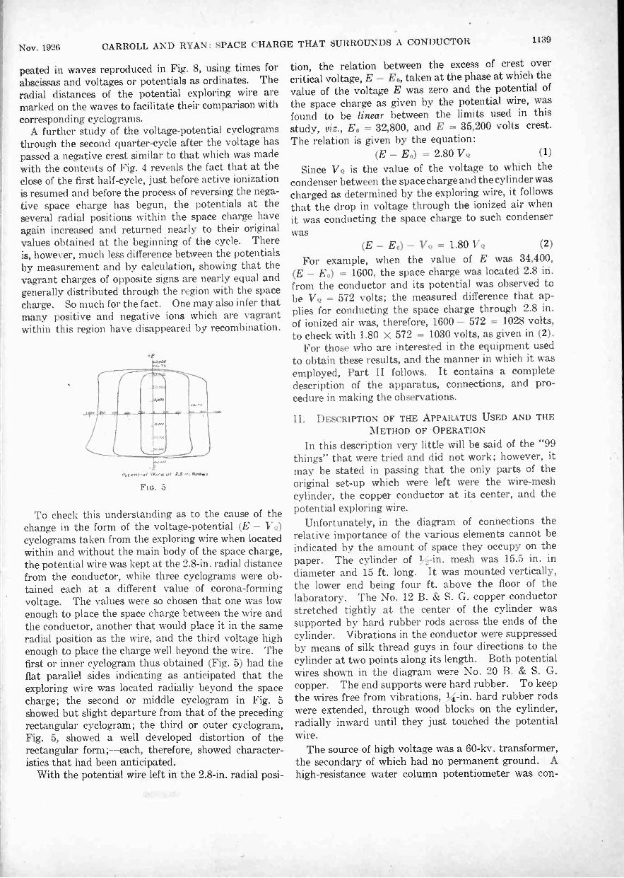
Nov. 1926 CARROLL AND RYAN: SPACE CHARGE THAT SURROUNDS A CONDUCTOR 1139
peated in waves reproduced in Fig. 8, using times forabscissas and voltages or potentials as ordinates. Theradial distances of the potential exploring wire aremarked on the waves to facilitate their comparison withcorresponding cyclograms.
A further study of the voltage -potential cyclogramsthrough the second quarter -cycle after the voltage haspassed a negative crest similar to that which was madewith the contents of Fig. 4 reveals the fact that at theclose of the first half -cycle, just before active ionizationis resumed and before the process of reversing the nega-tive space charge has begun, the potentials at theseveral radial positions within the space charge haveagain increased and returned nearly to their originalvalues obtained at the beginning of the cycle. Thereis, however, much less difference between the potentialsby measurement and by calculation, showing that thevagrant charges of opposite signs are nearly equal andgenerally distributed through the region with the spacecharge. So much for the fact. One may also infer thatmany positive and negative ions which are vagrantwithin this region have disappeared by recombination.
tr
rc of 2$ Woos
FIG. 5
To check this understanding as to the cause of thechange in the form of the voltage -potential (E - VQ1cyclograms taken from the exploring wire when locatedwithin and without the main body of the space charge,the potential wire was kept at the 2.8 -in. radial distancefrom the conductor, while three cyclograms were ob-tained each at a different value of corona -formingvoltage. The values were so chosen that one was lowenough to place the space charge between the wire andthe conductor, another that would place it in the sameradial position as the wire, and the third voltage highenough to place the charge well beyond the wire. Thefirst or inner cyclogram thus obtained (Fig. 5) had theflat parallel sides indicating as anticipated that theexploring wire was located radially beyond the spacecharge; the second or middle cyclogram in Fig. 5showed but slight departure from that of the precedingrectangular cyclogram; the third or outer cyclogram,Fig. 5, showed a well developed distortion of therectangular form;-each, therefore, showed character-istics that had been anticipated.
With the potential wire left in the 2.8 -in. radial posi-
tion, the relation between the excess of crest overcritical voltage, E - Eo, taken at the phase at which thevalue of the voltage E was zero and the potential ofthe space charge as given by the potential wire, wasfound to be linear between the limits used in thisstudy, viz., E0 = 32,800, and E = 35,200 volts crest.The relation is given by the equation:
(E - E0) = 2.80 VQ (1)
Since VQ is the value of the voltage to which thecondenser between the space charge and the cylinder wascharged as determined by the exploring wire, it followsthat the drop in voltage through the ionized air whenit was conducting the space charge to such condenserwas
(E - E0) - VQ = 1.80 VQ (2)
For example, when the value of E was 34,400,(E - E0' = 1600, the space charge was located 2.8 iri.from the conductor and its potential was observed tobe VQ = 572 volts; the measured difference that ap-plies for conducting the space charge through 2.8 in.of ionized air was, therefore, 1600 - 572 = 1028 volts,to check with 1.80 x 572 = 1030 volts, as given in (2).
For those who are interested in the equipment usedto obtain these results, and the manner in which it wasemployed, Part II follows. It contains a completedescription of the apparatus, connections, and pro-cedure in making the observations.
II. DESCRIPTION OF THE APPARATUS USED AND THEMETHOD OF OPERATION
In this description very little will be said of the "99things" that were tried and did not work; however, itmay be stated in passing that the only parts of theoriginal set-up which were left were the wire -meshcylinder, the copper conductor at its center, and thepotential exploring wire.
Unfortunately, in the diagram of connections therelative importance of the various elements cannot beindicated by the amount of space they occupy on thepaper. The cylinder of mesh was 15.5 in. indiameter and 15 ft. long. It was mounted vertically,the lower end being four ft. above the floor of thelaboratory. The No. 12 B. & S. G. copper conductorstretched tightly at the center of the cylinder wassupported by hard rubber rods across the ends of thecylinder. Vibrations in the conductor were suppressedby means of silk thread guys in four directions to thecylinder at two points along its length. Both potentialwires shown in the diagram were No. 20 B. & S. G.copper. The end supports were hard rubber. To keepthe wires free from vibrations, VI -in. hard rubber rodswere extended, through wood blocks on the cylinder,radially inward until they just touched the potentialwire.
The source of high voltage was a 60-kv. transformer,the secondary of which had no permanent ground. Ahigh -resistance water column potentiometer was con-
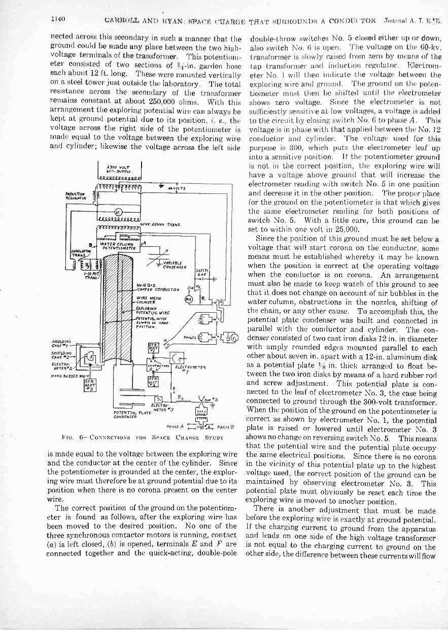
1140 CARR.OLL AND RYAN: SPAI'M CHARON
nected across this secondary in such a manner that theground could be made any place between the two high-voltage terminals of the transformer. This potentiom-eter consisted of two sections of garden hoseeach about 12 ft. long. These were mounted verticallyon a steel tower just outside the laboratory. The totalresistance across the secondary of the transformerremains constant at about 250,000 ohms. With thisarrangement the exploring potential wire can always bekept at ground potential due to its position, i. e., thevoltage across the right side of the potentiometer ismade equal to the voltage between the exploring wireand cylinder; likewise the voltage across the left side
NDUCTONREGULATOR
2300 VOLT4.0^, JUPPLY
0 0 g
ftqqgfqii ff-931?11
INSULATINGTRA NSA
SHIELDINGCAGE..f
SHIELDINGCAGE
ELECTRO-METER -"
0f-12.19 P Q..0 e,ee,
bo try 2OHva TRANSoaaaaoada-n0
0VoLTS
WATER COLUMNPOTENTioMETER
1-10 Po7,TRANS
- =IHARD RUBBER Roo-*:
VARIABLECONDENSER
1412 B'sCOPPER cOrvOucroR
WIRE MESHYLINDER
EXPLORINGWIRE
TENTIAL WIREALWAY3 IN SAMEPOSITION.
POTENTIALCONDENSER
Co roTAc ToR5
PLATE
ELECTRO-METER
SAFETYGAP
I..
w
PRokas 3.
ELECTROMETER#1
ommE A 47-1. NOM B
FIG. 6-CONNECTIONS FOR SPACE CHARGE STUDY
is made equal to the voltage between the exploring wireand the conductor at the center of the cylinder. Sincethe potentiometer is grounded at the center, the explor-ing wire must therefore be at ground potential due to itsposition when there is no corona present on the centerwire.
The correct position of the ground on the potentiom-eter is found as follows, after the exploring wire hasbeen moved to the desired position. No one of thethree synchronous contactor motors is running, contact(a) is left closed, (b) is opened, terminals E and F areconnected together and the quick -acting, double -pole
THAT SURROUNDS A CONDUCTOR Journal A. I. 1.;.'11;.
double -throw switches No. 5 closed either up or down,also switch No. 6 is open. The voltage on the 60-kv.transformer is slowly raised from zero by means of thetap transformer and induction regulator. Electrom-eter No. 1 will then indicate the voltage between theexploring wire and ground. The ground on the poten-tiometer must then be shifted until the electrometershows zero voltage. Since the electrometer is notsufficiently sensitive at low voltages, a voltage is addedto the circuit by closing switch No. 6 to phase A. Thisvoltage is in phase with that applied between the No. 12conductor and cylinder. The voltage used for thispurpose is 300, which puts the electrometer leaf upinto a sensitive position. If the potentiometer groundis not in the correct position, the exploring wire willhave a voltage above ground that will increase theelectrometer reading with switch No. 5 in one positionand decrease it in the other position. The proper placefor the ground on the potentiometer is that which givesthe same electrometer reading for both positions ofswitch No. 5. With a little care, this ground can beset to within one volt in 25,000.
Since the position of this ground must be set below avoltage that will start corona on the conductor, somemeans must be established whereby it may be knownwhen the position is correct at the operating voltagewhen the conductor is on corona. An arrangementmust also be made to keep watch of this ground to seethat it does not change on account of air bubbles in thewater column, obstructions in the nozzles, shifting ofthe chain, or any other cause. To accomplish this, thepotential plate condenser was built and connected inparallel with the conductor and cylinder. The con-denser consisted of two cast iron disks 12 in. in diameterwith amply rounded edges mounted parallel to eachother about seven in. apart with a 12 -in. aluminum diskas a potential plate N in. thick arranged to float be-tween the two iron disks by means of a hard rubber rodand screw adjustment. This potential plate is con-nected to the leaf of electrometer No. 3, the case beingconnected to ground through the 300 -volt transformer.When the position of the ground on the potentiometer iscorrect as shown by electrometer No. 1, the potentialplate is raised or lowered until electrometer No. 3shows no change on reversing switch No. 5. This meansthat the potential wire and the potential plate occupythe same electrical positions. Since there is no coronain the vicinity of this potential plate up to the highestvoltage used, the correct position of the ground can bemaintained by observing electrometer No. 3. Thispotential plate must obviously be reset each time theexploring wire is moved to another position.
There is another adjustment that must be madebefore the exploring wire is exactly at ground potential.If the charging current to ground from the apparatusand leads on one side of the high voltage transformeris not equal to the charging current to ground on theother side, the difference between these currents will flow

Nov. 1926 CARROLL AND RYAN: SPACE CHARGE THAT SURROUNDS A CONDUCTOR 1141
through one side of the potentiometer, thus shifting thephase of the voltage across this side with respect to theother, and making it impossible to find the correctposition of the ground. To overcome this, a variablecondenser must be connected on the side of the trans-former furnishing the least charging current to ground.The test for the right amount of capacitance to be addedis made by throwing switch No. 6 to phase B, which is.in quadrature with respect to phase A. The variablecondenser is then adjusted until the reading of electron=eter No. 1 does not change on reversing switch No. 5.This adjustment must also be made each time theposition of the exploring wire is changed, but when thebalance is once made it will "stay put" and does nothave to be watched. It is necessary when making thiscondenser balance to follow it up with the correct
+--- V Put.cry DRIVEN BY SMAI.L.REVERSIDt.E MOTOR THRU ASET OE REOUGiNO GEARS.
HEAVY COTTON4 --CORD
TANK FOR SETTLING AIRcouT of WATER TO KEEP
AIR RUBBLES OUT OF ROSE.
BRASS CI-UNS
lflOVERFLOW
TO THE TAP
SE &eof H vTRANS,1
FIG. 7-HIGH-VOLTAGE POTENTIOMETER
position of the potentiometer ground by occasionallythrowing switch No. 6 to phase A. The exploring wiremust truly be at ground potential when there is nochange in the reading of electrometer No. 1 for phase Aand phase B when switch No. 5 is reversed.
With the exploring wire at ground potential due toits position it will show no voltage until corona appearson the . conductor; then the voltage it indicates onelectrometer No. 1 will be that set up by the chargesent out by corona. The effective value of this voltagecan be measured by disconnecting E from F and ground-ing E. However, we are not only interested in theamount of this voltage but also in its wave form. Thelatter was determined by means of synchronous con-
. tactors and the gold leaf electrometer No. 1.
The three synchronous motors shown in the diagramwere four -pole, p. induction motors, the rotorsof which had been slotted for salient poles. The'motors were mounted vertically to eliminate end play,ball bearings being used for the upper bearing. Thecontactors consisted of a hardened steel pin and thinlaminated steel spring, contact being made on thecenter lamination only. Synchronous motor No. 1was supplied with voltage from a phase shifter con-sisting of a wound -rotor two-phase induction motor.The phase angle was read on a scale fastened to theframe with a pointer on the rotor shaft. Motors No. 2and No. 3 were driven from a voltage supply having afixed phase angle.
First, motors No. 1 and No. 2 are started up. To besure that motor No. 1 has the same polarity each timeit is started up, the clips M and N are connected acrosscontact (a); E and F are not connected; and thedouble -pole, double -throw switches No. 1, No. 2 andNo. 3 are all thrown to the right. The polarity of themotor must be such that the d -c. voltmeter V2 readspositive when the phase shifter is on zero. To find thepolarity of motor No. 2, the clips M and N are con-nected across the leads to, electrometer No. 1, switchNo. 1 is open, and switch No. 2 and switch No. 3 areclosed to the left. By listening in the phones as thephase angle of motor No. 1 is shifted, a click will beheard at a certain position which means of course thatcontactors (a) and (b) are hitting at the same instant.The phasescale.
Clips M and N are removed and voltage is appliedbetween conductor and cylinder; when corona appearson the conductor, electrometer No. 1 will indicate avoltage due to space charge. The wave form of thisvoltage is determined by a step-by-step process. Con-tactor (b) was set so that it made contact when theapplied voltage was zero; this was where the spacecharge was changing least rapidly. The phase angleof (a) was changed by means of the phase shifter andthe angle read on the scale, the electrometer being readfor each position. Readings were taken every 10 deg.where the voltage changed most rapidly and every20 deg. on the fiat parts. Suppose (b) is contacting atthe point (x) on the curve taken at six in., and the phaseshifter is set on zero; the difference in voltage of thesetwo points on the wave, then, is 330 volts, which isread on the electrometer. The contactor (a) is set,say 10 deg. later, by means of the phase shifter and thevoltage is found to be 420 and so on. When we get to,say, 240 deg., the voltage on the electrometer is practi-cally zero, so that to get this hall of the wave, motorNo. 2 is slipped a pole, making the contactor (b) shift180 deg. to (y), and then when the contactor (a) ison 240 deg. the voltage on the electrometer is 550.
In order to tie-in all the curves taken this way withthe voltage wave, the exploring wire is disconnectedfrom the contactors and the clips M and N are connected

1142 CARROLL AND RYAN: SPACE CHARGE THAT SURROUNDS A CONDUCTOR Journal A. I. E. E.
across contactor (a). Switch No. 4 is thrown to theright, switch No. 1 left, switch No. 2 right, and switchNo. 3 left. The phase shifter is then adjusted untilthere is no sound in the phones, which means that (a)is making contact when the voltage across R1 is zero.The angle is then read on the phase shifter scale.
The potential wire at the left of the conductor,Fig. 6, was used in controlling the voltage. Thedistance between the conductor and this wire was sixin. Motor No. 3 drove a contactor in which the twocontacts connected to electrometer No. 2 were 180electrical deg. apart, both making contact very nearlythe instant when the voltage between the conductorand cylinder is zero. This charged the electrometerwith the voltage due to the space charge, the pluscrest on one side of the electrometer and the minuscrest on the other side. Since the voltage due to posi-tion amounted to considerably more than the spacecharge voltage, it would be necessary to keep the con -
FIG. 8
tactors hitting exactly when the voltage due to positionwas zero. Practically, this could not be done with anydegree of assurance. To overcome this difficulty,the voltage of this potential wire due to position wasbucked out by surrounding the electrometer with awire screen cage, No. 1, which was raised to the potentialof the wire due to position by means of the transformersas shown in the diagram. R3 was connected across thesecondary of the insulating transformer to compensatefor the shift in phase angle in the 60-kv. transformercaused by the water column resistance load. To pre-vent any variation in shielding as the ground on thewater column potentiometer was shifted, cage No. 1was surrounded by a wire screen cage No. 2 which wasconnected to the wire -mesh cylinder. ElectrometerNo. 3 was read by means of a telescope and the voltageheld so that it read "23" throughout all the runs whichgave the data for the curves in Fig. 8.
III. DISCUSSION
From the results of the preceding and present studies,it is now known that corona at all ordinary voltage waveforms, frequencies, and air densities is due essentiallyto the formation of mixed ions in the air near the con-ductor where the electric intensity exceeds a certaincritical value (30 kv. per cm., or 26.4 X 10⁻¹⁰ cou-lombs per sq. cm. in air at unit density, 5 = 1, whichoccurs at a temperature of 25 deg. cent. and a barom-eter of 76 cms.). The mixed ions include only atomsthat have lost or gained electrons and have thusbecome positive or negative ions of low mobilities, 1.36and 1.83 cms. per sec. per volt per cm., and free electrons.The last function as negative ions having mobilitieshundreds of times greater and which, when the electricintensity falls to about one -thirtieth of that which causedionization, attach themselves to neutral atoms toform negative ions with their corresponding lowmobilities. This electric intensity at which free elec-trons form negative ions occurred in the present studiesat about 1000 volts per cm., or 0.88 X 10⁻¹⁰ coulombsper sq. cm., the air density being near unity. Muchexperimental work will have to be done to determine thelimits through which the electric intensity varies atwhich the free electrons combine with neutral atomsto form slow moving negative ions.
During copious ionization near the conductor theions that carry charges having signs unlike the chargeon the conductor due to the applied voltage are drawnto contact with the conductor and thus discharged;the ions of the same sign are repelled to a radial distanceat which the electric intensity has fallen to the valuewhereat free electrons can no longer exist, as such,and must form negative ions of low mobility instead.Further details of the action are not as yet clearlydefined and much further study is necessary. Howeverthe fact is now known that the presence of free electronsin the midst of mixed ions, in aggregate effect, greatlyincreases the mobility of all the ions, and when thatregion of the field is reached in which the free electronscombine with neutral atoms to form negative ions,both positive and negative ions are actuated only by thelow mobilities above specified. So low are such mo-bilities that the further effects they produce at 60cycles are nearly the same as though they did not moveappreciably during the remainder of the half -cycle.
Thus it comes about that electric stress in the regionsurrounding the conductor, between it and the nearlyfixed space charge, can be increased but a small amount,if at all, by raising the applied voltage above the criticalvalue of the voltage. The increase in voltage, E-E.,is consumed in two ways: (1) by the ionic conductionthat delivers the space charge at the radial distanceabove specified, and (2) by the space charge itself.While this understanding of the nature of corona is nowclearly indicated by the results of many observers todate, much experimental work will have to be done to
know the amount and position of the space charge under

Nov. 1926 CARROLL AND RYAN: SPACE CHARGE THAT SURROUNDS A CONDUCTOR 1143
most circumstances in order that corresponding formulascan be derived and used reliably for practical purposes.
Something should be said in conclusion in regard tothe background of the subject of this paper. There maybe many causes of contributing factors that bring aboutthe occasional unexpected flashovers of high voltageinsulators that function in air, but among them mustalways be remembered three factors as follows:
I. Surface conductivity,II. Surface charger,9III. Space charge.Surface conduction is a chaotic factor that neverthe-
less is much better known and understood than theother two. Nishi9 found that when corona in air ispresent near an insulator, the surface of the insulatordielectric becomes heavily charged even when thevoltage is alternating. There can be little doubt thatthe space and surface charges are related and that thenature of such relation qualitatively and quantitativelyshould be known. It is altogether likely that the zoneof a comparatively heavy space charge standing well outaround a transmission line conductor is a factor thatwill have to be reckoned with in various practicalundertakings such, for example, as the coupling ofcarrier currents to power transmission lines. It maybe that knowledge of the space charges due to the coronaon insulator hardware, of surface charge, and of surfaceleakage will go far toward an understanding of thenature of things that requires the magnitude of towerclearances that practise is now slowly but surely dis-covering to be necessary.
The dimensional manner for many differing con-ditions in which the radial distance is related to thecrest voltage in the production of space charge, and. tothe electric intensity of the field wherein the spacecharge is lodged, should be determined as soon aspracticable. In the present study such radial distancewas found to be at the average rate of 8.3 kv. (s. w.rms.) per in. and the corresponding electric intensityat the location of the space charge was found to be onekv. per cm. Our reconnaissance has revealed muchevidence that the radial distance of the space chargefrom the conductor, cable, point or other high voltageelectrode, is approximately equal to the distancethrough a needle gap that the corresponding voltagewill discharge and, therefore, approximately at thedistance -rate of one in. per 10 kv. (s. w. rms.). Itmust be remembered, however, that corona phenomenahave always a strong tendency toward chaotic behaviorand that few things can be taken for granted and .thatmost of them must be determined by exact orderly pro-cedure and measurement.
Until the values thus indicated have been reliablydetermined, it would be premature to write formulas forthe power lost in corona due to the boundaries deter-mined by the space charge and its capacitance. Thetemptation to do so is there, of course, because the
9. T. Nishi, Surface Charges on High Voltage Insulators,A. I. E. E. JOURNAL, November, 1920.
energy in such charge is drawn from the source, isnever returned and is, therefore, a measure of the lossproduced by corona when due allowance has been madefor the ionic conduction by which the space charge wasplaced in position.
IV. CONCLUSIONS
1. A conductor in corona is surrounded by a freemobile space charge of the same sign as that on theconductor during the preceding voltage crest.
2. The sign of the space charge is reversed by thecopious ionization that is produced during each suc-ceeding voltage crest.
3. The mobility of the space charge is so low duringinterval between voltage crests that it behaves almostas though it were fixed in space about the conductorin corona.
4. The mobility of the mixed ions, positive, negativeand free electrons, that reverse the space charge duringthe voltage crests is much higher than the mobility of thespace charge during the interval between voltage crests.
5. For the most part, the space charge has an orderlyrelation in amount and space position to the voltageapplied to the conductor and its dimensions and to theenergy lost per cycle in corona at all ordinary fre-quencies used in the power industry.
A NEW CATHODE RAY TUBEA vacuum tube which produces as many electrons per
second as a ton of radium-and there is only a pound ofthat rare substance in the world-was announced byDr. W. D. Coolidge of the research laboratory of theGeneral Electric Company at a meeting of the FranklinInstitute of Philadelphia, on the occasion of the awardto him of the Howard N. Potts gold medal of theInstitute for his outstanding work in the developmentof x-ray tubes.
Radium is constantly disintegrating, and in so doingis bombarding electrons-infinitely small particles ofmatter or electricity-into space at very high velocities.The rate at which radium disintegrates is beyond humancontrol; nothing that man can do seems to affect therate at which the element breaks down. The cathoderay tube likewise bombards high speed electrons intospace, but at a rate that can be controlled by man, andin quantities far greater than by all the radium in theworld. The electrons given off by radium are of higheraverage velocity than those so far produced with thecathode ray tube,, but otherwise the two are alike.
So much more concentrated are the rays from thetube that many startling experiments have been con-ducted with the new device. Crystals of the mineralcalcite apparently become red hot coals when exposedfor a moment to the rays, but they are glowing withcold light; ordinary salt is turned brown, and consider-able time elapses before it again becomes the colorlesssubstance it usually is; bacteria and small flies arealmost instantly killed by exposure to the rays; ordi-narily colorless acetylene gas is transformed into ayellowsolid which cannot be dissolved.

lUni)alance(1 Cm idtiett)t. '"Ni()11StS to allow Their 11:1.1(Cis /Mg N);IH )11
111' E. S. IlEALNI \ I \\HI1.111'.A NM t A I. E. E.
Synopsis.- Stony I tacit -8n nu studies of the unbobinci it It 118111118produced by heavy ice loadings on luny 61)11118 Biliquillt 51 by swipe it-aion institutors were made in the course of desiuniny the -ecentlycompleted W alienpaupack-Sieyfried 2.e0-kv. line of the Pt tinsyl-va n in Power and Light Company. These studies includedinvestigations of the effects produced on suspension insulator
GENERAL PROBLEM OF UNBALANCED CONDUCTORTENSIONS
PREDETERMINING the effect of carrying longspans on suspension insulators has long been aperplexing problem. Span lengths have been
gradually increased without any undue operatingdifficulties until several lines are now in operation withspans averaging well over 1000 ft. Studies for extrahigh -voltage lines show economies for even longer spans,especially when some of the very high -strength con-ductors are considered. Such construction requirescareful attention to prevent unbalanced conductor ten-sions,-of no particular importance on shorter spans,-from assuming serious proportions, where combinedwith long insulator strings and heavy ice loading. Infact, the ice loading appears to be the most importantfactor.
The unbalanced loads caused by a broken conductor
FIG. I.-SPAN LOADED WITH SAND BAGS BETWEEN TOWERNo. 3 AND TOWER No. 4
are also of greater importance with the higher -strengthconductors. The usual design for lines carrying com-paratively small conductors, making each tower ofsufficient strength to support one or more brokenconductors, does not seriously affect the cost. Thesame assumption applied to very high -strength con-ductors so seriously affects the cost of the entire con -
1. Transmission Line Engineer and Asst. Transmission LineEngineer of the Electric Bond and Share Company, New YorkCity.
Presented at the Pacific Coast Convention of the A. I. E. E.,Salt Lake City, Utah, Sept. 6-9, 1926.
construction by a broken conthielio . t'om potations ,feed
in an approri node wily by erprr,nnnls ur, a Mu -Mac Mel hint ofthe act mil line. /''or the most petit, ft 5111/i are wren in duty, m mat lcform, in suflirirr,l detail to allots both until !psis awl p mylt.application to similar problems.
struction as:to make a careful study of the characterand amount of the loads caused by a break decidedlyimportant.
In working out the designs for the Wallenpaupack-Siegfried line of the Pennsylvania Power & LightCompany, both of these problems assumed consider-able importance. The 1100 -ft. spans and insulatorswith an effective mechanical length of over nine ft.,located in a very bad sleet country, combined tocreate rather unusual conditions. Some tests andcomputations made of these problems on that lineare given here in the hope that they may be of assist-ance in similar studies and in the consideration ofextra high -strength conductors.
PROBLEMS ENCOUNTERED ON THE WALLENPAUPACK-SIEGFRIED LINE
As a basis for certain features of design of the Wallen-paupack-Siegfried line, a rather extensive set of calcu-lations was made of the effect of unbalanced conductortensions. The computed results are summarized intwo charts, Fig. 5 showing the unequal tensions causedby a heavy ice load forming on a series of spans ofunequal length and Fig. 6, the effect of ice droppingoff of all but one or two of a series of spans. Extensivecalculations were also made to determine the effectof the longitudinal swing of the insulatOr string and ofthe resulting slack thrown into the adjacent spans fol-lowing a failure of the conductor.
The calculations were intended to obtain results fora few general conditions which could be used as a basisof selecting specific tower locations and as an aid injudging whether special precautions were necessary tomeet any particular conditions encountered. Forinstance, when extra long spans were required overrough country, these calculations gave a logical meansof determining how long a span could safely be carriedon suspension insulators.
Realizing the importance of a practical verificationof the computed results, a set of tests was made assoon as the construction work had reached a stage whereit was possible to string a test conductor over a typicalsection of the actual line. The results of the experi-ments and a comparison with some of the computedresults are shown in the diagrams, Figs. 2, 3, 4, 7, 8 and 9.
1144
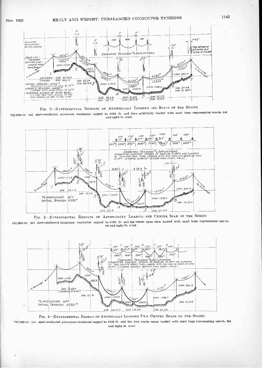
Nov. 1926 HEALY AND WRIGHT: UNBALANCED CONDUCTOR TENSIONS 1145
4"
1...
.3'
IN.50,1ATORperLecrIoNoAFTER LOAD/N6
SOLID LINE-453f
*
;-
\ 17ComPureo
1100
TENsloivs44'0DEFLECT/ONS
I woo' lloo
i
I
-../' 6"
..-
17.:
/'- 64"
TM de//IonLirtbabli-cluetoWlp al on.LOADED
DOTTED LINE-LOADED wirtt
SANDBAG
oAriC li
(3(04
UNLOADED
1
/480'SPAN //
-SAG 35
*SA
45A
....,\......-0
... ft,
SPAN885,1,
'..
\\\ 176\ 004.
4cZr'',- '
-"
- --
,
:\
Z
,A5t30*
f i4.550It.
1.-.35°°
SPAN 892 R`3 -
LOADED -SAG 44#
ff. SAG 22.08,, 'c0
- - - 4' 4520
,./....... ----'is
14200
SAG 29.68SAG 3/.6519.
7INITIAL TENS/ON-4550
LOADED TENSLOADED Mil
AVERAGE WE/GMT3./7 L85. PER/NCH RADIAL
ON- /794000 4480 *SAND BAGS A
OF SAND BFOOT, EQUAL
ICE AND 6 LBS.
SAG 2845 *F
35°FGSONE
/ND
758 34 SPAN-is
A
.
&,.
SAG
//00R
P.
:../482SPA
SAG
_.--6 0
/ /200 H.
4/ ;1: 1 . ' ' .5
SPAN
''.,1*5A'
/3988
6155.2 fi.SAG .7A SAG 52.2A ISAG 72.4H
FIG. 2 -EXPERIMENTAL RESULTS OF ARTIFICIALLY LOADING ALL SPANS OF THE SERIES
795 000-cir. mil steel -reinforced aluminum conductor sagged to 4550 lb. and then artificially loaded with sand bags representing one -in. iceand eight -lb. wind
1.96'
1100' /7.2 A.
5609159701 6/20'1
00' 1100' 1,00',. 16.2' 1 244°
.945o1 l000l
/200'
. 30-3. I
d''500 17000'
Iwo' //00/
1 64.50
660*
%4.,,...,41
h.1%1
11 2. 79'1.,
11.
COMPUTEDCONDUCTOR/N. CENTERAT 0' F. (LOA.OING
I
4.65-,1 r-
TENSIONS%ASSUMED STRUNGSPAN THEN LOADED
SLIGHTLY' HEAVIER
I4.54=-I -'
DerLecrAONSTO 4800L85.47-80*"
WITH ONETHAN
1.37 -
AND CLAMPEDNCH ICE AND 8L85.
F/6 6).,.
r-eBA
WIND
IAO°
ft -
-SPAN 1/15
SAG
ft
v 2
23.5 R
inis.
SPAIN
585R.
"(0
6s.
411in
kit)
11,1
N NN N -
4
vvt
q.t.ii
tt
``)(r)
I
N. Os.. 6/b
SPAN 892 A!
TEMPERATUREIN/7/AL TENSION
SAG IS. 0 It '
.9°F.SPAN
45.50#'
SAG 23
//DOA.
4/ R
c22..
PA
,-,Jr4oGR-
/200A./S
.
le<
SAG /6.55fi
- -'
SPAN 1398R.
'
SA6 37.15R.
FIG. 3 -EXPERIMENTAL RESULTS OF ARTIFICIALLY LOADING THE CENTER SPAN OF THE SERIES
795,000-cir. mil steel -reinforced aluminum conductor sagged to 4550. lb. and the center span then loaded with sand bags representing one -in.ice and eight -lb. wind
329'- i noo' 2 /100' '5 ROO' 4 //50' /150' 6 oo' 7
't°
i 4.75'
It ift
.pel
CONDUCTORINATOP.
Aar 1,22.2°
6440169001
COMPUTEDASSUMED
TWO CENTER SPANS( LORO/NO .5l6H7Z),
1129' ..
7530°
TENSSTRUNGTHEN
365'
9900'ONSso
TOLOAD
HEAVIER
38.5'
I.9."EFLECTIONS 800LB.C. AT
WITH ONEAN CHART,
,
7530
490*/'/NCH
FIB
4
ANDrE A/v06 )
CLAMPED8[85 WINO
'(0
SPAN I/158,
SAG" 79.658
.,,,,"-; SPA,
r
88sfi
0'
t iio tz,nil, 10-i
6
it1Y7/6
4,6
ts..
*3
SPAN 892 Ft
TEMPERATUREfNITIAL
( W, E17 yin
34?"TENSION 4550
0 .SAD /3.'
*
ft w,OPAN
- o^
0
/1001/,
a
/r;0, SPAN
0'/200H
15PRA 398fSAG /4./5 .4-
- SAG 59.73 ft SAG 70 .5 ft SAG 32.58. 1I
FIG. 4 -EXPERIMENTAL RESULT OF ARTIFICALLY LOADING Two CENTER SPANS OF THE SERIES795,000-cir. mil. steel -reinforced aluminum conductor sagged to 4550 lb. and the two center spans loaded with sand bags representing one -in. ice
and eight -lb. wind
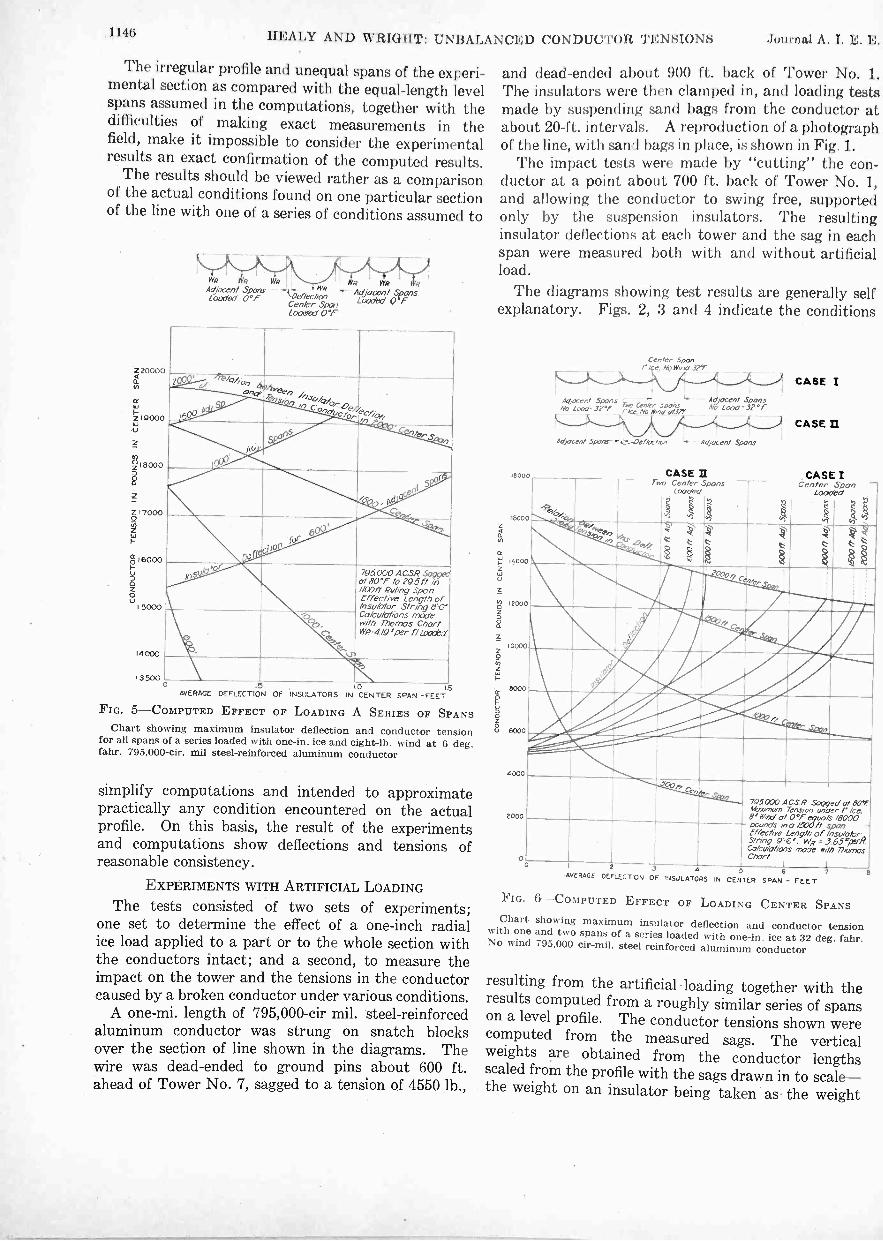
,1146 HEALY AND WRIGHT: UNI3ALANCEI) CONDUCTOR TENSIONS Journal A. I. E. E.
The irregular profile and unequal spans of the experi-mental section as compared with the equal -length levelspans assumed in the computations, together with thedifficulties of making exact measurements in thefield, make it impossible to consider the experimentalresults an exact confirmation of the computed results.
The results should be viewed rather as a comparisonof the actual conditions found on one particular sectionof the line with one of a series of conditions assumed to
220000
cc
219000
2
;18000
2170000
16000
VI 5000
14000
3500
R WR II.. We WRAtocent Spores ,genect,P,1:n ' Aojocent SpansLoaded 0°F L000bd Q'Cen/er Span
Combo' O'r
2, iPekv/0,0aehr
0,7a#e,
"7 //Ak/A.,
o0,7,0,Como'looc./.;ecA,0.
A
l,-
5.,. e , li
I10
f-_
tor795000 A.CSR Soggee
of 80°F 10 29.5 ft in//00 ft Ruling Spanrffective Length of/nsakdor String 0'0'Calculations madewdh Thomas ChartWP-4/904er f//nxi-..i
1,-o
c,
ks-.*-
.5AVERAGE DFFLECT1ON OF INSULATORS
FIG. 5-COMPUTED EFFECT
1.0 15IN CENTER SPAN -FEET
OF LOADING A SERIES OF SPANSChart showing maximum insulator deflection and conductor tension
for all spans of a series loaded with one -in. ice and eight -lb. wind at 6 deg.[aim 795,000-cir. mil steel -reinforced aluminum conductor
simplify computations and intended to approximatepractically any condition encountered on the actualprofile. On this basis, the result of the experimentsand computations show deflections and tensions ofreasonable consistency.
EXPERIMENTS WITH ARTIFICIAL LOADING
The tests consisted of two sets of experiments;one set to determine the effect of a one -inch radialice load applied to a part or to the whole section withthe conductors intact; and a second, to measure theimpact on the tower and the tensions in the conductorcaused by a broken conductor under various conditions.
A one-mi. length of 795,000-cir mil. steel -reinforcedaluminum conductor was strung on snatch blocksover the section of line shown in the diagrams. Thewire was dead -ended to ground pins about 600 ft.ahead of Tower No. 7, sagged to a tension of 4550 lb.,
and dead -ended about 900 ft. back of Tower No. 1.The insulators were then clamped in, and loading testsmade by suspending sand bags from the conductor atabout 20 -ft. intervals. A reproduction of a photographof the line, with sand bags in place, is shown in Fig. 1.
The impact tests were made by "cutting" the con-ductor at a point about 700 ft. back of Tower No. 1,and allowing the conductor to swing free, supportedonly by the suspension insulators. The resultinginsulator deflections at each tower and the sag in eachspan were measured both with and without artificialload.
The diagrams showing test results are generally selfexplanatory. Figs. 2, 3 and 4 indicate the conditions
18000
16000
14000
12000
10000
8000
6000
4000
2000
Center Spanr Ice, No woo' 37,-
4 Lat- Spans Centerriee,No 49ny o;.1?,"
Ad acent SporesNo/Laad 32°F
Ao'facent. Spons--c_.-Oef&-Non - Ao:/ocen/ Spans
CASE II
CASE I
CASE /I
. CASE I
NI\
Two CenterLocoed
n
Spans
tr) 'I
CenterLoaded
Soon
-
C.,,pe.4, '2r .0,_
§ Z
4O.5.7:
UMilli 2000,,/
s -,
11. ls.
11/1111Aili:44111111.$
,
,,,,4
'MNAbripply/
111120..0"4%12, ,_..
iiih....._." Cc" r. ,3
795000 ACSRAtivmum8' weed of
Sagged ot 110TTension under /' Ice.0°15-07s 49000
poundeffectisrein0Leng/n
ofrunlakrString 9=0°. WR . 3.63°µ%RC,olcutotiens mode with ThomasChart
I) 2 4 n /AVERAGE DEFLECTION OF .NsULATORS IN CENTER SPAN - FEET
FIG. 6-COMPUTED EFFECT OF LOADING CENTER SPANSChart showing maximum insulator deflection and conductor tensionwith one and two spans of a series loaded with one -in. ice at 32 deg. fahr.No wind 795,000 cir-mil. steel-reinforced aluminum conductor
resulting from the artificial loading together with theresults computed from a roughly similar series of spanson a level profile. The conductor tensions shown werecomputed from the measured sags. The verticalweights are obtained from the conductor lengthsscaled from the profile with the sags drawn in to scale-the weight on an insulator being taken as- the weight

Nov. 1926 HEALY AND WRIGHT: UNBALANCED CONDUCTOR. TENSIONS 1147
of conductor from the insulator to the low point of the accurate methods of measurement would not have in -
sag. All of these quantities show slight discrepancies creased materially the value of the results.
due to:small errors in the sag measurements, but more These experiments may be considered as an approxi-
iNSuLAIIIRDEFLECTIONSAFTER Cur
39.u0 Love- -EFORE
Coorrct, LINE -A'rz.s Cur
Cur NeRr -
4-0
Lsr:ref 3.5.45
. F - c4jsao 29.9? 3
IMPACT 6804 :1'7'16,27,-. .-1- -4))*1-----
i 44 '!3A60-°:1.Q,..,:l
:2467C' 2620.
0
'1
o
SPAN /1/51.
TEmPER.47ruRf
165
COMA/ T
11: 36,001
.3.900 '64:
4z,
.5 342 A4 546! '4, 0 6 5 Iss.8 55500 42956 SAO kr-15 fr 15R9 56.66_
420011a I
0 TENSIONS 94r DEFLECTIONS
J.590
4266
.256
.11.1''.12eto`
SA; 22.66SAG 23.86
Flo. 7-EXPERIMENTAL RESULT OF BREAKING CONDUCTOR AT NORMAL TENSION
795,000-cir. mil steel -reinforced aluminum conductor "cut" when sagged to 4550 -lb. tension. Clamps set to prevent slipping.
IMPACT 8700"
insu-aroa? 41:6Dercec raws , /7/5Aareo Cur
o
SOLO -
oarre0 Lave -4-reA Cur
Cur hest'
TEMPfRA7VRE 324,'
r
4549 522R V SAo 72.48
- .546 '69 25 n ISR9 .90.06'
SA-i 3/.656SAO 3S4 6
FIG. 8-EXPERIMENTAL RESULT OF BREAKING CONDUCTOR UPON ARTIFICIAL. LOAD
795.000-cir. mil steel -reinforced aluminum conductor strung to 4550 lb. and then an artificial load of approximately 3.17 lb. per ft. addedequivalent to one -in. and eight -lb. wind. Clamps set to slip at 5000 lb.
IRA:447mOrazzrrioNSAFTER Cur
SOLID LINE -PC&PE
borrzo LAVE-Arrcp Cur /
Cur HERE
-001 1PoG" Ete'roRf cur- SAG 10.12R
APTER CUT -SAO 26.8514
TEAOERATuRE
IMPACT 154504-.3.0'
T c-1.`-552- 5...s/o+ 6 soeio"
.111,,, lit ... _4,
,, ,, i ° -5/- i
/.5.5.P0' 595 0
--.. ,..., --,,,____, us6.901\L 7770,
,..Th'f$0 \ ...°0 . %V" .dZ' , I
''',T,., ' * -- r" . .t.2417, z..
1AV77701'11 84/0' lie5P9N Ise SPAN,
I
)."...044 C,li 10
2 58.5,9 ,i-'40-.. k 84/0''''r ,i27195Itt
1
.z3
)5675;7- /4924°SA6 6.82R
, 9300SAG 17.6611 3 SPAN //006.
I 4540 /OJ/4 A
SAO 20,0 A
SPAN 1200R.
9270. 9590.*
o 1506°
SPAIN /3986
SAO 11239O: S SAG 16.0ASAG 121.85 G. .546 27.06.
SPAN .992A
SAP 6586SAO /0.7
7
FIG. 9-EXPERIMENTAL RESULTS OF BREAKING CONDUCTOR AT 15,000 -LB. TENSION
795,000-dr. mil steel -reinforced aluminum conductor "cut" when sagged to 15.000 -lb. tension without artificial loading. Clamp on Tower No. 1
set with positive grip. Other clamps set to slip.

1148 HEALY AND WRIGHT: UNBALANCED CONDUCTOR TENSIONS Journal A. 1. E.
mate check of one of the many combinations of spanlengths given by computation and shown in diagramin Figs. 5 and 6.
EXPLANATION OF CHARTS SHOWING COMPUTED RESULTS
Some explanation is required of the use of these chartsand methods of making the calculations.
A series of spans was assumed with the insulatorsupports all on the same level and the conductorstrung to the correct sagging tension at 80 deg. fahr.The series of spans consisted of a long "center span"or, in one case, two "center spans" and several equal-
FIG. 10-TRIPPING DEVICE USED TO GIVE THE EFFECT OF"CUTTING" THE CONDUCTOR IN MAKING BROKEN -CONDUCTORTESTS
A pull on the lower arm instantly releases the clamp, shown at right of theillustration, to which the conductor was attached
length shorter "adjacent spans" on each side of thecenter.
Fig. 5 shows the average deflection of the insulatorson the center span and the tension in the conductorof the center span caused by dropping the temperaturefrom 80 deg. to 32 deg. fahr., and adding a one -inchice load to the entire series. The solution of eachcombination of adjacent and center span lengths wasmade by a series of trials, interpolating between trialresults for the correct solution. In making up thechart, a separate set of computations was carriedthrough for each of several combinations of spanlengths. These results were plotted and connectedby a curve again by interpolating, obtaining results ofintermediate conditions. As an example it may beassumed that in a section of the line over which spansaveraged about 1000 ft., a span of 2000 ft. was en-countered. For this case, the effect of a heavy ice loadmay be read from Fig. 5, thus: Following the curvefor a 2000 -ft. center span to its intersection with thecurve for 1000 -ft. adjacent spans, we find an insulatordeflection of 0.7 ft. and a conductor tension of about19,300 lb. in the center span. In the same manner, wemay determine the effect of one center span of anylength loaded with ice if the adjacent spans areunloaded from Case I, Fig. 6, or for two center spansloaded from Case II, Fig. 6. Sags may easily be com-puted from the tension.
Considering the computations involved in solvingthe various combinations of span lengths shown onFig. 5, it is evident that the heavy ice loading causesconsiderably more stress in the long center span thanin the shorter adjacent spans, and that this causes theinsulators to swing over until the horizontal componentof stress in the insulator string is equal to the differencein tension between the two adjacent spans. Thiseffect is, of course, complicated by the swing of succes-sive insulators on each side. However, it was found thatabout the fifth insulator from the center has a swing ofonly a few degrees, and that (approximately) the ten-sion in the next span beyond is unchanged. Casesinvolving very large insulator deflections or moreaccurate results require this assumption to take effectat a greater distance from the center span.
One other assumption was required-that thedeflections of the two insulators at the opposite ends of aspan had the effect of increasing or decreasing, as thecase might be, the length of the wire in the span bythe sum or difference of the insulator deflections. Withthis assumption, supplementary "deflection-tension"curves were made, showing the change in tension inany span of the particular conductor and loading underconsideration, for any increase or decrease in the lengthof the wire or as assumed difference in swing of thesupporting insulators. These curves are easily madeby use of the Thomas Chart, treating changes of wire
FIG. 11-TOWER No. 1 AFTER "CUT" SHOWING DUMMY INSU-LATOR EMBRACING SPRING DYNAMOMETER AND IMPACT DYNAMOM-ETER
Conductor cut about 700 feet to the left
length due to insulator swing exactly as if due to tem-perature change.
As a trial, the deflection of the fifth insulator wasassumed at some definite amount from one to 10 deg.and the conductor tension and insulator deflectioncomputed for each successive span by use of the"deflection -tension" curve for the "adjacent spans."On reaching the "center span" it was found that thedeflection and tension thus computed generally corre-sponded more or less closely to the relation betweendeflection and tension shown on the "deflection-tension"

Nov. 1926 HEALY AND WRIGHT: UNBALANCED CONDUCTOR TENSIONS 1149
curve for the "center span." Two or three trials weregenerally sufficient to interpolate for the correct results.
The chart shown on Fig. 6 was made in a similarmanner. .
Incidentally, there is shown in Fig. 2 an interestingcomparison between the experimental and computedtension resulting from adding an ice load to the steel -reinforced aluminum conductor. The computed ten-sion resulting from loading a 1100 -ft. span, sagged to4550 lb. with an ice load of 3.17 lb. per ft., is 13,800 lb.The average tension from the artificial loading in theexperimental span series was 14,480 lb.
The computations in this case assumed that thesteel and aluminum strands, initially of exactly thesame length, worked together, each taking load pro-portional to its respective area and modulus of elasticityup to the elastic limit of the aluminum strands. For
reduced by the swing of the insulator. There was,however, a great deal of doubt as to what relation thisreduced tension bore to the maximum load thrown on,the tower. This maximum load would be applied sud-denly and, depending on the momentum developedand the elasticity of the parts absorbing this momen-tum, the load on the tower might be anywhere froma few per cent to several times greater than the finaltension in the span.
The broken -conductor test results are shown indiagram in Figs. 7, 8 and 9. These tests were made todetermine the effect of a broken conductor undernormal tension, Fig. 7, under maximum ice load, Fig. 8,and under a heavy tension without ice load,- Fig. 9.In addition to the insulator deflections and conductortensions, these diagrams indicate the impact loadrecorded on the tower next the break. As a check on
TABLE ISUMMARY OF IMPACT TESTS
Description of test
Temp.Deg.Fahr.
Windvelocityft. permin.
Initialtension
in conductor,lb.
Finaltensionin spanadjacentto break,
lb.
Cylinderlength,
in.
Impactfrom
calibrationcurve,
lb.
Reading ofmaximum
hand ofdynamom-
eter,lb.
Seediagram
Conductor sagged to 4550 lb. Clampstightened with positive grip 41 410 4550 2680 0 . 3850 6800 6850 Fig. 7
Conductor sagged to 4550 lb. Clampstightened with positive grip 45 . . 4550 .. 0.3935 6500 ..
Conductor sagged to 4550 lb. Clampstightened with positive grip 45 . . 4550 .. 0 . 4028 6100 5800
Conductor sagged to 4550 lb. Clampstightened with positive grip 45 800 4550 .. 0 . 3837 6900 8000
Conductor sagged to 4560 lb. Clampsset to slip 32 . . 4500 0.3975 6300 . .
Conductor sagged to 15,000 lbClamp set with positive grip 35 15,000 5540 0.423 15,450 21,500 Fig. 9
0.426Conductor sagged to 4550 lb., then
loaded with sand bags to give atotal load of 4.19 lb. per ft. Clampsset to slip 32 .. 14,500 ..
0.427
0.4719 8470 10,000 Fig. 80.47160 . 4713
tensions greater than this, it was assumed that thesteel alone carried the increasing loads.
In this connection, it should be noted that theexperiments were made under roughly constant tempera-ture conditions and that while this temperatureactually averaged about 35 deg. fahr., the tensions inthe conductor corresponded to about 80 deg. fahr.These tensions were used to approximate usual summerconditions. Actually, therefore, the artificial loadingexperiments correspond to about one -in. radial ice andeight -lb. wind at 80 deg. fahr.
TESTS ON THE EFFECT OF A BROKEN CONDUCTOR
Computed results indicated that the tension in thespan adjacent to a break would be very materially
the impact readings, certain of these tests were re-peated. A summary of the results is shown on Table I.
The tests of a break under normal tension were madewith the suspension clamps all bolted down firmly toprevent any slipping and to obtain actual impactreadings. In the test of the conductor with artificialload, the suspension clamps were used as they wereassembled in the completed line; that is, to allowslipping under an unbalanced tension of about 5000lb. The third impact test was made withoutany superimposed load but under a tension of about15,000 lb. The conductor was positively gripped atthe suspension insulator Tower No. 1 but the remainingclamps were set to slip as before.
The specific values of insulator deflections recorded
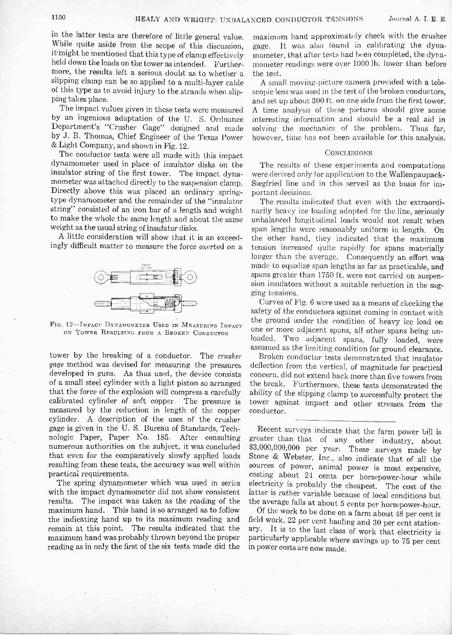
1150 HEALY AND WRIGHT: UNBALANCED CONDUCTOR TENSIONS Journal A. I. E. E.
in the latter tests are therefore of little general value.While quite aside from the scope of this discussion,itmight be mentioned that this type of clamp effectivelyheld down the loads on the tower as intended. Further-more, the results left a serious doubt as to whether aslipping clamp can be so applied to a multi -layer cableof this type as to avoid injury to the strands when slip-ping takes place.
The impact values given in these tests were measuredby an ingenious adaptation of the U. S. OrdnanceDepartment's "Crusher Gage" designed and madeby J. B. Thomas, Chief Engineer of the Texas Power& Light Company, and shown in Fig. 12.
The conductor tests were all made with this impactdynamometer used in place of insulator disks on theinsulator string of the first tower. The impact dyna-mometer was attached directly to the suspension clamp.Directly above this was placed an ordinary spring -type dynamometer and the remainder of the "insulatorstring" consisted of an iron bar of a length and weightto make the whole the same length and about the sameweight as the usual string of insulator disks.
A little consideration will show that it is an exceed-ingly difficult matter to measure the force exerted on a
FIG. 12-IMPACT DYNAMOMETER USED IN MEASURING IMPACTON TOWER RESULTING FROM A BROKEN CONDUCTOR
tower by the breaking of a conductor. The crushergage method was devised for measuring the pressuresdeveloped in guns. As thus used, the device consistsof a small steel cylinder with a light piston so arrangedthat the force of the explosion will compress a carefullycalibrated cylinder of soft copper. The pressure ismeasured by the reduction in length of the coppercylinder. A description of the uses of the crushergage is given in the U. S. Bureau of Standards, Tech-nologic Paper, Paper No. 185. After consultingnumerous authorities on the subject, it was concludedthat even for the comparatively slowly applied loadsresulting from these tests, the accuracy was well withinpractical requirements.
The spring dynamometer which was used in serieswith the impact dynamometer did not show consistentresults. The impact was taken as the reading of themaximum hand. This hand is so arranged as to followthe indicating hand up to its maximum reading andremain at this point. The results indicated that themaximum hand was probably thrown beyond the properreading as in only the first of the six tests made did the
maximum hand approximately check with the crushergage. It was also found in calibrating the dyna-mometer, that after tests had been completed, the dyna-mometer readings were over 1000 lb. lower than beforethe test.
A small moving -picture camera provided with a tele-scopic lens was used in the test of the broken conductors,and set up about 300 ft. on one side from the first tower.A time analysis of these pictures should give someinteresting information and should be a real aid insolving the mechanics of the problem. Thus far,however, time has not been available for this analysis.
CONCLUSIONS
The results of these experiments and computationswere derived only for application to the Wallenpaupack-Siegfried line and in this served as the basis for im-portant decisions.
The results indicated that even with the extraordi-narily heavy ice loading adopted for the line, seriouslyunbalanced longitudinal loads would not result whenspan lengths were reasonably uniform in length. Onthe other hand, they indicated that the maximumtension increased quite rapidly for spans materiallylonger than the average. Consequently an effort wasmade to equalize span lengths as far as practicable, andspans greater than 1750 ft. were not carried on suspen-sion insulators without a suitable reduction in the sag-ging tensions.
Curves of Fig. 6 were used as a means of ckecking thesafety of the conductors against coming in contact withthe ground under the condition of heavy ice load onone or more adjacent spans, all other spans being un-loaded. Two adjacent spans, fully loaded, wereassumed as the limiting condition for ground clearance.
Broken conductor tests demonstrated that insulatordeflection from the vertical, of magnitude for practicalconcern, did not extend back more than five towers fromthe break. Furthermore, these tests demonstrated theability of the slipping clamp to successfully protect thetower against impact and other stresses from theconductor.
Recent surveys indicate that the farm power bill isgreater than that of any other industry, about$3,000,000,000 per year. These surveys made byStone & Webster, Inc., also indicate that of all thesources of power, animal power is most expensive,costing about 24 cents per horsepower -hour whileelectricity is probably the cheapest. The cost of thelatter is rather variable because of local conditions butthe average falls at about 5 cents per horsepower -hour.
Of the work to be done on a farm about 48 per cent isfield work, 22 per cent hauling and 30 per cent station-ary. It is to the last class of work that electricity isparticularly applicable where savings up to 75 per centin power costs are now made.

Variable -Voltage Equipment for Electric PowerShovels
R. W. McNEILLIAssociate, A. I. E. E.
ALTHOUGH the power shovel was developed andbrought to a high state of perfection by usingsteam as a motive power, a constantly increasing
number of power shovels is being supplied for elec-trical operation. These electric power shovels are beingused for all sorts of work although they are in particularfavor for projects of a permanent nature or for thoserequiring a considerable period for completion. Insome cases the electric power shovel has been adoptedwhen starting these projects, or in other cases it hasreplaced the steam power shovel because of its superioroperating economies. This process of replacementis very active at the present time in connection withopen -pit copper and open -pit iron mines. Otherextensive uses for electric power shovels are found in"strip" coal mines, quarries with output used in crushedform (such as for blast -furnace purposes), road materials,cement manufacturing steel plants for rehandlingore and slag, and contract work on dams, canals, tunnels,etc.
This widespread use of the electric power shovel hasled to a considerable development in connectionwith this type of machine not only in connection withthe electrical equipment but also with regard to generalmechanical design. While earlier experiences withelectric power shovels had indicated that very goodresults were obtainable by taking the steam power shoveldesign and replacing the steam engines and boilerswith electrical equipment, later experience has shownthat in order to obtain the full advantage of benefitsof electrical operation, the shovel must be designedwith this point especially in view. Mechanical im-provements have taken the form of better gearing,(double helical gears having been substituted for coarsespur gears in many instances), and of better systems oflubrication for gears, bearings, etc.
The latest development in the line of electricalequipment for power shovel operation is characterizedby two outstanding features. First is simplicity ofcontrol, and second, sturdiness of the entire electricalequipment. Simplicity of control is secured by use ofthe variable -voltage system of motor speed control anddurability by designing all the electrical equipmentwith the same high standards as characterize the ruggedreliable d -c. mill -type motors used for operation of theshovel.
In!theldevelopment of this latest type of electrical
1. General Engineer, Westinghouse Electric and Mfg. Co.,East Pittsburgh, Pa.
Presented at the Pacific Coast Convention of the A. I. E. E.,Salt Lake City, Utah, Sept. 6-9, 1926.
equipment for operation of power shovels, every ad-vantage gained by experience in perfecting the steampower shovel has been utiliized and the equipmenthas been designed to duplicate the steam power shovel
in performance and digging characteristics, for it is awell recognized fact that the power characteristics ofthe steam engine are practically ideal for power -shovel
operation. The variable -voltage system of motorspeed control as developed for electric power shovelsemploys an individual motor for drive of each principalmotion, power being supplied to each motorJrom ,an
400
3007
a_-1-:U-
ZOO15
4.)
100
00 50 100
1r..00,
r'0=i-
Nr%
*z.
XI%
N9 /Series NolLoriY22Cinpat.11o/or
/00-/Y23 Sk0/7ih 70 /0
Bail Pull in Thousand Lb.FIG. 1-COMPARISON OF STEAM-ENGINE AND VARIABLE -
VOLTAGE -OPERATED MOTOR CHARACTERISTICS FOR POWERSHOVELS
individual generator of such design- that the speedtorque characteristics of the individual motors closelyresemble those of the steam engines used on steam powershovels, as shown in Fig. 1.
Electrical equipment using the variable -voltagescheme of motor control is adapted to all sizes of shovelsfrom the smallest to the largest, and its principle ofoperation is the same, regardless of the size of shovel.Where this system is used, a -c. power is usually suppliedto the shovel from a central station system. Thismeans that the complete electrical equipment for ashovel using the variable -voltage system will, of neces-
1151

1152 MeNE1L14: ELECTRIC POWER SHOVELS Journal A. 1. E.
sity, consist of the following principal items in the orderof their location with respect to the incoming power line.
1. Starting equipment for a -c. motor.2. Motor -generator set.
a. A -c. driving motor.b. D -c. generators for supplying power to
individual shovel motors.c. D -c. generator for furnishing excitation to
above d -c. generators, shovel motors and a -c.motor, if same is of synchronous type. (Thisexciter may be separate -motor -driven, if physicallimitations make it impossible to drive same frommain set.)
3. Controllers and field resistors.4. Shovel -driving motors.Auxiliary equipment may consist of air compressors,
magnet valves, solenoid brakes, etc.Due to differences in size of equipment, type of
driving motor, and voltage used, there will be consider-able variation in the type of starting equipment fur-nished for the main motor -generator set. For thelarger outfits using high -voltage synchronous drivingmotors, the usual practise will be to supply a combinedsynchronous motor and exciter panel of steel clad con-struction. If reduced -voltage starting is used, thispanel or switch structure will include auto -transformer,double -throw oil switch, field rheostats, necessary cur-rent and potential transformers, and meter equipment.If full -voltage startingis used, the auto -transformer willbe omitted, and if desirable, starting may be madeautomatic -operated circuitbreaker. On the smaller sized motor -generator setsdriven by induction motors, the equipment can besimplified and motor started at full -line voltage by useof an oil circuit breaker in case of high -voltage motors,and by means of an across -the -line type magnetic starterin case of low -voltage motors.
While the size of the motor -generator sets will varywith the different sizes and models of shovels, thegeneral scheme will always be the same and the setwill consist of an a -c. driving motor of either the syn-chronous or induction type, a d -c. generator for thehoist motion, a d -c. generator for the swing motion, ad -c. generator for the thrust motion, and a d -c. exciter.The exciter may or may not be part of the main motor -
generator set, depending upon whether or not spacelimitations will permit the use of a five -unit motor -gener-ator set. Where the exciter is separate -motor driven,it is usual to use a low -voltage driving motor, and, ifpower supply is at high voltage, to supply transformersfor furnishing power to the exciter motor -generator set.Driving motors for the larger shovel motor -generatorsets usually are wound so that by a simple change inconnections they can be operated on either 2200 or4000 volts. Smaller sets are wound for 2200, 550, or440 volts. Lower voltages are not recommended onaccount of poor line regulation. Either synchronousor induction motors can be designed for full -voltage
starting if desirable. In general, this will be thestandard method of starting the smaller induction-
motor -driven sets.The individual d -c. generators used for supplying
variable voltage to the various motions are of thedifferentially -compound -wound type, designed withthree separate field windings, viz., a separately -excitedshunt -field winding, a self-excited shunt -field winding,and a series, winding so connected as respects the arma-ture that its effect on total field strength will be sub-tractive or differential under -load current on thegenerator. This type of generator will deliver variable -
voltage power to the shovel motors, the exact voltagevalue at any instant being dependent on two factors:first, the value of the separate shunt -field excitation, andsecond, the value of the load current flowing in the
400
300
0
00 500 .1000
i
km..,,T,ii,
1
IIIIAIME.11111111INIllar
1,1_1
.1RII41,1
' III
Armature AmperesFIG. 2-VOLT-AMPERE CHARACTERISTICS OF DIFFERENTIAL
CONIPOUND GENERATOR AS USED SHOWING THE EFFECT OFEXCITATION CHANGES
armature and the differential series field winding.Fig. 2 shows voltage characteristics of a typical differen-tial -compound -wound d -c. generator for power -shovelservice under different conditions of separate -excitedfield strength and load currents. These character-istics are practically ideal for power -shovel operation,since by supplying power to the shovel motors from suchgenerators, we are enabled to obtain motor speed torquecharacteristics closely resembling those of the steamengines used for power -shovel service. Actual practisein the design of these generators proportions the shunt -field windings so as to give the required light -load volt-ages and proportions the differential series winding sothat the total field strength at heavy loads will be only

mr. 1926 McNEILL: ELECTRIC POWER SHOVELS 1153
such value as to force the maximum required cur-int through the main circuit consisting of motor andTnerator armatures, series and interpole field windingsad connecting cables between the machines.The motors used for driving the individual motions on
'triable -voltage equipped electric power shovels arei' the well known d -c. mill type, used so extensively forixiliary drives in steel mills and on heavy-duty cranes,Lr dumpers, etc. Open or ventilated type motors are3ually used on hoist and swing motions, and totallynclosed motors on the thrust motion. Mill motorswe massive cast steel frames split horizontally soiat the tap half can be readily swung back or lifted off.Tidespreading feet, cast integral with the lower half ofie frame, insure stability and freedom from vibrationhen the motor is bolted to a firm foundation. Elec-ically, the design is of the very highest order. Micarid asbestos insulation is used throughout; all main andammutating field poles are of laminated constructionrid coils are supported and banded in such a manneriat there can be no loosening in service.There is some variation in the type of field windings
mployed on d -c. motors used for shovel operation.'he swing and thrust motions are always operatedither by straight shunt-wound, separately-excited,-c. motors or by compound -wound motors havingaparately excited shunt fields. The hoist may beperated either by series -wound motors or by sep-rately-excited, shunt- or compound -wound motors.is compared to the compound -wound or series motor,he straight shunt-wound motor, when controlled byhe variable -voltage method, possesses the advantageif no reversal of main circuit connections being neces-ary to secure reversing of direction of rotation of thenotor. As compared to the series motor it has theadvantage of positive regenerative braking beingasily secured. As compared to the series and com-)ound wound motors it has the disadvantage of not beinglesigned to deliver the same maximum torque for the;ame current value and its speeds are inherently lowertt light loads.
On the swing and thrust motions, the necessity ofegenerative braking for quick stopping practically?liminates the series -wound motor, so that choice mustae made between the straight, shunt-wound motor and:he compound -wound motor. This also applies to theTloist-motion on high -lift shovels which use regenerativearaking in lowering the dipper. The main objectionto the use of compound -wound motors is that theiruse complicates the control, as it is necessary to furnishmeans of reversing the series fields for reversed service.On the smaller motors this is easily accomplished byadditional contacts in the small drum controllers usedfor governing the operation of each motion. But onthe larger motors, it is necessary either to add magneticcontactors for reversing these fields or to provide aseries exciter, or its equivalent, so that compoundmotor characteristics can be obtained with shunt -field
windings in the motor. These schemes do not eliminatethe reversing processes but do reduce the capacityrequired so that large magnetic contactors are
unnecessary. The choice between straight-shunt andcompound -wound motors for swing and crowd motionsis not very clearly defined; in some cases the extracomplications of the compound -wound motor will bejustified, while in others the simplicity of controlpossible with the straight shunt motor will be the de-ciding factor in determining its use.
On the hoist motion the problem of proper type ofmotor is further complicated by differences in practisein operation, particularly on low-lift shovels. Someshovel manufacturers prefer to use the motors inlowering, using regenerative braking to obtain speedcontrol, while other manufacturers prefer to lower the
5000 100
3250 75
_
2500 i50
00.)
ce
1250 25
0 0
)
?a113
44'. Q7
I'll
%
0ll/,_ , 51a'
/rQct.--
43c--
RR*51/11/Y fa. ..40
500Amperes
FIG. 3-SPEED-TORQUE CHARACTERISTICS OF 170-H. P., 230 -VOLT, D -C. MILL -TYPE MOTORS FOR POWER SHOVEL SERVICE
0 '1000
dipper on a foot brake without operation of the hoistmotor in the reverse direction. If the latter practiseis followed there is little advantage in using the straightshunt or the compound -wound type of motor andadvantage can be taken of the superior operatingcharacteristics of the series -wound motor for the hoistmotion. If, however, regenerative lowering is needed,a shunt or compound motor is used, control con-nections being so arranged on the compound woundmotor that in lowering, it operates as a straight shunt-wound motor. Comparative speed torque character-istics of shunt, compound and series motors are shownon Fig. 3.
The control equipment necessary with electric powershovels operated by the variable -voltage system is of

1154 McNEILL: ELECTRIC POWER SHOVELS Journal A. I. E. E.
the very simplest nature. Actual practise is to usesmall drum controllers and series resistors connectedinto the separately excited shunt fields of the individualgenerators in such a manner that operation of thesecontrollers will direct the flow current and currentstrength in these fields. Additional contacts areregularly provided in this controller for weakeningthe self-excited shunt field of thp generator in the offposition for connection of field discharge resistors andfor operation of brake and clutch circuits. Wherestraight shunt-wound motors are used, these controllersprovide for the weakening of the motor shunt field inthe off position and may provide for insertion of resist-ance into the motor field to secure high light -loadspeeds. When compound -wound motors are used,it is necessary to furnish not only the field weakeningpoint in the off position for the separately excitedshunt field, but also to furnish additional contactseither for reversing the series field direct throughmagnetic contactors or by reversing connections to aseparate exciter used to secure compound -woundmotor characteristics. Where series -wound motorsare used on the hoist, it is not necessary to provide forfrequent reversals, as the only time that reverse opera-tion is required is when the hoist motor is used forpropelling the shovel. This infrequent reversal isusually taken care of by a separate hand -operated re-versing switch. Typical diagrams for shunt, com-pound -wound and series motors are shown onFigs? 1, 2 and 3.
Controllers used with the variable -voltage equippedshovels are all ofthe same general type and constructionthough they may differ somewhat as to drum develop-inent and method of operation. The currents to behandled by these controllers are small and the designis determined more by the demand for rugged mechan-ical construction and ease of operation than for current-carrying capacity. Full revolving shovels are builtusually for one-man operation and for this reason thereis some demand for a foot -operated controller to beused on one of the motions on these shovels. Standardcontrollers for variable -voltage equipped shovels areconstructed with vertical operating handle. Thumb-operated auxiliary switches for operation of dipper-
trip mechanisms, magnet valves, etc., are frequentlyadded to the handle of standard controllers.
While the resistors used with the variable -voltageequipment are of small size and capacity, even on thelargest shovels, they are quite an important fekure ofequipment and it is very essential that they be of amplecapacity and rugged construction. Experience hasdemonstrated that these resistors should be wound oninsulated metal supports and that special care should betaken to insure against connections loosening due to vibra-tion. Practise in method of assembling resistor unitsvaries with shovel design. On one type of shovel it
may work out to advantage to assemble resistors allin one unit and provide this assembling with a terminalboard which will serve as a distribution center for allcontrol wiring. In other cases, space limitations canbest be met by making up the resistors in unit assembly,that is, one unit for hoist generator separate excitedfield, one unit for hoist generator sets excited field, etc.
Air compressors, when used with shovel equipment,are usually of the industrial type with a -c. drivingmotor. Air pressure is maintained at a constant valueby means of an automatic governor which stops andstarts the compressor as the air receiver pressure varies.Compressed air is used for operation of brakes on theswing and thrust motions and for brake and clutch onthe hoist motion.
Magnet valves are used to give electrical control ofthe air brakes, clutches, etc. Two types of valves areused; these are known as "straight" and inverted valves.Both types of valves are of three-way construction andthe difference between the two is in the method ofoperation. The straight valve is provided with threeopenings for pipe connections; one from the air supply,one to the brake or clutch cylinder, and an exhaustopening. With magnet of valve energized, the exhaustopening will be closed, the air inlet will be open, and full,air pressure will be exerted against the brake or clutchcylinder. Interruption of magnet circuit closes inletopening, opens exhaust port, and relieves pressure inbrake or clutch cylinder. Operation of "inverted"valve is just the reverse of above, as magnet coil isenergized to exhaust brakes or clutch cylinder andcircuit broken to apply air pressure. The straightvalve is always used on brakes which are of the spring -or gravity -applied, air -released type. The invertedvalve is used in connection with air applied springreleased clutches where it might be dangerous to use astraight valve as interruption of magnet circuit mightbe the cause of accident.
Solenoid brakes are used on electric -shovel equip-ments where compressor equipment is not supplied.On variable -voltage equipments these brakes ate of thed -c. type with shunt-wound operating coils designedto operate from the exciter circuit.
While the above has covered only the application ofthe variable -voltage system to power shovels of theconventional type, the system is equally adaptable todragline excavators, dipper dredges, and to hoist andswinging motions on all types of cranes, dredges, etc.It provides a simple automatic method of limiting motortorques where serious damage to the mechanical equip-ment might result if motor torques were not limited,and also provides a simple automatic method forobtaining high motor torques with low kw -input tothe motor. This last factor is a valuable one wherepower is purchased on a peak -load basis or where theprimary source of power is of limited capacity.

Nov. 1926 DISCUSSION AT MIDWINTER CONVENTION 1155
Discussion at Midwinter ConventionEXPERIMENTAL DETERMINATION OF LOSSES IN
ALTERNATORS1(ROTH)
NEW YORK, N. Y., FEBRUARY 9, 1926
W. F. Dawson: In an article published in 19202 I calledattention to the fact that in many cases load losses indicatedduring short-circuit test were greatly reduced when the machinewas run at full voltage and rated power factor.
I have since run many other tests and while I am not preparedto lay down any definite rule, I am prepared to suggest that thepresent A. I. E. E. rule (paragraph 470, No. 7) which chargesall of the load losses measured during short circuit against thelosses of the machine, is probably unfair, Since the publicationof my article in 1920, improved methods have been developed.At that time I intimated that electric heaters delivering a knownquantity of energy into the discharge duct could be employedas a calibrating device. I had tried them in a rather amateurishway. Since then we have perfected our electrical air heatersand we have also perfected resistance thermometers for measur-ing the inlet air, the outlet air, and the temperature of the airafter it has passed the electric heater. It is now a comparativelysimple matter to measure the actual losses of a machine havingan enclosed ventilating system, such as turbine alternators, underany condition of load.
We have satisfied ourselves that the question of convection,at least on high-speed machinery, introduces no appreciableerror, even though we have not been able to establish an exactemissivity constant. This may possibly vary from 0.0125watts per sq. in. per deg. cent. rise of the frame surface to 0.007watts per sq. in. per deg. cent. rise; but when it is realized thateven with the higher figure the convection loss amounts to lessthan two per cent of the total loss on an alternator as small as3750 kv-a. and the total loss in turn is only 4.2 per cent of therating (on 3000 kw.), the total loss due to convection will be onlyabout 0.08 per cent of the rating.
It has been my pleasure, during the last year, to build and testa turbine alternator rated three-phase, 480 volts, 7518 amperes,0.8 power factor. Cheek tests at full load, 0.8 power factor,were made 'on the customer's premises a few weeks ago. Thefactory test consisted of a zero -field (no excitation), open -circuitheat run at normal voltage and a short-circuit heat run at normalcurrent, the calorific method being used to estimate the losses.The aggregate of these losses, assuming the same losses underoperating condition as during short-circuit test, was 279 kw.On the customer's premises a check was made under contractconditions, except that the phases were slightly unbalanced;the average armature current was slightly over the rating andthe armature voltage slightly less. The normal rating of 5000kw. was maintained accurately, the field current held constantand the power factor, within one per cent of the 0.8 guaranteed.
What was the result? The generator was equipped with anair cooler. We installed flow meters to measure the quantity ofcooling water, thermometer wells, and calibrated mercury ther-mometers reading to within 0.1 deg. fahr. We also installednumerous thermometers for measuring the temperature of the(inlet and outlet) air. Assuming that the factory measurementof quantity of ventilating air was still correct value, total lossesby temperature gain of the ventilating air were 266 kw., whilefor the temperature gain of the cooling water, the value indicatedwas 270 kw., a check within 1.5 per cent. An average betweenthe 270 kw. and the 266 kw. (between the air and the watermethod) gave 268 kw., which was 11 kw. less than the aggregateshown by the factory measurement.
1. A. I. E. E. JOURNAL, May 1926, p. 422.2. G. E. Review, Feb. 1920, Page 161.
B. L. Barns: What I have to offer has reference to the gen-eral subject of the determination of losses in alternators.
We have built in Canada some very large vertical shaftalternators which are installed in the Queenston Power Houseof the Hydro -Electric Power Commission. In making the ac-ceptance tests it was not possible to determine the load lossesby any of the methods described in the A. I. E. E. rules, and forthe efficiency results an assumption was made regarding thevalue of these losses. Naturally in view of the size of these
generators we were curious to know just what was the true valueof these lo§ses. In reviewing the work that had been done it wasnoticed that in 1913 Mr. H. M. Hobart had suggested whathe called the calorimeter method. Later, in 1920, Mr. Dawsondescribed the method which he, himself, has mentioned. Mr.Dawson's method involved heating the air that passes throughthe machine and under the conditions existing at the QueenstonPower House it was quite difficult to take care of this feature.Furthermore it was very difficult to obtain an accurate measure-ment of the air passing through the generator.
Mr. Hobart's suggestion and Mr. Dawson's experimentsoffered a clue as to a method that might be used. An accuratedetermination had been made of the windage and friction andthe open -circuit core loss on which we had consistent checks.It was reasoned that since the value of the core loss was known,it would be possible to determine by test the temperature riseof the air passing through the generator due to the core loss;then, having determined this constant, the losses under any othercondition of load could be determined by measuring the tempera-ture rise of the air. Thus, if it were found that the temperaturerise of the air at full load was twice or three times the rise dueto core loss alone it would he reasonable to conclude that thetotal loss was two or three times the core loss. Accordingly, a
of tests of this nature have been carried out on two of the .
generators. The tests consisted of measuring the temperaturerise of the air under four conditions of load; windage and friction,open -circuit core loss, short-circuit core loss, and full rated load.It was necessary to separate the windage and friction from theopen -circuit losses because the losses in the thrust and guidebearings were not taken up by the cooling air but were carriedaway by the cooling water and circulating oil. The differencein the temperature rise of the cooling air under conditions ofopen -circuit, normal -voltage core loss and windage and frictionrepresents, therefore, the temperature rise for a known losswhich is the core loss and the field copper loss. These resultspermit the establishment of a constant representing the kilo-watts loss per degree rise of the cooling air: Having obtainedthe value of this constant, other runs at full load or on shortcircuit may be made and the temperature rise of the air measuredand the value of the 'total losses determined.
This method of test of course involves the measurement bysuitable test of the windage and friction and open -circuit coreloss so that a known loss may be used for determining the tem-perature -rise constant. These losses may be determined byrunning the alternator as a synchronous motor and measuringthe input, or by a retardation test. Tests by these two methodswere made on one of the Queenston generators and remarkablyconsistent results were obtained. Our first trial of this methodwas made in June 1924, but, due to some unforeseen conditions,we were not well satisfied with the results and they were laterrepeated with quite satisfactory results which were describedby the speaker in a paper which was read before the TorontoSection of the A. I. E. E., in February 1925. This method oftest is briefly described by Mr. Roth in his paper3 on the 60,000-kv-a. turbo alternators for Genevilliers.
3. Three-phase, 66,000-Ky-a., Turbo generators for Gennevilliers, by E.Roth, A. I. E. E. JOURNAL, September 1925, page 927.

1156 I)IS('IJSSION AT 14111/WINTER CONVENTION Journal A. I. E. E.
This method of test has certain limitations and obviously itmina be used on all types of machines. No doubt it could beused with success in the case of most turbo alternators and en-closed alternators, synchronous motors, and condensers. '1'11(1generator setting at the Quoenston Power House is particularlywell adapted to this method of test in that it is enclosed in achamber having walls of hollow tile so that the radiation and con-vection are reduced to so small an amount that the error wouldbe of a very small order. (A description of these generators andtheir setting is published in volume XLI, pp. 472-499, of theA. I. E. E. TRANSACTIONS). In carrying out a test of this kind itis essential that the true mean temperature of the air enteringand leaving the machine should be obtained and several methodsof doing this have been proposed. We have used a large numberof thermometers with 0.1 -deg. graduations together with anordinary copper wire resistance grid, and the average readingsof the thermometers have checked closely with the grid. Iwish to call attention to one necessary precaution in makingthis test; each run should be continued long enough to obtain aconstant temperature of the coils and iron of the machine and atthe same time the temperature of the cooling air should be con-stant because a rising or falling temperature of the cooling airwill introduce a considerable error even though a constant tem-perature rise of the air passing through the machine may be ob-served for considerable time. These precautions apply tothe methods described by Mr. Dawson as well as to the methodwhich I have described.
P. A. Borden: In most of the methods which have beenused for the determination of losses by measurement of tempera-ture rise in the cooling air, it would appear that there exists thenecessity of either determining the quantity of air supplied tothe machine, or of maintaining that quantity at a very steadyrate of flow. In the testing of large units, exact measurementof the air flow is usually very difficult, while the maintenance ofa uniform rate is seldom practicable.
While the following method is not offered as a panacea for allthe troubles attending such a measurement, it would seem thatthe fact of its not being inherently dependent in its results uponvolume or rate of air flow or upon temperature of the air supplywould tend to remove many of the objections to the thermalsystem of loss determination.
Basically, the method, like a number of others, consists ofintroducing into the inlet and outlet air passages resistance gridshaving the same temperature coefficient, connected as two armsof a Wheatstone bridge. The bridge is first balanced in what wechoose to call the "zero" position. After a steady condition oflosses is established, the unbalance of the bridge due to the tem-perature gradient in the air column is corrected; but the restoringof the balance is not accomplished by manipulation of the circuitof the bridge, but by "artificially" raising the temperature of thecooler grid to meet that of the other. Measurement is thenmade of the power necessary to be introduced into the cool armof the bridge to equalize the balance; and this value, expressedin watts, should bear a constant proportionality to the heatenergy communicated to the air by the losses in the machine.
The elementary parts of the system are shown in the accom-panying sketch, where RI and R2 represent the resistance gridsin the air inlet and outlet, respectively. These grids, as units,form two arms of a bridge circuit and are balanced on the gal-vanometer G by means of the slidewire S. The grid in theincoming air passage is itself made up in the form of a balancedWheatstone bridge, so that the auxiliary heating current may bepassed though it without disturbing the balance of the mainbridge circuit. This current is derived from an auxiliary source(preferably alternating), and supplied to equipotential pointsof the grid R. It will be seen that with this arrangementneither the voltage drop due to the auxiliary current nor theresistance of the auxiliary circuit has any direct effect upon thebalance of the main bridge. The other grid, while not neces-sarily a duplicate, is preferably of a similar construction and of
approximately equal resistance. Upon the establishment of atemperature difference between I he t wo grids, with a consequentunbalancing of the bridge, current from the auxiliary sourer' isfed into RI and t ljustod until the balance is restored. A readingon the %vat I meter II" of the amount of power thus supplied tothe grid then gives a measure of the heat dissipated by themachine under lest and communicated to the outgoing air.Calibration of t he set-up is accomplished by making one or more'determinations with it known Valli() Of losses dissipated by themachine, thus establishing the relationship between the measuredvalue of the auxiliary watts and the quantity under investigation.
The controlling factor in the acceptability of this method oftest would appear to lie in the constancy of ratio between thevalues of the auxiliary watts and the watts dissipated as lossesin the machine; and there has not as yet (Feb. 1926) been anopportunity to study the soundness of the system on an actualpower house installations. Laboratory tests have been inde-
BALANCE METHOD FOR DETERMINING LOSSES IN TOTALLYENCLOSED MACHINES
pendently made, however, by the writer and by Mr. Baker ofthe Ontario Power Company, using set-ups of dissimilar designand following different courses of procedure, but both with aview to establishing the constancy of the ratio under varyingconditions, principally of air flow and watts loss.
While at the present time a compilation of the results of thesetests is rather premature, it has been possible to arrive at con-clusions which would appear to justify further investigationunder actual service conditions; and it will be of great interest tolearn of others following out a similar application of the principledescribed.
W. J. Foster: It is interesting to note that the authorpoints out what many of us have been conscious of all along;that our method of determining the total losses of machines isapproximate.
I should like to revert to the first attempt made to estimate loadlosses and speak of the two men whom I think had more to dowith the exact formula than any others. I refer to Mr. Lammeand Dr. Steinmetz. They both regarded the determinationof losses under short circuit as giving excessive values for loadlosses due to the very abnormal conditions the worst possibledistortion of the flux existing. Consequently, they made anestimate of one-third of the short-circuit load losses as the loadlosses.
It soon became evident to all designers that that was notsufficient. On the occasion referred to by two or three of thespeakers, when so many papers were prepared, determinationshad been made by input and output method on a number ofmachines, and it was found that on the machines selected, theaddition of the entire short-circuit losses to the other segregatedlosses gave efficiencies that agreed very closely with the over-allefficiency. That is how it happened to be agreed upon.
4. Since presentation of the above discussion this method has beentried out in a large hydroelectric station with very promising results.

Nov. 1926 DISCUSSION AT MADISON1157
Mr. Roth speaks of the method, I think, as applying to turbogenerators. We are all aware that there is a difference inthe type of generator. Turbo generators have almost invariablydistributed field windings; that is, the field windings are in severalslots, with practically uniform air -gap, and with the end windingssecured by binding bands usually containing magnetic material.These bands are at almost the same radius, standing out in theline of the air -gap. Thus the determination of short-circuitlosses undoubtedly involves larger losses at the heads of therotor than exist under normal operating conditions.
In like manner the operation of that type of machine which hasonly a few poles on short-circuit results in losses at the heads ofthe stator that probably do not exist under ordinary operatingconditions, especially at the 80 per cent power factor condition.
C. J. Fechheimer: Mr. Roth applies his method to a com-paratively small, slow -speed machine, in which the "load losses"are almost negligible; that is, k r is only 9.4 per cent greater thanr. Has he applied his method to machines in which the loadlosses are high, and if so, how close did it check with other tests?
It is questionable whether the method is applicable to thegeneral case in which the power factor does not approach zero.Usually the cross -magnetization of the armature greatly distortsthe flux, with the result that the magnetic inductions in the teeth,and to some extent in the core, are far from uniform. The ironlosses may be considerably augmented thereby. It is believedthat this statement is especially applicable to the machinesdescribed in a recent paper by Mr. Roth3. For those machinesthe armature ampere -turns are higher than are needed to excitethe machine for no-load normal voltage.
Mr. Roth assumes the equation of the iron -loss curve to be aquadratic parabola (Fig. 2 in the paper). Inasmuch as whensaturation is approached, that loss increases faster than thesquare of the voltage, so that a simple exponential form ofequation can no longer be applied, he uses his method at 2000volts instead of the normal 3000, in the machine he tested. Howdoes Mr. Roth propose to extend his method so as to make itapplicable at the normal voltage of the machine? If he assumesthat the value of k is the same at normal voltage as at thereduced voltage, and if he allows for the incremental iron lossesdue to saturation by extending the tests as plotted in Fig. 2to normal voltage plus the internal impedance drop added vec-torially, it is questionable whether the method is correct. Alarge number of tests would have to be made to confirm the ac-curacy of the method.
In 1920 a method of separating the iron loss from the mechan-ical losses was suggested.5 That did not require the assumptionthat the iron loss is proportional to the square of the voltage.The method has frequently been used at the Westinghouse Com-pany, and Mr. Roth may find it useful. The machine is runidle as a synchronous motor with minimum excitation, just asas Mr. Roth does for Fig. 2. The calculations are, however,different.
A considerable part of the discussion has centered upon thethermal method of measuring losses. Many of us have attemptedto measure losses that way, but it is rather difficult to obtainaccurate results. The check that should be used is to run themachine without mechanically -connected load or driving machine,and measure the input with calibrated wattmeters. Then, ifone is assured that the testing equipment is accurate, the loadconditions may be fixed. It is expected that the results of testsalong that line will be reported in an early paper by one of theWestinghouse engineers.
E. H. Frelburghouse: Mr. Roth points out, just as othershave done, that there is considerable difficulty involved in meas-uring power input to a synchronous motor running light at low -power factor. It is more difficult to measure the power inputto a stator of an alternator with the rotor removed. As stated
5. "A Method for Separating No -Load Losses in Electrical Machinery,"by Carl J. Fechheimer. A. I. E. E. TRANSACTIONS, 1920, p. 291.
by Mr. Roth, the input to the alternator running as a synchro-nous motor can be measured quite accurately by determining the
rate of flow and temperature rise of the air which cools it.In other words, it is quite possible to measure' the entire lossesof the alternator at low power factor. The method which heproposes, however, for determining the constants k and pdepends upon the assumption that the electric losses of thealternator as a synchronous motor are the same when it is over-
excited as when under -excited. I do not believe this assumptionis justified since it is well known that the stray losses in the endstructure of the stator are very much less when it is over -excitedthan when it is under -excited. These losses as defined by Mr.Roth are electrical, since they are known to be generated by theinduction of the stator winding.
This is the principal criticism which I have to make of themethod which he has proposed. It is rather ingenious andobtains results which seem to agree quite closely with the testswhich he made upon the three different alternators. He foundthat in all cases the losses as determined by his method checkedwithin 4.3 per cent with the losses as determined by the Rulesof the A. I. E. E. and the French Rule.
Mr. Fechheimer called attention to the function of the voltagewhich appears in the equation on the sixth page. Of
course that has been assumed as a square function; that is,
as the square of the voltage. He assumed that and used that part.of the no-load loss curve in which the relationship of loss to volt-age was a square curve.
Mr. Fechheimer also called attention to the distorted form ofFig. 7 in relation to the loss. That is an insignificant influencebecause it really is the condition which the author states existsat the minimum input current, which is, of course, an extremelysmall current as compared with the rated current of thatgenerator.
There is one other point; that is with reference to the crossmagnetization. I think he takes account of that in the terminalvoltage as a function of power factor. That is, one can determinethe voltage which causes the loss by combining the fluxes forterminal voltage and that of the reactance voltage.
Discussion at MadisonTHE QUALITY RATING OF HIGH-TENSION CABLE
WITH IMPREGNATED PAPER INSULATION'(ROPER AND HALPERIN)
MADISON, WISCONSIN, MAY 7., 1926
W. S. Clark: One very important feature in the paper ofMessrs. Roper and Halperin is the correlation of tests andservice, and nobody could do that except an operating man.
Now as to the rating of cable, I think it is most importantto get into it a figure based on the so-called accelerated life test,as we have not yet found in Schenectady any test which wouldgive us as correct a measure of the value of the cable as that.I should suggest that the tests on the cold and hot samples mighthave their ratings reduced to ten each, and the value of theadded accelerated life test be put in at twenty, possibly reducingsome of the observation tests because, of course, those are veryundesirable on account of the personal element.
I should like to second Mr. Atkinson's suggestion that insteadof testing to destruction by increasing the pressure 10 per centevery 30 sec. or every minute, the increase be at the rate of 15per cent and at 5 -min. intervals. I believe this would give morereliable data. The volts per mil, quoted in Mr. Farmer'spaper, for instance, represent probably less than the one -minute strength of the cable.
Referring to Fig. 11 of Mr. Roper's paper, the slope of thecurve in the type of cable on which it is based would be modifiedby temperature. It has been our experience with semi -solid
1. A. I. E. i:JOURNAL, June, 1926, p. 505.

1158 DISCUSSION AT MA D1SON Journal A. I. V,. I.;.
compounds and on single eonductors that the average life of avery large number of samples with insulation 0.28 in. thiek,tested at 11 kv., or about 156 volts per mil, with a 2/0 conductor,would run around -10 hr. On the same samples, tested at 85 deg.the average life was in the nature of 1000 hr., the reason beingthat voids were not present in the second case in the same degreeas in the first.. You cannot prevent some voids in cable due tothe process of manufacture unless you go back to the old Sie-mens' process and apply the lead cold, because the lead goes ontothe cable at a temperature around 200 deg. cent. and it is evidentthat this must warm up t hecable as a whole, so that when it coolsto room temperature there is some shrinkage and sonic voids arecreated. It is for this reason, I believe, that in the past cableswhich were operated at average voltage stresses of less than 50volts per mil have not given as much trouble as cables operatedabove 50 volts per mil average stress. This is due to the factthat at atmospheric pressure you get ionization effects around 50volts per mil.
To illustrate how. the curve in Fig. 11 may be varied withdifferent types of impregnating compound, I have checked upand found that there the voltage ordinarily varies inverselyas the seventh root of the time. We have this check on testsrunning up to 2800 hours and the results agree quite well withthe formula.
On oil -filled cables of the Pirelli type, however, we have foundthat the exponent, instead of being seven, should be somethingin the neighborhood of nineteen, indicating a very much flattercurve.
There is one piece of information involving very long andexpensive testing with reference to the effect of surges on cableon which I have data and I am giving a brief summary of resultsbelow:
Two samples of single -conductor 2/0 cable with insulation0.28 in. thick; 10 ft. under the lead.
Sample No. 1 was continuously subjected to 13.2 kv. at 60cycles at room temperature. Once a day a 50-kv., 10,000 -cyclesurge of approximately 300 microseconds was applied. Totalnumber of surges applied up to the termination of the test, 357.
Sample No. 2 was subjected to an impulse voltage of approxi-mately 300 microseconds duration from the lightning generator(the sphere -gap being set for 75 kv.) once a day. This samplewas, of course, also under continuous stress of 13.2 kv. Totalnumber of applications, 333.
Total length of time involved in the test on each sample -9933 hr.
The initial power factor at 28 kv., at room temperature, was0.5 per cent. The final power factors were as follows:
At 5 kv.- 0.6 per centAt 15 kv.- 0.5 per centAt 28 kv.-0.6 per cent (an extremely small increase in the
power factor.)The above tests were on sample No. 1.Sample No. 2 at the end of the test at 5 kv. showed 0.45 per
cent; at 15 kv., 0.5.per cent, and at 28 kv., 0.6 per cent.After the completion of the tests, samples were put under
continuous stress at 48 kv. a -c. and they stood in excess of 36 hr.R. W. Atkinson: Mr. Roper and his aids are to be com-
mended for the large measure of accomplishment they have madetoward the solution of the complex problem. They have shownthat cable having the insulation of their 13-kv. system will not befree from operating difficulties unless it can meet certain teststandards and that when it does meet these standards continuedsatisfactory operation seems assured, and, indeed, so far as theirconsiderable experience goes, is assured by a large margin.
I endorse most of Mr. Roper's conclusions but wish to discusstwo of them. The fourth one, stating that, the ratio of puncturevoltage obtained on cold bent samples to the puncture voltage ob-tained on the straight sample appears to be an excellent test ofworkmanship, contains a qualification which I wish to emphasize.
Mr. Roper uses the words "that this ratio upprrrrx to be nnexcellent test of workmanship." I 'tidoubtedly, in nutty ('14545 itis a iest of \\ orLinittisliip. In general, A meriean cables made atthis lime show approximately dieleel tie strength on the
tevitoliii:Ostiflittitil'itti theIl
:Ilia111.1'1:11Silej 711
is in the neighborhood of11iltIM
anti
al) "Allan nn a ore front improvenu ul iii generalI do mit believe that
id theexcellence ,,rowl., is relai 11111tillip bet \11.011 the ratio(plaid v of workmanship such that this condition will alwaysremain true and I I(iiete I hot the indi 'dual tests themselvesand other tests and aclual direct determinat ions of the quality
nitwit more important planof workmanship will be found to beany chance rat it, W hick 111:ly Seel)) I)) exist bet weer these two tests.If (i\,) to Ihese ()HUT things, then the ratiohei \keen the two tests can he omit led from considerall011.
I agree wit COlielleiffil 9, that qualit y rating tables can beused with reasonable ,:ceuritey to determine relative merits ofdifferent lots of cable. but if this comparison is to be more than avery rough apl,rusini:ation, softie additional typos of measure-ments must be made in order to find better means than are nowavailable 1,, ('o'er the su 16(.0 of uniformity.
There cannot he any doubt of the value of the so called lifetests, and the suggestion t, f these authors to change the eight-hour test in the Edison specification on reels to be used after-ward to destruction tests on shorter lengths marks a distinctadvance. For malty years, me been carrying on life tests inour laboratories, making these tests at relatively lower voltagesand carrying them for many hundreds or thousands of hours.It is interesting to note that very much the same sort of datais obtained in the relatively shorter period, and of course tests forthe shorter period have the very practical advantage that farmore data can be obtained with a given space and equipment. Iagree with these authors in placing this test as doubtlessly themost important single test. It is interesting therefore to notecurves in Figs. 12 and 13, from which the authors conclude thatthis test gives substantially the same result as the rating tableand that both are in general agreement with operatingexperience.The data given, however, do not juStify this as a generalconclusion.
Actually, the life test depends so largely upon the same thingsupon which the operating experience may be expected to dependthat ordinarily there will he a cry close relationship betweenthem. It is easy however, to cite cases where this will not betrue. The cable might he made with a compound of suchcharacteristics that it would not well withstand a cold bendingtest or handling while cold; then be installed in extremely coldweather and give a very bad service record in spite perhaps ofbeing able to pass an extremely severe life test.
If, when a group of cables is rated in the order of relativemerit, (as determined by the best information available) anycharacteristic is found to fall in the same order as the rating of thecables, on first thought this may be assumed to indicate that thischaracteristic has fundamental importance in regard to therating, or that it varies directly with some other very importantproperty. I have already shown that even such an importanttest as the life test may vary in a way different from the service-ableness of the cable. It is evident, then, that relatively minorproperties may vary, in some cases, as the relative value of thecable, and in other cases, in an entirely contrary direction. Toestablish the importance of any particular test or item in therating table, the individual item must be studied and its im-portance studied separately.
It follows, therefore, that we should be able to take a com-plete group of mechanical characteristics and get the same com-parison as for a correlated and complete group of electricalcharacteristics. If these results do not coincide, there is no doubtthat one or the other is not complete or is not properly evaluated.Each individual item that is given weight should be studied

Nov. 1926 DISCUSSION AT MADISON 1159
analytically and the weight determined in that way. Evalua-tion of these different properties by mere comparison withoperating experience, without the initial analytical comparison,is likely to be misleading.
These authors have followed the analytical method to someextent; for instance, in the case of the cold bending test. Theyhave pointed out installation conditions and have shown therelatively excessive number of failures which once occurred in themanholes. They have ascribed the large reduction in suchfailures to the use of cable better able to withstand the bendingtest. I should ask, at this point, if the better results may not bepartly a result of closer supervision of installation and greaterassurance that cables are not subjected to conditions from whichthey can be protected or for which they were not designed. Thegeneral analytical treatment given the bending test justifiesthat it be considered of important weight.
I have already mentioned that there is no justification for theuse in rating table of the ratio between breakdown of the bentand unbent samples. Substantially the same arithmeticalresult can be obtained by changing the weights and some changesin the limits. It may be asked, if there is no final arithmeticalchange in the rating due to making the change here proposed,what is the use of making it? In the first place, logic demandsit; secondly, there is a very important practical reason. If thetest on the bent sample is three times as important as the other,it warrants a great deal more relative attention. If it is threetimes as important, there should he three times as many testsmade of this kind as of the other. Half of the present number ofsamples now intended for the straight test should be added tothose tested after bending.
Uniformity of insulation resistance is given considerableweight in the rating table because it is assumed to be an indexof the uniformity of the cable. It is, however, a measure ofuniformity of only one property-insulation resistance. Ifinsulation resistance measurements can be used to indicateuniformity in properties important in themselves, those advo-cating it as important for that purpose should suggest whatproperties it indicates and should use the insulation resistencemeasurements to aid in picking out non -uniformities in theimportant property.
There is, however, another aspect of the matter. Conditionsin Chicago are known to be peculiar in one respect that hasundoubtedly greatly influenced the whole handling of the cableproblem. Street conditions have dictated a limitation ofdiameter to three inches and power requirements have been forvery large capacities at high voltages. No doubt the standardnecessarily set for 33 -k -v. cable had a bearing on a choice inChicago of insulation thickness less than for usual Americanpractise. Mr. Roper's experience has demonstrated that theproblem of suitable specifications for cables with such insulationthickness is vastly more complex than where thicker insulationis used.
I want to express too my pleasure in hearing Mr. Ropermention two things which I have been preaching for quite anumber of years. One is that low dielectric loss can be over-emphasized, and the other is that the cable manufacturers shouldnot be limited to a particular kind of compound. Mr. Roperspoke of resin and its value. Some years ago the cable manu-facturers had considerable difficulty in preventing operatingpeople from insisting on putting into specifications the stipula-tion that a compound should be a mineral -base compound.
D. M. Simons: In general I agree with most of the conclu-sions of the authors, but I feel that real consideration should begiven to the matter of whether or not some of the specific recom-mendations for tests are of general application or of generalnecessity. When the authors speak in general of a 13,000 -voltcable, they have in mind a three -conductor, 500,000-cir. milsector cable, insulated with 9/64 -in. paper on the conductor, and5/64 -in. belt insulation. The mental picture of a 13,000 -volt
cable in the mind of a manufacturer is very different. He willhave in mind various sizes of conductor with conductor insula-tion thicknesses varying from 9/64 in. up to the more usualthicknesses of 12/64 to 16/64 in., and of various belt thicknesses.The manufacturer therefore has a tendency to wonder if the testsand data are of sufficient generality, large as they may be inextent, to justify general conclusions?
I should like to mention one other point. The authors areknown to advocate very severe tests and also extremely thininsulation. I believe, however, that most companies go ratherslowly in reducing thicknesses. It is of course possible to go tothinner insulation than the average used in the country for agiven voltage, but, apparently, in order to do so, the severityand number of test's must be greatly increased so that at leastpart of the small saving in cable cost, due to thinner insulation,may be lost due to the increased cost of testing to find out if thecable is adequate. The authors state that some of the largeoperating companies have made reduction in the thicknessesof insulation. I do not find that this is by any means the generaltendency; in fact out of a list of some fifty of the larger centralstations I was able to note only three or four such cases in theentire country.
Percy Dunsheath: For twelve months I have known Mr.Roper has been working on this point of rating and I have notagreed with him. I have always felt that if you have a dozendifferent factors you can't add them together; any one of them,no matter how good the others are, may cause the cable to fail.For instance, if you have the papers on the cable very wellregistered, that counts for nothing if there is no compound inthe cable. I have always criticized this method of Mr. Roper'son that score, but now I see this curve and I think I am converted.The curve does demonstrate pretty definitely that the testingof a cable by Mr. Roper's method comes very near the truth.
R. J. Wiseman: Mr. Roper's quality rating is most valuableto manufacturers. By using the weighted values, each of uscan rate our own cables. Some of us may not agree entirely withthe various weights of the separate factors, but as a whole theresult should be a guide. As we get to know the various influenc-ing factors which will cause a cable to fail in service, wecan assign more weight to them. Is tearing in bending testsequal to half the weight of thoroughness in impregnation? Idon't believe so Today practically all manufacturers butt thetapes or use a slightly open wrap. There is not much differencebetween a tear and an open wrap. To be sure, too many -openings at one point are undesirable. Registration of tapes ismore serious than tears.
We still must consider that the dielectric strength of a cableis a big factor. I am glad to see Mr. Roper give most weightto items No. 9 and 10, dealing with voltage on the hot sampleand cold bent sample. I believe that practically all manufac-turers are getting nearly the same breakdown voltage for hotand cold samples. Therefore, it is possible to reduce the weightvalue of the ratio of the two and add a new factor, the long-timevoltage test on a 75 -ft. length. Some of its weight can be takenfrom item No. 11 and some from item No. 8. I think the weightof item No. 8 is too high. It is definitely known that powerfactor varies with voltage. Therefore, full weight should befor an actual change in power factor, say 0.5 per.cent.
Uniformity of impregnation is the great need today. As theauthors state in their paper, cable showing uniform tests, givesthe best service. Insulation resistance is one of the best waysto determine uniformity but sometimes even this will not showup a defective reel of cable. If used in conjunction with thea -c. specific inductive capacity, however, it is a good guide tothe uniformity of the cable. I am glad the authors recognizethat it is the variation in insulation resistance and not the actualvalue that is important. It appears that there may be a re-lationship between insulation resistance and dielectric loss, butin each case it must be for each individual manufacturer.

1160 DISCUSSION AT MADISON Journal A. I. E. E.
There are some who do not believe the ionization test is ofvalue. Here again, it is the individual manufacture as shown inFig. 6 of the paper. Each one of us has his own curve, dependingon the type of materials he uses and his own manufacturingmethods. Let the user obtain the curve for each manufacturerand then compare results with this curve.
The new test for stability of compound needs to be perfectedbefore we can use it as an accepted one. The idea is good butuntil we are able to prepare samples without entrapping air, weshall have to postpone using the test as a criterion for goodcompound.
The section of the paper dealing with the relationship betweenvoltage and time of application is most valuable. Althoughothers have referred to it and based their ideis upon short sampletests, the amount of data collected here give weight to the curvesobtained. I think it would have been interesting if the authorsplotted as ordinates, the logarithm of the maximum stress at theconductor instead of the ratio of breakdown voltage to ratedvoltage. Although some may question the accuracy of the for-mulas for calculating maximum stresses at the conductor formultiple -conductor cables, the work done by Atkinson andSimons has cleared up pretty well the discrepancies in the exactformulas. As it is now, a new set of curves must be drawn foreach voltage. It is the maximum stress that the material canstand which is important. Low -voltage cables are being madetoday the maximum stress of which at breakdown is as high asfor super -tension cables. Therefore, to expect a 33-kv. cableto withstand say seven times rated voltage for the same lengthof time as a 5-kv. or 13-kv. cable is asking too much.
There is a problem in connection with high -voltage testingwhich needs to be solved. We all know that we get differentresults if we apply a constant voltage until failure, noting thetime. If we build up to this same voltage in steps, holdingat each step, say one, five or ten minutes, and finally notingthe time at the last voltage, the total time will be . less, andit should be., On the way up to the last voltage the dielectricis being stressed; therefore, it is going through the fatiguepertaining to the breakdown phenomenon. The ultimate effectis the same failure. I believe the dielectric has been subjectto just the same total amount of strain as in the first case. Al-though it did not stand up as long at the final voltage, it may beequally as godd; in fact, it may be better. I have tried to evaluatethe step test and the single voltage test but so far I have not
-been successful.We must not misinterpret the formation of hot spots in a
cable while subject to high voltages. If only one or two occur,it is an indication of possible weak spots but where there are manyand uniformly distributed over the sample, I believe it is an in-dication of a uniformly manufactured cable, and although itmay not stand as high a voltage ultimately as one with less hotspots, it may be a preferable cable. The whole length is failingat the same time and not here and there.
H. G. Burd: Many cable failures are charged too readilyto defective cable. I should like to see considerable more studyof operating conditions. A 25 per cent improvement of cablequality (as shown by recent tests) should be paralleled by acorresponding improvement in treatment of cable during andafter installation. Quite radically different operating results indifferent cities on the same quality of cable present most con-vincing argument that many failures have a very close relationto operating problems and that even the best of cable as nowmade wouldn't overcome some operating handicaps.
F. A. Farmer: Some of us have been spending much timeduring the past two years trying to arrive at some method oftaking all of the more or less intangible things which go to makeup "quality" and combine them in such a way as to get a quanti-tative figure which we can call "quality." But even after wehave done this, the proposed method must be tested finally bycomparison with actual performance, and that is what Mr. Roper
has attempted to do. I think he is going to get a satisfactoryanswer before very long. That, to my mind, will be one of themost important contributions that has been made in many yearsto our discussion of this subject.
E. S. Lee: If you study the tables in the paper carefullyyou will find many interesting things. Take, for example, inTable I, the cable as represented by manufacturer D. Thiscable has the lowest rating for tearing in the bending tests and ithas the lowest rating for dielectric power loss at 80 deg. cent.It has a relatively low rating on workmanship, insulation andfillers, and it has a relatively low rating on the ionization test.In spite of these deficiencies, the relatively high value of the punc-ture voltage on straight, and particularly on cold bent samples,earned 'this cable the highest total quality rating. Nor doesthis honor seem to be misplaced, for from Fig. 12 we see thatsamples from cable D outlived all others by several fold. Evi-dently tearing in bending tests, dielectric power loss, workman-ship on insulation and fillers, and ionization test values, may havevery little weight when the insulation has high dielectric strength.
Those interested will certainly eagerly await the results of thiscable in actual operation. In other words, if we had had thesefigures from some cable that we were trying to rate, wouldn'tthe tendency have been for some to say, "Well, it has low tearing;it has relatively high dielectric power loss; it has a low ratingin the ionization test. Even though it has high dielectricstrength, will not these other factors possibly react to give alower endurance of the cable?" Evidently in this case they havenot, but perhaps in some other case they might.
Equally interesting is the fact that cables A and B rate practi-cally equal in all respects, the total rating being 81.9 and 80.3;yet from Fig. 12 we learn that the life test of cable B was 45 hr.as opposed to a life of 115 hr. for the sample of cable A, or anincrease in life of 156 per cent for the same quality rating. Per-haps this may be attributed to non -uniformity of insulation,though both cables are rated practically perfect as regards uni-formity of insulation.
Now on the other hand, cable C, which rates inferior to cable Bin practically every respect, having a total quality rating of only46 as opposed to 80 for cable B, has a life of 35 hr. compared withlife of only 45 hr. for cable B, or an increase in life for cable Bof only 29 per cent for a quality rating 72 per cent greater.
I bring these to your attention because I should like to haveexplained to me how one can use a quality rating of this kindwith these irregularities. I recognize that we have wide varia-tions in all of this work, and to me, it seems that the wide varia-tions are still present in this particular quality rating table.
I make an appeal, as has been done by several others, for theinclusion in this quality rating of two other tests, (1) the short -time breakdown test, with five-minute steps rather than one -minute steps, and (2) an electrical endurance test. Increasingthe time length of steps in the short -time breakdown test will notincrease the difficulties of the test but it will bring into accountmore prominently the effect of electrical endurance which Iknow both Mr. Farmer and Mr. Roper advocate. An electricalendurance test where some voltage such as Mr. Roper suggestedas 3.6 times normal or some other value times normal for differentratings of cable, (because it will probably have to be differentfor different ratings -I cable) are applied continuously, givingresults as in Fig. 12, will serve to take into account all the factorsin the quality rating which we can otherwise accomplish onlyimperfectly.
In Table II, cables P and Q, with total quality ratings muchbelow those for cables N and 0, have longer life, as shown byFig. 13. A possible explanation is the fact that cables P and Qhave low dielectric power losses, while cables N and 0 have highdielectric power losses. Apparently this factor obtains moreprominence in 35-kv. cables than in 13-kv. cables, and is an addedargument for including breakdown and electrical endurance testsin the quality ratings as suggested above.

Nov. 1926 DISCUSSION AT MADISON 1161
I do not present these points to disparage the idea of qualityratings; I advocate them, and I hope that we may be able toperfect them so that they will be of greater use; but there arestill uncertainties in these particular quality ratings, and I hopethat they may either be explained so that we won't have to worryabout them or that we can improve them so that they can bemade of greater use to us.
W. A. Del Mar: I should like to mention something inrelation to the point brought up by Mr. Wallace Clark: namely,that some of his associates, some years ago, showed that a de-termining critical stress in a cable is a stress of about 50 voltsper mil or 18-kv. per centimeter, in which a very thin film ofair ionizes at atmospheric pressure.
It is interesting to classify cables in accordance with theaverage stress at which they operate. I believe the averagestress is of more significance than the maximum stress in thisconnection, and I therefore divided the cables into three groups.
The diameter of a cable must not exceed from 3 to 3 M in.but conductor sizes have been going up from the A. W. G. sizesto 500,000 cir. mils and larger and in the last few years workingvoltages have been rising rapidly. The net result has been agreat decrease in the insulation thickness per volt; or in otherwords, a great increase in the electric stress. Confining ourdiscussion to triplex cables, this increase may be seen fromTable I:
TABLE I*13-Kv. Cable
Insulation Thickness Average Stress
64ths on Mils between Cm. between Volts pereach cond. cond. cond. rail Kv./Cm.
1614 437 1.111 29.7 11.712 375 0.953 34.6 13.611 244 0.874 37.8 14.910 312 0.794 41.6 16.4
9 281 0.714 46.3 18.2(a)* ---
8 250 0.635 52.0 20.47 219 0.556 59.4 23.4
27-Kv. Cable
Insulation Thickness Average Stress
64ths on Mils between Cm. between Volts pereach cond. cond. cond. mil Kv./Cm.
23 719 1.825 37.5 14.822 688 1.746 39.2 15.520 625 1.588 43.2 17.019 594 1.508 45.5 17.918 563 1.429 48.0 18.9
(a)*16 500 1.270 54.0 21.215 469 1.191 57.7 22.814 438 1.111 61.6 24.3
35-Kv. Cable
Insulation Thickness Average Stress
64ths on Mils between Cm. between Volts pereach cond. cond. cond. mil Kv./Cm.
30 938 2.38 37.3 14.723 719 1.83 48.7 19.122 687 1.75 50.9 20.021 656 1.67 63.4 21.020 625 1.59 56.0 22.019 594 1.51 59.0 23.2
(a)*18 563 1.43 62.1 24.5
*The lines (a) represent 1926 insulation minima
Considering cables on a basis of approximate equality of stress,we have the groups shown in Table II.
TABLE IIGroup I Group II Group III
Rated
Kv.
About 38or 15 Kv./Cm.
V./Mil About 48 V./Milor 19 Kv./Cm.
About 58or 23 Kv./Cm.
V. /Mil
64thseach)cond.
Mils be-tweencond.
64thseachcond.
Mils be-tweencond.
64thseachcond.
Mils be-tweencond.
132735
112330
344719938
91823
281563719
71519
219469594
The cables in Group I have, as a rule, given practically notrouble in operation; those in Group II have given some trouble,but those in Group III have very generally been failures both inthis country and abroad.
The reason is not far to seek if we remember the classic paperpresented to the A. I. E. E. in 1919 by G. B. Shanklin and J. J.Matson2. These authors showed that at a stress of about 19 kv.per cm., (48 volts per mil), ionization of thin films of entrappedair occurs, and it has since been shown that such ionization isdestructive due to its promotion of internal surface dischargesand chemical deterioration of the compound. Hence it is notsurprising to find Group I, without ionization, giving perfectservice, while Group II, on the verge of ionization, is in the bal-ance, and Group III, with decided ionization, is almost invariablyin trouble3.
Mr. Roper's paper brings into prominence the significance ofthe time -breakdown voltage characteristic of a cable as ameasure of its probable life in service. In this respect the paperdeals practically exclusively with Group II and attacks theproblem with rare insight and rationality. Mr. Roper showsthat in order that a Group II cable may operate continuously,(i. e., at a stress of 481 voltsper mil or 19.0 kv. per cm.), it musthave a time -voltage characteristic at least equal to that repre-sented by the stresses shown in Table III.
TABLE IIIAverage Stress
Factor = timesVolts/Mil Kv./Cm.Minutes the rated voltage
5 7 323 12816 6 278 11065 5 231 91
360 4 186 - 731000 3 X 162 64
He has shown also that certain manufacturers have solved theproblem of making Group II cables which are entirely satis-factory and he knows exactly how to obtain these cables andexclude those which are of poor or uncertain quality. This is abig forward step which marks an epoch in the cable industry.It should be noted that as thick insulation is weaker for unitthickness than thin insulation, the higher voltage cables havingheavier insulation will be somewhat more severely tested thanthose for the lower voltages.
Mr. Roper now takes a step which, in the light of events, mayor may not prove to be justifiable, for he does not furnish hisjustification. I refer to the extension of his conclusions to cover
2. Ionization of Occluded Gases in High -Tension Insulation, TRANS.A. I. E. E., 1919, p. 489.
3. The Shanklin and Matson paper deals with maximum stresses, butexperience has since shown that the average stress is more significant inrespect to ionization and breakdown. (See also the paper by P. L. Hoover,The Mechanism of Breakdown of Dielectrics, JOURNAL, A. I. Ei E., Septem-ber, 1926, p. 824.

11112 DISCUSSION AT MA D1SON Journal A. I. K.
all cables, including those in iroup Ill. It should be noted thathis 111110-V01 tUge curves and tables are not expressed in terms ofstresses but of factors of so many times the rated workingvoltage. When applied to cables in any ono of my groups, this isequivalent to specifying stresses but if applied to another group,the factors do not correspond to the stresses, but to either lowerones in Group I or higher ones in Group Ill.
The question arises, which is the cornet procedure, to usecertain stresses or factors based on the working voltage? Letus see the voltages obtained by these two systems, as shown onTable IV, considering for brevity, only the 5- and 1000 -min. tests.
TABLE IVGroup I
Kilovolts64ths
by byRated eachKv. cond. Min. Stress Factor
13 11 5 111 9111 1000 55..5 45.5
27 23 5 232 1891000 116 94.5
35 30 5 304 2451000 132 122.5
Group IIKilovolts
64thsby byRated each
Kv. cond. Min. Stress Factor
13 9 5 91 911000 45.5 45.5
27 18 5 182 1891000 95.5 94.5
35 23 5 232 2451000 116 122.5
Group IIIKilovolts
64thsby byRated each
Kv. cond. MM. Stress Factor
13 7 5 71 911000 35.5 45.5
27 15 5 152 1891000 76 '94.5
35 19 5 192 2451000 96 122.5
A study of Table IV, shows that if uniform quality of insulationis used in the three groups, so that the cables will stand thevoltages calculated from the stresses in Table III, the testvoltages for Group I will be far above those calculated by Mr.Roper's factors, whereas those for Group III will be equallybelow. Conversely, if the cables are to stand tests based onMr. Roper's factors, the insulation of Group I may be of in-ferior quality to that of Group II, whereas the insulation ofGroup III must be of superior quality to that of Group II.
Group I cables, however, are used in order to obtain a greatersafety factor, and it would be unfair for a manufacturer to give aninferior quality, as this would result in Group I cable users, whoare paying for heavier insulation, being given no greater securitythan users of Group II. The obviously correct procedure forGroup I cable users, is to rate their cables as of Group II in theirspecifications.
Experience tells us that 35-kv. Group III cables which pass thetest voltages calculated on the stress basis, are not necessarilygood cables. Cables impregnated with what would now be
considered highly unstable oils, will pass both the ri-min. and thetests. These cables would not have passed t he tA.Mtli
based On the working voltagePaeturs.Utalirlunalely the5 -min. test calculated by the factors cannot be tried for Iho
cables, as no kuomn lyl,eof 14.11111ml \% III consist etillypermit "15 hv. to Is maintained for live
Whit In.r the tests ealetilated from :qr. Itots factors willinstill. I he perm:teem., of Grim', III cables, ill Illy opinion, is yet amatter of minket tire. If this opinion is correct , prudence wouldsuggest that (iroup 11 design be adhered to in our generalpractise until Mr. Holier can do for (iroup III what he has soably done for (Inuit) II.
Prement indications point both to the necessity of departurefrom the present design of triplex cables, if Group III stresses areto becona practicable, and to the exercise of special care inoperation lo insure the maintenunee of saturation and suitableinternal pressure, so that the original quality which is insured byfactory tests, N% ill not lie (lest rayed by chemical deterioration andtemperature variations in operation.
Departure from the present standard design of triplex cableswill be necessary for (;rout) III cables, because the crude,twisted, paper fillers coast it ute nuclei of ionization and conse-quent surface discharges t hich must eventually lead to failure.It is somewhat early to prophesy the designs of the future, butnecessity will doubtless lead to their early perfection.
F. A. Brownell: These authors' idea of a quality ratingseems to be the best hat has been advanced for the rating ofcables.
The engineers of our company were very much impressedwith this idea and arrangements have been made with ourinspection department to gather the necessary data whileinspecting cable so that this method can be followed.
At the bottom of the fourth page there is a clause whichimplies that all the cable rated at 13 kv. in Table I, is made upwith manila paper. I should like to ask the authors if this is afact, or if any of the cable in this list is made up with wood -pulppaper?
When we stop to realize that the cable tested at the factoryand the cable after it has been in operation should have differentcharacteristics, it does not seem so strange that we are unableto devise factory tests that will eliminate failures after the cablehas been installed. We have set up a recording expansion meteron our cables at different times and have found that the cable isconstantly in motion either expanding or contracting and, dueto the different coefficients of expansion of lead, oil, paper andcopper, these several parts are moving at different rates.
S. J. Rosch: Mr. Roper's company is probably the only onethat has attempted to shed a little light upon what transpiresafter a cable has been installed; but after all, the results ob-tained are peculiar mainly to this particular system, because forany given voltage service, their thickness of insulation is lighterthan others and therefore the factors of safety in operation arenot comparable; and yet it is the work of the CommonwealthEdison Co. that has supplied the proper impetus necessary forfurther progress in the cable field.
The statement that a cable in the factory is not the same afterit has been installed is very true, since the different methods ofpulling cables into a duct are bound to change the physicalstructure of the cable more or less and consequently change someof the electrical characteristics as well.
I believe in placing greater reliance in the testing of cables thanof samples, because the results Obtained on a sample may notbe indicative of a weak portion which may actually exist in!thefull length from which it is taken. This was very clearly borneout in Mr. Lee's paper in 1925 in which he pointed out that eightsections of cable made under identical conditions gave entirelydifferent results. These are facts which cannot be denied, andin my opinion the only solution is a continuation of the 15 -min.voltage test on all reels of cable for operationsat voltages above15 kv.

Nov. 1926 DISCUSSION AT MADISON 1163
The quality rating table is a very desirable criterion of cablequality; nevertheless the points just brought out by Mr. Lee arevery pertinent. For example, cable D had practically thepoorest rating on all counts save one and yet the weight attachedto this particular phase caused it to have the highest rating of all.It seems that the method of evaluation must be in error whenpoor workmanship on insulation and filler, excessive tearing onbending test samples, and high dielectric loss can be outweighedby high dielectric strength tests on samples of cable. If thismethod of evaluation is correct, then we ought to recognize thisfact by changing our standards on those counts which are ap-parently unnecessary. This may change the entire method ofmanufacturing cables in this country.
But has cable D had an opportunity to demonstrate its superioroperating characteristics in the duct system? Will the tearsproduced in the bending test repeat themselves with tears pro-duced while pulling in the cables into the ducts, and will thesetears impair the life of cable D? Not until these questions havebeen answered, shall we know whether the present method ofquality rating of cables is the correct one.
J. L. R. Hayden (by letter): The curve in Fig. 1 herewithshowing disruptive voltage vs. time of application for breakdownappears to be representative of all solid insulations, and variousexperiments indicate that some such relation may also hold forgases and liquids. As to the relative values of voltage, time andcurve slope, these may vary over a wide range, depending upontype of insulation under consideration. The time element overwhich this characteristic has been generally determined is froma few seconds to an hour.
TINE IN MINUTES
Flo. 1
050
0.40
020
0.10
9 i
n060
I0.30
.
6
78
) 2E)11 12
I 2 3 4,0 5 10 15 20 25 30
MINUTES35 40 45 50
FIG. 2-CURRENT-TIME CURVES, CONTINUOUS VOLTAGE 10.9BV. -12 ELECTRODES-TOTAL CURRENT
The accompanying Fig. 2 showing current through the in-sulation plotted against time at constant voltage illustrates acharacteristic which has been frequently obtained on solid in-sulations of rather low specific resistance. Obviously, such acharacteristic is obtained only when the voltage applied is in the
range marked A, in Fig. 1. Such leakage currents are of theorder of a few milliamperes at the highest, and it is observed thatthe current begins to increase rapidly (run away) at very low
values of current. Because of these low current values and the
C
0000000
00000002
00000001
CURVE
i
A
I
_1.--E78reakriewn See Cave A
_10 20
TIME IN30
SECONDS
_40 50
160 320 404 640 BOO 960 1110
VOLTS PER MIL
FIG. 3-VOLT-AMPERE DETERIORATION CHARACTERISTIC OFBLACK VARNISHED CAMBRIC (0.012 IN. THICK) AT 25 DEG. CENT.
12130 1440 1600 1760
000009ercekdo
I
000000
000007 -
Iz 00)00e
a0
000006
CURVE A
a 000004
000003
000002
000001 -10 ZO 30 40 30 60 70 80 90 100 . 5.-TIME IN MINUTES Cave A
100 200 300 400 500 600 700 800
VOLTS PER MIL
FIG. 4-VOLT-AMPERE DETERIORATION CHARACTERISTIC OFBLACK VARNISHED CAMBRIC (0.048 IN. THICK) AT 100 DEG. CENT.
J.I.WIAILIVINCURVE A flfreekelmero
2.0 30 40 50
SeeO'MA --
1
TIME IN SECONDS
)00000007
0.00000005
0.00000003
000000001/7
BO 80 120 160 MO 240 260 320
VOLTS PER MIL.
FIG. 5-VOLT-AMPERE DETERIORATION CHARACTERISTIC OFPETROLATUM IMPREGNATED PAPER CABLE INSULATION (0.115IN. THICK) AT 100 DEG. CENT.
rapidity with which the current runs away previous, to failure,it is often found difficult to obtain this characteristic, especiallyon insulations of high specific resistance. For example, themagnetic oscillograph, when applied to the determination of this

1164 DISCUSSION AT MADISON .1 our' et I .1. I. E.
current before failure, %yin not. usually indicate it, beenek.,0 thecurrent is increasing al all talla.1110ati into when it. gets within therange of sensitivity of t he oscillograph.
Tho question of whether or not all failures are preceded by arise in eurrent is, of course, an unanswered one. Examinationof Fig. 2 will reveal that disruption of the insulation oecurredunder several electrodes without a detectable rise in currentpreceding the failure. This may mean that no gradual rise ofcurrent took place, or that the values of current were too low to beindicated. Also, comparing Figs. 3 and 4 herewith, taken onvarnished cambric, it is noted that, in one instance, a decidedincrease in current was measured before failure, while in theother the breakdown seemed to be instantaneous. In similartests on impregnated paper cable insulation no slow currentrises previous to disruption of the insulation were noted at 25 deg.nor 100 deg. cent. The results obtained are shown on the curvesin Figs. 5 and 6, of this discussion.
Attempts to substantiate the pyroelectric theory of failure bylimiting this run -away current with a series resistance haveusually been unsuccessful, because the current at the criticalspot is a small proportion of the total leakage through thesample'. We succeeded in overcoming this difficulty in an elec-trode of small area, as the Nernst filament, and in another waywith a large number of electrodes in parallel. Dr. Wagner's5
0000000014
0.00000 0 012
cc 0000000010
cc 0000000005a
E5 0000000006o.
0.000000004
0.000000002
CURVE A / 8nrIndown See Cwrs A --
--- 10TIME
20 30IN SECONDS
40 ippr1.11111L
ow
20 40 60 80 100 120 140 160
VOLTS PER MIL
FIG. 6-VOLT-AMPERE DETERIORATION CHARACTERISTIC OFPETROLATUM IMPREGNATED PAPER CABLE INSULATION (0.130IN. THICK) AT 25 DEG. CENT.
180 200 220
demonstrations of the same characteristic involved the use ofthe wooden block electrode.
While various experimenters have obtained results which seemto indicate that the mechanism of failure may be somethingother than a heat phenomenon, it is important that due recogni-tion be given to the difficulties which had to be overcome byMessrs. Hayden, Steinmetz and Wagner in their efforts todemonstrate its nature. Nor is it to be presumed that all in-sulation failures have this physical nature.
Very few data are available on insulation failures caused byhigh voltage transients of very short time duration, or upon thechemical or physical changes which may accompany long timeapplications of low voltages.
It appears that the cathode-ray oscillograph, because of itsgreat speed of operation, may be of considerable value in obtain-ing information on the run -away currents and the mechanismof failure with high voltages of short time duration.
D. W. Roper: I wish to compliment Mr. Lee upon the verycareful study he has given the paper; otherwise, he would nothave discovered the weak point in the quality rating table, theweak points being that we have not quite discovered how tomake a quality rating and an accelerated life test that would be
4. Insulation Failure-A Pyroelectric Effect: Hayden and Steinmetz,Electrical World, October 21, 1922.
Physical Nature of Electric Breakdown of Solid Insulations: Dr.K. W. Wagner, A. I. E. E. TRANS., 1922, p. 288.
0(011,4 fair to eul,les of low and of high ilieleetrie less. Theremast be some elnowe apparently both in the quality rulingtables and in the atecelerti led life test, Ilr,,l i l he voltage at v,hiehthe Hindi, in "mi.,- Ie de owl. We have not yet quitediscovered how it should be clone. 'Platt ueootints for some ofthe %Arial ions to which :11r. Lov willed ut I claim).
Mr. Iln)wliell inquired fOr ation regarding thecables which eon tained wood pulp paper and manila paper.The information Wits purposely omitted. The object of thepaper is to get better cable t1, cooperation with the manu-facturers and not to boost or,liserellit any manufacturer.
Several of the speakers have mentioned the plan of incorporat-ing the results of accelerated life test in the quality rating tables.To me it doesn't seem desirable to do that but it seems preferableto use the accelerated life test as a parallel method of qualityrating rather than to attempt incorporating the results of theaccelerated life test in the quality rating table. Apparently weshall do better if we carry along the two methods of qualityrating independently and see that we get results which are inaccord rather than to put the one result in the other table.
Mr. Del Mar referred to the subject of high -voltage cables andstated that for the very high -voltage cables we must either use adifferent quality of insulation or a different design. I think he isquite correct in that point. In my opinion, for each quality ofinsulation there is a maximum operating voltage for which thatquality should be used. If we wish to go to higher operatingvoltages, we cannot do so by merely increasing the thickness ofthe insulation, but we must improve the quality.
One of the speakers mentioned the point that in making thetest on the full reels, we may cause incipient troubles in thecables which will later develop in service. Our tests indicatethat with the full -reel test we are now requiring, high -voltagetest of each reel at the factory, and with the proposed require-ments which are given in the paper, the full -reel test as now beingmade will take about 2 per cent of the life of the cable if thecable is exactly on the line of the suggested requirements, whileit will actually take only about 1 per cent of the life of the averagequality that we are getting. We are getting above the sug-gested requirement. I think the manufacturing companies arewilling to sacrifice 1 per cent of the life in order to assure them-selves that the cable is of proper quality. Mr. Rosch, I believe,mentioned the fact, however, that we should test the cableitself rather than samples, and in the paper is mentioned aproposed test or a desired test should he made of each reel, if wecould devise the test, so that we could from the test determinethe minimum quality of the insulation of each section of cable asaccepted by the purchaser at the factory.
Mr. Rosch commented upon cable D and mentioned its longlife in spite of some deficiencies in workmanship as recorded in theearly portion of Table I. It may not be proper to talk aboutthe results of tests on the poorer grades of cable, but certainly noone can object to our giving a few details about the best cable.
This cable D, on the accelerated life test, showed a number ofhot spots and we were somewhat curious to discover the causes ofthose hot spots. We opened up a number of them and what didwe find? We found broken fillers, wandering fillers, missingfillers, and all of those other points that are given in the earlypart of Table I. My reaction is quite different from Mr. Rosch'son the point. To me it indicates that when this manufacturer Dhas been able to eliminate those defects in workmanship, whichhe undoubtedly will do, then what a remarkably high qualityof cable he will secure!
Herman Halperin: The data presented by Mr. Clarkregarding the slope of the voltage-time curves in Fig. 11 agreewith our data in that the voltage varied inversely with aboutthe seventh root of the time to failure for cables impregnated witha grease or a heavy oil and tested at room temperature. Whenan oil is used for the impregnating compound, the slope of the

Nov. 1926 DISCUSSION AT MADISON 1165
curve is different, according to Mr. Clark, and it becomes neces-sary to change the Curve S R.
Regarding conclusion No. 9, Mr. Atkinson's point that therating tables can be used only as "a very rough approximation"until better tests are available for covering the subject of uni-formity. This does not agree with our experience, since therating tables have been more consistent with our operatingrecords than Mr. Atkinson's statement indicates as possible.An attempt has been made to cover the subject of uniformity inaccordance with the best practise of today; and as has beenindicated in conclusions Nos. 5 and 6, uniformity is very essentialto obtaining the best cable.
Cable specifications allow cable to be installed with a minimumradius equal to six times the diameter of the cable, and it is thepractise of this company to make this radius in installation eightto twelve times the diameter of the cable.
We agree with Mr. Atkinson that the accelerated life test alonecannot be used as an indication of the quality of cable, but it hasbeen our experience that the rating table and life test togethergive a fairly accurate prediction of the quality.
In regard to the point by Messrs. Atkinson and Simons, thatwith thicker insulations the specifications need not be so strin-gent, it might be mentioned that considerable trouble has beenexperienced in this country with the so called thick insulations.The Commonwealth Edison Company, which has reduced the
thicknesses of insulation considerably during the past sevenyears, has found that the quality of the newer cable with thinnerinsulation is such that for a given voltage cable, the breakdownvoltages obtained on samples have increased from 60 per cent to120 per cent. Another way of stating the improvement inquality is that on 5000 -volt, four -conductor cable, with 5/64 -in. insulation around each conductor and 3/64-in. belt insulation,the voltage tests are higher now than were considered sufficienta few years ago for 10-kv. cable.
If we were to continue using thick insulations in this countrythere would be little progress towards obtaining satisfactoryextra high-tension cable, such as 35-kv., three -conductor, and75-kv. and higher, single -conductor cable. The importantthing for high-tension cable is to have high quality insulation.Then there will be considerably less liability of local spots of poorquality which contain germs of failures to take effect almokregardless of the thickness. With good insulation, it is aneconomic waste to have the extra great thicknesses that havebeen and still are used by some companies.
With reference to Mr. Simons point that manufacturers haveto deal with a large number of sizes while our paper in arriving atcertain test requirements presented data mainly for one size,our procedure is a common one in electrical practise. Theknowledge of the variation of the requirements due to differentsizes of conductor is entirely too indefinite now to arrive at anyscale of test values which might be arranged according to the sizeof the conductor. From a practical standpoint the test on500,000-cir. mil cable seems to be quite representative of thevarious sizes of commonly used conductors for transmissioncables; that is, sizes from No. 0 to 750,000 cir. mils.
In regard to Mr. Dunsheath's statement that one type ofdefect in the cable may be so bad as to cause the cable to fail,it should be pointed out that the rating tables are for cable thathas passed the specifications and has been shipped. Therefore,the cable would not be very likely to have a bad defect, such asa large number of registered tapes mentioned by him, as thespecified tests at the factory would very probably cause suchcable to be rejected. Furthermore, it has been our experiencethat when the cable of a certain manufacturer has more regis-tered tapes than allowed by the specifications, this deficiency isfound in several lengths and is revealed by poor results in severaltests. In such a case, the poor quality of the cable would beindicated on the items concerning workmanship of the insulation,increase of power factor with voltage and puncture -voltage tests.
Dr. Wiseman's point that the tearing in the bending testsis given as much as one-half of the weight for thoroughness ofimpregnation, (for 13-kv. cable), appears to be in error. In
Item 8, eight points are given for the increase in power -factortest (ionization), which test is generally considered the bestelectrical test known for thoroughness of impregnation. Thisweight of eight points and the weight of eight points for thevisual test for thoroughness of impregnation make a total of 16points, which is four times the points for tearing.
His point that the power factor always varies with voltageis not borne out for us by commercial tests made on severalmakes of high-tension cable.
Dr. Wiseman's statement that the stability test for compoundcannot be used until samples can be prepared with no air presentdoes not seem to be warranted by Mr. Farmer's test; but bethat as it may, a stability test for compound in high-tensioncable is necessary, and no doubt a test satisfactory to all partiesconcerned will be evolved shortly.
Dr. Wiseman and Mr. Del Mar have referred to dielectricstresses in judging cables. One of them prefers to use maximumdielectric stress in discussing the stress in the cable, while theother prefers average stress, thus indicating the indefinitenessof judging the stress in the cable. From the standpoint of opera-tion, what one wishes to know is the factor of assurance for thecable for a given service. For example, how many times thenormal operating voltage will a sample of the cable stand foreight hours? The operators see no reason why extra high-tensioncable should be purchased with a considerably lower factor ofassurance than is obtained for cable of the moderate voltages,such as 15 kv. As has been pointed out, the quality of the in-sulation for 35-kv. and 66 -k --v. cable and even higher voltagesshould be such that it will give a proper factor of assurance.Two of the discussors have stated that potheads are not availablefor testing 35-kv. cable at seven times its rated voltage for 5nun. If this is true, then the test can be made at a lower voltagefor which potheads are available; for instance, at six times therated voltage for 16 min., as was suggested in the paper.
The curve SR indicates the minimum test requirements forsatisfactory cable, and if a purchaser adds extra insulation for13-kv. cable, (such as indicated in Group I of Table II in Mr. DelMar's discussion), then the test requirements should be in-creased above the line SR in order to get the extra factor ofassurance that is desired.
Mr. Del Mar's statement that cables in Group III of TableII "have been very generally failures abroad" is not warrantedby our information concerning 35-kv. cables which have 19/64-in.insulation or less on each conductor. There are many cases, inEngland. France, and elsewhere, of these cables having been insuccessful operation from a few years up to ten.
It is agreed, with Dr. Wiseman, that the evaluation of a steptest to an equivalent test at one voltage is not easy, but it appearspossible to approximate the step test. In order to do this forany make of cable, it is necessary to know the nature of itsvoltage-time curve. After this curve is determined then thestep test can be drawn in on the curve sheet on log -log paper bythe following method:
Corresponding to the first step, draw a horizontal line at theordinate of the length representing the duration of this step.At the end of this line, draw another line parallel to the voltage-time curve and as high as the voltage of the next step. From theend of this diagonal line, draw a third line representing, in length,the duration of the second step. This process is continued untilthe last step is drawn and the result is the equivalent test givenfor the voltage of the last step. The abscissa for the resultingpoint at the end of the last line represents the equivalent time.If this test is to be evaluated for a test at another voltage, thenit can be done by drawing a line through this last point parallelto the voltage-time curve, and reading the values from this newvoltage-time curve for this particular test.

11(16 DIScUSSION A'I' \I.\ I Journal A. I. E. loo
As to Dr. Wiseman's discussion of the general distribution ofhot spots, in the high -voltage tests mentioned in the paper, thecable usually had a few pronotineed local hot spots which werefrom about 5 to 74 dug. vent. above the temperature of theadjacent cable sheath.
Mr. third's statement that different operating results have beenobtained with cable of the same quality when installed in differentoperating systems presupposes that the insulation thicknesseswere the same for given voltage cables installed in these differentcable systems. From general information this does not appearto be correct. No doubt, the treatment given the cable duringinstallation and operation will have some effect on the number offailures of the cable. It has been the aim of the company withwhich we aro associated to install and operate the cable inaccordance with the best practise. This kind of practise appearsto be followed by most companies, especially the relatively fewlarge operating companies, which are the ones that use most ofthe underground cable. In our experience of the cable failures,it has been frequently found that if the insulation, for instance,had been thoroughly impregnated, the failure would not haveoccurred.
In regard to Fig. 12, Mr. Lee has pointed out that the pointsfor cables A, B, and C did not come as close to the curve as theymight. The durations of the accelerated life tests on thesethree makes of cable were in consistent relative order as com-pared with the ratings in the table. The ratings are based onthe large number of various tests covering all of the 50,000 ft.or more of the cable for each manufacturer, while the acceleratedlife test results are based on tests on a few samples. It has beenusually found in dielectric -strength tests that there will be fairlylarge variations in the results and obtaining a life of 115 hr. forcable A, which was rated at 81.9, and only obtaining a life of45 hr. for cable B, which was rated at 80.3, would not usuallybe considered a great discrepancy for such long tests. Thevoltage-time curve for these tests indicates a difference in volt-age rating of only about 12 per cent.
Regarding the effect of dielectric loss on the life of the cable,the 35-kv. cables with high power factors of the dielectric willhave shorter lives than would cables with low power factors,but with the same qualities in other respects. On the 13-kv.cables the makes that had the highest dielectric loss were theones that had the longest lives, indicating high qualities in otherrespects.
Several discussors have made unfavorable comments abouttaking the variation of insulation resistance as an indication ofuniformity. To begin with, this item has been given a maximumweight of only six points. The experience has been that themakers who have the greatest variation of insulation resistancealso have other troubles. Manufacturers B and C in Table I,and manufacturer Q in Table II, had the highest variations,respectively, in the two tables, and these manufacturers are theones who had the most trouble at the factory and the lowestquality insulation in other respects.
Mr. Hayden's information regarding the mechanism of failureof insulation is interesting, and it is agreed that more suchinformation based on testing is needed.
PAPERS ON RURAL ELECTRIFICATION(NEFF1 AND POST2)
MADISON, WISCONSIN, MAY 6, 1926
Eugene Holcomb: I notice the difference in the rateschedules in these two papers. The rates shown by Mr. Postseem undoubtedly too low for average rural territory.
It has been our experience that copper -weld lines are moresatisfactory than aluminum lines and I believe that with proper
1. A. I. E. E. JOURNAL, August, 1926, p.(733.2. A. I. E. E. JOURNAL, May, 1926, p. 415.
s1%1H S1414'11.11 riir 1111 11(irls hi IS.111,11114'11, I his hill IS! foundgenerally true.
The N. limit as US'Ilii(AWII in the I,al,1t' 1114 156(1 II). mightalso IN, ela eked. The sun of tle sl Hiner; in aluminum cablegives an elastic limit of 1593 lii., his is stated in thetable as 1560 lb.
The clearances given in the paper are mentioned as 15 ft.I belie 0 IS ft. in the code is for a 15(1 -ft. span and for a 300 -ft.span it is 19.3 ft. 11 o \\ e1er, the clearances mentioned in thepaper may be sufficient.
Mr. Neff has gi \ en a \ ivid illustration of the magnitude ofrural electrification. Notwithstanding that only a very smalldent in the total has thus far been made, the 33,000 ni. of linesmentioned in the inter -mountain section of the country wouldreach mice I'llt in.!), around the earl h and one-third of the way onthe second lap. Suppose we consider the possibilities of com-pletely serving ono tomiship which is six miles square. Aline on each one -mile road would total 72 mi. of line, countingthe border lines as being half in the adjoining townships. Acost of $1200 per mile gives a total investment of $86,400 forlines. With an average of three customers per mile there wouldbe 216 customers per township. Using the rates given in thepaper and assuming the lowest monthly service charge at thestated average consumption, the monthly bill for each customerwould be $10.60 and the total annual revenue would be $27,475which, with good operating practise, would yield an adequate.return on the investment and provide for replacements and otherfixed charges.
Of the many forms of rate schedules proposed for ruralservice, the most practicable seem to be those which are basedupon a demand or service charge plus a low energy charge. Thesimplest measure of demand seems to be the installed trans-former capacity. This is tangible and easily understood andsufficiently accurate for the purpose. The energy charge shouldbe made low to encourage the liberal use of equipment. Theamount of the demand charge is determined by capacity orinvestment costs. Where the customer makes the investment inthe lines and turns them over to the utility to maintain andoperate, then the service charge should be reduced by the amountof interest on such investment. If the investment is $400, thedemand or service charge should be reduced $2.66 per monthfrom the amounts stated in Mr. Neff's paper and for a trans-former capacity of not over 1% kw., the amount of service chargebecomes $2.84. In respect to the costs to the customer, itmatters little who makes the investment. The matter ofpermitting the consumption of a few kilowatt hours to be in-cluded with the minimum charge is a question of costs and if weare to have the large monthly consumptions desired, thedifference would be very slight and by that time undoubtedlymost of the rates now in effect will be materially modified.
To electrify all the 6,500,000 farms in America will requiresome $6,500,000,000 of capital and years of time and probablysome remote parts never will be served. As stated in the paper,however, progress is being made and as equipment is developedand experience gained from the experimental lines, the work willproceed more rapidly. Above all things in order to avoidcostly mistakes, this work should be thoroughly mapped out andhandled by men who are devoted to rural service.
Unquestionably our industry will be able presently to show howelectricity can be utilized by the farmer so that it will be profit-able to him and not only that, but will help do things for him andthe people in the farm home that will make life there very muchmore attractive and satisfactory.
C. B. Hayden: There are a few points which I shall men-tion as important from the standpoint of the Railroad Com-mission in particular. The question of rural electrification isunquestionably important and the activity of the utility organi-zation is cooperating with the farm bureaus and college ex-perimental departments in developing a workable plan to bring

Nov. 1926 DISCUSSION AT MADISON 1167
about a complete consideration of the problems involved ishighly commendable. The response of the utilities has beenquite unanimous and I do not believe that it can be said that, intheir enthusiasm to provide this service, their interests havebeen completely submerged. And this is as it should be becausein some instances in the past the rural policy, at least in theearly years following the construction, would not provide re-turns sufficient to carry the investment and operating expenses.
I believe that the general policy shown by these papers, in thatit tends to provide rural service for the larger consumer atvery low service rates, is decidedly good. In this connection,however, we must not lose sight of the impression to be createdin the mind of the average urban consumer when he realizes that,under the average community rate, he cannot purchase energyas advantageously.
I realize fully that in order to make the service of value to thefarmer, aside, perhaps, for the use of lighting and small powerappliances, he must be able to purchase in quantity at low rates,and I think that in a few years the energy will be so used by theaverage farmer. For a number of years, however, and until theexperimental lines and special installations have proved that thefarmer can actually make money by the use of large quantitiesof energy on the farm, we must remember to provide for thesmaller user on terms that will not be prohibitive to him. Inthis connection, I should like to say that where the farmer wantsthe energy it has not been difficult for him to see that it is neces-sary to pay the cost of securing it. This applies to the averagewell-to-do farmer and does not apply to the smaller farmerwho is operating on 15 to 20 acres where he does not figure onmaking very much money, but on making a living and that is all.There the use of power in large quantities, except for specialuses, is out of the question.
I should like to make this point; that the average farmer mustbe given full consideration during this development period, andalso it must be borne in mind that the rates must not favor thefarmer as compared to the urban consumer for the same quantityconsumption.
E. W. Lehmann: I should like to outline briefly what Ithink is the purpose of this rural electrification program. Fromthe standpoint of the farmer, I believe it is first to provide serviceso that he can improve his efficiency in production; second, toimprove the economy or lower the cost of production; third,if possible to increase or improve the quality of produce; fourth,to make the job easier and more pleasant, and fifth, to improvehome life. From the standpoint of the public service company,however, I believe that the problem is to extend service to thefarmer and to build up a load which will pay for the servicerendered. The real job will be to sell the idea of the value ofelectricity and in that way sell more kilowatt hours.
It is difficult, I think, to estimate the part that electricity willplay in agricultural production in the future. A look into thepast, however, seeing what machinery and equipment have doneand analyzing our present problems will give a fair basis for anestimate.
There is no question but that machinery and equipment have.played a larger part during the past 75 years in increasing theproductive capacity of the individual farmer than any other fac-tor. While about 90 per cent of our population were farming 75years ago, only 26 per cent are doing the job at the present time.
In regard to the development of the dairy industry, which is soimportant in Wisconsin, in a statement before an agriculturalpolicy committee in Illinois a few years ago, Dr. M. W. Hepburn,an authority on dairying, said, "Ip a general way we may say thatfour factors have been largely responsible for the development ofdairy production. They are:
"1. The introduction and utilization of the silo."2. The centrifugal cream separator."3. The discovery of the simple test for fat in milk,-the
Babcock test, discovered at the University of Wisconsin.
"4. Better and more rapid transportation, together withthe development of refrigeration."
All recognize these factors as being mechanical and theireffectiveness is dependent on the application of power. Eventhe filling of the silo is a problem and there are other problems ofthe same kind.
In the whole field of crop production, equipment and machin-ery have played a large part; the production of wheat per personemployed increased eighteen times from 1850 to the beginningof the twentieth century. With the advent of the gas tractorand the combine harvester -thresher, the efficiency per individualhas been still further increased. A local farmer in Illinois whopurchased a combine harvester -thresher rather recently told methat he harvested his grain at about one-third the former laborcost.
In discussing horticultural production, Dr. J. C. Blair, head ofthe Department of Horticulture in the University of Illinois,stated, "Without the protection afforded by spraying, insect andfungus attack will no doubt make apple-growing in Illinois animpossibility." This would apply also to other states. Incertain sections of the country the application of electricity to thespray problem is being investigated with special attention to thestationary spray outfits. We should not overlook the fact thatelectrically driven equipment now plays an important part in theprocessing and manufacture of all sorts of fruits and gardenproduce. In addition to processing and canning, fruits aregraded with electrically -driven graders and in that way madeready for market. In fact, in every phase of agriculture, me-chanical equipMent has played and still is playing an importantpart.
In considering the farmer's immediate problem we mustrecognize the fact that he is interested most in increasing his netincome. There are three ways in which this may be done:First, by getting a better price for his produce; second, bylowering the cost of production; third, by producing more perworker. I believe the application of electricity will help in allof these methods.
In considering the application of electricity to the farm, re-member that there is more than the mere matter of equipmentand power involved in the farmer's problems. It is safe to saythat 'four types of problems will be met in a rural electrificationprogram; namely, (1) economic, (2) agricultural, (3) educational,(4) engineering.
I do not want to deprecate the part machinery has played inwhat I shall now say. From an economical standpoint, there arethree equally important factors in agricultural production-land, labor and capital, or equipment. In addition to this, we,of course, have the item of managerial ability; in other words, thefarmer himself. I believe he is as important a factor as any ofthe other three. Every manufacturer recognizes that there mustbe a proper balance between the three economic factors men-tioned for economic and efficient production.
Where there is an abundance of good land, the tendency istoward the bonanza type of farming, rightfully called "agricul-tural exploitation." The recent rapid agricultural developmentin the Argentine has been due to this type of farming. Theprimary need there was machinery. That was formerly true inthe Middle West. We cannot put too much emphasis now onthe value of the soil; in fact, the life of our nation depends uponit. Much of our soil is already becoming depleted of its fer-tility. For efficient, economic production, our land must bewell -drained, protected from erosion and must be used in ac-cordance with the best farming practises to maintain a high stateof fertility. The first step in economizing on land is a moreintensive type of farming and that is a thing farmers will dowhen there isn't a chance for expansion.
In countries where really intensive agriculture is practised,labor is cheap and a low standard of living is the rule. We do notwant this situation in America. Under our condition, we must

1160 DISCUSSION AT _MA DISoN Journal A. I. I;. R.
As to Dr. Wiseman's discussion of the general distribution ofhot spots, in the high -voltage tests mentioned in Ilie paper, thecable usually had a few pronouneed local het splits which werefrom about 5 to 74 deg. vent. almvu the temperature of theadjueent cable sheath.
Mr. 13tird's statement that different operating results have beenobtained with cable of the same quality when installed in differentoperating systems presupposes that the insulation thicknesseswere the same for given voltage cables installed in these differentcable systems. From general information this does not appearto be correct. No doubt, the treatment given the cable duringinstallation and operation will have some effect on the number offailures of the cable. It has been the aim of the company withwhich we are associated to install and operate the cable inaccordance with the best practise. This kind of practise appearsto be followed by most companies, especially the relatively fewlarge operating companies, which are the ones that use most ofthe underground cable. In our experience of the cable failures,it has been frequently found that if the insulation, for instance,had been thoroughly impregnated, the failure would not haveoccurred.
In regard to Fig. 12, Mr. Lee has pointed out that the pointsfor cables A, B, and C did not come as close to the curve as theymight. The durations of the accelerated life tests on thesethree makes of cable were in consistent relative order as com-pared with the ratings in the table. The ratings are based onthe large number of various tests covering all of the 50,000 ft.or more of the cable for each manufacturer, while the acceleratedlife test results are based on tests on a few samples. It has beenusually found in dielectric -strength tests that there will be fairlylarge variations in the results and obtaining a life of 115 hr. forcable A, which was rated at 81.9, and only obtaining a life of45 hr. for cable B, which was rated at 80.3, would not usuallybe considered a great discrepancy for such long tests. Thevoltage-time curve for these tests indicates a difference in volt-age rating of only about 12 per cent.
Regarding the effect of dielectric loss on the life of the cable,the 35-kv. cables with high power factors of the dielectric willhave shorter lives than would cables with low power factors,but with the same qualities in other respects. On the 13-kv.cables the makes that had the highest dielectric loss were theones that had the longest lives, indicating high qualities in otherrespects.
Several discussors have made unfavorable comments abouttaking the variation of insulation resistance as an indication ofuniformity. To begin with, this item has been given a maximumweight of only six points. The experience has been that themakers who have the greatest variation of insulation resistancealso have other troubles. Manufacturers B and C in Table I,and manufacturer Q in Table II, had the highest variations,respectively, in the two tables, and these manufacturers are theones who had the most trouble at the factory and the lowestquality insulation in other respects.
Mr. Hayden's information regarding the mechanism of failureof insulation is interesting, and it is agreed that more suchinformation based on testing is needed.
PAPERS ON RURAL ELECTRIFICATION(NEFF' AND POST2)
MADISON, WISCONSIN, MAY 6, 1926Eugene Holcomb: I notice the difference in the rate
schedules in these two papers. The rates shown by Mr. Postseem undoubtedly too low for average rural territory.
It has been our experience that copper -weld lines are moresatisfactory than aluminum lines and I believe that with proper
1. A. I. E. E. JOURNAI., August, 1926, p.1733.2. A. I. E. E. JOURNAL, May, 1926, p. 415.
HIM'S 141,leeit.ii 1.01* 1110 11'111'k to 1)11 1111101111411, I his %1 ill int foundgenerally true.
The elastic limit 1114 1111.11111)11141 iu the paper as ISM/ lb. mightalso be chi.eti.d. Thu seta of the strands in aluminum cable
r,9:1 whereas this in thegives an elle-Ale limit oftattle it, I slit! lb.
The clearances gi en in the paper are 1111111114)111.11 as 18 ft.1 beliee IS ft. in the code is for a.. I 50 -ft. span u.111li, ifrula
span it is 19.3 ft. However, the clearances niti in thepaper may lit. sufficient.
Mr. Nell has given a vivid illustration of the magnitude ofrural electrification. Notwithstanding that only a very smalldent ill the total has thus far been made, the 33,000 mi. of linesmentioned in the inter -mountain section of the country wouldreach once entirely around the earth mid one-third of the way onthe second lap. Suppost 4 cimsider the possibilities of com-pletely serving 0110 tow 'Ishii) which is six miles square. Alino on each one -mile road would total 72 mi. of line, countingthe border lines as being half in the adjoining townships. Acost of $1200 per mile gives a total investment of $86,400 forlines. With an average of three customers per mile there wouldbe 216 customers per township. Using the rates given in thepaper and assuming the lowest monthly service charge at thestated average consumption, the monthly bill for each customerwould be $10.60 and the total annual revenue would be $27,475which, with good operating practise, would yield an adequate,return on the investment and provide for replacements and otherfixed charges.
Of the many forms of rate schedules proposed for ruralservice, the most practicable seem to be those which are basedupon a demand or service charge plus a low energy charge. Thesimplest measure of demand seems to be the installed trans-former capacity. This is tangible and easily understood andsufficiently accurate for the purpose. The energy charge shouldbe made low to encourage the liberal use of equipment. Theamount of the demand charge is determined by capacity orinvestment costs. Where the customer makes the investment inthe lines and turns them over to the utility to maintain andoperate, then the service charge should be reduced by the amountof interest on such investment. If the investment is $400, thedemand or service charge should be reduced $2.66 per monthfrom the amounts stated in Mr. Neff's paper and for a trans-former capacity of not over 1M kw., the amount of service chargebecomes $2.84. In respect to the costs to the customer, itmatters little who makes the investment. The matter ofpermitting the consumption of a few kilowatt hours to be in-cluded with the minimum charge is a question of costs and if weare to have the large monthly consumptions desired, thedifference would be very slight and by that time undoubtedlymost of the rates now in effect will be materially modified.
To electrify all the 6,500,000 farms in America will requiresome $6,500,000,000 of capital and years of time and probablysome remote parts never will be served. As stated in the paper,however, progress is being made and as equipment is developedand experience gained from the experimental lines, the work willproceed more rapidly. Above all things in order to avoidcostly mistakes, this work should be thoroughly mapped out andhandled by men who are devoted to rural service.
Unquestionably our industry will be able presently to show howelectricity can be utilized by the farmer so that it will be profit-able to him and not only that, but will help do things for him andthe people in the farm home that will make life there very muchmore attractive and satisfactory.
C. B. Hayden: There are a few points which I shall men-tion as important from the standpoint of the Railroad Com-mission in particular. The question of rural electrification isunquestionably important and the activity of the utility organi-zation is cooperating with the farm bureaus and college ex-perimental departments in developing a workable plan to bring

Nov. 1926 DISCUSSION AT MADISON ' 1167
about a complete consideration of the problems involved ishighly commendable. The response of the utilities has beenquite unanimous and I do not believe that it can be said that, intheir enthusiasm to provide this service, their interests havebeen completely submerged. And this is as it should be becausein some instances in the past the rural policy, at least in theearly years following the construction, would not provide re-turns sufficient to carry the investment and operating expenses.
I believe that the general policy shown by these papers, in thatit tends to provide rural service for the larger consumer atvery low service rates, is decidedly good. In this connection,however, we must not lose sight of the impression to be createdin the mind of the average urban consumer when he realizes that,under the average community rate, he cannot purchase energyas advantageously.
I realize fully that in order to make the service of value to thefarmer, aside, perhaps, for the use of lighting and small powerappliances, he must be able to purchase in quantity at low rates,and I think that in a few years the energy will be so used by theaverage farmer. For a number of years, however, and until theexperimental lines and special installations have proved that thefarmer can actually make money by the use of large quantitiesof energy on the farm, we must remember to provide for thesmaller user on terms that will not be prohibitive to him. Inthis connection, I should like to say that where the farmer wantsthe energy it has not been difficult for him to see that it is neces-sary to pay the cost of securing it. This applies to the averagewell-to-do farmer and does not apply to the smaller farmerwho is operating on 15 to 20 acres where he does not figure onmaking very much money, but on making a living and that is all.There the use of power in large quantities, except for specialuses, is out of the question.
I should like to make this point; that the average farmer mustbe given full consideration during this development period, andalso it must be borne in mind that the rates must not favor thefarmer as compared to the urban consumer for the same quantityconsumption.
E. W. Lehmann: I should like to outline briefly what Ithink is the purpose of this rural electrification program. Fromthe standpoint of the farmer, I believe it is first to provide serviceso that he can improve his efficiency in production; second, toimprove the economy or lower the cost of production; third,if possible to increase or improve the quality of produce; fourth,to make the job easier and more pleasant, and fifth, to improvehome life. From the standpoint of the public service company,however, I believe that the problem is to extend service to thefarmer and to build up a load which will pay for the servicerendered. The real job will be to sell the idea of the value ofelectricity and in that way sell more kilowatt hours.
It is difficult, I think, to estimate the part that electricity willplay in agricultural production in the future. A look into thepast, however, seeing what machinery and equipment have doneand analyzing our present problems will give a fair basis for anestimate.
There is no question but that machinery and equipment have.played a larger part during the past 75 years in increasing theproductive capacity of the individual farmer than any other fac-tor. While about 90 per cent of our population were farming 75years ago, only 26 per cent are doing the job at the present time.
In regard to the development of the dairy industry, which is soimportant in Wisconsin, in a statement before an agriculturalpolicy committee in Illinois a few years ago, Dr. M. W. Hepburn,an authority on dairying, said, "Ip a general way we may say thatfour factors have been largely responsible for the development ofdairy production. They are:
"1. The introduction and utilization of the silo."2. The centrifugal cream separator."3. The discovery of the simple test for fat in milk,-the
Babcock test, discovered at the University of Wisconsin.
"4. Better and more rapid transportation, together withthe development of refrigeration."
All recognize these factors as being mechanical and theireffectiveness is dependent on the application of power. Eventhe filling of the silo is a problem and there are other problems ofthe same kind.
In the whole field of crop production, equipment and machin-ery have played a large part; the production of wheat per personemployed increased eighteen times from 1850 to the beginningof the twentieth century. With the advent of the gas tractorand the combine harvester -thresher, the efficiency per individualhas been still further increased. A local farmer in Illinois whopurchased a combine harvester -thresher rather recently told methat he harvested his grain at about one-third the former laborcost.
In discussing horticultural production, Dr. J. C. Blair, head ofthe Department of Horticulture in the University of Illinois,stated, "Without the protection afforded by spraying, insect andfungus attack will no doubt make apple-growing in Illinois animpossibility." This would apply also to other states. Incertain sections of the country the application of electricity to thespray problem is being investigated with special attention to thestationary spray outfits. We should not overlook the fact thatelectrically driven equipment now plays an important part in theprocessing and manufacture of all sorts of fruits and gardenproduce. In addition to processing and canning, fruits aregraded with electrically -driven graders and in that way madeready for market. In fact, in every phase of agriculture, me-chanical equipthent has played and still is playing an importantpart.
In considering the farmer's immediate problem we mustrecognize the fact that he is interested most in increasing his netincome. There are three ways in which this may be done:First, by getting a better price for his produce; second, bylowering the cost of production; third, by producing more perworker. I believe the application of electricity will help in allof these methods.
In considering the application of electricity to the farm, re-member that there is more than the mere matter of equipmentand power involved in the farmer's problems. It is safe to saythat 'four types of problems will be met in a rural electrificationprogram; namely, (1) economic, (2) agricultural, (3) educational,(4) engineering.
I do not want to deprecate the part machinery has played inwhat I shall now say. From an economical standpoint, there arethree equally important factors in agricultural production-land, labor and capital, or equipment. In addition to this, we,of course, have the item of managerial ability; in other words, thefarmer himself. I believe he is as important a factor as any ofthe other three. Every manufacturer recognizes that there mustbe a proper balance between the three economic factors men-tioned for economic and efficient production.
Where there is an abundance of good land, the tendency istoward the bonanza type of farming, rightfully called "agricul-tural exploitation." The recent rapid agricultural developmentin the Argentine has been due to this type of farming. Theprimary need there was machinery. That was formerly true inthe Middle West. We cannot put too much emphasis now onthe value of the soil; in fact, the life of our nation depends uponit. Much of our soil is already becoming depleted of its fer-tility. For efficient, economic production, our land must bewell -drained, protected from erosion and must be used in ac-cordance with the best farming practises to maintain a high stateof fertility. The first step in economizing on land is a moreintensive type of farming and that is a thing farmers will dowhen there isn't a chance for expansion.
In countries where really intensive agriculture is practised,labor is cheap and a low standard of living is the rule. We do notwant this situation in America. Under our condition, we must
11(N DISCUSSION A'I' NIA DISON Journal A. I. K. H.
economize On labor as well as On land. With the apparently highwages paid in the industries competing with the farm, labor on t hofarm must not be wasted by the use of poor and inalequateequipment. Farm operations and organization must be morecarefully studied so that the distribution of labor will tend towardmore efficiency and greater economy in production.
Whether the farmer receives a living wage from his producewill depend on his ability as a manager as well as a worker.The average of forty cents an hour for the farmer as his wage isreally a misnomer because he does not receive a wage until hisexpenses are paid and his products are sold. So the farmer is notreceiving forty cents an hour as might be inferred from the re-marks of the previous speaker.
We must also remember that the problems of the individualfarmer will not be solved by greater production in the aggregate,but greater production per man and at lower cost. It is truethat labor is one of the big items of farm production cost and wecan well economize on this point. The farmer has many ways toeconomize on labor. His whole system of farming should heplanned with this idea in mind. In agriculture, the rotationof crops, methods of handling, all affect the item of labor. Onoof the methods of harvesting submitted by our Farm Manage-ment Department is to use hogs. Another is to use sheep,-in other words, no equipment at all,-practically eliminating theentire item of labor and producing a finished product without theuse of equipment as far as the harvesting of the crop is concerned.
It remains true however, in production that ordinarily when weeconomize on labor we must spend more for equipment. Werecognize that the farmer's equipment must be adequate for theparticular problems on the farm. I am emphasizing this be-cause I believe the average engineer, or the man who goes out onrural electrification development work, must have a true ap-preciation and a true understanding of the farmer's problems,for unless he does have this true understanding he is likely tomake mistakes concerning the application and the substituting ofpower in farming operations.
As I said before, the farmer's equipment must be adequate.But what was adequate twenty years ago might not be now.At the present time the cost of equipment on the farm is quitean item. If we study any problem in agriculture in the aggre-gate however, it will assume large proportions. For examplethe valuation of farm buildings in Illinois is around $750,000,000.On the basis of depreciation, interest on investment and upkeepat 10 per cent, the farm buildings in Illinois are costing eachyear $75,000,000. The cost of electrification from the standpointof the farmer, getting his wiring done, lines connected andequipment installed might represent a little more than his build-ing cost for a two-year period. Fifty dollars a year, if set asideon each farm, would electrify all of our farms in less than twentyyears. This amount is about one-third of what it cost per yearto own a low-priced car.
However, we cannot expect all our farms to be electrified.I think it is a wrong idea to believe that every section is goingto be influenced the same way. The man who farms the poorland and has a small income cannot have the same type of equip-ment and the same buildings as the man who farms the mostfertile lands.
There are situations where there is so much labor in a particu-lar farm family that even if it costs only a few cents to operate amotor, it will be next to impossible to have it adopted.
From an agricultural standpoint, the individual farmer and theindividual farm must be considered. There are a number offactors that would affect the amount and kind of equipmentthat can be economically used on a farm; but I will not discussthis phase of the subject. The present tendency is towardlarger and fewer farms, better equipped. As you may know,there are fewer and larger farms now than ten years ago. Onthe larger farms the tendency is to displace labor with equip-ment, and this will continue as long as equipment costs less than
labor. When 4)114+ farmer drops out and t4.411M his land (0 hieneighbor, t hat neighbor expands 11.1111 IMPS difT1.11.111 methods.
'!'here are agricultural as well !LH economic problems involved.In 011'1111A log to ekel rift' the principle HI1011141 he recognized
that bile the type of farming may be changed successfullyby a few indii+luals on appl.\ int; electricity, this practise cannot,he generally followed. I n other words, because electricityplays a large part in poultry and dairy farming, we cannot expectevery farmer N ho has his farm electrified to buy cows andchickens and build new barns and poultry houses. We mustelectrify grain farms and cotton farms as well as dairy farms.
Then there is the big problem of education. The fourthfactor in production which I mentioned, managerial ability,will be greatly influenced by education. The trained farmer isinterested in the largest possible net income, but with all factorsof production considered. His labor income should not be pro-duced at the expense of his land.
One particular point that I wish to mention is the question ofseeing that the buildings are properly wired and that they havethe proper number of outlets. If the wiring is left to the farmerand he hires a contractor, it is likely that a lot of needed outletswill he left out.. My suggestion would be to have the ruralservice man make a definite plan and get this plan approved bythe farmer when he is interested and knows just what he expectsto install and then have the plan carried out by a reliable con-tractor. I believe every man from the utility company whocomes in contact with the farmer should be a salesman, notnecessarily a salesman of merchandise but one who can sell theidea of electric service. Regarding rates, I believe that we shouldhave a rate that will encourage the use of electricity, and to dothat you don't want to put into the rate schedule something thatis going to penalize the farmer who is going to use this service.We should have a simple rate that is easily understood.
The question of financing the line has been discussed. Thepossibility of having the company finance the line and eliminateall refunds and special records, and the possibility of eliminatingmisunderstanding and suspicion on the part of the farmer as towhether he is getting back all that he should are matters thatshould be considered.
Mr. Post's schedule of rates may be adequate, but I reallydoubt it. I wonder if it is taking care of the situation. It seemsto me that any rate schedule that makes it necessary to chargea man when he installs additional outlets, penalizes him andmakes it harder to build up a load. I don't believe that thefarmer wants to have, as would be indicated by this particularpaper, one rate when service is started and a different rate later.I think the farmer should be sold on the basis of what it is goingto cost him. Farmers are not looking for charity or any specialprivileges. To avoid misunderstandings and dissatisfaction,the rate should be simple and easily understood; this is quiteimportant.
It does not necessarily hold true that rural electric serviceis going to cost the farmer either more or less than the urbancustomer; it might be more or it might be less. A farmer mightbe classed as a manufacturer, and there would be no question sofar as the people in town criticizing are concerned because of thefact that he was getting a lower rate. The farmer expects topay for what he gets whether used in his home or in his productionwork.
F. W. Duffee: I wish to speak of the matter of rate, becauseI believe that the matter of rate is one of the most importantthings to be taken up and settled first, as we believe that the ratecan either kill or make the proposition.
There are just a few things we might mention as having beendiscovered about electric service and rates. The first isthat the farmers all want electric service and they want it verymuch. They want light probably more than anything else,and very frequently that is about all they think of until they

.ov. 1926 DISCUSSION AT MADISON 1169
nd out through education and experience the things they cano with electricity.The next thing they want is a low monthly bill, $1, $2 or $3
could suit them finely, but less than that would suit them stilletter. When you start talking about $5 or $6 as a minimumonthly bill it hurts and it hurts bad for a while until they are
hown that they can actually get out of it $5, $6, $7 or18 worth of value. That is a point we have to educate them upo, because probably the minimum monthly bill is going to beomewhere around $5 or $6.
Then, of course, we must show them the advantage of using4'quipment; and the rate should be such as to encourage the use of,quipment, because there is no question, in any one's mind Irelieve, that a low rate per kw -hr. can only be secured by a largeonsumption and the rate should be such as to favor that to avery great extent. A great deal of effort should be directed,oward educating the people to the fact that a large current con-iumption will bring a low rate. Some of the rates in effect nown Wisconsin are such that, with a consumption of around 200cw-hr. per month, the rate per kw -hr. is actually less than in;ome of the fairly good-sized cities.
As to our line at Ripon which has been built and upon whichwe have been working, it might be interesting to say in con-vection with the point that Mr. Neff brought out regarding themount of power which each worker uses, that on some of these'arms we have from 10 to 12 h. p. of connected load around the!armstead at the present time. That includes all motorsInd all household equipment. I don't believe that weare beginning as yet to get the maximum results from thatconnected load by any manner of means. I believe we can do agreat deal toward increasing the use of that equipment, therebydecreasing the amount of work which the man and woman haveto do around the barn and around the farmstead, and as youreduce the time that he must spend around his barn, you canthereby increase the amount of time he can spend in his field.That is a way to make more money; it is an indirect way, but avery real way just the same.
Regarding the matter of rate, I have one very interestingexample. Up near Ripon a farmer had built for himself a line.He was a rather well-to-do farmer. This lirie cost him about$1500. He was the only one on it. It was built when the priceswere high, but nevertheless it was quite long, I think a mile.He had installed and connected an electric range, refrigerator,motor -operated milking machine, a water pump and a largenumber of household appliances. His total consumption hadbeen running less than 100 kw -hr. for all of that equipment.When asked why he didn't operate if after he had spent all of hismoney for this line and equipment, he said it would break him tooperate it because the rate was constructed in such a waythat it was prohibitive to use any large quantity of current.He has gone onto a different rate recently and I haven't heardwhat his consumption is at the present time.
As to the particular projects, some things which we consider ofthe greatest importance, I shall just mention:
1. Grain elevating and handling.2. Grinding feed.3. Grinding bones for chickens.4. General utility motor.5. Hoisting hay.6. Individual cooking units.Some of the above applications are fairly successful now, but
it seems as if there was room for development in order to obtainthe maximum benefits. That will be discussed later.
The following equipment is mechanically satisfactory if onecan afford the initial expense of the equipment or the high cost ofoperation:
1. Electric ranges.2. Electric refrigerators.3. Electric ironers.4. Water heaters for household use.
Electric ranges, surprising as it may seem, have been foundrather economical in certain conditions where there is no naturalfuel on the farm. We found, in one case, that they couldoperate an electric range for just about what they would pay forcoal. It has been shown by monthly readings that they mustlearn to use a range and they must use certain types of utensilswith it to get the best results. For example, one farmer boughthis wife a pressure cooker. The current consumption dropped off
about 20 or 25 per cent immediately afterward.The handling of grain by elevators is a thing that can be done
very readily by electric power and is something that is not donegenerally at the present time. At threshing time it usuallytakes anywhere from two to four extra hands to handle the grain:That can be cut down very readily to about one hand and a smallmotor and little equipment.
We have found that a small feed mill operated by a 3-h. p. to5-h. p. motor can be equipped with an overhead self -feed hopperand a bin underneath for ground feed or an elevator to take itaway. Two such mills are in operation and another could beoperated with self -feed, except that it makes a good job for an11 -year old boy.
During the six -months' grinding season, these mills haveaveraged, monthly, from 12 to 35 kw -hr., grinding from 150 to300 lb. daily. On the average these mills increase the monthlybill of each farmer 63 cents, grinding about 3.45 tons.
The local mills charge about $2.00 to $2.50 per ton. Evenafter adding interest, depreciation and repair on the motor andmill, the actual cash saving will almost pay the total monthly billfor electricity during the six months of use, to say nothing ofthe time saved in bagging up the grain and hauling it to town andback.
In connection with this it is important to note that two of themills are not troubleproof. In one case, a mill clogged and a beltwas burned in two. The third mill is priced so high as to put itout of the reach of the average farmer. We firmly believe,however, that developments will soon be made overcoming theseobjections. All of the mills will produce a satisfactory productwhen grinding small grains, and one of them will handle corn onthe cob with a little special feeding mechanism.
Hoisting hay is a comparatively short job in the year, but agood job, providing we can operate a hoist satisfactorily with amotor. From a mechanical standpoint there is a tremendousoverload at the beginning of the operation in breaking thebunchof hay away from the load, and you need either some kind ofgear mechanism for quickly changing from a low speed to ahigher speed or a large motor to handle the load at that time.
The ordinary household appliances are, of course, just assatisfactory on the farm as anywhere else, and some more so.The washing machine, for example, is worth more to the farmer'swife than to the city man's wife, I believe, for the reason that shehas a great deal of hard work and many chores to do.
Incubation and brooding is a matter to which we have givenconsiderable attention. Last year electric incubators did notwork as well as the oil incubators, probably partly due to thefact that the operators were unfamiliar with the electric incuba-tors. This year results show that they now compare favorably.In the meantime we have done some work in trying to perfectsome of the electric controls because it has seemed that theywere not sufficiently sensitive.
The problem of operating a milking machine is one to whichelectricity adapts itself most admirably. Electrical milkers arebeing used more all the time.
In this connection it is interesting to note that just recently thetariff has been raised on butter from eight to twelve cents, topermit farmers in this country to compete with the Danishfarmer and the New Zealand farmer. The New Zealand farmerdoes not put butter on the market at a low price altogetherbecause of the climatic conditions. It is true they have pasturepractically all the year round, but at the same time they do use allthe latest and best labor-saving equipment. I should like to

1170 DISCUSSION AT MADISON Journal A. I. E. E.
repeat a remark that was made to me recently by an engineer.He said he thought there wasn't a milking machine on theAmerican market that was the equal of the average milkingmachine sold in New Zealand.
Another job that has proved very successful is water heatingfor the dairy. That has been a difficult problem. The electricwater heater solved it very, very successfully and at a moderatecost, the average being 57 kw -hr. per month in one case. Byturning on the switch when you start milking, the water will behot by the time you get around to washing your utensils.
Water pumping is another job which can be very successfullyhandled by electricity. There are a few features about thatwhich we have found are not taken care of in the ordinary system.The current will occasionally be disconnected and the stockabsolutely must be watered. We must have. some kind ofstandby power to be able to pump water while the current is offor else we must have storage. Most of the automatic systemsare so arranged with the electric motor built into the system thatit is impossible to operate them by hand or in any other way.This means you either have to have a big storage system,another well, or two pumps in one well so that you can operateone by hand or by some other means when the current is off.This is a rather important problem.
E. A. Stewart: The papers by Mr. Post and Mr. Neff areevidences of the fact that rural electrification is soon to be put ona sound scientific basis. The methods used in the past, wherebyeach public utility company blindly and arbitrarily developedsome haphazard method of carrying out rural extensions, arenow being superseded by orderly methods. The results securedby experimental work, such as we are doing at Red Wing,Minnesota, and in nearly a score of other states, will be of noavail to our farmers unless the electric utilities adopt some suchplans as are proposed in these two papers. The steps taken bythese two companies in adopting a uniform method of developingrural service in each of their territories is a wonderful step in theright direction. This movement should be enlarged so as tocontinue throughout the state and even across the state bound-aries. I mean that these companies and other companiesoperating in this state should get together and agree upon certainfundamental factors so that the rural service will be put on auniform basis throughout the state and eventually throughout allcontiguous, comparable territory.
You will note that the methods of financing rural extensionsand the fundamental methods of rate making as proposed bythese two executives are radically different. One proposes thatthe company finance the major cost of the line, the other proposesthe farmers finance the major part of the costs. Some com-panies propose to finance the entire cost of high line, trans-formers, and secondaries, while others propose to have thefarmers finance the entire cost. Urban utility business is nowfinanced largely on the same basis throughout all contiguousterritory. It is essential that farni extensions be treated in asimilar way.
On account of the difference in rate structures proposed bythese two companies, at the fringes of their territories where thetwo services meet there will be a misunderstanding of these ratesby the farmers and dissatisfaction produced. One proposes arate based on a fixed or service charge, which we are inclined tocall a delivery charge, and a low energy rate. The other pro-poses a rate using a minimum charge based upon energy con-sumption and type of installation. The former proposal is likethe rate that was put into effect at Red Wing, Minn., in 1923,after a rate study extending over four years had been made.So far as I know, this was the first place in the U. S. A. to use thistype of rate for farm service. This type of rate is being used nowby companies in at least eight different states. Our Red Wingrate, based on three customers per mile of line with all 3 -k -v -a.transformer installations, is a delivery charge of $6.90 per monthper customer, and the first 30 kw -hr. at 5 cents per kw -hr., and
all excess at 3 cents per kw -hr. It may be necessary to modifythis rate for consumptions beyond 500 kw -hr. per month, andfor water -heating loads. There are about ten different types ofrates in use throughout this middle -west territory. These ratesmust be unified and coordinated to allay distrust and to makesome of them more equitable and applicable.
A movement has been started in Minnesota to unify methodsof operating rural extensions. A committee is working oncoordination of methods in making rural extensions, particularlyas regards financing, rate structure, organization, line construc-tion and utilization in rural service. We believe that it is es-sential for all states to agree on some comprehensive, workableplan that will unify methods of farm electric service.
The rate structure proposed by Mr. Post has some featureswhich may be disadvantageous and complicate the explanationsthat must be given to the farmer. It makes no difference to apower company whether a man has ten rooms or three rooms,if his maximum demand at time of system demand is the samein both cases. Is not the installed transformer capacity neces-sary to carry the load a more probable indicator of demand?The active -room basis may apply to farm service as it has been,but not as it should be, and, may I predict, as it will be. Mini-mum -bill type of rates have influenced thousands of farmers tokeep energy consumptions down to minimum -bill size by thepsychological effect. High energy charges on the minimumamounts is bad propaganda and customers forget the cheapenergy on the excess rate.
Methods of financing the farm lines are important. If thefarmer is to make his electric service earn money and if he is tobe a satisfied customer with such high basic costs as are necessaryfor farm service, he must utilize electricity for many uses. Touse electricity in many operations requires adequate wiring andconsiderable equipment. Wiring and equipment will cost from$500 to $1500. The farmer needs his money and credit to carryout this program. It is obvious that the power companyshould carry the investment in the high line, and even servicesto the farm house, as is done in urban service.
In reference to disparity of average kilowatt-hour charges onfarms and in adjacent towns and cities, I cannot see how theycan be the same and be equitable. Are costs for taxes, foodstuffs,fuels, and transportation the same? Obviously they cannot be.The average kilowatt-hour rate on the Red Wing farms is nowbelow six cents per kw -hr. Some farmers have as high as ninecents, and why should they be the same or the same as in urbanservice.
I want to commend the suggestion that the rural salesman sellservice. Also I want to say "more power to you," when you sug-gest that farm service must be as reliable as city service. Onehundred and eighty-five acetylene lighting plants were recentlyinstalled in a district having rural service. Many electricinstallations were removed. The farmers were right. Theelectric service was execrable. Electric incubators can be boughtfor a song in this territory. By its type of service this companyhas blasted the possibilities of electric service to hundreds offarmers.
I wish to commend Mr. Neff's suggestions on the formation ofa department of rural service; also his suggestion as to the de-sirability of a proper type of rate. The manner of convertingpresent customers over to the new rate structure must be care-fully worked out. Some plan will be proposed for Minnesotavery shortly. It may involve refunds to purchase equipment.
I am glad to hear the suggestion in regard to a rural serviceman. The farmer should have service. Many companies thatare now selling farm equipment are already putting in servicedepartments. Two large nation-wide organizations have startedsuch service as suggested by Mr. Neff during the past year. Theelectric utility companies must adopt some such plan.
I wish to close this paper with a plea for unified action, not onlywithin the state, but in adjoining states on rural service programs.
Nov. 1926 DISCUSSION AT MADISON 1171
K. A. Pauly: I was particularly impressed with the convinc-ing demonstration by Mr. Neff-that the farmer could neverhope to be prosperous so long as his production is so largelydependent upon manual labor. This is a fact which all of us, whoare connected with the electrical industry, fully appreciate, butI am afraid that too few workers realize the part which machineryplays in the prosperity of the wage earner.
Mr. Neff confirms the statement which I have frequentlymade myself and have heard others make, to the effect that itis not an unhealthy sign to see farmers' sons leaving the farm andgoing to the city. This merely indicates that improved methodsin agriculture have made it possible for the ever increasingneeds of the cities to be met without a corresponding increasein farm labor, a distinctly healthy, rather than unhealthy,symptom.
Without electric power, it would have been impossible to placeat the disposal of the industrial worker the power which he nowdirects and which is the secret of bis prosperity and I believethat the opportunities for the application of electric power inagriculture are just as great as they were in the industrial field.The tremendous advances in industries have been due largelyto new methods made possible by electric power. So we mustlook for modifications in agricultural methods for our greatestgains, which methods will be, as was the case with the industries,built up around the convenience and flexibility of electric service.Just as the developments in the industries have been gradual andthe outgrowth of experience with electric power, so, I believe,they will be in agriculture and the new ways of doing thingswill come step by step.
While I heartily advocate a thorough study of all the problemsinvolved to avoid unnecessary and expensive errors, I am notoptimistic to the degree of believing that we shall ever approachthe ideal without putting into practise improved methods as theyappear, and confidently expecting in the future to make stillfurther improvements. Experience thus gained may be ofmaterial assistance in hastening the further development or mayeven point the way to entirely different lines of study whichotherwise would not have been suggested. Advance in theindustries has not been haphazard. On the contrary, muchstudy and experimentation has been at the bottom of most of theessential advances.
A. H. Fords In connection with the question of financingfarm lines I wonder how many public utility men have consideredthat the farmer turns his capital very much slower than does thepublic utility? As the result of this, the public utility shouldfinance the farm lines rather than leave it to the farmer; becauseit is too hard for the farmer to get the necessary capital.
Practically all the discussion concerning electric service on thefarm has been based on the premises that the farm is a factoryand everyone has been waiting for the time to come when thefarm factory can use electric service to advantage. It will nowbe demonstrated that this is not necessary. The farm is a homeas well as a factory. If the interest and taxes on the farm homeand on a city home of the same grade are computed, each at thecommon rate, it will be found that the difference amounts toabout $100 per year. The fixed charges on a farm line will beless than this amount per customer. A farm with electric servicecan have the town advantages of water supply, electric light,refrigeration and electric cooking at a cost not greater than thesame services would cost in town. It seems unnecessarytherefore to wait until economical methods are developed for the'use of electric service on the farm. Electric service can be soldto him at once for use in his home and at a price which he canafford to pay rather than move to town in order to get the use ofthe town utilities.
A couple of speakers have mentioned selling kilowatt-hours.I wish that we could forget that expression. We are not sellingkilowatt-hours but electric power service. However, those whoare engaged in the electric power business 'have thought in terms
of kilowatt-hours so long that they seem unable to get away from
it. We are selling electric power service which involves a de-mand cost as well as an energy cost and if we talk about sellingkilowatt-hours we are apt to forget the demand cost and thecorresponding charge which should be made. We are also proneto talk kilowatt-hours to our customers who know nothing of theterm. What the customer wants is service and he is not in-terested in kilowatt-hours. .The sooner we stop talking kilo-watt-hours and talk service, the better off we will be.
G. G. Post: Mr. Holcomb questions the elastic limit ofthe aluminum conductor mentioned in my paper. Since themeeting, the elastic limit of 1860 lb. given in the paper waschecked with data furnished by the Aluminum Company ofAmerica and was found to be correcti.
Mr. Holcomb made the statement that there was little differ-ence as to who makes the investment in the line, whether it isthe farmer or the utility. Of course in the long run the farmerpays for all that he gets. There is this to be borne in mind,however; where the farmer finances a portion of the line cost,he pays his money at the beginning; where the utility financesthe extension work, the utility reminds the farmer every monthforever thereafter that he has paid something toward the costof the line. People who contribute toward the cost of extensionshave the faculty, you know, of forgetting in time that theyhave paid, and it seems to me that in the long run the man whopays the smallest monthly bill is the one who is going to bepermanently satisfied.
Two of the discussors stated that the rates to the small con-sumer under the two plans given are about the same. Con-sider the case of the farmer who uses perhaps 20 kw -hr. in amonth. Under one. rate he would pay $2.00 and under theother he would pay $6.60.
Mr. Lehman apparently is under a misapprehension concerningsome of the provisions of the rate outlined in my paper. Hespoke of the effect of changing the number of outlets from timeto time. The number of outlets does not affect the rates.The amount that the farmer pays depends upon the activerooms which he has in all of his buildings and upon the h. p.of connected motor load in excess of 3 h. p.
There also seems to be a misapprehension concerning the mean-ing of the statement "a rate schedule designed to pay full returnson investment from the very start, by using burdensome mini-mum charges or high rates per kw-kr., will produce the oppositeresult." It is not the intention to change the rate in order toincrease the return; the rate remains the same. What is meantis that a line which may not be productive of adequate returnin the beginning will give an adequate return later when theuse of the service on the line has grown sufficiently.
I think there was also some question as to the active -roombasis taking care of motors.. It is true it does not take care ofthe motors. Motors are taken care of in another way by addingfifty cents to the minimum charge for each h. p. connectedabove three.
COOPERATION BETWEEN THE COLLEGES AND THEINDUSTRIES IN RESEARCH
(WICKENDEN, POTTER, BAILEY1, BENNETT)MADISON, WISCONSIN, MAT, 7, 1926
E. B. Paine: The Engineering Experiment Station of theUniversity of Illinois was established December 8, 1903. Theobject of this experiment station was stated to be the encourage-ment of training in engineering and the study of problems ofspecial importance to professional engineers and to engineeringindustries.
The control of the engineering Experiment Station is vestedin the executive staff, composed of the director, the heads of thenine departments in the College of Engineering, and the pro -
1. A. I. E. E. JOURNAL, August, 1926, p. 742.

1172 DISC1I8SION AT NIA DIS( )N 3.)1111i111 .1. I. h F.,
fosse!. of Industrial Chemistry. The reheard' of I II,' sin, ionis conducted by a corps consisting of 32 full-time II estigators,14 research graduate assistants who devote oil, half of theirtime to research and the other half to graduate study, and 50members of the teaching staff of the college, who devote partof their time to research investigations. For the year 1925-26,approximately $95,000 has been appropriated for this work frontstate funds and over $60,000 has been contributed from outsidesources for carrying on cooperative investigations.
The present list of research investigations includes 88 titlesdistributed among the engineering departments as follows:-Ceramic Engineering 10; Civil Engineering! 1; Electrical En-gineering 8; Mechanical Engineering 14; Mining Engineering 4;Theoretical and Applied Mechanics 13; Physics 8; RailwayEngineering 6; Industrial Chemistry 14. Some of these investi-gations are carried on in part by funds from the state and inpart by funds from industrial organizations. Work is now inprogress on 25 cooperative investigations.
The Engineering Experiment Station, supported chiefly bypublic funds, cannot be employed in the exploitation of inventionsor processes or in the conduct of scientific work, the results ofwhich are to be held from the public. Cooperative research isundertaken only in those instances where the chief purpose is toestablish fundamental principles and physical laws which havea wide practical application.
The standard agreement for a cooperative investigation at theUniversity of Illinois provides that the University contribute theuse of its facilities. It will also assume the general administra-tion of the investigation and publish in bulletins or circulars ofthe Engineering Experiment Station the results of the investi-gation. The cooperating agency furnishes the funds which arenecessary to pay the salaries of special investigators, to purchasematerials and special apparatus needed for the work, and othernecessary expenses of the investigation. The university retainsthe ownership of all data secured. The research program isoutlined by an advisory committee representing the cooperativeagency and the executive staff of the Engineering ExperimentStation.
The Engineering Experiment Station will not undertakecommercial tests except under unusual circumstances. In nocase will it undertake such a test if the results are to be used foradvertising purposes.
Whenever discoveries and inventions result from researchinvestigations, whether conducted with funds from the state orwith funds furnished by a cooperating agency, the member ofthe University staff who made the discovery may be required toobtain a patent at university expense and assign the patent tothe University.
John Mills: Professor Bennett's well ordered paper is bothdiagnostic and specific of a functional disorder in our educationalsystem. Financial considerations and a natural impatience toget to work will probably always act to limit the number ofstudents who can pursue continuously more than the usual fouryears of an engineering course. Financial progress and increasedscales of personal expenses will also act to prevent any largenumber of practising engineers from returning to residentgraduate study. Since, in general, the student will neitherremain nor return, the university must go to him; and ProfessorBennett's suggested method seems worthy of wide trial and verydefinite support.
It presupposes on the part of- the practising engineers aninterest in further study which is found as a rule only in thoseengaged in investigative work as distinct from work in com-mercial relations with the public or in the industrial managementof routine operations. It is immediately, evident that it is notfor those who brag that they have never had occasion in theirengineering careers to consult the theoretical books or to use thecalculus tables of their student days.
Of the three types of seminar which are proposed, the first two
deser% I' Iof HIV pri ' l'ilt writer who
idi,,v,, 'hid a csum binuliun or lb, Istii \\"ulll lu InuNl gut is -
Noon.. In Midi a e1/111billUllull the cuir_iikroi.o, rte.1,1
mivaners lievonipally and serve to moil \ ilWN illllll'Xtl'inii1MS Uf 1114111.H ical considerat ions.
This is the I.\ pl. Id post -graduate study in industry w ill, whichthe writer is most familiar. Within Bell Telephone Laboratoriesthere was it 14011111V for such study which for some yearshas been organized by (;etirge B. Thuinits, its Personnel Director.
id scientists is large enough toThere the group of engineers 11.1carry work as it stIi-contained group without assistancefront educational institutions. Courses of graduate grade ofdifficulty, highly analytical in character, but illustrated bycurrent problems and recent developments, are offered to themembers of its technical staff. These are given by other mem-bers of the staff who are experts in the particular subjects. Eachyear there are several hundred registrations for these courses.Both instruction and attendance and study are on the time ofthe individual and are entirely optional. The preparation ofthe text material, however, is carried out as part of the regularcompany duties as. are all the other mat tors with the exception ofinstruction and attendance. Ineidentally there are neithertuition fees nor special payments to instructors, for the immediaterewards of instruction are non -financial although ultimatelythere may he financial return.
Some of the text material has attracted interest in academiccircles and one of the. texts, namely on telephonic transmissionwas published some time ago. Another on the subject of soundis at present on the press, and the text material of certain othercourses, in mimeograph form, is being revised for publication.Such a cooperative scheme of advances in education, however,is probably unique and will always be limited to large groups,homogeneous in training and interests. To provide for similargroups representing members of different corporations somescheme like Professor Bennett's must ultimately be adopted.That advanced education of the character described is valuableboth to the individual and to industry has been proved in theeight years' experience with the so-called "Out -of -Hour Courses"in Bell Telephone Laboratories. That it should be availablemore widely and could be accomplished under the proposedplans appears to the writer of these remarks to be so self-evidentthat Professor Bennett's program should meet with immediateacceptance and trial in several localities.
S. H. Mortensen: Speaking as a practising engineer, Ifeel that seminars conducted along the lines suggested in Pro-fessor Bennett's paper would be of great value to the experiencedengineer as well as to the young graduates.
Practising engineers frequently encounter problems the suc-cessful solution of which could he quickly facilitated by meansof a discussion with university professors and research workersas well as with engineers active in the same or allied fields.
Certain of these problems would be suitable for investigationin a research department of the universities and others for factoryor field tests. Cooperation in this work between the universitiesand the industries would lead to improved measures and abroader interpretation of the results obtained.
In arranging a program for practising engineers it might bewell to bear in mind that they are called away frequently onbusiness trips. For this reason it would be desirable if each meet-ing would take care of one subject in such a manner that itwould be more or less independent of the preceding and thefollowing meetings, thereby making continuity of attendanceless imperative.
There is little doubt in my mind that the proposed seminarswill benefit universities and industries alike. The universityresearch department and teaching staff will be in touch with theproblems of the day and the practising engineers -will gain addedexperience and broadened vision.
J. S. Coldwell: Professor Bennett's paper appeals to me

ov. 1926 DISCUSSION AT MADISON 1173
' ry much and I believe if any university would plan severalch seminars and properly approach practising engineers anddustrial concerns, they would be well attended.Cooperation between the universities and industry would beutually beneficial. The industrial organization would keepice with the advance of science and would have available ary high type of research organization. On the other hand,,e arrangement would broaden the university professors,:ep them in touch with industrial conditions, make their teach -g more effective and probably serve as a means for increasedmuneration. Of the two I should say that the universitiesid the professors would profit the most and it is significant totte that the five papers presented were given either by ammissioner of education or by college deans. I get the im-ession of an effort to sell the research ability of the universityindustry.In the first place,. this cooperation can be achieved only when,ith the university and industry have the same point of view.t present the universities' point of view is generally the advance-unt of science whereas industry's point of view is profit.In order to serve industry properly and to be sought for serviceindustry, it will be necessary for the universities to get the
;at point of view and sell their services to the industry asaything else is sold to industry. Any time the university canow industry anything which will lead to a profit in dollars andlilts, it will be taken up immediately by industry.At present it is doubtful that industry can refer immediate andtncrete problems to the university for research on account ofte need for familiarity with the many commercial, manufactur-g, service, and other factors, also the need for quick action andsthermore on account of patent complications and competitivetuations.It is significant that in the ten years I have been with the Cutlerammer Mfg. Company, I have seen only two university
imfessors who visited our department. The universitiesid the professors should interest themselves in industry, callSon industry with much the same general point of view as a.lesman, get acquainted with industrial problems and bringtemselves to the attention of industry. If I were a universityofessor, I should visit various industrial plants, making myself:quainted with their problems and their personnel, at the sameme letting them know of my familiarity with certain particular-oblems which they are working upon and that in a very shortme the industry would be naturally turning to me as a source offormation on their particular problems.
j The university professors would be very welcome at our ant or other plants, and we would be glad to discuss many
teresting problems with them, even pointing out the roadr many important investigations of a general nature which wenow have a .commercial demand but which we either cannotford to work upon or which do not tie in with our particularrobleins occupying most of our time.Furthermore, if the universities want to serve industry, andthe same time maintain their organization and personnel,
Ley will have to cut loose from traditional restrictions and makepossible for their professors to sell their services and their
atents at such a price that their income would be sufficient toSep them with the university.Some years ago when I was with a concern in the East, we
ad an instructor from the Cornell Metallurgical Laboratoryorking as a draftsman during the summer. While he wassere, a rather difficult heat -treating problem came up and inie course of time it occurred to some one that he might be able) help us. The minute we put the problem up to him he gaves a general answer, and after very little checking he gave a)ecific answer. Immediately all the other heat -treatingroblems which arose were 'referred to him, and he continued) take. care of their metallurgical problems after he went back
: ) Cornell.
F. E. Turneaure: The question of research in the engineer-ing colleges has been of much interest to me for many years,-infact, ever since I began teaching at Washington University,St. Louis, where the late Dean J. B. Johnson was operating amaterials -testing laboratory. In the early days of collegeresearch the subject of probably the most general interest wasthat of strength of materials. It is a research subject compara-tively easy to develop in a college laboratory, and many of theengineering constants and empirical formulas used in civil -engineering design have been determined in the college researchlaboratory. Later on, many other lines of research have beendeveloped, as have been explained before this meeting, andconcerning which most of you are well informed. Along withthis development of college research work has come a much closercooperation between engineers and teachers. I suppose this isbecause the practitioner is becoming more scientific and the col-lege professor more practical. This is well illustrated in theorganization of the research committees of our national engineer-ing societies, made up as they generally are of a combination ofengineers and professors. The college professor is relied upongenerally to conduct the research, and the practitioner offerspractical suggestions relative to his experience. It is interestingto note how harmoniously they now cooperate, and at theirmeetings it is often difficult to distinguish between the professorand the practitioner. It is a good illustration of the growingscientific basis of engineering practise; and in electrical engi-neering this condition has, of course, obtained for many years.
Considering the trend of things, it would seem certain thatthere will .be a considerable further extension of cooperative
research between engineers and colleges or between industriesand colleges. I believe that such cooperation is one of the verybest aids in the development of the right kind of engineeringinstruction. Perhaps the most valuable feature is the effect thatit has upon the teachers themselves, and through them, uponthe students.
President Frank of the University of Wis-consin has emphasized the importance and necessity of makingpractical the pure research which has been developed duringthe last ten years. It seems to me the principal object of thisdiscussion is the converse of that proposition; namely, thedevelopment of research in the colleges and universities resultingfrom practical problems. Many of these haVe been listed inthe different institutions of the country.
At Purdue University we have been particularly interestedin high -voltage developments. The great educational valueof our high -voltage laboratory and the research carried on thereinhas resulted very largely from what may be considered com-mercial tests undertaken primarily as tests of a practical engi-neering nature of particular interest to the public utilities of theState. Like the tests at Illinois, as outlined by Professor Paineno commercial tests are undertaken unless they have somedevelopment or research value, bUt, for example, if competitivehigh -voltage insulator tests are made, in practically every casea long series of researches has resulted which has been valuable, Ibelieve, to the profession as a whole. The same thing is true ofcorona tests between wires, started in the first place as a purelycommercial investigation and developed in a number of yearsinto a fundamental research in connection with corona losses.A number of other similar cases might be listed as illustrations.
In addition to this, the value of senior and graduate theses andinvestigations carried on partly as a result of cooperation on thepart of utilities and manufacturers has enhanced very greatlythe educational work of the institution.
Commenting upon Professor Bennett's excellent suggestion,it seems to me that the conferences which have been held atdifferent technical universities are bordering very closely uponthe B and C types of seminars which he outlined. Most of youare familiar with the conferences for electric meter men that areheld at the different educational institutions. Following that

1174 DISCUSSION AT ANNUAL CONVENTION Journal A. I. E. E.
precedent, conferences for superintendents of distribution,particularly in the State of Indiana, and quite recently the in-novation of industrial electric heating conferences, one of whichwas just concluded last month, have in all cases developed a finecooperation between the university, manufacturers and publicutilities of the state and have resulted in continued researchand development problems of value.
So it seems to me that the work outlined in these papers isperhaps on a par with the application of pure research to industryas outlined by President Frank.
Edward Bennett: In his discussion, Mr. Coldwell makesone statement which calls for comment; namely, the statementthat "if the universities want to serve industry, and at the sametime maintain their organization and personnel, they will have tocut loose from traditional restrictions and make it possible fortheir professors to sell their services and their patents at such aprice that their income would be sufficient to keep them with theuniversity."
In other words, university professors, whose primary loyaltyshould be to the ideals and objectives of the educational world,are to find it feasible to remain in educational work because ofthe compensation received from industry for services rendereddirectly to industry!
When the proposal is stated in these terms it should requirebut slight reflection to see that in the conduct of its own affairs,industry does not subscribe to such - a doctrine of dividedloyalty. The old statement still holds that "No man can serve
two masters: for either he will hate the ono, and love theother; or else he will hold to the one and despise the other."
I cannot emphasize too strongly my view that a policy ofmeeting the situation or the competition pictured in Mr.Coldwell's statement simply by permitting and encouragingeducators (engineering, medical, or otherwise) to supplement aninadequate salary by private practish is a short-sighted policyfor which society is paying dear. The results obtained undersuch a program, as ontrasted with those obtained under aprogram displaying educational statesmanship, are well pre-sented in an article entitled, "The Extension of the Full -TimePlan of Teaching to Clinical Medicine" appearing in Science forAug. 11, 1922.
As stated in my paper, it seems to many educators that theessential features of a policy under which a State university andan industrial enterprise can effectively cooperate in industrialresearch are set forth in the circular of the Engineering Experi-ment Station of the University of Illinois, entitled "The Func-tions of the Engineering Experiment Station of the University ofIllinois." In his discussion, Professor Paine has outlined thispolicy.
There is, however, an element of truth in Mr. Coldwell'sstatement, and it seems to me to lie in his definite recognition ofthe fact that no engineering college can hope to enter upon theworth -while and greatly desired program of cooperative researchwith industry so long as it pays inadequate salaries. One of theessential first steps in the advancement of such a program is theadoption of an adequate scale of salaries.
Discussion at Annual ConventionREMOTELY CONTROLLED SUBSTATIONS'
(BLACKWOOD)
WHITE SULPHUR SPRINGS, W. VA., JUNE 23, 1926C. M. Gilt: 'The load and service requirements in the
metropolitan districts are such that there has been some hesi-tancy in the introduction of purely automatic stations. Inthese territories it is common practise to maintain crews on 24 -hr.duty for the promptest possible restoration of service in caseof feeder outages. It is therefore important that the repaircrews learn of the outage of any particular feeder as quickly aspossible after it has occurred.
The purely automatic station does not provide this informationwithout special indicating equipment approaching remote -control in cost and complications. In some eases indicatorshave been installed to show that a feeder in a particular sub-station is out and in other cases, the indication has shown inaddition, which feeder is open.
The remote -control equipment not only indicates whichfeeder has gone out for any cause, but makes it possible for theoperator to reclose the breaker under directions from the repaircrews as soon as they find the trouble or sectionalize the feeder.It also provides some indication of load characteristics anddistribution as well as voltage conditions which frequently areof great value in maintaining proper service.
As indicated by this paper, equipment is available for ac-complishing the results over comparatively few wires, and inspite of the fact that it appears light and delicate to the manaccustomed to powerhouse equipment, it seems to have a re-markably satisfactory record of performance. It is to be hopedthat the manufacturers will continue their efforts in developingsimpler and more sturdy devices for this very important type ofcontrol.
F. B. Johnson: Mr. Blackwood spoke of bus regulation andif I understand him correctly, that refers to bus regulation on the
1. A. I. E. E. JOURNAL, June, 1926, p. 531.
4000 -volt side of the substation. I would like to ask him howlarge blocks of power are regulated through bus regulation?
Chester Lichtenberg: The remotely -controlled substationswhich have been described seem to be only an intermediate stepin the development of the art. They seem to be merely an ex-tension of the manual operation of substations and, therefore,are only a step towards the ultimate which probably is a com-pletely automatic system.
In many parts of the country, central station companieshave adopted the use of automatic substations for the class ofservice described by Mr. Blackwood. Some of the stations areremotely supervised where this has been deemed necessary.
A consideration of remotely -controlled substations bringswith it a very important question. It is the hazard introducedif equipment designed for supervisory purposes is used forremote -control purposes.
Remote -control equipment in common use today has a dis-tinctive feature. It is provided with at least one wire betweenthe controlling point and the outlying station for each device tobe controlled. Supervisory equipment, on the contrary, usesonly a few wires for controlling a number of devices in an out-lying station. It uses these wires in a predetermined fashion andas a result there may be quite an appreciable time lag betweenthe operation called for by a supervisory equipment and thefunctioning of the devices at the remote end. Besides, this timeinterval may vary from one to two seconds up to eight or tenseconds. It is therefore difficult to operate a supervisorysystem as a remote -control system unless the limitations of thesupervisory equipment are realized.
G. 0. Brown: We have advanced' beyond the remote-,controlled substations by the use of entirely automaticsubstations.
In about 1920 the Kansas City Power & Light Companyput in two substations entirely automatic and during the nextyear added only the indicating part of the supervisory control

Nov. 1926 DISCUSSION AT ANNUAL CONVENTION 1175
so the load dispatcher would know what was going on in thosestations.
Within the last two years we have added two automaticsubstations of the same type and this fall we shall convert thelast two of our manually operated stations into automatic. Thiswill make all substations within Kansas City entirely automatic.
Our experience with this method of operation; using the super-visory -control devices for indication only, has been highly satis-factory. There have been less interruptions, and the time re-quired to restore service has been much less than in the manu-ally controlled stations.
E. K. Huntington: Our experience has been somewhatsimilar to that mentioned by Mr. Brown, in having two fullyautomatic, a -c. substations built about three years ago. Laterwe installed a simple form of remote indication which advisesthe system operator of trouble in the stations. This indicationdivides the trouble into three classes: transformers and stationequipment; fOeder circuits; and street -lighting circuits, so thatthe proper gangs may be sent out. Inasmuch as we have torely upon circuits available from the local telephone company,I fear that at times entire control of the station by this meanswould be rather unsatisfactory. Much better service could beobtained by the use of a direct line, preferably underground,between the substation and system operator's office.
I fully agree with what Mr. Lichtenberg has said in connectionwith the automatic station having a number of advantages overthe station which is entirely remote -controlled with no automaticequipment whatsoever in the station.
R. J. Wensley: The two stations described by Mr. Black-wood presented many new problems in design of the supervisorycontrol equipment. The requirements of the induction -regula-tor control and of the single -pole breakers on the three-phase,four -wire circuits presented the most difficult problems. In thesolution of these and other new problems incident to the remotecontrol of the stations described, it is believed that a reasonablysatisfactory solution of a complex problem has been obtained.
The author gives as his conclusion that supervisory controlequipment should be made more sturdy. He is misled by thebelief popular among engineers used to dealing with heavypower equipment, that size constitutes sturdiness. There aremany cases where increase in size or weight of parts actuallymakes the device less suitable for its duty.
In his discussion2 of the Lichtenberg paper on the subjectof supervisory systems, (presented at the Midwinter Convention,February 1926). F. R. McBerty, President of the North ElectricManufacturing Co. and a telephone engineer of many yearsstanding, gives an excellent brief for the telephone relay as areliable device. He shows that the design tests on this class ofequipment run into many millions of continuously successfulop'erations. In the equipment described by Mr. Blackwood,the telephone -type relays have been improved by the additionof twin contacts. These operate on the halves of a split spring,each half of which is free to move independently. The chanceof failure due to simultaneous contact trouble is small. Thistwin -spring construction has been standard with one manu-facturer for about three years.
The upward swing of the sales curve of supervisory controlequipment is so pronounced that it is felt that the idea is nowwell established and that there is a large future for this class ofequipment. So many possibilities in the flexible and economicalcontrol of power distribution systems are revealed when theseproblems are examined as potential applications of supervisorycontrol that many large power systems are being studied todetermine where this new art may he used to advantage. An-other year will undoubtedly show a groat increase in number ofequipments in service as well as some improvement in general
2. A. I. E. E. JOURNAL, July, 1926, p. 672.
design. This improvement will probably show mostly in sim-plification rather than in change in design of essential parts.
W. C. Blackwood: I shall close by answering the questionas to the blocks of power which are bus -regulated. In theHollis Station we have three 7500-kv-a. transformers and thetotal station load of 15,000 kv-a. will be bus regulated. Thearea served by the station is approximately a circle with a radiusof from about 2 to 2 M miles.
GENERAL THEORY OF THE AUTO -TRANSFORMER'(UPSON)
WHITE SULPHIIRTSPRINGS, W. VA., JUNE 25, 1926
J. R. Craighead: ¶` In calculations on instrument transform-ers, more exact work is necessary than on power transformersif the results obtained are to be worthy of the accuracy whichcan be developed in the transformer itself.
One of the main difficulties that we have found in obtainingexact results by calculation is the separation of the primaryself-inductance from the secondary self-inductance. It is veryeasy to obtain a total self-inductance for a transformer but noteasy to separate the two components.
We have used various methods and are now able to separatethe two quantities with reasonable accuracy on standard trans-formers. In certain cases where auto -transformers are con-cerned, there is considerable difficulty in finding a method whichwill accurately separate the tv;ro components.
I should like to ask if Mr. Upson has any suggestions as to howthis fundamental separation of the two inductances can be madefor purposes of accurate calculation?
In attempting the separation. of secondary reactance in currenttransformers we have calculated ratio and phase angle fromexciting current and losses. Successive assumptions were madeof secondary reactance until a value was found which broughtthe result of calculation into agreement with test results. Thisvalue of secondary reactance was then assumed to be character-istic of the structure of the type of transformer under considera-tion. We also built models in which the secondary was made ofcored wire so that the inner wire could be used to obtain measure-ments from which the secondary resistance was excluded.
If we did that with the auto -transformer, would the resultingcomplex of primary and secondary voltage render the functionan unsatisfactory one from which to calculate?
W. L. Union: I don't think we should have any greaterdifficulty with the auto -transformer. In general, I think itwould be more symmetrical than the other, or may be made soat any rate.
If you are going to fix up an auto -transformer, you can carrythe wires themselves right along together so that they will beperfectly symmetrical with respect to one another and that willgive you the minimum leakage reactance, which is what you want.In general, that is true; I don't know whether you want it for yourcurrent transformers, but I presume that you do. You getbetter action from an auto -transformer with the minimum re-actance and there is no reason why you shouldn't get your leakagereactances by that method in the auto transformer if you canin the other.
I think we can get the leakage reactances and inductancescombined with some fair degree of accuracy. But, to separatethem into their two parts and got the correct values for both ofthem,-the only way I know of doing that, (and it is no good foraccurate work) is by some sort of graphical or geometrical studyof the system.
I have a feeling, though, that we can make some progressin that kind of determination and that that is about as far as Ican go. I don't know how to get at it in any other way.
1. A. I. E. E. JOURNAL, July, 1926, p. 001.

1176 DISCUSSION AT ANNUAL CONVENTION Journal A. I. E. E.
PRODUCTION AND APPLICATION OF LIGHT(MILLAR)
WHITE SULPHUR SPRINGS, W. VA., JUNE 22, 1926W. E. Beaty (Cincinnati): The application of individual
motor drive to varied machines, and particularly to the machinesrequiring 5 h. p. and below, has introduced the need for indi-cating lamps in connection particularly with automatic controlof such machines. The gaseous lamp shown may meet thatproblem, and I should like to ask Mr. Millar what the voltagelimitations are on a lamp of that character? I am wonderingif the lamp can be used on all circuits up to, say, including 550volts?
W. N. Goodwin: We are quite familiar with these gaseouslamps for advertising purposes hi tubes several feet long em-ploying a few thousand volts. I understand that in those, thethe voltage is frequently a function of the distance between theelectrodes, so that it should be quite easily possible to adopt themfor any voltage from 115 volts up to several thousand.
P. S. Millar: The Committee Report records the achieve-ment of operating these small lamps on a voltage as low as 115.It should be easy to make them operate on 220 or 550 volts.
THE HIGH-SPEED CIRCUIT BREAKER IN RAILWAYFEEDER NETWORKS'
(MCNAIRY)
WHITE SULPHUR SPRINGS, W. VA., JUNE 23, 1926J. J. Linebaugh: Very few engineers other than those
actively engaged in railway substation and distribution workappreciate the great advance made during the last few years inthe protection of substation apparatus and railway networks, dueto the development of the high-speed breaker.
It should be appreciated that the high-speed breaker operatesand opens the circuit so quickly that practically all of thephenomena regarding amperes, volts, etc., are actually transients.This opens up possibility of obtaining selectivity and protectionwhich has not been possible in'the past.
Another important feature of the high-speed breaker de-scribed by Mr. McNairy is the characteristic that it only operateswith current in one direction. This feature makes it possible toobtain maximum selectivity in railway networks under shortcircuits.
It is now possible to tie as many tracks together as desiredutilizing all the copper in regular operation to the best advantageand isolate any section if it should become grounded or short-circuited without disturbing other tracks or sections. Thisis particularly applicable and advantageous on systems of two ormore tracks.
The high-speed breaker has practically eliminated shortcircuits as we originally knew them on substation apparatusand distribution systems; that is, the breaker operates soquickly after short circuit occurs that the current is preventedfrom reaching dangerous values which would cause seriousdamage. This is due to the speed with which it attacks thecircuit rather than the speed or time of rupturing the circuitwhich is about the same as with an ordinary breaker.
The advantages of high-speed breaker protection are becomingmore evident as their use is extended. Figures now availableindicate that they very materially decrease locomotive andsubstation maintenance.
Chester Lichtenberg: The circuit breakers described havebeen of the so called magnetic type. In addition, there is thelatched -in type of high-speed breaker. Emphasis is laid uponthe difference between these two types because in applying themdifferent parameters must be recognized. Those of the latched -intype were the first high-speed circuit breakers developed. Themagnetic type followed.. Both have been very successful where
1. A. I. E. E. JOURNAL, July, 1926, p. 619.
their inherent characteristics were recognized and applicationscorrectly made.
A prime characteristic of the latched -in type is that it willalways trip at a definite current depending upon the setting of itsoverload feature. It always trips at the same current whetherthe rate of rise of current is slow or rapid.
The magnetic type described in the paper has a quite dif-ferent characteristic. It is provided with a so called buckingbar, which gives it a discriminating characteristic; that is, if sotfor tripping at a definite, steady current, it will trip at alower current. The difference between the point of trippingand the point of setting will depend upon the rate of rise of thecurrent.
This characteristic can be and sometimes has been incorporatedin the latched -in type of high-speed breaker and wherever thisdiscriminating feature is incorporated in the breaker, allowancemust be made in its application.
This point is quite important in the application of high-speed breakers because if they are not correctly adjusted or set,they will open when they should not. The discriminatingcharacteristic is a point of very great importance because itextends their application.
MERCURY ARC RECTIFIERS(PRINCE)
WHITE SULPHUR SPRINGS, W. VA., JUNE 25, 1926A. Odermatt: While it is true that there are still some
phenomena in connection with the mercury arc rectifier which wedon't quite understand, it is also true that we know enough aboutthe process taking place inside the rectifier to design perfectlyreliable converters of both the glass -bulb and the iron -clad types.
Statistics covering about 800 rectifiers in service, with a totaloutput of over 400,000 kw. supplied by the European BrownBoveri Company, show that the percentage of failures with recti-fiers is smaller than with most of the other classes of electricalmachinery such as synchronous converters, generators andmotors. This refers to big rectifiers in iron casings but probablyalso holds good for the glass -bulb type. With the latter, ofcourse, the risk of breakage should be taken into account, but onthe other hand, it is easy to have available spare tubes forreplacement.
I mention this in order to emphasize that the mercury arcrectifier, after having gone through a period of development ofover twenty years, is today a thoroughly reliable apparatus, andits many advantages at higher d -c. voltages especially give thestatic mercury vapor converter a marked superiority over therotating type.
The Brown Boveri Company is still using the condensingchamber, which has given excellent results in preventing themercury from being extracted by the air pump. This ratherlong chamber of comparatively small diameter acts indeed as akind of safety device in that direction, the piping through whichthe air and gases are exhausted being connected to the top of thecondensing chamber.
It has been mentioned previously that the operating engineersin Chicago do not feel very enthusiastic about the results ob-tained with the rectifiers there. So far as the Brown Boverirectifiers installed by the Commonwealth Edison Co. are con-cerned, I should like to make the following statement:
Two rectifier substations were installed there in the summer of1925, both of which have given excellent results until the springof 1926, when there was some trouble with one of them. Theother one has given entire satisfaction all the time. The troublewhich occurred was due to an external cause and had nothing todo with the proper working of the rectifier. It was water enter-ing the working chamber, as a result of corrosion at thewelding seam, that caused the breakdown; and not only rectifiers,

Nov. 1926 DISCUSSION AT ANNUAL CONVENTION 1177
but most electrical apparatus would stop working satisfactorilyunder such conditions.
Although it is easy to prevent the repetition of a breakdownof that kind, it is most, unfortunate that this should have hap-pened in one of the few plants installed in this country, becauseit is likely to put the reliability of the rectifier in a wrong light.I can give assurance, however, that rectifiers installed in greatnumbers-I mentioned the number of 800 before-have givensuch excellent results that the percentage of failures is actuallysmaller than with other electrical equipment. The 800 rectifiersof which I am speaking are spread over the five continents of theworld and the fact that over 50 of them are operating very satis-factorily, as far away as Australia and Japan, is the best. evidenceof the great. reliability of this apparatus.
C. P. Osborne: About twenty-three years ago, the companywith which I am associated was the first to try out the mercuryarc rectifiers for street lighting. These sets were installed by theGeneral Electric Company and some of them are stillin operation.
The operating engineer today is greatly interested i mercuryarc rectifiers not only for street. lighting but for low -voltagedistribution. Operating companies will no doubt install mored -c. distribution in the future than in the past, if it can he donewith the mercury arc rectifier.
Our company is confronted at this time with a program whichnecessitates moving motor -generators which feed our d -c., three -wire Edison system from one location to another. At presentthe system is fed by motor -generator sets and it would he muchmore convenient if mercury arc rectifiers could be used and nothave rotating apparatus in the new building.
I feel that the 1400 -volt mercury arc rectifier will be a successand that the manufacturers' further developments and researchwill succeed in building lower voltage sets at a reasonable costso they can be considered instead of converters and motor -generator sets for d -c. systems.
We visited in Chicago a substation where the mercury arerectifier was furnishing energy for railway operation, and we didnot find a great deal of enthusiasm among the men from theresults they were getting from the mercury arc rectifier. Thesets had just been started, however, and no doubt there will bechanges which will be found necessary in order to get the desiredresults.
We operating men are responsible to the public for good serviceand in trying out new equipment we feel the manufacturersshould be sure of its good operation before it is placed in servicefor the public. We are anxious to give the public good service inthe cheapest. way, but we must consider that the service comes first.
J. A. Cook: A small power application of mercury arcrectifier tubes is important to electric utility companies in street -lighting work. Glass tubes_ for this service have an averagelife of several thousand hours. Individual tubes may lastdouble normal life or may fail after a few hours' operation.Such failure is attended by darkness on those city streets wherelamps are located which depend upon this tube for their supplyof current. It follows that failures of tubes should be anticipatedso far as possible. C. M. Green, at West Lynn, advances the theorythat failure can in some instances be anticipated. He uses a1 -to -1 ratio current transformer designed to operate at opencircuit without excessive heating. The secondary of this trans-former is connected through suitable resistance to the vibratorof an oscillograph. This gives a view of the ripples super-imposed on the direct current. When certain tubes are aboutto fail there will be noted a pronounced peak which occurs on an
otherwise flat portion of the wave. I should like to ask Mr.Prince if he can tell us of a test of this kind and whether tubescan be successfully treated to restore their full usefulness afterthe indication of approaching failure has been observed. Ishould also like to ask him if there is on the market an inex-
pensive oscillograph for visual use which would permit anoperator to detect this condition in advance of failure.
I have tried the oscilloscope and find that it is not adequatefor routine use by a station operator. The mirror is not drivensynchronously, but is turned with the thumb. A wave withouta peak can be made to show a peak. I have also tried an oscillo-graph of the spring -galvanometer type. Depending upon thetension of the spring, a large number of wave forms can be ob-served due to mechanical resonance of the vibrator system. Ishould repeat that a device which would indicate approachingfailure of rectifier tubes on street -lighting work will be mostvaluable to public utility companies.
W. A. Hillebrand: I should like to ask if the use of themercury arc rectifier is accompanied by any danger from radiointerference, particularly in railway service? Is there any dangerthat arcing between trolley wire and collector will be more likelyto set up troublesome oscillations when the circuit is suppliedthrough a rectifier than when the source of supply is a rotatingmachine?
D. C. Prince: There are two general ways in which seriesstreet -lighting rectifiers fail. In one, the rectifiers actuallybreak down at the peak of the voltage wave, due either to poorvacuum or to high temperature in the tank. If the failure bedue to too high temperature it can, of course, be guarded againstby keeping track of the temperature and reducing it by additionalcooling water if it passes the safe value. The other type of failureis due to too perfect a vacuum. As the tube operates, the vacuumbecomes more and more perfect until there is nothing to removecharges which accumulate on the glass arms. These chargesprevent the current from shifting from one anode to anotheruntil a high voltage has been built up, and then the transferoccurs with a considerable shock which may break down somepart of the tube or connected apparatus. This kind of break-down in its incipient state appears as a distortion of the wave,such as is shown in Steitunetz' "Transient Electric PhenomenonOscillations," first edition, Fig. 77. This condition can bedetected by any sort of oscillograph. When this condition be-comes apparent, the tube may be taken out of service and it iscustomary in some utility properties to impair the vacuumslightly by heating the tube in oil, water, or a small oven, afterwhich the tube can usually be returned to service if the heatinghas not been overdone.
The questipn of radio interference has been raised a great manytimes. As far as we know, a rectifier in good order does notproduce any radio interference. However, interference may becaused by the fading condition which produces oscillations, suchas shown in Dr. Steinmetz's oscillogram, or by loose contacts.'When complaints of radio interference have been made in the past,I believe they have always originated in one or the other of theseways.
Regarding the use of rectifiers on locomotives, I believe thatthe Westinghouse Company operated a motor car by means of arectifier over the New Canaan branch of the New Haven railroad.There are naturally difficulties due to vibration, but I do notbelieve any of them is insurmountable.
As to the voltage limit of mercury arc rectifiers, I believe Mr.Odermatt will corroborate me in saying that his company hasin operation a 4000 -volt, d -c. railroad system supplied bymercury arc rectifiers. We have experimentally operated at10,000 volts and there is no apparent theoretical limit, providedthe proper temperatures can be maintained.
At present the floor space required by a 600 -volt mercury arcrectifier is greater than that required by rotating equipmentof the same voltage. At 1500 volts and higher, I believe thatthe advantage is in favor of the rectifier. It is probable that asrectifiers become more standardized it will be possible to reduceconsiderably the area, which they require.

1178 DISCUSSION AT ANNUAL CONVENTION Journal A. I. E. E.
MULTIPLEX WINDINGS FOR D.C. MACHINES(NELSON)
WHITE SULPHUR SPRINGS, W. VA., JUNE 23, 1926H. B. Dwight: Part of the work done by Mr. Nelson in
preparing his paper was a detailed study of all editions of Pro-fessor Arnold's books as well as a study of the few other bookswhich have referred to multiplex windings on cross -connectedd -c. armatures.
While Arnold's recommendations were valuable, they worenot, by any means, complete. They consisted mainly of isolatedexamples. A clear description of the types of windings recom-mended and the types which should be avoided was not given.Some of the earlier editions of Arnold's books contained arrange-ments of multiplex windings with armature cross connectionswhich were unworkable or inadvisable, and which were notincluded in the later editions. Probably they were recognized byProfessor Arnold as being inadvisable. Other types of windings,which Mr. Nelson's paper states appear favorable and should betried out by the industry on practical machines, were not de-scribed in Arnold's books.
J. L. Burnham: The impression I get from reading thispaper is that the entire emphasis is given to the necessity ofequalizing at points 360 electrical degrees apart and devisingwindings that will give interconnecting points exactly 360 degreesapart in the different windings employed. The necessary con-dition for obtaining windings that can be so equalized involvesthe use of an odd number of armature slots per pair of poles,thereby giving armature circuits having unequal numbers ofconductors in parallel between adjacent sets of brushes of op-posite polarity. This point is mentioned in the first paragraphof the third page and passed over casually as possibly of noimportance. I believe that this is a very vital objection to thesearrangements of multiplex windings. The intimate connectionthrough the brushes of these adjacent circuits having unequalvoltages varying in a cyclical manner to produce a continuousexchange of current through the brushes, is harmful to commu-tation, causing excessive local currents in the brush contactsurfaces. I have observed performance of such machines inwhich the brushes were severely burned in sharply defined zones,causing very rapid wear of brushes and roughening and pittingof the commutator bars.
The arrangements of windings described in this paper are notnew. It seems strange that such arrangements of windings havenot been used commercially if they have the merits claimed.It is probable that they have been tried and found inferior to themore usual types of simple windings.
The frog -leg winding, to which reference is made at the end ofthe paper, has been discussed considerably of late. With thisarrangement, which requires four layers of windings in thearmature slots, the objections mentioned above have been dimin-ished, but it is my feeling that well equalized, simple windings,giving equal circuits between adjacent sets of brushes, are to bepreferred. The conductors of such windings may be split toreduce eddy -current losses to any degree equivalent to thatobtained in the frog -leg winding. When commutation limits arereached with the simple coil, it is possible to split the individualcoils to reduce the reactance voltage, giving the equivalent forwhich investigators have been striving in devising the multiplexwindings without the objectionable features that preclude goodperformance in the type of windings described in this paper andthe objectionable structural features of the four -layer frog -legwinding.
H. B. Dwight: The fact that duplex wave windings are suc-cessfully used at the present time by designers of machines inthe United States and Canada, is one of the strongest reasonsfor giving a thorough practical try -out to other multiplex wind-ings, which are in some ways very similar to the approved duplexwave windings.
Duplex wave windings consist of two wave windings side byside but cross -connected and built according to the rules de-scribed in the paper by M r. Nelson. Duplex wave windings, aswell as simplex wave windings, have a cyclic variation in thenumber of conductors per path. This does not seem to increasethe sparking at t he brushes. On the contrary, duplex wave wind-ings have been proved by test to have less sparking than thecorresponding simplex windings of the same voltage and amper-age rating but with fewer and wider commutator bars. The im-provement in eommutation that goes with more, and narrower,commutator bars, is due, probably, as stated by Mr. Nelson, to thesubstantial decrease in amperes per bar and the resulting decreasein the number of amperes that are reversed when a brush leavesa commutator bar. Au example of this is commonly observed bydesigners; namely, when they change a two -circuit, wave -wound,four -pole armature so as to give the same voltage and amperagewith a multiple winding. The latter requires twice as manycommutator bars and the improvement in commutation is mostmarked.
One criterion of the commutation characteristics of a windingis the width of the commutator bar, other things being equal.If the narrow bars are obtained by using a duplex wave winding,which is as irregular as any winding described in Mr. Nelson'spaper, it has been shown by test that the improvement in com-mutation is obtained. Nothing has been shown to prove thatthe improvement will not he obtained by using other multiplexwindings, such as the duplex lap winding, in order to have narrowcommutator bars. Consequently, such windings should begiven a trial.
Some failures with multiplex windings 25 or 30 years ago weredue clearly to the lack of cross -connections. The inequalityin length of paths was probably not a contributing factor. Itis not peculiar that these failures put all kinds of multiplex wind-ings into disrepute, for the action of armature cross -connectionswas not well known at that time, when they were just beginningto be used with simplex lap windings.
The improvements due are probablythat it gives thorough cross -connection and reduces the amperesper commutator bar. It cannot be said that it does away withinequality in length of paths, for it is made up of usual simplexand multiplex windings. Reference 7 specifies that the numberof bars divided by the number of pairs of poles should be aninteger, but not necessarily an even number. Thus, in Part IIof Reference 7 there are 52% slots per pole in the 1000 -kw.generator, and so the number of coil sides between two adjacentbrushes continually varies between 52 and 53.
A. A. Nims: The cross -connections in multiple or multiplexarmature windings should connect points which are at equalpotential for all positions of the armature. To make sure ofthis a general method of examination is preferable to one basedupon a definite position of the armature.
Such a general method is indicated by the fact that theseveral coil e. m. f's. are essentially alternating and thereforemay be represented by vectors. Though these coil e. m. f's. arelikely not to be sinusoidal, they are identical in wave -shapeand amplitude, disregarding any minor effect of different posi-tions of the various conductors in a slot. Therefore, someconvention may readily be devised' whereby the coil e. m. f's. maybe represented by vectors of equal length, but in proper phase.
To apply this scheme to some of the windings illustratedin the paper, it will be found more convenient to use coil -sidevoltage vectors rather than coil voltage, as thereby the potentialsof the rear noses of the coils, to which cross -connections areattached, become apparent.
Fig. 1A shown herewith then represents vectorially the con-ductor voltages of the winding of Case I, Fig 1 of the paper.For clearness, the several vectors are radiated from a nine -sidedpolygon instead of from a point, since there are nine slots per
1. Electrical World, September 28, 1912, p. 660.

Nov. 1926 DISCUSSION AT ANNUAL CONVENTION 1179
pair of poles. The vectors labeled with 'the slot number followedby the letter b represent the voltages of the bottom coil -sides orconductors, assumed to be shown at the left side of each slotin the original paper, while t suffixed to the slot number desig-nates the voltages of the top coil sides assumed to be shownat the right of the slots.
In Fig. 2B herewith these coil -side voltage vectors are combinedin the order shown in Fig. 1 of the original paper; the outer
k
FIG. 1 A-COIL-SIDE
a
VOLTAGE VECTORS SEPARATE. DOTTED
LINES REFER TO ONE WINDING; SOLID
7bb
FIG. 1B-COIL-SIDE VOLTAGE VECTORS COMBINED IN THE ORDERSHOWN IN WINDING OF FIG. 1, ORIGINAL PAPER
The vector diagrams for both windings coincide; thus all lines appearsolid.
points of the star correspond to commutator bars, and the innerpoints to the rear noses of the armature coils. It is then evidentthat for every commutator bar or rear nose in one of the windingsthere is a commutator bar or rear nose respectively at the samepotential in the other winding. This is in agreement with thestatement in the paper that equipotential connections may allbe located at the rear end of the armature.
Cross -connections are often used between the 'equipotentialpointrof a simplex lap winding. These points are under alter-nate poles as in the case of the duplex winding. But it is to benoted that in the winding proposed as typical, duplexing thewinding has not increased the number of points 'having anygiven potential. There is only one point in each winding having
Gt
a Si J7 26t
i
1t
/4
2.1t,
a
- -10t
19t
FIG. 2A-: -COIL -SIDE VOLTAGE VECTORS SEPARATE. DOTTEDLINES REFER TO COIL -SIDES AT BOTTOM OF SLOTS
9b
1b
lib
2b-22( .5t
19b 10b-13t
.3t/No'`9
-12t
26b
.25t
3b
-14t 21 b%
(16 -1St I
-2t-11t
iSb ,Ft\16b-lot -27t/12/6 - 9 t17b
- 19 t 26 t
\ 25 b
7b
-244 b
7 t
(.0";,
226/-16t
-lit- S t 23b
lib
15b
13 b
5b
b
FIG. 2B-COIL-SIDE VOLTAGE VECTORS COMBINED IN THE ORDERSHOWN IN WINDING OF FIG. 2, ORIGINAL PAPER
any given potential, and the cross -connections still unite onlytwo points.
Fig. 2, A and B, are corresponding diagrams for Case II ofthe original paper, showing that there are three commutatorbars or rear noses having a given potential. The cross -connec-tions now tie three points together, as in simplex lap winding for

1180 DISCUSSION AT ANNUAL CONVENTION Journal A. I. E. E.
six poles. Since there aro only two windings, these three pointsmust be in one winding, or two in one winding and one in theother. With single re-entrancy as in this ease, the distinctionbetween the two windings practically disappears, and since theequipotential points divide the winding into three equal parts,the symmetry appears to be complete.
In the earlier treatises on armature windings, practically theonly consideration imposed on multiplex windings, either lap orwave, seemed to be the election of a proper number of commu-tator bars, armature coils or coil sides to permit re-entrancy.Later study brought out the importance of symmetry betweencircuits, and in 1916 there was added to the usual winding for-mulas the condition that the ratio of poles to armature circuitsmust be integral2.
This condition limits windings to the usual simplex lap andwave windings, the duplex wave winding in four -pole machines,the triplex in six -pole machines, the duplex and quadruplex ineight -pole machines, the duplex, triplex and sextuplex in twelve-pole machines, and so on, always keeping to a degree of multi-plicity which is an exact factor of the number of bipolar elementsof the machine.
Multipolar machines may be regarded as an aggregation ofbipolar elements. If each of these elements be regarded as a unitin arranging the series -parallel grouping, the numerical reason forthe condition that the ratio of poles to armature circuits must beintegral is apparent from Fig. 3, which shows the possible com-
POLES
4
6
8
10
12
16
-oo--Goo-
-acHao- Q0 Q0 QC)00-0-0-Goo- Q0000-oo-0000- Q Q
Q000000000000-o- ,c,0 Q0
(:)()(X) 0000 0000000(:)FIG. 3-MULTIPOLAR ARMATURE WINDINGS; COMBINATIONS OF
BIPOLAR ELEMENTS
binations of different numbers of units up to 16 poles, except for14 poles, which has the same combinations as 10 poles.
It is now suggested that some of these parallel combinationsmay be duplexed or even triplexed, thereby making the numberof circuits greater than the number of poles. This, of course,violates the condition of an integral ratio of poles to paths.Such a procedure appears to give symmetrical windings that canbe cross -connected conveniently, and records of satisfactoryperformance are cited. Evidently some modification of the con-dition just mentioned is indicated.
Experience with four -circuit, six -pole windings has been suchas to warrant staying pretty close to the rule that the ratio ofpoles to paths must be integral when the paths are fewer than thepoles. But if more paths than poles are desired, the indicationsare that the ratio of paths to poles should be integral.
C. C. Nelson: At the present time we are not in possessionof any complete and conclusive evidence to show that multiplexwindings will not work. The knowledge we have on such wind-ings is of a fragmentary nature and consists mostly of what wehave gained from the observation of a few isolated cases. In
2. S. P. Smith, London Electrician. June, 1926.
regard to Mr. Burnham's dismission, I grunt that there may be acyclical change in the number of conductors per path but therehas not been any direct work done in connection with this toshow that it is a vital objection. We do have the cross -connectedduplex wave winding, however, which now operates well butwhich was not satisfactory before cross -connections were applied,indicating that the cross -connections have made it a useful typeof winding, commercially, whereas formerly it was objectionable.As pointed out by Professor Dwight, this winding is as irregularas any of those described, and yet it has given a satisfactoryimprovement in commutation when the cross -connections weresuitably applied.
To my knowledge, the duplex wave winding with cross -con-nections is the only multiplex winding which has gained a greatdeal of commercial importance before the introduction of therecent frog -leg winding. For this reason the other types de-scribed in the paper should be tried, with a view to possibly in-creasing the number of types of windings which are to be con-sidered useful. If designers are to be satisfied with only simplewindings we cannot hope to progress very far in the armature -winding art.
Professor Nims' general method of pointing out the equipo-tential points may be preferable to one based upon a definiteposition of the armature. The conclusions reached by the twoschemes are in agreement, indicating that the general methodmay be of some value.
On the first doubly re-entm'ant wave windings used withoutcross -connections there was considerable unbalancing betweenthe two parts of the winding and hence cross -connections joiningthe two parts of the winding were put on to equalize and l?alancethe circuits. Before cross -connections were used the resultssecured with the singly re-entrant winding may have caused it togain some favor due to the fact that the singly re-entrant windingis continuous and not separated like the doubly re-entrant typeand hence would probably not unbalance so much as the doublyre-entrant type.
Professor Nims states that the number of equipotentialpoints with the duplex lap winding is not greater than the num-ber of equipotential points secured with the simplex lap winding.This is true but the fact that unbalancing between the separateparts of a multiplex winding was experienced when these partswere not interconnected indicates that multiplex windings shouldbe designed so that the cross -connections join the separate partsand cause as good equilization between the circuits as possible.It is probable that a greater number of cross -connections wouldbe necessary on multiplex windings than on simplex windings.
Professor Nims further states that the ratio of poles to arma-ture circuits must be integral and cites the case of the four -cir-cuit, six -pole winding as being a violation of- this rule. I inferfrom his statement that he believes experience has shown thisto be an unfavorable type of winding. The four -circuit, six -polewinding of regular design cannot be cross -connected and hencethere are no means whereby the circuits can be kept balanced.This is evident from the following explanation.
To produce points of equipotential it is necessary for oneconductor to occupy a position under one pole while anotherconductor occupies a similar position under another pole ofsimilar polarity, assuming, of course, that the flux in the poles isequal and similarly distributed. As the conductors are in slots,it is necessary that the slots occupy similar positions. If nzdenotes the number of slots per x poles, where x is necessarilyan even number if similarly situated slots are to be obtained,then the total number of slots is given by
N = nz , where p = the total number of poles.
In the above p/x must be a whole number so that the total num-ber of slots can be a whole number, remembering of course thatnz must be a whole number. Also p/x must be greater than one

Nov. 1926 DISCUSSION AT ANNUAL CONVENTION 1181
if similarly situated slots are desired, or in other words x is notto be taken equal to or greater than the number of poles, p.Then for duplex wave windings the commutator pitch is given by
Y=nz p
xB, = 2 number of bars = 2
p pairs of poles2
2n, 4
x p
and because p = 2 P where P = the pairs of poles the aboveequation becomes
Y = 2
, where B, = the bars per slot,
nzBa 1
P )The commutator pitch, Y, must be a whole number. The
product, nz B,, must be a whole number because each individ-ually must be a whole number. Therefore Y can be only awhole number when x = P and as x must be even, P, the pairs ofpoles, must be even. Furthermore the similarly situated slotsare x poles apart and as x = P, where P = numerically half thenumber of poles, the similarly situated slots are necessarilydiametrically opposite. The above explanation is general andholds for all duplex wave windings.
If the nature of the four -circuit, six -pole winding was suchthat cross -connections could be conveniently applied so as tobalance the circuits it then probably would be a favorable typeof multiplex winding.
REPORT OF STANDARDS COMMITTEE(OsaossE)
WHITE SULPHUR SPRINGS, W. VA., JUNE 22, 1926
H. M. Hobart: It seems to me that we are only just begin-ning a much larger activity in standardization. Now that theStandards are being brought out in a large number of differentpamphlets, it seems to me that we are just at the beginning of anera when hundreds of people can be doing the standardizingwork.
Those people should he doing the work who are specialists inparticular subjects. It seems to me that the most natural way tobring this about is for each Technical Committee to take onautomatically those Standards relating to the subjects comingunder the purview of that technical committee. Each com-mittee would probably have two or three Standards that would beits special property, and it would be its special responsibility tokeep those up to date.
Some progress has been made in that direction. In theElectrical Machinery Committee we have a subcommittee onStandards, of which Mr. .J. C. Parker is Chairman, and duringthe past year this committee has done a good deal of veryvigorous work in connection with the further revision ofstandards.
There is one Standard entitled Synchronous Alternators whichhas been adopted for less than a year but since that time verymany suggestions have come from very many people. Am-biguities have been pointed out; the attention of the committeehas been called to incorrect statements; the need for revision invarious limits has been urged. Take, for instance, in thecompany where I work, there used to he just a few peopleinterested in standardization. Now that we have Standards inseparate pamphlet t he designing and commercial departmentsare interested and t bey have made at least a dozen suggestionssince the revision suggesting that that Standards Committee,when opportunity presents itself, should have certain changesmade.
That ought to be going on all °vitr the country in all of themanufacturing companies. They could either come straight to
the Standards Committee with those suggestions or send them tothe particular Technical Committee that would deal with thesubjects in which they are interested.
I want to suggest that now it isn't necessary for a few of us to beworking hard on standards, but it is arranged so nicely andnaturally that the subject falls into the hands of hundreds ofmembers of the Institute in respective committees, if the com-mittees see fit to turn their attention in that direction.
. VIBRATION RECORDER'(MERSHON)
WHITE SULPHUR SPRINGS, W. VA., JUNE 25, 1926
W. F. Davidson: Some time ago, I had occasion to considerthe possibility of carrying on measurements of about the typedescribed by Mr. Mershon and looked into the possibility ofseveral methods, but we seemed to run into difficulties becausethe vibrations that we wanted to record were in the order of200 cycles. Modulating a 500 -cycle wave with 200 cycles doesnot give a very satisfactory wave to work on. On the other hand,using frequencies higher than 500 cycles is likely to lead to somecircuit difficulties, especially if an oscillograph is to be used. Ihave wondered whether it might be possible to use frequenciesin the order of several thousand cycles and then, through avalve arrangement similar to a radio detectorcircuit, unscramblethe composite current so that the wave can pass through theoscillograph and reproduce truly the original modulating action.It seems to me that there is a possible development of consider-able value in this direction.
J. W. Leda: Mr. Mershon's paper proves that the study ofvibrations in turbines, and in machinery in general; must be veryimportant or such recording apparatus would not have beendeveloped by several large companies in approximately the sameperiod of time.
Mr. Mershon has perfected one method of recording minutevibrations with the oscillograph. The apparatus described isnicely arranged and has many of the undesirable features of thatmethod eliminated. However, this particular method, oftransforming mechanical vibrations into changes in currentthrough an oscillograph vibrator, had so many drawbacks thatthe writer abandoned this method years ago and chose to pushthrough a design which required no high -frequency alternatorfor excitation and which gave a true wave record and not a modu-lated record.
The final design consisted of an inductor -alternator modifica-tion which generated a voltage and set up a current in theoscillograph vibrator which was always proportional to the actualvibrations being studied. The calibration was constant overthe range of vibrations studied. This apparatus was much moresensitive than that described by Mr. Mershon, and operatedover a much greater range. Furthermore it required no 500 -cycle motor -generator set nor any other electrical excitation oramplification. A cobalt -steel permanent magnet was the only excitation, and the complete apparatus was no larger than amedium-sized fan motor.
This vibration converter fitted into a cavity in the end of theshaft of a steam turbine or other rotating apparatus. Torsionalvibrations of even less than 0.01 deg. and longitudinal vibrationsof even less than 0.00001 in., at frequencies oven above 2000cycles, have been recorded. On the same film, within a smallfraction of a second, more than a dozen different frequencieshave been recorded ranging from 60 cycles to 2200 cycles persecond. Such records could never he made by modulating a500 -cycle wave, or even a 5000 -cycle wave.
In order to achieve these results, the usual principle of thealternator was modified so that the rotor would tenet to seek theposition where a slight relative movement lioN pep rotor andstator would give the maximuin v dtago general (41 in the wind -
I. A. 1. K. E. JOURNAL, Soptoinbar, 1920, p. 820.

1182 DISCUSSION AT ANNUAL CON V EN 'PION Journal A. I. E. E.
ing, instead of minimum voltage. Also the flux distribution wasuniform, each side of this stable position. Both rotor and statorof this special inductor alternator rotated at the same speedas the machine being studied, but one member (usually the out-side member) was rigidly fixed to the shaft of the machine beingstudied, while the other member (usually the inside member,consisting of permanent magnet, polo tips and shaft) was free torotate at a strictly uniform angular velocity even though theother member vibrated torsionally or longitudinally while itrotated at the same speed.
The special cobalt -steel magnet was magnetized, in place,with 300,000 ampere -turns, and the magnetizing coil (of copper)was allowed to remain on the magnet to have an additionalfly -wheel effect.
One end of the permanent magnet had a multiplicity of northpoles, each under two teeth of the stator. The stator teethhad a series winding in which was induced the torsional vibrationcurrents. The other end of the permanent magnet had a ring-shaped south pole inside a toroidal winding on the outsidemember. This winding had radial punchings on each side sothat longitudinal vibrations induced currents in this windingproportional to the amplitude of vibration of the machine beingstudied. The inductive drop in each winding was kept largecompared with the ohmic -resistance drop, over the range offrequency to be studied, and hence a calibration constant couldbe used in place of a complicated calibration curve.
The extreme sensitivity, efficiency and compactness of thisapparatus made it possible to install several of these vibrationconverters in different positions in the shafts of the turbines ofan ocean liner. Tests were made under actual operating con-ditions of the vessel during a severe storm, without in any wayinterfering with its reliability in carrying the usual quota offirst-class passengers and freight. The portable oscillographwas located in a first-class cabin at the end of a 250 -ft., 12 -con-ductor cable.
In spite of the simplicity of this device, it recorded more minutein the turbine blades themselves, by reaction through
the turbine shaft to the vibration converter, than could berecorded by the apparatus described by Mr. Mershon eventhough the latter were attached to the blades themselves.
The outstanding advantages of the inductor -alternatorvibration -converter scheme over that of the varying inductance;bridge and 500 -cycle motor -generator set, may be summarizedas follows:
1. Extremely compact (about the size of a fan motor).2. Fits in a cavity in the end of_ the shaft of the machine
being studied.3. Requires no wires stretching up into the heart of the
apparatus being studied.4. Will operate on a standard steam turbine running in
normal service and yet record the vibration of turbine bladeswhich may be at a dull red temperature in highly super -heatedsteam.
5. Has actually recorded turbine vibrations of 0.00001 in.at frequencies up to 2200 cycles per second. This is not the limitof possibilities.
6. Has a calibration constant and not the complications of acalibration curve, over the operating range of frequencies.
7. When once determined, this calibration constant did notvary perceptibly even when the converters remained on turbinesoperating over 12,000 mi. of ocean.
8. Oscillograms are comparatively easy to read even thoughmany different frequencies of vibration are present in a recordmade in 0.1 sec.
9. Both longitudinal and torsional components of vibrationmay be recorded simultaneously with but one converter and twooscillograph elements.
A. V. Mershon: In regard to the possibility of measuringmechanical vibrations around 200 cycles per sec., I might speak
of Fig. 7 as having a natural mechanical frequency of 120 cyclesper see. What is called approximately 500 cycles in my articleis actually around 7(H) cycles for Fig. 7. We (lid not try in anyease to hold the 500 -cycle generator at 500 cycles and I feelsure that the same circuit can be used to measure a 200 -cyclemechanical frequency with very good results, and in that case,in order to old ;till proper shading, it would be necessary to boostup the frequency of the 500 -cycle generator to around 1000 or2000 cycles. This frequency 1 do not believe would be harmfulto the working of the oscillograph. In this case, as the frequencyis boosted up the losses which occur around the coil woulddecrease the sensit iv ity, but not seriously.
The main difference between the vibration converter describedby Mr. Legg and the vibration recorder presented in the presentpaper lies in the results obtained on the oscillograms. Thedeflections obtained on the oseillograms using the vibrationconverter are a function of the frequency. The oscillogramdeflections obtained by the vibration recorder are true representa-tions of the magnitude of the mechanical vibrations regardlessof frequency.
The vibration converter is designed and built to do one classof investigational work and is more analytical than quantitative.The vibration recorder is designed to investigate a differentkind of mechanical motion and the results obtained are morequantitative. Each circuit has its own class of investigationalwork to perform and should be able to perform one class of workbetter than the other.
The vibration converter cannot be applied at the point wherethe vibration occurs on turbine blades because a piece of ap-paratus as heavy as a fan motor is too large. The vibrationconverter evidently will not work well without the magnetizingcoil attached to add weight so that the rotor will have a fly -wheeleffect. A heavy vibration converter the size of a fan motor couldnot be mounted on the turbine blades on account of the mechani-cal strength required to hold it in place, furthermore if such ascheme of mounting could be used it would damp out the vibra-tion and destroy its natural period. many cases inwhich the weight of a fan motor would change the naturalperiod of a vibrating mass and render the application of avibration converter impracticable.
The vibration recorder requires a small test coil only 1 in.in diameter by 3% in. thick which is not attached to the vi-brating part. This small coil can be mounted at the peripheryof a rotating wheel adjacent to the blade that is vibrating andmeasure the vibrations without changing the natural period,and it will not damp the vibrating blade. A calibration curveis determined very easily, simply by varying the air-gap a fixedamount and observing the oscillographic deflections.
The vibration recorder has an additional advantage of beingable to measure pressure variations. Pressure variations asslow as one per minute can be measured as easily as 200 per sec.
ENGLAND HAS ALL -ELECTRIC VILLAGEAn all -electric village has grown up in Eltham,
England. When the housing scheme of the WoolwichBorough Council was first proposed it was the intentionto provide electricity for lighting only and gas forcooking. The plan was apparently dealt a heavy blowwhen it was found that gas would not be available inthat locality. Subsequent investigation however, in-dicated that the advantages of complete electric servicecould be had without sacrificing economy so that todaya thriving community of 600 houses uses electricityentirely for lighting, cooking, heating and the perform-ance of household chores.

1 Nov. 1926 INSTITUTE AND RELATED ACTIVITIES 1183
==
74
E 'JOURNAL....
t-- OF THE
EE. AmericanInstitute.
,...._
of ElectricalEngineers
F.:
=
.t.PUBLISHED MONTHLY BY THE A. I. E. E.
33 West 39th Street, New YorkUnder the Direction of the Publication Committee
-.2-
-2-
C. C. CHESNEY, President
GEORGE A. HAMILTON, F. L. HUTCHINSON,National Treasurer National Secrztary
PUBLICATION COMMITTEEL. F. Monenouse, Chairman
F. L. HUTCHINSON E. B. MEYERDONALD MCNICOL I. E. MOULTROP
GEORGE R. METCALFE, Editor
Subscription. $10.00 per year to United States, Mexico,g Cuba, Porto Rico. Hawaii and the Phillipines: $10.50 to Canada2 and $11.00 to all other countries. Single copies $1.00. Volumes
begin with the January issue.7:-.- Changes of advertising copy should reach this office by the
15th of the month for the issue of the following month.The Institute is not responsible for the statements and
= opinions given in the papers and discussions publishedherein. These are the views of individuals to whom they are
E credited and are not binding on the membership as a whole.
New York Regional MeetingNOVEMBER 11 AND 12, 1926
A program of very timely interest will be presented at theRegional Meeting to be held in New York City, November 11and 12, under the direction of District No. 3 of the AmericanInstitute of Electrical Engineers. There will be three instruc-tive technical sessions and other attractive features. The Engi-neering Societies Building, 33 West 39th Street, will be head-quarters for the meeting.
TECHNICAL PAPERSThe technical papers will include the general subjects of a -c.
distribution networks, illumination and communication'Demonstration of the Induction Lamp. A striking demonstra-
tion of the electrodeless induction lamp will be made on Fridaymorning, November 12, in connection with the paper on thissubject by T. E. Foulke.
LECTURE THURSDAY EVENINGOn Thursday evening a lecture of great general interest will
be given by a well-known and able speaker.BUFFET LUNCHEONS
An excellent opportunity for pleasant informal associationof those at the meeting is offered by the buffet luncheons whichwill be served at a reasonable charge after the morning sessionon each day. These luncheons will be served on the fifth floorof the Engineering Societies Building so that it will be convenientfor all to attend.
INSPECTION TRIPSA number of interesting trips of inspection are planned among
which are those to the Lighting Institute of the Edison Lamp
Works, 'picture transmission and machine switching at a plantof the American Telephone and Telegraph Company, shops andsignal system of the Interborough Rapid Transit Company, theElectrical Testing Laboratories, the New York -New JerseyVehicular Tunnel and the Hudson Avenue Plant of the BrooklynEdison Company. Further details of these trips may be ob-
tained at the meeting.REGISTER IN ADVANCE
All who will attend this meeting are urged to notify InstituteHeadquarters as soon as possible. Also please indicate whetheror not you will take lunch with the other members in the Engi-neering Societies Building. All should visit the registrationdesk at the meeting as early as possible to receive badges, to regis-
ter for trips, etc. This desk will open at 9:00 o'clock each morn-ing 'and the sessions will begin promptly at 10:00 a. m.
The committee in charge of the New York Regional Meetingis as follows: G. L. Knight, Vice -President, District No. 3;H. A. Kidder, General Chairman; 0. B. Blackwell, H. V. Bozell,W. A. Del Mar, H. E. Farrer, E. B. Meyer and G. H. Stickney.
PROGRAMTHURSDAY MORNING
9:00 a. m. Registration.10:00 a. m. Distribution Session (Auditorium).
Recent Progress in Distribution Practise, J. F. Fairman andR. C. Rifenburg, Brooklyn Edison Company.
Design and Application of A -C. Network Units, G. G.Grissinger, Westinghouse Electric & Mfg. Co.
Evolution of the Automatic Network Relay, J. S. Parsons,Westinghouse Electric & Mfg. Co.
Operating Requirements of the Automatic Network Relay, W.R. Bullard, Electric Bond and Share Company.
A -C. Network Relay Characteristics, D. K. Blake, GeneralElectric Company.
THURSDAY NOON
Buffet Luncheon (Fifth Floor)THURSDAY AFTERNOON
2:00 p. m. Inspection Trips.
THURSDAY EVENING
8:15 p. m. Lecture (Auditorium).
FRIDAY MORNING
10:00 A. M. Illumination Session (Auditorium).(Joint session with N. Y. Section of Illuminating Engineer-
ing Society).Remote Control of Multiple Street -Lighting Systems, W. S.
Dempsey, New York Edison Company.Lighting of Railway Classification Yards, G. T. Johnson,
New York, New Haven and Hartford R. R.Illumination from Atoms.
(a) Theoretical Considerations, Saul Dushman, GeneralElectric Company.
(b) The Induction Lamp, A New Source of Visible andUltra -Violet Radiation, T. E. Foulke, Cooper -Hewitt Electric Company.
(Interesting demonstrations of the induction lamp willbe made.)
FRIDAY NOON
Buffet Luncheon (Fifth Floor.)FRIDAY AFTERNOON
2:00 p. m. Communication Session (Auditorium.)Frequency Measurements with the Cathode -Ray Oscillograph,
F. J. Rasmussen, Bell Telephone Laboratories, Inc.A Shielded Bridge for Inductive -Impedance Measurements,
W. J. Shackelton, Bell Telephone Laboratories, Inc.Radio Broadcast Coverage of City Areas, Lloyd Espenschied,
American Telephone and Telegraph Company.

I\ 1\D vri Ii \ "rIVITIES .letuf gliti I E.
k%iii-41 .14,1in Fritz Nledul for 1927111th ,11111 Fritz Geld \ I. dal for 1927 was awarded l hI 111.21,,
,Illbrtliai Sperry of NeW York, for th, d, 1, I..pmeet of the gyro-eonipass and the application or the gyro .,Ito the stabilization of ships tool 1u roplunt n.
This annual award was mole untuliuluu,ly by the 'ward offour founder Ain, ricilt,(';vii, \I tiling
Nletallurgieill, \I cc ha nioal and Eke' rival engineers, rel.''' , ot a-tive of an aggregate membership of .)6,0110. gl% ell fornotable scientific or industrial aehie% ement, without restrictionas to sex or nationality and is a memorial to Jelin Fritz ofBethlehem, Pa., the great leader in the Ai it iron and steelindustry.
This is the 23rd award; the first was to Mr. Fritz himself in1902, in celebration of his eightieth birthday. A few of 'thesubsequent medalists have been Lord Kelvin, George Westing-house, Alexander Graham Bell, Charles T. Porter, Alfred Noble,James Douglas anti Henry NI. Howe.
The members of the Board of Award for 1927 were as follows:American Society of Civil Engineers: John R. Freeman, (7harlesF. Loweth, C. E. Grunsky, Robert Ridgway, American Instituteof Mining and Metallurgical Engineers: Charles F. Rand,Arthur S. Dwight, William Kelly, J. V. W. Reynders. TheAmerican Society of Mechanical Engineers: Fred J. Miller,Henry B. Sargent, Fred R. Low, W. F. Durand, and the AmericanInstitute of Electrical Engineers: Frank B. Jewett, Gam) Dunn,Farley Osgood, M. I. Pupin, all past presidents of the Institute.
The official presentation of the medal will take place on theevening of Tuesday, December 7, at 8:3(1 o'clock in the En-gineering Auditorium, 29 \Vest 39th Street, New York us afunction of the annual meeting of the American Society of Me-chanical Engineers. At this session President William L. Abbott,of the Society, will deliver the annual address and Mr. CharlesM. Schwab, President-elect, will be inaugurated. The medalwill be presented .by Frank B. Jewett, Ph. D., Chairman of theboard which made the award. Members of the four FounderSocieties and ladies are invited to attend the presentation ofthe medal and the other ceremonies of the evening.
Elmer Ambrose Sperry, engineer and inventer, was born inCortland, New York, October 12, 1860. In 1879, when not yettwenty, he had become the inventer of a successful device,perfecting one of the first electric are lights in America, andsecured its practical adoption. The following year he foundedthe Sperry Electric Company, of Chicago, for the manufactureof arc lamps, dynamos, motors and other electric appliances.In 1883, he erected on Lake Michigan the highest electricalbeacon in the world, (about 350 ft.) equipped with 40,000 c -p.arc lights. In 1888 he won the distinction of having been thefirst to produce electrical mining machinery.
Shortly after his first successes in mining machinery, Mr.Sperry designed electrical street railway ears. He then foundedthe Sperry Electric Railway Company, of Cleveland, Ohio, tomanufacture his cars, and continued with success to 1884, whenthe patents were purchased by the General Electric Company.
While the earliest pioneers of the American gasoline automo-bile were still conducting experiments, Mr. Sperry designed asuccessful electric carriage, which he manufactured for severalyears. He also drove the first American built automobile inParis in 1896 and 1897, where afterward, a large number wassold.
The field of electrochemistry is also indebted to Mr. Sperry.An important commercial process for producing caustic sodaand bleach is due to his activity. The National Battery Coni-pany was organized and operates under Sperry patents. Amongother of his achievements may be mentioned an electrolyticprocess whereby white lead of superior quality is produced atlow cost from waste of copper mines.
About thirty years ago Mr. Sperry turned his attention to the
10'111.1411W and Mutt rt,111.111111,41 010 Ibis "IM11.1111n.' hilt eenil&Mild be 11111 lie %oil It I lin III11ni i k!ittlultn Iril flilll ?ft Ow l 1,,-fthat it could It lined Ws a !fie' 0,111111,lien, And It %ID Nbn mad&the first successful gyro -compass.
For nuteN veers II was obvious that something should beIdelelul,rd tut liel,lll: Ind! ships. Frisitbss itt tceipts %seri. made bynu% ;old engineers throughout the world, but oopractical in, nit- v,, r. brought forth until as a result of tediousand 1'11)4'11,11V \14,11, NIr. Sperry's, gyroseepie ship's stabilizer was
t naval archi-e% 46'11 It bills b0411 1114 rg111/.11.11 by OW for,
(eels it all lIllee% id tun reiolotemiting ships hull design, Mai byinsuring a steady gun plat liWrtallPtVit the VniellIli'y of navalgunnery Mali.% !line,.
Mr. Sp ern, has dem much also to inerease the effieieney ofarc lights. Seme eight years ago he made tin' first publicannouncement ef his high intensitv are se blight. Not wit h-arestanding the far! Iiiat the ohd typi, of eurboo arc hail beenaccepted as the ultimate. The art with at a standstill. The oldtype or sturehultghuI, huVk cr, was of praetieully no value formilitary and naval use nuthi the increased range of gunnery andthe advent or the 011e steel Mr. Sperry producedpractical light milt a brightness 54$) per cent greater than thebrightest pre% toils artificial light, an ad which may beranked with Sir Humphrey Davy's disemery in 1807 of the elec-trie arc itself. By using a positive carbon with a mineralizedcore, or a vapor -producing material, an incandescent gas isgenerated to give brilliancy as high as 900 e. p. per sq. min. witha temperature of nearly Iit)($) deg. C4111. Development of thisform of are, together with the electrical and mechanicalfor operating it and caring for tremendously high temperatures,produced a searchlight which is standard for the principal armiesand navies and used successfully rot aircraft and coast linebeacons, gibing a While linger of light that has been Seen upwardsof a hundred miles.
This light has revolutionized also the production of motionpictures, and the same light is utilized for projecting pictureson the screens in theatres.
About thirty years ago \I r. Sperry produced his first com-pound, internal eon/bust ion engine, since then adding substantialcontributions to its development from time to time. Ilisgreatest achievement is his compound diesel engine, lately putinto a practical power plant usage with the lowest grade fuel oilbut giving high cniejeneY
Soon after Wright and Curtiss built their first airplanes, Mr.Sperry became inierested in aerodynamies and has broughtforth several inventions for the aircraft industry. In 1914 hewas awarded first prize by the Aero Club of France for his air-plane stabilizer, or automatic pilot, which is also the basis for theaerial torpedo. With its aid, aerial torpedoes have been madeto function reliably for distances of over 2(X) mi. The gyro-compass has also been adapted to aireraft. Mr. Sperry alsobrought out the drift indicator, (for which in 1918 he was awardedthe Collier trophy ), and the turn indicator which makes it,possible to fly in fogs and other adverse weather. He is anactive member of the Naval Consulting Board and chairman oftwo important committees thereof. The value of his contribu-tions to Ameriean and foreign goveTnments during the late waris inestimable.
N1r. Sperry is a charter member of the American Instituteof Electrical Engineers and the American Electro-chemicalSociety, a member of the American Society of Mechanical
Engineers, Ameriean Chemical Society, Society of NavalArchitects and Marine Engineers, Society of AutomotiveEngineers, and many others. lie has been the recipient of thefollowing Awards: Honorable :Mention, World ColumbiaExposition, 1894, for Mining Machines; First Prize, Aero ('tubof France, 1914; Franklin Aledal, Philzeldphia, 1914; GrandPrize for Gyro -Compass and Gyroscopes, San Francisco Exposi-tion, 1915; American Alum-gun of Safety Medal. He was deeo-

. Nov. 1926 INSTITUTE AND RELATED ACTIVITIES 1185
rated by Czar Nicholas III, of Russia, for navigational equipment,and in 1922 received the Order of the Rising Sun fromthe Emperor of Japan.
A. I. E. E. Directors' MeetingThe regular meeting of the Board of Directors of the American
Institute of Electrical Engineers was held at Institute head-quarters, New York, on Friday, October 15, 1926.
There were present: President C. C. Chesney, Pittsfield,Mass.; Past President Farley Osgood, New York; Vice -PresidentsW. P. Dobson, Toronto, H. M. Hobart, Schenectady, N. Y.,G. L. Knight, Brooklyn, N. Y.; Managers H. P. Charlesworth,New York, E. B. Merriam, Schenectady, H. A. Kidder, NewYork, I. E. Moultrop, Boston, H. C. Don Carlos, Toronto,F. J. Chesterman, Pittsburgh; National Secretary F. L. Hutchin-son, New York. Present by invitation: Dr. William McClellan,Dr. Clayton H. Sharp.
The minutes of the Directors' meeting of August 10, 1926,were approved as previously circulated.
Action of the Executive Committee, under date of September24, 1926, in approving applications for Student enrolment,admission to membership, and transfer to higher grades of mem-bership, was ratified.
Reports were presented of meetings of the Board of Examiners,held September 20 and October 11, 1926, and upon the recom-mendation of the Board of Examiners, the following actionswere taken upon pending applications: 166 Students wereordered enrolled; 36 applicants were elected to the grade ofAssociate; 3 applicants were eleCted to the grade of Member;43 applicants were transferred to the grade of Member.
Upon request, the Meetings and Papers Committee was givenauthority to accept for presentation at the New York RegionalMeeting, November 11-12, papers from four non-members.
Upon application from the various Districts concerned, re-gional meetings were authorized as follows:
Kansas City, Mo., March 17-18, 1927(South West District)
Bethlehem, Pa., April 14-15, 1927(Middle Eastern District)
Pittsfield, Mass., May 25-27, 1927(North Eastern District) -
Approval by the Finance Committee for payment of monthlybills amounting to $33,119.73 was ratified.
A budget for the appropriation year beginning October 1,1926, was adopted as prepared by the Finance Committee.
Upon the recommendation of the National Secretary, anincrease of approximately twenty per cent in the advertisingrates of the Institute Journal was authorized.
A selection of five members of the Board to serve on theNational Nominating Committee, as required by the by-laws,was made as follows: H. P. Charlesworth, G. L. Knight, E. B.Merriam, I. E. Moultrop, E. C. Stone.
Upon application, the Board authorized the organization of aSection of the Institute at Louisville, Kentucky, and StudentBranches at the Municipal University of Akron, Akron, Ohio;the College of Engineering of the Newark Technical School,Newark, N. J., and the University of Santa Clara, Santa Clara,Calif.
A revision of Sec. 83 of the By-laws was adopted, changingthe date upon which the president of the Institute becomes amember of the John Fritz Medal Board of Award from the thirdFriday in January to the third Friday in October, to conformwith the change in date of the annual meeting of the Board.
Upon the recommendation of the Marine Committee and theStandards Committee, the Marine Rules of the Institute wereadopted as Section 45 of the Institute Standards; with the title"Recommended Practise for Electrical Installations onShipboard."
Consideration was given to the appointment of a Local
Honorary Secretary in Australia to fill a vacancy. Mr. H. W.Flashman of Sydney was appointed.
The folloWing representatives were appointed: Mr. CalvertTownley, on the Board of Trustees of the United EngineeringSociety, to succeed Mr. H. H. Barnes, Jr.; Mr. L. B. Stillwell,on Engineering Foundation Board (reappointment); Mr. H. M.Hobart, on American Engineering Standards Committee (re-appointment); Dr. J. Franklin Meyer, Mr. John C. Parker, andMr. L. T. Robinson, alternates on American EngineeringStandards Committee.
The following were appointed as a special committee to makerecommendations upon the design and conditions of Awardof the Lamme Gold Medal, for the annual award of which theInstitute received a bequest from Benjamin G. Lamme: Pro-fessor Charles F. Scott (Chairman), Messrs. H. H. Barnes, Jr.,E. B. Meyer, L. W. W. Morrow, and N. W. Storer.
Other matters of importance were discussed, reference towhich may be found in this and future issues of the JOURNAL.
Future Section MeetingsCleveland
Inspection Trip to Avon Power Plant of the Cleveland ElectricIlluminating Company. Joint meeting with Association ofIron and Steel Electrical Engineers. November 18.
The Transmission of Pictures over Telephone Lines, by EL D.Parker, American'Tel. & Tel. Co. December 16.
ColumbusStandards, by C. E. Skinner, Westinghouse Electric & Mfg. Co.
December 3.Pittsfield
Mr. C. C. Chesney, National President, A. I. E. E., will give anaccount of his trip to the Pacific Coast. November 2.
Modern Reproduction of Sound, by L. T. Robinson., GeneralElectric Co. November 16.
Why Intelligent People Do not Vote, by W. J. Millard, FieldSecretary of the National Municipal League. December 16.
St. LouisThe Public Utility Engineer's Privileges and Responsibilities, by
B. H. Peek, Illinois Power & Light Corp. November 17.Radio -Photography, by Dr. E. F. W. Alexanderson, General
Electric Co. December 15.Seattle
The Geology of the Puget Sound Region, by Dean Henry Landes,University of Washington. November 17.
Ei2blo Development of the Skagit River Project, by J. D. Ross,Supt. of the Lt. and Pr. Dept., City of Seattle. Decem-ber 15.
New York Section MeetingThe first meeting of the New York Section of the Institute for
the year 1926-27 was held on Friday evening, October 8, 1926,at the Engineering Societies Building, New York. Before anaudience of over 700 Dr. Irving Langmuir of the ResearchLaboratory, General Electric Company, delivered an exceedinglyinteresting talk on "The Flames of Atomic Hydrogen."
Dr. Langmuir's work, originating some fifteen years ago in atheoretical investigation of the heat loss of tungsten filamentsof incandescent lamps in a hydrogen atmosphere, has now beenapplied in a different field-the development of a new method ofwelding. In brief, a stream of hydrogen is passed betweentwo electrodes, the heat of the arc breaking up the hydrogenmolecules into atoms. These combine again a short distancein front of the arc with the liberation of an enormous amount ofheat. Much higher temperatures are obtained than with usualwelding methods, and welding can be accomplished withoutoxidation and without fluxes. The speaker illustrated his talkwith a very interesting collection of slides and a motion pictureof the actual application of atomic hydrogen in welding. The

1186 INSTITUTE AND RELATED ACTIVITIES Journal A. I. E. E.
great interest manifested in the meeting was evidenced bythe fact that when Chairman E. B. Meyer opened the mootingto questions and discussion, the questions occupied a period ofover one hour.
2,000,000 -Volt, High -Tension, Laboratoryat Stanford University
The highest voltage yet obtained by man was demonstrated inthe new laboratory of Stanford University, California, on Friday,September 17, before an assemblage of eminent men of scienceincluding Cummings C. Chesney, president of the Institueeducators, and the press, a ribbon of living flame, more than20 ft. long, leaped between two points high into the air abovesix giant transformers, marking the highest voltage yet attainedat commercial frequency. -2,100,000 volts.
With this new equipment experiments will be carried on underthe direction of Professor Harris J. Ryan, of the electrical engi-neering department of the University and past president of theA. I. E. E., who with his assistants, will endeavor to determine thenecessary facts for engineers toward design of equipment tohandle the high voltages which will be needed in the near futurewhen electrical power in the far west (utilizing 60 per cent of thewhole nation's water power) will have to be carried over longdistances from its sources in the waters of the mountains tocities and valleys hundreds of miles away. The laboratory willalso be used by scientists and engineers of the electrical industry,with whom Professor Ryan has 'cooperated for a number ofyears in working out practical problems.
The laboratory has been erected by Stanford University andthe nation with the aid of a number of the large electrical con-cerns of the Pacific Coast, as a monument in recognition ofProfessor Ryan's contributions to electrical science and industryand to insure his continuing his research work which has out-grown the capacity of the high -voltage laboratory buildingerected by the University in 1913.
The new laboratory is an immense structure, the main buildingbeing 173 ft. long, 60 ft. wide, and 65 ft. high, with an interiorheight of 50 ft. in the clear to the roof trusses, with no supportingcolumns.
When expedient the building can be made light -proof, not aray penetrating to its vast interior. For other uses, practicallyone whole side can be rolled away, utilizing three doors that arethe largest every constructed, each 47 ft. high and 40 ft. wide.A single man can move them easily, opening a space 120 ft. long.
The studies and tests which Professor Ryan and his assistantswill carry on in the new laboratory are vitally essential to thegrowth and continued development of the Far West.
Chas. M. Schwab, President Elect of theAmerican Society of Mechanical Engineers
The American Society of Mechanical Engineers announcesCharles M. Schwab as its president elect of the Societyfor the coming year. Mr. Schwab is already well known to the18,000 members of this national engineering organization,having been elected an Honorary Member in 1918 in recognitionof his great part in the upbuilding of the steel industry and hisability as an industrialist, a financier and an organizer of men.
Mr. Schwab will formally assume his new office as A. S. M. E.President at the Annual Meeting of the Society in New Yorkearly in December, at which time he will succeed William L.Abbott of Chicago.
Use of Safety CodesA series of statements have been issued recently by the
Bureau of Labor Statistics in the Department of Labor giving arecord of industrial accidents and accident prevention. Theyalso summarize in outline form, the use of national safety codes
by the various States. Although humorous codes have beenissued in various publicat ions, it, was shown that they have notbeen widely toloptcd. From several States, however, reportswere received indica I Mg that sintilar codes were being enforcedor that the standardized (o dos were being studied from thestandpoint of enacting suit tilde
The Bureau's statement gives complete references to thesafety codes as approved by the American Engineering StandardsCommittee and the results of a questionnaire which was sentto all States.
University of Pennsylvania PlacementBureau
Following action by its Board of Directors and with the ap-pointment of Professor Clarence Edward Clewoll as its firstdirector, the University of Pennsylvania has established a Place-ment Service, according to announcement made by DoctorJosiah H. Penniman, President and Provost.
The creation of this service marks the first important steptaken by the trustees toward fulfillment of the plans for graduateeducational service designed to supply cultural and technicalinformation to the University's graduates and to render themsuch further service as may be possible. It is the expressedopinion of Doctor Penniman that the bureau will be able to per-form an important economic service to alumni, the industries,and, incidentally, the various communities throughout thecountry.
Tests of Welded Rail JointsThe American Electric Railway Association and the American
Bureau of Welding (The Bureau is the welding research de-partment of the American Welding Society and the Division ofEngineering, National Research Council), united in an authorita-tive investigation of various types of welded rail joints in com-mercial use, through a representative Committee which wasorganized late in 1921. This Committee now has a membershipof about sixty individuals including Way Engineers of severalof the larger street railway companies, representatives of manu-facturers of welded joints and welding equipment, weldingexperts, scientists and testing experts.
Dr. G. K. Burgess head of the Division of Metallurgy, Bureauof Standards at the time this investigation was organized and nowDirector of the Bureau of Standards, was elected Chairman.Mr. E. M. T. Ryder, Way Engineer of the Third Avenue RailwaySystem was selected Vice -Chairman and Mr. W. Spraragen,29 W. 39th St., New York City, Secretary of the Division ofEngineering and the American Bureau of Welding, was ap-pointed Executive Secretary. Inasmuch as it was impossibleto have this large committee meet more than once or twice ayear, the administration of the affairs of the committee were leftin the hands of a small representative Executive Committee.
Three progress reports have been made, Report No. 2 con-taining 72 pages and Report No. 3, 136 pages of proved data.
The committee is now studying and testing the effect ofvarying the form and dimensions of the side bars and of variationsin the method of welding. This work will result, it is believed,in a material increase in the life of the joints under serviceconditions.
,,,,, 111111 tttttttt 11111 iiiiii 11112111111141111111111 iiiiiii 111111111111111110111011111111111111111iiiiiii 1111111111111111 iiiiii 1.11...11111111.1111111111,1111111,,,
iii 111111111131.11.11110111111111111111 iiiiiiiii 11111111111 iiiiii 1 iiiiiiiiii 1111111111111111111111111111 iiiiiii111111/1 iiiii 111111111111111111111111 iiiii 111111111111111111111.111511111111.1 iiiiimown/
ENGINEERING FOUNDATION
DETROIT HONORS ENGINEERING FOUNDATIONFor the purpose of promoting the cause of Engineering Founda-
tion and its service as a joint engineering research organization,the Associated Technical Societies of Detroit gave a dinner atHotel Statler, in that city, on October 4, with Mr. Ambrose

Nov. 1926 INSTITUTE AND RELATED ACTIVITIES 1187
Swasey, Founder of Engineering Foundation, as guest of honor.Captain Harrington Place, Chairman of the Associated TechnicalSocieties, presided. Mr. Rose, Technical Adviser to MayorJohn W. Smith of Detroit, spoke on behalf of the Mayor, whowas unable to be present and Vice -Chairman, Elmer A. Sperry,of Engineering Foundation, widely known as an inventor and,for his work on gyroscopic compasses and stabilizers for shipsand aircraft, medallist of the John Fritz Award for 1927, was the
principal speaker. He told of the history and general benefitsof applied science research and described some notable research
achievements. Alfred D. Flinn, Director of the Foundation,told of its purposes and policies, also describing a number ofprojects which the Foundation was aiding and the work which ithad accomplished in the years gone by. Mr. Swasey closed thespeaking of the evening with an expression of appreciation forthe value of the service being done by science and engineeringfor the benefit of mankind, and a plea for the spiritual values oflife along with the material advancement.
A New Offer Announced for Muscle ShoalsA group of New York engineers and financiers are prepared to
make a new offer for Muscle Shoals, involving stock from$20,000,000 to $80,000,000 depending upon whether or not thethird dam is constructed. The plan for development and theoffer will be presented to Congress when it convenes in December.The proposal, which will come from the Farmer; FederatedFertilizer Company, is understood to involve a 50 year lease ofthe property with guarantee for using the power generated inmaking nitrate for fertilizer.
,,,,,, NIII NI
AMERICAN ENGINEERING COUNCIL,,,, i1011111111111111111111111/1111111111111111111111m llllll Inv llllllllllllll lllll IIIIIIIIIII/111 llllllll 0111111111111111111111111/111/01111111110111111111111/11111111111111 lllllllll
ADMINISTRATIVE BOARD MEETS AT CORNELL
Upon invitation from President Dexter S. Kimball, the Ad-ministrative Board of American Engineering Council has decidedto hold its next meeting at Cornell University, Ithaca, N. Y.,November 11 and 12. The regular meeting of the ExecutiveCommittee will precede the meeting of the Board.
The program of work for this meeting has not been completed,but will he issued about the middle of October.
PROPOSAL FOR NEW PATENT OFFICE BUILDINGIt now seems certain that the Department of Commerce will
get a new building. It is the wish of Secretary Hoover that alloffices of this department shall be located in the samebuilding andalthough the Public Buildings Commission and the NationalCommission of Fine Arts are still giving consideration to thenature of the proposed new building and its location, it is under-stood that it will probably be located on Pennsylvania Avenueat 14th Street.
American Engineering Council, the National Association ofManufacturers, and the American Patent Attorneys Associationare using their influence for a new Patent Office Building out ofthe $50,000,000 appropriation now available for the District ofColumbia, and to have it either in or near the new CommerceDepartment Building.
Those interested in the Patent Office can help in this effort bywriting to the Buildings Commission or the National Commissionof Fine Arts, both of which are located in the District of Colum-bia, urging that the Patent Office be put in a new building in ornear the proposed new Department of Commerce Building.Meetings will he held early in November in an effort to reachfinal decision on this question so that early action is required.
Work in the improvement of Patent Office equipment has beenstarted with the installation of four miles of steel shelves for thefiling of copies of patents. This is the beginning of the replace-ment of approximately 20 miles of wooden shelves on whichcopies have formerly been filed.
PARTICIPATION IN STREET AND HIGHWAY SAFETYCONFERENCE
Committees of the National Conference on Street and HighwaySafety, of which the Council is a member, met with SecretaryHoover on October 15th for the purpose of reviewing their work
to date.It now appears that American Engineering Council will be
supplied with finances for extending the work of the Street andHighway Traffic Facilities Committee so that a complete surveymay be made to develop the best form of lighting system, traffic
control, and other engineering phases of the problem. The
Committee on Elimination and Protection of Grade Crossingsreported that a large number of crossings had been eliminated at
great expense.Mr. Hoover emphasized to the conference the importance of
this work and urged that all branches of it be pushed forward tothe fullest extent. He pointed out that while some excellent
results had been obtained there were still many places in whichthere was no apparent improvement.
Those attending the Conference as representatives of Ameri-
can Engineering Council were: Dean A. N. Johnson, W. B.Powell, H. E. Riggs, and L. W. Wallace.
History of EngineeringThe Engineering Societies library is the most complete library
on engineering subjects in the world. Among other features ithas an interesting collection of books on the history of engineer-ing which it is anxious to better, for it finds considerable demandfor such books and few subjects are more alluring to the technicalman. The library has, however, but a'small fund with which topurchase books, and this fund must necessarily, be used in thepurchase of such new books appear as from time to time on engi-neering subjects. Quite a number of engineers have interestedthemselves during .the course of their professional career incollecting books upon the history of engineering. These booksare usually of little interest to the family of the engineer and al-though they may have cost the owner a relatively large sum ofmoney, they can seldom be disposed of with much advantage tothe estate. This condition has suggested to the Library Board apossible method of building up the historical side of engineeringwithin the library. It is requested that those engineers who havecollections of books on the history of engineering or relatedsubjects communicate with Mr. Sydney N. Ball, Chairman ofthe Library Board, or Dr. Harrison W. Craver, Director, Engi-neering Societies Library, and indicate 'their willingness to be-queath to the library their books upon the history of any branchof engineering. The library proposes to keep a card catalogueof such bequests. If the owners of books on the history of engi-neering feel disposed to cooperate with the Library Board inthis way the library's historical collection can be strengthenedgradually but greatly.
.11.141.111191.11011111,1 lllll 11.011111.10111.111110 llllll III.W111.11...11.....01101.14.1.1.14.111Pwl..mmil.omMail011111.11.1,1011111.0.11111111111110,141111111lllllll
PERSONAL MENTIONlllllllll
LEONARD S. HORNER has been appointed president of theNiles -Bement -Pond Company, having resigned the vice-presi-dency of the Acme Wire Company of New Haven to acceptthis new position, with headquarters in New York.
THOMAS J. MAITLAND has resigned his position as instructorin Electrical Engineering at the University of New Hampshireand has accepted a position with the Long Lines Dept. of theAmerican Telegraph and Telephone Company. New York City.
IRVING W. PHILLIPS, formerly with Perry & Whipple, Provi-dence, R. I., has formed new connections with Gray's ElectricalEngineering and Construction Company,-also of that city-engaged in the construction of power and light installations andspecializing in power plant and large industrial work.

1188 INSTITUTE AND RELATED ACTIVITI ES Journal A. I. E. E.
JAMES E. THOMPSON, until recently in the office of the Metro-politan Division Traffic Superintendent, Now York, is now onleave of absence and is acting as Instructor in Mathematics at.Pratt Institute. Mr. Thompson is pursuing his graduate studiesin Physics and Electricity at Columbia College as well.
ELMER L. GOLDSMITH, who, for some time has been associatedwith Lockwood & Lockwood, Patent and Trade -Mark At-torneys, Indianapolis, Ind., has just been elected a member ofthe firm, with the Company name of Lockwood, Lockwood,Goldsmith & Galt.
NOEL F. HARRISON, formerly of Winnipeg, Canada, hasopened an office of his own in Bri Cualann, County Wicklow,Ireland, where he will carry on general engineering practise indesign, supervision, investigation and reports. Mr. Harrisonwas for some years assistant to the late R. J. Parke, consultingengineer of Toronto, prior to going to Western Canada wherehe served with the Canadian Northern Railway Company, theManitoba Power Commission and the Manitoba PowerCompany.
DR. HERBERT GROVE DORSEY, research engineer in theSubmarine Signal Corp., Boston, Mass., has been appointedSenior Electrical Engineer in the U. S. Coast and GeodeticSurvey. In the Hydrographic and Topographic Division 'of theCoastal Survey, he will continue his research work in acousticmethods of depth measurement and radio acoustic methods ofposition finding, to facilitate and lend accuracy to the making ofcharts. This work was begun on the S. .S. Lydonia at Wilming-ton, N. C.,-later transferred to the Pacific Coast.
GUSTAV F. WITTIG, formerly Assistant Professor of ElectricriEngineering at Yale, has resigned that position to becomeStatistical Editor of the Electrical World, New York, N. Y.For the past two years he has been a regular contributor to theDigest of Electrical Literature of the "World." Before goingto Yale he had been head of the Departmenb of Physics and Elec-trical Engineering at the University of Alabama for eight years,having joined the faculty shortly after the organization of theCollege of Engineering to include the newer engineering depart-ments. He also taught for a time at the University of Maine.Mr. Wittig is a graduate of Rutgers and also holds the degree ofE. E. from Columbia. He joined the Institute in 1905.
"Behind the Pyramids"The National Carbon Company, Inc., Cleveland, Ohio, has
prepared a moving picture entitled "Behind the Pyramids"which shows in a very interesting manner the manufacture,application, operation and care of carbon brushes and othercarbon products used in the electrical industry. This picturewill be shown before technical society meetings, operating de-partment groups, engineering college classes, etc. There arethree reels, requiring approximately forty-five minutes for show-ing. Arrangements for this filmmay be made with the CarbonSales Division, National Carbon Company, Inc., at Cleveland,Ohio.
ObituaryGeorge Schley Davis, president of the Wireless Specialty
Apparatus Company, Boston, Mass., and Associate of theInstitute since 1913, died suddenly at Brookline, Mass., October10, 1926. Mr. Davis was born at North Platte, Nebraska,October 1, 1884. At the completion of his high school education,he undertook his technical education through the United StatesNaval Training Schools and home study courses. He had sevenyears in the Navy School and as chief electrician in charge of thewireless telegraph station, Navy Yard, Brooklyn, N. Y. Forthree and a half years he was with the United Fruit Company aschief operator and assistant superintendent; then superintendent,and at the time of his death he was one of its vice-presidents.
He was a director of the Radio Corporation of America and aFellow of the Institute of Radio Engineers, having been closelyidentified with the development of radio engineering for manyyears. I I e was an intimate I1iend of Marconi, Edison,General Harbor(' as well as of oilier notable scientists and his losswill be felt keenly in this -field of service to mankind.
Adolphe Alfred Dion, env of the most prominent electricalengineers of Canada, and a Fellow of the Institute, died October8, 1926, in the Water Street General Hospital, Ottawa, Canada,following a critical operation. Born and educated in the cityof Quebec, Mr. Dion's activity in the electrical field includedtelegraphy, railway operations and electric light and powerwork. When he removed to Ottowa, he entered the employ ofthe Old Dominion Telegraph Company. After occupyingvarious positions there, he was given charge of the electricalwork of the Intercolonial Railway, running from Montreal toHalifax: in fact for 35 years he has been identified with elec-trical enterprises in Ottowa, in addition to engaging in his ownconsulting work.
In spite of his many activities and responsibilities in publicutilities, Mr. Dion found time to participate in association work,and was for four terms president of the Canadian ElectricalAssociation, first in 1900 and 1901 and again in 1912 and 1913.He joined the Institute in 1890 and was transferred to the gradeof Fellow in July 1913. He was also a member of the BritishInstitutionof Electrical Engineers and of the Canadian Societyof Civil Engineers. At the time of his death, he was generalmanager of the Ottowa Electric Company, the Ottowa Light,Heat and Power Company and the Ottowa Gas Company.
. Addresses WantedA list of members whose mail has been returned by the postal
authorities is given below, together with the addresses as theynow appear on the Institute records. Any member knowing thepresent address of any of these members is requested to communi-cate with the Secretary at 33 West 39th Street, New York.
All members are urged to notify the Institute Headquarterspromptly of any change in mailing or business address, thusrelieving the member of needless annoyance and also assuringthe prompt delivery of Institute mail, the accuracy of our mail-ing records, and the elimination of unnecessary expense for post-age and clerical work.
1.-M. C. Benedict, 940 Ash St., Johnstown, Pa.2.-R. L. Bertolacci, 2937 So. Normandie Ave., Los Angeles,
Calif.3.-Eric G. Blomquist, 1954 Winona St., Chicago, Ill.4.-Lincoln Bouillon, 731 21st Avenue N, Seattle, Wash.5.-William A. R. Brown, c/o Radio Corp. of Am., 33,W. 42nd
St. New York.6.-Andres R. Conde, 505 So. 5th Ave., Maywood, Ill.7.-John C. Donahue, 1601 No. 8th St., Tacoma, Wash.8.-I. H. El-Kordi, Royal Consulate of Egypt, 103 Park Ave.,
New York, N. Y.9.-John C. Fretz, N. Y. & Queens Elec. Lt. & Pr. Co. Bridge
Plaza North, Long Island City, New York.10.-Wm. F. Gilman, Belgrade Lakes, Me.11.-Newman D. Gray, 41 Sanford Street, St. Augustine, Fla.12.-Edward C. Hanson, Box 59, Pinelawn, New York.13.-A. Hirth, 519 Lincoln Pl., Apt. 20; Brooklyn, N. Y.14.-M. Kalapesi, Faculty of Tech. Union, Sackville St., Man-
chester, Eng.15.-Eric Kjellgren, 145 13th Street, Milwaukee, Wis.16.-Victor J. Kubanyi, 708 St. Nicholas Ave., New York, N. Y.17.-Otto U. Lawrence, Avenue A., Bound Brook, New Jersey.18.-Akos Ludasy, P. 0. Box 1841, Chicago, Ill.19.-L. Lustig, Krizik Elec. Mfg. Co., Karlin -Prague, Czecho-
slovakia.20.-Ronald W. S. Manaus:), 714 Curtis Avenue, Merchantville,
New York.

Nov. 1926 INSTITUTE AND RELATED ACTIVITIES 1189
21.-Eugene Messinger, Otis Elevator Co. Engg. Dept., 26th St.& 11th Ave., 4th Floor, New York, N. Y.
22.-Wilbur Miller, Y. M. C. A., Dallas, Texas.23.-Stafford Montgomery, Riverside, Ill.24. Jack Nile, 378 Boyden Avenue, Hilton; New Jersey.25.-Edward W. Parry, 23 Passaic Avenue, Passaic, New Jersey.
26.-G. K. Pierce, 2619 So. 59th Court, Cicero, Ill.27.-Irving T. Roberts, 2355 Prairie Avenue, Evanston, Ill.-28.-Orville B. Weeks, 305 Martense St., Brooklyn, New York.29.-E. J. Schouw; 775 27th St., Milwaukee, Wis.30.-Wm. E. Seaman, 1253 Leland Avenue, New York, N. Y.31.-N. V. Stonestreet, Central Y. M. C. A., Baltimore, Md.
0.4.114.481811.11M11111011.11MM1.111/14/1111i111111111111111111111.1...... 11.1141.1.11.11118111111 ..... 1111181 ...... 11111...... Inn ...... 1111111 .......... 11111.1141110 ..... I ........ 101111111111111111 .....111111111111111111111 ......... 1 ................ 1 .....1 ......
Engineering Societies Library.............................................................. ....... 111111111111111111..... 1 ...... ...... in ................... in ........ ....... ..... 11111111.111111111 ......... 1 ......
The library is a cooperative activity of the American Institute of Electrical Engineers, the American Society of
Civil Engineers, the American Institute of Mining and Metallurgical Engineers and the American Society of Mechan-
ical Engineers. It is administered for these Founder Societies by the United Engineering Society, as a public reference
library of engineering and the allied sciences. It contains 150,000 volumes and pamphlets and receives currentlymost of the important periodicals in its field. It is housed in the Engineering Societies Building, 29 West Thirty-ninth St., New York.
In order to place the resources of the Library at the disposal of those unable to visit it in person, the Library isprepared to furnish lists of references to engineering subjects, copies or translations of articles, and similar assistance.Charges sufficient to cover the cost of this work are made.
The Library maintains a collection of modern technical books which may be rented by members residing in North.4 merica. A rental of five cents a day, plus transportation, is charged.
The Director of the Library will gladly give information concerning charges for the various kinds of service tothose interested. In asking for information, letters should be made as definite as possible, so that the investigator mayunderstand clearly what is desired.
The library is open from 9 a. m. to 10 p. m. on all week days except holidays throughout the year except duringJuly and August when the hours are 9 a. m. to 5 p. m.
BOOK NOTICES (SEPTEMBER 1 -30, 1926)Unless otherwise specified, books in this list have been pre-
sented by the publishers. The Society does not assume responsi-bility for any statement made; these are taken from the prefaceor the text .of the hook.
All books listed may be consulted in the Engineering SocietiesLibrary.AIRCRAFT YEAR BOOK, 1926.
. N. Y., Aeronautical Chamber of Commerce of America, 1926.331 pp., illus., diagrs., 9 x 6 in., cloth. $5.25.
The 1926 Yearbook presents the customary review of thedevelopments of the year in commercial aviation in Americaand abroad. It gives a concise account of the principal eventsin this country-commercial, governmental and technical.Chapters are devoted to special uses of aircraft in agriculture,exploration, etc. Legislative needs are discussed. A chronologyand revision of the year are given as well as a summary of techni-cal development. Appendixes contain data on commercialand technical associations, government services and appropria-tions., etc.AMERICAN MACHINISTS' HANDBOOK.
By Fred H. Colvin and Frank A. Stanley. Fourth edition.N. Y., McGraw-Hill Book Co., 1926. 972 pp., illus., tables,7 x 4 in., fabrikoid. $4.00.
The new edition of this popular handbook is but little largerthan its predecessor, which it closely resembles in appearance.The authors state, however, that it has been thoroughly revisedand that much of the earlier material has been replaced by newstandards and shop practices, so that the book is again representa-tive of the best current practise.DIELEKTRISCHES MATERIAL.
By A. Bultemann. Berlin, Julius Springer, 1926. 160 pp.,diagrs., 10 x 7 in., paper. 10, 50 r. m.
The manufacture of insulating materials is constantly beingundertaken, says Dr. Bultemann, by persons who are insuffi-ciently conversant with the existing information on these im-portant substances. As a result there are placed on the marketall kinds of insulating materials, many of which are practicallyworthless and lead at times to heavy losses.
To disseminate correct information on the subject is thepurpose of the present book. It sets forth, in easily understoodfashion, the properties of all classes of dielectrics-gases, liquids,plastics and solids. The chemical and physical propertiesof each are explained and the effect of these on their dielectricproperties- is discussed. The methods of manufacture are setforth concisely. Methods of testing are given, with Germanand foreign standard specifications. The book affords a usefulconcise survey of the subject, with special emphasis onmanufacture.
ELEKTROCHEMIE . . . V. 3; ENERGIE.By Heinrich Danneel. Ber. & Lpz., Walter de Gruyter & Co.,
1926. 149 pp., 6 x 4 in., cloth. 1, 50 r. m.The third volume of Dr. Danneel's treatise on electrochemistry
is devoted to the question of energy. In it he discusses thetheoretical thermodynamical principles, the total energy, energyand equilibrium, electrode potentials, galvanic cells and the useof E. M. F. measurements in chemistry.EMPLOYEE REPRESENTATION.
By Ernest Richmond Burton. Balt., Williams & Wilkins,1926. (Human Relations series). 283 pp., tables, 8 x 6 in.,cloth. $3.00.
The author presents a careful investigation of employeerepresentation which has occupied his time during the pastseven years. His purp6se has been to ascertain the historyof the movement, the reasons that have prompted employers toadopt the plan, the extent to which it has achieved the objectssought, and the difficulties that have beset the movement. Thebook also endeavors to define the place and function of employeerepresentation in the policy of personnel relations and to indicatethe desirable direction of its development.ENGLISH APPLIED IN TECHNICAL WRITING.
By Clyde W. Park. N. Y., F. S. Crofts & Co., 1926. 313 pp.,8 x 6 in., cloth. $2.25.
This book, by the Professor of English in .the College of En-gineering and Commerce, University of Cincinnati, is intendedfor use as a textbook in technical schools. The aim of the authoris to assist the student to acquire a clear personal style and theability to express his ideas correctly in practical writing.Throughout the book, instruction in English is linked with, thewritten work done by the students in their technical courses.The book is not only a good text but will also be useful as areference book for counsel.
ENLARGED HEAT DROP TABLES: H. P. GAUGE PRESSURES, L. P.ABSOLUTE PRESSURES.
By Herbert Moss, from the formulae and enlarged steamtables of H. L. Callendar. Lond., Edward Arnold & Co., 1925.88 pp., 9 x 6 in., cloth. $3.75. (Gift of Longmans, Green & Co.,N. Y.)
In 1917 Mr. Moss published a set of tables, based on ProfessorCallendar's formulas and tables, showing the adiabatic heatdrop of steam with initial pressures up to 400 lbs. per sq. in.and vacua from 27.0 to 29. 1 in. The present book supplementsthe original set. It gives new tables of the adiabatic heat dropof 1 lb. Of steam, in British thermal units, for initially dry saturat-ed or supersaturated steam of pressures from 400 to 2000 lbs.per sq. in. gauge and vacua from 27.0 to 29.5 in. of mercury.It also extends the original tables to vacua from 29.2 to 29.5inches.

1190 INSTITUTE AND R ELATED ACTIVITIES Journal A. I. E. E.
ENLARGED MOWER Olt 11A) DIAGRAM FOR SATURATED ANDSUPERHEATED STEAM.
Plotted by H. L. Callendar from his enlarged steam tables.Lond., Edward Arnold & Co., 1926. 30 x 40 in. paper. $1.35.(Gift of Longmans, Green & Co., N. Y.)
An excellent diagram, clearly printed on heavy paper andsufficiently large to be road easily.GENERAL CHEMISTRY.
By Hamilton P. Cady. 2nd edition. N. Y., McGraw-HillBook Co., 1926. (International chemical series). 540 pp.,illus., 8 x 6 in., cloth. $3.25.
A textbook intended to meet the usual requirements of ageneral college course in chemistry. It is based on the author's"Inorganic Chemistry," being to some extent an abridgmentand simplification of that work. The new edition has beencarefully revised and considerable new matter has been added.INTRODUCTION TO THE THEORY OF INFINITE SERIES.
By T. J. I'a. Bromwich. 2nd ed., revised. Lond. & N. Y.Macmillan Co., 1926. 535 pp., 9 x 6 in., cloth. $10.50.
Beginners with an adequate knowledge of the differential andintegral calculus will find this book a very satisfactory introduc-tion to the study of infinite series. The author includes muchmaterial that is not easily accessible elsewhere to English readersand has also provided a great number of examples.
The new edition consists largely of a reproduction of the firstedition, with additional theorems and examples.MECHANICS FOR ENGINEERING STUDENTS.
By G. W. Bird. N. Y. & Lond., Isaac Pitman & Sons, 1926.(Technical School Series). 142 pp., diagrs., 9 x 6 in., cloth.$1.50.
A concise textbook covering the subjects required as prepara-tion for the British National Certificate examination. Thecourse is designed for one year and is marked by the large numberof worked examples.PETROLEUM REGISTER.
1926. N. Y., Holland S. Reavis, 1926. 587 pp., 12 x 9 in.,cloth. $10.00.
A reference book for those in the oil industry. Contains abuyers' guide to manufacturers and dealers in all kinds of equip-ment, and directories of refiners, marketers, jobbers, producers,pipe lines and producers of natural gasoline. Other features arean index of trade names, a traffic guide to refineries and a direc-tory of drilling contractors, a list of oil associations and an al-phabetical list of the chief executives of the companies in theoil business. Various tables of statistics are given and there areoutline maps of the oil -producing countries, showing the locationof the oil fields.PHOTOGRAPHIC PHOTOMETRY.
By G. M. B. Dobson, I. 0. Griffith and D. N. Harrison.Oxford, Clarendon Press, 1926. 121 pp., plates, diagrs., tables,8 x 5 in., cloth. 7s 6d. (Gift of Oxford Univ. Press, Amer.Branch, N. Y.)
In view of the increasing applications of photographic methodsfor measuring the intensity of light, this book by authors who .have spent much time and research during recent years on thebest technique for photographic photometry, will be welcome.In it is reviewed the whole subject, theory and practise. Theprincipal methods employed, the sources of errors, how theseerrors can be minimited, and generally how to find the bestmethod of working, are the topics here discussed. The bookshould prove most usful to any one starting work in this subject.PRINCIPLES UNDERLYING THE DESIGN OF ELECTRICAL
MACHINERY.By W. I. Slichter: N. Y., John Wiley & Sons, 1926. 312 pp.,
illus., diagrs., tables, 9 x 6 in., cloth. $3.75.Contents: General principles and fundamental relations.-
Continuous-current generator.-Salient-pole alternating -currentgenerator.-Turbine-driven alternating -current generator.-Transformer.-Induction motor.-Index.
Dr. Slichter's book is developed from a course of lectures givenat Columbia University and from his experience as a designing.engineer. It is to some extent an amplification of his articleson the subject written for Pender's "Handbook of ElectricalEngineering."The purpose throughout is to give a practical method ofdesign, with explanations of the physical meaning of the arbitraryconstants used by the professional designer. To assist in this,the author derives the formulas from fundamental principles,
explains each of them and gives the reasons for the various stand-ards of practise. 11(1 gives a systematic 11)e1 hod of procedurefor the design of each I pe of machine treale(I, with a completesample maculation in (.11(.11 case.
The book is intended as a text for a course on design. It willalso ho an aid to young engincerg through its explanation of thereasons for certain conventional practises.RAILROAD FREIGII'F SERVICE.
By Grover G. Huebner and Emory R. Johnson. N. Y., I).Appleton & Co., 1926. 589 pp., diagrs., forms, maps, 9 x 6 in.,cloth. $5.00.
Written to assist railroad officials and those in charge of thetraffic and transportation activities of industries. The hookdescribes in detail the railroad freight services, freight trafficrules and practises, and the organization of the departmentsthat perform the services. The authors have succeeded in com-pressing a comprehensive acecount of the railroad freightservice, in all its phases, into a single volume.DER RUHRVERBAND.
By Karl Imhoff. Berlin-Dahlem, Verlag Wasser, Druckvon C. W. Haarfeld in Essen, 1926. 29 pp.. map, 12 x 8 in.,paper. 3,-r. m.
The Ruhr industrial region has a population of 1,266,000wholly dependent for its water supply on the Ruhr river. Theproblem of keeping the river water sufficiently pure, a difficultone in so thickly populated a district, has been met by the erec-tion of large purifying works. These works are administeredby the Ruhrverband, at the expense of the waterworks that servethe district.
This pamphlet briefly sets forth the history and administrationof the Ruhrverband and describes briefly the plants that havebeen erected.STORY OF STEEL.
By J. Bernard Walker. N. Y., Harper & Bros., 1926. 208pp., illus., 8 x 6 in., cloth. $4.00.
A non-technical description of the manufacture of steel ascarried on in this country, based on an extended inspection ofthe properties and methods of the United States Steel Corpora-tion. Starting at the Minnesota mines, the author traces theprocesses through the blast -furnace and the steel furnace to thefinished sheet, pipe and section. Chapters are also devoted tothe social and economic policies of the Corporation.THEORIE DER BRENNKRAFTMASCHINEN UND DEREN BRENN-
STOFFE VOM STANDPUNKTE DER CHEMISCHEN GLEICH-GEWICHTSLEHRE.
By Markus Brutzkus. Halle (Saale), Wilhelm Knapp, 1926.62 pp., diagrs., tables, 10 x 7 in., paper. 3, 80 r. m.
While most branches of modern engineering owe their originand development principally to theoretical knowledge, accordingto this author, the industrial development of the internal com-bustion engine is, even today, more advanced than its theory.Only once, in the case of Diesel, has theoretical contemplationled to any important improvement.
This condition arises, he thinks, because students of the theoryand designers have turned their attention principally to purethermodynamics, and left out of consideration theoreticalchemistry, in which field lie the most important problems ofthe theory of these motors. The problem of best converting agiven quantity of heat into mechanical energy has been con-stantly studied, but the equally important problem of achievingthe combustion in a time not greater than four one -hundredthsof a second has scarcely been considered. To answer the latterquestion, from the point of view of chemical theory, is the taskundertaken in this book.DER ZUGVERSUCH.
By G. Sachs and G. Fiek. Lpz., Akademische verlagsgesell-schaft. 1926. 252 pp., illus., diagrs., 9 x 6 in., paper. 12-mk.
A discussion of tensile strength tests by two experiencedGerman engineers, addressed to those who have the task ofdrawing useful conclusions from tests of materials, especiallymakers and users of structural materials, and engineers of tests.It contains, in addition to directions for the practical conductof our most important test of materials, a thorough discussionof all the points of view which are of importance for the processof testing, on the one hand, and for the interpretation of theresults on the other.
In the first part of the book the authors discuss thoroughlythe signification of strength, ductility and other characteristics,the influence of nicks and other flaws, and the relation of tensiletests to other tests. A section is devoted to the influence ofcombined requirements.

Nov. 1926 INSTITUTE AND RELATED ACTIVITIES 1191
The second part briefly reviews the structure of materialsand also those influences on tensile tests, such as temperature,speed and cold working, which presuppose a knowledge ofstructure. The third section discusses the choice of equipmentfor testing for any given purpose.
An appendix, describing the shapes of test pieces used in differ-ent countries, and a bibliography are given.DOMESTIC ENGINEERING CATALOG DIRECTORY.
1926. Chic., Domestic Engineering Co., 1926. 1972 pp.,illus., 11 x 8 in., bound. $5.00.
A convenient collection of condensed catalogs representingseveral hundred manufacturers of plumbing and heating supplies,classified by products for the convenience of buyers. The bookalso contains a directory of manufacturers with addresses; alist of all materials used by the plumbing and heating industry,
with the names of manufacturers and an exhaustive index;and a collection of useful standard tables and rules.METHODS OF TEACHING INDUSTRIAL SUBJECTS.
By Arthur F. Payne. N. Y., McGraw-Hill Book Co., 1926.293 pp., 9 x 6 in., cloth. $3.00.
The teacher of industrial subjects, selected because of hismastership of some trade, usually finds himself to be a novicein the profession of teaching and handicapped by his ignoranceof the philosophy, principles and technique of teaching.
To remedy this situation, he must master the techniques of hisnew profession, and the present book is a contribution towardthat end. It brings together the fundamentals of the techniquesof teaching, presents them as simply as possible and indicatestheir use in the teaching of industrial subjects. Good biblio ;toraphies are given.
o ............ ...................... III/11 ..... 111111111111111110111111111111111111111111111111111111111111111111111101111/1.1101 ..... I .....
Past Section and Branch MeetingsI I I I
........ .1111111111111.111.11111111111111111111 ................. I ........................ I ......................... I 00000000000000000 1111111111111111 000000000011111111111111111111111111111111 00000000 11111110111/1111111111111111111111 0000000 I 00000 11111/11111111111111.11.111111111111111111110111100000 moroimommeopyracmunC
SECTION MEETINGSChicago
Flames of Atomic Hydrogen, by Dr. living Langmuir. Sep-tember 27. Attendance 400.
Detroit -Ann ArborSociil Meeting. A talk was given by Therman Miller. Sep-
tember 29. Attendance 109.Fort Wayne
Social Meeting. September 30. Attendance 50.Los Angeles
Standardization in the Development of A -C. Systems, by C. C.Chesney, National President, A. I. E. E.;
Lightning, by F. W. Peek, Jr., General Electric Co. Illustrated;and
Lightning Protection, by K. B. McEachron, General Electric Co.The meeting was preceded by a dinner. September 14.Attendance 244.
MexicoBusiness Meeting. The following officers were elected: Chair-
man, Carlos Macias; Secretary -Treasurer, G. Solis Payan.September 2. Attendance 37.
PittsburghNew Landmarks in Electrical Communication, by P. B. Findley,
Bell Telephone Laboratories. Illustrated. September 14.Attendance 220.
Automatic Train Control, by L. F. Howard, Union Switch andSignal Company. October 12. Attendance 425.
PortlandGrowth and Standardization, by C. C. Chesney, National Presi-
dent, A. I. E. E.;Lightning Protection for Oil Tanks, by F. W. Peek, Jr.; General
Electric Co. Illustrated; andThe Cathode -Ray Oscillograph, by K. B. McEachron, General
Electric Co. September 20. Attendance 80.St. Louis
Dinner Meeting. Joint with Engineers' Club of St. Louis.A talk was given by Lawrence McDaniel. September 15.Attendance 124.
SeattleResearch, by C. C. Chesney, National President, A. I. E. E.; andLightning Protection, by K. 13. McEachron, General Electric Co.
Illustrated. A motion picture showing the manufactureof transformers was also shown. A dinner preceded themeeting. September 22. Attendance 115.
Southern VirginiaInterconnection of Transmission Lines in Virginia and North
Carolina, by W. C. Bell, Virginia Electric & Power Co. ;The Design of a High -Pressure Industrial Power Plant, by R. S.
Boynton: andThe Opportunity of the Engineer in Industry, by Arthur Scrivener.
September 29. Attendance 45.Spokane
The Development and Manufacture of Transformers, by C. C.Chesney, National President, A. I. E. E.; and
Lightning Protection, by K. B. McEaehron, General Electric Co.Illustrated. A dinner preceded the meeting. September24. Attendance 65.
SpringfieldSome Recent Developments in Radio -Frequency Amplification, by
W. F. Cotter and B. V. K. French, American!Bosch MagnetoCo. September 27. Attendance 51.
TorontoA -C. and D -C. Current Rectification forlRadio Uses, bylProfessors
H. W. Price and T. R. Rosebrugh, iToronto University.September 24. Attendance 175.
VancouverLuncheon, Inspection Trip in Vancouver Harbor, and Dinner.
Members of A. I. E. E., Engineering Institute of Canadaand others. August 28. Attendance 64.
Inspection trip to Britannia Mining and Smelting Co. Septem-ber 11. Attendance 93.
Standardization and Research, by C. -"C. Chesney, NationalPresident, A. I. E. E. A film, entitled "Development andManufacture of Large Transformers," was shown.
Lightning Protection, by K. B. McEachron, General Electric Co.September 27. Attendance 90.
WashingtonA short talk was given by Hon. Proctor L. Dougherty, District
Commissioner. September 16. Attendance 52.Electrical Work of the Bureau of Standards, by E. C. Critten-den, Bureau of Standards. Motion pictures entitled "TheWorld of Paper" and "The Magic of Communication" wereshown. October 12. Attendance 244.
The
BRANCH MEETINGSAlabama Polytechnic Institute
R. C. Crawford, student, gave a review of the paper by H. H.Henline, entitled Engineering Education -Its History andProspects. September 22. Attendance 40.
The Development and Uses of Bakelite, by Professor C. R. Hixon.September 29. Attendance 70.
Talks on their experiences during the summer were given byJ. L. Jones and J. B. Walters. October 6. f Attendance 29.
University of ArkansasA short talk was given by Professor W. B. Stelzner., September
28. Attendance 15.University of California
The Use of the Trielectrode Vacuum Tube in Telephone Circuits,by H. (1. Tasker, Pacific Telephone and Telegraph Co. Amotion picture entitled "The Transmission of Voice byElectricity" was also shown. September 8. Attendance 50.
Banquet. September 14. Attendance 89.Business Meeting. September 29. Attendance 23.
University of ColoradoStudent Membership in. the A. I. E. E., by Dean H. S. Evans.
September 29. Attendance 85.University of Denver
Business Meeting. October 1. Attendance 15.Drexel Institute
The Greater View of the Engineering Profession, by ProfessorDisque. October 8. Attendance 33.
University of FloridaBusiness Meeting. The following officers wore elected: Chair-
man, W. Stanwix-Hay; Vice-(7hairman, R. T. Lundy;Secretary, R. D. Ross. September 27. Attendance 10.

1192 INSTITUTE AN ELATED A( "I' IVITI ES A. I. E. E.
University of IdahoThe Salt Lake City Convention of the A. I. E. E., by Professor
.1. II. Johnson. October 5. Attendance 18.Kansas State College
111 y Summer Employment, by R. II. Mears, H. V. Rathbun andL. E. Woodman. October 4. Attendance 76.
University of KansasSocial Meeting. October 7. Attendance 115.
Marquette UniversitySmoker. September 23. Attendance 55.
University of New HampshireBusiness Meeting. The following officers were elected:" Chair-
man, T. C. Tappan; Secretary, F. W. Hussey. September27. Attendance 38.
A motion picture entitled "White Coal" was shown. October 4.Attendance 40.
A motion picture entitled "The Single Ridge Method" wasshown. October 11. Attendance 42.
College of the City of New YorkInspection Trip to the Schenectady Plant of the General Electric
Co. September 20 and 21. Attendance 8.Business Meeting. October 7. Attendance 20.
North Carolina State CollegeBusiness Meeting. October 5. Attendance 17.
Ohio Northern UniversitySmoker. September 23. Attendance 44.Radio, by Messrs. Wadsworth and Neff. October 7. Atten-
dance 34.Pennsylvania State College
Business Meeting. 'September 29. Attendance :39.A talk was given by Dr. E. C. Woodruff on his trip to Europe
last summer. October 6. Attendance 200.Purdue University
Central American Experiences, by Dr. Bray, andA. I. E. E. and the Purdue Branch, by Professors C. F. Harding
and A. N. Topping. October 5. Attendance 250.
Rensselaer Polytechnic InstituteBusiness Meeting. The following (avers were eleeied : Chair-
man, F. M. Sebast ; Secretary -Treasurer, W. C. Michels.October 6. Attendance 25.
South Dakota State School of MinesThe Training of Young Men by the General Electric Company, by
Professor J. O. Kammerman. September 29. Attendance 15.University of South Dakota
Kinetic Theory of Gases, by Mamie() Nelles. . The followingofficers were elected: Chairman, Maurice Nelles; Secretary,Stanley Boegler. September 29. Attendance 12.
Stevens Institute of TechnologyIndependence in Engineering, by I,. A. Hazeltine, Research
Engineer. September 29. Attendance 66.Texas Agricultural and Mechanical College
Business Meeting. The following officers were elected: Chair-man, C. A. Altenbern; Vice -Chairman, G. D. Iloye; Secre-tary, J. L. Pratt. October 1. Attendance 160.
West Virginia UniversityBusiness Meeting. The following officers were elected: Chair-
man, I. L. Smith; Vice -Chairman, 11. S. Muller; Secretary,P. E. Davis. September 27. Attendance 37.
The Current -Carrying Capacity of Busses, by G. H. Cornell;The Dipping and Baking of Armature Coils, by W. W. Reed;The Use of Electric Power in Steel Mills, by A. L. P.Schmiechel; Life of George Westinghouse, by L. T. Kight;Industry, by G. E. Phillips; Method of Testing InsulatedRotary Parts, by H. S. Muller; Porcelain Insulators, byH. S. McGowan; Cone Loud Speakers, by H. H. Hunter, andRoutine Test of Telephone Engineers, by S. C. Hill. October4. Attendance 37.
Safety and the Engineer, by W. F. Davis; 'High -Power D -C.Line Tests, by W. E. Vellines; Florida East Coast Railway,by D. Carle; Re -Determination of the Velocity of Light, byE. W. Conway; New Ships for Old, by P. E. Davis; UsingX -Ray to Solve Puzzles, by E. R. Long; Accelerometers, byA. M. Kale; Testing Radio Sets, by P. L. Johnston; andHow a Long -Distance Call is Made, by J. P. Paine. October11. Attendance 37.
Yale UniversitySocial Meeting. September 14. Attendance 35.
FFFFFFF 111111111M1111/11111111111111111111100111.011011111/1111111111111.11114111111111111111111111111 lllll 10111111.1.111/ iiiiiiiii 1111111.111111.01.1.1Venoninie11111111011111i11111 iiiii teiel iiiiiiiii 111111111.11111111
Engineering Societies Employment Serviceiiiiii
iiiiiiiiiiiii 111 iiiiiiiiiii 1 iiiiii 11111111111111111111111111111111111111111111111111 iiiiii 111111111111111.1111.1/111111111,,".... ,,,,,, 1111111111//111/11/1 iiiiiiiii 1111 iiiiiiiii 1111111 iiiiii 111111 iiiiiii 111111111111 iiiiiiii 1/11111111111111111111111 iiiiiiiii iiiiiii
Under joint management of the national societies of Civil. Mining. Mechanical and Electrical Engineers cooperatingwith the Western Society of Engineers. The service is available only to their membership, and is maintained as a cooper°,Use bureau by contributions from the societies and their individual members who are directly benefited.
Offices: -33 West 39th St., New York, N. Y .,-W . V. Brown, Manager.58 West Jackson Blv' de., Room 1738, Chicago, Ill.,A. K. Krauser, Manager.67 Post St., San Francisco, Calif., N. D. Cook, f anager.
MEN AV AI LABLE.-Brief announcements will be published without charge but will not be repeated except uponrequests received after an interval of one month. Names and records will remain in the active files of the bureau for aperiod of three months and are renewable upon request. Notices for this Department should be addressed toEMPLOYMENT SERVICE, 33 West 39th Street, New York City, and should be received prior to the 16th ofthe month.
OPPORTUNITIES. -.A Bulletin of engineering positions available is published weekly and is available tomembers of the Societies concerned at a subscription rate of $3 per quarter, or $10 per annum, payable in advance. Posi-tions not filled promptly as a result of publication in the Bulletin may be announced herein, as formerly.
VOLUNTARY CON T RI BU TIONS.-Members obtaining positions through the medium of this service areinvited to cooperate with the Societies in the financing of the work by nominal contributions made within thirtydays afterplacement, on the basis of $10 for all positions paying a salary of $2000 or less per annum; $10 plus one per cent of allamounts in excess of $000 per annum; temporary positions (of one month or less) three per cent of total salary received.The income contributed by the members, together with the finances appropriated by the four societies named above, willit is hoped, be sufficient not only to maintain, but to increase and extend the service.
REPLIES TO ANNOUNCEMENTS. -Replies to announcements published herein or in the Bulletin, shouldbe addressed to the key number indicated in each case, with a two cent stamp attached for reforwarding, and forwardedto the Employment Service as above. Replies received by the bureau after the positions to which they refer have beenfilled will not be forwarded.
POSITIONS OPENELECTRICAL DESIGN ENGINEER, on
large direct current machines having at least fiveyears' design experiente: experience in steel millapplications of direct current motors is desirable.Apply by letter giving full particulars concerningage, technical education, design experience, refer-ences, salary expected. and date when available.Apply by letter. Location. Pennsylvania.X -819-C.
SALES ENGINEER, must be thoroughly con-versant with air compressors. Apply by letter.Salary $4000 a year. and commission. Location,East. X-955.
MEN AVAILABLECOMMERCIAL ENGINEER, E. E. graduate,
26. Westinghouse graduate engineering courseand test, application engineering experience, rail-way operating investigation. Desires positionwith public utility or holding and management
company which will lead to administrative work.Can furnish good reference. Available on reason-able notice. B-9001.
TECHNICALLY TRAINED MAN, 36; mar-ried. thirteen years' experience in construction.operating and estimating, substation and powerhouse work. Desires position with construction orholding company or contractor. New York Cityor vicinity preferred. Available on two weeks'notice. B-1011.

Nov. 1926 INSTITUTE AND RELATED ACTIVITIES 1193
ELECTRICAL ENGINEER, 33, married,graduate B. S. in E. E., eight years' electrical engi-neering experience; one year steel mill engineeringon electrical applications and equipment, threeyears telephone engineering and design of pro-tective apparatus for telephone and telegraphequipment, over four years control engineeringdesign and controlling equipment for industrialand special control applications. Executiveaccustomed to assuming responsibility. Goodrecord and references. At present employed.Available month's notice. Location, East. C-1864.
JUNIOR ENGINEER, 1923 graduate electricalengineer, two years' experience as illuminatingengineer, three years electrical testing and inspec-tion, desires position in construction or powerinstallation work. Would consider sales engi-neering position if located in East. B-8148.
A RECENT GRADUATE in science and elec-trical engineering seeks afternoon employment(part time 1 P. M. on) at either instructing inphysics, mathematics or engineering, or in elec-trical engineering, radio engineering, or patentlaw. At present studying for a J. D. degree (inlaw) in the morning. Good draftsman. Collegeexperience with thermionic vacuum tubes.Location, New York City only. C-1969.
ELECTRICAL ENGI NEER, college graduate'26, age 28, single, speaks Russian, English andFrench, desires to work in company that deals withforeign countries. Location, any place. Avail-able at any time. C-1981.
EXECUTIVE with an E. E. degree, 36, mar-ried, desires an opportunity. Experienced inoperation and distribution problems involving alarge system using A. C. and D. C. Am partic-ularly interested in relays and their application toprotection problems and automatic control ofoperations. B-7701.
TECHNICAL GRADUATE, 28, single, withfour years' experience with the Westinghouse E. &M. Co. Two years in testing department, andtwo years in their Electrical Service EngineeringDept. Desires position with industrial firm asElectrical Engineer or Chief Electrician. B-8985.
ELECTRICAL ENGINEER, age 34, technicalgraduate, will be available January 1st. Experi-ence on factory test, service and construction, andgeneral office engineering with large manufacturer.Now employed as field engineer on large hydroelectric development. A total of thirteen years ofbroad experience. First class references. Loca-tion desired. East or Middlewest. B-9936-97.
EXECUTIVE, M. E., E. E. degrees, age 37,married: five years apprenticeship mechanicalengineering; fifteen years' industrial engineering.Scientific management and business organization.Six years public utility, Chief Engineer in chargeof design, construction, operation and mainte-nance of Power Plant, substations, transmissionand distributing lines, desires position as GeneralSuperintendent, Manager, Chief Engineer, Me-chanical Electrical Superintendent or Con-sultant. Available immediately. B-7944.
ELECTRICAL ENGINEER, University(Leeds, Eng.), 38, married, nine year operationand maintenance, two years Westinghouse Com-pany, Ltd., on erection, service, drafting anddesign, seven months general electrical design forplant extension. Can organize and control menand plant. Desires executive position, anywherein Canada, preferably east or B. C., as superin-tendent or assistant superintendent of plant,power supply or industrial, or as underwriter.Minimum salary $200.00 a month. Availableafter November 1st, 1926. C-1989.
TRANSMISSION LINE ENGINEER, uni-versity graduate, ten years' experience in design oftransmission lines with special regard to mechan-ical features and safety. Experience includesformulation and application of safety codes, de-sign of structures, standardization, sag and tensioninvestigations, estimating, etc. At present assist-ant transmission line engineer in charge of designfor a large public utility. Salary 84200 perannum. C-2014.
TECHNICAL GRADUATE in E. E., 32. mar-ried. able in assuming responsibility and handlingof men with results. Three years mechanicalinstallations and repairs, five and half yearsgeneral electrical construction, installations,maintenance and tests power plant and sub-stations, one year operating and plant problems,wishes position. Speaks French and someSpanish. Location, United States or abroad.Available at once, present station about com-pleted. References present employer. C-2021.
SUPERINTENDENT OF POWER, electricalengineer with twelve years' experience steampower plants and electrical generating stations.Construction, operation, maintenance. SpeaksSpanish. Location, preferably foreign. C-1372.
GENERAL SALES EXECUTIVE, 40, mar-ried, electrical and mechanical engineer, considereda keen analyst of business conditions, an organizerand successful negotiator of large contractsinvolving power and equipment. Specialist onpower rates and application of power to largeindustries. Salary 87500. Now retiring frompresent position and will be available 'sixty days.B-4221.
MERCHANDISING OR SALES PROMO-TION EXECUTIVE, nine years' central stationcommercial and merchandising experience, includ-ing department management, four years managerlarge industrial purchasing department, four yearsgeneral manager gas and electric appliance Jobbingand retail stores. Engineering university gradu-ate. Services available November 1st. Loca-tion preferred, Eastern States. B-6619.
SALES EXECUTIVE ENGINEER, technicalgraduate, electrical design, construction, sales ofpower house equipment. Has large activeclientele in New York City. Age 39. Location,New York. Salary $6000. B-2123.
COMMERCIAL ENGINEER, technicalgraduate, nine years' experience in the publicutility business' on design, construction and
operation of hydroelectric machinery and sub-stations. Desires position as commercial engineerwith manufacturing or utility company withpossibility for advancement. Available one
month. C-2035.ELECTRICAL ENGINEER, with twenty
years' practical experience in industry and utility,desires position of responsibility in a growingorganization with modern business policies.Research and developmental department onsmall electro-mechanical apparatus desired; metersand instruments a specialty. At present em-ployed in charge of laboratory. C-1867.
SUPERINTENDENT of hydroelectric prop-erties wishes new connection. Eighteenyears' experience in operation, control andmanagement, general public utility business,including maintenance, purchasing and financing.Recently discharged as "receiver" of internationalcorporation. Age 35. Location immaterial.Salary $3000. B-6686.
PHYSICIST, honor gradual:, with Ph. D.degree. Three years of university practical post-graduate research in electrical and radio problems.Two years' experience in industrial research forelectrical firms. At present head of departmentof physics and dean of college of pre -engineeringat a prominent university. Inventor and ownerof three famous basic radio patents. Salarymust exceed $4500. Age 27. Available January1, 1927, or June 1, 1927. C-2048.
ENGINEER, mechanical and construction,ten years' general experience in American methods,is returning to England on November 6th and isopen to represent or execute commissions for areliable American concern. Excellent connectionsin Europe. B-7433.
ELECTRICAL ENGINEER, 29, seven years'experience, layout and design of power house,substation, transmission line, with materialrequisition work. At present doing wiring plans,specifications, etc., on theatres, office buildings,hotels, desires similar position with architect orelectrical contracting firm anywhere in UnitedStates or Canada. Available within four weeks.B-4217.
ELECTRICAL AND VALUATION ENGI-NEER, 33, married, with ten years' experience,formerly with New York State Public ServiceCommission, desires position with public utilityestablishing inventories and appraisals, classify-ing fixed capital accounting systems and propertyrecords. Location, New York City or New YorkState. B-9636.
CABLE ENGINEER, 36, married, cableengineer and inspector. Long experience on allkinds of wire and cable, especially high tensionpaper cable. Can write specifications, supervisemanufacture, make tests at factory, supervisecable installation and final tests. Long experiencewith public utility and construction work. Loca-tion, prefers New York District or State. B-3625.
01111.1111111111111111111111111111111111,1111111111111111111111111131.1111111111111111111 lllll
llllllllll 1,1111111111/1/11111:11111111111111 lllllll I/111111/1111M llllllll 11111 llllllllllllllllll mar
MEMBERSHIP- Applications, Elections, Transfers, Etc........11,111.111111111104 H1111111111111111 lllll 111111111111.11111111111111111111111 llllll 111111111 llllllllll 111111 llllll
llllllll 1111111111111111111111111111111111111111/1.111111111111111111111111111111111111/11111111111111111111111111141111111/4.
ASSOCIATES ELECTED OCTOBER 15, 1928ATKINS, GEORGE E., Inspection Engineer,
Bell Telephone Laboratories, Inc., 463 WestSt., New York, N. Y.: for mail, Jersey City,N. J.
ATKINSON, CHARLES SYDNEY, ChiefOperator, Shawinigan Water & Power Co.,Power Bldgs., Craig St., Montreal; res.,.Shawinigan Falls, P. Q., Can.
BANERJEE, ANIL CHANDRA, Asst. ElectricalEngineer, Ramptu. State, Rampur, U. P.,India.
BRANDT, ROBERT, Central Station Engg.Dept., General Electric Co., Schenectady,N. Y.
BRIGGS. MELVIN JOHN, Electrical Subfore-man, Stone & Webster, Tampa, Fla.
CAMPBELL, IVOR S., Professor of Elec. Engg.,Ohio Northern University, Ada, Ohio.
CARTER, THOMAS E., Asst. Load Dispatcher,Florida Power & Light Co., 523 N. W.11th St., Miami, Fla.
COPELAND. WILLIAM T., Electrical Engineer,E. H. Faile & Co., 441 Lexington Ave.,New York: res., Mt. Vernon, N. Y.
CULLWICK, ERNEST GEOFFREY, Draughts-man, Canadian General Electric Co., Peter-boro, Ont., Can.
DANIELS, CLIFFORD CLAYTON, PowerHouse Operator, Mystic Lake Plant, TheMontana Power Co., Columbus, Mont.
DOWDY, JOSEPH WILSON, Electrician &Licensed Marine Engineer, 1086 Bush St.,San Francisco, Calif.
DURE, HENRY J., Transformer Engineer,Edison Electric Illuminating Co. of Boston,1165 Mass. Ave., Roxbury; res., Medford,Mass.
FINIGAN, WILLIAM, Supt., Federal Trust &Clinton Buildings, 24 Commerce St., Newark,N. J.
FITZGERALD, EDWARD BERNARD, 28Meridian St., Greenfield, Mass.
FOLEY, JOHN RAYMOND, Asst. Engineer.Appalachian Electric Power Co., RoanokeVa.

1194 INSTITUTE AND RELATED AVIIVITIES Journal A. I. E.
GAYLORD, CLAIR EUGENE, Outside PlantEngineer, Now York Telephone Co., 63 E.Delavan Ave., Buffalo, N. Y.
HUFFMAN, GEORG E A., Telephone EquipmentEngineer, Now England Tel & Tel. Co.,50 Oliver St., Boston, Mass.
KEMPF, RUPERT EDWARD, Foreman, PacificOil & Lead Works, 155 Townsend St., SanFrancisco; res., Berkeley, Calif.
KUCHER, ANDREW ALBERT, ConsultingEngineer, Westinghouse Elec. & Mfg. Co.,812 Glen Terrace, Chester, Pa.
LUNDGREEN, SVEN 0. G., Draftsman,General Electric Co., 6801 Elmwood Ave.,West Philadelphia, Pa.
MAIMAN, ABE, 1430 Van Ness Ave., Fresno,Calif.
MAX, CHARLES, Draftsman, Elec. Dept.,Central Railroad of Now Jersey, Elizabeth-port; res., Dunellen, N. J.
MAYOR, ROMAN, Ja., Engineer, GeneralElectric Co. of Cuba, Havana, Cuba.
McLEAN, MARCUS M. M., Student ElectricalEngineer, General Electric Co., West Lynn,Mass.
REMALY, CURTIS E., Sales Engineer, TheR. Thomas & Sons Co., East Liverpool; formail, Sandusky, Ohio.
REMINGTON, HENRY NOYES, Special SalesEngineer, International Creosoting & Con-struction Co., 6748 Crandon Ave., Chicago,Ill.
RIENSTRA, ALBERT R., Engineer, BellTelephone Laboratories, Inc., 463 West St.,New York, N. Y.
SCANAVINO, STEVEN ANGELO, Asst. Fore-man Electrician, Pacific Gas & Electric Co.,San Francisco; res., Stockton. Calif.
SHORTALL, WILBERT JOSEPH, TestingDept., General Electric Co., 1 River Road,Schenectady, N. Y.
STOCKWELL, HARLAN LOOMIS, SubstationInspector, Tampa Electric Co., Tampa, Fla.
STORM, S. B., Secretary, Marine Electric Co.,104 E. Market St., Louisville, Ky.
*WAGNER, HERMAN H., Student, AutomaticElectric Co., Inc., 1001 W. Van Buren St.,Chicago, Ill.
WEINER, WILLIAM W., Electrical Engineers'Office, Pennsylvania Railroad System, Al-toona, Pa.
WILSON, HORACE R., Electrical Designer,Philadelphia Electric Co., 1000 Chestnut St.,Philadelphia, Pa.
ZUCKERMAN, HARRY, Wholesale RadioEquipment Co., 115 Leonard St., New York,N. Y.
Total 35*Formerly Enrolled Student.
ASSOCIATE REELECTED OCTOBER 15, 1926HALL, HENRY MONROE, Electrical Engineer -
American Copper Products Corp., 233 Broad.way, New York, N. Y.; res., Plainfield, N. J,
MEMBERS ELECTED OCTOBER 15, 1926BRADT, ANDY WOODRE, General Supt.,
Hamilton Hydro Electric System, 12 KingSt., E., Hamilton, Ont., Can.
BROWN, WILLIAM WILBUR, Electrical RadioEngineer, General Electric Co., Schenectady,N.Y.
DELLA RICCIA, ANGELO, Consulting Electri-cal Engineer, 253 Chaussee d'Alsemberg,Brussels, Belgium.
TRANSFERRED TO GRADE OF MEMBEROCTOBER 15, 1926
ANDREWS, HARDAGE L., Assistant Engineer,Railway Engineering Dept., General ElectricCo., Schenectady, N. Y.
ANDREWS, JOSEPH F., American Tel. & Tel.Co., New York, N. Y.
AUTY, CLARENCE, Assistant Electrical En-gineer, C. H. Tenney & Co., Boston, Mass.
BALE, LAWRENCE D., Supt. of Power, Cleve-land Railway Co., Cleveland, Ohio.
BA'PES, LOUIS I., Engineer of Electric Dis-tribution, Bronx ( las & Electric Co., NewYork, N. Y.
BENTON, JOH N it., Professor of Physics andElectrical Engineering, University of Florida,Gainesville, Fla.
BETTANNIER, EUGENIC L., Electrical En-gineer, Municipal Light & Power Depart-ment, Pasadena, Calif.
BOWMAN, HAROLD L., Service Engineer,Westinghouse Electric & Mfg. Co., NewYork, N. Y.
BROWN, HUGH A.. Assistant Professor ofElectrical Engineering, University of Illinois,Urbana, Ill.
CAVE, JOSEPH, Electrical Superintendent,Canadian General Electric Co., Toronto,Ont.
DREW, ERNEST C., Assistant Engineer, BellTel. Co. of Pennsylvania, Philadelphia, Pa.
DUBOSE, McNEELY, Electrical Superintendent.,Aluminum Co. of Canada, Ltd., Arvida, Que.,Can.
FISHEL, ANTHONY D., Sales, and ElectricalEngineer, A. D. Fishel Co., Cleveland, Ohio.
FROM, OWEN C., Telephone Systems Engineer,Bell Telephone Laboratories, Inc., New York,N. Y.
GILLILAN, P. M., Railway Engineer, GeneralElectric Co., Schenectady, N. Y.
HAMILTON, HAROLD C., Asst. Supt., Stand-ardizing & Testing Dept., Edison ElectricIlluminating Co. of Boston. Boston, Mass.
HART, R. PHILIP, Manager, CazenoviaElectric and Cazenovia Tel. Corp., Cazenovia,N. Y.
HENLINE, HENRY H.. Associate Professor ofElectrical Engineering, Stanford University,Stanford University, Calif.
HIGHT, WILLIAM R., Assistant CompassEngineer, Sperry Gyroscope Co., Brooklyn,N. Y.
JOHNSON, FRANCIS E., Professor of ElectricalEngineering, University of Kansas. Lawrence,
. Kans.KONGSTED, L. P., Research Engineer, Ameri-
can Bosch Magneto Corp., Springfield, Mass.KURTZ, EDWIN, Professor and Head, Dept. of
Electrical Engineering, Oklahoma A. & 1\1.College, Stillwater, Okla.
LA ROQUE, HAROLD B., Switchboard En-gineering Dept., General Electric Co.,Schenectady, N. Y. .
McFARLIN, JOHN R., Electrical Engineer,Electric Service Supplies Co., Philadel-phia. Pa.
McMILLAN, FRED 0., Associate Professor ofElectrical Engineering, Oregon State Agri-cultural College, Corvallis, Ore.
MICHENER, HAROLD, Asst. to ExecutiveEngineer, Southern California Edison Co.,Los Angeles, Calif.
MILLER, JOHN H., Chief Electrical Engineer,Jewell Electrical Instrument Co., Chicago, Ill.
MONG, CLIFFORD E., Engineer, Pacific Tel. &Tel. Co., Seattle. Wash.
MONROE, WENDELL P., Assistant Engineer,Illinois Central Railroad, Chicago, Ill.
MORROW, ALLEN, Department Head, PowerDepartment, Standard Oil Co. of California,Richmond, Calif.
NETHERCUT, DONALD W., DistributionSupt., Ohio Public Service Co., Sandusky,Ohio.
NYMAN, ALEXANDER, Director, Radio Pat-ents Corp., New York, N. Y.
O'NEAL, J. P., Westinghouse Electric & Mfg.Co., Sharon, Pa.
PACKARD, ANSEL A., Division Manager.Connecticut Power Co., Middletown, Conn.
PETERS, LEO J., Asst. Professor of ElectricalEngineering, University of Wisconsin, Madi-son, Wis.
POTTS, LOUIS M., Electrical Engineer, BellTelephone Laboratories, Inc., New York,N. Y.
REA! ), W A LTIC It V., Telephone Engliiper,American Tel. & Tel. Co,, New York, N. Y.
RODEN', 111C.RN A RD S., Jot., Engineer Account,ant, United Electrie Light & Power Co.,New York, N. Y.
R VA N, FICA NCI S M Radio ICitgliteer, BellLaboratories, Inc.,New York. N. Y.
SCHENCK, ( '11 IC STE It, Al at erlals Engineer,Elec. Engl.. Dept., Commonwealth PowerCorp., Jackson, Midi.
SII AC K E FORD , BENJAMIN IC., Chief Physi-cist, Westinghouse Lamp Co., Illoomfirld,N. J.
THOMAS, RALPH L., Asst. to General Super-intendent, Pennsylvania Water & Power Co.,Baltimore, Md.
WORRALL, ROBERT H., Radio Engineer,U. S. Naval Research Laboratory, Bellevue,D. C.
RECOMMENDED FOR TRANSFERTito Board of Examiners, at its meetings held
September 20 and October 11, 1926, recommendedthe following members for transfer to the grade ofmembership indicated. Any objection to thesetransfers should be filed at once with the NationalSecretary.
To Grade of FellowBEAVER, J. LYN FOR D, Associate Professor of
Electrical Engineering, Lehigh University,Bethkehem, Pa.
LEE, LOUIS R., Engineer, CommonwealthPower Corporation, Jackson, Michigan.
MOURADIAN, H., Toll Fundamental PlanEngineer, Bell Tel. Co. of Pennsylvania,Philadelphia. Pa.
PAN TER, THOMAS ALFRED, ElectricalEngineer, Bureau of Power & Light, City ofLo Angeles, Los Angeles, Calif.
ROSSMAN, ALLEN M., Electrical Engineer,Sargent & Lundy, Chicago, Ill.
SI NDEBAND, M. L., Vice President, AmericanGas & Electric Company, New York, N. Y.
To Grade of MemberADAMS, LEE F., Commercial
Electric Company, Schenectady, N. Y.ARMOR, JAMES C., Electrical Engineer, Pitts-
burgh Transformer Company, Pittsburgh, Pa.BACHRACH, ALFRED, Commercial Engineer,
General Electric Company, Los Angeles,Calif.
BEN NETT, CLARENCE S., ConstructionEngineer, General Electric Company, Port-land, Oregon.
BERKLEY, H. WALTER, Electrical Engineer,Westinghouse Electric & Mfg. Company,East Pittsburgh, Pa.
BILLHIMER, FRANK M., General Engineer,Westinghouse Electric & Mfg. Company,East Pittsburgh, Pa.
BOISSONNAULT, F. L., Control Engineer,Westinghouse Electric & Mfg. Company,San Francisco, Calif.
BROWN, STEWART K., Assistant Superin-tendent, Meter Department, Potomac Elec-tric Power Company, Washington, D. C.
CAROTHERS, ROBERT M., In AdministrativeCliarge, Flow Meter Regular EngineeringDepartment, General Electric Company,Schenectady, N. Y.
CROSBY, GEORGE L., Vice President (Sales),Roller -Smith Company, New York, N. Y.
CURRIER, PHILLIP M., Electrical Engineer,General Electric Company, Schenectady,N. Y.
DART, HARRY F., Radio Engineer, Westing-house Lamp Company, Bloomfield, N. J.
DICKINSON, WILBUR K., Electrical Engineer,General Electric Company, West Lynn, Mass.
DUNCAN, P. M., Electrical Engineer, Allis-Chalmers Mfg. Company, Milwaukee, Wis.
DUNN, STEPHEN E., Sales Engineer, Clappand LaMorse, San Francisco. Calif.
EDWARDS, GEORGE DE FOREST, Tele-phone Engineer, Bell Telephone Laboratories,Inc., New York, N. Y.
Nov. 1926 INSTITUTE AND RELATED ACTIVITIES 1195
ELDER, L. R., Manager, Motor Department,General Electric Company, Portland, Oregon.
FALLOON, E. J., Hydraulic Engineer, GlenAlden Coal Company, Scranton, Pa.
FETHERLING, H. G., Sales Engineer, GeneralElectric Company, Pittsburgh, Pa.
FLANNERY, DANIEL THOMAS, AssistantEngineer, Hydro -Electric Power Commissionof Ontario, Toronto, Ont.. Canada.
FRITS, HAROLD T., Research Engineer. BellTelephone Laboratories, Inc., Cliffwood, N. J.
GARMAN, CHARLES P.. Electrical Engineer.Dept. of Water and Power, Los Angeles,Calif.
GA SSAWAY, STEPHEN G., Assistant Manager,Commercial Dept., Oklahoma Gas & ElectricCompany. Oklahoma City, Okla.
GEORGE, CLIFFORD H., Superintendent,Light and Power, Puget Sound Power &Light Company, Wenatchee, Washington.
HAGAR, GEORGE H., Assistant to GeneralSuperintendent, Great Western Power Com-pany, San Francisco, Calif.
HAMILTON, WILLIAM STORRS H., ElectricalEngineer, Railway Engineering Department.General Electric Company, Schenectady,N. Y.
HANSEN, EDMUND H., Research Engineer,Radio Corporation of America. New York,N. Y.
HOGG, CHARLES J., Engineer,' New EnglandTel. & Tel. Company, Boston, Mass.
KNOWLES. EVERETT H., Assistant Chief,Operation of Substations, Chile ExplorationCompany, Chuquicamata, Chile, S. A.
KOBROCK, JOHN P.. Division Plant Engineer,New England Tel. & Tel. Company. Boston,Mass.
KRIEGSMANN, ARNOLD E., Assistant En-gineer, Hodenpyl, Hardy & Company, Inc.,New York. N. Y.
LAMPE. J. HAROLD, Instructor in ElectricalEngineering, Johns Hopkins University,Baltimore, Md.
LAWRENCE, ROGER C., Electrical Engineer,American Steel & Wire Company, Cleveland,Ohio.
LEWIS, HOWARD 0., Assistant Engineer,Electrical Engineering Department, BostonElevated .Railway, Boston, Mass.
LOVELL, CLEMENS M., Designing Engineer,Moloney Electric Company. St. Louis, Mo.
LYON, WILLIAM R., Electrical Engineer,Products Protection Corporation, NewHaven, Conn.
MARTIN, HARRISON A., Assistant ElectricalEngineer, Electric Bond & Share Company.New York, N. Y.
MAXSTADT, FRANCIS W., Instructor ofElectrical Engineering, California Instituteof Technology, Pasadena, Calif.
McGRATH, MAURICE K., Managing Director,Le Materiel Telephonique, Paris. France.
McLAGAN, ERNEST G., Sales Engineer, Allis-Chalmers Mfg. Company, St. Louis, Mo.
MEREDITH, GAILEN E., Superintendent.Engineering Research Laboratory, KansasCity Power and Light Company, KansasCity, Mo.
MILLER, WILLIAM J., Dean of Engineering.Texas Technological College, Lubbock, Texas.
NEEDHAM, OLLIE, Electrical Engineer, West-inghouse Electric & Mfg. Company, EastPittsburgh, Pa.
NELSON, ARTHUR L., Manager, ConstructionDept., Jackson & Moreland, Boston, Mass.
OSHIMA, HIROYOSHI, Director and ChiefEngineer, Osaka Electric Lamp Co., Ltd.,Osaka City, Japan.
PANCOAST, D. F., Consulting Engineer,Cleveland, Ohio.
ROBBINS, FRANCIS J., Supt. Distribution,Grays Harbor Railway and Light Company,Aberdeen, Washington.
SAMUELS. IRVING, President, AutomaticDevices Company, President, Samuels Stab-ilarc Company, Allentown, Pa.
SHEPARD, WILLIAM M., Vice President andGeneral Agent, The California Oregon PowerCompany, Medford. Oregon.
SMITH. CHARLES GROVER, Physicist, Ray-theon Mfg. Company, Cambridge, Mass.
SMITH, WALTER C., Sales Engineer, Metersand Transformers. General Electric Com-pany, San Francisco, Calif.
STAUFFACHER, EDWIN R., Superintendentof Protection, Southern California EdisonCompany, Los Angeles, Calif.
THOMPSON, RUSSELL G., Assistant Superin-tendent, North East Electric Company,Rochester, N. Y.
TRAWICK, HENRY PHILLIPS, ProposalEngineer, Switchboard Sales, General Elec-tric Company, Baltimore, Md.
APPLICATIONS FOR ELECTIONApplications have been received by the Sec-
retary from the following candidates for electionto membership in the Institute. Unless otherwiseindicated, the applicant has applied for admis-sion as an Associate. If the applicant has appliedfor direct admission to a higher grade than Asso-ciate, the grade follows immediately after thename. Any member objecting to the electionof any of these candidates should so inform theSecretary before July 31, 1926.Abbott, A. C., Shawinigan Water & Power Co.,
Montreal. P. Q., Can.Abbott, T. A., Sheffield Scientific School, Yale
Univ., New Haven, Conn.Alger, ,E. C., Bethlehem Shipbuilding Corp.,
Quincy, Mass.Andrews, J. L., Carolina Power & Light Co.,
Moncure, N. C.Bair, B., with C. E. Wise, Detroit. Mich.Barney, H. S.. Chester County Light & Power
Co.. Kennett Square, Pa.(Applicant for re-election.)
Beck, Partner, Beck Bros., Philadelphia, Pa.Bell, N. W., Gibbs & Hill, Inc., New York, N. Y.Bishop, N., Bell Telephone Laboratories, Inc.,
New York, N. Y.Bowman, C. F.. Pittsburgh & Lake Erie Railroad,
Pittsburgh. Pa.Brown, G. N., Okonite Co., Atlanta, Ga.Bruno. S. F.. General Electric Co., New York,
N.Y.Buresch, E. E., Contracting, 1016 Caton Ave.,
Brooklyn, N. Y.Bryant, L. A., The Dayton Power & Light Co.,
Daytion, OhioCarlson, L., Western Electric Co., New York,
N. Y.Chunko, P. P.. Westinghouse Elec. & Mfg. Co.,
East Pittsburgh. Pa.Cleaveland, V. M., General Electric Co., Pitts-
field, Mass.Close, G. A.. Electrical Engineer & Contractor.
Portland, Me.Cole, I. V.. Lexington Electric Prod. Co., New
York, N. Y.Colyer, A. R., New York Edison Co., New York,
N. Y.Cone, W. B., Shevlin-Hixon Co., Bend. Ore.Connor, F. A., (Member), General Electric Co.,
Pittsburgh, Pa.Cooley, G. R., (Member). Electrical Engr.,
90 Columbia St., Seattle, Wash.Doolittle, F. B.. So. California Edison Co.,
Los Angeles, Calif.English, J. R., (Member), Erie Lighting Co.,
Penn Public System, Erie, Pa.Eschmann, W. G., Splitdorf Electrical Co.,
Newark, N. J.Evans, L. E., General Electric Co., Kansas City,
Mo.Gates, S. H., Southern Bell Tel. Sr Tel. Co.,
Louisville, Ky.Georgies, A. M.. Eisemann Magneto Corp.,
Brooklyn, N.Y.Gillmor, J., Toronto Hydro -Electric System,
Toronto, Ont., Can.Glasgow, E. M., Russell & Stoll Co., New York,
N. Y.
Greene, R. E., Detroit Edison. Co., Detroit, Mich.Greenwood, J., (Member), Electrical Engineer,
New York, N. Y.Gullette, D. P., Public Ledger Co., Philadelphia,
Pa.Haberer, J. P. A., General Electric Co., Lynn,
Mass.Hammond, C. S., Georgia Railway & Power Co.,
Atlanta, Ga.Hammond, R. A., General Electric Co., Kansas
City. Mo.Heim, H. J., Purdue University, Lafayette, Ind.Hendrickson, H. A., Westinghouse Elec. & Mfg.
Co., Sharon, Pa.Hildebrand, T. F., American Gas & Electric Co.,
New York, N. Y.Hodgman, J. W., General Electric Co., Fort
Wayne, Ind.Holbrook, P. H., (Member), Turners Falls Pr. &
Elec. Co., Agawam, Mass.Holmes, M. C., General Electric Co., West Lynn,
Mass.Hornberger, R. G., U. S. Bureau of Reclamation,
Denver, Colo.Hull, R. M.. Alabama Power Co., Birmingham,
Ala.Jorgenson, L. M., Kansas State Agricultural
College, Manhattan, Kans.Kaminsky. M. M., W. J. Holliday & Co., In-
dianapolis, Ind.Kasindorf, S.. Commodore Radio Corp., New
York, N. Y.Keonig, E. L., Engineer, 4130 Fifth St., Washing-
ton, D. C.Komives, L. I., The Detroit Edison Co., Detroit,
Mich.Kormendy, L., Westinghouse Elec. & Mfg. Co.,
Sharon, Pa.Kovach, A. J.. with Richard Bros., Detroit, Mich.Kroneberg. A. A., So. California Edison Co.,
Los Angeles, Calif.LeWald, H. P.. K & B., Elec. Equipment Co., Inc.,
New York, N. Y.Malmstrom, A. L., Detroit Edison Co., Detroit,
Mich.Manaseri, B. B.. Postal Telegraph Cable Co.,
New York, N. Y.Manuel, E. J., Detroit Edison Co.. Detroit, Mich.McCrea, W. S., Jr., Washington Water Po,wer
Co., Spokane, Wash.McHenry, W. C., Pennsylvania Power & Light
Co.. Allentown. Pa.Miller, J. E., Kentucky Utilities Co., Four Mile,
Ky.Moore, E. R., Detroit Edison Co., Detroit, Mich.Morrison, L. H.. Cia Mexicana de Terrenos Y
Petroleo, S. A., Grontera, Tabasco, Mex.Neimoeller, E., The Pacific Tel. & Tel. Co.,
Los Angeles, Calif.Nelson, W. L., The Ohio Public Service Co.,
Elyria, OhioGiving, B. G., New York Edison Co., New York,
N. Y.Peruzzi, E., Detroit Edison Co., Detroit, Mich.Poggemeyer, B. H.. U. S. Gypsum Co., Genoa,
OhioPringle, J. B., Northern Electric Co., Montreal,
P. Q., Can.Rasmussen, F. J., Bell Telephone Laboratories.
Inc., New York, N. Y.Rthigard, H., The New York Edison Co., New
York, N. Y.Rowland, W. B., Union Carbide & Carbon Corpor-
ations. Havana, CubaRussell, W., (Member), The New York Edison
Co., New York, N. Y.Schenck, F. W., Pine Hill Coal Co., Minersville,
Pa.Shears, C. C., Otis Elevator Co., Los Angeles,
Calif.Siewert, D. R., General Electric Co., Kansas
City, Mo.Sinclair, D., 218 Garfield Place, Brooklyn, N. Y.Skeels, W. R., Postal Telegraph Co., Chicago, Ill.Slepian, A., Wheeler Insulated Wire Co., Bridge-
port, Conn.

1111(1 INSTITUTE AND Id:LATE!) 11"l'IVITIES .!rearms! A. I.
Taylor, 11. Ii., !outlier), The Cramp &Sons Nhlp & Engine !Wilding Co., Phila-delphia, Pa.
Thomas, A. J., l,, .1 Heading & Co., Ltd., Tokyo,Japan.
Thornwell, E. A., (Member), Manufact urer'sAgent, Atlanta, (la.
Turpin, C. E., American Smelting & Refining Co.,Omaha, Nebr.
Wartiold, C. N., University of Richmond, Rich-mond, Va.
Widen. B. A., Jr., (Member), General Electric Co.,Erie, Pa.
Work, H. R., Crocker -Wheeler Electric Mfg. Co.,Ampere, N. J.
Zielinksi, F. J., General Electric Co., Worcester,Mass.
Total 86
ForeignCater, 0.. c o Bank of London & South America,
Santiago, Chile, S. A.Hopkins, H. D., Melbourne City Council, Mel-
bourne, Victoria, Aust.Iyer, A. V. D., Kanadukathan Elec. Supply Co..
Kanadukathan, Ramnad Dt., Madras Pres.,India
Knighton, D. W. R., Ste. Madeleine Sugar Co.;Ltd., Usine Ste. Madeleine, San Fernando,Trinidad, B. W. I.
Leine, A. P., "Svetlana" Incandescent LampWorks, Lesnoj, Leningrad, Russia
Mani, R. S., Tata Hydro-Elec. Supply Co., Ltd.,Laiwady, Bombay 12, India
Pillay, J. M. P., Kastoorchand Mills, Dadar,Bombay, India
Shimidzu, K., Sumitomo Elec. & Wire CableWorks, Okijimaminamino-cho, Konohanaku,Osaka, Japan
Telmo, P. M., (Member), Public Utility Com-mission, Manila, P. I.
Total 9
STUDENTS ENROLLEDAckley, Norman D.. Ohio Northern UniversityAnderson, Rudolph W., University of So. Dak.Anewalt, Samuel B., Lafayette CollegeAnnand, George I., University of CaliforniaBally, L. W., Kansas State Agricultural CollegeBaker, Lyle W., Pennsylvania State CollegeBallantyne, Thomas J., Drexel InstituteBaumgartner, Alfred G., Iowa State CollegeBerry, Paul, Missouri School of MinesBlack, William F., Rice InstituteBlau, Elmer W., University of CaliforniaBlickkle, Herbert G., Case School of Applied
ScienceBradley, Richard D., Kansas State Agricultural
CollegeBrandt, Eugene S., Case School of Applied ScienceBridges, James M., University of MaineBroadbent, John H., Drexel InstituteBrown, Clyde L., Alabama Polytechnic InstituteBrown, Robert E., Alabama Poly. InstituteButcher, John H., Rice InstituteByther, Harry S., Jr., State College of WashingtonCameron, A. L., Alabama Poly. InstituteChappell, George R., University of MaineChew, Louis, University of CaliforniaChinn, Howard A., Mass. Inst. of TechnologyCoffman, Melvin C., Kansas State Agricultural
CollegeColes, Francis A., University of CaliforniaCook, Kenneth H., Kansas State Agricultural
College
'radfiffek, ierald V., Drox,1 Insulate(Willa, Fri is V., Drexel I list It ateCrosby, Lynn II., School ofCrowell, Ly.lo E., University of so DailDaniela, Harold IL, University of I 'allfornia'Wellman, Joseph l'., Case school of .1. polled
ScienceDobson, Ellsworth S., Lau ye I he CollegeDodge, Ernest If., Mass. Inst. of Teel logyDrane, Henry Tupper Alabama Poly. InstituteDuncan, Curtis 11., University of CaliforniaEarl, Edwin 0., Kansas State Agricultural
CollegeEarle, Clifford, NI arquet to UniversityEddy, George A., Rhode In111.11(1 State College,Ellard, Walter, Northeastern UniversityEvans, hotinis, Kansas State Agricultural
CollegeFenander, Walter A., University of CaliforniaPitield, Sumner IL, University of N I aim,Flanders, Norton B., University of CaliforniaFolsom, Elwood E., Jr., University of MaineFoulon, Fred., University of CaliforniaFraser, S. M., Kansas State Agricultural CollegeFulwiler, Harry, Jr., Alabama Polytechnic
InstituteGabon, Ronald E., Lafayette CollegeGilbert, Walter E., Drexel InstituteGooller, Charles P., Northeastern UniversityGorman, Walter J., Pennsylvania State CollegeGove, Kenneth 0., Mass. Inst. of Tech.Grant. D. William, Kansas State Agricultural
CollegeGray, Carl J., Pennsylvania State CollegeGregory, Claude H., University of CaliforniaGriswold, Elmer Prescott, Northeastern UniversityHale, Stuart 0., University of CaliforniaHancock, John L., Kansas State Agricultural
CollegeHansen, Joseph, Washington State CollegeHeal, John E., Drexel InstituteHottle. Warren M., Drexel InstituteHunter, James H.. Rice InstituteIshimura, Henry M., University of CaliforniaIvanof, Vladimir, University of CaliforniaJacobs, Frank C., University of CaliforniaJohnson, Harry A., University of CaliforniaJohnson, Thomas J., Rice InstituteJohnston, Richard H., Jr., Lafayette CollegeJones, Samuel C., Drexel InstituteKing, Arthur W., Pennsylvania State CollegeKirkland, Robert D., University of CaliforniaKnerr, Lewis R., University of CaliforniaKozel, Henry C., Oklahoma A. & M. collegeKranenburg, P. J., Iowa State CollegeLagrone, George N., Alabama Polytechnic
InstituteLarson, Oscar C., Rhode Island State CollegeLaufenberg, Clemens W., University of CaliforniaLindsay, James R., University of CaliforniaLinscott, Jack H., Kansas State Agricultural
CollegeLubcke, Harry R., University of CaliforniaLundry, Victor E., Kansas State Agr. CollegeLymburner, Lawrence E., University of MaineLynch, Thomas S., Alabama Poly. InstituteLynip, Benjamin F., Jr., University of CaliforniaMaxwell, John F., University of CaliforniaMelson, George H., Drexel InstituteMerrels, Joseph E., Lafayette CollegeMerrill, Oliver E., Northeastern UniversityMeyers, Clifford R., University of So. Dak.Michaels, Henry J., South Dakota State CollegeMichelman, Edward A., Mass. Inst. of TechnologyMikulasek, George W., University of CaliforniaMontin, J. Ragnar, University of CaliforniaMoore, John P., University of Maine
Nionvitii, Le Roy, Kansas pit40.0 Agr,t
Morgan, !!sward K . University of CaliforniaMortimer, Harold K., Rice Institute
NI., \IC( illl UniversityNowlpfilii, 1ii, I Iv: , I vim's State
l'o11rgeNikon, Hilary C., llfiltiThlty of Californiaohreelo, It. tiartlitter, Kaunas Matt' Agr. Collegeoishl. Ta, UllIVerhliy of ruiltorniaCdpoti, I ta mond C.. University of California
\ ell, William 11., Jr., Northeastern UniversityPunt ores .1, Eugene, Drexel I fist It lae
1001110nd 'I'., Rhode Island State CollegePetersen, Wilbur C., Case School of Applied
scieueePet hick, Frank I., .1r., Pennsylvania State CollegePhillips, William 11., Nliuiff. Inst. of TechnologyPickett, I Oklahoma A. & M. CollegePoling, 1 111111 I 1., 01110 Northern UniversityPotter, James L., Kansas State Agr. CollegePower, .lames It., Carnegie Inst. of TechnologyPutnam, William If. II., Alabama Polytechnic
InstituteItavenscroft, Henry A.. University of CaliforniaReinert), Fred P., Univ. of CaliforniaBettis, I ;eorge, University of CaliforniaRichards, AniN le P., Oklahoma A. & M. CollegeRichardson, Harvey C., State Col. of WashingtonRicker, Raymond A., Northeastern UniversityRigby, \Villiam H., Drexel InstituteItitchie, Edward C., University of CaliforniaRobinson, Edward P., Ohio Northern UniversityRogers, Thomas A., University of CaliforniaRose, Harry B., University of New HampshireSacco, Benjamin J., Northeastern UniversitySauter, John 1)., The Pennsylvania State CollegeSehmidhatner, Stephen F., Pennsylvania State
CollegeSchrock, John E., Kansas State Agr. CollegeSeal -Ilan, Blair ('., I '4 tinsylvania State CollegeSeehurg. Albert L., University of CaliforniaShattuck, Orris ('., Jr., University of So. Dak.Shenk, Eli, C., Kansas State Agr. CollegeSisk, Harland I'.. Mass. Inst. of Tech.Sloan, Claude W.. Kansas State Agr. CollegeSmith, Arthur A., University of MaineSoorin, Andrew J., University of CaliforniaSorg, Harold E., University of Californiasou t nwick, Alva F., Michigan State CollegeStephens, Paul E., Pennsylvania State CollegeStevens, John F., University of New HampshireStewart. James D., Alabama Polytechnic InstituteStockwell, Donald P., University of So. Dak.Stone. Leighton A., University of CaliforniaTabor, Howard L., Alabama Poly. InstituteThompson, Wesley A., Kansas State Agr. CollegeThurber, Walter P., University of New HampshireTines. Abe, University of CaliforniaTouraine, Edgar J., University of CaliforniaValle, Robert B., Jr., California Inst. of Tech.Vallin, Gordon, University of So. Dak.Vogel, M. Augustus. Lafayette CollegeVologodsky, Nicholas T., University of CaliforniaWagener, Winfield G., University of CaliforniaWahlander, Adrian A., University of CaliforniaWalker, Robert I., Pennsylvania State CollegeWendel, William R., Pennsylvania State CollegeWheeler, Henry J., University of North CarolinaWhite, Harold D., University of CaliforniaWhite, Harry J., University of CaliforniaWilkins, Frank F., Pennsylvania State CollegeWiner, John, Pennsylvania State CollegeWoolman, Harold A., Drexel InstituteZbradovsky, Boris V., California Inst. of Tech.Zehner, Richard W., Pennsylvania State CollegeTotal 167

Nov. 1926 INSTITUTE AND RELATED ACTIVITIES 1197
OFFICERS OF A. I. E. E. 1926-1927
M. I. PUPIN
P. 'M. DOWNINGHERBERT S. SANDSW. E. MITCHELL.ARTHUR G. PIERCEW. P. DOBSON
PresidentC. C. CHESNEY
Junior Past PresidentsFARLEY OSGOOD
Vice -PresidentsH. M. HOBARTB. G. JAMIESONGEORGE L. KNIGHTH. H. SCHOOLFIELDA. E. BETTIS
WILLIAM M. MCCONAHEYW. K. VANDERPOELH. P. CHARLESWORTHJOHN B. WHITEHEADJ. M. BRYANTE. B. MERRIAM
National TreasurerGEORGE A. HAMILTON
ManagersM. M. FOWLERH. A. KIDDERE. C. STONEI. E. MOULTROPH. C. DON CARLOSF. J. CHESTERMAN
National SecretaryF. L. HUTCHINSON
Honorary SecretaryRALPH W. POPE
LOCAL HONORARY SECRETARIEST. J. Fleming, Calle B. Mitre 519, Buenos Aires, Argentina, S. A.H. W. Flashman. Aus. Westinghouse Elec. Co. Ltd., Cathcart House,
11 Castelreagh St., Sydney, N. S. W., Australia.Carroll M. Mauseau, Caixa Postal No. 571, Rio de Janeiro, Brazil, S. A.Charles le Maistre, 28 Victoria St., London, S. W. 1, England.A. S. Garfield, 45 Bd. Beausejour, Paris 16 E, France.F. W. Willis, Tata Power Companies, Bombay House, Bombay, India.Guido Semenza, 39 Via Monte Napoleone, Milan, Italy.P. H. Powell, Canterbury College. Christchurch, New Zealand.Axel F. Enstrom, 24a Grefturegatan, Stockholm, Sweden.W. Elsdon-Dew. P. 0. Box 4563, Johannesburg, Transvaal, Africa.
A. I. E. E. COMMITTEES(A list of the personnel of Institute committees may be found in the September
issue of the JOURNAL and will be published again in the January 1927 issue.)
GENERAL STANDING COMMITTEES AND CHAIRMENEXECUTIVE, C. C. ChesneyFINANCE, H. A. ladderMEETINGS AND PAPERS, E. B. Meyer
COORDINATION OF INSTITUTE ACTIVITIES, Farley OsgoodBOARD OF EXAMINERS, Erich HausmannSECTIONS, Harold B. SmithSTUDENT BRANCHES. C. E. MagnussonMEMBERSHIP, L. S. O'RoarkHEADQUARTERS. G. L. KnightLAW, W. I. SlichterPUBLIC POLICY, Gano DunnSTANDARDS, J. Franklin MeyerEDISON MEDAL, Gano DunnCODE OF PRINCIPLES OF PROFESSIONAL CONDUCT, John W. LiebCOLUMBIA UNIVERSITY SCHOLARSHIP, W. I. SlichterAWARD OF INSTITUTE PRIZES, E. B. MeyerSAFETY CODES, J. P. JACKSON
Name Chairman
SPECIAL COMMITTEESLICENSING OF ENGINEERS, Francis BlossomTECHNICAL ACTIVITIES, A. G. Pierce
TECHNICAL COMMITTEES AND CHAIRMENCOMMUNICATION, H. P. CharlesworthEDUCATION, P. M. LincolnELECTRICAL MACHINERY, H. M. HobartELECTROCHEMISTRY AND ELECTROMETALLURGY, George W. VinalELECTROPHYSICS, V. KarapetoffINSTRUMENTS AND MEASUREMENTS, A. E. KnowltonAPPLICATIONS TO IRON AND STEEL PRODUCTION, A. G. PiercePRODUCTION AND APPLICATION OF LIGHT, Preston S. MillarAPPLICATIONS TO MARINE WORK, G. A. PierceAPPLICATIONS TO MINING WORK, W. H. LesserGENERAL POWER APPLICATIONS, A. M. MacCutcheonPOWER GENERATION, H. W. EalesPOWER TRANSMISSION AND DISTRIBUTION, Philip TorchioPROTECTIVE DEVICES, F. L. HuntRESEARCH, John B. WhiteheadTRANSPORTATION, J. V. B. Duer
A. I. E. E. REPRESENTATION(The Institute is represented on the following bodies; the names of the
representatives may be found in the September issue of the JOURNAL and will be
published again in the January 1927 issue.)AMERICAN ASSOCIATION FOR THE ADVANCEMENT OF SCIENCE, COUNCIL
AMERICAN BUREAU OF WELDINGAMERICAN COMMITTEE OF ELECTROLYSISAMERICAN ENGINEERING COUNCIL.AMERICAN ENGINEERING STANDARDS COMMITTEEAMERICAN MARINE STANDARDS COMMITTEEAMERICAN YEAR BOOK, ADVISORY BOARDAPPARATUS MAKERS AND USERS COMMITTEEBOARD OF TRUSTEES, UNITED ENGINEERING SOCIETYCHARLES A. COFFIN FELLOWSHIP AND RESEARCH FUND COMMITTEECOMMITTEE ON ELIMINATION OF FATIGUE, SOCIETY OF INDUSTRIAL ENGINEERS
ENGINEERING FOUNDATION BOARDJOHN FRITZ MEDAL BOARD OF AWARDJOINT COMMITTEE ON COMPENSATION, CHARLES F. SCOTTJOINT COMMITTEE ON WELDED RAIL JOINTSJOINT CONFERENCE COMMITTEE OF FOUR FOUNDER SOCIETIESLIBRARY BOARD, UNITED ENGINEERING SOCIETYNATIONAL FIRE PROTECTION ASSOCIATION, ELECTRICAL COMMITTEENATIONAL FIRE WASTE COUNCILNATIONAL MUSEUM OF ENGINEERING AND INDUSTRY, BOARD OF TRUSTEESNATIONAL RESEARCH COUNCIL, ENGINEERING DIVISIONNATIONAL SAFETY COUNCIL, ELECTRICAL COMMITTEE OF ENGINEERING SECTION
THE NEWCOMEN SOCIETYRADIO ADVISORY COMMITTEE, BUREAU OF STANDARDSSOCIETY FOR THE PROMOTION OF ENGINEERING EDUCATION, BOARD IF INVESTI-
GATION AND COORDINATION
C. S. NATIONAL COMMITTEE OF THE INTERNATIONAL ELECTROTECHNICALCOMMISSION
U. S. NATIONAL COMMITTEE OF THE INTERNATIONAL ILLUMINATION COM-MISSION
WASHINGTON AWARD, COMMISSION OF
LIST OF SECTIONSSecretary Name
Akron
Atlanta
Baltimore
Boston
Chicago
Cincinnati
Cleveland
Columbus
Connecticut
Denver
Detroit -Ann Arbor
Erie
A. R. Holden H. L. Steinbach, Electrical Engi-neering Dept., Goodyear Tire& Rubber Co., Akron, Ohio
C. E. Bennett W. F. Oliver, Box 2211, Atlanta,Ga.
W.B. Kouwenhoven R. T. Greer, Madison St. Building,Baltimore, Md.
Hartley Rowe W. H. Colburn, 39 Boylston St.Boston, Mass.
K. A. Auty William Wurth, 1634 Peoples GasBldg., Michigan Ave. at AdamsSt., Chicago, Ill.
W. P. Beattie L. J. Gregory, Union Gas & Elec-tric Co., Cincinnati, Ohio
H. L. Grant W. E. McFarland, 720 Illumina-ting Bldg., Cleveland, Ohio
A. W. Janowitz E. A. Williams, 231 N. Fifth St.,Columbus, Ohio
A. E. Knowlton R. G. Warner, Yale University,10 Hillhouse Ave., New Haven,Conn.
W. H. Edmunds R. B. Bonney, Telephone Bldg.,P. 0. Box 980, Denver, Colo.
Harold Cole F. H. Riddle, Champion PorcelainCo., Detroit, Mich.
F. A. Tennant L. H. Curtis, General Electric Co.,Erie, Pa.
Chairman Secretary
Fort Wayne
Indianapolis -Lafayette J. B. Bailey
Ithaca
Kansas City
Lehigh Valley
Los Angeles
Lynn
Madison
Mexico
Milwaukee
Minnesota
Nebraska
D. W. Merchant
R. F. Chamberlain
R. L. Baldwin
W. E. Lloyd, Jr.
R. E. Cunningham
D. F. Smalley
E. J. Kallevang
Carlos Macias
H.L.VanValkenberg
S. B. Hood
C. W. Minard
C. F. Beyer, General Electric Co.,Fort VVayne, Ind.
C. A. Fay, 4206 Cornelius Ave.,Indianapolis, Ind.
G. F. Bason, Electrical Engineer-ing Dept., Cornell University,Ithaca, N. Y.
S. M. De Camp, 510 DwightBldg., Kansas City, Mo.
G. W. Brooks, PennsylvaniaPower & Light Co., 8th &Hamilton Sts., Allentown, Pa.
L. C. Williams, H. W . HellmanBldg., Los Angeles, Calif.
Chas. Skoglun d, River Works. Gen-eral Eleatic Co..W.Lynn, Mass.
H. J. Hunt, D. W. Mead & C. V.Seastone, State Journal Bldg.,Madison, Wis.
G. Solis Payan, Ave. Portales 89,General Anaya, Mexico D. F.,Mexico.
R. G. Lockett, Cutler -HammerMfg. Co., Milwaukee, Wis.
M. E. Todd, University of Minne-sota, Minneapolis, Minn.
N. W. Kingsley, 1303 TelephoneBldg., Omaha, Nebr.

II9S IN sTIT1ITE .%N1) II ELATED .1( "I'IV ITI I:s
LIST OF SECTIONS Cotrittstirti
Joni -mil A. 1. I. E.
Name
New York
Niagara Frontier
Oklahoma
Panama
Philadelphia
Pittsburgh
Pittsfield
Portland, Ore.
Providence
Rochester
St. Louis
San Francisco
Saskatchewan
Schenectady
Seattle
111.,1111,.111
E. B. 111e5ri
H. B. Alverson
E. R. Page
L. W. Parsons
Louis J. Costa
D. M. Simons
E. F. Gehrkens
J. C. lienkle
Edwin E. Nelson
Earl C. Karker
W. H. Milian
D. I. Cone
S. R. Parker
R. E. Doherty
C. E. Mong
O. 11. Blackwell, American Tel.& Tel. Co., 195 lIroadway,NewYork, N. Y.
A. W. Underhill, Jr., (1011 LafayetteBldg., Buffalo, N. Y.
C. C. Stewart, Oklahoma Gus &Electric Co., Norman, Okla.
I. F. Mellhenny, Box 413, BalboaHeights, C. Z.
R. H. Silbert, 2301 Market St.,Philadelphia, Pa.
W. C. Goodwin. WestinghouseElec. & Mtg. Co., East Pitts-burgh, Pa.
C. H. Kline, General ElectricCo., Pittsfield, Mass.
J. E. Yates, Gasco Bldg., Portland,Ore.
F. W. Smith, Blackstone ValleyGas & Electric Co., Pawtucket,R. I.
Wade H. Reichard, General Ry.Signal Co., Rochester, N. Y.
L. N. Van Hook, 3869 Park Ave.,St. Louis, Mo.
A. G. Jones, 807 Rialto Bldg.,San Francisco, Calif.
W. P. Brattle, Dept of Telephones,Telephone Bldg., Regina, Sask.
R. F. Franklin, Room 301, Bldg.No. 41, General Electric Co.,Schenectady. N. Y.
C. R. Wallis, 600 Colman Bldg.,P. 0. Box 1858. Seattle. Wash.
Naas
Sharon
Southern Virginia
Spokane
II dliiiali
I.. I le
W. S. Itodnian
Rii hard McKuy
Springfield, Mass. 1. F. Cut tie
Syracuse
Toledo
Toronto
Urbana
Utah
Vancouver
Washington, D. C.
Worcester
Total 51
LIST OF BRANCHES
retalv
I.. It. 111114 V,'. -5t ingliouse Eke,& Mfg, Co., Sharon. Ps.
J, 11. Herr y, 1338 ItockbridipiAve., Norfolk. Vs.
Jame. II. Pisken, WashingtonVVutrr Powrr , Lincoln &Treat, Spokane, Wash.
J Prank Murray, United Electrio!Agra C. , 2151 Wilbraham Ave.,Springfield, Mess.
C. Dort F. If. Verilin.1115 City BankSyracuse, N. Y.
I). Max Neuber, 1257 PernwoodAve., Toledo, Ohio
M. B. Hastings F. P. Arnbuhl, 'Toronto 11 ydro-Electric System, 226 Yong.St., Toronto, Ontario
J. '1'. Tykociner L. B. Archer, 301 Electrical Engi-neering Lab., University ofIllinois, Urbana, III.
it. C. J. Wheatlake D. L. Brundige, Utah Power &Light Co., Box 1790, Salt LakeCity, Utah
R. L. Hall C. W. Colvin, . C. ElectricRailway Co., 425 Carrell St.,Vancouver, B. C.
C. A. Robinson D. S. Wegg, Dept. of Com-merce, Room 817, PennsylvaniaAve., at 10th St., N. W., Wash -ton, D. C.
C. F.Ilond F. 13. Crosby, Morgan Construc-tion Co., 15 Belmont St.,Worcester, Mass.
Name and Location Chairman SecretaryCounselor
(Member of Faculty)
Alabama Polytechnic Institute, Auburn, Ala J D. Stewart I. L. Knox W. W. HillAlabama, University of, University, Ala C.E. Rankin Sewell St. JohnArizona, University of, Tucson, Ariz J W. CruseArkansas, University of, Fayetteville, Ark Carroll Walsh W. H. Mann W. B. StelznerArmour Institute of Technology, Chicago, Ill M. T. Goetz C. W. Schramm D. P. MoretonBrooklyn Polytechnic Institute, Brooklyn, N. Y F Wanpel Joseph Heller Robin BeachBucknell University, Lewisburg, Pa A. Fogelsanger J. D. Johnson W. K. RhodesCalifornia Institute of Technology, Pasadena, Calif i Thomas L. Gottier Alan E. Capon R. W. SorensenCalifornia, University of, Berkeley, Calif C. F. Dalziel R. S. Briggs T. C. McFarlandCarnegie Institute of Technology, Pittsburgh, Pa J R. Power R. 0. Perrine B. C. DennisonCase School of Applied Science, Cleveland, 0 C. A. Baldwin E. E. Samson H. B. DatesCatholic University of Ainerica, Washington, D. C B J Kroeger J. E. O'Brien T. J. MacKavanaughCincinnati, University of, Cincinnati, 0 F Sanford W. C. Osterbrock W. C. OsterbrockClarkson College of Technology, Potsdam, N. Y W. R. MacGregor L. G. Carney A. R. PowersClemson Agricultural College, Clemson College, S. C L R. Miller J. U. Wilson S. R. RhodesColorado State Agricultural College, Ft. Collins, Colo C. 0. Nelson D. W. AsavColorado, Univerxity of, Boulder, Colo A D. Thomas J. A. Setter W. C. DuVallCooper Union, New York, N. Y F H. Miller H. T. Wilhelm Norman L. TowleDenver, University of, Denver, Colo Harold Henson Allea Ohlson R. E. NyswanderDrexel Institute, Philadelphia, Pa H. D. Baker R. S. Eininger, Jr. E. 0. LangeFlorida, University of, Gainesville, Fla W. Stanwix-Hay R.D. Ross J M. WeilGeorgia School of Technology, Atlanta, Ga W. M. McGraw F. L. Kaestle E. S. HannafordIdaho, University of, Moscow, Idaho J W. Gartin S. Blore J. H. JohnsonIowa State College, Ames, Iowa A. G. Baumgartner J. B. Cecil F. A. FishIowa, University of, Iowa CAM owa L Dimond A. C. Boeke A. H. FordKansas State College, Manhattan, Kans A M. Young John Yost C. E. ReidKansas, University of, Lawrence, Kans W. L. Immer H. R. Hilkey G. C. ShaadKentucky, University of, Lexington, Ky J A. Weingartner C. E. AlbertLafayette College, Easton, Pa Herbert Heinrich Daniel Paul Morland KingLehigh University, S. Bethlehem, Pa F G. Kear J. H. Shubert J. L. BeaverLewis Institute, Chicago, Ill 0 D. Westerberg R. G. Raymond F. A. RogersLouisiana State University, Baton Rouge, La. K J Ozment E. P. Athens M. 13. VoorhiesMaine, University of, Orono, Me S B. Coleman H. S. McPhee W. E. Barrows, Jr.Marquette University, Milwaukee, Wis R. M. Franey E. T. Baldwin J. F. H. DouglasMassachusetts Institute of Technology, Cambrdgie, Mass Constantine Bary E. A. Michelman W. H. TimbieMichigan State College, East Lansing Mr. Way Mr. Phelps L. S. FoltzMichigan, University of, Ann Arbor, Mich M. H. Nelson H. R. Stevenson B. F. BaileyMilwaukee, Engineering School of, Milwaukee, Wis S A Moore B. J. Chromy B. A. BoveeMinnesota, University of, Minneapolis, Minn C. H. Burmeister J. H. DuBois H. KuhlmannMissouri, University of, Columbia, Mo M. P. Weinbach L. Spraragen M. P. WeinbacnMissouri School of Mines and Metallurgy, Rolla. Mo W. J. Maulder R. P. Baumgartner I. H. LovettMontana State College, Bozeman, Mont W. E. Pakala J. A. Thaler J. A. ThalerNebraska, Universit,, of, Lincoln, Neb R. Worrest C. J. Madsen F. W. NorrisNevada, University of, Reno, Nev George Fairbrother Cornelius Fort S. G. PalmerNew Hampshire, University of, Durham, N. H. T. C. Tappan F. W. HusseyNew York, College of the City of; New York, N. Y Harold Wolf J. Leipziger Harry BaumNew York University, New York, N. Y H. U. Hefty Henry Och J. Loring ArnoldNorth Carolina State College, Raleigh, N. C T. W. Fagan W. E. Mathews G. C.. CoxNorth Carolina, University of, Chapel Hill H. L. Coe C. M. Lear P. H. DaggettNorth Dakota, University of, University V L. Cox 0. B. Medalen D. R. Jenkins

Nov. 1926 INSTITUTE AND RELATED ACTIVITIES 1199
LIST OF BRANCHES-ContinuedName and Location Chairman
CounselorSecretary (Member of Faculty)
Northeastern University, Boston, Mass W. P. Raffone John L. Clark W. L. SmithNotre Dame, University of, Notre Dame, Ind W.C. Davis C. H. Schamel J. A. CaparoOhio Northern University, Ada, Ohio M. Heft P. W. WadsworthOhio State University, Columbus, 0 Lee P. Doyle J. S. Hoddy F. C. Caldwell
Ohio University, Athens, Ohio N. R. Smith J. E. Quick A. A. Atkinson
Oklahoma A. & M. College, Stillwater, Okla W. J. Beckett Lee Rogers Edwin KurtzOklahoma, University of, Norman, Okla G. B. Brady J. C. Glaze F. G. TappanOregon Agricultural College, Corvallis, Ore F D. Crowther E. F. Reddy F. 0. McMillanPennsylvania State College, State College, Pa F F. Wilkins C. C. Huggler L. A. DoggettPennsylvania, University of, Philadelphia F H. Riordan, Jr. W. H. Hamilton C. D. FawcettPittsburgh, University of, Pittsburgh, Pa M. G. Jarrett D. P. Mitchell H. E. DychePurdue University, Lafayette, Ind A. Howard T. B. Holliday A. N. ToppingRensselaer Polytechnic Institute, Troy, N. Y F M. Sebast W. C. Michels F. M. SebastRhode Island State College, Kingston, R. I G. A. Eddy C. Easterbrooks Win. AndersonRose Polytechnic Institute, Terre Haute, Ind J H. Utt E. Letsinger C. C. KnipmeyerRutgers University, New Brunswick, N. J E C. Siddons W. H. Bohlke F. F. ThompsonSouth Dakota State School of Mines, Rapid City, S. D C Allen Harold Eade J. 0. KammermanSouth Dakota, University of, Vermillion, S. D Maurice Nelles Stanley Boegler B. B. BrackettSouthern California, University of. Los Angeles, Calif Karl Raife E. E. Smith C. E. GuseStanford University, Stanford University, Calif A V. Pering J. G. Sharp H. H. HenlineStevens Institute of Technology, Hoboken, N. J D. B. Wesstrom Gene Witham Frank C. StockwellSwarthmore College, Swarthmore, Pa J S. Donal, Jr. R. W. Lafore Lewis Fus.ellSyracuse University, Syracuse, N. Y G. F. Kern T. P. Hall C. W. HendersonTennessee, University of, Knoxville, Tenn 14 N. Green B. M. Gallaher Charles A. PerkinsTexas A. & M. College, College Station, Texas C A. Altenbern J. L. Pratt F. C. BoltonTexas, University of, Austin, Tex F W. Langner H. W. Zuch J. A. CorrellUtah, University of, Salt Lake City, Utah F C. Bates C. E. Hoffman J. F. MerrillVirginia Military Institute, Lexington, Va R. P. Williamson M. L. Waring S. W. AndersonVirginia Polytechnic Institute, Blacksburg, Va.. M. R. Staley R. M. Hutcheson Claudius LeeVirginia, University of, University, Va R. C. Small G. L. Lefevre W. S. RodmanWashington, State College of, Pullman, Wash S H. White H. R. Meahl H. V. CarpenterWashington University, St. Louis, Mo E B. Kempster. Jr. R. L. Belshe H. G. HakeWashington, University of, Seattle, Wash C M. Murray, Jr. Roy H. Crosby George S. SmithWashington and Lee University, Lexington, Va D. S. McCorkle C. M. Wood R. W. DickeyWest Virginia University, Morgantown, W. Va I L. Smith P. E. Davis A. H. FormanWisconsin, University of, Madison, Wis Benj. Teare N. B. Thayer C. M. JanskyWorcester Polytechnic Institute, Worcester, Mass D. A. Calder C. H. Kauke H. A. MaxfieldWyoming, University of, Laramie, Wyo John Hicks J. 0. Yates G. H. SechristYale University, New Haven, Conn W. W. Parker J. W. Hinkley Charles F. ScottTotal 89

1200 INSTITUTE AND ItELATE A(:TIV1TI ES Jun real \ I . E.
run. ..... iiiiiiii iiiiiiii innonnoninnininnInnoonenenonenninan014.0. iiiii iiiiii 00000000 iiiiiiii iiiiiiiii emboo. iiiiiiiii iiiii iiiiiii iiiii
li DIGEST OF CURRENT INDUSTRIAL NEWS......... ....... ..... 1.0.10Ininninitinnoninnolnrinnnnynntoonnwnnn ..... ........ nu,. ....... ,,,,, ono, ,,,,,,, ,,,,,, nn.nnnn ,,,,,,,,,,,, n ,,,,,,,,,,,,,,,,,,,,,,, .......... ............. ..... WIMWI
NEW CATALOGUES AND OTHER PUBLICATIONSMailed to interested readers by issuing, companies
Circuit Breakers.-Bulletin 1004, 40 pp. "The Selectionand Application of Oil Circuit Breakers." Condit ElectricalManufacturing Corporation, Boston, Mass.
Air Filters.-Bulletin 2223, 12 pp. Describes AmericanBlower air filters, cell construction type. American BlowerCompany, Detroit, Mich.
Tree Wire.-Bulletin, 24 pp. Describes Okonite tree wire,for use when electric light and power lines must be placedthrough trees. The Okonite Company, Passaic, N. J.
Power Rectifiers.-Bulletin 301, 20 pp. Describes mer-cury arc power rectifiers, manual or automatic control. Ameri-can Brown Boveri Electric Corporation, 165 Broadway, NewYork.
Motors.-Bulletin 111, 4 pp. Describes Type H -O selfstarting, squirrel cage motors, equipped with only one rotorwinding. Northwestern Manufacturing Company, Milwaukee,Wis.
Ball Bearings.-Bulletin, 32 pp. "Ball Bearings for Elec-tric Motors." Describes the advantages of ball bearings forelectrical machinery and economies effected by their use. Illus-trations show applications of ball bearing equipped motors inthe various industries. The Fafnir Bearing Company, NewBritain, Conn.
Control Apparatus.-Bulletin 600, 8 pp., A -C. ResistanceStarters; Bulletin 710, 4 pp., Across -The -Line Starting Switch;Bulletin 740, 4 pp., Automatic Resistance Starters. All bulle-tins with price lists. Allen-Bradley Company, 496 ClintonStreet, Milwaukee, Wis.
Ball Bearings.-Bulletin, 20 pp., "Cutting Your Costs orWhat New Departure Ball Bearings Mean In Your Motor."Describes the advantages of New Departure ball bearings whenapplied to electric motors, and gives figures showing upkeepsavings resulting through their use. The New DepartureManufacturing Company, Bristol, Conn.
Mica.-Bulletin, 24 pp., "Mica and Mica Products." Mate-rial from which this publication has been compiled was takenfrom a series of lectures on electrical insulating materials byProfessor H. Sehering, of Berlin, and describes the varieties andapplications of mica for electrical insulation principally. WilliamBrand & Company, 27 East 22nd Street, New York.
Roller Bearings.-The new Timken Engineering Journal,a loose-leaf book of 110 pp., contains technical informationrelative to the application of Timken bearings to automotiveand industrial machinery. Typical problems, with the solu-tions, involving the calculation of various loads and the selectionof suitable bearings are given. Tables showing bearing ratings,capacities and dimensions, as well as speed capacity -curves.are included. A full set of dimension sheets accurately drawnto scale, together with formulas and recommendations for theapplication of Timken bearings, developed through experiencegained in applying more than 150,000,000 bearings, compriseanother section. The Timken Roller Bearing Company,Canton, Ohio.
NOTES OF THE INDUSTRYNew Sales Manager for Wagner Electric Corporation.-
Edward H. Cheney has been appointed sales manager of theWagner Electric Corporation at St. Louis, succeeding ThomasT. Richards, who resigned October 1st. Mr. Cheney has beenwith the Wagner Corporation since 1905, when he was appointedChicago office manager. In 1909 he was promoted to Chicagodistrict manager, in which position he served up until his recentappointment as sales manager.
General Electric Sales.-The statement of sales and netearnings of the General Electric Company for the nine months
ending September 30, announeed by President Gerard Swope,shows the net, sales totalled $229,638,216 and the profit avail-able for dividends on (!()111111011 stock and surplus was $30,051,619.Orders received for the three months ending September :30,totalled $81,587,917, as compared with $73,561,483 for thesame quarter in 1925, an increase of 11%.
The Power Plant Supply Company, Widener Building,Philadelphia, has been organized to furnish power plants inPhiladelphia and vicinity with engineering equipment andsupplies. The activities of the company will he devoted be-tween two departments; the supply department will act asjobbers or agents for power plant supply material, and theengineering department will handle the consulting and specialservice work of its customers.
Ohio Brass Will Have New Office Building.-Muchneeded larger working quarters will be provided for the generaloffices of the Ohio Brass Company when the new administrationbuilding is completed, on which construction work startedOctober 1st. The new office building will cost approximately$500,000. It is to be a five -story steel and brick structure,fire -proof throughout.
Pennsylvania Railroad Orders More Electrical Equip-ment.-The Pennsylvania Railroad has recently placed anorder with the Westinghouse Electric & Manufacturing Com-pany for electrical equipment for ninety-three coaches. Inaddition, the contract calls for motors and control for fourlarge electrical passenger locomotives. These coaches will beput into service on the Wilmington Division now being modi-fied for electrical operation.
American Brown Boveri Appointments.-G. C. Barry hasbeen appointed assistant to Earle T. Hines, general sales managerof the American Brown Boveri Corporation at 165 Broadway,manufacturers of heavy electrical equipment. Mr. Barry beganhis electrical career with the Western Electric Company in 1912,and later became associated with the Hart ManufacturingCompany at Hartford. Major James R. Worth has been placedin charge of the Holding Company sales. Previously he hadbeen in charge of power plant construction in the U. S. Armyand was subsequently connected with other power companies.
Large New York Building To Be Floodlighted.-TheParamount Building on Times Square, New York, now nearingcompletion, will have the largest installation of floodlightswhich has ever been made, according to the General ElectricCompany. The building is thirty-five stories high, and from thethirteenth to the thirty-fifth floor it will be floodlighted. Theseupper stories are set back to conform to the new zoning law inNew York. The lighting equipment consists of 473 G -E typesL9-11-15 floodlights, with a total load of 230 kilowatts.
Cleveland Honors Electrical Industry.-The electricalindustry of Cleveland, on October 26, was toasted by 2,000 ofthe city's leading business men attending a huge luncheon meet-ing in the mammoth convention hall to learn about Cleveland'sposition in the electrical world. A special census developed thefact that Cleveland has 135 manufacturers of electrical productswhich utilize $75,000,000 of capital, outsidoe f the many millionsinvested in the electrical public utilities. The output of thesemanufacturers in the last year had a value of $130,000,000exclusive of the value of public utility services. Among thosepresented to the meeting were R. C. Norberg, vice-president ofthe Willard Storage Battery Company; Charles F. Brush,inventor of the arc lamp; Joseph H. Alexander, the new presidentof the Cleveland Railway Company; and Edwin F. Carter, newpresident of the Ohio Bell Telephone Company. The twoprincipal speakers were J. F. Lincoln, vice-president of theLincoln Electric Company, and M. H. Aylesworth, president ofthe newly formed National Broadcasting Company, Inc.

Nov. 1926 ADVERTISING SECTION I
The careful investor judges asecurity by the history of itsperformance.
KERITEin a half -century of continuous produc-tion, has spun out a record of perform-ance that is unequalled in the history ofinsulated wires and cables.
Kerite is a seasoned security.
Please mention the JOURNAL of the A. I. E. E. when writing to advertisers.

1200 INSTITUTE AND RELATED ACTIVITIES Journal A. I. E. E.
1
...... II ...... 1.11111114111111.1101111.1011111111111111$111 iiiiii $1.1111111111.111IIIIII iiiiiii IIIIIIIIIII iiiiiiiii IIIIIIIIIIIIIIiiiiii 1.0111111111/111061111.1111.1111 iiiii 111101.1.04.11.2.11.1NOM111011110011 .......s. 4. n r... MIIMIN41 NM 114
DIGEST OF CURRENT 'INDUSTRIAL NEWS -INEW CATALOGUES AND OTHER PUBLICATIONS
Mailed to interested readers by issuing. companiesCircuit Breakers.-Bulletin 1004, 40 pp. "The Selection
and Application of Oil Circuit Breakers." Condit ElectricalManufacturing Corporation, Boston, Mass.
Air Filters.-Bulletin 2223, 12 pp. Describes AmericanBlower air filters, cell construction type. American BlowerCompany, Detroit, Mich.
Tree Wire.-Bulletin, 24 pp. Describes Okonite tree wire,for use when electric light and power lines must be placedthrough trees. The Okonite Company, Passaic, N. J.
Power Rectifiers.-Bulletin 301, 20 pp. Describes mer-cury arc power rectifiers, manual or automatic control. Ameri-can Brown Boveri Electric Corporation, 165 Broadway, NewYork.
Motors.-Bulletin 111, 4 pp. Describes Type H -O selfstarting, squirrel cage motors, equipped with only one rotorwinding. Northwestern Manufacturing Company, Milwaukee,Wis.
Ball Bearings.-Bulletin, 32 pp. "Ball Bearings for Elec-tric Motors." Describes the advantages of ball bearings forelectrical machinery and economies effected by their use. Illus-trations show applications of ball bearing equipped motors inthe various industries. The Fafnir Bearing Company, NewBritain, Conn.
Control Apparatus.-Bulletin 600, 8 pp., A -C. ResistanceStarters; Bulletin 710, 4 pp.. Across -The -Line Starting Switch;Bulletin 740, 4 pp., Automatic Resistance Starters. All bulle-tins with price lists. Allen-Bradley Company, 496 ClintonStreet, Milwaukee, Wis.
Ball Bearings.-Bulletin, 20 pp., "Cutting Your Costs orWhat New Departure Ball Bearings Mean In Your Motor."Describes the advantages of New Departure ball bearings whenapplied to electric motors, and gives figures showing upkeepsavings resulting through their use. The New DepartureManufacturing Company, Bristol, Conn.
Mica.-Bulletin, 24 pp., "Mica and Mica Products." Mate-rial from which this publication has been compiled was takenfrom a series of lectures on electrical insulating materials byProfessor H. Schering, of Berlin, and describes the varieties andapplications of mica for electrical insulation principally. WilliamBrand & Company, 27 East 22nd Street, New York.
Roller Bearings.-The new 'Timken Engineering Journal,a loose-leaf book of 110 pp., contains technical informationrelative to the application of Timken bearings to automotiveand industrial machinery. Typical problems, with the solu-tions, involving the calculation of various loads and the selectionof suitable bearings are given. Tables showing bearing ratings,capacities and dimensions, as well as speed capacity -curves.are included. A full set of dimension sheets accurately drawnto scale, together with formulas and recommendations for theapplication of Timken bearings, developed through experiencegained in applying more than 150,000,000 bearings, compriseanother section. The Timken Roller Bearing Company,Canton, Ohio.
NOTES OF THE INDUSTRYNew Sales Manager for Wagner Electric Corporation.-
Edward H. Cheney has been appointed sales manager of theWagner Electric Corporation at St. Louis, succeeding ThomasT. Richards, who resigned October 1st. Mr. Cheney has beenwith the Wagner Corporation since 1905, when he was appointedChicago office manager. In 1909 he was promoted to Chicagodistrict manager, in which position he served up until his recentappointment as sales manager.
General Electric Sales.-The statement of sales and netearnings of the General Electric Company for the nine months
ending Septenls 30, announced by President (lorard Swope,shows the nit sales totalled $229,638,216 and the profit avail-able for dividends on common stock and surplus was $30,051,619.Orders received for the three months ending September 30,totalled $81,587,917, as compared with $73,561,483 for thesame quarter in 1925, an increase of 11%.
The Power Plant Supply Company, Widener Building,Philadelphia, has been organized to furnish power plants inPhiladelphia and vicinity with engineering equipment andsupplies. The activities of the company will be devoted be-tween two departments; the supply department will act asjobbers or agents for power plant supply material, and theengineering department will handle the consulting and specialservice work of its customers.
Ohio Brass Will Have New Office Building.-Muchneeded larger working quarters will be provided for the generaloffices of the Ohio Brass Company when the new administrationbuilding is completed, on which construction work startedOctober 1st. The new office building will cost approximately$500,000. It is to be a five -story steel and brick structure,fire -proof throughout.
Pennsylvania Railroad Orders Wire Electrical Equip-ment.-The Pennsylvania Railroad has recently placed anorder with the Westinghouse Electric & Manufacturing Com-pany for electrical equipment for ninety-three coaches. Inaddition, the contract calls for motors and control for fourlarge electrical passenger locomotives. These coaches will beput into service on the Wilmington Division now being modi-fied for electrical operation.
American Brown Boveri Appointments.-G. C. Barry hasbeen appointed assistant to Earle T. Hines, general sales manager
Brown Boveri Corporation at 165 Broadway,manufacturers of heavy electrical equipment. Mr. Barry beganhis electrical career with the Western Electric Company in 1912,and later became associated with the Hart ManufacturingCompany at Hartford. Major James R. Worth has been placedin charge of the Holding Company sales. Previously he hadbeen in charge of power plant construction in the U. S. Armyand was subsequently connected with other power companies.
Large New York Building To Be Floodlighted.-TheParamount Building on Times Square, New York, now nearingcompletion, will have the largest installation of floodlightswhich has ever been made, according to the General ElectricCompany. The building is thirty-five stories high, and from thethirteenth to the thirty-fifth floor it will be floodlighted. Theseupper stories are set back to conform to the new zoning law inNew York. The lighting equipment consists of 473 G -E typesL9-11-15 floodlights, with a total load of 230 kilowatts.
Cleveland Honors Electrical Industry.-The electricalindustry of Cleveland, on October 26, was toasted by 2,000 ofthe city's leading business men attending a huge luncheon meet-ing in the mammoth convention hall to learn about Cleveland'sposition in the electrical world. A special census developed thefact that Cleveland has 135 manufacturers of electrical productswhich utilize $75,000,000 of capital, outsidoe f the many millionsinvested in the electrical public utilities. The output of thesemanufacturers in the last year had a value of $130,000,000exclusive of the value of public utility services. Among thosepresented to the meeting were R. C. Norberg, vice-president ofthe Willard Storage Battery Company; Charles F. Brush,inventor of the arc lamp; Joseph H. Alexander, the new presidentof the Cleveland Railway Company; and Edwin F. Carter, newpresident of the Ohio Bell Telephone Company. The twoprincipal speakers were J. F. Lincoln, vice-president of theLincoln Electric Company, and M. H. Aylesworth, president ofthe newly formed National Broadcasting Company, Inc.

Nov. 1926 ADVERTISING SECTION 1
The careful investor judges asecurity by the history of itsperformance.
KERITEin a half -century of continuous produc-tion, has spun out a record of perform-ance that is unequalled in the history ofinsulated wires and cables.
Kerite is a seasoned security.
Please mention the JOURNAL of the A. I. E. E. when writing to advertisers.

A DV E wri sEcTioN .1g,tirli1L1 A. I. I.:
111101.............o.......I
I
77,
1,
PROTECTION.Cutter has made Circuit Breaker history-has designed, refined and perfected I -T -EProtection. Today, farsighted executivesand chief engineers demand I -T -E Breakersfor the safety they afford. I -T -E Protectionis adequate-it is sure-it is 100 per centdependable. It entirely displaces fuses,safety switches or other disconnectingdevices.
In short, I -T -E is the one and only rightprotection-and only a Cutter CircuitBreaker can give such far-reaching se-curity against the "shorts" and over-loads encountered in modern, every-day plant operation.
THE CUTTER COMPANYESTABLISHED 1888 - PHILADELPHIA
1829 Hamilton Street
U -RE - LITE
16,000arupere,
2 po/e/-7"-E carbon
Circuit13reaker
equippedwith
Autoite(non -closable
on over-
load)and Dalite
(InverseTime
Limit)
This /3reakerwas furnished
to the MajorEquip-
ment Companyof Chicago
'ITER43' I - T- E CIRCUIT BREAKERS
Please mention the JOURNAL of the A. I. E. E. when writing to advertisers.

Nov. 1926 ADVERTISING SECTION 3
Giving "General Purpose"a New and Broader Meaning
New Departure Ball Bearings in the generalpurpose electric motor permit mounting thatmotor with shaft horizontal, vertical, or tilted;-and with feet on the floor, wall or ceilingwithout change in the position of end bells.
New Departures permit the use of grease asa lubricant and this, with New Departure -designed seals and enclosures, banishes theseand many other difficulties inherent in thesleeve bearing electric motor.
Best of all, by equipping with New DepartureBall Bearings you reduce the cost of rewindingburned -out motors 70% -cut lubricating andinspection costs about 82%-save 80% of thecost of new bearings and 88% of the expense ofinstalling them.
"Cutting your Costs" is the name of a new booklet just off thepress outlining these worth -while economies. For engineers wehave issued a Technical Bulletin giving the complete story ijofball bearing electric motors. Both are available upon request.
The New Departure Manufacturing CompanyBristol, Connecticut
Detroit San Francisco Chicago
New DepartureQuo: Hy
Ball Bearings
439
Please mention the JOURNAL of the A. I. E. E. when writing to advertisers.

4 Journal A. I. E. E.ADVERTISING SECTION
Net just cemented by steam, but steam -cured.By this orj&W Locke method your instdatora.
have cievelo maximum strervh and are.-pre -is ed.-proof against chemical reactionsand
'changes --before they leave the
Locke factories.It is the only method known which eliminatestemperature -moisture -weight variables, andprovides definite assembly and service constant(Year after year Locke steam-cured.cemented
insulators and bushings are providing depend-able service and &smarm% performance,-.under all conditions.
LOCKE INSULATOR CORPORATION,Baltimore Md.
Factories at Victor,NY and Baltimore, Md..
L ,p, ricrice. continuous development and progress-these are the foundation, of service. The evidence of Locke Serviceis found in the long list of original methods and developments contributed to the high voltage porcelain industrywhich Locke founded 32 years ago.The unexcelled quality of Locke Porcelain Insulators is due in Large part to the long experience and loyal service ofthe men who exercise control over the extremely delicate processes required in their making. This number of employeesand their collective years of service is without parallel in the industry.
mention the Jul. iKNAL I the I hen writing to advcrtixro
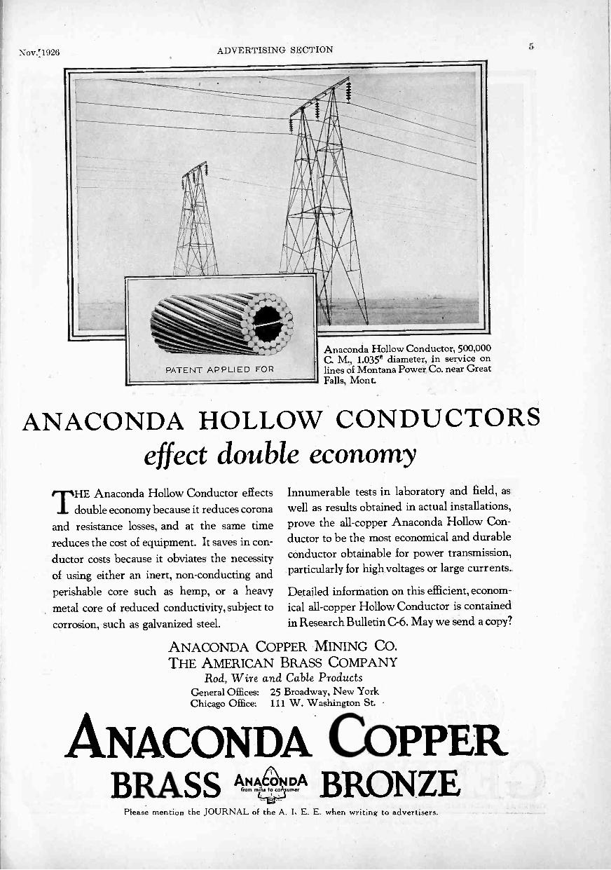
Nov.!1926 ADVERTISING SECTION 5
zortztirriPr'
PATENT APPLIED FOR
Anaconda Hollow Conductor, 500,000C. M., 1.035" diameter, in service onlines of Montana Power Co. near GreatFalls, Mont.
ANACONDA HOLLOW CONDUCTORSeffect double economy
THE Anaconda Hollow Conductor effectsdouble economy because it reduces corona
and resistance losses, and at the same timereduces the cost of equipment. It saves in con-ductor costs because it obviates the necessityof using either an inert, non -conducting andperishable core such as hemp, or a heavymetal core of reduced conductivity, subject tocorrosion, such as galvanized steel.
Innumerable tests in laboratory and field, aswell as results obtained in actual installations,prove the all -copper Anaconda Hollow Con-ductor to be the most economical and durableconductor obtainable for power transmission,particularly for high voltages or large currents.
Detailed information on this efficient, econom-ical all -copper Hollow Conductor is containedin Research Bulletin G6. May we send a copy?
ANACONDA COPPER MINING CO.THE AMERICAN BRASS COMPANY
Rod, Wire and Cable ProductsGeneral Offices: 25 Broadway, New YorkChicago Office: 111 W. Washington St.
ANACONDA COPPERBRASS ANAn to°coluDmer BRONZE
Please mention the JOURNAL of the A. I. E. E. when writing to advertisers.
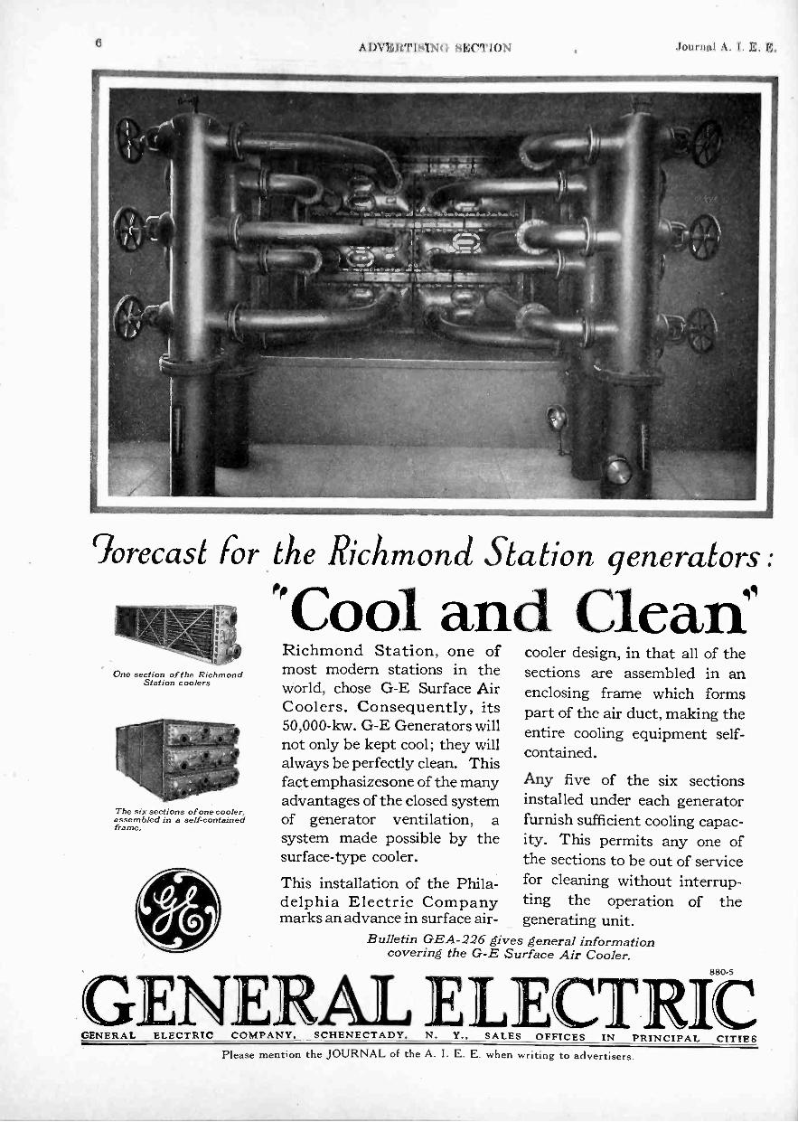
6 A 1)V1i; !CPIS! NI til,;( "I'l()N Jimirnal A. I. F.
%recast For the Richmond Station generators
One section of the RichmondStation coolers
The six sections of one cooler,assembled in a self-containedframe.
"Cool and Clew:ftRichmond Station, one ofmost modern stations in theworld, chose G -E Surface AirCoolers. Consequently, its50,000 -kw. G -E Generators willnot only be kept cool; they willalways be perfectly clean. Thisfact emphasizesone of the manyadvantages of the closed systemof generator ventilation, asystem made possible by thesurface -type cooler.
This installation of the Phila-delphia Electric Companymarks an advance in surface air-
cooler design, in that all of thesections are assembled in anenclosing frame which formspart of the air duct, making theentire cooling equipment self-contained.
Any five of the six sectionsinstalled under each generatorfurnish sufficient cooling capac-ity. This permits any one ofthe sections to be out of servicefor cleaning without interrup-ting the operation of thegenerating unit.
Bulletin GEA-226 gives general informationcovering the G -E Surface Air Cooler.
GENERAL ELECTRICGENERAL ELECTRIC COMPANY, SCHENECTADY, N. Y., SALES OFFICES IN PRINCIPAL CITIES
Please ment;on the JOURNAL of the A. I. E. E. when writing to advert;sers.

Nov. 1926 ADVERTISING SECTION 7
This portable De LavalTransformer Oil Purifier atthe Dix Dam :plant of Ken-tucky-HydroElectric Com-pany keeps both insulatingand lubricating oil clean anddry.
Clean, dry oilfor DixDam plant
Oil used at the Dix barn plant of the Kentucky -Hydro Electric Company is maintained at highefficiency by means of the portable De Laval Trans-former Oil Purifier shown above. A good part ofthe time the machine is operated as a stationary unitin the oil room, but it is a simple matter to move italongside a transformer or oil circuit breaker whichneeds dehydrating, oprf or that matter, to take it to asubstation miles out in the country.The chief engineer at Dix Dam states that thismachine has given very satisfactory service and hefinds it far superior to older types of oil filteringapparatus.Here is a big point to remember when consideringoil purifying methods: The disc construction of
the De Laval bowl which so greatly increases thepurifying efficiency of the machine also makes itpossible to design the entire machine along soundengineering lines... The bowl operates at a lownumber of revolutions per minute and is shaped sothat it spins naturally like a top. These are twinpoints of excellence which in a large measure ac-count for the many years of trouble -free service thatDe Lavals will give. Moreover, this disc construc-tion makes it possible to provide in the bowl a spacefor storing solid impurities removed from the dilwhere they cannot interfere with the effectiveness ofpurification.
Mail the coupon for information on what this hasmeant for others and what it can mean for you.
The De Laval Separator Company165 Broadway, New York 600 Jackson Blvd., Chicago
DE LAVAL PACIFIC COMPANYSan Francisco
De LavalOil Purifiers
1111IM=. .1=1=11 . 111111
Please send Bulletin containing further information re-garding the De Laval Oil Purifier as checked below:
O Purification of turbine lubricating oil.O Purification of Diesel lubricating oil and fuel oilO Dehydration of transformer oil. (Stationary Plant.)O Dehydration of transformer oil. (Portable Outfit.)
Name
CompanyJ. Ad. -637T
Address
Please mention the JOURNAL of the A. I. E. E. when writing to advertisers.

8 ADVERTISING SECTION Journal A. I. E. E.
23eati1/ul and ll'ellDesigned9?iciunand Station, The Thiladelphia Electric Company System
GENERALGENERAL ELECTRIC COMPANY, SCHENECTADY, N.
Please mention the JOURNAL of the A. I. E. E. when writing to advertisers.

Nov. 1926 ADVERTISING SECTION 9
1-ichmondon
Stone WebsterEngineers
MONG the modern steam power stations that have been placed1-L in operation during the past few years, the Richmond Stationof The Philadelphia Electric Company System is outstanding inmany respects. The location, the bliilding design (both from thestandpoint of operation and appearance), the protective features,the arrangement and uniformity of equipment to obtain utmostreliability, the operating efficiency -all received careful consider-ation and were subjects of the most painstaking investigations.The result is a source of much satisfaction to the operatingcompany and does great credit to the community.
The equipment in the first section of the Richmond Stationincludes the following furnished by General Electric:
2 -60,000 -kw. Turbine Generators2-Generator Air Cooler Equipments2-Generator Voltage Regulators
62-FHK-130 15,000 -volt Oil CircuitBreakers
58 -25,000 -volt gang -operated Discon-necting Switches
88-FKR-132B Oil Circuit Breakers600-Instrument Transformers
6-Current-Limiting Reactors forgenerators
63-Current-Limiting Reactors forfeeders
6-Motor-Generator Sets1 -30,000 -volt Testing Transformer1 -300,000 -volt Kenotron Cable Test-
ing Set130-Motors, totaling 6360 h. p. for
station auxiliaries
174-2
ECT RICOFFICES IN PRINCIPAL CITIES
Please mention the JOURNAL of the A. I. E. E. when writing to advertisers.

10 ADV Wri SING HECT1ON .14)(ininl A. I. K. FL
o Serve You evenThe photographs here cannot tell the entire story,but you will get from them an indication of theadditions that have recently been made to theKuhlman Factory-additions that will enable usto serve you and other transformer users evenbetter than we have in the past.
The increase and improvement is not only infactory space, but also in equipment and person-nel. The greater space permits arrangement of
equipment for more efficient production. Thenew building provides better light and morepleasant working conditions. These improve-ments are reflected in the product and the benefitsare thus realized by the purchasers of KuhlmanTransformers.
Another fact-these additions have been madepossible and necessary by the ever-growingdemand for Kuhlman Transformers.
Write for the Transformer Handbook A. 1. E. E 210
KUHLMAN ELECTRIC CO.BAY CITY, MICHIGAN
MUM ZDUA,Y11Ira&oeig mmIsmoPOWER- DISTRIBUTION - STREET LIGHTING
Please mention the JOURNAL of the A. I. E. E. when writing to advertisers.

Nov. 1926 ADVERTISING SECTION 11
a 2P- 771 ti-tt
c
tr rifle' trr!r1.1
.1
Graham -A nderson-Probst & White. Chicago Aransas.John Griffiths & Son Co.. Chicago Coruna/ Controctoni I rancid Electric Co., Chicago - Electrical Contractors
FirI isw-simpro
It I 41,-41-04;
The New UNION STATION, Chicago, Wired with
American &Americore
Rubber -covered WireTHE new Chicago Union Station - one
of the finest railroad stations in theworld, and Chicago terminal for four greatrailroads is equipped with every knownpractical convenience for the travelingpublic. It is electrically wired throughout,from foundation floor to roof top withAmerican Steel & Wire Company AmericoreWire.
In selecting the hundreds of thousands offeet of rubber covered electrical wire needed
CHICAGO 2011 So. 14. S.B. Stro4
CLEVELAND Rockal.Ilor 111.1,
DETROIT FM et First Mr..'CINCINNATI Union Tram lad.
BUNNEAPOUS -ST. PAULMeV dolga Nal Ilk. 11114., 14. Paul
Company's
for safely wiring this great new Chicago rail-road station, the most rigid specificationswere adopted. The fact that American Steel& Wire Company wire answered the speci-fications in every detail, expresses mostforcibly the uniform and dependable qualityof the product.
Let us send you an indexed catalogue andhandbook of Electrical Wires and Cables.Estimates furnished promptly from any ofour offices in all of the principal cities.
SALES OFFICESST. LOUIS .1116 Dl... Str.a.t NEW TORE .
KANSAS OTT. 117 Gre..4 A BOSTON ...OKLAHOMA CITY
I.e.. Nliaa1 11.1.4 1114 PITTSBURGH
/IMMINGHAM M.,. /144.PHILADELPHIA
MEMPHISUnion end Plasito N..k /11.1a. ATLANTA
30 Cbarrh Siraat WORCESTER 11 Crewe Straw. DALLAS ...... 11144
1115 Franklin Sireei
Prick 111.11.
BALTIMORE 12 Se. flier's. SireralDENVER ..11irla n.1. 01.1.
Wid.a.r /IdaBUFFALO 870 Ellicott 31roall
101 Ai...it. 0t,. WILKIESBARM/ Min... 11.4k Bldg. SALT LASS CITY Walks( Pk 1111.
UNITED STATES STEEL PRODUCTS COMI'ANY, tian Francisco, Los Portland, Seattle
1,11,,n 11, It II Ill NA I . of the All I when writii, ti. advrrtisers.

I''\ I i1 I I CI MK( "I'l N iiitirintl .1. I F. I.:.
AnotherDOSSERT
SERVICE . .
And here are a lot more serv-ices on which Dosserts willsave your time and money
Connecting cables, stranded or solidwires, rods and tubing.Connecting two conductors of samesize or different sizes.Connecting wires to cables, cables torods or tubing.Connecting conductors at right angles.Making three-way splices at rightangles or other angles or with wiresparallel.Connecting branch circuit to maincircuit.Connecting one or two conductors tolug direct or at an angle.Connecting wires to studs.Connecting one or two cables toanchor.To equalize load on two feeders.Connecting to service boxes andcutouts.Connecting grounds.Connectors for all iron pipe sizes oftubing.Special connectors for special services.
Write for the Dossert 20th YearBook which shows the line andthe data.
DOSSERT & COMPANYH. B. Logan, Pres.
242 West 41st St. New York, N. Y.
. on the lines ofthe Atlantic CityR.R.... Reading Systemat Camden, N. J.
Dossert Cable Taps used toconnect the horn gap disconnect-ing switch leads to the powerlines.
Please mention the JOURNAL of the A. I. E. E. when writing to advertisers.

Nov.'1926 ADVERTISING SECTION 13
MATTHEWSDISCONNECT -
BLADE
THEVACUUM FUSE
CARTRIDGE
On Dead Short Testsby power companies everywhere Matthews Fuswitches regularly prove amazingcertainty and economy of short control. In recent tests, as high as 53 consec-utive shorts, without injury to the box, have demonstrated perfect rupturing.
So completely have Matthews Fuswitchesovercome common faults in fuswitch designand operation that they mark an astonish-ing step forward in low cost maintenance.Consecutive shot tests, time and timeagain, reveal absolute certainty of rupturewithout slightest damage to box. Send fordetailed information.
Vacuum Fuse CartridgeThe Matthews vacuum principle, doubletube cartridge insures positive rupture ofthe heaviest surges, with simultaneous dis-charge of gases so directed that the vacuumformed in the lower tube positively extin-guishes the arc, so the arc cannot get to thelower contact midway between contacts.
10 Year Box Guarantee"The Wood Eternal," thoroughly seasoned,linseed oil treated, branded Tidewater Cy-press, is used. The three-ply roof is coppercovered. Heavy brass screw fasteningsthroughout-no nails. The door carries no
64
part of the fuse unit to cause interruptionof service during complete inspection offuse and contacts. It opens upward, fasten-ing automatically at 90 degrees, this featureis patented. Closes tight at bottom, pre-venting entrance of birds or of metallic gas-es after rupture. The entire box is coatedwith paint of high dielectric value whichalso has exceptional weather resistance andthorough insulation. Stands surface leakagetest of thousands of volts per inch. Eachbox for encasing Types OK and HQMatthews Fuswitches and DisconnectingSwitches is guaranteed to withstand weath-ering for a period of ten years. Send for de-tails of this guarantee on Matthews Fu -switch boxes.
Other AdvantagesCurrent leakage, danger to men and dam-age to property are avoided by excessiveflashover resistance-spacings stand fourtimes more than given ratings. Wet processporcelain of high tensile strength, repre-senting the highest development in resis-
tance to either dry or wet flashover, is usedfor support mountings and entrance bush-ings. Entrance wires may be admitted fromeither right or left side. Contact lugs doublysecured to resist' vibration. By simple sub-stitution of Matthews Disconnect Blade forthe patented vacuum fuse cartridge, theMatthews Fuswitch affords instant, lowcost dual service. Gives perfect protecteddisconnect service without need for ware-housing extra switches. In addition to fu -switches you need stock only the disconnectblades.
Read Bulletin 501Learn exactly why Matthews Fuswitchesand Disconnect Switches represent the out-standing triumph in this division of main-tenance supplies. See why they are bring-ing new conceptions of power company ser-vice to communities everywhere. How theybring rapid location and repair with mini-mum interruption of service, as well as low-er costs and maximum safety to men andapparatus. Write today.
W. N. MATTHEWS CORPORATION3706 Forest Park Blvd. St. Louis, U. S. A.
MpTTM EWSFUSWITCH ESand DISCONNECTING SWITCHES
Ask About TheseMatthews FuswitchesMatthews Disconnecting SwitchesMatthews Scrulix Anchors
Matthews Adjustable ReelMatthews Guy ClampsMatthews Slack PullerMatthews Cable Clamps
Matthews Lamp GuardsMatthews TelefaultMatthews TeleheightDistributors in all Principal Cities
Please mention the JOURNAL of the A. 1. E. E. when writing to advertisers.
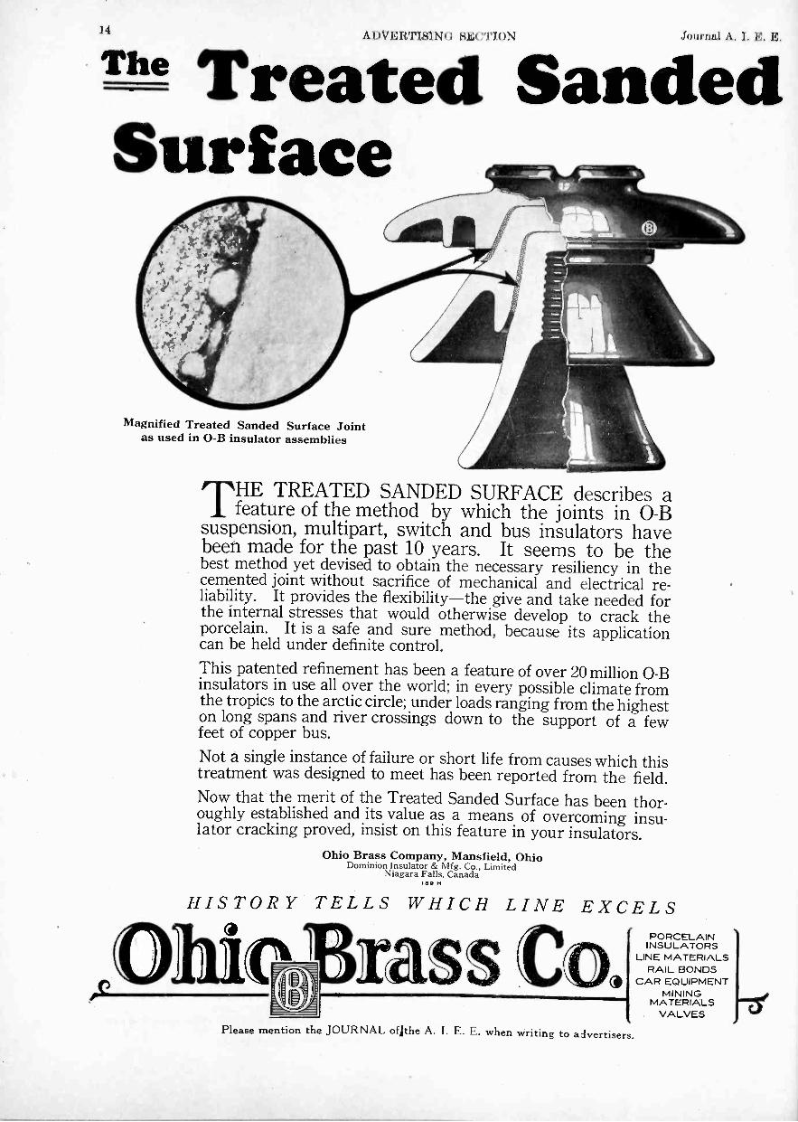
A IWERTISI NCI Si'(: "PION Journal A. I. B. H.
The Treated SandedSurface
Magnified Treated Sanded Surface Jointas used in O -B insulator assemblies
THE TREATED SANDED SURFACE describes afeature of the method by which the joints in 0-B
suspension, multipart, switch and bus insulators havebeen made for the past 10 years. It seems to be thebest method yet devised to obtain the necessary resiliency in thecemented joint without sacrifice of mechanical and electrical re-liability. It provides the flexibility-the give and take needed forthe internal stresses that would otherwise develop to crack theporcelain. It is a safe and sure method, because its applicationcan be held under definite control.This patented refinement has been a feature of over 20 million O -Binsulators in use all over the world; in every possible climate fromthe tropics to the arctic circle; under loads ranging from the higheston long spans and river crossings down to the support of a fewfeet of copper bus.Not a single instance of failure or short life from causes which thistreatment was designed to meet has been reported from the field.Now that the merit of the Treated Sanded Surface has been thor-oughly established and its value as a means of overcoming insu-lator cracking proved, insist on this feature in your insulators.
Ohio Brass Company, Mansfield, OhioDominion Insulator & Mfg. Co., Limited
Niagara Falls, Canadalee H
HISTORY TELLS WHICH LINE EXCELS
,Ohie rass CaPlease mention the JOURNAL ofjthe A. I. E. E. when writing to advertisers.
PORCELAININSULATORS
LINE MATERIALSRAIL BONDS
CAR EQUIPMENTMINING
MATERIALSVALVES -a?

Nov. 1926 ADVERTISING SECTION 15
In a restrictedresidential district lloo Feet
underground
Economic substation locationsare you taking advantage of them?
It has been proved manytimes that the extra expenseof automatic control is soonrepaid by reduced oper-ating and maintenance costsand by improved service.
The most economic location for a substation depends uponload and system conditions, but the expense or difficulty ofmanual operation often makes this location impracticable.However, it is possible to take advantage of such a locationby installing G -E Automatic Switching Equipment.
Substations thus controlled are operating successfully 1100feet underground in a salt mine, where a small station wouldnot justify the expense of an operator; in a restricted resi-dential district, where elimination of noise requires a sound-proof, and hence nearly airtight, construction; in a sewagedisposal plant, where hydrogen sulphide fumes are constantlypresent; and in many other unusual locations.
But G -E Automatic Switching Equipment does more thanenable you to secure the most economic location-for it alsooperates promptly, at least cost, and with accuracy, safety,and reliability.
461.2
GENERAL ELECTRICGENERAL ELECTRIC COMPANY, SCHENECTADY, N. Y., SALES OFFICES IN PRINCIPAL CITIES
Please mention the JOURNAL of the A. I. E. E. when writing to advertisers.

16 ADVERTISINn SE("11()N Journal A. I. 10:.
7he"rule of thumb'KING THUMB rules no more. The rule of
thumb, with all its costly guesswork, has noplace in Western Electric telephone making.
Here exact measuring standards are the rule,precise in many cases to the ten -thousandth part ofan inch. And this habit of being exact controlsevery factory activity-in the systematic planningof the great task of telephone production, in manu-facturing to known standards of quality, in con-stantly improving methods of work-not in hap-hazard experiment but by scientific attack by agroup of skilled industrial engineers.
At the same time, as makers of the nation'stelephones, Western Electric is meeting its respon-sibility by holding down the cost of telephoneapparatus to a figure well below the increased costof general commodities.
The liquid gauge,which measures tothe one-one-hundred-thousandthofan inch.
Looks like a bomb, but really a little"dark room" which permits the in-spector to know exactly whether a tinyswitchboard lamp comes up to the mark.
estem ElccnicSINCE 1882 MANUFACTURERS FOR THE BELL SYSTEM
Please mention the JOURNAL of the A. I. E. E. when writing to advertisers.

Nov. 1926 ADVERTISING SECTION 17
SOMETHING NEWand Just What You Have Been Waiting For!
16440E OV
Roller -Smith CO.EIEMLEMEM. PA, U S A.No. 47892
Real Pocket PortableDirect and Alternating Current
Ammeters,Voltmeters, Volt -Ammeters
and WattmetersROLLER -SMITH Types HTD andHTA.. Small enough for your pocket, yourtool kit or your traveling bag.
Compact and light enough to satisfy themost critical.
Accurate and rugged enough to suit themost exacting requirements.
A wide enough variety of ranges to covermany tests that have heretofore requiredlarge portables.
Send for New Bulletins AE- l io and AE -15o.
Use the coupon.
"Over thirty years' experienceis back of ROLLER -SMITH"
FOLLERSMITH COWAN"Electrical Measuring and Protective Apparatus I
.4.1
MAIN OFFICE WORKS12 Park Place, NEW YORK Bethlehem, Penna.
Offices in principal cities in U. S. A. and Canada.Representatives in Australia, Cuba and Japan.
ROLLER -SMITH COMPANY, 12 Park Place,New York City.
Gentlemen:Please send me ROLLER -SMITH Bulletins Nos. AE -110
and AE -150.
Name
Company
(Full Size) Address StatePlease mention the JOURNAL of the A. I. E. E. when writing to advertisers.

18 SI.:( "I'loN Journal A. I.
Double Commutator Generator,7500 amperes at 8 volts
Generators25 to 25,000 Amperes
Direct Connected to
Motors
G -E Synchronous Motor,200 h. p., .8 p. f., 3 -phase,
60 cycles, 2200 volts, 240 r. p. m.
Double Commutator Gen-erator, 7500 amperes
at 8 volts
15000 -AMPEREUNIT
OPERATING AT THE RIM GALVANIZING PLANT OF THE
FIRESTONE STEEL PRODUCTS CO.
Installed in 1926 CHANDEYSSON ELECTRIC CO., ST. LOUIS, U. S. A.
Please mention the JOURNAL of the A. I. E. E. when writing to advertisers.

19Nov. 1926 ADVERTISING SECTION
ConditOil Circuit Breaker
Frames areMassive andRIGID
Rigidity assures stability, proper function-ing of the mechanism, positive contactalignment on all poles, and strength to resistunbalanced stress and strain.
Manufacturers of Electrical Protective DevicesBOSTON, MASS
Northern Electric CompanyLIMITED
Sole Distributor for the Dominion of Canada
TYPE D-18.
SPECIFICATIONS :-800 Amperes or less, 15,000 volts; 1200 Amperes, 7500 volts. Two, three and four pole. Manually orelectrically operated. Interrupting capacity: 3600 Amperes at 15,000 volts. 72
VA
/ /.
/ //f/
Please mention the JOURNAL of the A. I. E. E. when writing to advertisers.

211 ti1.:1''I'I1N Journal .1. I. K. E.
Bakelite insulated Damsel Electro-Gauge, made by the Damsel Electro Gauge Co., Columbus, Ohio.
"Without Bakelite we would have beenunable to make our gauge"
This statement by the Damsel ElectroGauge Company, Columbus, Ohio, sum-marizes the importance of Bakelite in theconstruction of a very useful automotiveaccessory-an electrically operated gaso-line gauge.
A feature of this device is the automaticillumination of the indicator dial when thegasoline level falls to 2M gallons. Thevital part of the control mechanism is adisc of Bakelite molded I% in. indiameter, in which is solidly em-bedded a series of accurately spacedmetal contacts. When tested bythe underwriters' laboratories atChicago, this Bakelite part suc-cessfully withstood a 500 volt A Ctest-although the service for which
it is designed involves only low voltage. Ina vibration test, 600 heavy vibrations perminute, applied during eight consecutivehours, did not damage the Bakelite part.
Through the use of Bakelite the ideas ofmany designers have been made practicaland the performance of many devices hasbeen improved. The experience of ourengineers, and the facilities of our researchlaboratories, are offered without obligation,
to manufacturers interested in de-termining the possibilities ofBakelite in connection with theirparticular products.
Write for Booklet No. 3, "BakeliteMolded," and interesting descrip-tion of Bakelite and its uses.
BAKELITEMOLDED
BAKELITE CORPORATION247 Park Ave., New York, N. Y. Chicago Office: 636 West 22nd St.BAKELITE CORPORATION OF CANADA, LTD., 163 Dufferin Street, Toronto - - Ontario, Can
BAK LITETHE MATERIAL OF A THOUSAND USES
'"The registered Trade Mark and Symbol shown above may be used ordy on products made from materialsmanufactured by Bakelite Corporation. Under the capital -13" is the numerical sign for infinity. or unlimitedquantity It symbolizes the infinite number of present and future uses of Bakelite Corporation's products.,
Please mention the JOURNAL of the A. I. E. E. when writing to advertisers.

Nov. 1926 ADVERTISING SECTION 21
Although the bare Bel-denmold Bakelite van-ity case or match boxillustrated takes a beau-tiful finish, in some carsthe Beldenmold is cov-ered to match the up-holstery.
This picture showsa BeldenmoldBakelite vanitycase used in a pop-ular sedan.
eldenmold Replaces WoodLooks Better-Costs Less
HINK ofcases and match
holders in auto-mobiles, which formerlywere made of wood, arenow made of BeldenmoldBakelite. Why? Because itmakes a neat, durable casethat is far more substantialthan wood-and the cost isless. When used for uncov-ered receptacles it takes abeautiful, high polished fin-ish-for covered receptacles
it provides asmooth, even sur-face to which gluereadily adheres.
1LIOR many purposes in awide variety of indus-
tries Beldenmold is replac-ing wood and metal withresults that are surprisinglysatisfactory. Perhaps thereis a place in your businessfor Beldenmold parts. Ourengineering department isat your service. Just furnisha sample of the part youneed and let us tell you whatBeldenmold can do for you.More than likely we cansave money for you, too!Get our Beldenmold Book-let. Use the coupon.
Belden Manufacturing Company,2316B So. Western Ave.,Chicago, Illinois
Of course we want to know all aboutthe money saving possibilities of Belden -mold. Send us the Beldenmold Booklet.
Name
Address
Please mention the JOURNAL of the A. I. E. E. when writing to advertisers.

, A DV E la I sl N( sl.:( "I' I ( r\. .1, 'II iud 1 I I I
rERRANTI
43
4(Non -nu !virile rout Iron
.404,.., - Ferruntl-Duwmon Putent No. 20-15118.
v......,,....,
, ...___ N OMAG OPENS A NEW FIELDr ./ arz....41" .
.. FOR THE DESIGNER OF ELEC-TRICAL MACHINERY AND AP-
41'PARATUS.
IT COMBINES, IN A UNIQUE WAY,HIGH RESISTANCE AND LOWPERMEABILITY, AS SHOWN BY
44
444
THE FIGURES IN THE ADJACENTBase for a large Oil -Switch TABLE.
.1
4Al
4MagneticPerme-ability
Maximum.
SpecificResistance
Micr9-ohmsper cm. cube.
.
._
.
imi
4Ordinary Cast Iron
NOMAG . .
Brass . . .
330.00
1.031 -00
95.0
140.07.5
,,i
.
11 # .4 ' '
4
.4....i , -
. 1 1 - ' . '' '-, " i' - ' 7?::''4.1 .4i 1:
... 11P' ........tv,,,_,
.. _
,JI
4
111111......1111. ti,
,A %N.
1.,,,,: \
114.
Resistance Grid
End -ring for a Turbo -Alternator. Weight 31 tons.Ferranti, Ltd., The Ferranti Meter &Hollinwood, Transformer Manufacturing
EnglandCo., Ltd.
Toronto, Canada 4.
4.Please mention the JOURNAL of the A. I. E. E. when writing to advertisers.
Nov. 1926 ADVERTISING SECTION 23
0 / TaperedRoller
TAPERED design, POSITIVELY 4LIGNED ROLLSand Timken -made steel give Timken Bear-ings their extreme thrust and radial capacity.Higher all-around load capacity permits com-pact mountings. Compact mountings shortenthe shaft. Thus Timken Bearings largely offsetthe increased size which is necessary for en-closed motors.As in any type of Timken -equipped motor,the Timken Bearings themselves can be soperfectly enclosed, and they run so free offriction that the lubricant lasts for months ormore. Timken lubrication starts when the motordoes, which gives still more wear -prevention.
Timkens actually mean that the bearings willlast as long as any part of the motor, withalmost no attention, while improving everyphase of performance.
THE TIMKEN ROLLER BEARING CO., CANTON, OHIOTechnical information regarding bearing sizes and their mountings can be securedfrom the Timken Roller Bearing Service & Sales Company's Branches located in thefollowing cities: Atlanta. Boston, Buffalo. Chicago, Cincinnati, Cleveland. Dallas.Denver, Detroit, Kansas City, Los Angeles. Memphis, Milwaukee, Minneapolis,Newark, New York, Omaha, Philadelphia, Pittsburgh. Richmond, St. Louis, San
Francisco, Seattle, Toronto, Winnipeg
Please mention the JOURNAL of the A. I. E. E. when writing to advertisers.

2-1ADVERTISI N( I SE( "I'IoN
Motor Abilityis Limited by
Bearing Ability
Ask our engineers for moredata-or write for catalogs904, 905 and 915.
A motor can stand what its bearings will stand-and no more. It will last as long as its bearings-and no longer.
With "Norma" Precision Ball Bearings in successfulmonth -after -month operation at speeds up to 5o,000R.P.M.--
And with "Hoffmann" Precision Roller Bearingsstanding up month after month at speeds up to20,000 R.P.M.---
Need you look further for an answer to the question"what are the bearings to use for dependable motorservice ?"
Because-obviously-a bearing that is safe at thesesuper -speeds, has a still higher factor of safety at theusual motor speeds.
FIVICM1A-1-07FFMANN BEARINGS WRPVRATIVN5tama7rd- Connecticut
PRECISION BALL. ROLLER AND THRUST BEARINGS
Please mention the JOURNAL of the A. I. E. E. when writing to advertisers.

Nov. 1926 ADVERTISING SECTION
This Silver Strand(Reg )
now marks the shunts of allNational Pyramid Brushes
ON ANY brush -equipped electrical ma-chine, look at the brush shunts. Lookfor the Silver Strand. It is the visibleidentifying mark on all National Pyra-mid Brushes-your guarantee of satis-factory brush performance.
All shunts of National PyramidBrushes now bear this Silver Strandas an identifying mark, visible to themost casual glance. The familiar lettersNCC, the three pyramids and the gradenumber will still be found on the brushitself for your guidance in purchasing
CHICAGO, ILL.551 West Monroe St.
Phone: State 6092
and installing. When the brush is inservice, the Silver Strand in the shunt isa visual sign to all that here is a NationalPyramid Brush, supremely suited forthe work for which it is designed.
Thousands of brushes are now in usebearing this shunt, which has the sameconductivity as the former unmarkedshunts. The Silver Strand is a mark thatindicates, but does not affect, the per-fection of performance you have learnedto expect from National PyramidBrushes. Look for the Silver Strand.
NationalPyramid Brushes
Manufactured and guaranteed by
NATIONAL CARBON COMPANY, I N C .Carbon Sales DivisionCleveland, Ohio San Francisco, Cal.
Canadian National Carbon Co., Limited, Toronto, OntarioEmergency Service Plants
PITTSBURGH, PA. NEW YORK, N. Y.7th Floor, Arrott Power Bldg. No. 3, Barker Place 357 West 36th St.
Phone: Atlantic 3570 Phone; Lackawanna 8153
BIRMINGHAM, ALA.1824 Ninth Ave., N.Phone: Main 4016
Please mention the JOURNAL of the A. I. E. E. when writing to advertisers.

26 Journal A. I. 14:.A DVERTISINl; SE( l'ION
. 0041 ..... 101P ...... "" 6. ..... !.11;. ,
Oh .0.44 ...... .i..0 II
......... V. a
The Logical Source of SupplyFor Magnet Wire and Coils
The plain facts are that Dudlo resources, products, and servicemake Dudlo the logical source of supply
First: Volume. Volume reflects the abilityto supply quantity on short notice.It also reflects organization,facilities, financial strength andpopularity of product.
Second: Experience. The combined experi-ence of Dudlo magnet wire and coilexperts affords resources that arenot duplicated.
Third: Engineering Facilities. The Dudloengineering staff and experimentallaboratories offer buyers an expertfree service. They function as ifthey were a part of the buyer's ownorganization.
Fourth: Location. Fort Wayne is centrallylocated on trunk line railroads.With private side tracks directlyconnecting, unsurpassed shippingfacilities are made possible.
Fifth: Branch Offices. Branch offices andwarehouses at Newark, Chicago,St. Louis, San Francisco and otherpoints, are prepared to efficientlyserve those nearer to them than tothe Fort Wayne factory.
Sixth : Service. First, last, and always, thewhole Dudlo organization is gearedto and revolves around a servicethat leaves no loop hole for otherthan complete and uninterruptedsatisfaction.
.111=1,
DUDLO MANUFACTURING CORPORATION, FORT WAYNE, INDIANA412 Chamber of Commerce Bldg. 160 North La Salle Street 4153 Bingham Ave. 274 Brannan St.
NEWARK, N. J. CHICAGO, ILL. ST. LOUIS MO. SAN FRANCISCO, CALIFORNIAPlease mention the JOURNAL of the A. I. E. E. when writing to advertisers.

Nov. 1926 ADVERTISING SECTION 27
0UT on the open stretches and over the hills, into the trail of thesinking sun, follow the Gray Goose of the Wills Sainte Claire.
Men who possess that mysterious gift which creates and dares toventure, have built and are building the Wills Sainte Claire automobile.
Dozens of EC &M Automatic Compensators were placed on the roofof their machine shop building because space beneath that roof wasneeded for more machinery, placed where they must withstand thezero weather of Michigan's winters and the baking heat of its summersun, where no ordinary electrical equipment would be expected to standup, but where these men dared to place them.
For over five years these EC &M Oil -immersed Automatic Compen-sators for starting the electric motors in the plant below, from pushbuttons placed near the machines, have been working steadily underthese most trying weather conditions and have justified the confidenceof the men who placed them there.
THE ELECTRIC CONTROLLER Sc MFG. CO.BIRMINGHAM -BROWN -MARX BLDG. PHILADELPHIA-WITHERSPOON BLDG
CHICAGO-CONWAY BLDG. CLEVELAND OHIO PITTSBURGH-OLIVER BLDG.CINCINNATHENATIONAL BANK BLDG. SAN FRANCISCO -CALL BUILDINGDETROIT -DIME BANK BLDG. LOS ANGELES -THOMAS MACHINERY CO. SEATTLE -570 COLMAN BLDG.NEW YORK -50 CHURCH ST. AMERICAN BANK BLDG. TORONTO -TRADERS BANK BLDG
Please mention the JOURNAL of the A. I. E. E. when writing to advertisers.

ADVERTISING SECTION Journal A. 1. E.
When You BuyCondensers
When you buy condensers whatdo you demand?
Accuracy! Low Power Factor!Permanent Capacity!
Dubilier condensers meet theserequirements. They are used inpractically all transmitting sta-tions and U. S. Governmentinstallations.
Dubilier coupling condensers forpower line telephony are su-:preme.
Dubilier consulting engineers arealways at your service-theycan help you too.
4377 Bronx Blvd., New York, N. Y.
DubilierCONDENSER AND RADIO CORPORATION
2-.
L.-
E 102 Decade ResistancesE
E- E.
The 102 Decade Resistance boxes present aconvenient arrangement of standard resistances.
L--The resistances used are non -inductive and of
extremely low capacity, the Ayrton Perrymethod of winding being employed. g
The accuracy of adjustment is 0.1% on units.1'above 5 ohms resistance.
Convenient two, three and four dial decadearrangements include a range of one tenth theone hundred thousand ohms.
The Type 102 Boxes are particularly wellsuited for use in bridge set ups where anaccurate and easily variable resistance isrequired.
.; gBulletin 211E on request.E E-
E 2Prices $24.00 to $95.00E gE gGENERAL RADIO COMPANY
30 State Street Cambridge, Mass.E E
ELECTROSTATIC CONDENSERSFOR ALL PURPOSES
There are over 200 standard "FARADON" conden-sers on which immediate deliveries can be made.Complete new catalogue will be sent on request.Those interested in Carrier Current Coupling Conden-sers should ask for copy of Bulletin 101.
The engineering staff of the Wireless SpecialtyApparatus Company will co-operate fully withthose having special equipment under consider-ation. Estimating data, quotations or anyother information furnished promptly on request.
Wireless Specialty Apparatus Co.,Jamaica Plain, Boston, Mass.
Established 1907
g gEE. -
g D U N C AE
E. Watthour Meters E-
E EE
E.Ez
Model M2.
Accurateand
DependableWrite for bulletins
E --
.g.*
--I
a =E === THE ELEMENTS OF OUR BUSINESS= == == oSTAQ.=
E s=g_ =
EE.-M.
am .A
S. 4.._'',g1 '4,,-, =
,...xa a
.-
UND E.E=
TRADE-MARM E -g Automatic StartersE= Circuit Breakers Pressure RegulatorsRemote Switches
DUNCAN ELECTRIC MFG. CO.Lafayette. Irad.
Float Switches Speed RegulatorsHand Starters Transfer SwitchesMagnet Switches Valve ControlWRITE FOR CATALOG
Sundh Electric Company, Newark, N. J.Branch Offices or Sales Representatives in Principal Cities
Please mention the JOURNAL of the A. I. E. E. when writing to advertisers.

Nov. 1926 ADVERTISING SECTION 29
17 plates .00035 Mfd. Max.Cat. No. 251B, Price $3.50
23 plates, .0005 Mfd. Max.Cat. No. 251C, Price $4.50
From Start to FinishTrue
Straight Line FrequencyEVERY single part of the
Pacent True Straight LineFrequency Condenser wasespecially designed and con-structed for real straight linefrequency. operation.
When you buy a PacentStraight Line Frequency Con-denser, you are purchasing aproduct that is the result of18 months engineering re-search and experiment, andcan be absolutely sure of per-fect straight line frequencyoperation with wide, accuratespacing of stations.
Full information on request.
PACENT ELECTRIC CO., INC.91 SEVENTH AVENUE NEW YORK CITY
Canadian Licensed Manufacturer:White Radio Limited, Hamilton, Ont.Manufacturing Licensees for Great Britain
and Ireland:Igranic Electric Co., Ltd., London and
Bedford, England
PacentRADIO ESSENTIALS
WESTONRectangularSwitchboardInstruments
A. C. Ammeters, Voltmeters and Watt-meters, Reactive Component Meters,Frequency Meters, Power FactorMeters, Triplex Ammeters andD. C. Voltmeters and Ammeters.
THEY fill every power switchboardneed. Their great popularity is large-
ly due first to their high Weston stand-ard of performance and durability andto the numerous advantages of therectangular type. This rectangularcase, developed by Weston engineers,makes possible savings in switch-board space, gives greater readabil-ity, standardization of mountingand exceptionally simple andpleasing appearance. COur en-gineers will be glad to showyou the space savings you maymake in particular switch-board plans and to furnishyou with complete infor-mation and specifications.
S IN2-7-1 j
tbrativtglitifiSVO/
WESTON ELECTRICAL INSTRUMENTCORPORATION
48 Weston Avenue, Newark, N. J.STANDARD THE WORLD OVER
WESTON/Pioneers since 1888
Please mention the JOURNAL'of the A. I. E. E. when writing to advertisers.

ADVERTISING SECTION Journal A. I . E. E.
av,'-tezei
T
I MIT the Sangamo ElectricV Company's exhibit at the
Sesqui-Centennial Exposition;Machinery Palace, Building 5.
,,...,,..L..._....-ri...L.,-T.....--.L.r-r.L..-7....-r........r...,...-r
WORLD-WIDE1897 the Sangamo organization began opera-
tions in one room. Today, Sangamo is a world-wide organization with four factories on threecontinents, and representatives in the principalcities of the globe. The Sangamo products are:
Alternating -current Watthour Meters; Serviceand switchboard types; Direct -current Watthour
Meters, Service and switchboard types; Ampere -hour Meters, Service and switchboard types;Portable Test Meters; Distant -dial Mechanisms;Circuit -breakers; Current Shunts; InstrumentTransformers; Maximum -demand attachments.
Every sixteen seconds of every working day, aSangamo Meter is installed.
HE ASSOCIATED SANGAMO ELECTRIC COMPANIESSANGAMO ELECTRIC COMPANY
Springfield, Illinois
SANGAMO ELECTRIC COMPANYOF CANADA LIMITED
Toronto, Ontario
iBRITISH SANGAMO COMPANY LIMITED
Ponders End, Middlesex, England
ASHIDA ENGINEERING COMPANYOsaka, Japan
Please mention the JOURNAL of the A. I. E. E. when writing to advertisers.

ADVERTISING SECTIONNov. 1926 31
Accurate and well de-signed tools are essentialin the manufacture ofmeasuring instruments.Where clearances areclose Jewell tool makersmust build punches, dies,jigs and special tools,with exceptionally smalltolerances.
For Station Tie-Ins-
FrequencyMeter
Bristol's
Frequency
Meters
Load dispatchers like them and good reason why.It helps them to prevent bucking on station tie-ins.With the tie-ins that are made between different plantsand systems, it is very important that the frequency ofthe circuits be held within very close limits.Load dispatchers who are responsible for tying in thecircuits have advised us that they have found Bristol'sFrequency Meters of great value and that they are veryenthusiastic about them.These instruments are available in models using roundsmoked charts and strip charts.Write for detailed information.
itheTristol Company 'Waterbury, ConnecticutPOP 26 IlARS
BRISTOL' S IALC011 DI FM..11,41111TRUMUN'rel
Instrument mechanismthat insures accuracyunder all conditions
Wattless current or "elec-trical froth", as it was re-cently called, is costing thecountry a large sum. Whenreducing idle' current lossesand raising the power factorof your load, you should in-stall the proper measuringinstruments.
The Jewell power factor meteron the crossed coil dynamometerprinciple with its proven featuresof stability and accuracy of indi-cation assures accurate powerfactor measurement.
JEWELL ELECTRICAL INSTRUMENT CO.1650 Walnut StreetCHICAGO, ILL.
..............,....................mimmimummmumminmimmiummummolimmi7
MIDfor
.EST FILTERED AIR
the Power Plant1111111MIIIMIIIMIIIIIIMIIMIMMIIIIIIIIIIIIMIIIIMIMIMMIIIIIMIIIMMIUMMIMMA= irall
=
E
....=E.
11
=
g
==.4:
EEa=
= g= 5= Clean Midwest Air Pays onPower Plant Diesel Engines Too I =1
=c
= This type B-3 Midwest Filter serves the 200 H. P.i Type Y Fairbanks -Morse engine of the Biggar Elec- sI tric Co., Biggar, Saskatchewan. aI The overall operating cost of less than 10c. a day
is repaid many times by reduced repair and mainte- g1 nance costs. E= Ask Dept. E for complete performance reports on E.
Midwest installations in your field.=
nummumtimmumummiumulummumummuumiumimminimmummtummumumil
M IVI,
i .
AIR( }- LT. 00000 ....,,
BRADFORD PENNSYLVANIA
IMIIMMIIIIMMMUMMIIMIMMUMMIMMMUMMIMIMMMIMUMMIMMIMMMIMI
_Offices in Principal Cain
Please mention the JOURNAL. octlie A. I. E. E. when writing to advertisers.

DV ERTISIN( airi ail .1. I. l:. l:.
Low Voltage
LOW water destroys the reliabilityof the old mill wheel as a source
of power. Low voltage has thesame effect on motors that do not have the proper character.istics to meet low voltage conditions. MASTER GUARAN-TEED MOTORS will start and operate rated load on as lowas 70% normal voltage.
The Master Electric CompanyLinden & Master Ayes. Dayton, Ohio
STOCKS CARRIED IN PRINCIPAL CITIES
MASTERGUARANTEED MOTORS
" 7'2 " MASTER Less than 40°
S
Complete line of standard motors and generators,all sizes up to 75 h. p. and 50 kw. respectively.
Our Engineering Department at your service for all special applications
STAR ELECTRIC MOTOR CO.
almiumitionntionnimminutiminiimminmillimiounillimminiuminimunniumnummonffiniummillaillimilipz
tar Ball Bearing MotorsFor
HardUsage
A. C.and
D. C.
NEWARK, NEW JERSEY
I That Year in andYear out Service
ROWANImpedance
Starterfor
Squirrel CageInduction
Motors
Slurlevanl Elezrfit MorciFs-A. C. and D. C.; singleand polyphase-built insizes from small fractionalto 250 horse-power-de-signed to operate under aconstant full load whereuninterrupted service isdemanded.
B. F. STURTEVANT COMPANYHYDE PARK, BOSTON, MASS.
E
1 ELECTRICAL Inspections - Tests - ResearchTests may be used by the purchaser for the following purposes: =
= TESTING (1) To determine the quality of competing samples, This enables the purchase a=of the best quality for the money,
2. To make sure that shipments comply ,sith specifications, This makes possibleLABORATORIES (2)the assurance to the customer that shipments match buying samples, Eg. =(3) To furnish an impartial decision in case of disputes between purchaser and .::80th Street and East End Ave.E .manufacturer, == NEW YORK Testing places the whole buying problem on a sound basis.P.. E
FTHinglIVIIIIIIIIIIIIViiiitiliiiiiiiiIIIIMIIIIIIIIIIIIIiiiiiiiiiiiiiiiiimmiiminthiiviiiiVIVIIIIIIIIIVIIM I
Is your4 name on our159 mailing list
for bulletinsand catalog?
Please mention the JOURNAL of the A. I. E. E. when writing to advertisers.
MorganiteBrush Co., Inc.
519 W. 38th St.New York

Nov. 1926 ADVERTISING SECTION 33
miniumminuiniumininuminnintimuniumuniumminfluomintitimitmumuminomminionlimunitionnunitifluonominumnuming
CLASSIFIEDADVERTISEMENTSRATES. Forty cents per line; minimum charge
based on use of five lines; maximum space cannotexceed twenty lines.
Copy should be received by the 15th of themonth, for insertion in the following issue.
WANTED: RADIO TUBE PATENTS. The lar-gest exclusive manufacturer of radio tubes in the UnitedStates is ready to assist inventors and persons who haveuseful ideas or patents pertaining to radio tubes. Theseideas can take in processes and construction of 110 voltand other type tubes. This manufacturer has a wellequipped laboratory and the most up-to-date factorywhere all ideas can be brought to a successful conclusion,if at all practical from a manufacturing and merchan-dising standpoint. Satisfactory remuneration will bethe reward for ideas accepted. Address Class -117,JOURNAL of the A. I. E. E., 33 West 39th St., New York.
WANTED: Copies of the following back numbersof the JOURNAL of the A. I. E. E.: (1925 issues) JUNE,OCTOBER, NOVEMBER, DECEMBER. Wrappersreturning these copies should bear the sender's nameand address. Twenty-five cents will be paid for eachcopy received. Address American Institute of Electri-cal Engineers, 33 West 39th Street, New York.
A. I. E. E. STANDARDS
THE following approved STANDARDS areavailable in pamphlet form, at the prices
indicated, with a discount of 50% to A. I. E. E.members :
General Principles Upon Which Temperature Limitsare Based in the Rating of Electrical Machinery, (.20);Direct -Current Generators and Motors and Direct -Current Commutator Machines in General. (.40);Alternators, Synchronous Motors and SynchronousMachines in General, (.40); Synchronous Converters,(.40); Induction Motors and Induction Machines inGeneral, (.40); Direct -Current and Alternating -CurrentFractional Horse Power Motors, (.30); Railway Motors,(.30); Transformers, Induction Regulators and React-ors, (.40); Instrument Transformers, (.30); IndustrialControl Apparatus, (.40); Railway Control and MineLocomotive Control Apparatus, (.40); 011 CircuitBreakers, (.30); Disconnecting and Horn Clap Switches,(.30); Wires and Cables, (.40); Telegraphy and Tele-phony, (.30); Storage Batteries, (.20); Illumination,(.30); Electric Arc Welding Apparatus, (.40); ElectricResistance Welding Apparatus, (.30); Insulators, (.30);Symbols for Electrical Equipment of Buildings, (.20).
AMERICAN INSTITUTE ofELECTRICAL ENGINEERS33 West 39th Street New York
Dommitiminiiiimmillunimmimmimmommumniminimmimmomoomoomminmommiuminimminomumoimmoviimiumniiimmumg
Trade "ESCO" Mark
I ELECTRIC SPECIALTY CO. 1;7 Engineers and Manufacturers I
DESIGN - DEVELOP - PRODUCEa a-'17: Small Motors, Generators, Dynamotors,- Motor Generators, Rotary Converters, Etc. .
iFOR SPECIAL PURPOSES
= E-a ==
= Send Us Your Problems =E E-
a=
s---
Riummilimmiumininiuminitunuoitoommunitimionuminunuminiimunionimmiiiitionmintimiiiiimmimiiiiimoinitimummiud
222 South Street STAMFORD, CONN., U.S.A.
TRUMBULL
for years have stood themost exacting tests of scoresof the largest motor,dynamo, generator, andradio builders in the UnitedStates.Our Engineering Depart-ment is at your service.Write us concerning yourrequirements.
THE TRUMBULL STEEL COMPANY ;WARREN Mills, Laboratories and General Offices OHIO g_
THEI PIONEER MANUFACTURER
OF
Interpole & Ball BearingMotors
Y2 to 1000 II. P. D. C. and A. C.
S
ELECTRO DYNAMIC COMPANYaSa
Type "S" Bull Bearing Motorwith base and pulley
Established 1880BAYONNE, N. J.
Sales ()ffices in l'rInelptsl Cities
a
a
Please mention the JOURNAL. of the A. 1. E. E. when writing to advertisers.

A DVE 1SIN SECTII)N Awls 1. .
"no! Keep a - Running "
horse Power Century Repulsion -startInduction Single-phase Motor.
If the Load is Hard to StartUse Century Repulsion -start
Induction Single-phase MotorsCentury Repulsion -start Induction Single-phaseMotors start against heavy static loads, as inrefrigerating systems, air compressors, pumps,mixers and other machines of this character.
1
2
3
They develop the high starting torquenecessary to start heavy static loads.They start as repulsion motors, but,after attaining approximately fullspeed, the brush tension is removedautomatically and the motor then runsas an induction motor. The same con-struction as used for 23 years.Starting current is low-not in excessof 260% of full load current. Fusesused for full -load operation are usuallyof sufficient capacity to effect a start.
4 Any approved single -throw switch maybe used for starting.Suitable for all types of automatic orremote control service.The Century Wool -yarn System ofLubrication-applied to all one horsepower and smaller motors-assures atleast one year's continuous 24 -hour -per -day operation without re -oiling.
Temperature rise not more than 40° Centigrade.
Century Repulsion -start Induction Single-phaseMotors are built in all standard sizes from A to40 horse power.
Send for new Single-phase folders.
5
6
Century Electric Co.1806 Pine St. St. Louis, Mo.
For More Than 23 Years at St. Louis
A to 40 H. P. Ys to 40 H. P.
MOTORS
Hot Forged fromMolybdenum Steel!
INthe first place, the
balls which go into SRBBearings won their repu-tation long ago...estab-lished it, in years spentspeeding up and lighten-ing the loads of machinesin factory shops.
In the second place,these balls are now madefrom the newer, tougher,longer -lasting Molybden-um Steel...a steel whichproved its resistance inshell -battered army tanksduring the war. Durableas SRB Bearings were...this added still more yearsto their lives... at least25 % more in actual per-formance.
...and in the thirdplace, this tougher steelis shaped into balls bythe SRB
Hot Forgingprocess under BradleyHammers -a processknown by all metallur-gists to improve the grainstructure of steel... toshape it with minimumstrain... to toughen it...to strengthen it.
Now! Add point topoint and you will specify,not alone ball bearings,but SRB Bearings withBalls Hot Forged fromMolybdenum Steel.
SRB Service Now IncludesM -R-C Thrust Bearings
See our Exhibit in theFifth National Expo-sition of Power andMechanical Engineer-ing, Booth No. 336,Mezzanine Floor,Grand Central Palace,New York, December6th to 11th, 1926.
STANDARD STEEL AND BEARINGS INCORPORATEDPlainville
USE SRB BALL BEARINGS/- they'll last
Please mention the JOURNAL of the A. I. E. E. when writing to advertisers.
Connecticut

Nov. 1926
Pop Gets Hot About a Hot Motor
"Lad
ADVERTISING SECTION
I'm running to the ground every oneof these shutdowns we've had on the machines.They're nearly all due to your lack of regu-lar motor inspection. Here's a case wherethis fan was all loose and bent. Of coursethe motor heated up because you didn't catchthe trouble. Then you blame it on the motor."
35
"Yes, Pop-did you expect when you
bought those motors from your non -develop-ment gang that you'd have to spend the priceof the motors each year for private detectiveservice to watch over the crimes that the makerput into them? That could never-yes, NEVER-happen to a Linc-Weld motor because theymake their fans by punchings from He -Steelwelded (Stable -Arc of course) smack up againstthe rotor end plate."
See how they do it-Page 9 of the MotorBook. If you haven't a copy write to-
The Lincoln Electric Co., Cleveland, OhioMA -1
"Pi"'Weld"
Please mention the JOURNAL of the A. I. E. E. when writing to advertisers.
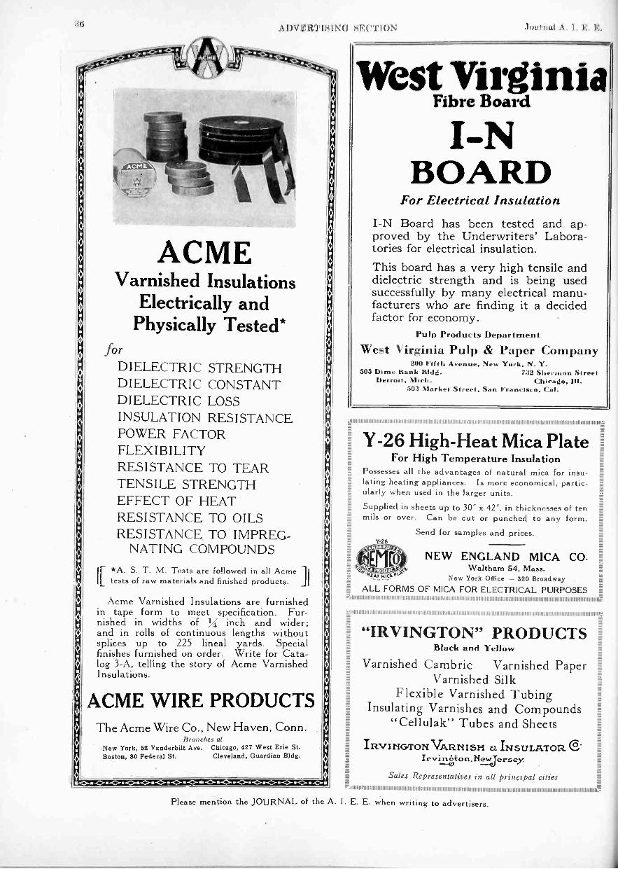
:11; A DVERTISINI; nlrnnl A I. I';.
ACMEVarnished Insulations
Electrically andPhysically Tested*
forDIELECTRIC STRENGTHDIELECTRIC CONSTANTDIELECTRIC LOSSINSULATION RESISTANCEPOWER FACTORFLEXIBILITYRESISTANCE TO TEARTENSILE STRENGTHEFFECT OF HEATRESISTANCE TO OILSRESISTANCE TO IMPREG-
NATING COMPOUNDS
IF *A. S. T. M. Tests are followed in all AcmeILtests of raw materials and finished products. jj
Acme Varnished Insulations are furnishedin tape form to meet specification. Fur-nished in widths of Y1 inch and wider;and in rolls of continuous lengths withoutsplices up to 225 lineal yards. Specialfinishes furnished on order. Write for Cata-log 3-A, telling the story of Acme VarnishedInsulations.
ACME WIRE PRODUCTSThe Acme Wire Co., New Haven, Conn.
Branches atNew York, 52 Vanderbilt Ave. Chicago, 427 West Erie St.Boston, 80 Federal St. Cleveland, Guardian Bldg.
Please mention the JOURNAL of the
West VirginiaFibre Board
I -NBOARD
For Electrical InsulationI -N Board has been tested and ap-proved by the Underwriters' Labora-tories for electrical insulation.This board has a very high tensile anddielectric strength and is being usedsuccessfully by many electrical manu-facturers who are finding it a decidedfactor for economy.
Pulp Products Department
West Virginia Pulp & Paper Company200 Fifth Avenue. New York. N. Y.
505 Dime Bank Bldd. 732 Sherman StreetDetroit, Mich. Chicado, Ill.
503 Market Street, San Francisco, Cal.
2
Y-26 High -Heat Mica Plate EE:
For High Temperature InsulationPossesses all the advantages of natural mica for insu-lating heating appliances. Is more economical, partic-ularly when used in the larger units.
Supplied in sheets up to 30' x 42', in thicknesses of tenmils or over. Can be cut or punched to any form.
Send for samples and prices.Y -26
ALL FORMS OF MICA FOR ELECTRICAL PURPOSES
NEW ENGLAND MICA CO.Waltham 54, Mass.
New York Office - 220 BroadwayCy1fAT P4ic?,
ff
A. I. E. E. when writing to advertisers.
"IRVINGTON" PRODUCTSBlack and Yellow
Varnished Cambric Varnished PaperVarnished Silk
Flexible Varnished TubingInsulating Varnishes and Compounds
"Cellulak" Tubes and Sheets
IRVINGTON VAIR.IIISH U INSULATOR C.Irviri.jyton,Newjersey.
Sales Representatives in all principal cities

Nov. 1926 ADVERTISING SECTION 37
ROTHMILL
TULLIS, RUSSELLCO. LTD.
HEAD OFFICE AND MILLSMARKINCH, SCOTLAND
CABLES-"TULLIS, MARKINCH"
'ESTABLISHED 1801:01SALES OFFICE
1, TUDOR STREET,
L°PkIBPPZFIETc;11
MANCHESTER OFFICEOFFICE378 CORN EXCHANGE BUILDING
CORPORATION STREETMANCHESTER
Please mention the JOURNAL of the A. I. E. E. when writing to advertisers.

38 A I) V HirrisiNcl sE( "'lox Journal A. I. I: H.
a
5.
ES
a
;It
E I
Lava Insulators are unexcelled ininstruments requiring a fixed relationof their parts under all conditions.Permanent in nature, lava is notsubject to variations in structureand composition.
AMERICAN LAVA CORPORATION
Chattanooga Tennesseefimmininimmolliffinioninornommimminimminimmomminiumuniumminlimmummo
J
L LAVA
NSULATORS
27-67 Williamson Street
Makesfine lines
forFiguringCheckingUnderscoringBlueprints,
etc.No.
Blue . . 1206Red. . . 1207Green . 1208Yellow. 1209Purple . 1210Brown. 1212Black. . 1213Orange. 1214White . 1215Light Blue
1216Pink . . 1217Light Green
1218
Trice$1.00per doz.
NIQUETHIN LEADColoredPencils
SOMETHING wantedfor years! A colored
pencil with the same di-ameter lead as in writingpencils; can be sharpenedin a pencil sharpener.An absolute necessityfor making fine lines incolor on charts andplans-something neverachieved before. The 12colors also enable eachexecutive to have hisown color symbol.
eAdopted byexecutives accountantsdraftsmen photographersartists teachers
useful to everyone
At all dealers, or write us direct
American Lead Pencil Co.204 Fifth Ave., New York
Makers of the famous 'Venus Pencils
Your health is ur greatest asset
BUY
CHRISTMAS
SEALS
and help us to keep
you healthy
THE NATIONAL. STATE AND LOCAL TUBERCULOSISASSOCIATIONS OF THE UNITED STATES
Please mention the JOURNAL of the A. I. E. F. when writing to advertisers.

Nov. 1926 ADVERTISING SECTION 39E=Contemporary Physics-.g
BY KARL K. DARROW,Member of the Technical Staff, Bell Telephone Laboratories.
A connected account of the chief phenomena uponwhich contemporary atomic theories are based, and anintroduction to the theories themselves. RecentlyPublished, $6.00.
Theory of Vibrating Systemsand Sound
E
for Telephonic Communication
D. VAN NOSTRAND COMPANY
BY IRVING B. CRANDALL,Member of the Technical Staff, Bell Telephone Laboratories.
Recently Published, $5.00.
Transmission Circuits
BY K. S. JOHNSON,Member of the Technical Staff, Bell Telephone Laboratories.
An epitome of facts on the theory and practical prin-ciples of transmission circuits and lines. Price $5.00.
X Rays and ElectronsBY ARTHUR COMPTON,
Professor of Physics at the University of Chicago.A detailed treatment of the phenomena of X Rays
and Electrons, covering the author's important originalinvestigations on the subject, as well as the valuable con-tributions of other scientists. Published October, $6.00.
8 Warren Street New York
The largest sellingQuality pencilin the world.
Also makers ofUnique Thin Lead
Colored Pencils12 colors
$1.00 per doz.
ENDSPENCILS4 c THE world's finest drawing pen-
-1- Cil" is what ' engineers callVENUS; because VENUS has given.to engineers a service incomparablymore perfect and complete thanthat of any other pencil.
For sketch, plan or blueprintVENUS is the pencil of precision.
17 black degrees, 3 copyingFor bold, heavy lines . . 6B -5B -4B -3BFor Writing. sketching . . 2B-B-HB-F-HFor clean, fine lines . 2H -3H -4H -5H -6HFor delicate, thin lines . . . 7H -811-9HPlain Ends, per doz $1 00Rubber Ends, per doz. . . . . 1.20
Al Stationers and Storesthroughout the World.
American Lead Pencil Co.204 Fifth Avenue, New York
BalkiteTrickle Charging
forTELEPHONEBATTERIES
Power for small telephone switchboards andprivate branch exchange boards is suppliedeither by storage or primary batteries or overwires from a central office. If storage batteriesare used, they are charged either over wiresfrom the central office or by a charging devicewhich operates from the local power supply.
Power furnished from the central office orby primary batteries is inherently expensiveand can be used only where
The best source of power is a storage battery,and the best way of charging such a battery isby the BALKITE TRICKLE CHARGINGSYSTEM.
Balkite Trickle Charging is simple, reliable.economical, and operates from the local alter-nating current power supply. It insures a con-stant power supply and releases telephonewires for revenue producing telephone service.
A complete booklet describing the systemand its operation is available on request.Write for it.
FANSTEEL PRODUCTS COMPANY, Inc., North Chicago, Ill.
F;1 f4A7-rEEL
alkiteBattery Chargers
FANSTEEL PRODUCTS COMPANY, Inc., North Chicago,litinoitGentlemen: Please send me a copy of Balkite Trickle Charging.
Name
Company
Address
Position
Please mention the JOURNAL of the A. I. E. E. when writing to advertisers.

1(1A DVERTISINI; SI,;( 7'1` I N Journal A. I. If:. H.
SELENIUMIn The
Tirex 60% Rubber Armorincreases the
Resistance to Abrasion50%
TIREX Cables have always been protectedby a sheath of the most wear -resisting rub-ber compound known to the art, but nowwith their new Selenium Rubber jacketthey have the toughest and most wear -
resisting protective armor ever made. Weartests prove this.
The process of vulcanizing rubber withSelenium was developed in our laboratoriesand is covered by U. S. patents Nos.1,249,272 and 1,364,055. This advance inthe art of rubber compounding increasesthe toughness or wear -resisting qualities ofa rubber compound fifty per cent.
The use of Selenium in rubber com-pounds to increase their wearing qualitiesis as important a development as wererubber sheathed cables, first put on the.market by us a few years ago.
.Write for further information.
SIMPLEX WIRE &CABE @MANUFACTURERS
201 DEVONSHIRE ST.. BOSTONCHICAGO SAN FRANCISCO NEW YORK
CLEVELAND SAINT AUGUSTINE
Please mention the JOURNAL
"AMERICAN BRAND"
Weatherproof Copper Wire and Cables
'MARK
"AME IcAN BRAND'tWEATHERPROOrWIRE AND CABLES
HAS NO EQUAL
COSTYou can buy weatherproof
wire cheap, but is it worthwhat it costa
"American Brand" givesyou more mileage per dollarswith a longer life on the line.
Get a sample and satisfyyourself.
American Insulated Wire & Cable Co.954 West 21st Street, Chicago
a
SE.,
S
PothlinElectrical Wires andCables. High in Con-ductivity and Reliability.JOhn A. Roebling's Sons Co.Trenton, New Jersey
ROE BLING
FT.
INSULATEDATLANTIC
WIRES
E.:
ATLANTIC INSULATED WIRE CABLE COMPANYRome, N. Y.
Including all types of rubber covered, and rubbercovered lead encased wires and cables, bare wire,)magnet wire, and flexible cords.
i.
WIRE PRODUCTSFor Varied Applications
We manufacture many types of wires, cordsand cables for specific uses. Among them are:
Rubber Covered Wire-Solid Conductor, StrandedConductor,Flexible Conductor,Extra Flexible Conductor.
Lamp Cords, Reinforced Cords, Heater Cord, Brew-ery Cord, Canvasite Cord, Packinghouse Cord, DeckCable, Stage Cable, Border Light Cable, FlexibleArmored Cable, Elevator Lighting Cable, Elevator Oper-ating Cable, Elevator Annunciator Cable. SwitchboardCables, Telephone Wire, Flameproof Wires and Cables,Railway Signal Wires, High Voltage Wires andCables. Automobile Ignition Cables, Automobile Light-ing Cables, Automobile Starting Cables, AutomobileCharging Cables. Moving Picture Machine Cable.
k --Boston Insulated Wire al Cable Co. gMain Office and Factory:Dorchester District Boston, Mass.
Canadian Branch, Office and Factory, Hamilton, Ont.Ezg--
of the A. I. E. E. when writing to advertisers.

Nov. 1926 ADVERTISING SECTION 41
E gg g_
o. g
....1. Z RDE:
E
gg=
12 S
--±Spiralweave
T. -
g g..t
g gg_ Eg E
-.4 TREE WIRE .__._.
The secret-E. EE Ng.- of its durability..-2
..- lies in the spiral weave.E EE E-
-T.- Highest grade rubber insulation, perfectly sealedfrom outside influences by the special rubberizedtape. Protective outer coat spiralwoven of hard, long ;_---.
staple cotton, thoroughly weatherproofed.E-- E
For protection from wear there is nothingwhich will surpass Hazard Spiralweave. E-
1 1Ask for our prices, stating size and voltage. Hazard Manufacturing Company
Samples on request. Wilkes-Barre, Pa.New York Pittsburgh Chicago Denver Birmingham Philadelphia :
E Maydwell & Hartzell, Agents, 158 11th St., San Francisco E==
MARKER
Something New in Electric CablesSPIRAL SPRING
,.------HOLLOW CORE
COPPERCONDUCTOR
PAPERINSULATION
PERFORATEDMETALLIZED=ER
LEAD=ATM
75KV TYPE H CABLE
The perforated, metallized paper over the insul-ation prevents ionization in gaps likely to existbetween cable insulation and the lead sheath. Usedif stresses are high.
STANDARD Type H Cableis winning recognition among large cable users onaccount of its dependability.
The Commonwealth Edison Co., Chicago, and theDuquesne Light Co., Pittsburgh, have installed75,000 -volt, single conductor, Type H cable on theirsystems.
A line to our nearest office will bring complete in-formation in regard to this economical type of cable.
Standard Underground Cable Co.BOSTON .
PHILADELPHIA ATLANTA CHICAGONEW YORK WASHINGTON PITTSBURGH DirrnoIT
SAN FRANCISCO
ST. LouisKANSAS CITY
SEATTLELos ANGELES
FOR CANADA: STANDARD UNDERGROUND CABLE CO., OP CANADA, LIMITED, HAMILTON, ONT.
Please mention the JOURNAL of the A. I. E. E. when writing to advertisers.

42 A I)V ERTISIN(l SE("I'ION .1()Iirtial A. I. le.. IG.
E
....
Er.
"BURKELECT" Moulded Controlead Terminal BlocksBy the use of these Terminal Blocks simplifications in all methods of control wiring circuits are possible
and offer many other advantages which are fully described in Bulletin H-2.
BURKE ELECTRIC COMPANYHIGH TENSION EQUIPMENT DIVISION
ERIE, PA.
The strength and life of the guy andmessenger wires are frequently thedetermining factors in the reliableand uninterrupted operation of anoverhead system.
When a guy or messenger rusts itsstrength and life are decreased.Its protective value is lessened.It is no longer a safeguard, but amenace.
TOPPERWELD"GUY AND WIRE
Does Not RustThus, the economic reasons justifying its useare- much longer life and protection fromrusting, with a consequent reduction in re-newals, labor and maintenance costs.You cannot afford to ignore the costly re,placement and damage losses caused byrusting. Minimize them by using Copperweld.
(ccOteclil o piaurojiMAIN OFFICE 6 MILLS1-BRA000CK P.O. RANK.N.RA
30 CHURCH ST. NEW YORK. 129 S. JEFFERSON ST. CHICAGO.
403 RIALTO BLDG. SAN FRANCISCO-
In Canada: Northern Electric Co., Ltd.
INEkALLIICINSULATINGCOMPOUNDS
For filling Cable Jointsand Potheads
on HighAroltage lines
c:4 safe specification"High dielectricStren th Approved
physicalproperties
INEItALLACELECTRIC COMPANY
1045 Washington Blvd.CHICAGO ILL.
,iI I IIIIIIII II III IIIIIIII III III II Itl II III IIIIINIIIIIIIIIIIIIIIIIIIIIIIIII IIIIIIIIII IIIIIIIIIIIIIIIIII'lllll 1111111 1111111 IIIII IIIIIIIIIIIIIIIIIIIIIIIIIIIIII 1111111 II IIIII IIIIIIIIIIIIIIIIIIIIIIIIIIIIIIIIIIIII II IIIII IIIIIIIIIIIIIIII1111111 III II IIIIIIIIIIIIIIIIIIIIIIII IIIII IIIIIIIIII IIIIIIIIII IIIIIIIIIIIIIIIIIIIII IIIII IIIIIIIIIIIIII IIIIIIII IIIIIIIIIIIIIIIIIIIIIIIIII IIIII Illillllllll IIIII IIIII II Illtltl IIII I IIII IIII
Pittsburgh Transformer CompanyLargest Manufacturers of Transformers exclusively
in the United States
Pittsburgh, Pennsylvania
Please mention the JOURNAL of the A. I. E. E. when writing to advertisers.
Nov. 1926 ADVERTISING SECTION 43
Exactly What You WantG & W design and manufacturepractically every device for the endof a cable. See catalog No. 26.
PotheadsSeries CutoutsPrimary CutoutsOil Fuse CutoutsOil Disconnects
Underground BoxesConduit BellsGround Pipe CapsGround Pipe PointsVault Units
MORE THAN PROTECTION FOR CABLE ENDS ES
SECTIONALIZE THELOW TENSION
WITH TYPE. "M"BOXES.
The Type'M' boxes'areibuilt for'one, two, three and four conductors, forany numbedof cables, for any size of cable, for 250 and 600 volts.Box operation does not cease when a cable is damaged. The G & W unitplan of construction makes each cable a unit right up to the bus. The linksare pulled. The cable head and cable are removed as a unit without dis-turbing the rest of the box. This is most valuable where service continuity isparamount.The busses are mounted under the panel for safety. The same internalarrangement is used for multiconductor cables or singles. The cables aresealed in the cable heads.The illustration shows a 250 volt, 400 ampere, two-way, three -conductor,Type M box for three one -conductor and one three -conductor cable.Sectionalize your present low tension cables with the Type M box.
G (&,W ELECTRIC SPECIALTY CO.7780 DANTE AVE. CHICAGO. ILL.
MoloneyTransformers
Every Installation FullyDemonstrates Moloney Quality
High quality performance hasbeen identified with the nameMoloney over a period of thirtyyears. During this time we haveapplied our complete efforts, timeand experience to giving industrybetter transformers.
Complete information furnished upon requets
Moloney Electric CompanySt. Louis, Mo.
Please mention the JOURNAL of the A. I. E. E. when writing to advertisers.

4.1 ADVERTISINII SECTION Journal .1. 1. E. K.
rE"
2400 Block, Fulton St. Chicago, Illinois ulllll 1111!1 lllltl 111 llllllllllllll!I 111111 IIIII II III IIIII 111111 II I IIIIIII IIIIIIIIIIIIIIIIIIIIII! I II II I I I I I I I I I I I I I II I II II III II II I I I!I I I I II I I I II II I II II I I I II II III IIIIIIII IIIIIIIII IIIII IIIII I II II II I I I II I I I I I I!III! I I II I II I I I I I I I I II I II II II IIIII II I II I II II I I I I I II II II I III II II 1111111 II II I I)11111II111lIIIIII IIIII IIIII IIIIIIIIIIIII IIIIIIIIII IIIIIIIIIIIIII! I II I II I I I II I I I I I I! I I III 111111 II I I I IIIII III II I II IIIIIIIIIIuuI
goommomminmanimmillinommimmummumniminmoinmomoinomoommuunionominiiiiiiiiiimiiiiiiiiiiiimmininimilionmilioimics
HOW MANY MANUFACTURERSHAVE A 750 K.V.TESTING ROOM?
We have
and it is
At Your Service OIN
Simpler
Stronger
Better-
Installation K -P -F60 KV. Switches,San Joaquin Lt. &Pwr. Corpn., Calif.
K -P -F POLE TOP SWITCHES consist of fewerparts, are more rugged and require less laborand material for installation than any other.Each pole becomes a self-contained unit.Switches are shipped ready to bolt on to cross -arm in place of line insulator.One crossarm supports it. Contacts are farremoved from insulators and a unique deviceprevents sticking or freezing.Send for bulletin K105 containing full details.
855-859 Howard St. San FranciscoK -P -F ELECTRIC CO.
MODELSMANUFACTURING STANDARDS
SALES DEMONSTRATION AND DISPLAY
Experimental Development under Client SupervisionUSE IN LITIGATION
MANUFACTURERS' & INVENTORS'ELECTRIC CO.
(Smith Building)228 West Broadway, N. Y. City
Incorporated 1897
lietm. jini1111111111111 00000 I 00000 11.1411111111111110111111111.111/1111
M.VgarTe.- ',
bomas QualityPORCELAIN INSULATORS
LINE HARDWAREWIRING PORCELAINS
andPorcelain Specialties
An American Standard since '73
THE R. THOMAS & SONS CO.New York East Liverpool, Ohio .,Cl'oinc,14fpnoBoston
Eaa
E111111111111111111111111111111111111111111111111111111111111111111111111111111111111111iiiiiiiiiiiiiiiiiiiiiiii I I I I I II I 1111111111111111111111111111111111111111111111111111111111111111111111111111111e
IIIIIIIIIIIIII IIIIII=a
aE==
Ea
==;I , Transmission Line Structures .
E. .i6
Etit
Q.E IRE
E.-- 00kQE i PACIFIC CLIAST STEEI C II M FAINtip .41=E kAl itE INIMitib.1._ It"'
Built of High Elastic Limit SteelRefined - Rolled - Fabricated -
Galvanized in Our Own Plants
MANUFACTURERS OF
OPEN HEARTH STEELSTRUCTURAL SHAPES MERCHANT AND REINFORCING BARS
TRANSMISSION TOWERS AND STRUCTURESGael Office: Rialto Bldg., San Francisco Plants: San Francisco, Portland, Seattle)
Please mention the JOURNAL of the A. I. E. E. when writing to advertisers.

Nov. 1926 ADVERTISING SECTION 45
STEEL
E
AMERICAN BRIDGE COMPANY
E-.
TOWERSand component parts
FOR ELECTRIC TRANSMISSION
71 Broadway, New York City
TOWER DEPARTMENTFrick Building, Pittsburgh, Pa.
Offices in Principal Cities
N r -
Lapp Insulatorsdo not fail!
LAPP INSULATOR CO., Inc.LE ROY, N. Y.
Sales RepresentativesBIRMINGHAM, ALA., Industrial Supply Co., 21 BrownAlarx Bldg.BOSTON, Van Rosen Co , 141 Milk St.CHARLOTTE, N. C., J. W. Fraser & Co., Commercial Bank Bldg.CHICAGO, Tmnselectrie Co.. Inc., 300 No. Michigan Ave.COLUMBUS, 0., Engineering Merchandising Syndicate, 000 Joyce Realty Bldg.DALLAS, TEX., J. IL Webb, 1021 Commerce St.DENVER, The 0. H. Davidson Equipt. Co., 1033 Tremont St.INDIANAPOLIS W. D. Hamer Co., 618 Tree. Terminal Bldg.KANSAS CITY, MO.. Power Machinery Co., 301 Dwight Bldg.LOS ANGELES, S. Herbert Lanyon, 210 Transportation Bldg.MINNEAPOLIS, J. E. Sumpter Co., 919 Security Bldg.NEW YORK crry, Shield Electric Co., 149 Broadway.PHILADELPHIA, Harris & Butler, Real Estate Trust Bldg.PITTSBURGH, Henry N. Muller Co., 2204 First National Bank Bldg.SAN ANTONIO, TEX. L. G. Bassett, 723 Navarro St.SAN FRANCISCO, S. Herbert Lanyon. 009 New Call Bldg.SYDNEY, AUSTRALIA, Chas. M. Terry.WELLINGTON, NEW ZEALAND, Jam. J. Niven & Co.
Please mention the JOURNAL
I I 0 I I I I I I I I I I 9 I LI II I I I I I I I I I I I I I I I I I I I I I I I I I I I I I I I I I I I I I I I I I I I I I I I I I I I I I I I I I I I I I I I I I I I I I I I I I I I I I I I I I I I I I I I I I I I I I I I I I I I I I I I I I I I I I I I I I I I I I I I I I I I I I I I I I I I I I I I I I I I I I I I I I I I I I I I I 0 I I 11..L'
1111111Pr-=
The New
THONER & MARTENSunderslung outdoordisconnecting switch
THE standard T & M underslung outdoordisconnecting switch, 800 amp., is now
equipped with choke coil.
Working pressure is 22,000 volts, dry flushis over 88,000 volts and wet flush over55,000 volts.
Other T & M features are the Bolt typelock and new sleet cover.
Write for further details
THONER & MARTENS463 Commercial St., Boston, Mass., U. S. A.
of the A. I. E. E. when writing to advertisers.

46 ADVEWPISING SE( "NON Journal A. I. K. K.
PROFESSIONAL ENGINEERING DIRECTORYFor Consultants in the Finds of Engineering, and Related Arts and Scirlice,,
Established 1857
ALEXANDER & DOWELLAttorneys at Law
PATENT, TRADEMARK ANDCOPYRIGHT CASES
902 F Street, N. W. Washington, D. C.
AMBURSEN DAMSHydroelectric Developments
Water Supply and Irrigation DamsDAMS ON DIFFICULT FOUNDATIONS
AMBURSEN CONSTRUCTION CO.Incorporated
Grand Central Terminal, New YorkKansas City, Mo. Atlanta, Ga.
THE AMERICAN APPRAISAL CO.Valuations and Reports
ofPublic utility, industrialand all other properties
Rate Cases Condemnation SuitsReorganizations Liquidations
NEW YORK MILWAUKEE1896 And Principal Cities 1926
W. S. BARSTOW & COMPANYIncorpora ted
Financial and OperatingManagers of
Public Utilities50 Pine Street New York
BATTEY & KIPPIncorporated
ENGINEERSComplete Industrial Plants
Power Plants & Electrical InstallationsEngineering Reports, Analyses & Appraisals
291 South LaSalle Street CHICAGO
BLACK & VEATCHConsulting Engineers
Water, Steam and Electric Power Investiga-tions, Design, Supervision of Construction,
Valuation and Tests.
Mutual Building KANSAS CITY, MO.
BYLLESBYENGINEERING AND MANAGEMENT
CORPORATION
New York
231 S. La Salle StreetCHICAGO
San Francisco
WALTER G. CLARKConsulting Engineer
Electrical, Mining and IndustrialReports
Supervision of Organization and Arrange-ments for Financing
LOS ANGELES NEW YORK1211 Insurance Exch. Bldg. 40 Wall St.
EDWARD E. CLEMENTFellow A. I. E. E.
Attorney and Expertin Patent Causes
Soliciting, Consultation, Reports,Opinions
McLachlen Bldg. Washington, D. C.700 10th St., N. W.
C. E. CLEWELLConsulting Engineer
Municipal Street Lighting SystemsFactory and Office Lighting
Engineering Bldg. Philadelphia, Pa.33rd and Locust Streets
HAROLD A. DANNE
LIGHT AND POWER
41 PARK ROW NEW YORK
DAY & ZIMMERMANN, Inc.Engineers
Power Plants, Sub -Stations,Transmission Lines, Industrial PlantsExaminations and Reports, Valuations,
Management of Public Utilities1600 WALNUT ST., PHILADELPHIA
New York Chicago
DAVID V. FENNESSY
Consulting Power Engineer
MILLS BUILDING EL PASO, TEXAS
FORD, BACON & DAVISIncorporated
ENGINEERS115 Broadway, New York
Philadelphia Chicago San Francisco
FRANK F. FOWLE & CO.
Electrical and MechanicalEngineers
MONADNOCK BUILDING CHICAGO
FREYN ENGINEERING COMPANYIndustrial Electric Power
Generation-Application-PurchaseCombustion EngineeringElectric Furnace Installations
CHICAGO PHILADELPHIA910 South Michigan Ave. 1500 Chestnut St.
M. H. GERRY, JR.Consulting Engineer
Electrical Transmission of PowerHydroelectric Developments
Steam and Diesel PlantsIndustrial Applications
1107 Hobart Building San Francisco
A. BARNETT GREEN
ENGINEERING PUBLICITY
1328 BROADWAY NEW YORK
EDITING - COMPILING - WRITING
L. F. HARZA
HYDRO -ELECTRIC ENGINEER
Monadnock Bldg. Chicago
AUGUSTUS M. HENRY
COUNSELOR AT LAW
(Patents and Patent Causes)
WOOLWORTH BLDG. NEW YORK
HOOSIER ENGINEERING CO.
Erectors ofTransmission Lines and Substations
325 South New Jersey StreetINDIANAPOLIS INDIANA
AKE your name and specialized servicewell known to the electrical industry
through a card in the ENGINEERING DIRECTORY
Please mention the JOURNAL of the A. I. E. E. when writing to advertisers.

Nov. 1926 ADVERTISING SECTION 47
sP:
. PROFESSIONAL ENGINEERING DIRECTORY iFor Consultants in the Fields of Engineering and Related Arts and Sciences
F--.==
P_
E
=E.
=
Dugald C. Jackson PUBLIC SERVICE William M. Stockbridge Victor D. BorstP:
E
Edward L. Moreland PRODUCTION COMPANYEngineers and Constructors STOCKBRIDGE & BORST ..-.
JACKSON & MORELAND-a.
Design and Construct: Power Plants,E.
=g Transmission Lines, Industrial Plants, Patent ers
CONSULTING ENGINEERS Highways, Railroad Shops and Terminals, Lawy
a Gas Plants, Commercial Buildingss.
El
41 PARKSiSt. James Ave. Boston, Mass.
Make: Examinations, Reports and Valuations ROW NEW YORK CITYP
P.*
80 PARK PLACE NEWARK, N. J. P.'
=2==
g."
PERCY H. THOMASConsulting EngineerELECTRIC POWER
Generation - TransmissionApplications
ChicagoNEW YORK120 BROADWAY
W. E. MOORE & CO.
E. S. LINCOLNConsulting Electrical Engineer
Designs Investigations Reports
Electrical Research Laboratory
594 Congress St. PORTLAND, MAINE
MCCLELLAN & JUNKERSFELDIncorporated
Engineering and ConstructionPower Developments-Industrial Plants
Electrifications-ExaminationsReports-Valuations
NEW YORK68 Trinity Place
EngineersPlans and Specifications for
Hydroelectric and Steam Power PlantsIndustrial Plants and Electric FurnacesUnion Bank Building Pittsburgh, Pa.
N. J. NEALL
Consulting Engineerfor
Electrical and Industrial Properties
12 PEARL STREET BOSTON, MASS.
NEILER, RICH & CO.Electrical and Mechanical
EngineersConsulting, Designing and
SANDERSON & PORTERENGINEERS
PUBLIC UTILITIES & INDUSTRIALSDesign Construction Management
Examinations Reports Valuations
Chicago New York San Francisco
STONE & WEBSTERIncorporated
Examinations Reports Appraisalson
Industrial and Public ServiceProperties
NEW YORK BOSTON CHICAGO
St. Louis
Supervising
481 So. Dearborn St. - - - Chicago
OPHULS & HILL, Inc.Formerly Ophuls, Hill & McCreery, Inc.
SARGENT & LUNDYIncorporated
Mechanical and ElectricalEngineers
1412 Edison Bldg., 72 West Adams StreetCHICAGO ILLINOIS
SCOFIELD ENGINEERING CO.Consulting Engineers
Power Stations Gas WorksHydraulic Developments Electric RailwaysExaminations & Reports Valuations
Philadelphia
Card space limitedto 1"x2" for eachadvertiser.
J. E. SIRRINE & COMPANYEngineers
Textile Mills; Hydro -Electric Develop-ments; Tobacco Products Plants; Cotton,Tobacco and General Warehousing; Indus-trial Housing; Steam Power Plants; Steam
Utilization.Greenville Chattanooga
South Carolina Tennessee
JOHN A. STEVENS
THE U. G. I. CONTRACTING CO.Engineers & Constructors
Power Developments, Industrial Plants, GasPlants, Transmission Systems, Appraisals
Broad & Arch Sts., PHILA., PA.421 Peoples Gas 928 Union TrustBldg., Chicago, Ill. Bldg., Pittsburgh, Pa.
VIELE, BLACKWELL & BUCKEngineers
Designs and ConstructionHydroelectric and Steam Power Plants
Transmission Systems Industrial PlantsReports Appraisals
49 WALL STREET NEW YORK
THE J. G. WHITEENGINEERING CORPORATION
Engineers-ConstructorsOil Refineries and Pipe Lines,
Steam and Water Power Plants,Transmission Systems, Hotels, Apartments,Offices and Industrial Buildings, Railroads43 EXCHANGE PLACE NEW YORK
J. G. WRAY & CO.Engineers
J. G. Wray, Fellow A.I.E.E. Cyrus G. Hill
Utilities and Industrial PropertiesAppraisals Construction Rate SurveysPlans Organization EstimatesFinancial Investigations Management
E EP:
P
P E
Es=
=CONSULTING ENGINEERS
112-114 WEST 42nd ST.,NEW YORK CITYIce Making and Refrigeration
Investigations and Reports
FARLEY OSGOODConsultant
Design, Construction, OperationInter -Connection
ofPUBLIC UTILITIES
National Bank of Commerce Building31 Nassau Street, New York, N. Y.
Tel.: Rector 7878 Cable Address: Fargood
Please mention the JOURNAL of the A. I. E. E. when writing to advertisers.
CONSULTING POWER ENGINEER
16 Shattuck StreetLOWELL MASSACHUSETTS
STEVENS & WOODINCORPORATED
Engineers and Constructors120 BROADWAY, NEW YORK
Youngstown, 0.
1217 First National Bank Bldg. ,Chicago
To be printed in the following
issue, copy for carjis must bereceived by the 20th of the month.

I,, A DV RTISI Nti SE(71oN riud A. I. K.
Classified Advertiser's Index for BuyersManufacturers and agents for machinery and supplies used in the electrical and allied industries.
Note: For reference to the Advertisements see the Alphabetical List of Advertisers on page 54.AIR COMPRESSORS
Allis-Chalmers Mfg. Co., MilwaukeeGeneral Electric Co., SchenectadyWestern Electric Co., All Principal Cities
AIR COMPRESSOR FILTERSMidwest Air Filters, E nc., Bradford, Pa.
AIR FILTERS, COOLINGMidwest Air Filters, Inc., Bradford. Pa.
AIR WASHERSSturtevant Company, B. F., Boston
ALARMS, TEMPERATURE, PRESSURECory & Son, Inc.. Chas., New York
A M METER COMPENSATING COILSMinerallac Electric Co., Chicago
AMMETER, VOLTMETERS(See INSTRUMENTS, ELECTRICAL )
ANCHORS, GUYMatthews Corp., W. N., St. Louis
ANNUNCIATORS, AUDIO -VISIBLECory & Son, Inc., Chas., New York
BATTERY CHARGING APPARATUSElectric Specialty Co., Stamford, Conn.Fansteel Products Co., Inc., North ChicagoGeneral Electric Co., SchenectadyWard Leonard Electric Co., Mt.Vernon, N. Y.Western Electric Co., All Principal CitiesWestinghouse Elec. & Mfg. Co., E. Pitts-
burghBEARINGS, BALL
New Departure Mfg. Co., The, Bristol, Conn.Norma -Hoffmann Bearings Corp., Stamford,
Conn.Standard Steel & Bearings, Inc., Plainville,
Conn.BEARINGS, ROLLER
Timken Roller Bearing Co., The, Canton, 0.BOOKS, TECHNICAL
Van Nostrand Company, D., New YorkBOXES, FUSE
General Electric Co., SchenectadyMetropolitan Device Corp. Brooklyn,N. Y.Western Electric Co., All Principal CitiesWestinghouse Elec. & Mfg. Co., Pitts-
burghBOXES, JUNCTION
G & W Elec. Specialty Co., ChicagoMetropolitan Device Corp., Brooklyn, N. Y.Standard Underground Cable Co., Pittsburgh
BRUSHES, COMMUTATORbon
Morganite Brush Co., Inc., New YorkNational Carbon Co., Ina., ClevelandWestinghouse Elec. & Mfg. Co., E. Pitts-
burghCopper Graphite
Morganite Brush Co., Inc., New YorkNational Carbon Co., Inc., ClevelandWestinghouse Elec. & Mfg. Co., E. Pitts-
burghBUS BAR FITTINGS
Delta -Star Electric Co., ChicagoGeneral Electric Co., SchenectadyWestinghouse Elec. & Mfg. Co., E. Pitts-
burghCABLE ACCESSORIES
Delta -Star Electric Co., ChicagoDossert & Co., New YorkG & W Electric Specialty Co., ChicagoGeneral Electric Co., SchenectadyMinerallac Electric Co., ChicagoStandard Underground Cable Co., PittsburghWestern Electric Co., All Principal Cities
CABLESSee WIRES AND CABLES
CABLEWAYSAmerican Steel & Wire Co., ChicagoRoebling's Sons Co., John A., Trenton, N. J.
CAMBRIC, VARNISHEDBelden Mfg. Co., ChicagoIrvington Varnish & Ins. Co., Irvington, N. J.
CARRIER CURRENT TELEPHONE EQUIP-MENT
Dubilier Condenser & Radio . Y.Western Electric Co., All Principal
Corp.,dities
Wireless Specialty Apparatus Co., BostonCIRCUIT BREAKERS
Air-EnclosedCutter Co., The, PhiladelphiaRoller -Smith Co., New YorkSundh Electric Co., Newark, N. J.Ward Leonard Electric Co., Mt.Vernon, N.Y.Western Electric Co., All Principal Cities
OilCondit Electrical Mfg. Corp., BostonGeneral Electric Co., SchenectadyWestinghouse Elec. & Mfg. Co., E. Pitts-
burghCLAMPS, GUY & CABLE
Matthews Corp., W. N., St. Louis.COILS, CHOKE
Burke Electric Co., Erie, Pa.General Electric Co., SchenectadyWestinghouse Elec. & Mfg. Co., E. Pitts-
burgh
COILS, MAGNETAcme Wire Co., New Haven, Conn.Belden Mfg. Co., ChicagoDudlo Mfg. Corp., Ft. Wayne, Ind.General Electric Co., SchenectadyWestinghouse Elec. & Mfg. Co., E. Pitts-
burghCONDENSATION PRODUCTS
Bakelite Corporation, New YorkCONDENSERS, COUPLING
For Carrier Current TelephoneDubilier Condenser & Radio Corp., New YorkWireless Specialty Apparatus Co., Boston
CONDENSERS, RADIODubilier Condenser & Radio Corp., New YorkGeneral Radio Co., Cambridge, Mass.Pacent Electric Co., New YorkWireless Specialty Apparatus Co., Boston
CONDENSERS, STEAMAllis-Chalmers Mfg. Co., MilwaukeeGeneral Electric Co., SchenectadyWestinghouse Elec. & Mfg. Co., E. Pittsburgh
CONDUIT, UNDERGROUND FIBREWestern Electric Co., All Principal Cities
CONNECTORS, SOLDERLESSDossert & Co., New YorkWestern Electric Co., All Principal CitiesWestinghouse Elec. & Mfg. Co., E. Pitts-
burghCONNECTORS AND TERMINALS
Belden Mfg. Co., ChicagoBurke Electric Co., Erie, Pa.Dossert & Co., New YorkG & W Electric Specialty Co., ChicagoWestern Electric Co., All Principal CitiesWestinghouse Elec. & Mfg. Co., E. Pitts-
burghCONTACTS, TUNGSTEN
Fansteel Products Co., Inc., North ChicagoGeneral Electric Co., Schenectady
CONTROL SYSTEMSWard Leonard Electric Co.. Mt. Vernon N. Y.
CONTROLLERSElectric Controller & Mfg. Co., ClevelandGeneral Electric Co., SchenectadyRowan Controller Co., BaltimoreSundh Electric Co., Newark, N. J.Ward Leonard Electric Co., Mt.Vernon, N. Y.Western Electric Co., All Principal CitiesWestinghouse Elec. & Mfg. Co., E. Pitts-
burghCONVERTERS-SYNCHRONOUS
Allis-Chalmers Mfg. Co., MilwaukeeElectric Specialty Co., Stamford, Conn.Westinghouse Elec. & Mfg. Co., E. Pitts-
burghCOPPER CLAD WIRE
Belden Mfg. Co., ChicagoCopperweld Steel Co., Rankin, Pa.Standard Underground Cable Co., PittsburghWestern Electric Co., All Principal Cities
CUT-OUTSCondit Electrical Mfg. Corp., S. BostonGeneral Electric Co., SchenectadyG & W Electric Specialty Co., ChicagoMetropolitan Device Corp., Brooklyn, N. Y.Western Electric Co., All Principal CitiesWestinghouse Elec. & Mfg. Co., E. Pitts-
burghDIMMERS, THEATRE
Ward Leonard Electric Co., Mt. Vernon, N. Y.DYNAMOS
(See GENERATORS AND MOTORS)DYNAMOTORS
Burke Electric Co., Erie, Pa.Electric Specialty Co., Stamford, Conn.
ELECTRIFICATION SUPPLIES, STEAMROAD
General Electric Co., SchenectadyOhio Brass Co., Mansfield, OhioWestinghouse Elec. & Mfg. Co., E. Pitts-
burghENGINEERS, CONSULTING AND CON-
TRACTING(See PROFESSIONAL ENGINEERINGDIRECTORY)
ENGINES Gas & GasolineAllis-Chalmers Mfg. Co., MilwaukeeSturtevant Company, B. F., Boston
OilAllis-Chalmers Mfg. Co., MilwaukeeSturtevant Company, B. F., Boston
SteamAllis-Chalmers Mfg. Co., MilwaukeeSturtevant Company, B. F., Boston
FANS, MOTORCentury Electric Co., St. LouisGeneral Electric Co., SchenectadyStar Electric Motor Co., Newark, N. J.Sturtevant Company, B. F., BostonWestern Electric Co., All Principal CitiesWestinghouse Elec. & Mfg. Co., E. Pitts-
burghFARM LIGHTING GENERATORS
Western Electric Co., All Principal CitiesWestinghouse Elec. & Mfg. Co., E. Pitts-
burgh
FIBREBelden Mfg. Co., Chicago
FIRE PROTECTION APPARATUSKidde & Co., Inc., Walter, New York
FLOW METERSCory & Son, Inc., Chas., New YorkGeneral Electric Co., Schenectady
FURNACES, ELECTRICGeneral Electric Co., SchenectadyWestinghouse Elec. & Mfg. Co., E. Pitts-
burghFUSES Enclosed Refillable
General Electric Co., SchenectadyWestern Electric Co., All Principal CitiesWestinghouse Elec. & Mfg. Co., E. Pitts-
burghEnclosed Non -Refillable
General Electric Co., SchenectadyWestern Electric Co., All Principal Cities
Open LinkGeneral Electric Co., SchenectadyMetropolitan Device Corp., Brooklyn, N. Y.Western Electric Co., All Principal Cities
High TensionDelta -Star Electric Co., ChicagoMetropolitan Device Corp., Brooklyn, N. Y.Western Electric Co., All Principal Cities
GEARS, FIBREGeneral Electric Co. ,Schenectady
GENERATORS AND MOTORSAllis-Chalmers Mfg. Co., MilwaukeeBurke Electric Co., Erie, Pa.Century Electric Co., St. LouisChandeysson Electric Co., St. LouisElectric Specialty Co., Stamford, Conn.Electro-Dynamic Co., Bayonne, N. J.General Electric Co., SchenectadyLincoln Electric Co., The, ClevelandMaster Electric Co., The, Dayton, 0.Star Electric Motor Co., Newark, N. J.Sturtevant Company, B. F., BostonWestern Electric Co., All Principal CitiesWestinghouse Elec. & Mfg. Co., E. Pitts-
burghGENERATING STATION EQUIPMENT
Allis-Chalmers Mfg. Co., MilwaukeeBurke Electric Co., Erie, Pa.General Electric Co., SchenectadyWestern Electric Co., All Principal CitiesWestinghouse Elec. & Mfg. Co., E. Pitts-
burghGROUND RODS
Copperweld Steel Co., Rankin, Pa.Western Electric Co., All Principal Cities
HEADLIGHTSOhio Brass Co., Mansfield, 0.
HEATERS, INDUSTRIALGeneral Electric Co., SchenectadyWestern Electric Co., All Principal CitiesWestinghouse Elec. & Mfg. Co., E. Pitts-
burghINDICATORS, LOAD
Cory & Son, Inc., Chas., New YorkINDICATORS, SPEED
Bristol Co., The, Waterbury, Conn.Roller -Smith Co., New York
INDICATORS WATER LEVELBristol Co., The, Waterbury, Conn.Cory & Son, Inc., Chas., New York
INSTRUMENTS, ELECTRICALGraphic
Bristol Co., The, Waterbury, Conn.Ferranti, Ltd., London, Eng.Ferranti Meter & Transformer Mfg. Co.,
Ltd., Toronto, Ont.General Electric Co., SchenectadyWestinghouse Elec. & Mfg. Co., E. Pitts-
burghIndicating
Bristol Co., The, Waterbury, Conn.Ferranti, Ltd., London, Eng.Ferranti Meter & Transformer Mfg. Co.,
Ltd., Toronto, Ont.General Electric Co., SchenectadyJewell Elec. Instrument Co., ChicagoRoller -Smith Co., New. YorkWestinghouse Elec. & Mfg. Co , E. Pitts-
burghWeston Elec. Inst. Corp., Newark, N. J.
IntegratingDuncan Elec. Mfg. Co., Lafayette, Ind.Ferranti, Ltd., London, Eng.Ferranti Meter & Transformer Mfg. Co.,
Ltd., Toronto, Ont.General Electric Co., SchenectadyRoller -Smith Co., New YorkSangamo Elec. Co., Springfield, Ill.Western Electric Co., All Principal CitiesWestinghouse Elec. & Mfg. Co., E. Pitts-
burghRadio
General Radio Co. Cambridge, Mass.Jewell Elec. Instrument Co., Chicago
Repairing and TestingElectrical Testing Laboratories, New YorkJewell Elec. Instrument Co., Chicago
Please mention the JOURNAL of the A. I. E. E. when writing to advertisers.

Nov. 1926 ADVERTISING SECTION 49
Today's topic in radio isbattery eliminators
Everyone interested in radio is talking eliminators. The new powertubes for receivers require higher plate voltages. This means that aneliminator must be used. Resistance is one of the essentials of everyeliminator, and this resistancemust carry power; in otherwords, it gets hot. Heat breaksdown an improperly made re-sistor. The surest way to pre-vent this happening is by using
Ward LeonardVitrohm Resistors
Electrical men know from experience that thereis only one permanently satisfactory resistance-a wire wound resistance, vitreous enamelled. Inbrief, Ward Leonard Vitrohm. It is practically in-destructible; non -inductive; always accurate, be-cause it started that way and time does not alter it.
For 34 years, Ward Leonard Vitrohm Resis-tors have been specified by technical men, becauseheat does not affect the enamel enclosure. Thenewest branch of the electrical industry radio-finds Ward Leonard prepared to furnishVitrohm resistors in forms that meet its needs.
Any desired resistance; handy kits containingassorted resistor units totalling 21,750 ohms; Edi-son base units; tab terminals and screw terminals;units for AC eliminators and units for DCeliminators; made in forms so compact that10,000 ohms can be furnished in the size of acigarette. High watts capacity.
Let us quote on your specifications.
Atlanta G. P. AtkinsonBaltimore J. E. PerkinsBoston --W. W. CaskillChicago- Weetburg Eng. Co.
Vitrohm Resistor Unit showing stepsin the process of manufacture
1
Porcelain -like tube.
2Resistive conductor of prac-tically zero temperatureco -efficient of resistivity.
3Mechanically strong, per-manent electrical connec-tion to terminal leads, withnegligible resistance.
4Unit is coated with vitre-ous enamel and fired at redheat. Enamel fused sotightly to wire and tubethat unit is practically onesolidified mass. This pro-motes rapid conduction ofheat. Firing "ages'" resis-tive conductor.
5Joints sealed in enameleffectively prevent corro-sion and loosening of parts.No other method providesan equally good joint.
6Vitreous enamel is the mostperfect known insulatingmaterial. It is moisture -proof and acid resisting,fully protecting resistiveconductor against deteri-oration.
Ward Leonar ctric Company37-41 South Street Mount Vernon. N. Y.
Cleveland -W. P. Ambos Co.Detroit-C. E. Wise Philadelphia W. Miller TompkinsLos Angeles-- -Bell ti Summon San
-W. A. Bittner Co.New Orleans --Electron Eng. Co.. Inc.
San F rancisco --Elec. Mat'l Co.Seattle T. S. Wood
Melbourne and Sydney, Australia --Warburton, Franki, Ltd.
Please mention the JOURNAL of the A. I. E. E. when writing to advertisers.
St. Louis-C. W. PieksenMontreal- Bishop Sales Corp.Toronto-D, M. Fraser, Ltd.London, Eng.-W. Geipel 63 Co.

Journal A. 1. E. E.50 ADVERTISING SE( "I'ION
Classified Advertiser's Index for Buyers-ContinuedINSTRUMENTS, ELECTRICAL-Continued
Scientific, Laboratory, TestingGeneral Electric Co., SchenectadyJewell Elec. Instrument Co., ChicagoMetropolitan Device Corp., Brooklyn, N. Y.Roller -Smith Co., New YorkWestern Electric Co., All Principal CitiesWestinghouse Elec. & Mfg. Co., E. Pitts-
burghWeston Elec. Inst. Corp., Newark, N. J.
TelegraphWestern Electric Co., All Principal Cities
INSULATING MATERIALSBoard
West Va. Pulp & Paper Co., New YorkCloth
Acme Wire Co., New Haven, Conn.Irvington Varnish & Ins. Co., Irvington, N.J.Minerallac Electric Co., ChicagoWestinghouse Elec. & Mfg. Co., E. Pitts-
burghComposition
American Lava Corp., ChattanoogaBakelite Corporation, New YorkBelden Mfg. Co., ChicagoWestinghouse Elec. & Mfg. Co., E. Pittsburgh
CompoundsMinerallac Electric Co., ChicagoStandard Underground Cable Co., PittsburghWestern Electric Co., All Principal Cities
FibreWest Va. Pulp & Paper Co., New York
LavaAmerican Lava Corp., Chattanooga, Tenn.
MicaNew England Mica Co., Waltham, Mass.
PaperAcme Wire Co., New Haven, Conn.Irvington Varnish & Ins. Co., Irvington, N.J.Tullis, Russell ee' Co., Ltd., London, Eng.
SilkAcme Wire Co., New Haven, Conn.Irvington Varnish & Ins. Co., Irvington, N.J.
TapeBelden Mfg. Co., ChicagoMinerallac Electric Co., ChicagoOkonite Co., The, Passaic, N. J.Western Electric Co., Ali Principal CitiesWestinghouse Elec. & Mfg. Co., E. Pittsburgh
VarnishesAcme Wire Co., New Haven, Conn.General Electric Co., SchenectadyIrvington Varnish & Ins. Co., Irvington, N. J.Minerallac Electric Co., Chicago
INSULATORS, HIGH TENSIONComposition
General Electric Co., SchenectadyGlass
Hemingray Glass Co., Muncie, Ind.Porcelain
General Electric Co., SchenectadyLapp Insulator Co., Inc., ReRoy, N. Y.Locke Insulator Corp., BaltimoreOhio Brass Co., Mansfield, 0.Thomas & Sons Co., R., East Liverpool, 0.Western Electric Co., All Principal CitiesWestinghouse Elec. & Mfg. Co., E. Pitts-
burghPost Type
Delta -Star Electric Co., ChicagoINSULATORS, TELEPHONE & TELEGRAPH
Hemingray Glass Co., Muncie, Ind.Western Electric Co., All Principal Cities
LAMP GUARDSMatthews Corp., W. N., St. LouisWestern Electric Co., All Principal Cities
LAVAAmerican Lava Corp., Chattanooga
LIGHTING FIXTURESCory & Son, Inc., Chas., New York
LIGHTNING ARRESTERSDelta -Star Electric Co., ChicagoGeneral Electric Co., SchenectadyWestern Electric Co., All Principal CitiesWestinghouse Elec. & Mfg. Co., E. Pitts-
burghLOCOMOTIVES, ELECTRIC
General Electric Co., SchenectadyWestinghouse Elec. & Mfg. Co., E. Pitts-
burghMAGNETIC SEPARATORS
Electric Controller & Mfg. Co., Cleve:andMETERS, ELECTRICAL
(SEE INSTRUMENTS, ELECTRICAL)MICA
New England Mica Co., Waltham, Mass.MOLDED INSULATION
Bakelite Corporation, New YorkBelden Mfg. Co., ChicagoBurke Electric Co., Erie, Pa.Westinghouse Elec. & Mfg. Co., E. Pitts-
burghMOLYBDENUM
Fansteel Products Co., Inc., North ChicagoMOTORS
(See GENERATORS AND MOTORS)OHMMETERS
Cory & Son, Inc. Chas., New YorkJewell Elec. Instrument Co. ChicagoRoller -Smith Co., New YorkWeston Elec. Instr. Corp. Newark, N. J.
OIL SEPARATORS & PURIFIERSDeLaval Separator Co., The, New YorkSharpies Specialty Co., The, PhiladelphiaWestinghouse Elec. & Mfg. Co., E. Pitts-
burgh
PANEL BOARDS(See SWITCHBOARDS)
PATENT ATTORNEYS(See PROFESSIONAL ENGINEERING
DIRECTORY)PLUGS
Delta -Star Electric Co., ChicagoGeneral Electric Co., SchenectadyWestern Electric Co., All Principal CitiesWestinghouse Elec. & Mfg. Co., E. Pitts-
burghPOLES, STEEL
American Bridge Co., PittsburghPacific Coast Steel Co., San FranciscoWestern Electric Co., All Principal Cities
POLES-TIES, WOODWestern Electric Co., All Principal Cities
POTHEADSG & W Electric Specialty Co., ChicagoStandard Underground Cable Co., PittsburghWestern Electric Co., All Principal Cities
PROTECTIVE DEVICESMetropolitan Device Corp., Brooklyn, N. Y.Western Electric Co.. All Principal Cities
PULLERS, SLACKMatthews Corp., W. N., St. Louis
PUMPSAllis-Chalmers Mfg. Co., Milwaukee
PUMPS, SPIRALCramp & Sons Ship & Engine Bldg. Co.,
The Wm., PhiladelphiaRADIO LABORATORY APPARATUS
General Radio Co., Cambridge, Mass.Westinghouse Elec. & Mfg. Co., E. Pitts-
burghRAILWAY SUPPLIES, ELECTRIC
General Electric Co., SchenectadyOhio Brass Co., Mansfield, 0.Western Electric Co., All Principal CitiesWestinghouse Elec. & Mfg. Co., E. Pitts-
burghREACTORS
General Electric Co., SchenectadyMetropolitan Device Corp., Brooklyn, N. Y.
RECTIFIERSFansteel Products Co., Inc., North ChicagoGeneral Electric Co., SchenectadyWestern Electric Co., All Principal CitiesWestinghouse Elec. & Mfg. Co., E. Pitts-
burghREELS, PAYOUT AND TAKEUP
Matthews Corp., W. N., St. LouisREGULATORS, VOLTAGE
Burke Electric Co., Erie, Pa.General Electric Co., SchenectadyWestern Electric Co., All Principal CitiesWestinghouse Elec. & Mfg. Co., E. Pitts-
burghRELAYS
Cory & Son, Inc.. Chas., New YorkElectric Controller & Mfg. Co., ClevelandWestinghouse Elec. & Mfg. Co., E. Pitts-
burghRESISTOR UNITS
General Electric Co., SchenectadyWard Leonard Electric Co., Mt. Vernon, N.Y.
RHEOSTATSGeneral Electric Co., SchenectadySundh Electric Co., Newark, N. J.Ward Leonard Electric Co., Mt. Vernon, N.Y.Western Electric Co., All Principal CitiesWestinghouse Elec. & Mfg. Co., E. Pitts-
burghROPE, WIRE
American Steel & Wire Co., ChicagoRoebling's Sons Co., John A., Trenton, N. J.
SEARCHLIGHTSGeneral Electric Co., SchenectadyWestinghouse Elec. & Mfg. Co., E. Pitts-
burghSHEETS, ELECTRICAL
Trumbull Steel Co., The. Warren, 0.SOCKETS AND RECEPTACLES
General Electric Co., SchenectadyWestern Electric Co., All Principal CitiesWestinghouse Elec. & Mfg. Co., E. Pitts-
burghSOLENOIDS
Acme Wire Co., New Haven, Conn.Belden Mfg. Co., ChicagoDudlo Mfg. Co., Ft. Wayne. Ind.Electric Controller & Mfg. Co., ClevelandGeneral Electric Co., SchenectadySundh Electric Co., Newark, N. J.Ward Leonard Electric Co., Mt.Vernon, N.Y.Westinghouse Elec. & Mfg. Co., E. Pitts-
burghSPRINGS
American Steel & Wire Co., ChicagoSTARTERS, MOTOR
Condit Electrical Mfg. Corp.. BostonElectric Controller & Mfg. Co. ClevelandGeneral Electric Co., SchenectadyRowan Controller Co., Baltimore, Md.Sundh Electric Co., Newark, N. J.Ward Leonard Electric Co., Mt.Vernon, N. Y.Westinghouse Elec. & Mfg. Co., E. Pitts-
burghSTEEL, SHEET & STRIPS
Trumbull Steel Co., The, Warren, 0.STOKERS, MECHANICAL
Sturtevant Company, B. F., BostonWestinghouse Elec. & Mfg. Co., E. Pitts-
burgh
SUB -STATIONSGeneral Electric Co., SchenectadyWestinghouse Elec. & Mfg. Co., E. Pitts-
burghSWITCHBOARDS
Allis-Chalmers Mfg. Co., MilwaukeeCondit Electrical Mfg. Corp., BostonGeneral Electric Co., SchenectadyMetropolitan Device Corp., Brooklyn, N. Y.Western Electric Co., All Principal CitiesWestinghouse Elec. & Mfg. Co., E. Pitts-
burghSWITCHES Automatic Time
Ferranti, Ltd., London, Eng.Ferranti Meter & Transformer
Ltd., Toronto, Ont.General Electric Co., SchenectadyMinerallac Electric Co., ChicagoSundh Electric Co., Newark, N. J.Westinghouse Elec. & Mfg. Co., E. Pitts-
burghDisconnecting
Burke Electric Co., Erie, Pa.Condit Electrical Mfg. Corp., BostonDelta -Star Electric Co., ChicagoGeneral Electric Co., SchenectadyK -P -F Electric Co., San FranciscoMatthews Corp., W. N., St. LouisThoner & Martens, Boston
FuseGeneral Electric Co., SchenectadyMatthews Corp., W. N., St. LouisMetropolitan Device Corp., Brooklyn, N. Y.Thoner & Martens, Boston
KnifeCondit Electrical Mfg. Corp., BostonElectric Controller & Mfg. Co., ClevelandGeneral Electric Co., SchenectadyMatthews Corp., W. N., St. LouisWestern Electric Co., All Principal CitiesWestinghouse Elec. & Mfg. Co., E. Pitts-
burghMagnetic
Ward Leonard Electric Co., Mt.Vernon. N.Y.Oil
Condit Electrical Mfg. Corp., BostonGeneral Electric Co., SchenectadyWestern Electric Co., All Principal CitiesWestinghouse Elec. & Mfg. Co., E. Pitts-
burghRemote Control
Condit Electrical Mfg. Corp., BostonGeneral Electric Co., SchenectadyRowan Controller Co., BaltimoreSundh Electric Co., Newark, N. J.Western Electric Co., All Principal CitiesWestinghouse Elec. & Mfg. Co., E. Pittsburgh
TANTALUMFansteel Products Co.,T nc., North Chicago
TELEGRAPH APPARATUSWestern Electric Co., All Principal Cities
TELEPHONE EQUIPMENTCory & Son, Inc., Chas., New YorkWestern Electric Co., All Principal Cities
TESTING LABORATORIESElectrical Testing Labs., New York
TOWERS, TRANSMISSIONAmerican Bridge Co., PittsburghPacific Coast Steel Co., San FranciscoWestern Electric Co., All Principal Cities
TRANSFORMERSAllis-Chalmers Mfg. Co.. MilwaukeeAmerican Transformer Co., Newark, N. J.Duncan Elec. Mfg. Co., Lafayette, Ind.Ferranti, Ltd., London, Eng.Ferranti Meter & Transformer Mfg. Co.,
Ltd., Toronto, Ont.General Electric Co., SchenectadyKuhlman Electric Co., Bay City, Mich.Moloney Electric Co., St. LouisPittsburgh Transformer Co., PittsburghWestern Electric Co., All Principal CitiesWestinghouse Elec. & Mfg. Co., E. Pittsburgh
FactoryAmerican Transformer Co., Newark, N. J.Kuhlman Electric Co., Bay City, Mich.Moloney Electric Co., St. LouisPittsburgh Transformer Co.. PittsburghWestern Electric Co., All Principal Cities
FurnaceAllis-Chalmers Mfg. Co., MilwaukeeAmerican Transformer Co., Newark, N. J.Moloney Electric Co., St. LouisPittsburgh Transformer Co., Pittsburgh
MeteringAmerican Transformer Co., Newark, N. J.Ferranti, Ltd., London, Eng.Ferranti Meter - & Transformer Mfg. Co.,
Ltd., Toronto, Ont.Pittsburgh Transformer Co., Pittsburgh
Mill TypePittsburgh Transformer Co., Pittsburgh
RadioAmerican Transformer Co., Newark, N. J.
Street LightingKuhlman Electric Co.' Bay City, Mich.Western Electric Co.. All Principal Cities
TROLLEY LINE MATERIALSGeneral Electric Co., SchenectadyOhio Brass Co., Mansfield, 0.Western Electric Co., All Principal CitiesWestinghouse Elec. & Mfg. Co., E. Pitts-
burgh
Please mention the JOURNAL of the A. I. E. E. when writing to advertisers.
Mfg. Co.,

Nov. 1926 ADVERTISING SECTION
111111111111
111111111111
SteamTurbo-
Generatorsduumimiiiiiiiiiimimummiii
12,500 kSteam TurbineGenerator Unitcomplete withSurfaceCondenser,Turbine -drivenCirculating andCondensatePumps, all ofAllis-Chalmersmanufacture.
111:11111111111111111111111111111111111
The relatively lowsteam velocities em-ployed in Allis-Chal-mers Steam Turbinescombined with lowblade velocities andhighest type of bladeconstruction insureslong blade life andsustained efficiency.
Serving Public UtilitiesMany public service companies testify to the advantages and appreciable sav-ings under the Allis-Chalmers plan of "Undivided Responsibility," where themanufacturer assumes complete responsibility for the design, building andplacing in operation of the principal equipment for the power plant.
Complete equipment "from .prime mover to switchboard" is built by the Allis-Chalmers organization. This includes all types of prime movers-steam tur-bines, hydraulic turbines, steam, gas and oil engines, together with completeelectrical equipment. Condensers of all types, pumps, air compressors andmany other auxiliaries are also supplied. Allis-Chalmers equipment is used inplants of all sizes, and includes some of the largest power units ever built.
Let .fillis-Chalmers Engineers Serve You.
Electrical MachinerySteam TurbinesSteam Engines MANUFACTURING - COMPANY
WSCHALMER5 Flour and Saw Mill MachineryPower Transmission Machinery
PRODUCTSALLIS-CHALMERS ALLIS -CHALMERSPRODUCTS
Gas and Oil Engines Purntnng Eninnes-Centrdusal P.M:*
Hydraulic Turbines Steam and Electric HoistsCrushing and Cement Air Compressors - Air Brakes
MachineryMining Machinery MILWAUKEE, WISCONSIN. U.S.A. Agricultural
derueMachinery
Conrs
Please mention the JOURNAL of the A. I. E. E. when writing to advertisers.
ADVERTISIN(ISECTION Journal A. I. 10,.
Science AbstractsALL electrical engineers actively engaged in the practice of their pro-
fession should subscribe to "Science Abstracts."Published monthly by the Institution of Electrical Engineers, London, in associa-
tion with the Physical Society of London, and with the cooperation of the AmericanInstitute of Electrical Engineers, the American Physical Society and the AmericanElectrochemical Society, they constitute an invaluable reference library.
Through "Science Abstracts" engineers are enabled to keep in touch with engineer-ing progress throughout the world, as one hundred and sixty publications, in variouslanguages, are regularly searched and abstracted. "Science Abstracts" are publishedin two sections, as follows:
"A"-PHYSICS--deals with electricity, magnetism, light,heat, sound, astromony, chemical physics.
"B"-ELECTRICAL ENGINEERING-deals with electricalplant, power transmission, traction, lighting, tele-graphy, telephony, wireless telegraphy, prime movers,engineering materials, electrochemistry.
Through special arrangement, members of the A.I.E.E.may subscribe to "Science Abstracts" at the reduced rateof $5.00 for each section. and 810 for both. Rates to non-members are $7.50 for each se"tlon and $12.50 for both.
Subscriptions should start with the January issue.The first volume was issued in 1898. Back numbers areavailable, and further information regarding these can beobtained upon application to Institute headquarters.
American Institute of Electrical Engineers33 West 39th Street, New York
Classified Advertiser's Index for Buyers-ContinuedTURBINES, HYDRAULIC
Allis-Chalmers Mfg. Co., MilwaukeeCramp & Sons Ship & Engine Bldg. Co.,
The Wm., PhiladelphiaTURBINES, STEAM
Allis-Chalmers Mfg. Co. MilwaukeeGeneral Electric Co., Schenectady ,Sturtevant Company, B. F., BostonWestern Electric Co., All Principal CitiesWestinghouse Elec. & Mfg. Co., E. Pitts-
burghTURBINE SIGNAL SYSTEMS
Cory & Son, Inc., Chas., New YorkTURBO -GENERATORS
Allis-Chalmers Mfg. Co., MilwaukeeWestinghouse Elec. & Mfg. Co., E. Pitts-. buh
VALVE CONTROL, ELECTRICBristol Company, The, Waterbury, Conn.Cory & Son, Inc., Chas., New York
VALVES, JOHNSON HYDRAULICCramp & Sons Ship & Engine Bldg. Co.,
The Win., PhiladelphiaVARNISHES, INSULATING
General Electric Co., SchenectadyIrvington Varnish & Ins. Co., Irvington, N. J.Minerallac Electric Co., ChicagoWestinghouse Elec. & Mfg. Co., E. Pitts-
burghWELDING EQUIPMENT, ELECTRICAL
General Electric Co. SchenectadyLincoln Electric Co.,The, ClevelandOhio Brass Co.' Mansfield, 0.Westinghouse Elec. & Mfg. Co., E. Pitts-
burghWIRES AND CABLES
Armored CableAmerican Steel & Wire Co., ChicagoAtlantic Ins. Wire & Cable Co., Rome, N. Y.Belden Mfg. Co., ChicagoBoston Ins. Wire & Cable Co., BostonGeneral Electric Co., SchenectadyHazard Manufacturing Co., Wilkes-Barre, Pa.Kerite Ins. Wire & Cable Co., New YorkOkonite Company, The Passaic, N. J.Roebling'r Sons Co., John A., Trenton, N. J.Simplex Wire & Cable Co., BostonStandard Underground Cable Co., PittsburghWestern Electric Co., All Principal Cities
A sbestos CoveredAmerican Steel & Wire. Co., ChicagoAtlantic Ins. Wire & Cable Co., Rome, N. Y.Belden Mfg. Co., ChicagoGeneral Electric Co.. Schenectady
Please mention
A utomltiveAmerican Steel & Wire Co.' ChicagoAtlantic Ins. Wire & Cable Co., Rome, N. Y.Belden Mfg. Co., ChicagoBoston Ins. Wire & Cable Co., BostonGeneral Electric Co., SchenectadyKerite Ins. Wire & Cable Co., New YorkRoebling's Sons Co., John A., Trenton, N. J.Simplex Wire & Cable Co., BostonStandard Underground Cable Co., PittsburghWestern Electric Co., All Principal Cities
Bare CopperAmerican Ins. Wire & Cable Co., ChicagoAmerican Steel & Wire Co., ChicagoAnaconda Copper Mining Co., ChicagoAtlantic Ins. Wire & Cable Co., Rome, N. Y.Belden Mfg. Co., ChicagoCopperweld Steel Co., Rankin, Pa.Hazard Manufacturing Co., Wilkes-Barre, Pa.Roebling's Sons Co., John A., Trenton, N. J.Standard Underground Cable Co., PittsburghWestern Electric Co., All Principal Cities
Copper CladAmerican Steel & Wire Co., ChicagoCopperweld Steel Co., Rankin, Pa.Standard Underground Cable Co. PittsburghWestern Electric Co., All Principal Cities
Flexible CordAmerican Steel & Wire Co.' ChicagoAtlantic Ins. Wire & Cable Co., Rome, N. Y.Belden Mfg. Co., ChicagoBoston Ins. Wire & Cable Co., BostonGeneral Electric Co., SchenectadyHazard Manufacturing Co., Wilkes-Barre, Pa.Okonite Company, The, Passaic, N. J.Roebling's Sons Co., John A., Trenton, N. J.Simplex Wire & Cable Co., BostonStandard Underground Cable Co., PittsburghWestern Electric Co., All Principal Cities
FuseAmerican Steel & Wire Co., ChicagoGeneral Electric Co., SchenectadyRoebling's Sons Co., John A., Trenton, N. J.Western Electric Co., All Principal CitiesLead Covered (Paper' and Varnished cambric
insulated)American Steel & Wire Co., ChicagoAnaconda Copper Mining Co., ChicagoAtlantic Ins. Wire & Cable Co., Rome, N. Y.General Electric Co., SchenectadyHazard Manufacturing Co.,Wilkes-Barre, Pa.Kerite Ins. Wire & Cable Co., New YorkOkonite Company, The, Passaic, N. J.
Okonite-Callender Cable Co., The, Inc..Passaic, N. J.
Roebling's Sons Co., John A., Trenton, N. J.Simplex Wire & Cable Co., BostonStandard Underground Cable Co., PittsburghWestern Electric Co., All Principal Cities
MagnetAmerican Steel & Wire Co., ChicagoAtlantic Ins. Wire & Cable Co., Rome, N. Y.Belden Mfg. Co., ChicagoDudlo Mfg. Corp., Fort Wayne, Ind.General Electric Co., SchenectadyRoebling's Sons Co., John A., Trenton, N. J.Standard Underground Cable Co., PittsburghWestern Electric Co., All Principal Cities
Rubber InsulatedAmerican Steel & Wire Co., ChicagoAtlantic Ins. Wire & Cable Co., Rome, N.Y.Belden Mfg. Co., ChicagoBoston Ins. Wire & Cable Co., BostonGeneral Electric Co., SchenectadyHazard Manufacturing Co.,Wilkes-Barre,Pa.Kerite Ins. Wire & Cable Co., New YorkOkonite Company, The, Passaic, N. J.Roebling's Sons Co., John A., Trenton, N. J.Simplex Wire & Cable Co., BostonStandard Underground Cable Co., PittsburghWestern Electric Co., All Principal Cities
Tree WireHazard Manufacturing Co.,Wilkes-Barre,Pa.Okonite Company, The, Passaic, N. J.Simplex Wire & Cable Co., Boston
TrolleyAmerican Steel & Wire Co., ChicagoAnaconda Copper Mining Co., ChicagoAtlantic Ins. Wire & Cable Co., Rome, N. Y.Copperweld Steel Co., Rankin, Pa.Roebling's Sons Co., John A., Trenton, N. J.Standard Underground Cable Co., PittsburghWestern Electric Co., All Principal Cities
WeatherproofAmerican Ins. Wire & Cable Co., ChicagoAmerican Steel & Wire Co., ChicagoAnaconda Copper Mining Co., ChicagoAtlantic Ins. Wire & Cable Co., Rome, N. Y.Copperweld Steel Co., Rankin, Pa.General Electric Co., SchenectadyKerite Ins. Wire & Cable Co., New YorkOkonite Company, The, Passaic, N. J.Roebling's Sons Co., John A. Trenton, N.U.Simplex Wire & Cable Co., BostonStandard Underground Cable Co., PittsburghWestern Electric Co., All Principal Cities
the JOURNAL of the A. I. E. E. when writing to advertisers.

ADVERTISING1SECTION53
Nov. 1926
If electricity wereyour children's clothes
YOU realize how prices havegone up when you pay billsfor clothing-for food, fuel,furniture.
Suppose business in otherlines was like the electric servicethat managers, by improving methods, were ableto offset rising costs and even reduce prices toa point where your bills today were less thanthey were in 1913.
That would make a big difference in yourhousehold budget, wouldn't it?
1Q20116.5% above
t$10s InT1925
77.9%above
1913 Level of Prices
19208% below
Cost ofCil-trent.
192136% below
5
business-so
Considering everything the familyuses, it costs you $1.77 for the samethings a dollar bought back in 1913.That includes things to wear, thingsto eat, things to improve the home.
However, if all the necessities of lifehad followed the same price trend as
has electricity, you'd pay only 87 cents today forwhat now costs you $1.77.
Here's another example of the advantagesyou derive from the capable management of theelectric service companies. It's another casewhere public service has been construed in itsliteral sense-as good service plus good value.
WESTINGHOUSE ELECTRIC &_ MANUFACTURING COMPANY Offices in Al/ Principal Cities 1 Representatives Everywhere
Localized Service -Men, Parts, Shops
Westinghouse© 1926. W. E. & M. Co.
Please mention the JOURNAL of the A. I. E. E. when writing to advertisers.
54 ADVERTISIN(I SECTION Journal A. 1.
A typical cabletesting trans-former recent-ly installed.220 volt prim-ary and 50,000and 100,000volt secondary
Solving Cable ProblemsDISTRIBUTION engineers today are vitally interested in tests that can
be made in a laboratory on cables up to 132 kw. and made in such amanner as to approximate as far as possible conditions met in actual practice.Developing standard loads that may be used as a basis of comparison -determining standard life tests, etc., are some of the problems that are beingstudied and that no doubt will be solved.
Many of the larger utilities are experimenting on higher voltage cables bothin the laboratory and by making actual installations for test purposes.For the former, a number of power companies are depending upon AmericanTransformers built especially for this service. They know by experiencethat they can get special equipment, designed correctly and built quickly, withwhich they can get accurate results.
Whatever your requirement consult with us. Full information, includingprices, will be given on transformers to meet your specifications.
Bulletins 1025 and 1030 on testingtransformers sent on request.
AMERICAN TRANSFORMER COMPANY176 Emmet Street, NEWARK, N. J. -
A Transformer for every special requirement
ALPHABETICAL LIST OF ADVERTISERSPAGE
Acme Wire Company, The 36Alexander & Dowell 46Allis-Chalmers Manufacturing Co 51Ambursen Construction Company, Inc 46American Appraisal Company, The 46American Bridge Company 45American Insulated Wire & Cable Co 40American Lava Corporation 38American Lead Pencil Company 38, 39American Steel & Wire Comparly 11American Transformer Company 54Anaconda Copper Mining Company 5Atlantic Insulated Wire & Cable Co 40Bakelite Corporation 20Barstow & Company, Inc., W. S 46Battey & Kipp, Inc. 46Belden Manufacturing Company 21Black & Veatch 46Boston Insulated Wire & Cable Co 40Bristol Company, The 31Burke Electric Company 42Byllesby Engineering & Management Corp. 46
Century Electric CompanyChandeysson Electric CompanyChristmas SealsClark, Walter GClassified AdvertisementsClement, Edward EClewell, C. ECondit Electrical Manufacturing CorpCopperweld Steel CompanyCutter Company, TheDanne, Harold ADay & Zimmermann, IncDe Laval Separator CompanyDelta -Star Electric CompanyDessert & CompanyDubilier Condenser & Radio CorpDudlo Manufacturing CorporationDuncan Electric Manufacturing Co
341838463346461942
2
4646
74412282628
Electric Controller & Mfg. Co., The 27Electric Specialty Company 33Electrical Testing Laboratories 32Electro Dynamic Company 33Engineering Directory ..46, 47
Fansteel Products Company, TheFennessy, David V 46
39
PAGEFerranti, Limited 22Ford, Bacon & Davis, Inc 46Fowle & Company, Frank F 46Freyn Engineering Company 46
G & W Electric Specialty CompanyGeneral Electric Company 6, 8, 9, 15,General Radio CompanyGerry, M. H., JrGreen, A. Barnett
4355284646
Harza, L. F 46Hazard Manufacturing Company 41Henry, Augustus M 46Hoosier Engineering Company 46
Irvington Varnish & Insulator CompanyJackson & Moreland 47Jewell Electrical Instrument Company 31
Kerite Insulated Wire & Cable Co., Inc. 1Kidde & Co., Inc., Walter . Back CoverK -P -F Electric Company 44Kuhlman Electric Company 10
Lapp Insulator Company, Inc 45Lincoln, E. S 47Lincoln Electric Company, The 35Locke Insulator Corporation 4
Manufacturers' & Inventors' Elec. Co 44Master Electric Company, The 32Matthews Corporation, W. N 13McClellan & Junkersfeld, Inc 47Metropolitan Device Corporation 56Midwest Air Filters, Inc 31Minerallac Electric Company 42Moloney Electric Company 43Moore & Company, W. E 47Morganite Brush Company, Inc., The 32
National Carbon Company, Inc 25Neall, N. J 47Neiler, Rich & Company 47New Departure Manufacturing Co., The.. 3New England Mica Company 36Norma -Hoffmann Bearings Corporation 24
Ohio Brass Company, The 14Okonite Company, The 3rd CoverOkonite-Callender Cable Co., Inc. 3rd Cover
PAGEOphuls & Hill, Inc 47Osgood, Farley 47
Pacent Electric Company, Inc 29Pacific Coast Steel Company 44Pittsburgh Transformer Company 42Public Service Production Company 47
Roebling's Sons Company, John A 40Roller -Smith Company 17Rowan Controller Company, The 32
Sanderson & Porter 47Sangamo Electric Company 30Sargent & Lundy, Inc 47Science Abstracts 52
36 Scofield Engineering Company 47Simplex Wire & Cable Company 40Sirrine & Co., J. E 47Standard Steel & Bearings, Inc 34Standard Underground Cable Company 41Standards of A. I. E. E 33Star Electric Motor Company 32Stevens, John A 47Stevens & Wood, Inc 47Stockbridge & Borst 47Stone & Webster, Inc 47Sturtevant, B. F., Company 32Sundh Electric Company 23
Thomas, Percy H 47Thomas & Sons Company, The R 44Thoner & Martens 45Timken Roller Bearing Company 23Trumbull Steel Company, The 33Tullis, Russell & Co., Ltd 37
U. G. I. Contracting Company, The 47
Van Nostrand Company, D. 39Viele, Blackwell & Buck 47
Ward Leonard Electric Company 49West Va. Pulp & Paper Company 36Western Electric Company 16Westinghouse Elec. & Mfg. Co 53Weston Electrical Instrument Corp 29White Engineering Corp., The J. G 47Wireless Specialty Apparatus Company 28Wray & Company, J G 47
(For classified list of Advertisers see pages 48, 50 and 52.)
Please mention the JOURNAL of the A. I. E. E. when writing to advertisers.

Nov. 1926 ADVERTISING SECTION 55
When an interruption occurson your a -c. distribution system,
how soon is service restored?
The G -E Motor -OperatedTimer is used to initiatethe automatic reclosing ofa -c. feeders after an inter-ruption has occurred, andcan control both motor -
solenoid -operatedmechanisms.
Relays are an increasingly im-portant factor in the genera-tion, distribution, andutilization of electric power andthe protection of electricalapparatus. Hence the Protec-tion Engineer, who thoroughlyknows relays and their appli-cations, can be of service toevery operating department.
BECAUSE continuity of service demandsthat outages be of the shortest possible
duration, power companies are relying more andmore upon automatic equipment for reclosing.
In order to provide the automatic equipmentthat will restore service as soon as possible, itis necessary to know the conditions that mustprevail on the lines before the breaker is re -closed. These conditions vary for different typesof lines and cause procedures that vary fromthrowing in a breaker three times at definiteintervals to synchronizing twa systems.
Consideration of the requirements of only oneline will result in relay installations that willoperate to protect only that one line withoutregard to the rest of the system. Service is bestmaintained on the system in which all therelays are co-ordinated a task that requiresthe supervision of a Protection Engineer.
There are many different types of relay instal-lations that are satisfactorily maintainingservice on distribution lines throughout thecountry. The experience obtained on thesesystems is available to Protection Engineersthrough G -E Relay Specialists, whose assist-ance will prove most valuable in planningany type of relay installation.
`,014
GENERAL ELECTRICtJ I I( A I I I ( I 11 I( ( I )M PANV, `,( III NEC I Al)Y, SALES ()IAA( l ti IN PRINGll'A I CI I Ili IN
Please mention the JOURNAL of the A. I. E. E. when writing to ad ver timers.

A DVERTISINCI HECTI(c. N. I. I;. I'
Super TensionCable Joints
The effectiveness of the METROPOLITANMETROLATUM FILLED CABLE JOINT hasbeen proved through years of operation andtest. We have found, however, through inti-mate touch with the industry and the studyof their problems, an added feature whichwe have embodied in the joint.
Lead sleeve which is sup-plied with entire materialfor making splice.
MURRAY PATE.r
We are now supplying what we have termed a "Dome TypeSleeve," which provides a greater reservoir for the storing ofa reserve quantity of METROLATUM in the joint, thus makingprovision for the absorption of the METROLATUM in the voidscaused by the expansion of the cable lead sheath.In enlarging the sleeves usual space requirements have beencarefully considered so that standard spacings between cablesneed not be altered to accomodate adjacent joints.
Entire material for making a joint; packed intwo cartons-ready for splicer on the job. Clipcoupon for booklet.
Metropolitan Device Corporation1250 Atlantic Avenue
BROOKLYN, NEW YORK
METROPOLITAN DEVICE CORPORATION1250 Atlantic Avenue, Brooklyn, N. Y.
Gentlemen: Please send me 16 -page booklet describing High -Tension Cable Joints.
Name
Address
Company
Title
Please mention the JOURNAL of the A. I. E. E. when writing to advertisers.
OkoniteProductsOKONITEINSULATEDWIRES ANDCABLES
VARNISHEDCAMBRICCABLES
OKONITEINSULATINGTAPEMANSON &DUNDEEFRICTIONTAPES
OKONITECEMENTOKOCORD
OKOLOOM
Okonite-CallenderProductsIMPREGNATEDPAPERCABLES
SUPER -TENSIONCABLES
SPLICINGMATERIALS
ScientificallylifadeImpregnatedPaper Cables
OKONITE-CALLENDER Im-pregnated Paper Cables are the
result of many years of scientificresearch and experimenting togetherwith years of practical test in the
operating field.All possible types and kinds of raw
materials have been carefully studiedboth chemically and electrically. Evenaging tests of the dielectric underelectrical stress have been carried oncontinuously for more than twentyyears.
The result is a Cable that can bedepended upon to do the work forwhich it was designed.
Order Okonite-Callender Impreg-nated Paper Cables and let theirperformance tell their story. OurElectrical Research Laboratory andour Engineering Department are atyour service to assist you in yourcable problems.
Send ForFull Particulars
THE OKONITE COMPANY
THE OKONITE-CALLENDER _CABLE COMPANY, INC.FACTORIES: PASSAIC, N. J. PATERSON, N. J.
SALES OFFICES: NEW YORK . CHICAGO . PITTSBURGH . ST. LOUIS . ATLANTA
BIRMINGHAM SAN FRANCISCO LOS ANGELES SEATTLE
Pettingell-Andrews Co., Boston, Mass. F. D. Lawrence Electric Co., Cincinnati, 0.Novelty Electric Co., Philadelphia, Pa.
Canadian Representatives: Engineering Materials Limited, MontrealCuban Representatives: Victor G. Mendoza Co., Havana

Engineers of the Public Service Pro-duction Company are protecting the new15,000 kv-a. Synchronous Condenserin the Trenton Switching Station ofthe Public Service Electric & Gas Co.with LUX released carbon dioxide.
FIRE EXTINGUISHING SYSTEMSan FranciscoMontrealSeattleParis
Walter Kidde& Contpatty,Inc.140 Cedar Street
New Ito rk
The HagueHamburg
LondonMilanToltio